88964 Catalog
88964-Attachment 88964-Attachment 88964-Attachment 781810 Batch8 unilog cesco-content
2014-09-27
: Pdf 88964-Catalog 88964-Catalog 781810 Batch8 unilog
Open the PDF directly: View PDF ![]() .
.
Page Count: 1002 [warning: Documents this large are best viewed by clicking the View PDF Link!]
- Cover
- 2014 Master Catalog
- MECHANICAL
- TYPES KS & KS-3
- TYPE SC
- TYPE KSU
- TYPE KSA
- TYPE KVS
- TYPE KVSU
- TYPE KVSW
- TYPE KVS-A
- TYPE QPX
- TYPE QPX-Y
- TYPE KPA
- TYPE KPA-UP
- TYPE KLU
- TYPE KA
- TYPE EA
- TYPE BGBL
- TYPE CL50-1 & CL50-1TN
- TYPE CL
- TYPES QA, QQA
- TYPE Q2A
- TYPE Q3A
- TYPE QB
- TYPE Q2B
- TYPE QDA
- TYPE QR
- TYPE VT
- TYPE E-C-G
- TYPES VA, VVA
- TYPE HFB-P1
- TYPE HFB-N
- TYPES KA-U, KKA-U
- TYPES KA-UAR
- TYPE K2A-U
- TYPES K3A-U, KK3A-U
- TYPES K4A-U, KK4A-U
- TYPES K11A-U, K21A-U,K22A-U
- TYPES K6A-U, K8A-U,KK6A-U, KK8A-U
- TYPE KAU-KIT
- TYPES K-AG1
- TYPES K-G1
- TYPE AMS
- TYPE AGSKIT
- TYPE UGSKIT
- Direct Burial UNITAP™ Connectors
- TYPE UGSKIT8
- TYPE UGS350ULDB
- BURNDY UNITAP™ THE MOLE™
- TYPE QGFL
- TERMINAL BLOCKS
- POWER DISTRIBUTION BLOCKS U-BLOK™
- U-BLOK™ MOUNTING PLATFORMS
- SPEC-BLOK™ POWER DISTRIBUTION CONNECTORS
- SPEC-BLOK™ MOUNTING PLATFORMS
- Questionnaire for SPEC-BLOK™ Applications
- UL LISTED POWER DISTRIBUTION BLOCKS VERSIPOLE™
- VERSIPOLE™ POWER DISTRIBUTION BLOCKS
- TYPES BIT, BITO, BISR
- TYPE BIBS
- TYPE BIBD
- TYPE BIBS-MT, BIBD-MT
- UV RATED BLACK UNITAP™
- TYPE BWTE
- TYPE BPTE
- SMALL TERMINALS
- Performance
- MILITARY SPECIFICATIONS
- TYPES T AND YAD
- TYPE YAD
- TYPES TP AND BA
- TYPES TN AND YAES
- TYPES YAE-G
- TYPE YAE-N
- TYPE YHSA
- TYPE YAES-K
- TYPES YAV BOX AND YAV
- TYPES YAV-L BOX AND YAV-L
- TYPES YAV-H BOX AND YAV-H
- TYPES YAEVAND YAEV-L
- TYPE YAEV-H
- TYPES YAV-R, YAV-RS
- TYPES YAEV-RS
- TYPE YAEV-RH
- TYPE YBM
- TYPE T-F AND YAD-F
- TYPES TP-F AND BA-EF
- TYPES TN-F AND YAES-F
- TYPES YAE-N-F BOX AND YAE-N-F
- TYPE YHSA-F
- TYPE T-LF
- TYPE TP-LF AND BA-EL
- TYPE TN-LF
- TYPE YAE-N-LF
- TYPE YHSA-K-LF
- TYPE T-BF
- TYPE TP-BF
- TYPE TN-BF
- TYPE YAE-N-BF
- TYPE YHSA-K-BF
- TYPE TP-Z AND BA-EZ
- TYPES YAE-Z BOX AND YAE-Z
- TYPES YAV-T-F BOX AND YAV-T-F
- TYPES YAV-H-F BOX,YAV-H-F AND YAV-Z
- TYPE YSV-B
- TYPE SP
- TYPE SN
- TYPE SN-B
- TYPES YSE BOX,YSE-H BOX
- TYPE YSE-HHS
- TYPE YSES-K
- TYPE YSV
- TYPE YSV-L
- TYPE YSV-H
- TYPE YSM
- TYPE YSCM
- TYPES YSV, YRV-L
- TYPE YHSS
- TYPE Q-M FINGRIP™
- TYPE Q-F FINGRIP™
- TYPE QP-M FINGRIP™
- TYPE QP-F FINGRIP™
- TYPE FQP-F FINGRIP™
- TYPE QN-M FINGRIP™
- TYPE QN-F FINGRIP™
- TYPE FQN-M FINGRIP™
- TYPE YHSQ-M
- TYPE YHSQ-F
- TYPE YHSFQ-F
- TYPE PG
- TYPE PGHS
- TYPE PGP FINGRIP™
- TYPE PGN FINGRIP™
- TYPE FLN FINGRIP™
- TYPE FL FINGRIP™
- TYPE YAIT
- TYPE TTV
- TYPE YATW-P
- TYPE YATW-N
- TYPE YATW-NG
- TYPE YATW-HS
- TYPE YAFW-P
- TYPE YAFW-N
- TYPE YAFW-NG
- TYPE YAFW-HS
- TYPE BULM-P
- TYPE BULM-N
- TYPE BULM-NG
- TYPE BULM-HS
- TYPE BULF-P
- TYPE BULF-N
- TYPE BULF-NG
- TYPE BULF-HS
- TYPE PTV
- TYPE YF-UI
- TYPE YF-I FERRULES Series D, T & W
- TYPE YF-TW
- SMALL TERMINAL KITS
- TYPE HSKIT
- BURCAP TYPES YQE, RK
- COMPRESSION CONNECTIONS
- Connector Selector Chart
- COMPRESSION CONNECTORS
- Telecommunications Connectors…
- Expanded Ranges with Y644 Family of Tools
- Expanded Ranges with Y81KFT Family of Tools
- U Die and W Die Sets
- Die Index Chart
- TYPE YAEBA-S
- TYPE YAEBA-F
- TYPE YAGB
- TYPES YBA, YBA-FX and YBAV-FX
- TYPE YBA-A
- TYPES YBA-KIT, YA-KIT, YBAFX-KIT, YAFX-KIT
- TYPES YA-2NU, YA-4NU
- TYPES YA-L, YA-L-TC
- TYPE YA-L-NT
- TYPES YA, YA-TC
- TYPE YAZ
- TYPES YAV-2TC, YA-L2L,YA-2LN, AND YA-L-2TC
- TYPES YA-L-2NT
- TYPES YA-2N, YA-2TC,YA-4N
- TYPES YAZ-2N, YAZ-2TC
- TYPE YA
- TYPES YA-L, YA-L-FX, YAV,YAV-L-FX
- TYPE YAV-L-NTFX
- TYPE YAG-L-TC
- TYPE YA-LB
- TYPES YAZ, YAZV
- TYPES YA-TC-FXB,YAV-TC-FXB
- TYPES YA-L-2TC,YA-L-2TC-FX, YAV-L-2TC-FX
- TYPE YAV-L-2NTFX
- TYPE YAZ-FX
- TYPES YA-2TC-FXB,YAV-2TC-FXB
- TYPES YAZ-2-NTFX,YAZV-2NTFX
- TYPE YAG-L-TC-LD
- TYPE YAG-L-2TC-LD
- TYPE YAS-L-2TC-FX,60
- TYPES YA-L2TC-SL ANDYAV-L2TC-FXSL
- TYPE YA-2TC-SL
- TYPE YAZ-2TC-SL
- TYPES YAV-2TC-SL ANDYAZV-2TC-FXSL
- TYPES YA-4TC, YAV-4TC-FX
- TYPE YAZ-4TC
- TYPE YAV-M
- TYPE YALB-M
- TYPE YAV-2M
- TYPE YALB-2M
- TYPE YAV-FM
- TYPE YALB-FM
- TYPE YAV-F2M
- TYPE YALB-F2M
- TYPE YA-E
- TYPE YSCM
- TYPE YS-L
- TYPE YS
- TYPES Y-R
- TYPE YS-LB
- TYPES YS-T AND YSP-T
- TYPE YS-FXB
- TYPE YS-TC
- TYPE YSR-TC
- TYPE YC-L
- TYPE YC-C
- TYPE YCHC
- TYPE YH
- TYPE CF-FR
- TYPE CCF-FR
- TYPES YSH
- TYPE YST
- TYPE NYT
- TYPES YE-P, YE-P-FX
- TYPE ASA-U
- TYPE CUSA
- TYPES YA-A AND YA-A-TN
- TYPE YA-A
- TYPE YA-A-KIT
- TYPE AYP, AYPO
- TYPE YS-A
- TYPE YS-AT
- TYPE YRB
- TYPES YFD, YFN,YFOAND YFR
- TYPES CFA AND CFA-FR
- ACCESSORIES & HARDWARE
- HARDWARE DATA
- DURIUM™ BOLT
- DURIUM™ NUTS
- DURIUM™ FLAT WASHERS
- DURIUM™ SPLIT LOCKWASHERS
- DURIUM™ INTERNAL TOOTH LOCKWASHERS
- ALUMINUM HARDWARE
- BOLTS
- NUTS
- FLAT WASHERS
- SPLIT LOCKWASHERS
- GALVANIZED STEEL HARDWARE
- BOLTS
- NUTS
- FLAT WASHERS
- INTERNAL TOOTH LOCKWASHERS
- STAINLESS STEEL HARDWARE
- BOLTS
- NUTS
- SPLIT LOCKWASHERS
- FLAT WASHERS
- STAINLESS STEEL HARDWARE BELLEVILLE WASHERS
- TYPE TMH
- TYPE TMH-SS
- TYPE UB
- GROUNDING (COMPRESSION, MECHANICAL, EXOTHERMIC)
- HYGROUND® Irreversible Compression Grounding
- Mechanical Grounding
- TYPES KC, K2C
- TYPE KCKF
- TYPES KC-J12, EQC632C
- TYPE KS
- TYPE GKA
- TYPE KPB
- TYPES CL50-1 & CL50-1TN
- TYPE CL
- WEEB™ Washers and other products for Solar Photovoltaic applications
- TYPE GAR
- TYPES GAR-BU AND GAR3902 SERIES
- TYPE GAR-RB
- TYPE GAR-TC
- TYPE GD
- TYPE GP
- TYPE GK
- TYPE BDT
- BONDIT® - Wall Mounted
- CAST BRONZE CLAMPS FOR CONDUIT
- CAST BRONZE GROUND CLAMPS
- BUDGET PRICE CASTBRONZE GROUND CLAMP
- Cast Bronze Ground Clamps
- DIE CAST CLAMPS
- CAST BRONZE CLAMPS
- CAST BRONZE CLAMP FOR RIGID CONDUIT
- CAST BRONZE CLAMP WITH COPPER STRAP
- TYPE GC-A
- TYPE GG
- TYPE GQ
- TYPE GX
- TYPE GRC
- TYPE GCRT1/0 GROUND CONNECTORS
- TYPE GRL
- FLEXIBLE COPPER BRAID JUMPERS
- BULK BRAID
- CUSTOM DESIGNS
- CUSTOM VARIATIONS
- TYPE B
- TYPES GB, GBM
- TYPES GC, GCM
- TYPE GL
- TYPE GZ
- TYPE GC-CT
- TYPE GIE-G
- TYPE GCB63T13G1
- Static Discharge Reels
- RAIL CONNECTOR
- TYPE QGFL
- TYPE GA-H
- TYPE GXP1828RF
- TYPE GRF
- TYPES GP-G1, GP-RT
- TYPE BBB
- BURNDYWeld® Exothermic Grounding
- BURNDYWeld® Weld Metal
- BURNDYWeld®
- Making a BURNDYWeld® Connection
- BURNDYWeld®Weld Metal
- BCC-1 TYPE MOLDS
- TYPE BCC-2 MOLDS
- TYPE BCC-4 MOLDS
- TYPE BCC-11 MOLDS
- BCC-6 TYPE MOLDS
- BCC-14 TYPE MOLDS
- BCC-7 TYPE MOLDS
- TYPE BCR-1 MOLDS
- TYPE BCR-2 MOLDS
- TYPE BCR-3 MOLDS
- TYPE BCR-17 MOLDS
- TYPE BCR-24 MOLDS
- SINGLE SHOT MOLDS
- TYPE BCS-1 MOLDS
- TYPE BCS-8 MOLDS
- TYPE BCS-2 MOLDS
- TYPE BCS-9 MOLDS
- TYPE BCS-3 MOLDS
- TYPE BCS-23 MOLDS
- TYPE BCS-4 MOLDS
- TYPE BCS-6 MOLDS
- TYPE BCS-7 MOLDS
- TYPE BCS-18 MOLDS
- TYPE BCS-5 MOLDS
- TYPE BCRE-1 MOLDS
- TYPE BCRE-2 MOLDS
- TYPE BCRE-3 MOLDS
- TYPE BCRE-4 MOLDS
- TYPE BCRE-6 MOLDS
- GROUNDMAX™
- GRIDMAX®
- B-106 & B-107 HANDLE CLAMPS
- B40-0106-75 HANDLE ATTACHMENT
- MOLD SUPPORT CLAMP
- VERTICAL MAGNETIC CLAMPS
- HORIZONTAL & VERTICAL CHAIN CLAMPS
- BURNDYWeld® ACCESSORIES
- B38-0330-00 Cable Clamp
- Cable Cleaning and Card Cloth Brush
- Mold Cleaners
- Packing Material
- BURNDYWeld® Tool Kit
- BURNDYWeld® Tools
- B38-0101-00 Rasp
- B38-0309-00 Flint Ignitor
- Ground Rod Driving Sleeves
- SHIM STOCK AND ADAPTER SLEEVES
- ACCESSORIES
- UNIRAP CABLE TIES
- NYLON CABLE TIES
- Available Materials
- Material Performance Guide
- Military SpecificationUNIRAP™ Cable Ties
- STANDARD CABLE TIES
- TYPE UG
- Mounting Bases
- RELEASABLE CABLE TIES
- IDENTIFICATION CABLE TIES
- TYPE 145PTAG
- MOUNTING HOLECABLE TIES
- Type CT-SSB
- HALAR® TIES
- TEFZEL® TIES
- Type CTHS
- TYPE TFV-B HOOK AND LOOP
- MOUNTING BASES
- CABLE HANGERS
- Type CTSS Stainless Steel 304 Cable Ties
- Type CTSS Stainless Steel 316 Cable Ties
- Type CTSS-FC Fully Coated 304 Cable Ties
- Type CTSS-FC Fully Coated 316 Cable Ties
- Type CTSS-PC Partially Coated 304 Cable Ties
- Type CTSS-PC Partially Coated 316 Cable Ties
- CABLE TIE VARIETY PACK
- CABLE TIE TOOLS
- OVERHEAD DISTRIBUTION
- MECHANICAL (BOLTED) TAP CONNECTORS
- COMPRESSION TAP CONNECTORS
- TYPE YC-C
- TYPE YP-C
- TYPE YC-A
- TYPE YP-U
- TYPE YPC-U
- TYPE YC-U
- TYPES YPC-A-U,YPC-R-U
- TYPE CC
- Seven Connector Selector
- TYPES YHO & YHD
- TYPE YHN & YHR
- LOKTAP™
- TYPE YCT
- TYPE YOT
- TYPE YTU-R-R
- TYPE YTA-R-2N
- TYPES YKA-R-2N &YKA-A-2N
- TYPE YSA-R-2N
- TYPE YTA-2N
- TYPE YKA-2N
- TYPE YCB-R
- TYPES YCB-U & YCB-R-U
- TYPES J990 & J1252
- TYPES YHO-J,YHD-J, YHN-J
- TRANSFORMER AND EQUIPMENT TAP CONNECTORS
- COMPRESSION SPLICES
- TYPE ES
- TYPE YSU
- TYPE YSD
- TYPES YSS, YCS-R & YDS-AT
- TYPE YCS-R
- TYPE YCS-RL
- TYPE YCS-A
- TYPE YCR
- TYPE YCR-R-G
- TYPES YDS & YCS
- TYPE YCU-A
- TYPES YCU-R & YOU-R
- TYPE YCU-R
- TYPE YDSR-RL UNISPLICE™ Replacement Splice
- TYPES YDS-A & YDS-AT
- TYPES YDS & YDS-C
- TYPES YDS-W & YDS
- TYPES YDS-R SET,YDS-RP1 (Aluminum Sleeve) YDS-RP2 (Steel Sleeve)
- FOR ACSR “STATIC” WIRE
- TYPE YDS-RLY
- TYPES YDS-RL & YDS-LT
- TYPES YDS-A & YDS-AT
- TYPES YDS-R & YDS- RE
- TYPES YDS-E, YDS-H, YDS-U
- TYPE YDS-K
- TYPE YTS-E
- TYPES YDS-KT & YDS-F
- TYPE YDS-M-T
- DEADEND FITTING AND ACCESSORIES
- COMPRESSION TERMINALS AND ACCESSORIES
- TRANSMISSION
- ACSR Conductor Accessories
- ACSS Conductor Accessories
- TYPES YTW-R-REKHT,YTW-RHT, YTW-REHT,BYNA-R-HHT
- TYPES YTW-RD-REKHT,YTW-RDHT, YTW-REHT,BYNA-R-HHT
- TYPES YTW-RT-REKHT,YTW-RTHT, YTW-REHT,BYNA-RT-HHT EHV
- TYPES YTW-RDT-REKHT,YTW-RDTHT,BYNA-RT-HHT EHV
- TYPE YTS-R-RSHT
- TYPE YTS-RT-RSHTEHV
- TYPES BYNA-R15HT,BYNA-RHT
- TYPES BYNA-RT15HT,BYNA-RTHT EHV
- TYPE BYNS-RHT
- TYPE BYNS-RTHT EHV
- TYPE YNT-R-RHT
- TYPE YNTA-RHT
- TYPE YNU-RHT
- AAC/ACAR Conductor Accessories
- TYPES YTW-A-AEK,YTW-A, YTW-AE,YNA-RH
- TYPES YTW-AT-AEK,YTW-AT, YTW-AE,YNA-RTH EHV
- TYPES YTW-AD-AEK,YTW-AD, YTW-AE,YNA-RH
- TYPES YTW-ADT-AEK,YTW-ADT, YTW-AE,YNA-RTH EHV
- TYPE YTS-A
- TYPE YTS-AR
- TYPE YTS-AT EHV
- TYPE YTS-ART EHV
- TYPES YNA-R15& YNA-R
- TYPES YNA-RT15,YNA-RT, EHV
- TYPE YNS-R
- TYPE YNS-RT EHV
- TYPE YNTA-R
- TYPE YNT-R-R
- TYPE YNU-R
- Steel / Alumoweld Conductor Accessories
- ACCC® Conductor Accessories
- IMPLO® Implosive Connectors
- Motion Control Accessories
- THE WEJTAP SYSTEM
- TABLE OF CONTENTS
- WEJTAP™ Video QR Codes
- WEJTAP™ Booster Function Video :55 Seconds
- Closing the Breech Video :22 Seconds
- Removal of Booster Video :27 Seconds
- Connector Installation Video 2 min. 19 Seconds
- Connector Removal Video 1 min. 57 Seconds
- Slow Motion Installation Video :18 Seconds
- WEJTAP™ Tool Cleaning Video 2 min. 50 Sec.
- Tightening of Tool Video :26 Seconds
- CONNECTION SYSTEM
- TEST DATA
- WEJTAP™
- WEJTAP™ COVER
- BURNDY WEJTAP™ SELECTION CHART
- WEJTAP™ COPPER WEJTAP™
- WEJTAP™ STIRRUP™ AND POWER BOOSTERS
- BURNDY WEJTAP™ STIRRUP™ SELECTION CHART
- WEJTAP™ INSTALLATION TOOLS
- WEJTAP™ INSTALLATION TOOL ACCESSORIES
- WEJTAP™ POWERLUG™
- WEJTAP™ HOTSTICK ACCESSORIES
- WEJTAP™ KIT ORDERING INSTRUCTIONS
- WEJTAP™ In-Line Disconnect
- UNDERGROUND
- UNDERGROUND SYSTEM CONNECTION AND PROTECTION
- TYPES OF BURNDY® UNDERGROUND CONNECTORS & ACCESSORIES
- MULTIPLE OUTLET CONNECTORS
- HOW TO ODER YOUR BURNDY® MOLE™
- MOLE™ TYPE ZM 1500 AMPERES
- MOLE™ TYPE ZMT 1500 AMPERES
- MOLE™ TYPE ZME 1500 AMPERES
- MOLE™ TYPE ZML 1500 AMPERES
- MOLE™ TYPE ZMX 1500 AMPERES
- MOLE™ TYPE ZMK 1500 AMPERES
- MOLE™ TYPE ZM 2000-2500 AMPERES
- MOLE™ TYPE ZMT 2000-2500 AMPERES
- MOLE™ TYPE ZME 2000-2500 AMPERES
- MOLE™ TYPE ZML 2000-2500 AMPERES
- MOLE™ TYPE ZMX 2000-2500 AMPERES
- MOLE™ TYPE ZMK 2000-2500 AMPERES
- MOLE™ TYPE ZM 3000 AMPERES
- MOLE™ TYPE ZMT 3000 AMPERES
- MOLE™ TYPE ZME 3000 AMPERES
- MOLE™ TYPE ZML 3000 AMPERES
- MOLE™ TYPE ZMX 3000 AMPERES
- MOLE™ TYPE ZMK 3000 AMPERES
- TYPE ZMLDN MOLE™ STUD CONNECTOR
- TYPE Z2MLDN MOLE™ STUD CONNECTOR
- TYPE ZMDN MOLE™ STUD CONNECTOR
- TYPE ZMTDN MOLE™ STUD CONNECTOR
- TYPE Z-P MOLE™ OUTLET PLUGS
- TYPE Z-NR SOCKET AND NUT ASSEMBLY
- TYPE Z MOLE™ COMPRESSION CONE
- TYPE ZMS MOLE™ COUPLER
- TYPE CM NOTAPE™ MOLE™ SLEEVE
- TYPE Z-C MOLE™ OUTLET INSULATING SLEEVE
- HYCRAB™ CONNECTORS
- TYPE YM INSULATED HYCRAB™
- TYPE YNM HYCRAB™
- NETWORK PROTECTION
- TYPES YFS-CR AND YFS-CP LIMITER ASSEMBLY
- TYPE YFS-CPL LONG LIMITER ASSEMBLY
- TYPES YFSR, YFSP LIMITER
- TYPE YFSP-L LONG LIMITER
- TYPES YFA-CR, YFA-CP LIMITER LUG ASSEMBLY
- TYPE YFA-CPL LONG LIMITER LUG ASSEMBLY
- TYPES YFAR, YFAP LIMITER LUG
- TYPE YFAP-L LONG LIMITER LUG
- TYPES YFM-CR, YFM-CP MOLIMITER™ ASSEMBLY
- TYPE YFM-CPL LONG MOLIMITER™ ASSEMBLY
- TYPES YFMR, YFMP MOLIMITER™
- TYPE YFMP-L LONG MOLIMITER™ ASSEMBLY
- TYPE VYFT LIMITER TAP ASSEMBLY
- TYPE NYFT LIMITER TEE TAP
- TYPE LYS REPLACEABLE LINK LIMITER
- TYPE LYM REPLACEABLE LINK MOLIMITER™
- TYPE LF LIMITER LINK
- TYPE LYBASE LIMITER BASE
- TYPE LYS34P2 LIMITER SLEEVE
- TYPE LYS-P5 HYLUG™
- TYPE LYM34P3 BUSHING
- TYPE LYS-P6 BUSHING
- TYPES Y, Z NETWORK PROTECTOR FUSES AND CERAMIC ENCLOSURES
- NYT T-CONNECTOR
- HIGH CAPACITY LIMITER - 200,000 AMPERES AT 600 VOLTS
- PRODUCTS FOR UNDERGROUND RESIDENTIAL DISTRIBUTION SYSTEMS
- TYPE RDMD-28G URD STUD MOLE™
- TYPE RDMD-2858D STUD MOLE™
- TYPE RDMD-28CR RUBBER INSULATING BOOT
- TYPE RDM-28 URD MOLE™
- TYPE RDM-28T URD MOLE™
- TYPES RA6UC-SL, RA6UCR-SL URD STREET LIGHTING TAP KIT
- TYPES RYA-UC, RYA-AC MOLE™ TAP KITS
- TYPE BSSBC OVERHEAD OR UNDERGROUND SECONDARY CONNECTORS
- TYPES BSSBC, BDESS SUBMERSIBLE SECONDARY CONNECTORS
- TYPE YS-CG URD INSULATED SPLICE KIT
- TYPES J1207 & J1592 Y-LOK
- TYPE YRB-U HYREDUCER™ SPLICE
- TYPE YRB-T HYREDUCER™ SPLICE
- TYPES BSSI, BTWTC SUBMERSIBLE SPLICE COVERS
- TYPE K-P-C URD
- COMPRESSION SERVICE TAPS AND TRANSFORMER TERMINALS
- TYPE YPC-C TIN-PLATED COPPER CRIMPIT™
- TYPES K6B AND K33B URD TRANSFORMER TERMINALS
- TYPE F-A URD FUSED TRANSFORMER TERMINALS
- TYPE K6A34U TRANSFORMER TERMINALS
- TYPE K-P-UC UNIVERSAL URD SERVICE TAP
- TYPES BPD & BPD2 POWER DISTRIBUTION BLOCKS
- SUBSTATION - BOLTED
- COPPER SUBSTATION CONNECTORS
- TYPE NAS
- TYPE NA
- TYPE NAH
- TYPE N2AH
- TYPE VA
- TYPE VVA
- TYPE XA
- TYPE NT
- TYPE NSNT
- TYPE NHNT
- TYPE VT
- TYPE NS
- TYPE XP
- TYPE UH
- TYPE UHR
- TYPE LH
- TYPE LHR
- TYPE NDR
- TYPE FD
- TYPE QGFL
- TYPE FCB
- TYPE E-C-G
- TYPE HFBW
- TYPE HFB-P1
- TYPE HFB-N
- TYPE NNT
- TYPE NNTR
- TYPE NNTR
- TYPE NS-A
- TYPE NA-A
- TYPE XA-A
- TYPE NAR
- TYPE NBC-A
- TYPE UHG
- TYPE UHKR-A
- TYPE LB-A
- TYPE WAS-A
- TYPE WASC-A-N
- TYPE WG
- SUBSTATION - WELDED/EHV
- INTRODUCTION
- BURNDY® DESIGN CRITERIA
- NOMOGRAM FOR DETERMING THE EQUIVALENT
- Formula for Determining the Voltage Gradient Notations Used
- NOMOGRAM FOR FINDING THE AVERAGE CONDUCTOR-SURFACE VOLTAGE-GRADIENT FROM LINE DIMENSIONS AND VOLTAGE
- RADIO INTERFERENCEVOLTAGE
- EFFECT OF CONDUCTORSIZE ON TESTING
- CONTAMINATION
- TYPICAL CURVE
- SWA-A-N for Cable
- SWA-A-N
- SWAC-A-N
- SWXA-A-NK
- SWXA-A-N
- WSLB-A
- WS-A
- SWXP-A-A
- SWAB-A-N
- SWT-A-A
- SWT-A-A-75
- SWAT-A-A-30
- SWOH-A
- SWHRH-A
- SWVH-A
- SWXHP-A
- SWL-A
- WLB-A
- SCB-A
- SWCB-A
- WSBC-A
- STS-A-N
- STS-A-NCG
- S2GBP-A (Spacer) S2GBPA-A (Terminal Tap) SH2GBP-A (Bus Support)
- S2GBP-AB2 (Spacer)S2GBPA-AB2 (Terminal Tap)SH2GBP-A-B2 (Bus Support)
- S3GBP-A
- SF2A-NL-EX
- SW3A-A44N8
- SW3AB-A44N8
- TOOLING
- INTRODUCTION
- 12-TON U DIES
- W DIES
- BURNDY® U DIE KITS
- FORCEGAUGE12-15
- PATRIOT® PAT46-LI
- PATRIOT® PAT46-18V
- PATRIOT® PAT46LW-LI
- PATRlOT® PAT46LW-18V
- PATRIOT® PAT750-LI
- PATRIOT® PAT750XT-18V
- PAT750K-LI (Li-Ion)
- PAT750K-18V (Ni-MH)
- PATRIOT® PAT644-LI
- PATRIOT® PAT644XT-18V
- 4-POINT® PATRIOT® PAT81KFT-LI
- 4-POINT® PATRIOT® PAT81KFT-18V
- 4-POINT® PATRIOT® PAT4PC834-LI
- 4-POINT® PATRIOT® PAT4PC834-18V
- PATRIOT® PAT600-LI
- PATRIOT® PAT600-18V
- PATRIOT® IN-LINE® PATMD6-LI SERIES
- PATMD6LICUTKIT1
- PATMD68LICUTKIT1
- PATMD66LICUTKIT1
- PATMD6LIWCJ
- PATMD66LIWCJ
- PATMD68LIWCJ
- PATJAWSMD6
- PATJAWSMD6-8
- PATJAWSMD6-6
- PATJAWSMD6K
- PATJAWSCUT
- PATMD6-LI
- PATMD6-8-LI
- PATMD6-6-LI
- PATJMD6-K-LI
- PATRIOT® IN-LINE® PATMD6-14V SERIES
- PATMD6-14V
- PATMD6-8-14V
- PATMD6-6-14V
- PATJMD6-K-14V
- PATJAWSMD6
- PATJAWSMD6-8
- PATJAWSMD6-6
- PATJAWSMD6K
- PATJAWSCUT
- Y750HSXT
- Y750CHSXT RUBBER COVERED HEAD
- Y35
- Y35-2
- Y35 SERIES ACCESSORIES
- Y39
- Y644HSXT DIELESS HYPRESS™
- 4-POINT® Y81KFT
- 4-POINT® Y4PC834
- Y500CT-HS
- Y60BHU
- TYPE “L” DIES
- Y60LW
- Y46
- Y46C
- Y45
- Y750BHXT
- Y750CBHXT RUBBER COVERED HEAD
- Y35BH HYPRESS™
- Y39BH HYPRESS™
- Y644MBH
- 4-POINT® Y81KFTMBH
- 4-POINT®Y4PC834MBH
- Y34BH
- Y29BH
- Y10D
- Y10-22
- TYPE YF22-10FL
- YF-TOOL
- Y8MRB-1
- MR8
- MRE10-22B
- MRE10-22NV
- MR15
- MR18
- MR20
- MR4C
- TYPE Y10MRSA1
- Y122CMR
- Y1MRTC
- M8ND
- MRC840
- MRC840AL
- MY28 Series
- MY29 Series
- MY29-3
- MY29-3C (covered handles)
- MY29-3CF (fully covered)
- MY29 UNIVERSAL KIT
- MY29-11
- MY29-11C (covered handles)
- MY28
- MY28-4
- MY28-6 (nylon covered connector)
- OH25
- OUR840
- MD6-8
- MD6
- MD6-4
- MD6-14
- MD6-12
- MD6-6
- MD6-37
- MD6-38
- MD6-K
- MD7 POSI-PRESS™
- MD7-8
- MD7-6
- MD7
- MD7-34R POSI-PRESS™
- MD7-34R
- MD7-34R-KIT1
- MD7-34
- MD7-34-KIT1
- MD6 HOTSTICK TOOLS
- MD6HS60
- MD6HS72
- MD6-6HS60
- MD6-6HS72
- MD6-8HS60
- MD6-8HS72
- MD6-AH48
- MD6-8AH48
- MD6/MD7 TOOLING ACCESSORIES
- W-BG
- W-28K
- MD6-CP1
- PT6744
- W-687
- W-702
- PT4931-1 Die Button Repair Kit
- PT4925 Canvas Bag
- CASEWDIES
- WDIETREE
- PT4952-1 Steel Carrying Case
- PT6733 Hot-Line Tool Carrying Bag
- WIREMIKE™
- RK194-2
- Y6NCP1
- Y6NCP1SD
- Y6NCP1FTSW
- Y6NCP1BMNT
- J6NCP1CH
- SD10NCP1CH
- J1022NC1
- J1022NC2
- J1022NC3
- J1022NC4
- J1022NC5
- Y2CNC w/ J8CNC
- Y2CNC w/ J6CNC
- Y2CNC w/ J4CNC
- BECNVSD
- BECBSD
- Y29NC
- Micro-Adjustable “Click-Type”Torque Wrenches
- PATRIOT®PATHCC10-18V SERIES
- PATRIOT® PATCUT129-LI
- PATRIOT® PATCUT129ACSR-18V
- PATRIOT® PATCUT245-LI
- PATRIOT® PATCUT245CUAL-18V
- PATRIOT® PATCUT2156-LI
- PATRIOT® PATCUT2156-18V
- PATRIOT® IN-LINE® PATMDCUT Series Li-lon or Ni-MH powered styles
- PATRIOT® IN-LINE® POLE CUTTERS Li-ION or Ni-MH Battery Actuated Cutter
- BCC1000CUAL
- YCUT129ACSR
- RHCC10
- RHCC10C
- RHCC129ACSR
- RHCC245CUAL
- MCC600
- MCC1000
- RCC336
- RCC556
- RCC600E
- RCC750HD
- RCC954ACSR1K
- RCC1000
- RWRC516
- RWRC916
- HP10
- HP8
- HP6
- FP10
- FP8
- FP6
- Y10AC9
- EPP10
- EPP6
- EPAC10
- EPAC8
- EPAC6
- EP10
- EP10-2
- EP8
- EP6
- EP10-1HP
- EP10-1HP-2
- GP10
- NON CONDUCTIVE HOSES
- CONDUCTIVE HOSES
- PT 29074-1 Insulated hose carrying bag
- PT 29402-1 (for Y35BH)
- PT 10128 (for Y46)
- DIE CASES PT 29291
- DIE CASES PT 6545
- PT 29091 (male)
- PT 29214-1 (female)
- HYFLUID™
- ALFLUID™
- PT 94 (male)
- PT 93 (female)
- PT 11018
- ENFORCER® HIW716ENF
- HIW716ENFTGKIT
- HIW716MAG MAG Series - Machined Aluminum, Gerotor Design
- Drilling Solutions Auger Bits
- KOMPRESSOR™ LPHY750XT
- LPHY750CXT
- HBR40 HYDRAULIC BREAKER
- HBR66 HYDRAULIC BREAKER
- HTP3, HP33″ SUBMERSIBLE PUMPS
- HP2HV (HIGH VOLUME) 2″ SUBMERSIBLE PUMPS
- HPTR1 Series POLE TAMPERS
- HHS SERIES HAND CHAIN SAWS
- HPS SERIES POLE CHAIN SAWS
- HPS-LW SERIES POLE CHAIN SAWS
- HPP18, HPP18-2 HYDRAULIC POWER PACK
- HPP5 HYDRAULIC POWER PACK
- Low Pressure Hydraulic Accessories
- Knockouts — Mechanical and Ratchet
- B12E, B34E12R, B1E34R CONDUIT HAND BENDERS
- BEB122ELECTRIC CONDUIT BENDER
- The SmartCart®
- REFERENCE
- Introduction - Basic Electrical Connection Principles
- HARDWARE DATA
- Recommended Tightening Torque
- DURIUM™ (Silicon Bronze) Hexagonal Bolt Data
- Recommended Termination Hardware
- Recommended Tightening Torque per UL486A & UL486B Table 21 - Tightening torque for screws
- Recommended Tightening Torque per UL486A & UL486B Table 22 - Tightening torque for slotted head screws smaller than No. 10 intended for use with 8 AWG (8.4 mm2) or smaller conductors
- Recommended Tightening Torque per UL486A & UL486B Table 23 - Tightening torque for screws with recessed allen or square drives
- Recommended Clamping on Bolted Connectors
- CABLE DATA
- COPPER TUBE (BUS)
- SOLID COPPER WIRE (ASTM B1, B2, & B3)
- COMPACT STRANDED COPPER CABLE(ASTM SPEC. B496)
- STRANDED COPPER WIRE (ASTM B8 EXCLUDING BREAKING LOADS)
- FLEXIBLE COPPER STRANDED CABLE
- ALUMINUM TUBE
- ALUMINUM 1350 CABLE BARE-CLASSES AA AND A - Hard Drawn
- ALUMINUM 1350 CABLE BARE-CLASS B
- ACSR
- HIGH STRENGTH ACSR
- COMPACT ALUMINUM 1350 CABLE (ASTM B400) EXTRA HARD
- ALUMINUM ALLOY 5005 CABLE (ASTM B397)
- ALUMINUM ALLOY 6201 CABLE (ASTM B399)
- ALUMINUM ALLOY 8000 SERIES “O” TEMPER CABLE ASTM B801)
- COMPACT ACSR (ASTM B401)
- ACSR/TW (TRAP WIRE) CABLE (ASTM B779)
- AAC/TW (ALL ALUMINUM TRAP WIRE) (ASTM B778)
- ACAR CABLE (ASTM B524)
- SSAC CABLE
- SOLID COPPERWELD CABLE (ASTM B227)
- STRANDED COPPERWELD CABLE (ASTM B228)
- COPPERWELD-COPPER CABLE (ASTM B229)
- GALVANIZED STEEL CABLE (ASTM A475)
- ALUMINUM-COATED STEEL CABLE (ASTM A474)
- TERMINAL STUD SIZE CHART*
- AWG VS. METRIC WIRE SIZES
- INCHES & MILLIMETERS CONVERSION CHART
- BURNDY CONDUCTOR NUMBERING SYSTEM
- PRESENT INSTALLATION TOOL INDEX
- COLOR CODING FOR OVERHEAD CONNECTORS
- COLOR CODING FOR AL/CU CONNECTORS
- COLOR CODING FOR COPPER LUGS AND SPLICES
- BURNDY® REGISTERED AND TRADE NAMES
- ALPHA-NUMERIC INDEX BY CATALOG NUMBER
- MECHANICAL
- Back Cover

Master Catalog
Connecting Power to Your WorldTM

Connecting Power to Your WorldTM
Stronger Together
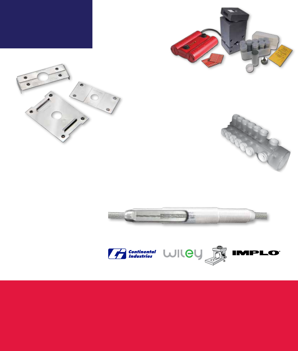
thermOweld®
With BURNDY’s recent addition of Continental
Industries’ assets—and its industry-
leading thermOweld® line of
exothermic grounding products
as well as the EZ Lite Remote®
Electric Ignition System—two
industry heavyweights are fusing
their resources: the power of thermOweld®
and BURNDY’s legendary customer service.
Wiley
With BURNDY’s acquisition of Wiley Electronics, we continue to lead the solar
evolution as technology becomes more accessible and affordable—thanks in part
our innovative product line that’s anchored by the bonding technology of the WEEB
washers, which allows 1.5 times faster installation than
traditional grounding methods.
CMC
CMC/CCC and BURNDY have worked closely together for
over 20 years. Now that CMC is part of BURNDY, we are uniquely
positioned to provide the most comprehensive offering of electrical
connector solutions. Plus, it’s now easier to access CMC’s Barfield brand
enclosures and pole line hardware.
IMPLO®
IMPLO® delivers industry-leading service performance, time-saving installation technology
and the ability to string transmission splices through travelers easily and safely.
There Is Only One IMPLO®
.
Our acquisitions are made with
the future in mind. With every
one, we’re better positioned to
grow our company and serve our
customers.

BURNDY Company Facts
• BURNDY was founded in July 1924 in Brooklyn, New York, by Bern Dibner, who fostered
a lifelong dedication to science and technology
• Acquired by Hubbell Incorporated in October 2009
• U.S.-based headquarters in Manchester, NH, with manufacturing sites in:
• BURNDY® is The Grounding SuperstoreTM—home to three versatile grounding systems:
mechanical grounding; BURNDYWeld® and thermOweld® exothermic grounding; and
HYGROUND® irreversible compression grounding
• BURNDY’s engineers can provide intricate, connector customization in a fraction
of the time. Our in-house advanced engineering support teams utilize today’s most
revolutionary technology: 3D neutral files in CAD; CAM and PDM; plus numerical
simulation, rapid prototyping and state-of-the-art testing equipment
Interested in Learning More?
Call us and a BURNDY® Customer Service Professional will answer the phone and your
questions—without having to press 1 or any other numbers!
We provide personal service to all our customers. Instead of installing a canned voice
and menu of options, we’ve focused resources on giving you immediate access to a
BURNDY® representative.
Based in Londonderry, New Hampshire, our Customer Service Center is staffed from 8 a.m.
to 8 p.m. Eastern Time, Monday through Friday. We ship products until 7 p.m. ET and also
provide emergency services 24 hours a day, seven days a week, 365 days a year.
2014 marks BURNDY’s 90th year of bringing a dedication to
engineering, manufacturing and offering high-quality, reliable
products for the commercial and industrial as well as the electric
utility markets. With that kind of market knowledge and history,
there’s no doubt we’re here for the long haul.
- Lincoln, NH
- Littleton, NH
- Bethel, CT
- Greenville, AL
- Hamilton, OH
- Broken Arrow, OK
- Tulsa, OK
- Manchester, TN
- Brechin, ON, Canada
- Toluca, Mexico
- Sao Paulo, Brazil
Customer Service Department
7 Aviation Park Drive
Londonderry, NH 03053
1-800-346-4175
1-800-451-4956 (Technical Services)
1-603-647-5299 (International)
Canada
1-800-361-6975 (Quebec)
1-800-387-6487 (All other provinces)
Mexico
011-52-722-265-4400
Brazil
011-55-11-5515-7225
Tool Service Center
Littleton Industrial Park
Littleton, NH 03561
1-800-426-8720

BURNDY®
Blue highlighted items are industry standard and most frequently ordered.
Canada: 1-800-387-6487 www.burndy.com US: 1-800-346-4175
Mechanical
A-1
TABLE OF CONTENTS
A-3
A-4
A-5
A-6
A-7
A-8
A-9
A-10
A-11
A-12
A-13
A-14
A-15
A-16
A-17
A-18
A-19
A-20
A-21
A-22
A-23
A-24
Types KS, KS-3, SC
Type KSU
Type KSA
Types KVS, KVSU
Types KVSW, KVS-A
Type QPX
Type QPX-Y
Types KPA, KPA-UP
Type KLU
Types KA, EA
Type BGBL
Types CL50-1, CL50-1TN, CL
Types QA, QQA
Types Q2A, Q3A
Types QB, Q2B
Types QDA, QR
Types VT, E-C-G
Types VA, VVA
Type HFB-P1
Type HFB-N
Types KA-U, KKA-U
Type KA-UAR
Type K2A-U
Types K3A-U, KK3A-U
Types K4A-U, KK4A-U,
K11A-U, K21A-U, K22A-U
Types K6A-U, K8A-U,
KK6A-U, KK8A-U
Type KAU-KIT
Type K-AG1
Type K-G1
Type AMS
Types AGSKIT, UGSKIT
Type BIBS-DB
Types UGSKIT8,
UGS350ULDB
Type BISR-DB
Types QGFL, FCB
Types KPU-AC, UCU-AC
Type BIPC
Terminal Blocks
U-BLOK™ and Platforms
SPEC-BLOK™
UL Listed Distribution
Blocks
Power Distribution Blocks,
Splice/Reducer Blocks
Types BIT, BITO, BISR
Type BIBS
Type BIBD
Types BIBS-MT, BIBD-MT
Type 1PL
Type BWTE
Type BPTE
A-25
A-26
A-27
A-28
A-29
A-30
A-31
A-32
A-33
A-34
A-35
A-36
A-37
A-38
A-39
A-40
A-41,
A-42
A-43
to
A-46
A-47
to
A-50
A-51
to
A-55
A-56
A-57
A-58
A-59
A-60
A-61
A-62
BURNDY®
Blue highlighted items are industry standard and most frequently ordered.
US: 1-800-346-4175 www.burndy.com Canada: 1-800-387-6487
Mechanical
A-2 LIGHTNING PROTECTION INFO.
Basic rules for selection are:
1. Must be like material to the conductor.
2. Two bolts to ground rod - minimum.
3. Cable to cable connections can be anything,
one bolt, two bolt, compression, etc.
4. Cable to steel structure must have 8 square
inch contact with steel.
Complies with NFPA 78-86 Ordinary Structures.
Complies with NFPA 78-86 Heavy Duty
Stacks. (Order: LD for Lead Plating for Heavy
Duty Stack applications.)
5. Heavy duty stacks - mechanical only.
6. On all connectors with heavy duty stack
rating, we must offer 1/16” thick lead plating
as an option. The reason for that is closest
25 ft. to stack opening must use lead coated
product.
SPECIAL FEATURES
Other features are also available for products
listed, such as undrilled or special drilling, 45° or
90° pad angles, belling for extra exible cable,
smooth or special threaded studs, special label-
ALL OTHER SPECIAL REQUESTS
PLEASE CONTACT
BURNDY CUSTOMER SERVICE
1-800-346-4175
REVOLUTIONARY
BURNDY® DESIGN
MEETS STRICT UL486B
STANDARDS
... and puts the bite on
aluminum connections
forever!
For use on all combinations
• Aluminum to aluminum
• Aluminum to copper
• Copper to copper
Patented
Unique “bite and grip”
TRITAP™ SERVIT® contact
delivers safe, long-term
reliability — even without
scratch brushing ... without
oxide inhibiting compounds.†
Available in sizes from #10 through 500 kcmil
Spacer provides built-in
separation to retard
galvanic corrosion
Triangular edges bite into
cable to break through
surface oxides:
• provide low contact
resistance
• produces gas tight
seal
Tin-plated contact
surface inhibits oxide
formation
Special heat-treated hard,
aluminum alloy
Anti-galling, high
efciency threaded
components result
in high contact force.
Easily installed using
standard, everyday
wrenches.
† When used in NEC applications of insulated
cables only.
ing or packaging, extra long braid, and nuclear
certication. Please contact BURNDY Customer
Service for any inquiries.
BURNDY®
Blue highlighted items are industry standard and most frequently ordered.
Canada: 1-800-387-6487 www.burndy.com US: 1-800-346-4175
Mechanical
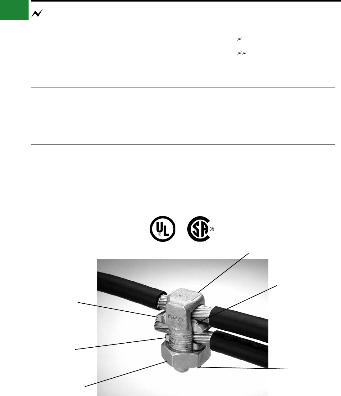
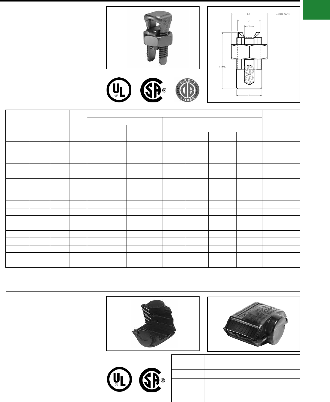
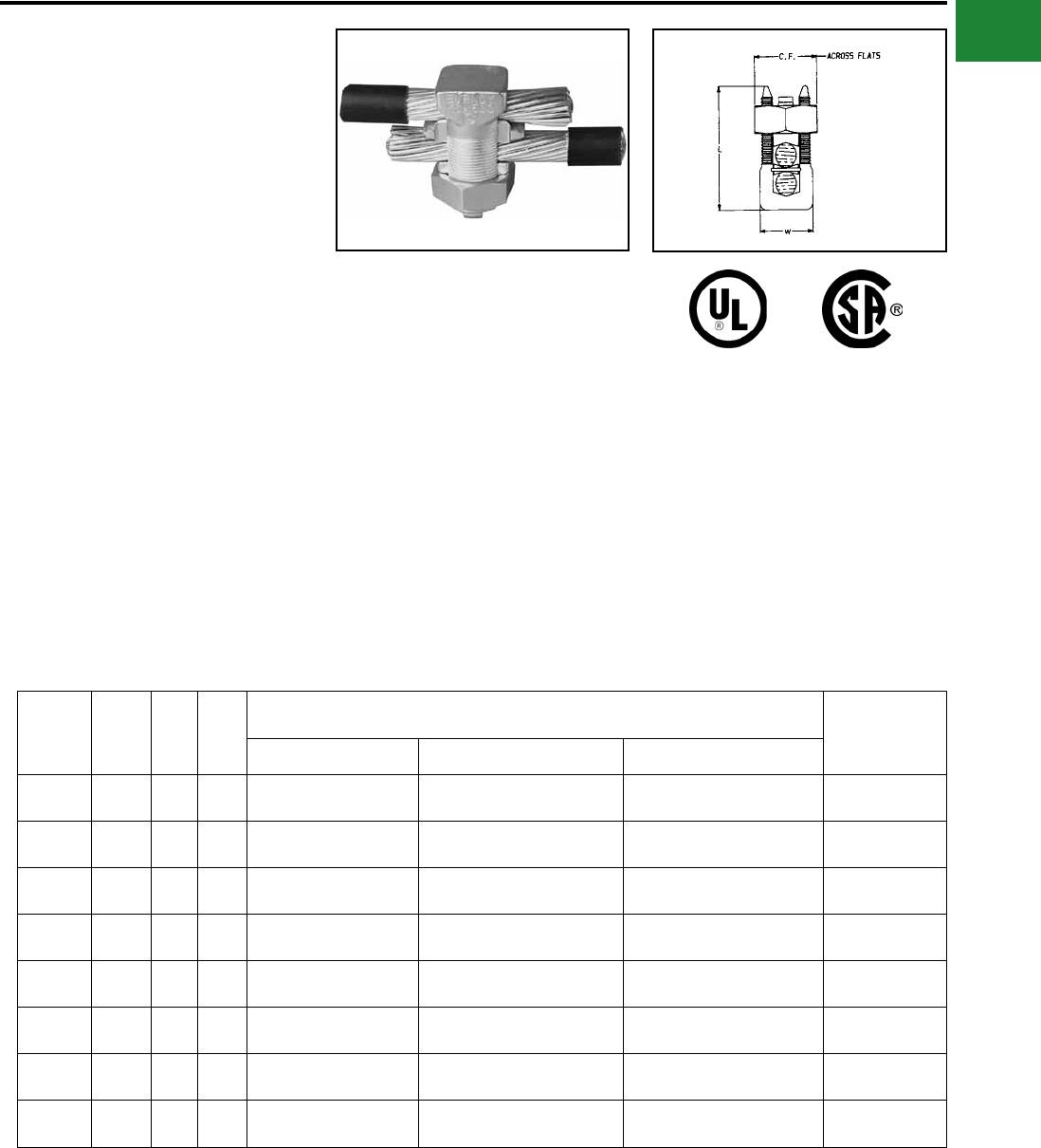
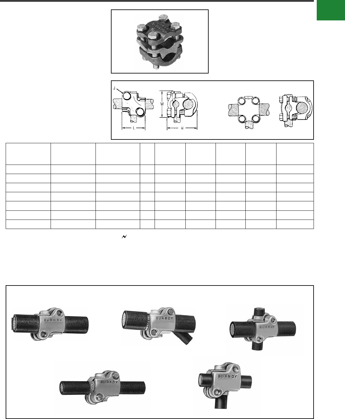
TYPES KS & KS-3
SERVIT®
For Copper, Copperweld
Compact, high strength, high copper alloy SERVIT®
split-bolt has free-running threads and easy to grip
wrench ats. Highly resistant to season cracking
and corrosion, the SERVIT® provides maximum
pressure and assures a secure connection on
all combinations of run and tap conductors. Type
KS-3 accommodates 3 maximum size conductors.
Catalog
Number
Cross
Flats L W
Conductor ▲
Recommended
Tightening
Torque (in-lb)
Copper Copperweld
Equal Run & Tap Min Tap with
Max Run
Maximum Run and Tap
Sol. Str. Type A Type D
† KS90 0.50 0.85 0.38 12 - 10 Str. 16 Str. #10 — — — 80
† KS15 0.50 0.85 0.38 10 - 8 Str. 14 Str. #8 — — — 80
† KS17 0.63 1.14 0.45 8 Str. - 6 Sol. 14 Str. #6 3 #12 8A 9-1/2D 165
* KS17-3 0.62 0.98 0.70 8 Str. - 6 Sol. 16 Str. #6 3 #12 8A 9-1/2D 165
† KS20 0.69 1.20 0.51 8 Str. - 4 Sol. 14 Str. #4 3 #10 6A 8D 165
* KS20-3 0.68 1.17 0.78 8 Str. - 4 Sol. 14 Str. #4 3 #10 6A 8D 165
† KS22 0.75 1.50 0.60 6 Str. - 2 Sol. 14 Str. #2 3 #8 4A 6D 275
* KS22-3 0.74 1.33 0.84 6 Str. - 2 Sol. 14 Str. #2 3 #8 4A 6D 275
† KS23 0.82 1.54 0.62 6 Str. - 2 Str. 14 Str. #1 3 #7 3A 5D 275
† KS25 0.94 1.77 0.73 4 Str. - 1/0 Str. 14 Str. 2/0 3 #5 2A 4D 385
† KS26 1.05 1.94 0.82 2 Str. - 2/0 Str. 14 Str. 3/0 7 #7 — — 385
† KS27 1.36 1.86 1.17 1 Str. - 3/0 Str. 8 Sol. — — — — 500
† KS29 1.36 2.07 1.17 1 Str. - 250 8 Str. 4/0 7 #5 — — 650
† KS31 1.70 2.51 1.41 1/0 Str. - 350 1/0 Str. — 19 #8 — — 650
† KS34 1.82 2.79 1.48 2/0 Str. - 500 2/0 Str. — 19 #6 — — 825
KS39 2.31 3.29 1.94 4/0 Str. - 750 4/0 Str. — 19 #5 — — 1000
KS44 2.56 3.73 2.19 300 - 1000 4/0 Str. — — — — 1100
▲ Listed torque values are for maximum conductor combinations accommodated. Consult UL486 Tables 7-4, 7-5, 7-6 for smaller conductor combinations.
See note LIGHTNING PROTECTION INFO.
* Not UL Listed or CSA Certied.
† In addition to UL Listed for wire connectors and CSA Certied, these items are also UL rated for direct burial.
TYPE SC
SERVIT® COVER
HUG-A-BUG
Used indoors or outdoors, this compact, one-piece
plastic SERVIT® cover saves time and material,
eliminates costly taping of split-bolts. Positive latch
snaps easily and quickly over connector, ideal for
tight quarters. Self-positioning plastic ngers wrap
around wires fully insulating joint. UL Listed for 600
volt indoor application with type KS. Three covers
accommodate a range of 6 SERVIT® sizes through
2/0 Str.
Catalog
Number For Use With
SC4 KS17, KS17-3, KS20, KSU17, KSU20
SC2 KS22, KS20-3, KS23, KS22-3, KSA6, KSA4,
KSU22, KSU23
SC2/0 KS25, KS26, KSA2, KSA1/0, KSU25, KSU26
A-3
BURNDY®
Blue highlighted items are industry standard and most frequently ordered.
US: 1-800-346-4175 www.burndy.com Canada: 1-800-387-6487
Mechanical
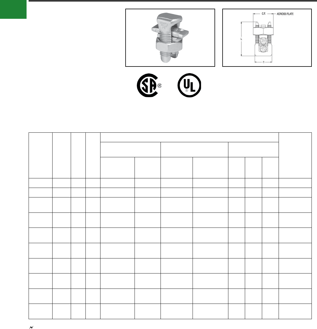
TYPE KSU
UNIVERSAL SERVIT®
For Use On All Combinations of
Copper, Aluminum, ACSR, AAAC,
5005, and Steel
Tin-plated, high strength, copper alloy SERVIT®
with spacer. Spacer separates dissimilar
conductors and provides long contact length that
prevents high pressure point contacts between run
and tap conductors.
Use of PENETROX™ joint compound
recommended with Aluminum and ACSR.
Catalog
Number
Cross
Flats L W
Conductor
Recommended
Tightening
Torque (in-lb)
Run Tap Steel
(Max Conductor)
Copper &
Aluminum
ACSR
AAAC
5005
Copper &
Aluminum
ACSR AAAC
5005
Sol.
BWG
3 Str.
BWG
Nom.
Dia.
KSU17 0.62 0.92 0.42 12 Sol. - 6 Sol. 8 (6-1) 12 Sol. - 6 Sol. 8 (6-1) 8 — 5/32 165
KSU20 0.69 1.05 0.48 10 Sol. - 4 Sol. 6 (6-1) 10 Sol. - 4 Sol. 6 (6-1) 6 8 7/32 165
KSU22 0.74 1.25 0.57 10 Sol. - 2 Sol. 6 (6-1) -
4 (7-1) 10 Sol. - 2 Sol. 6 (6-1) - 4 (7-1) 4 6 1/4 275
KSU23 0.81 1.48 0.59 8 Str. - 2 Str. 3 (6-1) -
2 (6-1) 8 Sol. - 2 Str. 6 (6-1) - 2 (6-1) — 4 5/16 275
KSU25 0.93 1.77 0.70 2 Str. - 1/0 Str. 3 (6-1) -
1 (6-1) 10 Str. - 1/0 Str. 6 (6-1) - 1 (6-1) — — 3/8 385
KSU26 1.04 1.93 0.79 2 Str.-2/0 Str. 1 (6-1) -
1/0 (6-1) 8 Str. - 2/0 Str. 6 (6-1) - 1/0 (6-1) — — 7/16 385
KSU27 1.38 2.34 1.12 1 Str. - 3/0 Str. 1 (6-1) -
2/0 (6-1) 8 Sol. - 3/0 Str. 8 (6-1) - 2/0 (6-1) — — 1/2 500
KSU29 1.38 2.50 1.58 1Str. -250 kcmil 2/0 (6-1) -
4/0 (6-1) 8 Str. - 250 6 (6-1) - 4/0 (6-1) — — 1/2 650
KSU31 1.69 2.88 1.36 1/0 Str. -
350 kcmil
3/0 (6-1) -
4/0 (6-1) 4 Str. - 350 4 (6-1) - 4/0 (6-1) — — 5/8 650
KSU34 2.00 3.12 1.47 400 - 500 kcmil 336 (30-7) -
477 (18-1) 2 Str. - 500 2 (6-1) - 477
(18-1) — — — 825
Copper Only 486A
Copper Only
Accommodates compressed conductors within conductor ranges.
See note LIGHTNING PROTECTION INFO.
A-4
BURNDY®
Blue highlighted items are industry standard and most frequently ordered.
Canada: 1-800-387-6487 www.burndy.com US: 1-800-346-4175
Mechanical
TYPE KSA
TRITAP™ SERVIT®
For All Combinations of Aluminum to
Aluminum, Aluminum to Copper and
Copper to Copper, Aluminum Alloy Tin
Plated
PATENTED TRIANGULAR
PENETRATION TECHNOLOGY
CONTACT
Catalog
Number
Cross
Flats L W
Alum. to Alum., Alum. to Copper, Copper to Copper Conductors Recommended
▲ Tightening
Torque (in-lb)
Max Run to Max Tap Min Run to Min Tap Max Run to Min Tap
KSA6 0.75 1.58 0.56 #6 Str. (0.184) -
#6 Str. (0.184)
#10 Sol. (0.102) -
#10 Sol. (0.102)
#6 Str. (0.184) -
#10 Sol. (0.102) 165
KSA4 0.81 1.38 0.62 #4 Str. (0.232) -
#4 Str. (0.232)
#8 Sol. (0.129) -
#10 Sol. (0.102)
#4 Str. (0.232) -
#10 Sol. (0.102) 165
KSA2 0.94 1.58 0.69 #2 Str. (0.292) -
#2 Str. (0.292)
#6 Sol. (0.169) -
#8 Str. (0.146)
#2 Str. (0.292) -
#8 Sol. (0.146) 275
KSA1/0 1.00 1.92 0.75 #1/0 Str. (0.373) -
#1/0 Str. (0.373)
#2 Str. Compact (0.268) -
#8 Sol. (0.129)
#1/0 Str. (0.373) -
#8 Sol. (0.129) 385
KSA2/0 1.12 1.92 0.88 #2/0 Str. (0.418) -
#2/0 Str. (0.418)
#2 Str. Compact (0.268) -
#8 Str. (0.146)
#2/0 Str. (0.418) -
#8 Str. (0.146) 385
KSA4/0 1.49 2.54 1.13 #4/0 Str. (0.528) -
#4/0 Str. (0.528)
#2 Str. Compact (0.268) -
$6 Str. (0.184)
#4/0 Str. (0.528) -
$6 Str. (0.184) 500
KSA350 1.69 3.24 1.50 350 kcmil (0.681) -
350 kcmil (0.681)
#1/0 Str. Compact (0.336) -
#4 Str. (0.232)
350 kcmil (0.681) -
#4 Str. (0.232) 650
KSA500 2.00 3.62 1.73 500 kcmil (0.813) -
500 kcmil (0.813)
400 kcmil Compact (0.659) -
#2 Str. Compact (0.268)
500 kcmil (0.813) -
#2 Str. Compact (0.268) 825
Features & Benets
• No scratch brushing required.
• No oxide inhibitor required.
• Orients the conductor.
• Provides maximum pressure and
assures a secure connection of run and
tap conductors.
• Facilitates piercing the aluminum
conductor surface oxides.
• UL 486B listed, 90°C rated.
• Provides a low contact resistance.
• Provides equal coefcient of expansion
• Inhibits the reformation of oxides by
producing a gas-tight seal.
• Provides improved retention of minimum
to maximum conductor combinations.
▲ Listed torque values are for maximum conductor combinations accommodated. Consult UL486 Tables 7-4, 7-5, 7-6 for smaller conductor combinations.
** No scratch brushing or oxide inhibiting compounds required for insulated 90° C max. rated conductor for N.E.C. applications.
A-5
BURNDY®
Blue highlighted items are industry standard and most frequently ordered.
US: 1-800-346-4175 www.burndy.com Canada: 1-800-387-6487
Mechanical
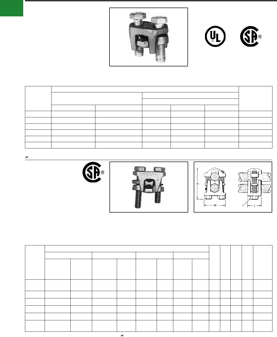
TYPE KVS
OKLIP™
Copper & Copperweld
Compact, two-piece, high strength, high copper
alloy BURNDY® OKLIP™ recommended for heavy
duty connections. Neoprene rings hold DURIUM™
bolts in place during installation. Installed with
ordinary wrench.
Catalog
Number
Conductor ▲
Recommended
Tightening
Torque (in-lb)
Copper Copperweld
Max Run & Tap
Run Tap Sol. Str. Type V
KVS26 2 Str. - 2/0 Str. 6 Str. - 2/0 Str. 3/0 7 #8 — 180
KVS28 1/0 Str. - 4/0 Str. 10 Str. - 4/0 Str. 4/0 7 #6 V3/0 250
KVS31 250 - 350 kcmil 10 Str. - 350 kcmil — 19 #8 V250 325
KVS34 400 - 500 kcmil 10 Str. - 500 kcmil — 19 #6 V350 375
KVS40 400- 800 kcmil 3/0 Str. - 800 kcmil — 19 #5 — 500
KVS44 500 - 1000 kcmil 3/0 Str. - 1000 kcmil — — — 500
▲ Listed torque values are for maximum conductor combinations accommodated. Consult UL486 Tables 7-4, 7-5, 7-6 for smaller conductor combinations.
See note LIGHTNING PROTECTION INFO.
TYPE KVSU
UNIVERSAL OKLIP™
Mechanical Connector All
Combinations of Copper, Aluminum,
ACSR, AAAC & 5005
Compact, high strength, tin plated copper alloy two-
piece connector with spacer and tin-plated silicon
bronze DURIUM™ hardware. Recommended
for heavy duty connections. Spacer separates
dissimilar conductors and provides long contact
length. Neoprene ring prevents loss of shorter
bolt during installation. Longer peened bolt
Catalog
Number
Conductor
H J L W
Rec.
Tightening
Torque
(in-lb)
Run Tap Run Tap
Copper &
Alum
ACSR,
AAAC, &
5005
Copper & Alum
ACSR,
AAAC,
& 5005
Copper
Sol.,
Copperweld
Sol.
Steel
Nom.
Dia.
Copper
Sol.,
Copper-
weld Sol.
Steel
Nom.
Dia.
KVSU26 2 Str. - 2/0 Str. 3 - 2/0 6 Str. - 2/0 Str. 6 - 2/0 1 - 3/0 5/16 -
7/16 #6 - 3/0 3/16 -
7/16 2 5/16 1 1-1/2 180
KVSU28 1/0 Str. - 4/0 Str. 1/0 - 4/0 6 Str. - 4/0 Str. 6 - 4/0 2/0 - 4/0 3/8 - 1/2 #6 - 4/0 5/32 - 1/2 2-3/8 3/8 1-1/8 1-3/4 250
KVSU31 250 - 350 kcmil 4/0 - 300 #6 - 350 6 - 300 - 9/16 - 5/8 #6 - 4/0 3/16 - 5/8 2-5/8 1/2 1-3/8 2-1/8 325
KVSU34 400 - 500 kcmil 336.4 - 397.5 #4 - 500 5 - 397.5 - 3/4 - 3/4 #4 - 4/0 7/32 - 3/4 3 1/2 1-1/2 2-1/4 375
KVSU40 400 - 800 kcmil 4/0 - 800 4/0 - 800 3/0 - 715.5 - 3/4 - 1 - 1/2 - 1 3-1/2 1/2 1-5/8 2-1/2 500
KVSU44 500 - 1000
kcmil 4/0 - 1000 4/0 - 1000 kcmil 4/0 - 900 - 7/8 - 1
1/8 -1/2 - 1
1/8 4 3/8 2 3 500
permits swivel action for easier installation. Use
of PENETROX™ joint compound recommended
with aluminum and ACSR.
See note LIGHTNING PROTECTION INFO.Accomodates compressed conductors within diameter range.
A-6
BURNDY®
Blue highlighted items are industry standard and most frequently ordered.
Canada: 1-800-387-6487 www.burndy.com US: 1-800-346-4175
Mechanical
See note LIGHTNING PROTECTION INFO.
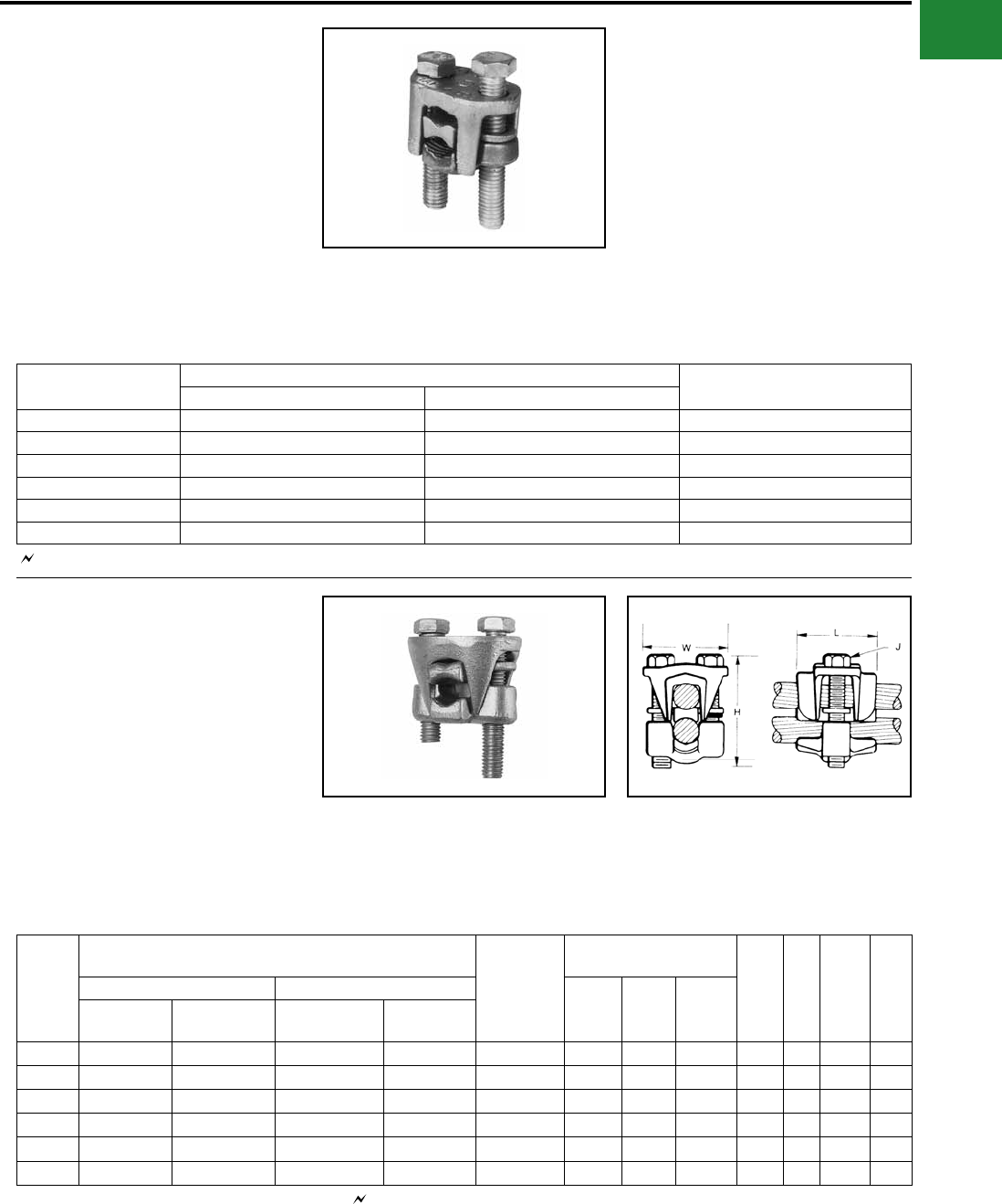
TYPE KVSW
OKLIP™
Mechanical Connector
For Copper and Copperweld
Similiar to OKLIP™ Type KVS except for a high
copper alloy spacer that separates run and tap
conductors. Provides high contact pressure,
connes conductor strands, and assures vibration-
proof connection. Longer peened bolt, permits
swivel action for easier installation. Silicon bronze
DURIUM™ hardware.
Catalog
Number
Conductor Recommended Tightening
Torque (in-lb)Run Tap
KVSW26 2 Str. - 2/0 Str. 6 Sol. - 2/0 Str. 180
KVSW28 1/0 Str. - 4/0 Str. 6 Sol. - 4/0 Str. 250
KVSW31 250 - 350 kcmil 4 Sol. - 350 kcmil 325
KVSW34 400 - 500 kcmil 4 Str. - 500 kcmil 375
KVSW40 400 - 800 kcmil AWG 4/0 - 800 kcmil 500
KVSW44 500 - 1000 kcmil 250 - 1000 kcmil 500
See note LIGHTNING PROTECTION INFO.
TYPE KVS-A
ALUMINUM OKLIP™
For Use On All Combinations of
Copper, Aluminum†, ACSR†, AAAC
and 5005
Three-piece, high-conductivity, non-copper
bearing aluminum alloy connector with thick spacer
and aluminum hardware. Hardware in KVS26A
and KVS28A is stainless steel. Recommended for
heavy duty dissimilar metal applications. Spacer
separates conductors and provides long contact
length. Belled entrances prevent chang, permit
easier assembly of conductors. Longer peened
bolt permits swivel action for easier installation.
Neoprene ring prevents loss of shorter bolt.
PENETROX™ joint compound recommended
with aluminum and ACSR.
Catalog
Number
Conductor
Rec.
Tightening
Torque (in-lb)
Conductor Range by
Diameter
H J L W
Run Tap Min.
Run
Dia.
Min.
Tap
Dia.
Max.
Run &
Tap Dia.
Copper,
& Alum.†
ACSR†,
AAAC, & 5005
Copper,
& Alum.†
ACSR†,
AAAC & 5005
KVS26A 2 Str. - 2/ 0 Str. #4 - 2/0 10 Str. - 2/0 Str. #6 - 2/0 180 0.28 0.12 0.45 2-1/4 5/16 1-1/4 1-5/8
KVS28A 1/0 Str. - 4/0 Str. 1/0 - 4/0 10 Str. - 4/0 Str. #6 - 4/0 240 0.36 0.12 0.56 3 3/8 1-5/8 2-1/16
KVS31A 250 - 350 4/0 - 336.4 6 Str. - 350 kcmil #6 - 336.4 kcmil 300 0.57 0.18 0.68 3-1/16 1/2 1-15/16 2-7/16
KVS34A 400 - 500 336.4 - 397.5 4 Str. - 500 kcmil #5 -397.5 kcmil 300 0.73 0.22 0.81 3-9/16 1/2 2-5/16 2-5/8
KVS40A 400 - 800 336.4 - 715.5 kcmil 3/0 Str. - 800 kcmil #3/0 - 715.5 300 0.73 0.47 1.04 4-1/16 1/2 2-7/16 2-7/8
KVS44A 500 - 1000 397.5 - 900 kcmil 3/0 Str. - 1000 kcmil #3/0 - 900 kcmil 480 0.80 0.47 1.16 4-7/8 5/8 2-1/2 3-1/8
† Accommodates compressed conductors within diameter range.
THESE CONNECTORS CAN ACCOMMODATE
ACSR CONDUCTORS OVER ARMOR ROD
WITHIN THE DIAMETER RANGE INDICATED.
APPLICATION OVER ARMOR ROD
A-7
BURNDY®
Blue highlighted items are industry standard and most frequently ordered.
US: 1-800-346-4175 www.burndy.com Canada: 1-800-387-6487
Mechanical
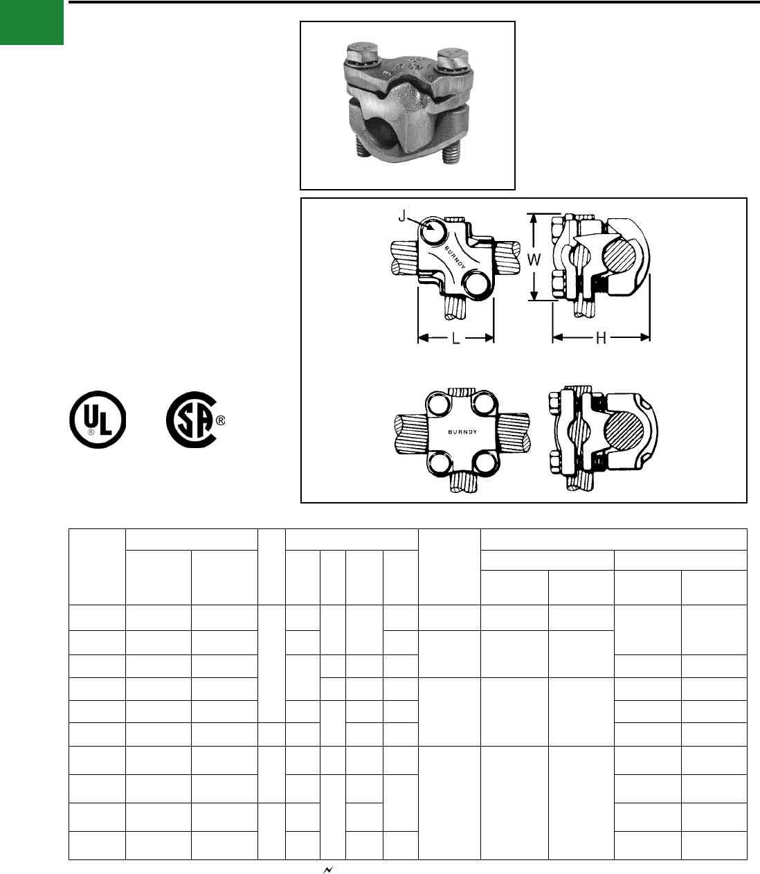
TYPE QPX
VERSITAP™
Parallel Clamp For Copper,
Copperweld, Copperweld-Copper
The VERSITAP™ Type QPX is
recommended for Tee, Cross, Parallel,
Butt and Tap connections. Range-
taking, only 10 connectors required to
accommodate conductor sizes from #6
Str. to 1000 kcmil. Edges are rounded
for easy taping. Made of high strength,
high-conductivity copper alloy and silicon
bronze DURIUM™ hardware.
Catalog
Number
Copper Conductor
Fig.
No.
Dimensions Rec.
Tightening
Torque
in-lb ▲
Conductor
Run Tap H J L W
Run Tap
Copperweld Copperweld
- Copper Copperweld Copperweld
- Copper
QPX2C2C 6 Str. - 2 Str. 6 Str. - 2 Str.
1
1-1/2
5/16 1-5/16
1-3/8 150 5 Sol. - 3 #7 8A - 4A
5 Sol. - 3 #7 8A - 4A
QPX282C 1 Str. - 4/0 Str. 6 Str. - 2 Str. 2-1/16 1-9/16
250 7 #9 - 7 #5 3A - 3/0V
QPX2828 1 Str. - 4/0 Str. 1 Str. - 4/0 Str.
2-3/8
3/8 1-13/16 1-13/16 7 #9 - 7 #5 3A - 3/0V
QPX342C 250 - 500 kcmil 6 Str. - 2 Str. 5/16 1-3/8 1-7/8
375 19 #19 - 19 #6 4/0 EK
5 Sol. - 3 #7 8A - 4A
QPX3428 250 - 500 kcmil 1 Str. - 4/0 Str. 2-3/4
3/8
1-3/4 2-1/16 7 #9 - 7 #5 3A - 3/0 V
QPX3434 250 - 500 kcmil 250 - 500 kcmil 2 3 2-1/16 2-3/16 19 #19 - 19 #6 4/0 EK
QPX442C 500 - 1000
kcmil 6 Str. - 2 Str.
1
2-11/16 5/16 1-3/8 2-1/4
500 19 #6 —
5 Sol. - 3 #7 8A - 4A
QPX4428 500 - 1000
kcmil 1 Str. - 4/0 Str. 2-7/8
3/8
1-13/16
2-7/16
7 #9 - 7 #5 3A - 3/0V
QPX4434 500 - 1000
kcmil 250 - 500 kcmil
2
3-1/16 2-1/16 19 #19 - 19 #6 4/0 EK
QPX4444 500 - 1000
kcmil
500 - 1000
kcmil 3-7/16 2-5/8 2-9/16 19 #6 —
▲ Listed torque values are for maximum conductor combinations
accommodated. Consult UL486 Tables 7-4, 7-5, 7-6 for smaller
conductor combinations.
See note LIGHTNING PROTECTION INFO.
Fig. 1
Fig. 2
* For various congurations, see page
TYPE QPX-Y
A-8
BURNDY®
Blue highlighted items are industry standard and most frequently ordered.
Canada: 1-800-387-6487 www.burndy.com US: 1-800-346-4175
Mechanical
TYPE QPX-Y
UNIVERSAL VERSITAP™
Universal Parallel Clamp For Copper
and Aluminum
High copper alloy cast connector, tin-plated for use
with copper or aluminum cable. Makes parallel,
tap, tee, cross or end-to-end connections. Edges
rounded for easy taping. PENETROX™ joint
compound recommended.
Catalog
Number Run Tap
Fig.
No. H J L W
Recommended
Tightening
Torque in-lb ▲
QPX2C2C-Y 6 Str.-2 Str. 6 Str.-2 Str. 1 1-5/8 5/16 1-1/2 1-5/8 150
QPX282C-Y 1 Str. - 4/0 Str. 6 Str.-2 Str. 1 1-7/8 5/16 1-1/2 1-7/8 150
QPX2828-Y 1 Str. - 4/0 Str. 1 Str. - 4/0 Str. 1 2 3/8 2 2-1/8 250
QPX342C-Y 250 - 500 kcmil 6 Str.-2 Str. 1 2-1/4 5/16 1-1/2 2-1/8 375
QPX3428-Y 250 - 500 kcmil 1 Str. - 4/0 Str. 1 2-1/2 3/8 2 2-1/2 375
QPX3434-Y 250 - 500 kcmil 200 - 500 kcmil 2 2-7/8 3/8 2-1/2 2-5/8 375
QPX4444-Y 750 - 1000 kcmil 750 - 1000 kcmil 2 3-7/8 1/2 3-1/2 3-1/2 500
Fig. 1 Fig. 2
▲ Listed torque values are for maximum conductor
combinations accommodated. Consult UL486 Tables
7-4, 7-5 7-6 for smaller conductor combinations.
See note LIGHTNING PROTECTION INFO.
APPLICATION
VARIATIONS
PARALLEL
SPLICE
CROSSTAP
TEE
A-9
BURNDY®
Blue highlighted items are industry standard and most frequently ordered.
US: 1-800-346-4175 www.burndy.com Canada: 1-800-387-6487
Mechanical
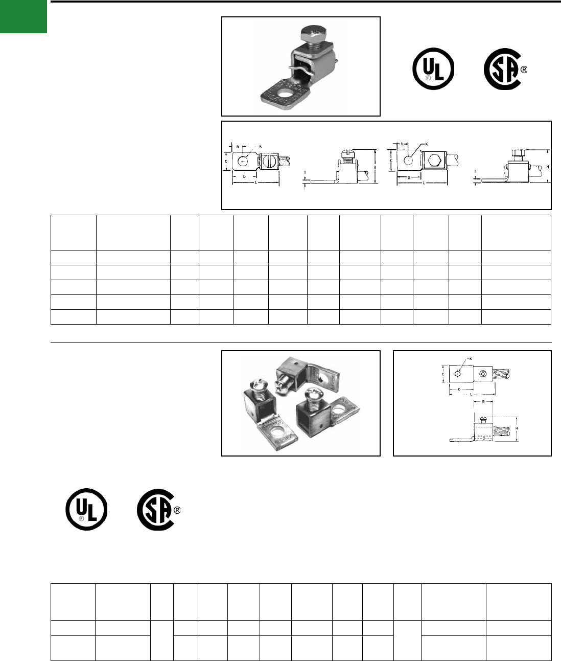
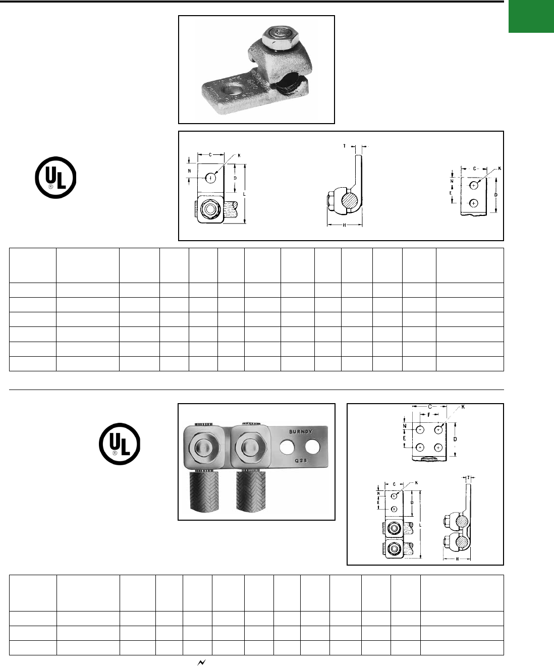
TYPE KPA
SCRULUG™
For Copper Cable
High copper alloy tin-plated terminal for joining
a wide range of cable to equipment pads or
terminal blocks. Especially good in light industrial
applications. The tongue and body are a one-piece
design. The pressure bar equalizes pressure over
the conductor and prevents the screw from cutting
into the cable.
Catalog
Number Wire Range Fig.
No. C D H K Stud
Hole Size L N T
Recommended
Tightening
Torque (in-lb)
KPA8C 14 Sol. - 8 Str. 1 0.38 0.47 0.72 0.21 #10 0.97 0.22 0.06 25
KPA4C 14 Sol. - 4 Str. 1 0.50 0.59 0.94 0.27 1/4 1.22 0.30 0.06 35
KPA25 4 Str. - 1/0 Str. 2 0.75 0.81 1.25 0.33 5/16 1.82 0.41 0.10 180
KPA28 1/0 Str. - 4/0 Str. 2 0.97 1.12 1.66 0.39 3/8 2.40 0.53 0.13 250
KPA34 4/0 Str. - 500 kcmil 2 1.38 1.38 2.44 0.54 1/2 3.32 0.75 0.20 375
Fig. 1 Fig. 2
TYPE KPA-UP
SCRULUG™
For Copper Cable
High copper alloy terminal for joining a wide range
of cable to equipment pads or terminal blocks.
Plain copper nish. Features & Benets
• One piece design.
◊ Superior torque and pull out
performance.
• Convenient range taking design.
◊ Reduces catalog numbers. One
catalog number accommodates several
conductor sizes.
• High conductivity copper alloy.
◊ Long lasting, reliable contact.
• Compact design.
◊ Easy to use.
• Slot Robertson screw, hex head, hex
socket bolt.
◊ No special installation tools required.
Eliminates over-torquing/potential
conductor damage.
Catalog
Number Wire Range
Fig.
No. C D H K
Stud Hole
Size L N T Hardware
Recommended
Tightening
Torque (in-lb)
KPA8CUP 14 Sol. - 6 Str.
1
0.38 0.56 0.81 0.20 #10 1.04 0.22
0.07
# 12-24 SLOT 35
KPA4CUP 14 Sol. - 4 Str. 0.50 0.71 1.00 0.28 1/4 1.28 0.33 5/16 DIA.SLOT
ROBERTSON 45
NOTE: For tin plating drop “-UP” sufx and add “-TP” sufx
(example: KPA4CTP).
For use in grounding applications with a green screw, contact
factory. Listed for grounding per UL467.
Fig. 1
NOTE: For unplated version add “UNPL” sufx.
A-10
BURNDY®
Blue highlighted items are industry standard and most frequently ordered.
Canada: 1-800-387-6487 www.burndy.com US: 1-800-346-4175
Mechanical
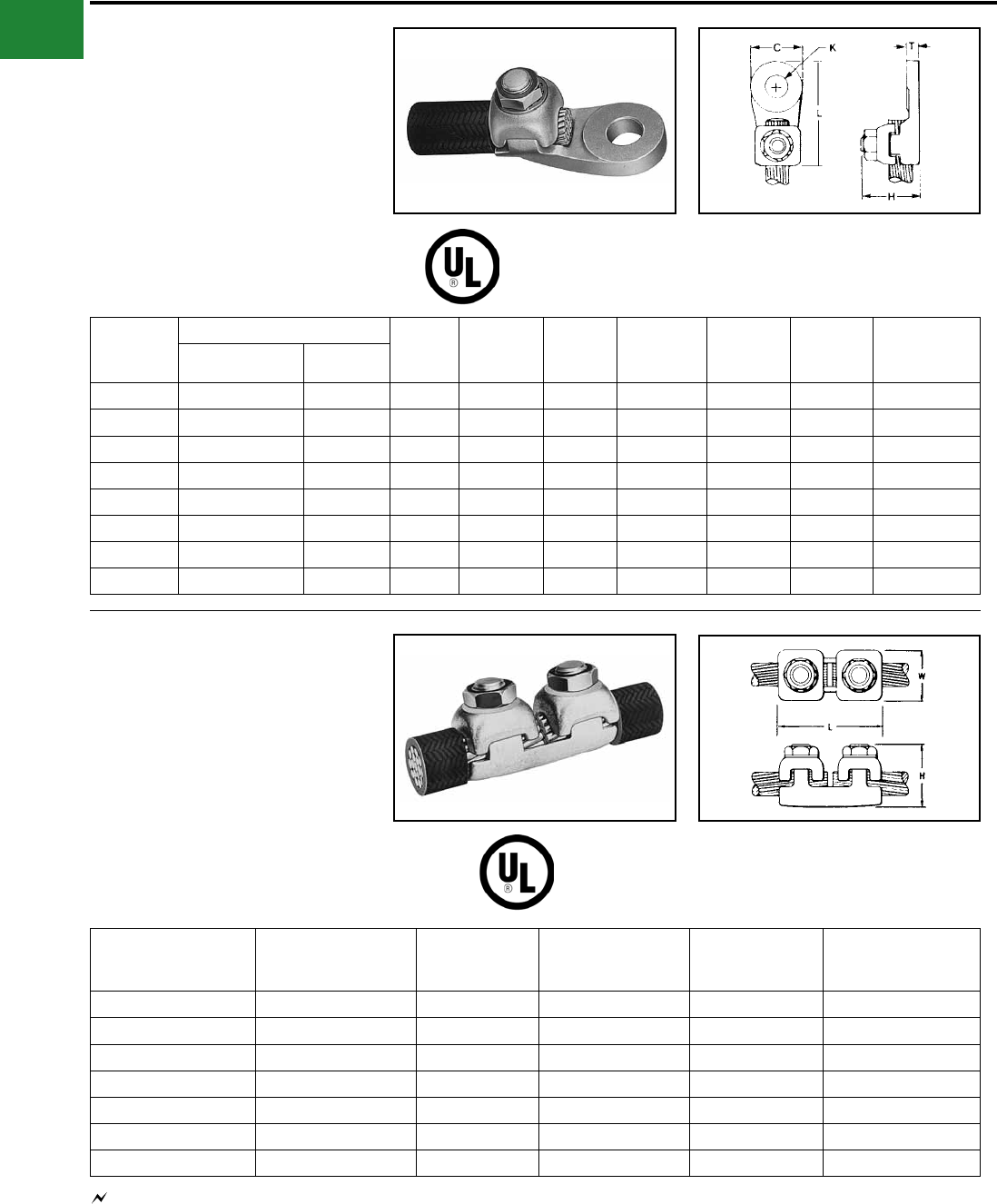
TYPE KLU
SCRULUG™
FOR COPPER CABLE -
OFFSET TONGUE - NON-PLATED
High copper alloy terminal with offset tongue for
joining a wide range of cable to equipment pads
or bar. Easy to install with screwdriver or wrench.
Connector is reusable. Plain copper nish.
Catalog
Number Conductor
Fig.
No.
B
(MM/IN)
C
(MM/IN)
K
(MM/IN)
L
(MM/IN)
N
(MM/IN)
T
(MM/IN)
Rec.
Tightening
Torque
(in-lb) Hardware
Stud
Hole
Size
Strip
Length
(in)
KLU25 14 Sol. .064 Dia.to
10 Sol. .102 Dia. CU 37.00
0.28
8.00
0.31
4.00
0.14
26.0
1.02
5.00
0.21
2.00
0.07 20 No. 8-32 Slotted Round
Machine Screw #6 7/16
KLU25TP
KLU35 14 Sol. .0641 Dia.to
6 Str. .184 Dia. CU 211.0
0.43
10.0
0.39
5.00
0.20
31.0
1.24
6.00
0.22
2.00
0.07 35 1/4 UNF Slotted Set
Screw #10 5/8
KLU35TP
KLU70 8 Sol. .129 Dia. to
2 Str. .292 Dia. CU 213.0
0.50
12.0
0.47
7.00
0.26
39.0
1.55
6.00
0.25
2.00
0.08 40 5/16 UNF Slotted Set
Screw 1/4 3/4
KLU70TP
KLU125 2 Str. .292 Dia. to
1/0 Str. .372 Dia. CU 215.0
0.61
16.0
0.62
7.00
0.26
50.0
1.98
11.0
0.42
3.00
0.11 50 3/8 UNF Slotted Set
Screw 1/4 15/16
KLU125TP
KLU175 4 Str. .232 Dia. to
3/0 Str. .470 Dia. CU 118.0
0.72
19.0
0.75
10.0
0.39
56.0
2.20
11.0
0.43
4.00
0.16 250 3/8 UNF Socket/Hex
Screw 3/8 1
KLU175TP
KLU225 2 Str. .292 Dia. to
4/0 Str. .528 Dia. CU 124.0
0.94
25.0
0.99
9.00
0.34
65.0
2.55
13.0
0.51
3.00
0.12 250 7/16 UNF Socket/Hex
Screw 5/16 1-5/16
KLU225TP
KLU300 1/0 Str. .372 Dia. to
350 kcmil .681 Dia. CU 131.0
1.22
25.0
0.99
10.0
0.39
72.0
2.83
13.0
0.52
3.00
0.12 325 5/8 UNF Socket/Hex
Screw 3/8 1-5/8
KLU300TP
KLU400 1/0 Str. .372 Dia. to
500 kcmil .813 Dia. CU 136.0
1.42
38.0
1.50
10.0
0.39
104.0
4.09
23.0
0.91
5.00
0.18 375 5/8 UNF Socket/Hex
Screw 3/8 1-5/32
KLU400TP
Features & Benets
• Convenient range-taking design.
◊ Reduces catalog numbers.
One conductor accommodates several
conductor sizes.
• High conductivity copper alloy
◊ Long lasting reliable contact.
• Compact design
◊ Easy to use. Reduces labor time.
• Slot Robertson screw, hex head/hex
socket bolt
◊ No special installation tools required.
eliminates over-torquing/potential
conductor damage.
NOTES:
Sufx “-TP” on catalog number denotes tin plate (example: KLU400TP).
2 Material: Copper alloy.
1
1
A-11
BURNDY®
Blue highlighted items are industry standard and most frequently ordered.
US: 1-800-346-4175 www.burndy.com Canada: 1-800-387-6487
Mechanical
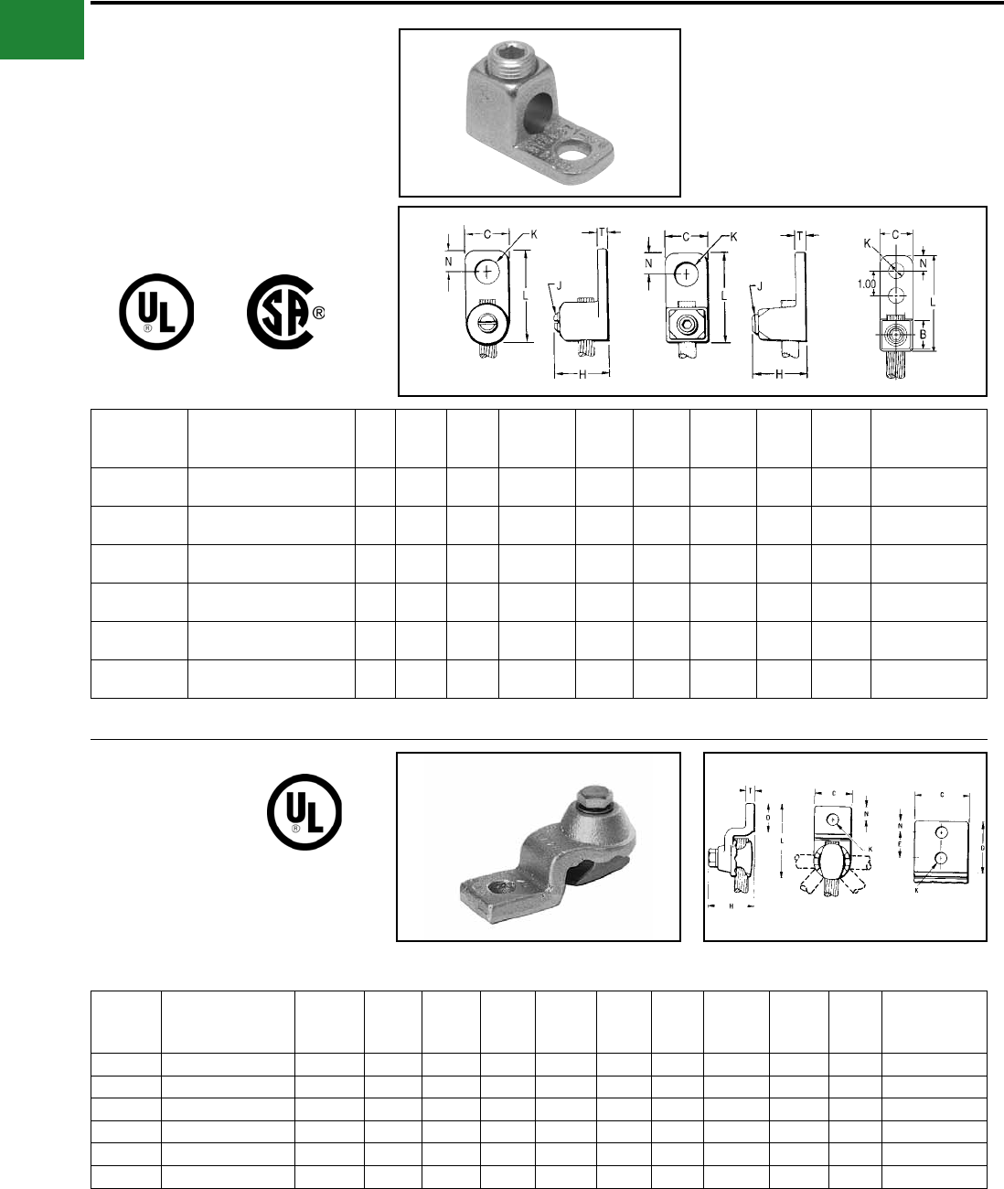
TYPE KA
KA-LUG™
For Copper Cable
Compact, economical, high copper alloy terminal
for joining a wide range of cable to equipment pads
or terminal blocks.
Catalog
Number Conductor Fig.
No. C H J K
Stud
Hole
Size
L N T
Recommended
Tightening
Torque (in-lb)
KA8C # 14 Sol. (0.064 Dia.) -
8 Str. (0.416 Dia.) 1 3/8 5/8 #12 7/32 #10 13/16 3/16 3/32 25
KA4C # 14 Sol. (0.064 Dia.) -
4 Str. (0.232 Dia.) 1 9/16 3/4 5/16" 9/32 1/4 1-1/8 1/4 7/64 45
KA25 # 4 Str. (0.232 Dia.) -
1/0 Str. (0.373 Dia.) 2 3/4 15/16 1/2"27/64 3/8 1-11/16 3/8 1/8 200
KA25-2TC38 # 4 Str. (0.232 Dia.) -
1/0 Str. (0.373 Dia.) 3 3/4 15/16 1/2" 27/64 3/8 2-13/16 3/8 1/8 200
KA28 # 1 Str. (0.332 Dia.) -
4/0 Str. (0.528 Dia.) 2 15/16 1-1/4 5/8" 27/64 3/8 1-15/16 7/16 3/16 275
KA34 4/0 Str. (0.528 Dia.) -
500 kcmil (0.814 Dia.) 2 1-3/8 2-3/32 13 /16" 9/16 1/2 2-9/16 9/16 9/32 375
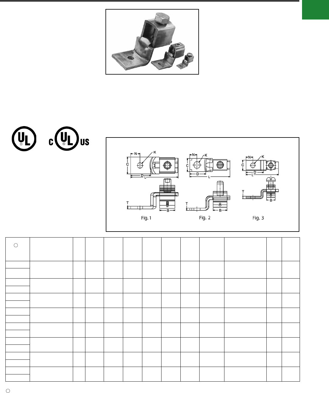
TYPE EA
VERSILUG™
For Copper Cable
Compact, high copper alloy terminal for joining
a wide range of cable to equipment pads or bar.
Clamping element adjustable to several angles.
One-wrench installation.
Catalog
Number Wire Range
No. of
holes in
pad
C D E H K
Stud
Hole
Size
L N T
Rec.
Tightening
Torque (in-lb)
EA2C 8 AWG-2 AWG 1 13/16 1-1/16 — 1-3/8 7/16 3/8 2-1/2 13/32 1/4 150
EA25 2 AWG-1/0 1 7/8 1-1/8 — 1-7/16 7/16 3/8 2-11/16 7/16 1/4 180
EA28 1/0 -4/0 AWG 1 1-1/16 1-3/8 — 1-3/4 7/16 3/8 3-3/16 17/32 5/16 250
EA28-2N 1/0 -4/0 AWG 2 1-1/16 3-5/8 1-3/4 1-3/4 9/16 1/2 5-1/8 5/8 5/16 250
EA34 250 kcmil-500 kcmil 1 1-3/8 1-5/8 — 2-1/4 9/16 1/2 4 13/16 3/8 375
EA34-2N 250 kcmil-500 kcmil 2 1-3/8 3-5/8 1-3/4 2-1/4 9/16 1/2 5-5/8 5/8 3/8 375
▲ Listed torque values are for maximum conductor sizes
accommodated.
Consult UL486 Tables 7-4, 7-5, 7-6 for smaller conductor sizes.
* “N” indicates NEMA standard stud holes.
▲ Listed torque values are for maximum conductor sizes
accommodated.
Consult UL486 Tables 7-4, 7-5, 7-6 for smaller conductor sizes.
Fig. 1 Fig. 2 Fig. 3
A-12
BURNDY®
Blue highlighted items are industry standard and most frequently ordered.
Canada: 1-800-387-6487 www.burndy.com US: 1-800-346-4175
Mechanical
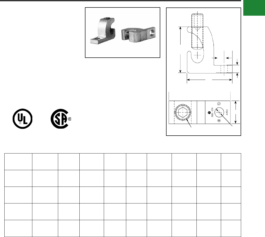
TYPE BGBL
LAY-IN QIKLUG™
UL LISTED 90° C, 600 V
The Lay-In QIKLUG™, Type BGBL is
manufactured from high strength 6061-T6
aluminum, and is ideally suited for grounding and
bonding applications accommodating both copper
and aluminum conductor sizes #14 AWG to 250
kcmil. The BGBL4SS with Stainless Steel screw is
UL 467 Listed for grounding and bonding.
Catalog
Number
Conduc-
tor Range C H J K L N T Hex
Size
BGBL-4 14 - 4 0.38
[10]
0.78
[20] 1/4 - 28 0.22
[6]
1.07
[27]
0.19
[5]
0.15
[4] Slot
BGBL4SS* 14 - 4 0.38
[10]
0.78
[20] 1/4 - 28 0.22
[6]
1.07
[27]
0.19
[5]
0.15
[4] Slot
BGBL-1/0 14 - 1/0 0.60
[15]
1.17
[30] 3/8 - 24 0.27
[7]
1.50
[38]
0.30
[8]
0.22
[6] Slot
BGBL-250 6 - 250
kcmil
0.80
[20]
1.79
[45] 9/16 - 18 0.33
[8]
2.20
[56]
0.40
[10]
0.30
[8] 5/16
Features & Benets
• UL 486B listed, AL9CU rated
◊ For copper and aluminum conductor
combinations up to 90° C, 600 Volt
applications.
• UL Recognized for grounding and
bonding
◊ Ensures reliability.
• Electro-tin plated
◊ Provides low contact resistance.
• Lay-in feature
◊ Eases installation.
* Suitable for copper conductors only.
L
T
N
H
REF
K DIA.
C
J
A-13
BURNDY®
Blue highlighted items are industry standard and most frequently ordered.
US: 1-800-346-4175 www.burndy.com Canada: 1-800-387-6487
Mechanical
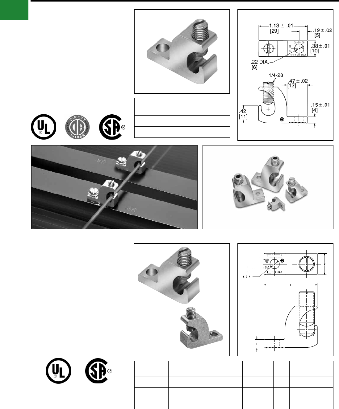
TYPE CL50-1 & CL50-1TN
COPPER LAY-IN QIKLUG™
For Copper
The Lay-In QIKLUG™ is manufactured from
high strength pure electrolytic copper to ensure
maximum strength and conductivity. UL467
Listed for direct burial in earth or concrete. The
open-faced design allows for fast lay-in of the
conductor without the need for cutting or breaking.
Stainless steel screws used for excellent corrosion
resistance. Catalog
Number
Conductor
Range
Stud
Hole
CL50-1 14 AWG-4 AWG #10
CL50-1TN 14 AWG-4 AWG #10
TYPE CL
COPPER LAY-IN QIKLUG™
For Copper
Manufactured for maximum strength and
conductivity, these lay-in lugs allow for continuous
runs of conductor and are well suited as
terminations as well. Tin-plated, set screw style
connectors, three sizes cover a range from
#14AWG to 250 kcmil. CL3/0-516TN and CL250-
516TN are UL Listed and CSA certied. CL1/0-
14TN UL Listed for grounding and CSA certied.
90° C rated. Suitable for copper conductors only.
Photo above shows a typical solar panel installation using CL50-1 connectors.
Catalog
Number
Wire Range
Copper H W L T K
Dia Hex Size
CL1/0-14TN #14 - 1/0 AWG 1.17 0.60 1.50 0.22 0.27 7/16-20 (Slotted)
CL3/0-516TN #6 - 3/0 AWG 1.56 0.80 2.00 0.30 0.33 9/16-18 (0.25 Hex)
CL250-516TN #6 AWG - 250 kcmil 1.79 0.80 2.20 0.30 0.33 9/16-18 (0.25 Hex)
A-14
BURNDY®
Blue highlighted items are industry standard and most frequently ordered.
Canada: 1-800-387-6487 www.burndy.com US: 1-800-346-4175
Mechanical
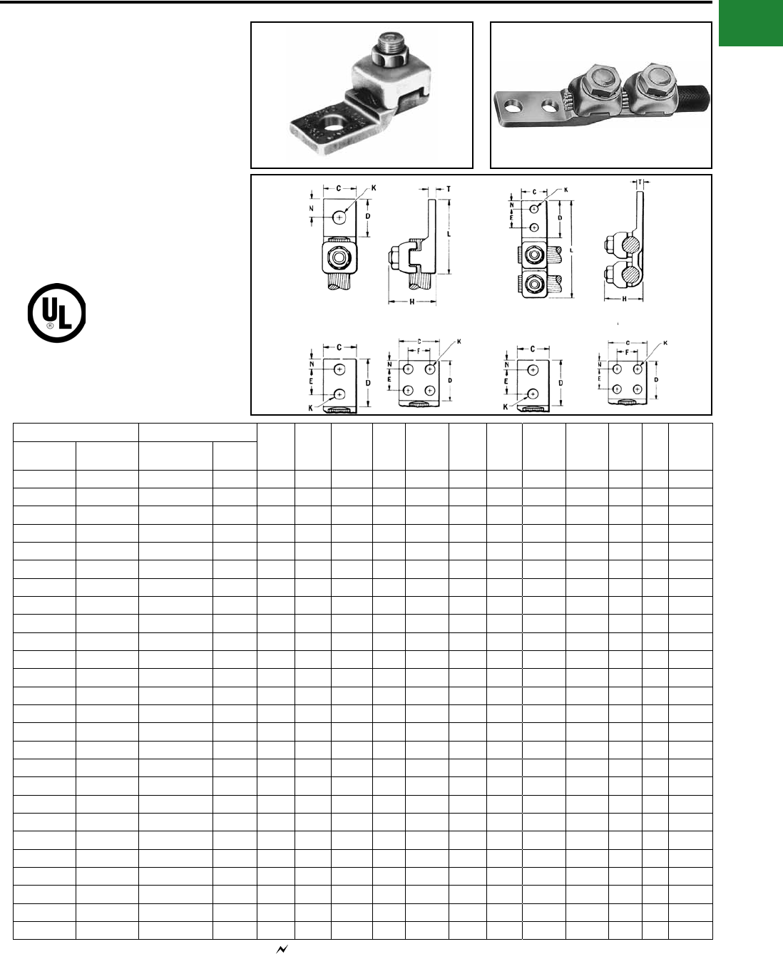
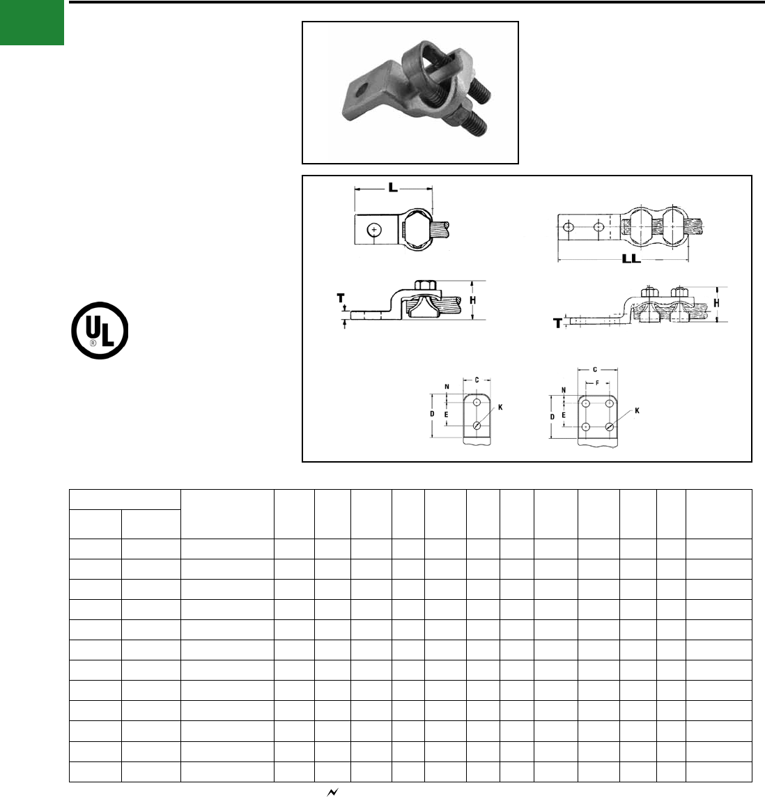
TYPES QA, QQA
QIKLUG™
Copper Cable
Type QA heavy duty, compact, high copper
alloy terminal for joining a wide range of cable
to equipment pads or bar. Fast one-wrench
installation. Type QQA heavy duty, high copper
alloy terminal for joining cable to equipment
pads or bar. Twin clamping elements secure joint
vibration and exing. One-wrench installation.
Catalog Number* Conductor Holes
in Pad C D E & F H K
Stud
Hole
Size
L LL N T Torque
(in-lb)
Type QA Type QQA Commercial Navy
QA8C-B QQA8C 14 Sol. - 8 Str. 4-14 1 9/16 9/16 — 11/16 7/32 #10 1-3/8 2-5/16 9/32 5/32 75
QA8C-2B QQA8C-2 14 Sol. - 8 Str. 4-14 2 9/16 1-1/14 5/8 11/16 7/32 #10 2 3 5/16 5/32 75
QA4C-B QQA4C 8 Str. - 4 Str. 23-40 1 5/8 5/8 — 3/4 9/32 1/4 1-7/16 2-3/8 5/16 3/16 110
QA4C-2B QQA4C-2 8 Str. - 4 Str. 23-40 2 5/8 1-3/16 5/8 3/4 9/32 1/4 2 2-15/16 5/16 3/16 110
QA1C-B QQA1C 4 Str. - 1 Str. 50-75 1 5/8 3/4 — 1 9/32 1/4 1-3/4 2-13/16 11/32 7/32 150
QA1C-2B QQA1C-2 4 Str. - 1 Str. 50-75 2 5/8 1-9/16 7/8 1 11/32 5/16 2-9/16 3-5/8 11/32 7/32 150
QA26-B QQA26 1/0 Str. - 2/0 Str. 100-125 1 13/16 1 — 1-3/16 13/32 3/8 2 3-3/16 7/16 7/32 180
QA26-2B QQA26-2 1/0 Str. - 2/0 Str. 100-125 2 13/16 1-15/16 1 1-3/16 13/32 3/8 3 4-3/16 7/16 7/32 180
QA28-B QQA28 3/0 Str. - 4/0 Str. 150-200 1 1 1-1/16 — 1-5/16 13/32 3/8 2-1/4 3-9/16 17/32 1/4 250
QA28-2B — 3/0 Str. - 4/0 Str. — 2 1 2 1 1-9/29 13/32 3/8 3-1/5 — 7/16 1/4 250
QA28-2N* QQA28-2N* 3/0 Str. - 4/0 Str. 150-200 2 1 3-1/8 1-3/4 1-5/16 9/16 1/2 4-5/16 5-5/8 5/8 1/4 250
QA31-B QQA31 250 - 350 kcmil 250-350 1 1-3/16 1-3/8 — 1-11/16 17/32 1/2 2-11/36 4-1/8 11/16 5/16 325
QA31-2B — 250 - 350 kcmil 250-350 2 1-3/16 1-31/32 1 1-11/16 7/16 3/8 3-3/8 — 7/16 5/16 325
QA31-2N QQA31-2N* 250 - 350 kcmil 250-350 2 1-3/16 3 1-3/4 1-11/16 9/16 1/2 4-7/16 5-7/8 5/8 5/16 325
QA34-B — 400 - 500 kcmil 400-500 1 1-3/8 1-5/8 — 2 17/32 1/2 3-3/16 4-7/8 13/16 5/16 375
QA34-2B — 400 - 500 kcmil 400-500 2 1-3/8 2 1 2 13/32 3/8 3-9/16 — 7/16 5/16 375
QA34-4B QQA34 400 - 500 kcmil 400-500 4 1-7/8 1-15/16 1 2 7/16 3/8 3-1/2 — 7/16 5/16 375
QA34-2N* QQA34-2N* 400 - 500 kcmil 400-500 2 1-3/8 3-3/32 1-3/4 2 9/16 1/2 4-11/16 6-9/32 5/8 5/16 375
QA40-B — 600 - 800 kcmi 650-800 1 1-5/8 1-7/8 — 2-7/16 11/16 5/8 3-11/16 — 27/32 3/8 500
QA40-2N* QQA40-2N* 600 - 800 kcmi 650-800 2 1-5/8 3 1-3/4 2-7/16 9/16 1/2 4-14/16 7-3/32 5/8 3/8 500
QQA40-4N* — 600 - 800 kcmi 650-800 4 3 3 1-3/4 2-7/16 9/16 1/2 — 7-3/32 5/8 3/8 500
QA44-B — 850 - 1000 kcmil 1000 1 1-7/8 2 — 2-3/4 11/16 5/8 3-15/16 — 1 1/2 500
QA44-2N* QQA44-2N* 850 - 1000 kcmil 1000 2 1-7/8 3 1-3/4 2-3/4 9/16 1/2 5 7-1/8 5/8 1/2 500
QA44-4N* QQA44-4N* 850 - 1000 kcmil 1000 4 3 3-1/16 1-3/4 2-3/4 9/16 1/2 5 7-1/8 5/8 1/2 500
QA46-2N* — 1100 - 1500 kcmil 1300 2 2-1/8 3 1-3/4 3-1/8 9/16 1/2 5-1/4 — 5/8 9/16 600
QA46-B — 1100 - 1500 kcmil 1300 1 2-1/8 2-1/8 — 3-1/8 13/16 3/4 4-3/8 — 1-1/16 9/16 600
* ‘‘N’’ indicates NEMA standard stud holes. All 4N items see note LIGHTNING PROTECTION INFO.
Type QA Type QQA
A-15
BURNDY®
Blue highlighted items are industry standard and most frequently ordered.
US: 1-800-346-4175 www.burndy.com Canada: 1-800-387-6487
Mechanical
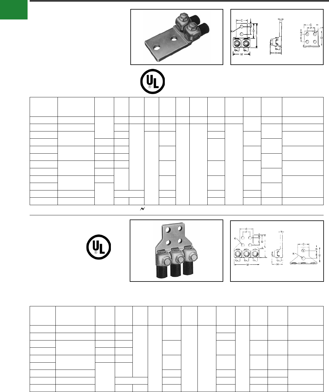
TYPE Q2A
QIKLUG™
For Copper Cable
Compact, high copper alloy terminal for joining two
cables to equipment pads or bars. Each element
accommodates a wide range of cable. One-
wrench installation.
Catalog
Number* Conductor
No. of
Holes in
Pad
C D E & F H K
Stud
Hole
Size
L N T W
Recommended
Tightening
Torque in-lb
Q2A1C-2 4 Str. - 1 Str.
2
1-1/2 1-7/8 1 1-1/16 7/16 3/8 2-7/8 7/16 7/32 1-13/16 150
Q2A26-2N 1/0 Str. - 2/0 Str. 1-5/8
3-1/8
3/4 1-3/16
9/16 1/2
4-3/16
5/8
1-15/16 180
Q2A28-2N 3/0 Str. - 4/0 Str. 1-7/8
1-3/4
1-3/8 4-3/8 1/4 250
Q2A28-4N 4 3
4-1/2 2-1/8
Q2A31-2N 250 - 350 kcmil 2 2-3/8 1-11/16 5/16 325
Q2A31-4N 4 3 3
Q2A34-2N 400 - 500 kcmil 2 2-1/2 2 4-11/16 3/8 375
Q2A34-4N 4
33-3/4
Q2A40-2N 600 - 800 kcmil 22-7/16 5 7/16 500Q2A40-4N
44-11/32
Q2A44-4N 850 - 1000 kcmil 3-1/4 2-3/4 5-1/4 1/2
Q2A46-4N 1100 - 1500 kcmil 3-1/2 3-1/4 3-1/8 5-1/2 11/16 5 600
TYPE Q3A
QIKLUG™
For Copper Cable
Compact, high copper alloy terminal for joining
three cables to equipment pads or bar. Each
element accommodates a wide range of cable.
One-wrench installation.
Catalog
Number* Conductor
No. of
Holes in
Pad
C D E & F H K
Stud
Hole
Size
L N T W
Recommended
Tightening
Torque in lb
Q3A28-2N 3/0 Str. - 4/0 Str. 2 1-7/8
3-1/8
1-3/4
1-3/8
9/16 1/2
4-5/16
5/8
1/4 3-3/16 250
Q3A28-4N 3/0 - 4/0 Str. 4 3 4-3/8
Q3A31-2N 250 - 350 kcmil 2 2-3/8 1-11/16 4-7/16 5/16 4-1/16 325
Q3A31-4N 4 3
Q3A34-2N 400 - 500 kcmil 2 2-1/2 1-15/16 4-3/4 3/8 4-9/16 375
Q3A34-4N
4
3
Q3A40-4N 600 - 800 kcmil 2-7/16 5 7/16 5-13/16 500
Q3A44-4N 850 - 1000 kcmil 3-1/4 2-3/4 5-1/4 1/2 6-5/8
Q3A46-4N 1100 - 1500 kcmil 3-1/2 3-1/4 3-1/8 5-1/2 11/16 7-7/8 600
* ‘‘N’’ indicates NEMA standard stud holes. All 4N items see note LIGHTNING PROTECTION INFO.
* ‘‘N’’ indicates NEMA standard stud holes.
A-16
BURNDY®
Blue highlighted items are industry standard and most frequently ordered.
Canada: 1-800-387-6487 www.burndy.com US: 1-800-346-4175
Mechanical
TYPE QB
QIKLUG™
For Copper Cable
Compact, high copper alloy side entrance terminal
for joining a range of cable at right angles to
terminal blocks. One-wrench installation.
Catalog
Number* Conductor
No. of
Holes in
Pad
C D E H K
Stud
Hole
Size
L N T
Recommended
Tightening
Torque in-lb
QB8C 14 Sol. - 8 Str. 1 9/16 9/16 — 7/8 7/32 #10 1-1/8 9/32 5/32 75
QB4C 8 Str. - 4 Str. 1 11/16 27/32 — 13/16 9/32 1/4 1-3/8 11/32 1/4 110
QB1C 4 Str. - 1 Str. 1 11/16 13/16 — 1 9/32 1/4 1-1/2 11/32 7/32 150
QB26 1/0 Str. - 2/0 Str. 1 13/16 1 — 1-1/32 13/32 3/8 1-13/16 7/16 7/32 180
QB28 3/0 Str. - 4/0 Str. 1 1 1-1/16 — 1-5/16 13/32 3/8 2-1/16 17/32 1/4 250
QB31-2N 250 - 350 kcmil 2 13/16 3-1/4 1-3/4 1-11/16 9/16 1/2 4-1/2 5/8 5/16 325
* ‘‘N’’ indicates NEMA standard stud holes.
TYPE Q2B
QIKLUG™
For Copper Cable
Compact, high copper alloy terminal for joining two
cables at right angles to a single terminal block.
Each element accommodates a range of cable.
One-wrench installation.
Catalog
Number* Conductor
No. of
Holes in
Pad
C D E & F H K
Stud
Hole
Size
L N T
Recommended
Tightening
Torque in-lb
Q2B28-2N 3/0 Str. - 4/0 Str. 2 1-7/8 3-1/8 1-3/4 1-3/8 9/16 1/2 5-3/16 5/8 1/4 250
Q2B31-2N 250 - 350 kcmil 2 2-3/8 3-3/16 1-11/16 1-3/8 9/16 9/16 5-7/8 5/8 5/16 325
Q2B40-4N 600 - 800 kcmil 4 3 3-1/16 1-3/8 2-5/16 9/16 3/4 6-11/16 5/8 7/16 500
* ‘‘N’’ indicates NEMA standard stud holes. All 4N items see note LIGHTNING PROTECTION INFO.
A-17
BURNDY®
Blue highlighted items are industry standard and most frequently ordered.
US: 1-800-346-4175 www.burndy.com Canada: 1-800-387-6487
Mechanical
TYPE QDA
QIKLUG™
For Copper Cable
Compact, high copper alloy terminal for joining a
wide range of cable to equipment studs. Provides
low contact resistance when gripped between two
contact nuts. One wrench installation.
Catalog
Number
Conductor
C H K
Stud
Hole
Size
L T
Recommended
Tightening
Torque in-lb
Commercial Navy
QDA8C 14 Sol. - 8 Str. 3 - 14 1 11/16 7/16 3/8 1-7/8 3/16 75
QDA4C 8 Str. - 4 Str. 23 - 40 1 3/4 7/16 3/8 1-7/8 7/32 110
QDA1C 4 Str. - 1 Str. 50 - 75 1 1 7/16 3/8 2-3/16 9/32 150
QDA26 1/0 Str. - 2/0 Str. 100 - 125 1-1/4 1-3/16 9/16 1/2 2-1/2 5/16 180
QDA28 3/0 Str. - 4/0 Str. 150 - 200 1-1/4 1-5/16 9/16 1/2 2-5/8 5/16 250
QDA31 250 - 350 kcmil 250 - 350 1-1/2 1-11/16 11/16 5/8 3 5/16 325
QDA34 400 - 500 kcmil 400 - 500 1-7/8 2 13/16 3/4 3-5/8 5/16 375
QDA40 600 - 800 kcmil 650 - 800 2-1/8 2-5/16 1-1/16 1 4-3/16 3/8 500
TYPE QR
QIKLINK™ SPLICE OR REDUCER
For Copper Cable to Cable
High copper alloy splicer/reducer for joining a
range of cable end to end. Neat, compact easy to
tape installation. One-wrench installation.
Catalog Number Conductor
Either Side H L W
Recommended
Tightening
Torque in-lb
QR4C 6 Sol. - 4 Str. 3/4 1-11/16 5/8 110
QR1C 4 Str. - 1 Str. 1-1/16 1-15/16 11/16 150
QR26 1/0 Str. - 2/0 Str. 1-3/16 2-1/8 13/16 180
QR28 3/0 Str. - 4/0 Str. 1-3/8 2-3/8 1 250
QR31 250 - 350 kcmil 1-11/16 2-5/8 1-1/4 325
QR34 400 - 500 kcmil 1-15/16 3-1/16 1-7/16 375
QR40 600 - 800 kcmil 2-7/16 3-5/8 1-7/8 500
See note LIGHTNING PROTECTION INFO.
A-18
BURNDY®
Blue highlighted items are industry standard and most frequently ordered.
Canada: 1-800-387-6487 www.burndy.com US: 1-800-346-4175
Mechanical
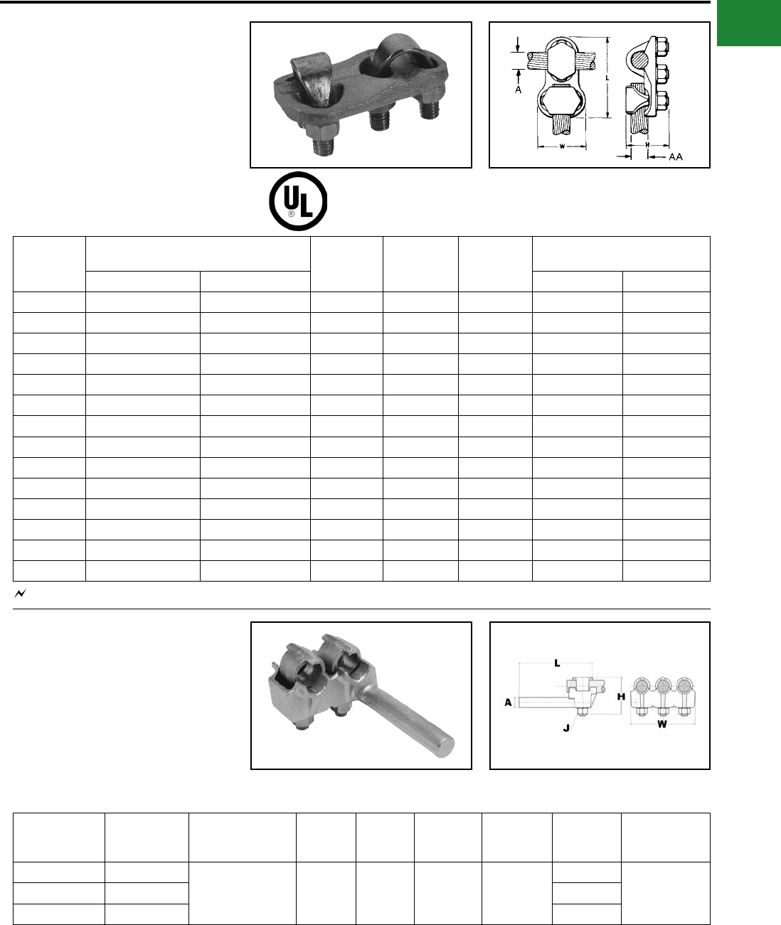
TYPE VT
VARITAP™ T-CONNECTOR
For Copper Cable to Cable
High copper alloy T-connector for cable run, cable
tap. V-bolt clamping elements accommodate large
range of cable and are particularly suited for extra
exible cable. One-wrench installation.
Catalog
Number
Conductor H L W
Recommended
Tightening Torque
Run (A) Tap (AA) Run Tap
VT2C2C 8 AWG-2 AWG 8 AWG-2 AWG 1-5/16 2-5/16 1-5/16 275 275
VT2525 6 AWG-1/0 6 AWG-1/0 1-5/8 2-5/8 1-7/16 385 385
VT2825 1/0 -4/0 AWG 6 AWG-1/0 1-5/8 3-1/8 1-1/4 250 385
VT2828 1/0 -4/0 AWG 1/0 -4/0 AWG 1-5/8 3-1/16 1-11/16 250 250
VT3025 1/0 -300 kcmil 6 AWG-1/0 1-7/8 3-3/8 1-3/8 325 385
VT3030 1/0 -300 kcmil 1/0 -300 kcmil 1-7/8 3-5/16 1-15/16 325 325
VT3425 300 kcmil-500 kcmil 6 AWG-1/0 3-11/32 3-11/16 1-1/2 375 385
VT3428 300 kcmil-500 kcmil 1/0 -4/0 AWG 3-11/32 3-1/2 1-11/16 375 250
VT3430 300 kcmil-500 kcmil 1/0 -300 kcmil 3-11/32 3-5/8 1-15/16 375 325
VT3434 300 kcmil-500 kcmil 300 kcmil-500 kcmil 3-11/32 3-3/4 2-1/4 375 375
VT4040 500 kcmil-800 kcmil 500 kcmil-800 kcmil 2-9/16 4-1/2 2-5/8 500 500
VT4425 750 kcmil-1000 kcmil 6 AWG-1/0 2-7/8 4-5/16 1-3/16 500 385
VT4428 750 kcmil-1000 kcmil 1/0 -4/0 AWG 2-7/8 4-1/8 1-11/16 500 250
VT4834 1500 kcmil-2000 kcmil 300 kcmil-500 kcmil 4-1/4 5-1/4 2-1/4 600 375
TYPE E-C-G
TRANSFORMER TAP ADAPTER
For Copper
Multi-tap, range-taking cast copper alloy connector
designed to take 2, 3 or 4 conductors from a single
secondary transformer outlet.
See note LIGHTNING PROTECTION INFO.
Catalog Number Number of
Conductors
Conductor
Size A dia H J L W
Recommended
Tightening
Torque
E2C34G1 2
1/0 Sol. - 500 kcmil 0.78 2-7/8 1/2"-13 6-1/4
3-1/2
480E3C34G1 3 5-1/4
E4C34G1 4 6-7/8
A-19
BURNDY®
Blue highlighted items are industry standard and most frequently ordered.
US: 1-800-346-4175 www.burndy.com Canada: 1-800-387-6487
Mechanical
TYPES VA, VVA
VARILUG™
For Copper Cable
High copper alloy terminal for joining a wide range
of cable to equipment pads or bar. Particularly
suitable for use on extra exible cable. One-
wrench installation. Type VVA, twin elements
secure joint against vibration and exing.
Particularly recommended for use on extra exible
cables. One-wrench installation.
Catalog Number*
Conductor
No. of
Holes
in Pad
C D E&F H K
Stud
Hole
Size
L LL N T
Rec.
Tightening
Torque
Type VA Type VVA
VA2C VVA2C 8 AWG-2 AWG 1 13/16 1-1/4 — 1-1/2 7/16 3/8 2-3/4 4-1/16 13/32 1/4 275
VA25 VVA25 6 AWG-1/0 1 7/8 1-5/16 — 1-7/8 7/16 3/8 2-7/8 4-5/16 7/16 1/4 385
VA28 VVA28 1/0 -4/0 AWG 1 1-1/16 1-1/2 — 2-1/4 7/16 3/8 2-7/8 4-1/8 17/32 5/16 250
VA28-2N VVA28-2N 1/0 -4/0 AWG 2 1-1/16 3-1/2 1-3/4 2-1/4 9/16 1/2 4-15/16 6-1/5 5/8 5/16 250
VA30 VVA30 1/0 -300 kcmil 1 1-1/8 1-5/8 — 2-3/16 7/16 3/8 3-1/4 4-5/8 5/8 5/16 325
VA30-2N VVA30-2N 1/0 -300 kcmil 2 1-1/8 3-9/16 1-3/4 2-3/16 9/16 1/2 5-3/16 6-9/16 5/8 5/16 325
VA34 VVA34 300 kcmil-500 kcmil 1 1-3/8 2 — 3-11/32 9/16 1/2 3-13/16 5-5/16 13/16 3/8 375
VA34-2N VVA34-2N 300 kcmil-500 kcmil 2 1-3/8 3-5/8 1-3/4 3-11/32 9/16 1/2 5-3/8 6-7/8 5/8 3/8 375
VA34-4N VVA34-4N 300 kcmil-500 kcmil 4 3 3-5/8 1-3/4 3-11/32 9/16 1/2 5-3/8 6-7/8 5/8 3/8 375
VA40 VVA40 500 kcmil-800 kcmil 1 1-5/8 2-5/16 — 2-7/8 11/16 5/8 4-1/2 6-3/8 15/16 3/8 500
VA40-2N VVA40-2N 500 kcmil-800 kcmil 2 1-5/8 3-5/8 1-3/4 2-7/8 9/16 1/2 5-13/16 7-11/16 5/8 3/8 500
VA40-4N VVA40-4N 500 kcmil-800 kcmil 4 3 2-5/8 1-3/4 2-7/8 9/16 1/2 5-13/16 7-11/16 5/8 3/8 500
All 4N items see note LIGHTNING PROTECTION INFO.* “N” indicates NEMA standard stud holes.
Type VA Type VVA
A-20
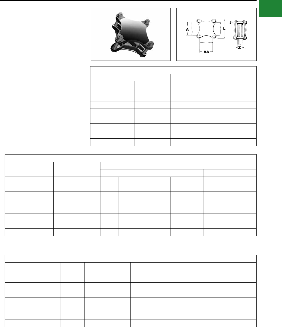
BURNDY®
Blue highlighted items are industry standard and most frequently ordered.
Canada: 1-800-387-6487 www.burndy.com US: 1-800-346-4175
Mechanical
TYPE HFB-P1
BAR CLAMP ASSEMBLY
COMPONENTS
For Copper Bar
To build your own high strength clamp assembly
for multiple at bar using type HFB-P1 bar clamps
and clamping hardware, the following tables have
been provided. The clamp assembly eliminates the
need for drilling the at bar and is used in indoor
and outdoor applications.
One Clamp Half
Bar Clamp Bar “J” Bolt
Dia. L W Z
Recommended
Tightening
Torque in-lb
Catalog
Number Run ‘A’ Tap ‘AA’
HFB22P1 2 2 3/8 4.38 4.38 * 240
HFB33P1 3 3 3/8 4.38 4.38 * 240
HFB42P1 4 2 3/8 5.75 5.75 * 240
HFB44P1 4 4 1/2 5.75 5.75 * 480
HFB63P1 6 3 1/2 7.75 4.75 * 480
HFB66P1 6 6 5/8 8.12 8.12 * 660
HFB88P1 8 8 3/4 10.50 10.50 * 1990
Bar Clamp Assembly Components †
Copper Bus Bar Width (in) Bar Clamp Silicon Bronze Clamping Hardware
Bolts Nuts Split Lock Washers
Run-A Tap-AA Qty Cat. No. Qty Cat. No. Qty Cat. No. Qty Cat. No.
2 2 2 HFB22P1 438 X (*) HEB 438CHEN 438SW
3 3 2 HFB33P1 438 X (*) HEB 438CHEN 438SW
4 2 2 HFB42P1 438 X (*) HEB 438CHEN 438SW
4 4 2 HFB44P1 450 X (*) HEB 450CHEN 450SW
6 3 2 HFB63P1 450 X (*) HEB 450CHEN 450SW
6 6 2 HFB66P1 462 X (*) HEB 462CHEN 462SW
8 8 2 HFB88P1 475 X (*) HEB 475CHEN 475SW
Bolt Length
Clamp
Number
“J”
Bolt Dia.
When
Z = 1.25
When
Z = 1.50
When
Z = 1.75
When
Z = 2.00
When
Z = 2.25
When
Z = 2.50
When
Z = 2.75
When
Z = 3.00
HFB22P1 3/8 3.00 3.25 3.50 4.00 4.00 4.50 4.50 5.00
HFB33P1 3/8 3.00 3.25 3.50 4.00 4.00 4.50 4.50 5.00
HFB42P1 3/8 3.00 3.25 3.50 4.00 4.00 4.50 4.50 5.00
HFB44P1 1/2 3.25 3.50 3.75 4.00 4.50 4.50 5.00 5.00
HFB63P1 1/2 3.25 3.50 3.75 4.00 4.50 4.50 5.00 5.00
HFB66P1 5/8 3.50 4.00 4.00 4.50 4.50 5.00 5.00 5.50
HFB88P1 3/4 3.75 4.00 4.50 4.50 5.00 5.00 5.50 5.50
*Z=Space between the bar clamp contact surfaces
† Ordered separately from BURNDY®.
* See table below when ordering assembly clamping
bolts to specify correct bolt length in Cat. #.
NOTE: When ordering assembly bolts specify correct bolt
length in catalog number as indicated in table.
A-21
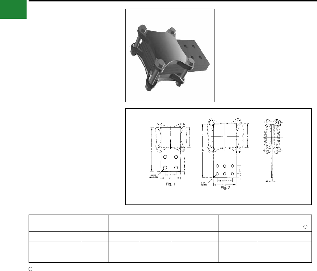
BURNDY®
Blue highlighted items are industry standard and most frequently ordered.
US: 1-800-346-4175 www.burndy.com Canada: 1-800-387-6487
Mechanical
TYPE HFB-N
BAR CLAMP TAP PAD ADAPTER
For Copper Bar
High conductivity copper, tap pad adapter provides
a NEMA drilled contact pad when assembled to the
HFB-P1 clamps. Tap connections can be made
from copper bus bar(s) without drilling, by bolting
standard mechanical or compression terminal
pads directly to the pre-drilled tap pad adapter.
Catalog
Number Fig. # A & C E & F L N Use with ‘H’ Clamp
Catalog Number
HFB33-4N 1 3.00 1.75 7.00 0.62 HFB33P1
HFB44-4N 1 4.00 1.75 9.12 1.12 HFB44P1
HFB66-6N 2 6.00 1.75 11.31 1.12 HFB66P1
‘H’ Clamp (two required per assembly) and hardware
(as shown) not included with bar clamp tap pad, order
separately.
1
1
A-22
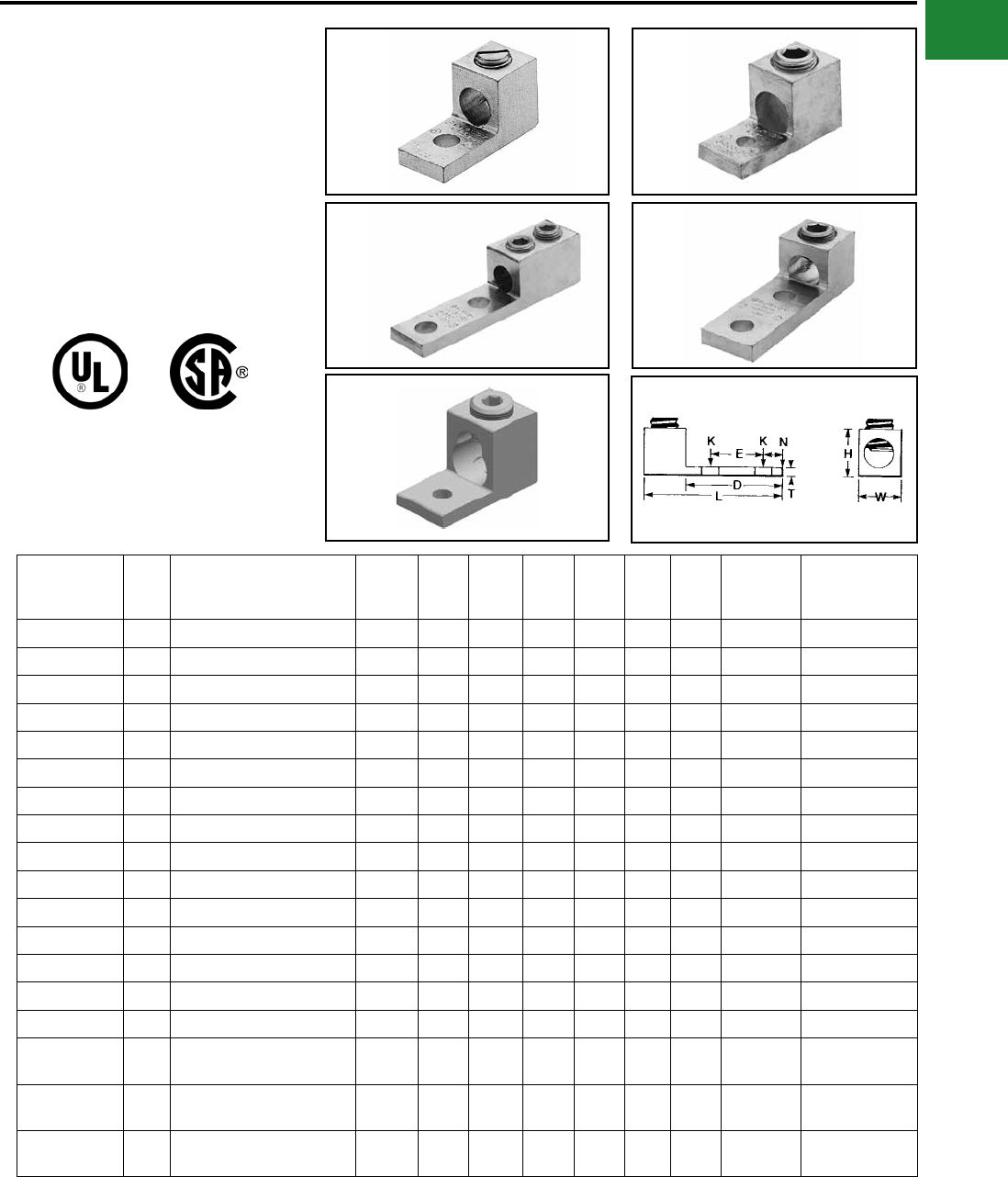
BURNDY®
Blue highlighted items are industry standard and most frequently ordered.
Canada: 1-800-387-6487 www.burndy.com US: 1-800-346-4175
Mechanical
TYPES KA-U, KKA-U
UNIVERSAL TERMINAL
For Aluminum and Copper
Conductors
These dual-rated one-conductor lugs are
constructed from high strength aluminum alloy
and electro tin-plated to provide low contact
resistance.
AL9CU
Catalog
Number*
Fig.
No.
Wire Range
Aluminum or Copper
Stud
Hole
Size
D L N **
W
E T **
H
Recommended
Tightening ▲
Torque (in-lb)
KA6U 1 14 AWG-6 AWG 1/4 0.63 1.06 0.25 0.50 — 0.09 0.51 45
KA2U 1 14-2 1/4 0.63 1.16 0.31 0.50 — 0.10 0.56 50
KA25U 1 14 AWG-1/0 1/4 0.81 1.50 0.44 0.63 — 0.19 0.92 50
KA26U 2 6-2/0 1/4 0.81 1.47 0.45 0.63 — 0.19 0.80 120
KA29U 2 6-250 5/16 0.94 2.00 0.47 1.00 — 0.25 1.14 275
KA30U 2 6 AWG-300 kcmil 5/16 0.94 2.00 0.45 1.00 — 0.25 1.14 275
KA31U 2 6 AWG-350 kcmil 3/8 1.03 2.25 0.52 1.13 — 0.25 1.27 275
KA34U 2 4 AWG-500 kcmil 3/8 1.50 2.81 0.88 1.51 — 0.31 1.58 500
KA36U 2 2 AWG-600 kcmil 3/8 1.72 3.19 0.78 1.50 — 0.44 1.58 500
KA40U 2 300 kcmil-800 kcmil 1/2 1.85 3.50 0.81 1.75 — 0.50 1.95 550
KA44U 2 500 kcmil-1000 kcmil 1/2 1.69 3.50 0.88 1.75 — 0.50 1.95 550
KKA31U-2N 3 6 AWG-350 kcmil 1/2 3.16 5.50 0.63 1.25 1.75 0.38 1.52 275
KA36U-2N 4 2 AWG-600 kcmil 1/2 3.22 4.69 0.63 1.50 1.75 0.44 1.57 500
KA40U-2N 4 300 kcmil-800 kcmil 1/2 3.03 4.75 0.63 1.75 1.75 0.50 1.95 500
KA44U-2N 4 500 kcmil-1000 kcmil 1/2 3.03 4.75 0.63 1.75 1.75 0.50 1.95 550
KA30226U 52 Str. - 300 kcmil or
(2) 4 Str. - 2/0 Str. 5/16 1.31 2.31 2.00 0.86 – 0.25 1.50 275
KA36229U 54 Str. - 600 kcmil or
(2) 250 kcmil - 1/0 Str. 5/8 1.50 2.81 1.00 1.38 – 0.31 1.81 375
KA39229U 51/0 Str. - 750 kcmil or
(2) 1/0 Str. - 250 kcmil 1/2 1.50 2.81 1.00 1.38 – 0.31 1.81 375
Fig. 1
Fig. 3
Fig. 5
Fig. 2
Fig. 4
* “N” indicates NEMA standard stud holes.
▲ Listed torque values are for maximum conductor sizes accommodated.
Consult UL486 Tables 7-4, 7-5, 7-6 for smaller conductor sizes.
** Maximum dimension.
A-23
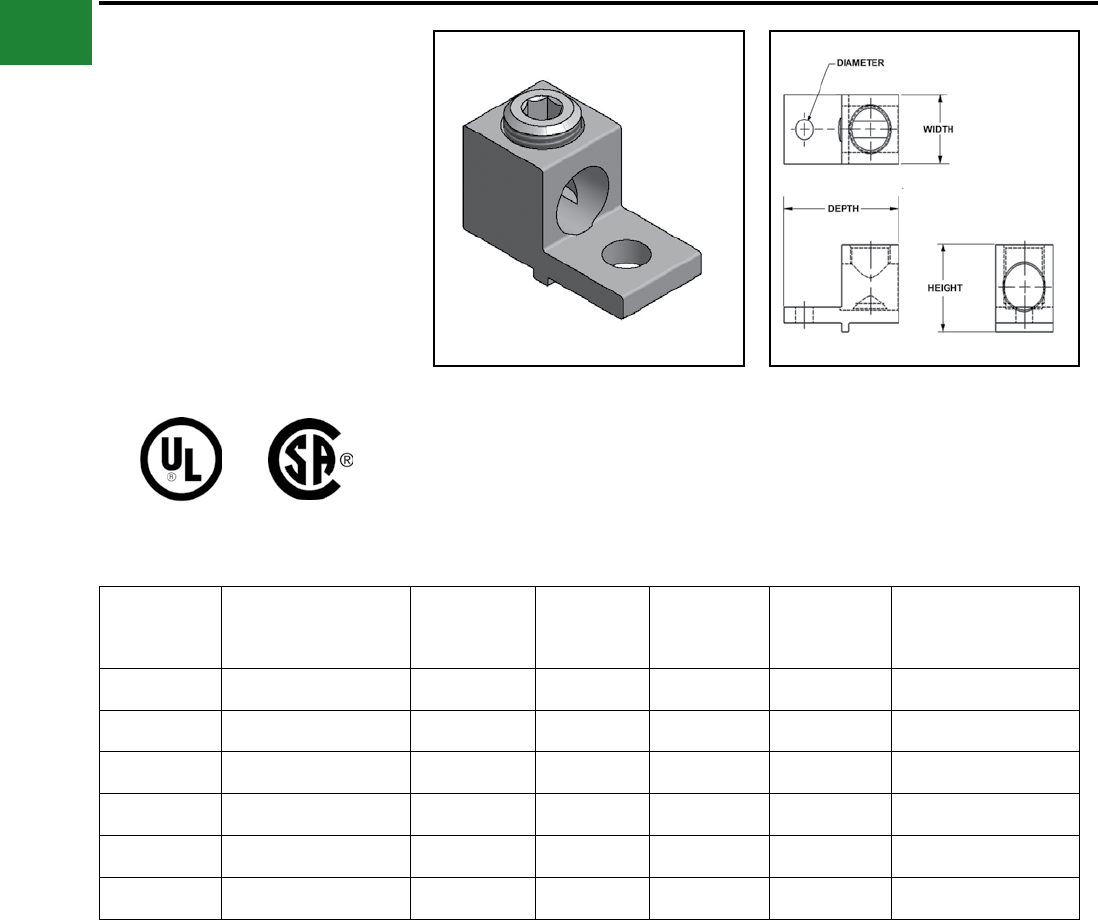
BURNDY®
Blue highlighted items are industry standard and most frequently ordered.
US: 1-800-346-4175 www.burndy.com Canada: 1-800-387-6487
Mechanical
TYPES KA-UAR
UNIVERSAL ANTI-ROTATE
TERMINALS
(One Conductor)
For Aluminum and Copper
Conductors
These dual-rated one-conductor lugs are
constructed from high strength aluminum alloy and
electro tin-plated to provide low contact resistance.
These lugs also contain a bottom anti-turn tab.
Catalog
Number
Wire Range
Aluminum or Copper
Stud
Hole
Size
Depth Width Height
Recommended
Tightening ▲
Torque (in-lb)
KA4UAR 14 - 4 1/4 1.16 0.50 0.55 45
KA25UAR 14 - 1/0 1/4 1.47 0.63 0.81 50
KA26UAR 14 - 2/0 1/4 1.47 0.63 0.81 120
KA30UAR 6 - 300 1/4 1.56 0.94 1.13 275
KA31UAR 6 - 350 5/16 1.19 1.00 1.13 275
KA36UAR 4 - 600 3/8 2.75 1.38 1.57 375
AL9CU
Listed torque values are for maximum conductor sizes
accommodated. Consult UL486 Tables 7-4, 7-5, 7-6 for
smaller conductor sizes.
A-24
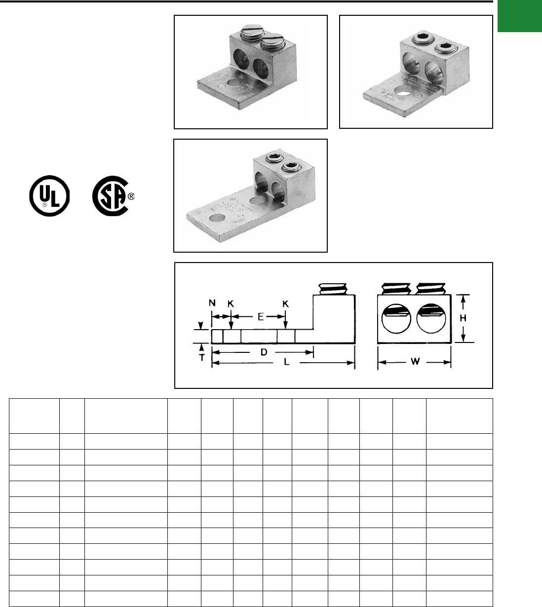
BURNDY®
Blue highlighted items are industry standard and most frequently ordered.
Canada: 1-800-387-6487 www.burndy.com US: 1-800-346-4175
Mechanical
TYPE K2A-U
UNIVERSAL TERMINAL
(Two Conductor)
For Aluminum and Copper
Conductors
These dual-rated two-conductor lugs are
constructed from high strength aluminum alloy and
electro tin-plated to provide low contact resistance.
AL9CU
Catalog
Number*
Fig.
No.
TWO: Wire Range
(Aluminum or Copper)
Stud
Hole
Size
D L N **
WE T **
H
Recommended
Tightening ▲
Torque (in-lb)
K2A25U 1 14 AWG-1/0 1/4 0.81 1.47 0.44 1.13 — 0.19 0.79 50
K2A26U 2 14 AWG-2/0 AWG 1/4 0.81 1.47 0.44 1.25 — 0.19 0.80 120
K2A29U 2 6 AWG-250 kcmil 3/8 1.50 2.56 0.50 1.66 — 0.25 1.20 275
K2A31U 2 6 AWG-350 kcmil 1/2 1.69 2.88 0.88 1.94 — 0.25 1.26 275
K2A36U 2 2 AWG-600 kcmil 1/2 1.75 3.20 0.63 2.41 — 0.44 1.58 375
K2A40U 2 300 kcmil-800 kcmil 5/8 1.66 3.38 0.88 3.19 — 0.50 1.95 500
K2A44U 2 500 kcmil-1000 kcmil 5/8 1.66 3.50 0.88 3.52 — 0.50 1.95 500
K2A31U-2N 3 6 AWG-350 kcmil 1/2 3.00 4.50 0.63 2.31 1.75 0.31 1.39 275
K2A36U-2N 3 2 AWG-600 kcmil 1/2 3.22 4.69 0.63 2.41 1.75 0.44 1.39 375
K2A40U-2N 3 300 kcmil-800 kcmil 1/2 3.03 4.75 0.63 3.19 1.75 0.50 1.95 375
K2A44U-2N 3 500 kcmil-1000 kcmil 1/2 3.03 4.75 0.63 3.19 1.75 0.50 1.95 375
* “N” indicates NEMA standard stud holes.
▲ Listed torque values are for maximum conductor sizes
accommodated. Consult UL486 Tables 7-4, 7-5, 7-6 for
smaller conductor sizes.
** Maximum dimension.
Fig. 1
Fig. 3
Fig. 2
A-25
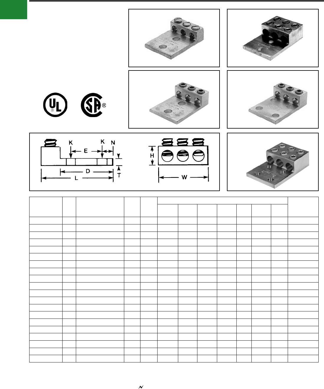
BURNDY®
Blue highlighted items are industry standard and most frequently ordered.
US: 1-800-346-4175 www.burndy.com Canada: 1-800-387-6487
Mechanical
TYPES K3A-U, KK3A-U
UNIVERSAL TERMINAL
(Three Conductor)
For Aluminum and Copper Conductors
Dual-rated three-conductor lugs are constructed
from high strength aluminum alloy and electro tin-
plated to provide low contact resistance.
Catalog
Number**
Fig.
No.
THREE: Wire Range
(Aluminum or Copper) K
Stud
Hole
Size
Dimensions Rec.
Tightening ▲
Torque (in-lb)
D L N W E T H
K3A2U-2* 1 14 AWG-2 AWG 11/32 5/16 1.63 2.19 0.34 1.59 0.88 0.19 0.62 50
K3A25U-2* 1 14 AWG-1/0 7/16 3/8 2.09 2.91 0.34 1.94 1.00 0.25 0.88 50
K3A26U-2N 3 14 AWG-2/0 AWG 9/16 1/2 3.06 3.75 0.63 1.95 1.75 0.19 1.79 50
K3A27U-2N 3 6 AWG-3/0 AWG 9/16 1/2 3.00 3.88 0.63 2.81 1.75 0.31 1.12 275
K3A29U-2N 3 6 AWG-250 kcmil 9/16 1/2 3.16 4.00 0.63 2.81 1.75 0.31 1.19 275
K3A31U-2N 3 6 AWG-350 kcmil 9/16 1/2 3.16 4.31 0.63 3.52 1.75 0.31 1.38 275
K3A36U-2N 3 2 AWG-600 kcmil 9/16 1/2 3.22 4.69 0.63 3.63 1.75 0.44 1.56 375
KK3A36U-2N 2 2 AWG-600 kcmil 9/16 1/2 3.00 5.50 0.63 4.22 1.75 0.38 1.52 375
KK3A40U-2N 2 300 kcmil-800 kcmil 9/16 1/2 3.34 6.19 0.63 4.81 1.75 0.56 1.89 375
KK3A44U-2N 2 500 kcmil-1000 kcmil 9/16 1/2 3.34 6.19 0.63 4.75 1.75 0.56 1.90 500
K3A2U-4* 4 14 AWG-2 AWG 11/32 5/16 1.63 2.19 0.34 1.59 0.88 0.19 0.62 50
K3A25U-4* 4 14 AWG-1/0 7/16 3/8 2.09 2.91 0.34 1.94 1.00 0.25 0.88 50
K3A27U-4N 4 6 AWG-3/0 AWG 9/16 1/2 3.00 3.88 0.63 2.81 1.75 0.31 1.12 275
K3A29U-4N 4 6 AWG-250 kcmil 9/16 1/2 3.00 4.00 0.63 2.81 1.75 0.31 1.19 275
K3A31U-4N 4 6 AWG-350 kcmil 9/16 1/2 3.00 4.31 0.63 3.00 1.75 0.31 1.38 275
K3A36U-4N 4 2 AWG-600 kcmil 9/16 1/2 3.22 4.69 0.63 3.63 1.75 0.44 1.56 375
K3A40U-4N 4 300 kcmil-800 kcmil 9/16 1/2 3.03 4.75 0.63 4.81 1.75 0.50 1.94 375
KK3A36U-4N 5 2 AWG-600 kcmil 9/16 1/2 3.00 5.50 0.63 4.22 1.75 0.38 1.52 375
KK3A40U-4N 5 300 kcmil-800 kcmil 9/16 1/2 3.34 6.19 0.63 5.34 1.75 0.56 1.89 500
KK3A44U-4N 5 500 kcmil-1000 kcmil 9/16 1/2 3.34 6.19 0.63 4.75 1.75 0.56 1.90 500
* Slotted screw.
** ‘‘N” indicates NEMA standard stud holes.
▲ Listed torque values are for maximum conductor sizes
accommodated. Consult UL486 Tables 7-4, 7-5, 7-6 for
smaller conductor sizes.
AL9CU
All 4N items see note LIGHTNING PROTECTION INFO.
Fig. 1
Fig. 3
Fig. 2
Fig. 4
Fig. 5
A-26
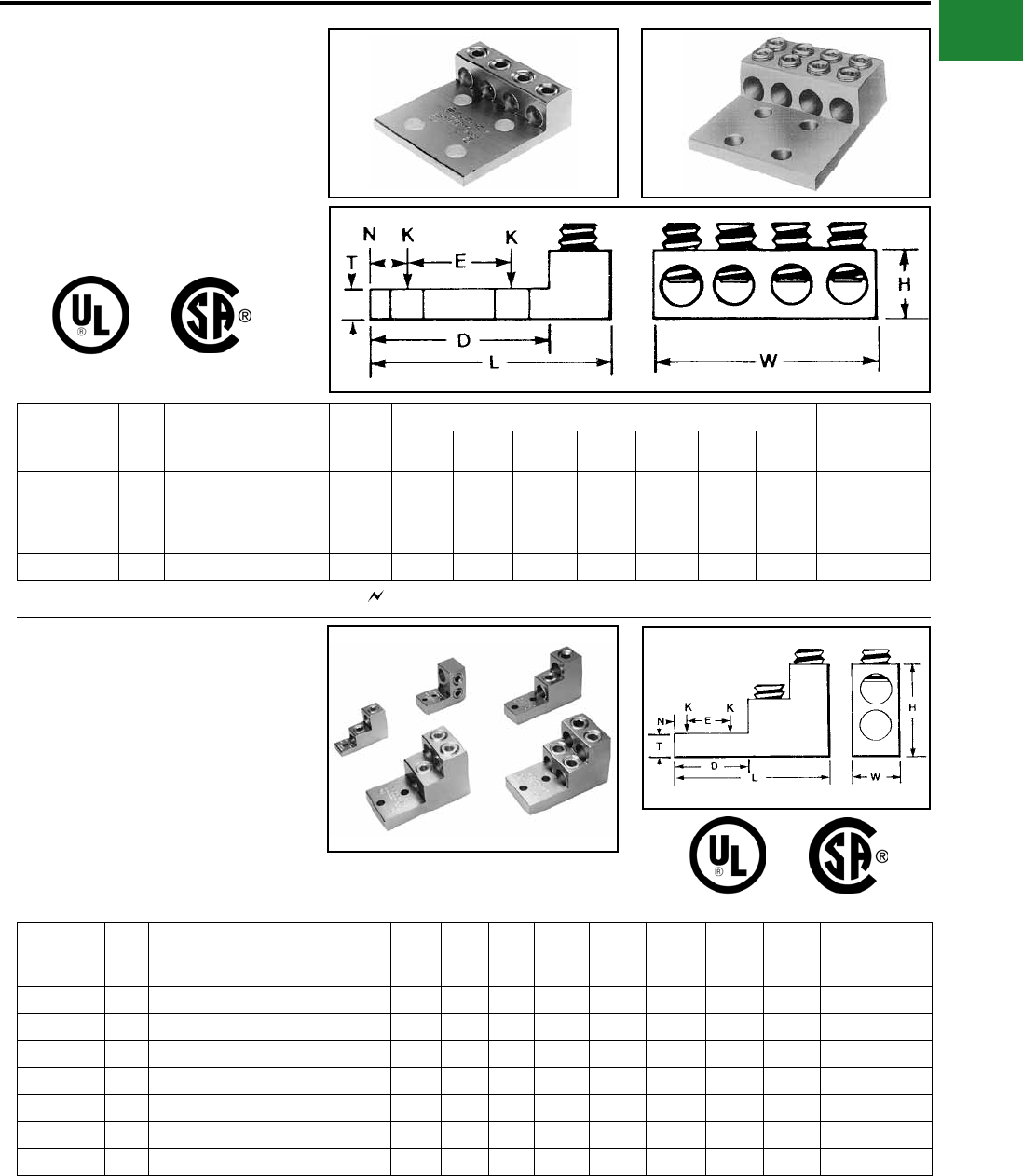
BURNDY®
Blue highlighted items are industry standard and most frequently ordered.
Canada: 1-800-387-6487 www.burndy.com US: 1-800-346-4175
Mechanical
TYPES K4A-U, KK4A-U
UNIVERSAL TERMINAL
(Four Conductor)
For Aluminum and Copper Conductors
These dual-rated four conductor lugs are
constructed from high strength aluminum alloy and
electro tin-plated to provide low contact resistance.
Catalog
Number*
Fig.
No.
FOUR: Wire Range
(Aluminum or Copper)
Stud
Hole
Size
Dimensions Recommended
Tightening
Torque (in-lb)
D L N W E T H
K4A29U-4N 1 6 AWG-250 kcmil 1/2 3.16 4.25 0.63 3.69 1.75 0.31 1.19 275
K4A31U-4N 1 6 AWG-350 kcmil 1/2 3.00 4.50 0.63 5.04 1.75 0.31 1.38 275
KK4A36U-4N 2 2 AWG-600 kcmil 1/2 3.34 5.63 0.63 5.00 1.75 0.44 1.51 375
KK4A40U-4N 2 300 kcmil-800 kcmil 1/2 3.41 6.19 0.63 6.00 1.75 0.56 1.88 375
AL9CU
TYPES K11A-U, K21A-U,
K22A-U
UNIVERSAL TERMINAL
For Aluminum and Copper Conductors
Dual-rated panelboard lugs are constructed from
high strength extruded aluminum alloy and electro
tin-plated to provide low contact resistance.
Catalog
Number
Fig.
No.
# of
Conductors
Wire Range
(Aluminum or Copper)
Stud
Hole
Size
D L N W E T H
Recommended
Tightening ▲
Torque (in-lb)
K11A30U 1 2 6 AWG-300 kcmil 5/16 0.94 3.00 0.47 1.00 — 0.50 2.03 275
K11A34U-2 2 2 4/0 AWG-500 kcmil 1/4 2.31 2.91 0.25 1.44 0.69 0.63 2.40 375
K11A36U-2 3 2 2 AWG-600 kcmil 3/8 2.31 4.91 0.38 1.50 1.38 0.75 3.02 375
K21A36U-2 4 3 2 AWG-600 kcmil 3/8 2.31 4.91 0.38 2.50 1.38 0.75 3.03 375
K22A36U-2 5 4 2 AWG-600 kcmil 3/8 2.31 4.91 0.38 2.50 1.38 0.75 3.03 375
K11A39U-2 3 2 1/0 -750 kcmil 3/8 2.31 4.91 0.38 1.69 1.38 0.75 3.02 375
K22A39U-2 5 4 1/0 -750 kcmil 3/8 2.31 4.91 0.38 3.06 1.38 0.75 3.02 375
* ‘‘N” indicates NEMA standard stud holes. All 4N items see note LIGHTNING PROTECTION INFO.
AL9CU
▲ Listed torque values are for maximum conductor sizes accommodated. Consult UL486
Tables 7-4, 7-5, 7-6 for smaller conductor sizes.
Fig. 1 Fig. 2
Fig. 1
Fig. 2 Fig. 3
Fig. 4 Fig. 5
A-27
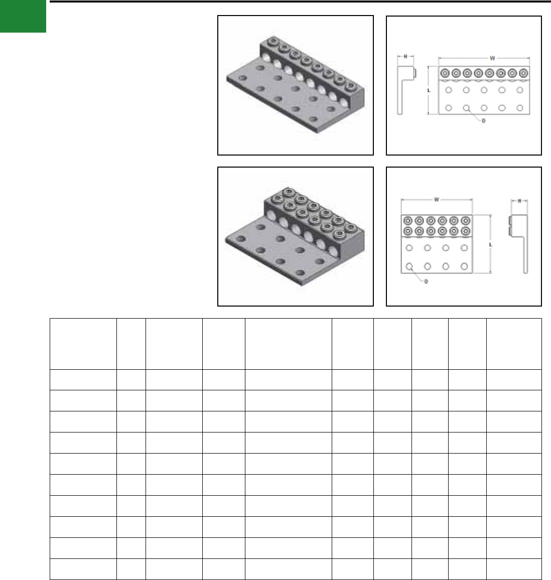
BURNDY®
Blue highlighted items are industry standard and most frequently ordered.
US: 1-800-346-4175 www.burndy.com Canada: 1-800-387-6487
Mechanical
TYPES K6A-U, K8A-U,
KK6A-U, KK8A-U
UNIVERSAL TERMINALS
(Six and Eight Conductor)
For Aluminum and
Copper Conductors
These dual-rated six and eight conductor lugs are
constructed from high strength aluminum alloy and
electro tin-plated to provide low contact resistance.
Catalog
Number
Fig.
No.
No. of
Conductors
No. of
Mtg
Holes
Wire Range
Aluminum
or Copper
Stud
Hole
Size
Depth Width Height
Rec.
Tightening
Torque
in-lb ♦
K6A34U-8 1 6 8 2 AWG - 500 kcmil 9/16 4.63 6.75 1.56 375
K8A34U-10 1 8 10 2 AWG - 500 kcmil 9/16 4.63 8.75 1.56 375
KK6A31U-8 2 6 8 6 AWG - 350 kcmil 9/16 5.31 6.38 1.50 275
KK8A31U-10 2 8 10 6 AWG - 350 kcmil 9/16 5.31 8.13 1.50 275
KK6A34U-8 2 6 8 2 AWG - 500 kcmil 9/16 5.50 6.75 1.50 375
KK8A34U-10 2 8 10 2 AWG - 500 kcmil 9/16 5.50 8.75 1.50 375
KK8A39U-10 2 6 10 2 AWG - 750 kcmil 9/16 6.19 8.25 1.88 550
KK8A39U-12 2 8 12 2 AWG - 750 kcmil 9/16 6.19 10.25 1.88 550
KK6A44U-12 2 6 12 350 kcmil - 1000 kcmil 9/16 6.19 10.00 1.88 550
KK8A44U-14 2 8 14 350 kcmil - 1000 kcmil 9/16 6.19 12.12 1.88 550
♦ Listed torque values are for maximum conductor sizes
accommodated. Consult UL486 Tables 7-4, 7-5, & 7-6
for smaller conductor sizes
Fig. 1
Fig. 2
A-28
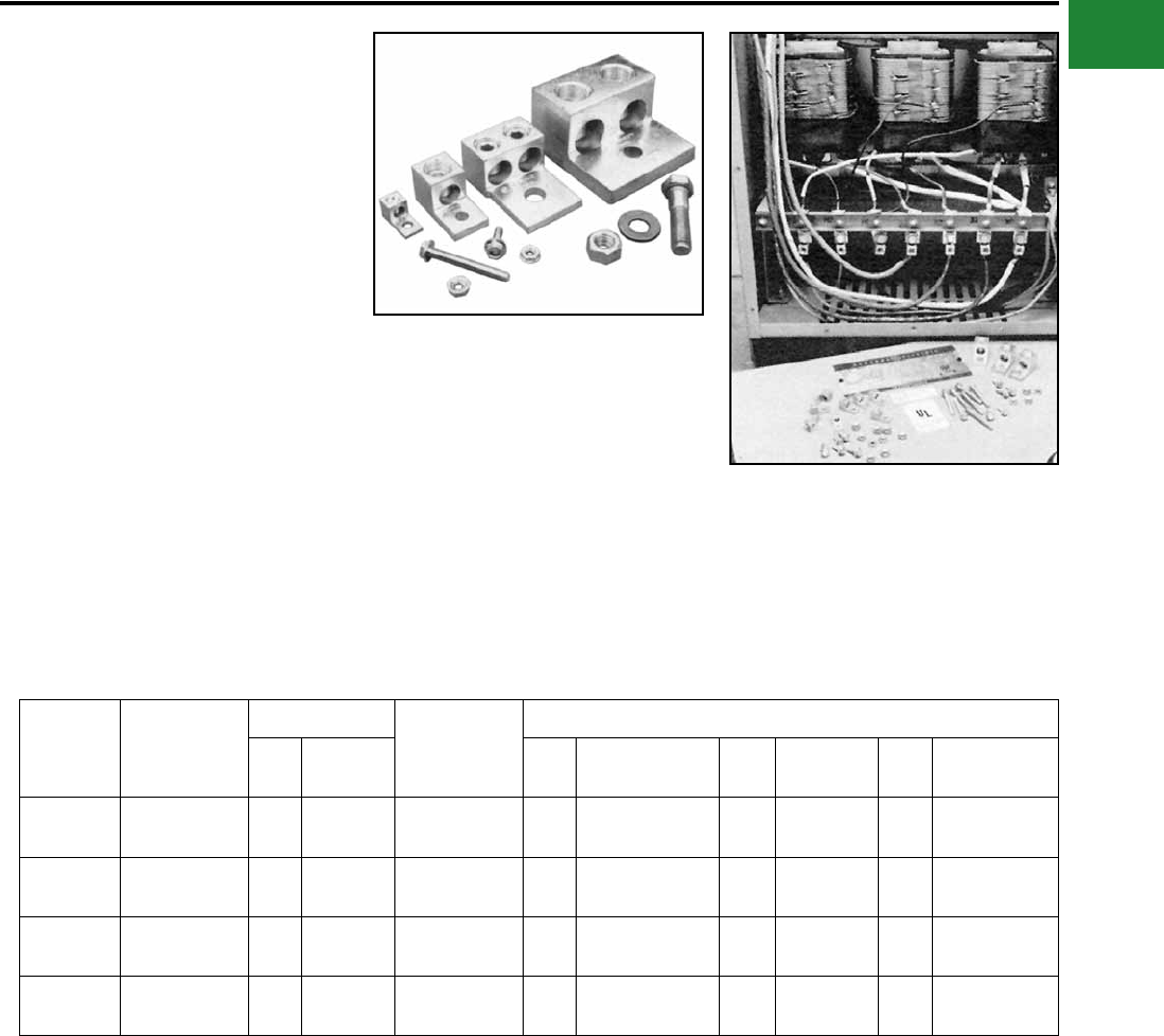
BURNDY®
Blue highlighted items are industry standard and most frequently ordered.
Canada: 1-800-387-6487 www.burndy.com US: 1-800-346-4175
Mechanical
TYPE KAU-KIT
TRANSFORMER LUG KIT
These dual-rated lugs are constructed from
high strength aluminum alloy and electro tin-
plated to provide low contact resistance. Lugs and
mounting hardware packaged together in these
kits.
Features & Benets
• UL Listed AL9CU dual rated set screw
terminals and CSA Certied
◊ Ensure the transformer feeders and
taps are terminated properly.
• Plated steel cap screws and hex nuts
with captive conical washers or individual
Belleville washers
◊ Terminal to bus connections are made
using proper hardware resulting in true
torque to pressure performance -
compensates for dissimilar metal
expansion and contraction.
Catalog
Number
Transformer
KVA Rating
Terminals Wire Range
Aluminum
or Copper
Hardware
Qty Catalog
Number Qty Bolt Size Qty Nut Qty Washer
KAU-KIT1 15 - 37.5 1Ø
15 - 45 3Ø
8
4
KA2U
KA29U
14 AWG-250
kcmil 8 1/4-20 X 3/4 HH 8 1/4 X 20 HN - Captive to Nut
KAU-KIT2 50 - 75 1Ø
75 - 112.5 3Ø 12 KA29U 6 AWG-250
kcmil
8
8
1/4-20 X 3/4 HH
1/4-20 X 2 HH 16 1/4 X 20 HN - Captive to Nut
KAU-KIT3 100 - 167 1Ø
150 - 300 3Ø
6
7
K2A31U
K2A40U
6 AWG-800
kcmil
5
6
1/2-13 X 3 HH
1/2-13 X 2-1/2 HH 11 1/2-13 HN 22
11
1/2 FW
1/2 Belleville
KAU-KIT4 400 - 500 3Ø 15 K2A40U 300 kcmil-800
kcmil
7
4
1/2-13 X 2 HH
1/2-13 X 2-1/2 HH 11 1/2-13 HN 22
11
1/2 FW
1/2 Belleville
HH = Hex Head
HN = Hex Nut
FW = Flat Washer
• Hardware packed in plastic bag
◊ No lost hardware prior to installation.
• Larger 800 kcmil lugs in KIT3 and KIT4
◊ Accommodates common 750 kcmil tap
conductors in larger transformers.
A-29
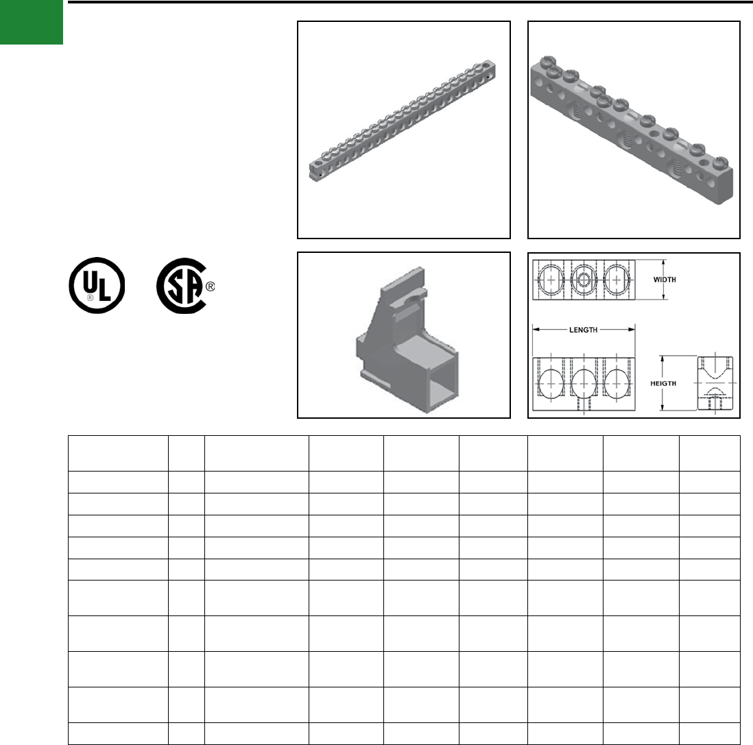
BURNDY®
Blue highlighted items are industry standard and most frequently ordered.
US: 1-800-346-4175 www.burndy.com Canada: 1-800-387-6487
Mechanical
TYPES K-AG1
ALUMINUM NEUTRAL BAR
These aluminum neutral bars are dual rated
for copper and aluminum conductors, and
are manufactured from high strength 6061-T6
aluminum alloy and are electro tin plated to provide
low contact resistance and protection against
corrosion.
AL9CU
Catalog
Number Fig. Wire Range
Aluminum or Copper
Total Number
of Holes
Total Number
of Circuits
Mount Hole
Locations Height Width Length
K2P4CAG1 1 14 - 4 3 2 2 0.44 0.31 1.09
K3P4CAG1 1 14 - 4 5 3 1, 5 0.44 0.31 1.67
K9P4CAG1 1 14 - 4 11 9 4, 8 0.44 0.31 3.53
K13P4CAG1 1 14 - 4 15 13 6, 12 0.44 0.31 4.77
K15P4CAG1 1 14 - 4 17 15 6, 14 0.44 0.31 6.01
K5P6C2P1/0CAG1 214 - 1/0
14 - 6 7(5) 14 - 6
(2) 14 - 1/0 – 0.62 0.38 2.26
K12P6C3P1/0CAG1 214 - 1/0
14 - 6 15 (12) 14 - 6
(3) 14 - 1/0 – 0.62 0.38 4.34
K14P6C5P1/0CAG1 214 - 1/0
14 - 6 19 (14) 14 - 6
(5) 14 - 1/0 – 0.62 0.38 5.77
K16P6C5P1/0CAG1 214 - 1/0
14 - 6 23 (16) 14 - 6
(5) 14 - 1/0 – 0.62 0.38 6.97
KAG1MTGBRKT ♦ 3 – – – – – –
♦ (2) KAG1MTGBRKT are necessary to mount neutral bars into enclosure
Fig. 1 Fig. 2
Fig. 3
A-30
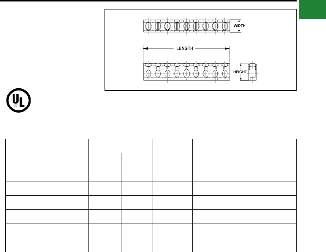
BURNDY®
Blue highlighted items are industry standard and most frequently ordered.
Canada: 1-800-387-6487 www.burndy.com US: 1-800-346-4175
Mechanical
TYPES K-G1
COPPER NEUTRAL BAR
These copper neutral bars are manufactured from
high strength pure electrolytic copper to insure
maximum strength and conductivity.
AL9CU
Catalog
Number
Number of
Outlets
Conductor Range Mounting
Holes Dimensions Width Length
Line Circuit
K6P4CG1 6 14 - 4 6 - 14 0.20 0.23 0.34 3.56
K8P4CG1 8 14 - 4 6 - 14 0.20 0.47 0.34 4.37
K10P4CG1 10 14 - 4 6 - 14 0.20 0.75 0.34 5.15
K12P4CG1 12 14 - 4 6 - 14 0.20 0.75 0.34 5.94
K14P4CG1 14 14 - 4 6 - 14 0.20 0.75 0.34 6.75
K174P4CG1 174 14 - 4 6 - 14 none 0.47 0.34 69.00
A-31
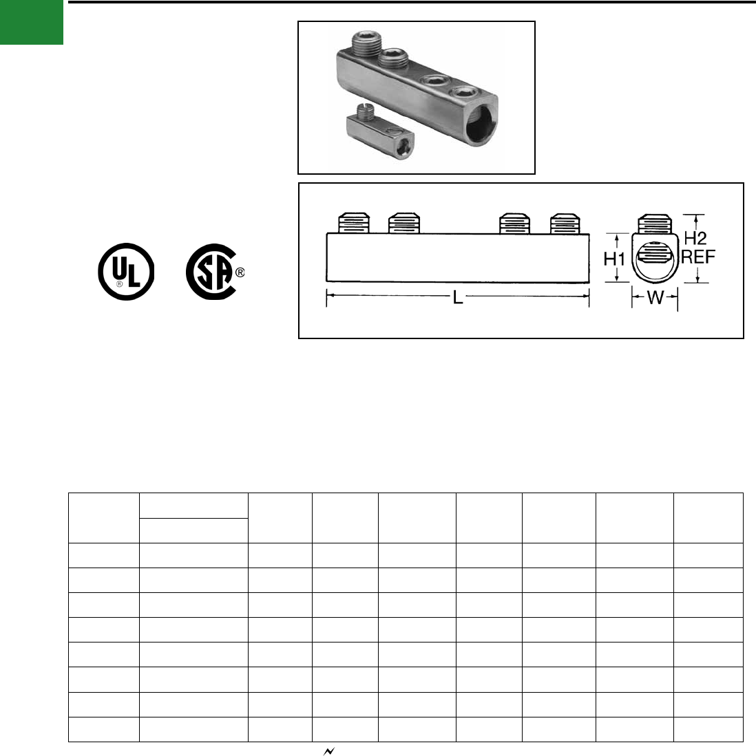
BURNDY®
Blue highlighted items are industry standard and most frequently ordered.
US: 1-800-346-4175 www.burndy.com Canada: 1-800-387-6487
Mechanical
TYPE AMS
DUAL RATED SPLICER/REDUCER
For Copper and Aluminum Cable
All splicer/reducers are dual rated for use
with aluminum and copper conductors and
are constructed from high strength, tin plated
aluminum. PENETROX™ oxide inhibiting joint
compounds are recommended for all aluminum
applications.
Catalog
Number
Wire Range
L W H1 H2 Max Number of
Screws
Screw
Diameter
Hex
Size
Aluminum & Copper
AMS-2*14 AWG-2 AWG 1-19/32 9/16 9/16 0.79 2 3/8 Slot
AMS-0*14 AWG-1/0 1-29/32 3/4 3/4 0.86 2 7/16 Slot
AMS-4/0 6 AWG-4/0 AWG 2-5/16 1 1-3/32 1.28 2 9/16 5/16
AMS-250 6 AWG-250 kcmil 4-3/32 1 1-3/32 1.29 4 5/8 5/16
AMS-350 6 AWG-350 kcmil 4-11/32 1 1-3/32 1.3 4 11/16 5/16
AMS-500 3/0 AWG-500 kcmil 4-25/32 1-1/4 1-3/8 1.48 4 13/16 3/8
AMS-750 250 kcmil-750 kcmil 6-1/6 1-7/16 1-5/8 1.98 4 15/16 1/2
AMS-1000 500 kcmil-1000 kcmil 8-11/16 1-21/32 1-7/8 2.34 6 1-1/8 9/16
Features & Benets
• All connectors are tin-plated
◊ Provide low contact resistance and
prevents galvanic corrosion
• Connectors feature rounded bottoms
◊ Facilitates taping
• Solid center barrier
◊ Prevents contact of dissimilar metals
• Large screw diameters
◊ Ensures greater surface contact with
wires for maximum pullout force
• Large cable ranges
◊ Each splice is also an effective
reducing connector
* Slotted Screws. H2 measured with maximum conductors,
reference only.
Complies with NFPA 78-86.
A-32
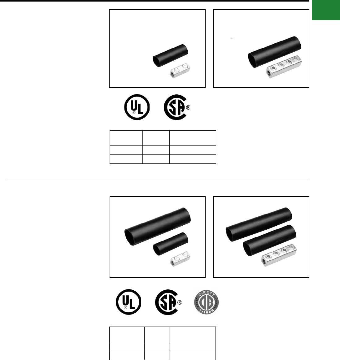
BURNDY®
Blue highlighted items are industry standard and most frequently ordered.
Canada: 1-800-387-6487 www.burndy.com US: 1-800-346-4175
Mechanical
TYPE AGSKIT
ABOVE GRADE SPLICE KITS
For all Aluminum or Copper/Aluminum
Combinations
Type AGS Above Grade Splice Kit consists of a
standard AMS splice/reducer and a heavy wall
heat-shrink sleeve. The AMS Splice is dual rated
for use with aluminum and copper conductors
and are constructed from high strength, tin plated
aluminum that provides low contact resistance
and reduces the effects of galvanic corrosion.
Connector is installed with common installation
tools. The heavy wall heat shrink sleeve is lined
with adhesive material, providing a positive seal
against moisture egress. Heat shrink sleeve is
installed with standard propane torch, or electric
heat gun.
Catalog
Number
Figure
Number Wire Range
AGSKIT2 1 8 AWG-2 AWG
AGSKIT250 2 1 AWG-250 kcmil
Fig. 1
Fig. 1
Fig. 2
Fig. 2
TYPE UGSKIT
WATERTIGHT/
UNDERGROUND SPLICE KITS
For all Aluminum or Copper/Aluminum
Combinations
Type UGS Watertight Underground Splice Kit
consists of a standard AMS splice/reducer and
two heavy wall heat-shrink sleeves. The AMS
Splice is dual rated for use with aluminum and
copper conductors and are constructed from
high strength, tin plated aluminum that provides
low contact resistance and reduces the effects
of galvanic corrosion. Connector installed with
common installation tools. Both heavy wall heat
shrink sleeves are lined with adhesive material,
providing a watertight splice that can withstand
abrasions that may occur during direct burial
applications. Heat shrink sleeve installed with
standard propane torch, or electric heat gun.
Catalog
Number
Figure
Number Wire Range
UGSKIT2*1 8 AWG-2 AWG
UGSKIT250*2 1 AWG-250 kcmil
*UL486D Listed for Direct Burial
A-33
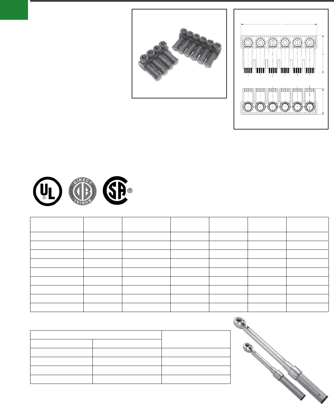
BURNDY®
Blue highlighted items are industry standard and most frequently ordered.
US: 1-800-346-4175 www.burndy.com Canada: 1-800-387-6487
Mechanical
Direct Burial UNITAP™
Connectors
UNITAP™
Dual Rated Multiple Tap Connector
These rubber insulated, dual rated connectors are
for use in networks up to 600V. Suitable in light
xture pole bases in commercial, industrial, or
residential markets. Distribution within strip malls,
for use in any multi-tenant facility. No taping or
heat shrink required.
Catalog Number # of Ports Wire Range
(AWG/kcmil) L W H Wire Strip Length
(in)
BIBS3502DB 2 12 AWG-350 kcmil 2.61 4.06 2.46 1.125
BIBS3503DB 3 12 AWG-350 kcmil 3.82 4.06 2.46 1.125
BIBS3504DB 4 12 AWG-350 kcmil 5.03 4.06 2.46 1.125
BIBS3505DB 5 12 AWG-350 kcmil 6.24 4.06 2.46 1.125
BIBS3506DB 6 12 AWG-350 kcmil 7.45 4.06 2.46 1.125
BIBS5003DB 3 10 AWG-500 kcmil 4.31 4.58 3.13 1.50
BIBS5004DB 4 10 AWG-500 kcmil 5.69 4.58 3.13 1.50
BIBS5005DB 5 10 AWG-500 kcmil 7.06 4.58 3.13 1.50
BIBS5006DB 6 10 AWG-500 kcmil 8.44 4.58 3.13 1.50
Features & Benets
• Dual rated for aluminum or copper
conductors
• Each unit is individually marked for
ease of identication
• Supplied with aluminum set-screws
• Covering is the highest quality
EPDM rubber
• Supplied with oxide inhibitor pre-
installed
• Suitable for direct burial
• Meets ANSI C119.1 and C119.4
requirements
• Rated 600V and 90° C; UL Listed
and CSA Certied
• For use in wet or damp locations
• Silicone provided for conductor
insertion
Recommended Torque Values for Direct Burial UNITAP™ Recommended BURNDY®
Torque Wrench
Conductor Size Recommended Torque Range
#12 - #6 AWG 125 - 150 in-lbs BTW30150
#4 - 3/0 AWG 180 - 240 in-lbs BTW150750
4/0 - 350 AWG 275 - 450 in-lbs BTW150750
400 - 1000 AWG 475 - 550 in-lbs BTW150750
A-34
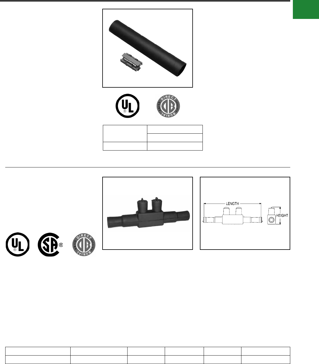
BURNDY®
Blue highlighted items are industry standard and most frequently ordered.
Canada: 1-800-387-6487 www.burndy.com US: 1-800-346-4175
Mechanical
TYPE UGSKIT8
UF DIRECT BURIAL
SPLICE KIT
Type UGS UF Splice Kit consists of a UF splice
connector and a heavy wall heat-shrink sleeve.
The UF splice connector can accommodate up to
four UF conductors and is installed with common
installation tools. The heavy wall heat shrink
sleeve is lined with an adhesive material, providing
a water-tight splice that can withstand abrasions
that may occur during direct burial applications.
Heat shrink sleeve installed with standard propane
torch, or electric heat gun.
Catalog
Number
Wire Range
Copper
UGSKIT8*14 AWG-8 AWG
*UL486D Listed for Direct Burial
TYPE UGS350ULDB
IN-LINE SPLICE/REDUCER
For Direct Burial
Catalog Number Wire Range Length Height Hex Size Torque (In. Lbs.)
UGS350ULDB 12 AWG-350 kcmil 8.50 2.81 5/16 350
Features & Benets
• EPDM rubber covered 6061-T6
aluminum connector
• Dual rated AL9CU for copper or
aluminum conductor
• UL Listed and CSA Certied for Direct
Burial
• Broad range taking capability
• Low installation cost
A-35
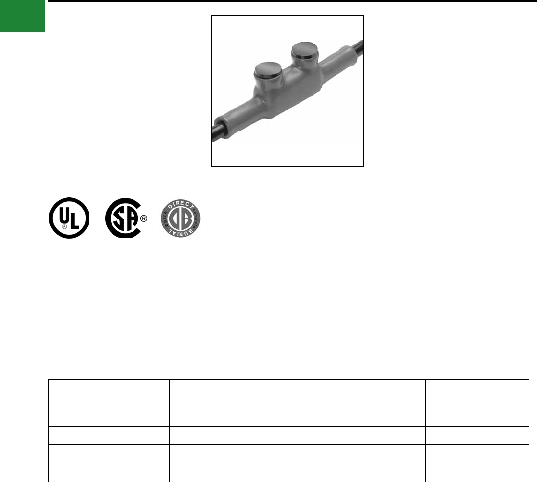
BURNDY®
Blue highlighted items are industry standard and most frequently ordered.
US: 1-800-346-4175 www.burndy.com Canada: 1-800-387-6487
Mechanical
BURNDY UNITAP™
THE MOLE™
For Direct Burial
600V, 90° C
Designed specically for direct burial applications,
the MOLE™ in-line splice/reducer is made with a
specialized plastisol material that forms a rugged
weathertight connection.
Catalog
Number
Number of
Ports
Wire Range (AWG/
kcmil) L W H Hex Key Torque
(In.-lbs.)
Wire Strip
Length
BISR4-DB 2 #6 AWG-#4 AWG 4.30 0.68 1.39 1/8 50 7/8"
BISR1-DB 2 #2 AWG-#1 AWG 6.30 0.88 1.75 5/32 130 1-3/32"
BISR3/0-DB 2 1/0 -3/0 AWG 6.25 0.99 1.96 3/16 220 1-3/32"
BISR250-DB 2 4/0 AWG-250 kcmil 6.70 1.18 2.17 5/16 360 1-5/16"
Features & Benets
• UL486D Listed for direct burial.
• AL9CU Dual-rated for copper and
aluminum applications. 600V 90°C.
• Plastisol covered AL6061-T6 aluminum
body saves time by eliminating the need
for heat shrink.
• Oxide inhibitor pre-installed preventing
moisture and contaminants from entering
contact area.
• Range-taking capability reduces the
number of connectors carried in inventory.
BISR-DB = BURNDY Inline Splice/Reducer Direct Burial.
UNITAP™ rated for code conductor only.
A-36
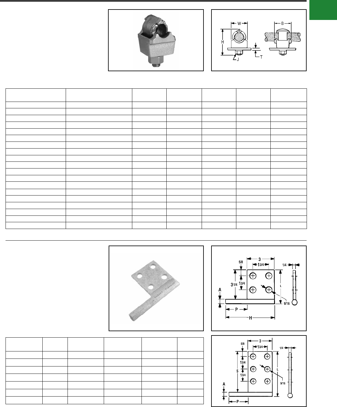
BURNDY®
Blue highlighted items are industry standard and most frequently ordered.
Canada: 1-800-387-6487 www.burndy.com US: 1-800-346-4175
Mechanical
QGFL
BARTAP™
For Copper Cable to Flat Bar or
Pad
High copper alloy BARTAP™ for joining a range
of cable to bar or pad. One-wrench installation.
DURIUM™ nut and lockwasher.
Catalog
Number
Copper
Conductor B H J T
(Max) W
QGFL1CB1 #10 Sol-#1 Str 1-1/8 1-7/8 3/8 1/4 1
QGFL1CB1T6 #10 Sol-#1 Str 1-1/8 2-3/8 3/8 3/4 1
QGFL26B1 #8 Sol-#2/0 Str 1-1/4 2-1/8 3/8 1/4 1-1/8
QGFL26B1T6 #8 Sol-#2/0 Str 1-1/4 2-5/8 3/8 3/4 1-1/8
QGFL26B2* #8 Sol-#2/0 Str 1-1/4 2-8/25 1/2 1/4 1-1/8
QGFL26B2T6* #8 Sol-#2/0 Str 1-1/2 2-40/50 1/2 3/4 1-1/8
QGFL29B1* #6 Str-250 kcmil 1-2/5 2-5/8 1/2 1/4 1-3/8
QGFL29B1T6* #6 Str-250 kcmil 1-5/8 3-1/8 1/2 3/4 1-3/8
QGFL31B1* 2 AWG-350 kcmil 1-3/4 2-7/8 1/2 1/4 1-5/8
QGFL31B1T6* 2 AWG-350 kcmil 1-3/4 3-1/4 1/2 3/4 1-5/8
QGFL34B1 1/0 -500 kcmil 2 3-1/8 1/2 1/4 1-3/4
QGFL34B1T6 1/0 -500 kcmil 2 3-5/8 1/2 3/4 1-3/4
QGFL39B1 350 kcmil-750 kcmil 2-1/4 3-1/4 1/2 1/4 1-3/4
QGFL39B1T6 350 kcmil-750 kcmil 2-1/4 3-5/8 1/2 3/4 1-3/4
QGFL44B1 750 kcmil-1000 kcmil 2-1/4 3-3/8 1/2 1/4 2-1/8
QGFL44B1T6 750 kcmil-1000 kcmil 2-1/4 4-1/8 1/2 3/4 2-1/8
QGFL46B1 1000 kcmil-1500 kcmil 2-1/4 4 1/2 1/4 2-1/2
QGFL46B1T6 1000 kcmil-1500 kcmil 2-1/4 4-1/2 1/2 3/4 2-1/2
QGFL48B1 1500 kcmil-2000 kcmil 2-1/4 4-3/4 1/2 1/4 3
* Can be installed side by side or in-line on NEMA drilled bar.
FCB
TRANSFORMER TAP ADAPTER
Copper and Aluminum
Cast in one piece from copper alloy. Transformer
tap adapter designed to accommodate from 1
to 6 NEMA drilled copper or aluminum terminal
taps from a single secondary transformer outlet.
Tin-plated. Order mounting hardware and tap
terminals separately.
Catalog
Number
Fig.
No.
A
Diameter
H
Ref. L P
FCB63-4N 1 0.50 5.25 3.75 2.25
FCB63-6N 2 0.50 5.25 5.50 2.25
FCB64-4N 1 0.75 5.75 4.00 2.75
FCB64-6N 2 0.75 5.75 5.75 2.75
FCB65-4N 1 1.00 7.00 4.25 4.00
FCB63-2NP300 Not Shown 0.50 5.00 3.50 3.00
FCB64-44NP50 Not Shown 0.75 9.00 5.00 5.00
NOTE: All pads are NEMA drilled.
Fig. 1
Fig. 2
A-37
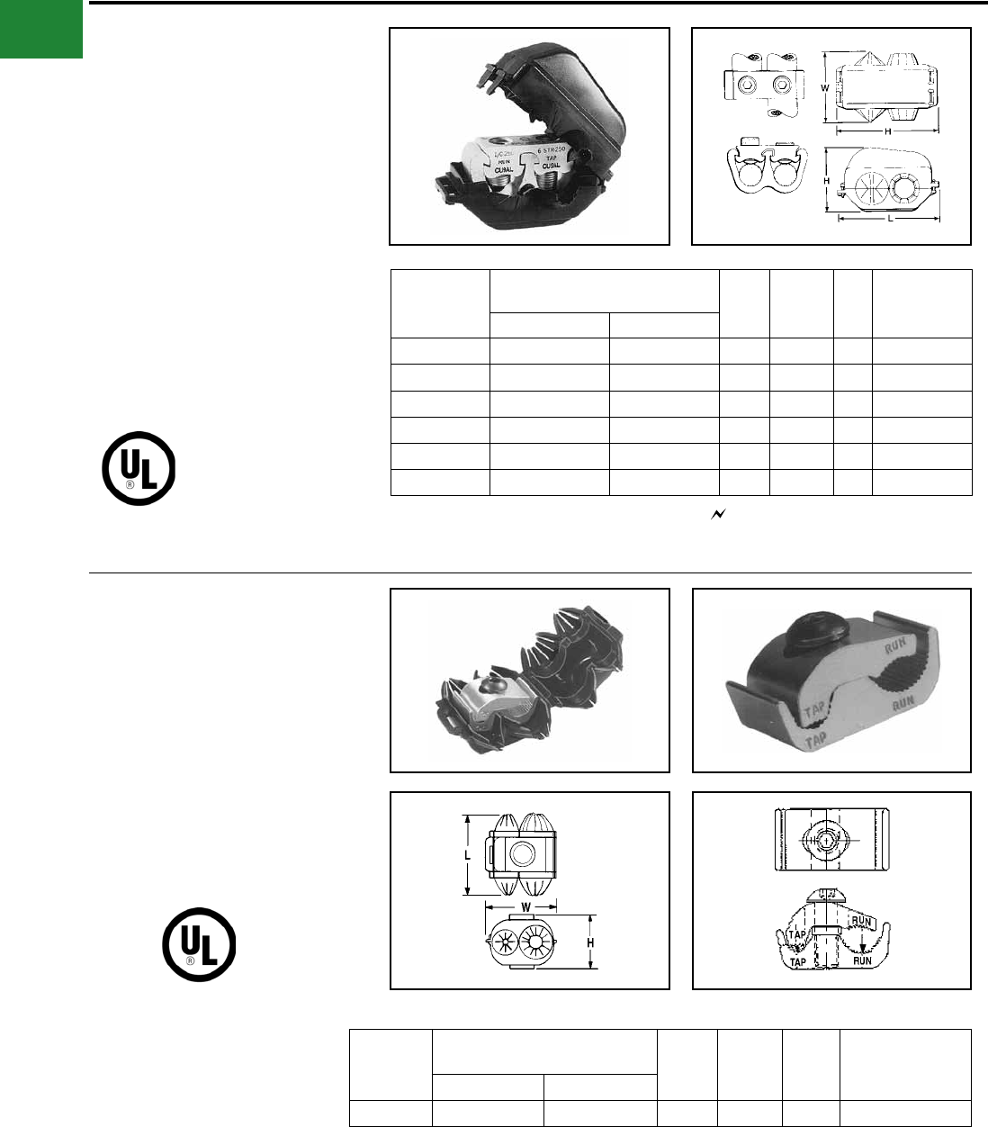
BURNDY®
Blue highlighted items are industry standard and most frequently ordered.
US: 1-800-346-4175 www.burndy.com Canada: 1-800-387-6487
Mechanical
TYPE KPU-AC
POLYTAP™
Insulated Gutter Tap for All Copper
and Aluminum Combinations
Wide range-taking tin-plated aluminum parallel
clamp and insulating cover assembly for industrial
and multiple story structure applications. Only
six connectors cover the entire 14 Sol.-750 kcmil
range. Covers having exible ngers that conform
to conductor, fully insulating the connection.
UL486B Listed for 600 volts maximum 90° C
service. Cover and connector are packaged
together. No taping required.
600 Volt Max. 90° C
Catalog
Number
Conductor
Copper or Aluminum W H L
Rec.
Tightening
▲ Torque in-lb
Run Tap
KPU29A26AC 1/0 -250 kcmil 14 AWG-2/0 AWG 3-1/8 3-3/8 4.24 375
KPU29A29AC 1/0 -250 kcmil 6 AWG-250 kcmil 3-1/8 3-3/8 4.24 375
KPU34A26AC 4/0 AWG-500 kcmil 14 AWG-2/0 AWG 3-1/2 3-1/2 4.58 450
KPU34A34AC 4/0 AWG-500 kcmil 6 AWG-500 kcmil 3-1/2 3-1/2 4.58 450
KPU39A26AC 500 kcmil-750 kcmil 14 AWG-2/0 AWG 3-1/2 3-83/100 5.06 600
KPU39A39AC 500 kcmil-750 kcmil 1/0 -750 kcmil 3-1/2 3-83/100 5.06 600
▲ Listed torque values are for maximum conductor
combinations accommodated. Consult UL486 Tables
7-4, 7-5, 7-6 for smaller combinations.
▲ Listed torque values are for maximum conductor
combinations accommodated. Consult UL486 Tables
7-4, 7-5, 7-6 for smaller combinations.
See note LIGHTNING PROTECTION INFO.
TYPE UCU-AC
RISER TAP
600 VOLT MAX. 90° C MAX.
Parallel-groove riser tap and insulation cover for
copper and aluminum. Wide range-taking assembly
for apartment house and light industrial applications.
Cover and connector are packaged together. Covers
having insulating ngers that conform to conductors,
fully insulating the connection. UL486B Listed for 600
volts max. 90° C service.
Catalog
Number
Conductor
Copper or Aluminum W H L
Recommended
Tightening ▲
Torque in-lb
Run Tap
UCU28AC #2 Str.- 4/0 Str. #10 Sol. - #2 Str. 2-1/4 1-13/16 2-5/8 120
A-38
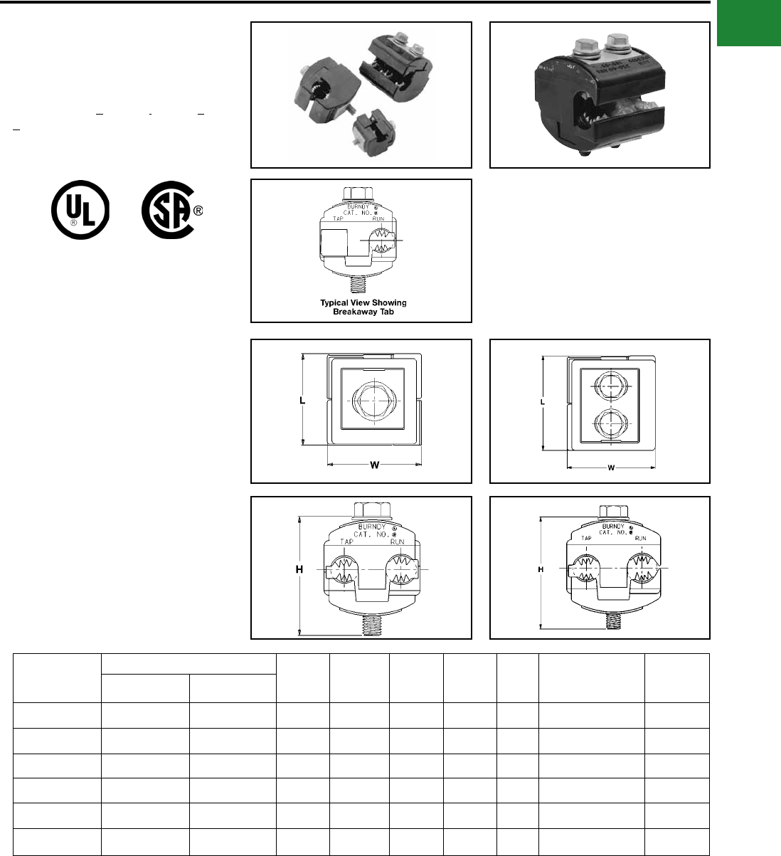
BURNDY®
Blue highlighted items are industry standard and most frequently ordered.
Canada: 1-800-387-6487 www.burndy.com US: 1-800-346-4175
Mechanical
TYPE BIPC
UL Listed 90° C, *600 Volt
The Type BIPC, BURNDY® Insulation Piercing
Connector is ideally suited for splicing and tapping
aluminum and copper conductor wire sizes: #10
AWG to 500 kcmil.
Catalog
Number
Conductor Range
Bolt Size Socket
Size H L W
Recommended
Tightening
Torque
Max.
Voltage
Rating
Run Tap
BIPC1/0-2* 1/0 - 8 AWG 2 - 8 AWG 5/16 1/2 2.00 1.53 1.53 180 600 V
BIPC4/0-6 4/0 - 1/0 AWG 1/0 - 6 AWG 5/16 1/2 2.50 2.12 2.00 250 300 V
BIPC4/0-1/0 4/0 - 1/0 AWG 4/0 - 1/0 AWG 5/16 1/2 2.50 2.12 2.06 250 300 V
BIPC350-4/0 350 - 4/0 AWG 4/0 - 10 AWG 3/8 9/16 3.00 1.59 2.50 375 300 V
BIPC350-350 350 - 4/0 AWG 350 - 4/0 AWG 3/8 9/16 3.00 2.62 2.75 300 300 V
BIPC500-4/0* 500 - 350 kcmil 4/0 - 4 AWG 3/8 9/16 3.25 1.80 2.62 400 600 V
Features & Benets
• Insulation piercing capability
◊ Eliminates the need for conductor
insulation stripping.
• UL486B Listed, AL9CU rated
◊ For copper and aluminum conductor
combinations up to 90° *600 Volt
applications.
• Insulation piercing design
◊ For use on hot-line applications -
eliminates the need for taping.
• Easy snap-out tabs
◊ Eases installation, protects connection
from dirt and debris.
• Simple bolt-on connection
◊ Eases installation.
Fig. 1 Fig. 2
* 600 Volt
A-39
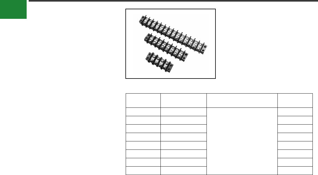
BURNDY®
Blue highlighted items are industry standard and most frequently ordered.
US: 1-800-346-4175 www.burndy.com Canada: 1-800-387-6487
Mechanical
MISCELLANEOUS
ACCESSORIES
TERMINAL BLOCKS
Molded General Purpose Phenolic Base 30
amps,
#10 studs, 1 piece per card, 300-volt rating
Meets UL component requirements
CLASS B:
Commercial Equipment 300 V RMS
CLASS C:
General Industrial 300 V RMS
Withstands volts, Vdc 10,500
Steel nickel plated screws
Catalog
Number Number of Circuits General Description Overall Length
RK149-2 2
Molded General Purpose
Phenolic Base 30 amps, #10 studs
1 piece, per card 300-volt rating
2-3/32"
RK150-2 4 3-7/32"
RK225-2 6 4-11/32"
RK151-2 8 5-15/32"
RK152-2 10 6-19/32"
RK226-2 12 7-23/32"
RK153-2 14 8-27/32"
RK227-2 16 9-31/32"
For bulk pack contact factory.
A-40
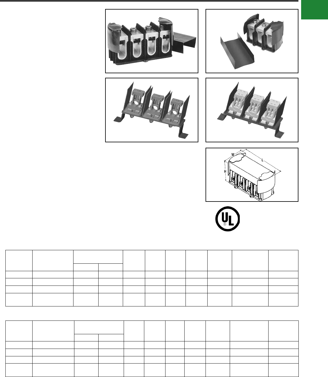
BURNDY®
Blue highlighted items are industry standard and most frequently ordered.
Canada: 1-800-387-6487 www.burndy.com US: 1-800-346-4175
Mechanical
POWER DISTRIBUTION
BLOCKS
U-BLOK™
For Junction Box Applications
The U-BLOK™ system is a modern, state-of-
the-art approach to multi-load power distribution
applications. Among typical uses are multi-story
or multi-unit buildings, HVAC, refrigeration,
control panels, motor control, switch gear, elevator
systems and materials handling equipment.
U-BLOK™ is UL Listed for Copper or Aluminum
conductors and rated for 600-volt applications.
U-BLOK™ can be mounted on bases for use in
troughs or bolted directly to junction boxes. AL9CU
rated.
Catalog
Number
Max. Number of
Wires per Phase
Conductor
Copper or Aluminum* W L H Weight
Each
Allen
Wrench
Size
Recommended
Tightening
Torque
Strip Length
Run Tap
FT3B4/0 2 3/0 - 4/0 6 - 4/0 3-7/8 5-7/8 4-1/8 1-1/4 1/4 200 1-1/2
FT3B500 2 400 - 500 6 - 500 3-7/8 5-7/8 4-1/8 2-1/8 3/8 375 2-5/16
3S 2 250 - 350 6 - 350 3-5/8 9-3/4 4-7/8 3 1/4 200 1-3/4
3U 1 Run / 8 Tap 3/0 - 500 6 - 1/0 4-3/4 9-3/4 5-1/2 3 5/32 110 2-5/16 (Run);
1-5/32 (Tap)
Features & Benets
• Connector top slides OFF/ON for quick
cable lay-in
◊ Labor savings. Easy access for
installation, modications or retrot.
• Electro-tin plated connectors in each
pole
◊ Durability. High-conductivity and
resistance to corrosion.
• Compact size
◊ Requires less space than traditional
connection methods.
• Trough installations can be mounted on
raised platforms
◊ Passage of cables under block means
through-cables need not be terminated
• Insulating covers and mounting blocks
rated 94-VO
◊ Saves costly taping, time and material.
Conforms to or exceeds building codes.
• Connectors accommodate a wide range
of wire sizes
◊ Reduces parts inventory requirements.
• Feeder conductors can be cut or fed
through on a continuous run
◊ Ease of installation.
FT4B500
3S 3U
FT3B4/0
Catalog
Number
Max. Number of
Wires per Phase
Conductor
Copper or Aluminum* W L H Weight
Each
Allen
Wrench
Size
Recommended
Tightening
Torque
Strip
Length
Run Tap
FT4B4/0 2 3/0 - 4/0 6 - 4/0 3-7/8 7-7/8 4-1/8 2 1/4 200 1-1/2
FT4B500 2 400 - 500 6 - 500 3-7/8 7-7/8 4-1/8 2-3/4 3/8 375 2-5/16
4S 2 250 - 350 6 - 350 3-5/8 11-3/4 4-7/8 3-1/2 1/4 200 1-3/4
4U 1 Run / 8 Tap 3/0 - 500 6 - 1/0 4-3/4 11-3/4 5-1/2 3-1/2 5/32 110 2-5/16 (Run);
1-5/32 (Tap)
3 WIRE POWER DISTRIBUTION BLOCKS
4 WIRE POWER DISTRIBUTION BLOCKS
PENETROX™ inhibitor is recommended for all aluminum
wire connections.
For two wire tap range is 8 through 1/0.
* Aluminum and copper conductors cannot be assembled
under the same pressure plate or t-bar.
A-41
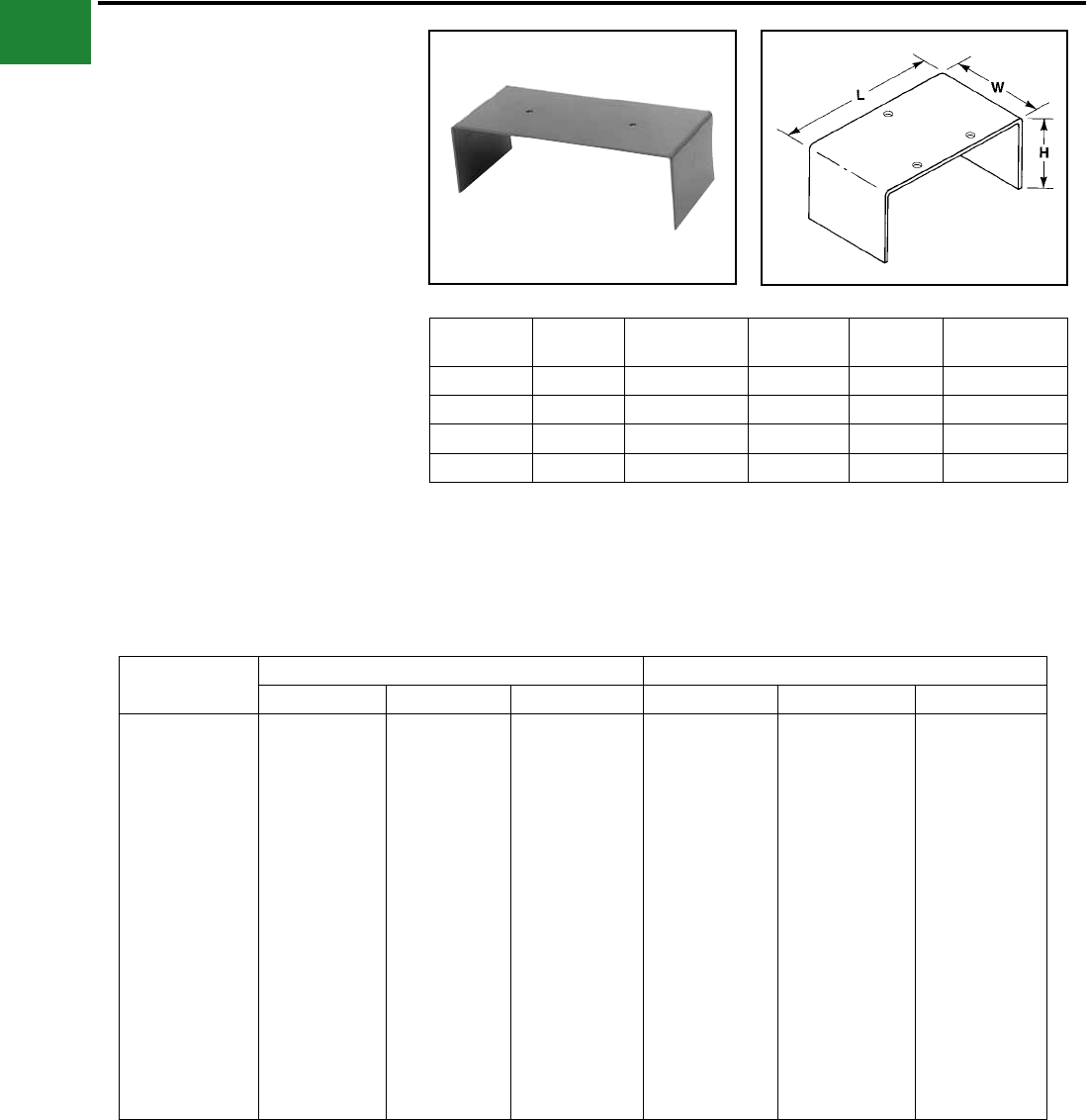
BURNDY®
Blue highlighted items are industry standard and most frequently ordered.
US: 1-800-346-4175 www.burndy.com Canada: 1-800-387-6487
Mechanical
U-BLOK™ MOUNTING
PLATFORMS
For Trough Applications
Catalog
Number W L H Gutter
Size Weight Each (lb)
TBPT6* 4-1/4 5-7/8 1-1/2 6'3/4
TBPT8 4-1/4 7-7/8 3-1/2 8"1-1/4
TBPT10 4-1/4 9-7/8 4 10"1-1/2
TBPT12 4-1/4 11-7/8 4 12"1-3/4
Hole pattern shown is for reference only.
* Supercedes TBPT4/0-6 and TBPT350/500-6.
FLEXI-TAP™
ALLOWABLE AMPACITIES OF INSULATED CONDUCTOR, 60° TO 90° C **
Size AWG
kcmil
Copper Al or Copper Clad Al
60 deg. C 75 deg. C 90 deg. C 60 deg. C 75 deg. C 90 deg. C
12
10
8
6
4
3
2
1
1/0
2/0
3/0
4/0
250
300
350
400
500
600
700
750
25
30
40
55
70
85
95
110
125
145
165
195
215
240
260
280
320
355
385
400
25
35
50
65
85
100
115
130
150
175
200
230
255
285
310
335
380
420
460
475
30
40
55
75
95
110
130
150
170
195
225
260
290
320
350
380
430
475
520
535
20
25
30
40
55
65
75
85
100
115
130
150
170
190
210
225
260
285
310
320
20
30
40
50
65
75
90
100
120
135
155
180
205
230
250
270
310
340
375
385
25
35
45
60
75
85
100
115
135
150
175
205
230
255
280
305
350
385
420
435
** NOTE: Values referenced from Article 310 of the National Electric Code, Table 310-16, 1996. The above
chart is to be used for REFERENCE ONLY. Please consult Table 310-16 of the National Electric Code (lat-
est revision) for information regarding insulation type, voltage range, and conductor housings/surroundings.
U-TAP™, U-BLOK™, and SPEC-BLOK™ connectors are rated for 90 deg. C by Underwriters’ Laboratories.
Use of 60 deg. C and 75 deg. C conductor(s) is valid, though only as determined by the National Electric
Code.
A-42
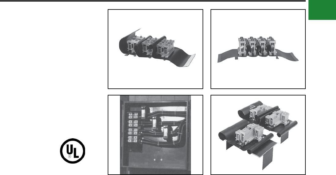
BURNDY®
Blue highlighted items are industry standard and most frequently ordered.
Canada: 1-800-387-6487 www.burndy.com US: 1-800-346-4175
Mechanical
SPEC-BLOK™
POWER DISTRIBUTION
CONNECTORS
Unique, modular, made-to-order, power distribution
assemblies accommodate any number of supply
and load conductors in any number of poles.
Capacity matches the conductors accommodated
and SPEC-BLOK™ assures uniform loading.
Adjacent poles are separated by easy-to handle,
wrap-around insulating covers which eliminate
taping and reduce heat build-up by allowing air to
ow freely around connectors. SPEC-BLOK™ is
UL Listed for copper or aluminum conductors for
600 volts. (AL9CU) Assemblies are mounted on
platforms suitable for easy installation in wireway
or junction box.
Features & Benets
• Accommodate unlimited conductors
◊ Fits wide range of applications.
Eliminates need for non-UL-Listed
improvisation.
• Connector elements tin-plated
◊ Provides high reliability,
low-resistance connections.
• User friendly, space-saving design
◊ Easy to install - saves labor.
• 94-VO rated insulation folds into
place insulating the components
◊ Saves time and material. Allows
easy installation.
• Connector caps removable for easy
cable lay-in
◊ Saves labor. Makes installation
easier - allows installation of
straight-through conductors.
Eases retrot.
• Belleville washers built-in on
pressure screw assemblies, except
in assemblies installed with a 5/32"
Allen wrench
◊ Provides high-integrity connections.
• Conductors can be cut or fed straight
through
◊ Straight through installation ideal
for riser applications.
Contact BURNDY® or Technical Services: 1-800-451-4956,
or BURNDY® Customer Service: 1-800-346-4175
A-43
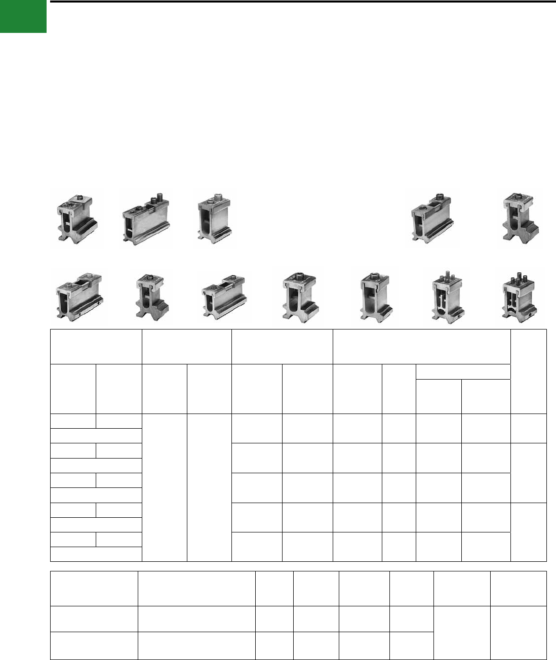
BURNDY®
Blue highlighted items are industry standard and most frequently ordered.
US: 1-800-346-4175 www.burndy.com Canada: 1-800-387-6487
Mechanical
SPEC-BLOK™ Features & Benets
• The SPEC-BLOK™ system includes
12 connector elements
◊ A wide variety of conductor sizes can
be accommodated
• Each element can be bolted together
in parallel
◊ Provides an efcient ow of current
from one element to another
• AL9CU rated for Copper or Aluminum
conductors
◊ Dual-rated system, with UL486B’s
highest temperature rating
• 2 Wire (series), 4 (parallel), and
Multi-Tap versions available
◊ Nearly any conductor combination can
be terminated
• Tin-plated Aluminum Alloy Construction
◊ High-strength, corrosion-resistant
connector elements
• All SPEC-BLOK™ connectors are
custom made for nearly any Power
Distribution system requirement
◊ Time savings — pre-assembled in our
factory for immediate installation!
SPEC-BLOK™ CONNECTORS
E W D S
C B R
A
Q U P
Catalog Designation
(Maximum
Conductor)
Number of
Conductors
Accommodated
AL or CU
Wire Range Under
Each Cap
Dimensions
Allen
Wrench
Size
4
Conductor
2
Conductor
4
Conductor
2
Conductor
First
Conductors
MUST Be
Second
Conductor
(if required)
May Be
Height On
Max
Conductors
Width
Length Without Insulator
4
Conductor
2
Conductor
A Q
1 to 4
(0, 1 or 2
per cap)
1 or 2
per cap
1/0 - 2/0 #12 - 2/0 2-9/16" 1-1/2" 2-1/8" 7/8" 5/32"
(2/0)
B R 3/0 - 250 #6 - 250 3-1/8" 1-11/16" 4-1/4" 1-3/8"
1/4"
(250)
C S 250 - 350 #6 - 350 3-5/16" 1-13/16" 4-5/8" 1-1/2"
(350)
D T 400 - 500 #6 - 500 4-1/16" 2" 5-5/8" 1-3/4"
3/8"
(500)
E W 600 - 750 3/0 - 750 4-7/8" 2-1/4" 7-1/4" 2-5/8"
(750)
Catalog Designation
(Maximum Conductor)
Number of Conductors
Accommodated
Large
Groove
Small
Grooves**
Height On
Maximum
Conductors
Width
Length
Without
Insulator
Allen
Wrench
Size
P (1/0) 1 to 8 (0, 1 or 2 under each screw) __ 6 - 1/0 3-1/2" 2"
1-3/4" 5/32"
U (1/0 & 500) 2 to 9 (0, 1 or 2 under each screw
plus one large conductor) 3/0 - 500 6 - 1/0 4-1/8" 2"
** This range may be expanded to include #8 provided two conductors are being installed in that particular element.
T
A-44
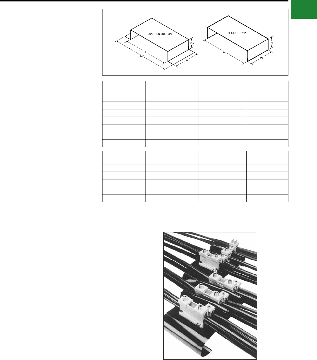
BURNDY®
Blue highlighted items are industry standard and most frequently ordered.
Canada: 1-800-387-6487 www.burndy.com US: 1-800-346-4175
Mechanical
SPEC-BLOK™
MOUNTING PLATFORMS
SPEC-BLOK™ Mounting Platforms
are rigid steel construction with a
black nish.
They can be supplied for junction box mounting or
wireway construction allowing trough conductors
to pass underneath the assemblies.
SPEC-BLOK™ IS A SYSTEM THAT CAN SOLVE MOST POWER DISTRIBUTION APPLICATIONS!
SPEC-BLOK™ catalog numbers describe exactly how
the distribution block is assembled: 5DR-NDST-GQP-12 (assembly pictured)
5 Total number of poles in the
completed assembly
DR One ‘D’ unit and one ‘R’ unit, bolted in parallel,
forming each phase pole (3 phase poles)
NDenotes the beginning of the neutral pole (where
required)
DST One ‘D’ unit, one ‘S’ unit, and one ‘T’ unit, bolted
in parallel, forming the neutral pole
GDenotes the beginning of the ground pole
description (where required)
QP One ‘Q’ unit and one ‘P’ unit,
bolted in parallel, forming the ground pole
12
Size (inches) of the wireway or trough that is need-
ed to enclose the assembly. If a junction box en-
closure is used, no number is used to denote the
size of the enclosure
Catalog
Number
L
(Nominal)
L
(Overall)
W
(Overall)
CPB6 6 7-3/4 2-1/2
CPB8 8 9-3/4 2-1/2
CPB10 10 11-3/4 2-1/2
CPB12 12 13-3/4 3-1/2
CPB14 14 15-3/4 3-1/2
CPB16-5/8 16-5/8 18-3/8 3-1/2
CPB21-1/4 21-1/4 23 3-1/2
Catalog
Number
L
(Nominal) HW
(Overall)
CPT6 5-7/8 2-1/4 2-1/2
CPT8 7-7/8 3 3-1/2
CPT10 9-7/8 3-1/2 3-1/2
CPT12 11-7/8 4 3-1/2
CPT16 15-7/8 4 3-1/2
(CPT-)(CPB-)
A-45
BURNDY®
Blue highlighted items are industry standard and most frequently ordered.
US: 1-800-346-4175 www.burndy.com Canada: 1-800-387-6487
Mechanical
How many poles in the system? (3-wire, 4-wire, single phase, etc.)?___________ poles
Are neutral conductors (when required) different sizes (AWG/kcmil) than the phase conductors?
___________ same size ___________ different size
Is a ground connection required? □ Yes □ No
What are the quantities, sizes (AWG/kcmil) and material (AI/Cu) of the incoming line conductors
and outgoing load conductors?
Are any conductors continuous? □ Yes □ No
If yes, which ones? ______________________________________________________________________________________
_______________________________________________________________________________________________________
What kind of enclosure is the connection assembly being mounted in and what are the inside space dimensions?
Wireway/trough size _______________________________________________________________________________________
Box, panel, cabinet, other size _______________________________________________________________________________
When is a quotation required? Date ______________ _____ When is the material required? Date __________________
Name of requestor ______________ ____________________ Job name/reference _____________ ___________________
Is there a preference for a particular BURNDY distributor? □ Yes □ No
If yes, please give the name, location and telephone number
Name ________________________________________________________________ Phone______________________________
Address ________________________________________________________________________________________________
________________________________________________________________________________________________
PER PHASE
PER PHASE
PER PHASE
LINE
LOAD
LINE
LOAD
LINE
LOAD
QUANTITY SIZE CONDUCTOR TYPE
For SPEC-BLOK™ Applications
Questionnaire
Questions? Call BURNDY® Technical Services at 800-451-4956.
A-46
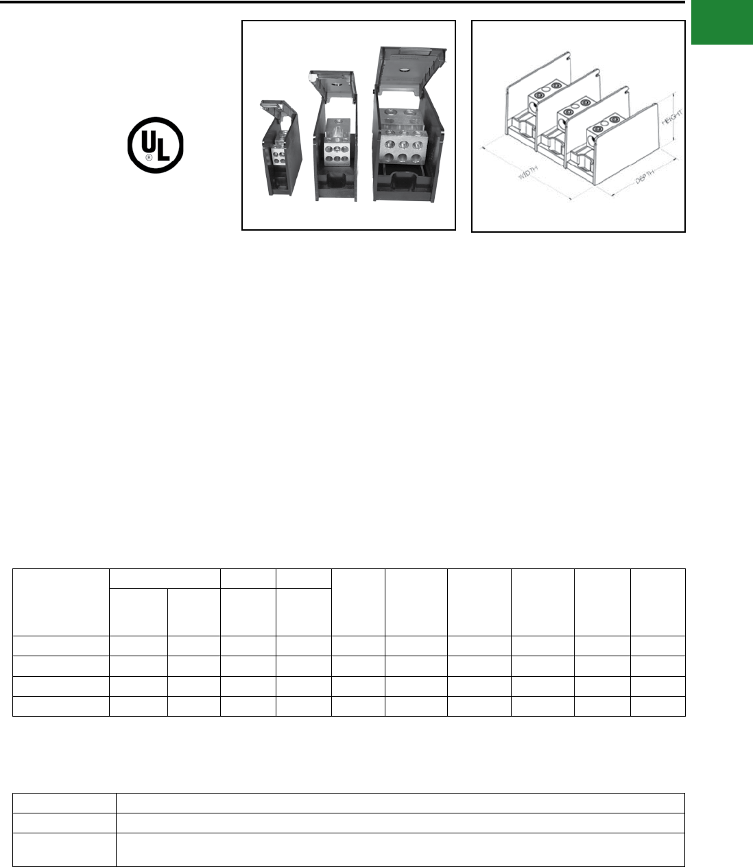
BURNDY®
Blue highlighted items are industry standard and most frequently ordered.
Canada: 1-800-387-6487 www.burndy.com US: 1-800-346-4175
Mechanical
UL LISTED
POWER DISTRIBUTION
BLOCKS
VERSIPOLE™
These Power Distribution Blocks are Listed to the
Power Distribution Block Standard UL 1953. They
contain the same features and characteristics
as the non-Listed blocks however, these have
spacings that are suitable for installations in
most industrial control panel feeder and branch
circuits, HVAC systems, and Wireways (with
optional cover; sold separately). They are
available in one, two, or three pole congurations.
An “Adder” is also available with optional End
Barrier (sold separately), to allow user customized
congurations.
Catalog Number
Connector Run Tap
Width Height Depth
Ampere
Rating per
Pole
Number
of Poles SCCR1
Number
of Run(s)
Number
of Tap(s)
Wire
Range
AL9CU
Wire
Range
AL9CU
BDCSHC142/01 1 4 14-2/0 14-4 1.05 2.81 3.08 175 1 100kA
BDASHC142/01 1 4 14-2/0 14-4 0.93 2.81 3.08 175 Adder 100kA
BDCSHC112/01 1 1 14-2/0 14-2/0 1.05 2.81 3.08 175 1 100kA
BDASHC112/01 1 1 14-2/0 14-2/0 0.93 2.81 3.08 175 Adder 100kA
Features & Benets
• Single or dual run connections allow the
user to minimize the number of connections
required
• Suitable for use with aluminum or copper
conductors providing maximum versatility
• Available in 3 sizes for optimization of space
• 600V, ALCU Rated; meets or exceeds
industry standard requirements
• Range taking designs to accommodate wire
sizes up to 600 kcmil
• High Short-Circuit Rating up to 100kA with
proper fusing
• Meets spacing requirements of Industrial
Control Panel Standard UL 508A (spacing
of 1” through air and 2” over surface)
• Adders and End Barriers available sepa-
rately for all 3 sizes providing capability to
create as many poles as required
• Hinged Covers available separately to cover
3 sizes providing user protection and easy
access to connector terminal block
1 Short-Circuit Current Rating with proper fusing
Small Series:
Small Series Hinged Cover and End Barrier:
Catalog Number Description
BDASHCEB End Barrier for Small Series Adder Distribution Blocks
BDBSHCCOVER Hinged Cover for use with Small Series Distribution Blocks and Adders (use of End Barrier necessary with Adders to attach
cover). Order 1 cover per pole
A-47
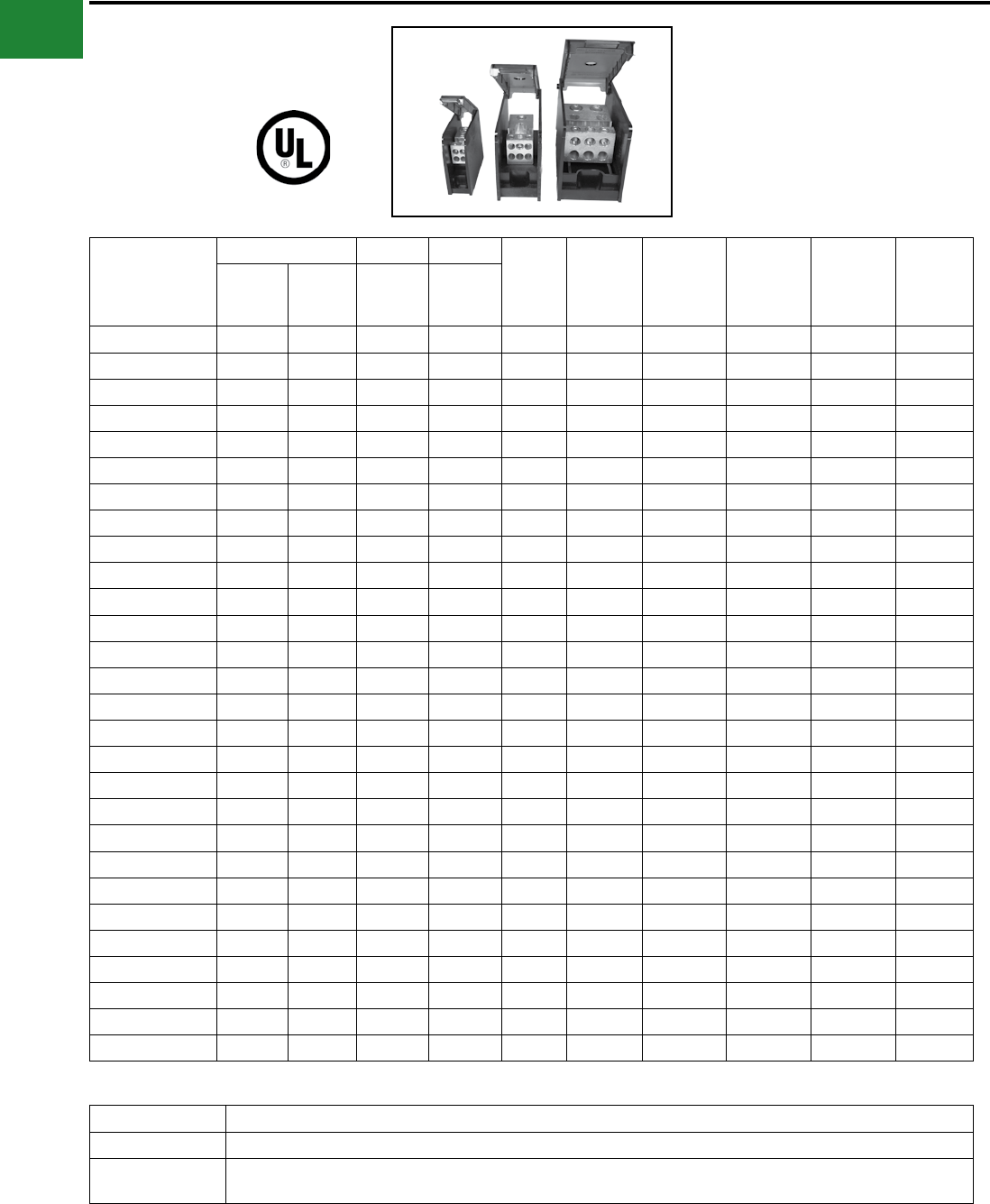
BURNDY®
Blue highlighted items are industry standard and most frequently ordered.
US: 1-800-346-4175 www.burndy.com Canada: 1-800-387-6487
Mechanical
UL LISTED
POWER DISTRIBUTION
BLOCKS
VERSIPOLE™
Medium Series:
Catalog Number
Connector Run Tap
Width Height Depth
Ampere
Rating per
Pole
Number of
Poles SCCR1
Number
of Run(s)
Number
of Tap(s)
Wire
Range
AL9CU
Wire
Range
AL9CU
BDBMHC162/01 1 6 14-2/0 14-2 1.85 3.25 5 175 1 100kA
BDBMHC162/02 1 6 14-2/0 14-2 3.57 3.25 5 175 2 100kA
BDBMHC162/03 1 6 14-2/0 14-2 5.28 3.25 5 175 3 100kA
BDAMHC162/0 1 6 14-2/0 14-2 1.72 3.25 5 175 Adder 100kA
BDBMHC112/01 1 1 14-2/0 14-2/0 1.85 3.25 5 175 1 100kA
BDBMHC112/02 1 1 14-2/0 14-2/0 3.57 3.25 5 175 2 100kA
BDBMHC112/03 1 1 14-2/0 14-2/0 5.28 3.25 5 175 3 100kA
BDAMHC112/0 1 1 14-2/0 14-2/0 1.72 3.25 5 175 Adder 100kA
BDBMHC113501 1 1 6-350 6-350 1.85 3.25 5 310 1 100kA
BDBMHC113502 1 1 6-350 6-350 3.57 3.25 5 310 2 100kA
BDBMHC113503 1 1 6-350 6-350 5.28 3.25 5 310 3 100kA
BDAMHC11350 1 1 6-350 6-350 1.72 3.25 5 310 Adder 100kA
BDBMHC262/01 2 6 14-2/0 14-2 1.85 3.25 5 350 1 100kA
BDBMHC262/02 2 6 14-2/0 14-2 3.57 3.25 5 350 2 100kA
BDBMHC262/03 2 6 14-2/0 14-2 5.28 3.25 5 350 3 100kA
BDAMHC262/0 2 6 14-2/0 14-2 1.72 3.25 5 350 Adder 100kA
BDBMHC222/01 2 2 14-2/0 14-2/0 1.85 3.25 5 350 1 100kA
BDBMHC222/02 2 2 14-2/0 14-2/0 3.57 3.25 5 350 2 100kA
BDBMHC222/03 2 2 14-2/0 14-2/0 5.28 3.25 5 350 3 100kA
BDAMHC222/0 2 2 14-2/0 14-2/0 1.72 3.25 5 350 Adder 100kA
BDBMHC145001 1 4 4-500 14-2/0 1.85 3.25 5 380 1 100kA
BDBMHC145002 1 4 4-500 14-2/0 3.57 3.25 5 380 2 100kA
BDBMHC145003 1 4 4-500 14-2/0 5.28 3.25 5 380 3 100kA
BDAMHC14500 1 4 4-500 14-2/0 1.72 3.25 5 380 Adder 100kA
BDBMHC1625001 1 6 4-500 14-2 1.85 3.25 5 380 1 100kA
BDBMHC1625002 1 6 4-500 14-2 3.57 3.25 5 380 2 100kA
BDBMHC1625003 1 6 4-500 14-2 5.28 3.25 5 380 3 100kA
BDAMHC162500 1 6 4-500 14-2 1.72 3.25 5 380 Adder 100kA
Medium Series Hinged Cover and End Barrier:
Catalog Number Description
BDAMHCEB End Barrier for Medium Series Adder Distribution Blocks
BDBMHCCOVER Hinged Cover for use with Medium Series Distribution Blocks and Adders (use of End Barrier necessary with Adders to attach
cover). Order 1 cover per pole
A-48
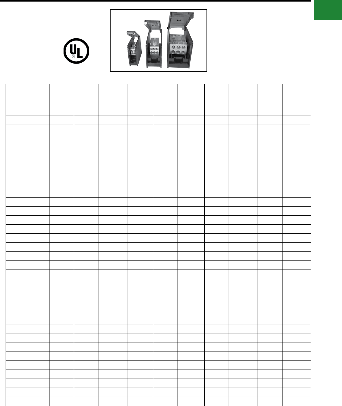
BURNDY®
Blue highlighted items are industry standard and most frequently ordered.
Canada: 1-800-387-6487 www.burndy.com US: 1-800-346-4175
Mechanical
UL LISTED
POWER DISTRIBUTION
BLOCKS
VERSIPOLE™
Catalog Number
Connector Run Tap
Width Height Depth
Ampere
Rating per
Pole
Number
of Poles SCCR1
Number
of Run(s)
Number
of Tap(s)
Wire
Range
AL9CU
Wire
Range
AL9CU
BDBLHC1123501 1 12 6-350 14-4 2.73 3.55 5.7 310 1 100kA
BDBLHC1123502 1 12 6-350 14-4 5.31 3.55 5.7 310 2 100kA
BDBLHC1123503 1 12 6-350 14-4 7.89 3.55 5.7 310 3 100kA
BDALHC112350 1 12 6-350 14-4 2.58 3.55 5.7 310 Adder 100kA
BDBLHC163501 1 6 6-350 4-2/0 2.73 3.55 5.7 310 1 100kA
BDBLHC163502 1 6 6-350 4-2/0 5.31 3.55 5.7 310 2 100kA
BDBLHC163503 1 6 6-350 4-2/0 7.89 3.55 5.7 310 3 100kA
BDALHC16350 1 6 6-350 4-2/0 2.58 3.55 5.7 310 Adder 100kA
BDBLHC115001 1 1 4-500 4-500 2.73 3.55 5.7 380 1 100kA
BDBLHC115002 1 1 4-500 4-500 5.31 3.55 5.7 380 2 100kA
BDBLHC115003 1 1 4-500 4-500 7.89 3.55 5.7 380 3 100kA
BDALHC11500 1 1 4-500 4-500 2.58 3.55 5.7 380 Adder 100kA
BDBLHC165001 1 6 4-500 4-2/0 2.73 3.55 5.7 380 1 100kA
BDBLHC165002 1 6 4-500 4-2/0 5.31 3.55 5.7 380 2 100kA
BDBLHC165003 1 6 4-500 4-2/0 7.89 3.55 5.7 380 3 100kA
BDALHC16500 1 6 4-500 4-2/0 2.58 3.55 5.7 380 Adder 100kA
BDBLHC2125001 2 12 4-500 14-4 2.73 3.55 5.7 760 1 100kA
BDBLHC2125002 2 12 4-500 14-4 5.31 3.55 5.7 760 2 100kA
BDBLHC2125003 2 12 4-500 14-4 7.89 3.55 5.7 760 3 100kA
BDALHC212500 2 12 4-500 14-4 2.58 3.55 5.7 760 Adder 100kA
BDBLHC263501 2 6 6-350 14-2/0 2.73 3.55 5.7 620 1 100kA
BDBLHC263502 2 6 6-350 14-2/0 5.31 3.55 5.7 620 2 100kA
BDBLHC263503 2 6 6-350 14-2/0 7.89 3.55 5.7 620 3 100kA
BDALHC26350 2 6 6-350 14-2/0 2.58 3.55 5.7 620 Adder 100kA
BDBLHC223501 2 2 6-350 6-350 2.73 3.55 5.7 620 1 100kA
BDBLHC223502 2 2 6-350 6-350 5.31 3.55 5.7 620 2 100kA
BDBLHC223503 2 2 6-350 6-350 7.89 3.55 5.7 620 3 100kA
BDALHC22350 2 2 6-350 6-350 2.58 3.55 5.7 620 Adder 100kA
BDBLHC225001 2 2 4-500 4-500 2.73 3.55 5.7 760 1 100kA
BDBLHC225002 2 2 4-500 4-500 5.31 3.55 5.7 760 2 100kA
BDBLHC225003 2 2 4-500 4-500 7.89 3.55 5.7 760 3 100kA
BDALHC22500 2 2 4-500 4-500 2.58 3.55 5.7 760 Adder 100kA
Large Series:
A-49
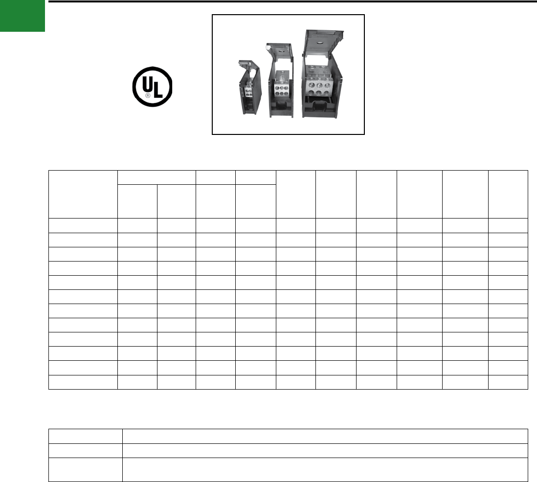
BURNDY®
Blue highlighted items are industry standard and most frequently ordered.
US: 1-800-346-4175 www.burndy.com Canada: 1-800-387-6487
Mechanical
Large Series (continued):
Catalog Number
Connector Run Tap
Width Height Depth
Ampere
Rating per
Pole
Number of
Poles SCCR1
Number
of Run(s)
Number
of Tap(s)
Wire
Range
AL9CU
Wire
Range
AL9CU
BDBLHC265001 2 6 4-500 14-2/0 2.73 3.55 5.7 760 1 100kA
BDBLHC265002 2 6 4-500 14-2/0 5.31 3.55 5.7 760 2 100kA
BDBLHC265003 2 6 4-500 14-2/0 7.89 3.55 5.7 760 3 100kA
BDALHC26500 2 6 4-500 14-2/0 2.58 3.55 5.7 760 Adder 100kA
BDBLHC245001 2 4 4-500 6-4/0 2.73 3.55 5.7 760 1 100kA
BDBLHC245002 2 4 4-500 6-4/0 5.31 3.55 5.7 760 2 100kA
BDBLHC245003 2 4 4-500 6-4/0 7.89 3.55 5.7 760 3 100kA
BDALHC24500 2 4 4-500 6-4/0 2.58 3.55 5.7 760 Adder 100kA
BDBLHC226001 2 2 2-600 2-600 2.73 3.55 5.7 840 1 100kA
BDBLHC226002 2 2 2-600 2-600 5.31 3.55 5.7 840 2 100kA
BDBLHC226003 2 2 2-600 2-600 2.73 3.55 5.7 840 3 100kA
BDALHC22600 2 2 2-600 2-600 2.58 3.55 5.7 840 Adder 100kA
UL LISTED
POWER DISTRIBUTION
BLOCKS
VERSIPOLE™
Large Series Hinged Cover and End Barrier:
Catalog Number Description
BDALHCEB End Barrier for Large Series Adder Distribution Blocks
BDBLHCCOVER Hinged Cover for use with Large Series Distribution Blocks and Adders (use of End Barrier necessary with Adders to attach cover).
Order 1 cover per pole
A-50
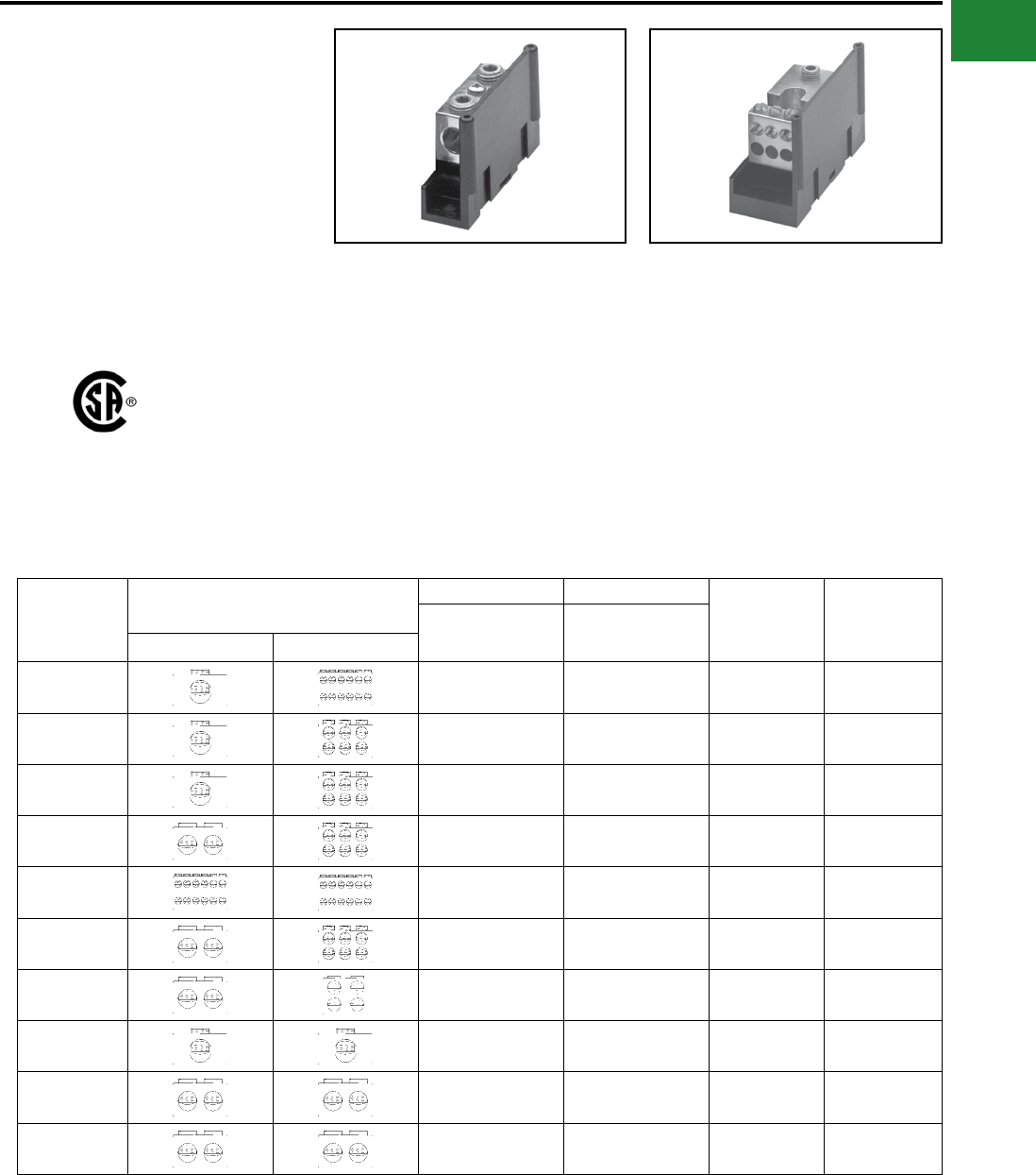
BURNDY®
Blue highlighted items are industry standard and most frequently ordered.
Canada: 1-800-387-6487 www.burndy.com US: 1-800-346-4175
Mechanical
VERSIPOLE™
POWER DISTRIBUTION
BLOCKS
VERSIPOLE™ Power Distribution Blocks are
designed to provide modular solutions to power
distribution applications. Each connector element
is made from a high conductivity aluminum alloy
which is insulated with a high strength polymer
housing. One, two, and three pole versions
available. “Add” a pole (snap-together) blocks are
also available for wire sizes up to 500 kcmil. For
use with Cu or Al. 600 V, AL9CU rated.
• “Add” a pole feature available
◊ Provides capability to create as many
poles as required
• Up to 30 tap conductors accommodated
◊ Ideal for current distribution to multiple
locations
• Single or dual run connections
◊ Allows user to minimize the number of
connectors needed to do the job
• Suitable for use with aluminum or copper
conductors
Features and Benets
◊ Provides maximum versatility
• 600 V, AL9CU rated*
◊ Meets or exceeds industry standard
requirements
• Dead-front covers available
◊ Provides user protection – one cover
per pole
Catalog
Number
Connector Run Tap Ampere
Rating per
Pole
Number of
Poles
Wire Range
AL9CU
Wire Range
AL9CU
Run Tap
BDA-112-350 AWG 6 - 350 kcmil AWG 14 - 4 310 ADDER
BDA-16-350 AWG 6 - 350 kcmil AWG 14 - 2/0 310 ADDER
BDA-16-500 AWG 4 - 500 kcmil AWG 4 - 2/0 380 ADDER
BDA-26-350 AWG 6 - 350 kcmil AWG 14 - 2/0 620 ADDER
BDA-212-500 AWG 4 - 500 kcmil AWG 14 - 4 760 ADDER
BDA-26-500 AWG 4 - 500 kcmil AWG 14 - 2/0 760 ADDER
BDA-24-500 AWG 4 - 500 kcmil AWG 6 - 4/0 760 ADDER
BDA-11-500 AWG 4 - 500 kcmil AWG 4 - 500 kcmil 380 ADDER
BDA-22-350 AWG 6 - 350 kcmil AWG 6 - 350 kcmil 620 ADDER
BDA-22-500 AWG 4 - 500 kcmil AWG 4 - 500 kcmil 760 ADDER
VERSIPOLE™
Snap-Together Blocks
NOTES:
1. Order Optional BDB COVER1 per pole if desired.
2. Snap-together blocks can also be assembled to 1, 2, 3
pole blocks to create multi-pole distribution blocks.
* BDB-430-500-1 not CSA certied
A-51
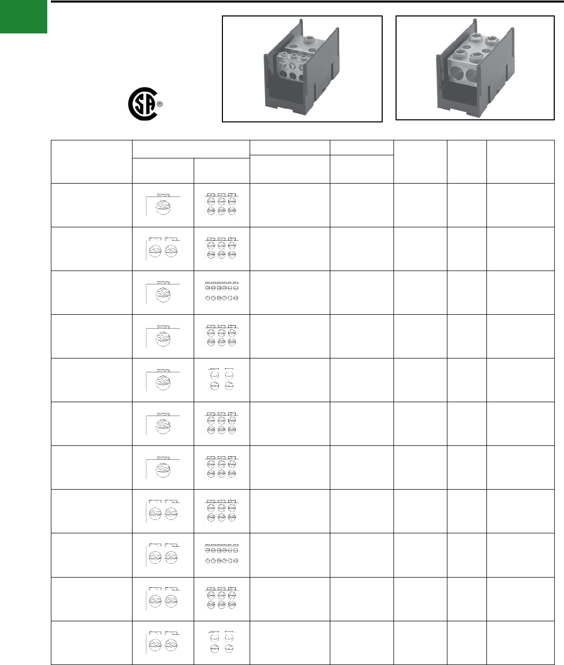
BURNDY®
Blue highlighted items are industry standard and most frequently ordered.
US: 1-800-346-4175 www.burndy.com Canada: 1-800-387-6487
Mechanical
VERSIPOLE™
VERSIPOLE™ 1, 2, 3 Pole
Distribution Blocks
Catalog
Number
Connector Run Tap Ampere
Rating per
Pole
Number
of
Poles
Optional
Cover Order
1 per Pole
Wire Range
AL9CU
Wire Range
AL9CURun Tap
BDB-16-2/0-1
BDB-16-2/0-2
BDB-16-2/0-3
AWG 12 - 2/0 AWG 14 - 4 175
1
2
3
BDBCOVER2
BDB-26-2/0-1
BDB-26-2/0-2
BDB-26-2/0-3
AWG 14 - 2/0 AWG 14 - 2 350
1
2
3
BDBCOVER2
BDB-112-350-1
BDB-112-350-2
BDB-112-350-3
AWG 6 - 350 kcmil AWG 14 - 4 310
1
2
3
BDBCOVER1
BDB-16-350-1
BDB-16-350-2
BDB-16-350-3
AWG 6 - 350 kcmil AWG 14 - 2/0 310
1
2
3
BDBCOVER1
BDB-14-500-1
BDB-14-500-2
BDB-14-500-3
AWG 4 - 500 kcmil AWG 14 - 2/0 380
1
2
3
BDBCOVER2
BDB-16-500-1
BDB-16-500-2
BDB-16-500-3
AWG 4 - 500 kcmil AWG 14 - 2/0 380
1
2
3
BDBCOVER1
BDB-162-500-1
BDB-162-500-2
BDB-162-500-3
AWG 4 - 500 kcmil AWG 14 - 2 380
1
2
3
BDBCOVER2
BDB-26-350-1
BDB-26-350-2
BDB-26-350-3
AWG 6 - 350 kcmil AWG 14 - 2/0 620
1
2
3
BDBCOVER1
BDB-212-500-1
BDB-212-500-2
BDB-212-500-3
AWG 4 - 500 kcmil AWG 14 - 4 760
1
2
3
BDBCOVER1
BDB-26-500-1
BDB-26-500-2
BDB-26-500-3
AWG 4 - 500 kcmil AWG 14 - 2/0 760
1
2
3
BDBCOVER1
BDB-24-500-1
BDB-24-500-2
BDB-24-500-3
AWG 4 - 500 kcmil AWG 6 - 4/0 760
1
2
3
BDBCOVER1
A-52
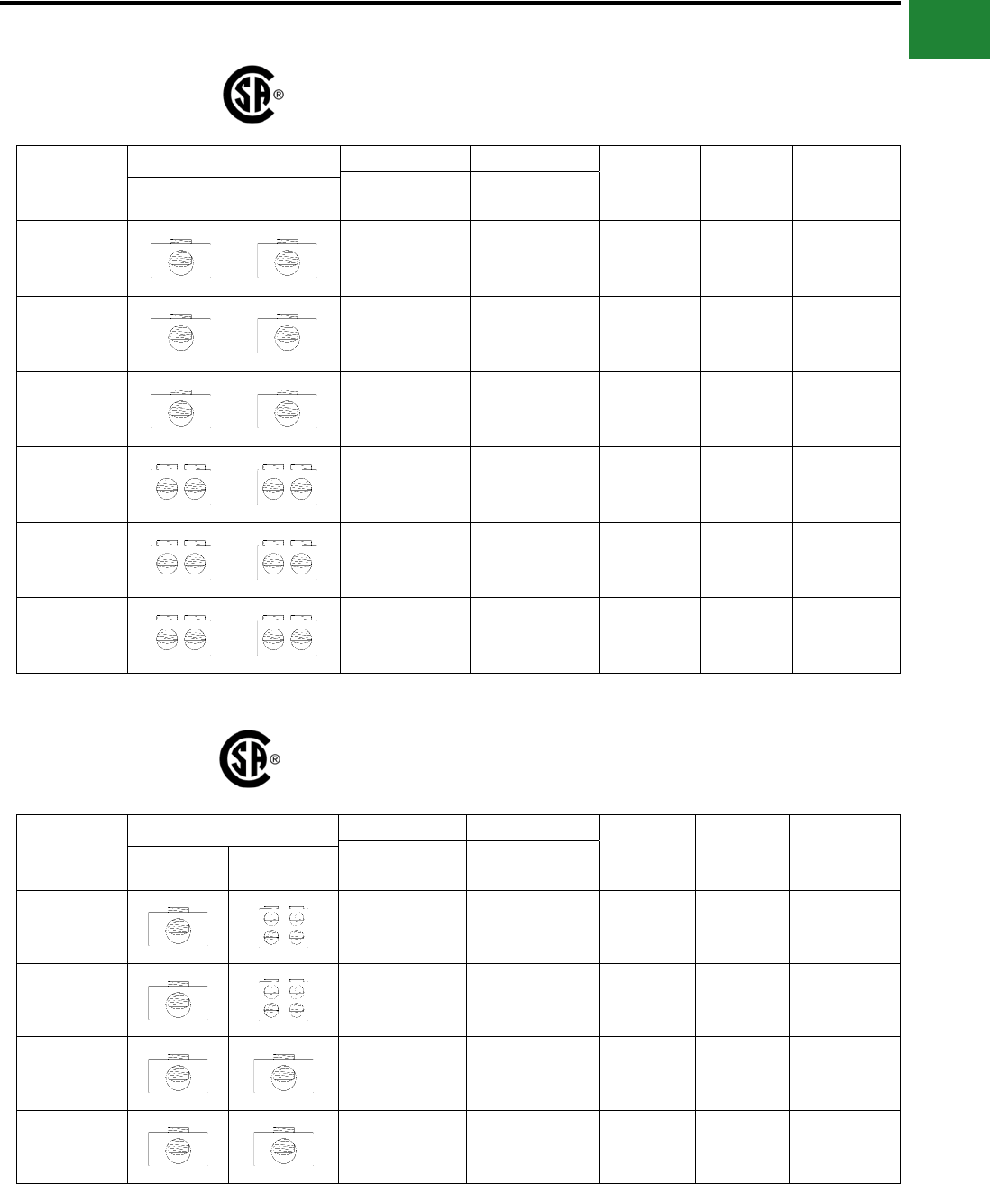
BURNDY®
Blue highlighted items are industry standard and most frequently ordered.
Canada: 1-800-387-6487 www.burndy.com US: 1-800-346-4175
Mechanical
VERSIPOLE™
VERSIPOLE™ 1, 2, 3
Splice/Reducer Blocks
Catalog
Number
Connector Run Tap Ampere
Rating per
Pole
Number of
Poles
Optional
Cover Order
1 per Pole
Wire Range
AL9CU
Wire Range
AL9CURun Tap
BDB-11-2/0-1
BDB-11-2/0-2
BDB-11-2/0-3
AWG 14 - 2/0 AWG 14 - 2/0 175
1
2
3
BDBCOVER2
BDB-11-350-1
BDB-11-350-2
BDB-11-350-3
AWG 6 - 350 kcmil AWG 6 - 350 kcmil 310
1
2
3
BDBCOVER2
BDB-11-500-1
BDB-11-500-2
BDB-11-500-3
AWG 6 - 500 kcmil AWG 6 - 500 kcmil 380
1
2
3
BDBCOVER1
BDB-22-2/0-1
BDB-22-2/0-2
BDB-22-2/0-3
AWG 14 - 2/0 AWG 14 - 2/0 350
1
2
3
BDBCOVER2
BDB-22-350-1
BDB-22-350-2
BDB-22-350-3
AWG 6 - 350 kcmil AWG 6 - 350 kcmil 620
1
2
3
BDBCOVER1
BDB-22-500-1
BDB-22-500-2
BDB-22-500-3
AWG 4 - 500 kcmil AWG 4 - 500 kcmil 760
1
2
3
BDBCOVER1
SNAP TOGETHER
SPLICE/REDUCER
BLOCKS
Catalog
Number
Connector Run Tap Ampere
Rating per
Pole
Number of
Poles
Optional
Cover Order
1 per Pole
Wire Range
AL9CU
Wire Range
AL9CURun Tap
BDC-14-2/0-1 AWG 14 - 2/0 AWG 14 - 4 175 1 BDBCOVER3
BDA-14-2/0-1 AWG 14 - 2/0 AWG 14 - 4 175 ADDER BDBCOVER3
BDC-11-2/0-1 AWG 14 - 2/0 AWG 14 - 2/0 175 1 BDBCOVER3
BDA-11-2/0-1 AWG 14 - 2/0 AWG 14 - 2/0 175 ADDER BDBCOVER3
A-53
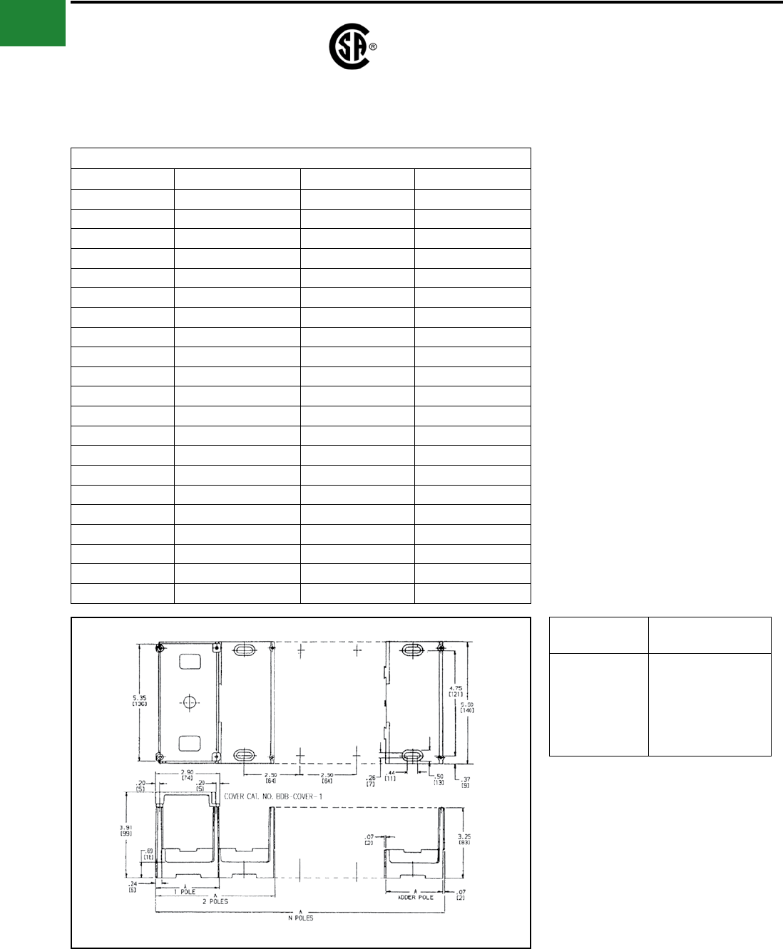
BURNDY®
Blue highlighted items are industry standard and most frequently ordered.
US: 1-800-346-4175 www.burndy.com Canada: 1-800-387-6487
Mechanical
VERSIPOLE™
(Continued)
VERSIPOLE™ 1, 2, 3
Splice/Reducer Blocks
The Figure to the Lower Right is Applicable to the Following:
Catalog Number Number of Poles Catalog Number Number of Poles
BDA-11-500 1 (adder) BDB-16-500-3 3
BDA-112-350 1 (adder) BDB-212-500-1 1
BDA-16-350 1 (adder) BDB-212-500-2 2
BDA-16-500 1 (adder) BDB-212-500-3 3
BDA-212-500 1 (adder) BDB-22-350-1 1
BDA-22-350 1 (adder) BDB-22-350-2 2
BDA-22-500 1 (adder) BDB-22-350-3 3
BDA-24-500 1 (adder) BDB-22-500-1 1
BDA-26-350 1 (adder) BDB-22-500-2 2
BDA-26-500 1 (adder) BDB-22-500-3 3
BDB-11-500-1 1BDB-24-500-1 1
BDB-11-500-2 2BDB-24-500-2 2
BDB-11-500-3 3BDB-24-500-3 3
BDB-112-350-1 1BDB-26-350-1 1
BDB-112-350-2 2BDB-26-350-2 2
BDB-112-350-3 3BDB-26-350-3 3
BDB-16-350-1 1BDB-26-500-1 1
BDB-16-350-2 2BDB-26-500-2 2
BDB-16-350-3 3BDB-26-500-3 3
BDB-16-500-1 1BDB-430-500-1* 1
BDB-16-500-2 2
No. of
Poles
Dimensions A
Inches
Adder
1
2
3
N
2.50
2.81
5.31
7.81
(2.50 X N) + 0.31
Example for 10 poles:
A = (2.50 X 10) + 0.31 = 25
These tables and illustrations refer to the specic
VERSIPOLE™ Power Distribution Blocks listed.
* BDB-430-500-1 not CSA certied
A-54
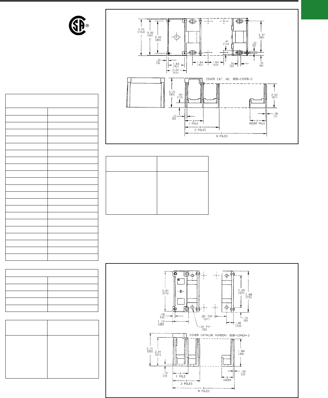
BURNDY®
Blue highlighted items are industry standard and most frequently ordered.
Canada: 1-800-387-6487 www.burndy.com US: 1-800-346-4175
Mechanical
VERSIPOLE™
(Continued)
VERSIPOLE™ 1, 2, 3
Splice/Reducer Blocks
These tables and illustrations refer to the specic
VERSIPOLE™ Power Distribution Blocks listed.
The Figure to the Lower Right is
Applicable to the Following:
Catalog Number Number of Poles
BDB-11-2/0-1 1
BDB-11-2/0-2 2
BDB-11-2/0-3 3
BDB-11-350-1 1
BDB-11-350-2 2
BDB-11-350-3 3
BDB-14-500-1 1
BDB-14-500-2 2
BDB-14-500-3 3
BDB-16-2/0-1 1
BDB-16-2/0-2 2
BDB-16-2/0-3 3
BDB-162-500-1 1
BDB-162-500-2 2
BDB-162-500-3 3
BDB-22-2/0-1 1
BDB-22-2/0-2 2
BDB-22-2/0-3 3
BDB-26-2/0-1 1
BDB-26-2/0-2 2
BDB-26-2/0-3 3
Applicable VERSI-POLETM Items
Catalog Number Number of Poles
BDA-14-2/0-1 1 (adder)
BDC-14-2/0-1 1
BDA-11-2/0-1 1 (adder)
BDC-11-2/0-1 1
No. of
Poles
Dimensions A
Inches
Adder
1
2
3
N
0.81
1.08
1.89
2.70
(0.81 X N) + 0.27
Example for 10 poles:
A = (.81 X 10) + 0.30 = 8.37
No. of
Poles
Dimensions A
Inches
Adder
1
2
3
N
1.64
1.94
3.57
5.20
(1.64 X N) + 0.30
Example for 10 poles:
A = (1.64 X 10) + 0.30 = 16.20
A-55
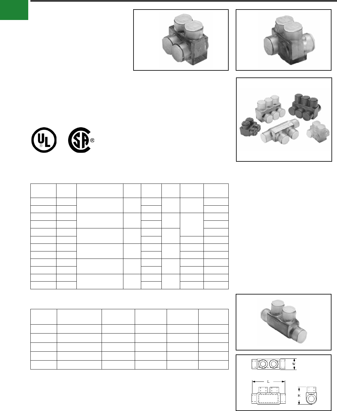
BURNDY®
Blue highlighted items are industry standard and most frequently ordered.
US: 1-800-346-4175 www.burndy.com Canada: 1-800-387-6487
Mechanical
TYPES BIT, BITO, BISR
UNITAP™
Clear Insulated Multiple Tap
Connectors
Tap connections and in-line splice/reductions are
made quickly and easily with the UNITAP™ line
of connectors. UL486B Listed. Dual-rated AL9CU
for any stranded copper or stranded aluminum
applications. 600 Volt, 90° C.
Features & Benets
• Clear Plastisol covered AL6061-T6
aluminum body
◊ Saves time, lowers installation
costs, eliminates taping.
• Clear Plastisol
◊ Allows visual conrmation that
conductor is properly inserted.
• Oxide inhibitor pre-installed
◊ Inhibits moisture and contaminants
from entering the contact area.
• Range-taking
◊ Reduces number of connectors
carried in inventory.
Catalog
Number
# of
Ports
Wire Range
(AWG/kcmil) L W H Hex
Key
Figure
Number
BIT4 214 AWG-4 AWG 1.16 1.16 1.25 1/8 1
BITO4 2 1.50 2
BIT2/0 214 AWG-2/0 AWG 1.52 1.40 1.38 3/16
1
BITO2/0 2 1.56 2
BIT250 210 AWG-250 kcmil 2.03 2.07 2.13 1
BITO250 2 2.64 5/16 2
BIT350 210 AWG-350 kcmil 2.22 2.32 2.50 3/16 1
BITO350 2 3.00 5/16 2
BIT600 24 AWG-600 kcmil 2.72 2.38 2.75 3/16 1
BITO600 2 3.00 3/8 2
BIT750 * 22 AWG-750 kcmil 2.87 2.70 3.00 3/16 1
BITO750 * 2 3.38 3/8 2
Fig. 1 Fig. 2
2 Port, 1 or 2 Sided Entry
* BIT750 and BITO750 are not UL Listed.
UNITAP™ rated for code conductor only.
Catalog
Number
Wire Range
(AWG/kcmil) L W H Hex Key
BISR2 #14-2 2.38 0.75 1.22 5/32
BISR1/0 #14-1/0 2.91 0.91 1.38 3/16
BISR250 #10-250 4.01 1.19 2.10 5/16
BISR350 #10-350 4.63 1.34 2.35 5/16
BISR500 #6-500 5.00 1.62 2.62 3/8
In-Line Splicer/Reducer
A-56
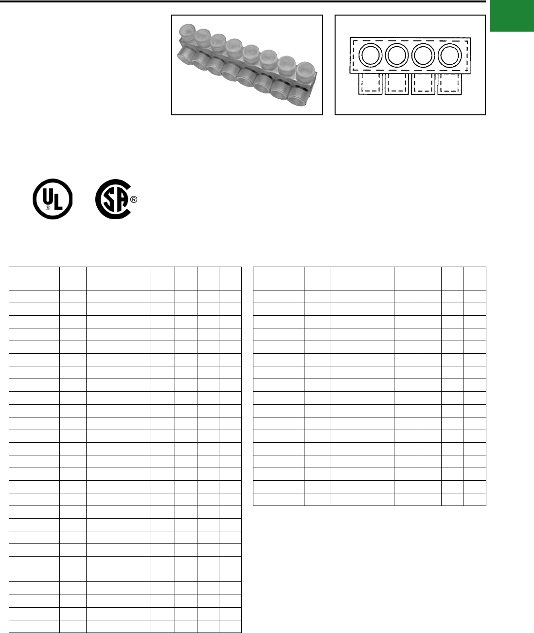
BURNDY®
Blue highlighted items are industry standard and most frequently ordered.
Canada: 1-800-387-6487 www.burndy.com US: 1-800-346-4175
Mechanical
TYPE BIBS
UNITAP™
Clear Insulated Multiple Tap
Connectors
Tap connections and in-line splice/reductions are
made quickly and easily with the UNITAP™ line
of connectors. UL486B Listed. Dual-rated AL9CU
for any stranded copper or stranded aluminum
applications. 600 Volt, 90° C.
Features & Benets
• Clear Plastisol covered AL6061-T6
aluminum body
◊ Saves time, lowers installation
costs, eliminates taping
• Clear Plastisol
◊ Allows visual conrmation that
conductor is properly inserted
Catalog
Number
# of
Ports
Wire Range
(AWG/kcmil) L W H Hex
Key
BIBS4-3 3 14 AWG-4 AWG 1.51 1.25 1.25 1/8
BIBS4-4 4 14 AWG-4 AWG 1.95 1.25 1.25 1/8
BIBS4-5 5 14 AWG-4 AWG 2.39 1.25 1.25 1/8
BIBS4-6 6 14 AWG-4 AWG 2.83 1.25 1.25 1/8
BIBS4-8 8 14 AWG-4 AWG 3.71 1.25 1.25 1/8
BIBS2/0-3 3 14 AWG-2/0 Str 2.19 1.31 1.38 3/16
BIBS2/0-4 4 14 AWG-2/0 Str 2.86 1.31 1.38 3/16
BIBS2/0-5 5 14 AWG-2/0 Str 3.53 1.31 1.38 3/16
BIBS2/0-6 6 14 AWG-2/0 Str 4.20 1.31 1.38 3/16
BIBS2/0-8 8 14 AWG-2/0 Str 5.55 1.31 1.38 3/16
BIBS2/0-10 10 14 AWG-2/0 Str 6.89 1.31 1.38 3/16
BIBS2/0-12 12 14 AWG-2/0 Str 8.24 1.31 1.38 3/16
BIBS2/0-14 14 14 AWG-2/0 Str 9.58 1.31 1.38 3/16
BIBS250-3 3 10 AWG-250 kcmil 2.97 2.07 2.13 5/16
BIBS250-4 4 10 AWG-250 kcmil 3.91 2.07 2.13 5/16
BIBS250-5 5 10 AWG-250 kcmil 4.84 2.07 2.13 5/16
BIBS250-6 6 10 AWG-250 kcmil 5.78 2.07 2.13 5/16
BIBS250-8 8 10 AWG-250 kcmil 7.66 2.07 2.13 5/16
BIBS250-10 10 10 AWG-250 kcmil 9.53 2.07 2.13 5/16
BIBS250-12 12 10 AWG-250 kcmil 11.41 2.07 2.13 5/16
BIBS250-14 14 10 AWG-250 kcmil 13.29 2.07 2.13 5/16
BIBS350-3 3 10 AWG-350 kcmil 3.13 2.32 2.50 5/16
BIBS350-4 4 10 AWG-350 kcmil 4.04 2.32 2.50 5/16
BIBS350-5 5 10 AWG-350 kcmil 4.95 2.32 2.50 5/16
BIBS350-6 6 10 AWG-350 kcmil 5.86 2.32 2.50 5/16
BIBS350-8 8 10 AWG-350 kcmil 7.68 2.32 2.50 5/16
BIBS350-10 10 10 AWG-350 kcmil 9.50 2.32 2.50 5/16
Catalog
Number
# of
Ports
Wire Range
(AWG/kcmil) L W H Hex
Key
BIBS350-12 12 10 AWG-350 kcmil 11.32 2.32 2.50 5/16
BIBS350-14 14 10 AWG-350 kcmil 13.14 2.32 2.50 5/16
BIBS600-3 3 4 AWG-600 kcmil 4.00 2.38 2.75 3/8
BIBS600-4 4 4 AWG-600 kcmil 5.28 2.38 2.75 3/8
BIBS600-5 5 4 AWG-600 kcmil 6.56 2.38 2.75 3/8
BIBS600-6 6 4 AWG-600 kcmil 7.84 2.38 2.75 3/8
BIBS600-8 8 4 AWG-600 kcmil 10.41 2.38 2.75 3/8
BIBS600-10 10 4 AWG-600 kcmil 12.97 2.38 2.75 3/8
BIBS600-12 12 4 AWG-600 kcmil 15.53 2.38 2.75 3/8
BIBS600-14 14 4 AWG-600 kcmil 18.09 2.38 2.75 3/8
BIBS750-3* 3 2 AWG-750 kcmil 4.00 2.70 3.00 3/8
BIBS750-4* 4 2 AWG-750 kcmil 5.38 2.70 3.00 3/8
BIBS750-6* 6 2 AWG-750 kcmil 8.13 2.70 3.00 3/8
BIBS750-8* 8 2 AWG-750 kcmil 10.88 2.70 3.00 3/8
BIBS750-10* 10 2 AWG-750 kcmil 13.63 2.70 3.00 3/8
BIBS750-12* 12 2 AWG-750 kcmil 16.38 2.70 3.00 3/8
BIBS750-14* 14 2 AWG-750 kcmil 19.13 2.70 3.00 3/8
MULTI-PORT
Single-Sided Entry
NOTE: Only 1 conductor per port allowed.
* Not UL Listed.
UNITAP™ rated for code conductor only.
• Oxide inhibitor pre-installed
◊ Inhibits moisture and contaminants
from entering the contact area
• Range-taking
◊ Reduces number of connectors
carried in inventory
A-57
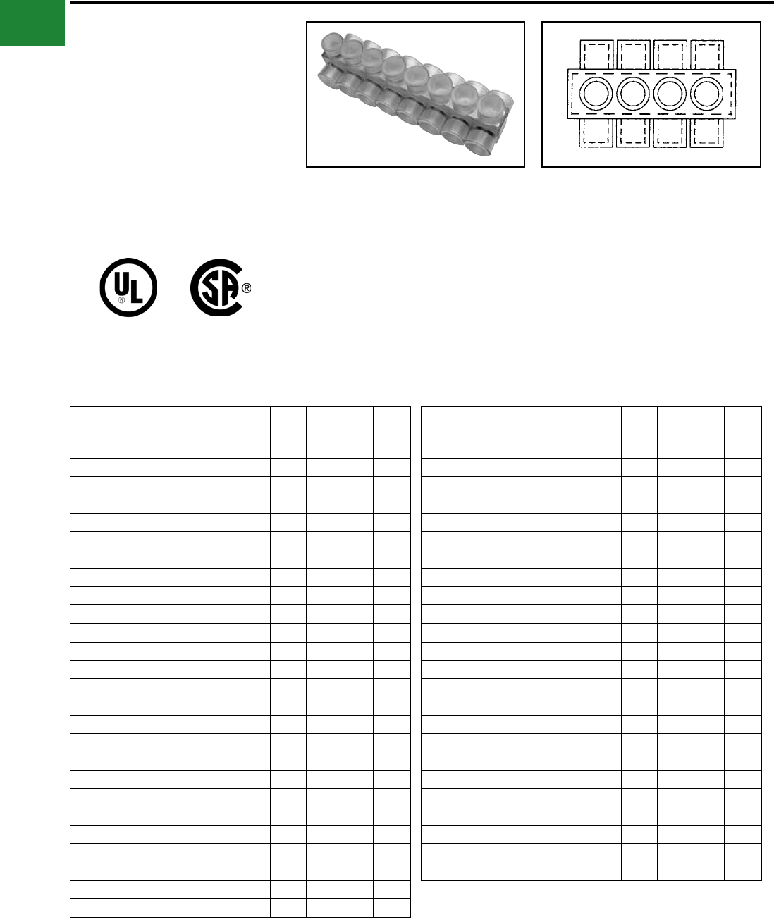
BURNDY®
Blue highlighted items are industry standard and most frequently ordered.
US: 1-800-346-4175 www.burndy.com Canada: 1-800-387-6487
Mechanical
TYPE BIBD
UNITAP™
Clear Insulated Multiple Tap
Connectors
Tap connections and in-line splice/reductions are
made quickly and easily with the UNITAP™ line
of connectors. UL486B Listed. Dual-rated AL9CU
for any stranded copper or stranded aluminum
applications. 600 Volt, 90° C.
Features & Benets
• Clear Plastisol covered AL6061-T6
aluminum body
◊ Saves time, lowers installation costs,
eliminates taping
• Clear Plastisol
◊ Allows visual conrmation that
conductor is properly inserted
MULTI-PORT
Double-Sided Entry
Catalog
Number
# of
Ports
Wire Range
(AWG/kcmil) W L H Hex
Key
BIBD4-2 2 14 AWG-4 Str 1.50 1.08 1.25 1/8
BIBD4-3 3 14 AWG-4 Str 1.50 1.51 1.25 1/8
BIBD4-4 4 14 AWG-4 str 1.50 1.95 1.25 1/8
BIBD4-5 5 14 AWG-4 Str 1.50 2.39 1.25 1/8
BIBD4-6 6 14 AWG-4 Str 1.50 2.83 1.25 1/8
BIBD4-8 8 14 AWG-4 str 1.50 3.71 1.25 1/8
BIBD2/0-2 2 14 AWG-2/0 Str 1.56 1.52 1.38 3/16
BIBD2/0-3 3 14 AWG-2/0 Str 1.56 2.19 1.38 3/16
BIBD2/0-4 4 #14-2/0 Str 1.56 2.86 1.38 3/16
BIBD2/0-5 5 #14-2/0 Str 1.56 3.53 1.38 3/16
BIBD2/0-6 6 14 AWG-2/0 Str 1.56 4.20 1.38 3/16
BIBD2/0-8 8 14 AWG-2/0 Str 1.56 5.55 1.38 3/16
BIBD2/0-10 10 14 AWG-2/0 Str 1.56 6.89 1.38 3/16
BIBD2/0-12 12 14 AWG-2/0 Str 1.56 8.24 1.38 3/16
BIBD2/0-14 14 14 AWG-2/0 Str 1.56 9.58 1.38 3/16
BIBD250-2 2 10 AWG-250 kcmil 2.64 2.03 2.13 5/16
BIBD250-3 3 10 AWG-250 kcmil 2.64 2.97 2.13 5/16
BIBD250-4 4 10 AWG-250 kcmil 2.64 3.91 2.13 5/16
BIBD250-5 5 10 AWG-250 kcmil 2.64 4.84 2.13 5/16
BIBD250-6 6 10 AWG-250 kcmil 2.64 5.78 2.13 5/16
BIBD250-8 8 10 AWG-250 kcmil 2.64 7.66 2.13 5/16
BIBD250-10 10 10 AWG-250 kcmil 2.64 9.53 2.13 5/16
BIBD250-12 12 10 AWG-250 kcmil 2.64 11.41 2.13 5/16
BIBD250-14 14 10 AWG-250 kcmil 2.64 13.29 2.13 5/16
BIBD350-2 2 10 AWG-350 kcmil 3.00 2.22 2.50 5/16
BIBD350-3 3 10 AWG-350 kcmil 3.00 3.13 2.50 5/16
Catalog
Number
# of
Ports
Wire Range
(AWG/kcmil) W L H Hex
Key
BIBD350-4 4 10 AWG-350 kcmil 3.00 4.04 2.50 5/16
BIBD350-5 5 10 AWG-350 kcmil 3.00 4.95 2.50 5/16
BIBD350-6 6 10 AWG-350 kcmil 3.00 5.86 2.50 5/16
BIBD350-8 8 10 AWG-350 kcmil 3.00 7.68 2.50 5/16
BIBD350-10 10 10 AWG-350 kcmil 3.00 9.50 2.50 5/16
BIBD350-12 12 10 AWG-350 kcmil 3.00 11.32 2.50 5/16
BIBD350-14 14 10 AWG-350 kcmil 3.00 13.14 2.50 5/16
BIBD600-2 2 4 AWG-600 kcmil 3.00 2.56 2.75 3/8
BIBD600-3 3 4 AWG-600 kcmil 3.00 3.77 2.75 3/8
BIBD600-4 4 4 AWG-600 kcmil 3.00 4.97 2.75 3/8
BIBD600-5 5 4 AWG-600 kcmil 3.00 6.17 2.75 3/8
BIBD600-6 6 4 AWG-600 kcmil 3.00 7.37 2.75 3/8
BIBD600-8 8 4 AWG-600 kcmil 3.00 9.78 2.75 3/8
BIBD600-10 10 4 AWG-600 kcmil 3.00 12.97 2.75 3/8
BIBD600-12 12 4 AWG-600 kcmil 3.00 15.53 2.75 3/8
BIBD600-14 14 4 AWG-600 kcmil 3.00 18.09 2.75 3/8
BIBD750-2* 2 2 AWG-750 kcmil 3.38 2.87 3.00 3/8
BIBD750-3* 3 2 AWG-750 kcmil 3.38 4.25 3.00 3/8
BIBD750-4* 4 2 AWG-750 kcmil 3.38 5.63 3.00 3/8
BIBD750-6* 6 2 AWG-750 kcmil 3.38 8.37 3.00 3/8
BIBD750-8* 8 2 AWG-750 kcmil 3.38 11.13 3.00 3/8
BIBD750-10* 10 2 AWG-750 kcmil 3.38 13.87 3.00 3/8
BIBD750-12* 12 2 AWG-750 kcmil 3.38 16.63 3.00 3/8
BIBD750-14* 14 2 AWG-750 kcmil 3.38 19.37 3.00 3/8
NOTE: Only 1 conductor per port allowed.
* Not UL Listed.
UNITAP™ rated for code conductor only.
• Oxide inhibitor pre-installed
◊ Inhibits moisture and contaminants
from entering the contact area
• Range-taking
◊ Reduces number of connectors
carried in inventory
A-58
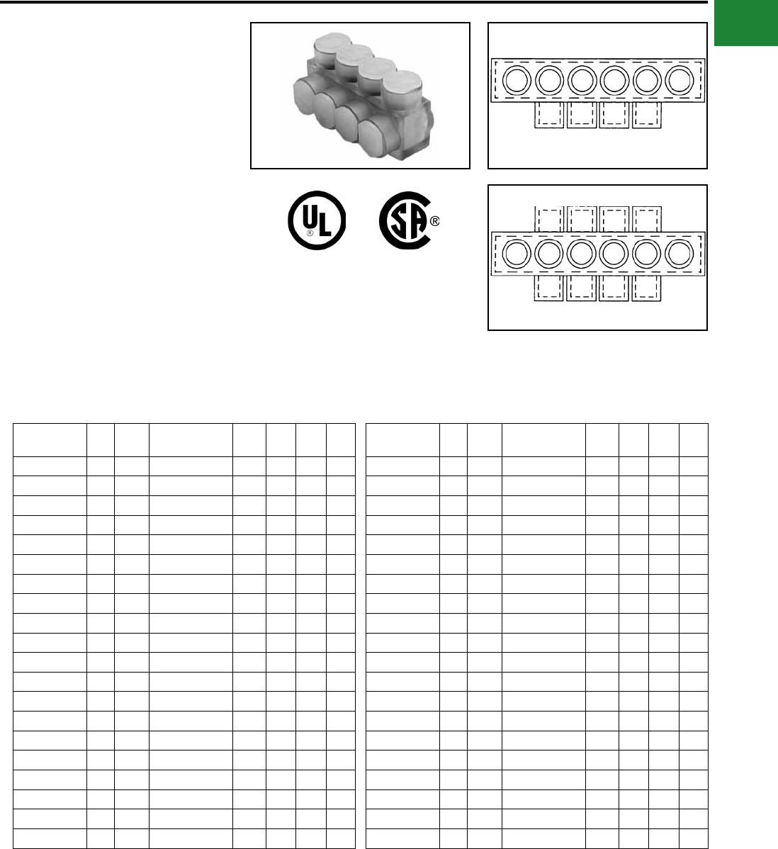
BURNDY®
Blue highlighted items are industry standard and most frequently ordered.
Canada: 1-800-387-6487 www.burndy.com US: 1-800-346-4175
Mechanical
TYPE BIBS-MT, BIBD-MT
UNITAP™
Clear Insulated Multiple Tap
Connectors Mounting Version
The BIBS-MT and BIBD-MT series UNITAP™
offer the same multi-port capabilities as the
standard UNITAP™ connectors except these -MT
types are provided with two isolated mounting
holes at both ends of the connector for direct
mounting to a trough, gutter or wireway. They will
accommodate up to standard 1/4" hardware.
Fig. 1
Fig. 2
Catalog
Number
Fig.
#
# of
Ports
Wire Range
(AWG/kcmil) L W H Hex
Key
BIBS2/04MT 1 4 #14 -2/0 Str 4.20 1.25 1.50 3/16
BIBS2/06MT 1 6 #14 -2/0 Str 5.54 1.25 1.50 3/16
BIBS2/08MT 1 8 14 AWG-2/0 Str 6.89 1.25 1.50 3/16
BIBS2/010MT 1 10 14 AWG-2/0 Str 8.23 1.25 1.50 3/16
BIBS2/012MT 1 12 14 AWG-2/0 Str 9.58 1.25 1.50 3/16
BIBS2504MT 1 4 10 AWG-250 kcmil 5.78 1.95 2.63 5/16
BIBS2506MT 1 6 10 AWG-250 kcmil 7.65 1.95 2.63 5/16
BIBS2508MT 1 8 10 AWG-250 kcmil 9.53 1.95 2.63 5/16
BIBS25010MT 1 10 10 AWG-250 kcmil 11.41 1.95 2.63 5/16
BIBS25012MT 1 12 10 AWG-250 kcmil 13.28 1.95 2.63 5/16
BIBS3504MT 1 4 10 AWG-350 kcmil 5.86 2.19 2.63 5/16
BIBS3506MT 1 6 10 AWG-350 kcmil 7.68 2.19 2.63 5/16
BIBS3508MT 1 8 10 AWG-350 kcmil 9.50 2.19 2.63 5/16
BIBS35010MT 1 10 10 AWG-350 kcmil 11.32 2.19 2.63 5/16
BIBS35012MT 1 12 10 AWG-350 kcmil 13.41 2.19 2.63 5/16
BIBS6004MT 1 4 4 AWG-600 kcmil 7.84 2.25 2.88 3/8
BIBS6006MT 1 6 4 AWG-600 kcmil 10.41 2.25 2.88 3/8
BIBS6008MT 1 8 4 AWG-600 kcmil 12.97 2.25 2.88 3/8
BIBS60010MT 1 10 4 AWG-600 kcmil 15.53 2.25 2.88 3/8
BIBS60012MT 1 12 4 AWG-600 kcmil 18.09 2.25 2.88 3/8
Catalog
Number
Fig.
#
# of
Ports
Wire Range
(AWG/kcmil) L W H Hex
Key
BIBD2/04MT 2 4 14 AWG-2/0 AWG 4.20 1.56 1.50 3/16
BIBD2/06MT 2 6 14 AWG-2/0 AWG 5.54 1.56 1.50 3/16
BIBD2/08MT 2 8 14 AWG-2/0 AWG 6.89 1.56 1.50 3/16
BIBD2/010MT 2 10 14 AWG-2/0 AWG 8.23 1.56 1.50 3/16
BIBD2/012MT 2 12 14 AWG-2/0 AWG 9.58 1.56 1.50 3/16
BIBD2504MT 2 4 10 AWG-250 kcmil 5.78 2.64 2.26 5/16
BIBD2506MT 2 6 10 AWG-250 kcmil 7.65 2.64 2.26 5/16
BIBD2508MT 2 8 10 AWG-250 kcmil 9.53 2.64 2.26 5/16
BIBD25010MT 2 10 10 AWG-250 kcmil 11.41 2.64 2.26 5/16
BIBD25012MT 2 12 10 AWG-250 kcmil 13.28 2.64 2.26 5/16
BIBD3504MT 2 4 10 AWG-350 kcmil 5.86 3.00 2.63 5/16
BIBD3506MT 2 6 10 AWG-350 kcmil 7.68 3.00 2.63 5/16
BIBD3508MT 2 8 10 AWG-350 kcmil 9.50 3.00 2.63 5/16
BIBD35010MT 2 10 10 AWG-350 kcmil 11.32 3.00 2.63 5/16
BIBD35012MT 2 12 10 AWG-350 kcmil 13.41 3.00 2.63 5/16
BIBD6004MT 2 4 4 AWG-600 kcmil 7.84 3.00 2.88 3/8
BIBD6006MT 2 6 4 AWG-600 kcmil 10.41 3.00 2.88 3/8
BIBD6008MT 2 8 4 AWG-600 kcmil 12.97 3.00 2.88 3/8
BIBD60010MT 2 10 4 AWG-600 kcmil 15.53 3.00 2.88 3/8
BIBD60012MT 2 12 4 AWG-600 kcmil 18.09 3.00 2.88 3/8
MULTI-PORT
Single-Sided Entry
MULTI-PORT
Double-Sided Entry
UNITAP™ rated for code conductor only. UNITAP™ rated for code conductor only.
A-59
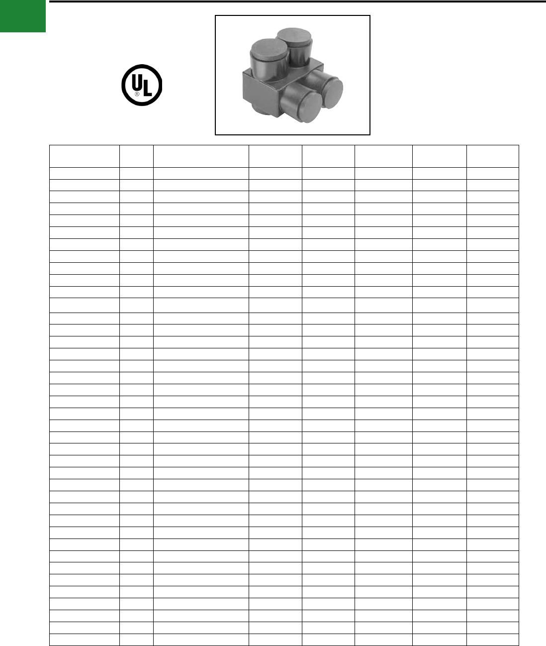
BURNDY®
Blue highlighted items are industry standard and most frequently ordered.
US: 1-800-346-4175 www.burndy.com Canada: 1-800-387-6487
Mechanical
UV RATED
BLACK UNITAP™
UNITAP™
600V, 90°C
Features & Benets
• UV Rated Plastisol covered AL6061-T6
aluminum body saves time by eliminating
the need for taping.
• Oxide inhibitor pre-installed inhibits
moisture and contaminants from entering
the contact area.
• Range-taking capability reduces the
number of connectors carried in inventory.
• UL486B Listed, AL9CU, 600V 90°C.
Catalog Number # of
Ports
Wire Range
(AWG/kcmil) L W H Hex Key Torque
1PL42 2 14 AWG-4 AWG 1.08 1.16 1.25 1/8 45
1PLO42 2 14 AWG-4 AWG 1.08 1.50 1.25 1/8 45
1PL2/02 2 14 AWG-2/0 AWG 1.52 1.40 1.38 3/16 120
1PLO2/02 2 14 AWG-2/0 AWG 1.52 1.56 1.38 3/16 120
1PL2502 2 10 AWG-250 kcmil 2.03 2.07 2.13 5/16 275
1PLO2502 2 10 AWG-250 kcmil 2.03 2.64 2.13 5/16 275
1PL3502 2 10 AWG-350 kcmil 2.22 2.32 2.50 5/16 275
1PLO3502 2 #10-350 kcmil 2.22 3.00 2.50 5/16 275
1PL6002 2 10 AWG-600 kcmil 2.72 2.38 2.75 3/8 375
1PLO6002 2 4 AWG-600 kcmil 2.72 3.00 2.75 3/8 375
1PBS2 2 14 AWG-2 AWG 2.38 0.75 1.22 5/32 45
1PBS1/0 2 14 AWG-1/0 2.91 0.91 1.38 3/16 120
1PBS250 2 10 AWG-250 kcmil 4.01 1.19 2.10 5/16 120
1PBS350 2 10 AWG-350 kcmil 4.63 1.34 2.35 1/3 275
1PBS500 2 6 AWG-500 kcmil 5.00 1.62 2.62 3/8 375
1PL43 3 14 AWG-4 AWG 1.51 1.25 1.25 1/8 45
1PL44 4 14 AWG-4 AWG 1.95 1.25 1.25 1/8 45
1PL2/03 3 14 AWG-2/0 AWG 2.19 1.31 1.38 3/16 120
1PL2503 3 10 AWG-250 kcmil 2.97 2.07 2.13 1/3 275
1PLD43 3 14 AWG-4 AWG 1.51 1.50 1.25 1/8 45
1PLD44 4 14 AWG-4 AWG 1.95 1.50 1.25 1/8 45
1PLD2/02 2 14 AWG-2/0 AWG 1.52 1.56 1.38 1/5 120
1PLD2/03 3 14 AWG-2/0 AWG 2.19 1.56 1.38 3/16 120
1PLD2/04 4 14 AWG-2/0 AWG 2.86 1.56 1.38 3/16 120
1PLD2/06 6 14 AWG-2/0 AWG 4.20 1.56 1.38 3/16 120
1PLD2502 2 10 AWG-250 kcmil 2.03 2.64 2.13 5/16 275
1PLD2503 3 10 AWG-250 kcmil 2.97 2.64 2.13 5/16 275
1PLD2504 4 10 AWG-250 kcmil 3.91 2.64 2.13 5/16 275
1PLD2506 6 10 AWG-250 kcmil 5.78 2.64 2.13 5/16 275
1PLD3502 2 10 AWG-350 kcmil 2.22 3.00 2.50 5/16 375
1PLD3503 3 10 AWG-350 kcmil 3.13 3.00 2.50 5/16 375
1PLD3504 4 10 AWG-350 kcmil 4.04 3.00 2.50 5/16 375
1PLD3506 6 10 AWG-350 kcmil 5.86 3.00 2.50 5/16 375
1PLD3508 8 10 AWG-350 kcmil 7.68 3.00 2.50 5/16 375
1PLD6002 2 4 AWG-600 kcmil 2.72 3.00 2.75 3/8 375
1PLD6003 3 4 AWG-600 kcmil 4.00 3.00 2.75 3/8 375
1PLD6004 4 4 AWG-600 kcmil 5.28 3.00 2.75 3/8 375
1PLD6005 5 4 AWG-600 kcmil 6.56 3.00 2.75 3/8 375
1PLD6006 6 4 AWG-600 kcmil 7.84 3.00 2.75 3/8 375
1PLD6008 8 4 AWG-600 kcmil 10.40 3.00 2.75 3/8 375
1PL = 2 Port Single Sided Entry
1PLO = 2 Port Offset Entry
1PLD = Multi-Port Double Sided Entry
UNITAP™ rated for code conductor only.
1PBS = In-line Splice/Reducer
1PL = Multi-Port Single Sided Entry
A-60
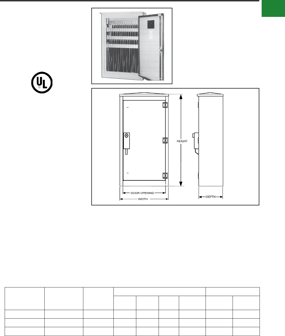
BURNDY®
Blue highlighted items are industry standard and most frequently ordered.
Canada: 1-800-387-6487 www.burndy.com US: 1-800-346-4175
Mechanical
TYPE BWTE
WALL-MOUNTED TERMINATION
ENCLOSURES
These are three-phase, NEMA 3R
(rain-proof), 600 Volt Rated wall
mounted termination enclosures.
Features and Benets
• Aluminum mechanical bar connectors
eliminates need for compressions tools,
lugs, and bolt assemblies
• Aluminum enclosure is lightweight, low
maintenance and has excellent corrosion
resistance
• Ample working space, allowing for easier
termination with a removeable swinging
door
• All-welded construction: welds and
seams are ground smooth
• Manufactured to meet or exceed ANSI
C57-12.28 for wall-mounted equipment
enclosure integrity
• Three-point positive latch mechanism
(secured and operated by a half-turn,
captive and recessed penta-head bolt)
and shielded padlock shackle
• Finish meets or exceeds proposed EEI
paint specication
• Finish is gray, oven cured powder coat
• All mounting hardware is 18-8 stainless
steel
Catalog
Number
Conductor
Range (AWG)
Number of
Conductors
per phase
Dimensions UL Listed Amp Rating
W D H Door
Opening Copper Aluminum
BWTE21-500 10 - 500 kcmil 21 32.00 16.00 51.00 28.00 3800 3100
BWTE21-750 2 - 750 kcmil 14 32.00 16.00 51.00 28.00 3325 2695
BWTE21-1000 1/0 - 1000 kcmil 14 32.00 16.00 51.00 28.00 3815 3115
AL9CU
A-61
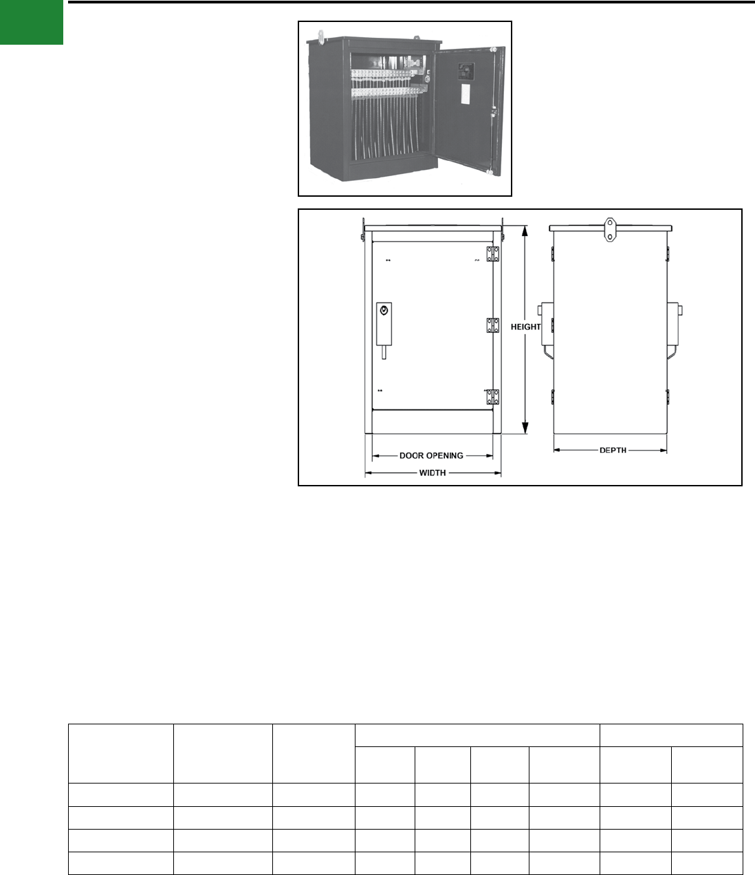
BURNDY®
Blue highlighted items are industry standard and most frequently ordered.
US: 1-800-346-4175 www.burndy.com Canada: 1-800-387-6487
Mechanical
TYPE BPTE
PAD-MOUNTED TERMINATION
ENCLOSURES
These are three-phase, NEMA 3R
(rain-proof), 600 Volt Rated pad
mounted termination enclosures.
Features and Benets
• Aluminum mechanical bar connectors
eliminates need for compressions tools,
lugs and bolt assemblies
• Aluminum enclosure is lightweight, low
maintenance and has excellent corrosion
resistance
• Ample working space, allowing for easier
termination with a removeable swinging
door
• All-welded construction: welds and
seams are ground smooth
• Manufactured to meet or exceed ANSI
C57-12.28 for wall-mounted equipment
enclosure integrity
• Removable swinging doors - doors have
stainless steel lift off hinges with
stainless steel three point locking
handles and recessed stainless steel
penta-head bolts for security
• Finish is Munsell green, oven cured
powder coat
• All mounting hardware is 18-8 stainless
steel
Catalog
Number
Conductor
Range (AWG)
Number of
Conductors
per phase
Dimensions UL Listed Amp Rating
W D H Door
Opening Copper Aluminum
BPTE26-500 10 - 500 kcmil 26 36.00 30.00 44.00 30.00 4560 3720
BPTE22-750 2 - 750 kcmil 22 36.00 30.00 44.00 30.00 5225 4235
BPTE20-1000 350 - 1000 kcmil 20 36.00 30.00 44.00 30.00 4905 4005
BPTE14-750 2 - 750 kcmil 14 25.00 24.00 44.00 19.00 3800 3100
A-62

BURNDY®
Blue highlighted items are industry standard and most frequently ordered.
Canada: 1-800-387-6487 www.burndy.com US: 1-800-346-4175
Small Terminals
B-1
TABLE OF CONTENTS
B-2, B3
B-4
B-5
B-6, B-7
B-8
B-9
B-10
B-11
B-12
B-13,
B-14
B-15
B-16,
B-17
B-18
B-19,
B-20
B-21,
B-22
B-23
B-24
B-25
B-26
B-27
B-28
B-29
B-30
B-31
B-32
B-33
B-34
B-35
B-36
B-37
B-38
B-39
B-40
B-41
B-42
General Information
Mil. Spec. Equivalents
RING TERMINALS
Types T & YAD (Bare)
Type YAD (Bare)
Types TP & BA (Vinyl)
Types TN & YAES (Nylon)
Type YAE-G (Nylon)
Type YAE-N (Nylon)
Type YHSA (Heat Shrink)
Type YAES-K
(Radiation Resistant)
Types YAV BOX & YAV (Bare)
Types YAV-L BOX & YAV-L
(Bare)
Types YAV-H BOX & YAV-H
(Bare - Shroud)
Types YAEV & YAEV-L
(Nylon)
Type YAEV-H
(Nylon - for Expanded Ins.)
Types YAV-R & YAV-RS
(Bare - Right Angle)
Type YAEV-RS
(Nylon - Right Angle)
Type YAEV-RH
(Nylon - Right Angle)
Type YBM (Bare - Flag Type)
FORK TERMINALS
Types T-F & YAD-F (Bare)
Types TP-F & BA-EF (Vinyl)
Types TN-F & YAES-F (Nylon)
Types YAE-N-F BOX &
YAE-N-F (Nylon)
Type YHSA-F (Heat Shrink)
Type T-LF (Bare - Lock)
Types TP-LF & BA-EL
(Vinyl - Lock)
Type TN-LF (Nylon - Lock)
Type YAE-N-LF (Nylon - Lock)
Type YHSA-K-LF
(Heat Shrink - Lock)
Type T-BF (Bare - Block)
Type TP-BF (Vinyl - Block)
Type TN-BF (Nylon - Block)
Type YAE-N-BF (Nylon - Block)
Type YHSA-K-BF
(Heat Shrink - Block)
Types TP-Z & BA-EZ
(Vinyl - Flange)
Types YAE-Z BOX & YAE-Z
(Nylon - Flange)
Types YAV-T-F BOX & YAV-T-F
(Bare)
Types YAV-H-F BOX, YAV-H-F,
& YAV-Z (Bare - Shroud)
SPLICES
Type YSV-B (Bare)
Type SP (Vinyl)
Type SN (Nylon)
Type SN-B (Nylon)
Types YSE BOX & YSE-H BOX
(Nylon - Strain Relief)
Type YSE-HHS
(Heat Shrink - Strain Relief)
Type YSES-K
(Radiation Resistant)
Type YSV (Bare)
Type YSV-L (Bare)
Type YSV-H (Bare - Strain Relief)
Type YSM (Bare - Parallel)
Type YSCM (Bare - Parallel)
Types YSV & YRV-L (Reducer)
Type YHSS (Heat Shrink)
DISCONNECTS
Type Q-M (Male - Bare)
Type Q-F (Female - Bare)
Type QP-M (Male - Vinyl)
Type QP-F (Female - Vinyl)
Type FQP-F (Female - Full Vinyl)
Type QN-M (Male - Nylon)
Type QN-F (Female - Nylon)
Type FQN-M (Male - Full Vinyl)
Type YHSQ-M
(Male - Heat Shrink)
Type YHSQ-F
(Female - Heat Shrink)
Type YHSFQ-F
(Female - Full Heat Shrink)
Type PG (Male/Female
Combo - Bare)
Type PGHS (Male/Female
Combo - Heat Shrink)
Type PGP (Male/Female
Combo - Vinyl)
Type PGN (Male/Female
Combo - Nylon)
Type FLN (Female Flag - Nylon)
Type FL (Female Flag - Bare)
MISCELLANEOUS
Type YAIT (Splice - no tools req’d)
Type TTV (Tap, Insulation
Piercing - no tools req’d)
Type YATW-P (3-way - Vinyl)
Type YATW-N (3-way - Nylon)
Type YATW-NG
(3-way - Nylon Grip)
Type YATW-HS
(3-way - Heat Shrink)
Type YAFW-P (4-way - Vinyl)
Type YAFW-N (4-way - Nylon)
Type YAFW-NG
(4-way - Nylon Grip)
Type YAFW-HS
(4-way - Heat Shrink)
Type BULM-P (Bullet Male - Vinyl)
Type BULM-N (Bullet Male - Nylon)
Type BULM-NG (Bullet Male -
Nylon Grip)
Type BULM-HS (Bullet Male -
Heat Shrink)
Type BULF-P
(Bullet Female - Vinyl)
Type BULF-N
(Bullet Female - Nylon)
Type BULF-NG
(Bullet Female - Nylon Grip)
Type BULF-HS
(Bullet Female - Heat Shrink)
Type PTV (Pin Terminal - Vinyl)
Type YF-UI (Bare Ferrules)
Type YF-I (Insulated Ferrules)
Type YF-TW
(Twin Insulated Ferrules)
Small Terminal Kits
Heat Shrink Kit
Types YQE & RK
(Pigtail Splice - Nylon)
B-43
B-44
B-45
B-46
B-47
B-48
B-49
B-50
B-51
B-52
B-53
B-54
B-55
B-56
B-57
B-58
B-59
B-60
B-61
B-62
B-63
B-64
B-65
B-66
B-67
B-68
B-69
B-70
B-71
B-71
B-72
B-73
B-74
B-74
B-75
B-75
B-76
B-76
B-77
B-77
B-78
B-78
B-79
B-79
B-80
B-80
B-81
B-81
B-82
B-82
B-83
B-83
B-84
B-85,
B-86
B-87,
B-88
B-89
B-90
B-91
B-92
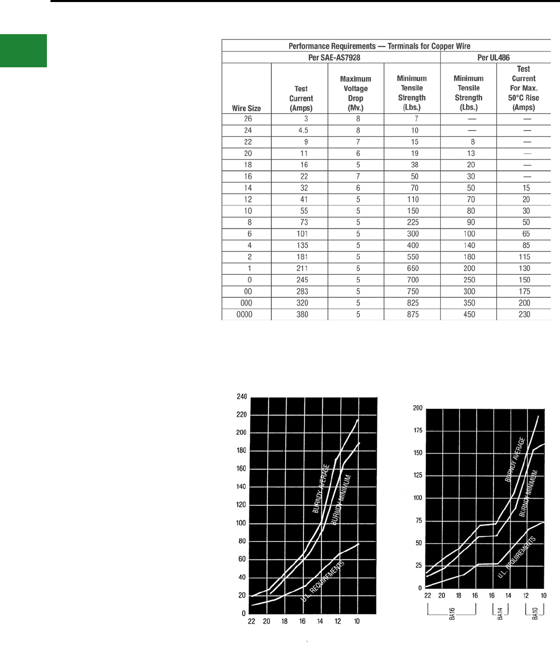
BURNDY®
Blue highlighted items are industry standard and most frequently ordered.
US: 1-800-346-4175 www.burndy.com Canada: 1-800-387-6487
Small Terminals
Performance
The terminals and splices in this catalog are
approved, per SAE-AS7928 and/or UL486,
where indicated. Table 1 shows the performance
requirements for terminals used in military and
commercial equipment. The voltage drops listed
are maximum allowable values taken at currents
well above rated current for the wires. Tensile
values assure that the wires will not become
separated from the terminals under reasonably
expected stresses. UL tensile values are chosen
to reect the severest expected duty. MIL
Specication tensile values apply only to crimp
terminations and reect minimum values that are
obtained in good crimp joints. Actual performance
of BURNDY terminals exceeds the requirements
of Table 1. Typical values are shown in Figures
1-5. For High Temperature applications BURNDY®
YAV series with nickel plating “-NK” sufx provide
for continuous operation to 650° F and 750° F
intermittent service.
Fig. 1. Tensile strength of YAD HYLUG™ after
axial rotation stresses.
Fig. 2. Tensile strength of BA VINYLUG™ after
axial rotation stresses.
Table 1
TENSILE STRENGTH IN POUNDS
TENSILE STRENGTH IN POUNDS
COMMERCIAL WIRE SIZECOMMERCIAL WIRE SIZE
B-2
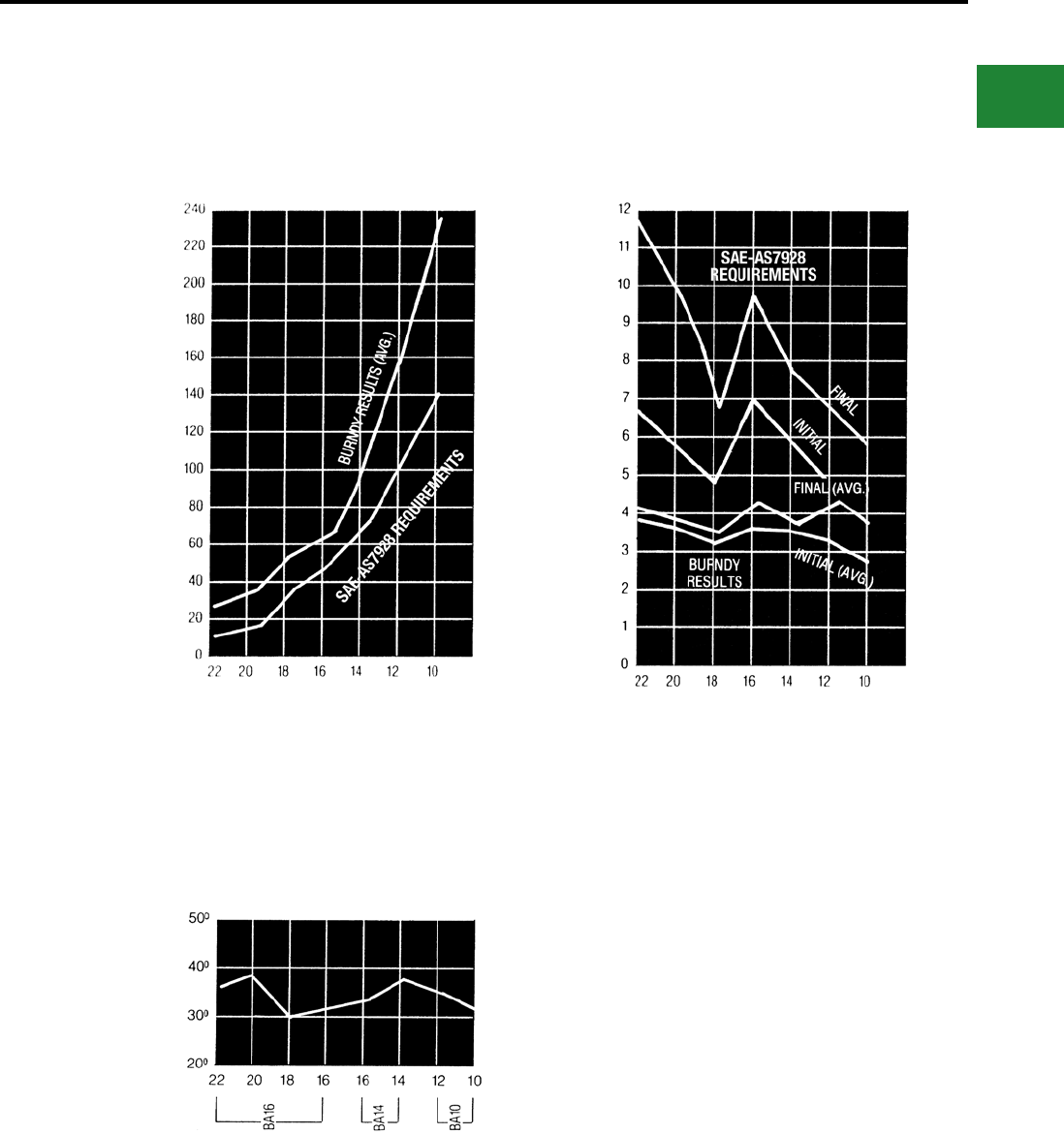
BURNDY®
Blue highlighted items are industry standard and most frequently ordered.
Canada: 1-800-387-6487 www.burndy.com US: 1-800-346-4175
Small Terminals
Fig. 3. Tensile strength of YAES INSULUG™
after vibration.
Fig. 5. Voltage drops of YAES at currents per
Table 1 after vibration.
Fig. 4. Temperature rise of BA VINYLUG™ at
currents per Table 1.
TENSILE STRENGTH IN POUNDS
VOLTAGE DROP mV
DEGREES CENTIGRADE
COMMERCIAL WIRE SIZE
TERMINAL
SIZE
AN WIRE SIZE AN WIRE SIZE
B-3
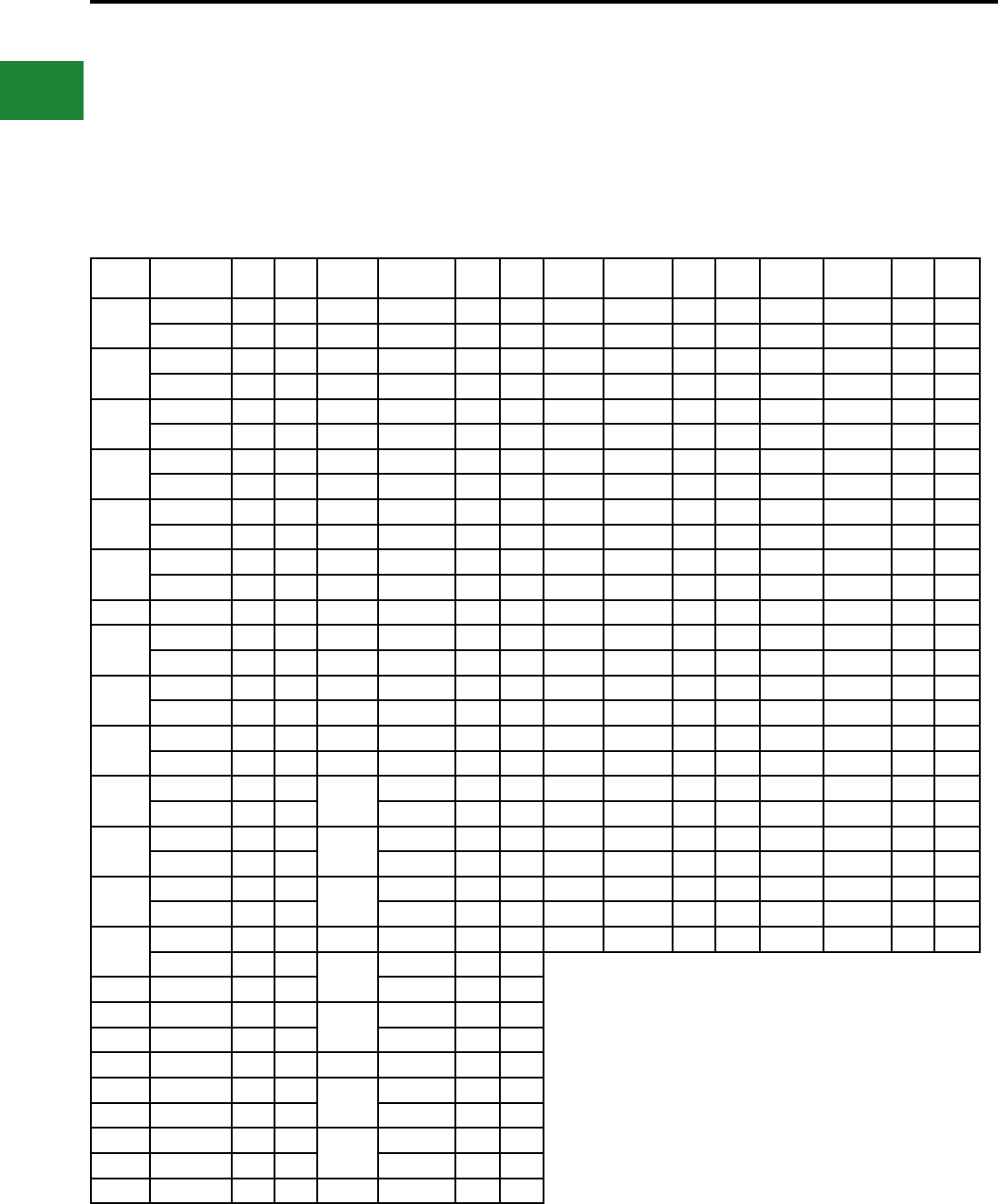
BURNDY®
Blue highlighted items are industry standard and most frequently ordered.
US: 1-800-346-4175 www.burndy.com Canada: 1-800-387-6487
Small Terminals
EQUIVALENT TABLES
MILITARY SPECIFICATIONS
Terminals
BURNDY® Equivalents to SAE-AS25036 in
accordance with Specication SAE-AS7928.
Terminals
BURNDY® Equivalents to SAE-AS20659 in
accordance with Specication SAE-AS7928.
AS25036
Dash No.
Catalog
Number
Class
1
Class
2
AS25036
Dash No.
Catalog
Number
Class
1
Class
2
AS20659
Dash No.
Catalog
Number
Class
1
Class
2
AS20659
Dash No.
Catalog
Number
Class
1
Class
2
101 YAES18-N1 X X 124 YAEV4C-L4 X105 YAV10 X X 134 YAV1C-L3 X
YAE18-G43 X125 YAEV4C-L2 X X 106 YAV10-T2 X X 135 YAV25-L3 X
102 YAES18-N2 X X 126 YAEV2C-L1 X X 107 YAV8C-L X136 YAV26-L3 X X
YAE18-N21 X127 YAEV2C-L X108 YAV8C-L2 X137 YAV28-L54 X
103 YAES18-N3 X X 128 YAEV2C-L4 X X 109 YAV6C-L X X 140 YAV8C-L14 X
YAE18N X129 YAEV1C-L1 X110 YAV6C-L2 X141 YAV8C-L1 X X
104 YAES18-N4 X X 130 YAEV1C-L X X 111 YAV4C-L X X 142 YAV8C-L4 X
YAE18-N3 X131 YAEV1C-L3 X112 YAV4C-L2 X143 YAV6C-L10 X
105 YAES18-N5 X X 132 YAEV25-L1 X113 YAV2C-L1 X144 YAV4C-L3 X
YAE18-N15 X133 YAEV25-L X X 114 YAV2C-L X145 YAV4C-L5 X
106 YAES14-N6 X X 134 YAEV25-L3 X115 YAV1C-L1 X X 146 YAV2C-L3 X
YAE14-N43 X135 YAEV26-L2 X116 YAV1C-L X147 YAV2C-L2 X X
107 YAES14-N7 X X 136 YAEV26-L X117 YAV25-L1 X148 YAV2C-L11 X
108 YAES14-N8 X X 137 YAEV26-L3 X118 YAV25-L X X 149 YAV1C-L2 X
YAES14N X143 YAE22-G18 X119 YAV26-L2 X150 YAV1C-L4 X
109 YAES14-N9 X X 144 YAE22-G16 X120 YAV26-L X151 YAV25-L2 X
YAE14-N3 X145 YAE22-G13 X121 YAV27-L X X 152 YAV25-L16 X
110 YAES14-N10 X146 YAE22-G14 X122 YAV27-L1 X153 YAV26-L1 X
YAE14-N4 X147 YAE22-G15 X123 YAV28-L X154 YAV26-L16 X
111 YAES10-N11 X X 148 YAES18-N48 X X 124 YAV28-L12 X X 155 YAV27-L20 X
YAE10-N5 XYAE18-N17 X128 YAV10-T4 X X 156 YAV27-L18 X
112 YAES10-N12 X X 149 YAES18-N49 X X 129 YAV8C-L3 X157 YAV28-L56 X
YAE10N XYAE18N1 X130 YAV6C-L1 X158 YAV28-L60 X
113 YAES10-N13 X X 150 YAES18-N50 X X 131 YAV6C-L4 X159 YAV28-L13 X
YAE10-N2 XYAE18-N2 X132 YAV4C-L4 X160 YAV28-L14 X
114 YAES10-N14 X152 YAES14-N52 X X 133 YAV2C-L4 X165 YAV10-T7 X X
YAE10-N4 X153 YAES14-N53 X X
115 YAEV8C-L X X YAE14-N1 X
116 YAEV8C-L1 X154 YAES14-N54 X X
117 YAEV8C-L2 XYAE14-N2 X
118 YAEV8C-L3 X155 YAES14-N55 X X
119 YAEV6C-L1M X X 156 YAES10-N56 X X
120 YAEV6C-LM XYAE10-N11 X
121 YAEV6C-L4M X157 YAES10-N57 X X
122 YAEV6C-L2M XYAE10-N3 X
123 YAEV4C-L X158 YAES10-N58 X X
Main Ofce Cage Code Number: 1NJK8
Notes:
For factory cage code numbers, please contact your local BURNDY® sales
representative or the Headquarters at the phone number shown below.
SAE standes for the Society of Automotive Engineering, which has replaced
the Military Specications.
B-4
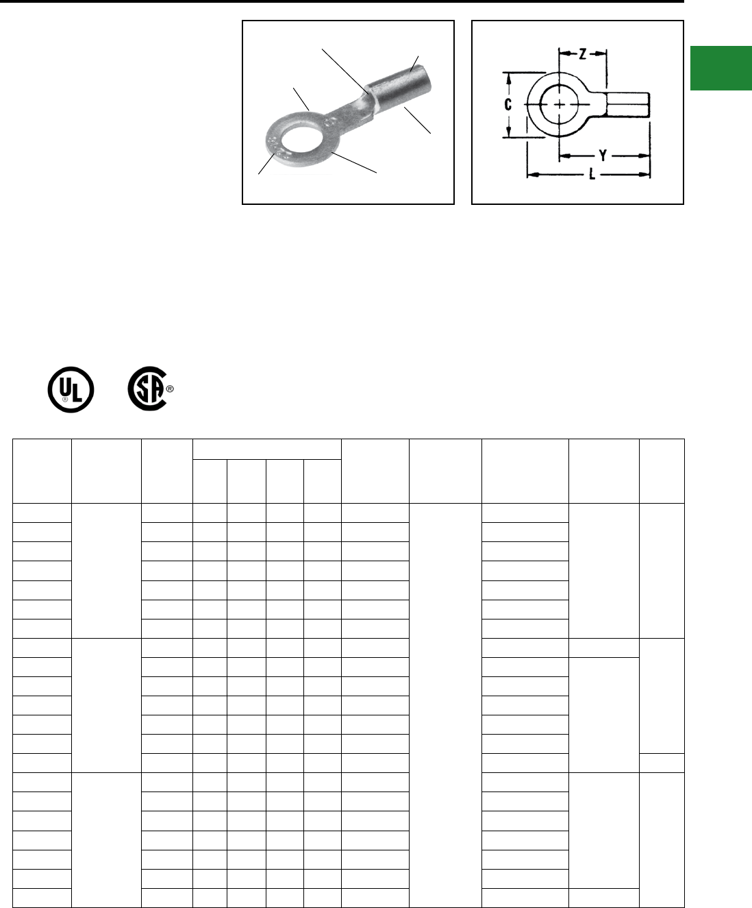
BURNDY®
Blue highlighted items are industry standard and most frequently ordered.
Canada: 1-800-387-6487 www.burndy.com US: 1-800-346-4175
Small Terminals
TYPES T AND YAD
HYLUG™
Uninsulated Compression Ring
Tongue Terminal
The Type T uninsulated terminals are constructed
of pure electrolytic copper. Designed with a long
brazed seam barrel, standard neck, deep V
groove inner serrations and electro-tin plated. The
terminals are ideal for control wiring and other
standard duty applications.
The ring tongue provides a secure termination
under the screw head that cannot be removed
without the complete removal of the screw. Two
or more terminals can easily be stacked on a
common stud.
Features & Benets
• Constructed of pure electrolytic copper
◊ Provides maximum conductivity, low
resistance and ductility for excellent
crimp forming properties
• Long brazed seam barrel and deep V groove
inner serrations
◊ Provides optimum conductivity
reliability and holding power after
crimping
• Electro-tin plated
◊ Provides durable long-lasting
corrosion resistance
• Wire range is clearly marked on terminal
◊ Provides easy identication
• Inspection hole
◊ Provides an easy visual check of wire
insertion
• Long neck terminal
◊ Permits easy bending and stacking of
several terminals on a common stud
DEEP “V” GROOVE
SERRATIONS
LONG BRAZED
SEAM BARREL
ELECTRO-TIN
PLATED
WIRE
RANGE
RING
TONGUE
WIRE
CRIMP
Catalog
Number
Wire Range
(AWG/kcmil)
Stud
Size
Dimensions Bulk
Catalog
Number
Installation
Tooling
Tape Mounted
Catalog Number
2000/Reel
Installation
Tooling
Wire
Strip
Length
CL
Max.
Y
Max.
Z
Min.
T18-4
22 AWG-
18 AWG
#3 - #4 0.25 0.65 0.53 0.24 YAD18-4
Non-Ratchet:
Y10D, Y10-22
Ratchet:
MRE1022B,
MR8G98,
Y8MRB-1,
MR20
YAD18-4M
TFM with
DFM6D1 Die 9/32"
T18-6 #4 - #6 0.25 0.65 0.53 0.24 YAD18-6 YAD18-6M
T18-8 #6 - #8 0.31 0.77 0.61 0.33 YAD18-8 YAD18-8M
T18-10 #8 - #10 0.31 0.77 0.61 0.33 YAD18-10 YAD18-10M
T18-14 1/4 0.45 0.96 0.73 0.44 YAD18-14 YAD18-14M
T18-516 5/16 0.45 0.96 0.73 0.44 YAD18-516 —
T18-38 3/8 0.53 1.05 0.78 0.49 YAD18-38 —
T14-4
20 AWG-
14 AWG
#3 - #4 0.25 0.67 0.55 0.26 YAD14-4 — —
9/32”
T14-6 #4 - #6 0.25 0.67 0.55 0.26 YAD14-6 YAD14-6M
TFM with
DFM5D1 Die
T14-8 #6 - #8 0.31 0.77 0.61 0.33 YAD14-8 YAD14-8M
T14-10 #8 - #10 0.31 0.77 0.61 0.33 YAD14-10 YAD14-10M
T14-14 1/4 0.45 0.96 0.73 0.44 YAD14-14 YAD14-14M
T14-516 5/16 0.45 0.96 0.73 0.44 YAD14-516 —
T14-38 3/8 0.53 1.05 0.78 0.49 YAD14-38 YAD14-38M 11/32”
T10-6
12 AWG-
10 AWG
#4 - #6 0.37 0.83 0.64 0.29 YAD10-6 —
TFM with
DFM4D1 Die 11/32”
T10-8 #6 - #8 0.37 0.83 0.64 0.29 YAD10-8 YAD10-8M
T10-10 #8 - #10 0.38 0.83 0.64 0.29 YAD10-10 —
T10-14 1/4 0.46 0.97 0.74 0.39 YAD10-14 YAD10-14M
T10-516 5/16 0.53 1.02 0.76 0.41 YAD10-516 YAD10-516M
T10-38 3/8 0.58 1.08 0.79 0.44 YAD10-38 YAD10-38M
T10-12* 1/2 0.69 1.21 0.86 0.61 — — —
* Not UL Listed or CSA Certied.
B-5
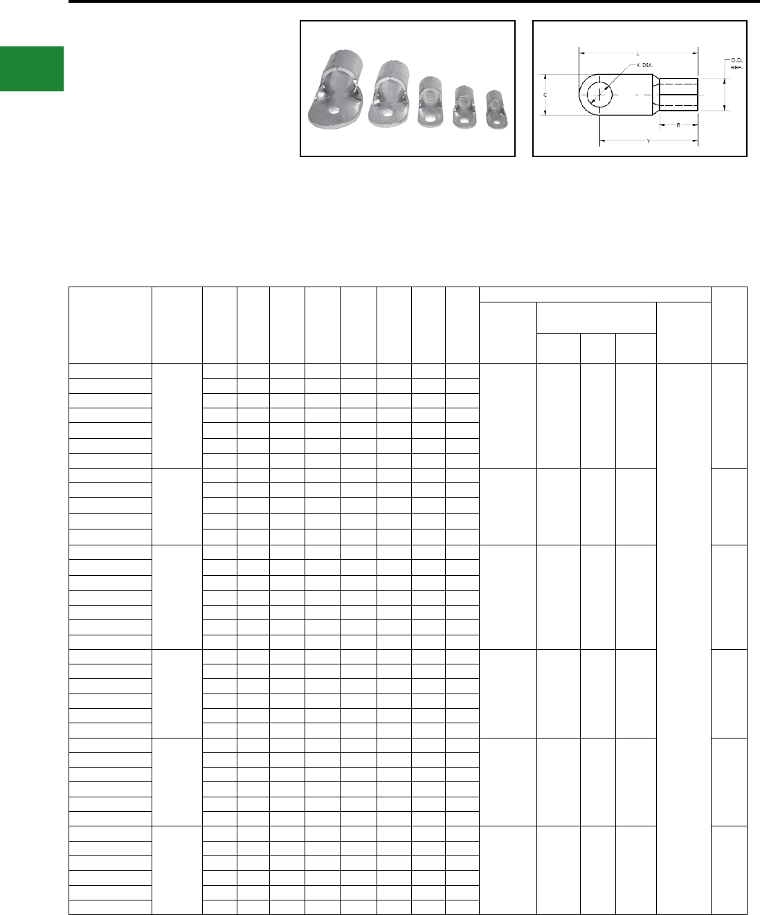
BURNDY®
Blue highlighted items are industry standard and most frequently ordered.
US: 1-800-346-4175 www.burndy.com Canada: 1-800-387-6487
Small Terminals
TYPE YAD
HYLUG™
Uninsulated Compression Terminal
The YAD uninsulated OEM lug terminal is
constructed of electrolytic copper. Designed with
a brazed seam barrel, standard neck, V-groove
inner serrations and electro-tin plated. The round
ring tongue provides for a secure termination
under the screw head that cannot be removed
without the complete removal of the screw. Two
or more terminals can easily be stacked on a
common stud. These terminals are ideal for use
with code or ex cable.
Catalog
Number
Wire
Range
Copper
Code &
Flex
[mm]
Stud
Size B C K Dia. L OD T Y
Installation Tooling
Wire
Strip
Length
Mechanical
Tooling
Hydraulic Tooling
(requires nest & indentor) Dieless
Tooling
(no dies
required)
Tool Die
Nest Indentor
YAD8CM4E8
8 AWG
[6-10]
#8 0.31 0.40 0.17 0.83 0.26 0.04 0.63
Y1MRTC
Y8MRB-1
Red Groove
Y35, Y39,
Y750,
PAT750
UV8L Y34PL
Y81KFT
Series
PAT81KFT
Series
Y4PC834
Series
PAT4PC834
Series
3/8"
YAD8CM5E10 #10 0.31 0.40 0.21 0.83 0.26 0.04 0.63
YAD8CM6E14 1/4 0.31 0.43 0.26 0.89 0.26 0.04 0.67
YAD8CM8E516 5/16 0.31 0.55 0.33 1.06 0.26 0.04 0.79
YAD8CM10E38 3/8 0.31 0.71 0.41 1.18 0.26 0.04 0.83
YAD8CM12E12 1/2 0.31 0.87 0.51 1.34 0.26 0.04 0.91
YAD8CM16E58 5/8 0.31 1.10 0.67 1.93 0.26 0.04 1.38
YAD6CM5E10
6 AWG
[10-16]
#10 0.40 0.43 0.21 1.00 0.32 0.05 0.79
Y1MRTC
Blue Groove
Y35, Y39,
Y750,
PAT750
UV6L Y34PL 7/16"
YAD6CM6E14 1/4 0.40 0.43 0.26 1.00 0.32 0.05 0.79
YAD6CM8E516 5/16 0.40 0.55 0.33 1.14 0.32 0.05 0.87
YAD6CM10E38 3/8 0.40 0.71 0.41 1.30 0.32 0.05 0.95
YAD6CM12E12 1/2 0.40 0.87 0.51 1.46 0.32 0.05 1.02
YAD4CM5E10
4 AWG
[16-25]
#10 0.43 0.47 0.21 1.22 0.41 0.06 0.98
—
Y35, Y39,
Y750,
PAT750
U2CD1 Y34PR 1/2"
YAD4CM6E14 1/4 0.43 0.47 0.26 1.22 0.41 0.06 0.98
YAD4CM8E516 5/16 0.43 0.63 0.33 1.30 0.41 0.06 0.98
YAD4CM10E38 3/8 0.43 0.71 0.41 1.38 0.41 0.06 1.02
YAD4CM12E12 1/2 0.43 0.87 0.51 1.65 0.41 0.06 1.22
YAD4CM16E58 5/8 0.43 1.10 0.67 1.93 0.41 0.06 1.38
YAD4CM20E34 3/4 0.43 1.10 0.80 1.93 0.41 0.06 1.38
YAD2CM6E14
2 AWG
[25-35]
1/4 0.47 0.59 0.26 1.32 0.48 0.06 1.02
—
Y35, Y39,
Y750,
PAT750
U1CD1 Y34PR 17/32"
YAD2CM8E516 5/16 0.47 0.63 0.33 1.34 0.48 0.06 1.02
YAD2CM10E38 3/8 0.47 0.71 0.41 1.42 0.48 0.06 1.06
YAD2CM12E12 1/2 0.47 0.87 0.51 1.65 0.48 0.06 1.22
YAD2CM16E58 5/8 0.47 1.10 0.67 1.97 0.48 0.06 1.42
YAD2CM20E34 3/4 0.47 1.10 0.80 1.97 0.48 0.06 1.42
YAD1CM6E14
1 AWG
[35-50]
1/4 0.63 0.71 0.26 1.69 0.57 0.07 1.34
—
Y35, Y39,
Y750,
PAT750
UV26L Y34PA 3/4"
YAD1CM8E516 5/16 0.63 0.71 0.33 1.69 0.57 0.07 1.34
YAD1CM10E38 3/8 0.63 0.71 0.41 1.69 0.57 0.07 1.34
YAD1CM12E12 1/2 0.63 0.87 0.51 1.85 0.57 0.07 1.42
YAD1CM16E58 5/8 0.63 1.10 0.67 2.13 0.57 0.07 1.57
YAD1CM20E34 3/4 0.63 1.10 0.80 2.13 0.57 0.07 1.57
YAD25M6E14
1/0 AWG
[35-50]
1/4 0.63 0.71 0.26 1.69 0.57 0.07 1.34
—
Y35, Y39,
Y750,
PAT750
UV26L Y34PA 3/4"
YAD25M8E516 5/16 0.63 0.71 0.33 1.69 0.57 0.07 1.34
YAD25M10E38 3/8 0.63 0.71 0.41 1.69 0.57 0.07 1.34
YAD25M12E12 1/2 0.63 0.87 0.51 1.85 0.57 0.07 1.42
YAD25M16E58 5/8 0.63 1.10 0.67 2.13 0.57 0.07 1.57
YAD25M20E34 3/4 0.63 1.10 0.80 2.13 0.57 0.07 1.57
Features & Benets
• Terminals utilize a brazed seam
• Provide excellent high conductivity
connections
• Electro-tin plated for durable long lasting
corrosion resistance
• Vibration resistance and tensile strength is well
within the limits of commercial specications
B-6
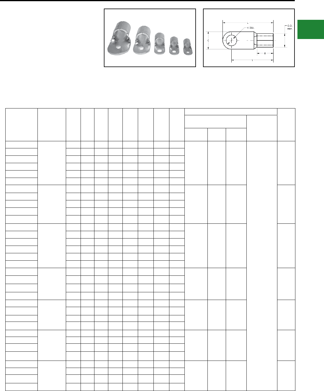
BURNDY®
Blue highlighted items are industry standard and most frequently ordered.
Canada: 1-800-387-6487 www.burndy.com US: 1-800-346-4175
Small Terminals
TYPE YAD
(Continued)
HYLUG™
Uninsulated Compression Terminal
Catalog Number
Wire
Range
Copper Code
& Flex
[mm]
Stud
Size B C K Dia. L OD T Y
Installation Tooling
Wire
Strip
Length
Hydraulic Tooling
(requires nest & indentor) Dieless
Tooling
(no dies
required)
Tool Die
Nest Indentor
YAD26M6E14
2/0 AWG
[50-70]
1/4 0.71 0.87 0.26 1.93 0.67 0.08 1.50
Y35, Y39,
Y750,
PAT750
UV28D1 Y34PR2
Y81KFT
Series
PAT81KFT
Series
Y4PC834
Series
PAT4PC834
Series
13/16"
YAD26M8E516 5/16 0.71 0.87 0.33 1.93 0.67 0.08 1.50
YAD26M10E38 3/8 0.71 0.87 0.41 1.93 0.67 0.08 1.50
YAD26M12E12 1/2 0.71 0.87 0.51 1.93 0.67 0.08 1.50
YAD26M16E58 5/8 0.71 1.10 0.67 2.20 0.67 0.08 1.65
YAD26M20E34 3/4 0.71 1.10 0.80 2.20 0.67 0.08 1.65
YAD27M8E516
3/0 AWG
[70-95]
5/16 0.79 0.95 0.33 2.13 0.79 0.10 1.65
Y35, Y39,
Y750,
PAT750
UV29D1 Y34PR2 7/8"
YAD27M10E38 3/8 0.79 0.95 0.41 2.13 0.79 0.10 1.65
YAD27M12E12 1/2 0.79 0.95 0.51 2.13 0.79 0.10 1.65
YAD27M16E58 5/8 0.79 1.10 0.67 2.28 0.79 0.10 1.73
YAD27M20E34 3/4 0.79 1.10 0.80 2.28 0.79 0.10 1.73
YAD28M6E14
4/0 AWG
[95-120]
1/4 0.87 0.95 0.26 2.20 0.89 0.12 1.73
Y35, Y39,
Y750,
PAT750
U32D1 Y34PR2 1"
YAD28M8E516 5/16 0.87 0.95 0.33 2.20 0.89 0.12 1.73
YAD28M10E38 3/8 0.87 0.95 0.41 2.20 0.89 0.12 1.73
YAD28M12E12 1/2 0.87 0.95 0.51 2.20 0.89 0.12 1.73
YAD28M16E58 5/8 0.87 1.10 0.67 2.44 0.89 0.12 1.89
YAD28M20E34 3/4 0.87 1.10 0.80 2.44 0.89 0.12 1.89
YAD30M10E38
250-300 kcmil
[120-150]
3/8 0.95 1.18 0.41 2.56 1.00 0.13 1.97
Y46, PAT46 P34D P48PR2 1-1/8"
YAD30M12E12 1/2 0.95 1.18 0.51 2.56 1.00 0.13 1.97
YAD30M16E58 5/8 0.95 1.18 0.67 2.56 1.00 0.13 1.97
YAD30M20E34 3/4 0.95 1.18 0.80 2.56 1.00 0.13 1.97
YAD31M10E38
300-350 kcmil
[150-185]
3/8 1.10 1.42 0.41 2.68 1.12 0.14 1.97
Y46, PAT46 P34D P48PR2 1-1/4"
YAD31M12E12 1/2 1.10 1.42 0.51 2.68 1.12 0.14 1.97
YAD31M16E58 5/8 1.10 1.42 0.67 2.68 1.12 0.14 1.97
YAD31M20E34 3/4 1.10 1.42 0.80 2.68 1.12 0.14 1.97
YAD33M10E38
400-450 kcmil
[185-240]
3/8 1.26 1.50 0.41 2.95 1.24 0.16 2.20
Y46, PAT46 P36D P48PR2 1-3/8"
YAD33M12E12 1/2 1.26 1.50 0.51 2.95 1.24 0.16 2.20
YAD33M16E58 5/8 1.26 1.50 0.67 2.95 1.24 0.16 2.20
YAD33M20E34 3/4 1.26 1.50 0.80 2.95 1.24 0.16 2.20
YAD36M10E38
500-600 kcmil
[240-300]
3/8 1.38 1.97 0.41 3.70 1.44 0.18 2.72
Y46, PAT46 P44D P48PR2 1-1/2"
YAD36M12E12 1/2 1.38 1.97 0.51 3.70 1.44 0.18 2.72
YAD36M16E58 5/8 1.38 1.97 0.67 3.70 1.44 0.18 2.72
YAD36M20E34 3/4 1.38 1.97 0.80 3.70 1.44 0.18 2.72
B-7
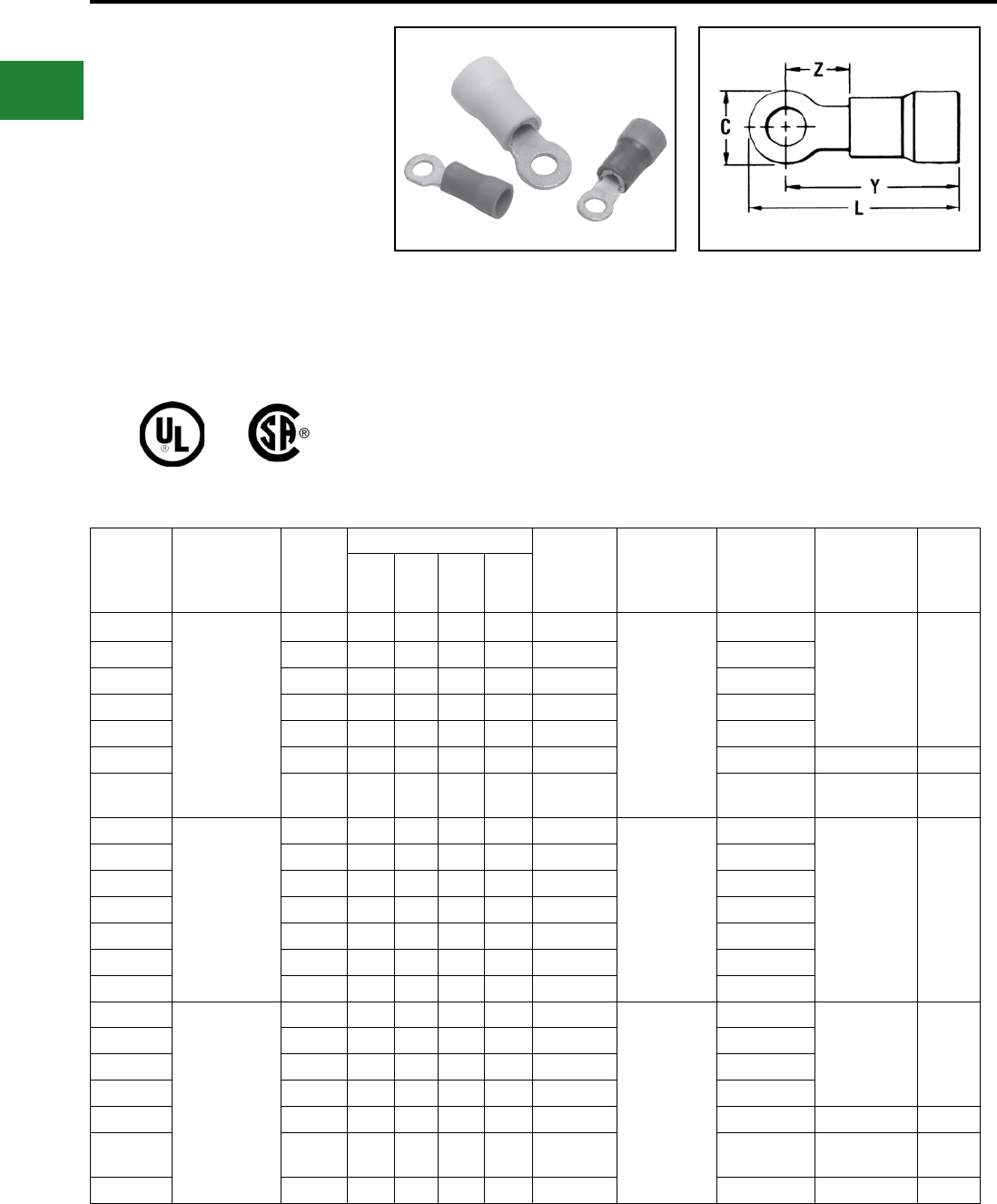
BURNDY®
Blue highlighted items are industry standard and most frequently ordered.
US: 1-800-346-4175 www.burndy.com Canada: 1-800-387-6487
Small Terminals
TYPES TP AND BA
VINYLUG™
Terminal — Polyvinylchloride
Insulated, Ring Tongue
600 Volts Max., 105° C Max.
VINYLUG™ Type TP is designed for commercial
and light duty industrial control and power circuit
applications. Supplied with an expanded polyvinyl
chloride (PVC) insulation shroud, many tongue
variations and rated 600V makes TP terminals
versatile and economical.
Catalog
Number
Wire Range
(AWG/kcmil)
Stud
Size
Dimensions Bulk
Catalog
Number
Installation
Tooling
Tape Mounted
Catalog
Number
2000/Reel
Installation
Tooling
Wire
Strip
Length
C L Y Z
TP16-4
22-16
Max. Insul.
Dia.Accom.:.145
Color Code:
Red
#3-#4 0.22 0.71 0.61 0.17 BA16E4M
Plier Type:
Y10-22, Y10D
or Ratchet Tool:
MR8-89-1,
MR8-G96,
MR15
MRE1022NV
BA16E4M
TFM with
DFM3D-1 Die 13/64"
TP16-6 #6 0.25 0.74 0.62 0.18 BA16E6M BA16E6M
TP16-8 #6 - #8 0.31 0.85 0.70 0.26 BA16E8M BA16E8M
TP16-10 #8 - #10 0.31 0.85 0.70 0.26 BA16E10M BA16E10M
TP16-14 1/4 0.40 0.99 0.79 0.36 BA16E14M BA16E14M
TP16-516* 5/16 0.47 1.11 0.88 0.41 — — — 13/64"
TP16-38 3/8 0.53 1.15 0.88 0.45 BA16E38M BA16E38M TFM with
DFM3D-1 Die 13/64"
TP14-4
16-14
Max. Insul.
Dia. Accom.:.180
Color Code:
Blue
#4 0.22 0.11 0.61 0.17 BA14E4M
Plier Type:
Y10-22, Y10D
or Ratchet Tool:
MR8-89-1,
MR8-G96,
MR15
MRE1022NV
BA14E4M
TFM with
DFM2D-1 Die 13/64"
TP14-6 #6 0.25 0.74 0.62 0.18 BA14E6M BA14E6M
TP14-8 #6 - #8 0.31 0.85 0.70 0.26 BA14E8M BA14E8M
TP14-10 #8 - #10 0.31 0.85 0.70 0.26 BA14E10M BA14E10M
TP14-14 1/4 0.40 0.99 0.79 0.36 BA14E14M BA14E14M
TP14-516 5/16 0.53 1.15 0.88 0.45 BA14E516M BA14E516M
TP14-38 3/8 0.53 1.15 0.88 0.45 BA14E38 —
TP10-6
12-10
Max. Insul.
Dia. Accom.:.260
Color Code:
Yellow
#6 0.31 0.68 0.75 0.20 BA10E6M
Plier Type:
Y10-22, Y10D
or Ratchet:
MR8-89-1,
MR15, M8ND
w/N10HET-23
MRE1022NV
BA10E6M
TFM with
DFM1D5 Die 19/64"
TP10-8 #6 - #8 0.36 1.00 0.81 0.26 BA10E8M BA10E8M
TP10-10 #8-#10 0.36 1.00 0.81 0.26 BA10E10M BA10E10M
TP10-14 1/4 0.53 1.22 0.95 0.40 BA10E14M BA10E14M
TP10-516 5/16 0.53 1.22 0.95 0.42 BA10E516 — — 19/64"
TP10-38 3/8 0.53 1.27 1.00 0.45 BA10E38M BA10E38M TFM with
DFM1D5 Die 19/64"
TP10-12* 1/2 0.69 1.51 1.17 0.61 — — — 19/64"
Features & Benets
• Expanded insulation support accepts standard
and large wire diameters
◊ Lowers inventory requirements,
permits greater exibility and provides
insulation support
• Funnel entry
◊ Easy wire insertion
• Manufactured of pure electrolytic copper
◊ Provides maximum conductivity, low
resistance and ductility for excellent
crimp forming properties
• Deep V groove serrations in the inner barrel
◊ Provides added holding strength and
better conductivity
• Electro-tin plated
◊ Provides durable long-lasting corrosion
resistance
* Not UL Listed or CSA Certied.
B-8
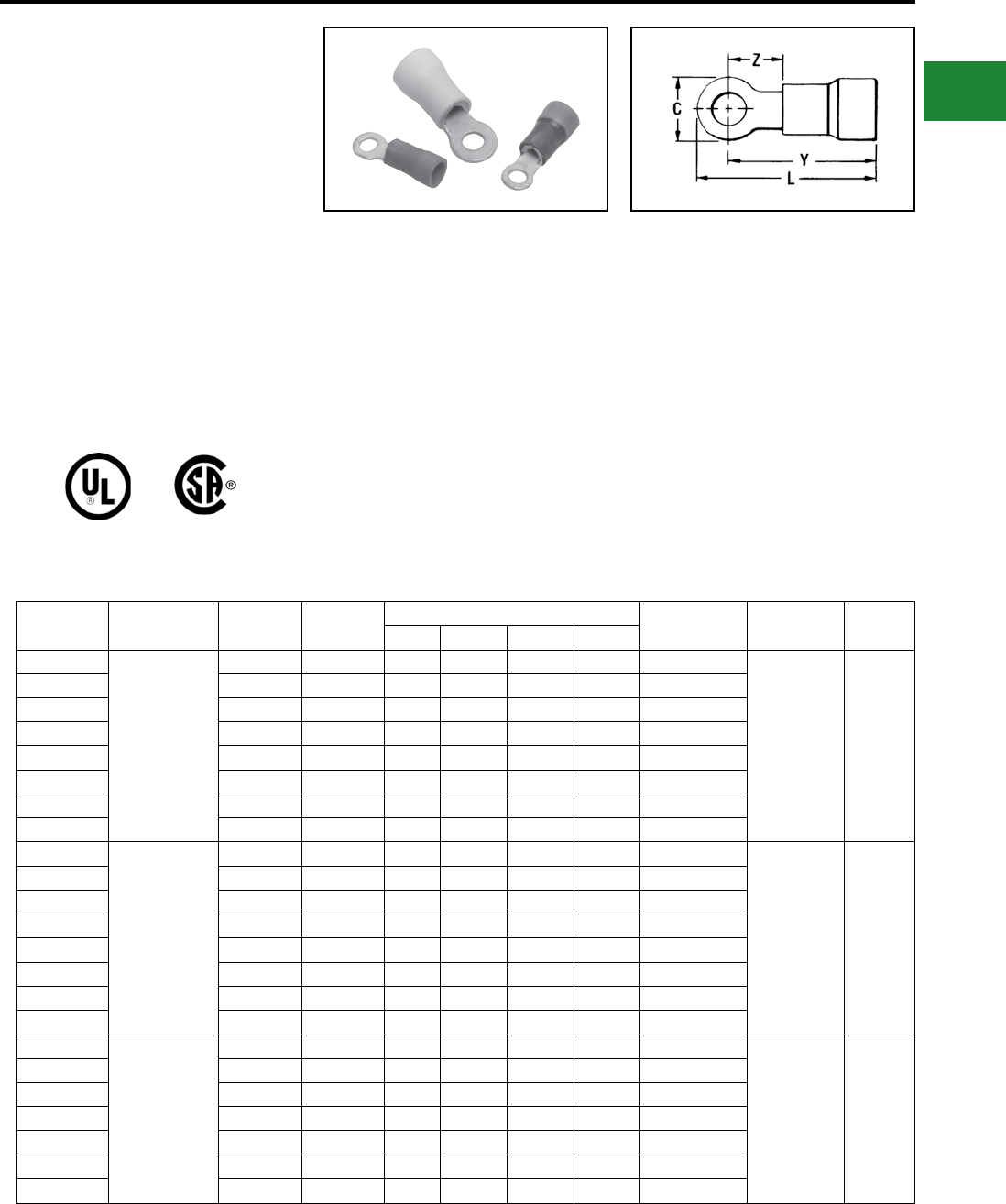
BURNDY®
Blue highlighted items are industry standard and most frequently ordered.
Canada: 1-800-387-6487 www.burndy.com US: 1-800-346-4175
Small Terminals
TYPES TN AND YAES
INSULUG™
Terminal - Nylon Insulated,
Ring Tongue
600 Volts Max., 105° C Max.
INSULUG™ type TN Nylon-insulated terminals
are designed for heavy duty industrial, utility and
military power and control-circuit applications
for wire sizes 26 AWG through 10 AWG. They
offer high dielectric strength and stability in oily
conditions and meet military CLASS 1 and
CLASS 2 requirements per SAE-AS25036 and
the requirements of military specications SAE-
AS7928.
Features & Benets
• An integral one-piece copper barrel / insulation
grip and wire strain relief design
◊ Provides improved physical strength
characteristics over a multi-piece design
• Manufactured of pure electrolytic copper
◊ Provides maximum conductivity, low
resistance and ductility for excellent crimp
forming properties
• Brazed seam
◊ Provides a stronger barrel design to minimize
any possible splitting and eliminates folding
• Deep inner barrel serrations
◊ Provides excellent electrical conductivity and
pullout strength values
Catalog
Number
Wire Range
(AWG/kcmil) Stud Size SAE-25036 Dimensions Bulk Catalog
Number
Installation
Tooling
Wire Strip
Length
C L Max. Y Max. Z Max.
TN18-4
22-18
Max. Insul.
Dia. Accom.: .120
Color Code:
Red
#3 - #4 -148 0.23 0.76 0.64 0.20 YAES18N48
Ratchet:
MR8-83
MRE1022NV
Non-Ratchet:
Y10D,
Y1022
7/32
TN18-6 #4 - #6 -101 0.25 0.76 0.64 0.20 YAES18N1
TN18-6G1* #4 - #6 -102 0.25 0.87 0.74 0.49 YAES18N2
TN18-8 #6 - #8 -149 0.31 0.91 0.76 0.29 YAES18N49
TN18-10 #8 - #10 -103 0.31 0.91 0.76 0.29 YAES18N3
TN18-14 #12-1/4 -150 0.46 1.09 0.87 0.41 YAES18N50
TN18-516 5/16 -104 0.46 1.09 0.87 0.41 YAES18N4
TN18-38 3/8 -105 0.53 1.17 0.91 0.45 YAES18N5
TN14-4
16-14
Max. Insul.
Dia. Accom.: .153
Color Code:
Blue
#3 - #4 -152 0.25 0.79 0.67 0.24 YAES14N52
Ratchet:
MR8-83
MRE1022NV
Non-Ratchet:
Y10D,
Y1022
7/32
TN14-6 #4 - #6 -106 0.25 0.79 0.67 0.24 YAES14N6
TN14-6G1* #4 - #6 -107 0.30 0.91 0.76 0.51 YAES14N7
TN14-8 #6 - #8 -153 0.31 0.89 0.74 0.31 YAES14N53
TN14-10 #8 - #10 -108 0.31 0.89 0.74 0.31 YAES14N8
TN14-14 #12-1/4 -154 0.45 1.08 0.86 0.43 YAES14N54
TN14-516 5/16 -109 0.45 1.08 0.86 0.43 YAES14N9
TN14-38 3/8 -110 0.53 1.16 0.90 0.47 YAES14N10
TN10-6
12-10
Max. Insul.
Dia. Accom.:.210
Color Code:
Yellow
#4 - #6 -111 0.37 1.12 0.94 0.26 YAES10N11
Ratchet:
MR8-83
MRE1022NV
Non-Ratchet:
Y10D,
Y1022
11/32
TN10-8 #6 - #8 -156 0.37 1.12 0.94 0.26 YAES10N56
TN10-10 #8 - #10 -112 0.37 1.12 0.94 0.26 YAES10N12
TN10-14 #12-1/4 -157 0.53 1.32 1.06 0.37 YAES10N57
TN10-516 5/16 -113 0.53 1.32 1.06 0.37 YAES10N13
TN10-38 3/8 -114 0.58 1.34 1.05 0.40 YAES10N14
TN10-12* 1/2 — 0.69 1.51 1.18 0.61 YAES10N58
* Not UL Listed or CSA Certied.
• Smooth funnel entry
◊ Easy wire insertion
• The insulation is locked in place
◊ Will not twist off, thereby maintains proper
dielectric values
• Electro-tin plated
◊ Provides durable long-lasting resistance to
corrosion
• Color-coded and clearly marked
◊ Provides quick, easy wire size identication
• Ring Tongue
◊ Provides a secure termination under the
screw head that can not be removed without
complete removal of the screw
• Two or more terminals may be stacked on a
common stud easily
◊ Provides exibility and versatility
B-9
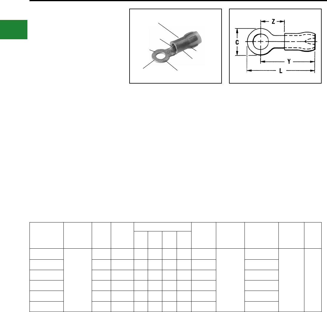
BURNDY®
Blue highlighted items are industry standard and most frequently ordered.
US: 1-800-346-4175 www.burndy.com Canada: 1-800-387-6487
Small Terminals
TYPES YAE-G
INSULUG™
Terminal — Nylon Insulated,
Ring-Tongue Multi-Finger
Insulation Grip
300 Volts Max., 105° C Max.
INSULUG™ Types YAE-G and YAE-N nylon
insulated terminals are designed with a multi-
nger insulation grip for paper, EPR and other
elastic or hard to grip insulations. The metal ngers
rml grip the insulation providing superior holding
characteristics, cable support and strain relief.
Types YAE-G and YAE-N terminals are rated 105°
C and meet military standard AS25036 Class 2
and SAE-AS7928 requirements.
Catalog
Number
Wire Range
(AWG/kcmil)
Stud
Size
**
SAE-
AS25036-
Dimensions Bulk
Catalog
Number
Installation
Tooling
Tape Mounted
Catalog Number
2000/Reel
Installation
Tooling
Wire
Strip
Length
CL
Max.
Y
Max.
Z
Max.
YAE22G18BOX
26-20
Max. Insul.
Dia. Accom.:
.098
Color Code:
Amber
#2 148 0.15 0.69 0.62 0.22 YAE22G18
M8ND
with
N14HET-25V1
Die
MR8-1A
YAE22G18M
TFM
with
DFM11D1
Die
5/32"
YAE22G12BOX #1 - #2 — 0.25 0.74 0.62 0.22 YAE22G12 —
YAE22G16BOX #4 144 0.18 0.75 0.62 0.22 YAE22G16 YAE22G16M
YAE22G13BOX #4 - #6 145 0.25 0.74 0.62 0.22 YAE22G13 YAE22G13M
YAE22G14BOX #6 - #8 146 0.32 0.82 0.67 0.27 YAE22G14 —
YAE22G15BOX #8 - #10 147 0.32 0.83 0.67 0.27 YAE22G15 —
Features & Benets
• Multi-nger insulation grip
◊ Provides superior insulation holding
characteristics, especially on EPR and
other elastic-type insulations
• Brazed seam
◊ Provides stronger more durable
termination
• Manufactured of pure electrolytic copper
◊ Provides maximum conductivity, low
resistance and ductility for excellent
crimp forming properties
• Deep V groove, inner barrel serrations
◊ Provide optimum conductivity,
reliability, and holding power
• Smooth funnel entry
◊ Easy wire insertion
* 1000/Box
** Class 2
WIRE CRIMP
MULTI-FINGER
INSULATION GRIP
DEEP “V”
SERRATIONS
TIN
PLATED
WIRE SIZE
RANGE RING
TONGUE
COLOR CODED
NYLON INSULATION
INSULATION
CRIMP
B-10
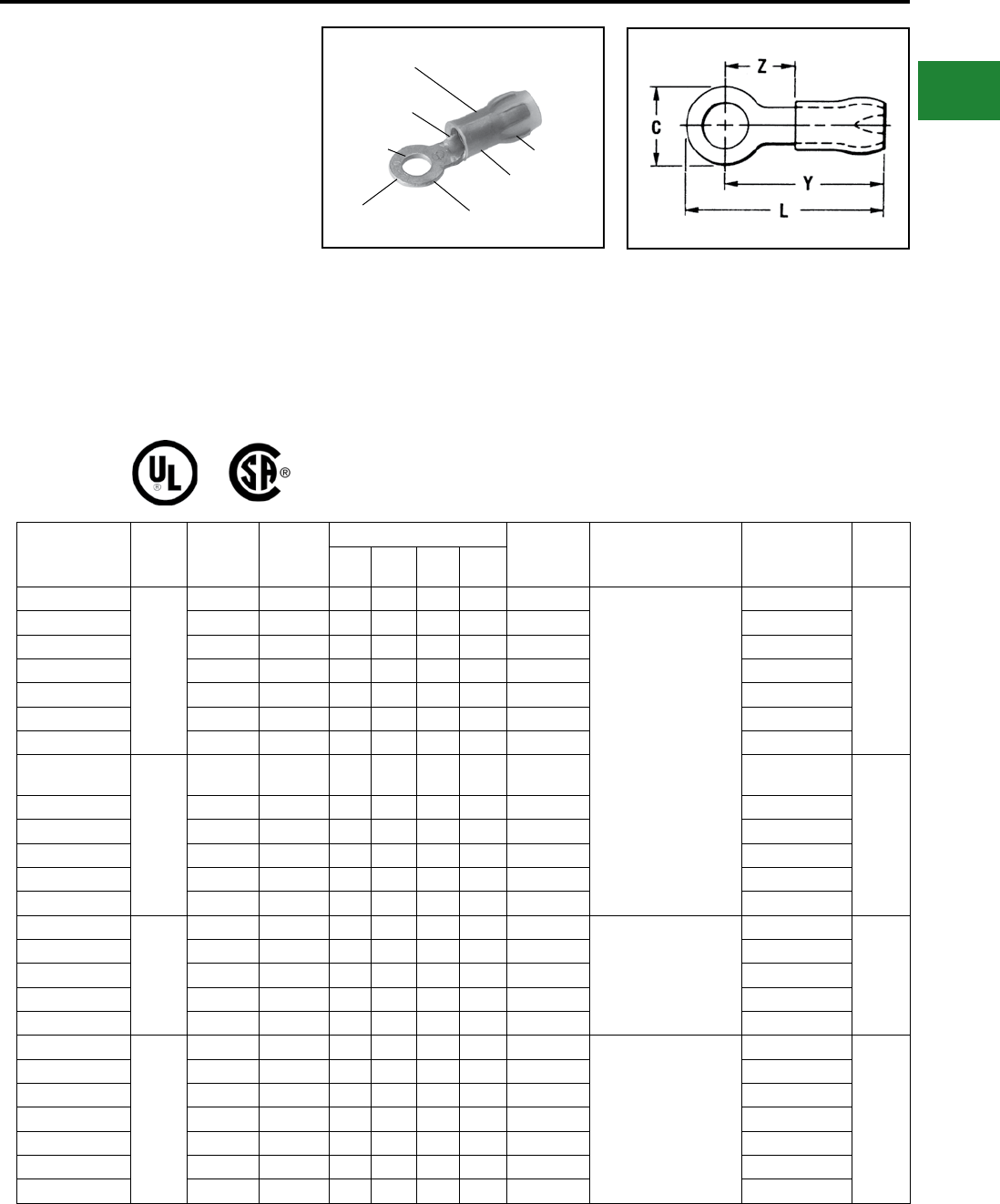
BURNDY®
Blue highlighted items are industry standard and most frequently ordered.
Canada: 1-800-387-6487 www.burndy.com US: 1-800-346-4175
Small Terminals
TYPE YAE-N
INSULUG™
Terminal - Nylon Insulated,
Ring Tongue Multi-Finger
Insulation Grip
600 Volts Max., 105° C Max.
INSULUG™ Type YAE-N nylon insulated
terminals are designed with a multi-nger
insulation grip for paper, EPR and other elastic or
hard to grip insulations. The metal ngers rmly
grip the insulation providing superior holding
characteristics, cable support and strain relief.
Type YAE-N terminals are rated 105° C and meet
military standard AS25036 Class 2 and SAE-
AS7928 requirements.
Features & Benets
• Multi-nger insulation grip
• Provides superior insulation holding
characteristics, especially on EPR and other
elastic-type insulations
• Brazed seam
• Provides stronger more durable
termination
• Manufactured of pure electrolytic copper
• Provides maximum conductivity, low
resistance and ductility for excellent crimp
forming properties
• Deep V groove, inner barrel serrations
• Provide optimum conductivity, reliability, and
holding power
• Smooth funnel entry
• Easy wire insertion
* Not UL Listed or CSA Certied.
WIRE CRIMP
MULTI-FINGER
INSULATION GRIP
DEEP “V”
SERRATIONS
TIN
PLATED
WIRE SIZE
RANGE RING
TONGUE
COLOR CODED
NYLON INSULATION
INSULATION
CRIMP
Catalog
Number
Wire
Range
Stud
Size
***SAE-
AS25036
Dimensions Bulk
Catalog
Number
Installation
Tooling
Tape Mounted
Catalog Number
2000/Reel
Wire
Strip
Length
CL
Max.
Y
Max.
Z
Min.
YAE18N26BOX
22 - 16
#4 — 0.22 0.78 0.70 0.19 YAE18N26
MR8-1A, MR8-33T-1
(no extra dies required)
M8ND with one of the
following dies:
N14HET-25V1
N10ET-9
N14HET-15
N10ET-23
or
Y10D
Y10-22
YAE18N26M
3/16"
YAE18N21BOX #4-#6 102 0.25 0.89 0.77 0.28 YAE18N21 YAE18N21M
YAE18N24BOX #6-#8 — 0.28 0.90 0.77 0.28 YAE18N24 YAE18N24M
YAE18NBOX #8-#10 103 0.31 0.92 0.77 0.28 YAE18N YAE18NM
YAE18N2BOX 1/4 150 0.45 1.10 0.88 0.40 YAE18N2 YAE18N2M
YAE18N3BOX 5/16 104 0.45 1.11 0.88 0.40 YAE18N3 YAE18N3M
YAE18N15BOX 3/8 105 0.53 1.19 0.93 0.43 YAE18N15 YAE18N15M
YAE14N43BOX
16 - 14
#4-#6 106
107 0.25 0.82 0.69 0.21 YAE14N43 YAE14N43M
3/16"
YAE14N1BOX #6-#8 153 0.31 0.92 0.75 0.28 YAE14N1 YAE14N1M
YAE14NBOX #8-#10 108 0.31 0.92 0.75 0.28 YAE14N YAE14NM
YAE14N2BOX 1/4 154 0.45 1.11 0.88 0.40 YAE14N2 YAE14N2M
YAE14N3BOX 5/16 109 0.45 1.11 0.88 0.40 YAE14N3 YAE14N3M
YAE14N4BOX 3/8 110 0.53 1.19 0.93 0.45 YAE14N4 YAE14N4M
YAE12N9BOX
14 - 12
#6-#8 — 0.31 1.06 0.90 0.29 YAE12N9
MR8-1A, MR8-33T-1
(no extra dies required)
Y10D
M8ND with N12HET-1
YAE12N9M
21/64"
YAE12N1BOX #6-#8 — 0.31 1.06 0.90 0.29 YAE12N1 YAE12N1M
YAE12N2BOX 1/4 — 0.45 1.25 1.02 0.40 YAE12N2 YAE12N2M
YAE12N7BOX #5 — 0.31 1.06 0.90 0.29 YAE12N7 YAE12N7M
YAE12NBOX #8-#10 — 0.31 1.06 0.90 0.29 YAE12N YAE12NM
YAE10N5BOX
12 - 10
#4-#6 111 0.38 1.15 0.96 0.28 YAE10N5 MR8-33T-1
(no extra dies required)
M8ND with one of the
following dies:
N10HET-15, N10ET-9,
N10ET-23
Y10D
Y10-22
YAE10N5M
3/8"
YAE10N11BOX #6-#8 156 0.38 1.17 0.98 0.30 YAE10N11 YAE10N11M
YAE10NBOX #8-#10 112 0.38 1.15 0.96 0.28 YAE10N YAE10NM
YAE10N3BOX 1/4 157 0.54 1.39 1.12 0.44 YAE10N3 YAE10N3M
YAE10N2BOX 5/16 113 0.54 1.39 1.12 0.44 YAE10N2 YAE10N2M
YAE10N4BOX 3/8 114 0.54 1.39 1.12 0.44 YAE10N4 YAE10N4M
YAE10N79BOX 1/2 — 0.72 1.50 1.20 0.58 YAE10N79 —
B-11
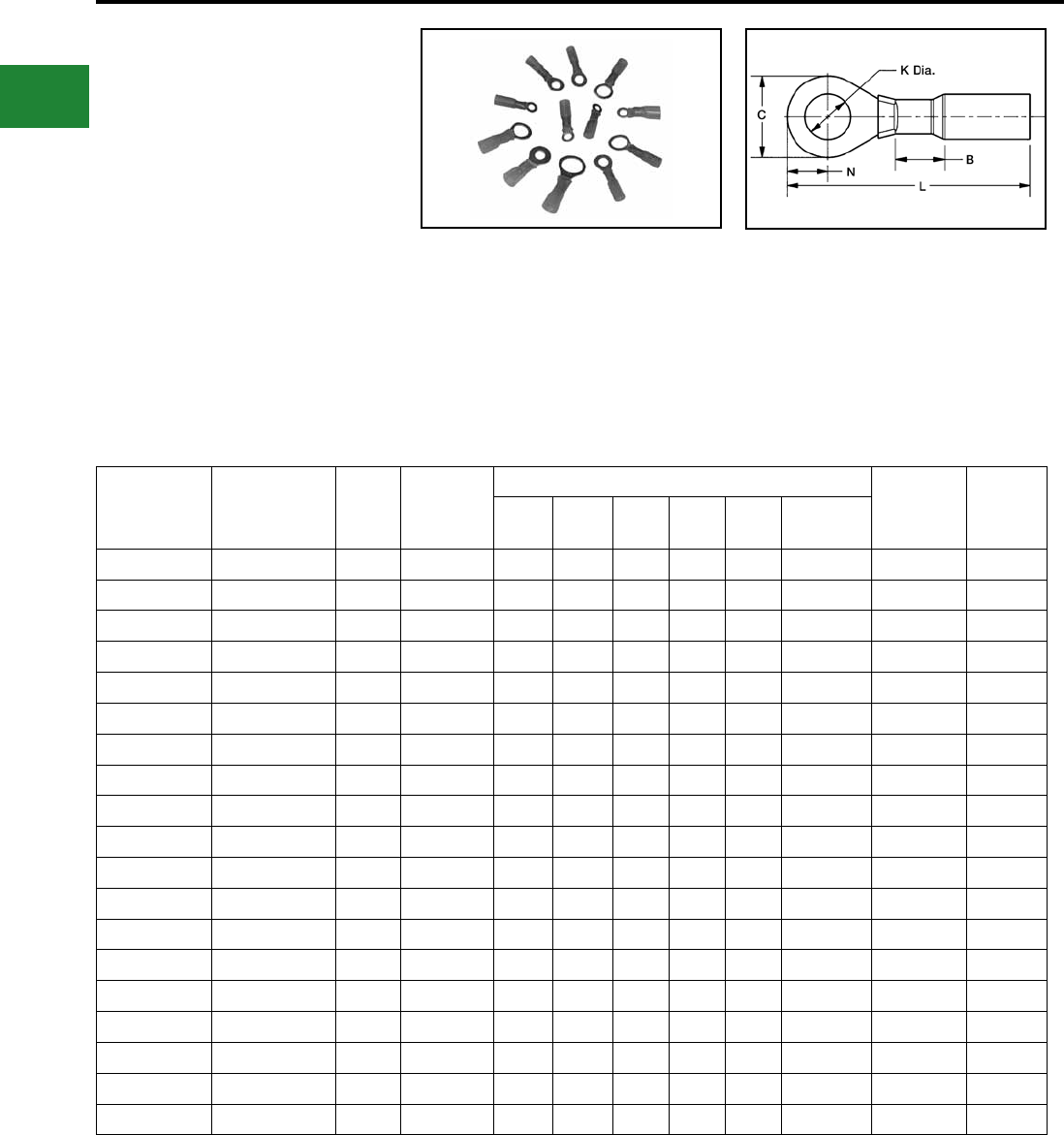
BURNDY®
Blue highlighted items are industry standard and most frequently ordered.
US: 1-800-346-4175 www.burndy.com Canada: 1-800-387-6487
Small Terminals
TYPE YHSA
HYDENT™ HEAT SHRINK
RING TERMINALS
For Use on Copper Conductor
Standard crimp terminals leave the wire exposed
allowing in moisture or other contaminants which
can result in corrosion. Corrosion reduces the
amount of current the wire can carry safely.
The integrity of the electrical system can
be compromised when unsealed electrical
connections are utilized. Heat shrink terminals
provide a durable seal blocking out contaminants
ensuring a better connection.
Features & Benets
• Made from pure copper, annealed for
maximum strength
• Color-coded, imprinted with wire size
• Serrated barrels offer maximum wire
contact and tensile strength
• Electro tin plated for corrosion resistance
• Wire Strip Length 5/16"
Catalog No.
(100/bag)
Catalog No.
(20/bag)
Stud
Size
Conductor
Size
Dimensions Installation
Tooling
Wire Strip
Length
B C K L N Tongue
Thickness
YHSA18K6 YHSA18K6RK 4-6 22-18 AWG 0.22 0.29 0.14 1.18 0.14 0.03 MR22 5/16
YHSA18K8 YHSA18K8RK 6-8 22-18 AWG 0.22 0.32 0.17 1.18 0.17 0.03 MR22 5/16
YHSA18K10 YHSA18K10RK 8-10 22-18 AWG 0.22 0.32 0.20 1.18 0.33 0.03 MR22 5/16
YHSA18K14 YHSA18K14RK 1/4 22-18 AWG 0.22 0.47 0.27 1.40 0.38 0.03 MR22 5/16
YHSA18K516 YHSA18K516RK 5/16 22-18 AWG 0.22 0.47 0.33 1.40 0.23 0.04 MR22 5/16
YHSA18K38 YHSA18K38RK 3/8 22-18 AWG 0.22 0.56 0.40 1.45 0.28 0.03 MR22 5/16
YHSA14K6 — 4-6 16-14 AWG 0.22 0.30 0.14 1.18 0.15 0.04 MR22 5/16
YHSA14K8 YHSA14K8RK 6-8 16-14 AWG 0.22 0.32 0.17 1.18 0.16 0.03 MR22 5/16
YHSA14K10 YHSA14K10RK 8-10 16-14 AWG 0.22 0.32 0.20 1.18 0.17 0.03 MR22 5/16
YHSA14K14 YHSA14K14RK 1/4 16-14 AWG 0.22 0.47 0.26 1.40 0.23 0.03 MR22 5/16
YHSA14K516 — 5/16 16-14 AWG 0.22 0.47 0.33 1.35 0.23 0.04 MR22 5/16
YHSA14K38 YHSA14K38RK 3/8 16-14 AWG 0.22 0.56 0.40 1.45 0.28 0.03 MR22 5/16
YHSA10K6 — 4-6 12-10 AWG 0.22 0.34 0.14 1.15 0.17 0.04 MR22 5/16
YHSA10K8 — 6-8 12-10 AWG 0.22 0.34 0.17 1.15 0.17 0.04 MR22 5/16
YHSA10K10 YHSA10K10RK 8-10 12-10 AWG 0.22 0.34 0.20 1.15 0.18 0.04 MR22 5/16
YHSA10K14 YHSA10K14RK 1/4 12-10 AWG 0.22 0.56 0.26 1.45 0.15 0.04 MR22 5/16
YHSA10K516 — 5/16 12-10 AWG 0.22 0.56 0.34 1.45 0.28 0.04 MR22 5/16
YHSA10K38 YHSA10K38RK 3/8 12-10 AWG 0.22 0.56 0.40 1.45 0.28 0.04 MR22 5/16
YHSA10K12 YHSA10K12RK 1/2 12-10 AWG 0.22 0.69 0.53 1.69 0.36 0.04 MR22 5/16
B-12
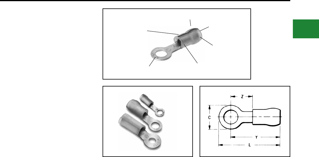
BURNDY®
Blue highlighted items are industry standard and most frequently ordered.
Canada: 1-800-387-6487 www.burndy.com US: 1-800-346-4175
Small Terminals
TYPE YAES-K
INSULUG™
200 MEGARADS, –60° THROUGH
150° C, 600 VOLTS
The type YAES-K, radiation resistant insulated
terminals are designed and have been tested to
meet the requirements for class 1E critical circuits
as set by the Nuclear Regulatory Commission
(NRC). Additional testing for compatibility under
loss of coolant accident (LOCA) conditions with
cross-link polyethylene (XLP) and HYPALON®
insulations was completed successfully.
Compatibility with ethylene propylene rubber
(EPR) insulation was determined by analysis.
Each terminal is manufactured of pure electrolytic
copper per QQ-C 576 and bright tin-plated per
MIL-T-10727 and meets or exceeds MIL-T-7928
using stranded copper AWG wire. The KYNAR®
insulation offers 200 megarad radiation resistance.
The Type YAES-K radiation resistant insulated
terminals are suitable for class 1E critical circuits and
non-critical nuclear associated applications.
Features & Benets
• Insulation provides 200 megarad
radiation resistance plus successfully
tested for insulation compatibility
• An integral one-piece copper barrel/
insulation grip and wire strain relief
design
◊ Provides improved physical strength
characteristics over a multi-piece design.
• The insulation is locked in place
◊ The insulation will not move or twist
off, thereby maintains proper dielectric
values.
• Manufactured from pure electrolytic
copper
◊ Provides maximum conductivity, low
resistance and ductility for excellent
crimp forming properties.
• Bright tin-plated per MIL-T-10727
◊ Provides durable long-lasting
resistance to corrosion.
• Deep inner barrel serrations
◊ Provides excellent electrical
conductivity and tensile strength values.
• Brazed seam
◊ Provides a stronger barrel design to
minimize any possible splitting and
eliminates folding.
• Smooth funnel entry
◊ Easy wire insertion.
• Color coded terminals
◊ Provides easy wire size identication
and inspection.
• Coded raised dots in the die area of the
connection after compression
◊ Provides visual identication that the
correct tool and die were used for
proper installation.
• Inspection hole
◊ Permits visual check for proper wire
insertion.
• Ring tongue design
◊ Provides a secure termination under
screw head that cannot be removed
without the complete removal of the
screw.
• Multiple terminals may be stacked on a
common stud easily
◊ Provides exibility and versatility.
COLOR CODED
KYNAR INSULATION
BRAZED SEAM
ON BARREL
SMOOTH
FUNNEL
ENTRY
WIRE SIZE
INTEGRAL
SUPPORT
INSULATION
KYNAR - is a registered trademark of the Pennwalt
Corp. for Polyvinylindene Floride (PVF2)
HYPALON - Is a registered trademark of the E.I.
DuPont deNemours & Co., Inc.
B-13
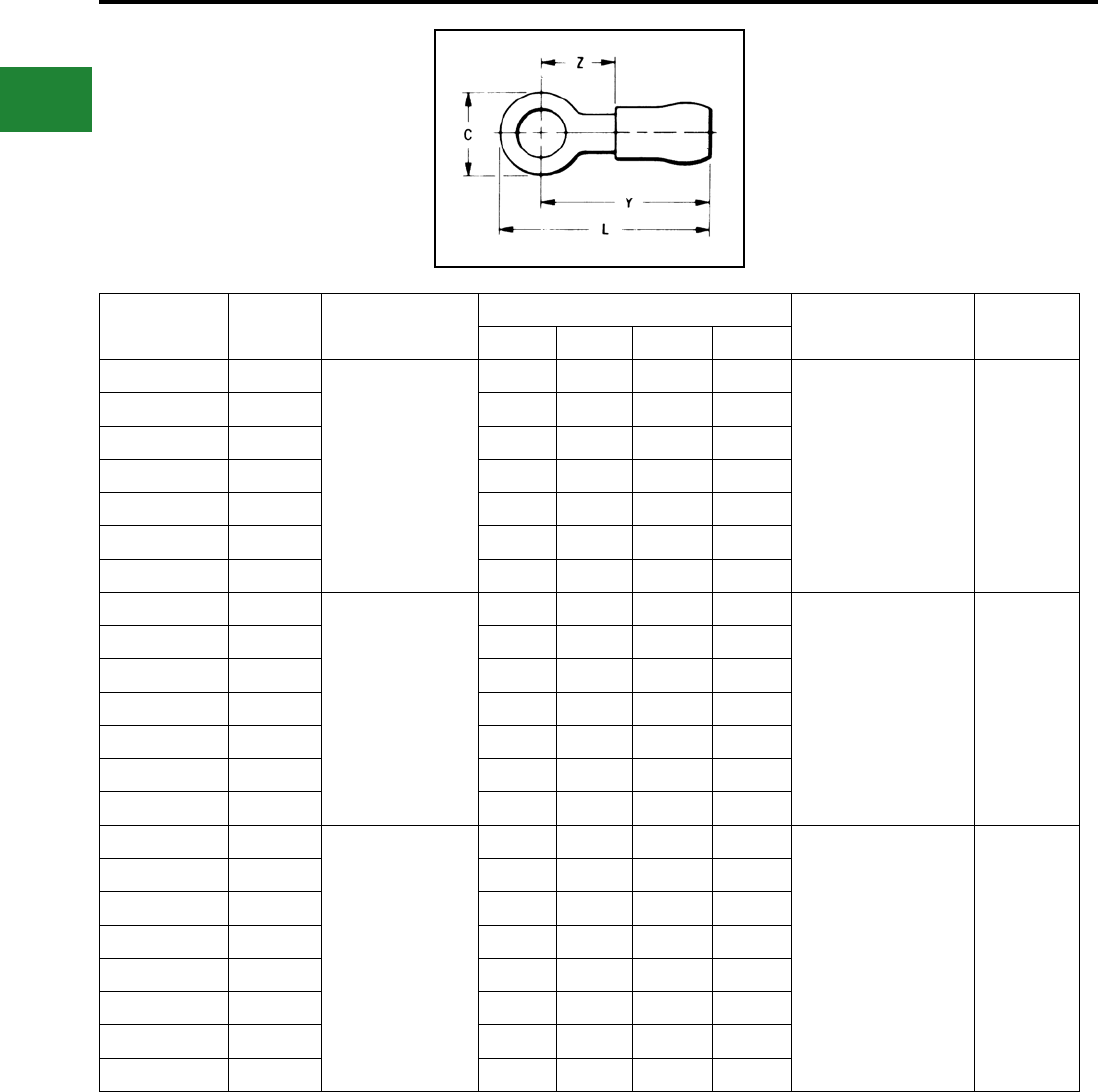
BURNDY®
Blue highlighted items are industry standard and most frequently ordered.
US: 1-800-346-4175 www.burndy.com Canada: 1-800-387-6487
Small Terminals
TYPE YAES-K
(Continued)
INSULUG™
200 MEGARADS, –60° THROUGH
150° C, 600 VOLTS
Catalog
Number
Stud
Size
Conductor
Size
Dimensions Installation
Tooling
Wire Strip
Length
C L Max. Y Max. Z Max.
YAES18K1 #6
22-18 AWG str.
Max. Insul.
Dia. Accom.: 0.12
Color Code: Red
0.23 0.76 0.64 0.20
Ratchet Tool:
MR10G6
Crimp Mark:
(1) Small Dot
Red Groove
Calibration Gauge:
PG-373-1
7/32"
YAES18K2 #6 0.25 0.87 0.74 0.29
YAES18K49 #8 0.32 0.91 0.76 0.29
YAES18K3 #10 0.32 0.91 0.76 0.29
YAES18K50 1/4 0.46 1.09 0.86 0.41
YAES18K4 5/16 0.46 1.09 0.87 0.41
YAES18K5 3/8 0.54 1.17 0.91 0.45
YAES14K6 #6
16-14 AWG str.
Max. Insul.
Dia. Accom.: 0.15
Stock Thickness: 0.03
Color Code: Blue
0.26 0.77 0.65 0.22
Ratchet Tool:
MR10G6
Crimp Mark:
(2) Small Dots
Blue Groove
Calibration Gauge:
PG-371-1
7/32"
YAES14K7 #6 0.32 0.91 0.76 0.29
YAES14K53 #8 0.32 0.91 0.76 0.29
YAES14K8 #10 0.32 0.91 0.76 0.29
YAES14K54 1/4 0.46 1.09 0.86 0.41
YAES14K9 5/16 0.46 1.09 0.86 0.41
YAES14K10 3/8 0.53 1.18 0.91 0.45
YAES10K11 #6
12-10 AWG str.
Max. Insul.
Dia. Accom.: 0.21
Stock Thickness: 0.04
Color Code: Yellow
0.38 1.12 0.94 0.26
Ratchet Tool:
MR10G6
Crimp Mark:
(1) Large Dot
Calibration Gauge:
PG-372-1
3/8"
YAES10K11T1 #6 0.31 1.09 0.94 0.26
YAES10K56 #8 0.38 1.12 0.94 0.26
YAES10K12 #10 0.38 1.12 0.94 0.26
YAES10K57 1/4 0.54 1.32 1.06 0.37
YAES10K13 5/16 0.54 1.32 1.06 0.37
YAES10K14 3/8 0.58 1.34 1.05 0.40
YAES10K58 1/2 0.72 1.41 1.06 0.45
B-14
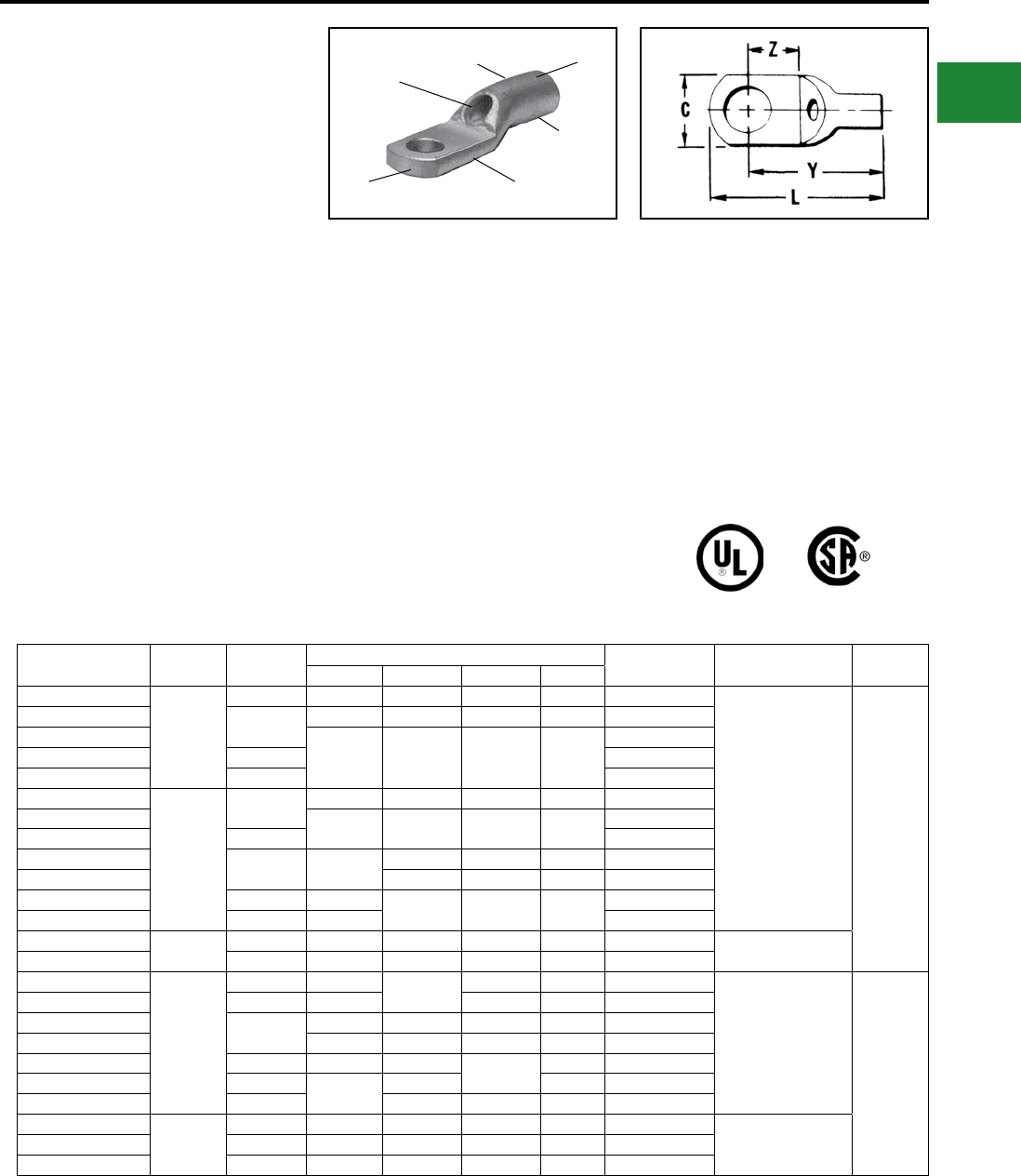
BURNDY®
Blue highlighted items are industry standard and most frequently ordered.
Canada: 1-800-387-6487 www.burndy.com US: 1-800-346-4175
Small Terminals
TYPES YAV BOX
AND YAV
HYLUG™
Seamless Uninsulated Compression
Heavy Duty Ring Tongue Terminal
HYLUG™ type YAV is a seamless, heavy duty
uninsulated compression ring tongue terminal
manufactured from pure electrolytic copper
tubing and is for use on copper commercial (code)
cable, type AN aircraft cable and extra exible
conductors. Because of its seamless design,
the YAV HYLUG™ also accommodates solid
conductors.
The seamless tubing produces a double thick
tongue and a strong connector for demanding
applications that require high reliability.
Applications include industrials, hospitals, electric
utilities, aircraft, shipboard and marine, computers,
steel mills, mining equipment and other equipment
that is subject to vibration or requiring depandable
electrical performance.
The YAV HYLUG™ terminals meet the
requirements of SAE-AS7928.
Features & Benets
• Manufactured from seamless pure electrolytic
copper tubing
• Provides maximum conductivity, low resistance
and excellent ductility for crimping
• Seamless tubular crimp barrel design
• No seams to split resulting in a very high
quality electrical connection, also can be used
on solid conductor
• Double thick tongue
• Provides a very strong terminal tongue
• Produced from tubular copper
• Extra copper material assures the
compression connector will operate cooler
than the conductors it connects
• Internally bevelled barrel
• Provides easy cable entry, especially for
exible conductors
• Inspection hole
• Provides easy visual check for proper
conductor insertion
• Electro-tin plated
• Provides long lasting durable corrosion
resistance
• Nickel plating available, add “NK” sufx
• Nickel plated HYLUG™ provide high
termperature applications up to 650° F
continuous service and 750° F intermittent
service
Catalog
Number
Wire
Range
Stud
Size
Dimensions Bulk Catalog
Number
Installation
Tooling
Wire Strip
Length
C L Max. Y Max. Z Min.
YAV18-T4BOX 22-18
Str.
and
Sol.
3,4 0.19 0.59 0.54 0.16 YAV18T4
Non-Ratchet:
Y10D, Y10-22
Ratchet:
MR8G98, MR8-9Q,
Y8MRB-1, MR20,
MRE1022B
9/32"
YAV18-L33BOX 4-6 0.25 0.63 0.55 0.18 YAV18L33
YAV18-T5BOX
0.31 0.76 0.61 0.24
YAV18T5
YAV18-T1BOX 6-8 YAV18T1
YAV18BOX 8-10 YAV18
YAV14-L33BOX
20-14
Str.
20-12
Sol.
4-6 0.25 0.67 0.59 0.18 YAV14L33
YAV14-T5BOX 0.31 0.79 0.64 0.24 YAV14T5
YAV14-T1BOX 6-8 YAV14T1
YAV14-L36BOX 8-10 0.29 0.70 0.59 0.18 YAV14L36
YAV14BOX 0.79 0.64 0.24 YAV14
YAV14-T2BOX 1/4 0.40 0.99 0.75 0.32 YAV14T2
YAV14-T3BOX 5/16 0.44 YAV14T3
YAV12-G2BOX ■ † 14-12
Str.
8-10 0.30 0.78 0.67 0.24 YAV12G2 Y10D, Y8MRB-1,
M8ND w/N14HT
YAV12-G3BOX ■ 1/4 0.34 1.00 0.76 0.33 YAV12G3
YAV10-T7BOX 14 Str.
12-10
Str.
and
Sol.
4-6 0.28 0.93 0.78 0.24 YAV10T7* Non-Ratchet:
Y10D, Y10-22
Ratchet:
MR8G98, MR8-9Q,
Y8MRB-1, MR20,
N10HT, N10HT-24,
MRE1022B
7/16"
YAV10-T11BOX 6-8 0.38 0.79 0.26 YAV10T11
YAV10-L36BOX 8-10 0.29 0.86 0.71 0.23 YAV10L36
YAV10BOX 0.36 0.97 0.79 0.25 YAV10*
YAV10-T3BOX 1/4 0.45 1.10 0.87 0.32 YAV10T3
YAV10-T2BOX 5/16 0.53 1.13 0.31 YAV10T2*
YAV10-T4BOX 3/8 1.20 0.88 0.36 YAV10T4*
YAV9C-L36BOX 10-9
Str.
8-10 0.31 0.94 0.83 0.15 YAV9CL36 Ratchet:
MR8-9Q,
Y8MRB-1
YAV9C-T9BOX 1/4 0.44 1.15 0.95 0.31 YAV9CT9
YAV9C-T4BOX 5/16 0.52 1.23 1.02 0.36 YAV9CT4
■ Use #14 groove
† UL Listed for 14 Str. to #10 Sol. & Str. when installed with MR8G98 and Y8MRB-1 tools only.
* Class 1 & 2 connectors
INSPECTION
HOLE
SEAMLESS
BARREL
BEVELED
ENTRY
CRIMP
DOUBLE THICK
TONGUE
ELECTRO-TIN
PLATED
B-15
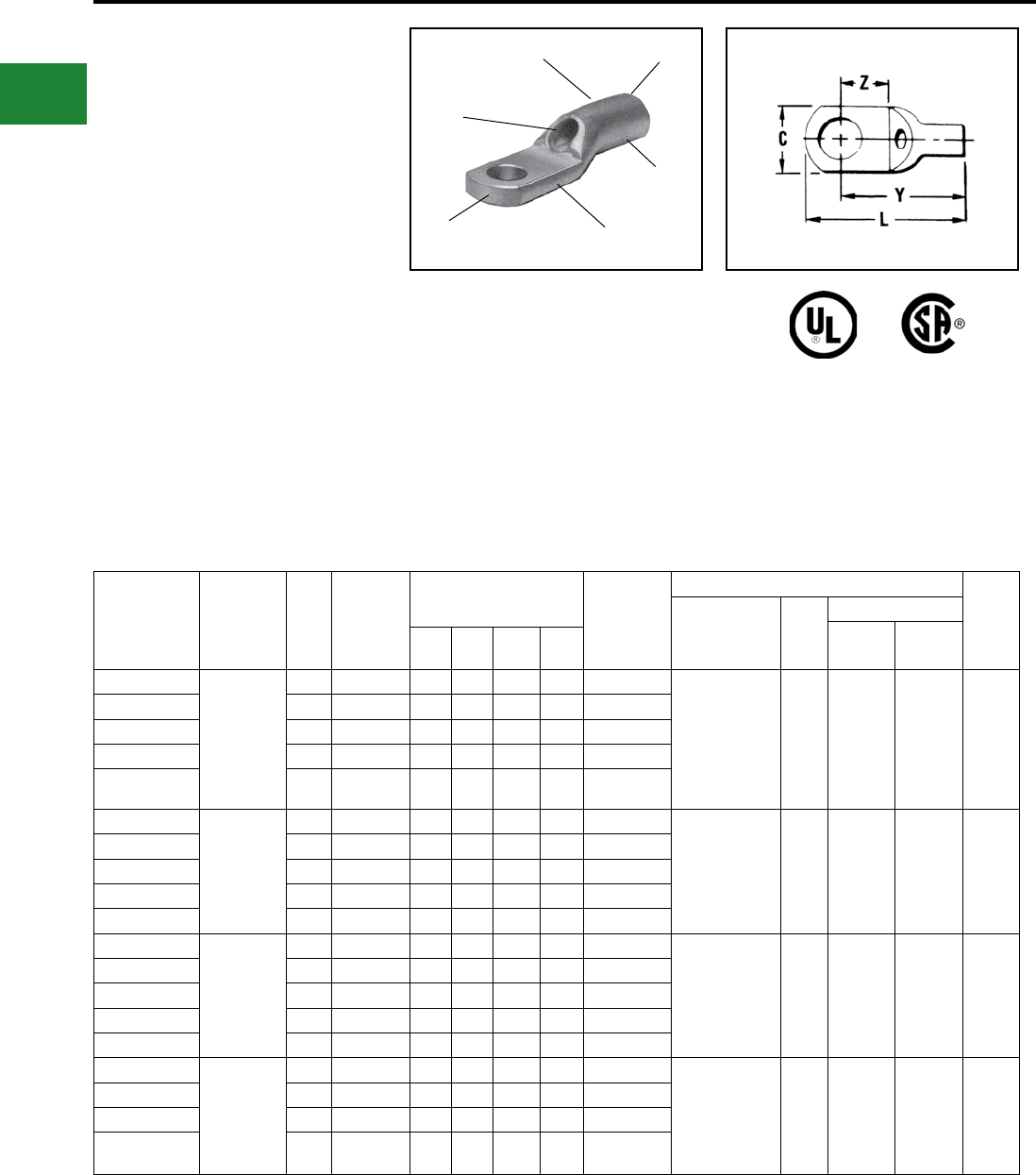
BURNDY®
Blue highlighted items are industry standard and most frequently ordered.
US: 1-800-346-4175 www.burndy.com Canada: 1-800-387-6487
Small Terminals
TYPES YAV-L BOX AND
YAV-L
HYLUG™
Large Size Uninsulated Compression
Terminals Seamless Uninsulated
Compression Ring Tongue Terminal
#8-4/0 Str. Copper
HYLUG™ Type YAV is a seamless, heavy duty
uninsulated compression terminal manufactured
from electrolytic copper and is for use on Type
AN aircraft cable, extra exible conductors and
commercial (code) conductors. The seamless
tubing produces a double thick tongue and
seamless barrel design provides a strong
connector for demanding applications requiring
high reliability.
Applications include aircraft, industrials, hospitals,
electric utilities, marine, computers, and other
equipment subject to vibration or requiring
dependable electrical performance. The YAV
HYLUG™ terminals meet the requirements of
SAE-AS7928 and are listed per AS20659 for use
with copper aircraft cable per MIL-W-5086
The benets of YAV-L connectors are the same as
YAV connectors for stranded conductors.
Catalog
Number
Wire Range
(AWG/kcmil)
Stud
Size
SAE -
AS20659
Dash No. †
Dimensions (Inches) Bulk
Catalog
Number
Installation Tooling
Wire
Strip
Length
HYTOOL™ ■ Die
Index
HYPRESS™
Y29B,
Y29NC
Y35, Y39,
Y750 ▲
CL
Max.
Y
Max.
Z
Max.
YAV8C-LBOX
8
Aircraft
AN 8
Flex
8-10 -107 0.41 1.15 0.94 0.28 YAV8C-L● Non-Ratchet:
MY29-11
Ratchet:
MR4C, MR8-9Q,
Y8MRB-1, M8ND
w/ N8CT Die Set
38
DV8L-1
Nest
Y29PL
Indentor
(1) Crimp
UV8L
Nest
Y34PL
Indentor
(1) Crimp
1/2"
YAV8C-L1BOX 1/4 -141 0.46 1.22 0.99 0.32 YAV8C-L1●
YAV8C-L2BOX 5/16 -108 0.57 1.30 1.01 0.34 YAV8C-L2
YAV8C-L3BOX 3/8 -129 0.57 1.30 1.01 0.34 YAV8C-L3●
YAV8C-L4BOX 1/2 -142 0.73 1.52 1.14 0.48 YAV8C-L4●
YAV6C-L1BOX
5 & 6
Aircraft
AN 5 & 6
Flex
8-10 -130 0.46 1.31 1.06 0.29 YAV6C-L1● Non-Ratchet:
MY28,
MY29-11
Ratchet:
MR4C
39
DV6L
Nest
Y29PL
Indentor
(1) Crimp
UV6L
Nest
Y34PLA
Indentor
(1) Crimp
1/2"
YAV6C-LBOX 1/4 -109 0.50 1.28 1.06 0.29 YAV6C-L●
YAV6C-L4BOX 5/16 -131 0.58 1.43 1.13 0.35 YAV6C-L4●
YAV6C-L2BOX 3/8 -110 0.60 1.43 1.13 0.36 YAV6C-L2●
YAV6C-L10BOX 1/2 -143 0.74 1.64 1.26 0.49 YAV6C-L10
YAV4C-L3BOX
4
Aircraft
AN 4
Flex
8-10 -144 0.55 1.37 1.11 0.28 YAV4C-L3● Non-Ratchet:
MY28,
MY29-11
Ratchet:
MR4C
40
DV4L
Nest
Y29PL
Indentor
(1) Crimp
UV4L
Nest
Y34PLA
Indentor
(1) Crimp
1/2"
YAV4C-LBOX 1/4 -111 0.55 1.37 1.11 0.28 YAV4C-L
YAV4C-L4BOX 5/16 -132 0.63 1.48 1.17 0.33 YAV4C-L4●
YAV4C-L2BOX 3/8 -112 0.63 1.48 1.17 0.33 YAV4C-L2●
YAV4C-L5BOX 1/2 -145 0.73 1.68 1.30 0.47 YAV4C-L5
YAV2C-L1BOX
2
Aircraft
AN 2
Flex
1/4 -113 0.69 1.72 1.37 0.35 YAV2C-L1●
Non-Ratchet:
MY28,
MY29-11
41
DV2L
Nest
Y29PL
Indentor
(1) Crimp
UV2L
Nest
Y34PLA
Indentor
(1) Crimp
5/8"
YAV2C-L2BOX 5/16 -147 0.69 1.72 1.37 0.35 YAV2C-L2●
YAV2C-LBOX 3/8 -114 0.69 1.72 1.37 0.35 YAV2C-L●
YAV2C-L4BOX 1/2 -133 0.77 1.88 1.49 0.46 YAV2C-L4
† Class 1.
● Available in (90°) right angle design. Sufx “RS”
Replaces Sufx “L”.
▲Use Y35P3 Indentor Adapter with Y35 and Y39 Tool.
■ Bench Mount Adapter - Cat. BMY-BCH-MT is available for Type “MY” HYTOOLS™.
Add “NK” sux for nickel plated HYLUGs™ for high temperature applications up to 650° F
continuous service and 750° intermittent service.
SEAMLESS
BARREL
BEVELED
ENTRY
INSPECTION
HOLE
ELECTRO-TIN
PLATED DOUBLE THICK
TONGUE
CRIMP
B-16
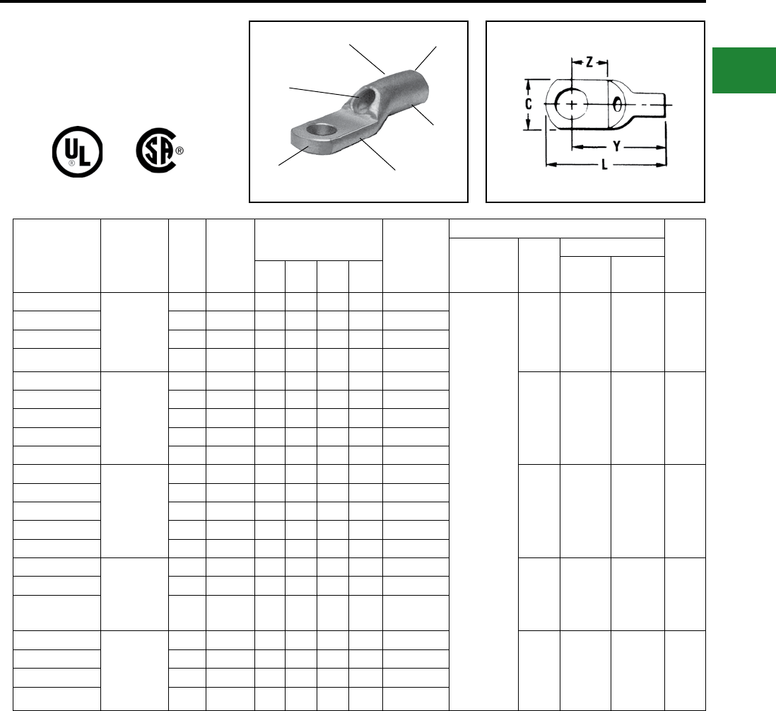
BURNDY®
Blue highlighted items are industry standard and most frequently ordered.
Canada: 1-800-387-6487 www.burndy.com US: 1-800-346-4175
Small Terminals
TYPES YAV-L BOX AND
YAV-L (Continued)
HYLUG™
Catalog
Number
Wire Range
(AWG/kcmil)
Stud
Size
SAE -
AS20659
Dash
No. †
Dimensions (Inches) Bulk
Catalog
Number
Installation Tooling
Wire
Strip
Length
■
HYTOOL™
Die
Index
HYPRESS™
Y29B,
Y29NC
Y35, Y39,
Y750 ▲
CL
Max.
Y
Max.
Z
Max.
YAV1C-L1BOX 1
Aircraft
AN 1
Flex
1/4 -115 0.76 1.84 1.45 0.38 YAV1C-L1 ●
Non-Ratchet:
MY28,
MY29-11
42
DV1L
Nest
Y29PL
Indentor
(1) Crimp
UV1L
Nest
Y34PLA
Indentor
(1) Crimp
5/8"
YAV1C-L2BOX 5/16 -149 0.76 1.84 1.45 0.38 YAV1C-L2 ●
YAV1C-LBOX 3/8 -116 0.76 1.84 1.45 0.38 YAV1C-L
YAV1C-L3BOX 1/2 -134 0.86 1.97 1.54 0.46 YAV1C-L3
YAV25-L1BOX
1/0
Aircraft
AN 1/0
Flex
1/4 -117 0.83 2.01 1.61 0.43 YAV25-L1
43
DV25L
Nest
Y29PR
Indentor
(1) Crimp
UV25L
Nest
Y34PA
Indentor
(1) Crimp
11/16"
YAV25-L2BOX 5/16 -151 0.83 2.03 1.61 0.43 YAV25-L2
YAV25-LBOX 3/8 -118 0.83 2.03 1.61 0.43 YAV25-L ●
YAV25-L3BOX 1/2 -135 0.88 2.09 1.64 0.46 YAV25-L3 ●
YAV25-L4BOX 5/8 — 0.88 2.31 1.80 0.62 YAV25-L4
YAV26-L1BOX
2/0
Aircraft
AN 2/0
Flex
1/4 -153 0.93 2.32 1.85 0.48 YAV26-L1
44
DV26L
Nest
Y29PR
Indentor
(1) Crimp
UV26L
Nest
Y34PA
Indentor
(1) Crimp
13/16"
YAV26-L2BOX 5/16 -119 0.93 2.32 1.85 0.48 YAV26-L2
YAV26-LBOX 3/8 -120 0.93 2.32 1.85 0.48 YAV26-L ●
YAV26-L3BOX 1/2 -136 0.93 2.32 1.85 0.48 YAV26-L3 ●
YAV26-L12BOX 5/8 — 0.93 2.52 1.99 0.62 YAV26-L12
YAV27-LBOX 3/0
Aircraft
AN 3/0
Flex
3/8 -121 1.03 2.45 1.93 0.52 YAV27-L ●
45 —
UV27L
Nest
Y34PA
Indentor
(1) Crimp
13/16"
YAV27-L1BOX 1/2 -122 1.03 2.45 1.93 0.52 YAV27-L1
YAV27-L15BOX 5/8 — 1.03 2.60 2.03 0.62 YAV27-L15
YAV28-LBOX 4/0
Aircraft
AN 4/0
Flex
3/8 -123 1.12 2.72 2.16 0.60 YAV28-L
46 —
UV28L
Nest
Y34PA
Indentor
(1) Crimp
7/8"
YAV28-L12BOX 1/2 -124 1.12 2.72 2.16 0.60 YAV28-L12
YAV28-L13BOX 5/8 -159 1.12 2.72 2.16 0.60 YAV28-L13
YAV28-L14BOX 3/4 -160 1.23 2.95 2.33 0.78 YAV28-L14
† Class 1.
● Available in (90°) right angle design. Sufx "RS"
Replaces Sufx "L".
▲Use Y35P3 Indentor Adapter with Y35 and Y39 Tool.
■ Bench Mount Adapter - Cat. BMY-BCH-MT is available
for Type "MY" HYTOOLS™.
Add "NK" sux for nickel plated HYLUGs™ for high
temperature applications up to 650° F continuous
service and 750° intermittent service.
SEAMLESS
BARREL
BEVELED
ENTRY
INSPECTION
HOLE
ELECTRO-TIN
PLATED DOUBLE THICK
TONGUE
CRIMP
B-17
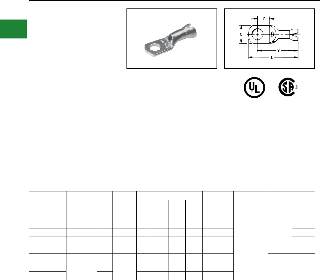
BURNDY®
Blue highlighted items are industry standard and most frequently ordered.
US: 1-800-346-4175 www.burndy.com Canada: 1-800-387-6487
Small Terminals
TYPES YAV-H BOX AND
YAV-H
HYLUG™
Seamless Uninsulated Compression
Ring Tongue Terminal With Shroud
The type YAV-H HYLUG™ is a seamless heavy
duty uninsulated compression ring tongue
terminal with a shroud for an insulation grip and
cable support. They are manufactured from
pure electrolytic copper tubing for use on copper
commercial (code) cable, Type AN aircraft cable
and extra exible conductors.
The seamless design produces a double thick
tongue and the seamless barrel provides a strong
highly reliable connection. Meets the requirements
of SAE-AS7928. The benets of the Type YAV
apply to the YAV-H HYLUG™.
Catalog
Number
Wire Range
(AWG/kcmil)
Stud
Size
Max.
Insul. Dia.
Accom.
Dimensions
Bulk Catalog
Number
Installation
Tooling Dies
Wire
Strip
Length
C L Max. Y Max. Z Min.
YAV18-HBOX 22-18 8 - 10 0.120" 0.31 0.88 0.76 0.24 YAV18H Plier:
Y10D, Y10-22*
Ratchet:
MR8-G98,
MR8-9Q,
Y8MRB-1*,
MR20, M8ND,
MRE1022B
M8ND,
with
N14HT,
N14HT-5
Die
9/32"
YAV14-H1BOX 16-14 6 - 8 0.150" 0.31 0.92 0.80 0.24 YAV14H1 9/32"
YAV14-HBOX 20-14 8 - 10 0.150" 0.31 0.95 0.80 0.24 YAV14H 9/32"
YAV14-H2BOX 1/4 0.42 1.14 0.90 0.32 YAV14H2
YAV10-H25BOX
12-10
6 - 8
0.192"
0.31 1.00 0.90 0.24 YAV10H25
M8ND,
N10HT-24 7/16"
YAV10-HBOX 8 - 10 0.38 1.05 0.91 0.24 YAV10H
YAV10-H3BOX 1/4 0.47 1.22 0.99 0.32 YAV10H3
Features & Benets
• Shroud/insulation grip cable support
and strain relief
◊ Protects the wire against breaking
under vibration or exing conditions
• Electro-tin plated
◊ Provides long-lasting corrosion
resistance
* For conductor crimp only.
B-18
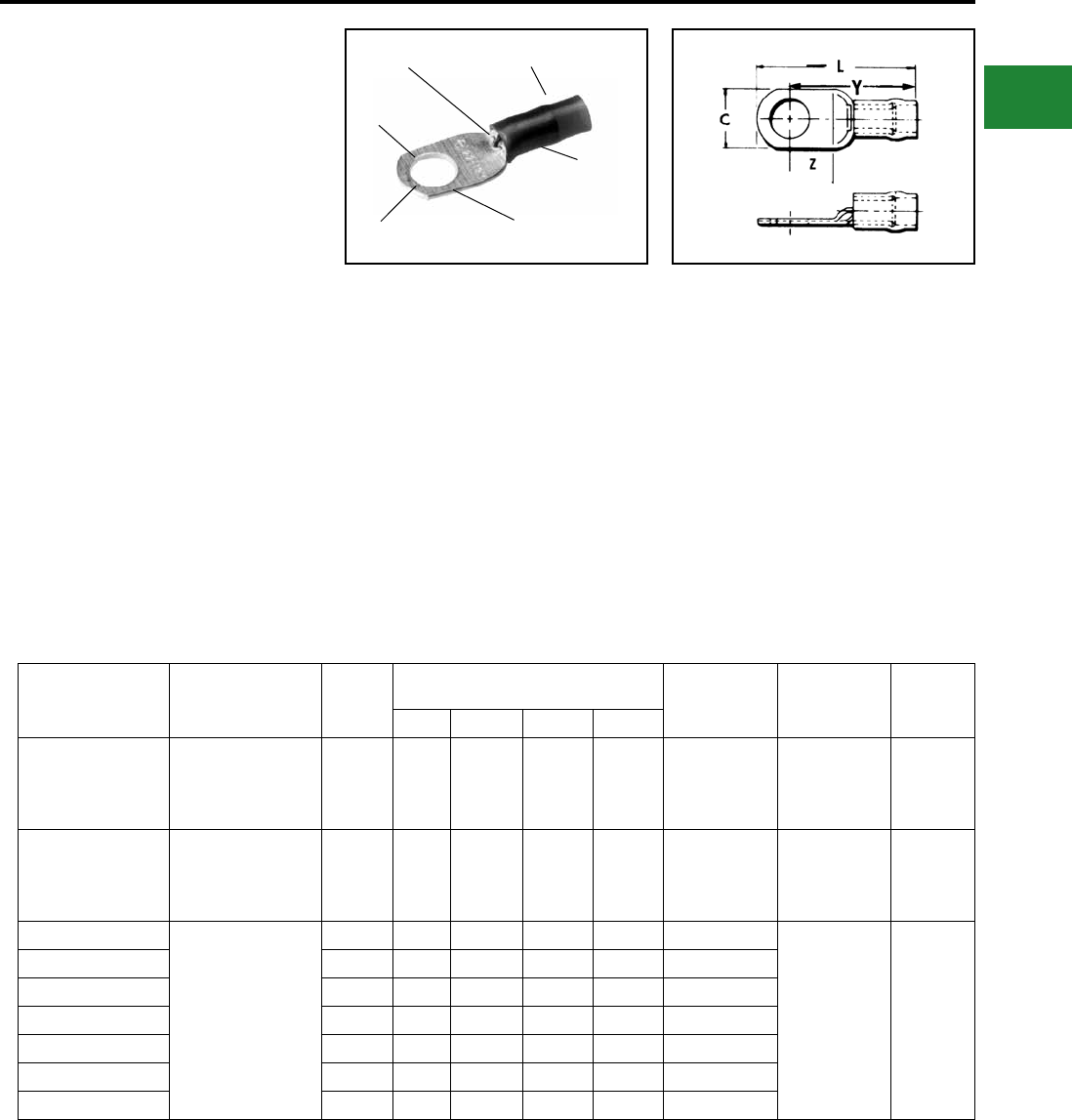
BURNDY®
Blue highlighted items are industry standard and most frequently ordered.
Canada: 1-800-387-6487 www.burndy.com US: 1-800-346-4175
Small Terminals
TYPES YAEV
AND YAEV-L
INSULUG™
Terminal — Nylon Insulated —
Ring-Tongue
300 Volts Max., 105° C Max.
The INSULUG™ type YAEV is designed for
very demanding high vibration applications
encountered in aircraft and aboard ships as well as
motor lead applications in hospitals, industrials and
generating plants. The nylon insulated seamless,
electrolytic copper barrel with double thick tongue
provides an extra strong insulated connection. The
terminal is rated 105°C and meets MIL-T-7928
requirements.
Features & Benets
• Double thick tongue.
◊ Provides maximum reliability and
electrical capacity plus an extra strong
terminal tongue.
• Manufactured from one-piece pure electrolytic
copper.
◊ Provides high conductivity, low
resistance with no seams to split plus
ductility for excellent crimp forming
properties.
• Electro-tin plated.
◊ Provides long-lasting corrosion
resistance.
• Nylon insulation is locked in place.
◊ Insulation will not move or twist off
• 300 volt nylon insulation.
◊ High dielectric strength and stability in
demanding oily environmental
conditions.
• Color Coded.
◊ Provides quick, easy wire size
connector selection.
Catalog
Number
Wire Range
AWG, AN
Aircraft
Stud
Size
Dimensions Bulk
Catalog
Number
Installation
Tooling
Wire
Strip
Length
C Z Min. Y Max. L Max.
YAEV18BOX
22-18
Max. Insul.
Dia. Accom.: .125
Color Code: Red
8-10 0.31 0.24 0.77 0.91 YAEV18
Ratchet:
MR8D94,
MRE1022NV
1/4"
YAEV14BOX
18-14
Max. Insul.
Dia. Accom.: .154
Color Code: Blue
8-10 0.31 0.24 0.81 0.94 YAEV14
Ratchet:
MR8D94,
MRE1022NV
1/4"
YAEV10-T7BOX
12-10
Max. Insul.
Dia. Accom.: .209
Color Code: Yellow
4-6 0.30 0.24 0.95 1.12 YAEV10-T7
Ratchet:
MR8D94
MR8-33-T1
M8ND with
N10ET-9 Die
MR4 10M
MRE1022NV
5/16"
YAEV10-T11BOX 6-8 0.37 0.26 0.97 1.16 YAEV10-T11
YAEV10BOX 8-10 0.37 0.26 0.97 1.16 YAEV10
YAEV10-L36BOX 8-10 0.30 0.18 0.89 1.04 YAEV10-L36
YAEV10-T3BOX 1/4 0.47 0.38 1.12 1.30 YAEV10-T3
YAEV10-T2BOX 5/16 0.53 0.31 1.12 1.36 YAEV10-T2
YAEV10-T4BOX 3/8 0.56 0.35 1.12 1.38 YAEV10-T4
INSPECTION
HOLE
COLOR CODED
NYLON INSULATION
RING
TONGUE
TIN PLATED DOUBLE THICK
TONGUE
SEAMLESS
BARREL
B-19
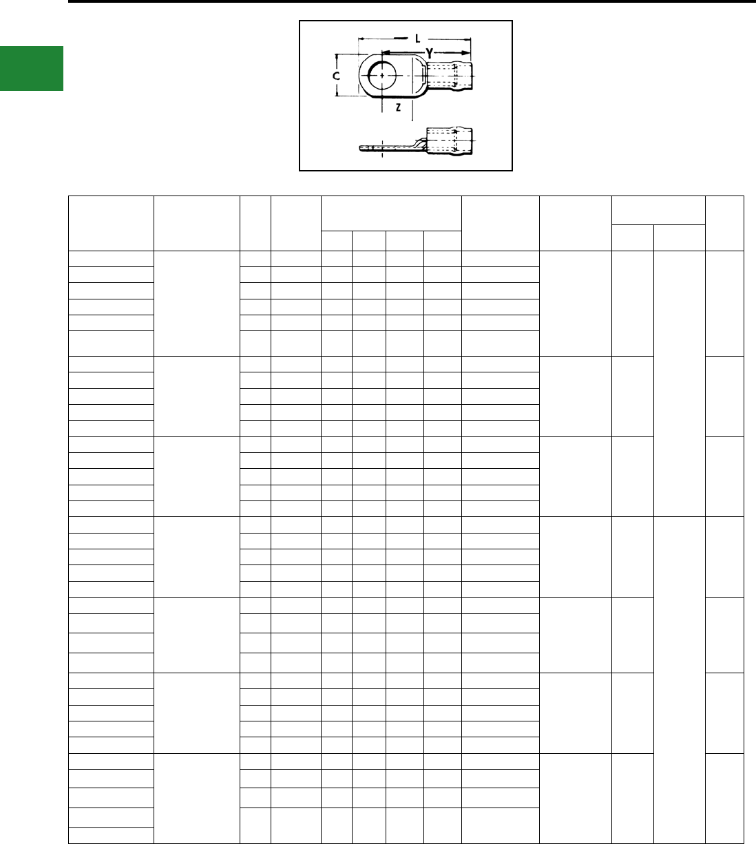
BURNDY®
Blue highlighted items are industry standard and most frequently ordered.
US: 1-800-346-4175 www.burndy.com Canada: 1-800-387-6487
Small Terminals
TYPES YAEV AND YAEV-L
(Continued)
INSULUG™
Catalog
Number
Wire Range
AWG, AN
Aircraft
Stud
Size
AS25036-
No.
Dimensions Bulk
Catalog
Number
Installation
Tooling
HYPRESS™
Y29NC Wire
Strip
Length
Nest Indentor
C Z Min. Y Max. L Max.
YAEV8C-L14BOX
8 Str. Max. Insul.
Dia. Accom.: .258
Color Code: Red
8 — 0.41 0.28 1.18 1.40 YAEV8C-L14 Ratchet:
M8ND with
N8CET-2 Die
Non-Ratchet:
MY28-6*
Hydraulic:
Y35, Y39 with
U8CET Die Set
DEV8L
Y29PLE-1
Y29PLE-1
7/16"
YAEV8C-L1BOX 1/4 -115 0.46 0.32 1.23 1.47 YAEV8C-L1
YAEV8C-L2BOX 5/16 -116 0.57 0.34 1.25 1.54 YAEV8C-L2
YAEV8C-L3BOX 3/8 -117 0.57 0.34 1.25 1.54 YAEV8C-L3
YAEV8C-L4BOX 1/2 -118 0.73 0.48 1.39 1.77 YAEV8C-L4
YAEV8C-LBOX 10 — 0.41 0.28 1.18 1.40 YAEV8C-L
—6 Str.
Max. Insul.
Dia. Accom.: .313
Color Code:
Blue
8-10 -119** 0.48 0.29 1.33 1.56 YAEV6C-L1** Non-Ratchet:
MY28-6*
Hydraulic:
Y35, Y39 with
U6CET Die Set
DEV6L 1/2"
—1/4 -120** 0.48 0.29 1.33 1.56 YAEV6C-L**
—5/16 -121** 0.60 0.36 1.39 1.68 YAEV6C-L4**
—3/8 -122** 0.60 0.36 1.39 1.68 YAEV6C-L2**
—1/2 — 0.73 0.47 1.53 1.91 YAEV6C-L10
—4 Str.
Max. Insul.
Dia. Accom.: .374
Color Code:
Yellow
8-10 — 0.55 0.28 1.40 1.62 YAEV4C-L3 Non-Ratchet:
MY28-6*
Hydraulic:
Y35, Y39 with
U4CET Die Set
DEV4L 1/2"
—1/4 -123 0.55 0.28 1.37 1.62 YAEV4C-L
—5/16 -124 0.63 0.34 1.43 1.74 YAEV4C-L4
—3/8 -125 0.63 0.34 1.43 1.74 YAEV4C-L2
—1/2 — 0.73 0.47 1.56 1.92 YAEV4C-L5
—2 Str.
Max. Insul.
Dia. Accom.: .459
Color Code:
Red
10 — 0.69 0.35 1.72 2.03 YAEV2C-L3 Non-Ratchet:
MY28-6*
Hydraulic:
Y35, Y39 with
U2CET Die Set
DEV2L
Y29PLE
Y29PLE
5/8"
—1/4 -126 0.69 0.35 1.61 2.03 YAEV2C-L1
—5/16 — 0.69 0.35 1.68 2.03 YAEV2C-L2
—3/8 -127 0.69 0.35 1.69 2.03 YAEV2C-L
—1/2 -128 0.77 0.47 1.80 2.16 YAEV2C-L4
—1 Str.
Max. Insul.
Dia. Accom.: .516
Color Code:
White
1/4 -129 0.76 0.38 1.63 2.14 YAEV1C-L1 Non-Ratchet:
MY28-6*
Hydraulic:
Y35, Y39 with
U1CET Die Set
DV26L 5/8"
—5/16 — 0.76 0.38 1.71 2.14 YAEV1C-L2
—3/8 -130 0.76 0.38 1.72 2.14 YAEV1C-L
—1/2 -131 0.86 0.47 1.86 2.27 YAEV1C-L3
—1/0 Str.
Max. Insul.
Dia. Accom.: .564
Color Code:
Blue
1/4 -132 0.83 0.43 1.97 2.40 YAEV25-L1 Non-Ratchet:
MY28-6*
Hydraulic:
Y35, Y39 with
U25ET Die Set
DEV25L 11/16"
—5/16 — 0.83 0.43 1.97 2.40 YAEV25-L2
—3/8 -133 0.83 0.43 1.97 2.40 YAEV25-L
—1/2 -134 0.88 0.47 2.02 2.46 YAEV25-L3
—5/8 — 0.88 0.63 2.17 2.67 YAEV25-L4
—
2/0 Str.
Max. Insul.
Dia. Accom.: .628
Color Code:
Yellow
1/4 — 0.93 0.49 2.19 2.72 YAEV26-L1 Non-Ratchet:
MY28-6*
Hydraulic:
Y35, Y39, Y750
with
U26ET Die Set
DEV26L 13/16"
—5/16 -135 0.93 0.49 2.19 2.72 YAEV26-L2
—3/8 -136 0.93 0.49 2.19 2.72 YAEV26-L
—1/2 -137 0.93 0.49 2.27 2.72 YAEV26-L3
—
† Additional terminal stud sizes available.
* BMY, BNCH-MT bench mount adapter available.
** NOTE: Add sufx “M” to cat. number to conform to AS25036 - standard for these items only
(example: YAEV6C-L1M). See above. Contact BURNDY® for UL Listed products.
B-20
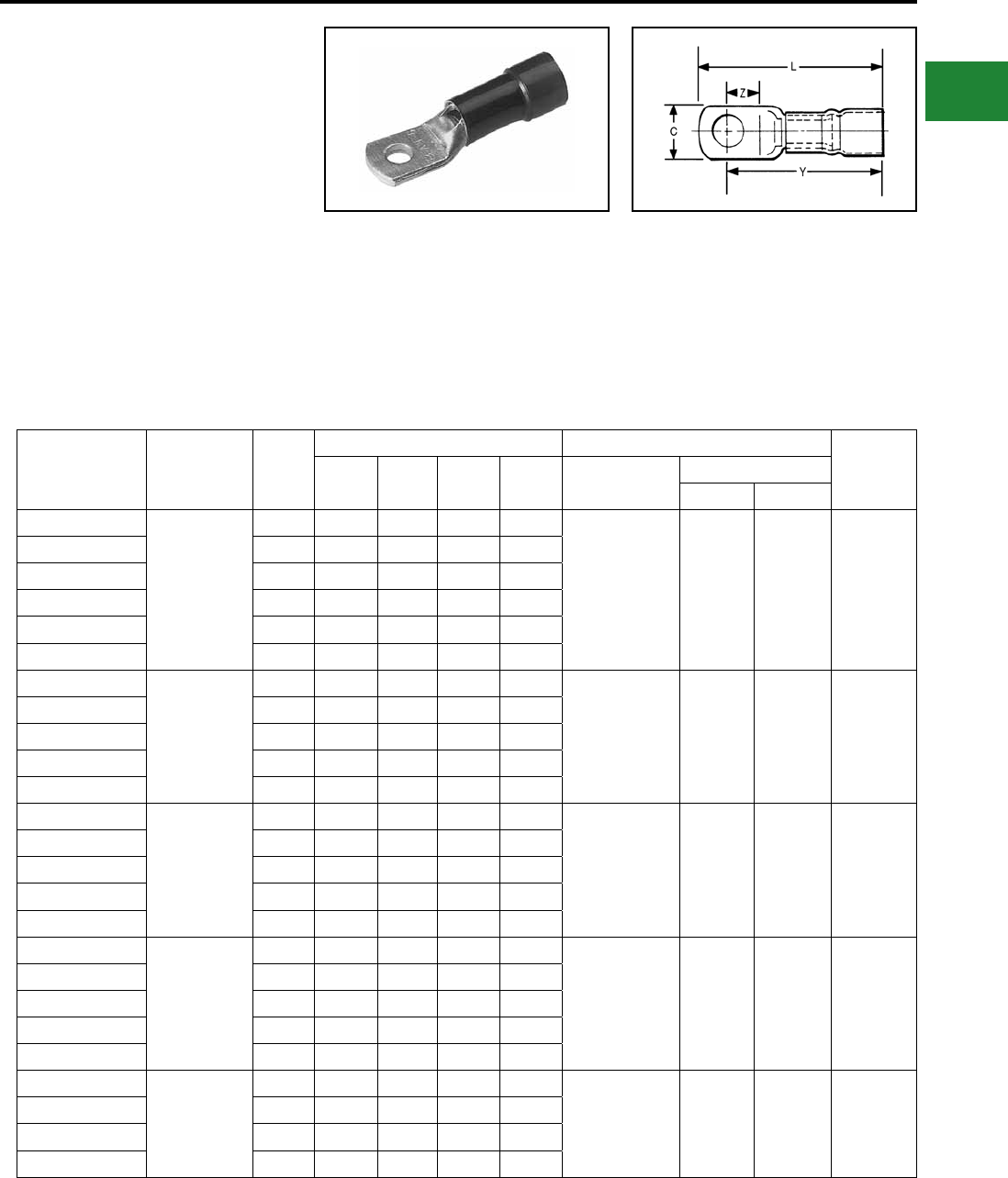
BURNDY®
Blue highlighted items are industry standard and most frequently ordered.
Canada: 1-800-387-6487 www.burndy.com US: 1-800-346-4175
Small Terminals
TYPE YAEV-H
INSULUG™
Ring-Tongue Terminals
Nylon-Insulated
For Expanded Insulation
Designed to accommodate larger conductor
insulation diameters. Made of one piece tin
plated pure electrolytic seamless copper tubing
for maximum conductivity and ductility. Color-
coded insulating sleeves are locked into position.
Inspection hole permits visual check of wire
insertion. Meets requirements of SAE-AS7928.
Bulk
Catalog
Number
Wire
Range
Stud
Size
Dimensions in Inches Installation Tooling Wire
Strip
Length
CZ
Min.
Y
Max.
L
Max.
HYTOOL™
HYPRESS™
Y29NC, Y29BH
Nest Indentor
YAEV8C-H14
8
Max. Insul.
Dia.: .30"
Sleeve
Color: Red
8 0.41 0.25 1.32 1.53
M8ND
with
N8CET-2 Die
My28-6*
Y35, Y29 with
U8CET Die
DEV8L Y29PLE-1 7/16"
YAEV8C-H 10 0.41 0.25 1.34 1.53
YAEV8C-H1 1/4 0.46 0.28 1.37 1.60
YAEV8C-H2 5/16 0.57 0.33 1.39 1.68
YAEV8C-H3 3/8 0.57 0.33 1.39 1.68
YAEV8C-H4 1/2 0.73 0.47 1.52 1.90
YAEV6C-H1
6
Max. Insul.
Dia.: .38"
Sleeve
Color: Blue
10 0.48 0.28 1.48 1.72
My28-6*
Y35, Y39
with U6CET
Die Set
DEV6L Y29PLE-1 1/2"
YAEV6C-H 1/4 0.48 0.28 1.48 1.72
YAEV6C-H4 5/16 0.60 0.33 1.54 1.85
YAEV6C-H2 3/8 0.60 0.34 1.54 1.85
YAEV6C-H10 1/2 0.73 0.47 1.68 2.06
YAEV4C-H3
4
Max. Insul.
Dia.: .44"
Sleeve
Color: Yellow
10 0.55 0.28 1.60 1.86
MY28-6*
Y35, Y39
with
U4CET
Die Set
DEV4L Y29PLE-1 1/2"
YAEV4C-H 1/4 0.55 0.28 1.60 1.86
YAEV4C-H4 5/16 0.63 0.34 1.66 1.98
YAEV4C-H2 3/8 0.63 0.34 1.66 1.98
YAEV4C-H5 1/2 0.73 0.47 1.79 2.17
YAEV2C-H3
2
Max. Insul. Dia.:
.52"
Sleeve
Color: Red
10 0.69 0.35 1.98 2.33
MY28-6*
Y35, Y39
with
U2CET Die
DEV2L Y29PLE 5/8"
YAEV2C-H1 1/4 0.69 0.35 1.98 2.33
YAEV2C-H2 5/16 0.69 0.35 1.98 2.33
YAEV2C-H 3/8 0.69 0.35 1.98 2.33
YAEV2C-H4 1/2 0.77 0.47 2.10 2.49
YAEV1C-H1 1
Max. Insul.
Dia.: .58"
Sleeve
Color: White
1/4 0.76 0.38 2.10 2.48 MY28-6*
Y35, Y39
with
U1CET Die
DV26L Y29PLE 5/8"
YAEV1C-H2 5/16 0.76 0.38 2.10 2.48
YAEV1C-H 3/8 0.76 0.38 2.10 2.48
YAEV1C-H3 1/2 0.86 0.46 2.10 2.62
* BMY BNCH-MT bench mount adapter available.
B-21
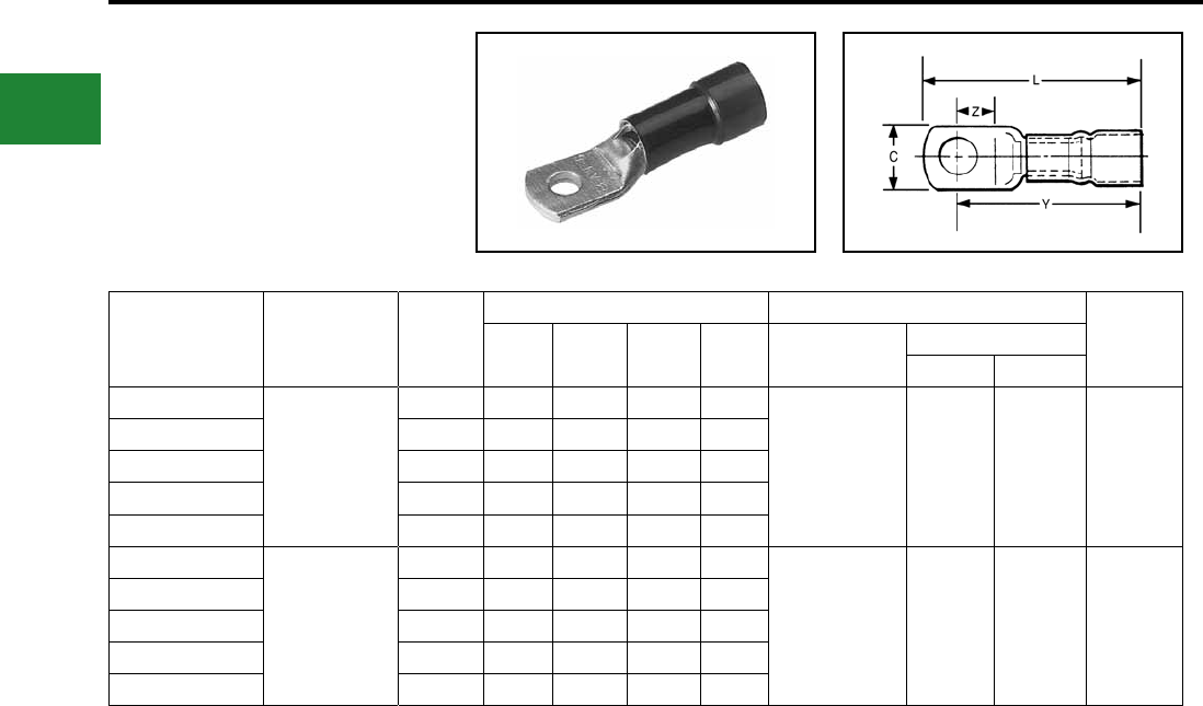
BURNDY®
Blue highlighted items are industry standard and most frequently ordered.
US: 1-800-346-4175 www.burndy.com Canada: 1-800-387-6487
Small Terminals
TYPE YAEV-H
(Continued)
Bulk
Catalog
Number
Wire
Range
Stud
Size
Dimensions in Inches Installation Tooling Wire
Strip
Length
CZ
Min.
Y
Max.
L
Max.
HYTOOL™
HYPRESS™
Y29NC, Y29BH
Nest Indentor
YAEV25-H1
1/0
Max. Insul.
Dia.: .66" Sleeve
Color: Blue
1/4 0.83 0.43 2.39 2.82
MY28-6*
Y35, Y39
with U25ET
Die Set
DEV25L Y29PLE 11/16"
YAEV25-H2 5/16 0.83 0.43 2.39 2.82
YAEV25-H 3/8 0.83 0.43 2.39 2.82
YAEV25-H3 1/2 0.88 0.46 2.43 2.88
YAEV25-H4 5/8 0.88 0.62 2.58 3.09
YAEV26-H1
2/0
Max. Insul.
Dia.: .73"
Sleeve Color:
Yellow
1/4 0.94 0.48 2.65 3.12
MY28-6*
Y35, Y39
with U26ET
Die Set
DEV26L Y29PLE 13/16"
YAEV26-H2 5/16 0.94 0.48 2.65 3.12
YAEV26-H 3/8 0.94 0.48 2.65 3.12
YAEV26-H3 1/2 0.94 0.48 2.65 3.12
YAEV26-H12 5/8 0.94 0.62 2.79 3.33
* BMY BNCH-MT bench mount adapter available.
B-22
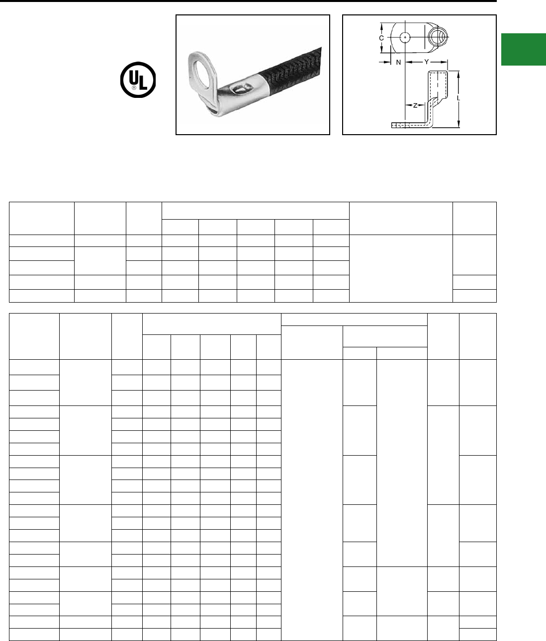
BURNDY®
Blue highlighted items are industry standard and most frequently ordered.
Canada: 1-800-387-6487 www.burndy.com US: 1-800-346-4175
Small Terminals
TYPES YAV-R, YAV-RS
HYLUG™
Heavy Duty Right-Angle
Terminals
Factory formed right angle HYLUG™ connectors
made of seamless pure copper tubing. These
rugged terminals withstand the most severe
applications. Inspection hole in barrel permits
visual check of wire insertion. Tin plated to resist
corrosion. Meets requirements of SAE-AS7928.
Catalog
Number
Wire Range
(AWG/kcmil)
Stud
Size
Dimensions Installation
Tooling
Wire
Strip
Length
C L Max. Y Max. Z Min. N
YAV18-R 22-18 8-10 0.31 0.34 0.46 0.25 0.16 Non-Ratchet:
Y10D
Ratchet:
Y8MRB-1, MR20,
MR8-G98, MR8-9Q
1/4
YAV14-RL33 20-14 4-6 0.25 0.37 0.45 0.21 0.12
YAV14-R 8-10 0.31 0.36 0.48 0.25 0.16
YAV10-R 12-10 8-10 0.38 0.53 0.46 0.25 0.19 5/16
YAV10-R3BOX 12-10 1/4 0.47 0.55 0.50 .28 0.23 5/16
Catalog
Number
Wire Range
(AWG/kcmil)
Stud
Size
Dimensions in Inches Installation Tooling Wire
Strip
Length
Tool ▲
Index
Number
Ratchet,
Non-Ratchet,
HYTOOL™
HYPRESS™ Y29NC,
Y29BH
C L Max. Y Max. Z Min. N Nest Indentor
YAV8C-RS
8
8-10 0.41 0.95 0.62 0.25 0.20
MY28
MY29-11
DV8L*
Y29PL
7/16 38YAV8C-RS1 1/4 0.41 0.95 0.65 0.28 0.20
YAV8C-RS3 3/8 0.56 0.95 0.71 0.34 0.31
YAV6C-RS1
6
8-10 0.50 0.98 0.67 0.28 0.25
DV6L
1/2
39
YAV6C-RS 1/4 0.50 0.98 0.67 0.28 0.25
YAV6C-RS4 5/16 0.59 0.98 0.73 0.34 0.31
YAV6C-RS2 3/8 0.59 0.98 0.73 0.34 0.31
YAV4C-RS3
4
8-10 0.53 1.00 0.70 0.28 0.25
DV4L 40
YAV4C-RS 1/4 0.53 1.00 0.70 0.28 0.25
YAV4C-RS4 5/16 0.62 1.00 0.77 0.34 0.31
YAV4C-RS2 3/8 0.62 1.00 0.77 0.34 0.31
YAV2C-RS1
2
1/4 0.68 1.27 0.82 0.34 0.33
DV2L
5/8
41YAV2C-RS2 5/16 0.68 1.27 0.82 0.34 0.33
YAV2C-RS 3/8 0.68 1.27 0.82 0.34 0.33
YAV1C-RS1 11/4 0.73 1.31 0.88 0.34 0.33 DV1L 42
YAV1C-RS2 5/16 0.73 1.31 0.88 0.34 0.33
YAV25-RS 1/0 3/8 0.81 1.46 1.01 0.44 0.39 DV25L
Y29PR
11/16 43
YAV25-RS3 1/2 0.88 1.46 1.04 0.47 0.44
YAV26-RS 2/0 3/8 0.92 1.58 1.00 0.47 0.39 DV26L 13/16 44
YAV26-RS3 1/2 0.92 1.58 1.00 0.47 0.39
YAV27-RS 3/0 3/8 1.02 1.61 1.12 0.47 0.48 — — 7/8 45
YAV28-RS 4/0 3/8 1.12 1.75 1.15 0.47 0.48 46
* For aircraft applications (Flex\ible Cable) use die DV8L-1
▲ See Present Installation Tool Index
B-23
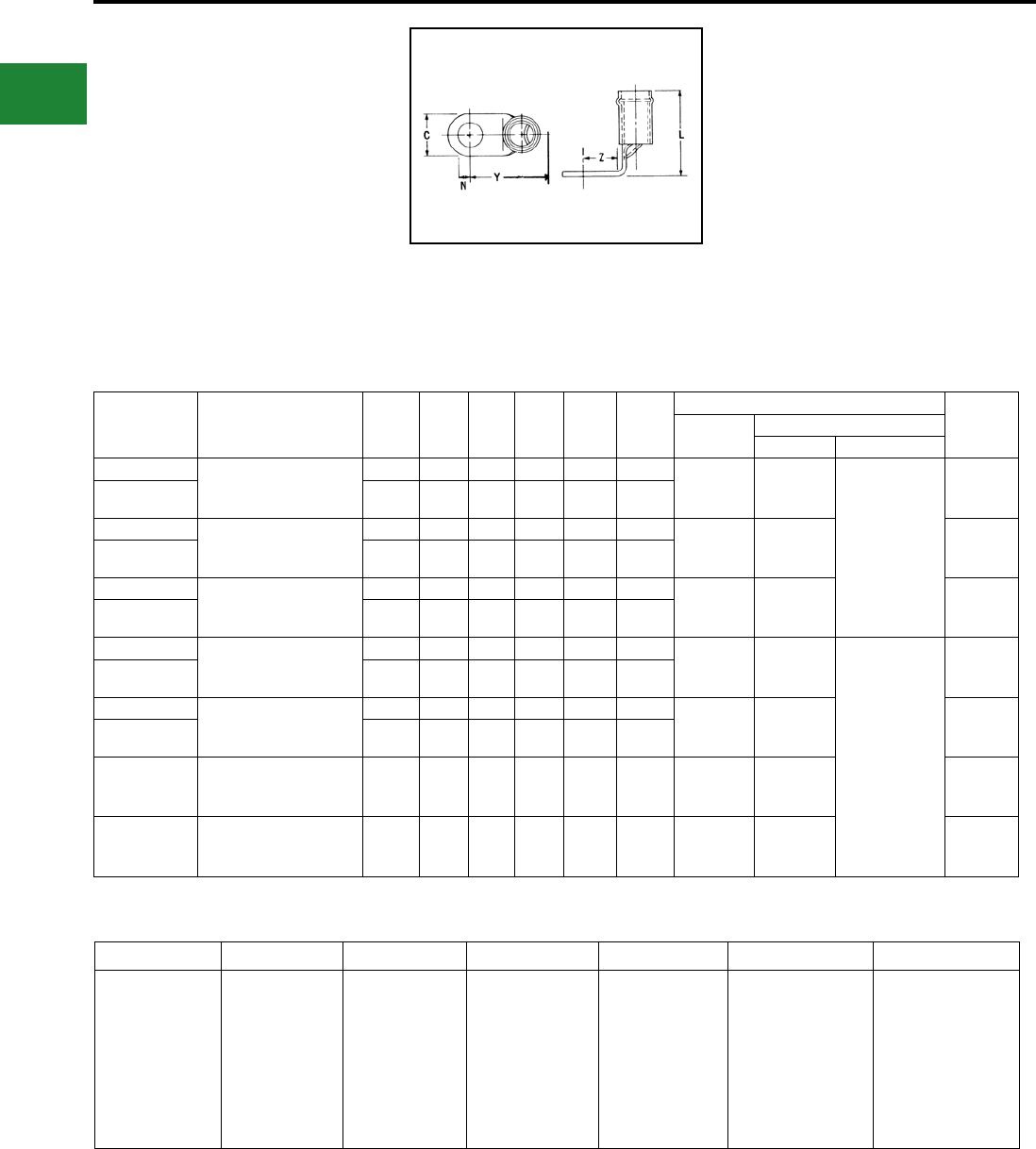
BURNDY®
Blue highlighted items are industry standard and most frequently ordered.
US: 1-800-346-4175 www.burndy.com Canada: 1-800-387-6487
Small Terminals
TYPES YAEV-RS
INSULUG™
Nylon-Insulated
Right-Angle Terminals
Factory formed right angle INSULUG™
connectors made of seamless pure copper tubing.
These rugged terminals withstand the most severe
applications. Inspection hole in barrel permits
visual check of wire insertion. Meets requirements
of SAE-AS7928.
Catalog
Number Wire Range Stud
Size N C Z Min. Y Max. L Max.
Installation Tooling Wire Strip
Length
HYTOOL™ HYPRESS™ Y29NC, Y29BH
Nest Indentor
YAEV8C-RS 8
Max. Insul. Dia.: .258"
Sleeve Color: Red
8-10 0.20 0.41 0.25 0.82 1.25
A DEV8L
Y29PLE-1
7/16"
YAEV8C-RS1 1/4 0.25 0.41 0.28 0.84 1.25
YAEV6C-RS1 6
Max. Insul. Dia.: .313"
Sleeve Color: Blue
8-10 0.25 0.50 0.28 0.88 1.28
B DEV6L 1/2"
YAEV6C-RS 1/4 0.25 0.50 0.28 0.88 1.28
YAEV4C-RS 4
Max. Insul. Dia.: .374"
Sleeve Color: Yellow
1/4 0.25 0.53 0.28 0.95 1.28
C DEV4L 1/2"
YAEV4C-RS2 3/8 0.31 0.62 0.34 1.02 1.28
YAEV2C-RS1 2
Max. Insul. Dia.: .459"
Sleeve Color: Red
1/4 0.33 0.68 0.34 1.13 1.59
D DEV2L
Y29PLE
5/8"
YAEV2C-RS 3/8 0.33 0.68 0.34 1.13 1.59
YAEV1C-RS2 1
Max. Insul. Dia.: .516"
Sleeve Color: White
5/16 0.33 0.73 0.34 1.13 1.65
E DV26L 5/8"
YAEV1C-RS 3/8 0.33 0.73 0.34 1.22 1.65
YAEV25-RS
1/0
Max. Insul. Dia.: .564"
Sleeve Color: Blue
3/8 0.39 0.81 0.44 1.46 1.88 F DEV25L 11/16"
YAEV26-RS
2/0
Max. Insul. Dia.: .628"
Sleeve Color: Yellow
3/8 0.39 0.92 0.47 1.48 2.06 G DEV26 13/16"
A B C D E F G
Ratchet:
M8ND
with
N8CET-2 Die
Non-Ratchet:
MY28-6††
Hydraulic:
Y35, Y39 with
U8CET Die Set
Non-Ratchet:
MY28-6††
Hydraulic:
Y35, Y39 with
U6CET
Die Set
Non-Ratchet:
MY28-6††
Hydraulic:
Y35, Y39 with
U4CET
Die Set
Non-Ratchet:
MY28-6††
Hydraulic:
Y35, Y39 with
U2CET
Die Set
Non-Ratchet:
MY28-6††
Hydraulic:
Y35, Y39 with
U1CET
Die Set
Non-Ratchet:
MY28-6††
Hydraulic:
Y35, Y39 with
U25ET
Die Set
Non-Ratchet:
MY28-6††
Hydraulic:
Y35, Y39 with
U26ET
Die Set
†† BMY BNCH-MT bench mount adapter available.
B-24
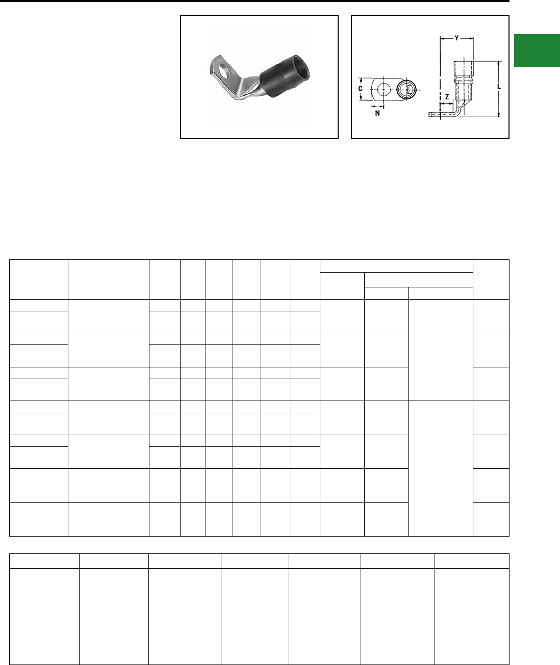
BURNDY®
Blue highlighted items are industry standard and most frequently ordered.
Canada: 1-800-387-6487 www.burndy.com US: 1-800-346-4175
Small Terminals
TYPE YAEV-RH
INSULUG™
Nylon-Insulated
Right-Angle Terminals
Designed to Accommodate Larger
Conductor Insulation Diameters
Factory formed right angle INSULUG™
connectors made of seamless pure copper tubing.
These rugged terminals withstand the most severe
applications. Inspection hole in barrel permits
visual check of wire insertion. Tin plated to resist
corrosion. Meets requirements of SAE-AS7928.
Catalog Number Wire Range Stud
Size N C Z Min. Y Max. L Max.
Installation Tooling Wire
Strip
Length
HYTOOL™ HYPRESS™ Y29NC, Y29BH
Nest Indentor
YAEV8C-RH 8
Max. Insul. Dia.: .30"
Sleeve Color: Red
8-10 0.20 0.41 0.25 0.87 1.38
A DEV8L
Y29PLE-1
7/16"
YAEV8C-RH1 1/4 0.25 0.41 0.28 0.90 1.38
YAEV6C-RH1 6
Max. Insul. Dia.: .38"
Sleeve Color: Blue
8-10 0.25 0.50 0.28 0.97 1.43
B DEV6L 1/2"
YAEV6C-RH 1/4 0.25 0.50 0.28 0.97 1.43
YAEV4C-RH 4
Max. Insul. Dia.: .44"
Sleeve Color: Yellow
1/4 0.25 0.53 0.28 1.04 1.53
C DEV4L 1/2"
YAEV4C-RH2 3/8 0.31 0.62 0.34 1.11 1.53
YAEV2C-RH1 2
Max. Insul. Dia.: .52"
Sleeve Color: White
1/4 0.33 0.67 0.34 1.22 1.88
D DEV2L
Y29PLE
5/8"
YAEV2C-RH 3/8 0.33 0.67 0.34 1.22 1.88
YAEV1C-RH2 1
Max. Insul. Dia.: .52"
Sleeve Color: White
5/16 0.33 0.73 0.34 1.32 1.99
E DV26L 5/18"
YAEV1C-RH 3/8 0.33 0.73 0.34 1.32 1.99
YAEV25-RH
1/0
Max. Insul. Dia.: .66"
Sleeve Color: Blue
3/8 0.39 0.81 0.44 1.50 2.29 F DEV25L 11/16"
YAEV26-RH
2/0
Max. Insul. Dia.: .73"
Sleeve Color: Yellow
3/8 0.39 0.92 0.47 1.60 2.42 G DEV26L 13/16"
A B C D E F G
Ratchet:
M8ND
with
N8CET-2 Die
Non-Ratchet:
MY28-6††
Hydraulic:
Y35, Y39 with
U8CET Die Set
Non-Ratchet:
MY28-6††
Hydraulic:
Y35, Y39 with
U6CET
Die Set
Non-Ratchet:
MY28-6††
Hydraulic:
Y35, Y39 with
U4CET
Die Set
Non-Ratchet:
MY28-6††
Hydraulic:
Y35, Y39 with
U2CET
Die Set
Non-Ratchet:
MY28-6††
Hydraulic:
Y35, Y39 with
U1CET
Die Set
Non-Ratchet:
MY28-6††
Hydraulic:
Y35, Y39 with
U25ET
Die Set
Non-Ratchet:
MY28-6††
Hydraulic:
Y35, Y39 with
U26ET
Die Set
†† BMY BNCH-MT bench mount adapter available.
B-25
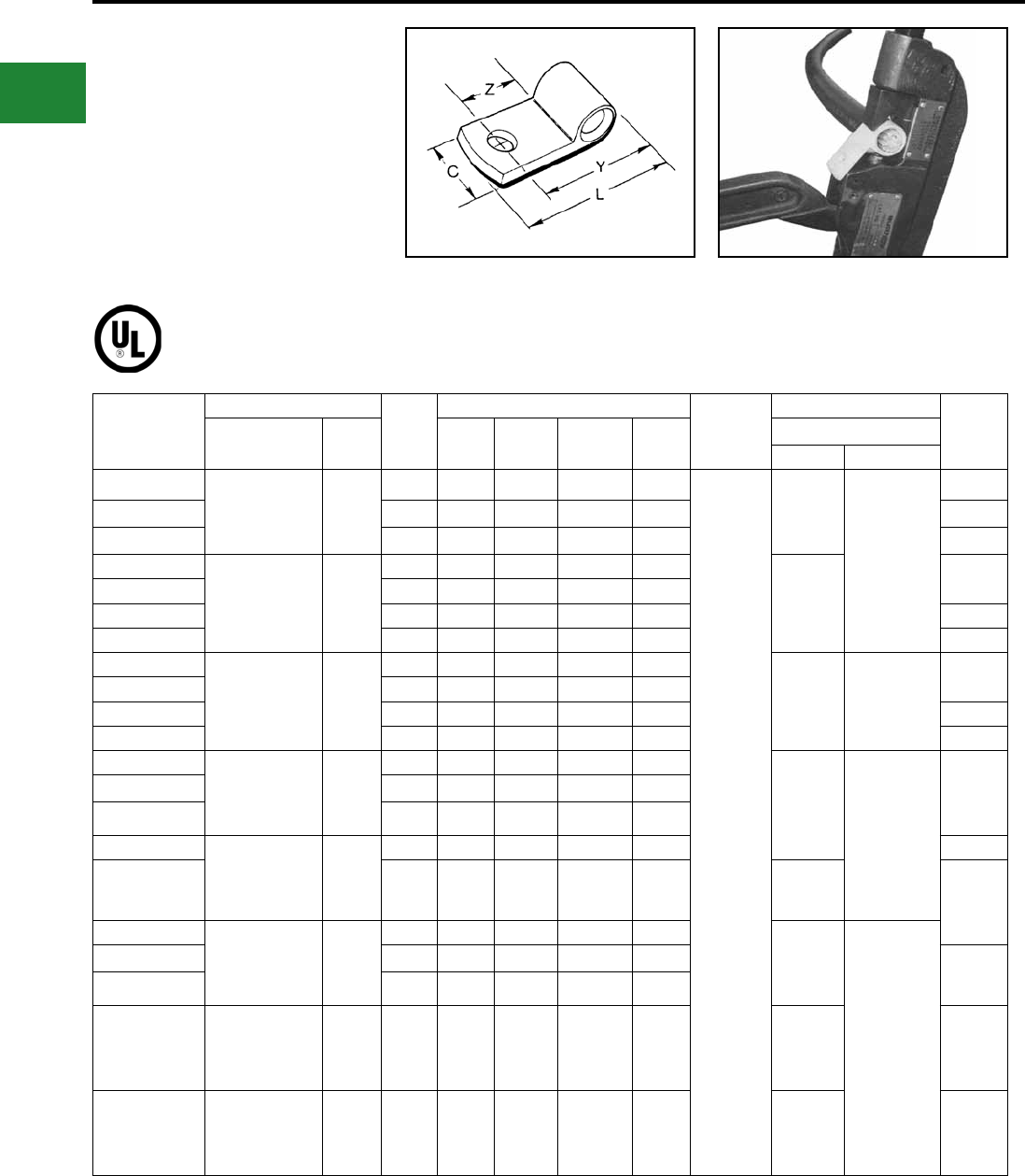
BURNDY®
Blue highlighted items are industry standard and most frequently ordered.
US: 1-800-346-4175 www.burndy.com Canada: 1-800-387-6487
Small Terminals
TYPE YBM
HYLUG™
Flag-Type
Ring-Tongue Terminals
Made of pure electrolytic copper for maximum
conductivity and ductility. Seamless extrusion tin
plated to resist corrosion.
Catalog*
Number
Wire Range
Stud
Size
Dimensions in Inches
**
HYTOOL™
**Installation Tooling Wire
Strip
Length
Flex Code C Z Min. Y Approx. L Max. HYPRESS™ Y29NC, Y29B
Nest Indentor
YBM8C 8
Class I, K,
DLO (37/24)
MIL-W-5086
8
8-10 0.47 0.33 0.59 1.01
MY28
DV8B
Y29PBL
7/16"
YBM8C-T2 1/4 0.53 0.36 0.62 1.07 1/2"
YBM8CT4 3/8 0.66 0.42 0.68 1.19 9/16"
YBM6C-L9 6
Class I,
DLO (81/24)
MIL-W-5086
6
8-10 0.53 0.36 0.64 1.09
DV6BL-1
1/2"
YBM6C-L 1/4 0.53 0.36 0.64 1.12
YBM6C-L2 5/16 0.59 0.42 0.70 1.21 9/16"
YBM6C-L3 3/8 0.66 0.42 0.70 1.24 5/8"
YBM4C-L4 4
Class I,
DLO (105/24)
MIL-W-5086
4
8-10 0.53 0.36 0.69 1.18
DV4BL Y29PBL
1/2"
YBM4C-L 1/4 0.53 0.36 0.69 1.21
YBM4C-L1 5/16 0.59 0.42 0.75 1.3 9/16"
YBM4C-L2 3/8 0.66 0.42 0.75 1.33 5/8"
YBM2C-L1 2
Class I,
DLO (150/24)
MIL-W-5086
2
1/4 0.66 0.36 0.73 1.28
DV2BL
Y29PL
5/8"
YBM2C-L2 5/16 0.66 0.42 0.79 1.38
YBM2C-L 3/8 0.66 0.42 0.79 1.35
YBM1C-L3 1
Class I,
DLO (225/24)
MIL-W-5086
1
1/2 0.91 0.61 1.00 1.78 1"
YBM1C-L 3/8 0.66 0.49 0.88 1.53 DV1BL 5/8"
YBM25-L1 1/0
Class I,
DLO (275/24)
MIL-W-5086
—
1/4 0.72 0.42 0.86 1.49
DV25BL-1
Y29PR
YBM25-L2 5/16 0.72 0.45 0.88 1.56 3/4"
YBM25-L 3/8 0.72 0.49 0.92 1.62
YBM26-L
2/0
Class I,
DLO (325/24)
MIL-W-5086
— 3/8 0.84 0.49 0.98 1.71 DV26L 13/16"
YBM28-1/4
4/0
Class I,
DLO (550/24)
MIL-W-5086
— 1/4 0.95 0.72 1.66 2.06 DV28L 1"
* Lead Plated available, contact factory.
** See top illustration for recommended connector insertion
into tools.
B-26
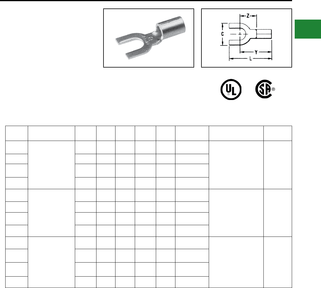
BURNDY®
Blue highlighted items are industry standard and most frequently ordered.
Canada: 1-800-387-6487 www.burndy.com US: 1-800-346-4175
Small Terminals
TYPE T-F AND YAD-F
HYLUG™
Uninsulated Compression Terminal,
Fork Tongue
Type T-F is constructed in the same manner as
the type “T” and employs a fork tongue. The fork
permits rapid installation of the terminal under
a screw head without completely removing the
screw. Two or more terminals may be stacked
easily on a common stud.
Features & Benets
• Fork tongue design.
◊ Faster installation-screw needs only to
be loosened for termination.
Catalog
Number Wire Range Stud
Size C L Max Y Max Z Min Bulk Catalog
Number Installation Tooling Wire Strip
Length
T18-6F
22 AWG-18 AWG
#4 - #6 0.28 0.68 0.55 0.25 YAD186F
Non-Ratchet:
Y10D, Y10-22
Ratchet:
MRE1022B,
MR8G98, Y8MRB-1, MR20
9/32
T18-8F #6 - #8 0.31 0.74 0.57 0.27 YAD188F
T18-10F #8 - #10 0.37 0.74 0.58 0.29 YAD1810F
T18-14F 1/4 0.47 0.92 0.69 0.39 YAD1814F
T14-6F
20 AWG-14 AWG
#4 - #6 0.28 0.68 0.55 0.25 YAD146F
Non-Ratchet:
Y10D, Y10-22
Ratchet:
MRE1022B,
MR8G98, Y8MRB-1, MR20
9/32
T14-8F #6 - #8 0.31 0.74 0.57 0.27 YAD148F
T14-10F #8 - #10 0.37 0.74 0.58 0.29 YAD1410F
T14-14F 1/4 0.47 0.92 0.69 0.39 YAD1414F
T10-6F
14 AWG-10 AWG (Str.)
12 AWG-10 AWG (Sol.)
#4 - #6 0.28 0.74 0.61 0.25 YAD106F
Non-Ratchet:
Y10D, Y10-22
Ratchet:
MRE1022B,
MR8G98, Y8MRB-1, MR20
11/32
T10-8F #6 - #8 0.31 0.80 0.63 0.27 YAD108F
T10-10F #8 - #10 0.41 0.87 0.68 0.32 YAD1010F
T10-14F 1/4 0.50 1.00 0.75 0.39 YAD1014F
B-27
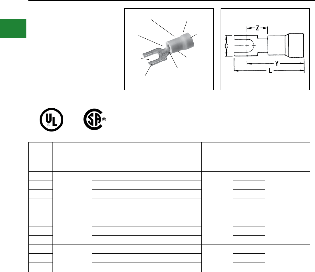
BURNDY®
Blue highlighted items are industry standard and most frequently ordered.
US: 1-800-346-4175 www.burndy.com Canada: 1-800-387-6487
Small Terminals
TYPES TP-F AND BA-EF
VINYLUG™
Terminal - Polyvinylchloride Insulated,
Fork Tongue
600 Volts Max., 105° C Max.
The Type TP-F is a fork tongue variation of the TP
design and makes installation easier.
Features & Benets
• Fork tongue design
◊ Faster installation-screw needs only to
be loosened for termination
EXPANDED SHROUD
INSULATION CRIMP
SMOOTH
ENTRY
COLOR CODED
INSULATION
DEEP “V”
SERRATIONS
TIN
PLATED
FORK
TONGUE
WIRE SIZE
RANGE
WIRE
CRIMP
Catalog
Number
Wire
Range
Stud
Size
Dimensions Bulk
Catalog
Number •
Installation
Tooling
Tape Mounted
Catalog
Number
2000/Reel
Installation
Tooling
Wire
Strip
Length
CL.
Max
Y
Max.
Z
Min.
TP16-2F 22 - 16
Max. Insul. Dia.
Accom.: 0.15
Color Code: Red
#1-
#2 0.17 0.75 0.66 0.23 BA16EF2
Plier Type:
Y10-22
Ratchet Tool:
MRE1022NV
MR8-89-1
BA16EF2M TFM
with
DFM3D-1
Die
13/64"
TP16-6F #4-#6 0.28 0.80 0.66 0.23 BA16EF6 BA16EF6M
TP16-8F #6
-
#8 0.31 0.86 0.69 0.26 BA16EF8 BA16EF8M
TP16-10F #8
-
#10 0.41 0.95 0.75 0.31 BA16EF10 BA16EF10M
TP14-2F 16 - 14
Max. Insul. Dia.
Accom.: 0.18
Color Code: Blue
#1
-
#2 0.17 0.75 0.66 0.23 BA14EF2 — TFM
with
DFM2D-1
Die
13/64"
TP14-6F #3
-
#6 0.28 0.80 0.66 0.23 BA14EF6 —
TP14-8F #6
-
#8 0.31 0.86 0.69 0.26 BA14EF8 BA14EF8M
TP14-10F #8
-
#10 0.41 0.95 0.75 0.31 BA14EF10 BA14EF10M
TP10-6F 12 - 10
Max. Insul. Dia.
Accom.: 0.26
Color Code: Yellow
#3
-
#6 0.28 0.95 0.81 0.26 BA10EF6 MRE1022NV,
MR15, M8ND
with N10ET-23
*BA10EF6M TFM
with
DFM1D5
Die
19/64"TP10-8F #6
-
#8 0.31 0.98 0.81 0.26 BA10EF8 *BA10EF8M
TP10-10F #8
-
#10 0.41 1.07 0.87 0.31 BA10EF10 *BA10EF10M
• UL Listed and CSA Certied with MR8-89-1 and MR15 only
* 1000/Box
B-28
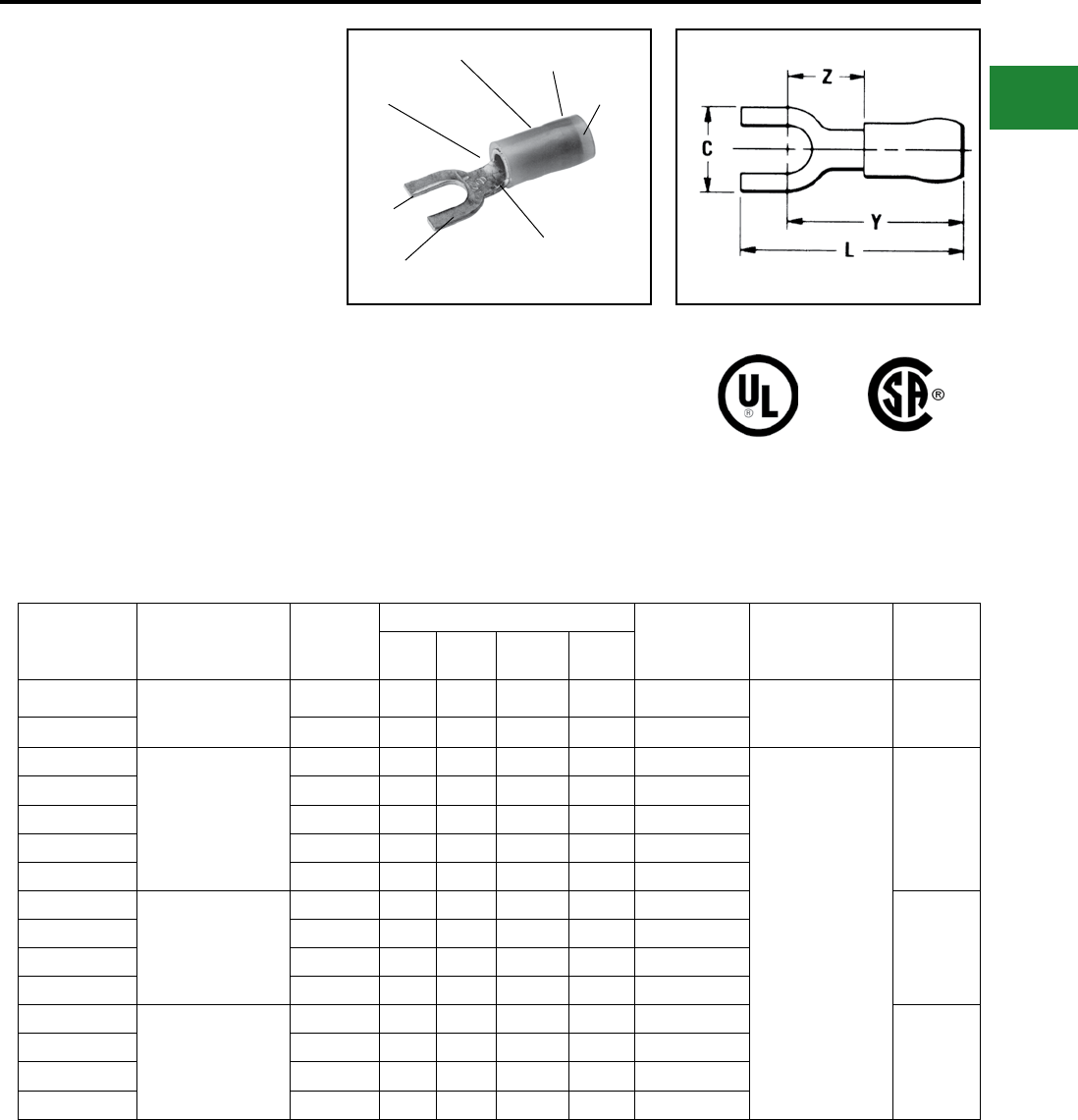
BURNDY®
Blue highlighted items are industry standard and most frequently ordered.
Canada: 1-800-387-6487 www.burndy.com US: 1-800-346-4175
Small Terminals
TYPES TN-F AND YAES-F
INSULUG™
Terminal - Nylon Insulated,
Fork Tongue
600 Volts Max., 105° C Max.
The type TN-F, nylon insulated fork tongue terminal
has the same high quality as the TN. It is designed
to meet the heavy-duty requirements of industrial
and utility applications.
Used on both power and control circuits for wire
sizes #26 AWG through #10 AWG. The TN-F
provides high dielectric strength and stability in oily
conditions.
The TN-F is identical to the TN with the addition
of a fork tongue which allows installation without
complete removal of its supporting screw.
Features & Benets
• Fork tongue
◊ Provides faster and easier installation
by permitting insertion under the screw
head without completely removing it.
SMOOTH
FUNNEL
ENTRY
INSULATION
CRIMP
WIRE CRIMP
BRAZED
SEAM
FORK
TONGUE
TIN
PLATED
DEEP “V”
SERRATIONS
Catalog
Number
Wire
Range
Stud
Size
Dimensions Bulk
Catalog
Number
Installation
Tooling
Wire
Strip
Length
C L Max. Y Max. Z Min.
TN20-2F* 26-20 Max. Insul.
Dia. Accom.: 0.10
Color Code: Amber
#1
-
#2 0.18 0.76 0.65 0.24 —M8ND with
N14HET-25V1
Die Set
3/16"
TN20-6F* #4-#6 0.28 0.80 0.70 0.28 —
TN184F*
22-18 Max. Insul.
Dia. Accom.: 0.12
Color Code: Red
#3
-
#4 0.23 0.75 0.65 0.24 —
Non-Ratchet:
Y10D
Y1022
Ratchet:
MRE1022NV
MR8-83**
MR18
7/32"
TN18-6F #4 - #6 0.28 0.79 0.65 0.24 YAES18N1F
TN18-8F #6
-
#8 0.31 0.84 0.67 0.26 YAES18N49F
TN18-10F #8
-
#10 0.37 0.84 0.68 0.27 YAES18N3F
TN18-14F 1/4 0.47 1.03 0.79 0.38 YAES18N50F
TN14-6F
16-14 Max. Insul.
Dia. Accom.: 0.15
Color Code: Blue
#4 - #6 0.28 0.79 0.65 0.24 YAES14N6F
7/32"
TN14-8F #6
-
#8 0.31 0.84 0.67 0.26 YAES14N53F
TN14-10F #8
-
#10 0.37 0.84 0.68 0.27 YAES14N8F
TN14-14F 1/4 0.47 1.03 0.79 0.38 YAES14N54F
TN10-6F
12-10 Max. Insul.
Dia. Accom.: 0.21
Color Code: Yellow
#4-#6 0.28 0.96 0.82 0.24 YAES10N11F
11/32"
TN10-8F #6
-
#8 0.31 1.01 0.84 0.26 YAES10N56F
TN10-10F #8
-
#10 0.41 1.09 0.89 0.31 YAES10N12F
TN10-14F 1/4 0.50 1.21 0.96 0.38 YAES10N57F
* Not UL Listed or CSA Certied.
** Or other tool conforming to military specication
AS25036 or AS90413
B-29
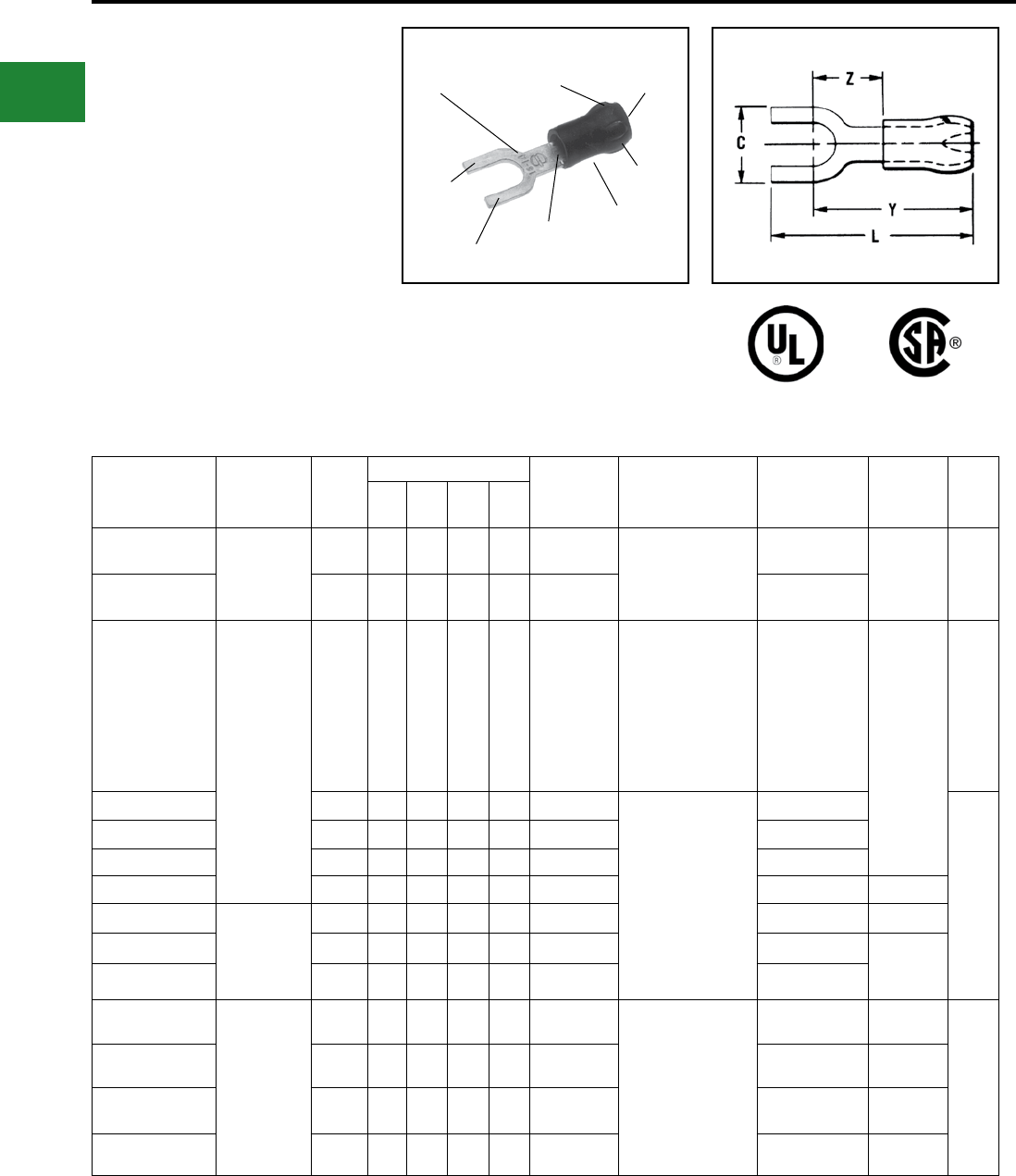
BURNDY®
Blue highlighted items are industry standard and most frequently ordered.
US: 1-800-346-4175 www.burndy.com Canada: 1-800-387-6487
Small Terminals
TYPES YAE-N-F BOX AND
YAE-N-F
INSULUG™
Terminal - Nylon Insulated,
Fork Tongue
Multi-Finger Insulation Grip
600 Volts Max. 105° C Max.
INSULUG™ type YAE-N-F nylon insulated
terminals are designed with a Multi-Finger
Insulation grip, are rated 105° C and are supplied
with a fork tongue for easy terminal insertion and
removal.
Features & Benets
• Fork tongue
◊ Permits rapid easy installation of the
terminal under the screw head without
complete removal of the screw
MULTI-FINGER
INSULATION GRIPS
AND CABLE SUPPORT
FUNNEL
ENTRY
WIRE SIZE
ELECTRO-TIN
PLATED
FORK
TONGUE
DEEP “V”
SERRATIONS
WIRE
CRIMP
INSULATION
CRIMP
Catalog
Number
Wire
Range
Stud
Size
Dimensions Bulk
Catalog
Number
Installation
Tooling **
Tape Mounted
Catalog Number
2000/Reel
Installation
Tooling
Wire
Strip
Length
CL
Max.
Y
Max.
Z
Min.
YAE22N65FBOX
*24 - 20 Max.
Insul. Dia.: 0.10"
Sleeve Color:
Amber
#2 0.18 0.73 0.63 0.22 YAE22N65F Ratchet:
M8ND
N14HET25V1 Die
YAE22N65FM TFM
with
DFM11D1
Die
5/32"
YAE22N66FBOX
*#4 - #6 0.28 0.80 0.67 0.27 YAE22N66F YAE22N66FM
YAE18N60FBOX
*
22 - 16 Max.
Insul. Dia.: 0.13"
Sleeve Color:
Red
#4 0.21 0.92 0.73 0.24 YAE18N60F
Non-Ratchet: Y10D
or Y1022
Ratchet:MRE1022NV,
MR8-33T-1, M8ND
with one of the
following dies:
N14HET-25V1,
N10ET-9,
N14HET-15, N10ET-23
YAE18N60FM TFM
with
DFM10D1
Die
3/16"
YAE18G43FBOX #4 - #6 0.25 0.78 0.68 0.18 YAE18G43F Non-Ratchet: Y10D
or Y1022
Ratchet: MR8-33T-1,
M8ND
with one of the
following dies:
N14HET-25V1,
N10ET-9,
N14HET-15,
N10ET-23
YAE18G43FM
3/16"
YAE18N56FBOX
†#4 - #6 0.28 0.82 0.71 0.21 YAE18N56F —
YAE18N57FBOX #6 - #8 0.31 0.96 0.77 0.28 YAE18N57F YAE18N57FM
YAE18N58FBOX #8 0.36 1.02 0.82 0.33 — — —
YAE14N76FBOX 16 - 14 Max.
Insul. Dia.: 0.16"
Sleeve Color:
Blue
#4 - #6 0.28 0.85 0.74 0.25 YAE14N76F — —
YAE14N77FBOX #6 - #8 0.31 0.96 0.77 0.29 YAE14N77F YAE14N77FM TFM with
DFM9D1
Die
YAE14N78FBOX #8 - #10 0.36 1.01 0.79 0.20 YAE14N78F YAE14N78FM
YAE10N80FBOX
*
12 - 10
#4 - #6 0.35 1.02 0.67 0.29 —Non-Ratchet: Y10D,
Y10-22
Ratchet: MRE1022NV,
MR8-33-T1,
M8ND with one of the
following dies:
N14HET25V1,
N10ET-9,
N14ET-15, N10ET-23
——
3/8"
YAE10N81FBOX
*#6 - #8 0.35 1.02 0.67 0.29 — — —
YAE10N82FBOX
*#10 - #9 0.37 1.02 0.65 0.29 — — —
YAE10N83FBOX 1/4 0.50 1.20 0.70 0.29 — — —
* Not UL Listed or CSA Certied.
† Not UL Listed; is CSA Certied.
** For UL Listed applications, consult BURNDY® factory.
B-30
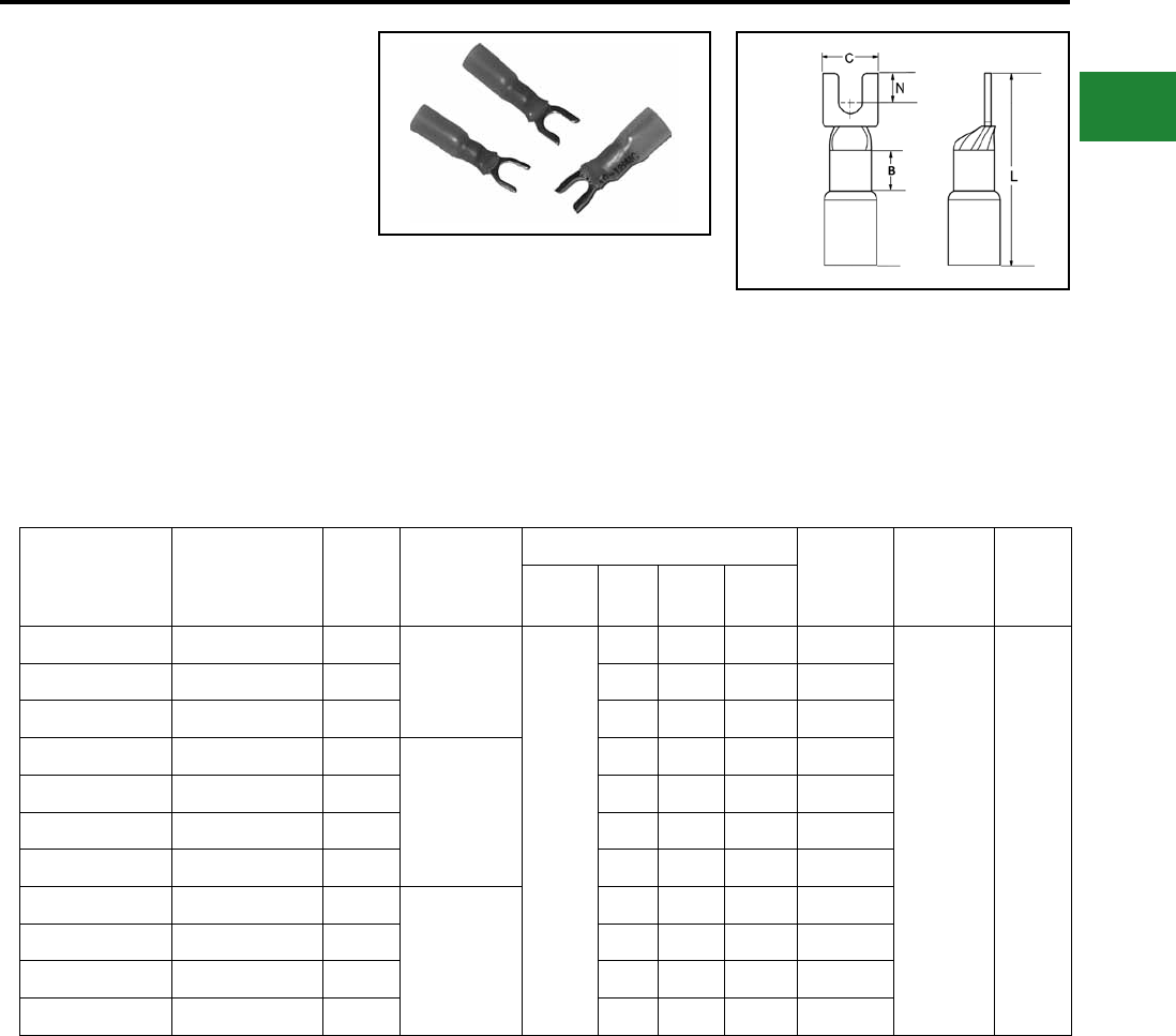
BURNDY®
Blue highlighted items are industry standard and most frequently ordered.
Canada: 1-800-387-6487 www.burndy.com US: 1-800-346-4175
Small Terminals
TYPE YHSA-F
HYDENT™ HEAT SHRINK
FORK TONGUE TERMINALS
For Use on Copper Conductor
Standard crimp terminals leave the wire exposed
allowing in moisture or other contaminants which
can result in corrosion. Corrosion reduces the
amount of current the wire can carry safely.
The integrity of the electrical system can
be compromised when unsealed electrical
connections are utilized. Heat shrink terminals
provide a durable seal blocking out contaminants
ensuring a better connection.
Catalog No.
(100/bag)
Catalog No.
(20/bag)
Stud
Size
Conductor
Size
Dimensions
Tongue
Thickness
Installation
Tooling
Wire
Strip
Length
B C L N
YHSA18K6F YHSA18K6FRK 4-6
22-18 AWG
0.22
0.25 1.17 0.32 0.04
MR22 5/16
YHSA18K8F YHSA18K8FRK 6-8 0.32 1.17 0.32 0.04
YHSA18K10F YHSA18K10FRK 8-10 0.31 1.18 0.27 0.03
YHSA14K6F YHSA14K6FRK 4-6
16-14 AWG
0.25 1.17 0.30 0.04
YHSA14K8F YHSA14K8FRK 6-8 0.34 1.17 0.30 0.04
YHSA14K10F YHSA14K10FRK 8-10 0.34 1.17 0.27 0.03
YHSA14K14FRK — 1/4 0.50 1.17 0.30 0.04
YHSA10K6F — 4-6
12-10 AWG
0.35 1.17 0.29 0.04
YHSA10K8F YHSA10K8FRK 6-8 0.35 1.17 0.29 0.04
YHSA10K10F YHSA10K10FRK 8-10 0.37 1.16 0.27 0.04
YHSA10K14FRK — 1/4 0.50 1.17 0.30 0.04
Features & Benets
• Made from pure copper, annealed for
maximum strength
• Color-coded, imprinted with wire size
• Serrated barrels offer maximum wire
contact and tensile strength
• Electro tin plated for corrosion
resistance
• Wire Strip Length 5/16"
B-31
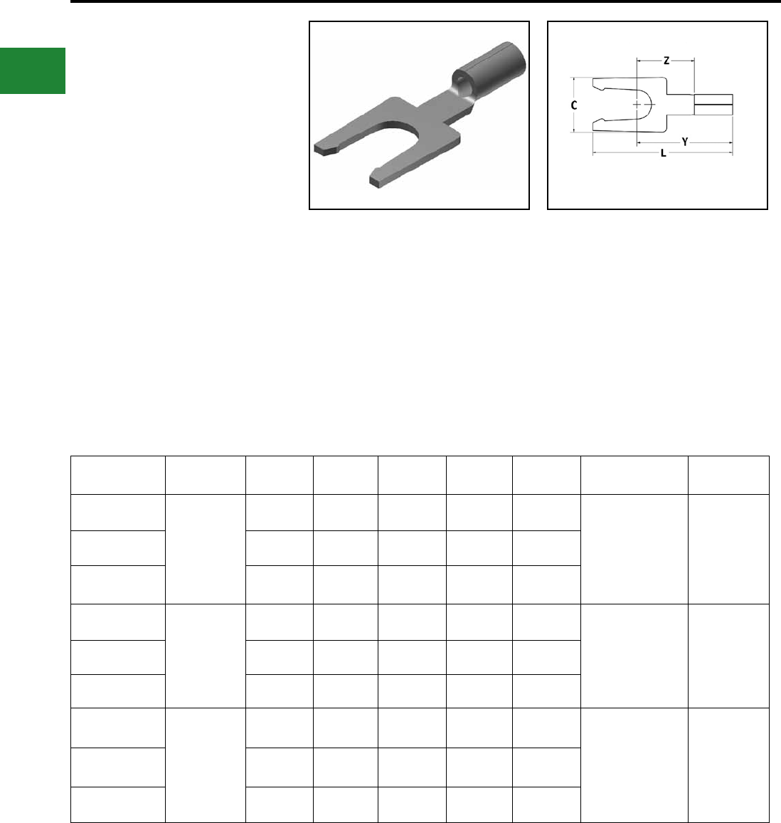
BURNDY®
Blue highlighted items are industry standard and most frequently ordered.
US: 1-800-346-4175 www.burndy.com Canada: 1-800-387-6487
Small Terminals
TYPE T-LF
HYLUG™
Uninsulated Compression Terminal
Locking Fork Tongue
Type T-LF employs a locking fork tongue for fast
installation and security.
Features & Benets
• Locking fork tongue design allows fast
installation - screw only has to be loosened for
termination
• Internal conguration of the fork prevents the
terminal from coming off the screw without
applying a pulling force
• Locking fork is made from a copper alloy;
permits many installations while maintaining
proper spring retention of forks
Catalog Number Wire Range Stud Size C L Y Z Installation Tooling Wire Strip
Length
T166LF
22 - 16 AWG
#4 - #6 0.25 0.83 0.54 0.32 MRE1022B
MR8G98
Y8MRB-1
MR20
Y10D
Y10-22
9/32
T168LF #6 - #8 0.31 0.83 0.57 0.32
T1610LF #8 - #10 0.31 0.83 0.63 0.32
T146LF
16 - 14 AWG
#4 - #6 0.25 0.81 0.54 0.30 MRE1022B
MR8G98
Y8MRB-1
MR20
Y10D
Y10-22
9/32
T148LF #6 - #8 0.30 0.83 0.57 0.30
T1410LF #8 - #10 0.32 0.83 0.63 0.30
T106LF
12 - 10 AWG
#4 - #6 0.30 0.90 0.54 0.29 MRE1022B
MR8G98
Y8MRB-1
MR20
Y10D
Y10-22
11/32
T108LF #6 - #8 0.33 0.90 0.57 0.29
T1010LF #8 - #10 0.35 0.90 0.63 0.29
B-32
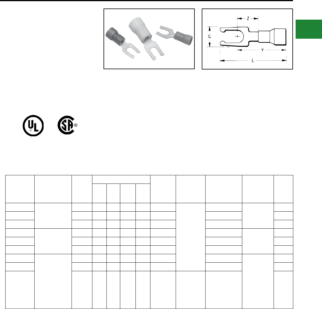
BURNDY®
Blue highlighted items are industry standard and most frequently ordered.
Canada: 1-800-387-6487 www.burndy.com US: 1-800-346-4175
Small Terminals
TYPE TP-LF AND BA-EL
VINYLUG™
Terminal - Polyvinylchloride Insulated,
Locking Fork Tongue
600 Volts Max., 105° C Max.
Type TP-LF is a variation of the Type TP design
and employs a locking fork tongue for fast
installation and security.
Features & Benets
• Locking fork tongue design
◊ Allows fast installation-screw only has
to be loosened for termination.
• Internal conguration of the fork
◊ Prevents the terminal from coming off
the screw without applying a pulling
force.
• Locking fork is made from a copper alloy
◊ Permits many installations while maintaining
proper spring retention of forks.
Catalog
Number Wire Range Stud
Size
Dimensions Bulk
Catalog
Number •
Installation
Tooling
Tape Mounted
Catalog
Number 2000/
Reel
Installation
Tooling
for tape
mounted
Wire
Strip
Length
CL.
Max
Y
Max.
Z
Min.
TP16-6LF 22 - 16 Max. Insul.
Dia. Accom.: 0.15
Color Code: Red
#4 - #6 0.28 0.80 0.66 0.23 BA16EL6
Plier Type:
Y10-22
Ratchet Tool:
MRE1022NV
MR8-89-1
MR15
BA16EL6M
TFM with
DFM3D-1 Die
13/64
TP16-8LF #6 - #8 0.31 0.86 0.69 0.26 BA16EL8 BA16EL8M 13/64
TP16-10LF #8 - #10 0.41 0.95 0.75 0.31 BA16EL10 BA16EL10M 13/64
TP14-6LF 16 - 14 Max. Insul.
Dia. Accom.: 0.18
Color Code: Blue
#4 - #6 0.28 0.80 0.66 0.23 BA14E6L BA14E6LM
TFM with
DFM2D1 Die
13/64
TP14-8LF #6 - #8 0.31 0.86 0.69 0.26 BA14EL8 BA14EL8M 13/64
TP14-10LF #8 - #10 0.41 0.95 0.75 0.31 BA14EL10 BA14EL10M 13/64
TP10-6LF
12 - 10 Max. Insul.
Dia. Accom.: 0.26
Color Code:
Yellow
#4 - #6 0.28 0.95 0.81 0.26 BA10EL6 * BA10EL6M
TFM with
DFM1D5 Die
19/64
TP10-8LF #6 - #8 0.31 0.98 0.81 0.26 BA10EL8 * BA10EL8M 19/64
TP10-10LF #8 - #10 0.41 1.07 0.87 0.31 BA10EL10
Plier Type:
Y10-22
Ratchet Tool:
MR8-89-1
MR15
* BA10EL10M 19/64
• UL LIisted and CSA Certied with MR8-89-1 and MR15.
* 1000/Reel.
B-33
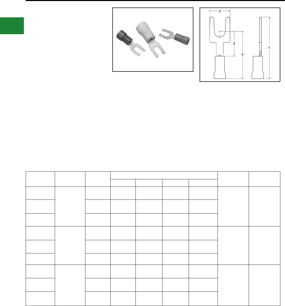
BURNDY®
Blue highlighted items are industry standard and most frequently ordered.
US: 1-800-346-4175 www.burndy.com Canada: 1-800-387-6487
Small Terminals
TYPE TN-LF
INSULUG™
Terminal - Nylon Insulated,
Locking Fork Tongue
300 Volts Max., 105° C Max.
The Type TN-LF, nylon insulated fork tongue
terminal has the same high quality as the TN. It is
designed to meet the heavy-duty requirements of
industrial and utility applications.
Used on both power and control circuits for wire
sizes #26 AWG through #10 AWG. The TN-LF
provides high dielectric strength and stability in oily
conditions.
The TN-LF is identical to the TN with the addition
of a fork tongue which allows installation without
complete removal of its supporting screw.
Features & Benets
• Locking fork tongue design
◊ Allows fast installation-screw only has
to be loosened for termination
• Internal conguration of the fork
◊ Prevents the terminal from coming off
the screw without applying a pulling
force
• Locking fork is made from a copper alloy
◊ Permits many installations while main-
taining proper spring retention of forks
Catalog
Number Wire Range Stud Size Dimensions Installation
Tooling
Wire Strip
Length
C L Max. Y Max. Z Min.
TN18-6LF 22 - 18
Max. Insul.
Dia. Accom:
0.145
Color Code: Red
4-6 0.25 0.95 0.66 0.32
MRE1022NV,
MR8-83, Y10D,
Y1022
7/32
TN18-8LF 6-8 0.31 0.95 0.69 0.32
TN18-10LF 8-10 0.31 0.95 0.75 0.32
TN14-6LF 16 - 14
Max. Insul.
Dia. Accom:
0.180
Color Code: Blue
4-6 0.25 0.93 0.66 0.30
MRE1022NV,
MR8-83, Y10D,
Y1022
7/32
TN14-8LF 6-8 0.30 0.95 0.69 0.30
TN14-10LF 8-10 0.32 0.95 0.75 0.30
TN10-6LF 12 - 10
Max. Insul.
Dia. Accom:
0.260
Color Code:
Yellow
4-6 0.30 1.02 0.66 0.29
MRE1022NV,
MR8-83, Y10D,
Y1022
11/32
TN10-8LF 6-8 0.33 1.02 0.69 0.29
TN10-10LF 8-10 0.35 1.02 0.75 0.29
B-34
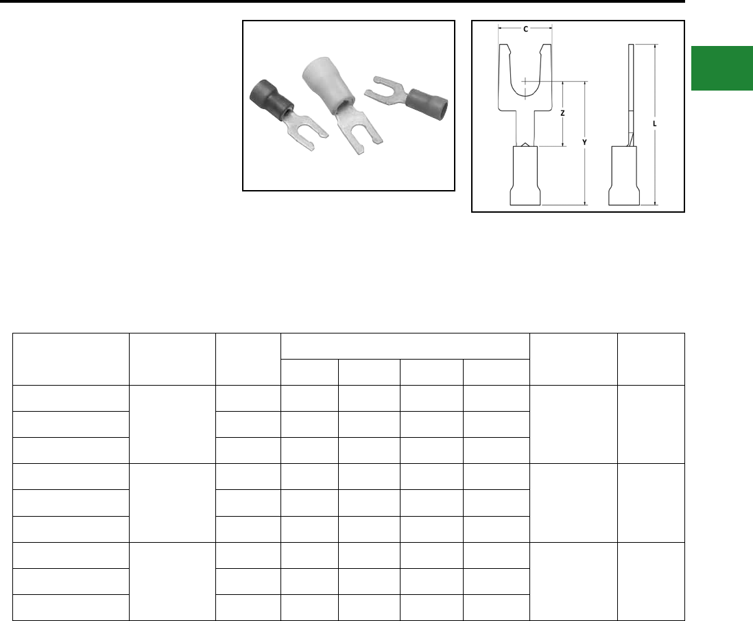
BURNDY®
Blue highlighted items are industry standard and most frequently ordered.
Canada: 1-800-387-6487 www.burndy.com US: 1-800-346-4175
Small Terminals
TYPE YAE-N-LF
INSULUG™
Terminal - Nylon Insulated,
Locking Fork Tongue
300 Volts Max., 105° C Max.
The YAE-N-LF Locking Fork is nylon insulated with
an insulation grip and accepts a 22-10 AWG wire.
The spring-like tongue locks into place around the
stud even when the mount screw is not tightened.
Catalog Number Wire Range Stud Size
Dimensions Installation
Tooling
Wire Strip
Length
C L Max. Y Max. Z Min.
YAE18N104LFBOX
22 - 18
#4 - #6 0.25 0.95 0.66 0.32 MRE1022NV
MR8-83
Y10-22
Y10D
7/32YAE18N105LFBOX #6 - #8 0.31 0.95 0.69 0.32
YAE18N106LFBOX #8 - #10 0.31 0.95 0.75 0.32
YAE14N107LFBOX
16 - 14
#4 - #6 0.25 0.93 0.66 0.30 MRE1022NV
MR8-83
Y10-22
Y10D
7/32YAE14N108LFBOX #6 - #8 0.30 0.95 0.69 0.30
YAE14N109LFBOX #8 - #10 0.32 0.95 0.75 0.30
YAE10N110LFBOX
12 - 10
#4 - #6 0.30 1.02 0.81 0.29 MRE1022NV
MR8-83
Y10-22
Y10D
11/32YAE10N111LFBOX #6 - #8 0.33 1.02 0.81 0.29
YAE10N112LFBOX #8 - #10 0.35 1.02 0.87 0.29
Features & Benets
• Locking Fork Tongue
• Rapid easy installation of terminal
without complete removal of screw
B-35
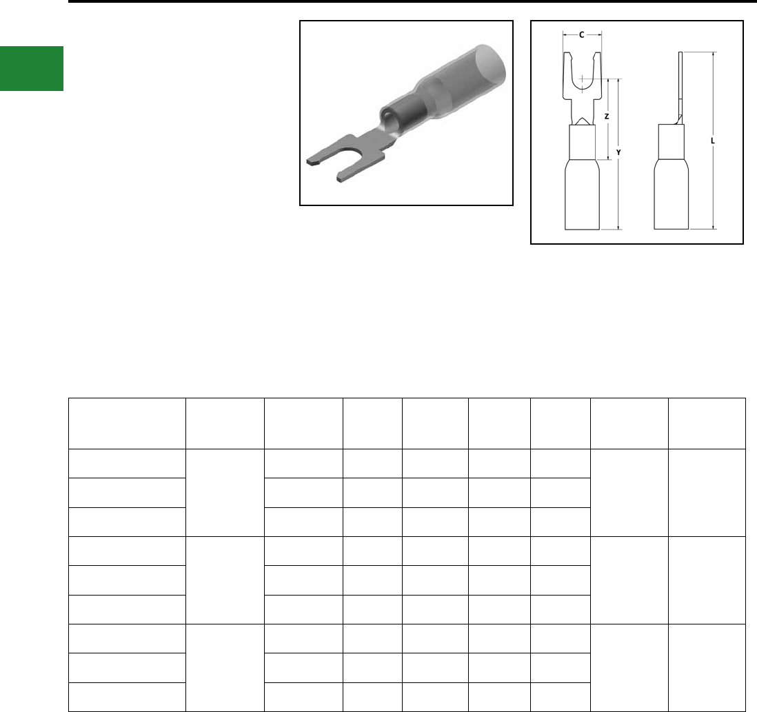
BURNDY®
Blue highlighted items are industry standard and most frequently ordered.
US: 1-800-346-4175 www.burndy.com Canada: 1-800-387-6487
Small Terminals
TYPE YHSA-K-LF
HYDENT™ HEAT SHRINK FORK
For Use on Copper Conductor
Standard crimp terminals leave the wire exposed
allowing in moisture or other contaminants which
can result in corrosion. Corrosion reduces the
amount of current the wire can carry safely.
The integrity of the electrical system can
be compromised when unsealed electrical
connections are utilized. Heat shrink terminals
provide a durable seal blocking out contaminants
ensuring a better connection.
Catalog Number Wire Range Stud Size L C Y Z Installation
Tooling
Wire Strip
Length
YHSA18K6LF
22 - 18
#6 1.20 0.25 0.66 0.32
MR22 5/16"YHSA18K8LF #8 1.20 0.31 0.69 0.32
YHSA18K10LF #10 1.20 0.31 0.75 0.32
YHSA14K6LF
16 - 14
#6 1.18 0.25 0.66 0.30
MR22 5/16"YHSA14K8LF #8 1.20 0.30 0.69 0.30
YHSA14K10LF #10 1.20 0.32 0.75 0.30
YHSA10K6LF
12 - 10
#6 1.27 0.30 0.81 0.29
MR22 5/16"YHSA10K8LF #8 1.27 0.33 0.81 0.29
YHSA10K10LF #10 1.27 0.35 0.87 0.29
Features & Benets
• Made from copper, annealed for maximum
strength
• Color-coded, imprinted with wire size
• Serrated barrels offer maximum wire contact
and tensile strength
• Electro tin plated for corrosion resistance
B-36
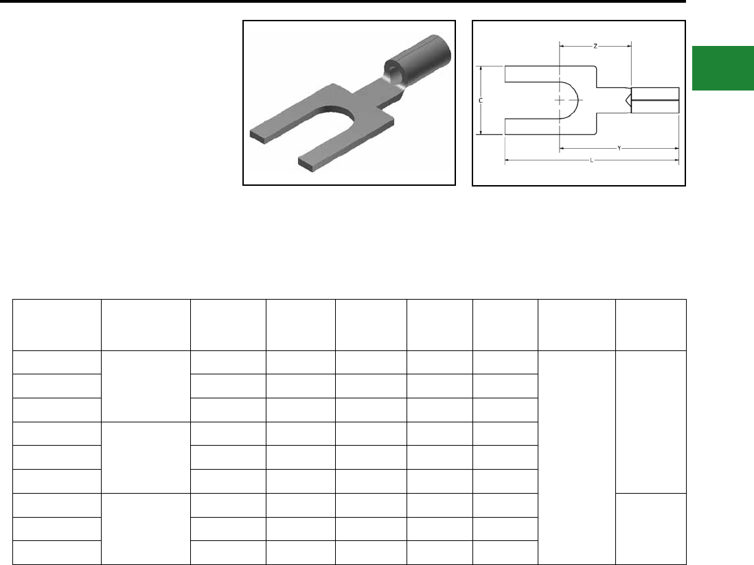
BURNDY®
Blue highlighted items are industry standard and most frequently ordered.
Canada: 1-800-387-6487 www.burndy.com US: 1-800-346-4175
Small Terminals
TYPE T-BF
FINGRIP™
Uninsulated Compression Terminal
Block Fork Tongue
Type T-BF is made from pure electrolytic copper.
Electro-tin plated for corrosion resistance. Block
spade design, featured squared-off ends.
Features & Benets
• Permits rapid, easy installation of the
terminal under the screw head without
complete removal of the screw
Catalog
Number
Wire
Range
Stud
Size C L Y Z Installation
Tooling
Wire
Strip
Length
T166BF
22 - 16 AWG
#4 - #6 0.25 0.83 0.20 0.83
MRE1022B
MR8G98
Y8MRB-1
MR20
Y10D
Y10-22
9/32"
T168BF #6 - #8 0.31 0.83 0.20 0.79
T1610BF #8 - #10 0.31 0.83 0.20 0.79
T146BF
16 - 14 AWG
#4 - #6 0.25 0.81 0.18 0.81
T148BF #6 - #8 0.30 0.83 0.18 0.80
T1410BF #8 - #10 0.32 0.83 0.18 0.79
T106BF
12 - 10 AWG
#4 - #6 0.30 0.90 0.17 0.87
11/32"T108BF #6 - #8 0.33 0.90 0.17 0.86
T1010BF #8 - #10 0.35 0.90 0.17 0.85
B-37
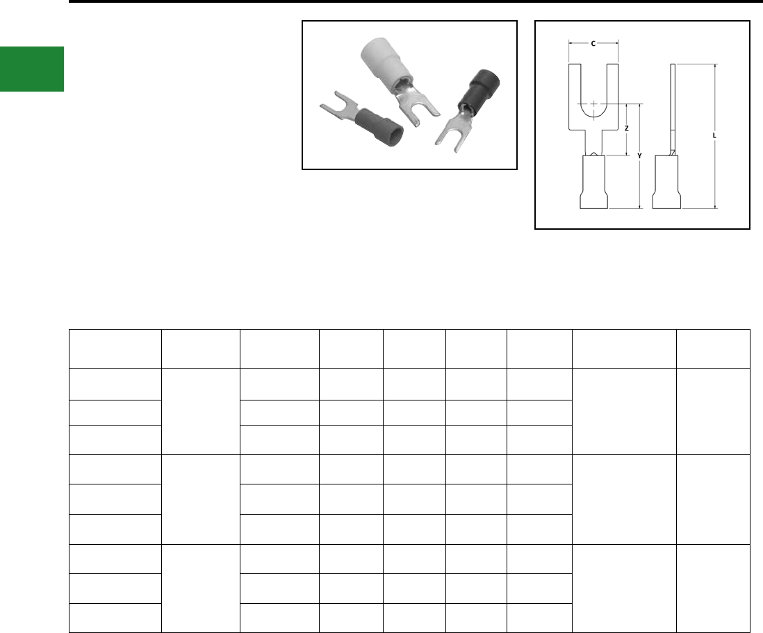
BURNDY®
Blue highlighted items are industry standard and most frequently ordered.
US: 1-800-346-4175 www.burndy.com Canada: 1-800-387-6487
Small Terminals
TYPE TP-BF
INSULUG™
Terminal - Vinyl Insulated,
Block Fork Tongue
Type TP-BF terminals are made from pure
electrolytic copper. Electro-tin plated for corrosion
resistance and Vinyl insulated. Block spade design
features squared off ends.
Features & Benets
• Permits rapid and easy installation of the ter-
minal under the screw head without complete
removal of the screw
Catalog Number Wire Range Stud Size C L Y Z Installation Tooling Wire Strip
Length
TP166BF
22 - 16
#4 - #6 0.25 0.95 0.83 0.32 Y10-22
MR8-89-1
MR8-G96
MR15
MRE1022NV
13/64
TP168BF #6 - #8 0.31 0.95 0.79 0.32
TP1610BF #8 - #10 0.31 0.95 0.79 0.32
TP146BF
16 - 14
#4 - #6 0.25 0.93 0.81 0.30 Y10-22
MR8-89-1
MR8-G96
MR15
MRE1022NV
13/64
TP148BF #6 - #8 0.30 0.95 0.80 0.30
TP1410BF #8 - #10 0.32 0.95 0.79 0.30
TP106BF
12 - 10
#4 - #6 0.30 1.02 0.87 0.29 Y10-22
MR8-89-1
MR8-G96
MR15
MRE1022NV
19/64
TP108BF #6 - #8 0.33 1.02 0.86 0.29
TP1010BF #8 - #10 0.35 1.02 0.85 0.29
B-38
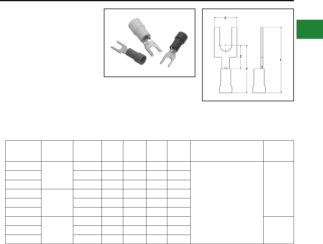
BURNDY®
Blue highlighted items are industry standard and most frequently ordered.
Canada: 1-800-387-6487 www.burndy.com US: 1-800-346-4175
Small Terminals
TYPE TN-BF
HYDENT™
Terminal - Nylon Insulated,
Block Fork Tongue
600 Volts Max., 105° C Max.
Type TN-BF terminals are made from pure
electrolytic copper. Electro tin plated for corrosion
resistance. Block spade design features squared-
off ends.
Features & Benets
• Permits rapid and easy installation of the
terminal under the screw head without
complete removal of the screw.
Catalog
Number
Wire
Range
Stud
Size C L Y Z Installation
Tooling
Wire
Strip
Length
TN186BF
22 - 18
#4 - #6 0.25 0.95 0.83 0.32
MRE1022NV
MR81A
Y10D
Y10-22
M8ND with one
of the following
N14HET25V1,
N10ET9,
N14ET15,
N10ET23
3/16"
TN188BF #6 - #8 0.31 0.95 0.79 0.32
TN1810BF #8 - #10 0.31 0.95 0.79 0.32
TN146BF
16 - 14
#4 - #6 0.25 0.93 0.81 0.30
TN148BF #6 - #8 0.30 0.95 0.80 0.30
TN1410BF #8 - #10 0.32 0.95 0.79 0.30
TN106BF
12 - 10
#4 - #6 0.30 1.02 0.87 0.29
3/8"TN108BF #6 - #8 0.33 1.02 0.86 0.29
TN1010BF #8 - #10 0.35 1.02 0.85 0.29
B-39
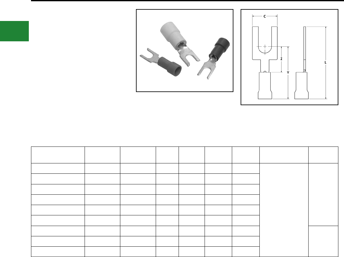
BURNDY®
Blue highlighted items are industry standard and most frequently ordered.
US: 1-800-346-4175 www.burndy.com Canada: 1-800-387-6487
Small Terminals
TYPE YAE-N-BF
INSULUG™
Terminal - Nylon Insulated
Block Fork Tongue
600 Volts Max., 105° C Max.
Type YAE-N-BF terminals are a block spade
design featuring squared-off ends.
Catalog
Number
Wire
Range
Stud
Size C L Y Z Installation
Tooling
Wire Strip
Length
YAE18N104BFBOX 22 - 18 #4 - #6 0.25 0.95 0.83 0.32
MRE1022NV,
MR8-1A,
MR8-33T-1,
Y10D, Y1022,
M8ND with one of the
following dies:
N14HET-25V1,
N10ET-9,
N14ET-15, N10ET-23
3/16"
YAE18N105BFBOX 22 - 18 #6 - #8 0.31 0.95 0.79 0.32
YAE18N106BFBOX 22 - 18 #8 - #10 0.31 0.95 0.79 0.32
YAE14N107BFBOX 16 - 14 #4 - #6 0.25 0.93 0.81 0.30
YAE14N108BFBOX 16 - 14 #6 - #8 0.30 0.95 0.80 0.30
YAE14N109BFBOX 16 - 14 #8 - #10 0.32 0.95 0.79 0.30
YAE10N110BFBOX 12 - 10 #4 - #6 0.30 1.02 0.87 0.29
3/8"YAE10N111BFBOX 12 - 10 #6 - #8 0.33 1.02 0.86 0.29
YAE10N112BFBOX 12 - 10 #8 - #10 0.35 1.02 0.85 0.29
Features & Benets
• Rapid easy installation of terminal under
the screw head without complete removal
of the screw
B-40
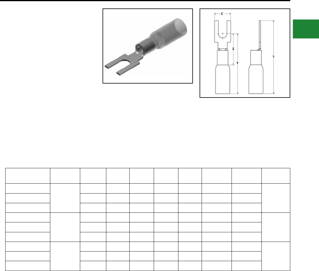
BURNDY®
Blue highlighted items are industry standard and most frequently ordered.
Canada: 1-800-387-6487 www.burndy.com US: 1-800-346-4175
Small Terminals
TYPE YHSA-K-BF
HYDENT™ HEAT SHRINK
BLOCK FORK
For Use on Copper Conductor
Standard crimp terminals leave the wire exposed
allowing in moisture or other contaminants which
can result in corrosion. Corrosion reduces the
amount of current the wire can carry safely.
The integrity of the electrical system can
be compromised when unsealed electrical
connections are utilized. Heat shrink terminals
provide a durable seal blocking out contaminants
ensuring a better connection.
Catalog
Number
Wire
Range
Stud
Size C L Y Z Tongue
Thickness
Installation
Tooling
Wire Strip
Length
YHSA18K6BF
22 - 18
#4 - #6 0.25 1.20 0.66 0.13 0.04 MR22
5/16"YHSA18K8BF #6 - #8 0.31 1.20 0.69 0.16 0.04 MR22
YHSA18K10BF #8 - #10 0.31 1.20 0.75 0.16 0.04 MR22
YHSA14K6BF
16 - 14
#4 - #6 0.25 1.18 0.66 0.13 0.04 MR22
5/16"YHSA14K8BF #6 - #8 0.30 1.20 0.69 0.15 0.04 MR22
YHSA14K10BF #8 - #10 0.32 1.20 0.75 0.16 0.04 MR22
YHSA10K10BF
12 - 10
#4 - #6 0.30 1.27 0.87 0.15 0.04 MR22
5/16"YHSA10K6BF #6 - #8 0.33 1.27 0.81 0.16 0.04 MR22
YHSA10K8BF #8 - #10 0.35 1.27 0.81 0.18 0.04 MR22
Features & Benets
• Made from copper, annealed for
maximum strength
• Color-coded, imprinted with wire size
• Serrated barrels offer maximum wire
contact and tensile strength
• Electro tin plated for corrosion
resistance
B-41
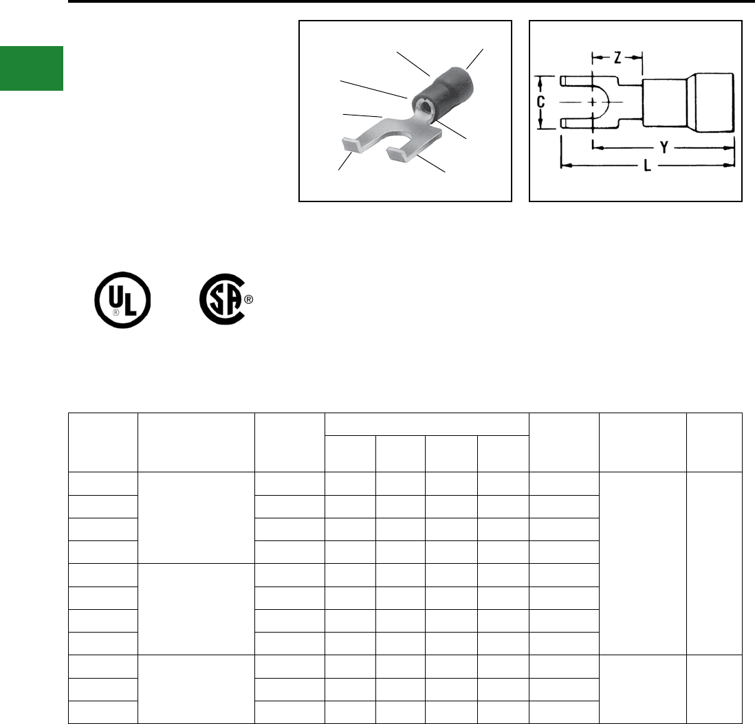
BURNDY®
Blue highlighted items are industry standard and most frequently ordered.
US: 1-800-346-4175 www.burndy.com Canada: 1-800-387-6487
Small Terminals
TYPE TP-Z AND BA-EZ
VINYLUG™
Terminal - Polyvinylchloride Insulated,
Flanged Fork Tongue
600 Volts Max., 105° C Max.
VINYLUG™ Type TP-Z is a variation of the Type
TP and employs a anged fork tongue for fast
installation and security. Features & Benets
• Flange fork tongue design
◊ Allows fast installation—screw only has to be
loosened for termination.
• The anges on the end of the fork
terminal aid in preventing a slightly
loose terminal from becoming fully
disconnected from the screw
◊ Flanges make re-securing a loose terminal
easier.
EXPANDED SHROUD
INSULATION
CRIMP
FUNNEL
ENTRY
DEEP “V”
SERRATIONS
TIN PLATEDFLANKED
FORK
WIRE SIZE
RANGE
WIRE
CRIMP
Catalog
Number
Wire
Range
Stud
Size
Dimensions Bulk
Catalog
Number
Installation
Tooling
Wire
Strip
Length
CY
Max.
Z
Min.
L
Max.
TP16-2Z
22 - 16 Max. Insul.
Dia. Accom.: 0.15
Color Code Red
#1 - #2 0.17 0.66 0.23 0.78 BA16EZ2
Plier Type:
Y10-22
Ratchet Tool:
MRE1022NV
MR8-89-1
1/4"
TP16-6Z #4 - #6 0.28 0.66 0.23 0.83 BA16EZ6
TP16-8Z #6 - #8 0.31 0.69 0.26 0.88 BA16EZ8
TP16-10Z #8 - #10 0.41 0.75 0.31 0.96 BA16EZ10
TP14-2Z
16 - 14 Max. Insul.
Dia. Accom.: 0.18
Color Code: Blue
#1 - #2 0.17 0.66 0.23 0.78 BA14EZ2
TP14-6Z #4 - #6 0.28 0.66 0.23 0.83 BA14EZ6
TP14-8Z #6 - #8 0.31 0.69 0.26 0.88 BA14EZ8
TP14-10Z #8 - #10 0.41 0.75 0.31 0.96 BA14EZ10
TP10-6Z 12 - 10 Max. Insul.
Dia. Accom.: 0.26
Color Code: Yellow
#4 - #6 0.28 0.81 0.26 0.99 BA10EZ6 MRE1022NV,
MR15,
M8ND with
N10ET-23
11/32"TP10-8Z #6 - #8 0.31 0.81 0.26 1.01 BA10EZ8
TP10-10Z #8 - #10 0.41 0.81 0.31 1.09 BA10EZ10
B-42
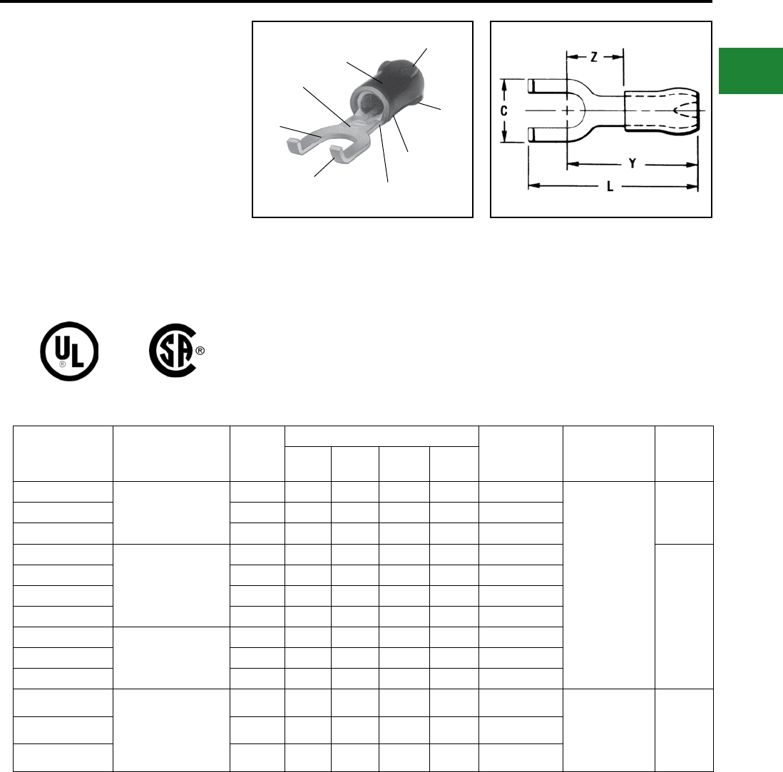
BURNDY®
Blue highlighted items are industry standard and most frequently ordered.
Canada: 1-800-387-6487 www.burndy.com US: 1-800-346-4175
Small Terminals
TYPES YAE-Z BOX
AND YAE-Z
INSULUG™
Terminal - Nylon Insulated,
Flanged Fork, Multi-Finger
Insulation Grip
600 Volts Max. 105° C Max.
INSULUG™ type YAE-Z is identical to type YAE-N
and employs a anged fork tongue for faster
installation while maintaining security if supporting
screw becomes loose.
Features & Benets
• Flanged fork
◊ permits rapid, easy installation of the
terminal under the screw head without
complete removal of the screw.
◊ Additionally, it may not be removed with only
a slight loosening of the screw.
MULTI-FINGER
INSULATION GRIPS
AND CABLE SUPPORT
FUNNEL
ENTRY
INSULATION
CRIMP
WIRE CRIMP
DEEP “V”
SERRATIONS
FLANGED
FORK
ELECTRO-TIN
PLATE
WIRE SIZE
Catalog
Number
Wire
Range
Stud
Size
Dimensions Bulk
Catalog
Number
Installation
Tooling
Wire
Strip
Length
CZ
Min.
Y
Max.
L
Max.
YAE22Z1BOX * 26 - 20 Max. Insul. Dia.:
.098"
Sleeve Color: Amber
#2 0.18 0.21 0.63 0.75 YAE22Z1
MRE1022NV,
MR8-33T-1, M8ND
with one of the
following dies:
N14HET-15,
N10ET-9,
N10ET-23,
N14HET-25V1
Y10D, Y1022
5/32"YAE22Z2BOX * #4 - #6 0.28 0.24 0.67 0.83 YAE22Z2
YAE22Z3BOX * #6 - #8 0.31 0.28 0.70 0.92 YAE22Z3
YAE18Z1BOX
22 - 16 Max. Insul. Dia.
Accom.: .125"
Color Code: Red
#2 0.18 0.21 0.70 0.83 YAE18Z1
3/16"
YAE18Z2BOX #4 - #6 0.28 0.24 0.74 1.00 YAE18Z2
YAE18Z3BOX #6 - #8 0.31 0.28 0.77 1.00 YAE18Z3
YAE18Z4BOX #8 - #10 0.36 0.32 0.82 1.08 YAE18Z4
YAE14Z2BOX 16 - 14 Max. Insul. Dia.
Accom.: .156"
Color Code: Blue
#4 - #6 0.28 0.25 0.74 0.90 YAE14Z2
YAE14Z3BOX #6 - #8 0.31 0.29 0.77 1.00 YAE14Z3
YAE14Z4BOX #8 - #10 0.36 0.33 0.82 1.08 YAE14Z4
YAE12Z2BOX
14 - 12 Max. Insul. Dia.
Accom.: .180"
Color Code: Green
#4 - #6 0.28 0.25 0.88 1.04 YAE12Z2 MRE1022NV,
MR833T-1, M8ND
with N12HET-1
Y10D, Y1022
21/64"
YAE12Z3BOX #6 - #8 0.31 0.30 0.93 1.16 YAE12Z3
YAE12Z4BOX #8 - #10 0.36 0.34 0.97 1.23 YAE12Z4
* UL Recognized and CSA Certied; Not UL Listed
B-43
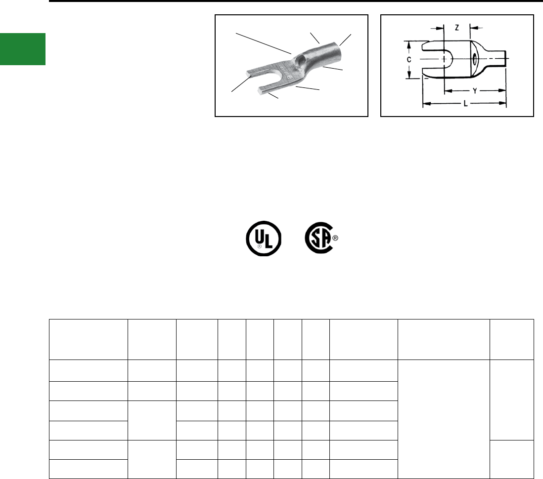
BURNDY®
Blue highlighted items are industry standard and most frequently ordered.
US: 1-800-346-4175 www.burndy.com Canada: 1-800-387-6487
Small Terminals
TYPES YAV-T-F BOX AND
YAV-T-F
HYLUG™
Seamless Uninsulated Compression
Fork Tongue Terminal
The type YAV-T-F HYLUG™ is a seamless heavy
duty uninsulated compression fork-tongue terminal
manufactured from electrolytic copper for use on
copper commercial (code) cable, Type AN aircraft
cable and extra exible conductors.
The seamless design produces a double thick
tongue and the seamless barrel provides a strong
highly reliable connection.
All the benets of the Type YAV apply for the same
wire sizes.
Features & Benets
• Fork tongue
◊ Allows installation of compression
terminal under screw head without
complete removal of the screw.
INSPECTION
HOLE
SEAMLESS
BARREL
BEVELED
ENTRY
ELECTRO-TIN
PLATED DOUBLE THICK
FORK TONGUE
WIRE SIZE
CRIMP
Catalog Number Wire
Range
Stud
Size C L Y Z
Bulk
Catalog
Number
Installation
Tooling
Wire
Strip
Length
YAV18-T19FBOX 22-18 #4-#6 0.31 0.84 0.55 0.25 YAV18T19F
Non-Ratchet:
Y10D, Y10-22
Ratchet:
MR8-G98, MR8-9Q, MR20,
Y8MRB-1, MRE10-22B
9/32"
YAV18-T21FBOX 20-18 #8-#10 0.37 0.84 0.55 0.25 YAV18T21F
YAV14-T32FBOX
20-14
#4-#6 0.31 0.84 0.57 0.25 YAV14T32F
YAV14-T34FBOX #8-#10 0.37 0.82 0.60 0.26 YAV14T34F
YAV10-T21FBOX
12-10
#8-#10 0.36 0.99 0.69 0.26 YAV10T21F
7/16"
YAV10-T23FBOX 1/4 0.47 1.03 0.75 0.34 YAV10T23F
B-44
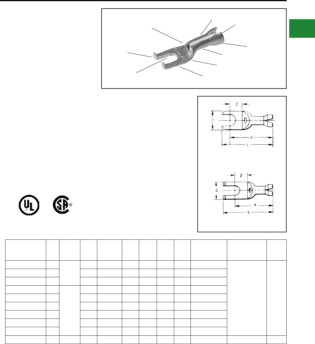
BURNDY®
Blue highlighted items are industry standard and most frequently ordered.
Canada: 1-800-387-6487 www.burndy.com US: 1-800-346-4175
Small Terminals
TYPES YAV-H-F BOX,
YAV-H-F AND YAV-Z
HYLUG™
Uninsulated Compression
Terminal Fork Tongue With
Seamless Shroud
The type “YAV-H-F” HYLUG™ is a seamless
heavy duty uninsulated compression fork tongue
terminal with a shroud for an insulation grip and
cable support. Manufactured from electrolytic
copper tubing for use on copper commercial
(code) cable, Type “AN” aircraft and extra exible
conductors.
The seamless tubing produces a double thick
tongue while the seamless barrel design
provides a very strong connector for very
demanding applications that require highly reliable
connections.
In addition to the benets described for the YAV
box series of connectors the YAVH-F Box and
YAV-Z terminals provide the following benets.
Features & Benets
• Fork tongue
• ◊ Allows installation of compression terminal
under screw head without complete removal of
the screw thereby lowering installation costs
• Flanged fork tongue
• ◊ Allows installation of compression terminal
under screw head without complete removal of
the screw plus aids in maintaining the terminal
on the stud should the screw loosen slightly
Catalog
Number Fig. Wire
Range
Stud
Size
Max. Insul.
Dia.
Accom.
C L Max Y Max Z Min Bulk
Catalog #
Installation
Tooling
Wire
Strip
Length
YAV18-H6F BOX 1
22-18
4-6 0.120 0.25 0.89 0.80 0.19 YAV18-H6F
Non-Ratchet:
Y10D*, Y14MV,
Y10-22*
Ratchet:
MR8-G98,
MR8-9Q,
Y8MRB-1*,
MR20, and M8ND
with N14HT-5 Die or
N14HT
1/4"
YAV18-H19F BOX 1 4-6 0.120 0.30 0.97 0.75 0.21 YAV18-H19F
YAV18-H21F BOX 1 8-10 0.120 0.37 0.97 0.76 0.22 YAV18-H21F
YAV14-Z5 BOX 2
20-14
4-6 0.150 0.31 0.86 0.69 0.13 YAV14-Z5
YAV14-H32F BOX 1 4-6 0.150 0.30 0.96 0.78 0.23 YAV14-H32F
YAV14-H56F BOX 1 6-8 0.150 0.30 0.96 0.78 0.23 YAV14-H56F
YAV14-H34F BOX 1 8-10 0.150 0.38 0.96 0.78 0.23 YAV14-H34F
YAV14-HF BOX 1 8-10 0.150 0.31 0.92 0.78 0.23 YAV14-HF
YAV14-Z6 BOX 2 8-10 0.150 0.37 1.00 0.78 0.21 YAV14-Z6
YAV10-HF BOX 1 12-10 8-10 0.192 0.38 1.07 0.78 0.24 YAV10-HF N10HT-24 7/16"
* Crimps conductor crimp only.
SEAMLESS
BARREL
INSPECTION
HOLE
ELECTRO-TIN
PLATED
FLANGED
FORK TONGUE DOUBLE THICK
TONGUE
WIRE RANGE
CRIMP
CRIMP
INSULATION
GRIP AND
CABLE SUPPORT
Fig .1
Fig .2
B-45
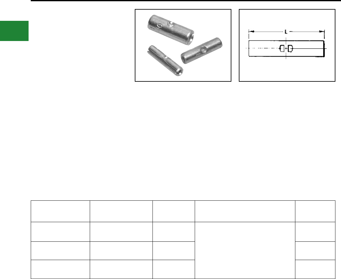
BURNDY®
Blue highlighted items are industry standard and most frequently ordered.
US: 1-800-346-4175 www.burndy.com Canada: 1-800-387-6487
Small Terminals
TYPE YSV-B
HYDENT™
Uninsulated Butt Splice
HYLINK™ type YSV-B rolled splice connector is
used to splice stranded and solid copper conductors
in virtually all heavy duty industrial and general
purpose applications.
Catalog
Number
Wire
Range LInstallation
Tooling
Wire
Strip
Length
YSV18BBOX 22 - 18 AWG 0.62 Y10D
Y10-22
MRE1022B
Y8MRB-1
MR8-9Q
MR8-G98
MR20
1/4"
YSV14BBOX 16 - 14 AWG 0.64 1/4"
YSV10BBOX 12 - 10 AWG 0.75 5/16"
Features & Benets
• Constructed of pure electrolytic copper
• Provides maximum conductivity, low
resistance and ductility for excellent
crimp forming properties
• Long brazed seam barrel
• Provides optimum conductivity, reliability
and holding power after crimping
• Electro-tin plated
• Provides durable long-lasting corrosion
resistance
B-46
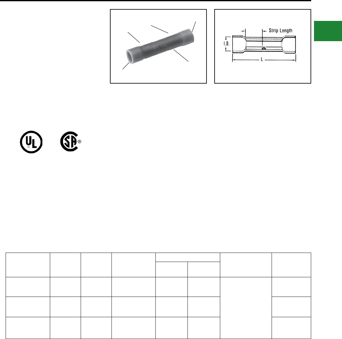
BURNDY®
Blue highlighted items are industry standard and most frequently ordered.
Canada: 1-800-387-6487 www.burndy.com US: 1-800-346-4175
Small Terminals
TYPE SP
VINYLINK™
Splice, Polyvinylchloride Insulated
600 Volts Max., 105° C Max.
The Type SP VINYLINK™ is a PVC insulated
seamless butt splice. Type SP VINYLINK™ is
designed to accommodate a broad range of 600
volt cables.
Catalog
Number
Wire
Range
Color
Code
Bulk
Catalog
Number
Dimensions (Inches) Installation
Tooling
Wire
Strip
Length
L
Max.
Max
Insul. Dia
SP16 22 - 16 Red BS16 1.00 0.15
Non-Ratchet: Y10-22
Ratchet: MRE1022NV
MR8G-98
MR15
MR8-89-1
1/4"
SP14 16 - 14 Blue BS14 1.00 0.18 1/4"
SP10 12 - 10 Yellow BS10 1.23 0.26 21/64"
Features & Benets
• Manufactured from seamless electrolytic
copper tubing
◊ Provides maximum conductivity and
tensile strength, in a high quality
design with NO seams to split
• Funnel entry
◊ Provides easy wire insertion
• Electro-tin plated
◊ Provides durable long lasting
resistance to corrosion
• Expanded insulation support
◊ Lower inventory requirements
• Red wire range of 22-16
◊ Lower inventory requirements
• Vinyl insulator
◊ Economical means of providing high
dielectric values and cable insulation
support
INSULATION
SUPPORT
CRIMP
CRIMP
SMOOTH
ENTRY
COLOR CODED
B-47
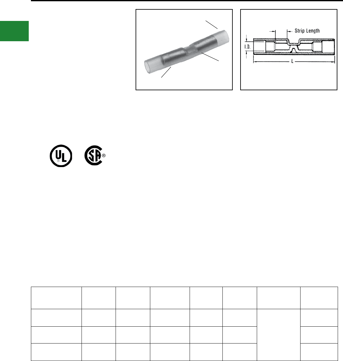
BURNDY®
Blue highlighted items are industry standard and most frequently ordered.
US: 1-800-346-4175 www.burndy.com Canada: 1-800-387-6487
Small Terminals
TYPE SN
INSULINK™
Butt Splice, Nylon Insulated
600 Volts Max., 105° C Max.
The Type SN INSULINK™ is a high quality nylon-
insulated butt splice designed to meet heavy duty
application requirements.
Meets the functional requirements of MIL-T-7928
(ASG) and conforms to the requirements of
NAS1388.
Catalog
Number
Wire
Range
Color
Code
Bulk
Catalog
Number
L
Max.
Max
Insul Dia
Installation
Tooling
Wire
Strip
Length
SN18 22 - 18 Red YSE18HN 1.25 0.12 Plier:
Y10D
Y1022
Ratchet:
MRE1022NV
MR8-83
MR18
15/64"
SN14 16 - 14 Blue YSE14HN 1.25 0.15 7/32"
SN10 12 - 10 Yellow YSE10HN 1.64 0.22 3/8"
Features & Benets
• Manufactured from seamless tubing
◊ A high quality design with no seams
to split
• Pure electrolytic copper
◊ Provides maximum conductivity, low
resistance and ductility for excellent
crimp forming properties
• Electro-tin plated
◊ Provides durable long-lasting
resistance to corrosion
• Positive center wire stops
◊ Provides for proper depth of wire insertion
• Color-coded in red, blue and yellow
◊ Provides easy wire size identication
• Manufactured from one-piece tin-plated
seamless copper tubing with an integral
barrel/insulation grip
◊ Provides maximum tensile strength,
plus excellent cable support and strain
relief and eliminates failures due to
vibration
• Smooth funnel entry
◊ Provides easy wire insertion
• Window position locator for full cycle
ratchet tool crimp
◊ Provides proper tool/connector
alignment for correct crimp
• Nylon insulation offers high dielectric
strength and stability in oily
environmental conditions
◊ Maintains a high quality connection in
demanding applications
• The nylon is locked into position
◊ The connector will not move
NYLON
INSULATION
INTEGRAL METAL
CABLE SUPPORT
AND STRAIN RELIEF
SEAMLESS ELECTRO-TIN
PLATED SPLICE
B-48
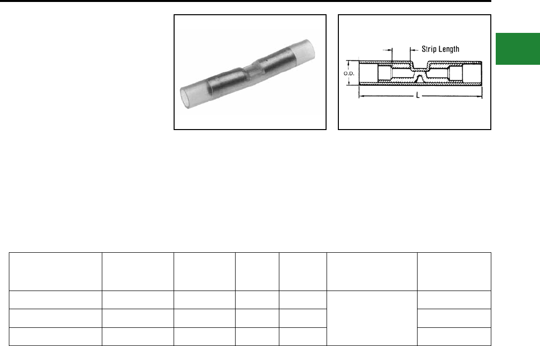
BURNDY®
Blue highlighted items are industry standard and most frequently ordered.
Canada: 1-800-387-6487 www.burndy.com US: 1-800-346-4175
Small Terminals
TYPE SN-B
HYDENT™
Butt Splice, Nylon Insulated
600 Volts Max., 105° C Max.
The Type SN-B INSULINK™ is a high quality
nylon-insulated butt splice.
Catalog
Number
Wire
Range
Color
Code L OD Installation
Tooling
Wire
Strip
Length
SN18B 22 - 18 AWG Red 1.25 0.12 Y10D
Y1022
MRE1022NV
MR8-85
15/64"
SN14B 16 - 14 AWG Blue 1.25 0.15 7/32"
SN10B 12 - 10 AWG Yellow 1.64 0.22 3/8"
Features & Benets
• Tin plated copper brazed butt seam
• Smooth funnel entry provides easy wire
insertion
• Nylon insulation offers high dielectric
strength and stability
B-49
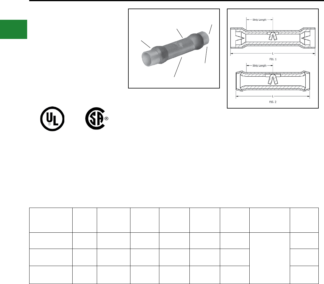
BURNDY®
Blue highlighted items are industry standard and most frequently ordered.
US: 1-800-346-4175 www.burndy.com Canada: 1-800-387-6487
Small Terminals
TYPES YSE BOX,
YSE-H BOX
INSULINK™
600 Volts Max., 105° C Max.
The Types YSE and YSE-H INSULINK™ splices
are high quality nylon insulated designed for
splicing aircraft and commercial exible cables.
Catalog
Number Figure
Wire Range
(Code, AWG,
Aircraft, AN)
Color
Code
Bulk
Catalog
Number
L
Max.
Max
Dia. Insul.
Installation
Tooling
Wire
Strip
Length
YSE18H-BOX 1 22 - 18 Red YSE18H 1.22 0.12
Y10D
Y1022
Ratchet:
MRE1022NV
MR8-33T-1
9/32"
YSE14H-BOX 1 16 - 14 Blue YSE14H 1.36 0.15 11/32"
YSE10-BOX 2 12 - 10 Yellow YSE10 1.15 0.21 23/64"
Features & Benets
• Manufactured from tin plated, seamless
electrolytic copper tubing with integral
barrel/insulation grip
◊ Provides maximum conductivity and
tensile strength, plus excellent cable
support and strain relief
• Split heavy wall insulation grip
◊ Provides stronger insulation grip and
strain relief
• Smooth funnel entry
◊ Provides easy wire insertion
• Transparent nylon insulation
◊ Permits easy wire inspection
FUNNEL
ENTRY
NYLON
INSULATION
SEAMLESS
INSPECTION
WINDOW
SPLIT HEAVY
WALL INSULATION
GRIP
B-50
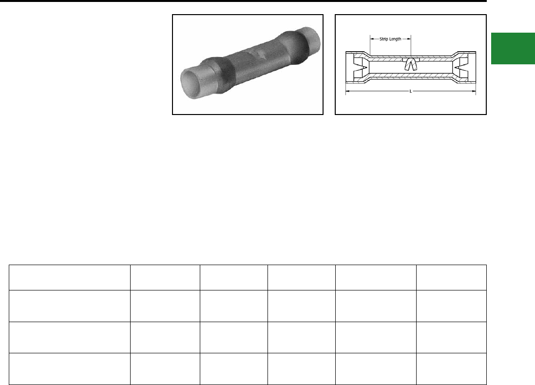
BURNDY®
Blue highlighted items are industry standard and most frequently ordered.
Canada: 1-800-387-6487 www.burndy.com US: 1-800-346-4175
Small Terminals
TYPE YSE-HHS
HYDENT™
Heat Shrink Butt Splices
Heat shrink butt connectors are color-coded to
industry standard wire range. Heat shrink protects
against corrosion.
Catalog Number Wire Range L W Installation Tooling Wire Strip Length
YSE18HHS 18 - 22 1.50 0.17 Y10D, Y1022
MR8-33T-1 9/32"
YSE14HHS 16 - 14 1.50 0.20 Y10D, Y1022
MR8-33T-1 11/32"
YSE10HHS 12 - 10 1.60 0.25 Y10D, Y1022
MR8-33T-1 23/64"
Features & Benets
• Manufactured from tin plated, seamless
electrolytic copper tubing with integral barrel.
◊ Provides maximum conductivity and
tensile strength, plus excellent cable
support and strain relief.
• Smooth funnel entry.
◊ Provides easy wire insertion.
• Transparent heat shrink insulation.
◊ Provides waterproong and weather
resistance.
B-51
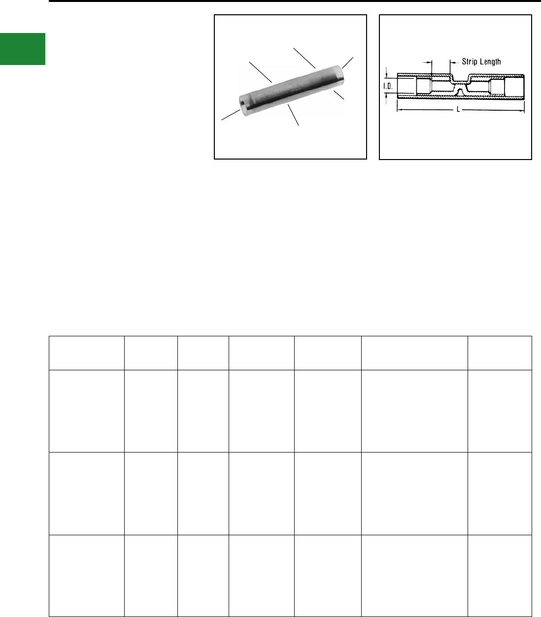
BURNDY®
Blue highlighted items are industry standard and most frequently ordered.
US: 1-800-346-4175 www.burndy.com Canada: 1-800-387-6487
Small Terminals
TYPE YSES-K
INSULINK™
Radiation Resistant Insulated Butt
Splice, Polyvinylidene Flouride
(PVF2) Insulated
200 Megarads - 60° C
Through 150° C, 600 Volts
The Type YSES-K radiation resistant insulated
splices are suitable for class 1E applications
plus non critical nuclear associated applications.
The splice is manufactured from pure electrolytic
copper seamless tubing which eliminates potential
splitting of seams. A color code stripe is used for
wire size identication and a window is provided
for inspection of proper wire insertion.
Catalog
Number
Wire
Range
Color
Stripe
Dimension
Max. Insul.
Dia. Accom.
L
Max.
Installation
Tooling
Wire
Strip
Length
YSES18K 22-18 Red 0.11 1.00
Ratchet Tool:
MR10G8
Red Groove
Calibration Gauge:
PG-373-1
Crimp ID Mark:
(1) Small Dot
3/16"
YSES14K 16-14 Blue 0.15 1.00
Ratchet Tool:
MR10G8
Blue Groove
Calibration Gauge:
PG-371-1
Crimp ID Mark:
(2) Small Dots
3/16"
YSES10K 12-10 Yellow 0.21 1.38
Ratchet Tool:
MR10G8
Yellow Groove
Calibration Gauge:
PG-372-1
Crimp ID Mark:
(1) Large Dot
7/16"
Features & Benets
• These insulated splices are suitable for
class 1E applications
• Pure electrolytic copper seamless tubing
eliminates potential splitting of seams
• Color coded stripe identies wire size
• Window is provided for inspection of
proper wire insertion
• Suitable for 200 Megarads Rated
60°C - 150°C
• 600 Volt rated
INSPECTION
WINDOW
KYNAR
INSULATED SMOOTH
FUNNEL
ENTRY
SEAMLESS
ELECTRO-TIN
PLATED SPLICE
COLOR CODED
INSULATOR
INTEGRAL METAL
CABLE SUPPORT
AND STRAIN RELIEF
B-52
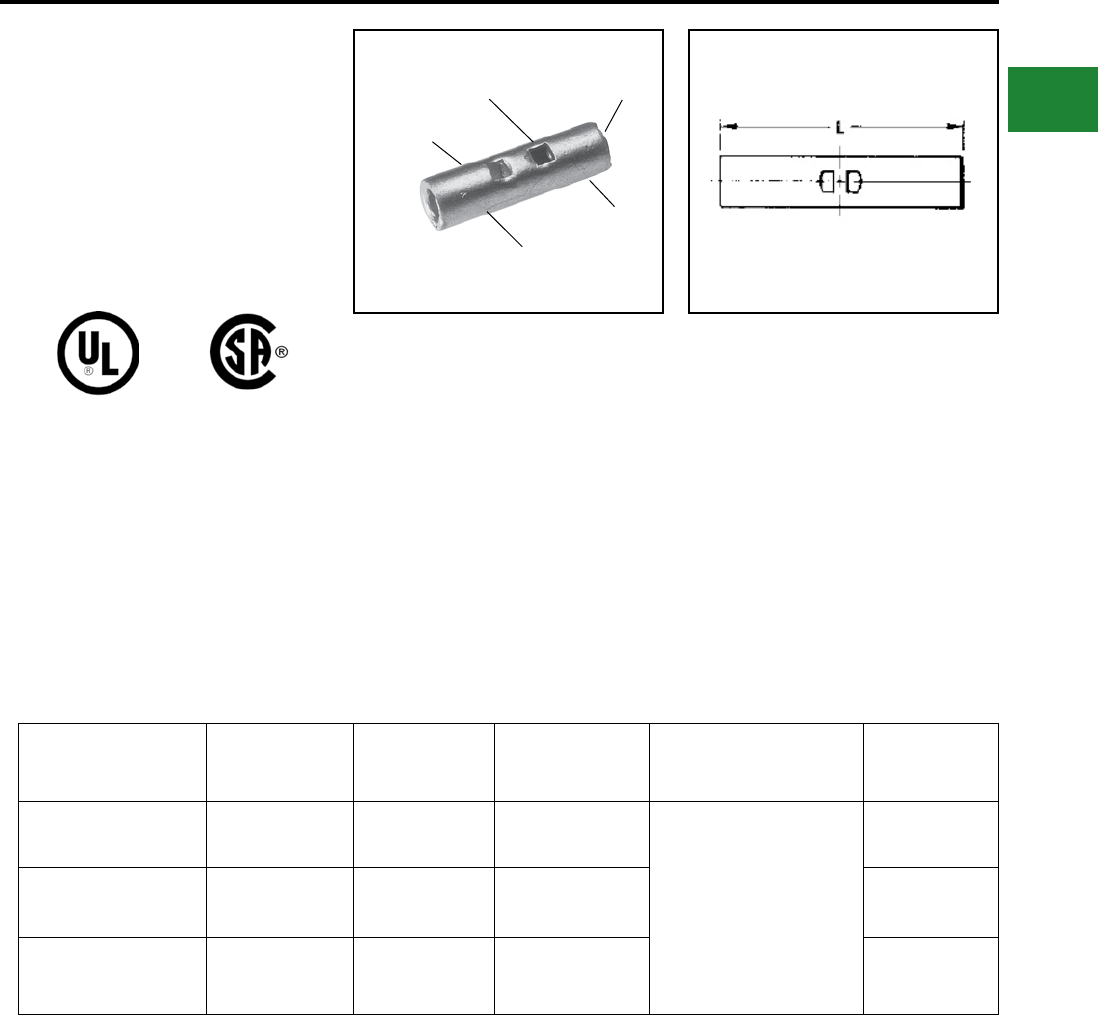
BURNDY®
Blue highlighted items are industry standard and most frequently ordered.
Canada: 1-800-387-6487 www.burndy.com US: 1-800-346-4175
Small Terminals
TYPE YSV
HYLINK™
Uninsulated Butt Splice
HYLINK™ Type YSV seamless splice connector
is used to splice stranded and solid copper
conductors in virtually all heavy duty industrial and
general purpose applications.
Catalog
Number
Wire
Range L
Bulk
Catalog
Number
Installation
Tooling
Wire
Strip
Length
YSV18BOX 22 - 18 0.62 YSV18
Non-Ratchet:
Y10D, Y1022
Ratchet:
MRE1022B,
MR20, Y8MRB-1,
MR8-9Q*, MR8-G98
1/4"
YSV14BOX 20 - 14 0.64 YSV14 1/4"
YSV10BOX 12 - 10 0.75 YSV10 5/16"
Features & Benets
• Manufactured from seamless tubing
◊ A high quality design with no seams
to split
• Electrolytic copper
◊ Provides maximum conductivity, low
resistance and ductility for excellent
crimp forming properties
• Electro-tin plated
◊ Provides durable long lasting
resistance to corrosion
• Positive center wire stops
◊ Provides proper depth of wire insertion
• Marked with wire size
◊ Provides easy wire size identication
• The HYLINK™ splice connectors have
inspection holes
◊ Provides easy visual inspection for
proper wire insertion
INSPECTION HOLE
AND WIRE STOP
SEAMLESS
TUBING
TIN-PLATED
CRIMP
CRIMP
BEVELED
ENTRY
* Remove stop plate.
B-53
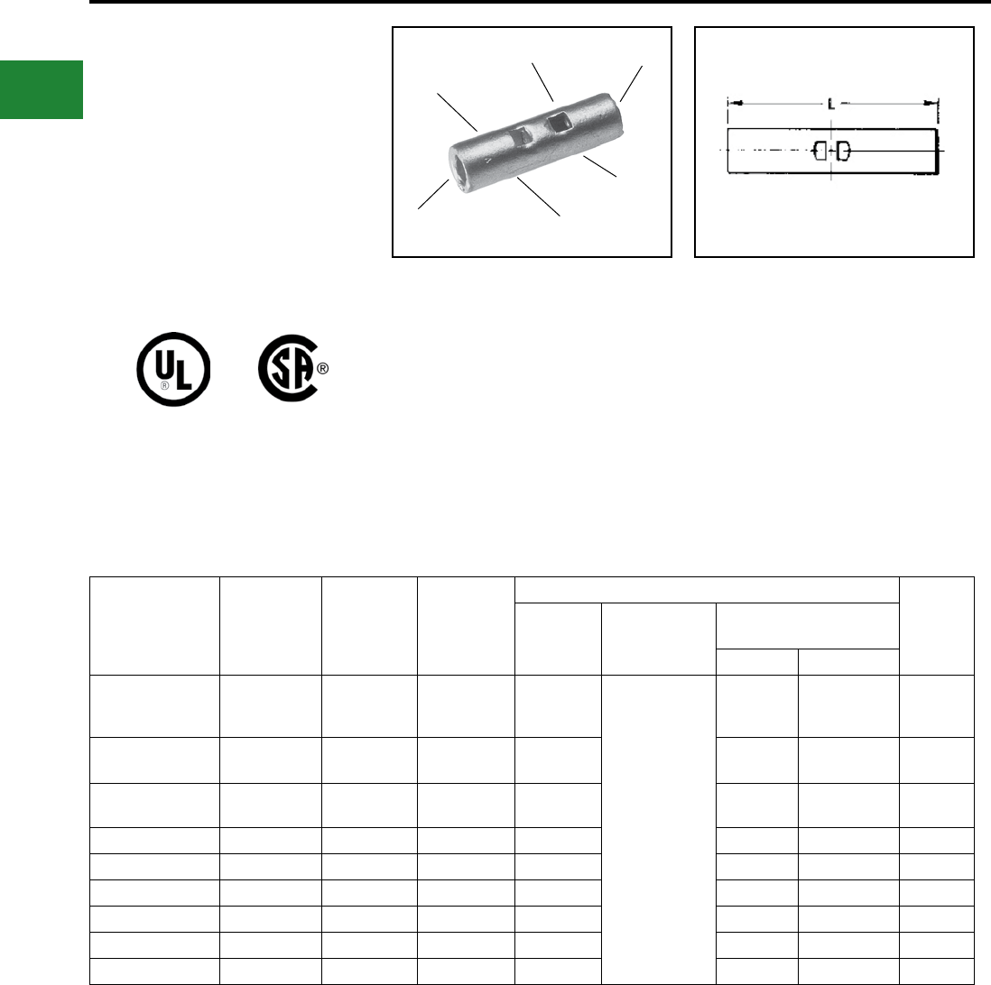
BURNDY®
Blue highlighted items are industry standard and most frequently ordered.
US: 1-800-346-4175 www.burndy.com Canada: 1-800-387-6487
Small Terminals
TYPE YSV-L
HYLINK™
Uninsulated Butt Splice
#8 Through 4/0 Copper
HYLINK™ Type YSV-L seamless splice connector
is used to splice Type AN aircraft cables plus
commercial stranded and solid AWG conductors.
Suitable for aircraft, light duty industrial and
general purpose applications. Features & Benets
• Manufactured from seamless tubing
◊ A high quality design with no seams to
split
• Electrolytic copper
◊ Provides maximum conductivity, low
resistance and ductility for excellent
crimp forming properties
• Electro-tin plated
◊ Provides durable long lasting
resistance to corrosion
◊ Provides proper depth of wire insertion
Catalog
Number
Wire Range
Aircraft-AN
Comm’l-AWG
Str. & Sol.
Dimensions
L
Bulk
Catalog
Number
Installation Tooling
Wire Strip
Length
Ratchet HYTOOL™ **
HYPRESS™ • Y35, Y35BH,
Y39, Y39BH*
Nest Indentor
YSV8C-LBOX 8 AWG 1.00 YSV8CL
MR89Q,
Y8MRB-1,
Y1MRTC
MY28
(for Type AH
Aircraft Cable);
All others:
MY29-3,
MY29-11 1
Crimp
UV8L-1 Y34PL 7/16"
YSV6C-LBOX 6 AWG 1.12 YSV6CL Y1MRTC,
MR4C UV6L Y34PLA 5/8"
YSV4C-LBOX 4 AWG 1.12 YSV4CL Y1MRTC,
MR4C UV4L Y34PLA 5/8"
YSV2C-LBOX 2 AWG 1.41 YSV2CL Y1MRTC UV2L Y34PLA 5/8"
YSV1C-LBOX 1 AWG 1.46 YSV1CL — UV1L Y34PLA 5/8"
YSV25-LBOX 1/0 AWG 1.53 YSV25L — UV25L Y34PA 11/16"
YSV26-LBOX 2/0 AWG 1.78 YSV26L — UV26L Y34PA 13/16"
YSV27-LBOX 3/0 AWG 1.81 YSV27L — UV27L Y34PA 13/16"
YSV28-LBOX 4/0 AWG 1.94 YSV28L — UV28L Y34PA 7/8"
* Remove stop plate
• Use Y35P3 Indentor Adaptor.
** Bench Mount Adaptor - Cat. No. BMY-BCH-MT is
available for Type MY HYTOOLS™.
INSPECTION HOLE
AND WIRE STOP
ELECTRO-TIN
PLATED
SEAMLESS
TUBING
BEVELED
ENTRY
CRIMP
CRIMP
• Marked with wire size
◊ Provides easy wire size identication
• The HYLINK™ splice connectors have
inspection holes
◊ Provides easy visual inspection for
proper wire insertion
B-54
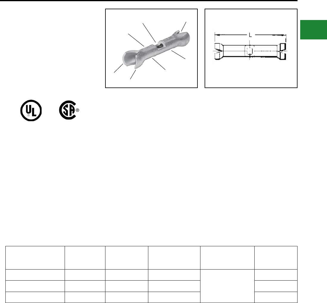
BURNDY®
Blue highlighted items are industry standard and most frequently ordered.
Canada: 1-800-387-6487 www.burndy.com US: 1-800-346-4175
Small Terminals
TYPE YSV-H
HYLINK™
Uninsulated Butt Splice with
Cable Strain Relief
The Type YSV-H HYLINK™ seamless splice
connector has the added benet of an insulation
support and cable strain relief.
Catalog
Number
Wire
Range L
Bulk
Catalog
Number
Installation
Tooling
Wire
Strip
Length
YSV18-HBOX 22 - 18 0.89 YSV18H MRE1022B
MR8-9Q*
MR8-G98
1/4"
YSV14-HBOX 20 - 14 0.94 YSV14H 1/4"
YSV10-HBOX 12 - 10 1.06 YSV10H 5/16"
Features & Benets
• Manufactured from seamless tubing
◊ A high quality design with no seams
to split
• Electrolytic copper
◊ Provides maximum conductivity, low
resistance and ductility for excellent
crimp forming properties
• Electro-tin plated
◊ Provides durable long lasting
resistance to corrosion
• Positive center wire stops
◊ Provides proper depth of wire insertion
• Marked with wire size
◊ Provides easy wire size identication
• The HYLINK™ splice connectors have
inspection holes
◊ Provides easy visual inspection for
proper wire insertion
INSPECTION HOLE
AND WIRE STOP
SEAMLESS
TUBING
TIN-PLATED
CABLE SUPPORT
CRIMP
CRIMP
BEVELED
ENTRY
* Remove stop plate.
B-55
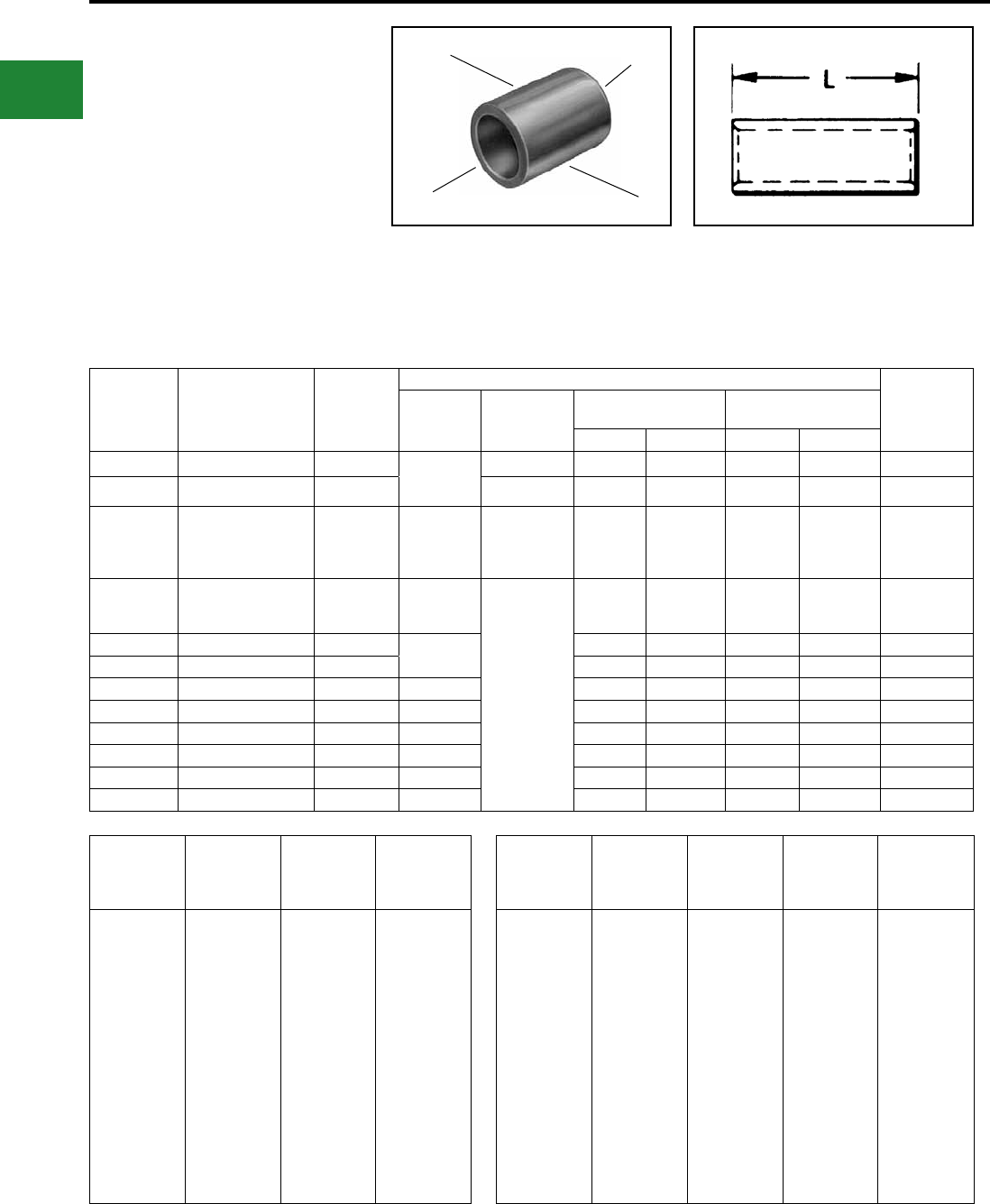
BURNDY®
Blue highlighted items are industry standard and most frequently ordered.
US: 1-800-346-4175 www.burndy.com Canada: 1-800-387-6487
Small Terminals
TYPE YSM
HYLINK™
Uninsulated Parallel Splice
HYLINK™ Type YSM seamless parallel splice
connector permits wires to be laid parallel inside the
connector and spliced together with the BURNDY
family of HYTOOL™ installation tooling. Each YSM
connector accommodates a wide combination of
round, square, and rectangular copper conductors
that have a total combined circular mil area listed in
the table below. The conductors to be spliced must
physically t within title splice without being forced.
Features & Benets
• Seamless tubing
• Beveled barrel for ease of wire entry
• Tin plated
• Parallel design results in only one crimp
* Remove stop plate.
SEAMLESS
TUBING
BEVELED
ENTRY
ELECTRO-TIN
PLATED CRIMP
Catalog
Number
Circular Mil.
Range
Dim.
L
Installation Tooling Wire
Strip
Length
Ratchet Mechanical
HYTOOLTM
Y29B HYPRESS™•
Y35BH, Y39BH*
Nest Indentor Nest Indentor
YSM18 300 - 1,909 0.25 MR8-9Q*
Y14MRQ
Y8MRB-1
— — — — — 5/16
YSM14 477 - 4,107 0.25 — — — — — 5/16
YSM10 4,107 - 10,380 0.36
MR8-9Q*
MR4CQ
Y10MRQ
Y8MRB-1
— — — — — 7/16
YSM8C 6,088 - 16,864 0.41
Y2MR
MR4CQ
MR8-9Q*
MY29-11
or
MY28
(1) Crimp
DV8L-1 Y29PQ UV8L-1 Y29PQ 1/2
YSM6C 10,380 - 26,813 0.44 Y2MR
MR4CQ
DV6L Y29PQ UV6L Y29PQ 1/2
YSM4C 26,813 - 42,613 0.50 DV4L Y29PQ UV4L Y29PQ 9/16
YSM2C 42,613 - 66,832 0.62 Y2MR DV2L Y29PQ UV2L Y29PQ 11/16
YSM1C 66,832 - 81,807 0.62 — DV1L Y29PQ UV1L Y29PQ 11/16
YSM25 81,807 - 104,110 0.69 — DV25L Y29PQ-6 UV25L Y29PQ-6 3/4
YSM26 104,110 - 133,650 0.81 — DV26L Y29PQ-6 UV26L Y29PQ-6 7/8
YSM27 133,650 - 167,332 0.81 — DV27L Y29PQ-6 UV27L Y29PQ-6 7/8
YSM28 167,332 - 211,954 0.88 — DV28L Y29PQ-6 UV28L Y29PQ-6 5/16
Wire
Size
Area
Cir. Mils.
Solid
Wire Dia.
(In.)
Concentric
Str. Max.
Dia. (In.)
30
29
28
27
26
25
24
23
22
21
20
19
18
17
16
15
14
100.5
126.7
159.8
201.5
254.1
320.4
404.0
509.5
642.4
810.1
1022
1288
1624
2048
2583
3257
4107
0.010003
0.01126
0.01264
0.01420
0.01594
0.01790
0.02010
0.02257
0.02535
0.02845
0.03196
0.03589
0.04030
0.04526
0.05082
0.05707
0.06408
0.012
–
0.015
–
0.019
–
0.024
–
0.030
–
0.038
–
0.0460
–
0.0585
–
0.0735
Wire
Size
Area
Cir. Mils.
Solid
Wire Dia.
(In.)
Concentric
Str. Max.
Dia. (In.)
Flex. Bunch
or Rope
Lay Dia.
(In Approx.)
13
12
11
10
9
8
7
6
5
4
3
2
1
1/0
2/0
3/0
4/0
5178
6530
8234
10380
13090
16510
20820
26250
33100
41740
52640
66370
83690
105500
133100
167800
211600
0.07196
0.08081
0.09074
0.1019
0.1144
0.1285
0.1433
0.1620
0.1819
0.2043
0.2294
0.2576
0.2893
0.3249
0.3648
0.4096
0.4600
–
0.0931
–
0.117
0.132
0.148
0.166
0.186
0.209
0.235
0.264
0.297
0.333
0.374
0.420
0.472
0.530
–
0.101
–
0.126
0.146
0.157 – 0.162
0.179 – 0.196
0.207 – 0.215
0.235 – 0.240
0.263 – 0.269
0.219 – 0.305
0.319 – 0.337
0.367 – 0.376
0.441 – 0.423
0.500 – 0.508
0.549 – 0.576
0.613 – 0.645
• Uninsulated barrel provides an
economical termination solution when
insulation is not specied
B-56

BURNDY®
Blue highlighted items are industry standard and most frequently ordered.
Canada: 1-800-387-6487 www.burndy.com US: 1-800-346-4175
Small Terminals
B-57
TYPE YSCM
HYLINK™
Color-Coded
Uninsulated Parallel Splice
Type YSCM HYLINK™ seamless parallel
splice connectors permit stranded wires to be
laid parallel inside the connector and spliced
together with BURNDY® compression tools.
Each YSCM connector accommodates a wide
range of conductors and is color-coded to ensure
proper tool and die match. YSCM connectors are
cULus Listed Wire Connectors per UL 486A/B.
Catalog
Number
Conductor Range
Cable‡
Dimensions
Inches [mm] Color
Code
Die
Index
Recommended Installation Tooling Wire
Strip†
Length
Circular Mils L
±.03
O.D.
±.01
OUR840, Y500CTHS,
PAT60018V Series
Y35, Y750,
PAT750
Series
Min. Max.
YSCM17 13,060 16,910 0.5
[13]
0.27
[7] Red 49 X8CRT, W8CRT U8CRT 11/16
YSCM27 16,910 26,890 0.5
[13]
0.31
[8] Blue 7 X5CRT, W5CRT U5CRT 11/16
YSCM42 29,970 41,520 0.5
[13]
0.38
[10] Gray 8 X4CRT, W4CRT U4CRT 11/16
YSCM66 42,750 66,040 0.62
[16]
0.47
[12] Brown 10 X2CRT, W2CRT U2CRT 3/4
YSCM80 67,980 80,020 0.62
[16]
0.52
[13] Green 11 X1CRT-1, W1CRT-1 U1CRT-1 3/4
YSCM104 82,870 103,630 0.69
[18]
0.57
[14] Pink 12 X25RT, W25RT U25RT 15/16
YSCM133 104,960 133,220 0.81
[21]
0.64
[16] Black 13 X26RT, W26RT U26RT 1-1/16
YSCM167 134,340 166,560 0.81
[21]
0.7
[18] Orange 14 X27RT, W27RT U27RT 1-1/16
YSCM212 167,380 211,820 0.88
[22]
0.78
[20] Purple 15 X28RT, W28RT U28RT 1-1/16
YSCM231 230,800 230,800 1.05
[27]
0.8
[21] Yellow 16 X29RT, W29RT, * U29RT 1-1/16
Circular Mil Table per ASTM B8
Size ASTM Strandings
Circular
Mils AWG Class Cable
Diameter (in)
1,022 20 B 0.036
1,624 18 B 0.045
2,583 16 B 0.057
4,107 14 B 0.072
6,530 12 B 0.091
10,380 10 B 0.116
13,090 9 B 0.130
16,510 8 B 0.146
20,820 7 B 0.164
26,250 6 B 0.184
33,100 5 B 0.206
41,740 4 AA 0.254
41,740 4 B & A 0.232
52,630 3 AA 0.285
52,630 3 B & A 0.260
SEAMLESS
TUBING
COLOR-CODE
AND DIE INDEX BEVELED
ENTRY
ELECTRO-TIN
PLATED
Notes:
Material: Copper per ASTM B75.
Finish: Tin plated. For nickel plating, add sufx “NK” to the
Catalog Number.
Dimensions in brackets [ ] are in millimeters rounded off to
the nearest millimeter, unless otherwise noted, and are for
reference only.
†Recommended strip length. Strip length dependent on size,
no. of wires and insulation thickness.
‡Refer to Circular Mil Table per ASTM B8 for total Class B
Circular Mil calculations.
*YSCM231 can also be installed with MY29-3 and retain
Listings.
Circular Mil Table per ASTM B8
Size ASTM Strandings
Circular
Mils AWG Class Cable
Diameter (in)
66,370 2 AA 0.320
66,370 2 B & A 0.292
83,690 1 AA 0.360
83,690 1 A 0.328
83,690 1 B 0.332
105,500 1/0 A & A 0.368
105,500 1/0 - 0.390
105,500 1/0 B 0.373
133,100 2/0 A & A 0.414
133,100 2/0 - 0.438
133,100 2/0 B 0.419
167,800 3/0 A & A 0.464
167,800 3/0 - 0.492
167,800 3/0 B 0.470
211,600 4/0 A & A 0.522
211,600 4/0 - 0.522
211,600 4/0 B 0.528
Add the circular mils of the wires you wish to
splice; that sum would be used to determine
the correct splice using the Min/Max columns
on the table above.
The tables to the right are for reference only.
Additionally, they are cULus Listed for Grounding
and Bonding per UL 467 and rated for direct burial
in Earth and Concrete.
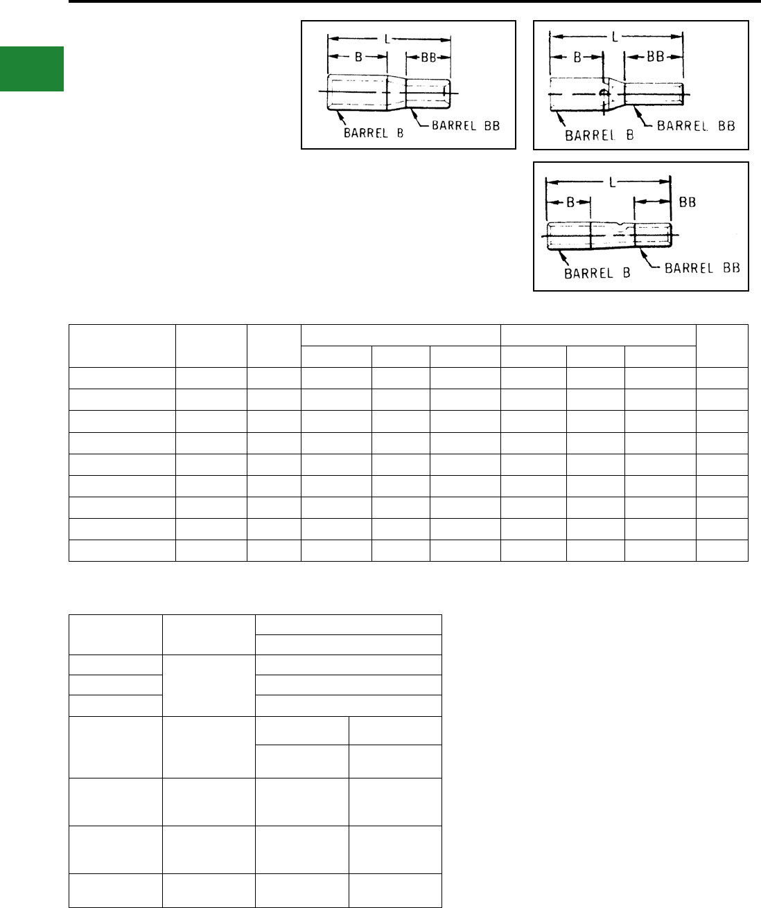
BURNDY®
Blue highlighted items are industry standard and most frequently ordered.
US: 1-800-346-4175 www.burndy.com Canada: 1-800-387-6487
Small Terminals
TYPES YSV, YRV-L
HYREDUCER™
Reducer Butt Splice
The HYREDUCER™ is a connector for splicing
two different size wires. The larger conductor
is inserted rst and butts against the center of
the connector where the smaller barrel begins.
Constructed of pure electrolytic copper tubing
for maximum conductivity, tin plated to resist
corrosion, the HYREDUCER™ accommodates a
wide range of cable sizes.
Dimensional information may be found in Table
1. Table 2 is a comprehensive tooling index for
these connectors.
Catalog
Number
Total Wire
Range
Fig.
No.
B Barrel* BB Barrel* L
Max.
Wire Size B Dim. Tool Index Wire Size BB Dim. Tool Index
YSV1418 22 - 14 1 20 - 14 0.27 1 22 - 18 0.27 2 0.60
YSV1214-G1 16 - 12 2 12 0.31 4 16 - 14 0.27 1 0.81
YSV1014-G2 20 - 10 2 12 - 10 0.31 4 20 - 14 0.27 1 0.77
YRV8CV14-L 20 - 8 3 8 0.44 5 20 - 14 0.39 1 1.16
YRV8CV10-L 12 - 8 3 8 0.44 5 12 - 10 0.53 4 1.15
YRV6CV10-L 12 - 6 3 6 0.50 6 12 - 10 0.53 4 1.25
YRV6CV8C-L 8 - 6 3 6 0.50 6 8 0.53 5 1.18
YRV4CV6C-L 6 - 4 3 4 0.50 7 6 0.54 6 1.24
YRV2CV6C-L 6 - 2 3 2 0.62 8 6 0.51 6 1.60
Fig. 1 Fig. 2
Fig. 3
TABLE 1
TABLE 2
* B and BB dimensions are wire strip lengths.
* For aircraft applications (exible cables).
Index
Number
Hand
Tools
Tools With Dies
Y29NC
1MR8G98
Y8MRB-1
MR8-9Q†
MR20
—
2—
4—
5
Y8MRB-1
MY28
MR4C
Y1MRTC
Nest Indentor
DV8L-1* Y29PL
6
MY28
MR4C
Y1MRTC
DV6L Y29PL
7
MY28
MR4C
Y1MRTC
DV4L Y19PL
8Y1MRTC
MY28 DV2L Y29PL
TOOL INDEX
B-58
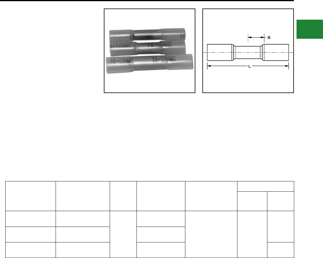
BURNDY®
Blue highlighted items are industry standard and most frequently ordered.
Canada: 1-800-387-6487 www.burndy.com US: 1-800-346-4175
Small Terminals
TYPE YHSS
HYDENT™ HEAT SHRINK
BUTT SPLICES
For Use On Copper Conductor
Standard crimp terminals leave the wire exposed
allowing in moisture or other contaminants which
can result in corrosion. Corrosion reduces the
amount of current the wire can carry safely.
The integrity of the electrical system can
be compromised when unsealed electrical
connections are utilized. Heat shrink terminals
provide a durable seal blocking out contaminants
ensuring a better connection.
Catalog Number
(100/bag)
Catalog No.
(20/bag)
Fig.
No.
Conductor
Size
Connector
Type
Dimensions
B L
YHSS18 YHSS18RK
1
22 - 18 AWG
Butt Splice 0.25"
1.50"
YHSS14 YHSS14RK 16 - 14 AWG
YHSS10 YHSS10RK 12 - 10 AWG 1.60"
Features & Benets
• Made from pure copper, annealed for
maximum strength
• Color-coded, imprinted with wire size
• Serrated barrels offer maximum wire contact
and tensile strength
• Electro tin plated for corrosion resistance
• Wire strip length 5/16"
Recommended Tooling MR22
Fig. 1
B-59
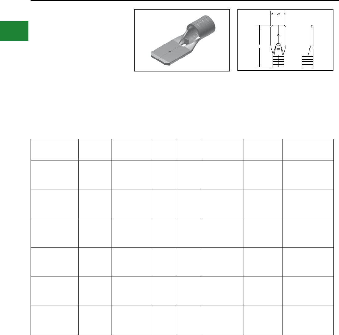
BURNDY®
Blue highlighted items are industry standard and most frequently ordered.
US: 1-800-346-4175 www.burndy.com Canada: 1-800-387-6487
Small Terminals
TYPE Q-M FINGRIP™
NON-INSULATED MALE QUICK
DISCONNECTS
Material: Tin-Plated Brass
Non Insulated Quick disconnects allows for quickly
connecting or disconnecting a terminal. The front
end of the terminal has a female-type receptacle
which allows the terminal to slide onto and off of
a male blade.
Catalog
Number
Wire
Range
NEMA
Tab Size L W Installation
Tool
Wire Strip
Length
Bulk
Catalog
Number
Q18M11X02D 18 - 22 0.110 X 0.020 0.66 0.110
MRE1022B
MR20
Y10D
Y1022
3/8" —
Q18M18X02D 18 - 22 0.187 X 0.020 0.66 0.187
MRE1022B
MR20
Y10D
Y1022
3/8" Q18M18X02B
Q18M25X03D 18 - 22 0.250 X 0.032 0.66 0.250
MRE1022B
MR20
Y10D
Y1022
3/8" Q18M25X03B
Q14M18X02D 14 - 16 0.187 X 0.020 0.66 0.187
MRE1022B
MR20
Y10D
Y1022
3/8" Q14M18X02B
Q14M25X03D 14 - 16 0.250 X 0.032 0.66 0.250
MRE1022B
MR20
Y10D
Y1022
3/8" Q14M25X03B
Q10M25X03D 12 - 10 0.250 X 0.032 0.66 0.250
MRE1022B
MR20
Y10D
Y1022
3/8" —
Features & Benets
• Butted seam
• Chamfered barrel opening
◊ Assures quick and easy wire insertion
• Mates with dimpled female socket detent
◊ Ensures rm grip
B-60
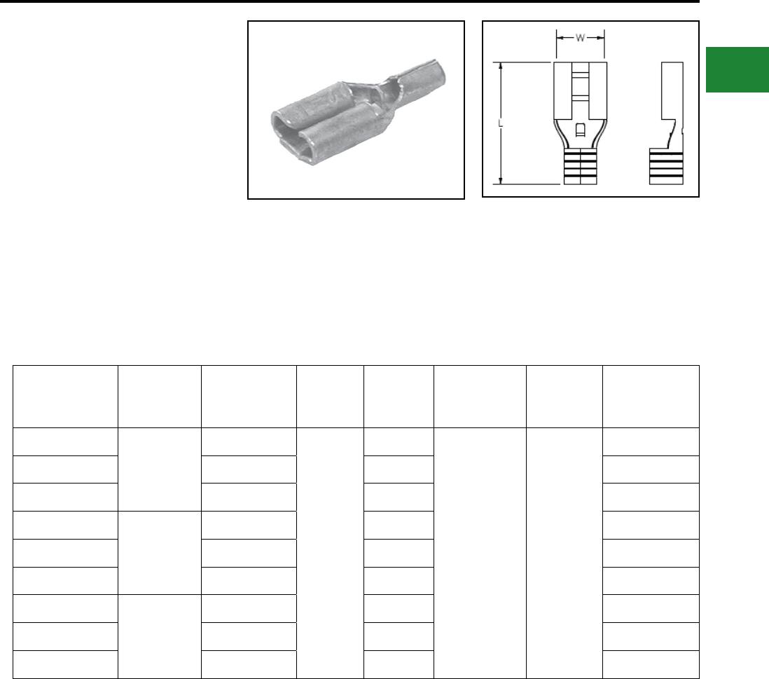
BURNDY®
Blue highlighted items are industry standard and most frequently ordered.
Canada: 1-800-387-6487 www.burndy.com US: 1-800-346-4175
Small Terminals
TYPE Q-F FINGRIP™
NON-INSULATED FEMALE
QUICK DISCONNECTS
Material: Tin-Plated Brass
Non Insulated Quick disconnects allows for quickly
connecting or disconnecting a terminal. The front
end of the terminal has a female-type receptacle
which allows the terminal to slide onto and off of
a male blade. Features & Benets
• Butted seam
• Chamfered barrel opening
◊ Assures quick and easy wire insertion
• Dimpled female socket detent
◊ Ensures rm grip
Catalog
Number
Wire
Range
NEMA
Tab Size L W Installation
Tooling
Wire
Strip
Length
Bulk
Catalog
Number
Q18F11X02D
18 - 22
0.110 x 0.020
0.66
0.110
MRE1022B
Y10D
MR20
3/8"
—
Q18F18X02D 0.187 x 0.020 0.187 Q18F18X02B
Q18F25X03D 0.250 x 0.032 0.250 Q18F25X03B
Q14F11X02D
14 - 16
0.110 x 0.020 0.110 Q14F11X02B
Q14F18X02D 0.187 x 0.020 0.187 Q14F18X02B
Q14F25X03D 0.250 x 0.032 0.250 Q14F25X03B
Q10F11X02D
12 - 10
0.110 x 0.020 0.110 —
Q10F18X02D 0.187 x 0.020 0.187 —
Q10F25X03D 0.250 X 0.032 0.250 Q10F25X03B
B-61
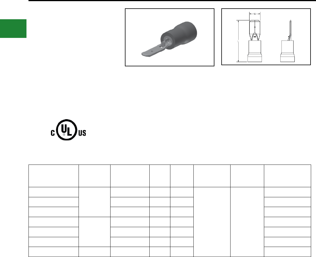
BURNDY®
Blue highlighted items are industry standard and most frequently ordered.
US: 1-800-346-4175 www.burndy.com Canada: 1-800-387-6487
Small Terminals
TYPE QP-M FINGRIP™
VINYL INSULATED MALE
QUICK DISCONNECTS
Material: Tin-Plated Brass
600 Volts Max., 105° C Max.
Vinyl Insulated Quick disconnects allows for
quickly connecting or disconnecting a terminal.
The front end of the terminal has a female-type
receptacle which allows the terminal to slide onto
and off of a male blade.
Catalog
Number
Wire
Range NEMA Tab Size L W Installation
Tool
Wire Strip
Length
Bulk
Catalog
Number
QP18M11X02D
18 - 22
0.11 X 0.02 0.76 0.11
MRE1022NV
Y1022
Y10D
3/8"
—
QP18M18X02D 0.19 X 0.02 0.76 0.19 QP18M18X02B
QP18M25X03D 0.25 X 0.03 0.84 0.25 QP18M25X03B
QP14M11X02D
14 - 16
0.11 X 0.02 0.76 0.11 —
QP14M18X02D 0.19 X 0.02 0.76 0.19 QP14M18X02B
QP14M25X03D 0.25 X 0.03 0.84 0.25 QP14M25X03B
QP10M25X03D 12 - 10 0.25 X 0.03 0.93 0.25 —
Features & Benets
• Butted seam
• Funnel entry barrel opening
◊ Assures quick and easy wire insertion
• Mates with dimpled female socket detent
◊ Ensures rm grip
B-62
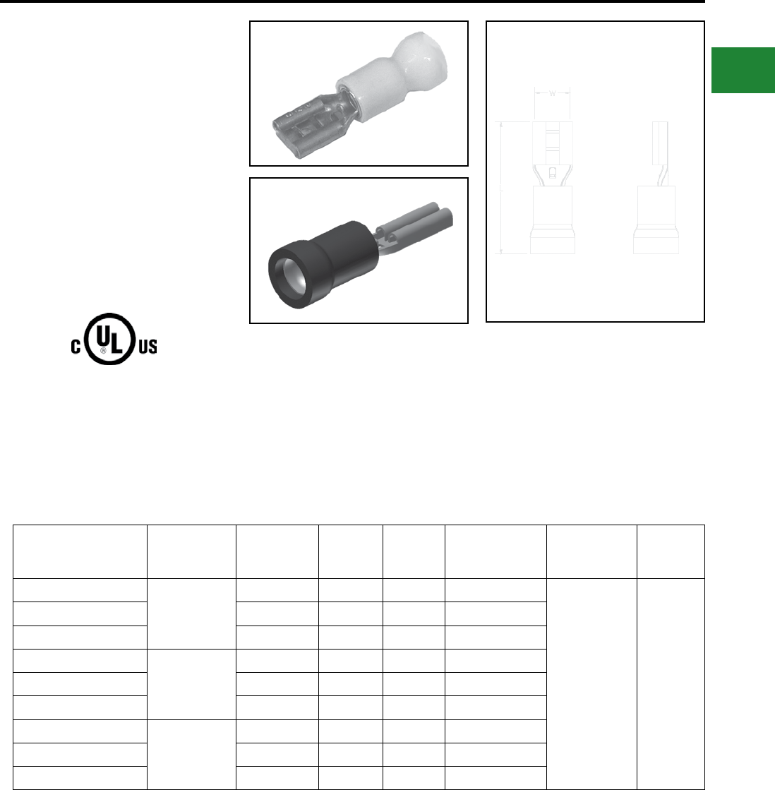
BURNDY®
Blue highlighted items are industry standard and most frequently ordered.
Canada: 1-800-387-6487 www.burndy.com US: 1-800-346-4175
Small Terminals
TYPE QP-F FINGRIP™
VINYL INSULATED FEMALE
QUICK DISCONNECTS
Material: Tin-Plated Brass
600 Volts Max., 105° C Max.
Vinyl Insulated Quick disconnects allows for
quickly connecting or disconnecting a terminal.
The front end of the terminal has a female-type
receptacle which allows the terminal to slide onto
and off of a male blade.
Catalog
Number
Wire
Range
NEMA Tab
Size L W
Bulk
Catalog
Number
Installation
Tool
Wire
Strip
Length
QP18F11X02D
16 - 22
0.11 X 0.02 0.75 0.11 —
MRE1022NV
Y10D 3/8"
QP18F18X02D 0.19 X 0.02 0.79 0.22 QP18F18X02B
QP18F25X03D 0.25 X 0.03 0.87 0.29 QP18F25X03B
QP14F11X02D
14 - 16
0.11 X 0.02 0.75 0.11 —
QP14F18X02D 0.19 X 0.02 0.79 0.23 QP14F18X02B
QP14F25X03D 0.25 X 0.03 0.87 0.29 QP14F25X03B
QP10F18X02D*
10 - 12
0.19X 0.02 0.98 0.29 QP10F18X02B
QP10F25X03D 0.25 X 0.03 0.98 0.29 QP10F25X03B
QP10F38X05D* 0.38 x 0.05 1.12 0.39 —
Features & Benets
• Butted seam
• Insulated connectors
◊ Eliminate the need for post installation
insulation
• Funnel entry barrel opening
◊ Assures quick and easy wire insertion
• Dimpled female socket detent
◊ Ensures rm grip
* Not cULus.
B-63
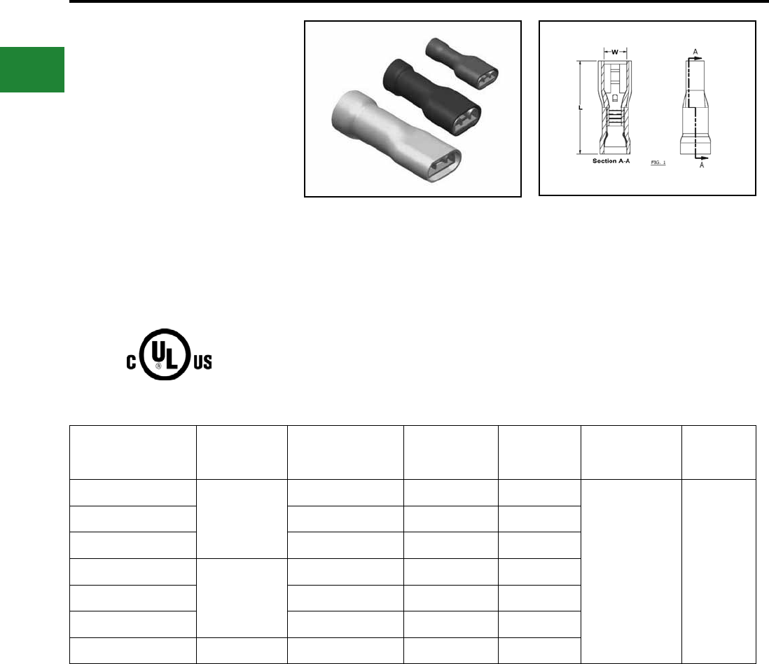
BURNDY®
Blue highlighted items are industry standard and most frequently ordered.
US: 1-800-346-4175 www.burndy.com Canada: 1-800-387-6487
Small Terminals
TYPE FQP-F FINGRIP™
VINYL FULLY INSULATED FEMALE
QUICK DISCONNECTS
Material: Tin-Plated Brass
600 Volts Max., 105° C Max.
Vinyl Fully Insulated Quick disconnects allows for
quickly connecting or dis-connecting a terminal.
The front end of the terminal has a female-type
receptacle which allows the terminal to slide onto
and off of a male blade.
Catalog
Number
Wire
Range
NEMA Tab
Size L W Installation
Tool
Wire
Strip
Length
FQP18F11X03D
18 - 22
0.11 x 0.03 0.79 0.11
MRE1022NV
Y1022 3/8"
FQP18F18X02D 0.19 x 0.02 0.80 0.19
FQP18F25X03D 0.25 x 0.03 0.90 0.25
FQP14F11X03D
14 - 16
0.11 x 0.03 0.79 0.11
FQP14F18X02D 0.19 x 0.02 0.80 0.19
FQP14F25X03D 0.25 x 0.03 0.90 0.25
FQP10F25X03D 10 - 12 0.25 x 0.03 0.97 0.25
Features & Benets
• Fully insulated connectors
◊ Eliminate the need for post installation
insulation
• Funnel entry barrel opening
◊ Assures quick and easy wire insertion
• Dimpled female socket detent
◊ Ensures rm grip
B-64
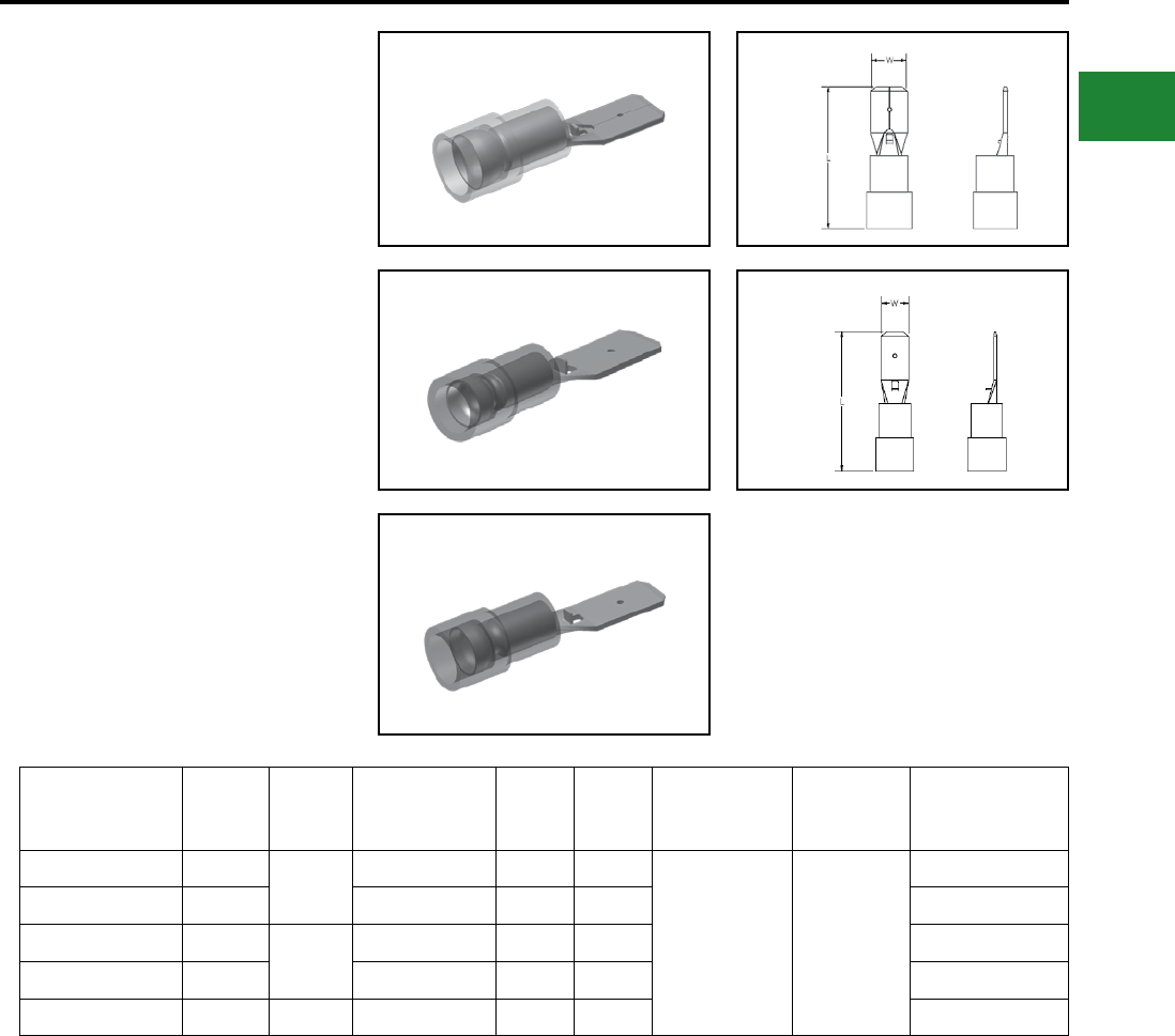
BURNDY®
Blue highlighted items are industry standard and most frequently ordered.
Canada: 1-800-387-6487 www.burndy.com US: 1-800-346-4175
Small Terminals
TYPE QN-M FINGRIP™
NYLON INSULATED MALE
QUICK DISCONNECTS
Material: Tin-Plated Brass
600 Volts Max., 105° C Max.
Nylon Insulated Quick disconnects allow for
quickly connecting or disconnecting a terminal.
The front end of the terminal has a female-type
receptacle which allows the terminal to slide onto
and off of a male blade.
Catalog
Number
Figure
Number
Wire
Range NEMA Tab Size L W Installation
Tool *
Wire
Strip
Length
Bulk
Catalog
Number
QN18M18X02D 218 - 22 0.19 X 0.02 0.80 0.19
MRE1022NV
Y10D
T1022
3/8"
QN18M18X02B
QN18M25X03D 1 0.25 X 0.03 0.87 0.25 QN18M25X03B
QN14M18X02D 214 - 16 0.19 X 0.02 0.80 0.19 QN14M18X02B
QN14M25X03D 1 0.25 X 0.03 0.87 0.25 QN14M25X03B
QN10M25X03D 1 12 - 10 0.25 X 0.03 0.95 0.25 —
Features & Benets
• Sleeved barrel
• Funnel entry barrel opening
◊ Assures quick and easy wire insertion
• Mates with dimpled female socket detent
◊ Ensures rm grip
Fig. 1
Fig. 2
B-65
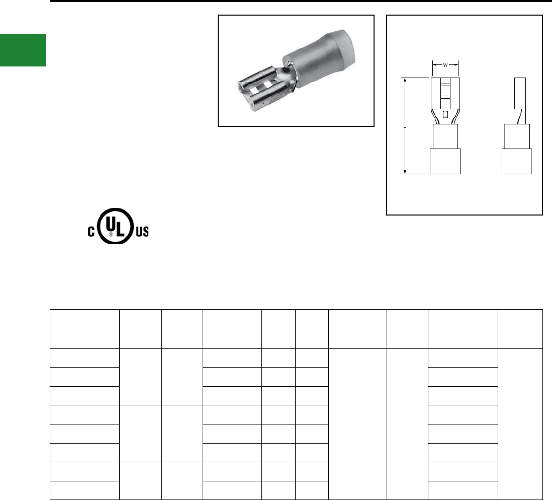
BURNDY®
Blue highlighted items are industry standard and most frequently ordered.
US: 1-800-346-4175 www.burndy.com Canada: 1-800-387-6487
Small Terminals
TYPE QN-F FINGRIP™
NYLON INSULATED FEMALE
QUICK DISCONNECTS
Material: Tin-Plated Brass
300 Volts Max., 105° C Max.
Insulated Quick disconnects allows for quickly
connecting or disconnecting a terminal. The front
end of the terminal has a female-type receptacle
which allows the terminal to slide onto and off of
a male blade.
Standard
Catalog
Number
Std.
Pkg.
Qty
Wire
Range
NEMA Tab
Size L W Installation
Tool *
Wire
Strip
Length
Bulk
Catalog
Number
Bulk.
Pkg. Qty.
QN18F11X02D
100 16 - 22
0.11 X 0.02 0.77 0.11
MRE1022NV
Y10D
Y1022
3/8"
QN18F11X02B
1000
QN18F18X02D 0.19 X 0.02 0.79 0.19 QN18F18X02B
QN18F25X03D 0.25 X 0.03 0.87 0.25 QN18F25X03B
QN14F11X02D
100 14 - 16
0.11 X 0.02 0.77 0.11 QN14F11X02B
QN14F18X02D 0.19 X 0.02 0.79 0.19 QN14F18X02B
QN14F25X03D 0.25 X 0.03 0.87 0.25 QN14F25X03B
QN10F18X02D*
50 12 - 10
0.19 X 0.02 0.87 0.19 QN10F18X02B
QN10F25X03D 0.25 X 0.03 0.95 0.25 QN10F25X03B
Features & Benets
• Sleeved barrel
• Insulated connectors
◊ Eliminate the need for post installation
insulation
• Funnel entry barrel opening
◊ Assures quick and easy wire insertion
• Dimpled female socket detent
◊ Ensures rm grip
(Mates with Type QN-M Male Disconnects)
* Not cULus.
B-66
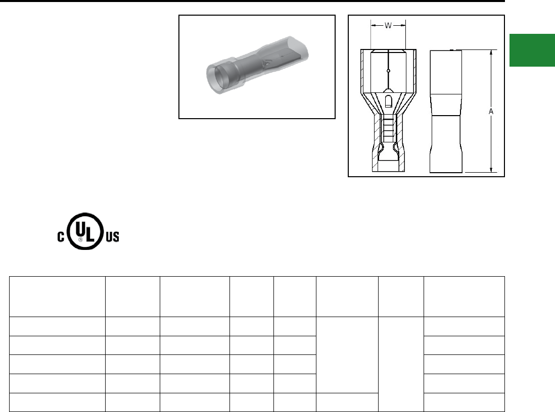
BURNDY®
Blue highlighted items are industry standard and most frequently ordered.
Canada: 1-800-387-6487 www.burndy.com US: 1-800-346-4175
Small Terminals
TYPE FQN-M FINGRIP™
NYLON FULLY INSULATED
MALE QUICK DISCONNECTS
Material: Tin-Plated Brass
600 Volts Max., 105° C Max.
Nylon Fully Insulated Quick disconnects allows
for quickly connecting or dis-connecting a
terminal. The front end of the terminal has
a female-type receptacle which allows the
terminal to slide onto and off of a male blade.
Catalog
Number
Wire
Range NEMA Tab Size L W Installation
Tool *
Wire
Strip
Length
Bulk
Catalog
Number
FQN18M18X02D* 18 - 22 0.19 X 0.02 0.88 0.19
MRE1022NV
Y10D
Y1022 3/8"
—
FQN18M25X03D 18 - 22 0.25 X 0.03 0.80 0.25 FQN18M25X03B
FQN14M18X02D* 14 - 16 0.19 X 0.02 0.80 0.19 —
FQN14M25X03D 14 - 16 0.25 X 0.03 0.88 0.25 FQN14M25X03B
FQN10M25X03D 10 - 12 0.25 X 0.03 0.96 0.25 MRE1022NV FQN10M25X03B
Features & Benets
• Fully insulated connectors
◊ Eliminate the need for post installation
insulation
• Funnel entry barrel opening
◊ Assures quick and easy wire insertion
• Dimpled female socket detent
◊ Ensures rm grip
* Not cULus.
B-67
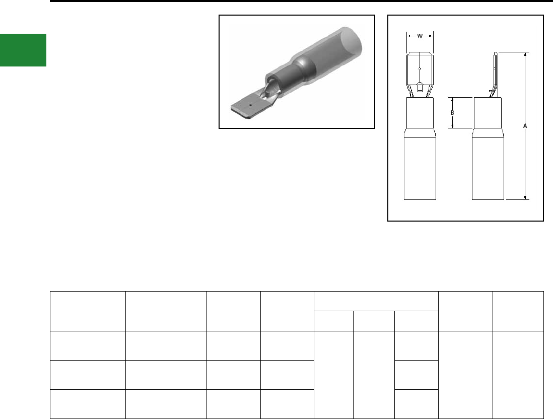
BURNDY®
Blue highlighted items are industry standard and most frequently ordered.
US: 1-800-346-4175 www.burndy.com Canada: 1-800-387-6487
Small Terminals
TYPE YHSQ-M
HYDENT™ HEAT SHRINK
MALE QUICK DISCONNECTS
For Use on Copper Conductor
Standard crimp terminals leave the wire exposed
allowing in moisture or other contaminants which
can result in corrosion. Corrosion reduces the
amount of current the wire can carry safely.
The integrity of the electrical system can
be compromised when unsealed electrical
connections are utilized. Heat shrink terminals
provide a durable seal blocking out contaminants
ensuring a better connection.
Catalog No.
(100/bag)
Catalog No.
(20/bag)
Conductor
Size
NEMA Tab
Size
Dimensions Installation
Tooling
Wire
Strip
Length
B W A
YHSQ18M25X03 YHSQ18M250X03RK 22-18 AWG 0.250 X 0.032
0.22 0.25
1.25
MR22 5/16"YHSQ14M25X03 YHSQ14M25X03RK 16-14 AWG 0.250 X 0.032 1.25
YHSQ10M25X03 YHSQ10M25X03RK 12-10 AWG 0.250 X 0.032 1.19
Features & Benets
• Made from pure copper, annealed for
maximum strength
• Color-coded, imprinted with wire size
• Serrated barrels offer maximum wire contact
and tensile strength
• Electro tin plated for corrosion resistance
B-68
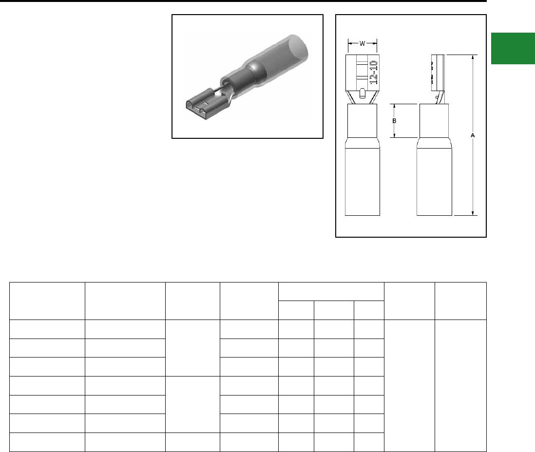
BURNDY®
Blue highlighted items are industry standard and most frequently ordered.
Canada: 1-800-387-6487 www.burndy.com US: 1-800-346-4175
Small Terminals
TYPE YHSQ-F
HYDENT™ HEAT SHRINK
FEMALE QUICK DISCONNECTS
For Use on Copper Conductor
Standard crimp terminals leave the wire exposed
allowing in moisture or other contaminants which
can result in corrosion. Corrosion reduces the
amount of current the wire can carry safely.
The integrity of the electrical system can
be compromised when unsealed electrical
connections are utilized. Heat shrink terminals
provide a durable seal blocking out contaminants
ensuring a better connection.
Catalog No.
(100/bag)
Catalog No.
(20/bag)
Conductor
Size Tab Size
Dimensions Installation
Tooling
Wire Strip
Length
B W A
YHSQ18F11X02D —
22-18 AWG
0.110 X 0.020 0.17 0.16 1.28
MR22 5/16"
YHSQ18F18X02D — 0.187 X 0.020 0.17 0.23 1.28
YHSQ18F25X03 YHSQ18F25X03RK 0.250 X 0.032 0.22 0.30 1.27
YHSQ14F11X02D —
16-14 AWG
0.110 X 0.020 0.17 0.16 1.28
YHSQ14F18X02D — 0.187 X 0.020 0.17 0.23 1.28
YHSQ14F25X03 YHSQ14F25X03RK 0.250 X 0.032 0.22 0.30 1.27
YHSQ10F25X03 YHSQ10F25X03RK 12-10 AWG 0.250 X 0.032 0.22 0.30 1.27
Features & Benets
• Made from pure copper, annealed for
maximum strength
• Color-coded, imprinted with wire size
• Serrated barrels offer maximum wire contact
and tensile strength
• Electro tin plated for corrosion resistance
B-69
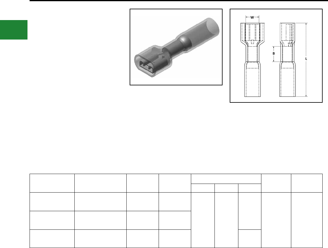
BURNDY®
Blue highlighted items are industry standard and most frequently ordered.
US: 1-800-346-4175 www.burndy.com Canada: 1-800-387-6487
Small Terminals
TYPE YHSFQ-F
HYDENT™ HEAT SHRINK
FULLY INSULATED QUICK
DISCONNECTS
For Use on Copper Conductor
Standard crimp terminals leave the wire exposed
allowing in moisture or other contaminants which
can result in corrosion. Corrosion reduces the
amount of current the wire can carry safely.
The integrity of the electrical system can
be compromised when unsealed electrical
connections are utilized. Heat shrink terminals
provide a durable seal blocking out contaminants
ensuring a better connection.
Catalog No.
(100/bag)
Catalog No.
(20/bag)
Conductor
Size
NEMA Tab
Size
Dimensions Installation
Tooling
Wire Strip
Length
B W L
YHSFQ18F25X03 YHSFQ18F25X03RK 22-18 AWG 0.250 X 0.032
0.22 0.38
1.28
MR22 5/16"YHSFQ14F25X03 YHSFQ14F25X03RK 16-14 AWG 0.250 X 0.032
YHSFQ10F25X03 YHSFQ10F25X03RK 12-10 AWG 0.250 X 0.032 1.34
Features & Benets
• Made from pure copper, annealed for
maximum strength
• Color-coded, imprinted with wire size
• Serrated barrels offer maximum wire contact
and tensile strength
• Electro tin plated for corrosion resistance
B-70
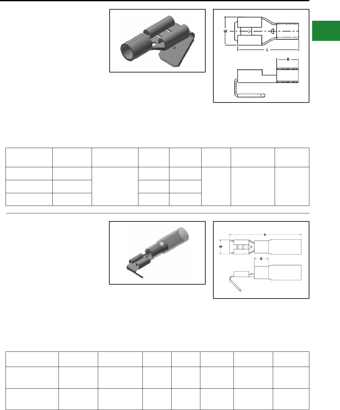
BURNDY®
Blue highlighted items are industry standard and most frequently ordered.
Canada: 1-800-387-6487 www.burndy.com US: 1-800-346-4175
Small Terminals
TYPE PG
MALE/FEMALE COMBINATION
QUICK DISCONNECTS
Material: Tin Plated Brass
Piggy-back connectors or piggy-back terminals
are designed to allow for additional terminals to be
connected.
Catalog Number Wire Range NEMA Tab Size B L W Installation Tool Wire Strip
Length
PG1825X03D 22 - 18 AWG
0.250 X 0.032
0.17 0.79
0.25
MRE1022B
Y10D
Y10-22
3/8"PG1425X03D 16 - 14 AWG 0.17 0.79
PG1025X03D 12 - 10 AWG 0.27 0.89
Features & Benets
• Sleeved Barrel
• Combination connector - allows for more than
one connection to a circuit
• Funnel entry barrel opening - assures quick
and easy wire insertion
• Dimpled female socket detent - ensure rm grip
TYPE PGHS
HEAT SHRINK COMBINATION
DISCONNECT TERMINALS
For Use on Copper Conductor
Standard crimp terminals leave the wire exposed
allowing in moisture or other contaminants which
can result in corrosion. Corrosion reduces the
amount of current the wire can carry safely.
The integrity of the electrical system can
be compromised when unsealed electrical
connections are utilized. Heat shrink terminals
provide a durable seal blocking out contaminants
ensuring a better connection.
Catalog Number Wire Range NEMA Tab Size A B W Installation Tool Wire Strip
Length
PGHS1825X03D 22 - 18 AWG 0.250 X 0.032 0.91 0.17 0.25
Y10D
Y1022
MR22
5/16"
PGHS1425X03D 16 - 14 AWG 0.250 X 0.032 0.91 0.17 0.25
Y10D
Y1022 5/16"
Features & Benets
• Made from pure copper, annealed for
maximum strength
• Color-coded, imprinted with wire size
• Serrated barrels offer maximum wire contact
and tensile strength
• Electro tin plated for corrosion resistance
B-71
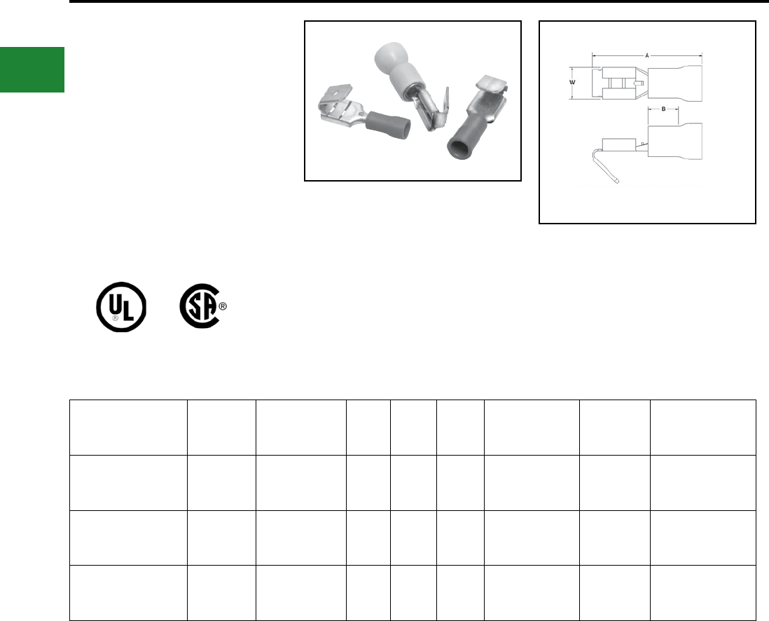
BURNDY®
Blue highlighted items are industry standard and most frequently ordered.
US: 1-800-346-4175 www.burndy.com Canada: 1-800-387-6487
Small Terminals
TYPE PGP FINGRIP™
VINYL MALE/FEMALE
COMBINATION QUICK
DISCONNECTS
Material: Tin-Plated Brass
600 Volts Max. 105° C Max.
Piggy-back connectors or piggy-back terminals
are designed to allow for additional terminals to be
connected.
Standard Catalog
Number
Wire
Range
NEMA Tab
Size A B W Installation
Tool*
Wire Strip
Length
Bulk Catalog
Number
PGP1825X03D 18 - 22 0.250 X 0.032 0.91 0.17 0.28 MRE1022NV
Y1022 3/8" PGP1825X03B
PGP1425X03D 14 - 16 0.250 X 0.032 0.91 0.17 0.28 MRE1022NV
Y1022 3/8" PGP1425X03B
PGP1025X03D 10 - 12 0.250 X 0.032 0.95 0.27 0.28 MRE1022NV
Y1022 3/8" PGP1025X03B
Features & Benets
• Sleeved barrel
• Combination connector
◊ Allows for more than one connection
to a circuit
• Funnel entry barrel opening
◊ Assures quick and easy wire insertion
• Dimpled female socket detent
◊ Ensures rm grip
* For UL Listed applications, consult BURNDY® factory.
B-72
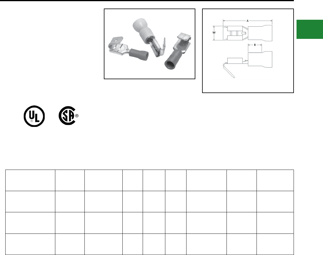
BURNDY®
Blue highlighted items are industry standard and most frequently ordered.
Canada: 1-800-387-6487 www.burndy.com US: 1-800-346-4175
Small Terminals
TYPE PGN FINGRIP™
NYLON COMBINATION
DISCONNECT TERMINALS
Material: Tin-Plated Brass
600 Volts Max. 105° C Max.
Piggy-back connectors or piggy-back terminals
are designed to allow for additional terminals to be
connected.
Standard Catalog
Number
Wire
Range
NEMA Tab
Size A B W Installation
Tool*
Wire Strip
Length
Bulk Catalog
Number
PGN1825X03D 18 - 22 0.250 X 0.032 0.90 0.17 0.28 MRE1022NV
Y10D 3/8" PGN1825X03B
PGN1425X03D 14 - 16 0.250 X 0.032 0.90 0.17 0.28 MRE1022NV
Y10D 3/8" PGN1425X03B
PGN1025X03D 10 - 12 0.250 X 0.032 0.95 0.27 0.28 MRE1022NV
Y10D 3/8" PGN1025X03B
Features & Benets
• Sleeved barrel
• Combination connector
◊ Allows for more than one connection
to a circuit
• Funnel entry barrel opening
◊ Assures quick and easy wire insertion
• Dimpled female socket detent
◊ Ensures rm grip
* For UL Listed applications, consult BURNDY® factory.
B-73
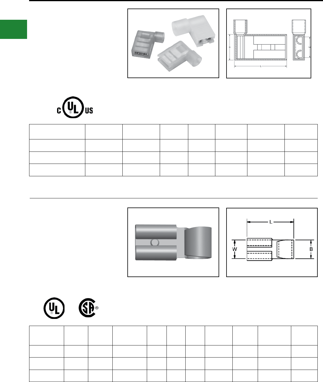
BURNDY®
Blue highlighted items are industry standard and most frequently ordered.
US: 1-800-346-4175 www.burndy.com Canada: 1-800-387-6487
Small Terminals
TYPE FLN FINGRIP™
NYLON FLAG-STYLE FEMALE
QUICK DISCONNECT
Material: Tin-Plated Brass
Flag style female quick disconnects provide quick,
reliable snap-together interconnections without
the use of tools. Side entrance chamfer to permit
connections of ninety degrees without bending the
wire.
Catalog
Number
Wire
Range
NEMA
Tab Size L B W Installation Tool Wire Strip
Length
FLN1825X03D 22 - 18 0.250 X 0.032 0.60 0.40 0.25 MRE1422FLN 3/8"
FLN1425X03D 16 - 14 0.250 X 0.032 0.63 0.40 0.25 MRE1422FLN 3/8"
FLN1025X03D* 12 - 10 0.250 X 0.032 0.64 0.40 0.25 MRE1422FLN 3/8"
Features & Benets
• Dimpled female socket detent
◊ Ensures rm grip
TYPE FL FINGRIP™
FLAG-STYLE FEMALE QUICK
DISCONNECT
Material: Tin-Plated Brass
Flag style female quick disconnects provide quick,
reliable snap-together interconnections without
the use of tools. Side entrance chamfer to permit
connections of ninety degrees without bending the
wire.
Catalog
Number
Std. Pkg.
Qty
Wire
Range
NEMA Tab
Size L B W Installation
Tool
Wire Strip
Length
Bulk Catalog
Number
Bulk Pkg.
Qty
FL1825X03D 100 18 - 22 0.250 x 0.032 0.67 0.17 0.25 BTH-450 3/8" FL1825X03B 1000
FL1425X03D 100 14 - 16 0.250 x 0.032 0.67 0.17 0.25 BTH-450 3/8" FL1425X03B 1000
FL1025X03D 50 10 - 12 0.250 x 0.032 0.67 0.17 0.25 BTH-450 3/8" FL1025X03B 1000
Features & Benets
• Dimpled female socket detent
◊ Ensures rm grip
* Not cULus.
B-74
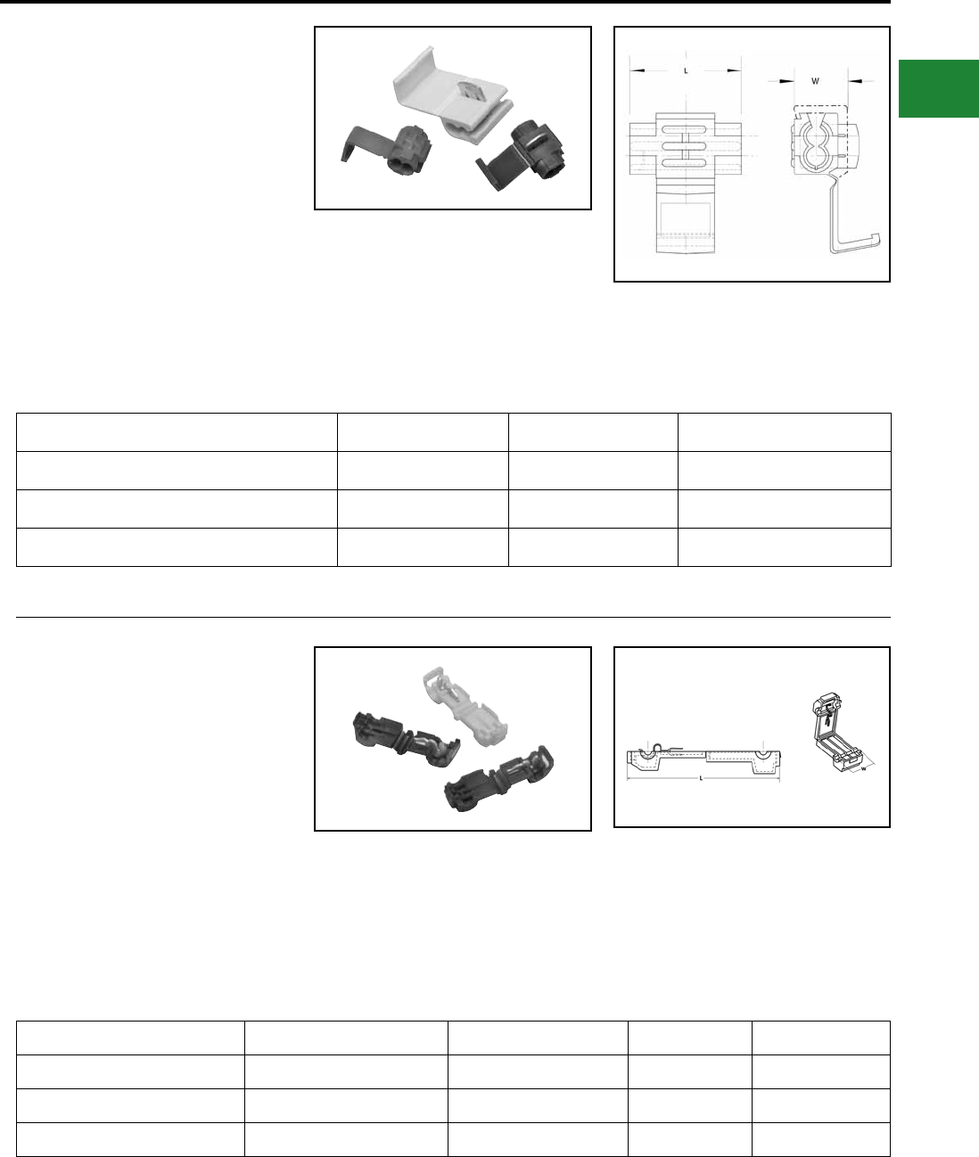
BURNDY®
Blue highlighted items are industry standard and most frequently ordered.
Canada: 1-800-387-6487 www.burndy.com US: 1-800-346-4175
Small Terminals
TYPE YAIT
QIKTAP™
QIKTAP™ Splices
QIKTAP™ connectors are quick and convenient.
Makes quick splices with no stripping, twisting,
soldering or special tooling.
Catalog Number Wire Range L W
YAIT2218R 22 - 18 0.80 0.37
YAIT1814B 16 - 14 0.80 0.37
YAIT1210Y 12 - 10 0.80 0.37
Features & Benets
• Easy to Use
• Saves time
• Color Coded
• No special tools required (just squeeze to
install)
• Dependable connection
TYPE TTV
QIKTAP™
Insulation Piercing Style, Tap
Connector
TTV type electrical connectors allow for an easy
tap off of a run conductor. This tap allows for
a male quick disconnect to complete the tap
connection. This is especially useful when multiple
reconnections could be necessary.
Catalog Number Wire Range Insulation Color W L
TTV18 22 - 18 AWG Red 0.38 1.44
TTV14 16 - 14 AWG Blue 0.38 1.44
TTV10 12 - 10 AWG Yellow 0.38 1.44
Features & Benets
• Allows user to tap into a wire in mid-span
without cutting or stripping the wire
• Connector then mates with a .250 inch male
quick disconnect tab, making a reusable quick-
connect wiring termination
B-75
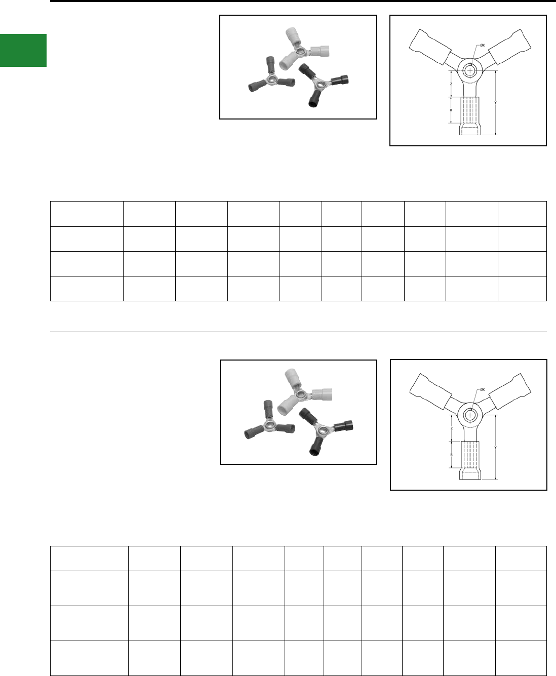
BURNDY®
Blue highlighted items are industry standard and most frequently ordered.
US: 1-800-346-4175 www.burndy.com Canada: 1-800-387-6487
Small Terminals
TYPE YATW-P
HYDENT™
Terminal - Vinyl Insulated, Three-Way
Ring Tongue
Insulated 3-way terminal is constructed of 3 ring
terminals riveted together through the stud holes.
Allows multiple wires to be quickly and securely
connected.
Catalog Number Wire Range Insulation
Type
Insulation
Color B Z K Y Installation
Tooling
Wire Strip
Length
YATW18P 22 - 18 AWG Vinyl Red 0.25 0.23 0.15 0.73 MRE1022NV
Y1022 5/16"
YATW14P 16 - 14 AWG Vinyl Blue 0.25 0.28 0.15 0.78 MRE1022NV
Y1022 5/16"
YATW10P 12 - 10 AWG Vinyl Yellow 0.25 0.28 0.15 0.84 MRE1022NV
Y1022 5/16"
Features & Benets
• Robust design of a standard insulated terminal
integrated into one connector
• Standard BURNDY® tooling to install
TYPE YATW-N
HYDENT™
Terminal - Nylon Insulated, Three-
Way Ring Tongue
600 Volts Max., 105° C Max.
Insulated 3-way terminal is constructed of 3 ring
terminals riveted together through the stud holes.
Allows multiple wires to be quickly and securely
connected.
Catalog Number Wire Range Insulation
Type
Insulation
Color B Z K Y Installation
Tooling
Wire Strip
Length
YATW18N 22 - 18 AWG 2 Piece Nylon Red 0.25 0.23 0.15 0.73
MRE1022NV
Y10D
Y1022
5/16"
YATW14N 16 - 14 AWG 2 Piece Nylon Blue 0.25 0.28 0.15 0.78
MRE1022NV
Y10D
Y1022
5/16"
YATW10N 12 - 10 AWG 2 Piece Nylon Yellow 0.25 0.28 0.15 0.84
MRE1022NV
Y10D
Y1022
5/16"
Features & Benets
• Robust design of a standard insulated terminal
integrated into one connector
• Standard BURNDY® tooling to install
B-76
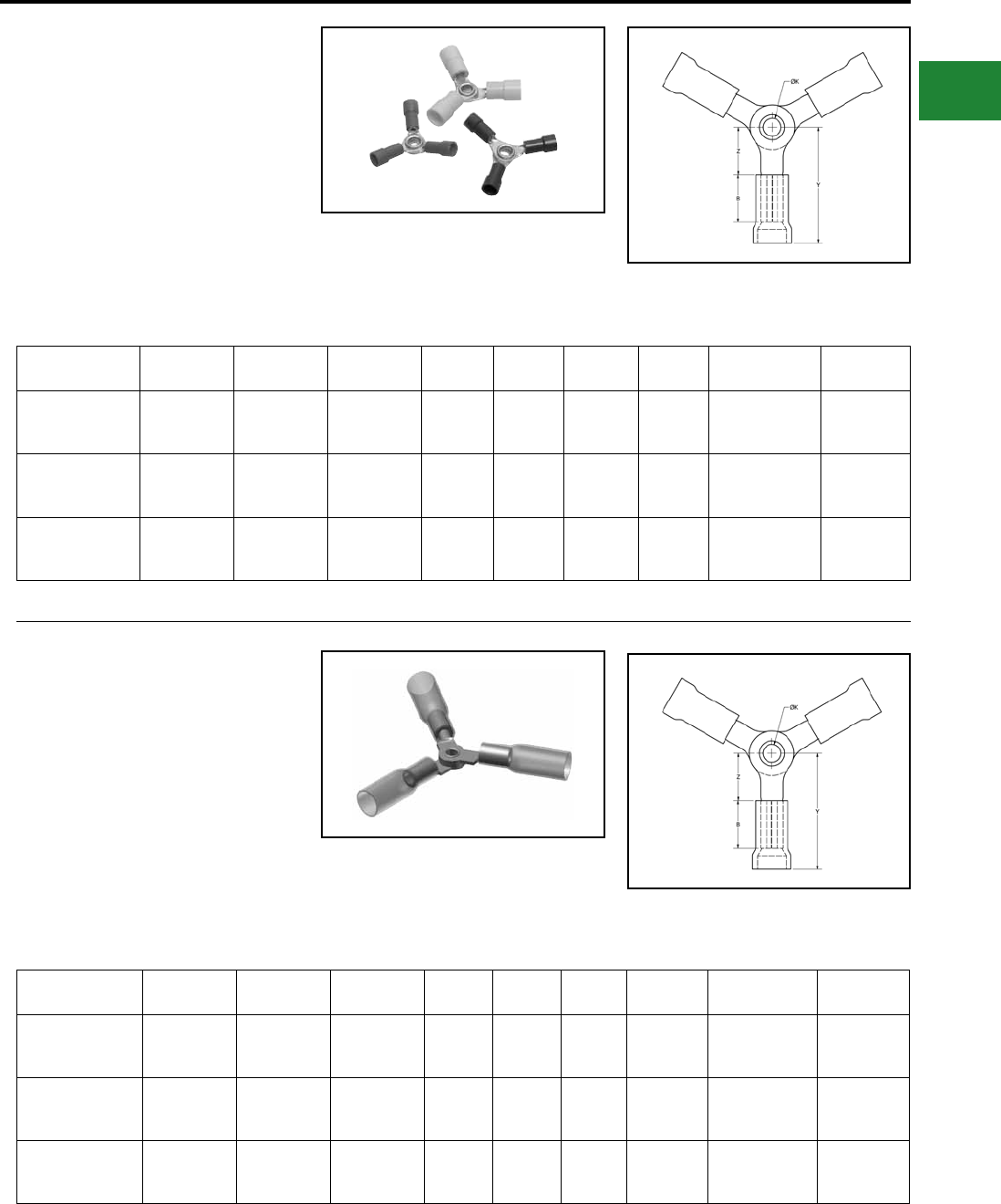
BURNDY®
Blue highlighted items are industry standard and most frequently ordered.
Canada: 1-800-387-6487 www.burndy.com US: 1-800-346-4175
Small Terminals
TYPE YATW-NG
HYDENT™
Terminal - Nylon Grip Insulated,
Three-Way Ring Tongue
600 Volts Max., 105° C Max.
Insulated 3-way terminal is constructed of 3 ring
terminals riveted together through the stud holes.
Allows multiple wires to be quickly and securely
connected.
Catalog Number Wire Range Insulation
Type
Insulation
Color B Z K Y Installation
Tooling
Wire Strip
Length
YATW18NG 22 - 18 AWG 3 Piece Nylon Red 0.25 0.23 0.15 0.73
MRE1022NV
Y10D
Y1022
5/16"
YATW14NG 16 - 14 AWG 3 Piece Nylon Blue 0.25 0.28 0.15 0.78
MRE1022NV
Y10D
Y1022
5/16"
YATW10NG 12 - 10 AWG 3 Piece Nylon Yellow 0.25 0.28 0.15 0.84
MRE1022NV
Y10D
Y1022
5/16"
Features & Benets
• Robust design of a standard insulated
terminal integrated into one connector
• Standard BURNDY® tooling to install
TYPE YATW-HS
HYDENT™
Terminal - Fully Insulated Heat Shrink,
Three-Way Ring Tongue
Insulated 3-way terminal is constructed of 3 ring
terminals riveted together through the stud holes.
Allows multiple wires to be quickly and securely
connected.
Catalog Number Wire Range Insulation
Type
Insulation
Color B Z K Y Installation
Tooling
Wire Strip
Length
YATW18HS 22 - 18 AWG Heat Shrink Red 0.25 0.23 0.15 1.26
MR22
Y10D
Y1022
5/16"
YATW14HS 16 - 14 AWG Heat Shrink Blue 0.25 0.28 0.15 1.31
MR22
Y10D
Y1022
5/16"
YATW10HS 12 - 10 AWG Heat Shrink Yellow 0.25 0.28 0.15 1.37
MR22
Y10D
Y1022
5/16"
Features & Benets
• Robust design of a standard insulated
terminal integrated into one connector
• Standard BURNDY® tooling to install
B-77
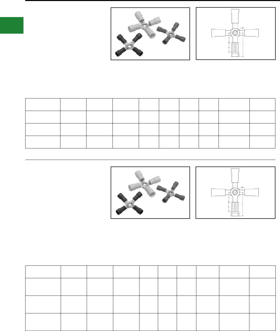
BURNDY®
Blue highlighted items are industry standard and most frequently ordered.
US: 1-800-346-4175 www.burndy.com Canada: 1-800-387-6487
Small Terminals
TYPE YAFW-P
HYDENT™
Terminal - Vinyl Insulated,
Four-Way Ring Tongue
Insulated 4-way terminal is constructed of 4 ring
terminals riveted together through the stud holes.
Allows multiple wires to be quickly and securely
connected.
Catalog Number Wire Range Insulation
Type
Insulation
Color B Z K Y Installation
Tooling
Wire Strip
Length
YAFW18P 22 - 18 AWG Vinyl Red 0.25 0.23 0.15 0.73 MRE1022NV
Y1022 5/16"
YAFW14P 16 - 14 AWG Vinyl Blue 0.25 0.28 0.15 0.78 MRE1022NV
Y1022 5/16"
YAFW10P 12 - 10 AWG Vinyl Yellow 0.25 0.28 0.15 0.84 MRE1022NV
Y1022 5/16"
Features & Benets
• Robust design of a standard insulated terminal
integrated into one connector
• Standard BURNDY® tooling to install
TYPE YAFW-N
HYDENT™
Terminal - Nylon Insulated,
Four-Way Ring Tongue
600 Volts Max., 105° C Max.
Insulated 4-way terminal is constructed of 4 ring
terminals riveted together through the stud holes.
Allows multiple wires to be quickly and securely
connected.
Catalog Number Wire Range Insulation
Type
Insulation
Color B Z K Y Installation
Tooling
Wire Strip
Length
YAFW18N 22 - 18 AWG 2 Piece Nylon Red 0.25 0.23 0.15 0.73
MRE1022NV
Y10D
Y1022
5/16"
YAFW14N 16 - 14 AWG 2 Piece Nylon Blue 0.25 0.28 0.15 0.78
MRE1022NV
Y10D
Y1022
5/16"
YAFW10N 12 - 10 AWG 2 Piece Nylon Yellow 0.25 0.28 0.15 0.84
MRE1022NV
Y10D
Y1022
5/16"
Features & Benets
• Robust design of a standard insulated terminal
integrated into one connector
• Standard BURNDY® tooling to install
B-78
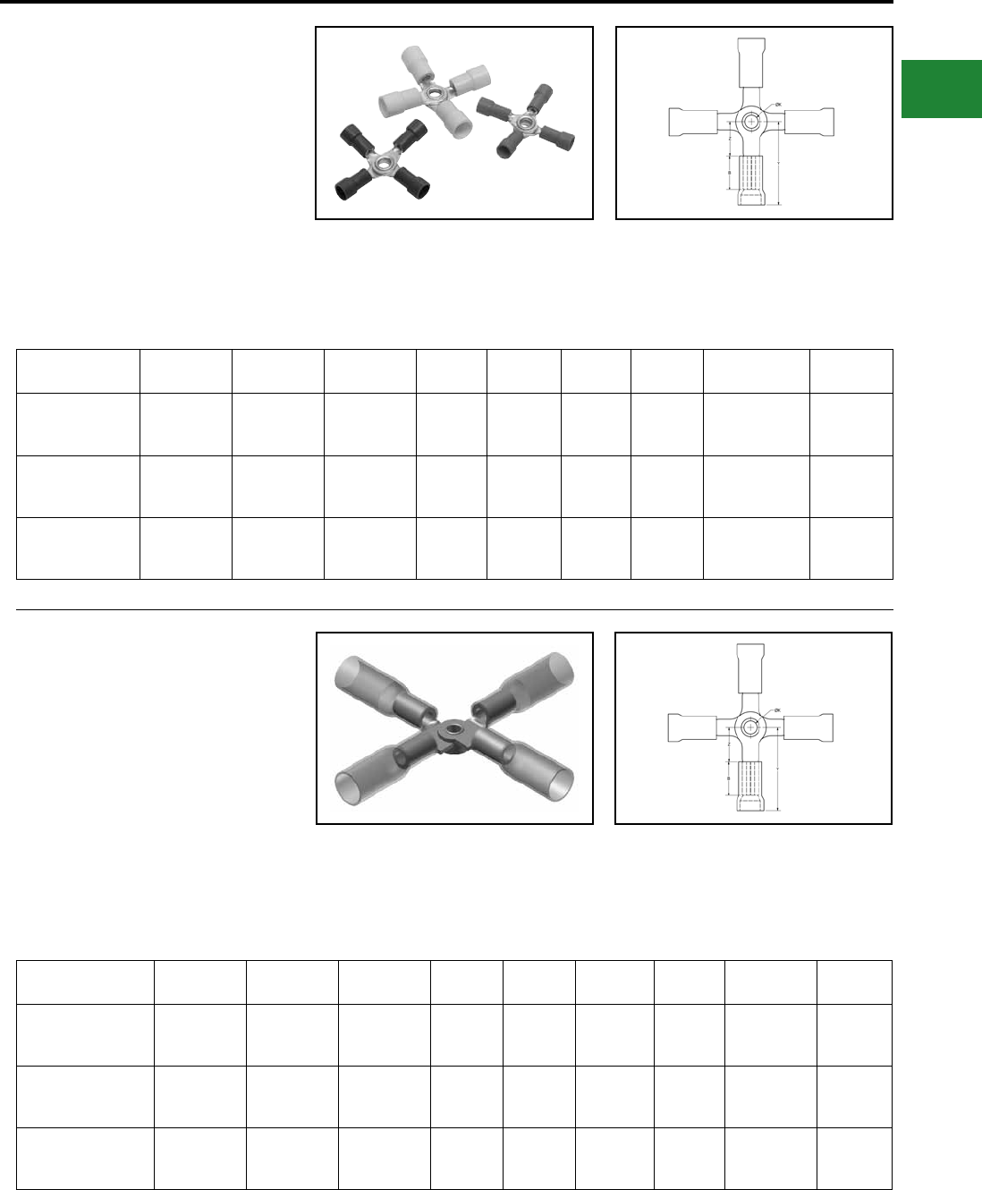
BURNDY®
Blue highlighted items are industry standard and most frequently ordered.
Canada: 1-800-387-6487 www.burndy.com US: 1-800-346-4175
Small Terminals
TYPE YAFW-NG
HYDENT™
Terminal - Nylon Grip Insulated,
Four-Way Ring Tongue
600 Volts Max., 105° C Max.
Insulated 4-way terminal is constructed of 4 ring
terminals riveted together through the stud holes.
Allows multiple wires to be quickly and securely
connected.
Catalog Number Wire Range Insulation
Type
Insulation
Color B Z K Y Installation
Tooling
Wire Strip
Length
YAFW18NG 22 - 18 AWG 3 Piece Nylon Red 0.25 0.23 0.15 0.73
MRE1022NV
Y10D
Y1022
5/16"
YAFW14NG 16 - 14 AWG 3 Piece Nylon Blue 0.25 0.28 0.15 0.78
MRE1022NV
Y10D
Y1022
5/16"
YAFW10NG 12 - 10 AWG 3 Piece Nylon Yellow 0.25 0.28 0.15 0.84
MRE1022NV
Y10D
Y1022
5/16"
Features & Benets
• Robust design of a standard insulated terminal
integrated into one connector
• Standard BURNDY® tooling to install
TYPE YAFW-HS
HYDENT™
Terminal - Fully Insulated Heat Shrink,
Four-Way Ring Tongue
Insulated 4-way terminal is constructed of 4 ring
terminals riveted together through the stud holes.
Allows mutiple wires to be quickly and securely
connected.
Catalog Number Wire Range Insulation
Type
Insulation
Color B Z K Y Installation
Tooling
Wire Strip
Length
YAFW18HS 22 - 18 AWG Heat Shrink Red 0.25 0.25 0.15 1.26
MR22
Y10D
Y1022
5/16"
YAFW14HS 16 - 14 AWG Heat Shrink Blue 0.25 0.25 0.15 1.31
MR22
Y10D
Y1022
5/16"
YAFW10HS 12 - 10 AWG Heat Shrink Yellow 0.25 0.25 0.15 1.37
MR22
Y10D
Y1022
5/16"
Features & Benets
• Robust design of a standard insulated terminal
integrated into one connector
• Standard BURNDY® tooling to install
B-79
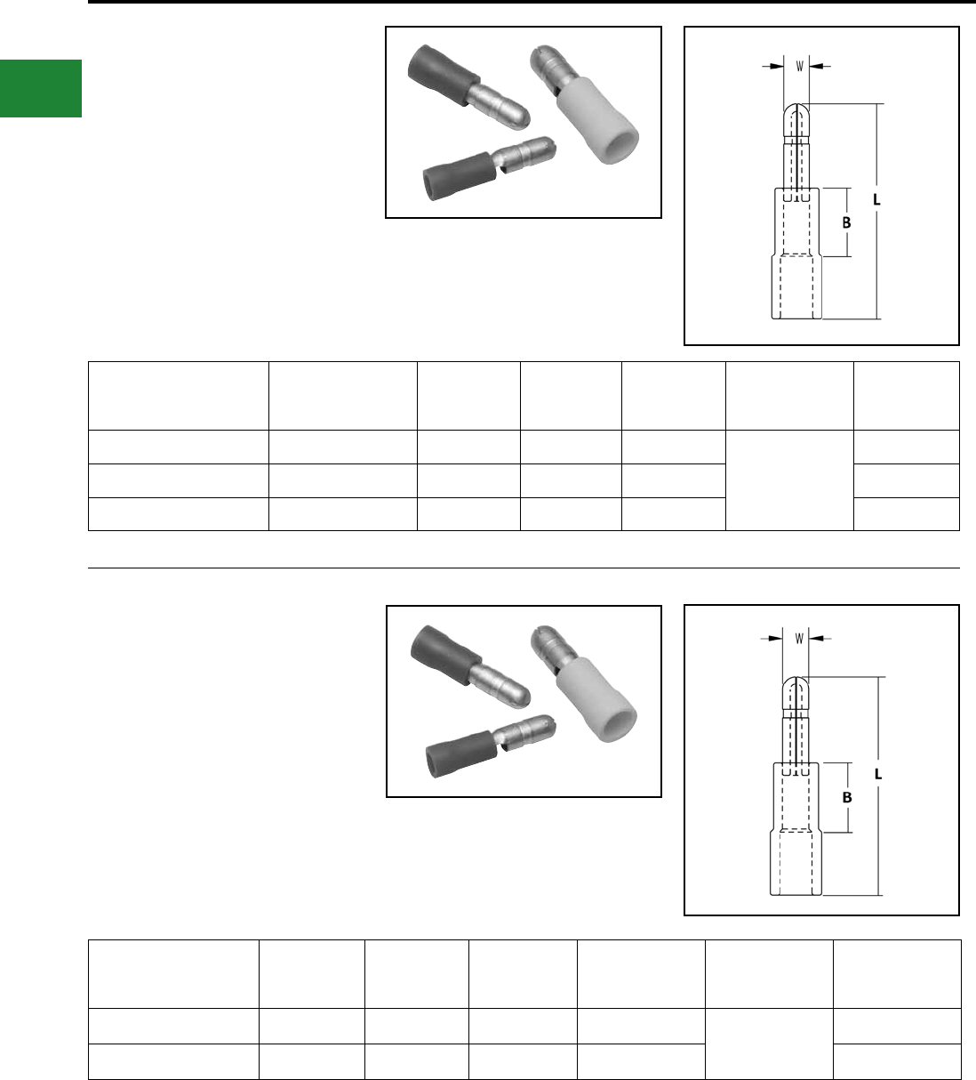
BURNDY®
Blue highlighted items are industry standard and most frequently ordered.
US: 1-800-346-4175 www.burndy.com Canada: 1-800-387-6487
Small Terminals
TYPE BULM-P
Vinyl Insulated Male
Bullet-style Connectors
Type BULM-P Male Bullet connectors are vinyl
insulated connectors with a ared entry for easier
wire insertion. Color-coded barrels for easy wire
size identication.
Catalog
Number
Wire
Range L W B Tooling
Wire
Strip
Length
BULM18P 22-18 0.83 0.16 0.21
MRE1022NV
Y1022
5/16"
BULM14P 16-14 0.83 0.16 0.21 5/16"
BULM10P 12-10 0.83 0.20 0.21 5/16"
Features & Benets
• Vinyl insulation
• Color-coded barrels
• Flared entry provides easier use
TYPE BULM-N
Nylon Insulated Male
Bullet-style Connectors
600 Volts Max., 105° C Max.
Type BULM-N Male Bullet connectors are nylon
insulated connectors with a ared entry for easier
wire insertion. Color-coded barrels for easy wire
size identication.
Features & Benets
• Nylon insulation
• Color-coded barrels
• Flared entry provides easier use
Catalog
Number
Wire
Range L B W Installation
Tooling
Wire
Strip
Length
BULM18N 22 - 18 0.83 0.21 0.16 MRE1022NV
Y10D
Y1022
5/16"
BULM14N 16 - 14 0.83 0.21 0.16 5/16"
B-80
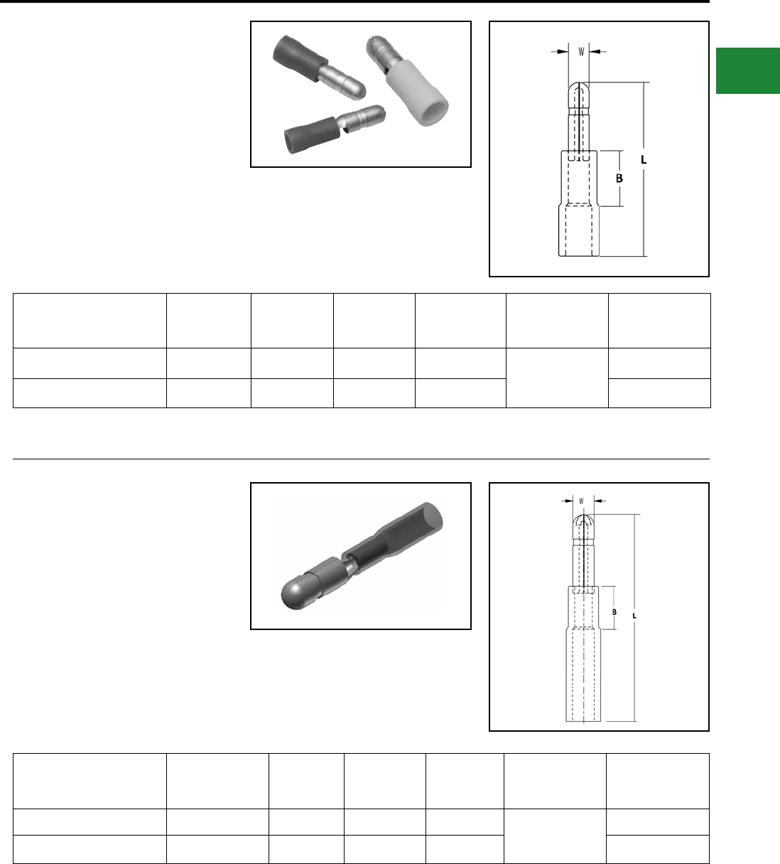
BURNDY®
Blue highlighted items are industry standard and most frequently ordered.
Canada: 1-800-387-6487 www.burndy.com US: 1-800-346-4175
Small Terminals
TYPE BULM-NG
Nylon Grip Insulated Male
Bullet-style Connectors
600 Volts Max., 105° C Max.
Type BULM-NG Male Bullet connectors are nylon
grip insulated connectors with a ared entry for
easier wire insertion. Color-coded barrels for easy
wire size identication.
Catalog
Number
Wire
Range L B W Installation
Tooling
Wire
Strip
Length
BULM18NG 22 - 18 0.83 0.21 0.16 MRE1022NV
Y10D
Y1022
5/16"
BULM14NG 16 - 14 0.83 0.21 0.16 5/16"
Features & Benets
• Nylon grip insulation
• Color-coded barrels
• Flared entry provides easier use
TYPE BULM-HS
Heat Shrink Insulated Male
Bullet-style Connectors
Type BULM-HS Male Bullet connectors are heat
shrink insulated connectors with a ared entry for
easier wire insertion. Color-coded barrels for easy
wire size identication.
Catalog
Number
Wire
Range L B W Installation
Tooling
Wire
Strip
Length
BULM18HS 22 - 18 1.30 0.21 0.16 MR22
Y10D
Y1022
5/16"
BULM14HS 16 - 14 1.30 0.21 0.16 5/16"
Features & Benets
• Heat Shrink insulation
• Color-coded barrels
• Flared entry provides easier use
B-81
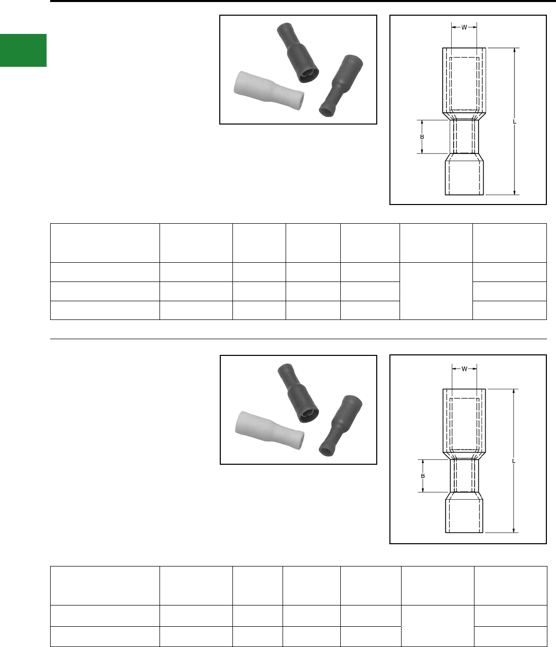
BURNDY®
Blue highlighted items are industry standard and most frequently ordered.
US: 1-800-346-4175 www.burndy.com Canada: 1-800-387-6487
Small Terminals
TYPE BULF-P
Vinyl Insulated Female
Bullet-style Connectors
Type BULF-P Female Bullet vinyl insulated
connectors mate with type BULM-P Male
connectors. Flared insulation entry for easier wire
insertion. Color-coded for wire size identication.
Installed with standard BURNDY® tooling.
Catalog
Number
Wire
Range L B W Installation
Tooling
Wire
Strip
Length
BULF18P 22 - 18 0.89 0.21 0.16
MRE1022NV
Y1022
5/16"
BULF14P 16 - 14 0.89 0.21 0.16 5/16"
BULF10P 12 - 10 0.89 0.20 0.20 5/16"
Features & Benets
• Vinyl insulated
• Color-coded barrels
• Flared entry
• Uses standard BURNDY® tooling
TYPE BULF-N
Nylon Insulated Female
Bullet-style Connectors
600 Volts Max., 105° C Max.
Type BULF-N Female Bullet nylon
insulated connectors mate with BULM-N
Male connectors. Flared insulation for
easier wire insertion. Color-coded for
wire size identication. Installed with
standard BURNDY® tooling.
Catalog
Number
Wire
Range L B W Installation
Tooling
Wire
Strip
Length
BULF18N 22 - 18 0.89 0.21 0.16 MRE1022NV
Y10D
Y1022
5/16"
BULF14N 16 - 14 0.89 0.21 0.16 5/16"
Features & Benets
• Nylon insulation
• Color-coded barrels
• Flared entry
• Uses standard BURNDY® tooling
B-82
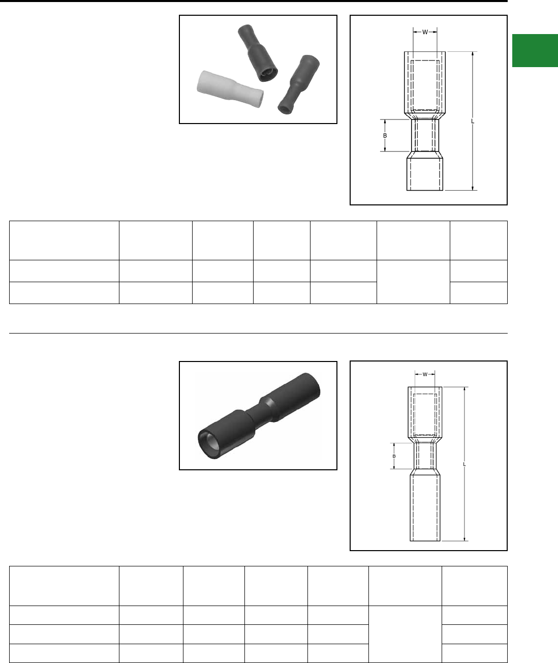
BURNDY®
Blue highlighted items are industry standard and most frequently ordered.
Canada: 1-800-387-6487 www.burndy.com US: 1-800-346-4175
Small Terminals
TYPE BULF-NG
Nylon Grip Insulated Female
Bullet-style Connectors
600 Volts Max., 105° C Max.
Type BULF-NG Female Bullet nylon grip insulated
connectors mate with type BULM-NG Male
connectors. Flared insulation entry for easier wire
insertion. Color-coded for wire size identication.
Installed with standard BURNDY® tooling.
Catalog
Number
Wire
Range L B W Installation
Tooling
Wire
Strip
Length
BULF18NG 22 - 18 0.89 0.21 0.16 MRE1022NV
Y10D
Y1022
5/16"
BULF14NG 16 - 14 0.89 0.21 0.16 5/16"
Features & Benets
• Nylon Grip insulation
• Color-coded barrels
• Flared entry
• Uses standard BURNDY® tooling
TYPE BULF-HS
Heat Shrink Insulated Female
Bullet-style Connectors
Type BULF-HS Female Bullet heat shrink insulated
connectors mate with type BULM-HS connectors.
Flared insulation entry for easier wire insertion.
Color-coded for wire size identication. Installed
with standard BURNDY® tooling.
Catalog
Number
Wire
Range L B W Installation
Tooling
Wire
Strip
Length
BULF18HS 22 - 18 1.40 0.21 0.16 MR22
Y10D
Y1022
5/16"
BULF14HS 16 - 14 1.40 0.21 0.16 5/16"
BULF10HS 12 - 10 1.40 0.20 0.20 5/16"
Features & Benets
• Heat Shrink insulation
• Color-coded barrels
• Flared entry
• Uses standard BURNDY® tooling
B-83
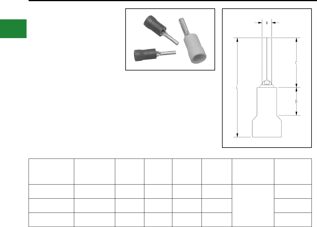
BURNDY®
Blue highlighted items are industry standard and most frequently ordered.
US: 1-800-346-4175 www.burndy.com Canada: 1-800-387-6487
Small Terminals
TYPE PTV
VINYLUG™
Pin Terminal
Material: Tin-Plated Brass
Insulated Pin Terminals are electrical connectors
used to terminate stranded wires, creating a
quality, reliable connection by ensuring each
wire strand conducts curent when properly
crimped. This is especially useful when multiple
reconnections could be necessary within terminal
blocks or other similar devices. No breakage of
wire strands when wire is bent, under stress or in a
vibration environment.
Catalog
Number
Wire
Range B C L W
Installation
Tooling
Wire
Strip
Length
PTV18 22 - 18 AWG 0.19 0.41 0.80 0.07
MRE1022NV
Y1022
5/16"
PTV14 16 - 14 AWG 0.19 0.41 0.80 0.07 5/16"
PTV10 12 - 10 AWG 0.27 0.50 0.97 0.11 5/16"
Features & Benets
• Provides an easy and effective way to
terminate stranded wire into European/
metric-style terminal blocks
B-84
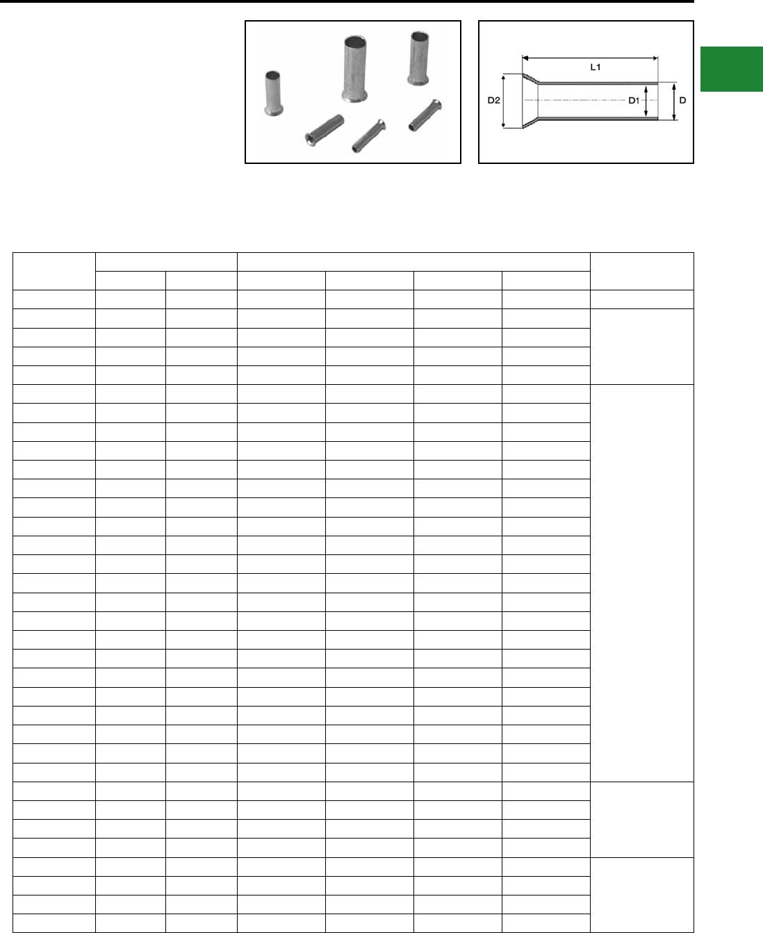
BURNDY®
Blue highlighted items are industry standard and most frequently ordered.
Canada: 1-800-387-6487 www.burndy.com US: 1-800-346-4175
Small Terminals
TYPE YF-UI
BARE FERRULES
For Use On Copper Conductor
Wire ferrules are also known as cord end
terminals or bootlace ferrules. These are electrical
connectors used to terminate stranded wires.
These terminals are made of electrolytically tin
plated copper, uninsulated ferrules are designed to
form neat end terminations to multi-strand cables
or wires. Smooth funnel entry assists in wire
Features & Benets
• Made of electrolytic copper, tin plated
• Seamless barrels
• Smooth funnel entry to make wire insertion easier
• RoHS compliant
Catalog
Number
Wire Size Dimensions in Inches Recommended
Tooling
AWG mm² L1 Dim (in) D Dim (in) D1 Dim (in) D2 Dim (in)
YF2807UI 28 0.14 0.28 0.04 0.03 0.06 YF3206TOOL
YF2605UI 26 0.25 0.19 0.04 0.03 0.06
YF3206TOOL
YF2610TOOL
YF2607UI 26 0.25 0.28 0.04 0.03 0.06
YF2405UI 24 0.34 0.19 0.05 0.03 0.06
YF2407UI 24 0.34 0.28 0.05 0.03 0.06
YF2206UI 22 0.50 0.24 0.05 0.04 0.09
YF3206TOOL
YF2610TOOL
YF2214TOOL
YF2210TOOL
YF2210FL
YF2208UI 22 0.50 0.32 0.05 0.04 0.07
YF2210UI 22 0.50 0.40 0.05 0.04 0.07
YF2212UI 22 0.50 0.40 0.05 0.04 0.07
YF2006UI 20 0.75 0.24 0.06 0.05 0.10
YF2010UI 20 0.75 0.39 0.06 0.05 0.08
YF2012UI 20 0.75 0.47 0.06 0.05 0.08
YF1806UI 18 1.00 0.24 0.07 0.06 0.11
YF1808UI 18 1.00 0.32 0.07 0.06 0.09
YF1810UI 18 1.00 0.39 0.07 0.06 0.09
YF1812UI 18 1.00 0.47 0.07 0.06 0.09
YF1607UI 16 1.50 0.28 0.08 0.07 0.09
YF1608UI 16 1.50 0.32 0.08 0.07 0.12
YF1610UI 16 1.50 0.39 0.08 0.07 0.12
YF1612UI 16 1.50 0.47 0.08 0.07 0.12
YF1618UI 16 1.50 0.71 0.08 0.07 0.12
YF1407UI 14 2.50 0.28 0.10 0.09 0.13
YF1408UI 14 2.50 0.32 0.10 0.09 0.13
YF1410UI 14 2.50 0.39 0.10 0.09 0.13
YF1412UI 14 2.50 0.47 0.10 0.09 0.13
YF1418UI 14 2.50 0.71 0.10 0.09 0.13
YF1209UI 12 4.00 0.35 0.13 0.11 0.15 YF3206TOOL
YF2610TOOL
YF2210TOOL
YF2210FL
YF1212UI 12 4.00 0.47 0.13 0.11 0.17
YF1215UI 12 4.00 0.59 0.13 0.11 0.15
YF1218UI 12 4.00 0.71 0.13 0.11 0.15
YF1010UI 10 6.00 0.39 0.15 0.14 0.19 YF3206TOOL
YF2610TOOL
YF2210TOOL
YF1006TOOL
YF2210FL
YF1012UI 10 6.00 0.47 0.15 0.14 0.19
YF1015UI 10 6.00 0.59 0.15 0.14 0.19
YF1018UI 10 6.00 0.71 0.15 0.14 0.19
insertion. Specically designed to aid in termination
of extra exible ne stranded conductor, provides
enhanced exibility relating to wire termination and
management. A positive contact surface helps
ensure system integrity.
B-85
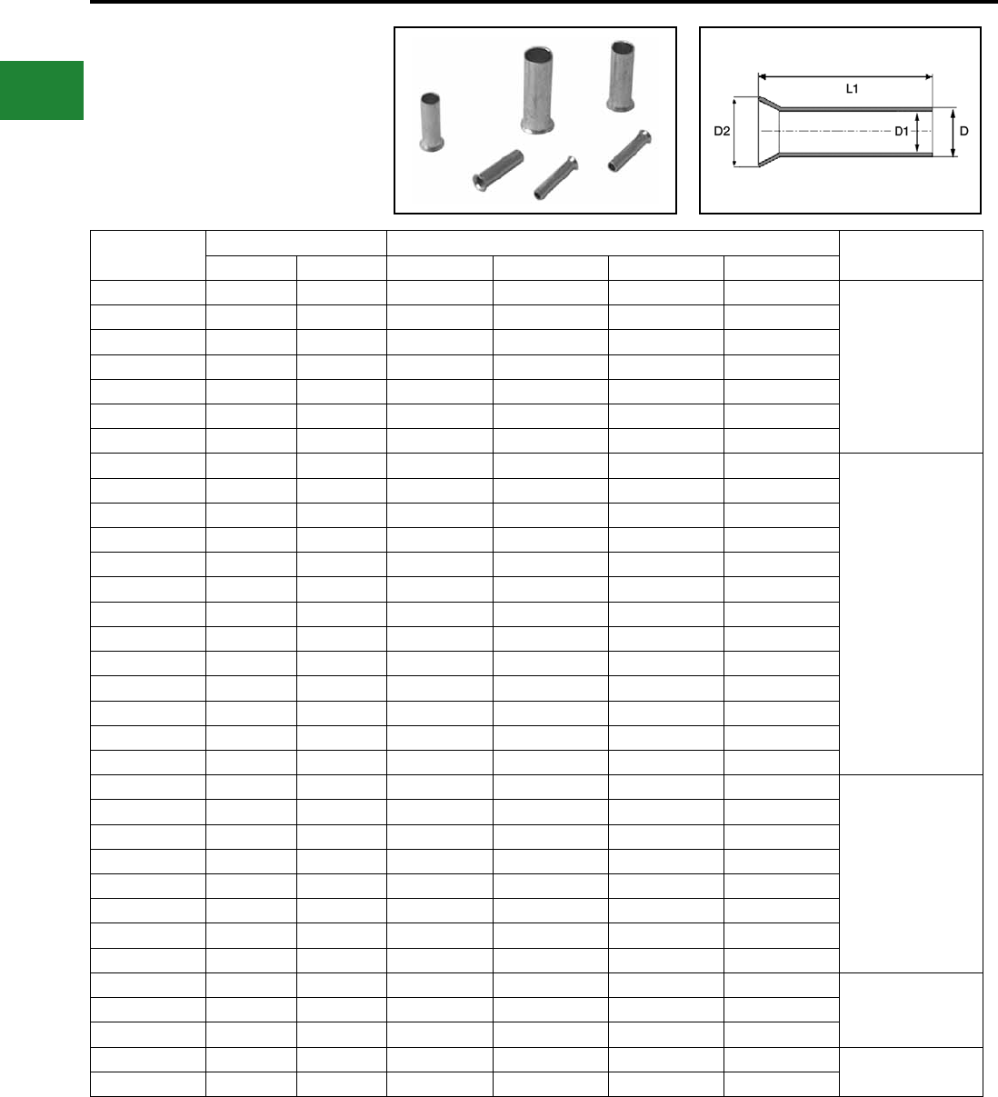
BURNDY®
Blue highlighted items are industry standard and most frequently ordered.
US: 1-800-346-4175 www.burndy.com Canada: 1-800-387-6487
Small Terminals
TYPE YF-UI
(Continued)
BARE FERRULES
For Use On Copper Conductor
Catalog
Number
Wire Size Dimensions in Inches Recommended Tooling
AWG mm² L1 Dim (in) D Dim (in) D1 Dim (in) D2 Dim (in)
YF0812UI 8 10.00 0.47 0.19 0.18 0.29
YF3206TOOL
YF1006TOOL
YF0801TOOL
YF0815UI 8 10.00 0.59 0.19 0.18 0.29
YF0818UI 8 10.00 0.71 0.19 0.18 0.29
YF0612UI 6 16.00 0.47 0.24 0.23 0.30
YF0615UI 6 16.00 0.59 0.24 0.23 0.30
YF0618UI 6 16.00 0.71 0.24 0.23 0.30
YF0625UI 6 16.00 0.98 0.24 0.23 0.30
YF0412UI 4 25.00 0.47 0.31 0.29 0.38
YF0801TOOL
YF0401TOOL
YF0415UI 4 25.00 0.59 0.31 0.29 0.38
YF0418UI 4 25.00 0.70 0.31 0.29 0.38
YF0420UI 4 25.00 0.79 0.31 0.29 0.38
YF0425UI 4 25.00 0.98 0.31 0.29 0.38
YF0432UI 4 25.00 1.26 0.31 0.29 0.38
YF0215UI 2 35.00 0.59 0.34 0.33 0.42
YF0220UI 2 35.00 0.79 0.34 0.33 0.42
YF0225UI 2 35.00 0.98 0.34 0.33 0.42
YF0232UI 2 35.00 1.26 0.34 0.33 0.42
YF0122UI 1 50.00 0.87 0.43 0.41 0.52
YF0125UI 1 50.00 0.98 0.43 0.41 0.52
YF0132UI 1 50.00 1.26 0.43 0.41 0.52
YF2/022UI 2/0 70.00 0.87 0.56 0.53 0.64
YF1/03/0TOOL
YF2/025UI 2/0 70.00 0.98 0.56 0.53 0.64
YF2/032UI 2/0 70.00 1.26 0.56 0.53 0.64
YF3/025UI 3/0 95.00 0.98 0.61 0.58 0.68
YF3/030UI 3/0 95.00 1.18 0.61 0.58 0.68
YF3/032UI 3/0 95.00 1.26 0.61 0.58 0.68
YF4/032UI 4/0 120.00 1.26 0.70 0.70 0.81
YF4/034UI 4/0 120.00 1.39 0.70 0.70 0.81
YF4/040UI 4/0 120.00 1.57 0.70 0.70 0.81
YF4/0250TOOLYF25032UI 250 150.00 1.26 0.81 0.77 0.91
YF25040UI 250 150.00 1.57 0.81 0.77 0.91
YF35032UI 350 185.00 1.26 0.84 0.79 0.94 Y644HSXT
YF35040UI 350 185.00 1.57 0.84 0.80 0.94
B-86
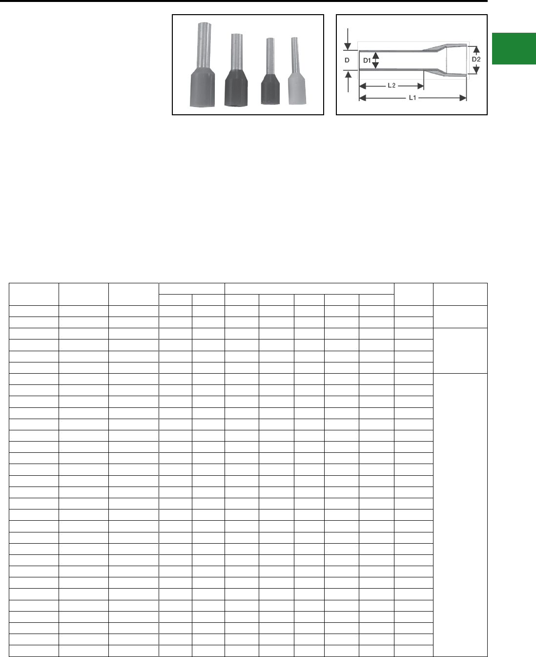
BURNDY®
Blue highlighted items are industry standard and most frequently ordered.
Canada: 1-800-387-6487 www.burndy.com US: 1-800-346-4175
Small Terminals
TYPE YF-I FERRULES
Series D, T & W
INSULATED FERRULES
For Use On Copper Conductor
Offered in Series D, T & W
Ferrules are electrical connectors used to
terminate stranded wires, creating a quality, reliable
connection by ensuring each wire strand conducts
current when properly crimped. Especially useful
when multiple reconnections could be necessary
within terminal blocks or other similar devices. No
breakage of wire strands when wire is bent, under
stress or in a vibration environment. Twin ferrule
designs allow two individual stranded conductors
to be connected to the same termination,
most benecial in jumpering or other similar
applications. Both styles (single and twin) offer the
same features and benets. The YF-TOOL series
has been designed to crimp both the bare (type
YF-UI) and insulated (type YF-I) ferrules.
Features & Benets
• Made of electrolytic copper, tin plated
• Smooth funnel entry to make wire
insertion easier
• Secure contacting even after multiple
reconnections
• Long-term contact resistance
• No fraying of strands
• No breakage of wire strands when wire
is bent, under stress or in vibration
environment
• RoHS compliant
W Series D Series T Series Wire Size Dimensions in Inches Bag Qty Tooling
AWG mm² L1 (in) L2 (in) D (in) D1 (in) D2 (in)
YF2806IW — YF2806IT 28 0.14 0.39 0.22 0.04 0.03 0.07 500 YF3206TOOL
YF2808IW — YF2808IT 28 0.14 0.49 0.32 0.04 0.03 0.04 500
YF2606IW YF2606ID YF2606IT 26 0.25 0.40 0.23 0.05 0.03 0.08 500
YF3206TOOL,
YF2610TOOL
YF2608IW YF2608ID YF2608IT 26 0.25 0.49 0.32 0.04 0.03 0.08 500
YF2406IW — YF2406IT 24 0.34 0.48 0.31 0.04 0.03 0.08 500
YF2408IW — YF2408IT 24 0.34 0.40 0.31 0.04 0.03 0.08 500
YF2205IW YF2205ID YF2205IT 22 0.50 0.44 0.21 0.05 0.04 0.11 500
YF3206TOOL,
YF2610TOOL,
YF2214TOOL,
YF2210TOOL,
YF2210FL
YF2206IW YF2206ID YF2206IT 22 0.50 0.47 0.24 0.05 0.04 0.10 500
YF2208IW YF2208ID YF2208IT 22 0.50 0.55 0.32 0.05 0.04 0.11 500
YF2210IW YF2210ID YF2210IT 22 0.50 0.63 0.39 0.05 0.04 0.10 500
YF2212IW YF2212ID YF2212IT 22 0.50 0.47 0.24 0.05 0.04 0.10 500
YF2006IW YF2206ID YF2006IT 20 0.75 0.47 0.24 0.06 0.05 0.11 500
YF2008IW YF2008ID YF2008IT 20 0.75 0.56 0.31 0.06 0.05 0.12 500
YF2010IW YF2010ID YF2010IT 20 0.75 0.63 0.39 0.06 0.05 0.11 500
YF2012IW YF2012ID YF2012IT 20 0.75 0.71 0.47 0.06 0.05 0.11 500
YF2018IW YF2018ID YF2018IT 20 0.75 0.96 0.71 0.06 0.05 0.11 500
YF1806IW YF1806ID YF1806IT 18 1.00 0.47 0.24 0.07 0.06 0.12 500
YF1808IW YF1808ID YF1808IT 18 1.00 0.56 0.32 0.07 0.05 0.12 500
YF1810IW YF1810ID YF1810IT 18 1.00 0.63 0.39 0.07 0.06 0.12 500
YF1812IW YF1812ID YF1812IT 18 1.00 0.71 0.47 0.07 0.06 0.12 500
YF1818IW YF1818ID YF1818IT 18 1.00 0.96 0.71 0.07 0.06 0.12 500
YF1606IW YF1606ID YF1606IT 16 1.50 0.48 0.24 0.08 0.07 0.14 500
YF1608IW YF1608ID YF1608IT 16 1.50 0.55 0.32 0.08 0.07 0.14 500
YF1610IW YF1610ID YF1610IT 16 1.50 0.63 0.39 0.08 0.07 0.14 500
YF1612IW YF1612ID YF1612IT 16 1.50 0.71 0.47 0.08 0.07 0.14 500
YF1615IW YF1615ID YF1615IT 16 1.50 0.84 0.59 0.08 0.07 0.14 500
YF1618IW YF1618ID YF1618IT 16 1.50 0.95 0.71 0.08 0.07 0.14 500
YF1408IW YF1408ID YF1408IT 14 2.50 0.62 0.32 0.10 0.09 0.17 500
YF1410IW YF1410ID YF1410IT 14 2.50 0.69 0.39 0.09 0.09 0.17 500
YF1412IW YF1412ID YF1412IT 14 2.50 0.71 0.47 0.09 0.09 0.17 500
YF1418IW YF1418ID YF1418IT 14 2.50 0.95 0.71 0.09 0.09 0.17 500
B-87
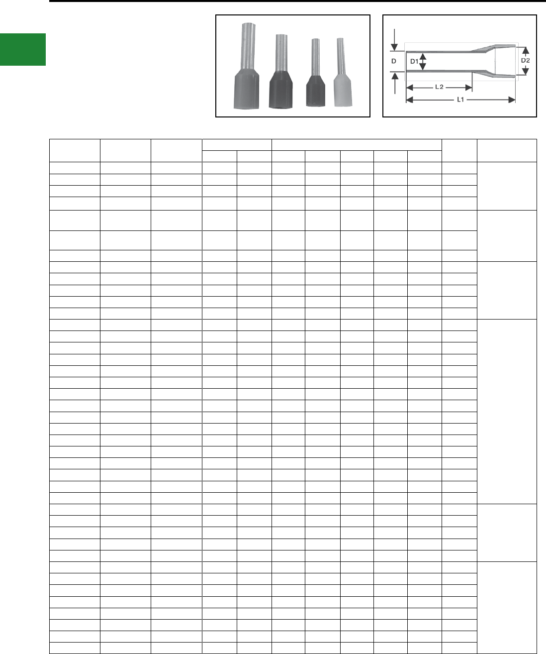
BURNDY®
Blue highlighted items are industry standard and most frequently ordered.
US: 1-800-346-4175 www.burndy.com Canada: 1-800-387-6487
Small Terminals
TYPE YF-I FERRULES
Series D, T & W
(Continued)
INSULATED FERRULES
W Series D Series T Series Wire Size Dimensions in Inches Bag Qty Tooling
AWG mm² L1 (in) L2 (in) D (in) D1 (in) D2 (in)
YF1209IW YF1209ID YF1209IT 12 4.00 0.65 0.32 0.13 0.11 0.19 500 YF3206TOOL,
YF2610TOOL,
YF2210TOOL,
YF2210FL
YF1210IW YF1210ID YF1210IT 12 4.00 0.71 0.39 0.13 0.11 0.13 500
YF1212IW YF1212ID YF1212IT 12 4.00 0.79 0.47 0.13 0.11 0.19 500
YF1218IW YF1218ID YF1218IT 12 4.00 1.02 0.71 0.13 0.11 0.19 500
YF1010IW YF1010ID YF1010IT 10 6.00 0.73 0.39 0.15 0.14 0.25 100 YF3206TOOL,
YF2610TOOL,
YF2210TOOL,
YF1006TOOL,
YF2210FL
YF1012IW YF1012ID YF1012IT 10 6.00 0.82 0.47 0.15 0.14 0.23 100
YF1018IW YF1018ID YF1018IT 10 6.00 1.02 0.71 0.15 0.15 0.25 100
YF0812IW YF0812ID YF0812IT 8 10.00 0.91 0.46 0.19 0.18 0.31 100
YF3206TOOL,
YF1006TOOL,
YF0801TOOL
YF0815IW YF0815ID YF0815IT 8 10.00 0.93 0.59 0.19 0.18 0.29 100
YF0818IW YF0818ID YF0818IT 8 10.00 1.10 0.71 0.19 0.18 0.29 100
YF0612IW YF0612ID YF0612IT 6 16.00 0.89 0.43 0.25 0.23 0.34 100
YF0618IW YF0618ID YF0618IT 6 16.00 0.89 0.43 0.25 0.23 0.34 100
YF0412IW YF0412ID YF0412IT 4 25.00 0.94 0.47 0.31 0.29 0.44 100
YF0801TOOL,
YF0401TOOL
YF0415IW YF0415ID YF0415IT 4 25.00 1.06 0.59 0.30 0.29 0.44 100
YF0416IW YF0416ID YF0416IT 4 25.00 1.10 0.63 0.30 0.29 0.44 100
YF0418IW YF0418ID YF0418IT 4 25.00 1.18 0.71 0.30 0.29 0.44 100
YF0422IW YF0422ID YF0422IT 4 25.00 1.42 0.87 0.30 0.29 0.44 100
YF0425IW YF0425ID YF0425IT 4 25.00 1.45 0.98 0.30 0.29 0.44 100
YF0216IW YF0216ID YF0216IT 2 35.00 1.17 0.64 0.34 0.32 0.48 100
YF0218IW YF0218ID YF0218IT 2 35.00 1.26 0.71 0.34 0.33 0.50 100
YF0222IW YF0222ID YF0222IT 2 35.00 1.41 0.87 0.34 0.33 0.50 100
YF0225IW YF0225ID YF0225IT 2 35.00 1.53 0.98 0.34 0.33 0.50 100
YF0112IW YF0112ID YF0112IT 1 50.00 1.10 0.47 0.43 0.41 0.59 50
YF0116IW YF0116ID YF0116IT 1 50.00 1.26 0.63 0.43 0.41 0.59 50
YF0120IW YF0120ID YF0120IT 1 50.00 1.45 0.79 0.43 0.40 0.58 50
YF0122IW YF0122ID YF0122IT 1 50.00 1.50 0.87 0.43 0.41 0.59 50
YF0125IW YF0125ID YF0125IT 1 50.00 0.98 0.43 0.43 0.41 0.59 50
YF0130IW YF0130ID YF0130IT 1 50.00 1.18 0.43 0.43 0.41 0.59 50
— YF2/020ID — 2/0 70.00 1.45 0.79 0.56 0.53 0.63 25
YF1/03/0TOOL
— YF2/025ID — 2/0 70.00 1.65 0.98 0.56 0.53 0.63 25
— YF2/027ID — 2/0 70.00 1.73 1.06 0.56 0.53 0.63 25
— YF3/025ID — 3/0 95.00 1.73 0.98 0.61 0.58 0.73 25
— YF3/030ID — 3/0 95.00 1.95 1.18 0.61 0.58 0.73 25
— YF4/027ID — 4/0 120.00 1.87 1.06 0.70 0.66 0.80 25
YF4/0250TOOL
— YF4/030ID — 4/0 120.00 2.01 1.18 0.70 0.66 0.80 25
— YF4/032ID — 4/0 120.00 2.07 1.26 0.70 0.66 0.80 25
— YF4/034ID — 4/0 120.00 2.15 1.34 0.70 0.66 0.80 25
— YF25025ID — 250 150.00 1.99 0.98 0.81 0.77 0.92 25
— YF25027ID — 250 150.00 2.07 1.06 0.81 0.77 0.92 25
— YF25032ID — 250 150.00 2.27 1.26 0.81 0.77 0.92 25
— YF25038ID — 250 150.00 2.50 1.50 0.81 0.77 0.92 25
B-88
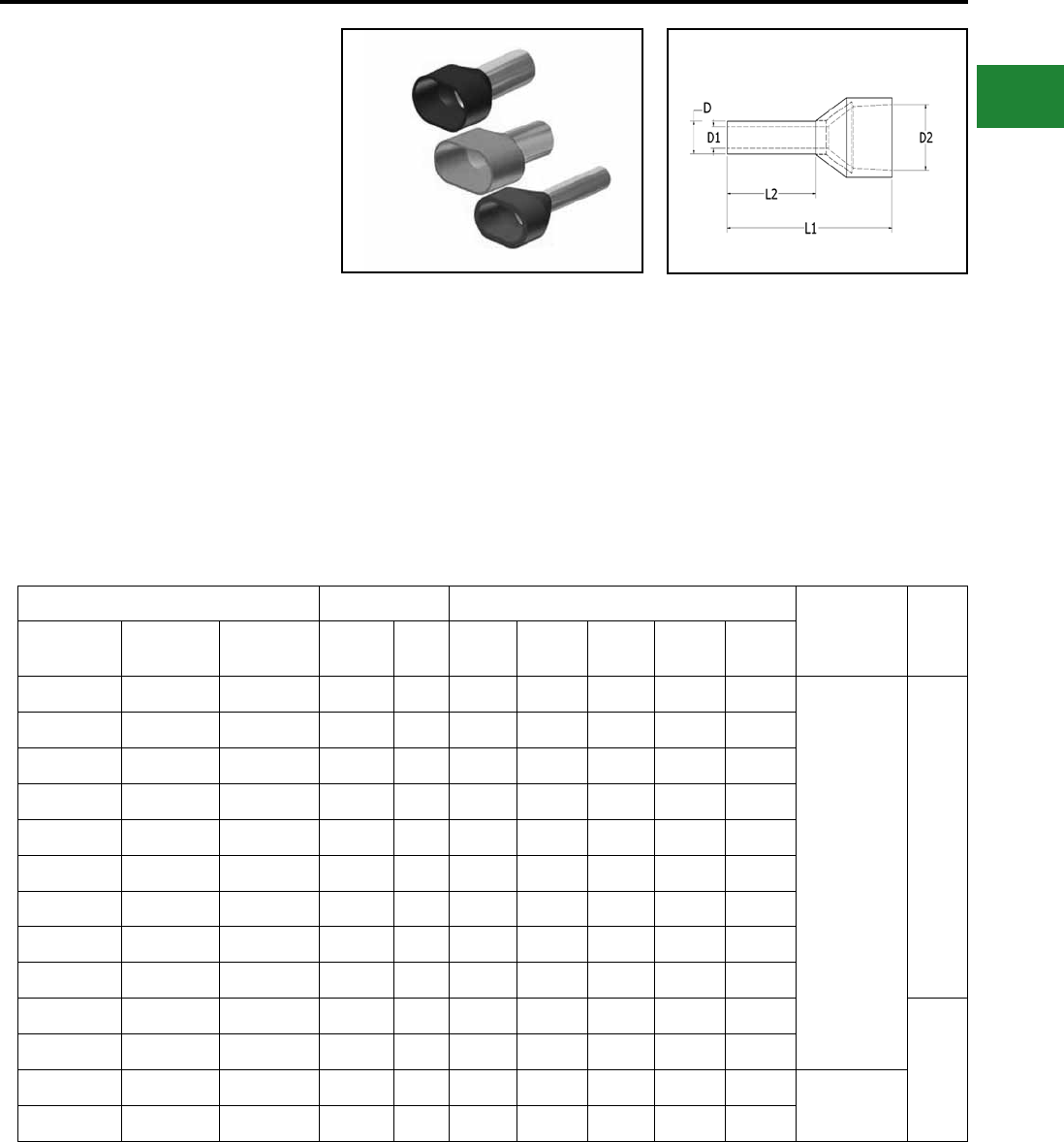
BURNDY®
Blue highlighted items are industry standard and most frequently ordered.
Canada: 1-800-387-6487 www.burndy.com US: 1-800-346-4175
Small Terminals
TYPE YF-TW
INSULATED TWIN FERRULES
For Use on Copper Conductor
Ferrules are electrical connectors used to
terminate stranded wires, creating a quality, reliable
connection by ensuring each wire strand conducts
current when properly crimped. Especially useful
when multiple reconnections could be necessary
within terminal blocks or other similar devices. No
breakage of wire strands when wire is bent, under
stress or in a vibration environment. Twin ferrule
designs allow two individual stranded conductors
to be connected to the same termination,
most benecial in jumpering or other similiar
applications. Both styles (single and twin) offer the
same features and benets. The YF-TOOL series
has been designed to crimp both the bare (type
YF) and insulated (type YF-I) ferrules.
Features & Benets
• Made of electrolytic copper, tin plated
• Smooth funnel entry to make wire
insertion easier
• Secure contacting even after multiple
reconnections
• Long-term contact resistance
• No fraying of strands
• No breakage of wire strands when wire
is bent, under stress or in vibration
environment
• RoHS compliant
Catalog Number Wire sizes Dimensions in Inches
Tooling Bag
Qty
W Series T Series D Series AWG mm2L1 Dim
(in)
L2 Dim
(in)
D Dim
(in)
D1 Dim
(in)
D2 Dim
(in)
YFTW2208W YFTW2208T YFTW2208D 22 AWG 0.50 0.60 0.30 0.07 0.06 0.19
YF32016TOOL
YF2210TOOL
YF2210FL
100
YFTW2010W YFTW2010T YFTW2010D 20 AWG 0.75 0.66 0.39 0.08 0.07 0.22
YFTW2008W YFTW2008T YFTW2008D 20 AWG 0.75 0.60 0.31 0.08 0.07 0.20
YFTW1810W YFTW1810T YFTW1810D 18 AWG 1.00 0.67 0.39 0.09 0.08 0.22
YFTW1808W YFTW1808T YFTW1808D 18 AWG 1.00 0.62 0.31 0.09 0.08 0.22
YFTW1612W YFTW1612T YFTW1612D 16 AWG 1.50 0.77 0.47 0.10 0.09 0.25
YFTW1608W YFTW1608T YFTW1608D 16 AWG 1.50 0.65 0.31 0.10 0.09 0.26
YFTW1413W YFTW1413T YFTW1413D 14 AWG 2.50 0.85 0.51 0.13 0.11 0.32
YFTW1410W YFTW1410T YFTW1410D 14 AWG 2.50 0.77 0.39 0.13 0.11 0.31
YFTW1212W YFTW1212T YFTW1212D 12 AWG 4.00 0.92 0.46 0.17 0.15 0.36
500
YFTW1014W YFTW1014T YFTW1014D 10 AWG 6.00 0.99 0.53 0.21 0.19 0.41
YFTW0814W YFTW0814T YFTW0814D 8 AWG 10.00 1.04 0.55 0.27 0.25 0.51 YF0801TOOL
YF1006TOOL
YFTW0614W YFTW0614T YFTW0614D 6 AWG 16.00 1.23 0.55 0.34 0.33 0.75
B-89
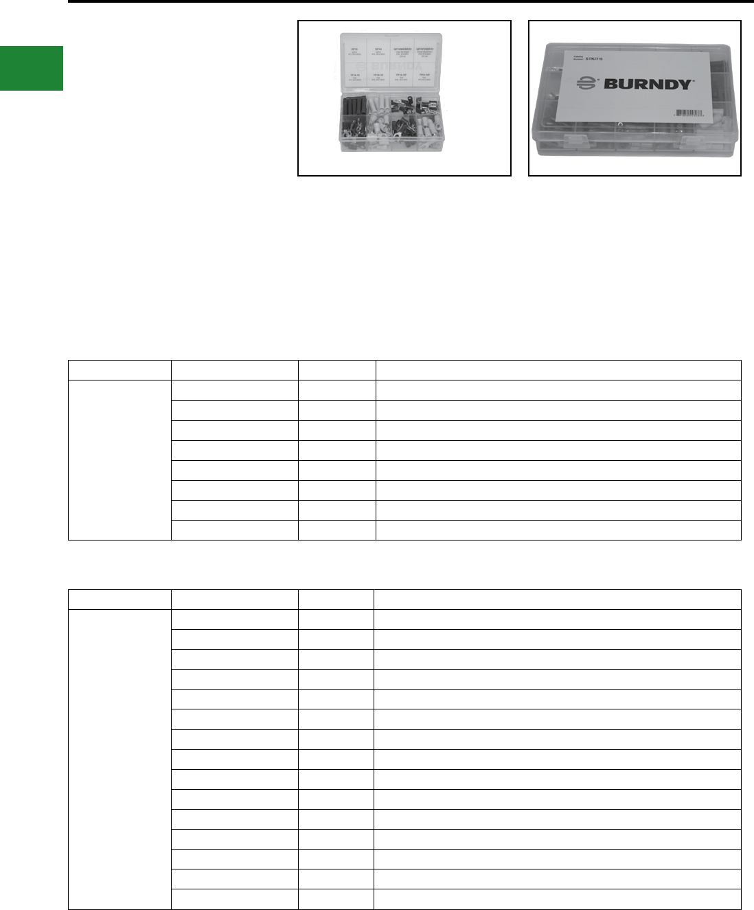
BURNDY®
Blue highlighted items are industry standard and most frequently ordered.
US: 1-800-346-4175 www.burndy.com Canada: 1-800-387-6487
Small Terminals
SMALL TERMINAL KITS
PACKAGED KITS OF VARIOUS
TYPES OF SMALL TERMINALS
For Use On Copper Conductor
Small Terminal Kits are packaged in reusable
plastic cases with secure compartments for each
type of connector. Clearly marked on the inside
front cover with part numbers and descriptions, the
kits contain some of the most common terminals
needed on everyday installations.
Features & Benets
• Quality terminals of various types packaged
together for convenience
• Color-coded barrels
• Reusable, re llable container
• Clearly marked with part numbers and
descriptions on inside cover
Kit Catalog Number Quantity Description
STKIT08
SP14 20 #16 - #14 AWG splice; vinyl insulation
QP14M25X03D 10 #16 - #14 AWG male disconnect; .250 tab size; vinyl insulation
QP14F25X03D 10 #16 - #14 AWG female disconnect; .250 tab size; vinyl insulation
TP14-10 20 #16 - #14 AWG ring terminal; 8 - 10 stud size; vinyl insulation
TP14-10F 20 #16 - #14 AWG fork terminal; 8 - 10 stud size; vinyl insulation
SP10 10 #12 - #10 AWG splice; vinyl insulation
TP10-10 20 #12 - #10 AWG ring terminal; 8 - 10 stud size; vinyl insulation
TP10-10F 20 #12 - #10 AWG fork terminal; 8 - 10 stud size; vinyl insulation
Kit Catalog Number Quantity Description
STKIT15
QP18M18X02D 20 #22 - #18 AWG male disconnect; .187 tab; vinyl insulation
QP18M25X03D 20 #22 - #18 AWG male disconnect; .250 tab; vinyl insulation
QP18F18X02D 20 #22 - #18 AWG female disconnect; .187 tab; vinyl insulation
QP18F25X03D 20 #22 - #18 AWG female disconnect; .250 tab; vinyl insulation
BULM18P 20 #22 - #18 AWG male bullet disconnect; vinyl insulation
BULF18P 20 #22 - #18 AWG female bullet disconnect; vinyl insulation
SP18 20 #22 - #18 AWG splice; vinyl insulation
QP14M18X02D 20 #16 - #14 AWG male disconnect; .187 tab; vinyl insulation
QP14M25X03D 20 #16 - #14 AWG male disconnect; .250 tab; vinyl insulation
QP14F18X02D 20 #16 - #14 AWG female disconnect; .187 tab; vinyl insulation
QP14F25X03D 20 #16 - #14 AWG female disconnect; .250 tab; vinyl insulation
BULM14P 20 #16 - #14 AWG male bullet disconnect; vinyl insulation
BULF14P 20 #16 - #14 AWG female bullet disconnect; vinyl insulation
SP14 20 #16 - #14 AWG splice; vinyl insulation
SP10 20 #12 - #10 AWG splice; vinyl insulation
Catalog Number: STKIT08
Contains:
Catalog Number: STKIT15
Contains:
B-90
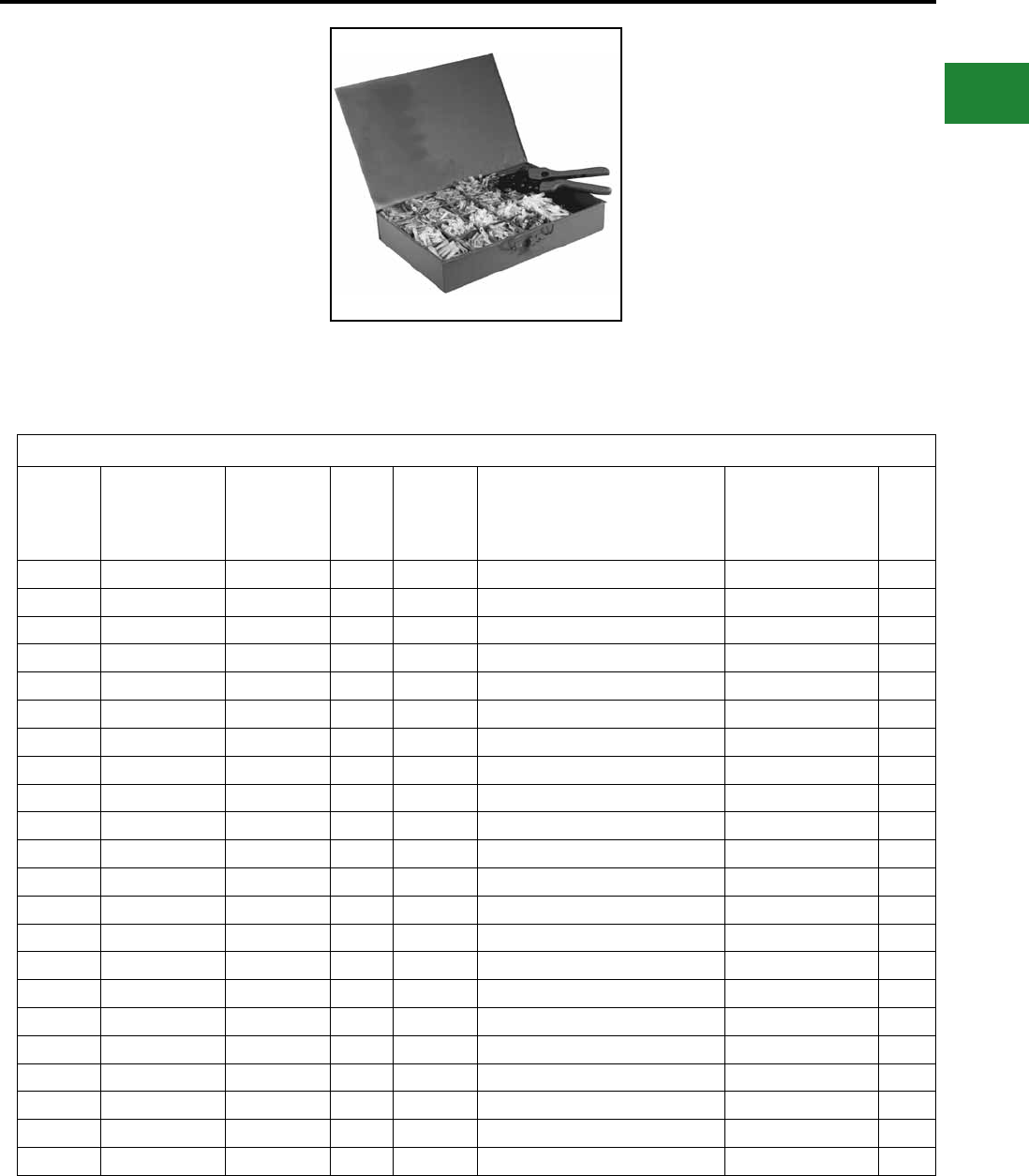
BURNDY®
Blue highlighted items are industry standard and most frequently ordered.
Canada: 1-800-387-6487 www.burndy.com US: 1-800-346-4175
Small Terminals
TYPE HSKIT
HYDENT™ HEAT SHRINK
CONNECTORS AND
INSTALLATION TOOL
For Use On Copper Conductor
Standard crimp terminals leave the wire exposed
allowing in moisture or other contaminants which
can result in corrosion. Heat shrink terminals
provide a durable seal, blocking out contaminants,
ensuring a better connection.
Features & Benets
• Made from pure copper, annealed for
maximum strength
• Color-coded, imprinted with wire size
• Serrated barrels offer maximum wire contact
and tensile strength
• Electro tin plated for corrosion resistance
• Wire strip length 5/16"
List of Items Included in HSKIT
Quantity
of Pieces
included
in kit
Description Conductor
Size
Stud
Size
Quantity
of Pieces
included
in kit
Description Conductor
Size
Stud
Size
50 Butt Splice 22 - 18 AWG — 10 Fork Terminal 22 - 18 AWG #6
50 Butt Splice 16 - 14 AWG — 10 Fork Terminal 22 - 18 AWG #8
30 Butt Splice 12 - 10 AWG — 10 Fork Terminal 22 - 18 AWG #10
15 Butt Splice #8 AWG — 10 Fork Terminal 16 - 14 AWG #6
10 Ring Terminal 22 - 18 AWG #6 10 Fork Terminal 16 - 14 AWG #8
10 Ring Terminal 22 - 18 AWG #8 10 Fork Terminal 16 - 14 AWG #10
10 Ring Terminal 22 - 18 AWG #10 10 Fork Terminal 12 - 10 AWG #6
10 Ring Terminal 22 - 18 AWG 5/16″ 10 Fork Terminal 12 - 10 AWG #8
10 Ring Terminal 22 - 18 AWG 1/4″ 10 Fork Terminal 12 - 10 AWG #10
10 Ring Terminal 22 - 18 AWG 3/8″ 15 Fork Terminal #8 AWG 3/8"
10 Ring Terminal 16 - 14 AWG #8 50 (25 ea) Male & Female Quick Disc. 22 - 18 AWG —
10 Ring Terminal 16 - 14 AWG #10 50 (25 ea) Male & Female Quick Disc. 16 - 14 AWG —
10 Ring Terminal 16 - 14 AWG 5/16″ 50 (25 ea) Male & Female Quick Disc. 12 - 10 AWG —
10 Ring Terminal 16 - 14 AWG 1/4″ 30 (15 ea) Male & Female Bullet 16 - 14 AWG —
10 Ring Terminal 16 - 14 AWG 3/8″ 20 (10 ea) Male & Female Ins. Quick Disc. 22 - 18 AWG —
10 Ring Terminal 16 - 14 AWG #6 20 (10 ea) Male & Female Ins. Quick Disc. 16 - 14 AWG —
10 Ring Terminal 12 - 10 AWG #8 20 (10 ea) Male & Female Ins. Quick Disc. 12 - 10 AWG —
10 Ring Terminal 12 - 10 AWG #10 10 Step Down Butt Splice 16 - 14 to 22 - 18 AWG —
10 Ring Terminal 12 - 10 AWG 5/16″ 10 Step Down Butt Splice 12 - 10 to 16 - 14 AWG —
10 Ring Terminal 12 - 10 AWG 1/4″ 1 Ratchet Crimp Tool — —
10 Ring Terminal 12 - 10 AWG 3/8″ 1 Metal Case with Dividers — —
15 Ring Terminal #8 AWG #10
B-91
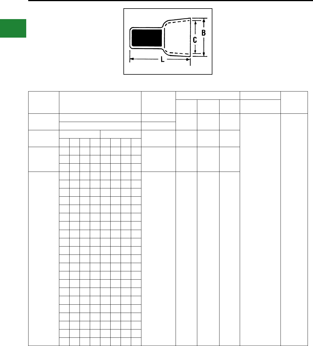
BURNDY®
Blue highlighted items are industry standard and most frequently ordered.
US: 1-800-346-4175 www.burndy.com Canada: 1-800-387-6487
Small Terminals
BURCAP TYPES YQE, RK
PIGTAIL SPLICE,
NYLON-INSULATED
Rated at 600 volts for building wire and 1000 volts
for xtures and signs,the BURCAP is designed to
splice a wide range of different cable sizes.
Catalog
Number Wire Combinations Total Area
Circular Mils
Dimension in Inches Installation Tools Wire
Strip
Length
L B C M8ND, Y8ND,
HYTOOL™
YQE-91† 1 # 16 & 1 # 18, 4205 0.76 0.30 0.24
N150WT 5/16"
2# 18 3250
*RK141-2 RK141ABOX100 RK142ABOX100 500 - 5,180 0.61
(16, 4)
0.31
(7, 9)
0.27
(8, 6)
22 20 18 16 18 16 14 12
*RK142-2
7 1 1
2,400 - 13,100 0.72
(18, 3)
0.44
(11, 2)
0.38
(9, 8)
6 1 2 1
5 1 3 1
4 2 1 1
4 1 2 1
3 2 3 1
3 2 1 1
3 1 2 1
2 3 1 1
2 2 2 1
2 1 3 1
14 221
1 2 2
1 1 1 1
4 2 1
3 1 3 1
2 2 4 1
2 1 1 2
1 2 2 2
1 1 3 2
3 2
2 1 3
3
5
NOTE:
* Convenience Package. For Box quantity, order
RK141ABOX100 and RK142ABOX100 respectively.
† This item is UL Listed
B-92

BURNDY®
Canada: 1-800-387-6487 www.burndy.com US: 1-800-346-4175
TABLE OF CONTENTS
Compression Connections
Compression Connectors
Selection & Use
Tooling
Industry Standards
Telecommunications Connectors
Circumferential Crimps
Tooling
Industry Standards
Y644 Family Expanded Ranges
Y81KFT Family Expanded Ranges
12 Ton U-Dies
W Dies
Index Chart
Battery Terminals
Straight Style
T-Style
Grounding/Starter
Break-Away HYLUG™ Connectors
Copper
Aluminum
Cu/Al Wind Turbine Kits
Blank Tongue Connectors
One Hole HYLUG™ for Code
Conductor
Standard Barrel
Standard Barrel - Narrow Tongue
Long Barrel
Long Barrel - with Inspection Window
Two Hole HYLUG™ for Code
Conductor
Standard Barrel
Standard Barrel - Narrow Tongue
Long Barrel
Long Barrel - with Inspection Window
Four Hole HYLUG™ for Code
Conductor
Long Barrel
One Hole HYLUG™ for Flex
Conductor
Standard Barrel
Standard Barrel - Narrow Tongue
Standard Barrel - No Inspection Window
Standard Barrel - Belled End
Long Barrel - with Inspection Window
Long Barrel - Belled End
Two Hole HYLUG™ for Flex
Conductor
Standard Barrel
Standard Barrel - Narrow Tongue
Long Barrel - with Inspection Window
Long Barrel - Belled End
Long Barrel - Narrow Tongue
Lead Plated for Flex Conductor
One Hole Standard Barrel
Two Hole Standard Barrel
Specialty Design
Two Hole - Double Barrel for Flex
Two Hole - Slotted Tongue, Standard
Barrel for Code/Flex
Two Hole - Slotted Tongue, Long Barrel
for Code
Two Hole - Slotted Tongue, Long Barrel
with Inspection Window for Code
Two Hole - Slotted Tongue, Long Barrel
with Inspection Window for Flex
Split Tongue Design - Standard Barrel
for Code/Flex
Split Tongue Design - Long Barrel
with Inspection Window for Code/Flex
C-4
C-4
C-4
C-5
C-5
C-5
C-6
C-7, C-8
C-9
C-9
C-10
C-11
C-12
C-13
C-14, C-15
C-16
C-17
C-18 to C-20
C-21 to C-24
C-25, C-26
C-27 to C-30
C-31 to C-33
C-34 to C-37
C-38, C-39
C-40 to C-42
C-43 to C-46
C-47
C-48 to C-50
C-51, C-52
C-53, C-54
C-55
C-56, C-57
C-58, C-59
C-60 to C-62
C-63, C-64
C-65 to C-67
C-68 to C-70
C-71, C-72
C-73 to C-75
C-76 to C-78
C-79
C-80
C-81
C-82
C-83, C-84
C-85
C-86
C-1

BURNDY®
US: 1-800-346-4175 www.burndy.com Canada: 1-800-387-6487
TABLE OF CONTENTS
(Continued)
Metric Connectors
One Hole Standard Barrel for Code
One Hole Long Barrel for Code
Two Hole Standard Barrel for Code
Two Hole Long Barrel for Code
One Hole Standard Barrel for Flex
One Hole Long Barrel for Flex
Two Hole Standard Barrel for Flex
Two Hole Long Barrel for Flex
E-LINE HYLUG™ Connectors
One and Two Hole - Narrow Tongue for
Copper/Aluminum
HYLINK™ Splices
Color-Coded Parallel
Standard Barrel for Copper
Long Barrel for Copper
Reducing Adaptors for Copper
Standard Barrel - Belled Ends for Flex
Standard Barrel - Tapered Ends for Code
Long Barrel - Belled Ends for Flex
HYSPLICE™ In-Line Splice Kits
Standard Barrel with Inspection Window
for Code/Flex
HYREDUCER™ In-Line Reducer
Splice Kits
Reducing Splices for Code/Flex
Copper Taps
C-Tap - Thin Wall
CRIMPIT™ C-Tap - Unplated
CRIMPIT™ C-Tap - Tin-plated
CRIMPIT™ H-Tap
H-Tap Covers - Black and Clear
Split H-Tap CRIMPIT™
T Connectors
HYTEE™ Coupler
Bolted Run/Compression Tap
HYPLUG™
Copper Adaptors
HYSTACK™
Stacking Adaptors for Copper/Aluminum
Aluminum Connectors
One Hole for Aluminum/Copper
Two Hole/Four Hole for Aluminum/Copper
Transformer Lug Kit
For Aluminum/ Copper
HYPLUG™ Adaptors
Adaptors for Aluminum/Copper
HYLINK™ Splices
Splices for Aluminum/Copper
Tapered End Splices for Aluminum/Copper
HYREDUCER™ Splice
Reducing Splices for Aluminum/Copper
H CRIMPIT™ Connectors
Tap Connectors for Aluminum/Copper
Insulating/Flame Retardant Covers
C-87 to C-89
C-90 to C-92
C-93 to C-95
C-96 to C-98
C-99, C-100
C-101, C-102
C-103, C-104
C-105, C-106
C-107, C-108
C-109
C-110
C-111
C-112
C-113 to C-115
C-116
C-117
C-118
C-119 to C-128
C-129
C-130
C-131
C-132 to C-134
C-135
C-136
C-137
C-139
C-139 to C-141
C-142
C-143, C-144
C-145, C-146
C-147
C-148, C-149
C-150, C-151
C-152
C-153
C-154
C-155
C-2
Compression Connections
BURNDY®
Canada: 1-800-387-6487 www.burndy.com US: 1-800-346-4175
ONE HOLE YA-L, YA-L-TC C-21 to C-24
NARROW TONGUE YA-L-NT C-25, C-26
NARROW TONGUE TWO HOLE YA-L-2NT C-38, C-39
TWO HOLE YA-2L, YA-2LN, YA-L-2TC C-34 to C-37
ONE HOLE YA, YA-TC, YAZ C-27 to C-33
TWO HOLE YA-2N, YA-2TC, YAZ C-40 to C-46
FOUR HOLE YA-4N, YAB-4N C-47
STANDARD LENGTH YS-L C-110
LONG BARREL YS, YS-T, YSP-T C-111, C-116
REDUCER ADAPTER Y-R C-112
TEE YST, NYT C-137, C-138
C-TAP YC-C C-130
LIGHT DUTY C TAP YC-L C-129
ONE HOLE - STANDARD / LONG YAVM, YALBM C-82 to C-92
TWO HOLE - STANDARD / LONG YAV2M, YALB2M C-93 to C-98
ONE HOLE YA-L-FX, YAV, YAV-L-FX, YAG-L-FX C-48 to C-54
ONE HOLE-WIDE BELLED ENTRY YA-LB C-55
ONE HOLE-LEAD PLATED YAG-L-TC-LD C-73 to C-75
TWO HOLE YA-L-2TC-FX, YAV-L-2TC-FX C-60 to C-64
TWO HOLE-LEAD PLATED YAG-L-2TC-LD C-77, C-78
ONE HOLE YA-TC-FXB, YAV-TC-FXB, YAZV C-57 to C-59
TWO HOLE YA-2TC-FXB, YAV-2TC-FXB, YAZV C-65 to C-72
PIN ADAPTER YEV-P-FX, YEP-FX, YEP C-139 to C-141
YA-A-KIT C-147
ASA-U, CUSA C-142
YRB C-153
STANDARD BARREL - BELLED YS-LB C-113
LONG BARREL - BELLED YS-FXB C-117
C-TAP YC-L, YC-C, YCHC C-129 to C-131
H-TAP YH C-132 to C-134
LONG H TAP YSH C-136
COVERS FOR H TAPS CF-FR, CCF-FR C-135
ONE HOLE - STANDARD / LONG YAVFM, YALBFM C-99 to C-102
TWO HOLE - STANDARD / LONG YAV2FM, YALB2FM C-103 to C-106
ONE HOLE YA-E C-107
TWO HOLE YA-2-E C-107
ONE HOLE YA-A, YA-A-TN C-143, C-144
TWO HOLE YA-A C-145, C-146
STRAIGHT AYP C-148, C-149
OFFSET AYPO C-148, C-149
STANDARD YS-A C-150, C-151
TAPERED FOR HIGH VOLTAGE YS-AT C-152
H-TAPS YFD, YFN, YFO, YFR C-154
COVERS FOR H TAPS CFA, CFA-FR C-155
ONE HOLE YA-E C-107, C-108
TWO HOLE YA-E C-107, C-108
STANDARD BARREL YA-L-2TC-SL C-80
LONG BARREL YA-2TC-SL, YAZV-2TC-SLFX C-81 to C-84
STD. LENGTH
LUGS
STRANDED
CODE
CLASS B
CABLE
FLEXIBLE
EXTRA FLEX
Accepts code and
Flex Cables Up to 4/0
LONG
BARREL LUGS
COPPER
SPLICES
REDUCER
ADAPTER
COPPER
TAPS
METRIC
LUGS
STD. LENGTH
BARREL LUGS
LONG
BARREL LUG
PIN
ADAPTER
COPPER
TAPS
RANGE TAKING
SPECIALS
METRIC
LUGS
TRANSFORM.
LUG KIT
SPLIT TONGUE
SLOTTED
TERMINALS
STACKING
ADAPTER
PIN
ADAPTER
SPLICE
E-LINE
LUGS
SPLICES
REDUCERS
TAPS
E-LINE
COPPER
ALUMINUM
STANDARD BARREL C-85
LONG BARREL C-86
YSR-TCKITC C-119 to C-122
YSR
Compression Connections
Connector Selector Chart
C-3
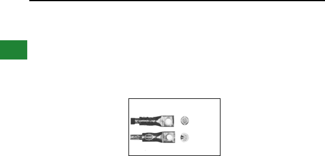
BURNDY®
Blue highlighted items are industry standard and most frequently ordered.
US: 1-800-346-4175 www.burndy.com Canada: 1-800-387-6487
Compression Connections
COMPRESSION
CONNECTORS
BURNDY® compression connectors are designed
for reliable and controllable electrical connections.
The complete installation is fully inspectable. They
are high conductivity copper and operate cooler
than the wire on which they are installed. The
connectors withstand a wide range of electrical
and environmental conditions, including current
surges, temperatures, corrosion and vibrations,
for a wide variety of applications. These features
mean a consistently high quality connection at a
low installed cost.
Copper compression connectors are manufac-
tured from high-conductivity electrolytic copper.
The connectors are normally tin-plated, lead-
plated, or plated with proprietary BURNDY® brite
nish to provide durable long-lasting corrosion re-
sistance. The connector design has been matched
to the cable size to provide the necessary physical
strength requirements for reliable electrical perfor-
mance.
Aluminum compression connectors are
manufactured from high conductivity, high
purity wrought aluminum. They are designed
with sufcient mass and are electro-tin plated
to minimize corrosion due to galvanic action
between dissimilar metals. The connector barrels
are pre-lled with PENETROX™, BURNDY oxide
inhibiting compound.
PENETROX™ contains homogeneously
suspended metallic particles which penetrate
the wire’s oxides to establish excellent continuity
between the individual strands and the
connector barrel for a low-resistance connection.
PENETROX™ maintains an air-tight connection.
Each barrel end is covered with a color-coded
plastic dust cap which prevents foreign matter
from entering the connector before it is used. The
connector design has been engineered to match
the cable size to provide the necessary physical
strength requirements for reliable electrical
performance.
Copper compression connectors are recommend-
ed for use on copper conductors. Aluminum com-
pression connectors are recommended for use on
aluminum conductors. Dual-rated aluminum com-
pression connectors may be used on both copper
and aluminum conductors.
Two basic compression designs are available: Cir-
cumferential and indent.
Tooling systems are essential for proper installation
of a compression connector. Since connectors and
dies are designed as a unit for specic wire sizes,
only the recommended tools and dies should
be used. Most aluminum and copper HYLUG™
terminals and HYLINK™ splices are marked with
a die index number and are color-coded to identify
the correct installation die. Dies marked with the
matching die index number and color can be used
to install the connector.
BURNDY® tooling installs a wide range of
connectors, is reliable, cost effective, and precision
engineered for durable, long-lasting service and
quality connections. The tools include small plier
types, full cycle ratchet designs and hydraulically-
powered HYPRESS™ heads and new Battery
Actuated Tools. Some have permanent die
grooves or adjustable dies, while others require a
change of die sets or nest die for each connector
size. BURNDY recommended tools achieve crimp
performance consistent with UL and other industry
standards. Since several tools are suitable for most
connectors, the most economical and practical
tool can be chosen for each application.
BURNDY compression terminals, splices and
tap connectors requiring third party testing and
approval are listed by Underwriters’ Laboratories,
Inc. Many have also received CSA approval and
are approved under SAE-AS7928 and other
military standards. All conform to applicable
sections of the National Electrical Code.
BURNDY® also offers connectors and splices
which meet the (LOCA Seismec and Aging)
requirements of IEEE standards 323, 383 and
344 for class 1E critical circuits for use in Nuclear
Utility Applications. Certication to 10CFR50 and
10CFR21 available.
Detail catalog listings should be consulted to obtain
the appropriate standards for each connector and
splice.
After compression, virtually all the air is removed
leaving a tight homogeneous mass of connector
and conductor.
The circumferential crimp design is recommended
for color coded connectors in low and high voltage
applications. Die index number embossment
provides an easy inspection where required
to verify the use of the proper connector/die
combination. It is also recommended for insulated
connectors and for terminating exible and welding
cables.
The circumferential crimp design dies compress
cable strands into polygonal shapes forming
intimate contact with each other and the
connector barrel. This compression forms a
tight homogeneous mass with virtually no air
pockets. The circumferential crimp provides an
excellent electrical connection with high pull-out
values. The circumferential crimp is ideal for high
voltage applications leaving the connector barrel
symmetrical, which is easier to insulate.
The indent type crimp can be used in virtually
any application except polyvinylchloride (PVC)
insulated terminals and splices. It is an excellent
means of terminating exible, extra exible and
welding cables. The indentor compresses the
cable strands to form intimate contact with each
other and the connector barrel. The result is an
excellent electrical connection with high pull-
out strength. Laboratory work testing curves
established the proper depth and shape of indent
for each type of connector and wire combination.
SELECTION AND USE TOOLING
INDUSTRY STANDARDS
Circumferential
compression is solid
and symmetrical.
No sharp Flash.
Indent compression.
The connector is
swaged to
the conductor.
C-4

BURNDY®
Blue highlighted items are industry standard and most frequently ordered.
Canada: 1-800-387-6487 www.burndy.com US: 1-800-346-4175
Compression Connections
BURNDY®
Telecommunications
Connectors…
BURNDY® provides a complete selection of one
and two hole compression’s terminals, H-taps,
C-taps, and other compression connection
products specically engineered to meet the
demanding applications of both the Central Ofce
and Wireless communications markets.
All of the BURNDY compression products are
designed for reliable and controllable electrical
connections. All connectors are made from high
conductivity electrolytic copper and operate at
cooler temperatures than the conductor on which
they are installed. The connectors are normally
tin-plated, lead-plated, or plated with a proprietary
BURNDY® brite nish to provide the industry
standard in long-lasting corrosion resistance.
The complete installation is fully inspectable and
UL Listed when installed with BURNDY® dies.
Every die in the system is color-coded and provides
die index embossment for complete inspectability.
The BURNDY® circumferential crimp provides a
solid, homogenous connection, with high pull out
values and is rated for high voltage applications,
more than sufcient for the 48V DC operating
voltage common in the telecom market. In addition
the circumferential crimp doesn’t require the
removal of the copper ash produced by other die
systems. This not only saves time in installation but
removes a potential safety hazard from the job.
All of the dies in the system are color-coded to
match the connectors and feature die index and
die number matching to the connector for ease of
installation.
BURNDY® tooling installs a wide range of
connectors, is reliable, cost effective, and precision
engineered for durable, long-lasting service and
quality connections. BURNDY compression
tooling system ranges from full cycle ratchet
hand tools to 12 and 15 ton hydraulically-powered
HYPRESS™ heads. Hydraulic tools are available
in self-contained, battery powered, and AC service
electrically powered pump and remote head
designs to meet all possible installation situations.
BURNDY compression terminals, splices and
tap connectors requiring third party testing and
approval are listed by Under writers Laboratories,
Inc. Many have also received CSA approval,
and all conform to the applicable sections of the
National Electric Code.
The industry’s rst choice in
compression connections...
The Circumferential Crimp… BURNDY® Tooling…
the right choice for the job
Industry Standards
Circumferential compression is solid
and symmetrical. No sharp ash.
C-5
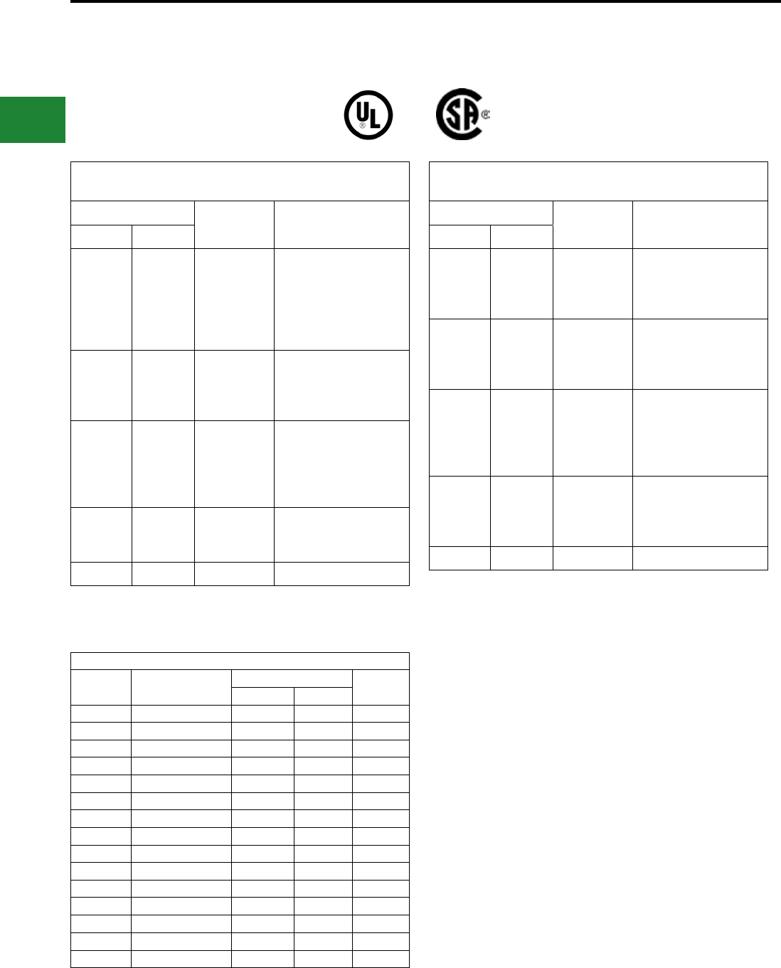
BURNDY®
US: 1-800-346-4175 www.burndy.com Canada: 1-800-387-6487
EXPANDED RANGES
COPPER ALUMINUM
The following connectors are range taking when crimped onto
code conductor using Y644HS family of tools:
Copper HYLUG™ & HYLINK™ Connectors
Types YA, YA-L, YAB, YS, YS-L, YST, YS-T, YSP-T
Catalog No. Standard
Wire Size
Expanded
Wire RangeTerminal* Splice**
YA6C-
YA5C-
YA4C-
YA3C-
YA2C-
YA1C-
YS6C-
YS5C-
YS4C-
YS3C-
YS2C-
YS1C-
#6 AWG
#5 AWG
#4 AWG
#3 AWG
#2 AWG
#1 AWG
#6 AWG
#5 - #6 AWG
#4 - #6 AWG
#3 - #6 AWG
#2 - #6 AWG
#1 - #6 AWG
YA25-
YA26-
YA27-
YA28-
YS25-
YS26-
YS27-
YS28-
1/0 AWG
2/0 AWG
3/0 AWG
4/0 AWG
1/0 - #6 AWG
2/0 - #4 AWG
3/0 - #2 AWG
4/0 - #1 AWG
YA29-
YA30-
YA31-
YA32-
YA34-
YS29-
YS30-
YS31-
YS32-
YS34-
250 kcmil
300 kcmil
350 kcmil
400 kcmil
500 kcmil
250 kcmil - 1/0 AWG
300 kcmil - 2/0 AWG
350 kcmil - 3/0 AWG
400 kcmil - 4/0 AWG
500 kcmil - 4/0 AWG
YA36-
YA39-
YA40-
YS36-
YS39-
YS40-
600 kcmil
750 kcmil
800 kcmil
600 - 250 kcmil
750 - 500 kcmil
800 - 500 kcmil
YA44- YS44- 1000 kcmil 1000 - 750 kcmil
Aluminum HYLUG™ & HYLINK™ Connectors
Types YA-A & YS-A (Copper or Aluminum Conductor)
Catalog No. Standard
Wire Size
Expanded
Wire RangeTerminal* Splice**
YA6CA-
YA4CA-
YA2CA-
YA1CA-
YS6CA-
YS4CA-
YS2CA-
YS1CA-
#6 AWG
#4 AWG
#2 AWG
#1 AWG
#6 AWG
#4 - #6 AWG
#2 - #6 AWG
#1 - #2 AWG
YA25A-
YA26A-
YA27A-
YA28A-
YS25A-
YS26A-
YS27A-
YS28A-
1/0 AWG
2/0 AWG
3/0 AWG
4/0 AWG
1/0 - #1 AWG
2/0 - #1 AWG
3/0 - #1 AWG
4/0 - #1 AWG
YA29A-
YA30A-
YA31A-
YA32A-
YA34A-
YS29A-
YS30A-
YS31A-
YS32A-
YS34A-
250 kcmil
300 kcmil
350 kcmil
400 kcmil
500 kcmil
250 kcmil - 1/0 AWG
300 kcmil - 2/0 AWG
350 kcmil - 3/0 AWG
400 kcmil - 4/0 AWG
500 kcmil - 4/0 AWG
YA36A-
YA39A-
YA40A-
YA42A- †
YS36A-
YS39A-
YS40A-
YS42A- ‡
600 kcmil
750 kcmil
800 kcmil
900 kcmil ▲
600 - 250 kcmil
750 - 500 kcmil
800 - 500 kcmil
900 - 600 kcmil
YA44A- YS44A- 1000 kcmil 1000 - 750 kcmil
* 1 Crimp
** 1 Crimp per side
* 1 Crimp
** 1 Crimp per side
Compression Connections
Expanded Ranges with Y644 Family of Tools
▲900 AL only
† 2 Crimps
‡ 2 Crimps per side
AYP/AYPO CONNECTORS
(Aluminum and Copper — Code & Compact)
Wire Size Expanded Range
Pin
# CrimpsStraight Offset
#6 AWG #6 AWG AYP6 — 1
#4 AWG #4 AWG AYP4 — 1
#2 AWG #4 - #2 AWG AYP2 — 1
#1 AWG #2 - #1 AWG AYP1 — 1
1/0 AWG #2 - 1/0 AWG AYP1/0 — 1
2/0 AWG #1 - 2/0 AWG AYP2/0 AYPO2/0 2
3/0 AWG 1/0 - 3/0 AWG AYP3/0 AYP03/0 2
4/0 AWG 2/0 - 4/0 AWG AYP4/0 AYPO4/0 2
250 kcmil 3/0 - 250 kcmil AYP250 AYP0250 2
300 kcmil 4/0 - 300 kcmil AYP300 AYP0300 2
350 kcmil 250 - 350 kcmil AYP350 AYP0350 2
400 kcmil 350 - 500 kcmil AYP400 AYP0400 2
500 kcmil 350 - 500 kcmil AYP500 AYPO500 2
600 kcmil 400 - 600 kcmil AYP600 AYPO600 3
750 kcmil 500 - 750 kcmil AYP750 AYP0750 3
C-6
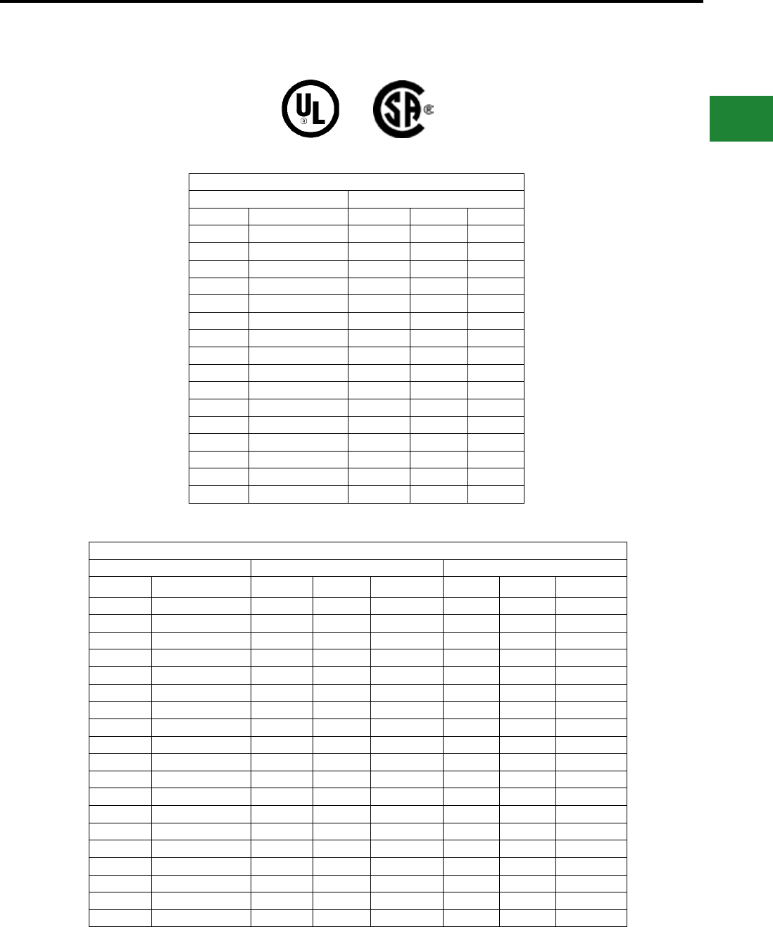
BURNDY®
Canada: 1-800-387-6487 www.burndy.com US: 1-800-346-4175
EXPANDED RANGES
ALUMINUM CONNECTORS
COPPER CONNECTORS
The following connectors are range taking when crimped onto
code & ex conductor using 4-POINT® family of tools:
Aluminum & Copper Conductor (Code & Compact)
Conductor Connector
Wire Size Expanded Range Terminal Splice # Crimps
#8 AWG #8 AWG YA8CA- YS8CA- 1
#6 AWG #6 AWG YA6CA- YS6CA- 1
#4 AWG #6 - #4 AWG YA4CA- YS4CA- 1
#2 AWG #6-#2 AWG YA2CA- YS2CA- 2
#1 AWG #6-#1 AWG YA1CA- YS1CA- 2
1/0 AWG #6-1/0 AWG YA25A- YS25A- 2
2/0 AWG #4 - 2/0 AWG YA26A- YS26A- 2
3/0 AWG #2 - 3/0 AWG YA27A- YS27A- 2
4/0 AWG #1 - 4/0 AWG YA28A- YS28A- 2
250 kcmil 1/0 - 250 YA29A- YS29A- 2
300 kcmil 2/0 - 300 YA30A- YS30A- 2
350 kcmil 3/0 - 350 YA31A- YS31A- 3
400 kcmil 4/0 - 400 YA32A- YS32A- 4
500 kcmil 4/0 - 500 YA34A- YS34A- 4
600 kcmil 250 - 600 YA36A- YS36A- 4
750 kcmil 500-750 YA39A- YS39A- 4
Copper Conductor (Code & Compact)
Conductor Standard Barrel Long Barrell
Wire Size Expanded Range Terminal Splice # of Crimps* Terminal Splice # of Crimps*
#8 AWG #8 AWG YA8CL- YS8CL- 1 YA8C- YS8C- 1
#6 AWG #6 AWG YA6CL- YS6CL- 1 YA6C- YS6C- 1
#4 AWG #6 - #4 YA4CL- YS4CL- 1 YA4C- YS4C- 1
#2 AWG #6-#2 YA2CL- YS2CL- 1 YA2C- YS2C- 2
#1 AWG #6-#1 YA1CL- YS1CL- 1 YA1C- YS1C- 2
1/0 AWG #6-1/0 YA25L- YS25L- 1 YA25- YS25- 2
2/0 AWG #4 - 2/0 YA26L- YS26L- 1 YA26- YS26- 2
3/0 AWG #2 - 3/0 YA27L- YS27L- 2 YA27- YS27- 2
4/0 AWG #1 - 4/0 YA28L- YS28L- 2 YA28- YS28- 2
250 kcmil 1/0 - 250 YA29L- YS29L- 2 YA29- YS29- 2
300 kcmil 2/0 - 300 YA30L- YS30L- 2 YA30- YS30- 3
350 kcmil 3/0 - 350 YA31L- YS31L- 2 YA31- YS31- 3
400 kcmil 4/0 - 400 YA32L- YS32L- 2 YA32- YS32- 3
500 kcmil 4/0 - 500 YA34L- YS34L- 2 YA34- YS34- 4
600 kcmil 250 - 600 YA36L- YS36L- 2 YA36- YS36- 4
700 kcmil 350-700 YA38L- YS38L- 3 YA38- YS38- 4
750 kcmil 500-750 YA39L- YS39L- 3 YA39- YS39- 4
800 kcmil 500-800 YA40L- YS40L- 3 YA40- YS40- 4
1000 kcmil 750-1000 YA44L- YS44L- 3 YA44- YS44- 4
*Same number of recommended crimps for both Standard and Expanded wire ranges
Compression Connections
Expanded Ranges with Y81KFT Family of Tools
C-7
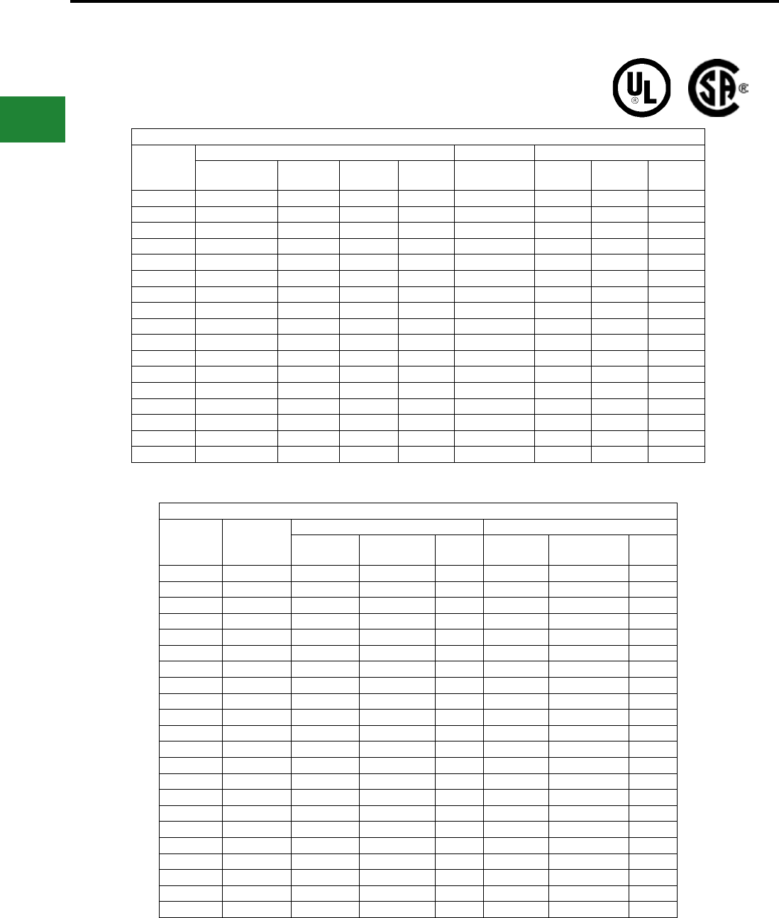
BURNDY®
Blue highlighted items are industry standard and most frequently ordered.
US: 1-800-346-4175 www.burndy.com Canada: 1-800-387-6487
Compression Connections
Expanded Ranges with Y81KFT Family of Tools
EXPANDED RANGES
COPPER CONNECTORS
COPPER CONNECTORS
The following connectors are range taking when crimped onto
code & ex conductor using 4-POINT® family of tools:
Copper Conductor (Flex Only)
Nominal
Flex Wire
Size
Standard Barrel Long Barrell
Expanded
Range Terminal Splice
# of
Crimps*
Expanded
Range Terminal Splice
# of
Crimps*
#8 AWG #8 AWG YAV8CL- YSV8CL- 1 #8 AWG YAV8C- YSV8C- 1
#6 AWG #6 AWG YAV6CL- YSV6CL- 1 #6 AWG YAV6C- YSV6C- 1
#4 AWG #6 - #4 AWG YAV4CL- YSV4CL- 1 #6 - #4 AWG YAV4C- YSV4C- 1
#2 AWG #6 - #2 AWG YAV2CL- YSV2CL- 1 #6 - #2 AWG YAV2C- YSV2C- 1
#1 AWG #4 - #1 AWG YAV1CL- YSV1CL- 1 #4 - #1 AWG YAV1C- YSV1C- 1
1/0 AWG #4 - 1/0 AWG YAV25L- YSV25L- 1 #6 - 1/0 AWG YAV25- YSV25- 2
2/0 AWG #2 - 2/0 AWG YAV26L- YSV26L- 1 #4 - 2/0 AWG YAV26- YSV26- 2
3/0 AWG #1 - 3/0 AWG YAV27L- YSV27L- 1 #2 - 3/0 AWG YAV27- YSV27- 2
4/0 AWG 1/0 - 4/0 AWG YAV28L- YSV28L- 1 #1 - 4/0 AWG YAV28- YSV28- 2
250 kcmil 3/0 - 250 YAV29L- - 1 1/0 - 250 YAV29- YS29- 2
300 kcmil 4/0 - 313.1 YA32L- YS32L- 1 2/0 - 313.1 YA32- YS32- 2
350 kcmil 250 - 373.7 YA34L- YS34L- 1 3/0 - 373.7 YA34- YS34- 2
450 kcmil 250 - 444.4 YA36L- YS36L- 1 4/0 - 444.4 YA36- YS36- 2
500 kcmil 373.7 - 535.3 YA38L- YS38L- 1 4/0 - 535.3 YA38- YS38- 2
600 kcmil 373.7 - 600 YA39L- YS39L- 2 250 - 600 YA39- YS39- 3
650 kcmil 444.4 - 646 YA40L- YS40L- 2 373.3 - 646 YA40- YS40- 3
750 kcmil 535.3 - 777.7 YA44L- YS44L- 2 535.3 - 777.7 YA44- YS44- 3
E-Line Connectors
Wire Size
Expanded
Wire Range
Aluminum Copper
Offset
Cat. No.
Center formed
Cat. No.
No. of
Crimps
Offset
Cat. No.
Center formed
Cat. No.
No. of
Crimps
#8 AWG #8 AWG YA8CA-T-E 1
#6 AWG #6 AWG
#4 AWG #6 - #4
#2 AWG #6-#2 YA2CA-T-E YAC2CA-T-E 1
#1 AWG #6-#1
1/0 AWG #6-1/0 YA25A-T-E 1 YA25L-T-E YAC25L-T-E 1
2/0 AWG #4 - 2/0 YA26A-T-E 2 YA26L-T-E YAC26L-T-E 1
3/0 AWG #2 - 3/0 YA27A-T-E YAC27A-T-E 2
4/0 AWG #1 - 4/0 YA28A-T-E 2
250 kcmil 1/0 - 250
300 kcmil 2/0 - 300 YA30A-T-E 2 YA30L-T-E YAC30L-T-E 2
350 kcmil 3/0 - 350 YA31A-T-E YAC31A-T-E 2
400 kcmil 4/0 - 400 YA32A-T-E 4
500 kcmil 4/0 - 500 YA34A-T-E 4 YA34L-T-E 2
500 kcmil 4/0-500 YA342L-T-E 2
600 kcmil 250 - 600 YA36A-T-E 4 YA36L-T-E 2
600 kcmil 250-600 YA362L-T-E 2
700 kcmil 350-700
750 kcmil 500-750 YA39A-T-E 4 YA39L-T-E 2
750 kcmil 500-750 YA392L-T-E 2
800 kcmil 500-800
1000 kcmil 750-1000
*Same number of recommended crimps for both Standard and Expanded wire ranges
C-8
BURNDY®
Blue highlighted items are industry standard and most frequently ordered.
Canada: 1-800-387-6487 www.burndy.com US: 1-800-346-4175
Compression Connections
U Die and W Die Sets
12-TON U DIES*
BURNDY® Die Sets
Fits Y35, Y39, Y750 Series,
PAT750-18V Series,
PAT46-18V, Y46
(W/PUADP-1 Adapter)
Wire Size Copper Aluminum
Small #8 Str. U8CRT U8CABT
#6 , #5 Str. U5CRT U6CABT
#4 Str. U4CRT U4CABT
#3 Str. U3CRT N/A
#2 Str. U2CRT U2CABT
#1 Str. U1CRT-1 U1CART
1/0 Str. U25RT U25ART
2/0 Str. U26RT U26ART
3/0 Str. U27RT U27ART
4/0 Str. U28RT U28ART
250 kcmil U29RT U29ART
U die case Part# PT29291, holds up to 15 dies
* Non-tension U-type 12-ton dies for YA, YS, YA-A,
YS-A style connectors.
NOTE: N/A = not applicable.
W DIES
BURNDY® Die Sets
Fits Tools MD6, MD7, Y500CTHS,
PAT600-18V, PATMD6
Wire Size Copper Copper Aluminum
Small #8 W8CVT W8CRT X8CART
#6 W5CVT W5CRT W161
#4 W4CVT W4CRT W162
#3 W3CRT W3CRT N/A
#2 W2CVT W2CRT W239
#1 W1CVT W1CRT W163
1/0 W25VT W25CRT W241
2/0 W26VT W26CRT W245
3/0 W27VT W27CRT W166
4/0 W28VT W28CRT W660
250 *W29VT W29CRT N/A
300 *W30VT W30CRT N/A
350 *W31VT W31CRT *W31ART
400 *W32VT W32CRT N/A
450 W33VT W33CRT N/A
500 *W34VT W34CRT N/A
Large 600 **W36RT W36CRT N/A
Wire Size Copper Aluminum
300 kcmil U30RT U30ART
350 kcmil U31RT U31ART
400 kcmil U32RT U32ART
500 kcmil U34RT U34ART
535 Flex kcmil U38XRT N/A
600 kcmil U36RT U36ART
750 kcmil U39RT U39ART2
Large 777 Flex U44XRT N/A
* These sizes (250-500) for Y5000CTHS,
MD7-34(R), BAT500, BCT500HS only.
** For PAT600-18V only.
NOTE: N/A = not applicable.
Suitable for use on YA, YS, YA-A, YS-A type
non-tension connectors.
W die case Part# CASEWDIES, holds up to 24 dies
C-9
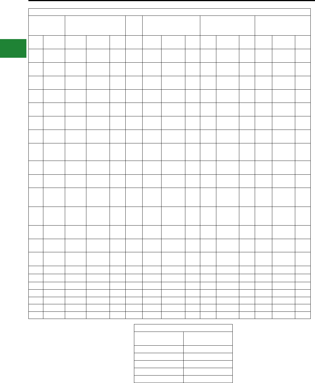
BURNDY®
Blue highlighted items are industry standard and most frequently ordered.
US: 1-800-346-4175 www.burndy.com Canada: 1-800-387-6487
Installation Tooling System
Conductor
Lugs & Splices
One & Two
Hole
T&B
Index*
Taps
Thin-Wall C-taps
Run=Tap, AWG only
Taps
Heavy Duty C-Taps
Run=Tap
Taps
H-Taps
Run=Tap
AWG Flex Die Color Index
Code
(Flex) Die Color Index Die Color Index Die Color Index
#8/#6
sol #8 W8CVT
U8CRT RED 49 21 W4CVT GRAY 8 U240 RED 240 U11T-1 GREEN 11
#6 #6 W5CVT
U5CRT BLUE 7 24 W2CVT BROWN 10 UC BROWN CUB-
GRT ORANGE BG
#4 #4 W4CVT
U4CRT GRAY 8 29 W25VT PINK 12 UC BROWN C UC BROWN C
#3/#2
sol
W3CRT
U3CRT WHITE 9 29 W26VT BLACK 13 UC BROWN C UC BROWN C
#2 #2 W2CVT
U2CRT BROWN 10 33 W27VT ORANGE 14 UC BROWN C UC BROWN C
#1 #1 W1CVT
U1CRT-1 GREEN 11 33
(37) W28VT PURPLE 15 U997 ORANGE 997 U654 PURPLE 654
1/0 1/0 W25VT
U25RT PINK 12 37
(42) W29VT YELLOW 16 U997 ORANGE 997 U654 PURPLE 654
2/0 2/0 W26VT
U26RT BLACK 13 42
(45)
REFER
TO
CATALOG
U997 ORANGE 997 U654 PURPLE 654
3/0 3/0 W27VT
U27RT ORANGE 14 45
(50) --- U997 ORANGE 997 U654 PURPLE 654
4/0 4/0 W28VT
U28RT PURPLE 15 50
(54) --- U997 ORANGE 997 U654 PURPLE 654
250
4/0 / 250
class
G & H
W29VT
U29RT YELLOW 16 62 - -- U997 ORANGE 997 U654 PURPLE 654
300
262/250
class
I, K & M
W30VT
U30RT WHITE 17 62 - -- U1104 BROWN 1104 U1104 BROWN 1104
350 313 W31VT
U31RT RED 18 66 - -- U1104 BROWN 1104 U1104 BROWN 1104
350 / 373 W32VT
U32RT BLUE 19 (76) - -- U1104 BROWN 1104 U1104 BROWN 1104
500 444 W34VT
U34RT BROWN 20 76
(87) --- U1104 BROWN 1104 U1104 BROWN 1104
500 / 535 U38XRT PINK L99 (99) - -- P1103 BLUE 1103 PYFR YELLOW KR
600 U36RT GREEN 22 87 - -- P1103 BLUE 1103 PYFR YELLOW KR
700 U38RT PINK 400 99 - -- P1103 BLUE 1103 PYFR YELLOW KR
750 646 U39RT BLACK 24 (106) - -- P1103 BLUE 1103 PYFR YELLOW KR
750 / 777 U44XRT YELLOW L115 (115)
800 P40RT ORANGE 25 106 - -- P1102 WHITE 1102 PYFR YELLOW KR
1000 P44RT WHITE 27 - -- P1102 WHITE 1102 PYFR YELLOW KR
* Die set with a dash CK are not UL Listed. Please
consult factory for further information Bolt Equivalent
Unied Inch
Hole Size
Metric
Equivalent
1/4″M6
5/16″M8
3/8″M10
1/2″M12
5/8″M16
C-10
Compression Connections
Die Index Chart
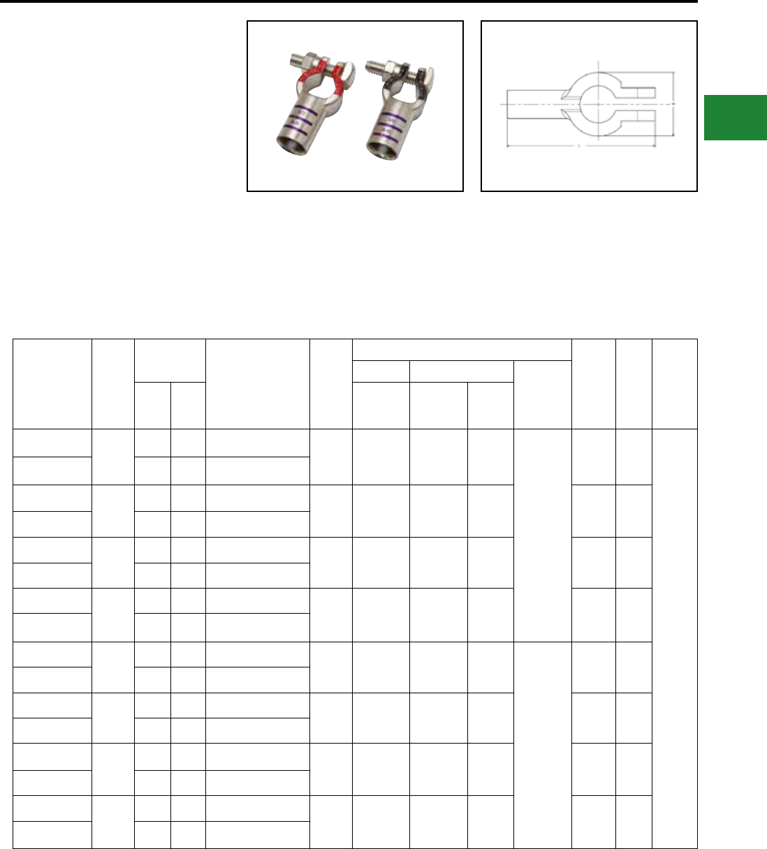
BURNDY®
Blue highlighted items are industry standard and most frequently ordered.
Canada: 1-800-387-6487 www.burndy.com US: 1-800-346-4175
TYPE YAEBA-S
STRAIGHT STYLE BATTERY POST
HYDENT TERMINALS
#6 - 4/0 AWG Solid and
Stranded Copper
BURNDY battery post terminals are made from
pure copper alloy and are tin plated to prevent
corrosion. They adhere to SAE, JIS and DIN stud
standards. Typical applications are automotive,
marine, transportation, Petrochemical, OEM
markets.
Features & Benets
• Color coded for easy identication
• Chamfered end
• Made of copper alloy, tin plated for
corrosion resistance
• Comes standard with stainless steel hardware
installed
Catalog
Number
Wire
Range
Dimensions
Bulk
Catalog Number
Conn.
Color
Code
Installation Tooling
Color
Code
Die
Die
Index
Strip
Length
Mech. Hyd.
Dieless
(# Crimps)
L W MD 6
MD7-34R
PATMD6
PAT600
Y35,
Y750,
PAT750
YAEBAS6CNTN
#6
2.30" 0.98" YAEBAS6CNTNOEM
Blue W5CVT (1)
W5CRT (1)
W5CVT (1)
W5CRT (1)
U5CRT
(1)
Hyd.
PAT81KFT
PAT4-C834
PAT644
(1)
Mech..
MY29-11
MRC840
(1)
Blue 7
1-3/32"
YAEBAS6CPTN 2.30" 1.02" YAEBAS6CPTNOEM
YAEBAS4CNTN
#4
2.30" 0.98" YAEBAS4CNTNOEM
Gray W4CVT (1)
W4CRT (1)
W4CVT (1)
W4CRT (1)
U4CRT
(1) Gray 6
YAEBAS4CPTN 2.30" 1.02" YAEBAS4CPTNOEM
YAEBAS2CNTN
#2
2.30" 0.98" YAEBAS2CNTNOEM
Green W2CVT (1)
W2CRT (1)
W2CVT (1)
W2CRT (1)
U2CRT
(1) Brown 10
YAEBAS2CPTN 2.30" 1.02" YAEBAS2CPTNOEM
YAEBAS1CNTN
#1
2.30" 0.98" YAEBAS1CNTNOEM
Pink
W1CVT (1)
W1CRT-1
(1)
W1CVT (1)
W1CRT-1
(1)
U1CRT
(1) Green 11
YAEBAS1CPTN 2.30" 1.02" YAEBAS1CPTNOEM
YAEBAS25NTN
1/0
2.36" 0.98" YAEBAS25NTNOEM
Black W25VT (1)
W25RT (1)
W25VT (1)
W25RT (1)
U25RT
(1)
Hyd.
PAT81KFT
PAT4-C834
PAT644
(1)
Mech..
MY29-11
MRC840
(2)
Pink 12
YAEBAS25PTN 2.36" 1.02" YAEBAS25PTNOEM
YAEBAS26NTN
2/0
2.36" 0.98" YAEBAS26NTNOEM
Orange W26VT (1)
W26RT (1)
W26VT (1)
W26RT (1)
U26RT
(1) Black 13
YAEBAS26PTN 2.36" 1.02" YAEBAS26PTNOEM
YAEBAS27NTN
3/0
2.36" 0.98" YAEBAS27NTNOEM
Purple W27VT (1)
W27RT (1)
W27VT (1)
W27RT (1)
U27RT
(1) Orange 14
YAEBAS27PTN 2.36" 1.02" YAEBAS27PTNOEM
YAEBAS28NTN
4/0
2.36" 0.98" YAEBAS28NTNOEM
Yellow W28VT (1)
W28RT (1)
W28VT (1)
W28RT (1)
U28RT
(1) Purple 15
YAEBAS28PTN 2.36" 1.02" YAEBAS28PTNOEM
Compression Connections
Battery Terminals— Straight Style Terminals
C-11
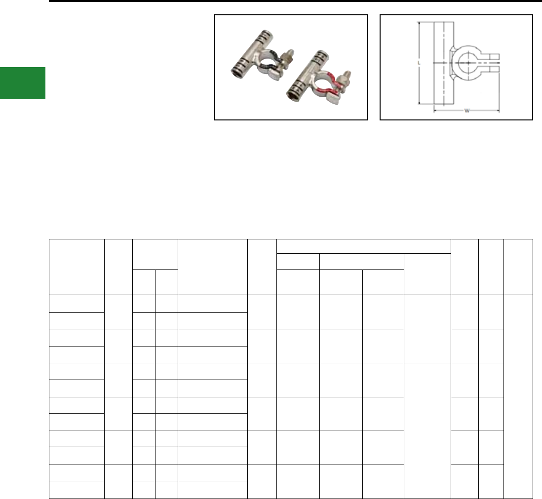
BURNDY®
Blue highlighted items are industry standard and most frequently ordered.
US: 1-800-346-4175 www.burndy.com Canada: 1-800-387-6487
Compression Connections
Battery Terminals — T Style Terminals
TYPE YAEBA-F
T STYLE BATTERY POST
HYDENT™ TERMINALS
#2 - 4/0 AWG Solid and Stranded
Copper
BURNDY battery post terminals are made from
pure copper alloy and are tin plated to prevent
corrosion. They adhere to SAE, JIS and DIN stud
standards. Typical applications are automotive,
marine, transportation, Petrochemical, OEM
markets.
Features & Benets
• Color coded for easy identication
• Chamfered end
• Made of copper alloy, tin plated for
corrosion resistance
• Comes standard with stainless steel hardware
installed
Catalog
Number
Wire
Range
Dimensions Bulk
Catalog Number
Conn.
Color
Code
Installation Tooling
Die
Color
Code
Die
Index
Strip
Length
Mechanical Hydraulic Dieless
(# Crimps)
L W MD 6
MD7-34R
PAT MD6
PAT600
Y35, Y750,
PAT750
YAEBAF2CNTN #2 2.36" 1.89" YAEBAF2CNTNOEM Green W2CVT (1)
W2CRT (1)
W2CVT (1)
W2CRT (1) U2CRT (1) MECH.
MY29-11(1)
MRC840 (1)
Brown 10
1-9/32"
YAEBAF2CPTN 2.36" 1.89" YAEBAF2CPTNOEM
YAEBAF1CNTN #1 2.36" 1.89" YAEBAF1CNTNOEM Pink W1CVT (1)
W1CRT-1 (1)
W1CVT (1)
W1CRT-1 (1) U1CRT-1 (1) Green 11
YAEBAF1CPTN 2.36" 1.89" YAEBAF1CPTNOEM
YAEBAF25NTN 1/0 2.36" 1.89" YAEBAF25NTNOEM Black W25VT (1)
W25RT (1)
W25VT (1)
W25RT (1) U25RT (1)
MECH.
MY29-11(1)
MRC840 (2)
Pink 12
YAEBAF25PTN 2.36" 1.89" YAEBAF25PTNOEM
YAEBAF26NTN 2/0 2.36" 1.97" YAEBAF26NTNOEM Orange W26VT (1)
W26RT (1)
W26VT (1)
W26RT (1) U26RT (1) Black 13
YAEBAF26PTN 2.36" 1.97" YAEBAF26PTNOEM
YAEBAF27NTN 3/0 2.36" 1.97" YAEBAF27NTNOEM Purple W27VT (1)
W27RT (1)
W27VT (1)
W27RT (1) U27RT (1) Or-
ange 14
YAEBAF27PTN 2.36" 1.97" YAEBAF27PTNOEM
YAEBAF28NTN 4/0 2.36" 1.97" YAEBAF28NTNOEM Yellow W28VT (1)
W28RT (1)
W28VT (1)
W28RT (1) U28RT (1) Purple 15
YAEBAF28PTN 2.36" 1.97" YAEBAF28PTNOEM
C-12
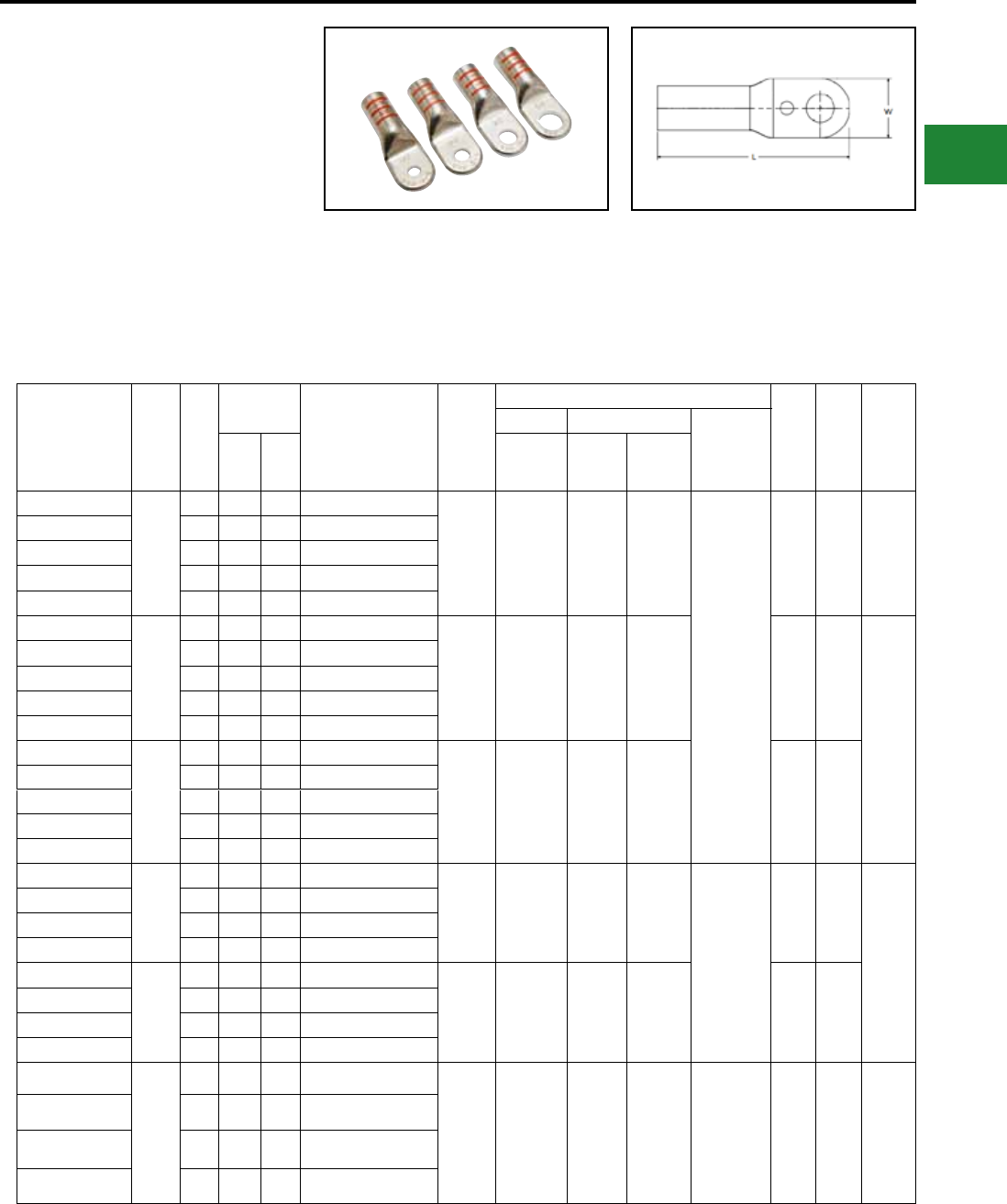
BURNDY®
Blue highlighted items are industry standard and most frequently ordered.
Canada: 1-800-387-6487 www.burndy.com US: 1-800-346-4175
Compression Connections
Battery Terminals — Grounding/Starter Lugs
TYPE YAGB
ONE HOLE HYLUG™ BATTERY
TERMINAL
#6 - 4/0 AWG Solid and Stranded
Copper
BURNDY battery terminals are made from pure
copper alloy and are tin plated to prevent corrosion.
They adhere to SAE, JIS and DIN stud standards.
Typical applications are automotive, marine,
transportation, Petrochemical, OEM markets.
Features & Benets
• Color coded for easy identication
• Chamfered end
• Made of copper alloy, tin plated for
corrosion resistance
Catalog Number Wire
Range
Stud
Size
Dimensions
Bulk
Catalog Number
Conn.
Color
Code
Installation Tooling
Color
Code
Die
Die
Index
Strip
Length
Mech. Hyd.
Dieless
(# Crimps)
L W MD 6
MD7-34R
PATMD6
PAT600
Y35,
Y750,
PAT750
YAGB6CLTC10FX
#6
#10 1.46" 0.44" YAGB6CLTC10FXOEM
Blue W5CVT (1)
W5CRT (1)
W5CVT
(1)
W5CRT
(1)
U5CRT (1)
HYD.
PAT81KFT
PAT4PC834
PAT644 (1)
MECH.
MY29-11
MRC840 (1)
Blue 7 7/8"
YAGB6CLTC14FX 1/4" 1.46" 0.44" YAGB6CLTC14FXOEM
YAGB6CLTC516FX 5/16" 1.61" 0.60" YAGB6CLTC516FXOEM
YAGB6CLTC38FX 3/8" 1.61" 0.60" YAGB6CLTC38FXOEM
YAGB6CLTC12FX 1/2" 1.73" 0.74" YAGB6CLTC12FXOEM
YAGB4CLTC10FX
#4
#10 1.97" 0.75" YAGB4CLTC10FXOEM
Gray W4CVT (1)
W4CRT (1)
W4CVT
(1)
W4CRT
(1)
U4CRT (1) Gray 6
15/16"
YAGB4CLTC14FX 1/4" 1.97" 0.75" YAGB4CLTC14FXOEM
YAGB4CLTC516FX 5/16" 1.97" 0.75" YAGB4CLTC516FXOEM
YAGB4CLTC38FX 3/8" 1.97" 0.75" YAGB4CLTC38FXOEM
YAGB4CLTC12FX 1/2" 1.97" 0.75" YAGB4CLTC12FXOEM
YAGB2CLTC10FX
#2
#10 2.09" 0.81" YAGB2CLTC10FXOEM
Green W2CVT (1)
W2CRT (1)
W2CVT
(1)
W2CRT
(1)
U2CRT (1) Brown 10
YAGB2CLTC14FX 1/4" 2.09" 0.81" YAGB2CLTC14FXOEM
YAGB2CLTC516FX 5/16" 2.09" 0.81" YAGB2CLTC516FXOEM
YAGB2CLTC38FX 3/8" 2.09" 0.81" YAGB2CLTC38FXOEM
YAGB2CLTC12FX 1/2" 2.09" 0.81" YAGB2CLTC12FXOEM
YAGB25LTC14FX
1/0
1/4" 2.40" 0.87" YAGB25LTC14FXOEM
Black W25VT (1)
W25RT (1)
W25VT
(1)
W25RT
(1)
U25RT (1) HYD.
PAT81KFT
PAT4PC834
PAT644 (1)
MECH.
MY29-11
MRC840 (2)
Pink 12
1-3/16"
YAGB25LTC516FX 5/16" 2.40" 0.87" YAGB25LTC516FXOEM
YAGB25LTC38FX 3/8" 2.40" 0.87" YAGB25LTC38FXOEM
YAGB25LTC12FX 1/2" 2.40" 0.87" YAGB25LTC12FXOEM
YAGB26LTC14FX
2/0
1/4" 2.44" 0.91" YAGB26LTC14FXOEM
Orange W26VT (1)
W26RT (1)
W26VT
(1)
W26RT
(1)
U26RT (1) Black 13
YAGB26LTC516FX 5/16" 2.44" 0.91" YAGB26LTC516FXOEM
YAGB26LTC38FX 3/8" 2.44" 0.91" YAGB26LTC38FXOEM
YAGB26LTC12FX 1/2" 2.44" 0.91" YAGB26LTC12FXOEM
YAGB28LTC14FX
4/0
1/4" 2.56" 1.10" YAGB28LTC14FXOEM
Yellow W28VT (1)
W28RT (1)
W28VT
(1)
W28RT
(1)
U28RT (1)
HYD.
PAT81KFT
PAT4PC834
PAT644 (1)
MECH.
MY29-11
MRC840 (2)
Purple 15 1-3/16"
YAGB28LTC516FX 5/16" 2.56" 1.10" YAGB28LTC516FXOEM
YAGB28LTC38FX 3/8" 2.56" 1.10" YAGB28LTC38FXOEM
YAGB28LTC12FX 1/2" 2.56" 1.10" YAGB28LTC12FXOEM
C-13
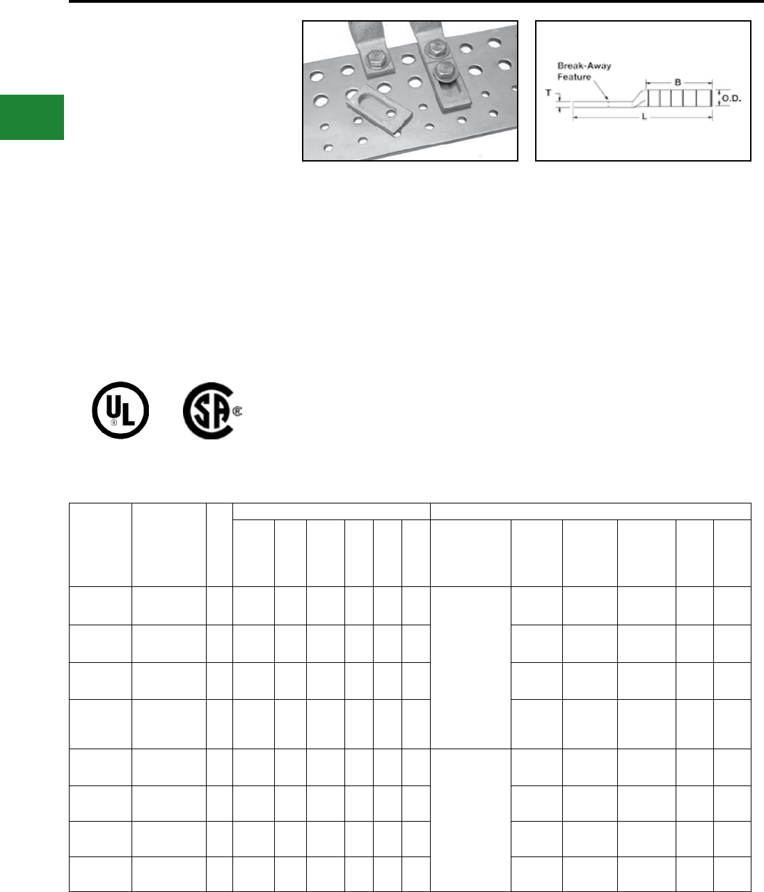
BURNDY®
Blue highlighted items are industry standard and most frequently ordered.
US: 1-800-346-4175 www.burndy.com Canada: 1-800-387-6487
TYPES YBA, YBA-FX
and YBAV-FX
HYLUG™
Copper and Aluminum
Compression Terminals
UL Listed 90° C,
600 Volts to 35 kV
The Break-Away HYLUG™ line of Copper and
Aluminum terminals are designed to provide
maximum eld exibility by allowing the installer
(using the Break-Away feature) to easily convert
two-hole terminals to one-hole terminals to suit the
application.
The Break-Away HYLUG™ line of terminals
encompasses a wide range of features that
affords the installer the exibility in meeting the
requirements for challenging projects.
Features & Benets
• Break-Away feature allows for eld
modication of the terminal from a two-hole
design to a one-hole
• design while retaining UL Listing and CSA
Certication
• Field modication of the terminal does not
require specialized tooling or training
• Stud size is 1/2″ (12mm2) on the rst stud
as well as the slotted second stud
• Slotted second stud provides built in
exibility for the terminal to conform to
various bus bar dimensions. With the
slotted second stud the terminal can be
used on two-hole spacing
• ranging from 1.00 to 1.75 for 1/2 stud hole
sizes and 0.63 to 1.00 for 1/4 stud hole
size
• Narrow tongue design allows for the
terminal to t into tight spaces
• Accommodates a wide range of conductor
combinations (AWG, Compact, DLO, Flex
and Metric)
• Break-Away HYLUG™ line of terminals
can be installed with standard BURNDY®
tooling such as PAT750XT-18V and U-Dies
• Terminals are range taking when installed
with Y644HSXT or PAT644XT-18V tooling
platforms
Catalog
Number
Conductor
Size mm²
Dimensions Installation Tooling (# of Crimps)
Stud
Hole
Spacing
Stud
Hole
Size
[MM]
Tongue
Width B T L Dieless
MD6, MD7,
MD7-34R
platforms
OUR840**
Y500CTHS,
PAT60018V,
PATMD6
platform
Y35, Y39,
Y750, *Y46,
PAT750,
*PAT46
platforms
Color
Code
Die
Index
YBAV25FX14 1/0 Flex (275/24);
1/0 AWG 50 0.63″
to 1.08″
1/4″
[6] 0.73″1.50″0.13″3.69″
MY29
(MY29 platform
tools can only be
used on Code
Conductor),
PAT644XT-18V &
Y644 platforms (1)
4-POINT®
Y81KFT,
PAT81KFT,
Y4PC, PAT4PC
platforms (2)
W25VT (4)
X25RT (4)
W25RT (4)
W25VT (4)
X25RT (4)
W25RT (4)
U25RT (2) Pink
12
or
348
YBAV26FX14 2/0 Flex (325/24);
2/0 AWG 70 0.63″
to 1.08″
1/4″
[6] 0.89″1.50″0.13″3.74″
W26VT (4)
X26RT (4)
W26RT (4)
W26VT (4)
X26RT (4)
W26RT (4)
U26RT (2) Black 13
YBAV27FX14 3/0 Flex (450/24);
3/0 AWG 95 0.63″
to 1.08″
1/4″
[6] 0.87″1.50″0.14″3.78″
W27VT (4)
X27RT (4)
W27RT (4)
W27VT (4)
X27RT (4)
W27RT (4)
U27RT (4) Orange 14
YBAV28FX 4/0 Flex (550/24);
4/0 AWG 120 1″
to 1.75″
1/2″
[12] 0.94″1.62″0.14″5.24″
X28RT (6)
W28RT (4)
W28VT (4)
X28RT (6)
W28RT (4)
W28VT (4)
U28RT (2) Purple 15
YBA29 250 kcmil
(Class A & B) —1″
to 1.75″
1/2″
[12] 0.96″1.62″0.16″5.21″PAT644XT-18V &
Y644 platforms (1),
4-POINT®
Y81KFT,
PAT81KFT, Y4PC,
PAT4PC platforms
(2) for YBA29,
(3) for YBA31FX &
YBA32FX
(4) for YBA34FX
W29RT (4)
W29VT (4)
W29RT (4)
W29VT (4) U29RT (2) Yellow 16
YBA31FX 250 kcmil
(Class I;K & M) 150 1″
to 1.75″
1/2″
[12] 0.96″2.00″0.18″5.68″W30VT(4)
W30RT(4)
W30VT (4)
W30RT (4) U30RT (4) White 17
or 298
YBA32FX 313.1 kcmil Flex
(775/24) 185 1″
to 1.75″
1/2″
[12] 0.96″2.12″0.19″5.85″W31VT (4)
W31RT (4)
W31VT (4)
W31RT (4) U31RT (4) Red 18
or 324
YBA34FX 373.7 kcmil Flex
(775/24) 240 1″
to 1.75″
1/2″
[12] 0.96″2.25″0.23″6.08″W32VT (4)
W32RT (4)
W32VT (4)
W32RT (4) U32RT (4) Blue 19
or 470
Copper Conductor
* Y46 and PAT46 platforms require PUADP-1
adaptor to use U dies
** OUR840 can use X-style dies only
C-14
Compression Connections
Copper Compression — Long Barrel - Break-Away
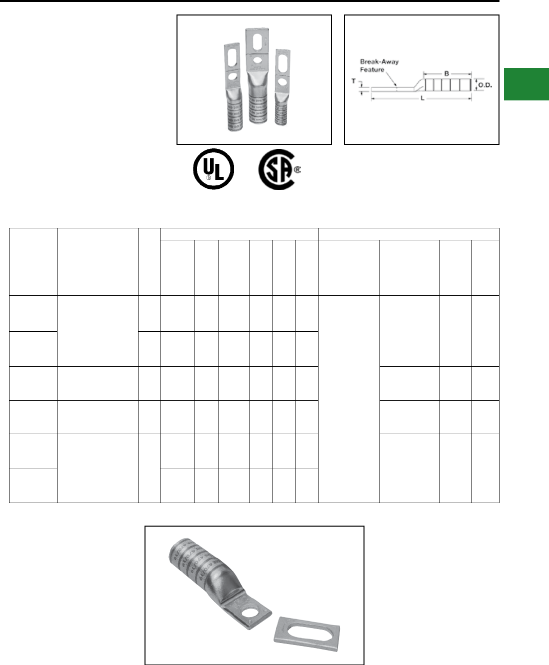
BURNDY®
Blue highlighted items are industry standard and most frequently ordered.
Canada: 1-800-387-6487 www.burndy.com US: 1-800-346-4175
TYPES YBA, YBA-FX
and YBAV-FX
BREAK-AWAY HYLUG™
(Continued)
Copper and Aluminum
Compression Terminals
UL Listed 90° C,
600 Volts to 35 kV
Copper Conductor
(Continued)
* Y46 and PAT46 platforms require PUADP-1
adaptor to use U dies
Catalog
Number Conductor Size mm²
Dimensions Installation Tooling (# of Crimps)
Stud
Hole
Spacing
Stud
Hole
Size
[MM]
Tongue
Width B T L Dieless
Y35, Y39, Y750,
*Y46, PAT750,
*PAT46
platforms
Color
Code
Die
Index
YBA36FX 444.4 kcmil
(1100/24);
450 kcmil Flex
-
1"
to
1.75"
1/2"
[12] 1.47"2.69"0.27"6.59"
Y644HSXT
(1)
PAT644XT-18V
(1)
Y81KFT
(2)
PAT81KFT
(2)
U34RT (4) Brown
20
or
299
YBA36FX58 -
1"
to
1.75"
5/8"
[16] 1.47"2.69"0.27"6.59"
YBA38FX
535.3
(1325/#24);
500 kcmil
300
1"
to
1.75"
1/2"
[12] 1.62"2.81"0.27"6.76"U38XRT (4) Pink L99
YBA39
750 kcmil
(Code Class AA; A
& B)
-
1"
to
1.75"
1/2"
[12] 1.63"2.88"0.27"6.87"U39RT (4) Black 24
YBA44FX 777.7
(1925/#24)
750 kcmil Flex
500
1"
to
1.75"
1/2"
[12] 1.62"3.00"0.32"7.14"
U44XRT (4) Yellow L115
YBA44FX58
1"
to
1.75"
5/8"
[16] 1.62"3.00"0.32"7.14"
C-15
Compression Connections
Copper Compression — Long Barrel — Break-Away
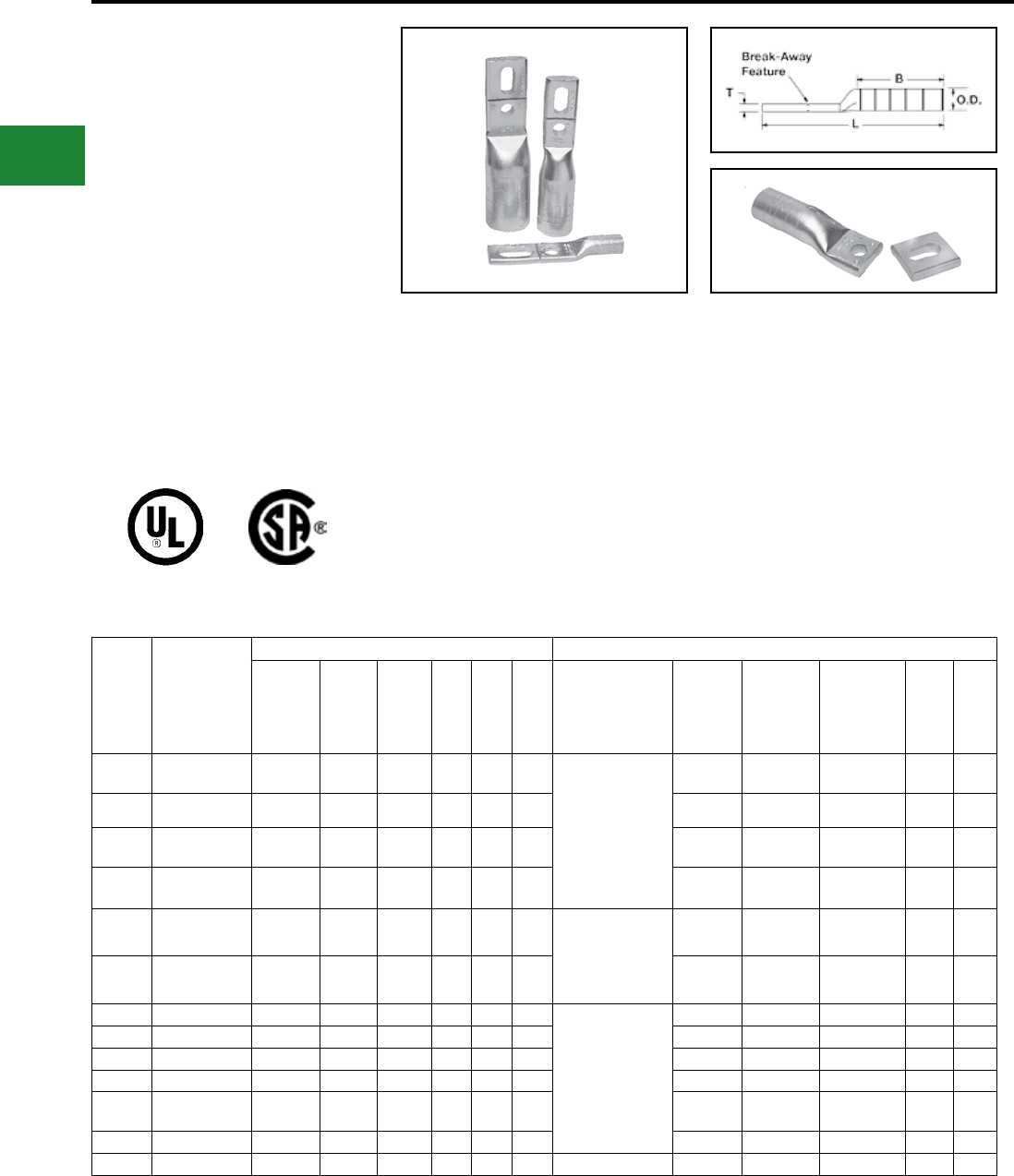
BURNDY®
Blue highlighted items are industry standard and most frequently ordered.
US: 1-800-346-4175 www.burndy.com Canada: 1-800-387-6487
TYPES YBA-A
BREAK-AWAY HYLUG™
Copper and Aluminum
Compression Terminals
UL Listed 90° C,
600 Volts to 35 kV
The Break-Away HYLUG™ line of Copper and
Aluminum
terminals are
designed to provide
maximum eld exibility by allowing the installer
(using the break-away feature) to easily convert a
two-hole terminal into a one-hole terminal to suit
the application.
The Break-Away HYLUG™ line of terminals
encompasses a wide range of features that offers
the installer the exibility to meet the requirements
of challenging projects.
Features & Benets
• Break-Away feature allows for eld
modication of the terminal from a two-hole
design to a one-hole design while retaining
UL Listing and CSA Certication
• Field modication of the terminal does not
require specialized tooling or training
• Stud size is 1/2″ on the rst stud as well as
the slotted second stud
• Narrow tongue design allows for the
terminal to t into tight spaces
• Slotted second stud provides built in
exibility for the terminal to conform to
various bus bar dimensions. With the
slotted second stud the terminal can be
used on two-hole spacing ranging from
1.75″ down to 1.00″ for 1/2″ stud size
• Break-Away HYLUG™ line of terminals
can be installed with standard BURNDY®
tooling such as PAT750XT-18V and U-Dies
• Terminals are range taking when installed
with Y644 or PAT644XT-18V tooling
platforms
Catalog
Number
Conductor
Size
(Concentric
and Compact)
Dimensions Installation Tooling (# of crimps)
Stud
Hole
Spacing
Stud
Hole
Size
Tongue
Width B T L Dieless
MD6,
MD7,
MD7-34R
platforms
OUR840**
Y500CTHS,
PAT60018V,
PATMD6
platform
Y35, Y39,
Y750, *Y46,
PAT750,
*PAT46
platforms
Color
Code
Die
Index
YBA25A 1/0 1" to 1.75"1/2" [12] 1.03"1.05"0.17"4.59"MY29 (MY29
platform tools can
only be used on
Code Conductor),
PAT644XT-18V &
Y644 platforms (1),
4-POINT®
Y81KFT, PAT81KFT,
Y4PC, PAT4PC
platforms (2)
W241 (2)
X241 (4) W241 (2) U25ART (1) Tan 296
YBA26A 2/0 1" to 1.75"1/2" [12] 1.03"1.17"0.20"4.78"— — U26ART (2) Olive 297
YBA27A 3/0 1" to 1.75"1/2" [12] 1.04"1.31"0.26"5.02"— — U27ART (2) Ruby 467
YBA28A 4/0 1" to 1.75"1/2" [12] 1.17"1.39"0.30"5.19"W660 (4)
X660 (8) W660 (4) U28ART (2) White 298
YBA29A 250 kcmil 1" to 1.75"1/2" [12] 1.26"1.45"0.33"5.28"PAT644XT-18V &
Y644 platforms (1),
4-POINT® Y81KFT,
PAT81KFT, Y4PC,
PAT4PC
platforms (2)
— — U29ART (2) Red 324
YBA30A 300 kcmil 1" to 1.75"1/2" [12] 1.38"1.53"0.36"5.64"— — U30ART (2) Blue 470
YBA31A 350 kcmil 1" to 1.75"1/2" [12] 1.52"1.85"0.39"6.07"
PAT644XT-18V &
Y644 platforms (1),
4-POINT® Y81KFT,
PAT81KFT, Y4PC,
PAT4PC
platforms (4)
— — U31ART (2) Brown 299
YBA32A 400 kcmil 1" to 1.75"1/2" [12] 1.62"2.26"0.43"6.15"— — U32ART (4) Green 472
YBA34A 500 kcmil 1" to 1.75"1/2" [12] 1.62"2.34"0.46"6.80"— — U34ART (4) Pink 300
YBA36A 600 kcmil 1" to 1.75"1/2" [12] 1.31"2.47"0.52"7.09"— — U36ART (4) Black 473
YBA39A 700 & 750 kcmil 1" to 1.75"1/2" [12] 1.62"2.46"0.43"7.07"— — U39ART-2 (2) Yellow 936
YBA42A 600 - 900 kcmil 1" to 1.75"1/2" [12] 1.62"2.46"0.39"7.15"— — U42ART (4)^Gray 303
YBA44A 1000 kcmil 1" to 1.75"1/2" [12] 1.65"2.74"0.55"7.76"Y644HSXTBH (1) — — P44ART† (4) Brown 302
† Can only be crimped with PAT46 or Y46 platform
tools using the P44ART die
* Y46 and PAT46 platforms require PUADP-1 adaptor
to use U dies
** OUR840 can use X-style dies only
^ U die for 900 AL only
Aluminum Conductor
C-16
Compression Connections
Aluminum Compression — Break-Away
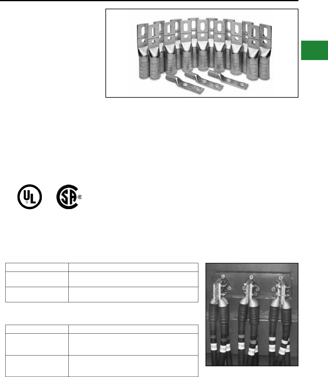
BURNDY®
Blue highlighted items are industry standard and most frequently ordered.
Canada: 1-800-387-6487 www.burndy.com US: 1-800-346-4175
TYPES YBA-KIT,
YA-KIT, YBAFX-KIT,
YAFX-KIT
Copper and Aluminum
Turbine Lug Kits
UL Listed 90°C,
600 Volts to 35 kV
Aiding in the staging and ow of material on
a project, the BURNDY® Turbine Lug Kits are
designed to meet the termination requirements
for the standard 1.5 MW wind turbine, improving
overall project efciency. Each lug kit contains UL
Listed and CSA Certied copper or aluminum lugs.
Kits include the required number of lugs needed
to terminate aluminum or copper conductors on
the low voltage side of a base transformer or the
down tower switchgear. There are four individual
kits, two for aluminum, two for copper, they are
all custom designed to handle any termination
requirements.
Catalog Number Includes:
YBAFX15CLKIT 15 pcs YBA44FX (777.7 Flex Cu 2-hole NEMA lug);
3 pcs YA29-2N (250 kcmil Cu 2-hole NEMA lug)
YAFX15CLKIT 15 pcs YAZ442NNTFX (777.7 Flex Cu 2-hole NEMA lug);
3 pcs YA29-2N (250 kcmil Cu 2-hole NEMA lug)
Features & Benets
• YA44A3 (1000 kcmil aluminum) HYLUG™,
2-hole, narrow tongue aluminum
compression terminal that is dual rated for
both copper and aluminum
• YBA44A (1000 kcmil, 1000 compact
aluminum) Break-Away HYLUG™, 2-hole
narrow tongue aluminum compression
terminal that is dual rated for both copper
and aluminum. The break-away feature
allows for eld modication of the terminal
from a 2-hole to a 1-hole terminal and still
retain UL Listing and CSA Certication
• YAZ442NNTFX (777.7 Flex,1925/24 str.,
750 kcmil copper) HYLUG™, 2-hole narrow
tongue copper compression terminal that
accommodates ex and AWG conductor
• YBA44FX (777.7 Flex, 1925/24 str. [750
kcmil] nom. copper) Break-Away HYLUG™,
2-hole, narrow tongue copper compression
terminal that accepts a wide range of
conductor combinations (AWG, compact,
DLO, ex, metric). The Break-Away feature
allows eld modication of the terminal from
a 2-hole to 1-hole terminal and still retain UL
Listing and CSA Certication
• Both aluminum and copper low voltage
turbine lug kits include YA29-2N (250
kcmil, copper, 2-hole) lugs for terminating
grounding conductor
• Aluminum kits are shipped with squeeze
packets of PENETROX™ oxide inhibitor for
terminating aluminum conductor
Catalog Number Includes:
YBA15ALKIT
15 pcs YBA44A (1000 Al 2-hole NEMA lug);
3 pcs YA29-2N (250 kcmil Cu 2-hole NEMA lug);
1 squeeze tube (1/2 oz) of PENETROX™ oxide inhibitor
YA15ALKIT
15 pcs YA44A3 (1000 Al 2-hole NEMA lug);
3 pcs YA29-2N (250 kcmil Cu 2-hole NEMA lug);
1 squeeze tube (1/2 oz) of PENETROX™ oxide inhibitor
Copper Kits
Aluminum Kits
Heat shrink and mounting hardware sold separately.
Compression Connections
Copper/Aluminum Wind Turbine Kits
C-17
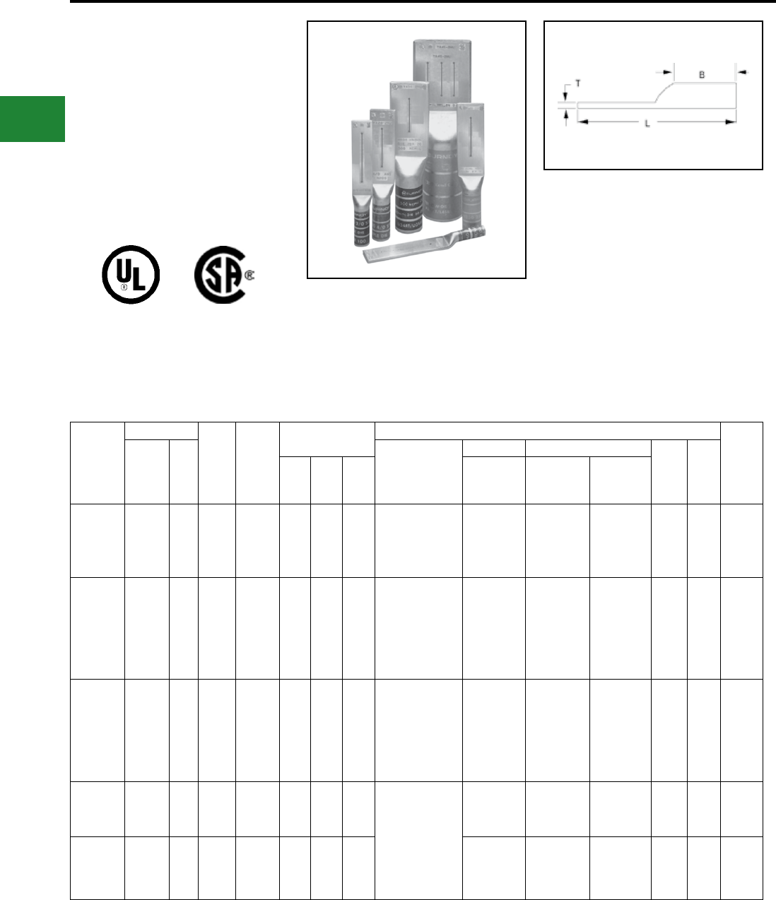
BURNDY®
Blue highlighted items are industry standard and most frequently ordered.
US: 1-800-346-4175 www.burndy.com Canada: 1-800-387-6487
TYPES YA-2NU,
YA-4NU
Blank Tongue HYLUG™
The Blank Tongue line of Copper Code HYLUG™
terminals are designed to provide maximum
eld exibility. Scored lines prevent the drill from
walking when trying to drill in this area. This
innovative design allows the installer to customize
the tongue drilling to t their specic application
while maintaining UL Listing and CSA Certication.
Features & Benets
• Manufactured from seamless high
conductivity electrolytic copper tubing
with heavy duty wall thickness
• Internally beveled barrel end
• Proper compression systems form a
highly efcient electrical connection
Catalog
Number
Conductor
Min.
Bolt
Hole**
Tongue
Width
Figure Dimensions
Installation Tooling (# of crimps)
Wire
Strip
LengthAWG
***
MM² Dieless
Mechanical Hydraulic
Color
Code
Die
IndexB T L
MD6,
OUR840,
MD7-34R
BCT500HS,
Y500CTHS
Y750, Y46*,
PAT750
YA8C2NU
#8 AWG
#6 Sol
#8 Sol
#8 Weld
37/24
— #10 0.83"0.81"0.12"4.08"
Y1MRTC (2)
MY29- 11 (1)
MY29-3 (1)
W8CRT (1)
W8CVT (1)
X8CRT (2)
W8CRT (1) U8CRT (1)
U8CRT (1) Red 49 7/8"
YA6C2NU #6 AWG — #10 0.83"1.12"0.12"4.40"
Y1MRTC (2)
MY29-11 (1)
MY29-3 (1)
MRC840 (2)
Y81KFT (1)
Y81KFTBMH (1)
PAT81KFT-18V (1)
W5CVT (2)
W5CRT (2)
X5CRT (2)
X8CART (2)
W5CVT (2)
W5CRT (2)
X5CRT (2)
X8CART (2)
U5CRT (2)
U8CABT (2) Blue
7
or
374
1-3/16"
YA5C2NU #5 AWG 16 — 0.83"1.12"0.12"4.43"
MY29-3 (2)
MY29-1 (2)
MRC840 (2)
Y644HSXT (1)
Y81KFT (1)
Y81KFTMBH (1)
PAT81KFT-18V (1)
W5CRT (2)
W5CVT (2)
X5CRT (2)
X5CRT (2)
X5CVT (2)
W5CRT (2)
U5CRT (2) Blue 7 1-3/16"
YA4C2NU #4 AWG — #10 0.83"1.12"0.12"4.45"
Y1MRTC (4)
MY29-3 (2)
MY29-11 (2)
MRC840 (2)
Y644HSXT (1)
Y81KFT (1)
Y81KFTBMH (1)
PAT81KFT-18V (1)
W4CVT (2)
W4CRT (2)
X4CRT (2)
W4CVT (2)
W4CRT (2)
X4CRT (2)
U4CRT (2)
U6CABT (2) Gray
8
or
346
1-3/16"
YA3C2NU #3 AWG
#2 Sol. 25 1/4"0.83"1.25"0.12"4.62"W3CRT (2) W3CRT (2) U3CRT (2) White 9 1-5/16"
* Use PUADP-1 adaptor with U dies in Y46 HYPRESS™
** Minimum bolt hole size must be maintained for UL &
CSA
• Dimples located at each end of the
scored line represent the location of the
NEMA standard hole spacing
• Scored line locates the center of the
tongue and prevents the drill from
walking when trying to drill in this area
• Offered in a wide range of code
conductor sizes
*** The MM2 conductor sizes listed are the
recommendations for Class 2 conductor
‡ Requires Y60BHU HYPRESS™
C-18
Compression Connections
Copper Compression — Code — Long Barrel — Blank Tongue
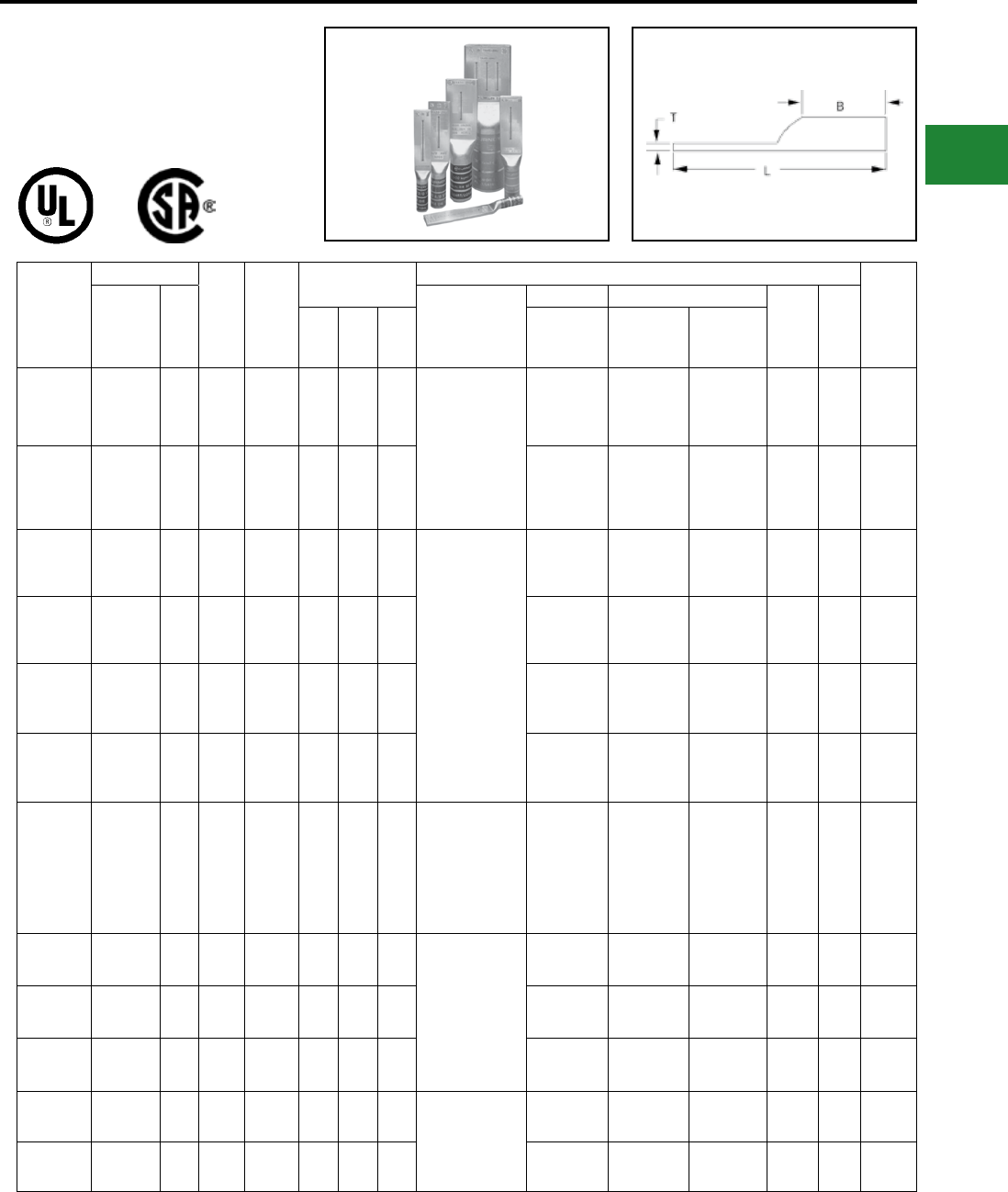
BURNDY®
Blue highlighted items are industry standard and most frequently ordered.
Canada: 1-800-387-6487 www.burndy.com US: 1-800-346-4175
TYPES YA-2NU,
YA-4NU
Blank Tongue HYLUG™
(Continued)
Catalog
Number
Conductor
Min.
Bolt
Hole**
Tongue
Width
Figure Dimensions
Installation Tooling (# of crimps)
Wire
Strip
LengthAWG
***
MM² Dieless
Mechanical Hydraulic
Color
Code
Die
IndexB T L
MD6,
OUR840,
MD7-34R
BCT500HS,
Y500CTHS
Y750, Y46*,
PAT750
YA2C2NU #2 AWG 35 1/4"0.83"1.25"0.12"4.64"
Y1MRTC (4)
MY29-3 (2)
MY29-11 (2)
MRC840 (2)
Y644HSXT (1)
Y81KFT (2)
Y81KFTBMH (2)
PAT81KFT-18V (2)
W2CVT (2)
W2CRT (2)
X2CRT (2)
W2CVT (2)
W2CRT (2)
X2CRT (2)
U2CRT (2) Brown 10 1-5/16"
YA1C2NU #1 AWG 50 1/4"0.83"1.38"0.12"4.82"
W1CVT (2)
W1CRT-1 (2)
X1CRT-1 (2)
W1CVT (2)
W1CRT-1 (2)
X1CRT-1 (2)
U1CRT-1 (2)
U4CABT (2) Green 11 1-7/16"
YA252NU 1/0 AWG — 1/4"0.83"1.38"0.11"4.81"
MY29-3 (2)
MY29-11 (2)
MRC840 (4)
Y644HSXT (1)
Y81KFT (2)
Y81KFTMBH (2)
PAT81KFT-18V (2)
W25VT (4)
W25RT (4)
X25RT (4)
W25VT (4)
W25RT (4)
X25RT (4)
U25RT (2)
U2CABT (2) Pink 12 to
348 1-7/16"
YA262NU 2/0 AWG 70 1/4"0.83"1.50"0.12"4.97"
W26VT (4)
W26RT (4)
X26RT (4)
W26VT (4)
W26RT (4)
X26RT (4)
U26RT (2) Black 13 1-9/16"
YA272NU 3/0 AWG — 1/4"0.91"1.50"0.13"5.01"
W27VT (4)
W27RT (4)
X27RT (6)
W27VT (4)
W27RT (4)
X27RT (6)
U27RT (2) Orange 14 1-9/16"
YA282NU 4/0 AWG — 1/4"1.02"1.62"0.14"5.17"
W28VT (4)
W28RT (4)
X28RT (6)
W28VT (4)
W28RT (4)
X28RT (6)
U28RT (2) Purple 15 1-11/16"
YA292NU 250 kcmil 120 1/4"1.11"1.62"0.16"5.21"
MY29-3 (2)
MY29-11 (2)
Y644HSXT (1)
Y81KFT (2)
Y81KFTMBH (2)
PAT81KFT-18V (2)
W29VT (4)
X29RT (8)
W29VT (4)
W29RT (4)
X29RT (8)
U29RT (2) Yellow 16 1-11/16"
YA302NU 300 kcmil 150 1/4"1.20"2.00"0.16"5.64"
Y644HSXT (1)
Y81KFT (3)
Y81KFTMBH (3)
PAT81KFT-18V (3)
W30VT (4) W30VT (4)
W30RT (4)
U30RT (4)
U28ART (4) White 17 2-1/16"
YA312NU 350 kcmil 185 1/4"1.29"2.00"0.18"5.68"W31VT (4) W31VT (4)
W31RT (4)
U31RT (4)
U29ART (4) Red 18 2-1/16"
YA322NU 400 kcmil — 3/8"1.40"2.12"0.19"5.85"W32VT (4) W32VT (4)
W32RT (4)
U32RT (4)
U30ART (4) Blue 19 or
470 2-3/16"
YA342NU 500 kcmil 240 3/8"1.55"2.25"0.22"6.06"Y644HSXT (1)
Y81KFT (4)
Y81KFTMBH (4)
PAT81KFT-18V (4)
W34VT (4) W34VT (4)
W34RT (4)
U34RT (4)
U31ART (4) Brown 20 or
299 2-5/16"
YA362NU 600 kcmil 300 3/8"1.73"2.69"0.26"6.59"— — U36RT (4)
U32ART (4) Green 22 or
472 2-3/4"
*** The MM2 conductor sizes listed are the
recommendations for Class 2 conductor
‡ Requires Y60BHU HYPRESS™* Use PUADP-1 adaptor with U dies in Y46 HYPRESS™
** Minimum bolt hole size must be maintained for UL & CSA
C-19
Compression Connections
Copper Compression — Code — Long Barrel — Blank Tongue
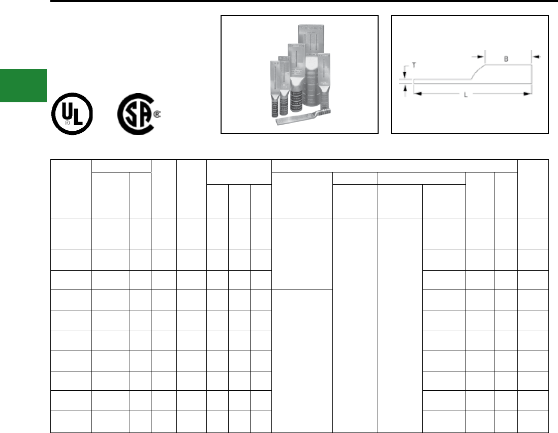
BURNDY®
Blue highlighted items are industry standard and most frequently ordered.
US: 1-800-346-4175 www.burndy.com Canada: 1-800-387-6487
Catalog
Number
Conductor
Min.
Bolt
Hole**
Tongue
Width
Figure Dimensions
Installation Tooling (# of crimps)
Wire
Strip
LengthAWG
***
MM² Dieless
Mechanical Hydraulic
Color
Code
Die
IndexB T L
MD6,
OUR840,
MD7-34R
BCT500HS,
Y500CTHS
Y750, Y46*,
PAT750
YA392NU 750 kcmil 375 3/8"1.91"2.88"0.26"6.87"Y644HSXT (1)
Y81KFT (3)
Y81KFTMBH (3)
PAT81KFT-18V (3)
— —
U39RT (4)
P39RT (4)** Black 24 2-15/16"
YA402NU 800 kcmil 400 3/8"1.98"2.94"0.30"6.95"P40RT (4) Orange 25 3"
YA442NU 1000 kcmil 500 3/8"2.18"3.00"0.32"7.14"P44RT (4)** White 27 3-1/16"
YA452NU 1250 kcmil — 3/8"2.46"3.19"0.38"7.44"
—
P45RT (6)** Yellow 29 3-1/4"
YA462NU 1500 kcmil 800 3/8"2.69"3.19"0.40"7.55"P46RT (6)** Green 31 3-1/4"
YA472NU ‡ 1750 kcmil — 3/8"2.90"3.44"0.42"7.89"‡ Gray 33 3-1/2"
YA482NU ‡ 2000 kcmil 1000 3/8"3.10"3.44"0.46"7.98"‡ Brown 34 3-1/2"
YA444NU 1000 kcmil 500 3/8"3.00"3.00"0.23"7.14"P44RT White 27 3-1/16"
YA454NU 1250 kcmil — 3/8"3.00"3.19"0.30"7.44"P45RT Yellow 29 3-1/4"
YA464NU 1500 kcmil 800 3/8"3.00"3.19"0.34"7.55"P46RT Green 31 3-1/4"
*** The MM2 conductor sizes listed are the
recommendations for Class 2 conductor
‡ Requires Y60BHU HYPRESS™* Use PUADP-1 adaptor with U dies in Y46 HYPRESS™
** Minimum bolt hole size must be maintained for UL & CSA
TYPES YA-2NU,
YA-4NU
Blank Tongue HYLUG™
(Continued)
C-20
Compression Connections
Copper Compression — Code — Long Barrel — Blank Tongue
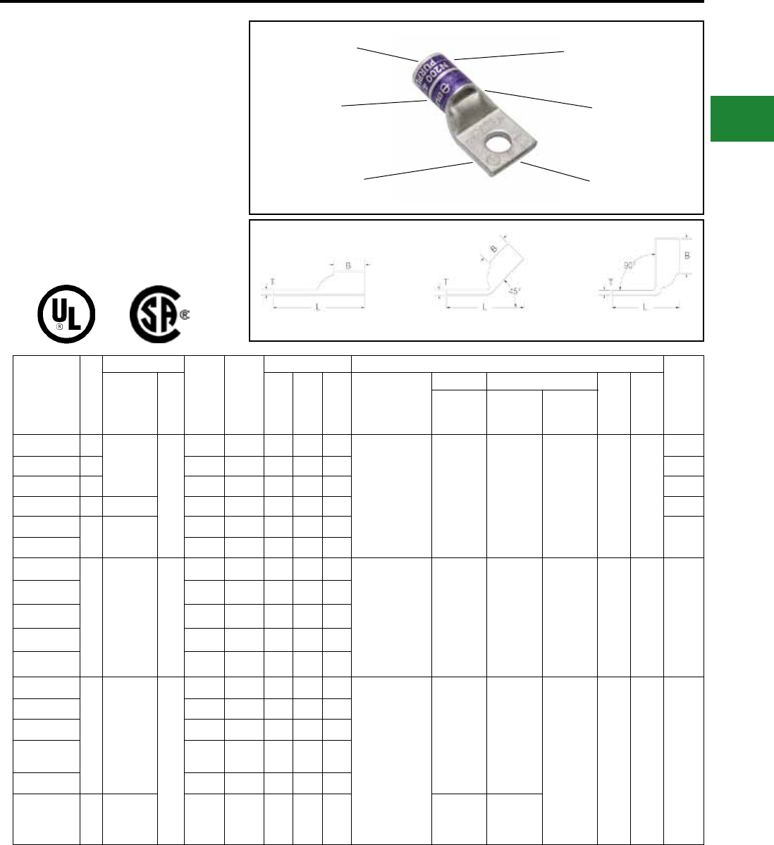
BURNDY®
Blue highlighted items are industry standard and most frequently ordered.
Canada: 1-800-387-6487 www.burndy.com US: 1-800-346-4175
ONE HOLE HYLUG™
CODE CONDUCTOR
STANDARD BARREL
TYPES YA-L, YA-L-TC
UNINSULATED COPPER
COMPRESSION TERMINAL
UL Listed 90° C,
600 Volts to 35kV ♦
45° and 90° angles available. Please contact
Customer Service to order : 1-800-346-4175.
BEVELED
ENTRY
CABLE
ACCOMMODATION ELECTRO-TIN
PLATED
INSPECTION
WINDOW
DIE AND COLOR
CODE INFORMATION
CRIMP
Fig. 1 45° 90°
Catalog
Number
Fig
#
Conductor
Stud
Hole
Size
Tongue
Width
Figure Dimensions Installation Tooling
Wire
Strip
LengthAWG
***
MM² (B) (T) (L)
Dieless
(# of crimps)
Mechanical Hydraulic
Color
Code
Die
Index
MD6,
OUR840,
MD7-34R
BCT500HS,
Y500CTHS
Y35, Y39
Y750, Y46*
PAT750
YAV10BOX 1
#14-#10 Str
#12-#10 Sol
6
#8 - #10 0.38"0.40"0.06"0.97"Non-Ratchet:
Y10D, Y10-22
Ratchet:
MR8G98,
MR8-9Q,
Y8MRB-1, MR20,
N10HT, N10HT-24
— — — — —
7/16"
YAV10R-BOX 3 #8 - #10 0.38"0.38"0.06"0.53"3/8"
YAV10-T2BOX 1 1/4"0.53"0.39"0.04"1.13"7/16"
YAV10-R3BOX 3 #10-#12 1/4"0.47"0.38"0.05"0.55"5/16"
YAV10-T3BOX 1#14-#10 Str
#12-#10 Sol
5/16"0.45"0.41"0.05"1.10"7/16"
YAV10-T4BOX 3/8"0.55"0.45"0.04"1.17"
YA8CL-BOX
1
#8 AWG
#8 Weld
37/24
#6 sol.
#8 sol.
†
10
#8 - #10 0.41"0.44"0.08"1.16"Y1MRTC (1)
MY29-3 (1)
MY29-11 (1)
MRC840 (1)
Y4PC834 (1)
Y8MRB-1 (1)
Y81KFT (1)
PAT81KFT (1)
W8CVT (1)
W8CRT (1)
X8CRT (1)
W8CVT (1)
W8CRT (1)
X8CRT (1)
U8CRT (1) Red 49 7/16"
YA8CL1-BOX 1/4"0.44"0.44"0.08"1.26"
YA8CL2-BOX 5/16"0.52"0.44"0.06"1.38"
YA8CL3-BOX 3/8"0.58"0.44"0.06"1.51"
YA8CL4-BOX 1/2"0.71"0.44"0.05"1.76"
YA6CL1-BOX
1 #6 AWG
—
#8 - #10 0.41"0.54"0.09"1.27"
Y1MRTC (1)
MY29-3 (1)
MY29-11 (1)
MRC840 (1)
Y81KFT (1)
Y81KFTBMH (1)
PAT81KFT-18V (1)
W5CVT (1)
W5CRT (1)
X5CRT (1)
X8CART (1)
W5CVT (1)
W5CRT (1)
X5CRT (1)
X8CART (1) U5CRT (1)
U8CABT (1) Blue 7
or 374 9/16"
YA6CL-BOX 1/4"0.45"0.54"0.08"1.45"
YA6CL3-BOX 5/16"0.52"0.54"0.07"1.52"
YA6CL4-BOX 3/8"0.63"0.54"0.06"1.62"
YA6CL-6 1/2"0.75"0.54"0.12"1.87"
YA5CL 1 #5 AWG 1/4"0.44"0.81"0.07"1.65"
W5CRT (1)
W5CVT (1)
X5CRT (1)
W5CRT (1)
X5CRT (1)
W5CVT (1)
* Use PUADP-1 adapter with U dies in Y46 HYPRESS™
** P-RT die sets for use in Y46 HYPRESS™ only,
PUADP-1 adapter not required
*** The MM2 conductor sizes listed are the
recommendations for Class 2 conductor
† The MM2 conductor size listed is for both Class 2 and
Class 5 conductor
▲ See tooling section of this catalog for complete tool
and die listings
♦ For applications greater than 2000 Volts consult cable
manufacturer for voltage stress relief instructions
Note: All dimensions shown are for reference only.
Compression Connections
Copper Compression — Code
C-21
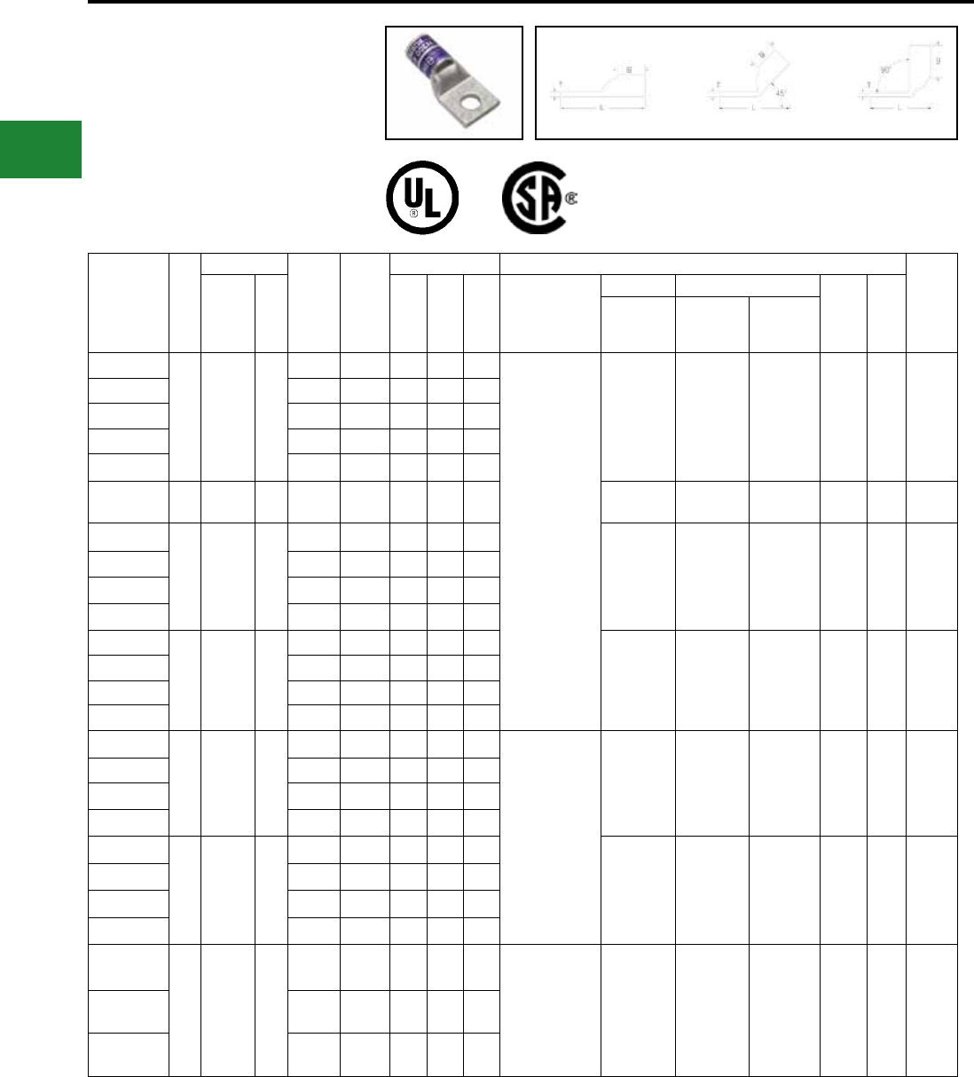
BURNDY®
Blue highlighted items are industry standard and most frequently ordered.
US: 1-800-346-4175 www.burndy.com Canada: 1-800-387-6487
Compression Connections
Copper Compression — Code
ONE HOLE HYLUG™
CODE CONDUCTOR
STANDARD BARREL
(Continued)
45° and 90° angles available. Please contact
Customer Service to order: 1-800-346-4175.
Fig. 1 45° 90°
Catalog
Number
Fig
#
Conductor
Stud
Hole
Size
Tongue
Width
Figure Dimensions Installation Tooling
Wire
Strip
LengthAWG
***
MM² (B) (T) (L)
Dieless
(# of crimps)
Mechanical Hydraulic
Color
Code
Die
Index
MD6,
OUR840,
MD7-34R
BCT500HS,
Y500CTHS
Y35, Y39
Y750, Y46*
PAT750
YA4CL1-BOX
1 #4 AWG —
#8 - #10 0.50"0.81"0.09"1.58"
Y1MRTC (2)
MY29-3 (1)
MY29-11 (1)
MRC840 (1)
Y644HSXT (1)
Y81KFT (1)
Y81KFTMBH (1)
PAT81KFT-18V (1)
W4CVT (1)
W4CRT (1)
X4CRT (1)
W4CVT (1)
W4CRT (1)
X4CRT (1)
U4CRT (1)
U6CABT (1) Gray 8 7/8"
YA4CL-BOX 1/4"0.50"0.81"0.09"1.74"
YA4CL3-BOX 5/16"0.50"0.81"0.08"1.79"
YA4CL4-BOX 3/8"0.58"0.81"0.09"1.92"
YA4CL6-BOX 1/2"0.71"0.81"0.06"2.20"
YA3CL 1#3 Str
#2 Sol 25 5/16"0.55"0.88"0.09"1.88"W3CRT (1) W3CRT (1) U3CRT (1) White 9 15/16"
YA2CL2-BOX
1 #2 AWG 35
1/4"0.61"0.88"0.11"1.88"
W2CVT (1)
W2CRT (1)
X2CRT (1)
W2CVT (1)
W2CRT (1)
X2CRT (1)
U2CRT (1) Brown 10 15/16"
YA2CL-BOX 5/16"0.61"0.88"0.11"1.93"
YA2CL4-BOX 3/8"0.61"0.88"0.11"2.06"
YA2CL6-BOX 1/2"0.73"0.88"0.09"2.32"
YA1CL2
1 #1 AWG 50
1/4"0.68"0.88"0.10"1.81"
W1CVT (1)
W1CRT-1 (1)
X1CRT-1 (1)
W1CVT (1)
W1CRT-1 (1)
X1CRT-1 (1)
U1CRT-1 (1)
U4CABT (1) Green
11
or
375
15/16"
YA1CL-BOX 5/16"0.68"0.88"0.10"1.94"
YA1CL4-BOX 3/8"0.68"0.88"0.10"2.06"
YA1CL6-BOX 1/2"0.73"0.88"0.09"2.37"
YA25L2-BOX
1 1/0 AWG —
1/4"0.75"0.88"0.12"1.84"
MY29-3 (1)
MY29-11 (1)
MRC840 (2)
Y644HSXT (1)
Y81KFT (1)
Y81KFTMBH (1)
PAT81KFT-18V (1)
W25VT (2)
W25RT (2)
X25RT (2)
W25VT (2)
W25RT (2)
X25RT (2)
U25RT (1)
U2CABT (1) Pink 12 15/16"
YA25L-BOX 5/16"0.75"0.88"0.12"1.96"
YA25L4-BOX 3/8"0.75"0.88"0.12"2.09"
YA25L6-BOX 1/2"0.75"0.88"0.12"2.34"
YA26L2-BOX
1 2/0 AWG 70
1/4"0.83"0.94"0.12"1.94"
W26VT (2)
W26RT (2)
X26RT (2)
W26VT (2)
W26RT (2)
X26RT (2)
U26RT (1) Black 13 1"
YA26L-BOX 3/8"0.83"0.94"0.12"2.19"
YA26L6-BOX 1/2"0.83"0.94"0.12"2.44"
YA26L60 3/4"1.02"0.94"0.10"2.96"
YA27L3
1 3/0 AWG —
5/16"0.91"1.00"0.13"2.16"MY29-3 (1)
MY29-11 (1)
MRC840 (2)
Y644HSXT (1)
Y81KFT (2)
Y81KFTMBH (2)
PAT81KFT-18V (2)
W27VT (2)
W27RT (2)
X27RT (3)
W27VT (2)
W27RT (2)
X27RT (3)
U27RT (1) Orange 14 1-1/16"
YA27L4-BOX 3/8"0.91"1.00"0.13"2.29"
YA27L-BOX 1/2"0.91"1.00"0.13"2.54"
* Use PUADP-1 adapter with U dies in Y46 HYPRESS™
** P-RT die sets for use in Y46 HYPRESS™ only,
PUADP-1 adapter not required
*** The MM2 conductor sizes listed are the
recommendations for Class 2 conductor
† The MM2 conductor size listed is for both Class 2 and
Class 5 conductor
▲ See tooling section of this catalog for complete tool
and die listings
♦ For applications greater than 2000 Volts consult cable
manufacturer for voltage stress relief instructions
Note: All dimensions shown are for reference only.
C-22
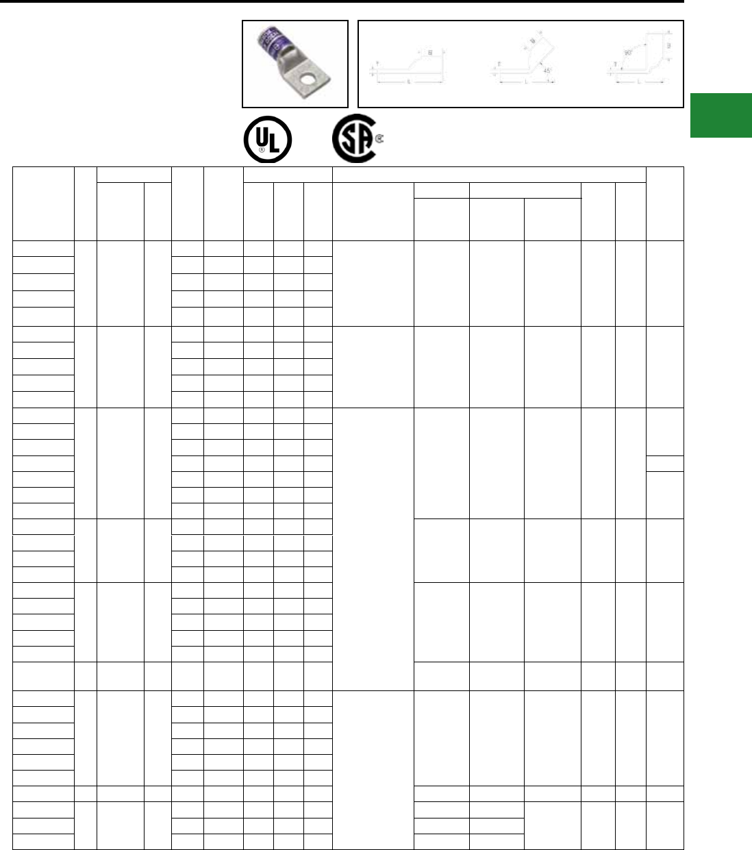
BURNDY®
Blue highlighted items are industry standard and most frequently ordered.
Canada: 1-800-387-6487 www.burndy.com US: 1-800-346-4175
Compression Connections
Copper Compression — Code
ONE HOLE HYLUG™
CODE CONDUCTOR
STANDARD BARREL
(Continued)
45° and 90° angles available. Please contact
Customer Service to order: 1-800-346-4175.
Fig. 1 45° 90°
Catalog
Number
Fig
#
Conductor
Stud
Hole
Size
Tongue
Width
Figure Dimensions Installation Tooling
Wire
Strip
LengthAWG
***
MM² (B) (T) (L)
Dieless
(# of crimps)
Mechanical Hydraulic
Color
Code
Die
Index
MD6,
OUR840,
MD7-34R
BCT500HS,
Y500CTHS
Y35, Y39
Y750, Y46*
PAT750
YA28L2
1 4/0 AWG —
1/4"1.02"0.88"0.14"1.96"MY29-3 (1)
MY29-11 (1)
MRC840 (2)
Y644HSXT (1)
Y81KFT (2)
Y81KFTMBH (2)
PAT81KFT-18V (2)
W28VT (2)
W28RT (2)
X28RT (3)
W28VT (2)
W28RT (2)
X28RT (3)
U28RT (1) Purple 15 1-1/8"
YA28L3 5/16"1.02"0.88"0.14"2.08"
YA28L4-BOX 3/8"1.02"0.88"0.14"2.21"
YA28L-BOX 1/2"1.02"0.88"0.14"2.46"
YA28L56 3/4"1.05"0.88"0.13"2.90"
YA29L2
1 250 kcmil —
1/4"1.11"1.06"0.16"2.17"MY29-3 (1)
MY29-11 (1)
Y644HSXT (1)
Y81KFT (2)
Y81KFTMBH (2)
PAT81KFT-18V (2)
W29VT (2)
X29RT (4)
W29VT (2)
W29RT (2)
X29RT (4)
U29RT (1) Yellow 16 1-1/8"
YA29L7 5/16"1.11"1.06"0.16"2.30"
YA29L4 3/8"1.11"1.06"0.16"2.42"
YA29L-BOX 1/2"1.11"1.06"0.16"2.67"
YA29LTC78 7/8"1.11"1.06"0.14"3.36"
YA30L1
1 300 kcmil 150
5/16"1.20"1.03"0.16"2.31"
Y644HSXT (1)
Y81KFT (2)
Y81KFTMBH (2)
PAT81KFT-18V (2)
W30VT (2) W30VT (2)
W30RT (2)
U30RT (2)
U28ART (2) White 17
1-1/16"YA30L24 3/8"1.20"1.03"0.16"2.44"
YA30L 1/2"1.20"1.03"0.16"2.69"
YA30LN 1/2"1.20"1.03"0.16"2.87"1"
YA30L7 5/8"1.20"1.03"0.16"2.94"
1-1/16"YA30L28 3/4"1.20"1.03"0.16"3.12"
YA30L27 7/8"1.20"1.03"0.16"3.37"
YA31L11
1 350 kcmil 185
3/8"1.29"1.06"0.18"2.50"
W31VT (2) W31VT (2)
W31RT (2)
U31RT (2)
U29ART (2) Red 18 1-1/8"
YA31L 1/2"1.29"1.06"0.18"2.75"
YA31L7 5/8"1.29"1.06"0.18"3.00"
YA31L36 7/8"1.29"1.06"0.18"4.02"
YA32L14
1 400 kcmil —
3/8"1.40"1.19"0.19"2.68"
W32VT (2) W32VT (2)
W32RT (2)
U32RT (2)
U30ART (2) Blue 19 1-1/4"
YA32LN 1/2"1.40"1.19"0.19"3.12"
YA32L1 1/2"1.40"1.19"0.19"2.93"
YA32L 5/8"1.40"1.19"0.19"3.18"
YA32LTC78 7/8"1.40"1.19"0.19"3.62"
YA33L 1 450 kcmil — 5/8"1.48"1.50"0.21"3.57"W33VT (2) W33VT (2)
W33RT (2) U33RT (2) Gray 326 1-9/16"
YA34L37
1 500 kcmil 240
3/8"1.55"1.27"0.23"2.87"
Y644HSXT (1)
Y81KFT (2)
Y81KFTMBH (2)
PAT81KFT-18V (2)
W34VT (2) W34VT (2)
W34RT (2)
U34RT (2)
U31ART (1) Brown 20 1-7/16"
YA34L6 1/2"1.55"1.27"0.23"3.12"
YA34L 5/8"1.55"1.27"0.23"3.37"
YA34L8 3/4"1.55"1.27"0.23"3.55"
YA34L9 7/8"1.55"1.27"0.23"3.80"
YA34L20 1"1.55"1.27"0.23"4.05"
YA35L 1 550 kcmil — 5/8"1.65"1.69"0.25"3.81"— — U35RT (2) Yellow 21 1-3/4"
YA36L11
1 600 kcmil 300
1/2"1.74"1.38"0.27"3.29"— — U36RT (2)
U32ART (2) Green
22
or
472
1-3/4"YA36L 5/8"1.74"1.38"0.27"3.54"— —
YA36LTC78 7/8"1.74"1.38"0.27"3.97"— —
* Use PUADP-1 adapter with U dies in Y46 HYPRESS™
** P-RT die sets for use in Y46 HYPRESS™ only,
PUADP-1 adapter not required
*** The MM2 conductor sizes listed are the
recommendations for Class 2 conductor
† The MM2 conductor size listed is for both Class 2 and
Class 5 conductor
▲ See tooling section of this catalog for complete tool
and die listings
♦ For applications greater than 2000 Volts consult cable
manufacturer for voltage stress relief instructions
Note: All dimensions shown are for reference only.
C-23
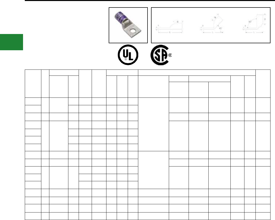
BURNDY®
Blue highlighted items are industry standard and most frequently ordered.
US: 1-800-346-4175 www.burndy.com Canada: 1-800-387-6487
Compression Connections
Copper Compression — Code
ONE HOLE HYLUG™
CODE CONDUCTOR
STANDARD BARREL
(Continued)
45° and 90° angles available. Please contact
Customer Service to order: 1-800-346-4175.
Fig. 1 45° 90°
Catalog
Number
Fig
#
Conductor
Stud
Hole
Size
Tongue
Width
Figure Dimensions Installation Tooling
Wire
Strip
LengthAWG
***
MM² (B) (T) (L)
Dieless
(# of crimps)
Mechanical Hydraulic
Color
Code
Die
Index
MD6,
OUR840,
MD7-34R
BCT500HS,
Y500CTHS
Y35, Y39
Y750, Y46*
PAT750
YA37L 1 650 kcmil — 5/8"1.80"1.39"0.27"3.57"
Y644HSXT (1)
Y81KFT (3)
Y81KFTMBH (3)
PAT81KFT-18V (3)
— — U37RT (2) Orange 23 1-15/16"
YA37L1 — 5/8"1.80"1.39"0.27"3.76"
YA38L 1 700 kcmil — 5/8"1.84"1.45"0.27"3.66"— — U38RT (2) Pink 400 1-15/16"
YA39L6
1 750 kcmil
— 1/2"1.91"1.42"0.27"3.41"
— — U39RT (2)
P39RT (2)** Black 24 1-15/16"
YA39L — 5/8"1.91"1.42"0.27"3.57"
YA39L2 — 7/8"1.91"1.42"0.27"4.10"
YA39L9 — 1-1/4"1.91"1.42"0.27"4.85"
YA40L 1 800 kcmil 400
5/8"
1.98"1.42"0.30"3.81"Y644HSXT (1)
Y81KFT (3)
Y81KFTMBH (3)
PAT81KFT-18V (3)
Y644HSXTBH (1)
PAT644XT-18V (1)
— — P40RT (3) ** Orange 25 1-15/16"
YA41L 1 850 kcmil —
5/8"
2.01"1.88"0.31"4.15"— — — Gold 26 1-15/16"
YA44L2
1 1000 kcmil 500
1/2"2.19"1.65"0.33"3.98"
— —
P44RT (3) **
White 27 1-15/16"
YA44L 5/8"2.19"1.65"0.33"4.04"
YA44L23 1"2.19"1.65"0.33"4.73"
YA45L 1 1250 kcmil 630 3/4"2.46"2.00"0.38"4.68"— — —
P45RT (3) **
Yellow 29 2-1/16"
YA453L 1 1300 kcmil — 3/4"2.53"2.00"0.39"4.71"— — —
—
Orange 30 2-1/16"
YA46L 1 1500 kcmil 800 3/4"2.69"2.00"0.40"4.78"— — — P46RT (3) ** Green 31 2-1/16"
YA48L 1 2000 kcmil 1000 3/4"3.10"2.25"0.46"5.19"— — — — Brown 34 2-3/8"
* Use PUADP-1 adapter with U dies in Y46 HYPRESS™
** P-RT die sets for use in Y46 HYPRESS™ only,
PUADP-1 adapter not required
*** The MM2 conductor sizes listed are the
recommendations for Class 2 conductor
*** The MM2 conductor sizes listed are the
recommendations for Class 2 conductor.
▲ See tooling section of this catalog for complete tool
and die listings.
♦ For applications greater than 2000 Volts consult cable
manufacturer for voltage stress relief instructions.
Note: All dimensions shown are for reference only.
C-24
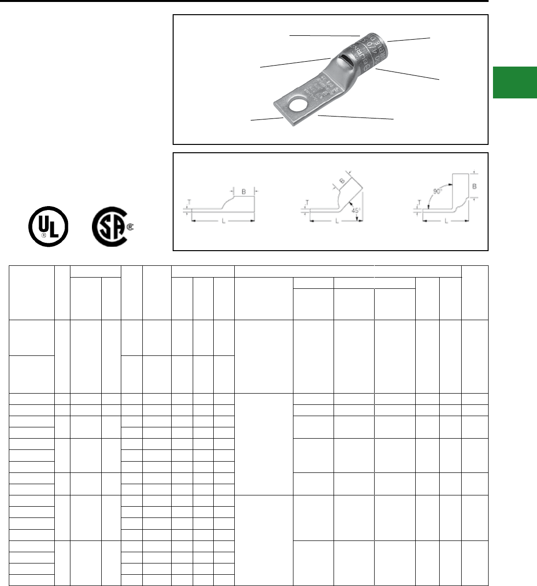
BURNDY®
Blue highlighted items are industry standard and most frequently ordered.
Canada: 1-800-387-6487 www.burndy.com US: 1-800-346-4175
Compression Connections
Copper Compression — Code — Narrow Tongue
ONE HOLE HYLUG™ CODE
CONDUCTOR STANDARD
BARREL NARROW TONGUE
TYPE YA-L-NT
UNINSULATED COPPER
COMPRESSION NARROW
TONGUE TERMINAL
UL Listed 90° C,
600 Volts to 35 kV ♦
45° and 90° angles available. Please contact
Customer Service to order: 1-800-346-4175
BEVELED
ENTRY
CABLE
ACCOMMODATION
ELECTRO-TIN
PLATED
INSPECTION
WINDOW
DIE AND COLOR
CODE INFORMATION
CRIMP
Catalog
Number
Fig
#
Conductor
Stud
Hole
Size
Tongue
Width
Figure Dimensions ▲Installation Tooling (# of crimps)
Wire
Strip
LengthAWG
***
MM² (B) (T) (L)
****
Dieless
Mechanical Hydraulic
Color
Code
Die
Index
MD6,
OUR840,
MD7-34R
BCT500HS,
Y500CTHS
Y35, Y39
Y750, Y46*
PAT750
YA8CLNT6
1
#8 AWG
#8 Weld
37/24
#8 Sol
#6 Sol
**
10
#6 0.29"0.44"0.09"1.08"
Y1MRTC (1)
Y8MRB-1 (1)
MY29-3 (1)
MY29-11 (1)
MRC840 (1)
Y81KFT (1)
Y81KFTMBH (1)
PAT81KFT-18V (1)
W8CVT (1) X8CRT (1) U8CRT (1) Red 49 1/2"
YA8CLNT8 #8 0.33"0.44"0.09"1.18"
YA6CLNT6 1 #6 AWG — #6 0.29"0.54"0.09"1.17"
Y1MRTC (1)
MY29-3 (1)
MY29-11 (1)
MRC840
Y644HSXT (1)
Y81KFT (1)
Y81KFTMBH (1)
PAT81KFT-18V (1)
W5CVT (1) X5CRT (1) U5CRT (1) Blue 7 7/8"
YA4CLNT10 1 #4 AWG — #10 0.40"0.81"0.09"1.73"W4CVT (1) X4CRT (1) U4CRT (1) Gray 8 7/8"
YA3CLNT14 1#3 AWG
#2 Sol. 25 1/4"0.41"0.88"0.08"1.82"W3CVT (1) W3CVT (1) U3CRT (1) White 9 15/16"
YA3CLNT516 5/16"0.49"0.88"0.08"1.80"
YA2CLNT10
1 #2 AWG 35
#10 0.48"0.88"0.11"1.80"
W2CVT (1) X2CRT (1) U2CRT (1) Brown 10 15/16"YA2CLNT14 1/4"0.50"0.88"0.11"1.80"
YA2CLNT516 5/16"0.49"0.88"0.11"1.82"
YA1CLNT10 1 #1 AWG 50 #10 0.50"0.88"0.10"2.23"W1CVT (1) X1CRT-1 (1) U1CRT-1 (1) Green 11 15/16"
YA1CLNT14 1/4"0.50"0.88"0.10"2.23"
YA25LNT10
1 1/0 AWG —
#10 0.62"0.88"0.12"2.28"
MY29-3 (1)
MY29-11 (1)
MRC840
Y644HSXT (1)
Y81KFT (1)
Y81KFTMBH (1)
PAT81KFT-18V (1)
W25VT (2) X25RT (2) U25RT (1) Pink 12 15/16"
YA25LNT14 1/4"0.48"0.88"0.12"1.93"
YA25LNT516 5/16"0.62"0.88"0.12"2.28"
YA25LNT38 3/8"0.62"0.88"0.12"2.18"
YA26LNT10
1 2/0 AWG 70
#10 0.62"0.94"0.13"2.62"
W26VT (2) X26RT (2) U26RT (1) Black 13 1"
YA26LNT14 1/4"0.48"0.94"0.12"2.02"
YA26LNT516 5/16"0.62"0.94"0.13"2.62"
YA26LNT38 3/8"0.72"0.94"0.12"2.48"
* Use PUADP-1 adapter with U dies in Y46 HYPRESS™
** The MM2 conductor size listed is for Class 2 and
Class 5 conductor
*** The MM2 conductor sizes listed are the
recommendations for Class 2 conductor
**** Y644HSXT is not recommended for standard barrel
length #6 AWG HYLUG™
▲ See tooling section of this catalog for complete
tool and die listings. Use ONLY color-coded die
recommendations for FX connectors. For
nest/indentor system contact factory
♦ For applications greater than 2000 Volts consult cable
manufacturer for voltage stress relief instructions
Note: All dimensions shown are for reference only.
Fig. 1 45° 90°
C-25
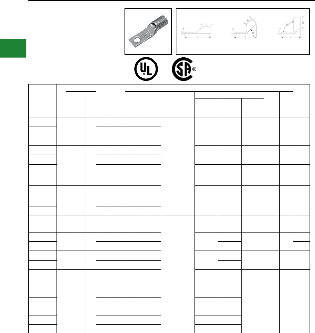
BURNDY®
Blue highlighted items are industry standard and most frequently ordered.
US: 1-800-346-4175 www.burndy.com Canada: 1-800-387-6487
Compression Connections
Copper Compression — Code — Narrow Tongue
ONE HOLE HYLUG™ CODE
CONDUCTOR STANDARD
BARREL NARROW TONGUE
(Continued)
45° and 90° angles available. Please contact
Customer Service to order: 1-800-346-4175
Catalog
Number
Fig
#
Conductor
Stud
Hole
Size
Tongue
Width
Figure Dimensions ▲Installation Tooling (# of crimps)
Wire
Strip
LengthAWG
***
MM² (B) (T) (L)
****
Dieless
Mechanical Hydraulic
Color
Code
Die
Index
MD6,
OUR840,
MD7-34R
BCT500HS,
Y500CTHS
Y35, Y39
Y750, Y46*
PAT750
YA27LNT14
1 3/0 AWG —
1/4"0.76"1.00"0.13"2.10"
MY29-3 (1)
MY29-11 (1)
MRC840 (2)
Y644HSXT (1)
Y81KFT (2)
Y81KFTMBH (2)
PAT81KFT-18V (2)
W27VT (2) X27RT (3) U27RT (1) Orange 14 1-1/16"
YA27LNT516 5/16"0.60"1.00"0.12"2.17"
YA27LNT38 3/8"0.76"1.00"0.12"2.73"
YA28LNT14
1 4/0 AWG —
1/4"0.76"0.88"0.14"2.60"
W28VT (2) X28RT (3) U28RT (1) Purple 15 1-1/8"
YA28LNT516 5/16"0.70"0.88"0.14"2.09"
YA28LNT38 3/8"0.76"0.88"0.14"2.67"
W28VT (2)
W28RT (2)
X28RT (3)
X28RT (3) U28RT (1) Purple 15 1-1/16"
YA29LENT516
1 250 kcmil —
5/16"0.76"1.06"0.16"2.49"
W29VT (2) X29RT (4) U29RT (1) Yellow 16 1-1/8"
YA29LENT38 3/8"0.76"1.06"0.16"2.96"
YA29LNT38 3/8"0.96"1.06"0.16"2.96"
YA30LNT14 1 300 kcmil 150 1/4"0.83"1.03"0.16"2.26"
Y644HSXT (1)
Y81KFT (2)
Y81KFTMBH (2)
PAT81KFT-18V (2)
W30VT (4) —U30RT (2) White 17 1-1/8"
YA30LNT38 3/8"0.96"1.03"0.16"2.97"—
YA31LNT38
1 350 kcmil 185
3/8"0.96"1.06"0.18"3.31"
W31VT (4)
—
U31RT (2) Red 18
1-1/8"
YA31LNT12 1/2"0.88"1.06"0.18"2.75"— 1-3/16"
YA32LNT38
1 400 kcmil —
3/8"0.96"1.19"0.20"3.21"
W32VT (4)
—
U32RT (2) Blue 19 1-1/4"
YA32LNT12 1/2"0.96"1.19"0.19"3.21"—
YA34LNT38
1 500 kcmil 240
3/8"0.96"1.27"0.23"3.65"
W34VT (4)
—
U34RT (2) Brown 20 1-7/16"
YA34LNT12 1/2"0.96"1.27"0.23"3.65"—
YA36LNT38
1 600 kcmil 300
3/8"1.12"1.38"0.27"4.09"— —
U36RT (2) Green 22 1-3/4"
YA36LNT12 1/2"1.00"1.38"0.27"3.29"— —
YA39LNT38
1 750 kcmil —
3/8"1.12"1.42"0.27"4.24"Y81KFT (3)
Y81KFTMBH (3)
PAT81KFT-18V (3)
— —
U39RT (2) Black 24
1-15/16"
YA39LNT12 1/2"1.12"1.42"0.27"4.24"— —
YA39LNT58 5/8"1.30"1.42"0.27"3.67"— —
* Use PUADP-1 adapter with U dies in Y46 HYPRESS™
** The MM2 conductor size listed is for Class 2 and Class
5 conductor
*** The MM2 conductor sizes listed are the
recommendations for Class 2 conductor
**** Y644HSXT is not recommended for standard barrel
length #6 AWG HYLUG™
▲ See tooling section of this catalog for complete
tool and die listings. Use ONLY color-coded die
recommendations for FX connectors. For
nest/indentor system contact factory
♦ For applications greater than 2000 Volts consult cable
manufacturer for voltage stress relief instructions
Note: All dimensions shown are for reference only.
Fig. 1 45° 90°
C-26
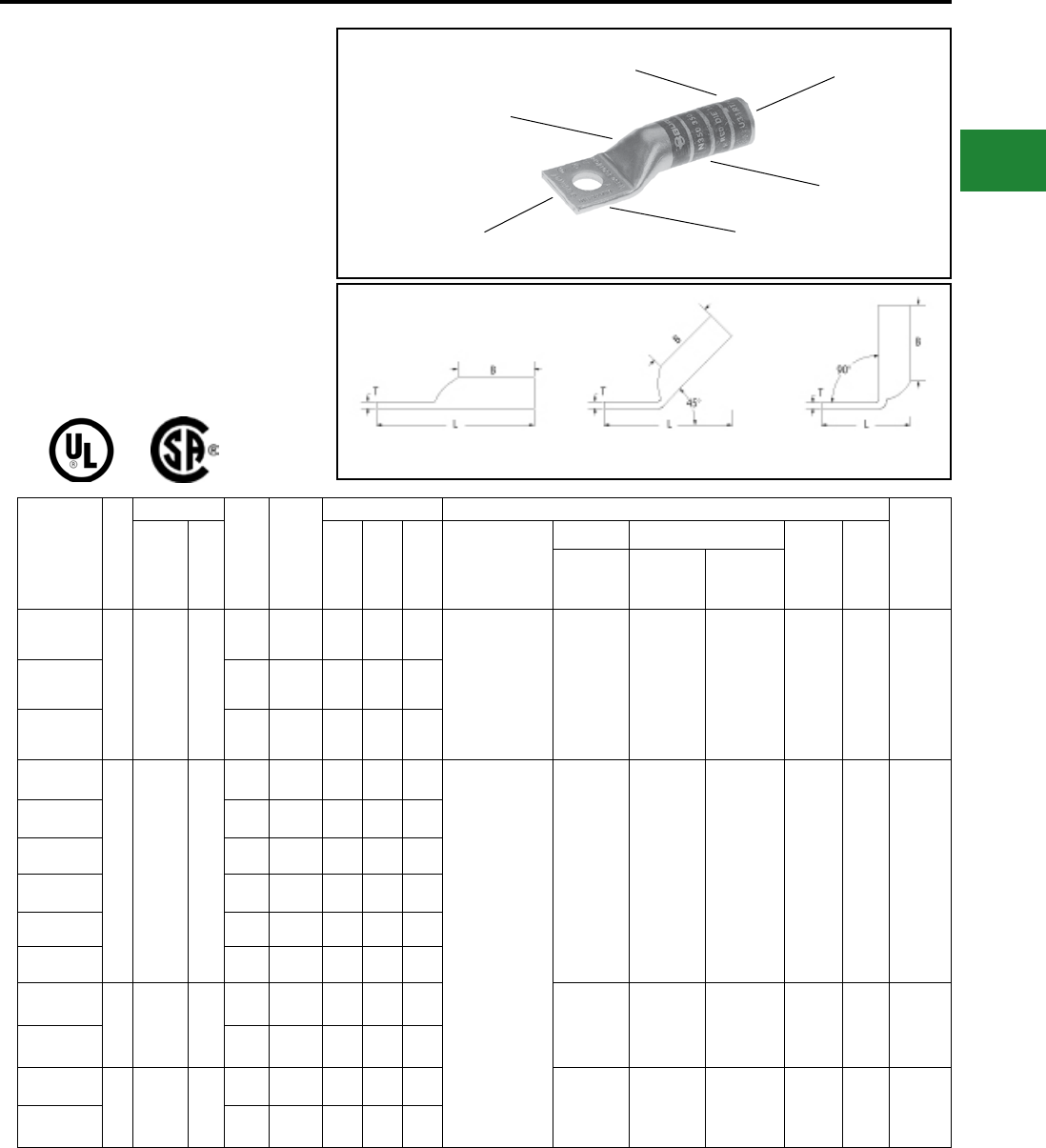
BURNDY®
Blue highlighted items are industry standard and most frequently ordered.
Canada: 1-800-387-6487 www.burndy.com US: 1-800-346-4175
Compression Connections
Copper Compression — Code — Long Barrel — No Inspection Window
ONE HOLE HYLUG™
CODE CONDUCTOR
LONG BARREL
TYPES YA, YA-TC
UNINSULATED COPPER
COMPRESSION TERMINAL
UL Listed 90° C,
600 Volts to 35kV ♦
45° and 90° angles are available.
Please contact Customer Service to
order: 1-800-346-4175
Fig. 1 45° 90°
DIE AND COLOR
CODE INFORMATION
CABLE
ACCOMMODATION
BEVELED
ENTRY
CRIMPS
NO INSPECTION
WINDOW
ELECTRO-TIN
PLATED
Catalog
Number
Fig
#
Conductor
Stud
Hole
Size
Tongue
Width
Figure Dimensions Installation Tooling
Wire
Strip
LengthAWG
***
MM² (B) (T) (L)
Dieless
(# of crimps)
Mechanical Hydraulic
Color
Code
Die
Index
MD6,
OUR840,
MD7-34R
BCT500HS,
Y500CTHS
Y35, Y39
Y750, Y46*
PAT750
YA8CTC10
1
#8 AWG
#8 Weld
37/24
#6 Sol
#8 Sol
†
10
#10 0.41"0.81"0.08"1.57"MRC840 (2)
MY29-3 (2)
MY29-11 (2)
Y8MBR-1 (1)
Y1MRTC (2)
Y81KFT (1)
Y81KFTMBH (1)
PAT81KFT-18V (1)
W8CVT (2)
W8CRT (2)
X8CRT (2)
W8CVT (2)
W8CRT (2)
X8CRT (2)
U8CRT (2) Red 49 7/8"
YA8CTC14 1/4"0.44"0.81"0.08"1.69"
YA8CTC38 3/8"0.58"0.81"0.06"1.88"
YA6CTC8
1
#6
AWG —
#8 0.42"
1.12"0.09"1.83"
Y1MRTC (2)
MRC840 (2)
MY29-3 (2)
MY29-11 (2)
Y644HSXT (1)
Y81KFT (1)
Y81KFTMBH (1)
PAT81KFT-18V (1)
W5CVT (2)
W5CRT (2)
X5CRT (2)
X8CART (2)
W5CVT (2)
W5CRT (2)
X5CRT (2)
X8CART (2)
U5CRT (2)
U8CABT (2) Blue 7 or
374 1-3/16"
YA6CTC10 #10 0.42"1.12"0.09"1.89"
YA6C 1/4"0.41"1.12"0.09″ 1.81"
YA6CN 1/2"0.83"1.12"0.12"2.64"
YA6CTC516 5/16"0.52"
1.12"0.07"2.08"
YA6CTC38 3/8"0.58"
1.12"0.06"2.21"
YA5C
1#5 AWG —
1/4"0.44"1.12"0.07"1.98"W5CVT (2)
W5CRT (2)
X5CRT (2)
W5CVT (2)
W5CRT (2)
X5CRT (2)
U5CRT (2) Blue 7 or
374 1-3/16"
YA5CN 1/2"0.83"1.12"0.12"2.67"
YA4CTC10
1#4 AWG —
#10 0.50"1.12"0.09"1.94"W4CVT (2)
W4CRT (2)
X4CRT (2)
W4CVT (2)
W4CRT (2)
X4CRT (2)
U4CRT (2)
U6CABT (2) Gray 8 or
346 1-3/16"
YA4C 1/4"0.50"1.12"0.09"1.87"
* Use PUADP-1 adapter with U dies in Y46 HYPRESS™
** P-RT die sets for use in Y46 HYPRESS™ only,
PUADP-1 adapter not required
*** The MM2 conductor sizes listed are the
recommendations for Class 2 conductor
† The MM2 conductor size listed is for Class 2 and
Class 5 conductor
▲ See tooling section of this catalog for complete
tool and die listings. Use ONLY color coded die
recommendations for -FX connectors. For
nest/indentor system contact factory
• Available undrilled. Add sufx U to catalog number
(example: YA25U)
♦ For applications greater than 2000 Volts consult cable
manufacturer for voltage stress relief instructions
Note: All dimensions shown are for reference only
C-27
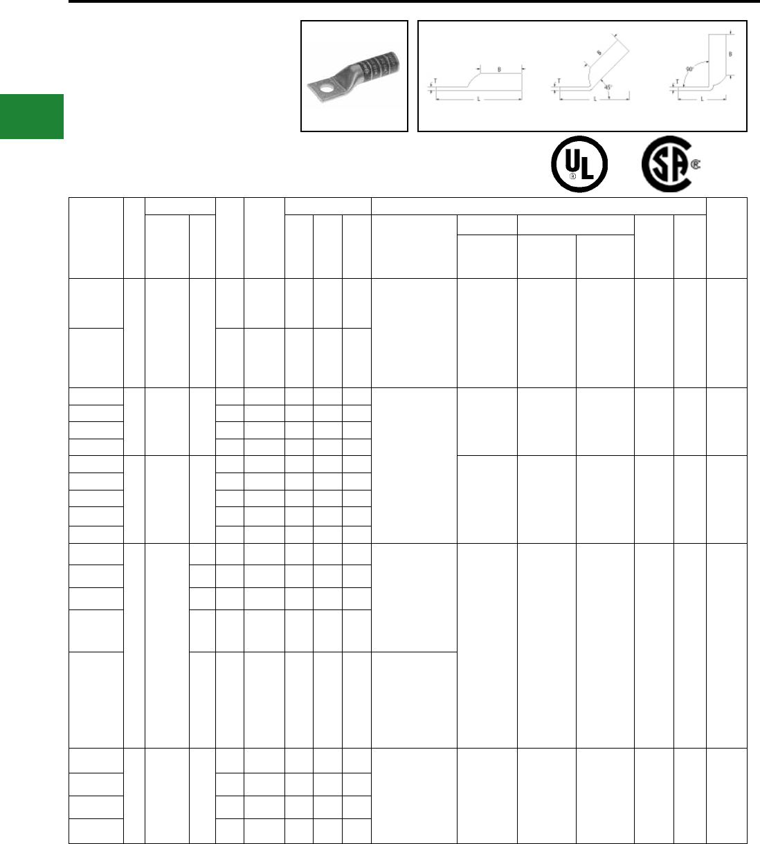
BURNDY®
Blue highlighted items are industry standard and most frequently ordered.
US: 1-800-346-4175 www.burndy.com Canada: 1-800-387-6487
ONE HOLE HYLUG™
CODE CONDUCTOR
LONG BARREL
(Continued)
UL Listed 90° C,
600 Volts to 35kV ♦
Fig. 1 45° 90°
Catalog
Number
Fig
#
Conductor
Stud
Hole
Size
Tongue
Width
Figure Dimensions Installation Tooling
Wire
Strip
LengthAWG
***
MM² (B) (T) (L)
Dieless
(# of crimps)
Mechanical Hydraulic
Color
Code
Die
Index
MD6,
OUR840,
MD7-34R
BCT500HS,
Y500CTHS
Y35, Y39
Y750, Y46*
PAT750
YA4CTC38
1 #4 AWG —
3/8″ 0.58″ 1.12″ 0.08″ 2.25″
MRC840 (2)
MY29-3 (2)
MY29-11 (2)
Y644HSXT (1)
Y1MRTC (4)
Y81KFT (1)
Y81KFTMBH (1)
PAT81KFT-18V (1)
W4CVT (2)
W4CRT (2)
X4CRT (2)
W4CVT (2)
W4CRT (2)
X4CRT (2)
U4CRT (2)
U6CABT (2) Gray
8
or
346
1-3/16″
YA4CN 1/2″ 0.83″ 1.12″ 0.12″ 2.69″
YA3CTC14
1#3 AWG
#2 Solid 25
1/4″ 0.55″ 1.25″ 0.09″ 2.23″
Y1MRTC (4)
MRC840 (2)
MY29-3 (2)
MY29-11 (2)
Y644HSXT (1)
Y81KFT (2)
Y81KFTMBH (2)
W3CRT (2) W3CRT (2) U3CRT (2) White 9 1-5/16″
YA3C 5/16″ 0.55″ 1.25″ 0.09″ 2.30″
YA3CTC38 3/8″ 0.58″ 1.25″ 0.08″ 2.42″
YA3CN 1/2″ 0.83″ 1.25″ 0.12″ 2.86″
YA2CTC10
1 #2 AWG 35
#10 0.60″ 1.25"0.11″ 2.10″
W2CVT (2)
W2CRT (2)
X2CRT (2)
W2CVT (2)
W2CRT (2)
X2CRT (2)
U2CRT (2) Brown 10 1-5/16″
YA2CTC14 1/4″ 0.60″ 1.25"0.11″ 2.23″
YA2C 5/16″ 0.60″ 1.25″ 0.11″ 2.29″
YA2CTC38 3/8" 0.60 1.25 0.11 2.41
YA2CN 1/2″ 0.83″ 1.25"0.12″ 2.88″
YA1CTC10
1 #1 AWG
50 #10 0.68″ 1.38″ 0.10″ 2.27″
PAT81KFT-18V (2)
Y1MR (4)
MRC840 (2)
MY29-3 (2)
MY29-11 (2)
Y644HSXT (1)
Y81KFT (2)
Y81KFTMBH (2)
W1CVT (2)
W1CRT-1 (2)
X1CRT-1 (2)
W1CVT (2)
W1CRT-1 (2)
X1CRT-1 (2)
U1CRT-1 (2)
U4CABT (2) Green 11 1-7/16″
YA1CTC14
—
1/4 0.68 1.38 0.10 2.39
YA1C 50 5/16″ 0.68″ 1.38″ 0.10″ 2.45″
YA1CTC38
—
3/8 0.68 1.38 0.10 2.58
YA1CN 1/2″ 0.83″ 1.38″ 0.12″ 3.06″
PAT81KFT-18V (2)
Y1MR (4)
MRC840 (2)
MY29-3 (2)
MY29-11 (2)
Y644HSXT (1)
Y81KFT (2)
YA25TC10
1 1/0 AWG —
#10 0.75″ 1.38″ 0.12″ 2.30″ MRC840 (4)
MY29-3 (2)
MY29-11 (2)
Y644HSXT (1)
Y81KFT (2)
Y81KFTMBH (2)
PAT81KFT-18V (2)
W25VT (4)
W25RT (4)
X25RT (4)
W25VT (4)
W25RT (4)
X25RT (4)
U25RT (2)
U2CABT (2) Pink 12 1-7/16″
YA25 5/16″ 0.75″ 1.38″ 0.13″ 2.48″
YA25TC38 3/8″ 0.75″ 1.38″ 0.12″ 2.61″
YA25N 1/2″ 0.83″ 1.38″ 0.11″ 3.05″
* Use PUADP-1 adapter with U dies in Y46 HYPRESS™
** P-RT die sets for use in Y46 HYPRESS™ only,
PUADP-1 adapter not required
*** The MM2 conductor sizes listed are the
recommendations for Class 2 conductor
▲ See tooling section of this catalog for complete
tool and die listings. Use ONLY color coded die
recommendations for -FX connectors. For
nest/indentor system contact factory
• Available undrilled. Add sufx U to catalog number
(example: YA25U)
♦ For applications greater than 2000 Volts consult cable
manufacturer for voltage stress relief instructions
Note: All dimensions shown are for reference only
Compression Connections
Copper Compression — Code — Long Barrel — No Inspection Window
45° and 90° angles are available. Please
contact Customer Service to order:
1-800-346-4175
C-28
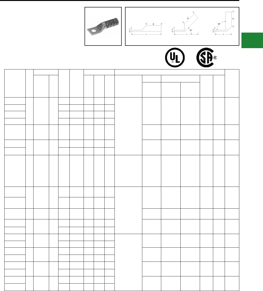
BURNDY®
Blue highlighted items are industry standard and most frequently ordered.
Canada: 1-800-387-6487 www.burndy.com US: 1-800-346-4175
Fig. 1 45° 90°
Catalog
Number
Fig
#
Conductor
Stud
Hole
Size
Tongue
Width
Figure Dimensions Installation Tooling
Wire
Strip
LengthAWG
***
MM² (B) (T) (L)
Dieless
(# of crimps)
Mechanical Hydraulic
Color
Code
Die
Index
MD6,
OUR840,
MD7-34R
BCT500HS,
Y500CTHS
Y35, Y39
Y750, Y46*
PAT750
YA26TC14
1 2/0 AWG 70
1/4"0.83 1.50 0.12 2.58
MRC840 (4)
MY29-3 (2)
MY29-11 (2)
Y644HSXT (1)
Y81KFT (2)
Y81KFTMBH (2)
PAT81KFT-18V (2)
W26VT (4)
W26RT (4)
X26RT (4)
W26VT (4)
W26RT (4)
X26RT (4)
U26RT (2) Black 13 1-9/16″
YA26TC516 5/16"0.83 1.50 0.12 2.65
YA26 3/8″ 0.83″ 1.50″ 0.12″ 2.77″
YA26N 1/2″ 0.83″ 1.50″ 0.12″ 3.21″
YA27 1 3/0 AWG — 1/2″ 0.91″ 1.50″ 0.13″ 3.06″
W27VT (4)
W27RT (4)
X27RT (6)
W27VT (4)
W27RT (4)
X27RT (6)
U27RT (2) Orange 14 1-9/16″
YA28TC38
1 4/0 AWG —
3/8″ 1.02″ 1.62″ 0.14″ 2.98″ W28VT (4)
W28RT (4)
X28RT (6)
W28VT (4)
W28RT (4)
X28RT (6)
U28RT (2) Purple 15 1-9/16″
YA28 1/2″ 1.02″ 1.62″ 0.14″ 3.23″
YA29 1 250 kcmil — 1/2″ 1.11″ 1.62″ 0.16″ 3.26″
MY29-3 (2)
MY29-11 (2)
Y644HSXT (1)
Y81KFT (2)
Y81KFTMBH (2)
PAT81KFT-18V (2)
W29VT (4)
X29RT (8)
W29VT (4)
W29RT (4)
X29RT (8)
U29RT (2) Yellow 16 1-11/16"
YA30
1 300 kcmil 150
1/2″ 1.20″ 2.00″ 0.16″ 3.69″
Y644HSXT (1)
Y81KFT (3)
Y81KFTMBH (3)
PAT81KFT-18V (3)
W30VT (4) W30VT (4)
W30RT (4)
U30RT (4)
U28ART (4) White 17 or
298 2-1/16″
YA30N 1/2 1.20 2.00
0.16″
3.88
YA31 1 350 kcmil 185 1/2″ 1.29″ 2.00″ 0.18″ 3.73″ W31VT (4) W31VT (4)
W31RT (4)
U31RT (4)
U29ART (4) Red 18 or
324 2-1/16″
YA32N 1 400 kcmil — 1/2″ 1.40″ 2.12″ 0.19″ 4.09″ W32VT (4) W32VT (4)
W32RT (4)
U32RT (4)
U30ART (4) Blue 19 or
470 2-3/16″
YA32 5/8″ 1.40″ 2.12″ 0.19″ 4.15″
YA33N 1 450 kcmil — 1/2″ 1.48″ 2.13″ 0.21″ 4.17″
Y644HSXT (1)
Y81KFT (4)
Y81KFTMBH (4)
PAT81KFT-18V (4)
W33VT (4) W33VT (4)
W33RT (4) U33RT (4) Gray 326 or
538 2-5/16″
YA33 5/8″ 1.48″ 2.13″ 0.21″ 4.24″
YA34N 1 500 kcmil 240 1/2″ 1.55″ 2.25″ 0.23″ 4.32″ W34VT (4) W34VT (4)
W34RT (4)
U34RT (4)
U31ART (2) Brown 20 or
299 2-5/16″
YA34 5/8″ 1.55″ 2.25″ 0.23″ 4.39″
YA35N 1 550 kcmil — 1/2″ 1.65″ 2.63″ 0.25″ 4.73″ — — U35RT (4) Yellow 21 2-11/16″
YA35 5/8″ 1.65″ 2.63″ 0.25″ 4.79″
YA36N 1 600 kcmil 300 1/2″ 1.74″ 2.69″ 0.27″ 4.83″ — — U36RT (4)
U32ART (4) Green 22 or
472 2-3/4″
YA36 5/8″ 1.74″ 2.69″ 0.27″ 4.90″
* Use PUADP-1 adapter with U dies in Y46 HYPRESS™
** P-RT die sets for use in Y46 HYPRESS™ only,
PUADP-1 adapter not required
*** The MM2 conductor sizes listed are the
recommendations for Class 2 conductor
▲ See tooling section of this catalog for complete
tool and die listings. Use ONLY color coded die
recommendations for -FX connectors. For
nest/indentor system contact factory
• Available undrilled. Add sufx U to catalog number
(example: YA25U)
♦ For applications greater than 2000 Volts consult cable
manufacturer for voltage stress relief instructions
Note: All dimensions shown are for reference only
ONE HOLE HYLUG™
CODE CONDUCTOR
LONG BARREL
(Continued)
UL Listed 90° C,
600 Volts to 35kV ♦
Compression Connections
Copper Compression — Code — Long Barrel — No Inspection Window
45° and 90° angles are available. Please
contact Customer Service to order:
1-800-346-4175
C-29
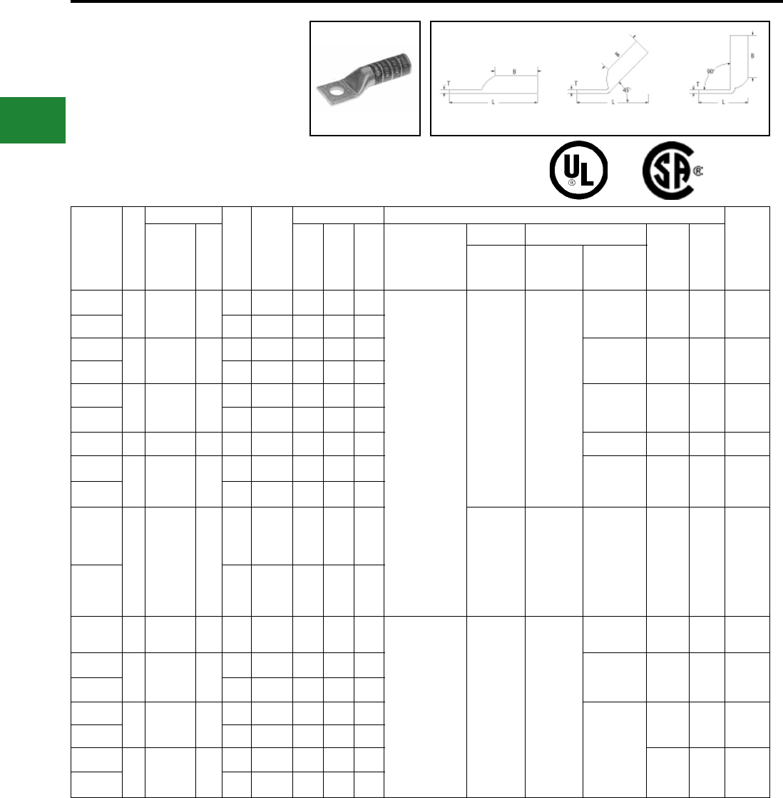
BURNDY®
Blue highlighted items are industry standard and most frequently ordered.
US: 1-800-346-4175 www.burndy.com Canada: 1-800-387-6487
Compression Connections
Copper Compression — Code — Long Barrel — No Inspection Window
Fig. 1 45° 90°
ONE HOLE HYLUG™
CODE CONDUCTOR
LONG BARREL
(Continued)
UL Listed 90° C,
600 Volts to 35kV ♦45° and 90° angles are available.
Please contact Customer Service to order:
1-800-346-4175
Catalog
Number
Fig
#
Conductor
Stud
Hole
Size
Tongue
Width
Figure Dimensions Installation Tooling
Wire
Strip
LengthAWG
***
MM² (B) (T) (L)
Dieless
(# of crimps)
Mechanical Hydraulic
Color
Code
Die
Index
MD6,
OUR840,
MD7-34R
BCT500HS,
Y500CTHS
Y35, Y39
Y750, Y46*
PAT750
YA37N
1 650 kcmil —
1/2″ 1.80″ 2.81″ 0.27″ 4.98″
Y644HSXT (1)
Y81KFT (4)
Y81KFTMBH (4)
PAT81KFT-18V (4)
— —
U37RT (4) Orange 23 2-7/8″
YA37 5/8″ 1.80″ 2.81″ 0.27″ 5.05″
YA38N
1 700 kcmil —
1/2″ 1.84″ 2.81″ 0.27″ 5.01″
U38RT (4) Pink 400 2-7/8″
YA38 5/8″ 1.84″ 2.81″ 0.27″ 5.07″
YA39N
1 750 kcmil —
1/2″ 1.91″ 2.88″ 0.27″ 5.11″ U39RT (4)
P39RT (4)** Black 24 2-15/16″
YA39 5/8″ 1.91″ 2.88″ 0.27″ 5.17″
YA40 1 800 kcmil 400 5/8″ 1.98″ 2.94″ 0.30″ 5.25″ P40RT (4)** Orange 25 3″
YA41N
1 850 kcmil —
1/2″ 2.01″ 2.94″ 0.31″ 5.20″
— Gold 26 3″
YA41 5/8″ 2.01″ 2.94″ 0.31″ 5.26″
YA44N
1 1000 kcmil 500
1/2″ 2.19″ 3.00″ 0.33″ 5.38″
— — P44RT (4)** White 27 3-1/16″
YA44 5/8″ 2.19″ 3.00″ 0.33″ 5.45″
YA45 1 1250 kcmil — 3/4″ 2.46″ 3.19″ 0.38″ 5.93″
─ — —
P45RT (6)** Yellow 29 3-1/4″
YA46N
1 1500 kcmil —
1/2″ 2.69″ 3.19″ 0.40″ 5.79″
P46RT (6)** Green 31 3-5/16″
YA46 3/4″ 2.69″ 3.19″ 0.40″ 6.04″
YA47N
1 1750 kcmil —
1/2″ 2.90″ 3.44″ 0.42″ 6.13″
—
Gray 33 3-1/2″
YA47 3/4″ 2.90″ 3.44″ 0.42″ 6.38″
YA48N
1 2000 kcmil —
1/2″ 3.10″ 3.44″ 0.46″ 6.22″
Brown 34 3-1/2″
YA48 3/4″ 3.10″ 3.44″ 0.46″ 6.47″
* Use PUADP-1 adapter with U dies in Y46 HYPRESS™
** P-RT die sets for use in Y46 HYPRESS™ only,
PUADP-1 adapter not required
*** The MM2 conductor sizes listed are the
recommendations for Class 2 conductor
▲ See tooling section of this catalog for complete
tool and die listings. Use ONLY color coded die
recommendations for -FX connectors. For
nest/indentor system contact factory
• Available undrilled. Add sufx U to catalog number
(example: YA25U)
♦ For applications greater than 2000 Volts consult cable
manufacturer for voltage stress relief instructions
Note: All dimensions shown are for reference only
C-30
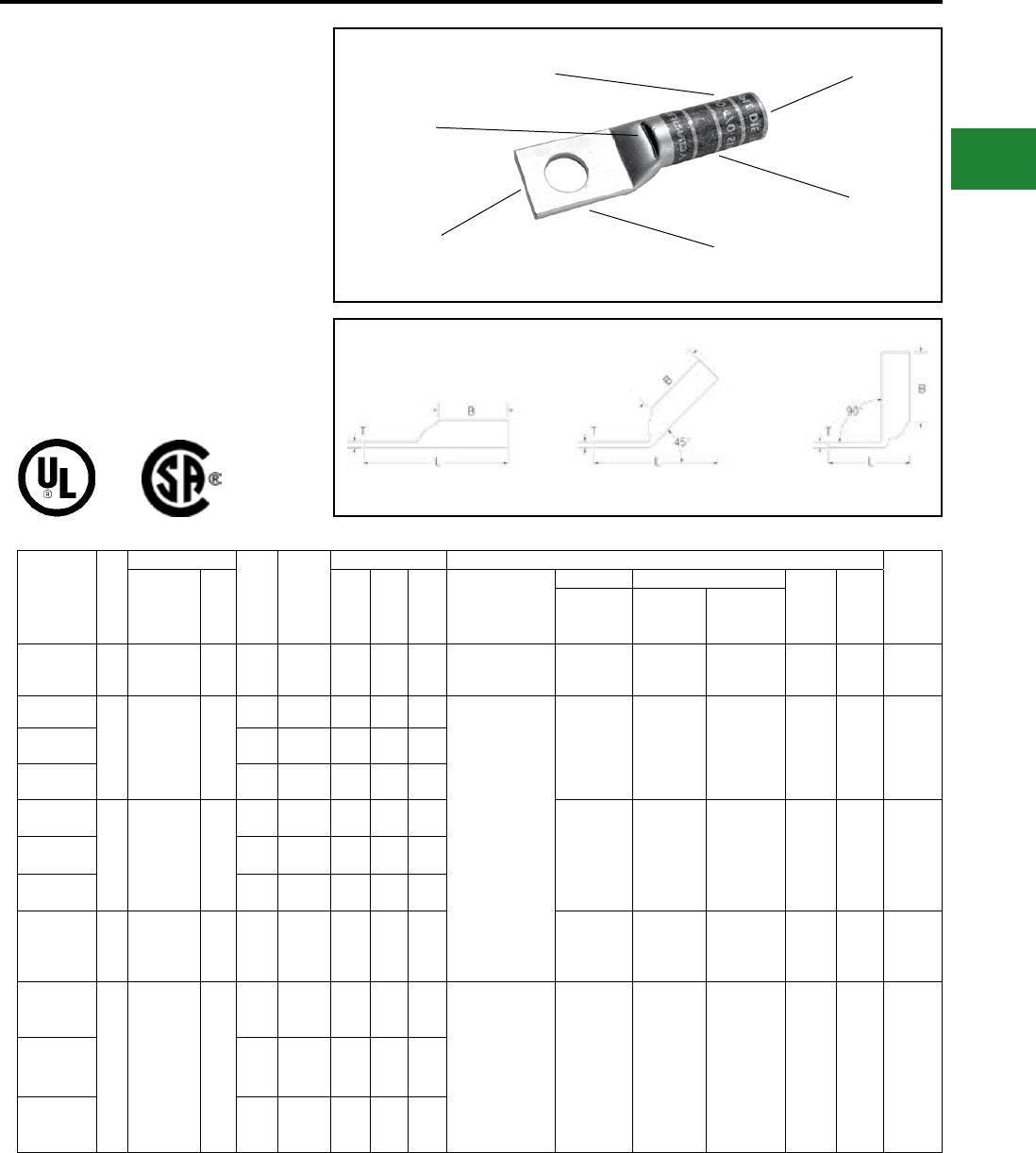
BURNDY®
Blue highlighted items are industry standard and most frequently ordered.
Canada: 1-800-387-6487 www.burndy.com US: 1-800-346-4175
ONE HOLE HYLUG™
CODE CONDUCTOR
LONG BARREL WITH
INSPECTION WINDOW
TYPE YAZ
UNINSULATED COPPER
COMPRESSION TERMINAL
UL Listed 90° C,
600 Volts to 35 kV ♦
45° and 90° angles are available.
Please contact Customer Service to order:
1-800-346-4175
DIE AND COLOR
CODE INFORMATION
ELECTRO-TIN
PLATED
BEVELED
ENTRY
CRIMP
CABLE
ACCOMMODATION
INSPECTION
WINDOW
Fig. 1 45° 90°
Catalog
Number
Fig
#
Conductor
Stud
Hole
Size
Tongue
Width
Figure Dimensions ▲Installation Tooling
Wire
Strip
LengthAWG
***
MM² (B) (T) (L)
Dieless
(# of crimps)
Mechanical Hydraulic
Color
Code
Die
Index
MD6,
OUR840,
MD7-34R
BCT500HS,
Y500CTHS
Y35, Y39
Y750,Y46*
PAT750
YAZV10TC14 1#14-10 Str
#12- 10 Sol 6 1/4″ 0.41″ 0.69″ 0.05″ 1.52″ Y8MRB-1 (2) — — — — — 3/4″
YAZ8CTC10
1
#8 AWG
#8 Weld
37/24
#6 Sol
#8 Sol
†
10
#10 0.41″ 0.75″ 0.08″ 1.43″
Y1MRTC (2)
MY29-3 (2)
MY29-11 (2)
MRC840 (2)
Y644HSXT (1)
Y81KFT (1)
Y81KFTMBH (1)
PAT81KFT-18V (1)
W8CVT (2)
W8CRT (2)
X8CRT (2)
W8CVT (2)
W8CRT (2)
X8CRT (2)
U8CRT (2) Red 49 13/16″
YAZ8CTC14 1/4″ 0.44″ 0.75″ 0.08″ 1.56″
YAZ8CTC38 3/8″ 0.58″ 0.75″ 0.06″ 1.75″
YAZ6CTC14
1 #6 AWG —
1/4″ 0.45″ 1.12″ 0.08″ 2.02″ W5CVT (2)
W5CRT (2)
X5CRT (2)
X8CART (2)
W5CVT (2)
W5CRT (2)
X5CRT (2)
X8CART (2)
U5CRT (2)
U8CABT (2) Blue
7
or
374
1-3/16″
YAZ6CTC38 3/8″ 0.58″ 1.12″ 0.06″ 2.21″
YAZ6CTC12 1/2″ 0.75″ 1.12″ 0.12″ 2.46″
YAZ5CTC12 1 #5 AWG — 1/2″ 0.83″ 1.12″ 0.12″ 2.48″
W5CRT (2)
W5CRT (2)
X5CRT (2)
W5CVT (2)
X5CRT (2)
W5CRT (2)
U5CRT (2) Blue
7
or
374
1-3/16″
YAZ4CTC14
1 #4 AWG —
1/4″ 0.50″ 1.12″ 0.09″ 2.04″ Y1MRTC (4)
MY29-3 (2)
MY29-11 (2)
MRC840 (2)
Y644HSXT (1)
Y81KFT (1)
Y81KFTMBH (1)
PAT81KFT-18V (1)
W4CVT (2)
W4CRT (2)
X4CRT (2)
W4CVT (2)
W4CRT (2)
X4CRT (2)
U4CRT (2)
U6CABT (2) Gray
8
or
346
1-3/16″
YAZ4CTC38 3/8″ 0.58″ 1.12″ 0.08″ 2.22″
YAZ4CTC12 1/2″ 0.73″ 1.12″ 0.06″ 2.50″
* Use PUADP-1 adapter with U dies in Y46 HYPRESS™
** P-RT die sets for use in Y46 HYPRESS™ only,
PUADP-1 adapter not required
*** The MM2 conductor sizes listed are the
recommendations for Class 2 conductor
† The MM2 conductor size listed is for Class 2 and
Class 5 conductor
▲ See tooling section of this catalog for complete tool
and die listings
• Available undrilled. Add suffix U to catalog number
(example: YA25U)
♦ For applications greater than 2000 Volts consult cable
manufacturer for voltage stress relief instructions
Note: All dimensions shown are for reference only
Compression Connections
Copper Compression — Code — Long Barrel — Inspection Window
C-31
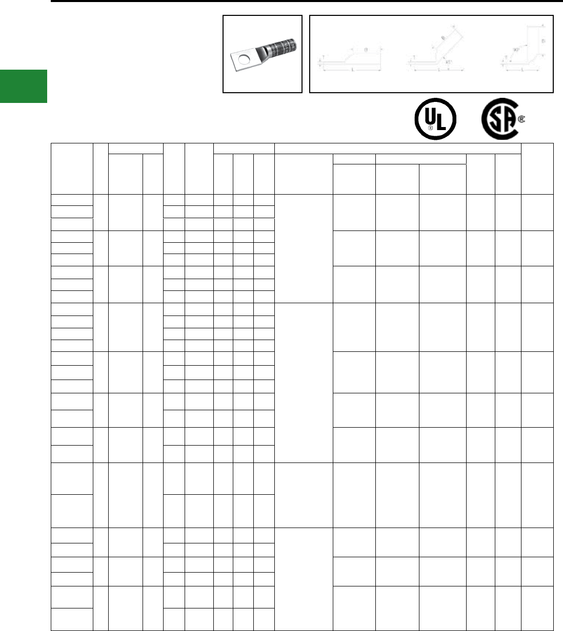
BURNDY®
Blue highlighted items are industry standard and most frequently ordered.
US: 1-800-346-4175 www.burndy.com Canada: 1-800-387-6487
ONE HOLE HYLUG™
CODE CONDUCTOR
LONG BARREL WITH
INSPECTION WINDOW
(Continued)
UL Listed 90° C,
600 Volts to 35 kV ♦
Fig. 1 45° 90°
45° and 90° angles are available.
Please contact Customer Service to order:
1-800-346-4175
Catalog
Number
Fig
#
Conductor
Stud
Hole
Size
Tongue
Width
Figure Dimensions ▲Installation Tooling
Wire
Strip
LengthAWG
***
MM² (B) (T) (L)
Dieless
(# of crimps)
Mechanical Hydraulic
Color
Code
Die
Index
MD6,
OUR840,
MD7-34R
BCT500HS,
Y500CTHS
Y35, Y39
Y750, Y46*
PAT750
YAZ3CTC14
1#3 AWG
#2 Sol 25
1/4″ 0.55″ 1.25″ 0.09″ 2.19″
Y1MRTC (4)
MY29-3 (2)
MY29-11 (2)
MRC840 (2)
Y644HSXT (1)
Y81KFT (2)
Y81KFTMBH (2)
PAT81KFT-18V (2)
W3CRT (2) W3CRT (2) U3CRT (2) White 9 1-5/16″
YAZ3CTC38 3/8″ 0.58″ 1.25″ 0.08″ 2.38″
YAZ3CTC12 1/2″ 0.71″ 1.25″ 0.07″ 2.63″
YAZ2CTC14
1 #2 AWG 35
1/4″ 0.60″ 1.25″ 0.11″ 2.21″ W2CVT (2)
W2CRT (2)
X2CRT (2)
W2CVT (2)
W2CRT (2)
X2CRT (2)
U2CRT (2) Brown 10 1-5/16″
YAZ2CTC38 3/8″ 0.60″ 1.25″ 0.11″ 2.40″
YAZ2CTC12 1/2″ 0.73″ 1.25″ 0.09″ 2.65″
YAZ1CTC14
1 #1 AWG 50
1/4″ 0.68″ 1.38″ 0.10″ 2.37″ W1CVT (2)
W1CRT-1 (2)
X1CRT-1 (2)
W1CVT (2)
W1CRT-1 (2)
X1CRT-1 (2)
U1CRT-1 (2)
U4CABT (2) Green 11 or
375 1-7/16″
YAZ1CTC38 3/8″ 0.68″ 1.38″ 0.10″ 2.56″
YAZ1CTC12 1/2″ 0.73″ 1.38″ 0.09″ 2.81″
YAZ25TC14
1 1/0 AWG —
1/4″ 0.75″ 1.38″ 0.12″ 2.40″
MY29-3 (2)
MY29-11 (2)
MRC840 (4)
Y644HSXT (1)
Y81KFT (2)
Y81KFTMBH (2)
PAT81KFT-18V (2)
W25VT (4)
W25RT (4)
X25RT (4)
W25VT (4)
W25RT (4)
X25RT (4)
U25RT (2)
U2CABT (2) Pink 12 or
348 1-7/16″
YAZ25TC516 5/16″ 0.75″ 1.38″ 0.12″ 2.46″
YAZ25TC38 3/8″ 0.75″ 1.38″ 0.12″ 2.59″
YAZ25TC12 1/2″ 0.75″ 1.38″ 0.12″ 2.84″
YAZ26TC14
1 2/0 AWG 70
1/4″ 0.83″ 1.50″ 0.12″ 2.56″ W26VT (4)
W26RT (4)
X26RT (4)
W26VT (4)
W26RT (4)
X26RT (4)
U26RT (2) Black 13 1-9/16″
YAZ26TC38 3/8″ 0.83″ 1.50″ 0.12″ 2.75″
YAZ26TC12 1/2″ 0.83″ 1.50″ 0.12″ 3.00″
YAZ27TC38
1 3/0 AWG —
3/8″ 0.90″ 1.50″ 0.12″ 2.79″ W27VT (4)
W27RT (4)
X27RT (6)
W27VT (4)
W27RT (4)
X27RT (6)
U27RT (2) Orange 14 1-9/16″
YAZ27TC12 1/2″ 0.90″ 1.50″ 0.12″ 3.04″
YAZ28TC38
1 4/0 AWG —
3/8″ 1.02″ 1.62″ 0.14″ 2.95″ W28VT (4)
W28RT (4)
X28RT (6)
W28VT (4)
W28RT (4)
X28RT (6)
U28RT (2) Purple 15 1-11/16″
YAZ28TC12 1/2″ 1.02″ 1.62″ 0.14″ 3.20″
YAZ29TC38
1 250 kcmil —
3/8″ 1.10″ 1.62″ 0.16″ 2.98″ MY29-3 (2)
MY29-11 (2)
Y644HSXT (1)
Y81KFT (2)
Y81KFTMBH (2)
PAT81KFT-18V (2)
W29VT (4)
X29RT (8)
W29VT (4)
W29RT (4)
X29RT (6)
U29RT (2) Yellow 16 1-11/16″
YAZ29TC12 1/2″ 1.10″ 1.62″ 0.16″ 3.23″
YAZ30TC38 1 300 kcmil 150 3/8″ 1.20″ 2.00″ 0.16″ 3.41″
Y644HSXT (1)
Y81KFT (3)
Y81KFTMBH (3)
PAT81KFT-18V (3)
W30VT (4) W30VT (4)
W30RT (4)
U30RT
U28ART (4) White 17 or
298 2-1/16″
YAZ30TC12 1/2″ 1.20″ 2.00″ 0.16″ 3.66″
YAZ31TC38 1 350 kcmil 185 3/8″ 1.29″ 2.00″ 0.18″ 3.44″ W31VT (4) W31VT (4)
W31RT (4)
U31RT
U29ART (4) Red 18 or
324 2-1/16″
YAZ31TC12 1/2″ 1.29″ 2.00″ 0.18″ 3.69″
YAZ32TC38
1 400 kcmil —
3/8″ 1.40″ 2.12″ 0.19″ 3.61″
W32VT (4) W32VT (4)
W32RT (4)
U32RT
U30ART (4) Blue 19 or
470 2-3/16″
YAZ32TC12 1/2″ 1.40″ 2.12″ 0.19″ 3.86″
* Use PUADP-1 adapter with U dies in Y46 HYPRESS™
** P-RT die sets for use in Y46 HYPRESS™ only,
PUADP-1 adapter not required
*** The MM2 conductor sizes listed are the
recommendations for Class 2 conductor
▲ See tooling section of this catalog for complete tool
and die listings
• Available undrilled. Add suffix U to catalog number
(example: YA25U)
♦ For applications greater than 2000 Volts consult cable
manufacturer for voltage stress relief instructions
Note: All dimensions shown are for reference only
Compression Connections
Copper Compression — Code — Long Barrel — Inspection Window
C-32
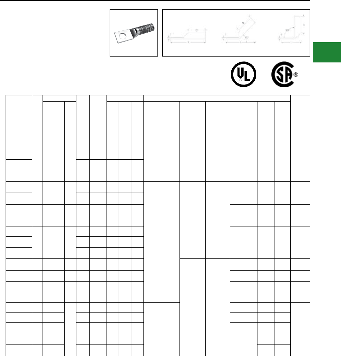
BURNDY®
Blue highlighted items are industry standard and most frequently ordered.
Canada: 1-800-387-6487 www.burndy.com US: 1-800-346-4175
Catalog
Number
Fig
#
Conductor
Stud
Hole
Size
Tongue
Width
Figure Dimensions ▲Installation Tooling
Wire
Strip
LengthAWG
***
MM² (B) (T) (L)
Dieless
(# of crimps)
Mechanical Hydraulic
Color
Code
Die
Index
MD6,
OUR840,
MD7-34R
BCT500HS,
Y500CTHS
Y35, Y39
Y750, Y46*
PAT750
YAZ33TC12 1 450 kcmil — 1/2″ 1.48″ 2.12″ 0.21″ 3.95″
Y644HSXT (1)
Y81KFT (4)
Y81KFTMBH (4)
PAT81KFT-18V (4)
W33VT (4) W33VT (4)
W33RT (4) W33RT (4) Gray
326
or
538
2-5/16″
YAZ34TC38
1 500 kcmil 240
3/8″ 1.55″ 2.25″ 0.23″ 3.84″
W34VT (4) W34VT (4)
W34RT (4)
U34RT (4)
U31ART (2) Brown
20
or
299
2-5/16″
YAZ34TC12 1/2″ 1.55″ 2.25″ 0.23″ 4.10″
YAZ35TC12 1 550 kcmil — 1/2″ 1.65″ 2.62″ 0.25″ 4.50″ — — U35RT (4) Yellow 21 2-11/16″
YAZ36TC38
1 600 kcmil 300
3/8″ 1.74″ 2.69″ 0.26″ 4.54″
Y644HSXT (1)
Y81KFT (4)
Y81KFTMBH (4)
PAT81KFT-18V (4)
— —
U36RT (4)
U32ART (4) Green
22
or
472
2-3/4″
YAZ36TC12 1/2″ 1.74″ 2.69″ 0.26″ 4.60″
YAZ37TC12 1 650 kcmil — 1/2″ 1.80″ 2.81″ 0.27″ 4.75″ U37RT (4) Orange 23 2-7/8″
YAZ38TC12 1 700 kcmil — 1/2″ 1.84″ 2.81″ 0.27″ 4.77″ U38RT (4) Pink 400 2-7/8″
YAZ39TC38
1 750 kcmil —
3/8″ 1.91″ 2.88″ 0.27″ 4.81″
U39RT (4)
P39RT (4)** Black 24 2-15/16″
YAZ39NT12 1/2″ 1.63″ 2.88″ 0.27″ 4.87″
YAZ39TC12 1/2″ 1.91″ 2.88″ 0.27″ 4.87″
YAZ40TC12 1 800 kcmil 400 1/2″ 1.98″ 2.94″ 0.30″ 4.94″
— —
P40RT (4)** Orange 25 3″
YAZ41TC12 1 850 kcmil — 1/2″ 2.01″ 2.94″ 0.31″ 4.96″ — Gold 26 3″
YAZ44TC38
1 1000 kcmil 500
3/8″ 2.19″ 3.00″ 0.33″ 5.08″
P44RT (4)** White 27 3-1/16″
YAZ44TC12 1/2″ 2.19″ 3.00″ 0.33″ 5.14″
YAZ45TC12 1 1250 kcmil
—
1/2″ 2.46″ 3.19″ 0.38″ 5.43″
—
P45RT (6)** Yellow 29
3-1/4″
YAZ453TC12 1 1300 kcmil 1/2″ 2.53″ 3.19″ 0.39″ 5.46″ — Orange 30
YAZ46TC12 1 1500 kcmil 1/2″ 2.69″ 3.19″ 0.40″ 5.53″ P46RT (6)** Green 31
YAZ47TC12 1 1750 kcmil 1/2″ 2.90″ 3.44″ 0.42″ 5.87″
—
Gray 33
3-1/2″
YAZ48TC12 1 2000 kcmil 1/2″ 3.10″ 3.44″ 0.46″ 5.95″ Brown 34
* Use PUADP-1 adapter with U dies in Y46 HYPRESS™
** P-RT die sets for use in Y46 HYPRESS™ only,
PUADP-1 adapter not required
*** The MM2 conductor sizes listed are the
recommendations for Class 2 conductor
▲ See tooling section of this catalog for complete tool
and die listings
• Available undrilled. Add suffix U to catalog number
(example: YA25U)
♦ For applications greater than 2000 Volts consult cable
manufacturer for voltage stress relief instructions
Note: All dimensions shown are for reference only
ONE HOLE HYLUG™
CODE CONDUCTOR
LONG BARREL WITH
INSPECTION WINDOW
(Continued)
UL Listed 90° C,
600 Volts to 35 kV ♦
45° and 90° angles are available.
Please contact Customer Service to order:
1-800-346-4175
Compression Connections
Copper Compression — Code — Long Barrel — Inspection Window
Fig. 1 45° 90° C-33
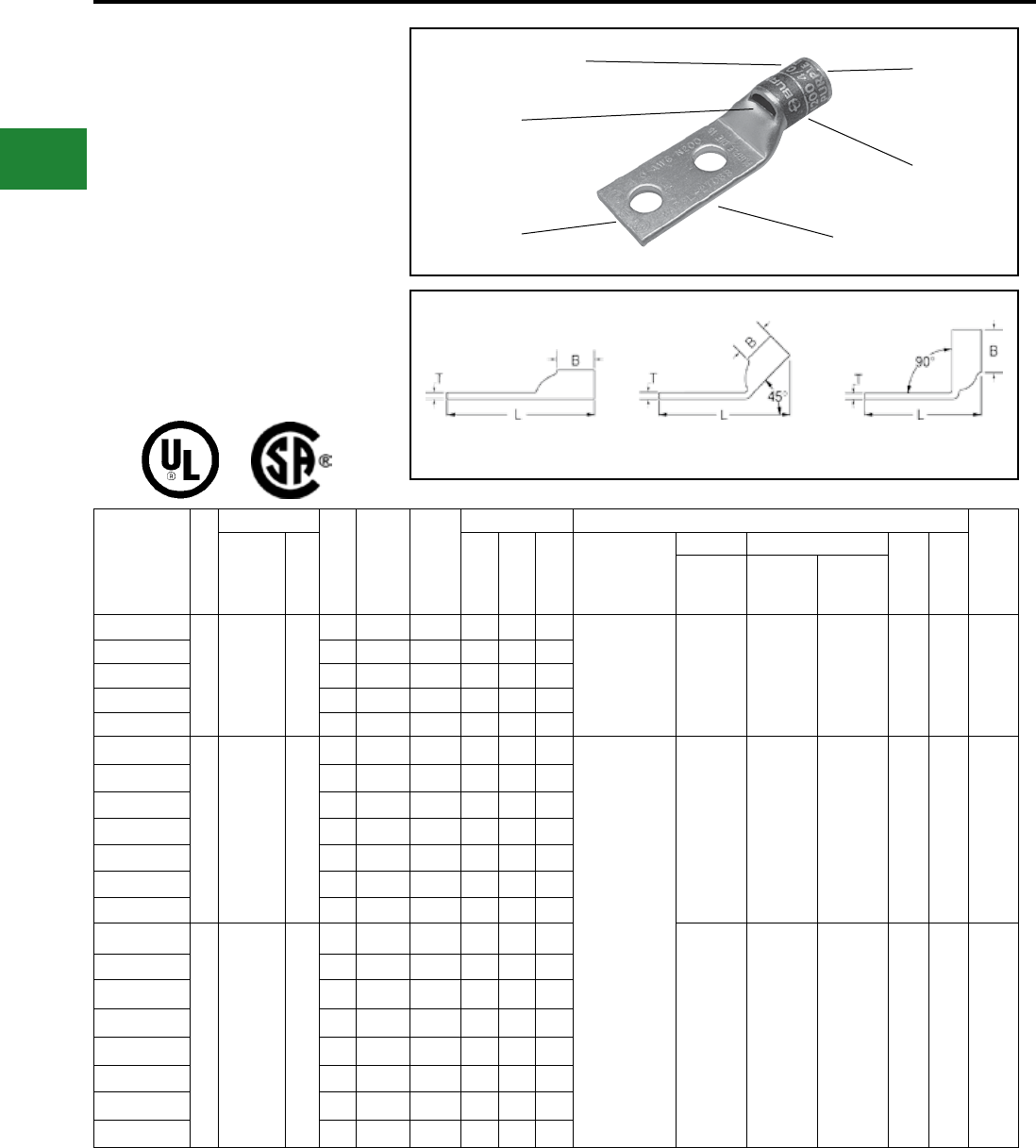
BURNDY®
Blue highlighted items are industry standard and most frequently ordered.
US: 1-800-346-4175 www.burndy.com Canada: 1-800-387-6487
TWO HOLE HYLUG™ CODE
CONDUCTOR STANDARD
BARREL
TYPES YAV-2TC, YA-L2L,
YA-2LN, AND YA-L-2TC
COPPER COMPRESSION
TERMINAL
UL Listed 90° C,
600 Volts to 35 kV ♦
45° and 90° angles are available.
Please contact Customer Service to order.
1-800-346-4175
Catalog
Number
Fig
#
Conductor
Stud
Hole
Size
Stud
Hole
Spacing
Tongue
Width
Figure Dimensions ▲Installation Tooling
Wire
Strip
LengthAWG
***
MM² (B) (T) (L)
Dieless
(# of crimps)
Mechanical Hydraulic
Color
Code
Die
Index
MD6,
OUR840,
MD7-34R
BCT500HS,
Y500CTHS
Y35, Y39,
Y750, Y46*
PAT750
YAV10-2TC10
1
#14-10 Str.
#12-10
Sol.
6
#10 5/8″ 0.36″ 0.38″ 0.06″ 1.72″
Y8MRB-1 (1) — — — — — 7/16″
YAV10-2TC14 1/4″ 5/8″ 0.41″ 0.38″ 0.05″ 1.84″
YAV10-2TC14E2 1/4″ 3/4″ 0.41″ 0.38″ 0.05″ 1.97″
YAV10-2TC14E1 1/4″ 1″ 0.41″ 0.38″ 0.05″ 2.22″
YAV10-2TC38 3/8″ 1″ 0.56″ 0.38″ 0.04″ 2.40″
YA8C-L2TC10
1
#8 AWG
#8 Weld
37/24
#6 Sol.
#8 Sol.
†
10
#10 5/8″ 0.41″ 0.44″ 0.08″ 1.83″
Y1MRTC (1)
Y8MRB-1 (1)
MY29-3 (1)
MY29-11 (1)
MRC840 (1)
Y81KFT (1)
Y81KFTMBH (1)
PAT81KFT-18V (1)
W8CVT (1)
W8CRT (1)
X8CRT (1)
W8CVT (1)
W8CRT (1)
X8CRT (1)
U8CRT (1) Red 49 1/2″
YA8CL-2TC10E2 #10 3/4″ 0.41″ 0.44″ 0.08″ 1.95″
YA8C-L2TC14 1/4″ 5/8″ 0.44″ 0.44″ 0.08″ 1.95″
YA8C-L2TC14E2 1/4″ 3/4″ 0.44″ 0.44″ 0.08″ 2.08″
YA8C-L2TC14E1 1/4″ 1″ 0.44″ 0.44″ 0.08″ 2.33″
YA8C-L2TC38 3/8″ 1″ 0.58″ 0.44″ 0.06″ 2.52″
YA8C-2LN 1/2″ 1-3/4″ 0.83″ 0.44″ 0.12″ 3.75″
YA6C-2L51
1 #6 AWG —
#10 1/2″ 0.42″ 0.54″ 0.09″ 1.79″
W5CVT (1)
W5CRT (1)
X5CRT (1)
X8CART (1)
W5CVT (1)
W5CRT (1)
X5CRT (1)
X8CART (1)
U5CRT (1)
U8CABT (1) Blue
7
or
374
5/8″
YA6CL-2TC10 #10 5/8″ 0.42″ 0.54″ 0.09″ 1.94″
YA6C-2L52 1/4″ 1/2″ 0.45″ 0.54″ 0.08″ 1.88″
YA6CL-2TC14E 1/4″ 1/2″ 0.45″ 0.54″ 0.08″ 1.94″
YA6C-2L 1/4″ 5/8″ 0.45″ 0.54″ 0.08″ 2.01″
YA6CL-2TC14 1/4″ 5/8″ 0.45″ 0.54″ 0.08″ 2.07″
YA6CL-2TC14E2 1/4″ 3/4″ 0.45″ 0.54″ 0.08″ 2.19″
YA6CL-2TC14E1 1/4″ 1″ 0.45″ 0.54″ 0.08″ 2.44″
DIE AND COLOR
CODE INFORMATION
CABLE
ACCOMMODATION
INSPECTION
WINDOW
ELECTRO-TIN
PLATED
BEVELED
ENTRY
CRIMP
Fig. 1 45° 90°
-- Color code not assigned
* Use PUADP-1 adapter with U dies in Y46 HYPRESS™
** P-RT die sets for use in Y46 HYPRESS™ only,
PUADP-1 adapter not required
*** The MM2 conductor sizes listed are the
recommendations for Class 2 conductor
† The MM2 conductor size referenced here is for both
Class 2 and Class 5
▲ See tooling section of this catalog for complete tool
and die listings
♦ For applications greater than 2000 volts consult cable
manufacturer for voltage stress relief instructions
Note: All dimensions shown are for reference only
Compression Connections
Copper Compression — Code — Inspection Window
C-34
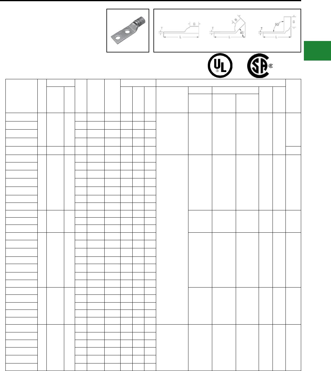
BURNDY®
Blue highlighted items are industry standard and most frequently ordered.
Canada: 1-800-387-6487 www.burndy.com US: 1-800-346-4175
TWO HOLE HYLUG™ CODE
CONDUCTOR STANDARD
BARREL
(Continued)
UL Listed 90° C,
600 Volts to 35 kV ♦
45° and 90° angles are available.
Please contact Customer Service to order.
1-800-346-4175
Catalog
Number
Fig
#
Conductor
Stud
Hole
Size
Stud
Hole
Spacing
Tongue
Width
Figure Dimensions ▲Installation Tooling
Wire
Strip
LengthAWG
***
MM² (B) (T) (L)
Dieless
(# of crimps)
Mechanical Hydraulic
Color
Code
Die
Index
MD6,
OUR840,
MD7-34R
BCT500HS,
Y500CTHS
Y35, Y39,
Y750, Y46*
PAT750
YA6CL-2TC516E2
1 #6 AWG —
5/16″ 3/4″ 0.52″ 0.54″ 0.07″ 2.53″ Y1MRTC (1)
MY29-3 (1)
MY29-11 (1)
MRC840 (1)
Y81KFT (1)
Y81KFTMBH (1)
PAT81KFT-18V (1)
W5CVT (1)
W5CRT (1)
X5CRT (1)
X8CART (1)
W5CVT (1)
W5CRT (1)
X5CRT (1)
X8CART (1)
U5CRT (1)
U8CABT (1) Blue
7
or
374
5/8″
YA6CL-2TC516 5/16″ 1″ 0.52″ 0.54″ 0.07″ 2.78″
YA6CL-2TC38 3/8″ 1″ 0.58″ 0.54″ 0.06″ 2.63″
YA6C-2LN 1/2″ 1-3/4″ 0.83″ 0.54″ 0.12″ 4.10″
YA5C-2L 1 #5 AWG — 1/4″ 5/8″ 0.44″ 0.81″ 0.07″ 2.28″ 7/8″
YA4C-2L
1 #4 AWG —
1/4″ 5/8″ 0.50″ 0.81″ 0.09″ 2.30″
Y1MRTC (2)
MY29-3 (1)
MY29-11 (1)
MRC840 (1)
Y644HSXT (1)
Y81KFT (1)
Y81KFTMBH (1)
PAT81KFT-18V (1)
W4CVT (1)
W4CRT (1)
X4CRT (1)
W4CVT (1)
W4CRT (1)
X4CRT (1)
U4CRT (1)
U6CABT (1) Gray
8
or
346
7/8″
YA4CL-2TC14 1/4″ 5/8″ 0.50″ 0.81″ 0.09″ 2.36″
YA4CL-2TC14E2 1/4″ 3/4″ 0.50″ 0.81″ 0.09″ 2.49″
YA4CL-2TC14E1 1/4″ 1″ 0.50″ 0.81″ 0.09″ 2.74″
YA4CL-2TC516 5/16″ 1″ 0.52″ 0.81″ 0.09″ 2.80″
YA4CL-2TC38 3/8″ 1″ 0.58″ 0.81″ 0.08″ 2.96″
YA4C-2LN 1/2″ 1-3/4″ 0.83″ 0.81″ 0.12″ 4.14″
YA3CL-2TC14
1#3 AWG
#2 Sol. 25
1/4″ 5/8″ 0.55″ 0.88″ 0.09″ 2.45″
W3CRT (1) W3CRT (1) U3CRT (1) White 9 15/16″
YA3C-2L 5/16″ 5/8″ 0.55″ 0.88″ 0.09″ 2.64″
YA3CL-2TC38 3/8″ 1″ 0.58″ 0.88″ 0.08″ 3.06″
YA2CL-2TC14
1 #2 AWG 35
1/4″ 5/8″ 0.60″ 0.88″ 0.11″ 2.47″
W2CVT (1)
W2CRT (1)
X2CRT (1)
W2CVT (1)
W2CRT (1)
X2CRT (1)
U2CRT (1) Brown 10 15/16″
YA2CL-2TC14E2 1/4″ 3/4″ 0.60″ 0.88″ 0.11″ 2.60″
YA2CL-2TC14E1 1/4″ 1″ 0.60″ 0.88″ 0.11″ 2.85″
YA2C-2L 5/16″ 3/4″ 0.60″ 0.88″ 0.11″ 2.67″
YA2CL-2TC516 5/16″ 1″ 0.60″ 0.88″ 0.11″ 2.91″
YA2CL-2TC38 3/8″ 1″ 0.60″ 0.88″ 0.11″ 3.03″
YA2C-2LN 1/2″ 1-3/4″ 0.83″ 0.88″ 0.12″ 4.27″
YA1CL-2TC14
1 #1 AWG 50
1/4″ 5/8″ 0.68″ 0.88″ 0.10″ 2.51″
W1CVT (1)
W1CRT-1 (1)
X1CRT-1 (1)
W1CVT (1)
W1CRT-1 (1)
X1CRT-1 (1)
U1CRT-1 (1)
U4CABT (1) Green
11
or
375
15/16″
YA1CL-2TC14E2 1/4″ 3/4″ 0.68″ 0.88″ 0.10″ 2.64″
YA1C-2L 5/16″ 7/8″ 0.68″ 0.88″ 0.10″ 2.82″
YA1CL-2TC38 3/8″ 1″ 0.68″ 0.88″ 0.10″ 3.07″
YA1C-2LN 1/2″ 1-3/4″ 0.83″ 0.88″ 0.12″ 4.32″
YA25L-2TC14
1 1/0 AWG —
1/4″ 5/8″ 0.75″ 0.88″ 0.12″ 2.54″ MY29-3 (1)
MY29-11 (1)
MRC840 (2)
Y644HSXT (1)
Y81KFT (1)
Y81KFTMBH (1)
PAT81KFT-18V (1)
W25VT (2)
W25RT (2)
X25RT (2)
W25VT (2)
W25RT (2)
X25RT (2)
U25RT (1)
U2CABT (1) Pink
12
or
348
15/16″
YA25L-2TC14E2 1/4″ 3/4″ 0.75″ 0.88″ 0.12″ 2.66″
YA25L-2TC14E1 1/4″ 1″ 0.75″ 0.88″ 0.12″ 2.91″
YA25-2L 5/16″ 7/8″ 0.75″ 0.88″ 0.12″ 2.85″
YA25L-2TC38 3/8″ 1″ 0.75″ 0.88″ 0.12″ 3.10″
YA25-2LN 1/2″ 1-3/4″ 0.83″ 0.88″ 0.11″ 4.29″
-- Color code not assigned
* Use PUADP-1 adapter with U dies in Y46 HYPRESS™
** P-RT die sets for use in Y46 HYPRESS™ only,
PUADP-1 adapter not required
*** The MM2 conductor sizes listed are the
recommendations for Class 2 conductor
▲ See tooling section of this catalog for complete tool
and die listings
♦ For applications greater than 2000 volts consult cable
manufacturer for voltage stress relief instructions
Note: All dimensions shown are for reference only
Fig. 1 45° 90°
Compression Connections
Copper Compression — Code — Inspection Window
C-35
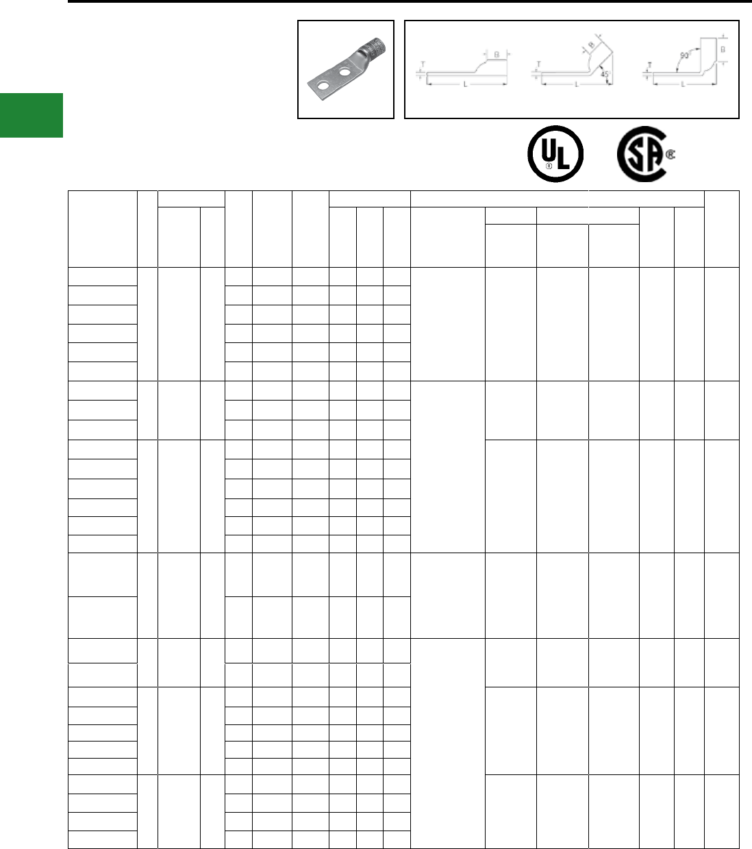
BURNDY®
Blue highlighted items are industry standard and most frequently ordered.
US: 1-800-346-4175 www.burndy.com Canada: 1-800-387-6487
Catalog
Number
Fig
#
Conductor
Stud
Hole
Size
Stud
Hole
Spacing
Tongue
Width
Figure Dimensions ▲Installation Tooling
Wire
Strip
LengthAWG
***
MM² (B) (T) (L)
Dieless
(# of crimps)
Mechanical Hydraulic
Color
Code
Die
Index
MD6,
OUR840,
MD7-34R
BCT500HS,
Y500CTHS
Y35, Y39,
Y750, Y46*
PAT750
YA26L-2TC14
1 2/0 AWG 70
1/4″ 5/8″ 0.83″ 0.94″ 0.12″ 2.64″ MY29-3 (1)
MY29-11 (1)
MRC840 (2)
Y644HSXT (1)
Y81KFT (1)
Y81KFTMBH (1)
PAT81KFT-18V (1)
W26VT (2)
W26RT (2)
X26RT (2)
W26VT (2)
W26RT (2)
X26RT (2)
U26RT (1) Black 13 1″
YA26L-2TC14E2 1/4″ 3/4″ 0.83″ 0.94″ 0.12″ 2.76″
YA26L-2TC14E1 1/4″ 1″ 0.83″ 0.94″ 0.12″ 3.01″
YA26-2L 5/16″ 7/8″ 0.83″ 0.94″ 0.12″ 2.95″
YA26L-2TC38 3/8″ 1″ 0.83″ 0.94″ 0.12″ 3.20″
YA26-2LN 1/2″ 1-3/4″ 0.83″ 0.94″ 0.12″ 4.39″
YA27L-2TC14E2
1 3/0 AWG —
1/4″ 3/4″ 0.91″ 1.00″ 0.12″ 2.86″
MY29-3 (1)
MY29-11 (1)
MRC840 (2)
Y644HSXT (1)
Y81KFTMBH (2)
PAT81KFT-18V (2)
Y81KFT (2)
W27VT (2)
W27RT (2)
X27RT (3)
W27VT (2)
W27RT (2)
X27RT (3)
U27RT (1) Orange 14 1-1/16″
YA27L-2TC38 3/8″ 1″ 0.91″ 1.00″ 0.12″ 3.30″
YA27-2LN 1/2″ 1-3/4″ 0.91″ 1.00″ 0.13″ 4.48″
YA28L-2TC14E2
1 4/0 AWG —
1/4″ 3/4″ 1.02″ 0.88″ 0.14″ 2.78″
W28VT (2)
W28RT (2)
X28RT (3)
W28VT (2)
W28RT (2)
X28RT (3)
U28RT (1) Purple 15 1-1/8″
YA28L-2TC14E1 1/4″ 1″ 1.02″ 0.88″ 0.14″ 3.03″
YA28L2NTC516 5/16″ 1-3/4″ 1.02″ 0.88″ 0.14″ 3.84″
YA28L-2TC38E2 3/8″ 3/4″ 1.02″ 0.88″ 0.14″ 2.97″
YA28L-2TC38 3/8″ 1″ 1.02″ 0.88″ 0.14″ 3.22″
YA28-2LN 1/2″ 1-3/4″ 1.02″ 0.88″ 0.14″ 4.41″
YA29L-2TC38
1 250 kcmil —
3/8″ 1.00″ 1.10″ 1.06″ 0.16″ 3.43″
MY29-3 (1)
MY29-11 (1)
Y644HSXT (1)
Y81KFT (2)
Y81KFTMBH (2)
PAT81KFT-18V (2)
W29VT (2)
X29RT (4)
W29VT (2)
W29RT (2)
X29RT (4)
U29RT (1) Yellow 16 1-1/8″
YA29-2LN 1/2″ 1-3/4″ 1.10″ 1.06″ 0.16″ 4.62″
YA30L-2TC-38
1 300 kcmil 150
3/8″ 1″ 1.20″ 1.03″ 0.16″ 3.45″
Y644HSXT (1)
Y81KFT (2)
Y81KFTMBH (2)
PAT81KFT-18V (2)
W30VT (2) W30VT (2)
W30RT (2)
U30RT (2)
U28ART (2) White
17
or
298
1″
YA30-2LN 1/2″ 1-3/4″ 1.20″ 1.03″ 0.16″ 4.63″
YA31L-2TC14E2
1 350 kcmil 185
1/4″ 3/4″ 1.29″ 1.06″ 0.18″ 3.07″
W31VT (2) W31VT (2)
W31RT (2)
U31RT (2)
U29ART (2) Red
18
or
324
1-1/8″
YA31L-2NTC516 5/16″ 1-3/4″ 1.29″ 1.06″ 0.18″ 4.13″
YA31L-2TC38 3/8″ 1″ 1.29″ 1.06″ 0.18″ 3.51″
YA31L-2TC12 1/2″ 1-1/4″ 1.29″ 1.06″ 0.18″ 4.01″
YA31-2LN 1/2″ 1-3/4″ 1.29″ 1.06″ 0.18″ 4.70″
YA32-2L
1 400 kcmil —
3/8″ 1″ 1.40″ 1.19″ 0.19″ 3.75″
W32VT (2) W32VT (2)
W32RT (2)
U32RT (2)
U30ART (2) Blue
19
or
470
1-1/4″
YA32L-2TC38 3/8″ 1″ 1.40″ 1.19″ 0.19″ 3.69″
YA32L-2TC38E5 3/8″ 1-1/16″ 1.40″ 1.19″ 0.19″ 3.75″
YA32-2LN 1/2″ 1-3/4″ 1.40″ 1.19″ 0.19″ 4.88″
-- Color code not assigned
* Use PUADP-1 adapter with U dies in Y46 HYPRESS™
** P-RT die sets for use in Y46 HYPRESS™ only,
PUADP-1 adapter not required
*** The MM2 conductor sizes listed are the
recommendations for Class 2 conductor
▲ See tooling section of this catalog for complete tool
and die listings
♦ For applications greater than 2000 volts consult cable
manufacturer for voltage stress relief instructions
Note: All dimensions shown are for reference only.
TWO HOLE HYLUG™ CODE
CONDUCTOR STANDARD
BARREL
(Continued)
UL Listed 90° C,
600 Volts to 35 kV ♦
Compression Connections
Copper Compression — Code — Inspection Window
45° and 90° angles are available.
Please contact Customer Service to order.
1-800-346-4175
Fig. 1 45° 90°
C-36
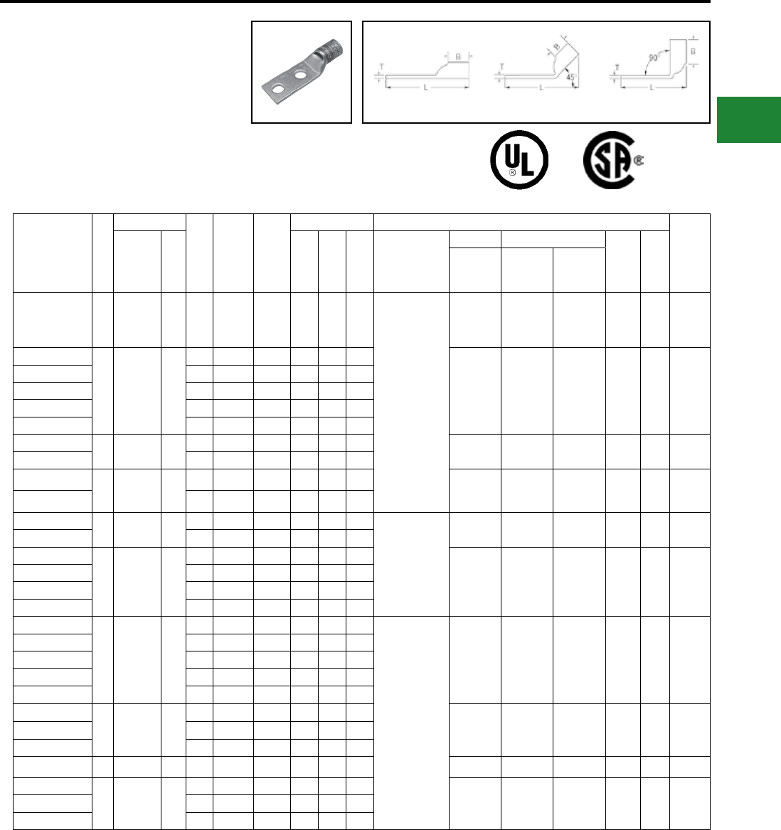
BURNDY®
Blue highlighted items are industry standard and most frequently ordered.
Canada: 1-800-387-6487 www.burndy.com US: 1-800-346-4175
Catalog
Number
Fig
#
Conductor
Stud
Hole
Size
Stud
Hole
Spacing
Tongue
Width
Figure Dimensions ▲Installation Tooling
Wire
Strip
LengthAWG
***
MM² (B) (T) (L)
Dieless
(# of crimps)
Mechanical Hydraulic
Color
Code
Die
Index
MD6,
OUR840,
MD7-34R
BCT500HS,
Y500CTHS
Y35, Y39,
Y750, Y46*
PAT750
YA33-2LN 1 450 kcmil — 1/2″ 1-3/4″ 1.48″ 1.50″ 0.21″ 5.23″
Y644HSXT (1)
Y81KFT (2)
Y81KFTMBH (2)
PAT81KFT-18V (2)
W33VT (2) W33VT (2)
W33RT (2) U33RT (2) Gray
326
or
538
1-9/16″
YA34L-2TC14E2
1 500 kcmil 240
1/4″ 3/4″ 1.55″ 1.27″ 0.23″ 3.44″
W34VT (2) W34VT (2)
W34RT (2)
U34RT (2)
U31ART (2) Brown
20
or
299
1-7/16″
YA34-2L 3/8″ 1″ 1.55″ 1.27″ 0.23″ 3.94″
YA34L-2TC38 3/8″ 1″ 1.55″ 1.27″ 0.23″ 3.88″
YA34L-2TC12 1/2″ 1-1/4″ 1.55″ 1.27″ 0.23″ 4.38″
YA34-2LN 1/2″ 1-3/4″ 1.55″ 1.27″ 0.23″ 5.06″
YA35-2L 1 550 kcmil — 3/8″ 1-1/8″ 1.65″ 1.69″ 0.25″ 4.64″ — — U35RT (2) Yellow 21 1-3/4″
YA35-2LN 1/2″ 1-3/4″ 1.65″ 1.69″ 0.25″ 5.51″
YA36L-2TC38 1 600 kcmil 300 3/8″ 1″ 1.74″ 1.38″ 0.27″ 4.23″ — — U36RT (2)
U32ART (2) Green
22
or
472
1-3/4″
YA36-2LN 1/2″ 1-3/4″ 1.74″ 1.38″ 0.27″ 5.23″
YA37-2L 1 650 kcmil — 3/8″ 1-1/8″ 1.80″ 1.39″ 0.27″ 4.40″
Y644HSXT (1)
Y81KFT (3)
Y81KFTMBH (3)
PAT81KFT-18V (3)
— — U37RT (2) Orange 23 1-15/16″
YA37-2LN 1/2″ 1-3/4″ 1.80″ 1.39″ 0.27″ 5.27″
YA38L-2TC38
1 700 kcmil —
3/8″ 1″ 1.84″ 1.45″ 0.27″ 4.35″
— — U38RT (2) Pink 400 1-15/16″
YA38-2L 3/8″ 1-1/8″ 1.84″ 1.45″ 0.27″ 4.48″
YA38L-2TC12 1/2″ 1-1/2″ 1.84″ 1.45″ 0.27″ 4.67″
YA38-2LN 1/2″ 1-3/4″ 1.84″ 1.45″ 0.27″ 5.35″
YA39L-2TC38
1 750 kcmil —
3/8″ 1″ 1.91″ 1.42″ 0.27″ 4.36″
Y644HSXT (1)
Y81KFT (3)
Y81KFTMBH (3)
PAT81KFT-18V (3)
— — U39RT (2)
P39RT (2)** Black 24 1-15/16″
YA39-2L 3/8″ 1-1/8″ 1.91″ 1.42″ 0.27″ 4.48″
YA39L-2TC12E3 1/2″ 1-1/2″ 1.91″ 1.42″ 0.27″ 4.92″
YA39-2LN 1/2″ 1-3/4″ 1.91″ 1.42″ 0.27″ 5.36″
YA39L-2TC58 5/8″ 1-1/2″ 1.91″ 1.42″ 0.27″ 5.17″
YA40L-2TC38
1 800 kcmil 400
3/8″ 1″ 1.98″ 1.42″ 0.30″ 4.37″
— — P40RT (3)** Orange 25 1-15/16″
YA40-2L 3/8″ 1-1/8″ 1.98″ 1.42″ 0.30″ 4.50″
YA40-2LN 1/2″ 1-3/4″ 1.98″ 1.42″ 0.30″ 5.38″
YA41-2L 1 850 kcmil — 3/8″ 1-1/8″ 2.01″ 1.88″ 0.31″ 4.97″ — — — Gold 26 1-15/16″
YA44-2L
1 1000 kcmil 500
1/2″ 1-1/4″ 2.19″ 1.65″ 0.33″ 5.24″
— — P44RT (3)** White 27 1-15/16″YA44L-2TC12 1/2″ 1-1/4″ 2.19″ 1.65″ 0.33″ 5.05″
YA44-2LN 1/2″ 1-3/4″ 2.19″ 1.65″ 0.33″ 5.74″
-- Color code not assigned
* Use PUADP-1 adapter with U dies in Y46 HYPRESS™
** P-RT die sets for use in Y46 HYPRESS™ only,
PUADP-1 adapter not required
*** The MM2 conductor sizes listed are the
recommendations for Class 2 conductor
▲ See tooling section of this catalog for complete tool
and die listings.
♦ For applications greater than 2000 volts consult cable
manufacturer for voltage stress relief instructions.
Note: All dimensions shown are for reference only.
Compression Connections
Copper Compression — Code — Inspection Window
TWO HOLE HYLUG™ CODE
CONDUCTOR STANDARD
BARREL
(Continued)
UL Listed 90° C,
600 Volts to 35 kV ♦
45° and 90° angles are available.
Please contact Customer Service to order.
1-800-346-4175
Fig. 1 45° 90°
C-37
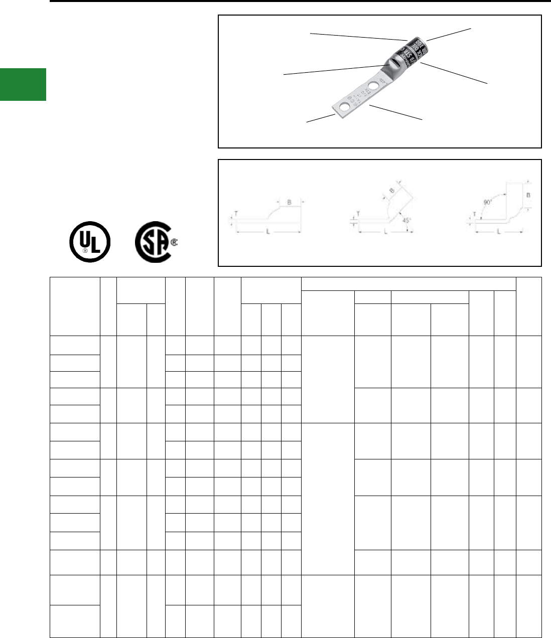
BURNDY®
Blue highlighted items are industry standard and most frequently ordered.
US: 1-800-346-4175 www.burndy.com Canada: 1-800-387-6487
TWO HOLE HYLUG™ CODE
CONDUCTOR STANDARD
BARREL NARROW TONGUE
TYPES YA-L-2NT
COPPER COMPRESSION
TERMINAL
UL Listed 90° C,
600 Volts to 35 kV ♦
45° and 90° angles are available.
Please contact Customer Service to order:
1-800-346-4175
DIE AND COLOR
CODE INFORMATION
CABLE
ACCOMMODATION
BEVELED
ENTRY
CRIMP
INSPECTION
WINDOW
ELECTRO-TIN
PLATED
Fig. 1 45° 90°
Catalog
Number
Fig
#
Conductor
Stud
Hole
Size
Stud
Hole
Spacing
Tongue
Width
Figure Dimensions
▲ Installation Tooling
Wire
Strip
Length
Dieless
(# of crimps)
Mechanical Hydraulic
Color
Code
Die
IndexAWG
***
MM² (B) (T) (L)
MD6,
OUR840,
MD7-34R
BCT500HS,
Y500CTHS
Y35, Y39
Y750, Y46*
PAT750
YA2CL2NT14E2
1 #2 AWG 35
1/4″ 1/4″ 0.48″ 0.88″ 0.11″ 2.60″ MRC840 (1)
MY29-3 (1)
MY29-11 (1)
Y644HSXT (1)
Y1MRTC (2)
Y81KFT (1)
Y81KFTMBH (1)
PAT81KFT-18V (1)
W2CVT (1) W2CVT (1) U2CRT (1) Brown 10 15/16″
YA2CL2NT14 1/4″ 5/8″ 0.48″ 0.88″ 0.11″ 2.47″
YA2CL2NT14E1 1/4″ 1″ 0.48″ 0.88″ 0.11″ 2.84″
YA1CL2NT14
1 #1 AWG 50
1/4″ 5/8″ 0.50″ 0.88″ 0.10″ 2.55″
W1CVT (1) W1CRT-1 (1) U1CRT-1 (1) Green 11 15/16″
YA1CL2NT14E2 1/4″ 3/4″ 0.50″ 0.88″ 0.10″ 2.68″
YA25L2NT14
1 1/0 AWG —
1/4″ 5/8″ 0.48″ 0.88″ 0.12″ 2.56″
MRC840 (2)
MY29-3 (1)
MY29-11 (1)
Y644HSXT (1)
Y81KFT (1)
Y81KFTMBH (1)
PAT81KFT-18V (1)
W25VT (2) W25VT (2) U25RT (1) Pink 12 15/16″
YA25L2NT14E1 1/4″ 1″ 0.48″ 0.88″ 0.12″ 3.28″
YA26L2NT14
1 2/0 AWG 70
1/4″ 5/8″ 0.48″ 0.94″ 0.12″ 2.66″
W26VT (1) W26VT (2)
X26RT (2) U26RT (1) Black 13 1″
YA26L2NT14E1 1/4″ 1″ 0.48″ 0.94″ 0.12″ 3.03″
YA27L2NT14
1 3/0 AWG —
1/4″ 5/8″ 0.76″ 1.00″ 0.13″ 2.73″
W27VT (2)
W27RT (2)
X27RT (3)
W27VT (2)
W27RT (2)
X27RT (3)
U27RT (1) Or-
ange 14 1-1/16″
YA27L2NT516 5/16″ 1″ 0.60″ 1.00″ 0.13″ 3.26″
YA27L2NT38 3/8″ 1″ 0.60″ 1.00″ 0.13″ 3.30″
YA28L2NT14 1 4/0 AWG — 1/4″ 5/8″ 0.76″ 0.88″ 0.13″ 2.65″ W28RT (2) W28RT (2)
X28RT (3) U28RT (1) Purple 15 1-1/16″
YA29L2NT38
1 250 kcmil —
3/8″ 1″ 0.80″ 1.00″ 0.16″ 3.43″ MY29-3 (1)
MY29-11 (1)
Y644HSXT (1)
Y81KFT (1)
Y81KFTMBH (1)
PAT81KFT-18V (1)
W29VT (2)
X29RT (2)
W29VT (2)
W29RT (2)
X29RT (2)
U29RT (1) Yellow 16 1-1/8″
YA29L2NT38E16 3/8″ 1-3/4″ 0.80″ 1.06″ 0.16″ 4.18″
* Use PUADP-1 adapter with U dies in Y46 HYPRESS™. *** The MM2 conductor sizes listed are the
recommendations for Class 2 conductor.
Note: All dimensions shown are for reference only.
Compression Connections
Copper Compression — Code — Two Hole Narrow Tongue — Inspection Window
C-38
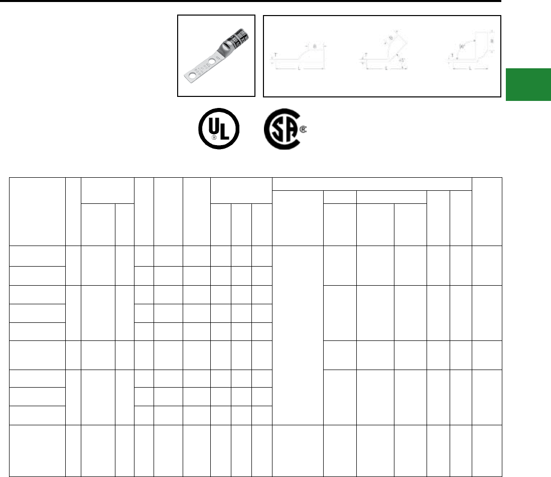
BURNDY®
Blue highlighted items are industry standard and most frequently ordered.
Canada: 1-800-387-6487 www.burndy.com US: 1-800-346-4175
TWO HOLE HYLUG™ CODE
CONDUCTOR STANDARD
BARREL NARROW TONGUE
(Continued)
UL Listed 90° C,
600 Volts to 35kV ♦
45° and 90° angles are available.
Please contact Customer Service to order:
1-800-346-4175
Fig. 1 45° 90°
Catalog
Number
Fig
#
Conductor
Stud
Hole
Size
Stud
Hole
Spacing
Tongue
Width
Figure Dimensions
▲ Installation Tooling
Wire
Strip
Length
Dieless
(# of crimps)
Mech. Hydraulic
Color
Code
Die
IndexAWG
***
MM² (B) (T) (L)
MD6,
OUR840,
MD7-34R
BCT500HS,
Y500CTHS
Y35, Y39
Y750,
Y46*
PAT750
YA31L2NT38
1 350 kcmil 185
3/8″ 1″ 0.96″ 1.06″ 0.18″ 3.51″
Y644HSXT (1)
Y81KFT (1)
Y81KFTMBH (1)
PAT81KFT-18V (1)
W31VT
(2)
W31VT (2)
W31RT (2)
U31RT (1)
U29ART
(2)
Red 18 1-1/8″
YA31L2NT38E16 3/8″ 1-3/4″ 0.88″ 1.06″ 0.18″ 4.26″
YA34L2NT38
1 500 kcmil 240
3/8″ 1″ 0.96″ 1.27″ 0.23″ 3.65″
W34VT
(4) W34VT (4) U34RT (2) Brown
20
or
22
1-7/16″
YA34L2NT38E16 3/8″ 1-3/4″ 0.96″ 1.27″ 0.23″ 4.63″
YA34L2NT12E1 1/2″ 1″ 0.96″ 1.27″ 0.23″ 4.13″
YA36L2NNT 1 600 kcmil 300 1/2″ 1-3/4″ 1.12″ 1.38″ 0.27″ 5.43″ — — U36RT (2) Green 472 1-3/4″
YA39L2NT38
1 750 kcmil —
3/8″ 1″ 1.63″ 1.42″ 0.27″ 4.34″
— — U39RT (2) Black 24 1-1/2″
YA39L2NT38E16 3/8″ 1-3/4″ 1.30″ 1.42″ 0.27″ 5.11″
YA39L2NT12E1 1/2″ 1″ 1.30″ 1.42″ 0.27″ 4.42″
YA44L-2NTC12E24 1 1000 kcmil — 1/2" 1-7/8" 1.63" 1.65" 0.33" 5.65"
Y644HSXT (1)
Y81KFT (3)
Y81KFTMBH (3)
PAT81KFT-18V
(3)
— — P44RT
(3)** White 27 1-15/16"
* Use PUADP-1 adapter with U dies in Y46 HYPRESS™ *** The MM2 conductor sizes listed are the
recommendations for Class 2 conductor.
Note: All dimensions shown are for reference only.
Compression Connections
Copper Compression — Code — Two Hole Narrow Tongue — Inspection Window
C-39
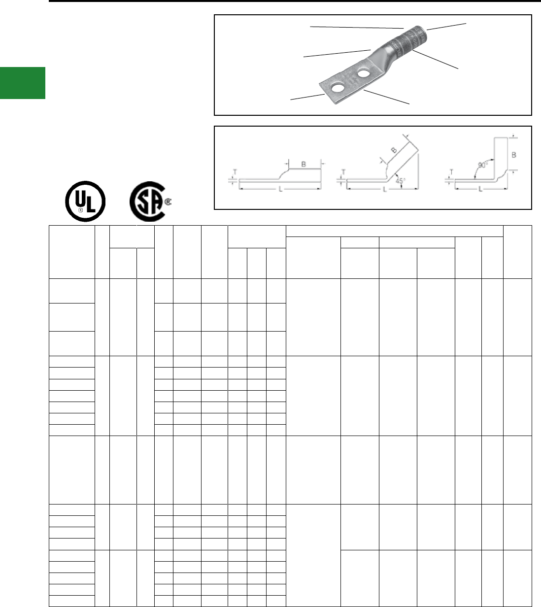
BURNDY®
Blue highlighted items are industry standard and most frequently ordered.
US: 1-800-346-4175 www.burndy.com Canada: 1-800-387-6487
TWO HOLE HYLUG™
CODE CONDUCTOR LONG
BARREL
TYPES YA-2N, YA-2TC,
YA-4N
UL Listed 90° C,
600 Volts to 35kV ♦
45° and 90° angles are available.
Please contact Customer Service to order:
1-800-346-4175
Fig. 1 45° 90°
Catalog
Number
Fig
#
Conductor Stud
Hole
Size
Stud
Hole
Spacing
Tongue
Width
Figure
Dimensions
▲Installation Tooling
Wire
Strip
Length
Dieless
(# of crimps)
Mechanical Hydraulic
Color
Code
Die
Index
AWG ***
MM² (B) (T) (L)
MD6,
OUR840,
MD7-34R
BCT500HS,
Y500CTHS
Y35, Y39
Y750, Y46*
PAT750
YA8C2TC14
1
#8 Str.
#6 Sol.
#8 Sol.
#8 Weld
37/24
†
10
1/4″ 5/8″ 0.44″ 0.81″ 0.08″ 2.33″ Y1MRTC (2)
Y8MRB-1 (2)
MY29-3 (2)
MY29-11 (2)
MRC840 (2)
Y81KFT (1)
Y81KFTMBH (1)
PAT81KFT-18V (1)
W8CVT (2)
W8CRT (2)
X8CRT (2)
W8CVT (2)
W8CRT (2)
X8CRT (2)
U8CRT (1) Red 49 7/8″
YA8C2TC14E2 1/4″ 3/4″ 0.44″ 0.81″ 0.08″ 2.45″
YA8C2TC38 3/8 ″ 1″ 0.58″ 0.81″ 0.06″ 2.89″
YA6C2TC14
1 #6 AWG —
1/4″ 5/8″ 0.45″ 1.12″ 0.08″ 2.65″ Y1MRTC (2)
MY29-3 (2)
MY29-11 (2)
MRC840 (2)
Y81KFT (1)
Y81KFTMBH (1)
PAT81KFT-18V (1)
W5CVT (2)
W5CRT (2)
X5CRT (2)
X8CART (2)
W5CVT (2)
W5CRT (2)
X5CRT (2)
X8CART (2)
U5CRT (2)
U8CABT (2) Blue
7
or
374
1-3/16″
YA6C2TC14E2 1/4″ 3/4″ 0.45″ 1.12″ 0.08″ 2.78″
YA6C2TC14E1 1/4″ 1″ 0.45″ 1.12″ 0.08″ 3.03″
YA6C2TC38E2 3/8″ 3/4″ 0.58″ 1.12″ 0.06″ 2.97″
YA6C2TC38E6 3/8″ 7/8″ 0.58″ 1.12″ 0.06″ 3.09″
YA6C2TC38 3/8″ 1″ 0.58″ 1.12″ 0.06″ 3.22″
YA6C2N 1/2″ 1-3/4″ 0.83″ 1.12″ 0.12″ 4.40″
YA5C2N 1 #5 AWG — 1/2″ 1-3/4″ 0.83″ 1.12″ 0.12″ 4.43″
MY29-3 (2)
MY29-11 (2)
MRC840 (2)
Y644HSXT (1)
Y81KFT (1)
Y81KFTMBH (1)
PAT81KFT-18V (1)
W5CVT (2)
W5CRT (2)
X5CRT (2)
W5CVT (2)
W5CRT (2)
X5CRT (2)
U5CRT (2) Blue
7
or
374
1-3/16″
YA4C2TC14
1 #4 AWG —
1/4″ 5/8″ 0.50″ 1.12″ 0.09″ 2.70″
Y1MRTC (4)
MY29-3 (2)
MY29-11 (2)
MRC840 (2)
Y644HSXT (1)
Y81KFT (1)
Y81KFTMBH (1)
PAT81KFT-18V (1)
W4CVT (2)
W4CRT (2)
X4CRT (2)
W4CVT (2)
W4CRT (2)
X4CRT (2)
U4CRT (2)
U6CABT (2) Gray
8
or
346
1-3/16″
YA4C2TC14E2 1/4″ 3/4″ 0.50″ 1.12″ 0.09″ 2.83″
YA4C2TC38 3/8″ 1″ 0.58″ 1.12″ 0.08″ 3.26″
YA4C2N 1/2″ 1-3/4″ 0.83″ 1.12″ 0.12″ 4.45″
YA3C2TC14
1
#3 Str.
#3 AWG
#2 Sol.
25
1/4″ 5/8″ 0.55″ 1.25″ 0.09″ 2.87″
W3CRT (2) W3CRT (2) U3CRT (2) White 9 1-5/16″
YA3C2TC14E2 1/4″ 3/4″ 0.55″ 1.25″ 0.09″ 2.99″
YA3C2TC38E2 3/8″ 3/4″ 0.58″ 1.25″ 0.08″ 3.18″
YA3C2TC38 3/8″ 1″ 0.58″ 1.25″ 0.08″ 3.43″
YA3C2N 1/2″ 1-3/4″ 0.83″ 1.25″ 0.12″ 4.62″
DIE AND COLOR
CODE INFORMATION
ELECTRO-TIN
PLATED
BEVELED
ENTRY
CRIMP
CABLE
ACCOMMODATION
NO INSPECTION
WINDOW
▲ See tooling section of this catalog for complete tool
and die listings
* Use PUADP-1 adaptor with U dies in Y46 HYPRESS™
** P-RT die sets for use in Y46 HYPRESS™ only,
PUADP-1 adapter not required
*** The MM2 conductor sizes listed are the
recommendations for Class 2 conductor
† The MM2 conductor size listed here is for Class 2
and Class 5 conductor
Available undrilled. Add suffix U to catalog number
(example: YA25U)
♦ For applications greater than 2000 Volts consult cable
manufacturer for voltage stress relief instructions
Note: All dimensions shown are for reference only
Compression Connections
Copper Compression — Code — Long Barrel — No Inspection Window
C-40
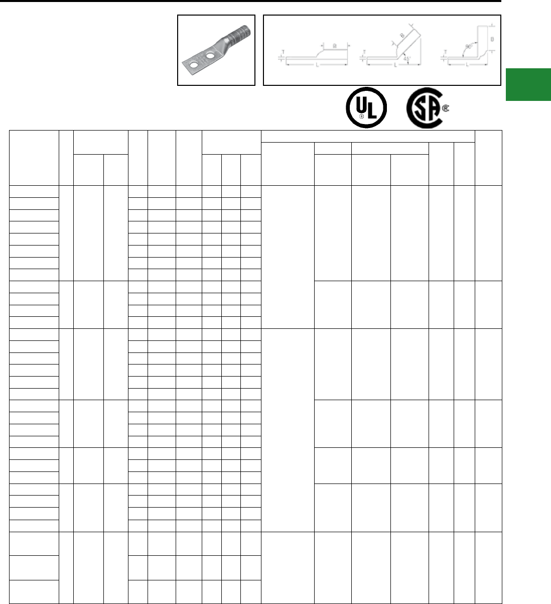
BURNDY®
Blue highlighted items are industry standard and most frequently ordered.
Canada: 1-800-387-6487 www.burndy.com US: 1-800-346-4175
TWO HOLE HYLUG™
CODE CONDUCTOR
LONG BARREL
(Continued)
UL Listed 90° C,
600 Volts to 35kV ♦45° and 90° angles are available.
Please contact Customer Service to order:
1-800-346-4175
Catalog Number Fig
#
Conductor Stud
Hole
Size
Stud
Hole
Spacing
Tongue
Width
Figure
Dimensions
▲Installation Tooling
Wire
Strip
Length
Dieless
(# of crimps)
Mechanical Hydraulic
Color
Code
Die
Index
AWG ***
MM² (B) (T) (L)
MD6,
OUR840,
MD7-34R
BCT500HS,
Y500CTHS
Y35, Y39
Y750, Y46*
PAT750
YA2C2TC14
1 #2 AWG
35
Class 2
25
Class 5
1/4″ 5/8″ 0.60″ 1.25″ 0.11″ 2.86″
Y1MRTC (4)
MY29-3 (2)
MY29-11 (2)
MRC840 (2)
Y644HSXT (1)
Y81KFT (2)
Y81KFTMBH (2)
PAT81KFT-18V (2)
W2CVT (2)
W2CRT (2)
X2CRT (2)
W2CVT (2)
W2CRT (2)
X2CRT (2)
U2CRT (2) Brown 10 1-5/16″
YA2C2TC14E2 1/4″ 3/4″ 0.60″ 1.25″ 0.11″ 2.98″
YA2C2TC516E2 5/16″ 3/4″ 0.60″ 1.25″ 0.11″ 3.05″
YA2C2TC38E2 3/8″ 3/4″ 0.60″ 1.25″ 0.11″ 3.17″
YA2C2TC38E6 3/8″ 7/8″ 0.60″ 1.25″ 0.11″ 3.30″
YA2C2TC38 3/8″ 1″ 0.60″ 1.25″ 0.11″ 3.42″
YA2C2NTC38 3/8″ 1-3/4″ 0.60″ 1.25″ 0.11″ 4.17″
YA2C2N 1/2″ 1-3/4″ 0.83″ 1.25″ 0.12″ 4.64″
YA1C2TC14
1 #1 AWG 50
1/4″ 5/8″ 0.67″ 1.38″ 0.10″ 3.03″
W1CVT (2)
W1CRT-1 (2)
X1CRT-1 (2)
W1CVT (2)
W1CRT-1 (2)
X1CRT-1 (2)
U1CRT-1 (2)
U4CABT (2) Green
11
or
375
1-7/16″
YA1C2TC14E2 1/4″ 3/4″ 0.67″ 1.38″ 0.10″ 3.15″
YA1C2TC38 3/8″ 1″ 0.67″ 1.38″ 0.10″ 3.59″
YA1C2N 1/2″ 1-3/4″ 0.83″ 1.38″ 0.12″ 4.82″
YA252TC14
1 1/0 AWG —
1/4″ 5/8″ 0.75″ 1.38″ 0.12″ 3.05″
MY29-3 (2)
MY29-11 (2)
MRC840 (4)
Y644HSXT (1)
Y81KFT (2)
Y81KFTMBH (2)
PAT81KFT-18V (2)
W25VT (4)
W25RT (4)
X25RT (4)
W25VT (4)
W25RT (4)
X25RT (4)
U25RT (2)
U2CABT (2) Pink 12 1-7/16″
YA252TC14E2 1/4″ 3/4″ 0.75″ 1.38″ 0.12″ 3.18″
YA252TC516 5/16″ 1″ 0.75″ 1.38″ 0.12″ 3.49″
YA252TC38 3/8″ 1″ 0.75″ 1.38″ 0.12″ 3.62″
YA252NTC38 3/8″ 1-3/4″ 0.75″ 1.38″ 0.12″ 4.37″
YA252N 1/2″ 1-3/4″ 0.83″ 1.38″ 0.11″ 4.81″
YA262TC14
1 2/0 AWG 70
1/4″ 5/8″ 0.83″ 1.50″ 0.12″ 3.22″
W26VT (4)
W26RT (4)
X26RT (4)
W26VT (4)
W26RT (4)
X26RT (4)
U26RT (2) Black 13 1-9/16″
YA262TC14E2 1/4″ 3/4″ 0.83″ 1.50″ 0.12″ 3.34″
YA262TC38 3/8″ 1″ 0.83″ 1.50″ 0.12″ 3.78″
YA262N 1/2″ 1-3/4″ 0.83″ 1.50″ 0.12″ 4.97″
YA272TC14E2
1 3/0 AWG —
1/4″ 3/4″ 0.90″ 1.50″ 0.12″ 3.38″ W27VT (4)
W27RT (4)
X27RT (6)
W27VT (4)
W27RT (4)
X27RT (6)
U27RT (2) Orange 14 1-9/16″YA272TC38 3/8″ 1″ 0.90″ 1.50″ 0.12″ 3.82″
YA272N 1/2″ 1-3/4″ 0.91″ 1.50″ 0.13″ 5.01″
YA282TC14E2
1 4/0 AWG —
1/4″ 3/4″ 1.02″ 1.62″ 0.14″ 3.55″
W28VT (4)
W28RT (4)
X28RT (6)
W28VT (4)
W28RT (4)
X28RT (6)
U28RT (2) Purple 15 1-11/16″
YA282TC38 3/8″ 1″ 1.02″ 1.62″ 0.14″ 3.99″
YA282NTC38 3/8″ 1-3/4″ 1.02″ 1.62″ 0.14″ 4.74″
YA282N 1/2″ 1-3/4″ 1.02″ 1.62″ 0.14″ 5.17″
YA292TC38
1 250 kcmil —
3/8″ 1″ 1.10″ 1.62″ 0.16″ 4.02″ MY29-3 (2)
MY29-11 (2)
Y644HSXT (1)
Y81KFT (2)
Y81KFTMBH (2)
PAT81KFT-18V (2)
W29VT (4)
X29RT (8)
W28VT (4)
W28RT (4)
X28RT (8)
U29RT (2) Yellow 16 1-11/16″
YA292N 1/2″ 1-3/4″ 1.11″ 1.62″ 0.16″ 5.21″
YA292TC58E16 5/8 1-3/4"1.11 1.62″ 0.16″ 5.27″
▲ See tooling section of this catalog for complete tool
and die listings
* Use PUADP-1 adaptor with U dies in Y46 HYPRESS™
** P-RT die sets for use in Y46 HYPRESS™ only,
PUADP-1 adapter not required
*** The MM2 conductor sizes listed are the
recommendations for Class 2 conductor
Available undrilled. Add suffix U to catalog number
(example: YA25U)
♦ For applications greater than 2000 Volts consult cable
manufacturer for voltage stress relief instructions
Note: All dimensions shown are for reference only
Fig. 1 45° 90°
Compression Connections
Copper Compression — Code — Long Barrel — No Inspection Window
C-41
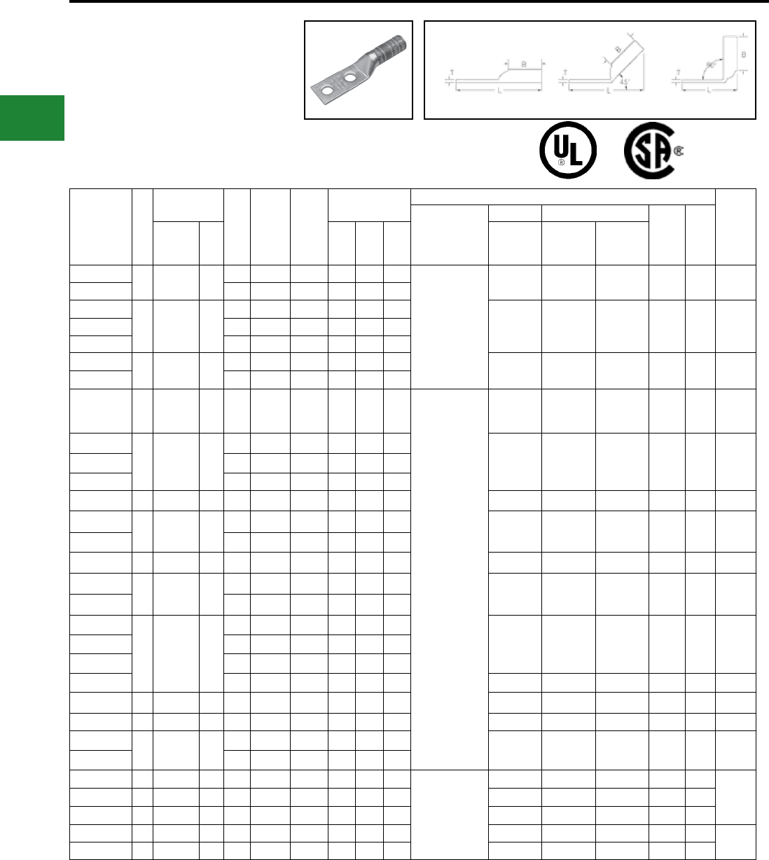
BURNDY®
Blue highlighted items are industry standard and most frequently ordered.
US: 1-800-346-4175 www.burndy.com Canada: 1-800-387-6487
Catalog
Number
Fig
#
Conductor Stud
Hole
Size
Stud
Hole
Spacing
Tongue
Width
Figure
Dimensions
▲Installation Tooling
Wire
Strip
Length
Dieless
(# of crimps)
Mechanical Hydraulic
Color
Code
Die
Index
AWG ***
MM² (B) (T) (L)
MD6,
OUR840,
MD7-34R
BCT500HS,
Y500CTHS
Y35, Y39
Y750, Y46*
PAT750
YA302TC38 1 300 kcmil 150 3/8″ 1″ 1.20″ 2.00″ 0.16″ 4.45″
Y644HSXT (1)
Y81KFT (3)
Y81KFTMBH (3)
PAT81KFT-18V (3)
W30VT (4) W30VT (4)
W30RT (4)
U30RT (4)
U28ART (4) White 17 or
298 2-1/16″
YA302N 1/2″ 1-3/4″ 1.20″ 2.00″ 0.16″ 5.64″
YA312TC14E2
1 350 kcmil 185
1/4″ 3/4″ 1.29″ 2.00″ 0.18″ 4.05″
W31VT (4) W31VT (4)
W31RT (4)
U31RT (4)
U29ART (4) Red 18 or
324 2-1/16″
YA312TC38 3/8″ 1″ 1.29″ 2.00″ 0.18″ 4.49″
YA312N 1/2″ 1-3/4″ 1.29″ 2.00″ 0.18″ 5.69″
YA322TC38 1 400 kcmil — 3/8″ 1″ 1.40″ 2.12″ 0.19″ 4.66″ W32VT (4) W32VT (4)
W32RT (4)
U32RT (4)
U30ART (4) Blue 19 or
470 2-3/16″
YA322N 1/2″ 1-3/4″ 1.40″ 2.12″ 0.19″ 5.85″
YA332N 1 450 kcmil — 1/2″ 1-3/4″ 1.48″ 2.13″ 0.21″ 5.93″
Y644HSXT (1)
Y81KFT (4)
Y81KFTMBH (4)
PAT81KFT-18V (4)
W33VT (4) W33VT (4)
W33RT (4) U33RT Gray
326
or
538
2-3/16″
YA342TC14E2
1 500 kcmil 240
1/4″ 3/4″ 1.55″ 2.25″ 0.23″ 4.46″
W34VT (4) W34VT (4)
W34RT (4)
U34RT (4)
U31ART (2) Brown 20 or
299 2-5/16″
YA342TC38 3/8″ 1″ 1.55″ 2.25″ 0.23″ 4.90″
YA342N 1/2″ 1-3/4″ 1.55″ 2.25″ 0.23″ 6.06″
YA352N 1 550 kcmil — 1/2″ 1-3/4″ 1.65″ 2.63″ 0.25″ 6.49″ — — U35RT (4) Yellow 21 2-11/16″
YA362TC38 1 600 kcmil 300 3/8″ 1″ 1.74″ 2.69″ 0.26″ 5.59″ — — U36RT (4)
U32ART (4) Green 22 or
472 2-3/4″
YA362N 1/2″ 1-3/4″ 1.74″ 2.69″ 0.27″ 6.59″
YA372N 1 650 kcmil — 1/2″ 1-3/4″ 1.80″ 2.81″ 0.27″ 6.74″ — — U37RT (4) Orange 23 2-7/8″
YA382TC38 1 700 kcmil — 3/8″ 1″ 1.84″ 2.81″ 0.27″ 5.76″ — — U38RT (4) Pink 400 2-7/8″
YA382N 1/2″ 1-3/4″ 1.84″ 2.81″ 0.27″ 6.77″
YA392NT38
1 750 kcmil —
3/8″ 1″ 1.63″ 2.88″ 0.27″ 5.87″
— — U39RT (4)
P39RT (4)** Black 24 2-15/16″
YA392TC38 3/8″ 1"1.91″ 2.88″ 0.27″ 5.87″
YA392N 1/2″ 1-3/4"1.91″ 2.88″ 0.27″ 6.87″
YA392ENNT 1/2 1-3/4" 1.30 2.88 — 6.87 — — — Black 24 2-15/16″
YA402N 1 800 kcmil 400 1/2″ 1-3/4"1.98″ 2.94″ 0.30″ 6.95″ — — P40RT (4)** Orange 25 3″
YA412N 1 850 kcmil — 1/2″ 1-3/4"2.01″ 2.94″ 0.31″ 6.96″ — — — Gold 26 3″
YA442TC38 1 1000 kcmil 500 3/8″ 1″ 2.19″ 3.00″ 0.33″ 6.14″ — — P44RT (4)** White 27 3-1/16″
YA442N 1/2″ 1-3/4"2.19″ 3.00″ 0.32″ 7.14″
YA452N 1 1250 kcmil — 1/2″ 1-3/4″ 2.46″ 3.19″ 0.38″ 7.44″
—
— — P45RT (6)** Yellow 29
3-1/4″
YA4532N 1 1300 kcmil — 1/2″ 1-3/4″ 2.53″ 3.19″ 0.39″ 7.48″ — — — Orange 30
YA462N 1 1500 kcmil — 1/2″ 1-3/4″ 2.69″ 3.19″ 0.40″ 7.55″ — — P46RT (6)** Green 31
YA472N 1 1750 kcmil — 1/2″ 1-3/4″ 2.90″ 3.44″ 0.42″ 7.89″ — — — Gray 33 3-1/2″
YA482N 1 2000 kcmil — 1/2″ 1-3/4″ 3.10″ 3.44″ 0.46″ 7.98″ — — — Brown 34
▲ See tooling section of this catalog for complete tool
and die listings.
* Use PUADP-1 adaptor with U dies in Y46 HYPRESS™
** P-RT die sets for use in Y46 HYPRESS™ only,
PUADP-1 adapter not required.
*** The MM2 conductor sizes listed are the
recommendations for Class 2 conductor.
Available undrilled. Add suffix U to catalog number
(example: YA25U).
♦ For applications greater than 2000 Volts consult cable
manufacturer for voltage stress relief instructions.
Note: All dimensions shown are for reference only.
Compression Connections
Copper Compression — Code — Long Barrel — No Inspection Window
TWO HOLE HYLUG™
CODE CONDUCTOR
LONG BARREL
(Continued)
UL Listed 90° C,
600 Volts to 35kV ♦45° and 90° angles are available.
Please contact Customer Service to order:
1-800-346-4175
Fig. 1 45° 90°
C-42
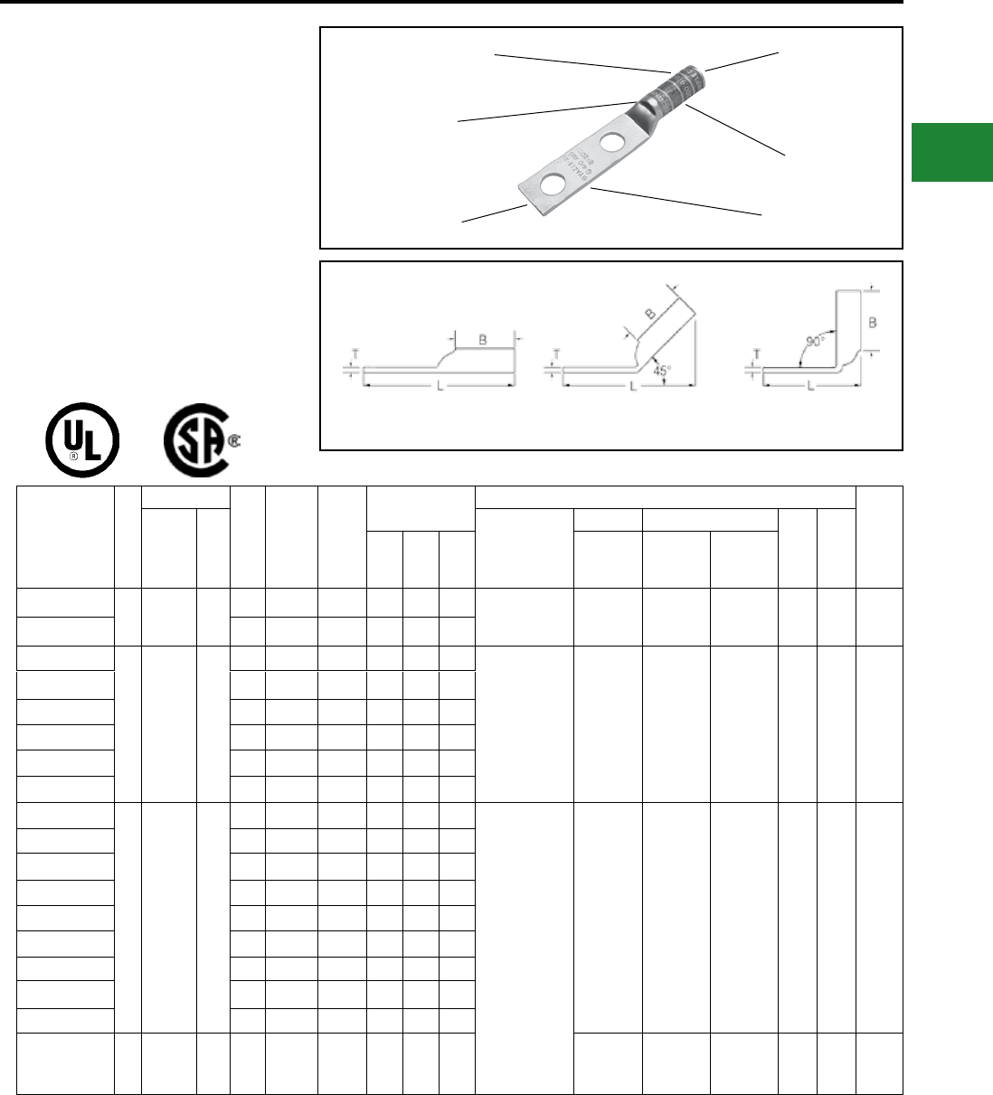
BURNDY®
Blue highlighted items are industry standard and most frequently ordered.
Canada: 1-800-387-6487 www.burndy.com US: 1-800-346-4175
TWO HOLE HYLUG™
CODE CONDUCTOR LONG
BARREL WITH INSPECTION
WINDOW
TYPES YAZ-2N, YAZ-2TC
COPPER COMPRESSION
TERMINAL
UL Listed 90° C,
600 Volts to 35kV ♦
45° and 90° angles are available. Please
contact Customer Service to order:
1-800-346-4175
Catalog
Number
Fig
#
Conductor
Stud
Hole
Size
Stud
Hole
Spacing
Tongue
Width
Figure
Dimensions
▲Installation Tooling
Wire
Strip
LengthAWG
***
MM²
Dieless
(# of crimps)
Mechanical Hydraulic
Color
Code
Die
Index(B) (T) (L)
MD6,
OUR840,
MD7-34R
BCT500HS,
Y500CTHS
Y35, Y39
Y750, Y46*
PAT750
YAZV10-2TC14
1#14 - #10
AWG 6
1/4″ 5/8″ 0.41″ 0.69″ 0.05″ 2.16″
Y8MRB-1 (2) — — — — — 3/4″
YAZV10-2TC14E2 1/4″ 3/4″ 0.41″ 0.69″ 0.05″ 2.28″
YAZ8C-2TC10
1
#8 Str
#6 Sol
#8 Weld
37/24
#8 Sol
†
10
#10 5/8″ 0.41″ 0.75″ 0.08″ 2.07″ Y1MRTC (2)
Y8MRB-1 (2)
MY29-3 (2)
MY29-11 (2)
MRC840 (2)
Y81KFT (1)
Y81KFTMBH (1)
PAT81KFT-18V (1)
W8CVT (2)
W8CRT (2)
X8CRT (2)
W8CVT (2)
W8CRT (2)
X8CRT (2)
U8CRT (2) Red 49 7/8″
YAZ8C-2TC10E2 #10 3/4″ 0.41″ 0.75″ 0.08″ 2.19″
YAZ8C-2TC14 1/4″ 5/8″ 0.44″ 0.75″ 0.08″ 2.19″
YAZ8C-2TC14E2 1/4″ 3/4″ 0.44″ 0.75″ 0.08″ 2.32″
YAZ8C-2TC14E1 1/4″ 1″ 0.44″ 0.75″ 0.08″ 2.57″
YAZ8C-2TC38 3/8″ 1″ 0.58″ 0.75″ 0.06″ 2.76″
YAZ6C-2TC10E2
1 #6 AWG —
#10 3/4″ 0.42″ 1.12″ 0.09″ 2.65″
Y1MRTC (2)
MY29-3 (2)
MY29-11 (2)
MRC840 (2)
Y644HSXT (2)
Y81KFT (1)
Y81KFTMBH (1)
PAT81KFT-18V (1)
W5CVT (2)
W5CRT (2)
X5CRT (2)
X8CART (2)
W5CVT (2)
W5CRT (2)
X5CRT (2)
X8CART (2)
U5CRT (2)
U8CABT (2) Blue
7
or
374
1-3/16″
YAZ6C-2TC14 1/4″ 5/8″ 0.45″ 1.12″ 0.08″ 2.65″
YAZ6C-2TC14E2 1/4″ 3/4″ 0.45″ 1.12″ 0.08″ 2.78″
YAZ6C-2TC14E1 1/4″ 1″ 0.45″ 1.12″ 0.08″ 3.03″
YAZ6C-2TC38E2 3/8″ 3/4″ 0.58″ 1.12″ 0.06″ 2.97″
YAZ6C-2TC38E6 3/8″ 7/8″ 0.58″ 1.12″ 0.06″ 3.09″
YAZ6C-2TC38 3/8″ 1″ 0.58″ 1.12″ 0.06″ 3.22″
YAZ6C2TC38E16 3/8 1-3/4" 0.58″ 1.12″ 0.06″ 3.97″
YAZ6C-2N 1/2″ 1-3/4″ 0.83″ 1.12″ 0.12″ 4.40″
YAZ5C-2N 1 #5 AWG — 1/2″ 1-3/4″ 0.83″ 1.12″ 0.12″ 4.43″
W5CRT (2)
W5CVT (2)
X5CRT (2)
W5CVT (2)
W5CRT (2)
X5CRT (2)
U5CRT (2) Blue
7
or
374
1-3/16″
DIE AND COLOR
CODE INFORMATION
CABLE
ACCOMMODATION
BEVELED
ENTRY
CRIMP
INSPECTION
WINDOW
ELECTRO-TIN
PLATED
Fig. 1 45° 90°
▲ See tooling section of this catalog for complete tool
and die listings
* Use PUADP-1 adaptor with U dies in Y46 HYPRESS™
** P-RT die sets for use in Y46 HYPRESS™ only,
PUADP-1 adapter not required
*** The MM2 conductor sizes listed are the
recommendations for Class 2 conductor.
† The MM2 conductor size referred to here is for
Class 2 and Class 5 conductor.
Available undrilled. Add sufx U to catalog number
(example: YA25U)
♦ For applications greater than 2000 Volts consult cable
manufacturer for voltage stress relief instructions.
Note: All dimensions shown are for reference only.
Compression Connections
Copper Compression — Code — Long Barrel — Inspection Window
C-43

BURNDY®
Blue highlighted items are industry standard and most frequently ordered.
US: 1-800-346-4175 www.burndy.com Canada: 1-800-387-6487
TWO HOLE HYLUG™
CODE CONDUCTOR LONG
BARREL WITH INSPECTION
WINDOW
(Continued)
UL Listed 90° C,
600 Volts to 35kV ♦
Fig. 1 45° 90°
45° and 90° angles are available.
Please contact Customer Service to order:
1-800-346-4175
Catalog
Number
Fig
#
Conductor
Stud
Hole
Size
Stud
Hole
Spacing
Tongue
Width
Figure Dimensions ▲Installation Tooling
Wire
Strip
LengthAWG
***
MM² (B) (T) (L)
Dieless
(# of crimps)
Mechanical Hydraulic
Color
Code
Die
Index
MD6,
OUR840,
MD7-34R
BCT500HS,
Y500CTHS
Y35, Y39
Y750, Y46*
PAT750
YAZ4C-2TC10-E2
1 #4 AWG —
#10 3/4″ 0.50″ 1.12″ 0.09″ 2.67″ Y1MRTC (4)
MY29-3 (2)
MY29-11 (2)
MRC840 (2)
Y644HSXT (2)
Y81KFT (1)
Y81KFTMBH (1)
PAT81KFT-18V (1)
W4CVT (2)
X4CRT (2)
X4CRT (2)
W4CVT (2)
W4CRT (2)
X4CRT (2)
U4CRT (2)
U6CABT (2) Gray
8
or
346
1-3/16″
YAZ4C-2TC14 1/4″ 5/8″ 0.50″ 1.12″ 0.09″ 2.67″
YAZ4C-2TC14E2 1/4″ 3/4″ 0.50″ 1.12″ 0.09″ 2.80″
YAZ4C-2TC38 3/8″ 1″ 0.58″ 1.12″ 0.08″ 3.23″
YAZ4C-2N 1/2″ 1-3/4″ 0.83″ 1.12″ 0.12″ 4.45″
YAZ3C-2TC14
1#3 AWG
#2 Sol 25
1/4″ 5/8″ 0.55″ 1.25″ 0.09″ 2.83″ Y1MRTC (4)
MY29-3 (2)
MY29-11 (2)
MRC840 (2)
Y644HSXT (2)
Y81KFT (2)
Y81KFTMBH (2)
PAT81KFT-18V (2)
W3CRT (2) W3CRT (2) U3CRT (2) White 9 1-5/16″
YAZ3C-2TC14E2 1/4″ 3/4″ 0.55″ 1.25″ 0.09″ 2.95″
YAZ3C-2TC38E2 3/8″ 3/4″ 0.58″ 1.25″ 0.08″ 3.14″
YAZ3C-2TC38 3/8″ 1″ 0.58″ 1.25″ 0.08″ 3.39″
YAZ3C-2N 1/2″ 1-3/4″ 0.83″ 1.25″ 0.12″ 4.62″
YAZ2C-2TC10E2
1 #2 AWG 35
#10 3/4″ 0.60″ 1.25″ 0.11″ 2.85″
Y1MRTC (4)
MY29-3 (2)
MY29-11 (2)
MRC840 (2)
Y644HSXT (1)
Y81KFT (2)
Y81KFTMBH (2)
PAT81KFT-18V (2)
W2CVT (2)
W2CRT (2)
X2CRT (2)
W2CVT (2)
W2CRT (2)
X2CRT (2)
U2CRT (2) Brown 10 1-5/16″
YAZ2C-2TC14 1/4″ 5/8″ 0.60″ 1.25″ 0.11″ 2.85″
YAZ2C-2TC14E2 1/4″ 3/4″ 0.60″ 1.25″ 0.11″ 2.97″
YAZ2C-2TC14E1 1/4″ 1″ 0.60″ 1.25″ 0.11″ 3.22″
YAZ2C2TC516E7 5/16″ 5/8"0.60"1.25″ 0.11″ 2.91″
YAZ2C-
2TC516E2 5/16″ 3/4″ 0.60″ 1.25″ 0.11″ 3.03″
YAZ2C-2TC38E2 3/8″ 3/4″ 0.60″ 1.25″ 0.11″ 3.16″
YAZ2C-2TC38E6 3/8″ 7/8″ 0.60″ 1.25″ 0.11″ 3.28″
YAZ2C-2TC38 3/8″ 1″ 0.60″ 1.25″ 0.11″ 3.41″
YAZ2C-2NTC38 3/8″ 1-3/4″ 0.60″ 1.25″ 0.11″ 4.16″
YAZ2C-2N 1/2″ 1-3/4″ 0.83″ 1.25″ 0.12″ 4.64″
YAZ1C-2TC14
1 #1 AWG 50
1/4″ 5/8″ 0.67″ 1.38″ 0.10″ 3.01″
W1CVT (2)
W1CRT-1 (2)
X1CRT-1 (2)
W1CVT (2)
W1CRT-1 (2)
X1CRT-1 (2)
U1CRT-1 (2)
U4CABT (2)
Green
11
or
375
1-7/16″
YAZ1C-2TC14E2 1/4″ 3/4″ 0.67″ 1.38″ 0.10″ 3.13″
YAZ1C-2TC38 3/8″ 1″ 0.67″ 1.38″ 0.10″ 3.57″
YAZ1C-2N 1/2″ 1-3/4″ 0.83″ 1.38″ 0.12″ 4.82″
▲ See tooling section of this catalog for complete tool
and die listings
* Use PUADP-1 adaptor with U dies in Y46 HYPRESS™
** P-RT die sets for use in Y46 HYPRESS™ only,
PUADP-1 adapter not required
*** The MM2 conductor sizes listed are the
recommendations for Class 2 conductor.
† The MM2 conductor size referred to here is for
Class 2 and Class 5 conductor.
Available undrilled. Add sufx U to catalog number
(example: YA25U).
♦ For applications greater than 2000 Volts consult cable
manufacturer for voltage stress relief instructions.
Note: All dimensions shown are for reference only.
Compression Connections
Copper Compression — Code — Long Barrel — Inspection Window
C-44
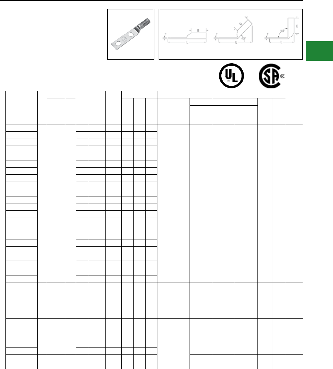
BURNDY®
Blue highlighted items are industry standard and most frequently ordered.
Canada: 1-800-387-6487 www.burndy.com US: 1-800-346-4175
Catalog
Number
Fig
#
Conductor
Stud
Hole
Size
Stud
Hole
Spacing
Tongue
Width
Figure Dimensions ▲Installation Tooling
Wire
Strip
LengthAWG
***
MM² (B) (T) (L)
Dieless
(# of crimps)
Mechanical Hydraulic
Color
Code
Die
Index
MD6,
OUR840,
MD7-34R
BCT500HS,
Y500CTHS
Y35, Y39
Y750, Y46*
PAT750
YAZ25-2TC14
1 1/0 AWG —
1/4″ 5/8″ 0.75″ 1.38″ 0.12″ 3.04″
MY29-3 (2)
MY29-11 (2)
MRC840 (4)
Y644HSXT (1)
Y81KFT (2)
Y81KFTMBH (2)
PAT81KFT-18V (2)
W25VT (4)
W25RT (4)
X25RT (4)
W25VT (4)
W25RT (4)
X25RT (4)
U25RT (2)
U2CABT (2) Pink
12
or
348
1-7/16″
YAZ25-2TC14E2 1/4″ 3/4″ 0.75″ 1.38″ 0.12″ 3.16″
YAZ25-2TC14E1 1/4″ 1″ 0.75″ 1.38″ 0.12″ 3.41″
YAZ252TC14E3 1/4"1"0.75″ 1.38″ 0.12″ 3.42″
YAZ25-2TC516E6 5/16″ 7/8″ 0.75″ 1.38″ 0.12″ 3.35″
YAZ25-2TC516 5/16″ 1″ 0.75″ 1.38″ 0.12″ 3.47″
YAZ25-2TC38 3/8″ 1″ 0.75″ 1.38″ 0.12″ 3.60″
YAZ25-2NTC38 3/8″ 1-3/4″ 0.75″ 1.38″ 0.12″ 4.35″
YAZ25-2N 1/2″ 1-3/4″ 0.83″ 1.38″ 0.11″ 4.79″
YAZ26-2TC14
1 2/0 AWG 70
1/4″ 5/8″ 0.83″ 1.50″ 0.12″ 3.20″
W26VT (4)
W26RT (4)
X26RT (4)
W26VT (4)
W26RT (4)
X26RT (4)
U26RT (2) Black 13 1-9/16″
YAZ26-2TC14E2 1/4″ 3/4″ 0.83″ 1.50″ 0.12″ 3.32″
YAZ262TC14E1 1/4″ 1″ 0.83″ 1.50″ 0.12″ 3.57″
YAZ26-2TC38 3/8″ 1″ 0.83″ 1.50″ 0.12″ 3.76″
YAZ262TC38E16 3/8″ 1-3/4″ 0.83″ 1.50″ 0.12″ 4.51″
YAZ26-2N 1/2″ 1-3/4″ 0.83″ 1.50″ 0.12″ 4.95″
YAZ27-2TC14E2
1 3/0 AWG —
1/4″ 3/4″ 0.90″ 1.50″ 0.12″ 3.36″ W27VT (4)
W27RT (4)
X27RT (6)
W27VT (4)
W27RT (4)
X27RT (6)
U27RT (2) Orange 14 1-9/16″YAZ27-2TC38 3/8″ 1″ 0.90″ 1.50″ 0.12″ 3.80″
YAZ27-2N 1/2″ 1-3/4″ 0.91″ 1.50″ 0.12″ 4.98″
YAZ28-2TC14E2
1 4/0 AWG —
1/4″ 3/4″ 1.02″ 1.62″ 0.14″ 3.55″
W28VT (4)
W28RT (4)
X28RT (6)
W28VT (4)
W28RT (4)
X28RT (6)
U28RT (2) Purple 15 1-11/16″
YAZ28-2TC38 3/8″ 1″ 1.02″ 1.62″ 0.14″ 3.99″
YAZ28-2NTC38 3/8″ 1-3/4″ 1.02″ 1.62″ 0.14″ 4.74″
YAZ28-2N 1/2″ 1-3/4″ 1.02″ 1.62″ 0.14″ 5.15″
YAZ29-2TC38
1 250 kcmil —
3/8″ 1″ 1.10″ 1.62″ 0.14″ 3.99″
MY29-3 (2)
MY29-11 (2)
Y644HSXT (1)
Y81KFT (2)
Y81KFTMBH (2)
PAT81KFT-18V (2)
W29VT (4)
W29RT (8)
W29VT (4)
W29RT (4)
X29RT (8)
U29RT (2) Yellow 16 1-11/16″
YAZ29-2N 1/2″ 1-3/4″ 1.10″ 1.62″ 0.16″ 5.18″
YAZ30-2TC38 1 300 kcmil 150 3/8″ 1″ 1.20″ 2.00″ 0.16″ 4.42″
Y644HSXT (1)
Y81KFT (3)
Y81KFTMBH (3)
PAT81KFT-18V (3)
W30VT (4) W30VT (4)
W30RT (4)
U30RT (4)
U28ART (4) White 17 or
298 2-1/16″
YAZ30-2N 1/2″ 1-3/4″ 1.20″ 2.00″ 0.16″ 5.60″
YAZ31-2TC14E2
1 350 kcmil 185
1/4″ 3/4″ 1.29″ 2.00″ 0.18″ 4.02″
W31VT (4) W31VT (4)
W31RT (4)
U31RT (4)
U29ART (4) Red 18 or
324 2-1/16″YAZ31-2TC38 3/8″ 1″ 1.29″ 2.00″ 0.18″ 4.45″
YAZ31-2N 1/2″ 1-3/4″ 1.29″ 2.00″ 0.18″ 5.64″
YAZ32-2TC38 1 400 kcmil — 3/8″ 1″ 1.40″ 2.12″ 0.19″ 4.62″ W32VT (4) W32VT (4)
W32RT (4)
U32RT (4)
U30ART (4) Blue 19 or
470 2-3/16″
YAZ32-2N 1/2″ 1-3/4″ 1.40″ 2.12″ 0.19″ 5.81″
▲ See tooling section of this catalog for complete tool
and die listings
* Use PUADP-1 adaptor with U dies in Y46 HYPRESS™
** P-RT die sets for use in Y46 HYPRESS™ only,
PUADP-1 adapter not required
*** The MM2 conductor sizes listed are the
recommendations for Class 2 conductor.
† The MM2 conductor size referred to here is for
Class 2 and Class 5 conductor.
Available undrilled. Add sufx U to catalog number
(example: YA25U).
♦ For applications greater than 2000 Volts consult cable
manufacturer for voltage stress relief instructions.
Note: All dimensions shown are for reference only.
Compression Connections
Copper Compression — Code — Long Barrel — Inspection Window
TWO HOLE HYLUG™
CODE CONDUCTOR LONG
BARREL WITH INSPECTION
WINDOW
(Continued)
UL Listed 90° C,
600 Volts to 35kV ♦
Fig. 1 45° 90°
45° and 90° angles are available.
Please contact Customer Service to order:
1-800-346-4175
C-45
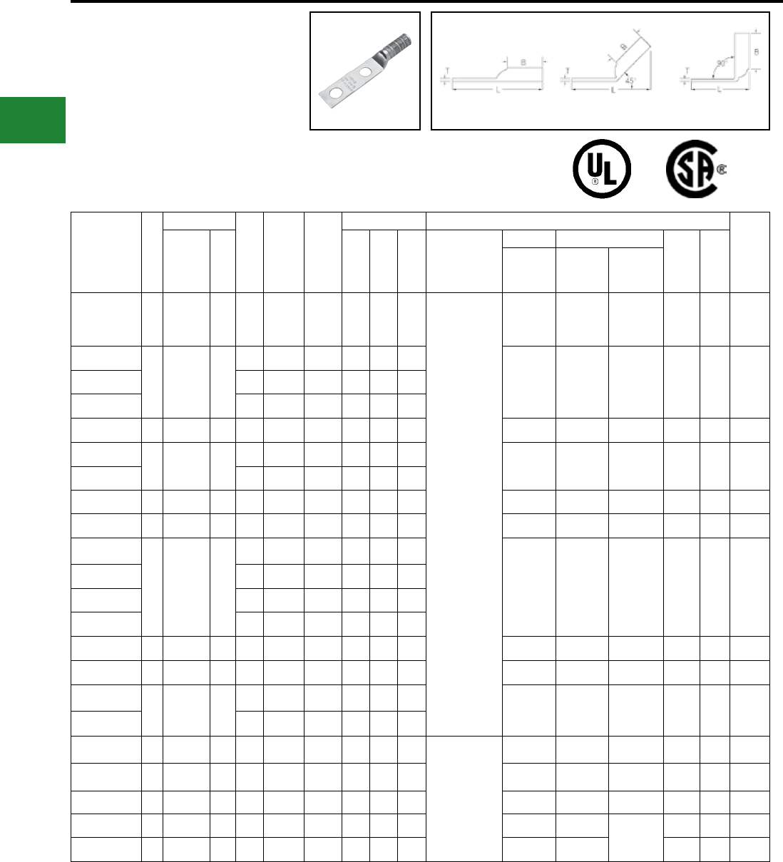
BURNDY®
Blue highlighted items are industry standard and most frequently ordered.
US: 1-800-346-4175 www.burndy.com Canada: 1-800-387-6487
Catalog
Number
Fig
#
Conductor
Stud
Hole
Size
Stud
Hole
Spacing
Tongue
Width
Figure Dimensions ▲Installation Tooling
Wire
Strip
LengthAWG
***
MM² (B) (T) (L)
Dieless
(# of crimps)
Mechanical Hydraulic
Color
Code
Die
Index
MD6,
OUR840,
MD7-34R
BCT500HS,
Y500CTHS
Y35, Y39
Y750, Y46*
PAT750
YAZ33-2N 1 450 kcmil — 1/2″ 1-3/4″ 1.48″ 2.12″ 0.21″ 5.89″
Y644HSXT (1)
Y81KFT (4)
Y81KFTMBH (4)
PAT81KFT-18V (4)
W33VT (4) W33VT (4)
W33RT (4) U33RT (4) Gray
326
or
538
2-5/16"
YAZ34-2TC14E2
1 500 kcmil 240
1/4″ 3/4″ 1.55″ 2.25″ 0.23″ 4.42″
W34VT (4) W34VT (4)
W34RT (4)
U34RT (4)
U31ART (4) Brown
20
or
299
2-5/16"YAZ34-2TC38 3/8″ 1″ 1.55″ 2.25″ 0.23″ 4.85″
YAZ34-2N 1/2″ 1-3/4″ 1.55″ 2.25″ 0.23″ 6.04″
YAZ35-2N 1 550 kcmil — 1/2″ 1-3/4″ 1.65″ 2.62″ 0.25″ 6.45″ — — U35RT (4) Yellow 21 2-11/16"
YAZ36-2TC38
1 600 kcmil 300
3/8″ 1″ 1.74″ 2.69″ 0.26″ 5.55″
— — U36RT (4)
U32ART (4) Green
22
or
472
2-3/4"
YAZ36-2N 1/2″ 1-3/4″ 1.74″ 2.69″ 0.26″ 6.55″
YAZ37-2N 1 650 kcmil — 1/2″ 1-3/4″ 1.80″ 2.81″ 0.27″ 6.70″ — — U37RT (4) Orange 23 2-7/8"
YAZ38-2N 1 700 kcmil — 1/2″ 1-3/4″ 1.84″ 2.81″ 0.27″ 6.72″ — — U38RT (4) Pink 400 2-7/8"
YAZ39-2NT38
1 750 kcmil —
3/8″ 1″ 1.63″ 2.88″ 0.27″ 5.82″
— — U39RT (4)
P39RT (4)** Black 24 2-15/16"
YAZ39-2TC38 3/8″ 1″ 1.91″ 2.88″ 0.27″ 5.82″
YAZ39-2N 1/2″ 1-3/4″ 1.91″ 2.88″ 0.27″ 6.82″
YAZ39-2NNT 1/2″ 1-3/4″ 1.63″ 2.88″ 0.27″ 6.82″
YAZ40-2N 1 800 kcmil 400 1/2″ 1-3/4″ 1.98″ 2.94″ 0.30″ 6.89″ — — P40RT (4)** Orange 25 3"
YAZ41-2N 1 850 kcmil — 1/2″ 1-3/4″ 2.01″ 2.94″ 0.31″ 6.91″ — — — Gold 26 3"
YAZ44-2TC38
1 1000 kcmil 500
3/8″ 1″ 2.19″ 3.00″ 0.33″ 6.09″
— — P44RT (4) ** White 27 3-1/16"
YAZ44-2N 1/2″ 1-3/4″ 2.19″ 3.00″ 0.33″ 7.08″
YAZ45-2N — 1250 kcmil — 1/2″ 1-3/4″ 2.46″ 3.19″ 0.38″ 7.38″
—
— — P45RT (6) ** Yellow 29 3-1/4"
YAZ453-2N — 1300 kcmil — 1/2″ 1-3/4″ 2.53″ 3.19″ 0.39″ 7.41″ — — — Orange 30 2-1/16"
YAZ46-2N — 1500 kcmil — 1/2″ 1-3/4″ 2.69″ 3.19″ 0.40″ 7.48″ — — P46RT (6) ** Green 31 3-5/16"
YAZ47-2N — 1750 kcmil — 1/2″ 1-3/4″ 2.90″ 3.44″ 0.42″ 7.82″ — —
—
Gray 33 3-1/2"
YAZ48-2N — 2000 kcmil — 1/2″ 1-3/4″ 3.10″ 3.44″ 0.46″ 7.89″ — — Brown 34 3-1/2"
▲ See tooling section of this catalog for complete tool
and die listings
* Use PUADP-1 adaptor with U dies in Y46 HYPRESS™
** P-RT die sets for use in Y46 HYPRESS™ only,
PUADP-1 adapter not required
*** The MM2 conductor sizes listed are the
recommendations for Class 2 conductor
† The MM2 conductor size referred to here is for
Class 2 and Class 5 conductor
Available undrilled. Add sufx U to catalog number
(example: YA25U)
♦ For applications greater than 2000 Volts consult cable
manufacturer for voltage stress relief instructions
Note: All dimensions shown are for reference only
Compression Connections
Copper Compression — Code — Long Barrel — Inspection Window
TWO HOLE HYLUG™
CODE CONDUCTOR LONG
BARREL WITH INSPECTION
WINDOW
(Continued)
UL Listed 90° C,
600 Volts to 35kV ♦
Fig. 1 45° 90°
45° and 90° angles are available.
Please contact Customer Service to order:
1-800-346-4175
C-46
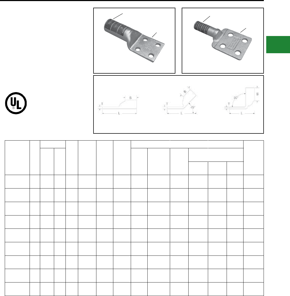
BURNDY®
Blue highlighted items are industry standard and most frequently ordered.
Canada: 1-800-387-6487 www.burndy.com US: 1-800-346-4175
FOUR HOLE HYLUG™
CODE CONDUCTOR
TYPE YA
UL Listed 90° C,
600 Volts to 35kV
45° and 90° angles are available.
Please contact Customer Service to order:
1-800-346-4175
Catalog
Number
Fig.
#
Conductor
Stud
Hole
Size
Stud
Hole
Spacing
Tongue
Width
Tongue
Angle
Installation Tooling
Wire
Strip
LengthAWG
***
MM²
Barrel
Length
Tongue
Thickness
Length
(Total)
Hydraulic
(Y35, Y39, Y750 Y46*)
*
**
Color
Code
Die
Index
YAB344N ▲ 1500
kcmil — 1/2″ 1.75″ 3.00″ Straight 2.25″ 0.25″ 6.33″ U34RT Brown 20 2-5/16″
YAB364N ▲ 1600
kcmil — 5/8" 1.75" 3.00" Straight 2.69" 0.25" 6.79"U36RT Green 22 or
472 2-3/4"
YAB394N ▲ 1750
kcmil — 1/2″ 1.75″ 3.00″ Straight 2.88″ 0.25″ 7.15″ U39RT Black 24 2-15/16″
YA444N 11000
kcmil 500 1/2″ 1.75″ 3.00″ Straight 3.00″ 0.23″ 7.14″ P44RT White 27 3-1/16″
YA454N 11250
kcmil — 1/2″ 1.75″ 3.00″ Straight 3.19″ 0.30″ 7.44″ P45RT Yellow 29 3-1/4″
YA464N 11500
kcmil — 1/2″ 1.75″ 3.00″ Straight 3.19″ 0.34″ 7.55″ P46RT Green 31 3-1/4″
YA474N 11750
kcmil — 1/2″ 1.75″ 2.90″ Straight 3.44″ 0.42″ 6.13″ ‡L47RT Gray 33 3-1/2″
YA484N 12000
kcmil — 1/2″ 1.75″ 3.10″ Straight 3.44″ 0.46″ 7.98″ ‡L48RT Brown 34 3-1/2″
YA4864N 12500
kcmil — 1/2″ 1.75″ 3.46″ Straight 4.69″ 0.52″ 9.38″ ‡L486RT — — 4-3/4″
* Use PUADP-1 adaptor with U dies in Y46 HYPRESS™
** P dies for use with Y46 HYPRESS™ only. PUADP-1
adapter not required
*** The MM2 conductor sizes listed are for Class 2
conductor. For applications greater than 2000 Volts,
consult cable manufacturer for voltage stress relief
instructions
Available undrilled. Add sufx U to catalog number
(example YA444NU)
Fig. 1 45° 90°
‡ Requires Y60BHU HYPRESS™
▲ Not UL Listed
Note: All dimensions shown are for reference only
YA-4N YAB-4N
DIE AND COLOR
CODE INFORMATION DIE AND COLOR
CODE INFORMATION
TIN PLATED
TIN PLATED
Compression Connections
Copper Compression — Code — Long Barrel — No Inspection Window
C-47
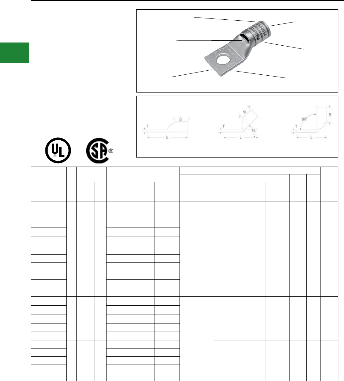
BURNDY®
Blue highlighted items are industry standard and most frequently ordered.
US: 1-800-346-4175 www.burndy.com Canada: 1-800-387-6487
ONE HOLE HYLUG™
FLEX CONDUCTOR
STANDARD BARREL
TYPES YA-L, YA-L-FX, YAV,
YAV-L-FX
COPPER COMPRESSION
TERMINAL
UL Listed 90° C,
600 Volts to 35 kV ♦
45° and 90° angles are available.
Please contact Customer Service to order:
1-800-346-4175
Catalog
Number
Fig
#
Conductor
Stud
Hole
Size
Tongue
Width
Figure
Dimensions
▲Installation Tooling
Wire
Strip
Length
Dieless
(# of crimps)
Mechanical Hydraulic
Color
Code
Die
IndexAWG
***
MM² (B) (T) (L)
MD6,
OUR840,
MD7-34R
BCT500HS,
Y500CTHS
Y35, Y39,
Y750, Y46*,
PAT750
YA8CL-BOX
1
#8 Weld
37/24
#8 AWG
#6 Sol.
#8 Sol.
**
10
#8 - #10 0.41″ 0.44″ 0.08″ 1.16″ Y1MRTC (1)
MY29-3 (1)
MY29-11 (1)
MRC840 (1)
Y4PC834(1)
Y8MRB-1 (1)
Y81KFT (1)
W8CVT 1)
W8CRT (1)
X8CRT (1)
W8CVT (1)
W8CRT (1)
X8CRT (1)
U8CRT (1) Red 49 7/16″
YA8C-L1-BOX 1/4″ 0.44″ 0.44″ 0.08″ 1.26″
YA8C-L2-BOX 5/16″ 0.52″ 0.44″ 0.06″ 1.38″
YA8C-L3-BOX 3/8″ 0.58″ 0.44″ 0.06″ 1.51″
YA8C-L4-BOX 1/2″ 0.71″ 0.44″ 0.05″ 1.76″
YAV6CL-TC10-FX
1
61/24
#6 Weld
#6 AWG
**
16
#10 0.48″ 0.50″ 0.08″ 1.30″
Y1MRTC (1)
MY29-11 (1)
MRC840 (1)
Y644HSXT (1)
Y81KFT (1)
W5CVT (1)
W5CRT (1)
X5CRT (1)
W5CVT (1)
W5CRT (1)
X5CRT (1)
U5CRT (1) Blue 7 1/2″
YAV6CL-TC14-FX 1/4″ 0.48″ 0.50″ 0.08″ 1.43″
YAV6CL-TC516-FX 5/16″ 0.52″ 0.50″ 0.07″ 1.49″
YAV6CL-TC38-FX 3/8″ 0.58″ 0.50″ 0.06″ 1.61″
YAV6CL-TC12-FX 1/2″ 0.75″ 0.50″ 0.12″ 1.86″
YAV6CL-TC34-FX 3/4″ 1.04″ 0.50″ 0.09″ 2.66″
YAV4CL-TC10-FX
1
91/24
105/24
#4 Weld
#4AWG
—
#10 0.55″ 0.50″ 0.09″ 1.32″
Y1MRTC (2)
Y644HSXT (1)
MY29-11 (1)
Y81KFT (1)
PAT4PC834 (1)
Y4PC834 (1)
PAT81KFT-18V (1)
W4CVT (1)
W4CRT (1)
X4CRT (1)
W4CVT (1)
W4CRT (1)
X4CRT (1)
U4CRT (1) Gray 8 1/2″
YAV4CL-TC14-FX 1/4″ 0.55″ 0.50″ 0.09″ 1.44″
YAV4CL-TC516-FX 5/16″ 0.55″ 0.50″ 0.09″ 1.51″
YAV4CL-TC38-FX 3/8″ 0.58″ 0.50″ 0.08″ 1.67″
YAV4CL-TC12-FX 1/2″ 0.71″ 0.50″ 0.07″ 1.92″
YAV2CL-TC10-FX
1
125/24
150/24
#2 Weld
#2 AWG
35
#10 0.68″ 0.63″ 0.10″ 1.50″
W2CVT (1)
W2CRT (1)
X2CRT (1)
W2CVT (1)
W2CRT (1)
X2CRT (1)
U2CRT (1) Brown 10 11/16″
YAV2CL-TC14-FX 1/4″ 0.68″ 0.63″ 0.10″ 1.62″
YAV2CL-TC516-FX 5/16″ 0.68″ 0.63″ 0.10″ 1.69″
YAV2CL-TC38-FX 3/8″ 0.68″ 0.63″ 0.10″ 1.81″
YAV2CL-TC12-FX 1/2″ 0.73″ 0.63″ 0.09″ 2.12″
Fig. 1 45° 90°
DIE AND COLOR
CODE INFORMATION
ELECTRO-TIN
PLATED
BEVELED
ENTRY
CRIMP
CABLE
ACCOMMODATION
INSPECTION
WINDOW
* Use PUADP-1 adapter with U dies in Y46 HYPRESS™
** The MM2 conductor size listed is for both Class 2 and
Class 5 conductors
*** The MM2 conductor sizes listed are the
recommendations for Class 5 conductor
▲See tooling section of this catalog for complete tool and
die listings. Use only color-coded die recommendations
for -FX connectors. For nest/indentor system contact
factory
♦ For applications greater than 2000 Volts consult cable
manufacturer for voltage stress relief instructions
Note: All dimensions shown are for reference only
Compression Connections
Copper Compression — Flex — Inspection Window
C-48
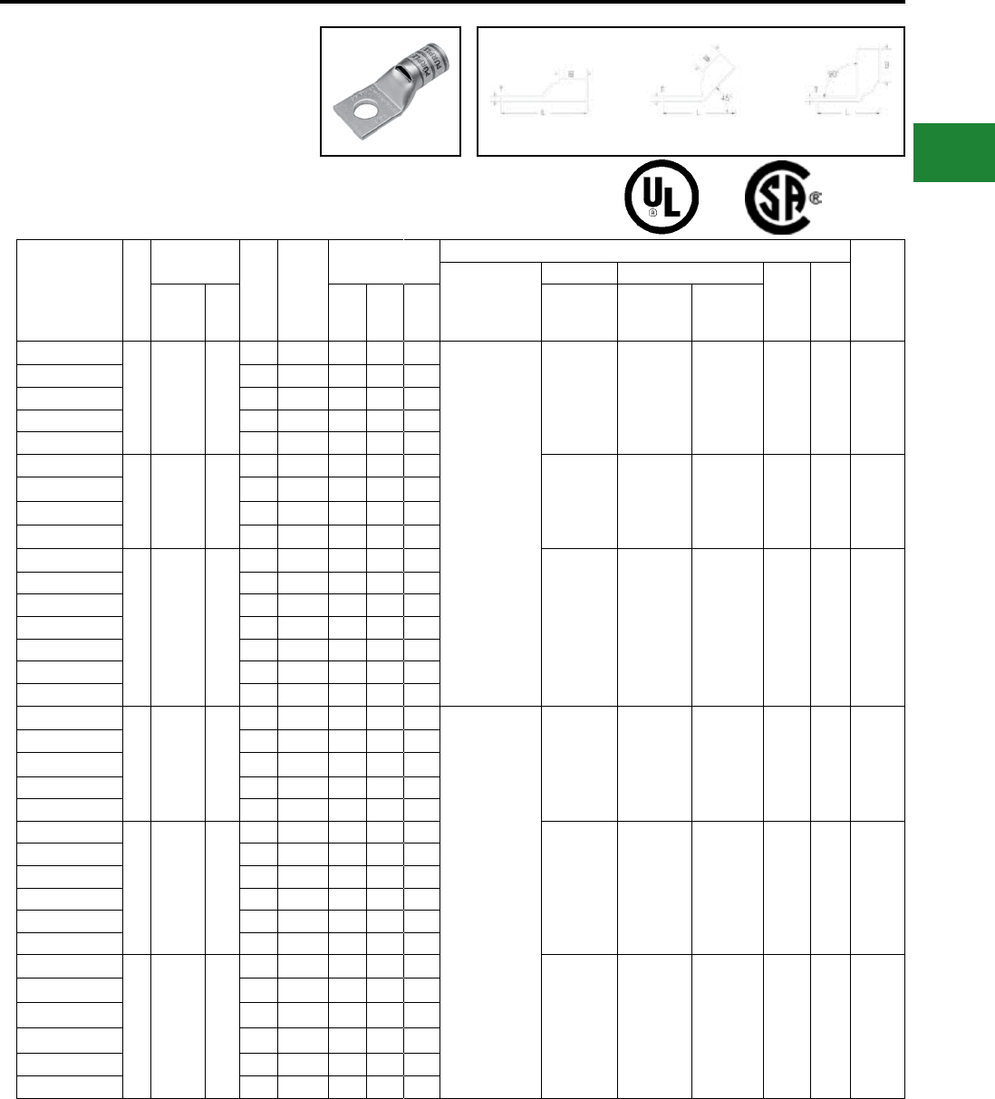
BURNDY®
Blue highlighted items are industry standard and most frequently ordered.
Canada: 1-800-387-6487 www.burndy.com US: 1-800-346-4175
ONE HOLE HYLUG™
FLEX CONDUCTOR
STANDARD BARREL
(Continued)
UL Listed 90° C,
600 Volts to 35kV ♦
45° and 90° angles are available.
Please contact Customer Service to order:
1-800-346-4175
Fig. 1 45° 90°
Catalog
Number
Fig
#
Conductor
Stud
Hole
Size
Tongue
Width
Figure
Dimensions
▲Installation Tooling
Wire
Strip
Length
Dieless
(# of crimps)
Mechanical Hydraulic
Color
Code
Die
IndexAWG
***
MM² (B) (T) (L)
MD6,
OUR840,
MD7-34R
BCT500HS,
Y500CTHS
Y35, Y39
Y750, Y46*
PAT750
YAV1CL-TC10-FX
1
175/24
225/24
#1 Weld
#1 AWG
—
#10 0.75″ 0.62″ 0.12″ 1.52″
Y644HSXT (1)
MY29-11 (1)
PAT644XT-18V (1)
Y81KFT (1)
PAT4PC834 (1)
Y4PC834 (1)
PAT81KFT (1)
W1CVT (1)
W1CRT-1 (1)
X1CRT-1 (1)
W1CVT (1)
W1CRT-1 (1)
X1CRT-1 (1)
U1CRT-1 (1) Green 11 11/16″
YAV1CL-TC14-FX 1/4″ 0.75″ 0.62″ 0.12″ 1.65″
YAV1CL-TC516-FX 5/16″ 0.75″ 0.62″ 0.12″ 1.71″
YAV1CL-TC38-FX 3/8″ 0.75″ 0.62″ 0.12″ 1.84″
YAV1CL-TC12-FX 1/2″ 0.75″ 0.62″ 0.12″ 2.09″
YAV25L-TC14-FX
1
275/24
1/0 Weld
1/0 AWG
50
1/4″ 0.83″ 0.69″ 0.12″ 1.75″
W25VT (2)
W25RT (2)
X25RT (2)
W25VT (2)
W25RT (2)
X25RT (2)
U25RT (1) Pink 12 11/16″
YAV25L-TC516-FX 5/16″ 0.83″ 0.69″ 0.12″ 1.81″
YAV25L-TC38-FX 3/8″ 0.83″ 0.69″ 0.12″ 1.94″
YAV25L-TC12-FX 1/2″ 0.83″ 0.69″ 0.12″ 2.19″
YAV26L-TC10-FX
1
325/24
2/0 Weld
2/0 AWG
70
#10 0.93″ 0.81″ 0.13″ 1.80″
W26VT (2)
W26RT (2)
X26RT (2)
W26VT (2)
W26RT (2)
X26RT (2)
U26RT (1) Black 13 13/16″
YAV26L-TC14-FX 1/4″ 0.93″ 0.81″ 0.13″ 1.92″
YAV26L-TC516-FX 5/16″ 0.93″ 0.81″ 0.13″ 1.98″
YAV26L-TC38-FX 3/8″ 0.93″ 0.81″ 0.13″ 2.11″
YAV26L-TC12-FX 1/2″ 0.93″ 0.81″ 0.13″ 2.36″
YAV26L-TC58-FX 5/8″ 0.93″ 0.81″ 0.13″ 2.61″
YAV26L-TC34-FX 3/4″ 1.10″ 0.81″ 0.11″ 2.89″
YAV27L-TC10-FX
1
450/24
3/0 Weld
3/0 AWG
95
#10 1.03″ 1.00″ 0.14″ 2.03″
Y644HSXT (1)
MY29-11 (1)
PAT644XT-18V (1)
Y81KFT (2)
PAT4PC834 (2)
Y4PC834 (2)
PAT81KFT (2)
W27VT (2)
W27RT (2)
X27RT (3)
W27VT (2)
W27RT (2)
X27RT (3)
U27RT (1) Orange 14 1″
YAV27L-TC14-FX 1/4″ 1.03″ 1.00″ 0.14″ 2.15″
YAV27L-TC516-FX 5/16″ 1.03″ 1.00″ 0.14″ 2.21″
YAV27L-TC38-FX 3/8″ 1.03″ 1.00″ 0.14″ 2.34″
YAV27L-TC12-FX 1/2″ 1.03″ 1.00″ 0.14″ 2.59″
YAV28L-TC14-FX
1
550/24
4/0 Weld
4/0 AWG
**
120
1/4″ 1.14″ 1.03″ 0.15″ 2.23″
W28VT (2)
W28RT (2)
X28RT (3)
W28VT (2)
W28RT (2)
X28RT (3)
U28RT (1) Purple 15 1-1/16″
YAV28L-TC516-FX 5/16″ 1.14″ 1.03″ 0.15″ 2.29″
YAV28L-TC38-FX 3/8″ 1.14″ 1.03″ 0.15″ 2.42″
YAV28L-TC12-FX 1/2″ 1.14″ 1.03″ 0.15″ 2.67″
YAV28L-TC58-FX 5/8″ 1.14″ 1.03″ 0.15″ 2.92″
YAV28L-TC34-FX 3/4″ 1.14″ 1.03″ 0.15″ 3.11″
YAV29L-TC14-FX
1550/24
4/0 Weld —
1/4″ 1.18″ 1.03″ 0.16″ 2.23″
W29VT (2)
X29RT (4)
W29VT (2)
W29RT (2)
X29RT (4)
U29RT (1) Yellow 16 1-1/16″
YAV29L-TC516-FX 5/16″ 1.18″ 1.03″ 0.16″ 2.30″
YAV29L-TC38-FX 3/8″ 1.18″ 1.03″ 0.16″ 2.42″
YAV29L-TC12-FX 1/2″ 1.18″ 1.03″ 0.16″ 2.67″
YAV29L-TC58-FX 5/8″ 1.18″ 1.03″ 0.16″ 2.92″
YAV29L-TC34-FX 3/4″ 1.18″ 1.03″ 0.16″ 3.11″
* Use PUADP-1 adapter with U dies in Y46 HYPRESS™
** The MM2 conductor size listed is for both Class 2 and
Class 5 conductors
*** The MM2 conductor sizes listed are the
recommendations for Class 5 conductor
▲See tooling section of this catalog for complete tool and
die listings. Use only color-coded die recommendations
for -FX connectors. For nest/indentor system contact
factory
♦ For applications greater than 2000 Volts consult cable
manufacturer for voltage stress relief instructions
Note: All dimensions shown are for reference only
Compression Connections
Copper Compression — Flex — Inspection Window
C-49
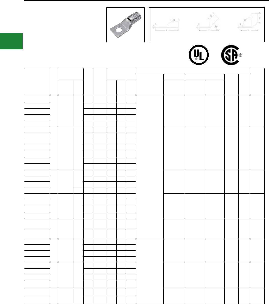
BURNDY®
Blue highlighted items are industry standard and most frequently ordered.
US: 1-800-346-4175 www.burndy.com Canada: 1-800-387-6487
Catalog
Number
Fig
#
Conductor
Stud
Hole
Size
Tongue
Width
Figure
Dimensions
▲Installation Tooling
Wire
Strip
Length
Dieless
(# of crimps)
Mechanical Hydraulic
Color
Code
Die
IndexAWG
***
MM² (B) (T) (L)
MD6,
OUR840,
MD7-34R
BCT500HS,
Y500CTHS
Y35, Y39,
Y750, Y46*,
PAT750
YA30L-TC516-FX
1
250 Flex
CLASS G
259 Str.
CLASS H
427 Str.
—
5/16″ 1.20″ 1.03″ 0.16″ 2.31″
Y644HSXT (1)
PAT644XT-18V (1)
Y81KFT (2)
PAT4PC834 (2)
Y4PC834 (2)
PAT81KFT (2)
W29VT (2)
X29RT (4)
W29VT (2)
W29RT (2)
X29RT (4)
U29RT (1) Yellow 16 1-1/8″
YA30L-TC38-FX 3/8″ 1.20″ 1.03″ 0.16″ 2.44″
YA30L-TC12-FX 1/2″ 1.20″ 1.03″ 0.16″ 2.69″
YA30L-TC58-FX 5/8″ 1.20″ 1.03″ 0.16″ 2.94″
YA30L-TC34-FX 3/4″ 1.20″ 1.03″ 0.16″ 3.12″
YA31L-TC14-FX
1
250 Flex
637/24
CLASS
I, K, M
150
1/4″ 1.29″ 1.06″ 0.18″ 2.31″
W30VT (2) W30VT (2)
W30RT (2) U30RT (2) White
17
or
298
1-1/8″
YA31L-TC516-FX 5/16″ 1.29″ 1.06″ 0.18″ 2.37″
YA31L-TC38-FX 3/8″ 1.29″ 1.06″ 0.18″ 2.50″
YA31L-TC12-FX 1/2″ 1.29″ 1.06″ 0.18″ 2.75″
YA31L-NT12-FX 1/2″ 0.96″ 1.06″ 0.18″ 2.75″
YA31L-TC58-FX 5/8″ 1.29″ 1.06″ 0.18″ 3.00″
YA31L-TC34-FX 3/4″ 1.29″ 1.06″ 0.18″ 3.19″
YA32L-TC38-FX
1
313 kcmil
775/24
300 Flex
185
3/8″ 1.40″ 1.19″ 0.19″ 2.68″
W31VT (2) W31VT (2)
W31RT (2) U31RT (2) Red
18
or
324
1-1/4″
YA32L-TC12-FX 1/2″ 1.40″ 1.19″ 0.19″ 2.93″
YA32L-TC58-FX 5/8″ 1.40″ 1.19″ 0.19″ 3.18″
YA32L-TC100-FX 1″ 1.74″ 1.19″ 0.27″ 3.87″
YA34L-TC516-FX
1
373.7
kcmil
925/24
350 FLEX
240
5/16″ 1.55″ 1.27″ 0.23″ 2.74″
W32VT (2) W32VT (2)
W32RT (2) U32RT (2) Blue
19
or
470
1-5/16″
YA34L-TC38-FX 3/8″ 1.55″ 1.27″ 0.23″ 2.87″
YA34L-TC12-FX 1/2″ 1.55″ 1.27″ 0.23″ 3.12″
YA34L-TC58-FX 5/8″ 1.55″ 1.27″ 0.23″ 3.37″
YA36L-TC12-FX
1
444.4
kcmil
450 Flex
1100/24
—
1/2″ 1.74″ 1.38″ 0.27″ 3.29″
— — U34RT (2) Brown
20
or
299
1-3/8″
YA36L-TC58-FX 5/8″ 1.74″ 1.38″ 0.27″ 3.54″
YA38L-TC516-FX
1
535.3
kcmil
1325/24
500 Flex
300
5/16″ 1.84″ 1.45″ 0.27″ 3.03″
Y644HSXT (1)
PAT644XT-18V (1)
Y81KFT (2)
PAT4PC834 (3)
Y4PC834 (3)
PAT81KFT (3)
— — U38XRT (2) Pink L99 1-7/16″
YA38L-TC38-FX 3/8″ 1.84″ 1.45″ 0.27″ 3.34″
YA38L-TC12-FX 1/2″ 1.84″ 1.45″ 0.27″ 3.41″
YA38L-TC58-FX 5/8″ 1.84″ 1.45″ 0.27″ 3.66″
YA40L-TC516-FX
1646 kcmil
1600/24 400
5/16″ 1.98″ 1.42″ 0.30″ 3.05″
— — U39RT (2) Black 24 1-7/16″
YA40L-TC38-FX 3/8″ 1.98″ 1.42″ 0.30″ 3.38″
YA40L-TC12-FX 1/2″ 1.98″ 1.42″ 0.30″ 3.43″
YA40L-TC58-FX 5/8″ 1.98″ 1.42″ 0.30″ 3.68″
YA44L-TC12-FX
1
777.7
kcmil
1925/24
500
1/2″ 2.19″ 1.65″ 0.33″ 3.79″
— — U44XRT (2) Yellow L115 1-5/8″
YA44L-TC58-FX 5/8″ 2.19″ 1.65″ 0.33″ 4.04″
* Use PUADP-1 adapter with U dies in Y46 HYPRESS™
** The MM2 conductor size listed is for both Class 2 and
Class 5 conductors
*** The MM2 conductor sizes listed are the
recommendations for Class 5 conductor
▲See tooling section of this catalog for complete tool and
die listings. Use only color-coded die recommendations
for -FX connectors. For nest/indentor system contact
factory.
♦ For applications greater than 2000 Volts consult cable
manufacturer for voltage stress relief instructions.
Note: All dimensions shown are for reference only.
Compression Connections
Copper Compression — Flex — Inspection Window
ONE HOLE HYLUG™
FLEX CONDUCTOR
STANDARD BARREL
(Continued)
UL Listed 90° C,
600 Volts to 35kV ♦
45° and 90° angles are available.
Please contact Customer Service to order:
1-800-346-4175
Fig. 1 45° 90°
C-50
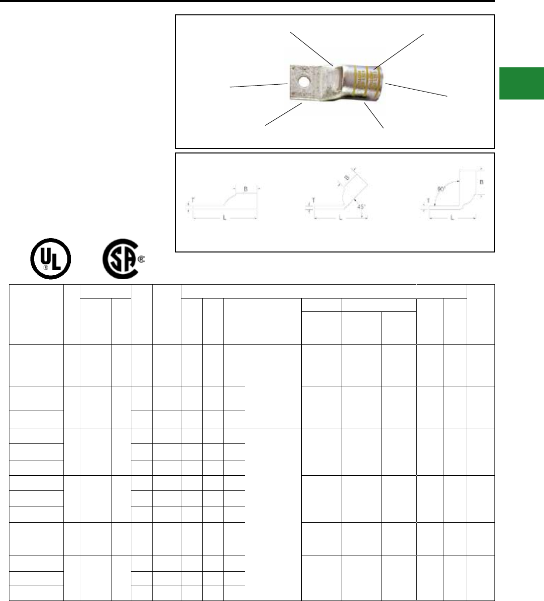
BURNDY®
Blue highlighted items are industry standard and most frequently ordered.
Canada: 1-800-387-6487 www.burndy.com US: 1-800-346-4175
ONE HOLE HYLUG™
FLEX CONDUCTOR
STANDARD BARREL
NARROW TONGUE
TYPE YAV-L-NTFX
COPPER COMPRESSION
NARROW TONGUE
TERMINAL
UL Listed 90° C,
600 Volts to 35 kV ♦
45° and 90° angles are available.
Please contact Customer Service to order:
1-800-346-4175 Fig. 1 45° 90°
Catalog
Number
Fig
#
Conductor
Stud
Hole
Size
Tongue
Width
Figure Dimensions Installation Tooling
Wire
Strip
LengthAWG
***
MM² (B) (T) (L)
Dieless
(# of crimps)
Mechanical Hydraulic
Color
Code
Die
Index
MD6,
OUR840,
MD7-34R
BCT500HS,
Y500CTHS
Y35, Y39
Y750,Y46*
PAT750
YAV4CLNT10FX 1
#4 AWG
#4 Weld
91/24
105/24
— #10 0.41″ 0.50″ 0.09″ 1.32″ Y1MRTC (2)
MY29-11 (1)
Y81KFT (1)
Y81KFTMBH (1)
PAT81KFT-18V (1)
Y644HSXT (1)
W4CRT (1)
W4CVT (1)
X4CRT (1)
W4CRT (1)
W4CVT (1)
X4CRT (1)
U4CRT (1) Gray 8 1/2″
YAV2CLNT14FX
1
#2 AWG
#2 Weld
125/24
150/24
35
1/4″ 0.46″ 0.63″ 0.10″ 1.71″ W2CRT (1)
W2CVT (1)
X2CRT (1)
W2CVT (1)
W2CRT (1)
X2CRT (1)
U2CRT (1) Brown 10 11/16″
YAV2CLNT516FX 5/16″ 0.44″ 0.63″ 0.10″ 1.78″
YAV25LNT14FX
1
1/0 AWG
1/0 Weld
275/24
50
1/4″ 0.67″ 0.69″ 0.12″ 1.75″
MY29-11 (1)
Y644HSXT (1)
Y81KFT (1)
Y81KFTMBH (1)
PAT81KFT-18V (1)
W25VT (2)
W25RT (2)
X25RT (2)
W25VT (2)
W25RT (2)
X25RT (2)
U25RT (1) Pink 12 11/16″
YAV25LNT516FX 5/16″ 0.67″ 0.69″ 0.12″ 1.81″
YAV25LNT38FX 3/8″ 0.76″ 0.69″ 0.13″ 1.94″
YAV26LNT516FX
1
2/0 AWG
2/0 Weld
325/24
70
5/16″ 0.90″ 0.81″ 0.13″ 1.98″ W26VT (2)
W26RT (2)
X26RT (2)
W26VT (2)
W26RT (2)
X26RT (2)
U26RT (1) Black 13 13/16″
YAV26LNT38FX 3/8″ 0.90″ 0.81″ 0.13″ 2.11″
YAV26LNT12FX 1/2″ 0.87″ 0.81″ 0.13″ 2.36″
YAV27LNT12FX 1
3/0 AWG
3/0 Weld
450/24
— 1/2″ 0.76″ 1.00″ 0.14″ 2.59″
W27VT (2)
W27RT (2)
X27RT (3)
W27VT (2)
W27RT (2)
X27RT (3)
U27RT (1) Orange 14 1-1/16″
YAV28LNT516FX
1
4/0 AWG
4/0 Weld
550/24
—
5/16″ 0.94″ 1.03″ 0.15″ 2.29″ W28VT (2)
W28RT (2)
X28RT (3)
W28VT (2)
W28RT (2)
X28RT (3)
U28RT (1) Purple 15 1-1/16″
YAV28LNT38FX 3/8″ 0.94″ 1.03″ 0.15″ 2.42″
YAV28LNT12FX 1/2″ 0.76″ 1.03″ 0.15″ 2.67″
Consult cable manufacturers for stress relief instructions
♦ For applications greater than 2000 Volts consult cable
manufacturer for voltage stress relief instructions
* Use PUADP-1 adaptor with U dies in Y46 HYPRESS™
*** The MM2 conductor sizes Listed are the
recommendations for CLASS 5 conductor
▲See tooling section of this catalog for complete tool and
die listings. Use ONLY color-coded die recommendations
for -FX connectors
Note: All dimensions shown are for reference only.
Compression Connections
Copper Compression — Flex — Standard Barrel — Narrow Tongue
DIE AND COLOR
CODE INFORMATION
CABLE
ACCOMMODATION
INSPECTION
WINDOW
ELECTRO-TIN
PLATED BEVELED
ENTRY
CRIMP
C-51
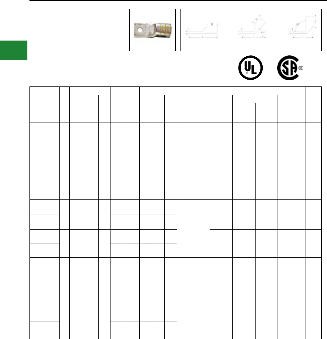
BURNDY®
Blue highlighted items are industry standard and most frequently ordered.
US: 1-800-346-4175 www.burndy.com Canada: 1-800-387-6487
ONE HOLE HYLUG™
FLEX CONDUCTOR
STANDARD BARREL
NARROW TONGUE
(Continued)
UL Listed 90° C,
600 Volts to 35 kV ♦
Fig. 1 45° 90°
45° and 90° angles are available.
Please contact Customer Service to order:
1-800-346-4175
Catalog
Number
Fig
#
Conductor
Stud
Hole
Size
Tongue
Width
Figure Dimensions Installation Tooling
Wire
Strip
LengthAWG
***
MM² (B) (T) (L)
Dieless
(# of crimps)
Mechanical Hydraulic
Color
Code
Die
Index
MD6,
OUR840,
MD7-34R
BCT500HS,
Y500CTHS
Y35, Y39
Y750, Y46*
PAT750
YA30LNT516FX 3250 Flex
637/24 150 5/16″ 0.96″ 1.03″ 0.15″ 2.48″
Y644HSXT (1)
Y81KFT (2)
Y81KFTMBH (2)
PAT81KFT-18V (2)
W29VT (2)
X29RT (2)
W29VT (2)
W29RT (2)
X29RT (2)
U29RT (2) Yellow 16 1-1/8″
YA31L-NT12-FX 1
250 Flex
637/24
CLASS
I, K, M
150 1/2″ 0.96″ 1.06″ 0.18″ 2.75″
PAT644XT-18V (1)
Y81KFT (2)
PAT4PC834 (2)
Y4PC834 (2)
PAT81KFT (2)
W30VT (2) W30VT (2)
W30RT (2) U30RT (2) White 17 1-1/8″
YA32LNT516FX
1
313.1
kcmil
775/24
300 Flex
185
5/16″ 0.96″ 1.19″ 0.19″ 2.65″
Y644HSXT (1)
Y81KFT (2)
Y81KFTMBH (2)
PAT81KFT-18V (2)
W31VT (2) W31VT (2)
W31RT (2) U31RT (2) Red 18 1-1/4″
YA32LNT38FX 3/8″ 0.96″ 1.19″ 0.19″ 2.68″
YA38LNT12FX
1
535.3
kcmil
1325/24
500 Flex
300
1/2″ 1.63″ 1.45″ 0.27″ 3.41″
— — U38XRT (2) Pink L99 1-7/16″
YA38LNTM20FX M20 1.63″ 1.45″ 0.27″ 3.84″
YA40LENT12FX 1
646 WELD
1600/24
650 kcmil
CLASS
B,C,D,G,H,I,K,M
— 1/2″ 1.35"1.42"0.30"3.43"
Y644M (1)
PAT644 (1)
Y81KFT (2)
PAT81KFT (3)
Y4PC834 (3)
PAT4PC834 (3)
— — U39RT (2) Black 24 1-5/16″
YA44LNT38FX
1
777.7
kcmil
1925/24
750 Flex
500
3/8″ 1.50″ 1.65″ 0.33″ 3.79″ Y644HSXT (1)
Y81KFT (2)
Y81KFTMBH (2)
PAT81KFT-18V (2)
— — U44XRT (2) Yellow L115 1-5/8″
YA44LNT12FX 1/2″ 1.62″ 1.65″ 0.33″ 3.98″
Consult cable manufacturers for stress relief instructions
♦ For applications greater than 2000 Volts consult cable
manufacturer for voltage stress relief instructions
* Use PUADP-1 adaptor with U dies in Y46 HYPRESS™
*** The MM2 conductor sizes Listed are the
recommendations for CLASS 5 conductor
▲See tooling section of this catalog for complete tool and
die listings. Use ONLY color-coded die recommendations
for -FX connectors.
Note: All dimensions shown are for reference only.
Compression Connections
Copper Compression — Flex — Standard Barrel — Narrow Tongue
C-52
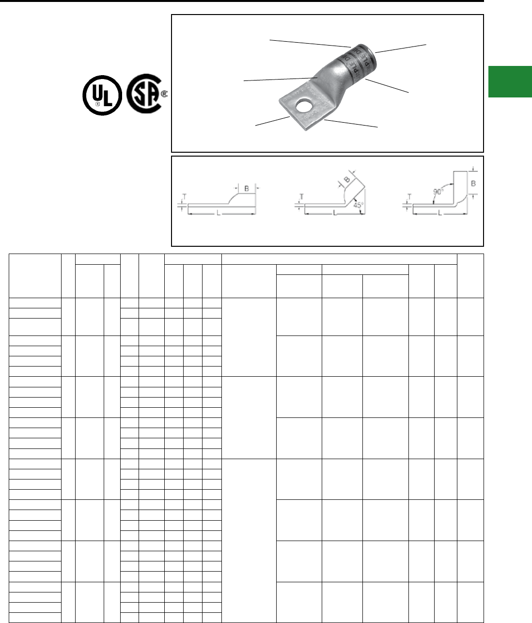
BURNDY®
Blue highlighted items are industry standard and most frequently ordered.
Canada: 1-800-387-6487 www.burndy.com US: 1-800-346-4175
ONE HOLE HYLUG™
FLEX CONDUCTOR
STANDARD BARREL
NO INSPECTION
WINDOW
TYPE YAG-L-TC
COPPER COMPRESSION
TERMINAL
UL Listed 90° C,
600 Volts to 35 kV
45° and 90° angles are available.
Please contact Customer Service to order:
1-800-346-4175
Catalog
Number
Fig
#
Conductor
Stud
Hole
Size
Tongue
Width
Figure Dimensions ▲ Installation Tooling
Wire
Strip
LengthAWG
***
MM² (B) (T) (L)
Dieless
(# of crimps)
Mechanical Hydraulic
Color
Code
Die
Index
MD6, OUR840,
MD7-34R
BCT500HS,
Y500CTHS
Y35, Y39, Y750
Y46*, PAT750
YAG8CLTC14FX
1
37/24
#8 Weld
#8 Sol
#8 AWG
10
1/4"0.44"0.44"0.08"1.32"
MY29-11 (1)
Y1MRTC (1)
Y81KFT (1)
Y81KFTMBH (1)
PAT81KFT-18V (1)
W8CVT (1)
W8CRT (1)
X8CRT (1)
W8CVT (1)
W8CRT (1)
X8CRT (1)
U8CRT (1) Red 49 1/2"
YAG8CLTC516FX 5/16"0.52"0.44"0.06"1.38"
YAG8CLTC12FX 1/2"0.71"0.44"0.05"1.76"
YAG6CLTC14FX
1
61/24
#6 Weld
#6 AWG
16
1/4"0.48"0.50"0.08"1.43"W5CVT (1)
W5CRT (1)
X5CRT (1)
W5CVT (1)
W5CRT (1)
X5CRT (1)
U5CRT (1) Blue 7 1/2"
YAG6CLTC516FX 5/16"0.52"0.50"0.07"1.49"
YAG6CLTC38FX 3/8"0.58"0.50"0.06"1.61"
YAG6CLTC12FX 1/2"0.75"0.50"0.12"1.86"
YAG4CLTC14FX
1
91/24
105/24
#4 AWG
#4 Weld
—
1/4"0.55"0.50"0.09"1.48"
MY29-11 (1)
Y1MRTC (2)
Y81KFT (1)
Y81KFTMBH (1)
PAT81KFT-18V (1)
Y644HSXT (1)
W4CVT (1)
W4CRT (1)
X4CRT (1)
W4CVT (1)
W4CRT (1)
X4CRT (1)
U4CRT (1) Gray 8 1/2"
YAG4CLTC516FX 5/16"0.55"0.50"0.09"1.55"
YAG4CLTC38FX 3/8"0.58"0.50"0.08"1.67"
YAG4CLTC12FX 1/2"0.71"0.50"0.07"1.92"
YAG2CLTC14FX
1
#2 AWG
#2 Weld
125/24
150/24
35
1/4"0.68"0.63"0.10"1.64"W2CVT (1)
W2CRT (1)
X2CRT (1)
W2CVT (1)
W2CRT (1)
X2CRT (1)
U2CRT (1) Brown 10 11/16"
YAG2CLTC516FX 5/16"0.68"0.63"0.10"1.70"
YAG2CLTC38FX 3/8"0.68"0.63"0.10"1.83"
YAG2CLTC12FX 1/2"0.73"0.63"0.09"2.12"
YAG1CLTC14FX
1
#1 AWG
#1 Weld
175/24
225/24
—
1/4"0.75"0.62"0.12"1.67"
MY29-11(1)
Y644HSXT (1)
Y81KFT (1)
Y81KFTMBH (1)
PAT81KFT-18V (1)
W1CVT (1)
W1CRT-1 (1)
X1CRT-1 (1)
W1CVT (1)
W1CRT-1 (1)
X1CRT-1 (1)
U1CRT-1 (1) Green 11 11/16"
YAG1CLTC516FX 5/16"0.75"0.62"0.12"1.73"
YAG1CLTC38FX 3/8"0.75"0.62"0.12"1.86"
YAG1CLTC12FX 1/2"0.75"0.62"0.12"2.11"
YAG25LTC14FX
1
1/0 AWG
1/0 Weld
225/24
50
1/4"0.83"0.69"0.12"1.77"W25CVT (2)
W25CRT (2)
X25CRT (2)
W25VT (2)
W25RT (2)
X25RT (2)
U25RT (1) Pink 12 11/16"
YAG25LTC516FX 5/16"0.83"0.69"0.12"1.84"
YAG25LTC38FX 3/8"0.83"0.69"0.12"1.96"
YAG25LTC12FX 1/2"0.83"0.69"0.12"2.21"
YAG26LTC14FX
1
2/0 AWG
2/0 Weld
325/24
70
1/4"0.93"0.81"0.13"1.95"W26VT (2)
W26RT (2)
X26RT (2)
W26VT (2)
W26RT (2)
X26RT (2)
U26RT (1) Black 13 13/16"
YAG26LTC516FX 5/16"0.93"0.81"0.13"2.01"
YAG26LTC38FX 3/8"0.93"0.81"0.13"2.13"
YAG26LTC12FX 1/2"0.93"0.81"0.13"2.38"
YAG27LTC14FX
1
3/0 AWG
3/0 Weld
450/24
95
1/4"1.03"1.00"0.14"2.18"W27VT (2)
W27RT (2)
X27RT (3)
W27VT (2)
W27RT (2)
X27RT (3)
U27RT (1) Orange 14 1"
YAG27LTC516FX 5/16"1.03"1.00"0.14"2.24"
YAG27LTC38FX 3/8"1.03"1.00"0.14"2.37"
YAG27LTC12FX 1/2"1.03"1.00"0.14"2.62"
* Use PUADP-1 adapter with U dies in Y46 HYPRESS™
** The MM2 conductor size referenced here is for Class 5
conductor
▲ See tooling section of this catalog for complete tool
and die listings
Fig. 1 45° 90°
DIE AND COLOR
CODE INFORMATION
NO INSPECTION
WINDOW
ELECTRO TIN
PLATED
BEVELED
ENTRY
FLEXIBLE CONDUCTOR
ACCOMMODATION
CRIMPS
Note: All dimensions shown are for reference only.
Compression Connections
Copper Compression — Flex — Standard Barrel — No Inspection Window
C-53
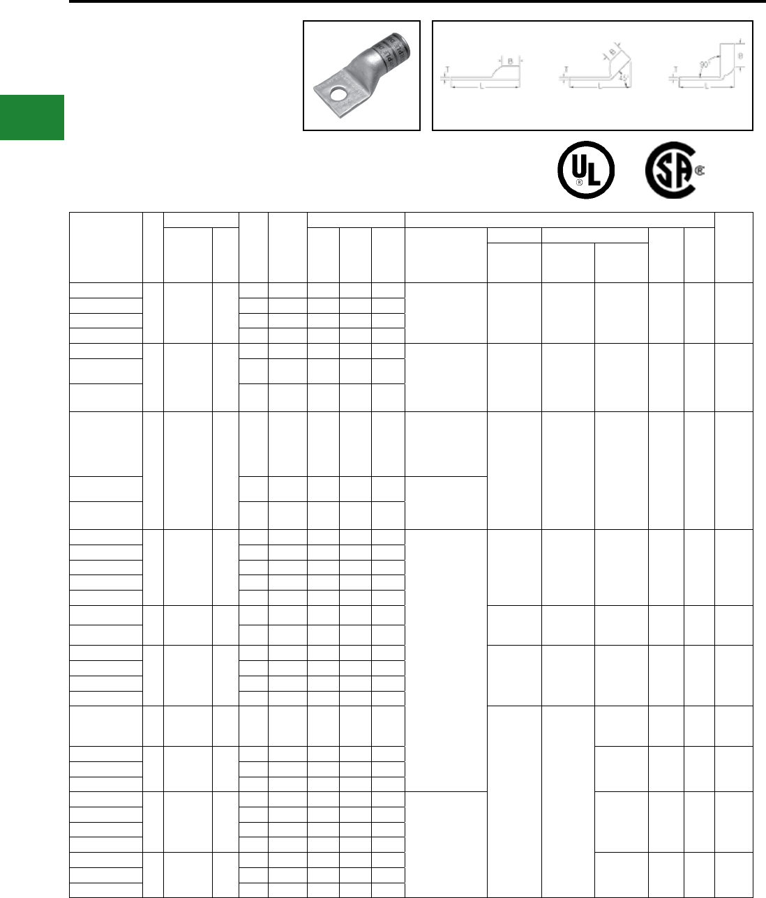
BURNDY®
Blue highlighted items are industry standard and most frequently ordered.
US: 1-800-346-4175 www.burndy.com Canada: 1-800-387-6487
ONE HOLE HYLUG™
FLEX CONDUCTOR
STANDARD BARREL
NO INSPECTION
WINDOW
(Continued)
UL Listed 90° C,
600 Volts to 35 kV
* Use PUADP-1 adapter with U dies in Y46 HYPRESS™
** The MM2 conductor size referenced here is for Class 5
conductor
▲ See tooling section of this catalog for complete tool
and die listings
Fig. 1 45° 90°
Catalog
Number
Fig
#
Conductor
Stud
Hole
Size
Tongue
Width
Figure Dimensions ▲ Installation Tooling
Wire
Strip
Length
AWG **
MM² (B) (T) (L) Dieless
(# of crimps)
Mechanical Hydraulic
Color
Code
Die
Index
MD6,
OUR840,
MD7-34R
BCT500HS,
Y500CTHS
Y35, Y39
Y750, Y46*
PAT750
YAG28LTC14FX
1
4/0 AWG
4/0 Weld
550/24
—
1/4"1.14"1.03"0.15"2.26"MY29-11 (1)
Y644HSXT (1)
Y81KFT (1)
Y81KFTMBH (1)
PAT81KFT-18V (1)
W28VT (2)
W28RT (2)
X28RT (3)
W28VT (2)
W28RT (2)
X28RT (3)
U28RT (1) Purple 15 1-1/16"
YAG28LTC516FX 5/16"1.14"1.03"0.15"2.32"
YAG28LTC38FX 3/8"1.14"1.03"0.15"2.45"
YAG28LTC12FX 1/2"1.14"1.03"0.15"2.70"
YAG29LTC38FX
14/0 Weld
550/24 —
3/8"1.18"1.03"0.16"2.45"Y644HSXT (1)
Y81KFT (1)
Y81KFTMBH (1)
PAT81KFT-18V (1)
W29VT (2)
X29RT (4)
W29VT (2)
W29RT (2)
X29RT (4)
U29RT (1) Yellow 16 1-1/16"
YAG29LTC12FX 1/2"1.18"1.03"0.16"2.70"
YAG29LTC58FX 5/8"1.18"1.03"0.16"2.95"
YAG30LTC38FX
1
250 Flex
Class G
259 Str.
Class H
427 Str.
—
3/8"1.20"1.03"0.16"2.47"
MY29-11 (1)
Y644HSXT (1)
Y81KFT (1)
Y81KFTMBH (1)
PAT81KFT-18V (1) W29VT (2)
X29RT (4)
W29VT (2)
W29RT (2)
X29RT (4)
U29RT (1) Yellow 16 1-1/16"
YAG30LTC12FX 1/2"1.20"1.03"0.16"2.72"Y644HSXT (1)
Y81KFT (1)
Y81KFTMBH (1)
PAT81KFT-18V (1)
YAG30LTC58FX 5/8"1.20"1.03"0.16"2.97"
YAG31LTC14FX
1
250 Flex
637/24
Class I,K,M
150
1/4"1.29"1.06"0.18"2.35"
Y644HSXT (1)
Y81KFT (1)
Y81KFTMBH (1)
PAT81KFT-18V (1)
W30VT (2) W30VT (2)
W30RT (2) U30RT (2) White 17 1-1/8"
YAG31LTC516FX 5/16"1.29"1.06"0.18"2.41"
YAG31LTC38FX 3/8"1.29"1.06"0.18"2.53"
YAG31LTC12FX 1/2"1.29"1.06"0.18"2.78"
YAG31LTC58FX 5/8"1.29"1.06"0.18"3.03"
YAG32LTC12FX 1
313.1 kcmil
775/24
300 Flex
185 1/2"1.40"1.19"0.19"2.97"W31VT (2) W31VT (2)
W31RT (2) U31RT (2) Red 18 1-1/4"
YAG32LTC58FX 5/8"1.40"1.19"0.19"3.22"
YAG34LTC516FX
1
373.3 kcmil
925/24
350 Flex
240
5/16"1.55"1.27"0.23"2.78"
W32VT (2) W32VT (2)
W32RT (2) U32RT (2) Blue 19 1-5/16"
YAG34LTC38FX 3/8"1.55"1.27"0.23"2.91"
YAG34LTC12FX 1/2"1.55"1.27"0.23"3.16"
YAG34LTC58FX 5/8"1.55"1.27"0.23"3.41"
YAG36LTC38FX 1
444.4 kcmil
1100/24
450 Flex
— 3/8"1.73"1.38"0.27"3.27"
— —
U34RT (2) Brown 20 1-3/8"
YAG38LTC516FX
1
535.5 kcmil
1325/24
500 Flex
300
5/16"1.84"1.45"0.27"3.08"
U38XRT (2) Pink L99 1-7/16"YAG38LTC38FX 3/8"1.84"1.45"0.27"3.39"
YAG38LTC12FX 1/2"1.84"1.45"0.27"3.46"
YAG40LTC14FX
1
646 kcmil
1600/24
650 Flex
400
1/4"1.96"1.42"0.30"3.04"
Y644HSXT (1)
Y81KFT (2)
Y81KFTMBH (2)
PAT81KFT-18V (2)
U39RT (2) Black 24 1-5/16"
YAG40LTC516FX 5/16"1.96"1.42"0.30"3.11"
YAG40LTC38FX 3/8"1.96"1.42"0.30"3.42"
YAG40LTC12FX 1/2"1.96"1.42"0.30"3.48"
YAG44LTC516FX
1
777.7 kcmil
1925/24
750 Flex
500
5/16"2.18"1.65"0.33"3.81"
U44XRT (2) Yellow L115 1-5/8"YAG44LTC38FX 3/8"2.18"1.65"0.33"3.81"
YAG44LTC12FX 1/2"2.18"1.65"0.33"3.85"
45° and 90° angles are available.
Please contact Customer Service to order:
1-800-346-4175
Note: All dimensions shown are for reference only.
Compression Connections
Copper Compression — Flex — Standard Barrel — No Inspection Window
C-54
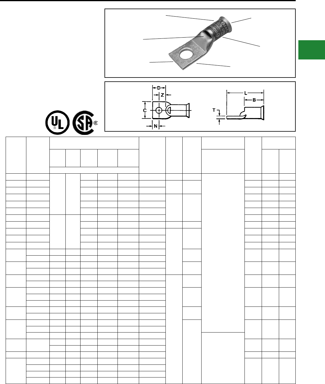
BURNDY®
Blue highlighted items are industry standard and most frequently ordered.
Canada: 1-800-387-6487 www.burndy.com US: 1-800-346-4175
ONE HOLE HYLUG™
FLEX CONDUCTOR
STANDARD BARREL
BELLED END
TYPE YA-LB
COPPER COMPRESSION
TERMINAL
UL Listed 90° C,
600 Volts to 35kV ♦
DIE AND COLOR
CODE INFORMATION
FLEXIBLE CONDUCTOR
ACCOMMODATION
INSPECTION
WINDOW
ELECTRO-TIN
PLATED
BELLED END
ASSISTS FLEXIBLE
WIRE INSERTION
CRIMPS
Catalog
Number
Flexible
Conductor
Size
AWG/kcmil
Stranding Class (Size of Strand)
Locomotive
Cable
Bolt
Hole
Size
Wire Strip
Length
Installation
Tooling
Die
Index
Dimensions
G H
I
(#24
Str.)
Battery
Cable K
(#30 Str.)
Welding
Cable M
(#34 Str.) Dieless
(# of crimps) B LNumber of Strands
YA8C-LB 8
49 133
41 168 420 37/24 #10 7/16″
Y81KFT (1)
Y81KFTMBH (1)
PAT81KFT-18V (1)
1013 0.41″ 1.12″
YA5C-LB 6 63 266 665 61/24 1/4″ 7/8″ 1014 0.44″ 1.73″
YA4C-LB 5 84 336 836 91/24 1015 0.50″ 1.73″
YA3C-LB 4 105 420 1064 105/24
5/16″ 15/16″
1016 0.55″ 1.94″
YA2C-LB 3 133 532 1323 125/24 1017 0.61″ 1.97″
YA1C-LB 2 161 665 1666 150/24 1018 0.68″ 2.02″
YA25-LB 1
133 259
210 836 2107 225/24 1019 0.75″ 2.26″
YA26-LB 1/0 266 1064 2646 275/24 3/8″ 1″ 1020 0.83″ 2.61″
YA27-LB 2/0 342 1323 3325 325/24
1/2″
1-1/16″
1021 0.91″ 2.67″
YA28-LB 3/0 418 1666 4256 450/24 1022 1.02″ 2.77″
YA29-LB 4/0 — — — — 1023 1.11″ 2.82″
YA30-LB 4/0 — — 532 2107 5320 550/24 1-1/8″ 1024 1.20″ 2.93″
250 259 427 — — — —
YA31-LB 250 — — — — — — 1-3/16″ 1025 1.29″ 3.31″
262.2 — — 637 2499 6384 650/24
YA32-LB 300 259 427 735 2989 7851 —
5/8″
1 1/4″ 1026 1.40″ 3.56″
313.1 — — — — — 775/24
YA34-LB
350 — — — 3458 8806 —
1-7/16″ 1027 1.52″ 3.83″373.7 — — — — — 925/24
400 259 427 980 — — —
YA36-LB 444.4 — — — — — 1100/24 1-3/4″ 1028 1.69″ 4.31″
450 — — 1127 4522 11396 —
YA38-LB
500 — — — — 12691 —
1-15/16″
1029 1.81″ 4.27″535.3 — — — — — 1325/24
550 427 703 1372 5054 — —
Y81KFT (2)
Y81KFTMBH (2)
PAT81KFT-18V (2)
YA39-LB 600 — — — — 13664 — 1030 1.89″ 4.27″
427 — — — — —
YA40-LB — — 703 1470 — 14945 1600/24 1031 1.95″ 4.27″
YA44-LB
— — — — 5985 — —
1032 2.17″ 4.5″
650 — — 1596 — — —
750 427 703 — — — —
777.7 — — — — — 1925/24
Note: All dimensions shown are for reference only.
Compression Connections
Copper Compression — Flex — Belled End — Inspection Window
C-55
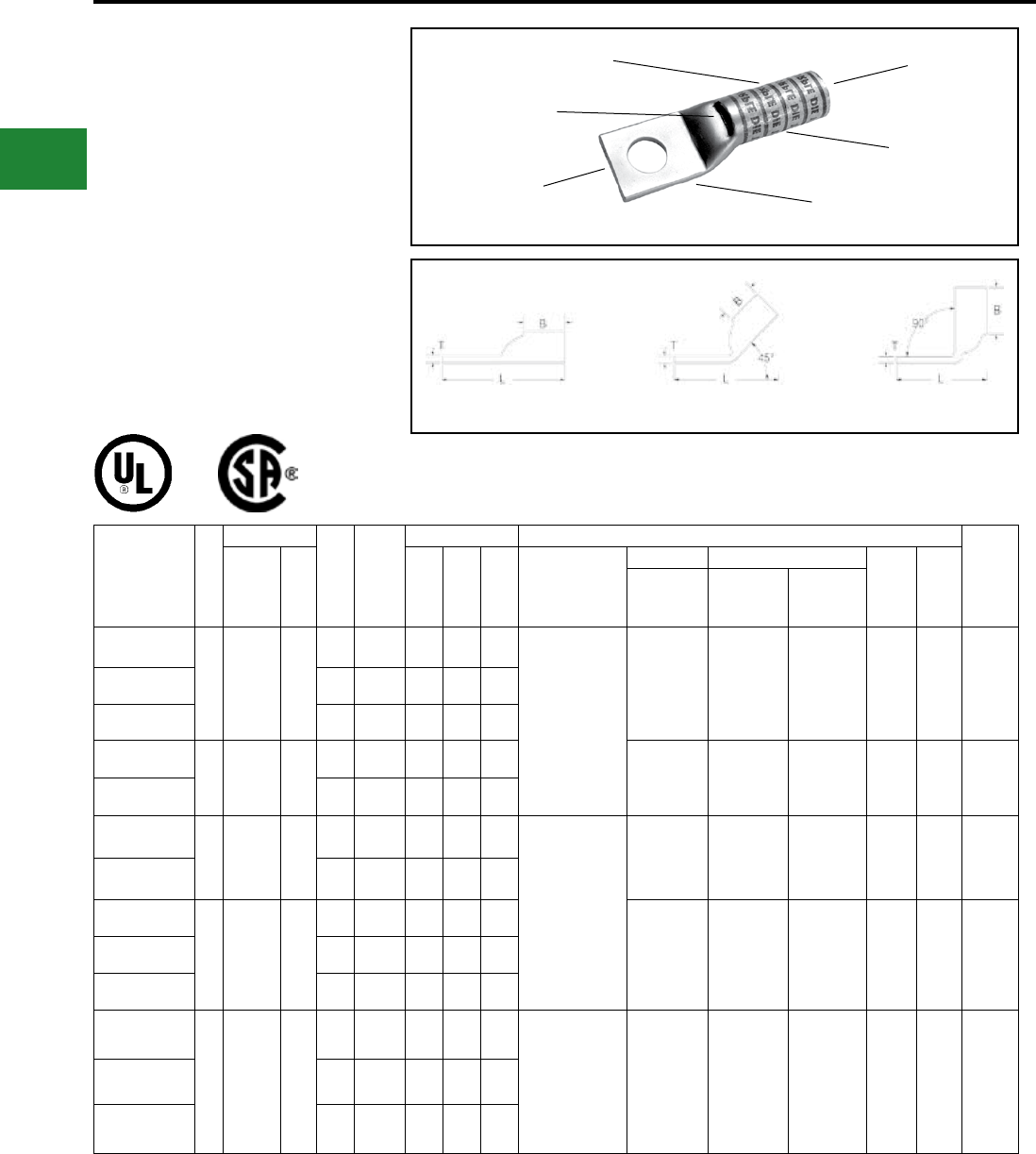
BURNDY®
Blue highlighted items are industry standard and most frequently ordered.
US: 1-800-346-4175 www.burndy.com Canada: 1-800-387-6487
ONE HOLE HYLUG™
FLEX CONDUCTOR
LONG BARREL WITH
INSPECTION WINDOW
TYPES YAZ, YAZV
COPPER COMPRESSION
TERMINAL
UL Listed 90° C,
600 Volts to 35kV ♦
45° and 90° angles are available.
Please contact Customer Service to order:
1-800-346-4175
Catalog
Number
Fig
#
Conductor
Stud
Hole
Size
Tongue
Width
Figure Dimensions ▲ Installation Tooling
Wire
Strip
LengthAWG
***
MM² (B) (T) (L)
Dieless
(# of crimps)
Mechanical Hydraulic
Color
Code
Die
Index
MD6,
OUR840,
MD7-34R
BCT500HS,
Y500CTHS
Y35, Y39
Y750, Y46*
PAT750
YAZ8CTC10
1
#8 AWG
#8 Weld
37/24
#6 Sol
#8 Sol
10
#10 0.41″ 0.75″ 0.08″ 1.43″ Y1MRTC (2)
MY29-3 (2)
MY29-11 (2)
MRC840 (2)
Y644HSXT (1)
Y81KFT (1)
Y81KFTMBH (1)
PAT81KFT-18V (1)
W8CVT (2)
W8CRT (2)
X8CRT (2)
W8CVT (2)
W8CRT (2)
X8CRT (2)
U8CRT (2) Red 49 13/16″
YAZ8CTC14 1/4″ 0.44″ 0.75″ 0.08″ 1.56″
YAZ8CTC38 3/8″ 0.58″ 0.75″ 0.06″ 1.75″
YAZV6CTC14FX
1
61/24
#6 Weld
#6 AWG
**
16
1/4″ 0.48″ 0.75″ 0.08″ 1.59″ W5CVT (2)
W5CRT (2)
X5CRT (2)
W5CVT (2)
W5CRT (2)
X5CRT (2)
U5CRT (2) Blue
7
or
374
13/16″
YAZV6CTC38FX 3/8″ 0.58″ 0.75″ 0.06″ 1.77″
YAZV4CTC14FX
1
91/24
105/24
#4 Weld
#4 AWG
—
1/4″ 0.55″ 1.25″ 0.09″ 2.19″ Y1MRTC (4)
MY29-3 (2)
MY29-11 (2)
MRC840 (2)
Y644HSXT (1)
Y81KFT (1)
Y81KFTMBH (1)
PAT81KFT-18V (1)
W4CVT (2)
W4CRT (2)
X4CRT (2)
W4CVT (2)
W4CRT (2)
X4CRT (2)
U4CRT (2) Gray
8
or
346
1-5/16″
YAZV4CTC38FX 3/8″ 0.58″ 1.25″ 0.08″ 2.42″
YAZV2CTC14FX
1
125/24
150/24
#2 Weld
#2 AWG
35
1/4″ 0.68″ 1.38″ 0.10″ 2.37″
W2CVT (2)
W2CRT (2)
X2CRT (2)
W2CVT (2)
W2CRT (2)
X2CRT (2)
U2CRT (2) Brown 10 1-7/16″
YAZV2CTC38FX 3/8″ 0.68″ 1.38″ 0.10″ 2.56″
YAZV2CTC12FX 1/2″ 0.83″ 1.38″ 0.09″ 2.87″
YAZV1CTC14FX
1
174/24
225/24
#1 Weld
#1 AWG
—
1/4″ 0.75″ 1.38″ 0.12″ 2.40″ MY29-3 (2)
MY29-11 (2)
MRC840 (2)
Y644HSXT (1)
Y81KFT (1)
Y81KFTMBH (1)
PAT81KFT-18V (1)
W1CVT (2)
W1CRT-1 (2)
X1CRT-1 (2)
W1CVT (2)
W1CRT-1 (2)
X1CRT-1 (2)
U1CRT-1 (2) Green
11
or
375
1-7/16″
YAZV1CTC516FX 5/16″ 0.75″ 1.38″ 0.12″ 2.46″
YAZV1CTC38FX 3/8″ 0.75″ 1.38″ 0.12″ 2.59″
DIE AND COLOR
CODE INFORMATION
ELECTRO-TIN
PLATED
BEVELED
ENTRY
CRIMP
CABLE
ACCOMMODATION
INSPECTION
WINDOW
Fig. 1 45° 90°
* Use PUADP-1 adapter with U dies in Y46 HYPRESS™
** The MM2 conductor size referenced here is for both
Class 2 and Class 5 conductor
*** The MM2 conductor sizes listed are the
recommendations for Class 5 conductor
▲See tooling section of this catalog for complete tool and
die listings. Use ONLY color-coded die recommendations
for -FX connectors. For nest/indentor system contact
factory
♦ For applications greater than 2000 Volts consult cable
manufacturer for voltage stress relief instructions.
Note: All dimensions shown are for reference only.
Compression Connections
Copper Compression — Flex — Long Barrel — Inspection Window
C-56
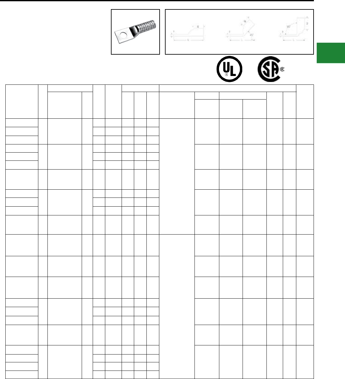
BURNDY®
Blue highlighted items are industry standard and most frequently ordered.
Canada: 1-800-387-6487 www.burndy.com US: 1-800-346-4175
ONE HOLE HYLUG™
FLEX CONDUCTOR
LONG BARREL WITH
INSPECTION WINDOW
(Continued)
UL Listed 90° C,
600 Volts to 35kV ♦
Catalog
Number
Fig
#
Conductor
Stud
Hole
Size
Tongue
Width
Figure Dimensions Installation Tooling
Wire
Strip
LengthAWG MM² (B) (T) (L)
Dieless
(# of crimps)
Mechanical Hydraulic
Color
Code
Die
Index
MD6,
OUR840,
MD7-34R
BCT500HS,
Y500CTHS
Y35, Y39
Y750, Y46
PAT750
YAZV25TC14FX
1
275/24
1/0 Weld
1/0 AWG
50
1/4″ 0.83″ 1.50″ 0.12″ 2.56″
MY29-11 (2)
Y644HSXT (1)
Y81KFT (2)
Y81KFTMBH (2)
PAT81KFT-18V (2)
W25VT (4)
W25RT (4)
X25RT (4)
W25VT (4)
W25RT (4)
X25RT (4)
U25RT (2) Pink
12
or
348
1-9/16″
YAZV25TC38FX 3/8″ 0.83″ 1.50″ 0.12″ 2.75″
YAZV25TC12FX 1/2″ 0.83″ 1.50″ 0.12″ 3.00″
YAZV26TC14FX
1
325/24
2/0 Weld
2/0 AWG
70
1/4″ 0.93″ 1.50″ 0.13″ 2.61″ W26VT (4)
W26RT (4)
X26RT (4)
W26VT (4)
W26RT (4)
X26RT (4)
U26RT (2) Black 13 1-9/16″
YAZV26TC38FX 3/8″ 0.93″ 1.50″ 0.13″ 2.80″
YAZV26TC12FX 1/2″ 0.93″ 1.50″ 0.13″ 3.05″
YAZV27TC38FX 1
450/24
3/0 Weld
3/0 AWG
95 3/8″ 1.03″ 1.50″ 0.14″ 2.84″
W27VT (4)
W27RT (4)
X27RT (6)
W27VT (4)
W27RT (4)
X27RT (6)
U27RT (2) Orange 14 1-9/16″
YAZV28NT38FX
1
550/24
4/0 Weld
4/0 AWG
120
3/8″ 0.94″ 1.62″ 0.14″ 3.01″ W28VT (4)
W28RT (4)
X28RT (4)
W28VT (4)
W28RT (4)
X28RT (6)
U28RT (2) Purple 15 1-11/16″
YAZV28TC38FX 3/8″ 1.14″ 1.62″ 0.14″ 3.01″
YAZV28TC12FX 1/2″ 1.14″ 1.62″ 0.14″ 3.26″
YAZV29NT516FX 1550/24
4/0 Weld — 5/16″ 0.96″ 2.00″ 0.16″ 3.27″ W29VT (4)
X29RT (8)
W29VT (4)
W29RT (4)
X29RT (8)
U29RT (2) Yellow 16 2-1/16″
YAZ30TC38FX 1
250 Flex
CLASS G 259 Str.
CLASS H 427 Str.
— 3/8″ 1.20″ 2.00″ 0.16″ 3.41″
Y644HSXT (1)
Y81KFT (2)
Y81KFTMBH (2)
PAT81KFT-18V (2)
W29VT (4)
X29RT (8)
W29VT (4)
W29RT (4)
X29RT (8)
U29RT (2) Yellow 16 2-1/16″
YAZ31TC38FX 1
262.2 Flex
637/24
CLASS I,K,M
150 3/8″ 1.28″ 2.00″ 0.18″ 3.44″ W30VT (4) W30VT (4)
W30RT (4) U30RT (4) White
17
or
298
2-1/16″
YAZ32TC38FX 1
775/24
313.1 kcmil
300 Flex
185 3/8″ 1.55″ 2.12″ 0.19″ 3.61″ W31VT (4) W31VT (4)
W31RT (4) U31RT (4) Red
18
or
324
2-3/16″
YAZ34NT38FX
1
925/24
373.3 kcmil
350 Flex
240
3/8″ 0.96″ 2.25″ 0.23″ 3.84″
W32VT (4) W32VT (4)
W32RT (4) U32RT (4) Blue 19 2-5/16″YAZ34TC12FX 3/8″ 1.52″ 2.25″ 0.23″ 4.09″
YAZ34TC38FX 1/2″ 1.52″ 2.25″ 0.23″ 3.84″
YAZ36TC38FX 1
1100/24
444.4 kcmil
450 Flex
— 3/8″ 1.72″ 2.69″ 0.26″ 4.54″ — — U34RT (4) Brown
20
or
299
2-3/4″
YAZ38NT38FX
1
1325/24
535.3 kcmil
500 Flex
300
3/8″ 1.63″ 2.81″ 0.27″ 4.71″
— — U38XRT (4) Pink L99 2-7/8″
YAZ38TC38FX 3/8″ 1.81″ 2.81″ 0.27″ 4.71″
YAZ38NT12FX 1/2″ 1.63″ 2.81″ 0.27″ 4.77″
YAZ38TC12FX 1/2″ 1.81″ 2.81″ 0.27″ 4.77″
Fig. 1 45° 90°
45° and 90° angles are available.
Please contact Customer Service to order:
1-800-346-4175
* Use PUADP-1 adapter with U dies in Y46 HYPRESS™
** The MM2 conductor size referenced here is for both
Class 2 and Class 5 conductor
*** The MM2 conductor sizes listed are the
recommendations for Class 5 conductor
▲See tooling section of this catalog for complete tool and
die listings. Use ONLY color-coded die recommendations
for -FX connectors. For nest/indentor system contact
factory.
♦ For applications greater than 2000 Volts consult cable
manufacturer for voltage stress relief instructions.
Note: All dimensions shown are for reference only.
Compression Connections
Copper Compression — Flex — Long Barrel — Inspection Window
C-57
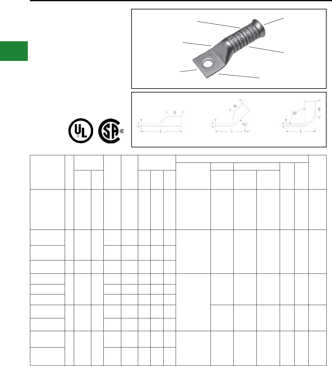
BURNDY®
Blue highlighted items are industry standard and most frequently ordered.
US: 1-800-346-4175 www.burndy.com Canada: 1-800-387-6487
ONE HOLE HYLUG™
FLEX CONDUCTOR
LONG BARREL
BELLED END
TYPES YA-TC-FXB,
YAV-TC-FXB
UL Listed 90° C,
600 Volts to 35kV ♦
45° and 90° angles are available.
Please contact Customer Service to order:
1-800-346-4175
DIE AND COLOR
CODE INFORMATION
FLEXIBLE CONDUCTOR
ACCOMMODATION
BELLED END
ASSISTS FLEXIBLE
WIRE INSERTION
CRIMPS
NO INSPECTION
WINDOW
ELECTRO-TIN
PLATED
Fig. 1 45° 90°
Catalog
Number
Fig
#
Conductor
Stud
Hole
Size
Tongue
Width
Figure
Dimensions
▲Installation Tooling
Wire
Strip
Length
Dieless
(# of crimps)
Mechanical Hydraulic
Color
Code
Die
IndexAWG
***
MM² (B) (T) (L)
MD6,
OUR840,
MD7-34R
BCT500HS,
Y500CTHS
Y35, Y39
Y750, Y46*
PAT750
YA8C-TC14-FXB 1
37/24
#8 Weld
8 AWG
#8 Sol
**
10 1/4″ 0.44″ 0.90″ 0.08″ 1.78″
MRC840 (2)
MY29-11 (2)
Y1MRTC (2)
Y81KFT (1)
Y81KFTMBH (1)
PAT81KFT-18V (1)
W8CVT (2) W8CVT (2) U8CRT (2) Red 49 1″
YAV6C-TC10-FXB
1
61/24
#6 Weld
#6 AWG
91/24
#5 Str.
**
16
#8 - #10 0.48″ 1.22″ 0.08″ 2.00″ MY29-11 (2)
Y1MRTC (2)
Y644HSXT (1)
Y81KFT (1)
Y81KFTMBH (1)
PAT81KFT-18V (1)
W5CVT (2) W5CVT (2) U5CRT (2) Blue 7 1-5/16″
YAV6C-TC14-FXB 1/4″ 0.48″ 1.22″ 0.08″ 2.12″
YA5CTC14FXB 1 #5 AWG — 1/4″ 0.44″ 1.22″ 0.07″ 2.12″
YAV4C-TC10-FXB
1
91/24
105/24
#4 Weld
#4 AWG
—
#8 - #10 0.55″ 1.22″ 0.09″ 2.05″
MY29-11 (2)
Y1MRTC (4)
Y644HSXT (1)
Y81KFT (1)
Y81KFTMBH (1)
PAT81KFT-18V (1)
W4CVT (2) W4CVT (2) U4CRT (2) Gray 8 1-5/16″YAV4C-TC14-FXB 1/4″ 0.55″ 1.22″ 0.09″ 2.17″
YAV4C-TC516-FXB 5/16″ 0.55″ 1.22″ 0.09″ 2.24″
YAV2C-TC10-FXB
1
125/24
150/24
#2 Weld
#2 AWG
35
#8 - #10 0.68″ 1.35″ 0.10″ 2.24″
W2CVT (2) W2CVT (2) U2CRT (2) Brown 10 1-7/16″
YAV2C-TC516-FXB 5/16″ 0.68″ 1.35″ 0.10″ 2.43″
YAV1C-TC10-FXB
1
175/24
225/24
#1 Weld
#1AWG
—
#8 - #10 0.75″ 1.50″ 0.12″ 2.41″ MY29-11 (2)
Y644HSXT (1)
Y81KFT (1)
Y81KFTMBH (1)
PAT81KFT-18V (1)
W1CVT (2) W1CVT (2) U1CRT-1 (2) Green 11 1-9/16″
YAV1C-TC516-FXB 5/16″ 0.75″ 1.50″ 0.12″ 2.60″
* Use PUADP-1 adapter with U dies in Y46 HYPRESS™
** The 16 MM2 and 120 MM2 referenced here are for both
Class 2 and Class 5 conductor.
*** The MM2 conductor sizes listed are the
recommendations for Class 5 conductor.
‡ P44RT for use with Y46 HYPRESS™ only,
PUADP-1 adapter not required
▲See tooling section of this catalog for complete tool and
die listings. Use ONLY color-coded die recommendations
for -FX connectors. For nest/indentor system contact
factory
♦ For applications greater than 2000 Volts consult cable
manufacturer for voltage stress relief instructions
Note: All dimensions shown are for reference only.
Compression Connections
Copper Compression — Flex — Long Barrel — Belled End — No Inspection Window
C-58
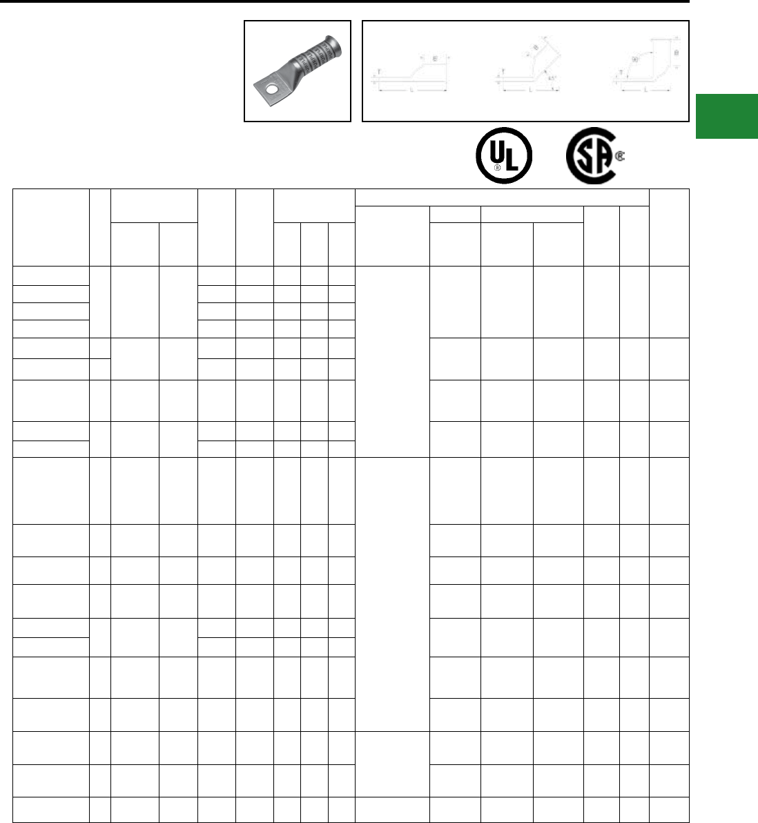
BURNDY®
Blue highlighted items are industry standard and most frequently ordered.
Canada: 1-800-387-6487 www.burndy.com US: 1-800-346-4175
ONE HOLE HYLUG™
FLEX CONDUCTOR
LONG BARREL
BELLED END
(Continued)
UL Listed 90° C,
600 Volts to 35kV ♦
Fig. 1 45° 90°
Catalog
Number
Fig
#
Conductor
Stud
Hole
Size
Tongue
Width
Figure
Dimensions
▲Installation Tooling
Wire
Strip
Length
Dieless
(# of crimps)
Mechanical Hydraulic
Color
Code
Die
IndexAWG
***
MM² (B) (T) (L)
MD6,
OUR840,
MD7-34R
BCT500HS,
Y500CTHS
Y35, Y39
Y750, Y46*
PAT750
YAV25-TC10-FXB
1
275/24
1/0 Weld
1/0 AWG
50
#8 - #10 0.83″ 1.50″ 0.12″ 2.45″
MY29-11 (2)
Y644HSXT (1)
Y81KFT (2)
Y81KFTMBH (2)
PAT81KFT-18V (2)
W25VT (4) W25VT (4) U25RT (2) Pink 12 1-9/16″
YAV25-TC516-FXB 5/16″ 0.83″ 1.50″ 0.12″ 2.64″
YAV25-TC38-FXB 3/8″ 0.83″ 1.50″ 0.12″ 2.77″
YAV25-TC12-FXB 1/2″ 0.83″ 1.50″ 0.12″ 3.20″
YAV26-TC38-FXB 1352/24
2/0 Weld
2/0 AWG
70 3/8″ 0.93″ 1.63″ 0.13″ 2.95″ W26VT (4) W26VT (4) U26RT (2) Black 13 1-13/16″
YAV26-TC12-FXB 1 1/2″ 0.93″ 1.63″ 0.13″ 3.39″
YAV27-TC12-FXB 1
3/0 AWG
450/24
3/0 Weld
95 1/2″ 1.04″ 1.64″ 0.14″ 3.44″ W27VT (4) W27VT (4) U27RT (2) Orange 14 1-13/16″
YAV28-TC38-FXB 1 4/0 AWG 4/0 Str.
(550/24)
— 1.14″ 1.77″ 0.14″ 3.19″ W28VT (4) W28VT (4) U28RT (2) Purple 15 1-7/8″
YAV28-TC12-FXB — 1.14″ 1.77″ 0.14″ 3.63″
YA30-TC12-FXB 1
Class G
259 str.
Class H
427 str.
250 Flex
— 1/2″ 1.20″ 2.16″ 0.16″ 4.04″
Y644HSXT (1)
Y81KFT (2)
Y81KFTMBH (2)
PAT81KFT-18V (2)
W29VT (4) W29VT (4) U29RT (2) Yellow 16 2-1/4″
YA31-TC12-FXB 1637/24
Class I,K,M 150 1/2″ 1.29″ 2.18″ 0.18″ 4.09″ W30VT (4) W30VT (4) U30RT (4) White 17 2-1/4″
YA32-TC12-FXB 1 313.1 kcmil 185 1/2″ 1.40″ 2.32″ 0.19″ 4.28″ W31VT (4) W31VT (4) U31RT (4) Red 18 2-1/4″
YA34-TC12-FXB 1373.7 kcmil
925/24 240 1/2″ 1.55″ 2.48″ 0.23″ 4.54″ W32VT (4) W32VT (4) U32RT (4) Blue 19 2-9/16″
YA36-TC12-FXB 1444.4 kcmil
1100/24 —1/2″ 1.73″ 2.95″ 0.26″ 5.09″ — — U34RT (4) Brown 20 3-1/16″
YA36-TC58-FXB 5/8″ 1.73″ 2.95″ 0.26″ 5.15″
YA38-TC12-FXB 1
550
kcmil
1325/24
300 1/2″ 1.07"3.08"0.27"5.07"— — U38RT (4) Pink L99 3-3/16″
YA38-TC58-FXB 1535.3 kcmil
1325/24 300 5/8″ 1.84″ 3.08″ 0.27″ 5.32″ — — U38XRT (4) Pink L99 3-3/16″
YA40-TC58-FXB 1646 kcmil
1600/24 400 5/8″ 1.98″ 3.24″ 0.30″ 5.53″ Y644HSXT (1)
Y81KFT (3)
Y81KFTMBH (3)
PAT81KFT-18V (3)
— — U39RT (4) Black 24 3-5/16″
YA44-TC58-FXB 1777.7 kcmil
1925/24 500 5/8″ 2.18″ 3.33″ 0.32″ 5.71″ — — U44XRT (4) Yellow L115 3-7/16″
YA46-TC58-FXB 1 1111 kcmil — 5/8″ 2.69″ 3.58″ 0.39″ 6.19″ — — — **P45RT (4) Yellow 29 3-11/16″
45° and 90° angles are available.
Please contact Customer Service to order:
1-800-346-4175
* Use PUADP-1 adapter with U dies in Y46 HYPRESS™
** The 16 MM2 and 120 MM2 referenced here are for both
Class 2 and Class 5 conductor
*** The MM2 conductor sizes listed are the
recommendations for Class 5 conductor
‡ P44RT for use with Y46 HYPRESS™ only.
PUADP-1 adapter not required.
▲See tooling section of this catalog for complete tool and
die listings. Use ONLY color-coded die recommendations
for -FX connectors. For nest/indentor system contact
factory.
♦ For applications greater than 2000 Volts consult cable
manufacturer for voltage stress relief instructions
Note: All dimensions shown are for reference only.
Compression Connections
Copper Compression — Flex — Long Barrel — Belled End — No Inspection Window
C-59
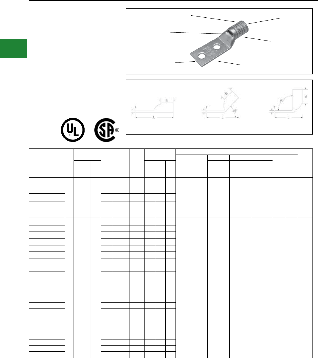
BURNDY®
Blue highlighted items are industry standard and most frequently ordered.
US: 1-800-346-4175 www.burndy.com Canada: 1-800-387-6487
TWO HOLE HYLUG™
FLEX CONDUCTOR
STANDARD BARREL
TYPES YA-L-2TC,
YA-L-2TC-FX, YAV-L-2TC-FX
COPPER COMPRESSION
TERMINAL
UL Listed 90° C,
600 Volts to 35kV ♦
45° and 90° angles are available.
Please contact Customer Service to order:
1-800-346-4175
Catalog
Number
Fig.
#
Conductor
Stud
Hole
Size
Stud
Hole
Spacing
Tongue
Width
Figure
Dimensions
▲ Installation Tooling
Wire
Strip
Length
Dieless
(# of Crimps)
Mechanical Hydraulic
Color
Code
Die
IndexAWG
***
MM² (B) (T) (L)
MD6,
OUR840,
MD7-34R
BCT500HS,
Y500CTHS
Y35, Y39
Y750, Y46*
PAT750
YA8C-L2TC10
1
#8 Weld
#8 AWG
37/24
#8 Sol
#6 Sol
10
#10 5/8″ 0.41″ 0.44″ 0.08″ 1.83″ MRC840 (1)
MY29-3 (1)
MY29-11 (1)
Y8MRB-1 (1)
Y1MRTC (1)
Y81KFT (1)
Y81KFTMBH (1)
PAT81KFT-18V (1)
W8CVT (1)
W8CRT (1)
X8CRT (1)
W8CVT (1)
W8CRT (1)
X8CRT (1)
U8CRT (1) Red 49 7/16″
YA8C-L2TC14 1/4″ 5/8″ 0.44″ 0.44″ 0.08″ 1.95″
YA8C-L2TC14E2 1/4″ 3/4″ 0.44″ 0.44″ 0.08″ 2.08″
YA8C-L2TC14E1 1/4″ 1″ 0.44″ 0.44″ 0.08″ 2.33″
YA8C-L2TC38 3/8″ 1″ 0.58″ 0.44″ 0.06″ 2.52″
YAV6C-L2TC10E9-FX
1
61/24
#6 Weld
#6 AWG
16
#10 1/2″ 0.48″ 0.50″ 0.08″ 1.81″
MRC840 (1)
MY29-11 (1)
Y1MRTC (1)
Y81KFT (1)
Y81KFTMBH (1)
PAT81KFT-18V (1)
Y644HSXT (1)
W5CVT (1)
W5CRT (1)
X5CRT (1)
W5CVT (1)
W5CRT (1)
X5CRT (1)
U5CRT (1) Blue 7 1/2″
YAV6C-L2TC10-FX #10 5/8″ 0.45″ 0.50″ 0.08″ 1.94″
YAV6C-L2TC10E4-FX #10 11/16″ 0.45″ 0.50″ 0.08″ 2.00″
YAV6C-L2TC10E2-FX #10 3/4″ 0.48″ 0.50″ 0.08″ 2.06″
YAV6C-L2TC14-FX 1/4″ 5/8″ 0.48″ 0.50″ 0.08″ 2.06″
YAV6C-L2TC14E2-FX 1/4″ 3/4″ 0.48″ 0.50″ 0.08″ 2.16″
YAV6C-L2TC14E1-FX 1/4″ 1″ 0.48″ 0.50″ 0.08″ 2.44″
YAV6C-L2TC516-FX 5/16″ 1″ 0.52″ 0.50″ 0.07″ 2.50″
YAV6C-L2TC38-FX 3/8″ 1″ 0.58″ 0.50″ 0.06″ 2.62″
YAV6C-L2NTC-FX 1/2″ 1-3/4″ 0.83″ 0.50″ 0.12″ 3.81″
YAV4C-L2TC14-FX
1
91/24
105/24
#4 Weld
#4 AWG
—
1/4″ 5/8″ 0.55″ 0.50″ 0.09″ 2.08″ MY29-11 (1)
Y1MRTC (1)
Y81KFT (1)
Y81KFTMBH (1)
PAT81KFT-18V (1)
Y644HSXT (1)
W4CVT (1)
W4CRT (1)
X4CRT (1)
W4CVT (1)
W4CRT (1)
X4CRT (1)
U4CRT (1) Gray 8 1/2″
YAV4C-L2TC14E2-FX 1/4″ 3/4″ 0.55″ 0.50″ 0.09″ 2.20″
YAV4C-L2TC14E1-FX 1/4″ 1″ 0.55″ 0.50″ 0.09″ 2.45″
YAV4C-L2TC516-FX 5/16″ 1″ 0.55″ 0.50″ 0.09″ 2.52″
YAV4C-L2TC38-FX 3/8″ 1″ 0.58″ 0.50″ 0.08″ 2.68″
YAV4C-L2NTC-FX 1/2″ 1-3/4″ 0.83″ 0.50″ 0.12″ 3.87″
YAV2C-L2TC14-FX
1
125/24
150/24
#2 Weld
#2 AWG
35
1/4″ 5/8″ 0.68″ 0.63″ 0.10″ 2.26″ MY29-11 (1)
Y1MRTC (2)
Y81KFT (1)
Y81KFTMBH (1)
PAT81KFT-18V (1)
Y644HSXT (1)
W2CVT (1)
W2CRT (1)
X2CRT (1)
W2CVT (1)
W2CRT (1)
X2CRT (1)
U2CRT (1) Brown 10 11/16″
YAV2C-L2TC14E2-FX 1/4″ 3/4″ 0.68″ 0.63″ 0.10″ 2.38″
YAV2C-L2TC14E1-FX 1/4″ 1″ 0.68″ 0.63″ 0.10″ 2.63″
YAV2C-L2TC516-FX 5/16″ 1″ 0.68″ 0.63″ 0.10″ 2.71″
YAV2C-L2TC38-FX 3/8″ 1″ 0.68″ 0.63″ 0.10″ 2.82″
YAV2C-L2NTC-FX 1/2″ 1-3/4″ 0.83″ 0.63″ 0.08″ 4.07″
COLOR CODE AND
DIE INFORMATION
INSPECTION
WINDOW
ELECTRO-TIN
PLATED CABLE
ACCOMMODATION
BEVELED
ENTRY
CRIMP
Fig. 1 45° 90°
* Use PUADP-1 adaptor with U dies in Y46 HYPRESS™
** The MM2 conductor size referenced here is for both
Class 2 and Class 5 conductor
*** The MM2 conductor sizes listed are the
recommendations for Class 5 conductor
▲See tooling section of this catalog for complete tool and
die listings. Use ONLY color-coded die recommendations
for -FX connectors. For nest/indentor system contact
factory
♦ For applications greater than 2000 Volts consult cable
manufacturer for voltage stress relief instructions
Note: All dimensions shown are for reference only.
Compression Connections
Copper Compression — Flex — Inspection Window
C-60
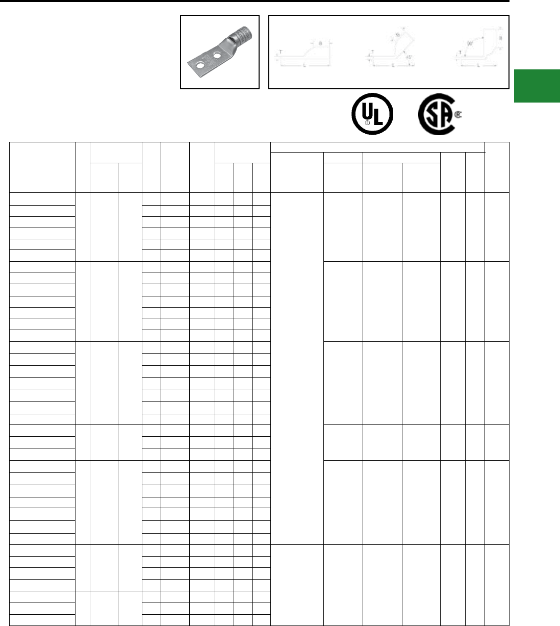
BURNDY®
Blue highlighted items are industry standard and most frequently ordered.
Canada: 1-800-387-6487 www.burndy.com US: 1-800-346-4175
TWO HOLE HYLUG™
FLEX CONDUCTOR
STANDARD BARREL
(Continued)
UL Listed 90° C,
600 Volts to 35kV ♦
Fig. 1 45° 90°
Catalog
Number
Fig.
#
Conductor
Stud
Hole
Size
Stud
Hole
Spacing
Tongue
Width
Figure Dimen-
sions
▲ Installation Tooling
Wire
Strip
Length
Dieless
(# of Crimps)
Mechanical Hydraulic
Color
Code
Die
IndexAWG
***
MM² (B) (T) (L)
MD6,
OUR840,
MD7-34R
BCT500HS,
Y500CTHS
Y35, Y39
Y750, Y46*
PAT750
YAV1C-L2TC14-FX
1
175/24
225/24
#1 Weld
#1 AWG
—
1/4″ 5/8″ 0.75″ 0.62″ 0.12″ 2.28″
MY29-11 (1)
Y644HSXT (1)
Y81KFT (1)
Y81KFTMBH (1)
PAT81KFT-18V (1)
W1CVT (1)
W1CRT-1 (1)
X1CRT-1 (1)
W1CVT (1)
W1CRT-1 (1)
X1CRT-1 (1)
U1CRT-1 (1) Green 11 11/16″
YAV1C-L2TC14E2-FX 1/4″ 3/4″ 0.75″ 0.62″ 0.12″ 2.41″
YAV1C-L2TC14E1-FX 1/4″ 1″ 0.75″ 0.62″ 0.12″ 2.65″
YAV1C-L2TC516-FX 5/16″ 1″ 0.75″ 0.62″ 0.12″ 2.72″
YAV1C-L2TC38-FX 3/8″ 1″ 0.75″ 0.62″ 0.12″ 2.85″
YAV1C-L2NTC-FX 1/2″ 1-3/4″ 0.83″ 0.62″ 0.11″ 4.04″
YAV25-L2TC14-FX
1
275/24
1/0 Weld
1/0 AWG
50
1/4″ 5/8″ 0.83″ 0.69″ 0.12″ 2.39″
W25VT (2)
W25RT (2)
X25RT (2)
W25VT (2)
W25RT (2)
X25RT (2)
U25RT (1) Pink 12 11/16″
YAV25-L2TC14E2-FX 1/4″ 3/4″ 0.83″ 0.69″ 0.12″ 2.51″
YAV25-L2TC516E2-FX 5/16″ 3/4″ 0.83″ 0.69″ 0.12″ 2.57″
YAV25-L2TC516-FX 5/16″ 1″ 0.83″ 0.69″ 0.12″ 2.82″
YAV25-L2TC38-FX 3/8″ 1″ 0.83″ 0.69″ 0.12″ 2.95″
YAV25-L2TC12E1-FX 1/2″ 1″ 0.83″ 0.69″ 0.12″ 3.20″
YAV25-L2NTC-FX 1/2″ 1-3/4″ 0.83″ 0.69″ 0.12″ 4.14″
YAV26-L2TC14-FX
1
325/24
2/0 Weld
2/0 AWG
70
class 5
95
class 2
1/4″ 5/8″ 0.93″ 0.81″ 0.13″ 2.56″
W26VT (2)
W26RT (2)
X26RT (2)
W26VT (2)
W26RT (2)
X26RT (2)
U26RT (1) Black 13 13/16″
YAV26-L2TC14E2-FX 1/4″ 3/4″ 0.93″ 0.81″ 0.13″ 2.68″
YAV26-L2TC516-FX 5/16″ 1″ 0.93″ 0.81″ 0.13″ 2.99″
YAV26-L2TC38-FX 3/8″ 1″ 0.93″ 0.81″ 0.13″ 3.12″
YAV26-L2TC38E10-FX 3/8″ 1-1/4″ 2.08″ 0.81″ 0.13″ 3.37″
YAV26-L2TC12E1-FX 1/2″ 1″ 0.93″ 0.81″ 0.13″ 3.37″
YAV26-L2NTC-FX 1/2″ 1-3/4″ 0.93″ 0.81″ 0.13″ 4.31″
YAV27-L2TC14-FX
1
450/24
3/0 Weld
3/0 AWG
95
1/4″ 5/8″ 1.03″ 1.00″ 0.14″ 2.79″ W27VT (2)
W27RT (2)
X27RT (3)
W27VT (2)
W27RT (2)
X27RT (3)
U27RT (1) Orange 14 1″
YAV27-L2TC38-FX 3/8″ 1″ 1.03″ 1.00″ 0.14″ 3.35″
YAV27-L2NTC-FX 1/2″ 1-3/4″ 1.03″ 1.00″ 0.14″ 4.54″
YAV28-L2TC14E2-FX
1
550/24
4/0 Weld
4/0 AWG
120
1/4″ 3/4″ 1.14″ 1.03″ 0.15″ 2.99″
W28VT (2)
W28RT (2)
X28RT (3)
W28VT (2)
W28RT (2)
X28RT (3)
U28RT (1) Purple 15 1-1/16″
YAV28-L2TC14-FX 1/4″ 5/8″ 1.14″ 1.03″ 0.15″ 2.86″
YAV28-L2TC516-FX 5/16″ 1″ 1.14″ 1.03″ 0.15″ 3.30″
YAV28-L2TC38-FX 3/8″ 1″ 1.14″ 1.03″ 0.15″ 3.43″
YAV28-L2TC12E1-FX 1/2″ 1″ 1.14″ 1.03″ 0.15″ 3.68″
YAV28-L2TC12-FX 1/2″ 1-1/4″ 1.14″ 1.03″ 0.15″ 3.93″
YAV28-L2NTC-FX 1/2″ 1-3/4″ 1.14″ 1.03″ 0.15″ 4.62″
YAV29-L2TC14-FX
1
550/24
4/0 Weld
4/0 AWG
—
1/4″ 5/8″ 1.18″ 1.03″ 0.16″ 2.87″
Y644HSXT (1)
Y81KFT (1)
Y81KFTMBH (1)
PAT81KFT-18V (1)
W29VT (2)
X29RT (4)
W29VT (2)
W29RT (2)
X29RT (4)
U29RT (1) Yellow 16 1-1/16″
YAV29-L2TC14E2-FX 1/4″ 3/4″ 1.18″ 1.03″ 0.16″ 2.99″
YAV29-L2TC516-FX 5/16″ 1″ 1.18″ 1.03″ 0.16″ 3.31″
YAV29-L2TC38-FX 3/8″ 1″ 1.18″ 1.03″ 0.16″ 3.43″
YAV29-L2TC12E1-FX
1550/24
4/0 Weld —
1/2″ 1″ 1.18″ 1.03″ 0.16″ 3.68″
YAV29-L2TC12-FX 1/2″ 1-1/4″ 1.18″ 1.03″ 0.16″ 3.93″
YAV29-L2NTC-FX 1/2″ 1-3/4″ 1.18″ 1.03″ 0.16″ 4.62″
* Use PUADP-1 adaptor with U dies in Y46 HYPRESS™
** The MM2 conductor size referenced here is for both
Class 2 and Class 5 conductor
*** The MM2 conductor sizes listed are the
recommendations for Class 5 conductor
▲See tooling section of this catalog for complete tool and
die listings. Use ONLY color-coded die recommendations
for -FX connectors. For nest/indentor system contact
factory
♦ For applications greater than 2000 Volts consult cable
manufacturer for voltage stress relief instructions
Note: All dimensions shown are for reference only.
Compression Connections
Copper Compression — Flex — Inspection Window
45° and 90° angles are available.
Please contact Customer Service to order:
1-800-346-4175
C-61
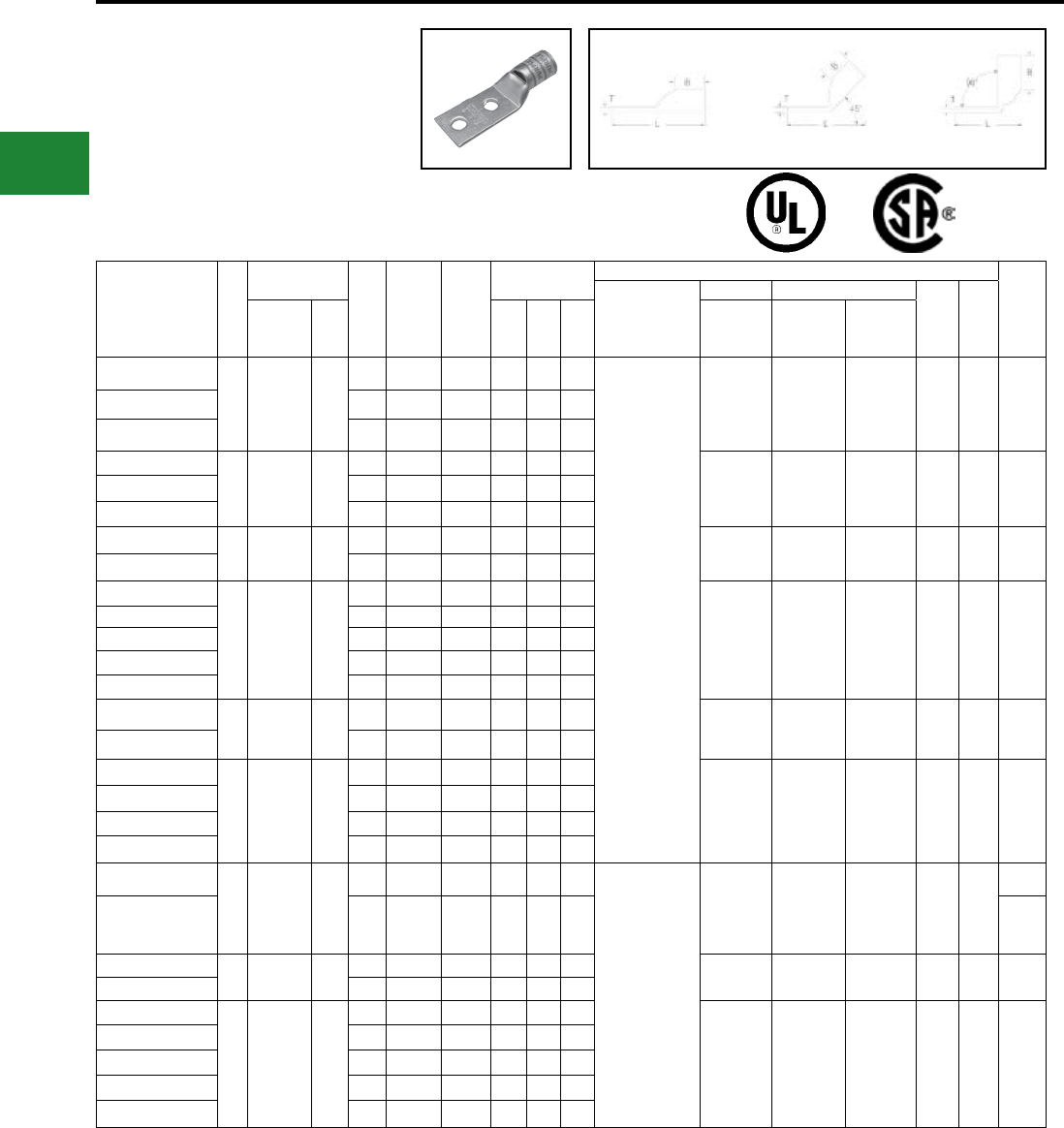
BURNDY®
Blue highlighted items are industry standard and most frequently ordered.
US: 1-800-346-4175 www.burndy.com Canada: 1-800-387-6487
Catalog
Number
Fig.
#
Conductor
Stud
Hole
Size
Stud
Hole
Spacing
Tongue
Width
Figure Dimen-
sions
▲ Installation Tooling
Wire
Strip
Length
Dieless
(# of Crimps)
Mechanical Hydraulic
Color
Code
Die
IndexAWG
***
MM² (B) (T) (L)
MD6,
OUR840,
MD7-34R
BCT500HS,
Y500CTHS
Y35, Y39
Y750, Y46*
PAT750
YA30-L2TC516-FX
1
250 Flex
CLASS G
259 Str.
CLASS H
427 Str.
—
5/16″ 1″ 1.69″ 1.03″ 0.16″ 3.32″
Y644HSXT (1)
Y81KFT (1)
Y81KFTMBH (1)
PAT81KFT-18V (1)
W29VT (2)
X29RT (4)
W29VT (2)
W29RT (2)
X29RT (4)
U29RT (1) Yellow 16 1-1/16″
YA30-L2TC38-FX 3/8″ 1″ 1.20″ 1.03″ 0.16″ 3.45″
YA30-L2NTC-FX 1/2″ 1-3/4″ 1.20″ 1.03″ 0.16″ 4.63″
YA31-L2TC38-FX
1
250 Flex
637/24
CLASS
I,K,M
150
3/8″ 1″ 1.29″ 1.06″ 0.18″ 3.51″
W30VT (2) W30VT (2)
W30RT (2) U30RT (2) White
17
or
298
1-1/8″
YA31-L2TC12-FX 1/2″ 1-1/4″ 1.29″ 1.06″ 0.18″ 4.01″
YA31-L2NTC-FX 1/2″ 1-3/4″ 1.29″ 1.06″ 0.18″ 4.70″
YA32-L2TC38-FX 1775/24
313.1 kcmil 185 3/8″ 1″ 1.40″ 1.19″ 0.19″ 3.69″ W31VT (2) W31VT (2)
W31RT (2) U31RT (2) Red
18
or
324
1-1/4"
YA32-L2NTC-FX 1/2″ 1-3/4″ 1.40″ 1.19″ 0.19″ 4.88″
YA34-L2TC516-FX
1
373.7 kcmil
925/24
(350 kcmil
Nom.)
240
5/16″ 1″ 1.55″ 1.27″ 0.23″ 3.75″
W32VT (2) W32VT (2)
W32RT (2) U32RT (2) Blue
19
or
470
1-5/16″
YA34-L2TC38-FX 3/8″ 1″ 1.55″ 1.27″ 0.23″ 3.88″
YA34-L2NTC38-FX 3/8″ 1-3/4″ 1.55″ 1.27″ 0.23″ 4.63″
YA34-L2TC12-FX 1/2″ 1-1/4″ 1.55″ 1.27″ 0.23″ 4.38″
YA34-L2NTC-FX 1/2″ 1-3/4″ 1.55″ 1.27″ 0.23″ 5.06″
YA36-L2TC38-FX 11100/24
444.4 kcmil —3/8″ 1″ 1.74″ 1.38″ 0.27″ 4.24″ — — U34RT (2) Brown
20
or
299
1-7/16″
YA36-L2NTC-FX 1/2″ 1-3/4″ 1.74″ 1.38″ 0.27″ 5.24″
YA38-L2TC516-FX
1
535.3 kcmil
1325/24
(500 kcmil
nom.)
300
5/16″ 1″ 1.84″ 1.45″ 0.27″ 4.04″
— — U38XRT (2) Pink L99 1-7/16″
YA38-L2TC38-FX 3/8″ 1″ 1.84″ 1.45″ 0.27″ 4.35″
YA38-L2TC12-FX 1/2″ 1-1/4″ 1.84″ 1.45″ 0.27″ 4.67″
YA38-L2NTC-FX 1/2″ 1-3/4″ 1.84″ 1.45″ 0.27″ 5.35″
YA39-L2TC38E10-FX
1600 kcmil
1472/24 —
3/8″ 1-1/4″ 2.26″ 1.42″ 0.27″ 4.61″
Y644HSXT (1)
Y81KFT (2)
Y81KFTMBH (2)
PAT81KFT-18V (2)
— — U38RT (2) Purple 400
1-1/2"
YA39-L2NTC-FX 1/2″ 1-3/4″ 1.91″ 1.42″ 0.27″ 5.36″ 1-3/8″
YA40-L2TC38-FX 1646 kcmil
1600/24 400 3/8″ 1″ 1.98″ 1.42″ 0.30″ 4.38″ — — U39RT (2) Black 24 1-5/16″
YA40-L2NTC-FX 1/2″ 1-3/4″ 1.98″ 1.42″ 0.30″ 5.38″
YA44-L2TC38-FX
1
777.7 kcmil
1925/24
750 kcmil
nom.)
500
3/8″ 1″ 2.19″ 1.65″ 0.33″ 4.74″
— — U44XRT (2) Yellow L115 1-5/8″
YA44-L2TC12-FX 1/2″ 1-1/4″ 2.19″ 1.65″ 0.33″ 5.05″
YA44-L2TC12E3-FX 1/2″ 1-1/2″ 2.19″ 1.65″ 0.33″ 5.30″
YA44-L2NTC-FX 1/2″ 1-3/4″ 2.19″ 1.65″ 0.33″ 5.74″
YA44-L2TC58-FX 5/8″ 1-1/2″ 2.19″ 1.65″ 0.33″ 5.55″
* Use PUADP-1 adaptor with U dies in Y46 HYPRESS™
** The MM2 conductor size referenced here is for both
Class 2 and Class 5 conductor
*** The MM2 conductor sizes listed are the
recommendations for Class 5 conductor
▲See tooling section of this catalog for complete tool and
die listings. Use ONLY color-coded die recommendations
for -FX connectors. For nest/indentor system contact
factory
♦ For applications greater than 2000 Volts consult cable
manufacturer for voltage stress relief instructions
Note: All dimensions shown are for reference only.
TWO HOLE HYLUG™
FLEX CONDUCTOR
STANDARD BARREL
(Continued)
UL Listed 90° C,
600 Volts to 35kV ♦
Compression Connections
Copper Compression — Flex — Inspection Window
Fig. 1 45° 90°
45° and 90° angles are available.
Please contact Customer Service to order:
1-800-346-4175
C-62
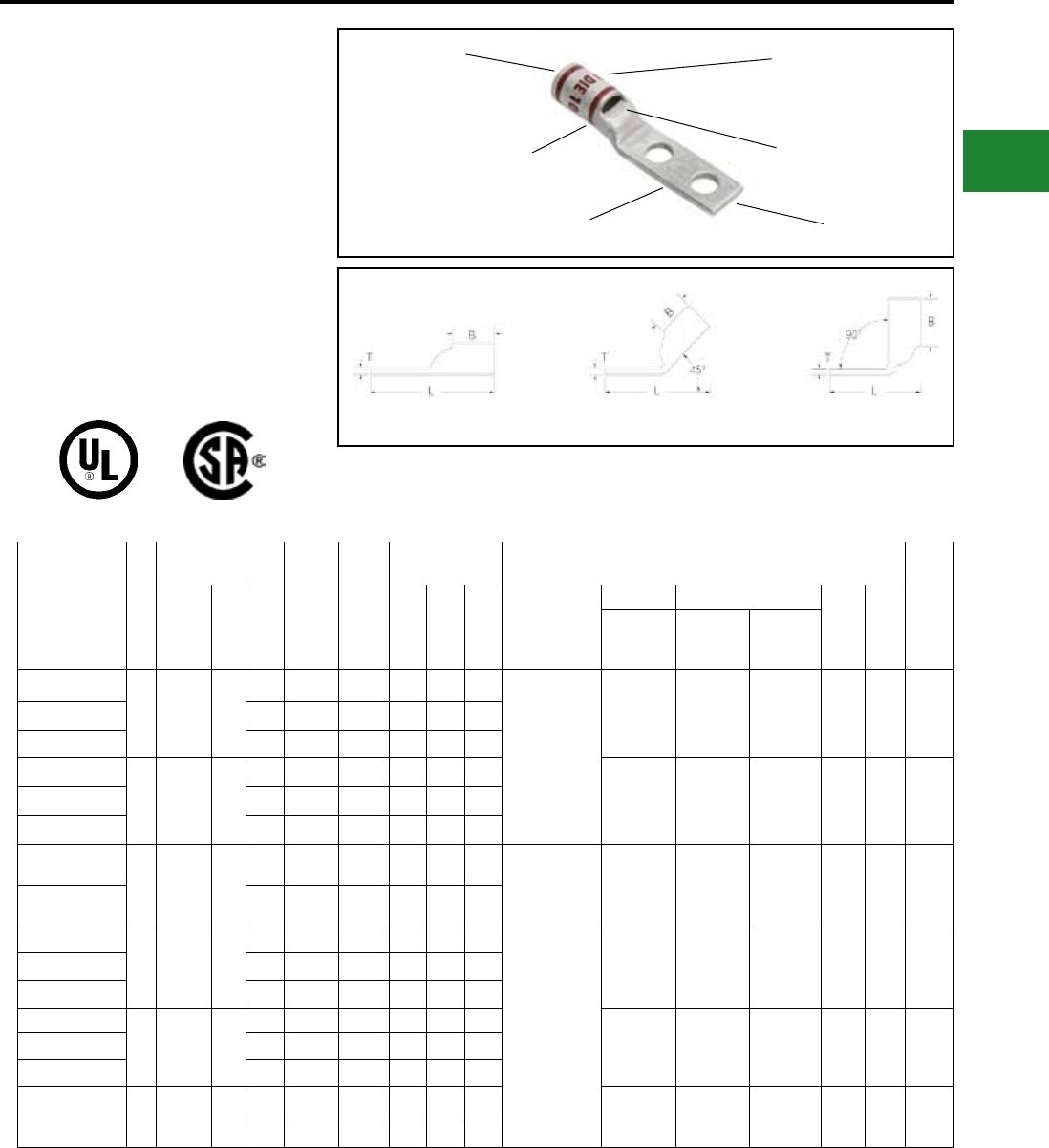
BURNDY®
Blue highlighted items are industry standard and most frequently ordered.
Canada: 1-800-387-6487 www.burndy.com US: 1-800-346-4175
TWO HOLE HYLUG™ FLEX
CONDUCTOR STANDARD
BARREL NARROW TONGUE
TYPE YAV-L-2NTFX
COPPER COMPRESSION
NARROW TONGUE TERMINAL
UL Listed 90º C
600 Volts to 35 kV ♦
45° and 90° angles are available.
Please contact Customer Service to order:
1-800-346-4175
Catalog
Number
Fig
#
Conductor
Stud
Hole
Size
Stud
Hole
Spacing
Tongue
Width
Figure
Dimensions ▲ Installation Tooling
Wire
Strip
LengthAWG
***
MM² (B) (T) (L)
Dieless
(# of crimps)
Mechanical Hydraulic
Color
Code
Die
Index
MD6,
OUR840,
MD7-34R
BCT500HS,
Y500CTHS
Y35, Y39
Y750, Y46*
PAT750
YAV4CL2NT10FX
1
#4 AWG
#4 Weld
91/24
105/24
—
#10 5/8″ 0.41″ 0.50" 0.09" 1.95"
MY29-11 (1)
Y1MRTC (2)
Y81KFT (1)
Y81KFTMBH (1)
PAT81KFT-18V (1)
Y644HSXT (1)
W4CVT (1)
W4CRT (1)
X4CRT (1)
W4CVT (1)
W4CRT (1)
X4CRT (1)
U4CRT (1) Gray 8 9/16"
YAV4CL2NT10E1FX #10 1″ 0.41″ 0.50" 0.09" 2.33"
YAV4CL2NT14FX 1/4″ 5/8″ 0.45″ 0.50" 0.09" 2.08"
YAV2CL2NT10FX
1
#2 AWG
#2 Weld
1 25/24
150/24
35
#10 5/8″ 0.48″ 0.63" 0.10" 2.14" W2CVT (1)
W2CRT (1)
X2CRT (1)
W2CVT (1)
W2CRT (1)
X2CRT (1)
U2CRT (1) Brown 10 11/16"
YAV2CL2NT14FX 1/4″ 5/8″ 0.48″ 0.63" 0.10" 2.26"
YAV2CL2NT14E1FX 1/4″ 1″ 0.48″ 0.63" 0.10" 2.63"
YAV1CL2NT14FX
1
#1 AWG
#1 Weld
175/24
225/24
—
1/4″ 5/8″ 0.50″ 0.62" 0.12" 2.28"
MY29-11 (1)
Y644HSXT (1)
Y81KFT (1)
Y81KFTMBH (1)
PAT81KFT-18V (1)
W1CVT (1)
W1CRT-1 (1)
X1CRT-1 (1)
W1CVT (1)
W1CRT-1 (1)
X1CRT-1 (1)
U1CRT-1 (1) Green 11 11/16"
YAV1CL2NT516FX 5/16″ 1″ 0.58″ 0.62" 0.12" 2.72"
YAV25L2NT14FX
1
1/0 AWG
1/0 Weld
275/24
50
1/4″ 5/8″ 0.64″ 0.69" 0.12" 2.39" W25VT (2)
W25RT (2)
X25RT (2)
W25VT (2)
W25RT (2)
X25RT (2)
U25RT (1) Pink 12 11/16"
YAV25L2NT14E1FX 1/4″ 1″ 0.64″ 0.69" 0.12" 2.76"
YAV25L2NT516FX 5/16″ 1″ 0.58″ 0.69" 0.12" 2.82"
YAV26L2NT14FX
1
2/0 AWG
2/0 Weld
325/24
70
1/4″ 5/8″ 0.64″ 0.81" 0.13" 2.56" W26VT (2)
W26RT (2)
X26RT (2)
W26VT (2)
W26RT (2)
X26RT (2)
U26RT (1) Black 13 13/16"
YAV26L2NT516FX 5/16″ 1″ 0.58″ 0.81" 0.13" 2.99"
YAV26L2NT38FX 3/8″ 1″ 0.63″ 0.81" 0.13" 3.23"
YAV28L2ENT14FX
1
4/0 AWG
4/0 Weld
550/24
—
1/4″ 5/8″ 0.76″ 1.03" 0.15" 2.86" W28VT (2)
W28RT (2)
X28RT (3)
W28VT (2)
W28RT (2)
X28RT (3)
U28RT (1) Purple 15 1-1/16"
YAV28L2NT38FX 3/8″ 1″ 0.94″ 1.03" 0.15" 3.43"
Consult cable manufacturers for stress relief instructions
♦ For applications greater than 2000 Volts consult cable
manufacturer for voltage stress relief instructions
* Use PUADP-1 adaptor with U dies in Y46 HYPRESS™
*** The MM2 conductor sizes Listed are the
recommendations for CLASS 5 conductor
▲See tooling section of this catalog for complete tool and
die listings. Use ONLY color-coded die recommendations
for -FX connectors
Note: All dimensions shown are for reference only
COLOR CODE AND
DIE INFORMATION
INSPECTION
WINDOW
ELECTRO-TIN
PLATED
CABLE
ACCOMMODATION
BEVELED
ENTRY
CRIMP
Fig. 1 45° 90°
Compression Connections
Copper Compression — Flex — Standard Barrel — Narrow Tongue
C-63
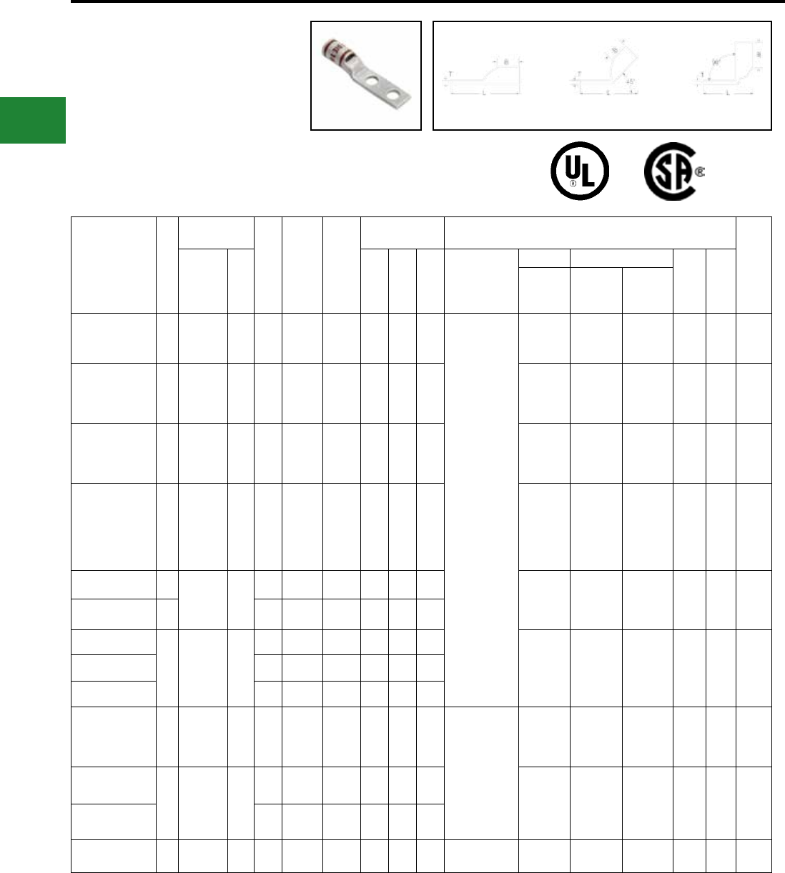
BURNDY®
Blue highlighted items are industry standard and most frequently ordered.
US: 1-800-346-4175 www.burndy.com Canada: 1-800-387-6487
TWO HOLE HYLUG™
FLEX CONDUCTOR
STANDARD BARREL
NARROW TONGUE
(Continued)
UL Listed 90º C
600 Volts to 35 kV ♦
45° and 90° angles are available.
Please contact Customer Service to order :
1-800-346-4175
Catalog Number
Fig
#
Conductor
Stud
Hole
Size
Stud
Hole
Spacing
Tongue
Width
Figure
Dimensions ▲ Installation Tooling
Wire
Strip
LengthAWG
***
MM² (B) (T) (L)
Dieless
(# of crimps)
Mechanical Hydraulic
Color
Code
Die
In-
dex
MD6,
OUR840,
MD7-34R
BCT500HS,
Y500CTHS
Y35, Y39
Y750, Y46*
PAT750
YAV29L2NT38FX 1
4/0 AWG
4/0 Weld
550/24
— 3/8" 1" 0.94" 1.03" 0.16" 3.43"
Y644HSXT (1)
Y81KFT (1)
Y81KFTMBH (1)
PAT81KFT-18V (1)
W29VT (2)
X29RT (4)
W29VT (2)
W29RT (2)
X29RT (4)
U29RT (1) Yellow 16 1-1/16"
YA31L2NT38FX 1
250 Flex
637/24
Class I,K,M
150 3/8" 1" 0.96" 1.06" 0.18" 3.51" W30VT (2) W30VT (2)
W30RT (2) U30RT (2) White
17
or
298
1-1/8"
YA32L2NT38FX 1
313.1 kcmil
775/24
300 Flex
185 3/8" 1" 0.96" 1.19" 0.20" 3.69" W31VT (2) W31VT (2)
W31RT (2) U31RT (2) Red 18 1-1/4"
YA34L2NT38FX 1
373.7 kcmil
925/24
(350 kcmil
Nom.)
240 3/8" 1" 0.96" 1.27" 0.23" 3.88" W32VT (2) W32VT (2)
W32RT (2) U32RT (2) Blue
19
or
470
1-5/16"
YA36L2NT38FX 1444.4 kcmil
1100/24
450 Flex
—
3/8" 1" 1.63" 1.38" 0.27" 4.24"
— — U34RT (2) Brown 20 1-7/16"
YA36L2ENT38E10FX 1 3/8" 1-1/4″ 2.30" 1.38" 0.27" 4.49"
YA38L2ENT38FX
1
535.3 kcmil
1325/24
500 Flex
300
3/8" 1" 1.50" 1.45" 0.27" 4.35"
— — U38XRT (2) Pink L99 1-7/16"
YA38L2NT38FX 3/8" 1" 1.63" 1.45" 0.27" 4.35"
YA38L2NNTFX 1/2" 1-3/4″ 1.63" 1.45" 0.27" 5.35"
YA40L2NNTFX 1
646 kcmil
1600/24
650 Flex
400 1/2" 1-3/4″ 1.63" 1.42" 0.30" 5.38"
Y644HSXT (1)
Y81KFT (2)
Y81KFTMBH (2)
PAT81KFT-18V (2)
— — U39RT (2) Black 24 1-5/16"
YA44L2NT38FX
1
777.7 kcmil
1925/24
(750 kcmil
nom.)
500
3/8" 1" 1.63" 1.65" 0.33" 4.74"
— — U44XRT (2) Yellow L115 1-5/8"
YA44L2NNTFX 1/2" 1-3/4″ 1.63" 1.65" 0.33" 5.74"
YA45L2NT38FX 1929 kcmil
2300/24 — 3/8" 1" 1.70" 2.00" 0.38" 5.18" — — — P44RT (2) White 27 2-1/16"
Consult cable manufacturers for stress relief instructions
♦ For applications greater than 2000 Volts consult cable
manufacturer for voltage stress relief instructions
* Use PUADP-1 adaptor with U dies in Y46 HYPRESS™
*** The MM2 conductor sizes Listed are the
recommendations for CLASS 5 conductor
▲See tooling section of this catalog for complete tool and
die listings. Use ONLY color-coded die recommendations
for -FX connectors
Note: All dimensions shown are for reference only.
Fig. 1 45° 90°
Compression Connections
Copper Compression — Flex — Standard Barrel — Narrow Tongue
C-64
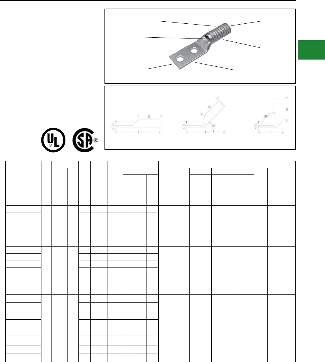
BURNDY®
Blue highlighted items are industry standard and most frequently ordered.
Canada: 1-800-387-6487 www.burndy.com US: 1-800-346-4175
TWO HOLE HYLUG™
FLEX CONDUCTOR
LONG BARREL WITH
INSPECTION WINDOW
TYPE YAZ-FX
COPPER COMPRESSION
TERMINAL
UL Listed 90° C,
600 Volts to 35kV ♦
45° and 90° angles are available.
Please contact Customer Service to order :
1-800-346-4175
DIE AND COLOR
CODE INFORMATION
CABLE
ACCOMMODATION
INSPECTION
WINDOW
ELECTRO-TIN
PLATED
BEVELED
ENTRY
CRIMPS
Fig. 1 45° 90°
Catalog Number
Fig.
#
Conductor
Stud
Hole
Size
Stud
Hole
Spacing
Tongue
Width
Figure
Dimensions
▲ Installation Tooling
Wire
Strip
LengthAWG
***
MM²
Dieless
(# of Crimps)
Mechanical Hydraulic
Color
Code
Die
Index(B) (T) (L)
MD6,
OUR840,
MD7-34R
BCT500HS,
Y500CTHS
Y35, Y39
Y750, Y46*
PAT750
YAZV102TC14E1 114-10
AWG — 1/4″ 1″ 1.65″ 0.69″ 0.05″ 2.53″ Y8MRB-1 (2)
Y10D (2) — — — — — 3/4″
YAZ8C2TC10FX
1
37/24
#8 Weld
#8 AWG
#8 Sol
#6 Sol
**
10
#10 5/8″ 0.41″ 0.81″ 0.08″ 2.20″ Y8MRB-1 (2)
MY29-11 (2)
Y1MRTC (2)
Y81KFT (1)
Y81KFTMBH (1)
PAT81KFT-18V (1)
W8CVT (2)
W8CRT (2)
X8CRT (2)
W8CVT (2)
W8CRT (2)
X8CRT (2)
U8CRT (2) Red 49 1″
YAZ8C2TC10E2FX #10 3/4″ 0.41″ 0.75″ 0.08″ 2.33″
YAZ8C2TC14FX 1/4″ 5/8″ 0.44″ 0.81″ 0.08″ 2.32″
YAZ8C2TC14E2FX 1/4″ 3/4″ 0.44″ 0.81″ 0.08″ 2.45″
YAZ8C2TC14E1FX 1/4″ 1″ 0.44″ 0.81″ 0.08″ 2.70″
YAZ8C2TC38FX 3/8″ 1″ 0.58 0.81″ 0.06″ 2.89″
YAZV6C2TC10E2FX
1
61/24
#6 Weld
#6 AWG
**
16
#10 3/4″ 0.48″ 0.75″ 0.08″ 2.22″
MY29-11 (2)
Y644HSXT (1)
Y1MRTC (2)
Y81KFT (1)
Y81KFTMBH (1)
PAT81KFT-18V (1)
W5CVT (2)
W5CRT (2)
X5CRT (2)
W5CVT (2)
W5CRT (2)
X5CRT (2)
U5CRT (2) Blue
7
or
374
1-3/16″
YAZV6C2TC14FX 1/4″ 5/8″ 0.48″ 0.75″ 0.08″ 2.22″
YAZV6C2TC14E2FX 1/4″ 3/4″ 0.48″ 0.75″ 0.08″ 2.35″
YAZV6C2TC14E1FX 1/4″ 1″ 0.48″ 0.75″ 0.08″ 2.60″
YAZV6C2TC38E2FX 3/8″ 3/4″ 0.58″ 0.75″ 0.06″ 2.53″
YAZV6C2TC38E6FX 3/8″ 7/8″ 0.58″ 0.75″ 0.06″ 2.66″
YAZV6C2TC38FX 3/8″ 1″ 0.58″ 0.75″ 0.06″ 2.78″
YAZV4C2TC14FX
1
91/24-
105/24
#4 Weld
#4 AWG
—
1/4″ 5/8″ 0.55″ 1.25″ 0.09″ 2.83″ Y1MRTC (4)
MY29-11 (2)
Y644HSXT (1)
Y81KFT (1)
Y81KFTMBH (1)
PAT81KFT-18V (1)
W4CVT (2)
W4CRT (2)
X4CRT (2)
W4CVT (2)
W4CRT (2)
X4CRT (2)
U4CRT (2) Gray
8
or
346
1-5/16″
YAZV4C2TC14E2FX 1/4″ 3/4″ 0.55″ 1.25″ 0.09″ 2.95″
YAZV4C2TC38E2-FX 3/8″ 3/4″ 0.58″ 1.25″ 0.08″ 3.14″
YAZV4C2TC38FX 3/8″ 1″ 0.58″ 1.25″ 0.08″ 3.39″
YAZV2C2TC14FX
1
125/24-
150/24
#2 Weld
#2 AWG
35
1/4″ 5/8″ 0.68″ 1.38″ 0.10″ 3.01″ Y1MRTC (4)
MY29-11 (4)
Y644HSXT (1)
Y81KFT (1)
Y81KFTMBH (1)
PAT81KFT-18V (1)
W2CVT (2)
W2CRT (2)
X2CRT (2)
W2CVT (2)
W2CRT (2)
X2CRT (2)
U2CRT (2) Brown 10 1-7/16″
YAZV2C2TC14E2FX 1/4″ 3/4″ 0.68″ 1.38″ 0.10″ 3.13″
YAZV2C2TC38FX 3/8″ 1″ 0.68″ 1.38″ 0.10″ 3.57″
YAZV2C2NTCFX 1/2″ 1-3/4″ 0.83″ 1.38″ 0.10″ 4.76″
* Use PUADP-1 adapter with U dies in Y46 HYPRESS™
** The MM2 conductor size referenced here is for both
Class 2 and Class 5 conductor
*** The MM2 conductor sizes listed are the
recommendations for Class 5 conductor
▲See tooling section of this catalog for complete tool and
die listings. Use ONLY color-coded die recommendations
for -FX connectors. For nest/indentor system contact
factory
♦ For applications greater than 2000 Volts consult cable
manufacturer for voltage stress relief instructions
Note: All dimensions shown are for reference only.
Compression Connections
Copper Compression — Flex — Long Barrel — Inspection Window
C-65
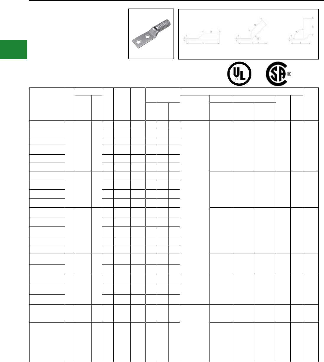
BURNDY®
Blue highlighted items are industry standard and most frequently ordered.
US: 1-800-346-4175 www.burndy.com Canada: 1-800-387-6487
TWO HOLE HYLUG™
FLEX CONDUCTOR
LONG BARREL WITH
INSPECTION WINDOW
(Continued)
UL Listed 90° C,
600 Volts to 35kV ♦
45° and 90° angles are available.
Please contact Customer Service to order:
1-800-346-4175
Fig. 1 45° 90°
Catalog Number
Fig.
#
Conductor
Stud
Hole
Size
Stud
Hole
Spacing
Tongue
Width
Figure
Dimensions
▲ Installation Tooling
Wire
Strip
LengthAWG
***
MM²
Dieless
(# of Crimps)
Mechanical Hydraulic
Color
Code
Die
Index(B) (T) (L)
MD6,
OUR840,
MD7-34R
BCT500HS,
Y500CTHS
Y35, Y39
Y750, Y46*
PAT750
YAZV1C2TC14FX
1
175/24-
225/24
#1 Weld
#1 AWG
—
1/4″ 5/8″ 0.75″ 1.38″ 0.12″ 3.04″
MY29-11 (2)
Y644HSXT (1)
Y81KFT (2)
Y81KFTMBH (2)
PAT81KFT-18V (2)
W1CVT (2)
W1CRT-1 (2)
X1CRT-1 (2)
W1CVT (2)
W1CRT-1 (2)
X1CRT-1 (2)
U1CRT-1 (2) Green
11
or
375
1-7/16″
YAZV1C2TC14E2FX 1/4″ 3/4″ 0.75″ 1.38″ 0.12″ 3.16″
YAZV1C2TC14E1FX 1/4″ 1″ 0.75″ 1.38″ 0.12″ 3.41″
YAZV1C2TC516E6FX 5/16″ 7/8″ 0.75″ 1.38″ 0.12″ 3.35″
YAZV1C2TC516FX 5/16″ 1″ 0.75″ 1.38″ 0.12″ 3.47″
YAZV1C2TC38FX 3/8″ 1″ 0.75″ 1.38″ 0.12″ 3.60″
YAZV252TC14FX
1
275/24
1/0 Weld
1/0 AWG
50
1/4″ 5/8″ 0.83″ 1.50″ 0.12″ 3.20″
W25VT (4)
W25RT (4)
X25RT (4)
W25VT (4)
W25RT (4)
X25RT (4)
U25RT (2) Pink
12
or
348
1-9/16″
YAZV252TC14E2FX 1/4″ 3/4″ 0.83″ 1.50″ 0.12″ 3.32″
YAZV252TC38FX 3/8″ 1″ 0.83″ 1.50″ 0.12″ 3.76″
YAZV252NTCFX 1/2″ 1-3/4″ 0.83″ 1.50″ 0.12″ 4.95″
YAZV262TC14FX
1
325/24
2/0 Weld
2/0 AWG
70
1/4″ 5/8″ 0.93″ 1.50″ 0.13″ 3.20″
W26VT (4)
W26RT (4)
X26RT (4)
W26VT (4)
W26RT (4)
X26RT (4)
U26RT (2) Black 13 1-9/16″
YAZV262TC14E2FX 1/4″ 3/4″ 0.93″ 1.50″ 0.13″ 3.32″
YAZV262TC38E6FX 3/8″ 7/8″ 1.71"1.50″ 0.13″ 3.68″
YAZV262TC38FX 3/8″ 1″ 0.93″ 1.50″ 0.13″ 3.76″
YAZV262NTCFX 1/2″ 1-3/4″ 0.93″ 1.50″ 0.13″ 4.95″
YAZV272TC14E2FX
1
450/24
3/0 Weld
3/0 AWG
95
1/4″ 3/4″ 1.03″ 1.50″ 0.14″ 3.36″ W27VT (4)
W27RT (4)
X27RT (6)
W27VT (4)
W27RT (4)
X27RT (6)
U27RT (2) Orange 14 1-9/16″
YAZV272TC38FX 3/8″ 1″ 1.03″ 1.50″ 0.14″ 3.80″
YAZV282TC14E2FX
1
550/24
4/0 Weld
4/0 AWG
120
1/4″ 3/4″ 1.14″ 1.62″ 0.15″ 3.52″
W28VT (4)
W28RT (4)
X28RT (6)
W28VT (4)
W28RT (4)
X28RT (6)
U28RT (2) Purple 15 1-11/16″
YAZV282TC38FX 3/8″ 1″ 1.14″ 1.62″ 0.15″ 3.96″
YAZV282NTCFX 1/2″ 1-3/4″ 1.14″ 1.62″ 0.15″ 4.93″
YAZV292NT516FX 1
4/0 Flex
Class I,
K, M
— 5/16″ 1-3/4″ 0.96″ 2.00″ 0.16″ 4.62″
Y644HSXT (1)
Y81KFT (2)
Y81KFTMBH (2)
PAT81KFT-18V (2)
W29VT (4)
X29RT (8)
W29RT (4)
W29VT (4)
X29RT (8)
U29RT (2) Yellow 16 2-1/16″
YAZ302TC38FX 1
250 Flex
CLASS
G 259
Str.
CLASS
H 427
Str.
— 3/8″ 1″ 1.20″ 2.00″ 0.16″ 4.42″ W29VT (4)
X29RT (8)
W29RT (4)
W29VT (4)
X29RT (8)
U29RT (2) Yellow 16 2-1/16″
* Use PUADP-1 adapter with U dies in Y46 HYPRESS™
** The MM2 conductor size referenced here is for both
Class 2 and Class 5 conductor
*** The MM2 conductor sizes listed are the
recommendations for Class 5 conductor
▲See tooling section of this catalog for complete tool and
die listings. Use ONLY color-coded die recommendations
for -FX connectors. For nest/indentor system contact
factory
♦ For applications greater than 2000 Volts consult cable
manufacturer for voltage stress relief instructions
Note: All dimensions shown are for reference only.
Compression Connections
Copper Compression — Flex — Long Barrel — Inspection Window
C-66
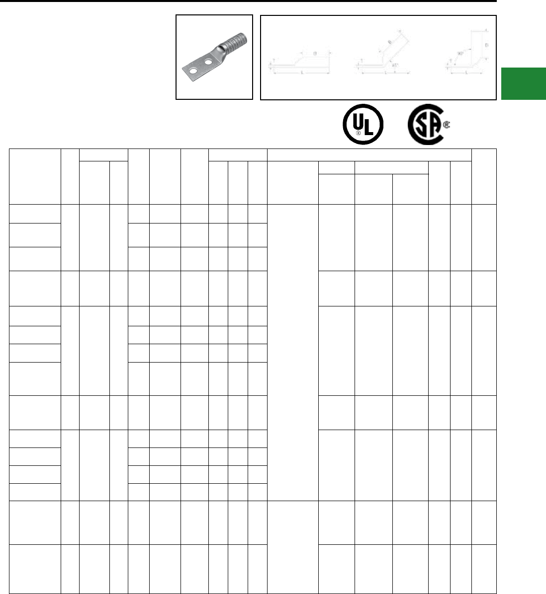
BURNDY®
Blue highlighted items are industry standard and most frequently ordered.
Canada: 1-800-387-6487 www.burndy.com US: 1-800-346-4175
TWO HOLE HYLUG™
FLEX CONDUCTOR LONG
BARREL WITH INSPECTION
WINDOW
(Continued)
UL Listed 90° C,
600 Volts to 35kV ♦
Catalog Number
Fig.
#
Conductor
Stud
Hole
Size
Stud Hole
Spacing
Tongue
Width
Figure Dimensions ▲ Installation Tooling
Wire
Strip
LengthAWG
***
MM² (B) (T) (L)
Dieless
(# of Crimps)
Mechanical Hydraulic
Color
Code
Die
Index
MD6,
OUR840,
MD7-34R
BCT500HS,
Y500CTHS
Y35, Y39,
Y750, Y46*,
PAT750
YAZ312TC14E2FX
1
250 Flex
637/24
CLASS I,
K, M
150
1/4″ 3/4″ 1.29″ 2.00″ 0.18″ 4.02″
Y644HSXT (1)
Y81KFT (2)
Y81KFTMBH (2)
PAT81KFT-18V (2)
W30VT (4) W30VT (4)
W30RT (4) U30RT (4) White
17
or
298
2-1/16″
YAZ312TC38FX 3/8″ 1″ 1.29″ 2.00″ 0.18″ 4.45″
YAZ312NTCFX 1/2″ 1-3/4″ 3.02″ 2.00″ 0.18″ 5.64″
YAZ322TC38FX 1
775/24
313.1
kcmil
185 3/8″ 1″ 1.40″ 2.12″ 0.19″ 4.62″ W31VT (4) W31VT (4)
W31RT (4) U31RT (4) Red
18
or
324
2-3/16″
YAZ342TC14E2FX
1
373.3
kcmil
925/24
(350 kcmil
nom.)
240
1/4″ 3/4″ 1.55″ 2.25″ 0.23″ 4.42″
W32VT (4) W32VT (4)
W32RT (4) U32RT (4) Blue
19
or
470
2-5/16″
YAZ342TC38FX 3/8″ 1″ 1.55″ 2.25″ 0.23″ 4.85″
YAZ342NT38FX 3/8″ 1″ 0.96″ 2.25″ 0.23″ 4.85″
YAZ342NTCFX 1/2″ 1-3/4″ 1.55″ 2.25″ 0.23″ 6.04″
YAZ362TC38FX 1
1100/24
444.4
kcmil
— 3/8″ 1″ 1.74″ 2.69″ 0.27″ 5.55″ — — U34RT (4) Brown
20
or
299
2-3/4″
YAZ382NT38FX
1
535.3
kcmil
1325/24
500 kcmil
Flex
300
3/8″ 1″ 1.62″ 2.81″ 0.27″ 5.72″
— — U38XRT (4) Pink L99 2-7/8″
YAZ382TC38FX 3/8″ 1″ 1.84″ 2.81″ 0.27″ 5.72″
YAZ382NNTFX 1/2″ 1-3/4″ 1.62″ 2.81″ 0.27″ 6.72″
YAZ382NTCFX 1/2″ 1-3/4″ 1.62″ 2.81″ 0.27″ 6.72″
YAZ402NTCFX 1
646 kcmil
1600/24
650 kcmil
Flex
— 1/2″ 1-3/4″ 1.98″ 2.94″ 0.30″ 6.89″
Y644HSXT (1)
Y644MBH (1)
U39RT (4) — U39RT (4) Black 24 3″
YAZ442NT38FX 1
777.7
kcmil
1925/24
750 Flex
— 3/8″ 1″ 1.62″ 3.00″ 0.33″ 6.08″ — — U44XRT (4) Yellow L115 3-1/16″
* Use PUADP-1 adapter with U dies in Y46 HYPRESS™
** The MM2 conductor size referenced here is for both
Class 2 and Class 5 conductor
*** The MM2 conductor sizes listed are the
recommendations for Class 5 conductor
▲See tooling section of this catalog for complete tool and
die listings. Use ONLY color-coded die recommendations
for -FX connectors. For nest/indentor system contact
factory
♦ For applications greater than 2000 Volts consult cable
manufacturer for voltage stress relief instructions.
Note: All dimensions shown are for reference only.
Compression Connections
Copper Compression — Flex — Long Barrel — Inspection Window
45° and 90° angles are available.
Please contact Customer Service to order:
1-800-346-4175
Fig. 1 45° 90° C-67
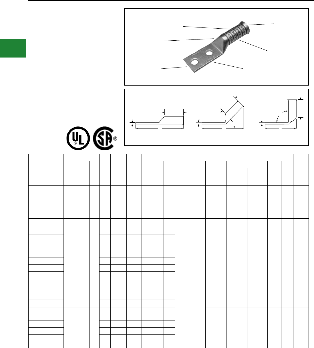
BURNDY®
Blue highlighted items are industry standard and most frequently ordered.
US: 1-800-346-4175 www.burndy.com Canada: 1-800-387-6487
TWO HOLE HYLUG™
FLEX CONDUCTOR
LONG BARREL
BELLED END
TYPES YA-2TC-FXB,
YAV-2TC-FXB
COPPER COMPRESSION
TERMINAL
UL Listed 90° C,
600 Volts to 35kV ♦
45° and 90° angles are available.
Please contact Customer Service to order:
1-800-346-4175
T
B
B
B
TT90°
L
L
45°
L
DIE AND COLOR
CODE INFORMATION
CABLE
ACCOMMODATION
NO INSPECTION
WINDOW
ELECTRO-TIN
PLATED
BEVELED
ENTRY
CRIMP
Fig. 1 45° 90°
Catalog Number
Fig
#
Conductor
Stud
Hole
Size
Stud
Hole
Spacing
Tongue
Width
Figure Dimensions ▲Installation Tooling
Wire
Strip
LengthAWG
***
MM² (B) (T) (L)
Dieless
(# of crimps)
Mechanical Hydraulic
Color
Code
Die
Index
MD6,
OUR840,
MD7-34R
BCT500HS,
Y500CTHS
Y35, Y39,
Y750, Y46*,
PAT750
YA8C2TC14E2-FXB
1
37/24
#8 Weld
#8 AWG
#8 Sol
#6 Sol
**
10
1/4″ 3/4″ 0.44″ 0.90″ 0.08″ 2.54″
Y8MRB-1 (2)
Y1MRTC (2)
MY29-11 (2)
Y81KFT (1)
Y81KFTMBH (1)
PAT81KFT-18V (1)
W8CRT (2)
W8CVT (2)
X8CRT (2)
W8CVT (2)
W8CRT (2)
X8CRT (2)
U8CRT (2) Red 49 1″
YA8C2TC38-FXB 3/8″ 1″ 0.58″ 0.90″ 0.06″ 2.98″
YAV6C2TC14-FXB
1
61/24
#6 Weld
#6 AWG
**
16
1/4″ 5/8″ 0.48″ 1.22″ 0.08″ 2.76″ Y1MRTC (2)
MY29-11 (2)
Y644HSXT (1)
Y81KFT (1)
Y81KFTMBH (1)
PAT81KFT-18V (1)
W5CVT (2)
W5CRT (2)
X5CRT (2)
W5CVT (2)
W5CRT (2)
X5CRT (2)
U5CRT (2) Blue 7 1-5/16″
YAV6C2TC14E2-FXB 1/4″ 3/4″ 0.48″ 1.22″ 0.08″ 2.88″
YAV6C2TC38-FXB 3/8″ 1″ 0.58″ 1.22″ 0.06″ 3.32″
YAV6C2N-FXB 1/2″ 1-3/4″ 0.83″ 1.22″ 0.12″ 4.51″
YAV4C2TC14-FXB
1
91/24 -
105/24
#4 Weld
#4 AWG
—
1/4″ 5/8″ 0.55″ 1.22″ 0.09″ 2.81″ Y1MRTC (4)
MY29-11 (2)
Y644HSXT (1)
Y81KFT (1)
Y81KFTMBH (1)
PAT81KFT-18V (1)
W4CVT (2)
W4CRT (2)
X4CRT (2)
W4CVT (2)
W4CRT (2)
X4CRT (2)
U4CRT (2) Gray 8 1-5/16″
YAV4C2TC14E2-FXB 1/4″ 3/4″ 0.55″ 1.22″ 0.09″ 2.93″
YAV4C2TC516-FXB 5/16″ 1″ 0.55″ 1.22″ 0.09″ 3.24″
YAV4C2TC38-FXB 3/8″ 1″ 0.58″ 1.22″ 0.09″ 3.37″
YAV4C2N-FXB 1/2″ 1-3/4″ 0.83″ 1.22″ 0.12″ 4.56″
YA3C2TC516-FXB
1
105/24 -
125/24
#3 Weld
#3 AWG
—
5/16″ 1″ 0.55″ 1.48″ 0.09″ 3.51″
Y1MRTC (4)
MY29-11 (2)
Y644HSXT (1)
Y81KFT (1)
Y81KFTMBH (1)
PAT81KFT-18V (1)
W3CRT (2) W3CRT (2) U3CRT (2) White 9 1-9/16″
YA3C2TC38-FXB 3/8″ 1″ 0.58″ 1.48″ 0.09″ 3.64″
YAV3C2NFXB 1/2"1.75"0.83"1.48″ 0.12"4.83"
YAV2C2TC14-FXB
1
125/24 -
150/24
#2 Weld
#2 AWG
35
1/4″ 5/8″ 0.68″ 1.35″ 0.10″ 3.00″
W2CVT (2)
W2CRT (2)
X2CRT (2)
W2CVT (2)
W2CRT (2)
X2CRT (2)
U2CRT (2) Brown 10 1-7/16″
YAV2C2TC14E2-FXB 1/4″ 3/4″ 0.68″ 1.35″ 0.10″ 3.13″
YAV2C2TC14E1-FXB 1/4″ 1″ 0.68″ 1.35″ 0.10″ 3.38″
YAV2C2TC516-FXB 5/16″ 1″ 0.68″ 1.35″ 0.10″ 3.44″
YAV2C2TC38-FXB 3/8″ 1″ 0.68″ 1.35″ 0.10″ 3.57″
YAV2C2N-FXB 1/2″ 1-3/4″ 0.83″ 1.35″ 0.12″ 4.76″
Consult cable manufacturers for stress relief instructions
♦ For applications greater than 2000 Volts consult cable
manufacturer for voltage stress relief instructions
* Use PUADP-1 adaptor with U dies in Y46 HYPRESS™
** The MM2 conductor sizes referenced here are for both
Class 2 and Class 5 conductors
*** The MM2 conductor sizes listed are the
recommendations for Class 5 conductor
‡ P-RT die sets for use in Y46 HYPRESS™ only,
PUADP adapter not required
Note: All dimensions shown are for reference only.
▲ See tooling section of this catalog for complete tool
and die listings. Use ONLY color-coded die
recommendations for -FX connectors
Consult shielded cable manufacturers for stress relief
instructions.
Compression Connections
Copper Compression — Flex — Long Barrel — Belled End — No Inspection Window
C-68
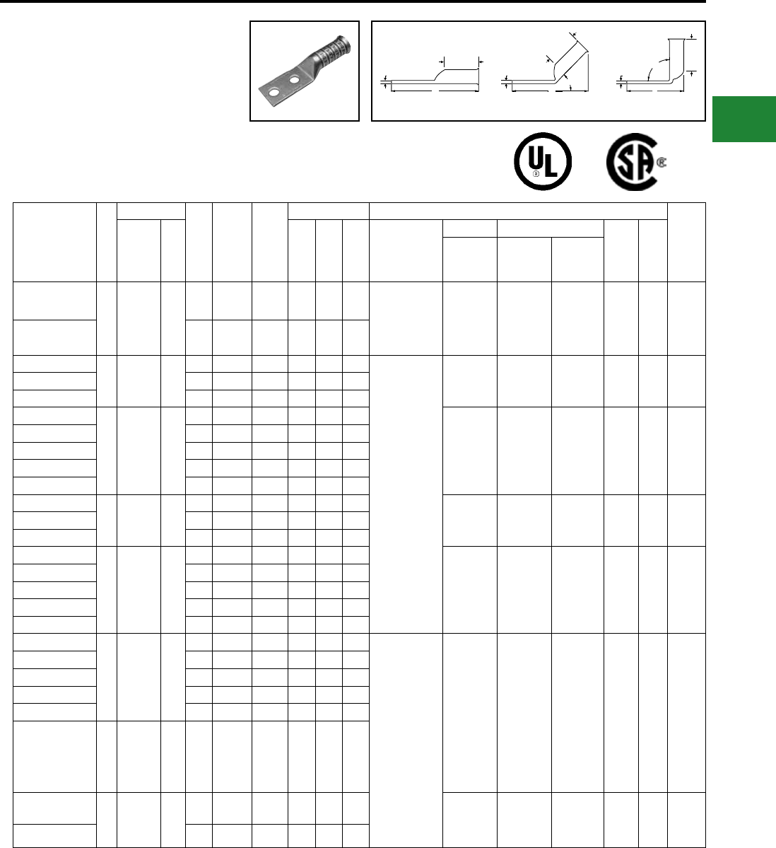
BURNDY®
Blue highlighted items are industry standard and most frequently ordered.
Canada: 1-800-387-6487 www.burndy.com US: 1-800-346-4175
TWO HOLE HYLUG™
FLEX CONDUCTOR
LONG BARREL
BELLED END
(Continued)
UL Listed 90° C,
600 Volts to 35kV ♦
T
B
B
B
TT90°
L
L
45°
L
Fig. 1 45° 90°
Catalog
Number
Fig
#
Conductor
Stud
Hole
Size
Stud
Hole
Spacing
Tongue
Width
Figure Dimensions ▲Installation Tooling
Wire
Strip
LengthAWG
***
MM² (B) (T) (L)
Dieless
(# of crimps)
Mechanical Hydraulic
Color
Code
Die
Index
MD6,
OUR840,
MD7-34R
BCT500HS,
Y500CTHS
Y35, Y39
Y750, Y46*
PAT750
YAV1C2TC38-FXB
1
175/24-
225/24
#1 Weld
#1 AWG
—
3/8″ 1″ 0.75″ 1.50″ 0.12″ 3.74″ MY29-11 (2)
Y644HSXT (1)
Y81KFT (1)
Y81KFTMBH (1)
PAT81KFT-18V (1)
W1CVT (2)
W1CRT-1 (2)
X1CRT-1 (2)
W1CVT (2)
W1CRT-1 (2)
X1CRT-1 (2)
U1CRT-1 (2) Green 11 1-9/16″
YAV1C2N-FXB 1/2″ 1-3/4″ 0.83″ 1.50″ 0.11″ 4.92″
YAV252TC14-FXB
1
275/24
1/0 Weld
1/0 AWG
50
1/4″ 5/8″ 0.83″ 1.50″ 0.12″ 3.21″
MY29-11 (2)
Y644HSXT (1)
Y81KFT (2)
Y81KFTMBH (2)
PAT81KFT-18V (2)
W25VT (4)
W25RT (4)
X25RT (4)
W25VT (4)
W25RT (4)
X25RT (4)
U25RT (2) Pink 12 1-9/16″YAV252TC14E2-FXB 1/4″ 3/4″ 0.83″ 1.50″ 0.12″ 3.34″
YAV252TC38-FXB 3/8″ 1″ 0.83″ 1.50″ 0.12″ 3.78″
YAV262TC14-FXB
1
325/24
2/0 Weld
2/0 AWG
70
1/4″ 5/8″ 0.93″ 1.63″ 0.13″ 3.40″
W26VT (4)
W26RT (4)
X26RT (4)
W26VT (4)
W26RT (4)
X26RT (4)
U26RT (2) Black 13 1-13/16″
YAV262TC14E2-FXB 1/4″ 3/4″ 0.93″ 1.63″ 0.13″ 3.52″
YAV262TC38-FXB 3/8″ 1″ 0.93″ 1.63″ 0.13″ 3.96″
YAV262NTC38-FXB 3/8″ 1-3/4″ 0.93″ 1.63″ 0.13″ 4.71″
YAV262N-FXB 1/2″ 1-3/4″ 0.93″ 1.63″ 0.13″ 5.15″
YAV272TC14E2-FXB
1
450/24
3/0 Weld
3/0 AWG
95
1/4″ 3/4″ 1.03″ 1.64″ 0.14″ 3.58″ W27VT (4)
W27RT (4)
X27RT (6)
W27VT (4)
W27RT (4)
X27RT (6)
U27RT (2) Orange 14 1-13/16″YAV272TC38-FXB 3/8″ 1″ 1.03″ 1.64″ 0.14″ 4.01″
YAV272N-FXB 1/2″ 1-3/4″ 1.03″ 1.64″ 0.14″ 5.20″
YAV282TC14E2-FXB
1
550/24
4/0 Weld
4/0 AWG
**
120
1/4″ 3/4″ 1.14″ 1.77″ 0.14″ 3.76″
W28VT (4)
W28RT (4)
X28RT (6)
W28VT (4)
W28RT (4)
X28RT (6)
U28RT (2) Purple 15 1-7/8″
YAV282TC38-FXB 3/8″ 1″ 1.14″ 1.77″ 0.14″ 4.20″
YAV282NT38-FXB 3/8″ 1″ 1.14″ 1.77″ 0.14″ 4.20″
YAV282NTC38-FXB 3/8″ 1-3/4″ 1.14″ 1.77″ 0.14″ 4.20″
YAV282N-FXB 1/2″ 1-3/4″ 1.14″ 1.77″ 0.14″ 5.39″
YAV292TC14E2-FXB
1550/24
4/0 Weld —
1/4″ 3/4″ 1.18″ 2.16″ 0.16″ 4.19″
Y644HSXT (1)
Y81KFT (2)
Y81KFTMBH (2)
PAT81KFT-18V (2)
W29VT (4)
X29RT (6)
W29VT (4)
W29RT (4)
X29RT (6)
U29RT (2) Yellow 16 2-1/4″
YAV292TC38-FXB 3/8″ 1″ 1.18″ 2.16″ 0.16″ 3.62″
YAV292NT38-FXB 3/8″ 1″ 0.75″ 2.16″ 0.16″ 5.54″
YAV292NTC38-FXB 3/8″ 1-3/4″ 1.18″ 2.16″ 0.16″ 5.37″
YAV292N-FXB 1/2″ 1-3/4″ 1.18″ 2.16″ 0.16″ 5.81″
YA302N-FXB 1
250 Flex-
CLASS
G 259 Str.
CLASS
H 427 Str.
— 1/2″ 1-3/4″ 1.20″ 2.16″ 0.16″ 5.80″
YA312TC38-FXB
1
250 Flex
637/24
CLASS
I,K,M
150
3/8″ 1″ 1.29″ 2.18″ 0.18″ 4.66″
W30VT (4) W30VT (4)
W30RT (4) U30RT (4) White 17 2-1/4″
YA312N-FXB 1/2″ 1-3/4″ 1.29″ 2.18″ 0.18″ 5.85″
45° and 90° angles are available.
Please contact Customer Service to order:
1-800-346-4175
Consult cable manufacturers for stress relief instructions
♦ For applications greater than 2000 Volts consult cable
manufacturer for voltage stress relief instructions
* Use PUADP-1 adaptor with U dies in Y46 HYPRESS™
** The MM2 conductor sizes referenced here are for both
Class 2 and Class 5 conductors
*** The MM2 conductor sizes listed are the
recommendations for Class 5 conductor
‡ P-RT die sets for use in Y46 HYPRESS™ only,
PUADP adapter not required
Note: All dimensions shown are for reference only.
▲ See tooling section of this catalog for complete tool
and die listings. Use ONLY color-coded die
recommendations for -FX connectors
Consult shielded cable manufacturers for stress relief
instructions.
Compression Connections
Copper Compression — Flex — Long Barrel — Belled End — No Inspection Window
C-69
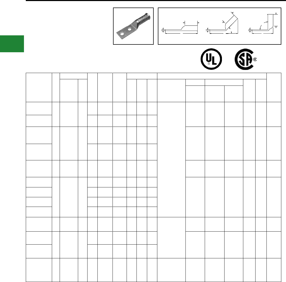
BURNDY®
Blue highlighted items are industry standard and most frequently ordered.
US: 1-800-346-4175 www.burndy.com Canada: 1-800-387-6487
Catalog
Number
Fig
#
Conductor
Stud
Hole
Size
Stud
Hole
Spacing
Tongue
Width
Figure Dimensions ▲Installation Tooling
Wire
Strip
LengthAWG
***
MM² (B) (T) (L)
Dieless
(# of crimps)
Mechanical Hydraulic
Color
Code
Die
Index
MD6,
OUR840,
MD7-34R
BCT500HS,
Y500CTHS
Y35, Y39
Y750, Y46*
PAT750
YA322TC38-FXB
1775/24
313.1 kcmil 185
3/8″ 1″ 1.40″ 2.32″ 0.19″ 4.85″
Y644HSXT (1)
Y81KFT (2)
Y81KFTMBH (2)
PAT81KFT-18V (2)
W31VT (4) W31RT (4)
W31VT (4) U31RT (4) Red 18 2-1/4″
YA322N-FXB 1/2″ 1-3/4″ 1.40″ 2.32″ 0.19″ 6.04″
YA342TC38-FXB
1
925/24
373.7 kcmil
(350 kcmil
nom.)
240
3/8″ 1″ 1.55″ 2.48″ 0.23″ 5.10″
W32VT (4) W32RT (4)
W32VT (4) U32RT (4) Blue 19 2-9/16″
YA342N-FXB 1/2″ 1-3/4″ 1.55″ 2.48″ 0.23″ 6.29″
YA362NFXB 11100/24
444.4 kcmil 300 1/2″ 1-3/4″ 1.73″ 2.95″ 0.26″ 6.84″ — — U34RT (4) Brown 20 3-1/16″
YA382TC38-FXB
1
1325/24
535.3 kcmil
(500 kcmil
nom.)
300
3/8″ 1″ 1.84″ 3.08″ 0.26″ 6.01″
— — U38XRT (4) Pink L99 3-3/16″
YA382N-FXB 3/8″ 1-3/4″ 1.84″ 3.08″ 0.26″ 7.01″
YA382-FXBG3 1/2″ 1-3/16″ 1.84″ 3.08″ 0.27″ 6.26″
YA382-FXBG2 1/2″ 2″ 1.84″ 3.08″ 0.27″ 6.82″
YA402N-FXB 11600/24
646 kcmil 400 1/2″ 1-3/4″ 1.98″ 3.24″ 0.30″ 7.22″
Y644HSXT (1)
Y81KFT (3)
Y81KFTMBH (3)
PAT81KFT-18V (3)
— — U39RT (4) Black 24 3-5/16″
YA442TC38-FXB
1
1925/24
777.7 kcmil
(750 kcmil
nom.)
500
3/8″ 1″ 2.19″ 3.33″ 0.33″ 6.44″
— — U44XRT (4) Yellow L115 3-7/16″
YA442N-FXB 1/2″ 1-3/4″ 2.19″ 3.33″ 0.33″ 7.44″
YA462N-FXB 1
2750/24
1111 kcmil
(1000 kcmil
nom.)
— 1/2″ 1-3/4″ 2.69″ 3.58″ 0.39″ 7.91″ — — — P45RT (4) ‡ — 29 3-11/16″
Consult cable manufacturers for stress relief instructions
♦ For applications greater than 2000 Volts consult cable
manufacturer for voltage stress relief instructions
* Use PUADP-1 adaptor with U dies in Y46 HYPRESS™
** The MM2 conductor sizes referenced here are for both
Class 2 and Class 5 conductors
*** The MM2 conductor sizes listed are the
recommendations for Class 5 conductor
‡ P-RT die sets for use in Y46 HYPRESS™ only,
PUADP adapter not required
Note: All dimensions shown are for reference only.
▲ See tooling section of this catalog for complete tool
and die listings. Use ONLY color-coded die
recommendations for -FX connectors
Consult shielded cable manufacturers for stress relief
instructions.
TWO HOLE HYLUG™
FLEX CONDUCTOR
LONG BARREL
BELLED END
(Continued)
UL Listed 90° C,
600 Volts to 35kV ♦
Compression Connections
Copper Compression — Flex — Long Barrel — Belled End — No Inspection Window
T
B
B
B
TT90°
L
L
45°
L
Fig. 1 45° 90°
45° and 90° angles are available.
Please contact Customer Service to order:
1-800-346-4175
C-70
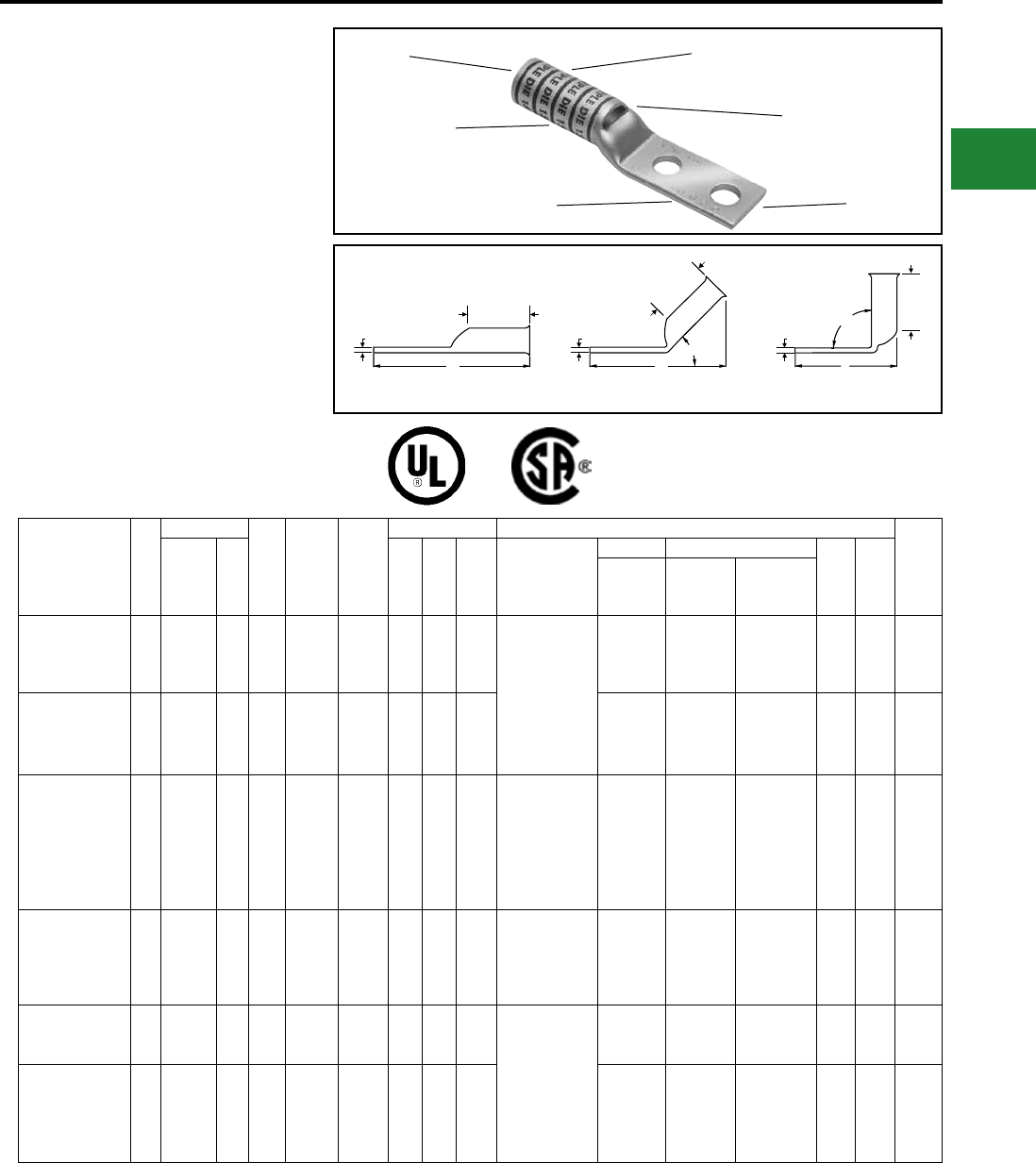
BURNDY®
Blue highlighted items are industry standard and most frequently ordered.
Canada: 1-800-387-6487 www.burndy.com US: 1-800-346-4175
TWO HOLE HYLUG™
FLEX CONDUCTOR
LONG BARREL
NARROW TONGUE
TYPES YAZ-2-NTFX,
YAZV-2NTFX
COPPER COMPRESSION
NARROW TONGUE TERMINAL
UL Listed 90° C,
600 Volts to 35 kV ♦
45° and 90° angles are available.
Please contact Customer Service to order:
1-800-346-4175
Catalog
Number
Fig.
#
Conductor
Stud
Hole
Size
Stud
Hole
Spac-
ing
Tongue
Width
Figure Dimensions ▲ Installation Tooling
Wire
Strip
LengthAWG
***
MM² (B) (T) (L)
Dieless
(# of crimps)
Mechanical Hydraulic
Color
Code
Die
Index
MD6,
OUR840,
MD7-34R
BCT500HS,
Y500CTHS
Y35, Y39,
Y750, Y46*,
PAT750
YAZV4C2NT14E2FX 1
#4 AWG
#4 Weld
91/24
105/24
— 1/4″ 0.75″ 0.44″ 1.25″ 0.09″ 2.95″ Y1MRTC (4)
MY29-11 (2)
Y644HSXT (1)
Y81KFT (1)
Y81KFTMBH (1)
PAT81KFT-18V (1)
W4CVT (2)
W4CRT (2)
X4CRT (2)
W4CVT (2)
W4CRT (2)
X4CRT (2)
U4CRT (2) Gray 8 1-5/16″
YAZV2C2NT14E2FX 1
#2 AWG
#2 Weld
125/24
150/24
35 1/4″ 0.75″ 0.50″ 1.38″ 0.10″ 3.14″
W2CVT (2)
W2CRT (2)
X2CRT (2)
W2CVT (2)
W2CRT (2)
X2CRT (2)
U2CRT (2) Brown 10 1-7/16″
YAZV252NT14FX 1
1/0 AWG
1/0 Weld
275/24
— 1/4″ 0.62″ 0.48″ 1.50″ 0.12″ 3.35″
Y644HS (1)
Y644MBH (1)
PAT644 (1)
Y81KFT (2)
PAT81KFT (2)
Y4PC834 (2)
PAT4PC834 (2)
W25VT (4)
W25RT (4)
X25RT (4)
W25VT (4)
W25RT (4)
X25RT (4) U25RT (2) Pink 12 or
348 1-9/16″
YAZV282NT38FX 1
4/0 AWG
4/0 Weld
550/24
— 3/8″ 1.00″ 0.94″ 1.62″ 0.17″ 3.96″
MY29-11 (2)
Y644HSXT (1)
Y81KFT (2)
Y81KFTMBH (2)
PAT81KFT-18V (2)
W28VT (4)
W28RT (4)
X28RT (6)
W28VT (4)
W28RT (4)
X28RT (6)
U28RT (2) Purple 15 1-11/16″
YAZV292NT516FX 1
4/0 Flex
Class I,
K, M
— 5/16″ 1.00″ 0.96″ 2.00″ 0.16″ 4.28″
Y644HSXT (1)
Y81KFT (2)
Y81KFTMBH (2)
PAT81KFT-18V (2)
W29VT (4)
X29RT (8)
W29VT (4)
W29RT (4)
X29RT (8)
U29RT (2) Yellow 16 2-1/16″
YAZ342NT38FX 1
373.7
kcmil
925/24
350 kcmil
Flex
240 3/8″ 1.00″ 0.96″ 2.25″ 0.23″ 4.85″ W32VT (4) W32VT (4)
W32RT (4) U32RT (4) Blue 19 2-5/16″
Consult cable manufacturers for stress relief instructions
♦ For applications greater than 2000 Volts consult
cable manufacturer for voltage stress relief instructions
* Use PUADP-1 adaptor with U dies in Y46 HYPRESS™
*** The MM2 conductor sizes Listed are the
recommendations for Class 5 conductor.
▲ See tooling section of this catalog for complete tool
and die listings. Use ONLY color-coded die
recommendations for -FX connectors.
Note: All dimensions shown are for reference only.
COLOR CODE AND
DIE INFORMATION
INSPECTION
WINDOW
ELECTRO-TIN
PLATED
CABLE
ACCOMMODATION
BEVELED
ENTRY
CRIMP
T
B
B
B
TT90°
L
L
45°
L
Fig. 1 45° 90°
Compression Connections
Copper Compression — Flex — Long Barrel — Narrow Tongue
C-71
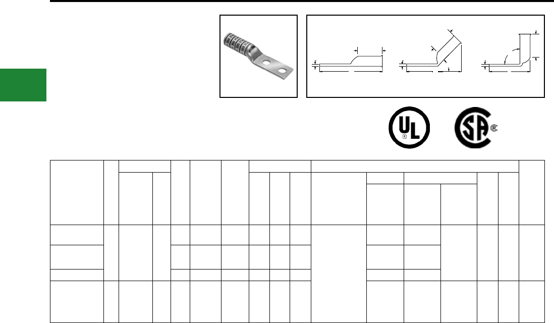
BURNDY®
Blue highlighted items are industry standard and most frequently ordered.
US: 1-800-346-4175 www.burndy.com Canada: 1-800-387-6487
TWO HOLE HYLUG™
FLEX CONDUCTOR
LONG BARREL
NARROW TONGUE
(Continued)
UL Listed 90° C,
600 Volts to 35 kV ♦
45° and 90° angles are available.
Please contact Customer Service to order:
1-800-346-4175
Catalog
Number
Fig.
#
Conductor
Stud
Hole
Size
Stud
Hole
Spacing
Tongue
Width
Figure Dimensions ▲ Installation Tooling
Wire
Strip
LengthAWG
***
MM² (B) (T) (L)
Dieless
(# of crimps)
Mechanical Hydraulic
Color
Code
Die
Index
MD6,
OUR840,
MD7-34R
BCT500HS,
Y500CTHS
Y35, Y39,
Y750, Y46*,
PAT750
YAZ382ENT38FX
1
535.3 kcmil
1325/24
500 kcmil
Flex
300
3/8″ 1.00″ 1.46″ 2.81″ 0.27″ 5.72″
Y644HSXT (1)
Y81KFT (2)
Y81KFTMBH (2)
PAT81KFT-18V (2)
— —
U38XRT (4) Pink L99 2-7/8″
YAZ382NT38FX 3/8″ 1.00″ 1.62″ 2.81″ 0.27″ 5.72″ — —
YAZ382NNTFX 1/2″ 1.75″ 1.62″ 2.81″ 0.27″ 6.72″ — —
YAZ442NT38FX 1
777.7 kcmil
1925/24
750 Flex
500 3/8″ 1.00″ 1.62″ 3.00″ 0.33″ 6.09″ — — U44XRT (4) Yellow L115 3-1/16″
Consult cable manufacturers for stress relief instructions
♦ For applications greater than 2000 Volts consult cable
manufacturer for voltage stress relief instructions
*** The MM2 conductor sizes listed are the
recommendations for Class 5 conductor.
* Use PUADP-1 adaptor with U dies in Y46 HYPRESS™
▲ See tooling section of this catalog for complete tool
and die listings. Use ONLY color-coded die
recommendations for -FX connectors
Note: All dimensions shown are for reference only.
Compression Connections
Copper Compression — Flex — Long Barrel — Narrow Tongue
T
B
B
B
TT90°
L
L
45°
L
Fig. 1 45° 90°
C-72
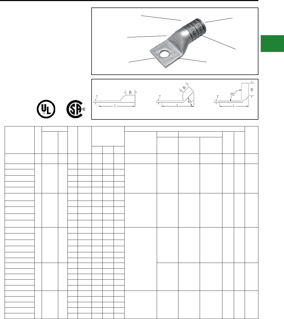
BURNDY®
Blue highlighted items are industry standard and most frequently ordered.
Canada: 1-800-387-6487 www.burndy.com US: 1-800-346-4175
Fig. 1 45° 90°
ONE HOLE HYLUG™
FLEX CONDUCTOR
STANDARD BARREL
LEAD PLATED
TYPE YAG-L-TC-LD
UL Listed 90° C,
600 Volts to 35kV ♦
45° and 90° angles are available.
Please contact Customer Service to order:
1-800-346-4175
DIE AND COLOR
CODE INFORMATION
NO INSPECTION
WINDOW
BEVELED
ENTRY
FLEXIBLE CONDUCTOR
ACCOMMODATION
CRIMP
LEAD PLATED
Catalog
Number
Fig
#
Conductor
Stud
Hole
Size
Tongue
Width
Figure
Dimensions
▲Installation Tooling
Wire
Strip
LengthAWG
***
MM²
Dieless
(# of crimps)
Mechanical Hydraulic
Color
Code
Die
Index
MD6,
OUR840,
MD7-34R
BCT500HS,
Y500CTHS
Y35, Y39,
Y750, Y46*,
PAT750(B) (T) (L)
YAG18TC516LD 1#22 - #18
AWG — 5/16" 0.35" 0.32" 0.06" 1.42" MR20 (1) — — 1/4"
YAG8CLTC10LD
1
37/24
#8 Weld
#8 AWG
#8 Sol
#6 Sol
**
10
#10 0.41" 0.44" 0.08" 1.19" MY29-11 (1)
Y1MRTC (1)
Y81KFT (1)
Y81KFTMBH (1)
PAT81KFT-18V (1)
W8CVT (1)
W8CRT (1)
X8CRT (1)
W8CVT (1)
W8CRT (1)
X8CRT (1)
U8CRT (1) Red 49 1/2"
YAG8CLTC14LD 1/4" 0.44" 0.44"0.08"1.32"
YAG8CLTC516LD 5/16" 0.52" 0.44"0.06" 1.38"
YAG8CLTC38LD 3/8" 0.58" 0.44"0.06"1.51"
YAG8CLTC12LD 1/2" 0.71" 0.44"0.05" 1.76"
YAG6CLTC10LD
1
61/24
#6 Weld
#6 AWG
**
16
#10 0.48" 0.50" 0.08" 1.30" Y1MRTC (1)
MY29-11 (1)
Y81KFT (1)
Y81KFTMBH (1)
PAT81KFT-18V (1)
Y644HSXT (1)
W5CVT (1)
W5CRT (1)
X5CRT (1)
W5CVT (1)
W5CRT (1)
X5CRT (1)
U5CRT (1) Blue 7 1/2"
YAG6CLTC14LD 1/4" 0.48"0.50"0.08"1.43"
YAG6CLTC516LD 5/16" 0.52" 0.50"0.07" 1.49"
YAG6CLTC38LD 3/8" 0.58" 0.50"0.06" 1.61"
YAG6CLTC12LD 1/2" 0.75" 0.50"0.12" 1.86"
YAG4CLTC10LD
1
91/24-
105/24
#4 Weld
#4 AWG
—
#10 0.55" 0.50" 0.09" 1.36"
Y1MRTC (2)
MY29-11 (1)
Y81KFT (1)
Y81KFTMBH (1)
PAT81KFT-18V (1)
Y644HSXT (1)
W4CVT (1)
W4CRT (1)
X4CRT (1)
W4CVT (1)
W4CRT (1)
X4CRT (1)
U4CRT (1) Gray 8 1/2"
YAG4CLNT10LD #10 0.41" 0.50"0.09"1.36"
YAG4CLTC14LD 1/4" 0.55" 0.50"0.09"1.48"
YAG4CLTC516LD 5/16" 0.55"0.50"0.09"1.55"
YAG4CLTC38LD 3/8" 0.58" 0.50"0.08" 1.67"
YAG4CLTC12LD 1/2" 0.71" 0.50"0.07" 1.92"
YAG2CLTC10LD
1
125/24
#2 Weld
#2 AWG
35
#10 0.68" 0.63" 0.10" 1.52"
W2CRT (1)
W2CVT (1)
X2CRT (1)
W2CRT (1)
W2CVT (1)
X2CRT (1)
U2CRT (1) Brown 10 11/16"
YAG2CLTC14LD 1/4" 0.68"0.63"0.10"1.64"
YAG2CLTC516LD 5/16" 0.68"0.63"0.10"1.70"
YAG2CLTC38LD 3/8" 0.68"0.63"0.10"1.83"
YAG2CLTC12LD 1/2" 0.73" 0.63"0.09" 2.12"
YAG1CLTC10LD
1
225/24
175/24-
#1 Weld
#1 AWG
—
#10 0.75" 0.65" 0.12" 1.54" MY29-11 (1)
Y81KFT (1)
Y81KFTMBH (1)
PAT81KFT-18V (1)
W1CVT (1)
W1CRT-1 (1)
X1CRT-1 (1)
W1CVT (1)
W1CRT-1 (1)
X1CRT-1 (1)
U1CRT-1 (1) Green 11 11/16"
YAG1CLTC14LD 1/4" 0.75"0.65"0.12"1.67"
YAG1CLTC516LD 5/16" 0.75"0.65"0.12"1.73"
YAG1CLTC38LD 3/8" 0.75"0.65"0.12"1.86"
YAG1CLTC12LD 1/2" 0.75"0.65"0.12"2.11"
* Use PUADP-1 adapter with U dies in Y46 HYPRESS™
** The MM2 conductor size referenced here is for both
Class 2 and Class 5 conductor.
*** The MM2 conductor sizes Listed are the
recommendations for Class 5 conductor.
▲ See tooling section of this catalog for complete tool
and die listings.
† Alternate Tooling includes Y8MRB-1, MY29-11
♦ For applications greater than 2000 Volts consult cable
manufacturer for voltage stress relief instructions.
Note: All dimensions shown are for reference only.
Compression Connections
Copper Compression — Flex — Lead Plated — No Inspection Window
C-73
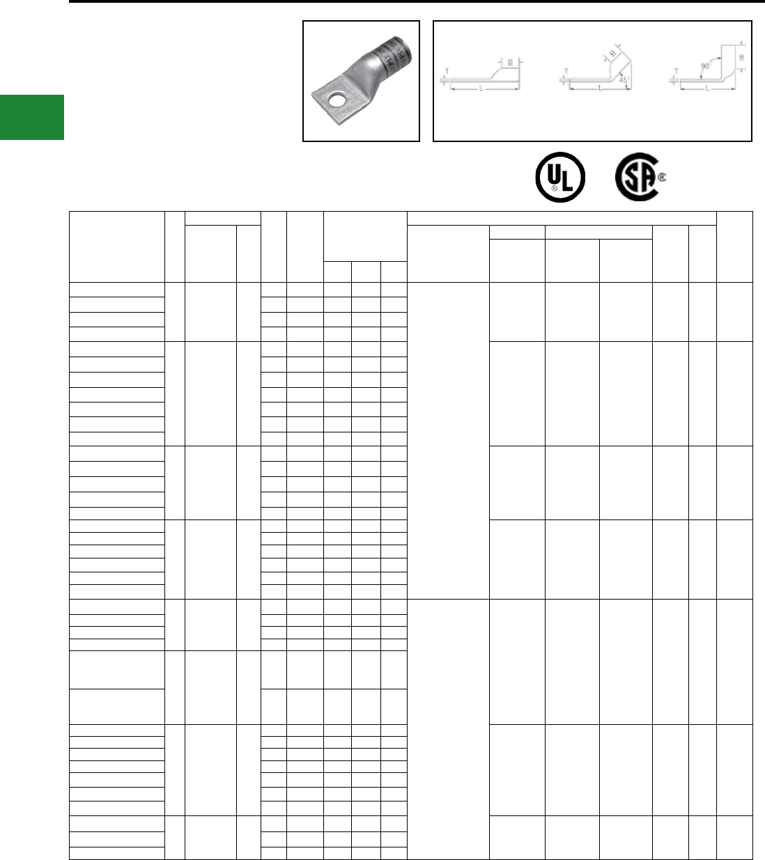
BURNDY®
Blue highlighted items are industry standard and most frequently ordered.
US: 1-800-346-4175 www.burndy.com Canada: 1-800-387-6487
Fig. 1 45° 90°
Compression Connections
Copper Compression — Flex — Lead Plated — No Inspection Window
ONE HOLE HYLUG™
FLEX CONDUCTOR
STANDARD BARREL
LEAD PLATED
(Continued)
UL Listed 90° C,
600 Volts to 35kV ♦
Catalog Number
Fig
#
Conductor
Stud
Hole
Size
Tongue
Width
Figure
Dimensions
▲Installation Tooling
Wire
Strip
LengthAWG
***
MM²
Dieless
(# of crimps)
Mechanical Hydraulic
Color
Code
Die
Index
MD6,
OUR840,
MD7-34R
BCT500HS,
Y500CTHS
Y35, Y39,
Y750, Y46*,
PAT750
(B) (T) (L)
YAG25LTC14LD
1
275/24
1/0 Weld
1/0 AWG
50
1/4"0.83" 0.69" 0.12"1.77"
MY29-11 (1)
Y644HSXT (1)
Y81KFT (1)
Y81KFTMBH (1)
PAT81KFT-18V (1)
W25VT (2)
W25RT (2)
X25RT (2)
W25VT (2)
W25RT (2)
X25RT (2)
U25RT (1) Pink 12 11/16"
YAG25LTC516LD 5/16"0.83"0.69"0.12"1.84"
YAG25LTC38LD 3/8"0.83"0.69"0.12"1.96"
YAG25LTC12LD 1/2"0.83"0.69"0.12"2.21"
YAG26LTC10LD
1
325/24
2/0 Weld
2/0 AWG
70
#10 0.93" 0.81" 0.13" 1.82"
W26VT (2)
W26RT (2)
X26RT (2)
W26VT (2)
W26RT (2)
X26RT (2)
U26RT (1) Black 13 13/16"
YAG26LTC14LD 1/4"0.93"0.81"0.13"1.95"
YAG26LTC516LD 5/16"0.93"0.81"0.13"2.01"
YAG26LTC38LD 3/8"0.93"0.81"0.13"2.13"
YAG26LTC12LD 1/2"0.93"0.81"0.13"2.38"
YAG26LTC58LD 5/8"0.93"0.81"0.13"2.63"
YAG26LTC34LD 3/4" 0.93"0.81"0.11" 2.89"
YAG27LTC10LD
1
450/24
3/0 Weld
3/0 AWG
95
#10 1.03" 1.00" 0.14" 2.05"
W27VT (2)
W27RT (2)
X27RT (3)
W27VT (2)
W27RT (2)
X27RT (3)
U27RT (1) Orange 14 1"
YAG27LTC14LD 1/4"1.03"1.00"0.14"2.18"
YAG27LTC516LD 5/16"1.03"1.00"0.14"2.24"
YAG27LTC38LD 3/8"1.03"1.00"0.14"2.37"
YAG27LTC12LD 1/2" 1.03"1.00"0.14"2.62"
YAG28LTC14LD
1
550/24
4/0 Weld
4/0 AWG
**
120
1/4" 1.14" 1.03" 0.15" 2.26"
W28VT (2)
W28RT (2)
X28RT (3)
W28VT (2)
W28RT (2)
X28RT (3)
U28RT (1) Purple 15 1-1/16"
YAG28LTC516LD 5/16" 1.14"1.03"0.15"2.32"
YAG28LTC516N66LD 5/16"1.14"1.03"0.15"2.64"
YAG28LTC38LD 3/8" 1.14"1.03"0.15"2.45"
YAG28LTC12LD 1/2" 1.14"1.03"0.15"2.70"
YAG28LTC58LD 5/8" 1.14"1.03"0.15"2.95"
YAG29LTC516LD
1550/24
4/0 Weld —
5/16" 1.18" 1.03" 0.16" 2.33"
Y644HSXT (1)
Y81KFT (1)
Y81KFTMBH (1)
PAT81KFT-18V (1)
W29VT (2)
X29RT (4)
W29VT (2)
W29RT (2)
X29RT (4)
U29RT (1) Yellow 16 1 1/16"
YAG29LTC38LD 3/8" 1.18"1.03"0.16"2.45"
YAG29LTC12LD 1/2" 1.18"1.03"0.16"2.70"
YAG29LTC34LD 3/4" 1.18"1.03"0.16"3.14"
YAG30LTC58LD
1
250 Flex
CLASS
G- 259 Str.
CLASS
H- 427 Str.
—
5/8" 1.20" 1.03" 0.16" 2.97"
YAG30LTC34LD 3/4" 1.20"1.03"0.16"3.16"
YAG31LTC14LD
1
637/259
250 Flex
CLASS
I,K,M
150
1/4" 1.29" 1.06" 0.18" 2.35"
W30VT (2) W30VT (2)
W30RT (2) U30RT (2) White 17 1-1/8"
YAG31LTC516LD 5/16" 1.29"1.06"0.18"2.41"
YAG31LTC38LD 3/8" 1.29"1.06"0.18"2.53"
YAG31LTC12LD 1/2" 1.29"1.06"0.18"2.78"
YAG31LNT12LD 1/2"0.96" 1.06"0.18"2.78"
YAG31LTC58LD 5/8" 1.29" 1.06"0.18"3.03"
YAG31LTC34LD 3/4" 1.29"1.06"0.18"3.22"
YAG32LTC38LD
1
775/24-300
Flex
313.1 kcmil
185
3/8" 1.40" 1.19" 0.19" 2.72"
W31VT (2) W31VT (2)
W31RT (2) U31RT (2) Red 18 1-1/4"
YAG32LTC12LD 1/2" 1.40"1.19"0.19"2.97"
YAG32LTC58LD 5/8" 1.40"1.19"0.19"3.22"
45° and 90° angles are available.
Please contact Customer Service to order:
1-800-346-4175
* Use PUADP-1 adapter with U dies in Y46 HYPRESS™
*** The MM2 conductor sizes listed are the
recommendations for Class 5 conductor.
** The MM2 conductor size referenced here is for
both Class 2 and Class 5 conductor.
▲ See tooling section of this catalog for complete tool
and die listings.
† Alternate Tooling includes Y8MRB-1, MY29-11
♦ For applications greater than 2000 Volts consult cable
manufacturer for voltage stress relief instructions.
Note: All dimensions shown are for reference only.
C-74
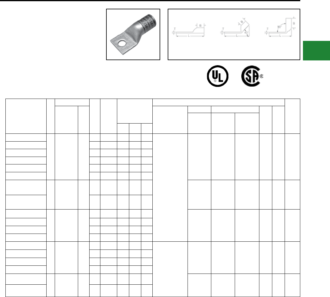
BURNDY®
Blue highlighted items are industry standard and most frequently ordered.
Canada: 1-800-387-6487 www.burndy.com US: 1-800-346-4175
Compression Connections
Copper Compression — Flex — Lead Plated — No Inspection Window
Catalog Number
Fig
#
Conductor
Stud
Hole
Size
Tongue
Width
Figure
Dimensions
▲Installation Tooling
Wire
Strip
LengthAWG MM²
Dieless
(# of crimps)
Mechanical Hydraulic
Color
Code
Die
Index
MD6,
OUR840,
MD7-34R
BCT500HS,
Y500CTHS
Y35, Y39,
Y750,Y46*,
PAT750(B) (T) (L)
YAG34LTC516LD
1
925/24-
350 Flex
373.7 kcmil
240
5/16" 1.55" 1.27" 0.23" 2.78"
Y644HSXT (1)
Y81KFT (1)
Y81KFTMBH (1)
PAT81KFT-18V (1)
W32VT (2) W32VT (2)
W32RT (2) U32RT (2) Blue 19 1-5/16"
YAG34LTC516N66LD 5/16" 1.54" 1.27" 0.23" 3.09"
YAG34LNT516N66LD 5/16" 0.96" 1.27" 0.23" 3.09"
YAG34LTC38LD 3/8" 1.55" 1.27" 0.23" 2.91"
YAG34LTC12LD 1/2" 1.55" 1.27" 0.23" 3.16"
YAG34LTC58LD 5/8" 1.55" 1.27" 0.23" 3.41"
YAG36LTC12LD
1
1100/24-
450 Flex
444.4 kcmill
—
1/2" 1.73" 1.38" 0.27" 3.34"
— — U34RT (2) Brown 20 1-3/8"
YAG36LTC58LD 5/8" 1.73" 1.38" 0.27" 3.59"
YAG38LTC516LD
1
1325/24-
500 Flex
535.3 kcmil
300
5/16" 1.84" 1.45" 0.27" 3.08"
— — U38XRT (2) Pink L99 1-7/16"
YAG38LTC38LD 3/8" 1.84" 1.45" 0.27"3.39"
YAG38LTC12LD 1/2" 1.84" 1.45" 0.27" 3.46"
YAG38LTC58LD 5/8" 1.84" 1.45" 0.27" 3.71"
YAG40LTC516LD
1
1600/24-
646 kcmil
650 Flex
400
5/16" 1.96" 1.42" 0.30" 3.11"
Y644HSXT (1)
Y81KFT (2)
Y81KFTMBH (2)
PAT81KFT-18V (2)
— — U39RT (2) Black 24 1-5/16"
YAG40LTC38LD 3/8" 1.96" 1.42" 0.30" 3.42"
YAG40LTC12LD 1/2" 1.96" 1.42" 0.30" 3.48"
YAG40LTC58LD 5/8" 1.96" 1.42" 0.30" 3.73"
YAG44LTC12LD
1
1925/24-
750 Flex
777.7 kcmil
500
1/2" 2.18" 1.65" 0.33" 3.85"
— — U44XRT (2) Yellow L115 1-5/8"
YAG44LTC58LD 5/8" 2.18" 1.65" 0.33" 4.10"
Fig. 1 45° 90°
ONE HOLE HYLUG™
FLEX CONDUCTOR
STANDARD BARREL
LEAD PLATED
(Continued)
UL Listed 90° C,
600 Volts to 35kV ♦
45° and 90° angles are available.
Please contact Customer Service to order:
1-800-346-4175
* Use PUADP-1 adapter with U dies in Y46 HYPRESS™
*** The MM2 conductor sizes listed are the
recommendations for Class 5 conductor.
▲ See tooling section of this catalog for complete tool
and die listings.
† Alternate Tooling includes Y8MRB-1, MY29-11
♦ For applications greater than 2000 Volts consult cable
manufacturer for voltage stress relief instructions.
Note: All dimensions shown are for reference only.
C-75
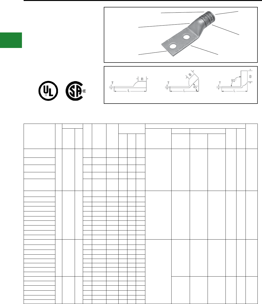
BURNDY®
Blue highlighted items are industry standard and most frequently ordered.
US: 1-800-346-4175 www.burndy.com Canada: 1-800-387-6487
TWO HOLE HYLUG™ FLEX
CONDUCTOR STANDARD
BARREL LEAD PLATED
TYPE YAG-L-2TC-LD
COPPER COMPRESSION
TERMINAL
UL Listed 90° C,
600 Volts to 35 kV ♦
Catalog
Number
Fig.
#
Conductor
Stud
Hole
Size
Stud
Hole
Spacing
Tongue
Width
Figure
Dimensions
▲ Installation Tooling
Wire
Strip
LengthAWG
***
MM²
Dieless
(# of Crimps)
Mechanical Hydraulic
Color
Code
Die
Index(B) (T) (L)
MD6,
OUR840,
MD7-34R
BCT500HS,
Y500CTHS
Y35, Y39,
Y750, Y46*,
PAT750
YAG8CL-2TC10-LD
1
#8 Weld
37/24
#8 AWG
#8 Sol
#6 Sol
**
10
#10 5/8″ 0.41″ 0.44″ 0.08″ 1.84″ MRC840 (1)
MY29-3 (1)
MY29-11 (1)
Y8MRB-1 (1)
Y1MRTC (1)
Y81KFT (1)
Y81KFTMBH (1)
PAT81KFT-18V (1)
W8CVT (1)
W8CRT (1)
X8CRT (1)
W8CVT (1)
W8CRT (1)
X8CRT (1)
U8CRT (1) Red 49 7/16″
YAG8CL-2TC14-LD 1/4″ 5/8″ 0.44″ 0.44″ 0.08″ 1.95″
YAG8CL-2TC14E2-LD 1/4″ 3/4″ 0.44″ 0.44″ 0.08″ 2.08″
YAG8CL-2TC14E1-LD 1/4″ 1″ 0.44″ 0.44″ 0.08″ 2.33″
YAG8CL-2TC38-LD 3/8″ 1″ 0.58″ 0.44″ 0.06″ 2.52″
YAG6CL-2TC10E-LD
1
#6 Weld
61/24
#6 AWG
**
16
#10 1/2″ 0.48″ 0.50″ 0.08″ 1.81″
MY29-11 (1)
Y1MRTC (1)
Y81KFT (1)
Y81KFTMBH (1)
PAT81KFT-18V (1)
Y644HSXT (1)
W5CVT (1)
W5CRT (1)
X5CRT (1)
W5CVT (1)
W5CRT (1)
X5CRT (1)
U5CRT (1) Blue 7 1/2″
YAG6CL-2TC10-LD #10 5/8″ 0.45″ 0.50″ 0.08″ 1.94″
YAG6CL-2TC10E4-LD #10 11/16″ 0.44″ 0.50″ 0.07″ 2.00″
YAG6CL-2TC10E2-LD #10 3/4″ 0.48″ 0.50″ 0.08″ 2.06″
YAG6CL-2TC14-LD 1/4″ 5/8″ 0.48″ 0.50″ 0.08″ 2.06″
YAG6CL-2TC14E2-LD 1/4″ 3/4″ 0.48″ 0.50″ 0.08″ 2.18″
YAG6CL-2TC14E1-LD 1/4″ 1″ 0.48″ 0.50″ 0.08″ 2.44″
YAG6CL-2TC516-LD 5/16″ 1″ 0.52″ 0.50″ 0.07″ 2.50″
YAG6CL-2TC38-LD 3/8″ 1″ 0.58″ 0.50″ 0.06″ 2.62″
YAG6CL-2NTC-LD 1/2″ 1-3/4″ 0.83″ 0.50″ 0.12″ 3.81″
YAG4CL-2NT10-LD
1
#4 Weld
91/24
105/24
#4 AWG
—
#10 5/8″ 0.41″ 0.50″ 0.09″ 1.99″
MY29-11 (1)
Y1MRTC (2)
Y81KFT (1)
Y81KFTMBH (1)
PAT81KFT-18V (1)
W4CVT (1)
W4CRT (1)
X4CRT (1)
W4CVT (1)
W4CRT (1)
X4CRT (1)
U4CRT (1) Gray 8 1/2″
YAG4CL-2NT10E1-LD #10 1″ 0.41″ 0.50″ 0.09″ 2.37″
YAG4CL-2TC14-LD 1/4″ 5/8″ 0.55″ 0.50″ 0.09″ 2.11″
YAG4CL-2TC14E2-LD 1/4″ 3/4″ 0.55″ 0.50″ 0.09″ 2.24″
YAG4CL-2TC14E1-LD 1/4″ 1″ 0.55″ 0.50″ 0.09″ 2.49″
YAG4CL-2TC516-LD 5/16″ 1″ 0.55″ 0.50″ 0.09″ 2.56″
YAG4CL-2TC38-LD 3/8″ 1″ 0.58″ 0.50″ 0.08″ 2.68″
YAG4CL-2NTC-LD 1/2″ 1-3/4″ 0.83″ 0.50″ 0.12″ 3.87″
YAG2CL-2TC14-LD
1
#2 Weld
125/24
150/24
#2 AWG
35
1/4″ 5/8″ 0.68″ 0.63″ 0.10″ 2.28″
W2CVT (1)
W2CRT (1)
X2CRT (1)
W2CVT (1)
W2CRT (1)
X2CRT (1)
U2CRT (1) Brown 10 11/16″
YAG2CL-2TC14E2-LD 1/4″ 3/4″ 0.68″ 0.63″ 0.10″ 2.40″
YAG2CL-2TC14E1-LD 1/4″ 1″ 0.68″ 0.63″ 0.10″ 2.63″
YAG2CL-2TC516-LD 5/16″ 1″ 0.68″ 0.63″ 0.10″ 2.71″
YAG2CL-2TC38-LD 3/8″ 1″ 0.68″ 0.63″ 0.10″ 2.84″
YAG2CL-2NTC-LD 1/2″ 1-3/4″ 0.83″ 0.63″ 0.08″ 4.03″
Fig. 1 45° 90°
DIE AND COLOR
CODE INFORMATION
CABLE
ACCOMMODATION
NO INSPECTION
WINDOW
LEAD
PLATED
BEVELED
ENTRY
CRIMP
* Use PUADP-1 adapter with U dies in Y46 Hypress™.
** The MM2 conductor size referenced here is for both
Class 2 and Class 5 conductor.
*** The MM2 conductor sizes listed are the
recommendations for Class 5 conductor.
♦ For applications greater than 2000 Volts consult cable
manufacturer for voltage stress relief instructions.
Note: All dimensions shown are for reference only.
Compression Connections
Copper Compression — Flex — Lead Plated — No Inspection Window
45° and 90° angles are available.
Please contact Customer Service to order:
1-800-346-4175
C-76
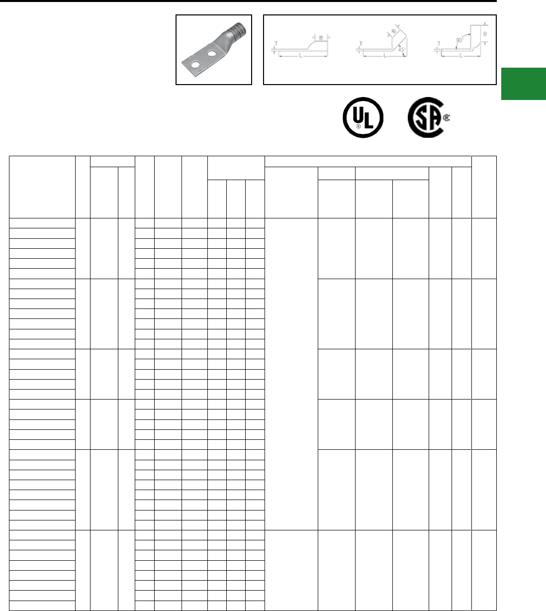
BURNDY®
Blue highlighted items are industry standard and most frequently ordered.
Canada: 1-800-387-6487 www.burndy.com US: 1-800-346-4175
TWO HOLE HYLUG™
FLEX CONDUCTOR
STANDARD BARREL
LEAD PLATED
(Continued)
UL Listed 90° C,
600 Volts to 35kV ♦
45° and 90° angles are available.
Please contact Customer Service to order:
1-800-346-4175
Fig. 1 45° 90°
Catalog
Number
Fig.
#
Conductor
Stud
Hole
Size
Stud
Hole
Spacing
Tongue
Width
Figure
Dimensions
▲ Installation Tooling
Wire
Strip
LengthAWG
***
MM²
Dieless
(# of Crimps)
Mechanical Hydraulic
Color
Code
Die
Index(B) (T) (L)
MD6,
OUR840,
MD7-34R
BCT500HS,
Y500CTHS
Y35, Y39,
Y750, Y46*,
PAT750
YAG1CL-2TC14-LD
1
#1 Weld
175/24
225/24
#1 AWG
—
1/4″ 5/8″ 0.75″ 0.62″ 0.12″ 2.30″
MY29-11 (1)
Y644HSXT (1)
Y81KFT (1)
Y81KFTMBH (1)
PAT81KFT-18V (1)
W1CVT (1)
W1CRT-1 (1)
X1CRT-1 (1)
W1CVT (1)
W1CRT-1 (1)
X1CRT-1 (1)
U1CRT-1 (1) Green 11 11/16″
YAG1CL-2TC14E2-LD 1/4″ 3/4″ 0.75″ 0.69″ 0.12″ 2.49″
YAG1CL-2TC14E1-LD 1/4″ 1″ 0.75″ 0.69″ 0.12″ 2.73″
YAG1CL-2TC516-LD 5/16″ 1″ 0.75″ 0.62″ 0.12″ 2.74″
YAG1CL-2TC38-LD 3/8″ 1″ 0.75″ 0.62″ 0.12″ 2.87″
YAG1CL-2NTC-LD 1/2″ 1-3/4″ 0.83″ 0.62″ 0.11″ 4.06″
YAG25L-2TC14-LD
1
1/0 Weld
275/24
1/0 AWG
50
1/4″ 5/8″ 0.83″ 0.69″ 0.12″ 2.41″
W25VT(2)
W25RT(2)
X25RT(2)
W25VT (2)
W25RT (2)
X25RT (2)
U25RT (1) Pink 12 11/16″
YAG25L-2TC14E2-LD 1/4″ 3/4″ 0.83″ 0.69″ 0.12″ 2.53″
YAG25L-2TC516E2-LD 5/16″ 3/4″ 0.83″ 0.69″ 0.12″ 2.60″
YAG25L-2TC516-LD 5/16″ 1″ 0.83″ 0.69″ 0.12″ 2.85″
YAG25L-2TC38-LD 3/8″ 1″ 0.83″ 0.69″ 0.12″ 2.97″
YAG25L-2NTC-LD 1/2″ 1-3/4″ 0.83″ 0.69″ 0.12″ 4.16″
YAG25L-2TC12E1-LD 1/2″ 1″ 0.83″ 0.69″ 0.12″ 3.22″
YAG26L-2TC14-LD
1
2/0 Weld
325/24
2/0 AWG
70
1/4″ 5/8″ 0.93″ 0.81″ 0.13″ 2.58″
W26VT (2)
W26RT (2)
X26RT (2)
W26VT (2)
W26RT (2)
X26RT (2)
U26RT (1) Black 13 13/16″
YAG26L-2TC14E2-LD 1/4″ 3/4″ 0.93″ 0.81″ 0.13″ 2.71″
YAG26L-2TC516-LD 5/16″ 1″ 0.93″ 0.81″ 0.13″ 3.02″
YAG26L-2TC38-LD 3/8″ 1″ 0.93″ 0.81″ 0.13″ 3.14″
YAG26L-2NTC-LD 1/2″ 1-3/4″ 0.93″ 0.81″ 0.13″ 4.33″
YAG27L-2TC14-LD
1
3/0 Weld
450/24
3/0 AWG
95
1/4″ 5/8″ 1.03″ 1.00″ 0.14″ 2.81″
W27VT (2)
W27RT (2)
X27RT (3)
W27VT (2)
W27RT (2)
X27RT (3)
U27RT (1) Orange 14 1″
YAG27L-2TC14E2-LD 1/4″ 3/4″ 1.03″ 1.00″ 0.14″ 2.94″
YAG27L-2TC516-LD 5/16″ 1″ 1.03″ 1.00″ 0.14″ 3.25″
YAG27L-2TC38-LD 3/8″ 1″ 1.03″ 1.00″ 0.14″ 3.38″
YAG27L-2NTC-LD 1/2″ 1-3/4″ 1.03″ 1.00″ 0.14″ 4.56″
YAG28L-2TC14-LD
1
4/0 Weld
550/24
4/0 AWG
120
1/4″ 5/8″ 1.14″ 1.03″ 0.15″ 2.90″
W28VT (2)
W28RT (2)
X28RT (3)
W28VT (2)
W28RT (2)
X28RT (3)
U28RT (1) Purple 15 1-1/16″
YAG28L-2TC14E2-LD 1/4″ 3/4″ 1.14″ 1.03″ 0.15″ 3.02″
YAG28L-2TC516-LD 5/16″ 1″ 1.14″ 1.03″ 0.15″ 3.33″
YAG28L-2TC38-LD 3/8″ 1″ 1.14″ 1.03″ 0.15″ 3.46″
YAG28L-2NT38-LD 3/8″ 1″ 0.94″ 1.03″ 0.17″ 3.48″
YAG28L-2TC12E1-LD 1/2″ 1″ 1.14″ 1.03″ 0.17″ 3.71″
YAG28L-2TC12-LD 1/2″ 1-1/4″ 1.14″ 1.03″ 0.15″ 3.96″
YAG28L-2NTC-LD 1/2″ 1-3/4″ 1.14″ 1.03″ 0.15″ 4.65″
YAG29L-2TC14-LD
14/0 Flex
250 Code —
1/4″ 5/8″ 1.14″ 1.03″ 0.16″ 2.90″
Y644HSXT (1)
Y81KFT (1)
Y81KFTMBH (1)
PAT81KFT-18V (1)
W29VT (2)
X29RT (4)
W29VT (2)
W29RT (2)
X29RT (4)
U29RT (1) Yellow 16 1-1/16″
YAG29L-2TC14E2-LD 1/4″ 3/4″ 1.18″ 1.03″ 0.16″ 3.03″
YAG29L-2TC516-LD 5/16″ 1″ 1.18″ 1.03″ 0.16″ 3.34″
YAG29L-2TC38-LD 3/8″ 1″ 1.18″ 1.03″ 0.16″ 3.43″
YAG29L-2NT38-LD 3/8″ 1″ 0.94″ 1.03″ 0.16″ 3.48″
YAG29L-2TC12E1-LD 3/8″ 1″ 1.14″ 1.03″ 0.16″ 3.71″
YAG29L-2TC12-LD 1/2″ 1-1/4″ 1.18″ 1.03″ 0.16″ 3.96″
YAG29L-2NTC-LD 1/2″ 1-3/4″ 1.18″ 1.03″ 0.16″ 4.65″
* Use PUADP-1 adapter with U dies in Y46 Hypress™.
** The MM2 conductor size referenced here is for both
Class 2 and Class 5 conductor.
*** The MM2 conductor sizes listed are the
recommendations for Class 5 conductor.
♦ For applications greater than 2000 Volts consult cable
manufacturer for voltage stress relief instructions.
Note: All dimensions shown are for reference only.
Compression Connections
Copper Compression — Flex — Lead Plated — No Inspection Window
C-77
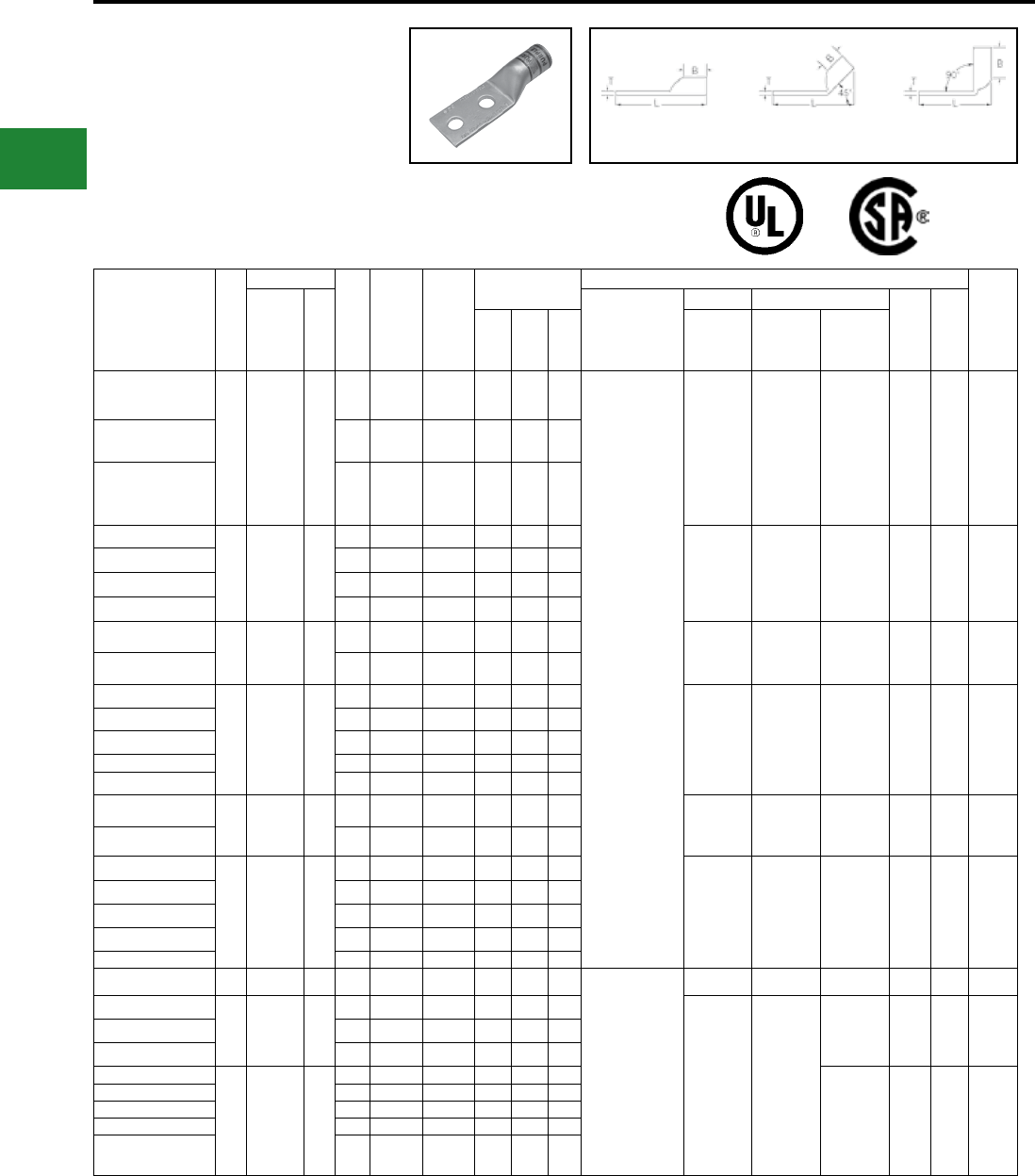
BURNDY®
Blue highlighted items are industry standard and most frequently ordered.
US: 1-800-346-4175 www.burndy.com Canada: 1-800-387-6487
TWO HOLE HYLUG™
FLEX CONDUCTOR
STANDARD BARREL
LEAD PLATED
(Continued)
UL Listed 90° C,
600 Volts to 35kV ♦
45° and 90° angles are available.
Please contact Customer Service to order:
1-800-346-4175
Fig. 1 45° 90°
Catalog
Number
Fig.
#
Conductor
Stud
Hole
Size
Stud
Hole
Spacing
Tongue
Width
Figure
Dimensions
▲ Installation Tooling
Wire
Strip
LengthAWG
***
MM²
Dieless
(# of Crimps)
Mechanical Hydraulic
Color
Code
Die
Index(B) (T) (L)
MD6,
OUR840,
MD7-34R
BCT500HS,
Y500CTHS
Y35, Y39,
Y750, Y46*,
PAT750
YAG30L-2TC38-LD
1
250 kcmil
CLASS G
259 Str.
CLASS H
427 Str.
—
3/8″ 1″ 1.20″ 1.03″ 0.16″ 3.48″
Y644HSXT (1)
Y81KFT (1)
Y81KFTMBH (1)
PAT81KFT-18V (1)
W29VT (2)
X29RT (4)
W29VT (2)
W29RT (2)
X29RT (4)
U29RT (1) Yellow 16 1-1/16″
YAG30L-2TC12-LD 1/2″ 1-1/4″ 1.20″ 1.03″ 0.16″ 3.98″
YAG30L-2NTC-LD 1/2″ 1-3/4″ 1.20″ 1.03″ 0.16″ 4.67″
YAG31L-2TC38-LD
1
250 Weld
637/24
CLASS I,
K, M
150
3/8″ 1″ 1.29″ 1.06″ 0.18″ 3.54″
W30VT(2) W30VT (2)
W30RT (2) U30RT (2) White 17 1-1/8″
YAG31L-2NTC38-LD 3/8″ 1-3/4″ 1.29″ 1.06″ 0.18″ 3.54″
YAG31L-2TC12-LD 1/2″ 1-1/4″ 1.29″ 1.06″ 0.18″ 4.04″
YAG31L-2NTC-LD 1/2″ 1-3/4″ 1.29″ 1.06″ 0.18″ 4.73″
YAG32L-2TC38-LD
1
775/24
313.1
kcmil
185
3/8″ 1″ 1.40″ 1.19″ 0.19″ 3.73″
W31VT (2) W31VT (2)
W31RT (2) U31RT (2) Red 18 1-1/4″
YAG32L-2NTC-LD 1/2″ 1-3/4″ 1.40″ 1.19″ 0.19″ 4.91″
YAG34L-2TC516-LD
1
373.7
kcmil
925/24
350 kcmil
CLASS I
240
5/16″ 1″ 1.55″ 1.27″ 0.23″ 3.79″
W32VT (2) W32VT (2)
W32RT (2) U32RT (2) Blue 19 1-5/16″
YAG34L-2TC38-LD 3/8″ 1″ 1.55″ 1.27″ 0.23″ 3.92″
YAG34L-2NT38-LD 3/8″ 1-3/4″ 0.96″ 1.27″ 0.23″ 3.92″
YAG34L-2TC12-LD 1/2″ 1-1/4″ 1.55″ 1.27″ 0.23″ 4.42″
YAG34L-2NTC-LD 1/2″ 1-3/4″ 1.55″ 1.27″ 0.23″ 5.11″
YAG36L-2TC38-LD
1
1100/24
444.4
kcmil
—
3/8″ 1″ 1.73″ 1.38″ 0.27″ 4.28″
— — U34RT(2)
U31ART(1) Brown 20 1-3/8″
YAG36L-2NTC-LD 1/2″ 1-3/4″ 1.73″ 1.38″ 0.27″ 5.28″
YAG38L-2TC516-LD
1
535.3
kcmil
1325/24
500 kcmil
CLASS I
300
5/16″ 1″ 1.82″ 1.45″ 0.27″ 4.09″
— — U38XRT (2) Pink L99 1-3/8″
YAG38L-2NT38-LD 3/8″ 1″ 1.63″ 1.45″ 0.27″ 4.40″
YAG38L-2TC38-LD 3/8″ 1″ 1.82″ 1.45″ 0.27″ 4.40″
YAG38L-2TC12-LD 1/2″ 1-1/4″ 1.82″ 1.45″ 0.27″ 4.72″
YAG38L-2NTC-LD 1/2″ 1-3/4″ 1.82″ 1.45″ 0.27″ 5.40″
YAG39L-2NTC-LD 1 600 kcmil — 1/2″ 1-3/4″ 1.90″ 1.19″ 0.27″ 5.29″
Y644HSXT (1)
Y81KFT (2)
Y81KFTMBH (2)
PAT81KFT-18V (2)
— — U38RT (2) Purple 400 1-3/8″
YAG40L-2TC38-LD
1646 kcmil
1600/24 400
3/8″ 1″ 1.98″ 1.42″ 0.30″ 4.43″
— —
U39RT (2) Black 24 1-5/16″YAG40L-2NNT-LD 1/2″ 1-3/4″ 1.63″ 1.42″ 0.30″ 5.43″
YAG40L-2NTC-LD 1/2″ 1-3/4″ 1.98″ 1.42″ 0.30″ 5.43″
YAG44L-2TC38-LD
1
777.7
kcmil
1925/24
750 kcmil
CLASS I
500
3/8″ 1″ 2.18″ 1.65″ 0.33″ 4.80″
U44XRT (2) Yellow L115 1-5/8″
YAG44L-2TC12-LD 1/2″ 1-1/4″ 2.18″ 1.65″ 0.33″ 5.11″
YAG44L-2TC12E3-LD 1/2″ 1-1/2″ 2.18″ 1.65″ 0.33″ 5.36″
YAG44L-2NTC-LD 1/2″ 1-3/4″ 2.18″ 1.65″ 0.33″ 5.80″
YAG44L-2TC58-LD 5/8″ 1-1/2″ 2.18″ 1.65″ 0.33″ 5.61″
* Use PUADP-1 adapter with U dies in Y46 Hypress™.
** The MM2 conductor size referenced here is for both
Class 2 and Class 5 conductor.
*** The MM2 conductor sizes listed are the
recommendations for Class 5 conductor.
♦ For applications greater than 2000 Volts consult cable
manufacturer for voltage stress relief instructions.
Note: All dimensions shown are for reference only.
Compression Connections
Copper Compression — Flex — Lead Plated — No Inspection Window
C-78
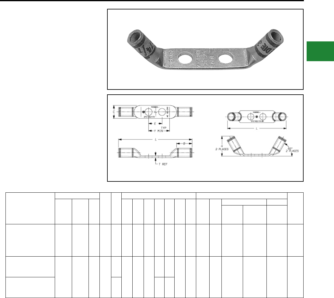
BURNDY®
Blue highlighted items are industry standard and most frequently ordered.
Canada: 1-800-387-6487 www.burndy.com US: 1-800-346-4175
TYPE YAS-L-2TC-FX,60
TWO HOLE HYLUG™ -
DOUBLE BARREL
COPPER COMPRESSION
TERMINAL
Catalog Number
Conductor
Bolt
Size
Fig.
No.
Dimensions Installation Tooling
Wire
Strip
LengthFlex AWG
**
MM² B C E H L
T
Ref.
Y
Min.
Die
Index
Color
Code
Mechanical Hydraulic
MD7-34
MD6
OUR840 Y1MRTC
Y750, Y35,
Y39, Y46*
YASG6CL-2TC14E2-FX #6 Weld
61/24 #6 AWG 16 1/4″ 1 0.50 0.48 0.75 — 3.0
(78)
0.08
(2)
1.14
(29) 7 Blue W5CVT (1)
W5CRT (1) Y1MRTC (1) U5CRT (1) 9/16″
YASV6CL-2TC14E2-FX**
#6 Weld
61/24 #6 AWG 16 1/4″
1
0.50 0.48 0.75
—3.0
(78) 0.08
(2)
1.14
(29) 7 Blue W5CVT (1)
W5CRT (1) Y1MRTC (1) U5CRT (1) 9/16″
YASV6CL-2TC14E2-FX-60** 2 0.73 2.9
(75)
Fig. 1 Fig. 2
♦ For applications greater than 2000 Volts consult cable
manufacturer for voltage stress relief instructions.
* Use PUADP-1 adapter with U dies in Y46 HYPRESS™.
Compression Connections
Copper Compression — Flex
** Type YASV series have inspection hole.
*** The MM2 conductor sizes listed are the
recommendations for Class 2 and Class 5 conductor.
Note: All dimensions shown are for reference only.
C-79
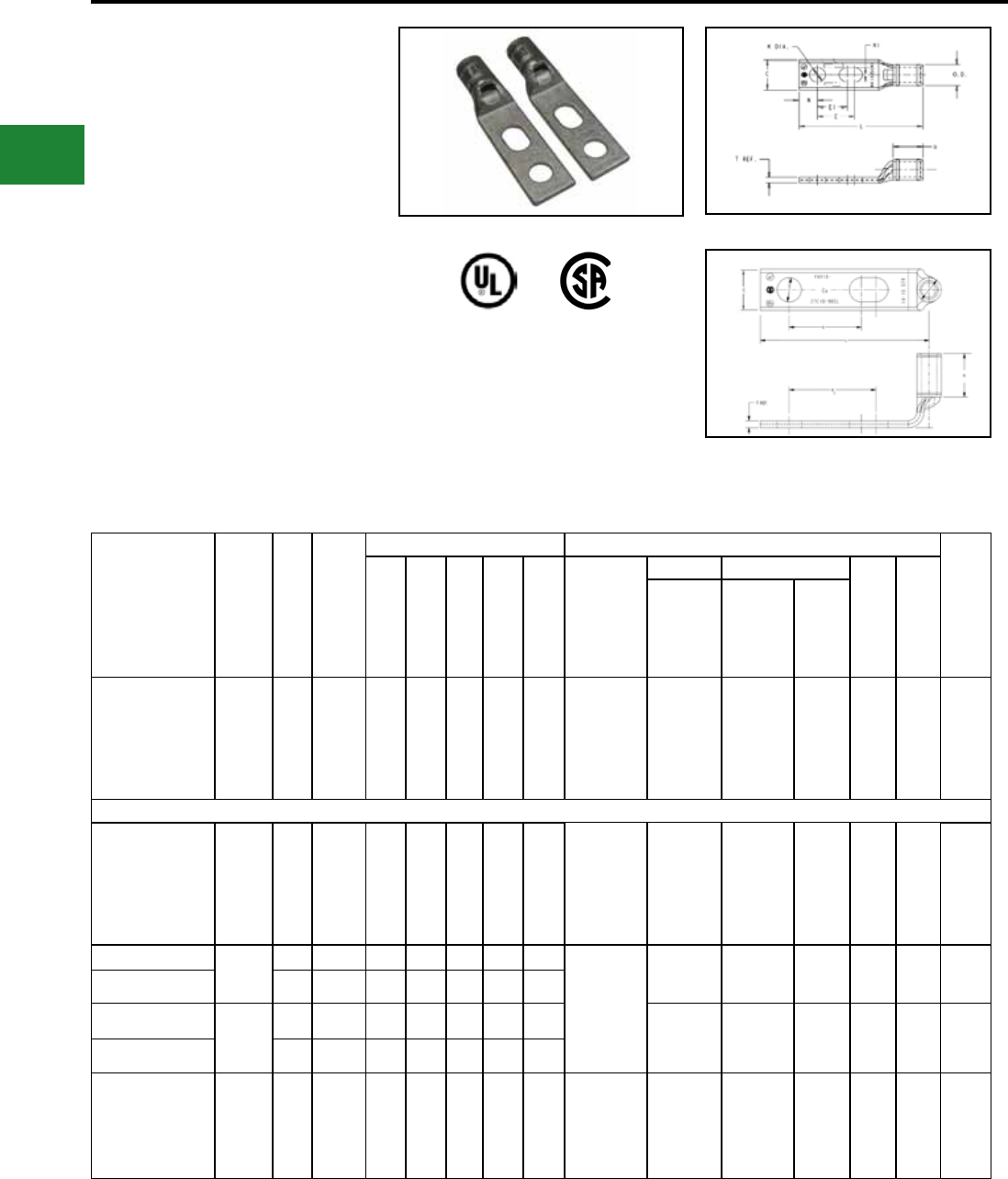
BURNDY®
Blue highlighted items are industry standard and most frequently ordered.
US: 1-800-346-4175 www.burndy.com Canada: 1-800-387-6487
Compression Connections
Copper Compression — Slotted — Standard Barrel — Code/Flex
TWO HOLE SLOTTED
HYLUG™ STANDARD
BARREL
TYPES YA-L2TC-SL AND
YAV-L2TC-FXSL
COPPER COMPRESSION
TERMINAL
UL Listed 90° C,
600 Volts to 35 kV
Compression Slotted Lugs connect copper
or tinned copper conductors to bus bars, CPI
Racks, Cabinets or Cable Runway. Slotted
and 90° Slotted lugs have one round and one
oblong hole to match hole spacing on equipment
mounting rails on CPI Racks and Cabinets and
on most bus bars.
Features & Benets
• Slotted stud provides built in exibility for
the terminal to conform to spacing
requirements
• Accommodates a wide range of conductor
combinations (AWG, Compact, DLO, Flex
and Metric).
* Denotes 900 Angle
Note: All dimensions shown are for reference only.
Catalog Number Cond.
Size
Stud
Hole
Size
Tongue
Width
Dimensions (Inch) Installation Tooling (# of crimps)
Wire
Strip
Length
B T L E E1 Dieless
Mechanical Hydraulic
Color
Code
Die
Index
MD6,
OUR840,
MD7-34R
PATMD6,
Y500CTHS
PAT60018V
Y35, Y39,
Y750
Y46,
PAT750
YA6CL2TC14E2SL #6 AWG 1/4" 0.45" 0.81" 0.08" 2.47" 0.62" 0.75"
Y1MRTC (1)
MY29-3 (1)
MY29-11 (1)
Y644HSXT-18V
(1)
PAT644XT-18V
(1)
W5CVT (1)
W5CRT (1)
X5CRT (1)
X8CART (1)
W5CVT (1)
W5CRT (1)
U5CRT
(1)
U8CABT
(1)
Blue 7 or
374 7/8"
YAV6CL2TC10FX90SL*
61/24
#6 WELD
#6 AWG
#10 0.48" 0.50" 0.08" 1.54" 0.62" 0.75"
Y1MRTC (1)
MY29-3 (1)
MY29-11 (1)
Y644HSXT-18V
(1)
PAT644XT-18V
(1)
W5CVT (1)
W5CRT (1)
X5CRT (1)
X8CART (1)
W5CVT (1)
W5CRT (1)
U5CRT
(1)
U8CABT
(1)
Blue 7 or
374 1/2"
YAV4CL2TC14FXSL
#4 AWG
1/4" 0.55" 0.50" 0.09" 2.08" 0.50" 0.62" Y1MRTC (2)
MY29-11 (1)
Y644HSXT-18V
(1)
PAT644XT-18V
(1)
W4CVT (1)
W4CRT (1)
X4CRT (1)
W4CVT (1)
W4CRT (1)
X4CRT (1)
U4CRT
(1) Gray 8 9/16"
YAV4CL2TC38FXSL 3/8" 0.58" 0.50" 0.08" 2.68" 0.75" 1.00"
YAV2CL2TC14FXSL
#2 AWG
1/4" 0.68" 0.62" 0.10" 2.26" 0.50" 0.62" W2CVT (1)
W2CRT (1)
X2CRT (1)
W2CVT (1)
W2CRT (1)
X2CRT (1)
U2CRT
(1) Brown 10 11/16"
YAV2CL2TC38FXSL 3/8" 0.68" 0.62" 0.10" 2.82" 0.75" 1.00"
YA44L2NNTFXSL 750 kcmil 5/8" 1.63" 1.65" 0.33" 5.74" 1.58" 1.75"
Y81KFT (2)
Y1MRTC (2)
Y644HSXT-18V
(1)
PAT81KFT-18V
(2)
— — U44XRT
(2) Yellow L115 1-2/3"
Electro-Tin
Plated
C-80
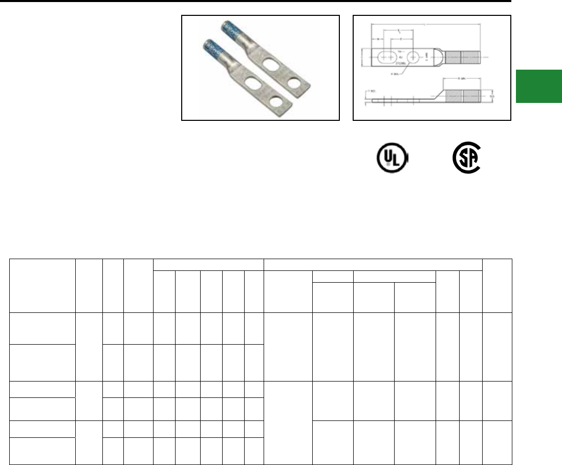
BURNDY®
Blue highlighted items are industry standard and most frequently ordered.
Canada: 1-800-387-6487 www.burndy.com US: 1-800-346-4175
Compression Connections
Copper Compression — Slotted — Long Barrel — Code
TWO HOLE SLOTTED
HYLUG™ LONG BARREL
TYPE YA-2TC-SL
Copper Compression Terminals
UL Listed 90° C,
600 Volts to 35 kV
Compression Slotted Lugs connect copper
or tinned copper conductors to bus bars, CPI
Racks, Cabinets or Cable Runway. Slotted
and 90° Slotted lugs have one round and
one obround hole to match hole spacing on
equipment mounting rails on CPI Racks and
Cabinets and on some bus bars.
Catalog Number Wire
Size
Stud
Hole
Size
Tongue
Width
Figure Dimensions Installation Tooling (# of crimps)
Wire
Strip
Length
(B) (T) (L) (E) (E1) Dieless
Mechanical Hydraulic
Color
Code
Die
Index
MD6,
OUR840,
MD7-34R
BCT500HS,
Y500CTHS
Y35, Y39,
Y750
Y46, PAT750
YA6C2TC38SL
#6
AWG
3/8" 0.58" 1.12" 0.06" 3.22" 0.75" 1.0"
Y1MRTC (2)
MY29-3 (2)
MY29-11 (2)
MRC840 (2)
Y81KFTMBH (1)
Y81KFT (1)
PAT81KFT (1)
W5CVT (2)
W5CRT (2)
W5CVT (2)
W5CRT (2) U5CRT (2) Blue 7 or
374 1-3/16
YA6C2TC38SLBOX500 3/8" 0.58" 1.12" 0.06" 3.22" 0.75" 1.0"
YA3C2TC38SL #3
AWG
3/8" 0.58" 1.25" 0.08" 3.43" 0.75" 1.0" Y1MRTC (4)
MY29-3 (2)
MY29-11 (2)
MRC840 (2)
Y644HSXT (1)
PAT644HSXT (1)
PAT81KFT (1)
Y81KFT (1)
W3CRT (2) W3CRT (2) U3CRT (2) White 9 1 5/16
YA3C2TC38SLBOX500 3/8" 0.58" 1.25" 0.08" 3.43" 0.75" 1.0"
YA2C2TC38SL
#2
AWG
3/8" 0.60" 1.25" 0.11" 3.42" 0.75" 1.0"
W2CVT (2)
W2CRT (2)
W2CVT (2)
W2CRT (2) U2CRT (2) Brown 10 1-5/16
YA2C2TC38SLBOX500 3/8" 0.60" 1.25" 0.11" 3.42" 0.75" 1.0"
Features & Benets
• Slotted stud provides built in exibility for
the terminal to conform to various space
requirements.
• Accommodates a wide range of conductor
combinations (AWG, Compact, DLO, Flex
and Metric).
Note: All dimensions shown are for reference only.
Electro-Tin
Plated
C-81
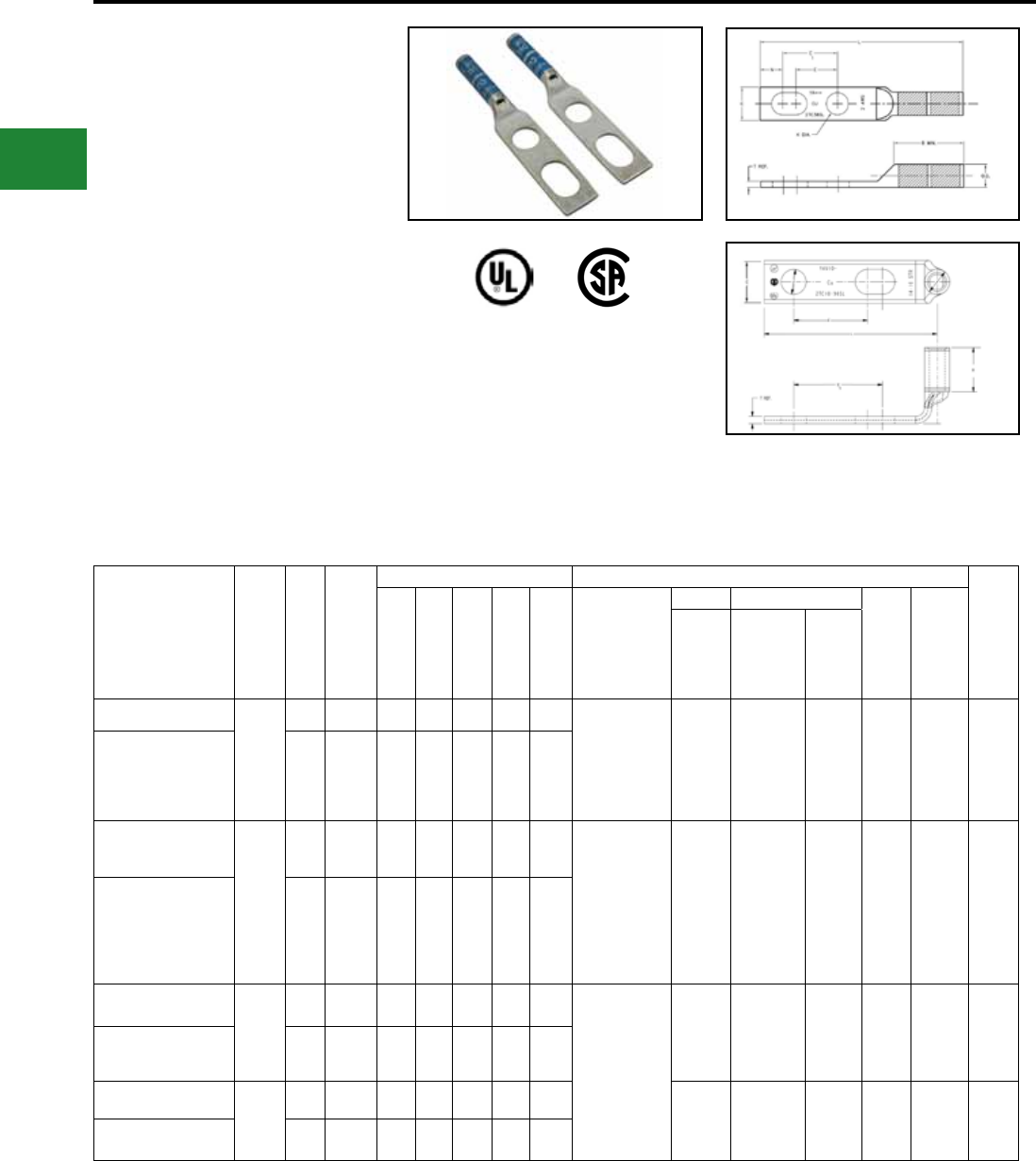
BURNDY®
Blue highlighted items are industry standard and most frequently ordered.
US: 1-800-346-4175 www.burndy.com Canada: 1-800-387-6487
TWO HOLE SLOTTED
HYLUG™ LONG BARREL
WITH INSPECTION
WINDOW
TYPE YAZ-2TC-SL
COPPER COMPRESSION
TERMINAL
UL Listed 90° C,
600 Volts to 35 kV
Compression Slotted Lugs connect copper
or tinned copper conductors to bus bars, CPI
Racks, Cabinets or Cable Runway. Slotted
and 90° Slotted lugs have one round and
one obround hole to match hole spacing on
equipment mounting rails on CPI Racks and
Cabinets and on some bus bars.
Catalog Number Wire
Size
Stud
Hole
Size
Tongue
Width
Figure Dimensions Installation Tooling (# of crimps)
Wire
Strip
Length
(B) (T) (L) (E) (E1) Dieless
Mech. Hydraulic
Color
Code
Die
Index
MD6,
OUR840,
MD7-34R
BCT500HS,
Y500CTHS
Y35,
Y39,
Y750
Y46,
PAT750
YAZ8C2TC10SL
# 8
AWG
#10 0.41" 0.75" 0.08" 2.21" 0.62" 0.75" Y1MRTC (2)
Y8MRB-1 (2)
MY29-3 (1)
MY29-11 (2)
PAT81KFT-18V (1)
MRC840 (2)
W8CVT
(2)
W8CRT
(2)
X8CRT
(2)
W8CRT (2) U8CRT
(2) Red 49 13/16"
YAZ8C2TC1090SL* #10 0.41" 0.75" 0.08" 1.50" 0.62" 0.75"
YAZ6C2TC38SL
#6
AWG
3/8" 0.58" 1.12" 0.08" 3.22" 0.75" 1.00" Y1MRTC (2)
Y8MRB-1 (2)
MY29-3 (1)
MY29-11 (2)
MRC840 (2)
Y81KFT (1)
Y81KFTMBH (1)
PAT81KFT-18V (1)
W5CVT
(2)
W5CRT
(2)
W5CVT (2)
W5CRT (2)
U5CRT
(2) Blue 7 or 374 1-3/16"
YAZ6C2TC38SLBOX500 3/8" 0.58" 1.12" 0.08" 3.22" 0.75" 1.00"
YAZ3C2TC38SL
# 3
AWG
3/8" 0.58" 1.25" 0.08" 3.39" 0.75" 1.00" Y1MRTC (4)
MRC840 (2)
PAT81KFT-18V (1)
Y81KFT (1)
Y81KFTMBH (1)
MY29-3 (2)
MY29-11 (2)
Y644HSXT (1)
PAT644HSXT (1)
W3CRT
(2) W3CRT (2) U3CRT
(2) White 9 1-5/16"
YAZ3C2TC38SLBOX500 3/8" 0.58" 1.25" 0.08" 3.43" 0.75" 1.00"
YAZ2C2TC38SL # 2
AWG
3/8" 0.60" 1.25" 0.11" 3.41" 0.75" 1.00" W2CVT
(2)
W2CRT
(2)
W2CVT (2)
W2CRT (2)
U2CRT
(2) Brown 10 1-5/16"
YAZ2C2TC38SLBOX500 3/8" 0.60" 1.25" 0.11" 3.42" 0.75" 1.00"
Features & Benets
• Slotted stud provides built in exibility for
the terminal to conform to various space
requirements.
• Accommodates a wide range of conduc-
tor combinations (AWG, Compact, DLO,
Flex and Metric).
* Denotes 900 Angle
Note: All dimensions shown are for reference only.
Compression Connections
Copper Compression — Slotted — Long Barrel — Code
Electro-Tin
Plated
C-82
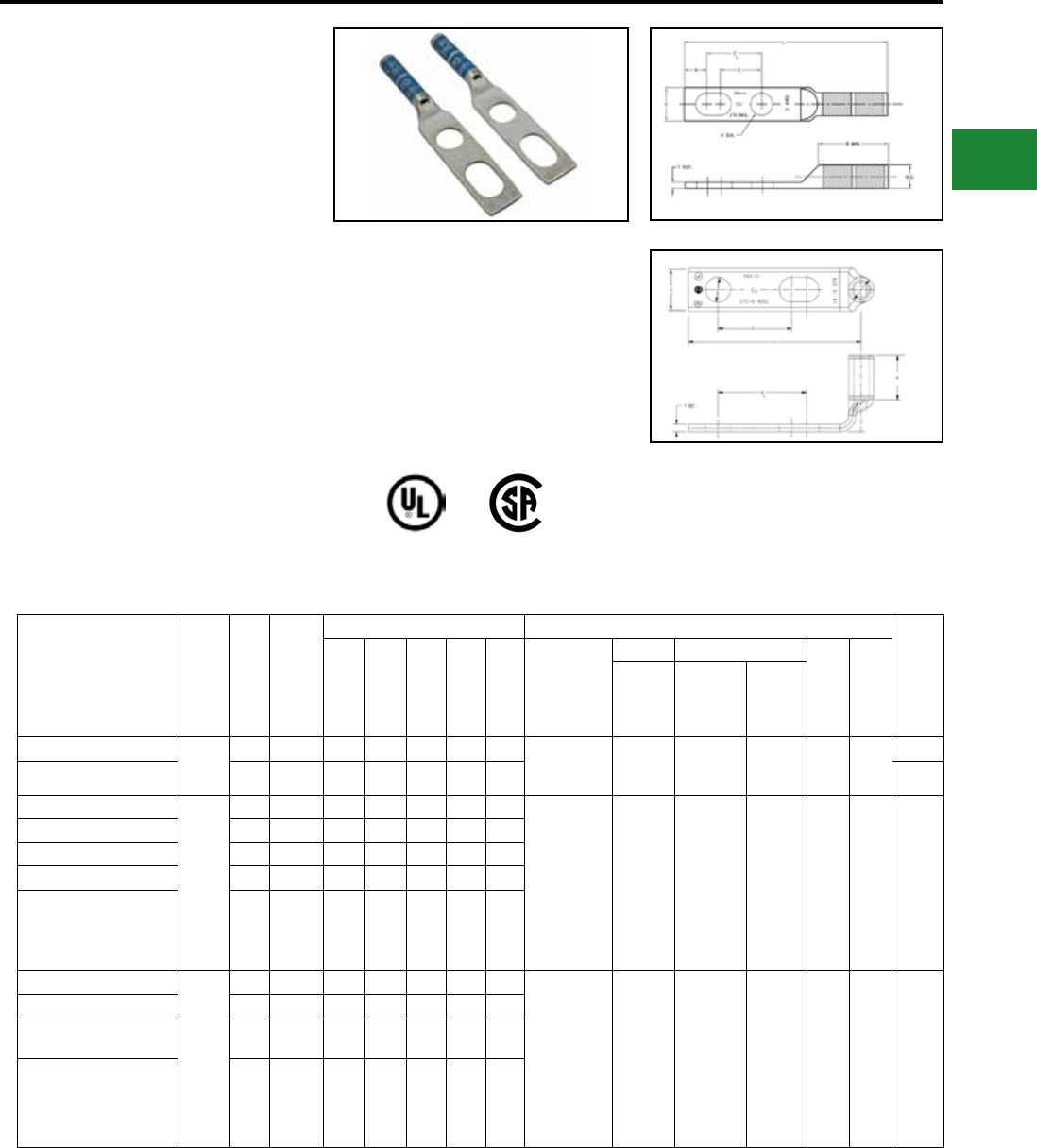
BURNDY®
Blue highlighted items are industry standard and most frequently ordered.
Canada: 1-800-387-6487 www.burndy.com US: 1-800-346-4175
TWO HOLE SLOTTED
HYLUG™ LONG BARREL
WITH INSPECTION
WINDOW
TYPES YAV-2TC-SL AND
YAZV-2TC-FXSL
COPPER COMPRESSION
TERMINAL
UL Listed 90° C,
600 Volts to 35 kV
Compression Slotted Lugs connect copper
or tinned copper conductors to bus bars, CPI
Racks, Cabinets or Cable Runway. Slotted
and 90° Slotted lugs have one round and one
oblong hole to match hole spacing on equipment
mounting rails on CPI Racks and Cabinets and
on most bus bars.
Catalog Number Cond.
Size
Stud
Hole
Size
Tongue
Width
Dimensions Installation Tooling (# of crimps)
Wire
Strip
Length
B T L E E1 Dieless
Mech. Hydraulic
Color
Code
Die
Index
MD6,
OUR840,
MD7-34R
PATMD6,
Y500CTHS
PAT60018V
Y35, Y39,
Y750
Y46,
PAT750
YAV102TC1090SL #14 -
#10
AWG
#10 0.36" 0.38" 0.06" 1.46" 0.63" 0.75"
Y8MRB-1 (1) — — — — —
7/16"
YAZV102TC14SL 1/4" 0.41" 0.69" 0.05" 2.28" 0.62" 0.75" 3/4"
YAZV6C2TC10FX90SL*
#6
AWG
#10 0.48" 0.75" 0.08" 1.50" 0.75" 1.00" YIMRTC (2)
Y8MRB-1 (2)
MY29-3 (1)
MY29-11 (2)
MRC840 (2)
Y81KFT (1)
Y81KFTMBH
(1)
PAT81KFT-18V
(1)
W5CVT
(2)
W5CRT
(2)
W5CVT (2)
W5CRT (2)
U5CRT
(2) Blue 7 or
374 1-3/16"
YAZV6C2TC14FXSLBOX500 1/4 0.58" 1.12" 0.08" 3.22" 0.63" 1.00"
YAZV6C2TC14FXSL 1/4 0.58" 1.12" 0.08" 3.22" 0.63" 1.00"
YAZV6C2TC38FXSLBOX500 3/8" 0.58" 1.12" 0.08" 3.22" 0.63" 1.00"
YAZV6C2TC38FXSL 3/8" 0.58" 1.12" 0.08" 3.22" 0.63" 1.00"
YAZV4C2TC14FXSL
#4
AWG
1/4" 0.55" 1.25" 0.09" 2.95" 0.63" 1.00" Y1MRTC (4)
MY29-3 (2)
MY29-11 (2)
MRC840 (2)
Y644HSXT (2)
Y81KFT (1)
Y81KFTMBH
(1)
PAT81KFT-18V
(1)
W4CVT
(2)
W4CRT
(2)
X4CRT
(2)
W4CVT (2)
W4CRT (2)
X4CRT (2)
U4CRT
(2) Gray 8 or
346 1-5/16"
YAZV4C2TC14FXSLBOX500 1/4" 0.55" 1.25" 0.09" 2.95" 0.63" 1.00"
YAZV4C2TC38FXSL 3/8" 0.55" 1.25" 0.09" 2.95" 0.63" 1.00"
YAZV4C2TC38FXSLBOX500 3/8" 0.55" 1.25" 0.09" 2.95" 0.63" 1.00"
Features & Benets
• Slotted stud provides built in exibility for
the terminal to conform to various space
requirements.
• Accommodates a wide range of conduc-
tor combinations (AWG, Compact, DLO,
Flex and Metric).
* Denotes 900 Angle
Note: All dimensions shown are for reference only.
Compression Connections
Copper Compression — Slotted — Long Barrel — Flex
Electro-Tin
Plated
C-83
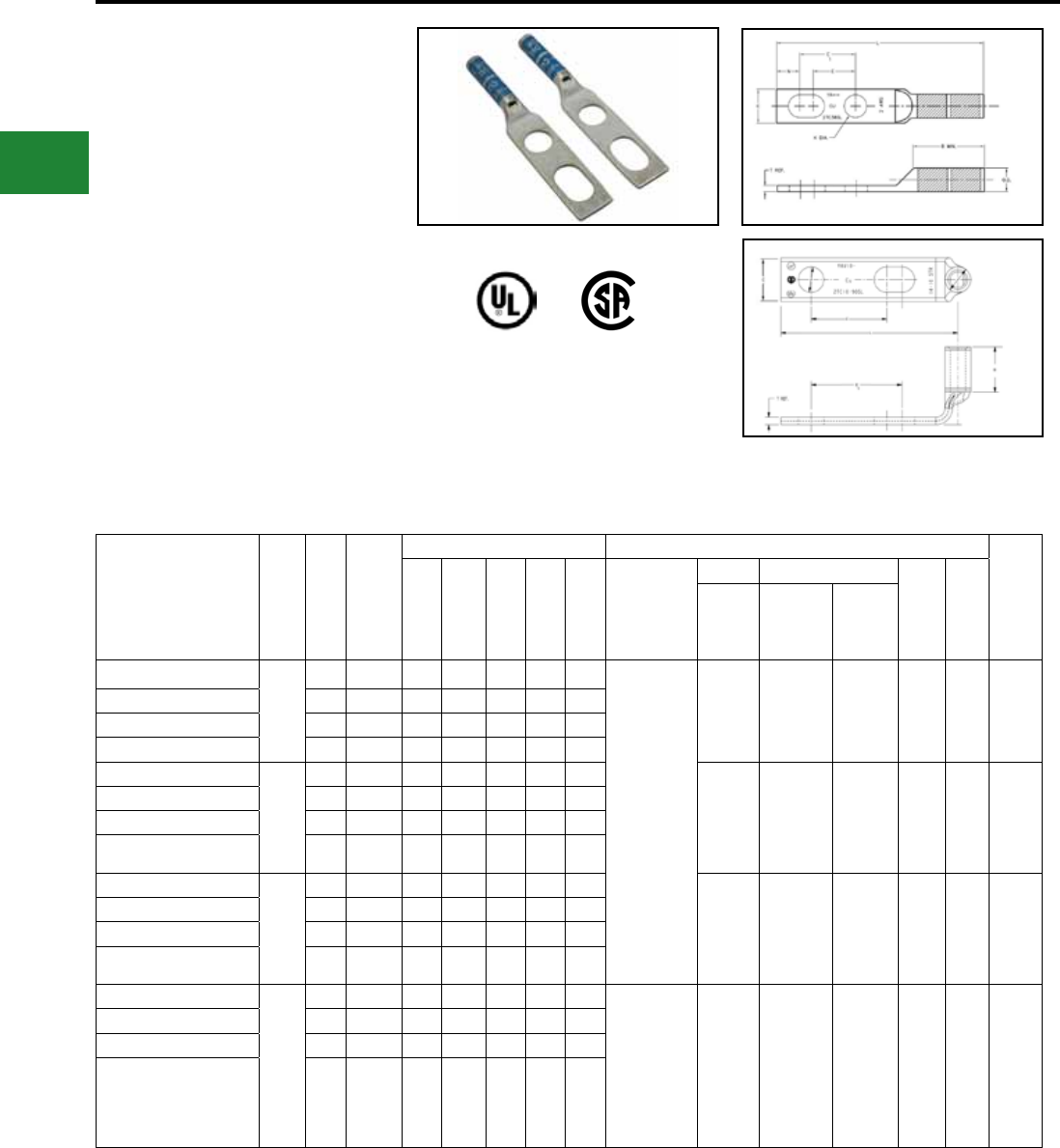
BURNDY®
Blue highlighted items are industry standard and most frequently ordered.
US: 1-800-346-4175 www.burndy.com Canada: 1-800-387-6487
TWO HOLE SLOTTED
HYLUG™ LONG BARREL
WITH INSPECTION
WINDOW
TYPES YAZ-2TC-SL AND
YAZV-2TC-SL
(Continued)
Note: All dimensions shown are for reference only.
Catalog Number Cond.
Size
Stud
Hole
Size
Tongue
Width
Dimensions Installation Tooling (# of crimps)
Wire
Strip
Length
B T L E E1 Dieless
Mech. Hydraulic
Color
Code
Die
Index
MD6,
OUR840,
MD7-34R
PATMD6,
Y500CTHS
PAT60018V
Y35, Y39,
Y750
Y46,
PAT750
YAZV2C2TC14FXSL
2
AWG
1/4" 0.60" 1.25" 0.11" 3.42" 0.75" 1.00"
Y1MRTC (4)
MY29-3 (2)
MY29-11 (2)
MRC840 (2)
Y644HSXT
(1)
Y81KFT (2)
Y81KFTMBH
(2)
PAT644XT-18V
(2
W2CVT
(2)
W2CRT
(2)
W2CVT (2)
W2CRT (2) U2CRT (2) Brown 10 1-5/16"
YAZV2C2TC14FXSLBOX500 1/4" 0.60" 1.25" 0.11" 3.42" 0.75" 1.00"
YAZV2C2TC38FXSL 3/8' 0.60" 1.25" 0.11" 3.42" 0.75" 1.00"
YAZV2C2TC38FXSLBOX500 3/8" 0.60" 1.25" 0.11" 3.42" 0.75" 1.00"
YAZV252TC14FXSL
1/0
AWG
1/4" 0.83" 1.50" 0.12" 3.44" 0.63" 1.00" W25VT
(4)
W25RT
(4)
X25RT
(4)
W25VT (4)
W25RT (4)
X25RT (4)
U25RT (2) Pink 12 1-9/16"
YAZV252TC14FXSLBOX500 1/4" 0.83" 1.50" 0.12" 3.44" 0.63" 1.00"
YAZV252TC38FXSL 3/8" 0.83" 1.50" 0.12" 3.44" 0.63" 1.00"
YAZV252TC38FXSLBOX500 3/8" 0.83" 1.50" 0.12" 3.44" 0.63" 1.00"
YAZV262TC14FXSL
2/0
AWG
1/4" 0.93" 1.50" 0.13" 3.58" 0.63" 1.00" W26VT
(4)
W26RT
(4)
X26RT
(4)
W26VT (4)
W26RT (4)
X26RT (4)
U26RT (2) Black 13 1-9/16"
YAZV262TC14FXSLBOX500 1/4" 0.93" 1.50" 0.13" 3.58" 0.63" 1.00"
YAZV262TC38FXSL 3/8" 0.93" 1.50" 0.13" 3.58" 0.63" 1.00"
YAZV262TC38FXSLBOX500 3/8" 0.93" 1.50" 0.13" 3.58" 0.63" 1.00"
YAZV282TC14FXSL
4/0
AWG
1/4" 1.14" 1.62" 0.15" 3.64" 0.63" 1.00" MY29-3 (2)
MY29-11 (2)
MRC840 (4)
Y644HSXT (1)
Y81KFT (2)
Y81KFTMBH
(2)
PAT644XT-18V
(2)
W28VT
(4)
W28RT
(4)
X28RT
(6)
W28VT (4)
W28RT (4)
X28RT (6)
U28RT (2) Purple 15 1-11/16"
YAZV282TC14FXSLBOX500 1/4" 1.14" 1.62" 0.15" 3.64" 0.63" 1.00"
YAZV282TC38FXSL 3/8" 1.14" 1.62" 0.15" 3.64" 0.63" 1.00"
YAZV282TC38FXSLBOX500 3/8" 1.14" 1.62" 0.15" 3.64" 0.63" 1.00"
Compression Connections
Copper Compression — Slotted — Long Barrel — Flex
Electro-Tin
Plated
C-84
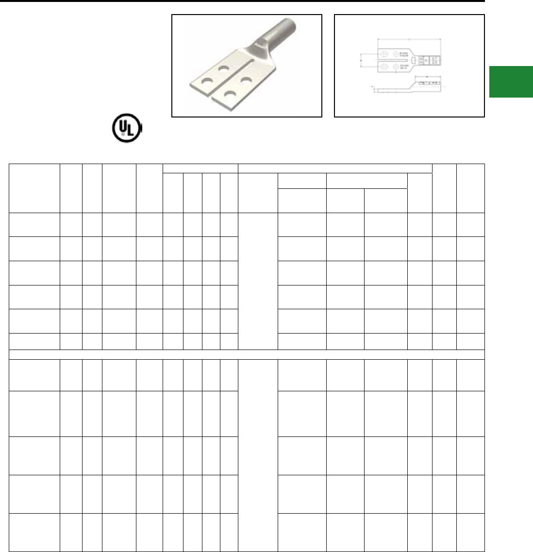
BURNDY®
Blue highlighted items are industry standard and most frequently ordered.
Canada: 1-800-387-6487 www.burndy.com US: 1-800-346-4175
HYLUGTM SPLIT TONGUE
STANDARD BARREL
TERMINALS
TYPES YA-4TC, YAV-4TC-FX
UL Listed 90° C,
600 Volts to 35 kV♦
Catalog
Number
Wire
Size
Stud
Hole
Size
Stud
Hole
Spacing
Tongue
Width
Figure Dimensions Installation Tooling (# of crimps)
Color
Code
Wire
Strip
Length
(B) (T) (L) (W) Dieless
Mechanical Hydraulic
Die
Index
MD6, OUR840,
MD7-34R
BCT500HS,
Y500CTHS
Y35, Y39,
Y750
Y46, PAT750
YA25L4TCG1 1/0
AWG 1/4" 0.62" 1.38" 0.88" 0.21" 3.05" 0.75"
MY29-3
(1)
MY29-11
(1)
Y644HSXT-18V
(1)
PAT644XT-18V
(1)
W25VT(2)
W25RT(2)
X25RT(2)
W25VT(2)
W25RT(2)
X25RT(2)
U25RT(1)
U2CABT(1)
12 or
348 Pink 15/16"
YA26L4TCG1 2/0
AWG 1/4" 0.62" 1.38" 0.94" 0.21" 3.15" 0.75"
W26VT(2)
W26RT(2)
X26RT(2)
W26VT(2)
W26RT(2)
X26RT(2)
U26RT(1)
U26D-1(1) 13 Black 1"
YA27L4TCG1 3/0
AWG 1/4" 0.62" 1.38" 1.00" 0.21" 3.25" 0.75"
W27VT(2)
W27RT(2)
X27RT(2)
W27VT(2)
W27RT(2)
X27RT(2)
U27RT(1)
U27D-1(1) 14 Orange 1-1/16"
YA28L4TCG1 4/0
AWG 1/4" 0.62" 1.38" 1.00" 0.21" 3.29" 0.75"
W28VT(2)
W28RT(2)
X28RT(2)
W28VT(2)
W28RT(2)
X28RT(2)
U28RT(1)
U28D-1(1) 15 Purple 1-1/8"
YA29L4TCG1 250
kcmil 1/4" 0.62" 1.38" 1.06" 0.21" 3.39" 0.75"
W29VT(2)
W29RT(2)
X29RT(2)
W29VT(2)
W29RT(2)
X29RT(2)
U29RT(1)
U29D-1(1) 16 Yellow 1-1/8"
YA31L4TCG1 350
kcmil 1/4" 0.62" 1.38" 1.06" 0.21" 3.46" 0.75" W31RT(2)
W31VT(2)
W31RT(2)
W31VT(2)
U31RT(2)
U29ART(2)
18 or
324 Red 1-1/8"
FLEX CONDUCTORS
YAV2CL4TC14FXG1
125/2
#2
Weld
2 AWG
1/4" 0.62" 1.38" 0.62" 0.11" 2.84" 0.75"
MY29-3
(1)
MY29-11
(1)
Y644HSXT-18V
(1)
PAT644XT-18V
(1)
W2CVT(1)
W2CRT(1)
X2CRT(1)
W2CVT(1)
W2CRT(1)
X2CRT(1)
U2CRT(1) 10 Brown 11/16"
YAV25L4TC14FXG1
275/24
1/0
Weld
1/0
AWG
1/4" 0.62" 1.38" 0.69" 0.21" 2.90" 0.75"
W25VT(1)
W25RT(1)
X25RT(1)
W25VT(1)
W25RT(1)
X25RT(1)
U25RT(1)
U2CABT(1)
12 or
348 Pink 13/16"
YAV26L4TC14FXG1
325/24
2/0
Weld
2/0
AWG
1/4" 0.62" 1.38" 0.81" 0.21" 3.07" 0.75"
W26VT(1)
W26RT(1)
X26RT(1)
W26VT(1)
W26RT(1)
X26RT(1)
U26RT(1)
U26D-1(1) 13 Black 1-1/16"
YAV27L4TC14FXG1
450/24
3/0
Weld
3/0
AWG
1/4" 0.62" 1.38" 1.00" 0.21" 3.30" 0.75"
W27RT(2)
X27RT(3)
W27RT(2)
X27RT(3) U27RT(1)
U27D-1(1) 14 Orange 1-1/16"
YAV28L4TC14FXG1
550/24
4/0
Weld
4/0
AWG
1/4" 0.62" 1.38" 1.00" 0.21" 3.38" 0.75"
W28VT(2)
W28RT(2)
X28RT(3)
W28VT(2)
W28RT(2)
X28RT(3)
U29RT(1)
U29D-1(1) 15 Purple 11/16"
Compression Connections
Copper Compression — Split Tongue — Standard Barrel — Code/Flex
Electro-Tin
Plated
C-85
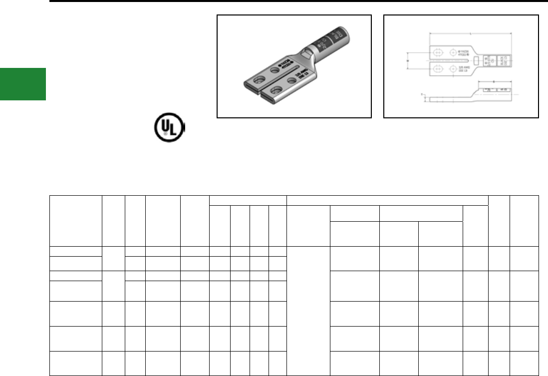
BURNDY®
Blue highlighted items are industry standard and most frequently ordered.
US: 1-800-346-4175 www.burndy.com Canada: 1-800-387-6487
Compression Connections
Copper Compression — Split Tongue — Long Barrel — Code/Flex
HYLUGTM SPLIT TONGUE
LONG BARREL TERMINALS
WITH INSPECTION
WINDOW
TYPE YAZ-4TC
UL Listed 90° C,
600 Volts to 35 kV♦
Catalog
Number
Wire
Size
Stud
Hole
Size
Stud
Hole
Spacing
Tongue
Width
Figure Dimensions Installation Tooling (# of crimps)
Color
Code
Wire
Strip
Length
(B) (T) (L) (W) Dieless
Mechanical Hydraulic
Die
Index
MD6, OUR840,
MD7-34R
BCT500HS,
Y500CTHS
Y35, Y39,
Y750
Y46, PAT750
YAZ254TCG1 1/0
AWG
1/4" 0.62"-0.75" 1.38" 1.38" 0.11" 3.55" 0.75"
MY29-3
(1)
MY29-11
(1)
Y644HSXT-18V
(1)
PAT644XT-18V
(1)
W25VT(1)
W25RT(1)
X25RT(1)
W25VT(1)
W25RT(1)
X25RT(1)
U25RT (2)
U2CABT (2) 12 or
348 Pink 1-7/16"
YAZ254TC38E1G1 3/8" 1.00"-1.13" 1.63" 1.38" 0.11" 3.93" 0.88"
YAZ264TCG1
2/0
AWG
1/4" 0.62"-0.75" 1.38" 1.50" 0.21" 3.71" 0.75" W26VT(2)
W26RT(2)
X26RT(2)
W26VT(2)
W26RT(2)
X26RT(2)
U26RT (2)
U26D-1 (2) 13 Black 1-9/16"
YAZ264TC38E1G1 3/8" 1.00"-1.13" 1.63" 1.50" 0.21" 4.09" 0.88"
YAZ284TCG1 4/0
AWG 1/4" 0.62"-0.75" 1.38" 1.62" 0.21" 3.91" 0.75"
W28VT(2)
W28RT(2)
X28RT(3)
W28VT(2)
W28RT(2)
X28RT(3)
U28RT(1) 15 Purple 1-11/16"
YAZ294TCG1 250
kcmil 1/4" 0.62"-0.75" 1.38" 1.62" 0.21" 3.94" 0.75"
W29VT(2)
W29RT(2)
X29RT(3)
W29VT(2)
W29RT(2)
X29RT(3)
U29RT (2)
U29D-1 (2) 16 Yellow 1-11/16"
YAZ314TCG1 350
kcmil 1/4" 0.62"-0.75" 1.38" 2.00" 0.21" 4.39" 0.75" W31VT(2)
W31RT(2)
W31VT(2)
W31RT(2)
U31RT (2)
U29ART (2)
U31D-1 (2)
18 or
324 Red 2-1/16"
Electro-Tin
Plated
C-86

BURNDY®
Blue highlighted items are industry standard and most frequently ordered.
Canada: 1-800-387-6487 www.burndy.com US: 1-800-346-4175
ONE HOLE HYLUG™
CODE CONDUCTOR
STANDARD BARREL
TYPE YAV-M
Made from electrolytic copper tube and is
electro tin plate. Wire range is from 2.5 mm2 to
630 mm2 for class 2. Compatible to IEC61238-1.
Compression Connections
Metric Lugs — Copper Compression — Code — Standard Barrel
* Use equivalent AWG setting on tool for installation ** PUADP-1 Adaptor is required to use “U” Dies in Y46 and
PAT46 series tools
† P-RT Die sets for use in Y46 only,
PUADP-1 Adaptor not required
Catalog
Number
Wire
Range
(MM2)
Stud
Size
Dimensions (mm) Installation Tooling
Wire
Strip
Length
Tongue
Thickness (B) (C) (L) Dieless*
Mechanical Hydraulic
Die
Index
MD6,
OUR840,
MD7-34R
BCT500HS,
Y500CTHS
Y35, Y39,
Y750, PAT750,
Y46**, PAT46**
YAV025M3
2.5
M3 1.0 6.9 7.9 19.1
Y10D (1)
Y10-22 (1)
MR8G98 (1)
MR8-9Q (1)
Y8MRB-1 (1)
MR20 (1)
— — — — 7
YAV025M4 M4 1.0 6.9 7.9 19.1
YAV025M5 M5 1.0 6.9 7.9 19.1
YAV025M6 M6 0.8 6.9 10.7 24.2
YAV025M8 M8 0.8 6.9 11.2 24.2
YAV06M4
6
M4 1.5 10.4 9.7 23.9
— — — — 11
YAV06M5 M5 1.5 10.4 9.7 23.9
YAV06M6 M6 1.3 10.4 11.9 26.9
YAV06M8 M8 1.0 10.4 13.5 28.7
YAV06M10 M10 1.0 11.9 14.2 29.1
YAV10M4
10
M4 2.0 11.2 10.4 29.1
Y1MRTC (1)
MY29-11 (1)
MRC840 (1)
Y81KFT (1)
PAT81KFT-18V (1)
W8CVT (1)
W8CRT (1)
X8CRT (1)
W8CVT (1)
W8CRT (1)
X8CRT (1)
U8CRT (1) 49 11
YAV10M5 M5 1.8 11.2 10.4 28.5
YAV10M6 M6 1.8 11.2 11.7 31.0
YAV10M8 M8 1.5 11.2 13.2 33.0
YAV10M10 M10 1.3 11.2 14.5 33.0
YAV10M12 M12 1.3 11.2 18.5 38.6
YAV16M4
16
M4 2.0 12.7 12.2 31.5 Y1MRTC (1)
MY29-11 (1)
MRC840 (1)
Y644HSXT (1)
PAT644XT18V (1)
Y81KFT (1)
PAT81KFT-18V (1)
W5CVT (1)
W5CRT (1)
X5CRT (1)
W5CVT (1)
W5CRT (1)
X5CRT (1)
U5CRT (1) 7 13
YAV16M5 M5 2.0 12.7 12.2 33.0
YAV16M6 M6 2.0 12.7 12.2 33.0
YAV16M8 M8 1.5 12.7 15.2 36.3
YAV16M10 M10 1.5 12.7 14.7 40.9
YAV16M12 M12 1.3 12.7 18.8 41.6
YAV25M5
25
M5 2.3 12.7 14.0 33.5
Y1MRTC (2)
MY29-11 (1)
MRC840 (1)
Y644HSXT (1)
PAT644XT18V (1)
Y81KFT (1)
PAT81KFT-18V (1)
W3CRT (1) W3CRT (1) U3CRT (1) 9 13
YAV25M6 M6 2.0 12.7 12.7 34.5
YAV25M8 M8 2.0 12.7 16.0 37.6
YAV25M10 M10 2.0 12.7 14.7 41.4
YAV25M12 M12 1.5 12.7 18.5 42.7
YAV35M5
35
M5 2.5 16.0 17.3 38.1
W2CVT (1)
W2CRT (1)
X2CRT (1)
W2CVT (1)
W2CRT (1)
X2CRT (1)
U2CRT (1) 10 17
YAV35M6 M6 2.5 16.0 17.5 43.7
YAV35M8 M8 2.5 16.0 17.5 43.7
YAV35M10 M10 2.5 16.0 17.3 45.9
YAV35M12 M12 2.3 16.0 19.6 47.5
Electro-Tin
Plated
C-87
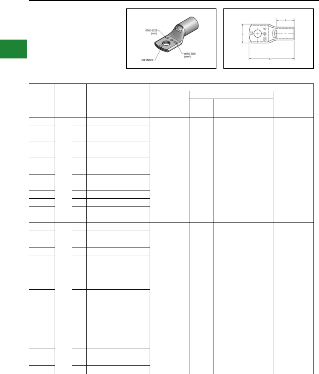
BURNDY®
Blue highlighted items are industry standard and most frequently ordered.
US: 1-800-346-4175 www.burndy.com Canada: 1-800-387-6487
ONE HOLE HYLUG™
CODE CONDUCTOR
STANDARD BARREL
TYPE YAV-M
(Continued)
* Use equivalent AWG setting on tool for installation ** PUADP-1 Adaptor is required to use “U” Dies in Y46 and
PAT46 series tools
† P-RT Die sets for use in Y46 only,
PUADP-1 Adaptor not required
Catalog
Number
Wire
Range
(MM2)
Stud
Size
Dimensions (mm) Installation Tooling
Wire
Strip
Length
Tongue
Thickness (B) (C) (L) Dieless*
Mechanical Hydraulic
Die
Index
MD6,
OUR840,
MD7-34R
BCT500HS,
Y500CTHS
Y35, Y39,
Y750, PAT750,
Y46**, PAT46**
YAV50M6
50
M6 2.5 16.0 17.3 38.1
MY29-11 (1)
MRC840 (2)
Y644HSXT (1)
PAT644XT18V (1)
Y81KFT (1)
PAT81KFT-18V (1)
W25VT (2)
W25RT (2)
X25RT (2)
W25VT (2)
W25RT (2)
X25RT (2)
U25RT (1) 12 17
YAV50M8 M8 2.5 16.0 17.3 42.9
YAV50M10 M10 2.5 16.0 17.3 45.9
YAV50M12 M12 2.5 16.0 18.5 52.3
YAV50M14 M14 3.0 16.0 21.1 53.3
YAV50M16 M16 3.6 16.0 25.9 58.7
YAV70M5
70
M5 3.0 17.5 21.1 41.4
W25VT (2)
W25RT (2)
X25RT (2)
W25VT (2)
W25RT (2)
X25RT (2)
U26RT (1) 13 19
YAV70M6 M6 3.0 17.5 21.1 44.5
YAV70M8 M8 3.0 17.5 21.1 46.0
YAV70M10 M10 3.0 17.5 21.1 49.3
YAV70M12 M12 3.0 17.5 21.1 55.6
YAV70M14 M14 2.8 17.5 22.4 56.6
YAV70M16 M16 2.8 17.5 22.4 62.0
YAV95M8
95
M8 3.3 20.6 23.6 50.3
MY29-11 (1)
MRC840 (2)
Y644HSXT (1)
PAT644XT18V (1)
Y81KFT (2)
PAT81KFT-18V (2)
W27VT (2)
W27RT (2)
X27RT (3)
W27VT (2)
W27RT (2)
X27RT (3)
U27RT (1) 14 22
YAV95M10 M10 3.3 20.6 23.6 53.6
YAV95M12 M12 3.3 20.6 23.6 59.9
YAV95M14 M14 3.3 20.6 23.6 61.0
YAV95M16 M16 3.3 20.6 23.6 66.3
YAV95M20 M20 4.1 20.6 30.5 77.4
YAV120M8
120
M8 3.8 26.2 29.0 58.2
W28VT (2)
W28RT (2)
X28RT (3)
W28VT (2)
W28RT (2)
X28RT (3)
U28RT (1) 15 27
YAV120M10 M10 3.8 26.2 29.0 61.5
YAV120M12 M12 3.8 26.2 29.0 67.8
YAV120M14 M14 3.8 26.2 29.0 68.8
YAV120M16 M16 3.8 26.2 29.0 74.2
YAV120M20 M20 3.8 26.2 29.0 85.2
YAV150M8
150
M8 4.1 26.2 30.5 58.7
Y644HSXT (1)
PAT644XT18V (1)
Y81KFT (2)
PAT81KFT-18V (2)
W30VT (2) W30VT (2)
W30RT (2) U30RT (2) 17 27
YAV150M10 M10 4.1 26.2 30.5 62.0
YAV150M12 M12 4.1 26.2 30.5 68.3
YAV150M14 M14 4.1 26.2 30.5 69.2
YAV150M16 M16 4.1 26.2 30.5 74.7
YAV150M20 M20 4.1 26.2 30.5 85.7
Compression Connections
Metric Lugs — Copper Compression — Code — Standard Barrel
Electro-Tin
Plated
C-88
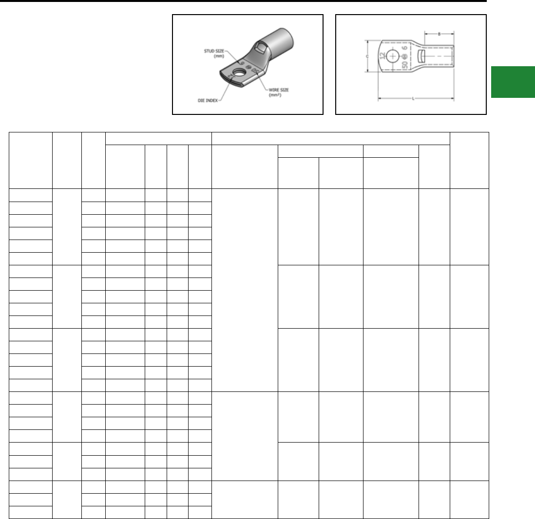
BURNDY®
Blue highlighted items are industry standard and most frequently ordered.
Canada: 1-800-387-6487 www.burndy.com US: 1-800-346-4175
* Use equivalent AWG setting on tool for installation ** PUADP-1 Adaptor is required to use “U” Dies in Y46 and
PAT46 series tools
† P-RT Die sets for use in Y46 only,
PUADP-1 Adaptor not required
Catalog
Number
Wire
Range
(MM2)
Stud
Size
Dimensions (mm) Installation Tooling
Wire
Strip
Length
Tongue
Thickness (B) (C) (L) Dieless*
Mechanical Hydraulic
Die
Index
MD6,
OUR840,
MD7-34R
BCT500HS,
Y500CTHS
Y35, Y39,
Y750, PAT750,
Y46**, PAT46**
YAV185M8
185
M8 4.6 26.9 32.8 60.2
Y644HSXT (1)
PAT644XT18V (1)
Y81KFT (2)
PAT81KFT-18V (2)
W31VT (2) W31VT (2)
W31RT (2) U31RT (2) 18 29
YAV185M10 M10 4.3 26.9 32.8 63.5
YAV185M12 M12 4.3 26.9 32.8 69.9
YAV185M14 M14 4.6 26.9 32.8 70.8
YAV185M16 M16 4.6 26.9 32.8 76.2
YAV185M20 M20 4.6 26.9 32.8 87.3
YAV240M10
240
M10 5.8 32.3 39.4 72.9
W34VT (2) W34VT (2)
W34RT (2) U34RT (2) 20 33
YAV240M12 M12 5.6 32.3 39.4 80.2
YAV240M14 M14 5.8 32.3 39.4 81.3
YAV240M16 M16 5.8 32.3 39.4 85.6
YAV240M20 M20 5.8 32.3 39.4 96.6
YAV300M10
300
M10 6.9 35.1 44.2 77.2
— — U36RT (2) 22 35
YAV300M12 M12 6.6 35.1 44.2 83.6
YAV300M14 M14 6.9 35.1 44.2 84.6
YAV300M16 M16 6.9 35.1 44.2 89.9
YAV300M20 M20 6.9 35.1 44.2 100.9
YAV400M12
400
M12 7.6 36.1 50.3 87.1
Y644HSXT (1)
PAT644XT18V (1)
Y81KFT (3)
PAT81KFT-18V (3)
— — U39RT (3) 24 37
YAV400M14 M14 7.6 36.1 50.3 88.1
YAV400M16 M16 7.6 36.1 50.3 93.5
YAV400M20 M20 7.6 36.1 50.3 104.5
YAV500M12
500
M12 8.1 41.9 55.6 96.2
— — U44XRT (3) L115 43YAV500M16 M16 8.4 41.9 55.6 102.6
YAV500M20 M20 8.4 41.9 55.6 113.7
YAV630M12
630
M12 9.7 50.8 62.5 107.7
— — — † P45RT (3) 29 55YAV630M16 M16 9.7 50.8 62.5 114.0
YAV630M20 M20 9.7 50.8 62.5 125.2
ONE HOLE HYLUG™
CODE CONDUCTOR
STANDARD BARREL
TYPE YAV-M
(Continued)
Compression Connections
Metric Lugs — Copper Compression — Code — Standard Barrel
Electro-Tin
Plated
C-89
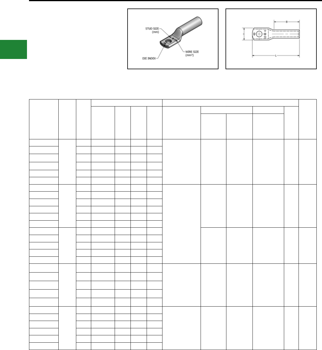
BURNDY®
Blue highlighted items are industry standard and most frequently ordered.
US: 1-800-346-4175 www.burndy.com Canada: 1-800-387-6487
ONE HOLE HYLUGTM
CODE CONDUCTOR
LONG BARREL
TYPE YALB-M
Made from electrolytic copper tube and is
electro tin plate. Wire range is from 10 mm2 to
630 mm2 for class 2. Compatible to IEC61238-1.
Compression Connections
Metric Lugs — Copper Compression — Code — Long Barrel
Catalog
Number
Wire
Range
(MM2)
Stud
Size
Dimensions (mm) Installation Tooling
Wire
Strip
Length
Tongue
Thickness (B) (C) (L) Dieless*
Mechanical Hydraulic
Die
Index
MD6,
OUR840,
MD7-34R
BCT500HS,
Y500CTHS
Y35, Y39,
Y750, PAT750,
Y46**, PAT46**
YALB10M4
10
M4 2.3 20.6 9.7 38.1
Y1MRTC (2)
MY29-11 (1)
MRC840 (2)
Y81KFT (1)
PAT81KFT-18V (1)
W8CVT (2)
W8CRT (2)
X8CRT (2)
W8CVT (2)
W8CRT (2)
X8CRT (2)
U8CRT (2) 49 22
YALB10M5 M5 2.0 20.6 10.4 39.8
YALB10M6 M6 2.0 20.6 11.2 42.9
YALB10M8 M8 1.5 20.6 13.2 44.5
YALB10M10 M10 1.4 20.6 14.7 47.7
YALB10M12 M12 3.0 20.6 21.1 58.8
YALB16M4
16
M4 2.0 28.4 11.4 47.2
Y1MRTC (2)
MY29-11 (2)
MRC840 (2)
Y644HSXT (1)
PAT644XT18V (1)
Y81KFT (1)
PAT81KFT-18V (1)
W5CVT (2)
W5CRT (2)
X5CRT (2)
W5CVT (2)
W5CRT (2)
X5CRT (2)
U5CRT (2) 7 30
YALB16M5 M5 2.0 28.4 11.4 48.8
YALB16M6 M6 2.0 28.4 12.2 51.8
YALB16M8 M8 1.8 28.4 13.2 53.6
YALB16M10 M10 1.5 28.4 14.7 59.2
YALB16M12 M12 3.0 28.4 19.1 63.0
YALB25M5
25
M5 2.3 31.8 14.0 53.6
W3CRT (2) W3CRT (2) U3CRT (2) 9 33
YALB25M6 M6 2.3 31.8 14.0 56.6
YALB25M8 M8 2.3 31.8 14.0 58.4
YALB25M10 M10 2.0 31.8 14.7 61.5
YALB25M12 M12 3.0 31.8 21.1 67.8
YALB35M5
35
M5 2.5 35.1 17.3 57.7 Y1MRTC (4)
MY29-11 (2)
MRC840 (2)
Y644HSXT (1)
PAT644XT18V (1)
Y81KFT (1)
PAT81KFT-18V (1)
W2CVT (2)
W2CRT (2)
X2CRT (2)
W2CVT (2)
W2CRT (2)
X2CRT (2)
U2CRT (2) 10 37
YALB35M6 M6 2.5 35.1 17.3 60.7
YALB35M8 M8 2.5 35.1 17.3 62.2
YALB35M10 M10 2.5 35.1 17.3 65.5
YALB35M12 M12 3.0 35.1 21.1 71.9
YALB50M6
50
M6 2.5 35.1 17.3 60.7 MY29-11 (2)
MRC840 (4)
Y644HSXT (1)
PAT644XT18V (1)
Y81KFT (2)
PAT81KFT-18V (2)
W25VT (4)
W25RT (4)
X25RT (4)
W25VT (4)
W25RT (4)
X25RT (4)
U25RT (2) 12 37
YALB50M8 M8 2.5 35.1 17.3 62.2
YALB50M10 M10 2.5 35.1 17.3 65.5
YALB50M12 M12 3.0 35.1 21.1 71.9
YALB50M14 M14 3.0 35.1 21.1 72.9
YALB50M16 M16 3.0 35.1 21.1 78.2
* Use equivalent AWG setting on tool for installation ** PUADP-1 Adaptor is required to use “U” Dies in Y46 and
PAT46 series tools
† P-RT Die sets for use in Y46 only,
PUADP-1 Adaptor not required
Electro-Tin
Plated
C-90
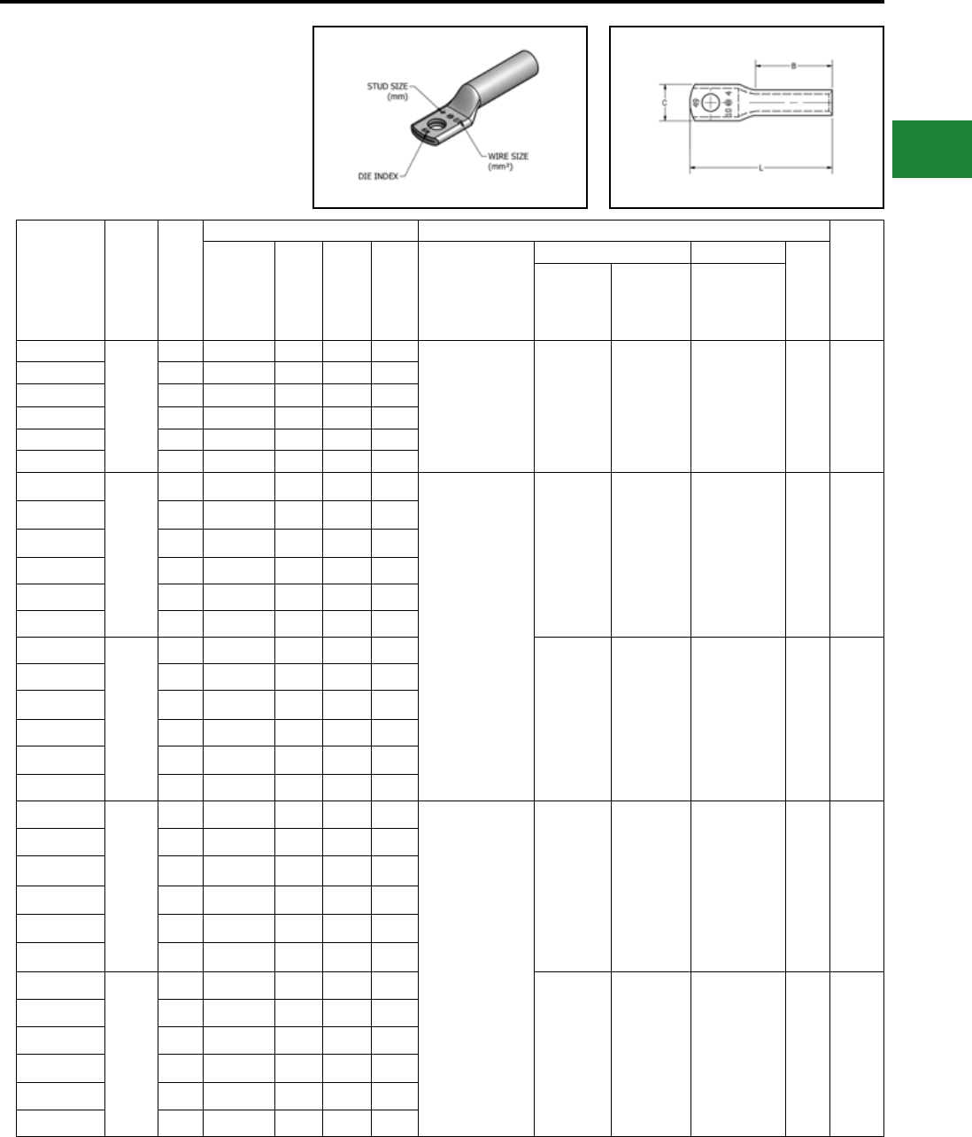
BURNDY®
Blue highlighted items are industry standard and most frequently ordered.
Canada: 1-800-387-6487 www.burndy.com US: 1-800-346-4175
Compression Connections
Metric Lugs — Copper Compression — Code — Long Barrel
Catalog
Number
Wire
Range
(MM2)
Stud
Size
Dimensions (mm) Installation Tooling
Wire
Strip
Length
Tongue
Thickness (B) (C) (L) Dieless*
Mechanical Hydraulic
Die
Index
MD6,
OUR840,
MD7-34R
BCT500HS,
Y500CTHS
Y35, Y39,
Y750, PAT750,
Y46**, PAT46**
YALB70M6
70
M6 3.0 38.1 21.1 65.5 MY29-11 (2)
MRC840 (4)
Y644HSXT (1)
PAT644XT18V (1)
Y81KFT (2)
PAT81KFT-18V (2)
W26VT (4)
W26RT (4)
X26RT (4)
W26VT (4)
W26RT (4)
X26RT (4)
U26RT (2) 13 40
YALB70M8 M8 3.0 38.1 21.1 67.3
YALB70M10 M10 3.0 38.1 21.1 70.4
YALB70M12 M12 3.0 38.1 21.1 76.7
YALB70M14 M14 3.0 38.1 21.1 77.7
YALB70M16 M16 3.0 38.1 21.1 86.4
YALB95M8
95
M8 3.3 38.1 23.6 68.6
MY29-11 (2)
MRC840 (4)
Y644HSXT (1)
PAT644XT18V (1)
Y81KFT (2)
PAT81KFT-18V (2)
W27VT (4)
W27RT (4)
X27RT (6)
W27VT (4)
W27RT (4)
X27RT (6)
U27RT (2) 14 40
YALB95M10 M10 3.3 38.1 23.6 71.6
YALB95M12 M12 3.3 38.1 23.6 78.0
YALB95M14 M14 3.3 38.1 23.6 79.0
YALB95M16 M16 3.3 38.1 23.6 84.3
YALB95M20 M20 4.1 38.1 30.5 95.5
YALB120M8
120
M8 3.6 41.1 29.0 73.9
W28VT (4)
W28RT (4)
X28RT (6)
W28VT (4)
W28RT (4)
X28RT (6)
U28RT (2) 15 43
YALB120M10 M10 3.6 41.1 29.0 79.6
YALB120M12 M12 3.6 41.1 29.0 83.6
YALB120M14 M14 3.6 41.1 29.0 84.6
YALB120M16 M16 3.6 41.1 29.0 89.9
YALB120M20 M20 4.3 41.1 30.5 101.1
YALB150M8
150
M8 4.1 50.8 30.5 84.1
Y644HSXT (1)
PAT644XT18V (1)
Y81KFT (3)
PAT81KFT-18V (3)
W30VT (4) W30VT (4)
W30RT (4) U30RT (4) 17 52
YALB150M10 M10 4.1 50.8 30.5 87.4
YALB150M12 M12 4.1 50.8 30.5 93.7
YALB150M14 M14 4.1 50.8 30.5 94.7
YALB150M16 M16 4.1 50.8 30.5 100.1
YALB150M20 M20 4.1 50.8 30.5 111.3
YALB185M8
185
M8 4.3 50.8 32.8 85.1
W31VT (4) W31VT (4)
W31RT (4) U31RT (4) 18 52
YALB185M10 M10 4.3 50.8 32.8 88.4
YALB185M12 M12 4.3 50.8 32.8 94.7
YALB185M14 M14 4.3 50.8 32.8 95.3
YALB185M16 M16 4.3 50.8 32.8 101.1
YALB185M20 M20 4.3 50.8 32.8 112.3
* Use equivalent AWG setting on tool for installation ** PUADP-1 Adaptor is required to use “U” Dies in Y46 and
PAT46 series tools
† P-RT Die sets for use in Y46 only,
PUADP-1 Adaptor not required
ONE HOLE HYLUGTM
CODE CONDUCTOR
LONG BARREL
TYPE YALB-M
(Continued)
Electro-Tin
Plated
C-91
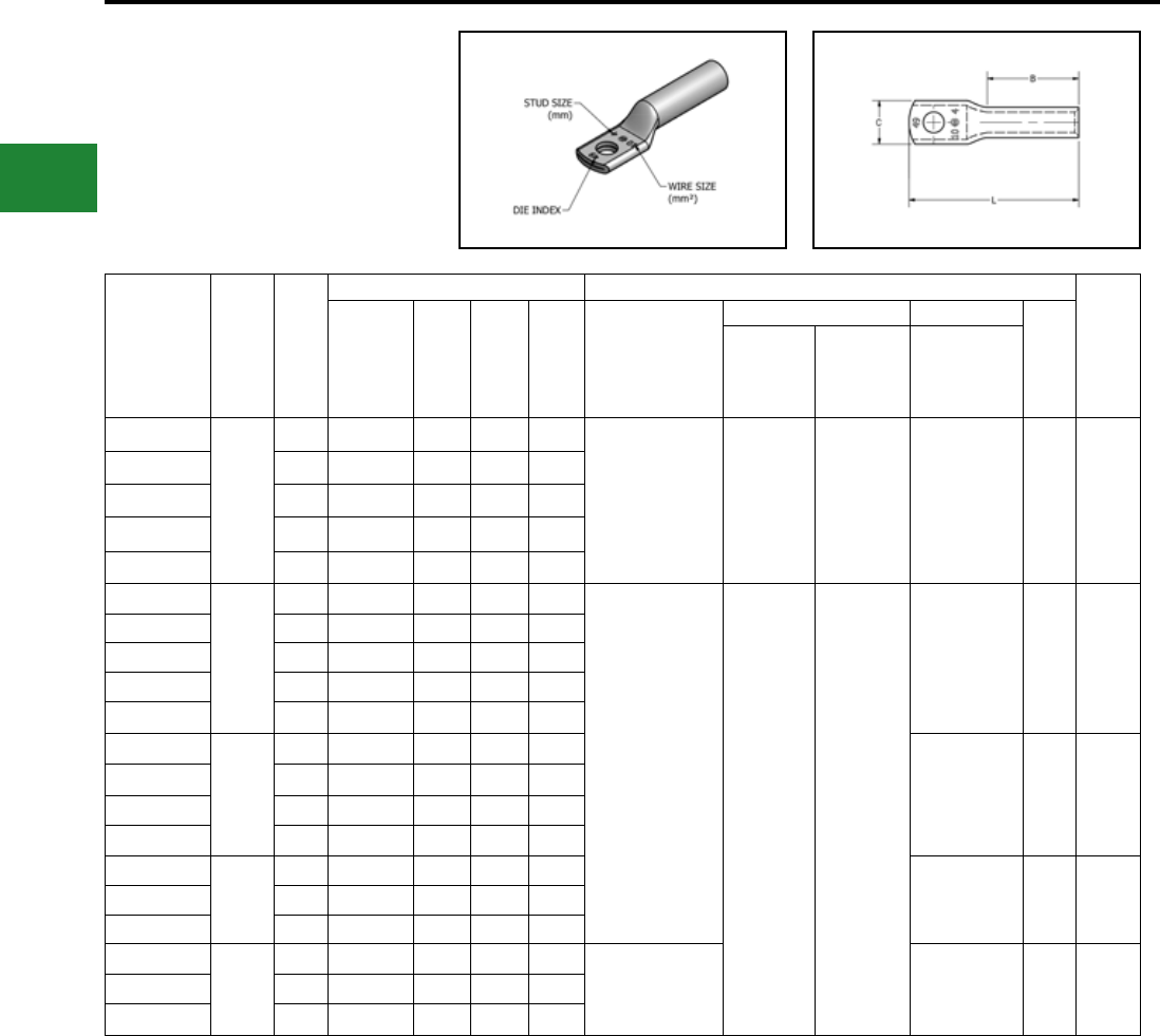
BURNDY®
Blue highlighted items are industry standard and most frequently ordered.
US: 1-800-346-4175 www.burndy.com Canada: 1-800-387-6487
Catalog
Number
Wire
Range
(MM2)
Stud
Size
Dimensions (mm) Installation Tooling
Wire
Strip
Length
Tongue
Thickness (B) (C) (L) Dieless*
Mechanical Hydraulic
Die
Index
MD6,
OUR840,
MD7-34R
BCT500HS,
Y500CTHS
Y35, Y39,
Y750, PAT750,
Y46**, PAT46**
YALB240M10
240
M10 5.6 57.2 39.4 98.0
Y644HSXT (1)
PAT644XT18V (1)
Y81KFT (4)
PAT81KFT-18V (4)
W34VT (4) W34VT (4) U34RT (4) 20 59
YALB240M12 M12 5.6 57.2 39.4 105.2
YALB240M14 M14 5.6 57.2 39.4 106.2
YALB240M16 M16 5.6 57.2 39.4 111.3
YALB240M20 M20 5.6 57.2 39.4 122.4
YALB300M10
300
M10 6.6 68.3 44.2 111.8
Y644HSXT (1)
PAT644XT18V (1)
Y81KFT (4)
PAT81KFT-18V (4) — —
U36RT (4) 22 70
YALB300M12 M12 6.6 68.3 44.2 118.1
YALB300M14 M14 6.6 68.3 44.2 119.1
YALB300M16 M16 6.6 68.3 44.2 124.5
YALB300M20 M20 6.6 68.3 44.2 135.4
YALB400M12
400
M12 7.6 74.7 50.2 127.0
U39RT (4) 24 76
YALB400M14 M14 7.6 74.7 50.2 128.0
YALB400M16 M16 7.6 74.7 50.2 133.4
YALB400M20 M20 7.6 74.7 50.2 144.3
YALB500M12
500
M12 8.1 76.2 55.7 132.1
U44XRT (4) L115 78
YALB500M16 M16 8.1 76.2 55.7 138.4
YALB500M20 M20 8.1 76.2 55.7 149.4
YALB630M12
630
M12 9.7 81.0 62.5 139.4
—† P45RT (6) 29 83
YALB630M16 M16 9.7 81.0 62.5 145.8
YALB630M20 M20 9.7 81.0 62.5 157.0
* Use equivalent AWG setting on tool for installation ** PUADP-1 Adaptor is required to use “U” Dies in Y46 and
PAT46 series tools
† P-RT Die sets for use in Y46 only,
PUADP-1 Adaptor not required
Compression Connections
Metric Lugs — Copper Compression — Code — Long Barrel
ONE HOLE HYLUGTM
CODE CONDUCTOR
LONG BARREL
TYPE YALB-M
(Continued)
Electro-Tin
Plated
C-92

BURNDY®
Blue highlighted items are industry standard and most frequently ordered.
Canada: 1-800-387-6487 www.burndy.com US: 1-800-346-4175
Catalog
Number
Wire
Range
(MM2)
Stud
Size
Stud
Hole
Spacing
Dimensions (mm) Installtion Tooling
Wire
Strip
Length
(mm)
Tongue
Thickness (B) (C) (L) Dieless*
Mechanical Hydraulic
Die
Index
MD6,
OUR840,
MD7-34R
PAT600,
Y500CTHS
Y35, Y39,
Y750,
PAT750,
Y46**,
PAT46**
YAV0252M3
2.5
M3 25.4 1.0 6.7 7.9 44.7
Y10D (1)
Y10-22 (1)
MR8G98 (1)
MR8-9Q (1)
Y8MRB-1 (1)
MR20 (1)
— — — —
7
YAV0252M4 M4 25.4 1.0 6.7 7.9 44.7
YAV0252M5 M5 25.4 1.0 6.7 7.9 44.7
YAV0252M6 M6 25.4 0.8 6.7 10.7 49.8
YAV0252M8 M8 25.4 0.8 6.7 11.0 49.8
YAV062M4
6
M4 25.4 1.5 10.4 9.5 49.5
11
YAV062M5 M5 25.4 1.5 10.4 9.5 49.5
YAV062M6 M6 25.4 1.3 10.4 11.9 52.6
YAV062M8 M8 25.4 1.0 10.4 13.5 54.4
YAV062M10 M10 25.4 1.0 11.9 14.2 54.6
YAV102M4
10
M4 44.5 2.0 11.2 10.4 73.4
Y1MRTC (1)
MY29-11 (1)
MRC840 (1)
Y81KFT (1)
PAT81KFT-18V (1)
W8CVT (1)
W8CRT (1)
X8CRT (1)
W8CVT (1)
W8CRT (1)
X8CRT (1)
U8CRT (1) 49 11
YAV102M5 M5 44.5 1.8 11.2 10.4 74.9
YAV102M6 M6 44.5 1.8 11.2 11.7 78.2
YAV102M8 M8 44.5 1.5 11.2 13.2 79.8
YAV102M10 M10 44.5 1.3 11.2 13.7 83.1
YAV102M12 M12 44.5 1.3 11.2 18.5 89.4
YAV162M4
16
M4 44.5 2.3 12.7 12.2 76.2 Y1MRTC (1)
MY29-11 (1)
MRC840 (1)
Y644HSXT (1)
PAT644XT18V (1)
Y81KFT (1)
PAT81KFT-18V (1)
W5CVT (1)
W5CRT (1)
X5CRT (1)
W5CVT (1)
W5CRT (1)
X5CRT (1)
U5CRT (1) 7 13
YAV162M5 M5 44.5 2.0 12.7 12.2 77.7
YAV162M6 M6 44.5 2.0 12.7 12.2 80.8
YAV162M8 M8 44.5 1.5 12.7 15.2 82.6
YAV162M10 M10 44.5 1.5 12.7 14.7 85.6
YAV162M12 M12 44.5 1.3 12.7 18.8 91.9
YAV252M5
25
M5 44.5 2.2 12.7 14.0 78.2
Y1MRTC (2)
MY29-11 (1)
MRC840 (1)
Y644HSXT (1)
PAT644XT18V (1)
Y81KFT (1)
PAT81KFT-18V (1)
W3CRT (1) W3CRT (1) U3CRT (1) 9 13
YAV252M6 M6 44.5 2.0 12.7 12.7 81.3
YAV252M8 M8 44.5 2.0 12.7 16.0 83.1
YAV252M10 M10 44.5 2.0 12.7 14.7 86.1
YAV252M12 M12 44.5 1.5 12.7 18.5 92.5
YAV352M5
35
M5 44.5 2.5 16.0 17.3 82.8
W2CVT (1)
W2CRT (1)
X2CRT (1)
W2CVT (1)
W2CRT (1)
X2CRT (1)
U2CRT (1) 10 17
YAV352M6 M6 44.5 2.5 16.0 17.3 86.0
YAV352M8 M8 44.5 2.5 16.0 17.3 87.6
YAV352M10 M10 44.5 2.5 16.0 17.3 90.7
YAV352M12 M12 44.5 2.3 16.0 17.3 97.0
YAV502M6
50
M6 44.5 2.5 16.0 17.3 85.9 MY29-11 (1)
MRC840 (2)
Y644HSXT (1)
PAT644XT18V (1)
Y81KFT (1)
PAT81KFT-18V (1)
W25VT (2)
W25RT (2)
X25RT (2)
W25VT (2)
W25RT (2)
X25RT (2)
U25RT (1) 12 17
YAV502M8 M8 44.5 2.5 16.0 17.3 87.6
YAV502M10 M10 44.5 2.5 16.0 17.3 90.7
YAV502M12 M12 44.5 2.5 16.0 18.5 97.0
YAV502M14 M14 44.5 3.0 16.0 21.1 98.0
YAV502M16 M16 44.5 3.6 16.0 25.9 104.9
* Use equivalent AWG setting on tool for installation. ** PUADP-1 Adaptor is required to use "U" Dies in Y46 and
PAT46 series tools.
† P-RT Die sets for use in Y46 only, PUADP-1 Adaptor not
required.
TWO HOLE HYLUG™
CODE CONDUCTOR
STANDARD BARREL
TYPE YAV-2M
Made from electrolytic copper tube and is
electro tin plate. Wire range is from 2.5 mm2 to
630 mm2 for class 2. Compatible to IEC61238-1.
Compression Connections
Metric Lugs — Copper Compression — Code — Standard Barrel
Electro-Tin
Plated
C-93
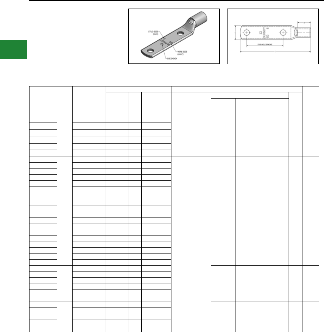
BURNDY®
Blue highlighted items are industry standard and most frequently ordered.
US: 1-800-346-4175 www.burndy.com Canada: 1-800-387-6487
Catalog
Number
Wire
Range
(MM2)
Stud
Size
Stud
Hole
Spacing
Dimensions (mm) Installtion Tooling
Wire
Strip
Length
(mm)
Tongue
Thickness (B) (C) (L) Dieless*
Mechanical Hydraulic
Die
Index
MD6,
OUR840,
MD7-34R
PAT600,
Y500CTHS
Y35, Y39,Y750,
PAT750,Y46**,
PAT46**
YAV702M6
70
M6 44.5 3.0 17.5 21.1 89.2 MY29-11 (1)
MRC840 (2)
Y644HSXT (1)
PAT644XT18V (1)
Y81KFT (1)
PAT81KFT-18V (1)
W26VT (2)
W26RT (2)
X26RT (2)
W26VT (2)
W26RT (2)
X26RT (2)
U26RT (1) 13 19
YAV702M8 M8 44.5 3.0 17.5 21.1 90.7
YAV702M10 M10 44.5 3.0 17.5 21.1 94.0
YAV702M12 M12 44.5 3.0 17.5 21.1 100.3
YAV702M14 M14 44.5 2.8 17.5 22.4 101.3
YAV702M16 M16 44.5 2.8 17.5 22.4 106.7
YAV952M8
95
M8 44.5 3.3 20.6 23.6 95.0
MY29-11 (1)
MRC840 (2)
Y644HSXT (1)
PAT644XT18V (1)
Y81KFT (2)
PAT81KFT-18V (2)
W27VT (2)
W27RT (2)
X27RT (3)
W27VT (2)
W27RT (2)
X27RT (3)
U27RT (1) 14 22
YAV952M10 M10 44.5 3.3 20.6 23.6 98.3
YAV952M12 M12 44.5 3.3 20.6 23.6 104.6
YAV952M14 M14 44.5 3.3 20.6 23.6 105.7
YAV952M16 M16 44.5 3.3 20.6 23.6 111.0
YAV952M20 M20 44.5 4.1 20.6 30.5 123.4
YAV1202M8
120
M8 44.5 3.8 26.2 29.0 102.9
W28VT (2)
W28RT (2)
X28RT (3)
W28VT (2)
W28RT (2)
X28RT (3)
U28RT (1) 15 27
YAV1202M10 M10 44.5 3.8 26.2 29.0 106.2
YAV1202M12 M12 44.5 3.8 26.2 29.0 112.5
YAV1202M14 M14 44.5 3.8 26.2 29.0 113.5
YAV1202M16 M16 44.5 3.8 26.2 29.0 118.9
YAV1202M20 M20 44.5 3.8 26.2 29.0 130.8
YAV1502M8
150
M8 44.5 4.1 26.2 30.5 103.4
Y644HSXT (1)
PAT644XT18V (1)
Y81KFT (2)
PAT81KFT-18V (2)
W30VT (2) W30VT (2)
W30RT (2) U30RT (2) 17 27
YAV1502M10 M10 44.5 4.1 26.2 30.5 106.7
YAV1502M12 M12 44.5 4.1 26.2 30.5 113.0
YAV1502M14 M14 44.5 4.1 26.2 30.5 114.8
YAV1502M16 M16 44.5 4.1 26.2 30.5 119.4
YAV1502M20 M20 44.5 4.1 26.2 30.5 131.3
YAV1852M8
185
M8 44.5 4.6 26.9 32.8 104.9
W31VT (2) W31VT (2)
W31RT (2) U31RT (2) 18 29
YAV1852M10 M10 44.5 4.3 26.9 32.8 108.2
YAV1852M12 M12 44.5 4.6 26.9 32.8 114.6
YAV1852M14 M14 44.5 4.6 26.9 32.8 116.6
YAV1852M16 M16 44.5 4.6 26.9 32.8 120.9
YAV1852M20 M20 44.5 4.6 26.9 32.8 133.1
YAV2402M10
240
M10 44.5 5.8 32.3 39.4 117.6
W34VT (2) W34VT (2)
W34RT (2) U34RT (2) 20 33
YAV2402M12 M12 44.5 5.6 32.3 39.4 125.0
YAV2402M14 M14 44.5 5.8 32.3 39.4 126.0
YAV2402M16 M16 44.5 5.8 32.3 39.4 130.3
YAV2402M20 M20 44.5 5.8 32.3 39.4 142.5
TWO HOLE HYLUG™
CODE CONDUCTOR
STANDARD BARREL
TYPE YAV-2M
(Continued)
Compression Connections
Metric Lugs — Copper Compression — Code — Standard Barrel
* Use equivalent AWG setting on tool for installation. ** PUADP-1 Adaptor is required to use "U" Dies in Y46 and
PAT46 series tools.
† P-RT Die sets for use in Y46 only, PUADP-1 Adaptor not
required.
Electro-Tin
Plated
C-94
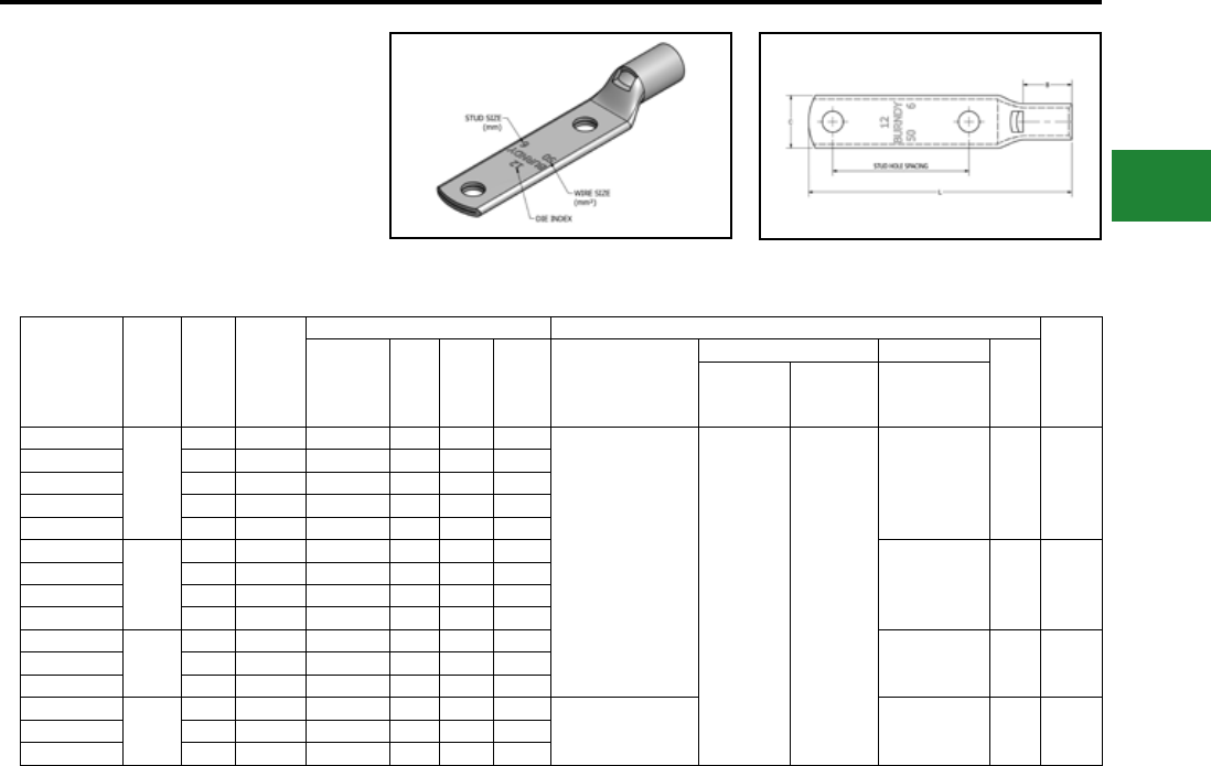
BURNDY®
Blue highlighted items are industry standard and most frequently ordered.
Canada: 1-800-387-6487 www.burndy.com US: 1-800-346-4175
Catalog
Number
Wire
Range
(MM2)
Stud
Size
Stud
Hole
Spacing
Dimensions (mm) Installtion Tooling
Wire
Strip
Length
(mm)
Tongue
Thickness (B) (C) (L) Dieless*
Mechanical Hydraulic
Die
Index
MD6,
OUR840,
MD7-34R
PAT600,
Y500CTHS
Y35, Y39,Y750,
PAT750,Y46**,
PAT46**
YAV3002M10
300
M10 44.5 6.9 35.1 44.2 121.9
Y644HSXT (1)
PAT644XT18V (1)
Y81KFT (2)
PAT81KFT-18V (2) — —
U36RT (2) 22 35
YAV3002M12 M12 44.5 6.6 35.1 44.2 128.3
YAV3002M14 M14 44.5 6.9 35.1 44.2 129.3
YAV3002M16 M16 44.5 6.9 35.1 44.2 134.6
YAV3002M20 M20 44.5 6.9 35.1 44.2 145.5
YAV4002M12
400
M12 44.5 7.6 36.1 50.3 131.8
U39RT (3) 24 37
YAV4002M14 M14 44.5 7.6 36.1 50.3 134.1
YAV4002M16 M16 44.5 7.6 36.1 50.3 138.2
YAV4002M20 M20 44.5 7.6 36.1 50.3 150.6
YAV5002M12
500
M12 44.5 8.1 41.9 55.6 139.4
U44XRT (3) L115 43YAV5002M16 M16 44.5 8.1 41.9 55.6 147.3
YAV5002M20 M20 44.5 8.1 41.9 55.6 160.0
YAV6302M12
630
M12 44.5 9.7 50.8 62.5 152.4
— † P45RT (3) 29 55YAV6302M16 M16 44.5 9.7 50.8 62.5 158.8
YAV6302M20 M20 44.5 9.7 50.8 62.5 169.9
TWO HOLE HYLUG™
CODE CONDUCTOR
STANDARD BARREL
TYPE YAV-2M
(Continued)
Compression Connections
Metric Lugs — Copper Compression — Code — Standard Barrel
* Use equivalent AWG setting on tool for installation. ** PUADP-1 Adaptor is required to use "U" Dies in Y46 and
PAT46 series tools.
† P-RT Die sets for use in Y46 only, PUADP-1 Adaptor not
required.
Electro-Tin
Plated
C-95
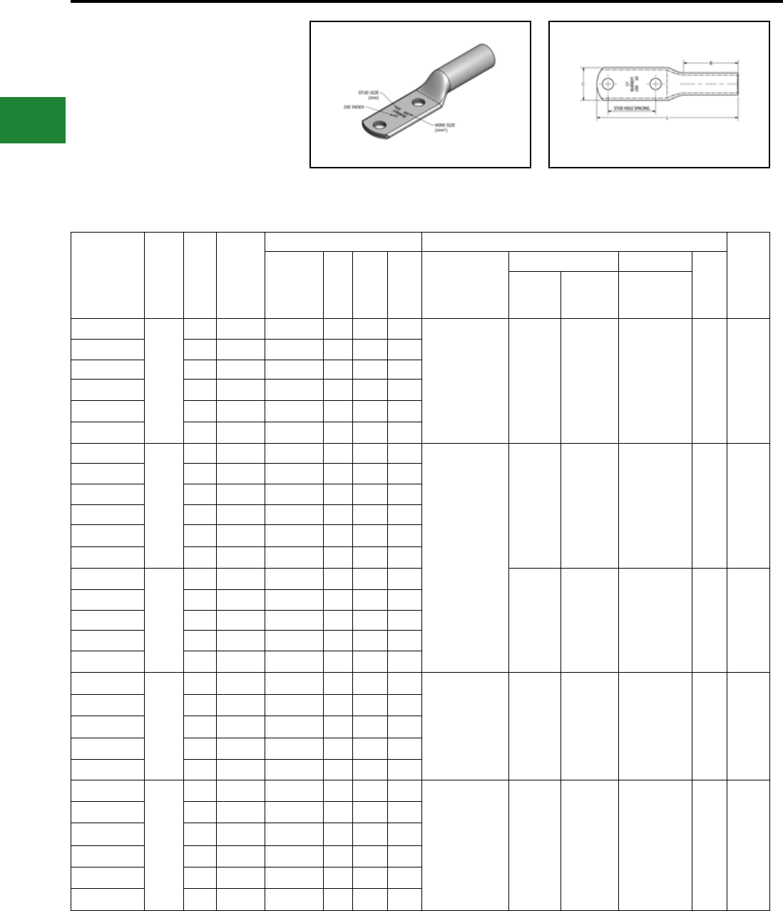
BURNDY®
Blue highlighted items are industry standard and most frequently ordered.
US: 1-800-346-4175 www.burndy.com Canada: 1-800-387-6487
TWO HOLE HYLUGTM
CODE CONDUCTOR
LONG BARREL
TYPE YALB-2M
Made from electrolytic copper tube and is
electro tin plate. Wire range is from 10 mm2 to
630 mm2 for class 2. Compatible to IEC61238-1.
Compression Connections
Metric Lugs — Copper Compression — Code — Long Barrel
Catalog
Number
Wire
Range
(MM
2
)
Stud
Size
Stud
Hole
Spacing
Dimensions (mm) Installtion Tooling
Wire
Strip
Length
(mm)
Tongue
Thickness (B) (C) (L) Dieless
*
Mechanical Hydraulic
Die
Index
MD6,
OUR840,
MD7-34R
PAT600,
Y500CTHS
Y35, Y39,
Y750,PAT750,
Y46**, PAT46**
YALB102M4
10
M4 44.5 2.3 20.6 9.9 82.6
Y1MRTC (2)
MY29-11 (1)
MRC840 (2)
Y81KFT (1)
PAT81KFT-18V (1)
W8CVT
(2)
W8CRT
(2)
X8CRT
(2)
W8CVT (2)
W8CRT (2)
X8CRT (2)
U8CRT (2) 49 22
YALB102M5 M5 44.5 2.0 20.6 10.4 84.3
YALB102M6 M6 44.5 2.0 20.6 11.2 87.4
YALB102M8 M8 44.5 1.5 20.6 13.2 88.9
YALB102M10 M10 44.5 1.5 20.6 14.7 92.2
YALB102M12 M12 44.5 3.0 20.6 21.1 103.4
YALB162M4
16
M4 44.5 2.3 28.4 11.4 91.7
Y1MRTC (2)
MY29-11 (2)
MRC840 (2)
Y644HSXT (1)
PAT644XT18V (1)
Y81KFT (1)
PAT81KFT-18V (1)
W5CVT
(2)
W5CRT
(2)
X5CRT
(2)
W5CVT (2)
W5CRT (2)
X5CRT (2)
U5CRT (2) 7 30
YALB162M5 M5 44.5 2.3 28.4 11.4 93.2
YALB162M6 M6 44.5 2.0 28.4 12.2 96.5
YALB162M8 M8 44.5 1.8 28.4 13.2 98.0
YALB162M10 M10 44.5 1.5 28.4 14.7 103.6
YALB162M12 M12 44.5 3.0 28.4 19.1 107.7
YALB252M5
25
M5 44.5 2.3 31.8 14.0 98.0
W3CRT
(2) W3CRT (2) U3CRT (2) 9 33
YALB252M6 M6 44.5 2.3 31.8 14.0 101.1
YALB252M8 M8 44.5 2.3 31.8 14.0 102.9
YALB252M10 M10 44.5 2.0 31.8 14.7 105.9
YALB252M12 M12 44.5 3.0 31.8 21.1 112.5
YALB352M5
35
M5 44.5 2.5 35.1 17.3 102.1 Y1MRTC (4)
MY29-11 (2)
MRC840 (2)
Y644HSXT (1)
PAT644XT18V (1)
Y81KFT (1)
PAT81KFT-18V (1)
W2CVT
(2)
W2CRT
(2)
X2CRT
(2)
W2CVT (2)
W2CRT (2)
X2CRT (2)
U2CRT (2) 10 37
YALB352M6 M6 44.5 2.5 35.1 17.3 105.2
YALB352M8 M8 44.5 2.5 35.1 17.3 106.8
YALB352M10 M10 44.5 2.5 35.1 17.3 110.0
YALB352M12 M12 44.5 3.0 35.1 21.1 116.4
YALB502M6
50
M6 44.5 2.5 35.1 17.3 105.2
MY29-11 (2)
MRC840 (4)
Y644HSXT (1)
PAT644XT18V (1)
Y81KFT (2)
PAT81KFT-18V (2)
W25VT
(4)
W25RT
(4) X25RT
(4)
W25VT (4)
W25RT (4)
X25RT (4)
U25RT (2) 12 37
YALB502M8 M8 44.5 2.5 35.1 17.3 106.7
YALB502M10 M10 44.5 2.5 35.1 17.3 110.0
YALB502M12 M12 44.5 3.0 35.1 21.1 116.3
YALB502M14 M14 44.5 3.0 35.1 21.1 117.3
YALB502M16 M16 44.5 3.0 35.1 21.1 122.7
* Use equivalent AWG setting on tool for installation ** PUADP-1 Adaptor is required to use “U” Dies in Y46 and
PAT46 series tools
† P-RT Die sets for use in Y46 only,
PUADP-1 Adaptor not required
Electro-Tin
Plated
C-96
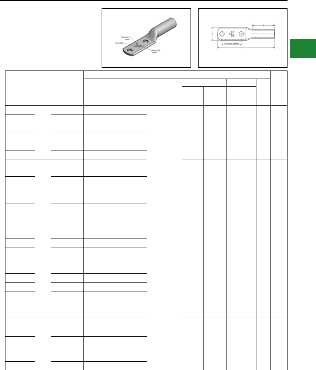
BURNDY®
Blue highlighted items are industry standard and most frequently ordered.
Canada: 1-800-387-6487 www.burndy.com US: 1-800-346-4175
Catalog
Number
Wire
Range
(MM
2
)
Stud
Size
Stud
Hole
Spacing
Dimensions (mm) Installtion Tooling
Wire
Strip
Length
(mm)
Tongue
Thickness (B) (C) (L) Dieless
*
Mechanical Hydraulic
Die
Index
MD6,
OUR840,
MD7-34R
PAT600,
Y500CTHS
Y35, Y39,
Y750,PAT750,
Y46**, PAT46**
YALB702M6
70
M6 44.5 3.0 38.1 21.1 110.0
MY29-11 (2)
MRC840 (4)
Y644HSXT (1)
PAT644XT18V (1)
Y81KFT (2)
PAT81KFT-18V (2)
W26VT
(4)
W26RT
(4) X26RT
(4)
W26VT (4)
W26RT (4)
X26RT (4)
U26RT (2) 13 40
YALB702M8 M8 44.5 3.0 38.1 21.1 111.8
YALB702M10 M10 44.5 3.0 38.1 21.1 114.8
YALB702M12 M12 44.5 3.0 38.1 21.1 121.4
YALB702M14 M14 44.5 3.0 38.1 21.1 122.2
YALB702M16 M16 44.5 3.0 38.1 21.1 130.8
YALB952M8
95
M8 44.5 3.3 38.1 23.6 113.0
W27VT
(4)
W27RT
(4) X27RT
(6)
W27VT (4)
W27RT (4)
X27RT (6)
U27RT (2) 14 40
YALB952M10 M10 44.5 3.3 38.1 23.6 116.1
YALB952M12 M12 44.5 3.3 38.1 23.6 122.4
YALB952M14 M14 44.5 3.3 38.1 23.6 123.4
YALB952M16 M16 44.5 3.3 38.1 23.6 128.8
YALB952M20 M20 44.5 4.1 38.1 30.5 140.0
YALB1202M8
120
M8 44.5 3.8 41.1 29.0 118.6
W28VT
(4)
W28RT
(4) X28RT
(6)
W28VT (4)
W28RT (4)
X28RT (6)
U28RT (2) 15 43
YALB1202M10 M10 44.5 3.8 41.1 29.0 124.1
YALB1202M12 M12 44.5 3.8 41.1 29.0 128.0
YALB1202M14 M14 44.5 3.8 41.1 29.0 129.0
YALB1202M16 M16 44.5 3.8 41.1 29.0 134.4
YALB1202M20 M20 44.5 4.3 41.1 30.5 145.5
YALB1502M8
150
M8 44.5 4.1 50.8 30.5 128.8
Y644HSXT (1)
PAT644XT18V (1)
Y81KFT (3)
PAT81KFT-18V (3)
W30VT
(4)
W30VT (4)
W30RT (4) U30RT (4) 17 52
YALB1502M10 M10 44.5 4.1 50.8 30.5 131.8
YALB1502M12 M12 44.5 4.1 50.8 30.5 138.2
YALB1502M14 M14 44.5 4.1 50.8 30.5 139.2
YALB1502M16 M16 44.5 4.1 50.8 30.5 145.3
YALB1502M20 M20 44.5 4.1 50.8 30.5 156.2
YALB1852M8
185
M8 44.5 4.3 50.8 32.8 129.8
W31VT
(4)
W31VT (4)
W31RT (4) U31RT (4) 18 52
YALB1852M10 M10 44.5 4.3 50.8 32.8 132.8
YALB1852M12 M12 44.5 4.3 50.8 32.8 139.2
YALB1852M14 M14 44.5 4.3 50.8 32.8 139.7
YALB1852M16 M16 44.5 4.3 50.8 32.8 145.5
YALB1852M20 M20 44.5 4.3 50.8 32.8 156.7
* Use equivalent AWG setting on tool for installation ** PUADP-1 Adaptor is required to use “U” Dies in Y46 and
PAT46 series tools
† P-RT Die sets for use in Y46 only,
PUADP-1 Adaptor not required
Compression Connections
Metric Lugs — Copper Compression — Code — Long Barrel
TWO HOLE HYLUGTM
CODE CONDUCTOR
LONG BARREL
TYPE YALB-2M
(Continued)
Electro-Tin
Plated
C-97
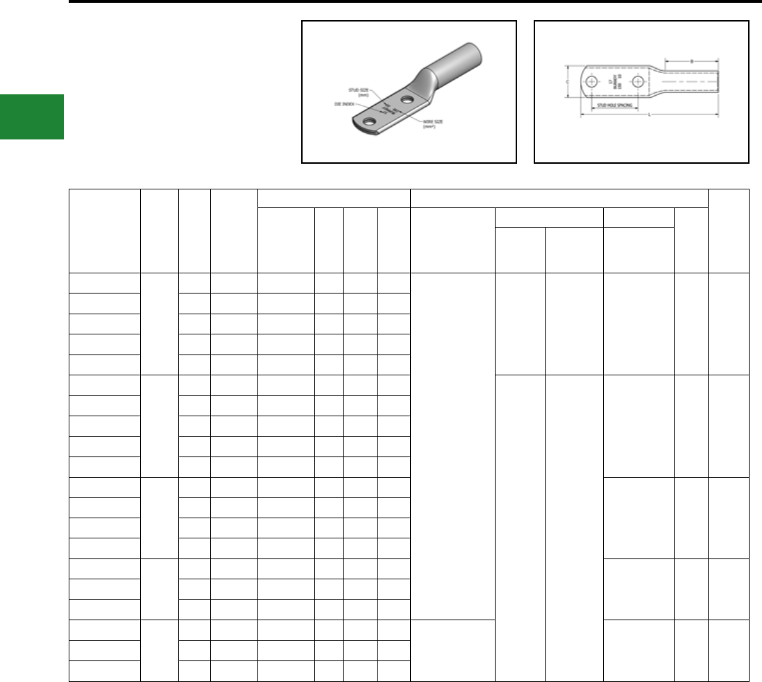
BURNDY®
Blue highlighted items are industry standard and most frequently ordered.
US: 1-800-346-4175 www.burndy.com Canada: 1-800-387-6487
* Use equivalent AWG setting on tool for installation ** PUADP-1 Adaptor is required to use “U” Dies in Y46 and
PAT46 series tools
† P-RT Die sets for use in Y46 only,
PUADP-1 Adaptor not required
TWO HOLE HYLUGTM
CODE CONDUCTOR
LONG BARREL
TYPE YALB-2M
(Continued)
Catalog
Number
Wire
Range
(MM
2
)
Stud
Size
Stud
Hole
Spacing
Dimensions (mm) Installtion Tooling
Wire
Strip
Length
(mm)
Tongue
Thickness (B) (C) (L) Dieless
*
Mechanical Hydraulic
Die
Index
MD6,
OUR840,
MD7-34R
PAT600,
Y500CTHS
Y35, Y39,
Y750,PAT750,
Y46**, PAT46**
YALB2402M10
240
M10 44.5 5.6 57.2 39.4 142.5
Y644HSXT (1)
PAT644XT18V (1)
Y81KFT (4)
PAT81KFT-18V (4)
W34VT
(4)
W34VT (4)
W34RT (4)
U34RT (4) 20 59
YALB2402M12 M12 44.5 5.6 57.2 39.4 149.6
YALB2402M14 M14 44.5 5.6 57.2 39.4 150.6
YALB2402M16 M16 44.5 5.6 57.2 39.4 156.0
YALB2402M20 M20 44.5 5.6 57.2 39.4 166.9
YALB3002M10
300
M10 44.5 6.6 68.3 44.2 156.2
— —
U36RT (4) 22 70
YALB3002M12 M12 44.5 6.6 68.3 44.2 162.6
YALB3002M14 M14 44.5 6.6 68.3 44.2 163.6
YALB3002M16 M16 44.5 6.6 68.3 44.2 168.9
YALB3002M20 M20 44.5 6.6 68.3 44.2 179.6
YALB4002M12
400
M12 44.5 7.6 74.7 50.3 171.4
U39RT (4) 24 76
YALB4002M14 M14 44.5 7.6 74.7 50.3 172.5
YALB4002M16 M16 44.5 7.6 74.7 50.3 177.8
YALB4002M20 M20 44.5 7.6 74.7 50.3 189.0
YALB5002M12
500
M12 44.5 8.1 76.2 55.6 176.5
U44XRT (4) L115 78YALB5002M16 M16 44.5 8.1 76.2 55.6 182.9
YALB5002M20 M20 44.5 8.1 76.2 55.6 194.1
YALB6302M12
630
M12 44.5 9.7 81.0 62.5 183.9
—† P45RT (6) 29 83
YALB6302M16 M16 44.5 9.7 81.0 62.5 190.5
YALB6302M20 M20 44.5 9.7 81.0 62.5 201.4
Compression Connections
Metric Lugs — Copper Compression — Code — Long Barrel
Electro-Tin
Plated
C-98
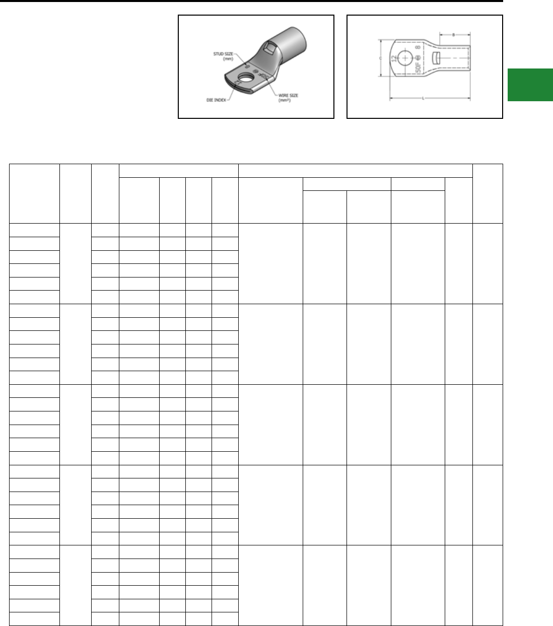
BURNDY®
Blue highlighted items are industry standard and most frequently ordered.
Canada: 1-800-387-6487 www.burndy.com US: 1-800-346-4175
ONE HOLE HYLUGTM
FLEX CONDUCTOR
STANDARD BARREL
TYPE YAV-FM
Made from electrolytic copper tube and is
electro tin plate. Wire range is from 50 mm2 to
630 mm2 for class 5. Compatible to IEC61238-1.
Catalog
Number
Wire
Range
(MM2)
Stud
Size
Dimensions (mm) Installation Tooling
Wire
Strip
Length
Tongue
Thickness (B) (C) (L) Dieless*
Mechanical Hydraulic
Die
Index
MD6,
OUR840,
MD7-34R
BCT500HS,
Y500CTHS
Y35, Y39,
Y750, PAT750,
Y46**, PAT46**
YAV50FM6
50
M6 3.0 17.5 21.1 46.0
MY29-11 (1)
MRC840 (2)
Y644HSXT (1)
PAT644XT18V (1)
Y81KFT (1)
PAT81KFT-18V (1)
W25VT (2)
W25RT (2)
X25RT (2)
W25VT (2)
W25RT (2)
X25RT (2)
U25RT (1) 12 19
YAV50FM8 M8 3.0 17.5 21.1 46.0
YAV50FM10 M10 3.0 17.5 21.1 49.3
YAV50FM12 M12 3.0 17.5 21.1 55.6
YAV50FM14 M14 3.0 17.5 22.4 56.6
YAV50FM16 M16 3.0 17.5 22.4 61.9
YAV70FM6
70
M6 3.3 20.6 23.6 49.0
MY29-11 (1)
MRC840 (2)
Y644HSXT (1)
PAT644XT18V (1)
Y81KFT (1)
PAT81KFT-18V (1)
W26VT (2)
W26RT (2)
X26RT (2)
W26VT (2)
W26RT (2)
X26RT (2)
U26RT (1) 13 22
YAV70FM8 M8 3.3 20.6 23.6 50.3
YAV70FM10 M10 3.3 20.6 23.6 54.0
YAV70FM12 M12 3.3 20.6 23.6 60.0
YAV70FM14 M14 3.3 20.6 23.6 61.0
YAV70FM16 M16 3.3 20.6 23.6 66.3
YAV95FM8
95
M8 3.6 25.4 26.2 56.0
MY29-11 (1)
MRC840 (2)
Y644HSXT (1)
PAT644XT18V (1)
Y81KFT (2)
PAT81KFT-18V (2)
W27VT (2)
W27RT (2)
X27RT (3)
W27VT (2)
W27RT (2)
X27RT (3)
U27RT (1) 14 27
YAV95FM10 M10 3.6 25.4 26.2 59.0
YAV95FM12 M12 3.6 25.4 26.2 66.0
YAV95FM14 M14 3.6 25.4 26.2 66.8
YAV95FM16 M16 3.6 25.4 26.2 72.1
YAV95FM20 M20 3.6 25.4 26.2 83.2
YAV120FM8
120
M8 3.8 26.2 29.0 58.2
MY29-11 (1)
MRC840 (2)
Y644HSXT (1)
PAT644XT18V (1)
Y81KFT (2)
PAT81KFT-18V (2)
W28VT (2)
W28RT (2)
X28RT (3)
W28VT (2)
W28RT (2)
X28RT (3)
U28RT (1) 15 27
YAV120FM10 M10 3.8 26.2 29.0 61.0
YAV120FM12 M12 3.8 26.2 29.0 68.0
YAV120FM14 M14 3.8 26.2 29.0 68.8
YAV120FM16 M16 3.8 26.2 29.0 74.1
YAV120FM20 M20 3.8 26.2 29.0 85.2
YAV150FM8
150
M8 4.6 26.9 32.8 60.2
Y644HSXT (1)
PAT644XT18V (1)
Y81KFT (2)
PAT81KFT-18V (2)
W30VT (2) W30VT (2)
W30RT (2) U30RT (2) 17 29
YAV150FM10 M10 4.6 26.9 32.8 64.0
YAV150FM12 M12 4.6 26.9 32.8 70.0
YAV150FM14 M14 4.6 26.9 32.8 70.8
YAV150FM16 M16 4.6 26.9 32.8 76.0
YAV150FM20 M20 4.6 26.9 32.8 87.3
Compression Connections
Metric Lugs — Copper Compression — Flex — Standard Barrel
* Use equivalent AWG setting on tool for installation ** PUADP-1 Adaptor is required to use “U” Dies in Y46 and
PAT46 series tools
† P-RT Die sets for use in Y46 only,
PUADP-1 Adaptor not required
Electro-Tin
Plated
C-99
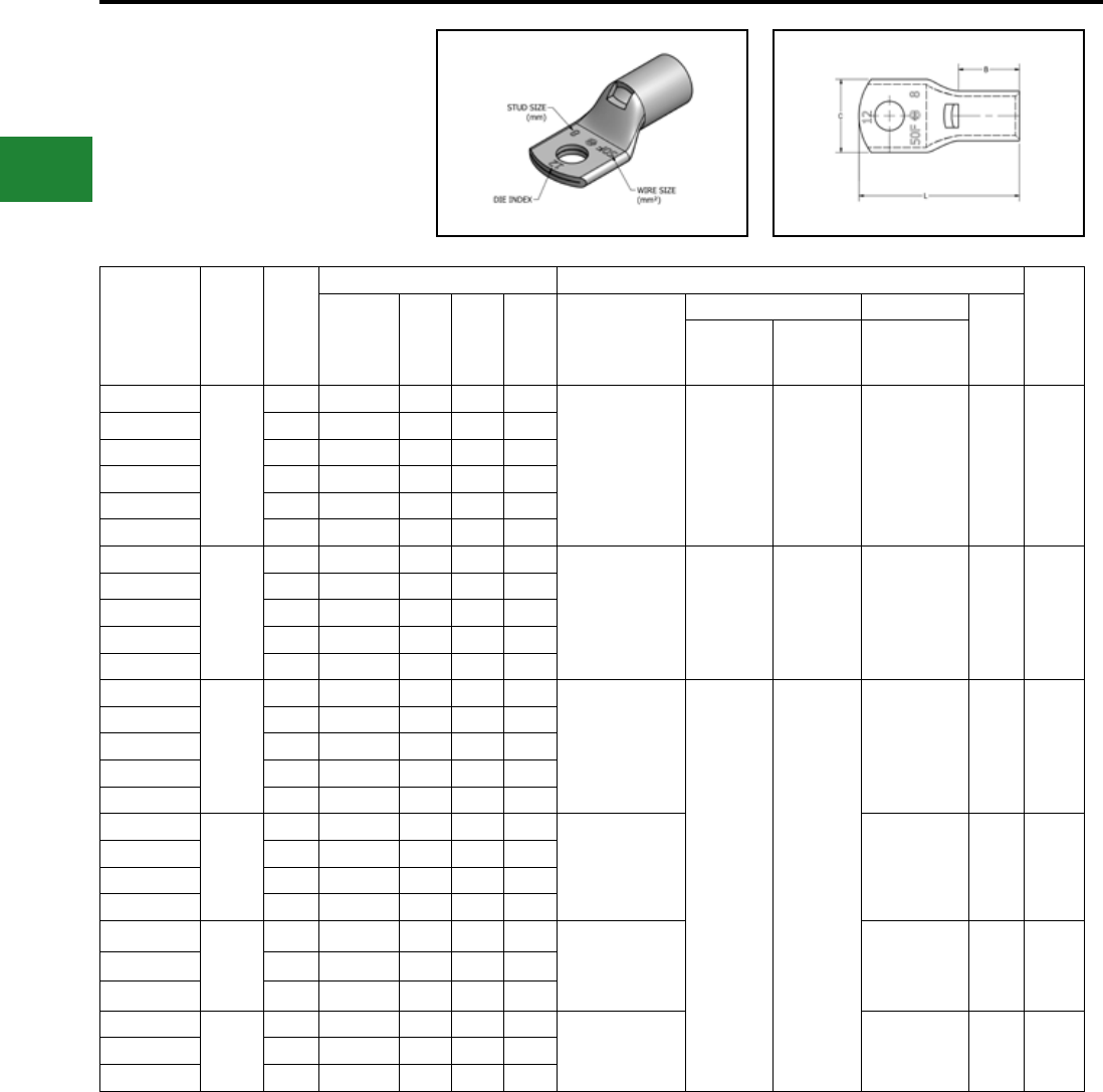
BURNDY®
Blue highlighted items are industry standard and most frequently ordered.
US: 1-800-346-4175 www.burndy.com Canada: 1-800-387-6487
Compression Connections
Metric Lugs — Copper Compression — Flex — Standard Barrel
Catalog
Number
Wire
Range
(MM2)
Stud
Size
Dimensions (mm) Installation Tooling
Wire
Strip
Length
Tongue
Thickness (B) (C) (L) Dieless*
Mechanical Hydraulic
Die
Index
MD6,
OUR840,
MD7-34R
BCT500HS,
Y500CTHS
Y35, Y39,
Y750, PAT750,
Y46**, PAT46**
YAV185FM8
185
M8 5.0 30.2 35.6 64.8
Y644HSXT (1)
PAT644XT18V (1)
Y81KFT (2)
PAT81KFT-18V (2)
W31VT (2) W31VT (2)
W31RT (2) U31RT (2) 18 29
YAV185FM10 M10 5.0 30.2 35.6 68.0
YAV185FM12 M12 5.0 30.2 35.6 74.0
YAV185FM14 M14 5.0 30.2 35.6 75.4
YAV185FM16 M16 5.0 30.2 35.6 81.0
YAV185FM20 M20 5.0 30.2 35.6 91.8
YAV240FM10
240
M10 5.8 32.3 39.4 72.9
Y644HSXT (1)
PAT644XT18V (1)
Y81KFT (2)
PAT81KFT-18V (2)
W34VT (2) W34VT (2)
W34VT (2) U34RT (2) 20 33
YAV240FM12 M12 5.8 32.3 39.4 79.0
YAV240FM14 M14 5.8 32.3 39.4 80.2
YAV240FM16 M16 5.8 32.3 39.4 85.5
YAV240FM20 M20 5.8 32.3 39.4 96.6
YAV300FM10
300
M10 6.9 36.8 46.7 80.2
Y644HSXT (1)
PAT644XT18V (1)
Y81KFT (2)
PAT81KFT-18V (2)
U36RT (2) 22 38
YAV300FM12 M12 6.9 36.8 46.7 87.0
YAV300FM14 M14 6.9 36.8 46.7 87.5
YAV300FM16 M16 6.9 36.8 46.7 93.0
YAV300FM20 M20 6.9 36.8 46.7 104.0
YAV400FM12
400
M12 7.6 36.1 50.3 87.0 Y644HSXT (1)
PAT644XT18V (1)
Y81KFT (3)
PAT81KFT-18V (3)
U39RT (3) 24 37
YAV400FM14 M14 7.6 36.1 50.3 88.1
YAV400FM16 M16 7.6 36.1 50.3 93.5
YAV400FM20 M20 7.6 36.1 50.3 104.5
YAV500FM12
500
M12 8.4 41.9 55.6 96.0 Y644HSXT (1)
PAT644XT18V (1)
Y81KFT (3)
PAT81KFT-18V (3)
U44XRT (3) L115 43
YAV500FM16 M16 8.4 41.9 55.6 102.6
YAV500FM20 M20 8.4 41.9 55.6 113.7
YAV630FM12
630
M12 9.9 50.8 68.3 110.2
—† P46RT (3) 31 55YAV630FM16 M16 9.9 50.8 68.3 116.6
YAV630FM20 M20 9.9 50.8 68.3 127.8
* Use equivalent AWG setting on tool for installation ** PUADP-1 Adaptor is required to use “U” Dies in Y46 and
PAT46 series tools
† P-RT Die sets for use in Y46 only,
PUADP-1 Adaptor not required
ONE HOLE HYLUGTM
FLEX CONDUCTOR
STANDARD BARREL
TYPE YAV-FM
(Continued)
Electro-Tin
Plated
C-100
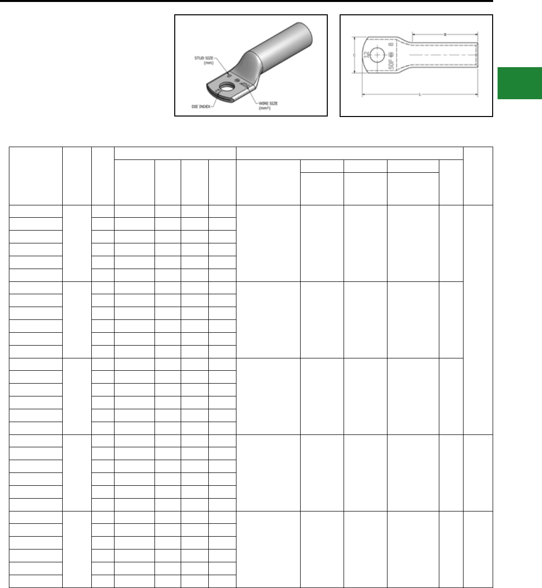
BURNDY®
Blue highlighted items are industry standard and most frequently ordered.
Canada: 1-800-387-6487 www.burndy.com US: 1-800-346-4175
Catalog
Number
Wire
Range
(MM2)
Stud
Size
Dimensions (mm) Installation Tooling
Wire
Strip
Length
Tongue
Thickness (B) (C) (L) Dieless*
Mechanical Mechanical Hydraulic
Die
Index
MD6,
OUR840,
MD7-34R
BCT500HS,
Y500CTHS
Y35, Y39,Y750,
PAT750,Y46**,
PAT46**
YALB50FM6
50
M6 3.0 38.1 21.1 65.5 MY29-11 (2)
MRC840 (4)
Y644HSXT (1)
PAT644XT18V (1)
Y81KFT (2)
PAT81KFT-18V (2)
W25VT (4)
W25RT (4)
X25RT (4)
W25VT (4)
W25RT (4)
X25RT (4)
U25RT (2) 12
40
YALB50FM8 M8 3.0 38.1 21.1 67.3
YALB50FM10 M10 3.0 38.1 21.1 70.4
YALB50FM12 M12 3.0 38.1 21.1 76.7
YALB50FM14 M14 3.0 38.1 21.1 77.7
YALB50FM16 M16 3.0 38.1 21.1 86.4
YALB70FM6
70
M6 3.3 38.1 23.6 66.3 MY29-11 (2)
MRC840 (4)
Y644HSXT (1)
PAT644XT18V (1)
Y81KFT (2)
PAT81KFT-18V (2)
W26VT (4)
W26RT (4)
X26RT (4)
W26VT (4)
W26RT (4)
X26RT (4)
U26RT (2) 13
YALB70FM8 M8 3.3 38.1 23.6 68.5
YALB70FM10 M10 3.3 38.1 23.6 71.7
YALB70FM12 M12 3.3 38.1 23.6 78.0
YALB70FM14 M14 3.3 38.1 23.6 79.0
YALB70FM16 M16 3.3 38.1 23.6 84.3
YALB95FM8
95
M8 3.6 38.1 26.2 68.8 MY29-11 (2)
MRC840 (4)
Y644HSXT (1)
PAT644XT18V (1)
Y81KFT (2)
PAT81KFT-18V (2)
W27VT (4)
W27RT (4)
X27RT (6)
W27VT (4)
W27RT (4)
X27RT (6)
U27RT (2) 14
YALB95FM10 M10 3.6 38.1 26.2 72.1
YALB95FM12 M12 3.6 38.1 26.2 78.5
YALB95FM14 M14 3.6 38.1 26.2 79.5
YALB95FM16 M16 3.6 38.1 26.2 84.8
YALB95FM20 M20 3.6 38.1 26.2 96.0
YALB120FM8
120
M8 3.8 41.1 29.0 73.9 MY29-11 (2)
MRC840 (4)
Y644HSXT (1)
PAT644XT18V (1)
Y81KFT (2)
PAT81KFT-18V (2)
W28VT (4)
W28RT (4)
X28RT (6)
W28VT (4)
W28RT (4)
X28RT (6)
U28RT (2) 15 43
YALB120FM10 M10 3.8 41.1 29.0 79.5
YALB120FM12 M12 3.8 41.1 29.0 83.6
YALB120FM14 M14 3.8 41.1 29.0 84.6
YALB120FM16 M16 3.8 41.1 29.0 89.9
YALB120FM20 M20 3.8 41.1 29.0 101.1
YALB150FM8
150
M8 4.3 50.8 32.8 85.1
Y644HSXT (1)
PAT644XT18V (1)
Y81KFT (3)
PAT81KFT-18V (3)
W30VT (4) W30VT (4)
W30RT (4) U30RT (4) 17 52
YALB150FM10 M10 4.3 50.8 32.8 88.4
YALB150FM12 M12 4.3 50.8 32.8 94.7
YALB150FM14 M14 4.3 50.8 32.8 95.3
YALB150FM16 M16 4.3 50.8 32.8 101.1
YALB150FM20 M20 4.3 50.8 32.8 112.3
Compression Connections
Metric Lugs — Copper Compression — Flex — Long Barrel
* Use equivalent AWG setting on tool for installation. ** PUADP-1 Adaptor is required to use "U" Dies in Y46 and
PAT46 series tools.
† P-RT Die sets for use in Y46 only, PUADP-1 Adaptor not
required.
ONE HOLE HYLUG™
FLEX CONDUCTOR
LONG BARREL
TYPE YALB-FM
Made from electrolytic copper tube and is
electro tin plate. Wire range is from 50 mm2 to
630 mm2 for class 5. Compatible to IEC61238-1.
Electro-Tin
Plated
C-101
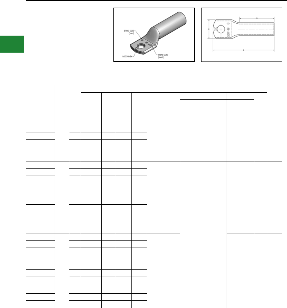
BURNDY®
Blue highlighted items are industry standard and most frequently ordered.
US: 1-800-346-4175 www.burndy.com Canada: 1-800-387-6487
Catalog
Number
Wire
Range
(MM2)
Stud
Size
Dimensions (mm) Installation Tooling
Wire
Strip
Length
Tongue
Thickness (B) (C) (L) Dieless*
Mechanical Mechanical Hydraulic
Die
Index
MD6,
OUR840,
MD7-34R
BCT500HS,
Y500CTHS
Y35, Y39,Y750,
PAT750,Y46**,
PAT46**
YALB185FM8
185
M8 4.8 53.8 35.6 88.6
Y644HSXT (1)
PAT644XT18V (1)
Y81KFT (3)
PAT81KFT-18V (3)
W31VT (4) W31VT (4)
W31RT (4) U31RT (4) 18 52
YALB185FM10 M10 4.8 53.8 35.6 91.7
YALB185FM12 M12 4.8 53.8 35.6 98.0
YALB185FM14 M14 4.8 53.8 35.6 99.1
YALB185FM16 M16 4.8 53.8 35.6 104.4
YALB185FM20 M20 4.8 53.8 35.6 115.6
YALB240FM10
240
M10 5.6 57.2 39.4 98.0
Y644HSXT (1)
PAT644XT18V (1)
Y81KFT (4)
PAT81KFT-18V (4)
W34VT (4) W34VT (4)
W34RT (4) U34RT (4) 20 59
YALB240FM12 M12 5.6 57.2 39.4 105.2
YALB240FM14 M14 5.6 57.2 39.4 106.2
YALB240FM16 M16 5.6 57.2 39.4 111.5
YALB240FM20 M20 5.6 57.2 39.4 122.4
YALB300FM10
300
M10 6.9 71.4 46.7 114.8
Y644HSXT (1)
PAT644XT18V (1)
Y81KFT (4)
PAT81KFT-18V (4)
— —
U36RT (4) 22 73
YALB300FM12 M12 6.9 71.4 46.7 121.2
YALB300FM14 M14 6.9 71.4 46.7 122.2
YALB300FM16 M16 6.9 71.4 46.7 127.5
YALB300FM20 M20 6.9 71.4 46.7 138.7
YALB400FM12
400
M12 7.6 74.7 50.3 127.0 Y644HSXT (1)
PAT644XT18V (1)
Y81KFT (4)
PAT81KFT-18V (4)
U39RT (4) 24 76
YALB400FM14 M14 7.6 74.7 50.3 128.0
YALB400FM16 M16 7.6 74.7 50.3 133.4
YALB400FM20 M20 7.6 74.7 50.3 144.5
YALB500FM12
500
M12 8.1 76.2 55.6 132.1 Y644HSXT (1)
PAT644XT18V (1)
Y81KFT (4)
PAT81KFT-18V (4)
U44XRT (4) L115 78
YALB500FM16 M16 8.1 76.2 55.6 138.4
YALB500FM20 M20 8.1 76.2 55.6 149.4
YALB630FM12
630
M12 9.9 81.0 68.3 140.5
— † P46RT (6) 31 83YALB630FM16 M16 9.9 81.0 68.3 146.8
YALB630FM20 M20 9.9 81.0 68.3 158.0
Compression Connections
Metric Lugs — Copper Compression — Flex — Long Barrel
* Use equivalent AWG setting on tool for installation. ** PUADP-1 Adaptor is required to use "U" Dies in Y46 and
PAT46 series tools.
† P-RT Die sets for use in Y46 only, PUADP-1 Adaptor not
required.
ONE HOLE HYLUG™
FLEX CONDUCTOR
LONG BARREL
TYPE YALB-FM
(Continued)
Electro-Tin
Plated
C-102
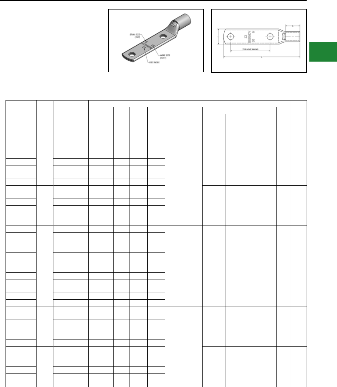
BURNDY®
Blue highlighted items are industry standard and most frequently ordered.
Canada: 1-800-387-6487 www.burndy.com US: 1-800-346-4175
* Use equivalent AWG setting on tool for installation. ** PUADP-1 Adaptor is required to use "U" Dies in Y46 and
PAT46 series tools.
† P-RT Die sets for use in Y46 only, PUADP-1 Adaptor not
required.
TWO HOLE HYLUG™
FLEX CONDUCTOR
STANDARD BARREL
TYPE YAV-F2M
Made from electrolytic copper tube and is
electro tin plate. Wire range is from 50 mm2 to
630 mm2 for class 5. Compatible to IEC61238-1.
Compression Connections
Metric Lugs — Copper Compression — Flex — Standard Barrel
Catalog
Number
Wire
Range
(MM2)
Stud
Size
Stud
Hole
Spacing
Dimensions (mm) Installtion Tooling
Wire
Strip
Length
(mm)
Tongue
Thickness (B) (C) (L) Dieless*
Mechanical Hydraulic
Die
Index
MD6,
OUR840,
MD7-34R
PAT600,
Y500CTHS
Y35, Y39,
Y750,
PAT750,
Y46**,
PAT46**
YAV50F2M6
50
M6 44.5 3.0 17.5 21.1 89.2
MY29-11 (1)
MRC840 (2)
Y644HSXT (1)
PAT644XT18V (1)
Y81KFT (1)
PAT81KFT-18V (1)
W25VT (2)
W25RT (2)
X25RT (2)
W25VT (2)
W25RT (2)
X25RT (2)
U25RT (1) 12 19
YAV50F2M8 M8 44.5 3.0 17.5 21.1 90.7
YAV50F2M10 M10 44.5 3.0 17.5 21.1 94.0
YAV50F2M12 M12 44.5 3.0 17.5 21.1 100.3
YAV50F2M14 M14 44.5 3.0 17.5 22.4 101.3
YAV50F2M16 M16 44.5 3.0 17.5 22.4 106.7
YAV70F2M6
70
M6 44.5 3.3 20.6 23.6 93.2
W26RT (2)
W26VT (2)
X26RT (2)
W26RT (2)
W26VT (2)
X26RT (2)
U26RT (1) 13 22
YAV70F2M8 M8 44.5 3.3 20.6 23.6 95.0
YAV70F2M10 M10 44.5 3.3 20.6 23.6 98.3
YAV70F2M12 M12 44.5 3.3 20.6 23.6 104.6
YAV70F2M14 M14 44.5 3.3 20.6 23.6 105.7
YAV70F2M16 M16 44.5 3.3 20.6 23.6 111.0
YAV95F2M8
95
M8 44.5 3.6 25.4 26.2 100.8
MY29-11 (1)
MRC840 (2)
Y644HSXT (1)
PAT644XT18V (1)
Y81KFT (2)
PAT81KFT-18V (2)
W27VT (2)
W27RT (2)
X27RT (3)
W27VT (2)
W27RT (2)
X27RT (3)
U27RT (1) 14 27
YAV95F2M10 M10 44.5 3.6 25.4 26.2 104.1
YAV95F2M12 M12 44.5 3.6 25.4 26.2 110.5
YAV95F2M14 M14 44.5 3.6 25.4 26.2 111.5
YAV95F2M16 M16 44.5 3.6 25.4 26.2 116.8
YAV95F2M20 M20 44.5 3.6 25.4 26.2 128.0
YAV120F2M8
120
M8 44.5 3.8 26.2 29.0 102.9
W28VT (2)
W28RT (2)
X28RT (3)
W28VT (2)
W28RT (2)
X28RT (3)
U28RT (1) 15 27
YAV120F2M10 M10 44.5 3.8 26.2 29.0 106.2
YAV120F2M12 M12 44.5 3.8 26.2 29.0 112.5
YAV120F2M14 M14 44.5 3.8 26.2 29.0 113.5
YAV120F2M16 M16 44.5 3.8 26.2 29.0 118.9
YAV120F2M20 M20 44.5 3.8 26.2 29.0 130.0
YAV150F2M8
150
M8 44.5 4.6 26.9 32.8 104.9
Y644HSXT (1)
PAT644XT18V (1)
Y81KFT (2)
PAT81KFT-18V (2)
W30VT (2) W30VT (2)
W30RT (2) U30RT (2) 17 29
YAV150F2M10 M10 44.5 4.6 26.9 32.8 108.2
YAV150F2M12 M12 44.5 4.6 26.9 32.8 114.6
YAV150F2M14 M14 44.5 4.6 26.9 32.8 115.6
YAV150F2M16 M16 44.5 4.6 26.9 32.8 120.9
YAV150F2M20 M20 44.5 4.6 26.9 32.8 132.1
YAV185F2M8
185
M8 44.5 4.8 30.2 35.6 109.5
W31VT (2) W31VT (2)
W31RT (2) U31RT (2) 18 29
YAV185F2M10 M10 44.5 4.8 30.2 35.6 112.8
YAV185F2M12 M12 44.5 4.8 30.2 35.6 119.1
YAV185F2M14 M14 44.5 4.8 30.2 35.6 120.1
YAV185F2M16 M16 44.5 4.8 30.2 35.6 125.5
YAV185F2M20 M20 44.5 4.8 30.2 35.6 136.7
Electro-Tin
Plated
C-103
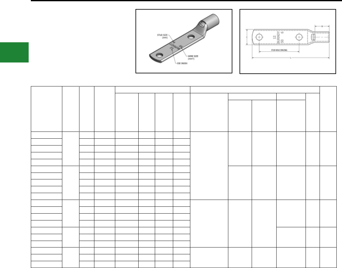
BURNDY®
Blue highlighted items are industry standard and most frequently ordered.
US: 1-800-346-4175 www.burndy.com Canada: 1-800-387-6487
Catalog
Number
Wire
Range
(MM2)
Stud
Size
Stud
Hole
Spacing
Dimensions (mm) Installtion Tooling
Wire
Strip
Length
(mm)
Tongue
Thickness (B) (C) (L) Dieless*
Mechanical Hydraulic
Die
Index
MD6,
OUR840,
MD7-34R
PAT600,
Y500CTHS
Y35, Y39,
Y750,
PAT750,
Y46**,
PAT46**
YAV240F2M10
240
M10 44.5 5.8 32.3 39.4 117.6
Y644HSXT (1)
PAT644XT18V (1)
Y81KFT (2)
PAT81KFT-18V (2)
W34VT (2) W34VT (2)
W34RT (2) U34RT (2) 20 33
YAV240F2M12 M12 44.5 5.8 32.3 39.4 123.9
YAV240F2M14 M14 44.5 5.8 32.3 39.4 124.9
YAV240F2M16 M16 44.5 5.8 32.3 39.4 130.3
YAV240F2M20 M20 44.5 5.8 32.3 39.4 141.3
YAV300F2M10
300
M10 44.5 6.9 36.8 46.7 124.9
— — U36RT (2) 22 38
YAV300F2M12 M12 44.5 6.9 36.8 46.7 131.3
YAV300F2M14 M14 44.5 6.9 36.8 46.7 132.2
YAV300F2M16 M16 44.5 6.9 36.8 46.7 137.7
YAV300F2M20 M20 44.5 6.9 36.8 46.7 148.7
YAV400F2M12
400
M12 44.5 7.6 36.1 50.3 131.8
Y644HSXT (1)
PAT644XT18V (1)
Y81KFT (3)
PAT81KFT-18V (3)
— —
U39RT (3) 24 37
YAV400F2M14 M14 44.5 7.6 36.1 50.3 132.8
YAV400F2M16 M16 44.5 7.6 36.1 50.3 138.2
YAV400F2M20 M20 44.5 7.6 36.1 50.3 149.2
YAV500F2M12
500
M12 44.5 8.4 41.9 55.6 140.9
U44XRT (3) L115 43YAV500F2M16 M16 44.5 8.4 41.9 55.6 147.3
YAV500F2M20 M20 44.5 8.4 41.9 55.6 158.4
YAV630F2M12
630
M12 44.5 9.9 50.8 68.3 154.9
— — — † P46RT (3) 31 55YAV630F2M16 M16 44.5 9.9 50.8 68.3 161.3
YAV630F2M20 M20 44.5 9.9 50.8 68.3 172.4
* Use equivalent AWG setting on tool for installation. ** PUADP-1 Adaptor is required to use "U" Dies in Y46 and
PAT46 series tools.
† P-RT Die sets for use in Y46 only, PUADP-1 Adaptor not
required.
Compression Connections
Metric Lugs — Copper Compression — Flex — Standard Barrel
TWO HOLE HYLUG™
FLEX CONDUCTOR
STANDARD BARREL
TYPE YAV-F2M
(Continued)
Electro-Tin
Plated
C-104
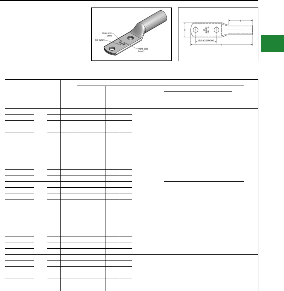
BURNDY®
Blue highlighted items are industry standard and most frequently ordered.
Canada: 1-800-387-6487 www.burndy.com US: 1-800-346-4175
Compression Connections
Metric Lugs — Copper Compression — Flex — Long Barrel
Catalog
Number
Wire
Range
(MM2)
Stud
Size
Stud
Hole
Spacing
Dimensions (mm) Installtion Tooling
Wire
Strip
Length
(mm)
Tongue
Width (B) (C) (L) Dieless*
Mechanical Hydraulic
Die
Index
MD6,
OUR840,
MD7-34R
PAT600,
Y500CTHS
Y35, Y39,Y750,
PAT750,Y46**,
PAT46**
YALB50F2M6
50
M6 44.5 3.0 38.1 21.1 110.2 MY29-11 (2)
MRC840 (4)
Y644HSXT (1)
PAT644XT18V (1)
Y81KFT (2)
PAT81KFT-18V (2)
W25VT (4)
W25RT (4)
X25RT (4)
W25VT (4)
W25RT (4)
X25RT (4)
U25RT (2) 12
40
YALB50F2M8 M8 44.5 3.0 38.1 21.1 112.0
YALB50F2M10 M10 44.5 3.0 38.1 21.1 115.1
YALB50F2M12 M12 44.5 3.0 38.1 21.1 121.4
YALB50F2M14 M14 44.5 3.0 38.1 21.1 122.4
YALB50F2M16 M16 44.5 3.0 38.1 21.1 131.1
YALB70F2M6
70
M6 44.5 3.3 38.1 23.6 111.0
MY29-11 (2)
MRC840 (4)
Y644HSXT (1)
PAT644XT18V (1)
Y81KFT (2)
PAT81KFT-18V (2)
W26VT (4)
W26RT (4)
X26RT (4)
W26VT (4)
W26RT (4)
X26RT (4)
U26RT (2) 13
YALB70F2M8 M8 44.5 3.3 38.1 23.6 113.3
YALB70F2M10 M10 44.5 3.3 38.1 23.6 116.3
YALB70F2M12 M12 44.5 3.3 38.1 23.6 122.7
YALB70F2M14 M14 44.5 3.3 38.1 23.6 123.7
YALB70F2M16 M16 44.5 3.3 38.1 23.6 129.0
YALB95F2M8
95
M8 44.5 3.6 38.1 26.2 114.3
W27VT (4)
W27RT (4)
X27RT (6)
W27VT (4)
W27RT (4)
X27RT (6)
U27RT (2) 14
YALB95F2M10 M10 44.5 3.6 38.1 26.2 117.6
YALB95F2M12 M12 44.5 3.6 38.1 26.2 124.0
YALB95F2M14 M14 44.5 3.6 38.1 26.2 125.0
YALB95F2M16 M16 44.5 3.6 38.1 26.2 130.3
YALB95F2M20 M20 44.5 3.6 38.1 26.2 141.2
YALB120F2M8
120
M8 44.5 3.8 41.1 29.0 118.6
W28VT (4)
W28RT (4)
X28RT (6)
W28VT (4)
W28RT (4)
X28RT (6)
U28RT (2) 15 43
YALB120F2M10 M10 44.5 3.8 41.1 29.0 124.2
YALB120F2M12 M12 44.5 3.8 41.1 29.0 128.3
YALB120F2M14 M14 44.5 3.8 41.1 29.0 129.3
YALB120F2M16 M16 44.5 3.8 41.1 29.0 134.6
YALB120F2M20 M20 44.5 4.3 41.1 30.5 145.8
YALB150F2M8
150
M8 44.5 4.3 50.8 32.8 129.8
Y644HSXT (1)
PAT644XT18V (1)
Y81KFT (3)
PAT81KFT-18V (3)
W30VT (4) W30VT (4)
W30RT (4) U30RT (4) 17 52
YALB150F2M10 M10 44.5 4.3 50.8 32.8 133.1
YALB150F2M12 M12 44.5 4.3 50.8 32.8 139.4
YALB150F2M14 M14 44.5 4.3 50.8 32.8 140.0
YALB150F2M16 M16 44.5 4.3 50.8 32.8 145.8
YALB150F2M20 M20 44.5 4.3 50.8 32.8 157.0
* Use equivalent AWG setting on tool for installation. ** PUADP-1 Adaptor is required to use "U" Dies in Y46 and
PAT46 series tools.
† P-RT Die sets for use in Y46 only, PUADP-1 Adaptor not
required.
TWO HOLE HYLUG™
FLEX CONDUCTOR
LONG BARREL
TYPE YALB-F2M
Made from electrolytic copper tube and is
electro tin plate. Wire range is from 50 mm2 to
630 mm2 for class 5. Compatible to IEC61238-1.
Electro-Tin
Plated
C-105
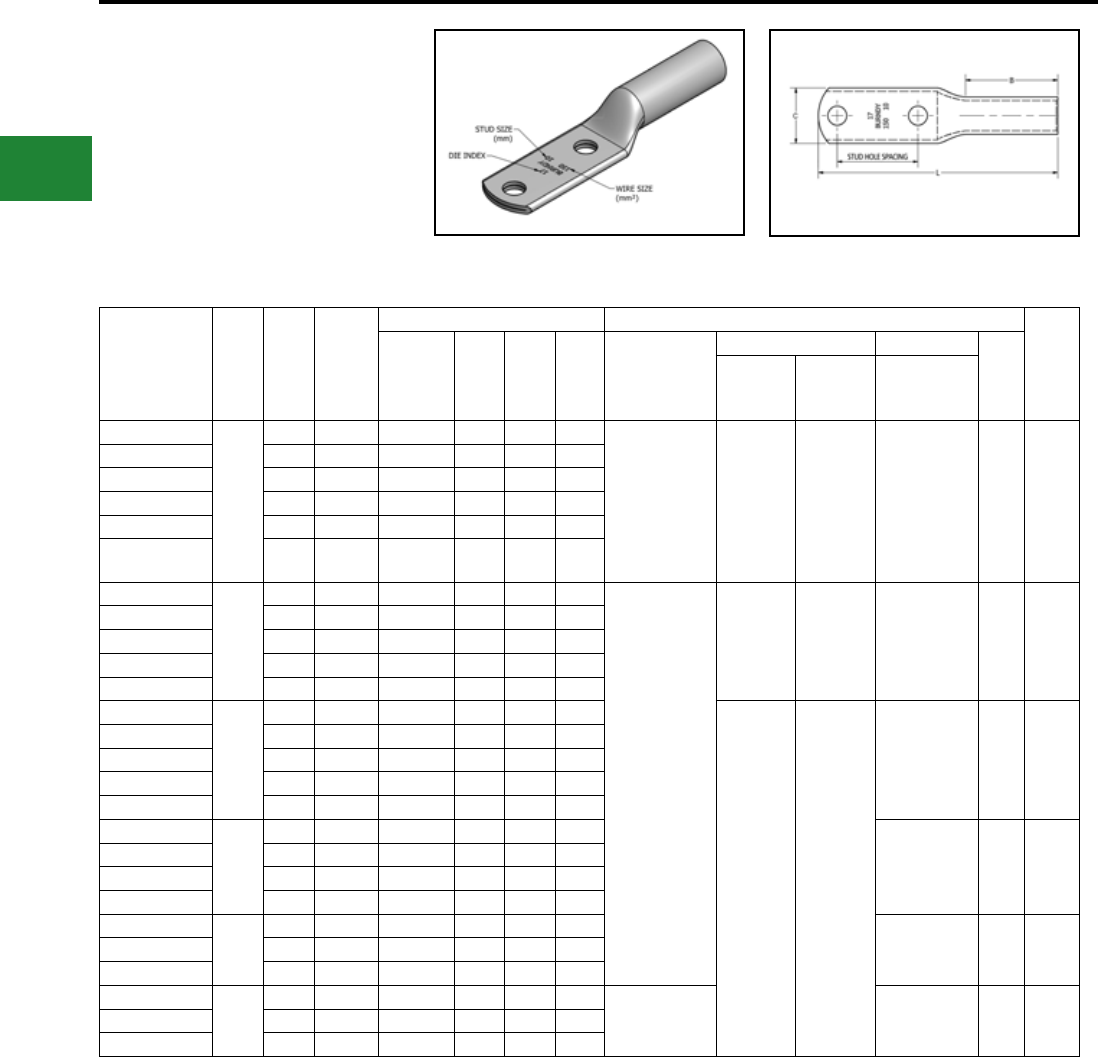
BURNDY®
Blue highlighted items are industry standard and most frequently ordered.
US: 1-800-346-4175 www.burndy.com Canada: 1-800-387-6487
Compression Connections
Metric Lugs — Copper Compression — Flex — Long Barrel
Catalog
Number
Wire
Range
(MM2)
Stud
Size
Stud
Hole
Spacing
Dimensions (mm) Installtion Tooling
Wire
Strip
Length
(mm)
Tongue
Thickness (B) (C) (L) Dieless*
Mechanical Hydraulic
Die
Index
MD6,
OUR840,
MD7-34R
PAT600,
Y500CTHS
Y35, Y39,Y750,
PAT750,Y46**,
PAT46**
YALB185F2M8
185
M8 44.5 4.8 53.8 35.6 134.1 Y644HSXT
(1)
PAT644XT18V
(1)
Y81KFT
(3)
PAT81KFT-18V
(3)
W31VT (4) W31VT (4)
W31RT (4) U31RT (4) 18 52
YALB185F2M10 M10 44.5 4.8 53.8 35.6 137.4
YALB185F2M12 M12 44.5 4.8 53.8 35.6 143.8
YALB185F2M14 M14 44.5 4.8 53.8 35.6 144.8
YALB185F2M16 M16 44.5 4.8 53.8 35.6 150.1
YALB185F2M20 M20 44.5 4.8 53.8 35.6 161.3
YALB240F2M10
240
M10 44.5 5.6 57.2 39.4 142.7
Y644HSXT
(1)
PAT644XT18V
(1)
Y81KFT
(4)
PAT81KFT-18V
(4)
W34VT (4) W34VT (4)
W34RT (4) U34RT (4) 20 59
YALB240F2M12 M12 44.5 5.6 57.2 39.4 149.9
YALB240F2M14 M14 44.5 5.6 57.2 39.4 150.9
YALB240F2M16 M16 44.5 5.6 57.2 39.4 156.2
YALB240F2M20 M20 44.5 5.6 57.2 39.4 167.1
YALB300F2M10
300
M10 44.5 6.9 71.4 46.7 160.8
— —
U36RT (4) 22 73
YALB300F2M12 M12 44.5 6.9 71.4 46.7 167.1
YALB300F2M14 M14 44.5 6.9 71.4 46.7 168.1
YALB300F2M16 M16 44.5 6.9 71.4 46.7 173.5
YALB300F2M20 M20 44.5 6.9 71.4 46.7 184.7
YALB400F2M12
400
M12 44.5 7.6 74.7 50.3 171.7
U39RT (4) 24 76
YALB400F2M14 M14 44.5 7.6 74.7 50.3 172.7
YALB400F2M16 M16 44.5 7.6 74.7 50.3 178.1
YALB400F2M20 M20 44.5 7.6 74.7 50.3 189.2
YALB500F2M12
500
M12 44.5 8.1 76.2 55.6 176.8
U44XRT (4) L115 78YALB500F2M16 M16 44.5 8.1 76.2 55.6 183.1
YALB500F2M20 M20 44.5 8.1 76.2 55.6 194.1
YALB630F2M12
630
M12 44.5 9.9 81.0 68.3 186.9
— † P46RT (6) 31 83YALB630F2M16 M16 44.5 9.9 81.0 68.3 193.3
YALB630F2M20 M20 44.5 9.9 81.0 68.3 204.5
* Use equivalent AWG setting on tool for installation. ** PUADP-1 Adaptor is required to use "U" Dies in Y46 and
PAT46 series tools.
† P-RT Die sets for use in Y46 only, PUADP-1 Adaptor not
required.
TWO HOLE HYLUG™
FLEX CONDUCTOR
LONG BARREL
TYPE YALB-F2M
(Continued)
Electro-Tin
Plated
C-106
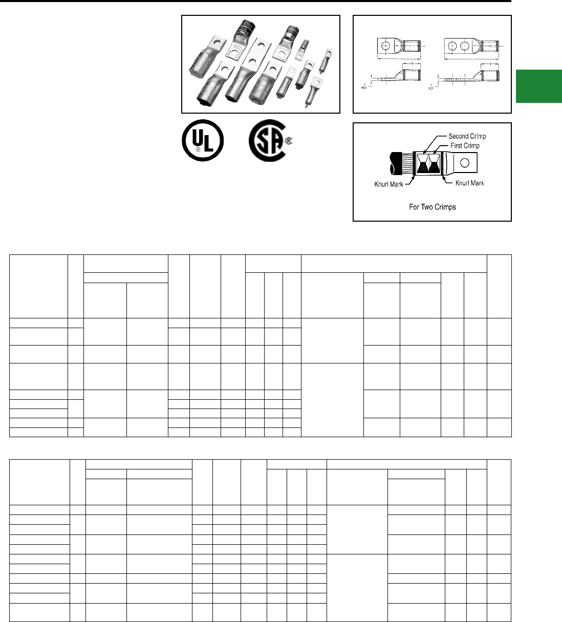
BURNDY®
Blue highlighted items are industry standard and most frequently ordered.
Canada: 1-800-387-6487 www.burndy.com US: 1-800-346-4175
E-LINE HYLUG™
EQUIPMENT LINE
TYPE YA-E
COPPER AND ALUMINUM
COMPRESSION TERMINAL
UL Listed 90° C,
600 Volts to 35 kV ♦
YA-E Equipment terminals are designed to
provide replacements for original equipment
mechanical or other compression terminals.
These narrow tongue terminals are specially
designed to t in tight areas. Whether you’re
upgrading or replacing, YA-E connectors
will provide for any of your cable termination
needs. When installed with our dieless tool,
these terminals can accommodate a range of
conductor sizes.
Catalog Number
Fig.
No.
Conductor
Accommodations
Stud
Hole
Size
Stud Hole
Spacing
Tongue
Width
(max)
Dimensions † Installation Tooling
Wire
Strip
Length
Copper Only
B T L
Dieless
(number of crimps)
Mechanical Hydraulic
Color
Code
Die
Index
Conventional
Wire Size
Expanded
Wire Range
using
Y644HSXT
MD6 , MD7
(number of
crimps)
Y35, Y750,
Y46*, PAT750
(number of
crimps)
YA25LN50T14E 1
1/0 AWG #6 - 1/0 AWG
1/4" — 0.50" 0.88" 0.12" 1.84" Y644HSXT (1)
PAT644XT-18VHS (1)
Y81KFT (1)
Y81KFTMBH (1)
PAT81KFT-18V (1)
W25VT (2)
W25RT (2)
U25RT (1)
U2CABT (1) Pink
12
or
348
15/16″
YA25LN64T516E 1 5/16" — 0.64" 0.88"0.12"1.96"
YA26LN50T14E 1 2/0 AWG #4 - 2/0 AWG 1/4" — 0.50" 0.94" 0.12" 1.94" W26VT (2)
W26RT (2) U26RT (1) Black 13 1″
YA30L24N100T38E 1 300 kcmil 2/0 AWG -
300 kcmil 3/8" — 1.00" 1.03" 0.16" 2.44" Y644HSXT (1)
PAT644XT-18VHS (1)
Y81KFT (2)
Y81KFTMBH (2)
PAT81KFT-18V (2)
W30RT (2) U30RT (2)
U28ART (2) White
17
or
298
1-1/16″
YA34L6N131T12E 1
500 kcmil 4/0 AWG -
500 kcmil
1/2" — 1.31" 1.27" 0.23" 3.31"
—
U34RT (2)
U31ART (2)
P34RT (2)
Brown
20
or
299
1-5/16″YA342LNN119T12E 21/2"1.75" 1.19" 1.27"0.22" 5.06"
YA342LNN131T12E 1/2"1.75"1.31" 1.27"0.22"5.06"
YA39L6N131T12E 1750 kcmil 500 - 750
kcmil
1/2" — 1.31" 1.42" 0.27" 3.61" — U39RT (2) Black 24 1-1/2″
YA392LNN131T12E 2 1/2"1.745" 1.31"1.42"0.27"5.37"
COPPER E-LINE HYLUG™ COMPRESSION TERMINALS
ALUMINUM E-LINE HYLUG™ COMPRESSION TERMINALS
† A variety of BURNDY® installation tools are available
and not all tools are listed. If you require additional
tooling information, please feel free to call our
customer service department for other
recommendations.
* Use PUADP-1 adapter with U dies in Y46 HYPRESS™,
P-RT die sets for use in Y46 HYPRESS™ only.
PUADP-1 adapter not required.
** 900 Compact Aluminum Cable not UL Listed. Tested
with Y644HSXT and PAT644XT-18V dieless tools only.
Note: All dimensions shown are for reference only.
Overlap crimps when using U Dies.
Catalog Number
Fig.
No.
Conductor Accommodations
Stud
Hole
Size
Stud
Hole
Spacing
Tongue
Width
(max)
Dimensions † Installation Tooling
Wire
Strip
Length
Aluminum Copper or Aluminum
B T L
Dieless
(number of crimps)
Hydraulic
Color
Code
Die
Index
Conventional
Wire Size
Expanded Wire Range
using Y644HSXT
Y35, Y750, Y46*,
PAT750
(number of crimps)
YA8CA3S56T14E 1 #8 AWG #8 AWG 1/4" — 0.56" 0.62" 0.09" 1.65" Y644HSXT (1)
PAT644XT-18VHS (1)
Y81KFT (1)
Y81KFTMBH (1)
PAT81KFT-18V (1)
U8CABT (1) Blue 374 11/16″
YA2CA5S53T14E 1 #2 AWG #6 - #2 AWG 1/4" — 0.53" 1.00" 0.22" 2.25" U2CABT (1) Pink 348 1-3/16″
YA2CA1S91T516E 5/16" — 0.91" 1.12" 0.16" 2.50"
YA25A1S60T516E 1 1/0 AWG #1 - 1/0 AWG 5/16" — 0.63" 1.00" 0.21" 2.29" U25ART (1) Tan 296 1-1/8″
YA25A3N69T38E 3/8" — 0.69" 1.05" 0.21" 2.38"
YA26A13N100T516E 1 2/0 AWG #1 - 2/0 AWG 5/16" — 1.00" 1.11" 0.24" 2.45"
Y644HSXT (1)
PAT644XT-18VHS (1)
Y81KFT (2)
Y81KFTMBH (2)
PAT81KFT-18V (2)
U26ART (2) Olive 297 1-3/16″
YA26A6N100T38E 3/8" — 1.00" 1.11"0.24"2.53"
YA27A10S76T516E 1 3/0 AWG #1 - 3/0 AWG 5/16" — 0.76" 1.11" 0.26" 2.58" U27ART (2) Ruby 467 1-3/16″
YA28A1N100T38E 1 4/0 AWG 1/0 - 4/0 AWG 5/16" — 1.00" 1.39" 0.30" 2.94" U28ART (2) White 298 1-7/16″
YA28A14N100T516E 3/8" — 1.00" 1.39"0.30"2.85"
YA30A9N100T516E 1 300 kcmil 2/0 AWG -
300 kcmil 5/16" — 1.00" 1.53" 0.36" 3.12" U30ART (2) Blue 470 1-5/8″
Fig. 1 Fig. 2
Compression Connections
Copper and Aluminum Compression — Narrow Tongue — One and Two Hole
C-107
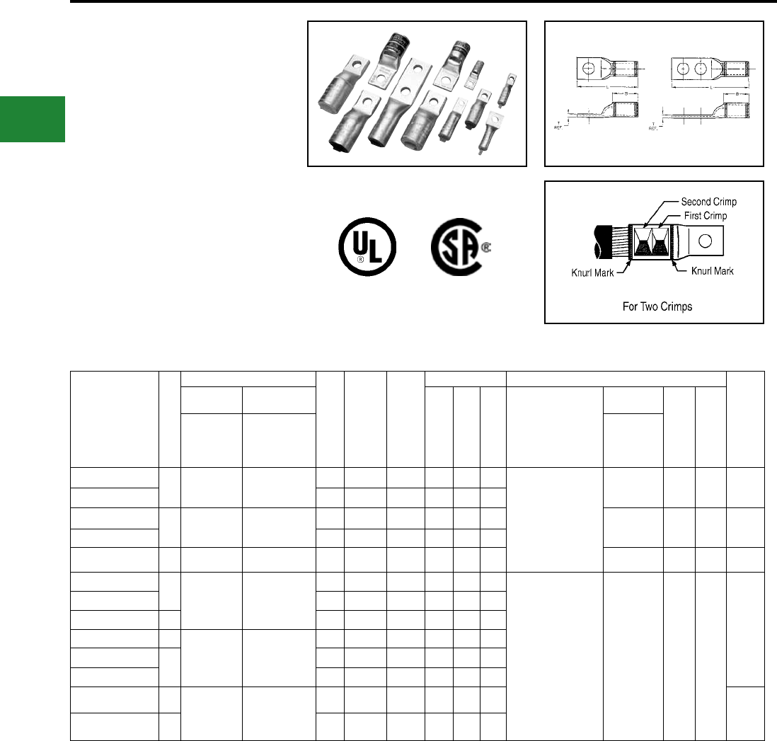
BURNDY®
Blue highlighted items are industry standard and most frequently ordered.
US: 1-800-346-4175 www.burndy.com Canada: 1-800-387-6487
E-LINE HYLUG™
EQUIPMENT LINE
TYPE YA-E
COPPER AND ALUMINUM
COMPRESSION TERMINAL
UL Listed 90° C,
600 Volts to 35 kV ♦
Catalog Number
Fig.
No.
Conductor Accommodations
Stud
Hole
Size
Stud
Hole
Spacing
Tongue
Width
(max)
Dimensions † Installation Tooling
Wire
Strip
Length
Aluminum
Copper or
Aluminum
B T L
Dieless
(number of crimps)
Hydraulic
Color
Code
Die
Index
Conventional
Wire Size
Expanded Wire
Range using
Y644HSXT
Y35, Y750,
Y46*, PAT750
(number of
crimps)
YA30A6N100T38E 1 300 kcmil 2/0 AWG - 300
kcmil
3/8" — 1.00" 1.53" 0.36" 3.20"
Y644HSXT (1)
PAT644XT-18VHS (1)
Y81KFT (2)
Y81KFTMBH (2)
PAT81KFT-18V (2)
U30ART (2) Blue 470 1-5/8
″
YA30A1N131T12E 1/2" — 1.31" 1.53"0.35" 3.57"
YA31A11N100T516E 1 350 kcmil 3/0 AWG - 350
kcmil
5/16" — 1.00" 1.85" 0.39" 3.51" U31ART (2) Brown 299 1-7/8
″
YA31A9N100T38E 3/8" — 1.00"1.85"0.39"3.59"
YA32A8N106T516E 1 400 kcmil 4/0 AWG - 400
kcmil 5/16" — 1.06" 2.26" 0.43" 3.92" U32ART (4) Green 472 2-5/16
″
YA34A8N131T38E 1500 kcmil 4/0 AWG - 500
kcmil
3/8" — 1.31" 1.64" 0.35" 3.88"
Y644HSXT (2)
PAT644XT-18VHS (2)
Y81KFT (2)
Y81KFTMBH (2)
PAT81KFT-18V (2)
U34ART (4) Pink 300
1-11/16
″
YA34A7N131T12E 1/2" — 1.31"1.64"0.35"3.88"
YA34A3N131T12E 2 1/2" 1.75 1.31"1.64"0.39" 5.71"
YA36A9N131TD12E 1
600 kcmil 250 - 600 kcmil
1/2" — 1.31" 1.64" 0.39" 3.98"
YA36A3N131TD38E 23/8" — 1.31"1.64"0.39"5.32"
YA36A3N131TD12E 1/2" 1.75 1.31"1.64"0.39"5.71"
YA39A1N131TD12E 1
750 kcmil
500 - 900 kcmil
Aluminum
500 kcmil
Copper Only
1/2" — 1.31" 1.86" 0.31" 4.28"
1-15/16
″
YA39A5N131TD12E 2 1/2" 1.75 1.31"1.86"0.31"6.09"
ALUMINUM E-LINE HYLUG™ COMPRESSION TERMINALS
† A variety of BURNDY® installation tools are available
and not all tools are listed. If you require additional
tooling information, please feel free to call our customer
service department for other recommendations.
* Use PUADP-1 adapter with U dies in Y46 HYPRESS™,
P-RT die sets for use in Y46 HYPRESS™ only.
PUADP-1 adapter not required.
** 900 Compact Aluminum Cable not UL Listed. Tested
with Y644HSXT and PAT644XT-18V dieless tools only.
Note: All dimensions shown are for reference only.
Overlap crimps when using U Dies.
Fig. 1 Fig. 2
Compression Connections
Copper and Aluminum Compression — Narrow Tongue — One and Two Hole
C-108
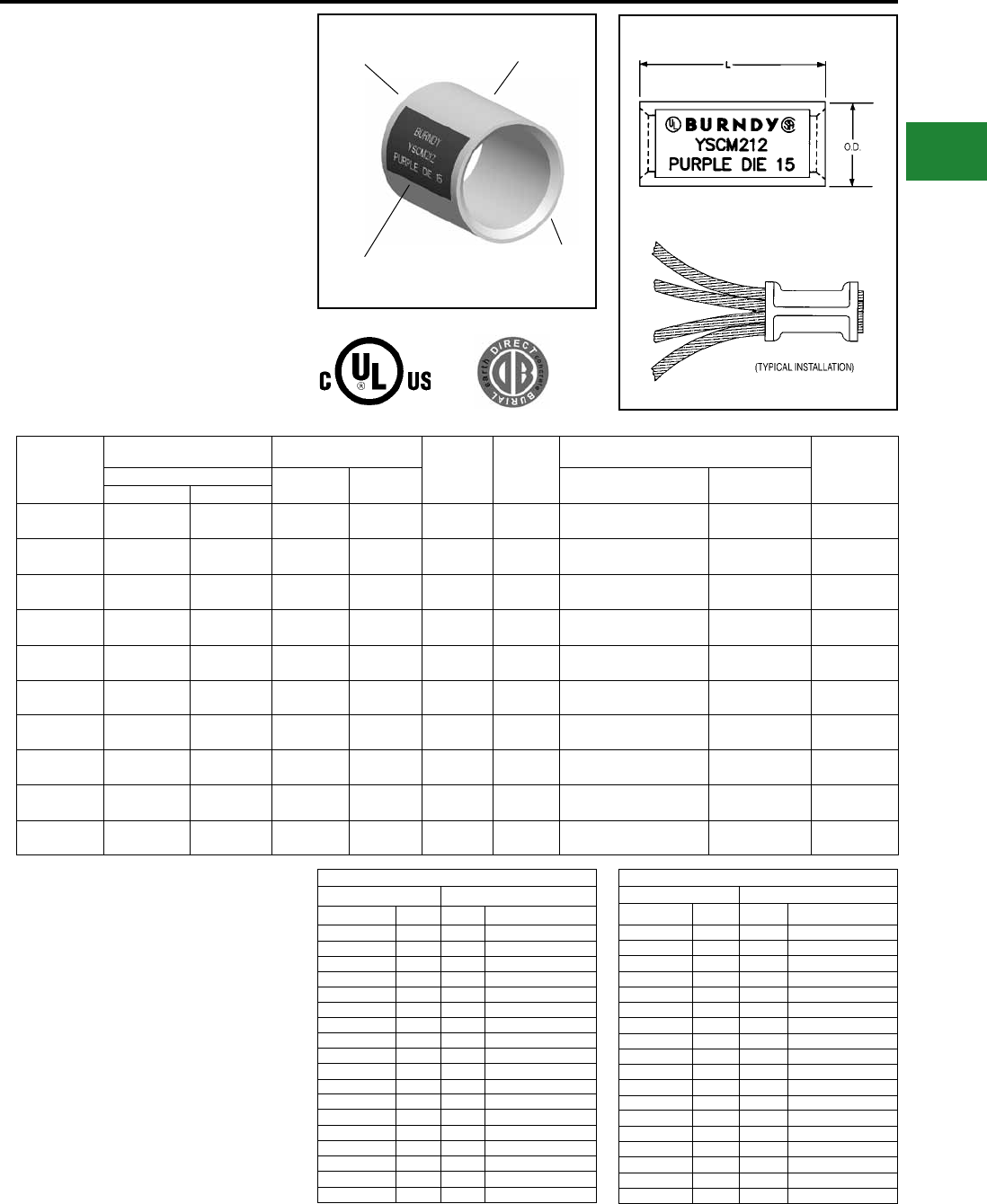
BURNDY®
Blue highlighted items are industry standard and most frequently ordered.
Canada: 1-800-387-6487 www.burndy.com US: 1-800-346-4175
TYPE YSCM
HYLINK™
Color-Coded
Uninsulated Parallel Splice
Type YSCM HYLINK™ seamless
parallel splice connectors permit
stranded wires to be laid parallel inside
the connector and spliced together
with BURNDY® compression tools.
Each YSCM connector accommodates
a wide range of conductors and is
color-coded to ensure proper tool
and die match. YSCM connectors are
cULus Listed WIRE CONNECTORS
per UL 486A/B for GROUNDING and
BONDING, and UL 467 and rated for
Direct Burial in Earth and Concrete.
Catalog
Number
Conductor Range Cable ‡
Dimensions
Inches [mm]
Color
Code
Die
Index
Recommended Installation Tooling Wire
Strip
Length †
Circular Mils L
±.03
O.D.
±.01
OUR840, Y500CTHS,
PAT60018V Series
Y35, Y750, PAT750
SeriesMin. Max.
YSCM17 13,060 16,910 0.50
[13]
0.27
[7] Red 49 X8CRT, W8CRT U8CRT 11/16
YSCM27 16,910 26,890 0.50
[13]
0.31
[8] Blue 7 X5CRT, W5CRT U5CRT 11/16
YSCM42 29,970 41,520 0.50
[13]
0.38
[10] Gray 8 X4CRT, W4CRT U4CRT 11/16
YSCM66 42,750 66,040 0.62
[16]
0.47
[12] Brown 10 X2CRT, W2CRT U2CRT 3/4
YSCM80 67,980 80,020 0.62
[16]
0.52
[13] Green 11 X1CRT-1, W1CRT-1 U1CRT-1 3/4
YSCM104 82,870 103,630 0.69
[18]
0.57
[14] Pink 12 X25RT, W25RT U25RT 15/16
YSCM133 104,960 133,220 0.81
[21]
0.64
[16] Black 13 X26RT, W26RT U26RT 1-1/16
YSCM167 134,340 166,560 0.81
[21]
0.70
[18] Orange 14 X27RT, W27RT U27RT 1-1/16
YSCM212 167,380 211,820 0.88
[22]
0.78
[20] Purple 15 X28RT, W28RT U28RT 1-1/16
YSCM231 230,800 230,800 1.05
[27]
0.81
[21] Yellow 16 X29RT, W29RT* U29RT 1-1/16
ELECTRO-TIN
PLATED
BEVELED
ENTRY
COLOR-CODE
AND DIE INDEX
SEAMLESS
TUBING
Circular Mil Table per ASTM B8
Size ASTM Strandings
Circular Mils AWG Class Cable Diameter (in)
1,022 20 B 0.036
1,624 18 B 0.045
2,583 16 B 0.057
4,107 14 B 0.072
6,530 12 B 0.091
10,380 10 B 0.116
13,090 9 B 0.130
16,510 8 B 0.146
20,820 7 B 0.164
26,250 6 B 0.184
33,100 5 B 0.206
41,740 4 AA 0.254
41,740 4 B&A 0.232
52,630 3 AA 0.285
52,630 3 B&A 0.260
Circular Mil Table per ASTM B8
Size ASTM Strandings
Circular Mils AWG Class Cable Diameter (in)
66,370 2 AA 0.320
66,370 2 B&A 0.292
83,690 1 AA 0.360
83,690 1 A 0.328
83,690 1 B 0.332
105,500 1/0 A&A 0.368
105,500 1/0 — 0.390
105,500 1/0 B 0.373
133,100 2/0 A&A 0.414
133,100 2/0 — 0.438
133,100 2/0 B 0.419
167,800 3/0 A&A 0.464
167,800 3/0 — 0.492
167,800 3/0 B 0.470
211,600 4/0 A&A 0.522
211,600 4/0 — 0.522
211,600 4/0 B 0.528
Notes:
1. Material: Copper per ASTM B75.
2. Finish: Tin plated. For nickel plating, add sufx “NK" to
the Catalog Number.
† Recommended strip length. Strip length dependant on
size, no. of wires and insulation thickness.
‡ Refer to Circular Mil Table per ASTM B8 for total
Class B Circular Mil calculations.
* YSCM231 can also be installed with MY29-3 and retain
Listings.
Add the circular mils of the wires you
wish to splice; that sum would be used
to determine the correct splice using
the Min/Max columns on the table
above.
The table to the right are for reference
only.
Compression Connections
Copper Compression — Splice
C-109
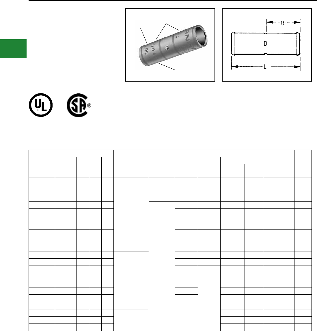
BURNDY®
Blue highlighted items are industry standard and most frequently ordered.
US: 1-800-346-4175 www.burndy.com Canada: 1-800-387-6487
TYPE YS-L
HYLINK™ SPLICE
STANDARD BARREL
COPPER COMPRESSION
UL Listed 90° C,
600 Volts to 35 kV ♦
Features & Benets
• Standard barrel length
◊
Ideal for limited space applications
while providing ample barrel length
for proper crimp
• Four (4) center conductor stops
◊ Provides a center wire stop for
proper conductor insertion
Catalog
Number
Conductor Dimensions Installation Tooling ▲
Wire
Strip
LengthAWG
***
MM² L B
Dieless
(# of crimps)
Mechanical Y35, ■Y39, Y750, Y46* ▲
Die Index
& Embossment
Y1MRTC
Y2MR MD7-34R
MD6
OUR840
Die Number
(# crimps)
Color
Code
YS8C-L-BOX 8 Str. 10 1.00 0.44
Y81KFT (1)
Y81KFTMBH (1)
PAT81KFT-18V (1)
Y1MRTC (1)
W8CVT (1) X8CRT (1) U8CRT (1) Red 49 1/2″
YS6C-LBOX 6 Str. — 1.75 0.81 W5CVT (1) X5CRT (1) U5CRT (1) Blue 7 or 374 7/8″
YS5C-LBOX 5 Str. 16 1.90 0.81
YS4C-LBOX 4 Str. — 1.75 0.81
Y1MRTC (2)
W4CVT (1) X4CRT (1) U4CRT (1) Gray 8 or 346 7/8″
YS3C-L 3 Str./
2 Sol. 25 2.05 0.88 — — U3CRT (1) White 9 15/16″
YS2C-LBOX 2 Str. — 2.00 0.88 W2CVT (1) X2CRT (1) U2CRT (1) Brown 10 15/16″
YS1C-LBOX 1 Str. 50 2.06 0.88 W1CVT (1) X1CRT (1) U1CRT-1 (1) Green 11 or 375 15/16″
YS25-LBOX 1/0 Str. — 2.08 0.88
—
W25VT (2) X25RT (2) U25RT (1) Pink 12 or 348 15/16″
YS26-LBOX 2/0 Str. 70 2.17 0.94 W26VT (2) X26RT (2) U26RT (1) Black 13 1″
YS27-LBOX 3/0 Str. 95 2.30 1.00
Y81KFT (2)
Y81KFTMBH (2)
PAT81KFT-18V (2)
W27VT (2) X27RT (2) U27RT (1) Orange 14 1-1/16″
YS28-LBOX 4/0 Str. — 2.32 1.00 W28VT (2) X28RT (2) U28RT (1) Purple 15 1-1/16″
YS29-LBOX 250 kcmil 120 2.46 1.06 W29VT (2)
—
U29RT (1) Yellow 16 1-1/8″
YS30-L 300 kcmil 150 2.47 1.06 W30VT (2) U30RT (2) White 17 or 298 1-1/8″
YS31-L 350 kcmil 185 2.60 1.12 W31VT (2) U31RT (2) Red 18 or 324 1-3/16″
YS32-L 400 kcmil — 2.74 1.19 W32VT (2) U32RT (2) Blue 19 or 470 1-1/4″
YS34-L 500 kcmil 240 3.15 1.38 W34VT (2) U34RT (2) Brown 20 or 299 1-7/16″
YS36-L 600 kcmil 300 3.22 1.38
—
U36RT (2) Green 22 or 472 1-7/16″
YS38-L 700 kcmil — 3.22 1.38 Y81KFT (3)
Y81KFTMBH (3)
PAT81KFT-18V (3)
U38RT (2) Pink 400 1-7/16″
YS39-L 750 kcmil — 3.72 1.62 U39RT (2) Black 24 1-11/16″
YS44-L 1000 kcmil 500 4.28 1.88 P44RT (2)** White 27 1-15/16″
▲ See tooling section of this catalog for complete tool
and die listings.
* Use PUADP-1 adapter with U dies in Y46 HYPRESS™.
** P44RT for use with Y46 HYPRESS™ only. PUADP-1
adaptor not required.
*** The MM2 conductor sizes listed are the recommendations
for Class 2 conductor.
■ The maximum size for the Y35 is 400 kcmil insulated
code cable.
♦ For applications greater than 2000 Volts consult cable
manufacturer for voltage stress relief instuctions.
Note: All dimensions shown are for reference only.
Compression Connections
Copper Compression — Code Splice
ELECTRO-TIN
PLATED
DIE AND COLOR
CODE INFORMATION
CRIMP
C-110
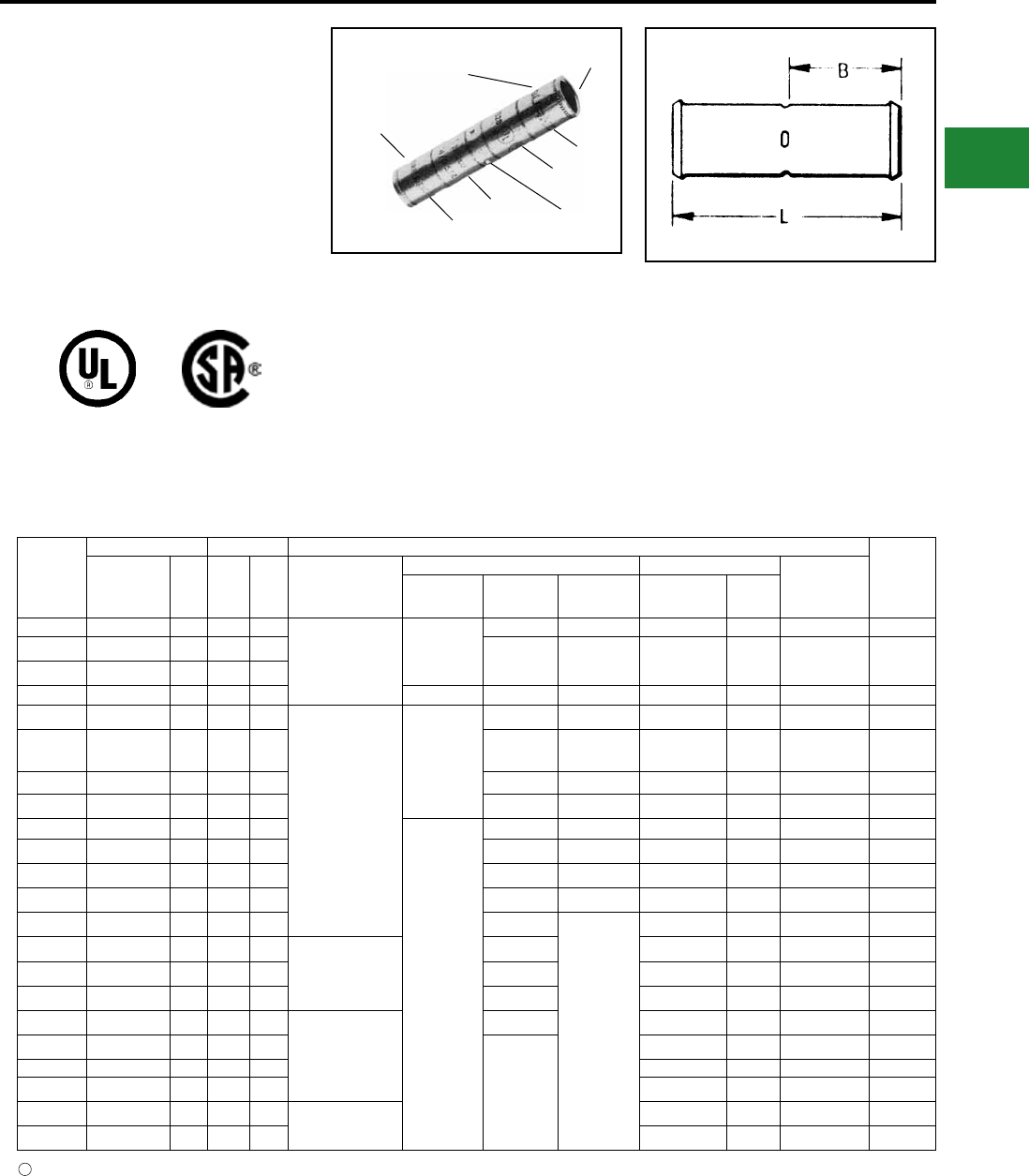
BURNDY®
Blue highlighted items are industry standard and most frequently ordered.
Canada: 1-800-387-6487 www.burndy.com US: 1-800-346-4175
TYPE YS
HYLINK™ SPLICE -
LONG BARREL
COPPER COMPRESSION
SPLICE
UL Listed 90° C,
600 Volts to 35 kV ♦Features & Benets
• Long barrel length
◊
Ideal for 600 volt heavy duty
applications
Also may be used at
higher voltages up to 35kV
• Four (4) center conductor stops
◊ Provides a center wire stop for
proper conductor insertion
• High pull out force
◊
Provides added security for much
greater
mechanical and electrical
properties
Catalog
Number
Conductor Dimensions Installation Tooling ▲
Wire
Strip
LengthAWG
***
MM² L B
Dieless
(# of crimps)
Mechanical Y35 ■, Y39, Y750, Y46* ▲
Die Index &
EmbossmentY1MRTC MD7-34R
MD6
OUR840
Die Number
(# crimps)
Color
Code
YS8C 8 Str. 10 1.75 0.78
Y81KFT (1)
Y81KFTMBH (1)
PAT81KFT-18V (1)
Y1MRTC (2)
W8CVT (2) X8CRT (2) U8CRT (2) Red 49 7/8″
YS6C 6 Str. — 2.38 1.09 W5CVT (2) X5CRT (2) U5CRT (2) Blue 7 or 374 1-3/16″
YS5C 5 Str. 16 2.55 1.09
YS4C 4 Str. — 2.55 1.09 Y1MRTC (4) W4CVT (2) X4CRT (2) U4CRT (2) Gray 8 or 346 1-3/16″
YS3C 3 Str. / 2 Sol. 25 2.80 1.22
Y81KFT (2)
Y81KFTMBH (2)
PAT81KFT-18V (2)
Y1MRTC (4)
— U3CRT (2) — White 9 1-5/16″
YR2C2WT 2 Str. / 2 Sol. 25 3.03 1.25 W2CVT (2)
W2CRT (2)
W2CVT (2)
W2CRT (2) U2CRT (2) Brown 10 1-5/8″
YS2C 2 Str. 35 2.82 1.22 W2CVT (2) X2CRT (2) U2CRT (2) Brown 10 1-5/16″
YS1C 1 Str. 50 3.07 1.34 W1CVT (2) X1CRT-1 (2) U1CRT-1 (2) Green 11 or 375 1-7/16″
YS25 1/0 Str. — 3.08 1.34
—
W25VT (4) X25RT (4) U25RT (2) Pink 12 or 348 1-7/16″
YS26 2/0 Str. 70 3.30 1.45 W26VT (4) X26RT (4) U26RT (2) Black 13 1-9/16″
YS27 3/0 Str. — 3.30 1.45 W27VT (4) X27RT (4) U27RT (2) Orange 14 1-9/16″
YS28 4/0 Str. — 3.57 1.58 W28VT (4) X28RT (4) U28RT (2) Purple 15 1-11/16″
YS29 250 kcmil 120 3.58 1.58 W29VT (4)
—
U29RT (2) Yellow 16 1-11/16″
YS30 300 kcmil 150 4.34 1.95 Y81KFT (3)
Y81KFTMBH (3)
PAT81KFT-18V (3)
W30VT (4) U30RT (4) White 17 or 298 2-1/16″
YS31 350 kcmil 185 4.35 1.95 W31VT (4) U31RT (4) Red 18 or 324 2-1/16″
YS32 400 kcmil — 4.62 2.08 W32VT (4) U32RT (4) Blue 19 or 470 2-3/16″
YS34 500 kcmil 240 4.91 2.2
Y81KFT (4)
Y81KFTMBH (4)
PAT81KFT-18V (4)
W34VT (4) U34RT (4) Brown 20 or 299 2-5/16″
YS36 600 kcmil 300 5.85 2.63
—
U36RT (4) Green 22 or 472 2-3/4″
YS39 750 kcmil — 6.38 2.81 U39RT (4) Black 24 2-15/16″
YS44 1000 kcmil 500 6.55 2.94 P44RT (2)** White 27 3-1/16″
YS46 1500 kcmil — 7.01 3.13 —P46RT (6)** Green 31 3-1/4″
YS48 2000 kcmil — 7.57 3.27 L48RT (4) Brown 34 3-3/8″
*** The MM2 conductor sizes listed are the recommendations
for Class 2 conductor.
■ The maximum size for the Y35 is 400 kcmil.
▲ See tooling section of this catalog for complete tool and
die listings
♦ For applications greater than 2000 Volts consult cable
manufacturer for voltage stress relief instructions.
† Requires Y60BHU HYPRESS™ with L48RT die set.
Note: All dimensions shown are for reference only.
BEVELED
ENTRY
(4) CENTER
WIRE STOPS
ELECTRO-TIN
PLATED
DIE AND COLOR
CODE INFORMATION
CRIMP
CRIMP
CRIMP
CRIMP
Not color coded.
* Use PUADP-1 adapter with U dies in Y46 HYPRESS™.
** P44RT for use with Y46 HYPRESS™ only. PUADP-1
adapter not required.
1
Compression Connections
Copper Compression — Code — Long Barrel — Splice
C-111
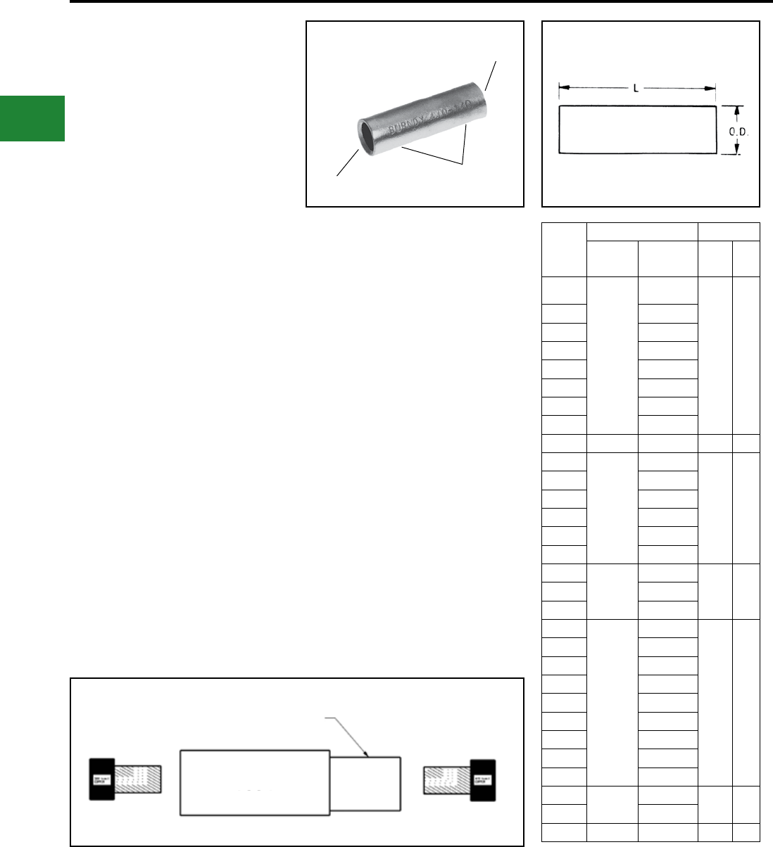
BURNDY®
Blue highlighted items are industry standard and most frequently ordered.
US: 1-800-346-4175 www.burndy.com Canada: 1-800-387-6487
TYPES Y-R
REDUCING ADAPTER
FOR COPPER
600 Volts to 35 kV ♦
The Y-R reducing adapter has been designed
to allow large size, long barrel, copper long
barrel. HYDENT™, HYSPLICE™ and HYTEE™
terminals, splices and T taps to be used on
smaller conductor sizes. To use, simply insert
the reducer into the barrel, insert the wire into
the reducer adapter and crimp the outer barrel
using its recommended tooling.
Features & Benets
• Wide range of conductors are
accommodated
◊ Lowers inventory requirements
and affords maximum versatility
• Same die set for all legs of the
connection
◊ Permits the same tool and die
combination normally used on the
compression barrel
• Length ts the long barrel connector design
(YS, YA)
◊ Can be used on all long barrel
connectors. Field cut to t shorter
length compression barrels
(YS-L, YA-L)
• Manufactured from high conductivity electro-
lytic copper and electro-tin plated
◊ Provides maximum conductivity
low resistance and ductility for an
excellent combination of electrical
and crimp forming properties
and provides long lasting corrosion
resistance
INTERNALLY
BEVELED ENDS
WIRE RANGE
ELECTRO-TIN
PLATED
Catalog
Number
Wire Range Dimensions
From To Max
O.D. L
Y286CR
4/0 Str.
6,8, Str. 6
Sol.
0.53 1.75
Y284WR 4 Sol.
Y284CR 4 Str.
Y282CR 2 Str.
Y281CR 1 Str.
Y2825R 1/0 Str.
Y2826R 2/0 Str.
Y2827R 3/0 Str.
Y2928R 250 kcmil 4/0 0.58 1.62
Y304CR
300 kcmil
#4
0.64 2.00
Y302CR #2
Y3025R 1/0
Y3026R 2/0
Y3027R 3/0
Y3028R 4/0
Y3126R
350 kcmil
2/0
0.69 2.00Y3128R 4/0
Y3129R 250
Y342CR
500 kcmil
2 Str.
0.82 2.50
Y3425R 1/0 Str.
Y3426R 2/0 Str.
Y3427R 3/0 Str.
Y3428R 4/0 Str.
Y3429R 250 kcmil
Y3430R 300 kcmil
Y3431R 350 kcmil
Y3432R 400 kcmil
Y3934R 750 kcmil 500 kcmil 1.02 2.88
Y3936R 600 kcmil
Y4439R 1000 kcmil 750 kcmil 1.30 3.00
Contact Technical Support for other sizes not listed.
♦ For applications greater than 2000 Volts consult
cable manufacturer for voltage stress relief instructions.
Note: All dimensions shown are for reference only.
Compression Connections
Copper Compression — Code — Reducing Adapter
Insert reducing adapter into splice connection as shown.
Crimp with U34RT, 4 crimps each side (a total of 8 crimps).
Y3428R
APPLICATION EXAMPLE
YS34
C-112
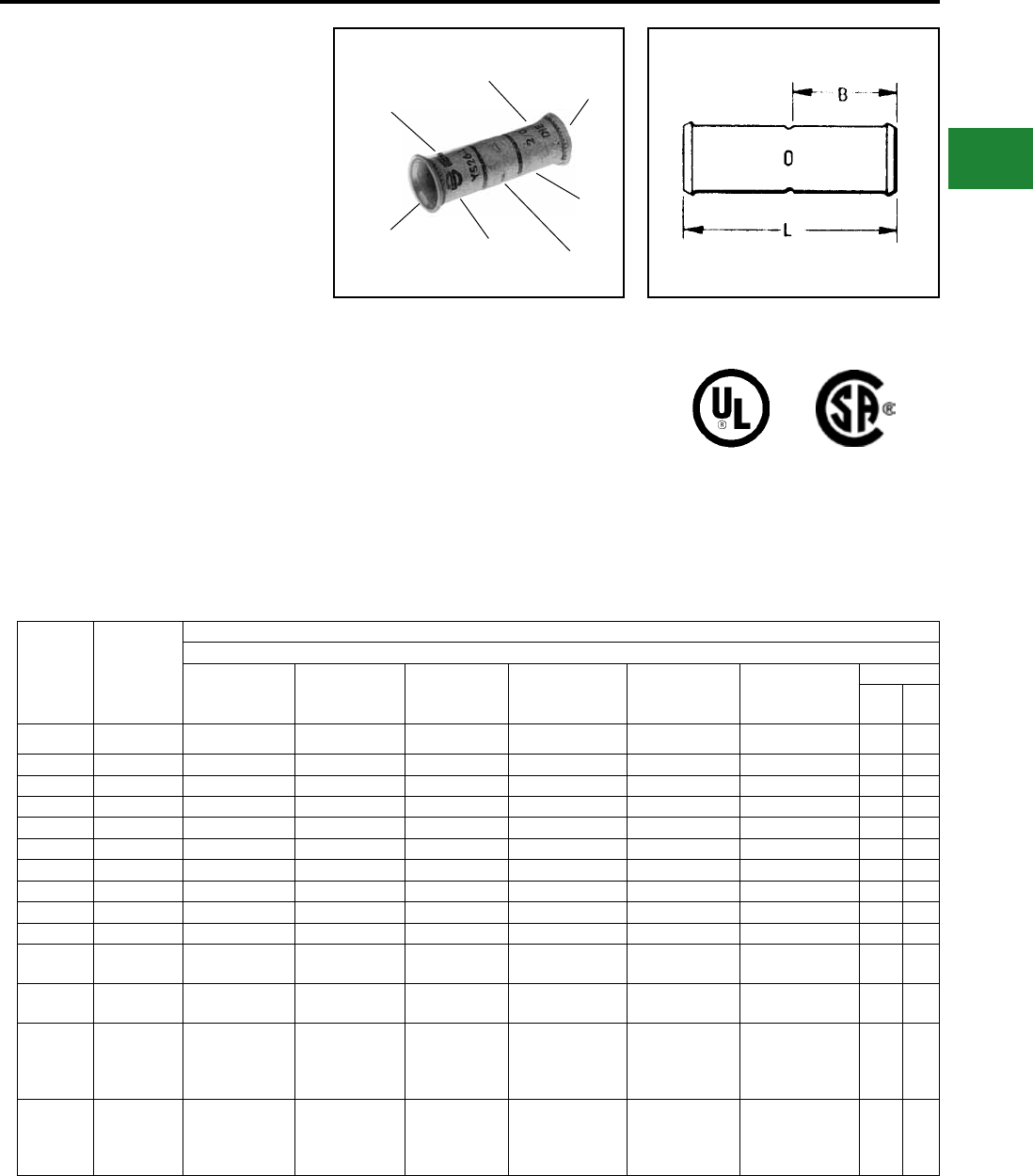
BURNDY®
Blue highlighted items are industry standard and most frequently ordered.
Canada: 1-800-387-6487 www.burndy.com US: 1-800-346-4175
TYPE YS-LB
HYLINK™
UNINSULATED
BELLED COPPER
COMPRESSION SPLICE
STANDARD LENGTH
BELLED BARREL
UL Listed 90° C,
600 Volts to 35 kV ♦
HYLINK™ type YS-LB splices are designed for
exible and extra exible copper conductors
used in mining machines, locomotives, welding
cables and other exible cable applications. The
seamless, high conductivity copper, electro-tin
plated belled barrel provides for easy insertion
of exible stranded conductors and the nest
indentor die system provides an excellent
electrical and mechanical connection.
Features & Benets
• Belled barrel ends
◊ Provides easy cable insertion into
the splice barrel and smooth cable
strain relief during cable exing
and movement
• Standard length barrel
◊ Permits easy passage around
pulleys yet is long enough for
easy crimping
DIE AND COLOR
CODE INFORMATION
ELECTRO-TIN
PLATED
(4) CENTER
WIRE STOP
BELLED
END
BELLED
END
CRIMP
CRIMP
Catalog
Number
Flex
Cable
Copper Cables *
Flexible and Extra Flexible Cables
Class G Class H Class I
Battery
Cable
Class K
Welding
Cable
Class M
Locomotive
Cable
Dimensions
B L
YS5C-LB 6 Flex #6 (49 str) #6 (133 str) #6 (63/24) #6 (266/30) #6 (665/34) #6 (61/24) 0.81 1.82
YS4C-LB 5 Flex #5 (49 str) #5 (133 str) #5 (84/24) #5 (336/30) #5 (836/34) #5 (91/24) 0.81 1.84
YS3C-LB 4 Flex #4 (49 str) #4 (133 str) #4 (105/24) #4 (420/30) #4 (1064/34) #4 (105/24) 0.88 1.96
YS2C-LB 3 Flex #3 (49 str) #3 (133 str) #3 (133/24) #3 (532/30) #3 (1323/24) #3 (125/24) 0.87 1.98
YS1C-LB 2 Flex #2 (49 str) #2 (133 str) #2 (161/24) #2 (665/30) #2 (1666/34) #2 (150/24) 0.87 1.97
YS25-LB 1 Flex #1 (133 str) #1 (259 str) #1 (210/24) #1 (836/30) #1 (2107/34) #1 (225/24) 0.87 2.00
YS26-LB 1/0 Flex 1/0 (133 str) 1/0 (259 str) 1/0 (266/24) 1/0 (1064/30) 1/0 (2646/34) 1/0 (275/24) 0.93 2.12
YS27-LB 2/0 Flex 2/0 (133 str) 2/0 (259 str) 2/0 (342/24) 2/0 (1323/30) 2/0 (3325/34) 2/0 (325/24) 0.99 2.24
YS28-LB 3/0 Flex 3/0 (133 str) 3/0 (259 str) 3/0 (418/24) 3/0 (1666/30) — 3/0 (450/24) 0.98 2.26
YS29-LB 4/0 Flex 4/0 (133 str) 4/0 (259 str) — — — — 1.04 2.40
YS30-LB 4/0 - 250 Flex 250 kcmil
(259 str)
250 kcmil
(427 str) 4/0 (532/24) 4/0 (2107/30) 4/0 (5320/34) 4/0 (550/24) 1.04 2.41
YS32-LB 300 kcmil 300 kcmil
(259 str)
300 kcmil
(427 str)
300 kcmil
(735/24)
300 kcmil
(2989/30)
300 kcmil
(7581/34)
313.1 kcmil
(775/24) 1.17 2.69
YS34-LB 350 kcmil
400 kcmil
350 kcmil
(259 str)
400 kcmil
(259 str)
350 kcmil
(427 str)
400 kcmil
(427 str)
350 kcmil
(882/24)
400 kcmil
(980/24)
350 kcmil
(3458/30)
350 kcmil
(8806/34)
373.7 kcmil
(925/24) 1.35 3.10
YS38-LB 500 kcmil 550 kcmil
(427 str)
550 kcmil
(703 str)
500 kcmil
(1225/24)
550 kcmil
(1372/24)
500 kcmil
(5054/30)
500 kcmil
(12691/34)
535.3 kcmil
(1325/24) 1.85 3.14
* Contact BURNDY® for conductors not shown.
Compression Connections
Copper Compression — Flex — Splice — Belled Ends
♦ For applications greater than 2000 Volts consult cable
manufacturer for voltage stress relief instructions.
Note: All dimensions shown are for reference only.
C-113
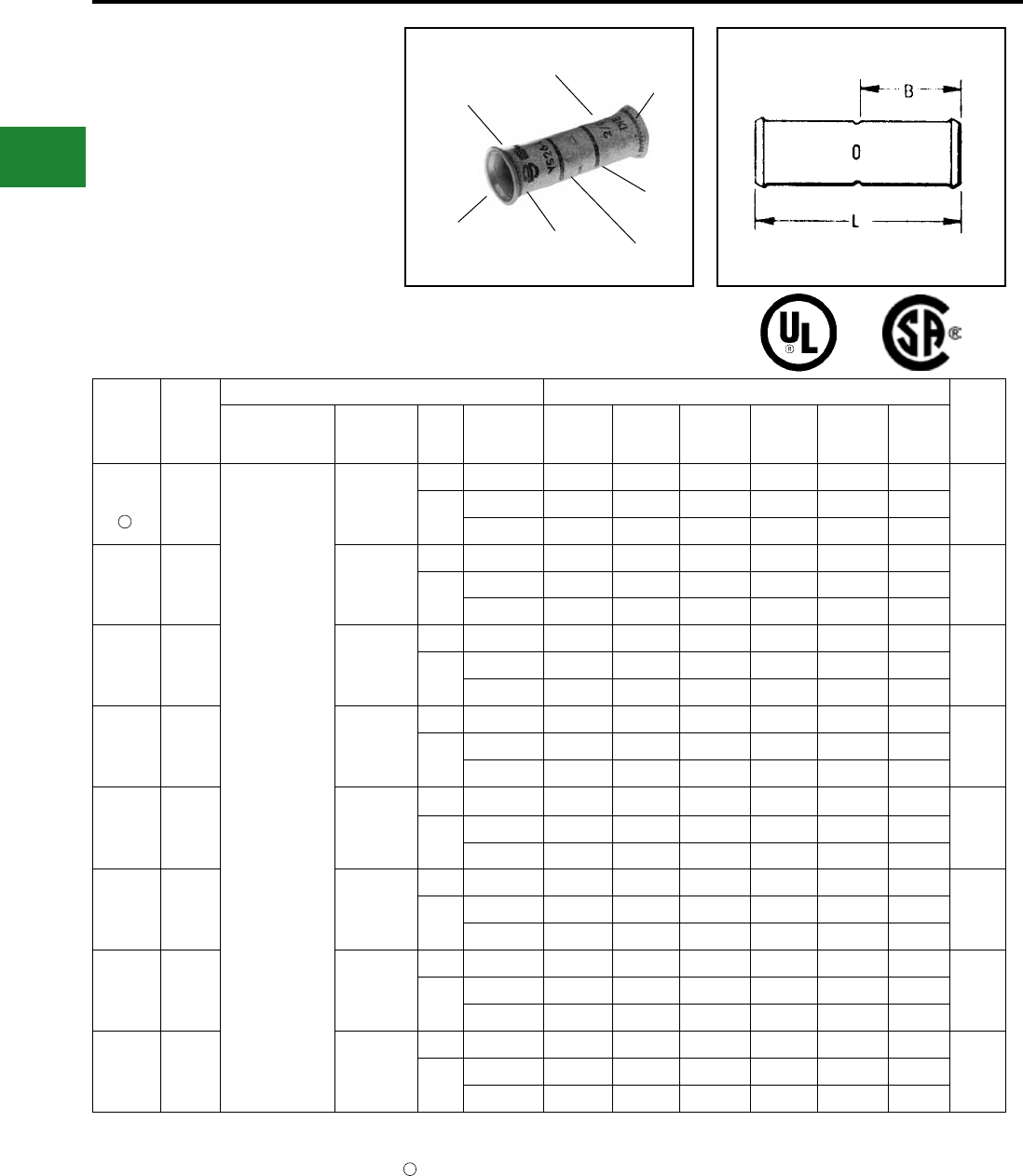
BURNDY®
Blue highlighted items are industry standard and most frequently ordered.
US: 1-800-346-4175 www.burndy.com Canada: 1-800-387-6487
TYPE YS-LB
INSTALLATION TOOLING
CHART
UNINSULATED
BELLED COPPER
COMPRESSION SPLICE
STANDARD LENGTH
BELLED BARREL
UL Listed 90° C,
600 Volts to 35 kV ♦
DIE AND COLOR
CODE INFORMATION
ELECTRO-TIN
PLATED
(4) CENTER
WIRE STOP
BELLED
END
BELLED
END
CRIMP
CRIMP
† Use Y35P3 adaptor with Y34PR indentor.
* Use PUADP-1 adaptor with U-DIES in
Y46 HYPRESS™.
▲ See Tooling section in this catalog for complete tool
and die listings.
Not color coded.
1
Catalog
Number
Flex
Cable
Installation Tooling ▲ Hydraulic
Wire
Strip
Length
Dieless
(# of Crimps)
Dieless
HYTOOL™
(# of crimps)
Die
Index
Die
Type Y35 † Y39 † Y750 † Y45 † Y46 * † Y60BHU
YS5C-LB 6 Flex
PAT644XT18V (1)
Y644HSXT (1)
Y644HSXTBH (1)
Y81KFT (1)
Y81KFTMBH (1)
PAT81KFT-18V (1)
MR4C
MY29-3
MY29-11
7 DIE SET U5CRT U5CRT U5CRT U5CRT U5CRT –
7/8"
1014 NEST U6CD-1 U6CD-1 U6CD-1 U6CD-1 U6CD-1 –
INDENTOR Y34PR Y34PR Y34PR Y34PR Y34PR –
YS4C-LB 5 Flex
MR4C
MY29-3
MY29-11
8 DIE SET U4CRT U4CRT U4CRT U4CRT U4CRT –
7/8"
1015 NEST U4CD-1 U4CD-1 U4CD-1 U4CD-1 U4CD-1 –
INDENTOR Y34PR Y34PR Y34PR Y34PR Y34PR –
YS3C-LB 4 Flex MY29-3
MY29-11
9 DIE SET U3CRT U3CRT U3CRT U3CRT U3CRT –
15/16"
1016 NEST U3CD-1 U3CD-1 U3CD-1 U3CD-1 U3CD-1 –
INDENTOR Y34PR Y34PR Y34PR Y34PR Y34PR –
YS2C-LB 3 Flex MY29-3
MY29-11
10 DIE SET U2CRT U2CRT U2CRT U2CRT U2CRT –
15/16"
1017 NEST U2CD-1 U2CD-1 U2CD-1 U2CD-1 U2CD-1 –
INDENTOR Y34PR Y34PR Y34PR Y34PR Y34PR –
YS1C-LB 2 Flex MY29-3
MY29-11
11 DIE SET U1CRT-1 U1CRT-1 U1CRT-1 U1CRT-1 U1CRT-1 –
15/16"
1018 NEST U1CD-1 U1CD-1 U1CD-1 U1CD-1 U1CD-1 –
INDENTOR Y34PR Y34PR Y34PR Y34PR Y34PR –
YS25-LB 1 Flex MY29-3
MY29-11
12 DIE SET U25RT U25RT U25RT U25RT U25RT –
15/16"
1019 NEST U25D-1 U25D-1 U25D-1 U25D-1 U25D-1 –
INDENTOR Y34PR-2 Y34PR-2 Y34PR-2 Y34PR-2 Y34PR-2 –
YS26-LB 1/0 Flex MY29-3
MY29-11
13 DIE SET U26RT U26RT U26RT U26RT U26RT –
1"
1020 NEST U26D-1 U26D-1 U26D-1 U26D-1 U26D-1 –
INDENTOR Y34PR-2 Y34PR-2 Y34PR-2 Y34PR-2 Y34PR-2 –
YS27-LB 2/0 Flex MY29-3
MY29-11
14 DIE SET U27RT U27RT U27RT U27RT U27RT –
1-1/16"
1021 NEST U27D-1 U27D-1 U27D-1 U27D-1 U27D-1 –
INDENTOR Y34PR-2 Y34PR-2 Y34PR-2 Y34PR-2 Y34PR-2 –
1
Compression Connections
Copper Compression — Flex — Splice — Belled Ends
♦ For applications greater than 2000 Volts consult
cable manufacturer for voltage stress relief
instructions.
Note: All dimensions shown are for reference only.
C-114
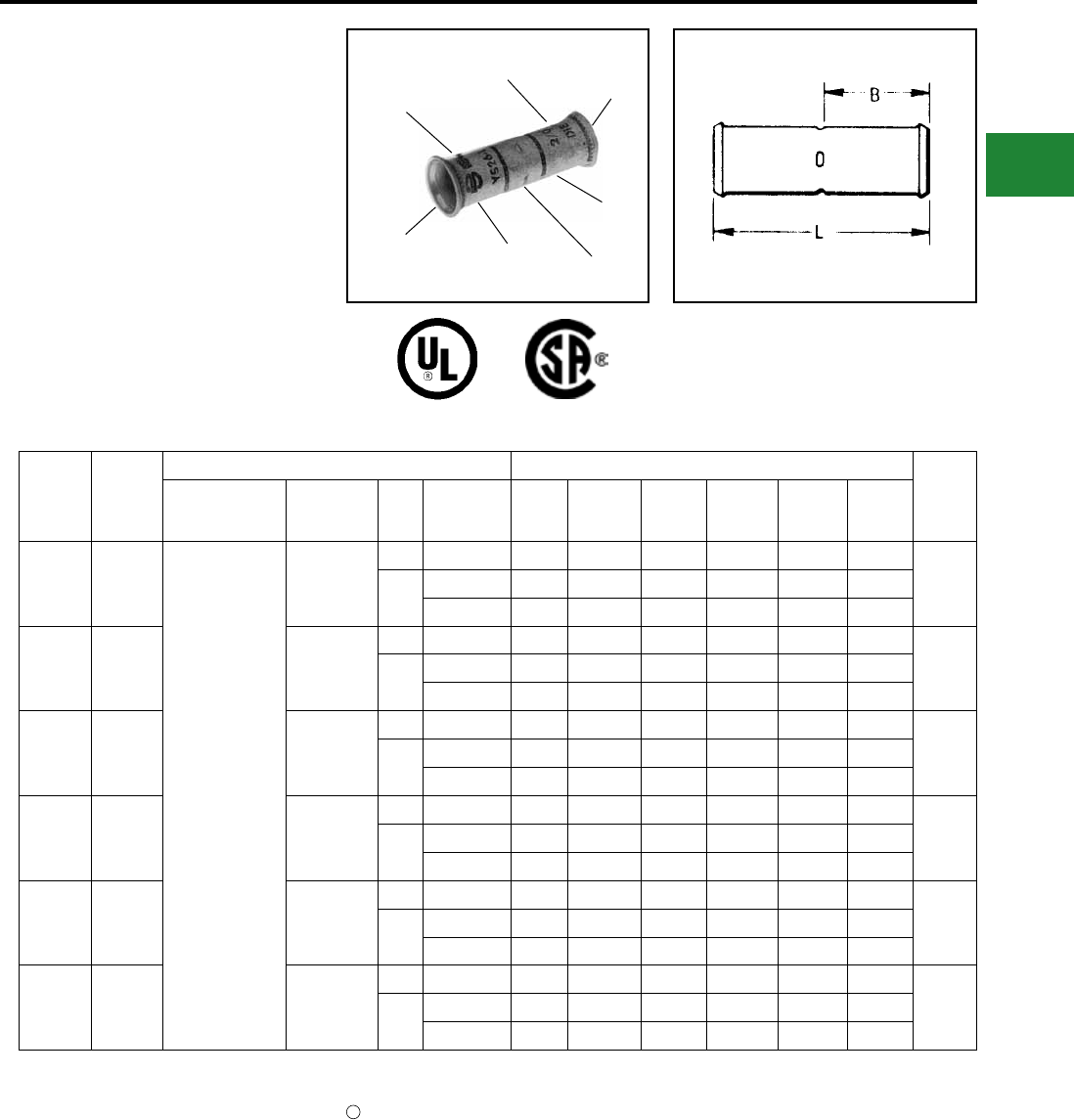
BURNDY®
Blue highlighted items are industry standard and most frequently ordered.
Canada: 1-800-387-6487 www.burndy.com US: 1-800-346-4175
Catalog
Number
Flex
Cable
Installation Tooling ▲ Hydraulic
Wire
Strip
Length
Dieless
(# of Crimps)
Dieless
HYTOOL™
(# of crimps)
Die
Index
Die
Type Y35 † Y39 † Y750 † Y45 † Y46* † Y60BHU
YS28-LB 3/0 Flex
PAT644XT18V (2)
Y644HSXT (2)
Y644HSXTBH (2)
Y81KFT (2)
Y81KFTMBH (2)
PAT81KFT-18V (2)
MY29-3
MY29-11
15 DIE SET U28RT U28RT U28RT U28RT U28RT –
1-1/16"
1022 NEST – U28D-1 U28D-1 U28D-1 U28D-1 –
INDENTOR – Y34PR-2 Y34PR-2 Y34PR-2 Y34PR-2 –
YS29-LB 4/0 Flex MY29-3
MY29-11
16 DIE SET U29RT U29RT U29RT U29RT U29RT –
1-1/16"
1023 NEST – U29D-1 U29D-1 U29D-1 U29D-1 –
INDENTOR – Y34PR-2 Y34PR-2 Y34PR-2 Y34PR-2 –
YS30-LB 4/0-250
Flex ─
17 DIE SET U30RT U30RT U30RT U30RT U30RT L30RT
1-1/8"
1024 NEST – U30D-1 U30D-1 U30D-1 U30D-1 –
INDENTOR – Y34PR-2 Y34PR-2 Y34PR-2 Y34PR-2 –
YS32-LB 300
kcmil ─
19 DIE SET U32RT U32RT U32RT U32RT U32RT L32RT
1 1/4"
1026 NEST – U32D-1 U32D-1 U32D-1 U32D-1 –
INDENTOR – Y34PR-2 Y34PR-2 Y34PR-2 Y34PR-2 –
YS34-LB 300 kcmil
400 kcmil ─
20 DIE SET – U34RT U34RT U34RT U34RT L34RT
1 7/16"
1027 NEST – U34D-1 U34D-1 U34D-1 U34D-1 –
INDENTOR – Y34PR-2 Y34PR-2 Y34PR-2 Y34PR-2 –
YS38-LB 550
kcmil ─
400 DIE SET U38RT U38RT U38RT U38RT U38RT –
1 15/16"
1029 NEST – – – – P38D –
INDENTOR – – – – P48PR-1 –
TYPE YS-LB
(Continued)
INSTALLATION TOOLING
CHART
UNINSULATED
BELLED COPPER
COMPRESSION SPLICE
STANDARD LENGTH
BELLED BARREL
UL Listed 90° C,
600 Volts to 35 kV ♦
DIE AND COLOR
CODE INFORMATION
ELECTRO-TIN
PLATED
(4) CENTER
WIRE STOP
BELLED
END
BELLED
END
CRIMP
CRIMP
† Use Y35P3 adaptor with Y34PR indentor.
* Use PUADP-1 adaptor with U-DIES in Y46 HYPRESS™.
▲ See Tooling section in this catalog for complete tool
and die listings.
Not color coded.
1
Compression Connections
Copper Compression — Flex — Splice — Belled Ends
♦ For applications greater than 2000 Volts consult
cable manufacturer for voltage stress relief instructions.
Note: All dimensions shown are for reference only.
C-115
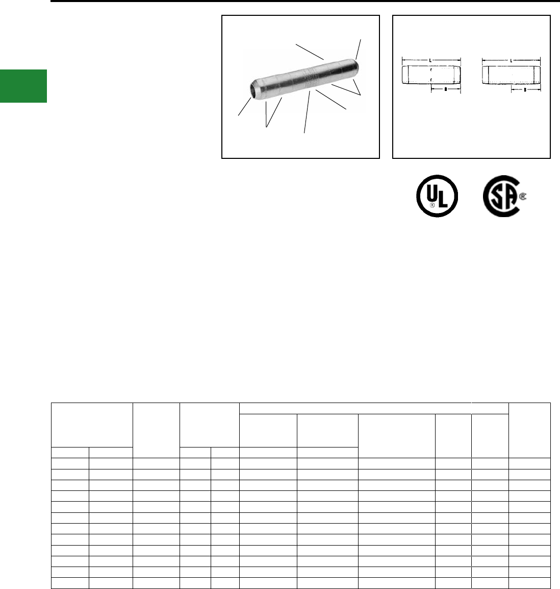
BURNDY®
Blue highlighted items are industry standard and most frequently ordered.
US: 1-800-346-4175 www.burndy.com Canada: 1-800-387-6487
TYPES YS-T AND YSP-T
HIGH-VOLTAGE HYLINK™
UNINSULATED HIGH
VOLTAGE COPPER
COMPRESSION SPLICE
STANDARD BARREL -
TAPERED ENDS
UL Listed 90° C,
600 Volts to 35 kV ♦
Seamless types YS-T and YSP-T high
conductivity copper electro-tin plated
compression HYLINK™ high-voltage splices
with standard barrel and tapered ends are
ideally suited for higher voltage applications
from 5 kV through 35 kV.
Type YS-T splice connector has four center wire
stops for proper conductor insertion.
Type YSP-T splice connector has a brazed in
place center plug to prevent the passage of oil
between two oil lled conductors or between
conductors without oil and conductors with
oil and acts as a center wire stop for proper
conductor insertion.
Features & Benets
• Tapered connector ends per EEI
standard TD160
◊ Suitable for use on voltages 5 kV
through 35 kV to aid in preventing
corona emission and simplify
taping thus lowering installed cost
• Type YS-T four center wire stops
◊ Provides a center wire stop for
proper conductor insertion
• Type YSP-T has a center plug
permanently brazed in place
◊ Prevents oil within oil-lled
conductors from passing through
the splice connector and provides
a center strip for proper conductor
insertion
YS-T YSP-T
CENTER OIL STOP
ELECTRO-TIN
PLATED
BRAZED CENTER
OIL STOP PLUG
(TYPE YSP-T)
(4) CENTER
WIRE STOPS
(TYPE YS-T)
TAPERED
END
CRIMPING
INFORMATION
CRIMP
CRIMP
Catalog Number Code
Conductors
Dimensions
Installation Tooling- Nest/Indentor ▲
Wire
Strip
Length
Y34B
Y34PR
Indentor
Y35, Y39, Y750,
Y34PR Indentor
Y35P3 Adaptor
Y35, Y39, Y750,
Y46*, PAT750
Die Number
(# of crimps per end)
Die
Index ▲
No. of
IndentYS-T YSP-T B L Nest Die Nest Die
YS6C-T** — 6 Str. 0.90 2.16 B6CD U6CD-1 U5CRT (2) 7 1 15/16″
YS4C-T** YSP4C-T** 4 Str. 0.90 2.16 B4CD U4CD-1 U4CRT (2) 8 1 15/16″
YS2C-T** YSP2C-T** 2 Str. 0.98 2.34 B2CD U2D-1 U2CRT (2) 10 1 1″
YS1C-T** YSP1C-T** 1 Str. 0.97 2.31 B1CD U1D-1 U1CRT-1 (2) 11 1 1″
YS25-T** YSP25-T** 1/0 Str. 0.98 2.35 B25D U25D-1 U25RT (2) 12 1 1-3/32″
YS26-T** YSP26-T** 2/0 Str. 1.04 2.47 B26D U26D-1 U26RT (2) 13 1 1-3/32″
YS28-T YSP28-T 4/0 Str. 1.13 2.67 B28D U28D-1 U28RT (2) 15 1 1-3/16″
YS29-T YSP29-T 250 kcmil 1.21 2.85 B29D U29D-1 U29RT (2) 16 1 1-3/32″
YS30-T YSP30-T 300 kcmil 1.22 2.87 B30D U30D-1 U30RT (4) 17 2 1-5/16″
YS31-T YSP31-T 350 kcmil 1.32 3.09 B31D U31D-1 U31RT (4) 18 2 1-3/5″
YS34-T YSP34-T 500 kcmil 1.68 3.86 No Die Needed U34D-1 U34RT (4) 20 2 1-3/4″
YS39-T YSP39-T 750 kcmil 2.00 4.60 — — U39RT (4) 24 2 2-1/8″
* Use adapter PUADP-1 with U Dies in Y46
HYPRESS™. Y46 HYPRESS™ uses the same nest
indentor and adaptor as the Y35, Y39 and Y750, but
with the PUADP-1 adaptors.
** A 0.06 radius at each end is used for sizes 6-27.
■ The maximum size for the Y35 is 400 kcmil.
▲ See tooling section of this catalog for complete tool
and die listings.
♦ For applications greater than 2000 Volts consult cable
manufacturer for voltage stress relief instructions.
Note: All dimensions shown are for reference only.
Compression Connections
Copper Compression — Code — Splice — Tapered Ends
C-116
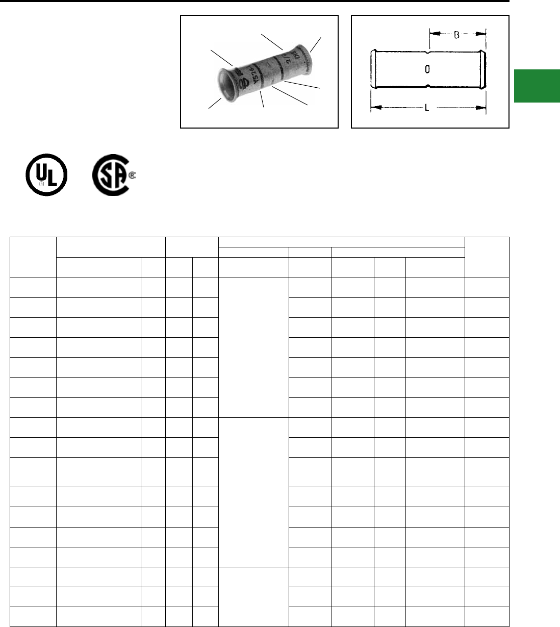
BURNDY®
Blue highlighted items are industry standard and most frequently ordered.
Canada: 1-800-387-6487 www.burndy.com US: 1-800-346-4175
TYPE YS-FXB
HYLINK™ - SPLICE - BELLED
LONG BARREL
UL Listed 90° C,
600 Volts to 35 kV ♦
Features & Benets
• Long barrel length
◊ High voltage terminations
• Four (4) center conductor stops
◊ Provides a center wire stop for
proper conductor insertion
• High pull out force
◊
Provides added security for greater
mechanical and electrical properties
• Belled cable entry
◊ A funnel type entry provide easy
insertion of extra exible cables
plus offers mechanical strain relief
for individual strands
Catalog
Number
Conductor Dimensions
Installation Tooling
Cable
Strip
Length
Mechanical Y35 ■, Y39, Y750, Y46*
Flexible Cable
Code AWG
***
MM²
L
(mm)
B
(mm)
Dieless
(# of crimps/end) Y1MRTC
Embossed
Die Index
Color
Code
Die Number
(# of crimps/end)
YS8C-FXB #8 Str. (37/24)
#8 AWG 10 1.99
(51)
0.90
(23)
Y81KFT (1)
Y81KFTMBH (1)
PAT81KFT-18V (1)
Y1MRTC (2) 49 Red U8CRT (2) 1″
(25)
YSV6C-FXB #6 Str. (61/24)
#6 AWG
†
16
2.62
(67)
1.22
(31) Y1MRTC (2) 7 Blue U5CRT (2) 1-5/16″
(33)
YSV4C-FXB #4 Str. (91/24-105/24)
#4 AWG —2.62
(67)
1.22
(31) Y1MRTC (4) 8 Gray U4CRT (2) 1-5/16″
(33)
YSV2C-FXB #2 Str. (125/24-105/24)
#2 AWG 35 2.89
(73)
1.35
(34) Y1MRTC (4) 10 Brown U2CRT (2) 1-7/16″
(37)
YSV1C-FXB #1 Str. (175/24-225/24)
#1 AWG —3.18
(81)
1.50
(38) — 11 Green U1CRT-1 (2) 1-9/16″
(40)
YSV25-FXB 1/0 Str. (275/24)
1/0 AWG 50 3.18
(81)
1.50
(38) — 12 Pink U25RT (2) 1-9/16″
(40)
YSV26-FXB 2/0 Str. (325/24)
2/0 AWG 70 3.44
(87)
1.63
(41) — 13 Black U26RT (2) 1-11/16″
(43)
YSV27-FXB 3/0 Str. (450/24)
3/0 AWG 95 3.46
(88)
1.64
(42)
Y81KFT (2)
Y81KFTMBH (2)
PAT81KFT-18V (2)
— 14 Orange U27RT (2) 1-11/16″
(43)
YSV28-FXB 4/0 Str. (550/24)
4/0 AWG
†
120
3.72
(94)
1.77
(45) — 15 Purple U28RT (2) 1-7/8″
(48)
YS30-FXB
250 kcmil Flex
Class G 259 Str.
Class H 427 Str.
—4.51
(115)
2.16
(55) — 16 Yellow U29RT (2) 2-1/4″
(57)
YS31-FXB 263 kcmil (650/24)
250 Flex Class I,K,M 150 4.54
(115)
2.18
(55) — 17 White U30RT (4) 2-1/4″
(57)
YS32-FXB 313.1 kcmil (775/24)
300 kcmil Nom. 185 4.82
(122)
2.32
(59) — 18 Red U31RT (4) 2-7/16″
(62)
YS34-FXB 373 kcmil (925/24)
350 kcmil Nom. 240 5.14
(131)
2.48
(63) — 19 Blue U32RT (4) 2-9/16″
(65)
YS36-FXB 444.4 kcmil (1100/24)
450 kcmil Nom. 300 6.09
(155)
2.95
(75) — 20 Brown U34RT (4) 3-1/16″
(79)
YS38-FXB 535.3 kcmil (1325/24)
500 kcmil Nom. —6.34
(161)
3.08
(78) Y81KFT (3)
Y81KFTMBH (3)
PAT81KFT-18V (3)
— L99 Pink U38XRT (4) 3-3/16″
(81)
YS40-FXB 646 kcmil (1600/24)
600 kcmil Nom. 400 6.66
(1.69)
3.24
(82) — 24 Black U39RT (4) 3-5/16″
(84)
YS44-FXB 777.7 kcmil (1925/24)
750 kcmil Nom. 500 6.84
(174)
3.33
(85) — L115 Yellow U44XRT (4) 3-7/16″
(87)
* Use PUADP-1 adapter with U dies in Y46 HYPRESS™.
** P44RT and P46RT dies sets are for use with
Y46 HYPRESS™ only. PUADP-1 adapter not required.
*** The MM2 conductor sizes listed are the recommendations
for Class 5 conductor.
† 16 MM2 and 120 MM2 referenced are for both Class 2 and
Class 5
■ The maximum size for the Y35 is 373.7 kcmil.
▲ See tooling section of this catalog for complete tool and
die listings.
♦ For applications greater than 2000 Volts consult cable
manufacturer for voltage stress relief instructions.
Note: All dimensions shown are for reference only.
Measurements in brackets [ ] are in metric dimensions.
Compression Connections
Copper Compression — Flex — Splice — Long Barrel — Belled Ends
DIE AND COLOR
CODE INFORMATION
ELECTRO-TIN
PLATED
(4) CENTER
WIRE STOP
BELLED
END
BELLED
END
CRIMP
CRIMP
C-117
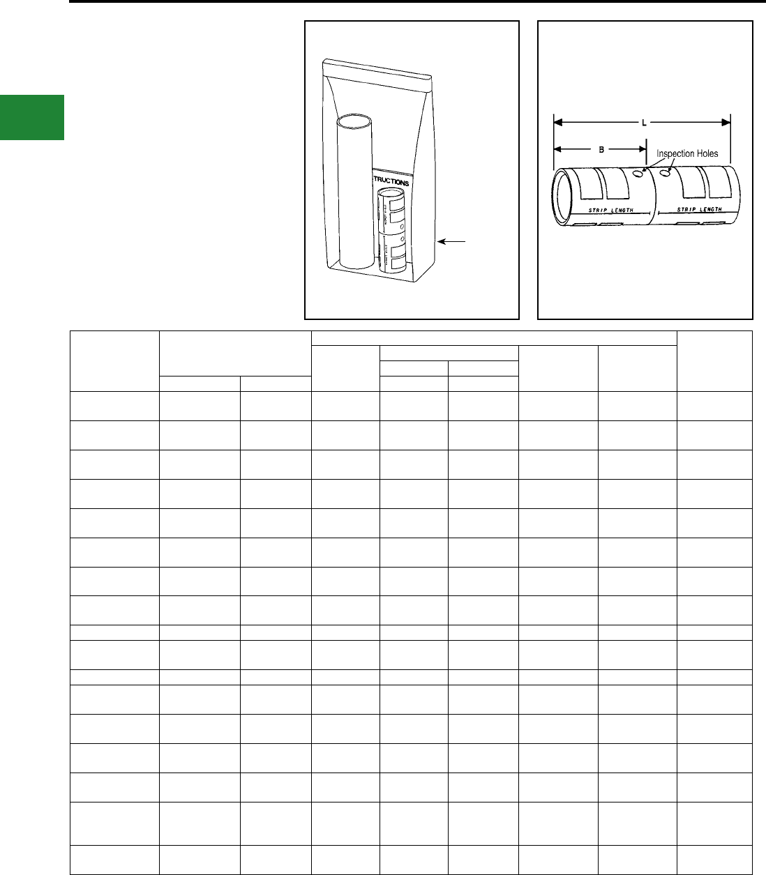
BURNDY®
Blue highlighted items are industry standard and most frequently ordered.
US: 1-800-346-4175 www.burndy.com Canada: 1-800-387-6487
TYPE YS-TC
HYSPLICE™
In-line Splice Kits for
Telecommunications Applications
YS-TC kits are for splicing cables and covering
the connection with clear heat shrink. Splices are
constructed from seamless, high conductivity
electrolytic copper tubing for maximum
conductivity and tin-plated to resist corrosion.
Each YS-TC splice is provided with inspection
holes and cable stops. The YS-TC family also
features the BURNDY® color code system.
* Clear
Heat Shrink Kit
Catalog Number
Wire Size
Connector
Wire
Strip
Length
Barrel
Type
Dimensions
Color
Code
Die
Index
Barrel Length
AWG mm² B L
YS44FXLTCKITC 750 kcmil
Flex
500 mm²
Class 5 Standard 1.90 4.30 Yellow L115 1.96
YS39LTCKITC 750 kcmil
Code — Standard 1.62 3.68 Black 23 1.67
YS38FXLTCKITC 500 kcmil
Flex
300 mm²
Class 5 Standard 1.71 3.87 Pink L99 1.77
YS34LTCKITC 500 kcmil
Code
240 mm²
Class 2 Standard 1.56 3.51 Brown 20 1.60
YS34FXLTCKITC 350 kcmil
Flex
240 mm²
Class 2 Standard 1.56 3.51 Blue 19 or
L80 1.60
YS31LTCKITC 350 kcmil
Code
185 mm²
Class 2 Standard 1.39 3.10 Red 17 1.42
YS29FXLTCKITC 4/0 AWG
Flex — Standard 1.36 2.98 Yellow 16 1.38
YS28LTCKITC 4/0 AWG
Code — Standard 1.23 2.69 Purple 15 1.24
YS26LTCKITC 2/0 AWG Code 70 mm² Standard 1.16 2.62 Black 13 1.10
YS26FXLTCKITC 2/0 AWG
Flex or Code
70 mm²
Class 5 Standard 1.09 2.41 Black 13 1.10
YS25LTCKITC 1/0 AWG Code — Standard 1.04 2.37 Pink 12 1.00
YS25FXLTCKITC 1/0 AWG
Flex or Code
50 mm²
Class 5 Standard 1.04 2.18 Pink 12 1.00
YS2CLTCKITC #2 AWG
Code
35 mm²
Class 5 Standard 0.82 1.88 Brown 10 0.78
YS2CFXLTCKITC #2 AWG
Flex or Code
35 mm²
Class 5 Standard 0.82 1.73 Brown 10 0.78
YS4CFXLTCKITC #4 AWG
Flex or Code — Standard 0.74 1.69 Gray 8 0.71
YS6CFXLTCKITC #6 AWG
Flex or Code
16 mm²
Class 5 or
Class 2
Standard 0.73 1.60 Blue 7 or
24 0.70
YS8CFXLTCKITC #8 AWG
Flex or Code — Standard 0.65 1.48 Red 49 0.62
Plastic
Bag/Kit
* Clear Heatshrink – UL224 VW1 Listed – passes
TELCORDIA GR-347-CORE Abrasion and Cut Test.
(Up to 750 kcmil Class B code cable. Contact factory for
750 ex cable applications.)
Compression Connections
Copper Compression — In Line Splice Kit — Code and Flex — Inspection Window
Note: All dimensions shown are for reference only.
C-118
BURNDY®
Blue highlighted items are industry standard and most frequently ordered.
Canada: 1-800-387-6487 www.burndy.com US: 1-800-346-4175
TYPE YSR-TC
HYREDUCER™
In-line Reducer Splice Kits for
Telecommunications
Applications
YSR-TC reducing splice kits provide for splicing
two different cable sizes with inspection holes.
The larger conductor is inserted rst and butts
against the center of the connector where
the smaller barrel begins. Constructed from
seamless, high conductivity electrolytic copper
tubing for maximum conductivity and tin plated
to resist corrosion. The YSR-TC family also
features the BURNDY® color code system.
Plastic
Bag/Kit
**Clear
Heat Shrink Kit
Catalog Number
Wire Size Connector Wire
Strip
LengthBarrel A Barrel B
Barrel
Type
Dimensions Color Code Die Index
AWG mm² AWG mm²
Barrel
A
Barrel
B L
Barrel
A
Barrel
B
Barrel
A
Barrel
B
Barrel
A
Barrel
B
YSR44FX39LTCKITC
750 kcmil
Flex
500 mm²
Class 5
750 kcmil Code —
Standard
2.09 1.78 4.38
Yellow
Black
L115
24
1.96
1.67
YSR44FX38FXLTCKITC 500 kcmil Flex 300 mm² 2.09 1.60 4.61 Pink L99 1.77
YSR44FX34LTCKITC 500 kcmil Code 240 mm² 2.09 1.69 4.91 Brown 20 1.60
YSR44FX34FXLTCKITC 350 kcmil Flex 240 mm² 2.09 1.69 4.91 Blue 19 or
L80 I.60
YSR44FX31LTCKITC 350 kcmil Code 185 mm² 2.09 1.49 5.18 Red 18 I.41
YSR44FX30LTCKITC 300 kcmil Code 150 mm² 2.09 1.30 5.01 White 17 or
298 1.24
YSR44FX29FXLTCKITC † 4/0 AWG Flex 120 mm² 2.09 1.44 5.33 Yellow 16 I.38
YSR44FX28FXLTCKITC † 4/0 AWG Flex or
Telco Flex 120 mm² 2.09 1.43 5.46 Purple 15 1.36
YSR44FX29LTCKITC † 250 kcmil Code — 2.09 1.44 5.53 Yellow 16 1.38
YSR44FX28LTCKITC † 4/0 AWG Code — 1.78 1.30 5.27 Purple 15 1.24
YSR3939LTCKITC
750 kcmil
Code —
750 kcmil Code — 1.78 1.78 4.13
Black
Black
24
24
1.67
1.67
YSR3938FXLTCKITC 500 kcmil Flex 300 mm² 1.78 1.88 3.79 Pink L99 1.77
YSR3934LTCKITC 500 kcmil Code 240 mm² 1.78 1.69 4.09 Brown 20 1.60
YSR3934FXLTCKITC 350 kcmil Flex 240 mm² 1.78 1.69 4.09 Blue 19 or
L80 1.60
YSR3931LTCKITC 350 kcmil Code 185 mm² 1.78 1.49 4.36 Red 18 1.41
YSR3930LTCKITC 300 kcmil Code 150 mm² 1.78 1.30 4.23 White 17 or
298 1.24
YSR3929LTCKITC † 250 kcmil Code — 1.78 1.44 4.71 Yellow 16 1.38
YSR3929FXLTCKITC 4/0 AWG Flex 120 mm² 1.78 1.44 4.59 Yellow 16 1.38
YSR3928FXLTCKITC † 4/0 AWG Flex or
Telco Flex 120 mm² 1.78 1.43 4.64 Purple 15 1.36
YSR3928LTCKITC † 4/0 AWG Code — 1.78 1.30 4.65 Purple 1.24
YSR38FX34LTCKITC 500 kcmil
Flex 300 mm²
500 kcmil Code 240 mm² 1.88 1.69 4.06
Pink
Brown
L99
20
1.77 1.60
YSR38FX34FXLTCKITC 350 kcmil Flex 240 mm² 1.88 1.69 4.06 Blue 19 or
L80
† Provided with 2 heat shrink tubings. One will overlap
the other. Install the smaller first and larger second.
** Clear Heatshrink – UL224 VW1 Listed – passes
TELCORDIA GR-347-CORE Abrasion and Cut Test.
(Up to 750 kcmil Class B code cable. Contact factory
for 750 flex cable applications.)
Note 1: All dimensions shown are for reference only.
Note 2: Non-inspection window versions are available.
Please contact customer service.
Note 3: Installation Tooling Charts on pages C-94 - C-99.
Compression Connections
Copper Compression — Reducing Splice Kit — Code and Flex — Inspection Window
C-119

BURNDY®
Blue highlighted items are industry standard and most frequently ordered.
US: 1-800-346-4175 www.burndy.com Canada: 1-800-387-6487
TYPE YSR-TC
HYREDUCER™
(Continued)
In-line Reducer Splice Kits for
Telecommunications
Applications
Plastic
Bag/Kit
**Clear
Heat Shrink Kit
Catalog Number
Wire Size Connector Wire
Strip
LengthBarrel A Barrel B
Barrel
Type
Dimensions Color Code Die Index
AWG mm² AWG mm²
Barrel
A
Barrel
B L
Barrel
A
Barrel
B
Barrel
A
Barrel
B
Barrel
A
Barrel
B
YSR38FX31LTCKITC
500 kcmil
Flex 300 mm²
350 kcmil Code 185 mm²
Standard
1.88 1.49 4.33
Pink
Red
L99
18
1.77
1.41
YSR38FX30LTCKITC 300 kcmil Code 150 mm² 1.88 1.30 4.2 White 17 or
298 1.24
YSR38FX29LTCKITC † 250 kcmil Code — 1.88 1.44 4.67 Yellow 16 1.38
YSR38FX29FXLTCKITC † 4/0 AWG FLEX-
CLASS I,K,M 120 mm² 1.88 1.44 4.48 Yellow 16 1.38
YSR38FX28FXLTCKITC † 4/0 AWG FLEX 1.88 1.43 4.6 Purple 15 1.36
YSR38FX28LTCKITC † 4/0 AWG Str. — 1.88 1.30 4.62 Purple 15 1.24
YSR38FX26FXLTCKITC † 2/0 AWG
FLEX-Str.
70 mm²
Class 5 1.88 1.13 4.62 Black 13 1.09
YSR3434FXLTCKITC
500 kcmil
Code 240 mm²
350 kcmil Flex 240 mm² 1.69 1.69 3.51
Brown
Blue
20
19 or
L80
1.60
1.60
YSR3431LTCKITC 350 kcmil Code 185 mm² 1.69 1.49 3.66 Red 18 1.41
YSR3429FXLTCKITC 4/0 AWG Flex
120 mm²
1.69 1.44 3.81 Yellow 16 1.38
YSR3428FXLTCKITC 4/0 AWG Flex or
Telco Flex 1.69 1.43 3.93 Purple 15 1.36
YSR3428LTCKITC 4/0 AWG Code — 1.69 1.30 3.95 Purple 1.24
YSR3426FXLTCKITC † 2/0 AWG
Flex- Str.
70 mm²
Str.-Flex 1.69 1.13 4.01 Black 13 1.09
YSR3425FXLTCKITC † 1/0 AWG
Flex- Str. 50 mm² 1.69 1.04 4.01 Pink 12 1.00
YSR34FX31LTCKITC
350 kcmil
Flex 240 mm²
350 kcmil Code 185 mm² 1.69 1.49 3.63
Blue
Red
19 or
L80
18
1.60
1.41
YSR34FX29FXLTCKITC 4/0 AWG Flex 120 mm² 1.69 1.44 3.81 Yellow 16 1.38
YSR34FX28FXLTCKITC 1.69 1.43 3.86 Purple 15 1.36
YSR34FX28LTCKITC 4/0 AWG Code — 1.69 1.30 3.95 1.24
YSR34FX26FXLTCKITC 2/0 AWG
Flex or Code
70 mm²
Class 5 1.69 1.13 3.94 Black 13 1.09
YSR34FX25FXLTCKITC 1/0 AWG
Flex or Code 50 mm² 1.69 1.04 4.01 Pink 12 1.00
YSR34FX2CFXLTCKITC #2 AWG
Flex or Code 35 mm² 1.69 0.82 4.02 Brown 10 0.78
YSR34FX4CFXLTCKITC† † #4 AWG
Flex or Code — 1.69 0.74 4.11 Gray 8 0.71
YSR34FX6CFXLTCKITC† † #6 AWG
Flex or Code 16 mm² 1.69 0.73 4.26 Blue 7 0.70
YSR32FX29FXLTCKITC 300 kcmil
Flex
185 mm²
Class 2
4/0 AWG Flex
120 mm²
1.57 1.44 3.50
Red
Yellow 19 or
L80
16
1.48
1.38
YSR32FX28FXLTCKITC 4/0 AWG Flex or
Telco Flex 1.57 1.43 3.46 Purple 15 1.36
YSR3129FXLTCKITC 350 kcmil
Code
185 mm²
Class 2
4/0 AWG Code 1.49 1.44 3.13 Yellow 18 16
1.41
1.38
YSR3128FXLTCKITC 4/0 AWG Flex or
Telco Flex 1.49 1.43 3.25 Purple 19 or
L80 15 1.36
† Provided with 2 heat shrink tubings. One will overlap the
other. Install the smaller first and larger second.
† † Provided with 4 heat shrink tubings. Install the smaller
first and continue with the next size.
** Clear Heatshrink – UL224 VW1 Listed – passes
TELCORDIA GR-347-CORE Abrasion and Cut Test.
(Up to 750 kcmil Class B code cable. Contact factory for
750 flex cable applications.)
Note 1: All dimensions shown are for reference only.
Note 2: Non-inspection window versions are available.
Please contact customer service.
Note 3: Installation Tooling Charts on pages C-94 - C-99.
Compression Connections
Copper Compression — Reducing Splice Kit — Code and Flex — Inspection Window
C-120
BURNDY®
Blue highlighted items are industry standard and most frequently ordered.
Canada: 1-800-387-6487 www.burndy.com US: 1-800-346-4175
TYPE YSR-TC
HYREDUCER™
(Continued)
In-line Reducer Splice Kits for
Telecommunications
Applications
Plastic
Bag/Kit
**Clear
Heat Shrink Kit
Catalog Number
Wire Size Connector Wire Strip
LengthBarrel A Barrel B
Barrel
Type
Dimensions Color Code Die Index
AWG mm² AWG mm²
Barrel
A
Barrel
B L
Barrel
A
Barrel
B
Barrel
A
Barrel
B
Barrel
A
Barrel
B
YSR3128LTCKITC
350 kcmil
Code
185 mm²
Class 2
4/0 AWG Code —
Standard
1.49 1.30 3.27 Red Purple 18 15 1.41 1.24
YSR3126FXLTCKITC 2/0 AWG
Flex or Code
70 mm²
Class 5 1.49 1.16 3.24 Red Black 18 13 1.41 1.10
YSR3125FXLTCKITC 1/0 AWG
Flex or Code 50 mm² 1.49 1.04 3.33 Red Pink 18 12 1.41 1.00
YSR312CFXLTCKITC #2 AWG
Flex or Code 35 mm² 1.49 0.82 3.37 Red Brown 18 10 1.41 0.78
YSR314CFXLTCKITC † #4 AWG
Flex or Code — 1.49 0.74 3.43 Red Gray 18 8 1.41 0.71
YSR316CFXLTCKITC † #6 AWG
Flex or Code 16 mm² 1.49 0.73 3.58 Red Blue 18 7 1.41 0.70
YSR29FX28LTCKITC
4/0 AWG
Flex 120 mm²
4/0 AWG Code — 1.44 1.30 3.00 Yellow Purple 16 15 1.38 1.24
YSR29FX25FXLTCKITC 1/0 AWG
Flex or Code 50 mm² 1.44 1.04 3.10 Yellow Pink 16 12 1.38 1.00
YSR29FX2CFXLTCKITC #2 AWG
Flex or Code 35 mm² 1.44 0.82 3.13 Yellow Brown 16 10 1.38 0.78
YSR28FX28LTCKITC
4/0 AWG
Flex or
Telco Flex
120 mm²
4/0 AWG Code — 1.43 1.43 3.00 Purple Purple 15 15 1.36 1.24
YSR28FX26FXLTCKITC 2/0 AWG
Flex or Code
70 mm²
Class 5 1.43 1.13 2.94 Purple Black 15 13 1.36 1.19
YSR28FX25FXLTCKITC 1/0 AWG
Flex or Code 50 mm² 1.43 1.04 3.07 Purple Pink 15 12 1.36 1.00
YSR28FX2CFXLTCKITC #2 AWG
Flex or Code 35 mm² 1.43 0.82 3.11 Purple Brown 15 10 1.36 0.78
YSR28FX4CFXLTCKITC † #4 AWG
Flex or Code — 1.43 0.74 3.10 Purple Gray 15 8 1.36 0.71
YSR2825FXLTCKITC
4/0 AWG
Code —
1/0 AWG
Flex or Code 50 mm² 1.30 1.04 2.66 Purple Pink 15 12 1.24 1.00
YSR282CFXLTCKITC #2 AWG
Flex or Code 35 mm² 1.30 0.82 2.7 Purple Brown 15 10 1.24 0.78
YSR284CFXLTCKITC † #4 AWG
Flex or Code — 1.30 0.74 2.69 Purple Gray 15 8 1.24 0.71
YSR286CFXLTCKITC † #6 AWG
Flex or Code 16 mm² 1.30 0.73 2.99 Purple Blue 15 7 1.24 0.70
YSR26FX25FXLTCKITC
2/0 AWG
Flex or
Code
70 mm²
1/0 AWG
Flex or Code 50 mm² 1.16 1.04 2.36 Black Pink 13 12 1.10 1.00
YSR26FX2CFXLTCKITC #2 AWG
Flex or Code 35 mm² 1.16 0.82 2.41 Black Brown 13 10 1.10 0.78
YSR26FX4CFXLTCKITC † #4 AWG
Flex or Code — 1.16 0.74 2.47 Black Gray 13 8 1.10 0.71
YSR26FX6CFXLTCKITC †#6 AWG
Flex or Code 16 mm² 1.16 0.73 2.71 Black Blue 13 7 1.10 0.70
† Provided with 2 heat shrink tubings. One will overlap
the other. Install the smaller first and larger second.
** Clear Heatshrink – UL224 VW1 Listed – passes
TELCORDIA GR-347-CORE Abrasion and Cut Test.
(Up to 750 kcmil Class B code cable. Contact factory for
750 flex cable applications.)
Note 1: All dimensions shown are for reference only.
Note 2: Non-inspection window versions are available.
Please contact customer service.
Note 3: Installation Tooling Charts on pages C-94 - C-99.
Compression Connections
Copper Compression — Reducing Splice Kit — Code and Flex — Inspection Window
C-121
BURNDY®
Blue highlighted items are industry standard and most frequently ordered.
US: 1-800-346-4175 www.burndy.com Canada: 1-800-387-6487
TYPE YSR-TC
HYREDUCER™
(Continued)
In-line Reducer Splice Kits
for Telecommunications
Applications
Plastic
Bag/Kit
**Clear
Heat Shrink Kit
Catalog Number
Wire Size Connector Wire Strip
LengthBarrel A Barrel B
Barrel
Type
Dimensions Color Code Die Index
AWG mm² AWG mm²
Barrel
A
Barrel
B L
Barrel
A
Barrel
B
Barrel
A
Barrel
B
Barrel
A
Barrel
B
YSR25FX2CFXLTCKITC
1/0 AWG
Flex or
Code
50 mm²
#2 AWG
Flex or Code 35 mm²
Standard
1.04 0.82 2.12 Pink Brown 12 10 1.00 0.76
YSR25FX4CFXLTCKITC † #4 AWG
Flex or Code — 1.04 0.74 2.18 Pink Gray 12 8 1.00 0.62
YSR25FX6CFXLTCKITC †#6 AWG
Flex or Code 16 mm² 1.04 0.73 2.42 Pink Blue 12 7 1.00 0.61
YSR25FX8CFXLTCKITC †#8 AWG
Flex- Str., #6 Sol
10 mm²
Str.-Flex 1.04 0.63 2.51 Pink Red 12 49 1.01 0.60
YSR2CFX4CFXLTCKITC
#2 AWG
Flex or
Code
35 mm²
#4 AWG
Flex or Code — 0.82 0.74 1.79 Brown Gray 10 8 0.78 0.63
YSR2CFX6CFXLTCKITC #6 AWG
Flex or Code 16 mm² 0.82 0.73 1.96 Brown Blue 10 7 0.78 0.61
YSR2CFX8CFXLTCKITC #8 AWG
Flex or Code 10 mm² 0.82 0.60 1.79 Brown Red 10 49 0.78 0.60
YSR4CFX6CFXLTCKITC
#4 AWG
Flex or
Code
—
#6 AWG
Flex or Code 16 mm² 0.74 0.73 1.67 Gray Blue 8 7 0.71 0.61
YSR4CFX8CFXLTCKITC #8 AWG
Flex or Code 10 mm² 0.74 0.60 1.50 Gray Red 8 49 0.71 0.60
YSR4CFX10CLTCKITC #10 AWG
Flex or Code
6 mm² Str.
or 2.5 mm²
Flex
0.74 0.66 1.66 Gray — 8 — 0.71 0.65
YSR6CFX8CFXLTCKITC
#6 AWG
Flex or
Code
16 mm²
#8 AWG
Flex or Code 10 mm² 0.73 0.60 1.37 Blue Red 7 49 0.70 0.57
YSR6CFX10CLTCKITC #10 AWG
Flex or Code 6 mm² Str.
or 2.5 mm²
Flex
0.73 0.66 1.53 Blue — 7 — 0.70 0.63
YSR6CFX14CLTCKITC
#14 - 10
Flex - Str.,
#12-10 Sol
0.73 0.66 1.53 Blue — 7 — 0.70 0.63
YSR8CFX10CLTCKITC #8 AWG
Flex or
Code
10 mm²
#10 AWG
Flex or Code 6 mm² Str.
or 2.5 mm²
Flex
0.60 0.66 1.41 Red — 49 — 0.57 0.63
YSR8CFX14CLTCKITC #14 AWG
Flex or Code 0.60 0.66 1.41 Red — 49 — 0.57 0.63
YSR10CFX12CLTCKITC #14-10
Flex-Str.
#12-10
Sol.
6 mm²
Str. or
2.5 mm²
Flex
#12 AWG
Flex or Code 6 mm² Str.
or 2.5 mm²
Flex
0.66 0.66 1.45 — — — — 0.63 0.63
YSR10CFX14CLTCKITC #14 AWG
Flex or Code 0.66 0.66 1.45 — — — — 0.63 0.63
† Provided with 2 heat shrink tubings. One will overlap the
other. Install the smaller first and larger second.
** Clear Heatshrink – UL224 VW1 Listed – passes
TELCORDIA GR-347-CORE Abrasion and Cut Test.
(Up to 750 kcmil Class B code cable. Contact factory for
750 flex cable applications.)
Note 1: All dimensions shown are for reference only.
Note 2: Non-inspection window versions are available.
Please contact customer service.
Note 3: Installation Tooling Charts on pages C-94 - C-99.
Compression Connections
Copper Compression — Reducing Splice Kit — Code and Flex — Inspection Window
C-122
BURNDY®
Blue highlighted items are industry standard and most frequently ordered.
Canada: 1-800-387-6487 www.burndy.com US: 1-800-346-4175
TYPE YSR-TC
INSTALLATION TOOLING
CHART
In-line Reducer Splice Kits for
Telecommunications
Applications
Installation Tooling
** Clear
Heat Shrink Kit
Catalog Number
Wire Range
Color Code Die Index
Hydraulic Hydraulic Mechanical Dieless
Barrel A Barrel B
Y750, Y35, Y46,
PAT750, BAT750
BCT500HS,
Y500CTHS
OUR840,
MD7-34
Y/PAT644XT-18V Series,
MY29-11
AWG mm² AWG mm²
Barrel
A
Barrel
B
Barrel
A
Barrel
B
Barrel
A
Barrel
B
Barrel
A
Barrel
B
Barrel
A
Barrel
B
Barrel
A
Barrel
B
YSR44FX39LTCKITC
750
kcmil
Flex
500
mm²
Class
5
750 kcmil
Code — Yellow Black L115 24 U44XRT (2) U39RT (2)
P39RT (2) — — — — Y644HSXT (1)
PAT644XT-18V (1)
Y644HSXT (1)
PAT644XT-18V (1)
YSR44FX38FXLTCKITC 500 kcmil
Flex
300
mm² Yellow Pink L115 L99 U44XRT (2) U38XRT (2) — — — — Y644HSXT (1)
PAT644XT-18V (1)
Y644HSXT (1)
PAT644XT-18V (1)
YSR44FX34LTCKITC 500 kcmil
Code
240
mm² Yellow Brown L115 20 U44XRT (2) U34RT (2)
U31ART (2) —W34VT (2)
W34RT (2) —W34VT (2)
W34RT (2)
Y644HSXT (1),
PAT644XT-18V (1)
Y644HSXT (1),
PAT644XT-18V (1)
YSR44FX34FXLTCKITC 350 kcmil
Flex
240
mm² Yellow Blue L115 19 or
L80 U44XRT (2) U32RT (2) — W32VT (2)
W32RT (2) —W32VT (2)
W32RT (2)
Y644HSXT (1),
PAT644XT-18V (1)
Y644HSXT (1),
PAT644XT-18V (1)
YSR44FX31LTCKITC 350 kcmil
Code
185
mm² Yellow Red L115 18 U44XRT (2) U31RT (2) — W31VT (2)
W31RT (2) —W31VT (2)
W31RT (2)
Y644HSXT (1),
PAT644XT-18V (1)
Y644HSXT (1),
PAT644XT-18V (1)
YSR44FX30LTCKITC 300 kcmil
Code
150
mm² Yellow White L115 17 or
298 U44XRT (2) U30RT (2) — W30VT (2)
W30RT (2) —W30VT (2)
W30RT (2)
Y644HSXT (1),
PAT644XT-18V (1)
Y644HSXT (1),
PAT644XT-18V (1)
YSR44FX29LTCKITC † 250 kcmil
Code — Yellow Yellow L115 16 U44XRT (2) U29RT (1) —
W29VT (2)
W29RT (2)
X29RT (4)
—W29VT (2)
X29RT (4)
Y644HSXT (1),
PAT644XT-18V (1)
Y644HSXT (1),
PAT644XT-18V (1)
YSR44FX29FXLTCKITC † 4/0 AWG
Flex
120
mm² Yellow Yellow L115 16 U44XRT (2) U29RT (1) —
W29VT (2)
W29RT (2)
X29RT (4)
—
W29VT (2)
W29RT (2)
X29RT (4)
Y644HSXT (1),
PAT644XT-18V (1)
Y644HSXT (1),
PAT644XT-18V (1)
YSR44FX28FXLTCKITC †
4/0 AWG
Flex or
Telco Flex
120
mm² Yellow Purple L115 15 U44XRT (2) U28RT (1) —
W28VT (2)
W28RT (2)
X28RT (3)
—
W28VT (2)
W28RT (2)
X28RT (3)
Y644HSXT (1),
PAT644XT-18V (1)
Y644HSXT (1),
PAT644XT-18V (1)
YSR44FX28LTCKITC † 4/0 AWG
Code — Yellow Purple L115 15 U44XRT (2) U28RT (1) —
W28VT (2)
W28RT (2)
X28RT (3)
—
W28VT (2)
W28RT (2)
X28RT (3)
Y644HSXT (1),
PAT644XT-18V (1)
MY29-11 (1),
Y644HSXT (1),
MRC840 (2)
PAT644XT-18V (1)
YSR3939LTCKITC
750
kcmil
Code
—
750 kcmil
Code — Black Black 24 24 U39RT (2)
P39RT (2)
U39RT (2)
P39RT (2) — — — — Y644HSXT (1),
PAT644XT-18V (1)
Y644HSXT (1),
PAT644XT-18V (1)
YSR3938FXLTCKITC 500 kcmil
Flex
300
mm² Black Pink 24 L99 U39RT (2)
P39RT (2) U38XRT (2) — — — — Y644HSXT (1),
PAT644XT-18V (1)
Y644HSXT (1),
PAT644XT-18V (1)
YSR3934LTCKITC 500 kcmil
Code
240
mm² Black Brown 24 20 U39RT (2)
P39RT (2)
U34RT (2)
U31ART (2) —W34VT (2)
W34RT (2) —W34VT (2)
W34RT (2)
Y644HSXT (1),
PAT644XT-18V (1)
Y644HSXT (1),
PAT644XT-18V (1)
YSR3934FXLTCKITC 350 kcmil
Flex
240
mm² Black Blue 24 19 or
L80
U39RT (2)
P39RT (2) U32RT (2) — W32VT (2)
W32RT (2) —W32VT (2)
W32RT (2)
Y644HSXT (1),
PAT644XT-18V (1)
Y644HSXT (1),
PAT644XT-18V (1)
YSR3931LTCKITC 350 kcmil
Code
185
mm² Black Red 24 18 U39RT (2)
P39RT (2) U31RT (2) — W31VT (2)
W31RT (2) —W31VT (2)
W31RT (2)
Y644HSXT (1),
PAT644XT-18V (1)
Y644HSXT (1),
PAT644XT-18V (1)
YSR3930LTCKITC 300 kcmil
Code
150
mm² Black White 24 17 or
298
U39RT (2)
P39RT (2) U30RT (2) — W30VT (2)
W30RT (2) —W30VT (2)
W30RT (2)
Y644HSXT (1),
PAT644XT-18V (1)
Y644HSXT (1),
PAT644XT-18V (1)
YSR3929LTCKITC † 250 kcmil
Code — Black Yellow 24 16 U39RT (2)
P39RT (2) U29RT (1) —
W29VT (2)
W29RT (2)
X29RT (4)
—W29VT (2)
X29RT (4)
Y644HSXT (1),
PAT644XT-18V (1)
Y644HSXT (1),
PAT644XT-18V (1)
YSR3929FXLTCKITC 4/0 AWG
Flex
120
mm² Black Yellow 24 16 U39RT (2)
P39RT (2) U29RT (1) —
W29VT (2)
W29RT (2)
X29RT (4)
—
W29VT (2)
W29RT (2)
X29RT (4)
Y644HSXT (1),
PAT644XT-18V (1)
Y644HSXT (1),
PAT644XT-18V (1)
YSR3928FXLTCKITC †
4/0 AWG
Flex or
Telco Flex
120
mm² Black Purple 24 15 U39RT (2)
P39RT (2) U28RT (1) —
W28VT (2)
W28RT (2)
X28RT (3)
—
W28VT (2)
W28RT (2)
X28RT (3)
Y644HSXT (1),
PAT644XT-18V (1)
Y644HSXT (1),
PAT644XT-18V (1)
YSR3928LTCKITC † 4/0 AWG
Code — Black Purple 24 15 U39RT (2)
P39RT (2) U28RT (1) —
W28VT (2)
W28RT (2)
X28RT (3)
—
W28VT (2)
W28RT (2)
X28RT (3)
Y644HSXT (1),
PAT644XT-18V (1)
MY29-11 (1),
Y644HSXT (1),
PAT644XT-18V (1)
MRC840 (2)
Note 1: All dimensions shown are for reference only.
Note 2: Non-inspection window versions are available.
Please contact customer service.
† Provided with 2 heat shrink tubings. One will overlap the
other. Install the smaller first and larger second.
** Clear Heatshrink – UL224 VW1 Listed – passes
TELCORDIA GR-347-CORE Abrasion and Cut Test.
(Up to 750 kcmil Class B code cable. Contact factory for
750 flex cable applications.)
(Installation Tooling Chart
continued on next 5 pages)
Compression Connections
Copper Compression — Reducing Splice Kit — Code and Flex — Inspection Window
Plastic
Bag/Kit
C-123
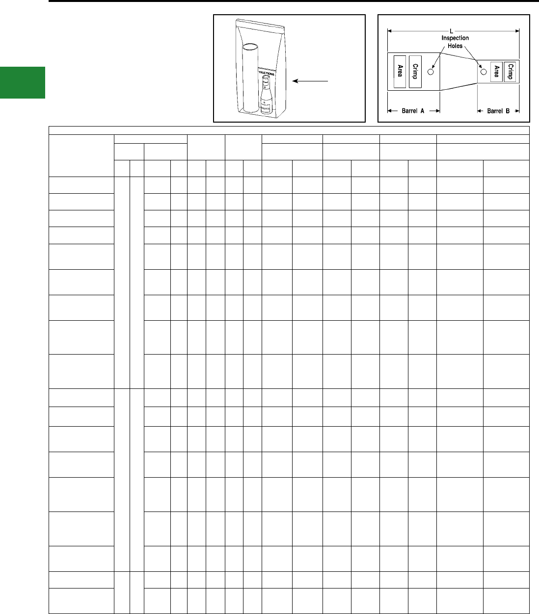
BURNDY®
Blue highlighted items are industry standard and most frequently ordered.
US: 1-800-346-4175 www.burndy.com Canada: 1-800-387-6487
Installation Tooling
** Clear
Heat Shrink Kit
Catalog Number
Wire Range
Color Code Die Index
Hydraulic Hydraulic Mechanical Dieless
Barrel A Barrel B
Y750, Y35, Y46,
PAT750, BAT750
BCT500HS,
Y500CTHS
OUR840,
MD7-34
Y/PAT644XT-18V Series,
MY29-11
AWG mm² AWG mm²
Barrel
A
Barrel
B
Barrel
A
Barrel
B
Barrel
A
Barrel
B
Barrel
A
Barrel
B
Barrel
A
Barrel
B
Barrel
A
Barrel
B
YSR38FX34LTCKITC
500
kcmil
Flex
300
mm²
500 kcmil
Code
240
mm² Pink Brown L99 20 U38XRT (2) U34RT (2)
U31ART (2) —W34VT (2)
W34RT (2) —W34VT (2)
W34RT (2)
Y644HSXT (1),
PAT644XT-18V (1)
Y644HSXT (1),
PAT644XT-18V (1)
YSR38FX34FXLTCKITC 350 kcmil
Flex
240
mm² Pink Blue L99 19 or
L80 U38XRT (2) U32RT (2) — W32VT (2)
W32RT (2) —W32VT (2)
W32RT (2)
Y644HSXT (1),
PAT644XT-18V (1)
Y644HSXT (1),
PAT644XT-18V (1)
YSR38FX31LTCKITC 350 kcmil
Code
185
mm² Pink Red L99 18 U38XRT (2) U31RT (2) — W31VT (2)
W31RT (2) —W31VT (2)
W31RT (2)
Y644HSXT (1),
PAT644XT-18V (1)
Y644HSXT (1),
PAT644XT-18V (1)
YSR38FX30LTCKITC 300 kcmil
Code
150
mm² Pink White L99 17 or
298 U38XRT (2) U30RT (2) — W30VT (2)
W30RT (2) —W30VT (2)
W30RT (2)
Y644HSXT (1),
PAT644XT-18V (1)
Y644HSXT (1),
PAT644XT-18V (1)
YSR38FX29LTCKITC † 250 kcmil
Code — Pink Yellow L99 16 U38XRT (2) U29RT (1) —
W29VT (2)
W29RT (2)
X29RT (4)
—W29VT (2)
X29RT (4)
Y644HSXT (1),
PAT644XT-18V (1)
Y644HSXT (1),
PAT644XT-18V (1)
YSR38FX29FXLTCKITC † 4/0 AWG
Flex
120
mm²Pink Yellow L99 16 U38XRT (2) U29RT (1) —
W29VT (2)
W29RT (2)
X29RT (4)
—
W29VT (2)
W29RT (2)
X29RT (4)
Y644HSXT (1),
PAT644XT-18V (1)
Y644HSXT (1),
PAT644XT-18V (1)
YSR38FX28FXLTCKITC †
4/0 AWG
Flex or
Telco Flex
120
mm² Pink Purple L99 15 U38XRT (2) U28RT (1) —
W28VT (2)
W28RT (2)
X28RT (3)
—
W28VT (2)
W28RT (2)
X28RT (3)
Y644HSXT (1),
PAT644XT-18V (1)
Y644HSXT (1),
PAT644XT-18V (1)
YSR38FX28LTCKITC † 4/0 AWG
Code — Pink Purple L99 15 U38XRT (2) U28RT (1) —
W28VT (2)
W28RT (2)
X28RT (3)
—
W28VT (2)
W28RT (2)
X28RT (3)
Y644HSXT (1),
PAT644XT-18V (1)
MY29-11 (1),
Y644HSXT (1),
PAT644XT-18V (1)
MRC840 (2)
YSR38FX26FXLTCKITC †
2/0 AWG
Flex or
Code
70
mm²
Class
5
Pink Black L99 13 U38XRT (2) U26RT (1) —
W26VT (2)
W26RT (2)
X26RT (2)
—
W26VT (2)
W26RT (2)
X26RT (2)
Y644HSXT (1),
PAT644XT-18V (1)
MY29-11 (1)
Y644HSXT (1)
PAT644XT-18V (1)
YSR3434FXLTCKITC
500
kcmil
Code
240
mm²
350 kcmil
Flex
240
mm² Brown Blue 20 19 or
L80
U34RT (2)
U31ART (2) U32RT (2) W34VT (2)
W34RT (2)
W32VT (2)
W32RT (2)
W34VT (2)
W34RT (2)
W32VT (2)
W32RT (2)
Y644HSXT (1),
PAT644XT-18V (1)
Y644HSXT (1),
PAT644XT-18V (1)
YSR3431LTCKITC 350 kcmil
Code
185
mm² Brown Red 20 18 U34RT (2)
U31ART (2) U31RT (2) W34VT (2)
W34RT (2)
W31VT (2)
W31RT (2)
W34VT (2)
W34RT (2)
W31VT (2)
W31RT (2)
Y644HSXT (1),
PAT644XT-18V (1)
Y644HSXT (1),
PAT644XT-18V (1)
YSR3429FXLTCKITC 4/0 AWG
Flex
120
mm² Brown Yellow 20 16 U34RT (2)
U31ART (2) U29RT (1) W34VT (2)
W34RT (2)
W29VT (2)
W29RT (2)
X29RT (4)
W34VT (2)
W34RT (2)
W29VT (2)
W29RT (2)
X29RT (4)
Y644HSXT (1),
PAT644XT-18V (1)
Y644HSXT (1),
PAT644XT-18V (1)
YSR3428FXLTCKITC
4/0 AWG
Flex or
Telco Flex
120
mm² Brown Purple 20 15 U34RT (2)
U31ART (2) U28RT (1) W34VT (2)
W34RT (2)
W28VT (2)
W28RT (2)
X28RT (3)
W34VT (2)
W34RT (2)
W28VT (2)
W28RT (2)
X28RT (3)
Y644HSXT (1),
PAT644XT-18V (1)
Y644HSXT (1),
PAT644XT-18V (1)
YSR3428LTCKITC 4/0 AWG
Code — Brown Purple 20 15 U34RT (2)
U31ART (2) U28RT (1) W34VT (2)
W34RT (2)
W28VT (2)
W28RT (2)
X28RT (3)
W34VT (2)
W34RT (2)
W28VT (2)
W28RT (2)
X28RT (3)
Y644HSXT (1),
PAT644XT-18V (1)
MY29-11 (1),
Y644HSXT (1),
PAT644XT-18V (1)
MRC840 (2)
YSR3426FXLTCKITC 2/0 AWG
Flex-Str.
70
mm²
Str.-
Flex
Brown Black 20 13 U34RT (2)
U31ART (2) U26RT (1) U34VT (2)
U34RT (2)
W26VT (2)
W26RT (2)
X26RT (2)
W34VT (2)
W26VT (2)
W26RT (2)
X26RT (2)
Y644HSXT (1),
PAT644XT-18V (1)
MY29-11 (1),
Y644HSXT (1),
PAT644XT-18V (1)
YSR3425FXLTCKITC †
1/0 AWG
Flex or
Code
50
mm² Brown Pink 20 12 U34RT (2)
U31ART (2) U25RT (1) W34VT (2)
W34RT (2)
W25VT (2)
W25RT (2)
X25RT (2)
W34VT (2)
W34RT (2)
W25VT (2)
W25RT (2)
X25RT (2)
Y644HSXT (1),
PAT644XT-18V (1)
MY29-11 (1),
Y644HSXT (1)
PAT644XT-18V (1)
YSR34FX31LTCKITC 350
kcmil
Flex
240
mm²
350 kcmil
Code
185
mm² Blue Red 19 or
L80 18 U32RT (2) U31RT (2) W32VT (2)
W32RT (2)
W31VT (2)
W31RT (2)
W32VT (2)
W32RT (2)
W31VT (2)
W31RT (2)
Y644HSXT (1),
PAT644XT-18V (1)
Y644HSXT (1),
PAT644XT-18V (1)
YSR34FX29FXLTCKITC 4/0 AWG
Flex
120
mm² Blue Yellow 19 or
L80 16 U32RT (2) U29RT (1) W32VT (2)
W32RT (2)
W29VT (2)
W29RT (2)
X29RT (4)
W32VT (2)
W32RT (2)
W29VT (2)
W29RT (2)
X29RT (4)
Y644HSXT (1),
PAT644XT-18V (1)
Y644HSXT (1),
PAT644XT-18V (1)
Note 1: All dimensions shown are for reference only.
Note 2: Non-inspection window versions are available.
Please contact customer service.
† Provided with 2 heat shrink tubings. One will overlap the
other. Install the smaller first and larger second.
** Clear Heatshrink – UL224 VW1 Listed – passes
TELCORDIA GR-347-CORE Abrasion and Cut Test.
(Up to 750 kcmil Class B code cable. Contact factory for
750 flex cable applications.)
(Installation Tooling Chart
continued on next 4 pages)
TYPE YSR-TC
INSTALLATION TOOLING
CHART (Continued)
In-line Reducer Splice Kits for
Telecommunications
Applications
Compression Connections
Copper Compression — Reducing Splice Kit — Code and Flex — Inspection Window
Plastic
Bag/Kit
C-124
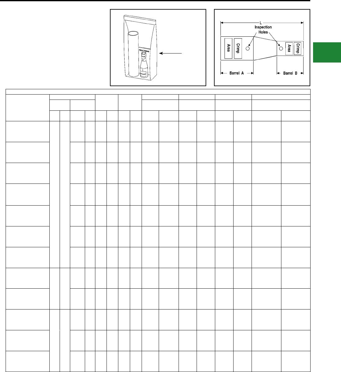
BURNDY®
Blue highlighted items are industry standard and most frequently ordered.
Canada: 1-800-387-6487 www.burndy.com US: 1-800-346-4175
Installation Tooling
** Clear
Heat Shrink Kit
Catalog Number
Wire Range
Color Code Die Index
Hydraulic Hydraulic Mechanical Dieless
Barrel A Barrel B
Y750, Y35, Y46,
PAT750, BAT750
BCT500HS,
Y500CTHS
OUR840,
MD7-34
Y/PAT644XT-18V Series,
MY29-11
AWG mm² AWG mm²
Barrel
A
Barrel
B
Barrel
A
Barrel
B
Barrel
A
Barrel
B
Barrel
A
Barrel
B
Barrel
A Barrel B Barrel A Barrel B
YSR34FX28FXLTCKITC
350
kcmil
Flex
240
mm²
4/0 AWG
Flex or
Telco
Flex
120
mm² Blue Purple 19 or
L80 15 U32RT (2) U28RT (1) W32VT (2)
W32RT (2)
W28VT (2)
W28RT (2)
X28RT (3)
W32VT (2)
W32RT (2)
W28VT (2)
W28RT (2)
X28RT (3)
Y644HSXT (1),
PAT644XT-18V (1)
Y644HSXT (1),
PAT644XT-18V (1)
YSR34FX28LTCKITC 4/0 AWG
Code — Blue Purple 19 or
L80 15 U32RT (2) U28RT (1) W32VT (2)
W32RT (2)
W28VT (2)
W28RT (2)
X28RT (3)
W32VT (2)
W32RT (2)
W28VT (2)
W28RT (2)
X28RT (3)
Y644HSXT (1),
PAT644XT-18V (1)
MY29-11 (1),
Y644HSXT (1),
PAT644XT-18V (1)
MRC840 (2)
YSR34FX26FXLTCKITC
2/0 AWG
Flex or
Code
70
mm²
Class
5
Blue Black 19 or
L80 13 U32RT (2) U26RT (1) W32VT (2)
W32RT (2)
W26VT (2)
W26RT (2)
X26RT (2)
W32VT (2)
W32RT (2)
W26VT (2)
W26RT (2)
X26RT (2)
Y644HSXT (1),
PAT644XT-18V (1)
MY29-11 (1),
Y644HSXT (1)
PAT644XT-18V (1)
YSR34FX25FXLTCKITC
1/0 AWG
Flex or
Code
50
mm² Blue Pink 19 or
L80 12 U32RT (2) U25RT (1)
U2CABT (1)
W32VT (2)
W32RT (2)
W25VT (2)
W25RT (2)
X25RT (2)
W32VT (2)
W32RT (2)
W25VT (2)
W25RT (2)
X25RT (2)
Y644HSXT (1),
PAT644XT-18V (1)
MY29-11 (1),
Y644HSXT (1)
PAT644XT-18V (1)
YSR34FX2CFXLTCKITC
#2 AWG
Flex or
Code
35
mm² Blue Brown 19 or
L80 10 U32RT (2) U2CRT (1) W32VT (2)
W32RT (2)
W2CVT (1)
W2CRT (1)
X2CRT (1)
W32VT (2)
W32RT (2)
W2CVT (1)
W2CRT (1)
X2CRT (1)
Y644HSXT (1),
PAT644XT-18V (1)
Y1MRTC (2),
MY29-11 (1),
Y644HSXT (1)
PAT644XT-18V (1)
YSR34FX4CFXLTCKITC ††
#4 AWG
Flex or
Code
— Blue Gray 19 or
L80 8 U32RT (2) U4CRT (1) W32VT (2)
W32RT (2)
W4CVT (1)
W4CRT (1)
X4CRT (1)
W32VT (2)
W32RT (2)
W4CVT (1)
W4CRT (1)
X4CRT (1)
Y644HSXT (1),
PAT644XT-18V (1)
Y1MRTC (2),
MY29-11 (1),
Y644HSXT (1)
PAT644XT-18V (1)
YSR34FX6CFXLTCKITC ††
#6 AWG
Flex or
Code
16
mm² Blue Blue 19 or
L80 7 U32RT (2) U5CRT (1) W32VT (2)
W32RT (2)
W5CVT (1)
W5CRT (1)
X5CRT (1)
W32VT (2)
W32RT (2)
W5CVT (1)
W5CRT (1)
X5CRT (1)
Y644HSXT (1),
PAT644XT-18V (1)
Y1MRTC (2),
MY29-11 (1),
Y644HSXT (1)
PAT644XT-18V (1)
YSR32FX29FXLTCKITC
300
kcmil
Flex
185
mm²
Class
2
4/0 AWG
Flex
120
mm² Red Yellow 19 or
L80 16 U31RT (2) U29RT (1) W31VT (2)
W31RT (2)
W29VT (2)
W29RT (2)
X29RT (4)
W31VT (2)
W31RT (2)
W29VT (2)
W29RT (2)
X29RT (4)
Y644HSXT (1),
PAT644XT-18V (1)
Y644HSXT (1),
PAT644XT-18V (1)
YSR32FX28FXLTCKITC
4/0 AWG
Flex or
Telco
Flex
120
mm² Red Purple 19 or
L80 15 U31RT (2) U28RT (1) W31VT (2)
W31RT (2)
W28VT (2)
W28RT (2)
X28RT (3)
W31VT (2)
W31RT (2)
W28VT (2)
W28RT (2)
X28RT (3)
Y644HSXT (1),
PAT644XT-18V (1)
MY29-11 (1),
Y644HSXT (1),
PAT644XT-18V (1)
MRC840 (2)
YSR3129FXLTCKITC
350
kcmil
Code
185
mm²
Class
2
4/0 AWG
Flex
120
mm² Red Yellow 18 16 U31RT (2) U29RT (1) W31VT (2) W29RT (2)
W31RT (2)
W29VT (2)
W31VT (2)
X29RT (4)
W29VT (2)
W29RT (2)
X29RT (4)
Y644HSXT (1),
PAT644XT-18V (1)
Y644HSXT (1),
PAT644XT-18V (1)
YSR3128FXLTCKITC
4/0 AWG
Flex or
Telco
Flex
120
mm² Red Purple 18 15 U31RT (2) U28RT (1) W31VT (2)
W31RT (2)
W28VT (2)
W28RT (2)
X28RT (3)
W31VT (2)
W28VT (2)
W28RT (2)
X28RT (3)
Y644HSXT (1),
PAT644XT-18V (1)
Y644HSXT (1),
PAT644XT-18V (1)
YSR3128LTCKITC 4/0 AWG
Code — Red Purple 18 15 U31RT (2) U28RT (1) W31VT (2)
W31RT (2)
W28VT (2)
W28RT (2)
X28RT (3)
W31VT (2)
W28VT (2)
W28RT (2)
X28RT (3)
Y644HSXT (1),
PAT644XT-18V (1)
MY29-11 (1),
Y644HSXT (1),
MRC840 (2)
PAT644XT-18V (1)
Note 1: All dimensions shown are for reference only.
Note 2: Non-inspection window versions are available.
Please contact customer service.
† Provided with 2 heat shrink tubings. One will overlap the
other. Install the smaller first and larger second.
** Clear Heatshrink – UL224 VW1 Listed – passes
TELCORDIA GR-347-CORE Abrasion and Cut Test.
(Up to 750 kcmil Class B code cable. Contact factory for
750 flex cable applications.)
(Installation Tooling Chart
continued on next 3 pages)
TYPE YSR-TC
INSTALLATION TOOLING
CHART (Continued)
In-line Reducer Splice Kits for
Telecommunications
Applications
Compression Connections
Copper Compression — Reducing Splice Kit — Code and Flex — Inspection Window
Plastic
Bag/Kit
C-125
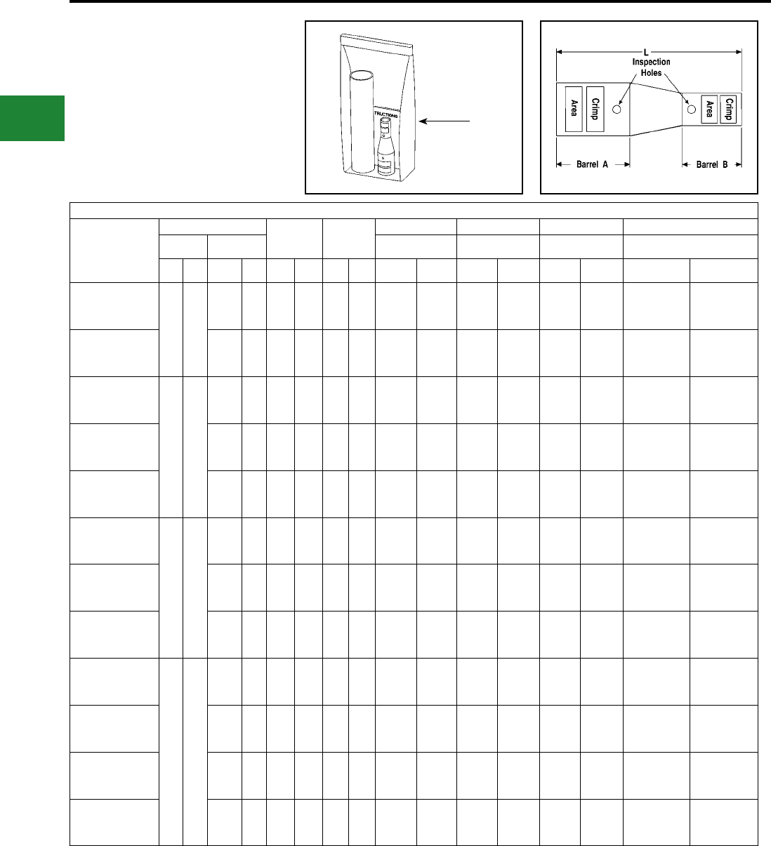
BURNDY®
Blue highlighted items are industry standard and most frequently ordered.
US: 1-800-346-4175 www.burndy.com Canada: 1-800-387-6487
Installation Tooling
** Clear
Heat Shrink Kit
Catalog Number
Wire Range
Color Code Die Index
Hydraulic Hydraulic Mechanical Dieless
Barrel A Barrel B
Y750, Y35, Y46,
PAT750, BAT750
BCT500HS,
Y500CTHS
OUR840,
MD7-34
Y/PAT644XT-18V Series,
MY29-11
AWG mm² AWG mm²
Barrel
A
Barrel
B
Barrel
A
Barrel
B
Barrel
A
Barrel
B
Barrel
A
Barrel
B
Barrel
A
Barrel
B
Barrel
A
Barrel
B
YSR3126FXLTCKITC
350
kcmil
Code
185
mm²
Class
2
2/0 AWG
Flex or
Code
70
mm²
Class
5
Red Black 18 13 U31RT (2) U26RT (1) W31VT (2)
W31RT (2)
W26VT (2)
W26RT (2)
X26RT (2)
W31VT (2)
W28VT (2)
W28RT (2)
X28RT (3)
Y644HSXT (1),
PAT644XT-18V (1)
MY29-11 (1),
Y644HSXT (1),
PAT644XT-18V (1)
YSR3125FXLTCKITC
1/0 AWG
Flex or
Code
50
mm² Red Pink 18 12 U31RT (2) U25RT (1) W31VT (2)
W31RT (2)
W25VT (2)
W25RT (2)
X25RT (2)
W31VT (2)
W28VT (2)
W28RT (2)
X28RT (3)
Y644HSXT (1),
PAT644XT-18V (1)
MY29-11 (1),
Y644HSXT (1),
PAT644XT-18V (1)
YSR312CFXLTCKITC
350
kcmil
Code
185
mm²
Class
2
#2 AWG
Flex or
Code
35
mm² Red Brown 18 10 U31RT (2) U2CRT (1) W31VT (2)
W31RT (2)
W2CVT (1)
W2CRT (1)
X2CRT (1)
W31VT (2)
W26VT (2)
W26RT (2)
X26RT (2)
Y644HSXT (1),
PAT644XT-18V (1)
Y1MRTC (2),
MY29-11 (1),
Y644HSXT (1),
PAT644XT-18V (1)
YSR314CFXLTCKITC †
#4 AWG
Flex or
Code
— Red Gray 18 8 U31RT (2) U4CRT (1) W31VT (2)
W31RT (2)
W4CVT (1)
W4CRT (1)
X4CRT (1)
W31VT (2)
W25VT (2)
W25RT (2)
X25RT (2)
Y644HSXT (1),
PAT644XT-18V (1)
Y1MRTC (2),
MY29-11 (1),
Y644HSXT (1),
PAT644XT-18V (1)
YSR316CFXLTCKITC †
#6 AWG
Flex or
Code
16
mm² Red Blue 18 7 U31RT (2) U5CRT (1) W31VT (2)
W31RT (2)
W5CVT (1)
W5CRT (1)
X5CRT (1)
W31VT (2)
W2CVT (1)
W2CRT (1)
X2CRT (1)
Y644HSXT (1),
PAT644XT-18V (1)
Y1MRTC (1),
MY29-11 (1),
Y644HSXT (1),
PAT644XT-18V (1)
YSR29FX28LTCKITC
4/0
AWG
Flex
120
mm²
4/0 AWG
Code — Yellow Purple 16 15 U29RT (1) U28RT (1)
W29VT (2)
W29RT (2)
X29RT (4)
W28VT (2)
W28RT (2)
X28RT (3)
W29VT (2)
W29RT (2)
X29RT (4)
W4CVT (1)
W4CRT (1)
X4CRT (1)
Y644HSXT (1),
PAT644XT-18V (1)
MY29-11 (1),
Y644HSXT (1),
PAT644XT-18V (1),
MRC840 (2)
YSR29FX25FXLTCKITC
1/0 AWG
Flex or
Code
50
mm² Yellow Pink 16 12 U29RT (1) U25RT (1)
W29VT (2)
W29RT (2)
X29RT (4)
W25VT (2)
W25RT (2)
X25RT (2)
W29VT (2)
W29RT (2)
X29RT (4)
W5CVT (1)
W5CRT (1)
X5CRT (1)
Y644HSXT (1),
PAT644XT-18V (1)
MY29-11 (1),
Y644HSXT (1),
PAT644XT-18V (1)
YSR29FX2CFXLTCKITC
#2 AWG
Flex or
Code
35
mm² Yellow Brown 16 10 U29RT (1) U2CRT (1)
W29VT (2)
W29RT (2)
X29RT (4)
W2CVT (1)
W2CRT (1)
X2CRT (1)
W29VT (2)
W29RT (2)
X29RT (4)
W29VT (2)
W29RT (2)
X29RT (4)
Y644HSXT (1),
PAT644XT-18V (1)
Y1MRTC (2),
MY29-11 (1),
Y644HSXT (1),
PAT644XT-18V (1)
YSR28FX28LTCKITC
4/0
AWG
Flex
or
Telco
Flex
120
mm²
4/0 AWG
Code — Purple Purple 15 15 U28RT (1) U28RT (1)
W28VT (2)
W28RT (2)
X28RT (3)
W28VT (2)
W28RT (2)
X28RT (3)
W28VT (2)
W28RT (2)
X28RT (3)
W28VT (2)
W28RT (2)
X28RT (3)
Y644HSXT (1),
PAT644XT-18V (1)
MY29-11 (1),
Y644HSXT (1),
PAT644XT-18V (1)
MRC840 (2)
YSR28FX26FXLTCKITC
2/0 AWG
Flex or
Code
70
mm²
Class
5
Purple Black 15 13 U28RT (1) U26RT (1)
W28VT (2)
W28RT (2)
X28RT (3)
W26VT (2)
W26RT (2)
X26RT (2)
W28VT (2)
W28RT (2)
X28RT (3)
W29VT (2)
W29RT (2)
X29RT (4)
Y644HSXT (1),
PAT644XT-18V (1)
MY29-11 (1),
Y644HSXT (1),
PAT644XT-18V (1)
YSR28FX25FXLTCKITC
1/0 AWG
Flex or
Code
50
mm² Purple Pink 15 12 U28RT (1) U25RT (1)
W28VT (2)
W28RT (2)
X28RT (3)
W25VT (2)
W25RT (2)
X25RT (2)
W28VT (2)
W28RT (2)
X28RT (3)
W28VT (2)
W28RT (2)
X28RT (3)
Y644HSXT (1),
PAT644XT-18V (1)
MY29-11 (1),
Y644HSXT (1),
PAT644XT-18V (1)
YSR28FX2CFXLTCKITC
#2 AWG
Flex or
Code
35
mm² Purple Brown 15 10 U28RT (1) U2CRT
(10)
W28VT (2)
W28RT (2)
X28RT (3)
W2CVT (1)
W2CRT (1)
X2CRT (1)
W28VT (2)
W28RT (2)
X28RT (3)
W28VT (2)
W28RT (2)
X28RT (3)
Y644HSXT (1),
PAT644XT-18V (1)
MY29-11 (1),
Y644HSXT (1),
PAT644XT-18V (1),
Y1MRTC (2)
Note 1: All dimensions shown are for reference only.
Note 2: Non-inspection window versions are available.
Please contact customer service.
† Provided with 2 heat shrink tubings. One will overlap the
other. Install the smaller first and larger second.
** Clear Heatshrink – UL224 VW1 Listed – passes
TELCORDIA GR-347-CORE Abrasion and Cut Test.
(Up to 750 kcmil Class B code cable. Contact factory for
750 flex cable applications.)
(Installation Tooling Chart
continued on next 2 pages)
TYPE YSR-TC
INSTALLATION TOOLING
CHART (Continued)
In-line Reducer Splice Kits for
Telecommunications
Applications
Compression Connections
Copper Compression — Reducing Splice Kit — Code and Flex — Inspection Window
Plastic
Bag/Kit
C-126
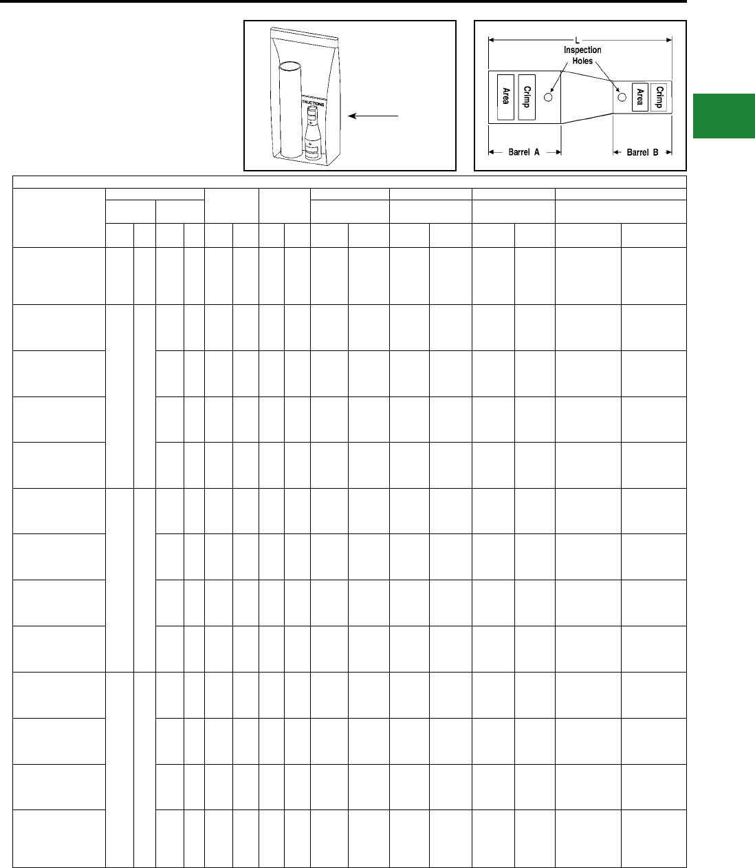
BURNDY®
Blue highlighted items are industry standard and most frequently ordered.
Canada: 1-800-387-6487 www.burndy.com US: 1-800-346-4175
Installation Tooling
** Clear
Heat Shrink Kit
Catalog Number
Wire Range
Color Code Die Index
Hydraulic Hydraulic Mechanical Dieless
Barrel A Barrel B
Y750, Y35, Y46,
PAT750, BAT750
BCT500HS,
Y500CTHS
OUR840,
MD7-34
Y/PAT644XT-18V Series,
MY29-11
AWG mm² AWG mm²
Barrel
A
Barrel
B
Barrel
A
Barrel
B
Barrel
A
Barrel
B
Barrel
A
Barrel
B
Barrel
A
Barrel
B
Barrel
A
Barrel
B
YSR28FX4CFXLTCKITC †
4/0
AWG
Flex or
Telco
Flex
120
mm²
#4
AWG
Flex or
Code
— Purple Gray 15 8 U28RT (1) U4CRT (1)
W28VT (2)
W28RT (2)
X28RT (3)
W4CVT (1)
W4CRT (1)
X4CRT (1)
W28VT (2)
W28RT (2)
X28RT (3)
W4CVT (1)
W4CRT (1)
X4CRT (1)
Y644HSXT (1),
PAT644XT-18V (1)
Y1MRTC (2),
MY29-11 (1),
Y644HSXT (1),
PAT644XT-18V (1)
YSR2825FXLTCKITC
4/0
AWG
Code
—
1/0
AWG
Flex or
Code
50
mm² Purple Pink 15 12 U28RT (1) U25RT (1)
W28VT (2)
W28RT (2)
X28RT (3)
W25VT (2)
W25RT (2)
X25RT (2)
W28VT (2)
W28RT (2)
X28RT (3)
W25VT (2)
W25RT (2)
X25RT (2)
MY29-11 (1),
Y644HSXT (1),
PAT644XT-18V (1)
MRC840 (2)
MY29-11 (1),
Y644HSXT (1),
PAT644XT-18V (1)
YSR282CFXLTCKITC
#2
AWG
Flex or
Code
35
mm² Purple Brown 15 10 U28RT (1) U2CRT (1)
W28VT (2)
W28RT (2)
X28RT (3)
W2CVT (1)
W2CRT (1)
X2CRT (1)
W28VT (2)
W28RT (2)
X28RT (3)
W2CVT (1)
W2CRT (1)
X2CRT (1)
MY29-11 (1),
Y644HSXT (1),
PAT644XT-18V (1)
MRC840 (2)
Y1MRTC (2),
MY29-11 (1),
Y644HSXT (1),
PAT644XT-18V (1)
YSR284CFXLTCKITC †
#4
AWG
Flex or
Code
— Purple Gray 15 8 U28RT (1) U4CRT (1)
W28VT (2)
W28RT (2)
X28RT (3)
W4CVT (1)
W4CRT (1)
X4CRT (1)
W28VT (2)
W28RT (2)
X28RT (3)
W4CVT (1)
W4CRT (1)
X4CRT (1)
MY29-11 (1),
Y644HSXT (1),
PAT644XT-18V (1)
MRC840 (2)
Y1MRTC (2),
MY29-11 (1),
Y644HSXT (1),
PAT644XT-18V (1)
YSR286CFXLTCKITC †
#6
AWG
Flex or
Code
16
mm² Purple Blue 15 7 U28RT (1) U5CRT (1)
W28VT (2)
W28RT (2)
X28RT (3)
W5CVT (1)
W5CRT (1)
X5CRT (1)
W28VT (2)
W28RT (2)
X28RT (3)
W5CVT (1)
W5CRT (1)
X5CRT (1)
MY29-11 (1),
Y644HSXT (1),
PAT644XT-18V (1)
MRC840 (2)
Y1MRTC (1),
MY29-11 (1),
Y644HSXT (1),
PAT644XT-18V (1)
YSR26FX25FXLTCKITC
2/0
AWG
Flex or
Code
70
mm²
1/0
AWG
Flex or
Code
50
mm² Black Pink 13 12 U26RT (1) U25RT (1)
W26VT (2)
W26RT (2)
X26RT (2)
W25VT (2)
W25RT (2)
X25RT (2)
W26VT (2)
W26RT (2)
X26RT (2)
W25VT (2)
W25RT (2)
X25RT (2)
MY29-11 (1),
Y644HSXT (1),
PAT644XT-18V (1)
MY29-11 (1),
Y644HSXT (1),
PAT644XT-18V (1)
YSR26FX2CFXLTCKITC
#2
AWG
Flex or
Code
35
mm² Black Brown 13 10 U26RT (1) U2CRT (1)
W26VT (2)
W26RT (2)
X26RT (2)
W2CVT (1)
W2CRT (1)
X2CRT (1)
W26VT (2)
W26RT (2)
X26RT (2)
W2CVT (1)
W2CRT (1)
X2CRT (1)
MY29-11 (1),
Y644HSXT (1),
PAT644XT-18V (1)
Y1MRTC (2),
MY29-11 (1),
Y644HSXT (1),
PAT644XT-18V (1)
YSR26FX4CFXLTCKITC †
#4
AWG
Flex or
Code
— Black Gray 13 8 U26RT (1) U4CRT (1)
W26VT (2)
W26RT (2)
X26RT (2)
W4CVT (1)
W4CRT (1)
X4CRT (1)
W26VT (2)
W26RT (2)
X26RT (2)
W4CVT (1)
W4CRT (1)
X4CRT (1)
MY29-11 (1),
Y644HSXT (1),
PAT644XT-18V (1)
Y1MRTC (2),
MY29-11 (1),
Y644HSXT (1),
PAT644XT-18V (1)
YSR26FX6CFXLTCKITC †
#6
AWG
Flex or
Code
16
mm² Black Blue 13 7 U26RT (1) U5CRT (1)
W26VT (2)
W26RT (2)
X26RT (2)
W5CVT (1)
W5CRT (1)
X5CRT (1)
W26VT (2)
W26RT (2)
X26RT (2)
W5CVT (1)
W5CRT (1)
X5CRT (1)
MY29-11 (1),
Y644HSXT (1),
PAT644XT-18V (1)
Y1MRTC (1),
MY29-11 (1),
Y644HSXT (1),
PAT644XT-18V (1)
YSR25FX2CFXLTCKITC
1/0
AWG
Flex or
Code
50
mm²
#2
AWG
Flex or
Code
35
mm² Pink Brown 12 10 U25RT (1) U2CRT (1)
W25VT (2)
W25RT (2)
X25RT (2)
W2CVT (1)
W2CRT (1)
X2CRT (1)
W25VT (2)
W25RT (2)
X25RT (2)
W2CVT (1)
W2CRT (1)
X2CRT (1)
MY29-11 (1),
Y644HSXT (1),
PAT644XT-18V (1)
Y1MRTC (2),
MY29-11 (1),
Y644HSXT (1),
PAT644XT-18V (1)
YSR25FX4CFXLTCKITC †
#4
AWG
Flex or
Code
— Pink Gray 12 8 U25RT (1) U4CRT (1)
W25VT (2)
W25RT (2)
X25RT (2)
W4CVT (1)
W4CRT (1)
X4CRT (1)
W25VT (2)
W25RT (2)
X25RT (2)
W4CVT (1)
W4CRT (1)
X4CRT (1)
MY29-11 (1),
Y644HSXT (1),
PAT644XT-18V (1)
Y1MRTC (1),
MY29-11 (1),
Y644HSXT (1),
PAT644XT-18V (1)
YSR25FX6CFXLTCKITC †
#6
AWG
Flex or
Code
16
mm² Pink Blue 12 7 U25RT (1) U5CRT (1)
W25VT (2)
W25RT (2)
X25RT (2)
W5CVT (1)
W5CRT (1)
X5CRT (1)
W25VT (2)
W25RT (2)
X25RT (2)
W5CVT (1)
W5CRT (1)
X5CRT (1)
MY29-11 (1),
Y644HSXT (1),
PAT644XT-18V (1)
Y1MRTC (1),
MY29-11 (1),
Y644HSXT (1),
PAT644XT-18V (1)
YSR25FX8CFXLTCKITC
#8
AWG
Flex or
Code,
#6 Sol
10
mm² Pink Red 12 49 U25RT (1) U8CRT (1)
W25VT (2)
W25RT (2)
X25RT (2)
W8CVT (1)
W8CRT (1)
X8CRT (1)
W25VT (2)
W25RT (2)
X25RT (2)
W8CVT (1)
W8CRT (1)
X8CRT (1)
MY29-11 (1),
Y644HSXT (1),
PAT644XT-18V (1)
Y8MRB-1 (1),
Y1MRTC (1),
MY29-3 (1),
MY29-11 (1),
Note 1: All dimensions shown are for reference only.
Note 2: Non-inspection window versions are available.
Please contact customer service.
† Provided with 2 heat shrink tubings. One will overlap the
other. Install the smaller first and larger second.
** Clear Heatshrink – UL224 VW1 Listed – passes
TELCORDIA GR-347-CORE Abrasion and Cut Test.
(Up to 750 kcmil Class B code cable. Contact factory for
750 flex cable applications.)
(Installation Tooling Chart
continued on next page)
TYPE YSR-TC
INSTALLATION TOOLING
CHART (Continued)
In-line Reducer Splice Kits for
Telecommunications
Applications
Compression Connections
Copper Compression — Reducing Splice Kit — Code and Flex — Inspection Window
Plastic
Bag/Kit
C-127
BURNDY®
Blue highlighted items are industry standard and most frequently ordered.
US: 1-800-346-4175 www.burndy.com Canada: 1-800-387-6487
Installation Tooling
** Clear
Heat Shrink Kit
Catalog Number
Wire Range
Color Code Die Index
Hydraulic Hydraulic Mechanical Dieless
Barrel A Barrel B
Y750, Y35, Y46,
PAT750, BAT750
BCT500HS,
Y500CTHS
OUR840,
MD7-34
Y/PAT644XT-18V Series,
MY29-11
AWG mm² AWG mm²
Barrel
A
Barrel
B
Barrel
A
Barrel
B
Barrel
A
Barrel
B
Barrel
A
Barrel
B
Barrel
A
Barrel
B
Barrel
A
Barrel
B
YSR2CFX4CFXLTCKITC
#2
AWG
Flex
or
Code
35
mm²
#4
AWG
Flex or
Code
— Brown Gray 10 8 U2CRT (1) U4CRT (1)
W2CVT (1)
W2CRT (1)
X2CRT (1)
W4CVT (1)
W4CRT (1)
X4CRT (1)
W2CVT (1)
W2CRT (1)
X2CRT (1)
W4CVT (1)
W4CRT (1)
X4CRT (1)
Y1MRTC (2),
MY29-11 (1),
Y644HSXT (1),
PAT644XT-18V (1)
Y1MRTC (2),
MY29-11 (1),
Y644HSXT (1),
PAT644XT-
18V (1)
YSR2CFX6CFXLTCKITC
#6
AWG
Flex or
Code
16 mm² Brown Blue 10 7 U2CRT (1) U5CRT (1)
W2CVT (1)
W2CRT (1)
X2CRT (1)
W5CVT (1)
W5CRT (1)
X5CRT (1)
W2CVT (1)
W2CRT (1)
X2CRT (1)
W5CVT (1)
W5CRT (1)
X5CRT (1)
Y1MRTC (2),
MY29-11 (1),
Y644HSXT (1),
PAT644XT-18V (1)
Y1MRTC (1),
MY29-11 (1),
Y644HSXT (1),
PAT644XT-
18V (1)
YSR2CFX8CFXLTCKITC
#8
AWG
Flex or
Code
10 mm² Brown Red 10 49 U2CRT (1) U8CRT (1)
W2CVT (1)
W2CRT (1)
X2CRT (1)
W8CVT (1)
W8CRT (1)
X8CRT (1)
W2CVT (1)
W2CRT (1)
X2CRT (1)
W8CVT (1)
W8CRT (1)
X8CRT (1)
Y1MRTC (2),
MY29-11 (1),
Y644HSXT (1),
PAT644XT-18V (1)
Y8MRB-1 (1),
Y1MRTC (1),
MY29-3 (1),
MY29-11 (1)
YSR4CFX6CFXLTCKITC
#4
AWG
Flex
or
Code
—
#6
AWG
Flex or
Code
16 mm² Gray Blue 8 7 U4CRT (1) U5CRT (1)
W4CVT (1)
W4CRT (1)
X4CRT (1)
W5CVT (1)
W5CRT (1)
X5CRT (1)
W4CVT (1)
W4CRT (1)
X4CRT (1)
W5CVT (1)
W5CRT (1)
X5CRT (1)
Y1MRTC (2),
MY29-11 (1),
Y644HSXT (1),
PAT644XT-18V (1)
Y1MRTC (1),
MY29-11 (1),
Y644HSXT (1),
PAT644XT-
18V (1)
YSR4CFX8CFXLTCKITC
#8
AWG
Flex or
Code
10 mm² Gray Red 8 49 U4CRT (1) U8CRT (1)
W4CVT (1)
W4CRT (1)
X4CRT (1)
W8CVT (1)
W8CRT (1)
X8CRT (1)
W4CVT (1)
W4CRT (1)
X4CRT (1)
W8CVT (1)
W8CRT (1)
X8CRT (1)
Y1MRTC (2),
MY29-11 (1),
Y644HSXT (1),
PAT644XT-18V (1)
Y8MRB-1 (1),
Y1MRTC (1),
MY29-3 (1),
MY29-11 (1)
YSR4CFX10CLTCKITC
#10
AWG
Flex or
Code
6 mm² Str.
or
2.5 mm²
Flex
Gray — 8 — U4CRT (1) —
W4CVT (1)
W4CRT (1)
X4CRT (1)
—
W4CVT (1)
W4CRT (1)
X4CRT (1)
—
Y1MRTC (2),
MY29-11 (1),
Y644HSXT (1),
PAT644XT-18V (1)
Y8MRB-1 (2),
MR8G98 (2),
Y10D (2)
YSR6CFX8CFXLTCKITC
#6
AWG
Flex
or
Code
16
mm²
#8
AWG
Flex or
Code
10 mm² Blue Red 7 49 U5CRT (1) U8CRT (1)
W5CVT (1)
W5CRT (1)
X5CRT (1)
W8CVT (1)
W8CRT (1)
X8CRT (1)
W5CVT (1)
W5CRT (1)
X5CRT (1)
W8CVT (1)
W8CRT (1)
X8CRT (1)
Y1MRTC (1),
MY29-11 (1),
Y644HSXT (1),
PAT644XT-18V (1)
Y8MRB-1 (1),
Y1MRTC (1),
MY29-3 (1),
MY29-11 (1)
YSR6CFX10CLTCKITC
#10
AWG
Flex or
Code
6 mm² Str.
or
2.5 mm²
Flex
Blue — 7 — U5CRT (1) —
W5CVT (1)
W5CRT (1)
X5CRT (1)
—
W5CVT (1)
W5CRT (1)
X5CRT (1)
—
Y1MRTC (1),
MY29-11 (1),
Y644HSXT (1),
PAT644XT-18V (1)
Y8MRB-1 (2),
MR8G98 (2),
Y10D (2)
YSR6CFX14CLTCKITC
#14-10
AWG
Flex -
Str.
#12-10
Sol
6 mm² Str.
or
2.5 mm²
Flex
Blue — 7 — U5CRT (1) —
W5CVT (1)
W5CRT (1)
X5CRT (1)
—
W5CVT (1)
W5CRT (1)
X5CRT (1)
—
Y1MRTC (1),
MY29-11 (1),
Y644HSXT (1),
PAT644XT-18V (1
Y8MRB-1 (2),
MR8G98 (2),
Y10D (2)
YSR8CFX10CLTCKITC #8
AWG
Flex
or
Code
10
mm²
#10
AWG
Flex or
Code
6 mm² Str.
or
2.5 mm²
Flex
Red — 49 — U8CRT (1) —
W8CVT (1)
W8CRT (1)
X8CRT (1)
—
W8CVT (1)
W8CRT (1)
X8CRT (1)
—
Y8MRB-1 (1),
Y1MRTC (1),
MY29-3 (1),
MY29-11 (1)
Y8MRB-1 (2),
MR8G98 (2),
Y10D (2)
YSR8CFX14CLTCKITC
#14
AWG
Flex or
Code
6 mm² Str.
or
2.5 mm²
Flex
Red — 49 — U8CRT (1) —
W8CVT (1)
W8CRT (1)
X8CRT (1)
—
W8CVT (1)
W8CRT (1)
X8CRT (1)
—
Y8MRB-1 (1),
Y1MRTC (1),
MY29-3 (1),
MY29-11 (1)
Y8MRB-1 (2),
MR8G98 (2),
Y10D (2)
YSR10CFX12CLTCKITC #10
AWG
Flex
or
Code
6
mm²
Str.
or
2.5
mm²
Flex
#12
AWG
Flex or
Code
6 mm² Str.
or
2.5 mm²
Flex
— — — — — — — — — —
Y8MRB-1 (2),
MR8G98 (2),
Y10D (2)
Y8MRB-1 (2),
MR8G98 (2),
Y10D (2)
YSR10CFX14CLTCKITC
#14
AWG
Flex or
Code
6 mm² Str.
or
2.5 mm²
Flex
— — — — — — — — — —
Y8MRB-1 (2),
MR8G98 (2),
Y10D (2)
Y8MRB-1 (2),
MR8G98 (2),
Y10D (2)
Note 1: All dimensions shown are for reference only.
Note 2: Non-inspection window versions are available.
Please contact customer service.
† Provided with 2 heat shrink tubings. One will overlap the
other. Install the smaller first and larger second.
** Clear Heatshrink – UL224 VW1 Listed – passes
TELCORDIA GR-347-CORE Abrasion and Cut Test.(Up to
750 kcmil Class B code cable. Contact factory for
750 flex cable applications.)
TYPE YSR-TC
INSTALLATION TOOLING
CHART (Continued)
In-line Reducer Splice Kits for
Telecommunications
Applications
Compression Connections
Copper Compression — Reducing Splice Kit — Code and Flex — Inspection Window
Plastic
Bag/Kit
C-128
BURNDY®
Blue highlighted items are industry standard and most frequently ordered.
Canada: 1-800-387-6487 www.burndy.com US: 1-800-346-4175
TYPE YC-L
THIN-WALL COPPER C-TAP
UL Listed to 600 Volts
Type YC-L is a thin-wall high conductivity copper
connector for making copper tap and parallel
connections from #14 to 3/0 AWG. Features & Benets
• Manufactured from high conductivity
wrought copper
◊ Provides low resistance and
excellent electrical conductivity
• Range-taking connector
◊ Lowers inventory requirements
• Reinforced ribs
◊ Provides maximum pull-out values
• Compact size
◊ Easy to tape and insulate
connection
• Economical
◊ Provides low installed cost
Catalog
Number
Accommodates No.
of
Ribs
Dimensions
Color
Code
Installation Tooling
Wire
Strip
Length
Mechanical Hydraulic
Y1MRTC
MD6,
0UR840 &
MD7-34R Die ▲
Index
Embossment
BCT500,
Y500CT,
BAT500
(# crimps)
Y35, Y39,
Y750, Y45,
Y46*
(# of crimps)
Die ▲
Index
EmbossmentRun Tap B C D T
Die No.
(# crimps)
YC8L12 10 10 0 0.25 0.21 0.6 0.07 Blue Blue (1) W5CVT (1) 7 — — — 5/8"
8 12
YC6L12 8 10-8 0 0.33 0.25 0.6 0.07 Gray Gray (2) W4CVT (1) 8 — — — 5/8"
6 12-10
YC4L12** 6 8-6 1 0.39 0.28 1.18 0.07 Brown Brown (2) W2CVT (2) 10 WC4 (1) UC4 (1) 10M 1-3/16"
5,4 12-8
YC3L12 5,4 6-5 1 0.46 0.27 1.18 0.08 Green — W1CVT (2) 11 — — — 1-3/16"
3 12-6
YC2L12**
4 4
1 0.5 0.36 1.18 0.08 Pink — W25VT (2) 12 WC2 (1) UC2 (1) 12M 1-3/16"3 5
2 12-6
YC1L12**
3 4-3
2 0.55 0.34 1.75 0.08 Black — W26VT (3) 13 WC1 (2) UC1 (1) 13M 1-13/16"2 5-4
1 12-5
YC25L12**
2 Str.
2 Sol.
2 Str. 2 Sol.
3 Str. 3 Sol.
2 0.62 0.42 1.75 0.09 Orange — W27VT (3) 14 WC25 (2) UC25 (1) 14M 1-13/16"
1 Str.
1 Sol.
4 Str. 4 Sol.
3 Str. 3 Sol.
1/0 Str.
1/0 Sol.
12 Str. 12 Sol.
4 Str. 4 Sol.
YC26L12
1 2-1
2 0.69 0.43 1.75 0.09 Purple — W28VT (3) 15 — UC26 (1) 15 1-13/16"1/0 3-2
2/0 12-3
YC27L12
1/0 1-1/0
2 0.81 0.48 1.75 0.09 Yellow — W29VT (3) 16 — — — 1-13/16"2/0 2-1
3/0 12-2
▲ See tooling section of this catalog for complete tool and
die listings.
* Use PUADP-1 adapter with U dies in Y46 HYPRESS™
For Tin plating add TN sufx (example = YC10L12TN)
Bare Copper
Compression Connections
Copper Compression — C-Tap — Thin Wall
Note: All dimensions shown are for reference only.
** Also Listed for Grounding and Bonding
(Cannot use Y1MRTC tool for this feature)
C-129
BURNDY®
Blue highlighted items are industry standard and most frequently ordered.
US: 1-800-346-4175 www.burndy.com Canada: 1-800-387-6487
TYPE YC-C
COPPER CRIMPIT™
UL Listed 90° C,
600 Volts to 35 kV ♦
Type YC-C copper CRIMPIT™ connector is a
range-taking C shape compression connector
for making tap or parallel copper connections
from #12 sol. to 4/0 strand conductor.
Catalog
Number Run Tap L
▲ Die
Index
Tools, Die Set, Catalog Number
and (‡No. of Crimps) ▲
CRIMPIT™ for 1 Str.
Copper
MD6 OUR840
Y35, Y750, Y45,
Y46* Run Tap
YC10C10 †12 Sol.-10 Str. 12 Sol.-10 Str. 3/8" 238 W238 (1) W238 (1) U238 (1) — —
YC8C8 8 Sol.-8 Str. 10 Sol.- 8 Str. 1/2" 162 W162 (2) W162 (2) U162** (1)
YC4C8
6 Sol.-4 Str.
8 Sol.- 8 Str.
5/8" BG or 5/8 BG (2)
W-BG** (1)
XBG (2)
XNBG (2) U-BG (1) — —YC4C6 6 Sol.- 6 Str.
YC4C4 4 sol.- 4 Str.
YC2C4 2 Sol.-2 Str. 8 Sol.- 4 Str. 3/4" C W-C (2) — U-C (1) 1 Str. 6.8 Str., 8 Sol.
YC2C2 2 Sol.- 2 Str. — —
YC26C2 1/0 Sol.-2/0 Str. 8 Sol.- 2 Str. 11/12" E or O — — U-E (3)
U-O (1)
1 Str. 1 or 2 Str.
YC26C26 1/0 Sol.- 2/0 Str. — —
YC28C2
3/0 Sol.-4/0 Str.
6 Sol.- 2 Str.
1-1/6" F or D3 — — U-F (3)
U-D3** (1) — —YC28C26 1/0 Sol.- 2/0 Str.
YC28C28 3/0.- 4/0 Str.
Features & Benets
• Range-taking conductor
◊ Lowers inventory requirements
• Compact size
◊ Easy to tape and insulate
connection
• Manufactured from high conductivity
wrought copper
◊ Provides low resistance and
excellent electrical conductivity
• Economical
◊ Provides low installed cost
† Not UL Listed.
‡ Number of Crimps.
▲ See tooling section of this catalog for complete tool
and die listings.
* Use PUADP-1 adapter when using U dies in the Y46
HYPRESS™.
** Multiple crimp die set. Makes more than one crimp per
tool compression. Figure ( ) indicates number of
compressions.
Copperweld-Copper Conductors
8A - Use CRIMPITS™ accommodating 6 str. Copper
6A - Use CRIMPITS™ accommodating 4 Str. Copper
4A - Use CRIMPITS™ accommodating 2 Str. Copper
2A - Use CRIMPITS™ accommodating 1/0 and 2/0
Copper
Bare
Copper
Compression Connections
Copper Compression — C-Tap
♦ For applications greater than 2000 Volts consult cable
manufacturer for voltage stress relief instructions.
Note: All dimensions shown are for reference only.
C-130
BURNDY®
Blue highlighted items are industry standard and most frequently ordered.
Canada: 1-800-387-6487 www.burndy.com US: 1-800-346-4175
TYPE YCHC
C-TAP COPPER CRIMPIT™
Features & Benets
• Wide range of run/tap combinations
including Class B code I and locomotive
exible conductor combinations. All (B/B, B/I,
I/I) combinations are recommended
◊ Each connector accommodates many
cable combinations, allowing maximum
exibility for the design and installation of
a system
• Color-coded on the connector that matches
the die
◊ Provides matched system for fast and
easy installation
• Each connector has a recommended insulat-
ing cover available. Flame
retardant type
CF-FR covers meet oxygen
index 28 and
UL94 V-O requirements
◊ A complete insulated UL Listed
installation is provided
• Die index embossed on connector after
completion of crimp
◊ Permanent inspectability of
installed
connector is insure
consistently reliable
and dependable connections
90° C
Electro Tin
Plated
BURNDY
Catalog
Number
Flame Retardant
Cover Conductor Sizes Code/(Flex) Cable ▲ Tooling († No. of Crimps)
▲ Die
Index &
Embossment H W L
Strip
Length
Clear
Cat. No.
Black
Cat.
No. ‡ Main Tap 1 Tap 2
Tap
3 Y35 † Y750 † Y46* †
Color
Code
YCHC44TC44 CCFR-FR CFR-FR 1000-750
(750-500)
1000-750
(750-500) — — — — — — P1102 1 White 1102 3.59 1.73 1.16 1-1/4″
YCHC39TC39 CCFR-FR CFR-FR
750-500
(550-500)
750-350
(550-350) — — — — — — P1103 1 Blue 1103 3.12 1.53 1.06 1-1/8″
YCHC39TC31 CCFR-FR CFR-FR 350-2
(250-2)
2-6 Str./
Sol.
(2-8)
8-14
(8-14) — — — — P1103 1 Blue 1103 2.96 1.53 1.31 1-3/8″
YCHC39TC2 CCFR-FR CFR-FR 2-6 Str./Sol.
(2-8)
8-14
(8-14) — — — — — P1103 1 Blue 1103 2.66 1.53 1.31 1-3/8″
YCHC34TC34 CCFN-FR CFN-FR
500-4/0
(350-4/0)
500-4/0
(350-4/0) — — — — U1104 2 U1104 1 Brown 1104 2.97 1.38 1.00 1-1/4″
YCHC34TC29 CCFN-FR CFN-FR 250-2
(4/0-2)
2-6 Str./
Sol.
(2-8)
— — — U1104 2 U1104 1 Brown 1104 2.45 1.26 0.88 1″
YCHC34TC2 CCFN-FR CFN-FR 2-6 Str./Sol.
(2-8)
8-14
(8-14) — — — U1104 2 U1104 1 Brown 1104 2.45 1.26 0.94 1″
YCHC29TC29 CCFDXFR CFD-FR 250-2
(4/0-2)
250-2
(4/0-2) — — — — U997 1 U997 1 Orange 997 2.12 0.98 0.94 1″
YCHC29TC2 CCFD-FR CFD-FR 2-6 Str./Sol.
(2-8)
8-14
(8-14) — — — U251 1 U251 1 Red 251 1.78 0.97 0.81 1″
YCHC2TC2 CCFO-FR CFO-FR
2-6 Str./
Sol.
(2-8)
2-6 Str./Sol.
(2-8)
8-14
(8-14) — U-C 1 U-C 1 U-C 1 Brown C 1.22 0.60 0.81 1″
YCHC8TC8 ♦ ♦ 8-12
(8-12)
8-12
(8-12) — — U-240 1 U-240 1 U-240 1 Red 240 0.53 0.35 0.56 5/8″
Note: To properly use tap 2 and/or tap 3 conductors in
YCHC connector a conductor from the tap 1 cable
range must be included in the tap 1 groove.
‡ To obtain covers made of polyethylene remove
sufx-FR (example: CFO). CFO is not ame retardant.
* Use PUADP-1 adaptor with U dies in Y46.
▲ See tooling section of Master Catalog for complete tool
and die listings.
♦ For applications requiring ame retardant cover, use
either a CCFBG-FR (Clear) or CFBG-FR (Black) cover
and YH2C2C connector by ordering YH8C8CWCC
(Clear) or YH8C8CWC (Black).
Note: All dimensions shown are for reference only.
Compression Connections
Copper Compression — C-Tap
C-131
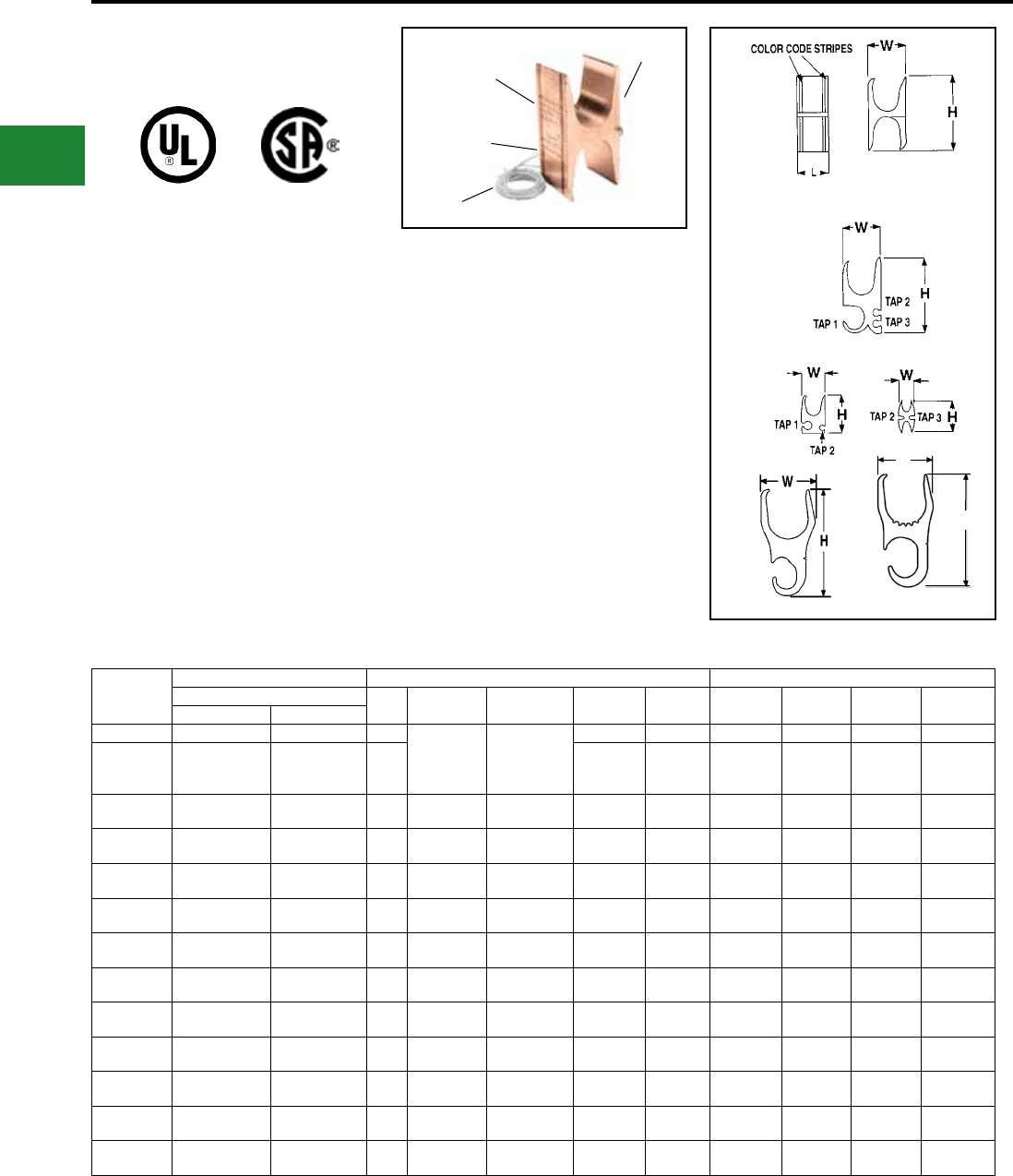
BURNDY®
Blue highlighted items are industry standard and most frequently ordered.
US: 1-800-346-4175 www.burndy.com Canada: 1-800-387-6487
TYPE YH
H-TAP COPPER CRIMPIT™
Features & Benets
• Accommodates a wide range of run/tap cop-
per cable combinations including both exible
and code
combinations. All (B/B, B/I, I/B, I/I) combina-
tions acceptable
◊ Each connector has many copper
cable combination applications
allowing maximum exibility for
the design and installation of a
system
• Tap grooves function independently of each
other. Use of one tap is
required. Balance may be used or left empty
◊ Provides maximum design and
installation exibility
• Color code on the connector matches instal-
lation die
◊ Provides matched system for fast
and easy installation
COLOR CODE
DIE AND
CRIMP
INFORMATION
ELECTRO-TIN
PLATED
CONDUCTOR
RANGE
THIRD HAND PATENTED
• Die index embossed on connector after com-
pletion of crimp
◊ Permanent inspectibility of installed
connectors to insure consistently
reliable and dependable
connections
• Recommended ame retardant type
CF-FR insulating covers meet
oxygen index 28 and UL94 V-O requirements
◊ A complete insulated UL Listed
installation is provided
• “Third Hand" constrains conductors
while installer completes crimp,
included with each connector
◊ Simplies installation, reducing
installed cost
H-Tap
Connector
Kit Catalog Number Conductor Sizes Code/(Flex Cable) Metric Conductor Sizes (mm²)
Flame Retardant Cover Fig.
No. Main Tap 1 Tap 2 Tap 3 Main Tap 1 Tap 2 Tap 3Clear Black ‡
YH4444 YH4444WCC YH4444WC 11000-750
(750-500)
(750)
1000-750
(750-500)
(750)
— — 500-400 500-400 — —
YH4434* YH4434WCC* YH4434WC 6 — —
1000-750
(777-500)
(777-750)
500-350
(350 FX) — —
YH4429 YH4429WCC YH4429WC 51000-750
(777-500)
250-2
(4/0-2) — — 500-400 150-35 — —
YH3939 YH3939WCC YH3939WC 1750-500
(550-500)
750-350
(550-313) — — 300-300 300-185 — —
YH3931 YH3931WCC YH3931WC 2750-350
(550-500)
4/0-1/0
(250-1/0)
1-6 Str/Sol
(1-8)
2-14
(2-14) 300-185 95-70 35-16 35-2.5
YH3434 YH3434WCC YH3434WC 1500-250
(350-4/0)
500-4/0
(350-4/0) — — 240-150 240-120 — —
YH3429 YH3429WCC YH3429WC 2500-4/0
(350-4/0)
250/1/0
(4/0-1/0)
1-6 Str/Sol
(1-8)
8-14
(8-14) 240-120 120-70 35-16 6-2.5
YH2929 YH2929WCC YH2929WC 1250-2
(4/0-2)
250-2
(4/0-2) — — 120-35 120-35 — —
YH292C YH292CWCC YH292CWC 3250-2
(4/0-2)
2-6 Str/Sol
(2-8) 8-14 — 120-35 35-16 6-2.5 —
YH298C YH298CWCC YH298CWC 3250-2
(4/0-2) 8-14 8-14 — 120-35 6-2.5 6-2.5 —
YH2C2C YH2C2CWCC YH2C2CWC 42-6 Str/Sol
(2-8)
2-6 Str/Sol
(2-8) 8-14 8-14 35-16 35-16 6-2.5 6-2.5
YH6C6C YH6C6CWCC YH6C6CWC 16-10
(6-10)
6-14
(6-14) — — 10-6 10-2.5 — —
YH8C8C YH8C8CWCC YH8C8CWC 48-14
(8-14)
8-14
(8-14) — — 6-2.5 6-2.5 — —
TABLE 1 CODE CONDUCTOR AND METRIC EQUIVALENT
• Use PUADP-1 adaptor with U dies in Y46.
▲ See tooling section of this catalog for complete tool and
die listings.
* Not CSA Approved.
Note: All H-Taps ROHS compliant.
Note: All dimensions shown are for reference only.
Compression Connections
Copper Compression — Code — H-Tap
Fig.1
Fig.2
Fig.4
Fig.5
Fig.3
Fig.6
w
H
C-132
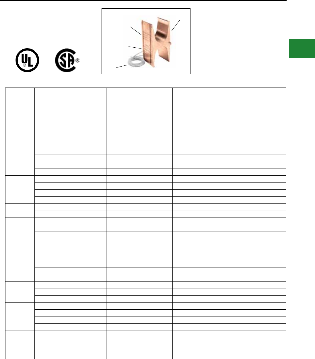
BURNDY®
Blue highlighted items are industry standard and most frequently ordered.
Canada: 1-800-387-6487 www.burndy.com US: 1-800-346-4175
TYPE YH
H-TAP COPPER CRIMPIT™
(Continued)
Catalog
Number
Maximum
Conductor in
Range
Maximum Metric
Dimensions
Diameter
mm
Minimum
Conductor in Range
Minimum
Metric
Dimensions
Diameter
mm
Flex Conductor
(AWG/kcmil) mm²
Flex Conductor
(AWG/kcmil) mm²
YH4444
Main 777 393 28 500 253 24
Tap 1 777 393 28 500 253 24
Main 777 393 28 750 380 31
YH4434* Tap 1 — — — 350 177 20
YH4429 Main 777 393 28 500 253 24
Tap 1 4/0 107 15.5 2 33.6 8
YH3939 Main 550 278 25 500 253 24
Tap 1 550 278 25 350 177 20
YH3931
Main 550 278 25 500 253 24
Tap1 250 126 17 1/0 53.5 11
Tap 2 1 42 9 8 8 4
Tap 3 2 33.6 8 14 2 2
YH3434 Main 350 177 20 4/0 107 15.5
Tap 1 350 177 20 4/0 107 15.5
YH3429
Main 350 177 20 4/0 107 15.5
Tap 1 4/0 107 15.5 1/0 53 11
Tap 2 1 42 9 8 8 4
Tap 3 8 8 4 14 2 2
YH2929 Main 4/0 107 15.5 2 33.6 8
Tap 1 4/0 107 15.5 2 33.6 8
YH292C
Main 4/0 107 15.5 2 33.6 8
Tap1 2 33.6 8 8 8 4
Tap 2 8 8 4 14 2 2
YH298C
Main 4/0 107 15.5 2 33.6 8
Tap1 8 8 4 14 2 2
Tap 2 8 8 4 14 2 2
YH2C2C
Main 2 33.6 8 8 8 4
Tap 1 2 33.6 8 8 8 4
Tap 2 8 8 4 14 2 2
Tap 3 8 8 4 14 2 2
YH6C6C Main 6 13 5 10 5 3
Tap 1 6 13 5 14 2 2
YH8C8C Main 8 8 4 14 2 2
Tap 1 8 8 4 14 2 2
COLOR CODE
DIE AND
CRIMP
INFORMATION
ELECTRO-TIN
PLATED
CONDUCTOR
RANGE
THIRD HAND
TABLE 2 FLEX AND METRIC CONDUCTOR RANGES
• Use PUADP-1 adaptor with U dies in Y46.
▲ See tooling section of this catalog for complete tool and
die listings.
* Not CSA Approved.
Note: All H-Taps ROHS compliant.
Note: All dimensions shown are for reference only.
Compression Connections
Copper Compression — Flex — H-Tap
C-133
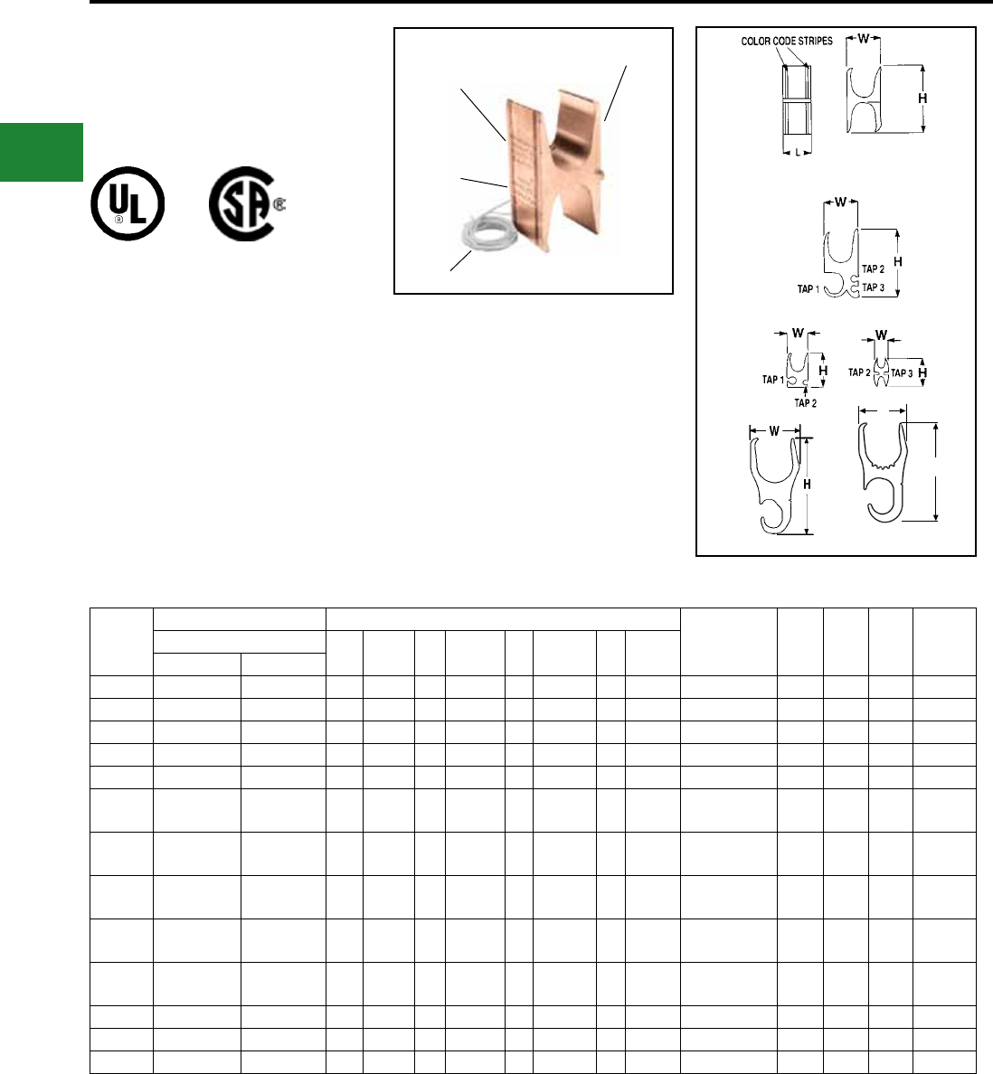
BURNDY®
Blue highlighted items are industry standard and most frequently ordered.
US: 1-800-346-4175 www.burndy.com Canada: 1-800-387-6487
TYPE YH
H-TAP COPPER CRIMPIT™
(Continued)
COLOR CODE
DIE AND
CRIMP
INFORMATION
ELECTRO-TIN
PLATED
CONDUCTOR
RANGE
THIRD HAND
Fig.1
Fig.2
Fig.4
Fig.5
Fig.3
BURNDY
Catalog
Number
Kit Catalog Number ▲ Tooling († No. of Crimps)
▲ Die Index &
Embossment H W L
Strip
Length
Flame Retardant Cover Fig.
No. Y35 † Y750 † Y46* †
Color
CodeClear Black ‡
YH4444 YH4444WCC YH4444WC 1 — — — — P1102 1 White 1102 3.38 1.70 1.00 1-1/8″
YH4434* YH4434WCC* YH4434WC 6 — — — — P1102 1 Yellow KR 3.38 1.70 1.00 1-3/8″
YH4429 YH4429WCC YH4429WC 5 — — — — PYFR 1 Yellow KR 3.22 1.70 1.00 1-3/8″
YH3939 YH3939WCC YH3939WC 1 — — — — PYFR 1 Yellow KR 2.97 1.50 1.25 1-3/8″
YH3931 YH3931WCC YH3931WC 2 — — — — PYFR 1 Yellow KR 2.97 1.50 0.95 1-1/16″
YH3434 YH3434WCC YH3434WC 1 — — U1104M
U1104
1
2
P1104
U1104M 1 Brown 1104 2.43 1.15 1.00 1-1/8″
YH3429 YH3429WCC YH3429WC 2 — — U1104M
U1104
1
2
P1104
U1104M 1 Brown 1104 2.23 1.31 1.00 1-1/8″
YH2929 YH2929WCC YH2929WC 1 — — U654 1 U654
P654 1 Purple 654 1.85 0.90 0.90 1-1/16″
YH292C YH292CWCC YH292CWC 3 — — U654 1 U654
P654 1 Purple 654 1.52 0.90 0.90 1-1/16″
YH298C YH298CWCC YH298CWC 3 — — U654 1 U654
P654 1 Purple 654 1.52 0.90 0.90 1-1/16″
YH2C2C YH2C2CWCC YH2C2CWC 4 U-C 1 U-C 1 U-C 1 Brown C 1.25 0.60 0.75 7/8″
YH6C6C YH6C6CWCC YH6C6CWC 1 UBGRT 1 UBGRT 1 UBGRT 1 Orange BG 0.81 0.39 0.60 3/4″
YH8C8C YH8C8CWCC YH8C8CWC 4 U11T-1 1 U11T-1 1 U11T-1 1 Green 11 0.63 0.40 0.60 3/4″
TABLE 3 INSTALLATION TOOLING + DIMENSIONS
• Use PUADP-1 adaptor with U dies in Y46.
▲ See tooling section of this catalog for complete tool and
die listings.
* Not CSA Approved.
Note: All H-Taps ROHS compliant.
Note: All dimensions shown are for reference only.
Compression Connections
Copper Compression — H-Tap
w
H
Fig.6
C-134
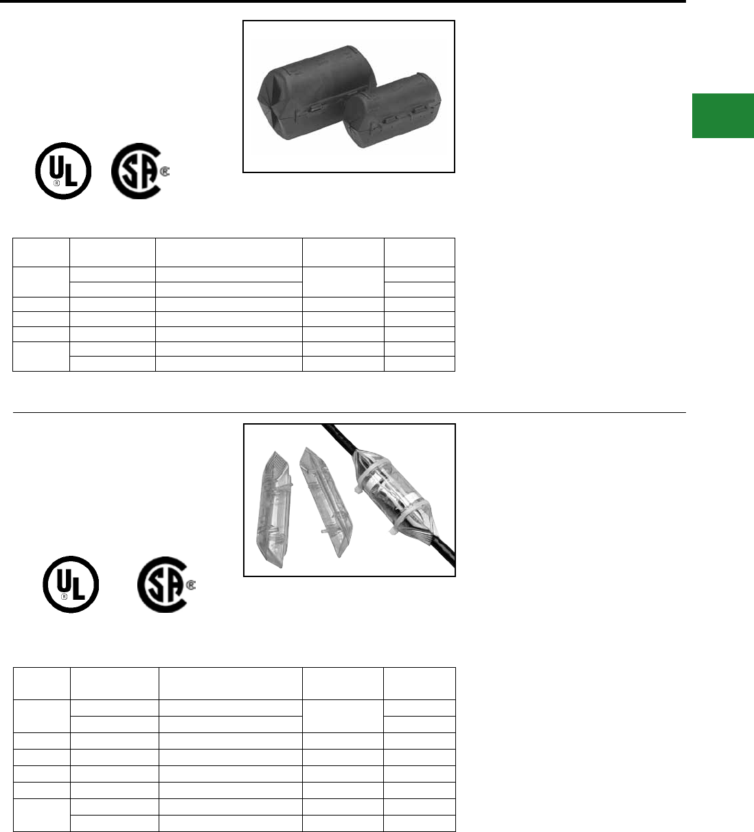
BURNDY®
Blue highlighted items are industry standard and most frequently ordered.
Canada: 1-800-387-6487 www.burndy.com US: 1-800-346-4175
TYPE CF-FR
H-TAP —
FLAME RETARDANT COVER
UL Listed to 600 Volts
Catalog
Number
Max. Conductor
Accommodated Matched H Copper CRIMPIT™
Max. Connector
Length
Connector
Color Code
CFBG-FR #8 AWG YH8C8C 0.65 Green
#6 AWG YH6C6C Orange
CFO-FR #2 AWG YH2C2C 0.80 Brown
CFD-FR 250 kcmil YH292C, YH298C, YH2929 0.95 Purple
CFN-FR 500 kcmil YH3434, YH3429* 1.10 Brown
CFR-FR † 750 kcmil YH3939, YH3931, YH4429 1.30 Yellow
1000 kcmil YH4434, YH4444 1.10 Yellow, White
Features & Benets
• One-piece design
◊ No extra parts or hardware required
• Slips over connector and latches
securely shut
◊ Fast, easy, reliable insulation of
H-Tap compression
• Eliminates taping
◊ Economical, fast, easy installation
• Flash barriers
◊ Protects against electrical ashover
• CF-FR ame retardant design
◊ Self-extinguishing retardant
properties
• Minimum 28 oxygen index
◊ Self-extinguishing retardant
properties
• UL 94 V-O rated
◊ Self-extinguishing retardant
properties
* Use CFN-FR for single tap installation; use CFR-FR
when 2 or more tap conductors are installed.
† Two-piece design packaged together.
Note: All dimensions shown are for reference only.
TYPE CCF-FR
CLEAR H-TAP —
FLAME RETARDANT COVER
UL Listed to 600 Volts
Catalog
Number
Max. Conductor
Accommodated Matched H Copper CRIMPIT™
Max. Connector
Length
Connector
Color Code
CCFBG-FR #8 AWG YH8C8C 0.65 Green
#6 AWG YH6C6C Orange
CCFO-FR #2 AWG YH2C2C 0.80 Brown
CCFD-FR 250 kcmil YH292C, YH298C 0.95 Purple
CCFDX-FR 250 kcmil YH2929 0.95 Purple
CCFN-FR 500 kcmil YH3434, YH3429* 1.10 Brown
CCFR-FR 750 kcmil YH3939, YH3931, YH4429 1.30 Yellow
1000 kcmil YH4434, YH4444 1.10 White
* Use CCFN-FR for single tap installation; use CCFR-FR
when 2 or more tap conductors are installed.
Note: All dimensions shown are for reference only.
Compression Connections
Flame Retardant H-Tap Covers
600 VOLT 90° C
600 VOLT 90° C
Features & Benets
• Two-Piece design with Positive
Locking Latch to ensure correct
installation, preventing opening after
installation and eliminating the need
for taping
• Mounted Magnifying Lens provides in
creased visibility of Die Embossment
on installed H-Tap Connectors
• Made of Polished Clear Polycarbonate-
material that provides:
◊ High visibility for inspection of
installed connectors
◊ Flame Retardant UL94 V-O Rated
Material-self-extinguishing retardant
properties
◊ High impact design
• Built in Channels to accommodate and
hold Cable ties, Hook & Loop ties, or
Waxed Cord, securely in place after
installation
• Patented highly exible ngers designed
to contour around the conductor
• Internal pockets designed to
accommodate Identication tags
(4 ID tags included)
• Molded barriers prevent installed H-Tap
Connectors from Electrical Flashover
• Covers come packaged complete with
(2) Cover Halves, (2) Cable Ties and
(4) Identication Labels
C-135
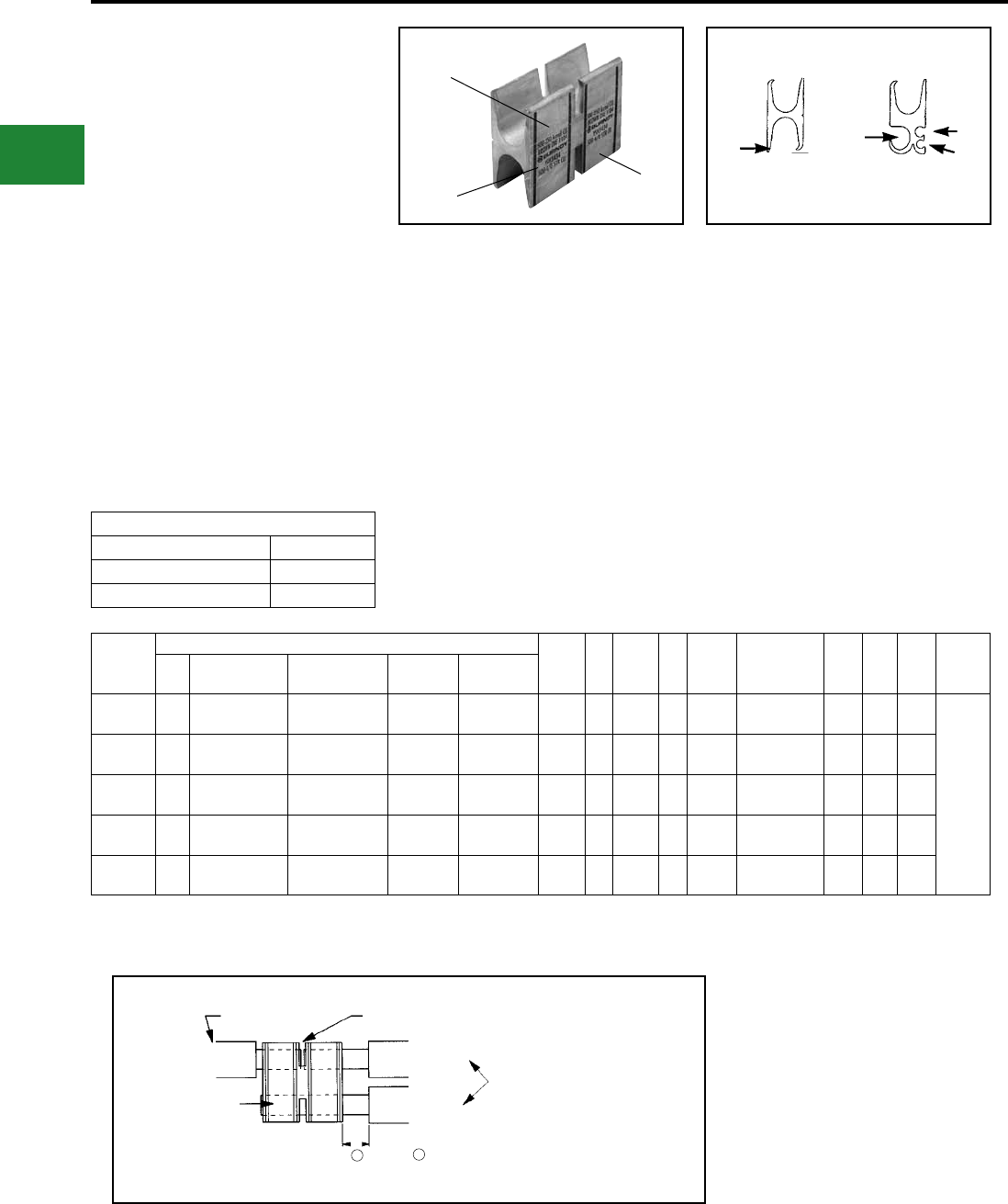
BURNDY®
Blue highlighted items are industry standard and most frequently ordered.
US: 1-800-346-4175 www.burndy.com Canada: 1-800-387-6487
TYPES YSH
H COPPER CRIMPIT™
COPPER SPLIT
COMPRESSION WYE TAP
CONNECTOR
The YSH heavy duty connectors are designed
for insulated underground wye splices. The
split H copper CRIMPIT™ connector is longer
than our standard H copper CRIMPIT™ and
is suitable for use on high voltage (15kV)
power cables with copper conductors. The
connectors cannot be used with oil lled or
mass impregnated cables since no oil stop
is provided. The connector is installed with
standard BURNDY® HYPRESS™ tools and is
made of tin-plated electrolytic copper.
Catalog
Number
Conductor Sizes Code Expanded Tap 1 (Flex Cable)
Y750 † Y46* †
Color
Code
Die
Index ▲&
Embossment H W L
Wire
Strip
Length
Fig.
# AWG Tap 1 Tap 2 Tap 3
YSH2929 1250 kcmil - #2
AWG (4/0-2)
250 kcmil - #2
AWG (4/0-2) - - U654 4 P654 2 Purple 654 1.85 0.90 3.00
1-1/2 in
YSH3429 2500 kcmil - 4/0
AWG (350-4/0)
250 kcmil -1/0
AWG (4/0-1/0)
#1-#6
AWG (1-8)
#8-#14
AWG (8-14) U1104 4 P1104 2 Brown 1104 2.23 1.31 3.00
YSH3434 1500- 250 Kcmil
(350-4/0)
500 kcmil - 4/0
AWG (350-4/0) - - U1104 4 P1104 2 Brown 1104 2.43 1.15 3.00
YSH3931 2750 - 350 Kcmil
(550-500)
4/0 - 1/0
AWG (350-1/0)
#1-#6
AWG (1-8)
#2-#14
AWG (2-14) - - PYFR 2 Yellow KR 2.97 1.50 3.00
YSH3939 1750 - 500 Kcmil
(550-500)
750 - 350 Kcmil
(550-350) - - - - PYFR 2 Yellow KR 2.97 1.50 3.00
Expanded Tap 1 Components
Expanded Catalog Number Tap 1 Range
YSH-292C-E #2 Str.
YSH-2925-E 1/0 Str.
Features & Benets
• Accommodates a wide range of run/tap cop-
per cable combinations including
both exible and code combinations.
All (B/B, B/I, I/B, I/I) combinations
acceptable
◊ Each connector has many copper
cable combination applications
allowing maximum exibility for
the design and installation of a
system
• Tap grooves function independently from
each other; use of one tap is required, bal-
ance may be used or left empty
◊ Provides maximum design and
installation exibility
• Color code on the connector matches instal-
lation die
◊ Provides matched system for fast
and easy installation
• Die index embossed on connector after
completion of crimp
◊ Permanent inspectability of
installed connectors to ensure
consistently reliable and depend-
able connections
• Insulation is not provided. Insulation can
be obtained from Raychem (800-272-9243)
type HVSY Splice kits for 15 kV installations
◊ A complete IEEE 404 15 kV
installation is provided
* Use PUADP-1 adaptor with U dies in Y46. The Y46 and
P dies result in a smooth crimp surface and is
recommended for voltages above 600 V.
▲ See tooling section of this catalog for complete tool
and die listings.
† Number of crimps per connector. U dies require double
crimps.
Note: All dimensions shown are for reference only.
For continuous and/or tap
connections refer to table
for conductor ranges.
Conductor ends remain visible
when conductor is split
Due to thickness of underground wire insulation
the minimum recommended strip length from the
connector edge is 1 inch.
Strip Length 1–1/2″
Main Conductor Main Conductor
Tap ConductorYSH Connector
11
Fig. 1 Fig. 2
TAP 3
TAP 2
TAP 1
TAP 1
Compression Connections
Copper Compression — Split H-Tap
Color Code Die and
Crimp Information
Conductor
Range
Electro-Tinplated
C-136
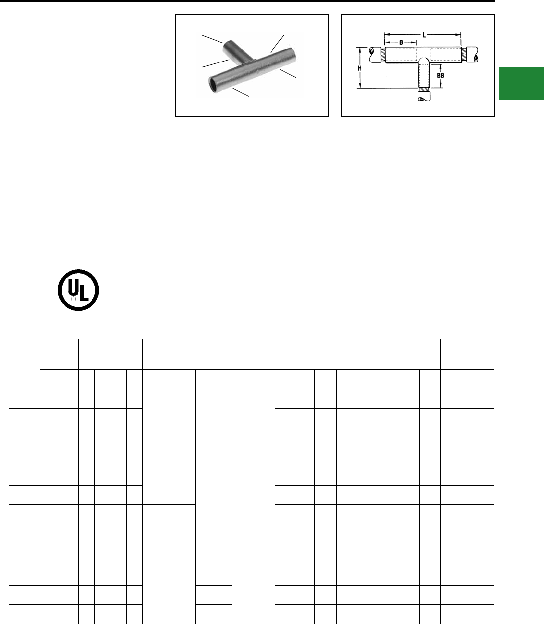
BURNDY®
Blue highlighted items are industry standard and most frequently ordered.
Canada: 1-800-387-6487 www.burndy.com US: 1-800-346-4175
TYPE YST
UNINSULATED T
COPPER HYTEE™ COUPLER
UL Listed 90° C,
600 Volts to 35 kV ♦
Type YST copper compression tee is designed
for connecting a run conductor with a
perpendicular tap conductor.
YST connectors are commonly used in junction
boxes and manholes to make a radial tap off a
main run. They are needed in many industrial,
utility generation and commercial applications.
The most common cable combinations are
listed below. BURNDY® Type Y-R reducers
can be used to accommodate most cable
combinations.
Catalog
Number
Code ●
Conductors Dimensions
Dieless
(# of crimps)
Installation Tooling ▲
Wire
Length
Run Conductors Tap Conductors
Y35, ▲ 739, Y750, Y46* Y35, ▲ 739, Y750, Y46*
Run Tap B BB H L (# of crimps)
Mechanical
HYTOOL™
Hydraulic
HYPRESS™
Die Number
(# of crimps)
Color
Code
Die
Index
Die Number
(# of crimps)
Color
Code
▲ Die
Index Run Tap
YST4C4C 4
str.
4
str. 1.12 1.38 1.72 3.25
Y81KFT (1)
Y81KFTMBH (1)
PAT81KFT-18V (1)
MY29-3 (2)
MY29-11 (2)
MD6 (4) **
MD7 (4) **
Y644HSXT (1)
U4CRT (2) Gray 8 U4CRT (2) Gray 8 1-3/16″ 1-3/16″
YST2C2C 2
str.
2
str. 1.25 1.56 1.98 3.56 U2CRT (2) Brown 10 U2CRT (2) Brown 10 1-5/16″ 1-5/16″
YST2525 1/0
str.
1/0
str. 1.38 1.56 1.91 3.81 U24RT (2) Pink 12 U25RT (2) Pink 12 1-7/16″ 1-7/16″
YST2626 2/0
str.
2/0
str. 1.50 1.67 2.18 3.94 U26RT (2) Black 13 U26RT (2) Black 13 1-9/16″ 1-9/16″
YST282C 4/0
str. 2 str. 1.62 1.50 2.12 3.94 U28RT (2) Purple 15 U2CRT (2) Brown 10 1-11/16″ 1-5/16″
YST2825 4/0
str.
1/0
str. 1.62 1.56 2.25 4.00 U28RT (2) Purple 15 U25RT (2) Pink 12 1-11/16″ 1-5/8″
YST2828 4/0
str.
4/0
str. 1.62 1.75 2.44 4.19 — U28RT (2) Purple 15 U28RT (2) Purple 15 1-11/16″ 1-13/16″
YST2929 250
kcmil
250
kcmil 1.62 1.78 2.53 4.25
Y81KFT (2)
Y81KFTMBH (2)
PAT81KFT-18V (2)
— U29RT (2) Yellow 16 U29RT (2) Yellow 16 1-11/16″ 1-11/16″
YST3131 350
kcmil
350
kcmil 2.00 2.25 3.12 5.50 — U31RT (4) Red 18 U31RT (4) Red 18 2″ 2″
YST3428 500
kcmil
4/0
str. 2.25 1.75 2.81 5.81 — U34RT (4) Brown 20 U28RT (2) Purple 15 2-5/16″ 1-11/16″
YST3434 500
kcmil
500
kcmil 2.25 2.70 3.76 6.19 — U34RT (4) Brown 20 U34RT (4) Brown 20 2-5/16″ 2-5/16″
YST3939 750
kcmil
750
kcmil 2.88 3.34 4.64 8.12 — U39RT (4) Black 24 U39RT (4) Black 24 2-15/16″ 2-15/16″
Features & Benets
• Manufactured from seamless high
conductivity electrolytic copper
tubing with heavy duty wall thickness
◊ Provides maximum conductivity,
low
resistance and ductility for an
excellent
combination of electrical
and crimp forming properties
• Long barrel design on all three (3) legs
◊ Provides for an additional crimp or
indent with almost twice the pull
out strength properties as a
standard length barrel plus a
connection that will operate cooler
under heavy loading
• Long barrel permits the use of the Y-R
reducers
◊ Affords total exibility and
versatility for virtually any
conductor combination
• Electro-tin plated
◊ Provides durable long-lasting
corrosion resistance
• Barrel diameter closely matches
commercial (code) cable and Navy cable
diameters
◊ Provides an excellent relationship
of the conductor/connector
combination to produce a high
quality electrical connection with
the recommended tooling
ELECTRO-TIN
PLATED
CRIMP
CRIMP
RUN
CRIMP
TAP
* Use adapter PUADP-1 with U Dies in Y46 HYPRESS™.
** Use with appropriate W Dies (see page O-29).
■ The maximum size for the Y35 is 400 kcmil.
● Contact factory for conductor combinations not shown.
▲ See tooling section of this catalog for complete tool and
die listings.
♦ For applications greater than 2000 Volts consult cable
manufacturer for voltage stress relief instructions.
Note: All dimensions shown are for reference only.
Compression Connections
Copper Compression — T-Coupler
C-137
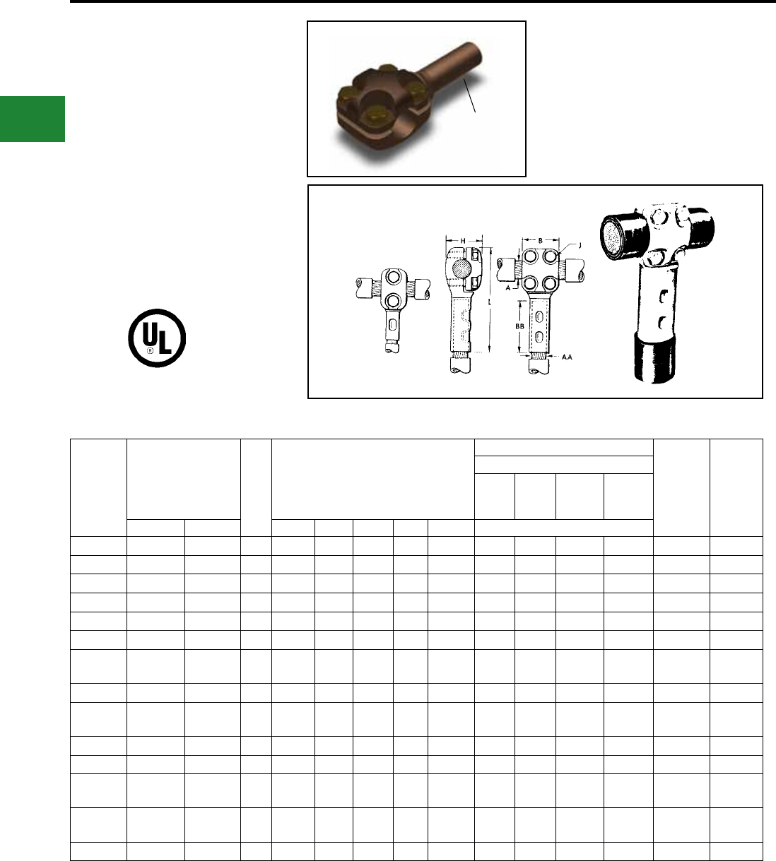
BURNDY®
Blue highlighted items are industry standard and most frequently ordered.
US: 1-800-346-4175 www.burndy.com Canada: 1-800-387-6487
T CONNECTOR
TYPE NYT
CABLE RUN — CABLE TAP
UL Listed 90° C,
600 Volts to 35 kV ♦
A T connector designed to provide a clamp
type element on the run and a permanent
HYPRESS™ connection on the tap.
Recommended for use on ring buses or for
applications where occasional disconnects from
the run conductor are desired without disturbing
the tap connection. Tin plated. For proper
installation of tap cable, see table below.
Catalog
Number
Conductor Size Fig.
No.
Dimensions in Inches
Installation Information
(No. of
Indents)
App.
Ship. Wt.
in Lbs.
HYPRESS™ and Indentor Die
Y29B
with
Y29PR
Y34A
with
Y34PR
Y34B
with
Y34PR
Y48B
with
Y44PR
Run A Tap AA B BB H J L Nest Die
NYT2828 4/0 Str. 4/0 Str. 2 2 1-5/8 1-3/8 3/8 4-5/16 D28L A28D B28D E28D (1) 2.2
NYT2925 250 kcmil 1/0 Str. 1 1-3/8 1-3/8 1-7/16 3/8 4-1/16 D25L A25D B25D — (1) 1.5
NYT2929 250 kcmil 250 kcmil 2 2 1-5/8 1-7/16 3/8 4-7/16 D29L A29D B29D E29D (1) 2.2
NYT3426 500 kcmil 2/0 Str. 1 1-3/8 1-1/2 1-5/8 3/8 4-7/16 D26L A26D B26D — (1) 1.7
NYT3428 500 kcmil 4/0 Str. 2 2 1-5/8 1-5/8 3/8 4-5/8 D28L A28D B28D E28D (1) 2.5
NYT3429 500 kcmil 250 kcmil 2 2 1-5/8 1-5/8 3/8 4-5/8 D29L A29D B29D E29D (1) 2.5
NYT3434 500 kcmil 500 kcmil 2 2 2-1/4 1-5/8 3/8 5-3/8 — A34D No Nest
Die Req. E34D (2) 2.5
NYT3929 750 kcmil 250 kcmil 2 2 1-5/8 1-7/8 3/8 4-13/16 D29L A29D B29D E29D (1) 2.5
NYT3934 750 kcmil 500 kcmil 2 2 2-1/4 1-7/8 3/8 5-9/16 — A34D No Nest
Die Req. E34D (2) 2.7
NYT4429 1000 kcmil 250 kcmil 2 2 1-5/8 2-1/8 3/8 5 D29L A29D B29D E29D (1) 2.5
NYT4431 1000 kcmil 350 kcmil 2 2 2 2-1/8 3/8 5-7/16 — A31D B31D E31D (2) 2.5
NYT4434 1000 kcmil 500 kcmil 2 2 2-1/4 2-1/8 3/8 5-3/4 — A34D No Nest
Die Req. E34D (2) 2.7
NYT4444 1000 kcmil 1000 kcmil 2 2-11/16 3 2-5/16 1/2 7 — — — No Nest
Die Req. (2) 3.2
NYT4646 1500 kcmil 1500 kcmil 2 2-11/16 3-3/16 2-3/4 1/2 7-11/16 — — — C46D* (2) 8.0
Fig. 1 Fig. 2
* Y48B HYPRESS™ with Y48PR indentor.
♦ For applications greater than 2000 Volts consult cable
manufacturer for voltage stress relief instructions.
Note: Circumferential dies may be used. For information
contact BURNDY®.
Note: All dimensions shown are for reference only.
Compression Connections
Bolted Run/Compression Tee Tap Connectors
Tinplated
C-138
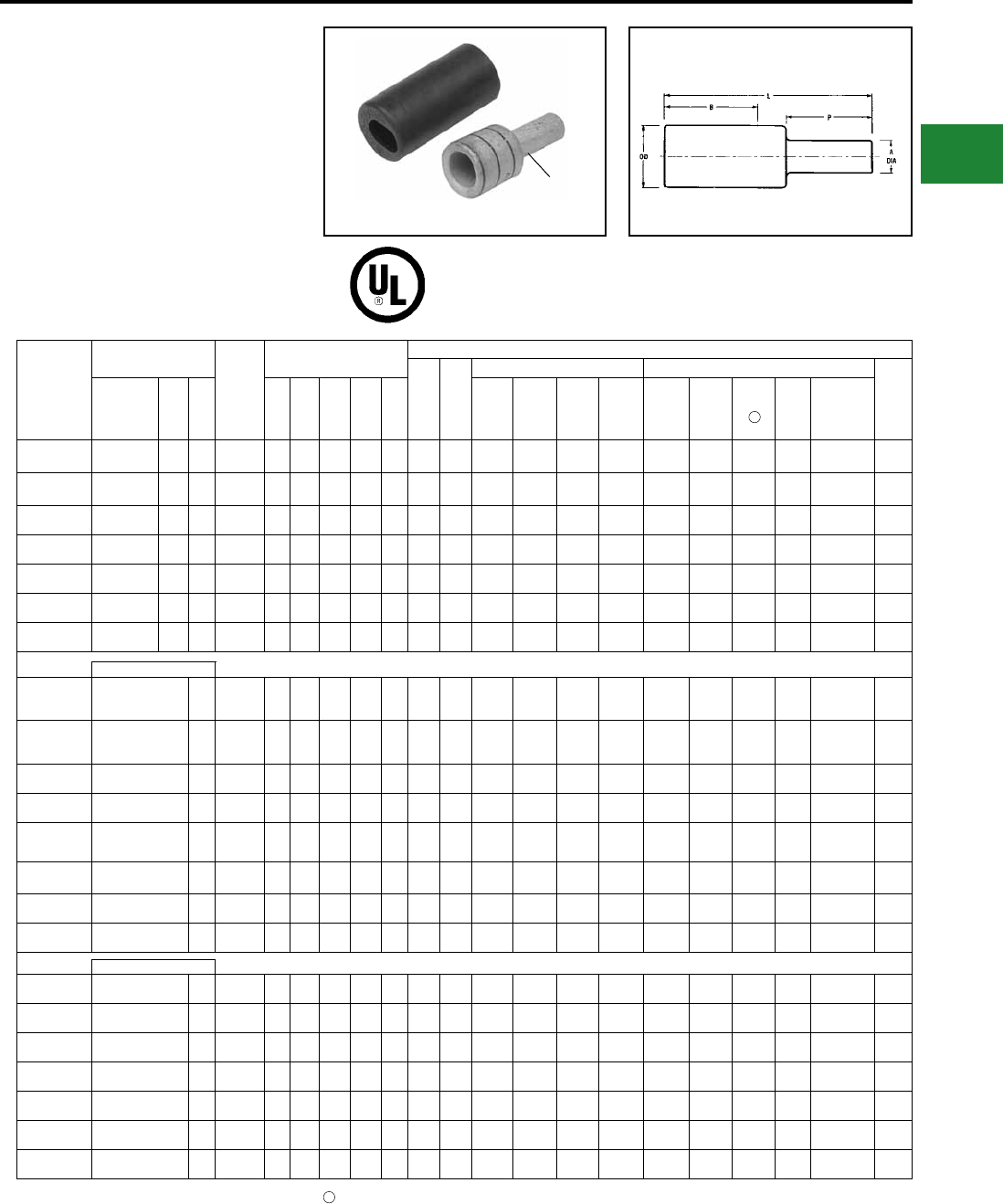
BURNDY®
Blue highlighted items are industry standard and most frequently ordered.
Canada: 1-800-387-6487 www.burndy.com US: 1-800-346-4175
TYPES YE-P, YE-P-FX
HYPLUG™ FOR COPPER
CONDUCTOR
Type YE-P copper compression adapters are
designed for reliable termination of copper
conductor when the current capacity of the
conductor is downsized, but larger conductor
is utilized. Typical applications are for voltage
drop protection when oversized conductors
are used or ex conductor is used. These
adapters facilitate the termination into existing
mechanical set screw connectors for various
stranded copper cables.
600 v, 900C EPDM rubber cover
Note: Cover supplied with the connector
90° C
1. For sizes above 4/0 the MD6-6R2 must be used. To use U Dies in Y46 HYPRESS™, catalog number
PUADP-1 die adaptor is required.
4Note: All dimensions shown are for reference only.
This page only is UL Listed
Catalog
Number
Accommodates
Copper Wire Sizes
Pin Size
Equivalent
Dimensions
Installation Data
Color
Code
Die
Index
Mech Tools (# of Crimps) Hydraulic Tools (# of Crimps)
Cable
Strip
LengthFlex Cable
Code
AWG Navy
A
Dia B L P OD MY Y1MRTC
MD7-
34R MD6/MD7
Y35/Y39
Y750 Y45 Y46
Y60
BHU
Y644HSXT
(Accomodates
Expanded
Wire Range)
YEV4CP20X75FX #4 Str.
(91/24-105/24) #4 40 4 AWG 0.20
[5]
1.37
[35]
2.27
[58]
0.75
[19]
0.38
[10] Gray 8 MY29-11
(1)
Y1MRTC
(4)
W4CVT
(2)
W4CRT
(2)
U4CRT
(2)
U4CRT
(2)
U4CRT
(2)) —#4 - #6
AWG(1) 1-1/2"
YEV2CP26X75FX #2 Str.
(125/24-150/24) #2 60 2 AWG 0.26
[7]
1.65
[42]
2.60
[66]
0.75
[19]
0.46
[12] Brown 10 MY29-11
(1)
Y1MRTC
(4)
W2CVT
(2)
W2CRT
(2)
U2CRT
(2)
U2CRT
(2)
U2CRT
(2) —#2 - #6
AWG(1) 1-3/4"
YEV1CP29X75FX #1 Str.
(175/24-225/24) #1 75 1 AWG 0.29
[8]
1.66
[42]
2.63
[67]
0.75
[19]
0.51
[13] Green 11 MY29-11
(1) —W1CVT
(2)
W1CRT-1
(2)
U1CRT-1
(2)
U1CRT-1
(2)
U1CRT-1
(2) —#1 - #6
AWG(1) 1-3/4"
YEV25P33X75FX 1/0 Str.
(275/24) 1/0 100 1/0 AWG 0.33
[8]
1.80
[46]
2.80
[71]
0.75
[19]
0.56
[14] Pink 12 MY29-11
(1) —W25VT
(4)
W25RT
(4)
U25RT
(2)
U25RT
(2)
U25RT
(2) —1/0 - #6
AWG(1) 1-7/8"
YEV26P37X75FX 2/0 Str.
(325/24) 2/0 125 2/0 AWG 0.37
[9]
1.82
[46]
2.86
[73]
0.75
[19]
0.63
[16] Black 13 MY29-11
(1) —W26VT
(4)
W26RT
(4)
U26RT
(2)
U26RT
(2)
U26RT
(2) —2/0 - #4
AWG(1) 1-7/8"
YEV27P41X82FX 3/0 Str.
(450/24) 3/0 150 3/0 AWG 0.41
[10]
1.97
[50]
3.11
[77]
0.82
[21]
0.70
[18]
Or-
ange 14 MY29-11
(1) —W27VT
(4)
W27RT
(4)
U27RT
(2)
U27RT
(2)
U27RT
(2) —3/0 - #2
AWG(1) 2-1/16"
YEV28P46X92FX 4/0 Str.
(550/24) 4/0 200 4/0 AWG 0.46
[12]
1.99
[51]
3.28
[81]
0.92
[23]
0.77
[20] Purple 15 MY29-11
(1) —W28VT
(4)
W28RT
(4)
U28RT
(2)
U28RT
(2)
U28RT
(2) —4/0 - #1
AWG(1) 2-1/16"
YE30P50X100FX
250 kcmil Flex
CLASS G 259 CLASS
H 427
— 250 kcmil 0.50
[10]
2.37
[60]
3.75
[95]
1.00
[25]
0.81
[21] Yellow 16 MY29-11
(1) —W29VT
(4)
W29RT
(4)
U29RT
(2)
U29RT
(2)
U29RT
(2)
L29RT
(1)
250kcmil-1/0
AWG (1) 2-3/8"
YE31P51X102FX
262.6 kcmil Flex
(650/24)
250 Flex CLASS I, K, M
— 262.6 kcmil 0.51
[13]
2.39
[61]
3.82
[97]
1.02
[26]
0.88
[22] White 17 — — W30VT
(8)
W30RT
(8)
U30RT
(4)
U30RT
(4)
U30RT
(4)
L30RT
(1)
250kcmil-1/0
AWG (1) 2-1/2"
YE32P55X110FX 313.1 kcmil (775/24)
(300 kcmil Nom) — 300 kcmil 0.55
[14]
2.53
[65]
4.08
[104]
1.10
[28]
0.95
[24] Red 18 — — W31VT
(8)
W31RT
(8)
U31RT
(4)
U31RT
(4)
U31RT
(4)
L31RT
(1)
300kcmil-2/0
AWG (1) 2-5/8"
YE34P59X118FX 373.7 kcmil (925/24)
(350 kcmil Nom) — 350 kcmil 0.59
[15]
2.68
[68]
4.36
[111]
1.18
[30]
1.06
[27] Blue 19 — — W32VT
(8)
W32RT
(8)
U32RT
(4)
U32RT
(4)
U32RT
(4)
L32RT
(1)
350kcmil-3/0
AWG (1) 2-3/4"
YE36P67X134FX 444.4 kcmil (1100/24)
(450 kcmil Nom) — 450 kcmil 0.67
[17]
3.14
[80]
5.04
[128]
1.34
[34]
1.19
[30] Brown 20 — — W34VT
(8)
W34RT
(8)
U34RT
(4)
U34RT
(4)
U34RT
(4)
L34RT
(2)
450kcmil-4/0
AWG (1) 3-1/4"
YE38P71X142FX 535.3 kcmil (1325/24)
(500 kcmil Nom) — 500 kcmil 0.71
[18]
3.29
[84]
5.30
[135]
1.42
[36]
1.25
[32] Pink L99 — — — — U38XRT
(4)
U38XRT
(4)
U38XRT
(4) —500kcmil-4/0
AWG (1) 3-3/8"
YE40P78X156FX 646 kcmil (1600/24)
(600 kcmil Nom) — 600 kcmil 0.78
[20]
3.31
[84]
5.51
[140]
1.56
[40]
1.35
[34] Black 24 — — — — U39RT
(4)
U39RT
(4)
U39RT
(4)
L39RT
(2)
600kcmil-250
kcmil (1) 3-7/16"
YE44P87X174FX 777.7 kcmil (1925/24)
(750 kcmil Nom) — 750 kcmil 0.87
[22]
3.54
[90]
5.99
[152]
1.74
[44]
1.50
[38] Yellow L115 — — — — U44XRT
(4)
U44XRT
(4)
U44XRT
(4) —750kcmil-500
kcmil (1) 3-5/8"
YE29P50X100 250 kcmil 250 250 kcmil 0.50
[13]
1.99
[51]
3.33
[84]
1.00
[25]
0.75
[19] Yellow 16 MY29-11
(1) —W29VT
(4)
W29RT
(4)
U29RT
(2)
U29RT
(2)
U29RT
(2) —250 kcmil - 1/0
AWG (1) 2-1/2"
YE30P55X110 300 kcmil 300 300 kcmil 0.55
[14]
2.37
[60]
3.85
[98]
1.10
[28]
0.81
[21] White 17 — — W30VT
(8)
W30RT
(8)
U30RT
(4)
U30RT
(4)
U30RT
(4)
L30RT
(1)
300 kcmil - 2/0
AWG(1) 2-5/8"
YE31P59X118 350 kcmil 350 350 kcmil 0.59
[15]
2.39
[61]
3.98
[101]
1.18
[30]
0.88
[22] Red 18 — — W31VT
(8)
W31RT
(8)
U31RT
(4)
U31RT
(4)
U31RT
(4)
L31RT
(1)
350 kcmil - 3/0
AWG(1) 2-3/4"
YE32P63X126 400 kcmil 400 400 kcmil 0.63
[16]
2.53
[65]
4.24
[108]
1.26
[32]
0.95
[24] Blue 19 — — W32VT
(8)
W32RT
(8)
U32RT
(4)
U32RT
(4)
U32RT
(4)
L32RT
(1)
400 kcmil - 4/0
AWG(1) 3-1/4"
YE34P71X142 500 kcmil — 500 kcmil 0.71
[18]
2.68
[68]
4.60
[117]
1.42
[36]
1.06
[27] Brown 20 — — W34VT
(8)
W34RT
(8)
U34RT
(4)
U34RT
(4)
U34RT
(4)
L34RT
(2)
500 kcmil - 4/0
AWG(1) 3-3/8"
YE36P78X156 600 kcmil — 600 kcmil 0.78
[20]
3.14
[80]
3.78
[133]
1.56
[40]
1.19
[30] Green 22 — — — — U36RT
(4)
U36RT
(4)
U36RT
(4)
L36RT
(2)
600 kcmil - 250
kcmil(1) 1-3/4"
YE39P87X174 750 kcmil — 750 kcmil 0.87
[22]
3.37
[86]
5.73
[145]
1.74
[44]
1.30
[33] Black 24 — — — — U39RT
(4)
S39RT
(4)
P39RT
(4)
L39RT
(2)
750 kcmil - 500
kcmil(1) 3-5/8"
Flex Cable Only
4
Compression Connections
Copper Compression — Adaptors
Tinplated
Code Conductor Only AWG
C-139
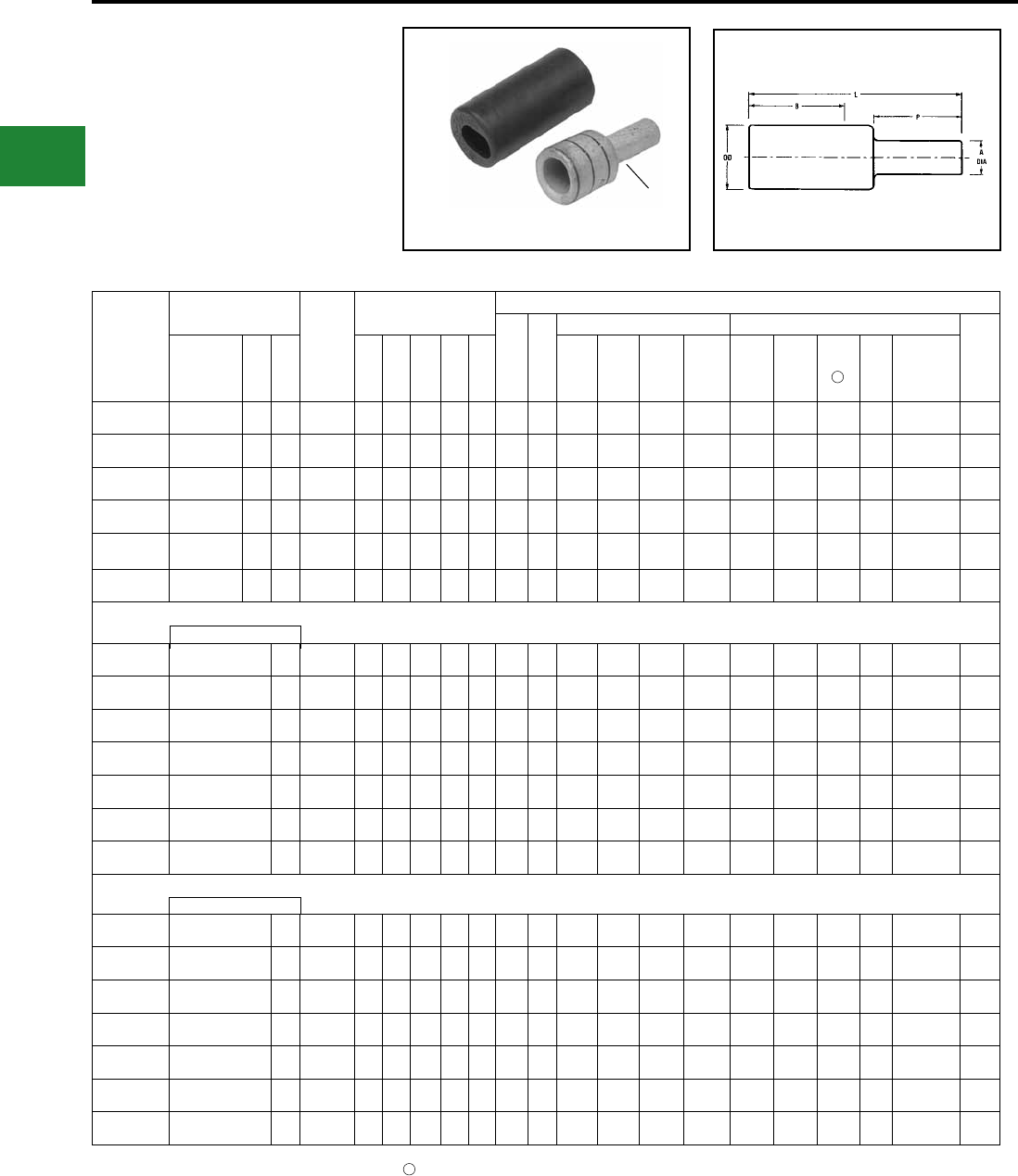
BURNDY®
Blue highlighted items are industry standard and most frequently ordered.
US: 1-800-346-4175 www.burndy.com Canada: 1-800-387-6487
TYPES YE-P, YE-P-FX
(Continued)
HYPLUG™ FOR COPPER
CONDUCTOR
600 v, 900C EPDM rubber cover
Note: Cover supplied with the connector
1. For sizes above 4/0 the MD6-6R2 must be used. To use U Dies in Y46 HYPRESS™, catalog number
PUADP-1 die adaptor is required.
4Note: All dimensions shown are for reference only.
Catalog
Number
Accommodates
Copper Wire Sizes
Pin Size
Equivalent
Dimensions
Installation Data
Color
Code
Die
Index
Mech Tools (# of Crimps) Hydraulic Tools (# of Crimps)
Cable
Strip
LengthFlex Cable
Code
AWG Navy
A
Dia B L P OD MY Y1MRTC MD7-34R MD6/MD7
Y35/Y39
Y750 Y45 Y46
Y60
BHU
Y644HSXT
(Accomodates
Expanded
Wire Range)
YEV2CP23X75FX #2 Str.
(125/24-150/24) #2 60 3 AWG 0.23
[6]
1.65
[42]
2.60
[66]
0.75
[19]
0.46
[12] Brown 10 MY29-11
(1)
Y1MRTC
(4)
W2CVT
(2)
W2CRT
(2)
U2CRT
(2)
U2CRT
(2)
U2CRT
(2) —#2 - #6
AWG(1) 1-3/4 “
YEV1CP26X75FX #1 Str.
(175/24-225/24) #1 75 2 AWG 0.26
[7]
1.66
[42]
2.63
[67]
0.75
[19]
0.51
[13] Green 11 MY29-11
(1) —W1CVT
(2)
W1CRT-1
(2)
U1CRT-1
(2)
U1CRT-1
(2)
U1CRT-1
(2) —#1 - #6
AWG(1) 1-3/4"
YEV25P29X75FX 1/0 Str.
(275/24) 1/0 100 1 AWG 0.29
[8]
1.80
[46]
2.80
[71]
0.75
[19]
0.56
[14] Pink 12 MY29-11
(1) —W25VT
(4)
W25RT
(4)
U25RT
(2)
U25RT
(2)
U25RT
(2) — 1/0 - #6 AWG(1) 1-7/8"
YEV26P33X75FX 2/0 Str.
(325/24) 2/0 125 1/0 AWG 0.33
[8]
1.82
[46]
2.86
[73]
0.75
[19]
0.63
[16] Black 13 MY29-11
(1) —W26VT
(4)
W26RT
(4)
U26RT
(2)
U26RT
(2)
U26RT
(2) — 2/0 - #4 AWG(1) 1-7/8"
YEV27P37X75FX 3/0 Str.
(450/24) 3/0 150 2/0 AWG 0.37
[9]
1.97
[50]
3.04
[77]
0.75
[19]
0.70
[18]
Or-
ange 14 MY29-11
(1) —W27VT
(4)
W27RT
(4)
U27RT
(2)
U27RT
(2)
U27RT
(2) — 3/0 - #2 AWG(1) 2-1/16"
YEV28P41X75FX 4/0 Str.
(550/24) 4/0 200 3/0 AWG 0.41
[10]
1.99
[51]
3.11
[81]
0.75
[21]
0.77
[20] Purple 15 MY29-11
(1) —W28VT
(4)
W28RT
(4)
U28RT
(2)
U28RT
(2)
U28RT
(2) — 4/0 - #1 AWG(1) 2-1/16"
YE30P46X92FX 250 kcmil Flex
Class G 259 Class H 427 — 4/0 0.46
[12]
2.37
[60]
3.67
[93]
0.92
[23]
0.81
[21] Yellow 16 MY29-11
(1) —W29VT
(4)
W29RT
(4)
U29RT
(2)
U29RT
(2)
U29RT
(2)
L29RT
(1)
250 kcmil - 1/0
AWG (1) 2-3/8 "
YE32P51X102FX 313.1 kcmil (775/24)
(300 kcmil Nom) —250 kcmil 0.51
[13]
2.53
[65]
4.00
[102]
1.02
[26]
0.95
[24] Red 18 — — W31VT
(8)
W31RT
(8)
U31RT
(4)
U31RT
(4)
U31RT
(4)
L31RT
(1)
300 kcmil - 2/0
AWG (1) 2-5/8 "
YE34P55X110FX 373.7 kcmil (925/24)
(350 kcmil Nom) —300 kcmil 0.55
[14]
2.68
[68]
4.28
[109]
1.10
[28]
1.06
[27] Blue 19 — — W32VT
(8)
W32RT
(8)
U32RT
(4)
U32RT
(4)
U32RT
(4)
L32RT
(1)
350 kcmil - 3/0
AWG (1) 2-3/4 "
YE36P59X118FX 444.4 kcmil (1100/24)
(450 kcmil Nom) —350 kcmil 0.59
[15]
3.14
[80]
4.88
[124]
1.18
[30]
1.19
[30] Brown 20 — — W34VT
(8)
W34RT
(8)
U34RT
(4)
U34RT
(4)
U34RT
(4)
L34RT
(2)
450 kcmil - 4/0
AWG (1) 3-1/4 "
YE38P67X134FX 535.3 kcmil (1325/24)
(500 kcmil Nom) —450 kcmil 0.67
[17]
3.29
[84]
5.22
[133]
1.34
[34]
1.25
[32] Pink L99 — — — — U38XRT
(4)
U38XRT
(4)
U38XRT
(4) —500 kcmil - 4/0
AWG (1) 3-3/8 "
YE40P71X142FX 646 kcmil (1600/24)
(600 kcmil Nom) —500 kcmil 0.71
[18]
3.31
[84]
5.37
[136]
1.42
[36]
1.35
[34] Black 24 — — — — U39RT
(4)
U39RT
(4)
U39RT
(4)
L39RT
(2)
600 kcmil - 250
kcmil (1) 3-7/16"
YE44P78X156FX 777.7 kcmil (1925/24)
(750 kcmil Nom) —600 kcmil 0.78
[20]
3.54
[90]
5.81
[148]
1.56
[40]
1.50
[38] Yellow L115 — — — — U44XRT
(4)
U44XRT
(4)
U44XRT
(4) —750 kcmil - 500
kcmil (1) 3-5/8 "
YE29P46X92 250 kcmil 250 4/0 0.46
[12]
1.99
[51]
3.25
[82]
0.92
[23]
0.75
[19] Yellow 16 MY29-11
(1) —W29VT
(4)
W29RT
(4)
U29RT
(2)
U29RT
(2)
U29RT
(2) —250 kcmil - 1/0
AWG (1) 2-1/2 "
YE30P50X100 300 kcmil 300 250 kcmil 0.50
[13]
2.37
[60]
3.75
[95]
1.00
[25]
0.81
[21] White 17 — —W30VT
(8)
W30RT
(8)
U30RT
(4)
U30RT
(4)
U30RT
(4)
L30RT
(1)
300 kcmil - 2/0
AWG (1) 2-5/8 "
YE31P55X110 350 kcmil 350 300 kcmil 0.55
[14]
2.39
[61]
3.90
[99]
1.10
[28]
0.88
[22] Red 18 — —W31VT
(8)
W31RT
(8)
U31RT
(4)
U31RT
(4)
U31RT
(4)
L31RT
(1)
350 kcmil - 3/0
AWG (1) 2-3/4 "
YE32P59X118 400 kcmil 400 350 kcmil 0.59
[15]
2.53
[65]
4.16
[106]
1.18
[30]
0.95
[24] Blue 19 — —W32VT
(8)
W32RT
(8)
U32RT
(4)
U32RT
(4)
U32RT
(4)
L32RT
(1)
400 kcmil - 4/0
AWG (1) 3-1/4 "
YE34P63X126 500 kcmil — 400 kcmil 0.63
[16]
2.68
[68]
4.44
[113]
1.26
[32]
1.06
[27] Brown 20 — —W34VT
(8)
W34RT
(8)
U34RT
(4)
U34RT
(4)
U34RT
(4)
L34RT
(2)
500 kcmil - 4/0
AWG (1) 3-3/8 "
YE36P71X142 600 kcmil — 500 kcmil 0.71
[18]
3.14
[80]
5.11
[130]
1.42
[36]
1.19
[30] Green 22 — —— — U36RT
(4)
U36RT
(4)
U36RT
(4)
L36RT
(2)
600 kcmil - 250
kcmil (1) 3-7/16 "
YE39P78X156 750 kcmil — 600 kcmil 0.78
[20]
3.37
[86]
5.55
[141]
1.56
[40]
1.30
[33] Black 24 — —— — U39RT
(4)
S39RT
(4)
P39RT
(4)
L39RT
(2)
750 kcmil - 500
kcmil (1) 3-5/8 "
4
Flex Cable Only
Code Conductor Only AWG
Compression Connections
Copper Compression — Adaptors
Tinplated
C-140
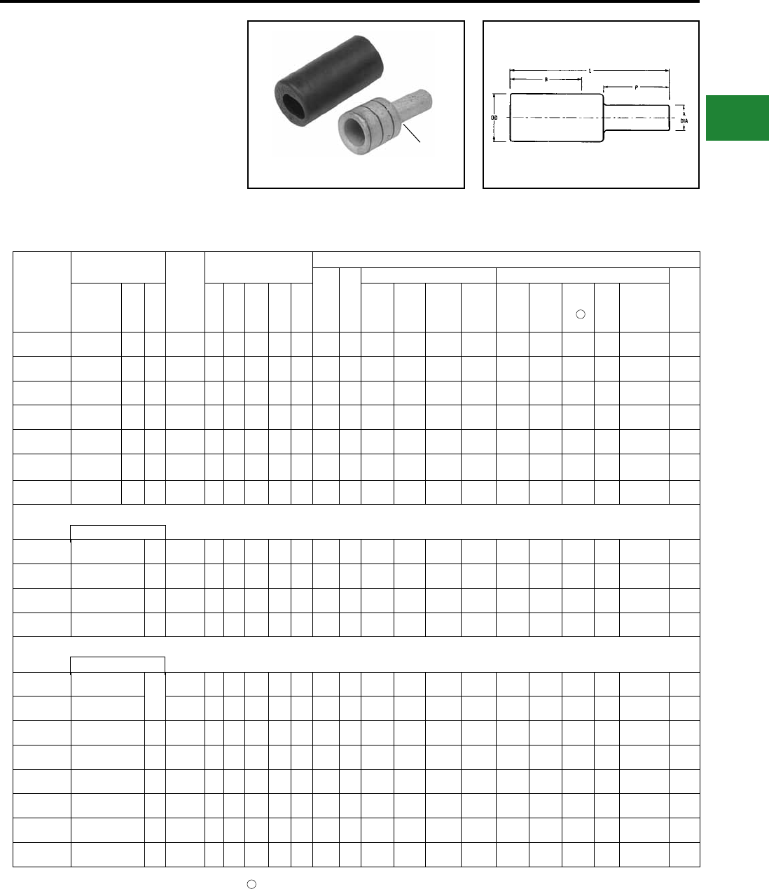
BURNDY®
Blue highlighted items are industry standard and most frequently ordered.
Canada: 1-800-387-6487 www.burndy.com US: 1-800-346-4175
TYPES YE-P, YE-P-FX
(Continued)
HYPLUG™ FOR COPPER
CONDUCTOR
600 v, 900C EPDM rubber cover
Note: Cover supplied with the connector
1. For sizes above 4/0 the MD6-6R2 must be used. To use U Dies in Y46 HYPRESS™, catalog number
PUADP-1 die adaptor is required.
4Note: All dimensions shown are for reference only.
Catalog
Number
Accommodates
Copper Wire Sizes
Pin Size
Equivalent
Dimensions
Installation Data
Color
Code
Die
Index
Mech Tools (# of Crimps) Hydraulic Tools (# of Crimps)
Cable
Strip
LengthFlex Cable
Code
AWG Navy
A
Dia B L P OD MY
Y1M-
RTC MD7-34R MD6/MD7
Y35/Y39
Y750 Y45 Y46
Y60
BHU
Y644HSXT
(Accomodates
Expanded
Wire Range)
YEV4CP16X75FX
#4 Str.
(91/24-105/24) #4 40 #6
0.16
[4]
1.37
[35]
2.27
[58]
0.75
[19]
0.38
[10] Gray 8 MY29-11
(1)
Y1MRTC
(2)
W4CVT
(2)
W4CRT
(2)
U4CRT
(2)
U4CRT
(2)
U4CRT
(2) —#4 - #6
AWG(1) 1-15/32 “
YEV2CP20X75FX #2 Str.
(125/24-150/24) #2 60 #4 0.20
[5]
1.65
[42]
2.60
[66]
0.75
[19]
0.46
[12] Brown 10 MY29-11
(1)
Y1MRTC
(2)
W2CVT
(2)
W2CRT
(2)
U2CRT
(2)
U2CRT
(2)
U2CRT
(2) —#2 - #6
AWG(1) 1-3/4 “
YEV1CP23X75FX #1 Str.
(175/24-225/24) #1 75 #3 0.23
[6]
1.66
[42]
2.63
[67]
0.75
[19]
0.51
[13] Green 11 MY29-11
(1) —W1CVT
(2)
W1CRT-1
(2)
U1CRT-1
(2)
U1CRT-1
(2)
U1CRT-1
(2) —#1 - #6
AWG(1) 1-3/4 "
YEV25P26X75FX 1/0 Str.
(275/24) 1/0 100 #2 0.26
[7]
1.80
[46]
2.80
[71]
0.75
[19]
0.56
[14] Pink 12 MY29-11
(1) —W25VT
(4)
W25RT
(4)
U25RT
(2)
U25RT
(2)
U25RT
(2) —1/0 - #6
AWG(1) 1-7/8 "
YEV26P29X75FX 2/0 Str.
(325/24) 2/0 125 #1 0.29
[8]
1.82
[46]
2.86
[73]
0.75
[19]
0.63
[16] Black 13 MY29-11
(1) —W26VT
(4)
W26RT
(4)
U26RT
(2)
U26RT
(2)
U26RT
(2) —2/0 - #4
AWG(1) 1-7/8 "
YEV27P33X75FX 3/0 Str.
(450/24) 3/0 150 1/0 0.33
[8]
1.97
[50]
3.04
[77]
0.75
[19]
0.70
[18] Orange 14 MY29-11
(1) —W27VT
(4)
W27RT
(4)
U27RT
(2)
U27RT
(2)
U27RT
(2) —3/0 - #2
AWG(1) 2-1/16 "
YEV28P37X75FX 4/0 Str.
(550/24) 4/0 200 2/0 0.37
[9]
1.99
[51]
3.11
[81]
0.75
[19]
0.77
[20] Purple 15 MY29-11
(1) —W28VT
(4)
W28RT
(4)
U28RT
(2)
U28RT
(2)
U28RT
(2) —4/0 - #1
AWG(1) 2-1/16 "
YE31P41X82FX 262.6 kcmil (650/24)
250 Flex Class I, K, M — 3/0 0.41
[10]
2.39
[61]
3.62
[92]
0.82
[21]
0.88
[22] White 17 — — W30VT
(8)
W30RT
(8)
U30RT
(4)
U30RT
(4)
U30RT
(4)
L30RT
(1)
250kcmil-1/0
AWG (1) 2-1/2"
YE34P51X102FX 373.7 kcmil (925/24)
(350 kcmil Nom) —250 kcmil 0.51
[13]
2.68
[68]
4.20
[107]
1.02
[26]
1.06
[27] Blue 19 — — W32VT
(8)
W32RT
(8)
U32RT
(4)
U32RT
(4)
U32RT
(4)
L32RT
(1)
350kcmil-3/0
AWG (1) 2-3/4"
YE38P59X118FX 535.3 kcmil (1325/24)
(500 kcmil Nom) —350 kcmil 0.59
[15]
3.29
[84]
5.06
[129]
1.18
[30]
1.25
[32] Pink L99 — — — — U38XRT
(4)
U38XRT
(4)
U38XRT
(4) —500kcmil-4/0
AWG (1) 3-3/8"
YE40P67X134FX 646 kcmil (1600/24)
(600 kcmil Nom) —450 kcmil 0.67
[17]
3.31
[84]
5.29
[134]
1.34
[34]
1.35
[34] Black 24 — — — — U39RT
(4)
U39RT
(4)
U39RT
(4)
L39RT
(2)
600kcmil-250
kcmil (1) 3-7/16"
YE29P31X109 250 kcmil
250
#1 0.31
[8]
1.06
[27]
2.49
[63]
1.09
[28]
0.75
[19] Yellow 16 — — — W29RT
(4)
U29RT
(2)
U29RT
(2)
U29RT
(2)
L29RT
(2) — 1-1/8
YE29P41X82 250 kcmil 3/0 0.41
[10]
1.99
[51]
3.15
[80]
0.82
[21]
0.75
[19] Yellow 16 MY29-11
(1) —W29VT
(4)
W29RT
(4)
U29RT
(2)
U29RT
(2)
U29RT
(2) —250 kcmil - 1/0
AWG(1) 2-1/2 "
YE30P46X92 300 kcmil 300 4/0 0.46
[12]
2.37
[60]
3.67
[93]
0.92
[23]
0.81
[21] White 17 — —W30VT
(8)
W30RT
(8)
U30RT
(4)
U30RT
(4)
U30RT
(4)
L30RT
(1)
300 kcmil - 2/0
AWG(1) 2-5/8 "
YE31P50X100 350 kcmil 350 250 kcmil 0.51
[13]
2.39
[61]
3.80
[96]
1.00
[25]
0.88
[22] Red 18 — —W31VT
(8)
W31RT
(8)
U31RT
(4)
U31RT
(4)
U31RT
(4)
L31RT
(1)
350 kcmil - 3/0
AWG(1) 2-3/4 "
YE36P63X126 600 kcmil 400 400 kcmil 0.63
[16]
3.14
[80]
4.95
[126]
1.26
[32]
1.19
[30] Green 22 — —— — U36RT
(4)
U36RT
(4)
U36RT
(4)
L36RT
(2)
600 kcmil - 250
kcmil(1) 3-7/16 "
YE39P71X142 750 kcmil — 500 kcmil 0.71
[18]
3.37
[86]
5.41
[137]
1.42
[36]
1.30
[33] Black 24 — —— — U39RT
(4)
S39RT
(4)
P39RT
(4)
L39RT
(2)
750 kcmil - 500
kcmil(1) 3-5/8"
YE32P55X110 400 kcmil — 300 kcmil 0.55
[14]
2.53
[65]
4.08
[104]
1.10
[28]
0.95
[24] Blue 19 — —W32VT
(8)
W32RT
(8)
U32RT
(4)
U32RT
(4)
U32RT
(4)
L32RT
(1)
400 kcmil - 4/0
AWG(1) 3-1/4 "
YE34P59X118 500 kcmil — 350 kcmil 0.59
[15]
2.68
[68]
4.36
[111]
1.18
[30]
1.06
[27] Brown 20 — —W34VT
(8)
W34RT
(8)
U34RT
(4)
U34RT
(4)
U34RT
(4)
L34RT
(2)
500 kcmil - 4/0
AWG(1) 3-3/8 "
4
Flex Cable Only
Code Conductor Only AWG
REDUCED PIN DIAMETER
Compression Connections
Copper Compression — Adaptors
Tinplated
C-141
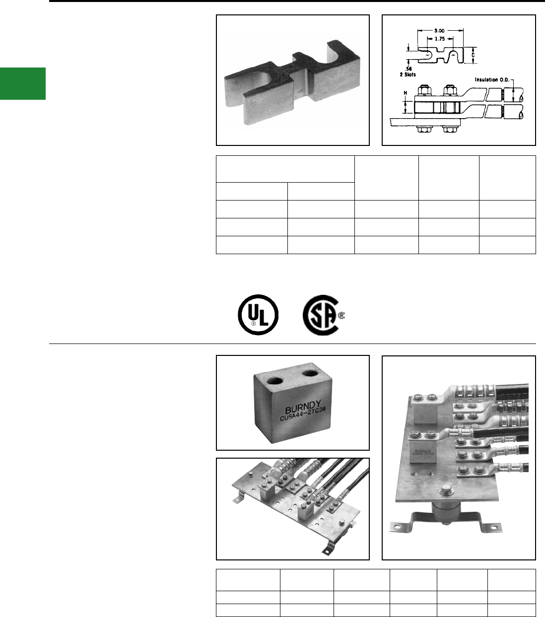
BURNDY®
Blue highlighted items are industry standard and most frequently ordered.
US: 1-800-346-4175 www.burndy.com Canada: 1-800-387-6487
TYPE ASA-U
HYSTACK™
TERMINAL STACKING
ADAPTOR
FOR ALUMINUM AND
COPPER TERMINALS
UL Listed 90° C,
600 Volts to 35 kV
The HYSTACK™ adaptor is specially designed
to allow standard terminals to be stacked
on two or four hole NEMA transformer or
equipment terminal pads. HYSTACK™ is tin-
plated, high-conductivity aluminum to provide
optimum corrosion resistance. Only three sizes
accommodate terminals from 250 mcm through
1000 mcm to help keep costly inventories to a
minimum.
Accommodates Copper and Aluminum
Compression Terminals
Catalog
Number C HConductor Max. Insulation O.D.
250 kcmil 0.87 ASA250U 1.00 0.77
800 kcmil 1.37 ASA800U 1.00 1.13
1000 kcmil 1.49 ASA1000U 1.25 1.25
To stack 4 hole NEMA drilled terminals use 2 adaptors
assembled side by side.
ASA-U stacking adaptors are recommended for use with
any BURNDY® UL Listed compression terminal, 2 or 4
hole NEMA pad aluminum and copper lugs,types YA,
YA-L, YA-A, and for all 2-hole NEMA spaced lugs in the
OVERHEAD and UNDERGROUND catalog sections.
Note: All dimensions shown are for reference only.
Compression Connections
Copper — Stacking Adaptors
TYPE CUSA
HYSTACK™
TERMINAL STACKING
ADAPTOR
This HYSTACK™ adaptor is specially designed
to get terminals to the back end of a bus bar or
other areas that require terminals to be elevated
off the mounting surface. This HYSTACK™ is
made from high conductivity copper and tin-
plated to provide optimum corrosion resistance.
It will accommodate #10 AWG through 750
kcmil HYLUG™ terminals.
Catalog
Number
Stud Hole
Size
Stud Hole
Spacing Length Width Height
CUSA442TC38 3/8″ 1″ 1.75″ 1.12″ 1.50″
CUSA442NTC 1/2″ 1-3/4″ 3.00″ 1.12″ 1.50″
Reference: Catalog Number TMH332.
This TMH332 Kit has just the right hardware when using
the CUSA442TC38 HYSTACK on a 1/4 bus bar with a 4/0
through 750 kcmil HYLUG™.
Note: All dimensions shown are for reference only.
C-142
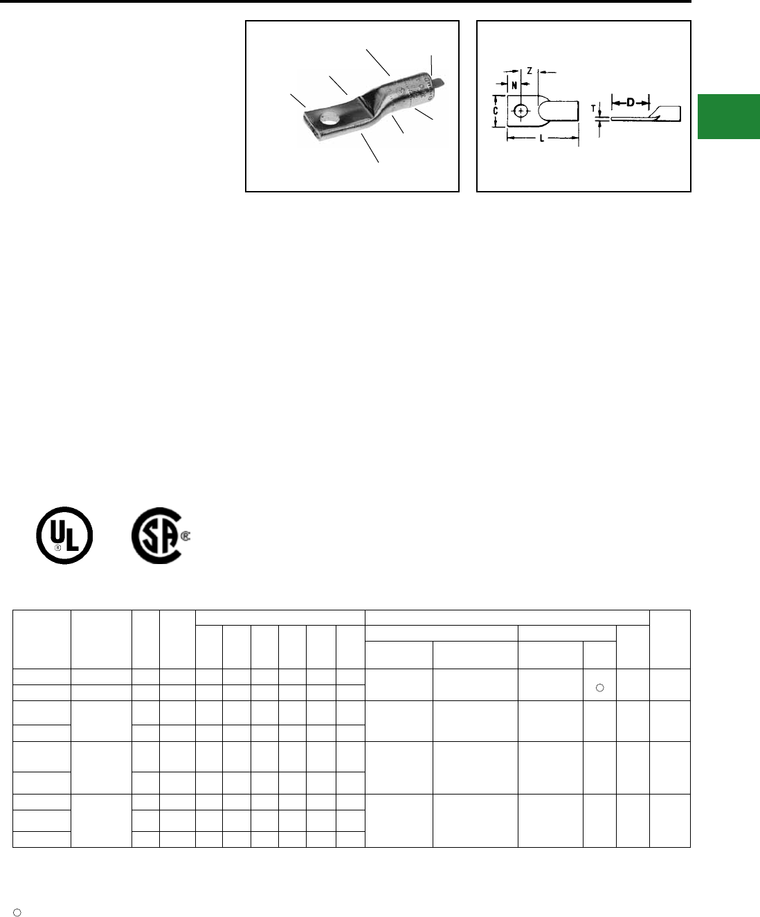
BURNDY®
Blue highlighted items are industry standard and most frequently ordered.
Canada: 1-800-387-6487 www.burndy.com US: 1-800-346-4175
TYPES YA-A
AND YA-A-TN
HYLUG™
UNINSULATED ALUMINUM
COMPRESSION TERMINAL
FOR ALUMINUM AND COPPER
CONDUCTORS
1-HOLE DESIGN
UL Listed 90° C,
600 Volts to 35 kV ♦
Type YA-A aluminum tin-plated compression
HYLUG™ terminals are dual-rated and
designed for use on both aluminum and copper
conductors from #12 sol. through 2000 kcmil.
They are designed for heavy duty applications
to 35kV. YA-A terminals are prelled with
PENETROX™, and assembled with color-
coded end caps. The aluminum HYLUG™
terminals are designed for a permanent trouble-
free electrical termination.
Features & Benets
• Manufactured from high conductivity, wrought
aluminum with heavy duty wall thickness
◊ Provides maximum conductivity,
low resistance and ductility for an
excellent combination of electrical
and crimp forming properties
• Electro-tin plated
◊ Provides durable long lasting
corrosion resistance
• Internally beveled barrel
◊ Provides easy cable insertion
• Meets UL486B 90° C requirements
◊ Provides a quality electrical dual
connection
• Connector is clearly marked with wire size, die
index, color-code and the proper number and
location of crimps
◊ Provides easy identication and
tooling recommendation for a proper
compression which forms a
homogeneous mass resulting in an
excellent electrical connection
• Factory prelled with PENETROX™ oxide
inhibiting compound
◊ Oxide inhibiting compound
contains homogeneously
suspended metallic particles to
penetrate the wires’ oxides,
establish electrical continuity and
forms an airtight connection
• Color-coded end caps inserted in barrel end
◊ Prevents foreign materials from
entering and contaminating the
connector prior to usage plus
identies the proper color-coded
die for a reliable connection
DIE AND CRIMP
INFORMATION
CABLE
ACCOMMODATION
CLOSED
BARREL
CRIMP
CRIMP
COLOR CODED
END CAP
ELECTRO-TIN
PLATED
Catalog
Number
Code
Conductor •
Stud
Size
No. of
Holes
in Pad
Dimensions Installation Tooling ▲
Wire
Strip
LengthC D L N T Z
Dieless (# of crimps) Y35, Y39, Y750, Y46* ▲
Die
Index
Mechanical
Tooling
Hydraulic
HYPRESS™
Die Number
(# of crimps)
Color
Code
YA12A-TN ‡ 12 Str. #10 1 0.41 0.50 1.19 0.20 0.07 0.30 MR8-27 (1) — — — 5/8″
YA10A-TN ‡ 10 Str. #10 1 0.41 0.50 1.22 0.20 0.06 0.30
YA8CA1 8 AWG #10 1 0.53 0.60 1.50 0.20 0.09 0.40 MY29-3 (1)
MRC840AL (1)
Y81KFT (1)
Y81KFTMBH (1)
PAT81KFT-18V (1)
U8CABT (1) Blue 374 5/8″
YA8CA3 1/4 1 0.53 0.75 1.65 0.25 0.09 0.50
YA6CA1 6 AWG 1/4 1 0.47 0.75 1.84 0.33 0.14 0.42 MY29-3 (1)
MRC840AL (1)
MY644HSXT (1)
Y81KFT (1)
Y81KFTMBH (1)
PAT81KFT-18V (1)
U6CABT (1) Gray 346 3/4″
YA6CA3 3/8 1 0.65 1.19 2.28 0.44 0.09 0.75
YA4CA1
4AWG
1/4 1 0.47 0.75 2.13 0.33 0.18 0.42
MY29-3 (1)
MRC840AL (1)
Y81KFT (1)
Y81KFTMBH (1)
PAT81KFT-18V (1)
Y644HSXT (1)
U4CABT (1) Green 375 7/8″
YA4CA3 5/16 1 0.80 0.87 2.25 0.41 0.12 0.46
YA4CA6 3/8 1 0.80 0.94 2.32 0.44 0.12 0.50
‡ UL Listed for Aluminum only.
* Use PUADP-1 adaptor with U dies in Y46 Hypress™.
♦ For applications greater than 2000 Volts consult cable
manufacturer for voltage stress relief instructions.
Note: All dimensions shown are for reference only.
• Contact BURNDY® for conductor, stud sizes and hole
drillings not shown.
▲ See tooling section of this catalog for complete tool and
die listings.
No color code assigned.
1
1
Compression Connections
Aluminum Compression — Tin Plated — For Aluminum & Copper Conductors
AL9CU
C-143
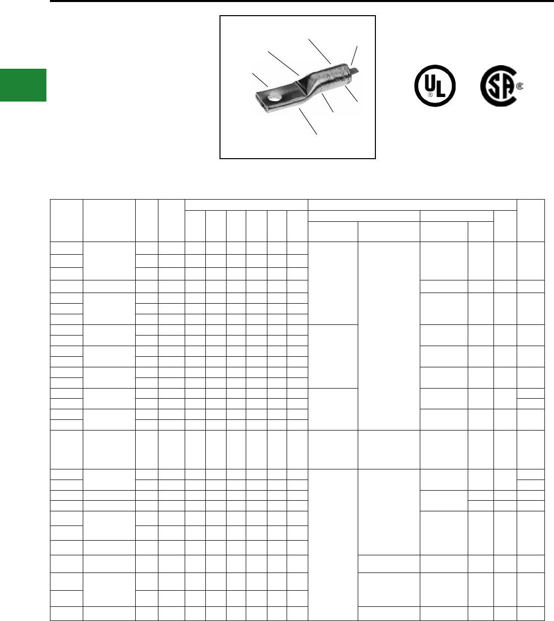
BURNDY®
Blue highlighted items are industry standard and most frequently ordered.
US: 1-800-346-4175 www.burndy.com Canada: 1-800-387-6487
TYPES YA-A
AND YA-A-TN
(Continued)
HYLUG™
UNINSULATED ALUMINUM
COMPRESSION TERMINAL
FOR ALUMINUM AND COPPER
CONDUCTORS
1-HOLE DESIGN
DIE AND CRIMP
INFORMATION
CABLE
ACCOMMODATION
CLOSED
BARREL
CRIMP
CRIMP
COLOR CODED
END CAP
ELECTRO-TIN
PLATED
UL Listed 90° C,
600 Volts to 35 kV ♦
Catalog
Number
Code
Conductor •
Stud
Size
No. of
Holes
in Pad
Dimensions Installation Tooling ▲
Wire
Strip
LengthC D L N T Z
Dieless (# of crimps) Y35, Y39, Y750, Y46* ▲
Die
Index
Mechanical
Tooling
Hydraulic
HYPRESS™
Die Number
(# of crimps)
Color
Code
YA2CA5
2AWG
1/4 1 0.50 0.75 2.25 0.33 0.22 0.42
MY29-3 (1)
MRC840AL (1)
Y81KFT (2)
Y81KFTMBH (2)
Y644HSXT (1)
PAT81KFT-18V (2)
U2CABT (1) Pink 348 1-1/8″YA2CA1 5/16 1 0.88 0.88 2.50 0.41 0.16 0.47
YA2CA3 3/8 1 0.88 0.94 2.56 0.44 0.16 0.50
YA1CA1 1 AWG 3/8 1 0.76 1.19 2.59 0.44 0.19 0.75 U1CART (1) Gold 471 15/16″
YA25A1
1/0
5/16 1 0.60 0.87 2.31 0.41 0.21 0.46
U25ART (1) Tan 296 1-1/16″YA25A3 3/8 1 0.82 1.18 2.67 0.63 0.21 0.55
YA25A9 1/2 1 1.03 1.34 2.83 0.63 0.17 0.71
YA26A6 2/0 AWG 3/8 1 0.67 1.89 2.79 0.44 0.24 0.74
MY29-3 (2)
MRC840AL (2)
U26ART (2) Olive 297 1-3/8″
YA26A1 1/2 1 1.03 1.36 3.03 0.63 0.20 0.73
YA27A1 3/0 AWG 3/8 1 0.73 1.18 2.88 0.44 0.26 0.74 U27ART (2) Ruby 467 1-1/2″
YA27A3 1/2 1 1.04 1.37 3.27 0.63 0.26 0.74
YA28A1 4/0 AWG 3/8 1 1.17 1.18 3.26 0.44 0.30 0.74 U28ART (2) White 298 1-5/8″
YA28A3 1/2 1 1.17 1.36 3.44 0.63 0.30 0.73
YA29A9 250 kcmil 3/8 1 1.26 0.83 3.09 0.41 0.33 0.42
—
U29ART (2) Red 324 1-9/16″
YA29A1 1/2 1 1.26 1.36 3.53 0.63 0.33 0.73 1-5/8″
YA30A6 300 kcmil 3/8 1 1.38 1.37 3.90 0.63 0.36 0.74 U30ART (2) Blue 470 1-3/4″
YA30A1 1/2 1 1.38 1.37 3.90 0.63 0.36 0.74
YA31A1 350 kcmil 1/2 1 1.52 1.37 4.33 0.63 0.39 0.74 —
Y644HSXT (1)
Y81KFT (3)
Y81KFTMBH (3)
PAT81KFT-18V (3)
U31ART (2) Brown 299 2-1/8″
YA32A9 400 kcmil 3/8 1 1.62 0.83 3.95 0.41 0.43 0.42
—
Y644HSXT (1)
Y81KFT (4)
Y81KFTMBH (4)
PAT81KFT-18V (4)
PAT644XT-18V (2)
U32ART (4) Green 472 2-5/16″
YA32A1 5/8 1 1.62 1.88 4.92 0.88 0.43 1.00 2-1/2″
YA34A1 500 kcmil 5/8 1 1.80 1.91 5.56 0.88 0.46 1.03 U34ART (4) Pink 300 2-5/8″
YA36A1 600 kcmil 5/8 1 1.97 1.88 5.82 0.88 0.52 1.00 Black 473 2-7/8″
YA39A1 700-750 kcmil
900 Compact
AL+
1/2 1 2.05 1.34 5.26 0.63 0.43 0.71
U39ART-2 (4) Yellow 936 2-7/8″YA39A3 5/8 1 2.05 1.88 5.80 0.88 0.43 1.00
YA39A34 700-750 kcmil 3/4 1 2.05 2.19 6.17 1.00 0.43 1.19
YA40A1 800 kcmil 5/8 1 1.65 1.87 6.12 0.88 0.60 0.99 Y644HSXTBH (1) P40ART (4) Gray 474 3"
YA42A1 900 kcmil AL
600 kcmil CU
1/2 1 2.14 1.36 5.32 0.63 0.39 0.71 Y644HSXT (2)
Y644HSXTBH (2)
PAT644XT-18V (2)
U42ART (4)
^
Gray 303 2-7/8″
YA42A3 5/8 1 2.14 1.36 5.32 0.63 0.39 1.00
YA44A1 1000 kcmil 5/8 1 2.50 1.89 6.50 0.88 0.66 1.01 — P44ART** (4) Gray 474 3″
AL9CU
• Contact BURNDY® for conductor, stud sizes and hole
drillings not shown.
▲ See tooling section of this catalog for complete tool and
die listings.
* Use PUADP-1 adaptor with U dies in Y46 HYPRESS™.
** P44ART for use with Y46 HYPRESS™ only. PUADP-1
adapter not required.
+ Tested with Y644HSXT and PAT644 dieless tools only
and not UL Listed with any tool on 900 Compact Al.
♦ For applications greater than 2000 Volts consult cable
manufacturer for voltage stress relief instructions.
^ U die for 900 AL only
Note: All dimensions shown are for reference only.
Compression Connections
Aluminum Compression — Tin Plated — For Aluminum & Copper Conductors
C-144
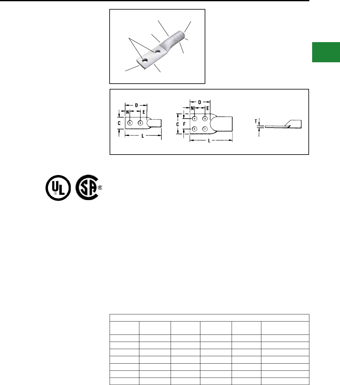
BURNDY®
Blue highlighted items are industry standard and most frequently ordered.
Canada: 1-800-387-6487 www.burndy.com US: 1-800-346-4175
TYPE YA-A
HYLUG™
UNINSULATED ALUMINUM
COMPRESSION TERMINAL
FOR ALUMINUM AND
COPPER CONDUCTORS
2-HOLE AND 4-HOLE DESIGNS
UL Listed 90° C,
600 Volts to 35 kV ♦
Type YA-A 2- and 4-hole pads inhibit connector
rotation and increase area contact. These
aluminum terminals have the same design
features and benets as the 1-hole YA-A with an
added stud hole for a more secure termination
to various types of equipment pads. They are
dual-rated for use on both aluminum and copper
conductors.
Features & Benets
• Manufactured from high conductivity,
wrought aluminum with heavy duty wall
thickness
◊ Provides maximum conductivity,
low resistance and ductility for an
excellent combination of electrical
and crimp forming properties
• Electro-tin plated
◊ Provides durable long lasting
corrosion resistance
DIE AND CRIMP
INFORMATION
ELECTRO-TIN
PLATED CABLE
ACCOMODATION
(2) HOLE
DRILLING
COLOR CODED
END CAP
CLOSED
BARREL
BEVELED
ENTRY
CRIMPS
• Internally beveled barrel
◊ Provides easy cable insertion
• Meets UL486B 90° C requirements
◊ Provides a quality electrical dual
connection
• Connector is clearly marked with wire size,
die index, color-code and the proper number
and location of crimps
◊ Provides easy identication and
tooling recommendation for a
proper compression which forms a
homogeneous mass resulting in an
excellent electrical connection
Y644HSXT DIELESS HYPRESS™
RANGE-TAKING
CAPABILITIES
The following size HYDENT™ lugs and two
way splices, when crimped with the Y644HSXT
DIELESS HYPRESS™ tool, produce the
following range taking capabilities:
Aluminum Connectors
Standard
Wire Size
Expanded
Wire Range
Standard
Wire Size
Expanded
Wire Range
Standard
Wire Size
Expanded
Wire Range
#6 AWG #6 AWG 1/0 AWG 1/0 - #1 AWG 250 kcmil 250 kcmil - 1/0 AWG
#4 AWG #4 - #6 AWG 2/0 AWG 2/0 - #1 AWG 300 kcmil 300 kcmil - 2.0 AWG
#2 AWG #2 - #6 AWG 3/0 AWG 3/0 - #1 AWG 350 kcmil 350 kcmil - 3/0 AWG
#1 AWG #1 - #2 AWG 4/0 AWG 4/0 - #1 AWG 400 kcmil 400 kcmil - 4/0 AWG
500 kcmil 500 kcmil - 4/0 AWG
600 kcmil 600 - 250 kcmil
750 kcmil 750 - 500 kcmil
Compression Connections
Aluminum Compression — Tin Plated — For Aluminum & Copper Conductors
AL9CU
• Factory prelled with PENETROX™ oxide
inhibiting compound
◊ Oxide inhibiting compound
contains homogeneously
suspended metallic particles to
penetrate the wires’ oxides,
establish electrical continuity and
forms an airtight connection
• Color-coded end caps inserted in barrel end
◊ Prevents foreign materials from
entering and contaminating the
connector prior to usage plus
identies the proper color-coded
die for a reliable connection
C-145
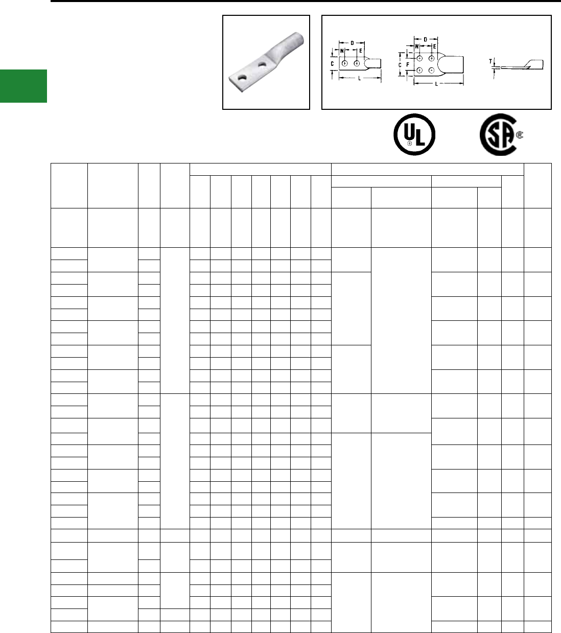
BURNDY®
Blue highlighted items are industry standard and most frequently ordered.
US: 1-800-346-4175 www.burndy.com Canada: 1-800-387-6487
TYPE YA-A
HYLUG™
UNINSULATED ALUMINUM
COMPRESSION TERMINAL
FOR ALUMINUM AND
COPPER CONDUCTORS
2-HOLE AND 4-HOLE DESIGNS
UL Listed 90° C,
600 Volts to 35 kV ♦
Catalog
Number
Code
Conductor
●
Stud
Size
●
No. of
Holes
in Pad
Dimensions Installation Tooling ▲
Wire
Strip
LengthC D
E
&
F L N
T
REF.
Z
MIN.
Dieless (# of crimps) Y35, Y39, Y750, Y46* ▲
Die
Index
Mechanical
Tooling
Hydraulic
HYPRESS
Die Number
(# of crimps)
Color
Code
YA2CA9 2 str. 1/2 2 0.88 3.11 1.75 4.73 0.63 0.16 0.73 MY29-3 (1)
Y644HSXT (1)
Y81KFT (1)
Y81KFTMBH (1)
PAT81KFT-18V (1)
U2CABT (1) Pink 348 1-1/8″
YA25A5 1/0 str 3/8
2
0.82 2.24 1.06 3.73 0.63 0.21 0.55 MY29-3 (1)
Y644HSXT (1)
Y81KFT (2)
Y81KFTMBH (2)
PAT81KFT-18V (2)
U25ART (1) Tan 296 1-1/16″
YA25A7 1/2 1.03 3.10 1.75 4.59 0.63 0.17 0.72
YA26A3 2/0 str. 1/2 1.03 3.11 1.75 4.78 0.63 0.20 0.73
MY29-3 (2)
U26ART (2) Olive 297 1-3/8″
YA26A5 3/8 0.92 1.89 1.00 3.56 0.44 0.24 0.45
YA27A5 3/0 str. 1/2 1.04 3.12 1.75 3.02 0.63 0.26 0.74 U27ART (2) Ruby 467 1-1/2″
YA27A7 3/8 1.04 1.89 1.00 3.79 0.44 0.26 0.45
YA28A5 4/0 str. 1/2 1.17 3.11 1.75 5.19 0.63 0.30 0.73 U28ART (2) White 298 1-5/8″
YA28A7 3/8 1.17 1.89 1.00 3.97 0.44 0.30 0.45
YA29A3 250 kcmil 1/2 1.26 3.11 1.75 5.28 0.63 0.33 0.73
—
U29ART (2) Red 324 1-5/8″
YA29A5 3/8 1.26 1.89 1.00 4.06 0.44 0.33 0.45
YA30A3 300 kcmil 1/2 1.38 3.11 1.75 5.64 0.63 0.36 0.73 U30ART (2) Blue 470 1-3/4″
YA30A5 3/8 1.38 1.89 1.00 4.42 0.44 0.36 0.45
YA31A5 350 kcmil 3/8
2
1.52 1.89 1.00 4.85 0.44 0.39 0.45
—
Y644HSXT (1)
Y81KFT (3)
Y81KFTMBH (3)
PAT81KFT-18V (3)
U31ART (2) Brown 299 2-1/8″
YA31A3 1/2 1.52 3.11 1.75 6.07 0.63 0.39 0.73
YA32A5 400 kcmil 3/8 1.62 1.89 1.00 4.93 0.44 0.43 0.45 U32ART (4) Green 472 2″
YA32A3 1/2 1.62 3.11 1.75 6.15 0.63 0.43 0.73
—
Y644HSXT (1)
Y81KFT (4)
Y81KFTMBH (4)
PAT81KFT-18V (4)
YA34A3 500 kcmil 1/2 1.62 3.15 1.75 6.80 0.63 0.46 0.77 U34ART (4) Pink 300 2-5/8″
YA34A5 3/8 1.80 1.89 1.00 5.54 0.44 0.46 0.45
YA36A3 600 kcmil 1/2 1.62 3.15 1.75 7.09 0.63 0.52 0.77 U36ART (4) Black 473 2-7/8″
YA36A5 3/8 1.97 1.89 1.00 5.64 0.69 0.52 0.45
YA39A5 700/750 kcmil
900 Compact
AL +
1/2 1.62 3.15 1.75 7.07 0.63 0.43 0.77 U39ART-2 (4) Yellow 936 2-7/8″
YA39A7 3/8 2.05 1.89 1.00 5.81 0.44 0.43 0.45
YA39AM2 1/2 1.69 3.12 1.75 7.31 0.63 0.57 0.74 P39ART** (4) Red 301 2-7/8″
YA40A3 800 kcmil 1/2 2 2.25 3.16 1.75 7.41 0.63 0.60 0.78 Y644HSXTBH (1) P40ART (4) Gray 474 3"
YA42A5 900 kcmil AL
600 kcmil Cu
1/2 21.62 3.13 1.75 7.09 0.63 0.39 0.77 —
Y644HSXT (2)
Y644HSXTBH (2)
PAT644XT-18V (2)
U42ART (4)^ Gray 303 2-7/8″
YA42A7 3/8 2.14 3.13 1.00 5.96 0.44 0.39 0.45
YA44A3 1000 kcmil 1/2
2
1.65 3.15 1.75 7.76 0.63 0.55 0.77
— —
P44ART** (4) Brown 302 3″
YA45A5^^ 1250 kcmil 1/2 2.59 3.12 1.75 7.73 0.63 0.51 0.74
YA46A3^^ 1500 kcmil 1/2 3.08 3.15 1.75 8.73 0.63 0.81 0.77 L46ART (2)
‡
Blue 478 2-3/4″
YA46A5^^ 1/2 4 3.08 3.15 1.75 8.73 0.63 0.81 0.77
YA48A3^^ 2000 kcmil 1/2 2 3.57 3.11 1.75 8.49 0.63 0.90 0.73 L48ART (2)
‡
Red 479 4-1/8″
• Contact BURNDY® for conductor, stud sizes and hole
drillings not shown.
▲ See tooling section of this catalog for complete tool and
die listings.
‡ Use Y60 BHU HYPRESS™ with L46ART and L48ART
die sets.
* Use PUADP-1 adaptor with U dies in Y46 HYPRESS™.
** P39ART and P44ART die sets for use with Y46
HYPRESS™ only. PUADP-1 adapter not required.
+ Tested with Y644HSXT and PAT644 dieless tools only
and not UL Listed with any tool on 900 Compact Al.
♦ For applications greater than 2000 Volts consult cable
manufacturer for voltage stress relief instructions.
^ U die for 900 AL only
^^ 75
o
C Rated
Note: All dimensions shown are for reference only.
Compression Connections
Aluminum Compression — Tin Plated — For Aluminum & Copper Conductors
AL9CU
C-146
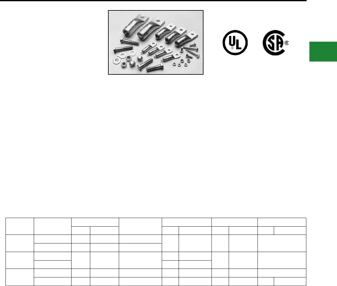
BURNDY®
Blue highlighted items are industry standard and most frequently ordered.
Canada: 1-800-387-6487 www.burndy.com US: 1-800-346-4175
TYPE YA-A-KIT
TRANSFORMER LUG KIT
Each kit contains the UL Listed and CSA
Certied AL9CU rated aluminum compression
connectors and tongue mounting hardware
needed to terminate aluminum or copper cables
in “dry type" transformers. The KVA rating
gives an approximate cross reference to the
appropriate kit.
Catalog
Number KVA
Terminals Wire Range
with Y644HSXT
Bolt Hardware Washer
Qty. Cat. No. Qty. Size Qty. Size Qty. Washer
YA-A-KIT1 15-37.5 1Ø 8 YA2C-A5 #6-2 AWG 8 1/4-20 X 3/4 8 1/2 x 20HN Captive
15-45.3 3Ø 4 YA30-A7 2/0 AWG-300 kcmil
YA-AKIT2 50-75 1Ø 12 YA30-A7 2/0 AWG-300 kcmil 8 1/4-20 X 3/4 16 1/4 X 20HN Captive
75-112.5 3Ø 8 1/4-20 X 2
YA-AKIT3 100-167 1Ø 3 YA30-A7 2/0 AWG-300 kcmil 3 1/4-20 X 3/4 3 1/4 X 20 Captive
150-300 3Ø 22 YA39-A1 500-750 kcmil 16 1/2-13 X 2 16 1/2-13 16 1/2 Belleville
Features & Benets
• UL Listed AL9CU dual rated
compression terminals and CSA
Certied
◊ Ensure the transformer feeders
and taps are terminated properly
• Plated steel cap screws and hex nuts with cap-
tive conical washers or
individual Belleville washers
◊ Terminal to bus connections are
made using proper hardware
resulting in true torque to pres
sure performance, compensates
for dissimilar metal expansion and
contraction
• Hardware packed in plastic bag
◊ No lost hardware prior to installation
CONNECTOR
HH- Hex Head
HN- Hex Nut
See Mechanical section for set screw terminal kits.
Note: All dimensions shown are for reference only.
C-147
Compression Connections
Aluminum Compression - Transformer Kits
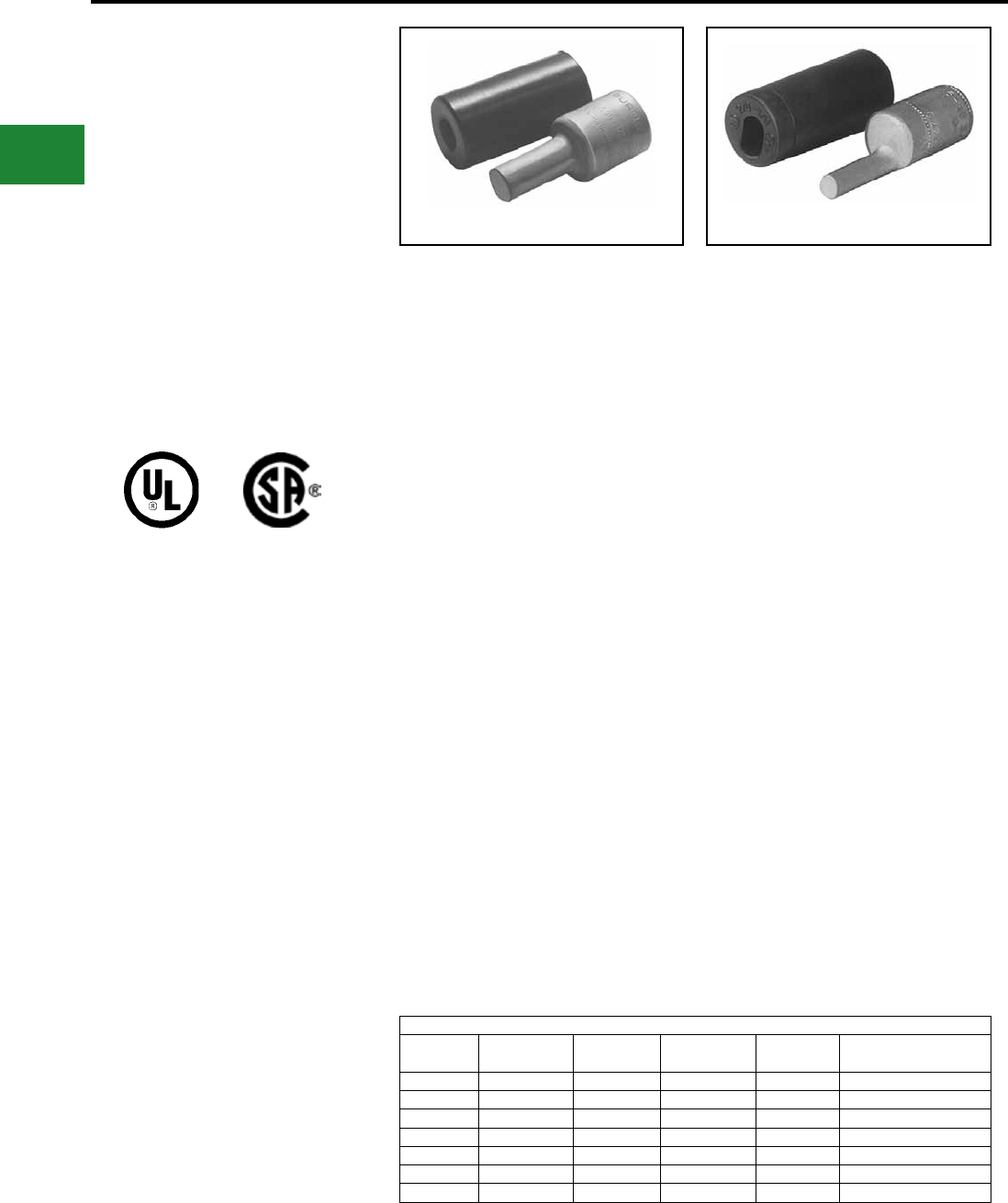
BURNDY®
Blue highlighted items are industry standard and most frequently ordered.
US: 1-800-346-4175 www.burndy.com Canada: 1-800-387-6487
TYPE AYP, AYPO
HYPLUG™
FOR ALUMINUM AND COPPER
CONDUCTOR
UL Listed 90° C,
600 Volts to 35 kV ♦
Types AYP and AYPO aluminum compression
adapters are designed for reliable termination of
aluminum and copper conductor in mechanical
connectors. Typical applications include
mechanical connectors in molded case circuit
breakers, panel board equipment and meter
sockets.
Features & Benets
• All-aluminum electro-tin plated
design
◊ Eliminates possible bi-metallic
corrosion and provides the
shortest connector length design
possible
• Shortest connector length design
possible
◊ Permits easy installation in
equipment with limited working
space
• Solid electro-tin plated aluminum plug
◊ Proper electrical connection made
easily. Eliminates “how tight is
tight" problem
• Smooth surface on the solid EC
aluminum electro-tin plated plug
◊ Provides greater area contact
establishing excellent electrical
conductivity
• Solid plug has same diameter as
current carrying equivalent copper
wire
◊ Permits use of larger aluminum
wire to connect equipment
• Offset plug design available in sizes 2/0
through 750 kcmil
◊ Provides exibility and maximizes
the use of limited space eliminating
interference between conductors
and equipment
• Electro-tin plated
◊ Resists corrosion
• Factory prelled with the proper amount of
PENETROX™ joint
compound
◊ PENETROX™, BURNDY
®
oxide
inhibiting compound with
conductive metallic particles
penetrates aluminum oxide
between strands and forms an
air-tight connection
• EPDM rubber covers are supplied with each
connector and are rated for 600 V
◊ Eliminates taping
• Only (5) die sets install the complete line from
#6 to 750 kcmil
◊ Lowers inventory requirements and
saves money
• Supplied in a plastic convenience pack
◊ The cover and connector are kept
together and free of foreign
material until used
• Connectors are clearly marked with catalog
number, wire size, and color coded die index
◊ Provides clear, easy to use
information to lower installed cost
AL9CU
TYPE AYP TYPE AYPO
Y644HSXT DIELESS HYPRESS™
RANGE-TAKING
CAPABILITIES
The following HYPLUG™ lugs and two way
splices, when crimped with the Y644HSXT
DIELESS HYPRESS™ tool, produce the
following range-taking capabilities for Aluminum
Conductor only:
Aluminum Connectors Only
Standard
Wire Size
Expanded
Wire Range
Standard
Wire Size
Expanded
Wire Range
Standard
Wire Size
Expanded
Wire Range
#6 AWG #6 AWG 1/0 AWG 1/0 - #1 AWG 250 kcmil 250 kcmil - 1/0 AWG
#4 AWG #4 - #6 AWG 2/0 AWG 2/0 - #1 AWG 300 kcmil 300 kcmil - 2.0 AWG
#2 AWG #2 - #6 AWG 3/0 AWG 3/0 - #1 AWG 350 kcmil 350 kcmil - 3/0 AWG
#1 AWG #1 - #2 AWG 4/0 AWG 4/0 - #1 AWG 400 kcmil 400 kcmil - 4/0 AWG
500 kcmil 500 kcmil - 4/0 AWG
600 kcmil 600 - 250 kcmil
750 kcmil 750 - 500 kcmil
♦ For applications greater than 2000 Volts consult cable
manufacturer for voltage stress relief instructions.
Compression Connections
Aluminum Compression — Adaptors
AL9
C-148
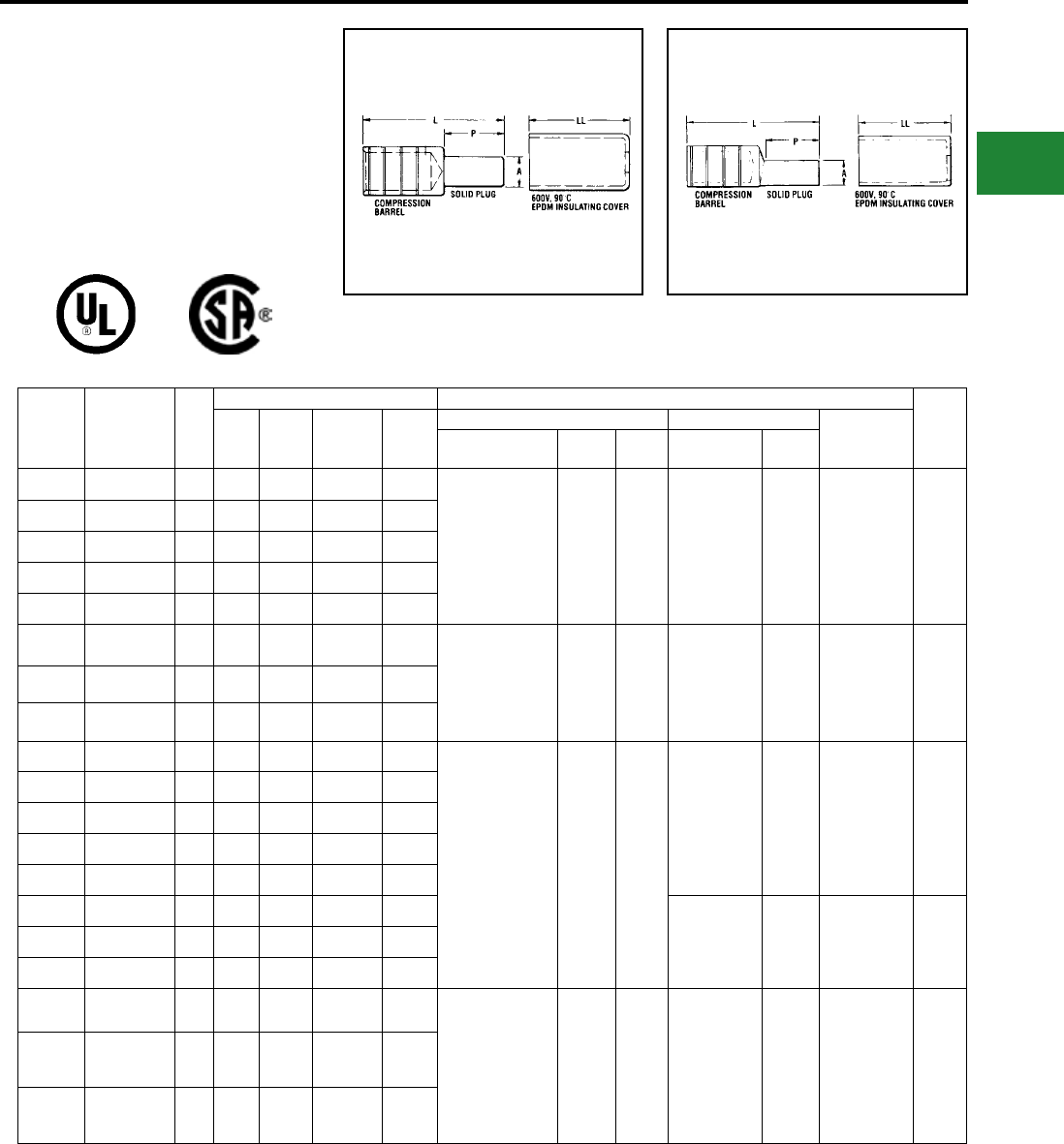
BURNDY®
Blue highlighted items are industry standard and most frequently ordered.
Canada: 1-800-387-6487 www.burndy.com US: 1-800-346-4175
Catalog
Number
Copper &
Aluminum
Conductor
Fig.
No.
Dimensions Installation Tooling ▲
Wire
Strip
Length
A ▼
Plug
Dia.
P
Plug
Length
L
HYPLUG
Length
LL
Cover
Length
HYTOOLS Y35, Y39, Y750, Y46* ▲ Die
Index &
Embossment
Dieless Tools
(# of crimps)
+
OH25
+
MD6
Die Number
(# of crimps)
Color
Code
AYP6 6 Str. 1 0.23 0.68 1.85 2.03
MY29-3 (2) ** +
Y644HSXT (1)
Y81KFT (1)
Y81KFTMBH (1)
PAT81KFT-18V (1)
1 crimp W241 U25ART (1) Tan 296 1-1/16″
AYP4 4 Str. 1 0.23 0.68 1.85 2.03
AYP2 2 Str. 1 0.23 0.68 1.85 2.03
AYP1 1 Str. 1 0.26 0.84 2.01 2.03
AYP1/0 1/0 Str. 1 0.29 0.84 2.01 2.03
AYPO2/0 2/0 Str. 2 0.33 1.09 2.70 2.23 MY29-3 (2) ** +
Y644HSXT (1)
Y81KFT (2)
Y81KFTMBH (2)
PAT81KFT-18V (2)
— — U28ART (2) White 298 1-1/8″
AYPO3/0 3/0 Str. 2 0.37 1.22 2.80 2.23
AYPO4/0 4/0 Str. 2 0.42 1.22 2.80 2.23
AYP250 250 kcmil 1 0.47 1.22 2.63 2.54
Hydraulic:
Y644HSXT (1)
Y81KFT (2)
Y81KFTMBH (2)
PAT81KFT-18V (2)
— —
U31ART (2) Brown 299 1-1/8″
AYPO250 250 kcmil 2 0.47 1.22 2.98 2.54
AYPO300 300 kcmil 2 0.53 1.34 3.08 2.54
AYP350 350 kcmil 1 0.57 1.34 2.75 2.54
AYPO350 350 kcmil 2 0.57 1.34 3.08 2.54
AYPO400 400 kcmil 2 0.63 1.60 3.43 2.81
U34ART (2) Pink 300 1-1/8″
AYP500 500 kcmil 1 0.68 1.60 3.08 2.81
AYPO500 500 kcmil 2 0.68 1.60 3.43 2.81
AYPO600 600 kcmil 2 0.73 1.64 4.02 3.69
Y644HSXT (1)
Y81KFT (3)
Y81KFTMBH (3)
PAT81KFT-18V (3)
— — U39ART-2 (3) Yellow 936 1-3/4″
AYP750
700/750 kcmil
900 Compact
AL†
1 0.81 1.76 3.79 3.69
AYPO750
700/750 kcmil
900 Compact
AL†
2 0.81 1.76 4.16 3.69
TYPES AYP, AYPO
HYPLUG™
FOR ALUMINUM AND COPPER
CONDUCTOR
UL Listed 90° C,
600 Volts to 35 kV♦Fig 1: TYPE AYP (Straight) Fig 2: TYPE AYPO (Offset)
AL9CU
Scratch brush aluminum conductor before installation.
▲ See tooling section of this catalog for complete tool and
die listings.
** For MY29-3 use aluminum index plate at 1/0 setting for
sizes #6 through 1/0 or at 4/0 setting for sizes 2/0
through 4/0.
+ Not UL Listed with these tools.
* Use PUADP-1 adaptor with U dies in Y46 HYPRESS™.
■ Also accomodates compressed and compact conductors
(except for 700 kcmil in 750 kcmil barrel).
† Tested with Y644HSXT and PAT644XT-18V dieless tools
only and not UL Listed with any tool on 900 Compact Al.
♦ For applications greater than 2000 Volts consult cable
manufacturer for voltage stress relief instructions.
Note: All dimensions shown are for reference only.
▼ For copper equivalent wire size see page O-11
(Aluminum 1350 Cable).
Note: CSA certified for AL Conductor only.
Compression Connections
Aluminum Compression — Adaptors
AL9
C-149
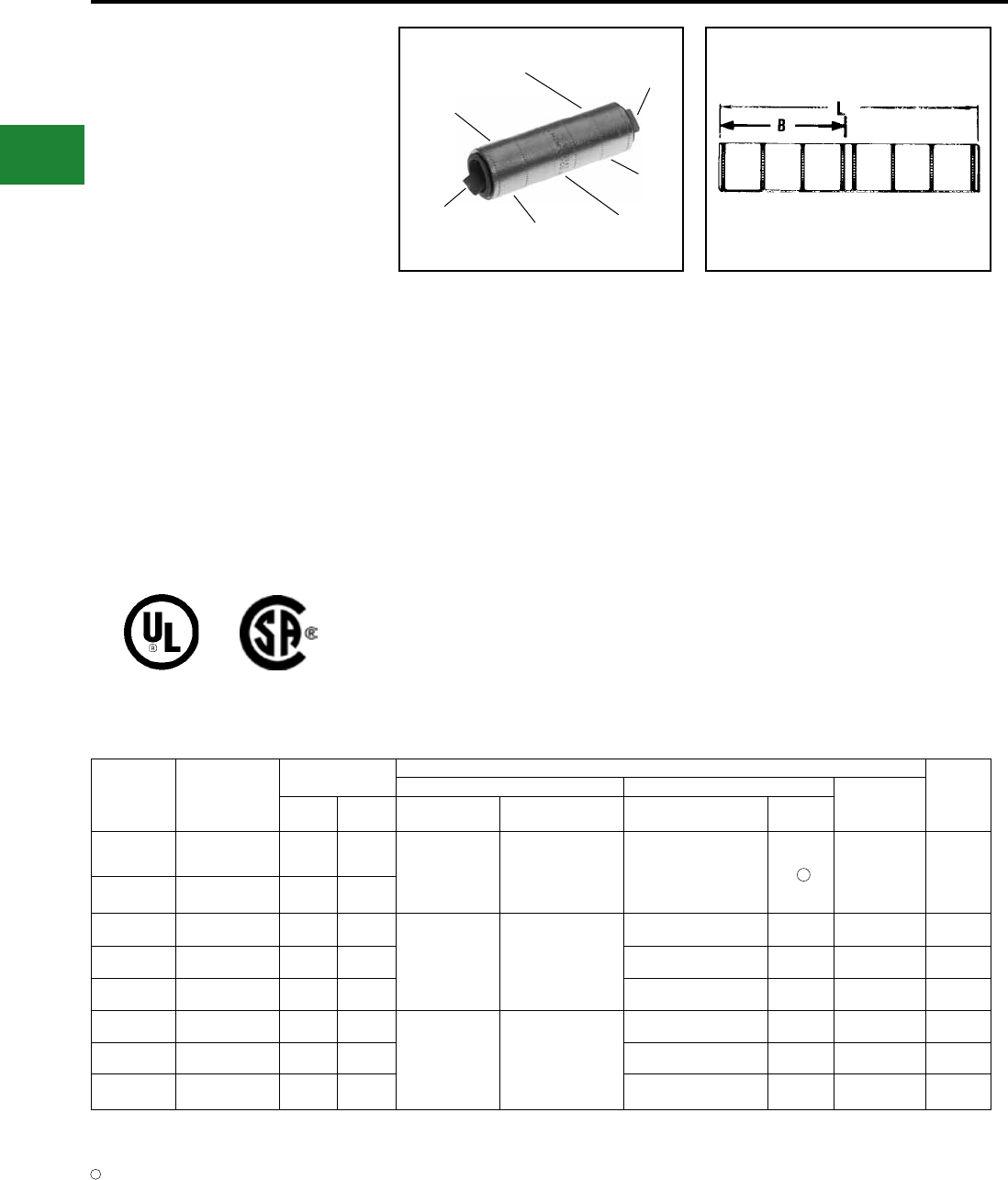
BURNDY®
Blue highlighted items are industry standard and most frequently ordered.
US: 1-800-346-4175 www.burndy.com Canada: 1-800-387-6487
TYPE YS-A
HYLINK™
UNINSULATED ALUMINUM
COMPRESSION SPLICE
UL Listed 90° C,
600 Volts to 35 kV ♦
Type YS-A is a high-conductivity aluminum
tin-plated compression butt splice for use on
all combinations of aluminum to aluminum,
aluminum to copper, and copper to copper
conductor combinations.
They are designed to accommodate
conductors from #12 str. through 1,000 kcmil in
standard and heavy duty applications. Prelled
with PENETROX™ oxide inhibiting compounds
and assembled with color-coded end caps, the
connectors provide a permanent trouble-free
electrical splice with exibility and low installed
cost.
Features and Benets
• Manufactured from high-conductivity wrought
aluminum with heavy duty wall thickness
◊ Provides high-conductivity/low
resistance and ductility for an
excellent combination of electrical
and crimp forming properties
• Electro-tin plated
◊ Provides durable long lasting
corrosion resistance
• Internally beveled barrel
◊ Provides easy cable entry
• Solid center stop and prelled with
PENETROX™ oxide inhibiting
compound
◊ Provides stop for proper conductor
insertion and an aid in forcing the
PENETROX™ between the
individual wire strands
• Color-coded end caps
◊ Provides easy wire size and die
code identication plus prevents
foreign materials from entering and
contaminating the connector prior
to usage
• Connector is clearly marked with wire size,
die index and the proper number and location
of crimps
◊ Provides easy identication and
tooling recommendation. Proper
compression forms a homogeneous
mass resulting in an excellent
electrical connection
DIE AND COLOR
CODE INFORMATION
ELECTRO-TIN
PLATED
BELLED
END
BELLED
END
(4) CENTER
WIRE STOP
CRIMP
CRIMP
Catalog
Number
Code ●
Conductor
Dimensions
Installation Tooling ▲
Wire
Strip
Length
Dieless (# of crimps/end) Y35, ■Y39, Y750, Y46* ▲
Die Index &
EmbossmentB L
Mechanical
HYTOOL™
Hydraulic
HYPRESS™
Die Number
(# of crimps per end)
Color
Code
YS12AG1 ‡ #12 Str. 0.45 1.03 Ratchet:
MR8-27 (1) — — — 5/8″
YS10WAG1 ‡ #10 Sol. 0.50 1.12
YS8CA1 8 Str. 0.59 1.44
MY29-3 (1)
MRC840AL (1)
Y644HSXT (1)
Y81KFT (1)
Y81KFTMBH (1)
PAT81KFT-18V (1)
U8CABT (1) Blue 374 5/8″
YS6CA1 6 Str. 0.72 1.70 U6CABT (1) Gray 346 3/4″
YS4CA1 4 Str. 0.86 1.97 U4CABT (1) Green 375 7/8″
YS2CA1 2 Str. 1.09 2.44
MY29-3 (1)
MRC840AL (1)
Y644HSXT (1)
Y81KFT (2)
Y81KFTMBH (2)
PAT81KFT-18V (2)
U2CABT (1) Pink 348 1-1/8″
YS1CA1 1 Str. 0.90 2.05 U1CART (1) Gold 471 15/16″
YS25A1 1/0 Str. 1.06 2.37 U25ART (1) Tan 296 1-1/16″
▲ See tooling section of this catalog for complete tool
and die listing.
No color code assigned.
‡ UL Listed for Aluminum only. Not CSA Certified.
* Use PUADP-1 adaptor with U dies in Y46 HYPRESS™.
■ The largest size for the Y35 is 400 kcmil.
♦ For applications greater than 2000 Volts consult cable
manufacturer for voltage stress relief instructions.
1
1
Compression Connections
Aluminum Compression — Splice
● Also accomodates compressed and compact conductors
(except for 700 kcmil in 750 kcmil barrel).
Note: All dimensions shown are for reference only.
C-150
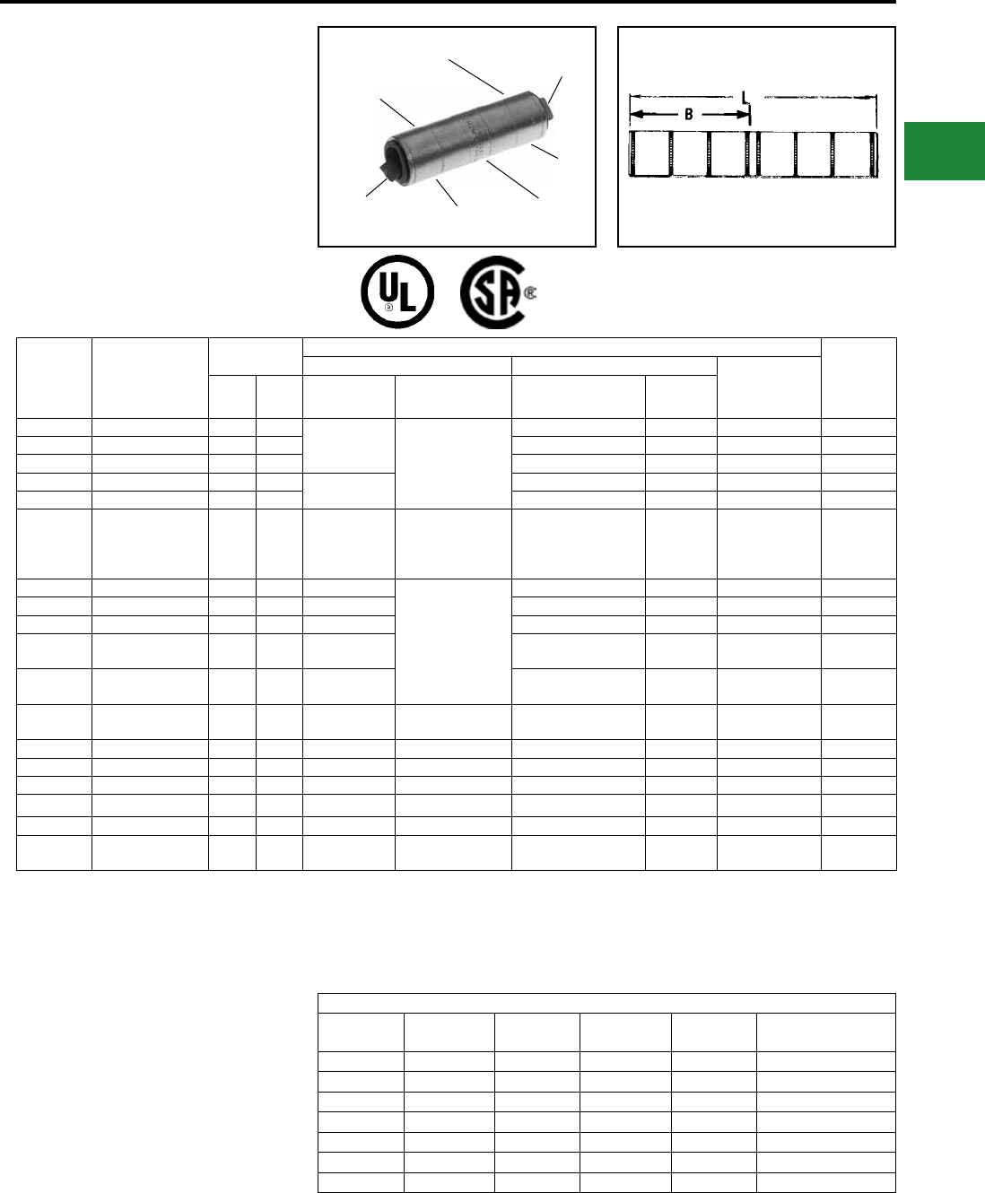
BURNDY®
Blue highlighted items are industry standard and most frequently ordered.
Canada: 1-800-387-6487 www.burndy.com US: 1-800-346-4175
TYPE YS-A
(Continued)
HYLINK™
UNINSULATED ALUMINUM
COMPRESSION SPLICE
UL Listed 90° C,
600 Volts to 35 kV ♦
DIE AND COLOR
CODE INFORMATION
ELECTRO-TIN
PLATED
BELLED
END
BELLED
END
(4) CENTER
WIRE STOP
CRIMP
CRIMP
Catalog
Number
Code ●
Conductor
Dimensions
Installation Tooling ▲
Wire
Strip
Length
Dieless (# of crimps/end) Y35, ■Y39, Y750, Y46* ▲
Die Index &
EmbossmentB L
Mechanical
HYTOOL™
Hydraulic
HYPRESS™
Die Number
(# of crimps per end)
Color
Code
YS26A1 2/0 str. 1.18 2.61 MY29-3 (2)
MRC840AL (2) Y644HSXT (1)
Y81KFT (2)
Y81KFTMBH (2)
PAT81KFT-18V (2)
U26ART (2) Olive 297 1-3/8″
YS27A1 3/0 str. 1.31 2.88 U27ART (2) Ruby 467 1-1/2″
YS28A1 4/0 str. 1.40 3.06 U28ART (2) White 298 1-5/8″
YS29A1 250kcmil 1.46 3.18 MY29-3 (2) U29ART (2) Red 324 1-5/8″
YS30A1 300 kcmil 1.47 3.20 U30ART (2) Blue 470 1-3/4″
YS31A1 350 kcmil 1.89 4.04 —
Y644HSXT (1)
Y81KFT (3)
Y81KFTMBH (3)
PAT81KFT-18V (3)
U31ART (2) Brown 299 2-1/8″
YS32A1 400kcmil 2.30 4.86 —
Y644HSXT (1)
Y81KFT (4)
Y81KFTMBH (4)
PAT81KFT-18V (4)
U32ART (2) Green 472 2-1/2″
YS34A1 500 kcmil 2.38 5.02 — U34ART (2) Pink 300 2-5/8″
YS36A1 600 kcmil 2.44 5.14 — U36ART (4) Black 473 2-7/8″
YS39A1*700/750 kcmil
900 Compact Al † 2.50 5.26 — U39ART-2 (4) Yellow 936 2-7/8″
YS39AM1* 700/750 kcmil
900 Compact Al † 2.63 5.58 — P39ART** (4) Red 301 2-7/8″
YS42A1 600 - 900 kcmil 2.50 5.26 — Y644HSXT (2)
PAT644HSXT (2) U42ART (4)
^
Gray — 2-7/8″
YS44A1
^^
1000 kcmil 2.84 5.94 — — P44ART** (4) Brown 302 3″
YS45A1
^^
1250 kcmil 2.84 6.21 — — P48PR1/L44ART** (6) Brown 302 2.88″
YS46A1
^^
1500 kcmil 3.40 7.05 — — L46ART*** (2) Blue 478 3.38″
YS47A1
^^
1750 kcmil 3.99 8.31 — — L47ART*** (2) White 587 4″
YS48A1
^^
2000 kcmil 3.66 7.58 — — L48ART*** (2) Red 479 3.63″
YS483A1
^^
2250 kcmil
ALUMINUM ONLY 3.66 7.58 — — L48ART*** (2) Red 479 3.63″
▲ See tooling section of this catalog for complete tool and
die listings.
‡ UL Listed for Aluminum only. Not CSA Certified.
* Use PUADP-1 adaptor with U dies in Y46 HYPRESS™.
** P39ART and P44ART for use with Y46 HYPRESS™
only. PUADP-1 adapter not required.
■ The largest size for the Y35 is 400 kcmil.
*** Y60BHU only.
90° C Rated.
† Tested with Y644HSXT and PAT644XT-18V dieless tools
only and not UL Listed with any tool on 900 Compact Al.
● Also accommodates compressed and compact
conductors. (Except 700 kcmil in 750 kcmil barrel)
Note: All dimensions shown are for reference only.
^ U Die for 900 AL only.
^^ 75° C Rated.
Y644HSXT DIELESS HYPRESS™
RANGE-TAKING
CAPABILITIES
The following HYLINK™ splices, when
crimped with the Y644HSXT DIELESS
HYPRESS™ tool, produce the range-
taking capabilities in the table to the
right.
Aluminum Splices
Standard
Wire Size
Expanded
Wire Range
Standard
Wire Size
Expanded
Wire Range
Standard
Wire Size
Expanded
Wire Range
#6 AWG #6 AWG 1/0 AWG 1/0 - #1 AWG 250 kcmil 250 kcmil - 1/0 AWG
#4 AWG #4 - #6 AWG 2/0 AWG 2/0 - #1 AWG 300 kcmil 300 kcmil - 2.0 AWG
#2 AWG #2 - #6 AWG 3/0 AWG 3/0 - #1 AWG 350 kcmil 350 kcmil - 3/0 AWG
#1 AWG #1 - #2 AWG 4/0 AWG 4/0 - #1 AWG 400 kcmil 400 kcmil - 4/0 AWG
500 kcmil 500 kcmil - 4/0 AWG
600 kcmil 600 - 250 kcmil
750 kcmil 750 - 500 kcmil
Compression Connections
Aluminum Compression — Splice
C-151
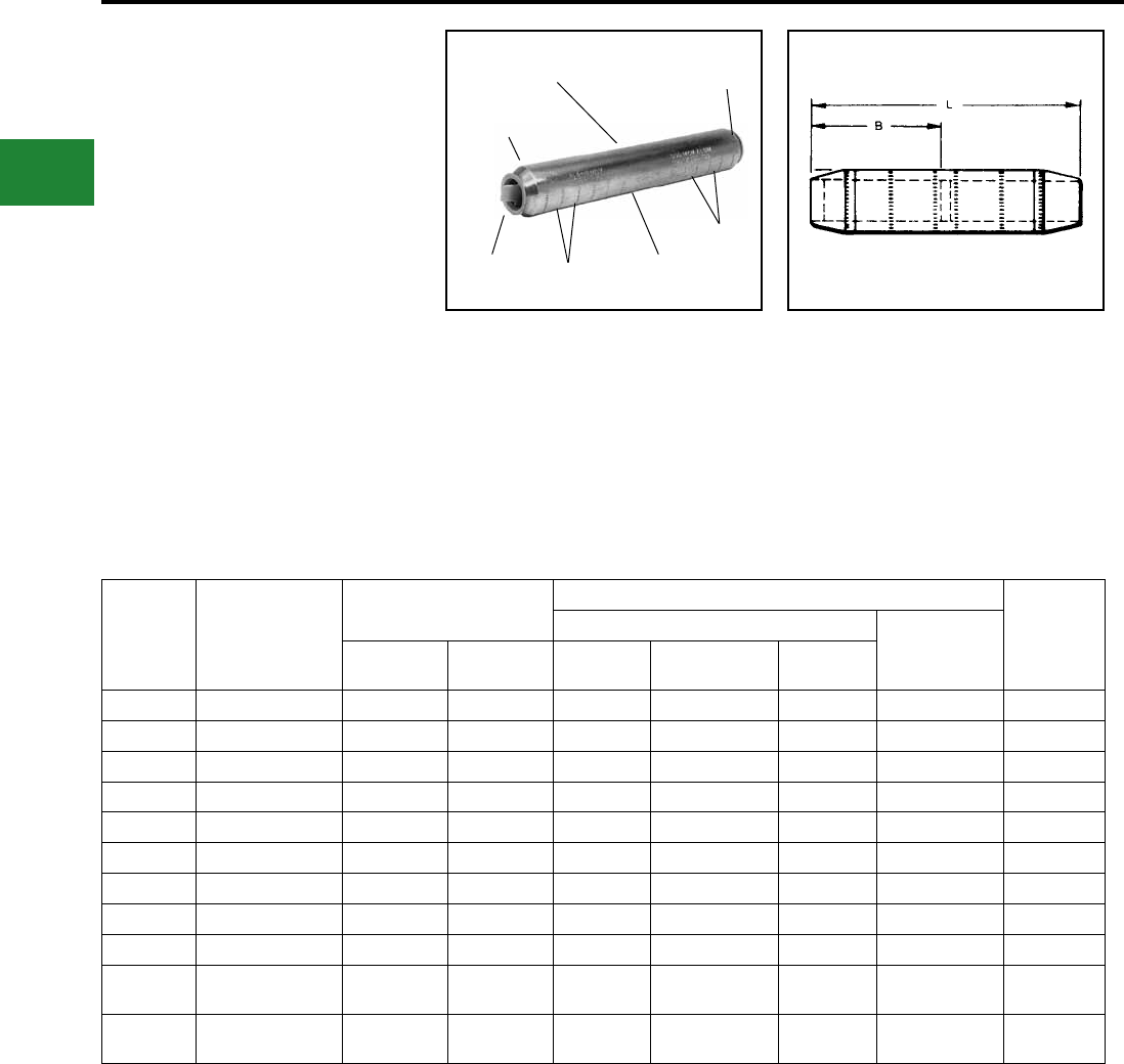
BURNDY®
Blue highlighted items are industry standard and most frequently ordered.
US: 1-800-346-4175 www.burndy.com Canada: 1-800-387-6487
TYPE YS-AT
HIGH VOLTAGE
UNINSULATED ALUMINUM
COMPRESSION SPLICE
Type YS-AT is a high-conductivity aluminum
electro-tin plated compression butt splice with
tapered ends for high voltage applications up
to 35 kV.
The YS-AT provides the same benets as the
YS-A with the addition of tapered ends for
easy installation of high voltage insulating kits.
Tapered ends aid in preventing corona emission
and insulation breakdown. Recommended for
high voltage splice applications.
Catalog
Number
● † Code
Conductor
Dimensions
Installation Tooling ▲
Wire
Strip
Length
Y35, ■Y39, Y750, Y46*
Die Index &
Embossment ▲B L
Die
Number (Crimps per End)
Color
Code
YS2CAT 2 str. 1.58 4.00 U2CABT ( 2 ) Pink 348 2 1/4″
YS25AT 1/0 str. 1.96 4.73 U25ART ( 2 ) Tan 296 2 5/8″
YS26AT 2/0 str. 1.83 4.29 U26ART ( 3 ) Olive 297 2 3/8″
YS27AT 3/0 str. 2.04 4.69 U27ART ( 3 ) Ruby 467 2 5/8″
YS28AT 4/0 str. 2.16 5.05 U28ART ( 3 ) White 298 2 3/4″
YS29AT 250 kcmil 2.29 5.37 U29ART ( 3 ) Red 324 2 7/8″
YS30AT 300 kcmil 2.54 5.91 U30ART ( 3 ) Blue 470 3 1/8″
YS31AT 350 kcmil 2.68 6.23 U31ART ( 3 ) Brown 299 3 3/8″
YS34AT 500 kcmil 3.39 7.79 U34ART ( 6 ) Pink 300 4 1/8″
YS39AT 700/750 kcmil ●
900 Compact AL ▼ 3.69 8.57 P39ART** ( 6 ) Red 301 4 1/2″
YS44AT 1000 kcmil
900 Compact AL▼ 3.77 9.69 P44ART** ( 6 ) Brown 302 4 3/4″
Features & Benets
• Tapered ends for applications through 35kV
◊ Permits easy taping and aids in
preventing corona emission and
insulation breakdown
• Heavy wall aluminum tubing
◊ For use with combinations of
AL-AL, AL-CU, CU-CU
DIE AND CRIMP
INFORMATION COLOR CODED
END CAPS
CENTER
STOP
TAPERED
END CRIMPS
CRIMPS
PRE-FILLED WITH
PENETROX
† Contact BURNDY® for conductor sizes not shown.
* Use PUADP-1 adapter for U dies.
** P39ART and P44ART for use with Y46 HYPRESS™
only. PUADP-1 adapter not required.
■ The maximum size for the Y35 is 400 kcmil.
▲ See tooling section of this catalog for complete tool and
die listings.
● Also accommodates compressed and compact
conductors (except 700 kcmil in 750 kcmil barrel).
▼ Tested with Y644HSXT and PAT644XT-18V dieless
tools only and not UL Listed with any tool on 900
Compact Al.
Note: All dimensions shown are for reference only.
Compression Connections
Aluminum Compression — Splice — Tapered Ends
C-152
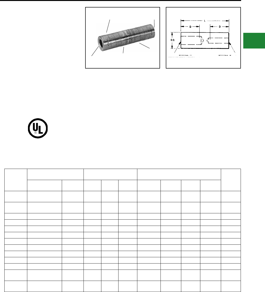
BURNDY®
Blue highlighted items are industry standard and most frequently ordered.
Canada: 1-800-387-6487 www.burndy.com US: 1-800-346-4175
TYPE YRB
HYREDUCER™
FOR ALUMINUM TO COPPER
AND ALUMINUM TO ALUMINUM
UL Listed 90° C,
600 Volts to 35 kV ♦
HYREDUCER™ type YRB reducer butt splice
is designed to splice two different conductor
sizes and is UL Listed for aluminum to copper
and aluminum to aluminum applications. The
outside diameter is held constant to minimize
installation dies and is factory prelled with
PENETROX™.
Catalog
Number
Conductor Range ●
Aluminum or Copper Size † Dimensions
Installation Tooling ▲
Hydraulic Tools, Die Sets (No. of Crimps ‡) Wire
Strip
LengthBarrel A Barrel B O.D D L
Y35 ■, Y39,
Y750, Y46* ‡
Die▲
Index
Color
Code
YRB2U4 1 str.
2 str.
4 str.
3 str. 0.65 0.88 2.00 U25ART ( 1 ) 296 Tan 15/16"
YRB25U2 1/0 str. 1 str.
2 str. 0.65 0.88 2.00 U25ART ( 1 ) 296 Tan 15/16"
YRB27U25 3/0 str. 1/0 str. 0.85 1.36 3.31 U28ART ( 2 ) 298 White 1-7/16"
YRB27U26 3/0 str. 2/0 str. 0.85 1.36 3.31 U28ART ( 2 ) 298 White 1-7/16"
YRB28U26 4/0 str. 2/0 str. 0.85 1.36 3.31 U28ART ( 2 ) 298 White 1-7/16"
YRB29U28 250 kcmil 4/0 str. 1.11 1.73 4.21 U31ART ( 2 ) 299 Brown 1-13/16"
YRB31U28 350 kcmil 4/0 str. 1.11 1.73 4.21 U31ART ( 2 ) 299 Brown 1-13/16"
YRB31U29 350 kcmil 250 kcmil 1.11 1.73 4.21 U31ART ( 2 ) 299 Brown 1-13/16"
YRB34U31 500 kcmil 350 kcmil 1.31 2.11 5.12 U34ART ( 4 ) 300 Pink 2-3/16"
YRB36U31 600 kcmil 350 kcmil 1.46 2.25 5.57 U39ART-2 ( 4 ) 936 Yellow 2-5/16"
YRB36U34 600 kcmil 500 kcmil 1.46 2.25 5.57 U39ART-2 ( 4 ) 936 Yellow 2-5/16"
YRB39U34 700/750 kcmil ●
900 Compact AL ▼ 500 kcmil 1.46 2.25 5.57 U39ART-2 ( 4 ) 936 Yellow 2-5/16"
YRB39U36 700/750 kcmil ●
900 Compact AL ▼ 600 kcmil 1.46 2.25 5.57 U39ART-2 ( 4 ) 936 Yellow 2-5/16"
Features & Benets
• Constant outside diameters. Electro
tin-plated
◊ Minimizes installation dies and
provides a smooth prole for easy
taping and provides durable long
lasting corrosion resistance
• Factory prelled with BURNDY
®
PENETROX™ oxide inhibiting compound
◊ Contains homogeneously
suspended conductive metallic
particles which penetrate oxides
between conductor strands and
forms an air tight connection
• Solid center barrier
◊ Provides center stop for correct
cable insertion and aids the
thorough penetration of
PENETROX™ oxide inhibiting
compound between conductor
strands
• Connectors are clearly marked with catalog
number, wire size, and
color-coded die index
◊ Provides clear, easy to use
information to lower installed costs
• Each barrel end has a plastic end cap
◊ Keeps the connector barrels free of
foreign materials
CRIMP
ELECTRO TIN
PLATED COLOR CODED
END CAPS
PRE-FILLED
WITH PENETROX
CRIMP
† Contact BURNDY® for conductor sizes not shown.
▲ See tooling section of this catalog for complete tool and
die listings.
‡ Number of crimps.
* Use PUADP-1 adaptor with U dies shown in Y46
HYPRESS™.
■ The maximum size for the Y35 is 400 kcmil.
♦ For applications greater than 2000 Volts consult cable
manufacturer for voltage stress relief instructions.
● Also accommodates compressed and compact
conductors (except 700 kcmil in 750 kcmil barrel).
▼ Tested with Y644HSXT and PAT644XT-18V dieless
tools only and not UL Listed with any tool on 900
Compact Al.
Note: All dimensions shown are for reference only.
Compression Connections
Aluminum Compression — Reducing Splice
C-153
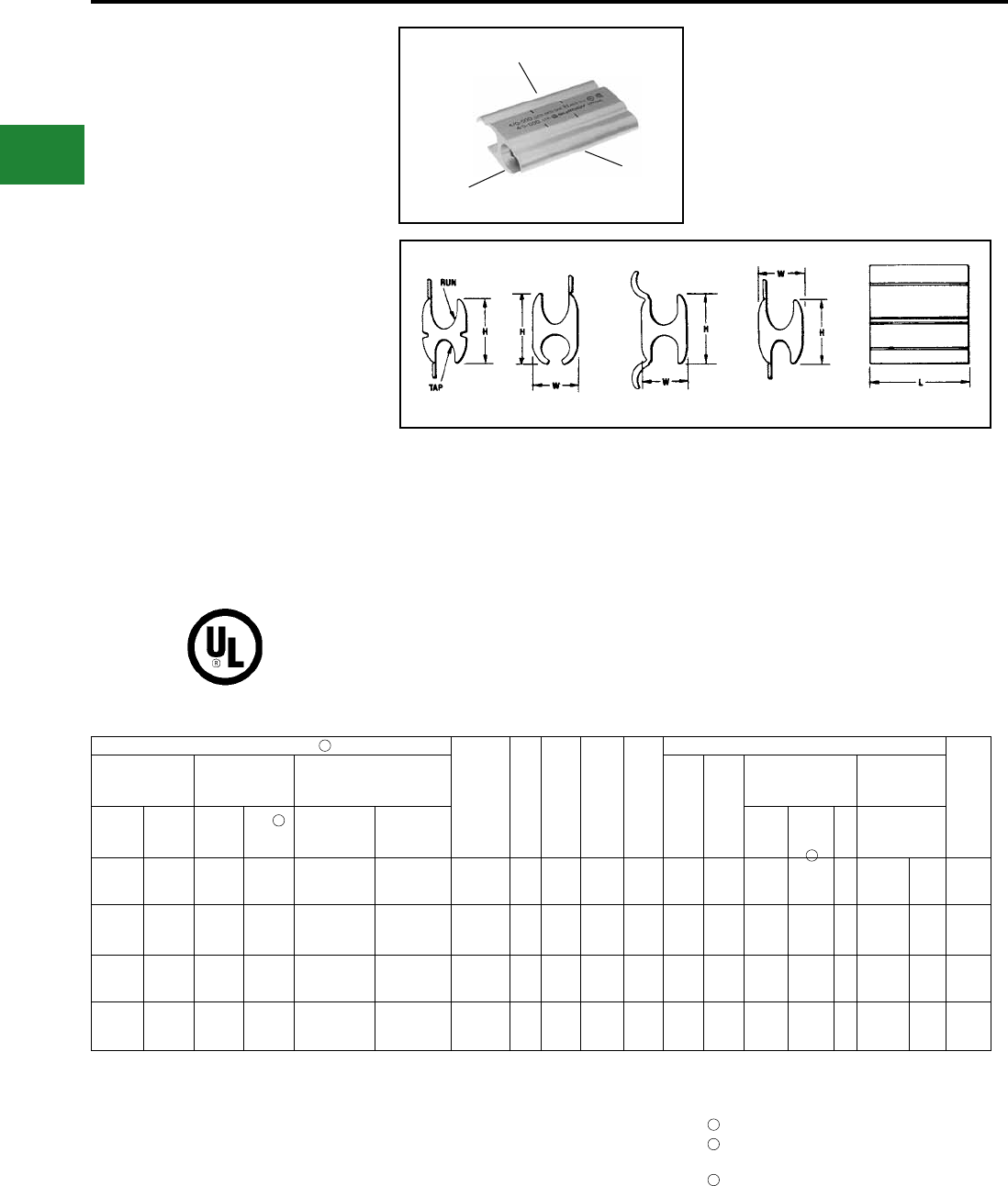
BURNDY®
Blue highlighted items are industry standard and most frequently ordered.
US: 1-800-346-4175 www.burndy.com Canada: 1-800-387-6487
TYPES YFD, YFN,YFO
AND YFR
H-CRIMPIT™
UNINSULATED
ALUMINUM COMPRESSION
TAP CONNECTOR
FOR ALUMINUM TO COPPER
AND ALUMINUM TO ALUMINUM
UL Listed 90° C,
600 Volts to 35 kV ♦
H-CRIMPIT™ compression tap connectors
Types YFD, YFN, YFO and YFR are for use with
aluminum to aluminum and aluminum to copper
connections.
The H-CRIMPIT™ is ideal for making both
parallel and tap compression connections in
risers and gutters. It should only be installed
with hydraulic tools.
Accommodates
Catalog
Number
Fig.
#
H
[mm]
L
[mm]
W
[mm]
Installation Tooling ▲
Wire
Strip
Length
Copper or
Aluminum Compact Dia. Range
▲
Die
Index
Color
Code
Hydraulic Tools,
Die Sets
(No. of Crimps)
Dieless Tools
Die Adaptor,
(No. of Crimps)
Run Tap Run Tap Run Tap
Y750,
Y35
Y39 Y46 ( )
Y644HSXT,
Y644MBH
1/0-6 Str 1-6 Str 2/0-6 1-6 Str 0.398 - 0.162 0.332 - 0.162 YFO-140* 11.15
[29.2]
1.62
[41.1]
0.70
[17.8] O Green UYFO,
U-O
UYFO,
U-O (2) PT30541 (1) 1-7/8″
4/0-1 Str 2/0-1 Str 250-1/0 3/0-1/0 0.563 - 0.338 0.477 - 0.338 YFD-365* 11.42
[36.1]
2.50
[63.5]
0.89
[22.6] D3 Blue U-D3,
U-YFD
U-D3,
U-YFD (3) PT30540 (2) 2-3/4″
500-4/0 500-4/0 500-250 500-250 0.815 - 0.522 0.815 - 0.522 YFN-540 31.82
[46.2]
4.50
[114.3]
1.23
[31.2] N Red U-N
U-YFN
P-N
P-YFN (3) — — 4-7/8″
900-600 600-350 900-700 600-400 1.1108 - 0.877 0.893 - 0.659 YFR-865 43.04
[77.2]
4.62
[117.3]
1.74
[44.2] KR Yellow — P-KR
P-YFR (4) — — 5″
Features & Benets
• Each connector is factory sealed in
polyethylene
◊ Maintains the connector free of dirt
and foreign materials prior to being
used
• When installed the connector has a smooth
prole
◊ Easy to tape or to install an
insulating CRIMPIT™ cover (See
Types CFA, CFA-FR) thereby
lowering installed costs
DIE AND COLOR CODE
AND CRIMP INFORMATION
PRE-FILLED WITH
PENETROX
CRIMP
Fig. 1 Fig. 2 Fig. 3 Fig. 4
• Connectors are marked with
color-codes to match installation die
◊ Easy die selections lower installed
cost
• UL 486B Listed
◊ Provides a quality electrical
connection
▲ See tooling section of this catalog for complete tool
and die listings.
† Do not use U-YFN die set with P-UADP-1 adapter in
Y46 HYPRESS™. Use P-YFN only.
Notes:
1 Material: Aluminum.
For Conductor combinations of AL to AL or AL to CU.
Catalog Number PUADP-1-Adaptor is required to use U
type dies in Y46 tools.
Other conductors not listed in table can be
accommodated as long as the conductor diameter
falls within diameter range specified.
2
2
3
4
4
3
Compression Connections
Aluminum Compression — Tin Plated — H-Tap
♦ For applications greater than 2000 Volts consult cable
manufacturer for voltage stress relief instructions.
* CSA Listed.
Note: All dimensions shown are for reference only.
C-154
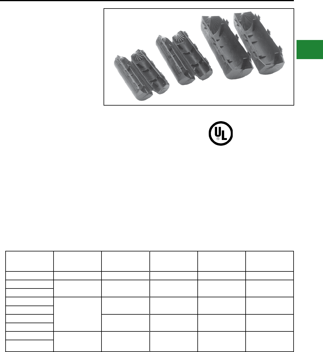
BURNDY®
Blue highlighted items are industry standard and most frequently ordered.
Canada: 1-800-387-6487 www.burndy.com US: 1-800-346-4175
Features & Benets
• One-piece design, no extra parts or
hardware required
• Slips over connector and latches securely
shut for fast, easy, reliable insulation of
H-Tap compression connectors
• Eliminates taping providing economical,
fast, easy installation
• Flash barriers protects against electrical
ashover
• CFA-FR ame retardant design with
minimum 28 oxygen index, UL 94 V-O
rated; self-extinguishing ame retardant
properties
TYPES CFA AND CFA-FR
H-CRIMPIT™
INSULATING COVERS AND
FLAME RETARDANT
INSULATING COVERS
FOR O, D3, N, AND KR DIE
SIZE H-TAP COMPRESSION
CONNECTORS
UL Listed to 600 Volts
Type CFA insulating covers are made of high
impact, high density polyethylene to insulate
H-tap CRIMPIT™ compression connectors.
Overlapping ash barriers protect both seams
against possible electrical ashover. End
ngers remain closed or wrap closely around
conductors. Multiple latches lock cover closed
securely.
Type CFA-FR ame retardant insulating
covers are made of high impact, high density
polypropylene with a minimum 28 oxygen index.
This cover incorporates all the features of the
CFA design plus the benet of self-extinguishing
ame retardant properties. Material is UL 94V-O
rated.
Both CFA and CFA-FR types are suitable for
indoor and outdoor use. Pliable in cool weather
application.
* Two piece design packaged together.
Note: All dimensions shown are for reference only.
Catalog Number Max. Conductor
Accommodated
Insulated
H-Tap CRIMPIT™
Connectors
Max. Conductor
Length Connector Die Index Connector Color
Code
CFAO-FR 1/0 YFO140 2-1/2" O Green
CFAD 4/0 YFD265, YFD365,
YFD415 3-1/8" D Blue
CFAD-FR
CFAN
500 kcmil
YFN515, YFN565 2-1/2" N-Short Connector Red
CFAN-FR
CFANL YFN465, YFN540,
YFN615 5-1/2" N-Long Connector Red
CFANL-FR
CFAR*
900 kcmil
YFR715, YFR765,
YFR815, YFR865,
YFR915
4-7/8" KR Yellow
CFAR-FR*
C-155
Compression Connections
Insulating and Flame Retardant Covers for H-Tap Connectors

BURNDY®
Blue highlighted items are industry standard and most frequently ordered.
Canada: 1-800-387-6487 www.burndy.com US: 1-800-346-4175
Accessories & Hardware
D-1
TABLE OF CONTENTS
D-2
D-3
D-3
D-3
D-3
D-4
D-4
D-4
D-4
D-5
D-5
D-5
D-5
D-6
D-6
D-6
D-6
D-7
D-8
D-8
D-9
DURIUM™ Hardware
Bolts
Nuts
Flat Washers
Split Lockwashers
Internal Tooth Lockwashers
Aluminum Hardware
Bolts
Nuts
Flat Washers
Split Lockwashers
Galvanized Steel Hardware
Bolts
Nuts
Flatwashers
Internal Tooth Lockwashers
Stainless Steel Hardware
Bolts
Nuts
Split Lockwashers
Flat Washers
Belleville Washers
TMH Terminal Mounting Hardware Kits
DURIUM™ Silicon Bronze
Stainless Steel
DURIUM™ U-Bolts
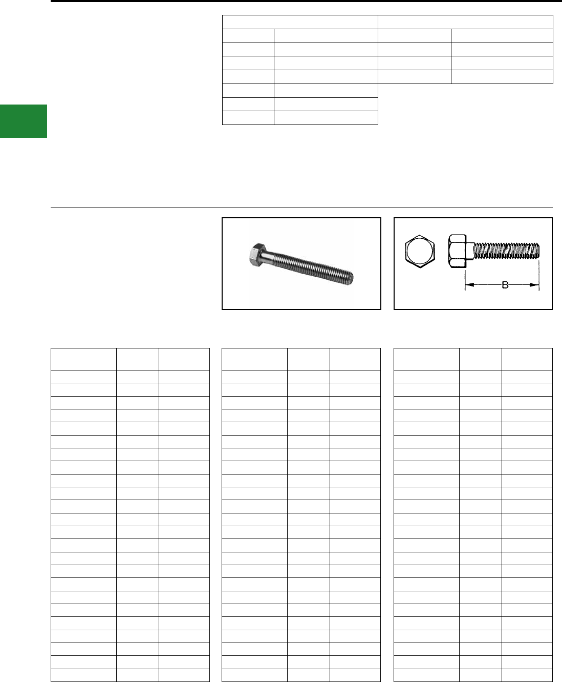
BURNDY®
Blue highlighted items are industry standard and most frequently ordered.
US: 1-800-346-4175 www.burndy.com Canada: 1-800-387-6487
Accessories & Hardware
DURIUM™ BOLT
SILICON BRONZE
BURNDY® introduced silicon-bronze bolts, nuts
and other hardware items on outdoor connector
applications in 1927. Today the DURIUM™
trademark is a standard for this use. DURIUM™
bolts combine high strength with corrosion
resistance. Heads have American Standard
HARDWARE DATA
RECOMMENDED
TIGHTENING TORQUE
The hardware used in connectors must be
compatible with the connector material, have high
mechanical strength and be corrosion resistant
and correspond to NEMA recommendations.
Copper alloy connectors have hardware made
of DURIUM™, which is BURNDY’s trade name
for silicon bronze alloy ASTMB99 type B. This
material was rst introduced by BURNDY® in 1927
for use in outdoor construction, and today, is the
standard throughout the industry.
Catalog Number Thread
Size
B Length
(Inches)
25x50HEBBOX 1/4-20 1/2
25x62HEBBOX 1/4-20 5/8
25x75HEBBOX 1/4-20 3/4
25x100HEBBOX 1/4-20 1
25x125HEBBOX 1/4-20 1-1/4
25x150HEBBOX 1/4-20 1-1/2
25x200HEBBOX 1/4-20 2
25x250HEBBOX 1/4-20 2-1/2
25x300HEBBOX 1/4-20 3
31x50HEBBOX 5/16-18 1/2
31x62HEBBOX 5/16-18 5/8
31x75HEBBOX 5/16-18 3/4
31x100HEBBOX 5/16-18 1
31x125HEBBOX 5/16-18 1-1/4
31x150HEBBOX 5/16-18 1-1/2
31x175HEBBOX 5/16-18 1-3/4
31x200HEBBOX 5/16-18 2
31x250HEBBOX 5/16-18 2-1/2
31x300HEBBOX 5/16-18 3
38x50HEBBOX 3/8-16 1/2
38x62HEBBOX 3/8-16 5/8
38x75HEBBOX 3/8-16 3/4
38x88HEBBOX 3/8-16 7/8
38x100HEBBOX 3/8-16 1
Catalog Number Thread
Size
B Length
(Inches)
38x125HEBBOX 3/8-16 1-1/4
38x150HEBBOX 3/8-16 1-1/2
38x175HEBBOX 3/8-16 1-3/4
38x200HEBBOX 3/8-16 2
38x225HEBBOX 3/8-16 2-1/4
38x250HEBBOX 3/8-16 2-1/2
38x275HEBBOX 3/8-16 2-3/4
38x300HEBBOX 3/8-16 3
38x325HEBBOX 3/8-16 3-1/4
38x350HEBBOX 3/8-16 3-1/2
38x400HEBBOX 3/8-16 4
38x450HEBBOX 3/8-16 4-1/2
38x500HEBBOX 3/8-16 5
44x150HEBBOX 7/16-14 1-1/2
44x200HEBBOX 7/16-14 2
50x75HEBBOX 1/2-13 3/4
50x100HEBBOX 1/2-13 1
50x125HEBBOX 1/2-13 1-1/4
50x150HEBBOX 1/2-13 1-1/2
50x175HEBBOX 1/2-13 1-3/4
50x200HEBBOX 1/2-13 2
50x225HEBBOX 1/2-13 2-1/4
50x250HEBBOX 1/2-13 2-1/2
50x275HEBBOX 1/2-13 2-3/4
dimension and the threads are per American
National Coarse Series, Class #2 t. The silicon
Catalog Number Thread
Size
B Length
(Inches)
50x300HEBBOX 1/2-13 3
50x325HEBBOX 1/2-13 3-1/4
50x350HEBBOX 1/2-13 3-1/2
50x375HEBBOX 1/2-13 3-3/4
50x400HEBBOX 1/2-13 4
50x450HEBBOX 1/2-13 4-1/2
50x500HEBBOX 1/2-13 5
50x550HEBBOX 1/2-13 4-1/2
50x600HEBBOX 1/2-13 6
62x100HEBBOX 5/8-11 1
62x125HEBBOX 5/8-11 1-1/4
62x150HEBBOX 5/8-11 1-1/2
62x175HEBBOX 5/8-11 1-3/4
62x200HEBBOX 5/8-11 2
62x225HEBBOX 5/8-11 2-1/4
62x250HEBBOX 5/8-11 2-1/2
62x275HEBBOX 5/8-11 2-3/4
62x300HEBBOX 5/8-11 3
62x325HEBBOX 5/8-11 3-1/4
62x350HEBBOX 5/8-11 3-1/2
62x400HEBBOX 5/8-11 4
62x450HEBBOX 5/8-11 4-1/2
62x500HEBBOX 5/8-11 5
62x600HEBBOX 5/8-11 6
DURIUM™ and Steel Hardware Aluminum Hardware
Bolt Size Rec. Torque (Inch Pounds) Bolt Size Rec. Torque (Inch Pounds)
1/4 - 20 80 1/2 - 13 300
5/16 - 18 180 5/8 - 11 480
3/8 - 16 240 3/4 - 10 650
1/2 - 13 480
5/8 - 11 660
3/4 - 10 1,050
Aluminum connectors generally have aluminum
alloy hardware. The bolts are 2024T4 and
anodized to resist corrosion. The nuts are 6061T6,
which is resistant to corrosion and does not require
anodizing. Both nuts and bolts are lubricated
to eliminate galling and to provide consistent
clamping forces.
To reduce or greatly exceed the recommended
torque can adversely affect the performance of the
connector.
bronze is per ASTM B99.
D-2
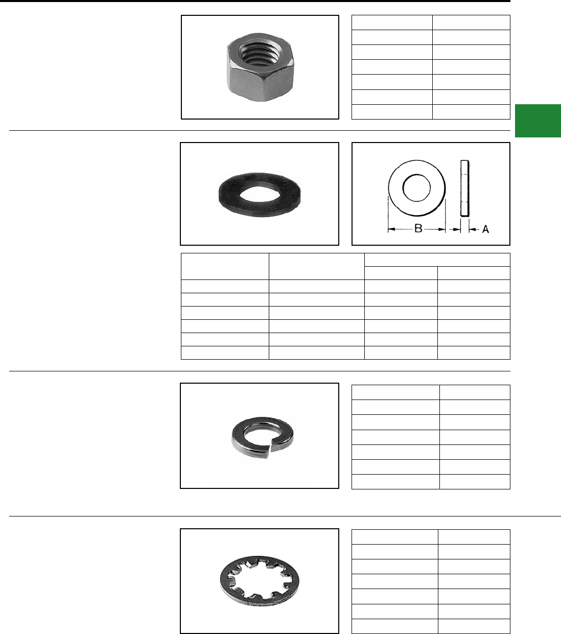
BURNDY®
Blue highlighted items are industry standard and most frequently ordered.
Canada: 1-800-387-6487 www.burndy.com US: 1-800-346-4175
Accessories & Hardware
DURIUM™ NUTS
SILICON BRONZE
DURIUM™ hexagon regular nuts are non-
magnetic and are made to American Standard
dimensions. American National Coarse Series
threads. #2 t.
Catalog Number Thread Size
25CHENBOX 1/4-20
31CHENBOX 5/16-18
38CHENBOX 3/8-16
44CHENBOX 7/16-14
50CHENBOX 1/2-13
62CHENBOX 5/8-11
DURIUM™ FLAT WASHERS
SILICON BRONZE
High strength DURIUM™ Flat Washers are non-
magnetic and free from galvanic action when in
contact with copper. Conforms to SAE standards.
DURIUM™ SPLIT
LOCKWASHERS
SILICON BRONZE
DURIUM™ spring type lockwasher has high
resiliency and exerts constant pressure on the
face of the nut, preventing vibration from loosening
the nut.
DURIUM™ INTERNAL TOOTH
LOCKWASHERS
SILICON BRONZE
DURIUM™ Internal Tooth Lockwashers are
available as illustrated. The teeth are twisted
slightly and present biting edges which grip the
nut and the part being clamped, preventing the nut
from backing off.
Catalog Number For Bolt Size Nominal Dimensions in Inches
A B
25FWBOX 1/4 1/16 5/8
31FWBOX 5/16 1/16 11/16
38FWBOX 3/8 1/16 13/16
44FWBOX 7/16 1/16 15/16
50FWBOX 1/2 3/32 1-1/16
62FWBOX 5/8 3/32 1-5/16
Catalog Number For Bolt Size
25SWBOX 1/4
31SWBOX 5/16
38SWBOX 3/8
44SWBOX 7/16
50SWBOX 1/2
62SWBOX 5/8
Catalog Number For Bolt Size
25NWBOX 1/4
31NWBOX 5/16
38NWBOX 3/8
44NWBOX 7/16
50NWBOX 1/2
62NWBOX 5/8
D-3
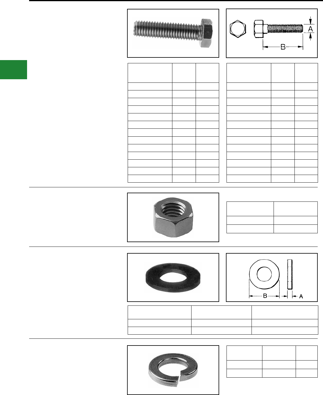
BURNDY®
Blue highlighted items are industry standard and most frequently ordered.
US: 1-800-346-4175 www.burndy.com Canada: 1-800-387-6487
Accessories & Hardware
ALUMINUM HARDWARE
BOLTS
BURNDY® aluminum hexagon head bolts are
manufactured of alloy 2024-T4 and are nished
with anodic coating and lubricated. Threads are
coarse series, class 2A t. Catalog
Number
Thread
Size
B
Length
(Inches)
50x150HABBOX 1/2-13 1-1/2
50x175HABBOX 1/2-13 1-3/4
50x200HABBOX 1/2-13 2
50x225HABBOX 1/2-13 2-1/4
50x250HABBOX 1/2-13 2-1/2
50x275HABBOX 1/2-13 2-3/4
50x300HABBOX 1/2-13 3
50x325HABBOX 1/2-13 3-1/4
50x350HABBOX 1/2-13 3-1/2
50x375HABBOX 1/2-13 3-3/4
50x400HABBOX 1/2-13 4
50x425HABBOX 1/2-13 4-1/4
50x450HABBOX 1/2-13 4-1/2
Catalog
Number
Thread
Size
B
Length
(Inches)
50x500HABBOX 1/2-13 5
50x550HABBOX 1/2-13 5-1/2
62x175HABBOX 5/8-11 1-3/4
62x200HABBOX 5/8-11 2
62x225HABBOX 5/8-11 2-1/4
62x250HABBOX 5/8-11 2-1/2
62x300HABBOX 5/8-11 3
62x350HABBOX 5/8-11 3-1/2
62x400HABBOX 5/8-11 4
62x450HABBOX 5/8-11 4-1/2
62x500HABBOX 5/8-11 5
62x550HABBOX 5/8-11 5-1/2
62x600HABBOX 5/8-11 6
NUTS
BURNDY® aluminum nuts are manufactured of
alloy 6061-T6, are nished type, coarse thread,
class 2B t.
Catalog
Number
Thread
Size
50HANBOX 1/2-13
62HANBOX 5/8-11
FLAT WASHERS
BURNDY® aluminum at washers are
manufactured of alloy 2024-T4 and are medium
design.
Catalog
Number Description For Bolt
Size
50FWABOX Flat Washer 1/2
62FWABOX Flat Washer 5/8
SPLIT LOCKWASHERS
BURNDY® aluminum split lockwashers are
manufactured of alloy 7075-T6 and are regular
design.
Catalog
Number Description
For Bolt
Size
50SWALBOX Split Washer 1/2
62SWALBOX Split Washer 5/8
D-4
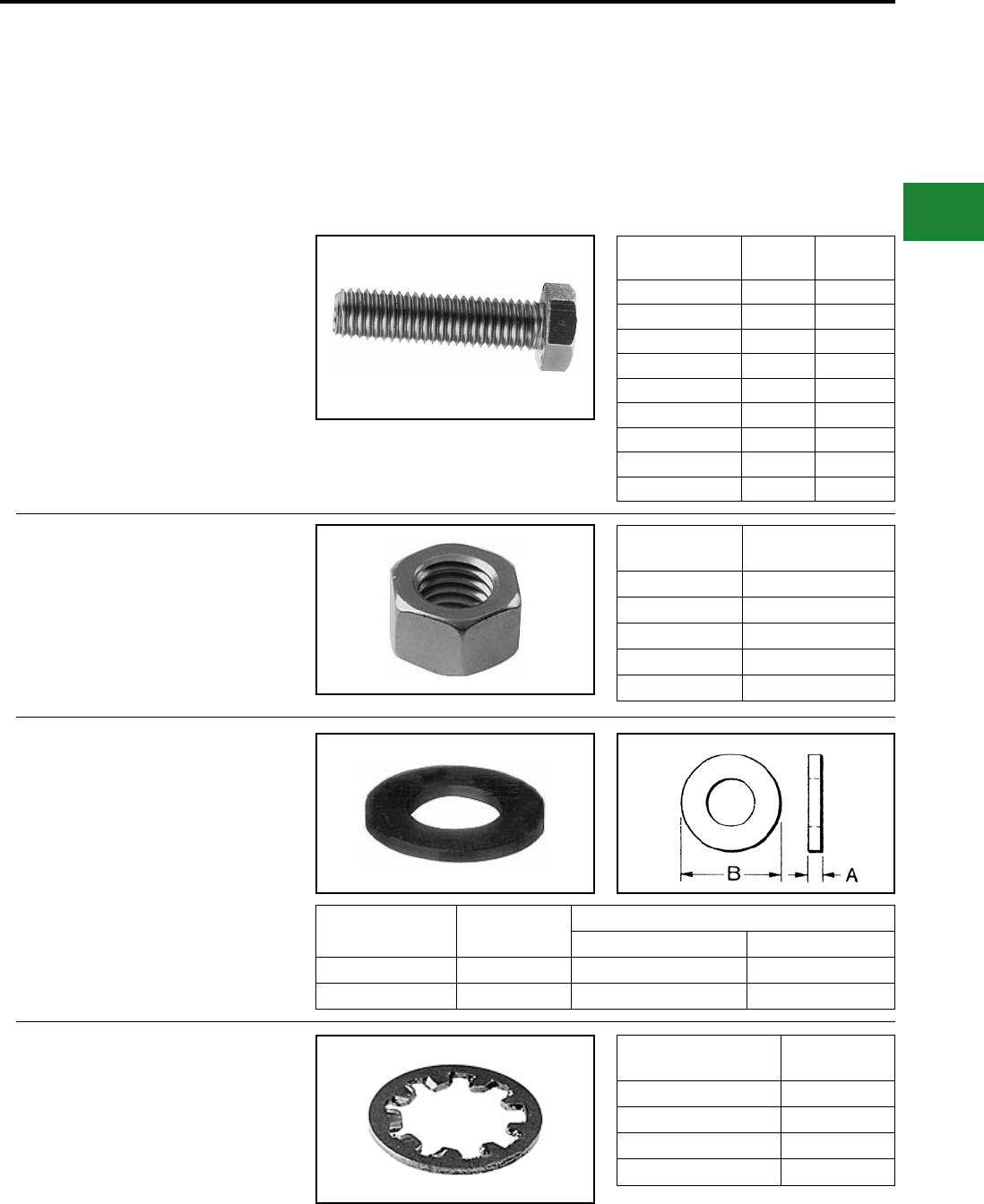
BURNDY®
Blue highlighted items are industry standard and most frequently ordered.
Canada: 1-800-387-6487 www.burndy.com US: 1-800-346-4175
Accessories & Hardware
GALVANIZED
STEEL HARDWARE
Galvanized bolts, nuts, atwashers, and internal
tooth lockwashers are manufactured per
ASTM307 Grade A. Nut surfaces and bolt heads
have American Standard dimensions, and the
Catalog
Number
Thread
Size Length (B)
38x125HGSB 3/8-16 1.25
38x275HGSB 3/8-16 2.75
38x225HGSB 3/8-16 2.25
50x100HGSB 1/2-13 1.00
50x150HGSB 1/2-13 1.50
50x200HGSB 1/2-13 2.00
62X100HGSB 5/8-11 1.00
62x175HGSB 5/8-11 1.75
75X125HGSB 3/4-11 1.25
Catalog
Number
Thread
Size
31CHGSN 5/16-18
38HGSN009 3/8-16
38HGSN 3/8-16
50HGSN 1/2-13
62HGSN 5/8-11
Catalog
Number
For Bolt
Size
Nominal Dimensions (Inches)
I.D.A O.D.B
38x81FWGS 3/8 0.41 0.81
50x106FWGS 1/2 0.53 1.06
threads are per American National Coarse Series,
Class #2 t. Galvanizing is per ASTM A153.
Catalog
Number
Bolt
Size
38NWGS 3/8
50NWGS 1/2
62NWGS 5/8
75NWGS 3/4
NUTS
BOLTS
FLAT WASHERS
INTERNAL TOOTH
LOCKWASHERS
D-5
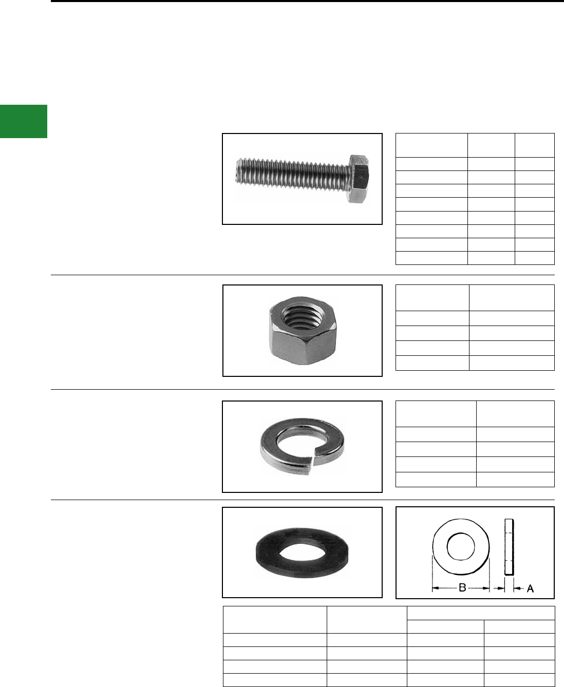
BURNDY®
Blue highlighted items are industry standard and most frequently ordered.
US: 1-800-346-4175 www.burndy.com Canada: 1-800-387-6487
Accessories & Hardware
STAINLESS STEEL
HARDWARE
Stainless steel bolts, nuts, atwashers and split
lockwashers are manufactured from 18-8 non-
magnetic material. Nut surfaces and bolt heads
have American National Coarse Series, Class #2
t.
Catalog
Number
Thread
Size
Length
B
38X125HSSB 3/8-16 1-1/4
38x225HSSB 3/8-16 2-1/4
38x250HSSB 3/8-16 2-1/2
38x275HSSB 3/8-16 2-3/4
50x200HSSB 1/2-13 2
50x250HSSB 1/2-13 2-1/2
50x300HSSB 1/2-13 3
62x300HSSB 5/8-11 3
BOLTS
NUTS
SPLIT LOCKWASHERS
FLAT WASHERS
Catalog
Number
Thread
Size
25HSSN 1/4-20
38HSSN 3/8-16
50HSSN 1/2-13
62HSSN 5/8-11
Catalog
Number
For Bolt
Size
25SWSSLT 1/4
38SWSSMD 3/8
50SWSSMD 1/2
62SWSSMD 5/8
Catalog
Number
For Bolt
Size
Nominal Dimensions (Inches)
I.D.A O.D.B
25FWSS 1/4 0.27 0.69
38FWSS 3/8 0.41 1.00
50FWSS 1/2 0.59 1.13
62FWSS 5/8 0.66 1.31
D-6
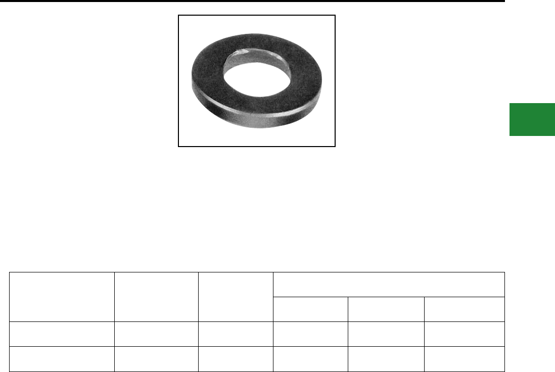
BURNDY®
Blue highlighted items are industry standard and most frequently ordered.
Canada: 1-800-387-6487 www.burndy.com US: 1-800-346-4175
Accessories & Hardware
STAINLESS STEEL
HARDWARE
BELLEVILLE WASHERS
Any bolted “pad to at” electrical connection should
include a bolt, two atwashers, and the nut. In
addition, if any of the at components is aluminum,
a properly designed Belleville washer should be
interposed between one of the atwashers and
either the bolt head or the nut, with the hollow of the
Belleville washer placed against the at washer.
BURNDY® Belleville washers are designed to
maintain substantial force when tightened to
NEMA-recommended values and nely nished
to avoid galling.
Catalog
Number Material Bolt
Size
Nominal Dimensions
Thickness I.D. O.D.
38x75BWSS Steel - Stainless 3/8 0.06 0.39 0.75
50x106BWSS Steel - Stainless 1/2 0.10 0.53 1.06
D-7
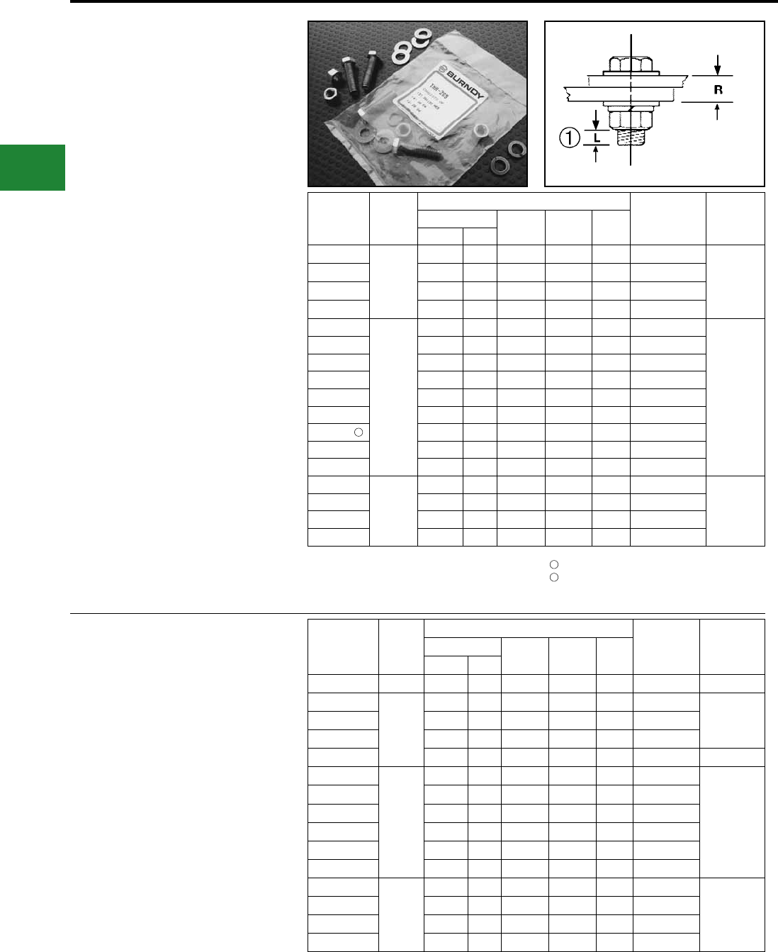
BURNDY®
Blue highlighted items are industry standard and most frequently ordered.
US: 1-800-346-4175 www.burndy.com Canada: 1-800-387-6487
Accessories & Hardware
TYPE TMH
DURIUM™ SILICON BRONZE
HARDWARE KITS
Type TMH are DURIUM™ silicon bronze
hardware kits. The kits can be ordered for specic
applications ensuring the proper type and amount
of hardware for each installation. Packaged in
separate sealed bags, they are convenient to use,
eliminating mismatched quantities. DURIUM™
silicon bronze material provides long lasting
corrosion resistance Grade 2.
Catalog
Number Size
Each TMH Kit Includes:
Working
Range (R)
Installation
Torque
(In-lbs)
Bolt Flat
Washer
Split
Washer
Hex
NutLength Qty
TMH262
1/4-20
0.75 2 4 2 2 0.09 - 0.34
80
TMH263 1.00 2 4 2 2 0.34 - 0.59
TMH264 1.25 2 4 2 2 0.59 - 0.84
TMH265 1.50 2 4 2 2 0.84 - 1.09
TMH266
3/8-16
0.75 2 4 2 2 0.00 - 0.19
240
TMH267 1.00 2 4 2 2 0.19 - 0.44
TMH268 1.25 2 4 2 2 0.44 - 0.69
TMH269 1.50 2 4 2 2 0.69 - 0.94
TMH270 1.75 2 4 2 2 0.94 - 1.19
TMH271 2.00 2 4 2 2 1.19 - 1.44
TMH332 2.75 2 4 2 2 -
TMH261 † 3.00 2 4 2 2 2.15 - 2.40
TMH289 †† 1.25 1 2 1 1 0.02 - 0.27
TMH295
1/2-13
1.25 2 4 2 2 0.27 - 0.49
480
TMH272 1.50 2 4 2 2 0.49 - 0.74
TMH294 1.75 2 4 2 2 0.74 - 0.99
TMH69 2.00 2 4 2 2 0.99 - 1.24
TYPE TMH-SS
STAINLESS STEEL
HARDWARE KITS
Type TMH-SS are stainless steel hardware kits.
Just like the standard TMH kits, these kits can
be ordered for specic applications ensuring the
proper type and amount of hardware for each
installation. They are packaged in separate sealed
bags and convenient for use and ordering.
Catalog
Number Size
Each TMH Kit Includes: Working
Range (R)
Installation
Torque
(In-lbs)
Bolt Flat
Washer
Split
Washer
Hex
Nut
Length Qty
TMH322SS 10-32 0.88 1 0 1 1 - 45
TMH262SS
1/4-20
0.75 2 4 2 2 0.09 - 0.34
80TMH263SS 1.00 2 4 2 2 0.34 - 0.59
TMH264SS 1.25 2 4 2 2 0.59 - 0.84
TMH265SS 1.50 2 4 2 2 0.84 - 1.09 —
TMH267SS
3/8-16
1.00 2 4 2 2 0.19 - 0.44
240
TMH268SS 1.25 2 4 2 2 0.44 - 0.69
TMH269SS 1.50 2 4 2 2 0.69 - 0.94
TMH270SS 1.75 2 4 2 2 0.94 - 1.19
TMH271SS 2.00 2 4 2 2 1.19 - 1.44
TMH261SS † 3.00 2 4 2 2 2.15 - 2.40
TMH295SS
1/2-13
1.25 2 4 2 2 0.27 - 0.49
480
TMH272SS 1.50 2 4 2 2 0.49 - 0.74
TMH294SS 1.75 2 4 2 2 0.74 - 0.99
TMH69SS 2.00 2 4 2 2 0.99 - 1.24
† For use with CUSA750-2TC38 copper spacer adaptor,
(2) terminals and °” thick equipment bus bar. For other
combinations contact BURNDY®.
†† For use with all GAR-TC connectors. “R” dimension is
allowable pad thickness of terminal
* For other combinations contact BURNDY®.
“L” dimension never exceeds 0.25"
For use with CUSA442TC38 on 1/4" bus bar and
HYLUG™ 4/0 - 750 kcmil.
1
2
2
D-8
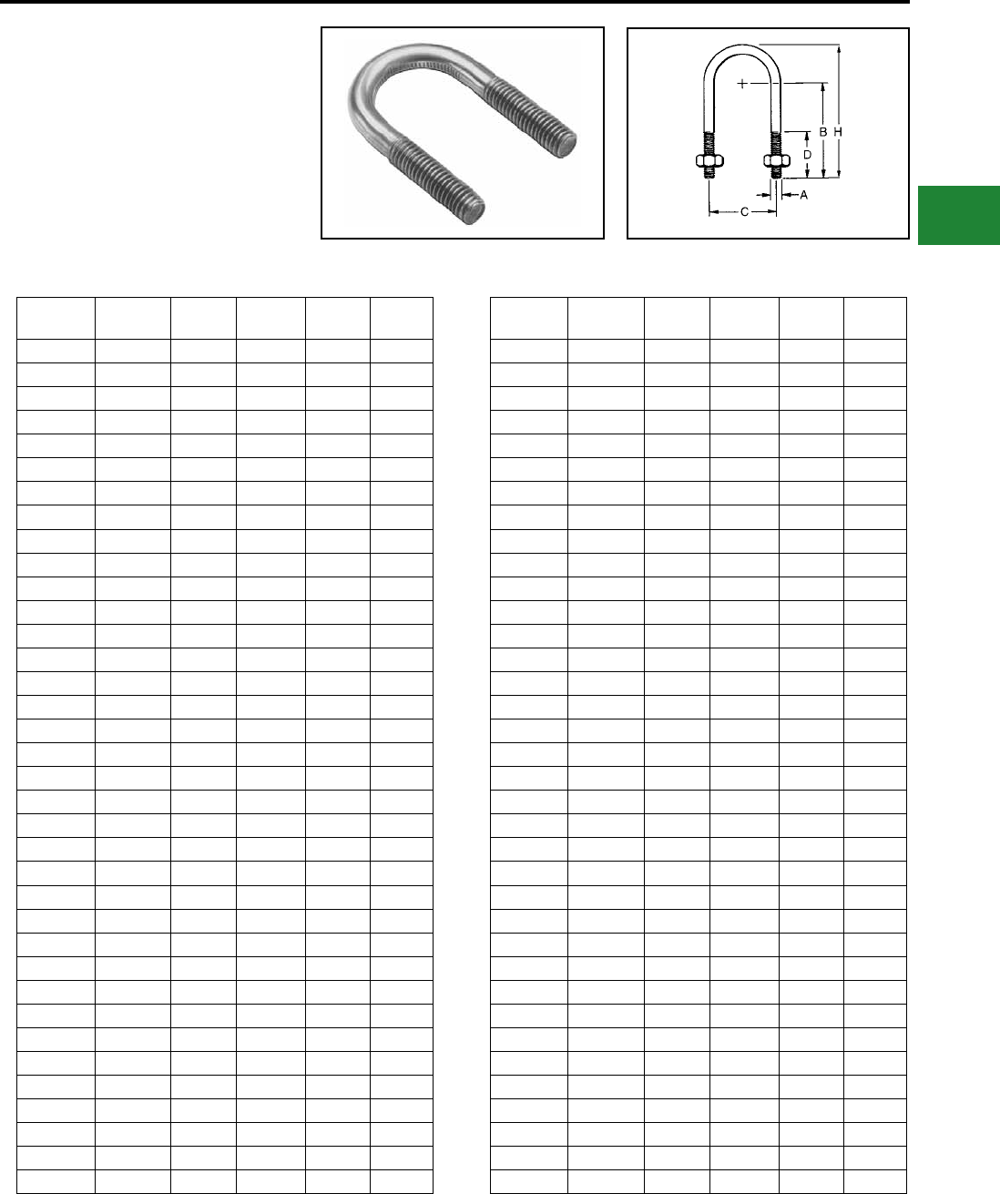
BURNDY®
Blue highlighted items are industry standard and most frequently ordered.
Canada: 1-800-387-6487 www.burndy.com US: 1-800-346-4175
Accessories & Hardware
TYPE UB
DURIUM™
SILICON BRONZE U-BOLTS
DURIUM™ U-BOLTS are specically designed
for electrical connections to pipe and rod. The
U-BOLTS are threaded on the straight portion of
the legs only allowing for more contact surface on
the pipe or rod. American National Coarse Threads
Class #2 t. The silicon bronze is per ASTM B99.
Catalog
Number
Thread
Size H C D B
UB101 1/4-20 1.38 0.75 0.75 0.88
UB104 1/4-20 1.81 1.12 0.88 1.12
UB105 1/4-20 2.03 1.31 1.00 1.25
UB106 1/4-20 2.31 1.62 1.12 1.38
UB107 1/4-20 2.66 1.94 1.31 1.56
UB336 3/8-16 1.50 0.88 0.62 0.88
UB178 3/8-16 2.00 0.88 0.75 1.38
UB354 3/8-16 2.44 1.25 1.00 1.62
UB187 3/8-16 2.47 1.16 1.06 1.69
UB271 3/8-16 2.50 1.00 1.19 1.81
UB222 3/8-16 2.69 1.50 1.12 1.75
UB242 3/8-16 2.72 1.16 1.31 1.94
UB383 3/8-16 2.75 0.94 1.47 2.09
UB269 3/8-16 2.78 1.19 1.38 2.00
UB357 3/8-16 2.78 1.69 1.12 1.75
UB384 3/8-16 2.91 1.44 1.38 2.00
UB249 3/8-16 3.00 1.50 1.44 2.06
UB1031 3/8-16 3.31 1.75 1.90 2.25
UB244 3/8-16 3.31 1.75 1.62 2.25
UB199 3/8-16 3.41 2.34 1.44 2.05
UB204 3/8-16 3.47 2.06 1.62 2.25
UB124 3/8-16 3.50 2.75 1.31 1.94
UB268 3/8-16 3.97 2.34 2.00 2.62
UB257 3/8-16 4.16 2.81 1.94 2.56
UB1032 3/8-16 4.41 2.81 2.56 2.81
UB310 3/8-16 4.41 2.81 2.19 2.81
UB266 3/8-16 4.97 3.31 2.50 3.12
UB267 3/8-16 5.53 3.94 2.75 3.38
UB258 3/8-16 5.56 4.00 2.75 3.38
UB264 3/8-16 6.16 4.44 3.12 3.75
UB1033 3/8-16 6.16 4.44 3.50 3.75
UB261 3/8-16 6.34 4.94 3.06 3.69
UB422 3/8-16 7.69 6.00 3.88 4.50
UB1027 3/8-16 8.12 7.12 2.88 4.38
UB1028 3/8-16 9.62 9.12 2.88 4.88
UB1029 3/8-16 11.20 11.25 2.88 5.38
Catalog
Number
Thread
Size H C D B
UB1030 3/8-16 12.70 13.25 2.88 5.88
UB224 1/2-13 2.44 1.12 0.88 1.62
UB358 1/2-13 2.66 1.31 1.00 1.75
UB291 1/2-13 2.81 1.19 1.19 1.97
UB293 1/2-13 2.81 1.75 1.75 1.69
UB464 1/2-13 3.12 1.81 1.81 1.96
UB540 1/2-13 3.19 1.38 1.38 2.25
UB254 1/2-13 3.41 1.31 1.31 2.50
UB328 1/2-13 3.41 2.94 2.94 1.69
UB400 1/2-13 4.03 1.31 1.31 3.12
UB230 1/2-13 4.34 2.94 2.94 2.62
UB311 1/2-13 4.44 1.88 1.88 3.25
UB302 1/2-13 4.62 2.47 2.47 3.12
UB232 1/2-13 4.97 3.44 3.44 3.00
UB260 1/2-13 5.34 2.94 2.94 3.62
UB390 1/2-13 5.38 2.50 2.50 3.88
UB263 1/2-13 5.78 4.56 4.56 3.25
UB282 1/2-13 6.31 4.12 4.12 4.00
UB236 1/2-13 6.41 5.06 5.06 3.62
UB399 1/2-13 6.66 1.31 1.31 5.75
UB436 1/2-13 6.66 4.56 4.56 4.12
UB262 1/2-13 6.78 5.06 5.06 4.00
UB392 1/2-13 7.06 1.62 1.62 6.00
UB416 1/2-13 7.53 5.06 5.06 4.75
UB300 1/2-13 7.62 6.12 6.12 4.31
UB306 1/2-13 7.88 6.12 6.12 4.56
UB275 1/2-13 8.16 7.19 3.54 4.31
UB437 1/2-13 8.56 6.12 6.12 5.25
UB294 5/8-11 3.50 1.38 1.38 2.50
UB314 5/8-11 3.66 2.09 2.09 2.31
UB425 5/8-11 3.72 2.31 2.31 2.25
UB317 5/8-11 4.97 1.81 1.81 3.75
UB315 5/8-11 5.56 2.09 2.09 4.19
UB318 3/4-10 4.22 2.44 2.44 2.62
UB344 3/4-10 4.72 1.94 1.94 3.38
UB319 3/4-10 6.34 2.44 2.44 4.75
D-9
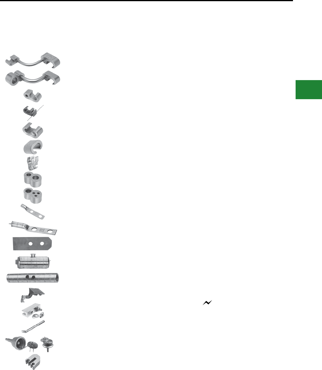
BURNDY®
Blue highlighted items are industry standard and most frequently ordered.
Canada: 1-800-387-6487 www.burndy.com US: 1-800-346-4175
Grounding
Compression, Mechanical, Exothermic
TABLE OF CONTENTS
E-1
HYGROUND® Irreversible Compression Grounding
Lightning Protection Info.
Basic rules for selection are:
1. Must be like material to the conductor.
2. Two bolts to ground rod—minimum, for mechanical.
3. Cable to cable connections can be installed with
one bolt, two bolt, or compression means.
4. Cable to steel structure must have 8 in.2 contact
with steel.
5. Heavy duty stacks—mechanical only.
6. On all connectors with heavy duty stack rating, we
must offer 1/16” thick lead plating as an option. The
reason is closest 25 ft. to stack opening must use
lead coated product.
7. UL 96 Listing.
E-5, E-6
E-7
E-8
E-9
E-10
E-11
E-12
E-13
E-14
E-15
E-16
E-17
E-18
E-19
E-20
E-21
E-22, E-23
E-24
E-25
E-26
HYGROUND® Features & Benets
Type YGL-C
Type YGLR-C
Type YGHP-C
Type YGHP-C
Type YGHC-C
Type YGC
Type YSHG
Type YGHR-C
Type YGHR-C
Type YGHA
Type YGA
GROUNDTAB
Type YGHS
Type YGS
Type YGF
Type YGIB
Type GSTUD-HY
Types YGT, YTTAG
Type YG-B
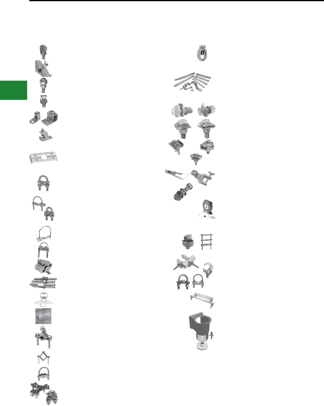
BURNDY®
Blue highlighted items are industry standard and most frequently ordered.
US: 1-800-346-4175 www.burndy.com Canada: 1-800-387-6487
Grounding
Compression, Mechanical, Exothermic
E-2
TABLE OF CONTENTS
Types KC, K2C
Type KCKF
Types KC-J, EQC632
Type KS
Types GKA, KPB
Types CL50-1, CL50-1TN,
CL
WILEY PV Solutions
Type GAR
Types GAR-BU, GAR3902,
GAR-RB
Type GAR-TC
Type GD
Type GP
Type GK
BONDIT® Intersystem Bonding
BONDIT® Intersystem Bonding
Water Pipe Grounding
Type GC-A
Type GG
Types GQ, GX
Types GRC, GCRT1/0, GRL
Braid Information
Type B
Types GB, GBM
GC, GCM
Types GL, GZ
Type GC-CT
Type GIE-G
Type GCB63T13G1
Static Discharge Reels
Rail Connectors
Types QGFL, GA-H
Raised Floor Ground Connectors
SUPER-CLAMP™ (Type GXP)
UNIGROUND™ (Type GRF)
Types GP-G1, GP-RT
Bus Bar (Type BBB)
Type BWB680 Series
Pool Water Bonding Kit
E-27
E-28
E-29
E-29
E-30
E-31
E-32,
E33
E-34,
E-35
E-36
E-37
E-38
E-39
E-40
E-41
E-42
E-43 -
E-47
E-48
E-49
E-50
E-51
E-52,
E-53
E-54 -
E-56
E-57
E-58
E-59
E-60
E-61
E-62
E-63
E-64
E-65
E-66
E-67
E-68,
E-69
E-70
Mechanical Grounding

BURNDY®
Blue highlighted items are industry standard and most frequently ordered.
Canada: 1-800-387-6487 www.burndy.com US: 1-800-346-4175
Grounding
Compression, Mechanical, Exothermic
E-3
TABLE OF CONTENTS (continued)
E-71
E-72
E-73
E-74
E-75
E-76
E-77
E-78
E-79
E-79
E-80
E-81
QIKLITE® BURNDYWeld®
Battery Ignition System
BURNDYWeld® Introduction
Making a BURNDYWeld®
Connection
BURNDYWeld® Weld Metal
Type BCC-1 Molds
Horizontal End to End
Type BCC-2 Molds
Horizontal Cable Tap to
Horizontal Cable Run
Type BCC-4 Molds
Horizontal to Horizontal
Cable Cross
Type BCC-11 Molds
Horizontal to Horizontal
Cable Cross
Type BCC-6 Molds
Horizontal Parallel Tap
Type BCC-14 Molds
Horizontal Parallel through
Cables
Type BCC-7 Molds
Horizontal Parallel through
Cables
Type BCR-1 Molds
Horizontal Cable Terminal
to Ground Rod
Type BCR-2 Molds
Horizontal Cable to
Ground Rod
Type BCR-3 Molds
Horizontal through Cable
to Ground Rod
Type BCR-17 Molds
Horizontal Run and Tap
Cables to Ground Rod
Type BCR-24 Molds
Horizontal Parallel Run
Cables to Ground Rod
SINGLE SHOT MOLDS
Type BCS-1 Molds
Horizontal Cable to
Horizontal Steel Surface
Type BCS-8 Molds
Horizontal Cable to
Horizontal Steel Surface
Type BCS-2 Molds
Horizontal through Cable to
Horizontal Steel Surface
Type BCS-9 Molds
Horizontal Cable to
Horizontal Steel Surface
Type BCS-3 Molds
Angular Cable Drop to
Vertical Steel Surface
Type BCS-23 Molds
Vertical Cable Drop to
Vertical Steel Surface
Type BCS-4 Molds
Vertical through Cable to
Vertical Steel Surface
Type BCS-6 Molds
Horizontal through Cable to
Vertical Steel Surface
Type BCS-7 Molds
Overhead Vertical Tap Cable
to Vertical Steel Surface
Type BCS-18 Molds
Horizontal Tap Cable to
Vertical Steel Surface
Type BCS-5 Molds
Horizontal Cable Tap to
Horizontal Cast Iron Surface
Type BCRE-1 Molds
Horizontal Parallel Tap
to Rebar
Type BCRE-2 Molds
Horizontal Parallel Tap
to Horizontal Rebar Run
Type BCRE-3 Molds
Horizontal through Cable to
Vertical Rebar
Type BCRE-4 Molds
Horizontal through Cable to
Horizontal Rebar
Type BCRE-6 Molds
Horizontal Cable Tap to
Vertical Rebar
E-82
E-83
E-84
E-85
E-86
E-87
E-87
E-88
E-88
E-89
E-90
E-90
E-91
E-91
E-92
E-92
E-93
E-94
E-95
E-96
E-97
BURNDYWeld® Exothermic Grounding

BURNDY®
Blue highlighted items are industry standard and most frequently ordered.
US: 1-800-346-4175 www.burndy.com Canada: 1-800-387-6487
Grounding
Compression, Mechanical, Exothermic
E-4
TABLE OF CONTENTS (continued)
E-98,
E-99
E-100
E-101
E-101
E-101
E-102
E-102
E-103
E-103
E-103
E-103
E-104
E-104
E-104
E-104
E-105
E-105
GROUNDMAX®
GRIDMAX™
B-106 & B-107 Handle Clamps
B40-0106-75
Handle Attachment
Mold Support Clamp
Vertical Magnetic Clamps
Horizontal & Vertical
Chain Clamps
BURNDYWeld® Accessories
B38-0330-00 Cable Clamp
Cable Cleaning Brush &
Card Cloth Brush
Mold Cleaners
Packing Material
BURNDYWeld® Tool Kits
BURNDYWeld® Tools
B38-0101-00 Rasp
B38-0309-00 Flint Ignitor
Ground Rod Driving Sleeves
Shim Stock, Adapter Sleeves
BURNDYWeld® Exothermic Grounding (continued)
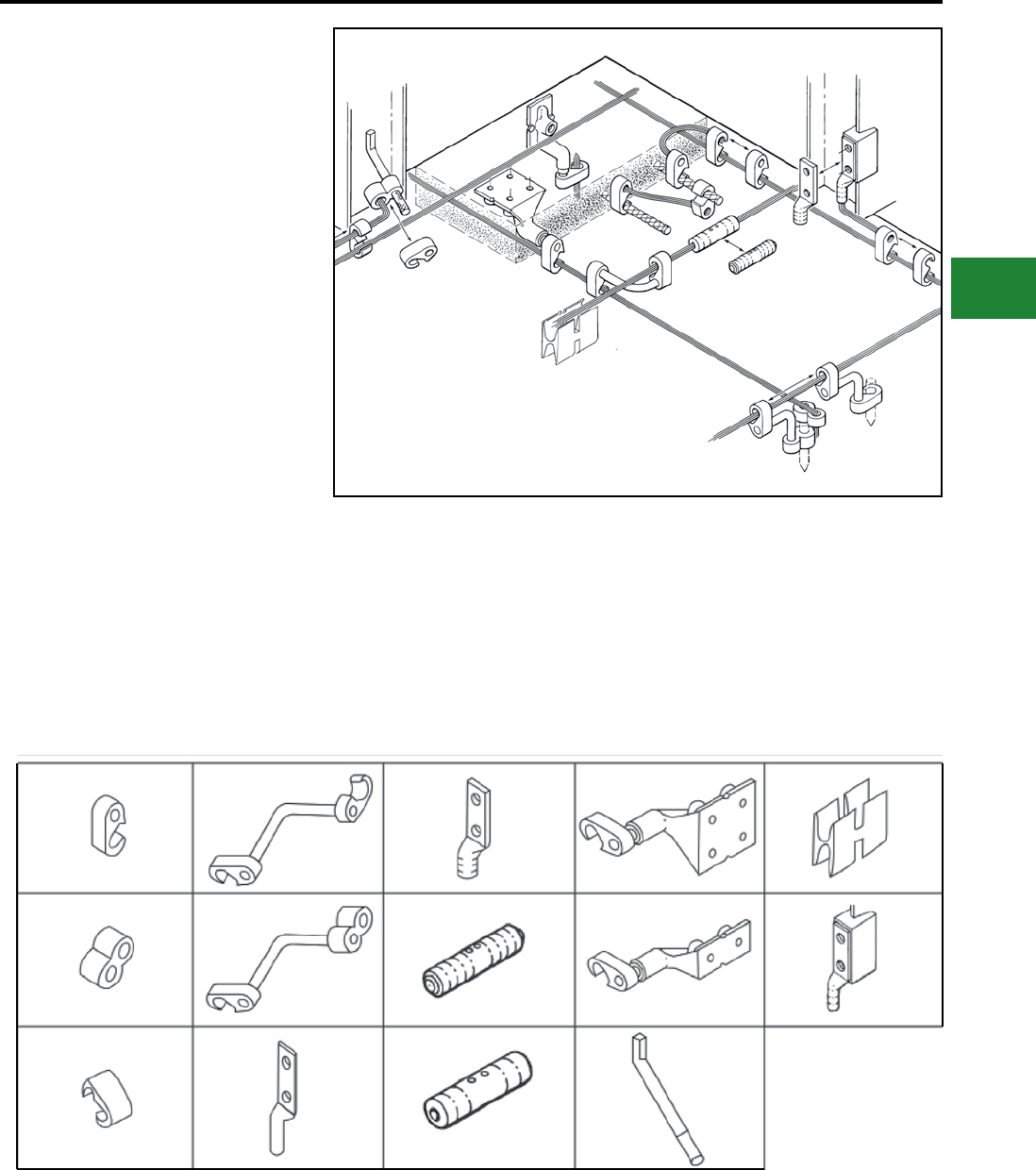
BURNDY®
Blue highlighted items are industry standard and most frequently ordered.
Canada: 1-800-387-6487 www.burndy.com US: 1-800-346-4175
Grounding
HYGROUND® Compression
THE HYGROUND®
IRREVERSIBLE
COMPRESSION
SYSTEM
BURNDY® has developed an irreversible
compression ground system which meets the most
stringent safety and performance requirements,
including those of OSHA and nuclear power
plant design. Performance excellence and long
life expectancy are the system’s basic design
guidelines. It is a complete system which consists
of connectors for grid cross connections, taps,
splices, cable to ground rod, ground plates and
terminations.
Our irreversible compression ground connectors
employ well-proven design principles and
technology that have been in existence for over 60
years.
Connectors are just one component of our
Irreversible Compression Ground System.
Installation tooling is also an integral part of this
system. BURNDY® pioneered the compression
connector principle and continues today to be the
leader in compression technology. Our tooling
package is the most extensive in the industry and
affords the user many options.
YGHPC
YGHR-C
YGHC-C
YGL-C
YGLR-C
YGA
YGHA
YGHS
YGS
YGF-4N
YGF-2N
GSTUD-HY
YSHG
YGIB
( LEGEND )
E-5

BURNDY®
Blue highlighted items are industry standard and most frequently ordered.
US: 1-800-346-4175 www.burndy.com Canada: 1-800-387-6487
Grounding
HYGROUND® Compression
THE HYGROUND®
IRREVERSIBLE
COMPRESSION
SYSTEM
(Continued)
Features and Benets
• Irreversible compression.
◊ Meets NEC code, section 250.
• Material-pure wrought copper extrusions,
rod and seamless tubing––identical material
to the conductor.
◊ Completely eliminates the possibility of
corrosion due to dissimilar metals.
• Heavy duty connector design.
◊ All connectors will carry the equivalent
or greater current carrying capacity of
the conductor while maintaining high
mechanical strength and electrical integrity.
• Range taking design––minimum number of
connector combinations required to install
a conductor range of #6 solid to 500 kcmil
plus 1/2", 5/8", 3/4", and 1" ground rods and
rebar.
◊ Inventories are kept to a minimum and
product selection is simplied.
• System engineered tooling.
◊ Each tooling recommendation has
been designed to ensure reliability of the
connection.
• Irreversible compression connectors can be
installed in all kinds of weather.
◊ Eliminates costly construction delays and
enables the installer to better schedule his
job.
• May be installed without special training or
special tools. Y750 crimps entire range.
◊ Low installed cost.
◊ Simplied installation.
• Each connection can be made in less than
3 minutes.
◊ Low installed cost.
◊ Simplied installation.
• Each connector is clearly marked with
catalog number, conductor size and
installation die information.
◊ Easy and accurate identication.
• Inspection ports are provided to assure
proper insertion of the conductor.
◊ Built-in quality assurance.
• The die index number is embossed on the
connector after completion of the crimp.
◊ Facilitates speedy inspection of installed
connectors to insure consistently reliable
and sound connections.
• Most HYGROUND® irreversible
compression elements are prelled with
PENETROX™ and individually sealed.
◊ Ensures that all contact surfaces are in
the proper condition for installation.
◊ Ensures the electrical integrity of the
nished connection by inhibiting moisture
and contaminates from entering the contact
area.
• All HYGROUND® irreversible compression
connectors are Listed in conformance with
Underwriters Laboratories Standard UL467
and conform to applicable sections of the
National Electrical Code.
◊ May be used in direct burial or concrete
embedded grounding applications.
• All HYGROUND® irreversible connectors
(with the exception of type YGA and YGS)
have been tested successfully according to
requirements of Standard IEEE 837.
◊ Meets tough industry performance
requirements.
◊ UPRECRIMP dies give added mechanical
strength. UPRECRIMP 34 for 3/4"
rod, UPRECRIMP 12 for 1/2" rod, and
UPRECRIMP 58 for 5/8" rod (now includes
undersized U.S. marketplace rods).
• Allows connection to most sizes of structural
steel with no drilling, tapping, or welding.
◊ Safely installed at low cost. Hot work
permits are not required to install in
hazardous areas
E-6
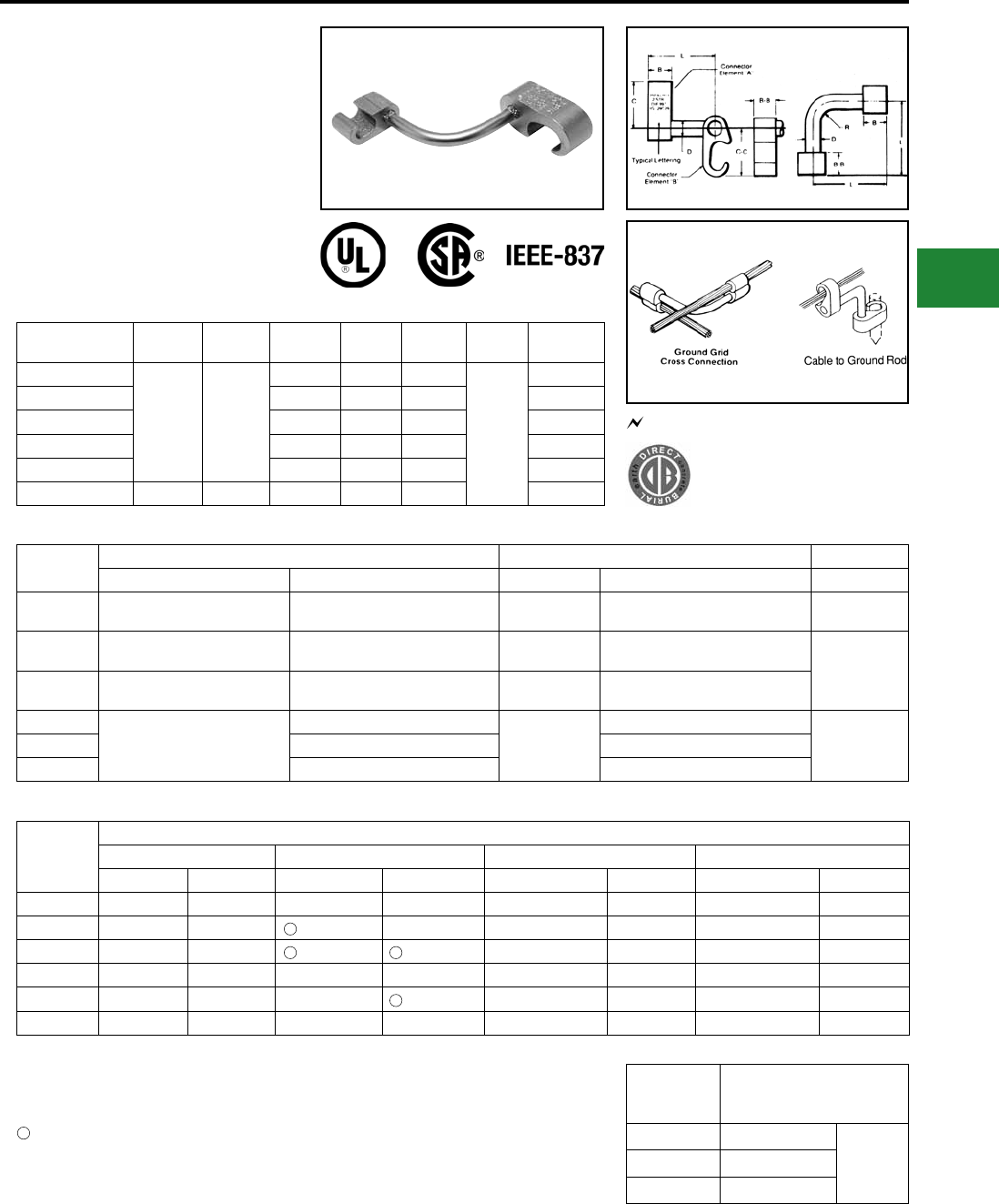
BURNDY®
Blue highlighted items are industry standard and most frequently ordered.
Canada: 1-800-387-6487 www.burndy.com US: 1-800-346-4175
Grounding
HYGROUND® Compression
TYPE YGL-C
HYGRID™ CROSS CONNECTOR
An irreversible compression ground grid cross
connector which allows adjustment of the
compression elements prior to installation. Only
six connectors and four dies are required to install
all combinations from #6 solid through 500 kcmil.
UL467 Listed. Acceptable for direct burial in
earth and concrete. Prelled with PENETROX™
compound and strip sealed.
Catalog
Number B BB C C-C D L R
YGL2C2
0.75 0.75
1.09 1.09 0.31
2.50
0.31
YGL29C2 1.66 1.09 0.31 0.31
YGL29C29 1.66 1.66 0.50 0.50
YGL34C2 2.09 1.09 0.31 0.31
YGL34C29 2.09 1.66 0.50 0.50
YGL34C34 1.10 1.10 2.28 2.28 0.75 0.75
Catalog
Number
Cable to Cable Cable to Ground Rod To Rebar
Element “A” Element “B” Element “A” Element “B” Element “A”
YGL2C2 #6 Sol. (0.162) - #2 Str. (0.292)
{59500} - {59500}
#6 Sol. (0.162) - #2 Str. (0.292)
{59500} - {59500} — — —
YGL29C2 #1 Str. (0.332) - 250 kcmil (0.575)
{98500} - {131500}
#6 Sol. (0.162) - #2 Str. (0.292)
{59500} - {59500} 1/2" - 5/8" Rod #6 Sol. (0.162) - #2 Str. (0.292) 3/8" - 1/2"
#3 - 4 Rebar
YGL29C29 #2 Str. (0.292) - 250 kcmil (0.575)
{65500} - {131500}
#2 Str. (0.292) - 250 kcmil (0.575)
{65500} - {131500} 1/2" - 5/8" Rod #2 Str. (0.292) - 250 kcmil (0.575)
YGL34C2
250 kcmil (0.575) - 500 kcmil (0.813)
#6 Sol. (0.162) - #2 Str. (0.292)
5/8" - 3/4" Rod
#6 Sol. (0.162) - #2 Str. (0.292)
5/8" - 3/4"
#5 - 6 Rebar
YGL34C29 #2 Str. (0.292) - 250 kcmil (0.575) #2 Str. (0.292) - 250 kcmil (0.575)
YGL34C34 250 kcmil (0.575) - 500 kcmil (0.813) 250 kcmil (0.575) - 500 kcmil (0.813)
Catalog
Number
Installation Tools, Die Set Catalog Number (Number of Crimps)
Y750/Y35/Y39 HYPRESS™ PAT750-18V Y45 HYPRESS™ Y46 HYPRESS™
Element “A” Element “B” Element “A” Element “B” Element “A” Element “B” Element “A” Element “B”
YGL2C2 U-O (1) U-O (1) U-O (1) U-O (1) U-O (1) U-O (1) U-O (1) U-O (1)
YGL29C2 U997 (1) U-O (1) U997P (1) U-O (1) U997 (1) U-O (1) U997 (1) U-O (1)
YGL29C29 U997 (1) U997 (1) U997P (1) U997P (1) U997 (1) U997 (1) U997 (1) U997 (1)
YGL34C2* - - PU998 (1) U-O (1) S998 or PU998 (1) U-O (1) P998 or PU998 (1) U-O (1)
YGL34C29* - - PU998 (1) U997P (1) S998 or PU998 (1) U997 (1) P998 or PU998 (1) U997 (1)
YGL34C34* - - U1011 (3) U1011 (3) S1011 (3) S1011 (3) P1011 (3) P1011 (3)
ORDERING INFORMATION
Dimensions in brackets { } represent lightning protection conductors.
1. Where a “U” or “PU” die is recommended with
Y45 HYPRESS™, a PT6515 adapter must be used.
2. Where a “U” or “PU” die is recommended with
the Y46 HYPRESS™, a PUADP-1 adapter must be
used.
Polarized die for the PAT750-18V.
* These connectors can only be installed using
the Y750, Y45, or Y46 HYPRESS™ with the
recommended dies.
3
3
3 3
3
NOTES:
• Before crimping, both connector elements can be
turned on rod diameter “D” to any desired position.
• Clean rust and/or protective coatings from rebar
prior to installation.
• When attaching connector to ground rod, ground
rod must be embossed with appropriate PRECRIMP™
die. For connections that must meet IEEE 837 re-
quirements UPRECRIMP-type PRE crimp dies must
be used for maximum clamping retention.
Ground Rod
Dia. PRECRIMP Dies
1/2" UPRECRIMP 12
U2CABT5/8" UPRECRIMP 58
3/4" UPRECRIMP 34
467 96
UL96 Listed for Lightning Protection.
E-7
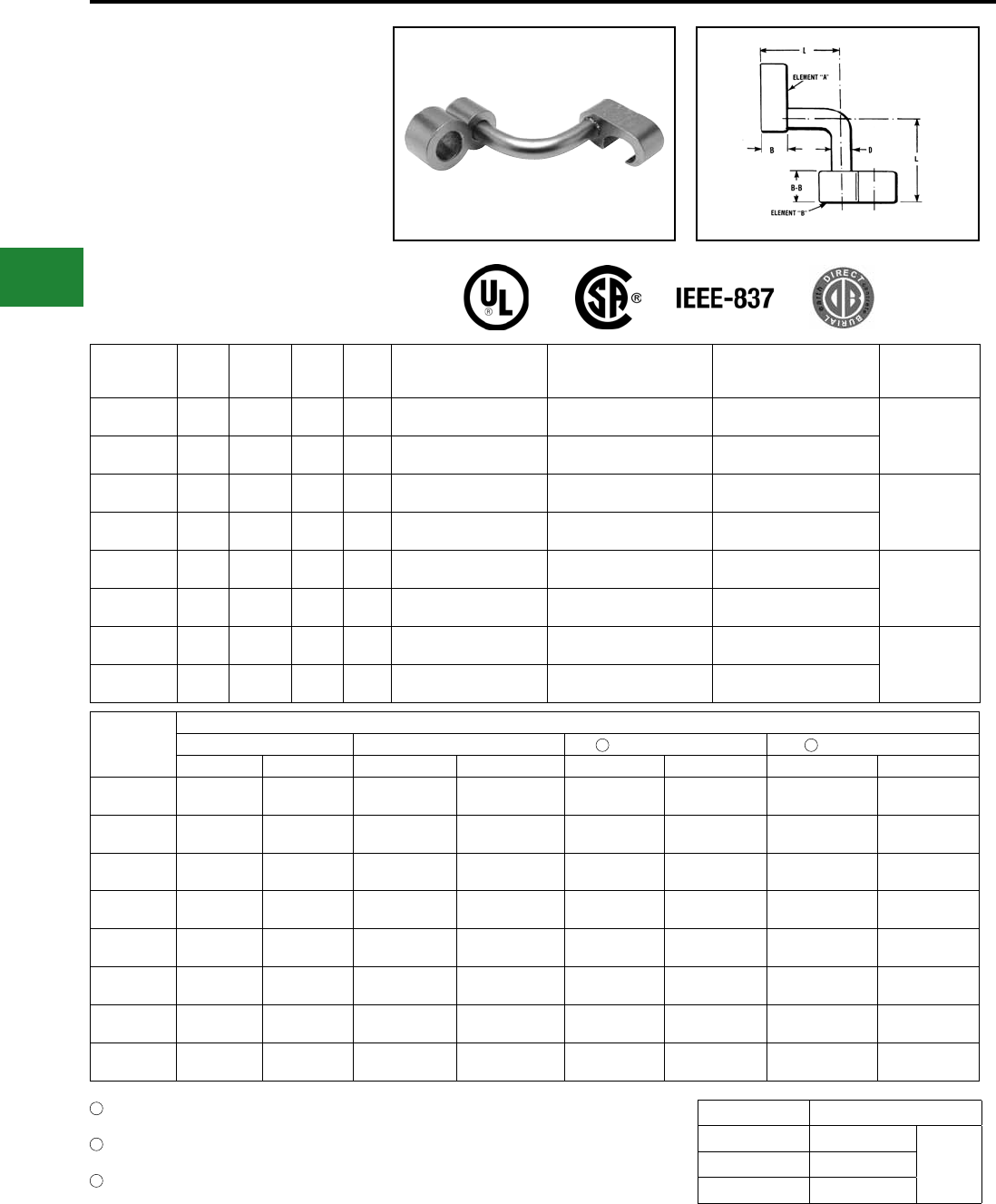
BURNDY®
Blue highlighted items are industry standard and most frequently ordered.
US: 1-800-346-4175 www.burndy.com Canada: 1-800-387-6487
Grounding
HYGROUND® Compression
TYPE YGLR-C
GRIDLOK™
High Strength Irreversible
Compression Ground Rod to Grid
Connector
Ground grid connector for a wide range of copper
cable to ground rod. Provides high torque strength
on ground rod. UL467 Listed. Acceptable for
direct burial in earth and concrete. Prelled with
PENETROX™ compound and strip sealed.
Catalog
Number B B-B D L
Commercial Copper
Cable Range
Element “A”
Metric Copper
Cable Range
Element “A”
CopperWeld Cable Range
Element “A”
Ground Rod Dia
Element “B”
YGLR29C12 0.75 0.88
[22.4] 0.31 2.53 #2 Str. (0.292 Dia.)
- 250 kcmil (0.575 Dia.)
35mm2 (7.62mm Dia.) -
120 mm2 (14.40mm Dia.)
91.65 kcmil (0.343 Dia.)
- 248.8 kcmil (0.572 Dia.) 1/2"
[12.7]
YGLR34C12 0.75 0.88
[22.4] 0.31 2.53 250 kcmil (0.575 Dia.)
- 500 kcmil (0.813 Dia.)
120 mm2(14.40mm Dia.)
- 240 mm2 (20.35mm Dia.)
248.8 kcmil (0.572 Dia.)
- 498.8 kcmil (0.810 Dia.)
YGLR29C58 0.75 0.88
[22.4] 0.31 2.53 #2 Str. (0.292 Dia.)
- 250 kcmil (0.575 Dia.)
35mm2 (7.62mm Dia.)
- 120 mm2 (14.40mm Dia.)
91.65 kcmil (0.343 Dia.)
- 248.8 kcmil (0.572 Dia.) 5/8"
[15.9]
YGLR34C58 0.75 0.88
[22.4] 0.31 2.53 250 kcmil (0.575 Dia.)
- 500 kcmil (0.813 Dia.)
120 mm2 (14.40mm Dia.)
- 240 mm2 (20.35mm Dia.)
248.8 kcmil (0.572 Dia.)
- 498.8 kcmil (0.810 Dia.)
YGLR29C34 0.75 0.88
[22.4] 0.50 2.63 #2 Str. (0.292 Dia.)
- 250 kcmil (0.575 Dia.)
35mm2 (7.62mm Dia.)
- 120 mm2 (14.40mm Dia.)
91.65 kcmil (0.343 Dia.)
- 248.8 kcmil (0.572 Dia.) 3/4"
[19.1]
YGLR34C34 0.75 0.88
[22.4] 0.50 2.63 250 kcmil (0.575 Dia.)
- 500 kcmil (0.813 Dia.)
120 mm2 (14.40mm Dia.)
- 240 mm2 (20.35mm Dia.)
248.8 kcmil (0.572 Dia.)
- 498.8 kcmil (0.810 Dia.)
YGLR29C100 0.75 0.88
[22.4] 0.50 2.63 #2 Str. (0.292 Dia.)
- 250 kcmil (0.575 Dia.)
35mm2 (7.62mm Dia.)
- 120 mm2 (14.40mm Dia.)
91.65 kcmil (0.343 Dia.)
- 248.8 kcmil (0.572 Dia.) 1"
[25.4]
YGLR34C100 0.75 0.88
[22.4] 0.50 2.63 250 kcmil (0.575 Dia.)
- 500 kcmil (0.813 Dia.)
120 mm2 (14.40mm Dia.)
- 240 mm2 (20.35mm Dia.)
248.8 kcmil (0.572 Dia.)
- 498.8 kcmil (0.810 Dia.)
Catalog
Number
Installation Tools, Die Set Cat. No. (Number of Crimps)
Y35/Y39 HYPRESS™ Y750/PAT750 Y45 HYPRESS™ Y46 HYPRESS™
Element “A” Element “B” Element “A” Element “B” Element “A” Element “B” Element “A” Element “B”
YGLR29C12 U997 (1) PU998 (1) U997 (1) U1011 (2) or
PU998 (1) U997 (1) S1012 (2) or
PU998 (1) U997 (1) P1011 (2) or
PU998 (1)
YGLR34C12 — — U1011 or
PU998 (1)
U1011 (2) or
PU998 (1)
S998 or
PU998 (1)
S1012 (2) or
PU998 (1)
P998 or
PU998 (1)
P1011 (2) or
PU998 (1)
YGLR29C58 U997 (1) PU998 (1) U997 (1) U1011 (2) or
PU998 (1) U997 (1) S1012 (2) or
PU998 (1) U997 (1) P1011 (2) or
PU998 (1)
YGLR34C58 — — U1011 or
PU998 (1)
U1011 (2) or
PU998 (1)
S998 or
PU998 (1)
S1012 (2) or
PU998 (1)
P998 or
PU998 (1)
P1011 (2) or
PU998 (1)
YGLR29C34 U997 (1) PU998 (1) U997 (1) U1011 (2) or
PU998 (1) U997 (1) S1012 (2) or
PU998 (1) U997 (1) P1011 (2) or
PU998 (1)
YGLR34C34 — — U1011 (2) or
PU998 (1)
U1011 (2) or
PU998 (1)
U1011 (2) or
PU998 (1)
S1012 (2) or
PU998 (1)
U1011 (2) or
PU998 (1)
P1011 (2) or
PU998 (1)
YGLR29C100 — — U997 (1) U1011 (2) or
PU998 (1) U997 (1) S1012 (2) or
PU998 (1) U997 (1) P1011 (2) or
PU998 (1)
YGLR34C100 — — U1011 (2) or
PU998 (1)
U1011 (2) or
PU998 (1)
U1011 (2) or
PU998 (1)
S1012 (2) or
PU998 (1)
U1011 (2) or
PU998
P1011 (2) or
PU998 (1)
Ground Rod Dia. PRECRIMP Dies
1/2″ UPRECRIMP 12
U2CABT5/8″ UPRECRIMP 58
3/4″ UPRECRIMP 34
Where a “U” or “PU” die is recommended with Y45
HYPRESS™, a PT6515 adapter is required
Where a "U" or "PU" die is recommended with Y46
HYPRESS™, a PUADP-1 adapter is required
Polarized die for the PAT750 series tool
2
3
4
2 3
NOTES:
• Before crimping, both connector elements can be
turned on rod diameter “D” to any desired position.
• When attaching connector to ground rod, ground rod
must be embossed with appropriate PRECRIMP die.
For connectors that must meet IEEE 837 requirements,
UPRECRIMP-type precrimp dies must be used for
maximum clamping retention. No precrimp needed if
using S1012, P1011 or U1011 die sets.
E-8
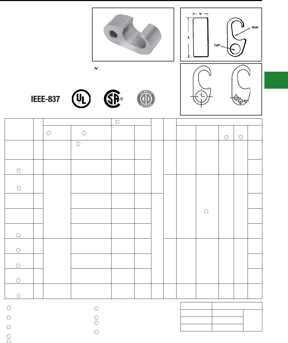
BURNDY®
Blue highlighted items are industry standard and most frequently ordered.
Canada: 1-800-387-6487 www.burndy.com US: 1-800-346-4175
Grounding
HYGROUND® Compression
TYPE YGHP-C
HYTAP™
Irreversible compression ground tap gure 6 can
be used as a tap connector or as a tap splice
connector. Four die sets and eight connectors can
accommodate a conductor range from #8 solid
through 500 kcmil plus 1/2", 5/8" and 3/4" copper
bonded ground rods. UL467 Listed. Acceptable
for direct burial in earth and concrete. Prelled
with PENETROX™ compound and strip sealed.
UL96 Listed for Lightning Protection.
467 96
Catalog
Number
Fig.
#
Accommodates Cable to Rebar
BDie
Index
Installation Data
Run Tap Run Tap Y750/Y35/
Y39 PAT750-18V Y45 Y46
#
of
Crimps
YGHP2C2 1
#6 Sol. (0.162)
{59500} -
#2 Str. (0.292)
{59500}
#6 Sol. (0.162)
{59500} -
#2 Str. (0.292)
{59500}
— —
0.75
O UO UO UO UO
1
YGHP2C6W6W 2 #6 Sol. (0.162) -
#2 Str. (0.292)
#8 Sol. (0.128) -
#6 Str. (0.184) Qty. 2 — — 1
YGHP29C6W6W 2
1/0 Str. (0.372)
{98500} -
250 kcmil (0.575)
{131500}
1/2” - 5/8” Rod
#8 Sol. (0.128) -
#6 Str. (0.184) Qty. 2
#3 Rebar 3/8
-
1/2 #4 Rebar
#8 Sol. -
6 Str.
997 U997 U997P U997 U997
1
YGHP29C2 1#4 Sol. (0.204) {#4 Sol.} -
#2 Str. (0.292) {#2 Str.}
#3 Rebar 3/8
-
1/2 #4 Rebar
#2 Str.
2.31
1
YGHP29C26 11/0 Str. (0.372) {98500} -
2/0 Str. (0.419) {98500}
#3 Rebar 3/8
-
1/2 #4 Rebar
1/0 Str. -
2/0 Str. 1
YGHP29C29 13/0 Str. (0.470) {131500} -
250 kcmil (0.575) {211500}
#3 Rebar 3/8
-
1/2 #4 Rebar
3/0 Str. -
250 kcmil 1
YGHP34C2 1
250 kcmil (0.575)
{250 kcmil} -
500 kcmil (0.813)
{500 kcmil}
5/8” - 3/4” Rod
#4 Sol. (0.204) -
#2 Str. (0.292)
#5 Rebar 5/8
-
3/4 #6 Rebar
—
998 PU998 PU998
PU998
or
S998
PU998
or
P998
1
YGHP34C26 11/0 Str. (0.372) {98500} -
2/0 Str. (0.419) {98500}
#5 Rebar 5/8
-
3/4 #6 Rebar
1/0 Str. -
2/0 Str. 1
YGHP34C29 13/0 Str. (0.470) {131500} -
250 kcmil (0.575) {211500}
#5 Rebar 5/8
-
3/4 #6 Rebar
3/0 Str. -
250 kcmil 1
YGHP34C34 1
250 kcmil (0.575) -
500 kcmil (0.813)
5/8” - 3/4” Rod
350 kcmil (0.681) -
500 kcmil (0.843)
#5 Rebar 5/8
-
3/4 #6 Rebar
350
kcmil -
500 kcmil
2.75 1011 U1011 U1011 S1011 P1011 3
Dimensions in brackets { } represent lightning
protection conductors.
Where a “U” or “PU” die is recommended with Y45
HYPRESS™, a PT6515 adapter is required.
Where a "U" or "PU" die is recommended with Y46
HYPRESS™, a PUADP-1 adapter is required.
Polarized die for the PAT750 series tool.
These connectors can only be installed using the
Y750, Y45 or Y46 series of HYPRESS™ tools;
cannot be installed with the Y35 or Y39 series.
NOTES: Ground Rod Dia. PRECRIMP Dies
1/2″ UPRECRIMP 12
U2CABT5/8″ UPRECRIMP 58
3/4″ UPRECRIMP 34
For increased rotational resistance on ground rods,
pre-crimp ground rod with U2CABT, UPRECRIMP dies
may be used for even greater rotation and vibration
resistance on ground rods.
7
1 1
6
9
2
4
3
7
8
5
5
5
5
1
2
3
4
5
6
7
8
9
Fig. 1 Fig. 2
When using #6 Sol in tap, fold conductor double
for improved ll.
Not UL96/CSA
When using 3/0 in tap, minimum run conductor
must be 2/0 Str.
Clean rust and protective coatings from rebar prior
to installation to provide proper ground connection.
Precrimping is not required.
E-9
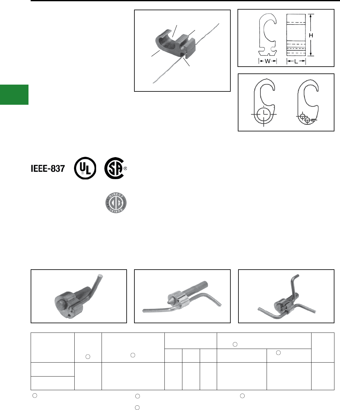
BURNDY®
Blue highlighted items are industry standard and most frequently ordered.
US: 1-800-346-4175 www.burndy.com Canada: 1-800-387-6487
Grounding
HYGROUND® Compression
TYPE YGHP-C
HYTAP™ CONNECTOR
High Strength Copper Irreversible
Compression
Ground Rod Tap Connector
Type YGHP-C irreversible compression ground
tap gure 6 can be used as a ground rod tap
connector for both continuous run and tapping
applications. An open groove allows ground rod
to be connected to a continuous run or tap. The
second groove is for a tap only. Prelled with
PENETROX™ E and strip sealed. UL467 Listed
for direct burial in earth or concrete.
Features & Benets
• Tap (A) accepts a continuous run on
tap conductor. Tap (B) accepts a tap
conductor only
◊ One connector style can be used for many
applications, reducing number of connec-
tors in inventory
• Material is high conductivity wrought
copper extrusion, identical material to the
conductor
◊ High-conductivity copper minimizes
resistance and voltage drop.
Eliminates the possibility of corrosion
due to dissimilar metals
• System engineered tooling
◊ The tooling recommendation has been
designed to ensure a reliable,
dependable connection every time
• The die index number is embossed on
conductor after completion of crimp
◊ Facilitates speedy inspection of
installed connectors to insure
consistently reliable and dependable
connections
• Prelled with PENETROX™ E and individually
sealed in clear polyethylene sheet
◊ Ensures the electrical integrity of the nished
connection by inhibiting moisture and con-
taminates from entering the contact area.
Maintains long-term high-conductivity
• UL467 Listed
◊ May be used in direct burial or
concrete embedded grounding
applications. Provides quality
assurance to recognized industry NEC
standards from an independent party
• “Third Hand” constrains conductors while
installer completes crimp, included with
each connector
◊ Simplies installation, reducing
installed cost
Catalog
Number
Ground
Rod Dia. Tap Conductor
Dimensions Installation Tooling Die Number
(# of Crimps) Die
Index
H L W Y35/Y750/PAT750
HYPRESS™
Y46
HYPRESS™
YGHP58C2W-2
1/2" - 5/8"
#2 Sol. - #6 Sol. Copper
(1) Continuous Run and
(1) Tap or up to
(2) Taps may be connected
1.90" 0.75" 0.94" U997 (1) U997 (1) 997
YGHP58C2W-2TN
SINGLE TAP CONTINUOUS RUN CONTINUOUS RUN AND TAP
Ground rod must be precrimped with die U2CABT
(Index 348); for greater rotational resistance use
UPRECRIMP die; Galvanized Steel Rods require
YGHP58C2W-2TN
NOTE:
A 12″ bend radius is recommended for the conductor
12
3
4
12
3
4
DIE INDEX
AND CONDUCTOR
INFORMATION
PREFILLED WITH
PENETROX™ E
“THIRD HAND”
TAP (B)
TAP (A)
PATENTED
Either tap position may be left void when fewer than (2)
conductors are used
See Tooling Section in Master Catalog for complete
tool and die listing
Use PUADP-1 with “U”-dies in Y46
E-10
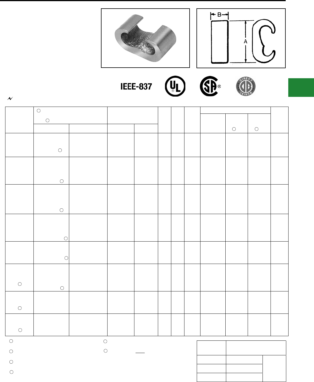
BURNDY®
Blue highlighted items are industry standard and most frequently ordered.
Canada: 1-800-387-6487 www.burndy.com US: 1-800-346-4175
Grounding
HYGROUND® Compression
TYPE YGHC-C
HYTAP™ CONNECTOR
Irreversible compression ground tap gure “C”
connectors. Accommodates all cable combinations
from #6 solid through 500 kcmil. “C”- shaped
opening permits placing two continuous parallel
cables into conductor groove. UL 467 Listed.
Acceptable for direct burial in earth or concrete.
Prelled with PENETROX™ compound and strip
sealed. Certain sizes are also UL467 Listed and
CSA Certied for wire to ground rod.
Catalog
Number
Commercial Copper
Cable to Cable or
Cable to Ground Rod
Stranded Copper
Cable Range Metric A B
Die
Index
No.
Installation Data No.
of
Crimps
Y750/Y35/
PAT750/Y39 Y45 Y46
Run Tap Run Tap
YGHC2C2
#6 Sol. (0.162)
#2 Str. (0.292)
1/4" Rod
#6 Sol. (0.162)
#2 Str. (0.292)
10 mm²
(4.12 mm)
35 mm²
(7.62 mm)
10 mm²
(4.12 mm)
35 mm²
(7.62 mm)
1.16 0.75 C U-C U-C U-C 1
YGHC26C2
1 Str. (0.328)
{98500}
2/0 Str. (0.419)
{98500}
3/8" Rod
#6 Sol. (0.162)
{#6 Sol.}
#2 Str. (0.292)
{#2 Str.}
35 mm²
(7.62 mm)
70 mm²
(10.9 mm)
10 mm²
(4.12 mm)
35 mm²
(7.62 mm)
1.41 0.75 O U-O U-O U-O 1
YGHC26C26
1 Str. (0.328)
{98500}
2/0 Str. (0.419)
{98500}
3/8" Rod
1 Str. (0.328)
{98500}
2/0 Str. (0.419)
{98500}
35 mm²
(7.62 mm)
70 mm²
(10.9 mm)
35 mm²
(7.62 mm)
70 mm²
(10.9 mm)
1.54 0.75 O U-O U-O U-O 1
YGHC29C26
3/0 Str. (0.470)
{3/0 Str.}
250 kcmil (0.575)
{250 kcmil}
1/2" or 5/8" Rod
6 Sol. (0.162)
{59500}
2/0 Str. (0.419)
{98500}
95 mm²
(12.5 mm)
120 mm²
(14.4 mm)
10 mm²
(4.10 mm)
70 mm²
(10.90 mm)
1.97 0.75 997 U997 U997 U997 1
YGHC29C29
3/0 Str. (0.470)
250 kcmil (0.575)
1/2" or 5/8" Rod
3/0 Str. (0.470)
250 kcmil (0.575)
95 mm²
(12.5 mm)
120 mm²
(14.4 mm)
95 mm²
(12.5 mm)
120 mm²
(14.4 mm)
2.06 0.88 997 U997 U997 U997 1
YGHC34C26
300 kcmil (0.630)
{300 kcmil}
500 kcmil (0.813)
{500 kcmil}
3/4" Rod
6 Sol. (0.162)
{59500}
2/0 Str. (0.419)
{98500}
150 mm²
(16 mm)
240 mm²
(20.35 mm)
10 mm²
(4.10 mm)
70 mm²
(10.90 mm)
2.42 0.88 1011 U1011 S1011 P1011 2
YGHC34C29 300 kcmil (0.630)
500 kcmil (0.813)
3/0 Str. (0.470)
250 kcmil (0.575)
150 mm²
(16 mm)
240 mm²
(20.35 mm)
95 mm²
(12.5 mm)
120 mm²
(14.4 mm)
2.67 0.88 1011 U1011 S1011 P1011 2
YGHC34C34 300 kcmil (0.630)
500 kcmil (0.813)
300 kcmil (0.630)
500 kcmil (0.813)
150 mm²
(16 mm)
240 mm²
(20.35 mm)
150 mm²
(16 mm)
240 mm²
(20.35 mm)
2.91 1.10 1011 U1011 S1011 P1011 3
467 96
Ground Rod
Dia. PRECRIMP Dies
1/2" UPRECRIMP 12
U2CABT5/8" UPRECRIMP 58
3/4" UPRECRIMP 34
Dimensions in brackets { } represent lightning protection
conductors
For ground rod to wire applications, ground rod must be
precrimped; see table for appropriate precrimp dies
Where a “U” or “PU” die is recommended with the Y45
HYPRESS™, a PT6515 adapter must be used
Where a “U” or “PU” die is recommended with the Y46
HYPRESS™, a PUADP-1 adapter must be used
NOTES:
Listed under UL486A for copper wire connectors
For connectors without PENETROX™ oxide inhibitor,add sufx
“NP” to the end of the catalog number (example: YGHC2C2-NP)
15
6
2
3
4
UL96 Listed for Lightning Protection.
3 4
5
5
5
5
5
6
6
6
1
2
5
Ground rod to copper cable is UL467 Listed for direct
burial in earth and concrete
These connectors cannot be installed with the Y35 or Y39
HYPRESS™
E-11
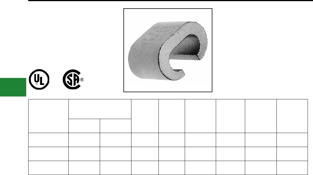
BURNDY®
Blue highlighted items are industry standard and most frequently ordered.
US: 1-800-346-4175 www.burndy.com Canada: 1-800-387-6487
Grounding
HYGROUND® Compression
TYPE YGC
COPPER CRIMPIT™
UL 467 Listed for direct burial in earth or concrete.
Prelled with PENETROX™ E2 oxide inhibitor.
Catalog
Number
Copper Conductor
(Sol. & Str.) H L Die Index OUR840 MD6/MD7 Number
of Crimps
Run Tap
YGC8C8 8 AWG 8 AWG 0.46 0.52 162 W162 W162 2
YGC6C8 6 AWG 8 AWG 0.73 0.62 BG XBG WBG 2
YGC6C6 6 AWG 6 AWG 0.76 0.62 BG XBG WBG 2
E-12
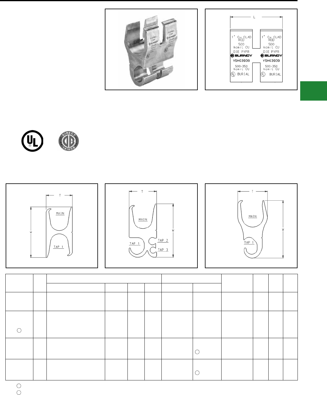
BURNDY®
Blue highlighted items are industry standard and most frequently ordered.
Canada: 1-800-387-6487 www.burndy.com US: 1-800-346-4175
Grounding
HYGROUND® Compression
TYPE YSHG
HIGH STRENGTH COPPER
IRREVERSIBLE COMPRESSION
Double H-Tap Connector
Type YSHG Double H-Tap grounding series
is comprised of ve connectors designed to
accommodate wire range sizes #14 through
500 kcmil, including ground rod sizes: 3/4", 1",
and rebar sizes: #6, #7, #8 and #9. Prelled with
PENETROX™ E2 and strip sealed.
Catalog
Number
Fig.
#
Conductor Sizes Tooling (# of crimps) Index
Embossment
W
±.06
T
±.04
L
±.06
Main Tap 1 Tap 2 Tap 3 PAT750/Y750 Y46
YSHG4429 3#9 & #8 Rebar,
1" [25] Ground Rod 250 - 2 — — — PYFR (2) KR 3.22 1.70 2.44
YSHG3931 2
#6 & #7 Rebar,
1" [25] Cu Clad Ground Rod,
3/4” Ground Rod
500 - 350 kcmil Copper
4/0 - 1/0 1 - 6 2 - 14 — PYFR (2) KR 2.97 1.50 2.34
YSHG3434 1
#6 Rebar,
3/4" [19] Ground Rod
400 - 250 kcmil Copper
400 - 4/0 — — U1104 (4) P1104 (2)
U1104 (4) 1104 2.43 1.15 2.44
YSHG3429 2
#6 Rebar,
3/4" [19] Ground Rod
400 - 4/0 kcmil Copper
3/0 - 1/0 1 - 4 8 - 14 U1104 (4) P1104 (2)
U1104 (4) 1104 2.23 1.31 2.44
Features & Benets
• UL467 Listed
◊ Suitable for direct burial in earth or concrete.
• Material is high conductivity copper
extrusion
◊ Minimizes resistance, eliminates
corrosion due to dissimilar metals.
• Grooves are prelled with PENETROX™
E2 oxide inhibitor and individually sealed
◊ Inhibits moisture and contaminants
ensuring electrical integrity.
Fig. 1 Fig. 2 Fig. 3
Not for use on 1″ steel ground rod
Use PUADP-1 adapter
1
2
1
2
2
E-13
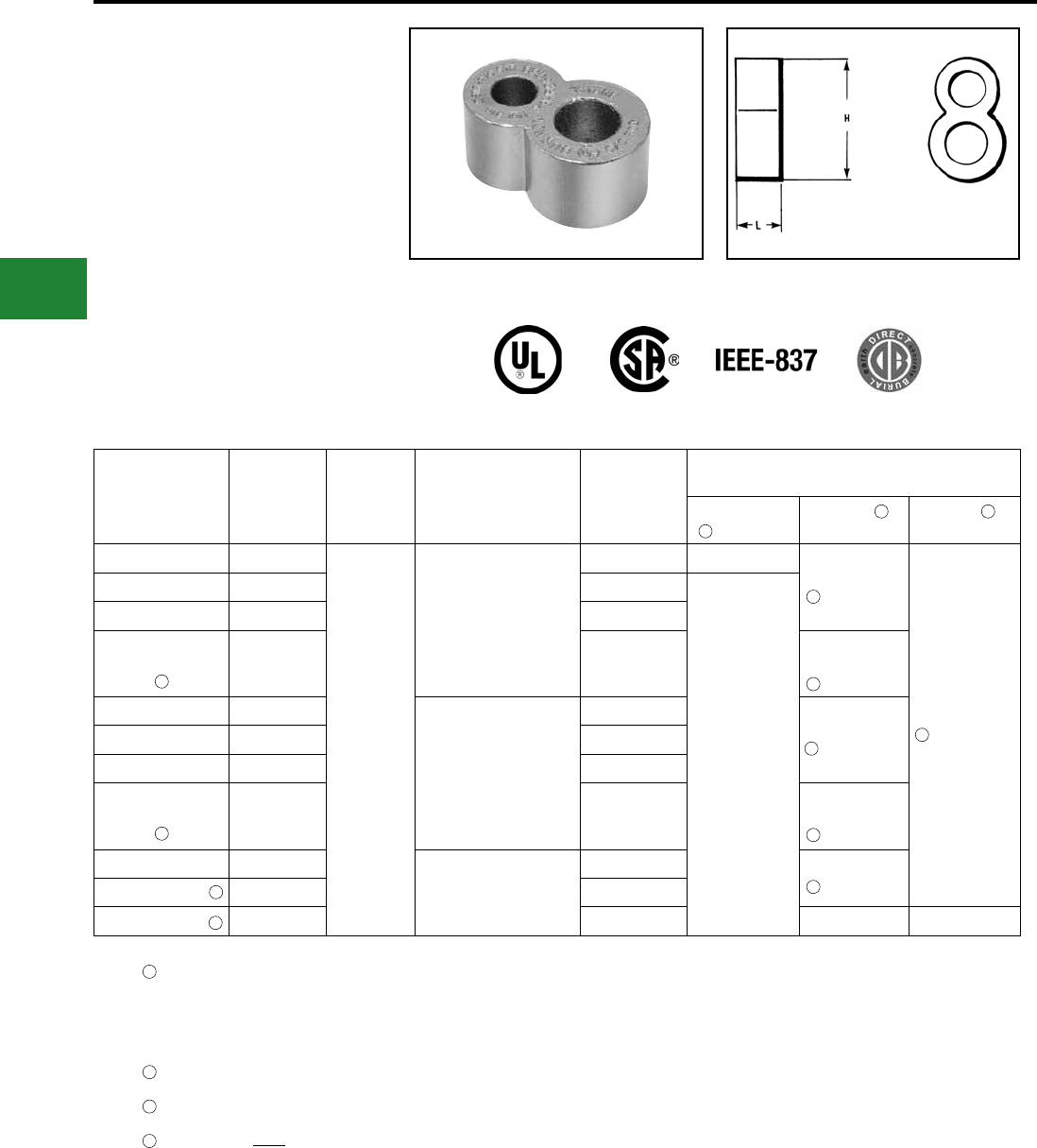
BURNDY®
Blue highlighted items are industry standard and most frequently ordered.
US: 1-800-346-4175 www.burndy.com Canada: 1-800-387-6487
Grounding
HYGROUND® Compression
TYPE YGHR-C
HYTAIL™
High Strength Irreversible
Compression Ground Rod Tap
Connectors
High torque strength ground rod connectors.
Accommodates a wide range of copper conductors
to ground rod. UL467 Listed. Acceptable for
direct burial in earth or concrete. Prelled with
PENETROX™ compound and strip sealed.
Ground rod must be pre-crimped with die U2CABT (index 348)
when the PU998 dies are used in the Y750, PAT750, Y35,
Y39, Y45, Y46 and PAT46 tools; pre-crimping is not
required when the P1011, S1011, S1012 or U1011 dies are
used; UPRECRIMP dies may be used for additional
mechanical resistance on ground rods.
Where a PU998 die is recommended with the Y45
HYPRESS™, a PT6515 adapter must be used.
Where a PU998 die is recommended with the Y46
HYPRESS™, a PUADP-1 adapter must be used.
These connectors cannot be installed with the Y35 or Y39
HYPRESS™.
NOTES:
The catalog numbers shown are for unplated copper connectors for
use on copper clad or stainless steel ground rod. To order electro-
tin plated connectors for use on galvanized steel ground rod add
sufx “-TN” to the catalog number. The ground rod hole diameter is
larger for galvanized steel ground rod in the tin plated connector.
Complete die catalog numbers do not always appear on the
connector, sometimes it is the die index.
1
2
3
4
Catalog
Number H L Commercial Copper
Cable Range
Nominal
Ground Rod
Dia.
Installation Tools, Die Set Catalog Number
(# of Crimps)
PAT750/Y750/
Y35/Y39
Y45
HYPRESS™
Y46
HYPRESS™
YGHR26C12 1.94
0.88
#2 Str. (0.29 Dia.) -
2/0 Str. (0.42 Dia.)
1/2" [12.70] —
S1012 (2)
PU998 (1)
P1011 (2)
PU998 (1)
YGHR26C58 1.97 5/8" [15.90]
U1011 (2)
PU998 (1)
YGHR26C34 2.19 3/4" [19.00]
YGHR26C100 2.55 1" [25.40]
S1011 (2)
S1012 (2)
PU998 (1)
YGHR29C12 1.94
#4/0 Str. (0.53 Dia.) -
250 kcmil (0.58 Dia.)
1/2" [12.70]
S1012 (2)
PU998 (1)
YGHR29C58 2.14 5/8" [15.90]
YGHR29C34 2.19 3/4" [19.00]
YGHR29C100 2.45 1" [25.40]
S1011 (2)
S1012 (2)
PU998 (1)
YGHR34C58 2.14
300 kcmil (0.63 Dia.) -
500 kcmil (0.81 Dia)
5/8" [15.90] S1012 (2)
PU998 (1)
YGHR34C34 2.44 3/4" [19.00]
YGHR34C100 2.45 1" [25.40] S1011 (2) P1011 (2)
1
1 1
2
2
2
2
2
3
4
4
4
4
E-14
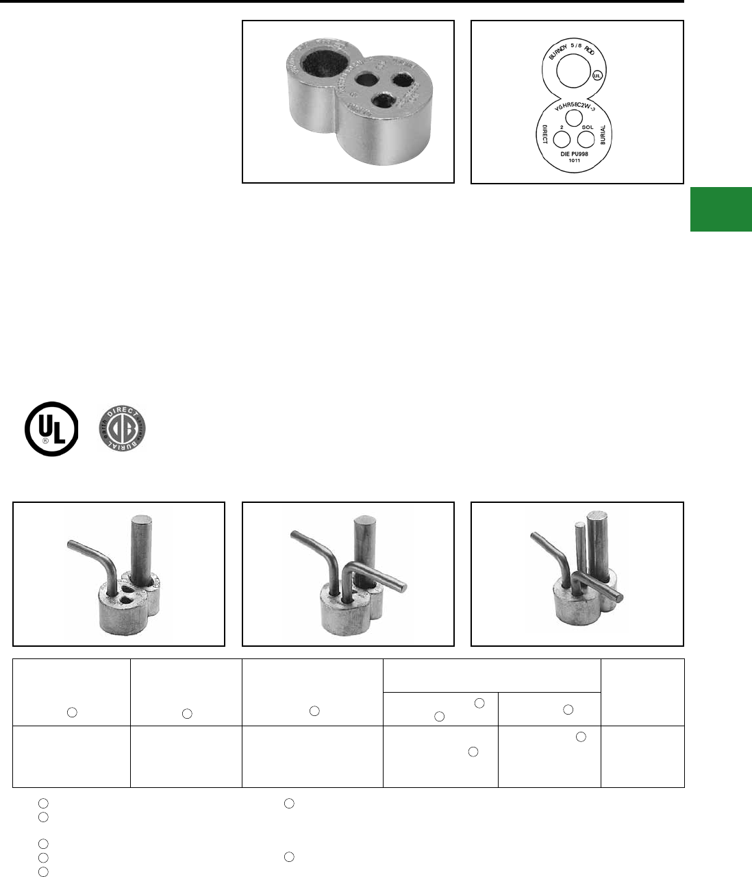
BURNDY®
Blue highlighted items are industry standard and most frequently ordered.
Canada: 1-800-387-6487 www.burndy.com US: 1-800-346-4175
Grounding
HYGROUND® Compression
Ground rod must be precrimped with die U2CABT (Index
348) when PU998 die set is used in the Y35, Y750 or Y46
HYPRESS™ tools; for even greater mechanical resistance
use UPRECRIMP58 dies
Tap positions may be left void when fewer than (3)
conductors are used
TYPE YGHR-C
HYTAIL™
High Strength Irreversible
Compression Ground Rod Tap
Connectors
Type YGHR-C irreversible compression
grounding connector is engineered specically
for the Telecommunications Industry for (1, 2 or
3) #2 solid, tinned or bare conductor taps. UL467
Listed. Acceptable for direct burial in earth or
concrete. BURNDY® has designed this connector
to meet the stringent requirements of OSHA,
the National Electric Code (NEC), UL, and the
Telecommunications Industry. Performance
and long life are this connector’s basic design
guidelines.
Features & Benets
• Tap side 1, 2 or 3 conductors
◊ One connector style can be used for
many applications.
• Material is high conductivity wrought
copper extrusion, identical material to the
conductor
◊ High-conductivity copper minimizes
resistance and voltage drop. Eliminates
the possibility of corrosion due to
dissimilar metals.
• System engineered tooling
◊ Each tooling recommendation has
been designed to provide a reliable,
dependable connection.
• The die index number is embossed on
connector after completion of crimp
◊ Facilitates speedy inspection of
installed connectors to ensure
consistently reliable and dependable
connections.
• Prelled with PENETROX™ and
individually sealed in clear polyethylene
sheet
◊ Ensures the electrical integrity of the
nished connection by inhibiting
moisture and contaminates from
entering the contact area. Maintains
long-term high-conductivity.
• UL 467 Listed. Acceptable for direct
burial
◊ May be used in direct burial or
concrete embedded grounding
applications. Provides quality
assurance to recognized industry NEC
standards from an independent party.
Contact BURNDY® for other ground rod diameters
PU998 and U1011 die sets require PUADP-1 adapter for use
in the Y46 HYPRESS™
The PAT750 and Y750 utilize PU dies and the U1011 die
The Y35 only uses PU998 die
To order electro-tin plated connector for use on galvanized
steel ground rod add sufx “-TN” to the catalog number; The
ground rod hole diameter is larger for galvanized steel ground
rod in the tin plated connector
1
2
3
4
5
6
7
Catalog Number Ground Rod
Diameter Tap Conductor
Installation Tools, Die Set Catalog Number
(# of Crimps) Die Index
PAT750/Y750
Y35 /Y39 Y46
YGHR58C2W-3 5/8" #2 Sol Copper 1, 2, or 3
may be connected
PU998 (1)
U1011 (2)
PU998 (1)
U1011 (2)
P998 (1)
P1011 (2)
998/1011
12
3
4
5
6
6
7
TAP TAP
AND
RUN RUN
E-15
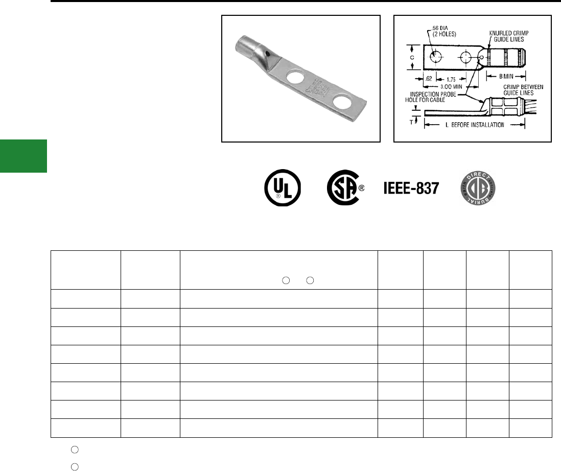
BURNDY®
Blue highlighted items are industry standard and most frequently ordered.
US: 1-800-346-4175 www.burndy.com Canada: 1-800-387-6487
Grounding
HYGROUND® Compression
TYPE YGHA
HYLUG™
Heavy Duty Irreversible Compression
Terminals
Heavy duty HYLUG™ irreversible compression
terminals designed not only to carry short circuit
load, but to also withstand high mechanical
stress. Each conductor element has an inspection
probe hole to ensure proper cable insertion.
UL467 Listed. Acceptable for direct burial in
earth or concrete. UL486A Listed. Prelled with
PENETROX™ compound and strip sealed.
Catalog
Number
Copper
Conductor
Size
Installation Tools, Die Set Catalog Number and
(# of Crimps)
HYPRESS™ Y35/Y39/Y45 /Y46 /Y750/PAT750
B C L T
YGHA2C-2N 2 AWG U1CRT (1) 0.75 0.97 4.21 0.26
YGHA25-2N 1/0 AWG U27RT (1) 0.83 0.91 4.60 0.19
YGHA26-2N 2/0 AWG U28RT (1) 0.83 0.97 4.38 0.26
YGHA27-2N 3/0 AWG U29RT (1) 1.18 1.08 4.94 0.29
YGHA28-2N 4/0 AWG U30RT (2) 1.18 1.22 4.94 0.30
YGHA29-2N 250 kcmil U31RT (2) 1.18 1.28 4.94 0.34
YGHA31-2N 350 kcmil U34RT (2) 1.18 1.62 5.00 0.43
YGHA34-2N 500 kcmil U36RT (3) 1.48 1.72 5.42 0.40
Where a “U” or “PU” die is recommended with the Y45
HYPRESS™, a PT6515 adapter must be used
Where a “U” or “PU” die is recommended with the Y46
HYPRESS™, a PUADP-1 adapter must be used
1
1
2
2
E-16
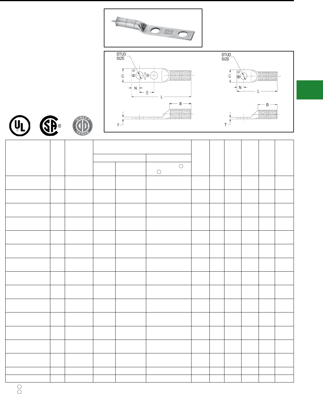
BURNDY®
Blue highlighted items are industry standard and most frequently ordered.
Canada: 1-800-387-6487 www.burndy.com US: 1-800-346-4175
Grounding
HYGROUND® Compression
Where a “U” or “PU” die is recommended with the Y45 HYPRESS™, a PT6515 adapter must be used
Where a “U” or “PU” die is recommended with the Y46 HYPRESS™, a PUADP-1 adapter must be used
TYPE YGA
HYLUG™
Grounding Irreversible Compression
Terminals
Irreversible compression HYLUG™ ground
terminal specically designed for grounding
applications. Each connector has an inspection
probe hole to ensure proper cable insertion.
UL467 Listed. Acceptable for direct burial in
earth or concrete. UL486A Listed. Prelled with
PENETROX™ compound and strip sealed.
Fig.1 Fig.2
1
2
Catalog Number Fig.
#
Copper
Conductor
Size
(Sol. & Str.)
Installation Tools, Die Set Cat. No. and
(# of Crimps) Stud
Size B C L T EMechanical Hydraulic
Y2MR MD7-34R or
OUR840
Y35/Y39/Y45 /
Y46 /Y750/PAT750
YGA8C-TC10 2 8 Sol./8 Str. Red (4) W8CVT (2)
X8CRT (2) U8CRT (2) #10 0.81 0.41 1.57 0.08 —
YGA8C-TC14 2 8 Sol./8 Str. Red (4) W8CVT (2)
X8CRT (2) U8CRT (2) 1/4 0.81 0.44 1.69 0.08 —
YGA8C-TC516 2 8 Sol./8 Str. Red (4) W8CVT (2)
X8CRT (2) U8CRT (2) 5/16 0.81 0.51 1.75 0.06 —
YGA8C-2N 1 8 Sol./8 Str. Red (4) W8CVT (2)
X8CRT (2) U8CRT (2) 1/2 0.78 0.83 4.09 0.12 1.75
YGA6C-TC10 2 6 Sol./6 Str. Blue (4) W5CVT (2)
X5CRT (2) U5CRT (2) #10 1.12 0.42 1.89 0.09 —
YGA6C-TC14 2 6 Sol./6 Str. Blue (4) W5CVT (2)
X5CRT (2) U5CRT (2) 1/4 1.12 0.45 2.02 0.08 —
YGA6C-TC516 2 6 Sol./6 Str. Blue (4) W5CVT (2)
X5CRT (2) U5CRT (2) 5/16 1.12 0.51 2.08 0.07 —
YGA6C-2TC38E2G1 1 6 Sol./6 Str. Blue (4) W5CVT (2)
X5CRT (2) U5CRT (2) 3/8 1.12 0.58 3.42 0.06 0.75
YGA6C-2N 1 6 Sol./6 Str. Blue (4) W5CVT (2)
X5CRT (2) U5CRT (2) 1/2 1.09 0.83 4.40 0.12 1.75
YGA2C-2TC38 1 2 Sol./2 Str. Brown (4) W2CRT (2)
X2CRT (2) U2CRT (2) 3/8 1.25 0.60 3.48 0.12 1.00
YGA2C-2N 1 2 Str. Brown (4) W2CRT (2)
X2CRT (2) U2CRT (2) 1/2 1.22 0.83 4.71 0.12 1.75
YGA25-2N 1 1/0 Str. — W25VT (4)
X25RT (4) U25RT (2) 1/2 1.35 0.83 4.81 0.12 1.75
YGA26-2N 1 2/0 Str. — W26VT (4)
X26RT (4) U26RT (2) 1/2 1.45 0.81 4.97 0.12 1.75
YGA28-2N 1 4/0 Str. — W28VT (4)
X28RT (4) U28RT (2) 1/2 1.57 1.00 5.17 0.14 1.75
YGA29-2N 1 250 kcmil — W29VT (4) U29RT (2) 1/2 1.57 1.09 5.21 0.16 1.75
YGA34-2N 1 500 kcmil — W34VT (4) U34RT (4) 1/2 2.20 1.52 6.08 0.23 1.75
1
2
E-17
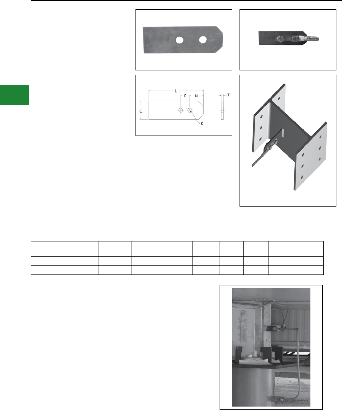
BURNDY®
Blue highlighted items are industry standard and most frequently ordered.
US: 1-800-346-4175 www.burndy.com Canada: 1-800-387-6487
Grounding
HYGROUND® Compression
E-18
TYPE GROUNDTAB
For any metal structure requiring
grounding
The BURNDY® GROUNDTAB offers a convenient
attachment point for terminations of ground wires
to steel structures or steel supports. The tabs are
easily welded to steel, with two mounting pattern
options available. The tabs are made of steel, 1/4”
thick, and can be used to attach 1-hole or 2-hole
terminals. Compression terminals, mechanical
terminals, or SERVIT® Posts can be used to attach
ground wires to steel tabs. All connection options
and necessary hardware are sold separately.
Often used when traditional connection methods
are not practical, or when temporary grounds
are required. Common applications include large
generators, mobile construction site modules,
housing structures built in permafrost areas, and
in any metal structure requiring a permanent or
temporary ground option.
Catalog
Number
L
Inches
C
Inches
T
Inches
N
Inches
No. of
Holes
Hole Size
(K)
Hole Spacing (E)
Inches
GROUNDTAB1/2 6.00 2.00 1/4” 1.50 2 1/2” 1.75
GROUNDTAB3/8 6.00 2.00 1/4” 1.50 2 3/8” 1.00
Features & Benets
• Convenient
• Can be used to attach 1-hole or 2-hole
terminals
• 1/4” thick steel
• Easily welds to steel
• Many connection options
• Used when traditional options are not
practical
Above: GROUNDTAB with Type YGA
HYGROUND® compression terminal and
hardware.
Right: Application image of GROUNDTAB
used with terminals
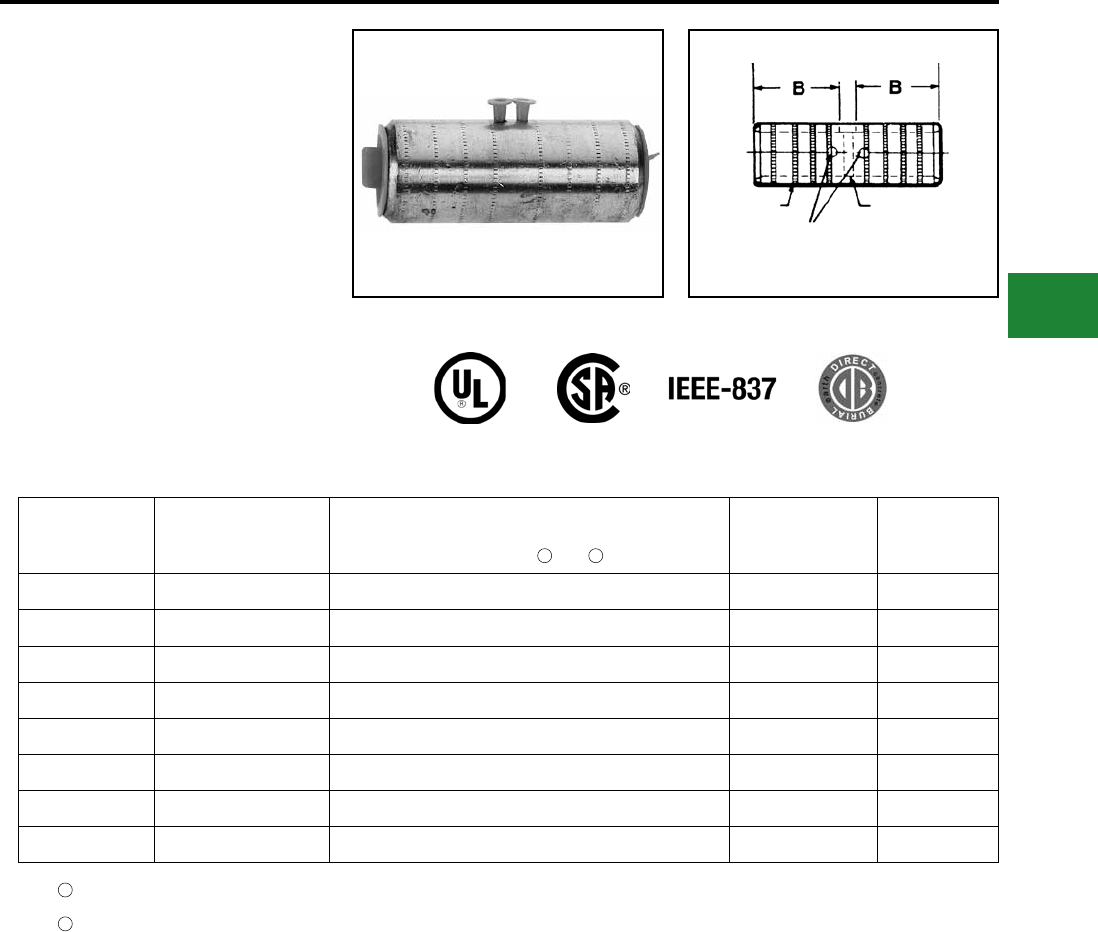
BURNDY®
Blue highlighted items are industry standard and most frequently ordered.
Canada: 1-800-387-6487 www.burndy.com US: 1-800-346-4175
Grounding
HYGROUND® Compression
TYPE YGHS
HYLINK™
Heavy Duty Irreversible Compession
Splices
Heavy duty HYLINK™ ground splice designed not
only to carry short circuit load, but to also withstand
high mechanical stress. Each conductor element
has an inspection probe hole and a center stop
to ensure proper cable insertion. UL467 Listed.
Acceptable for direct burial in earth or concrete.
UL486A Listed. Prelled with PENETROX™
compound and strip sealed.
Catalog
Number
Copper
Conductor
Size
Installation Tools, Die Set Catalog Number and
(# of Crimps)
HYPRESS™ Y35/Y39/Y45 /Y46 /Y750/PAT750
B L
YGHS2C 2 AWG U1CRT (1) 0.75 1.73
YGHS25 1/0 AWG U27RT (1) 0.83 1.89
YGHS26 2/0 AWG U28RT (1) 0.83 1.89
YGHS27 3/0 AWG U29RT (1) 1.18 2.59
YGHS28 4/0 AWG U30RT (2) 1.18 2.59
YGHS29 250 kcmil U31RT (2) 1.18 2.59
YGHS31 350 kcmil U34RT (2) 1.18 2.59
YGHS34 500 kcmil U36RT (3) 1.48 3.19
KNURLED
RINGS
INSPECTION PROBE HOLES
FOR CABLE STOP
Where a “U” or “PU” die is recommended with the Y45
HYPRESS™, a PT6515 adapter must be used
Where a “U” or “PU” die is recommended with the Y46
HYPRESS™, a PUADP-1 adapter must be used
1
1
2
2
E-19
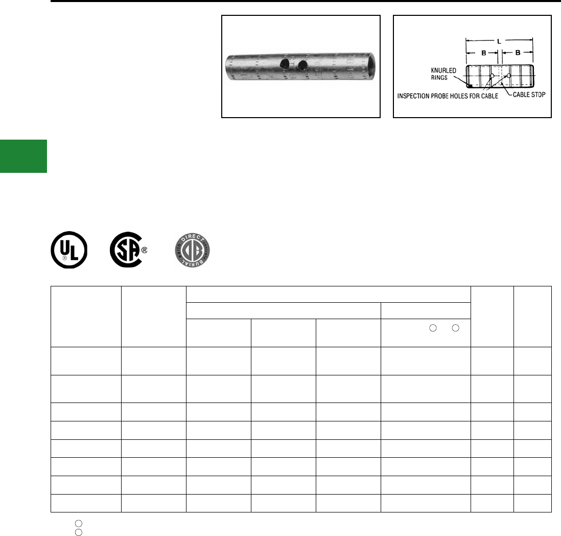
BURNDY®
Blue highlighted items are industry standard and most frequently ordered.
US: 1-800-346-4175 www.burndy.com Canada: 1-800-387-6487
Grounding
HYGROUND® Compression
TYPE YGS
HYLINK™
Grounding Irreversible Compression
Splices
Irreversible compression HYLINK™ ground
splices specically designed for grounding
applications. Each conductor element has an
inspection probe hole and a center stop to ensure
proper cable insertion. UL467 Listed. Acceptable
for direct burial in earth
or concrete. UL486A Listed.
Prelled with PENETROX™ E compound and strip
sealed.
Catalog
Number
Copper
Conductor Size
Installation Tools, Die Set Catalog Number and (# of Crimps)
B L
Mechanical Hydraulic
Y1MRTC MD7-34R OUR840 Y35/Y39/45 /Y46 /
Y750/PAT750
YGS8C 8 Sol./Str. Red (2) W8CRT, W8CVT X8CRT U8CRT (2) 0.78 1.75
YGS6C 6 Sol./Str. Blue (2) W5CRT, W5CVT X5CRT U6CRT (2) 1.09 2.38
YGS2C 2 Sol./Str. Brown (4) W2CVT (2) X2CVT (2) U2CRT (2) 1.22 2.67
YGS25 1/0 Sol./Str. — W25VT (4) X25RT (4) U25RT (2) 1.35 2.97
YGS26 2/0 Str. — W26VT (4) X26RT (4) U26RT (2) 1.45 3.13
YGS28 4/0 Str. — W28VT (4) X28RT (4) U28RT (2) 1.57 3.37
YGS29 250 kcmil — W29VT (4) — U29RT (2) 1.57 3.37
YGS34 500 kcmil — W34VT (4) — U34RT (4) 2.20 4.63
Where a “U” or “PU” die is recommended with the Y45 HYPRESS™, a PT6515 adapter must be used
Where a “U” or “PU” die is recommended with the Y46 HYPRESS™, a PUADP-1 adapter must be used
1
2
1 2
E-20
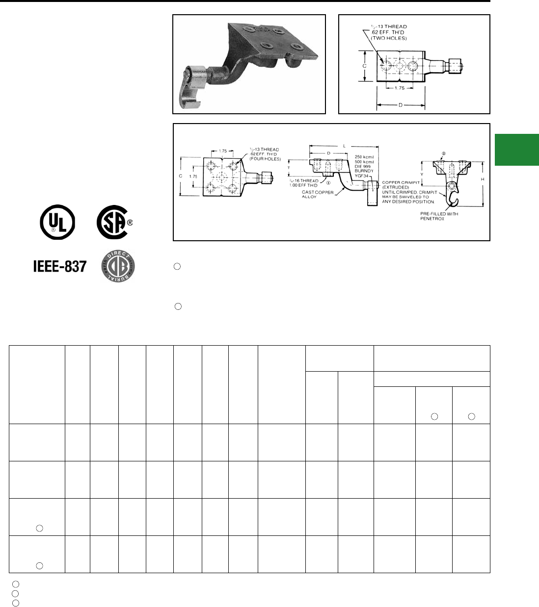
BURNDY®
Blue highlighted items are industry standard and most frequently ordered.
Canada: 1-800-387-6487 www.burndy.com US: 1-800-346-4175
Grounding
HYGROUND® Compression
TYPE YGF
GROUNDING PLATE
The irreversible compression ground plate is
designed to withstand the rigors of concrete
construction. The ground plates are made of high
strength, high-conductivity cast copper alloy body
with a pure wrought copper compression element.
In addition to the tapped NEMA size holes and
spacing on the face, the plate comes with a tapped
hole on the underside for ease of positioning prior
to pouring the concrete. UL467 Listed. Acceptable
for direct burial in earth or concrete. Prelled with
PENETROX™ compound and strip sealed.
Catalog
Number
Fig.
#C D H L T Y
Copper
Conductor
Range
Tapped Holes Installation Tools, Die Set Cat.
No., and (# of Crimps)
Size Hole
Centers
HYPRESS™
PAT750/
Y750/Y35/
Y39
Y45 Y46
YGF29-2N 1 2.00 3.25 3.62 5.78 1.31 2.00 2 AWG-250
kcmil 1/2 - 13 1-3/4 U997 (1) U997 (1) U997 (1)
YGF29-4N 2 3.25 3.25 3.62 5.78 1.31 2.00 2 AWG-250
kcmil 1/2 - 13 1-3/4 U997 (1) U997 (1) U997 (1)
YGF34-2N 1 2.00 3.25 4.62 5.40 1.31 2.19
250
kcmil-500
kcmil
1/2 - 13 1-3/4 U1011 (3) S1011 (2) P1011 (2)
YGF34-4N 2 3.75 3.75 4.62 5.90 1.31 2.19
250
kcmil-500
kcmil
1/2 - 13 1-3/4 U1011 (3) S1011 (2) P1011 (2)
3
3
1 2
Where a “U” or “PU” die is recommended with the Y45 HYPRESS™, a PT6515 adapter must be used
Where a “U” or “PU” die is recommended with the Y46 HYPRESS™, a PUADP-1 adapter must be used
These connectors can only be installed using the Y750, Y45 or Y46 HYPRESS™ with recommended dies, they cannot be installed with the Y35 or Y39 HYPRESS™
1
2
3
NOTES:
This tapped hole may be used to position the grounding plate on a threaded rod prior to placement of
the concrete. 3/8-16 thread with 1.00 EFF. Thread is standard. If other thread is required, add appropriate
sufx code to catalog number. -50 (1/2-13, .94 EFF. Thread), -62 (5/8-11, .94 EFF. Thread) and -75 (3/4-10,
.81 EFF. Thread) Example: YGF34-4N-50 is YGF34-4N with 1/2-13 Thread
Plastic plugs are provided to keep dirt out of the threaded holes until the attachment of grounding
terminals
1
2
Fig. 1
Fig. 2
E-21
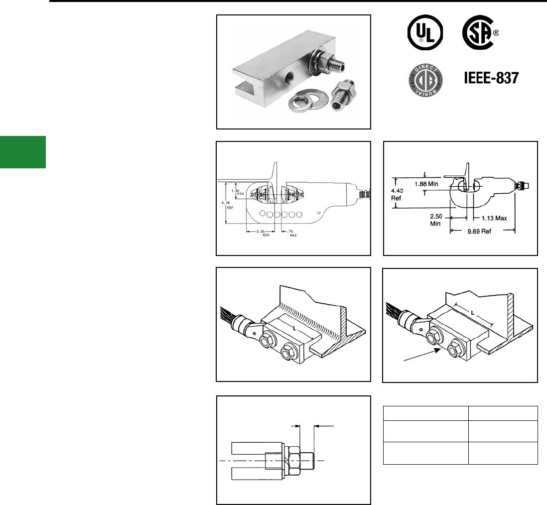
BURNDY®
Blue highlighted items are industry standard and most frequently ordered.
US: 1-800-346-4175 www.burndy.com Canada: 1-800-387-6487
Grounding
HYGROUND® Compression
TYPE YGIB
GROUNDLINK™
An irreversible compression ground connection
which allows attachment to a structural steel
standard (angled) or wide ange (parallel) beam.
Installed with a required 5-piece die set, Catalog
PIBEAMKIT or UIBEAMKIT. Die index 1105.
GROUNDLINK™ connectors are made of high-
conductivity wrought copper and come pre-lled
with PENETROX™ E compound and strip sealed.
Order terminal mounting hardware separately.
Connector shipped with thread protection studs only.
Order TMHG kits separately.
NOTES:
Terminal connector to be ordered separately.
When I-beam connector is used with type YGHA
terminal, the connection meets IEEE 837. YGA-
2N, YA-2N and other BURNDY® 2-hole NEMA
copper terminals are suitable.
Order TMHG Terminal Mounting Hardware Kit
separately. Kit consists of 2 studs, 2 at washers, 2
lockwashers and 2 hex nuts.
Using the 1/4 hex key wrench, screw the stud into
the connector until stud bottoms out in connector.
Install a YGHA terminal, at washer, lockwasher
and hex nut onto stud. Tighten and torque to 480
pound-inches.
Dimensions shown in i-Beam Flange Thickness
column reect the minimum dimensions required
on a beam to property install the i-Beam connector.
To correctly determine the appropriate YGIB
connector to use based on ange thickness, order
either YGIBGAUGE1 or YGIBKIT1 (KIT1 contains
wiremike).
1.84 In. Minimum ange depth.
3.06 In. Minimum ange width.
Y46 Series
use PIBEAMKIT
Y750 Series
use UIBEAMKIT
Standard Beams
(Flange Angled) use YGIBS
Fig. 1 Fig. 2
2 Hole NEMA
Spacing
Wide Flange Beams
(Flange Parallel) use YGIBW
“T” Ref. Maximum
Terminal Pad
Thickness
TERMINAL MOUNTING HARDWARE
Catalog Number “T”
TMHG-42 0.42
TMHG-92 0.92
NOTE: Use TMHG-92 to double stack lugs.
E-22
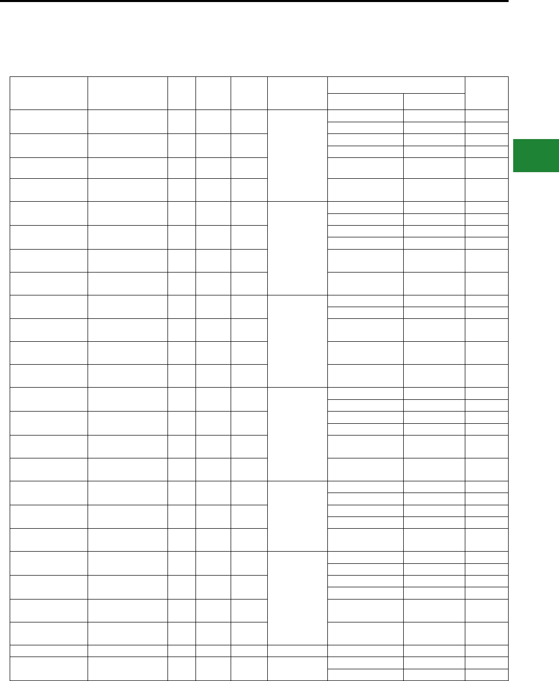
BURNDY®
Blue highlighted items are industry standard and most frequently ordered.
Canada: 1-800-387-6487 www.burndy.com US: 1-800-346-4175
Grounding
HYGROUND® Compression
TYPE YGIB
GROUNDLINK™ CONNECTOR
(Continued)
Catalog Number Copper Conductor
Size
Fig.
#L J I-Beam Flange
Thickness
Suggested Terminals T
Copper Conductor Terminal
YGIBS28-338-2N 2 AWG-4/0 AWG 1 3.00 1/2-13
0.250" - 0.338"
#2 Str. AWG YGHA2C-2N 0.26
1/0 Str. AWG YGHA25-2N 0.19
YGIBW28-338-2N 2 AWG-4/0 AWG 2 3.00 1/2-13 2/0 Str. AWG YGHA26-2N 0.26
4/0 Str. AWG YGHA28-2N 0.30
YGIBS34-338-2N 250 kcmil-500 kcmil 1 6.00 1/2-13 250 kcmil YGHA29-2N 0.34
0.40
YGIBW34-338-2N 250 kcmil-500 kcmil 2 6.00 1/2-13 500 kcmil YGHA34-2N 0.34
0.40
YGIBS28-400-2N 2 AWG-4/0 AWG 1 3.00 1/2-13
0.338" - 0.400"
#2 Str. AWG YGHA2C-2N 0.26
1/0 Str. AWG YGHA25-2N 0.19
YGIBW28-400-2N 2 AWG-4/0 AWG 2 3.00 1/2-13 2/0 Str. AWG YGHA26-2N 0.26
4/0 Str. AWG YGHA28-2N 0.30
YGIBS34-400-2N 250 kcmil-500 kcmil 1 6.00 1/2-13 250 kcmil YGHA29-2N 0.34
0.40
YGIBW34-400-2N 250 kcmil-500 kcmil 2 6.00 1/2-13 500 kcmil YGHA34-2N 0.34
0.40
YGIBS28-462-2N 2 AWG-4/0 AWG 1 3.00 1/2-13
0.400" - 0.462"
#2 Str. AWG YGHA2C-2N 0.26
1/0 Str. AWG YGHA25-2N 0.19
YGIBW28-462-2N 2 AWG-4/0 AWG 2 3.00 1/2-13 2/0 Str. AWG
4/0 Str. AWG
YGHA26-2N
YGHA28-2N
0.26
0.30
YGIBS34-462-2N 250 kcmil-500 kcmil 1 6.00 1/2-13 250 kcmil YGHA29-2N 0.34
0.40
YGIBW34-462-2N 250 kcmil-500 kcmil 2 6.00 1/2-13 500 kcmil YGHA34-2N 0.34
0.40
YGIBS28-550-2N 2 AWG-4/0 AWG 1 3.00 1/2-13
0.462" - 0.550"
#2 Str. AWG YGHA2C-2N 0.26
1/0 Str. AWG YGHA25-2N 0.19
YGIBW28-550-2N 2 AWG-4/0 AWG 2 3.00 1/2-13 2/0 Str. AWG YGHA26-2N 0.26
4/0 Str. AWG YGHA28-2N 0.30
YGIBS34-550-2N 250 kcmil-500 kcmil 1 6.00 1/2-13 250 kcmil YGHA29-2N 0.34
0.40
YGIBW34-550-2N 250 kcmil-500 kcmil 2 6.00 1/2-13 500 kcmil YGHA34-2N 0.34
0.40
YGIBS28-613-2N 2 AWG-4/0 AWG 1 3.00 1/2-13
0.550" - 0.613"
#2 Str. AWG YGHA2C-2N 0.26
1/0 Str. AWG YGHA25-2N 0.19
YGIBW28-613-2N 2 AWG-4/0 AWG 2 3.00 1/2-13 2/0 Str. AWG YGHA26-2N 0.26
4/0 Str. AWG YGHA28-2N 0.30
YGIBW34-613-2N 250 kcmil-500 kcmil 2 6.00 1/2-13 500 kcmil YGHA34-2N 0.34
0.40
YGIBS28-675-2N 2 AWG-4/0 AWG 1 3.00 1/2-13
0.613" - 0.675"
#2 Str. AWG YGHA2C-2N 0.26
1/0 Str. AWG YGHA25-2N 0.19
YGIBW28-675-2N 2 AWG-4/0 AWG 2 3.00 1/2-13 2/0 Str. AWG YGHA26-2N 0.26
4/0 Str. AWG YGHA28-2N 0.30
YGIBS34-675-2N 250 kcmil-500 kcmil 1 6.00 1/2-13 250 kcmil
500 kcmil YGHA29-2N 0.34
0.40
YGIBW34-675-2N 250 kcmil-500 kcmil 2 6.00 1/2-13 500 kcmil YGHA34-2N 0.34
0.40
YGIBW28-750-2N 2 AWG-4/0 AWG 3 3.00 1/2-13 0.690" - 0.750" 4/0 Str. AWG YGHA28-2N 0.30
YGIBW28-1000-2N 2 AWG-4/0 AWG 3 3.00 1/2-13 1.000" -1.060" 2/0 Str. AWG YGHA2C-2N 0.26
4/0 Str. AWG YGHA28-2N 0.30
E-23
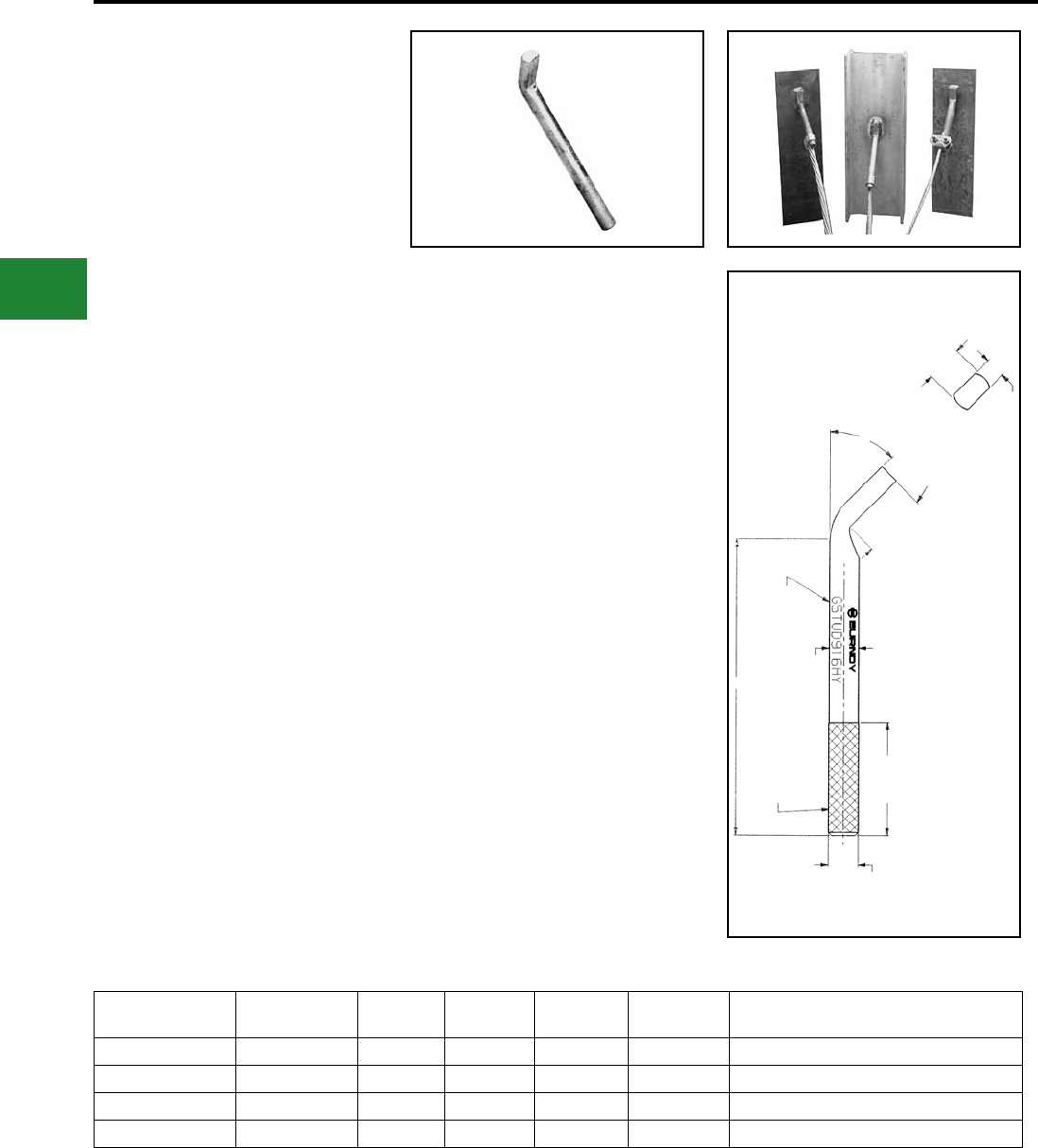
BURNDY®
Blue highlighted items are industry standard and most frequently ordered.
US: 1-800-346-4175 www.burndy.com Canada: 1-800-387-6487
Grounding
HYGROUND® Compression
TYPE GSTUD-HY
VERSITAIL™
Structural Steel Grounding Connector
INSTALLATION
1. Weld the VERSITAIL™ to the steel member.
2. Select the proper connector for your specic
application.
FOR COMPRESSION CONNECTORS
Select the proper BURNDY® “YGHP,” connector.
Clean the conductor, join the VERSITAIL™
and the grounding conductor together with
the recommended tool and die set, then crimp
the connector over the knurled area of the
VERSITAIL™.
FOR MECHANICAL CONNECTORS
Select the properly sized BURNDY® connector.
Clean the conductor, then apply PENETROX™
E oxide inhibiting compound on the contact
area for increased effectiveness and service
life. Put the connector over the knurled area of
the VERSITAIL™ and apply the recommended
torque value for correct installation.
Catalog Number Nom Rod Size A B L T Electrical Equivalent Copper Conductor
Size (AWG)*
GSTUD14HY 1/4" 0.25 0.26 4.81 0.19 #6
GSTUD38HY 3/8" 0.38 0.39 5.81 0.25 #3
GSTUD916HY 9/16” 0.56 0.57 5.68 0.38 1/0
GSTUD34HY 3/4" 0.75 0.76 5.81 0.51 4/0
Features & Benets
• The VERSITAIL™ may be welded to
steel surfaces quickly and easily with
normal construction equipment.
• The VERSITAIL™ eliminates costly disk
grinding and the need to expose virgin
metal, the welding process burns through
the oxidation and “scale” to establish
excellent electrical grounding continuity.
• The VERSITAIL™ may be installed by
the welder in the eld or at the steel
fabricator based on customer preference.
• The VERSITAIL™ pure copper coating
over low carbon, hot rolled steel is
compatible with standard welding
processes, no toxic gasses are
generated.
• The VERSITAIL™ knurled surface is
copper plated and specically designed
to ensure excellent mechanical gripping
and electrical integrity for BURNDY®
compression and mechanical connectors
in all grounding applications.
• The VERSITAIL™ may be installed
during adverse weather conditions thus
eliminating costly construction delays.
• Low installation cost.
• No drilling
• No cleaning
• No special preparation
• Low Carbon, hot rolled steel
• Pure copper plated nish
* This is the equivalent rating for continuous service.
Large conductors may be connected using both compression
and bolted connectors in potential ground fault applications.
45°
L
T
1.25
[32]
2.19
[56]
(FLATTENING
RESULTANT)
TYPICAL
LETTERING
A (STOCK
Dia.)
KNURLED
END
B (Dia. OVER KNURL)
E-24
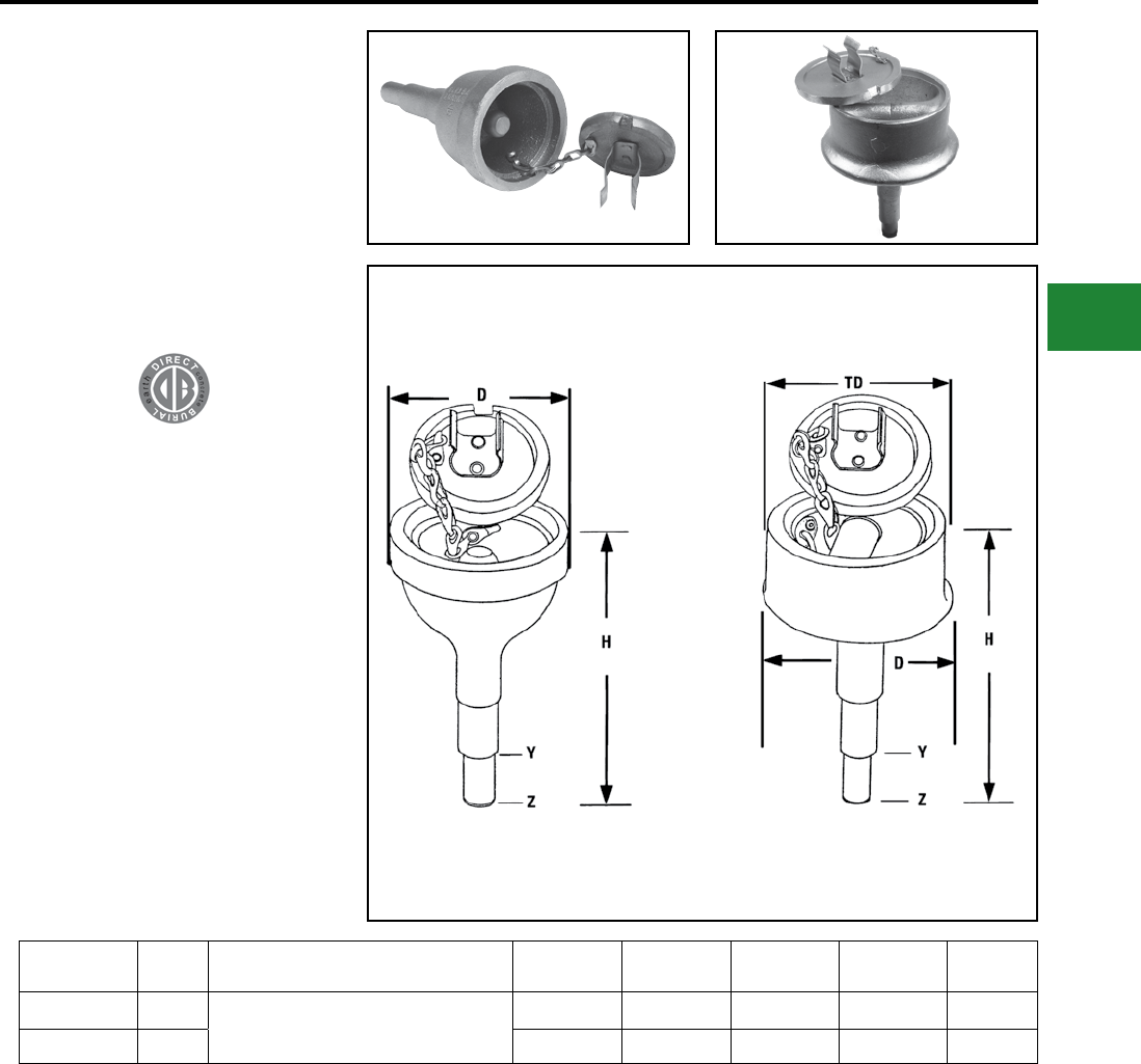
BURNDY®
Blue highlighted items are industry standard and most frequently ordered.
Canada: 1-800-387-6487 www.burndy.com US: 1-800-346-4175
Grounding
HYGROUND® Compression
TYPES YGT & YTTAG
Static Grounding Receptacle
Type YGT static grounding receptacles are
designed for static grounding of equipment. The
receptacle is connected to the ground grid with
HYGROUND® compression connectors and
nished ush with surface to provide a permanent
corrosion proof grounding point.
Catalog
Number Fig. # HYGROUND®
Connector H D Y Dia Z Dia TD
YGT275 1Select suitable YGHR, YGHP or YGLR
for 3/4" ground rod and sized to ground
conductor.
5.50 2.75 0.75 0.56 -
YTTAG388 2 6.50 4.75 0.75 0.56 4.30
Type YGT
Static Grounding Receptacle
with Cover
Type YTTAG Combination
Static Grounding Receptacle
and Aircraft Tie Down Bar
Fig. 1 Fig. 2
NOTES:
Install YGHR, YGHP or YGLR on Hub Y. Hub Z is inserted
into 1/2" rigid conduit. The conduit is driven into the earth
to provide support and provide correct level of receptacle
prior to cement pour.
E-25
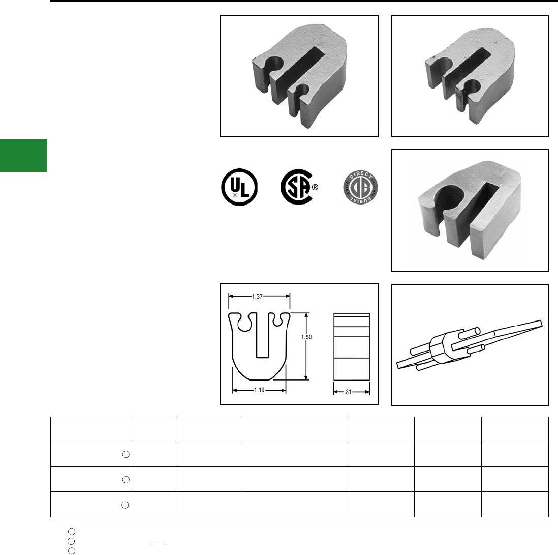
BURNDY®
Blue highlighted items are industry standard and most frequently ordered.
US: 1-800-346-4175 www.burndy.com Canada: 1-800-387-6487
Grounding
HYGROUND® Compression
TYPE YG-B
Bus Bar Connector
The BURNDY® YG-B series of compression bus
bar connectors are ideally suited for cellular tower,
bus bar and at steel applications and is easier
to use than exothermic connections. These high
conductivity copper connectors allow attachment
of a ground conductor to a bus bar or at steel,
with just one crimp using a BURNDY® Y750/
PAT750-style HYPRESS™ head and the U1105
die set. The exclusive design allows the user to
attach tap conductor(s) to 1/4” (1/8” to 1/4” if using
the YG14BTC28) thick copper bus bar or at steel.
Most connectors are suitable for 1 or 2 conductors
for power or grounding and bonding applications.
Prelled with PENETROX™ compound with the
addition of a grit material and strip sealed.
Catalog
Number Figure # Ground Bar
Thickness BusBar Tap Conductors Tooling Installation Die # of Crimps
YG14B2TC2C6C 1 1/4" #2 Sol. and/or Str. Copper
#6 Sol. and/or Str. Copper PAT750, Y750 U1105 1
YG14B2TC2C2C 2 1/4" #2
#2 PAT750, Y750 U1105 1
YG14BTC28 3 1/8" - 1/4” 4/0 AWG Str. to 1/0 AWG Str.
Copper PAT750, Y750 U1105 1
Fig. 1 Fig. 2
Fig. 3
UL Listed, CSA Certied, Rated for Direct Burial; can accept 1 or 2 conductors
U-shaped tap groove can only be used with #2 Solid wire; can accept 1 or 2 conductors; suitable for continuous uncut conductor applications
cULus Listed, Rated for Direct Burial; can accept only 1 conductor
1
2
3
1
2
3
E-26
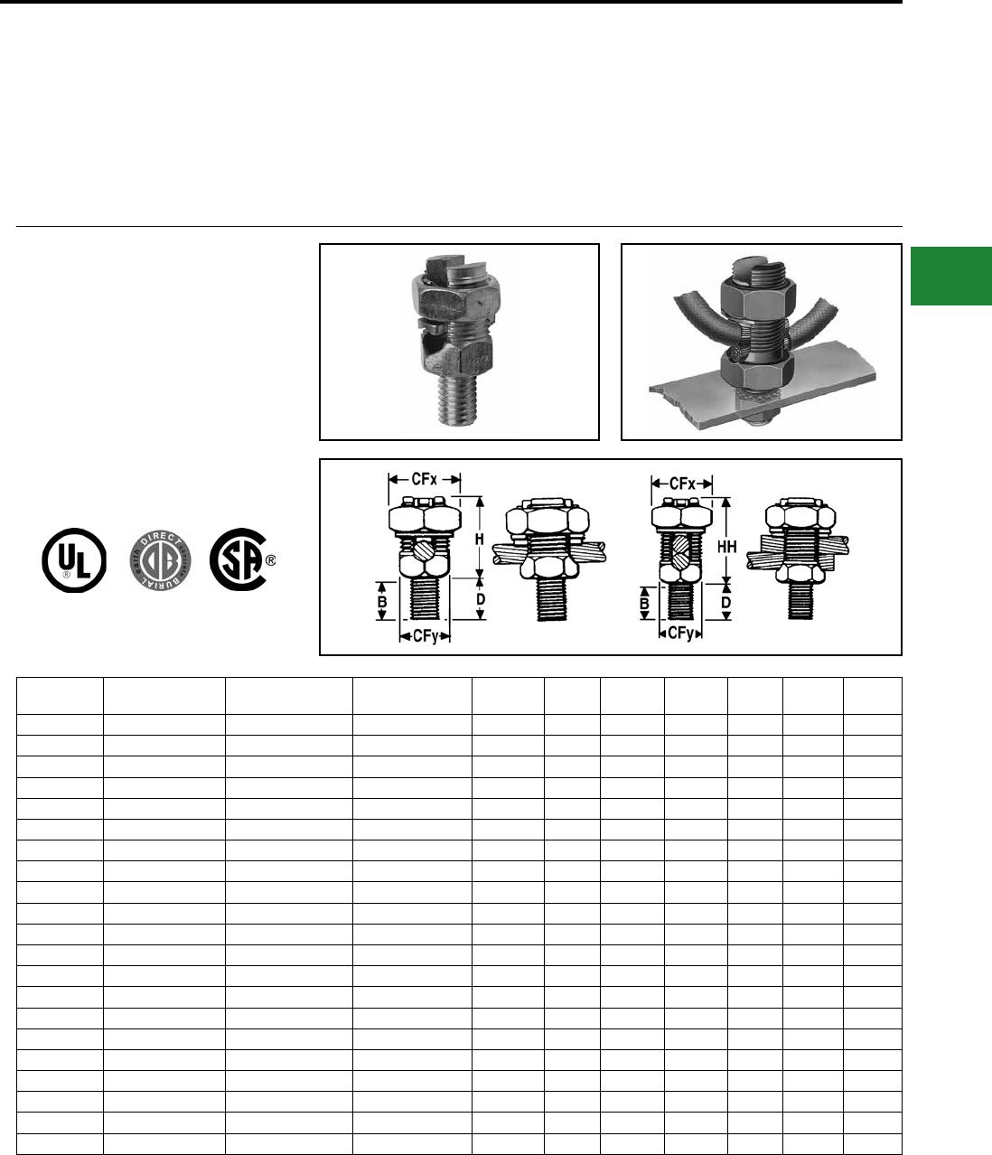
BURNDY®
Blue highlighted items are industry standard and most frequently ordered.
Canada: 1-800-387-6487 www.burndy.com US: 1-800-346-4175
Grounding
Mechanical
MECHANICAL GROUNDING
CONNECTORS
More than 60 years of technological innovation
has made BURNDY
®
mechanical grounding
connectors one of the most widely used, highly
respected lines in the industry There is virgually no
grounding application problem that this diversied
line cannot help solve.
TYPE KC
One Wire
TYPE K2C
One or Two Wires Stranded Solid Stud
Diameter B CFx CFy D H HH
KC15** K2C15** 12 AWG-9 AWG 12 AWG-8 AWG 1/4 -20 3/8 1/2 3/8 1/2 5/8 7/8
KC15B1 K2C15B1 12 AWG-9 AWG 12 AWG-8 AWG 1/4 -20 7/8 1/2 3/8 1 5/8 7/8
KC17 K2C17 10 AWG-7 AWG 10 AWG-6 AWG 1/4 -20 3/8 5/8 7/16 1/2 7/8 1
KC17B1 K2C17B1 10 AWG-7 AWG 10 AWG-6 AWG 1/4 -20 7/8 5/8 7/16 1 7/8 1
KC20 K2C20 10 AWG-5 AWG 10 AWG-4 AWG 5/16 -18 13/32 11/16 1/2 5/8 7/8 1-1/8
KC20B1 K2C20B1 10 AWG-5 AWG 10 AWG-4 AWG 5/16 -18 27/32 11/16 1/2 1 7/8 1-1/8
KC22 K2C22 10 AWG-3 AWG 10 AWG-2 AWG 3/8 - 16 15/32 3/4 5/8 5/8 1 1-1/4
KC22B1 K2C22B1 10 AWG-3 AWG 10 AWG-2 AWG 3/8 - 16 31/32 3/4 5/8 1-1/8 1 1-1/4
KC23 K2C23 8 AWG-2 AWG 10 AWG-1 AWG 3/8 - 16 15/32 13/16 5/8 5/8 1 1-3/8
KC23B1 K2C23B1 8 AWG-2 AWG 10 AWG-1 AWG 3/8 - 16 31/32 13/16 5/8 1-1/8 1 1-3/8
KC25 K2C25 2 AWG-1/0 AWG 2 AWG-2/0 AWG 1/2 -13 9/16 15/16 3/4 3/4 1-1/8 1-5/8
KC25B1 K2C25B1 2 AWG-1/0 AWG 2 AWG-2/0 AWG 1/2 -13 1-1/16 15/16 3/4 1-1/4 1-1/8 1-5/8
KC26 K2C26 2 AWG-2/0 AWG 2 AWG-3/0 AWG 1/2 -13 17/32 1 7/8 3/4 1-3/8 1-7/8
KC26B1 K2C26B1 2 AWG-2/0 AWG 2 AWG-3/0 AWG 1/2 -13 1-1/16 1 7/8 1-1/4 1-3/8 1-7/8
KC28 K2C28 1 AWG-4/0 AWG 1 AWG-4/0 AWG 5/8 - 11 3/4 1-1/2 1-3/16 1 1-3/4 2-1/4
KC28B1 K2C28B1 1 AWG-4/0 AWG 1 AWG-4/0 AWG 5/8 - 11 1-1/4 1-1/2 1-3/16 1-1/2 1-3/4 2-1/4
KC28G3 K2C28G3 1 AWG-4/0 AWG 1 AWG-4/0 AWG 1/2 - 13 1-1/4 1-1/2 1-3/16 1-1/2 1-3/4 2-1/4
KC31 K2C31 1 AWG-350 kcmil N/A 5/8 - 11 3/4 1-11/16 1-3/8 1 2-1/4 2-7/8
KC31B1 K2C31B1 1 AWG-350 kcmil N/A 5/8 - 11 1-1/4 1-11/16 1-3/8 1-1/2 2-1/4 2-7/8
KC34 K2C34 3/0 AWG-500 kcmil N/A 3/4 -10 1 2 1-5/8 1-1/4 2-3/8 3-1/4
KC34B1 K2C34B1 3/0 AWG-500 kcmil N/A 3/4 -10 1-1/2 2 1-5/8 1-3/4 2-3/8 3-1/4
NOTE:
** Not UL 467 rated
Add “-NSP” sufx to catalog numbers to have connector supplied with split lockwasher and nut.
KC K2C
TYPES KC, K2C
SERVIT POST™
For Copper Cable to Flat
SERVIT POST™ used to ground one or two cables
to steel structures, fence posts, transformers. Also
used to tap one or two cables from bus bar. One-
wrench installation.
All BURNDY mechanical grounding connectors
have been designed for easy installation and
for outstanding durability. Only the nest high
copper alloys are used in their manufacture,
ensuring top performance under the most extreme
environmental conditions.
UL467 Listed for direct burial applications in earth
or concrete.
E-27
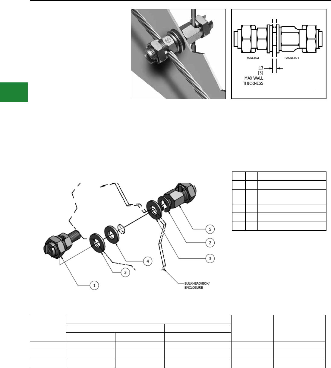
BURNDY®
Blue highlighted items are industry standard and most frequently ordered.
US: 1-800-346-4175 www.burndy.com Canada: 1-800-387-6487
Grounding
Mechanical
TYPE KCKF
Bulkhead Ground Connector
The “Bulkhead” connector is designed to allow
a ground wire to be connected from the inside
of a box or enclosure to the outside of a box or
enclosure.
This new connector is supplied in kit form with
a male SERVIT POST™, female SERVIT®, (2)
stainless steel washers, split lock washer and
sealing washer.
The available “Application Guideline” document
helps describe the application with visuals and
installation examples.
Catalog
Number
ACCOMMODATES
NUT TORQUE
IN-LBS [N-M] MAX. THRU HOLE
AWG METRIC
STRANDED SOLID STRANDED
KCKF23 #8 (.146) - #2 (.292) #10 (.102) - #1 (.289) 10mm2 (4.1) - 35mm2 (6.5) 275 [31.1] 7/16
KCKF25 #2 (.292) - 1/0 (.373) #2 (.258) - 2/0 (.365) 35mm2 (6.5) - 50mm2 (9.3) 385 [43.5] 9/16
KCKF28 #1 (.332) - 4/0 (.528) #1 (.289) - 4/0 (.460) 50mm2 (9.3) - 95mm2 (12.8) 500 [56.5] 11/16
Notes:
Dimensions in () are cable diameters.
Diameters of AWG wires are in inches.
Diameters for metric wires are given in mm.
*One flat washer and sealing washer to be
installed on outside of box or, where applicable,
to side of wall exposed to atmospheric or
contaminated conditions. Remaining hardware to
be mounted to opposite side of the wall as shown.
Features & Benets
• Provides an easy way to connect ground wires
“through” an enclosure wall
• Includes Male SERVIT POST™, Female
SERVIT®, (2) Stainless Steel Washers, Split
Lock Washer, Sealing Washer
• Split Lock Washer allows adjustment of
conductor orientation
• Made of Silicon Bronze material (connectors)
and Stainless Steel Hardware, Sealing Washer
• Meets NEMA 4X requirements when installed
correctly
• Application Guideline document available
• Industry proven split bolt/SERVIT POST™
technology
E-28
Qty Description
1 1 Male Servit Post
2 1 Stainless Steel Split Lock
Washer*
3 2 Stainless Steel Flat Washer*
4 1 Sealing Washer*
5 1 Female SERVIT®
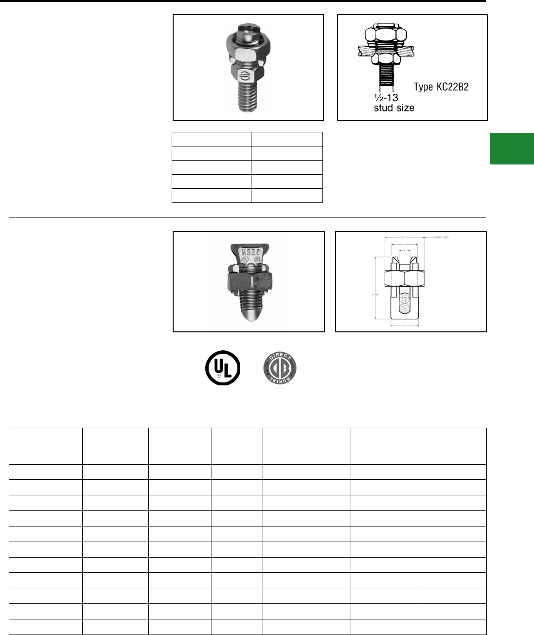
BURNDY®
Blue highlighted items are industry standard and most frequently ordered.
Canada: 1-800-387-6487 www.burndy.com US: 1-800-346-4175
Grounding
Mechanical
TYPES KC-J12, EQC632C
Transformer Ground Connectors
For Copper
Fits all standard EEI-NEMA distribution
transformers as tank grounding terminal.
Catalog Number Ranges
KC22J12T13 8 Sol. - 2 Sol.
KC26 2 Sol. - 2/0 Str.
KC34J12T13 3/0 - 500 Str.
EQC632C 8 Sol. - 2 Str.
TYPE KS
SERVIT®
For Copper
UL467 Listed for direct burial applications in earth
or concrete. Compact, highstrength, high copper
alloy SERVIT® split-bolt has free-running threads
and easy to grip wrench ats. Highly resistant to
cracking and corrosion.
Catalog
Number Cross Flats L W Copper Conductor
Range
Rebar with (1)
#8 Sol. Cu
Recommended
Tightening
Torque (in-lb)
KS15 0.50 0.85 0.38 10 - 8 Str. 14 Str. #8
KS17 0.63 1.14 0.45 8 Str. - 6 Sol. 14 Str. #6
KS20 0.69 1.20 0.51 8 Str. - 4 Sol. 14 Str. #4
KS22 0.75 1.50 0.60 6 Str. - 2 Sol. 14 Str. #2
KS23 0.82 1.54 0.62 6 Str. - 2 Str. 14 Str. #1
KS25 0.94 1.77 0.73 4 Str. - 1/0 Str. 14 Str. 2/0
KS26 1.05 1.94 0.82 2 Str. - 2/0 Str. 14 Str. 3/0
KS27 1.36 1.86 1.17 1 Str. - 3/0 Str. 8 Sol. —
KS29 1.36 2.07 1.17 1 Str. - 250 8 Str. 4/0
KS31 1.70 2.51 1.41 1/0 Str. - 350 1/0 Str. —
KS34 1.82 2.79 1.48 2/0 Str. - 500 2/0 Str. —
E-29
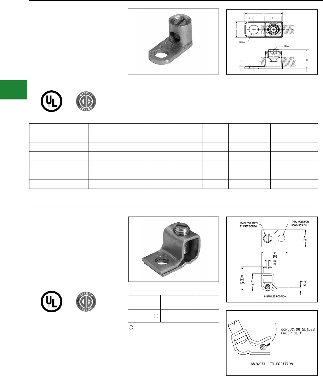
BURNDY®
Blue highlighted items are industry standard and most frequently ordered.
US: 1-800-346-4175 www.burndy.com Canada: 1-800-387-6487
Grounding
Mechanical
Catalog Number Cable Range B C H J Dia. K L
GKA8C* 10 AWG-8 AWG 0.31 0.38 0.58 #12-24 (Slot) 0.21 0.81
GKA4C* 14 AWG-4 AWG 0.46 0.54 0.71 5/16-24 (Slot) 0.28 1.13
GKA25 4 AWG-1/0 AWG 0.69 0.75 0.94 1/2-20 (Hex) 0.42 1.69
GKA28 1 AWG-4/0 AWG 0.81 0.94 1.25 5/8-18 (Hex) 0.42 1.94
GKA25SB 4 AWG-1/0 AWG 0.69 0.75 0.94 1/2-20 (Hex) 0.42 1.69
GKA28SB 1 AWG-4/0 AWG 0.81 0.94 1.25 5/8-18 (Hex) 0.42 1.94
TYPE GKA
For Copper
UL467 Listed for direct burial applications in
earth or concrete. One-piece body construction
insures mechanical integrity in an underground
environment. Supplied with stainless steel
headless screw, the GKA25SB and GKA28SB
have silicon bronze hardware.
TYPE KPB
For Copper
UL467 Listed for direct burial in earth or concrete.
UL486 listed. This exclusive BURNDY® design
accommodates #10 - #4 copper where continuous
conductor runs are preferable.
Catalog
Number
Copper Cable
Range
Stud
Hole
KPB4CG1 10 AWG-4 AWG #10
* GKA8C, GKA4C are cULus Listed.
Can be assembled with optional TMH322SS stain-
less steel hardware kit, ordered separately.
1
1
E-30
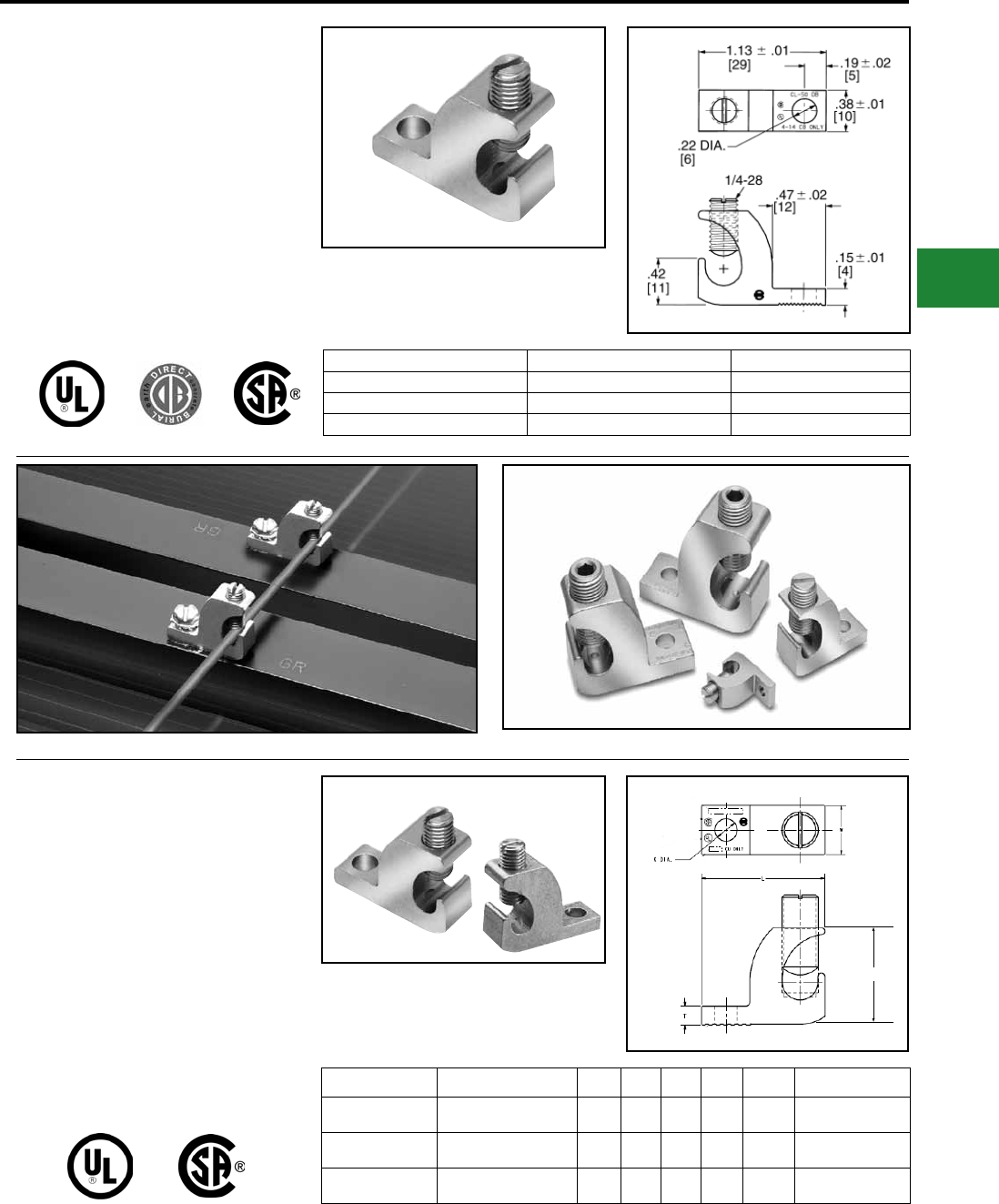
BURNDY®
Blue highlighted items are industry standard and most frequently ordered.
Canada: 1-800-387-6487 www.burndy.com US: 1-800-346-4175
Grounding
Mechanical
TYPES CL50-1 & CL50-1TN
COPPER LAY-IN QIKLUG™
For Copper
The Lay-In QIKLUG™ is manufactured from
high strength pure electrolytic copper to ensure
maximum strength and conductivity. UL467
Listed for direct burial in earth or concrete. The
open-faced design allows for fast layin of the
conductor without the need for cutting or breaking.
Stainless steel screws used for excellent corrosion
resistance.
Catalog Number Conductor Range Stud Hole
CL50-1 14 AWG-4 AWG #10
CL50-1TN 14 AWG-4 AWG #10
CL50-1TN BULK 14 AWG-4 AWG #10
TYPE CL
COPPER LAY-IN QIKLUG™
FOR COPPER
Manufactured for maximum strength and
conductivity, these lay-in lugs allow for continuous
runs of conductor and are well suited as
terminations as well. Tin-plated, set screw style
connectors, three sizes cover a range from
#14AWG to 250 kcmil. CL3/0-516TN and CL250-
516TN are UL Listed and CSA certied. CL1/0-
14TN UL Listed for grounding and CSA certied.
90° C rated. Suitable for copper conductors only.
Catalog Number Wire Range Copper H W L T K Dia. Hex Size
CL1/0-14TN #14 - 1/0 AWG 1.17 0.60 1.50 0.22 0.27 7/16-20 (Slotted)
CL3/0-516TN #6 - 3/0 AWG 1.56 0.80 2.00 0.30 0.33 9/16-18 (0.25 Hex)
CL250-516TN #6 AWG - 250 kcmil 1.79 0.80 2.20 0.30 0.33 9/16-18 (0.25 Hex)
Photo above shows a typical solar panel installation using CL50-1TN connectors.
H
E-31
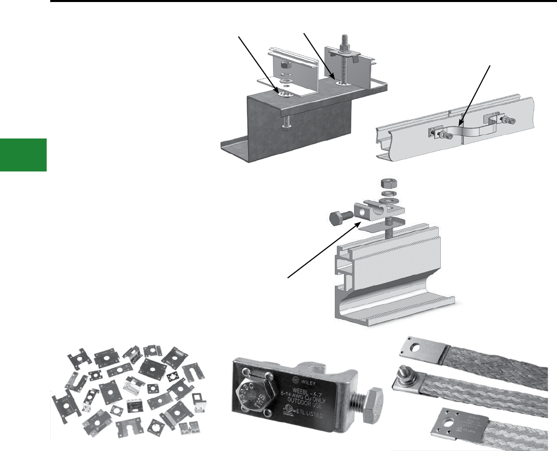
BURNDY®
Blue highlighted items are industry standard and most frequently ordered.
US: 1-800-346-4175 www.burndy.com Canada: 1-800-387-6487
WEEB™ Washers and other
products for Solar Photovoltaic
applications
WILEY is most widely recognized for the invention
of the WEEB™ Washer (Washer, Electrical
Equipment Bond). WILEY has always been
dedicated to developing and providing innovative,
high-quality solutions that address the evolving
needs of the PV industry in bonding, grounding,
and wire management. Our engineers work
closely with solar manufacturers and installers, and
develop products to enable customers to install PV
systems safely, efciently, and cost effectively.
BURNDY now offers the complete line of unique
solutions for Balance of System components for
photovoltaic applications.
For system compatibility please check the website:
www.we-llc/technical.html .
WEEB™
Washer, Electrical Equipment Bond
• Bonds PV modules to mounting structures
• Specialized teeth on washer embeds into
anodized aluminum to establish gas-tight
electrical connection
• Corrosion resistant 304 Stainless Steel
• Stock parts for most popular mounting
systems
• Custom WEEB™ washer designs available
• ETL Listed to UL 467
• UL Recognized to UL 2703
WEEB™ Lug
• Corrosion resistant, tin plated, copper lay-in
lug
• Features WEEB™ washer technology
• Available assembled or unassembled
• ETL Listed to UL 467
WEEB™ Bonding Jumper
• Corrosion resistant, tin plated, copper braid
• Maintains electrical bond across spliced
rails
• Features WEEB™ washer technology
• Equivalent to #6 AWG copper conductor
• Available assembled or unassembled
• ETL Listed to UL 467
WEEB-DSK516
Installed on a purlin.
WEEB-LUG-6.7
Installed on the channel
of a mounting rail.
WEEB-BNDJMP6.7
Installed on a mounting rail.
WEEB-LUG-6.7
Blue highlighted items are industry standard and most frequently ordered.
US: 1-800-346-4175 www.burndy.com Canada: 1-800-387-6487
Grounding
WILEY PV Solutions
E-32
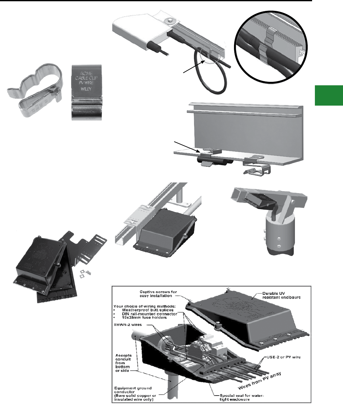
BURNDY®
Blue highlighted items are industry standard and most frequently ordered.
Canada: 1-800-387-6487 www.burndy.com US: 1-800-346-4175
WEEB™ Washers and other
products for Solar Photovoltaic
applications
Cable Clips
• Attaches to module frames or racking
systems
• Corrosion resistant 304 Stainless Steel
• Easy installation and removal
• Prevents damage to cables
• Sized for USE-2, PV, and Micro Inverter
cable leads
Conduit Entry Box
• Pass-through or combiner box with
mounting bracket
• Compatible with a variety of conduit
• Two-piece protective enclosure for
transitioning PV array wire to other wiring
means
• ETL Listed to UL 1741 Listed
• NEMA 3R outdoor rated
• Available up to 4 strings
Rail Mounted Pole Mounted
ACC-R2
Used to hold leads from a
Micro Inverter.
ACC-F90
Used to hold USE-2 or PV
wire. Mounts to module
frame in either a vertical or
horizontal orientation.
Blue highlighted items are industry standard and most frequently ordered.
Canada: 1-800-387-6487 www.burndy.com US: 1-800-346-4175
E-33
Grounding
WILEY PV Solutions
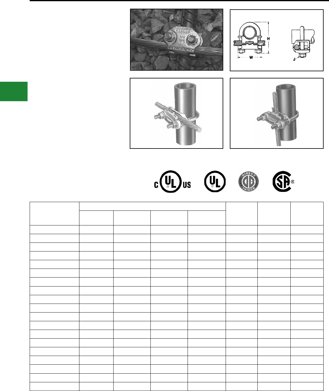
BURNDY®
Blue highlighted items are industry standard and most frequently ordered.
US: 1-800-346-4175 www.burndy.com Canada: 1-800-387-6487
Grounding
Mechanical
TYPE GAR
For Parallel or 90° Copper Cable
Connection to Rod or Pipe with the
Same Connector
High copper alloy ground connector for joining a
range of cable, parallel or at right angles to rod or
tube. Especially good for fence posts. High copper
alloy cast body with DURIUM™ U-bolts, nuts and
lockwashers, permit entire connection to be buried
in ground or concrete without danger of corrosion.
Features & Benets
• Wire to Rebar
• Fence Post Grounding Connector
• Wire to Pipe
• One-wrench installation
• UL467 Listed
• Acceptable for direct burial Wire at Right Angle to Pipe Wire Parallel to Pipe
Catalog Number
Conductor
H J W
Tube I.P.S.* Rod Size or
O.D. Range Rebar Size Cable Range
GAR114C 1/4 1/2 — 8 Sol. - 4 Str. 2-1/2 3/8 1-7/8
GAR1126 1/4 1/2 — 4 Sol. - 2/0 Str. 2-1/2 3/8 1-7/8
GAR1129 1/4 1/2 — 2/0 Sol. - 250 2-1/2 3/8 1-7/8
GAR644C 3/8 5/8 - 3/4 5 - 6 8 Sol. - 4 Str. 2-7/8 3/8 2-1/8
GAR6426 3/8 5/8 - 3/4 5 - 6 4 Sol. - 2/0 Str. 2-7/8 3/8 2-1/8
GAR6429 3/8 5/8 - 3/4 5 - 6 2/0 Sol. - 250 2-7/8 3/8 2-1/8
GAR6434 3/8 5/8 - 3/4 5 - 6 300-500 3-1/2 1/2 2-1/2
GAR144C 1/2-3/4 7/8 - 1 7 - 8 8 Sol. - 4 Str. 2-3/4 3/8 2-3/8
GAR1426 1/2-3/4 7/8 - 1 7 - 8 4 Sol. - 2/0 Str. 3 3/8 2-3/8
GAR1429 1/2-3/4 7/8 - 1 7 - 8 2/0 Sol. - 250 3 3/8 2-3/8
GAR1434 1/2-3/4 7/8 - 1 7 - 8 300-500 3-3/4 1/2 2-3/4
GAR154C 1 1-1/8 - 1-1/4 9 - 10 8 Sol. - 4 Str. 2-7/8 3/8 2-5/8
GAR1526 1 1-1/8 - 1-1/4 9 - 10 4 Sol. - 2/0 Str. 2-7/8 3/8 2-5/8
GAR1529 1 1-1/8 - 1-1/4 8 - 9 2/0 Sol. - 250 3-3/8 3/8 2-5/8
GAR1534 1 1-1/8 - 1-1/4 9 - 10 300-500 4-1/2 1/2 2-5/8
GAR164C 1-1/4 1-3/8 - 1-1/2 11 8 Sol. - 4 Str. 3-1/2 3/8 3
GAR1626 1-1/4 1-3/8 - 1-1/2 11 4 Sol. - 2/0 Str. 3-1/2 3/8 3
GAR1629 1-1/4 1-3/8 - 1-1/2 11 2/0 Sol. - 250 3-1/2 3/8 3
GAR1634 1-1/4 1-3/8 - 1-1/2 11 300-500 4-1/4 1/2 3-3/8
* This is the “Trade” Pipe Size reference.
E-34
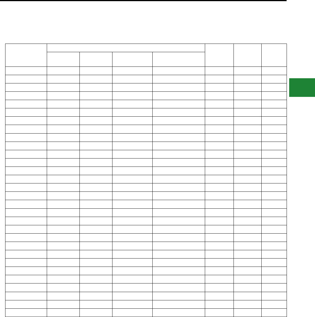
BURNDY®
Blue highlighted items are industry standard and most frequently ordered.
Canada: 1-800-387-6487 www.burndy.com US: 1-800-346-4175
Grounding
Mechanical
TYPE GAR
(Continued)
Catalog Number
Conductor
H J W
Tube I.P.S.* Rebar Size Rod Size or
O.D. Range Cable Range
GAR174C 1-1/2 — 1-5/8 - 1-7/8 8 Sol. - 4 Str. 4 3/8 3-1/4
GAR1726 1-1/2 — 1-5/8 - 1-7/8 4 Sol. - 2/0 Str. 4 3/8 3-1/4
GAR1729 1-1/2 — 1-5/8 - 1-7/8 2/0 Sol. - 250 4 3/8 3-1/4
GAR1734 1-1/2 — 1-5/8 - 1-7/8 300 - 500 4-5/8 1/2 2-5/8
GAR184C 2 — 2-2 - 3/8 8 Sol. - 4 Str. 4-1/4 3/8 3-3/4
GAR1826 2 — 2-2 - 3/8 4 Sol. - 2/0 Str. 4-1/4 3/8 3-3/4
GAR1829 2 — 2-2 - 3/8 2/0 Sol. - 250 4-1/2 3/8 3-3/4
GAR1834 2 — 2-2 - 3/8 300 - 500 5-1/4 1/2 4-1/8
GAR194C 2-1/2 — 2-1/2 - 2-7/8 8 Sol. - 4 Str. 5 3/8 4-1/4
GAR1926 2-1/2 — 2-1/2 - 2-7/8 4 Sol. - 2/0 Str. 5 3/8 4-1/4
GAR1929 2-1/2 — 2-1/2 - 2-7/8 2/0 Sol. - 250 5 3/8 4-1/4
GAR1934 2-1/2 — 2-1/2 - 2-7/8 300 - 500 5-5/8 1/2 4-5/8
GAR204C 3 — 3 - 3-1/2 8 Sol. - 4 Str. 5-5/8 3/8 4-3/4
GAR2026 3 — 3 - 3-1/2 4 Sol. - 2/0 Str. 5-5/8 3/8 4-3/4
GAR2029 3 — 3 - 3-1/2 2/0 Sol. - 250 5-5/8 3/8 4-3/4
GAR2034 3 — 3 - 3-1/2 300 - 500 6-3/8 1/2 5-1/4
GAR214C 3-1/2 — 3-1/2 - 4 8 Sol. - 4 Str. 6-1/4 3/8 5-3/8
GAR2126 3-1/2 — 3-1/2 - 4 4 Sol. - 2/0 Str. 6-1/4 3/8 5-3/8
GAR2129 3-1/2 — 3-1/2 - 4 2/0 Sol. - 250 6-1/4 3/8 5-3/8
GAR2134 3-1/2 — 3-1/2 - 4 300 - 500 6-3/4 1/2 5-3/4
GAR224C 4 — 4 - 4-1/2 8 Sol. - 4 Str. 6-3/8 3/8 5-7/8
GAR2226 4 — 4 - 4-1/2 4 Sol. - 2/0 Str. 6-3/8 3/8 5-7/8
GAR2229 4 — 4 - 4-1/2 2/0 Sol. - 250 6-3/8 3/8 5-7/8
GAR2234 4 — 4 - 4-1/2 300 - 500 6-7/8 1/2 6-1/4
GAR244C 5 — — 8 Sol. - 4 Str. 7-3/4 3/8 6-7/8
GAR2426 5 — — 4 Sol. - 2/0 Str. 7-3/4 3/8 6-7/8
GAR2429 5 — — 2/0 Sol. - 250 7-3/4 3/8 7-1/4
GAR2434 5 — — 300 - 500 8-5/8 1/2 7-1/4
GAR8629 6 — — 2/0 Sol. - 250 8-13/16 1/2 8-3/8
GAR8634 6 — — 300 - 500 8-13/16 1/2 8-3/8
* This is the “Trade” Pipe Size reference.
NOTE:
Contact BURNDY® for additional pipe and wire size combinations not shown.
E-35
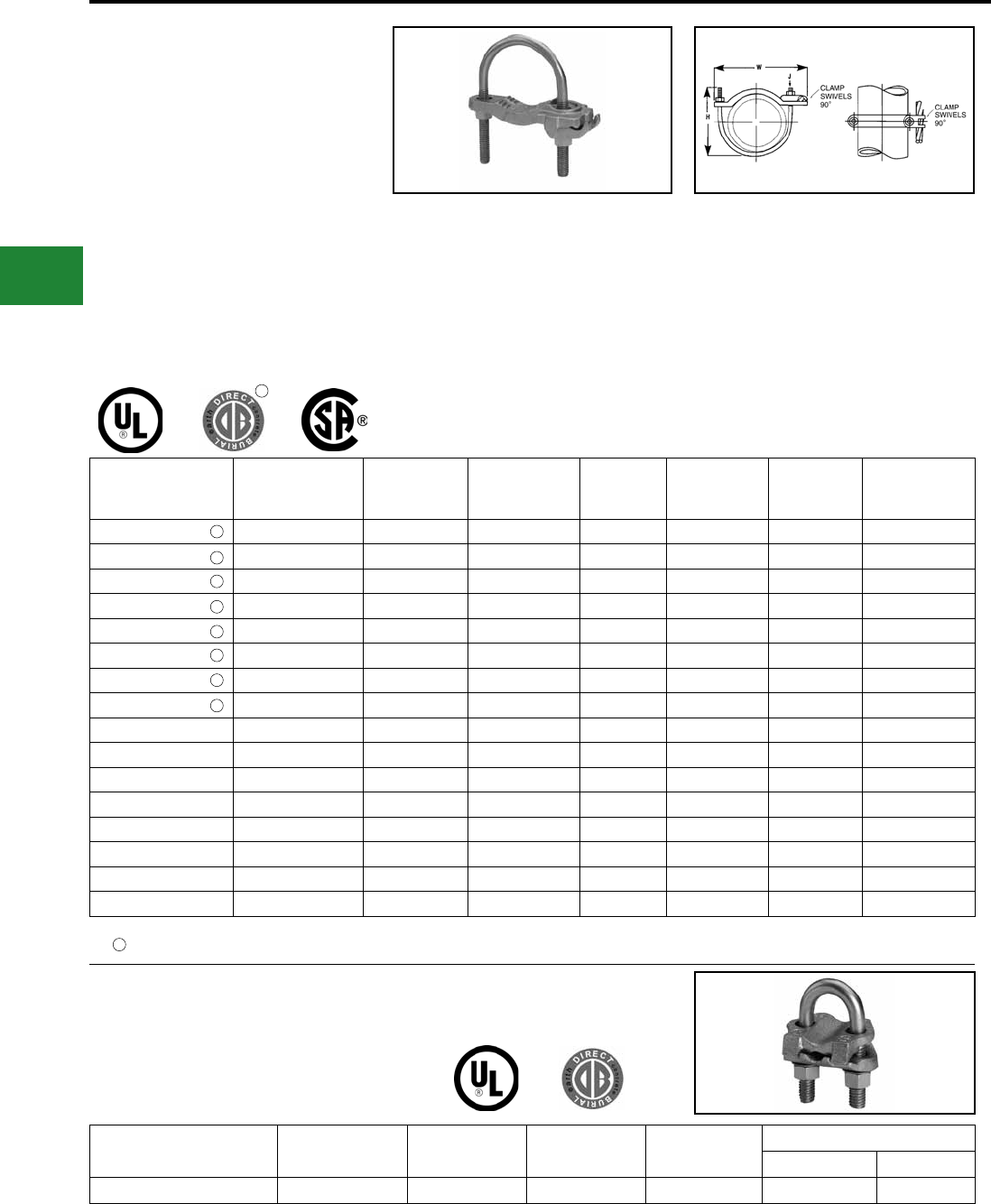
BURNDY®
Blue highlighted items are industry standard and most frequently ordered.
US: 1-800-346-4175 www.burndy.com Canada: 1-800-387-6487
Grounding
Mechanical
TYPES GAR-BU AND
GAR3902 SERIES
Ground Connectors
Type GAR-BU is a high-conductivity copper ground
connector for connecting a small to medium range
copper ground conductor to water pipe as well as
structural and reinforcing rod shapes. Universal
acceptance of several sizes of cylindrical shapes
makes this suitable for industrial construction and
maintenance work as well as cathodic protection.
Cable clamp swivels to permit parallel grounding
of one pipe or 90° degree cable run for grounding
several parallel pipes. Single wrench installation.
UL467 Listed and CSA Certied.
Catalog
Number Cable Range IPS Size ** O.D. Range H J W
Recommended
Tightening
Torque
GAR3902-BU #4- 4/0 AWG 1/2-1 0.84 - 1.32 3.50 3/8" - 16 3.25 240 in. - lbs.
GAR3903-BU #4- 4/0 AWG 1 1/4-2 1.66 - 2.38 4.00 3/8" - 16 4.25 240 in. - lbs.
GAR3904-BU #4- 4/0 AWG 2 1/2-3 1/2 2.88 - 4.00 6.50 3/8" - 16 6.00 240 in. - lbs.
GAR3905-BU #4- 4/0 AWG 4-5 4.50 - 5.56 7.50 3/8" - 16 7.50 240 in. - lbs.
GAR3906-BU #4- 4/0 AWG 6 6.62 8.50 3/8" - 16 8.62 240 in. - lbs.
GAR3907-BU #4- 4/0 AWG 8 8.62 10.00 3/8" - 16 10.62 240 in. - lbs.
GAR3908-BU #4- 4/0 AWG 10 10.75 12.00 3/8" - 16 12.75 240 in. - lbs.
GAR3909-BU #4- 4/0 AWG 12 12.75 14.00 3/8" - 16 14.75 240 in. - lbs.
GAR3902 #4- 4/0 AWG 1/2-1 0.84 - 1.32 3.50 3/8" - 16 3.25 240 in. - lbs.
GAR3903 #4- 4/0 AWG 1 1/4-2 1.66 - 2.38 4.00 3/8" - 16 4.25 240 in. - lbs.
GAR3904 #4- 4/0 AWG 2 1/2-3 1/2 2.88 - 4.00 6.50 3/8" - 16 6.00 240 in. - lbs.
GAR3905 #4- 4/0 AWG 4-5 4.50 - 5.56 7.50 3/8" - 16 7.50 240 in. - lbs.
GAR3906 #4- 4/0 AWG 6 6.62 8.50 3/8" - 16 8.62 240 in. - lbs.
GAR3907 #4- 4/0 AWG 8 8.62 10.00 3/8" - 16 10.62 240 in. - lbs.
GAR3908 #4- 4/0 AWG 10 10.75 12.00 3/8" - 16 12.75 240 in. - lbs.
GAR3909 #4- 4/0 AWG 12 12.75 14.00 3/8" - 16 14.75 240 in. - lbs.
Features & Benets
• Cable clamp swivels at 90°
◊ Permits parallel grounding of one pipe or a
90° cable run for grounding several parallel
pipes.
• One-wrench installation
◊ Simplied installation.
• DURIUM™ silicon bronze hardware (-BU Series)*
◊ Long lasting corrosion resistance and
acceptable for direct burial in earth or
concrete.
• UL467 Listed
◊ Provides quality assurance to
recognized industry NEC standards
from an independent party.
NOTE:
Type GAR-BU is supplied with DURIUM™ silicon bronze hardware and is Listed for direct burial.
** Refer to Section O for tube dimensions.
1
TYPE GAR-RB
For Reinforcement Bar
Catalog
Number Rebar I.P.S. O.D. Range Rod Size Copper Conductor
Min. Max.
GAR644C-RB #3 - 6 (0.38 - 0.75) 3/8 0.63 - 0.75 5/8-3/4 8 Sol. 4 Str.
NOTE:
UL 467 Listed for direct burial in earth or concrete.
1
1
1
1
1
1
1
1
1
E-36
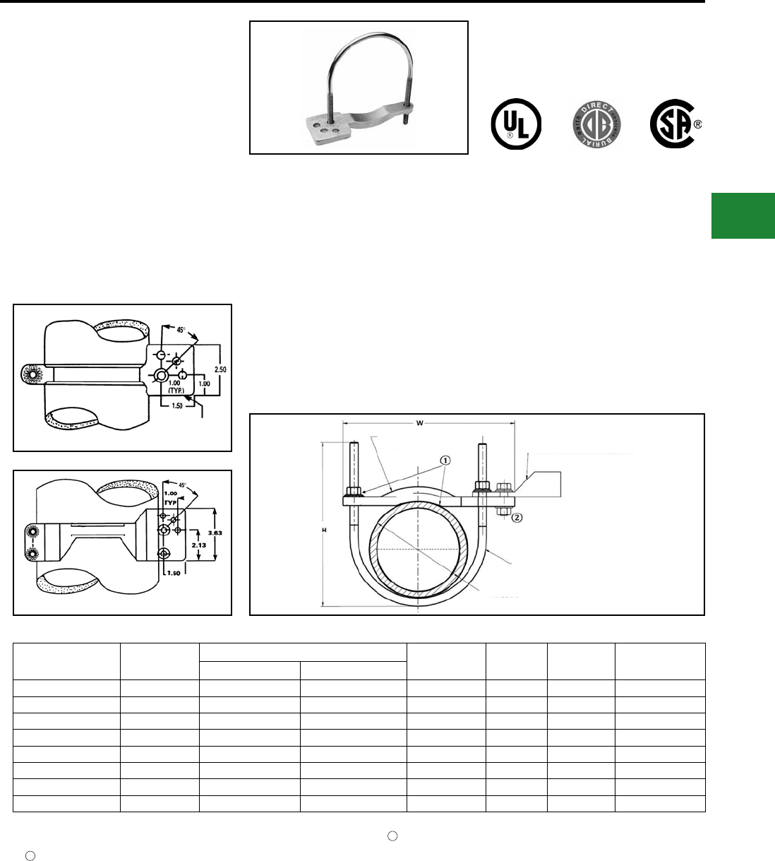
BURNDY®
Blue highlighted items are industry standard and most frequently ordered.
Canada: 1-800-387-6487 www.burndy.com US: 1-800-346-4175
Grounding
Mechanical
TYPE GAR-TC
Water Pipe
Ground Connector
Type GAR-TC is a high-conductivity copper
ground connector that features a pre-drilled
pad, allowing a 2-hole compression terminal to
be directly connected to water pipe as well as
structural and reinforcing rod shapes. Universal
acceptance of several sizes of cylindrical shapes
makes this suitable for industrial construction and
maintenance work as well as telecommunications
grounding. Terminal may be mounted parallel, 45°
or 90° degrees to the pipe. Acceptable for direct
burial.
Catalog
Number Figure # Accommodates H J W Recommended
Torque
I.P.S. ** O.D. Size
GAR3902TC 1 1/2-1 0.84 - 1.32 3.50 3/8 3.75 240
GAR3903TC 1 1 1/4-2 1.66 - 2.38 4.00 3/8 4.75 240
GAR3904TC 1 2 1/2-3 1/2 2.88 - 4.00 6.50 3/8 6.50 240
GAR3905TC 1 4-5 4.50 - 5.56 7.50 3/8 8.00 240
GAR3906TC 1 6 6.62 8.50 3/8 9.12 240
GAR3907TC 2 8 8.62 10.00 3/8 11.25 240
GAR3908TC 2 10 10.75 12.00 3/8 13.25 240
GAR3909TC 2 12 12.75 14.00 3/8 15.25 240
Features & Benets
• Large, smooth connector contact area
between pipe and ground clamp
◊ Provides large surface contact area to
maximize contact area between
connector and pipe.
• The GAR-TC mounting pad permits
parallel, 45° or 90° angle connections to
the pipe
◊ Provides maximum exibility for eld installation.
• Pre-drilled pad for (2) 3/8" bolts on 1"
centers
◊ Allows direct mounting of (2) hole
compression terminals up to 750 kcmil
to pipe.
• DURIUM™ silicon bronze hardware
◊ Provide long lasting corrosion
resistance acceptable for direct burial
in earth or concrete.
• One-wrench installation
◊ Simplied installation.
• UL467 Listed
◊ Provides quality assurance to
recognized industry NEC standards
from an independent party. Type
GAR-TC is acceptable for direct burial.
Fig. 1
Fig. 2
MOUNTING PAD
FOR (2) 3/8
BOLTS - 1" centers
PATENTED
NOTES:
** Refer to Section O for tube dimensions.
Add sufx “-TNET” for electro-tin plated connector and
electro-tin plated
DURIUM™ silicon bronze hardware. Tin plated catalog
number includes mounting hardware for second bolt hole.
OPTIONAL MOUNTING HARDWARE
TMH-289 includes (1) 38X125HEB bolt, (1) 38CHEN nut,
(1) 38SW split washer and (2) 38FW at washers, ordered
separately.
Clean pipe surface beneath saddle until virgin metal is exposed,
install GAR-TC ground connector and for maximum conductivity,
apply PENETROX™ E oxide inhibiting compound around
perimeter of saddle.
1
2
COMPRESSION LUG WITH PAD
FOR (2) 3/8″ Dia. BOLTS
ON 1 CENTERS. 750 KCMIL MAX.
J
MOUNTING PAD
DURIUM 3/8″
SILICON BRONZE
HARDWARE
PIPE Dia.
CAST HIGH COPPER ALLOY
SADDLE
E-37
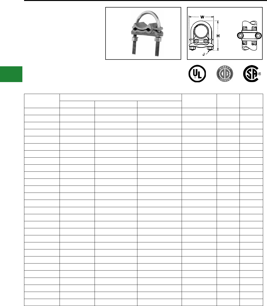
BURNDY®
Blue highlighted items are industry standard and most frequently ordered.
US: 1-800-346-4175 www.burndy.com Canada: 1-800-387-6487
Grounding
Mechanical
TYPE GD
Cable to Rod/Tube Ground
Connector
For Two Copper Cables
to Rod or Tube
High copper alloy ground connector for
joining a range of two parallel cables
to rod or pipe. Especially good for
grounding fence posts. High copper
alloy cast body with DURIUM™ U-bolts,
Catalog
Number
Conductor H J W
Tube I.P.S. ** Rod Size or O.D. Range Cable
GD1526 1 1-1/8 - 1-1/4 4 Sol. - 2/0 Str. 3-3/8 3/8 2-5/8
GD1529 1 1-1/8 - 1-1/4 2/0 Sol. - 250 3-3/8 3/8 2-5/8
GD1626 1-1/4 1-3/8 - 1-1/2 4 Sol. - 2/0 Str. 3-1/2 3/8 3
GD1629 1-1/4 1-3/8 - 1-1/2 2/0 Sol. - 250 3-1/2 3/8 3-1/4
GD174C 1-1/2 1-5/8 - 1-7/8 8 Sol. - 4 Str. 4 3/8 3-1/4
GD1726 1-1/2 1-5/8 - 1-7/8 4 Sol. - 2/0 Str. 4 3/8 3-1/4
GD1729 1-1/2 1-5/8 - 1-7/8 2/0 Sol. - 250 4 3/8 3-1/4
GD1734 1-1/2 1-5/8 - 1-7/8 300 - 500 4-5/8 1/2 3-5/8
GD184C 2 2 - 2-3/8 8 Sol. - 4 Str. 4-3/8 3/8 3-3/4
GD1826 2 2 - 2-3/8 4 Sol. - 2/0 Str. 4-3/8 3/8 3-3/4
GD1829 2 2 - 2-3/8 2/0 Sol. - 250 4-3/8 3/8 3-3/4
GD1834 2 2 - 2-3/8 300 - 500 5-3/8 1/2 4-1/8
GD194C 2-1/2 2-1/2 - 2-7/8 8 Sol. - 4 Str. 5 3/8 4-1/4
GD1926 2-1/2 2-1/2 - 2-7/8 4 Sol. - 2/0 Str. 5 3/8 4-1/4
GD1929 2-1/2 2-1/2 - 2-7/8 2/0 Sol. - 250 5 3/8 4-1/4
GD1934 2-1/2 2-1/2 - 2-7/8 300 - 500 5 1/2 4-5/8
GD204C 3 3 - 3-1/2 8 Sol. - 4 Str. 5-5/8 3/8 4-7/8
GD2026 3 3 - 3-1/2 4 Sol. - 2/0 Str. 5-5/8 3/8 4-7/8
GD2029 3 3 - 3-1/2 2/0 Sol. - 250 5-5/8 3/8 4-7/8
GD2034 3 3 - 3-1/2 300 - 500 6-3/8 1/2 5-1/4
GD214C 3-1/2 3-1/2 - 4 8 Sol. - 4 Str. 6-1/4 3/8 5-3/8
GD2126 3-1/2 3-1/2 - 4 4 Sol. - 2/0 Str. 6-1/4 3/8 5-3/8
GD2129 3-1/2 3-1/2 - 4 2/0 Sol. - 250 6-1/4 3/8 5-3/8
GD2134 3-1/2 3-1/2 - 4 300 - 500 6-7/8 1/2 5-3/4
GD224C 4 4 - 4-1/2 8 Sol. - 4 Str. 6-3/8 3/8 5-7/8
GD2226 4 4 - 4-1/2 4 Sol. - 2/0 Str. 6-3/8 3/8 5-7/8
GD2229 4 4 - 4-1/2 2/0 Sol. - 250 6-3/8 3/8 5-7/8
GD2234 4 4 - 4-1/2 300 - 500 6-7/8 1/2 6-1/4
nuts, and lockwashers make the GD
suitable for burial in ground or concrete.
One-wrench installation. UL467 Listed.
Acceptable for direct burial in earth or
concrete.
NOTE:
** Refer to Section O for tube dimensions.
Complies with NFPA 78-86 HEAVY DUTY stacks; use sufx “-LD”
for lead plating for HEAVY DUTY stack applications
E-38
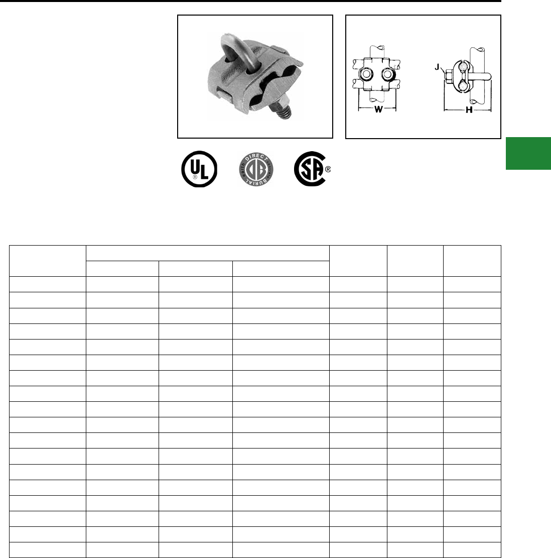
BURNDY®
Blue highlighted items are industry standard and most frequently ordered.
Canada: 1-800-387-6487 www.burndy.com US: 1-800-346-4175
Grounding
Mechanical
TYPE GP
Ground Connector
For Two Copper Cables to Rod
or Pipe
High copper alloy ground connector for joining
a range of parallel cables perpendicular to rod,
pipe or column. Also used with one groove for
run, the other for tap to equipment. High copper
alloy cast body and DURIUM™ U-bolts, nuts, and
lockwashers make the GP suitable for direct burial
in the ground or concrete. One-wrench installation.
UL467 Listed. Acceptable for direct burial in earth
or concrete.
Catalog
Number
Conductor H J W
Tube I.P.S. ** O.D. Size Cable
GP114C 1/4 1/2 8 Sol. - 4 Str. 2-1/2 3/8 1-7/8
GP1126 1/4 1/2 4 Sol. - 2/0 Str. 2-1/2 3/8 1-7/8
GP1129 1/4 1/2 2/0 Sol. - 250 2-1/2 3/8 1-7/8
GP644C 3/8 5/8 - 3/4 8 Sol. - 4 Str. 2-1/2 3/8 2-1/8
GP6426 3/8 5/8 - 3/4 4 Sol. - 2/0 Str. 2-1/2 3/8 2-1/8
GP6429 3/8 5/8 - 3/4 2/0 Sol. - 250 2-7/8 3/8 2-1/8
GP6434 3/8 5/8 - 3/4 300 - 500 3-1/2 1/2 2-5/9
GP144C 1/2-3/4 7/8 - 1 8 Sol. - 4 Str. 2-3/4 3/8 2-3/8
GP1426 1/2-3/4 7/8 - 1 4 Sol. - 2/0 Str. 3 3/8 2-3/8
GP1429 1/2-3/4 7/8 - 1 3/0 Sol. - 250 3 3/8 2-3/8
GP1434 1/2-3/4 7/8 - 1 300 - 500 3-3/4 1/2 2-5/9
GP164C 1-1/4 1-5/8 8 Sol. - 4 Str. 3-1/2 3/8 3
GP1629 1-1/4 1-5/8 2/0 Sol. - 250 3-1/2 3/8 3
GP1726 1-1/2 1-7/8 4 Sol. - 2/0 Str. 4 3/8 3-1/4
GP184C 2 2-3/8 8 Sol. - 4 Str. 4-1/8 3/8 3-11/16
GP1826 2 2-3/8 4 Sol. - 2/0 Str. 4-3/8 3/8 3-11/16
GP2026 3 3-1/2 4 Sol. - 2/0 Str. 5-1/2 3/8 4-13/16
GP2226 4 4-1/2 4 Sol. - 2/0 Str. 6-3/8 3/8 5-13/16
NOTE:
** Refer to Section O for tube dimensions.
E-39
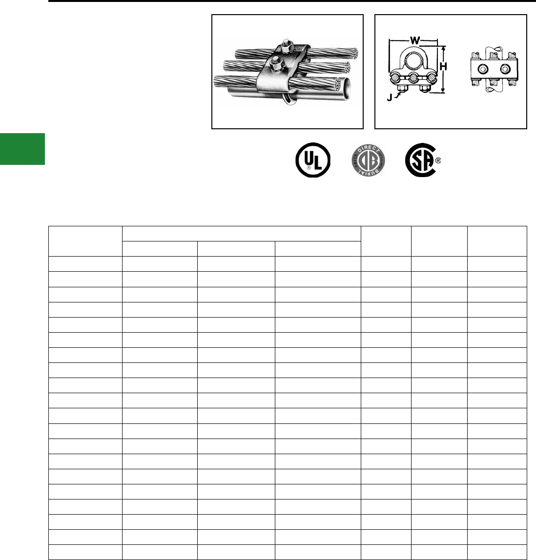
BURNDY®
Blue highlighted items are industry standard and most frequently ordered.
US: 1-800-346-4175 www.burndy.com Canada: 1-800-387-6487
Grounding
Mechanical
TYPE GK
Ground Connector
For Three Copper Cables
to Rod or Pipe
High copper alloy ground connector for joining
three equal cables to rod or tube. Cable grooves
take a wide range of cable. High copper alloy
cast body and DURIUM™ U-bolts, nuts, and
lockwashers make the GK suitable for direct
burial in soil or concrete. One-wrench installation.
UL467 Listed. Acceptable for direct burial in earth
or concrete.
Catalog
Number
Conductor H J W
Tube I.P.S. ** O.D. Size Cable
GK114C 1/4 1/2 8 Sol. - 4 Str. 2-1/2 3/8 2-1/2
GK1126 1/4 1/2 4 Sol. - 2/0 Str. 2-1/2 3/8 2-3/4
GK1129 1/4 1/2 2/0 Sol. - 250 2-1/2 1/2 3-3/8
GK644C 3/8 5/8 - 3/4 8 Sol. - 4 Str. 2-7/8 3/8 2-5/8
GK6426 3/8 5/8 - 3/4 4 Sol. - 2/0 Str. 2-7/8 3/8 3
GK6429 3/8 5/8 - 3/4 2/0 Sol. - 250 2-7/8 1/2 3-1/2
GK6434 3/8 5/8 - 3/4 300 - 500 3-1/2 1/2 4
GK1426 1/2 - 3/4 7/8 - 1 4 Sol. - 2/0 Str. 2-3/4 3/8 3-1/4
GK1429 1/2 - 3/4 7/8 - 1 2/0 Sol. - 250 3-3/4 1/2 3-7/8
GK1434 1/2 - 3/4 7/8 - 1 300 - 500 3-3/4 1/2 4-3/8
GK1526 1 1-1/8 - 1-1/4 4 Sol. - 2/0 Str. 3-3/8 3/8 3-1/2
GK1529 1 1-1/8 - 1-1/4 2/0 Sol. - 250 3-3/4 1/2 4-1/8
GK1626 1-1/4 1-3/8 - 1-1/2 4 Sol. - 2/0 Str. 3-1/2 3/8 3-7/8
GK1629 1-1/4 1-3/8 - 1-1/2 2/0 Sol. - 250 4-1/4 1/2 4-1/2
GK1726 1-1/2 1-5/8 - 1-7/8 4 Sol. - 2/0 Str. 4 3/8 4-1/8
GK1729 1-1/2 1-5/8 - 1-7/8 2/0 Sol. - 250 4-5/8 1/2 4-3/4
GK1826 2 2 - 2-3/8 4 Sol. - 2/0 Str. 4-1/4 3/8 4-5/8
GK1829 2 2 - 2-3/8 2/0 Sol. - 250 4-3/8 1/2 5-1/8
GK1926 2-1/2 2-1/2 - 2-7/8 4 Sol. - 2/0 Str. 5 3/8 5-1/8
GK1929 2-1/2 2-1/2 - 2-7/8 2/0 Sol. - 250 5 1/2 5-5/8
NOTE:
** Refer pages to Section-O for tube dimensions.
E-40
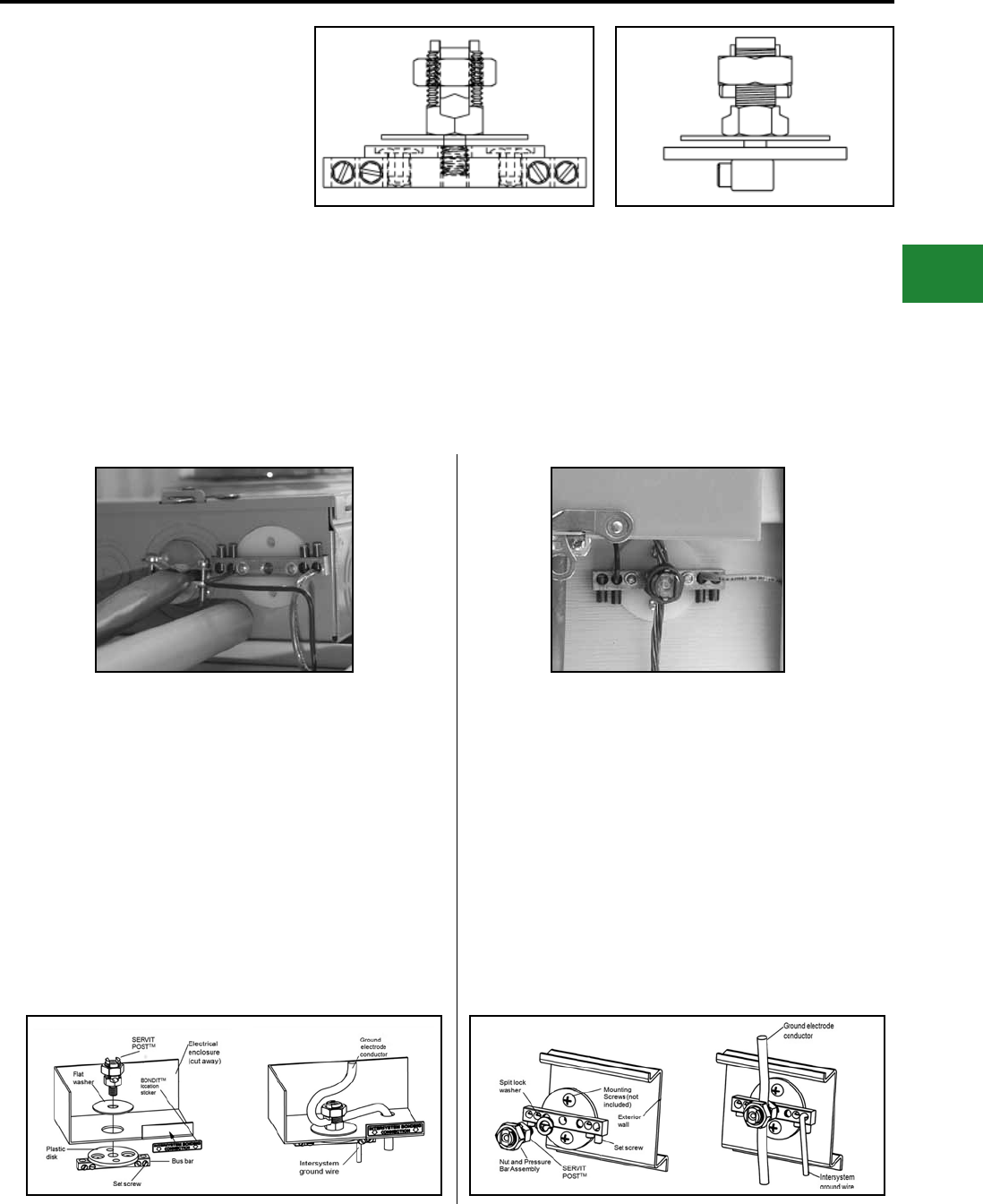
BURNDY®
Blue highlighted items are industry standard and most frequently ordered.
Canada: 1-800-387-6487 www.burndy.com US: 1-800-346-4175
Grounding
Mechanical
TYPE BDT
BONDIT® INTERSYSTEM
BONDING CONNECTOR
House Mounted or
Meter Socket Mounted
Designed to meet the requirements of NEC Article
250.94 “Bonding for Other Systems”. Corrosion-
resistant stainless steel set screws. Accepts main
ground wire (#2-#8) and up to 4 intersystem wires
(#6-#14). Same design can be mounted directly
to the meter socket or mounted to the house.
Innovative design does not damage meter socket
and will not void warranty.
Catalog Number: BDT1
Features & Benets
• Made in the USA!
• Meets Intersystem Bonding Requirements;
NEC 250.94
• One connector does it all
• House mount or meter socket mount
• Incorporates proven BURNDY® SERVIT
POST™ design
• Stainless steel set screws
• Accepts main ground wire (#2-#8), up to 4
intersystem wires (#6-#14)
• Easily mounts to meter box during new
installation or can be wall mounted
• Easy to follow instructions included
• Does not damage meter socket; no worries
about damaging the paint or voiding warranties
• Easily installed with a wrench and screwdriver
• Open design prevents buildup of hornets,
bees, spiders
CONFIGURATION 1 - MOUNTED TO ENCLOSURE
1. Punch out a 1/2" or 3/4" knock out on the electrical enclosure.
2. Begin assembly by installing the ground electrode conductor in
the SERVIT POST™ inside the electrical enclosure. Torque on
SERVIT® NUT: 275 in-lb max.
3. Install the rest of the connector shown below, it is not necessary
for the bus bar to be aligned parallel with the enclosure. (Note:
the split washer is not used in this conguration.)
4. Tighten the intersystem ground wires with set screws in the bus
bar to a maximum torque of 35 in-lb.
5. Adhere the BONDIT® location sticker to the front of the electrical
enclosure.
CONFIGURATION 2 - MOUNTED TO EXTERIOR WALL
1. Begin by assembling the connector as shown in gure below.
Be sure SERVIT POST™ is as tight as it can be while its groove
is aligned with the ground electrode conductor. (Note: the at
washer is not used in this conguration.)
2. Use two mounting screws (not included) to secure the connector
to the exterior wall so that the set screws in the bus bar face
downward.
3. Install the ground electrode conductor into the SERVIT POST™
while turning the nut/pressure bar assembly to a maximum torque
of 275 in-lb (use 2 wrenches if necessary).
4. Tighten the intersystem ground wires with the set screws in the
bus bar to a maximum torque of 35 in-lb.
5. If hidden from view, use the BONDIT® location sticker to indicate
the location.
E-41
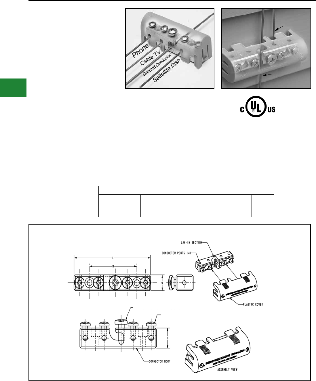
BURNDY®
Blue highlighted items are industry standard and most frequently ordered.
US: 1-800-346-4175 www.burndy.com Canada: 1-800-387-6487
Grounding
Mechanical
BONDIT® - Wall Mounted
Intersystem Bonding Connector
NEC 250.94 refers to a requirement in the 2008
National Electrical Code. In the past, gorund
wires from telephone systems or cable systems
were allowed to be grounded separately from the
GEC (Ground Electrode Conductor from the main
electrical service). With the new code, all ground
wires from separate systems such as telephone
systems, CATV and radio systems must be tied
together at one location to the GEC. Henc, the
term intersystem refers to tying all of the “system”
grounds together in one location. The BONDIT®-
Wall Mount is a great solution when the GEC is
exposed (not in conduit).
With the new BONDIT® - Wall Mount con-nector
BURNDY provides an economical solution that
meets the needs of NEC 250.94.
Catalog Number: BDTIBB
Catalog
Number
Conductor Range Reference Dimensions
Lay-In Section Conductor Ports L W H M
BDTIBB #6 - #2 AWG #14 - #4 AWG 3.99
[101]
0.71
[18]
0.91
[23]
2.46
[62]
Features & Benets
• Meets the Intersystem Bonding requirements
of NEC2008 250.94
• Provides an easy to access grounding point for
utilities such as telecom and cable
• Easy to install
• UL Listed and CSA Certied
• Tin-plated connector body provides long-
lasting corrosion resistance
• Stainless steel set screws
• Accepts main ground wire (#2 to #6), up to (4)
intersystem wires (#4 to #14)
• Supplied with durable cover, easily secured
over connector body
• Approved for use with solid or stranded
conductors
Intersystem
Ground Wire
(Ex.: Telephone)
Ground Coductor
(GEC)
STAINLESS STEEL SCREW
STAINLESS STEEL SCREW
(4 PLACES)
E-42
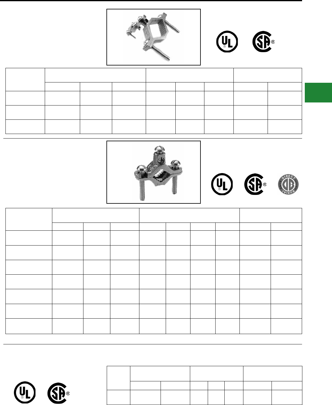
BURNDY®
Blue highlighted items are industry standard and most frequently ordered.
Canada: 1-800-387-6487 www.burndy.com US: 1-800-346-4175
Grounding
Mechanical
CAST BRONZE CLAMPS FOR
CONDUIT
Pressure bar type conduit hub adjusts for 1/2", 3/4"
EMT or 1/2" rigid conduit. Hub swings 360° for
easy alignment. Zinc plated hardware.
Catalog Number Accommodates Conductor Range Reference Dimensions Recommended Screw Torque
(Inch Pounds)
Water Pipe Ground Hub Size H L W Pipe Clamp Wire Clamp
C-11JPT 1/2 - 1
[13 - 25]
10 - 6
Sol.
1/2
[13]
2.07 in
[53]
3.19
[81]
2.70 in
[69] 50 in.-lb. 50 in.-lb.
C-22JPT 1-1/4 - 2
[32 - 51]
10 - 6
Sol.
1/2
[13]
2.70 in
[69]
3.83
[97]
2.70 in
[69] 50 in.-lb. 50 in.-lb.
C-4JPT 2-1/2 - 4
[64 - 102]
10 - 6
Sol.
1/2
[13]
4.39 in
[112]
5.15
[131]
2.70 in
[69] 50 in.-lb. 50 in.-lb.
CAST BRONZE GROUND
CLAMPS
For connecting grounding conductor to water pipe
or copper tube. “D” indicates UL467 Listed for
direct burial in earth and concrete and are supplied
with silicon bronze hardware. “B” indicates brass
hardware.
Catalog Number Accommodates Conductor Range Reference Dimensions Recommended Screw
Torque (Inch Pounds)
Water Pipe Rebar Ground H L W C Pipe Clamp Wire Clamp
C-11N 1/2 - 1
[13 - 25] — 10 - 2 Str. 1.81 in
[46]
2.25
[56]
0.63 in
[16]
0.63 in
[16] 50 in.-lb. 50 in.-lb.
C-11D 1/2 - 1
[13 - 25] #4 - #8 10 - 2 Str. 1.81 in
[46]
2.25
[56]
0.63 in
[16]
0.63 in
[16] 50 in.-lb. 50 in.-lb.
C-11B 1/2 - 1
[13 - 25] — 10 - 2 Str. 1.81 in
[46]
2.25
[56]
0.63 in
[16]
0.63 in
[16] 50 in.-lb. 50 in.-lb.
C-22*1-1/4 - 2
[32 - 51] — 10 - 2 Str. 2.38 in
[60]
3.63
[92]
0.75 in
[0.19]
1.00 in
[25] 50 in.-lb. 50 in.-lb.
C-22D 1-1/4 - 2
[32 - 51] — 10 - 2 Str. 2.38 in
[60]
3.63
[92]
0.75 in
[0.19]
1.00 in
[25] 50 in.-lb. 50 in.-lb.
C-4*2-1/2 - 4
[46 - 114] — 10 - 2 Str. 4.13 in
[105]
6.25
[159]
0.96 in
[24]
1.88 in
[48] 50 in.-lb. 50 in.-lb.
C-8* 4-1/2 - 6
[114 - 165] — 10 - 2 Str. 4.29 in
[109]
8.34
[212]
1.25 in
[32]
1.88 in
[48] 50 in.-lb. 50 in.-lb.
BUDGET PRICE CAST
BRONZE GROUND CLAMP
C5 similar to C11, but lighter duty.
Catalog
Number
Accommodates
Conductor Range Reference Dimensions Recommended Screw
Torque (Inch Pounds)
Water Pipe Ground H L W Pipe Clamp Wire Clamp
C-5 1/2 - 1
[13 -25] 10 - 2 Str. 1.56 in
[40]
2.25
[56]
0.56 in
[14] 50 in.-lb. 50 in.-lb.
* Supplied with zinc-plated steel hardware.
E-43
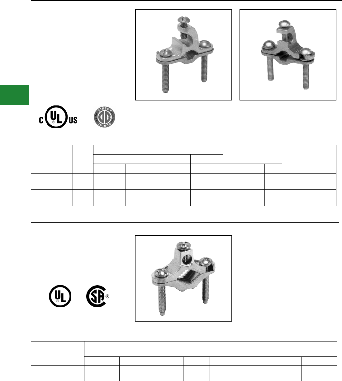
BURNDY®
Blue highlighted items are industry standard and most frequently ordered.
US: 1-800-346-4175 www.burndy.com Canada: 1-800-387-6487
Grounding
Mechanical
Cast Bronze Ground Clamps
With Lay-in Feature
For connecting grounding conductor to water pipe,
copper tube, ground rod or rebar. The open face
design allows for fast lay-in of the tap conductor
without the need for cutting. Simply reverse bottom
clamp for smaller size rebar or rod. Connectors are
provided with Silicon Bronze hardware.
Catalog
Number
Fig.
#
Accommodates Conductor Range Reference Dimensions Recommended Screw
Torque (Inch Pounds)
Main Tap
Water Pipe Rebar Ground Rod Ground H L W
C11K16D 11/2" - 1"
[13-25] #4 - #6 3/8" - 1" #10 - #2 Str. 1.64 2.28 0.66 50 in.-lbs.
C11K17D 21/2" - 1"
[13-25] #4 - #6 3/8" - 1" #10 - #2 Str. 1.64 2.28 0.66 50 in.-lbs.
Fig.1 Fig.2
DIE CAST CLAMPS
Die cast zinc with zinc plated screws.
Catalog Number
Accommodates Conductor
Range Reference Dimensions Recommended Screw Torque
(Inch Pounds)
Water Pipe Ground H L W C Pipe Clamp Wire Clamp
CZ-11 1/2" - 1"
[13-25] 10 - 2 Str. 1.56"
[40]
2.25"
[56]
0.56"
[14]
0.50"
[13] 50 in.-lb. 50 in.-lb.
E-44
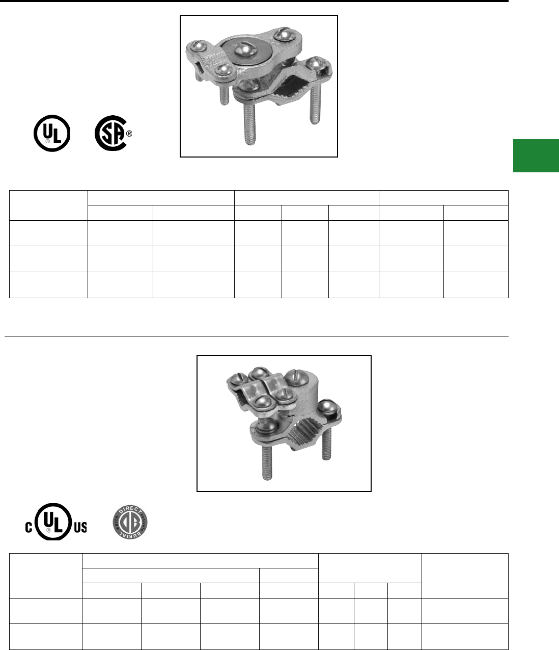
BURNDY®
Blue highlighted items are industry standard and most frequently ordered.
Canada: 1-800-387-6487 www.burndy.com US: 1-800-346-4175
Grounding
Mechanical
CAST BRONZE CLAMPS
To connect armored cable to water pipe. Zinc
plated screws. Pressure bar grips armor or
outer cable insulation. 360° swing hub for easy
alignment.
Catalog Number Accommodates Conductor Range Reference Dimensions Recommended Torque
Water Pipe Armored Conductor H L W Pipe Clamp Wire Clamp
C-11JA 1/2 - 1
[13-25] 10 - 6 Sol. 1.38"
[35]
3.05"
[77]
1.41"
[36] 50 in.-lb. 50 in.-lb.
C-22JA 1-1/4 - 2
[32-51] 10 - 6 Sol. 2.60"
[66]
3.69"
[94]
1.41"
[36] 50 in.-lb. 50 in.-lb.
C-4JA 2-1/2 - 4
[64-102] 10 - 6 Sol. 4.29"
[109]
5.01"
[128]
1.41"
[36] 50 in.-lb. 50 in.-lb.
CAST BRONZE GROUND
CLAMPS
For connecting grounding conductor, EMT
or rigid conduit to water pipe, copper tube,
ground rod or rebar. Hub swings 360° for
easy alignment. Simply reverse bottom clamp
for smaller size rebar or rod. Connectors are
provided with Silicon Bronze hardware.
Catalog Number
Accommodates Conductor Range Reference Dimensions Recommended Screw
Torque (Inch Pounds)
Main Tap
Water Pipe Rebar Ground Rod Ground H L W
C11HD4/0DB 1/2" - 1"
[13-25] #4 - #6 3/8" - 1" #8 - 4/0 AWG 2.25 2.65 1.56 50 in.-lbs.
C22HD4/0DB 1-1/4" - 2"
[32-51] — — #8 - 4/0 AWG 2.70 3.60 1.56 50 in.-lbs.
E-45
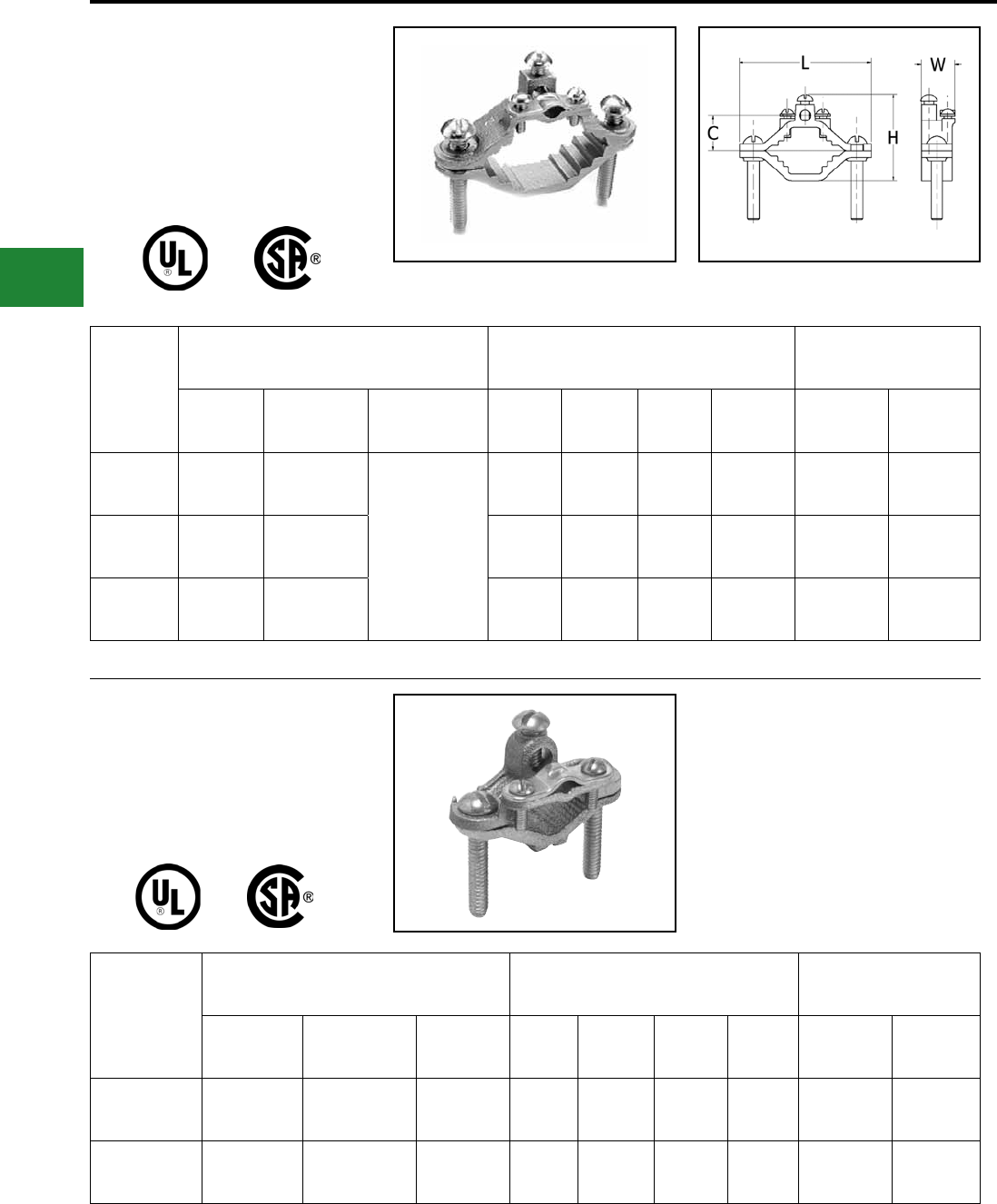
BURNDY®
Blue highlighted items are industry standard and most frequently ordered.
US: 1-800-346-4175 www.burndy.com Canada: 1-800-387-6487
Grounding
Mechanical
CAST BRONZE CLAMPS
GROUND CLAMP
For connecting armored cable to water pipe. Zinc
plated screws. “D” indicates UL467 for direct burial
in earth and concrete, supplied with silicon bronze
hardware.
Catalog
Number
Accommodates
Conductor Range Reference Dimensions Recommended Screw
Torque (Inch Pounds)
Water
Pipe Ground Ground
Clamp H L W C Pipe
Clamp
Wire
Clamp
C-6 1/2 - 1
[13-25] 10 - 2 Str.
Bare Armored
Unarmored
Wire Cables or
Cords
1.60"
[41]
2.34"
[59]
1.06"
[27]
0.63"
[16] 50 in.-lb. 50 in.-lb.
C-6D 1/2 - 1
[13-25] 10 - 2 Str. 1.60"
[41]
2.34"
[59]
1.06"
[27]
0.63"
[16] 50 in.-lb. 50 in.-lb.
C-7 1-1/4 - 2
[32-51] 10 - 2 Str. 2.38"
[60]
3.62"
[92]
0.94"
[24]
1.00"
[25] 50 in.-lb. 50 in.-lb.
CAST BRONZE
CLAMP FOR
RIGID CONDUIT
For grounding rigid conduit systems. Zinc plated
screws.
Catalog
Number
Accommodates Conductor Range Reference Dimensions Recommended Screw
Torque (Inch Pounds)
Water Pipe Ground Hub Size H L W C Pipe
Clamp
Wire
Clamp
C-61 1/2 - 1
[13-25] #6 Sol. Max. 1/2
[13]
2.07"
[53]
2.34"
[59]
1.34"
[34]
1.06"
[27] 50 in.-lb. 50 in.-lb.
C-66 1-1/4 - 2
[32-51] #6 Sol. Max. 1/2
[13]
2.69"
[68]
3.62"
[92]
1.34"
[34]
1.40"
[36] 50 in.-lb. 50 in.-lb.
E-46
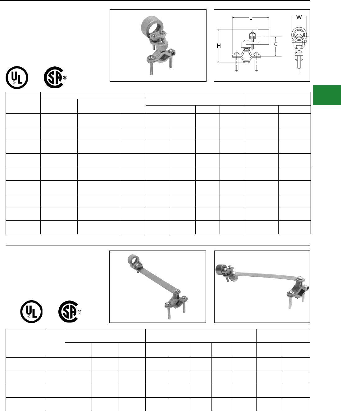
BURNDY®
Blue highlighted items are industry standard and most frequently ordered.
Canada: 1-800-387-6487 www.burndy.com US: 1-800-346-4175
Grounding
Mechanical
CAST BRONZE CLAMPS FOR
CONDUIT
For grounding rigid conduit systems. Continuity
from rigid conduit systems to ground provided
by cast bronze threaded conduit hub. Zinc plated
screws.
Catalog
Number
Accommodates Conductor Range Reference Dimensions Recommended Screw
Torque (Inch Pounds)
Water Pipe Ground Hub Size H L W C Pipe Clamp Wire Clamp
C-11LH-1 1/2 - 1
[13-25] 10 Str. - 6 Sol. 1/2
[13]
2.25"
[57]
3.23"
[83]
0.69"
[18]
0.97"
[25] 50 in.-lb. 50 in.-lb.
C-22LH-1 1-1/4 - 2
[32-51] 10 Str. - 6 Sol. 1/2
[13]
2.88"
[73]
3.50"
[89]
0.69"
[18]
1.34"
[34] 50 in.-lb. 50 in.-lb.
C-4LH-1 2-1/2 - 4
[54-102] 10 Str. - 6 Sol. 1/2
[13]
4.56"
[116]
4.82"
[122]
0.69"
[18]
2.44"
[62] 50 in.-lb. 50 in.-lb.
C-11LH-2 1/2 - 1
[13-25] 2/0 - 10 Str. 3/4
[19]
2.56"
[65]
2.86"
[73]
1.00"
[25]
1.13"
[29] 50 in.-lb. 50 in.-lb.
C-22LH-2 1-1/4 - 2
[32-51] 2/0 - 10 Str. 3/4
[19]
3.19"
[65]
3.50"
[89]
1.00"
[25]
1.50"
[38] 50 in.-lb. 50 in.-lb.
C-4LH-2 2-1/2 - 4
[64-102] 2/0 - 10 Str. 3/4
[19]
4.88"
[124]
4.82"
[122]
1.00"
[25]
2.38"
[60] 50 in.-lb. 50 in.-lb.
C-11LH-3 1/2 - 1
[13-25] 3/0 - 10 Str. 1
[25]
2.69"
[68]
2.86"
[73]
1.13"
[29]
1.19"
[30] 50 in.-lb. 50 in.-lb.
C-22LH-3 1-1/4 - 2
[32-51] 3/0 - 10 Str. 1
[25]
3.32"
[59]
3.50"
[89]
1.13"
[29]
1.56"
[40] 50 in.-lb. 50 in.-lb.
C-4LH-3 2-1/2 - 4
[64-102] 3/0 - 10 Str. 1
[25]
5.01"
[127]
4.82"
[122]
1.13"
[29]
2.44"
[62] 50 in.-lb. 50 in.-lb.
CAST BRONZE CLAMP WITH
COPPER STRAP
For grounding rigid conduit systems. Strap
helps protect conduit system from water system
vibrations. Zinc plated screws. Strap ETP copper.
Catalog
Number Fig. #
Accommodates Conductor Range Reference Dimensions Recommended Screw
Torque (Inch Pounds)
Water Pipe Ground Hub Size H L W C D Pipe
Clamp
Wire
Clamp
C-11CSH-1 11/2 -1
[13-25]
6 Sol.
Max.
1/2
[13]
1.75"
[44]
8.50"
[216]
1.06"
[27]
1.06"
[27]
6.12"
[155] 50 in.-lb. 50 in.-lb.
C-11CSH-2 11/2 -1
[13-25]
4/0 Str.
Max.
3/4
[19]
1.75"
[44]
8.50"
[216]
1.25"
[32]
1.50"
[38]
6.12"
[155] 50 in.-lb. 50 in.-lb.
C-11CSH-3 11/2 -1
[13-25]
4/0 Str.
Max.
1
[25]
1.75"
[44]
8.50"
[216]
1.50"
[38]
1.75"
[44]
6.12"
[155] 50 in.-lb. 50 in.-lb.
C11CSLH12 21/2 -1
[13-25]
2/0 Str.
Max.
1/2
[13]
1.75"
[44]
8.50"
[216]
1.18"
[30]
1.06"
[27]
6.12"
[155] 50 in.-lb. 45 in.-lb.
-2, -3 Versions*
Fig. 1 Fig. 2
* C-LH with -1 has one screw; -2 and -3 Versions have 2 screws as shown.
E-47
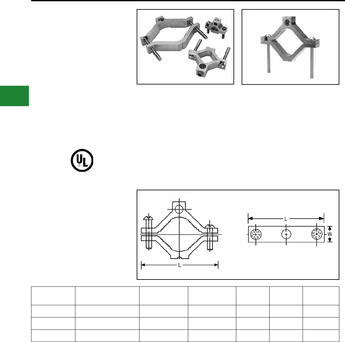
BURNDY®
Blue highlighted items are industry standard and most frequently ordered.
US: 1-800-346-4175 www.burndy.com Canada: 1-800-387-6487
Grounding
Mechanical
TYPE GC-A
Dual Rated
Ground Clamp
For Copper and
Aluminum Cable
GC-A ground clamps are UL Listed for use with
either copper or aluminum conductors to copper
water pipe, galvanized pipe or steel conduit. All
clamps are constructed from tin plated high-
strength extruded aluminum alloy. PENETROX™
oxide inhibiting joint compounds are recommended
for all aluminum applications.
Catalog
Number
Conduit, Pipe, or Water
Tube Size** Wire Range Screw Type W L Hex Size
GC15A 1/2 - 3/4 - 1 1/0 - 14 Slotted 11/16 2-1/4 Slot
GC18A 1-1/4 - 1-1/2 - 2 250 kcmil - 6 Hex Socket 13/16 3-3/4 5/16
GC22A 2-1/2 - 3 - 3-1/2 - 4 250 kcmil - 6 Hex Socket 1 6-5/16 5/16
Features & Benets
• Clamps are dual rated for both copper and
aluminum conductors
◊ Maximum exibility of application
• All connectors are tin plated
◊ Provide low contact resistance and
prevents galvanic corrosion
• All clamps are range taking
◊ Only 3 catalog numbers covers
complete range of applications from
1/2 - 4 inches
NOTE:
** Refer to Section O for tube dimensions.
E-48
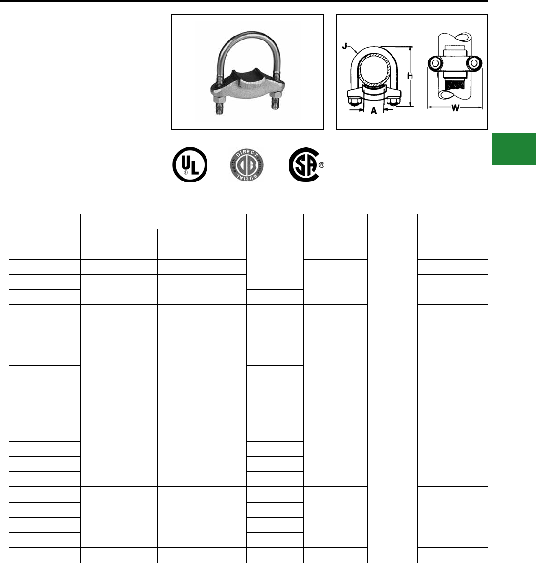
BURNDY®
Blue highlighted items are industry standard and most frequently ordered.
Canada: 1-800-387-6487 www.burndy.com US: 1-800-346-4175
Grounding
Mechanical
TYPE GG
GROUND CONNECTOR
For Copper Bar, Strap, Braid or Cable
to Rod or Tube
High copper alloy ground connector for joining bar,
strap, braid or cable to rod or tube. High copper
alloy cast body, DURIUM™ U-bolts, nuts and
lockwashers make the GG particularly effective
for use with braid for ground rods, switch handles,
fence posts and gates. One-wrench installation.
Catalog
Number
Conductor A H J W
Tube I.P.S. ** Rod
GG15-1 1 1-1/8 - 1-1/4
1
3-3/8
3/8
2-5/8
GG16-1 1-1/4 1-3/8 - 1-1/2
3-1/2
3
GG17-1 1-1/2 1-5/8 - 1-7/8 3-1/4
GG17-15 1-1/2
GG18-1
2 2 - 2-3/8
14-1/4 3-3/4
GG18-15 1-1/2
GG18-2 24-3/8
1/2
4-1/8
GG19-2 2-1/2 2-1/2 - 2-7/8 5 4-5/8
GG19-25 2-1/2
GG20-2
3 3 - 3-1/2
2
6-3/8
5-1/5
GG20-25 2-1/2 5-1/4
GG20-3 3
GG21-2
3-1/2 3-1/2 - 4
2
5-7/8 5-3/4
GG21-25 2-1/2
GG21-3 3
GG21-35 3-1/2
GG22-2
4 4 - 4-1/2
2
6-1/2 6-1/4
GG22-25 2-1/2
GG22-3 3
GG22-4 4
GG24-2 5 — 2 7-5/8 7-1/4
NOTE:
** Refer to Section O for tube dimensions.
E-49
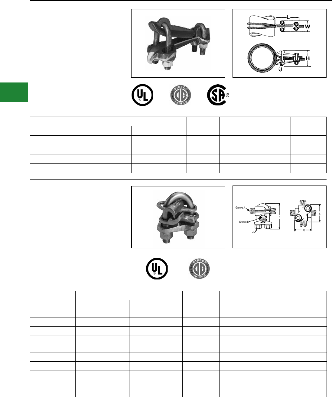
BURNDY®
Blue highlighted items are industry standard and most frequently ordered.
US: 1-800-346-4175 www.burndy.com Canada: 1-800-387-6487
Grounding
Mechanical
TYPE GQ
Ground Connector
For Copper Cable to Tube
High copper alloy ground connector for cross
connecting a wide range of cable. High copper
alloy, cast body, DURIUM™ U-bolts, nuts, and
lockwashers make the GQ suitable for burial in
soil or concrete. One-wrench installation. UL467
Listed. Acceptable for direct burial in earth or
concrete.
Catalog
Number
Conductor H J L W
I.P.S. Cable
GQ2626 6" Max. 4 Str. - 2/0 Str. 4-1/2 1/2 5 2-1/2
GQ26-1 Above 6" 4 Str. - 2/0 Str. 7-1/8 1/2 5 2-1/2
GQ2929 6" Max. 2/0 Str. - 250 4-1/8 1/2 6 2-3/4
GQ29-1 Above 6" 2/0 Str. - 250 7-1/2 1/2 6 2-3/4
TYPE GX
Ground Connector
For Copper Cables
High copper alloy ground connector for cross
connecting a wide range of cable. The high copper
alloy cast body, DURIUM™ U-bolts, nuts, and
lockwashers make the GX suitable for burial in
soil or concrete. One-wrench installation. UL467
Listed. Acceptable for direct burial in earth or
concrete.
Catalog
Number
Conductor H J L W
Groove A Groove B
GX4C4C 8 Sol. - 4 Str. 8 Sol. - 4 Str. 1-7/8 3/8 1-5/8 1-5/8
GX264C 4 Sol. - 2/0 Str. 8 Sol. - 4 Str. 2-1/2 3/8 1-3/4 1-2/3
GX2626 4 Sol. - 2/0 Str. 4 Sol. - 2/0 Str. 2-1/2 3/8 1-3/4 1-2/3
GX294C 2/0 Sol. - 250 8 Sol. - 4 Str. 2-3/4 3/8 1-7/8 1-7/8
GX2926 2/0 Sol. - 250 4 Sol. - 2/0 Str. 2-1/2 3/8 1-7/8 1-7/8
GX2929 2/0 Sol. - 250 2/0 Sol. - 250 2-3/4 3/8 1-7/8 1-7/8
GX344C 300 - 500 8 Sol. - 4 Str. 2-3/4 3/8 2-1/8 1-7/8
GX3426 300 - 500 4 Sol. - 2/0 Str. 2-3/4 3/8 2-1/8 1-7/8
GX3429 300 - 500 2/0 Sol. - 250 2-3/4 3/8 2-1/8 1-7/8
GX3434 300 - 500 300 - 500 4-1/4 1/2 2-5/8 2-5/8
E-50
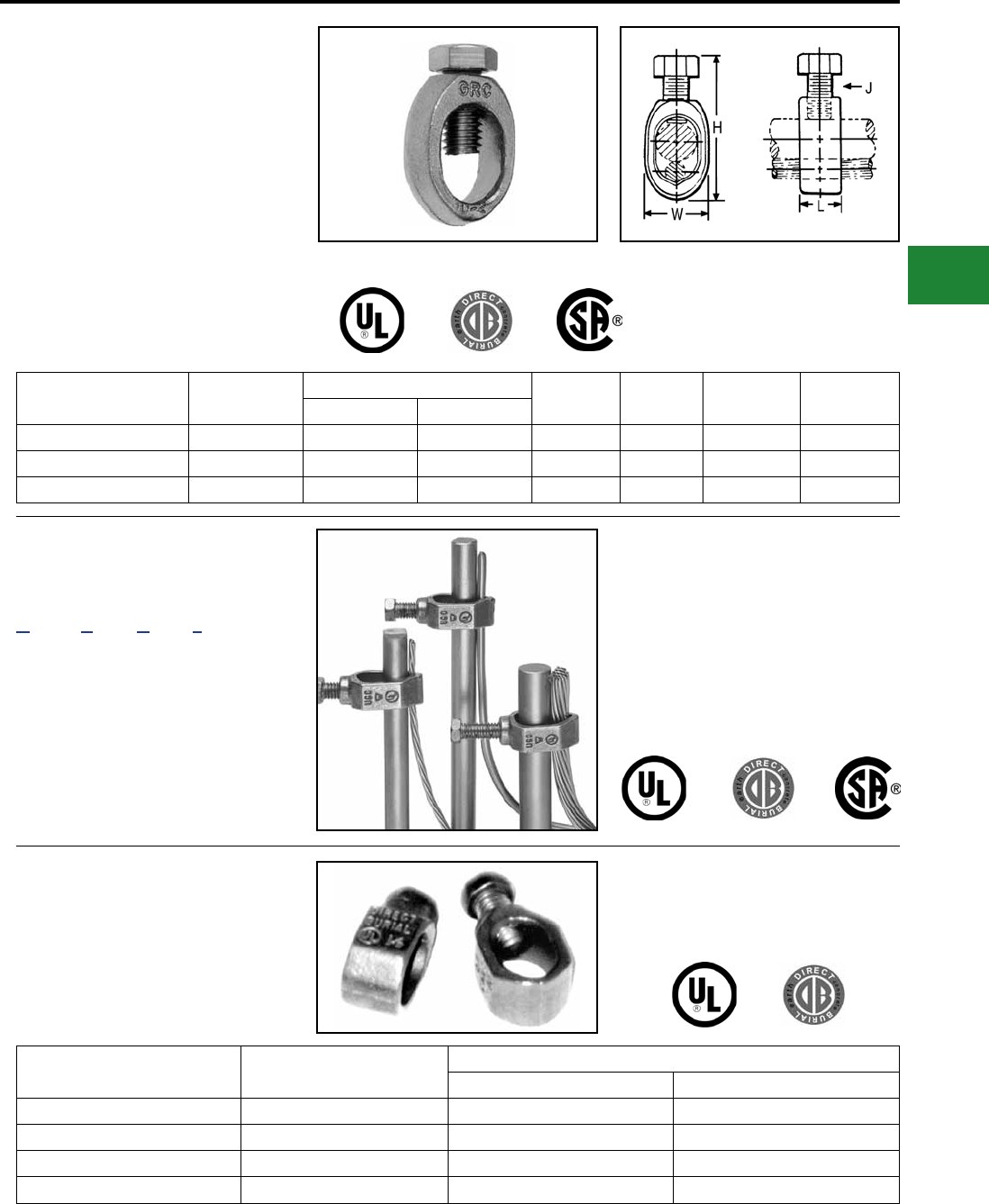
BURNDY®
Blue highlighted items are industry standard and most frequently ordered.
Canada: 1-800-387-6487 www.burndy.com US: 1-800-346-4175
Grounding
Mechanical
TYPE GRC
High Strength Ground Rod Clamp
For Copper Cable to Rod
High copper alloy ground connector for joining a
range of cable to copper clad, galvanized steel,
and stainless steel ground rods. Slips over end
of rod, one-wrench installation. UL467 Listed for
direct burial in earth and concrete.
Catalog Number Drive Rod Conductor Range H W L J
Min. Max.
GRC12 1/2 10 Sol. 2 Str. 2.00 0.89 0.63 3/8
GRC58 5/8 10 Sol. 1 Str. 2.19 0.95 0.63 3/8
GRC34 3/4 8 Sol. 1/0 Str. 2.47 1.09 0.65 3/8
TYPE GCRT1/0 GROUND
CONNECTORS
Ground Clamp Range Taking,
up to 1/0
The GCRT1/0 is a range taking ground rod clamp
offering another choice from the BURNDY® family of
connectors. The GCRT1/0 works on 1/2", 5/8" and
3/4" ground rods with a wire range of #8 through 1/0!
The clamp is UL467 Listed for direct burial in earth
and concrete. Catalog number GCRT1/0.
Features & Benets
• Range taking design helps reduce inventory
• UL Listed and CSA Certied
• UL467 Listed for direct burial in earth and
concrete
TYPE GRL
Light Duty Economical
Ground Rod Clamp
UL 467 Listed. Acceptable for direct burial
in earth and concrete.
Catalog Number Rod Size Conductor Range
Minimum Maximum
GRL3 3/8 in 10 AWG 4 AWG
GRL4 1/2 in 10 AWG 2 AWG
GRL5 5/8 in 10 AWG 2 AWG
GRL6 3/4 in 10 AWG 2 AWG
E-51
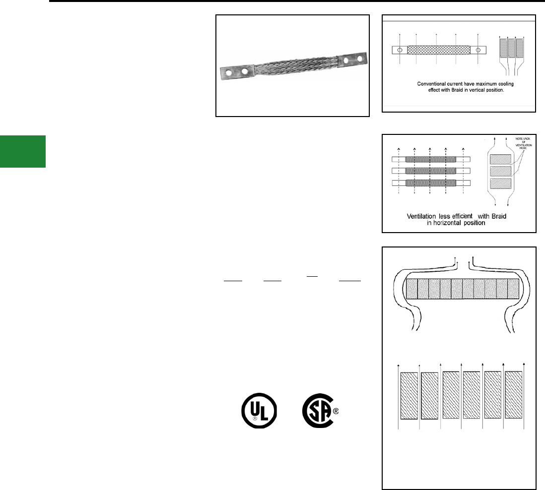
BURNDY®
Blue highlighted items are industry standard and most frequently ordered.
US: 1-800-346-4175 www.burndy.com Canada: 1-800-387-6487
Grounding
Mechanical
FLEXIBLE COPPER BRAID
JUMPER
Copper braid is made of tinned, pure copper wire
woven and attened into a rectangular shape for
greater exibility. Seamless, pure copper ferrules
are formed and assembled on each end to provide
appropriate contact surfaces.
Braid is used extensively to compensate for
expansion and contraction of moving parts and
for thermal movement of rigid devices; to prevent
breakage of insulators or bushings or equipment
because of misalignment during settling of
substation foundations; to absorb shock and
vibration of operating equipment; and to provide
exible current carrying leads between moving
parts of heavy machinery or equipment.
CURRENT CARRYING
CAPACITY
Flexible copper braid has generally better heat
dissipation properties than at bar, cable or other
conductors, and therefore can be expected to
have a greater current carerying capacity for given
cross-sectional area. This is due to its greater
surface area resulting from the woven construction
of ne strands. However, ventilation, due to the
vertical convection current of air, is appreciably
better when the long axis of the braid is vertical
rather than horizontal, so that the long sides of the
braid, rather than the edges, are exposed to the
moving air. This is particularly true when spaced
braids are used in multiple as can be seen by
comparing Figure 1 and 2.
To take full advantage of ventilation, the cooling
convection current of air should be permitted
to ow freely between the braids. Therefore, if
possible, the braids should be spaced apart, rather
than bunched together, as illustrated in Figure 3.
The effectiveness of spacing is, of course, greater
when the braids are in a vertical position.
BULK BRAID
Bulk braid can be ordered with a minimum order
quantity of 10 feet. Specify feet in number of
inches.
Example: 10 feet of 190 ampere braid is Catalog
No. BB077L120.
INDOOR
RATING
AMPS
EQUIV
CIRCULAR
AREA
CAT
NO.
APPROX
WEIGHT
PER FT
75
95
110
190
340
360
415
24,000
48,000
67,000
77,184
153,700
231,552
300,000
BB024L
BB048L
BB067L
BB077L
BB154L
BB226L
BB300L
0.06
0.16
0.22
0.24
0.49
0.76
1.06
CLOSELY BUNCHED
ARRANGEMENT
OPEN ARRANGEMENT
Cooling due to convection current much
more effectivewith spaced Braid
Fig. 1
Fig. 2
Fig. 3
E-52

BURNDY®
Blue highlighted items are industry standard and most frequently ordered.
Canada: 1-800-387-6487 www.burndy.com US: 1-800-346-4175
Grounding
Mechanical
FLEXIBLE
COPPER BRAID
CUSTOM DESIGNS
Flexible copper braid offers an economical and
efcient means of protecting electrical equipment
from the potentially harmful effects of shock
and vibration, terminal expansion, movement of
components and misalignment that may occur
during the service life of the equipment.
Many varieties of braid are required to meet
those needs which we can build to your
specications.
We also offer engineering assistance in the
selection of the most appropriate standard or
custom braid conguration for your application.
Drilling
* Undrilled
* Elongated (slotted) holes
* Special hole patterns and location
* Metric
* NEMA
Plating
* Tin
* Silver
* Nickel
* Unplated
Length
* Jumper (overall)
* Ferrule(s) contact
Insulated (covered)
* Tubular
* Heat shrink
Split Braid Assemblies
* Stacked
* Side-by-side
Multiple Ferrules
Preformed Congurations
* Offset contact surfaces
* Angular (e.g. 90°, 180°) bends
* Ferrule contact surfaces rotated
90° on braid axis
Combined Braid Assemblies
Combined connector - Braid Assemblies
Ferrule Variations
* Belled/unbelled
* Width/thickness
* Contact length
* Special shaping
* Bent at angle°
High Ampacity Requirements
CUSTOM VARIATIONS
E-53
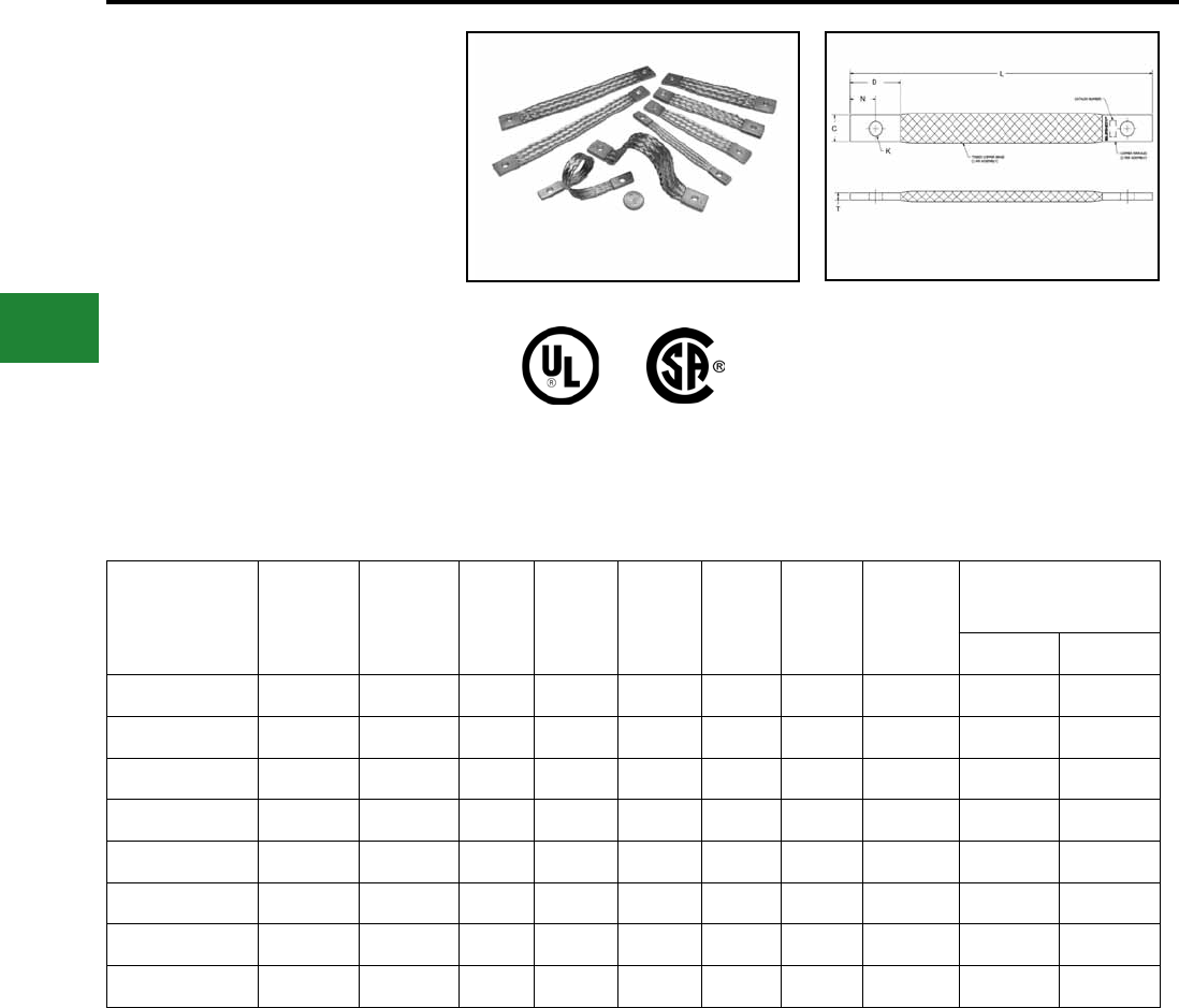
BURNDY®
Blue highlighted items are industry standard and most frequently ordered.
US: 1-800-346-4175 www.burndy.com Canada: 1-800-387-6487
Grounding
Mechanical
TYPE B
Flexible Copper Braid
Bonding Jumpers
Bonding Straps
Flexible copper braid jumpers designed to take
up linear expansion and contraction, compensate
for misalignment and absorb vibratory movement
of electrical equipment and devices. Made of
at extra exible, tinned, pure copper braid, with
unplated, seamless, pure copper ferrules formed
into a rectangular shape on each end. Shown are
standard 6 & 9 inch exible copper braids; other
lengths, plating and mounting hole sizes are
available; contact BURNDY for more information.
Catalog Number
Number of
Braids in
Ferrules
AWG
Equivalent C D K** L N T
Approximate Ampere
Rating
Indoor Outdoor
BB024L6T14* 1 #6 0.50 1 0.27 6 0.50 0.15 75 100
BB024L9T14* 1 #6 0.50 1 0.27 9 0.50 0.15 75 100
BB048L6T14* 1 #4 0.75 1 0.27 6 0.50 0.13 95 150
BB048L9T14* 1 #4 0.75 1 0.27 9 0.50 0.13 95 150
BB067L6T14 1 #2 0.83 1 0.27 6 0.50 0.17 110 180
BB067L9T14 1 #2 0.83 1 0.27 9 0.50 0.17 110 180
BD6T14 1 #1 0.94 1 0.27 6 0.50 0.13 190 225
BD9T14 1 #1 0.94 1 0.27 9 0.50 0.13 190 225
* Not UL Listed or CSA Certied
** K mounting hole .27" accommodates 1/4" hardware.
E-54
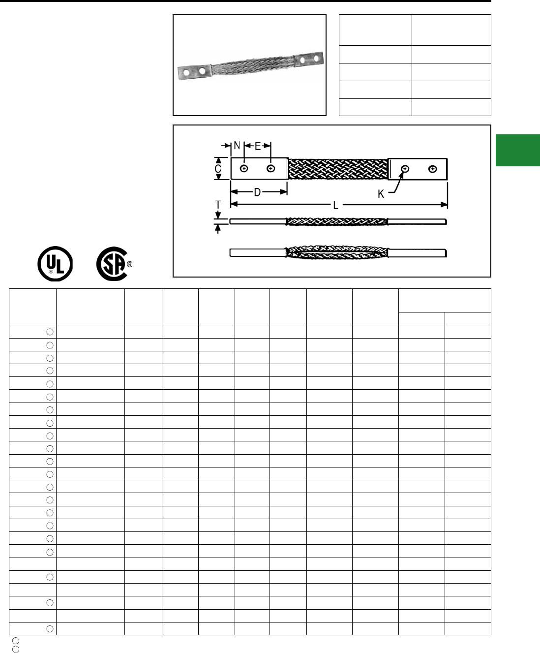
BURNDY®
Blue highlighted items are industry standard and most frequently ordered.
Canada: 1-800-387-6487 www.burndy.com US: 1-800-346-4175
Grounding
Mechanical
TYPE B
Flexible Copper Braid
Flexible copper braid jumpers designed to take up
linear expansion and contraction, compensate for
misalignment and absorb vibratory movement of
electrical equipment and devices.
Made of at extra exible, tinned, pure copper
braid, with unplated, seamless, pure copper
ferrules formed into a rectangular shape on each
end.
Last two numbers in catalog number indicate total
length of braid in inches (e.g., BD12N or BD12 is
12" long braid jumper).
Other lengths, plating and drilling are
available. Contact the factory.
Catalog
Number
Number of Braids
in Ferrules C D E K L N T
Approximate Ampere
Rating
Indoor Outdoor
BD12 1 0.94 2.50 1.25 0.44 12 0.62 0.13 190 225
BD12N 1 0.94 3.00 1.75 0.56 12 0.62 0.13 190 225
BD18 1 0.94 2.50 1.25 0.44 18 0.62 0.13 190 225
BD18N 1 0.94 3.00 1.75 0.56 18 0.62 0.13 190 225
BD24 1 0.94 2.50 1.25 0.44 24 0.62 0.13 190 225
BD24N 1 0.94 3.00 1.75 0.56 24 0.62 0.13 190 225
BE12 1 1.50 3.00 1.50 0.44 12 0.75 0.17 340 405
BE12N 1 1.50 3.00 1.75 0.56 12 0.62 0.17 340 405
BE18 1 1.50 3.00 1.50 0.44 18 0.75 0.17 340 405
BE18N 1 1.50 3.00 1.75 0.56 18 0.62 0.17 340 405
BE24 1 1.50 3.00 1.50 0.44 24 0.75 0.25 340 405
BE24N 1 1.50 3.00 1.75 0.56 24 0.62 0.17 340 405
BF12 1 1.19 3.00 1.50 0.44 12 0.75 0.25 360 430
BF12N 1 1.19 3.00 1.75 0.55 12 0.62 0.25 360 430
BF18 1 1.19 3.00 1.50 0.44 18 0.75 0.25 360 430
BF18N 1 1.19 3.00 1.50 0.44 18 0.75 0.25 360 430
BF24 1 1.19 3.00 1.50 0.44 24 0.75 0.25 360 430
BF24N 1 1.19 3.00 1.75 0.56 24 0.62 0.25 360 430
BG12 1 1.50 3.00 1.50 0.44 12 0.75 0.25 415 495
BG12N 1 1.50 3.00 1.75 0.56 12 0.62 0.25 415 495
BG18 1 1.50 3.00 1.50 0.44 18 0.75 0.25 415 495
BG18N 1 1.50 3.00 1.75 0.56 18 0.62 0.25 415 495
BG24 1 1.50 3.00 1.50 0.44 24 0.75 0.25 415 495
BG24N 1 1.50 3.00 1.75 0.56 24 0.62 0.25 415 495
Tongue drilled per (2) hole NEMA Standard
Certied to CSA C22.2, No. 41 Grounding and Bonding Equipment Standards in
addition to the UL467 Listing which all items above are Listed to.
1
2
NOTE: Equivalent sizes may be designated by sufx letters representing variations in
length, mounting congurations, pad size and nish. Contact factory for details.
For Tin plated ferrules add sufx -TN to the catalog number.
2
2
2
2
2
2
2
1
1
1
Catalog
# Prex
Equiv.
AWG Size
BD #1
BE 3/0
BF 4/0
BG 300 kcmil
2
2
2
2
2
2
2
2
2
2
2
E-55
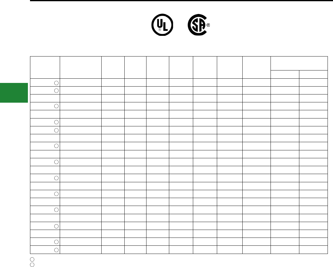
BURNDY®
Blue highlighted items are industry standard and most frequently ordered.
US: 1-800-346-4175 www.burndy.com Canada: 1-800-387-6487
Grounding
Mechanical
TYPE B
Flexible Copper Braid (Continued)
Tongue drilled per (2) hole NEMA Standard
Certied to CSA C22.2, No. 41 Grounding and Bond-
ing Equipment Standards in addition to the UL467
Listing which all items above are Listed to.
1
2
Catalog
Number
Number of Braids
in Ferrules C D E K L N T
Approximate Ampere
Rating
Indoor Outdoor
B2D12 2 0.94 2.5 1.25 0.44 12 0.62 0.25 380 455
B2D12N 2 0.94 3.00 1.75 0.56 12 0.62 0.25 380 455
B2E12 2 1.62 3.00 1.50 0.44 12 0.75 0.25 530 635
B2E12N 2 1.62 3.00 1.75 0.56 12 0.62 0.25 530 635
B2F12 2 1.38 3.00 1.50 0.44 12 0.75 0.38 600 720
B2F12N 2 1.38 3.00 1.75 0.56 12 0.62 0.38 600 720
B2G12N 2 1.50 3.00 1.75 0.56 12 0.62 0.50 700 840
B3D12 3 1.19 2.50 1.25 0.44 12 0.62 0.25 470 560
B3D12N 3 1.19 3.00 1.75 0.56 12 0.62 0.25 470 560
B3E12 3 1.64 3.00 1.50 0.44 12 0.75 0.31 700 840
B3E12N 3 1.64 3.00 1.75 0.56 12 0.62 0.31 700 840
B3F12 3 1.44 3.00 1.50 0.44 12 0.75 0.56 820 980
B3F12N 3 1.44 3.00 1.75 0.56 12 0.62 0.56 820 980
B3G12 3 1.69 3.00 1.50 0.44 12 0.75 0.69 960 1150
B3G12N 3 1.69 3.00 1.75 0.56 12 0.62 0.69 960 1150
B4D12 4 1.19 2.50 1.25 0.44 12 0.62 0.32 600 720
B4D12N 4 1.19 3.00 1.75 0.56 12 0.62 0.32 600 720
B4E12 4 1.64 3.00 1.50 0.44 12 0.75 0.38 850 1020
B4E12N 4 1.64 3.00 1.75 0.56 12 0.62 0.38 850 1020
B4F12 4 1.50 3.00 1.50 0.44 12 0.75 0.78 1000 1200
B4F12N 4 1.50 3.00 1.75 0.56 12 0.62 0.78 1000 1200
B4G12N 4 1.69 3.00 1.75 0.56 12 0.62 0.94 1200 1440
2
1
1
1
2
1
1
1
1
1
1
1
NOTE:
Equivalent sizes may be designated by sufx letters
representing variations in length, mounting congura-
tions, pad size and nish. Contact factory for details.
For Tin plated ferrules add sufx -TN to the catalog
number.
2
E-56
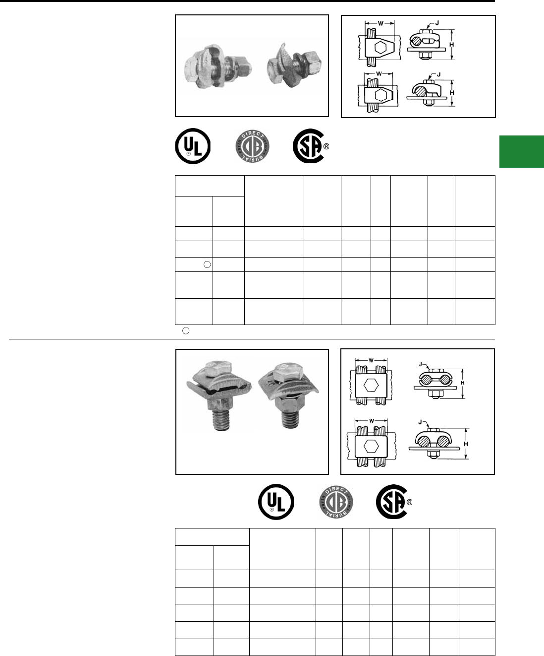
BURNDY®
Blue highlighted items are industry standard and most frequently ordered.
Canada: 1-800-387-6487 www.burndy.com US: 1-800-346-4175
Grounding
Mechanical
TYPES GB, GBM
Ground Connector
For Copper Cable to Bar
High copper alloy ground connector for joining
a range of cable to 1/4" thick bar.* Type GB
separates cable from bar, GBM clamps cable
directly on bar surface. One-wrench installation.
UL467 Listed. The high copper alloy cast body and
DURIUM™ bolts, nuts, and lockwashers make the
GB and GBM suitable for direct burial in concrete
or ground.
Catalog Number
Cable
H
Type
GB / GBL
H
Type
GBM
J
W
Type GB/
GBL
W
Type
GBM
Rec.
Torque
Type GB Type
GBM
GB4C GBM4C 8 AWG-4 AWG 1-1/2 1-1/2 3/8 1-1/4 1-1/4 240
GB26 GBM26 4 AWG-2/0 AWG 2 1-1/2 3/8 1-1/2 1-1/2 240
GBL30 — 4 AWG-300 kcmil 2 — 1/2 1-7/8 — 480
GB29 GBM29 2/0 AWG-250
kcmil 2 2 1/2 2 2 480
GB34 GBM34 300 kcmil-500
kcmil 3 2-1/4 1/2 2-3/8 2-3/8 480
TYPES GC, GCM
Ground Connector
For Two Copper Cables to Bar
High copper alloy ground connector for joining a
wide range of two parallel cables to 1/4" thick bar.*
Type GC separates cable from bar, GCM clamps
cable to bar surface. One-wrench installation.
UL467 Listed. The high copper alloy cast body and
DURIUM™ bolts, nuts, and lockwashers make the
GC and GCM suitable for direct burial in concrete
or ground.
Catalog Number
Cable
H
Type
GC
H
Type
GCM
J
W
Type
GC/GCL
W
Type
GCM
Rec.
Torque
Type GC Type
GCM
GC4C4C GCM4C 8 AWG-4 AWG 1-1/2 1-1/2 3/8 1-3/8 1 240
GC2626 GCM26 4 AWG-2/0 AWG 2 1-1/2 3/8 1-3/4 1-3/8 240
GCL30 GCM30 5 AWG-300 kcmil 2 — 1/2 1 — 480
GC2929 GCM29 2/0 AWG-250 kcmil 2-1/4 2 1/2 2-1/4 2 480
GC3434 GCM34 300 kcmil-500 kcmil 2-7/8 2-1/4 1/2 2-7/8 2-5/8 480
Type
GC
Type
GCM
Type
GB
Type
GBM
Type
GC
Type
GCM
The GB, GBM, GC, GCM, GL and GZ are all
used for joining a range of cable to bar. The
catalog numbers in each table accommodate
the indicated cable range and up to 1/4″
thick bar. Optional bolt lengths are available
to accommodate up to 1" thick bar. For bar
thicknesses from 1/4″ to 1/2″, add the sufx
“T4” to the catalog number in the table. For bar
thicknesses from 1/2″ to 1″, add the sufx “T8” to
the catalog number in the table.
NOTE:
*
GBL30 is not UL Listed
1
1
Type
GB
Type
GBM
E-57
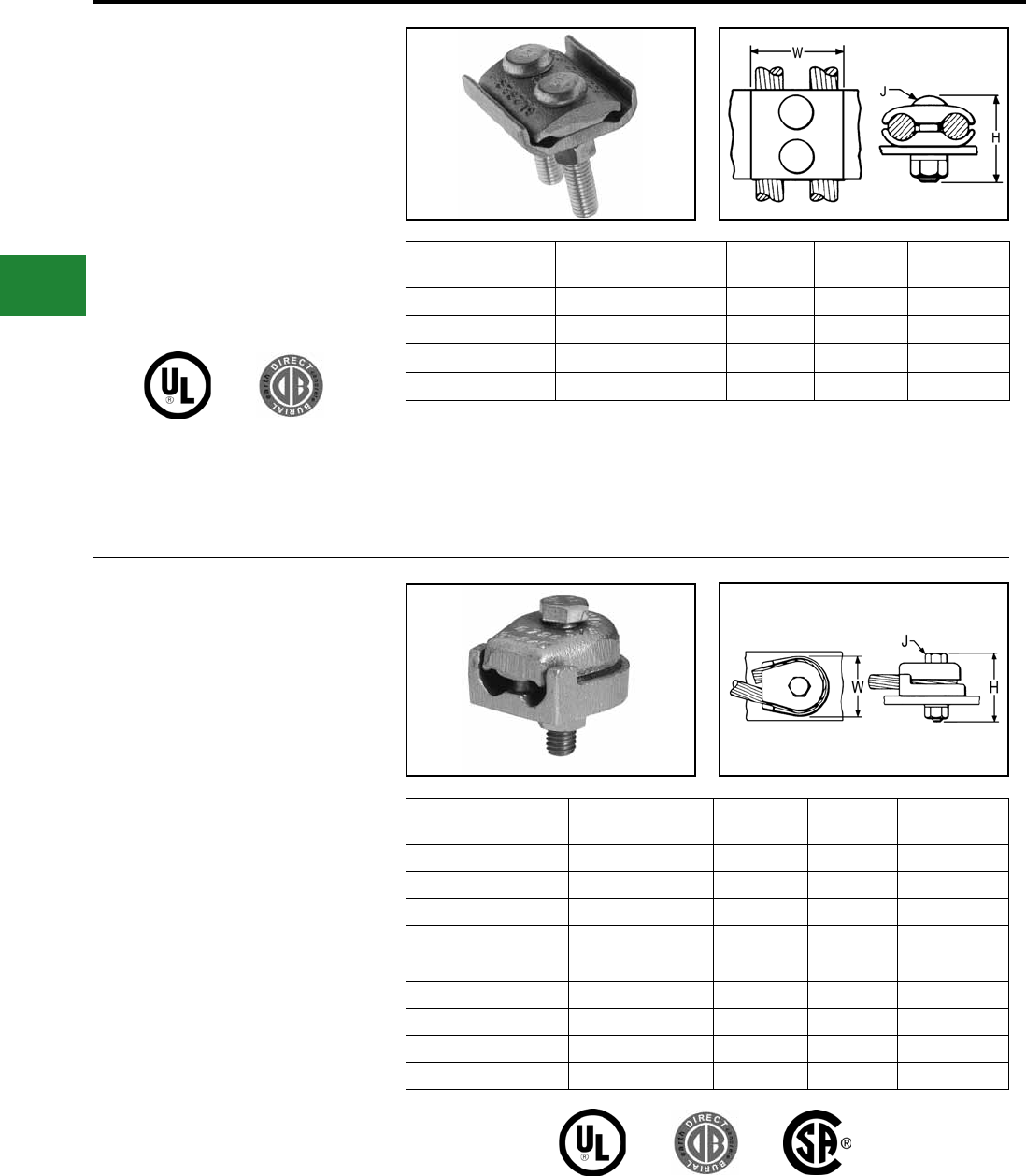
BURNDY®
Blue highlighted items are industry standard and most frequently ordered.
US: 1-800-346-4175 www.burndy.com Canada: 1-800-387-6487
Grounding
Mechanical
TYPE GL
Ground Connector
For Two Copper Cables to Bar
High copper alloy ground connector for joining a
wide range of two parallel cables to 1/4" thick bar.*
Two-bolt design, separates cable from bar. One-
wrench installation. UL467 Listed. The high copper
alloy cast body and DURIUM™ bolts, nuts, and
lockwashers make them suitable for direct burial
in concrete or ground.
Catalog
Number Conductor H J W
GL4C4C 8 AWG-4 AWG 1-1/2 3/8 1-3/8
GL2626 4 AWG-2/0 AWG 2 3/8 1-3/4
GL2929 2/0 AWG-250 kcmil 2-1/4 1/2 2-1/4
GL3434 300 kcmil-500 kcmil 2-7/8 1/2 2-7/8
TYPE GZ
Ground Connector
For Copper Cable to Bar
High copper alloy ground connector for joining
a wide range of cable to 1/4" thick bar*. Cable is
gripped by curving it around the clamping bolt in
connector groove. UL467 Listed. The high copper
alloy cast body and DURIUM™ bolts, nuts, and
lockwashers make them suitable for direct burial
in concrete or ground.
Catalog
Number Conductor H J W
GZ4C-38 8-4 1-1/2 3/8 1-1/8
GZ4C-12 8-4 1-7/8 1/2 1-3/4
GZ4C-58 8-4 2 5/8 1-3/4
GZ26-38 3-2/0 2 3/8 1-5/8
GZ26-12 3-2/0 2-1/8 1/2 1-3/4
GZ26-58 3-2/0 2-1/4 5/8 1-3/4
GZ29-38 3/0-250 2-1/4 3/8 2-1/4
GZ29-12 3/0-250 2-3/8 1/2 2-1/4
GZ29-58 3/0-250 2-1/2 5/8 2-1/4
The GB, GBM, GC, GCM, GL and GZ are all used for joining a range of cable to bar. The catalog
numbers in each table accommodate the indicated cable range and up to 1/4″ thick bar. Optional bolt
lengths are available to accommodate up to 1" thick bar. For bar thicknesses from 1/4″ to 1/2″, add the
sufx “T4” to the catalog number in the table. For bar thicknesses from 1/2″ to 1″, add the sufx “T8” to
the catalog number in the table.
NOTE:
*
The GB, GBM, GC, GCM, GL and GZ are all
used for joining a range of cable to bar. The
catalog numbers in each table accommodate
the indicated cable range and up to 1/4″
thick bar. Optional bolt lengths are available
to accommodate up to 1" thick bar. For bar
thicknesses from 1/4″ to 1/2″, add the sufx
“T4” to the catalog number in the table. For bar
thicknesses from 1/2″ to 1″, add the sufx “T8”
to the catalog number in the table.
NOTE:
*
E-58
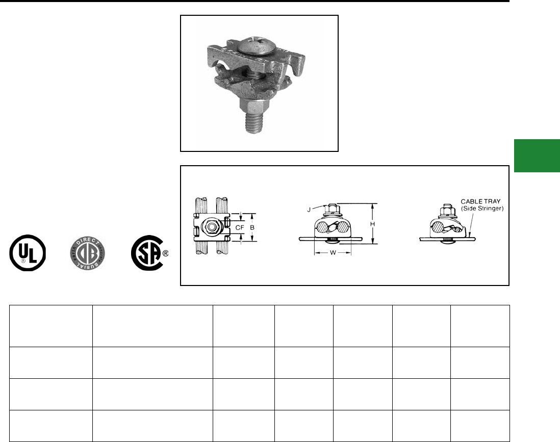
BURNDY®
Blue highlighted items are industry standard and most frequently ordered.
Canada: 1-800-387-6487 www.burndy.com US: 1-800-346-4175
Grounding
Mechanical
TYPE GC-CT
Cabletray Ground Clamp
This unique connector incorporates features
which are unmatched. Made of tin-plated cast
copper alloy, it accommodates either one or two
conductors, copper or aluminum cable. In addition
to a low prole head with a deep Phillips recess,
the galvanized steel bolt has a ribbed neck which
prevents rotation during installation when installed
in a 0.44 diameter hole. When used on aluminum
conductor, the cable must be scratch brushed
and PENETROX™ A joint compound must be
used on cable and connector. UL467 Listed for
copper conductor only. Suitable for direct burial in
concrete or earth.
Catalog
Number
Accommodates Copper or
Aluminum Conductor
in either groove
B CF H J W
GC2525CT #6 Sol. (0.16 Dia.) -
1/0 Str. (0.37 Dia.) 1.12 0.56 1.95 3/8 1.45
GC2626CT #2 Sol. (0.26 Dia.) -
2/0 Str. (0.42 Dia.) 1.12 0.56 1.95 3/8 1.70
GC2929CT 2/0 Str. (0.41 Dia.) -
250 kcmil (0.58 Dia.) 1.12 0.56 2.20 3/8 1.98
NOTE:
The bolt head is mounted on the inside wall of cabletray
to avoid damage to the cable insulation. May be used
with aluminum or galvanized steel cabletray.
E-59
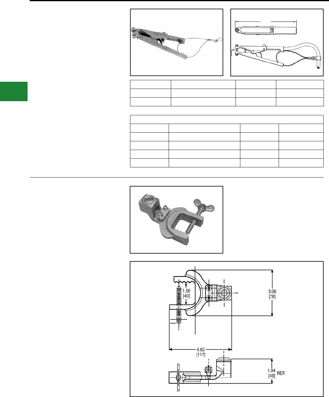
BURNDY®
Blue highlighted items are industry standard and most frequently ordered.
US: 1-800-346-4175 www.burndy.com Canada: 1-800-387-6487
Grounding
Mechanical
TYPE GIE-G
Ground Connector
For Vehicle Grounding Heavy Duty
Construction
High-strength copper alloy ground clamps for
grounding gasoline trucks, tank cars, aircraft and
other vehicles where danger of explosion due to
static electricity exists. Corrosion resistant and
supplied with nonsparking, adjustable, replaceable
contact grip screws. Automatic safety release
disconnects should a vehicle unexpectedly move
from the grounded area. Accommodates 4 Str.
exible copper cable.
Catalog Number Description Material Point Conguration
GIE4CG3 Assembly Beryllium Copper Beryllium Copper Assembly
GIE4CG4 Assembly Stainless Steel Stainless Steel Assembly
TYPE GIE-G
Ground Connector
For Vehicle Grounding, Heavy Duty
Construction
Accommodates exible rubber sheath cable
ranging from #6 to #2 conductor.
Catalog Number: GIE2CG3
Replacement Tips Only
Catalog Number Description Material Point Conguration
GIE4CG3P5 Beryllium Copper CONE Point Only Beryllium Copper Cone Point
GIE4CG3P7 Beryllium Copper CUP Point Only Beryllium Copper Cup Point
GIE4CG4P5 Stainless Steel CONE Point Only Stainless Steel Cone Point
GIE4CG4P7 Stainless Steel CUP Point Only Stainless Steel Cup Point
E-60
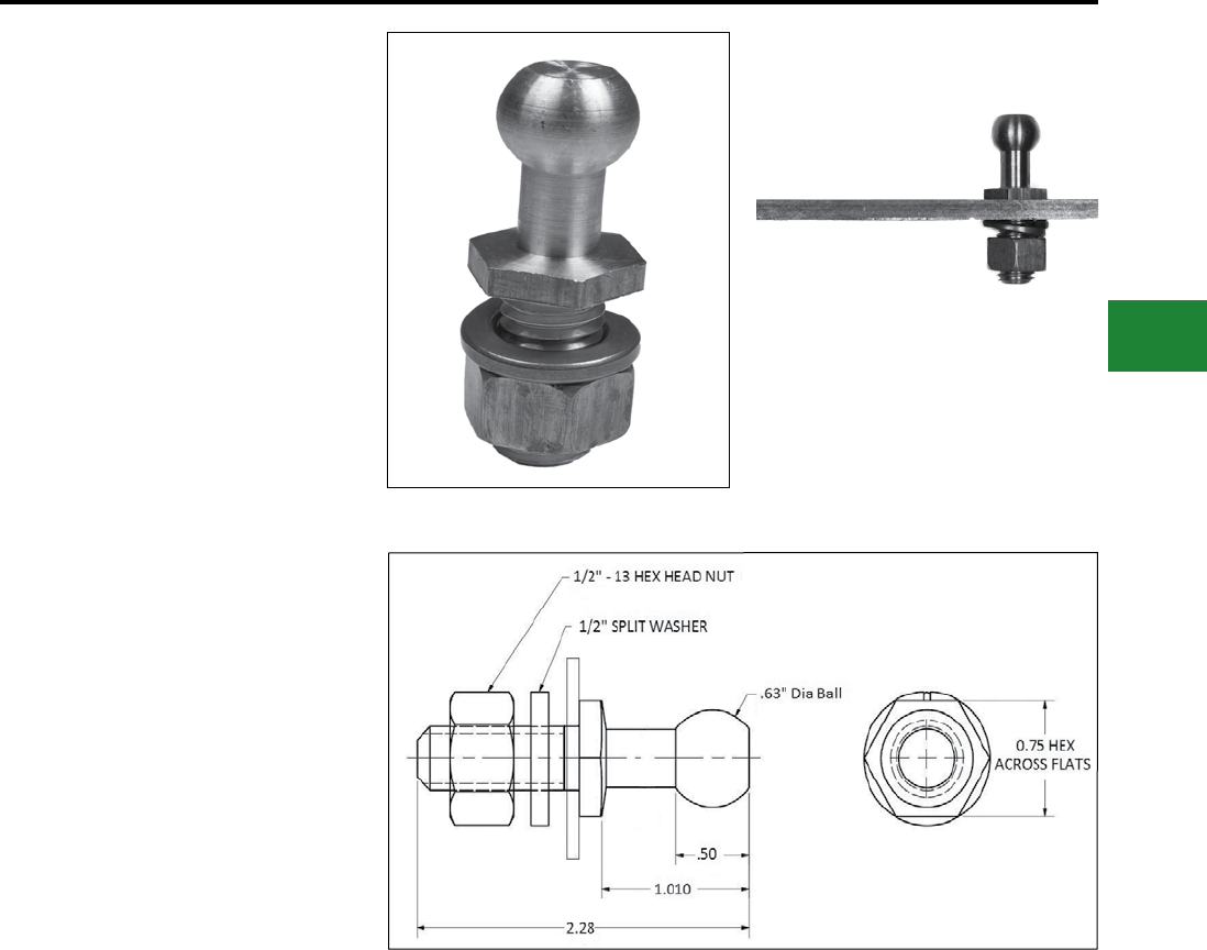
BURNDY®
Blue highlighted items are industry standard and most frequently ordered.
Canada: 1-800-387-6487 www.burndy.com US: 1-800-346-4175
Grounding
Mechanical
TYPE GCB63T13G1
STUDBUG™ for Static Grounding
Applications
GCB63T13G1 is a temporary grounding stud
for use on rail cars, chemical trucks, hazardous
waste tankers or a petroleum vehicle to allow for
static grounding protection, while in operation. It
provides a contact point, allowing the rail car, truck
or tanker to be grounded to an equipotential grid or
ground rod, by using static reel or a ground cable.
Features & Benets
• Made of bronze, and supplied with silicon
bronze hardware
• Secured by ½” hexagonal nut and split lock
washer
• Can be used with universal clamps and ball
stud clamps
• Can be used at various angles to reach
inaccessible areas
• Add sufx “SS” for grounding stud with
stainless steel hardware
Note:
Can be used with plate, bus bar or structural steel
up to 1/4” thick.
E-61
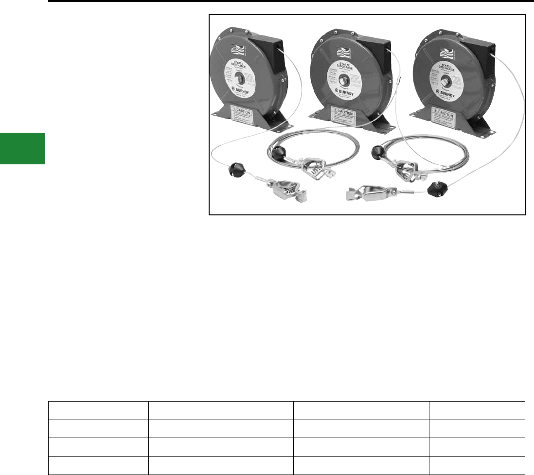
BURNDY®
Blue highlighted items are industry standard and most frequently ordered.
US: 1-800-346-4175 www.burndy.com Canada: 1-800-387-6487
Grounding
Mechanical
BURNDY® Static Discharge
Reels
Static Discharge Reels are an excellent addition
to the BURNDY® static discharge line of products.
These reels are often used to dissipate static
charge buildup developed while lling or dispensing
fuel or other combustible liquids from fuel trucks
or rail cars. Often used in the petroleum industry
but applicable in any area where static discharge
creates a potential hazard.
BURNDY® offers the three most common static
discharge reels found in the market. These reels
are heavy duty, with 50’ lengths and are supplied
with a 100 amp universal jaw-type grounding
clamp. All reels come standard with spring rewind
and centrifugal brake. The tension can be adjusted
on these reels and installation instructions are
included to ensure the most efcient mounting
method.
Every reel is Proudly Made in the USA and meets
the stringent quality expectations of the BURNDY®
portfolio of grounding products.
Catalog Number Cable Length # of Jaw-Type Grounding Clamps Weight (lb.)
BSD2050 50 Feet 1 12
BSD2050N 50 Feet (Nylon Covered) 1 12
BSD2050Y 35 Feet plus 15 Feet for ‘Y’ 2 13
Features & Benets
• Automatic E-Z PULL™ Rewinding
• Rugged Steel Construction
• Compact Enclosed Design
• Positive Ratchet Lock
• Includes Ratchet On/Off Switch
• Steel Cable Installed
• 100 Amp Universal Jaw-Type Grounding
Clamp
• Red Baked-on Finish
• 50' Cable Length
• Made in the USA
E-62
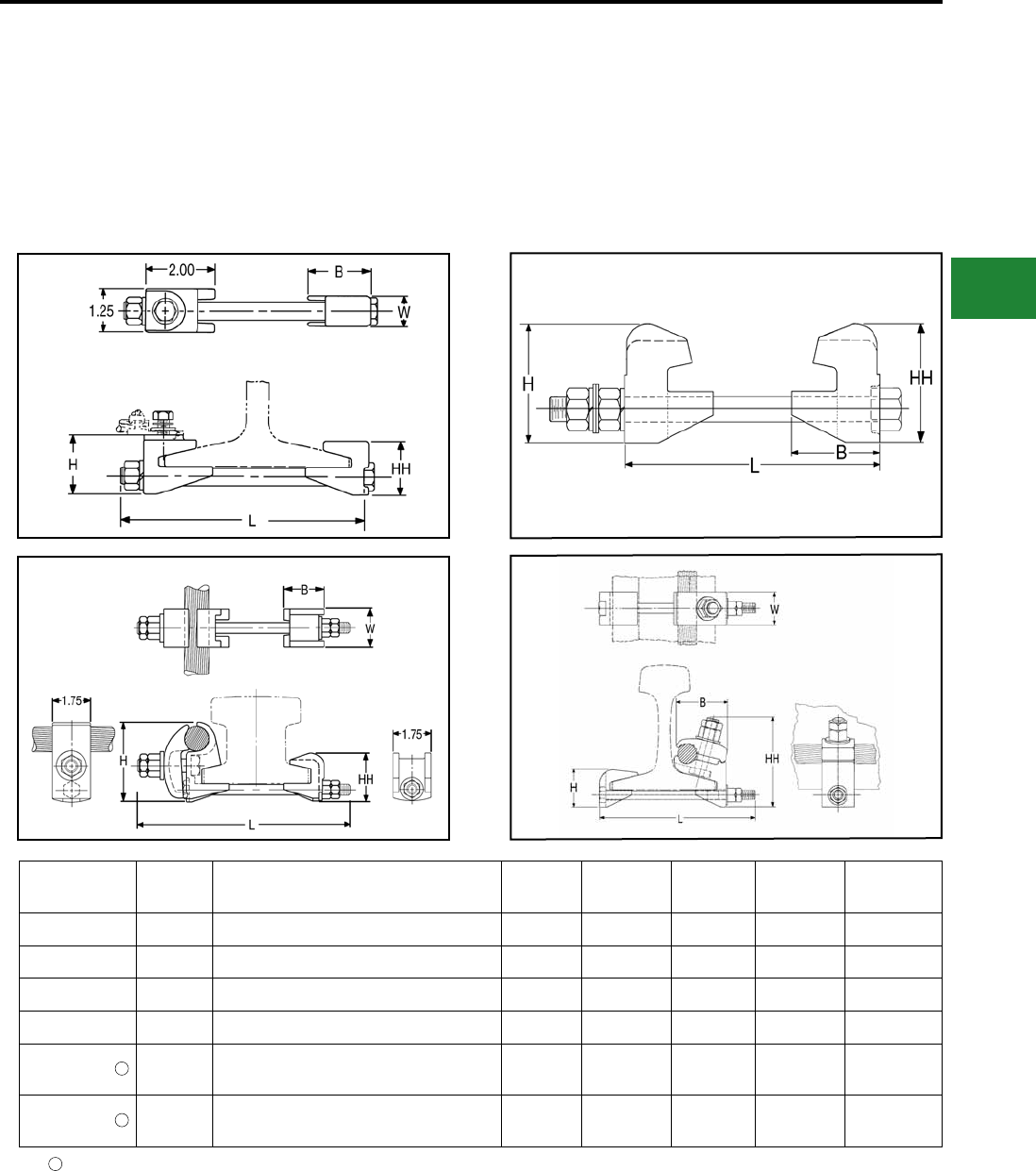
BURNDY®
Blue highlighted items are industry standard and most frequently ordered.
Canada: 1-800-387-6487 www.burndy.com US: 1-800-346-4175
Grounding
Mechanical
RAIL CONNECTOR
Mechanical clamp connectors designed for use
in power, contact or running rail applications.
Connectors are cast of a high conductivity copper
alloy, tin-plated, and assembled with high-strength
DURIUM™ hardware. Connectors designed for
extended service life.
Catalog
Number Fig. No. Accommodates B H HH L W
J278 1 100 Lbs. A.R.E.A Running Rail 1.81 1.88 1.72 7.50 0.88
J279 1 75 or 90 Lbs. Running Rail 1.81 1.71 1.55 7.50 0.88
J280 1 150 Lbs. Contact Rail 2.12 2.08 1.92 7.00 1.25
J295 2 150 Lbs. Third Rail 2.62 3.50 3.50 7.75 3.00
RGC44G1 3150 Lbs. NMC Contact Rail and
(1) 800-1000 kcmil CU Cable 1.75 2.82 2.25 10.00 1.75
RGC39G1 4115 Lbs. Contact or Running Rail and
(1) 500-750 kcmil CU Cable 2.75 2.00 4.78 8.32 1.25
Tin-plated
1
1
1
E-63
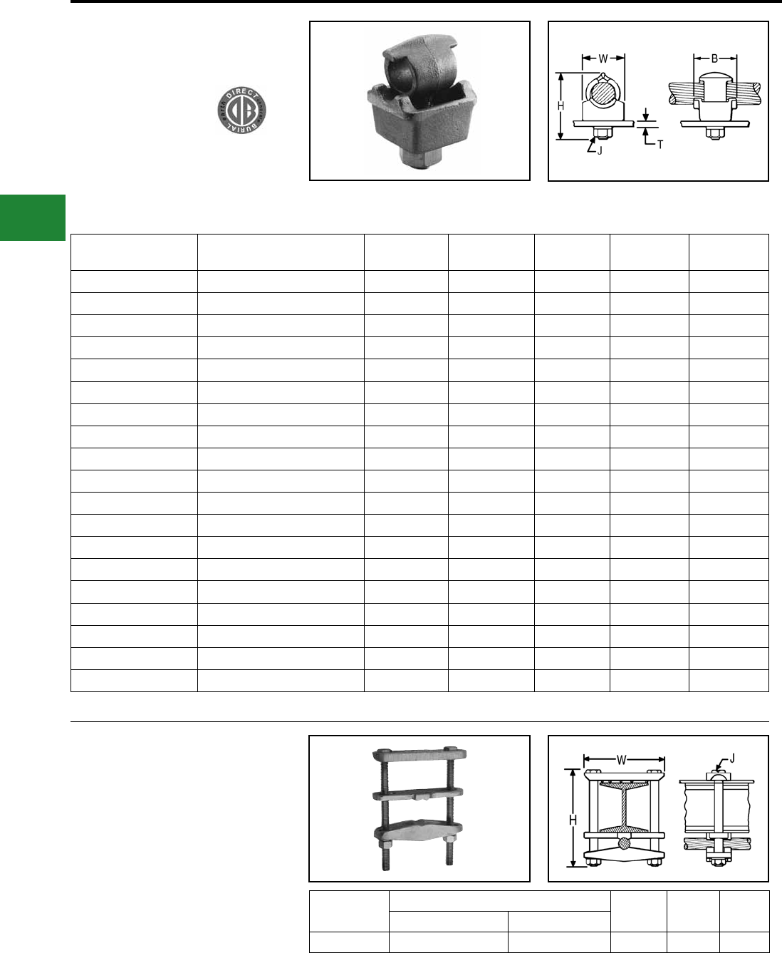
BURNDY®
Blue highlighted items are industry standard and most frequently ordered.
US: 1-800-346-4175 www.burndy.com Canada: 1-800-387-6487
Grounding
Mechanical
QGFL
BARTAP™
For Copper Cable to
Flat Bar or Pad
High copper alloy BARTAP™ for joining a range
of cable to bar or pad. One-wrench installation.
DURIUM™ nut and lockwasher. Can be installed
side by side or in line on NEMA drilled bar.
Catalog
Number
Copper
Conductor B H J T (Max) W
QGFL1CB1 #10 Sol. - #1 Str. 1-1/8 1-7/8 3/8 1/4 1
QGFL1CB1T6 #10 Sol. - #1 Str. 1-1/8 2-3/8 3/8 3/4 1
QGFL26B1 #8 Sol. - #2/0 Str. 1-1/4 2-1/8 3/8 1/4 1-1/8
QGFL26B1T6 #8 Sol. - #2/0 Str. 1-1/4 2-5/8 3/8 3/4 1-1/8
QGFL26B2* #8 Sol. - #2/0 Str. 1-1/4 2-8/25 1/2 1/4 1-1/8
QGFL26B2T6* #8 Sol. - #2/0 Str. 1-1/2 2-40/50 1/2 3/4 1-1/8
QGFL29B1* #6 Str. - 250 kcmil 1-2/5 2-5/8 1/2 1/4 1-3/8
QGFL29B1T6* #6 Str. - 250 kcmil 1-5/8 3-1/8 1/2 3/4 1-3/8
QGFL31B1* 2 AWG - 350 kcmil 1-3/4 2-7/8 1/2 1/4 1-5/8
QGFL31B1T6* 2 AWG - 350 kcmil 1-3/4 3-1/4 1/2 3/4 1-5/8
QGFL34B1 1/0 -500 kcmil 2 3-1/8 1/2 1/4 1-3/4
QGFL34B1T6 1/0 -500 kcmil 2 3-5/8 1/2 3/4 1-3/4
QGFL39B1 350 kcmil - 750 kcmil 2-1/4 3-1/4 1/2 1/4 1-3/4
QGFL39B1T6 350 kcmil - 750 kcmil 2-1/4 3-5/8 1/2 3/4 1-3/4
QGFL44B1 750 kcmil - 1000 kcmil 2-1/4 3-3/8 1/2 1/4 2-1/8
QGFL44B1T6 750 kcmil - 1000 kcmil 2-1/4 4-1/8 1/2 3/4 2-1/8
QGFL46B1 1000 kcmil - 1500 kcmil 2-1/4 4 1/2 1/4 2-1/2
QGFL46B1T6 1000 kcmil - 1500 kcmil 2-1/4 4-1/2 1/2 3/4 2-1/2
QGFL48B1 1500 kcmil - 2000 kcmil 2-1/4 4-3/4 1/2 1/4 3
TYPE GA-H
Ground Connector
For Copper Cable to “H” Beam
High copper alloy ground connector for joining
a wide range of cable parallel to “H” beams or
square tube. Hardware is made from DURIUM™
for superior corrosion protection. Catalog
Number
Conductor H J W
“H” Beam Cable
GA25H26 1-7/8" - 2-1/2" X 2-1/2" 4 Sol. - 2/0 Str. 4-3/4 3/8 4
* Can be installed side by side or in line on NEMA drilled bar.
E-64
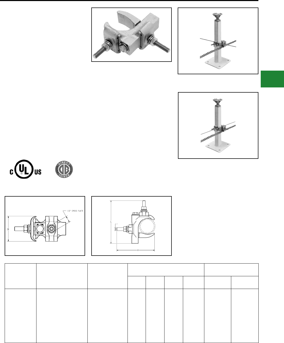
BURNDY®
Blue highlighted items are industry standard and most frequently ordered.
Canada: 1-800-387-6487 www.burndy.com US: 1-800-346-4175
Grounding
Mechanical
TYPE GXP1828RF
SUPER-CLAMPTM
SUPER-CLAMP™ RAISED FLOOR
GROUND CONNECTOR
Raised Floor Pedestal Ground Connector. The
GXP1828RF is a versatile, easy to install, range
taking ground connector. This grounding clamp
accepts a wide range of pedestals and conductors.
Accepted pedestal range is 3/4" through 2" (7/8 - 2"
round; 3/4" - 1-1/2" square). The wire range is #6
solid to 4/0 stranded. The wires can be arranged
in parallel or in a cross grid conguration - accepts
1 or 2 wires.
UL Listed for the US and Canadian markets
(cULus). A high copper alloy body ensures
excellent conductivity and the hardware is made
of stainless steel. The connector is also rated for
Direct Burial. The versatility of the connector makes
it an excellent choice for applications requiring
multiple conductor sizes and/or congurations.
Features & Benets
• Fits a wide range of raised oor
pedestals, from 3/4" to 2" (7/8 - 2" round;
3/4" - 1-1/2" square)
• Accepts a wide range of wire sizes, from
#6 solid to 4/0 stranded
• Accommodates parallel wires or cross
grid arrangements; wires can be
installed in cross grid conguration!
• Accepts one or two wires in any
conguration
• Easy to install - open design eliminates
need to disassemble before installing
• One socket size ts all hardware!
(1/2" socket size)
• Made of high copper alloy
• Stainless steel hardware
• UL Listed for the US and Canadian
markets (cULus)
• Rated for Direct Burial
Cross Grid Conguration
Works on either
Round or Square Pedestals
Parallel Conguration
Catalog
Number
Copper Conductor Range
(Concentric & Compact
Stranded 19 Str. Max)
Pedestal Range
Reference Dimensions Recommended Tightening
Torque (in-lb.)
L W H J Conductor
Saddle (Nut)
Pedestal
Clamp (Bolt)
GXP1828RF
6 AWG
5 AWG
4 AWG
3AWG
2 AWG
1AWG
1/0 AWG
2/0 AWG
3/0 AWG
4/0 AWG
Round: 7/8" - 2"
Square: 3/4" - 1-1/2" 4.53 3.94 1.96 5/16 120 180
E-65
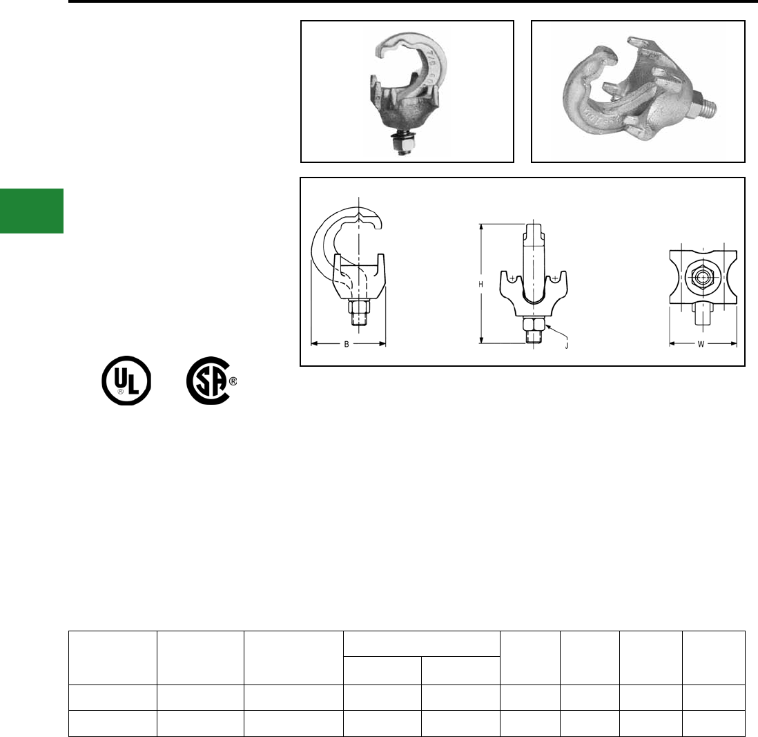
BURNDY®
Blue highlighted items are industry standard and most frequently ordered.
US: 1-800-346-4175 www.burndy.com Canada: 1-800-387-6487
Grounding
Mechanical
TYPE GRF
UNIGROUND™
UNIGROUND™ Raised Floor
Grounding Connector
The BURNDY® UNIGROUND™ is a universal
grounding clamp, specically designed for all
raised ooring systems. It can be installed on
round or square pedestals and can accommodate
one or two grounding wires to make an efcient
grid. The underoor signal reference grid provides
the low impedance ground path that attenuates
high frequency static and 60 Hz transient noise for
cleaner data output. UL467 Listed.
Catalog
Number
Number of
Conductors
Conductor Size
Sol. & Str.
Pedestal Type
B H J W
Round Square
GRF4C-3 1 or 2 #8 - #2 Up to 1" Up to 7/8" 1.96 3.14 3/8 1.76
GRF4C-4 1 or 2 #8 - #2 Up to 3/4" Up to 5/8" 1.79 3.13 3/8 1.40
Features & Benets
• One connector ts all applications
• Ease of specication and installation
• Single bolt design
-Ease of installation:
— No need to disassemble
— Single wrench installation
• Accepts 1 or 2 ground conductors
• Requires less connectors to install
signal reference grid
• Tin plated cast bronze construction
• Resists corrosion and provides
extended life ground connection
• Grounds all pedestals (round or square).
Will handle up to 7/8" square and 1"
round
• Ease of installation. One connector does
it all
• Serves 3 needs:
1. Signal Reference Grid
2. Static Ground
3. Fault Current Ground
• UNIGROUND™ solves all possible
grounding problems found in computer
applications today
E-66
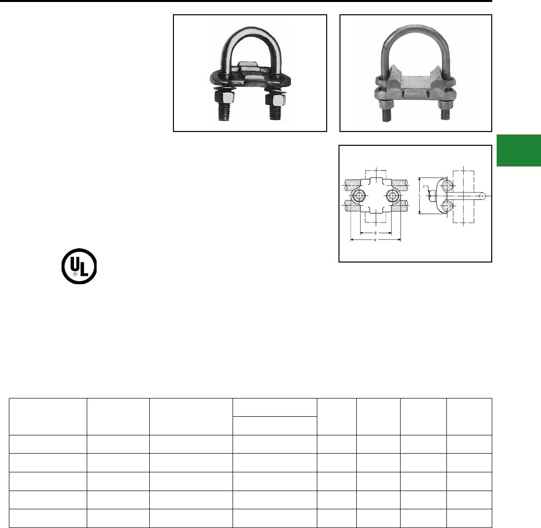
BURNDY®
Blue highlighted items are industry standard and most frequently ordered.
Canada: 1-800-387-6487 www.burndy.com US: 1-800-346-4175
Grounding
Mechanical
TYPES GP-G1, GP-RT
Raised Floor Grounding Clamps
High copper alloy ground connector for raised
oor computer grounding applications. These
connectors can be installed on round and square
pedestal applications and will accommodate one
or two grounding wires to make an efcient grid.
The underoor signal reference grid provides the
low impedance ground path that attenuates high
frequency static and 60 Hz transient noise for
cleaner data output. UL467 Listed.In addition we
offer the GP1726RT, which is especially designed
for penetrating epoxy paint on pedestals. This
patented connector offers a low impedance, time
saving connection between conductors and the
pedestal.
Catalog
Number
Number of
Conductors
Conductor Size
Sol. & Str.
Pedestal Type
B J L W
Round or Square
GP654CG1 1 or 2 #8 Sol. - 4 Str. Round/Square 1.50 3/8 1.31 2.38
GP64526G1 1 or 2 #4 Sol. - 2/0 Str. Round/Square 1.50 3/8 1.69 2.38
GP1526G1 1 or 2 #4 Sol. - 2/0 Str. Round 1.75 3/8 1.69 2.62
GP1726RT 1 or 2 #6 Sol. - 2/0 Str. Round/Square 2.12 3/8 1.50 3.22
GP1726G1 1 or 2 #6 Sol. - 2/0 Str. Round 2.12 3/8 1.50 3.22
Features & Benets
• Accepts 1 or 2 Ground Conductors
• Requires less connectors to install
signal reference grid
• Made of copper alloy
• DURIUM™ U-Bolts, nuts and
lockwashers
• Provides a low impedance ground path
for maximum performance
• Grounds all pedestals (round or square)
• Will handle from 3⁄4" to 1" round or
square
• Ease of installation.
• Serves 3 needs
1. Signal Reference Grid
2. Static Ground
3. Fault Current Ground
• Connectors solves all possible
grounding problems found in computer
applications today
E-67
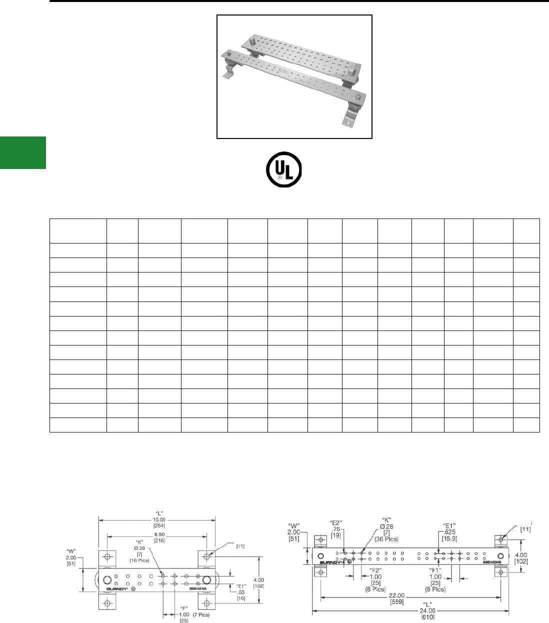
BURNDY®
Blue highlighted items are industry standard and most frequently ordered.
US: 1-800-346-4175 www.burndy.com Canada: 1-800-387-6487
Grounding
Mechanical
TYPE BBB
BURNDY® Bus Bar
Copper Bus Bar
Bare copper BusBar, UL Listed for grounding.
Available in many sizes and hole patterns.
Brackets and insulators included with most
styles. Also available in undrilled, horizontal and
vertical versions. BusBar is used in a variety of
applications. Can be used as a common ground
point and “power” applications as well.
Catalog
Number
Fig
No.
Insulator
& Bracket
T - Bar
Thickness
W - Bar
Width
L - Bar
Length E1 E2 E3 F1 F2 No. of
Holes K
BBB-14210A 1 0.63 1/4" 2 in 10” 0.63 — — 1.00 — 16 0.28
BBB-14224B 2 0.62 1/4" 2 in 24” 0.62 0.75 — 1.00 1.00 36 0.28
BBB-14410C 3 0.75 1/4" 4 in 10” 0.75 1.00 — 1.25 — 22 0.44
BBB-14410D 4 1.25 1/4" 4 in 10” 1.25 1.00 — 1.13 1.13 22 0.44
BBB-14412E 5 0.75 1/4" 4 in 12” 0.75 1.00 — 2.00 1.25 18 0.44
BBB-14412F 6 1.00 1/4" 4 in 12” 1.00 0.75 — 2.00 1.25 24 0.44
BBB-14416G 7 0.75 1/4" 4 in 16” 0.75 1.00 — 1.69 — 24 0.44
BBB-14416H 8 1.00 1/4" 4 in 16” 1.00 1.00 0.75 1.69 — 32 0.44
BBB-14420J 9 1.00 1/4" 4 in 20” 1.00 1.00 0.75 1.00 — 68 0.44
BBB412UD — N/A 1/4" 4 in 12” N/A N/A N/A N/A N/A 0 —
BBB-424-UD — N/A 1/4" 4 in 24” N/A N/A N/A N/A N/A 0 —
BBB-HR19 12 0.38 3/16" 3/4 in 19” 0.38 — — — — 8 —
BBB-VR36 13 0.32 1/4" 5/8 in 36” 0.32 — — — — 16 —
* Contact factory for custom sizes.
NOTE:
For separately ordering Insulator & Brackets use
catalog number B38723000.
Figure 1 Figure 2
0.38
0.38
E-68
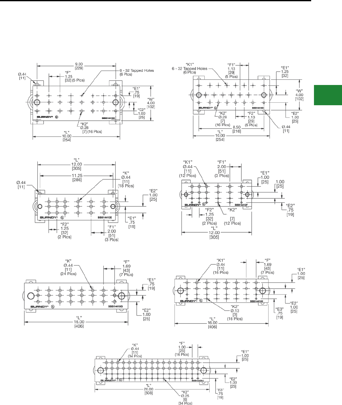
BURNDY®
Blue highlighted items are industry standard and most frequently ordered.
Canada: 1-800-387-6487 www.burndy.com US: 1-800-346-4175
Grounding
Mechanical
TYPE BBB
BURNDY® Bus Bar
Copper Bus Bar (Continued)
Figure 3 Figure 4
Figure 5 Figure 6
Figure 7 Figure 8
Figure 9
.28
E-69
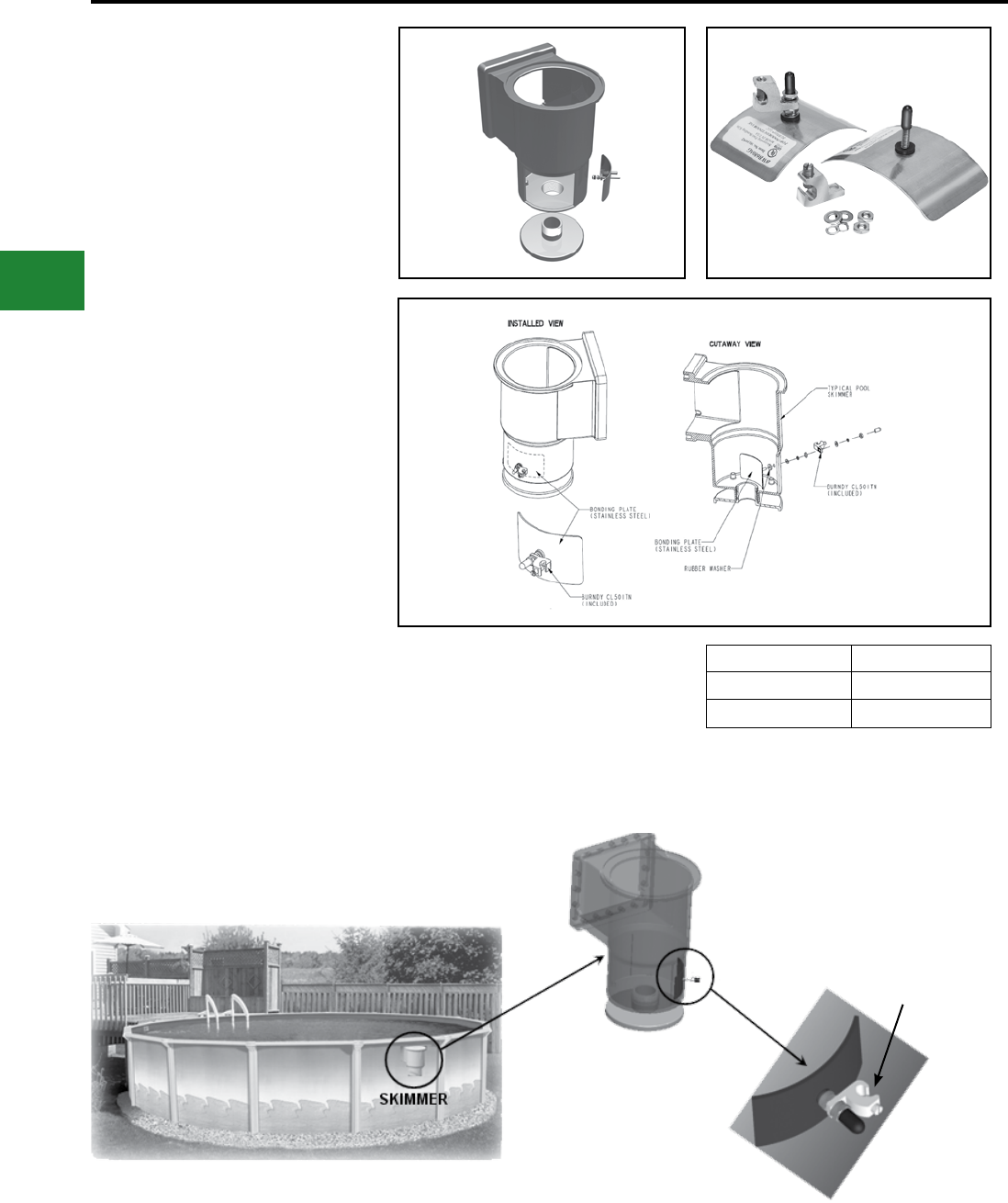
BURNDY®
Blue highlighted items are industry standard and most frequently ordered.
US: 1-800-346-4175 www.burndy.com Canada: 1-800-387-6487
Grounding
Mechanical
BWB680 Series
BURNDY® Pool Water Bonding Kit
NEC 680.26(C) states: “An intentional bond of
minimum conductive surface area of 9″ shall be
installed in contact with the pool water. This bond
shall be permitted to consist of parts that are
rquired to be bonded in 680.26(B)”.
In order to comply with this requirement BURNDY
is offering the BWB680 Series. Made of non-
corrosive stainless steel, the BURNDY water
bonding kit maintains constant contact with pool
water to ensure that the pool is effectively bonded
at all times.
BURNDY BWB680 Series is one of the few and
the most user friendly, products on the market that
complies with this code. Other products are placed
in the plumbing, which is not always in contact
wtih the water and therefore does not meet the
code. Since the BWB680 Series is placed in the
skimmer, it is always in contact with the water.
Included in the BURNDY BWB680 Series Bonding
Kit: One (1) bonding plate; one (1) rubber sealing
washer; two (2) at washers; two (2) lock washers;
two (2) nuts; and one (1) BURNDY CL501-TN
Catalog Number Pool Type
BWB680AG Above Ground
BWB680IG In-Ground
Features & Benets
• Easy installation
• Mounting hardware included
• UL Listed
• Placed out of the way on the side wall of the
skimmer below the basket
Bonding wire
goes here
E-70
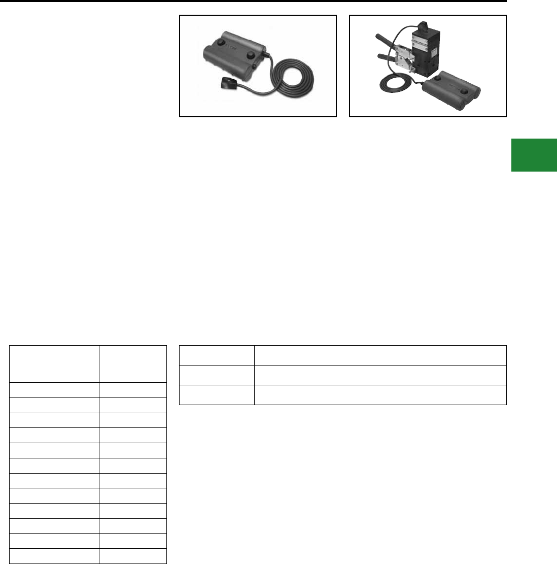
BURNDY®
Blue highlighted items are industry standard and most frequently ordered.
Canada: 1-800-387-6487 www.burndy.com US: 1-800-346-4175
Grounding
BURNDYWeld® Exothermic
BURNDYWeld®
QIKLITE®
BURNDYWeld® Weld Metal
Battery Ignition System
The self-contained unit offers a built-in battery life
indicator, 6’ ignitor cord and separate buttons for
power and ignition. Also, no starting powder is used
with this system so emissions are greatly reduced.
QIKLITE® works with “off-the-shelf” molds and
weld metal, so contractors and installers can
continue to use the same quality BURNDYWeld®
products.
Since the unit operates with standard weld metal
and molds, installers also have the option of using
a traditional int ignitor or the new QIKLITE®
system. Another feature is the speed of ignition,
with virtually no delay between depressing the
“push to operate” button and ignition of the weld
metal. This instant ignition feature offers quick
reassurance to the installer, without the delay.
Catalog Number Description
QIKLITE Battery Ignition System
QIKLITEKIT QIKLITE® Battery Ignition System and 20 QIKSTIK Ignitor Sticks
Features & Benets
• The QIKLITE® system allows installers to make
exothermic connections remotely
• Uses standard exothermic molds and weld
metal
• Use the new BURNDYWeld® QIKLITE® system
or use a int ignitor, this versatility makes this
system better than anything available in the
industry
• Installers have virtually 100% condence that
the connection can be completed with no
wasted material or weld metal shots
• No starting material required - which greatly
reduces the amount of emissions generated
• Power is supplied by 4 standard “D” Size
batteries
• Built-in battery life indicator
• There’s virtually no delay in ignition after
depressing the “push to operate” button
• Separate ON/OFF and Operate buttons
• Comes complete with durable 6’ heat resistant
cord
• Durable, long-lasting design
• QIKSTIK ignitor sticks are conveniently
packaged and available separately or available
packaged complete with standard weld metal
Catalog Number
Standard Cartridge
Size with Ignitor
Cartridges/
Ignitors
Per Box
15Q 20
25Q 20
32Q 10
45Q 20
65Q 20
90Q 10
115Q 10
150Q 10
200Q 10
250Q 10
500Q 10
QIKSTIK* 10
* Ignitor stick only.
E-71
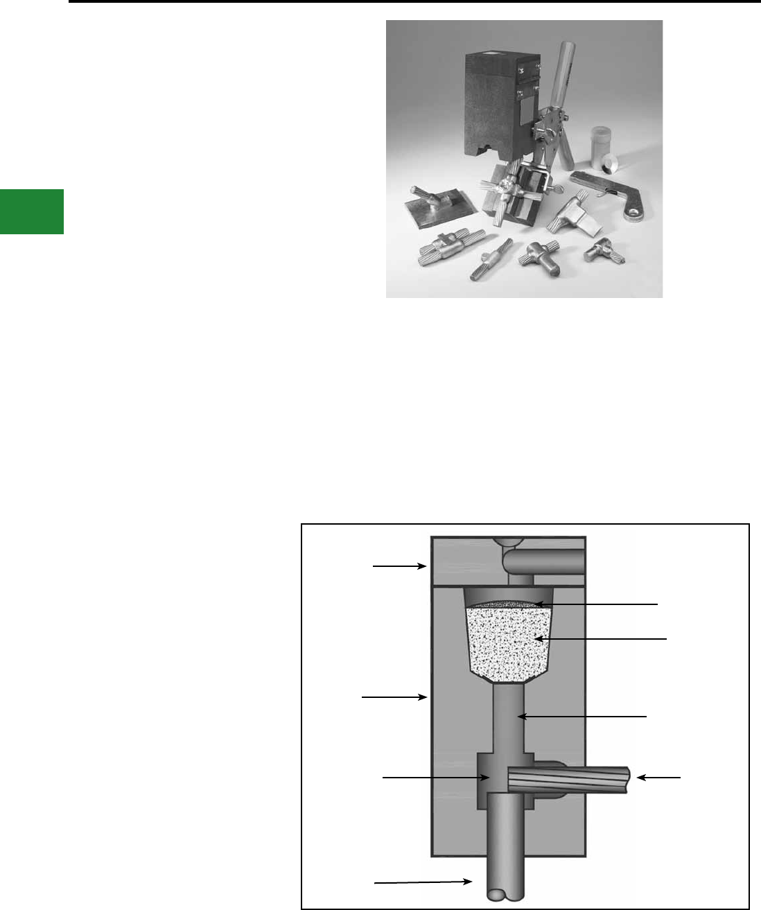
BURNDY®
Blue highlighted items are industry standard and most frequently ordered.
US: 1-800-346-4175 www.burndy.com Canada: 1-800-387-6487
Grounding
BURNDYWeld® Exothermic
BURNDYWeld®
The BURNDYWeld® connection process is a
simple, efcient method of welding copper to
copper or copper to steel. One advantage is
that NO outside power is required when using
the BURNDYWeld® exothermic process. The
BURNDYWeld® process uses high temperature
reaction of powdered copper oxide and aluminum.
The reaction takes place in a semi-permanent
graphite mold. These molds will last for fty or
more welds if proper car is given. The reaction
takes place very rapidly, therefore the total amount
of heat applied to the conductors or surfaces is
considerably less than that of brazing or soldering.
It is important to remember this when welding to
insulated cable or thin wall pipe.
This system is very eld friendly, since it is light and
portable and requires no outside power source. It
requires very little time or skill to obtain an efcient,
maintenance free connection when using the
BURNDYWeld® process.
For more information, visit our website at:
www.burndy.com.
The BURNDYWeld® process has been used to
weld materials other than copper for electrical
purposes. Materials welded include:
Stainless Steel
Copperweld®
Nichrome V
Galvanized Steel
Silicon Bronze
Copper Clad Steel
Columbium
Plain Steel
Everdur®
Kama
Stell Rail
Cor-Ten®
Brass
Bronze
Niobium
Chromax
Cast Iron
Monel
When welding to galvanized steel it is
recommended to resurface exposed bare steel.
The BURNDYWeld® connection is a molecular
weld. The weld metal has the same melting point
as copper. These factors along with the increased
cross section of the connection, BURNDYWeld®
connections:
1. Will not be affected by a high current
surge. Tests have shown that the
electrical conductor will melt before the
BURNDYWeld® connection when subjected
to high short circuit current. Consult IEEE
Standard 837-1989.
2. Will not loosen or corrode at the point of weld.
There are no contact surfaces or mechanical
pressures involved. A BURNDYWeld®
connection becomes an integral part of the
conductor.
3. Have a current-carrying capacity equal to or
greater than that of the conductors.
Lid
Graphite
Mold
Weld
Cavity
Ground
Rod
Starting
Powder
Weld
Metal
Tap Hole
Cable
E-72
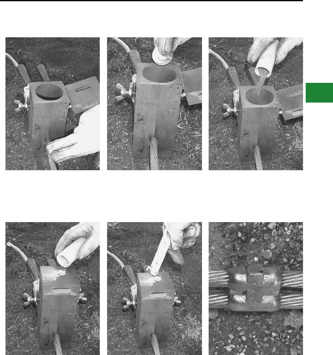
BURNDY®
Blue highlighted items are industry standard and most frequently ordered.
Canada: 1-800-387-6487 www.burndy.com US: 1-800-346-4175
Grounding
BURNDYWeld® Exothermic
Making a BURNDYWeld® Connection
Step 1
Position cleaned conductors in mold after
make sure mold is dry, by pre-heating or
making a test joint.
Step 6
Wait 15 seconds, then remove weld
and clean mold before making next
connection.
Step 5
Ignite the starting powder with the Flint
Ignitor.
Step 4
Close lid and place a small amount of
starting powder in the ignition pocket.
Step 3
Dump powder into crucible, being careful
not to loosen all the starting powder.
Step 2
Place metal disc in bottom of mold
crucible.
E-73
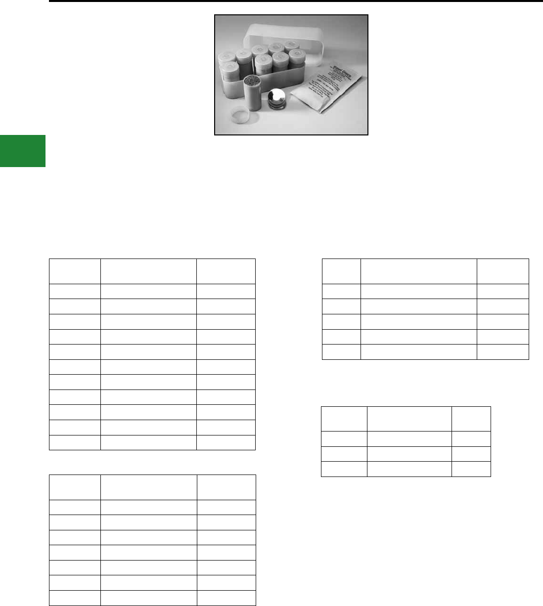
BURNDY®
Blue highlighted items are industry standard and most frequently ordered.
US: 1-800-346-4175 www.burndy.com Canada: 1-800-387-6487
Grounding
BURNDYWeld® Exothermic
BURNDYWeld®
Weld Metal
BURNDYWeld® Weld Metal is packed in moisture-
resistant plastic cartridges that have tight tting
caps. These cartridges, along with the necessary
steel discs, are then packed in boxes that are
hermetically sealed. This ensures the powder
arriving in good condition, always dry and ready for
fast positive ignition. BURNDYWeld® Weld Metal
comes in several types; one for welding copper to
copper, copper to steel, copper to cast iron and one
for welding copper to steel for cathodic protection.
The size and weight (in grams) of the cartridge are
marked on each individual cartridge.
Weld metal and steel discs are sold only in
standard box quantities.
Features & Benets
• Packed in moisture-resistant plastic cartridges
that have tight tting caps. These cartridges,
along with the necessary steel discs, are then
packed in boxes that are hermetically sealed.
This ensures the powder arriving in good
condition, always dry and ready for fast positive
ignition.
Catalog
Number * Description Cartridges
Per Box
15 Standard Cartridge 20
25 Standard Cartridge 20
32 Standard Cartridge 10
45 Standard Cartridge 20
65 Standard Cartridge 20
90 Standard Cartridge 10
115 Standard Cartridge 10
150 Standard Cartridge 10
200 Standard Cartridge 10
250 Standard Cartridge 10
500 Standard Cartridge 10
Catalog
Number Description Cartridges
Per Box
15CI Cast Iron Cartridge 20
25CI Cast Iron Cartridge 20
32CI Cast Iron Cartridge 10
45CI Cast Iron Cartridge 20
65CI Cast Iron Cartridge 20
90CI Cast Iron Cartridge 10
115CI Cast Iron Cartridge 10
Catalog
Number Description Cartridges
Per Box
15CP Cathodic Protection Cartridge 20
25CP Cathodic Protection Cartridge 20
32CP Cathodic Protection Cartridge 10
45CP Cathodic Protection Cartridge 20
65CP Cathodic Protection Cartridge 20
Weld Metal
Size
Catalog Number
Steel Discs Only
Package
Quantity
15 to 65 B370320-01 20
90 to 115 B370320-02 10
150 to 500 B370320-03 10
* Add Q to sufx to include Qikstik
E-74
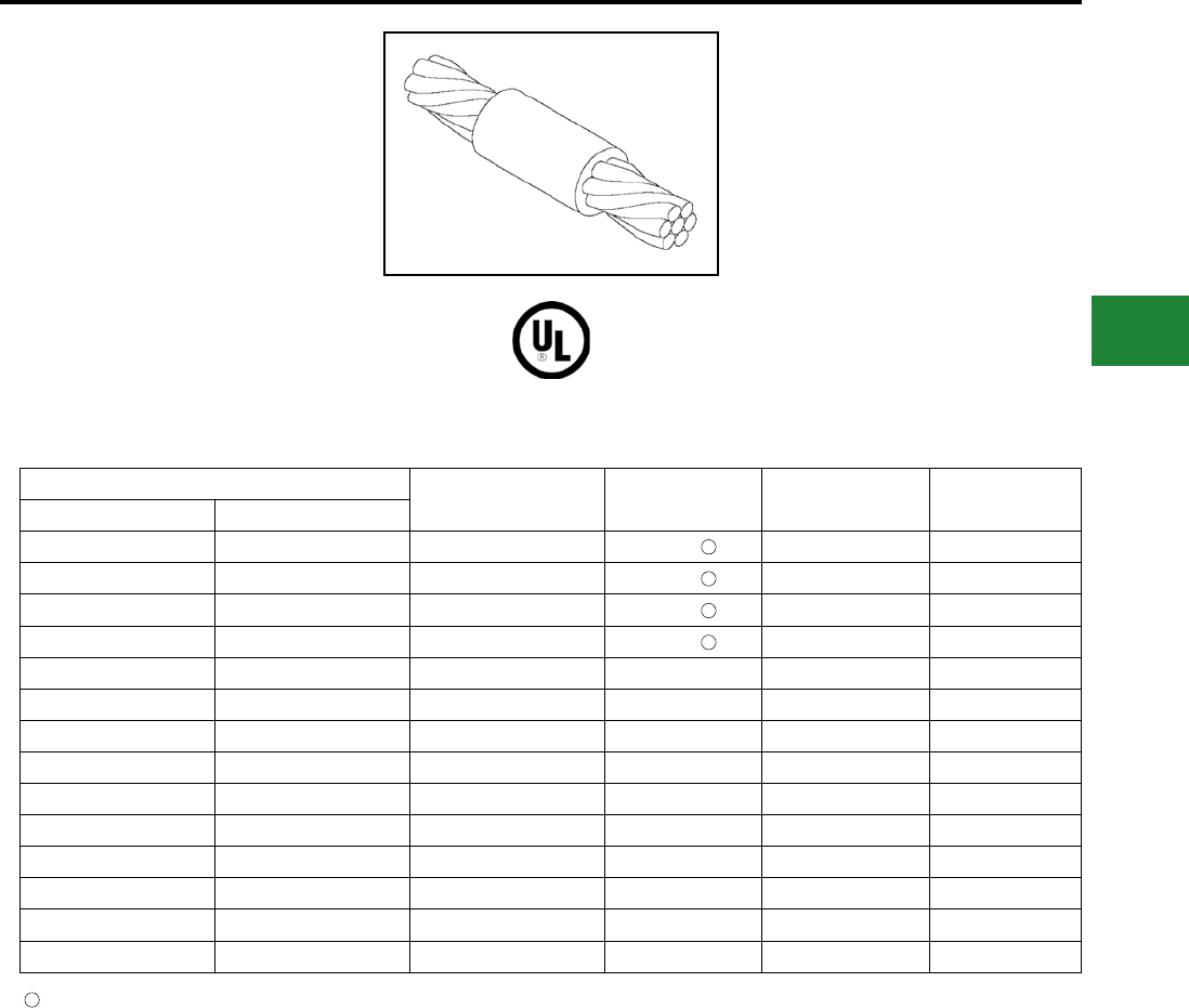
BURNDY®
Blue highlighted items are industry standard and most frequently ordered.
Canada: 1-800-387-6487 www.burndy.com US: 1-800-346-4175
Grounding
BURNDYWeld® Exothermic
BCC-1 TYPE MOLDS
Horizontal End to End
BCC-1 Type Molds are used for horizontal end to
end cable connections.
Size range is #6 through 1000 kcmil solid or
concentric stranded copper conductors.
Contact BURNDY® for information on molds for
conductors not listed below.
Cable Mold Number Price Key Weld Metal Handle Clamps
Run Tap
#4 #4 B-5623 18 25 Incl.
#3 #3 B-5624 18 32 Incl.
#2 #2 B-5625 18 32 Incl.
#1 #1 B-5626 18 32 Incl.
1/0 1/0 B-205 4 45 B-106
2/0 2/0 B-206 4 65 B-106
3/0 3/0 B-207 4 90 B-106
4/0 4/0 B-208 4 90 B-106
250 kcmil 250 kcmil B-209 4 115 B-106
300 kcmil 300 kcmil B-210 4 115 B-106
350 kcmil 350 kcmil B-211 4 150 B-106
500 kcmil 500 kcmil B-213 4 200 B-107
750 kcmil 750 kcmil B-214 5 2-150 B-107
1000 kcmil 1000 kcmil B-215 5 2-200 B-107
1
1
1
1
B38-0309-00 Flint ignitor included
1
NOTES:
• For sizes not listed, contact BURNDY®
• Molds listed are for concentric stranded cable; add sufx “-S” to mold number for solid conductors
• For heavy duty molds, molds with wear plates or molds for Copperweld ® cable, contact BURNDY®
• For expedited service, contact BURNDY®
Required Tools:
Handle Clamps - see chart for correct handle catalog number
Recommended Accessories:
B38-0309-00 Flint Ignitor
B38-3922-00 Mold Cleaning Brush
B38-0135-00 Cable Cleaning Brush
B38-0330-00 Cable Clamp
E-75

BURNDY®
Blue highlighted items are industry standard and most frequently ordered.
US: 1-800-346-4175 www.burndy.com Canada: 1-800-387-6487
Grounding
BURNDYWeld® Exothermic
TYPE BCC-2 MOLDS
Horizontal Cable Tap to
Horizontal Cable Run
Type BCC-2 Molds are used to join horizontal
cable tap to a horizontal run cable. Size range is
#6 through 750 kcmil solid or concentric stranded
copper conductors. Contact BURNDY® for
information on molds for conductors not listed
below.
Cable Mold
Number
Price
Key
Weld
Metal
Handle
Clamps
Run Tap
#4 #4 B-221 4 32 B-106
#2 #2 B-223 4 45 B-106
#4 B-224 4 45 B-106
#1
#1 B-225 4 45 B-106
#2 B-226 4 45 B-106
#4 B-227 4 45 B-106
1/0
1/0 B-228 4 90 B-106
#1 B-229 4 45 B-106
#2 B-230 4 45 B-106
#4 B-231 4 45 B-106
2/0
2/0 B-232 4 90 B-106
1/0 B-333 4 90 B-106
#1 B-234 4 45 B-106
#2 B-235 4 45 B-106
#4 B-5475 4 45 B-106
3/0
3/0 B-236 4 115 B-106
2/0 B-237 4 90 B-106
1/0 B-238 4 90 B-106
#1 B-239 4 45 B-106
#2 B-240 4 45 B-106
#4 B-5574 4 45 B-106
4/0
4/0 B-241 4 150 B-106
3/0 B-242 4 115 B-106
2/0 B-243 4 90 B-106
1/0 B-244 4 90 B-106
#1 B-245 4 90 B-106
#2 B-246 4 90 B-106
#4 B-5021 4 90 B-106
250 kcmil
250 kcmil B-247 4 150 B-106
4/0 B-248 4 150 B-106
3/0 B-249 4 150 B-106
2/0 B-250 4 90 B-106
1/0 B-251 4 90 B-106
#1 B-252 4 90 B-106
#2 B-253 4 90 B-106
Cable Mold
Number
Price
Key
Weld
Metal
Handle
Clamps
Run Tap
300 kcmil
300 kcmil B-254 4 200 B-106
250 kcmil B-255 4 150 B-106
4/0 B-256 4 150 B-106
3/0 B-257 4 150 B-106
2/0 B-258 4 90 B-106
1/0 B-259 4 90 B-106
#1 B-260 4 90 B-106
#2 B-261 4 90 B-106
350 kcmil
350 kcmil B-262 4 200 B-106
300 kcmil B-263 4 200 B-106
250 kcmil B-264 4 200 B-106
4/0 B-265 4 150 B-106
3/0 B-266 4 150 B-106
2/0 B-267 4 90 B-106
1/0 B-268 4 90 B-106
#1 B-269 4 90 B-106
#2 B-270 4 90 B-106
500 kcmil
500 kcmil B-280 4 2-150 B-106
350 kcmil B-282 4 200 B-106
300 kcmil B-283 4 200 B-106
250 kcmil B-284 4 200 B-106
4/0 B-285 4 150 B-106
2/0 B-286 4 90 B-106
1/0 B-287 4 90 B-106
#1 B-288 4 90 B-106
#2 B-289 4 90 B-106
750 kcmil
750 kcmil B-290 5 500 B-107
500 kcmil B-291 5 2-200 B-107
350 kcmil B-293 4 250 B-106
300 kcmil B-294 4 200 B-106
250 kcmil B-295 4 200 B-106
4/0 B-296 4 150 B-106
2/0 B-297 4 150 B-106
1/0 B-298 4 150 B-106
NOTES:
• For sizes not listed, contact BURNDY®
• Molds listed are for concentric stranded
cable; add suffix “-S” to mold number for solid
conductors
• For heavy duty molds, molds with wear plates or
molds for Copperweld ® cable, contact BURNDY®
• For expedited service, contact BURNDY®
Required Tools:
Handle Clamps - see chart for correct handle catalog
number
Recommended Accessories:
B38-0309-00 Flint Ignitor; B38-3922-00 Mold Cleaning
Brush; B38-0135-00 Cable Cleaning Brush;
B38-0330-00 Cable Clamp
E-76
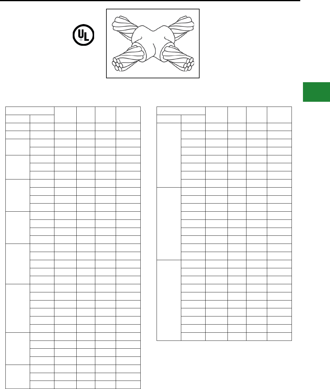
BURNDY®
Blue highlighted items are industry standard and most frequently ordered.
Canada: 1-800-387-6487 www.burndy.com US: 1-800-346-4175
Grounding
BURNDYWeld® Exothermic
TYPE BCC-4 MOLDS
Horizontal to Horizontal
Cable Cross
Type BCC-4 Molds are used to join two horizontal
cables at right angles. One cable is cut and the
other is a through run. Size range is #6 through
500 kcmil solid or concentric stranded copper
conductors. Contact BURNDY® for information on
molds for conductors not listed below.
Cable Mold
Number
Price
Key
Weld
Metal
Handle
Clamps
Run Tap
#4 #4 B-423 4 45 B-106
#3 #3 B-424 4 45 B-106
#2 #2 B-425 4 65 B-106
#4 B-426 4 65 B-106
#1
#1 B-427 4 65 B-106
#2 B-428 4 65 B-106
#4 B-429 4 65 B-106
1/0
1/0 B-430 4 90 B-106
#1 B-431 4 90 B-106
#2 B-432 4 90 B-106
#4 B-433 4 90 B-106
2/0
2/0 B-434 4 115 B-106
1/0 B-435 4 115 B-106
#1 B-436 4 115 B-106
#2 B-437 4 115 B-106
3/0
3/0 B-438 4 150 B-106
2/0 B-439 4 150 B-106
1/0 B-440 4 115 B-106
#1 B-441 4 115 B-106
#2 B-442 4 115 B-106
4/0
4/0 B-443 4 200 B-106
3/0 B-444 4 200 B-106
2/0 B-445 4 150 B-106
1/0 B-446 4 150 B-106
#1 B-447 4 115 B-106
#2 B-448 4 115 B-106
250 kcmil
250 kcmil B-449 4 200 B-106
4/0 B-450 4 200 B-106
3/0 B-451 4 200 B-106
2/0 B-452 4 150 B-106
250 kcmil
1/0 B-453 4 150 B-106
#1 B-454 4 115 B-106
#2 B-455 4 115 B-106
Cable Mold
Number
Price
Key
Weld
Metal
Handle
Clamps
Run Tap
300 kcmil
300 kcmil B-456 4 250 B-106
250 kcmil B-457 4 250 B-106
4/0 B-458 4 200 B-106
3/0 B-459 4 200 B-106
2/0 B-460 4 150 B-106
1/0 B-461 4 150 B-106
#1 B-462 4 115 B-106
#2 B-463 4 115 B-106
350 kcmil
350 kcmil B-464 4 250 B-106
300 kcmil B-465 4 250 B-106
250 kcmil B-466 4 250 B-106
4/0 B-467 4 200 B-106
3/0 B-468 4 200 B-106
2/0 B-469 4 200 B-106
1/0 B-470 4 200 B-106
#1 B-471 4 150 B-106
#2 B-472 4 150 B-106
500 kcmil
500 kcmil B-483 5 500 B-107
350 kcmil B-485 5 2-200 B-107
300 kcmil B-486 5 2-200 B-107
250 kcmil B-487 5 2-150 B-107
4/0 B-488 5 2-150 B-107
3/0 B-489 5 2-150 B-107
2/0 B-490 4 250 B-106
1/0 B-491 4 250 B-106
#1 B-492 4 200 B-106
#2 B-493 4 200 B-106
NOTES:
• For sizes not listed, contact BURNDY®
• Molds listed are for concentric stranded
cable; add suffix “-S” to mold number for solid
conductors
• For heavy duty molds, molds with wear plates or
molds for Copperweld ® cable, contact BURNDY®
• For expedited service, contact BURNDY®
Required Tools:
Handle Clamps - see chart for correct handle catalog
number
Recommended Accessories:
B38-0309-00 Flint Ignitor; B38-3922-00 Mold Cleaning
Brush; B38-0135-00 Cable Cleaning Brush;
B38-0330-00 Cable Clamp
E-77
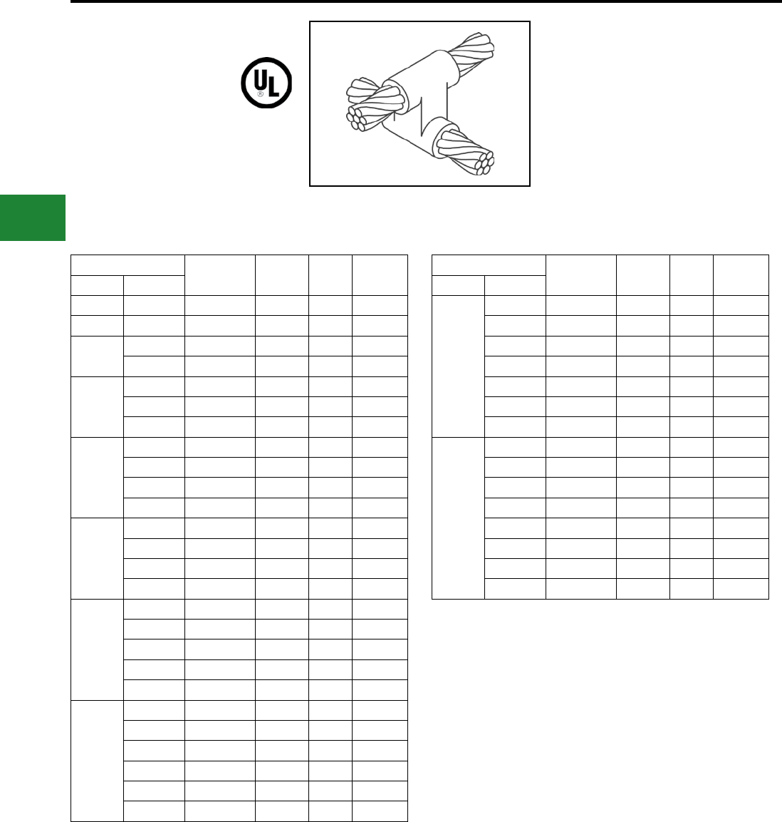
BURNDY®
Blue highlighted items are industry standard and most frequently ordered.
US: 1-800-346-4175 www.burndy.com Canada: 1-800-387-6487
Grounding
BURNDYWeld® Exothermic
TYPE BCC-11 MOLDS
Horizontal to Horizontal
Cable Cross
Type BCC-11 Molds are used to join uncut
horizontal cables at right angles to each other. Size
range is #6 through 500 kcmil solid or concentric
stranded copper conductors. Contact BURNDY®
for information on molds for conductors not listed
below.
Cable Mold
Number
Price
Key
Weld
Metal
Handle
Clamps
Run Tap
#6 #6 B-5432 19 45 Incl.
#4 #4 B-2687 4 65 B-106
#2 #2 B-2689 4 90 B-106
#4 B-2690 4 65 B-106
#1
#1 B-2691 4 115 B-106
#2 B-2692 4 90 B-106
#4 B-2693 4 90 B-106
1/0
1/0 B-2694 22 150 B-106
#1 B-2695 22 150 B-106
#2 B-2696 22 115 B-106
#4 B-2697 22 115 B-106
2/0
2/0 B-2698 22 200 B-106
1/0 B-2699 22 200 B-106
#1 B-2700 22 150 B-106
#2 B-2701 22 150 B-106
3/0
3/0 B-2702 22 250 B-106
2/0 B-2703 22 200 B-106
1/0 B-2704 22 200 B-106
#1 B-2705 22 150 B-106
#2 B-2706 22 150 B-106
4/0
4/0 B-2707 22 250 B-106
3/0 B-2708 22 250 B-106
2/0 B-2709 22 200 B-106
1/0 B-2710 22 200 B-106
#1 B-2711 22 150 B-106
#2 B-2712 22 150 B-106
Cable Mold
Number
Price
Key
Weld
Metal
Handle
Clamps
Run Tap
250 kcmil
250 kcmil B-2713 22 2-150 B-106
4/0 B-2714 22 2-150 B-106
3/0 B-2715 22 2-150 B-106
2/0 B-2716 22 250 B-106
1/0 B-2717 22 150 B-106
#1 B-2718 22 200 B-106
#2 B-2719 22 150 B-106
500 kcmil
500 kcmil B-2747 23 3-250 B-107
250 kcmil B-2751 23 500 B-107
4/0 B-2752 23 500 B-107
3/0 B-2753 23 500 B-107
2/0 B-2754 23 2-200 B-107
1/0 B-2755 22 2-150 B-106
#1 B-2756 22 250 B-106
#2 B-2757 22 250 B-106
NOTES:
• For sizes not listed, contact BURNDY®
• Molds listed are for concentric stranded
cable; add suffix “-S” to mold number for solid
conductors
• For heavy duty molds, molds with wear plates or
molds for Copperweld ® cable, contact BURNDY®
• For expedited service, contact BURNDY®
Required Tools:
Handle Clamps - see chart for correct handle catalog
number
Recommended Accessories:
B38-0309-00 Flint Ignitor; B38-3922-00 Mold Cleaning
Brush; B38-0135-00 Cable Cleaning Brush;
B38-0330-00 Cable Clamp
E-78
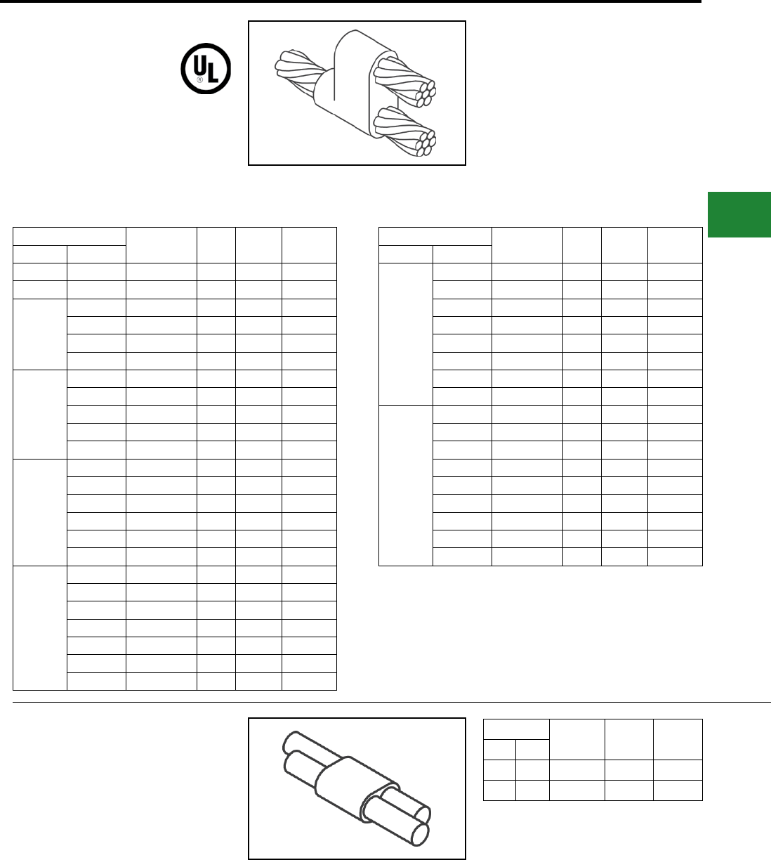
BURNDY®
Blue highlighted items are industry standard and most frequently ordered.
Canada: 1-800-387-6487 www.burndy.com US: 1-800-346-4175
Grounding
BURNDYWeld® Exothermic
BCC-6 TYPE MOLDS
Horizontal Parallel Tap
BCC-6 Type Molds are used to join horizontal
parallel tap to run connections. The tap cable is
over the run cable. Size range is #6 through 4/0
solid or concentric stranded copper conductors.
Contact BURNDY® for information on molds for
conductors not listed below.
Cable Mold Number Price
Key
Weld
Metal
Handle
Clamps
Run Tap
#6 Sol #6 Sol B-1270 4 25 B-106
#6 #6 B-1271 4 25 B-106
#4
#4 B-1272 4 32 B-106
#6 B-1273 4 32 B-106
#6 Sol B-1274 4 32 B-106
#8 Sol B-1275 4 32 B-106
#2
#2 B-1276 4 65 B-106
#4 B-1277 4 45 B-106
#6 B-1278 4 32 B-106
#6 Sol B-1279 4 32 B-106
#8 Sol B-1280 4 32 B-106
#1
#1 B-1281 4 65 B-106
#2 B-1282 4 65 B-106
#4 B-1283 4 45 B-106
#6 B-1284 4 45 B-106
#6 Sol B-1285 4 45 B-106
#8 Sol B-1286 4 45 B-106
1/0
1/0 B-1287 4 90 B-106
#1 B-1288 4 90 B-106
#2 B-1289 4 65 B-106
#4 B-1290 4 65 B-106
#6 B-1291 4 45 B-106
#6 Sol B-1292 4 45 B-106
#8 Sol B-1293 4 45 B-106
Cable Mold Number Price
Key
Weld
Metal
Handle
Clamps
Run Tap
2/0
2/0 B-1294 4 115 B-106
1/0 B-1295 4 115 B-106
#1 B-1296 4 90 B-106
#2 B-1297 4 90 B-106
#4 B-1298 4 65 B-106
#6 B-1299 4 65 B-106
#6 Sol B-1300 4 65 B-106
#8 Sol B-1301 4 65 B-106
4/0
4/0 B-1302 4 150 B-106
2/0 B-1303 4 115 B-106
1/0 B-1304 4 115 B-106
#1 B-1305 4 115 B-106
#2 B-1306 4 115 B-106
#4 B-1307 4 90 B-106
#6 B-1308 4 90 B-106
#6 Sol B-1309 4 90 B-106
#8 Sol B-1310 4 90 B-106
BCC-14 TYPE MOLDS
Horizontal Parallel through Cables
BCC-14 Type Molds are used to join horizontal
parallel through run cables. Cables run side by
side in the mold. Size range is #8 through #6
solid or concentric stranded copper conductors.
Contact BURNDY® for information on molds for
conductors not listed.
Cable Mold
Number
Price
Key
Weld
Metal
Run Tap
#8 #8 B-5709 18 15
#6 #6 B-5618 18 25
NOTES:
• For sizes not listed, contact BURNDY®
• Molds listed are for concentric stranded
cable; add suffix “-S” to mold number for solid
conductors
• For heavy duty molds, molds with wear plates or
molds for Copperweld ® cable, contact BURNDY®
• For expedited service, contact BURNDY®
Required Tools:
Handle Clamps - see chart for correct handle catalog
number
Recommended Accessories:
B38-0309-00 Flint Ignitor; B38-3922-00 Mold Cleaning
Brush; B38-0135-00 Cable Cleaning Brush;
B38-0330-00 Cable Clamp
NOTES:
• For sizes not listed, contact BURNDY®
• Molds listed are for concentric stranded
cable; add suffix “-S” to mold number for solid
conductors
• For heavy duty molds, molds with wear plates or
molds for Copperweld ® cable, contact BURNDY®
• For expedited service, contact BURNDY®
• Sold complete with handles
E-79
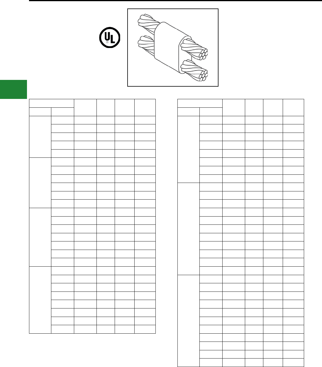
BURNDY®
Blue highlighted items are industry standard and most frequently ordered.
US: 1-800-346-4175 www.burndy.com Canada: 1-800-387-6487
Grounding
BURNDYWeld® Exothermic
BCC-7 TYPE MOLDS
Horizontal Parallel
through Cables
BCC-7 Type Molds are used to join horizontal
parallel through run cables. One cable runs above
the other cable in the mold. Size range is #6
through 4/0 solid or concentric stranded copper
conductors. Contact BURNDY® for information on
molds for conductors not listed below
Cable Mold
Number
Price
Key
Weld
Metal
Handle
Clamps
Run Tap
#4
#4 B-1311 4 32 B-106
#6 B-5627 4 32 B-106
#6 Sol B-8882 4 32 B-106
#8 B-5629 4 32 B-106
#8 Sol B-5630 4 32 B-106
#2
#2 B-1313 4 65 B-106
#4 B-1314 4 65 B-106
#6 B-5631 4 45 B-106
#6 Sol B-5632 4 45 B-106
#8 B-5634 4 45 B-106
#8 Sol B-5635 4 45 B-106
#1
#1 B-1315 4 65 B-106
#2 B-1316 4 65 B-106
#4 B-1317 4 65 B-106
#6 B-5636 4 65 B-106
#6 Sol B-5637 4 65 B-106
#8 B-5638 4 45 B-106
#8 Sol B-5639 4 45 B-106
1/0
1/0 B-1318 4 90 B-106
#1 B-1319 4 65 B-106
#2 B-1320 4 65 B-106
#4 B-1321 4 65 B-106
#6 B-5642 4 65 B-106
#6 Sol B-1208 4 65 B-106
#8 B-5644 4 65 B-106
#8 Sol B-5645 4 65 B-106
Cable Mold
Number
Price
Key
Weld
Metal
Handle
Clamps
Run Tap
2/0
2/0 B-1322 4 115 B-106
1/0 B-1323 4 115 B-106
#1 B-1324 4 90 B-106
#2 B-1325 4 90 B-106
#4 B-5659 4 90 B-106
#6 B-5342 4 90 B-106
#6 Sol B-5652 4 90 B-106
#8 B-5668 4 65 B-106
3/0
#8 Sol B-5943 4 65 B-106
3/0 B-1326 4 150 B-106
2/0 B-1327 4 150 B-106
1/0 B-1328 4 115 B-106
#1 B-1329 4 115 B-106
#2 B-1330 4 115 B-106
#4 B-6046 4 115 B-106
#6 B-5676 4 90 B-106
#6 Sol B-5679 4 90 B-106
#8 B-5680 4 90 B-106
#8 Sol B-5682 4 90 B-106
4/0
4/0 B-1331 4 200 B-106
3/0 B-1332 4 200 B-106
2/0 B-1333 4 150 B-106
1/0 B-1334 4 150 B-106
#1 B-1335 4 150 B-106
#2 B-1336 4 150 B-106
#4 B-5340 4 150 B-106
#6 B-5684 4 90 B-106
#6 Sol B-6552 4 90 B-106
#8 B-5686 4 90 B-106
#8 Sol B-5688 4 90 B-106
NOTES:
• For sizes not listed, contact BURNDY®
• Molds listed are for concentric stranded
cable; add suffix “-S” to mold number for solid
conductors
• For heavy duty molds, molds with wear plates or
molds for Copperweld ® cable, contact BURNDY®
• For expedited service, contact BURNDY®
Required Tools:
Handle Clamps - see chart for correct handle catalog
number
Recommended Accessories:
B38-0309-00 Flint Ignitor; B38-3922-00 Mold Cleaning
Brush; B38-0135-00 Cable Cleaning Brush;
B38-0330-00 Cable Clamp
E-80
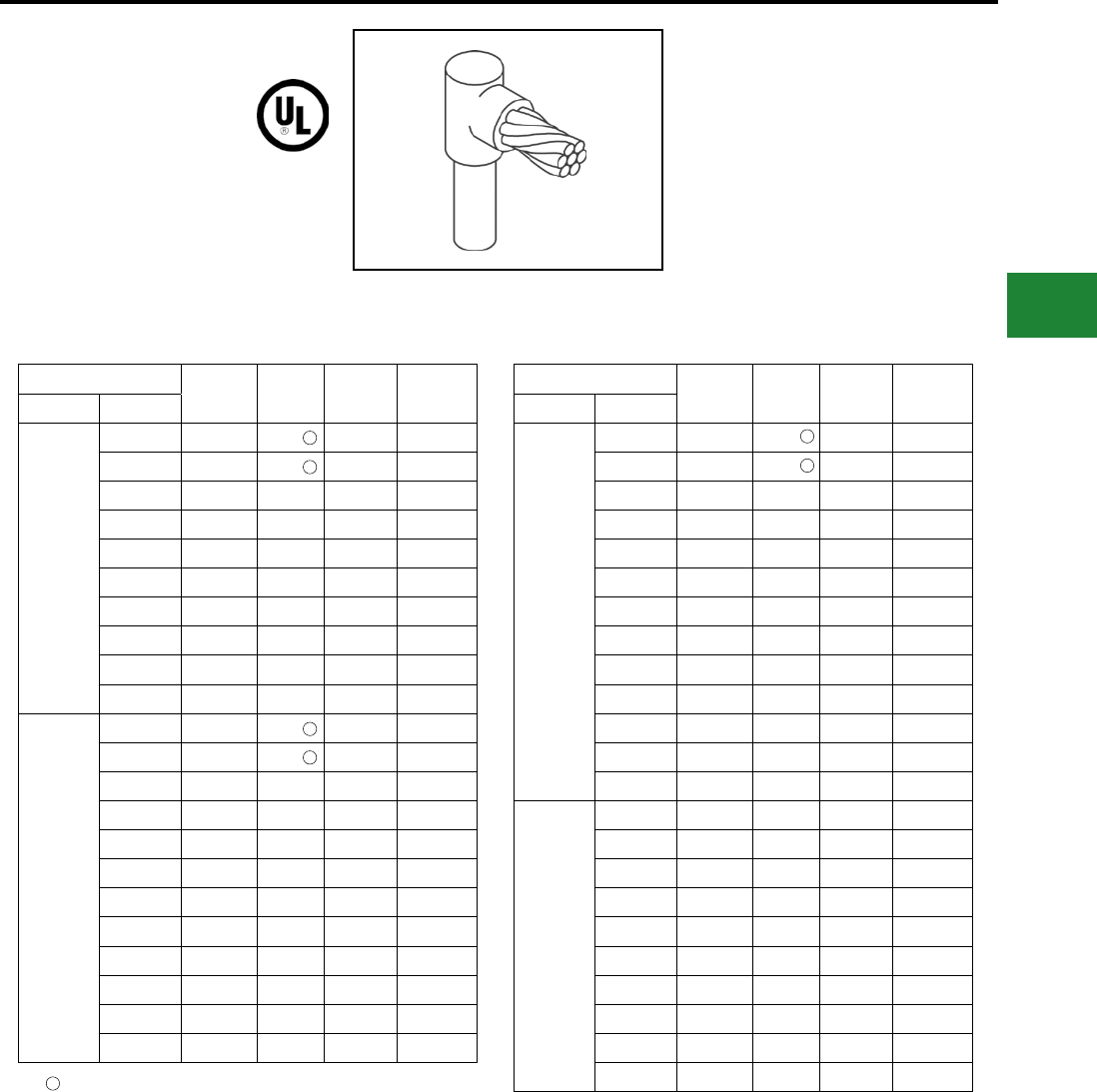
BURNDY®
Blue highlighted items are industry standard and most frequently ordered.
Canada: 1-800-387-6487 www.burndy.com US: 1-800-346-4175
Grounding
BURNDYWeld® Exothermic
TYPE BCR-1 MOLDS
Horizontal Cable Terminal
to Ground Rod
Type BCR-1 Molds are used to terminate horizontal
copper cable at the top of a vertical ground rod. Size
range is #6 through 1000 kcmil solid or concentric
stranded copper conductors; 1/2" through 1" for
the ground rod. Contact BURNDY® for information
on molds for conductors not listed below.
Cable Mold
Number
Price
Key
Weld
Metal
Handle
Clamps
Grd Rod Tap
1/2"
#6 B-8402 18 25 Incl.
#4 B-8403 18 25 Incl.
#2 B-495 4 65 B-106
#1 B-496 4 65 B-106
1/0 B-497 4 90 B-106
2/0 B-498 4 90 B-106
3/0 B-499 4 90 B-106
4/0 B-500 4 90 B-106
250 kcmil B-501 4 90 B-106
300 kcmil B-502 4 90 B-106
5/8"
#6 B-8414 18 32 Incl.
#4 B-8415 18 32 Incl.
#2 B-503 4 65 B-106
#1 B-504 4 65 B-106
1/0 B-505 4 90 B-106
2/0 B-506 4 90 B-106
3/0 B-507 4 90 B-106
4/0 B-508 4 90 B-106
250 kcmil B-509 4 90 B-106
300 kcmil B-510 4 115 B-106
350 kcmil B-511 4 115 B-106
500 kcmil B-513 4 150 B-106
Cable Mold
Number
Price
Key
Weld
Metal
Handle
Clamps
Grd Rod Tap
3/4"
#6 B-8422 18 32 Incl.
#4 B-8426 19 45 Incl.
#2 B-5781 4 90 B-106
#1 B-514 4 90 B-106
1/0 B-515 4 90 B-106
2/0 B-516 4 90 B-106
3/0 B-517 4 90 B-106
4/0 B-518 4 90 B-106
250 kcmil B-519 4 90 B-106
300 kcmil B-520 4 115 B-106
350 kcmil B-521 4 115 B-106
500 kcmil B-523 4 150 B-106
750 kcmil B-524 4 250 B-106
1"
1/0 B-525 4 150 B-106
2/0 B-526 4 150 B-106
3/0 B-527 4 150 B-106
4/0 B-528 4 150 B-106
250 kcmil B-529 4 150 B-106
300 kcmil B-530 4 200 B-106
350 kcmil B-531 4 200 B-106
500 kcmil B-533 4 200 B-106
750 kcmil B-534 4 250 B-106
1000 kcmil B-535 5 2-150 B-106
B38-0309-00 Flint ignitor included
1
1
1
1
1
NOTES:
• For sizes not listed, contact BURNDY®
• Molds listed are for concentric stranded
cable; add suffix “-S” to mold number for solid
conductors
• For heavy duty molds, molds with wear plates or
molds for Copperweld ® cable, contact BURNDY®
• For expedited service, contact BURNDY®
Required Tools:
Handle Clamps - see chart for correct handle catalog
number
Recommended Accessories:
B38-0309-00 Flint Ignitor; B38-3922-00 Mold Cleaning
Brush; B38-0135-00 Cable Cleaning Brush;
B38-0330-00 Cable Clamp
1
1
E-81
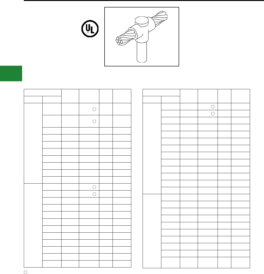
BURNDY®
Blue highlighted items are industry standard and most frequently ordered.
US: 1-800-346-4175 www.burndy.com Canada: 1-800-387-6487
Grounding
BURNDYWeld® Exothermic
TYPE BCR-2 MOLDS
Horizontal Cable to
Ground Rod
Type BCR-2 Molds are used to join horizontal
through copper cable to the top of a vertical ground
rod. Size range is #6 through 1000 kcmil solid or
concentric stranded copper conductors; 1/2"
through 1" for the ground rod. Contact BURNDY®
for information on molds for conductors not listed
below.
Cable Mold
Number Price Key Weld
Metal
Handle
Clamps
Grd Rod Tap
1/2"
#6 B-8434 18 32 Incl.
#4 B-8435 18 32 Incl.
#2 B-537 4 90 B-106
#1 B-538 4 90 B-106
1/0 B-539 4 90 B-106
2/0 B-540 4 90 B-106
3/0 B-541 4 115 B-106
4/0 B-542 4 115 B-106
250 kcmil B-543 4 150 B-106
300 kcmil B-544 4 200 B-106
5/8"
#6 B-8441 18 32 Incl.
#4 B-8442 18 32 Incl.
#2 B-545 4 90 B-106
#1 B-546 4 90 B-106
1/0 B-547 4 90 B-106
2/0 B-548 4 115 B-106
3/0 B-549 4 115 B-106
4/0 B-550 4 115 B-106
250 kcmil B-551 4 150 B-106
300 kcmil B-552 4 200 B-106
350 kcmil B-553 4 200 B-106
500 kcmil B-555 4 250 B-106
Cable Mold
Number Price Key Weld
Metal
Handle
Clamps
Grd Rod Tap
3/4"
#6 B-8452 19 45 Incl.
#4 B-8454 19 65 Incl.
#2 B-556 4 90 B-106
#1 B-557 4 90 B-106
1/0 B-558 4 115 B-106
2/0 B-559 4 115 B-106
3/0 B-560 4 115 B-106
4/0 B-561 4 115 B-106
250 kcmil B-562 4 150 B-106
300 kcmil B-563 4 200 B-106
350 kcmil B-564 4 200 B-106
500 kcmil B-566 4 250 B-106
750 kcmil B-567 5 2-200 B-107
1"
1/0 B-569 4 150 B-106
2/0 B-570 4 150 B-106
3/0 B-571 4 150 B-106
4/0 B-572 4 150 B-106
250 kcmil B-573 4 200 B-106
300 kcmil B-574 4 200 B-106
350 kcmil B-575 4 200 B-106
500 kcmil B-577 4 250 B-106
750 kcmil B-578 5 2-200 B-107
1000
kcmil B-579 5 500 B-107
1
1
1
1
1
1
1
B38-0309-00 Flint ignitor included
NOTES:
• For sizes not listed, contact BURNDY®
• Molds listed are for concentric stranded
cable; add suffix “-S” to mold number for solid
conductors
• For heavy duty molds, molds with wear plates or
molds for Copperweld ® cable, contact BURNDY®
• For expedited service, contact BURNDY®
Required Tools:
Handle Clamps - see chart for correct handle catalog
number
Recommended Accessories:
B38-0309-00 Flint Ignitor; B38-3922-00 Mold Cleaning
Brush; B38-0135-00 Cable Cleaning Brush;
B38-0330-00 Cable Clamp
E-82
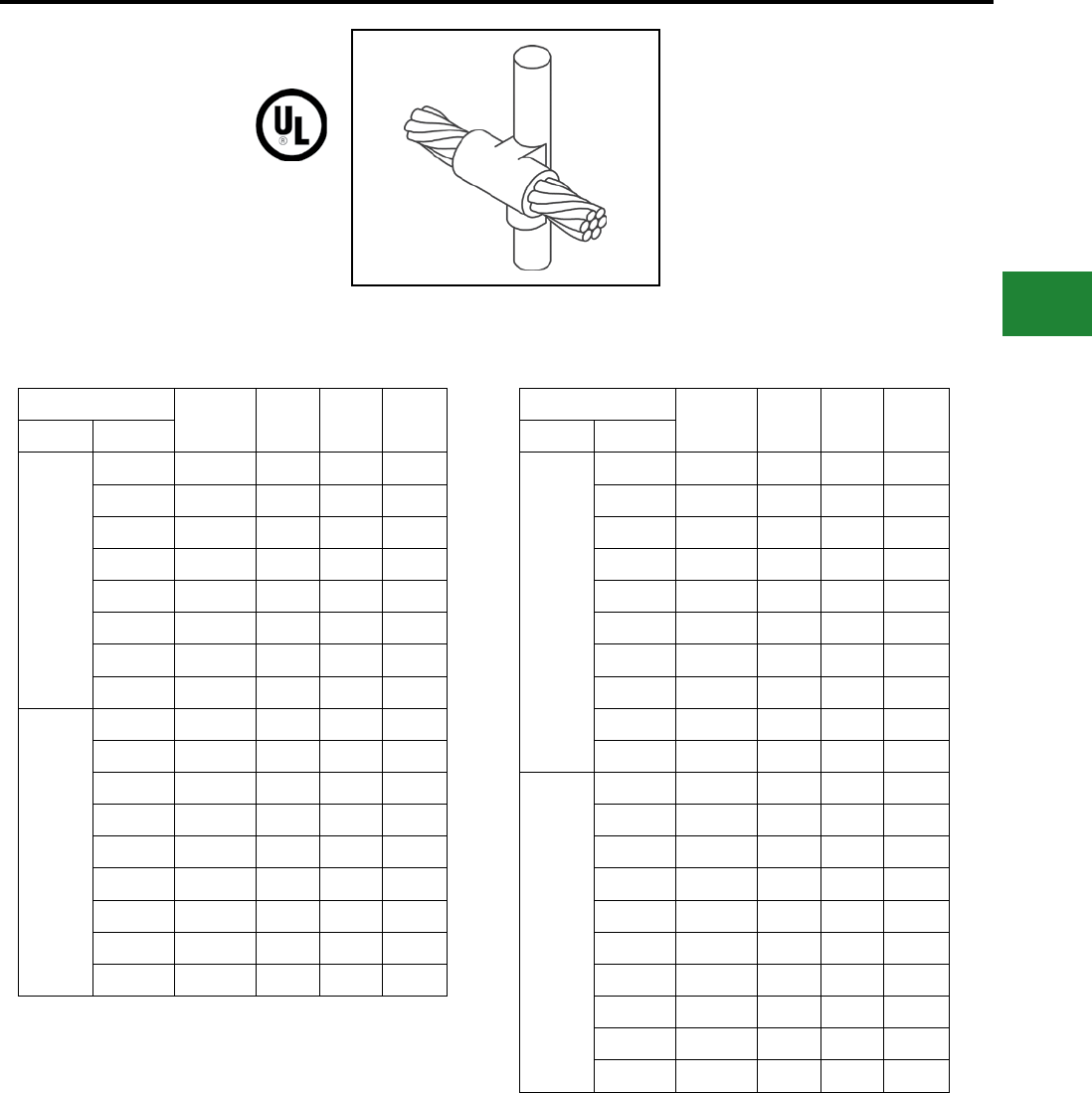
BURNDY®
Blue highlighted items are industry standard and most frequently ordered.
Canada: 1-800-387-6487 www.burndy.com US: 1-800-346-4175
Grounding
BURNDYWeld® Exothermic
TYPE BCR-3 MOLDS
Horizontal Through Cable
to Ground Rod
Type BCR-3 Molds are used to join horizontal
through run cable to the side of a vertical ground
rod. Size range is #6 through 1000 kcmil solid
or concentric stranded copper conductors; 1/2"
through 1" for the ground rod. Contact BURNDY®
for information on molds for conductors not listed
below.
Cable Mold
Number
Price
Key
Weld
Metal
Handle
Clamps
Grd Rod Tap
1/2"
#6 B-5321 24 65 B-106
#4 B2154 24 90 B-106
#2 B-2155 24 90 B-106
#1 B-2156 24 115 B-106
1/0 B-1581 24 115 B-106
2/0 B-1582 24 115 B-106
4/0 B-1583 24 150 B-106
250 kcmil B-1584 24 150 B-106
5/8"
#6 B-5660 24 65 B-106
#4 B-2157 24 90 B-106
#2 B-2158 24 90 B-106
#1 B-2159 24 115 B-106
1/0 B-1586 24 115 B-106
2/0 B-1587 24 115 B-106
4/0 B-1588 24 150 B-106
250 kcmil B-1589 24 150 B-106
500 kcmil B-1593 13 2-200 B-107
Cable Mold
Number
Price
Key
Weld
Metal
Handle
Clamps
Grd Rod Tap
3/4"
#6 B-6630 24 65 B-106
#4 B-2160 24 90 B-106
#2 B-2161 24 90 B-106
#1 B-2162 24 115 B-106
1/0 B-1594 24 115 B-106
2/0 B-1595 24 115 B-106
4/0 B-1596 24 150 B-106
250 kcmil B-1597 24 200 B-106
500 kcmil B-1601 13 500 B-107
750 kcmil B-1602 13 3-250 B-107
1"
#6 B-6906 24 90 B-106
#4 B-2163 24 90 B-106
#2 B-2164 24 90 B-106
#1 B-2165 24 115 B-106
1/0 B-1603 24 115 B-106
2/0 B-1604 24 115 B-106
4/0 B-1605 24 150 B-106
250 kcmil B-1606 24 200 B-106
500 kcmil B-1610 13 500 B-107
750 kcmil B-1611 13 3-250 B-107
NOTES:
• For sizes not listed, contact BURNDY®
• Molds listed are for concentric stranded
cable; add suffix “-S” to mold number for solid
conductors
• For heavy duty molds, molds with wear plates or
molds for Copperweld ® cable, contact BURNDY®
• For expedited service, contact BURNDY®
Required Tools:
Handle Clamps - see chart for correct handle catalog
number
Recommended Accessories:
B38-0309-00 Flint Ignitor; B38-3922-00 Mold Cleaning
Brush; B38-0135-00 Cable Cleaning Brush;
B38-0330-00 Cable Clamp
E-83
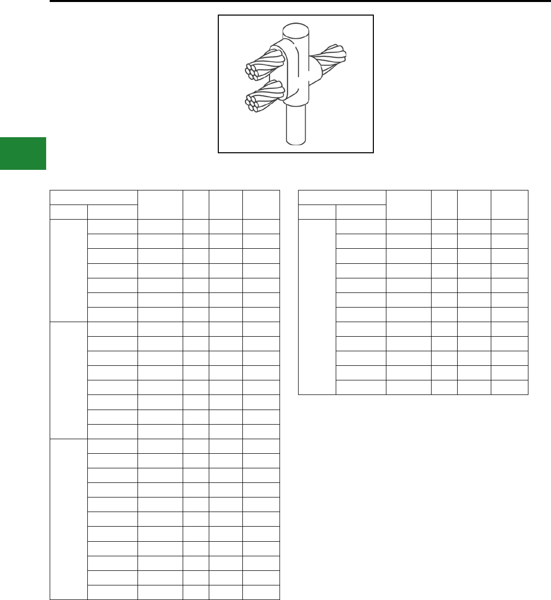
BURNDY®
Blue highlighted items are industry standard and most frequently ordered.
US: 1-800-346-4175 www.burndy.com Canada: 1-800-387-6487
Grounding
BURNDYWeld® Exothermic
TYPE BCR-17 MOLDS
Horizontal Run and Tap
Cables to Ground Rod
Type BCR-17 Molds are used to join horizontal
run and tap cables to the top of a vertical ground
rod. Size range is #4 through 750 kcmil solid or
concentric stranded copper conductors; 1/2"
through 1” for the ground rod. Contact BURNDY®
for information on molds for conductors not listed
below.
Cable Mold
Number
Price
Key
Weld
Metal
Handle
Clamps
Grd Rod Tap
1/2"
#4 B-5416 4 90 B-106
#2 B-6165 4 90 B-106
#1 B-5830 4 90 B-106
1/0 B-5940 4 115 B-106
2/0 B-5850 4 150 B-106
3/0 B-5833 4 200 B-106
4/0 B-5380 4 200 B-106
5/8"
#4 B-5972 4 90 B-106
#2 B-5935 4 115 B-106
#1 B-5699 4 115 B-106
1/0 B-5746 4 150 B-106
2/0 B-5963 4 200 B-106
3/0 B-5734 4 250 B-106
4/0 B-5732 4 250 B-106
250 kcmil B-5722 5 2-150 B-107
3/4"
#4 B-5698 4 90 B-106
#2 B-5294 4 115 B-106
#1 B-5390 4 115 B-106
1/0 B-6025 4 150 B-106
2/0 B-5738 4 200 B-106
3/0 B-6003 4 250 B-106
4/0 B-2566 4 250 B-106
250 kcmil B-5904 5 2-150 B-107
300 kcmil B-5857 5 2-200 B-107
350 kcmil B-5777 5 2-200 B-107
500 kcmil B-5961 5 3-200 B-107
Cable Mold
Number
Price
Key
Weld
Metal
Handle
Clamps
Grd Rod Tap
1"
#4 B-5556 4 115 B-106
#2 B-5555 4 150 B-106
#1 B-6048 4 150 B-106
1/0 B-5992 4 200 B-106
2/0 B-5877 4 250 B-106
3/0 B-5821 5 2-150 B-107
4/0 B-5820 5 2-150 B-107
250 kcmil B-5807 5 2-200 B-107
300 kcmil B-5803 5 500 B-107
350 kcmil B-5561 5 500 B-107
500 kcmil B-5515 6 3-250 B-107
750 kcmil B-5513 6 2-500 B-107
NOTES:
• For sizes not listed, contact BURNDY®
• Molds listed are for concentric stranded
cable; add suffix “-S” to mold number for solid
conductors
• For heavy duty molds, molds with wear plates or
molds for Copperweld ® cable, contact BURNDY®
• For expedited service, contact BURNDY®
Required Tools:
Handle Clamps - see chart for correct handle catalog
number
Recommended Accessories:
B38-0309-00 Flint Ignitor; B38-3922-00 Mold Cleaning
Brush; B38-0135-00 Cable Cleaning Brush;
B38-0330-00 Cable Clamp
E-84
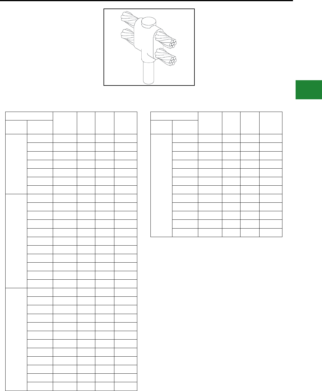
BURNDY®
Blue highlighted items are industry standard and most frequently ordered.
Canada: 1-800-387-6487 www.burndy.com US: 1-800-346-4175
Grounding
BURNDYWeld® Exothermic
TYPE BCR-24 MOLDS
Horizontal Parallel Run Cables to
Ground Rod
Type BCR-24 Molds are used to join horizontal
parallel cables to the top of a vertical ground
rod. Size range is #4 through 750 kcmil solid or
concentric stranded copper conductors; 1/2"
through 1" for the ground rod. Contact BURNDY®
for information on molds for conductors not listed
below.
Cable Mold
Number
Price
Key
Weld
Metal
Handle
Clamps
Grd Rod
Size Tap
1/2”
#4 B-5640 4 115 B-106
#2 B-5667 4 115 B-106
#1 B-6002 4 115 B-106
1/0 B-5767 4 150 B-106
2/0 B-5604 4 200 B-106
3/0 B-5560 4 250 B-106
4/0 B-6766 4 250 B-106
5/8”
#4 B-6208 4 115 B-106
#2 B-5702 4 150 B-106
#1 B-5517 4 150 B-106
1/0 B-5573 4 200 B-106
2/0 B-8451 4 250 B-106
3/0 B-2510 5 2-150 B-107
4/0 B-5428 5 2-150 B-107
250 kcmil B-1212 5 2-200 B-107
300 kcmil B-2084 5 500 B-107
350 kcmil B-2558 5 500 B-107
500 kcmil B-2450 5 3-250 B-107
3/4”
#4 B-8011 4 115 B-106
#2 B-2320 4 150 B-106
#1 B-2235 4 150 B-106
1/0 B-6051 4 200 B-106
2/0 B-8802 4 250 B-106
3/0 B-8726 5 2-150 B-107
4/0 B-5677 5 2-150 B-107
250 kcmil B-8461 5 2-200 B-107
300 kcmil B-8428 5 500 B-107
350 kcmil B-8294 5 500 B-107
500 kcmil B-8214 5 3-250 B-107
750 kcmil B-8027 6 2-500 B-107
Cable Mold
Number
Price
Key
Weld
Metal
Handle
Clamps
Grd Rod
Size Tap
1”
#4 B-5330 4 150 B-106
#2 B-5332 4 200 B-106
#1 B-5333 4 200 B-106
1/0 B-5334 4 250 B-106
2/0 B-5335 5 2-150 B-107
3/0 B-5336 5 2-200 B-107
4/0 B-5337 5 2-200 B-107
250 kcmil B-5338 5 500 B-107
300 kcmil B-5341 5 3-200 B-107
350 kcmil B-5351 5 3-200 B-107
500 kcmil B-5352 6 2-500 B-107
750 kcmil B-5353 64 5-250 B-107
NOTES:
• For sizes not listed, contact BURNDY®
• Molds listed are for concentric stranded
cable; add suffix “-S” to mold number for solid
conductors
• For heavy duty molds, molds with wear plates or
molds for Copperweld ® cable, contact BURNDY®
• For expedited service, contact BURNDY®
Required Tools:
Handle Clamps - see chart for correct handle catalog
number
Recommended Accessories:
B38-0309-00 Flint Ignitor; B38-3922-00 Mold Cleaning
Brush; B38-0135-00 Cable Cleaning Brush;
B38-0330-00 Cable Clamp
E-85
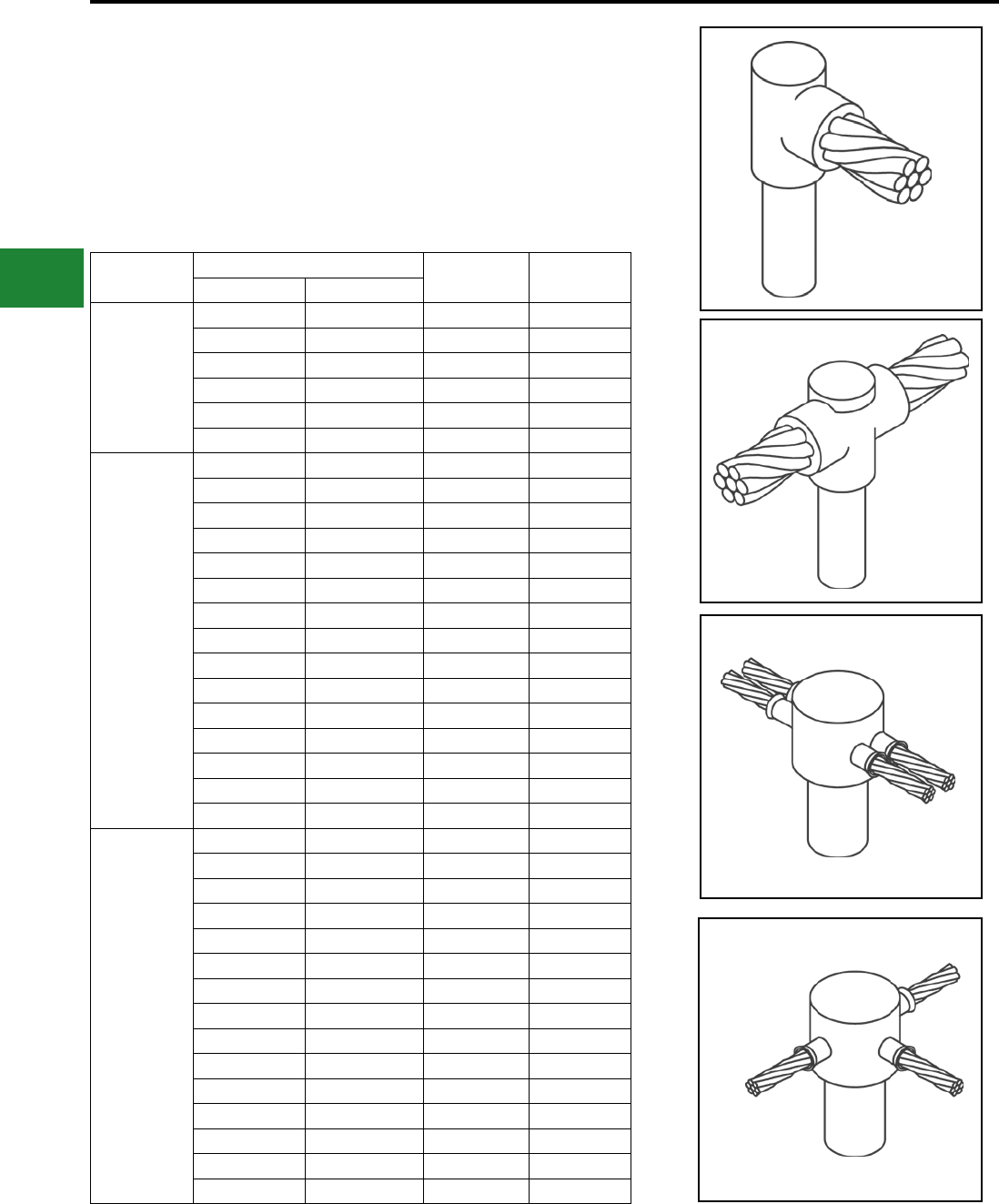
BURNDY®
Blue highlighted items are industry standard and most frequently ordered.
US: 1-800-346-4175 www.burndy.com Canada: 1-800-387-6487
Grounding
BURNDYWeld® Exothermic
SINGLE SHOT MOLDS
RUS Accepted
BURNDYWeld® Single Shot Molds are an
economical way to make cable connections
onto the top of a ground rod. The Single Shot is
a disposable single use ceramic mold that comes
complete with everything required except the Flint
Ignitor.
Ground Rod
Size
Cable Size Mold Number Type
Solid Stranded
1/2"
#6, #8 #8 BS-2009 BCR-1•
#3, #4 #4, #6 BS-2010 BCR-1•
#1, #2 #2, #3 BS-2011 BCR-1•
#6, #8 #8 BS-2024 BCR-2•
#3, #4 #4, #6 BS-2025 BCR-2•
#1, #2 #2, #3 BS-2026 BCR-1•
5/8"
#6, #8 #8 BS-2012 BCR-1•
#3, #4 #4, #6 BS-2013 BCR-1•
#1, #2 #2, #3 BS-2014 BCR-1•
2/0, 1/0 1/0, #1 BS-2015 BCR-1•
— 2/0 BS-2016 BCR-1•
#6, #8 #8 BS-2027 BCR-2•
#3, #4 #4, #6 BS-2028 BCR-2•
#1, #2 #2, #3 BS-2029 BCR-2•
2/0, 1/0 1/0, #1 BS-2030 BCR-2•
#6, #8 #8 BS-2105 BCR-24
#3, #4 #4, #6 BS-2106 BCR-14
#1, #2 #2, #3 BS-2107 BCR-24
#6, #8 #8 BS-2006 BCR-25
#3, #4 #4, #6 BS-2007 BCR-25
#1, #2 #2, #3 BS-2008 BCR-25
3/4"
#6, #8 #8 BS-2017 BCR-1
#3, #4 #4, #6 BS-2018 BCR-1•
#1, #2 #2, #3 BS-2019 BCR-1•
2/0, 1/0 1/0, #1 BS-2020 BCR-1•
— 2/0 BS-2021 BCR-1•
#6, #8 #8 BS-2031 BCR-2•
#3, #4 #4, #6 BS-2032 BCR-2•
#1, #2 #2, #3 BS-2033 BCR-2•
2/0, 1/0 1/0, #1 BS-2034 BCR-2•
#6, #8 #8 BS-2108 BCR-24
#3, #4 #4, #6 BS-2109 BCR-24
#1, #2 #2, #3 BS-2110 BCR-24
#6, #8 #8 BS-2068 BCR-25•
#3, #4 #4, #6 BS-2069 BCR-25•
#1, #2 #2, #3 BS-2070 BCR-25•
BCR-24
BCR-25
* UL Listed
E-86 BCR-1
BCR-2
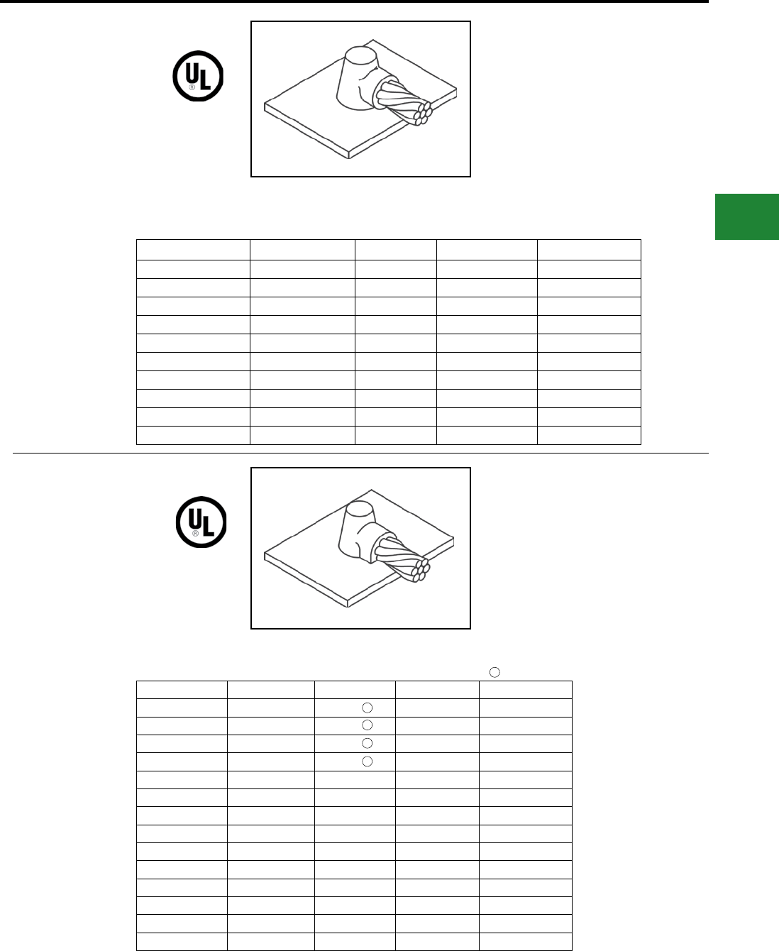
BURNDY®
Blue highlighted items are industry standard and most frequently ordered.
Canada: 1-800-387-6487 www.burndy.com US: 1-800-346-4175
Grounding
BURNDYWeld® Exothermic
TYPE BCS-1 MOLDS
Horizontal Cable to
Horizontal Steel Surface
Type BCS-1 Molds are used to terminate a
horizontal copper cable to any horizontal steel
surface. Note that the cable is OFF the surface.
Size range is 1/0 through 1000 kcmil solid or
concentric stranded copper conductors. Contact
BURNDY® for information on molds for conductors
not listed below.
Cable Size Mold Number Price Key Weld Metal Handle Clamps
1/0 B-644 4 90 B-106
2/0 B-645 4 90 B-106
3/0 B-646 4 115 B-106
4/0 B-647 4 115 B-106
250 kcmil B-648 4 115 B-106
300 kcmil B-649 4 150 B-106
350 kcmil B-650 4 200 B-106
500 kcmil B-652 4 200 B-106
750 kcmil B-653 5 2-150 B-106
1000 kcmil B-654 5 2-200 B-107
TYPE BCS-8 MOLDS
Horizontal Cable to
Horizontal Steel Surface
Type BCS-8 Molds are used to terminate a
horizontal copper cable to any horizontal steel
surface. Note that the cable is ON the surface.
Size range is #6 through 1000 kcmil solid or
concentric stranded copper conductors. Contact
BURNDY® for information on molds for conductors
not listed below.
Cable Size Mold Number Price Key Weld Metal Handle Clamps
#6 B-628 3 45 Incl.
#4 B-629 3 45 Incl.
#2 B-630 3 45 Incl.
#1 B-631 3 65 Incl.
1/0 B-7146 4 90 B-106
2/0 B-7075 4 90 B-106
3/0 B-2199 4 115 B-106
4/0 B-6114 4 115 B-106
250 kcmil B-2200 4 115 B-106
300 kcmil B-2506 4 150 B-106
350 kcmil B-2507 4 200 B-106
500 kcmil B-2509 4 200 B-106
750 kcmil B-2542 5 2-150 B-107
1000 kcmil B-2511 5 2-200 B-107
B38-0309-00 Flint ignitor included
1
1
1
1
1
NOTES:
• For sizes not listed, contact BURNDY®
• Molds listed are for concentric stranded
cable; add suffix “-S” to mold number for solid
conductors
• For heavy duty molds, molds with wear plates or
molds for Copperweld ® cable, contact BURNDY®
• For expedited service, contact BURNDY®
Required Tools:
Handle Clamps - see chart for correct handle catalog
number
Recommended Accessories:
B38-0309-00 Flint Ignitor; B38-3922-00 Mold Cleaning
Brush; B38-0135-00 Cable Cleaning Brush;
B38-0330-00 Cable Clamp
E-87
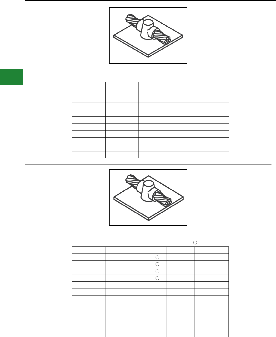
BURNDY®
Blue highlighted items are industry standard and most frequently ordered.
US: 1-800-346-4175 www.burndy.com Canada: 1-800-387-6487
Grounding
BURNDYWeld® Exothermic
TYPE BCS-2 MOLDS
Horizontal Through Cable to
Horizontal Steel Surface
Type BCS-2 Molds are used to join horizontal
through copper cable to any horizontal steel
surface. Note the cable is OFF the surface. Size
range is 1/0 through 1000 kcmil solid or concentric
stranded copper conductors. Contact BURNDY®
for information on molds for conductors not listed
below.
Cable Size Mold Number Price Key Weld Metal Handle Clamps
1/0 B-616 4 90 B-106
2/0 B-617 4 115 B-106
3/0 B-618 4 115 B-106
4/0 B-619 4 150 B-106
250 kcmil B-620 4 150 B-106
300 kcmil B-621 4 200 B-106
350 kcmil B-622 4 250 B-106
500 kcmil B-624 5 2-150 B-107
750 kcmil B-625-H 5 3-250 B-107
1000 kcmil B-626-H 5 2-500 B-107
TYPE BCS-9 MOLDS
Horizontal Through Cable to
Horizontal Steel Surface
Type BCS-9 Molds are used to join horizontal
through copper cable to any horizontal steel
surface. Note the cable is ON the surface. Size
range is #6 through 500 kcmil solid or concentric
stranded copper conductors. Contact BURNDY®
Products for information on molds for conductors
not listed below.
Cable Size Mold Number Price Key Weld Metal Handle Clamps
#6 B-602 3 45 Incl.
#4 B-603 3 45 Incl.
#2 B-604 3 45 Incl.
#1 B-605 3 65 Incl.
1/0 B-8379 4 90 B-106
2/0 B-5331 4 115 B-106
3/0 B-8381 4 115 B-106
4/0 B-7192 4 150 B-106
250 kcmil B-8413 4 150 B-106
300 kcmil B-8423 4 200 B-106
350 kcmil B-8410 4 250 B-106
500 kcmil B-5065 5 2-150 B-107
1
1
1
1
NOTES:
• For sizes not listed, contact BURNDY®
• Molds listed are for concentric stranded
cable; add suffix “-S” to mold number for solid
conductors
• For heavy duty molds, molds with wear plates or
molds for Copperweld ® cable, contact BURNDY®
• For expedited service, contact BURNDY®
Required Tools:
Handle Clamps - see chart for correct handle catalog
number
Recommended Accessories:
B38-0309-00 Flint Ignitor; B38-3922-00 Mold Cleaning
Brush; B38-0135-00 Cable Cleaning Brush;
B38-0330-00 Cable Clamp
B38-0309-00 Flint ignitor included
1
NOTES:
• For sizes not listed, contact BURNDY®
• Molds listed are for concentric stranded
cable; add suffix “-S” to mold number for solid
conductors
• For heavy duty molds, molds with wear plates or
molds for Copperweld ® cable, contact BURNDY®
• For expedited service, contact BURNDY®
Required Tools:
Handle Clamps - see chart for correct handle catalog
number
Recommended Accessories:
B38-0309-00 Flint Ignitor; B38-3922-00 Mold Cleaning
Brush; B38-0135-00 Cable Cleaning Brush;
B38-0330-00 Cable Clamp
E-88
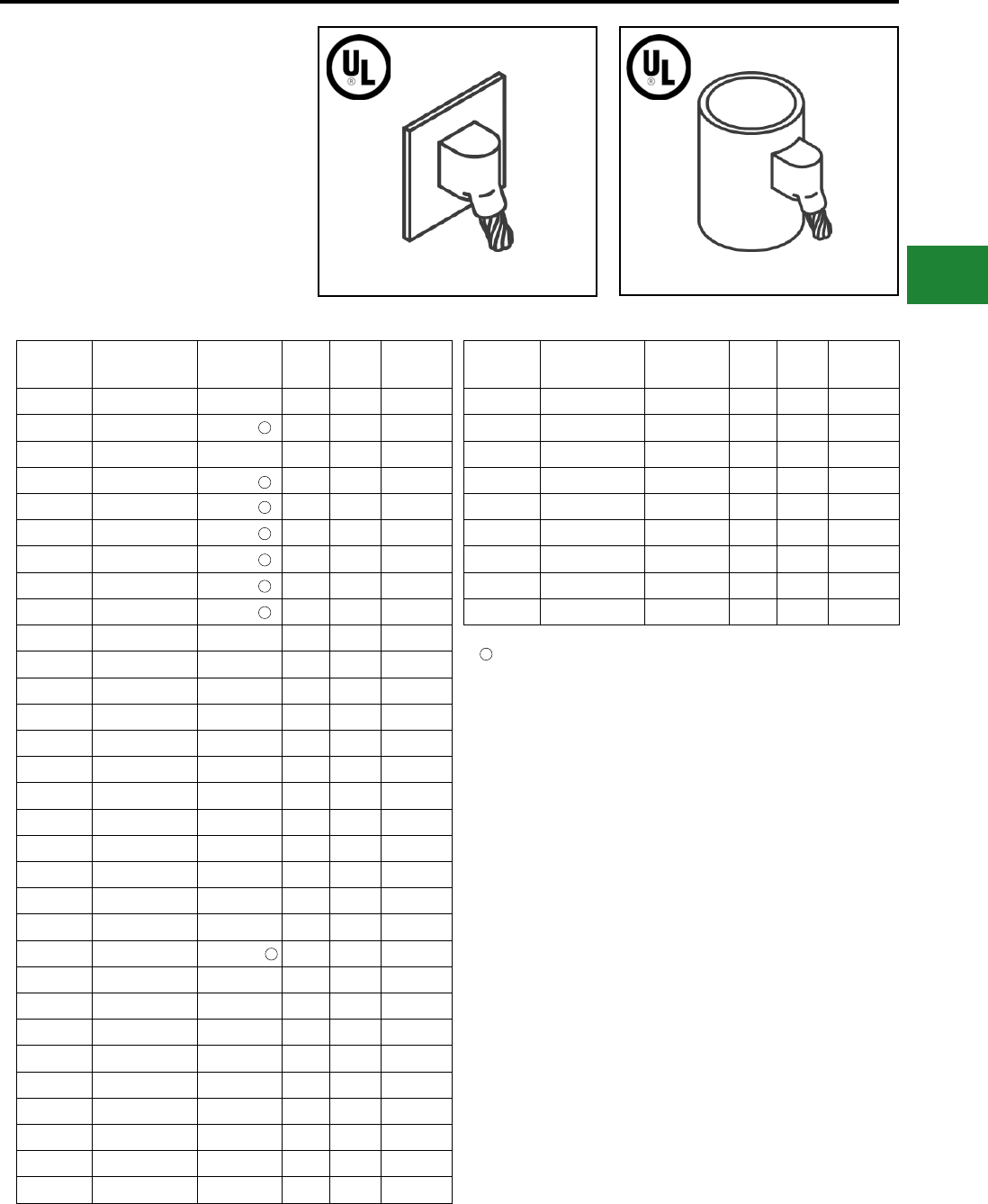
BURNDY®
Blue highlighted items are industry standard and most frequently ordered.
Canada: 1-800-387-6487 www.burndy.com US: 1-800-346-4175
Grounding
BURNDYWeld® Exothermic
TYPE BCS-3 MOLDS
Angular Cable Drop to Vertical
Steel Surface
Type BCS-3 Molds are used to join the end of
a copper cable at a 45° angle to a vertical steel
surface. Size range is #6 through 1000 kcmil
solid or concentric stranded copper conductors.
Contact BURNDY® for information on molds for
conductors not listed below. Cable to Flat Steel Cable to Pipe
Cable Size Pipe Size Mold
Number
Price
Key
Weld
Metal
Handle
Clamps
#6 Flat Steel Only B-585 4 45 B-106
#4 12" & up B-586 4 45 B-106
#3 Flat Steel Only B-587 4 45 B-106
#2 12" & up B-588 4 45 B-106
#1 12" & up B-589 4 65 B-106
1/0 12" & up B-590 4 90 B-106
2/0 12" & up B-591 4 90 B-106
3/0 12" & up B-592 4 115 B-106
4/0 12" & up B-593 4 115 B-106
250 kcmil Flat Steel Only B-594 4 115 B-106
300 kcmil Flat Steel Only B-595 4 150 B-106
350 kcmil Flat Steel Only B-596 4 200 B-106
500 kcmil Flat Steel Only B-598 4 200 B-106
750 kcmil Flat Steel Only B-599 5 2-150 B-106
1000 kcmil Flat Steel Only B-600 5 2-200 B-106
#4 1-1/4" to 4" B-2476 4 45 B-106
#4 4" to 6" B-2477 4 45 B-106
#4 6" to 10" B-2478 4 45 B-106
#2 Sol 1-1/4" to 4" B-9233-S 4 45 B-106
#2 Sol 4" to 6" B-2480-S 4 45 B-106
#2 Sol 6" to 10" B-2583-S 4 45 B-106
#2 Sol 12" & up B-588-S 4 45 B-106
#2 1-1/4" to 4" B-9233 4 45 B-106
#2 4" to 6" B-2480 4 45 B-106
#2 6" to 10" B-2583 4 45 B-106
#1 1-1/4" to 4" B-2482 4 65 B-106
#1 4" to 6" B-2483 4 65 B-106
#1 6" to 10" B-2484 4 65 B-106
1/0 1-1/4" to 4" B-2486 4 90 B-106
1/0 4" to 6" B-2487 4 90 B-106
1/0 6" to 10" B-2488 4 90 B-106
Cable Size Pipe Size Mold
Number
Price
Key
Weld
Metal
Handle
Clamps
2/0 1-1/4" to 4" B-8833 4 90 B-106
2/0 4" to 6" B-2490 4 90 B-106
2/0 6" to 10" B-2491 4 90 B-106
3/0 1-1/4" to 4" B-2493 4 115 B-106
3/0 4" to 6" B-2494 4 115 B-106
3/0 6" to 10" B-2495 4 115 B-106
4/0 1-1/4" to 4" B-9021 4 115 B-106
4/0 4" to 6" B-2497 4 115 B-106
4/0 6" to 10" B-2498 4 115 B-106
Flat Surface Mold; These items can be used to Flat Steel or to Pipe
1
1
1
1
1
1
1
1
1
NOTES:
• For sizes not listed, contact BURNDY®
• Molds listed are for concentric stranded cable; add suffix “-S” to mold
number for solid conductors
• For heavy duty molds, molds with wear plates or molds for Copperweld ®
cable, contact BURNDY®
• For expedited service, contact BURNDY®
Required Tools:
Handle Clamps - see chart for correct handle catalog number
Recommended Accessories:
B38-0309-00 Flint Ignitor
B38-3922-00 Mold Cleaning Brush
B38-0135-00 Cable Cleaning Brush
B38-0330-00 Cable Clamp
E-89
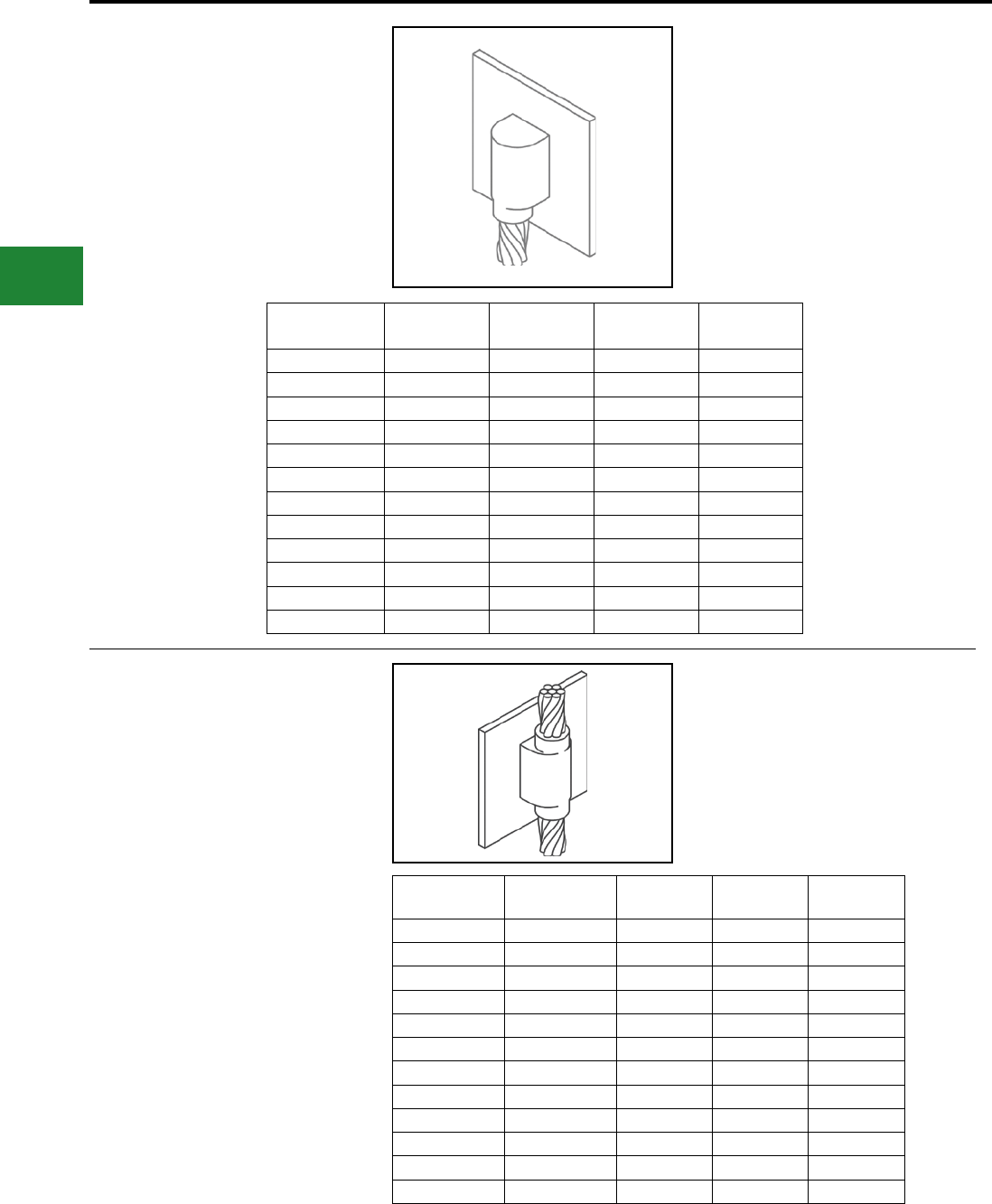
BURNDY®
Blue highlighted items are industry standard and most frequently ordered.
US: 1-800-346-4175 www.burndy.com Canada: 1-800-387-6487
Grounding
BURNDYWeld® Exothermic
TYPE BCS-23 MOLDS
Vertical Cable Drop to
Vertical Steel Surface
Type BCS-23 Molds are used to join vertical cable
down to a vertical steel surface. Note that the
cable is OFF the surface. Size range is #6 through
500 kcmil solid or concentric stranded copper
conductors. Contact BURNDY® for information on
molds for conductors not listed below.
Cable Size Mold Number Price Key Weld Metal Handle
Clamps
#6 B-5389 4 45 B-106
#4 B-5359 4 65 B-106
#2 B-2781 4 65 B-106
#1 B-5361 4 90 B-106
1/0 B-2189 4 115 B-106
2/0 B-2540 4 115 B-106
3/0 B-5362 4 150 B-106
4/0 B-8718 4 150 B-106
250 kcmil B-8165 4 200 B-106
300 kcmil B-5363 4 200 B-106
350 kcmil B-9029 4 250 B-106
500 kcmil B-8512 17 2-150 B-106
TYPE BCS-4 MOLDS
Vertical Through Cable to Vertical
Steel Surface
Type BCS-4 Molds are used to join a vertical
through copper cable to a vertical steel surface.
Note that the cable is OFF the surface. For molds
with the cable on the surface, contact BURNDY®.
Size range is #6 through 500 kcmil solid or
concentric stranded copper conductors. Contact
BURNDY® for information on molds for conductors
not listed.
Cable Size Mold Number Price Key Weld Metal Handle
Clamps
#6 B-1215 4 90 B-106
#4 B-1216 4 90 B-106
#2 B-1218 4 115 B-106
#1 B-1219 4 115 B-106
1/0 B-1220 17 200 B-106
2/0 B-1221 17 200 B-106
3/0 B-1222 17 250 B-106
4/0 B-1223 17 250 B-106
250 kcmil B-1224 17 250 B-106
300 kcmil B-1225-H 6 500 B-107
350 kcmil B-1226-H 6 3-200 B-107
500 kcmil B-1228-H 6 3-250 B-107
NOTES:
• For sizes not listed, contact BURNDY®
• Molds listed are for concentric stranded
cable; add suffix “-S” to mold number for solid
conductors
• For heavy duty molds, molds with wear plates or
molds for Copperweld ® cable, contact BURNDY®
• For expedited service, contact BURNDY®
Required Tools:
Handle Clamps - see chart for correct handle catalog
number
Recommended Accessories:
B38-0309-00 Flint Ignitor; B38-3922-00 Mold Cleaning
Brush; B38-0135-00 Cable Cleaning Brush;
B38-0330-00 Cable Clamp
E-90
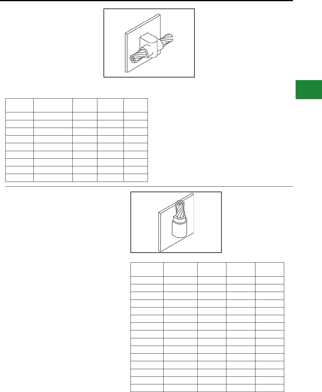
BURNDY®
Blue highlighted items are industry standard and most frequently ordered.
Canada: 1-800-387-6487 www.burndy.com US: 1-800-346-4175
Grounding
BURNDYWeld® Exothermic
TYPE BCS-6 MOLDS
Horizontal Through Cable to
Vertical Steel Surface
Type BCS-6 Molds are used to join horizontal
through copper cable to a vertical steel surface.
Note that the cable is OFF the surface. Size
range is #6 through 250 kcmil solid or concentric
stranded copper conductors. Contact BURNDY®
for information on molds for conductors not listed
below.
Cable Size Mold Number Price Key Weld Metal Handle
Clamps
#6 B-1626 4 65 B-106
#4 B-1627 4 65 B-106
#2 B-1628 4 65 B-106
#1 B-1629 4 90 B-106
1/0 B-1630 4 115 B-106
2/0 B-1631 4 115 B-106
3/0 B-1632 4 150 B-106
4/0 B-1633 4 150 B-106
250 kcmil B-1634 4 150 B-106
TYPE BCS-7 MOLDS
Overhead Vertical Tap Cable to
Vertical Steel Surface
Type BCS-7 Molds are used to join an overhead
vertical copper conductor drop tap to a vertical
steel surface. Size range is #6 through 1000 kcmil
solid or concentric stranded copper conductors.
Contact BURNDY® for information on molds for
conductors not listed. Cable Size Mold Number Price Key Weld Metal Handle
Clamps
#6 B-1635 4 65 B-106
#4 B-1636 4 65 B-106
#3 B-1637 4 65 B-106
#2 B-1638 4 65 B-106
#1 B-1639 4 90 B-106
1/0 B-1640 4 150 B-106
2/0 B-1641 4 150 B-106
3/0 B-1642 17 200 B-106
4/0 B1643 17 200 B-106
250 kcmil B-1644 17 200 B-106
300 kcmil B-1645 17 250 B-106
350 kcmil B-1646 6 2-150 B-107
500 kcmil B-1648 6 2-200 B-107
750 kcmil B-1649 6 500 B-107
1000 kcmil B-1650 6 3-200 B-107
NOTES:
• For sizes not listed, contact BURNDY®
• Molds listed are for concentric stranded cable; add suffix “-S” to mold
number for solid conductors
• For heavy duty molds, molds with wear plates or molds for
Copperweld ® cable, contact BURNDY®
• For expedited service, contact BURNDY®
Required Tools:
Handle Clamps - see chart for correct handle catalog number
Recommended Accessories:
B38-0309-00 Flint Ignitor
B38-3922-00 Mold Cleaning Brush
B38-0135-00 Cable Cleaning Brush
B38-0330-00 Cable Clamp
NOTES:
• For sizes not listed, contact BURNDY®
• Molds listed are for concentric stranded
cable; add suffix “-S” to mold number for solid
conductors
• For heavy duty molds, molds with wear plates or
molds for Copperweld ® cable, contact BURNDY®
• For expedited service, contact BURNDY®
Required Tools:
Handle Clamps - see chart for correct handle catalog
number
Recommended Accessories:
B38-0309-00 Flint Ignitor
B38-3922-00 Mold Cleaning Brush
B38-0135-00 Cable Cleaning Brush
B38-0330-00 Cable Clamp
E-91
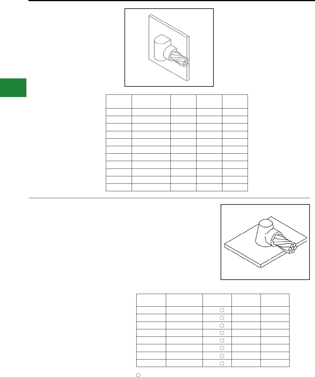
BURNDY®
Blue highlighted items are industry standard and most frequently ordered.
US: 1-800-346-4175 www.burndy.com Canada: 1-800-387-6487
Grounding
BURNDYWeld® Exothermic
TYPE BCS-18 MOLDS
Horizontal Tap Cable to Vertical
Steel Surface
Type BCS-18 Molds are used to connect a
horizontal conductor to a vertical steel surface.
Note that the cable is ON the surface. Size
range is #6 through 500 kcmil solid or concentric
stranded copper conductors. Contact BURNDY®
for information on molds for conductors not listed
below.
Cable Size Mold Number Price Key Weld Metal Handle
Clamps
#6 B-5910 4 45 B-106
#4 B-2761 4 45 B-106
#1 B-6060 4 65 B-106
1/0 B-5419 4 90 B-106
2/0 B-2567 4 90 B-106
3/0 B-6072 4 115 B-106
4/0 B-9253 4 115 B-106
250 kcmil B-2568 4 115 B-106
300 kcmil B-6061 4 150 B-106
350 kcmil B-6067 4 200 B-106
500 kcmil B-8359 4 200 B-106
TYPE BCS-5 MOLDS
Horizontal Cable Tap to Horizontal
Cast Iron Surface
Type BCS-5 Molds are used to join horizontal
cable taps to horizontal cast iron surfaces. Note
that the cable is ON the surface. Size range is #6
through #1 solid or concentric stranded copper
conductors. Contact BURNDY® for information on
molds for conductors not listed below.
Cable Size Mold Number Price Key Weld Metal Handle
Clamps
#6 Sol B-1613 3 2SCI Incl.
#6 B-1614 3 25CI Incl.
#4 Sol B-1615 3 45CI Incl.
#4 B-1616 3 45CI Incl.
#2 Sol B-1617 3 45CI Incl.
#2 B-1618 3 45CI Incl.
#1 Sol B-1619 3 65CI Incl.
#1 B-1620 3 65CI Incl.
B38-0309-00 Flint ignitor included
DO NOT use Type BCS-5 molds
on Soil Pipe (ASTM A74-82). A test
weld should be made on a section
of pipe being used to determine
the possibility of detrimental
metallurgical effects.
1
1
1
1
1
1
1
1
1
NOTES:
• For sizes not listed, contact BURNDY®
• Molds listed are for concentric stranded
cable; add suffix “-S” to mold number for solid
conductors
• For heavy duty molds, molds with wear plates or
molds for Copperweld ® cable, contact BURNDY®
• For expedited service, contact BURNDY®
Required Tools:
Handle Clamps - see chart for correct handle catalog
number
Recommended Accessories:
B38-0309-00 Flint Ignitor; B38-3922-00 Mold Cleaning
Brush; B38-0135-00 Cable Cleaning Brush;
B38-0330-00 Cable Clamp
NOTES:
• For sizes not listed, contact BURNDY®
• Molds listed are for concentric stranded
cable; add suffix “-S” to mold number for solid
conductors
• For heavy duty molds, molds with wear plates or
molds for Copperweld ® cable, contact BURNDY®
• For expedited service, contact BURNDY®
Required Tools:
Handle Clamps - see chart for correct handle catalog
number
Recommended Accessories:
B38-0309-00 Flint Ignitor
B38-3922-00 Mold Cleaning Brush
B38-0135-00 Cable Cleaning Brush
B38-0330-00 Cable Clamp
E-92
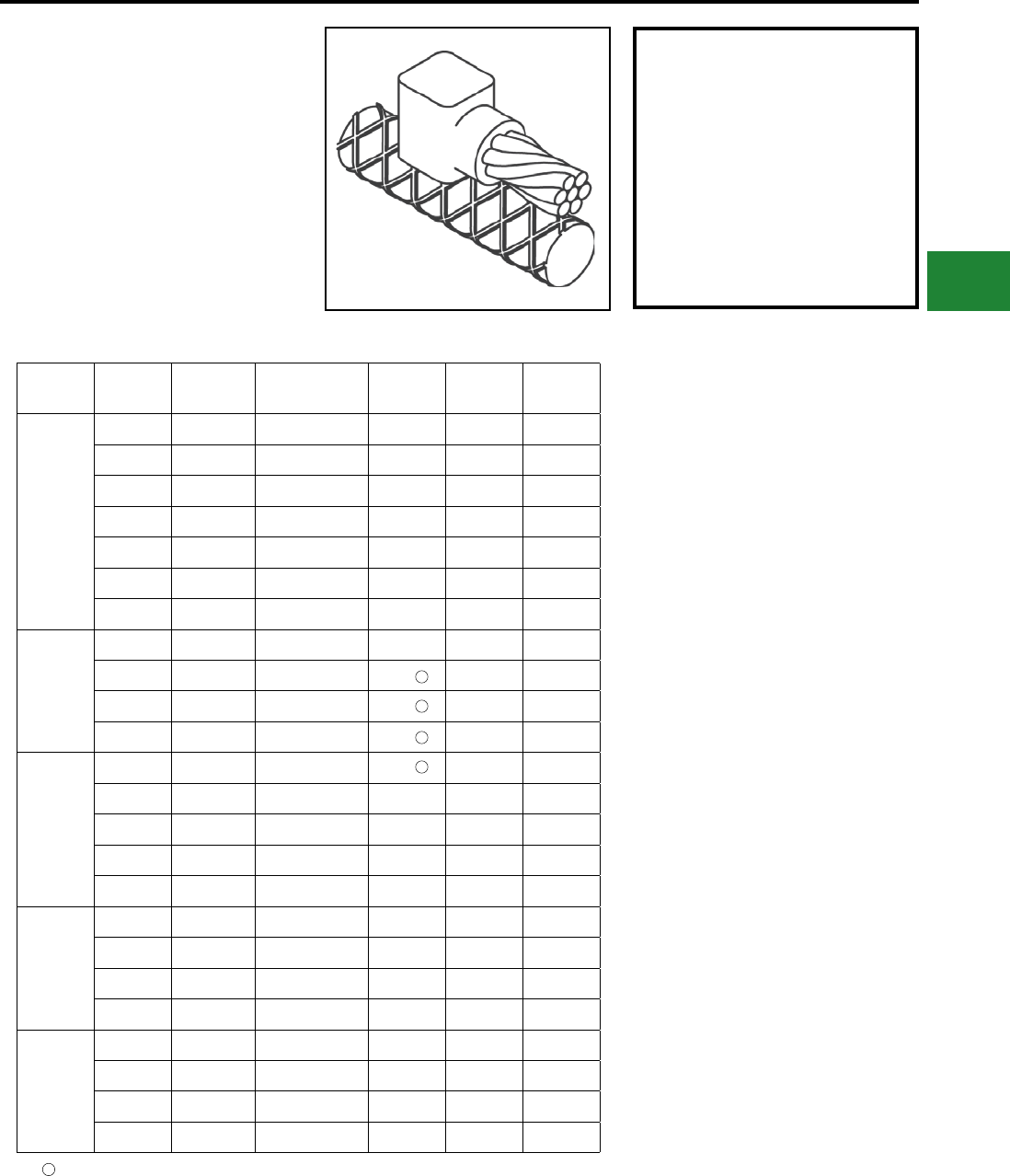
BURNDY®
Blue highlighted items are industry standard and most frequently ordered.
Canada: 1-800-387-6487 www.burndy.com US: 1-800-346-4175
Grounding
BURNDYWeld® Exothermic
TYPE BCRE-1 MOLDS
Horizontal Parallel Tap to Rebar
Type BCRE-1 Molds are recommended for parallel,
horizontal connections for solid or concentric
stranded conductors #6 through 4/0 joined to
reinforcing bars #3 through #6 and larger. The high
copper content joint has a higher current carrying
capacity than the conductors being joined and
is impervious to vibration and moisture. Contact
BURNDY® for information on molds for conductors
not listed below.
Rebar
Size
Cable
Size
Mold
Number
Packing
Material Price Key Weld
Metal
Handle
Clamps
3
#6 B-7500 B38032900 4 25 B-106
#4 B-7501 B38032900 4 32 B-106
#2 B-7502 B38032900 4 45 B-106
#1 B-7503 B38032900 4 65 B-106
1/0 B-7504 B38032900 4 90 B-106
2/0 B-7505 B38032900 4 90 B-106
3/0 B-7506 B38032900 4 115 B-106
4 & Larger
4/0 B-7507 B38032900 4 115 B-106
#6 B-7508 B38406100 3 25 Incl.
#4 B-7509 B38406100 3 32 Incl.
#2 B-7510 B38406100 3 45 Incl.
4
#1 B-7511 B38406100 3 65 Incl.
1/0 B-7512 B38032900 4 90 B-106
2/0 B-7513 B38032900 4 90 B-106
3/0 B-7514 B38032900 4 115 B-106
4/0 B-7515 B38032900 4 115 B-106
5
1/0 B-7520 B38032900 4 90 B-106
2/0 B-7521 B38032900 4 90 B-106
3/0 B-7522 B38032900 4 115 B-106
4/0 B-7523 B38032900 4 115 B-106
6 & Larger
1/0 B-7528 B38406200 14+ 90 Incl.
2/0 B-7529 B38406200 14+ 90 Incl.
3/0 B-7530 B38406200 14+ 115 Incl.
4/0 B-7531 B38406200 14+ 115 Incl.
PACKING MATERIAL NOTE
A packing pad is necessary when making
BURNDYWeld® connections to rebar.
Packing material B38032900 is copper shim
stock. Packing material numbers B38406100,
B38406200 and B38406300 are a ceramic
ber material and can be used for one
connection only. Be sure to specify packing
material catalog number when ordering mold
and weld metal.
B38-0309-00 Flint ignitor included
NOTES:
• For sizes not listed, contact BURNDY®
• Molds listed are for concentric stranded
cable; add suffix “-S” to mold number for solid
conductors
• For heavy duty molds, molds with wear plates or
molds for Copperweld ® cable, contact BURNDY®
• For expedited service, contact BURNDY®
Required Tools:
Handle Clamps - see chart for correct handle catalog
number
Recommended Accessories:
B38-0309-00 Flint Ignitor
B38-3922-00 Mold Cleaning Brush
B38-0135-00 Cable Cleaning Brush
B38-0330-00 Cable Clamp
1
1
1
1
1
E-93
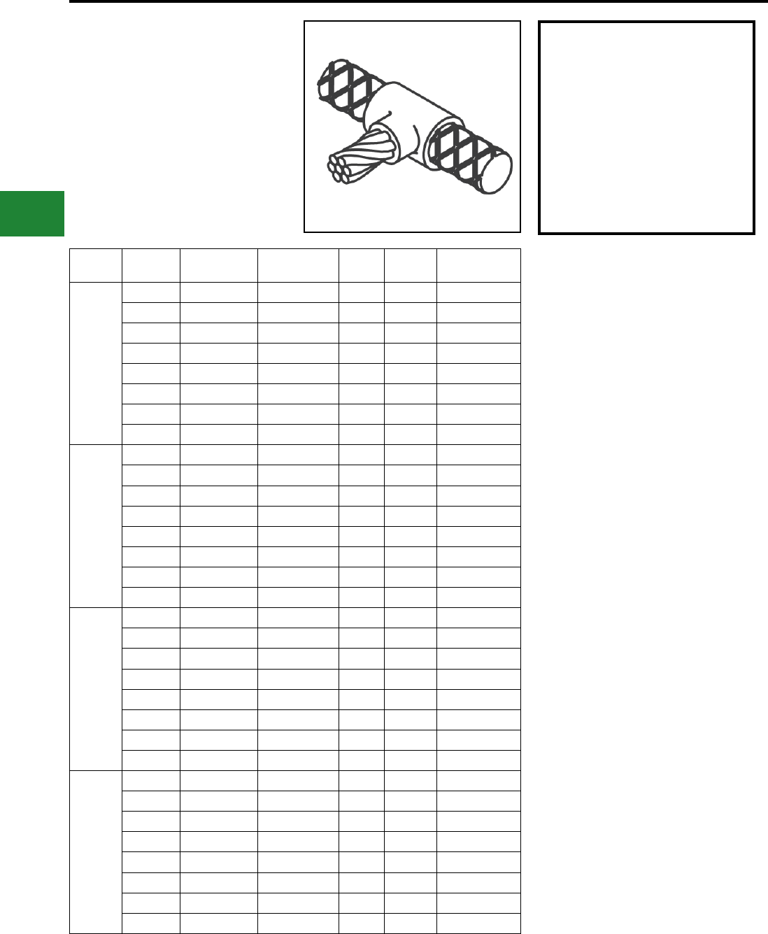
BURNDY®
Blue highlighted items are industry standard and most frequently ordered.
US: 1-800-346-4175 www.burndy.com Canada: 1-800-387-6487
Grounding
BURNDYWeld® Exothermic
TYPE BCRE-2 MOLDS
Horizontal Cable Tap to Horizontal
Rebar Run
Type BCRE-2 Molds are recommended for
right angle, horizontal connections for solid or
concentric stranded conductors #6 through 4/0
joined to reinforcing bars #3 through #6. The high
copper content joint has a higher current carrying
capacity than the conductors being joined and is
impervious to vibration and moisture.
Rebar
Size
Cable
Size
Mold
Number
Packing
Material
Price
Key
Weld
Metal
Handle
Clamps
3
#6 B-7588 B38032900 4 45 B-106
#4 B-7589 B38032900 4 45 B-106
#2 B-7590 B38032900 4 65 B-106
#1 B-7591 B38032900 4 65 B-106
1/0 B-7592 B38032900 4 90 B-106
2/0 B-7593 B38032900 4 90 B-106
3/0 B-7594 B38032900 4 115 B-106
4/0 B-7595 B38032900 4 115 B-106
4
#6 B-7596 B38032900 4 45 B-106
#4 B-7597 B38032900 4 45 B-106
#2 B-7598 B38032900 4 65 B-106
#1 B-7599 B38032900 4 65 B-106
1/0 B-7600 B38032900 4 90 B-106
2/0 B-7601 B38032900 4 90 B-106
3/0 B-7602 B38032900 4 115 B-106
4/0 B-7603 B38032900 4 115 B-106
5
#6 B-7604 B38032900 4 90 B-106
#4 B-7605 B38032900 4 90 B-106
#2 B-7606 B38032900 4 90 B-106
#1 B-7607 B38032900 4 90 B-106
1/0 B-7608 B38032900 4 115 B-106
2/0 B-7609 B38032900 4 115 B-106
3/0 B-7610 B38032900 4 150 B-106
4/0 B-7611 B38032900 4 150 B-106
6
#6 B-7612 B38032900 4 90 B-106
#4 B-7613 B38032900 4 90 B-106
#2 B-7614 B38032900 4 90 B-106
#1 B-7615 B38032900 4 90 B-106
1/0 B-7616 B38032900 4 115 B-106
2/0 B-7617 B38032900 4 115 B-106
3/0 B-7618 B38032900 4 150 B-106
4/0 B-7619 B38032900 4 150 B-106
PACKING MATERIAL NOTE
A packing pad is necessary when making
BURNDYWeld® connections to rebar.
Packing material B38032900 is copper shim
stock. Packing material numbers B38406100,
B38406200 and B38406300 are a ceramic
ber material and can be used for one
connection only. Be sure to specify packing
material catalog number when ordering mold
and weld metal.
NOTES:
• For sizes not listed, contact BURNDY®
• Molds listed are for concentric stranded
cable; add suffix “-S” to mold number for solid
conductors
• For heavy duty molds, molds with wear plates or
molds for Copperweld ® cable, contact BURNDY®
• For expedited service, contact BURNDY®
Required Tools:
Handle Clamps - see chart for correct handle catalog
number
Recommended Accessories:
B38-0309-00 Flint Ignitor
B38-3922-00 Mold Cleaning Brush
B38-0135-00 Cable Cleaning Brush
B38-0330-00 Cable Clamp
E-94
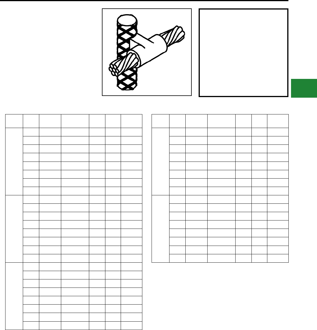
BURNDY®
Blue highlighted items are industry standard and most frequently ordered.
Canada: 1-800-387-6487 www.burndy.com US: 1-800-346-4175
Grounding
BURNDYWeld® Exothermic
TYPE BCRE-3 MOLDS
Horizontal through Cable to
Vertical Rebar
Type BCRE-3 Molds are recommended for
horizontal conductors to vertical rebar connections
for solid or concentric stranded conductors #6
through 4/0 joined to reinforcing bars #3 through #7
& larger. The high copper content joint has a higher
current carrying capacity than the conductors
being joined and is impervious to vibration and
moisture. Contact BURNDY® for information on
molds for conductors not listed below.
Rebar
Size
Cable
Size
Mold
Number
Packing
Material
Price
Key
Weld
Metal
Handle
Clamps
3
#6 B-7620 B38032900 24 90 B-106
#4 B-7621 B38032900 24 90 B-106
#2 B-7622 B38032900 24 90 B-106
#1 B-7623 B38032900 24 115 B-106
1/0 B-7624 B38032900 24 115 B-106
2/0 B-7625 B38032900 24 115 B-106
3/0 B-7626 B38032900 24 150 B-106
4/0 B-7627 B38032900 24 150 B-106
4
#6 B-7628 B38032900 24 90 B-106
#4 B-7629 B38032900 24 90 B-106
#2 B-7630 B38032900 24 90 B-106
#1 B-7631 B38032900 24 115 B-106
1/0 B-7632 B38032900 24 115 B-106
2/0 B-7633 B38032900 24 115 B-106
3/0 B-7634 B38032900 24 150 B-106
4/0 B-7635 B38032900 24 150 B-106
5
#6 B-7636 B38032900 24 90 B-106
#4 B-7637 B38032900 24 90 B-106
#2 B-7638 B38032900 24 90 B-106
#1 B-7639 B38032900 24 115 B-106
1/0 B-7640 B38032900 24 115 B-106
2/0 B-7641 B38032900 24 115 B-106
3/0 B-7642 B38032900 24 150 B-106
4/0 B-7643 B38032900 24 150 B-106
Rebar
Size
Cable
Size
Mold
Number
Packing
Material
Price
Key
Weld
Metal
Handle
Clamps
6
#6 B-7644 B38032900 24 90 B-106
#4 B-7645 B38032900 24 90 B-106
#2 B-7646 B38032900 24 90 B-106
#1 B-7647 B38032900 24 115 B-106
1/0 B-7648 B38032900 24 115 B-106
2/0 B-7649 B38032900 24 115 B-106
3/0 B-7650 B38032900 24 150 B-106
4/0 B-7651 B38032900 24 150 B-106
7
&
Larger
#6 B-7652 B38406300 4 90 B-106-41
#4 B-7653 B38406300 4 90 B-106-41
#2 B-7654 B38406300 4 90 B-106-41
#1 B-7655 B38406300 4 115 B-106-41
1/0 B-7656 B38406300 4 115 B-106-41
2/0 B-7657 B38406300 4 115 B-106-41
3/0 B-7658 B38406300 4 150 B-106-41
4/0 B-7659 B38406300 4 150 B-106-41
PACKING MATERIAL NOTE
A packing pad is necessary when making
BURNDYWeld® connections to rebar.
Packing material B38032900 is copper shim
stock. Packing material numbers B38406100,
B38406200 and B38406300 are a ceramic
ber material and can be used for one
connection only. Be sure to specify packing
material catalog number when ordering mold
and weld metal.
NOTES:
• For sizes not listed, contact BURNDY®
• Molds listed are for concentric stranded cable; add
suffix “-S” to mold number for solid conductors
• For heavy duty molds, molds with wear plates or
molds for Copperweld ® cable, contact BURNDY®
• For expedited service, contact BURNDY®
Required Tools:
Handle Clamps - see chart for correct handle catalog number
Recommended Accessories:
B38-0309-00 Flint Ignitor
B38-3922-00 Mold Cleaning Brush
B38-0135-00 Cable Cleaning Brush
B38-0330-00 Cable Clamp
E-95
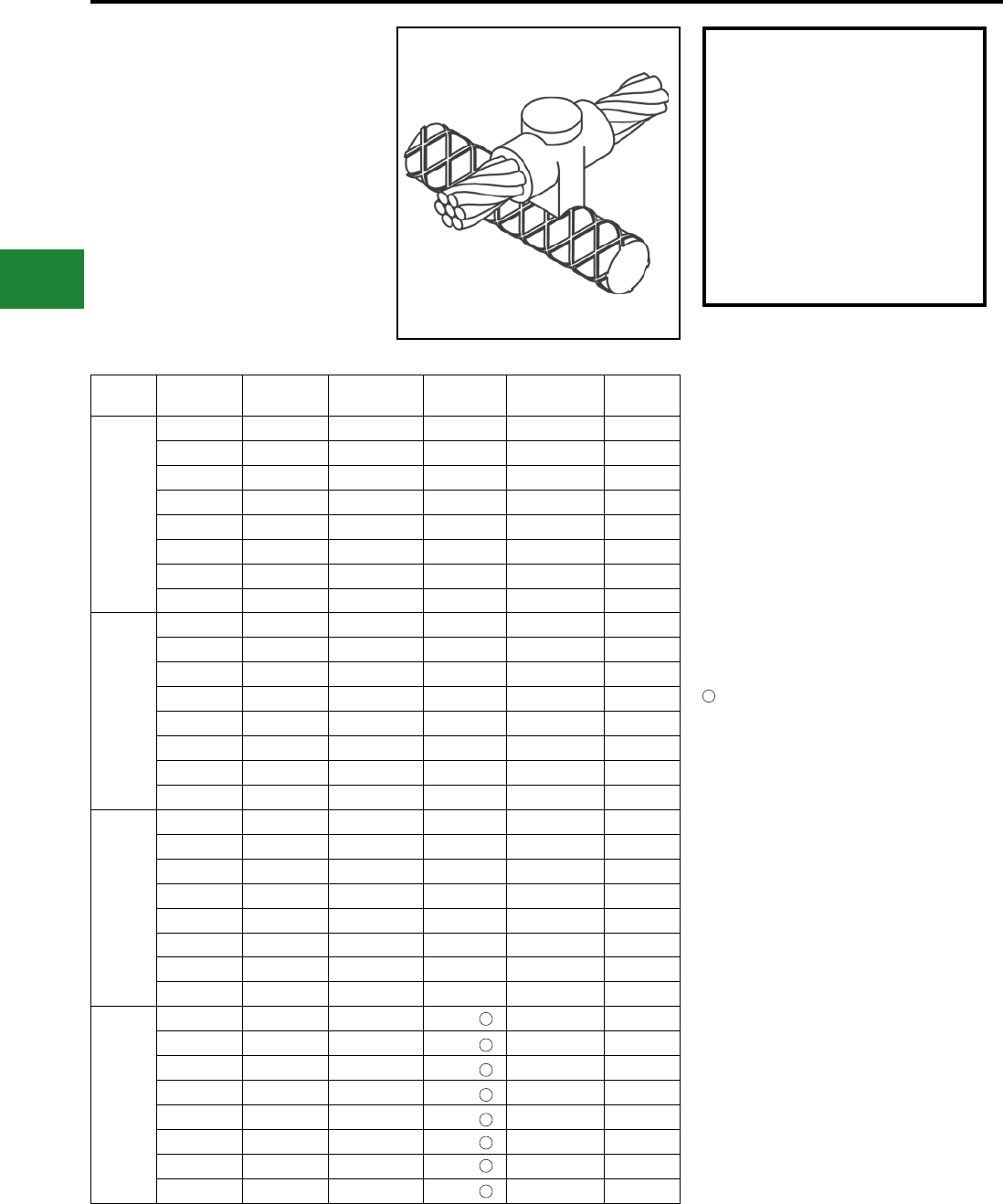
BURNDY®
Blue highlighted items are industry standard and most frequently ordered.
US: 1-800-346-4175 www.burndy.com Canada: 1-800-387-6487
Grounding
BURNDYWeld® Exothermic
TYPE BCRE-4 MOLDS
Horizontal through Cable to
Horizontal Rebar
Type BCRE-4 Molds are recommended for
horizontal through conductors to horizontal rebar
at right angle connections for solid or concentric
stranded conductors #6 through 4/0 joined to
reinforcing bars #3 through #6 & larger. The high
copper content joint has a higher current carrying
capacity than the conductors being joined and
is impervious to vibration and moisture. Contact
BURNDY® for information on molds for conductors
not listed below.
Rebar
Size Cable Size Mold
Number
Packing
Material Price Key Weld Metal Handle
Clamps
3
#6 B-7708 B38032900 4 90 B-106
#4 B-7709 B38032900 4 90 B-106
#2 B-7710 B38032900 4 90 B-106
#1 B-7711 B38032900 4 115 B-106
1/0 B-7712 B38032900 22 115 B-106
2/0 B-7713 B38032900 22 115 B-106
3/0 B-7714 B38032900 22 150 B-106
4/0 B-7715 B38032900 22 150 B-106
4
#6 B-7716 B38032900 4 90 B-106
#4 B-7717 B38032900 4 90 B-106
#2 B-7718 B38032900 4 90 B-106
#1 B-7719 B38032900 22 115 B-106
1/0 B-7720 B38032900 22 115 B-106
2/0 B-7721 B38032900 22 115 B-106
3/0 B-7722 B38032900 22 150 B-106
4/0 B-7723 B38032900 22 150 B-106
5
#6 B-7724 B38032900 4 90 B-106
#4 B-7725 B38032900 4 90 B-106
#2 B-7726 B38032900 4 90 B-106
#1 B-7727 B38032900 22 115 B-106
1/0 B-7728 B38032900 22 115 B-106
2/0 B-7729 B38032900 22 115 B-106
3/0 B-7730 B38032900 22 150 B-106
4/0 B-7731 B38032900 22 150 B-106
6
&
Larger
#6 B-7732 B38406100 14 90 Incl.
#4 B-7733 B38406100 14 90 Incl.
#2 B-7734 B38406100 14 90 Incl.
#1 B-7735 B38406100 14 115 Incl.
1/0 B-7736 B38406200 14 115 Incl.
2/0 B-7737 B38406200 14 115 Incl.
3/0 B-7738 B38406200 14 150 Incl.
4/0 B-7739 B38406200 14 150 Incl.
1
1
1
1
1
1
1
1
PACKING MATERIAL NOTE
A packing pad is necessary when making
BURNDYWeld® connections to rebar.
Packing material B38032900 is copper shim
stock. Packing material numbers B38406100,
B38406200 and B38406300 are a ceramic
ber material and can be used for one
connection only. Be sure to specify packing
material catalog number when ordering mold
and weld metal.
NOTES:
• For sizes not listed, contact BURNDY®
• Molds listed are for concentric stranded
cable; add suffix “-S” to mold number for solid
conductors
• For heavy duty molds, molds with wear plates or
molds for Copperweld ® cable, contact BURNDY®
• For expedited service, contact BURNDY®
Required Tools:
Handle Clamps - see chart for correct handle catalog
number
Recommended Accessories:
B38-0309-00 Flint Ignitor
B38-3922-00 Mold Cleaning Brush
B38-0135-00 Cable Cleaning Brush
B38-0330-00 Cable Clamp
B38-0309-00 Flint ignitor included
1
E-96
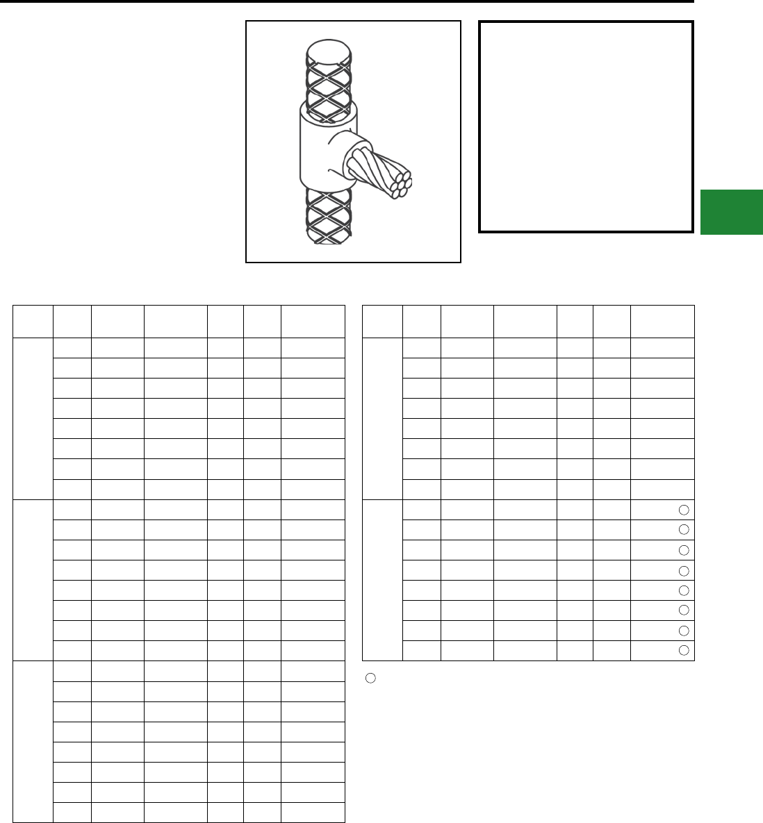
BURNDY®
Blue highlighted items are industry standard and most frequently ordered.
Canada: 1-800-387-6487 www.burndy.com US: 1-800-346-4175
Grounding
BURNDYWeld® Exothermic
TYPE BCRE-6 MOLDS
Horizontal Cable Tap to
Vertical Rebar
Type BCRE-6 Molds are recommended for
horizontal conductors terminating at right angles
to vertical rebar connections for solid or concentric
stranded conductors #6 through 4/0 joined to
reinforcing bars #3 through #7 and larger. The high
copper content joint has a higher current carrying
capacity than the conductors being joined and is
impervious to vibration and moisture.
Contact BURNDY® for information on molds for
conductors not listed below.
Rebar
Size
Cable
Size
Mold
Number
Packing
Material
Price
Key
Weld
Metal
Handle
Clamps
3
#6 B-7884 B38032900 4 90 B-106
#4 B-7885 B38032900 4 90 B-106
#2 B-7886 B38032900 4 90 B-106
#1 B-7887 B38032900 4 115 B-106
1/0 B-7888 B38032900 4 115 B-106
2/0 B-7889 B38032900 4 115 B-106
3/0 B-7890 B38032900 4 150 B-106
4/0 B-7891 B38032900 4 150 B-106
4
#6 B-7892 B38032900 4 90 B-106
#4 B-7893 B38032900 4 90 B-106
#2 B-7894 B38032900 4 90 B-106
#1 B-7895 B38032900 4 115 B-106
1/0 B-7896 B38032900 4 115 B-106
2/0 B-7897 B38032900 4 115 B-106
3/0 B-7898 B38032900 4 150 B-106
4/0 B-7899 B38032900 4 150 B-106
5
#6 B-7900 B38032900 4 90 B-106
#4 B-7901 B38032900 4 90 B-106
#2 B-7902 B38032900 4 90 B-106
#1 B-7903 B38032900 4 115 B-106
1/0 B-7904 B38032900 4 115 B-106
2/0 B-7905 B38032900 4 115 B-106
3/0 B-7906 B38032900 4 150 B-106
4/0 B-7907 B38032900 4 150 B-106
Rebar
Size
Cable
Size
Mold
Number
Packing
Material
Price
Key
Weld
Metal
Handle
Clamps
6
#6 B-7908 B38032900 4 90 B-106
#4 B-7909 B38032900 4 90 B-106
#2 B-7910 B38032900 4 90 B-106
#1 B-7911 B38032900 4 115 B-106
1/0 B-7912 B38032900 4 115 B-106
2/0 B-7913 B38032900 4 115 B-106
3/0 B-7914 B38032900 4 150 B-106
4/0 B-7915 B38032900 4 150 B-106
7
&
Larger
#6 B-7916 B38406300 4 90 B-106-32
#4 B-7917 B38406300 4 90 B-106-32
#2 B-7918 B38406300 4 90 B-106-32
#1 B-7919 B38406300 4 115 B-106-32
1/0 B-7920 B38406300 4 115 B-106-32
2/0 B-7921 B38406300 4 115 B-106-32
3/0 B-7922 B38406300 4 150 B-106-32
4/0 B-7923 B38406300 4 150 B-106-32
The B106-32 comes complete with a B-106 handle clamp and B40-0106-76
vertical chain clamp. Although good for use on all sizes of rebar, vertical chain
clamps are strongly recommended on large size rebar as they hold the mold
to the rebar securely. If you already have a B-106 handle clamp, you can
purchase the vertical chain clamps separately.
1
PACKING MATERIAL NOTE
A packing pad is necessary when making
BURNDYWeld® connections to rebar.
Packing material B38032900 is copper shim
stock. Packing material numbers B38406100,
B38406200 and B38406300 are a ceramic
ber material and can be used for one
connection only. Be sure to specify packing
material catalog number when ordering mold
and weld metal.
NOTES:
• For sizes not listed, contact BURNDY®
• Molds listed are for concentric stranded cable; add suffix “-S” to mold number
for solid conductors
• For heavy duty molds, molds with wear plates or molds for Copperweld ® cable,
contact BURNDY®
• For expedited service, contact BURNDY®
Required Tools:
Handle Clamps - see chart for correct handle catalog number
Recommended Accessories:
B38-0309-00 Flint Ignitor
B38-3922-00 Mold Cleaning Brush
B38-0135-00 Cable Cleaning Brush
B38-0330-00 Cable Clamp
1
1
1
1
1
1
1
1
E-97
BURNDY®
Blue highlighted items are industry standard and most frequently ordered.
US: 1-800-346-4175 www.burndy.com Canada: 1-800-387-6487
Grounding
BURNDYWeld® Exothermic
BURNDY® GROUNDMAX™
BURNDY® GROUNDMAX™ is an economical
solution for areas with very difcult grounding
issues. BURNDY® GROUNDMAX™ is highly
conductive in a wet or dry application and does
not require moisture to lower the resistance of your
grounding system. BURNDY® GROUNDMAX™
contains a corrosion inhibitor which forms a lm
on copper, creating a barrier against corrosion.
BURNDY® GROUNDMAX™ can be poured in dry
or pumped in slurry form. No tamping required. It is
very contractor friendly. No special tools required.
BURNDY® GROUNDMAX™
Advantages:
• Easy to install
• Electrically conductive
• Environmentally friendly
• Will not leach into the ground
• Positive low resistance, electrical
connection to earth
• Does not contain any hazardous
chemicals
• Compatible with all copper grounding
systems
• Contains a corrosion inhibitor to protect
copper
• Will not expand or shrink
• Not affected by freezing
• Excellent shelf life
• Typical resistivity <10 Ohm-cm
To calculate the pounds of material required to ll a trench:
• Determine desired thickness
• Move to the right on the chart above until you are under the known
width of the trench - this number will be the weight of the material in lbs/linear ft
• Take this number and multiply by the length of the trench in feet; your answer
will be the amount of BURNDY® GROUNDMAX™ material required to ll the
trench to the desired level in pounds
Material Required per Linear Foot of Trench
Width of Trench (inches)
4 6 8 10 12 14 16 18 20 22 24
Thickness of
BURNDY®
GROUNDMAX™
(Inches)
2 4.10 6.20 8.10 10.10 12.10 14.10 16.20 18.20 20.20 22.20 24.20
3 6.20 9.30 12.10 15.20 18.20 21.20 24.20 27.30 30.30 33.30 36.40
4 8.20 12.30 16.20 20.20 24.20 28.30 32.30 36.40 40.40 44.50 48.50
5 10.30 15.40 20.20 25.30 30.30 35.40 40.40 45.50 50.60 55.60 60.60
6 12.30 18.50 24.20 30.30 36.40 42.40 48.50 54.60 60.60 66.70 72.70
7 14.40 21.60 28.30 35.40 42.40 49.50 56.60 63.70 70.70 77.80 84.90
8 16.40 24.70 32.30 40.40 48.50 56.00 64.70 72.70 80.80 88.90 97.00
9 18.50 27.80 36.40 45.50 54.60 63.70 72.70 81.80 90.90 100.00 109.10
10 20.60 30.80 40.40 50.50 60.60 70.70 80.80 90.90 101.00 111.10 121.20
Example:
Thickness = 6 inches
Width of trench = 18 inches
54.6 lbs per linear ft (see table above)
Answer = 54.6 lbs per linear ft x 25 ft trench = 1,365 lbs of BURNDY® GROUNDMAX™
= Quantity of 28 50-lb bags of BURNDY® GROUNDMAX™
E-98
BURNDY®
Blue highlighted items are industry standard and most frequently ordered.
Canada: 1-800-387-6487 www.burndy.com US: 1-800-346-4175
Grounding
BURNDYWeld® Exothermic
BURNDY® GROUNDMAX™
Application Information
Vertical Installation
Drill or bore a hole the desired diameter and depth.
Suspend ground electrode in center of hole to
be lled. Pour BURNDY® GROUNDMAX™ until
desired level is obtained. No tamping is required.
Horizontal or Grid
Construction
Pour into horizontal trench until level of ground
wire is reached. Place ground wire. Pour additional
BURNDY® GROUNDMAX™ until wire is covered
to desired height. Cover with ll. No tamping
required.
For grid construction, pour BURNDY®
GROUNDMAX™ and spread over ground grid
until desired thickness is achieved. Cover with ll.
Entire grounding system should be surrounded
by BURNDY® GROUNDMAX™. Conductors
should be insulated as they exit BURNDY®
GROUNDMAX™ column.
1
1
Horizontal Construction
Grid Construction
Earth or Fill Copper Wire BURNDY®
GROUNDMAX™
Dry Volume of BURNDY®
GROUNDMAX™ vz. Hole Size
Ground Resistance
Comparison of Bare Rod vs.
Hole Size Lbs. of BURNDY®
GROUNDMAX™ Per Ft.
Hole Size with
5/8" x 10' Rod
in Center of 15' Hole
Percent Resistance
Compared to Rod
Only (100%)
4"
6"
8"
10"
12"
6.5
14.5
25.8
40.4
58.1
4"
6"
8"
10"
12"
52%
47%
44%
42%
40%
Steady State Leakage Resistance 2 Using 4/0 Copper Wire vs. BURNDY® GROUNDMAX™
Length
0.457"
Diameter
Wire Only
Percentage of Resistance with 0.457" Wire Plus BURNDY®
GROUNDMAX™ in Various Diameters Compared to Wire Only (100%)
2" 3" 4" 6"
25'
50'
75'
100'
150'
200'
250'
300'
100%
100%
100%
100%
100%
100%
100%
100%
83%
85%
86%
87%
88%
88%
89%
89%
78%
81%
82%
83%
84%
85%
85%
86%
74%
77%
79%
80%
82%
83%
83%
84%
69%
73%
75%
77%
78%
79%
80%
80%
The use of BURNDY® GROUNDMAX™ around the grounding system will also reduce surge impedance by
increasing the effective contact area of the electrode to soil.
2
Earth or Fill
Copper Wire
BURNDY® GROUNDMAX™
E-99
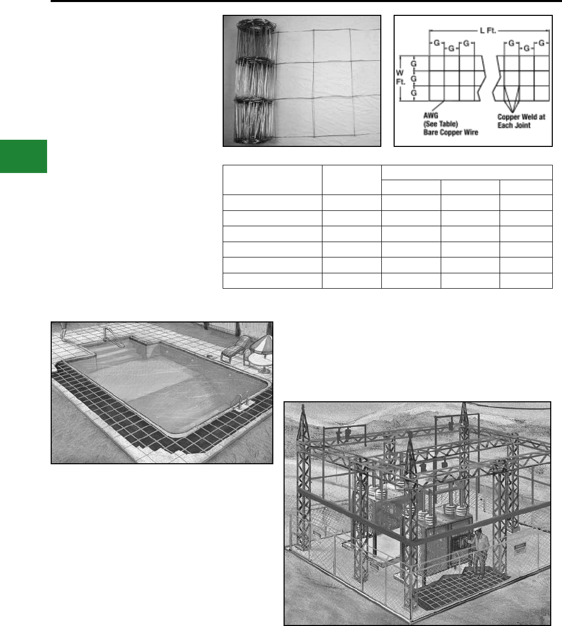
BURNDY®
Blue highlighted items are industry standard and most frequently ordered.
US: 1-800-346-4175 www.burndy.com Canada: 1-800-387-6487
Grounding
BURNDYWeld® Exothermic
BURNDY® GRIDMAX®
Grounding, Personnel Safety Mats,
Equipotential Bonding, Pool and
Spa Grounding
Catalog Number Conductor Dimensions
G (spacing) L (length) W (width)
BGM3100 8 AWG 12" 100’ 3’
BGM3050 8 AWG 12" 50’ 3’
BGM640044 6 AWG 4" 4’ 4’
BGM640068 6 AWG 8" 6’ 4’
BGM64006 6 AWG 12" 6’ 4’
BGM640066 6 AWG 6" 6’ 4’
Features & Benets
• Manufactured from bare solid copper
• Spaced on 4", 6" or 12" centers
• Copper to copper weld with 6% silver
• Furnished in sections with lengths from 4′ to
100′
• Easily and economically installed using
BURNDYWeld®, HYGROUND® or our
Mechanical connectors
• Sizes made specically for the Pool and Spa
market 3′ x 100′ and 3′ x 50′. But can be used
where any large area grounds are required
Example:
GRIDMAX™
3’ wide in pool area
Example:
GRIDMAX™
Personnel Safety Mat
Call for custom mats
E-100
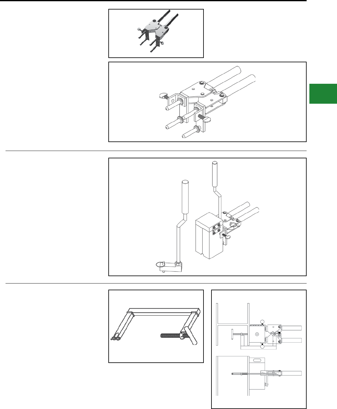
BURNDY®
Blue highlighted items are industry standard and most frequently ordered.
Canada: 1-800-387-6487 www.burndy.com US: 1-800-346-4175
Grounding
BURNDYWeld® Exothermic
B-106 & B-107
HANDLE CLAMPS
BURNDYWeld® Handle Clamps make possible the
use of many different sizes and types of molds with
only two different clamps. The two handle clamps
are catalog numbers B-106 & B-107. These will t
95% of all standard BURNDYWeld® molds.
1. Use B-106 clamps for all molds having a
price key 4, 7, 17, 22 or 24. These molds are
a nominal 3 1/8" x 3 1/8" square.
2. Use B-107 clamps for all molds having a
price key 5, 6, 8 or 23. These molds are a
nominal 4" x 4" square.
3. All molds having a price key 2, 3, 9, 10, 11,
12, 14, 15 or 16 have an attached frame;
separate handles are not required.
B40-0106-75 HANDLE
ATTACHMENT
This Handle Attachment is used to hold Price Key
14 molds in position. It easily attaches to the B-106
Handle Clamp. This Handle Attachment can be
used with weld types BCRE-1 and BCRE-4.
Catalog Number: B40-0106-75
MOLD SUPPORT CLAMP
The Mold Support Clamp is used to hold a mold
in position on a vertical steel column or angle.
It is easily attached to the Handle Clamps. The
Mold Support Clamp can be used with weld types
BCS-3, BCS-18, BCS-23 and BCS-27.
Catalog Number: B40-3657-00
E-101
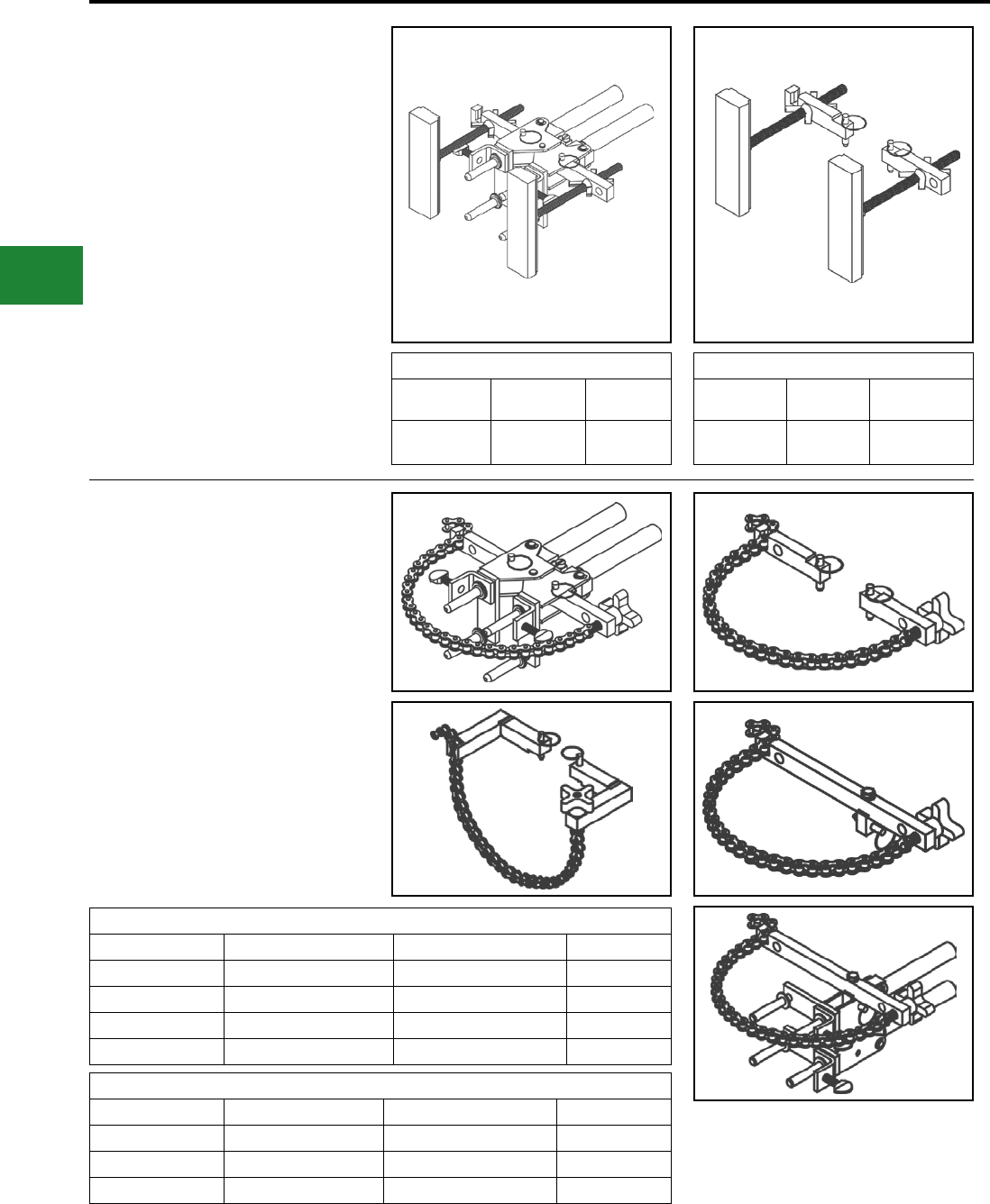
BURNDY®
Blue highlighted items are industry standard and most frequently ordered.
US: 1-800-346-4175 www.burndy.com Canada: 1-800-387-6487
Grounding
BURNDYWeld® Exothermic
VERTICAL MAGNETIC
CLAMPS
Magnetic Clamps are used to hold a mold in
position on a vertical steel surface. The magnetic
clamp can be purchased complete with B-106
Handle Clamps or if you already have a set of
handle clamps, you can order just the magnetic
mounting assembly. The mounting assembly
can easily be mounted on the prongs of your
existing B-106 handle clamps. A minimum of 10"
is required.
Magnetic Clamps with B106 Handle
Catalog
Number
Fits Molds w/
Price Key
For Use with
Weld Types
B40-4431-00 4 & 17 BCS-3, 4, 7
& 23
HORIZONTAL & VERTICAL
CHAIN CLAMPS
BURNDYWeld®
Chain Clamps are used to hold a mold in position
on horizontal or vertical pipe up to 4" in diameter.
For larger pipe a 20" chain extension is available to
allow the chain clamps to be used on pipe up to 10"
in diameter. The chain clamp can be purchased
complete with B-106 or B-107 Handle Clamps or if
you already have a set of handle clamps, you can
order just the chain clamp and mounting assembly.
The mounting assembly can easily attached to
your existing handle clamps. 20" Chain Extension
catalog number: B40-0106-27.
Chain Clamps
Catalog Number Fits Molds W/Price Key For Use With Weld Types Pipe Position
B106-32 4, 17, 22 & 24 BCS-3, 4, 7, 23 & BCRE-6 Vertical
B107-32 5, 6 & 23 BCS-3, 4, 7 & 23 Vertical
B106-37 4, 17, 22 & 24 BCS-1, 2, 5, 8 & 9 Horizontal
B106-41 4, 17 BCS-6, 18 & BCRE-3 Vertical
Magnetic Clamp Only
Catalog
Number
Fits Handle
Clamps
For Use with
Weld Types
B40-4431-00 B-106 &
B-107
BCS-3, 4, 7
& 23
Chain Clamp Only (Handle Clamps Not Included)
Catalog Number Fits Handle Clamp For Use With Weld Types Pipe Position
B40-0106-76 B-106 & B-107 BCS-3, 4, 7, 23 & BCRE-6 Vertical
B40-0106-78 B-106 & B-107 BCS-1, 2, 5, 8 & 9 Horizontal
B40-0106-77 B-106 & B-107 BCS-6, 18 & BCRE-3 Vertical
E-102
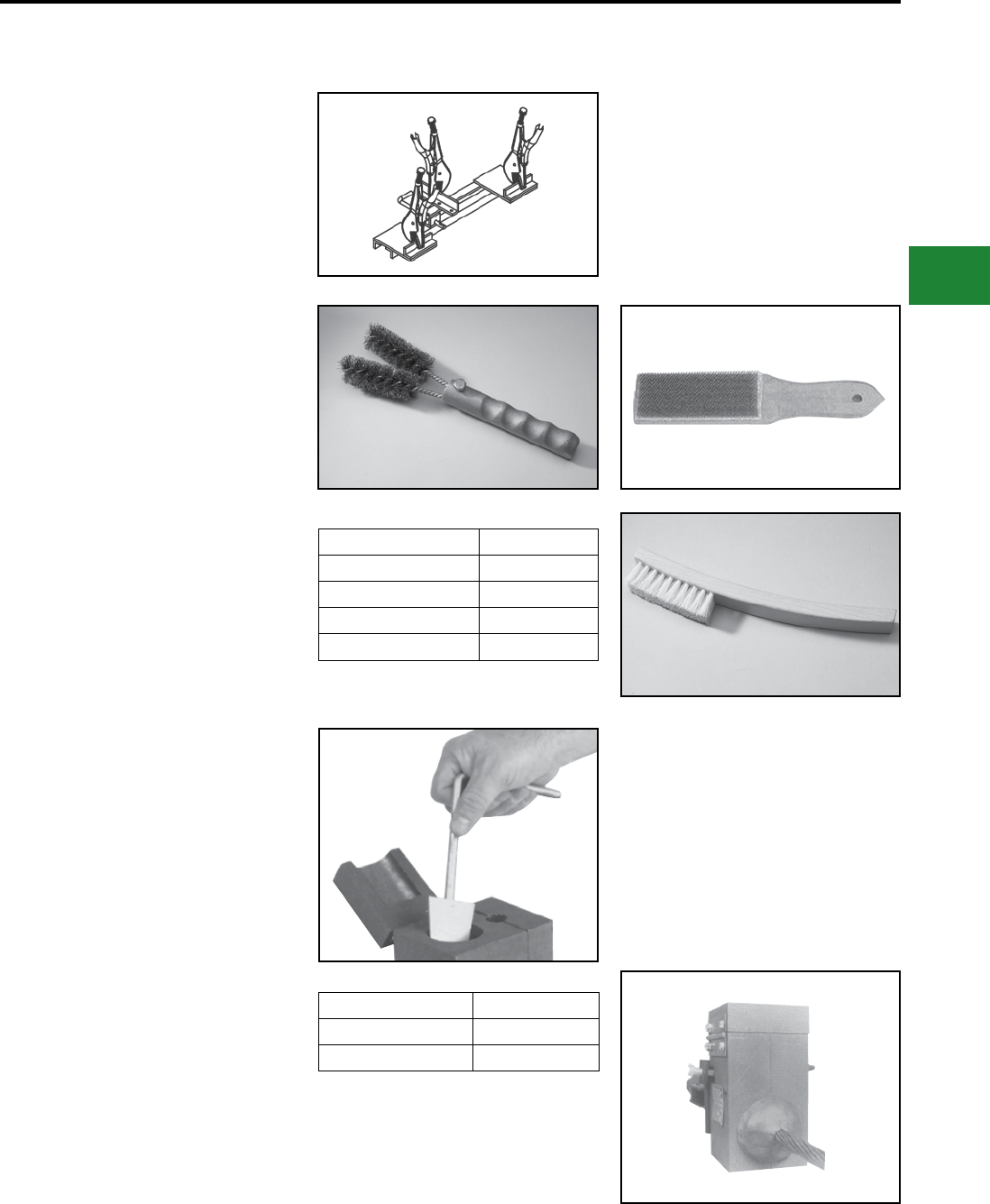
BURNDY®
Blue highlighted items are industry standard and most frequently ordered.
Canada: 1-800-387-6487 www.burndy.com US: 1-800-346-4175
Grounding
BURNDYWeld® Exothermic
BURNDYWeld®
ACCESSORIES
B38-0330-00 Cable Clamp
The BURNDYWeld® Cable Clamp is
recommended for holding a wide range of cables
properly in place in molds when welding cables
that are under tension. This prevents the cables
from pulling out of the mold when the weld is made.
Cable Cleaning and
Card Cloth Brush
The Cable Cleaning Brush is recommended for
cleaning heavily oxidized cables. The V-shape
brushes permit their use over a wide range of
cable sizes. Brush assembly consists of a handle
with two stiff wire bristle brushes that are rotatable,
for longer life and are replaceable.
The Card Cloth Brush is used for cleaning large
conductors and bus bar. It has short stiff bristles.
These brushes are for cleaning cable only, not
molds.
The Mold Cleaning Brush B38-3922-00 is used
to clean the graphite mold without scratching the
mold.
Description Catalog Number
Cable Cleaning Brush B38-0315-00
Replacement Brush B38-0135-01
Card Cloth Brush B38-0306-00
Mold Cleaning Brush B38-3922-00
Mold Cleaners
Mold Cleaners are used to clean the slag from
molds that are not split through the crucible.
B40-0319-01 for cartridge sizes #15
through #65
B40-0319-03 for cartridge sizes #90
through #500
Packing Material
Packing material is used to prevent the molten
weld metal from leaking out of the mold. When
the cable opening becomes worn from heavy
use, the packing material may be used to prolong
mold use. It is also used around 7 strand cable to
prevent leaking. Packing material comes in a 1 lb.
or 5 lb. package.
Description Catalog Number
1 lb. package B38412900
5 lb. package B38412905
E-103
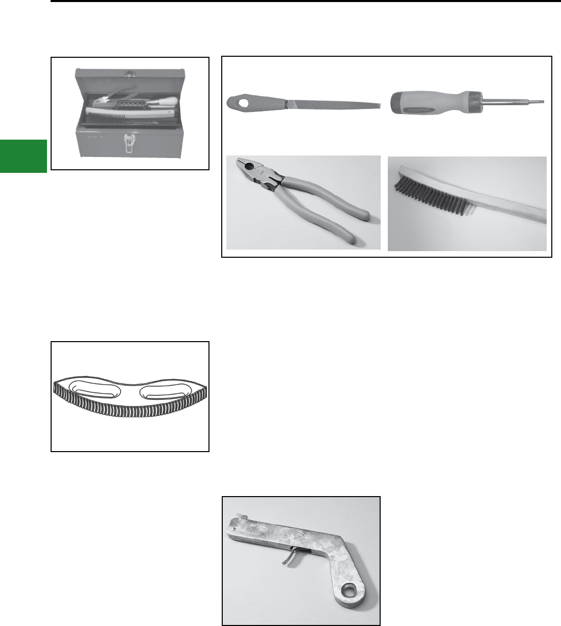
BURNDY®
Blue highlighted items are industry standard and most frequently ordered.
US: 1-800-346-4175 www.burndy.com Canada: 1-800-387-6487
Grounding
BURNDYWeld® Exothermic
BURNDYWeld®
ACCESSORIES
BURNDYWeld® Tool Kit
B38-0302-00 Tool Kit with Tools
Shown except Rasp
B38-0302-02 Tool Kit with Tools
Shown and Rasp
B38-0303-00 Tool Box only
BURNDYWeld® Tools
The B38-0309-00 Flint Ignitor is used to ignite
the starting powder. Each mold that is sold with
a frame has a Flint Ignitor included. For added
safety a Flint Ignitor extension is available, catalog
number B38-0904-00, that attaches to the
B38-0309-00 Flint Ignitor. This allows installers
to stay approximately 36" away from the mold.
To order replacement ints, specify part number
B38-0309-01.
B38-0101-00 Rasp
This tempered steel, curved rasp is recommended
for removing rust and mill scale from steel and cast
iron surfaces. The blade is replaceable. To order
replacement rasp blade, specify catalog number
B38-0101-01.
Not recommended for use on galvanized surfaces.
B38-0309-00 Flint Ignitor
The B38-0309-00 Flint Igniter is used to ignite
the starting powder. Each mold that is sold with
a frame has a Flint Igniter included. For added
safety a Flint Igniter extension is available, catalog
number B38-0904-00, that attaches to the
B38-0309-00 Flint Igniter. This allows installers to
stay approximately 36" away from the mold.
To order replacement ints, specify part number
B38-0309-01.
B38-0309-00 Flint Ignitor
B38-0304-00 8″ File
B38-0307-00 Crimping Tool
B38-3922-00 Mold Cleaning Brush
B38-0308-00 6″ Screwdriver
B38-0305-00 Wire Brush
B38-0101-00 Rasp
B38-0306-00 Card Cloth Brush
E-104
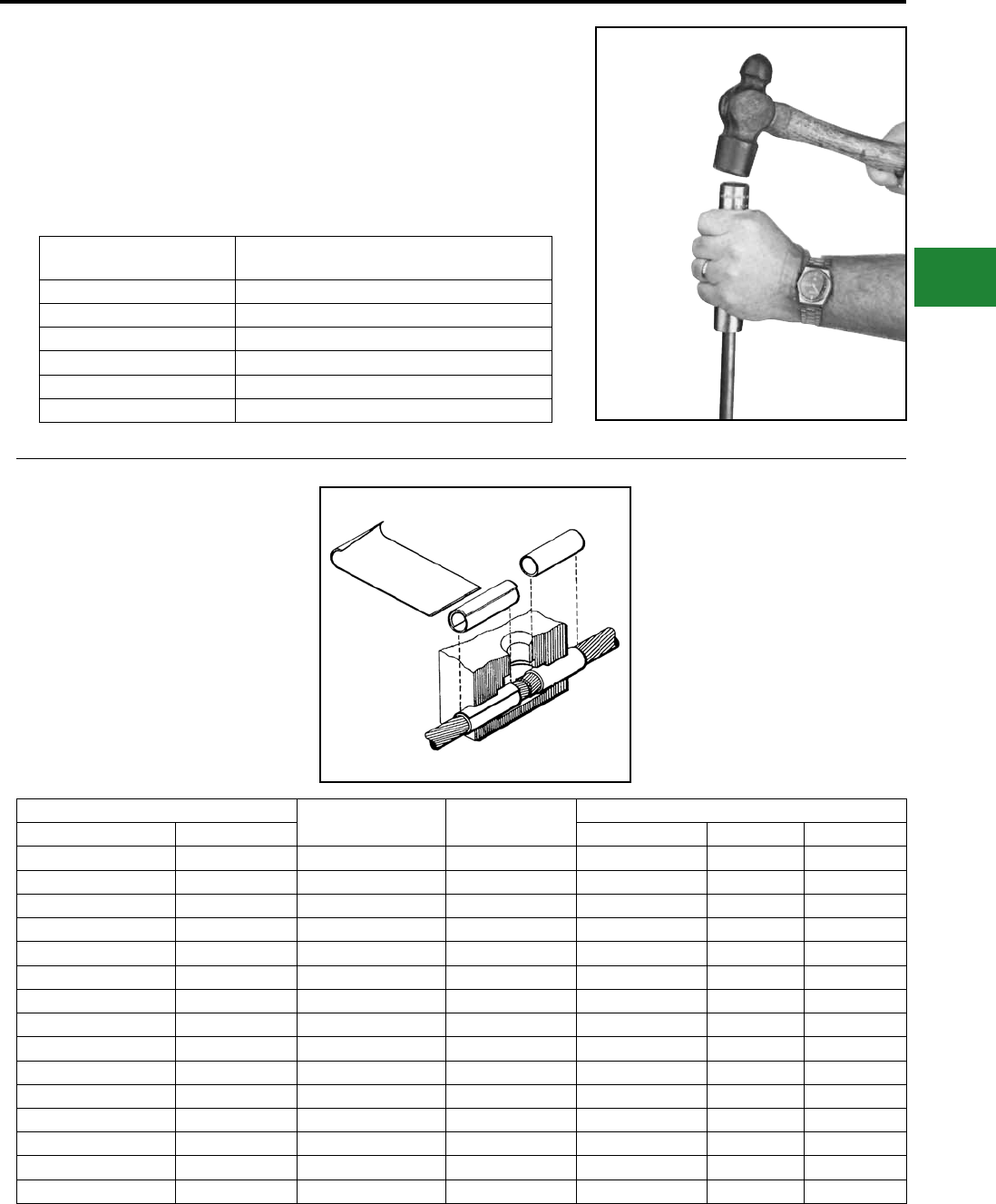
BURNDY®
Blue highlighted items are industry standard and most frequently ordered.
Canada: 1-800-387-6487 www.burndy.com US: 1-800-346-4175
Grounding
BURNDYWeld® Exothermic
Ground Rod
Driving Sleeves
Ground Rod Driving Sleeves are placed over the
top of a ground rod while driving it into the ground.
This prevents the top from mushrooming or aring
out. Ground rod driving sleeves are available in
sizes to t all standard unthreaded ground rods.
Catalog
Number For Use On
B38-3662-01 1/2" Copper Clad or Steel Ground Rod
B38-3662-02 5/8" Copper Clad Ground Rod
B38-3662-05 5/8" Steel Ground Rod
B38-3662-03 3/4" Copper Clad Ground Rod
B38-3662-06 3/4" Steel Ground Rod
B38-3662-04 1" Copper Clad Ground Rod
SHIM STOCK AND ADAPTER
SLEEVES
BURNDYWeld® molds designed for larger cable
sizes can be used on smaller diameter cables if
copper adapter sleeves or shim stock are utilized.
The copper shim stock, .0108" x 1-1/2" x 3", is
normally wrapped around cable until the diameter
is about equal to the cable opening. A tight t is not
necessary as the shim stock will unwrap slightly
and prevent leakage of weld metal. To order shim
stock use part number B38-0329-00. Shim stock
comes 100 pieces per box.
For Use on Cable Size Part Number Use in Mold Size Sleeve Dimensions
Stranded Solid O.D. Size I.D. Length
#12, #14 #10, #12, #14 BA-200 #6 Str. & Sol. 0.15 0.11 1.00
#9. #10 #8. #9. #10 BA-208 #4 Sol. 0.20 0.14 1.00
#7, #8, #10 #6, #8 BA-201 #4 0.22 0.17 1.00
#6 #5 BA-202 #2 0.29 0.19 1.00
#4, #5 #3, #4 BA-207 #2 0.30 0.24 1.00
#4 #2 BA-204 #1 0.34 0.24 1.00
#2 #1 BA-203 1/0 0.37 0.30 1.00
#1 1/0 BA-209 2/0 0.42 0.35 1.00
1/0, #1 2/0 BA-205 3/0 & 4/0 Sol. 0.46 0.38 1.00
2/0, 1/0 3/0 BA-240 4/0 0.52 0.43 1.50
4/0 — BA-211 300 kcmil 0.62 0.54 1.25
250 kcmil — BA-212 350 kcmil 0.67 0.59 1.25
350, 400 kcmil — BA-213 500 kcmil 0.81 0.76 1.50
250, 300, 350 kcmil — BA-214 500 kcmil 0.81 0.70 1.50
750, 800 kcmil — BA-215 1000 kcmil 1.15 1.05 1.50
E-105

BURNDY®
Blue highlighted items are industry standard and most frequently ordered.
Canada: 1-800-387-6487 www.burndy.com US: 1-800-346-4175
Accessories
F-1
TABLE OF CONTENTS
F-2
F-2
F-3, F-4
F-5
F-6
F-7
F-8
F-9
F-10
F-11
F-12
F-13
F-14
F-15
Introduction
PENETROX™ Oxide Inhibitor
(How to Install Connectors)
PENETROX™
Type BDSC Sealing Compound
Thin Wall Heat Shrink Tubing
Type HS-T-PF
6 Inch Lengths
4 Foot Reels
25 Foot Reels
Heavy Wall Heat Shrink Tubing
Type HS-H-PF
Cut Lengths; 4 Foot Sticks
Caps
Heavy Wall Heat Shrinkable End Cap
Type HSIC-FR
Super-Seal Waterproong Mastic Push-On
End cap
Type BSC
Force Fit Cable Caps
Type BPC
Fire Retardant Heat Shrink Tubing
Type HSC-FR; Clear VISI-SHRINK™
50’ or 250’ Reels
Type HS-FR
50’, 250’ or 100’ Reels
MISCELLANEOUS ACCESSORIES
Type BHSG1100 Heat Gun
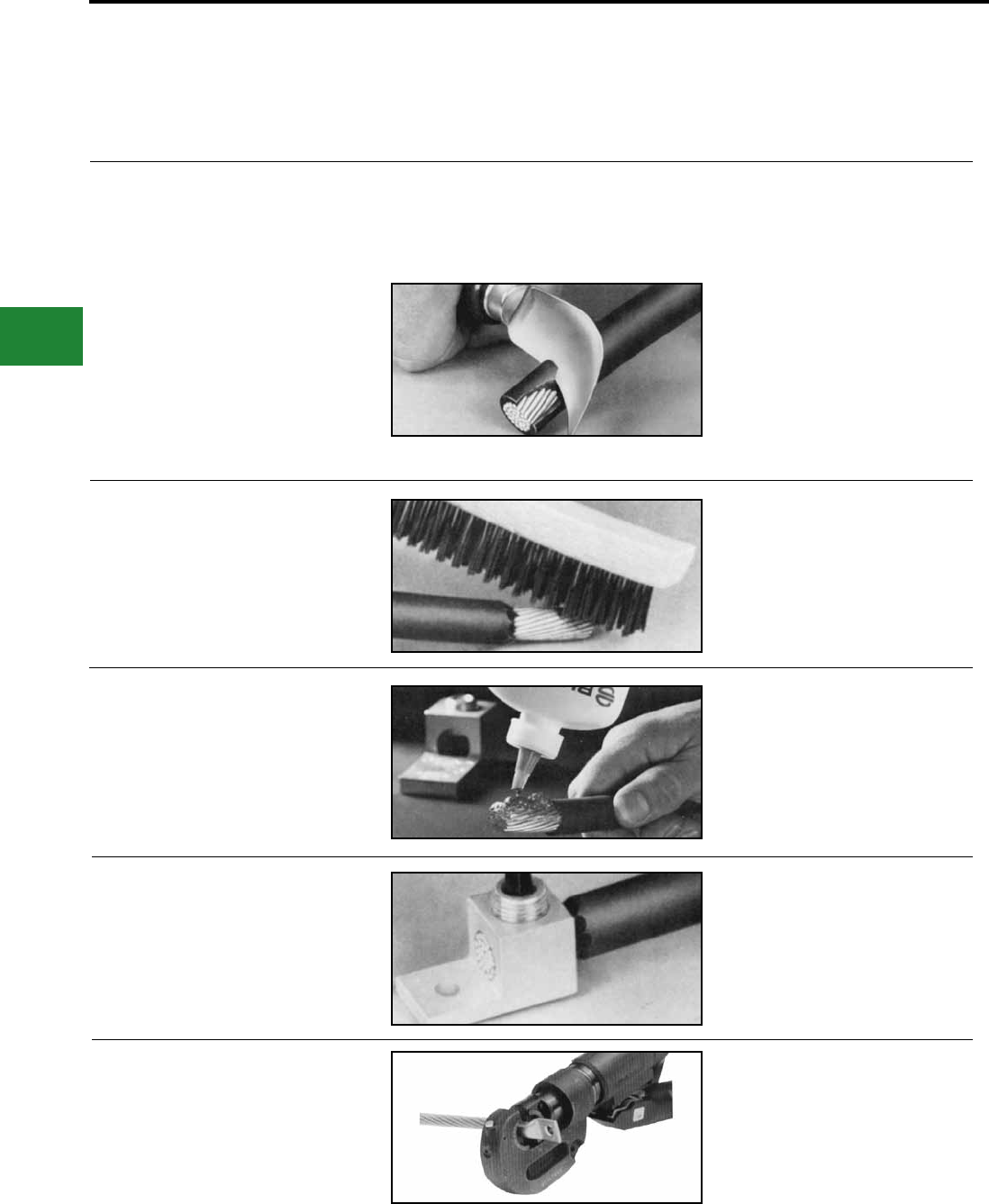
BURNDY®
Blue highlighted items are industry standard and most frequently ordered.
US: 1-800-346-4175 www.burndy.com Canada: 1-800-387-6487
Accessories
INTRODUCTION
BURNDY wiring accessories have been
designed to supplement and enhance BURNDY
connector selection and use. All have been
designed and engineered for easy installation
PENETROX™
HOW TO INSTALL CONNECTORS:
1. Select the right connector.
Always use an aluminum connector for aluminum
or copper conductor. Choose a connector that’s
marked for the wire size you’re using. Never use a
copper connector on aluminum conductor.
2. Strip carefully.
Remove the insulation without nicking the wire.
3. Brush thoroughly.
Always wire-brush the stripped portion of the wire.
An unplated terminal pad, and the surface to which
the terminal will be attached should also be wire-
brushed.
4. Apply PENETROX™
For mechanical connectors, apply PENETROX™
joint compound liberally to the conductor to prevent
the formation of surface oxides once the connec-
tion is made. Also apply PENETROX™ to any
terminal pad.
5. Tighten completely.
For mechanical connectors, use wrench or screw-
driver to securely tighten the aluminum connec-
tors, as recommended by BURNDY.
6. Crimp.
For compression connectors, choose the right
die and the right tool. Insert the wire completely
and make the recommended number of crimps.
and long life, reecting over 85 years of
experience and resulting contributions to all
aspects of the electrical industry.
F-2
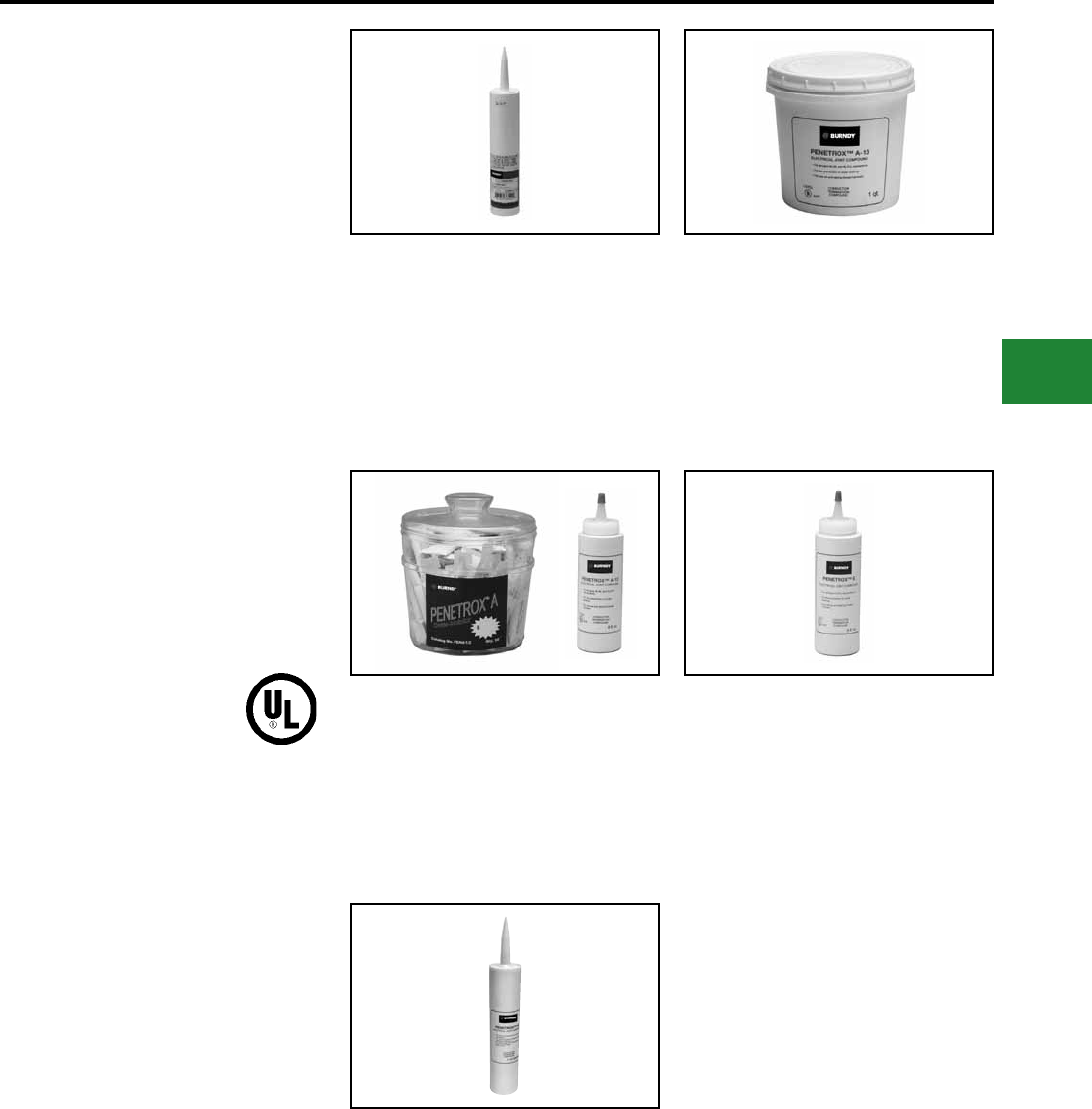
BURNDY®
Blue highlighted items are industry standard and most frequently ordered.
Canada: 1-800-387-6487 www.burndy.com US: 1-800-346-4175
Accessories
TYPES PENETROX™
A, A-13, E AND HT
OXIDE-INHIBITING
JOINT COMPOUNDS
PENETROX™ oxide-inhibiting compounds
produce low initial contact resistance, seal
out air and moisture, prevent oxidation
or corrosion, exhibit superior weathering
characteristics, are usable over wide temperature
ranges, and provide a high conductivity “gas-
tight” joint. All PENETROX™ compounds contain
homogeneously suspended metal particles. The
suspended metal particles assist in penetrating
thin oxide lms, act as electrical “bridges” between
conductor strands, aid in gripping the conductor,
improve electrical conductivity and enhance the
integrity of the connection.
The specially formulated PENETROX™
compounds are for use with compression and
bolted connectors providing an improved service
life for both copper and aluminum connections.
Additionally, the nontoxic compounds are an
excellent lubricant for threaded applications
reducing galling and seizing.
PENACARTRIDGE
PENACARTRIDGE is a 1 lb. cartridge lled
with PENETROX-A. It’s designed to t standard
caulking guns for easy insertion into transmis-
sion and distribution connectors. Additionally, this
packaging design provides a convenient method
for applying PENETROX™ to many different ap-
plications.
PENETROX™ A-13
PENETROX™ A-13 is a synthetic base compound
with evenly suspended zinc particles. It is recom-
mended for aluminum to aluminum, aluminum
to copper connections plus aluminum conduit
threads. It is compatible with rubber, polyethylene
and other insulating materials. UL Listed for all volt-
ages.
PENETROX™ A
PENETROX A is a natural (petroleum) base
compound with evenly suspended zinc particles. It
is recommended for aluminum to aluminum, alumi-
num to copper connections and aluminum conduit
threads. It is not recommended for use with rubber
or polyethylene insulated conductors. UL listed to
600V.
PENETROX™ E
PENETROX™ E is a synthetic base compound
with evenly suspended copper particles. It is rec-
ommended for copper to copper, copper threads
and all grounding applications. UL Listed.
PENETROX™ HT
PENETROX™ HT is a synthetic silicone based
compound with evenly suspended zinc particles
and nickel-aluminum alloy particles. It is recom-
mended for aluminum to aluminum connections.
It is compatible with rubber. Designed for use with
High Temperature ACSS and ACCC connectors.
Not UL Listed.
F-3
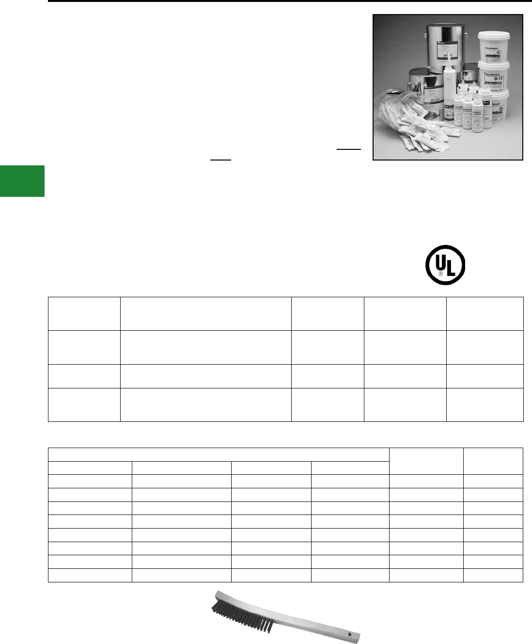
BURNDY®
Blue highlighted items are industry standard and most frequently ordered.
US: 1-800-346-4175 www.burndy.com Canada: 1-800-387-6487
Accessories
PENETROX™ A,
A-13, E AND HT
TECHNICAL INFORMATION
PENETROX A
PENETROX A consists of a natural (petroleum)
base vehicle in which zinc particles are
suspended. For aluminum to aluminum,
aluminum to copper applications and aluminum
conduit threads. It is not recommended for
use with rubber and polyethylene insulated
conductors. UL Listed to 600 volts.
PENETROX A-13
PENETROX A-13 consists of a non-petroleum
base vehicle in which zinc particles are
suspended. Recommended for aluminum to
aluminum, aluminum to copper applications
and aluminum conduit threads. Compatible
with insulating materials such as rubber, or
polyethylene. UL Listed and recommended for
all voltages.
PENETROX E
PENETROX E consists of a non-petroleum
base vehicle in which copper granules are
suspended. Recommended for copper to
copper applications, grounding and for use on
copper conduit threads. UL Listed to 600 volts.
PENETROX HT
PENETROX HT consists of a non-petroleum
base vehicle in which zinc and nickel-aluminum
particles are suspended. Recommended for use
with aluminum to aluminum High Temperature
rated ACSS and ACCC conductors. Not UL
Listed.
Easy to apply:
1. Scratch brush the conductor surfaces
until bright and clean.
2. Immediately apply PENETROX™ to the
conductive surfaces.
3. For EHV applications, remove all excess
PENETROX™ after installation is
complete.
SHELF LIFE
When stored in its original container in cool
(under 100°F) dry environment, PENETROX™
oxide inhibiting compound will remain workable
and functional for 5 years from the Date of
Manufacture (MO) marked on the container.
ORDERING INFORMATION
PROPERTIES OF PENETROX™
Property
Value
PENETROX™
Denition
PENETROX™
HT
PENETROX™
E & A13
PENETROX™
A
Penetration
(Unworked)
The value in accordance to ASTM D217 indicates
the consistency of a grease. The higher the number,
the softer the grease.
240 250 230
Dropping
Point (Minimum)
The temperature at which the grease passes from
the semi-solid to a liquid state under test conditions. >580° F 350° F 230° F
Pour Point
(Maximum)
The lowest termperature at which the compound will
ow. Pour point is the lubricant’s ability to perform in
cold conditions.
–58° F –40° F –15° F
* MSDS sheets available through customer service.
* 1 lb. cartridge will t standard caulking guns.
† Not UL Listed. B38-0305-00 Wire Brush
Catalog Number Container
Type
Container
Size
PENETROX™ A PENETROX™ A-13 PENETROX™ E PENETROX™ HT †
PENA 1/2 — — — Tube 1/2 oz.
PENA-4 PENA13-4 PENE-4 PENHT-4 Squeeze Bottle 4 oz.
P8A PENA13-8 PENE-8 PENHT-8 Squeeze Bottle 8 oz.
PENACARTRIDGE PENA13CARTRIDGE — PENHT1LB Cartridge 1 lb.*
PENA-QT PENA13-QT PENE-QT — Plastic Tub 1 Quart
PENA-GAL PENA13-GAL PENE-GAL PENHTGAL Can 1 Gallon
PENA-5GAL PENA13-5GAL PENE-5GAL — Pail 5 Gallons
PENA-55GAL PENA13-55GAL PENE-55GAL — Drum 55 Gallons
F-4
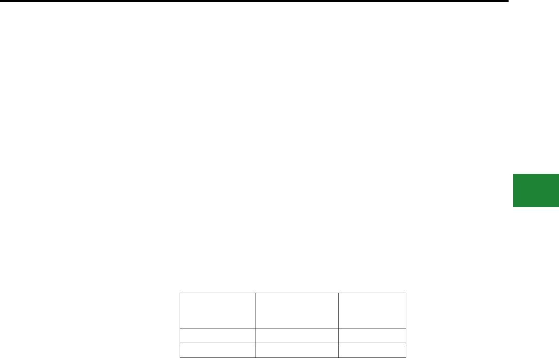
BURNDY®
Blue highlighted items are industry standard and most frequently ordered.
Canada: 1-800-387-6487 www.burndy.com US: 1-800-346-4175
Accessories
TYPE BDSC
Duct Sealing Compound
BDSC Asbestos Free Sealer is a gray,
permanently soft, nontoxic compound which
will adhere to most clean, dry surfaces. BDSC
Sealer will not adversely affect other plastic
materials or corrode metals. It also has no
adverse effect on human skin.
Supplied in a convenient block shape
overwrapped with release paper and bagged in
a clear reentry type PVC bag with application
data.
Catalog Number Block Size Carton Quantity
BDSC1 1 lb. 50 lbs.
BDSC5 5 lbs. 50 lbs.
• Unlimited shelf life
• Dielectric strength approximately 100V/
mil. using ASTM D149-64
• Nontoxic and nonirritating
• Easily shaped by hand to suit the
application
• 100% nonvolatile solids including
nondrying, synthetic polymers with inert
mineral bers
• Recommended working range when
applying is 20 degrees F. Tolerance range
is 40 degrees to 194 degrees F. Will not
sag at 280 degrees F when under such
exposure for brief periods
• Permanent pliable and non-cracking. May
be painted immediately
Details:
F-5
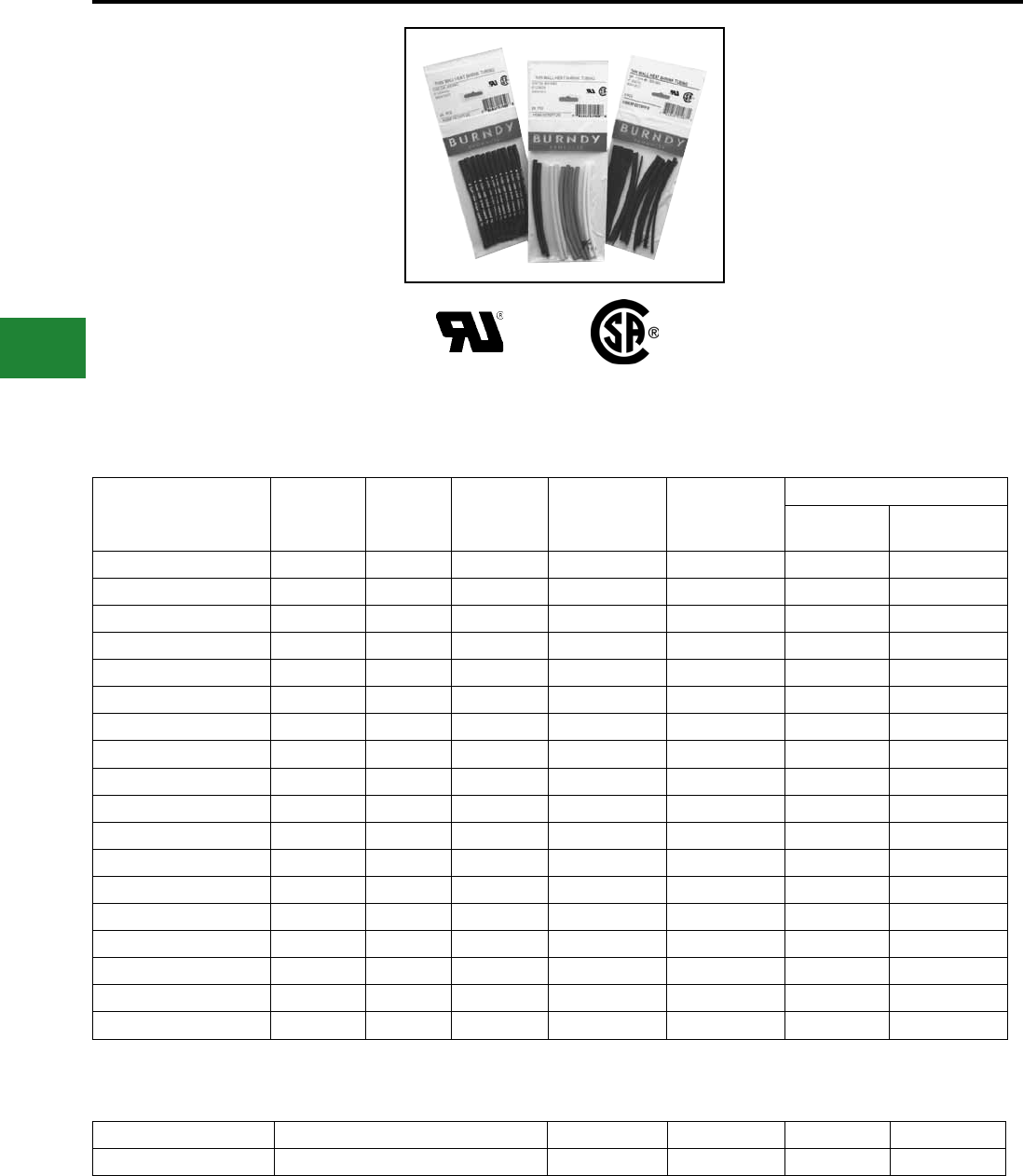
BURNDY®
Blue highlighted items are industry standard and most frequently ordered.
US: 1-800-346-4175 www.burndy.com Canada: 1-800-387-6487
Accessories
TYPE HS-T-PF
THIN WALL HEAT
SHRINK TUBING
Cross-Linked Polyolen
6 Inch Lengths
Type HS-T-PF is a exible thin wall, ame
retardant heat shrink tubing made of cross-linked
polyolen. The 2:1 shrink ratio allows for faster
shrink recovery, covering wire sizes: #18 AWG to
300 kcmil. Operating temperatures from –55° C to
135° C with a shrink temperature of 120° C.
Catalog
Number
Nominal
Diameter
Inches
Min.
Exp.
I.D. In.
Max.
Recov.
I.D. In.
Nom. Wall
Thickness
In.
Conductor
Range
Pieces per Package
# Pieces
Black
# Pieces Each
Color
HSM116T6PF26 1/16 0.06 0.03 0.02 #18 8 3
HSB116T6PF26 1/16 0.06 0.03 0.02 #18 26 0
HSM332T6PF24 3/32 0.09 0.05 0.02 #18-16 6 3
HSB332T6PF24 3/32 0.09 0.05 0.02 #18-16 24 0
HSM18T6PF20 1/8 0.12 0.06 0.02 #18-14 2 3
HSB18T6PF20 1/8 0.12 0.06 0.02 #18-14 20 0
HSM316T6PF18 3/16 0.19 0.09 0.02 #18-12 6 2
HSB316T6PF18 3/16 0.19 0.09 0.02 #18-12 18 0
HSM14T6PF14 1/4 0.25 0.12 0.18 #14-10 2 2
HSB14T6PF14 1/4 0.25 0.12 0.18 #14-10 14 0
HSM38T6PF12 3/8 0.38 0.19 0.02 #8-6 6 1
HSB38T6PF12 3/8 0.38 0.19 0.02 #8-6 12 0
HSM12T6PF10 1/2 0.50 0.12 0.02 #6-2 4 1
HSB12T6PF10 1/2 0.50 0.12 0.02 #6-2 10 0
HSM34T6PF8 3/4 0.75 0.38 0.02 #1-3/0 2 1
HSB34T6PF8 3/4 0.75 0.38 0.02 #1-3/0 8 0
HSM100T6PF7 1 1.00 0.50 0.18 2/0-300 1 1
HSB100T6PF7 1 1.00 0.50 0.18 2/0-300 7 0
HSB series — all black
HSM series — multiple colors: black, blue, clear, green, red, white, yellow
HSB11612T6PF14 1/16, 3/32, 1/8, 3/16, 1/4, 3/8, 1/2 — — 14 0
HSB38100T6PF8 3/8, 1/2, 3/4, 1" — — 8 0
Multiple diameter packages contain two pieces of each size listed: Black only.
Meets SAE-AMS-DTL-2305315
1000 V
F-6
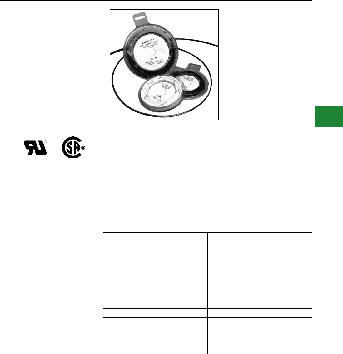
BURNDY®
Blue highlighted items are industry standard and most frequently ordered.
Canada: 1-800-387-6487 www.burndy.com US: 1-800-346-4175
Accessories
TYPE HS-T-PF
THIN WALL HEAT
SHRINK TUBING
Cross-Linked Polyolen
4 Foot Reels
Type HS-T-PF is a exible thin wall, ame
retardant heat shrink tubing made of cross-linked
polyolen. The 2:1 shrink ratio allows for faster
shrink recovery, covering wire sizes: #18 AWG to
300 kcmil. Operating temperatures from –55° C to
135° C with a shrink temperature of 120° C.
Catalog
Number
Nominal
Diameter
Inches
Min.
Exp.
I.D. In.
Max.
Recov.
I.D. In.
Nom. Wall
Thickness
In.
Conductor
Range
HS_116T48PF 1/16 0.06 0.03 0.018 #18
HS_332T48PF 3/32 0.09 0.05 0.020 #18 - 16
HS_18T48PF 1/8 0.12 0.06 0.020 #18 - 14
HS_316T48PF 3/16 0.19 0.09 0.020 #18 - 12
HS_14T48PF 1/4 0.25 0.12 0.180 #14 - 10
HS_38T48PF 3/8 0.38 0.19 0.020 #8 - 6
HS_12T48PF 1/2 0.50 0.12 0.020 #6 - 2
HS_34T48PF 3/4 0.75 0.38 0.020 #1 - 3/0
HS_100T48PF 1 1.00 0.50 0.180 2/0 - 300
HS_150T48PF 1-1/2 1.50 0.75 0.180 350 - 750
HS_200T48PF 2 2.00 1.00 0.180 250 - 500
Specify Color Code in Third Position of
Catalog Number:
Example: HSC316T48PF
BLACK
BLUE
CLEAR
GREEN
RED
WHITE
YELLOW
B :
BL:
C :
G :
R :
W :
Y :
Meets SAE-AMS-DTL-2305315
600 VOLTS
F-7
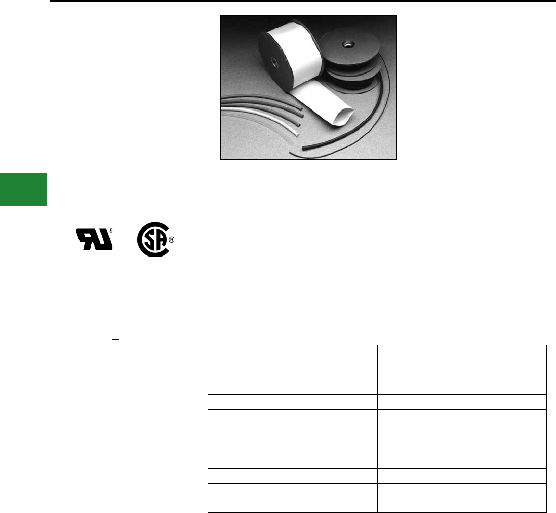
BURNDY®
Blue highlighted items are industry standard and most frequently ordered.
US: 1-800-346-4175 www.burndy.com Canada: 1-800-387-6487
Accessories
TYPE HS-T-PF
THIN WALL HEAT
SHRINK TUBING
Cross-Linked Polyolen
25 Foot Reels
Type HS-T-PF is a exible thin wall, ame retardant
heat shrink tubing made of cross-linked polyolen.
The 2:1 shrink ratio allows for faster shrink
recovery, covering wire sizes: #18 AWG to 300
kcmil. Operating tem-peratures from –55° C to
135° C with a shrink temperature of 120° C.
Meets SAE-AMS-DTL-2305315
600 VOLTS
Catalog
Number
Nominal
Diameter
Inches
Min.
Exp.
I.D. In.
Max.
Recov.
I.D. In.
Nom. Wall
Thickness
In.
Conductor
Range
HS_116T300PF 1/16 0.06 0.03 0.018 #18
HS_332T300PF 3/32 0.09 0.05 0.020 #18 - 16
HS_18T300PF 1/8 0.12 0.06 0.020 #18 - 14
HS_316T300PF 3/16 0.19 0.09 0.020 #18 - 12
HS_14T300PF 1/4 0.25 0.12 0.180 #14 - 10
HS_38T300PF 3/8 0.38 0.19 0.020 #8 - 6
HS_12T300PF 1/2 0.50 0.12 0.020 #6 - 2
HS_34T300PF 3/4 0.75 0.38 0.020 #1 - 3/0
HS_100T300PF 1 1.00 0.50 0.180 2/0 - 300
Specify Color Code in Third Position of
Catalog Number:
Example: HSC116T300PF
BLACK
BLUE
CLEAR
GREEN
RED
WHITE
YELLOW
B :
BL:
C :
G :
R :
W :
Y :
F-8
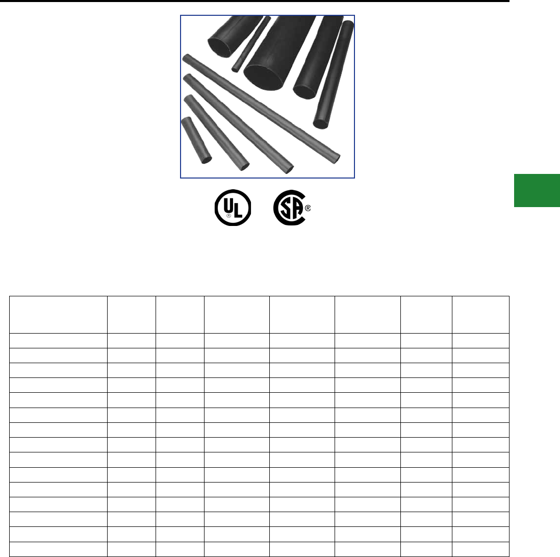
BURNDY®
Blue highlighted items are industry standard and most frequently ordered.
Canada: 1-800-387-6487 www.burndy.com US: 1-800-346-4175
Accessories
TYPE HS-H-PF
HEAVY WALL HEAT
SHRINK TUBING
Cross-Linked Polyolen
Cut Lengths and 4 Foot Sticks
Type HS-H-PF is a heavy wall, ame retardant
heat shrink tubing made of cross-linked polyolen.
The shrink ratio is 3:1, and the inside diameter is
coated with an adhesive sealant to protect against
moisture and corrosion. UL486D Listed for direct
burial applications. Accommodates #14 AWG -
500 kcmil conductors. Operating temperatures
from –55° C to 135° C with a shrink temperature
of 120° C.
Catalog
Number Length
Nominal
Diameter
Inches
Min.
Exp. I.D.
In.
Max.
Recov.
I.D. In.
Nom. Wall
Thickness
In.
Conductor
Range
Number
of Pcs. Per
Package
HSB35H3PF25 3" 0.35 0.35 0.15 0.07 #14-10 25
HSB35H6PF25 6" 0.35 0.35 0.15 0.07 #14-10 25
HSB35H48PF5 4" 0.35 0.35 0.15 0.07 #14-10 5
HSB34H6PF10 6" 0.75 0.75 0.22 0.09 #6-2 10
HSB34H9PF10 9" 0.75 0.75 0.22 0.09 #6-2 10
HSB34H48PF5 4" 0.75 0.75 0.22 0.09 #6-2 5
HSB110H6PF5 6" 1.10 1.10 0.40 0.12 #1-3/0 5
HSB110H9PF5 9" 1.10 1.10 0.40 0.12 #1-3/0 5
HSB110H48PF5 4" 1.10 1.10 0.40 0.12 #1-3/0 5
HSB150H9PF3 9" 1.50 1.50 0.50 0.16 2/0-350 3
HSB150H12PF3 12" 1.50 1.50 0.50 0.16 2/0-350 3
HSB150H48PF5 4" 1.50 1.50 0.50 0.16 2/0-350 5
HSB200H9PF2 9" 2.00 2.00 0.75 0.16 250-500 2
HSB200H12PF2 12" 2.00 2.00 0.75 0.16 250-500 2
HSB200H48PF2 4" 2.00 2.00 0.75 0.16 250-500 2
Meets SAE-AMS-DTL-2305315
1000 V
Available in black only.
F-9
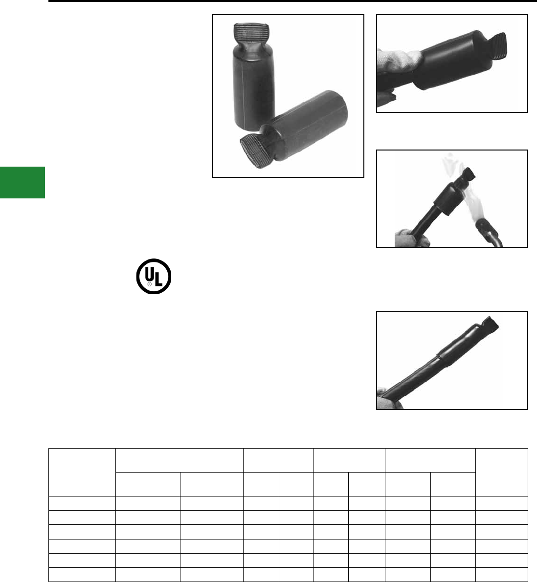
BURNDY®
Blue highlighted items are industry standard and most frequently ordered.
US: 1-800-346-4175 www.burndy.com Canada: 1-800-387-6487
Accessories
TYPE HSIC - FR
HEAVY WALL HEAT SHRINKABLE
END CAP
UL LISTED TO 600V
Type HSIC-FR, Heat Shrink Insulating End Cap
Fire Retardant is a heavy wall, re retardant end
cap made of cross-linked thermally stabilized black
polyolen. Used to insulate exposed conductors in
energized applications. The 3:1 shrink ratio offers
greater range, accommodating copper wire sizes,
#8 AWG thru 2500+ kcmil. Performs effectively
over lead, aluminum, steel, polyethylene, EPR, and
PVC jacketed materials. Blue thermal chromatic
lines disappear indicating correct installation
temperature and provide inspectability. I.D.
adhesive provides superior moisture and weather
resistant characteristics.
Catalog
Number
600V Cable Internal
Diameter
Wall
Thickness
Length
± 20% Number of
Pcs. per
Package
Code Flex (Min)
Exp.
(Max)
Rec Exp. Rec.
± 20% Exp. Rec.
HSIC8-1FR #8-#1 #8-#4 0.50 0.16 0.03 0.08 3.00 2.50 10
HSIC4-40FR #4-4/0 #4-2/0 0.75 0.24 0.03 0.08 3.50 2.50 10
HSIC10-500FR 1/0-500 kcmil #1-313.1 kcmil 1.10 0.35 0.04 0.12 4.00 3.00 5
HSIC30-1000FR 3/0-1000 kcmil 2/0-646 kcmil 1.50 0.47 0.05 0.16 4.50 3.25 5
HSIC200FR 300-1750 kcmil 250-1111 kcmil 2.00 0.63 0.05 0.16 4.50 3.50 5
HSIC350FR 1250 kcmil (min) — 3.50 1.18 0.05 0.16 5.00 4.50 5
Features & Benets
• Minimum 28 Oxygen index, UL94-VO rated.
◊ Self-extinguishing ame retardant
properties.
• 3:1 shrink ratio
◊ Minimum inventory required.
• Thermal chromatic lines
◊ Indicate proper installation.
• Low shrink temperature, 150°C
◊ Only requires common hot air gun to
apply.
• Meets sealing requirements:
ANSI-C119.1, UL486D
◊ Weather and moisture resistant.
1. Slide the HSIC-FR end cap onto the cable and
hold in place using forenger or thumb.
3. HSIC-FR end cap installed on cable.
2. Beginning at closed end apply heat, blue
thermochromatic lines will begin to disappear at
150° C. Gradually, move heat source to open end
and around cap. Once lines are no longer visible and
adhesive ows out of open end, discontinue heating.
F-10
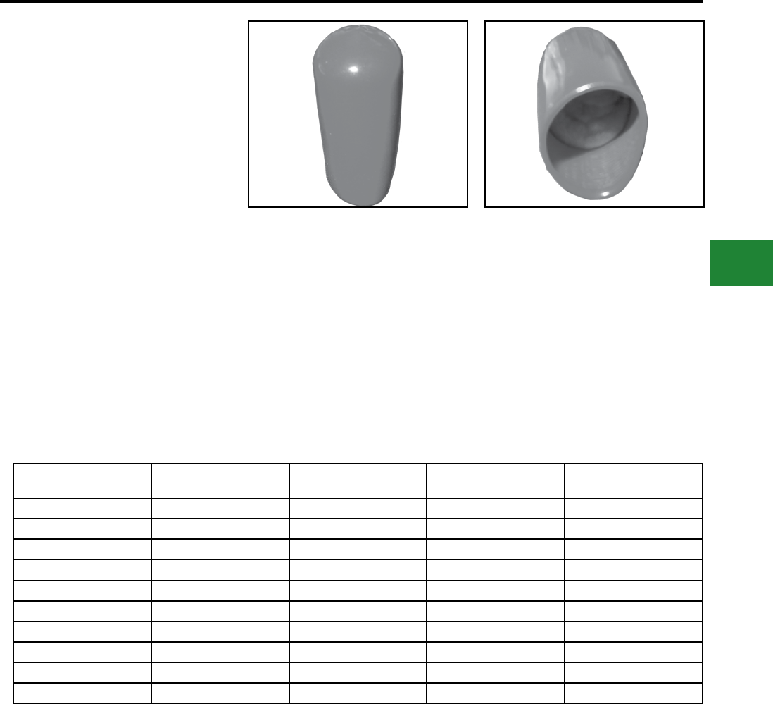
BURNDY®
Blue highlighted items are industry standard and most frequently ordered.
Canada: 1-800-387-6487 www.burndy.com US: 1-800-346-4175
Accessories
TYPE BSC
Push-On Cable End Cap
Containing “Super-Seal”
Waterproong Mastic
Waterproong selas work instantly and stay in
place with tape. The maximum conductors shown
in the table are based upon caps that have been
stretched when making the installations. The
same items can be effectively installed on small
conductors since the mastic has adhesive qualities
when pressed by rmly pushing the caps against
the conductor ends.
Bagged in clear polyethylene with an information
tag. Shelf service life is indenite since Super-Seal
is non-hardening. Super-Seal has no adverse
effect on cable insulation.
Additional intermediate sizes and larger sizes
through 4.88” O.D. can also be supplied on special
orders to specic color codes. Contact factory for
information.
Catalog Number Max. Conductor (O.D.
based on a Snug Cap Fit)
Cap Color Code Pieces per Bag Standard Box Quantity
BSC687 0.75 Red 3 300
BSC1000 1.06 Orange 3 300
BSC1125 1.21 Yellow 3 300
BSC1375 1.47 Gray 3 300
BSC1500 1.63 Black 3 300
BSC1875 1.94 Yellow 3 150
BSC2000 2.06 Black 3 150
BSC2375 2.44 Blue 3 150
BSC2500 2.56 Black 3 150
BSC25002.5 2.56 Black 3 150
Material:
600V PVC
F-11
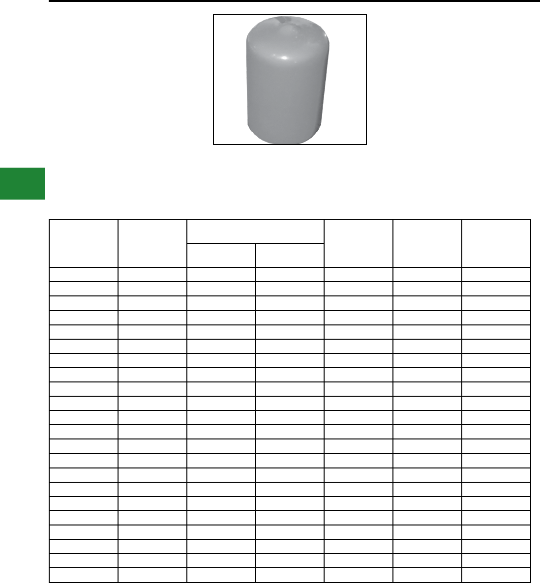
BURNDY®
Blue highlighted items are industry standard and most frequently ordered.
US: 1-800-346-4175 www.burndy.com Canada: 1-800-387-6487
Accessories
TYPE BPC
Force Fit Cable Caps
BPC caps are sized to provide force ts on the listed
diameters of conductors. Caps are color coded as
indicated and are packaged in clear polyethylene
bags which show size and application data. Caps
conform to the conductor shape and will remain in
place without using tape. A moisture seal cannot
always be assured using this method however. All
caps are 1.5” tall.
Additional intermediate sizes and larger sizes
through 4.88” O.D. can also be supplied on special
orders to specic color codes. Contact factory for
information.
Material:
600V PVC
Catalog Number Conductor O.D.
Range (inches)
Conductor Size Ratings (Based on 600
V XLP Insulation) Cap Color Code Pieces per Bag Standard Box
Quantity
Concentric &
Compressed Str. Compact Strand
BPC312 .32 - .38 6 & 4 6, 4 & 2 Orange 100 500
BPC375 .38 - .44 4 & 2 2 Red 100 500
BPC437 .44 - .51 1 1 & 10 Pink 100 500
BPC500 .51 - .55 1/0 2/0 Yellow 100 500
BPC562 .57 - .65 2/0 & 3/0 3/0 Pale Blue 100 500
BPC625 .63 - .70 - 4/0 Pink 100 500
BPC687 .69 - .75 4/0 250 Red 100 500
BPC750 .76 - .84 250 & 300 300 & 350 Black 100 500
BPC843 .85 - .93 350 400 Brown 50 250
BPC875 .88 - .96 400 500 Maroon 50 250
BPC1000 1.00 - 1.08 500 600 Orange 50 250
BPC1125 1.13 - 1.21 600 750 Yellow 50 250
BPC1187 1.19 - 1.27 750 - Black 50 250
BPC1250 1.30 - 1.38 - 1000 Red 50 250
BPC1375 1.38 - 1.47 1000 - Gray 50 250
BPC1500 1.53 - 1.63 1250 - Black 40 200
BPC1687 1.70 - 1.80 1500 - Pale Blue 40 200
BPC1875 1.90 - 2.04 2000 - Yellow 40 200
BPC2000 2.02 - 2.18 - - Orange 40 200
BPC2375 2.39 - 2.55 - - Blue 40 200
BPC2500 3.50 - 3.66 - - Black 40 200
BPC3500 3.50 - 3.66 - - Red 40 200
F-12
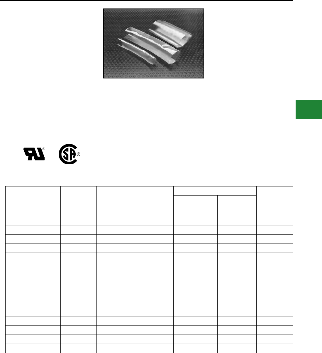
BURNDY®
Blue highlighted items are industry standard and most frequently ordered.
Canada: 1-800-387-6487 www.burndy.com US: 1-800-346-4175
Accessories
TYPE HSC-FR
VISI-SHRINKTM
Fire Retardant Clear Heat
Shrink Tubing
UL Recognized to 600V
Type HSC-FR is a exible polyvinyl chloride clear
heat-shrink tubing. Excellent ame retardant
properties and a 2:1 shrink ratio, the VISI-SHRINK
tubing enables inspectors to read die index
embossments on installed connectors easily.
UL Recognized, 105° C, 600V, the operating
temperature from –20° C to 105° C with a shrink
temperature of 135° C.
Catalog
Number
I.D.
Expanded
I.D. After
Recovery
Wall
Thickness
Conductor Range Standard
Reel Size
(Feet)
Code Flex
HSC18FR 0.13 0.06 0.03 #16-#14 #16-#14 50
HSC18FR250 0.13 0.06 0.03 #16-#14 #16-#14 250
HSC14FR 0.25 0.13 0.03 #12-#8 #12-#10 50
HSC14FR250 0.25 0.13 0.03 #12-#8 #12-#10 250
HSC38FR 0.38 0.19 0.03 #6-#4 #8-#6 50
HSC38FR250 0.38 0.19 0.03 #6-#4 #8-#6 250
HSC12FR 0.50 0.25 0.03 #4-#1 #6-#4 50
HSC12FR250 0.50 0.25 0.03 #4-#1 #6-#4 250
HSC34FR 0.75 0.38 0.03 1/0-3/0 #2-1/0 50
HSC34FR250 0.75 0.38 0.03 1/0-3/0 #2-1/0 250
HSC100FR 1.00 0.50 0.04 4/0-300 1/0-4/0 25
HSC100FR100 1.00 0.50 0.04 4/0-300 1/0-4/0 100
HSC112FR 1.50 0.75 0.04 350-750 250-500 25
HSC112FR100 1.50 0.75 0.04 350-750 250-500 100
HSC200FR 2.00 1.00 0.05 800-1000 500-750 25
HSC200FR100 2.00 1.00 0.05 800-1000 500-750 100
Features & Benets
• UL 224, VW-1 Rated
◊ Self-extinguishing ame retardant
properties.
• Clear Tubing
◊ Allows inspection of die index
embossment and shiner after installation
is complete. Should any corrosion
occur it will be visible during inspection.
• Low Shrink Temperature
◊ Only requires common hot air guns to
apply.
• Meets MIL-M-23053/Z-206C
NOTES:
1. Shrink temperature is 135° C (275° F).
2. For best results move heat gun along the length of heat
shrink to avoid concentrations.
3. To extend useful life, store material below 70°F.
4. For additional Heat Shrinkable Tubing see “URD”
section Type RYAC and RK169-2, RK170-2 in this
section.
F-13
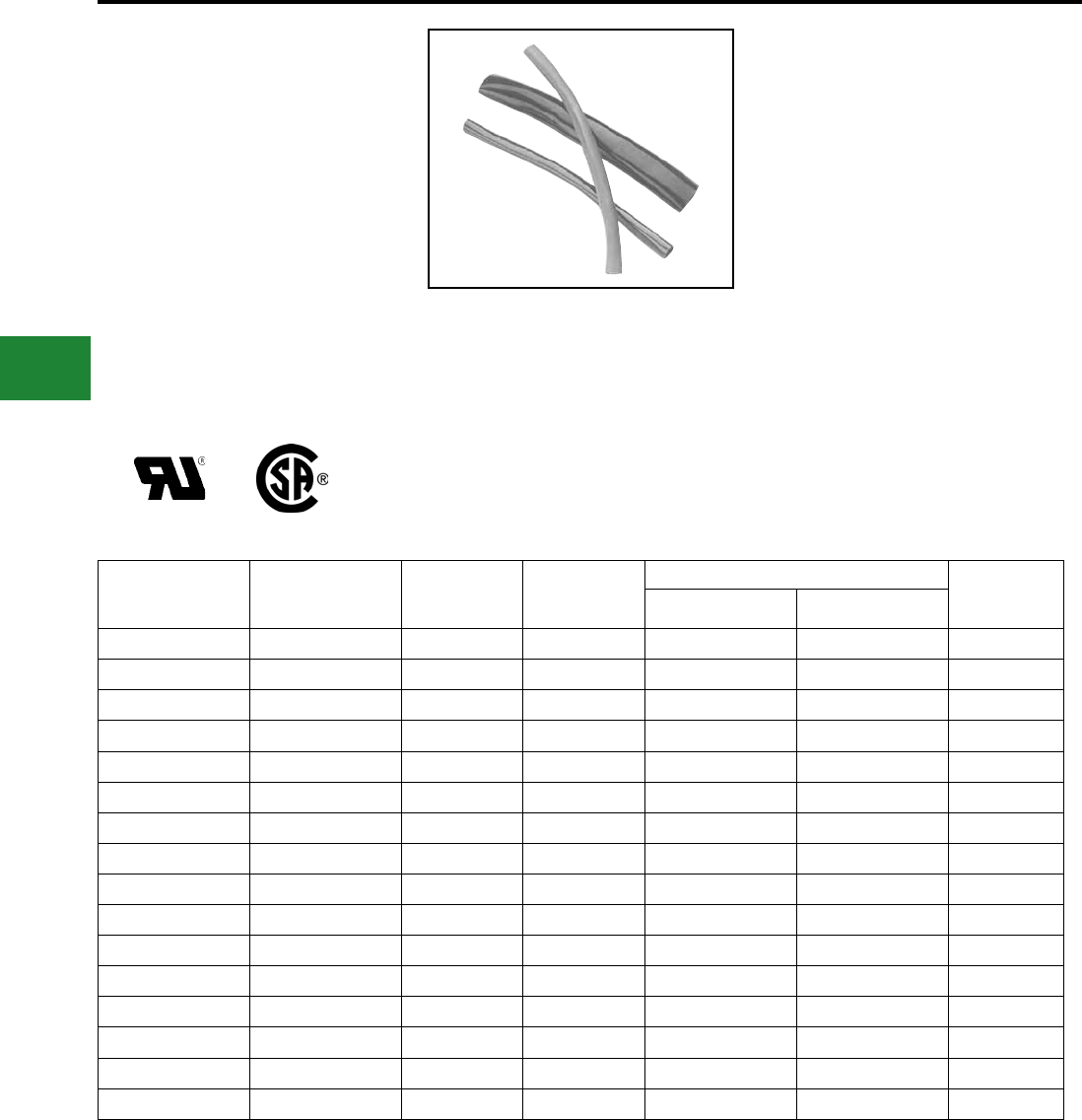
BURNDY®
Blue highlighted items are industry standard and most frequently ordered.
US: 1-800-346-4175 www.burndy.com Canada: 1-800-387-6487
Accessories
TYPE HS-FR
THIN WALL HEAT SHRINK
Fire Retardant
Heat Shrink Tubing
UL Recognized to 600V
Type HS-FR is a exible polyvinyl chloride thin wall
heat shrink. Offering insulating, color identication
and strain relieving properties for terminations and
splices. The 2:1 shrink ratio allows for faster shrink
recovery, covering wire sizes: #16 AWG to 1000
kcmil. UL Recognized, 105° C, 600V, operating
temperatures from –20° C to 105° C with a shrink
temperature of 135°.
Features & Benets
• UL 224, VW-1 Rated
◊ Self-extinguishing ame retardant properties.
• Multi-use Tubing
◊ Insulate, strain relief.
• Easy Identication
◊ Available in wide range of colors.
• Low Shrink Temperature
◊ Only requires common hot air guns to apply.
• Meets MIL-M-23053/Z-206C
NOTES:
1. Shrink temperature is 135° C (275° F).
2. For best results move heat gun along the length of heat
shrink to avoid concentrations.
3. To extend useful life, store material below 70° F.
4. For additional Heat Shrinkable Tubing see “URD”
section Type RYAC and RK169-2, RK170-2 in this
section.
How to Order:
Example: HSB18FR
B- Black
BLU - Blue
G- Green
R- Red
W- White
Y- Yellow
Catalog
Number
I.D.
Expanded
I.D. After
Recovery
Wall
Thickness
Conductor Range Standard
Reel Size
(Feet)
Code Flex
HS_18FR 0.125 0.062 0.025 #16 - #14 #16 - #14 50
HS_18FR250 0.125 0.062 0.025 #16 - #14 #16 - #14 250
HS_14FR 0.250 0.125 0.025 #12 - #8 #12 - #10 50
HS_14FR250 0.250 0.125 0.025 #12 - #8 #12 - #10 250
HS_38FR 0.375 0.187 0.025 #6 - #4 #8 - #6 50
HS_38FR250 0.375 0.187 0.025 #6 - #4 #8 - #6 250
HS_12FR 0.500 0.250 0.025 #4 - #1 #6 - #4 50
HS_12FR250 0.500 0.250 0.025 #4 - #1 #6 - #4 250
HS_34FR 0.750 0.375 0.030 1/0 - 3/0 #2 - 1/0 50
HS_34FR250 0.750 0.375 0.030 1/0 - 3/0 #2 - 1/0 250
HS_100FR 1.000 0.500 0.035 4/0 - 300 1/0 - 4/0 25
HS_100FR100 1.000 0.500 0.035 4/0 - 300 1/0 - 4/0 100
HS_112FR 1.500 0.750 0.040 350 - 750 250 - 500 25
HS_112FR100 1.500 0.750 0.040 350 - 750 250 - 500 100
HS_200FR 2.000 1.000 0.045 800 - 1000 500 - 750 25
HS_200FR100 2.000 1.000 0.045 800 - 1000 500 - 750 100
F-14

BURNDY®
Blue highlighted items are industry standard and most frequently ordered.
Canada: 1-800-387-6487 www.burndy.com US: 1-800-346-4175
Accessories
MISCELLANEOUS
ACCESSORIES
TYPE BHSG1100
HEAT GUN
250° - 1100° F (121° - 650° C)
Multi-purpose, low cost heat gun has an electronic
variable thermal control dial. BHSG1100 meets the
requirements of UL. It has a temperature range of
250° - 1100° F (121° - 650° C). 2 speed motor. Built-
in safety stand heat guard included. Professional
heat gun and accessories are recommended for all
of your BURNDY heat shrink applications.
F-15

BURNDY®
Blue highlighted items are industry standard and most frequently ordered.
Canada: 1-800-387-6487 www.burndy.com US: 1-800-346-4175
Cable Ties
G-1
TABLE OF CONTENTS - UNIRAP™
G-2 - G-4
G-5
G-6 - G-7
G-8 - G-9
G-10
G-11
G-11
G-12
G-13 - G-14
G15
G-15
G-16
G-17
G-18
G-19
G-20
G-21
G-22
G-23
G-24
G-25
G-26
G-26
Cable Tie Features and Specs
Military Spec Cable Ties
UNIRAP™ Standard Cable Ties
UNIRAP™ Type UG Universal Ties
UNIRAP™ Releasable Cable Ties
UNIRAP™ Indentifcation Cable Ties
Type 145PTAG - Blank Tag for Marking
UNIRAP™ Mounting Hole Cable Ties
UNIRAP™ Stainless Steel Barb Ties
UNIRAP™ Halar® Ties
UNIRAP™ Tefzel® Ties
UNIRAP™ Heat Stabilized Ties
Type TFV-B Hook & Loop Straps
Mounting Bases 4-Way & 2-Way
Cable Hangers
UNIRAP™ Stainless Steel Cable Ties
304 Stainless Steel (bare)
316 Stainless Steel (bare)
304 Stainless Steel (Fully Coated)
316 Stainless Steel (Fully Coated)
304 Stainless Steel (Partially Coated)
316 Stainless Steel (Partially Coated)
Cable Tie Variety Pack
Cable Tie Tools
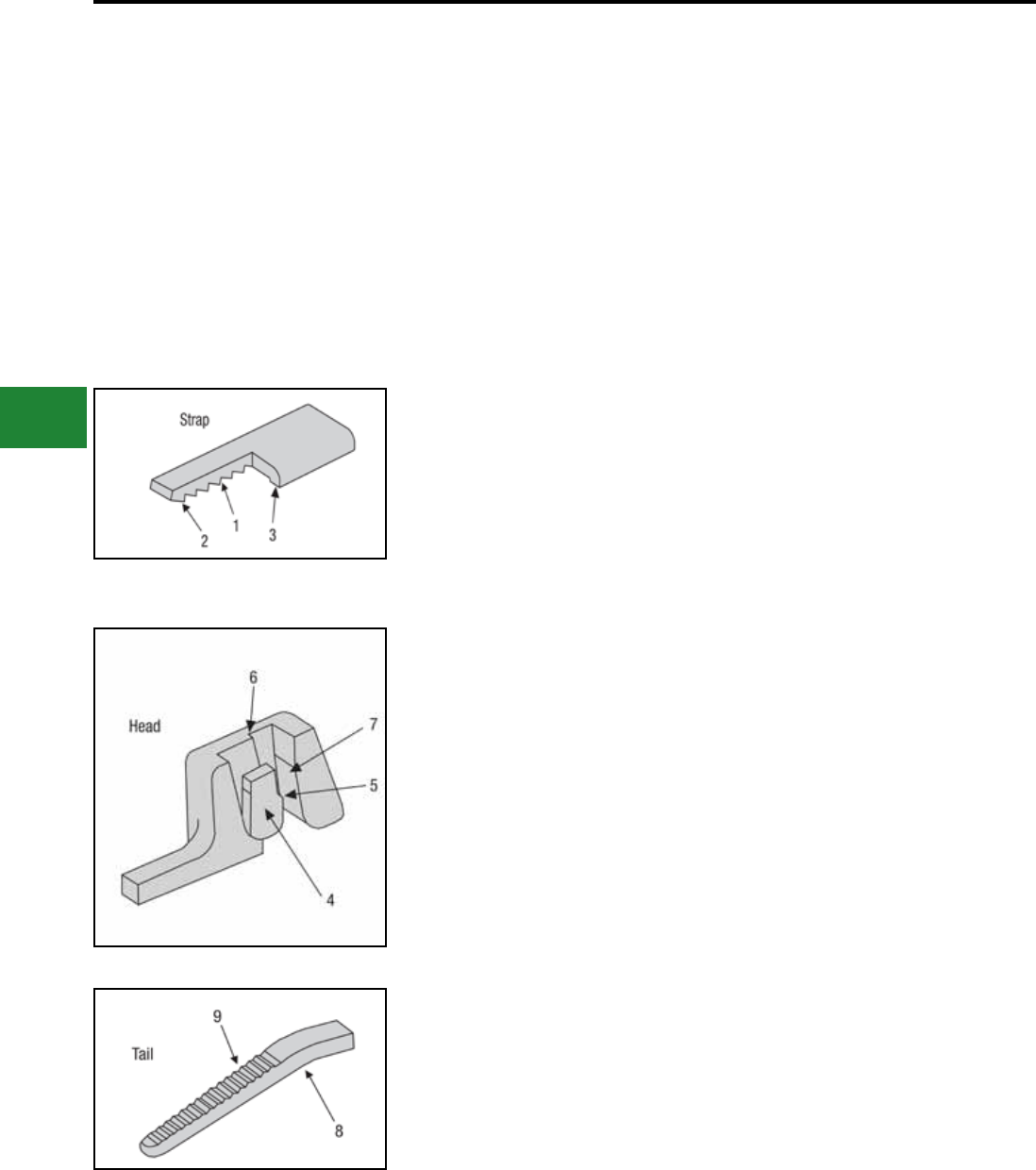
BURNDY®
Blue highlighted items are industry standard and most frequently ordered.
US: 1-800-346-4175 www.burndy.com Canada: 1-800-387-6487
Cable Ties
UNIRAP™
NYLON CABLE TIES
UNIRAP™ cable ties are fabricated of one piece
Nylon with no metal parts. The straps are tough,
resilient, lightweight and abrasion resistant. They
offer high tensile strength and are chemically
resistive to solvents, alkalies, oils, grease and
diluted acids. Self-locking, they secure without
twisting or leaving sharp projections.
Compact heads and pre-bent tips facilitate
cable bundling in a minimum of time and space.
UNIRAP™ cable ties are designed for both eld
and production line use and may be installed easily
by hand.
BURNDY® cable ties consist of three components:
strap, head, and tail. These components are
specically designed to function together to make
BURNDY® UNIRAP™ cable ties superior in quality
and performance. Shelf life of 5 years, when stored
in original packaging.
Component Precision Engineering Enhanced Performance
1. Includes load bearing serrations.
2. Features ats between the serrations.
3. Features the double outer rail system.
1. Serrations provide complete adjustability
within the fastening range.
2. Flats reduce stress concentrations and help
make the tie stronger.
3. Smooth rails promote low drag, as well as
minimize chang.
4. The pawl is integrally formed with the head.
5. The pawl is stepped in order to wedge
against the serrations in the strap to form the
lock.
6. The shoulders, or the sides of the
head, guide the strap and prevent it from
disengaging from the pawl during loaded
conditions.
7. The back supports the strap during the
wedging of the lock formation.
8. Features a bent tip.
9. Includes a ribbed grip.
4. The locking unit will not disengage. It also
promotes low insertion with high pull out
force for very easy installation.
5. The tie’s ultimate strength achieves optimum
levels.
6. Promotes cable tie strength, endurance and
longevity.
7. Ensure optimum locking capability.
8. Easy pick-up for installers, which leads to
fast assembly.
9. Allows for easy, no-slip grip.
G-2

BURNDY®
Blue highlighted items are industry standard and most frequently ordered.
Canada: 1-800-387-6487 www.burndy.com US: 1-800-346-4175
Cable Ties
Available Materials
Nylon 6/6 — General Purpose
General purpose nylon 6/6 features light weight,
high strength and a wide temperature range. It
is halogen free so it does not release dangerous
gases, such as chlorine, bromine, uorine and
iodine when burned. Nylon 6/6 is hygroscopic, and
therefore, absorbs or releases moisture depending
on its environment. Thus, the moisture level of the
material will affect tensile strength, stiffness and
elongation of the product.
Nylon 6/6 — Heat Stabilized
With similar properties and benets as nylon 6/6,
products manufactured with heat stabilized nylon
6/6 material have a chemical stabilizer added for
higher continuous temperature applications.
Nylon 6/6 — UV Stabilized
Chemical inhibitors are used to give nylon
6/6 material added properties to ght against
premature aging of products due to the effects of
ultraviolet rays.
Nylon 6/6 — UV Stabilized
(2% Carbon for Military Specication)
The physical properties of this material include
carbon, which acts as a UV stabilizer, prolonging
the life of the product under ultraviolet conditions.
It also allows cable ties to meet the particular
military specication for cable ties.
Nylon 6/6 — V0 Flame Retardant
This material meets UL 94V-0 ammability
requirements. Flame retardant additives
generally reduce tensile strength when
compared to general-purpose nylon 6/6, but
this resin has been formulated to minimize such
effects.
Nylon 6/6 — High Impact
Impact modiers are added to increase exibility.
High impact nylon 6/6 has stable tensile strength
due to its reduced inuence
from moisture. It is excellent for high vibration
applications, as within the aircraft and
automobile industries and performs better than
nylon 6/6 against ultraviolet rays. Good for
outdoor use.
Polypropylene
Polypropylene is used in environments where
chemical effects on nylon are a concern. It is
not affected by inorganic acids (hydrochloric),
polyhydric alcohols (ethyleneglycol), neutral
salts (sodium chloride) and basic salts (sodium
bicarbonate). Polypropylene also resists a
number of other chemicals with good results,
although it has lower tensile strength than nylon
6/6 (about half). Polypropylene has good UV
resistance.
Tefzel®
Although about two-thirds the strength of nylon
6/6, Tefzel is resistant to a wide range
of chemicals, such as concentrated hydrouoric
and sulfuric acids. It is also a low water
absorbing material, therefore, is not adversely
affected by water. Tefzel is radiation resistant
up to 100 megarads and meets the re and
smoke requirements of IEEE 383. Tefzel also
withstands high temperatures and ultraviolet
light exposure. Products made from Tefzel
material also have non-outgassing properties
for zero gravity applications.
Halar®
Halar is similar to Tefzel in performance and
benets. Halar is recognized for its low smoke
density attribute when burned. This
makes products made out of Halar more
desirable for use in areas where smoke
generation is a concern, as when bundling wire
and cable in air handling spaces.
Material
Continuous*
Operating
Temperature
Max. Min.
Tensile Strength at
73° F Dry as
Molded
ASTM D-638 (PSI)
UL
Flame
Rating
Oxygen
Index
%
Gamma
Radiation
Resistance
UV
Resistance
Military, Federal, ASTM,
and FDA Specications
Nylon 6/6 —
General Purpose (CT)
185° F –40° F
85° C –40° C 12,000 94V-2 28 1 x 10⁵ Rads Poor ASTM D-4066PA0111
FDA CFR177.1500
Nylon 6/6 —
Heat Stabilized (CTHS)
220° F –40° F
105° C –40° C 12,000 94V-2 26 1 x 10⁵ Rads Poor ASTM D-4066PA0121
Nylon 6/6 —
UV Stabilized (O)
185° F –40° F
85° C –40° C 12,000 94V-2 26 1 x 10⁵ Rads Good ASTM D4066PA0191
Nylon 6/6 — 2% Carbon
UV Stabilized (OO)
220° F –40° F
105° C –40° C 12,000 94V-2 26 1 x 10⁵ Rads Good ASTM D-4066PA0181
MS3367/8
Nylon 6/6 —
Flame Retardant (CTV)
185° F –40° F
85° C –40° C 10,800 94V-0 34 1 x 10⁵ Rads Poor ASTM D-4066PA0110
Nylon 6/6 —
High Impact
185° F –40° F
85° C –40° C 8,800 94-HB 19 1 x 10⁵ Rads Good ASTM D-4066PA0150
Polypropylene —
Chemical Resistant (CTPP)
185° F –40° F
85° C –40° C 3,400 94-HB N/A 1 x 10⁵ Rads Good ASTM D-4101PP0320
FDA CFR177.1520
Nylon 12 —
UV Stabilized
176° F –40° F
80° C –40° C 5,800 94-HB N/A 9 x 10⁶ Rads Good ASTM D-4066PA411
Tefzel® (CTZ) 302° F –50° F
150° C –46° C 5,800 94V-0 30 2 x 10⁸ Rads Excellent UL2043 Grade 1
ASTM D-3159 Type 1
Halar® (CTH) 284° F –50° F
140° C –46° C 6,100 94V-0 52 2 x 10⁸ Rads Excellent ASTM D-3275 Type 3
FDA CRF177.1380
* Elevated temperatures, over time, will affect materials’
properties such as tensile strength, stiffness, elongation
and appearance.
BURNDY® recommends the evaluation of cable ties in
the actual application to determine the suitability of the
tie for that application.
Tefzel® is a registered trademark of E.I. DuPont.
Halar® is a registered trademark of Ausimont Chemical
Co.
Material Specications
G-3
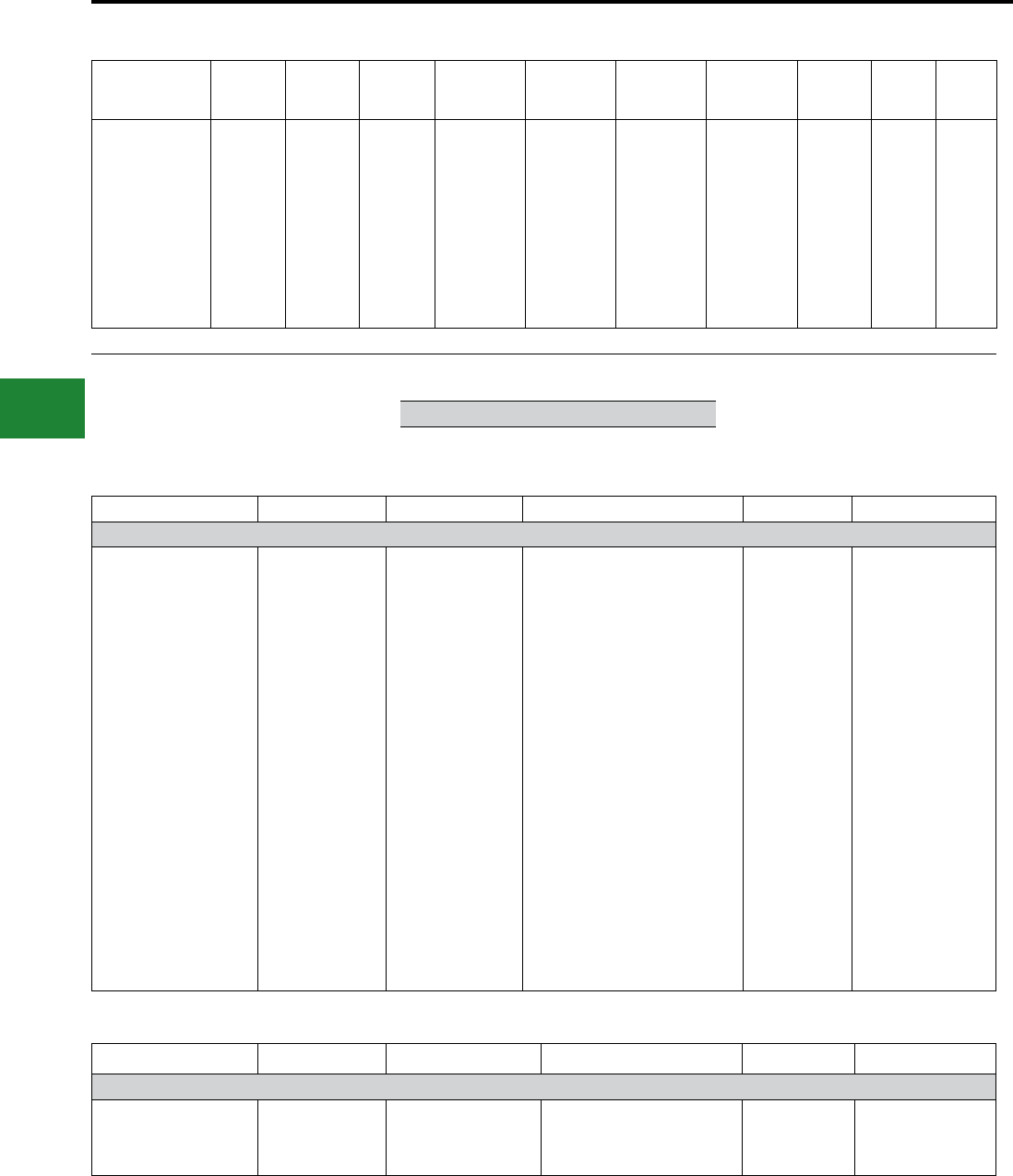
BURNDY®
Blue highlighted items are industry standard and most frequently ordered.
US: 1-800-346-4175 www.burndy.com Canada: 1-800-387-6487
Cable Ties
Material Performance Guide
Selection
Nylon 6/6
General
Purpose
Nylon 6/6
Heat
Stab.
Nylon 6/6
UV Stab.
Nylon 6/6
2% Carbon
UV Stab.
Nylon 6/6
Flame Ret.
V0
Nylon 6/6
High
Impact
Poly-
propylene
Nylon 12
UV Stab. Tefzel®Halar®
Tensile Strength
High Temp.
Flammability
UV Resistance
Radiation
Chemical
— Hydrocarbons
— Chlorinated
— Hydrocarbons
— Acids-Bases
— Salts
Relative Cost
8
2
5
1
3
6
8
6
2
6
3
Low
8
3
5
1
3
6
8
6
2
6
3
Low
8
2
5
5
3
6
8
6
2
6
3
Med.
9
2
5
8
3
6
8
6
2
6
3
Med.
7
2
10
1
3
6
8
6
2
6
3
Med.
8
2
2
2
3
6
8
6
2
6
3
Med.
2
2
2
5
6
8
6
3
8
8
10
Med.
4
1
2
3
3
8
8
8
5
6
8
Med.
5
10
10
10
10
10
10
10
10
10
10
High
5
10
10
10
10
10
10
10
10
10
10
High
1 = Least Recommended 10 = Most Recommended
The following chart is meant to help you understand
BURNDY’s cable tie catalog numbering system.
Not every cable tie is available in every listed
option. See below Catalog Numbering System
Charts or contact BURNDY® Customer Service for
more information.
Gray bars contain catalog number examples.
Type Tensile Bundle Dia. Feature Package Color
CT 50 175 C
CT = Nylon 6/6
Standard
CTAS =
Aerial Support
CTH =
Halar ®
CTZ =
Tefzel ®
CTHS = Nylon 6/6
Heat Stabilized
CTV = Nylon 6/6
Flame Retardant UL94V-0
CTPP =
Polypropylene
CTSS = Stainless Steel
18 = 18 lbs.
30 = 30 lbs.
40 = 40 lbs.
50 = 50 lbs.
100 = 100 lbs
110 = 110 lbs.
120 = 120 lbs.
175 = 175 lbs.
225 = 225 lbs.
250 = 250 lbs.
450 = 450 lbs.
500 = 500 lbs.
675 = 675 lbs.
700 - 700 lbs.
800 = 800 lbs.
900 = 900 lbs.
075 = 3/4"
087 = 7/8"
100 = 1"
125 = 1-1/4"
137 = 1-3/8"
150 = 1-1/2"
175 = 1-3/4"
200 = 2"
225 = 2-1/4”
250 = 2-1/2"
300 = 3"
325 = 3-1/4”
350 = 3-1/2”
400 = 4"
425 = 4-1/4”
500 = 5"
600 = 6"
700 = 7"
750 = 7-1/2”
800 = 8"
900 = 9"
1000 = 10"
1100 = 11"
1200 = 12"
1300 = 13"
1400 = 14"
EPR = Extended Pawl Releasable
ID = Single Head ID
ID2 = Double Head ID
ID3 = Triple Head ID
FL = ID Flag
MH4 = Mounting Hole #4
MH6 = Mounting Hole #6
MH8 = Mounting Hole #8
MH10 = Mounting Hole #10
MH14 = Mounting Hole #14
PM = Push Mount Tie
PML = Push Mount Tie w/Louvers
PMW = Push Mount Tie w/Wing
R = Releasable Tie
LP = Low Prole Tie
PS = Positive Stop
SSB = Stainless Steel Barb
FC304 = Fully Coated 304
FC316 = Fully Coated 316
PC304 = Partially Coated 304
PC316 = Partially Coated 316
V = 5
X = 10
Q = 25
L = 50
C = 100
B = 250
D = 500
M =
1000
1 = Brown
2 = Red
3 = Orange
4 = Yellow
5 = Green
6 = Blue
7 = Purple
8 = Gray
None = Natural
10 = White
11 = Telco Gray
0 = UV Black1
00 = UV Black2
02 = Red
20 = Black
Type Tensile Bundle Dia. Feature Package Color
CTB 100 RA 4 C 0
CTB =
Cable Tie Base
075 = 3/4"
125 = 1-1/4"
150 = 1=1/2"
RA = Rubber Adhesive
AA = Acrylic Adhesive
S = Screw Mounted
2 = 2 way
4 = 4 way
L = 50
C = 100
D = 500
M = 1000
0 = UV Black
1Material: Nylon 6/6 — UV Stabilized 2Material: Nylon 6/6 — 2% Carbon UV Stabilized (Mil. Spec.)
G-4
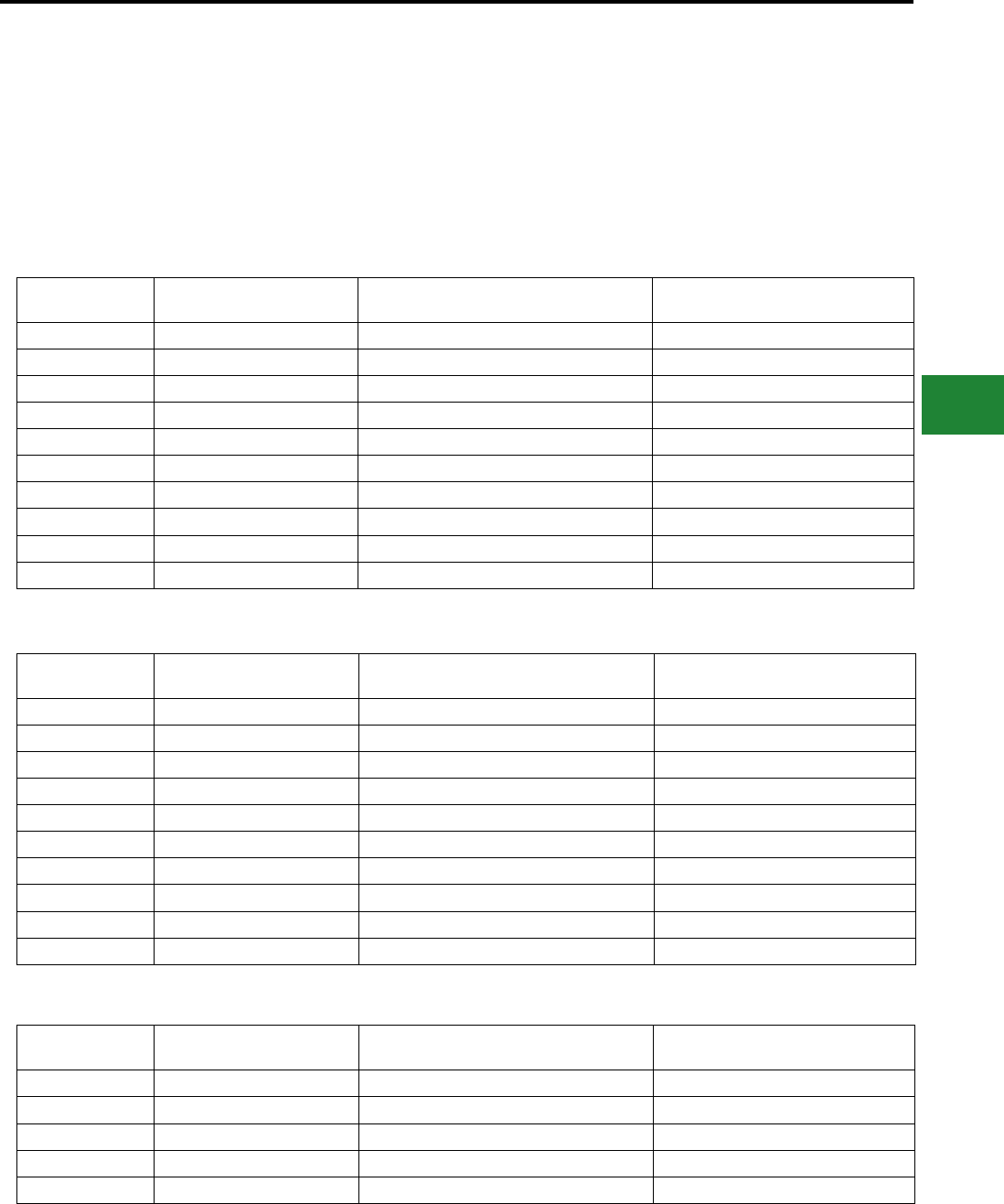
BURNDY®
Blue highlighted items are industry standard and most frequently ordered.
Canada: 1-800-387-6487 www.burndy.com US: 1-800-346-4175
Cable Ties
Military Specication
UNIRAP™ Cable Ties
The BURNDY® cable ties shown below meet
the requirements of SAE AS23190A (formerly
MIL-S-23190) in accordance with specication
MS3367, MS3368, and QPL-23190.
Mil Spec
Distributor Pack
Catalog Number
Bulk Pack
Catalog Number
Description
(Bundle Dia. - Tensile Strength)
MS3367-1-9 CT50175C CT50175M 1.75 - 50 lbs.
MS3367-2-9 CT50400C CT50400M 4 - 50 lbs.
MS3367-3-9 CT120400L CT120400D 4 - 120 lbs.
MS3367-3-9 CT175400Q N/A 4 - 175 lbs.
MS3367-3-9 CT175600Q N/A 6 - 175 lbs.
MS3367-4-9 CT18075C CT18075M 0.75 - 18 lbs.
MS3367-5-9 CT30125C CT30125M 1.25 - 30 lbs.
MS3367-6-9 CT120900L CT120900D 9 - 120 lbs.
MS3367-6-9 CT175900Q N/A 9 - 175 lbs.
MS3367-7-9 CT50300C CT50300M 3 - 50 lbs.
Natural Cable Ties
UV Resistant Black Cable Ties
Mil Spec
Distributor Pack
Catalog Number
Bulk Pack
Catalog Number
Description
(Bundle Dia. - Tensile Strength)
MS3367-1-0 CT50175C00 CT50175M00 1.75 - 50 lbs.
MS3367-2-0 CT50400C00 CT50400M00 4 - 50 lbs.
MS3367-3-0 CT120400L00 CT120400D00 4 - 120 lbs.
MS3367-3-0 N/A N/A 4 - 175 lbs.
MS3367-3-0 CT175600Q00 N/A 6 - 175 lbs.
MS3367-4-0 CT18075C00 CT18075M00 0.75 - 18 lbs.
MS3367-5-0 CT30125C00 CT30125M00 1.25 - 30 lbs.
MS3367-6-0 CT120900L00 CT120900D00 9 - 120 lbs.
MS3367-6-0 CT175900Q00 N/A 9 - 175 lbs.
MS3367-7-0 CT50300C00 CT50300M00 3 - 50 lbs.
Natural Identication Cable Ties
Mil Spec
Distributor Pack
Catalog Number
Bulk Pack
Catalog Number
Description
(Bundle Dia. - Tensile Strength)
MS3368-1-A CT50175IDC N/A 1.75 - 50 lbs.
MS3368-2-A CT50400IDC N/A 4 - 50 lbs.
MS3368-3-C CT50175ID2L N/A 1.75 - 50 lbs. Double Strap
MS3368-4-D CT50175ID3L N/A 1.75 - 50 lbs. Triple Strap
MS3368-5-E CT18075IDC N/A 0.75 - 18 lbs.
G-5
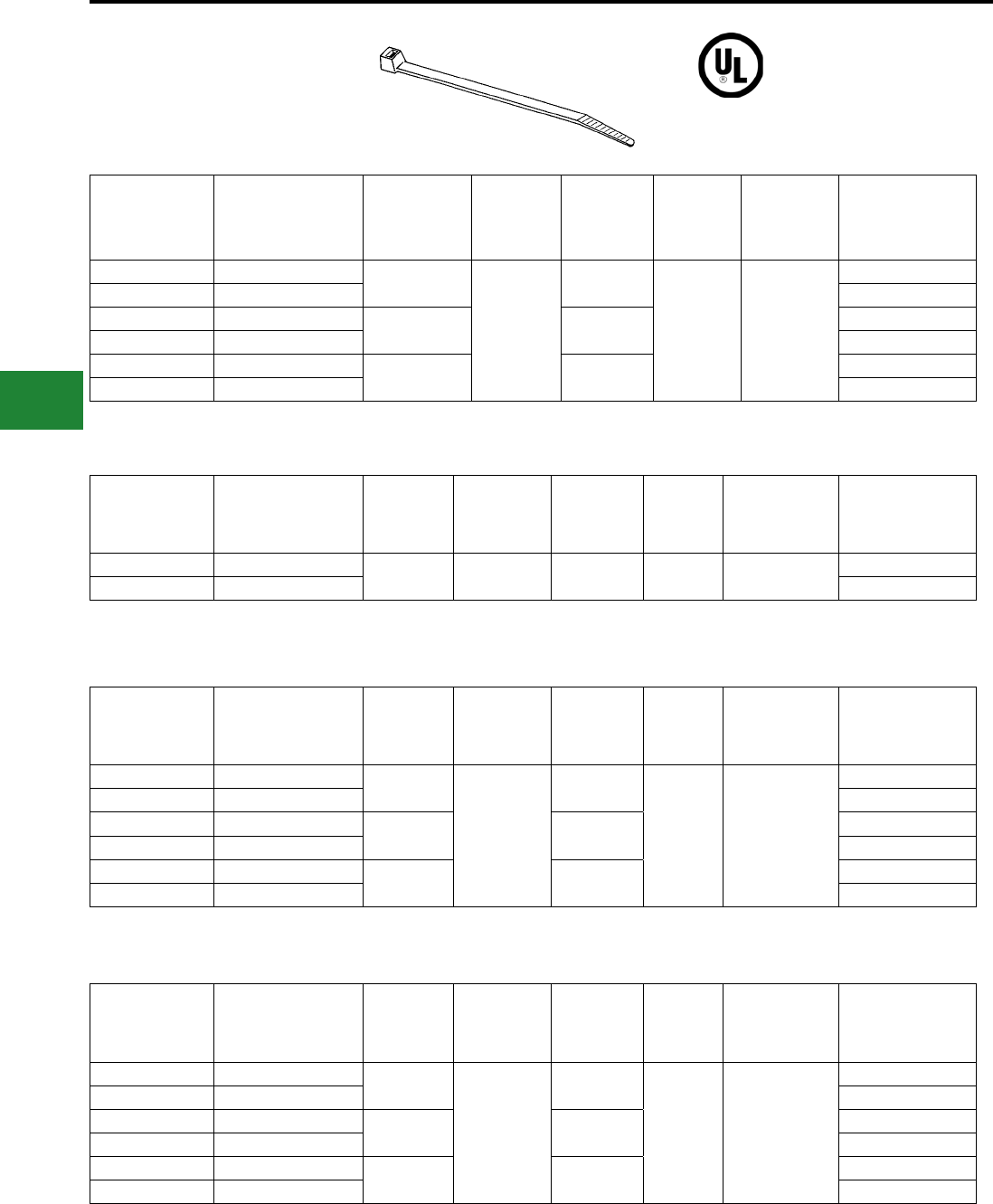
BURNDY®
Blue highlighted items are industry standard and most frequently ordered.
US: 1-800-346-4175 www.burndy.com Canada: 1-800-387-6487
Cable Ties
UNIRAP™
STANDARD CABLE TIES
18 Lb. Minimum Tensile Strength
30 Lb. Minimum Tensile Strength
40 Lb. Minimum Tensile Strength
50 Lb. Minimum Tensile Strength
Standard
Package
Catalog
Number
Material
Maximum
Bundle
Diameter
Inches[mm]
Minimum
Tensile
Strength
Lbs.
Length
Inches
Width
Inches
[mm]
Installation
Tool
Bulk
Package
Catalog
Number
CT18075C Natural Nylon 6/6 0.75 [19]
18
4.1
0.10 [3] TWT1, MK7,
CTT50
CT18075M
CT18075C0 Black Nylon 6/6 UV CT18075M0
CT18125C Natural Nylon 6/6 1.25 [32] 6.1 CT18125M
CT18125C0 Black Nylon 6/6 UV CT18125M0
CT18200C Natural Nylon 6/6 2.00 [51] 8.1 CT18200M
CT18200C0 Black Nylon 6/6 UV CT18200M0
Standard
Package
Catalog
Number
Material
Maximum
Bundle
Diameter
Inches[mm]
Minimum
Tensile
Strength
Lbs.
Length
Inches
Width
Inches
[mm]
Installation
Tool
Bulk
Package
Catalog
Number
CT30125C Natural Nylon 6/6 1.25 [32] 30 5.8 0.14 [3.6] TWT1, MK7,
CTT50
CT30125M
CT30125C0 Black Nylon 6/6 UV CT30125M0
Standard
Package
Catalog
Number
Material
Maximum
Bundle
Diameter
Inches[mm]
Minimum
Tensile
Strength
Lbs.
Length
Inches
Width
Inches
[mm]
Installation
Tool
Bulk
Package
Catalog
Number
CT40200C Natural Nylon 6/6 1.90 [48]
40
7.6
0.15 [4] TWT1, MK7,
CTT50
CT40200M
CT40200C0 Black Nylon 6/6 UV CT40200M0
CT40300C Natural Nylon 6/6 3.00 [76] 11.1 CT40300M
CT40300C0 Black Nylon 6/6 UV CT40300M0
CT40400C Natural Nylon 6/6 4.00 [102] 14.6 CT40400M
CT40400C0 Black Nylon 6/6 UV CT40400M0
Standard
Package
Catalog
Number
Material
Maximum
Bundle
Diameter
Inches[mm]
Minimum
Tensile
Strength
Lbs.
Length
Inches
[mm]
Width
Inches
[mm]
Installation
Tool
Bulk
Package
Catalog
Number
CT50175C Natural Nylon 6/6 1.75 [44]
50
8.00 [222]
0.18 [5] TWT1, MK7,
CTT50
CT50175M
CT50175C0 Black Nylon 6/6 UV CT50175M0
CT50300C Natural Nylon 6/6 3.00 [76] 11.75 [298] CT50300M
CT50300C0 Black Nylon 6/6 UV CT50300M0
CT50400C Natural Nylon 6/6 4.00 [102] 15.50 [394] CT50400M
CT50400C0 Black Nylon 6/6 UV CT50400M0
UL 62275
Type 2 & 21 All items on this page
G-6
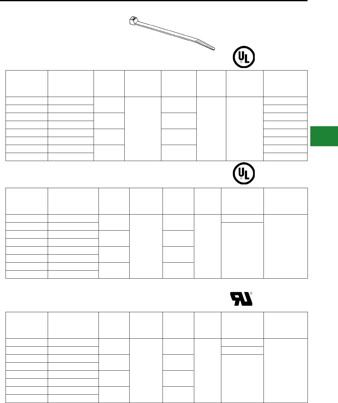
BURNDY®
Blue highlighted items are industry standard and most frequently ordered.
Canada: 1-800-387-6487 www.burndy.com US: 1-800-346-4175
Cable Ties
UNIRAP™
STANDARD CABLE TIES
(Continued)
Standard
Package
Catalog
Number
Material
Maximum
Bundle
Diameter
Inches[mm]
Minimum
Tensile
Strength
Lbs.
Length
Inches
[mm]
Width
Inches
[mm]
Installation
Tool
Bulk
Package
Catalog
Number
CT120200L Natural Nylon 6/6 2.00 [51]
120
9.0 [229]
0.30 [8] TWT2, MK9,
CTT50
CT120200D
CT120200L0 BlackNylon 6/6 UV CT120200D0
CT120300L Natural Nylon 6/6 3.00 [76] 12.0 [305] CT120300D
CT120300L0 black Nylon 6/6 CT120300D0
CT120400L Natural Nylon 6/6 4.00 [102] 15.0 [381] CT120400D
CT120400L0 black Nylon 6/6 UV CT120400D0
CT120800L Natural Nylon 6/6 8.00 [203] 29.2 [742] -
CT120800L0 Black Nylon 6/6 UV -
Standard
Package
Catalog
Number
Material
Maximum
Bundle
Diameter
Inches[mm]
Minimum
Tensile
Strength
Lbs.
Length
Inches
[mm]
Width
Inches
[mm]
Installation
Tool
Bulk
Package
Catalog
Number
CT1751100Q Natural Nylon 6/6 11.00 [279]
175
36 [914]
0.35 [9]
Heavy
—
CT1751100Q0 Black Nylon 6/6 UV
TWT2, MK9,
CTT50
CT175500Q Natural Nylon 6/6 5.50 [140] 18.25 [464]
CT175500Q0 Black Nylon 6/6 UV
CT175600Q Natural Nylon 6/6 7.00 [178] 24.00 [610]
CT175600Q0* Black Nylon 6/6 UV
CT175900Q Natural Nylon 6/6 8.75 [222] 30.00 [762]
CT175900Q0* Black Nylon 6/6 UV
Standard
Package
Catalog
Number
Material
Maximum
Bundle
Diameter
Inches[mm]
Minimum
Tensile
Strength
Lbs.
Length
Inches
[mm]
Width
Inches
[mm]
Installation
Tool
Bulk
Package
Catalog
Number
CT2501000Q Natural Nylon 6/6 10.00 [254]
250
35.00 [889]
0.50 [13]
Heavy
—
CT2501000Q0 Black Nylon 6/6 UV TWT2, MK9
CT2501200Q Natural Nylon 6/6 12.00 [305] 40.00 [1016]
TWT2, MK9
CT2501200Q0 Black Nylon 6/6 UV
CT250600Q Natural Nylon 6/6 6.00 [152] 22.00 [559]
CT250600Q0 Black Nylon 6/6 UV
CT250800Q Natural Nylon 6/6 8.00 [203] 29.00 [737]
CT250800Q0 Black Nylon 6/6 UV
120 Lb. Minimum Tensile Strength
175 Lb. Minimum Tensile Strength
250 Lb. Minimum Tensile Strength
UL 62275
Type 2 & 21
UL 62275
Type 2 & 21
UR 1565
Type 2 & 21
* Not UL Listed, but UR 1565
G-7
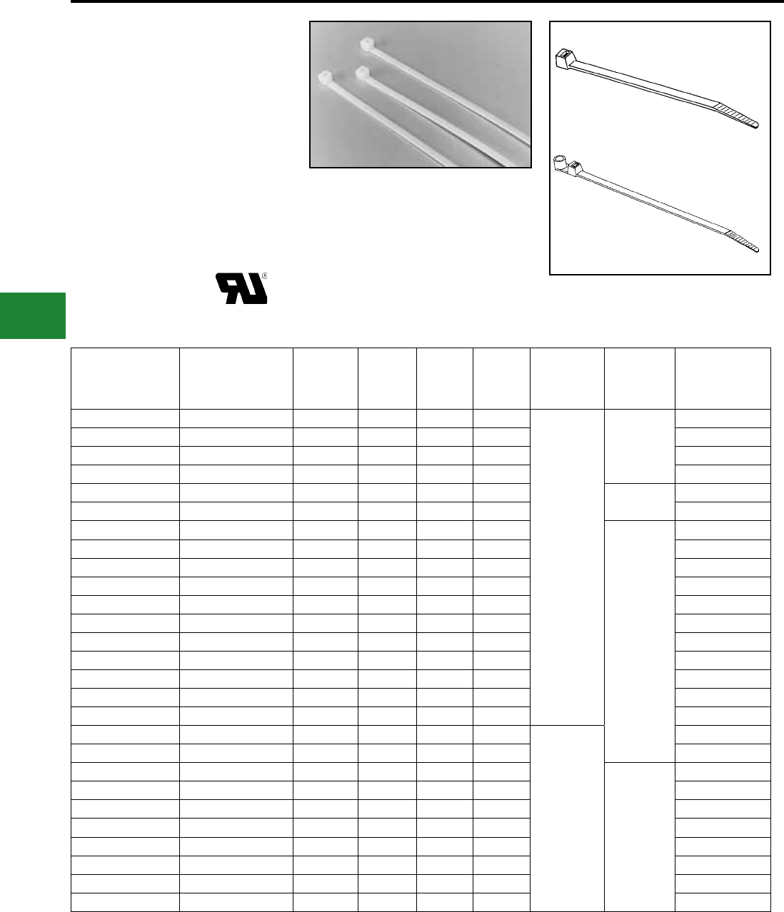
BURNDY®
Blue highlighted items are industry standard and most frequently ordered.
US: 1-800-346-4175 www.burndy.com Canada: 1-800-387-6487
Cable Ties
TYPE UG
UNIRAP™ Cable Ties
General purpose nylon 6/6 features light weight,
high strength and a wide temperature range. It
is halogen free so it does not release dangerous
gases, such as chlorine, bromine, uorine and
iodine when burned. Nylon 6/6 is hygroscopic,
and therefore, absorbs or releases moisture
depending on its environment. Thus, the moisture
level of the material will affect tensile strength,
stiffness and elongation of the product.
Features & Benets
• Nylon 6/6 Standard
• Available in Black and Natural
• One piece injection molded
• Maximum strength and adjustability for
versatility
• Chemically resistant to solvents, oils,
grease, and diluted acids
Standard
Mounting Hole
• Rounded edges and bent tip for easy
installation
• Self-Locking
Std. Pkg.
Catalog
Number
Material
Max.
Bundle
Diameter
(Inches)
Min.
Tensile
Strength
(lbs)
Length
(Inches)
Width
(Inches)
Installation
Tool
Tool
Setting
Bulk Catalog
Number
CT18075CUG Natural Nylon 6/6 .75 18 4.00 .10
TWT1, MK7,
CTT50
Mini
CT18075MUG
CT18075C0UG Black Nylon 6/6 UV .75 18 4.00 .10 CT18075M0UG
-Natural Nylon 6/6 2.00 18 8.00 .10 CT18200MUG
CT18200C0UG Black Nylon 6/6 UV 2.00 18 8.00 .10 -
CT30125CUG Natural Nylon 6/6 1.25 30 6.00 .14 Intermediate CT30125MUG
CT30125C0UG Black Nylon 6/6 UV 1.25 30 6.00 .14 -
CT40200CUG Natural Nylon 6/6 2.00 40 8.50 .15
Standard
CT40200MUG
CT40400C0UG Black Nylon 6/6 UV 4.00 40 14.50 .15 -
CT50175CUG Natural Nylon 6/6 1.75 50 8.00 .18 CT50175MUG
CT50175C0UG Black Nylon 6/6 UV 1.75 50 8.00 .18 CT50175M0UG
CT50300CUG Natural Nylon 6/6 3.00 50 11.30 .18 CT50300MUG
CT50300C0UG Black Nylon 6/6 UV 3.00 50 11.30 .18 CT50300M0UG
CT50400CUG Natural Nylon 6/6 4.00 50 15.50 .18 -
CT50400C0UG Black Nylon 6/6 UV 4.00 50 15.50 .18 -
CT120200L0UG Black Nylon 6/6 UV 2.00 120 8.87 .30 -
CT120400LUG Natural Nylon 6/6 4.00 120 15.25 .30 -
CT120400L0UG Black Nylon 6/6 UV 4.00 120 15.25 .30 CT120400C0UG
CT120500CUG Natural Nylon 6/6 5.00 120 20.00 .30
TWT2, MK9,
CTT50
CT120500D0UG
CT120900LUG Natural Nylon 6/6 9.00 120 29.75 .30 -
CT175400Q0UG Black Nylon 6/6 UV 4.00 175 15.00 .35
Heavy
-
CT175600QUG Natural Nylon 6/6 6.00 175 21.00 .35 -
CT175600Q0UG Black Nylon 6/6 UV 6.00 175 21.00 .35 -
CT175900Q0UG Black Nylon 6/6 UV 9.00 175 32.00 .35 -
CT1751100QUG Natural Nylon 6/6 11.00 175 36.00 .35 -
CT1751100Q0UG Black Nylon 6/6 UV 11.00 175 36.00 .35 -
CT1751400QUG Natural Nylon 6/6 14.00 175 52.00 .35 -
CT250800Q0UG Black Nylon 6/6 UV 8.00 250 52.00 .50 -
Standard Cable Ties
G-8
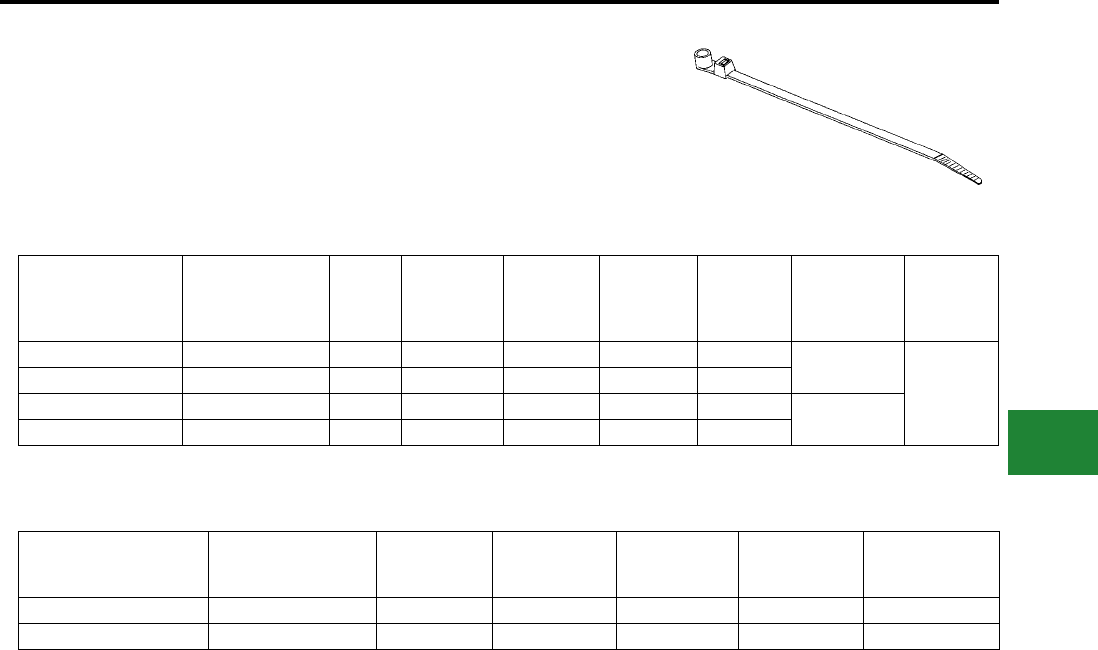
BURNDY®
Blue highlighted items are industry standard and most frequently ordered.
Canada: 1-800-387-6487 www.burndy.com US: 1-800-346-4175
Cable Ties
Std. Pkg.
Catalog
Number
Material Screw
Size
Max.
Bundle
Diameter
Inches
Min.
Tensile
Strength
(lbs)
Length
Inches
Width
Inches
Installation
Tool
Tool
Setting
CT50175MH10CUG Natural Nylon 6/6 #10 1.75 50 8.50 .18 MK7, CTT50
Standard
CT50175MH10C0UG Black Nylon 6/6 UV #10 1.75 50 8.50 .18
CT50300MH10GUG Natural Nylon 6/6 #10 3.00 50 11.75 .18 TWT1, MK7,
CTT50
CT50300MH10C0UG Black Nylon 6/6 UV #10 3.00 50 11.75 .18
Std. Pkg.
Catalog
Number
Mounting
Method
Maximum
Tie Slot
Width
Dimension
A
Dimension
B
Dimension
C
Bulk Catalog
Number
CTB075RA4CUG Rubber Adhesive 0.14” .75” .75” .75” -
CTB125RA4CUG Rubber Adhesive 0.20" 1.125" 1.125" 0.19" CTB125RA4DUG
Mounting Hole Cable Ties
Mounting Bases
UNIRAP™
Type UG Cable Ties
(Continued)
Mounting Hole
G-9
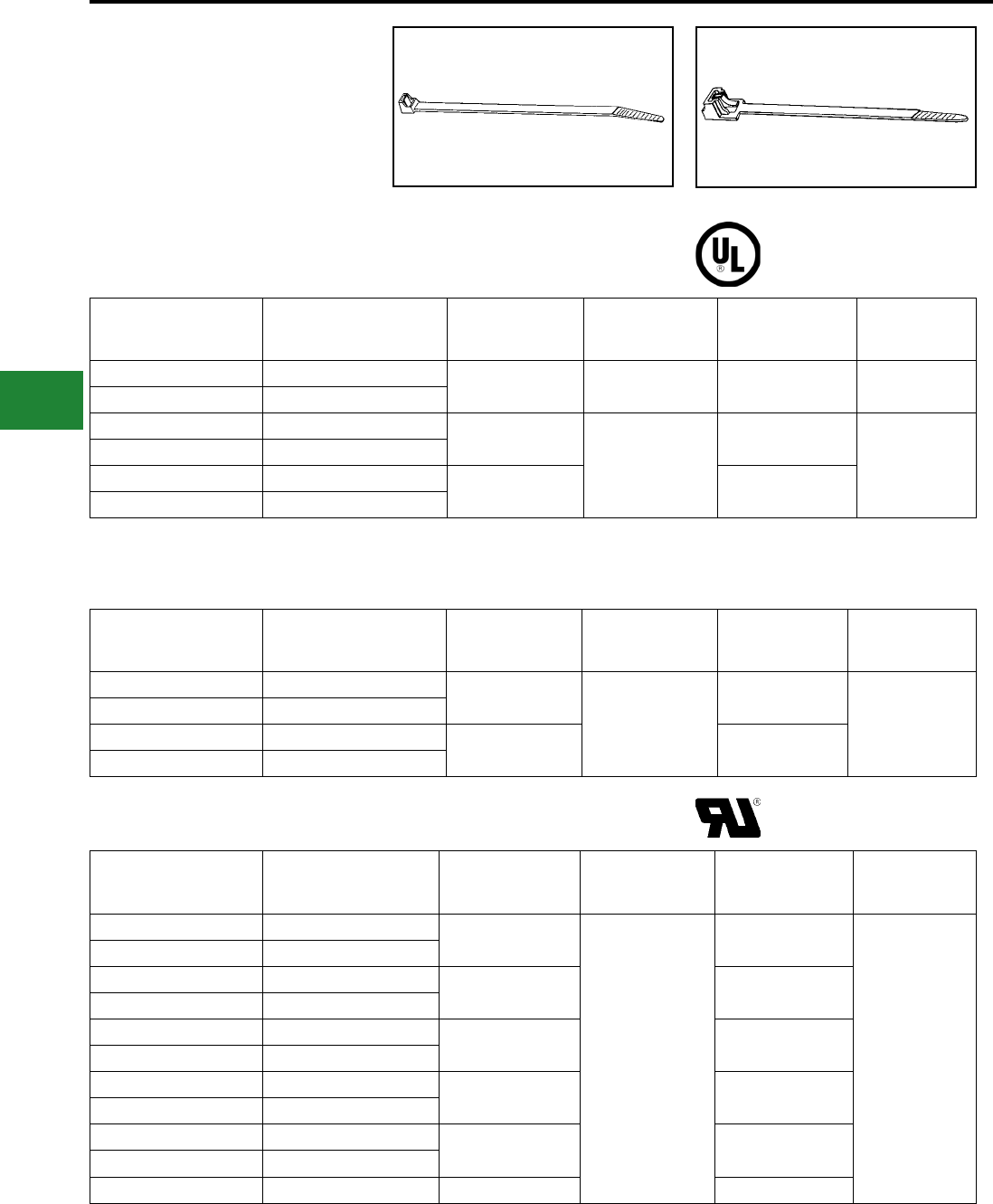
BURNDY®
Blue highlighted items are industry standard and most frequently ordered.
US: 1-800-346-4175 www.burndy.com Canada: 1-800-387-6487
Cable Ties
UNIRAP™
RELEASABLE CABLE TIES
Perfect for prototype construction, releasable cable
ties are ideal for temporary installations. Releasable
ties are also good for applications where service
requires adding or subtracting wires from an existing
wire bundle.
Std. Pkg.
Catalog
Number
Material
Max. Bundle
Diameter
Inches (mm)
Min. Tensile
Strength (lbs)
Length
Inches
Width
Inches (mm)
CT50175RC Natural Nylon 6/6 1.90 [48] 50 7.60 0.15 [4]
CT50175RC0 Black Nylon 6/6 UV
CT50137RC Natural Nylon 6/6 1.90 [48]
50
7.60
0.18 [5]
CT50137RC0 Black Nylon 6/6 UV
CT50400RC Natural Nylon 6/6 4.00 [102] 14.60
CT50400RC0 Black Nylon 6/6 UV
Standard Releasable Ties
Standard Releasable Cable Ties
Extended Pawl Releasable Cable Ties
Heavy Duty Releasable Cable Ties
Extended Pawl Releasable Ties
Std. Pkg.
Catalog
Number
Material
Max. Bundle
Diameter
Inches [mm]
Min. Tensile
Strength (lbs)
Length
Inches [mm]
Width
Inches [mm]
CT50137EPRC Natural Nylon 6/6 1.38 [35]
50
5.50 [140]
0.29 [7]
CT50137EPRC0 Black Nylon 6/6 UV
CT50250EPRC Natural Nylon 6/6 2.50 [64] 9.80 [249]
CT50250EPRC0 Black Nylon 6/6 UV
Std. Pkg.
Catalog
Number
Material
Max. Bundle
Diameter
Inches [mm]
Min. Tensile
Strength (lbs)
Length
Inches [mm]
Width
Inches [mm]
CT250200RQ Natural Nylon 6/6 2.25 [57]
250
9.00 [229]
0.50 [13]
CT250200RQ0 Black Nylon 6/6 UV
CT250500RQ Natural Nylon 6/6 6.00 [152] 22.00 [559]
CT250500RQ0 Black Nylon 6/6 UV
CT250600RQ Natural Nylon 6/6 6.00 [152] 22.00 [559]
CT250600RQ0 Black Nylon 6/6 UV
CT250800RQ Natural Nylon 6/6 8.00 [203] 29.00 [737]
CT250800RQ0 Black Nylon 6/6 UV
CT2501000RQ Natural Nylon 6/6 10.00 [254] 34.00 [864]
CT2501000RQ0 Black Nylon 6/6 UV
CT2501200RQ0 Black Nylon 6/6 UV 12.00 [305] 40.00 [1016]
UL 62275
Type 21
UR 1565
G-10
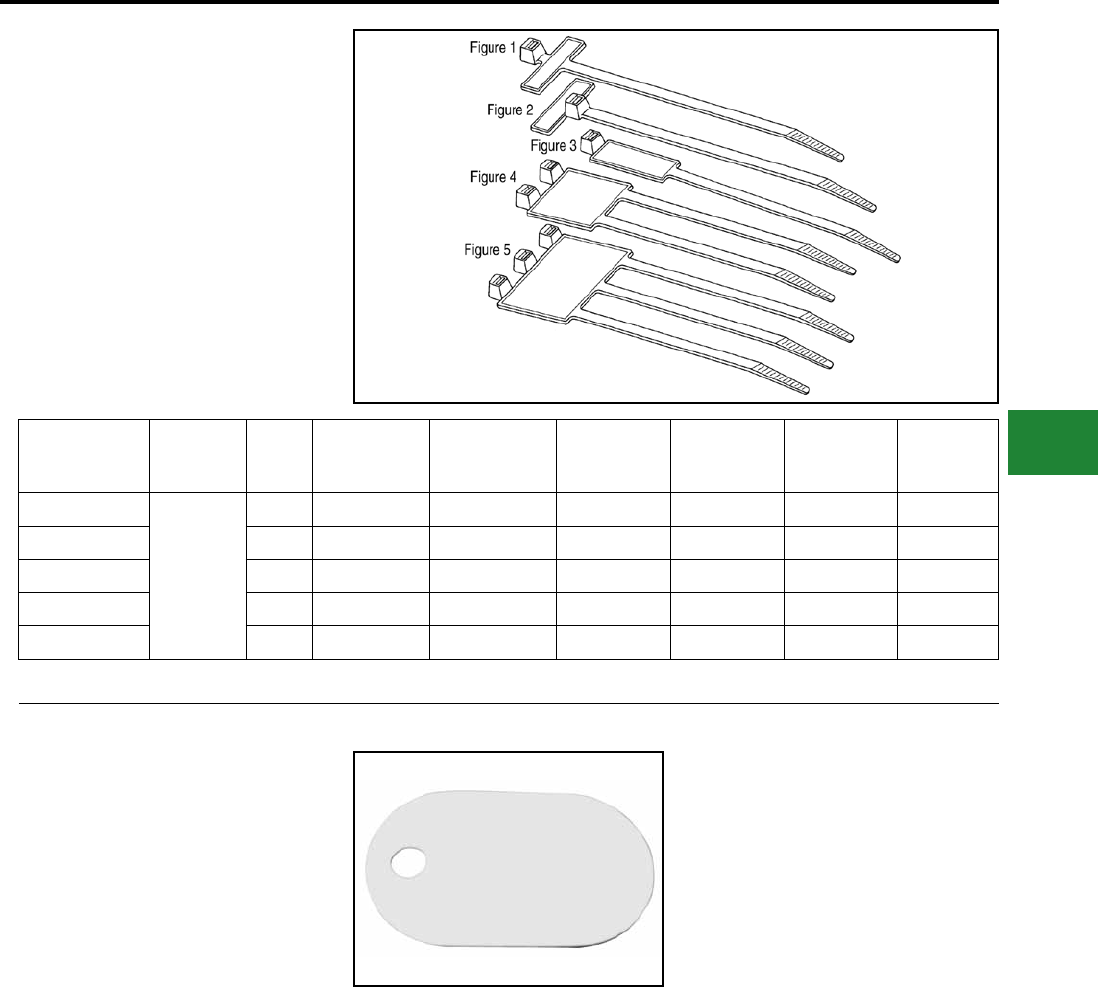
BURNDY®
Blue highlighted items are industry standard and most frequently ordered.
Canada: 1-800-387-6487 www.burndy.com US: 1-800-346-4175
Cable Ties
UNIRAP™
IDENTIFICATION CABLE TIES
Identication cable ties are used in both bundling
and identifying wire groups at the same time.
Std. Pkg.
Catalog
Number
Material Figure
No.
Marking
Pad Size
Inches
Max. Bundle
Diameter
Inches [mm]
Min. Tensile
Strength (lbs)
Length
Inches [mm]
Width
Inches [mm]
Installation
Tool
& (Setting)
CT18075IDC
Natural
Nylon 6/6
1 1 X 19/64 0.75 [19] 18 4.00 [102] 0.10 [3] MK7 (MIN)
CT18075FLC 2 13/16 X 5/16 0.75 [19] 18 4.25 [108] 0.10 [3] MK7 (MIN)
CT50175IDC 3 1 X 7/16 1.75 [44] 50 8.00 [203] 0.18 [5] MK7 (STD)
CT50175ID2L 4 1-11/16 X 5/16 1.75 [44] 50 8.00 [203] 0.18 [5] MK7 (STD)
CT50175ID3L 5 1-13/16 X 15/16 1.75 [44] 50 8.00 [203] 0.18 [5] MK7 (STD)
MISCELLANEOUS
ACCESSORIES
TYPE 145PTAG
94V0 Rated Plastic Tag for
Telecom, Transportation &
OEM Markets
The new 145PTAG has been designed
specically for the Telecom market. The tag
is manufactured from Flame Retardant Nylon
with a 94V0 rating. The tag is durable, non-
ammable and can be secured to cabling using
a multi-ply cord. Within the telecom market
these tags typically have P-Touch labels applied
or are manually stenciled on both sides. The
usual application is to mark the tags in the
eld with far end termination information, panel
Dimensions: 1" Х 1-3/4" by 0.06" thick
Material: White Nylon UL 94V0
Packaging: 25 tags per polybag
Tag Marking: Tags are shipped with no
markings; markings applied in
the eld based on application.
Specications
Catalog Number Description
145PTAG 94V0 Rated Plastic
identication, voice and data identication and
wire & cable marking. For the OEM user, in
addition to the P-Touch label or stenciling, tags
can be marked with information using most inks
or permanent markers, tags can be secured
with a waxed cord, UNIRAP™ cable tie or some
other equivalent.
G-11
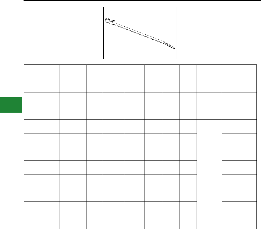
BURNDY®
Blue highlighted items are industry standard and most frequently ordered.
US: 1-800-346-4175 www.burndy.com Canada: 1-800-387-6487
Cable Ties
UNIRAP™
MOUNTING HOLE
CABLE TIES
Std. Pkg.
Catalog
Number
Material Screw
Size
Max.
Bundle
Diameter
Inches
[mm]
Min.
Tensile
Strength
(lbs)
Length
Inches
[mm]
Width
Inches
[mm]
Tool Tool
Setting
Bulk
Catalog
Number
CT18075MH4C Natural Nylon
6/6 #4 0.75 [19] 18 4.25
[108] 0.10 [3] MK7
Mini
CT18075MH4M
CT18075MH4C0 Black Nylon
6/6 UV #4 0.75 [19] 18 4.25
[108] 0.10 [3] MK7 —
CT30125MH8C Nylon 6/6 #8 1.25 [32] 30 6.10
[155] 0.14 [4] MK7
Intermediate
CT30125MH8M
CT30125MH8C0 Nylon 6/6 UV
Standard #8 1.25 [32] 30 6.25
[159] 0.14 [4] MK7 —
CT50175MH10C Nylon 6/6 #10 1.90 [48] 50 8.60
[218] 0.18 [5] MK7
Standard
CT50175MH10M
CT50175MH10C0 Nylon 6/6
Standard #10 1.90 [48] 50 8.60
[218] 0.18 [5] MK7 CT50175MH10M0
CT50400MH10C Nylon 6/6 #10 4.00 [102] 50 15.25
[387] 0.18 [5] MK7 —
CT50400MH10C0 Nylon 6/6
Standard #10 4.00 [102] 50 15.25
[387] 0.18 [5] MK7 CT50400MH10M0
CT120400MH14L Nylon 6/6 #14 4.00 [102] 120 15.90
[401] 0.30 [8] MK9 CT120400MH14D
CT120400MH14L0 Nylon 6/6 #14 4.00 [102] 120 15.90
[401] 0.30 [8] MK9 CT120400MH14D0
G-12
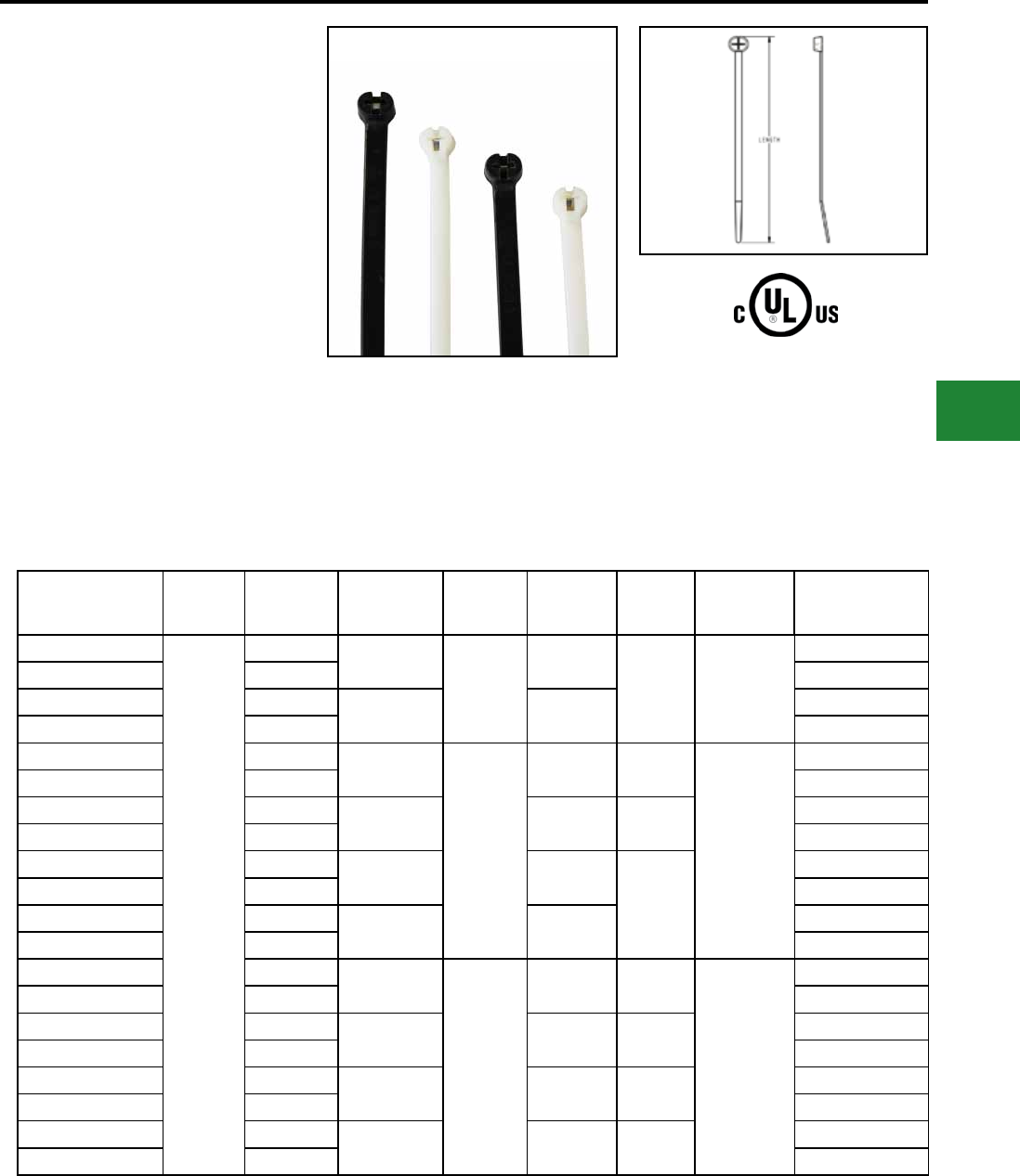
BURNDY®
Blue highlighted items are industry standard and most frequently ordered.
Canada: 1-800-387-6487 www.burndy.com US: 1-800-346-4175
Cable Ties
Type CT-SSB
UNIRAP™
The Stainless Steel Barb cable ties (Type CT-SSB)
are Nylon 6/6 with self locking stainless steel barbs
and have an oval low prole head. There are no
sharp edges helping prevent damaged cables. CT-
SSB ties have a curved tip for faster initial threading
to help speed installation and a no slip tail for easy
grip during tensioning. CT-SSB ties are currently
available in Natural and UV Black. Cable ties are
cULus Listed for Wiring Positioning Devices.
Features & Benets
• Nylon 6/6 Standard
• Self-locking stainless steel barb
• Available in Black and Natural
• Maximum strength and adjustability for
versatility
G-13
Catalog Number Material Color Max Bundle
Diameter
Tensile
Strength
(lbs)
Length Width Installation
Tool
Bulk Catalog
Number
CT18100SSBC
Nylon 6/6
Natural 0.91”
18
4.02”
.09”
MK7
TWT1
CTT50
MK9
CT18100SSBM
CT18100SSBC0 Black CT18100SSBM0
CT18200SSBC Natural 2.01” 7.91” CT18200SSBM
CT18200SSBC0 Black CT18200SSBM0
CT40137SSBC Natural 1.38”
40
5.91” .14”
MK7
TWT1
CTT50
MK9
CT40137SSBM
CT40137SSBC0 Black CT40137SSBM0
CT40200SSBC Natural 1.97” 7.87” .15” CT40200SSBD
CT40200SSBC0 Black CT40200SSBD0
CT40300SSBC Natural 3.15” 11.18”
.14”
CT40300SSBD
CT40300SSBC0 Black CT40300SSBD0
CT40400SSBC Natural 4.09” 14.49” CT40400SSBD
CT40400SSBC0 Black CT40400SSBD0
CT50175SSBC Natural 1.77”
50
7.32” .19”
MK7
TWT1
CTT50
MK9
CT50175SSBD
CT50175SSBC0 Black CT50175SSBD0
CT50200SSBC Natural 1.97” 7.87” .24” CT50200SSBB
CT50200SSBC0 Black CT50200SSBB0
CT50250SSBC Natural 2.56” 9.84” .19” CT50250SSBB
CT50250SSBC0 Black CT50250SSBB0
CT50300SSBC Natural 3.19” 11.61” .19” CT50300SSBB
CT50300SSBC0 Black CT50300SSBB0
Type 21
• Chemically resistant to solvents, oils,
grease, and diluted acids
• Rounded edges and bent tail for easy
installation
• Safe for air handling spaces
• Plenum rated
LISTED
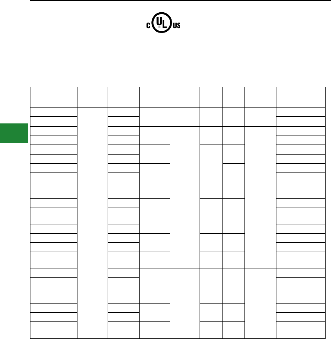
BURNDY®
Blue highlighted items are industry standard and most frequently ordered.
US: 1-800-346-4175 www.burndy.com Canada: 1-800-387-6487
Cable Ties
Type CT-SSB
UNIRAP™
(Continued)
G-14
Catalog Number Material Color Max Bundle
Diameter
Tensile
Strength
(lbs)
Length Width Installation
Tool
Bulk
Catalog Number
CT50425SSBC
Nylon 6/6
Natural 4.21” 50 14.96” .19” MK7, TWT1,
CTT50, MK9
CT50425SSBB
CT50425SSBC0 Black CT50425SSBB0
CT110200SSBC Natural 2.01”
110
8.70” .28”
MK9
CT110200SSBB
CT110200SSBC0 Black CT110200SSBB0
CT110300SSBL Natural 2.99”
11.81”
.32” CT110300SSBC
CT110300SSBL0 Black CT110300SSBC0
CT110325SSBC Natural 3.15” .28” CT110325SSBB
CT110325SSBC0 Black CT110325SSBB0
CT110350SSBL Natural 3.62” 13.78” .32” CT110350SSBC
CT110350SSBL0 Black CT110350SSBC0
CT110400SSBL Natural 4.02” 14.88” .28” CT110400SSBC
CT110400SSBL0 Black CT110400SSBC0
CT110500SSBL Natural 5.00” 18.11” .28” CT110500SSBC
CT110500SSBL0 Black CT110500SSBC0
CT110600SSBL Natural 5.98” 21.18” .28” CT110600SSBC
CT110600SSBL0 Black CT110600SSBC0
CT110800SSBL Natural 7.99” 27.52” .28” CT110800SSBC
CT110800SSBL0 Black CT110800SSBC0
CT120300SSBL Natural 3.15”
120
11.81” .39”
MK9
TWT2
CT120300SSBC
CT120300SSBL0 Black CT120300SSBC0
CT120350SSBL Natural 3.82” 13.78” .39” CT120350SSBC
CT120350SSBL0 Black CT120350SSBC0
CT120400SSBL Natural 4.33” 15.75” .39” CT120400SSBC
CT120400SSBL0 Black CT120400SSBC0
CT120500SSBL Natural 4.92” 17.72” .39” CT120500SSBC
CT120500SSBL0 Black CT120500SSBC0
Type 21
LISTED
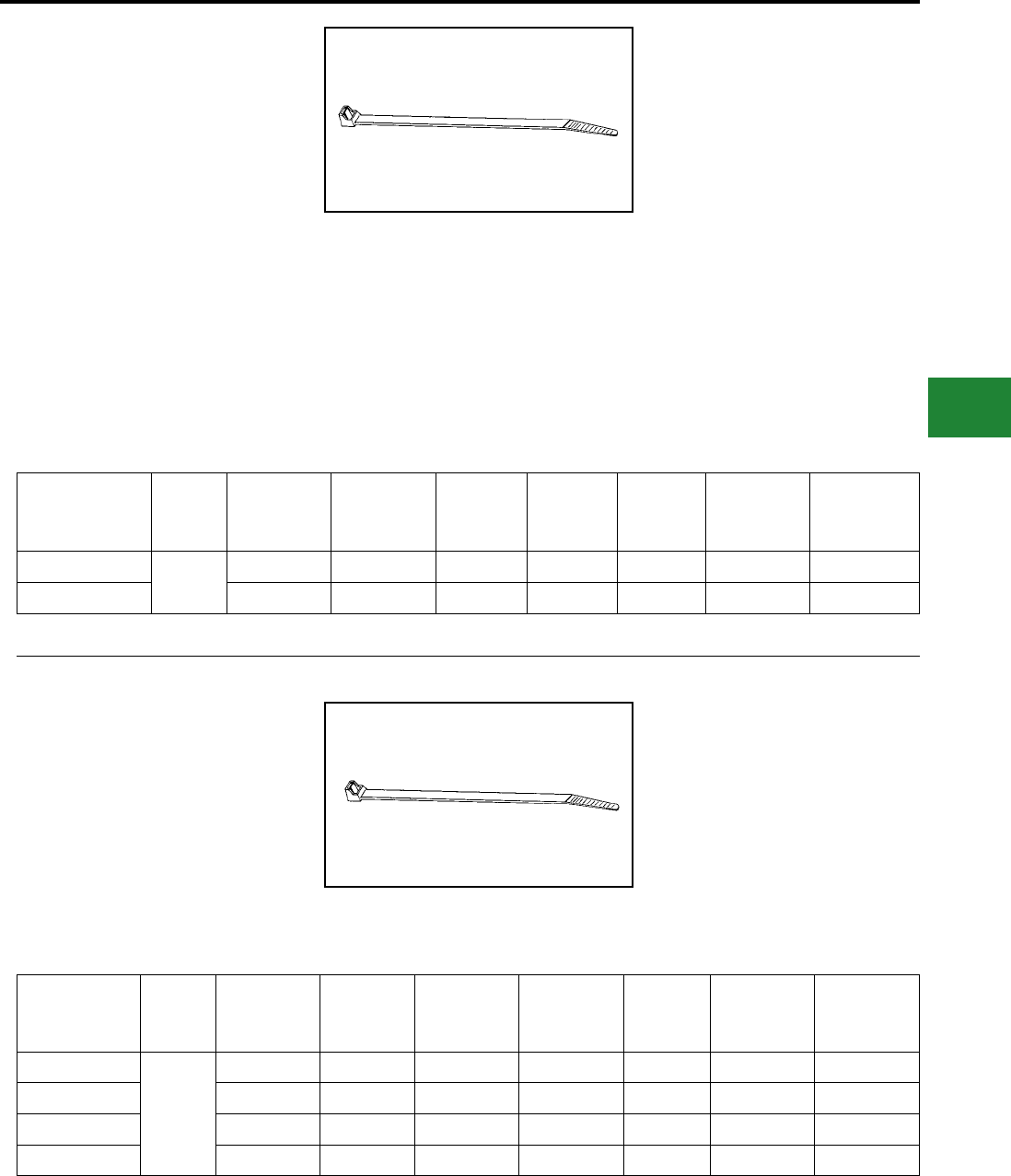
BURNDY®
Blue highlighted items are industry standard and most frequently ordered.
Canada: 1-800-387-6487 www.burndy.com US: 1-800-346-4175
Cable Ties
UNIRAP™
HALAR® TIES
Halar® ties meet NEC regulations and can be used
in applications where low smoke and low ame
are a concern, as in air handling spaces. The raw
material used to manufacture BURNDY® Halar®
cable ties is UL 94V-0 rated. These ties come in a
distinct color of red for easy identication.
Std. Pkg.
Catalog
Number
Material
Max. Bundle
Diameter
Inches[mm]
Min. Tensile
Strength (lbs)
Length
Inches[mm]
Width
Inches[mm]
Installation
Tool Tool Setting
Bulk
Catalog
Number
CTH30200C Halar 2.00 [51] 30 8.00 [203] 0.14 [4] MK7 Intermediate —
CTH50175C 1.75 [44] 50 8.00 [203] 0.18 [5] MK7 Standard CTH50175M
Features & Benets
• Smooth, rounded edges help ensure safe,
efcient handling
• Ergonomically designed installation tool
consistently tensions and cuts off ties leaving
ush edges
• Flame retardant and non-toxic for applications
where safety from re is critical
UNIRAP™
TEFZEL® TIES
Tefzel® ties provide excellent protection against
radiation, ultraviolet light, and a wide range of
chemicals. It is also rated for low outgassing
applications. BURNDY® Tefzel® ties offer
temperature stability to 150° C and come in a
standard color of blue for easy identication.
Std. Pkg.
Catalog
Number
Material
Max. Bundle
Diameter
Inches [mm]
Min. Tensile
Strength
(lbs)
Length
Inches
Width
Inches
Installation
Tool Tool Setting
Bulk
Catalog
Number
CTZ18075C
Tefzel
0.75 [19] 18 4.00 0.10 MK7 Mini —
CTZ30200C 2.00 [51] 30 8.00 0.14 MK7 Intermediate —
CTZ50175C 1.75 [44] 50 8.00 0.18 MK7 Standard —
CTZ120400L 4.00 [102] 120 14.50 .030 MK9 Standard CTZ120400D
Tefzel® Cable Ties
Halar® Cable Ties
G-15
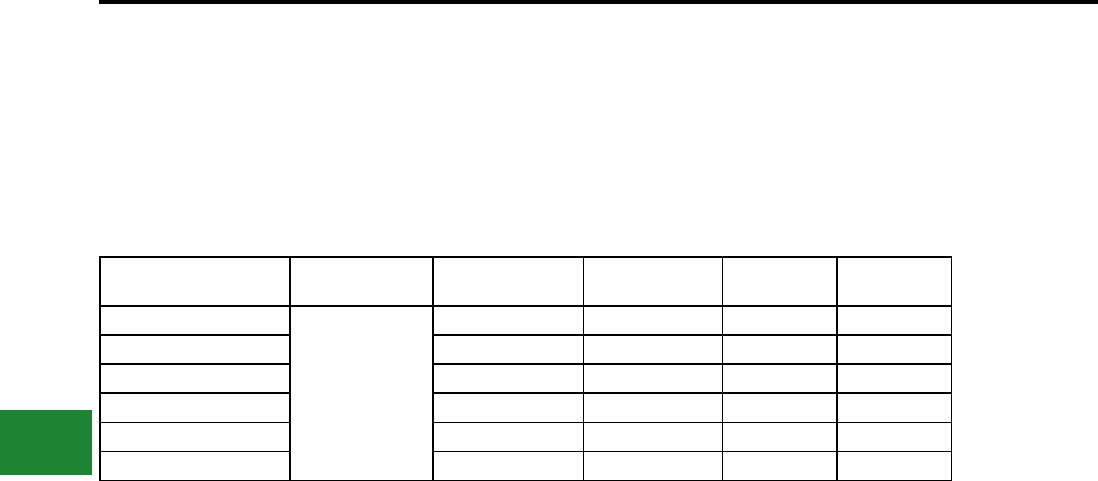
BURNDY®
Blue highlighted items are industry standard and most frequently ordered.
US: 1-800-346-4175 www.burndy.com Canada: 1-800-387-6487
Cable Ties
Catalog Number Material Max Bundle
Diameter Inches
Tensile Strength
Lbs. Length Inches Width Inches
CTHS18075M
Nylon 6/6 Heat
Stabilized
.75 18 4.1 .10
CTHS140125M 1.25 40 5.8 .14
CTHS50700M 1.90 50 7.6 .18
CTHS50300M 3.00 50 11.1 .18
CTHS50400M 4.00 50 14.6 .18
CTHS120400M 4.00 120 15.0 .30
Type CTHS
UNIRAP™
Heat Stabilized Cable Ties
G-16
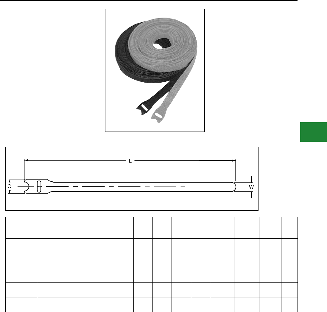
BURNDY®
Blue highlighted items are industry standard and most frequently ordered.
Canada: 1-800-387-6487 www.burndy.com US: 1-800-346-4175
Cable Ties
TYPE TFV-B
HOOK AND LOOP STRAPS
Reusable and exible BURNDY® Hook and Loop
Straps are a unique self-gripping fastening system.
These ties are specically used on beroptic
applications.
The TFV-V2 ame retardant straps are UL
Listed Wire Positioning Devices (ZODZ),
UL94-V2 rated for use in air handling spaces
in accordance with the NEC section 300-22 (c)
and (d). Perfect for plenum areas.
25 straps are conveniently packaged in each
polybag.
Catalog
Number Product Description C L W T
Max.
Bundle
Diameter
Avg.
Sheer
(PSI)
Avg.
Peel
(PIW)
Pkg.
Qty.
TFV3B12V2 VELCRO® hook and loop strap, 3/4" x 12",
Black, 25pk 0.75" 12.00" 0.50" 0.09" 3.0" 29 0.6 *1
TFV3B18V2 VELCRO® hook and loop strap, 3/4" x 18",
Black, 25pk 0.75" 18.00" 0.50" 0.09" 5.0" 29 0.6 *1
TFV3B6V2 VELCRO® hook and loop strap, 3/4" x 6",
Black, 25pk 0.75" 6.00" 0.50" 0.09" 1.0" 29 0.6 *1
TFV3BLU12 VELCRO® hook and loop strap, 3/4" x 12",
Royal Blue, 25pk 0.75" 12.00" 0.50" 0.09" 3.0" 23 0.5 *1
TFV3BLU18 VELCRO® hook and loop strap, 3/4" x 18",
Royal Blue, 25pk 0.75" 18.00" 0.50" 0.09" 5.0" 23 0.5 *1
* Straps sold by the package, quantity 1 package
equals 25 straps.
** UL94-V2 listed.
VELCRO® is a registered trademark of Velcro
USA, Inc.
G-17
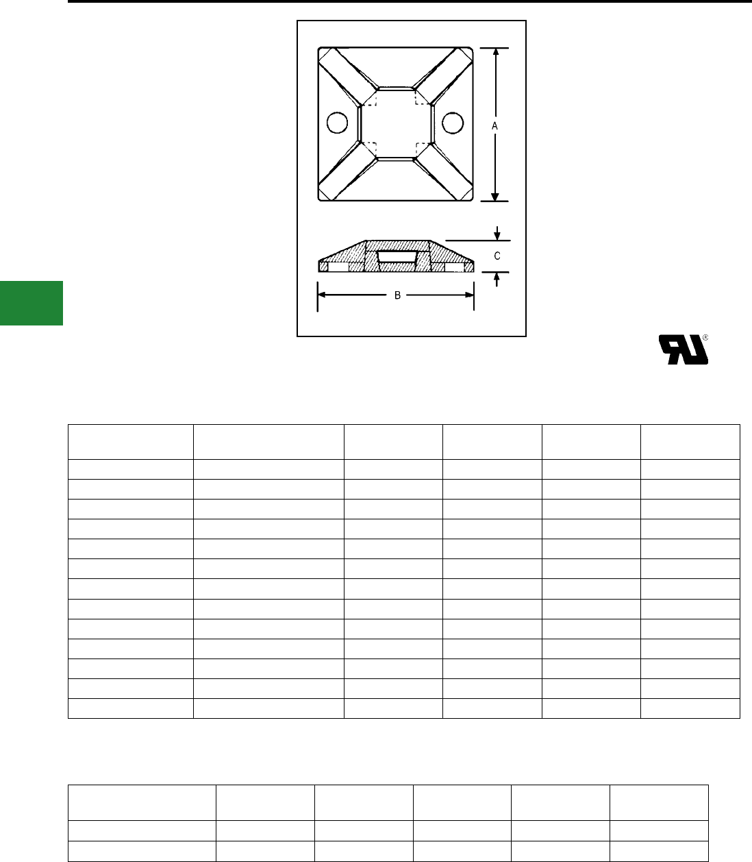
BURNDY®
Blue highlighted items are industry standard and most frequently ordered.
US: 1-800-346-4175 www.burndy.com Canada: 1-800-387-6487
Cable Ties
MOUNTING BASES
BURNDY® offers a wide variety of mounting
bases suited for many applications. Mounting
bases are used in conjunction with cable ties to
stabilize and secure wire bundles, both indoors
and outdoors. Mounting bases can be secured
to a surface using rubber based adhesive,
acrylic adhesive, or also can be screw mounted.
BURNDY’s 4-way mounting bases are available
in four sizes to accommodate CT18 through
CT50 series cable ties. Insertion of ties can
be made from all sides. Each mount may
be secured with two screws, with adhesive
backing, or both, for ease of application
and stability. For applications where higher
temperatures, certain chemicals, or UV radiation
are a concern and an adhesive is the preferred
method for securing, the acrylic adhesive
4-way mounting bases are recommended.
The 2-way mounting bases may be secured
with one screw, with adhesive backing, or both,
and allow ties to be inserted from two sides.
Catalog
Number
Mounting
Method
Maximum Tie
Slot Width
Dimension
A
Dimension
B
Dimension
C
CTB075S4C Screw 0.14" 0.75" 0.75" 0.15"
CTB075AA4C Acrylic Adhesive 0.14" 0.75" 0.75" 0.15"
CTB075RA4C Rubber Adhesive 0.14" 0.75" 0.75" 0.15"
CTB075RA4M Rubber Adhesive 0.14" 0.75" 0.75" 0.15"
CTB125S4C Screw 0.20" 1.12" 1.12" 0.19"
CTB125AA4C Acrylic Adhesive 0.20" 1.12" 1.12" 0.19"
CTB125RA4C Rubber Adhesive 0.20" 1.12" 1.12" 0.19"
CTB125RA4L Rubber Adhesive 0.20" 1.12" 1.12" 0.19"
CTB125RA4D Rubber Adhesive 0.20" 1.12" 1.12" 0.19"
CTB150S4B Screw 0.35" 1.50" 1.50" 0.25"
CTB150AA4C Acrylic Adhesive 0.35" 1.50" 1.50" 0.25"
CTB150RA4C Rubber Adhesive 0.35" 1.50" 1.50" 0.25"
CTB150RA4B Rubber Adhesive 0.35" 1.50" 1.50" 0.25"
Catalog
Number
Mounting
Method
Maximum Tie
Slot Width
Dimension
A
Dimension
B
Dimension
C
CTB125S2C Screw 0.18" 1.125" 1.125" 0.21"
CTB125RA2C Rubber Adhesive 0.18" 1.125" 1.125" 0.21"
4-Way
2-Way
All bases listed above are natural. UV Black mounting bases are also available in
nearly every size. Insert “0” after the part number.
All bases listed above are natural. UV Black mounting bases are also available in
nearly every size. Insert “0” after the part number.
G-18
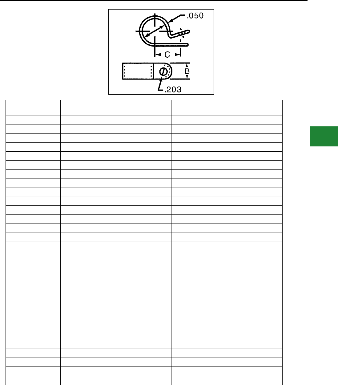
BURNDY®
Blue highlighted items are industry standard and most frequently ordered.
Canada: 1-800-387-6487 www.burndy.com US: 1-800-346-4175
Cable Ties
CABLE HANGERS
Cable Hangers provide a contact area range of
1/2" to 3/8" in width. All contact edges have a full
radius for product protection, and sizes are clearly
marked on each clamp.
Cable Hangers are injection molded. Available in
white nylon 6/6 and black nylon 6/6.
Catalog
Number Mounting Screw Maximum Bundle
Inches
Dimension B Inches
(Width)
Dimension C Inches
(Mount Hole Centers)
CH2C #10 Screw 0.12 0.37 0.32
CH2M #10 Screw 0.12 0.37 0.32
CH3C #10 Screw 0.18 0.37 0.43
CH3M #10 Screw 0.18 0.37 0.43
CH4C #10 Screw 0.25 0.37 0.41
CH4M #10 Screw 0.25 0.37 0.41
CH5C #10 Screw 0.31 0.37 0.49
CH5M #10 Screw 0.31 0.37 0.49
CH6C #10 Screw 0.37 0.37 0.59
CH6M #10 Screw 0.37 0.37 0.59
CH7C #10 Screw 0.43 0.37 0.57
CH7M #10 Screw 0.43 0.37 0.57
CH8C #10 Screw 0.50 0.37 0.60
CH8M #10 Screw 0.50 0.37 0.60
CH9C #10 Screw 0.56 0.37 0.60
CH9M #10 Screw 0.56 0.37 0.60
CH10C #10 Screw 0.62 0.37 0.60
CH10M #10 Screw 0.62 0.37 0.60
CH11C #10 Screw 0.62 0.50 0.65
CH11M #10 Screw 0.62 0.50 0.65
CH12C #10 Screw 0.75 0.50 0.78
CH12M #10 Screw 0.75 0.50 0.78
CH14C #10 Screw 0.87 0.50 0.84
CH14M #10 Screw 0.88 0.50 0.84
CH16C #10 Screw 1.00 0.50 0.91
CH16M #10 Screw 1.00 0.50 0.91
CH18C #10 Screw 1.12 0.50 0.97
CH18M #10 Screw 1.12 0.50 0.97
CH24L #10 Screw 1.50 0.50 1.19
CH24C #10 Screw 1.50 0.50 1.19
All hangers listed above are natural. UV Black cable hangers are also available in
nearly every size. Insert “0” after the part number.
G-19
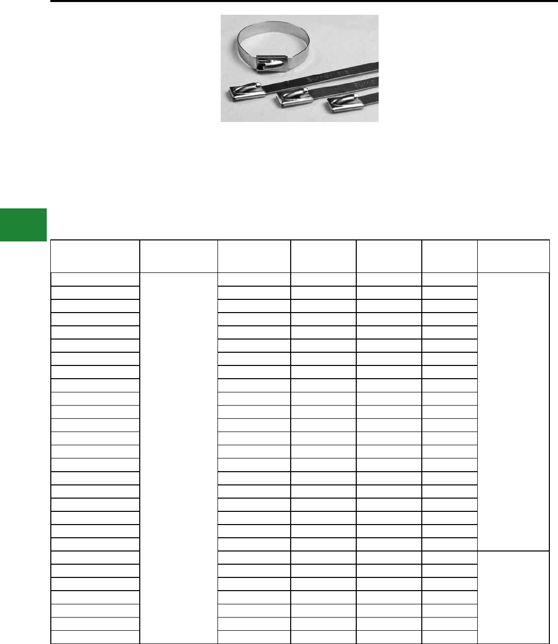
BURNDY®
Blue highlighted items are industry standard and most frequently ordered.
US: 1-800-346-4175 www.burndy.com Canada: 1-800-387-6487
Cable Ties
Type CTSS
UNIRAP™
Stainless Steel 304 Cable Ties
BURNDY® Stainless Steel ties are designed to
secure hoses, cables, poles, pipes and more when
harsh environmental conditions may adversely
affect the bundling application. Used where
corrosion, vibration, weathering, radiation, and
temperature extremes are a concern. BURNDY®
Stainless Steel ties can be used in virtually any
indoor, outdoor and underground application.
Catalog Number Material
Max Bundle
Diameter Inches
[mm]
Tensile Strength
Lbs. (N)
Length Inches
[mm]
Width Inches
[mm] Installation Tool
CTSS225100304C
304 Stainless Steel
0.99 [25] 225 (1000) 3.94 [100] 0.18 [4.6]
CTTSS900
MK9SST
CTSS225200304C 1.97 [50] 225 (1000) 7.87 [200] 0.18 [4.6]
CTSS225300304C 3.00 [76] 225 (1000) 11.81 [300] 0.18 [4.6]
CTSS225400304C 4.02 [102] 225 (1000) 15.75 [400] 0.18 [4.6]
CTSS225500304C 5.04 [128] 225 (1000) 19.68 [500] 0.18 [4.6]
CTSS225600304C 6.07 [154] 225 (1000) 23.62 [600] 0.18 [4.6]
CTSS500200304L 1.97 [50] 500 (2200) 7.87 [200] 0.31 [7.9]
CTSS500300304L 3.00 [76] 500 (2200) 11.81 [300] 0.31 [7.9]
CTSS500400304L 4.02 [102] 500 (2200) 15.75 [400] 0.31 [7.9]
CTSS500500304L 5.04 [128] 500 (2200) 19.68 [500] 0.31 [7.9]
CTSS500600304L 6.07 [154] 500 (2200) 23.62 [600] 0.31 [7.9]
CTSS500700304L 7.09 [180] 500 (2200) 27.56 [700] 0.31 [7.9]
CTSS500750304L 7.60 [193] 500 (2200) 31.50 [800] 0.31 [7.9]
CTSS500800304L 8.12 [206] 500 (2200) 39.37 [1000] 0.31 [7.9]
CTSS700200304L 1.97 [50] 700 (3113) 7.87 [200] 0.50 [12.7]
CTSS700300304L 3.00 [76] 700 (3113) 11.81 [300] 0.50 [12.7]
CTSS700400304L 4.02 [102] 700 (3113) 15.75 [400] 0.50 [12.7]
CTSS700500304L 5.04 [128] 700 (3113) 19.68 [500] 0.50 [12.7]
CTSS700600304L 6.07 [154] 700 (3113) 23.62 [600] 0.50 [12.7]
CTSS700700304L 7.09 [180] 700 (3113) 27.56 [700] 0.50 [12.7]
CTSS700800304L 8.12 [206] 700 (3113) 39.37 [1000] 0.50 [12.7]
CTSS900200304L 1.97 [50] 920 (4100) 7.87 [200] 0.62 [15.9]
CTTSS900
CTSS900300304L 3.00 [76] 920 (4100) 11.81 [300] 0.62 [15.9]
CTSS900400304L 4.02 [102] 920 (4100) 15.75 [400] 0.62 [15.9]
CTSS900500304L 5.04 [128] 920 (4100) 19.68 [500] 0.62 [15.9]
CTSS900600304L 6.07 [154] 920 (4100) 23.62 [600] 0.62 [15.9]
CTSS900700304L 7.09 [180] 920 (4100) 27.56 [700] 0.62 [15.9]
CTSS900800304L 8.12 [206] 920 (4100) 39.37 [1000] 0.62 [15.9]
Features & Benets
• Meet the requirements of ABS
• 304 grade stainless steel
• Suitable for general purpose applications
• Smooth, rounded edges help ensure safe
efcient handling
• Available in a wide range of lengths and
widths
• Self locking steel ball design speeds
installation and locks into place at any length
• Provides a strong durable method of cable
bundling
• Flame retardant and non-toxic for
applications where safety from re is critical
BURNDY® Stainless Steel ties are made from
Grade 304 Stainless Steel. This tie is designed
with a low prole clamping bearing head with fully
adjustable strap accommodating many bundle
diameters.
G-20
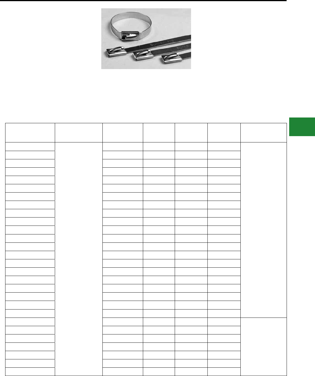
BURNDY®
Blue highlighted items are industry standard and most frequently ordered.
Canada: 1-800-387-6487 www.burndy.com US: 1-800-346-4175
Cable Ties
Catalog Number Material
Max Bundle
Diameter Inches
[mm]
Tensile
Strength Lbs.
(N)
Length Inches
[mm]
Width Inches
[mm] Installation Tooling
CTSS225100316C
316 Stainless Steel
0.99 [25] 225 (1000) 3.94 [100] 0.18 [4.6]
CTTSS900
MK9SST
CTSS225200316C 1.97 [50] 225 (1000) 7.87 [200] 0.18 [4.6]
CTSS225300316C 3.00 [76] 225 (1000) 11.81 [300] 0.18 [4.6]
CTSS225400316C 4.02 [102] 225 (1000) 15.75 [400] 0.18 [4.6]
CTSS225500316C 5.04 [128] 225 (1000) 19.68 [500] 0.18 [4.6]
CTSS225600316C 6.07 [154] 225 (1000) 23.62 [600] 0.18 [4.6]
CTSS500200316C 1.97 [50] 500 (2200) 7.87 [200] 0.31 [7.9]
CTSS500300316C 3.00 [76] 500 (2200) 11.81 [300] 0.31 [7.9]
CTSS500400316L 4.02 [102] 500 (2200) 15.75 [400] 0.31 [7.9]
CTSS500500316L 5.04 [128] 500 (2200) 19.68 [500] 0.31 [7.9]
CTSS500600316L 6.07 [154] 500 (2200) 23.62 [600] 0.31 [7.9]
CTSS500700316L 7.09 [180] 500 (2200) 27.56 [700] 0.31 [7.9]
CTSS500750316L 7.60 [193] 500 (2200) 31.50 [800] 0.31 [7.9]
CTSS500800316L 8.12 [206] 500 (2200) 39.37 [1000] 0.31 [7.9]
CTSS700200316L 1.97 [50] 700 (3113) 7.87 [200] 0.50 [12.7]
CTSS700300316L 3.00 [76] 700 (3113) 11.81 [300] 0.50 [12.7]
CTSS700400316L 4.02 [102] 700 (3113) 15.75 [400] 0.50 [12.7]
CTSS700500316L 5.04 [128] 700 (3113) 19.68 [500] 0.50 [12.7]
CTSS700600316L 6.07 [154] 700 (3113) 23.62 [600] 0.50 [12.7]
CTSS700700316L 7.09 [180] 700 (3113) 27.56 [700] 0.50 [12.7]
CTSS700800316L 8.12 [206] 700 (3113) 39.37 [1000] 0.50 [12.7]
CTSS900200316L 1.97 [50] 920 (4100) 7.87 [200] 0.62 [15.9]
CTTSS900
CTSS900300316L 3.00 [76] 920 (4100) 11.81 [300] 0.62 [15.9]
CTSS900400316L 4.02 [102] 920 (4100) 15.75 [400] 0.62 [15.9]
CTSS900500316L 5.04 [128] 920 (4100) 19.68 [500] 0.62 [15.9]
CTSS900600316L 6.07 [154] 920 (4100) 23.62 [600] 0.62 [15.9]
CTSS900700316L 7.09 [180] 920 (4100) 27.56 [700] 0.62 [15.9]
CTSS900800316L 8.12 [206] 920 (4100) 39.37 [1000] 0.62 [15.9]
Type CTSS
UNIRAP™
Stainless Steel 316 Cable Ties
BURNDY® Stainless Steel ties are designed to
secure hoses, cables, poles, pipes, and more when
harsh environmental conditions may adversely
affect the bundling application. Used where
corrosion, vibration, weathering, radiation and
temperature extremes are a concern, BURNDY®
Stainless Steel ties can be used in virtually any
indoor, outdoor and underground application.
Features & Benets
• Meet the requirements of ABS
• 316 grade stainless steel
• Suitable for rigorous corrosive conditions
• Smooth, rounded edges help ensure safe
efcient handling
• Available in a wide range of lengths and
widths
• Self locking steel ball design speeds instal-
lation and locks into place at any length
• Provides a strong durable method of cable
bundling
• Flame retardant and non-toxic for
applications where safety from re is critical
BURNDY® Stainless Steel ties are made from
Grade 316 Stainless Steel. This tie is designed
with a low prole clamping bearing head with fully
adjustable strap accommodating many bundle
diameters.
G-21
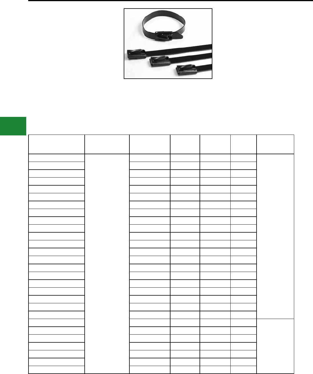
BURNDY®
Blue highlighted items are industry standard and most frequently ordered.
US: 1-800-346-4175 www.burndy.com Canada: 1-800-387-6487
Cable Ties
Type CTSS-FC
UNIRAP™
Fully Coated 304 Cable Ties
The Stainless Steel fully coated cable ties (Type
CTSS-FC) are designed with a steel ball type
locking mechanism. There are no sharp edges
which prevents damaged cables. These ties have
smooth, rounded edges and polyester coating
which add to the safety of the installer. High tensile
strength along with the shield of the polyester
coating offer a reliable and lasting bundling
solution. CTSS-FC ties are currently available
in black. BURNDY® stainless steel fully coated
cable ties can be used in any indoor, outdoor or
underground application.
Features & Benets
• Meet the requirements of ABS
• 304 grade stainless steel
• Available in black only
• Suitable for general purpose applications
• Smooth, rounded edges along with the
polyester coating add to the safety of the
installer
• Self locking steel ball design speeds
installation and locks into place at any length
• Available in a wide range of lengths and
widths
• Comes with a benet of halogen free low
smoke polyester coating
• Provides a strong durable method of cable
bundling
Catalog Number Material
Max Bundle
Diameter Inches
[mm]
Tensile
Strength
Lbs. (N)
Length
Inches [mm]
Width
Inches
[mm]
Installation Tool
CTSS100100FC304C
304 Stainless Steel
0.98 [25] 160 (712) 3.94 [100] 0.18 [4.6]
CTTSS900
MK9SST
CTSS100200FC304C 1.97 [50] 160 (712) 7.87 [200] 0.18 [4.6]
CTSS100300FC304C 3.00 [76] 160 (712) 11.81 [300] 0.18 [4.6]
CTSS100400FC304C 4.02 [102] 160 (712) 15.75 [400] 0.18 [4.6]
CTSS100500FC304C 5.04 [128] 160 (712) 19.68 [500] 0.18 [4.6]
CTSS100600FC304C 6.07 [154] 160 (712) 23.60 [600] 0.18 [4.6]
CTSS100800FC304C 8.11 [206] 160 (712) 31.50 [800] 0.18 [4.6]
CTSS250200FC304L 1.97 [50] 250 (1112) 7.87 [200] 0.31 [7.9]
CTSS250300FC304L 3.00 [76] 250 (1112) 11.81 [300] 0.31 [7.9]
CTSS250400FC304L 4.02 [102] 250 (1112) 15.75 [400] 0.31 [7.9]
CTSS250500FC304L 5.04 [128] 250 (1112) 19.68 [500] 0.31 [7.9]
CTSS250600FC304L 6.06 [154] 250 (1112) 23.62 [600] 0.31 [7.9]
CTSS250700FC304L 7.09 [180] 250 (1112) 27.56 [700] 0.31 [7.9]
CTSS250800FC304L 8.11 [206] 250 (1112) 39.37 [1000] 0.31 [7.9]
CTSS450200FC304L 1.97 [50] 450 (2002) 7.87 [200] 0.50 [12.7]
CTSS450300FC304L 3.00 [76] 450 (2002) 11.81 [300] 0.50 [12.7]
CTSS450400FC304L 4.02 [102] 450 (2002) 15.75 [400] 0.50 [12.7]
CTSS450500FC304L 5.04 [128] 450 (2002) 19.68 [500] 0.50 [12.7]
CTSS450600FC304L 6.06 [154] 450 (2002) 23.62 [600] 0.50 [12.7]
CTSS450700FC304L 7.09 [180] 450 (2002) 27.56 [700] 0.50 [12.7]
CTSS450800FC304L 8.11 [206] 450 (2002) 39.37 [1000] 0.50 [12.7]
CTSS675200FC304Q 1.97 [50] 675 (3003) 7.87 [200] 0.62 [15.9]
CTTSS900
CTSS675300FC304Q 3.00 [76] 675 (3003) 11.81 [300] 0.62 [15.9]
CTSS675400FC304Q 4.02 [102] 675 (3003) 15.75 [400] 0.62 [15.9]
CTSS675500FC304Q 5.04 [128] 675 (3003) 19.68 [500] 0.62 [15.9]
CTSS675600FC304Q 6.06 [154] 675 (3003) 23.62 [600] 0.62 [15.9]
CTSS675700FC304Q 7.09 [180] 675 (3003) 27.56 [700] 0.62 [15.9]
CTSS675800FC304Q 8.11 [206] 675 (3003) 39.37 [1000] 0.62 [15.9]
G-22
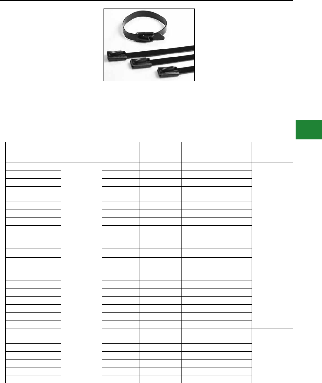
BURNDY®
Blue highlighted items are industry standard and most frequently ordered.
Canada: 1-800-387-6487 www.burndy.com US: 1-800-346-4175
Cable Ties
Catalog Number Material
Max Bundle
Diameter Inches
[mm]
Tensile Strength
Lbs. (N)
Length
Inches [mm]
Width Inches
[mm] Installation Tool
CTSS100100FC316C
316 Stainless Steel
0.98 [25] 160 (712) 3.94 [100] 0.18 [4.6]
CTTSS900
MK9SST
CTSS100200FC316C 1.97 [50] 160 (712) 7.87 [200] 0.18 [4.6]
CTSS100300FC316C 3.00 [76] 160 (712) 11.81 [300] 0.18 [4.6]
CTSS100400FC316C 4.02 [102] 160 (712) 15.75 [400] 0.18 [4.6]
CTSS100500FC316C 5.04 [128] 160 (712) 19.68 [500] 0.18 [4.6]
CTSS100600FC316C 6.07 [154] 160 (712) 23.60 [600] 0.18 [4.6]
CTSS100800FC316C 8.11 [206] 160 (712) 31.50 [800] 0.18 [4.6]
CTSS250200FC316L 1.97 [50] 250 (1112) 7.87 [200] 0.31 [7.9]
CTSS250300FC316L 3.00 [76] 250 (1112) 11.81 [300] 0.31 [7.9]
CTSS250400FC316L 4.02 [102] 250 (1112) 15.75 [400] 0.31 [7.9]
CTSS250500FC316L 5.04 [128] 250 (1112) 19.68 [500] 0.31 [7.9]
CTSS250600FC316L 6.06 [154] 250 (1112) 23.62 [600] 0.31 [7.9]
CTSS250700FC316L 7.09 [180] 250 (1112) 27.56 [700] 0.31 [7.9]
CTSS250800FC316L 8.11 [206] 250 (1112) 39.37 [1000] 0.31 [7.9]
CTSS450200FC316L 1.97 [50] 450 (2002) 7.87 [200] 0.50 [12.7]
CTSS450300FC316L 3.00 [76] 450 (2002) 11.81 [300] 0.50 [12.7]
CTSS450400FC316L 4.02 [102] 450 (2002) 15.75 [400] 0.50 [12.7]
CTSS450500FC316L 5.04 [128] 450 (2002) 19.68 [500] 0.50 [12.7]
CTSS450600FC316L 6.06 [154] 450 (2002) 23.62 [600] 0.50 [12.7]
CTSS450700FC316L 7.09 [180] 450 (2002) 27.56 [700] 0.50 [12.7]
CTSS450800FC316L 8.11 [206] 450 (2002) 39.37 [1000] 0.50 [12.7]
CTSS675200FC316Q 1.97 [50] 675 (3003) 7.87 [200] 0.62 [15.9]
CTTSS900
CTSS675300FC316Q 3.00 [76] 675 (3003) 11.81 [300] 0.62 [15.9]
CTSS675400FC316Q 4.02 [102] 675 (3003) 15.75 [400] 0.62 [15.9]
CTSS675500FC316Q 5.04 [128] 675 (3003) 19.68 [500] 0.62 [15.9]
CTSS675600FC316Q 6.06 [154] 675 (3003) 23.62 [600] 0.62 [15.9]
CTSS675700FC316Q 7.09 [180] 675 (3003) 27.56 [700] 0.62 [15.9]
CTSS675800FC316Q 8.11 [206] 675 (3003) 39.37 [1000] 0.62 [15.9]
Type CTSS-FC
UNIRAP™
Fully Coated 316 Cable Ties
The BURNDY® Stainless Steel fully coated cable
ties (Type CTSS-FC) are designed with a steel ball
self locking mechanism. There are no sharp edges
which prevents damaged cables. These ties have
smooth, rounded edges and polyester coating
which add to the safety of the installer. High tensile
strength along with the shield of the polyester
coating offer a reliable and lasting bundling
solution. CTSS-FC ties are currently available
in black. BURNDY® stainless steel fully coated
cable ties can be used in any indoor, outdoor or
underground application.
Features & Benets
• Meet the requirements of ABS
• 316 grade stainless steel
• Available in black only
• Suitable for rigorous corrosive conditions
• Smooth, rounded edges along with the
polyester coating add to the safety of the
installer
• Self locking steel ball design, speeds
installation and locks into place at any length
• Provides a strong durable method of cable
bundling
• Available in a wide range of lengths and
widths
• Comes with a benet of halogen free low
smoke polyester coating
G-23
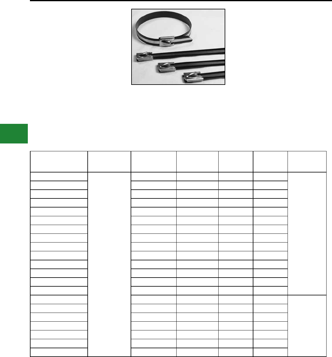
BURNDY®
Blue highlighted items are industry standard and most frequently ordered.
US: 1-800-346-4175 www.burndy.com Canada: 1-800-387-6487
Cable Ties
Catalog Number Material
Max Bundle
Diameter Inches
[mm]
Tensile Strength
Lbs. (N)
Length Inches
[mm]
Width Inches
[mm] Installation Tool
CTSS250200PC304L
304 Stainless Steel
1.97 [50] 270 (1201) 7.87 [200] 0.31 [7.9]
CTTSS900
MK9SST
CTSS250300PC304L 3.00 [76] 270 (1201) 11.81 [300] 0.31 [7.9]
CTSS250400PC304L 4.02 [102] 270 (1201) 15.75 [400] 0.31 [7.9]
CTSS250500PC304L 5.04 [128] 270 (1201) 19.68 [500] 0.31 [7.9]
CTSS250600PC304L 6.06 [154] 270 (1201) 23.62 [600] 0.31 [7.9]
CTSS250700PC304L 7.09 [180] 270 (1201) 27.56 [700] 0.31 [7.9]
CTSS250800PC304L 8.11 [206] 270 (1201) 39.37 [1000] 0.31 [7.9]
CTSS450200PC304L 1.97 [50] 450 (2002) 7.87 [200] 0.50 [12.7]
CTSS450300PC304L 3.00 [76] 450 (2002) 11.81 [300] 0.50 [12.7]
CTSS450400PC304L 4.02 [102] 450 (2002) 15.75 [400] 0.50 [12.7]
CTSS450500PC304L 5.04 [128] 450 (2002) 19.68 [500] 0.50 [12.7]
CTSS450600PC304L 6.06 [154] 450 (2002) 23.62 [600] 0.50 [12.7]
CTSS450700PC304L 7.09 [180] 450 (2002) 27.56 [700] 0.50 [12.7]
CTSS450800PC304L 8.11 [206] 450 (2002) 39.37 [1000] 0.50 [12.7]
CTSS675200PC304Q 1.97 [50] 675 (3003) 7.87 [200] 0.62 [15.9]
CTTSS900
CTSS675300PC304Q 3.00 [76] 675 (3003) 11.81 [300] 0.62 [15.9]
CTSS675400PC304Q 4.02 [102] 675 (3003) 15.75 [400] 0.62 [15.9]
CTSS675500PC304Q 5.04 [128] 675 (3003) 19.68 [500] 0.62 [15.9]
CTSS675600PC304Q 6.06 [154] 675 (3003) 23.62 [600] 0.62 [15.9]
CTSS675700PC304Q 7.09 [180] 675 (3003) 27.56 [700] 0.62 [15.9]
CTSS675800PC304Q 8.11 [206] 675 (3003) 39.37 [1000] 0.62 [15.9]
Type CTSS-PC
UNIRAP™
Partially Coated 304 Cable Ties
BURNDY® Stainless Steel partially coated cable
ties (Type CTSS-PC) are designed with a steel ball
self locking mechanism. There are no sharp edges
which prevents damaged cables. These ties have
smooth, rounded edges and polyester coating
which add to the safety of the installer. High tensile
strength along with the shield of the polyester
coating offer a reliable and lasting bundling
solution. CTSS-PC ties are currently available in
black. BURNDY® stainless steel partially coated
cable ties can be used in any indoor, outdoor or
underground application.
Features & Benets
• Meet the requirements of ABS
• 304 grade stainless steel
• Available in black only
• Suitable for general purpose applications
• Smooth, rounded edges along with the
polyester coating add to the safety of the
installer
• Self locking steel ball design speeds
installation and locks into place at any length
• Provides a strong durable method of cable
bundling
• Available in a wide range of lengths and
widths
• Comes with a benet of halogen free low
smoke polyester coating
G-24
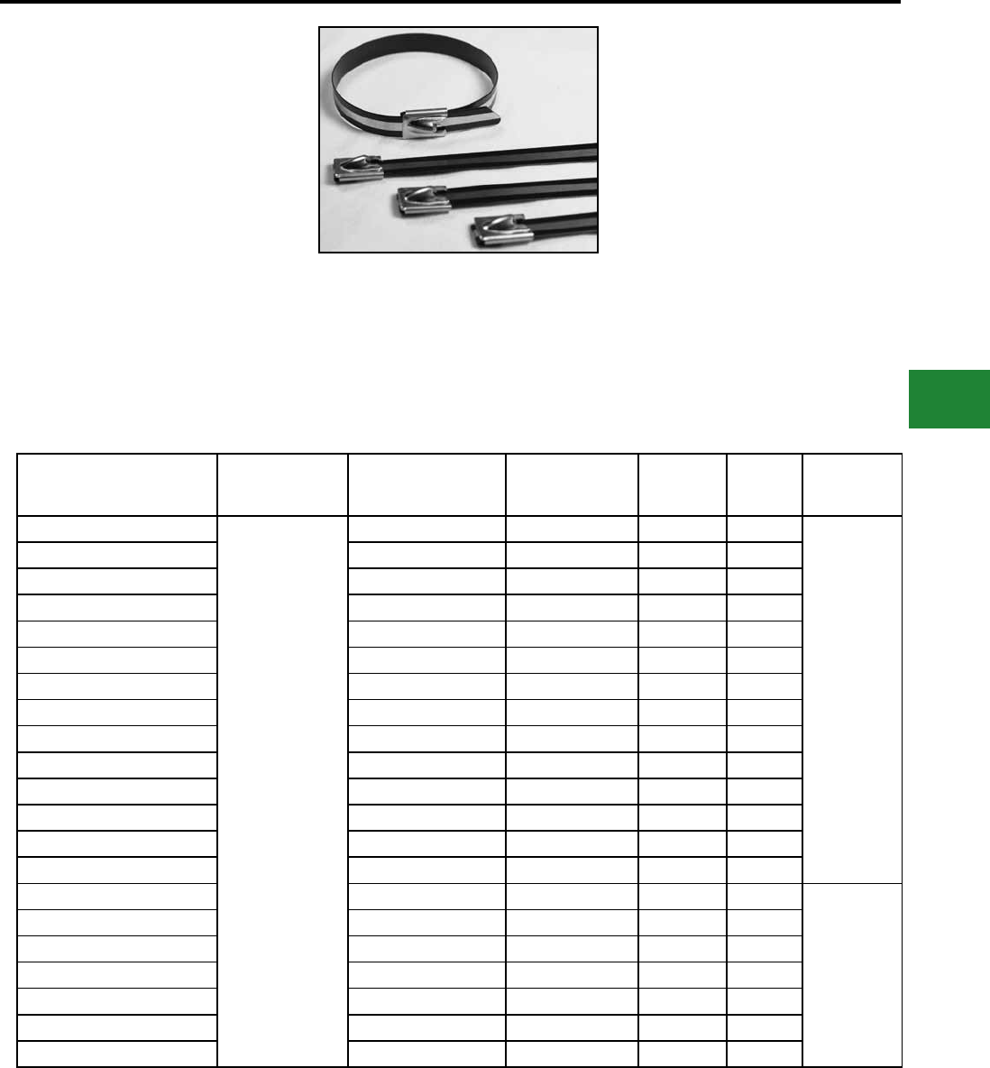
BURNDY®
Blue highlighted items are industry standard and most frequently ordered.
Canada: 1-800-387-6487 www.burndy.com US: 1-800-346-4175
Cable Ties
Catalog Number Material Max Bundle Diameter
Inches [mm]
Tensile Strength
Lbs. (N)
Length
Inches [mm]
Width
Inches
[mm]
Installation
Tool
CTSS250200PC316L
316 Stainless Steel
1.97 [50] 270 (1201) 7.87 [200] 0.31 [7.9]
CTTSS900
MK9SST
CTSS250300PC316L 3.00 [76] 270 (1201) 11.81 [300] 0.31 [7.9]
CTSS250400PC316L 4.02 [102] 270 (1201) 15.75 [400] 0.31 [7.9]
CTSS250500PC316L 5.04 [128] 270 (1201) 19.68 [500] 0.31 [7.9]
CTSS250600PC316L 6.06 [154] 270 (1201) 23.62 [600] 0.31 [7.9]
CTSS250700PC316L 7.09 [180] 270 (1201) 27.56 [700] 0.31 [7.9]
CTSS250800PC316L 8.11 [206] 270 (1201) 39.37 [1000] 0.31 [7.9]
CTSS450200PC316L 1.97 [50] 450 (2002) 7.87 [200] 0.50 [12.7]
CTSS450300PC316L 3.00 [76] 450 (2002) 11.81 [300] 0.50 [12.7]
CTSS450400PC316L 4.02 [102] 450 (2002) 15.75 [400] 0.50 [12.7]
CTSS450500PC316L 5.04 [128] 450 (2002) 19.68 [500] 0.50 [12.7]
CTSS450600PC316L 6.06 [154] 450 (2002) 23.62 [600] 0.50 [12.7]
CTSS450700PC316L 7.09 [180] 450 (2002) 27.56 [700] 0.50 [12.7]
CTSS450800PC316L 8.11 [206] 450 (2002) 39.37 [1000] 0.50 [12.7]
CTSS675200PC316Q 1.97 [50] 675 (3003) 7.87 [200] 0.62 [15.9]
CTTSS900
CTSS675300PC316Q 3.00 [76] 675 (3003) 11.81 [300] 0.62 [15.9]
CTSS675400PC316Q 4.02 [102] 675 (3003) 15.75 [400] 0.62 [15.9]
CTSS675500PC316Q 5.04 [128] 675 (3003) 19.68 [500] 0.62 [15.9]
CTSS675600PC316Q 6.06 [154] 675 (3003) 23.62 [600] 0.62 [15.9]
CTSS675700PC316Q 7.09 [180] 675 (3003) 27.56 [700] 0.62 [15.9]
CTSS675800PC316Q 8.11 [206] 675 (3003) 39.37 [1000] 0.62 [15.9]
Type CTSS-PC
UNIRAP™
Partially Coated 316 Cable Ties
BURNDY® Stainless Steel partially coated cable
ties (Type CTSS-PC) are designed with a steel ball
self locking mechanism. There are no sharp edges
which prevents damaged cables. These ties have
smooth, rounded edges and polyester coating
which add to the safety of the installer. High tensile
strength along with the shield of the polyester
coating offer a reliable and lasting bundling
solution.CTSS-PC ties are currently available in
black.BURNDY® stainless steel partially coated
cable ties can be used in any indoor, outdoor or
underground application.
Features & Benets
• Meet the requirements of ABS
• 316 grade stainless steel
• Available in black only
• Suitable for rigorous corrosive conditions
• Smooth, rounded edges along with the
polyester coating add to the safety of the
installer
• Self locking steel ball design speeds
installation and locks into place at any length
• Provides a strong durable method of cable
bundling
• Available in a wide range of length and width
• Comes with a benet of halogen free low
smoke polyester coating
G-25
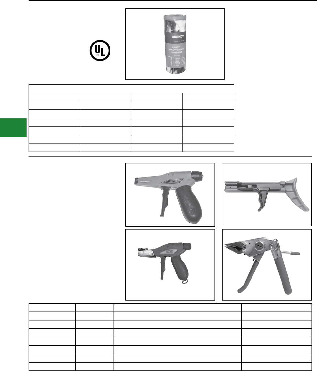
BURNDY®
Blue highlighted items are industry standard and most frequently ordered.
US: 1-800-346-4175 www.burndy.com Canada: 1-800-387-6487
Cable Ties
UNIRAP™
CABLE TIE VARIETY PACK
UL Listed
Catalog Number: CTASST
Contents
Quantity Length Color Strength
100 4"Natural 18# Strength
100 4"Black 18# Strength
100 8"Black 50# Strength
200 8"Natural 50# Strength
50 11"Natural 50# Strength
50 11"Black 50# Strength
CABLE TIE TOOLS
Ergonomics and the prevention of repetitive motion
injuries, coupled with the need to continually
improve assembly efciencies and procedures,
are a major concern with most cable tie users.
BURNDY® cable tie tools effectively address both
issues. BURNDY® has world class cable tie tools
to complement its line of high quality cable ties.
BURNDY® cable tie tools are truly state-of-the- art
in both design and performance.
BURNDY® tools make it easier for operators to
install cable ties, while maintaining correct tension
and ush cut-off. Worker safety is further enhanced
as the tools can eliminate the sharp edges of a cut-
off cable tie.
Catalog Number Ref. Figure Description For Use On
MK7 A Adjustable Tensioning Tool for Width 0.10” to 0.19” Nylon 18-50 lbs
MK9 B Adjustable Tensioning Tool for Width 0.19” to 0.35” Nylon 18-250 lbs
TWT1 C Non-adjustable Tensioning Tool for Width 0.10” to 0.19” Twist & Cut Nylon 18-50 lbs
TWT2 D Non-adjustable Tensioning Tool for Width 0.19” to 0.35” Twist & Cut Nylon 120-175 lbs
CTT50 E Adjustable Tensioning Tool for Width 0.10” to 0.19” Nylon up to 50 lbs
CTSS900 F Stainless Steel Tie Tool SS Ties up to 900 lbs
MK9SST G Stainless Steel Tie Tool SS Ties up to .5 width
A / B C / D
E / G F
G-26
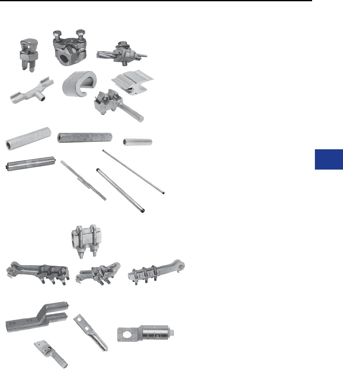
BURNDY®
Blue highlighted items are industry standard and most frequently ordered.
Canada: 1-800-387-6487 www.burndy.com US: 1-800-346-4175
Overhead Distribution
H-1
TABLE OF CONTENTS
H-3 - H-19
H-20 - H-39
H-40 - H-42
H-45 - H-48
H-48
H-49 - H-53
H-53 - H-54
H-55 - H-66
H-68 - H-69
H-70 - H-71
H-73 - H-78
TAP CONNECTORS
Mechanical (Bolted)
Compression
Transformer and Equipment
COMPRESSION SPLICES
Service Entrance
Neutral
Jumper
Repair Sleeve
Full Tension
DEADEND FITTING AND ACCESSORIES
Loop
Primary and Strain Bus
COMPRESSION TERMINALS AND
ACCESSORIES

BURNDY®
Blue highlighted items are industry standard and most frequently ordered.
US: 1-800-346-4175 www.burndy.com Canada: 1-800-387-6487
Overhead Distribution
H-2
H-25
H-26
H-27
H-28
H-29
H-30
H-31
H-31
H-32
H-33
H-34
H-35
H-35
H-36
H-37
H-38
H-38
H-39
H-40
H-41
H-41
H-42
H-42
Types YPC-A-U & YPC-R-U
Type CC
Seven Connector Selector Chart
Types YHO & YHD
Types YHN & YHR
LOKTAP™
Type YCT
Type YOT
Type YTU-R-R
Type YTA-R-2N
Types YKA-R-2N
Type YSA-R-2N
Type YTA-2N
Type YKA-2N
Type YCB-R
Types YCB-U & YCB-R-U
Types J990 & J1252
Types YHO-J, YHD-J, YHN-J
TRANSFORMER AND EQUIPMENT
Type E-C-G
Types KC2 & EQC632C
Type YA-2LH
Type YE-LH
Type YE-R, YE-W
H-3
H-4
H-5
H-5
H-6
H-6
H-7
H-8
H-9
H-10
H-11
H-12
H-12
H-13
H-13
H-14
H-15
H-16
H-16
H-17
H-18
H-19
H-20
H-21
H-21
H-22
H-23
H-24
H-25
MECHANICAL (BOLTED)
Mechanical Tap Connectors
Types KS & KS-3
Type SC
Type KSU
Type KVS
Type KVSW
Type KVSU
Type KVS-A
Type VG
Types UC-L, UC-K
Type CP-A
Type VP
Type UW-R
Type UC
Type CP
Type QPX
Type VT
Types UCG-R & UCG-RS
Types UC-R & UC-RS
Type UCT
Types UC KIT, UCCOVER1 & UCTCOVER
Type LSC
COMPRESSION
Compression Tap Connectors
Type YC-C
Type YP-C
Type YC-A
Type YP-U
Type YPC-U
Type YC-U
TAP CONNECTORS
TABLE OF CONTENTS
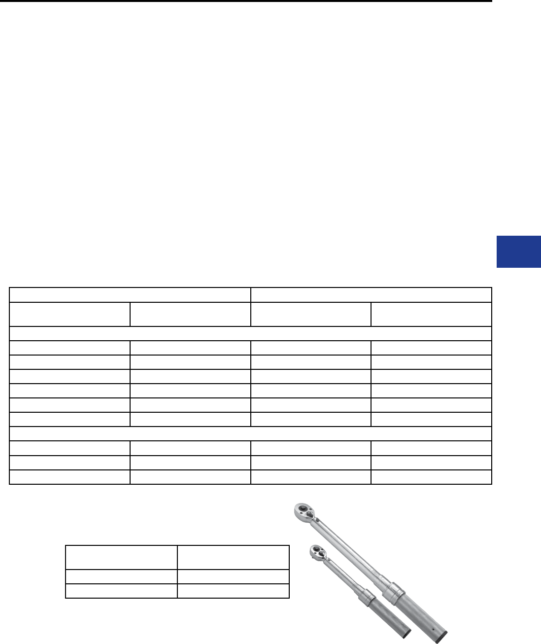
BURNDY®
Blue highlighted items are industry standard and most frequently ordered.
Canada: 1-800-387-6487 www.burndy.com US: 1-800-346-4175
Overhead Distribution
MECHANICAL (BOLTED) TAP
CONNECTORS
The BURNDY line of mechanical tap
connectors is the most complete, dependable
and economical available. These mechanical
connectors consist of service, parallel, and
midspan types.
Generally the alloys and hardware used depend
on whether the connector is for a strain or current
carrying application, and is made of aluminum
or copper. Particular alloys and hardware are
selected for strength, conductivity, durability,
ductility and resistance to corrosion.
In a copper connector, high strength alloys are
used in mechanical clamping components and
high conductivity alloy in current carrying elements.
Aluminum clamp type connectors are made of
alloy 356, which is impervious to stress corrosion.
In its heat-treated state, it has high strength and
is used for both current carrying and clamping
elements.
Hardware is high strength and corrosion-resistant.
In copper connectors, DURIUM™, a silicon bronze
alloy, is used. Anodized aluminum alloy 2024-T4
bolts and 6061-T6 nuts are used in aluminum
connectors. They provide the best combination
of strength, resistance to galling and corrosion,
and their thermal coefcient of expansion is most
suitable for aluminum. To insure dependable
connections, bolts should be tightened to the
recommended torque values shown in the specic
product table or in the table below.
These mechanical tap connectors are mainly
used in overhead distribution systems to provide
primary service taps and/or secondary service
drop connections to the end users.
A few of the key features and benets of these
connectors are:
Features and Benets
• High strength alloys
◊ Provides efcient and reliable
performance
• Range taking
◊ Accommodates a large range of
conductors in either groove reducing
inventory to a minimum
• Matched groove designs
◊ Ensures maximum contact with
conductors accommodated
• Hex bolts, nuts and washers
◊ Provides high contact pressure and
rapid assembly
Recommended Tightening Torque Standard Wrench Size
Bolt Size Recommended Torque
(Inch Lbs.) Bolt Nut
DURIUM™ and Galvanized Hardware
1/4 - 20 80 7/16 7/16
5/16 - 18 180 1/2 1/2
3/8 - 16 240 9/16 9/16
1/2 - 13 480 3/4 3/4
5/8 - 11 660 15/16 15/16
3/4 - 10 1050 1-1/8 1-1/8
Aluminum Hardware*
1/2 - 13 300 3/4 3/4
5/8 - 11 480 15/16 15/16
3/4 - 10 620 1-1/8 1-1/8
* Aluminum bolts are lubricated.
If no tightening torque is listed in the following catalog pages, use values in
table above.
Torque Range Recommended BURNDY®
Torque Wrench
30 - 150 in-lbs BTW30150
150 - 750 in-lbs BTW150750
H-3
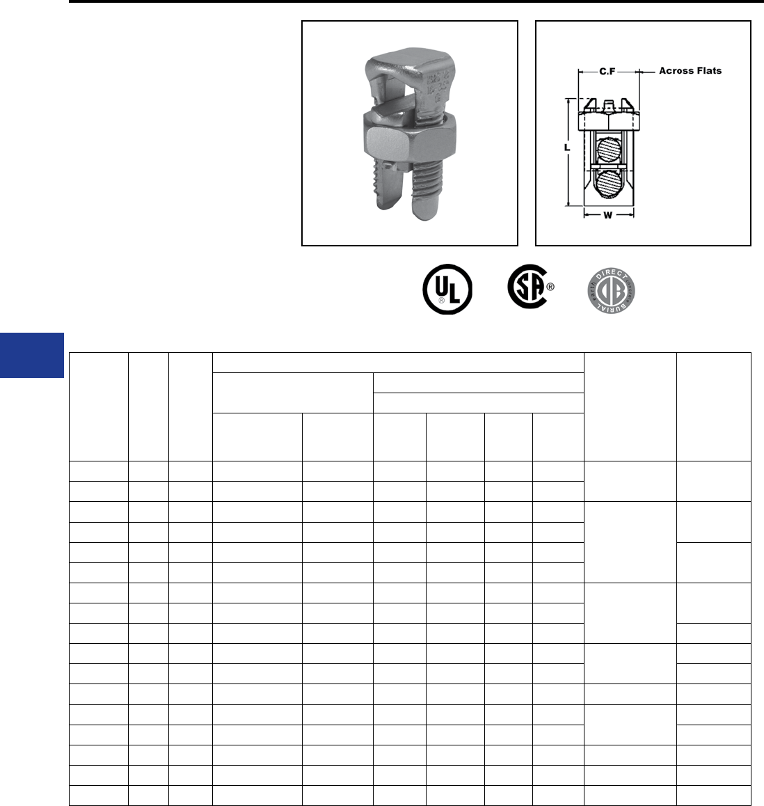
BURNDY®
Blue highlighted items are industry standard and most frequently ordered.
US: 1-800-346-4175 www.burndy.com Canada: 1-800-387-6487
Overhead Distribution
TYPES KS & KS-3
SERVIT®
ACCOMMODATES: COPPER,
COPPERWELD
MATERIAL: COPPER
Compact, high strength, high copper alloy SERVIT®
split-bolt has free-running threads and easy to grip
wrench ats. Highly resistant to season cracking
and corrosion, the SERVIT® provides maximum
pressure and assures a secure connection on
all combinations of run and tap conductors. Type
KS-3 accommodates 3 maximum size conductors.
Catalog
Number L W
Conductor
▲
Recommended
Tightening
Torque(in-lb)
Wrench Size
(across ats)
Copper Copperweld
Maximum Run and Tap
Range for Equal
Run and Tap
Min. Tap
with
Max. Run
Sol. Str. Type A Type D
† KS90 0.85 0.38 12 Str. - 10 Str. 16 Str. #10 — — — 80 1/2
† KS15 0.85 0.38 10 Str. - 8 Str. 14 Str. #8 — — —
† KS17 1.14 0.45 8 Str. - 6 Sol. 14 Str. #6 3 #12 8A 9-1/2D
165
5/8
* KS17-3 0.98 0.70 8 Str. - 6 Sol. 16 Str. #6 3 #12 8A 9-1/2D
† KS20 1.20 0.51 8 Str. - 4 Sol. 14 Str. #4 3 #10 6A 8D 11/16
* KS20-3 1.17 0.78 8 Str. - 4 Sol. 14 Str. #4 3 #10 6A 8D
† KS22 1.50 0.60 6 Str. - 2 Sol. 14 Str. #2 3 #8 4A 6D
275 3/4
* KS22-3 1.33 0.84 6 Str. - 2 Sol. 14 Str. #2 3 #8 4A 6D
† KS23 1.54 0.62 6 Str. - 2 Str. 14 Str. #1 3 #7 3A 5D 7/8
† KS25 1.77 0.73 4 Str. - 1/0 Str. 14 Str. 2/0 3 #5 2A 4D 385 1
† KS26 1.94 0.82 2 Str. - 2/0 Str. 14 Str. 3/0 7 #7 — — 1-1/16
† KS27 1.86 1.17 1 Str. - 3/0 Str. 8 Sol. — — — — 500 1-3/8
† KS29 2.07 1.17 1 Str. - 250 8 Str. 4/0 7 #5 — — 650 1-7/16
† KS31 2.51 1.41 1/0 Str. - 350 1/0 Str. — 19 #8 — — 2
† KS34 2.79 1.48 2/0 Str. - 500 2/0 Str. — 19 #6 — — 825 2-3/16
KS39 3.29 1.94 4/0 Str. - 750 4/0 Str. — 19 #5 — — 1000 2-3/8
KS44 3.73 2.19 300 - 1000 4/0 Str. — — — — 1100 2-9/16
▲ Listed torque values are for maximum conductor
combinations accommodated. Consult UL486 Tables
7-4, 7-5, 7-6 for smaller conductor combinations.
See note page A-2
* Not UL Listed or CSA Certied.
† In addition to UL Listed for wire connectors and CSA
Certied, these items are also UL rated for direct burial.
Mechanical Tap Connectors
To ensure proper tightening torque use BURNDY®
BTW Torque Wrenches.
H-4
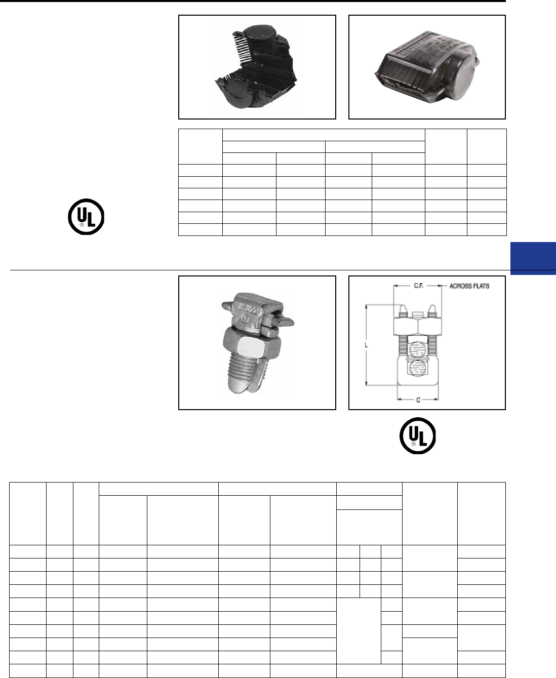
BURNDY®
Blue highlighted items are industry standard and most frequently ordered.
Canada: 1-800-387-6487 www.burndy.com US: 1-800-346-4175
Overhead Distribution
Catalog
Number
Conductor Range *For
Use
with
For
Use
with
Range for Equal Run/Tap Min. Tap/Max. Run
Min. Max. Min. Max.
SC4 8 Str. 6 Sol. 14 Str. 6 Sol. KS17 —
SC4 8 Str. 4 Sol. 14 Str. 4 Sol. KS20 —
SC2 6 Str. 2 Sol. 14 Str. 2 Sol. KS22 KSA6
SC2 6 Str. 2 Str. 14 Str. 2 Str. KS23 KSA4
SC2/0 4 Str. 1/0 Str. 14 Str. 1/0 Str. KS25 KSA2
SC2/0 2 Str. 2/0 Str. 14 Str. 2/0 Str. KS26 KSA1/0
TYPE SC
SERVIT® COVER
HUG-A-BUG
Used indoors or outdoors this compact, one-piece
plastic SERVIT® cover, saves time and material,
eliminates costly taping of split-bolts. Positive latch
snaps easily and quickly over connector, ideal
for tight quarters. Self positioning plastic ngers
wrap around wires fully insulating joint. UL Listed
for 600 volt indoor application. Three covers
accommodate a range of 6 SERVIT® sizes through
2/0 Str.
* UL Listing of Type SC Cover applies to use on
BURNDY® SERVIT® Type KS and to equivalent split-
bolt connectors indicated strip length is maintained,
TYPE KSU
UNIVERSAL SERVIT®
ACCOMMODATES: COPPER,
COPPERWELD,AAC,ACSR,
AAAC AND STEEL
MATERIAL: COPPER
(TIN PLATED)
Tin-plated, high strength copper alloy SERVIT®
with spacer. Spacer separates dissimilar
conductors and provides long contact length that
prevents high pressure point contacts between
run and tap conductors. Use of PENETROX™ 486A
Copper Only
Mechanical Tap Connectors and Covers
Catalog
Number L C
Run Tap Max. Conductor
Recommended
Tightening
Torque in-lb
Wrench Size
(across Flats)
Copper &
Aluminum ACSR / AAAC / 5005 Copper &
Aluminum ACSR/ AAAC/ 5005
Steel
Sol. 3 Str.
Nom. BWG
BWG Dia.
KSU17 0.92 0.42 12 Sol. - 6 Sol. 8 (6-1) 12 Sol. - 6 Sol. 8 (6-1) 8 — 5/32 165 5/8
KSU20 1.05 0.48 10 Sol. - 4 Sol. 6 (6-1) 10 Sol. - 4 Sol. 6 (6-1) 6 8 7/32 11/16
KSU22 1.25 0.57 10 Sol. - 2 Sol. 6 (6-1) - 4 (7-1) 10 Sol. - 2 Sol. 6 (6-1) - 4 (7-1) 4 6 1/4 275 3/4
KSU23 1.48 0.59 8 Str. - 2 Str. 3 (6-1) - 2 (6-1) 8 Sol. - 2 Str. 6 (6-1) - 2 (6-1) — 4 5/16 13/16
KSU25 1.77 0.70 2 Str. - 1/0 Str. 3 (6-1) - 1 (6-1) 10 Str. - 1/0 Str. 6 (6-1) - 1 (6-1)
—
3/8 385 15/16
KSU26 1.93 0.79 2 Str. - 2/0 Str. 1 (6-1) - 1/0 (6-1) 8 Str. - 2/0 Str. 6 (6-1) - 1/0 (6-1) 7/16 1-1/16
KSU27 2.34 1.12 1 Str. - 3/0 Str. 1 (6-1) - 2/0 (6-1) 8 Sol. - 3/0 Str. 8 (6-1) - 2/0 (6-1) 1/2 500 1-3/8
KSU29 2.50 1.58 1Str. -250 2/0 (6-1) - 4/0 (6-1) 8 Str. - 250 6 (6-1) - 4/0 (6-1) 650
KSU31 2.88 1.36 1/0 Str. - 350 3/0 (6-1) - 4/0 (6-1) 4 Str. - 350 4 (6-1) - 4/0 (6-1) 5/8 1-11/16
KSU34 3.12 1.47 400 - 500 336 (30-7) - 477 (18-1) 2 Str. - 500 2 (6-1) - 477 (18-1) — 825 1-13/16
joint compound recommended with Aluminum
and ACSR to limit oxide growth and increase life of
connection. To ensure proper tightening torque
use BURNDY® BTW Torque Wrenches.
maximum indicated conductor sizes are not exceeded,
and connector is properly located within recess
provided for it. H-5
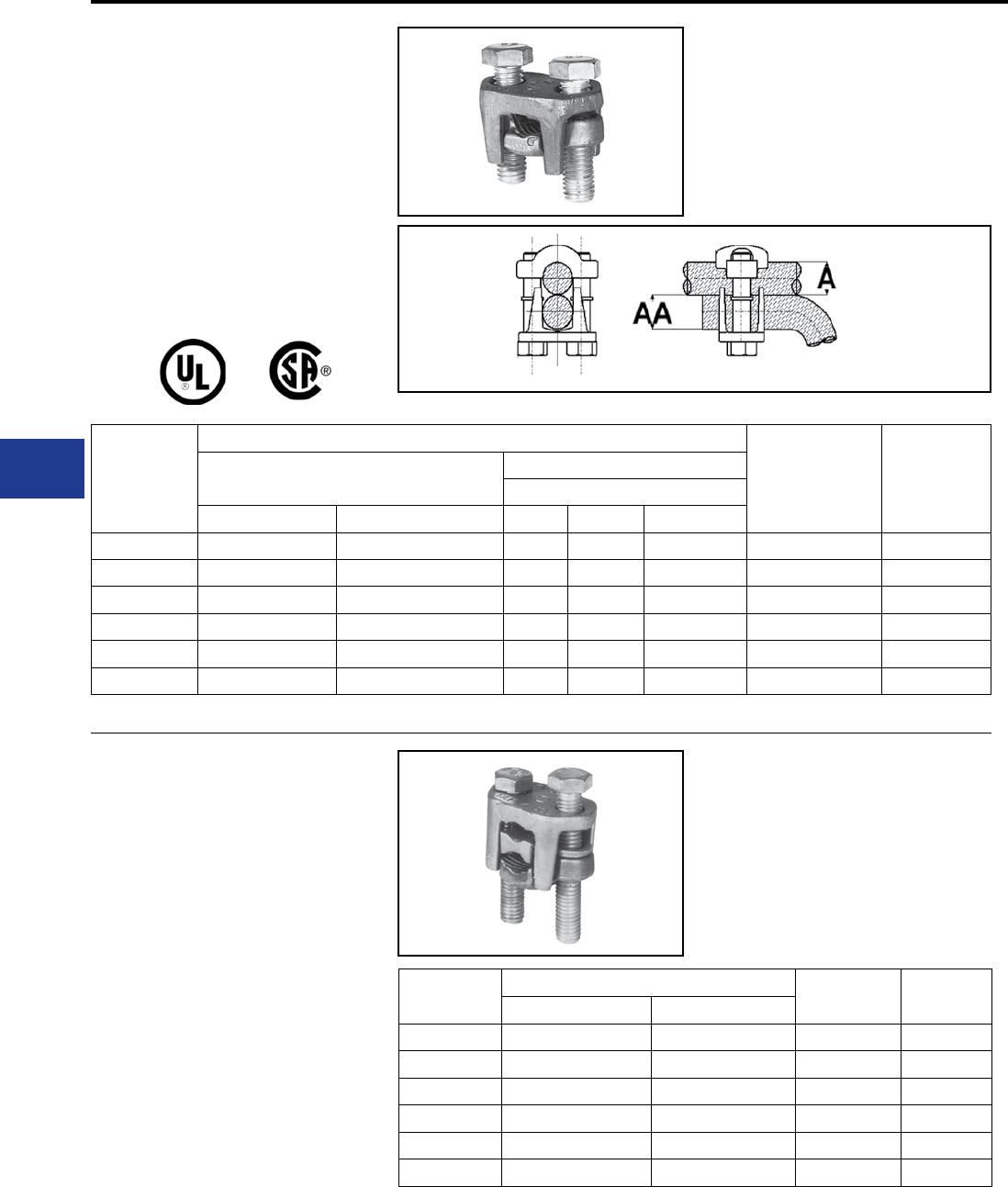
BURNDY®
Blue highlighted items are industry standard and most frequently ordered.
US: 1-800-346-4175 www.burndy.com Canada: 1-800-387-6487
Overhead Distribution
TYPE KVS
OKLIP™
ACCOMMODATES:
COPPER, COPPERWELD
MATERIAL: COPPER
Compact, two-piece, high strength; high copper
alloy BURNDY OKLIP™ recommended for heavy
duty connections.Neoprene rings hold bolts in
place during installation. Installed with ordinary
wrench.
Catalog
Number
Conductor
Recommended
Tightening Torque
(in-lb)
Wrench Size
(Cross ats)
Copper Copperweld
Max. Run & Tap
Run (A) Tap (AA) Sol. Str. Type V
KVS26 1 Str. - 2/0 Str. 6 Str. - 2/0 Str. 3/0 7 #8 — 180 1/2
KVS28 1/0 Str. - 4/0 Str. 10 Str. - 4/0 Str. 4/0 7 #6 V3/0 250 9/16
KVS31 250 - 350 kcmil 10 Str. - 350 kcmil — 19 #8 V250 325 3/4
KVS34 400 - 500 kcmil 10 Str. - 500 kcmil — 19 #6 V350 375 3/4
KVS40 400 - 800 kcmil 3/0 Str. - 800 kcmil — 19 #5 — 500 3/4
KVS44 500 - 1000 kcmil 3/0 Str. - 1000 kcmil — — — 500 15/16
TYPE KVSW
OKLIP™
ACCOMMODATES: COPPER,
COPPERWELD
MATERIAL: COPPER
Similar to OKLIP™ Type KVS except for high
copper alloy spacer that separates run and
tap conductor. Provides high contact pressure,
connes conductor strands, and assures vibration
proof connection. Longer peened bolt, permits
swivel action for easier installation.
Catalog
Number
Conductor Wrench Size
(Cross Flats)
Torque
in - lb
Run Tap
KVSW26 2 Str. - 2/0 Str. 6 Sol. - 2/0 Str. 1/2 180
KVSW28 1/0 Str. - 4/0 Str. 6 Sol. - 4/0 Str. 9/16 250
KVSW31 250 - 350 kcmil 4 Sol. - 350 kcmil 3/4 325
KVSW34 400 - 500 kcmil 4 Str. - 500 kcmil 3/4 375
KVSW40 400 - 800 kcmil 4/0 - 800 kcmil 3/4 500
KVSW44 500 - 1000 kcmil 250 - 1000 kcmil 15/16 500
Mechanical Tap Connectors
To ensure proper tightening torque use BURNDY® BTW Torque Wrenches.
To ensure proper tightening torque use BURNDY® BTW Torque Wrenches.
H-6
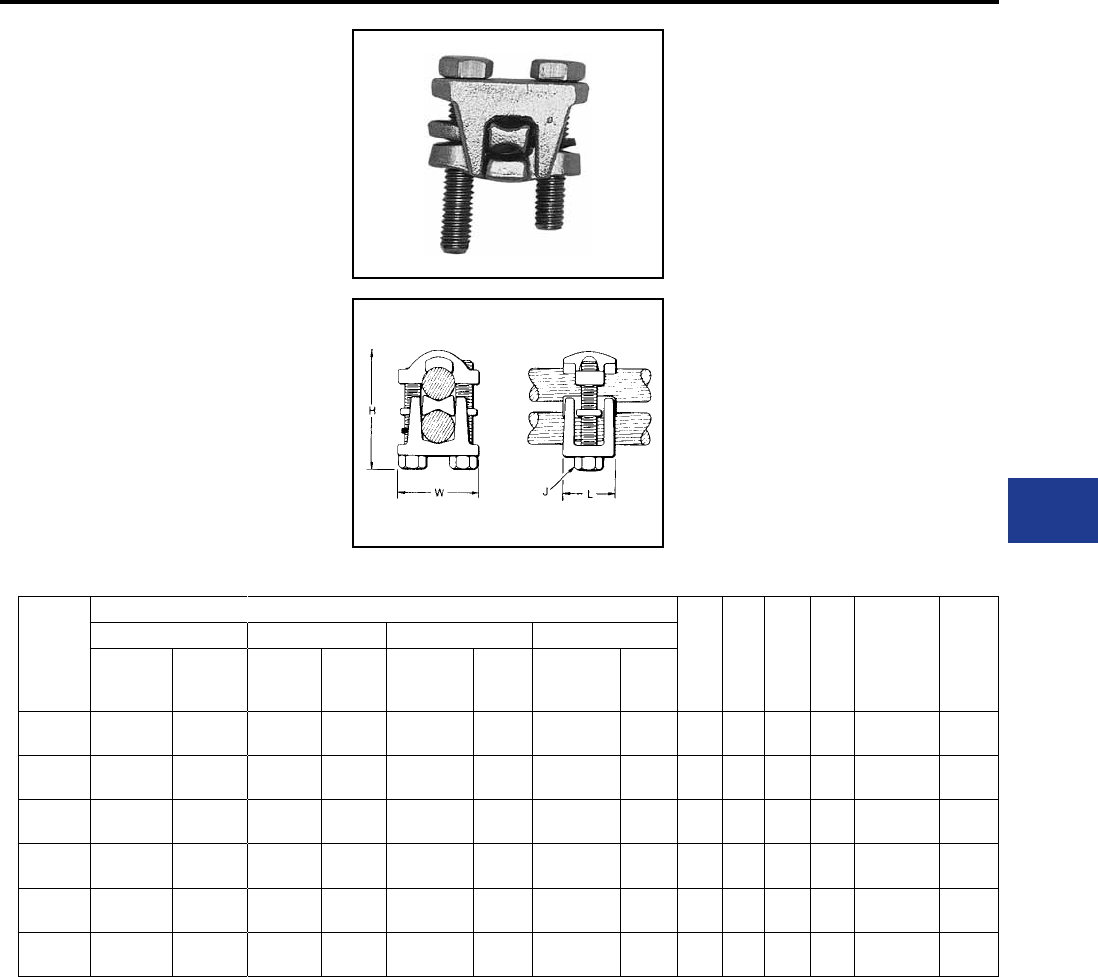
BURNDY®
Blue highlighted items are industry standard and most frequently ordered.
Canada: 1-800-387-6487 www.burndy.com US: 1-800-346-4175
Overhead Distribution
Mechanical Tap Connectors
TYPE KVSU
UNIVERSAL OKLIP™
ACCOMMODATES: COPPER,
COPPERWELD, AAC†, ACSR†, AAAC
MATERIAL: TIN PLATED COPPER
Compact, high strength, tin-plated copper alloy two-
piece connector with spacer and tin-plated silicon
bronze DURIUM™ hardware. Recommended
for heavy duty connections. Spacer separates
dissimilar conductors and provides long contact
length. Neoprene ring prevents loss of shorter bolt
during installation. Longer peened bolt permits
swivel action for easier installation.
Use of PENETROX™ joint compound
recommended with aluminum and ACSR.
Catalog
Number
Conductor
H J L W
Rec.
Tightening
Torque
(in-lb)
Wrench
Size
(Cross
Flats)
Run Tap Run Tap
Copper &
Alum.
ACSR,
AAAC, &
5005
Copper &
Alum.
ACSR,
AAAC,
& 5005
Copper Sol.,
Copperweld
Sol.
Steel
Nom.
Dia.
Copper Sol.,
Copperweld
Sol.
Steel
Nom.
Dia.
KVSU26 2 Str. -
2/0 Str.
3 -
2/0
6 Str. -
2/0 Str.
6 -
2/0 1 - 3/0 5/16 -
7/16 #6 - 3/0 3/16 -
7/16 2 5/16 1 1-1/2 180 1/2
KVSU28 1/0 Str. -
4/0 Str.
1/0 -
4/0
6 Str. -
4/0 Str.
6 -
4/0 2/0 - 4/0 3/8 -
1/2 #6 - 4/0 5/32 -
1/2 2-3/8 3/8 1-1/8 1-3/4 250 9/16
KVSU31 250 -
350 kcmil
4/0 -
300
#5 -
350
6 -
300 —9/16 -
5/8 #6 - 4/0 3/16 -
5/8 2-5/8 1/2 1-3/8 2-1/8 325 3/4
KVSU34 400 -
500 kcmil
336.4 -
397.5
#4 -
500
5 -
397.5 —3/4 -
3/4 #4 - 4/0 7/32 -
3/4 3 1/2 1-1/2 2-1/4 375 3/4
KVSU40 400 -
800 kcmil
336.4 -
715.5
4/0 -
800
3/0 -
715.5 —3/4 -
1—1/2 -
13-1/2 1/2 1-5/8 2-1/2 500 3/4
KVSU44 500 -
1000 kcmil
397.5 -
900
4/0 -
1000 kcmil
4/0 -
900 —7/8 -
1-1/8 —1/2 -
1-1/8 4 3/8 2 3 500 5/16
† Accommodates compressed conductors within diameter range.
To ensure proper tightening torque use BURNDY® BTW Torque Wrenches.
H-7
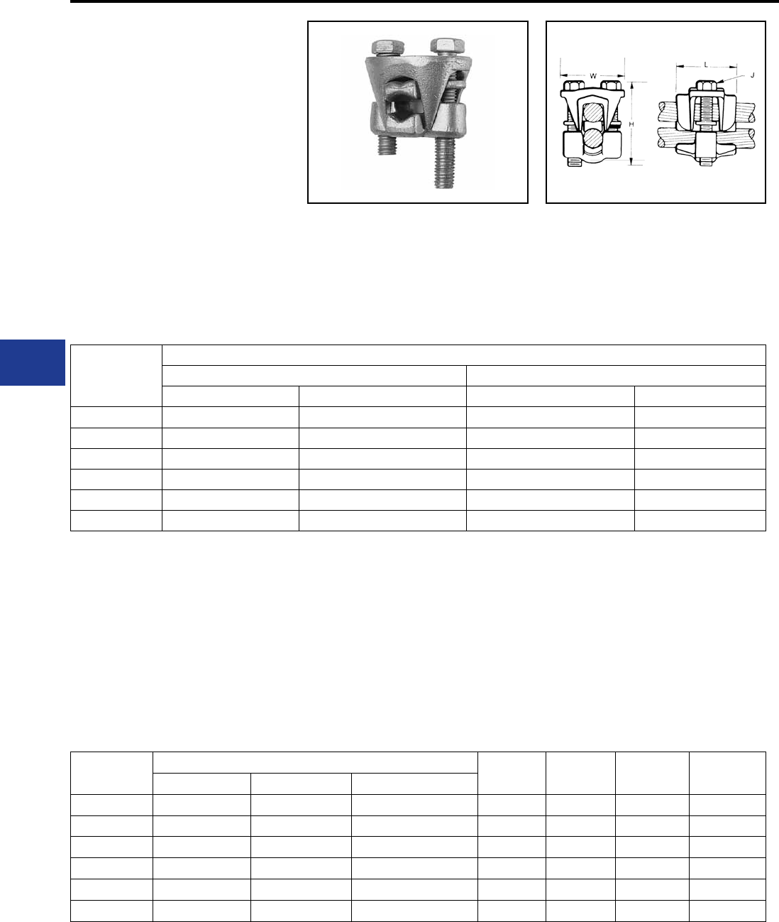
BURNDY®
Blue highlighted items are industry standard and most frequently ordered.
US: 1-800-346-4175 www.burndy.com Canada: 1-800-387-6487
Overhead Distribution
TYPE KVS-A
OKLIP™
ACCOMMODATES: COPPER,
COPPERWELD, AAC†, ACSR†, AAAC
MATERIAL: ALUMINUM
Three-piece, high-conductivity, non-copper
bearing aluminum alloy connector with thick spacer
and aluminum hardware. Hardware in KVS26A
and KVS28A is stainless steel. Recommended
for heavy duty dissimilar metal applications.
Spacer separates conductors and provides long
contact length. Belted entrances prevent chang
and permit easier assembly of conductors.
Longer, peened bolt, permits swivel action for
Catalog Number
Conductor
Run Tap
Copper & Aluminum† ACSR†, AAAC, & 5005 Copper & Aluminum† ACSR†, AAAC, & 5005
KVS26A 2 Str. - 2/0 Str. #4 - 2/0 10 Str. - 2/0 Str. #6 - 2/0
KVS28A 1/0 Str. - 4/0 Str. 1/0 - 4/0 10 Str. - 4/0 Str. #6 - 4/0
KVS31A 250 - 350 4/0 - 336.4 6 Str. - 350 kcmil #6 - 336.4 kcmil
KVS34A 400 - 500 336.4 - 397.5 4 Str. - 500 kcmil #5 - 397.5 kcmil
KVS40A 400 - 800 336.4 - 715.5 kcmil 3/0 Str. - 800 kcmil 3/0 - 715.5
KVS44A 500 - 1000 397.5 - 900 kcmil 3/0 Str. - 1000 kcmil 3/0 - 900 kcmil
Catalog
Number
Conductor Range by Diameter H J L W
Min. Run Dia. Min. Tap Dia. Max Run & Tap Dia.
KVS26A 0.28 0.11 0.44 2 5/16 1-3/8 1-5/8
KVS28A 0.36 0.11 0.56 2-3/8 3/8 1-5/8 2
KVS31A 0.56 0.18 0.68 3 1/2 2 2-5/8
KVS34A 0.72 0.21 0.81 3-3/8 1/2 2-1/2 2-5/8
KVS40A 0.72 0.47 1.03 4 1/2 3-1/8 3
KVS44A 0.80 0.47 1.16 4-1/2 5/8 3-1/2 3-3/8
easier installation. Neoprene ring prevents loss
of shorter bolt. PENETROX™ joint compound
recommended with aluminum and ACSR.
† Accommodates compressed conductors within diameter range.
To ensure proper tightening torque use BURNDY® BTW Torque Wrenches.
THESE CONNECTORS
CAN ACCOMMODATE
ACSR CONDUCTORS
OVER ARMOR ROD WITHIN
THE DIAMETER RANGE
INDICATED.
Application Over Armor Rod
Mechanical Tap Connectors
H-8
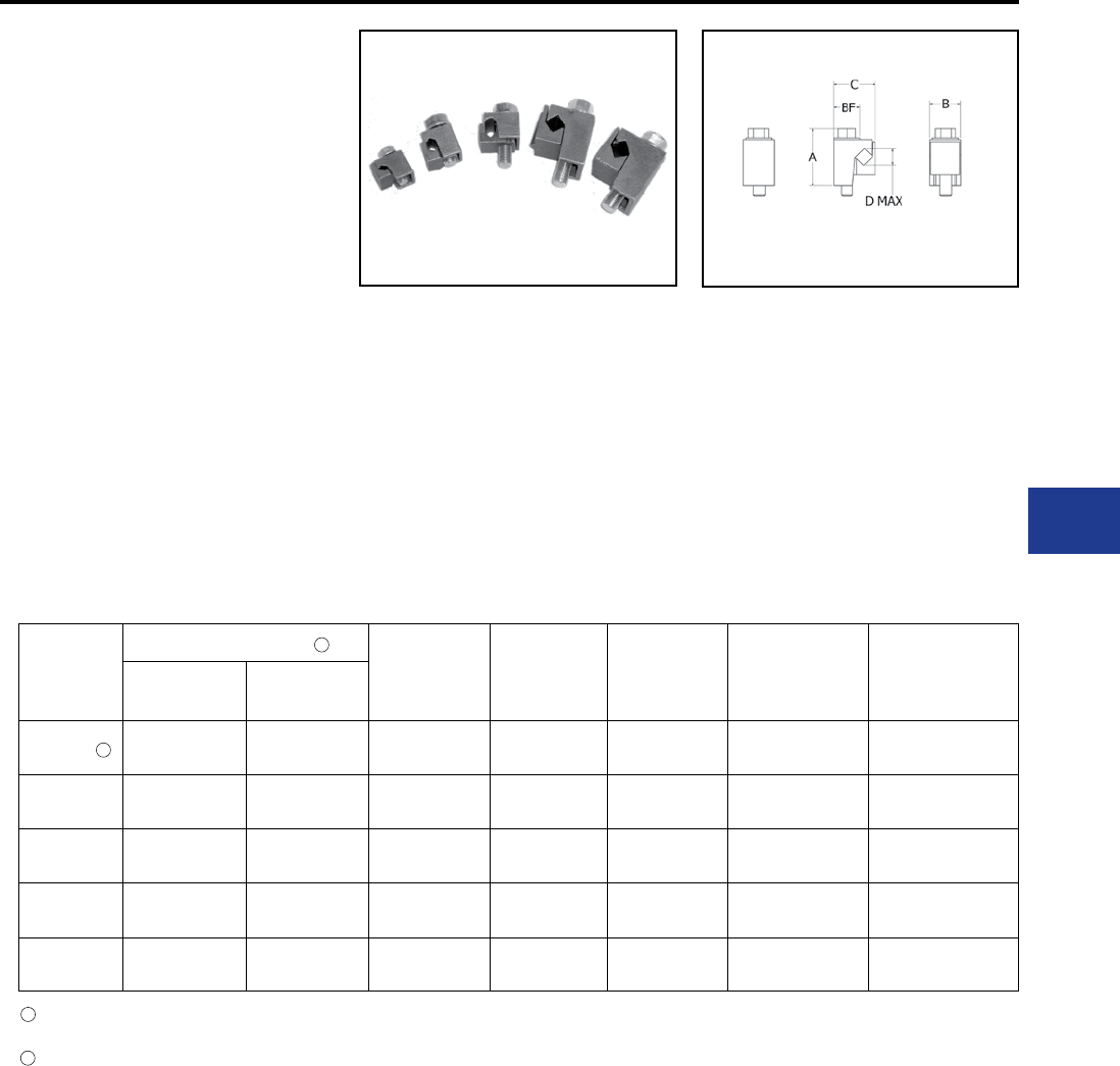
BURNDY®
Blue highlighted items are industry standard and most frequently ordered.
Canada: 1-800-387-6487 www.burndy.com US: 1-800-346-4175
Overhead Distribution
TYPE VG
VISEIT™ Connectors
ACCOMMODATES: COPPER
MATERIAL: COPPER
Copper VISEIT™ connectors are easy to install
and will not swivel. The interlocking will not rotate
out of the body. Supplied with hex head bolts, VG1
has a slotted hex bolt.
Catalog
Number
Conductor Range
A B C Bolt Head
(Hex.)
Recommended
Torque (In-Lb)
Max. 2
Conductor
Min. 2
Conductor
VG1 6 Sol. 10 Sol. 0.94" 0.63" 0.75" 3/8" (Slotted) 110 lbs/in
VG2 4 Str. 8 Str. 1.09" 0.70" 0.81" 9/16" 110 lbs/in
VG3 2 Sol. 6 Sol. 0.98" 0.83" 0.94" 9/16" 150 lbs/in
VG4 1/0 Str. 4 Sol. 1.70" 1.00" 1.33" 9/16" 180 lbs/in
VG5 2/0 Str. 3 Sol. 1.80" 0.98" 1.28" 9/16" 180 lbs/in
Features & Benets
• Single tool installation
◊ Keeps other hand free to contain
conductors.
• Compact prole after installation
◊ Facilitates laping and alignment with
conductors.
• Accomodates a wide range of conductors
◊ Minimizes number of connectors required.
• Side installation of conductors
◊ Eliminates having to seperate pieces
during installation.
• Copper alloy body design
◊ Provides combination of strength and
corrosion resistance
Connectors are capable of accepting any combination of conductors of conductors within
specied maximum range (example: VG1 can accept 7 Sol. - 9 Str. combination)
The VG1 hardware has a slotted hex. The other sizes are unslotted. Hardware is stainless steel.
1
1
2
2
Mechanical Tap Connectors and Covers
H-9
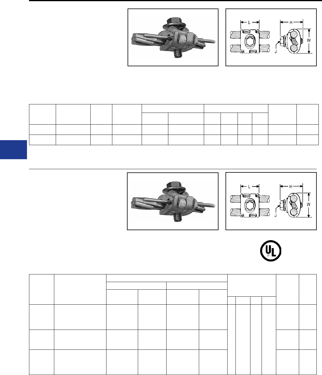
BURNDY®
Blue highlighted items are industry standard and most frequently ordered.
US: 1-800-346-4175 www.burndy.com Canada: 1-800-387-6487
Overhead Distribution
Mechanical Tap Connectors
TYPE UC-L
UNIVERSAL PARALLEL GROOVE
CLAMP
ACCOMMODATES:
COPPER, COPPERWELD,
AAC†, ACSR†, AAAC AND STEEL
MATERIAL: COPPER
(TIN PLATED)
TYPE UC-K
UNIVERSAL PARALLEL GROOVE
CLAMP
ACCOMMODATES: COPPER,
COPPERWELD, AAC, ACSR, AAAC
AND STEEL
MATERIAL: COPPER (TIN PLATED)
Catalog
Number For Use With:
Conductor Range
Dimensions Wrench
Size
(Cross
ats)
Torque
in - lb
Groove A Groove B
Maximum
Size
Minimum
Size
Maximum
Size
Minimum
Size L H J W
UCK-1UL †
Aluminum or Galvanized
Steel Strand to Copper or
Copper Bonded Steel Wire
1/0 ACSR
7/16 Galvanized
Steel Strand
#6 ACSR
2/0 Str. Copper
7/16 Copperweld,
2A Copperweld
#8 Sol.
Copper
9-1/2D
Copperweld
1 1-7/16 5/16 1-7/16
1/2 180
UCK-2UL
Aluminum or Galvanized
Steel Strand to Aluminum
or Galvanized Steel Strand
1/0 ACSR
7/16 Galvanized
Steel Strand
#6 ACSR
1/0 ACSR or
7/16 Galvanized
Steel Strand
#6 ACSR 1/2 180
UCK-3UL Copper to Copper
2/0 Str. Copper
7/16 Copperweld
2A Copperweld
#8 Sol.
Copper
9-1/2D
Copperweld
2/0 Str. Copper
7/16 Copperweld
2A Copperweld
#8 Sol.
Copper
9-1/2D
Copperweld
1/2 180
Interlocking nger design accommodates large
range of conductor sizes. Tin-plated, cast of high
copper alloy and clamped with plated steel bolt,
PENETROX™ joint compound recommended
with aluminum and ACSR.
Catalog
Number
Copper & Alum.
(Either Groove)
ACSR†,
6201,
5005
Copperweld
Steel Dimensions Wrench
(Cross ats)
Torque
in - lb
Nom. Dia. AWG L H J W
UC8W26-L 8 Sol. - 2/0 Str. 6 - 1/0 8 Sol. - 7 #7 5/32 - 7/16 8 Sol. - 4-3 Str. 1 1-1/2 5/16 1-7/16 1/2 180
UC2W28-L 2 Sol. - 4/0 Str. 3 - 4/0 3 #8 - 7 #6 9/32 - 9/16 4 - 3 Str. - 4 - 3 Str. 1-1/8 1-1/2 3/8 1-3/4 9/16 250
† Accommodates compact and compressed conductors within diameter range.
To ensure proper tightening torque use BURNDY® BTW Torque Wrenches.
Torque values are for max. conductor sizes.
Interlocking nger design accommodates large
range of conductor sizes. Tin-plated, cast of high
copper alloy and clamped with silicon bronze
DURIUM™ bolt, PENETROX™ joint compound
recommended with ACSR. Applications include
grounding for the Cable TV industry.
† Accommodates compact and compressed conductors within diameter range.
To ensure proper tightening torque use BURNDY® BTW Torque Wrenches.
Torque values are for max. conductor sizes.
H-10
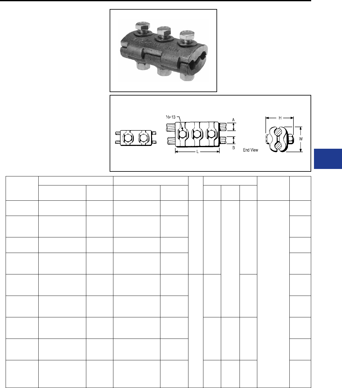
BURNDY®
Blue highlighted items are industry standard and most frequently ordered.
Canada: 1-800-387-6487 www.burndy.com US: 1-800-346-4175
Overhead Distribution
Mechanical Tap Connectors and Covers
TYPE CP-A
PARALLEL GROOVE CLAMP
ACCOMMODATES:
COPPER, COPPERWELD,
AAC†, ACSR, AAAC AND STEEL
MATERIAL: ALUMINUM (cast),
Aluminum Hardware
Type CP-A is recommended for tap or parallel
connections. High strength, high conductivity
aluminum body and hardware provide corrosion
resistant assembly. Long contact surface
insures excellent contact and full conductivity.
PENETROX™ joint compound recommended for
all combinations.
Catalog
Number
Groove A Groove B Fig.
No.
Dimensions Wrench Size
(cross ats)
Torque
in - lb
ACSR, 6201, 5005 Copper &
Aluminum ACSR, 6201, 5005 Copper &
Aluminum L H W
CP26A26A 1/0 3/0 Sol. -
2/0 Str. 1/0 3/0 Sol. -
2/0 Str.
1 4"
2-7/8"
2.13
3/4
150
CP27A27A
2/0
101.8 (12-7)
110.8 (12-7)
4/0 Sol. -
3/0 Str.
2/0
101.8 (12-7)
110.8 (12-7)
4/0 Sol. -
3/0 Str. 250
CP28A28A 3/0
134.6 (12-7) 4/0 Str. 3/0
134.6 (12-7) 4/0 Str. 250
CP29A29A
4/0
159 (12-7)
203 (8-7)
250
266.8
4/0
159 (12-7)
203 (8-7)
250
266.8 325
CP30A30A
176.9 (12-7)
190.8 (12-7)
266.8 (18-1, 6-7, 26-7)
300
176.9 (12-7)
190.8 (12-7)
266.8 (18-1, 6-7, 26-7)
300
2
4-1/2" 2.38
325
CP31A31A
211.3 (12-7)
300 (26-7, 30-7)
336.4 (18-1)
336.4
350
211.3 (12-7)
300 (26-7, 30-7)
336.4 (18-1)
336.4
350 325
CP32A32A
203.2 (16-19)
336.4 (26-7, 30-7)
397.5 (18-1)
397.5
400
203.2 (16-19)
336.4 (26-7, 30-7)
397.5 (18-1)
397.5
400
5" 3" 2.50
325
CP34A34A 397.5 (26-7, 30-7)
477 (18-1)
450
477
500
397.5 (26-7, 30-7)
477 (18-1)
450
477
500
325
CP37A37A
500 (30-7)
556.5 (24-7, 26-7, 30-7)
636 (36-1)
605 (24-7)
636
500 (30-7)
556.5 (24-7, 26-7, 30-7)
636 (36-1)
605 (24-7)
636 5-1/4" 3-3/8" 3.00 325
Fig. 1 Fig. 2
† Accommodates compact and compressed conductors within diameter range.
For other sizes contact factory.
Not recommended for copper to copper applications. Use copper connector.
To ensure proper tightening torque use BURNDY® BTW Torque Wrenches.
H-11
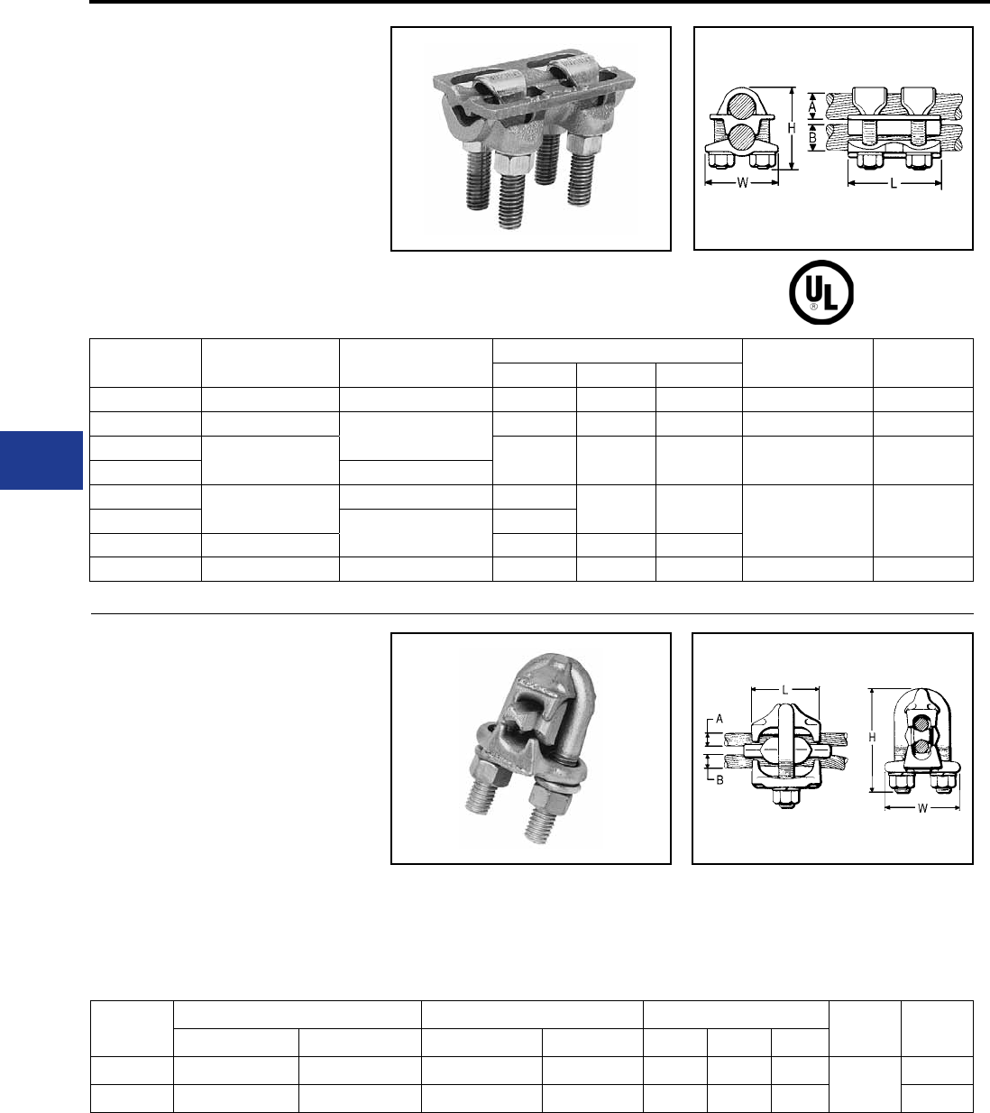
BURNDY®
Blue highlighted items are industry standard and most frequently ordered.
US: 1-800-346-4175 www.burndy.com Canada: 1-800-387-6487
Overhead Distribution
Mechanical Tap Connectors
TYPE VP
PARALLEL GROOVE CLAMP
ACCOMMODATES: COPPER
MATERIAL: COPPER
Multiple V-bolt connector especially suited for
exible or extra exible conductors.Made of high
strength, high conductivity copper. Clamping
elements accommodate a range of conductor sizes
in either groove. V-bolts provide high pressure and
Catalog
Number Groove A Groove B Dimensions Wrench Size
(Cross ats)
Torque
in - lb
L H W
VP2828 1/0 Str. - 4/0 Str. 1/0 Str. - 4/0 Str. 2-3/4" 2-1/8" 1.75" 9/16 250
VP3030 1/0 Str. - 300 1/0 Str. - 300 3-1/8" 2-1/2" 2.00" 11/16 325
VP3430 300 - 500 3-1/4" 3-1/8" 2.50" 3/4 375
VP3434 300 - 500
VP4030 500 - 800 1/0 Str. - 300 3-1/2" 4-3/8" 2.88" 7/8 500VP4040 500 - 800 3-3/4"
VP4440 750 - 1000 3-7/8" 5" 3.19"
VP4646 1000 - 1500 1000 - 1500 4-1/2" 5-3/8" 3.50" 15/16 600
TYPE UW-R
CLIPIT™
DEAD END CLAMP
ACCOMMODATES:
AAC†, ACSR†, AND AAAC
MATERIAL: ALUMINUM (Cast)
High strength aluminum casting with galvanized
steel U-bolt, extra long aluminum spacer, and
caps that conne strands. Holding strength
of installations using two CLIPIT™ deadends
Catalog
Number
Run A Tap B Dimensions Wrench Torque
in - lb
ACSR, 6201, 5005 Aluminum ACSR, 6201, 5005 Aluminum L H W
UW2R 6 - 2 6 Str. - 2 Str. 6 - 2 6 Str. - 2 Str. 1-1/2" 2-5/8" 1.82" 9/16 150
UW25R 6 - 1/0 6 Str. - 2/0 Str. 6 - 1/0 6 Str. - 2/0 Str. 1-7/8" 2-7/8" 1.98" 180
compress the conductor over long contact area.
Also recommended for jumper connections.
To ensure proper tightening torque use BURNDY® BTW Torque Wrenches.
† Accommodates compact and compressed conductors within diameter range.
To ensure proper tightening torque use BURNDY® BTW Torque Wrenches.
exceeds rated breaking strength of conductor.
Use of PENETROX™ joint compound is
recommended.
RUS Accepted
H-12
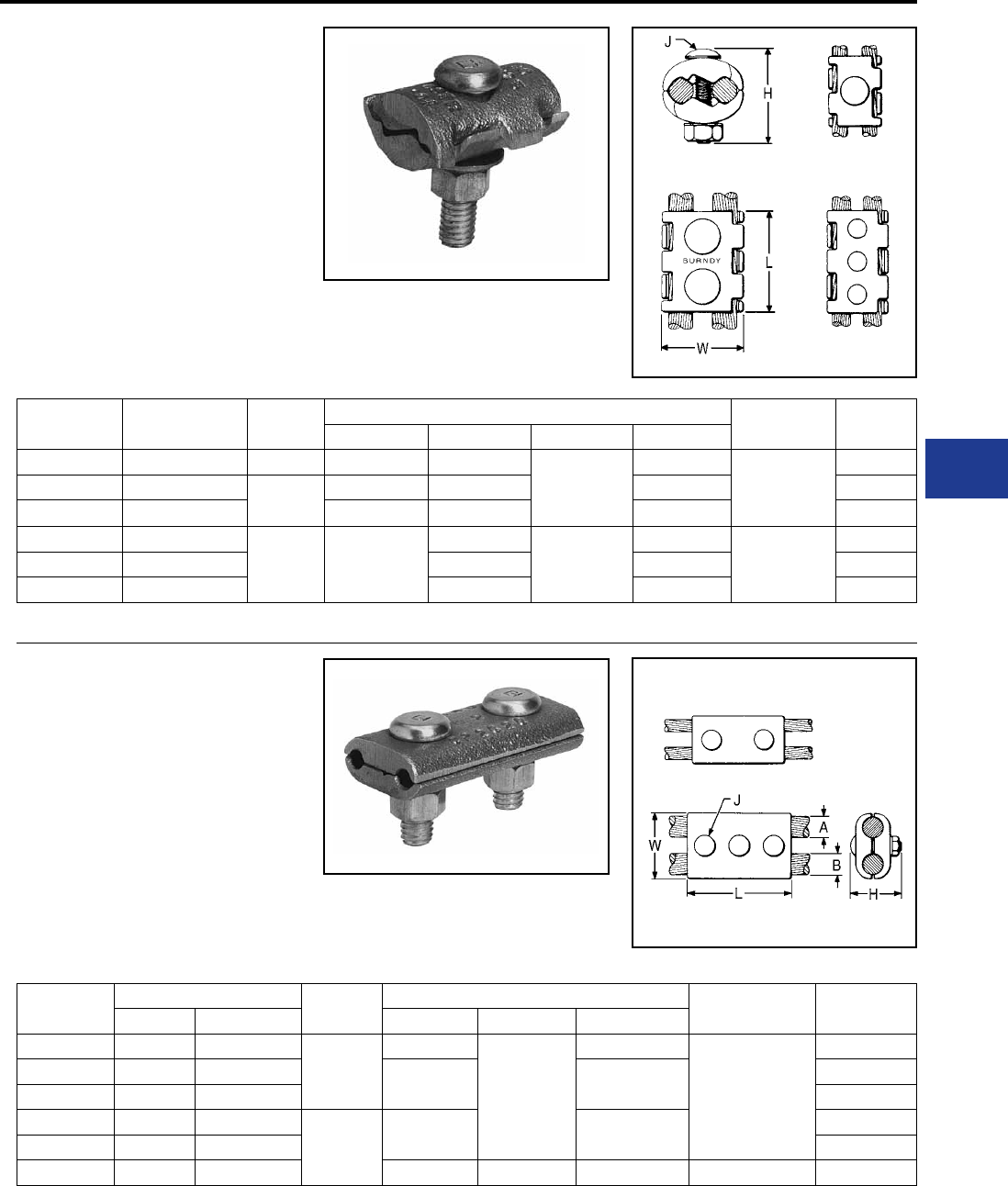
BURNDY®
Blue highlighted items are industry standard and most frequently ordered.
Canada: 1-800-387-6487 www.burndy.com US: 1-800-346-4175
Overhead Distribution
Mechanical Tap Connectors
TYPE UC
PARALLEL GROOVE CLAMP
ACCOMMODATES: COPPER
MATERIAL: COPPER
Type UC connector accommodates large range of
conductors in either groove, reducing inventory to
a minimum. Interlocking nger design provides rm
grip with maximum contact length. High strength,
corrosion resistant silicone bronze hardware. One
wrench installation.
Catalog
Number
Conductor
(Either Groove)
Figure
Number
Dimensions Wrench Size
(Cross ats)
Torque
in - lb
L H J W
UC6W25 6 Sol. - 1/0 Str. 1 1-3/4" 1-5/8"
3/8"
1-3/8"
9/16
180
UC4W28 4 Sol. - 4/0 Str. 22-1/8" 2" 1-3/4" 250
UC2W30 2 Sol. - 300 2-3/8" 2-1/8" 2" 325
UC2834 4/0 Str. - 500
3 4-1/4"
2-7/8"
1/2"
2-1/2"
3/4
375
UC3040 300 - 800 3-3/8" 3" 500
UC3444 500 - 1000 3-5/8" 3-1/2" 500
TYPE CP
PARALLEL GROOVE CLAMP
ACCOMMODATES: COPPER
MATERIAL: COPPER
High strength, high copper alloy Type CP is
recommended for heavy duty parallel connections.
Silicon bronze DURIUM™ hardware and cast
copper body provides corrosion resistant
assembly. Long contact surface provides excellent
contact and assures full conductivity.
Catalog
Number
Groove Figure
Number
Dimensions Wrench Size
(Cross ats)
Torque
in - lb
A B L J W
CP2C2C 2 Str. 2 Str.
1
2-1/2"
3/8"
1-1/4"
9/16
150
CP2525 1/0 Str. 1/0 Str. 3" 1-5/8" 150
CP2626 2/0 Str. 2/0 Str. 150
CP2828 4/0 Str. 4/0 Str.
24" 2" 250
CP2929 250 250 325
CP3434 500 500 5" 1/2" 2-1/2" 3/4 325
End View Type UC Fig. 1
Fig. 3
Fig. 2
Fig. 1
Fig. 2
To ensure proper tightening torque use BURNDY® BTW Torque Wrenches
For other sizes contact factory. To ensure proper tightening torque use BURNDY® BTW Torque Wrenches
H-13
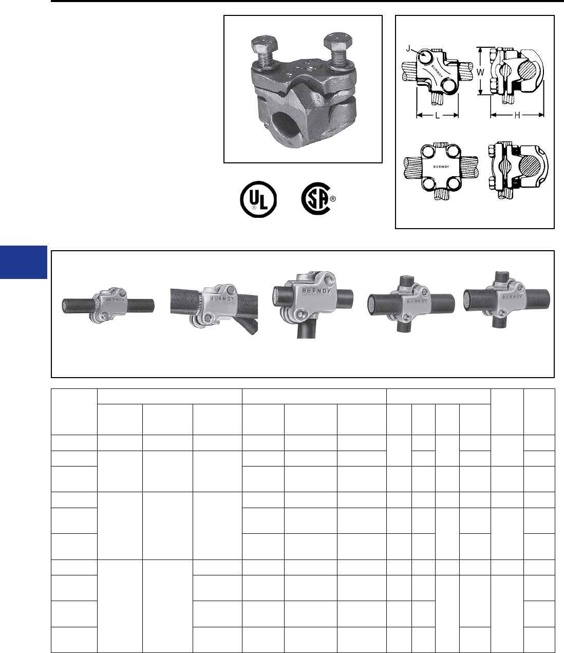
BURNDY®
Blue highlighted items are industry standard and most frequently ordered.
US: 1-800-346-4175 www.burndy.com Canada: 1-800-387-6487
Overhead Distribution
Mechanical Tap Connectors
TYPE QPX
VERSITAP™
ACCOMMODATES:
COPPER, COPPERWELD
MATERIAL: COPPER
The VERSITAP™ Type QPX is recommended for
Tee, Cross, Parallel, Butt and Tap connections.
Range-taking, only 10 connectors required to
accommodate conductor sizes from #6 Str. to
1000 kcmil. Edges are rounded for easy taping.
Made of high strength, high-conductivity copper
alloy and silicon bronze DURIUM™ hardware.
PARALLEL TAP TEE CROSS BUTT
To ensure proper tightening torque use BURNDY® BTW Torque Wrenches
Catalog
Number
Run Tap Dimensions Wrench
Size
(Cross
Flats)
Torque
in - lb
Copper
Str - RUN
Copperweld
Solid - RUN
Copperweld
Str - RUN
Copper
Str - TAP
Copperweld
Solid - TAP
Copperweld
Str - TAP L H J W
QPX2C2C 6 Str. - 2 Str. 5 Sol. - 3 #7 8A - 4A 6 Str. - 2 Str. 5 Sol. - 3 #7 8A - 4A 1-3/8 1.50 5/16 1-3/8 1/2 150
QPX282C 1 Str. - 4/0
Str. 7 #9 - 7 #5 3A - 3/0V
6 Str. - 2 Str. 5 Sol. - 3 #7 8A - 4A 2.06 1-9/16 250
QPX2828 1 Str. - 4/0
Str. 7 #9 - 7 #5 3A - 3/0V 1-7/8 2.38 3/8 1-13/16 9/16 250
QPX342C
250 - 500
kcmil 19 #19 - 19 #6 4/0 EK
6 Str. - 2 Str. 5 Sol. - 3 #7 8A - 4A 1-3/8 2.50 5/16 1-7/8 1/2 250
QPX3428 1 Str. - 4/0
Str. 7 #9 - 7 #5 3A - 3/0 V 1-3/4 2.75
3/8
2-1/16
9/16
250
QPX3434 250 - 500
kcmil 19 #19 - 19 #6 4/0 EK 2 3.00 2-3/16 250
QPX442C
500 - 1000
kcmil 19 #6
— 6 Str. - 2 Str. 5 Sol. - 3 #7 8A - 4A 1-3/8 2.63 5/16 2-1/4 1/2 250
QPX4428 —1 Str. - 4/0
Str. 7 #9 - 7 #5 3A - 3/0V 1-7/8 2.88
3/8
2-7/16
9/16
250
QPX4434 —250 - 500
kcmil 19 #19 - 19 #6 4/0 EK 2 3.06 250
QPX4444 —500 - 1000
kcmil 19 #6 — 2-5/8 3.44 2-9/16 250
H-14
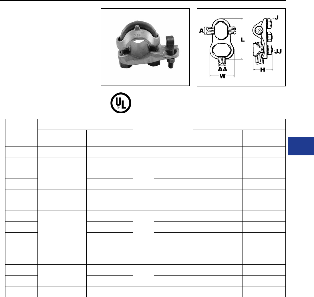
BURNDY®
Blue highlighted items are industry standard and most frequently ordered.
Canada: 1-800-387-6487 www.burndy.com US: 1-800-346-4175
Overhead Distribution
Mechanical Tap Connectors
TYPE VT
T-CONNECTOR
ACCOMMODATES: COPPER
MATERIAL: COPPER
High copper alloy T-connector for cable run, cable
tap. V-bolt clamping elements accommodate large
range of cable and are particularly suited for extra
exible cable. One-wrench installation.
Catalog
Number
Conductor
H L W
Torque Ratings
Run (A) Tap (AA) Wrench
1
Wrench
2
Torque
1
Torque
2
VT2C2C 8 AWG - 2 AWG 8 AWG - 2 AWG 1-3/8" 2-3/8" 1" 7/8 7/8 275 275
VT2525 6 AWG - 1/0
6 AWG - 1/0
1-5/8"
2-5/8" 1-1/4" 1 1 385 385
VT2825
1/0 - 4/0 AWG
3-1/8" 1-1/4" 9/16 1 250 385
VT2828 1/0 - 4/0 AWG 3-3/8" 1-3/4" 9/16 9/16 250 250
VT3025
1/0 - 300 kcmil
6 AWG - 1/0
1-7/8"
3-3/8" 1-1/8" 11/16 1 325 385
VT3030 1/0 - 300 kcmil 3-1/2" 2" 11/16 11/16 325 325
VT3425
300 kcmil - 500 kcmil
6 AWG - 1/0
2-3/8"
3-5/8" 1-1/4" 3/4 1 375 385
VT3428 1/0 - 4/0 AWG 3-1/2" 1-3/4" 9/16 3/4 250 250
VT3430 1/0 - 300 kcmil 3-5/8" 2" 3/4 1 480 385
VT3434 300 kcmil - 500 kcmil 3-3/4" 2-1/4" 3/4 3/4 480 480
VT4040 500 kcmil - 800 kcmil 500 kcmil - 800 kcmil 2-5/8" 4-3/8" 2-5/8" 7/8 7/8 600 600
VT4425
750 kcmil - 1000 kcmil
6 AWG - 1/0
2-7/8"
4-3/4" 1-1/4" 15/16 1 660 385
VT4428 1/0 - 4/0 AWG 4-1/8" 1-3/4" 15/16 9/16 660 240
VT4834 1500 kcmil - 2000 kcmil 300 kcmil - 500 kcmil 4-1/4" 5-1/4" 2-1/4" 1-1/8 3/4 1050 480
To ensure proper tightening torque use BURNDY® BTW Torque Wrenches
H-15
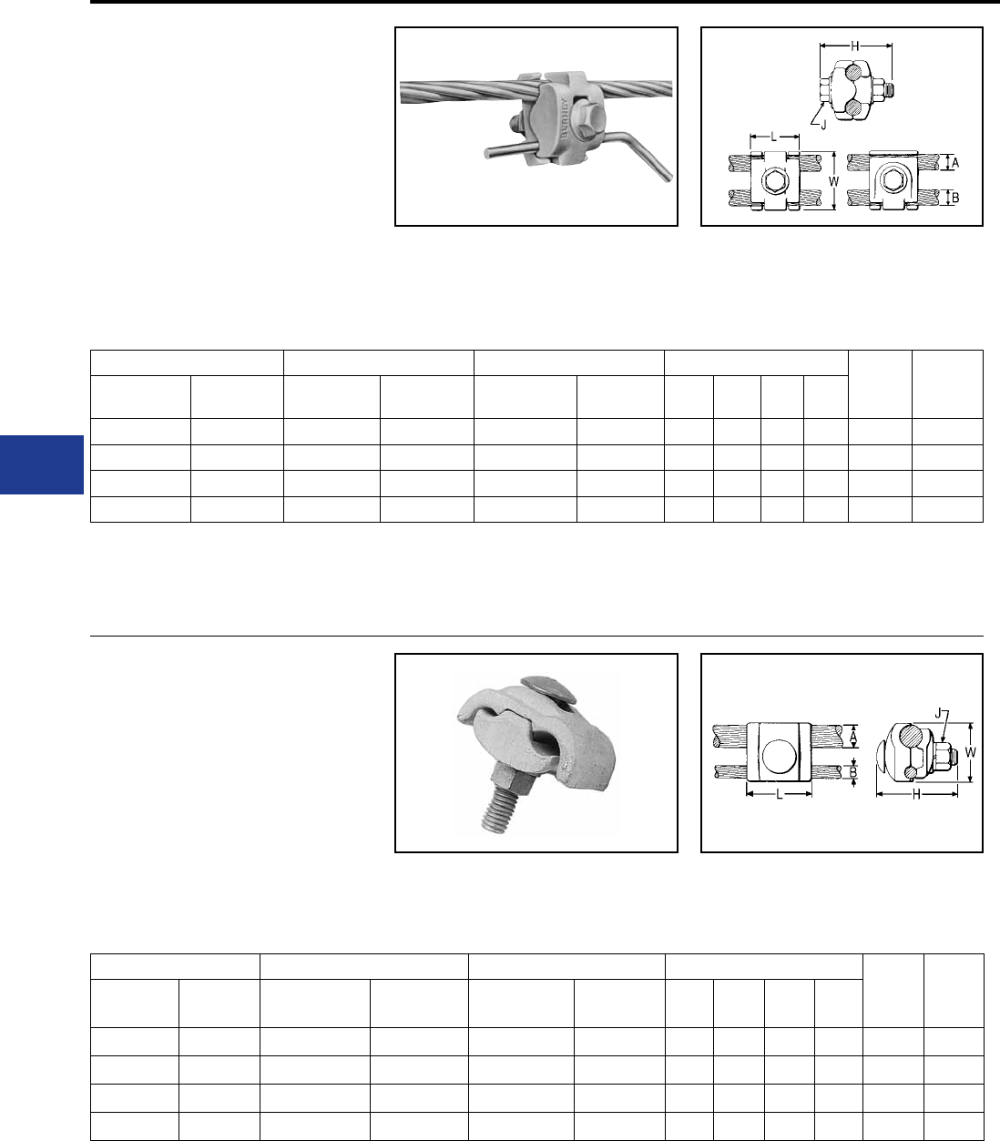
BURNDY®
Blue highlighted items are industry standard and most frequently ordered.
US: 1-800-346-4175 www.burndy.com Canada: 1-800-387-6487
Overhead Distribution
TYPES UCG-R & UCG-RS
TAPIT™ PARALLEL CLAMP
ACCOMMODATES: COPPER, AAC†,
ACSR†, AAAC
MATERIAL: ALUMINUM
Multiple purpose parallel groove clamp made
of high strength, high conductivity, non-copper
bearing aluminum alloy. Properly proportioned
to minimize stress corrosion and deterioration by
galvanic action.
Interlocking ngers on connector body halves
prevent mismatching. Square shank, hex head,
round collar, high strength galvanized steel bolt
allows one or two-wrench installation.
* Maximum recommended combinations: 1/0
Aluminum or ACSR Run - #2 Str. Copper Tap; 1/0
Copper Run - 1/0 Aluminum or ACSR Tap.
† Accommodates compact and compressed
conductors within diameter range.
TYPES UC-R & UC-RS
TAPIT™ PARALLEL CLAMP
ACCOMMODATES: COPPER, AAC†,
ACSR†, AAAC
MATERIAL: ALUMINUM
High strength, high conductivity, non-copper
bearing aluminum alloy, properly proportioned
to minimize stress corrosion and deterioration by
galvanic action.
Keying tabs on connector body halves prevent
mismatching. Square shank, high strength
galvanized steel bolt allows one wrench installation.
Also supplied pre-lled with PENETROX™ joint
compound and Stripsealed to limit oxide growth
and to increase the life of the connection.
Catalog Number Groove A Groove B Dimensions Wrench
Size
Torque
In-lb
With
Stripseal
Without
Stripseal
Copper &
Aluminum†
ACSR†,
6201, & 5005
Copper &
Aluminum†
ACSR†,
6201, & 5005 L H J W
UCG25R2RS** UCG25R2R** 6 Sol. - 1/0 Str. 8 Str. - 1/0 Str. 6 Sol. - 2 Str. 8 - 2 1-1/8″ 1-7/8″ 5/16″ 1-3/8″ 1/2 180
UCG25RS UCG25R 8 Str. - 1/0 Str. 6- 1/0 8 Str. - 1/0 Str. * 6 - 1/0 1-3/8″ 2-1/8″ 3/8″ 1-5/8″ 9/16 150
UCG28RS UCG28R 1/0 Str. - 4/0 Str. 1/0 - 4/0 1/0 Str. - 4/0 Str. 6 - 4/0 1-3/8″ 2-1/5″ 3/8″ 1″ 3/4 250
UCG32RS UCG32R 1/0 Str. - 397.5 1/0 - 336.4 8 Str. - 2/0 Str. 6 - 1/0 1-1/2″ 2-5/8″ 3/8″ 2-1/8″ 9/16 250
Catalog Number Groove A Groove B Dimensions
Wrench Torque
With
Stripseal
Without
Stripseal
Copper &
Aluminum†
ACSR†, 6201,
& 5005
Copper &
Aluminum†
ACSR†,
6201, & 5005 L H J W
UC25R2RS UC25R2R 8 Sol. - 1/0 Str. 6 - 1/0 8 Sol. - 2 Str. 6 - 2 1-1/8″ 1-5/8″ 5/16″ 1-3/8″ 1/2 180
UC28RS UC28R 1/0 Str.- 4/0 Str. 1/0 - 4/0 8 Sol. - 1/0 Str. 6 - 1/0 1-3/8″ 2-3/8″ 3/8″ 1-7/8″ 9/16 250
UC32RS UC32R 1/0 Str. - 397.5 336.4 6 Sol. - 2/0 Str. 6 - 1/0 1-1/2″ 2-3/8″ 3/8″ 2-1/4″ 9/16 250
— UC33R 4/0 Str. - 400 336.4 6 Sol. - 2/0 Str. 6 - 2/0 1-3/4″ 2-3/4″ 1/2″ 2-1/4″ 3/4 250
Mechanical Tap Connectors
RUS Accepted
** Supplied with galvanized steel, square shank
bolt.
Not recommended for copper to copper
applications. Use a copper connector to increase
connection life.
For proper installations use BURNDY® BTW
Toque Wrenches.
RUS Accepted
Also supplied pre-lled with PENETROX™ joint
compound and Stripsealed.
* Maximum recommended combinations: 4/0
Aluminum or ACSR Run - #2 Str. Copper Tap.
† Accommodates compact and compressed
conductors within diameter range.
Not recommended for copper to copper
applications. Use a copper connector to increase
connection life.
For proper installations use BURNDY® BTW
Toque Wrenches.
H-16
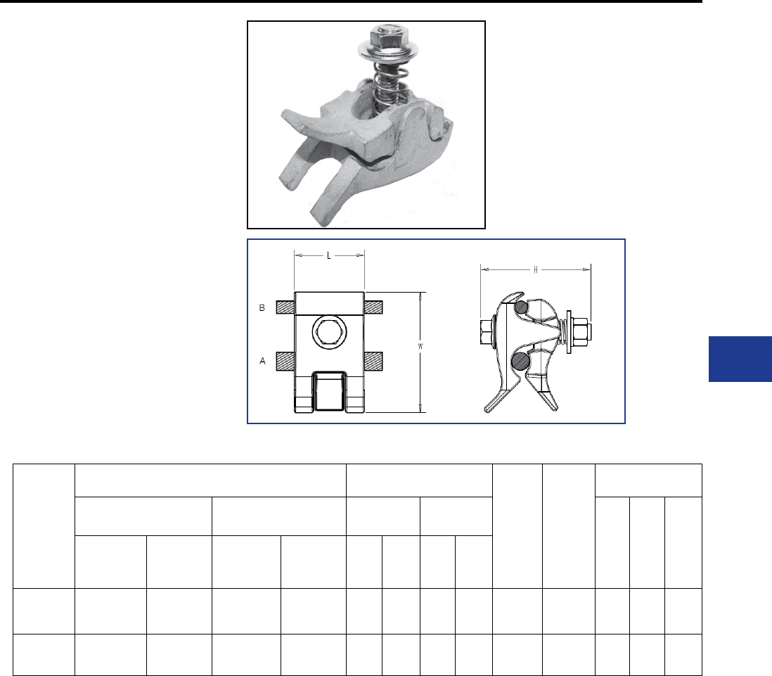
BURNDY®
Blue highlighted items are industry standard and most frequently ordered.
Canada: 1-800-387-6487 www.burndy.com US: 1-800-346-4175
Overhead Distribution
Mechanical Tap Connectors
TYPE UCT
FASTAP™ with
Lineman Assist™
ACCOMMODATES: AAC, AAAC,
ACSR, ACAR, Messenger Guy and
Copper Conductors
MATERIAL: Aluminum
Galvanized steel hardware
The BURNDY FASTAP™ with Lineman Assist™
utilizes a spring system that acts as a third hand
to assist in installation. This system helps secure
the tap conductor while installing on Primary,
Secondary, and service applications. Duck bill
handle simplies installation by providing a handle
to easily hold the connector while wearing dielectric
gloves. Conductor side entry facilitates installation
and helps keep inhibitor in the connector. Strip
sealed and prelled with PENETROX™ joint
compound to limit oxide growth and increase the
life of the connection.
Catalog
Number
Conductor Range Conductor Diameter
Torque
(in-lb)
Wrench
Size
Dimensions
Groove A (Run) Groove B (Tap) Groove A
(Run)
Groove B
(Tap)
L H W
Copper &
Aluminium
ACSR,
6201
& 5005
Copper &
Aluminium
ACSR,
6201
& 5005
Min Max Min Max
UCT26RS 8 Sol - 2/0
Str
6 Str - 2/0
Str
8 Sol - 2/0
Str
6 Str - 2/0
Str 0.13 0.45 0.13 0.45 250 9/16 1.62 2.62 2.50
UCT32RS 1 Sol - 400 2 Str-
336.4
8 Sol - 4/0
Str
6 Str- 4/0
Str 0.29 0.73 0.13 0.56 250 9/16 1.62 2.62 2.82
Remove “S” for no PENETROX™
Add “SS” for stainless steel hardware
Add “C” to include a cover
Add “HN” for shear nut
Cover may be ordered separately (UCTCOVER)
— Not recommended for Copper to Copper applications; use
copper connector
To ensure proper tightening torque, use BURNDY® BTW Torque
Wrenches.
H-17
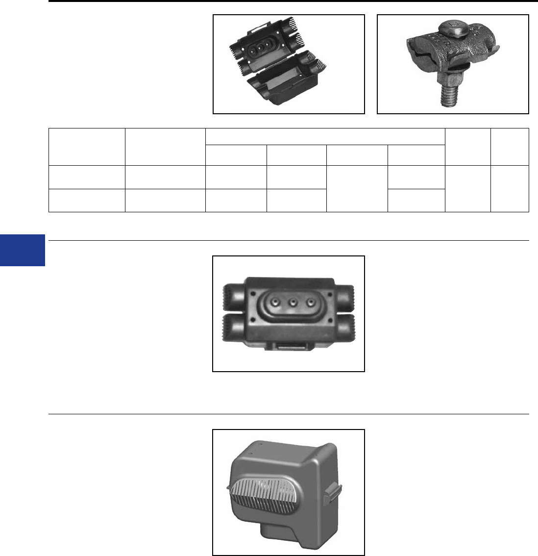
BURNDY®
Blue highlighted items are industry standard and most frequently ordered.
US: 1-800-346-4175 www.burndy.com Canada: 1-800-387-6487
Overhead Distribution
TYPE UC KIT
UC connector accommodates a large range of
copper conductors in either groove. Kits include
connector and cover.
Catalog Number Conductor
(Either Groove)
Dimensions
Wrench Torque
L H J W
UC6W25CONKIT 6 Sol. - 1/0 Str. 1-3/4" 1-5/8"
[3/8]"
1-3/8"
9/16 240
UC4W28CONKIT 4 Sol. - 4/0 Str. 2-1/8" 2" 1-3/4"
Note: For connectors with break-away bolt contact factory.
UCCOVER1BOX25
TAPIT™ COVER
For Selected UC and UCG Tap
Connectors
High density Polyethylene cover accommodates
several sizes of UC and UCG connectors. One
piece design. Simply slip over the connector and
snap shut. Supplied in black.
UCCOVER1 for use with:
UCG25R2RS
UCG25RS
UCG28RS
UC25R2RS
UC28RS
UC6W25
UCG25R2R
UCG25R
UCG28R
UC25R2R
UC28R
UC4W25
Mechanical Tap Connectors and Covers
UCTCOVER
FASTAP™ COVER
For Selected UCT and UCG Tap
Connectors
High density Polyethylene cover accommodates
all FASTAP™ connectors and select UCG
connectors. One piece design. Simply slip over the
connection and snap shut. Supplied in black.
UCTCOVER for use with all styles of:
UCT26RS
UCT32RS
UCG32RS
UCG26RS
H-18
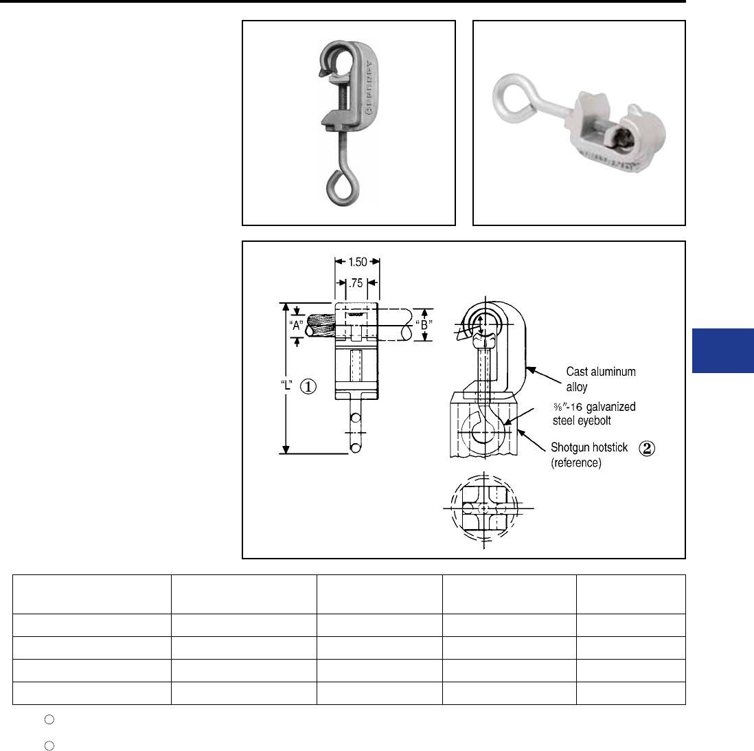
BURNDY®
Blue highlighted items are industry standard and most frequently ordered.
Canada: 1-800-387-6487 www.burndy.com US: 1-800-346-4175
Overhead Distribution
Lightning Shield Clamps
TYPE LSC
CATCHER
ACCOMMODATES:
AAC AND ACSR PRIMARY
COVERED CONDUCTOR
(TREE WIRE)
MATERIAL: ALUMINUM (cast)
Cast aluminum lightning shield clamp with a
galvanized steel eye bolt for use on covered
aluminum and ACSR primary overhead
distribution conductors (“Tree Wire”).
They are designed to protect the “Tree Wire” from
burn-down causing service interruption during
high lightning activity. For further application details
contact the factory.
Conductor groove is pre-lled with PENETROX™
A13, which is compatible with cable insulation and
individually bagged.
Catalog
Number Cable Accommodates
Cable Dia. “A” Insul. Dia. “B” (Max.) “L”
LSC1/0 1/0 Str. ACC - 1/0 ACSR 0.368 - 0.398 0.65" 4.50"
LSC1/0-1 1/0 Str. AAC - 1/0 ACSR 0.368 - 0.398 0.83" 4.50"
LSC556 4/0 Str. - 556.5 AAC 0.528 - 0.858 1.16" 5.90"
LSC556-1 4/0 Str. - 556.5 AAC 0.528 - 0.858 1.34" 5.90"
Approx. assembly length over eyebolt with cable
clamped. Also approx. eyebolt position when shipped.
Assembly can be installed using a shotgun hotstick as
shown. Assembly instructions are supplied with each
connector.
2
1
H-19

BURNDY®
Blue highlighted items are industry standard and most frequently ordered.
US: 1-800-346-4175 www.burndy.com Canada: 1-800-387-6487
Overhead Distribution
COMPRESSION TAP
CONNECTORS
The BURNDY line of compression connectors
are wide range-taking; accommodate copper,
aluminum and ACSR; are easy to install;
and are dependable and economical. They
are designed to be installed with BURNDY®
“matche” hand, hydraulic, and power-driven
hydraulic tooling. The connector line consists
of C-shaped, Figure 3, Figure 6-shaped, and
HYCRIMP™ tap connectors, disconnectable
T-taps, terminals and stirrups.
The copper CRIMPIT™ is a range-taking,
reversible, C-shaped compression tap conector
for combinations of copper conductors. Twelve
connectors take tap combinations from #10
AWG through 4/0, and all sizes are installed with
dies that also install aluminum connectors. Sizes
accommodating conductors up to #2 may be
installed with the MD6 and OUR840 family of tools.
All sizes may be installed with the Y35 or Y750
family of tools. They make “hot” installation easy
by permitting the lineman to grip the CRIMPIT™
in the compression tool and then place it on the
line. The tap is then inserted and the CRIMPIT™ is
compressed. Massive C-shape forces tap and line
conductors together to form dependable, low-cost,
low-resistance connections.
The CABLELOK™ CRIMPIT™ is a range-
taking universal and reversible, Figure 3-shaped
aluminum compression tap connector with an
adjustable spacer which separate the conductors.
It accommodates combinations of copper,
aluminum, and ACSR conductors from #6 up
to 4/0, and is installed with the common O and
D3 dies. The broad range capacity of each
CABELOK™ CRIMPIT 2 reduces the number
of connectors required and simplies connector
selection.
The spacer holds the run or tap in place permitting
the lineman either to approach the line with the
connector held in the tool and with the tap in the
connector, or to assemble the connector and tap
on the line and then bring up the tool to crimp.
Each CABELOK™ CRIMPIT™ is pre-lled with
PENETROX™ joint compound and individually
bagged. These packages are clearly marked
with the entire conductor range of the connector
as well as pertinent tooling information. The open
side of the CABELOK™ CRIMPIT™ makes “hot”
installations easy by allowing the connector to be
carried to the energized line in the crimping tool
(MD6, Y35, or Y750 families hot-line types).
The Figure 6-shaped aluminum compression
tap connector is one of the widest range-
taking compression tap connectors available.
It accommodates copper, aluminum, or ACSR
conductors in very broad ranges. Only four
connectors are required to accommodate a range
from #6 to 600 kcmil. This broad range is made
possible by the long ram stroke of the Y35 and
Y750 family of tools.
HYCRIMP™ compression tap connectors
accomodate ACSR, stranded copper or
aluminum, solid copper or aluminum, and compact
conductors. Seventeen sizes are available to
accommodate all conductors from #6 solid to 954
kcmil compact. All HYCRIMP™ connectors can be
installed with industry standard O, D, N and R dies.
Each connector is factory-lled with BURNDY®
PENETROX™ joint compound, and individually
boxed for ease of handling, identication, and
installation.
The BURNDY® line of disconnectable T-taps and
jumper loop slices offer an economical approach
to sectionalizing or isolating equipment on
energized lines. They combine the best featurres
of compression and mechanical connectors. The
pads can be easily assembled or separated from
each other with hot-line tools.
The STIRRUP™ combines a compression
C-shaped Figure 6-shaped or H-shaped element
for the run conductor, and a factory installed bail
which accommodates a hot-line clamp. The line
element can be gripped in teh tool and carried to
the line and then crimped.
Note: Aluminum bodied compression tap
connectors are not recommended for making
coper to copper connections. Two connectors
are recommended when feeding a line in both
directions.
H-20
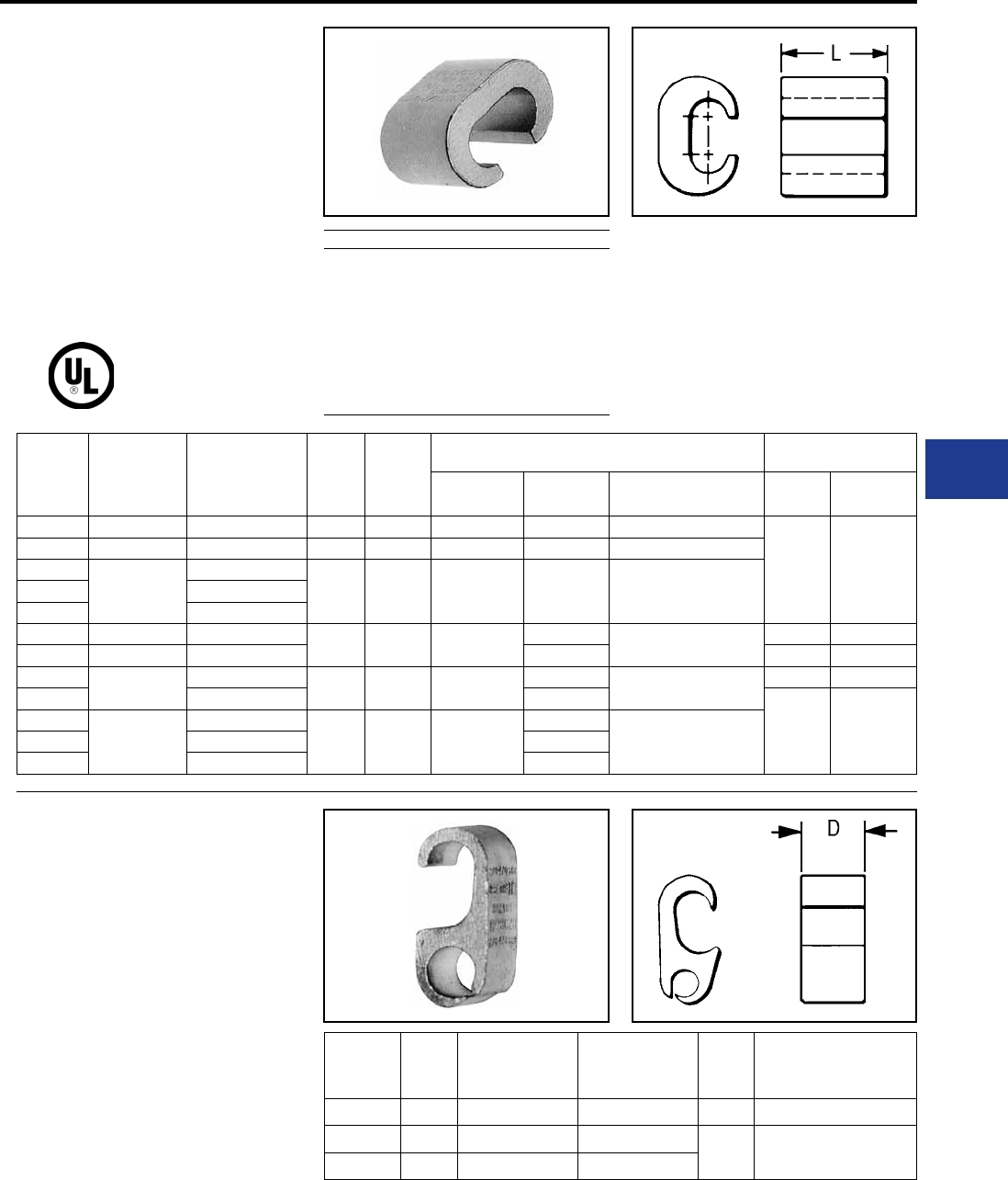
BURNDY®
Blue highlighted items are industry standard and most frequently ordered.
Canada: 1-800-387-6487 www.burndy.com US: 1-800-346-4175
Overhead Distribution
TYPE YC-C
COPPER CRIMPIT™
ACCOMMODATES: COPPER,
COPPERWELD
MATERIAL: COPPER
Range-taking compression tap connector made of
pure copper. Designed to be gripped in the jaws or
dies of installation tool, then slipped directly over
line for easy installation. Also used for deadending.
Catalog
Number Run Tap L Die
Index
Tools, Die Set Catalog Number, & (# of Crimps) CRIMPIT™ for
1 Str. Copper
MD7, MD6 OUR840 Y35, Y750, Y45 †, Y46 ‡ Run Tap
YC10C10*12 Sol. - 10 Str. 12 Sol. - 10 Str. 3/8 238 W238 (1) W238 (1) U238 (1)
— —
YC8C8 8 Sol. - 8 Str. 10 Sol. - 8 Str. 1/2 162 W162 (2) W162 (2) U162** (1)
YC4C8
6 Sol. - 4 Str.
8 Sol. - 8 Str.
5/8
BG
or
5/8
BG (2)
W-BG** (1) XBG (2) U-BG (1)
YC4C6 6 Sol. - 6 Str.
YC4C4 6 Sol. - 4 Str.
YC2C4 2 Sol. - 2 Str. 8 Sol. - 4 Str. 3/4 C W-C (2) —U-C (1) 1 Str. 6.8 Str., 8 Sol.
YC2C2 2 Sol. - 2 Str. 2 Sol. - 2 Str. — — —
YC26C2 1/0 Str. - 2/0 Str. 8 Sol. - 2 Str. 7/8 E or O — —U-E (3)
U-O (1)
1 Str. 1 or 2 Str.
YC26C26 1/0 Str. - 2/0 Str. —
— —
YC28C2
3/0 Str. -4/0 Str.
6 Sol. - 2 Str.
1-1/6 F or D3 —
—U-F (3)
U-D3** (1)
YC28C26 1/0 Str. - 2/0 Str. —
YC28C28 3/0 Str. - 4/0 Str. —
RUS Accepted
** Multiple crimp die set. Makes more than one crimp
per tool compression. Figure ( ) indicates number of
compressions.
† U Die with adapter PT-6515.
‡ U Die with adapter PUADP-1.
* Not UL Listed.
For faster installations use BURNDY® PATRIOT®
family of battery tools.
TYPE YP-C
COPPER CRIMPIT™
ACCOMMODATES: COPPER
MATERIAL: COPPER
Figure “6” -shaped, wide range-taking copper,
compression tap connector for primary service
taps and secondary service drops. Connector can
be gripped in tool and slipped over the line for easy
installation.
Catalog
Number D Run Tap Die
Index
Tools, Die Set Catalog
Number, & (# of Crimps)
Y35, Y750, Y45 †, Y46 ‡
YP2C2 0.75 6 Sol. - 2 Str. 6 Sol. - 2 Str. O U-O (1)
YP28C28 1.00 2/0 Sol. - 4/0 Str. 2/0 Sol. - 4/0 Str. D U-D3 (1)
YP29C26 0.75 1/0 Sol. - 250 4 Sol. - 2/0 Str.
† U Die with adapter PT-6515.
‡ U Die with adapter PUADP-1.
For faster installations use BURNDY® PATRIOT®
family of battery tools.
Compression Tap Large Range Taking
Copperweld-Copper Conductors
8A -
6A -
4A -
2A -
Use CRIMPIT™ accommodating 6 Str.
Copper
Use CRIMPIT™ accommodating 4 Str.
Copper
Use CRIMPIT™ accommodating 2 Str.
Copper
Use CRIMPIT™ accommodating 1/0 & 2/0
Copper
H-21
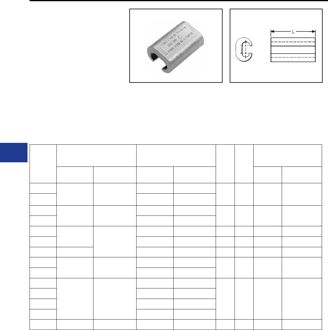
BURNDY®
Blue highlighted items are industry standard and most frequently ordered.
US: 1-800-346-4175 www.burndy.com Canada: 1-800-387-6487
Overhead Distribution
TYPE YC-A
ALUMINUM CRIMPIT™
ACCOMMODATES: AAC (STR,
COMPRESSED, COMPACT), ACSR
AND AAAC
MATERIAL: ALUMINUM
Range-taking, C-shaped aluminum compression
tap, or dead-ending connector designed to
eliminate effects of cold ow. Can be gripped in
tool and slipped over line for easy crimping. Pre-
lled with PENETROX™ joint compound and
Stripsealed to limit oxide growth and to increase
the life of the connection.
Catalog
Number
Run Tap
LDie
Index
Tools, Die Set Catalog
Number,
& (# of Crimps)
Aluminum ACSR, 6201, 5005 Aluminum ACSR, 6201, 5005 MD7, MD6 Y35, Y750,
Y45 †, Y46 ‡
YC4A6
6 Sol. - 4 Str. 6
6 Sol. & Str. —
1-1/4"
5/8
or
BG
BG (4)
W-BG (2)* U-BG (2)*
YC4A4 4 Sol. & Str. 6
YC2A4 2 Sol. & Str. 4 - 2 4 Sol. & Str. 6 1-1/2" C W-C (4) U-C (2)*
YC2A2 2 Sol. & Str. 4 - 2
YC25A4 1/0 Str. 1/0
6 Str. - 4 Str. 6 - 4 1-1/2" C W-C (4) U-C (2)*
YC25A2 2 Sol. & Str. 2 2-1/4" C W-C (6) U-C (3)*
YC25A25 1/0 Str. - 2/0 Str. 1/0 Str. - 2/0 Str. 1/0 1-3/4" Q W-Q (6)* —
YC26A25 1/0 Str. - 2/0 Str. 1/0 - 2/0 1/0 Str. 1/0 2-1/2" D** — U-D (3)
YC26A26 2/0 Str. 2/0
YC28A2
3/0 Str. - 4/0 Str. 3/0 - 4/0
6 Sol. - 2 Str. 6 - 2
2-3/4" H — U-H (3)
YC28A25 1/0 Str. 1/0
YC28A26 2/0 Str. 2/0
YC28A28 3/0 Str. - 4/0 Str. 3/0 - 4/0
YC33R26 300 - 397.5 336.4 (18-1) (26-7) 2 Str. - 2/0 Str. 2 - 1/0 1-1/2" R — U-R (2)
* Multiple crimp die set; makes more than one crimp per tool compression.
Figure indicates number of compressions.
** Index number “D” is not “D3” Cabelok CRIMPIT™ die.
† U Die with adapter PT-6515.
‡ U Die with adapter PUADP-1.
For faster installations use BURNDY® PATRIOT® family of battery tools.
Compression Tap
H-22
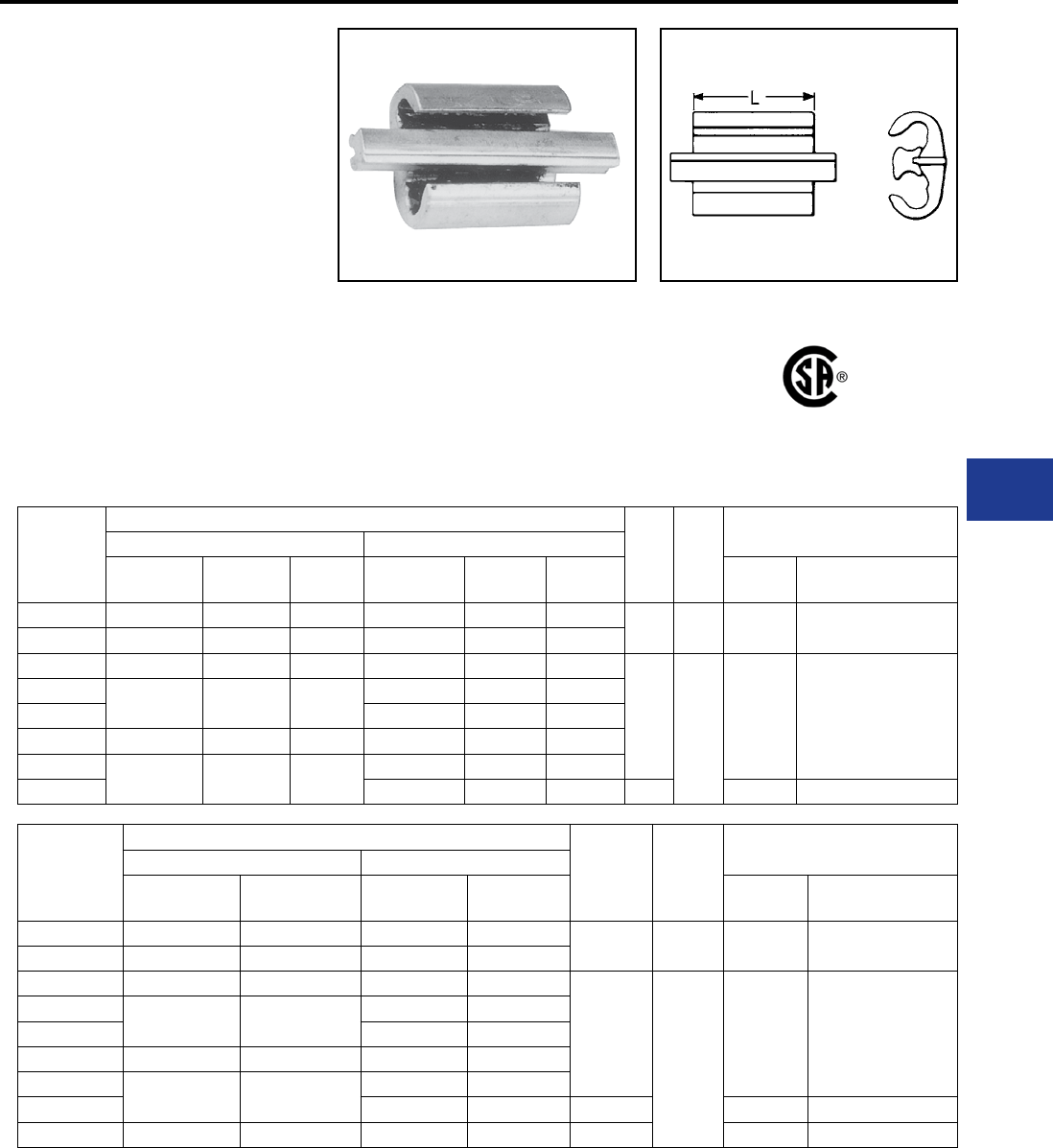
BURNDY®
Blue highlighted items are industry standard and most frequently ordered.
Canada: 1-800-387-6487 www.burndy.com US: 1-800-346-4175
Overhead Distribution
Compression Tap
TYPE YP-U
CABELOK™ CRIMPIT™
ACCOMMODATES: COPPER,
AAC (STR,COMPRESSED,
COMPACT), ACSR, AND AAAC
MATERIAL: ALUMINUM
Wide range, universal and reversible, Figure “3”
-shaped aluminum connector with adjustable
overhanging spacer that separates conductors.
Spacer holds run or tap in place permitting
lineman to either approach the line ready to crimp,
or to assemble connector and tap on run and
then crimp. Massive aluminum design minimizes
conductor corrosion due to galvanic action. Pre-
lled with PENETROX™ joint compound and
RUS Accepted
Catalog
Number
Conductor (See Chart Below for Compressed Conductor)
LDie
Index
Tools, Die Set Catalog Number,
& (# of Crimps)
Groove A Groove B
Solid Stranded ACSR Solid Stranded ACSR MD7,
MD6 Y35, Y750, Y45 †, Y46 ‡
YP2U3* 6, 4, 3 , 2 6, 4, 3 6,4 6, 4, 3 , 2 6, 4, 3 6,4 1-1/2" O W-0 (4) U-0(1)
YP26AU2 1, 1/0, 2/0, 3/0 2, 1, 1/0, 2/0 3, 2, 1, 1/0 6, 4, 3, 2, 1, 1/0 6, 4, 3, 2, 1 6, 4, 3, 2
YP25U25** 2/0, 3/0 1, 1/0, 2/0 1, 1/0 2/0, 3/0 1, 1/0, 2/0 1, 1/0
1-5/8" D3 MD6 (4) U-D3 (1)
YP27AU4 2/0, 3/0, 4/0 1,0 , 2/0, 3/0 1/0, 2/0 6, 4, 3, 2 6, 4, 3 6, 4
YP27AU2 2, 1, 1/0 3, 2, 1 4, 3, 2
YP27AU26 3/0, 4/0 2/0, 3/0 2/0 2/0, 3/0 1/0, 2/0 1, 1/0, 2/0
YP28U2 — 4/0 3/0, 4/0 2, 1, 1/0 4, 3, 2, 1 4, 3, 2
YP28U26 2/0, 3/0 1/0, 2/0 1, 1/0, 2/0 3-1/2" MD6 (9) U - D3 (2)
Catalog
Number
Compressed Conductor
LDie
Index
Tool, Die Set Catalog No.,
& (# of Crimps)
Groove A Groove B
Stranded
Aluminum ACSR Stranded
Aluminum ACSR MD7, MD6 Y36, Y750,Y45†, Y46‡
YP2U3 6, 4, 3, 2 6, 4, 3 6, 4, 3, 2 6, 4, 3 1-1/2" O W-0 (4) U-0(1)
YP26AU2 2, 1, 1/0, 2/0 2, 1, 1/0, 2,0 6, 4, 3, 2, 1 6, 4, 3, 2, 1
YP25U25 1/0, 2/0 1/0, 2/0 1/0, 2/0 1/0, 2/0
1-5/8"
D3
MD6 (4) U-D3 (1)
YP27AU4 2/0, 3/0 1/0, 2/0, 3/0 6, 4, 3 6, 4, 3
YP27AU2 3, 2, 1 4, 3, 2, 1
YP27AU26 3/0 2/0, 3/0 1/0, 2/0 , 3/0 1/0, 2/0
YP28U2 4/0, 250, 266.8 4/0, 266.8, (18/1) 3, 2, 1 4, 3, 2, 1
YP28U26 1/0, 2/0, 3/0 1/0, 2/0 3-1/2" MD6 () U - D3 (1)
YP28U28 4/0 3/0, 4/0 3/0, 4/0 3/0, 4/0 2-3/4” ─ U - D3 (2)
* TAKES UP to #2 ACSR maximum in either groove
if other wire is #2 solid or smaller.
** TAKES DOWN to #2 ACSR minimum in either
groove if other groove wire is 1/0 stranded or larger.
† U Die with adapter PT-6515.
‡ U Die with adapter PUADP-1.
Stripsealed to limit oxide growth and to increase
the life of the connection. Conductor range and
tooling information clearly printed on connector
and package.
Not recommended for copper to copper applications.
Use a copper connector to increase connection life.
For faster installations use BURNDY® PATRIOT®
family of battery tools.
H-23
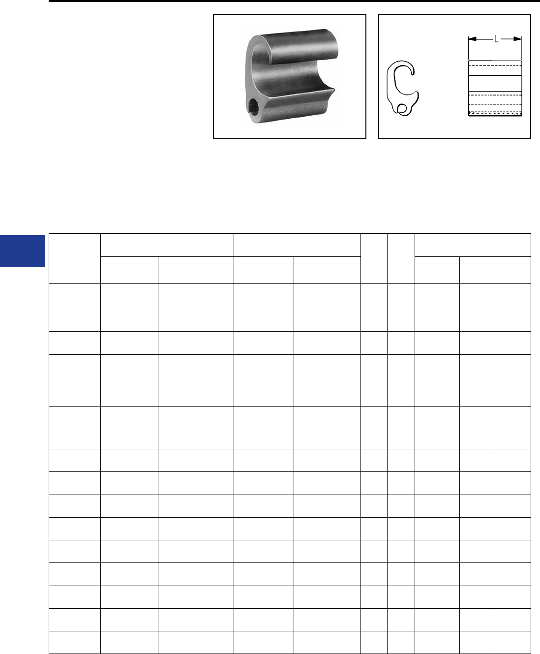
BURNDY®
Blue highlighted items are industry standard and most frequently ordered.
US: 1-800-346-4175 www.burndy.com Canada: 1-800-387-6487
Overhead Distribution
Compression Tap
TYPE YPC-U
UNIVERSAL CRIMPIT™
ACCOMMODATES: COPPER,
AAC (STR,COMPRESSED,
COMPACT), ACSR AND AAAC
MATERIAL: ALUMINUM
Extra wide range universal connector. Two dies and
5 connectors take run sizes 1/0-600, and tap sizes
6-400. Wide range made possible by long ram
travel of BURNDY HYPRESS™ tools. Figure “6”-
shape separates run and tap wires, and minimizes
galvanic corrosion of conductors. Connector can
be gripped in tool and slipped over line for easy
Catalog
Number
Run Tap
LDie
Index
Tools, Die Set Catalog
Number, & (# of Crimps)
Aluminum
& Copper ACSR, 5005 Aluminum
& Copper ACSR, 5005 Y35, Y750 Y45 † Y46 ‡
YPC28U4
3/0 - 4/0 Str.
& 4/0 - 250,
266.8 Alum.
Compressed
3/0 - 4/0 &
4/0, 266.8 (18/1)
ACSR
Compressed
6, 4, 3 Str.
6, 4, 3, 2 Sol. &
6, 4, 3 Alum.
Compressed
6, 4, 3 ACSR
Compressed 1-5/8 D3
U - D3 (1) U - D3
(1)
U - D3
(1)
YPC28U26 1/0 (7) -
4/0 (7) 1/0 - 4/0 3 Sol. - 2/0 (7) 4 - 1/0 2-3/4 D3 U - D3 (2) — —
YPC28U28
3/0 - 4/0 Str.
4/0 Sol. &
4/0, 250, 266.8
Alum.
Compressed
3/0 - 4/0 Str. &
3/0, 4/0, 266.8 (18/1)
ACSR
Compressed
2/0 - 4/0 Str.
4/0 Sol. &
3/0, 4/0, 250,
266.8 Alum.
Compressed
2/0 - 4/0 Str. &
3/0, 4/0,
266.8 (18/1) ACSR
Compressed
2-3/4 D3 U - D3 (2) U - D3
(2)
U - D3
(2)
YPC28R28A
3/0 - 4/0 Str. &
4/0 - 250, 266.8
Alum.
Compressed
3/0 - 4/0 & 4/0,
266.8 (18/1)
ACSR
Compressed
3/0 - 4/0 Str. &
4/0 Alum.
Compressed
3/0 &
4/0 ACSR
Compressed
2-3/4 D3 U - D3 (2) U - D3
(2)
U - D3
(2)
YPC33R26U 250 (37) -
400 (37)
266.8 (18-1) -
397.5 (18-1)
6 Sol. -
2/0 (19) 6 - 1/0 2-1/8 N U-N (2) S-N (2) P-N (2)
YPC33R28R 250 (37) -
477 (37)
266.8 (18-1) -
397.5 (18-1
2/0 (19) -
4/0 (19) 2/0 - 4/0 8-7/8 N U-N (3) S-N (3) P-N (3)
YPC33R33R 250 (37) -
400 (37)
266.8 (18-1) -
397.5 (18-1
250 (37) -
400 (37)
266.8 (18-1) -
397.5 (18-1) 8-7/8 N U-N (3) S-N (3) P-N (3)
YPC38R26U 477 (19) -
600 (61)
397.5 (26-7) -
556.5 (18-1)
6 Sol. -
2/0 (19) 6 - 1/0 2-1/8 N U-N (2) S-N (2) P-N (2)
YPC36A32 397.5 (19) -
600 (61)
336.5 (26-7) -
556.5 (18-1)
2/0 (7) -
400 (37)
2/0 (6-1) -
397.5 (18-1) 5 Z — S-Z (3) —
YPC36A36 397.5 (19) -
600 (61)
336.5 (26-7) -
556.5 (18-1)
397.5 (19) -
600 (61)
397.5 (26-7) -
556.5 (18-1) 6-3/4 Z — S-Z (4) —
YPC40A32 600 (61) -
800 (61)
556.6 (18-1) -
795 (26-7)
2/0 (7) -
400 (37)
2/0 (6-1) -
397.5 (18-1) 5 T — S-T (3) —
YPC40A36 600 (61) -
800 (61)
556.6 (18-1) -
795 (26-7)
397.5 (19) -
600 (61)
336.4 (26-7) -
556.5 (18-1) 5 T — S-T (3) —
YPC40A40 600 (61) -
954 (61)
556.6 (18-1) -
795 (26-7)
600 (61) -
954 (61)
556.5 (18-1) -
795 (26-7) 9-7/8 T — S-T (6) —
2/0 Str. Cu Aluminum and 2/0 ACSR may also
be installed in run when tap is 3/0 Str. or larger.
YPC28U4 only may be installed with MD6
HYTOOL™ and the BCT500HS with D3 groove.
installation. Pre-lled with PENETROX™ joint
compound and Stripsealed to limit oxide growth
and to increase the life of the connection.
† U Die with adapter PT-6515.
‡ U Die with adapter PUADP-1.
Not recommended for copper to copper
applications. Use a copper connector to increase
connection life.
For faster installations use BURNDY® PATRIOT®
family of battery tools.
H-24
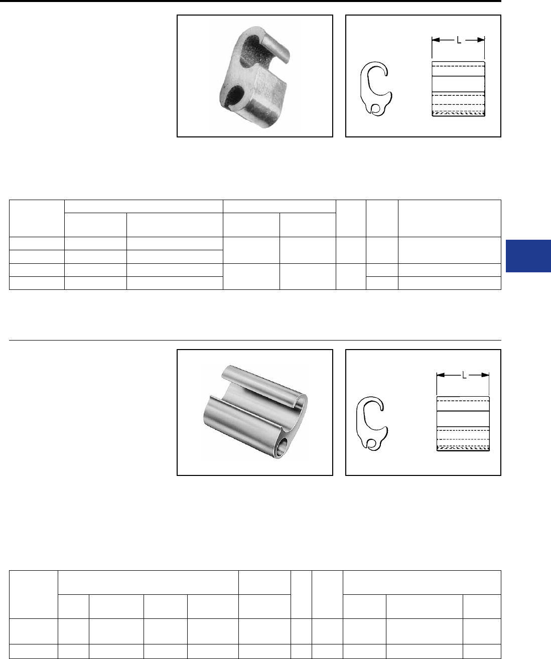
BURNDY®
Blue highlighted items are industry standard and most frequently ordered.
Canada: 1-800-387-6487 www.burndy.com US: 1-800-346-4175
Overhead Distribution
Compression Tap
TYPE YC-U
UNIVERSAL CRIMPIT™
ACCOMMODATES: COPPER,
AAC (STR, COMPRESSED,
COMPACT), ACSR AND AAAC
MATERIAL: ALUMINUM
Figure “6” -shaped, wide range-taking alum-inum
compression tap connector for smaller primary
service taps and secondary service drops. Minimizes
galvanic corrosion of conductors. Connector can
be gripped in tool and slipped over line for easy
Catalog
Number
Run Tap
LDie
Index
Tools, Die Set Catalog No.,
& (# of Crimps)
Y35, Y750, Y45 †, Y46 ‡
Aluminum &
Copper ACSR, 6201, 5005 Aluminum &
Copper
ACSR, 6201,
5005
YC4U1 4 Sol. - 4 Str. 4 6 Sol. - 1 Str. 6 - 1 Str. 1-7/8 D* U-D (2)
YC1U1 2 Str. - 1 Str. 2
YC28U26 1/0 Str. - 4/0 Str. 1/0 - 4/0 6 Sol. - 1/0 Str. 6 - 1/0 2-1/8 H U-H (2)
YC33R26U 300 - 400 266.8 (6-7) - 336.4 (30-7) R U-R (2)
installation. Installed with aluminum CRIMPIT™
dies. Pre-lled with PENETROX™ joint compound
and Stripsealed to limit oxide growth and to increase
the life of the connection.
TYPES YPC-A-U,
YPC-R-U
CRIMPIT™
STREET LIGHTING TAP
ACCOMMODATES: COPPER,
AAC (STR, COMPRESSED,
COMPACT), ACSR AND AAAC
MATERIAL: ALUMINUM
Compact compression connector designed to
tap small lighting wires from secondaries.
Figure
“6” -shape separates run and
tap, and minimizes
Catalog
Number
Run Tap
LDie
Index
Tools, Die Set Catalog Number,
& (# of Crimps)
ACSR Compressed
ACSR
Aluminum
& Copper
Compressed
Aluminum
Aluminum
& Copper MD7, MD6 Y35, Y750,
Y45 †, Y46 ‡ OUR840
YPC2A8U 6 - 4 6 - 2 4 - 2 Sol.
6 - 2 Str. 4 - 2 14 Sol. - 8 Str. 5/8 BG
or 5/8
BG (1)
W-BG (1)* U-BG (1) XBG
YPC26R8U 2 - 3/0 1 - 3/0 1 - 3/0 1/0 - 3/0 14 Sol. - 8 Str. 3/4 O W-O (2) U-O (1) W-O
galvanic corrosion. Connector can be gripped in tool
and slipped over line for easier installation. Pre-lled
with PENETROX™ joint compound and Stripsealed
to limit oxide growth and to increase the life of the
connection.
* Die Index “D” is not Die Index “D3”
(CABLELOK™ & Universal CRIMPIT™ Die).
† U Die with adapter PT-6515.
‡ U Die with adapter PUADP-1.
* Multiple crimp die set, makes more than one
crimp per tool compression. Figure indicates
number of compressions.
Not recommended for copper to copper ap-
plications. Use a copper connector to increase
connection life.
For faster installations use BURNDY® PATRIOT®
family of battery tools.
Not recommended for copper to copper
applications. Use a copper connector to increase
connection life.
For faster installations use BURNDY® PATRIOT®
family of battery tools.
H-25
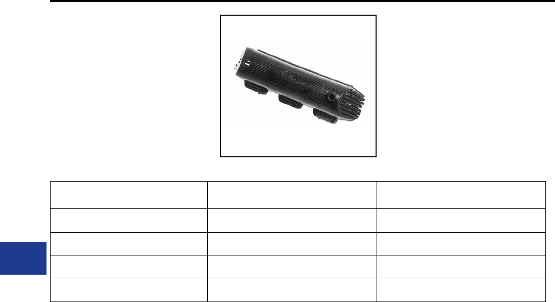
BURNDY®
Blue highlighted items are industry standard and most frequently ordered.
US: 1-800-346-4175 www.burndy.com Canada: 1-800-387-6487
Overhead Distribution
Compression Tap Covers
TYPE CC
CRIMPIT™ COVER
For All O, D and N Die Tap Connectors
High density polyethylene cover accommodates
most industry connectors in the O, D and N range.
Four sizes cover the full #6-600 kcmil conductor
range. One piece design. No extra hardware
needed. Simply slip over connector and snap shut.
Supplied in Black.
Catalog Number Maximum Connector Length Connector Series Accommodated
CCO 2-1/2 O Die
CCD 2-3/4 D Die
CCN 2-1/8 Short N Die
CCNL 5-3/16 Long N Die and YP28U26
H-26
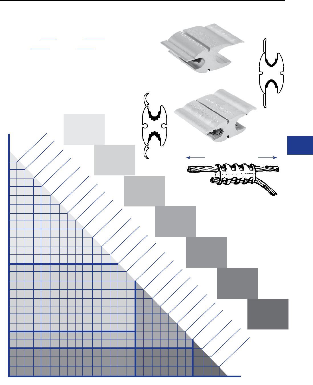
BURNDY®
Blue highlighted items are industry standard and most frequently ordered.
Canada: 1-800-387-6487 www.burndy.com US: 1-800-346-4175
Overhead Distribution
Seven Connector Selector
6 Sol.
6 ACSR
6 Str.
4 ACSR
2/0 Str.
4/0 ACSR
3 Sol.
4 Str.
1 Sol.
4 Sol.
2 Sol.
3 Str.
1 Str.
3 ACSR
2 Str.
2 ACSR
1/0 Sol.
1 ACSR
2/0 Sol.
1/0 Str.
1/0 ACSR
3/0 Sol.
2/0 ACSR
3/0 Str.
3/0 ACSR
4/0 Str.
1
2
3
5
4
67
YHO100
YHO1
(Zone 1)
YHO150
YHO2
(Zone 2)
YHD200
YHD3
(Zone 3)
YHD300
YHD4
(Zone 4)
YHD250
YHD5
(Zone 5)
YHD400
YHD7
(Zone 7)
3 Simple Selection Steps for BURNDY® HYCRIMP™
and LOKTAP™ Compression Tap Connectors:
1. Follow down from the smaller wire.
2. Go across from the larger wire.
3. Intersection of the two shows the proper connector.
Example:
#2 ACSR to #1/0 Stranded would fall in Zone 2; Catalog
Number: YHO150 (HYCRIMP™) or YHO2 (LOKTAP™)
Crimp Center Out
HYCRIMP™
LOKTAP™
NOTE:
The PATMD68LI (Lithium-Ion
battery), PATMD6814V (Nickel-
Metal Hydride battery) or the
MD6-8 hand-operated tool all
YHD350
YHD6
(Zone 6)
feature permanent “O”
and “D3” die grooves
to crimp all connectors
on this page!
H-27
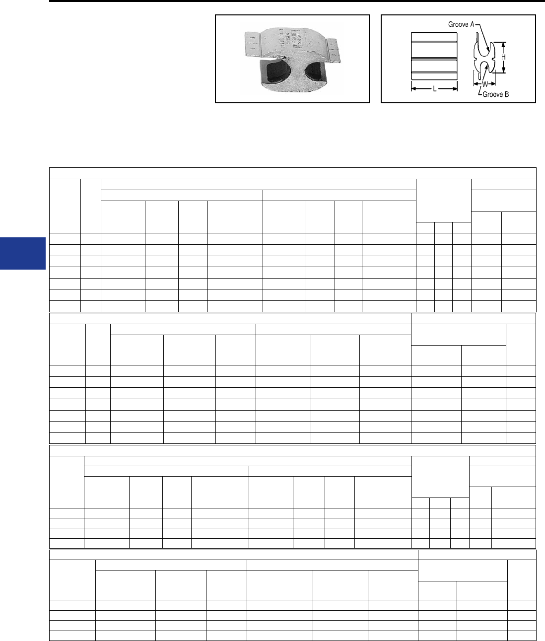
BURNDY®
Blue highlighted items are industry standard and most frequently ordered.
US: 1-800-346-4175 www.burndy.com Canada: 1-800-387-6487
Overhead Distribution
TYPES YHO & YHD
HYCRIMP™
Accommodates: Aluminum
(STR,Compressed, Compact) Copper,
ACSR, AAAC and Steel
Material: Aluminum
Wide range, universal and reversible gure H
shaped aluminum connector. Conductors are
separated by the shape of the connector. Bendable
RUS Accepted
tabs secure both run and tap conductors freeing
the lineman’s hands to work with the installation
tool. Massive aluminum design minimizes
corrosion due to galvanic corrosion. Prelled with
PENETROX™ joint compound and strip sealed
to limit oxid growth and increase the life of the
connection. Individually packaged and conductor
ranges and tooling clearly printed on connector
and package.
Handtool or Hydraulic 4 Connector Program
Catalog
Number
Conductors (See Below for Compact Conductors)
Dimensions
Installation Data
Groove A (Run) Groove B (Tap) Tool, Die Set Cat.
No. & (# of Crimps)
Wire Dia.
Range Sol. Str. ACSR Wire Dia.
Range Sol. Str. ACSR MD78
MD68
Y35, Y750,
Y45†, Y46‡
H L W
YHO-125 — #6 - 2/0 #6 - 1/0 6 (6/1) - 1/0 (6/1) — #6 - 1/0 6 - 1/0 #6 (6/1) - #2 (7/1) 1.15 1.62 0.70 O —
YHD-250 0.475 - 0.563 250 - 300 4/0 3/0 (6/1) - 4/0 (6/1) 0.162 - 0.332 #6 - 1/0 6 - 1/0 #6 (6/1) - #2 (7/1) 1.47 1.62 0.89 D3 UD3 (2)
YHD-350 0.461 - 0.563 250 - 300 3/0 - 4/0 3/0 (6/1) - 4/0 (6/1) 0.338 - 0.447 2/0 - 3/0 2/0 - 3/0 #1 (6/1) - 2/0 (6/1) 1.42 2.25 0.89 D3 UD3 (3)
YHD-400 0.461 - 0.563 250 - 300 3/0 - 4/0 3/0 (6/1) - 4/0 (6/1) 0.461 - 0.563 4/0 4/0 3/0 (6/1) - 4/0 (6/1) 1.40 2.50 0.84 D3 UD3 (3)
Compact Conductors Installation Data
Catalog
Number
Groove A (Run) Groove B (Tap) Tool, Die Set Catalog
No. & (No. of Crimps) Die
Index
Wire Diameter
Range Compact ACSR Compact
CU or AL
Wire Diameter
Range Compact ACSR Compact
CU or AL MD78
MD68
Y35, Y750,
Y45†, Y46‡
YHO-125 — #6 - 2/0 — — #6 - #1 — O — O
YHD-250 0.475 - 0.563 4/0 - 266.8 4/0 - 266 0.162 - 0.332 #6 - #1 #6 - #1 D3 UD3 (2) D3
YHD-350 0.461 - 0.563 3/0 - 266.8 4/0 - 266 0.338 - 0.447 #1 - 2/0 1/0 - 3/0 D3 UD3 (3) D3
YHD-400 0.461 - 0.563 3/0 - 266.8 4/0 - 266 0.461 - 0.563 3/0 - 266.8 4/0 - 266 D3 UD3 (3) D3
† U Die with adapter PT-6515
‡ U Die with adapter PUADP
For faster installations use BURNDY® PATRIOT
Handtool or Hydraulic 7 Connector Program
Catalog
Number
Code
No.
Conductors (See Below for Compact Conductors)
Dimensions
Installation Data
Groove A (Run) Groove B (Tap) Tool, Die Set Cat.
No. & (# Crimps)
Wire
Diameter
Range
Sol. Str. ACSR
Wire
Diameter
Range
Sol. Str. ACSR MD78
MD68
Y35, Y750,
Y45†, Y46‡
H L W
YHO-100 1 0.162 - 0.332 #6 - #1 #6 - #1 #6 (6/1) - #2 (7/1) 0.162 - 0.332 #6 - #1 #6 - #1 6 (6/1) - 2 (7/1) 1.12 1.25 0.70 (4) U-O (2)
YHO-150 2 0.260 - 0.419 #1 - 2/0 #3 - 2/0 #3 (6/1) - 1/0 (6/1) 0.162 - 0.332 #6 - 1/0 #6 - 1/0 6 (6/1) - 2 (7/1) 1.13 1.50 0.70 (5) U-O (2)
YHD-200 3 0.398 - 0.470 3/0 - 4/0 2/0 - 3/0 1/0 (6/1) - 2/0 (6/1) 0.162 - 0.332 #6 - 1/0 #6 - 1/0 6 (6/1) - 2 (7/1) 1.45 1.62 0.89 (5) UD3 (2)
YHD-250 4 0.475 - 0.563 250 - 300 4/0 3/0 (6/1) - 4/0 (6/1) 0.162 - 0.332 #6 - 1/0 #6 - 1/0 6 (6/1) - 2 (7/1) 1.47 1.62 0.89 (5) UD3 (2)
YHD-300 5 0.336 - 0.470 2/0 - 4/0 3 - 3/0 #1 (6/1) - 2/0 (6/1) 0.336 - 0.447 2/0 - 3/0 2/0 - 3/0 1/0 (6/1) - 2/0 (6/1) 1.42 1.62 0.89 (5) UD3 (2)
YHD-350 6 0.461 - 0.563 250 - 300 3/0 - 4/0 3/0 (6/1) - 4/0 (6/1) 0.338 - 0.447 2/0 - 3/0 2/0 - 3/0 1 (6/1) - 2/0 (6/1) 1.42 2.25 0.89 (7) UD3 (3)
YHD-400 7 0.461 - 0.563 250 - 300 3/0 - 4/0 3/0 (6/1) - 4/0 (6/1) 0.461 - 0.563 4/0 4/0 3/0 (6/1) - 4/0 (6/1) 1.40 2.50 0.84 (7) UD3 (3)
Compact Conductors Installation Data
Catalog
Number
Code
No.
Groove A (Run) Groove B (Tap) Tool, Die Set Catalog
No. & (# of Crimps) Die
Index
Wire
Diameter
Range
Compact ACSR Compact
CU or AL
Wire
Diameter
Range
Compact
ACSR
Compact
CU or AL MD78
MD68
Y35, Y750,
Y45†, Y46‡
YHO-100 1 0.162 - 0.336 #6 - #3 #6 - #4 - #1 0.162 - 0.268 #6 - #3 #6 - #1 (4) U-O (2) O
YHO-150 2 0.260 - 0.414 #2 - 1/0 #2 - 2/0 0.162 - 0.332 #6 - #1 #6 - #1 (5) U-O (2) O
YHD-200 3 0.398 - 0.470 2/0 - 3/0 3/0 0.162 - 0.332 #6 - #1 #6 - #1 (5) UD3 (2) D3
YHD-250 4 0.475 - 0.563 4/0 - 266.8 4/0 - 266 0.162 - 0.332 #6 - #1 #6 - #1 (5) UD3 (2) D3
YHD-300 5 0.336 - 0.470 1/0 - 3/0 1/0 - 3/0 0.338 - 0.477 1/0 - 3/0 1/0 - 3/0 (5) UD3 (2) D3
YHD-350 6 0.461 - 0.563 3/0 - 266.8 4/0 - 266 0.338 - 0.447 1- 2/0 1/0 - 3/0 (7) UD3 (3) D3
YHD-400 7 0.461 - 0.563 3/0 - 266.8 4/0 - 266 0.461 - 0.563 3/0 - 266.8 4/0 - 266 (7) UD3 (3) D3
family of battery tools.
See page H-27 for Seven Connector Selector Chart.
Permanent dies in tool install all sizes.
Not recommended for copper to copper applications.
Use a copper connector to increase connection life.
Compression Tap
H-28
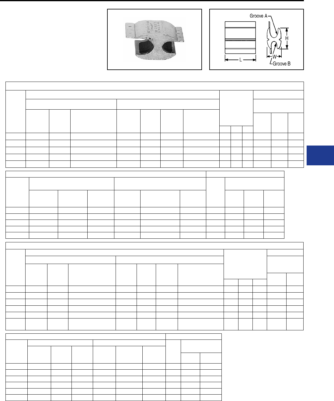
BURNDY®
Blue highlighted items are industry standard and most frequently ordered.
Canada: 1-800-387-6487 www.burndy.com US: 1-800-346-4175
Overhead Distribution
Compression Tap
TYPE YHN & YHR
HYCRIMP™
Accommodates: Aluminum (STR,
Compressed, Compact) Copper, ACSR,
AAAC and Steel
Material: Aluminum
N Die Connectors*
Catalog
Number
Conductors (See Below for Compact Conductors)
Dimensions
Installation Data
Groove A (Run) Groove B (Tap) Tool, Die Set Catalog No.
& (# of Crimps)
Wire
Diameter
Range
Str. ACSR
Wire
Diameter
Range
Sol. Str. ACSR Y35,
Y750 Y45 Y46
H L W
YHN-450 0.52 - 0.75 4/0 - 400 4/0 (6/1) - 397.5 (18/1) 0.52 - 0.75 336 - 477 4/0 - 400 266.8 (26/7) - 477 1.86 3.50 1.25 U-N (3) S-N (3) P-N (3)
YHN-500 0.52 - 0.81 4/0 - 500 4/0 (6/1) - 477.0 (18/1) 0.16 - 0.45 #6 - 3/0 #6 - 2/0 #6 (6/1) - 2/0 (6/1) 1.96 1.62 1.28 U-N (2) S-N (2) P-N (2)
YHN-525 0.52 - 0.81 4/0 - 500 4/0 (6/1) - 477.0 (18/1) 0.52 - 0.81 - 4/0 -500 266.8 (26/7) - 556.5 1.82 4.50 1.23 U-N (3) S-N (3) P-N (3)
YHN-550 0.57 - 0.81 250 - 500 266.8 (18/1) - 477.0 (18/1) 0.41 - 0.50 3/0 - 300 2/0 - 4/0 2/0 (6/1) - 266.8 1.90 2.00 1.28 U-N (2) S-N (2) P-N (2)
YHN-600 0.57 - 0.81 250 - 500 266.8 (18/1) - 477.0 (18/1) 0.57 - 0.68 336 - 400 266 - 336.4 300.0 (26/7) - 397.5 2.00 3.50 1.28 U-N (3) S-N (3) P-N (3)
Compact Conductors Installation Data
Catalog
Number
Groove A (Run) Groove B (Tap)
Die
Index
Tool, Die Set Catalog
No. & (# of Crimps)
Wire
Diameter
Range
Compressed
ACSR
Compact
CU or AL
Wire
Diameter
Range
Compressed
ACSR
Compact
CU or AL
Y35,
Y750 Y45 Y46
YHN-450 0.52 - 0.75 266.8 - 477 250 - 500 0.52 - 0.75 266.8 - 336.4 250 - 500 N U-N (3) S-N (3) P-N (3)
YHN-500 0.52 - 0.81 266.8 - 556.5 250 - 556 0.16 - 0.45 266.8 - 336.4 #6 - 3/0 N U-N (2) S-N (2) P-N (2)
YHN-525 0.52 - 0.81 266.8 - 556.5 250 - 556 0.52 - 0.81 266.8 - 336.4 250 - 556 N U-N (3) S-N (3) P-N (3)
YHN-550 0.57 - 0.81 300 - 556.5 300 - 556 0.41 - 0.56 2/0 - 266.8 3/0 - 266.8 N U-N (2) S-N (2) P-N (2)
YHN-600** 0.57 - 0.81 300 - 556.5 300 - 556 0.57 - 0.68 336.4 300 - 397.5 N U-N (3) S-N (3) P-N (3)
R Die Connectors*
Catalog
Number
Conductors (See Below for Compact Conductors)
Dimensions
Groove A (Run) Groove B (Tap) Tool, Die Set
Catalog
No. & (# of Crimps)
Wire
Diameter
Range
Str. ACSR
Wire
Diameter
Range
Sol. Str. ACSR Y45 Y46
H L W
YHR-700 .666 - .893 336 - 600 300 - 556 (18/1) .398 - .684 3/0 - 350 2/0 - 350 1/0 - 336.4 (18/1) 3.04 3.50 1.74 S-KR (3) P-KR (3)
YHR-750 .666 - .893 336 - 600 300 - 556 (18/1) .666 - .893 N/A 350 - 600 300 - 556 (18/1) 3.04 4.62 1.74 S-KR (4) P-KR (4)
YHR-800 .879 - 1.108 600 - 900 556.5 (18/1) - 795 (26/7) .398 - .684 3/0 - 350 2/0 - 350 1/0 - 336.4 (18/1) 3.05 3.50 1.74 S-KR (3) P-KR (3)
YHR-850 .879 - 1.108 600 - 900 556.5 (18/1) - 795 (26/7) .666 - .893 N/A 350 - 600 300 - 556 (18/1) 3.04 4.62 1.74 S-KR (4) P-KR (4)
YHR-900 .879 - 1.108 600 - 900 556.5 (18/1) - 795 (26/7) .879 - 1.108 N/A 600 - 900 556.5 (18/1) - 795 (26/7) 2.97 4.62 1.74 S-KR (4) P-KR (4)
YHR-950 .666 - 1.165 336 - 1000 556.5 (18/1) - 954 (45/7) .666 -
1.165 N/A 336 - 1000 336.4 (18/1) - 954 (45/7) 3.14 6.00 1.66 S-KR (5) P-KR (5)
Compact Conductors Installation Data
Catalog
Number
Groove A (Run) Groove B (Run)
Die
Index
Tool, Die Set Catalog
No. & (# of Crimps)
Wire
Diameter
Range
Comp.
ACSR
Compact
CU or AL
Wire
Diameter
Range
Comp.
ACSR
Compact
CU or AL Y45 Y46
YHR-700 .666 - .893 397 - 636 477 - 636 .398 - .684 2/0 - 397 (18/1) 3/0 - 397.5 KR S-KR (3) P-KR (3)
YHR-750 .666 - .893 397 - 636 477 - 636 .666 - .893 397 - 636 477 - 636 KR S-KR (4) P-KR (4)
YHR-800 .879 - 1.108 795 - 954 795 - 954 .398 - .684 2/0 - 397 (18/1) 3/0 - 397.5 KR S-KR (3) P-KR (3)
YHR-850 .879 - 1.108 795 - 954 795 - 954 .666 - .893 397 - 636 477 - 636 KR S-KR (4) P-KR (4)
YHR-900 .879 - 1.108 795 - 954 795 - 954 .879 - 1.108 795 - 954 795 - 954 KR S-KR (4) P-KR (4)
YHR-950 .666 - 1.165 - - .666 - 1.165 N/A - KR S-KR (5) P-KR (5)
* HYCRIMP™ connectors can be installed
with competitive R dies.
** Die Index S-T and S-Z may also be used
on sizes 700 - 900 only. S-KR required for
950 and S-Z.
For faster installations use BURNDY®
PATRIOT® family of battery tools.
Not recommended for copper to copper
applications. Use a copper connector to
increase connection life.
RUS Accepted
H-29
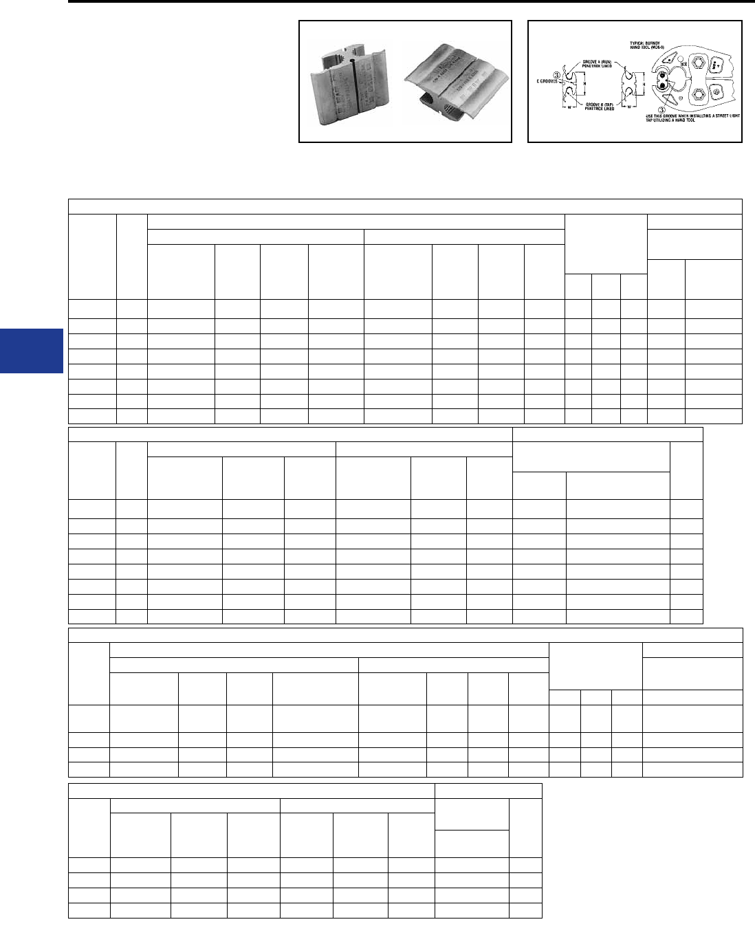
BURNDY®
Blue highlighted items are industry standard and most frequently ordered.
US: 1-800-346-4175 www.burndy.com Canada: 1-800-387-6487
Overhead Distribution
Compression Tap
LOKTAP™
LOKTAP™ compression connectors are high
quality, range-taking devices which accommodate
combinations of aluminum to copper, and
aluminum to aluminum conductors. BURNDY
seven connector program accommodates a
conductor range from #6 Sol. to 4/0 ACSR.
In addition, LOKTAP™ products feature a “C”
groove on both sides of the connector for use in
street lighting applications from #14 Sol. to #10
Handtool or Hydraulic 7 Connector Program
Catalog
Number
Code
No.
Conductors (See Below for Compact Conductors)
Dimensions
Installation Data
Groove A (Run) Groove B (Tap) Tool, Die Set Catalog
No. & (# of Crimps)
Wire
Diameter
Range
Sol. Str. ACSR
Wire
Diameter
Range
Sol. Str. ACSR
MD7,
MD6
Y35, Y750,
Y45†, Y46‡
H L W
YHO-1 1 0.162 - 0.332 #6 - #1 #6 - #1 #6 - #2 0.162 - 0.332 #6 - #2 #6 - #2 #6 - #2 1.11 1.25 0.67 (4) U-O (2)
YHO-2 2 0.260 - 0.419 #1 - 2/0 3 - 2/0 #3 - 1/0 0.162 - 0.332 #6 - #2 #6 - #2 #6 - #2 1.12 1.50 0.64 (5) U-O (2)
YHD-3 3 0.398 - 0.470 3/0 - 4/0 2/0 - 3/0 1/0 - 2/0 0.162 - 0.332 #6 - #2 #6 - #2 #6 - #2 1.47 1.88 0.76 (5) UD3 (2)
YHD-4 4 0.336 - 0.470 2/0 - 4/0 1 - 3/0 #1 - 2/0 0.336 - 0.477 #1 - 2/0 #1 - 2/0 #1 - 2/0 1.42 1.88 0.83 (5) UD3 (2)
YHD-5 5 0.475 - 0.563 250 - 300 4/0 3/0 - 4/0 0.162 - 0.332 #6 - #2 #6 - #2 #6 - #2 1.47 1.88 0.87 (5) UD3 (2)
YHD-6 6 0.461 - 0.563 250 - 300 3/0 - 4/0 3/0 - 4/0 0.336 - 0.447 #1 - 2/0 #1 - 2/0 #1 - 2/0 1.42 2.25 0.83 (6) UD3 (3)
YHD-7 7 0.461 - 0.563 250 - 300 250 - 300 3/0 - 4/0 0.461 - 0.563 3/0 - 4/0 3/0 - 4/0 3/0 - 4/0 1.40 2.52 0.84 (7) UD3 (3)
YHO-10** — 0.232 - 0.419** #2 - #1** #4 - 2/0** #4 - 1/0 0.232 - 0.419** #4 - 1/0** #4 - 1/0** #4 - 1/0 1.18 1.50 0.68 (4) U-O (2)
Compact Conductors Installation Data
Catalog
Number
Groove A (Run) Groove B (Tap) Tool, Die Set No.
& (# of Crimps) Die
Index
Wire Dia.
Range
Compact
ACSR
Compact
CU or AL
Wire Dia.
Range
Compact
ACSR
Compact
CU or AL Y35, Y750,
Y45†, Y46‡
YHO125 .162 - .398 #6 - 1/0 #2 - 2/0 .126 - .332 #6 - #1 #6 - #1 U-O (2) O
YHD-5 0.475 - 0.563 4/0 - 266 4/0 - 256 .162 - 0.332 #6 - #1 #6 - #1 UD3 (2) D3
YHD-6 0.461 - 0.563 3/0 - 266.8 4/0 - 266 .338 - 0.447 1/0 - 2/0 1/0 - 3/0 UD3 (3) D3
YHD-7 0.461 - 0.563 3/0 - 266.8 4/0 - 266 .461 - 0.563 3/0 - 266.8 4/0 - 266 UD3 (3) D3
Compact Conductors Installation Data
Catalog
Number
Code
No.
Groove A (Run) Groove B (Tap) Tool, Die Set Catalog
No. & (# of Crimps) Die
Index
Wire Diameter
Range
Compact
ACSR
Compact
CU or AL
Wire Diameter
Range
Compact
ACSR
Compact
CU or AL MD7,
MD6 Y35, Y750,Y45†, Y46‡
YHO-1 1 0.162 - 0.332 #6 - 1 #6 - #1 0.162 - 0.332 #6 - #1 #6 - #1 (4) U-O (2) O
YHO-2 2 0.260 - 0.419 #2 - 1/0 #2 - 2/0 0.162 - 0.332 #6 - #1 #6 - #1 (5) U-O (2) O
YHD-3 3 0.398 - 0.470 2/0 - 3/0 3/0 0.162 - 0.332 #6 - #1 #6 - #1 (5) UD3 (2) D3
YHD-4 4 0.336 - 0.470 1/0 - 3/0 1/0 - 3/0 0.338 - 0.447 1/0 - 2/0 1/0 - 3/0 (5) UD3 (2) D3
YHD-5 5 0.475 - 0.563 4/0 - 266 4/0 - 256 0.162 - 0.332 #6 - #1 #6 - #1 (5) UD3 (2) D3
YHD-6 6 0.461 - 0.563 3/0 - 266.8 4/0 - 266 0.338 - 0.447 1/0 - 2/0 1/0 - 3/0 (6) UD3 (3) D3
YHD-7 7 0.461 - 0.563 3/0 - 266.8 4/0 - 266 0.461 - 0.563 3/0 - 266.8 4/0 - 266 (7) UD3 (3) D3
YHO-10** — 0.232 - 0.419** #4 - 2/0 #2 - 2/0** 0.232 - 0.419** #4 - 2/0 #2 - 2/0** (4) U-O (2) O
Sol. LOKTAP™ connectors are designed to be
installed with BURNDY mechanical or hydraulic
tools and matching O and D3 die set.
Handtool or Hydraulic 4 Connector Program
Catalog
Number
Conductors (See Below for Compact Conductors)
Dimensions
Installation Data
Groove A (Run) Groove B (Tap) Tool, Die Set Catalog
No. & (# of Crimps)
Wire Dia.
Range Sol. Str. ACSR Wire Dia.
Range Sol. Str. ACSR H L W Y35, Y750, Y45†, Y46‡
YHO125 .162 - .398 #6 - 2/0 #6 - 1/0 #6 - 1/0 .162 - .332 #6 - 1/0 #6 - #1,
19 Str. #6 - #2 1.15 1.62 .70 U-O (2)
YHD-5 0.475 - 0.563 250 - 300 4/0 3/0 (6/1) - 4/0 (6/1) 0.162 - 0.332 #6 - 2 #6 - 2 #6 - #2 1.47 1.88 0.87 UD3 (2)
YHD-6 0.461 - 0.563 250 - 300 3/0 - 4/0 3/0 (6/1) - 4/0 (6/1) 0.336 - 0.447 #1 - 2/0 #1 - 2/0 #1 - 2/0 1.42 2.25 0.83 UD3 (3)
YHD-7 0.461 - 0.563 250 - 300 250 - 300 3/0 (6/1) - 4/0 (6/1) 0.461 - 0.563 3/0 - 4/0 3/0 - 4/0 3/0 - 4/0 1.40 2.52 0.84 UD3 (3)
See page H-27 for Seven Connector Selector Chart.
PERMANENT DIES IN TOOL INSTALL ALL SIZES.
- “C” grooves accommodate #10 Sol.-#14 Sol. range,
.116”-.064”. No “C” grooves on Cat. #YHO125. When
utilizing “C” groove(s) apply PENETROX™ A13 prior
to wire installation. If utilizing two (2) “C” groove taps,
installation to be made with HYDRAULIC TOOL ONLY.
All four (4) grooves CANNOT be utilized if using a hand
tool. When hand tool is used, only one (1) “C” groove can
be used; connector MUST be positioned as shown in
drawing.
** YHO-10: These ranges are for aluminum only.
Use only #4 Str. concentric copper tap.
† U Die with adapter PT-6515.
‡ U Die with adapter PUADP-1.
H-30
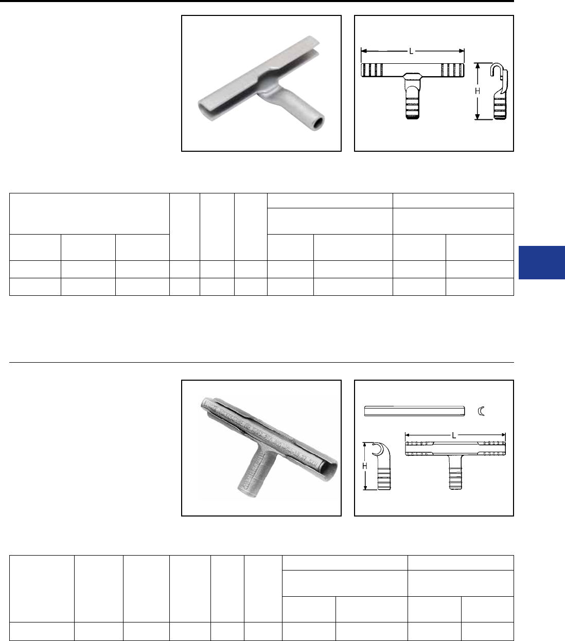
BURNDY®
Blue highlighted items are industry standard and most frequently ordered.
Canada: 1-800-387-6487 www.burndy.com US: 1-800-346-4175
Overhead Distribution
Compression T Tap
TYPE YCT
HYTEE™
ACCOMMODATES: COPPER
MATERIAL: TIN PLATED COPPER
One-piece, copper compression tap connector
with U-shaped run element and tubular tap for
joining hard and medium-hard drawn copper.
Preformed run element simplies installation on
larger conductors. Uses same die as equivalent
full-tension sleeve.
Conductors
H L Die
Index
Run Tap
Tools, Die Set Catalog Number,
& (Crimps per End)
Tools, Die Set Catalog Number,
& (Crimps per End)
Catalog
Number Run Tap MD7, MD6 Y35, Y750,
Y45 †, Y46 ‡ MD6 Y35, Y750,
Y45 †, Y46 ‡
YCT2626 2/0 (7, 12, 19) 2/0 (7, 12, 19) 3.26″ 5.62″ 166 W166 (4) U166/U459 (2) W166 (6) U-166 (3)
YCT2828 4/0 (7, 12, 19) 4/0 (7, 12, 19) 4.00″ 5.72″ 168 — U168(2) — U-168 (3)
† U Die with adapter PT-6515.
‡ U Die with adapter PUADP-1.
TYPE YOT
HYTEE™
ACCOMMODATES: COPPER
MATERIAL: TIN PLATED COPPER
Cast copper T-tap connector with two-piece
line element and tubular tap for joining hard
and medium drawn copper. Design simplies
installation on large conductors. Uses same die as
equivalent sleeve.
Catalog
Number Run Tap H L Die
Index
Run Tap
Tools, Die Set Catalog Number, &
(Crimps per End)
Tools, Die Set Catalog
Number, & (Crimps per End)
Y35, Y750,
Y45 †, Y46 ‡ Y60B Y35, Y750,
Y45 †, Y46 ‡ Y60BHU
YOT3434 500 (19, 37) 500 (19, 37) 4.82″ 10.38″ 210 U210 (6) L210 (2) U210 (6) L210 (2)
For faster installations use BURNDY® PATRIOT® family of
battery tools.
† U Die with adapter PT-6515.
‡ U Die with adapter PUADP-1.
For faster installations use BURNDY® PATRIOT® family of
battery tools.
H-31
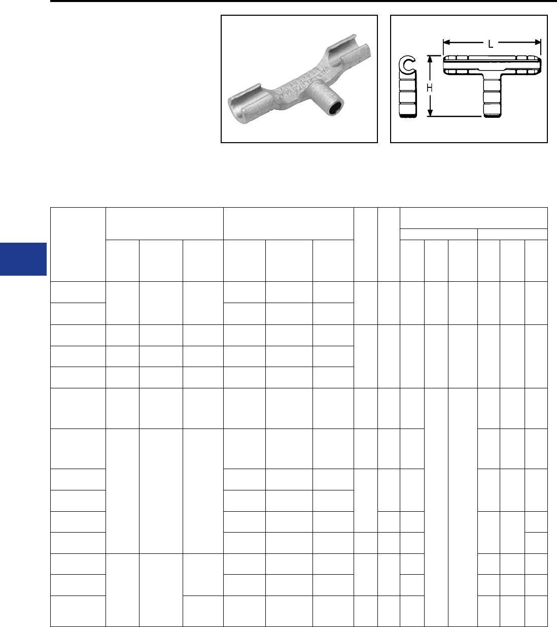
BURNDY®
Blue highlighted items are industry standard and most frequently ordered.
US: 1-800-346-4175 www.burndy.com Canada: 1-800-387-6487
Overhead Distribution
TYPE YTU-R-R
T-TAP
ACCOMMODATES: COPPER,
AAC (STR, COMPRESSED,
COMPACT), ACSR AND AAAC
MATERIAL: ALUMINUM
One-piece heavy-wall aluminum compression
tap connector for secondary service drop and
transformer tap to primary or secondary. Connector
can be gripped in tool for easy installation. Pre-lled
with PENETROX™ joint compound, stripsealed and
Catalog
Number
Run Tap
H L
Tools, Die Set
Catalog Number, & (Crimps per End)
Run Tap
ACSR,
6201,
5005
Aluminum Copper ACSR,
6201, 5005 Aluminum Copper Die
Index
MD7,
MD6
Y35,
Y750,
Y45†,
Y46‡
Die
Index
MD7,
MD6
Y35,
Y750,
Y45,
Y46‡
YTU25R4W 1/0
80 (8-1) 1/0 (7, 19) 1/0
(7, 12, 19)
#6 #4 (7)
#4 SLD
#4 (7)
#4 Sol. 2-3/8 4-7/8 C W-C
(2)
U-C
(1)* BG
BG
(3)
W-BG
(1)*
U-BG
(1)*
YTU25R25R 1/0
80 (8-1)
1/0
(7, 19) —
YTU26R26R 2/0 2/0 (7, 19) 2/0
(7, 12, 19) 2/0 2/0
(7, 19)
2/0
(7, 12, 19)
3-3/8 7 L W-L
(4)
U-L
(2) L — U-L
(2)
YTU27R27R 3/0 3/0 (7, 19) 3/0
(7, 12, 19) 3/0 3/0
(7, 19)
3/0
(7, 12, 19)
YTU28R28R 4/0 4/0 (7, 19) 4/0
(7, 12, 19) 4/0 4/0
(7, 19)
4/0
(7, 12, 19)
YTU30R30R
266.8
(18-1.
26-7,
6-7)
266.7
(7, 19, 37)
250 (19, 37)
300 (19, 37)
250
(12, 19, 37)
300
(19, 37)
266.8
(18-1, 26-7,
6-7)
266.7
(7, 19, 37)
250 (19, 37)
300 (19, 37)
250
(12, 19, 37) 4-3/8 8-3/4 M
—U-M
(3)
M — U-M
(3)
YTU321R2R
300
(26-7)
336.4
(18-1)
350
(19, 37)
336.4
(19, 37)
350
(19, 37)
2 2 (7 STR.) 2
(3, 7 Str.) 2-5/8 6-5/8 M BG
BG
(3)
W-BG
(1)*
U-BG
(1)*
YTU321R26R 2/0 2/0 (7, 19) 2/0
(7, 12, 19)
3-1/2
8-5/8 M L — U-L
(2)
YTU321R27R 3/0 3/0 (7, 19) 3/0
(7, 12, 19)
YTU321R28R 4/0 4/0 (7, 19) 4/0
(7, 12, 19) 8-3/5 M
M —
U-M
(3)
YTU321R321R 336.4 (18-1)
300 (26-7)
336.4 (19, 37)
350 (19, 37)
350
(19, 37) — — M U-M
(2)
YTU33R26R 336.4
(30.7)
(26-7)
397.5
(18.1)
397.5
(19, 37)
400
(19, 37)
400
(19, 37)
2/0 2/0
(7, 19)
2/0
(7, 12, 19) 3-1/2 8-5/8
M L — U-L
(2)
YTU33R28R 4/0 4/0
(7, 19)
4/0
(7, 12, 19) M L — U-L
(2)
YTU33R33R 400
(19, 37)
336.4 (30-7,
26-7)
397.5 (181)
397.5 (19, 37)
400 (19, 37)
400
(19, 37) 4-3/8 8-3/4 M M — U-M
(3)
* Multiple crimp die set, makes more than one crimp
per tool compression. Figure indicates number of
compressions.
† U Die with adapter PT-6515
‡ U Die with adapter PUADP-1.
capped to limit oxide growth and to increase the life
of the connection.
Not recommended for copper to copper applications.
Use a copper connector to increase connection life.
For faster installations use BURNDY® PATRIOT®
family of battery tools.
Compression T Tap
H-32
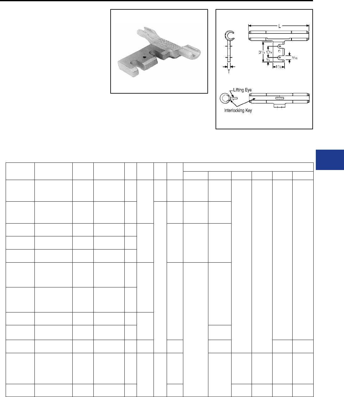
BURNDY®
Blue highlighted items are industry standard and most frequently ordered.
Canada: 1-800-387-6487 www.burndy.com US: 1-800-346-4175
Overhead Distribution
TYPE YTA-R-2N
DISCONNECTABLE T-TAP
(WITH PAD)
ACCOMMODATES: COPPER, AAC
(STR, COMPRESSED, COMPACT),
ACSR AND AAAC
MATERIAL: ALUMINUM
Aluminum primary T-tap connector with slotted
tap pad designed for easy disconnecting of tap
conductor. Tap pad accommodates compression
terminals Types YKA-R-2N and YKA-A-2N, and
has positioning socket for proper alignment. On
sizes larger than 336.4 ACSR, the YTA-R-2N
run element has two piece interlocking key with
lifting eye that simplies hotline installations.
Catalog number does not include mating terminal.
Catalog
Number
ACSR, 6201,
5005 Copper Aluminum Fig.
No. L T Die
Index
Tools, Die Set Catalog Number, & (# of Crimps per End)
MD7, MD6 Y35, Y750 Y45 † Y46 ‡ Y48B Y60BHU
YTA2R-2N 22 (3, 7)
1 (7)
2 (7)
1 (7) 1
6-1/8
3/8
BG
or
243
BG (2)
W-BG (1)*
W243 (2)
U- BG (1)*
U243 (1)
— —
— —
YTA25R-2N 1/0 1/0
(7, 12, 19) 1/0 (7, 19) 1
1/2
247
C
659
W-C (4)
W247 (1)
U659 (1)
U-C (1)
U247 (1)
YTA26R-2N 2/0 2/0
(7, 12, 19) 2/0 (7, 19) 1
7-7/8
L
or
251
W-L (4) U-L (2)
U251 (3)
YTA27R-2N 3/0 3/0
(7, 12, 19) 3/0 (7, 19) 1
YTA28R-2N 4/0 4/0
(7, 12, 19) 4/0 (7, 19) 1
YTA321R-2N
300
(26-7)
336.4
(18-1)
350
(19, 37)
336.4
(19, 37, 61)
350 (19, 37, 61)
1
9-1/2
M
—
U-M (3)
U317 (4)
YTA33R-2N
336.4
(26-7, 30-7)
397.5
(18-1)
400
(19, 37)
397.5
(19, 37, 61)
400
(19, 37, 61)
1
YTA361R-2N 477
(18-1) — — 2
13-1/8
YTA37R-2N 477
(24-7, 26-7, 30-7) —556.6
(19, 37) 2 U-M (5)
YTA39R-2N 556.5
(24-7, 26-7) —636 (37)
650 (61) 2 16-1/4 608 U608 (9) C608 (3) L608 (3)
YTA43R-2N
605 (30-19)
605 (30-9)
636
(24-7, 26-7, 30-19)
666.6 (24-7)
—795
(37, 61) 2
16-1/2 3/4
292
or
319 —
S929 (9)
S319 (9)
P929 (9)
P319 (9)
C929 (9)
P319 (9)
L929 (9)
P319 (9)
YTA391A-2N — — 795
(37, 61) 2 342 S342 (9) P342 (9) C342 (9) L342 (9)
* Multiple crimp die set, makes more than one crimp
per tool compression. Figure indicates number of
compressions.
Fig. 2
Fig. 1
Compression Tap (Disconnectable)
† U Die with adapter PT-6515.
‡ U Die with adapter PUADP-1.
For faster installations use BURNDY® PATRIOT®
family of battery tools.
H-33
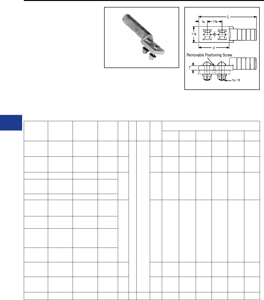
BURNDY®
Blue highlighted items are industry standard and most frequently ordered.
US: 1-800-346-4175 www.burndy.com Canada: 1-800-387-6487
Overhead Distribution
Compression Terminals
TYPES YKA-R-2N &
YKA-A-2N
DISCONNECTABLE TERMINAL
(WITH FIXED HARDWARE)
ACCOMMODATES:
AAC (STR, COMPRESSED,
COMPACT), COPPER, ACSR AND
AAAC
MATERIAL: ALUMINUM
Aluminum compression terminal with xed
hardware and positioning pin for making
disconnectable tap or jumper connections. Used
with slotted YTA-R-2N T-tap or YSA-R-2N terminal.
Catalog
Number
ACSR, 6201,
5005 Copper Aluminum L T Bolt
Length
Die
Index
Tools, Die Set Catalog Number,
& (Number of Crimps per End)
MD7,
MD6
Y35,
Y750 Y45 † Y46 ‡ Y48B Y60BHU
YKA2R-2N 21 (7)
2 (3, 7)
1 (7)
2 (7) 5-1/2
3/8 1-3/4
BG
or
243
BG (8)
W-BG (4)*
W243 (4)
U-BG (3)*
U243 (2) — — — —
YKA25R-2N 1/0 1/0 (7, 19) 1/0 (7, 19) 5-5/8
C
or
659
W-C (6) U-C (3)*
U629 (2) — — — —
YKA26R-2N 2/0 2/0 (7, 19) 2/0 (7, 19)
6
L
or
251
—U-L (2)
U251 (3) — — — —
YKA27R-2N
3/0
110.8
(12-7)
3/0 (7, 19) 3/0 (7, 19)
YKA28R-2N 4/0 4/0 (7, 19) 4/0 (7, 19)
YKA30R-2N
266.8
(18-1, 6-7,
26-7)
250 (12, 19, 37)
300 (19, 37)
250 (7, 37)
266 (19)
7-1/4
M
or
317
—U-M (3)
U317 (4) — — — —
YKA321R-2N 336.4 (18-1)
300 (26-7) 350 (19, 37) 300 (37, 61)
350 (37, 61)
YKA33R-2N
336.4
(26-7. 30-7)
397.5
(18-1)
—397.5 (19)
400 (37)
YKA361R-2N
397.5
(26-7, 30-7)
477 (18-1)
—477 (19, 37)
500 (37, 61)
YKA37R-2N
477
(24-7, 26-7,
30-7)
—556.5
(19, 37) 7-3/8 M — U-M (3) — — — —
YKA34CA-2N
397.5
(26-7, 30-7)
477 (18-1)
500 (19, 37) 477 (19, 37)
500 (37, 61) —
352
or
579
— — S352 (6)
S579 (6)
P352 (6)
P579 (6)
C352 (9)
C579 (9)
L352 (9)
L579 (9)
YKA391A-2N — — 795 (37, 61) 9-1/2 3/4 2-1/2 342 — — S342 (6) P342 (6) C342 (9) L342 (9)
Supplied with aluminum bolts and washer-face,
self locking nuts. Prelled with PENETROX™ joint
compound capped, and stripsealed to limit oxide
growth and to increase the life of the connection.
* Multiple crimp die set, makes more than one crimp
per tool compression. Figure indicates number of
compressions.
† U Die with adapter PT-6515.
‡ U Die with adapter PUADP-1.
For faster installations use BURNDY® PATRIOT®
family of battery tools.
H-34
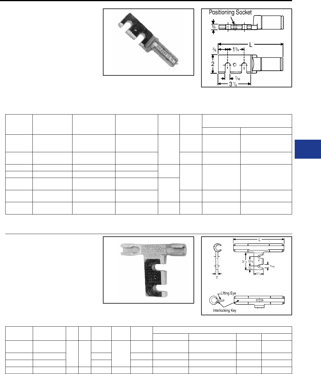
BURNDY®
Blue highlighted items are industry standard and most frequently ordered.
Canada: 1-800-387-6487 www.burndy.com US: 1-800-346-4175
Overhead Distribution
Compression Tap (Disconnectable)
TYPE YSA-R-2N
DISCONNECTABLE
TERMINAL
(WITH SLOTTED PAD)
ACCOMMODATES: AAC (STR,
COMPRESSED, COMPACT), COPPER,
ACSR AND AAAC
MATERIAL: ALUMINUM
Aluminum compression terminal with slotted pad
and positioning socket for making disconnectable
Catalog
Number ACSR, 6201, 5005 Copper Aluminum L Die Index
Tools, Die Set Catalog Number,
& (Number of Crimps)
MD7, MD8 Y35, Y750, Y45 †, Y46 ‡
YSA2R-2N 2 2 (3, 7) 1 (7) 2 (7) 1 (7)
6-1/4
BG or
243
BG (8)
W-BG (4)*
W243 (4)
U-BG (3)*
U243 (2)
YSA25R-2N 1/0 1/0 (7, 19) 1/0 (7, 19) C or
659 —
YSA26R-2N 2/0 2/0 (7, 19) 2/0 (7, 19) 6-5/8 L or
251 —U-L
U251
YSA28R-2N 4/0 4/0 (7, 19) 4/0 (7, 19)
YSA30R-2N 266.8
(18-1, 6-7, 26-7)
250 (12, 19, 37)
300 (19, 37)
250 (37)
266.8 (7, 19) 7-3/4
YSA321R-2N 336.4
(18-1) 300 (26-7) 350 (19, 37) 300 (37, 61)
350 (37, 61)
M or
317 —U-M (3)
U317 (4)
YSA37R-2N 477
(24-7, 26-26-7, 30-7) — 556.5 (19, 37) 7-7/8 M — U-M (3)
tap or jumper connections. Used with YKA-
R-2N xed hardware terminal. Pre-lled with
TYPE YTA-2N
DISCONNECTABLE T-TAP
ACCOMMODATES: COPPER
MATERIAL: TIN PLATTED COPPER
Cast copper primary t-tap connector with slotted
tap pad for easy disconnecting of tap conductor.
Tap pad accommodates compression terminal
Type YKA-2N. On sizes larger that 4/0, the YTA-2N
run element has a two-piece, interlocking key with
Catalog
Number Conductor Fig.
No. C L T Die Index Tools, Die Set Catalog Number, & (Number of Crimps)
MD7, MD6 Y35, Y750, Y45, Y46 Y48B Y60BHU
YTA2C-2N 2 (7)
1 1-1/2
5-5/8
3/8
163 W163 (3)
Crimps Overlap U163 (1)* — —
YTA26-2N 2/0 (7, 19) 7-3/8 166 W166 (6) U166 (3) — —
YTA28-2N 4/0 (7, 12, 19) 7-5/8 168 — U168 (4) — —
YTA34-2N 500 (19, 37, 61) 2 2 11-7/8 1/2 210 — U210 (6) C210 (2) L210 (2)
Fig. 2
Fig. 1
* Multiple crimp die set, makes more than one crimp
per tool compression. Figure indicates number of
compressions.
† U Die with adapter PT-6515.
‡ U Die with adapter PUADP-1.
For faster installations use BURNDY® PATRIOT®
family of battery tools.
PENETROX™ joint compound, stripsealed and
capped to limit oxide growth and to increase the
life of the connection.
lifting eye that simplies hot installations. Catalog
number does not include terminal or hardware.
* Multiple crimp die set, makes more than one crimp
per tool compression. Figure indicates number of
compressions.
† U Die with adapter PT-6515.
‡ U Die with adapter PUADP-1.
For faster installations use BURNDY® PATRIOT®
family of battery tools.
H-35
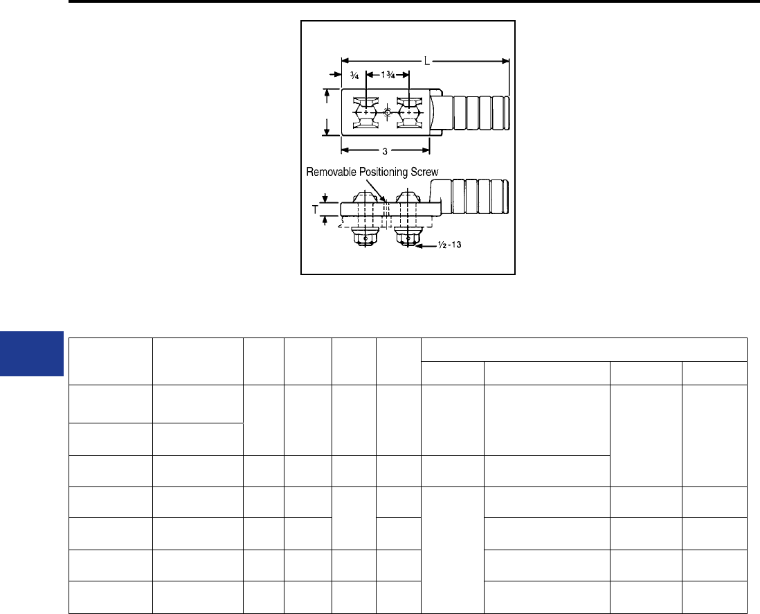
BURNDY®
Blue highlighted items are industry standard and most frequently ordered.
US: 1-800-346-4175 www.burndy.com Canada: 1-800-387-6487
Overhead Distribution
Compression Tap (Disconnectable)
TYPE YKA-2N
DISCONNECTABLE TERMINAL
(WITH FIXED HARDWARE)
ACCOMMODATES: COPPER
MATERIAL: TIN PLATED COPPER
Tin-plated copper compression terminal with xed
hardware for making disconnectable tap or jumper
connections. Used with slotted YTA-2N T-tap
or YSA-R-2N terminal. Supplied with tin-plated
DURIUM™ bolts and washer-face nuts.
Catalog
Number Conductor C L T Die
Index
Tools, Die Set Catalog Number, & (Number of Crimps)
MD7, MD6 Y35, Y750, Y45†, Y46‡ Y48B Y60BHU
YKA6C-2N 6 (7)
7/8 5 3/8 163
W163 (2)
Crimps
Overlap
U163 (1)* — —
YKA2C-2N 2 (7)
YKA26-2N 2/0 (7, 19, 37) 1 5-1/4 1/4 166 W166 (4) U166 (3)
YKA28-2N 4/0 (7, 12, 19, 37) 1-1/4 5-3/8
3/8
168
—
U168 (3) C168 (1) L168 (1)
YKA30-2N 300 (19, 37, 61) 1-1/2 5-1/2 170 U170 (5) C170 (1) L170 (1)
YKA34-2N 500 (19, 37 61) 1-7/8 6-1/2 1/2 210 U210 (6) C210 (2) L210 (2)
YKA44-2N 1000 (61) 2 7-5/8 1/2 345 — C345 (4) L345 (4)
C
* Multiple crimp die set, makes more than one crimp
per tool compression. Figure indicates number of
compressions.
† U Die with adapter PT-6515.
‡ U Die with adapter PUADP-1.
For faster installations use BURNDY® PATRIOT®
family of battery tools.
H-36
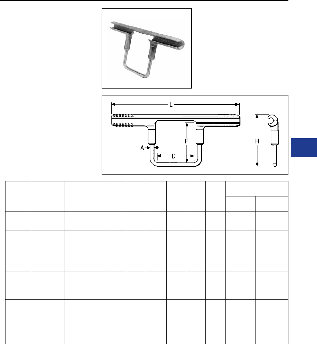
BURNDY®
Blue highlighted items are industry standard and most frequently ordered.
Canada: 1-800-387-6487 www.burndy.com US: 1-800-346-4175
Overhead Distribution
Hot Line Tap Bails
TYPE YCB-R
STIRRUP™ HOT-LINE CLAMP
ADAPTERS
ACCOMMODATES:
AAC (STR, COMPRESSED,
COMPACT), ACSR AND AAAC
MATERIAL: ALUMINIUM,
TIN PLATED COPPER BAIL
Permanent compression hot-line clamp
adapter with aluminum run and copper bail.
Accommodates any standard copper hotline
clamp on bail elements. Permits hot-line tapping
without arcing or chang damage to aluminum
conductor. Installed with standard tools and dies.
Prelled with PENETROXTM joint compound and
stripsealed to limit oxide growth and to increase
the life of the connection.
Catalog
Number Aluminum ACSR, 6201, 5005 A H L D F Die
Index
Tools, Die Set Catalog
Number, & (Crimps per End)
MD7, MD6 Y35, Y750,
Y45 †, Y46 ‡
YCB2R 2 Str. - 6 Sol. 2-4 2 Sol. 3-3/4 9 2-1/2 2-1/2 BG BG (6)
W-BG (2)* U-BG (2)*
YCB25R 1/0 (7, 19) 1/0 - 80 (8-1) 2 Sol. 5 9-3/4 2-1/2 3-1/2 C W-C (4) U-C (2)*
YCB26R 2/0 (7, 19) 2/0 1/0 Sol. 5 11-1/8 3-1/2 3-1/2 L W-L (4) U-L (2)
YCB27R 3/0 (7, 19) 3/0 1/0 Sol. 5 11-1/8 3-1/2 3-1/2 L W-L (4) U-L (2)
YCB28R 4/0 (7, 19) 4/0 1/0 Sol. 5 11-1/8 3-1/2 3-1/2 L W-L (4) U-L (2)
YCB321R 350 (19, 37)
336.4 (19, 37)
336.4 (18-1)
300 (26-7) 1/0 Sol. 5-3/8 12-3/4 3-1/2 3-1/2 M — U-M (3)
YCB33R 400 (19, 37)
397.5 (19, 37)
336.4 (26-4, 30-7)
397.5 (18-1) 1/0 Sol. 5-3/8 12-3/4 3-1/2 3-1/2 M — U-M (3)
YCB35R 500 (37, 61)
477 (19 , 37) 397.5 (26-7) (30-7) 1/0 Sol. 5-3/8 12-3/4 3-1/2 3-1/2 M — U-M (3)
YCB361R 477 (19, 37) 477 (18-1) 1/0 Sol. 5-1/4 13-1/4 3-1/2 3-1/2 317 — U317 (3)
* Multiple crimp die set, makes more than one crimp
per tool compression. Figure indicates number of
compressions.
† U Die with adapter PT-6515.
‡ U Die with adapter PUADP-1.
For faster installations use BURNDY® PATRIOT®
family of battery tools.
H-37
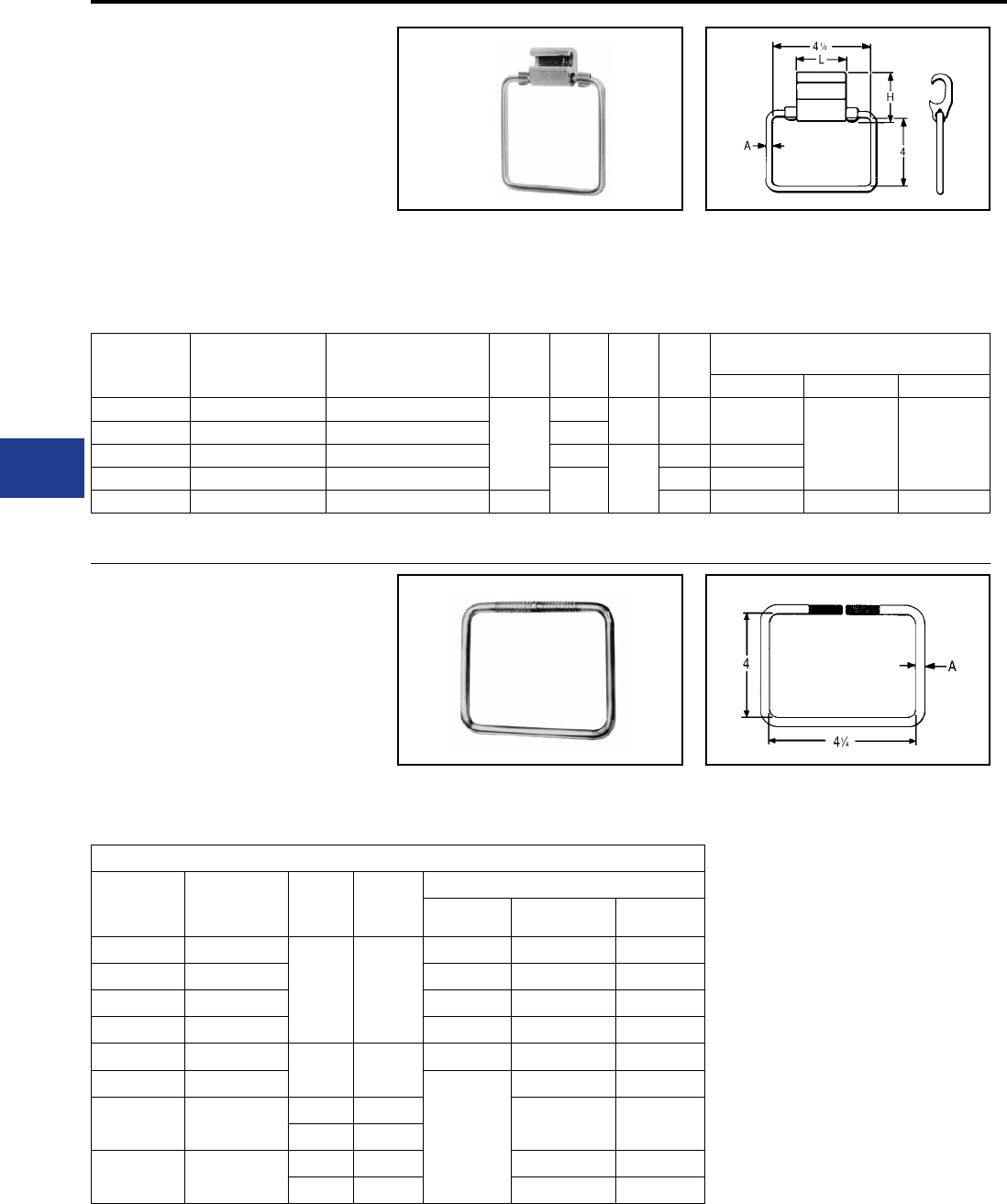
BURNDY®
Blue highlighted items are industry standard and most frequently ordered.
US: 1-800-346-4175 www.burndy.com Canada: 1-800-387-6487
Overhead Distribution
Compression Tap
TYPES YCB-U & YCB-R-U
CRIMPIT™ STIRRUP™
ACCOMMODATES:
AAC (STR, COMPRESSED), ACSR
AND AAAC
MATERIAL: ALUMINUM
TENSION RATING:
ANSI C119.4 CLASS 3
(NON TENSION)
Catalog
Number Aluminum ACSR, 6201, 5005 A H L Die
Index
Tools, Die Set Catalog Number,
& (Number of Crimps)
Y35, Y750 Y45 Y46
YCB4U1 4 Sol. - 4 (7) 4
2 Sol.
1-1/2 1-7/8 D U-D (2)
† ‡
YCB1U1 2 (7) - 1 (7) 2 1-5/8
YCB28U26 1/0 (7) - 4/0 (19) 1/0 - 4/0 2
2-1/8
H U-H (2)
YCB33R26U 300 (37) - 400 (37) 266.8 (6-7) - 336.4 (30-7) 2-1/4 R U-R (2)
YCB38R26U 397.5 (19) - 600 (61) 336.4 (26-7) - 556.5 (18-1) 1/0 Sol. N U-N (2) S-N (2) P-N (2)
TYPES J990 & J1252
HOT-LINE CLAMP BAILS
MATERIAL: TIN PLATED COPPER
Designed to make hot-line clamp adapter using
HYCRIMP™, CABELOK™ CRIMPIT™ or Figure
“6” -Shaped CRIMPIT™ connectors. Where hot
sticks are used, the CABELOK™ CRIMPIT™ or
Figure “6” -shaped CRIMPIT™ are recommended.
The line can be approached with the connector
Combines Figure “6” -shaped aluminum
CRIMPIT™ tap connector with tin-plated copper
bail. Can be gripped in tool and slipped over line
for easy installation. Five sizes take range from
#4 to 600 kcmil. Prelled with PENETROX™ joint
and bail held in the tool. Bails are tin-plated, hard
drawn copper.
* Index number “D” is not “D3” Cabelok CRIMPIT™
die.
* For additional run & tap
conductors see specic
connector catalog page.
compound and Stripsealed to limit oxide growth
and to increase the life of the connection.
Recommended Connector & Bail Combinations
HYCRIMP™
Cat. No.
CABELOK™
CRIMPIT™
Cat. No.
Bail A
Run Conductors Accommodated
Sol. Al Str. Al ACSR
YHO100 YP2U3
J990 #2
6 - 2 6 - 3 (7 Str.) 6,4
YHO150 YP26AU2 1 - 2/0 3 (3 Str.) - 1/0 3 - 1/0
YHD200 YP27AU4 3/0 - 4/0 2/0 - 3/0 1/0, 2/0
YHD250 YPC28U4 ─ 4/0 3/0, 4/0
YHD300 YP27AU26 J1252 2/0 3/0 2/0, 3/0 2/0
YHD350 YP28U26
─
4/0 3/0, 4/0
— YPC28U26 J990 #2 1/0 (7) - 4/0 1/0 - 4/0
J1252 2/0
YHN500 YPC33R26U J990 #2 250 (37) 266.8 (18-1)
J1252 2/0 400 (37) 397.5 (18-1)
† U Die with adapter PT-6515
‡ U Die with adapter PUADP-1.
For faster installations use BURNDY® PATRIOT®
family of battery tools.
H-38
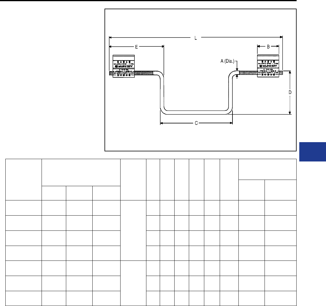
BURNDY®
Blue highlighted items are industry standard and most frequently ordered.
Canada: 1-800-387-6487 www.burndy.com US: 1-800-346-4175
Overhead Distribution
Compression T Tap
TYPES YHO-J,YHD-J, YHN-J
HYCRIMP™ STIRRUP™
ACCOMMODATES:
AAC (STR, COMPRESSED,
COMPACT) AND ACSR
MATERIAL: ALUMINUM,
TIN PLATED COPPER BAIL
Utilizing H-Framed Aluminum Tap Connectors
with tin-plated copper bail. Bendable tabs secure
run and bail freeing the lineman’s hands to work
with the installation tool conductor grooves.
Prelled with PENETROX™ joint compound and
stripsealed to limit oxide growth and to increase
the life of the connection.
Catalog
Number
Run Conductor Accommodates
A B C D E L Die
Index
Tools, Die Set Catalog
Number,
& (# of Crimps)
MD7-8
MD6-8
Y35, Y750,
Y45 †, Y46 ‡
Sol. Al Str. Al ACSR
YHO100J1444 6-1 6-1
(7 Str.) 6 - 2
2 Sol.
(0.258)
1.50 5.00 3.00 3.75 12.00 O (4) U-O (2)
YHO150J1444 1 - 2/0 3 - 2/0 3 - 1/0 1.75 5.00 3.00 3.75 12.00 O (5) U-O (2)
YHD200J1444 3/0 - 4/0 2/0 - 3/0 1/0 - 2/0 1.88 5.00 3.00 3.75 12.00 D3 (5) UD-3 (2)
YHD250J1444 250 - 300 4/0 3/0 - 4/0 1.88 5.00 3.00 3.75 12.00 D3 (5) UD-3 (2)
YHD300J1496 2/0 - 4/0 #1 -3/0 #1 - 2/0
2/0 Sol.
(0.365)
1.88 5.00 4.75 5.62 15.50 D3 (5) UD-3 (2)
YHD350J1496 250 - 300 3/0 - 4/0 3/0 - 4/0 2.50 5.00 4.75 5.62 15.50 D3 (7) UD-3 (2)
YHN500J1496 — 4/0 - 500 4/0 - 477
(18/1) 2.00 5.00 4.75 5.62 15.50 N — U-N (2)
Permanent dies in tool install all sizes.
† U Die with adapter PT-6515
‡ U Die with adapter PUADP-1.
For faster installations use BURNDY® PATRIOT®
family of battery tools.
H-39
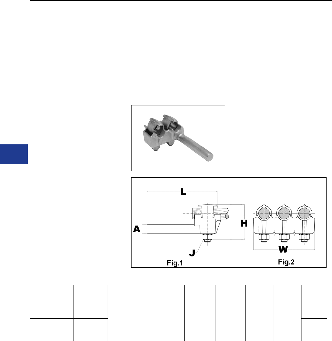
BURNDY®
Blue highlighted items are industry standard and most frequently ordered.
US: 1-800-346-4175 www.burndy.com Canada: 1-800-387-6487
Overhead Distribution
TRANSFORMER AND
EQUIPMENT TAP
CONNECTORS
Transformer and equipment tap connectors are
specically designed to provide single or multi-tap
connections from secondary transformer outlets,
disconnects, circuit breaker panels, and other
equipment pads or bar.
Catalog
Number
Number of
Conductors Conductor Size A dia. D H J L W
E2C34G1 2
1/0 -500 kcmil 0.78 3-3/4 3-7/8 1/2 - 13 6 - 1/4
3-1/2
E3C34G1 3 5-1/4
E4C34G1 4 6-7/8
TYPE E-C-G
TRANSFORMER TAP ADAPTER
ACCOMMODATES: COPPER
MATERIAL: COPPER
TENSION RATING:
ANSI C119.4 CLASS 3
(NON TENSION)
Multi-tap, range-taking cast copper alloy connector
designed to take 2, 3 or 4 conductors from a single
secondary transformer outlet.
Transformer Connectors
H-40
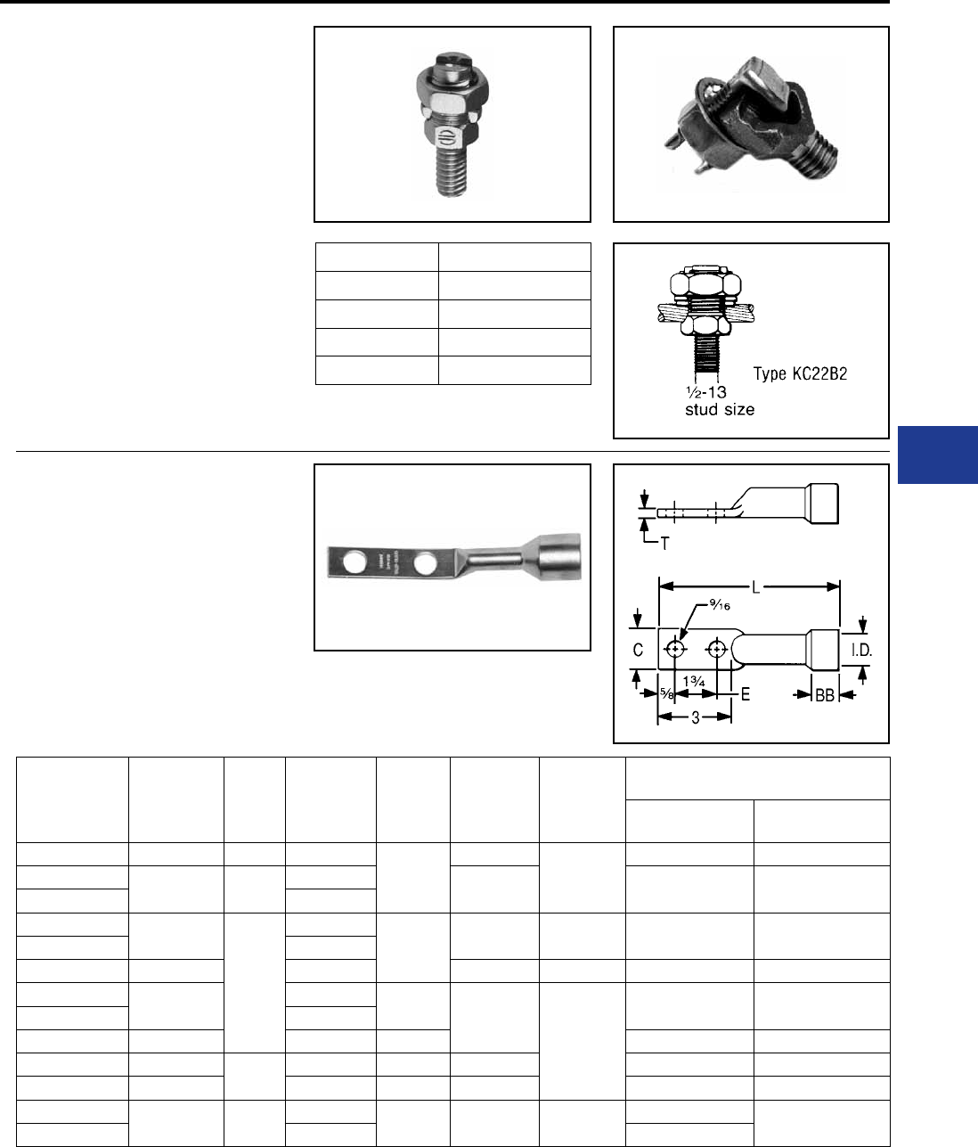
BURNDY®
Blue highlighted items are industry standard and most frequently ordered.
Canada: 1-800-387-6487 www.burndy.com US: 1-800-346-4175
Overhead Distribution
Transformer Connectors
TYPES KC22J12T13,
EQC632C
TRANSFORMER GROUND
CONNECTORS
ACCOMMODATES: COPPER
MATERIAL: COPPER
Fits all standard EEI-NEMA distribution
transformers as tank grounding terminal.
TYPE KC Ranges
KC22J12T13 8 Sol. - 2 Sol.
KC26 2 Sol. - 2/0 Str.
KC34J12T13 3/0 - 500 Str.
EQC632C 8 Sol. - 2 Str.
Both, one-wrench installation.
Type EQC632C
TYPE YA-2LH
HYSEALUG™
ACCOMMODATES: COPPER
MATERIAL: COPPER
Tin-plated, pure copper 2-hole NEMA compression
terminal with shrouded barrel for terminating
insulated copper conductor to transformers and
other equipment. Shroud prevents seepage of
Catalog
Number Conductor BB
Shroud
Inside
Diameter
C L T
Tools, Die Set Catalog Number,
& (Number of Crimps)
MD7, MD6 Y35, Y750,
Y45 †, Y46 ‡
YAB4C-2LH72 4 Str. 5/8 0.57
3/4
6-1/4
1/8
W161 (2) U4CRT (2)
YAB2C-2LH74 2 Str. 3/4 0.58 6-1/2 W162 (4) U2CRT (2)
YAB2C2LH75 0.91
YAB25-2LH70 1/0 Str.
1
0.69
7/8 6-3/4 3/8 W163 (4) U25RT (2)
YAB25-2LH71 0.98
YA26-2LH89 2/0 Str. 1.04 6-1/4 — W241 (2) U26RT (2)
YA28-2LH114 4/0 Str. 0.86 16-5/8
1/8
W-BG or
W243 (2) U28RT (2)
YA28-2LH115 1.24
YA29-2LH91 250 1.25 1-1/8 W166 (4) U29RT (2)
YA30-2LH85 300 1-1/4 0.92 1-1/4 7 — U30RT (2)
YA31-2LH90 350 1.40 1-3/8 7-5/8 W-0 (5) U31RT (2)
YA34-2LH110 500 1-1/2 1.14 1-1/2 7-3/4 1/4 —U34RT (2)
YA34-2LH111 1.88 —
† U Die with adapter PT-6515
‡ U Die with adapter PUADP-1.
water or moisture into conductor strands and
minimizes taping.
H-41
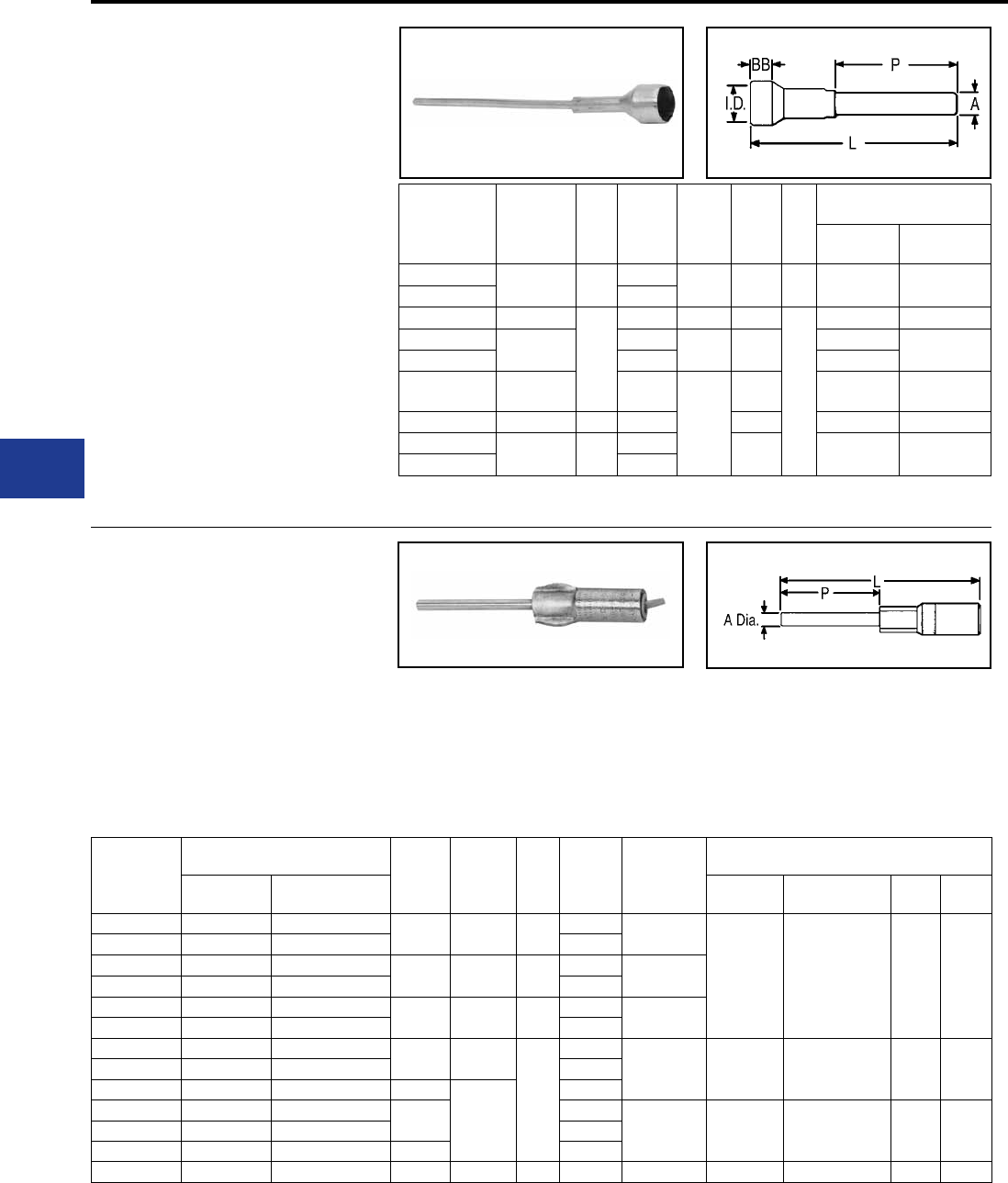
BURNDY®
Blue highlighted items are industry standard and most frequently ordered.
US: 1-800-346-4175 www.burndy.com Canada: 1-800-387-6487
Overhead Distribution
Compression Transformer Pin Terminals
TYPE YE-LH
HYSEALPLUG™
ACCOMMODATES: COPPER
MATERIAL: COPPER
TENSION RATING:
ANSI C119.4 CLASS 3
(NON TENSION)
Oil and water-tight terminal with shrouded,
tin-plated, copper barrel and brazed plug.
Recommended for terminating insulated copper
conductor at cutout, transformer and arrestor;
or for joining insulated copper riser to overhead
conductor. Shroud prevents seepage of water or
moisture into conductor strands and minimizes
taping. To obtain a tight t on some insulations in
the shroud it may be necessary to either “pencil”
the insulation down, or build it up with tape.
Catalog
Number Conductor BB
Shroud
Inside
Dia.
A Dia. L P
Tools, Die Set Catalog
Number, & (# of Crimps)
MD6, MD7 Y35, Y750,
Y45 †, Y46 ‡
YE2C-LH128 2 Str. 3/4 0.58 2 Sol. 9 6 W162 (4) U2CRT (2)
YE2C-LH129 0.91
YE25-LH97 1/0 Str.
1
0.98 1/0 Sol. 11-1/8
8
W163 (4) U25RT (2)
YE26-LH88 2/0 Str. 0.73 2/0 Sol. 11-3/8 W241 (2) U26RT (2)
YE26-LH89 1.04 W241 (2)
YE28-LH128 4/0 Str. 1.24
4/0 Sol.
11-1/2 W-BG or
W243 (2) U28RT (2)
YE31-LH96 350 1-1/4 1.03 12-1/4 W-O (5) U31RT (2)
YE34-LH119 500 1-1/2 1.14 13-1/4 — U34RT (2)
YE34-LH120 1.88
TYPES YE-R,YE-W
HYPLUG™
ACCOMMODATES: AAC (STR,
COMPRESSED), ACSR AND AAAC
MATERIAL: ALUMINUM
TENSION RATING:
ANSI C119.4 CLASS 3
(NON TENSION)
Catalog
Number
Conductor
A Dia. L P Color
Code Die Index
Tools, Die Set Catalog Number,
& (# of Crimps)
Aluminum ACSR MD7, MD6 Y35, Y750,
Y45 †, Y46 ‡ Y48BH Y60BH
YE6R-25 5, 6 Str. 6 4 Sol. 4-5/8 2-1/2 Blue K-5/8-1,
243, BG, 8A
BG
WBG
W243
U-BG
U243
UK5/8-1T
C243 L243
YE4R-25 3, 4 Str. 4 Orange
YE1WAG1 #1 Sol. (.289) — 0.25 8.58
(218) 6Red K-5/8-1,
243, BG
YE2WAG5 #2 Sol. (.258) — Orange
YE2R-25 1, 2 Str. 2 2 Sol. 4-5/8 2-1/2 Red K-5/8-1,
243, BG, 8A
YE25R-25 1/0 Str. 1/0 Yellow
YE26R-60 2/0 Str. 2/0 1/0 Sol. 9-1/2
6
Gray 249
840
11A
W249 or
W-K840
U249
U-K840T C249 L249YE27R-60 3/0 Str. 3/0 Black
YE28R-60 4/0 Str. 4/0 3/8
10-5/8
Pink
YE30R-60 300 266.8 (26/7) (18/1) 4/0 Sol. Blue 317,705,
K-1-1/8-1 —
U317
U705
U-K1-18-1T
C317 L317YE32R-60 350-400 336.4 (26/7) (18/1) Green
YE361R-60 477, 500 477 (18/1) 9/16 Pink
YE39R-60 600 556.5 (24/7) (26/7) 5/8 11-7/8 6 Yellow 608 — U608 C608 L608
In 1989 BURNDY® began shipping an improved pin
type connector. A proprietary coating system was
developed through intense research efforts which
vastly prolongs the life of this type of connection.
To help identify the new product, a hex shaped
crimp is now used on the pin interface crimp and
overhead color coded end caps are utilized.
Aluminum HYPLUG™ with tin-plated copper plug
for terminating aluminum or
ACSR cable at cut-
out, transformer and arrestor. Plug may be bent to
desired angle for easier insertion. Three die sets
accommodate 4 Str.-500 kcmil. Terminals are pre-
lled with PENETROX™ A-13 joint compound and
sealed with color coded end caps.
† U Die with adapter PT-6515.
‡ U Die with adapter PUADP-1.
* All crimps overlap
†U Die with adapter PT-6515.
‡U Die with adapter PUADP-1.
For faster installations use BURNDY® PATRIOT®
family of battery tools.
BURNDY® furnishes many special versions of YE-R
including: pin length variations, factory applied pin
angles, etc. Contact your BURNDY® representative for
your special needs.
For faster installations use BURNDY® PATRIOT® family
of battery tools.
H-42

BURNDY®
Blue highlighted items are industry standard and most frequently ordered.
Canada: 1-800-387-6487 www.burndy.com US: 1-800-346-4175
Overhead Distribution
Compression Splices
H-43
H-56
H-57
H-58
H-59 - H-60
H-61
H-62 - H-63
H-63
H-64
H-64
H-65
H-65
H-66
H-66
FULL TENSION
Types YDS-A & YDS-AT
Types YDS & YDS-C
Types YDS-W & YDS
Types YDS-R, YDS-RP1, YDS-RP2
Type YDS-RLY
Types YDS-RL & YDS-LT
Types YDS-A & YDS-AT
Types YDS-R & YDS-RE
Types YDS-E & YDS-H
Type YDS-K
Types YTS-E
Types YDS-KT & YDS-F
Type YDS-M-T
H-44
H-45
H-46
H-47
H-48
H-49
H-50
H-51
H-51
H-52
H-53
H-53
H-54
H-54
H-55
COMPRESSION SPLICES
SERVICE ENTRANCE
Type ES
Type YSU
Type YSD
NEUTRAL
Types YSS, YCS-R, YDS-AT
JUMPER
Type YCS-R
Type YCS-RL
Type YCS-A
Type YCR
Type YCR-R-G
Types YDS, YCS
REPAIR SLEEVE
Type YCU-A
Types YCU-R & YOU-R
Type YCU-R (Static Wire)
Type YDSR-RL
COMPRESSION SPLICES
TABLE OF CONTENTS

BURNDY®
Blue highlighted items are industry standard and most frequently ordered.
US: 1-800-346-4175 www.burndy.com Canada: 1-800-387-6487
Overhead Distribution
Compression Splices
COMPRESSION SPLICES
The BURNDY line of service, full-tension,
and jumper sleeves provide a dependable,
economical, and easy-to-install method
of splicing overhead transmission and
distribution lines.
A major part of the Total BURNDY® Compression
Program, they are available for copper, aluminum,
ACSR, COPPERWELD, ALUMOWELD, Steel,
6201, 5005, ACSR/AW, AWA, and compressed
forms for aluminum and ACSR. Each is clearly
marked with the installation Die Index number and
knurls are provided which show the installer the
correct number of crimps and the spacing required.
Connections made with BURNDY® INSULINK™
and HYSPLICE™ sleeves have a lower resistance
than an equal length of conductor.
HYSPLICE™ sleeves are tapered or chamfered at
the ends; externally to provide gradual reduction
of pressure on the conductor, and internally to
facilitate conductor insertion.
Service Sleeve Design
Service entrance connectors are available
insulated (INSULINK™) or uninsulated (LINKIT™).
Both are installed with the one-hand OH25 and
OUR840 HYTOOL™ or the MD6 HYTOOL™. The
INSULINK™ features polyethylene caps which
seal out dirt and moisture, and grip the cable
insulation leaving both hands free for crimping.
The aluminum insert is anchored to the nylon
jacket so that it will not move when crimped,
ensuring that the insert is always under the die.
The jacket is color coded for easy identication of
conductor size.
The aluminum LINKIT™ minimizes the effects of
galvanic corrosion. It is designed for easy location
of crimps, and is color coded.
The service HYSPLICE™ connectors are partial-
tension sleeves for splicing the neutral conductor
of triplex service. They are installed with MD6,
OUR840 and the OH25 HYTOOL™ on aluminum
and ACSR conductors from #6 to 1/0.
Copper HYSPLICE™ Sleeve Design
Full-tension holding strength and high conductivity
of BURNDY® copper HYSPLICE™ sleeves are
accomplished through the combined action of
correct contact length, proper number of circular
crimps of precisely controlled depth that perform a
current carrying and keying function between the
conductor and the sleeve.
Aluminum HYSPLICE™ Sleeve
Design
HYSPLICE™ sleeves for aluminum conductor not
only satisfy the basic tension requirements, but also
deal with the problems of “cold ow” of aluminum
and the oxide le which forms on the strands. “Cold
ow” is compensated for by carefully coordinating
the design of the sleeve and its associated
installation die. To offset the effects of the non-
conductive oxide lm present on the surfaces of
aluminum cable. BURNDY® HYSPLICE™ sleeves
are pre-lled with PENETROX™ joint compound
and capped or stripsealed. A solid center barrier
forces the PENETROX™ around the cable strands
during insertion.
ACSR HYSPLICE™ Sleeve Design
Two-Piece, Full-tension HYSPLICE™
Two-piece, full-tension HYSPLICE™ for ACSR
consists of an inner steel sleeve for joining the
steel core, and an outer aluminum sleeve for
connecting the aluminum strands. To install the
two-piece HYSPLICE™, the cable is cut, the
aluminum sleeve slid onto the cable, aluminum
strands cut back and the steel sleeve installed.
The aluminum sleeve is then centered over the
steel sleeve, PENETROX™ joint compound
injected (PENETROX™ is brushed on cable prior
to centering aluminum sleeve on smaller sizes),
and the sleeve is crimped.
Single-sleeve, Full-tension UNISPLICE™
The UNISPLICE™ is as easy to install as aluminum
full-tension sleeves. The single, heavy walled
aluminum sleeve is lled with a special inhibiting
compound containing grit particles which key the
steel strand in place. The UNISPLICE™ eliminates
cutting back of aluminum strands, the need for a
separate steel sleeve, and careful position of the
aluminum outer sleeve before crimping.
Since the standard pull-out tests are inadequate for
evaluating UNISPLICE™ performance, BURNDY®
has developed the sustained-tension test that
subjects a connector-conductor assembly to a 168
hour sustained load equal to 90% of the conductor
strength. This test simulates a service life of 30-40
years at 60% of the conductor strength.
Jumper Sleeves
Since the holding strength required for jumper
sleeves is less that that required for full-tension
sleeves, the jumper HYSPLICE™ sleeve is
shorter. Aluminum, ACSR, sleeves are pre-lled
with PENETROX™ joint compound and installed
with the same tools and dies as the full-tension
sleeves.
H-44
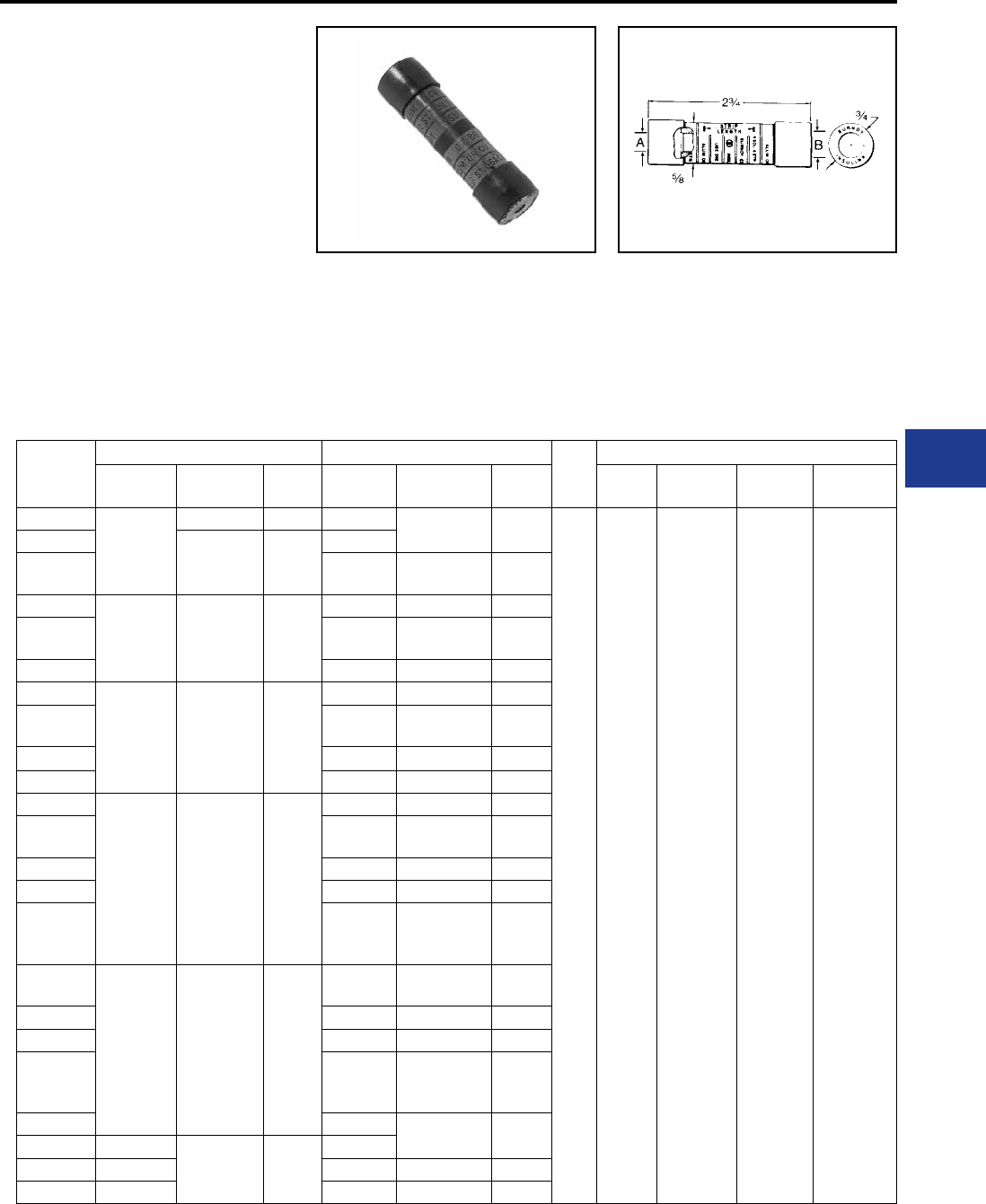
BURNDY®
Blue highlighted items are industry standard and most frequently ordered.
Canada: 1-800-387-6487 www.burndy.com US: 1-800-346-4175
Overhead Distribution
Compression Splices - Service Entrance
TYPE ES
INSULINK™
ACCOMMODATES:
AAC (STR, COMPRESSED,
COMPACT**), COPPER, ACSR,
AND AAAC
MATERIAL: ALUMINIUM
(INSULATED)
Pre-insulated service entrance compression
connector installed with OH25, OUR840 and MD6
HYTOOL™ as well as Y35 and Y750 HYPRESS™
tools. Polyethylene caps prevent dirt from
accumulating in barrel, grip cable for easy two-
hand installation, and seal out moisture. Aluminum
connector is anchored to jacket, assuring the
connector is under the die when crimping. Nylon
jacket insulates connector electrically and protects
against water and weather. Superior color coding.
Pre-lled with PENETROX™ joint compound and
stripsealed to limit oxidation and to increase the
life of the connection. Do not use insulated sealed
RUS Accepted
Catalog
Number
Side A ■Side B ■Die
Index
Installation Tooling* (# of Crimps per End)
ACSR,
6201, 5005
Aluminum
& Copper
Color
Code
ACSR,
6201, 5005
Aluminum
& Copper
Color
Code
Dieless
OH25
MD6/MD7
Series OUR840 Y35/Y750
Series
ES8W8W
—
10 Str. 8 Sol. Brown — 10 Str. 8 Sol. Brown
BG
or
5/8
(1) WBG (1)* XNBG (1)* UBG (1)*
ES6W8W 8 Str. 6 Sol.
#8 AL Compt Green
—
ES6W6W —8 Str. 6 Sol.
#8 AL Compt Green
ES4W8W
65, 6 Str. 4
Sol. Blue
— 10 Str. 8 Sol. Brown
ES4W6W —8 Str. 6 Sol.
#8 AL Compt Green
ES4W4W 6 5, 6 Str. 4 Sol. Blue
ES2W8W
43, 4 Str. 2
Sol. Orange
— 10 Str. 8 Sol. Brown
ES2W6W —8 Str. 6 Sol.
#8 AL Compt Green
ES2W4W 6 5, 6 Str. 4 Sol. Blue
ES2W2W 4 3, 4 Str. 2 Sol. Orange
ES2R8W
2
1 Str. 2 Str.
#1 AL Compt
#2 AL Compt
Red
— 10 Str. 8 Sol. Brown
ES2R6W —8 Str. 6 Sol.
#8 AL Compt Green
ES2R4W 6 5, 6 Str. 4 Sol. Blue
ES2R2W 4 3, 4 Str. 2 Sol. Orange
ES2R2R 2
1 Str. 2 Str.
#1 AL Compt
#2 AL Compt
Red
ES25R6W
1/0, 1 1/0 Str.
1-19 Str. Yellow
—8 Str. 6 Sol.
#8 AL Compt Green
ES25R4W 6 5, 6 Str. 4 Sol. Blue
ES25R2W 4 3, 4 Str. 2 Sol. Orange
ES25R2R 2
2 Str. 1 Str.
#1 AL Compt
#2 AL Compt
Red
ES25R25R 1/0, 1 1/0 Str. Yellow
ES25A25A —
1/0 Str. ▲ Yellow
—
ES25A4W — 6 5, 6 Str. 4 Sol. Blue
ES25A2W — 4 3, 4 Str. 2 Sol. Orange
■ Not for use on bare conductors.
▲Accommodates 1/0 stranded aluminum and copper,
concentric, compressed and compact conductors.
** Accommodates compact conductors where stated
in the table.
* For faster installations use BURNDY® PATRIOT®
family of battery tools.
connectors on bare conductors. Refer to LINKIT™
type connectors.
H-45
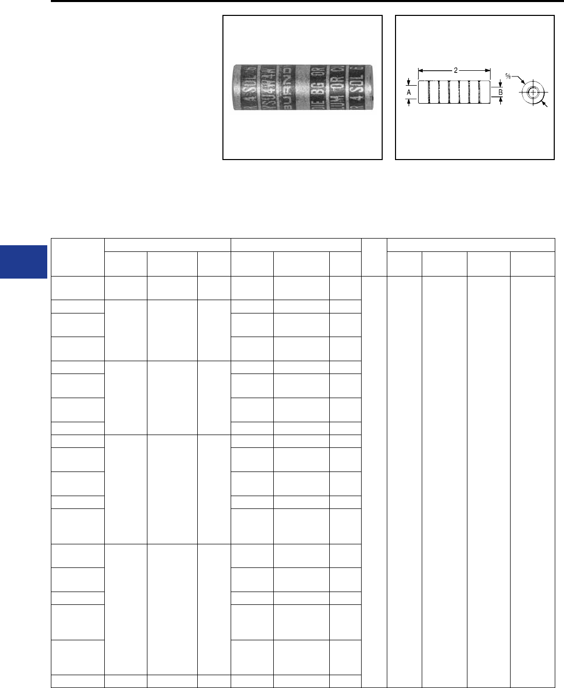
BURNDY®
Blue highlighted items are industry standard and most frequently ordered.
US: 1-800-346-4175 www.burndy.com Canada: 1-800-387-6487
Overhead Distribution
Compression Splices - Service Entrance
TYPE YSU
5/8" LINKIT™
ACCOMMODATES:
AAC (STR, COMPRESSED,
COMPACT**), COPPER, ACSR,
AND AAAC
MATERIAL: ALUMINIUM
(UNINSULATED)
Heavy-walled aluminum tubing with solid barrier
minimizes galvanic corrosion of conductors.
Accommodates neutral strands of Type SE
Service Entrance conductor as well as other
Catalog
Number
Side A Side B Die
Index
Installation Tooling* (# of Crimps per End)
ACSR,
6201, 5005
Aluminum
& Copper
Color
Code
ACSR,
6201, 5005
Aluminum
& Copper
Color
Code
Dieless
OH25
MD6/MD7
Series OUR840 Y35/Y750
Series
YSU6W6W —8 Str. 6 Sol.
#8 Al Compt Green — 8 Str. 6 Sol.
#8 Al Compt Green
243
BG
or
5/8
(1) WBG (1)* XNBG (1)* UBG (1)*
YSU4W8W
6
5, 6 Str. 4
Sol.
#4 Al Compt
Blue
— 8 Sol. 10 Str. Brown
YSU4W6W —6 Sol. 8 Str.
#8 Al Compt Green
YSU4W4W 65, 6 Str. 4 Sol.
#4 Al Compt Blue
YSU2W8W
43, 4 Str. 2
Sol. Orange
— 8 Sol. 10 Str. Brown
YSU2W6W —6 Sol. 8 Str.
#8 Al Compt Green
YSU2W4W 65, 6 Str. 4 Sol.
#4 Al Compt Blue
YSU2W2W 4 3, 4 Str. 2 Sol. Orange
YSU2R8W
2
2 Str. 1 Str.
#1 Al Compt
#2 Al Compt
Red
— 8 Sol. 10 Str. Brown
YSU2R6W —6 Sol. 8 Str.
#8 Al Compt Green
YSU2R4W 65, 6 Str. 4 Sol.
#4 Al Compt Blue
YSU2R2W 4 3, 4 Str. 2 Sol. Orange
YSU2R2R 2
2 Str. 1 Str.
#1 Al Compt
#2 Al Compt
Red
YSU25R6W
1/0
1/0 Str.
2/0 Al Compt
1/0 Al Compt
Yellow
—8 Str. 6 Sol.
#8 Al Compt Green
YSU25R4W 65, 6 Str. 4 Sol.
#4 Al Compt Blue
YSU25R2W 4 3, 4 Str. 2 Sol. Orange
YSU25R2R 2
2 Str. 1 Str.
#1 Al Compt
#2 Al Compt
Red
YSU25R25R 1/0
1/0 Str.
2/0 Al Compt
1/0 Al Compt
Yellow
YSU25A25A 1-1 1/0 Str. ▲ Yellow 1/0 1/0 Str. Yellow
▲ Accommodates 1/0 standard aluminum and
copper concentric, compressed and compact
conductors.
** Accommodates compact conductors where stated
in the table.
* For faster installations use BURNDY® PATRIOT®
family of battery tools.
conductors. Installed with standard tooling.
Color Coded. Pre-lled with PENE TROX™ joint
compound and Stripsealed to limit oxidation and to
increase the life of the connection.
RUS Accepted
H-46
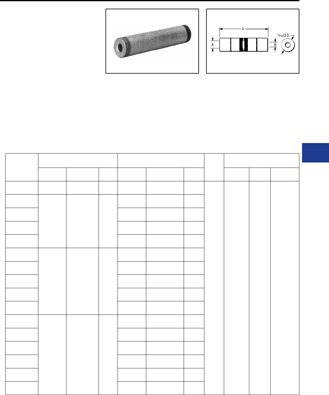
BURNDY®
Blue highlighted items are industry standard and most frequently ordered.
Canada: 1-800-387-6487 www.burndy.com US: 1-800-346-4175
Overhead Distribution
Compression Splices - Service Entrance
TYPE YSD
.840 LINKIT™
ACCOMMODATES:
AAC (STR, COMPRESSED,
COMPACT**), COPPER, ACSR,
AND AAAC
MATERIAL: ALUMINUM
(UNINSULATED)
Aluminum compression sleeve with solid center
barrier. Designed for commercial and heavy
residential services. Installed with standard tooling.
Pre-lled with PENETROX™ joint compound,
capped and stripsealed to limit oxidation and to
increase the life of the connection.
Catalog
Number
Side A Side B Die
Index
Installation Tooling ***
(Number of Crimps per End)
ACSR,
6201, 5005
Aluminum
& Copper
Color
Code
ACSR, 6201,
5005
Aluminum &
Copper
Color
Code
MD6/MD7
Series OUR840 Y35/Y750*
Series
YSD25R25R 1/0 1/0 Str.
2/0 AL Compt Yellow 1/0 1/0
2/0 ALCompt Yellow
249
K-840
WK840 (7)
W249 (4)
X840 (7)
X249 (8)
UK840 (4)
U249 (2)
YSD26R2W
2/0 2/0 Str.
3/0 AL Compt Gray
43, 4 Str. 2 Sol.
#2 AL Compt Orange
YSD26R2R 22 Str. 1 Sol.
1/0 AL Compt Red
YSD26R25R 1/0 1/0 Str.
2/0 AL Compt Yellow
YSD26R26R 2/0 2/0 Str.
3/0 AL Compt Gray
YSD27R2W
3/0 3/0 Str.
4/0 AL Compt Black
43, 4 Str. 2 Sol.
#2 AL Compt Orange
YSD27R2R 22 Str. 1 Sol.
1/0 AL Compt Red
YSD27R25R 1/0 1/0
2/0 ALCompt Yellow
YSD27R26R 2/0 2/0 Str.
3/0 AL Compt Gray
YSD27R27R 3/0 3/0 Str.
4/0 AL Compt Black
YSD28R2W
4/0 4/0 Str.
300 AL Compt Pink
43, 4 Str. 2 Sol.
#2 AL Compt Orange
YSD28R2R 22 Str. 1 Sol.
1/0 AL Compt Red
YSD28R25R 1/0 1/0
2/0 ALCompt Yellow
YSD28R26R 2/0 2/0 Str.
3/0 AL Compt Gray
YSD28R27R 3/0 3/0 Str.
4/0 AL Compt Black
YSD28R28R 4/0 4/0 Str.
300 AL Compt Pink
* Multiple crimp die set, makes more than one
crimp per tool compression. Figure indicates
number of compressions.
** Accommodates compact conductors where
stated in the table.
*** For faster installations use BURNDY®
PATRIOT® family of battery tools.
RUS Accepted
H-47
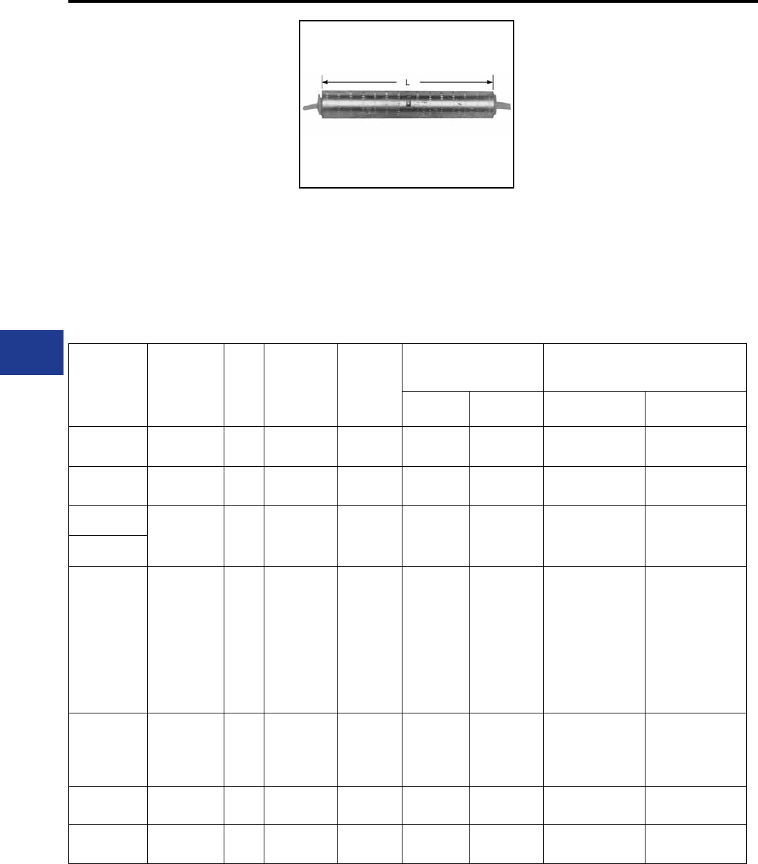
BURNDY®
Blue highlighted items are industry standard and most frequently ordered.
US: 1-800-346-4175 www.burndy.com Canada: 1-800-387-6487
Overhead Distribution
Compression Splices - Service Entrance & Short Span Lines (Neutrals)
TYPES YSS, YCS-R & YDS-AT
HYSPLICE™
ACCOMMODATES:
AAC (STR, COMPRESSED,
COMPACT**), COPPER, ACSR
AND AAAC
MATERIAL: ALUMINUM
Single aluminum sleeve designed for service
drop or short span overhead distribution lines.
Installed with OH25 one-hand tool, and other
standard tooling. Pre-lled with PENETROX™
joint compound and color coded capped and
stripsealed to limit oxidation and to increase the
life of the connection.
Catalog
Number Conductor L Die
Index Color Code
Tools,
Die Set Catalog Number***
& (Crimps per End)
OH25 Applications
MD7, MD6 Y35, Y750,
Y45†, Y46‡ Conductor OH25
(Indents per End)
YSS6RG2 6 ACSR
4 Sol. Al 4.00 BG Blue BG (6)
W-BG (3)* U-BG (3)* — —
YSS6R 6 ACSR
4 Sol. Al 4.72 162 Blue W162 (4) U162 (2)* — —
YDS4WA 4 Sol. Al
4 Str. Al (7) 2-5/8 162 Orange W162 (4) U162 (1)* — —
YDS4CA
YSS4R
4 ACSR
2 Sol. Al
4 Al (7)
3.78 BG or
5/8 Orange BG (6)
W-BG (3)* U-BG (3)*
4 7 Al
4 5005 Al
4 5005 Al
4 (6-1) ACSR
4 (6-1) ACSR
4 (7-1) ACSR
4 (7-1) ACSR
2 Sol. Al
2 Sol. Al
(3)
(2)
(3)
(3)
(2)
(3)
(2)
(3)
(2)
YSS2R 2 ACSR
2 Al (7) 3.78 BG or
5/8 Red BG (6)
W-BG (3)* U-BG (3)*
2 (6-1) ACSR
2 (7-1) ACSR
2 (7-1) ACSR
2 7 Al
(3)
(3)
(2)
(3)
YDS25AT 1/0 (7) 7-1/4 243 Yellow W243(6) U243(3) 1/0 7 Al (4)
YCS25R 1/0 ACSR 7.09 243 Yellow BG (12)
W-BG (6)* U-BG (6)* 1/0 (6-1) ACSR
1/0 (6-1) ACSR
(2)
(3)
* Multiple crimp die set; makes more than one
crimp per tool compression. Figure indicates
number of compressions.
** Accommodates compact conductors where
stated in the table.
† U Die with adapter PT-6515
‡ U Die with adapter PUADP-1.
*** For faster installations use BURNDY®
PATRIOT® family of battery tools.
H-48
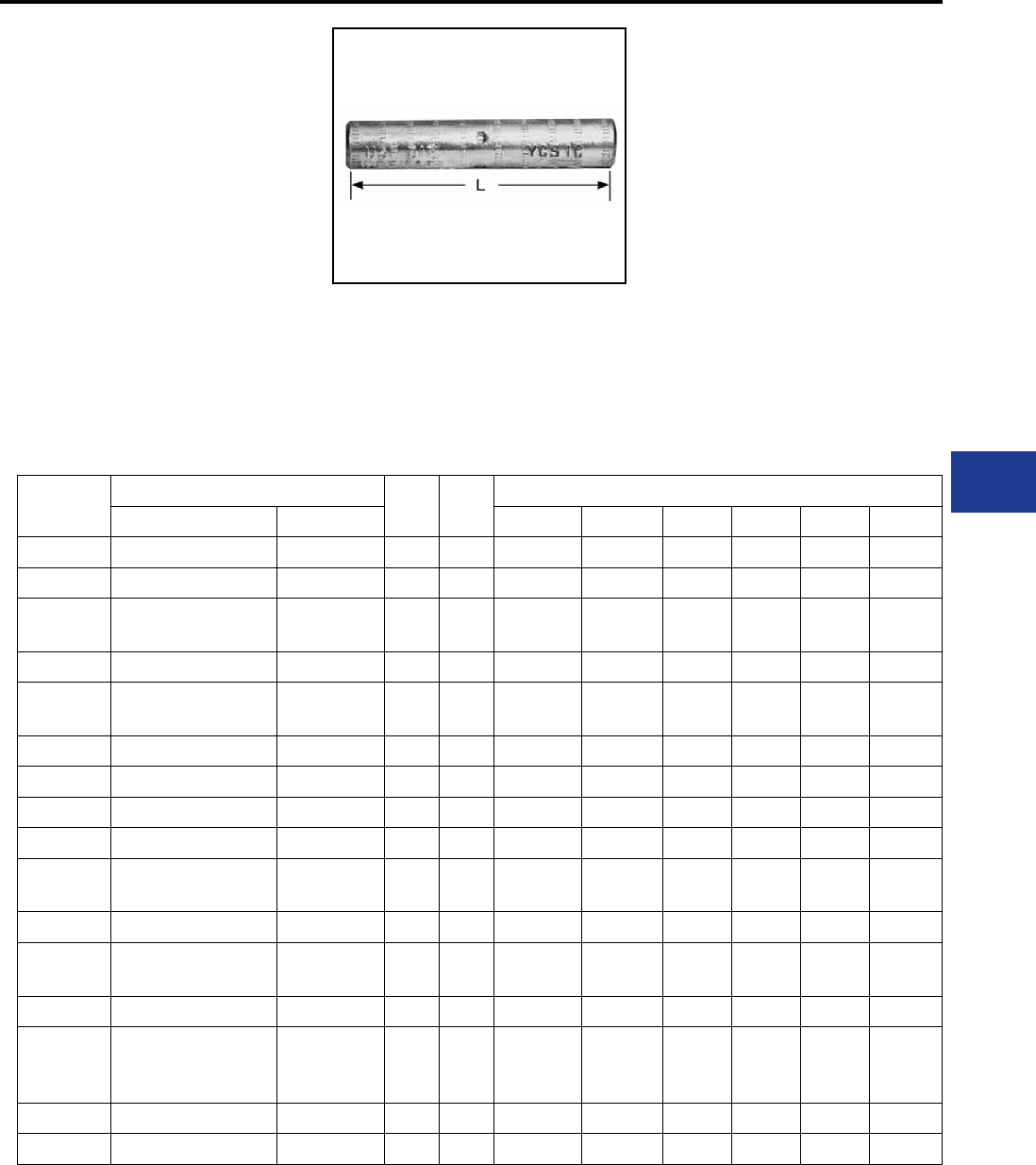
BURNDY®
Blue highlighted items are industry standard and most frequently ordered.
Canada: 1-800-387-6487 www.burndy.com US: 1-800-346-4175
Overhead Distribution
Compression Splices - Single Sleeve Jumper Partial Tension
TYPE YCS-R
HYSPLICE™
ACCOMMODATES:
AAC (STR, COMPRESSED), ACSR
AND AAAC
MATERIAL: ALUMINUM
TENSION RATING:
ANSI C119.4 CLASS 2
(PARTIAL TENSION)
HYSPLICE™ sleeve designed to withstand
jumper loop tensile and vibration stresses. Made
of aluminum with staked-in cable stop. Installed
with same die as equivalent full tension sleeves.
RUS Accepted
Catalog
Number
Conductor LDie
Index
Tools, Die Set Catalog Number, & (Crimps per End)
ACSR, 6201, 5005 All Aluminum MD7, MD6 Y35, Y750 Y45 Y46 Y48B Y60BHU
YCS4R 4 4 (7) 5 237 W237 (4) U237 (2) † ‡ — —
YCS2R 2 2 (7) 5 239 W239 (4) U239 (2) † ‡ — —
YCS25R 1/0 1/0 (7, 19) 7-1/8 243 W-BG (5)
W243 (7)
U-BG (6)*
U243 (4) † ‡ — —
YCS26R 2/0 2/0 (7, 19) 7 245 W245 (8) U245 (4) † ‡ — —
YCS27R 3/0
110.8 (12-7) 3/0 (7, 19) 5-3/4 247 W247 (6) U247 (3) † ‡ — —
YCS28R 4/0 4/0 (7, 19) 5-3/4 249 W249 (6) U249 (3) † ‡ C249 (2) L249 (2)
YCS30R 266.8 (6/7, 18-1, 26/7) 266.8 6-1/2 251 W251 (12) U251 (6) † ‡ C251 (3) L251 (3)
YCS321R 336.4 (18-1) 300 336.4 (19) 6-1/2 490 — U490 (5) † ‡ C490 (2) L490 (2)
YCS33R 336.4 (26-7, 30-7) 397.5 (19) 8-3/4 316 — U316 (6) † ‡ C316 (2) L316 (2)
YCS35R 397.5 (18-1, 26-7, 30-7) 477 (19, 37)
500 (37, 61) 8-7/8 317 — U317 (6) † ‡ C317 (2) L317 (2)
YCS361R 477 (18-1) 500 (37, 61) 8-1/4 327 — U327 (6) † ‡ C327 (2) L327 (2)
YCS37R 477 (24-7, 26-7, 30-7)
556.5 (18-1) 556.5 (19, 37) 8-3/4 261 — U261 (6) † ‡ C261 (2) L261 (2)
YCS39R 556.5 (24-7, 26-7) — 10-3/4 608 — U608 (9) † ‡ C608 (3) L608 (3)
YCS43R
605 (30-19)
636 (24-7, 26-7, 30-19)
666.6 (24-7,54-7)
795 (37) 10-5/8
292
or
319
— — S292 (6)
S319 (6)
P292 (6)
P319 (6)
C292 (3)
C319 (3)
L292 (3)
L319 (3)
YCS453R 795 (36-1, 45-7) — 10-5/8 292 — — S292 (6) P292 (6) C292 (3) L292 (3)
YCS45R 795 (26-7, 54-7) 900 (61, 91) 10-5/8 352 — — S352 (6) P352 (6) C352 (3) L352 (3)
† U Die with adapter PT-6515
‡ U Die with adapter PUADP-1.
For faster installations use BURNDY® PATRIOT®
family of battery tools.
Pre-lled with PENETROX™ joint compound,
stripsealed and capped to limit oxide growth and
to increase the life of the connection.
H-49
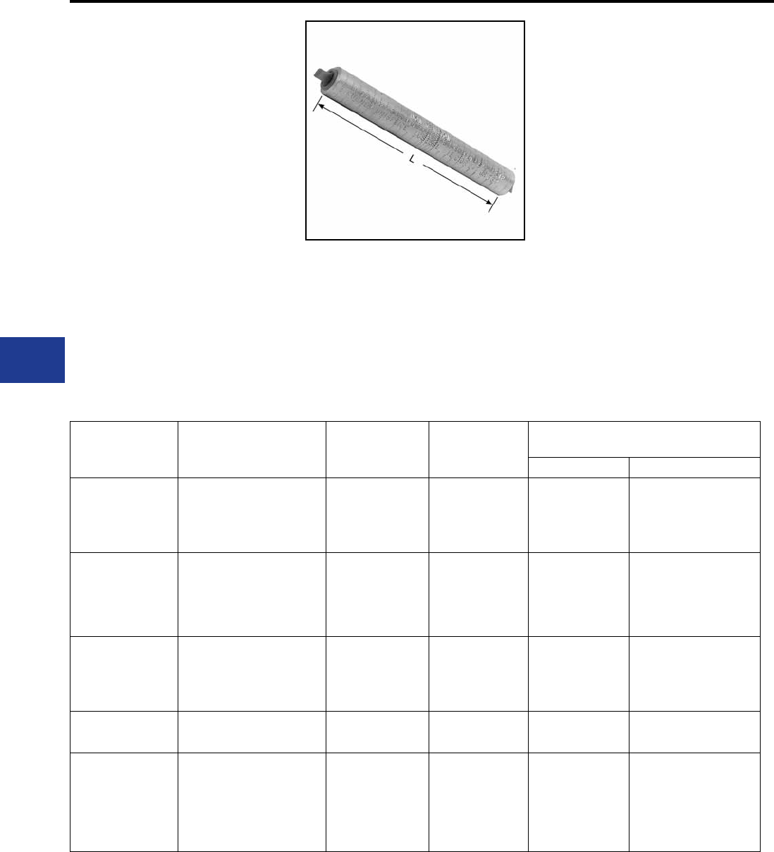
BURNDY®
Blue highlighted items are industry standard and most frequently ordered.
US: 1-800-346-4175 www.burndy.com Canada: 1-800-387-6487
Overhead Distribution
Compression Splices - Single Sleeve Jumper Partial Tension
TYPE YCS-RL
UNISPLICE™
ACCOMMODATES:
AAC (STR, COMPRESSED,
COMPACT), ACSR AND AAAC
MATERIAL: ALUMINUM
TENSION RATING:
ANSI C119.4 CLASS 2
(PARTIAL TENSION)
Aluminum jumper sleeve, with cable stop, designed
to be installed with same dies as equivalent full-
tension UNISPLICE™. Withstands jumper loop-
tensile and vibration stresses. Pre-lled with
PENETROX™ joint compound, stripsealed and
capped to limit oxide growth and to increase the
life of the connection.
Catalog
Number Conductor ††† L Die Index
Tools, Die Set Catalog Number,
& (Crimps per End)
MD7, MD6 Y35, Y750, Y45†, Y46‡
YCS25RL
1/0 ACSR (6-1)
1/0 6201 (7)
1/0 5005 (7)
1/0 AAC (7)
6-1/4 C or 247 or 702 W-C (12)
W702 (6)* U247 (3)
YCS26RL
2/0 ACSR (6-1)
2/0 6201 (7)
2/0 5005 (7)
2/0 AAC (7)
5-5/8 659 — U659 (3)
YCS28RL
4/0 ACSR (6-1)
4/0 6201 (7)
4/0 5005 (7)
4/0 AAC (7)
5-1/4 654 — U654 (3)
YCS321RL 336.4 ACSR (18-1)
336.4 AAC (19) 5-1/4 655 — U655 (3)
YCS341RL
397.5 AAC (19)
397.5 ACSR (18-1)
400 AAC (37, 61)
336.4 ACSR (18-1)
336.4 ACSR (26-7)
336.4 ACSR (30-7)
5-5/8 327 — U327 (4)
* MD6 NON-BOW Dies produce straight
sleeves without rotating tool.
† U Die with adapter PT-6515
‡ U Die with adapter PUADP-1.
††† Accommodates ACSR with aluminized steel
core.
For faster installations use BURNDY® PATRIOT®
family of battery tools.
H-50
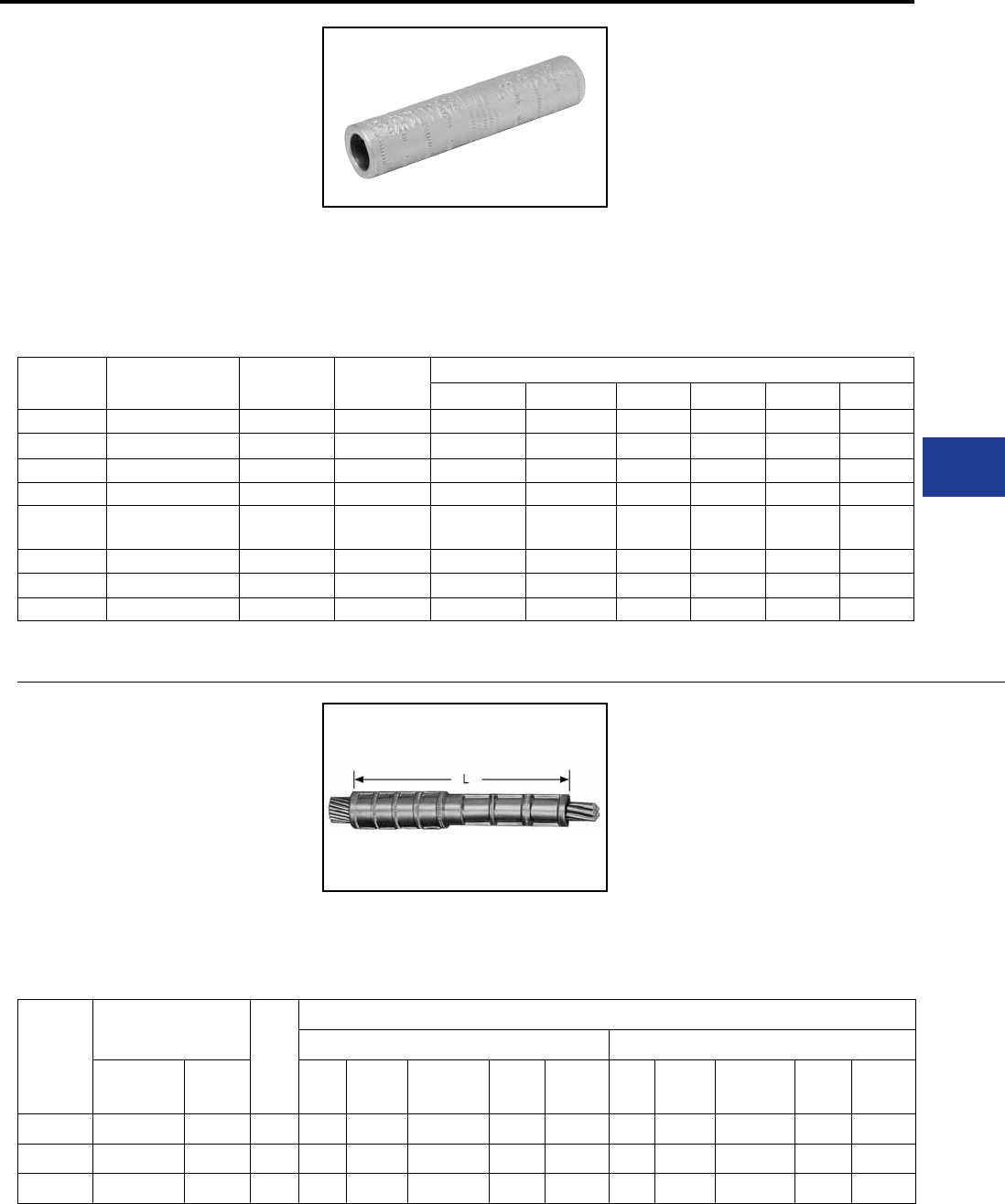
BURNDY®
Blue highlighted items are industry standard and most frequently ordered.
Canada: 1-800-387-6487 www.burndy.com US: 1-800-346-4175
Overhead Distribution
Compression Splices - Jumper Loop and Short Span
TYPE YCS-A
HYSPLICE™
ACCOMMODATES:
AAC (STR, COMPRESSED,
COMPACT)
MATERIAL: ALUMINIUM
TENSION RATING:
ANSI C119.4 CLASS 1A
(NORMAL TENSION)
Catalog
Number Conductor L Die Index Tools, Die Set Catalog Number, & (Crimps per End)
MD7, MD6 Y53, Y750 Y45 Y46 Y48B Y60BHU
YCS26A 2/0 (7) 5-1/8 245 W245 (4) U245 (2) † ‡ — —
YCS28A 4/0 (7, 19) 4 249 W249 (4) U249 (2) † ‡ C249 (1) L249 (1)
YCS301A 336.4 (19, 37) 4-3/8 321 — U321 (3) † ‡ C321 (2) L321 (2)
YCS311A 397.5 (19) 5-5/8 468 — U468 (4) † ‡ — —
YCS331A 477 (19, 37, 61)
500 (19, 37, 61) 6-1/4 317 — U317 (4) † ‡ C317 (2) L317 (2)
YCS351A 556.5 (19, 37) 8-3/4 261 — U261 (6) † ‡ C261 (2) L261 (2)
YCS361A 636 (37) 7-3/8 469 — — S469 (4) P469 (4) C469 (2) L469 (2)
YCS391A 795 (37, 61) 10-1/2 342 — — S342 (4) P342 (6) C342 (3) L342 (3)
TYPE YCR
JUMPER SLEEVE REDUCER
ACCOMMODATES: COPPER
MATERIAL: COPPER
TENSION RATING:
ANSI C119.4 CLASS 1A
(NORMAL TENSION)
Catalog
Number
Copper Conductor
L
Tool, Die Set Catalog Number, & (Crimps per End)
Side A Side B
Side A Side B Die
Index
MD7,
MD6
Y35, Y750,
Y45†, Y46‡ Y48B Y60BHU Die
Index MD6 Y35, Y750,
Y45†, Y46‡ Y48B Y60BHU
YCR2625 2/0 (7, 12, 19) 1/0 (7, 19) 3-3/8 166 W166 (6) U166/U459 C166 (1) L166 (1) 165 W165 (3) U165/U205 C165 (1) L165 (1)
YCR2725 3/0 (7, 19) 1/0 (7, 19) 3-1/2 167 — U167/U568 C167 (1) L167 (1) 165 W165 (3) U165/U205 C165 (1) L165 (1)
YCR2825 4/0 (7, 12, 19) 1/0 (7, 19) 3-3/8 168 — U168 (3) C168 (1) L168 (1) 165 W165 (3) U165/U205 C165 (1) L165 (1)
HYSPLICE™ sleeve designed to withstand jumper
loop tensile and vibration stresses up to 60% RBS.
Made of aluminum with staked-in cable stop.
Installed with same die as equivalent full-tension
sleeve. Made from electrolytic grade aluminum.
Surface oxides removed at factory and sealed.
* Multiple crimp die set; makes more than one
crimp per tool compression. Figure indicates
number of compressions.
† UDie with adapter PT-6515.
‡ U Die with adapter PUADP-1.
For faster installations use BURNDY® PATRIOT®
family of battery tools.
Pre-lled with PENETROX™ A joint compound,
stripsealed and capped to limit oxide growth and to
increase life of connection. For ACSR splices use
the YCS-R or YCS-RL.
Copper sleeve designed to join different size
copper conductors on transmission jumper
applications. Installed with same dies as full-
tension sleeves.
† U Die with adapter PT-6515
‡ U Die with adapter PUADP-1.
For faster installations use BURNDY® PATRIOT®
family of battery tools.
H-51
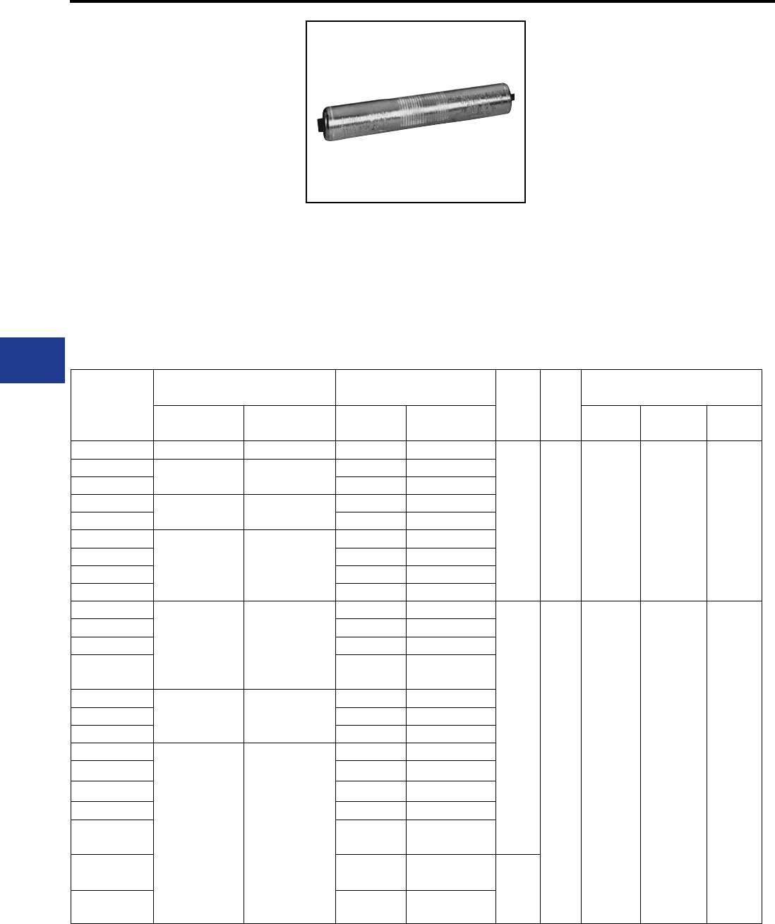
BURNDY®
Blue highlighted items are industry standard and most frequently ordered.
US: 1-800-346-4175 www.burndy.com Canada: 1-800-387-6487
Overhead Distribution
Compression Tap
TYPE YCR-R-G
HYSPLICE™
ACCOMMODATES:
AAC (STR, COMPRESSED),
ACSR, AAAC, COPPER
MATERIAL: ALUMINUM
TENSION RATING: ANSI
C119.4 CLASS 2
(PARTIAL TENSION)
Heavy-walled aluminum sleeve designed
to connect all aluminum or ACSR to copper
conductors, in all service conditions encountered
in transmission and distribution. Sleeve has solid
center barrier and is pre-lled with PENETROX™
Catalog
Number
Side A Side B
L O.D.
Tools, Die Set Catalog Number,
& (Crimps per End)
ACSR,
6201, 5005
Aluminum,
Copper
ACSR,
6201, 5005
Aluminum,
Copper Die Index Y35, Y750,
Y45 †, Y46 ‡ Y60B
YCR25RG6 1/0 (6-1) 1/0 (7, 12, 19) 1/0 (6-1) 1/0 (7, 12, 19)
6-3/8 1-1/16
654
or
705
U654
U705
Crimps
Overlap
L654
Crimps
Overlap
YCR26RG2 2/0 (6-1) 2/0 (7, 12, 19) 1/0 (6-1) 1/0 (7, 12, 19)
YCR26RG3 2/0 (6-1) 2/0 (7, 12, 19)
YCR27RG5 3/0 (6-1) 3/0 (7, 12, 19) 1/0 (6-1) 1/0 (7, 12, 19)
YCR27RG6 2/0 (6-1) 2/0 (7, 12, 19)
YCR28RG5
4/0 (6-1) 4/0 (7, 12, 19)
1/0 (6-1) 1/0 (7, 12, 19)
YCR28RG6 2/0 (6-1) 2/0 (7, 12, 19)
YCR28RG7 3/0 (6-1) 3/0 (7, 12, 19)
YCR28RG8 4/0 (6-1) 4/0 (7, 12, 19)
YCR291RG2
266.8 (18-1) 250 (19, 37)
266.8 (7, 12, 19)
2/0 (6-1) 2/0 (7, 12, 19)
7-3/8
1-1/4
317
or
705
U317
U705
Crimps
Overlap
L317
Crimps
Overlap
YCR291RG3 3/0 (6-1) 3/0 (7, 12, 19)
YCR291RG4 4/0 (6-1) 4/0 (7, 12, 19)
YCR291RG5 266.8 (18-1) 250 (19, 37)
266.8 (7, 12, 19)
YCR30RG4
266.8 (26-7) 300 (19, 37)
366.4 (19)
1/0 (6-1) 1/0 (7, 12, 19)
YCR30RG6 3/0 (6-1) 3/0 (7, 12, 19)
YCR30RG7 4/0 (6-1) 4/0 (7, 12, 19)
YCR32RG1
336.4 (18-1)
(26-7)
350 (19, 37)
397.5 (19)
1/0 (6-1) 1/0 (7, 12, 19)
YCR32RG2 2/0 (6-1) 2/0 (7, 12, 19)
YCR32RG3 3/0 (6-1) 3/0 (7, 12, 19)
YCR32RG4 4/0 (6-1) 4/0 (7, 12, 19)
YCR32RG5 266.8 (18-1) 250 (19, 37)
266.8 (7, 12, 19)
YCR32RG6 266.8 (26-7) 300 (19, 37)
366.4 (19) 6-5/8
YCR32RG7 336.4 (18-1)
(26-7)
350 (19, 37)
397.5 (19)
* Crimps overlap on both ends.
† U Die with adapter PT-6515
‡ U Die with adapter PUADP-1
For faster installations use BURNDY® PATRIOT®
family of battery tools.
joint compound, stripsealed and capped to limit
oxide growth and to increase life of connection.
H-52
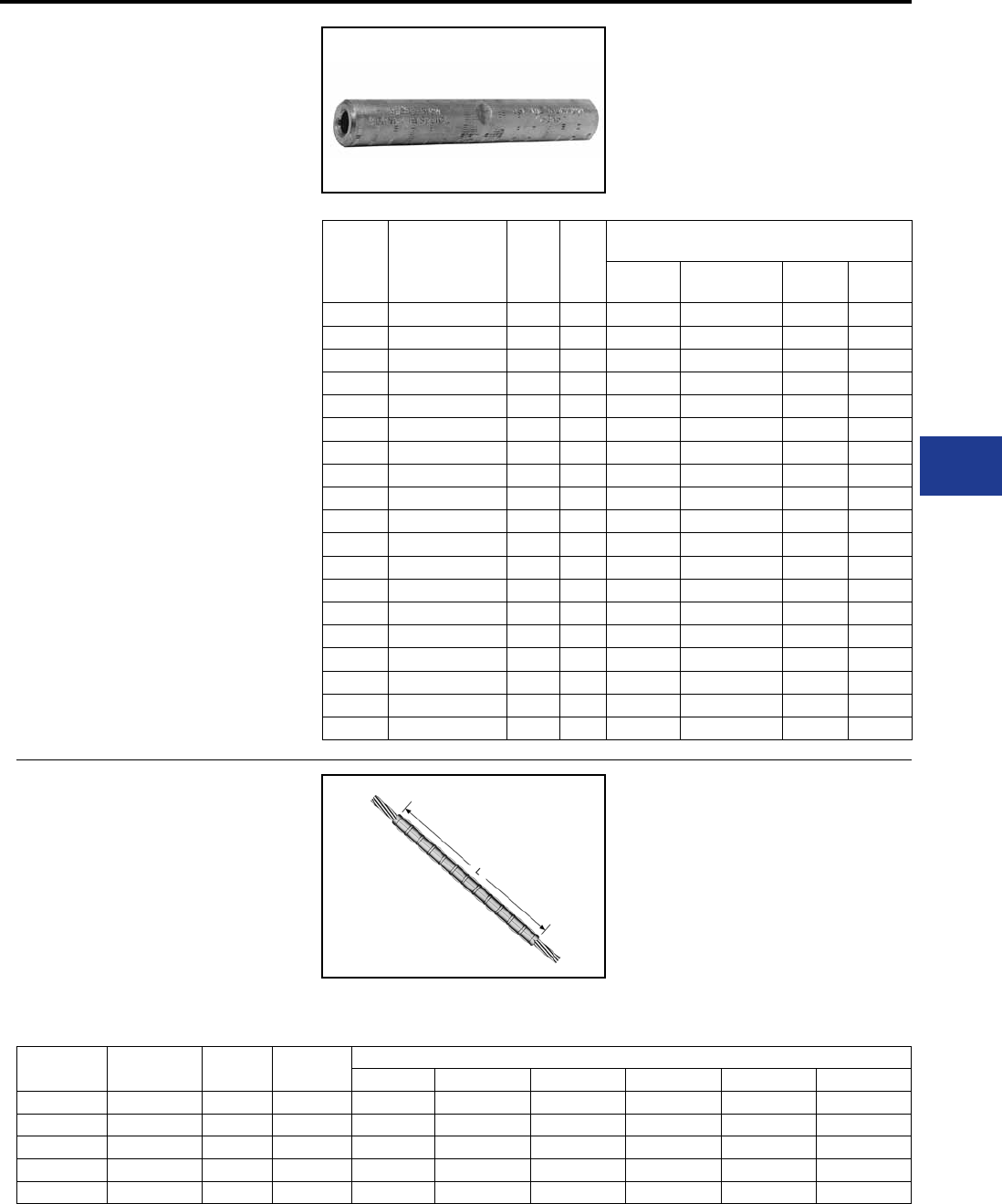
BURNDY®
Blue highlighted items are industry standard and most frequently ordered.
Canada: 1-800-387-6487 www.burndy.com US: 1-800-346-4175
Overhead Distribution
Compression Splices - Single Sleeve Jumper Normal Tension
TYPES YDS & YCS
HYSPLICE™
ACCOMMODATES: COPPER
MATERIAL: COPPER
TENSION RATING:
ANSI C119.4 CLASS 1A
(NORMAL TENSION)
Loop HYSPLICE™ connector designed to
withstand jumper loop tensile and vibration
stresses up to 60% RBS. Made of pure copper
tubing. Installed with standard HYSPLICE™ tools
and dies.
Catalog
Number Conductor L Die
Index
Tools, Die Set Catalog Number,
& (Crimps per End)
MD7, MD6 Y35, Y750,
Y45†, Y46‡ Y48B Y60BHU
YDS8W 8 Sol. 1-5/8 171 W171 (1) U171 (1)* — —
YDS6W 6 Sol. 2-5/8 161 W161 (2) U161 (1)* — —
YDS4W 4 Sol. 2-1/2 162 W162 (4) U162 (1)* — —
YDS2W 2 Sol. 3-3/4 163 W163 (6) U163 (2)* — —
YDS6C 6 (7) 2-3/4 161 W161 (2) U161 (1)* — —
YDS4C 4 (7) 2-5/8 162 W162 (4) U162 (1)* — —
YDS2C 2 (7), 3 (3) 3-5/8 163 W163 (6) U163 (2)* — —
YDS1C 1 (7, 19) 3-1/8 164 W164 (6) U164 (3)* — —
YCS25 1/0 (7, 19) 3-3/8 165 W165 (3) U165 (3) — —
YCS26 2/0 (7, 11, 12, 19) 3-3/8 166 W166 (6) U166 (3) — —
YCS27 3/0 (7, 19) 3-1/4 167 — U167 (3) — —
YCS28 4/0 (7, 12, 19) 3-1/8 168 — U168 (3) C168 (1) L168 (1)
YCS29 250 (7, 37, 19) 3-5/8 169 — U169 (4) C169 (2) L169 (2)
YCS30 300 (19, 37) 5-3/8 170 — U170 (4) C170 (1) L170 (1)
YCS31 350 (12, 19, 37) 5-3/8 267 — U267 (6) C267 (2) L267 (2)
YCS32 400 (19, 37) 5-3/4 209 — U209 (6) C209 (2) L209 (2)
YCS34 500 (19, 37) 5-1/8 210 — U210 (6) C210 (2) L210 (2)
YCS39 750 (37) 6-7/8 627 — — C627 (3) L627 (3)
YCS44 1000 (61, 37) 7-3/4 345 — — C345 (4) L345 (4)
RUS Accepted.
TYPE YCU-A
REPAIR SLEEVE
ACCOMMODATES: AAC (STR,
COMPRESSED, COMPACT)
MATERIAL: ALUMINUM
For restoring conductivity to damaged conductors.
Made of cast aluminum. Use same die as equivalent
Catalog
Number Conductor L Die Index Tools, Die Set Catalog Number, & (Number of Crimps)
MD7, MD6 Y35, Y750 Y45 Y46 Y48B Y60BHU
YCU2CA 2 (7) 7-5/8 163 W163 (27) U163 (9)* † ‡ — —
YCU25A 1/0 (7) 8-3/4 243 W243 (20) U243 (10) † ‡ — —
YCU28A 4/0 (7, 19) 11-7/8 249 W249 (28) U249 (14) † ‡ C249 (7) L249 (7)
YCU291A 266.8 (7) 11-5/8 251 — U251 (20) † ‡ C251 (10) L251 (10)
YCU301A 336.4 (19,37) 11-5/8 321 — U321 (20) † ‡ C231 (10) L231 (10)
full-tension sleeve. Use of PENETROX™ joint
compound required.
* Multiple crimp die set; makes more than one
crimp per tool compression. Figure indicates
number of compressions.
† UDie with adapter PT-6515.
‡ U Die with adapter PUADP-1.
For faster installations use BURNDY® PATRIOT®
family of battery tools.
* Multiple crimp die set; makes more than one
crimp per tool compression. Figure indicates
number of compressions.
† UDie with adapter PT-6515.
‡ U Die with adapter PUADP-1.
For faster installations use BURNDY® PATRIOT®
family of battery tools.
H-53
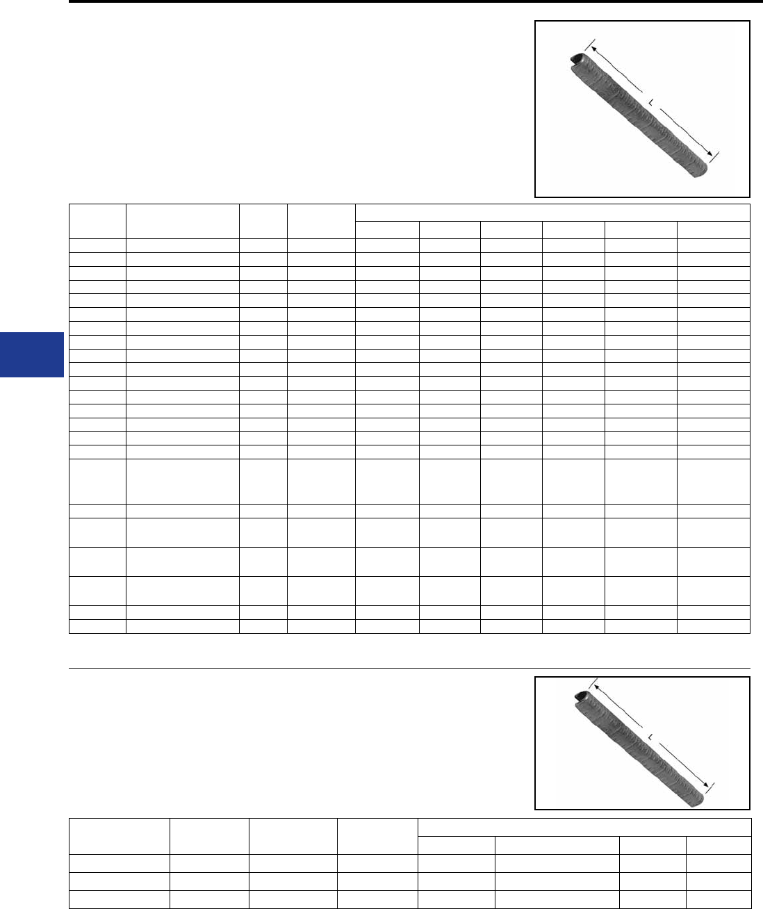
BURNDY®
Blue highlighted items are industry standard and most frequently ordered.
US: 1-800-346-4175 www.burndy.com Canada: 1-800-387-6487
Overhead Distribution
Compression Repair Sleeves
TYPES YCU-R & YOU-R
ACCOMMODATES: ACSR (STR,
COMPRESSED, COMPACT)
MATERIAL: ALUMINUM
For restoring conductivity to damaged conductors.
Made of cast aluminum. Sizes up thru 266.8
are U-shaped. For 300 and larger, sleeves are
Catalog
Number Conductor L Die
Index
Tools, Die Set Catalog Number & (Number of Crimps)
MD7, MD6 Y35, Y750 Y45 Y46 Y48B Y60BHU
YCU4R 4 (6-1), (7-1) 4AAC 6-1/4 237 W237 (12) U237 (6) † ‡ — —
YCU4RG1 4 (7-1) 8-1/4 239 W239 (16) U239 (8) † ‡ — —
YCU2R 2 (6-1, 7-1) 8-1/4 239 W239 (16) U239 (8) † ‡ — —
YCU25R 1/0 (6-1) 8-3/4 243 W243 (20) U243 (10) † ‡ — —
YCU26R 2/0 (6-1) 10 245 W245 (24) U245 (12) † ‡ — —
YCU27R 3/0 (6-1) 10 247 W247 (24) U247 (12) † ‡ — —
YCU28R 4/0 (6-1) 11-7/8 249 W249 (28) U249 (14) † ‡ C249 (7) L249 (7)
YCU30R 266.8 (6-1, 18-1, 26-7) 11-5/8 251 — U251 (20) † ‡ C251 (10) L251 (10)
YOU32R 300 (26-7) 13 316 — U316 (21) † ‡ C316 (7) L316 (7)
YCU321R 336.4 (18-1) 11-5/8 547, 655, 490 — U490 (20) † ‡ C490 (10) L490 (10)
YOU33R 336.4 (26-7, 30-7) 13 316 — U316 (21) † ‡ C316 (7) L316 (7)
YOU35R 397.5 (18-1, 26-7, 30-7) 13 317, 426 — U317 (21) † ‡ C317 (7) L317 (7)
YOU361R 477 (18-1) 12-47/50 327 — U327 (21) † ‡ C327 (7) L327 (7)
YOU37R 477 (24-7, 26-7, 30-7) 12-47/50 261, 318 — U261 (21) † ‡ C261 (7) L261 (7)
YOU39R 556.5 (24-7, 26-7) 13-3/4 608 — U608 (24) † ‡ C608 (8) L608 (8)
YOU41R 605 (24-7, 54-7) 13-3/4 292, 578, 319 — — S292 (24) P292 (24) C292 (8) L292 (8)
YOU43R
605 (30-19)
636 (26-7, 30-19)
666.6 (24-7, 54-7)
13-3/4 292, 319, 578 — — S292 (24)
S319 (24)
P292 (24)
P319 (24)
C352 (8)
C319 (8)
C292 (8)
L292 (8)
L319 (8)
YOU421R 636 (36-1) 13-3/4 292, 578 — — S292 (24) P292 (24) C292 (8) L292 (8)
YOU453R 715.5 (26-7)
795 (36-1) 13-3/4 292, 578 — — S292 (24) P292 (24) C292 (8) L292 (8)
L578 (8)
YOU44R 715.5 (54-7) 13-3/4 319 — — S319 (24) P319 (24) C319 (8) L319 (8)
YOU45R 795 (26-7, 54-7) 13-3/4 352, 579 — — S352 (24)
S579 (24)
P352 (24)
P579 (24)
C352 (8)
C579 (8)
L352 (8)
L579 (8)
YOU48R 900 (54-7) 954 (54-7) 14-1/4 575 — — — — C575 (10) L575 (10)
YOU49R 1033.5 (54-7) 14-1/4 422 — — — — — L422 (10)
TYPE YCU-R
Repair Sleeve for
ACSR “Static Wire”
HYSPLICE™ sleeve designed to withstand jumper
loop tensile and vibration stresses. Made of aluminum
with staked-in cable stop. Installed with same die
Catalog Number Conductor L Die
Index
Tools, Die Set Catalog Number & (Number of Crimps)
MD7, MD6 Y35, Y750, Y45†, Y46‡ Y48B Y60BHU
YCU27R 110.8 (12-7) 10 247 W247 (24) U247 (12) — —
YCU28R 159 (12-7) 11-7/8 249 W249 (28) U249 (14) C249 (7) L249 (7)
YCU30R 190.8 (12-7) 11-5/8 251 — U251 (20) C251 (10) L251 (10)
RUS Accepted
two-piece interlocking elements. Use same
die as equivalent full-tension sleeve. Use of
PENETROX™ joint compound required.
† U Die with adapter PT-6515. ‡ U Die with adapter PUADP-1. For faster installations use BURNDY® PATRIOT®
family of battery tools.
as equivalent full tension sleeves. Pre-lled with
PENETROX™ joint compound.
† U Die with adapter PT-6515. ‡ U Die with adapter PUADP-1. For faster installations use BURNDY® PATRIOT®
family of battery tools.
H-54
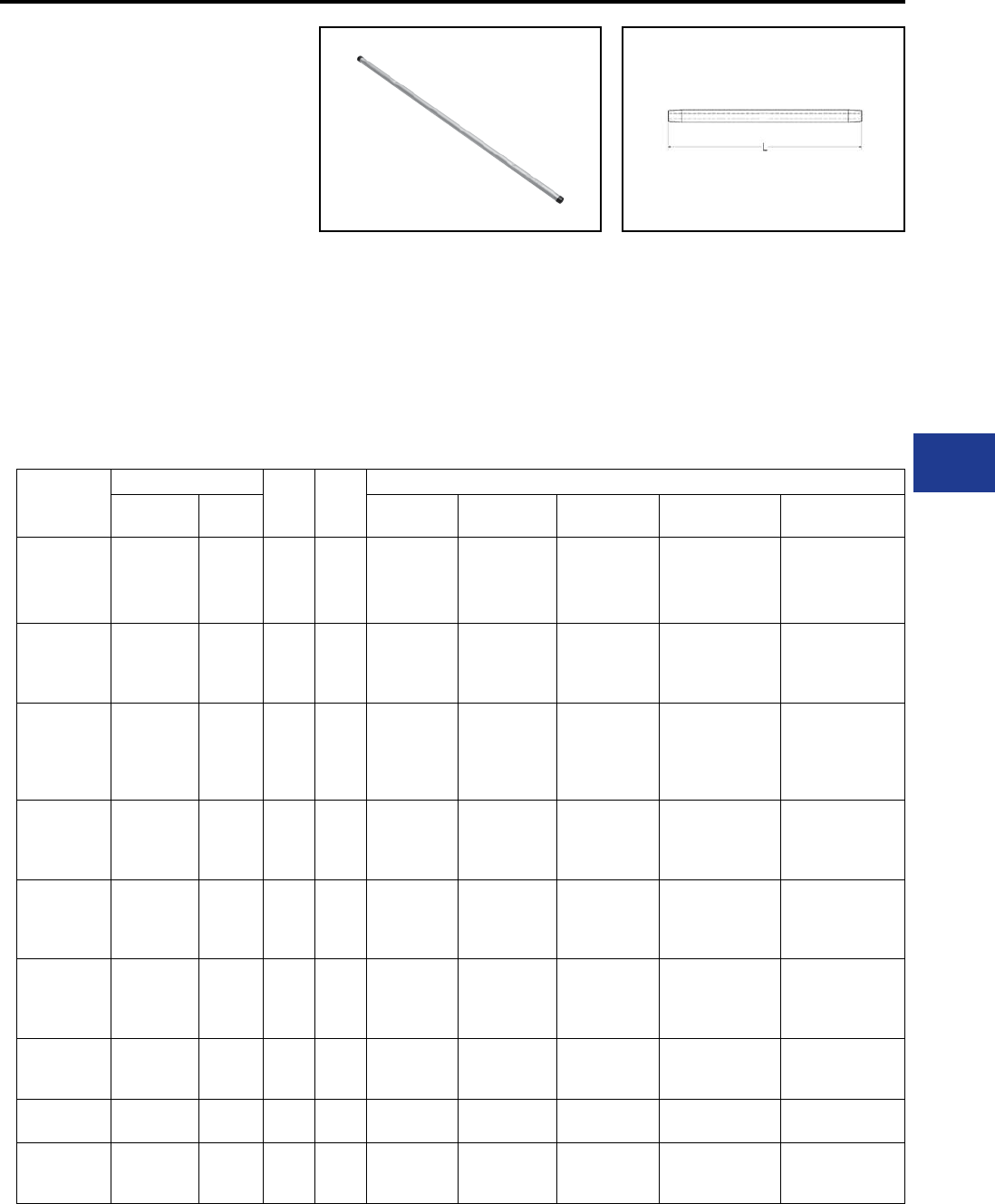
BURNDY®
Blue highlighted items are industry standard and most frequently ordered.
Canada: 1-800-387-6487 www.burndy.com US: 1-800-346-4175
Overhead Distribution
Compression Splices - Single Sleeve Full Tension Replacement
U Die with adapter PT-6515.
U Die with adapter PUADP-1.
* Multiple crimp die set; makes more than one
crimp per tool compression. Figure indicates
number of compressions.
** MD6 NON-BOW Dies produce straight
sleeves without rotating tool.
† Overlap Crimps
For faster installations use BURNDY® PATRIOT®
family of battery tools.
TYPE YDSR-RL
UNISPLICE™
Replacement Splice
UNISPLICE™
ACCOMMODATES: AAC (STR,
COMPACT), ACSR, and AAAC
MATERIAL: ALUMINUM
TENSION RATING:
ANSI C119.4 CLASS 1A
(FULL TENSION)
Single sleeve aluminum UNISPLICE™ is designed
to facilitate the permanent replacement of existing
line splices, including the automatic type. Utilizing
all the benets of the standard UNISPLICE™, the
extra long Replacement UNISPLICE™ lls the gap
of a cutout splice and eliminates the need to nd
like conductor. It also reduces installation time of
the current standard methods by half, reducing the
total number of splices from two to one. All splices
are prelled with PENETROX™ joint compound,
stripsealed and capped to limit oxide growth and to
increase the life of the connection.
Catalog
Number
Conductor
LDie
Index
Installation Tooling Data (# of crimps per end)
AWG / kcmil Str. MD7, MD6
HYTOOL™ Y35 Y750 Y45 Y46
YDSR4RL
4 ACSR
4 6201
4 5005
4 AAC
6-1; 7-1
7
7
7
24.63″
BG
687
243
W-BG (11)*
W687 (9)**
W243 (11)
UBG (9)*
U243 (6)
UBG (9)
U243 (6)
UBG (9)
U243 (6)
UBG (9)
U243 (6)
YDSR2RL
2 ACSR
2 6201
2 5005
2 AAC
6-1; 7-1
7
7
7
28.00″
BG
687
243
W-BG (20)
W687 (10)**
W243 (10)
UBG (8)*
U243 (5)
UBG (8)
U243 (5)
UBG (8)
U243 (5)
UBG (8)
U243 (5)
YDSR25RL
1/0 ACSR
1/0 6201
1/0 5005
1/0 AAC
6-1
7
7
7
34.13″
C
167
247
660
702
WC (30)
W247 (14)
W660 (15)
W702 (14)**
U167/U568 (15)
U247 (8)
U660 (8)
U167/U568 (15)
U247 (8)
U660 (8)
U167/U568 (15)
U247 (8)
U660 (8)
U167/U568 (15)
U247 (8)
U660 (8)
YDSR26RL
2/0 ACSR
2/0 6201
2/0 5005
2/0 AAC
6-1
7
7
7
35.50″ 659 — U659 †
(11)
U659 †
(11)
U659 †
(11)
U659 †
(11)
YDSR27RL
3/0 ACSR
3/0 6201
3/0 5005
3/0 AAC
6-1
7
7
7
42.25″ 658 — U658 †
(16)
U658 †
(16)
U658 †
(16)
U658 †
(16)
YDSR28RL
4/0 ACSR
4/0 6201
4/0 5005
4/0 AAC
6-1
7
7
7
45.75″ 654 — U654 †
(18)
U654 †
(18)
U654 †
(18)
U654 †
(18)
YDSR321RL
336.4 ACSR
336.4 AAC
350.0 AAC
18-1
19
19
45.75″ 655 — U655 †
(21)
U655 †
(21)
U655 †
(21)
U655 †
(21)
YDSR341RL 397.5 ACSR
419.6 5005
18-1
19 49.50″ 327 — U327 (18) U327 (18) U327 (18) U327 (18)
YDS361RL
477 (18-1)
556.5 (18-1)
587.2 5005
18-1
18-1
19
23.21″ 720
788 —U-788 †
(31)
U-788 †
(31)
U-788 †
(31)
U-788 †
(31)
H-55
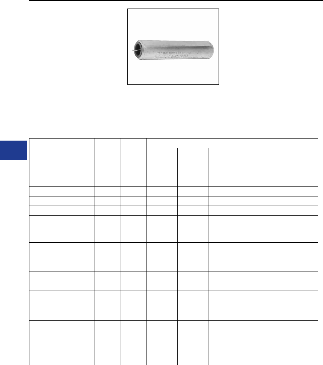
BURNDY®
Blue highlighted items are industry standard and most frequently ordered.
US: 1-800-346-4175 www.burndy.com Canada: 1-800-387-6487
Overhead Distribution
TYPES YDS-A & YDS-AT
HYSPLICE™
ACCOMMODATES: AAC (STR,
COMPRESSED, COMPACT)
MATERIAL: ALUMINUM
TENSION RATING:
ANSI C119.4 CLASS 1
(FULL TENSION)
Full-Tension HYSPLICE™ sleeve made of
aluminum tubing with staked-in cable stop. Sizes
1/0 and larger tapered for gradual transition of
stress. Installed with HYSPLICE™tools and dies.
Catalog
Number Conductor L Die
Index
Tools, Die Set Catalog Number & (Number of Crimps)
MD7, MD6 Y35, Y750 Y45 Y46 Y48B Y60BHU
YDS6WA 6 (1) 3 161 W161 (2) U161 (1)* † ‡ — —
YDS4WA 4 (1) 2-5/8 162 W162 (4) U162 (1)* † ‡ — —
YDS2WA 2 (1) 3-7/8 163 W163 (6) U163 (2) † ‡ — —
YDS6CA 6 (7) 3 161 W161 (2) U161 (1)* † ‡ — —
YDS4CA 4 (7) 2-5/8 162 W162 (4) U162 (1)* † ‡ — —
YDS2CA 2 (7) 3-7/8 163 W163 (6) U163 (2) † ‡ — —
YDS25AT 1/0 (7) 7-1/4 BG
243
BG (12)
W243 (6)
BG (6)
U243 (3) † ‡ — —
YDS26AT 2/0 (7) 9-1/4 245 W245 (9) U245 (5) † ‡ — —
YDS27AT 3/0 (7,19) 7-1/4 247 W247 (8) U247 (4) † ‡ C247 (3) L247 (3)
YDS28AT 4/0 (7, 19) 10-1/2 249 W249 (12) U249 (6) † ‡ C249 (3) L249 (3)
YDS29AT 250 (19) 7-1/2 616 — U616 (6) † ‡ — —
YDS291AT 266.8 (7,19) 8-5/8 251 — U251 (7) † ‡ C251 (4) L251 (4)
YDS301AT 336.4 (19, 37) 9-7/8 321 — U321 (8) † ‡ C321 (4) L321 (4)
YDS31AT 350 (19) 11 490 — U490 (9) † ‡ C490 (3) L490 (3)
YDS311AT 397.5 (19) 12-1/4 468 — 468 (10) † ‡ — —
YDS331AT 477 (19) 12-3/4 317 — U317 (9) † ‡ C317 (3) L317 (3)
YDS351AT 556.5 (19, 37) 12-3/4 261 — U261 (9) † ‡ C261 (3) L261 (3)
YDS361AT 636 (37) 13-1/2 469 — — S469 (8) P469 (8) C469 (4) L469 (4)
YDS391AT 795 (37),
800 (61) 13-5/8 342 — — S342 (8) P342 (8) C342 (4) L342 (4)
YDS431AT 954 (37, 61) 17-5/8 352 — — S352 (10) P352 (10) C352 (5) L352 (5)
* Multiple crimp die set; makes more than one crimp per tool compression.
Figure indicates number of compressions.
† U Die with adapter PT-6515.
‡ U Die with adapter PUADP-1.
For faster installations use BURNDY® PATRIOT® family of battery tools.
Pre-lled with PENETROX™ joint compound,
stripsealed and capped to limit oxide growth and
to increase the life of the connection.
Compression Splices - Single Sleeve Full Tension
H-56
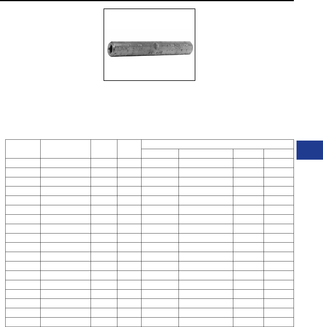
BURNDY®
Blue highlighted items are industry standard and most frequently ordered.
Canada: 1-800-387-6487 www.burndy.com US: 1-800-346-4175
Overhead Distribution
Compression Splices - Single Sleeve Full Tension
TYPES YDS & YDS-C
HYSPLICE™
ACCOMMODATES: STRANDED
COPPER
MATERIAL: COPPER
TENSION RATING:
ANSI C119.4 CLASS 1
(FULL TENSION)
Made of pure copper tubing. Designed to develop
the full rated breaking strength of hard drawn or
medium hard drawn copper conductor. Installed
with standard tooling.
Catalog
Number
Stranded
Conductor LDie
Index
Tools, Die Set Catalog Number, & (Crimps per End)
MD7, MD6 Y35, Y750, Y45†, Y46‡ Y48B Y60BHU
YDS6C 6 (7) 2-3/4 161 W161 (2) U161 (1)* — —
YDS4C 4 (7) 2-5/8 162 W162 (4) U162 (1)* — —
YDS3C-3 3 (3) 5-1/4 163 W163 (9) U163 (3)* — —
YDS2C 2 (7) 3-5/8 163 W163 (6) U163 (2)* — —
YDS2C-3 2 (3) 3-5/8 163 W163 (6) U163 (2)* — —
YDS1C 1 (7, 19) 4-1/4 164 W164 (6) U164 (3)* — —
YDS1C-3 1 (3) 6-1/4 459 — U459 (6) — —
YDS25 1/0 (7, 19) 5-3/8 165 W165 (3) U165 / U205 (6) — —
YDS26 2/0 (7, 12, 19) 6 166 W166 (12) U166 / U459 (6) — —
YDS27 3/0 (7, 19) 6-3/4 167 — U167 / U568 (7) — —
YDS28 4/0 (7, 12, 19) 6-7/8 168 — U168 (9) C168 (3) L168 (3)
YDS29 250 (7, 12, 37) 7-1/2 169 — C169 (9) C169 (3) L169 (3)
YDS30 300 (19, 37) 8-1/8 170 — U170 (13) C170 (3) L170 (3)
YDS31 350 (12, 19, 37) 10-1/4 267 — U267 (12) C267 (4) L267 (4)
YDS32 400 (19, 37) 12-3/4 209 — U209 (15) C209 (5) L209 (5)
YDS34 500 (19, 37) 11-5/8 210 — U210 (15) C210 (5) L210 (5)
YDS39 750 (37) 12-3/4 627 — — C627 (7) L627 (7)
YDS44 1000 (61, 37) 15-1/4 345 — — C345 (10) L345 (10)
* Multiple crimp die set; makes more than one crimp per tool compression.
Figure indicates number of compressions.
† U Die with adapter PT-6515.
‡ U Die with adapter PUADP-1.
For faster installations use BURNDY® PATRIOT® family of battery tools.
H-57
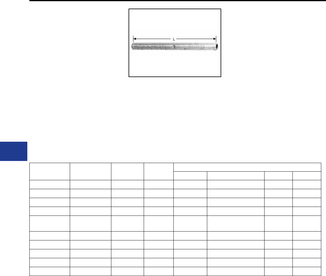
BURNDY®
Blue highlighted items are industry standard and most frequently ordered.
US: 1-800-346-4175 www.burndy.com Canada: 1-800-387-6487
Overhead Distribution
Compression Splices - Single Sleeve Full Tension
TYPES YDS-W & YDS
HYSPLICE™
ACCOMMODATES: SOLID COPPER
MATERIAL: COPPER
TENSION RATING:
ANSI C119.4 CLASS 1
(FULL TENSION)
YDS-W is designed to develop full rated breaking
strength of hard drawn and medium hard drawn
solid copper conductor. Made of pure copper
tubing. Installed with standard tooling.
RUS Accepted
Catalog
Number
Solid
Conductor LDie
Index
Tools, Die Set Catalog Number, & (Crimps per End)
MD7, MD6 Y35, Y750, Y45†, Y46‡ Y48B Y60BHU
YDS8WG1 8 Sol. 1-7/8 161 W161 (1) U161 (1) — —
YDS8W 8 Sol. 1-1/2 171 W171 (1) U171 (1)* — —
YDS6W 6 Sol. 2-5/8 161 W161 (2) U161 (1)* — —
YDS4W 4 Sol. 2-1/2 162 W162 (4) U162 (1)* — —
YDS3W 3 Sol. 2-7/8 163, 308 W163 (4) U163 (2)*
U308 (2)* — —
YDS2W 2 Sol. 3-3/4 163 W163 (6) U163 (2)* — —
YDS1W 1 Sol. 5-7/8 164 W164 (8) U164 (4)* — —
YDS75 1/0 Sol. 6-1/4 165 W165 (6) U165/U205 (6) — —
YDS76 2/0 Sol. 6-5/8 166 W166 (12) U166/U459 (6) — —
YDS78 4/0 Sol. 7-7/8 168 — U168 (9) C168 (3) L168 (3)
* Multiple crimp die set; makes more than one crimp per tool compression.
Figure indicates number of compressions.
† U Die with adapter PT-6515.
‡ U Die with adapter PUADP-1.
For faster installations use BURNDY® PATRIOT® family of battery tools.
H-58
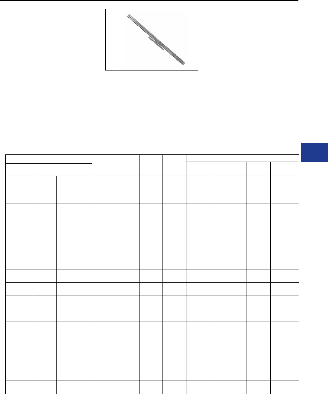
BURNDY®
Blue highlighted items are industry standard and most frequently ordered.
Canada: 1-800-387-6487 www.burndy.com US: 1-800-346-4175
Overhead Distribution
Compression Splices - Two Sleeve Full Tension
TYPES YDS-R SET,
YDS-RP1 (Aluminum Sleeve)
YDS-RP2 (Steel Sleeve)
HYSPLICE™
ACCOMMODATES: ACSR (STR,
COMPRESSED AND COMPACT)
MATERIAL:
ALUMINUM (OUTER SLEEVE),
STEEL (INNER SLEEVE)
TENSION RATING:
ANSI C119.4 CLASS 1
(FULL TENSION)
RUS Accepted
Catalog Number
Conductor L Die
Index
Tools, Die Set Catalog Number, & (Crimps per End)
MD7, MD6 Y35, Y750,
Y45†, Y46‡ Y48B Y60BHU
Set Sleeves
YDS021R Steel
Alum.
YDS25RP2
YDS021RP1 2 (7/1) Sparate 4.75"
17.00"
242
241
W242 (8)
W241 (10)
U242 (4)
U241 (5) — —
YDS1R Steel
Alum.
YDS1RP2
YDS1RP1 1 (6/1) Robin 4.13"
16.63"
240
241
W240 (6)
W241 (10)
U240 (3)
U241 (5) — —
YDS25R Steel
Alum.
YDS25RP2
YDS25RP1 1/0 (6/1) Raven 4.75"
17.00"
242
243
W242 (8)
W243 (12)
U242 (4)
U243 (6) — —
YDS26R Steel
Alum.
YDS26RP2
YDS26RP1 2/0 (6/1) Quail 5.25"
19.75"
242
245
W242 (8)
W245 (15)
U242 (4)
U245 (8) — —
YDS27R Steel
Alum.
YDS27RP2
YDS27RP1 3/0 (6/1) Pigeon 5.25"
16.75"
248
247
W246 (16)
W247 (12)
U248 (8)
U247 (6)
C248 (3)*
C247 (4)*
L248 (3)*
L247 (4)*
YDS28R Steel
Alum.
YDS28RP2
YDS28RP1 4/0 (6/1) Penquin 5.13"
18.88"
248
249
W248 (14)
W249 (14)
W248 (7)
W249 (7)
C248 (7)*
C249 (4)
L248 (4)*
L249 (4)
YDS291R Steel
Alum.
YDS1RP2
YDS291RP1 266.8 (18 - 1) 4-1/8"
19-3/4"
240
251
W240 (6)
—
U240 (3)
U251 (12)
—
C251 (6)
—
L251 (6)
YDS30R Steel
Alum.
YDS30RP2
YDS30RP1
266.8 (26/7) Owl
266.8 (26/7) Partridge
6.00"
19.75"
250
251 —U250 (10)
U251 (10)
C250 (3)
C251 (5)
L250 (3)
L251 (5)
YDS321R Steel
Alum.
YDS25RP2
YDS321RP1 336.4 (18/1) Merlin 4.75"
17.88"
242
490
W242 (8)
—
U242 (4)
U490 (10)
C242 (2)*
C490 (4)
L242 (2)*
L490 (4)
YDS32R Steel
Alum.
YDS32RP2
YDS33RP1
336.4 (26/7) Linnet
336.4 (30/7) Oriole
6.88"
22.25"
252
316 —U252 (9)
U316 (9)
C252 (3)
C316 (3)
L252 (3)
L316 (3)
YDS33R Steel
Alum.
YDS41RP2
YDS33RP1 336.4 (30/7) Oriole 8.63"
22.25"
305
316 —U305 (9)
U316 (9)
C305 (3)
C316 (3)
L305 (3)
L316 (3)
YDS34R Steel
Alum.
YDS34RP2
YDS35RP1
397.5 (26/7) Ibis
397.5 (30/7) Lark
6.25"
25.63"
253
317 —U253 (9)
U317 (12)
C253 (3)
C317 (4)
L253 (3)
L317 (4)
YDS35R Steel
Alum.
YDS44RP2
YDS35RP1 397.5 (30/7) Lark 8.00"
25.63"
255
317 —U255 (12)
U317 (12)
C255 (4)
C317 (4)
L255 (4)
L317 (4)
YDS361R Steel
Alum.
YDS27RP2
YDS361RP1 477.0 (18/1) Pelican 5.25"
25.63"
248
327
W248 (16)
—
U248 (8)
U327 (16)
C248 (4)*
C327 (5)
L248 (4)*
L327 (5)
YDS326R Steel
Alum.
YDS34RP2
YDS37RP1
477.0 (24/7) Flicker
477.0 (26/7) Hawk
477.0 (30/7) Hen
6.25"
26.38"
253
261 —U253 (9)
U261 (12)
C253 (3)
C261 (4)
L253 (3)
L261 (4)
YDS36R Steel
Alum.
YDS36RP2
YDS37RP1 477.0 (26/7) Hawk 7.88"
26.38"
350
261 —U350 (12)
U261 (12)
C350 (4)
C261 (4)
L350 (4)
L261 (4)
Two-piece, full tension HYSPLICE™, consists
of aluminum outer sleeve and steel inner sleeve.
Tapered outer sleeve provides gradual transition
of stress. Filler holes provided for PENETROX™
joint compound. Sizes 1/0 and larger supplied
with plugs for ller hole. Installed with standard
HYSPLICE™ tools and dies (thru 556 with Y35 or
Y750 HYPRESS™). Aluminum and steel sleeves
can be ordered separately or in sets.
* Multiple crimp die set; makes more than one crimp
per tool compression.
Figure indicates number of compressions.
† U Die with adapter PT-6515.
‡ U Die with adapter PUADP-1.
For faster installations use BURNDY® PATRIOT®
family of battery tools.
H-59
BURNDY®
Blue highlighted items are industry standard and most frequently ordered.
US: 1-800-346-4175 www.burndy.com Canada: 1-800-387-6487
Overhead Distribution
Compression Splices - Two Sleeve Full Tension
Catalog Number Conductor L Die
Index
Tools, Die Set Catalog Number, & (Crimps per End)
Y35, Y750, Y45 Y46 Y48B Y60BHU
Set Sleeves
YDS392R Steel
Alum.
YDS41RP2
YDS39RP1 556.5 (24-7) 8-5/8
26-1/8
305
608
U305 (9)
U608 (15)
†
†
‡
‡
C305 (3)
C608 (5)
L305 (3)
L608 (5)
YDS40R Steel
Alum.
YDS44RP2
YDS39RP1 556.5 (26-7) 8
26-1/8
255
608
U255 (12)
U608 (15)
†
†
‡
‡
C255 (4)
C608 (5)
L255 (4)
L608 (5)
YDS42R Steel
Alum.
YDS43RP2
YDS43RP1 636 (24-7) 8
32-1/2
254
319
—
—
S254 (15)
S319 (18)
P254 (15)
P319 (18)
C254 (5)
C319 (6)
L254 (5)
L319 (6)
YDS43R45RS Steel
Alum.
YDS45RP2
YDS43RP1 636 (26-7) 9
32-1/2
320
319
—
—
S320 (15)
S319 (18)
P320 (15)
P319 (18)
C320 (5)
C319 (6)
L320 (5)
L319 (6)
YDS43R43RS Steel
Alum.
YDS43RP2
YDS43RP1 666.6 (24-7) 8
32-1/2
254
319
—
—
S254 (15)
S319 (18)
P254 (15)
P319 (18)
C254 (5)
C319 (6)
L254 (5)
L319 (6)
YDS451R49RS Steel
Alum.
YDS49RP2
YDS451RP1 795 (26-7) 10
32-1/2
419
579
—
—
S419 (21)
S579 (13)
P419 (21)
P579 (13)
C419 (7)
C579 (6)
L419 (7)
L579 (6)
YDS45R45RS Steel
Alum.
YDS45RP2
YDS45RP1 795 (54-7) 9
32-1/2
320
352
—
—
S320 (15)
S352 (12)
P320 (15)
P352 (12)
C320 (5)
C352 (6)
L320 (5)
L352 (6)
YDS451R34RS Steel
Alum.
YDS34RP2
YDS451RP1 900 (45-7) 6-1/4
32-1/2
253
579
U253 (9)
—
†
S579
‡
P579
C253 (3)
C579 (6)
L253 (3)
L579 (6)
YDS49R Steel
Alum.
YDS49RP2
YDS49RP1 1033.5 (54-7) 10
37
419
422
—
—
—
—
—
—
C419 (7)
—
L419 (7)
L422 (8)
YDS50R Steel
Alum.
YDS36RP2
YDS49RP1 1113 (45-7) 7-7/8
37
350
422
U350 (12)
—
†
—
‡
—
C350 (4)
—
L350 (4)
L422 (8)
Catalog Number Conductor L Die
Index
Tools, Die Set Catalog Number, & (Crimps per End)
MD7, MD6 Y35, Y750, Y45†, Y46‡ Y48B Y60BHU
Set Sleeves
YDS011R Steel
Alum.
YDS27RP2
YDS011RP1 80 (8/1) 5-1/4
19-3/4
248
245
W248 (16)
W245 (12)
U248 (8)
U245 (6)
—
—
—
—
YDS251R Steel
Alum.
YDS34RP2
YDS251RP1 101.8 (12/7) 6-1/4
22-1/4
253
316
—
—
U253 (9)
U316 (9)
C253 (3)
C316 93)
L253 (3)
L316 (3)
YDS261R Steel
Alum.
YDS41RP2
YDS261RP1 134.6 (12/7) 8-5/8
22-1/4
305
316
—
—
U305 (9)
U316 (9)
C305 (3)
C316 (3)
L305 (3)
L316 (3)
YDS271R Steel
Alum.
YDS44RP2
YDS271RP1 159 (12/7) 8
25-5/8
255
317
—
—
U255 (12)
U317 (12)
C255 (4)
C317 (4)
L255 (4)
L317 (4)
† U Die with adapter PT-6515.
‡ U Die with adapter PUADP-1.
FOR ACSR “STATIC” WIRE
TYPES YDS-R SET,
YDS-RP1 (Aluminum Sleeve)
YDS-RP2 (Steel Sleeve)
(Continued)
HYSPLICE™
ACCOMMODATES: ACSR (STR,
COMPRESSED AND COMPACT) RUS Accepted
MATERIAL:
ALUMINUM (OUTER SLEEVE),
STEEL (INNER SLEEVE)
TENSION RATING:
ANSI C119.4 CLASS 1
(FULL TENSION)
† U Die with adapter PT-6515.
‡ U Die with adapter PUADP-1.
For faster installations use BURNDY® PATRIOT®
family of battery tools.
H-60
BURNDY®
Blue highlighted items are industry standard and most frequently ordered.
Canada: 1-800-387-6487 www.burndy.com US: 1-800-346-4175
Overhead Distribution
Compression Splices - Single Sleeve Full Tension (Reduced Bird Caging)
TYPE YDS-RLY
UNISPLICE™
ACCOMMODATES: AAC (STR,
COMPRESSED), ACSR AND AAAC
MATERIAL: ALUMINUM
TENSION RATING:
ANSI C119.4 CLASS 1
(FULL TENSION)
Single sleeve splice similar to UNISPLICE™ type
YDS-RL, except designed to eliminate possible
conductor basketing on ACSR. Installed by
crimping from end of connector towards center
with standard tooling. Supplied pre-lled with
PENETROX™ joint compound, stripsealed and
RUS Accepted
Catalog
Number Conductor ††† L Die
Index
Tools, Die Set Catalog Number, & (Crimps per End)
MD7, MD6 Y35, Y750, Y45†, Y46‡ Y48B Y60BHU
YDS4RLY
4ACSR (7-1)
4ACSR (6-1)
4 6201 (7)
4 5005 (7)
4AAC (7)
12-1/2 BG, or 243, or 687
BG (20)
W-BG (10)*
W687 (10)**
U-BG (8)*
U243 (6) C243 (3) L243 (3)
YDS2RLY
2ACSR (6-1)
2 6201 (7)
2 5005 (7)
2AAC (7)
12-3/8 BG, or 243, or 687
BG (20)
W-BG (10)*
W687 (10)**
U-BG (8)*
U243 (6) C243 (3) L243 (3)
YDS021RLY
2ACSR (7-1)
2ACSR (6-1)
2 6201 (7)
2AAC (7)
14-3/8 C, or 167, or
247, or 702
W-C (24)
W702 (11)**
U167 (12)
U247 (6) C167 (6) C167 (6)
YDS25RLY
1/0 ACSR (6-1)
1/0 6201 (7)
1/0 5005 (7)
1/0 AAC (7)
17 C, or 167, or 247, or
660, or 702
W-C (30)
W660 (16)
W702 (13)**
U660 (8)
U167 (16)
U247 (8)
C167 (5) C167 (5)
YDS26RLY
2/0 ACSR (6-1)
2/0 6201 (7)
2/0 5005 (7)
2/0 AAC (7)
15 659 —
U659
Crimps
Overlap
— —
YDS27RLY
3/0 ACSR (6-1)
3/0 6201 (7)
3/0 5005 (7)
3/0 AAC (7)
21 658 —
U658
Crimps
Overlap
— —
YDS28RLY
4/0 ACSR (6-1)
4/0 6201 (7)
4/0 5005 (7)
4/0 AAC (7)
21 654 —
U654
Crimps
Overlap
— —
YDS321RLY 336.4 ACSR (18-1)
336.4 AAC (19) 20-1/2 655 —
U655
Crimps
Overlap
— —
* Multiple crimp die set; makes more than one
crimp per tool compression. Figure indicates
number of compressions.
** MD6 NON-BOW Dies produce straight sleeves
without rotating tool.
‡ U Die with adapter PUADP-1.
† U Die with adapter PT-6515.
††† Accommodates ACSR with aluminized steel
core.
For faster installations use BURNDY® PATRIOT®
family of battery tools.
capped to limit oxide growth and to increase
the life of the connection. Factory installed tape
on pressure relief holes must be in place when
conductors are inserted.
H-61
BURNDY®
Blue highlighted items are industry standard and most frequently ordered.
US: 1-800-346-4175 www.burndy.com Canada: 1-800-387-6487
Overhead Distribution
Compression Splices - Single Sleeve Full Tension
TYPES YDS-RL & YDS-LT
UNISPLICE™
ACCOMMODATES: AAC (STR,
COMPRESSED), ACSR AND AAAC
MATERIAL: ALUMINUM
TENSION RATING:
ANSI C119.4 CLASS 1
(FULL TENSION)
Single-sleeve aluminum UNISPLICE™ designed
to splice ACSR as simply as all aluminum.
Pre-lled with PENETROX™ joint compound,
stripsealed and capped to limit oxide growth and
to increase the life of the connection. Eliminates
strand stripping, installing separate steel sleeve
RUS Accepted
Catalog
Number Conductor ††† L Die
Index
Tools, Die Set Catalog Number, & (Crimps per End)
MD7, MD6 Y35, Y750, Y45†, Y46‡ Y48B Y60BHU
YDS4RL
4 ACSR (7-1)
4 ACSR (6-1)
4 6201 (7)
4 5005 (7)
4 AAC (7)
11-7/8 BG, or 243, or 687
BG (24)
W-BG (11)*
W243 (9)
W687 (11)**
U-BG (9)*
U243 (6) C243 (3) L243 (3)
YDS2RL
2 ACSR (6-1) (7-1)
2 6201 (7)
2 5005 (7)
2 AAC (7)
10-1/4 BG, or 243, or 687
BG (20)
W-BG (10)*
W243 (10)
W687 (10)**
U-BG (8)*
U243 (5) C243 (3) L243 (3)
YDS021RL
2 ACSR (7-1)
2 ACSR (6-1)
2 6201 (7)
2 AAC (7)
11-1/4 C, or 167, or
247, or 702
W-C (30)
W247 (14)
W702 (11)**
U167/U568 (16)
U247 (7) C167 (7) C167 (7)
YDS25RL
1/0 ACSR (6-1)
1/0 6201 (7)
1/0 5005 (7)
1/0 AAC (7)
13-7/8 C, or 167, or 247, or
660, or 702
W-C (32)
W660 (16)
W702 (14)**
U167/U568 (15)
660 (8)
U247 (8)
C167 (5) C167 (5)
YDS26RL
2/0 ACSR (6-1)
2/0 6201 (7)
2/0 5005 (7)
2/0 AAC (7)
13-1/2 659 —
U659 (11)
Crimps
Overlap
— —
YDS27RL
3/0 ACSR (6-1)
3/0 6201 (7)
3/0 5005 (7)
3/0 AAC (7)
18-1/4 658 —
U658 (16)
Crimps
Overlap
— —
YDS28RL
4/0 ACSR (6-1)
4/0 6201 (7)
4/0 5005 (7)
4/0 AAC (7)
18-1/4 654 —
U654 (18)
Crimps
Overlap
— —
YDS321RL
336.4 ACSR (18-1)
336.4 AAC (19)
350 AAC
18-1/4 655 —
U655 (21)
Crimps
Overlap
— —
and lling with joint compound. Ends ACSR joint
failure due to faulty positioning of sleeve and lack
of joint compound. Simplies hot-line splicing.
Electrical and mechanical performance equal to
two-piece sleeves.
* Multiple crimp die set; makes more than one
crimp per tool compression. Figure indicates
number of compressions.
** MD6 NON-BOW Dies produce straight sleeves
without rotating tool.
‡ U Die with adapter PUADP-1.
† U Die with adapter PT-6515.
†† Accommodates compact conductor.
††† Accommodates ACSR with aluminized steel
core.
For faster installations use BURNDY® PATRIOT®
family of battery tools.
H-62
BURNDY®
Blue highlighted items are industry standard and most frequently ordered.
Canada: 1-800-387-6487 www.burndy.com US: 1-800-346-4175
Overhead Distribution
Compression Splices - Single Sleeve Full Tension
TYPES YDS-RL & YDS-LT
(Continued)
UNISPLICE™
ACCOMMODATES: AAC (STR,
COMPRESSED), ACSR AND AAAC
MATERIAL: ALUMINUM
TENSION RATING:
ANSI C119.4 CLASS 1
(FULL TENSION)
Catalog
Number Conductor Code L Die
Index
Tools, Die Set Catalog Number, & (Crimps per End)
Y35, Y750, Y45†, Y46‡ Y48B Y60BHU
YDS30LT 312.8 6201 BUTTE — 317 U317 C317 L317
YDS32LT
394.5 6201
394.5 5005
(336.4 E.C. Equiv.)
CANTON
RADIAN 14-1/2 642 U642 (12) C642 (4) L642 (4)
YDS341RL 397.5 ACSR (18-1)
419.6 5005 REDE 22 327 U327 (18) — —
YDS361RL
477 (18-1)
556.5 (18-1)
587.2 5005
RUBLE 23-1/4 720
788
U-788 (31)
Crimps
Overlap
—
L720
Crimps
Overlap
YDS36LT
559.5 6201
559.5 5005
(477 E.C. Equiv.)
DARIEN
REMEX 16 667 P667**
C667
Crimps
Overlap
L667
Crimps
Overlap
RUS Accepted.
Single-sleeve aluminum UNISPLICE™ designed
to splice ACSR as simply as all aluminum.
Pre-lled with PENETROX™ joint compound,
stripsealed and capped to limit oxide growth and
to increase the life of the connection. Eliminates
strand stripping, installing separate steel sleeve
** Y46 HYPRESS™ only.
TYPES YDS-A & YDS-AT
HYSPLICE™
ACCOMMODATES: AAC (STR,
COMPRESSED, COMPACT)
MATERIAL: ALUMINUM
TENSION RATING:
ANSI C119.4 CLASS 1
(FULL TENSION)
INSTALLED WITH BURNDY
OR EEI DIES
Full-Tension HYSPLICE™ sleeve made of
aluminum tubing with staked-in cable stop. Sizes
1/0 and larger tapered for gradual transition of
stress. Installed with HYSPLICE™ tools and dies.
Pre-lled with PENETROX™ joint compound,
stripsealed and capped to limit oxide growth and
to increase the life of the connection.
Catalog
Number Conductor L EEI Die
Index Index
Tools, Die Set Catalog Number
(Crimps per End)
MD7, MD6 Y35, Y750,
Y45†, Y46‡
YDS2CA 2 (7) 3-7/8 6A 693 W693 (8) U693 (2)
YDS25AT 1/0 (7) 7-1/4 8A 243 W243(6) U243(3)
YDS27AT 3/0 (7,19) 7-1/4 10A 694 W694 (8) U694 (4)
YDS28AT 4/0 (7, 19) 10-1/2 11A 249 W249 (12) U249 (6)
YDS311AT 397.5 (19) 12-1/4 13A 655 — U655 (10)
YDS331AT 477 (19) 12-3/4 14A 317 — U317 (9)
† U Die with adapter PT-6515.
‡ U Die with adapter PUADP-1.
For faster installations use BURNDY® PATRIOT®
family of battery tools.
and lling with joint compound. Ends ACSR joint
failure due to faulty positioning of sleeve and lack
of joint compound. Simplies hot-line splicing.
Electrical and mechanical performance equal to
two-piece sleeves.
For faster installations use BURNDY® PATRIOT®
family of battery tools.
H-63
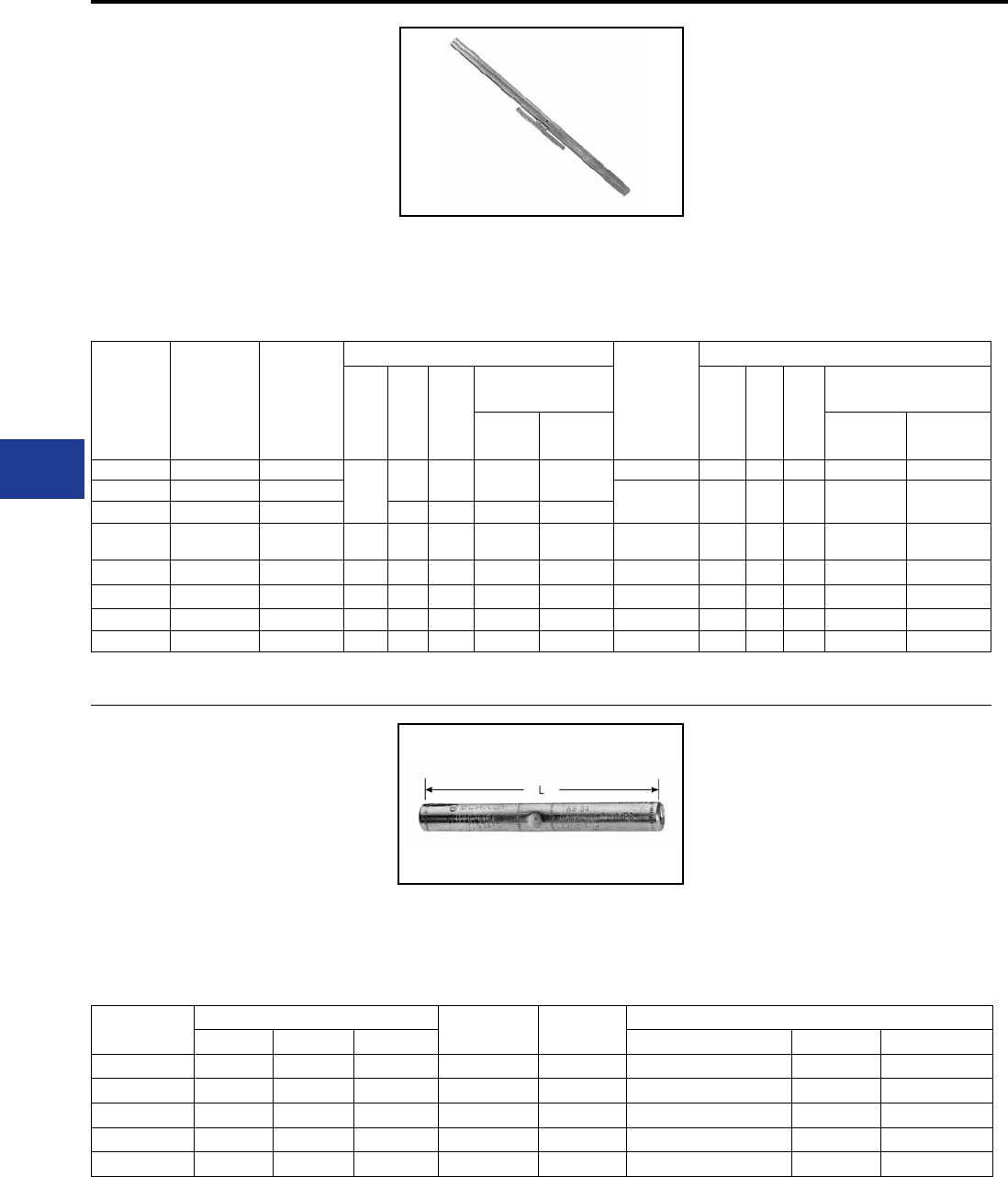
BURNDY®
Blue highlighted items are industry standard and most frequently ordered.
US: 1-800-346-4175 www.burndy.com Canada: 1-800-387-6487
Overhead Distribution
Compression Splices - Full Tension (EEI Dies) and Steel Conductor
TYPES YDS-R & YDS- RE
HYSPLICE™
ACCOMMODATES: ACSR
MATERIAL:
ALUMINUM (OUTER SPLICE),
STEEL (INNER SPLICE)
TENSION RATING:
ANSI C119.4 CLASS 1
(FULL TENSION)
Catalog
Number
Aluminum
& Steel
Sleeve Set
Catalog
Number
Aluminum
Sleeve
Conductor
Aluminum Outer Sleeve
Catalog
Number
Steel
Sleeve
Steel Inner Sleeve
L
EEI
Die
#
Die
Index
Tools, Die Set Catalog
No., & (Crimps per End) LL
EEI
Die
#
Die
Index
Tools, Die Set Catalog
No., & (Crimps per End)
MD6 Y35, Y750,
Y45†, Y46‡ MD6 Y35, Y750,
Y45†, Y46‡
YDS2RE YDS021REP1 2 (6-1)
17-1/8 6A 693 W693 (20) U693 (5) YDS2REP2 4-1/8 1S 690 W690 (8) U690 (4)
YDS021RE — 2 (7-1) YDS25REP2 4-3/4 2S 691 W691 (9) U691 (3)
— YDS25RP1 1/0 (6-1) 8A 243 W243 (10) U243 (5)
— YDS26RP1 2/0 (6-1) 19-3/4 9A 245 W245 (12) U245 (6) —5-1/4 4S 692 W692 (12) U692 (6)
YDS27RE YDS27RP1 3/0 (6-1) 16-3/4 10A 694 W694 (12) U694 (6) YDS27RP2 5-1/4 5S 248 W248 (8) U248 (8)
YDS28RE YDS28RP1 4/0 (6-1) 18-7/8 11A 249 W249 (14) U249 (7) YD28REP2 5-1/4 5S 248 W248 (8) U248 (8)
— — 336.4 (18-1) 17-7/8 13A 655 U655 (9) YDS25REP2 4-3/4 2S 691 W691 (9) U691 (3)
YDS361R YDS361RP1 477 (18-1) 25-1/2 14A 327 W327 U327 (16) YDS27RP2 5-1/4 5S 248 W248 (8) U248 (3)
TYPES YDS-E, YDS-H, YDS-U
HYSPLICE™
ACCOMMODATES: STEEL
MATERIAL: STEEL
TENSION RATING:
ANSI C119.4 CLASS 1
(FULL TENSION)
Catalog
Number
Conductor LDie
Index
Tools, Die Set Catalog Number, & (Crimps per End)
Size Str. Grade Y35, Y750, Y45†, Y46‡ Y48B Y60BHU
YDS250E 1/4 7 EHS 6-3/4 609 U609 (10) — —
YDS312H 5/16 7 HS 10-5/8 257 U257 (20) C257 (5)* L257 (5)*
YDS312E 5/16 7 EHS 8-1/2 305 U305 (6) C305 (3) L305 (3)
YDS375H 3/8 7 HS, UT 9 304 U304 (12) C304 (4) L304 (4)
YDS500H 1/2 7 HS 9-5/8 293 — C293 (6) L293 (6)
Full-tension HYSPLICE™ sleeves designed for
HS, EHS, Utilities (UT) or Siemens-Martin (SM)
galvanized steel guy, messenger, and “Static”
conductors. Made of hot-dip galvanized seamless
milled steel tubing lined with silicone carbide particles.
† U Die with adapter PT-6515.
‡ U Die with adapter PUADP-1.
Two-piece, full-tension HYSPLICE™, made of
aluminum outer sleeve and steel sleeve for steel
core. Designed to be installed with BURNDY® EEI
dies. BURNDY® and EEI die index numbers are
clearly marked on the sleeve.
For faster installations use BURNDY® PATRIOT® family
of battery tools.
* Multiple crimp die set; makes more than one
crimp per tool compression. Figure indicates
number of compressions.
† U Die with adapter PT-6515.
‡ U Die with adapter PUADP-1.
For faster installations use BURNDY® PATRIOT®
family of battery tools.
H-64
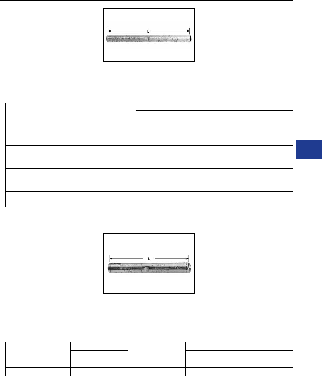
BURNDY®
Blue highlighted items are industry standard and most frequently ordered.
Canada: 1-800-387-6487 www.burndy.com US: 1-800-346-4175
Overhead Distribution
Compression Splices - Single Sleeve Full Tension
TYPE YDS-K
HYSPLICE™
ACCOMMODATES: COPPERWELD
MATERIAL: COPPER
TENSION RATING:
ANSI C119.4 CLASS 1
(FULL TENSION)
Catalog
Number Conductor L Die
Index
Tools, Die Set Catalog Number, & (Crimps per End)
MD7, MD6 Y35, Y750, Y45†, Y46‡ Y48B Y60BHU
YDS8WK 8 Sol. 3-3/4 285, or
162 W162 (6) U285 (2) — —
YDS6WK 6 Sol. 4-3/8 276, or
162 W162 (6) U276 (6) — —
YDS3K10 (3 #10) 4-7/8 403 — U403 (3)* — —
YDS3K8 (3 #8) 5-5/8 205 — U205 (5) — —
YDS3K7 5/16 (7 #10) (3 #7) 10 167 — U167/U568 (10) C167 (4) L167 (4)
YDS3K6 11/32 (7#9) (3#6) 9-1/2 331 — U331 (9) C331 (3) L331 (3)
YDS3K5 3/8 (7 #8) (3 #5) 6-7/8 259 — U259 (6) C259 (2) L259 (2)
YDS7K7 7/16 (7 #7) 6-7/8 328 — — C328 (3) L328 (3)
YDS7K6 1/2 (7 #6) 9-3/8 260 — — C260 (4) L260 (4)
YDS7K5 9/16 (7 #5) 11-3/8 344 — — C344 (6) L344 (6)
TYPE YTS-E
ACCOMMODATES: EHS STEEL
MATERIAL: ALUMINUM
TENSION RATING:
ANSI C119.4 CLASS 1
(FULL TENSION)
Full tension splice for EHS steel guy, messenger
or “static” cable. Sleeve is prelled with
PENETROX™ joint compound, stripsealed and
capped to limit oxide growth and to increase the
life of the connection.
Catalog Number Conductor † LTools, Die Sets
EHS Steel Die Index Y60BHU*
YTS375E 3/8" 7 Str. 10-3/8 723 L723
YTS438E 7/16" 7 Str. 11-7/8 726 L726
RUS Accepted
* Overlap crimps.
† Sleeve is high strength aluminum alloy for optimum
corrosion resistance.
Full-tension HYSPLICE™ designed to exceed
the minimum rated breaking strength of 30%
conductivity extra high strength Copperweld and
lower strength conductors. Made of pure copper
tubing. Installed with HYSPLICE™ tools and dies.
For faster installations use BURNDY® PATRIOT®
family of battery tools.
* Multiple crimp die set; makes more than one
crimp per tool compression. Figure indicates
number of compressions.
† U Die with adapter PT-6515.
‡ U Die with adapter PUADP-1.
For faster installations use BURNDY® PATRIOT®
family of battery tools.
H-65
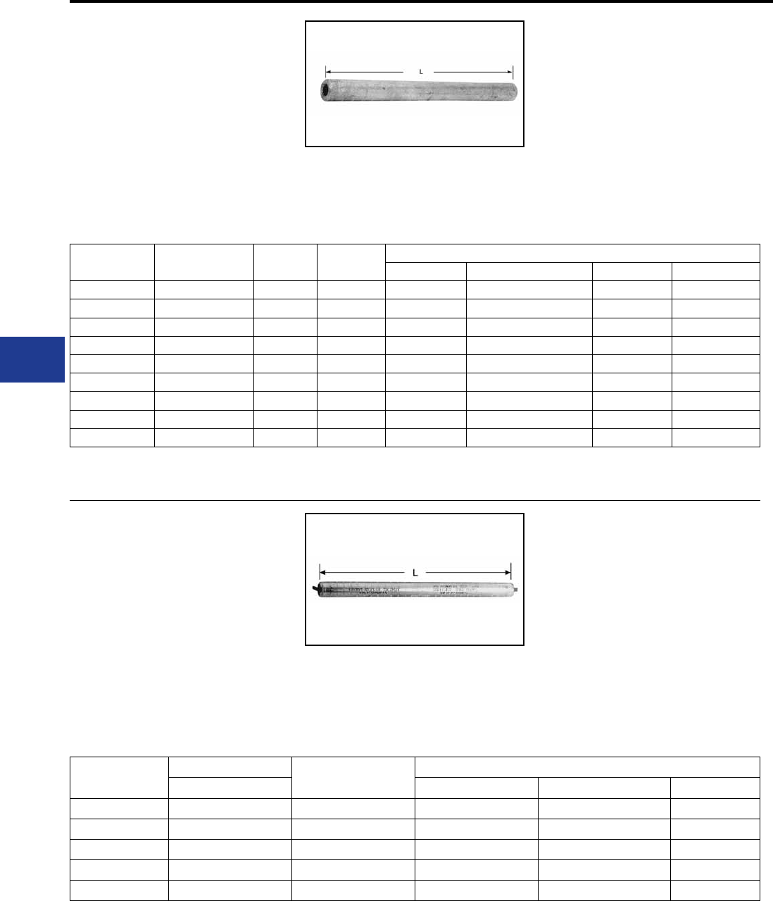
BURNDY®
Blue highlighted items are industry standard and most frequently ordered.
US: 1-800-346-4175 www.burndy.com Canada: 1-800-387-6487
Overhead Distribution
Compression Splices - Single Sleeve Full Tension
TYPES YDS-KT & YDS-F
HYSPLICE™
ACCOMMODATES: COPPERWELD -
COPPER
MATERIAL: COPPER
TENSION RATING:
ANSI C119.4 CLASS 1
(FULL TENSION)
Catalog
Number Conductor L Die
Index
Tools, Die Set Catalog Number, & (Crimps per End)
MD7, MD6 Y35, Y750, Y45†, Y46‡ Y48B Y60BHU
YDS8KT 8A 5 162 or 202 W162 (4) U202 (4)* — —
YDS6KT 6A 6-1/8 162 or 203 W162 (5) U203 (5)* — —
YDS4KT 4A 6-3/8 163 or 204 W163 (5) U204 (10) — —
YDS2KT 2A 7-3/4 205 — U205 — —
YDS3K6 11/32 (7#9) (3#6) 9-1/2 331 — U331 (9) C331 (3) L331 (3)
YDS2F 2F 6-1/4 329 — U329 (4) — —
YDS25F 1/0F 8-3/4 568 — U167/U568 (8) — —
YDS26F 2/0F 9-5/8 552 — U552 (11) — —
YDS28F 4/0F 11-7/8 331 — U331 (12) C331 (4) L331(4)
RUS Accepted
TYPE YDS-M-T
ACCOMMODATES: ALUMOWELD
MATERIAL: ALUMINUM
TENSION RATING:
ANSI C119.4 CLASS 1
(FULL TENSION)
Full-tension splice for Alumoweld trans-mission
lines. Five connectors accommodate eight conductor
sizes. Sleeve is pre-lled with PENETROX™ joint
compound and capped.
Catalog †††
Number
Conductor LTools, Die Sets
ALUMOWELD Die Index Y35, Y750, Y45†, Y46‡ Y60BHU
YDS7M10T 7 #10, 3 #7 10 676 or 721 U676 (8) L721
YDS7M9T 7 #9, 3 #6 10-3/8 677 U677 (10) —
YDS7M8T 7 #8, 3 #5 12-1/4 668 or 723 U668 (13) L723
YDS7M7T 7 #7 14-1/2 678 or 726 U678 (19) L726
YDS7M6T 7 #6 15-1/8 679 or 726 U679 (2) L726
RUS Accepted
* Overlap crimps.
† U Die with adapter PT-6515.
‡ U Die with adapter PUADP-1.
Full-tension HYSPLICE™ made of pure copper
tubing. Type YDS-KT is tapered to provide
gradual transition of stress on Type “A” conductor.
HYSPLICE™ Type YDS-F is recommended for
Type “F” conductor.
* Multiple crimp die set; makes more than one
crimp per tool compression. Figure indicates
number of compressions.
† U Die with adapter PT-6515.
‡ U Die with adapter PUADP-1.
For faster installations use BURNDY® PATRIOT®
family of battery tools.
††† Sleeve is high strength aluminum alloy for
optimum corrosion resistance.
For faster installations use BURNDY®
PATRIOT® family of battery tools.
H-66

BURNDY®
Blue highlighted items are industry standard and most frequently ordered.
Canada: 1-800-387-6487 www.burndy.com US: 1-800-346-4175
Overhead Distribution
Deadend Fittings and Accessories
H-67
H-68
H-69
H-69
H-70
H-70
H-71
H-71
LOOP
Type UP-R
Type BC
Type M
PRIMARY AND STRAIN BUS
Type CUW-E
Type DUW
Type CUW-A-E & CUW-R-E
Type DUW-A & DUW-A-E
DEADEND FITTING AND ACCESSORIES
TABLE OF CONTENTS
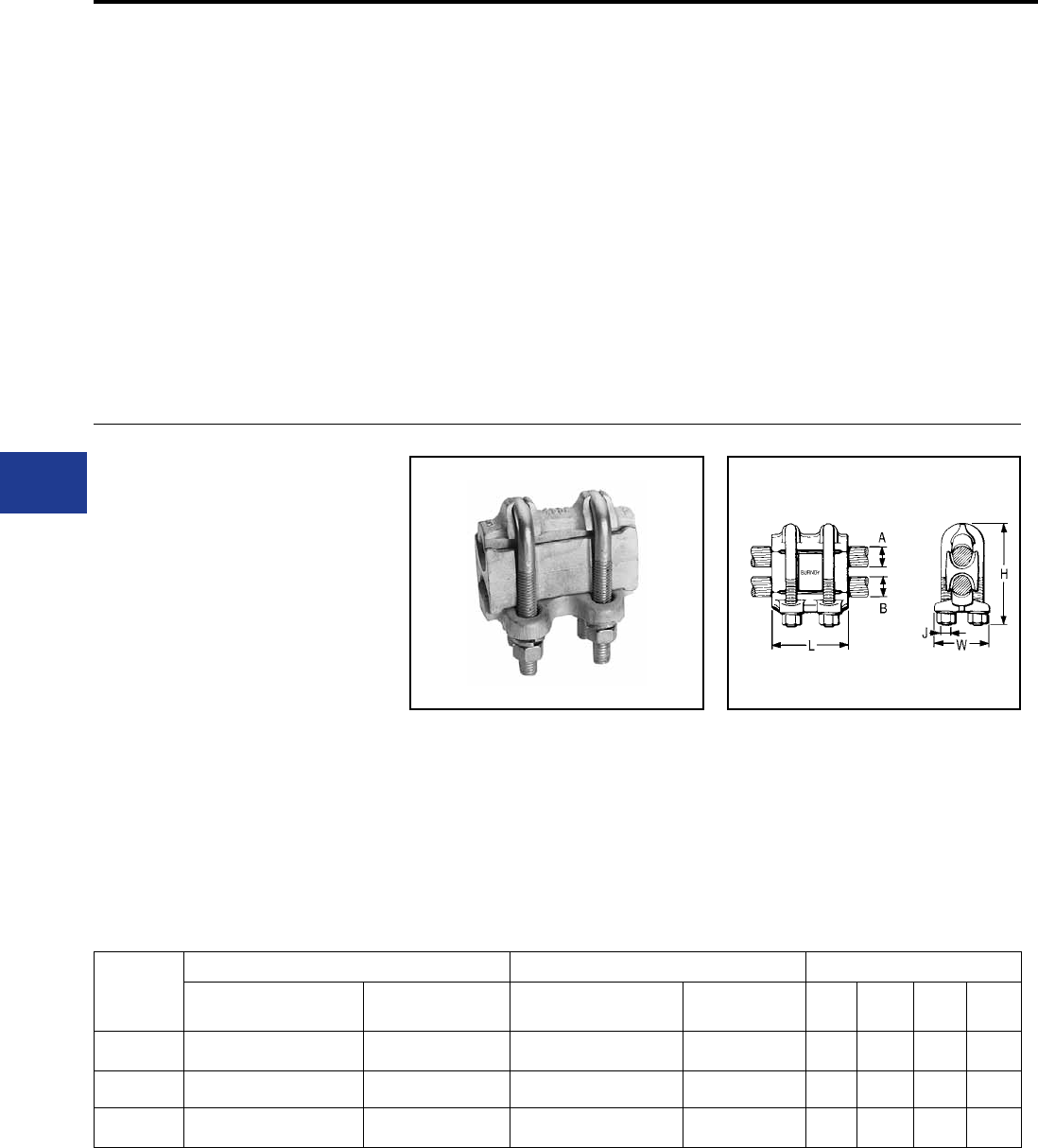
BURNDY®
Blue highlighted items are industry standard and most frequently ordered.
US: 1-800-346-4175 www.burndy.com Canada: 1-800-387-6487
Overhead Distribution
Mechanical Deadends
DEADEND FITTINGS
AND ACCESSORIES
The deadend method selected for any particular
application will depend upon the nature of the
application, the size of the conductor, holding
strength required, and preference for mechanical
or compression devices.
Secondaries are commonly deadended by
bending wire around a spool insulator and
snubbing with the same connectors used for
the secondary to service drop connection. On
copper conductor, connectors such as Ubolt Clip
BC, SERVIT™ KS, OKLIP™ KVS or CRIMPIT™
YC-C are recommended. These connectors
provide high holding strength without damaging
Catalog
Number
Groove A Groove B Dimensions
ACSR †, 6201, 5005 Copper or
Aluminum † ACSR †, 6201, 5005 Copper or
Aluminum † H J L W
UP34R 110.8 (12-7) - 397.5 (18-1) 3/0 Str. - 400 110.8 (12.7) - 397.5 (18-1) 3/0 Str. - 400 4-5/8 1/2-13 4 2-5/8
UP45R36R 336.4 (30-7) - 795 (30-19) 397.5 - 954 110.8 (12-7) - 447 (18-1) 3/0 Str. - 500 5-1/4 1/2-13 4 2-7/8
UP45R 336.4 (30-7) - 795 (30-19) 397.5 - 954 336.4 (30-7) - 795 (30-19) 397.5 - 954 6-1/4 5/8-11 4-1/2 3-1/4
TYPE UP-R
HEAVY DUTY
PARALLEL CLAMP
ACCOMMODATES:
AAC (STR, COMPRESSED,
COMPACT†), ACSR†, AAAC AND
COPPER
MATERIAL: ALUMINUM
Heavy duty aluminum connector for feeder,
subtransmission and primary distribution. Massive
design and large spacer give maximum protection
against galvanic action and overload conditions.
Spacing of U-bolts, tapered bell mouths and
modied V groove minimize cold ow, eliminate
cable damage, and produce wiping action on
conductors. Spacer taps conne cable strands to
conductor strands. On aluminum wires, CLIPIT™
UW-R, mechanical connector is recommended.
The same methods can also be used on primaries.
However, the straight line clamp Type CUW-A-E is
more popular for this application. They are easier
to install on either hot or de-energized lines. They
are particularly well suited to hot-line maintenance,
and allow easy re-sagging of conductors.
Straight line types are also popular for deadending
strain buses. These are normally large, hard to
handle conductors that do not lend themselves to
snub or “quadrant” types. Types DUW or CUW-E
RUS Accepted
† Accommodates compact and compressed conductors within diameter range.
To ensure proper tightening torque use BURNDY® BTW torque wrenches.
are recommended for copper conductor and
DUW-A and DUW-AE for aluminum and ACSR.
The pulling eye on the DUW-A-E is in line with the
cable to make installation easier.
prevent splaying. Captured, heat treated aluminum
alloy U-bolts. PENETROX™ joint compound
recommended for all combinations.
H-68
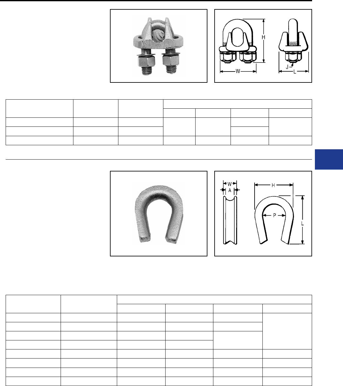
BURNDY®
Blue highlighted items are industry standard and most frequently ordered.
Canada: 1-800-387-6487 www.burndy.com US: 1-800-346-4175
Overhead Distribution
Mechanical Deadends
TYPE BC
CLIP
Deadend Clamp for Guy Wire
Deadend CLIP with DURIUM™ silicone bronze
U-bolt, nuts, and washers. Saddle made of high
strength corrosion resistant copper alloy.
Catalog
Number Copper
Guy
Wire
Dimensions
H J L W
BC2C 2 Sol. 5/16 2 3/8 1-1/4 1-3/4
BC25 1/0 Str. 3/8 1-3/8
BC28 2/0 Str. - 4/0 Str. 1/2 2-3/8 1/2 1-3/4 2-1/4
TYPE M
DEADEND THIMBLE
Deadend Copper Conductor or
Guy Wire
High strength corrosion resistant copper alloy
thimble groove to t any size guy wire used for
deadending. Generous radius prevents kinking or
overstressing outer strands of wire.
Catalog
Number
Groove
Size A
Dimensions
H L P W
M20 5/16 1-5/8 1-7/8 7/8
5/8
M30 3/8 1-7/8 2-1/8 1
M40 7/16 1-3/4 2-5/8 1-1/8
M50 1/2 1-7/8 2-1/4
M60 5/8 2-1/4 2-5/8 1-3/8 7/8
M70 3/4 2-5/8 3-1/4 1-1/2 1
M80 7/8 3 3-3/8 1-3/4 1-1/4
M90 1 3-3/8 3-3/4 2 1-3/8
H-69
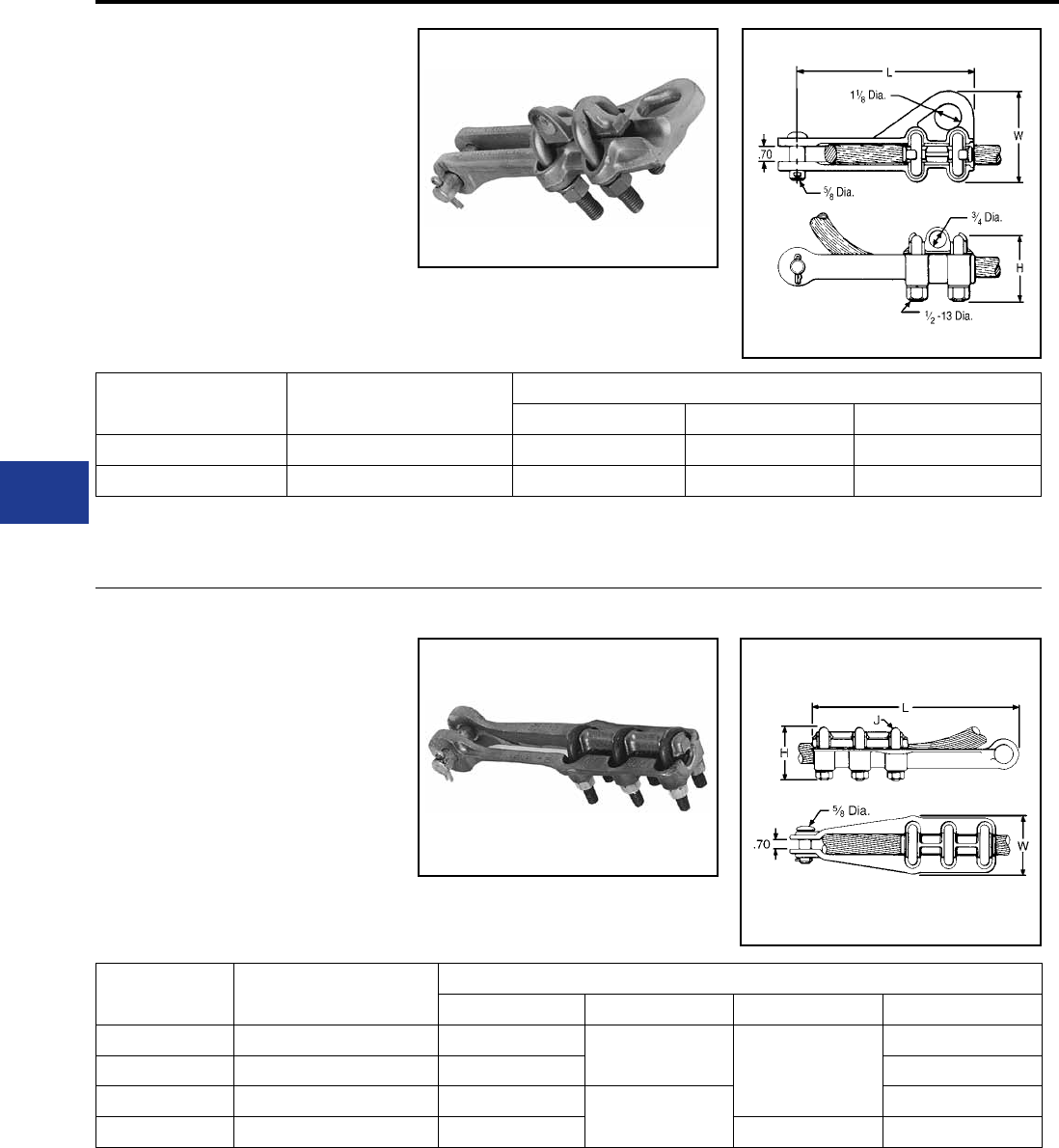
BURNDY®
Blue highlighted items are industry standard and most frequently ordered.
US: 1-800-346-4175 www.burndy.com Canada: 1-800-387-6487
Overhead Distribution
Mechanical Deadends
TYPE CUW-E
DEADEND CLAMP
ACCOMMODATES: COPPER
MATERIAL: COPPER
High strength, two-bolt, cast copper alloy strain
clamp with single saddle designed for short span
distribution and strain bus application. Galvanized
steel clevis pin, and U-bolts.
Catalog
Number Conductor Range Dimensions
H L W
CUW34-E 4/0 Str. - 500 3 7-3/8 4
CUW44-E 500 - 1000 3-3/8 8-3/4 4-1/2
TYPE DUW
DEADEND CLAMP
ACCOMMODATES: COPPER
MATERIAL: COPPER
High strength corrosion resistant copper alloy
strain clamp with three DURIUM™ U-bolts and
single serrated saddle. Galvanized steel clevis pin.
Catalog
Number Conductor Dimensions
H J L W
DUW28 1 Str. - 4/0 Str. 2-1/2 3/8 9-7/8
2-1/4
DUW31 4/0 Str. - 350 2 2-3/8
DUW34 350-500 2-5/8 1/2 2-3/4
DUW44 500-1000 2-7/8 11-3/8 3-1/4
To ensure proper tightening torque use BURNDY® BTW torque wrenches.
To ensure proper tightening torque use BURNDY® BTW torque wrenches.
H-70
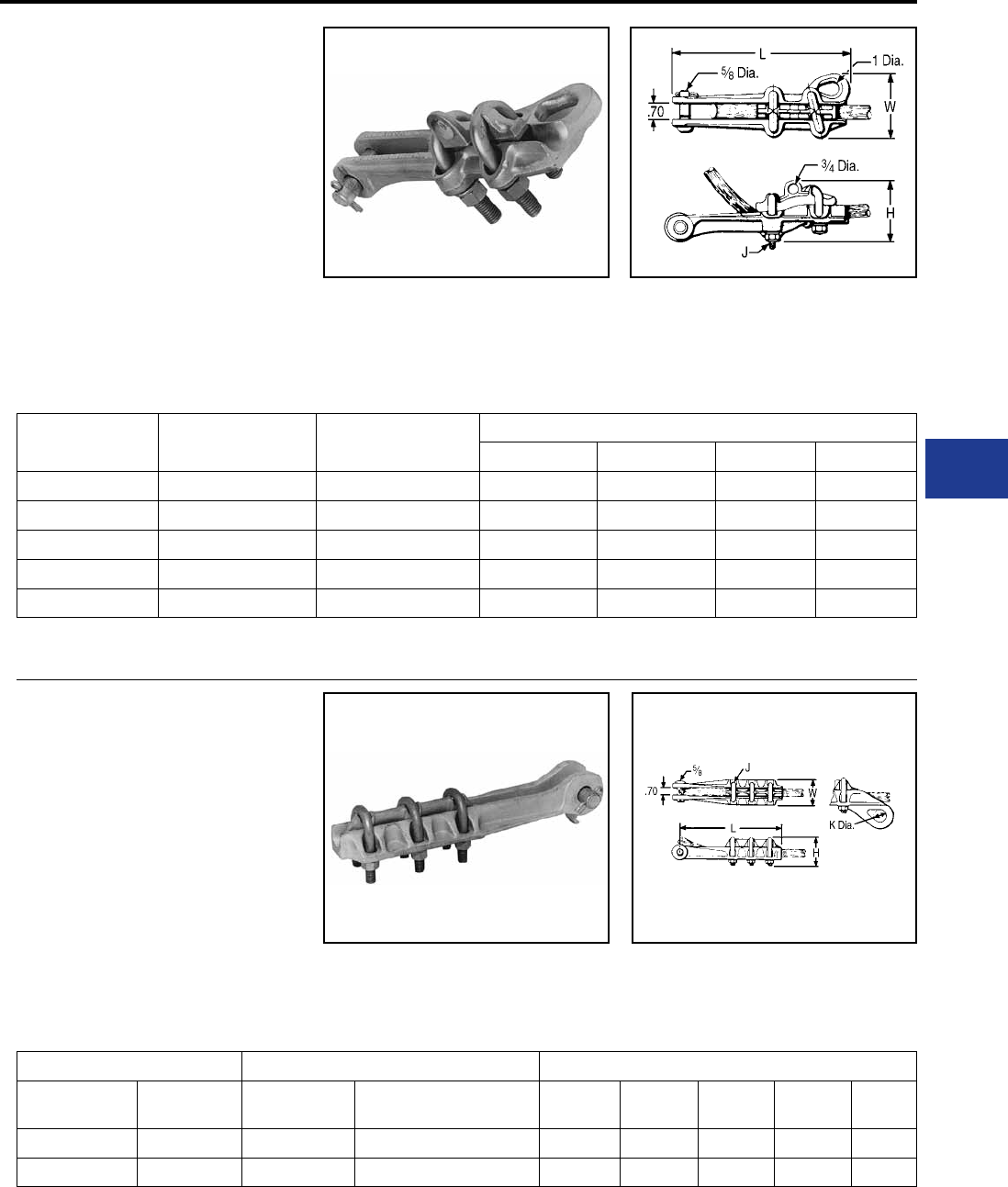
BURNDY®
Blue highlighted items are industry standard and most frequently ordered.
Canada: 1-800-387-6487 www.burndy.com US: 1-800-346-4175
Overhead Distribution
Mechanical Deadends
TYPES CUW-A-E
& CUW-R-E
DEADEND CLAMP
ACCOMMODATES:
AAC (STR, COMPRESSED†),
ACSR† AND AAAC
MATERIAL: ALUMINUM
High strength aluminum clamp for deadending
primary distribution lines. Straight-line design,
with hot stick lifting-eye, pulling-eye, and captured,
angled U-bolts, facilitates installation and
maintenance, especially on hot-line work. Snub-
Catalog
Number Aluminum † ACSR †, 6201, 5005 Dimensions
H J L W
CUW26RE-1 2 Str. - 2/0 (19) 4 - 2/0 3 3/8-16 8 3
CUW30A-E 1/0 (7) - 300 1/0 - 266.8 (18-1) 3-5/8 1/2-13 10 3-1/2
CUW32R-E 3/0 (7) - 350 3/0 - 336.4 (26-7) 4 1/2-13 10 3-5/8
CUW361R-E 4/0 - 500 4/0 - 477 (18-1) 4-1/8 1/2-13 11 3-5/8
CUW391A-E 336.4 - 795 300 (26-7) 636 (26-7) 4-7/8 1/2-13 11 4-1/8
RUS Accepted
† Accommodates compressed conductors within diameter range.
To ensure proper tightening torque use BURNDY® BTW torque wrenches.
TYPES DUW-A
& DUW-A-E
DEADEND CLAMP
ACCOMMODATES:
AAC (STR, COMPRESSED†),
ACSR† AND AAAC
MATERIAL: ALUMINUM
High strength cast aluminum alloy clamp
recommended for strain bus applications. Three
galvanized steel U-bolts, single saddle and headed
clevis pin provide high holding strength. Type
Catalog Number Conductor Dimensions
Without
Pulling Eye
With
Pulling Eye Aluminum † ACSR †, 6201, 5005 H J K L W
DUW28A — 1 - 4/0 2 (7-1) - 4/0 2 3/8 0.88 9-1/2 2-1/4
DUW44A DUW44A-E 500-1000 397.5 (30.7) - 900 (54-7) 3-3/8 1/2 1.25 11-1/4 3-5/8
pocket V-shaped, range-taking conductor groove
and galvanized steel U-bolts provide high holding
strength.
DUW-A-E has pulling-eye in line with conductor
for easier installation.
† Accommodates compressed conductors within diameter range.
To ensure proper tightening torque use BURNDY® BTW torque wrenches.
H-71

BURNDY®
Blue highlighted items are industry standard and most frequently ordered.
US: 1-800-346-4175 www.burndy.com Canada: 1-800-387-6487
Overhead Distribution
Compression Terminals and Accessories
H-72
H-73
H-74
H-75 - H-76
H-77
H-78
Types YCA-2N & YCAB-4N
Type YCA-RL-2N
Types YCA-R-N & YCAK-R-N
Type YAK-A-2G
Types YCAK-A & YRA
COMPRESSION TERMINALS AND ACCESSORIES
TABLE OF CONTENTS
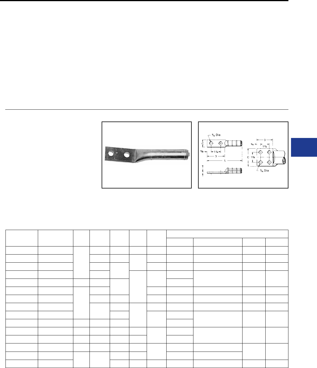
BURNDY®
Blue highlighted items are industry standard and most frequently ordered.
Canada: 1-800-387-6487 www.burndy.com US: 1-800-346-4175
Overhead Distribution
Compression Terminals
COMPRESSION
TERMINALS &
ACCESSORIES
Compression terminals are used to make
convenient and reliable connections to switch
pads, transformers, and other electrical equipment.
They accommodate either copper, aluminum,
ACSR, ACAR, Alumoweld, or steel conductor and
come with one, two or four hole NEMA drilled pads
to match the equipment drilling. Standard copper
and aluminum terminals are also listed in the
compression section C.
Catalog
Number Conductor Fig.
No. C L T Die
Index
Tools, Die Set Catalog Number, & (Number of Crimps)
MD7, MD6 Y35, Y750, Y45†, Y46‡ Y48B Y60BHU
YCA25-2N 1/0 (7, 19)
1
7/8 5-3/8 1/8 165 W165 (3) U165/U205 (3) — —
YCA26-2N 2/0 (7, 19, 37) 1 5-1/4 1/4 166 W166 (6) U166/U459 (3) — —
YCA27-2N 3/0 (7, 19) 1-1/8 5-3/8 167 — U167/U568 (3) C167 (1) L167 (1)
YCA28-2N 4/0 (7, 12, 19) 1-1/4
3/8
168 —U168 (3) C168 (1) L168 (1)
YCAB28-4N 4/0 (7, 12, 19) 2 3 5-5/8 —
YCA29-2N 250 (7, 19, 37)
1
1-3/8 169 — U169 (4) C169 (1) L169 (1)
YCA30-2N 300 (19, 37) 1-1/2 5-1/2 170 — U170 (5) C170 (1) L170 (1)
YCA31-2N 350 (12, 19, 37) 1-5/8 6-1/2
1/2
267 — U267 (6) C267 (2) L267 (2)
YCA32-2N 400 (19, 37) 6-3/4 209 —U209 (6) C209 (2) L209 (2)
YCAB32-4N 400 (19, 37) 2 3 7-1/8 —
YCA34-2N 500 (19, 37) 1 1-7/8 6-1/2 3/8 210 —U210 (6) C210 (2) L210 (2)
YCAB34-4N 500 (19, 37) 2 3 6-7/8 1/2 —
YCA39-2N 750 (37, 61) 1 2-3/8 7-1/4 5/8 627 — — C627 (3) L627 (3)
YCAB39-4N 750 (37, 61) 2 3 7-1/2 1/2 — —
YCAB44-4N 1000 (61) 7-7/8 5/8 345 — — C345 (4) L345 (4)
TYPES YCA-2N
& YCAB-4N
HYLUG™
ACCOMMODATES: COPPER
MATERIAL: COPPER
Compression HYLUG™ terminals designed for
terminating copper conductors to switch pads and
other substation or switch yard apparatus. NEMA
standard mounting holes. Made of pure copper.
Installed with same die as equivalent full-tension
jumper loop and repair sleeves.
Fig. 1 Fig. 2
YCAB have brazed pads. † U Die with adapter PT-6515
‡ U Die with adapter PUADP-1
To ensure proper tightening torque use
BURNDY® BTW torque wrenches.
H-73
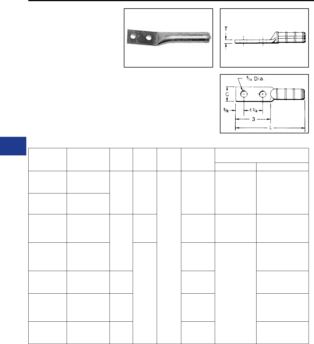
BURNDY®
Blue highlighted items are industry standard and most frequently ordered.
US: 1-800-346-4175 www.burndy.com Canada: 1-800-387-6487
Overhead Distribution
Compression Terminals
TYPE YCA-RL-2N
HYLUG™
ACCOMMODATES: AAC (STR,
COMPRESSED, COMPACT), ACSR
AND AAAC
MATERIAL: ALUMINUM
Aluminum compression HYLUG™ for terminating
overhead conductors to switch pads and other
substation or switch yard apparatus. NEMA
standard mounting holes. Installed with same die
as equivalent fulltension UNISPLICE™. Pre-lled
with PENETROX™ joint compound, stripsealed
and capped to limit oxide growth and to increase
the life of the connection.
Catalog
Number Conductor C L T Die Index
Tools, Die Set Catalog Number,
& (Number of Crimps)
MD7, MD6 Y35, Y750, Y45†, Y46‡
YCA4RL-2N
4 ACSR (6-1, 7-1)
4 6201 (7)
4 AAC (7) 7/8 6
3/8
BG, 243, 687
W-BG (8)
Fixed BG (8)
W687 (4
U243
YCA2RL-2N
2 ACSR (6-1, 7-1)
2 6201 (7)
2 AAC (7)
YCA25RL-2N
1/0 ACSR (6-1)
1/0 6201 (7)
1/0 AAC (7)
1/0 5005 (7)
1-1/8
7 C, 247, 702 WC (12)
W702 (4)** U247 (3)
YCA26RL-2N
2/0 ACSR (6-1)
2/0 6201 (7)
2/0 AAC (7)
2/0 5005 (7)
6-1/2
659
—
U659 (3)
YCA27RL-2N
3/0 ACSR (6-1)
3/0 6201 (7)
3/0 AAC (7)
1-1/4 658 U658 (3)
YCA28RL-2N
4/0 ACSR (6-1)
4/0 6201 (7)
4/0 AAC (7)
4/0 5005 (7)
1-1/2 654 U654 (3)
YCA321RL-2N
336.4 ACSR (18-1)
336.4 AAC (19)
500 AAC
1-5/8 655 U655 (3)
† U Die with adapter PT-6515.
‡ U Die with adapter PUADP-1.
** MD6 NON-BOW Dies produce straight
sleeves without rotating tool.
For faster installations use BURNDY®
PATRIOT® family of battery tools.
H-74
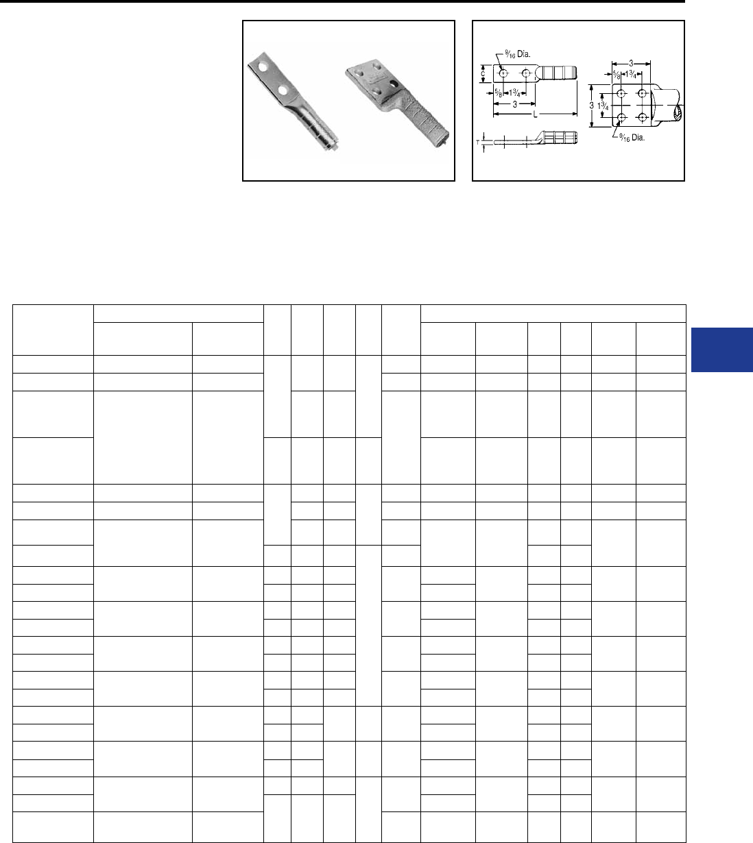
BURNDY®
Blue highlighted items are industry standard and most frequently ordered.
Canada: 1-800-387-6487 www.burndy.com US: 1-800-346-4175
Overhead Distribution
Compression Terminals
TYPES YCA-R-N &
YCAK-R-N
ACCOMMODATES: AAC (STR,
COMPRESSED, COMPACT), ACSR
AND AAAC
MATERIAL: ALUMINUM
Aluminum compression HYLUG™ for terminating
jumper loops and equipment taps at switchpads
and other substation apparatus, or to YDW-R
deadends. NEMA standard mounting holes.
Installed with same dies as equivalent full-tension
sleeves. Pre-lled with PENETROX™ joint
compound, stripsealed and capped to limit oxide
growth and to increase the life of the connection.
Fig. 1 Fig. 2
Catalog
Number
Conductor Fig
No. C L T Die
Index
Die Set, Tools Catalog Number, & (Number of Crimps)
ACSR, 6201, 5005 Aluminum MD7, MD6
Series Y35, Y750 Y45 Y46 Y48B Y60BHU
YCA4R-2N 4 4 (7)
1
1-1/4 5-5/8
1/4
237 W237 (3) U237 (2) † ‡ — —
YCA2R-2N 2 2 (7) 239 W239 (3) U239 (2) † ‡ — —
YCA25R-2N
1/0 1/0 (7,19)
7/8 6-1/4 KS18
243
BG
or
8A
BG (8)
W-BG (4)*
U243 (2)
U-BG (4) † ‡ — —
YCAK25R-4N 2 3 6-7/8 3/8
BG (8)
W-BG (4)*
U243 (2)
U243 (2) † ‡ C243 (2) L243 (1)
YCA26R-2N 2/0 2/0 (7,19)
1
1 6-3/8
1/4
245AA W245 (4) U245 (2) † ‡ C245 (2) L245 (1)
YCA27R-2N 3/0 - 110.8 (12-7) 3/0 (7,19) 1-1/8 6-3/4 247 W247 (6) U247 (3) † ‡ C247 (3) L247 (2)
YCA28R-2N 4/0 (6-1, 6-7) 4/0 (7,19) 1-1/4 6-7/8 249 K840
249
11A
U249 (3) † ‡ C249 (1) L249 (2)
YCAK28R-4N 2 3 7-3/8
3/8
249 † ‡
YCA30R-2N 266.8
(18-1, 6-7 26-7) 266.8 (7,19) 1 1-1/2 6-3/4 251 —U251 (4) † ‡ C251 (2) L251 (2)
YCAK30R-4N 2 3 7-3/8 — † ‡
YCA321R-2N 336.4 (18-1) 336.4 (19) -
350 (19, 37, 61)
1 1-1/2 7 321 —U321 (4) † ‡ C321 (2) L321 (2)
YCAK321R-4N 2 3 7-1/8 — † ‡
YCA33R-2N 336.4 (26-7, 30-7)
397.5 (18-1) 397.5 (19) 1 1-5/8 7-1/4 316 —U316 (4) † ‡ C316 (2) L316 (2)
YCAK33R-4N 2 3 7-3/8 — † ‡
YCA35R-2N 397.5 (26-7, 30-7) 477 (19, 37) -
500 (37, 61)
1 1-7/8 7-1/2 317 —U317 (4) † ‡ C317 (2) L317 (2)
YCAK35R-4N 2 3 7-3/8 — † ‡
YCA361R-2N 477 (18-1) 500 (37, 61) 1 1-7/8 7-5/8 7/16 327 —U327 (4) † ‡ C327 (2) L327 (2)
YCAK361R-4N 2 3 — † ‡
YCA37R-2N 556.5 (18-1)
477 (24-7, 26-7, 30-7) 556.5 (19, 37) 1 2 8-1/8 3/8 261 —U261 (5) † ‡ C261 (2) L261 (2)
YCAK37R-4N 2 3 — † ‡
YCA39R-2N 556.5 (24-7,26-7) — 1 2-1/8 8-3/8
1/2
608 —U608 (6) † ‡ C608 (2) L608 (2)
YCAK39R-4N
2 3 8-1/8
— † ‡
YCAK361A-4N — 636 (37) 469 — — S469
(6)
P469
(6) C469 (2) L469 (2)
* Multiple crimp die set; makes more than one
crimp per tool compression.
Figure indicates number of compressions.
† U Die with adapter PT-6515.
‡ U Die with adapter PUADP-1. (Table continued on next page.)
YCA HYLUGS™ are made from heavy walled
tubing.
YCA4R-2N, YCA2R-2N and all YCAK
HYLUGS™ are cast aluminum alloy.
For faster installations use BURNDY®
PATRIOT® family of battery tools.
H-75
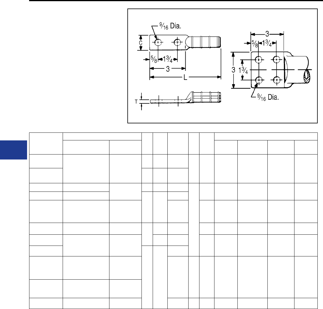
BURNDY®
Blue highlighted items are industry standard and most frequently ordered.
US: 1-800-346-4175 www.burndy.com Canada: 1-800-387-6487
Overhead Distribution
Compression Terminals
TYPES YCA-R-N &
YCAK-R-N
(Continued)
ACCOMMODATES: AAC (STR,
COMPRESSED, COMPACT), ACSR
AND AAAC
MATERIAL: ALUMINUM
Fig. 1 Fig. 2
Catalog
Number
Conductor Fig
No. C L T Die
Index
Die Set,Tools Catalog Number, & (Number of Crimps)
ACSR, 6201, 5005 Aluminum Y45 Y46 Y48B Y60BHU
YCA43R-2N 605 (30-19)
636 (24-7, 26-7, 30-19)
666.6 (24-7)
795 (37, 61)
700 (61)
750 (61)
1 2-/12 10-1/4
3/4
292
or
319
S292 (6)
S319 (6)
P292 (6)
P319 (6)
C292 (3)
C319 (3)
L292 (3)
L319 (3)
YCAK43R-4N 2 3 9-5/8
YCA391A-2N —795 (37)
750 (61)
1 2-3/8 10-1/8
5/8
342 S342 (6) P342 (6) C342 (3) L342 (3)
YCAK391A-4N —
2 3
9-7/8
YCAK453R-4N
795 (36-1)
715.5 (26-7)
795 (45-7)
— 9-5/8 292*,
578 S292 (6) P292 (6) C292 (6) L292 (3)
YCA44A2NG2 — 1000
1
2-3/8 11 342 S342 (6) P342 (6) C342 (3) L342 (3)
YCA45R-2N
795 (26-7, 54-7)
900 (61, 91)
954 (37, 61)
1000 (61)
2-1/2 10-1/4
352 S352 (6)
S579 (6)
P352 (6)
P579 (6)
C352 (3)
C579 (3)
352 (3)
L579 (3)
YCAK45R-4N
2 3
9-5/8
YCA48R-4N
900 (54-7)
954 (54-7) (45-7)
1033.5 (45-7) (36-1)
—
10 3/4 575 — — C575 (3) L575 (3)
YCA441A-4N —1033.5 (37, 61) -
113 (61)
YCA451A-4N 1113 (54-19) 1272 (61) 10-1/4 5/8 422 — — — L422 (3)
* Multiple crimp die set; makes more than one
crimp per tool compression.
Figure indicates number of compressions.
YCA HYLUGS™ are made from heavy walled
tubing.
YCA4R-2N, YCA2R-2N and all YCAK
HYLUGS™ are cast aluminum alloy.
For faster installations use BURNDY®
PATRIOT® family of battery tools.
H-76
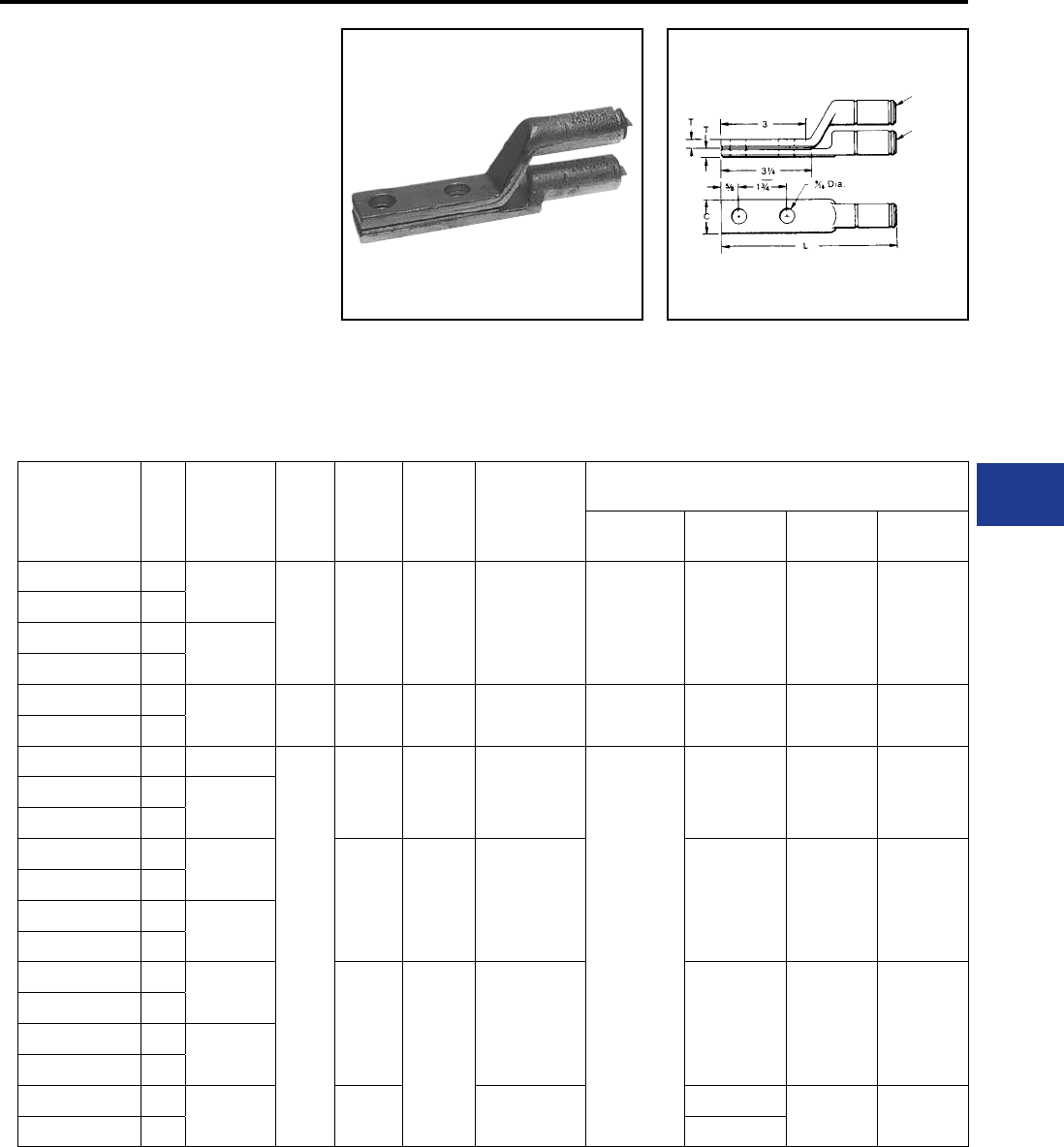
BURNDY®
Blue highlighted items are industry standard and most frequently ordered.
Canada: 1-800-387-6487 www.burndy.com US: 1-800-346-4175
Overhead Distribution
Compression Terminals - Stackable
TYPE YAK-A-2G
STACKING HYLUG™
ACCOMMODATES:
AAC (STR, COMPRESSED)
MATERIAL: ALUMINUM
Cast aluminum HYLUG™ with a special tongue
conguration for stacking of conductors on two
and four hole NEMA transformer or equipment
terminal pads. Up to eight conductors may be
stacked on one four hole NEMA pad. HYLUG™
is prelled with PENETROX™ joint compound,
stripsealed and capped to limit oxide growth and
to increase the life of the connection.
Catalog
Number
Fig
No. Conductor C L T Die
Index
Die Set,Tools Catalog Number, & (Number of Crimps)
MD7, MD6
Series Y35, Y750 Y45 Y46
YAK2CA2G1 12 Str.
7/8 5-5/8 1/4
BG
K-5/8
243
BG (3)
W-BG (1)
W243 (1)
U-BG (1)
UK 581T (3)
U243 (1)
†
†
†
‡
‡
‡
YAK2CA2G2 2
YAK25A-2G1 11/0 Str.
YAK25A-2G2 2
YAK28A-2G1 14/0 Str.** 1-1/8 6-1/4 5/16 249
K-840
W249*
W-K840* U249* †
†
‡
‡
YAK28A-2G2 2
YAK29A-2G1 1 250
1-5/8
6-7/8 3/8 299
705
—
U31ART*
U705
†
†
‡
‡
YAK31A-2G1 1350
YAK31A-2G2 2
YAK311A-2G1 1397.5
7-3/4 7/16 317
705
U317*
U705*
†
†
‡
‡
YAK311A-2G2 2
YAK34A-2G1 1500
YAK34A-2G2 2
YAK-361A-2G1 1600
636
8-1/4
5/8
608
722
786
U608*
U786*
†
S786*
S722*
‡
P786*
P722*
YAK-361A-2G2 2
YAK39A-2G1 1700
750
YAK39A-2G2 2
YAK44A-2NG8 11000 8-7/8 302 —S44ART* P44ART*
YAK44A-2NG7 2 —
* Overlap crimps.
** Accommodates 4/0 Str., Al or Cu.
Fig. 1
Fig. 2
† U Die with adapter PT-6515.
‡ U Die with adapter PUADP-1.
For faster installations use BURNDY® PATRIOT®
family of battery tools.
H-77
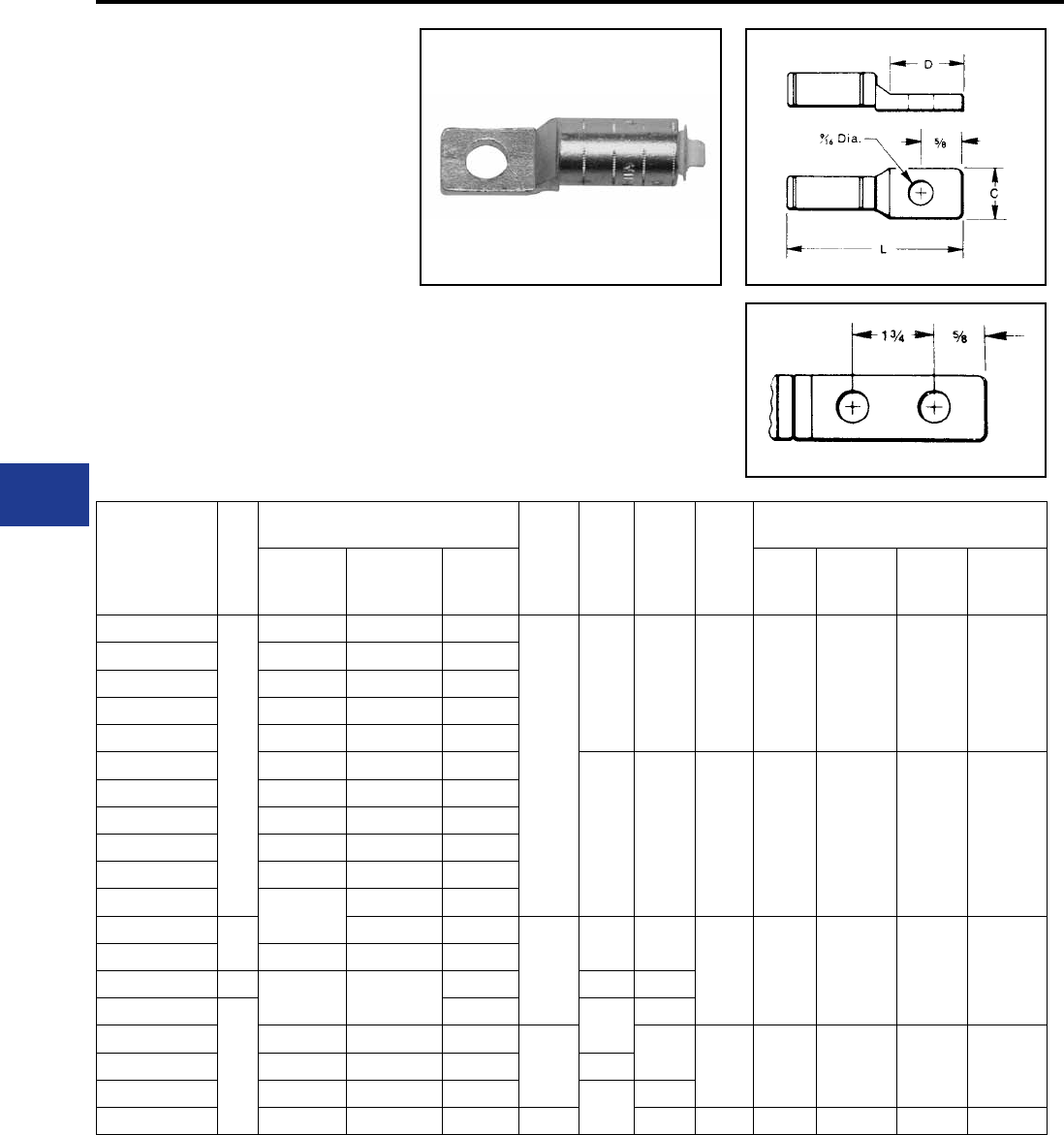
BURNDY®
Blue highlighted items are industry standard and most frequently ordered.
US: 1-800-346-4175 www.burndy.com Canada: 1-800-387-6487
Overhead Distribution
Compression Terminals
TYPES YCAK-A & YRA
ALUMINUM HYLUG™
ACCOMMODATES: AAC (STR,
COMPRESSED), ACSR AND COPPER
MATERIAL: ALUMINUM
Aluminum HYLUG™ for joining aluminum and
copper cable to transformer and equipment pads.
HYLUG™ is pre-lled with PENETROX™ joint
compound, stripsealed and capped to limit oxide
growth and to increase the life of the connection.
Installed with standard tooling, ve die sets install
fourteen terminal sizes.
Catalog
Number
Fig
No.
Conductor
C D L Die
Index
Die Set, Tool Catalog Number &
(Number of Crimps)
Copper
Aluminum
Conc.&
Compact
ACSR
MD7,
MD6
Series
Y35, Y750 Y45 Y46
YRA8CU-1
1
6 Sol. - 8 Sol. 8 Str. —
15/16
1-1/16 2-9/16 BG
243
BG (3)
K 5/8
243 (1)
U-BG
(1)
U-K-5/8-1T
(3)
U243
(1)
†
†
†
‡
‡
‡
YRA6CU-1 4 Sol. - 6 Str. 4 Sol. - 6 Str. 6 (6-1)
YRA4CU-1 2 Sol. - 4 Str. 2 Sol. - 4 Str. 4 (6-1, 7-1)
YRA1CU-1 1 Str. - 2 Str. 1 Str. - 2 Str.** 2 (6-1, 7-1)
YRA25A-1 — 1/0 Str. —
YRAL4CU 2 Sol. - 4 Str. 2 Sol. - 4 Str. 4 (6-1, 7-1)
1-1/4 3-1/4 249
K-840
W249*
WK840*
U249*
UK-840
†
†
‡
‡
YRAL1CU 1 Str. - 2 Str. 1 Str. - 2 Str. 2 (6-1, 7-1)
YRA25U 1/0 Str. 1/0 Str. 1/0 (6-1)
YRA26U 2/0 Str. 2/0 Str. 2/0 (6-1)
YRA27U 3/0 Str. 3/0 Str. —
YRA28U 4/0 Str. 4/0 Str. —
YCAK28A-2G1* 24/0 Str. —
1-1/4
3 5-5/8
317
705 —U317*
U705*
†
S705*
†
‡
P705*
‡
YCAK29A-2G1* 250 250 4/0 (6-1)
YCAK31AG1* 1350 350 — 1-5/16 4-1/2
YCAK31A-2G1*
2
——6-1/4
YCAK34A-2G3* 500 500 —
1-1/2 6-1/2 608
786
—
—
U608*
U786*
†
S786*
†
‡
P786*
‡
YCAK36A-2G1* — 600 — 3
YCAK39A-2G2* — 750 — —6-15/16
YCAK44A-2G2* — 1000 — 1-11/16 7-1/2 302 — — S44ART* P44ART*
* Overlap crimps.
** YRA1CU-1 not recommended for 2 comp. conductor.
† U Die with adapter PT-6515.
‡ U Die with adapter PUADP-1.
For faster installations use BURNDY® PATRIOT® family of battery tools.
Fig. 1
Fig. 2
H-78

BURNDY®
Blue highlighted items are industry standard and most frequently ordered.
Canada: 1-800-387-6487 www.burndy.com US: 1-800-346-4175
Transmission
I-1
I-3
I-4
I-5
I-6
I-7
I-8
I-9
I-10
I-11
I-12
I-13
I-14
I-15
I-16
I-17
I-18
I-19
I-20
I-21
I-22
I-23
I-24
I-25
I-26
I-27
I-28
ACSR Conductor Accessories
Deadends Single Pad
Deadends Double Pad
Deadends Single Pad EHV
Deadends Double Pad EHV
Splices
Splices EHV
Terminals
Terminals EHV
Loop Sleeve
Loop Sleeve EHV
T-Tap
T-Tap with Pad
Repair Sleeve
ACSS Conductor Accessories
Deadends Single Pad
Deadends Double Pad
Deadends Single Pad EHV
Deadends Double Pad EHV
Splices
Splices EHV
Terminals
Terminals EHV
Loop Sleeve
Loop Sleeve EHV
T-Tap
T-Tap with Pad
Repair Sleeve
TABLE OF CONTENTS
AAC/ACAR Conductor Accessories
Deadends Single Pad
Deadends Single Pad EHV
Deadends Double Pad
Deadends Double Pad EHV
Splices (Stranded)
Splices (ACAR)
Splices EHV (Stranded)
Splices EHV (ACAR)
Terminals
Terminals EHV
Loop Sleeve
Loop Sleeve EHV
T-Tap with Pad
T-Tap
Repair Sleeve
Steel / Alumoweld Conductor Accessories
Terminal
Splices (Alumoweld)
Splices (EHS Steel)
ACCC® Conductor Accessories
Deadend Kit
Splices
Terminals
T-Tap with Tap
Repair Sleeve
I-29
I-30
I-31
I-32
I-33
I-34
I-35
I-36
I-37
I-38
I-39
I-40
I-41
I-42
I-43
I-44
I-45
I-46
I-47
I-49
I-50
I-51
I-52

BURNDY®
Blue highlighted items are industry standard and most frequently ordered.
US: 1-800-346-4175 www.burndy.com Canada: 1-800-387-6487
Transmission
I-2
IMPLO® Implosive Connectors
ACSR
Joints, Deadends, Jumper Terminals,
Repair Sleeves
ACSS
Joints, Deadends, Jumper Terminals,
Repair Sleeves
ACSS/TW
Joints, Deadends, Jumper Terminals,
Repair Sleeves
AAC/AAAC/ASC
Joints, Deadends, Jumper Terminals,
Repair Sleeves
Static (Sky) Wire
Joints, Deadends
Motion Control Accessories
Stockbridge Damper
Spacer Damper
Rigid Spacers
I-54 - I-56
I-57
I-58
I-59
I-60
I-61
I-62
I-63
TABLE OF CONTENTS
(Continued)

BURNDY®
Blue highlighted items are industry standard and most frequently ordered.
Canada: 1-800-387-6487 www.burndy.com US: 1-800-346-4175
Transmission
TYPE YTW-R-REK,
YTW-R, YTW-RE,
YNA-R-H
Single Pad Full Tension
Deadend for ACSR Conductor
Full tension compression deadend for ACSR
transmission lines up to and including 230 kV.
Standard 15º NEMA tap pad provides either 0º or
30º tap when YNA-R15 terminal is used.
ACSR Deadends
ACSR Single Pad Inches Body
Die*‡ Steel Eye*
Inches Eye
Die
Terminal
with
Hardware
Term
Die*‡
Conductor
Name
Size
kcmil
Stranding Complete
Assembly
Alum.
Body L C T B K W
Alum. Steel
Linnet 336.4 26 7 YTW32R34REK YTW32R 17.53 2.25 0.50 L717 YTW34RE 2.50 0.88 0.62 L718 YNA32R15H L717
Oriole 336.4 30 7 YTW32R33REK YTW32R 17.53 2.25 0.50 L717 YTW33RE 2.50 0.88 0.62 L718 YNA32R15H L717
Ibis 397.5 26 7 YTW34R34REK YTW34R 17.60 2.25 0.50 L719 YTW34RE 2.50 0.88 0.62 L718 YNA34R15H L719
Flicker 477 24 7 YTW36R362REK YTW36R 19.41 2.25 0.50 L720 YTW362RE 2.50 0.88 0.62 L721 YNA36R15H L720
Hawk 477 26 7 YTW36R36REK YTW36R 19.41 2.25 0.50 L720 YTW36RE 2.50 0.88 0.62 L721 YNA36R15H L720
Parakeet 556.5 24 7 YTW39R43REK YTW39R 19.66 2.25 0.50 L722 YTW43RE 2.50 0.88 0.69 L723 YNA39R15H L722
Dove 556.5 26 7 YTW39R43REK YTW39R 19.66 2.25 0.50 L722 YTW43RE 2.50 0.88 0.69 L723 YNA39R15H L722
Peacock 605 24 7 YTW43R43REK YTW43R 20.49 3.25 0.50 L724 YTW43RE 2.50 0.88 0.69 L723 YNA43R15H L724
Squab 605 26 7 YTW43R43REK YTW43R 20.49 3.25 0.50 L724 YTW43RE 2.50 0.88 0.69 L723 YNA43R15H L724
Rook 636 24 7 YTW43R43REK YTW43R 20.49 3.25 0.50 L724 YTW43RE 2.50 0.88 0.69 L723 YNA43R15H L724
Grosbeak 636 26 7 YTW43R43REK YTW43R 20.49 3.25 0.50 L724 YTW43RE 2.50 0.88 0.69 L723 YNA43R15H L724
Flamingo 666.6 24 7 YTW43R43REK YTW43R 20.49 3.25 0.50 L724 YTW43RE 2.50 0.88 0.69 L723 YNA43R15H L724
Starling 715.5 26 7 YTW451R48REK YTW451R 25.41 3.25 0.50 L725 YTW48RE 2.69 1.25 0.75 L726 YNA451R15H L725
Cuckoo 795 24 7 YTW451R45REK YTW451R 25.41 3.25 0.50 L725 YTW45RE 2.69 1.25 0.75 L726 YNA451R15H L725
Drake 795 26 7 YTW451R48REK YTW451R 25.41 3.25 0.50 L725 YTW48RE 2.69 1.25 0.75 L726 YNA451R15H L725
Tern 795 45 7 YTW451R481REK YTW451R 25.41 3.25 0.50 L725 YTW481RE 2.69 1.25 0.75 L726 YNA451R15H L725
Condor 795 54 7 YTW451R45REK YTW451R 25.41 3.25 0.50 L725 YTW45RE 2.69 1.25 0.75 L726 YNA451R15H L725
Ruddy 900 45 7 YTW48R481REK YTW48R 25.50 3.25 0.50 L727 YTW481RE 2.69 1.25 0.75 L726 YNA49R15H L727
Rail 954 45 7 YTW48R481REK YTW48R 25.50 3.25 0.50 L727 YTW481RE 2.69 1.25 0.75 L726 YNA49R15H L727
Cardinal 954 54 7 YTW48R48REK YTW48R 25.50 3.25 0.50 L727 YTW48RE 2.69 1.25 0.75 L726 YNA49R15H L727
Ortolan 1033.5 45 7 YTW49R483REK YTW49R 27.35 3.25 0.50 L727 YTW483RE 2.69 1.25 1.00 L726 YNA49R15H L727
Curlew 1033.5 54 7 YTW49R50REK YTW49R 27.35 3.25 0.50 L727 YTW50RE 2.69 1.25 1.00 L726 YNA49R15H L727
Bluejay 1113 45 7 YTW49R483REK YTW49R 27.35 3.25 0.50 L727 YTW483RE 2.69 1.25 1.00 L726 YNA49R15H L727
Finch 1113 54 19 YTW52R50REK YTW52R 31.55 3.25 0.50 L728 YTW50RE 2.69 1.25 1.00 L726 YNA52R15H L728
Bunting 1192.5 45 7 YTW52R521REK YTW52R 31.55 4.00 0.62 L728 YTW521RE 2.69 1.25 1.00 L726 YNA52R15H L728
Bittern 1272 45 7 YTW52R521REK YTW52R 31.55 4.00 0.62 L728 YTW521RE 2.69 1.25 1.00 L726 YNA52R15H L728
Pheasant 1272 54 19 YTW52R56REK YTW52R 31.55 4.00 0.62 L728 YTW56RE 2.69 1.25 1.00 L726 YNA52R15H L728
Dipper 1351.5 45 7 YTW52R521REK YTW52R 31.55 4.00 0.62 L728 YTW521RE 2.69 1.25 1.00 L726 YNA52R15H L728
Martin 1351.5 54 19 YTW52R56REK YTW52R 31.55 4.00 0.62 L728 YTW56RE 2.69 1.25 1.00 L726 YNA52R15H L728
Nuthatch 1510.5 45 7 YTW549R521REK YTW549R 31.55 4.00 0.62 L729 YTW521RE 2.69 1.25 1.00 L726 YNA56R15H L729
Parrot 1510.5 54 19 YTW549R56REK YTW549R 31.55 4.00 0.62 L729 YTW56RE 2.69 1.25 1.00 L726 YNA56R15H L729
Lapwing 1590 45 7 YTW549R549REK YTW549R 31.55 4.00 0.62 L729 YTW549RE 2.69 1.25 1.00 L726 YNA56R15H L729
Falcon 1590 54 19 YTW56R590REK YTW56R 31.99 4.00 0.62 L729 YTW590RE 2.69 1.25 1.00 L726 YNA56R15H L729
Chukar 1780 84 19 YTW58R58REK YTW58R 32.99 4.00 0.62 L735 YTW58RE 2.69 1.25 1.00 L726 YNA58R15H L735
Bluebird 2156 84 19 YTW59R59REK YTW59R 33.34 4.00 0.62 L735 YTW59RE 2.69 1.25 1.00 L726 YNA59R15H L735
Kiwi 2167 72 7 YTW59R591REK YTW59R 33.34 4.00 0.62 L735 YTW591RE 2.69 1.25 1.00 L726 YNA59R15H L735
Complete Assembly: Includes Aluminum body, Steel eye,
15 degree terminal and aluminum hardware.
For stainless steel hardware add SS to end of
catalog number for complete assembly (example:
YTW32R34REKSS) or to terminal (YNA32R15HSS) if
ordered separately.
For assembly without terminal and hardware add NT to
end of complete assembly catalog number (example:
YTW32R34REKNT).
Two hole NEMA pads standard on conductors up to 556.5
kcmil; Four hole NEMA pads on larger conductor sizes.
* Overlap crimps.
‡ Wide dies may be used on aluminum only (no steel), add
sufx “W” to part number (example: L725W).
4-hole pad supplied on
556.5 kcmil and above.
2-hole pad supplied on
less than 556.5 kcmil.
I-3
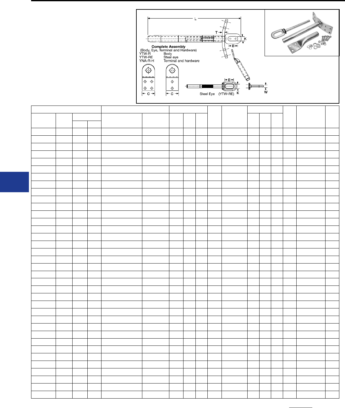
BURNDY®
Blue highlighted items are industry standard and most frequently ordered.
US: 1-800-346-4175 www.burndy.com Canada: 1-800-387-6487
Transmission
TYPES YTW-RD-REK,
YTW-RD, YTW-RE,
YNA-R-H
Double Pad Full Tension
Deadend for ACSR Conductor
Full tension compression deadend for ACSR
transmission lines up to and including 230 kV.
Standard 15º NEMA tap pad provides either 0º or
30º tap when YNA-R15 terminal is used.
ACSR Double Pad Inches Body
Die*‡ Steel Eye*
Inches Eye
Die
Terminal
with
Hardware
Term
Die*‡
Conductor
Name
Size
kcmil
Stranding Complete
Assembly
Alum.
Body L C T B K W
Alum. Steel
Linnet 336.4 26 7 YTW32RD34REK YTW32RD 17.53 2.25 0.50 L717 YTW34RE 2.50 0.88 0.62 L718 YNA32R15H L717
Oriole 336.4 30 7 YTW32RD33REK YTW32RD 17.53 2.25 0.50 L718 YTW33RE 2.50 0.88 0.62 L719 YNA32R15H L717
Ibis 397.5 26 7 YTW34RD34REK YTW34RD 17.60 2.25 0.50 L719 YTW34RE 2.50 0.88 0.62 L718 YNA34R15H L719
Flicker 477 24 7 YTW36RD362REK YTW36RD 15.44 2.25 0.50 L720 YTW362RE 2.50 0.88 0.62 L721 YNA36R15H L720
Hawk 477 26 7 YTW36RD36REK YTW36RD 19.41 2.25 0.50 L720 YTW36RE 2.50 0.88 0.62 L721 YNA36R15H L720
Parakeet 556.5 24 7 YTW39RD43REK YTW39RD 19.66 2.25 0.50 L722 YTW43RE 2.50 0.88 0.69 L723 YNA39R15H L722
Dove 556.5 26 7 YTW39RD43REK YTW39RD 19.66 2.25 0.50 L722 YTW43RE 2.50 0.88 0.69 L723 YNA39R15H L722
Peacock 605 24 7 YTW43RD43REK YTW43RD 20.49 3.25 0.50 L724 YTW43RE 2.50 0.88 0.69 L723 YNA43R15H L724
Squab 605 26 7 YTW43RD43REK YTW43RD 20.49 3.25 0.50 L724 YTW43RE 2.50 0.88 0.69 L723 YNA43R15H L724
Rook 636 24 7 YTW43RD43REK YTW43RD 20.49 3.25 0.50 L724 YTW43RE 2.50 0.88 0.69 L723 YNA43R15H L724
Grosbeak 636 26 7 YTW43RD43REK YTW43RD 20.49 3.25 0.50 L724 YTW43RE 2.50 0.88 0.69 L723 YNA43R15H L724
Flamingo 666.6 24 7 YTW43RD43REK YTW43RD 20.49 3.25 0.50 L724 YTW43RE 2.50 0.88 0.69 L723 YNA43R15H L724
Starling 715.5 26 7 YTW451RD48REK YTW451RD 25.41 3.25 0.50 L725 YTW48RE 2.69 1.25 0.75 L726 YNA451R15H L725
Cuckoo 795 24 7 YTW451RD45REK YTW451RD 25.41 3.25 0.50 L725 YTW45RE 2.69 1.25 0.75 L726 YNA451R15H L725
Drake 795 26 7 YTW451RD48REK YTW451RD 25.41 3.25 0.50 L725 YTW48RE 2.69 1.25 0.75 L726 YNA451R15H L725
Tern 795 45 7 YTW451RD481REK YTW451RD 25.41 3.25 0.50 L725 YTW481RE 2.69 1.25 0.75 L726 YNA451R15H L725
Condor 795 54 7 YTW451RD45REK YTW451RD 25.41 3.25 0.50 L725 YTW45RE 2.69 1.25 0.75 L726 YNA451R15H L725
Ruddy 900 45 7 YTW48RD481REK YTW48RD 25.50 3.25 0.50 L727 YTW481RE 2.69 1.25 0.75 L726 YNA49R15H L727
Rail 954 45 7 YTW48RD481REK YTW48RD 25.50 3.25 0.50 L727 YTW481RE 2.69 1.25 0.75 L726 YNA49R15H L727
Cardinal 954 54 7 YTW48RD48REK YTW48RD 25.50 3.25 0.50 L727 YTW48RE 2.69 1.25 0.75 L726 YNA49R15H L727
Ortolan 1033.5 45 7 YTW49RD483REK YTW49RD 27.35 3.25 0.50 L727 YTW483RE 2.69 1.25 1.00 L726 YNA49R15H L727
Curlew 1033.5 54 7 YTW49RD50REK YTW49RD 27.35 3.25 0.50 L727 YTW50RE 2.69 1.25 1.00 L726 YNA49R15H L727
Bluejay 1113 45 7 YTW49RD483REK YTW49RD 27.35 3.25 0.50 L727 YTW483RE 2.69 1.25 1.00 L726 YNA49R15H L727
Finch 1113 54 19 YTW52RD50REK YTW52RD 31.55 3.25 0.50 L728 YTW50RE 2.69 1.25 1.00 L726 YNA52R15H L728
Bunting 1192.5 45 7 YTW52RD521REK YTW52RD 31.55 4.00 0.62 L728 YTW521RE 2.69 1.25 1.00 L726 YNA52R15H L728
Bittern 1272 45 7 YTW52RD521REK YTW52RD 31.55 4.00 0.62 L728 YTW521RE 2.69 1.25 1.00 L726 YNA52R15H L728
Pheasant 1272 54 19 YTW52RD56REK YTW52RD 31.55 4.00 0.62 L728 YTW56RE 2.69 1.25 1.00 L726 YNA52R15H L728
Dipper 1351.5 45 7 YTW52RD521REK YTW52RD 31.55 4.00 0.62 L728 YTW521RE 2.69 1.25 1.00 L726 YNA52R15H L728
Martin 1351.5 54 19 YTW52RD56REK YTW52RD 31.55 4.00 0.62 L728 YTW56RE 2.69 1.25 1.00 L726 YNA52R15H L728
Nuthatch 1510.5 45 7 YTW549RD521REK YTW549RD 31.55 4.00 0.62 L729 YTW521RE 2.69 1.25 1.00 L726 YNA56R15H L729
Parrot 1510.5 54 19 YTW549RD56REK YTW549RD 31.55 4.00 0.62 L729 YTW56RE 2.69 1.25 1.00 L726 YNA56R15H L729
Lapwing 1590 45 7 YTW549RD549REK YTW549RD 31.55 4.00 0.62 L729 YTW549RE 2.69 1.25 1.00 L726 YNA56R15H L729
Falcon 1590 54 19 YTW56RD590REK YTW56RD 31.99 4.00 0.62 L729 YTW590RE 2.69 1.25 1.00 L726 YNA56R15H L729
Chukar 1780 84 19 YTW58RD58REK YTW58RD 32.99 4.00 0.62 L735 YTW58RE 2.69 1.25 1.00 L726 YNA58R15H L735
Bluebird 2156 84 19 YTW59RD59REK YTW59RD 33.34 4.00 0.62 L735 YTW59RE 2.69 1.25 1.00 L726 YNA59R15H L735
Kiwi 2167 72 7 YTW59RD591REK YTW59RD 33.34 4.00 0.62 L735 YTW591RE 2.69 1.25 1.00 L726 YNA59R15H L735
ACSR Deadends
4-hole pad supplied on
556.5 kcmil and above.
2-hole pad supplied on
less than 556.5 kcmil.
Complete Assembly: Includes Aluminum body, Steel eye,
15 degree terminal and aluminum hardware.
For stainless steel hardware add SS to end of
catalog number for complete assembly (example:
YTW32R34REKSS) or to terminal (YNA32R15HSS) if
ordered separately.
For assembly without terminal and hardware add NT to
end of complete assembly catalog number (example:
YTW32R34REKNT).
Two hole NEMA pads standard on conductors up to 556.5
kcmil; Four hole NEMA pads on larger conductor sizes.
* Overlap crimps.
‡ Wide dies may be used on aluminum only (no steel), add
sufx “W” to part number (example: L725W).
I-4
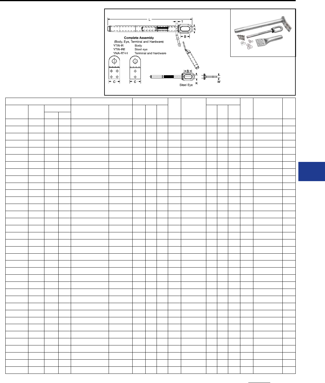
BURNDY®
Blue highlighted items are industry standard and most frequently ordered.
Canada: 1-800-387-6487 www.burndy.com US: 1-800-346-4175
Transmission
TYPES YTW-RT-REK,
YTW-RT, YTW-RE,
YNA-RT-H EHV
Single Pad, EHV Full Tension
Deadend for ACSR Conductor
Full tension compression deadend for ACSR
transmission lines at 345 kV and over. Standard
15º NEMA tap pad provides either 0º or 30º tap
when YNA-R15 terminal is used.
ACSR Single Pad Inches Body
Die*‡ Steel Eye*
Inches Eye
Die
Terminal
with
Hardware
Term
Die*‡
Conductor
Name
Size
kcmil
Stranding Complete
Assembly
Alum.
Body L C T B K W
Alum. Steel
Linnet 336.4 26 7 YTW32RT34REK YTW32RT 17.53 2.25 0.50 L717 YTW34RE 2.50 0.88 0.62 L718 YNA32RT15H L717
Oriole 336.4 30 7 YTW32RT33REK YTW32RT 17.53 2.25 0.50 L717 YTW33RE 2.50 0.88 0.62 L718 YNA32RT15H L717
Ibis 397.5 26 7 YTW34RT34REK YTW34RT 17.60 2.25 0.50 L719 YTW34RE 2.50 0.88 0.62 L718 YNA34RT15H L719
Flicker 477 24 7 YTW36RT362REK YTW36RT 19.41 2.25 0.50 L720 YTW362RE 2.50 0.88 0.62 L721 YNA36RT15H L720
Hawk 477 26 7 YTW36RT36REK YTW36RT 19.41 2.25 0.50 L720 YTW36RE 2.50 0.88 0.62 L721 YNA36RT15H L720
Parakeet 556.5 24 7 YTW39RT43REK YTW39RT 19.66 2.25 0.50 L722 YTW43RE 2.50 0.88 0.69 L723 YNA39RT15H L722
Dove 556.5 26 7 YTW39RT43REK YTW39RT 19.66 2.25 0.50 L722 YTW43RE 2.50 0.88 0.69 L723 YNA39RT15H L722
Peacock 605 24 7 YTW43RT43REK YTW43RT 20.49 3.25 0.50 L724 YTW43RE 2.50 0.88 0.69 L723 YNA43RT15H L724
Squab 605 26 7 YTW43RT43REK YTW43RT 20.49 3.25 0.50 L724 YTW43RE 2.50 0.88 0.69 L723 YNA43RT15H L724
Rook 636 24 7 YTW43RT43REK YTW43RT 20.49 3.25 0.50 L724 YTW43RE 2.50 0.88 0.69 L723 YNA43RT15H L724
Grosbeak 636 26 7 YTW43RT43REK YTW43RT 20.49 3.25 0.50 L724 YTW43RE 2.50 0.88 0.69 L723 YNA43RT15H L724
Flamingo 666.6 24 7 YTW43RT43REK YTW43RT 20.49 3.25 0.50 L724 YTW43RE 2.50 0.88 0.69 L723 YNA43RT15H L724
Starling 715.5 26 7 YTW451RT48REK YTW451RT 25.41 3.25 0.50 L725 YTW48RE 2.69 1.25 0.75 L726 YNA451RT15H L725
Cuckoo 795 24 7 YTW451RT45REK YTW451RT 25.41 3.25 0.50 L725 YTW45RE 2.69 1.25 0.75 L726 YNA451RT15H L725
Drake 795 26 7 YTW451RT48REK YTW451RT 25.41 3.25 0.50 L725 YTW48RE 2.69 1.25 0.75 L726 YNA451RT15H L725
Tern 795 45 7 YTW451RT481REK YTW451RT 25.41 3.25 0.50 L725 YTW481RE 2.69 1.25 0.75 L726 YNA451RT15H L725
Condor 795 54 7 YTW451RT45REK YTW451RT 25.41 3.25 0.50 L725 YTW45RE 2.69 1.25 0.75 L726 YNA451RT15H L725
Ruddy 900 45 7 YTW48RT481REK YTW48RT 25.50 3.25 0.50 L727 YTW481RE 2.69 1.25 0.75 L726 YNA49RT15H L727
Rail 954 45 7 YTW48RT481REK YTW48RT 25.50 3.25 0.50 L727 YTW481RE 2.69 1.25 0.75 L726 YNA49RT15H L727
Cardinal 954 54 7 YTW48RT48REK YTW48RT 25.50 3.25 0.50 L727 YTW48RE 2.69 1.25 0.75 L726 YNA49RT15H L727
Ortolan 1033.5 45 7 YTW49RT483REK YTW49RT 27.35 3.25 0.50 L727 YTW483RE 2.69 1.25 1.00 L726 YNA49RT15H L727
Curlew 1033.5 54 7 YTW49RT50REK YTW49RT 27.35 3.25 0.50 L727 YTW50RE 2.69 1.25 1.00 L726 YNA49RT15H L727
Bluejay 1113 45 7 YTW49RT483REK YTW49RT 27.35 3.25 0.50 L727 YTW483RE 2.69 1.25 1.00 L726 YNA49RT15H L727
Finch 1113 54 19 YTW52RT50REK YTW52RT 31.55 3.25 0.50 L728 YTW50RE 2.69 1.25 1.00 L726 YNA52RT15H L728
Bunting 1192.5 45 7 YTW52RT521REK YTW52RT 31.55 4.00 0.62 L728 YTW521RE 2.69 1.25 1.00 L726 YNA52RT15H L728
Bittern 1272 45 7 YTW52RT521REK YTW52RT 31.55 4.00 0.62 L728 YTW521RE 2.69 1.25 1.00 L726 YNA52RT15H L728
Pheasant 1272 54 19 YTW52RT56REK YTW52RT 31.55 4.00 0.62 L728 YTW56RE 2.69 1.25 1.00 L726 YNA52RT15H L728
Dipper 1351.5 45 7 YTW52RT521REK YTW52RT 31.55 4.00 0.62 L728 YTW521RE 2.69 1.25 1.00 L726 YNA52RT15H L728
Martin 1351.5 54 19 YTW52RT56REK YTW52RT 31.55 4.00 0.62 L728 YTW56RE 2.69 1.25 1.00 L726 YNA52RT15H L728
Nuthatch 1510.5 45 7 YTW549RT521REK YTW549RT 31.55 4.00 0.62 L729 YTW521RE 2.69 1.25 1.00 L726 YNA56RT15H L729
Parrot 1510.5 54 19 YTW549RT56REK YTW549RT 31.55 4.00 0.62 L729 YTW56RE 2.69 1.25 1.00 L726 YNA56RT15H L729
Lapwing 1590 45 7 YTW549RT549REK YTW549RT 31.55 4.00 0.62 L729 YTW549RE 2.69 1.25 1.00 L726 YNA56RT15H L729
Falcon 1590 54 19 YTW56RT590REK YTW56RT 31.99 4.00 0.62 L729 YTW590RE 2.69 1.25 1.00 L726 YNA56RT15H L729
Chukar 1780 84 19 YTW58RT58REK YTW58RT 32.99 4.00 0.62 L735 YTW58RE 2.69 1.25 1.00 L726 YNA58RT15H L735
Bluebird 2156 84 19 YTW59RT59REK YTW59RT 33.34 4.00 0.62 L735 YTW59RE 2.69 1.25 1.00 L726 YNA59RT15H L735
Kiwi 2167 72 7 YTW59RT591REK YTW59RT 33.34 4.00 0.62 L735 YTW591RE 2.69 1.25 1.00 L726 YNA59RT15H L735
ACSR Deadends-EHV
4-hole pad supplied on
556.5 kcmil and above.
2-hole pad supplied on
less than 556.5 kcmil.
Complete Assembly: Includes Aluminum body, Steel eye,
15 degree terminal and aluminum hardware.
For stainless steel hardware add SS to end of
catalog number for complete assembly (example:
YTW32R34REKSS) or to terminal (YNA32R15HSS) if
ordered separately.
For assembly without terminal and hardware add NT to
end of complete assembly catalog number (example:
YTW32R34REKNT).
Two hole NEMA pads standard on conductors up to 556.5
kcmil; Four hole NEMA pads on larger conductor sizes.
* Overlap crimps.
‡ Wide dies may be used on aluminum only (no steel), add
sufx “W” to part number (example: L725W).
I-5
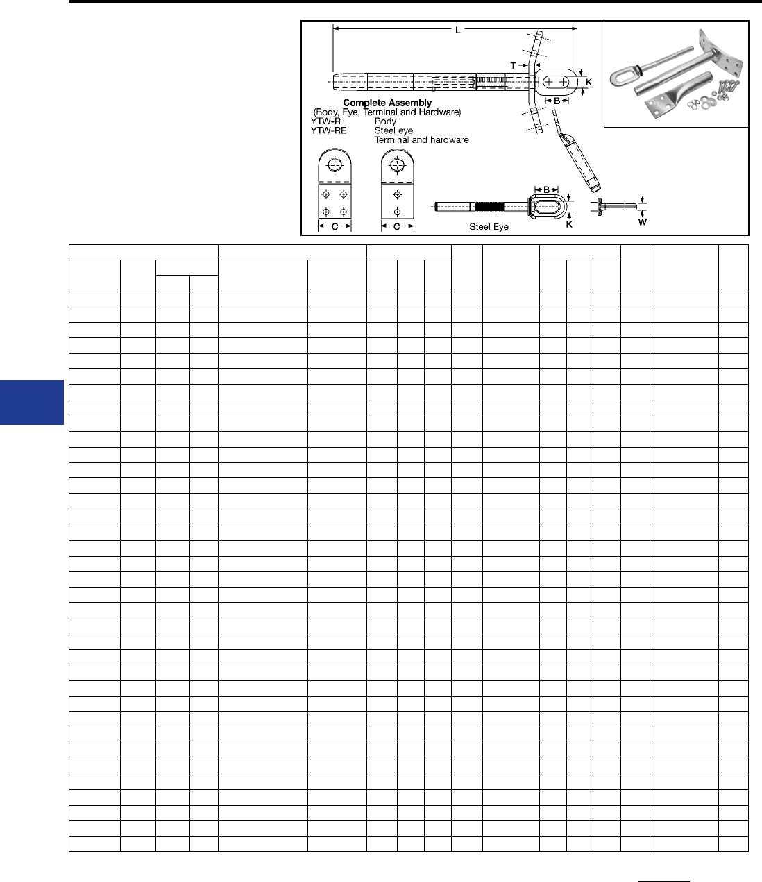
BURNDY®
Blue highlighted items are industry standard and most frequently ordered.
US: 1-800-346-4175 www.burndy.com Canada: 1-800-387-6487
Transmission
TYPES YTW-RDT-REK,
YTW-RDT, YTW-RE,
YNA-RT-H EHV
Double Pad, EHV Full Tension
Deadend for ACSR
Full tension compression deadend for ACSR
transmission lines at 345 kV and over. Standard
15º NEMA tap pad provides either 0º or 30º tap
when YNA-R15 terminal is used.
YNA-RT-H
ACSR Double Pad Inches
Body
Die*‡ Steel Eye*
Inches
Eye
Die
Terminal
with
Hardware
Term
Die*‡
Conductor
Name
Size
kcmil
Stranding Complete
Assembly
Alum.
Body L C T B K W
Alum. Steel
Linnet 336.4 26 7 YTW32RDT34REK YTW32RDT 17.53 2.25 0.50 L717 YTW34RE 2.50 0.88 0.62 L718 YNA32RT15H L717
Oriole 336.4 30 7 YTW32RDT33REK YTW32RDT 17.53 2.25 0.50 L717 YTW33RE 2.50 0.88 0.62 L718 YNA32RT15H L717
Ibis 397.5 26 7 YTW34RDT34REK YTW34RDT 17.60 2.25 0.50 L719 YTW34RE 2.50 0.88 0.62 L718 YNA34RT15H L719
Flicker 477 24 7 YTW36RDT362REK YTW36RDT 15.44 2.25 0.50 L720 YTW362RE 2.50 0.88 0.62 L721 YNA36RT15H L720
Hawk 477 26 7 YTW36RDT36REK YTW36RDT 19.41 2.25 0.50 L720 YTW36RE 2.50 0.88 0.62 L721 YNA36RT15H L720
Parakeet 556.5 24 7 YTW39RDT43REK YTW39RDT 19.66 2.25 0.50 L722 YTW43RE 2.50 0.88 0.69 L723 YNA39RT15H L722
Dove 556.5 26 7 YTW39RDT43REK YTW39RDT 19.66 2.25 0.50 L722 YTW43RE 2.50 0.88 0.69 L723 YNA39RT15H L722
Peacock 605 24 7 YTW43RDT43REK YTW43RDT 20.49 3.25 0.50 L724 YTW43RE 2.50 0.88 0.69 L723 YNA43RT15H L724
Squab 605 26 7 YTW43RDT43REK YTW43RDT 20.49 3.25 0.50 L724 YTW43RE 2.50 0.88 0.69 L723 YNA43RT15H L724
Rook 636 24 7 YTW43RDT43REK YTW43RDT 20.49 3.25 0.50 L724 YTW43RE 2.50 0.88 0.69 L723 YNA43RT15H L724
Grosbeak 636 26 7 YTW43RDT43REK YTW43RDT 20.49 3.25 0.50 L724 YTW43RE 2.50 0.88 0.69 L723 YNA43RT15H L724
Flamingo 666.6 24 7 YTW43RDT43REK YTW43RDT 20.49 3.25 0.50 L724 YTW43RE 2.50 0.88 0.69 L723 YNA43RT15H L724
Starling 715.5 26 7 YTW451RDT48REK YTW451RDT 25.41 3.25 0.50 L725 YTW48RE 2.69 1.25 0.75 L726 YNA451RT15H L725
Cuckoo 795 24 7 YTW451RDT45REK YTW451RDT 25.41 3.25 0.50 L725 YTW45RE 2.69 1.25 0.75 L726 YNA451RT15H L725
Drake 795 26 7 YTW451RDT48REK YTW451RDT 25.41 3.25 0.50 L725 YTW48RE 2.69 1.25 0.75 L726 YNA451RT15H L725
Tern 795 45 7 YTW451RDT481REK YTW451RDT 25.41 3.25 0.50 L725 YTW481RE 2.69 1.25 0.75 L726 YNA451RT15H L725
Condor 795 54 7 YTW451RDT45REK YTW451RDT 25.41 3.25 0.50 L725 YTW45RE 2.69 1.25 0.75 L726 YNA451RT15H L725
Ruddy 900 45 7 YTW48RDT481REK YTW48RDT 25.50 3.25 0.50 L727 YTW481RE 2.69 1.25 0.75 L726 YNA49RT15H L727
Rail 954 45 7 YTW48RDT481REK YTW48RDT 25.50 3.25 0.50 L727 YTW481RE 2.69 1.25 0.75 L726 YNA49RT15H L727
Cardinal 954 54 7 YTW48RDT48REK YTW48RDT 25.50 3.25 0.50 L727 YTW48RE 2.69 1.25 0.75 L726 YNA49RT15H L727
Ortolan 1033.5 45 7 YTW49RDT483REK YTW49RDT 27.35 3.25 0.50 L727 YTW483RE 2.69 1.25 1.00 L726 YNA49RT15H L727
Curlew 1033.5 54 7 YTW49RDT50REK YTW49RDT 27.35 3.25 0.50 L727 YTW50RE 2.69 1.25 1.00 L726 YNA49RT15H L727
Bluejay 1113 45 7 YTW49RDT483REK YTW49RDT 27.35 3.25 0.50 L727 YTW483RE 2.69 1.25 1.00 L726 YNA49RT15H L727
Finch 1113 54 19 YTW52RDT50REK YTW52RDT 31.55 3.25 0.50 L728 YTW50RE 2.69 1.25 1.00 L726 YNA52RT15H L728
Bunting 1192.5 45 7 YTW52RDT521REK YTW52RDT 31.55 4.00 0.62 L728 YTW521RE 2.69 1.25 1.00 L726 YNA52RT15H L728
Bittern 1272 45 7 YTW52RDT521REK YTW52RDT 31.55 4.00 0.62 L728 YTW521RE 2.69 1.25 1.00 L726 YNA52RT15H L728
Pheasant 1272 54 19 YTW52RDT56REK YTW52RDT 31.55 4.00 0.62 L728 YTW56RE 2.69 1.25 1.00 L726 YNA52RT15H L728
Dipper 1351.5 45 7 YTW52RDT521REK YTW52RDT 31.55 4.00 0.62 L728 YTW521RE 2.69 1.25 1.00 L726 YNA52RT15H L728
Martin 1351.5 54 19 YTW52RDT56REK YTW52RDT 31.55 4.00 0.62 L728 YTW56RE 2.69 1.25 1.00 L726 YNA52RT15H L728
Nuthatch 1510.5 45 7 YTW549RDT521REK YTW549RDT 31.55 4.00 0.62 L729 YTW521RE 2.69 1.25 1.00 L726 YNA56RT15H L729
Parrot 1510.5 54 19 YTW549RDT56REK YTW549RDT 31.55 4.00 0.62 L729 YTW56RE 2.69 1.25 1.00 L726 YNA56RT15H L729
Lapwing 1590 45 7 YTW549RDT549REK YTW549RDT 31.55 4.00 0.62 L729 YTW549RE 2.69 1.25 1.00 L726 YNA56RT15H L729
Falcon 1590 54 19 YTW56RDT590REK YTW56RDT 31.99 4.00 0.62 L729 YTW590RE 2.69 1.25 1.00 L726 YNA56RT15H L729
Chukar 1780 84 19 YTW58RDT58REK YTW58RDT 32.99 4.00 0.62 L735 YTW58RE 2.69 1.25 1.00 L726 YNA58RT15H L735
Bluebird 2156 84 19 YTW59RDT59REK YTW59RDT 33.34 4.00 0.62 L735 YTW59RE 2.69 1.25 1.00 L726 YNA59RT15H L735
Kiwi 2167 72 7 YTW59RDT591REK YTW59RDT 33.34 4.00 0.62 L735 YTW591RE 2.69 1.25 1.00 L726 YNA59RT15H L735
ACSR Deadends-EHV
4-hole pad supplied
on 556.5 kcmil and
above.
2-hole pad supplied
on less than 556.5
kcmil.
Complete Assembly: Includes Aluminum body, Steel eye,
15 degree terminal and aluminum hardware.
For stainless steel hardware add SS to end of
catalog number for complete assembly (example:
YTW32R34REKSS) or to terminal (YNA32R15HSS) if
ordered separately.
For assembly without terminal and hardware add NT to
end of complete assembly catalog number (example:
YTW32R34REKNT).
Two hole NEMA pads standard on conductors up to 556.5
kcmil; Four hole NEMA pads on larger conductor sizes.
* Overlap crimps.
‡ Wide dies may be used on aluminum only (no steel), add
sufx “W” to part number (example: L725W).
I-6
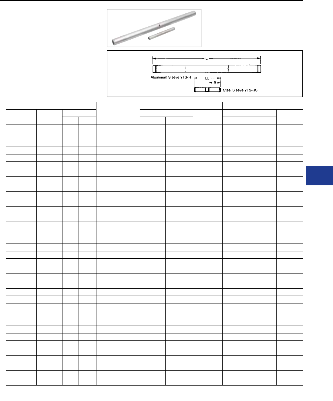
BURNDY®
Blue highlighted items are industry standard and most frequently ordered.
Canada: 1-800-387-6487 www.burndy.com US: 1-800-346-4175
Transmission
ACSR
Splice Kit
Aluminum Sleeve Steel Sleeve
Conductor
Name
Size
kcmil
Stranding Inches
Die*‡
Inches Die*
Alum. Steel L O.D. LL B
Linnet 336.4 26 7 YTS32R34RS 17.30 1.19 L717 5.74 2.45 L718
Oriole 336.4 30 7 YTS32R33RS 17.30 1.19 L717 5.74 2.45 L718
Ibis 397.5 26 7 YTS34R34RS 17.30 1.28 L719 5.74 2.45 L718
Flicker 477 24 7 YTS36R362RS 18.16 1.41 L720 5.88 2.46 L721
Hawk 477 26 7 YTS36R36RS 18.16 1.41 L720 5.76 2.46 L721
Parakeet 556.5 24 7 YTS39R43RS 19.88 1.50 L722 5.90 2.47 L723
Dove 556.5 26 7 YTS39R43RS 19.88 1.50 L722 5.90 2.47 L723
Peacock 605 24 7 YTS43R43RS 21.44 1.61 L724 5.90 2.47 L723
Squab 605 26 7 YTS43R43RS 21.44 1.61 L724 5.90 2.47 L723
Rook 636 24 7 YTS43R43RS 21.44 1.61 L724 5.90 2.47 L723
Grosbeak 636 26 7 YTS43R43RS 21.44 1.61 L724 5.90 2.47 L723
Flamingo 666.6 24 7 YTS43R43RS 21.44 1.61 L724 5.90 2.47 L723
Starling 715.5 26 7 YTS451R48RS 28.96 1.80 L725 9.00 4.00 L726
Cuckoo 795 24 7 YTS451R449RS 28.96 1.80 L725 9.00 4.00 L726
Drake 795 26 7 YTS451R48RS 28.96 1.80 L725 9.00 4.00 L726
Tern 795 45 7 YTS451R48RS 28.96 1.80 L725 9.00 4.00 L726
Condor 795 54 7 YTS451R449RS 28.96 1.80 L725 9.00 4.00 L726
Rail 954 45 7 YTS48R481RS 29.16 1.97 L727 9.00 4.01 L726
Cardinal 954 54 7 YTS48R48RS 29.16 1.97 L727 9.00 4.00 L726
Ortolan 1033.5 45 7 YTS49R483RS 29.02 1.97 L727 9.00 4.01 L726
Curlew 1033.5 54 7 YTS49R48RS 29.02 1.97 L727 9.00 4.00 L726
Bluejay 1113 45 7 YTS49R483RS 29.02 1.97 L727 9.00 4.01 L726
Finch 1113 54 19 YTS52R48RS 42.33 2.25 L728 9.00 4.00 L726
Bunting 1192.5 45 7 YTS52R521RS 42.33 2.25 L728 9.00 4.00 L726
Bittern 1272 45 7 YTS52R521RS 42.33 2.25 L728 9.00 4.00 L726
Pheasant 1272 54 19 YTS52R59RS 42.33 2.25 L728 9.10 4.07 L726
Dipper 1351.5 45 7 YTS52R521RS 42.33 2.25 L728 9.00 4.00 L726
Martin 1351.5 54 19 YTS52R59RS 42.33 2.25 L728 9.10 4.07 L726
Nuthatch 1510.5 45 7 YTS549R521RS 34.13 2.50 L729 9.00 4.00 L726
Parrot 1510.5 54 19 YTS549R59RS 34.13 2.50 L729 9.10 4.07 L726
Lapwing 1590 45 7 YTS549R549RS 34.13 2.50 L729 9.00 4.00 L726
Falcon 1590 54 19 YTS56R59RS 34.13 2.50 L729 9.10 4.07 L726
Chukar 1780 84 19 YTS58R48RS 35.46 2.50 L735 9.00 4.00 L726
Bluebird 2156 84 19 YTS59R59RS 42.91 2.50 L735 9.10 4.07 L726
Kiwi 2167 72 7 YTS59R521RS 42.91 2.50 L735 9.00 4.00 L726
Splice Kit: Includes aluminum sleeve and steel sleeve.
* Overlap crimps.
‡ Wide dies may be used on aluminum only (no steel), add sufx
“W” to part number (example: L725W).
TYPE YTS-R-RS
Full Tension Splice Kit
for ACSR Conductor
Full tension, two-piece, compression splice for
ACSR transmission lines up to and including 230
kV. Outer aluminum sleeve has ller hole and plug
for PENETROX™ joint compound. Kit includes the
outer aluminum and inner steel sleeve.
ACSR Splices
I-7
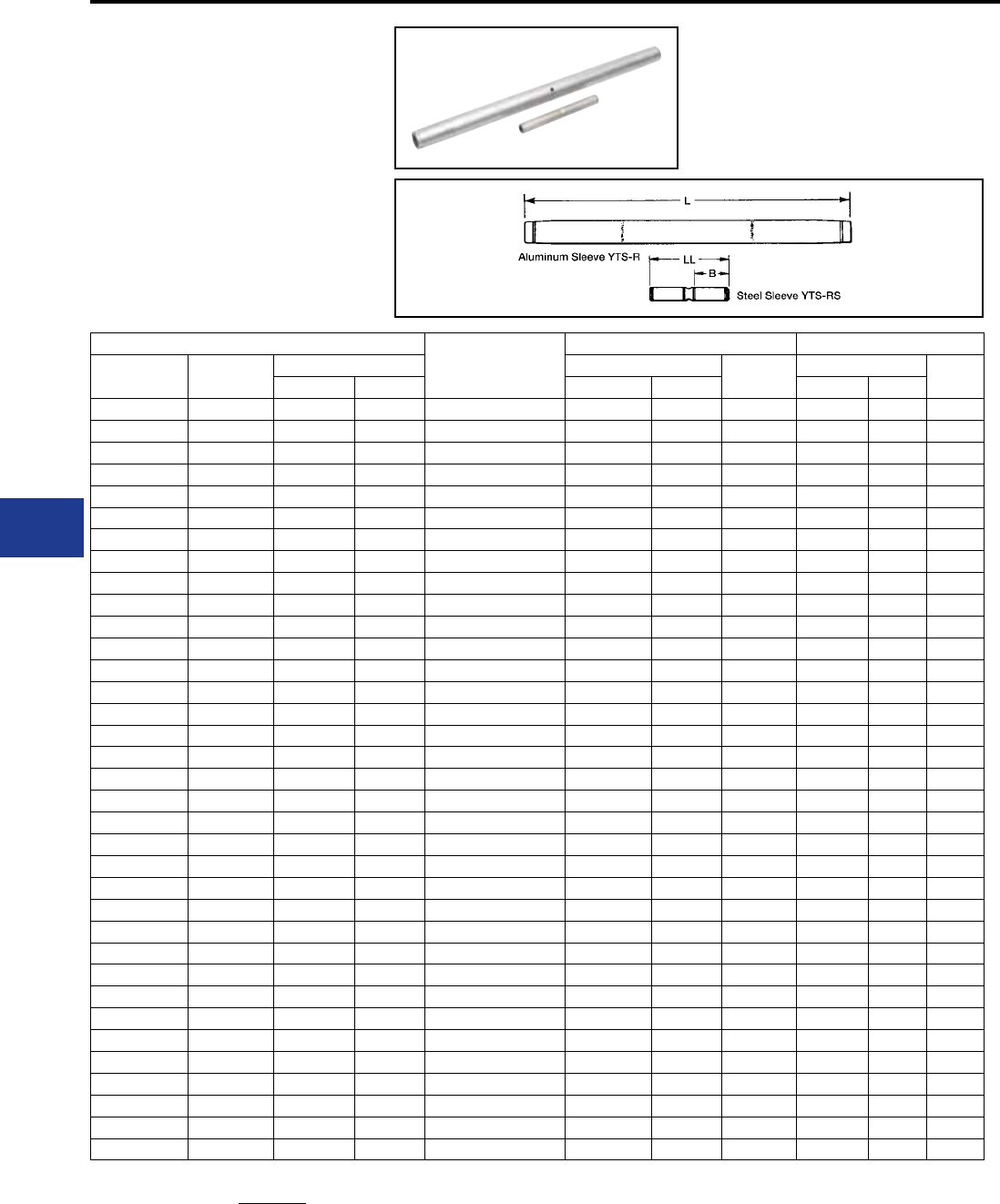
BURNDY®
Blue highlighted items are industry standard and most frequently ordered.
US: 1-800-346-4175 www.burndy.com Canada: 1-800-387-6487
Transmission
TYPE YTS-RT-RS EHV
Full Tension Splice Kit
for ACSR Conductor
Full tension, two-piece, compression splice for
ACSR transmission lines at 345 kV and over.
Outer aluminum sleeve has ller hole and plug for
PENETROX™ joint compound. Kit includes the
outer aluminum and inner steel sleeve.
ACSR
Splice Kit
Aluminum Sleeve Steel Sleeve
Conductor
Name
Size
kcmil
Stranding Inches
Die*‡
Inches Die*
Alum. Steel L O.D. LL B
Linnet 336.4 26 7 YTS32RT34RS 17.92 1.19 L717 5.74 2.45 L718
Oriole 336.4 30 7 YTS32RT33RS 17.92 1.19 L717 5.74 2.45 L718
Ibis 397.5 26 7 YTS34RT34RS 17.92 1.28 L719 5.74 2.45 L718
Flicker 477 24 7 YTS36RT362RS 18.92 1.41 L720 5.88 2.46 L721
Hawk 477 26 7 YTS36RT36RS 18.92 1.41 L720 5.76 2.46 L721
Parakeet 556.5 24 7 YTS39RT43RS 20.74 1.50 L722 5.90 2.47 L723
Dove 556.5 26 7 YTS39RT43RS 20.74 1.50 L722 5.90 2.47 L723
Peacock 605 24 7 YTS43RT43RS 22.28 1.61 L724 5.90 2.47 L723
Squab 605 26 7 YTS43RT43RS 22.28 1.61 L724 5.90 2.47 L723
Rook 636 24 7 YTS43RT43RS 22.28 1.61 L724 5.90 2.47 L723
Grosbeak 636 26 7 YTS43RT43RS 22.28 1.61 L724 5.90 2.47 L723
Flamingo 666.6 24 7 YTS43RT43RS 22.28 1.61 L724 5.90 2.47 L723
Starling 715.5 26 7 YTS451RT48RS 28.96 1.80 L725 9.00 4.00 L726
Cuckoo 795 24 7 YTS451RT449RS 28.96 1.80 L725 9.00 4.00 L726
Drake 795 26 7 YTS451RT48RS 28.96 1.80 L725 9.00 4.00 L726
Tern 795 45 7 YTS451RT48RS 28.96 1.80 L725 9.00 4.00 L726
Condor 795 54 7 YTS451RT449RS 28.96 1.80 L725 9.00 4.00 L726
Rail 954 45 7 YTS48RT481RS 29.16 1.97 L727 9.00 4.01 L726
Cardinal 954 54 7 YTS48RT48RS 29.16 1.97 L727 9.00 4.00 L726
Ortolan 1033.5 45 7 YTS49RT483RS 29.02 1.97 L727 9.00 4.01 L726
Curlew 1033.5 54 7 YTS49RT48RS 29.02 1.97 L727 9.00 4.00 L726
Bluejay 1113 45 7 YTS49RT483RS 29.02 1.97 L727 9.00 4.01 L726
Finch 1113 54 19 YTS52RT48RS 42.33 2.25 L728 9.00 4.00 L726
Bunting 1192.5 45 7 YTS52RT521RS 42.33 2.25 L728 9.00 4.00 L726
Bittern 1272 45 7 YTS52RT521RS 42.33 2.25 L728 9.00 4.00 L726
Pheasant 1272 54 19 YTS52RT59RS 42.33 2.25 L728 9.00 4.07 L726
Dipper 1351.5 45 7 YTS52RT521RS 42.33 2.25 L728 9.00 4.00 L726
Martin 1351.5 54 19 YTS52RT59RS 42.33 2.25 L728 9.00 4.07 L726
Nuthatch 1510.5 45 7 YTS549RT521RS 34.13 2.50 L729 9.00 4.00 L726
Parrot 1510.5 54 19 YTS549RT59RS 34.13 2.50 L729 9.10 4.07 L726
Lapwing 1590 45 7 YTS549RT549RS 34.13 2.50 L729 9.00 4.00 L726
Falcon 1590 54 19 YTS56RT59RS 34.13 2.50 L729 9.10 4.07 L726
Chukar 1780 84 19 YTS58RT48RS 35.46 2.50 L735 9.00 4.00 L726
Bluebird 2156 84 19 YTS59RT59RS 42.91 2.50 L735 9.10 4.07 L726
Kiwi 2167 72 7 YTS59RT521RS 42.91 2.50 L735 9.00 4.00 L726
ACSR Splices-EHV
Splice Kit: Includes aluminum sleeve and steel sleeve.
* Overlap crimps.
‡ Wide dies may be used on aluminum only (no steel), add sufx
“W” to part number (example: L725W).
I-8
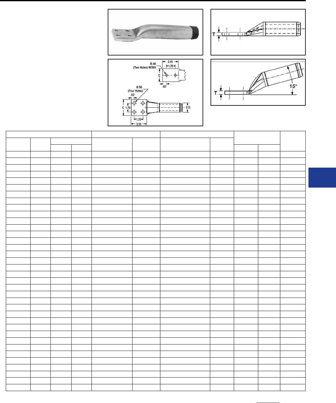
BURNDY®
Blue highlighted items are industry standard and most frequently ordered.
Canada: 1-800-387-6487 www.burndy.com US: 1-800-346-4175
Transmission
TYPES YNA-R15
& YNA-R
Compression Terminal
for ACSR Conductor
Compression terminal for ACSR transmission
lines up to and including 230 kV. Two hole NEMA
tongue through 556.5 kcmil and four hole on larger
sizes. Includes PENETROX™ joint compound in
barrel and oxide retardant on pad.
ACSR 15° Terminal Straight Terminal Inches Die*‡
Conductor
Name
Size
kcmil
Stranding Catalog
Number
Inches
L
Catalog
Number
Inches
L
Alum. Steel C† T
Linnet 336.4 26 7 YNA32R15 8.92 YNA32R 8.96 1.68 0.39 L717
Oriole 336.4 30 7 YNA32R15 8.92 YNA32R 8.96 1.68 0.39 L717
Ibis 397.5 26 7 YNA34R15 9.31 YNA34R 9.08 1.78 0.46 L719
Flicker 477 24 7 YNA36R15 9.62 YNA36R 9.47 1.96 0.48 L720
Hawk 477 26 7 YNA36R15 9.62 YNA36R 9.47 1.96 0.48 L720
Parakeet 556.5 24 7 YNA39R15 10.09 YNA39R 9.84 2.08 0.53 L722
Dove 556.5 26 7 YNA39R15 10.09 YNA39R 9.84 2.08 0.53 L722
Peacock 605 24 7 YNA43R15 10.16 YNA43R 10.07 3.07 0.36 L724
Squab 605 26 7 YNA43R15 10.16 YNA43R 10.07 3.07 0.36 L724
Rook 636 24 7 YNA43R15 10.16 YNA43R 10.07 3.07 0.36 L724
Grosbeak 636 26 7 YNA43R15 10.16 YNA43R 10.07 3.07 0.36 L724
Flamingo 666.6 24 7 YNA43R15 10.16 YNA43R 10.07 3.07 0.36 L724
Starling 715.5 26 7 YNA451R15 10.21 YNA451R 10.28 3.22 0.45 L725
Cuckoo 795 24 7 YNA451R15 10.21 YNA451R 10.28 3.22 0.45 L725
Drake 795 26 7 YNA451R15 10.21 YNA451R 10.28 3.22 0.45 L725
Tern 795 45 7 YNA451R15 10.21 YNA451R 10.28 3.22 0.45 L725
Condor 795 54 7 YNA451R15 10.21 YNA451R 10.28 3.22 0.45 L725
Ruddy 900 45 7 YNA49R15 10.35 YNA49R 10.46 3.22 0.52 L727
Rail 954 45 7 YNA49R15 10.35 YNA49R 10.46 3.22 0.52 L727
Cardinal 954 54 7 YNA49R15 10.35 YNA49R 10.46 3.22 0.52 L727
Ortolan 1033.5 45 7 YNA49R15 10.35 YNA49R 10.46 3.22 0.52 L727
Curlew 1033.5 54 7 YNA49R15 10.35 YNA49R 10.46 3.22 0.52 L727
Bluejay 1113 45 7 YNA49R15 10.35 YNA49R 10.46 3.22 0.52 L727
Finch 1113 54 19 YNA52R15 12.09 YNA52R 12.24 3.22 0.71 L728
Bunting 1192.5 45 7 YNA52R15 12.09 YNA52R 12.24 3.22 0.71 L728
Bittern 1272 45 7 YNA52R15 12.09 YNA52R 12.24 3.22 0.71 L728
Pheasant 1272 54 19 YNA52R15 12.09 YNA52R 12.24 3.22 0.71 L728
Dipper 1351.5 45 7 YNA52R15 12.09 YNA52R 12.24 3.22 0.71 L728
Martin 1351.5 54 19 YNA52R15 12.09 YNA52R 12.24 3.22 0.71 L728
Nuthatch 1510.5 45 7 YNA56R15 12.50 YNA56R 12.74 3.44 0.81 L729
Parrot 1510.5 54 19 YNA56R15 12.50 YNA56R 12.74 3.44 0.81 L729
Lapwing 1590 45 7 YNA56R15 12.50 YNA56R 12.74 3.44 0.81 L729
Falcon 1590 54 19 YNA56R15 12.50 YNA56R 12.74 3.44 0.81 L729
Chukar 1780 84 19 YNA58R15 13.25 YNA58R 13.34 3.47 0.76 L735
Bluebird 2156 84 19 YNA59R15 13.12 YNA59R 13.25 3.57 0.61 L735
Kiwi 2167 72 7 YNA59R15 13.12 YNA59R 13.25 3.57 0.61 L735
ACSR Terminals
† Two hole NEMA pads standard on conductors up to 556.5
kcmil; Four hole NEMA pads on larger conductor sizes.
* Overlap crimps.
‡ Wide dies may be used on aluminum only (no steel), add
sufx “W” to part number (example: L725W).
To specify hardware for bolting to corresponding Deadends
add the sufx H to the catalog number (example: YNA52RH).
I-9
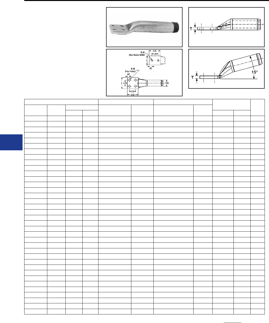
BURNDY®
Blue highlighted items are industry standard and most frequently ordered.
US: 1-800-346-4175 www.burndy.com Canada: 1-800-387-6487
Transmission
ACSR 15° Terminal Straight Terminal Inches Die*‡
Conductor
Name
Size
kcmil
Stranding Catalog
Number
Inches
L
Catalog
Number
Inches
L
Alum. Steel C† T
Linnet 336.4 26 7 YNA32RT15 9.04 YNA32RT 9.14 1.68 0.39 L717
Oriole 336.4 30 7 YNA32RT15 9.04 YNA32RT 9.14 1.68 0.39 L717
Ibis 397.5 26 7 YNA34RT15 9.21 YNA34RT 9.3 1.78 0.46 L719
Flicker 477 24 7 YNA36RT15 9.63 YNA36RT 9.7 1.96 0.48 L720
Hawk 477 26 7 YNA36RT15 9.63 YNA36RT 9.7 1.96 0.48 L720
Parakeet 556.5 24 7 YNA39RT15 10.02 YNA39RT 10.09 2.08 0.53 L722
Dove 556.5 26 7 YNA39RT15 10.02 YNA39RT 10.09 2.08 0.53 L722
Peacock 605 24 7 YNA43RT15 10.21 YNA43RT 10.32 3.22 0.36 L724
Squab 605 26 7 YNA43RT15 10.21 YNA43RT 10.32 3.22 0.36 L724
Rook 636 24 7 YNA43RT15 10.21 YNA43RT 10.32 3.22 0.36 L724
Grosbeak 636 26 7 YNA43RT15 10.21 YNA43RT 10.32 3.22 0.36 L724
Flamingo 666.6 24 7 YNA43RT15 10.21 YNA43RT 10.32 3.22 0.36 L724
Starling 715.5 26 7 YNA451RT15 10.65 YNA451RT 10.57 3.22 0.45 L725
Cuckoo 795 24 7 YNA451RT15 10.65 YNA451RT 10.57 3.22 0.45 L725
Drake 795 26 7 YNA451RT15 10.65 YNA451RT 10.57 3.22 0.45 L725
Tern 795 45 7 YNA451RT15 10.65 YNA451RT 10.57 3.22 0.45 L725
Condor 795 54 7 YNA451RT15 10.65 YNA451RT 10.57 3.22 0.45 L725
Ruddy 900 45 7 YNA49RT15 10.94 YNA49RT 10.77 3.22 0.52 L727
Rail 954 45 7 YNA49RT15 10.94 YNA49RT 10.77 3.22 0.52 L727
Cardinal 954 54 7 YNA49RT15 10.94 YNA49RT 10.77 3.22 0.52 L727
Ortolan 1033.5 45 7 YNA49RT15 10.94 YNA49RT 10.77 3.22 0.52 L727
Curlew 1033.5 54 7 YNA49RT15 10.94 YNA49RT 10.77 3.22 0.52 L727
Bluejay 1113 45 7 YNA49RT15 10.94 YNA49RT 10.77 3.22 0.52 L727
Finch 1113 54 19 YNA52RT15 12.62 YNA52RT 13.82 3.22 0.71 L728
Bunting 1192.5 45 7 YNA52RT15 12.62 YNA52RT 13.82 3.22 0.71 L728
Bittern 1272 45 7 YNA52RT15 12.62 YNA52RT 13.82 3.22 0.71 L728
Pheasant 1272 54 19 YNA52RT15 12.62 YNA52RT 13.82 3.22 0.71 L728
Dipper 1351.5 45 7 YNA52RT15 12.62 YNA52RT 13.82 3.22 0.71 L728
Martin 1351.5 54 19 YNA52RT15 12.62 YNA52RT 13.82 3.22 0.71 L728
Nuthatch 1510.5 45 7 YNA56RT15 13.36 YNA56RT 13.76 3.44 0.86 L729
Parrot 1510.5 54 19 YNA56RT15 13.36 YNA56RT 13.76 3.44 0.86 L729
Lapwing 1590 45 7 YNA56RT15 13.36 YNA56RT 13.76 3.44 0.86 L729
Falcon 1590 54 19 YNA56RT15 13.36 YNA56RT 13.76 3.44 0.86 L729
Chukar 1780 84 19 YNA58RT15 14.08 YNA58RT 13.7 3.47 0.80 L735
Bluebird 2156 84 19 YNA59RT15 13.75 YNA59RT 13.54 3.57 0.64 L735
Kiwi 2167 72 7 YNA59RT15 13.75 YNA59RT 13.54 3.57 0.64 L735
TYPES YNA-RT15,
YNA-RT EHV
Compression Terminal
for ACSR Conductor
Compression terminal for ACSR transmission
lines at 345 kV and over. Two hole NEMA
tongue supplied through 636 kcmil and four hole
on larger sizes. Includes PENETROX™ joint
compound in barrel and oxide retardant on pad.
† Two hole NEMA pads standard for conductors up to 556.5
kcmil; Four hole NEMA pads on larger conductor sizes. Shield-
ing cap STS43A-4N required for EHV applications (two caps
required).
ACSR Terminals-EHV
To specify hardware for bolting to corresponding Deadends
add the sufx H to catalog number (example: YNA52RTH).
* Overlap crimps.
‡ Wide dies may be used on aluminum only (no steel), add
sufx “W” to part number (example: L725W).
I-10
BURNDY®
Blue highlighted items are industry standard and most frequently ordered.
Canada: 1-800-387-6487 www.burndy.com US: 1-800-346-4175
Transmission
TYPE YNS-R
Jumper Loop Sleeve
for ACSR Conductor
Jumper sleeve for ACSR transmission lines up
to and including 230 kV. Sleeve is pre-lled with
PENETROX™ joint compound and capped.
ACSR
Catalog
Number
Inches Die*‡
Conductor
Name
Size
kcmil
Stranding
Alum. Steel L O.D.
Linnet 336.4 26 7 YNS32R 8.60 1.19 L717
Oriole 336.4 30 7 YNS32R 8.60 1.19 L717
Ibis 397.5 26 7 YNS34R 8.68 1.30 L719
Flicker 477 24 7 YNS36R 9.20 1.41 L720
Hawk 477 26 7 YNS36R 9.20 1.41 L720
Parakeet 556.5 24 7 YNS39R 9.76 1.50 L722
Dove 556.5 26 7 YNS39R 9.76 1.50 L722
Peacock 605 24 7 YNS43R 9.98 1.61 L724
Squab 605 26 7 YNS43R 9.98 1.61 L724
Rook 636 24 7 YNS43R 9.98 1.61 L724
Grosbeak 636 26 7 YNS43R 9.98 1.61 L724
Flamingo 666.6 24 7 YNS43R 9.98 1.61 L724
Starling 715.5 26 7 YNS451R 10.00 1.80 L725
Cuckoo 795 24 7 YNS451R 10.00 1.80 L725
Drake 795 26 7 YNS451R 10.00 1.80 L725
Tern 795 45 7 YNS451R 10.00 1.80 L725
Condor 795 54 7 YNS451R 10.00 1.80 L725
Ruddy 900 45 7 YNS49R 10.00 1.97 L727
Rail 954 45 7 YNS49R 10.00 1.97 L727
Cardinal 954 54 7 YNS49R 10.00 1.97 L727
Ortolan 1033.5 45 7 YNS49R 10.00 1.97 L727
Curlew 1033.5 54 7 YNS49R 10.00 1.97 L727
Bluejay 1113 45 7 YNS49R 10.00 1.97 L727
Finch 1113 54 19 YNS52R 15.48 2.25 L728
Bunting 1192.5 45 7 YNS52R 15.48 2.25 L728
Bittern 1272 45 7 YNS52R 15.48 2.25 L728
Pheasant 1272 54 19 YNS52R 15.48 2.25 L728
Dipper 1351.5 45 7 YNS52R 15.48 2.25 L728
Martin 1351.5 54 19 YNS52R 15.48 2.25 L728
Nuthatch 1510.5 45 7 YNS56R 14.80 2.50 L729
Parrot 1510.5 54 19 YNS56R 14.80 2.50 L729
Lapwing 1590 45 7 YNS56R 14.80 2.50 L729
Falcon 1590 54 19 YNS56R 14.80 2.50 L729
Chukar 1780 84 19 YNS58R 14.74 2.50 L735
Bluebird 2156 84 19 YNS59R 14.56 2.50 L735
Kiwi 2167 72 7 YNS59R 14.56 2.50 L735
ACSR Jumper Sleeve
* Overlap crimps.
‡ Wide dies may be used on aluminum only, add sufx “W” to
part number (example: L725W).
I-11
BURNDY®
Blue highlighted items are industry standard and most frequently ordered.
US: 1-800-346-4175 www.burndy.com Canada: 1-800-387-6487
Transmission
ACSR
Jumper Sleeve Inches Die*‡
Conductor
Name
Size
kcmil
Stranding
Alum. Steel L O.D.
Linnet 336.4 26 7 YNS32RT 8.96 1.19 L717
Oriole 336.4 30 7 YNS32RT 8.96 1.19 L717
Ibis 397.5 26 7 YNS34RT 9.10 1.30 L719
Flicker 477 24 7 YNS36RT 9.64 1.41 L720
Hawk 477 26 7 YNS36RT 9.64 1.41 L720
Parakeet 556.5 24 7 YNS39RT 10.26 1.50 L722
Dove 556.5 26 7 YNS39RT 10.26 1.50 L722
Peacock 605 24 7 YNS43RT 10.48 1.61 L724
Squab 605 26 7 YNS43RT 10.48 1.61 L724
Rook 636 24 7 YNS43RT 10.48 1.61 L724
Grosbeak 636 26 7 YNS43RT 10.48 1.61 L724
Flamingo 666.6 24 7 YNS43RT 10.48 1.61 L724
Starling 715.5 26 7 YNS451RT 10.60 1.80 L725
Cuckoo 795 24 7 YNS451RT 10.60 1.80 L725
Drake 795 26 7 YNS451RT 10.60 1.80 L725
Tern 795 45 7 YNS451RT 10.60 1.80 L725
Condor 795 54 7 YNS451RT 10.60 1.80 L725
Ruddy 900 45 7 YNS49RT 10.66 1.97 L727
Rail 954 45 7 YNS49RT 10.66 1.97 L727
Cardinal 954 54 7 YNS49RT 10.66 1.97 L727
Ortolan 1033.5 45 7 YNS49RT 10.66 1.97 L727
Curlew 1033.5 54 7 YNS49RT 10.66 1.97 L727
Bluejay 1113 45 7 YNS49RT 10.66 1.97 L727
Finch 1113 54 19 YNS52RT 16.20 2.25 L728
Bunting 1192.5 45 7 YNS52RT 16.20 2.25 L728
Bittern 1272 45 7 YNS52RT 16.20 2.25 L728
Pheasant 1272 54 19 YNS52RT 16.20 2.25 L728
Dipper 1351.5 45 7 YNS52RT 16.20 2.25 L728
Martin 1351.5 54 19 YNS52RT 16.20 2.25 L728
Nuthatch 1510.5 45 7 YNS56RT 15.58 2.50 L729
Parrot 1510.5 54 19 YNS56RT 15.58 2.50 L729
Lapwing 1590 45 7 YNS56RT 15.58 2.50 L729
Falcon 1590 54 19 YNS56RT 15.58 2.50 L729
Chukar 1780 84 19 YNS58RT 15.46 2.50 L735
Bluebird 2156 84 19 YNS59RT 15.14 2.50 L735
Kiwi 2167 72 7 YNS59RT 15.14 2.50 L735
TYPE YNS-RT EHV
Jumper Loop Sleeve
for ACSR Conductor
Jumper sleeve for ACSR transmission lines over
230 kV. Sleeve is pre-lled with PENETROX™
joint compound and capped.
ACSR Jumper Sleeve-EHV
* Overlap crimps.
‡ Wide dies may be used on aluminum only, add sufx “W” to
part number (example: L725W).
I-12
BURNDY®
Blue highlighted items are industry standard and most frequently ordered.
Canada: 1-800-387-6487 www.burndy.com US: 1-800-346-4175
Transmission
TYPE YNT-R-R
Compression T-Tap
for ACSR Conductor
Two piece compression T-Tap for ACSR
transmission lines that include up to
230 kV. Tap element is pre-lled with
PENETROX™ joint compound and sealed.
ACSR
T-Tap*
Inches
Die **‡
Conductor
Name
Size
kcmil
Stranding L H
Alum. Steel
Linnet 336.4 26 7 YNT32R32R 15.46 6.39 L717
Oriole 336.4 30 7 YNT32R32R 15.46 6.39 L717
Ibis 397.5 26 7 YNT34R34R 15.60 6.53 L719
Flicker 477 24 7 YNT36R36R 16.29 6.85 L720
Hawk 477 26 7 YNT36R36R 16.29 6.85 L720
Parakeet 556.5 24 7 YNT39R39R 16.69 7.13 L722
Dove 556.5 26 7 YNT39R39R 16.69 7.13 L722
Peacock 605 24 7 YNT43R43R 17.48 7.20 L724
Squab 605 26 7 YNT43R43R 17.48 7.20 L724
Rook 636 24 7 YNT43R43R 17.48 7.20 L724
Grosbeak 636 26 7 YNT43R43R 17.48 7.20 L724
Flamingo 666.6 24 7 YNT43R43R 17.48 7.20 L724
Starling 715.5 26 7 YNT451R451R 17.60 7.70 L725
Cuckoo 795 24 7 YNT451R451R 17.60 7.70 L725
Drake 795 26 7 YNT451R451R 17.60 7.70 L725
Tern 795 45 7 YNT451R451R 17.60 7.70 L725
Condor 795 54 7 YNT451R451R 17.60 7.70 L725
Ruddy 900 45 7 YNT49R49R 17.66 7.90 L727
Rail 954 45 7 YNT49R49R 17.66 7.90 L727
Cardinal 954 54 7 YNT49R49R 17.66 7.90 L727
Ortolan 1033.5 45 7 YNT49R49R 17.66 7.90 L727
Curlew 1033.5 54 7 YNT49R49R 17.66 7.90 L727
Bluejay 1113 45 7 YNT49R49R 17.66 7.90 L727
Finch 1113 54 19 YNT52R52R 21.61 11.10 L728
Bunting 1192.5 45 7 YNT52R52R 21.61 11.10 L728
Bittern 1272 45 7 YNT52R52R 21.61 11.10 L728
Pheasant 1272 54 19 YNT52R52R 21.61 11.10 L728
Dipper 1351.5 45 7 YNT52R52R 21.61 11.10 L728
Martin 1351.5 54 19 YNT52R52R 21.61 11.10 L728
Nuthatch 1510.5 45 7 YNT56R56R 23.65 11.08 L729
Parrot 1510.5 54 19 YNT56R56R 23.65 11.08 L729
Lapwing 1590 45 7 YNT56R56R 23.65 11.08 L729
Falcon 1590 54 19 YNT56R56R 23.65 11.08 L729
Chukar 1780 84 19 YNT58R58R 23.53 11.02 L735
Bluebird 2156 84 19 YNT59R59R 23.21 10.86 L735
Kiwi 2167 72 7 YNT59R59R 23.21 10.86 L735
ACSR T-Tap
* For EHV applications, add sufx “T” to catalog number
(example: YNT49R49RT).
** Overlap crimps.
‡ Wide dies may be used on aluminum only, add sufx “W” to
part number (example: L725W).
I-13
BURNDY®
Blue highlighted items are industry standard and most frequently ordered.
US: 1-800-346-4175 www.burndy.com Canada: 1-800-387-6487
Transmission
TYPE YNTA-R
T-Tap with Pad
for ACSR Conductor
Two piece compression T-Tap to a NEMA pad for
ACSR transmission lines. Up to and including 230
kV.
ACSR
T-Tap with Pad
Inches
Die *‡
Conductor
Name
Size
kcmil
Stranding L C H T
Alum. Steel
Linnet 336.4 26 7 YNTA32R 15.46 2.00 4.94 0.50 L717
Oriole 336.4 30 7 YNTA32R 15.46 2.00 4.94 0.50 L717
Ibis 397.5 26 7 YNTA34R 15.60 2.00 5.05 0.50 L719
Flicker 477 24 7 YNTA36R 16.29 2.25 5.16 0.56 L720
Hawk 477 26 7 YNTA36R 16.29 2.25 5.16 0.56 L720
Parakeet 556.5 24 7 YNTA39R 16.69 2.25 5.25 0.56 L722
Dove 556.5 26 7 YNTA39R 16.69 2.25 5.25 0.56 L722
Peacock 605 24 7 YNTA43R 17.48 3.25 5.36 0.56 L724
Squab 605 26 7 YNTA43R 17.48 3.25 5.36 0.56 L724
Rook 636 24 7 YNTA43R 17.48 3.25 5.36 0.56 L724
Grosbeak 636 26 7 YNTA43R 17.48 3.25 5.36 0.56 L724
Flamingo 666.6 24 7 YNTA43R 17.48 3.25 5.36 0.56 L724
Starling 715.5 26 7 YNTA451R 17.60 3.25 5.55 0.56 L725
Cuckoo 795 24 7 YNTA451R 17.60 3.25 5.55 0.56 L725
Drake 795 26 7 YNTA451R 17.60 3.25 5.55 0.56 L725
Tern 795 45 7 YNTA451R 17.60 3.25 5.55 0.56 L725
Condor 795 54 7 YNTA451R 17.60 3.25 5.55 0.56 L725
Ruddy 900 45 7 YNTA49R 17.66 3.25 5.72 0.56 L727
Rail 954 45 7 YNTA49R 17.66 3.25 5.72 0.56 L727
Cardinal 954 54 7 YNTA49R 17.66 3.25 5.72 0.56 L727
Ortolan 1033.5 45 7 YNTA49R 17.66 3.25 5.72 0.56 L727
Curlew 1033.5 54 7 YNTA49R 17.66 3.25 5.72 0.56 L727
Bluejay 1113 45 7 YNTA49R 17.66 3.25 5.72 0.56 L727
Finch 1113 54 19 YNTA54R 21.61 3.25 6.00 0.69 L728
Bunting 1192.5 45 7 YNTA54R 21.61 3.25 6.00 0.69 L728
Bittern 1272 45 7 YNTA54R 21.61 3.25 6.00 0.69 L728
Pheasant 1272 54 19 YNTA54R 21.61 3.25 6.00 0.69 L728
Dipper 1351.5 45 7 YNTA54R 21.61 3.25 6.00 0.69 L728
Martin 1351.5 54 19 YNTA54R 21.61 3.25 6.00 0.69 L728
Nuthatch 1510.5 45 7 YNTA56R 23.65 3.59 6.25 0.69 L729
Parrot 1510.5 54 19 YNTA56R 23.65 3.59 6.25 0.69 L729
Lapwing 1590 45 7 YNTA56R 23.65 3.59 6.25 0.69 L729
Falcon 1590 54 19 YNTA56R 23.65 3.59 6.25 0.69 L729
Chukar 1780 84 19 YNTA58R 23.53 3.59 6.25 0.69 L735
Bluebird 2156 84 19 YNTA59R 23.21 3.59 6.25 0.69 L735
Kiwi 2167 72 7 YNTA59R 23.21 3.59 6.25 0.69 L735
ACSR T-Tap with Pad
For EHV applications (2) two tap pad shielding caps (catalog
number STS43A4N) should be ordered.
* Overlap crimps.
‡ Wide dies may be used on aluminum only, add sufx “W” to
part number (example: L725W).
Two hole NEMA pads standard for conductors up to 556.5
kcmil; Four hole NEMA pads on larger conductor sizes.
For EVH applications, add sufx “T” to catalog number
(example: YNTA49RT).
I-14
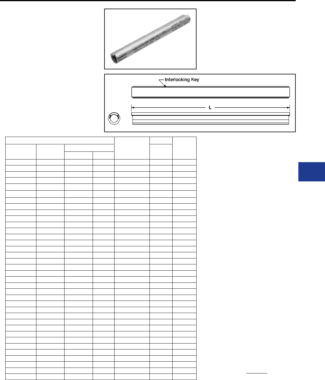
BURNDY®
Blue highlighted items are industry standard and most frequently ordered.
Canada: 1-800-387-6487 www.burndy.com US: 1-800-346-4175
Transmission
TYPE YNU-R
Repair Sleeve
for ACSR Conductor
For HV and EHV applications. Two-piece repair
sleeve for temporary restoration of conductivity
to damaged ACSR transmission lines. Use of
PENETROX™ joint compound required.
ACSR
Repair Sleeve
Inches
Die **‡
Conductor
Name
Size
kcmil
Stranding L
Alum. Steel
Linnet 336.4 26 7 YNU32R 14.00 L717
Oriole 336.4 30 7 YNU32R 14.00 L717
Ibis 397.5 26 7 YNU34R 14.00 L719
Flicker 477 24 7 YNU36R 14.00 L720
Hawk 477 26 7 YNU36R 14.00 L720
Parakeet 556.5 24 7 YNU39R 16.00 L722
Dove 556.5 26 7 YNU39R 16.00 L722
Peacock 605 24 7 YNU43R 16.00 L724
Squab 605 26 7 YNU43R 16.00 L724
Rook 636 24 7 YNU43R 16.00 L724
Grosbeak 636 26 7 YNU43R 16.00 L724
Flamingo 666.6 24 7 YNU43R 16.00 L724
Starling 715.5 26 7 YNU451R 16.00 L725
Cuckoo 795 24 7 YNU451R 16.00 L725
Drake 795 26 7 YNU451R 16.00 L725
Tern 795 45 7 YNU451R 16.00 L725
Condor 795 54 7 YNU451R 16.00 L725
Ruddy 900 45 7 YNU49R 16.00 L727
Rail 954 45 7 YNU49R 16.00 L727
Cardinal 954 54 7 YNU49R 16.00 L727
Ortolan 1033.5 45 7 YNU49R 16.00 L727
Curlew 1033.5 54 7 YNU49R 16.00 L727
Bluejay 1113 45 7 YNU49R 16.00 L727
Finch 1113 54 19 YNU54R 16.00 L728
Bunting 1192.5 45 7 YNU54R 16.00 L728
Bittern 1272 45 7 YNU54R 16.00 L728
Pheasant 1272 54 19 YNU54R 16.00 L728
Dipper 1351.5 45 7 YNU54R 16.00 L728
Martin 1351.5 54 19 YNU54R 16.00 L728
Nuthatch 1510.5 45 7 YNU56R 19.00 L729
Parrot 1510.5 54 19 YNU56R 19.00 L729
Lapwing 1590 45 7 YNU56R 19.00 L729
Falcon 1590 54 19 YNU56R 19.00 L729
Chukar 1780 84 19 YNU58R 19.00 L735
Bluebird 2156 84 19 YNU59R 19.00 L735
Kiwi 2167 72 7 YNU59R 19.00 L735
ACSR Repair Sleeve-EHV
* Overlap crimps.
‡ Wide dies may be used on aluminum only, add sufx “W” to
part number (example: L725W).
I-15
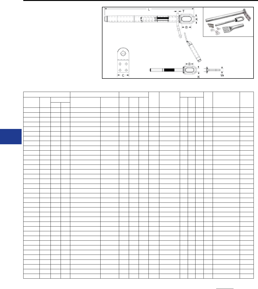
BURNDY®
Blue highlighted items are industry standard and most frequently ordered.
US: 1-800-346-4175 www.burndy.com Canada: 1-800-387-6487
Transmission
TYPES YTW-R-REKHT,
YTW-RHT, YTW-REHT,
BYNA-R-HHT
Single Pad Full Tension
Deadend for ACSS Conductor
Full tension compression deadend for 250º C rated
ACSS transmission lines up to and including 230
kV. Standard 15º NEMA tap pad provides either 0º
or 30º tap when BYNA-R15 terminal is used.
Complete Assembly
(Body, Eye, Terminal and Hardware)
YTW-RHT
YTW-RW
BYNA-RHHT
Body
Steel eye
Terminal and hardware
Steel Eye
ACSS Single Pad Inches Body
Die*‡ Steel Eye
Inches Eye
Die*
Terminal †
with
Hardware
Term
Die*‡
Conductor
Name
Size
kcmil
Stranding Complete
Assembly
Alum.
Body L C T B K W
Alum. Steel
Linnet 336.4 26 7 YTW32R34REKHT YTW32RHT 21.53 3.25 0.50 L717 YTW34REHT 2.50 0.88 0.62 L718 BYNA32R15HHT L717
Oriole 336.4 30 7 YTW32R33REKHT YTW32RHT 21.53 3.25 0.50 L717 YTW33REHT 2.50 0.88 0.62 L718 BYNA32R15HHT L717
Ibis 397.5 26 7 YTW34R34REKHT YTW34RHT 21.60 3.25 0.50 L719 YTW34REHT 2.50 0.88 0.62 L718 BYNA34R15HHT L719
Flicker 477 24 7 YTW36R362REKHT YTW36RHT 23.41 3.25 0.50 L720 YTW362REHT 2.50 0.88 0.62 L721 BYNA36R15HHT L720
Hawk 477 26 7 YTW36R36REKHT YTW36RHT 23.41 3.25 0.50 L720 YTW36REHT 2.50 0.88 0.62 L721 BYNA36R15HHT L720
Parakeet 556.5 24 7 YTW39R43REKHT YTW39RHT 23.66 3.25 0.50 L722 YTW43REHT 2.50 0.88 0.69 L723 BYNA39R15HHT L722
Dove 556.5 26 7 YTW39R43REKHT YTW39RHT 23.66 3.25 0.50 L722 YTW43REHT 2.50 0.88 0.69 L723 BYNA39R15HHT L722
Peacock 605 24 7 YTW43R43REKHT YTW43RHT 24.49 3.25 0.50 L724 YTW43REHT 2.50 0.88 0.69 L723 BYNA43R15HHT L724
Squab 605 26 7 YTW43R43REKHT YTW43RHT 24.49 3.25 0.50 L724 YTW43REHT 2.50 0.88 0.69 L723 BYNA43R15HHT L724
Rook 636 24 7 YTW43R43REKHT YTW43RHT 24.49 3.25 0.50 L724 YTW43REHT 2.50 0.88 0.69 L723 BYNA43R15HHT L724
Grosbeak 636 26 7 YTW43R43REKHT YTW43RHT 24.49 3.25 0.50 L724 YTW43REHT 2.50 0.88 0.69 L723 BYNA43R15HHT L724
Flamingo 666.6 24 7 YTW43R43REKHT YTW43RHT 24.49 3.25 0.50 L724 YTW43REHT 2.50 0.88 0.69 L723 BYNA43R15HHT L724
Starling 715.5 26 7 YTW451R48REKHT YTW451RHT 29.41 3.25 0.50 L725 YTW48REHT 2.69 1.25 0.75 L726 BYNA451R15HHT L725
Cuckoo 795 24 7 YTW451R45REKHT YTW451RHT 29.41 3.25 0.50 L725 YTW45REHT 2.69 1.25 0.75 L726 BYNA451R15HHT L725
Drake 795 26 7 YTW451R48REKHT YTW451RHT 29.41 3.25 0.50 L725 YTW48REHT 2.69 1.25 0.75 L726 BYNA451R15HHT L725
Tern 795 45 7 YTW451R481REKHT YTW451RHT 29.41 3.25 0.50 L725 YTW481REHT 2.69 1.25 0.75 L726 BYNA451R15HHT L725
Condor 795 54 7 YTW451R45REKHT YTW451RHT 29.41 3.25 0.50 L725 YTW45REHT 2.69 1.25 0.75 L726 BYNA451R15HHT L725
Ruddy 900 45 7 YTW48R481REKHT YTW48RHT 29.50 3.25 0.50 L727 YTW481REHT 2.69 1.25 0.75 L726 BYNA49R15HHT L727
Rail 954 45 7 YTW48R481REKHT YTW48RHT 29.50 3.25 0.50 L727 YTW481REHT 2.69 1.25 0.75 L726 BYNA49R15HHT L727
Cardinal 954 54 7 YTW48R48REKHT YTW48RHT 29.50 3.25 0.50 L727 YTW48REHT 2.69 1.25 0.75 L726 BYNA49R15HHT L727
Ortolan 1033.5 45 7 YTW49R483REKHT YTW49RHT 31.35 3.25 0.50 L727 YTW483REHT 2.69 1.25 1.00 L726 BYNA49R15HHT L727
Curlew 1033.5 54 7 YTW49R50REKHT YTW49RHT 31.35 3.25 0.50 L727 YTW50REHT 2.69 1.25 1.00 L726 BYNA49R15HHT L727
Bluejay 1113 45 7 YTW49R483REKHT YTW49RHT 31.35 3.25 0.50 L727 YTW483REHT 2.69 1.25 1.00 L726 BYNA49R15HHT L727
Finch 1113 54 19 YTW52R50REKHT YTW52RHT 35.55 3.25 0.50 L728 YTW50REHT 2.69 1.25 1.00 L726 BYNA52R15HHT L728
Bunting 1192.5 45 7 YTW52R521REKHT YTW52RHT 35.55 4.00 0.62 L728 YTW521REHT 2.69 1.25 1.00 L726 BYNA52R15HHT L728
Bittern 1272 45 7 YTW52R521REKHT YTW52RHT 35.55 4.00 0.62 L728 YTW521REHT 2.69 1.25 1.00 L726 BYNA52R15HHT L728
Pheasant 1272 54 19 YTW52R56REKHT YTW52RHT 35.55 4.00 0.62 L728 YTW56REHT 2.69 1.25 1.00 L726 BYNA52R15HHT L728
Dipper 1351.5 45 7 YTW52R521REKHT YTW52RHT 35.55 4.00 0.62 L728 YTW521REHT 2.69 1.25 1.00 L726 BYNA52R15HHT L728
Martin 1351.5 54 19 YTW52R56REKHT YTW52RHT 35.55 4.00 0.62 L728 YTW56REHT 2.69 1.25 1.00 L726 BYNA52R15HHT L728
Nuthatch 1510.5 45 7 YTW549R521REKHT YTW549RHT 35.55 4.00 0.62 L729 YTW521REHT 2.69 1.25 1.00 L726 BYNA56R15HHT L729
Parrot 1510.5 54 19 YTW549R56REKHT YTW549RHT 35.55 4.00 0.62 L729 YTW56REHT 2.69 1.25 1.00 L726 BYNA56R15HHT L729
Lapwing 1590 45 7 YTW549R549REKHT YTW549RHT 35.55 4.00 0.62 L729 YTW549REHT 2.69 1.25 1.00 L726 BYNA56R15HHT L729
Falcon 1590 54 19 YTW56R590REKHT YTW56RHT 35.99 4.00 0.62 L729 YTW590REHT 2.69 1.25 1.00 L726 BYNA56R15HHT L729
Chukar 1780 84 19 YTW58R58REKHT YTW58RHT 36.99 4.00 0.62 L735 YTW58REHT 2.69 1.25 1.00 L726 BYNA58R15HHT L735
Bluebird 2156 84 19 YTW59R59REKHT YTW59RHT 37.34 4.00 0.62 L735 YTW59REHT 2.69 1.25 1.00 L726 BYNA59R15HHT L735
Kiwi 2167 72 7 YTW59R591REKHT YTW59RHT 37.34 4.00 0.62 L735 YTW591REHT 2.69 1.25 1.00 L726 BYNA59R15HHT L735
ACSS Deadends
Complete Assembly: Includes Aluminum body, Steel eye,
15 degree terminal and aluminum hardware.
For stainless steel hardware add SS to end
of catalog number for complete assembly
(example: YTW32R34REKHTSS) or to terminal
(BYNA32R15HTSSHHTSS) if ordered separately.
For assembly without terminal and hardware add NT to
end of complete assembly catalog number (example:
YTW32R34REKHTNT).
† BYNA terminals must be crimped from cable end moving
toward pad end.
* Overlap crimps.
‡ Wide dies may be used on aluminum only (no steel), add
sufx “W” to part number (example: L725W).
I-16
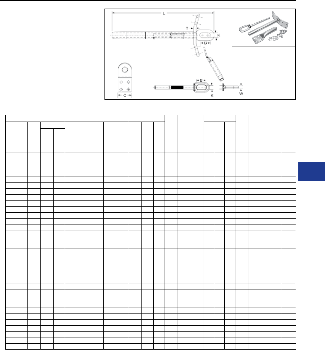
BURNDY®
Blue highlighted items are industry standard and most frequently ordered.
Canada: 1-800-387-6487 www.burndy.com US: 1-800-346-4175
Transmission
TYPES YTW-RD-REKHT,
YTW-RDHT, YTW-REHT,
BYNA-R-HHT
Double Pad Full Tension
Deadend for ACSS Conductor
Full tension compression deadend for 250º C rated
ACSS transmission lines up to and including 230
kV. Standard 15º NEMA tap pads provide either 0º
or 30º tap when BYNAR15 terminal is used.
Complete Assembly
(Body, Eye, Terminal and Hardware)
YTW-RDHT
YTW-REHT
BYNA-R-HHT
Body
Steel eye
Terminal and hardware
Steel Eye
ACSS Double Pad Inches Body
Die*‡ Steel Eye
Inches Eye
Die*
Terminal †
with
Hardware
Term
Die*‡
Conductor
Name
Size
kcmil
Stranding Complete
Assembly
Alum.
Body L C T B K W
Alum. Steel
Linnet 336.4 26 7 YTW32RD34REKHT YTW32RDHT 21.53 3.25 0.50 L717 YTW34REHT 2.50 0.88 0.62 L718 BYNA32R15HHT L717
Oriole 336.4 30 7 YTW32RD33REKHT YTW32RDHT 21.53 3.25 0.50 L717 YTW33REHT 2.50 0.88 0.62 L718 BYNA32R15HHT L717
Ibis 397.5 26 7 YTW34RD34REKHT YTW34RDHT 21.60 3.25 0.50 L719 YTW34REHT 2.50 0.88 0.62 L718 BYNA34R15HHT L719
Flicker 477 24 7 YTW36RD362REKHT YTW36RDHT 23.41 3.25 0.50 L720 YTW362REHT 2.50 0.88 0.62 L721 BYNA36R15HHT L720
Hawk 477 26 7 YTW36RD36REKHT YTW36RDHT 23.41 3.25 0.50 L720 YTW36REHT 2.50 0.88 0.62 L721 BYNA36R15HHT L720
Parakeet 556.5 24 7 YTW39RD43REKHT YTW39RDHT 23.66 3.25 0.50 L722 YTW43REHT 2.50 0.88 0.69 L723 BYNA39R15HHT L722
Dove 556.5 26 7 YTW39RD43REKHT YTW39RDHT 23.66 3.25 0.50 L722 YTW43REHT 2.50 0.88 0.69 L723 BYNA39R15HHT L722
Peacock 605 24 7 YTW43RD43REKHT YTW43RDHT 24.49 3.25 0.50 L724 YTW43REHT 2.50 0.88 0.69 L723 BYNA43R15HHT L724
Squab 605 26 7 YTW43RD43REKHT YTW43RDHT 24.49 3.25 0.50 L724 YTW43REHT 2.50 0.88 0.69 L723 BYNA43R15HHT L724
Rook 636 24 7 YTW43RD43REKHT YTW43RDHT 24.49 3.25 0.50 L724 YTW43REHT 2.50 0.88 0.69 L723 BYNA43R15HHT L724
Grosbeak 636 26 7 YTW43RD43REKHT YTW43RDHT 24.49 3.25 0.50 L724 YTW43REHT 2.50 0.88 0.69 L723 BYNA43R15HHT L724
Flamingo 666.6 24 7 YTW43RD43REKHT YTW43RDHT 24.49 3.25 0.50 L724 YTW43REHT 2.50 0.88 0.69 L723 BYNA43R15HHT L724
Starling 715.5 26 7 YTW451RD48REKHT YTW451RDHT 29.41 3.25 0.50 L725 YTW48REHT 2.69 1.25 0.75 L726 BYNA451R15HHT L725
Cuckoo 795 24 7 YTW451RD45REKHT YTW451RDHT 29.41 3.25 0.50 L725 YTW45REHT 2.69 1.25 0.75 L726 BYNA451R15HHT L725
Drake 795 26 7 YTW451RD48REKHT YTW451RDHT 29.41 3.25 0.50 L725 YTW48REHT 2.69 1.25 0.75 L726 BYNA451R15HHT L725
Tern 795 45 7 YTW451RD481REKHT YTW451RDHT 29.41 3.25 0.50 L725 YTW481REHT 2.69 1.25 0.75 L726 BYNA451R15HHT L725
Condor 795 54 7 YTW451RD45REKHT YTW451RDHT 29.41 3.25 0.50 L725 YTW45REHT 2.69 1.25 0.75 L726 BYNA451R15HHT L725
Ruddy 900 45 7 YTW48RD481REKHT YTW48RDHT 29.50 3.25 0.50 L727 YTW481REHT 2.69 1.25 0.75 L726 BYNA49R15HHT L727
Rail 954 45 7 YTW48RD481REKHT YTW48RDHT 29.50 3.25 0.50 L727 YTW481REHT 2.69 1.25 0.75 L726 BYNA49R15HHT L727
Cardinal 954 54 7 YTW48RD48REKHT YTW48RDHT 29.50 3.25 0.50 L727 YTW48REHT 2.69 1.25 0.75 L726 BYNA49R15HHT L727
Ortolan 1033.5 45 7 YTW49RD483REKHT YTW49RDHT 31.35 3.25 0.50 L727 YTW483REHT 2.69 1.25 1.00 L726 BYNA49R15HHT L727
Curlew 1033.5 54 7 YTW49RD50REKHT YTW49RDHT 31.35 3.25 0.50 L727 YTW50REHT 2.69 1.25 1.00 L726 BYNA49R15HHT L727
Bluejay 1113 45 7 YTW49RD483REKHT YTW49RDHT 31.35 3.25 0.50 L727 YTW483REHT 2.69 1.25 1.00 L726 BYNA49R15HHT L727
Finch 1113 54 19 YTW52RD50REKHT YTW52RDHT 35.55 3.25 0.50 L728 YTW50REHT 2.69 1.25 1.00 L726 BYNA52R15HHT L728
Bunting 1192.5 45 7 YTW52RD521REKHT YTW52RDHT 35.55 4.00 0.62 L728 YTW521REHT 2.69 1.25 1.00 L726 BYNA52R15HHT L728
Bittern 1272 45 7 YTW52RD521REKHT YTW52RDHT 35.55 4.00 0.62 L728 YTW521REHT 2.69 1.25 1.00 L726 BYNA52R15HHT L728
Pheasant 1272 54 19 YTW52RD56REKHT YTW52RDHT 35.55 4.00 0.62 L728 YTW56REHT 2.69 1.25 1.00 L726 BYNA52R15HHT L728
Dipper 1351.5 45 7 YTW52RD521REKHT YTW52RDHT 35.55 4.00 0.62 L728 YTW521REHT 2.69 1.25 1.00 L726 BYNA52R15HHT L728
Martin 1351.5 54 19 YTW52RD56REKHT YTW52RDHT 35.55 4.00 0.62 L728 YTW56REHT 2.69 1.25 1.00 L726 BYNA52R15HHT L728
Nuthatch 1510.5 45 7 YTW549RD521REKHT YTW549RDHT 35.55 4.00 0.62 L729 YTW521REHT 2.69 1.25 1.00 L726 BYNA56R15HHT L729
Parrot 1510.5 54 19 YTW549RD56REKHT YTW549RDHT 35.55 4.00 0.62 L729 YTW56REHT 2.69 1.25 1.00 L726 BYNA56R15HHT L729
Lapwing 1590 45 7 YTW549RD549REKHT YTW549RDHT 35.55 4.00 0.62 L729 YTW549REHT 2.69 1.25 1.00 L726 BYNA56R15HHT L729
Falcon 1590 54 19 YTW56RD590REKHT YTW56RDHT 35.99 4.00 0.62 L729 YTW590REHT 2.69 1.25 1.00 L726 BYNA56R15HHT L729
Chukar 1780 84 19 YTW58RD58REKHT YTW58RDHT 36.99 4.00 0.62 L735 YTW58REHT 2.69 1.25 1.00 L726 BYNA58R15HHT L735
Bluebird 2156 84 19 YTW59RD59REKHT YTW59RDHT 37.34 4.00 0.62 L735 YTW59REHT 2.69 1.25 1.00 L726 BYNA59R15HHT L735
Kiwi 2167 72 7 YTW59RD591REKHT YTW59RDHT 37.34 4.00 0.62 L735 YTW591REHT 2.69 1.25 1.00 L726 BYNA59R15HHT L735
ACSS Deadends
Complete Assembly: Includes Aluminum body, Steel eye,
15 degree terminal and aluminum hardware.
For stainless steel hardware add SS to end
of catalog number for complete assembly
(example: YTW32R34REKHTSS) or to terminal
(BYNA32R15HTSSHHTSS) if ordered separately.
For assembly without terminal and hardware add NT to
end of complete assembly catalog number (example:
YTW32R34REKHTNT).
† BYNA terminals must be crimped from cable end moving
toward pad end.
* Overlap crimps.
‡ Wide dies may be used on aluminum only (no steel), add
sufx “W” to part number (example: L725W).
I-17
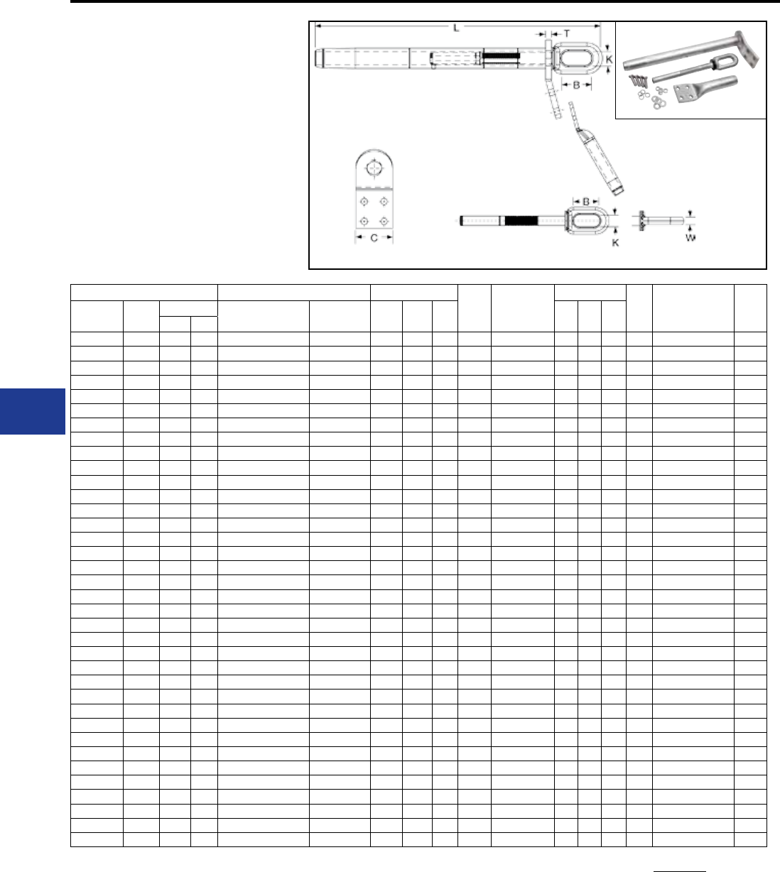
BURNDY®
Blue highlighted items are industry standard and most frequently ordered.
US: 1-800-346-4175 www.burndy.com Canada: 1-800-387-6487
Transmission
TYPES YTW-RT-REKHT,
YTW-RTHT, YTW-REHT,
BYNA-RT-HHT EHV
Single Pad, EHV
Full Tension Deadend
for ACSS Conductor
Full tension compression deadend for 250º C
rated ACSS transmission lines at 345 kV and over.
Standard 15º NEMA tap pad provides either 0º or
30º tap when BYNA-RT15 terminal is used.
Complete Assembly
(Body, Eye, Terminal and Hardware)
YTW-RHT
YTW-REHT
BYNA-RT-HHT
Body
Steel eye
Terminal and hardware
Steel Eye
ACSS Single Pad Inches Body
Die*‡ Steel Eye
Inches Eye
Die*
Terminal †
with
Hardware
Term
Die*‡
Conductor
Name
Size
kcmil
Stranding Complete
Assembly
Alum.
Body L C T B K W
Alum. Steel
Linnet 336.4 26 7 YTW32RT34REKHT YTW32RTHT 21.53 3.25 0.50 L717 YTW34REHT 2.50 0.88 0.62 L718 BYNA32RT15HHT L717
Oriole 336.4 30 7 YTW32RT33REKHT YTW32RTHT 21.53 3.25 0.50 L717 YTW33REHT 2.50 0.88 0.62 L718 BYNA32RT15HHT L717
Ibis 397.5 26 7 YTW34RT34REKHT YTW34RTHT 21.60 3.25 0.50 L719 YTW34REHT 2.50 0.88 0.62 L718 BYNA34RT15HHT L719
Flicker 477 24 7 YTW36RT362REKHT YTW36RTHT 23.41 3.25 0.50 L720 YTW362REHT 2.50 0.88 0.62 L721 BYNA36RT15HHT L720
Hawk 477 26 7 YTW36RT36REKHT YTW36RTHT 23.41 3.25 0.50 L720 YTW36REHT 2.50 0.88 0.62 L721 BYNA36RT15HHT L720
Parakeet 556.5 24 7 YTW39RT43REKHT YTW39RTHT 23.66 3.25 0.50 L722 YTW43REHT 2.50 0.88 0.69 L723 BYNA39RT15HHT L722
Dove 556.5 26 7 YTW39RT43REKHT YTW39RTHT 23.66 3.25 0.50 L722 YTW43REHT 2.50 0.88 0.69 L723 BYNA39RT15HHT L722
Peacock 605 24 7 YTW43RT43REKHT YTW43RTHT 24.49 3.25 0.50 L724 YTW43REHT 2.50 0.88 0.69 L723 BYNA43RT15HHT L724
Squab 605 26 7 YTW43RT43REKHT YTW43RTHT 24.49 3.25 0.50 L724 YTW43REHT 2.50 0.88 0.69 L723 BYNA43RT15HHT L724
Rook 636 24 7 YTW43RT43REKHT YTW43RTHT 24.49 3.25 0.50 L724 YTW43REHT 2.50 0.88 0.69 L723 BYNA43RT15HHT L724
Grosbeak 636 26 7 YTW43RT43REKHT YTW43RTHT 24.49 3.25 0.50 L724 YTW43REHT 2.50 0.88 0.69 L723 BYNA43RT15HHT L724
Flamingo 666.6 24 7 YTW43RT43REKHT YTW43RTHT 24.49 3.25 0.50 L724 YTW43REHT 2.50 0.88 0.69 L723 BYNA43RT15HHT L724
Starling 715.5 26 7 YTW451RT48REKHT YTW451RTHT 29.41 3.25 0.50 L725 YTW48REHT 2.69 1.25 0.75 L726 BYNA451RT15HHT L725
Cuckoo 795 24 7 YTW451RT45REKHT YTW451RTHT 29.41 3.25 0.50 L725 YTW45REHT 2.69 1.25 0.75 L726 BYNA451RT15HHT L725
Drake 795 26 7 YTW451RT48REKHT YTW451RTHT 29.41 3.25 0.50 L725 YTW48REHT 2.69 1.25 0.75 L726 BYNA451RT15HHT L725
Tern 795 45 7 YTW451RT481REKHT YTW451RTHT 29.41 3.25 0.50 L725 YTW481REHT 2.69 1.25 0.75 L726 BYNA451RT15HHT L725
Condor 795 54 7 YTW451RT45REKHT YTW451RTHT 29.41 3.25 0.50 L725 YTW45REHT 2.69 1.25 0.75 L726 BYNA451RT15HHT L725
Ruddy 900 45 7 YTW48RT481REKHT YTW48RTHT 29.50 3.25 0.50 L727 YTW481REHT 2.69 1.25 0.75 L726 BYNA49RT15HHT L727
Rail 954 45 7 YTW48RT481REKHT YTW48RTHT 29.50 3.25 0.50 L727 YTW481REHT 2.69 1.25 0.75 L726 BYNA49RT15HHT L727
Cardinal 954 54 7 YTW48RT48REKHT YTW48RTHT 29.50 3.25 0.50 L727 YTW48REHT 2.69 1.25 0.75 L726 BYNA49RT15HHT L727
Ortolan 1033.5 45 7 YTW49RT483REKHT YTW49RTHT 31.35 3.25 0.50 L727 YTW483REHT 2.69 1.25 1.00 L726 BYNA49RT15HHT L727
Curlew 1033.5 54 7 YTW49RT50REKHT YTW49RTHT 31.35 3.25 0.50 L727 YTW50REHT 2.69 1.25 1.00 L726 BYNA49RT15HHT L727
Bluejay 1113 45 7 YTW49RT483REKHT YTW49RTHT 31.35 3.25 0.50 L727 YTW483REHT 2.69 1.25 1.00 L726 BYNA49RT15HHT L727
Finch 1113 54 19 YTW52RT50REKHT YTW52RHT 35.55 3.25 0.50 L728 YTW50REHT 2.69 1.25 1.00 L726 BYNA52RT15HHT L728
Bunting 1192.5 45 7 YTW52RT521REKHT YTW52RTHT 35.55 4.00 0.62 L728 YTW521REHT 2.69 1.25 1.00 L726 BYNA52RT15HHT L728
Bittern 1272 45 7 YTW52RT521REKHT YTW52RTHT 35.55 4.00 0.62 L728 YTW521REHT 2.69 1.25 1.00 L726 BYNA52RT15HHT L728
Pheasant 1272 54 19 YTW52RT56REKHT YTW52RTHT 35.55 4.00 0.62 L728 YTW56REHT 2.69 1.25 1.00 L726 BYNA52RT15HHT L728
Dipper 1351.5 45 7 YTW52RT521REKHT YTW52RTHT 35.55 4.00 0.62 L728 YTW521REHT 2.69 1.25 1.00 L726 BYNA52RT15HHT L728
Martin 1351.5 54 19 YTW52RT56REKHT YTW52RTHT 35.55 4.00 0.62 L728 YTW56REHT 2.69 1.25 1.00 L726 BYNA52RT15HHT L728
Nuthatch 1510.5 45 7 YTW549RT521REKHT YTW549RTHT 35.55 4.00 0.62 L729 YTW521REHT 2.69 1.25 1.00 L726 BYNA56RT15HHT L729
Parrot 1510.5 54 19 YTW549RT56REKHT YTW549RTHT 35.55 4.00 0.62 L729 YTW56REHT 2.69 1.25 1.00 L726 BYNA56RT15HHT L729
Lapwing 1590 45 7 YTW549RT549REKHT YTW549RTHT 35.55 4.00 0.62 L729 YTW549REHT 2.69 1.25 1.00 L726 BYNA56RT15HHT L729
Falcon 1590 54 19 YTW56RT590REKHT YTW56RTHT 35.99 4.00 0.62 L729 YTW590REHT 2.69 1.25 1.00 L726 BYNA56RT15HHT L729
Chukar 1780 84 19 YTW58RT58REKHT YTW58RTHT 36.99 4.00 0.62 L735 YTW58REHT 2.69 1.25 1.00 L726 BYNA58RT15HHT L735
Bluebird 2156 84 19 YTW59RT59REKHT YTW59RTHT 37.34 4.00 0.62 L735 YTW59REHT 2.69 1.25 1.00 L726 BYNA59RT15HHT L735
Kiwi 2167 72 7 YTW59RT591REKHT YTW59RTHT 37.34 4.00 0.62 L735 YTW591REHT 2.69 1.25 1.00 L726 BYNA59RT15HHT L735
ACSS Deadends-EHV
Complete Assembly: Includes Aluminum body, Steel eye,
15 degree terminal and aluminum hardware.
For stainless steel hardware add SS to end
of catalog number for complete assembly
(example: YTW32R34REKHTSS) or to terminal
(BYNA32R15HTSSHHTSS) if ordered separately.
For assembly without terminal and hardware add NT to
end of complete assembly catalog number (example:
YTW32R34REKHTNT).
† BYNA terminals must be crimped from cable end moving
toward pad end.
* Overlap crimps.
‡ Wide dies may be used on aluminum only (no steel), add
sufx “W” to part number (example: L725W).
I-18
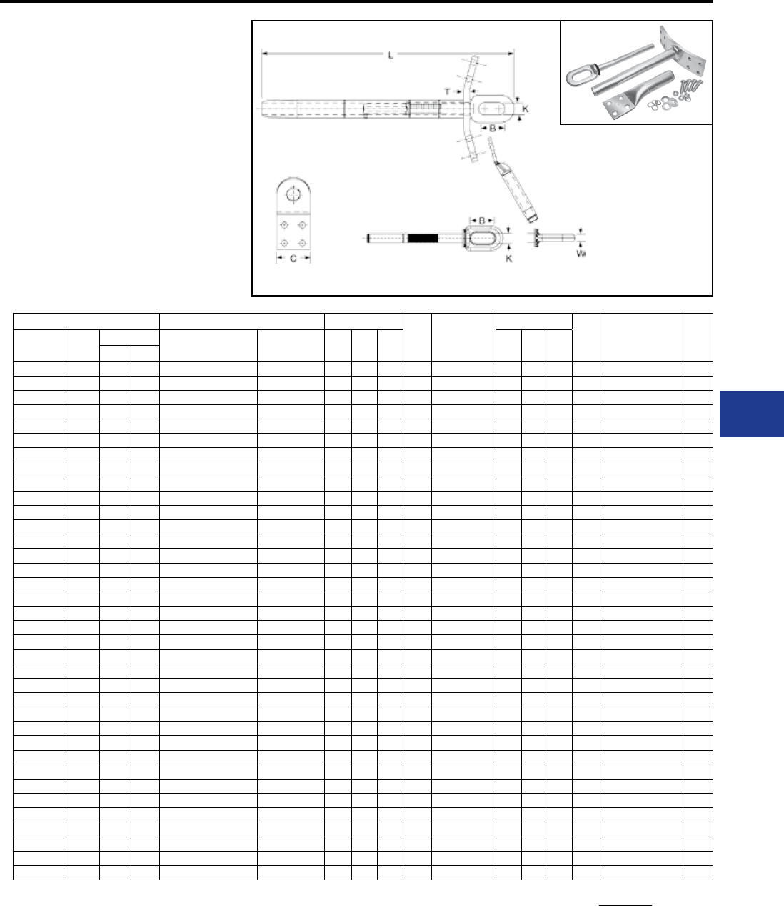
BURNDY®
Blue highlighted items are industry standard and most frequently ordered.
Canada: 1-800-387-6487 www.burndy.com US: 1-800-346-4175
Transmission
TYPES YTW-RDT-REKHT,
YTW-RDTHT,
BYNA-RT-HHT EHV
Double Pad, EHV
Full Tension Deadend
for ACSS Conductor
Full tension compression deadend for 250º C
rated ACSS transmission lines at 345 kV and over.
Standard 15º NEMA tap pad provides either 0º or
30º tap when BYNA-R15 terminal is used.
Complete Assembly
(Body, Eye, Terminal and Hardware)
YTW-RHT
YTW-REHT
BYNA-RT-HHT
Body
Steel eye
Terminal and hardware
Steel Eye
ACSS Double Pad Inches Body
Die*‡ Steel Eye
Inches Eye
Die*
Terminal †
with
Hardware
Term
Die*‡
Conductor
Name
Size
kcmil
Stranding Complete
Assembly
Alum.
Body L C T B K W
Alum. Steel
Linnet 336.4 26 7 YTW32RDT34REKHT YTW32RDTHT 21.53 3.25 0.50 L717 YTW34REHT 2.50 0.88 0.62 L718 BYNA32RT15HHT L717
Oriole 336.4 30 7 YTW32RDT33REKHT YTW32RDTHT 21.53 3.25 0.50 L717 YTW33REHT 2.50 0.88 0.62 L718 BYNA32RT15HHT L717
Ibis 397.5 26 7 YTW34RDT34REKHT YTW34RDTHT 21.60 3.25 0.50 L719 YTW34REHT 2.50 0.88 0.62 L718 BYNA34RT15HHT L719
Flicker 477 24 7 YTW36RDT362REKHT YTW36RDTHT 23.41 3.25 0.50 L720 YTW362REHT 2.50 0.88 0.62 L721 BYNA36RT15HHT L720
Hawk 477 26 7 YTW36RDT36REKHT YTW36RDTHT 23.41 3.25 0.50 L720 YTW36REHT 2.50 0.88 0.62 L721 BYNA36RT15HHT L720
Parakeet 556.5 24 7 YTW39RDT43REKHT YTW39RDTHT 23.66 3.25 0.50 L722 YTW43REHT 2.50 0.88 0.69 L723 BYNA39RT15HHT L722
Dove 556.5 26 7 YTW39RDT43REKHT YTW39RDTHT 23.66 3.25 0.50 L722 YTW43REHT 2.50 0.88 0.69 L723 BYNA39RT15HHT L722
Peacock 605 24 7 YTW43RDT43REKHT YTW43RDTHT 24.49 3.25 0.50 L724 YTW43REHT 2.50 0.88 0.69 L723 BYNA43RT15HHT L724
Squab 605 26 7 YTW43RDT43REKHT YTW43RDTHT 20.49 3.25 0.50 L724 YTW43REHT 2.50 0.88 0.69 L723 BYNA43RT15HHT L724
Rook 636 24 7 YTW43RDT43REKHT YTW43RDTHT 24.49 3.25 0.50 L724 YTW43REHT 2.50 0.88 0.69 L723 BYNA43RT15HHT L724
Grosbeak 636 26 7 YTW43RDT43REKHT YTW43RDTHT 24.49 3.25 0.50 L724 YTW43REHT 2.50 0.88 0.69 L723 BYNA43RT15HHT L724
Flamingo 666.6 24 7 YTW43RDT43REKHT YTW43RDTHT 24.49 3.25 0.50 L724 YTW43REHT 2.50 0.88 0.69 L723 BYNA43RT15HHT L724
Starling 715.5 26 7 YTW451RDT48REKHT YTW451RDTHT 29.41 3.25 0.50 L725 YTW48REHT 2.69 1.25 0.75 L726 BYNA451RT15HHT L725
Cuckoo 795 24 7 YTW451RDT45REKHT YTW451RDTHT 29.41 3.25 0.50 L725 YTW45REHT 2.69 1.25 0.75 L726 BYNA451RT15HHT L725
Drake 795 26 7 YTW451RDT48REKHT YTW451RDTHT 29.41 3.25 0.50 L725 YTW48REHT 2.69 1.25 0.75 L726 BYNA451RT15HHT L725
Tern 795 45 7 YTW451RDT481REKHT YTW451RDTHT 29.41 3.25 0.50 L725 YTW481REHT 2.69 1.25 0.75 L726 BYNA451RT15HHT L725
Condor 795 54 7 YTW451RDT45REKHT YTW451RDTHT 29.41 3.25 0.50 L725 YTW45REHT 2.69 1.25 0.75 L726 BYNA451RT15HHT L725
Ruddy 900 45 7 YTW48RDT481REKHT YTW48RDTHT 29.50 3.25 0.50 L727 YTW481REHT 2.69 1.25 0.75 L726 BYNA49RT15HHT L727
Rail 954 45 7 YTW48RDT481REKHT YTW48RDTHT 29.50 3.25 0.50 L727 YTW481REHT 2.69 1.25 0.75 L726 BYNA49RT15HHT L727
Cardinal 954 54 7 YTW48RDT48REKHT YTW48RDTHT 29.50 3.25 0.50 L727 YTW48REHT 2.69 1.25 0.75 L726 BYNA49RT15HHT L727
Ortolan 1033.5 45 7 YTW49RDT483REKHT YTW49RDTHT 31.35 3.25 0.50 L727 YTW483REHT 2.69 1.25 1.00 L726 BYNA49RT15HHT L727
Curlew 1033.5 54 7 YTW49RDT50REKHT YTW49RDTHT 31.35 3.25 0.50 L727 YTW50REHT 2.69 1.25 1.00 L726 BYNA49RT15HHT L727
Bluejay 1113 45 7 YTW49RDT483REKHT YTW49RDTHT 31.35 3.25 0.50 L727 YTW483REHT 2.69 1.25 1.00 L726 BYNA49RT15HHT L727
Finch 1113 54 19 YTW52RDT50REKHT YTW52RDTHT 35.55 3.25 0.50 L728 YTW50REHT 2.69 1.25 1.00 L726 BYNA52RT15HHT L728
Bunting 1192.5 45 7 YTW52RDT521REKHT YTW52RDTHT 35.55 4.00 0.62 L728 YTW521REHT 2.69 1.25 1.00 L726 BYNA52RT15HHT L728
Bittern 1272 45 7 YTW52RDT521REKHT YTW52RDTHT 35.55 4.00 0.62 L728 YTW521REHT 2.69 1.25 1.00 L726 BYNA52RT15HHT L728
Pheasant 1272 54 19 YTW52RDT56REKHT YTW52RDTHT 35.55 4.00 0.62 L728 YTW56REHT 2.69 1.25 1.00 L726 BYNA52RT15HHT L728
Dipper 1351.5 45 7 YTW52RDT521REKHT YTW52RDTHT 35.55 4.00 0.62 L728 YTW521REHT 2.69 1.25 1.00 L726 BYNA52RT15HHT L728
Martin 1351.5 54 19 YTW52RDT56REKHT YTW52RDTHT 35.55 4.00 0.62 L728 YTW56REHT 2.69 1.25 1.00 L726 BYNA52RT15HHT L728
Nuthatch 1510.5 45 7 YTW549RDT521REKHT YTW549RDTHT 35.55 4.00 0.62 L729 YTW521REHT 2.69 1.25 1.00 L726 BYNA56RT15HHT L729
Parrot 1510.5 54 19 YTW549RDT56REKHT YTW549RDTHT 35.55 4.00 0.62 L729 YTW56REHT 2.69 1.25 1.00 L726 BYNA56RT15HHT L729
Lapwing 1590 45 7 YTW549RDT549REKHT YTW549RDTHT 35.55 4.00 0.62 L729 YTW549REHT 2.69 1.25 1.00 L726 BYNA56RT15HHT L729
Falcon 1590 54 19 YTW56RDT590REKHT YTW56RDTHT 35.99 4.00 0.62 L729 YTW590REHT 2.69 1.25 1.00 L726 BYNA56RT15HHT L729
Chukar 1780 84 19 YTW58RDT58REKHT YTW58RDTHT 36.99 4.00 0.62 L735 YTW58REHT 2.69 1.25 1.00 L726 BYNA58RT15HHT L735
Bluebird 2156 84 19 YTW59RDT59REKHT YTW59RDTHT 37.34 4.00 0.62 L735 YTW59REHT 2.69 1.25 1.00 L726 BYNA59RT15HHT L735
Kiwi 2167 72 7 YTW59RDT591REKHT YTW59RDTHT 37.34 4.00 0.62 L735 YTW591REHT 2.69 1.25 1.00 L726 BYNA59RT15HHT L735
ACSS Deadends-EHV
Complete Assembly: Includes Aluminum body, Steel eye,
15 degree terminal and aluminum hardware.
For stainless steel hardware add SS to end
of catalog number for complete assembly
(example: YTW32R34REKHTSS) or to terminal
(BYNA32R15HTSSHHTSS) if ordered separately.
For assembly without terminal and hardware add NT to
end of complete assembly catalog number (example:
YTW32R34REKHTNT).
† BYNA terminals must be crimped from cable end moving
toward pad end.
* Overlap crimps.
‡ Wide dies may be used on aluminum only (no steel), add
sufx “W” to part number (example: L725W).
I-19
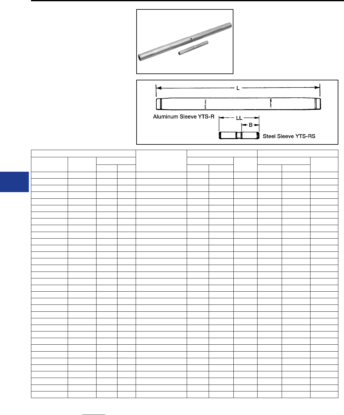
BURNDY®
Blue highlighted items are industry standard and most frequently ordered.
US: 1-800-346-4175 www.burndy.com Canada: 1-800-387-6487
Transmission
TYPE YTS-R-RSHT
Full Tension Splice Kit
for ACSS Conductor
Full tension, two-piece, compression splice
for 250° C ACSS transmission lines up to and
including 230 kV. Outer aluminum sleeve has ller
hole and plug for PENETROX™ joint compound.
Kit includes the outer aluminum and inner steel
sleeve.
ACSS
Splice Kit
Aluminum Sleeve Steel Sleeve
Conductor
Name Size kcmil Stranding Inches Die*‡ Inches Die*
Alum. Steel L O.D. LL B
Linnet 336.4 26 7 YTS32R34RSHT 25.30 1.19 L717 5-1/4″ 2.64 L718
Ibis 397.5 26 7 YTS34R34RSHT 25.20 1.28 L719 5-1/4″ 2.64 L718
Flicker 477 24 7 YTS36R362RSHT 26.16 1.41 L720 5-7/8″ 2.66 L721
Hawk 477 26 7 YTS36R36RSHT 26.16 1.41 L720 5-7/8″ 2.66 L721
Parakeet 556.5 24 7 YTS39R43RSHT 27.88 1.50 L720 5-7/8″ 2.66 L721
Dove 556.5 26 7 YTS39R43RSHT 27.88 1.50 L720 5-7/8″ 2.66 L721
Peacock 605 24 7 YTS43R43RSHT 29.44 1.61 L724 5-7/8″ 2.66 L723
Squab 605 26 7 YTS43R43RSHT 29.44 1.61 L724 5-7/8″ 2.66 L723
Rook 636 24 7 YTS43R43RSHT 29.44 1.61 L724 5-7/8″ 2.66 L723
Grosbeak 636 26 7 YTS43R43RSHT 29.44 1.61 L724 5-7/8″ 2.66 L723
Flamingo 666.6 24 7 YTS43R43RSHT 29.44 1.61 L724 5-7/8″ 2.66 L723
Starling 715.5 26 7 YTS451R48RSHT 36.00 1.80 L725 9″ 4.19 L726
Cuckoo 795 24 7 YTS451R449RSHT 36.00 1.80 L725 9″ 4.19 L726
Drake 795 26 7 YTS451R48RSHT 36.00 1.80 L725 9″ 4.19 L726
Tern 795 45 7 YTS451R48RSHT 36.00 1.80 L725 9-1/8″ 4.19 L726
Condor 795 54 7 YTS451R449RSHT 36.00 1.80 L725 9″ 4.19 L726
Rail 954 45 7 YTS48R481RSHT 36.00 1.97 L727 9-1/8″ 4.19 L726
Cardinal 954 54 7 YTS48R48RSHT 36.00 1.97 L727 9″ 4.19 L726
Ortolan 1033.5 45 7 YTS49R483RSHT 36.00 1.97 L727 9-1/8″ 4.19 L726
Curlew 1033.5 54 7 YTS49R48RSHT 36.00 1.97 L727 9″ 4.19 L726
Bluejay 1113 45 7 YTS49R483RSHT 36.00 1.97 L727 9-1/8″ 4.19 L726
Finch 1113 54 19 YTS52R48RSHT 49.07 2.25 L728 9″ 4.19 L726
Bunting 1192.5 45 7 YTS52R521RSHT 49.07 2.25 L728 9″ 4.19 L726
Bittern 1272 45 7 YTS52R521RSHT 49.07 2.25 L728 9″ 4.19 L726
Pheasant 1272 54 19 YTS52R59RSHT 49.07 2.25 L728 9-1/8″ 4.25 L726
Dipper 1351.5 45 7 YTS52R521RSHT 49.07 2.25 L728 9″ 4.19 L726
Martin 1351.5 54 19 YTS52R59RSHT 49.07 2.25 L728 9-1/8″ 4.25 L726
Nuthatch 1510.5 45 7 YTS549R521RSHT 39.73 2.50 L729 9″ 4.19 L726
Parrot 1510.5 54 19 YTS54959RSHT 39.73 2.50 L729 9-1/8″ 4.25 L726
Lapwing 1590 45 7 YTS549R549RSHT 39.73 2.50 L729 9″ 4.19 L726
Falcon 1590 54 19 YTS56R59RSHT 39.73 2.50 L729 9-1/8″ 4.25 L726
Chukar 1780 84 19 YTS58R48RSHT 42.20 2.50 L735 4-1/4″ 4.19 L726
Bluebird 2156 84 19 YTS59R59RSHT 49.93 2.50 L735 4-1/4″ 4.25 L726
Kiwi 2167 72 7 YTS59R521RSHT 49.93 2.50 L735 4-1/4″ 4.19 L726
ACSS Splices
Splice Kit: Includes aluminum sleeve and steel sleeve.
* Overlap crimps.
‡ Wide dies may be used on aluminum only (no steel), add sufx
“W” to part number (example: L725W).
I-20
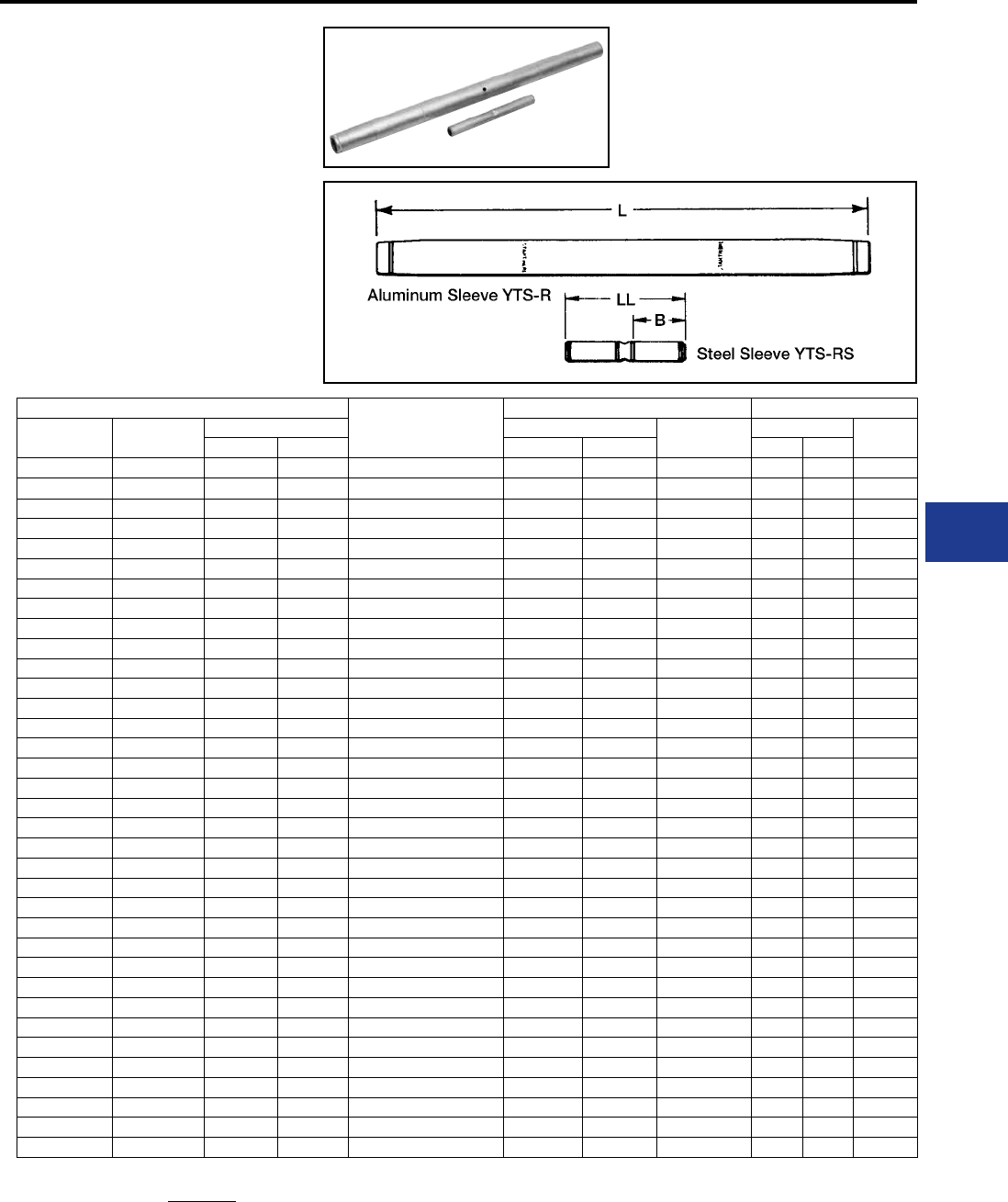
BURNDY®
Blue highlighted items are industry standard and most frequently ordered.
Canada: 1-800-387-6487 www.burndy.com US: 1-800-346-4175
Transmission
TYPE YTS-RT-RSHT
EHV
Full Tension Splice Kit
for ACSS Conductor
Full tension, two-piece, compression splice
for 250°C ACSS transmission lines at 345 kV and
over. Outer aluminum sleeve has ller hole and plug
for PENETROX™ joint compound. Kit includes the
outer aluminum and inner steel sleeve.
ACSS
Splice Kit
Aluminum Sleeve Steel Sleeve
Conductor
Name
Size
kcmil
Stranding Inches Die*‡ Inches Die*
Alum. Steel L O.D. LL B
Linnet 336.4 26 7 YTS32RT34RSHT 25.92 1.19 L717 5.74 2.45 L718
Oriole 336.4 30 7 YTS32RT33RSHT 25.92 1.19 L717 5.74 2.45 L718
Ibis 397.5 26 7 YTS34RT34RSHT 25.92 1.28 L719 5.74 2.45 L718
Flicker 477 24 7 YTS36RT362RSHT 26.92 1.41 L720 5.88 2.46 L721
Hawk 477 26 7 YTS36RT36RSHT 26.92 1.41 L720 5.76 2.46 L721
Parakeet 556.5 24 7 YTS39RT43RSHT 28.74 1.50 L722 5.90 2.47 L723
Dove 556.5 26 7 YTS39RT43RSHT 28.74 1.50 L722 5.90 2.47 L723
Peacock 605 24 7 YTS43RT43RSHT 30.28 1.61 L724 5.90 2.47 L723
Squab 605 26 7 YTS43RT43RSHT 30.28 1.61 L724 5.90 2.47 L723
Rook 636 24 7 YTS43RT43RSHT 30.28 1.61 L724 5.90 2.47 L723
Grosbeak 636 26 7 YTS43RT43RSHT 30.28 1.61 L724 5.90 2.47 L723
Flamingo 666.6 24 7 YTS43RT43RSHT 30.28 1.61 L724 5.90 2.47 L723
Starling 715.5 26 7 YTS451RT48RSHT 36.96 1.80 L725 9.00 4.00 L726
Cuckoo 795 24 7 YTS451RT449RSHT 36.96 1.80 L725 9.00 4.00 L726
Drake 795 26 7 YTS451RT48RSHT 36.96 1.80 L725 9.00 4.00 L726
Tern 795 45 7 YTS451RT48RSHT 36.96 1.80 L725 9.00 4.00 L726
Condor 795 54 7 YTS451RT449RSHT 36.96 1.80 L725 9.00 4.00 L726
Rail 954 45 7 YTS48RT481RSHT 37.96 1.97 L727 9.00 4.01 L726
Cardinal 954 54 7 YTS48RT48RSHT 37.96 1.97 L727 9.00 4.01 L726
Ortolan 1033.5 45 7 YTS49RT483RSHT 37.02 1.97 L727 9.00 4.01 L726
Curlew 1033.5 54 7 YTS49RT48RSHT 37.02 1.97 L727 9.00 4.00 L726
Bluejay 1113 45 7 YTS49RT483RSHT 37.02 1.97 L727 9.00 4.01 L726
Finch 1113 54 19 YTS52RT48RSHT 50.33 2.25 L728 9.00 4.00 L726
Bunting 1192.5 45 7 YTS52RT521RSHT 50.33 2.25 L728 9.00 4.00 L726
Bittern 1272 45 7 YTS52RT521RSHT 50.33 2.25 L728 9.00 4.00 L726
Pheasant 1272 54 19 YTS52RT59RSHT 50.33 2.25 L728 9.10 4.07 L726
Dipper 1351.5 45 7 YTS52RT521RSHT 50.33 2.25 L728 9.00 4.00 L726
Martin 1351.5 54 19 YTS52RT59RSHT 50.33 2.25 L728 9.10 4.07 L726
Nuthatch 1510.5 45 7 YTS549RT521RSHT 42.13 2.50 L729 9.00 4.00 L726
Parrot 1510.5 54 19 YTS549RT59RSHT 42.13 2.50 L729 9.10 4.07 L726
Lapwing 1590 45 7 YTS549RT549RSHT 42.13 2.50 L729 9.00 4.00 L726
Falcon 1590 54 19 YTS56RT59RSHT 42.13 2.50 L729 9.10 4.07 L726
Chukar 1780 84 19 YTS58RT48RSHT 43.46 2.50 L735 9.00 4.00 L726
Bluebird 2156 84 19 YTS59RT59RSHT 50.91 2.50 L735 9.10 4.07 L726
Kiwi 2167 72 7 YTS59RT521RSHT 50.91 2.50 L735 9.00 4.00 L726
ACSS Splices-EHV
Splice Kit: Includes aluminum sleeve and steel sleeve.
* Overlap crimps.
‡ Wide dies may be used on aluminum only (no steel), add sufx
“W” to part number (example: L725W).
I-21
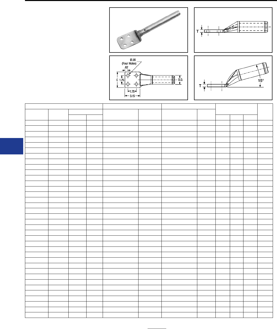
BURNDY®
Blue highlighted items are industry standard and most frequently ordered.
US: 1-800-346-4175 www.burndy.com Canada: 1-800-387-6487
Transmission
TYPES BYNA-R15HT,
BYNA-RHT
Compression Terminal
for ACSS Conductor
Compression terminal for ACSS
transmission lines up to and including
230 kV.
ACSS 15° Terminal Straight Terminal Inches Die*‡
Conductor
Name
Size
kcmil
Stranding Catalog
Number
Inches
L
Catalog
Number
Inches
L
Alum. Steel C D T
Linnet 336.4 26 7 BYNA32R15HT 16.21 BYNA32RHT 16.56 3.25 4.50 0.75 L717
Oriole 336.4 30 7 BYNA32R15HT 16.21 BYNA32RHT 16.56 3.25 4.50 0.75 L717
Ibis 397.5 26 7 BYNA34R15HT 16.24 BYNA34RHT 16.60 3.25 4.50 0.75 L719
Flicker 477 24 7 BYNA36R15HT 16.51 BYNA36RHT 16.92 3.25 4.50 0.75 L720
Hawk 477 26 7 BYNA36R15HT 16.51 BYNA36RHT 16.92 3.25 4.50 0.75 L720
Parakeet 556.5 24 7 BYNA39R15HT 16.89 BYNA39RHT 17.30 3.25 4.50 0.75 L722
Dove 556.5 26 7 BYNA39R15HT 16.89 BYNA39RHT 17.30 3.25 4.50 0.75 L722
Peacock 605 24 7 BYNA43R15HT 14.41 BYNA43RHT 15.46 3.07 3.95 0.36 L724
Squab 605 26 7 BYNA43R15HT 14.41 BYNA43RHT 15.46 3.07 3.95 0.36 L724
Rook 636 24 7 BYNA43R15HT 14.41 BYNA43RHT 15.46 3.07 3.95 0.36 L724
Grosbeak 636 26 7 BYNA43R15HT 14.41 BYNA43RHT 15.46 3.07 3.95 0.36 L724
Flamingo 666.6 24 7 BYNA43R15HT 14.41 BYNA43RHT 15.46 3.07 3.95 0.36 L724
Starling 715.5 26 7 BYNA451R15HT 15.10 BYNA451RHT 15.46 3.22 3.95 0.45 L725
Cuckoo 795 24 7 BYNA451R15HT 15.10 BYNA451RHT 15.46 3.22 3.95 0.45 L725
Drake 795 26 7 BYNA451R15HT 15.10 BYNA451RHT 15.46 3.22 3.95 0.45 L725
Tern 795 45 7 BYNA451R15HT 15.10 BYNA451RHT 15.46 3.22 3.95 0.45 L725
Condor 795 54 7 BYNA451R15HT 15.10 BYNA451RHT 15.46 3.22 3.95 0.45 L725
Ruddy 900 45 7 BYNA49R15HT 15.14 BYNA49RHT 15.66 3.22 3.95 0.52 L727
Rail 954 45 7 BYNA49R15HT 15.14 BYNA49RHT 15.66 3.22 3.95 0.52 L727
Cardinal 954 54 7 BYNA49R15HT 15.14 BYNA49RHT 15.66 3.22 3.95 0.52 L727
Ortolan 1033.5 45 7 BYNA49R15HT 15.14 BYNA49RHT 15.66 3.22 3.95 0.52 L727
Curlew 1033.5 54 7 BYNA49R15HT 15.14 BYNA49RHT 15.66 3.22 3.95 0.52 L727
Bluejay 1113 45 7 BYNA49R15HT 15.14 BYNA49RHT 15.66 3.22 3.95 0.52 L727
Finch 1113 54 19 BYNA52R15HT 16.81 BYNA52RHT 18.71 3.22 3.95 0.71 L728
Bunting 1192.5 45 7 BYNA52R15HT 16.81 BYNA52RHT 18.71 3.22 3.95 0.71 L728
Bittern 1272 45 7 BYNA52R15HT 16.81 BYNA52RHT 18.71 3.22 3.95 0.71 L728
Pheasant 1272 54 19 BYNA52R15HT 16.81 BYNA52RHT 18.71 3.22 3.95 0.71 L728
Dipper 1351.5 45 7 BYNA52R15HT 16.81 BYNA52RHT 18.71 3.22 3.95 0.71 L728
Martin 1351.5 54 19 BYNA52R15HT 16.81 BYNA52RHT 18.71 3.22 3.95 0.71 L728
Nuthatch 1510.5 45 7 BYNA56R15HT 17.56 BYNA56RHT 18.65 3.44 3.95 0.86 L729
Parrot 1510.5 54 19 BYNA56R15HT 17.56 BYNA56RHT 18.65 3.44 3.95 0.86 L729
Lapwing 1590 45 7 BYNA56R15HT 17.56 BYNA56RHT 18.65 3.44 3.95 0.86 L729
Falcon 1590 54 19 BYNA56R15HT 17.56 BYNA56RHT 18.65 3.44 3.95 0.86 L729
Chukar 1780 84 19 BYNA58R15HT 18.28 BYNA58RHT 18.59 3.47 3.95 0.80 L735
Bluebird 2156 84 19 BYNA59R15HT 17.95 BYNA59RHT 18.43 3.57 3.95 0.64 L735
Kiwi 2167 72 7 BYNA59R15HT 17.95 BYNA59RHT 18.43 3.57 3.95 0.64 L735
To specify hardware for bolting to corresponding dead-
ends add the sufx “H” to the catalog number (example:
BYNA52RHHT).
ACSS Terminals
* Overlap crimps.
‡ Wide dies may be used on aluminum only (no steel), add
sufx “W” to part number (example: L725W).
I-22
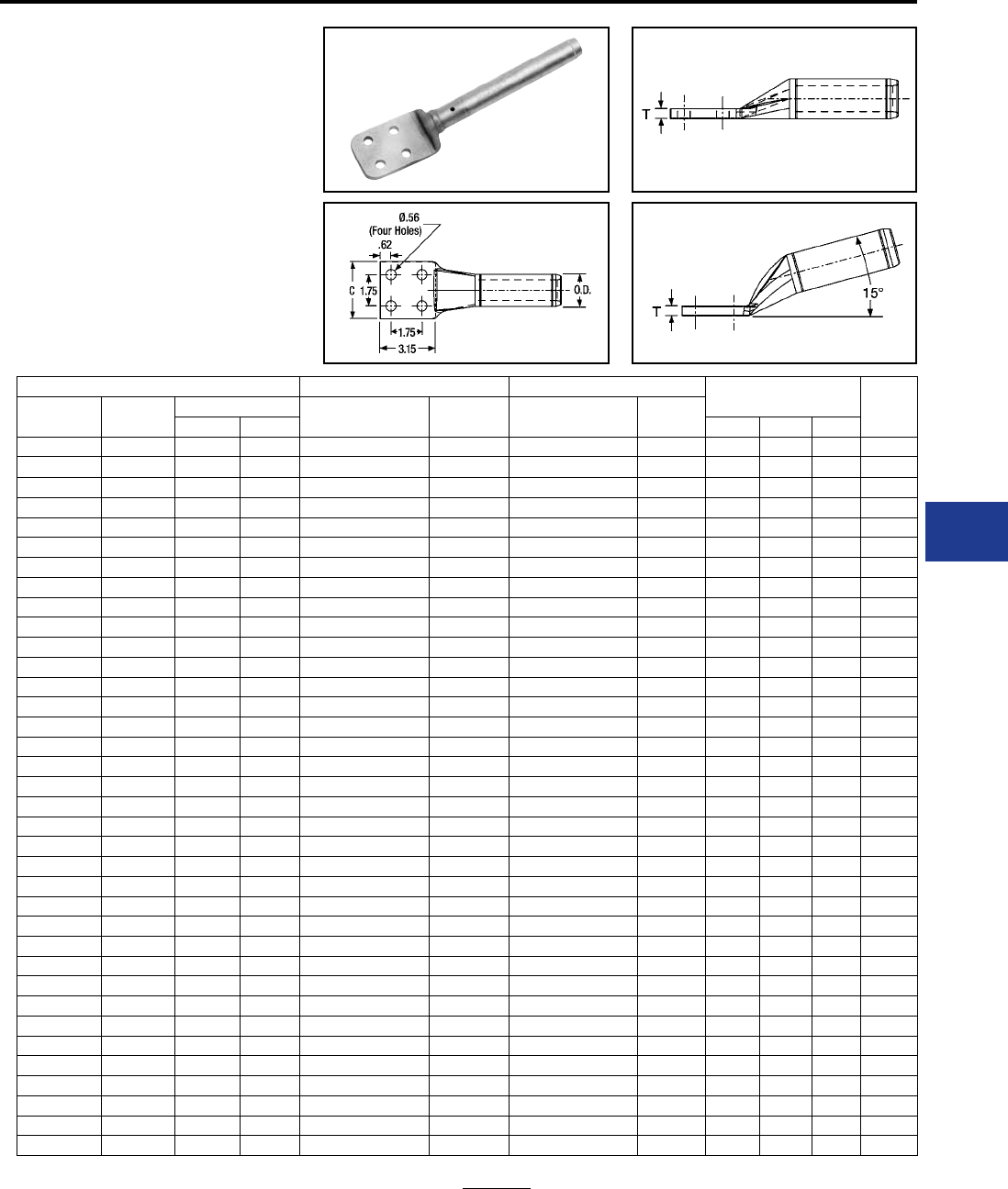
BURNDY®
Blue highlighted items are industry standard and most frequently ordered.
Canada: 1-800-387-6487 www.burndy.com US: 1-800-346-4175
Transmission
TYPES BYNA-RT15HT,
BYNA-RTHT EHV
Compression Terminal
for ACSS Conductor
Compression terminal for 250°C ACSS
transmission lines at 345 kV and over.
ACSS 15° Terminal Straight Terminal Inches Die*‡
Conductor
Name
Size
kcmil
Stranding Catalog
Number
Inches
L
Catalog
Number
Inches
L
Alum. Steel C D T
Linnet 336.4 26 7 BYNA32RT15HT 16.41 BYNA32RTHT 16.56 3.25 4.50 0.75 L717
Oriole 336.4 30 7 BYNA32RT15HT 16.41 BYNA32RTHT 16.56 3.25 4.50 0.75 L717
Ibis 397.5 26 7 BYNA34RT15HT 16.45 BYNA34RTHT 16.60 3.25 4.50 0.75 L719
Flicker 477 24 7 BYNA36RT15HT 16.76 BYNA36RTHT 16.92 3.25 4.50 0.75 L720
Hawk 477 26 7 BYNA36RT15HT 16.76 BYNA36RTHT 16.92 3.25 4.50 0.75 L720
Parakeet 556.5 24 7 BYNA39RT15HT 17.12 BYNA39RTHT 17.30 3.25 4.50 0.75 L722
Dove 556.5 26 7 BYNA39RT15HT 17.12 BYNA39RTHT 17.30 3.25 4.50 0.75 L722
Peacock 605 24 7 BYNA43RT15HT 14.41 BYNA43RTHT 15.46 3.07 3.95 0.36 L724
Squab 605 26 7 BYNA43RT15HT 14.41 BYNA43RTHT 15.46 3.07 3.95 0.36 L724
Rook 636 24 7 BYNA43RT15HT 14.41 BYNA43RTHT 15.46 3.07 3.95 0.36 L724
Grosbeak 636 26 7 BYNA43RT15HT 14.41 BYNA43RTHT 15.46 3.07 3.95 0.36 L724
Flamingo 666.6 24 7 BYNA43RT15HT 14.41 BYNA43RTHT 15.46 3.07 3.95 0.36 L724
Starling 715.5 26 7 BYNA451RT15HT 15.10 BYNA451RTHT 15.46 3.22 3.95 0.45 L725
Cuckoo 795 24 7 BYNA451RT15HT 15.10 BYNA451RTHT 15.46 3.22 3.95 0.45 L725
Drake 795 26 7 BYNA451RT15HT 15.10 BYNA451RTHT 15.46 3.22 3.95 0.45 L725
Tern 795 45 7 BYNA451RT15HT 15.10 BYNA451RTHT 15.46 3.22 3.95 0.45 L725
Condor 795 54 7 BYNA451RT15HT 15.10 BYNA451RTHT 15.46 3.22 3.95 0.45 L725
Ruddy 900 45 7 BYNA49RT15HT 15.14 BYNA49RTHT 15.66 3.22 3.95 0.52 L727
Rail 954 45 7 BYNA49RT15HT 15.14 BYNA49RTHT 15.66 3.22 3.95 0.52 L727
Cardinal 954 54 7 BYNA49RT15HT 15.14 BYNA49RTHT 15.66 3.22 3.95 0.52 L727
Ortolan 1033.5 45 7 BYNA49RT15HT 15.14 BYNA49RTHT 15.66 3.22 3.95 0.52 L727
Curlew 1033.5 54 7 BYNA49RT15HT 15.14 BYNA49RTHT 15.66 3.22 3.95 0.52 L727
Bluejay 1113 45 7 BYNA49RT15HT 15.14 BYNA49RTHT 15.66 3.22 3.95 0.52 L727
Finch 1113 54 19 BYNA52RT15HT 16.81 BYNA52RTHT 18.71 3.22 3.95 0.71 L728
Bunting 1192.5 45 7 BYNA52RT15HT 16.81 BYNA52RTHT 18.71 3.22 3.95 0.71 L728
Bittern 1272 45 7 BYNA52RT15HT 16.81 BYNA52RTHT 18.71 3.22 3.95 0.71 L728
Pheasant 1272 54 19 BYNA52RT15HT 16.81 BYNA52RTHT 18.71 3.22 3.95 0.71 L728
Dipper 1351.5 45 7 BYNA52RT15HT 16.81 BYNA52RTHT 18.71 3.22 3.95 0.71 L728
Martin 1351.5 54 19 BYNA52RT15HT 16.81 BYNA52RTHT 18.71 3.22 3.95 0.71 L728
Nuthatch 1510.5 45 7 BYNA56RT15HT 17.56 BYNA56RTHT 18.65 3.44 3.95 0.86 L729
Parrot 1510.5 54 19 BYNA56RT15HT 17.56 BYNA56RTHT 18.65 3.44 3.95 0.86 L729
Lapwing 1590 45 7 BYNA56RT15HT 17.56 BYNA56RTHT 18.65 3.44 3.95 0.86 L729
Falcon 1590 54 19 BYNA56RT15HT 17.56 BYNA56RTHT 18.65 3.44 3.95 0.86 L729
Chukar 1780 84 19 BYNA58RT15HT 18.28 BYNA58RTHT 18.59 3.47 3.95 0.80 L735
Bluebird 2156 84 19 BYNA59RT15HT 17.95 BYNA59RTHT 18.43 3.57 3.95 0.64 L735
Kiwi 2167 72 7 BYNA59RT15HT 17.95 BYNA59RTHT 18.43 3.57 3.95 0.64 L735
ACSS Terminals-EHV
To specify hardware for bolting to corresponding dead-
ends add the sufx “H” to the catalog number (example:
BYNA52RHHT).
* Overlap crimps.
‡ Wide dies may be used on aluminum only (no steel), add
sufx “W” to part number (example: L725W).
I-23
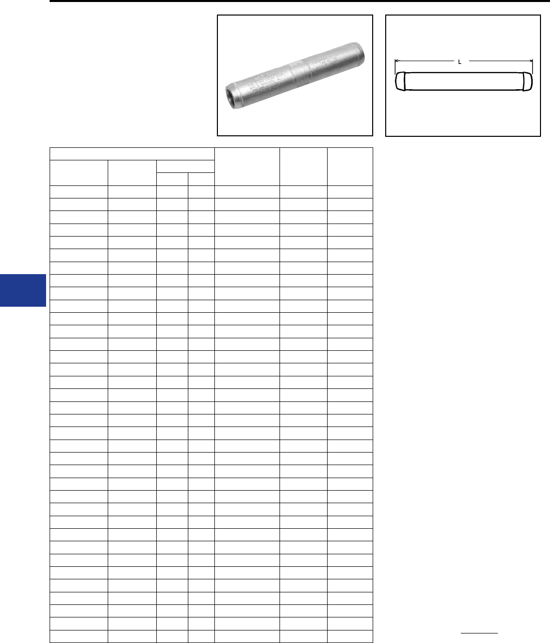
BURNDY®
Blue highlighted items are industry standard and most frequently ordered.
US: 1-800-346-4175 www.burndy.com Canada: 1-800-387-6487
Transmission
TYPE BYNS-RHT
Jumper Loop Sleeve
for ACSS Conductor
Jumper sleeve for 250°C ACSS transmission lines
up to and including 230 kV. Sleeve is pre-lled with
PENETROX™ joint compound and capped.
ACSS
Jumper Sleeve Inches
LDie*‡
Conductor
Name
Size
kcmil
Stranding
Alum. Steel
Linnet 336.4 26 7 BYNS32RHT 16.90 L717
Oriole 336.4 30 7 BYNS32RHT 16.90 L717
Ibis 397.5 26 7 BYNS34RHT 17.10 L719
Flicker 477 24 7 BYNS36RHT 17.60 L720
Hawk 477 26 7 BYNS36RHT 17.60 L720
Parakeet 556.5 24 7 BYNS39RHT 18.20 L722
Dove 556.5 26 7 BYNS39RHT 18.20 L722
Peacock 605 24 7 BYNS43RHT 18.50 L724
Squab 605 26 7 BYNS43RHT 18.50 L724
Rook 636 24 7 BYNS43RHT 18.50 L724
Grosbeak 636 26 7 BYNS43RHT 18.50 L724
Flamingo 666.6 24 7 BYNS43RHT 18.50 L724
Starling 715.5 26 7 BYNS451RHT 18.60 L725
Cuckoo 795 24 7 BYNS451RHT 18.60 L725
Drake 795 26 7 BYNS451RHT 18.60 L725
Tern 795 45 7 BYNS451RHT 18.60 L725
Condor 795 54 7 BYNS451RHT 18.60 L725
Ruddy 900 45 7 BYNS49RHT 18.70 L727
Rail 954 45 7 BYNS49RHT 18.70 L727
Cardinal 954 54 7 BYNS49RHT 18.70 L727
Ortolan 1033.5 45 7 BYNS49RHT 18.70 L727
Curlew 1033.5 54 7 BYNS49RHT 18.70 L727
Bluejay 1113 45 7 BYNS49RHT 18.70 L727
Finch 1113 54 19 BYNS52RHT 24.20 L728
Bunting 1192.5 45 7 BYNS52RHT 24.20 L728
Bittern 1272 45 7 BYNS52RHT 24.20 L728
Pheasant 1272 54 19 BYNS52RHT 24.20 L728
Dipper 1351.5 45 7 BYNS52RHT 24.20 L728
Martin 1351.5 54 19 BYNS52RHT 24.20 L728
Nuthatch 1510.5 45 7 BYNS56RHT 23.60 L729
Parrot 1510.5 54 19 BYNS56RHT 23.60 L729
Lapwing 1590 45 7 BYNS56RHT 23.60 L729
Falcon 1590 54 19 BYNS56RHT 23.60 L729
Chukar 1780 84 19 BYNS58RHT 23.40 L735
Bluebird 2156 84 19 BYNS59RHT 23.40 L735
Kiwi 2167 72 7 BYNS59RHT 23.20 L735
ACSS Jumper Sleeve
* Overlap crimps.
‡ Wide dies may be used on aluminum only (no steel), add
sufx “W” to part number (example: L725W).
I-24
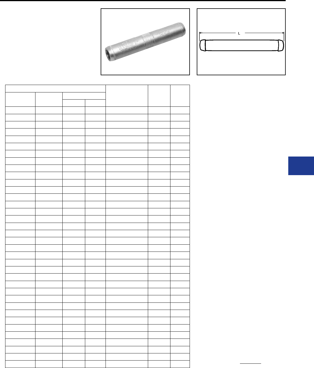
BURNDY®
Blue highlighted items are industry standard and most frequently ordered.
Canada: 1-800-387-6487 www.burndy.com US: 1-800-346-4175
Transmission
ACSS
Jumper Sleeve Inches
LDie*‡
Conductor
Name
Size
kcmil
Stranding
Alum. Steel
Linnet 336.4 26 7 BYNS32RTHT 18.84 L717
Oriole 336.4 30 7 BYNS32RTHT 18.84 L717
Ibis 397.5 26 7 BYNS34RTHT 18.98 L719
Flicker 477 24 7 BYNS36RTHT 19.52 L720
Hawk 477 26 7 BYNS36RTHT 19.52 L720
Parakeet 556.5 24 7 BYNS39RTHT 20.12 L722
Dove 556.5 26 7 BYNS39RTHT 20.12 L722
Peacock 605 24 7 BYNS43RTHT 20.24 L724
Squab 605 26 7 BYNS43RTHT 20.24 L724
Rook 636 24 7 BYNS43RTHT 20.24 L724
Grosbeak 636 26 7 BYNS43RTHT 20.24 L724
Flamingo 666.6 24 7 BYNS43RTHT 20.24 L724
Starling 715.5 26 7 BYNS451RTHT 20.36 L725
Cuckoo 795 24 7 BYNS451RTHT 20.36 L725
Drake 795 26 7 BYNS451RTHT 20.36 L725
Tern 795 45 7 BYNS451RTHT 20.36 L725
Condor 795 54 7 BYNS451RTHT 20.36 L725
Ruddy 900 45 7 BYNS49RTHT 20.42 L727
Rail 954 45 7 BYNS49RTHT 20.42 L727
Cardinal 954 54 7 BYNS49RTHT 20.42 L727
Ortolan 1033.5 45 7 BYNS49RTHT 20.42 L727
Curlew 1033.5 54 7 BYNS49RTHT 20.42 L727
Bluejay 1113 45 7 BYNS49RTHT 20.42 L727
Finch 1113 54 19 BYNS52RTHT 25.96 L728
Bunting 1192.5 45 7 BYNS52RTHT 25.96 L728
Bittern 1272 45 7 BYNS52RTHT 25.96 L728
Pheasant 1272 54 19 BYNS52RTHT 25.96 L728
Dipper 1351.5 45 7 BYNS52RTHT 25.96 L728
Martin 1351.5 54 19 BYNS52RTHT 25.96 L728
Nuthatch 1510.5 45 7 BYNS56RTHT 25.34 L729
Parrot 1510.5 54 19 BYNS56RTHT 25.34 L729
Lapwing 1590 45 7 BYNS56RTHT 25.34 L729
Falcon 1590 54 19 BYNS56RTHT 25.34 L729
Chukar 1780 84 19 BYNS58RTHT 25.22 L735
Bluebird 2156 84 19 BYNS59RTHT 24.9 L735
Kiwi 2167 72 7 BYNS59RTHT 24.9 L735
TYPE BYNS-RTHT EHV
Jumper Loop Sleeve
for ACSS Conductor
Jumper sleeve for 250°C ACSS transmission
lines at 345 kV and over. Sleeve is pre-lled with
PENETROX™ joint compound and capped.
ACSS Jumper Sleeve-EHV
* Overlap crimps.
‡ Wide dies may be used on aluminum only (no steel), add
sufx “W” to part number (example: L725W).
I-25

BURNDY®
Blue highlighted items are industry standard and most frequently ordered.
US: 1-800-346-4175 www.burndy.com Canada: 1-800-387-6487
Transmission
TYPE YNT-R-RHT
Compression T-Tap
for ACSS Conductor
Two piece compression T-Tap for ACSS
transmission lines that include up to 230 kV. Tap
element is pre-lled with PENETROX™ joint
compound and sealed.
ACSS
T-Tap*
Inches
Die*‡
Conductor
Name
Size
kcmil
Stranding L H
Alum. Steel
Linnet 336.4 26 7 YNT32R32RHT 23.46 10.39 L717
Oriole 336.4 30 7 YNT32R32RHT 23.46 10.39 L717
Ibis 397.5 26 7 YNT34R34RHT 23.60 10.53 L719
Flicker 477 24 7 YNT36R36RHT 24.29 10.85 L720
Hawk 477 26 7 YNT36R36RHT 24.29 10.85 L720
Parakeet 556.5 24 7 YNT39R39RHT 24.69 11.13 L722
Dove 556.5 26 7 YNT39R39RHT 24.69 11.13 L722
Peacock 605 24 7 YNT43R43RHT 25.48 11.20 L724
Squab 605 26 7 YNT43R43RHT 25.48 11.20 L724
Rook 636 24 7 YNT43R43RHT 25.48 11.20 L724
Grosbeak 636 26 7 YNT43R43RHT 25.48 11.20 L724
Flamingo 666.6 24 7 YNT43R43RHT 25.48 11.20 L724
Starling 715.5 26 7 YNT451R451RHT 25.60 11.70 L725
Cuckoo 795 24 7 YNT451R451RHT 25.60 11.70 L725
Drake 795 26 7 YNT451R451RHT 25.60 11.70 L725
Tern 795 45 7 YNT451R451RHT 25.60 11.70 L725
Condor 795 54 7 YNT451R451RHT 25.60 11.70 L725
Ruddy 900 45 7 YNT49R49RHT 25.66 11.90 L727
Rail 954 45 7 YNT49R49RHT 25.66 11.90 L727
Cardinal 954 54 7 YNT49R49RHT 25.66 11.90 L727
Ortolan 1033.5 45 7 YNT49R49RHT 25.66 11.90 L727
Curlew 1033.5 54 7 YNT49R49RHT 25.66 11.90 L727
Bluejay 1113 45 7 YNT49R49RHT 25.66 11.90 L727
Finch 1113 54 19 YNT52R52RHT 29.61 15.10 L728
Bunting 1192.5 45 7 YNT52R52RHT 29.61 15.10 L728
Bittern 1272 45 7 YNT52R52RHT 29.61 15.10 L728
Pheasant 1272 54 19 YNT52R52RHT 29.61 15.10 L728
Dipper 1351.5 45 7 YNT52R52RHT 29.61 15.10 L728
Martin 1351.5 54 19 YNT52R52RHT 29.61 15.10 L728
Nuthatch 1510.5 45 7 YNT56R56RHT 31.65 15.08 L729
Parrot 1510.5 54 19 YNT56R56RHT 31.65 15.08 L729
Lapwing 1590 45 7 YNT56R56RHT 31.65 15.08 L729
Falcon 1590 54 19 YNT56R56RHT 31.65 15.08 L729
Chukar 1780 84 19 YNT58R58RHT 31.53 15.02 L735
Bluebird 2156 84 19 YNT59R59RHT 31.21 14.86 L735
Kiwi 2167 72 7 YNT59R59RHT 31.21 14.86 L735
ACSS T-Tap
* Overlap crimps.
‡ Wide dies may be used on aluminum only (no steel), add
sufx “W” to part number (example: L725W).
For EHV applications add “T” to the catalog number
(example: YNT49R49RTHT).
I-26
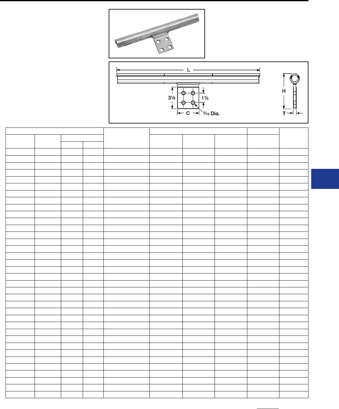
BURNDY®
Blue highlighted items are industry standard and most frequently ordered.
Canada: 1-800-387-6487 www.burndy.com US: 1-800-346-4175
Transmission
TYPE YNTA-RHT
T-Tap with Pad
for ACSS Conductor
Two piece compression T-Tap to a NEMA pad for
ACSS transmission lines. Up to and including 230
kV.
ACSS
T-Tap with Pad
Inches
Die*‡
Conductor
Name
Size
kcmil
Stranding L C H T
Alum. Steel
Linnet 336.4 26 7 YNTA32RHT 23.46 3.25 4.94 0.50 L717
Oriole 336.4 30 7 YNTA32RHT 23.46 3.25 4.94 0.50 L717
Ibis 397.5 26 7 YNTA34RHT 23.60 3.25 5.05 0.50 L719
Flicker 477 24 7 YNTA36RHT 24.29 3.25 5.16 0.56 L720
Hawk 477 26 7 YNTA36RHT 24.29 3.25 5.16 0.56 L720
Parakeet 556.5 24 7 YNTA39RHT 24.69 3.25 5.25 0.56 L722
Dove 556.5 26 7 YNTA39RHT 24.69 3.25 5.25 0.56 L722
Peacock 605 24 7 YNTA43RHT 25.48 3.25 5.36 0.56 L724
Squab 605 26 7 YNTA43RHT 25.48 3.25 5.36 0.56 L724
Rook 636 24 7 YNTA43RHT 25.48 3.25 5.36 0.56 L724
Grosbeak 636 26 7 YNTA43RHT 25.48 3.25 5.36 0.56 L724
Flamingo 666.6 24 7 YNTA43RHT 25.48 3.25 5.36 0.56 L724
Starling 715.5 26 7 YNTA451RHT 25.60 3.25 5.55 0.56 L725
Cuckoo 795 24 7 YNTA451RHT 25.60 3.25 5.55 0.56 L725
Drake 795 26 7 YNTA451RHT 25.60 3.25 5.55 0.56 L725
Tern 795 45 7 YNTA451RHT 25.60 3.25 5.55 0.56 L725
Condor 795 54 7 YNTA451RHT 25.60 3.25 5.55 0.56 L725
Ruddy 900 45 7 YNTA49RHT 25.66 3.25 5.72 0.56 L727
Rail 954 45 7 YNTA49RHT 25.66 3.25 5.72 0.56 L727
Cardinal 954 54 7 YNTA49RHT 25.66 3.25 5.72 0.56 L727
Ortolan 1033.5 45 7 YNTA49RHT 25.66 3.25 5.72 0.56 L727
Curlew 1033.5 54 7 YNTA49RHT 25.66 3.25 5.72 0.56 L727
Bluejay 1113 45 7 YNTA49RHT 25.66 3.25 5.72 0.56 L727
Finch 1113 54 19 YNTA54RHT 29.61 3.25 6.00 0.69 L728
Bunting 1192.5 45 7 YNTA54RHT 29.61 3.25 6.00 0.69 L728
Bittern 1272 45 7 YNTA54RHT 29.61 3.25 6.00 0.69 L728
Pheasant 1272 54 19 YNTA54RHT 29.61 3.25 6.00 0.69 L728
Dipper 1351.5 45 7 YNTA54RHT 29.61 3.25 6.00 0.69 L728
Martin 1351.5 54 19 YNTA54RHT 29.61 3.25 6.00 0.69 L728
Nuthatch 1510.5 45 7 YNTA56RHT 31.65 3.59 6.25 0.69 L729
Parrot 1510.5 54 19 YNTA56RHT 31.65 3.59 6.25 0.69 L729
Lapwing 1590 45 7 YNTA56RHT 31.65 3.59 6.25 0.69 L729
Falcon 1590 54 19 YNTA56RHT 31.65 3.59 6.25 0.69 L729
Chukar 1780 84 19 YNTA58RHT 31.53 3.59 6.25 0.69 L735
Bluebird 2156 84 19 YNTA59RHT 31.21 3.59 6.25 0.69 L735
Kiwi 2167 72 7 YNTA59RHT 31.21 3.59 6.25 0.69 L735
ACSS T-Tap with Pad
For EVH applications, add sufx “T” to catalog number
(example: YNTA49RTHT).
For EHV applications (2) two tap pad shielding caps (catalog
number STS-A-NCG) should be ordered.
* Overlap crimps.
‡ Wide dies may be used on aluminum only, add sufx “W” to
part number (example: L725W).
I-27
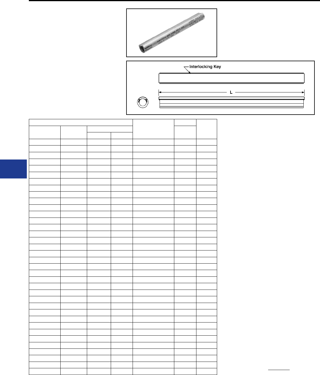
BURNDY®
Blue highlighted items are industry standard and most frequently ordered.
US: 1-800-346-4175 www.burndy.com Canada: 1-800-387-6487
Transmission
TYPE YNU-RHT
Repair Sleeve for ACSS
Conductor
For HV and EHV applications. Two-piece repair
sleeve for temporary restoration of conductivity
to damaged ACSS transmission lines. Use of
PENETROX™ joint compound required.
ACSS
Repair Sleeve
Inches
Die*‡
Conductor
Name
Size
kcmil
Stranding L
Alum. Steel
Linnet 336.4 26 7 YNU32RHT 22.00 L717
Oriole 336.4 30 7 YNU32RHT 22.00 L717
Ibis 397.5 26 7 YNU34RHT 22.00 L719
Flicker 477 24 7 YNU36RHT 22.00 L720
Hawk 477 26 7 YNU36RHT 22.00 L720
Parakeet 556.5 24 7 YNU39RHT 24.00 L722
Dove 556.5 26 7 YNU39RHT 24.00 L722
Peacock 605 24 7 YNU43RHT 24.00 L724
Squab 605 26 7 YNU43RHT 24.00 L724
Rook 636 24 7 YNU43RHT 24.00 L724
Grosbeak 636 26 7 YNU43RHT 24.00 L724
Flamingo 666.6 24 7 YNU43RHT 24.00 L724
Starling 715.5 26 7 YNU451RHT 24.00 L725
Cuckoo 795 24 7 YNU451RHT 24.00 L725
Drake 795 26 7 YNU451RHT 24.00 L725
Tern 795 45 7 YNU451RHT 24.00 L725
Condor 795 54 7 YNU451RHT 24.00 L725
Ruddy 900 45 7 YNU49RHT 24.00 L727
Rail 954 45 7 YNU49RHT 24.00 L727
Cardinal 954 54 7 YNU49RHT 24.00 L727
Ortolan 1033.5 45 7 YNU49RHT 24.00 L727
Curlew 1033.5 54 7 YNU49RHT 24.00 L727
Bluejay 1113 45 7 YNU49RHT 24.00 L727
Finch 1113 54 19 YNU54RHT 24.00 L728
Bunting 1192.5 45 7 YNU54RHT 24.00 L728
Bittern 1272 45 7 YNU54RHT 24.00 L728
Pheasant 1272 54 19 YNU54RHT 24.00 L728
Dipper 1351.5 45 7 YNU54RHT 24.00 L728
Martin 1351.5 54 19 YNU54RHT 24.00 L728
Nuthatch 1510.5 45 7 YNU56RHT 27.00 L729
Parrot 1510.5 54 19 YNU56RHT 27.00 L729
Lapwing 1590 45 7 YNU56RHT 27.00 L729
Falcon 1590 54 19 YNU56RHT 27.00 L729
Chukar 1780 84 19 YNU58RHT 27.00 L735
Bluebird 2156 84 19 YNU59RHT 27.00 L735
Kiwi 2167 72 7 YNU59RHT 27.00 L735
ACSS Repair Sleeves-EHV
* Overlap crimps.
‡ Wide dies may be used on aluminum only (no steel), add
sufx “W” to part number (example: L725W).
I-28
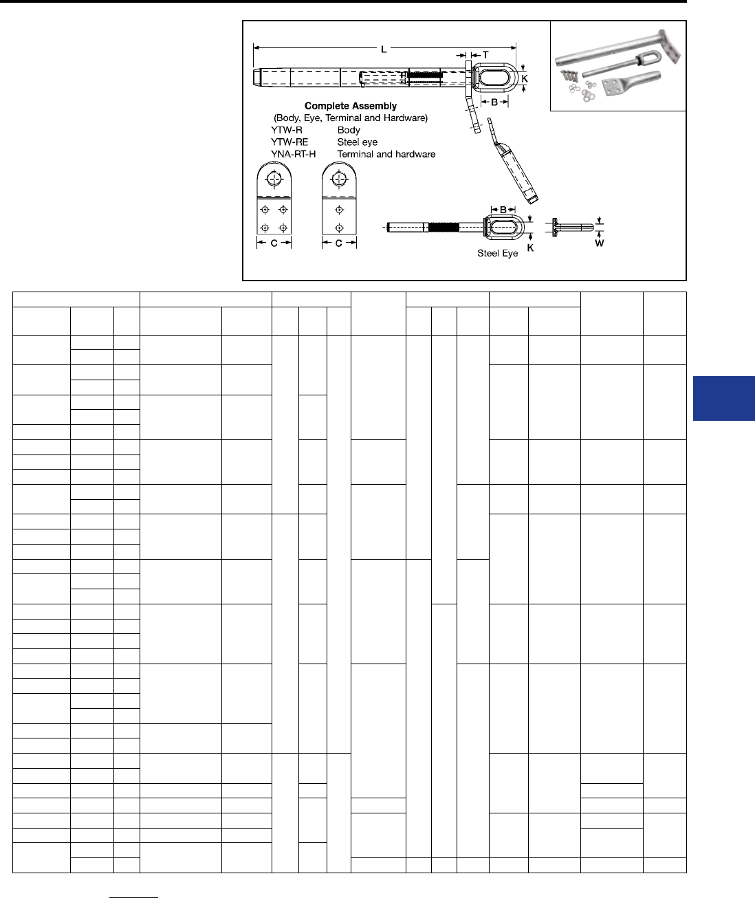
BURNDY®
Blue highlighted items are industry standard and most frequently ordered.
Canada: 1-800-387-6487 www.burndy.com US: 1-800-346-4175
Transmission
TYPES YTW-A-AEK,
YTW-A, YTW-AE,
YNA-RH
Single Pad Full Tension Deadend
for Stranded Aluminum Cable
Full tension compression deadend for SAC
transmission lines. One design for applications
up to and including 230 kV. Two hole NEMA tap
pad supplied through 636 kcmil. Larger sizes have
4 hole NEMA pad. Standard 15° tap pad when
used with YNA-R15H terminal provides either
0° or 30° tap. Aluminum body is pre-lled with
PENETROX™ joint compound and capped.
Aluminum Single Pad Inches Steel
Eye
Inches Tools Terminal
with
Hardware
Terminal
Die*‡
Conductor
Name kcmil Str. Complete
Assembly
Aluminum
Body C L T B K W Die
Index Y60BHU*‡
Tulip 336.4 19 YTW301A331AEK YTW301A
2.25
9.62
0.50
YTW331AE
2.50
0.88
0.62
717 L717 YNA32R15H L717
350 37
Canna 397.5 19 YTW311A331AEK YTW311A
719 L719 YNA34R15H L719
400 37
Cosmos 450 37
YTW331A331AEK YTW331A 9.75477 19
Syringa 477 37
Hyacinth 500 37
YTW351A351AEK YTW351A 11.62 YTW351AE 720 L720 YNA36R15H L720Dahlia 556.5 19
Mistletoe 556.5 37
Orchid 600 61 YTW361A39AEK YTW361A 12.25
YTW39AE 0.69
722 L722 YNA39R15H L722
636 37
Violet 715.5 37
YTW39A39AEK YTW39A
3.25
12.75
724 724 YNA43R15H 724
Nasturtium 715.5 61
Cattail 750 61
Arbutus 795 37
YTW391A431AEK YTW391A 14.38
YTW431AE
2.69
0.75
Lilac 795 61
800 61
Anemone 874.5 37
YTW431A431AEK YTW431A 14.75
1.25
725 L725 YNA451R15H L725
Crocus 874.5 61
Magnolia 954 37
Goldenrod 954 61
Bluebell 1033.5 37
YTW445A463AEK YTW445A
15.62
YTW463AE
1.00
727 L727 YNA49R15H L727
Larkspur 1033.5 61
Marigold 1113 37
1113 61
Hawthorn 1192.6 61 YTW451A463AEK YTW451A
Nacrcissus 1272 61
Columbine 1351.5 61 YTW457A463AEK YTW457A
4.00
16.50
0.62
728 L728
YNA52R15H L728Carnation 1431 61
Coreopsis 1590 61 YTW463A463AEK YTW463A 17.13 YNA54R15H
Jessamine 1750 61 YTW47A47AEK YTW47A
16.38
YTW47AE YNA56R15H L729
Cowslip 2000 91 YTW48A484AEK YTW48A
YTW484AE 735 L735
YNA58R15H
L735Sagebrush 2250 91 YTW484A484AEK YTW484A YNA59R15H
Lupine 2300 61 YTW486A486AEK YTW486A 18.50
2500 91 YTW486AE 4.00 3.12 1.25 740 L740 YNA594R15H L740
AAC/ACAR Deadends
* Overlap Crimp.
‡ Wide dies may be used on aluminum only, add sufx “W” to
part number (example: L725W).
Complete Assembly: Includes Aluminum Body, Steel eye, 15
degree terminal and aluminum hardware.
For stainless steel hardware add SS to the end of the
catalog number. For complete assembly (example:
YTW391A431AEKSS) or to terminal (YNA43R15HSS)
if ordered separately. For assembly without terminal and
hardware add NT to the end of the complete catalog number
(example: YTW391A431AEKNT).
I-29
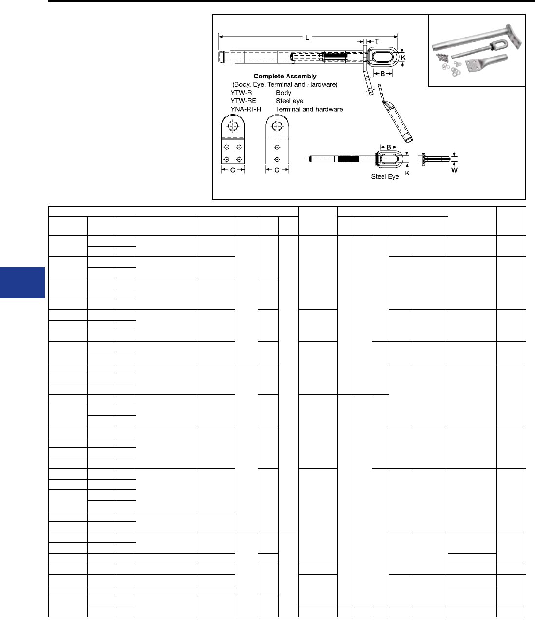
BURNDY®
Blue highlighted items are industry standard and most frequently ordered.
US: 1-800-346-4175 www.burndy.com Canada: 1-800-387-6487
Transmission
TYPES YTW-AT-AEK,
YTW-AT, YTW-AE,
YNA-RTH EHV
Single Pad, EHV Full Tension
Deadend for Stranded
Aluminum Cable
Full tension compression deadend for SAC
transmission lines at 345 kV and over. Two hole
NEMA tap pad supplied through 636 kcmil. Larger
sizes have 4 hole NEMA pad. Standard 15° tap
pad when used with YNAR15H terminal provides
either 0° or 30° tap. Aluminum body is pre-lled
with PENETROX™ joint compound and capped.
Aluminum Single Pad Inches Steel
Eye
Inches Tools Terminal
with
Hardware
Terminal
Die*‡
Conductor
Name kcmil Str. Complete
Assembly
Aluminum
Body C L T B K W Die
Index Y60BHU*‡
Tulip 336.4 19 YTW301AT331AEK YTW301AT
2.25
9.62
0.50
YTW331AE
2.50 0.88
0.62
717 L717 YNA32RT15H L717
350 37
Canna 397.5 19 YTW311AT331AEK YTW311AT
719 L719 YNA34RT15H L719
400 37
Cosmos 450 37
YTW331AT331AEK YTW331AT 9.75477 19
Syringa 477 37
Hyacinth 500 37
YTW351T351AEK YTW351AT 11.62 YTW351AE 720 L720 YNA36RT15H L720Dahlia 556.5 19
Mistletoe 556.5 37
Orchid 600 61 YTW361AT39AEK YTW361AT 12.25
YTW39AE 0.69
722 L722 YNA39RT15H L722
636 37
Violet 715.5 37
YTW39AT39AEK YTW39AT
3.25
12.75
724 L724 YNA43RT15H L724
Nasturtium 715.5 61
Cattail 750 61
Arbutus 795 37
YTW391AT431AEK YTW391AT 14.38
YTW431AE
2.69 1.25
0.75
Lilac 795 61
800 61
Anemone 874.5 37
YTW431AT431AEK YTW431AT 14.75 725 L725 YNA451RT15H L725
Crocus 874.5 61
Magnolia 954 37
Goldenrod 954 61
Bluebell 1033.5 37
YTW445AT463AEK YTW445AT
15.62
YTW463AE
1.00
727 L727 YNA49RT15H L727
Larkspur 1033.5 61
Marigold 1113 37
1113 61
Hawthorn 1192.6 61 YTW451AT463AEK YTW451AT
Nacrcissus 1272 61
Columbine 1351.5 61 YTW457AT463AEK YTW457AT
4.00
16.50
0.62
728 L728
YNA52RT15H L728Carnation 1431 61
Coreopsis 1590 61 YTW463AT463AEK YTW463AT 17.13 YNA54RT15H
Jessamine 1750 61 YTW47AT47AEK YTW47AT
16.38
YTW47AE YNA56RT15H L729
Cowslip 2000 91 YTW48AT484AEK YTW48AT
YTW484AE 735 L735
YNA58RT15H
L735Sagebrush 2250 91 YTW484AT484AEK YTW484AT YNA59RT15H
Lupine 2300 61 YTW486AT486AEK YTW486AT 18.50
2500 91 YTW486AE 4.00 3.12 1.25 740 L740 YNA594RT15H L740
AAC/ACAR Deadends-EHV
* Overlap Crimp.
‡ Wide dies may be used on aluminum only, add sufx “W” to
part number (example: L725W).
Complete Assembly: Includes Aluminum Body, Steel eye, 15
degree terminal and aluminum hardware.
For stainless steel hardware add SS to the end of the
catalog number. For complete assembly (example:
YTW391A431AEKSS) or to terminal (YNA43R15HSS)
if ordered separately. For assembly without terminal and
hardware add NT to the end of the complete catalog number
(example: YTW391A431AEKNT).
I-30
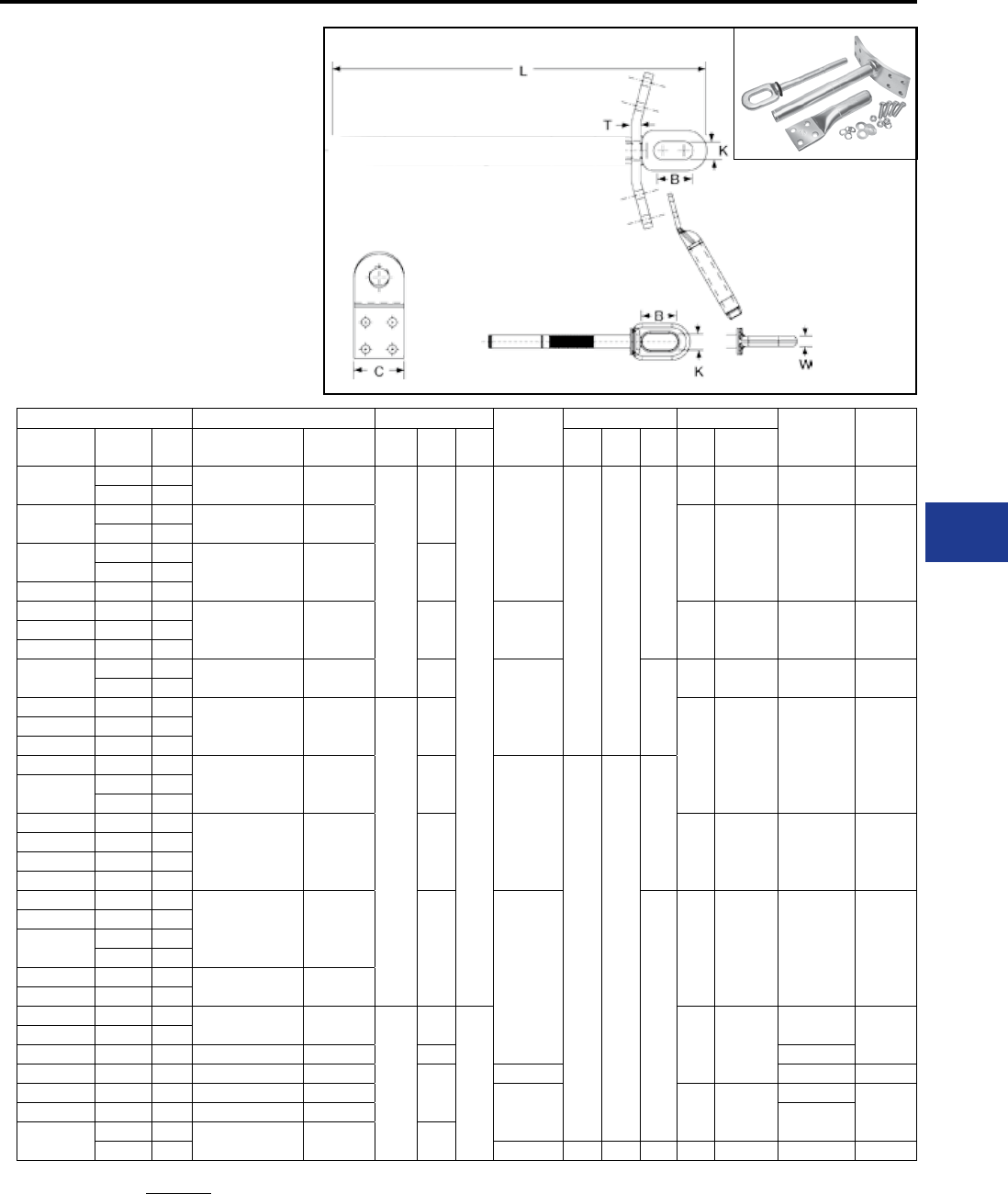
BURNDY®
Blue highlighted items are industry standard and most frequently ordered.
Canada: 1-800-387-6487 www.burndy.com US: 1-800-346-4175
Transmission
TYPES YTW-AD-AEK,
YTW-AD, YTW-AE,
YNA-RH
Double Pad Full Tension
Deadend for Stranded
Aluminum Cable
Full tension compression deadend for SAC
transmission lines. One design for applications
up to and including 230 kV. Two hole NEMA tap
pad supplied through 636 kcmil. Larger sizes have
4 hole NEMA pad. Standard 15° tap pad when
used with YNAR15H terminal provides either
0° or 30° tap. Aluminum body is pre-lled with
PENETROX™ joint compound and capped.
Aluminum Double Pad Inches Steel
Eye
Inches Tools Terminal
with
Hardware
Terminal
Die*‡
Conductor
Name kcmil Str. Complete
Assembly
Aluminum
Body C L T B K W Die
Index Y60BHU*‡
Tulip 336.4 19 YTW301AD331AEK YTW301AD
2.25
9.62
0.50
YTW331AE
2.50 0.88
0.62
717 L717 YNA32R15H L717
350 37
Canna 397.5 19 YTW311AD331AEK YTW311AD
719 L719 YNA34R15H L719
400 37
Cosmos 450 37
YTW331AD331AEK YTW331AD 9.75477 19
Syringa 477 37
Hyacinth 500 37
YTW351AD351AEK YTW351AD 11.62 YTW351AE 720 L720 YNA36R15H L720Dahlia 556.5 19
Mistletoe 556.5 37
Orchid 600 61 YTW361AD39AEK YTW361AD 12.25
YTW39AE 0.69
722 L722 YNA39R15H L722
636 37
Violet 715.5 37
YTW39AD39AEK YTW39AD
3.25
12.75
724 L724 YNA43R15H L724
Nasturtium 715.5 61
Cattail 750 61
Arbutus 795 37
YTW391AD431AEK YTW391AD 14.38
YTW431AE
2.69 1.25
0.75
Lilac 795 61
800 61
Anemone 874.5 37
YTW431AD431AEK YTW431AD 14.75 725 L725 YNA451R15H L725
Crocus 874.5 61
Magnolia 954 37
Goldenrod 954 61
Bluebell 1033.5 37
YTW445AD463AEK YTW445AD
15.62
YTW463AE
1.00
727 L727 YNA49R15H L727
Larkspur 1033.5 61
Marigold 1113 37
1113 61
Hawthorn 1192.6 61 YTW451AD463AEK YTW451AD
Nacrcissus 1272 61
Columbine 1351.5 61 YTW457AD463AEK YTW457AD
4.00
16.50
0.62
728 L728
YNA52R15H L728Carnation 1431 61
Coreopsis 1590 61 YTW463AD463AEK YTW463AD 17.13 YNA54R15H
Jessamine 1750 61 YTW47AD47AEK YTW47AD
16.38
YTW47AE YNA56R15H L729
Cowslip 2000 91 YTW48AD484AEK YTW48AD
YTW484AE 735 L735
YNA58R15H
L735Sagebrush 2250 91 YTW484AD484AEK YTW484AD YNA59R15H
Lupine 2300 61 YTW486AD486AEK YTW486AD 18.50
2500 91 YTW486AE 4.00 3.12 1.25 740 L740 YNA594R15H L740
YTW-AD
YTW-AE
YNA-R-H
Body
Steel eye
Terminal and hardware
Steel Eye (YTW-AE)
AAC/ACAR Deadends
Complete Assembly
(Body, Eye, Terminal and Hardware)
* Overlap Crimp.
‡ Wide dies may be used on aluminum only, add sufx “W” to
part number (example: L725W).
Complete Assembly: Includes Aluminum Body, Steel eye, 15
degree terminal and aluminum hardware.
For stainless steel hardware add SS to the end of the
catalog number. For complete assembly (example:
YTW391A431AEKSS) or to terminal (YNA43R15HSS)
if ordered separately. For assembly without terminal and
hardware add NT to the end of the complete catalog number
(example: YTW391A431AEKNT).
I-31
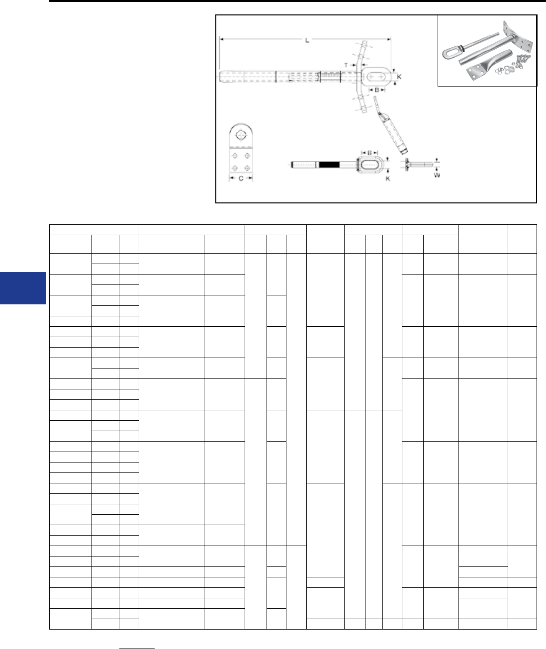
BURNDY®
Blue highlighted items are industry standard and most frequently ordered.
US: 1-800-346-4175 www.burndy.com Canada: 1-800-387-6487
Transmission
TYPES YTW-ADT-AEK,
YTW-ADT, YTW-AE,
YNA-RTH EHV
Double Pad, EHV Full Tension
Deadend for Stranded
Aluminum Cable
Full tension compression deadend for SAC
transmission line at 345 kV and over. Two hole
NEMA tap pad supplied through 636 kcmil. Larger
sizes have 4 hole NEMA pad. Standard 15° tap
pad when used with YNAR15H terminal provides
either 0° or 30° tap. Aluminum body is pre-lled
with PENETROX™ joint compound and capped.
Complete Assembly
(Body, Eye, Terminal and Hardware)
YTW-AD
YTW-AE
YNA-R-H
Body
Steel eye
Terminal and hardware
Steel Eye (YTW-AE)
Aluminum Double Pad Inches Steel
Eye
Inches Tools Terminal
with
Hardware
Terminal
Die*‡
Conductor
Name kcmil Str. Complete
Assembly
Aluminum
Body C L T B K W Die
Index Y60BHU*‡
Tulip 336.4 19 YTW301ADT331AEK YTW301ADT
2.25
9.62
0.50
YTW331AE
2.50 0.88
0.62
717 L717 YNA32R15H L717
350 37
Canna 397.5 19 YTW311ADT331AEK YTW311ADT
719 L719 YNA34R15H L719
400 37
Cosmos 450 37
YTW331ADT331AEK YTW331ADT 9.75477 19
Syringa 477 37
Hyacinth 500 37
YTW351ADT351AEK YTW351ADT 11.62 YTW351AE 720 L720 YNA36R15H L720Dahlia 556.5 19
Mistletoe 556.5 37
Orchid 600 61 YTW361ADT39AEK YTW361ADT 12.25
YTW39AE 0.69
722 L722 YNA39R15H L722
636 37
Violet 715.5 37
YTW39ADT39AEK YTW39ADT
3.25
12.75
724 L724 YNA43R15H L724
Nasturtium 715.5 61
Cattail 750 61
Arbutus 795 37
YTW391ADT431AEK YTW391ADT 14.38
YTW431AE
2.69 1.25
0.75
Lilac 795 61
800 61
Anemone 874.5 37
YTW431ADT431AEK YTW431ADT 14.75 725 L725 YNA451R15H L725
Crocus 874.5 61
Magnolia 954 37
Goldenrod 954 61
Bluebell 1033.5 37
YTW445ADT463AEK YTW445ADT
15.62
YTW463AE
1.00
727 L727 YNA49R15H L727
Larkspur 1033.5 61
Marigold 1113 37
1113 61
Hawthorn 1192.6 61 YTW451ADT463AEK YTW451ADT
Nacrcissus 1272 61
Columbine 1351.5 61 YTW457ADT463AEK YTW457ADT
4.00
16.50
0.62
728 L728
YNA52R15H L728Carnation 1431 61
Coreopsis 1590 61 YTW463ADT463AEK YTW463ADT 17.13 YNA54R15H
Jessamine 1750 61 YTW47ADT47AEK YTW47ADT
16.38
YTW47AE YNA56R15H L729
Cowslip 2000 91 YTW48ADT484AEK YTW48ADT
YTW484AE 735 L735
YNA58R15H
L735Sagebrush 2250 91 YTW484ADT484AEK YTW484ADT YNA59R15H
Lupine 2300 61 YTW486ADT486AEK YTW486ADT 18.50
2500 91 YTW486AE 4.00 3.12 1.25 740 L740 YNA594R15H L740
AAC/ACAR Deadends-EHV
* Overlap Crimp.
‡ Wide dies may be used on aluminum only, add sufx “W” to
part number (example: L725W).
Complete Assembly: Includes Aluminum Body, Steel eye, 15
degree terminal and aluminum hardware.
For stainless steel hardware add SS to the end of the
catalog number. For complete assembly (example:
YTW391A431AEKSS) or to terminal (YNA43R15HSS)
if ordered separately. For assembly without terminal and
hardware add NT to the end of the complete catalog number
(example: YTW391A431AEKNT).
I-32
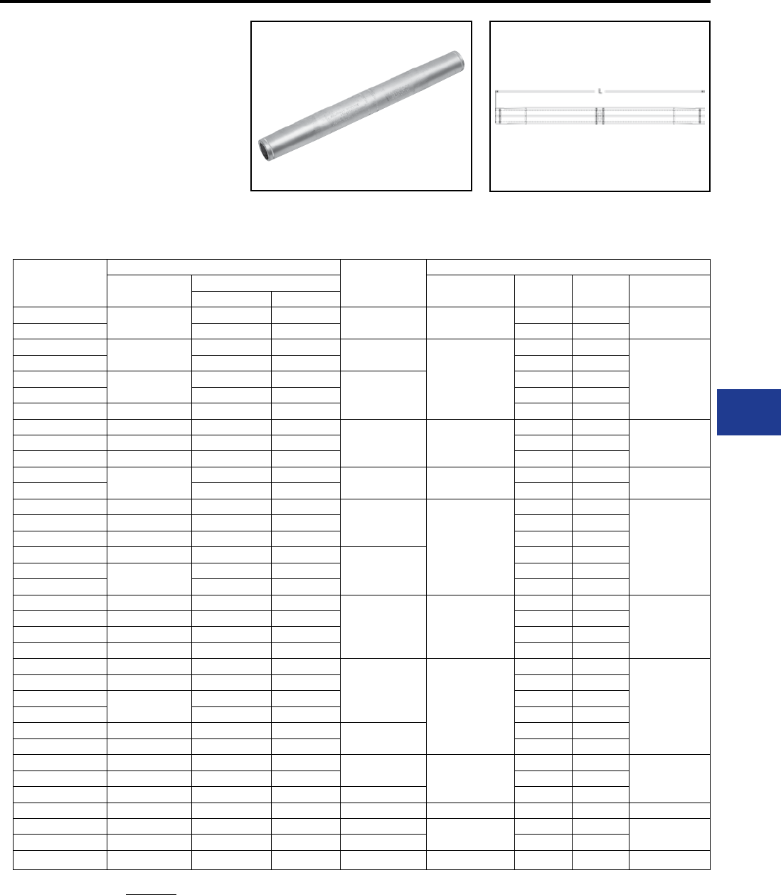
BURNDY®
Blue highlighted items are industry standard and most frequently ordered.
Canada: 1-800-387-6487 www.burndy.com US: 1-800-346-4175
Transmission
Catalog
Number
Conductor Inches
L
Tool, Die Sets
Conductor
Name
Aluminum Die
Index Y45* Y46* Y60BHU* ‡
kcmil Strands
YTS301A Tulip 336.4 19 9.13 717 S725 P725 L717
YTS301A 350 37 S725 P725
YTS311A Canna 397.5 19 9.29
719
S719 P719
L719
YTS311A 400 37 S719 P719
YTS331A Cosmos 450 37
9.27
S719 P719
YTS331A 477 19 S719 P719
YTS331A Syringa 477 37 S719 P719
YTS351A Hyacinth 500 37
11.18 720
S720 P720
L720YTS351A Dahlia 556.5 19 S720 P720
YTS351A Mistletoe 556.5 37 S720 P720
YTS361A Orchid 600 61 12.14 722 S722 P722 L722
YTS361A 636 37 S722 P722
YTS39A Violet 715.5 37
13.36
724
S724 P724
L724
YTS39A Nasturtium 715.5 61 S724 P724
YTS39A Cattail 750 61 S724 P724
YTS391A Arbutus 795 37
15.81
S724 P724
YTS391A Lilac 795 61 S724 P724
YTS391A 800 61 S724 P724
YTS431A Anemone 874.5 37
16.51 725
S725 P725
L725
YTS431A Crocus 874.5 61 S725 P725
YTS431A Magnolia 954 37 S725 P725
YTS431A Goldenrod 954 61 S725 P725
YTS445A Bluebell 1033.5 37
18.51
727
— —
L727
YTS445A Larkspur 1033.5 61 — —
YTS445A Marigold 1113 37 — —
YTS445A 1113 61 — —
YTS451A Hawthorn 1192.6 61 18.40 — —
YTS451A Nacrcissus 1272 61 — —
YTS457A Columbine 1351.5 61 19.96 728
— —
L728YTS457A Carnation 1431 61 — —
YTS463A Coreopsis 1590 61 21.50 — —
YTS47A Jessamine 1750 61 19.96 728 — — L728
YTS48A 2000 169 21.62 735 — — L735
YTS484A 2300 61 20.19 — —
YTS486A Lupine 2500 91 24.28 740 — — L740
TYPE YTS-A
Full Tension Splice for
Stranded Aluminum
Transmission Line
Full tension splice for Stranded Aluminum
Transmission line up to and including 230 kV.
Manufactured of aluminum tube with staked-in
cable stop. Pre-lled with PENETROX™ joint
compound and capped.
AAC/ACAR Splices
* Overlap Crimp.
‡ Wide dies may be used on aluminum only, add sufx “W” to
part number (example: L725W).
I-33
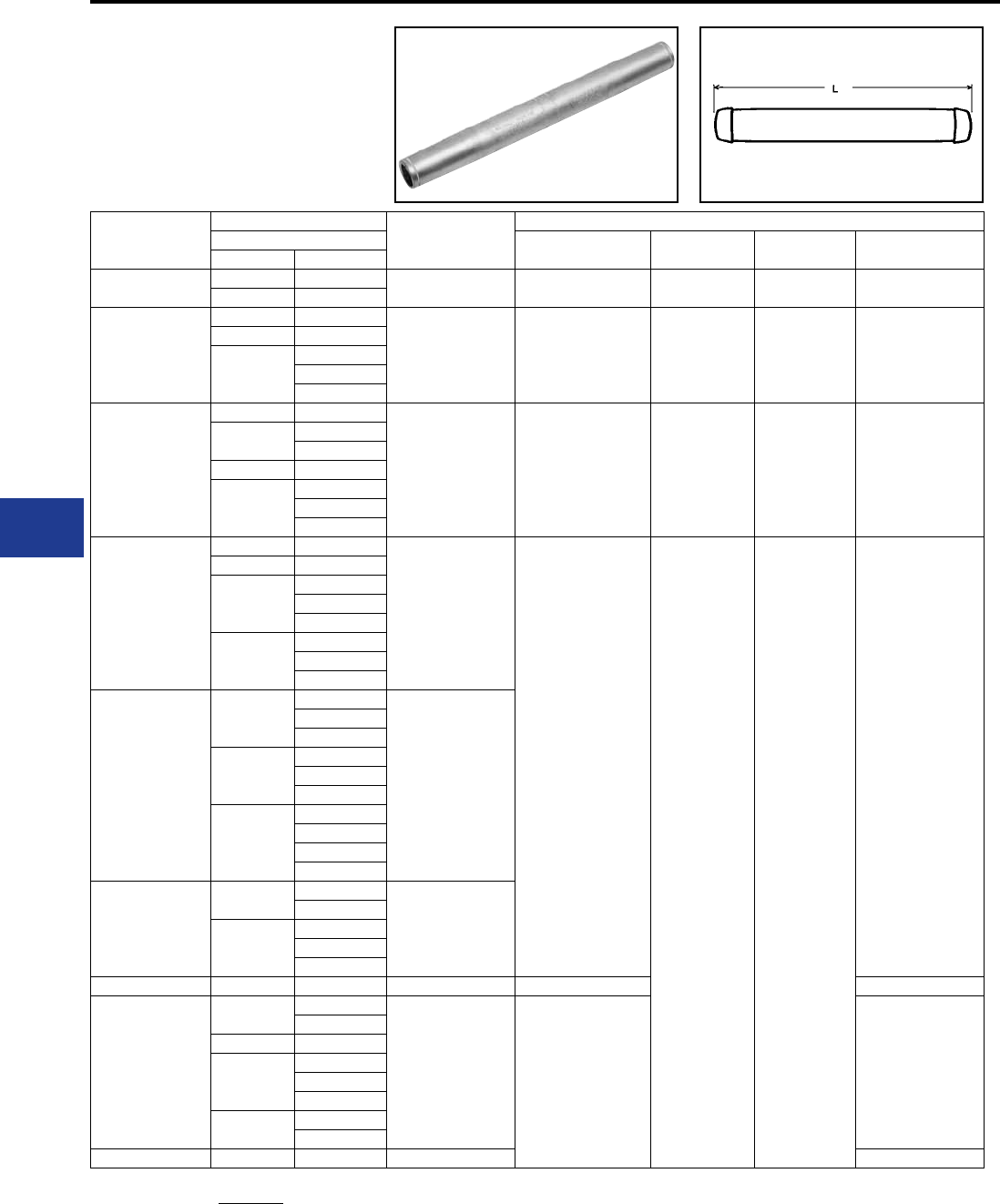
BURNDY®
Blue highlighted items are industry standard and most frequently ordered.
US: 1-800-346-4175 www.burndy.com Canada: 1-800-387-6487
Transmission
TYPE YTS-AR
Full Tension Splice for ACAR
Full tension splice for ACAR transmission lines
up to and including 230 kV. Manufactured of
aluminum tube with staked in cable stop. Pre-lled
with PENETROX™ joint compound and capped.
Catalog
Number
Conductor Inches
L
Tool, Die Sets
ACAR Die
Index Y45* Y46* Y60BHU* ‡
kcmil Str.
YTS32AR 395.1 12-7 15.18″ 717 S717 P71 7 L717
395.2 15-7
YTS39AR
634.9 12-7
16.39″ 722 S722 P722 L722
649.5 18-19
653.1
15-4
12-7
18-19
YTS451AR
840.2 24-13
19.58″ 725 S725 P725 L725
853.7 30-7
24-13
862.7 18-19
927.2
30-7
24-13
18-19
YTS48AR
983.1 30-7
21.36″
727
— —
L727
1012.2 24-13
1024.5
30-7
24-13
18-19
1081
30-7
24-13
18-19
YTS49AR
1109
30-7
21.42″
24-13
18-19
1172
30-7
24-13
18-19
1198
30-7
24-13
18-19
42-19
YTS51AR
1277 42-19
21.56″
54-7
1280
30-7
24-13
18-19
YTS55AR 1534 42-19 25.30″ 728 L728
YTS59AR
2267 54-7
23.50″ —**
48-13
2277 42-19
2338
54-7
48-13
42-19
2335 72-19
30-61
YTS592AR 2493 54-37 28.34″ ***
AAC/ACAR Splices
* Overlap Crimp.
‡ Wide dies may be used on aluminum only, add sufx “W” to
part number (example: L725W).
** Use die H814 in Alcoa Press H2H, die M814 in Alcoa
Press 150B and die MH814 in Alcoa Press 100A. These dies
are manufactured by BURNDY®.
***Use die H990 in Alcoa Press H2H, die M990 in Alcoa
Press 150B and die MH990 in Alcoa Press 100A. These dies
are manufactured by BURNDY®.
I-34
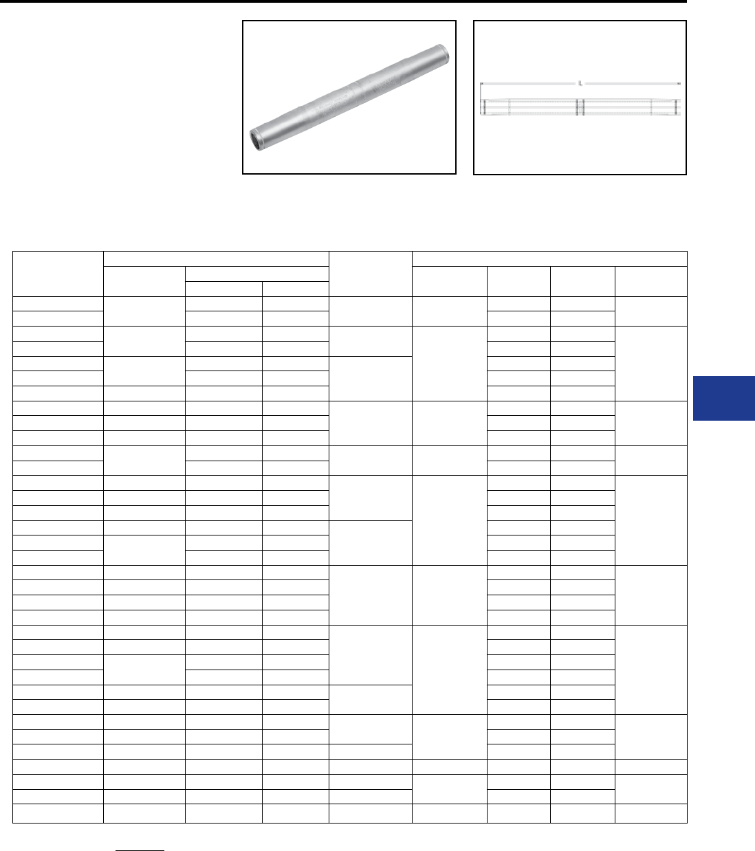
BURNDY®
Blue highlighted items are industry standard and most frequently ordered.
Canada: 1-800-387-6487 www.burndy.com US: 1-800-346-4175
Transmission
TYPE YTS-AT EHV
Full Tension Splice for
Stranded Aluminum
Transmission Line
Full tension splice for Stranded Aluminum
Transmission line at 345 kV and over.
Manufactured of aluminum tube with staked-in
cable stop. Pre-lled with PENETROX™ joint
compound and capped.
Catalog
Number
Conductor Inches
L
Tool, Die Sets
Conductor
Name
Aluminum Die
Index Y45* Y46* Y60BHU* ‡
kcmil Strands
YTS301AT Tulip 336.4 19 9.75 717 S725 P725 L717
YTS301AT 350 37 S725 P725
YTS311AT Canna 397.5 19 9.99
719
S719 P719
L719
YTS311AT 400 37 S719 P719
YTS331AT Cosmos 450 37
10.01
S719 P719
YTS331AT 477 19 S719 P719
YTS331AT Syringa 477 37 S719 P719
YTS351AT Hyacinth 500 37
11.88 720
S720 P720
L720YTS351AT Dahlia 556.5 19 S720 P720
YTS351AT Mistletoe 556.5 37 S720 P720
YTS361AT Orchid 600 61 12.92 722 S722 P722 L722
YTS361AT 636 37 S722 P722
YTS39AT Violet 715.5 37
14.36
724
S724 P724
L724
YTS39AT Nasturtium 715.5 61 S724 P724
YTS39AT Cattail 750 61 S724 P724
YTS391AT Arbutus 795 37
16.36
S724 P724
YTS391AT Lilac 795 61 S724 P724
YTS391AT 800 61 S724 P724
YTS431AT Anemone 874.5 37
17.92 725
S725 P725
L725
YTS431AT Crocus 874.5 61 S725 P725
YTS431AT Magnolia 954 37 S725 P725
YTS431AT Goldenrod 954 61 S725 P725
YTS445AT Bluebell 1033.5 37
19.57
727
— —
L727
YTS445AT Larkspur 1033.5 61 — —
YTS445AT Marigold 1113 37 — —
YTS445AT 1113 61 — —
YTS451AT Hawthorn 1192.6 61 19.24 — —
YTS451AT Nacrcissus 1272 61 — —
YTS457AT Columbine 1351.5 61 21.08 728
— —
L728YTS457AT Carnation 1431 61 — —
YTS463AT Coreopsis 1590 61 22.56 — —
YTS47AT Jessamine 1750 61 21.08 728 — — L728
YTS48AT 2000 169 23.02 735 — — L735
YTS484AT 2300 61 23.00 — —
YTS486AT Lupine 2500 91 24.28 740 — — L740
AAC/ACAR Splices-EHV
* Overlap Crimp.
‡ Wide dies may be used on aluminum only, add sufx “W” to
part number (example: L725W).
I-35
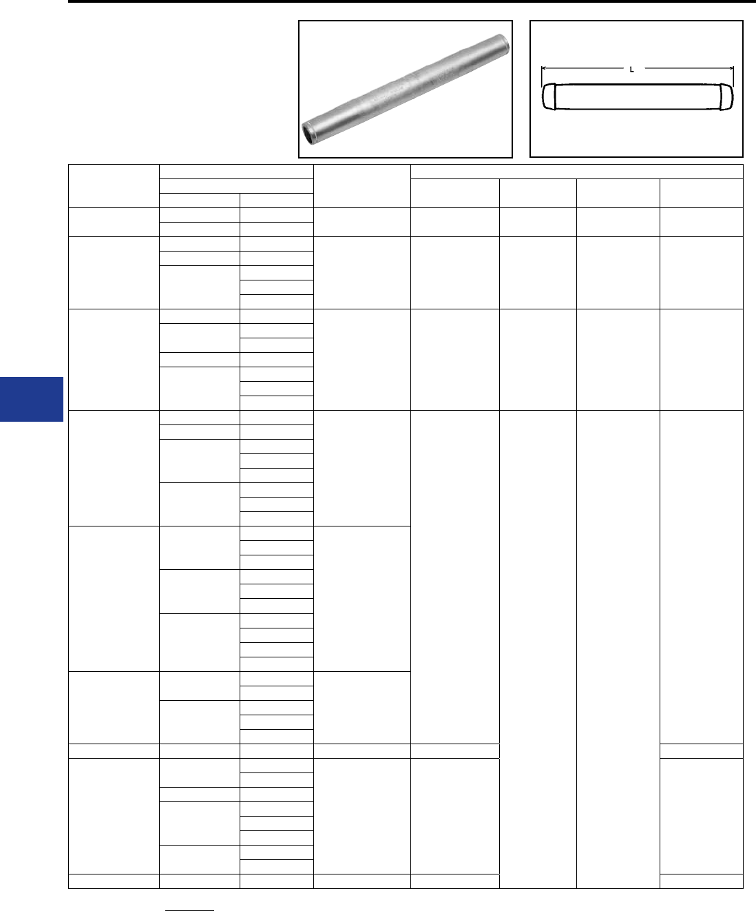
BURNDY®
Blue highlighted items are industry standard and most frequently ordered.
US: 1-800-346-4175 www.burndy.com Canada: 1-800-387-6487
Transmission
TYPE YTS-ART EHV
Full Tension Splice for ACAR
Full tension splice for ACAR transmission lines
at 345 kV and over. Manufactured of aluminum
tube with staked-in cable stop. Pre-lled with
PENETROX™ joint compound and capped.
Catalog
Number
Conductor Inches
L
Tool, Die Sets
ACAR Die
Index Y45* Y46* Y60BHU* ‡
kcmil Strands
YTS32ART 395.1 12-7 15.52″ 717 S717 P71 7 L717
395.2 15-7
YTS39ART
634.9 12-7
16.95″ 722 S722 P722 L722
649.5 18-19
653.1
15-4
12-7
18-19
YTS451ART
840.2 24-13
20.36″ 725 S725 P725 L725
853.7 30-7
24-13
862.7 18-19
927.2
30-7
24-13
18-19
YTS48ART
983.1 30-7
22.36″
727
— —
L727
1012.2 24-13
1024.5
30-7
24-13
18-19
1081
30-7
24-13
18-19
YTS49ART
1109
30-7
22.38″
24-13
18-19
1172
30-7
24-13
18-19
1198
30-7
24-13
18-19
42-19
YTS51ART
1277 42-19
22.46″
54-7
1280
30-7
24-13
18-19
YTS55ART 1534 42-19 26.40″ 728 L728
YTS59ART
2267 54-7
24.75″ 814 **
48-13
2277 42-19
2338
54-7
48-13
42-19
2335 72-19
30-61
YTS592ART 2493 54-37 29.40″ 990 ***
AAC/ACAR Splices-EHV
* Overlap Crimp.
‡ Wide dies may be used on aluminum only, add sufx “W” to
part number (example: L725W).
** Use die H814 in Alcoa Press H2H, die M814 in Alcoa
Press 150B and die MH814 in Alcoa Press 100A. These dies
are manufactured by BURNDY®.
***Use die H990 in Alcoa Press H2H, die M990 in Alcoa
Press 150B and die MH990 in Alcoa Press 100A. These dies
are manufactured by BURNDY®.
I-36
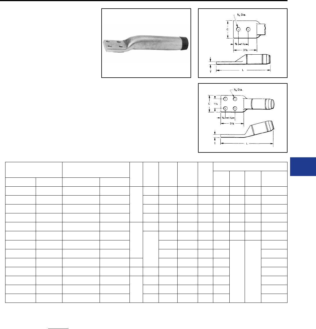
BURNDY®
Blue highlighted items are industry standard and most frequently ordered.
Canada: 1-800-387-6487 www.burndy.com US: 1-800-346-4175
Transmission
TYPES YNA-R15
& YNA-R
Compression Terminal for ACAR
and Stranded Aluminum Cable
Compression terminal ACAR and Stranded
Aluminum Cable. Two hole NEMA tongue supplied
through 650 kcmil Aluminum. For transmission line
up to and including 230 kV supplied on tongue
through 650 kcmil aluminum. Four hole NEMA
supplied on larger sizes. When used with YTW
Deadends the 15° angle tongue provides either a
0° or 30° tap. Uses same dies as equivalent full-
tension sleeve or deadend. Barrel pre-lled with
PENETROX™ joint compound and capped. Pad
coated with oxide-retardant.
Catalog Number † Conductor Fig.
#CL
15˚
L
Straight T
Tools, Die Sets
Die
Index Y45* Y46* Y60BHU*‡
15˚ Straight ACAR Aluminum
YNA32R15 YNA32R 395.1 - 395.2 336.4 - 350
1
1.68" 8.92" 8.96" 0.39" 717 S717 P717 L717
YNA34R15 YNA34R — 397.5 - 477 1.78" 9.31" 9.08" 0.46" 719 S719 P719 L719
YNA36R15 YNA36R — 500 - 556.5 1.96" 9.62" 9.47" 0.48" 720 S720 P720 L720
YNA39R15 YNA39R 634.9 - 653.1 600 - 650 2.08" 10.09" 9.84" 0.53" 722 S722 P722 L722
YNA43R15 YNA43R — 700 - 800
2
3.07" 10.16" 10.07" 0.36" 724 S724 P724 L724
YNA451R15 YNA451R 840.2 - 927.2 795 - 1000
3.22"
10.21" 10.28" 0.45" 725 S725 P725 L725
YNA49R15 YNA49R 983.1 - 1198 1033.5 - 1272 10.35" 10.46" 0.52" 727
— —
L727
YNA52R15 YNA52R 1277 - 1280 1351.5 - 1510 12.09" 12.24" 0.71" 728 L728
YNA54R15 YNA54R 1534 1590 - 1600 1 13.30" 13.46" 0.71" 728 L728
YNA56R15 YNA56R 1650 (42/19 STR) 1700 - 1800 2 3.44" 12.50" 12.74" 0.86" 729 L729
YNA58R15 YNA58R — 2000
1
3.47" 13.25" 13.34" 0.76" 735 L735
YNA59R15 YNA59R — 2250 - 2300 3.57" 13.12" 13.25" 0.61" 735 L735
YNA594R15 YNA594R 2267 - 2500 2500 3.70" 12.81" 14.35" 0.68" 740 L740
Fig. 1
Fig. 2
† To specify mounting hardware for bolting to
corresponding deadend pad, add sufx “H” to catalog
number (example: YNA54RTH)
* Overlap Crimp.
‡ Wide dies may be used on aluminum only, add sufx “W” to
part number (example: L725W).
AAC/ACAR Terminals
I-37
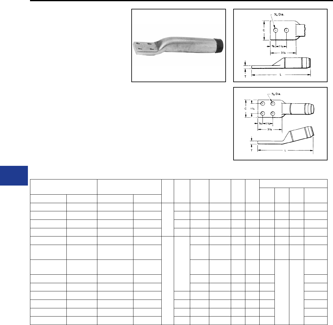
BURNDY®
Blue highlighted items are industry standard and most frequently ordered.
US: 1-800-346-4175 www.burndy.com Canada: 1-800-387-6487
Transmission
Fig. 1
TYPES YNA-RT15,
YNA-RT, EHV
Compression Terminal for ACAR
and Stranded Aluminum Cable
Compression terminal ACAR and Stranded
Aluminum Cable. Two hole NEMA tongue supplied
through 650 kcmil Aluminum. For transmission line
up to and including 230 kV supplied on tongue
through 650 kcmil Aluminum. Four hole NEMA
supplied on larger sizes. When used with YTW
Deadends the 15° angle tongue provides either a
0° or 30° tap. Uses same dies as equivalent full-
tension sleeve or deadend. Barrel pre-lled with
PENETROX™ joint compound and capped. Pad
coated with oxide-retardant.
Catalog Number † Conductor Fig.
No. CL
15˚
L
Straight T T 15
Tools, Die Sets
Die
Index Y45* Y46* Y60BHU*‡
15˚ Straight ACAR Aluminum
YNA32RT15 YNA32RT 395.1 - 395.2 336.4 - 350
1
1.68" 9.04" 9.14" 0.39" 0.39" 717 S717 P717 L717
YNA34RT15 YNA34RT — 397.5 - 477 1.78" 9.21" 9.30" 0.46" 0.46" 719 S719 P719 L719
YNA36RT15 YNA36RT — 500 - 556.5 1.96" 9.63" 9.70" 0.48" 0.48" 720 S720 P720 L720
YNA39RT15 YNA39RT 650 (37) 600 - 650 2.08" 10.02" 10.09" 0.53" 0.53" 722 S722 P722 L722
YNA43RT15 YNA43RT — 700 - 800
2
3.22"
10.21" 10.32" 0.36" 0.36" 724 S724 P724 L724
YNA451RT15 ‡‡ YNA451RT ‡‡ 850 (37)
900 (37) 795 - 1000 10.65" 10.57" 0.45" 0.45" 725 S725 P725 L725
YNA49RT15 ‡‡ YNA49RT ‡‡ 1000 (61)
1100 (61) 1033.5 - 1272 10.94" 10.77" 0.52" 0.52" 727
— —
L727
YNA52RT15 ‡‡ YNA52RT ‡‡ 4 (7) 1351.5 - 1510 12.62" 13.82" 0.71" 0.71" 728 L728
YNA54RT15 ‡‡ YNA54RT ‡‡ 1534 1590 - 1600 — — 0.71" 0.71" 728 L728
YNA56RT15 ‡‡ YNA56RT ‡‡ 1650 (42/19 STR) 1700 - 1800 3.44" 13.36" 13.76" 0.86" 0.86" 729 L729
YNA58RT15 ‡‡ YNA58RT ‡‡ — 2000 3.47" 14.08" 13.70" 0.80" 0.80" 735 L735
YNA59RT15 ‡‡ YNA59RT ‡‡ — 2250 - 2300 3.57" 13.75" 13.54" 0.64" 0.64" 735 L735
YNA594RT15 ‡‡ YNA594RT ‡‡ 2267 - 2500 2500 3.70" — — 0.68" 0.68" 740 L740
† To specify mounting hardware for bolting to corresponding
deadend pad, add sufx “H” to catalog number
(example: YNA54RTH)
* Overlap crimps
‡ Wide dies may be used, add sufx “W” to part number
(example: L725W)
Fig. 2
AAC/ACAR Terminals
‡‡ If shielding caps are required for this item, use Catalog
Number STS43A-4N
I-38
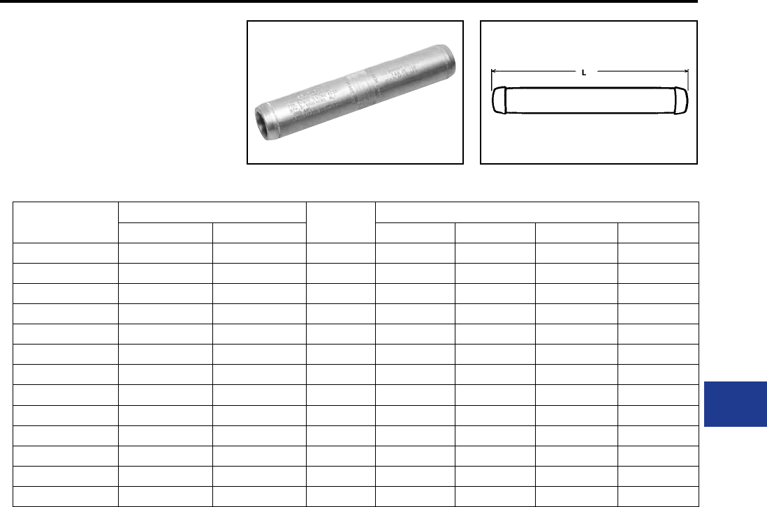
BURNDY®
Blue highlighted items are industry standard and most frequently ordered.
Canada: 1-800-387-6487 www.burndy.com US: 1-800-346-4175
Transmission
TYPE YNS-R
Jumper Loop Sleeve for ACAR and
Stranded Aluminum Conductor
Jumper sleeve for ACAR and Stranded Aluminum
Cable up to and including 230 kV. Sleeve prelled
with PENETROX™ joint compound and capped.
Catalog
Number
Conductor Inches
L
Tools, Die Sets
ACAR Aluminum Y45* Y46* Y60BHU*‡Die Index
YNS32R 336.4 - 350 336.4 - 350 8.60 S717 P717 L717 717
YNS34R 397.5 - 477 397.5 - 477 8.68 S719 P719 L719 719
YNS36R 500 - 556.5 500 - 556.5 9.20 S720 P720 L720 720
YNS39R 600 - 650 600 - 650 9.76 S722 P722 L722 722
YNS43R 700 - 800 700 - 800 9.98 S724 P724 L724 724
YNS451R 795 - 1000 795 - 1000 10.04 S725 P725 L725 725
YNS49R 1033.5 - 1272 1033.5 - 1272 10.08 — — L727 727
YNS52R 1351.5 - 1510 1351.5 - 1510 15.48 — — L728 728
YNS54R 1590 - 1600 1590 - 1600 15.48 — — L728 728
YNS56R 1700 - 1800 1700 - 1800 14.80 — — L729 729
YNS58R 2000 2000 14.74 — — L735 735
YNS59R 2250 - 2300 2250 - 2300 14.56 — — L735 735
YNS594R 2500 2500 14.04 — — L740 740
* Overlap crimps
‡ Wide dies may be used, add sufx “W” to part
number (example: L725W).
AAC/ACAR Jumper Sleeves
I-39
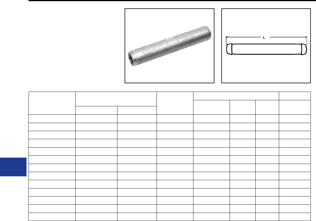
BURNDY®
Blue highlighted items are industry standard and most frequently ordered.
US: 1-800-346-4175 www.burndy.com Canada: 1-800-387-6487
Transmission
TYPE YNS-RT EHV
Jumper Loop Sleeve
for ACAR and Stranded
Aluminum Conductor
Jumper sleeve for ACAR and Stranded Aluminum
Cable over 230 kV. Sleeve prelled with
PENETROX™ joint compound and capped.
Catalog
Number
Conductor (Kcmil) Inches
L
Tools, Die Sets
Die
Index Y45* Y46* Y60BHU*‡
ACAR Aluminum
YNS32RT 395.1 - 395.2 336.4 - 350 8.96 717 S717 P717 L717
YNS34RT – 397.5 - 477 9.10 719 S719 P719 L719
YNS36RT – 500 - 556.5 9.64 720 S720 P720 L720
YNS39RT 634.9 - 653.1 600 - 650 10.26 722 S722 P722 L722
YNS43RT – 700 - 800 10.48 724 S724 P724 L724
YNS451RT 840.2 - 927.2 795 - 1000 10.60 725 S725 P725 L725
YNS49RT 983.1 - 1198 1033.5 - 1272 10.66 727 — — L727
YNS52RT 1277 - 1280 1351.5 - 1510 16.20 728 — — L728
YNS54RT 1534 1590 - 1600 16.11 728 — — L728
YNS56RT 1650 (42-19 STR) 1700 - 1800 15.58 729 — — L729
YNS58RT – 2000 15.46 735 — — L735
YNS59RT – 2250 - 2300 15.14 735 — — L735
YNS594RT 2267 - 2500 2500 16.53 740 — — L740
AAC/ACAR Jumper Sleeve-EHV
* Overlap crimps
‡ Wide dies may be used, add sufx “W” to part
number (example: L725W).
I-40
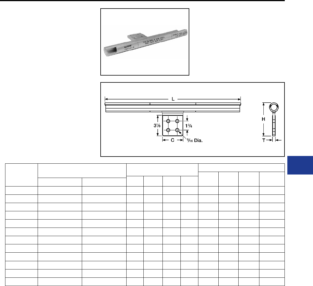
BURNDY®
Blue highlighted items are industry standard and most frequently ordered.
Canada: 1-800-387-6487 www.burndy.com US: 1-800-346-4175
Transmission
Two hole NEMA pads standard for conductors up to 650 kcmil.
Four hole NEMA pads on larger condcutor sizes.
* Overlap crimps.
** For Extra High Voltage (EHV) applications order two tap
pad shielding caps STS43A4N. Catalog number indicates
1 cap. Two caps required per assembly.
‡ Wide dies may be used add sufx “W” to the part number
(example: L725W).
Catalog
Number
Conductor (kcmil) Inches Tools, Die Sets
Die
Index Y45* Y46* Y60BHU*‡
L C H T
ACAR Aluminum
YNTA32R 350 (19) - 400 (19) 336.4 - 350 15.46 2.00 4.94 0.50 717 S717 P717 L717
YNTA34R — 397.5 - 477 15.60 2.00 5.05 0.50 719 S719 P719 L719
YNTA36R — 500 - 556.5 16.29 2.25 5.16 0.56 720 S720 P720 L720
YNTA39R 600 (37) - 650 (37) 600 - 650 16.69 2.25 5.25 0.56 722 S722 P722 L722
YNTA43R — 700 - 800 17.48 3.25 5.36 0.56 724 S724 P724 L724
YNTA451R 800 (37) - 950 (37) 795.5 - 1000 17.60 3.25 5.55 0.56 725 S725 P725 L725
YNTA49R 950 (37) - 1100 (61) 1033.5 - 1272.2 17.66 3.25 5.72 0.56 727 — — L727
YNTA54R — 1351.5 - 1600 21.61 3.25 6.00 0.69 728 — — L728
YNTA56R 1650 1700 - 1800 23.65 3.59 6.25 0.69 729 — — L729
YNTA58R — 2000 23.53 3.59 6.25 0.69 735 — — L729
YNTA59R — 2300 23.21 3.59 6.25 0.69 735 — — L735
YNTA594R 2267 - 2500 2500 24.30 3.59 6.35 0.69 740 — — L740
TYPE YNTA-R
T-Tap With Pad for ACAR and
Stranded Aluminum Cable
Two-piece compression T-Tap with pad for ACAR
and Stranded aluminum transmission lines.
AAC/ACAR T-Tap with Pad
I-41
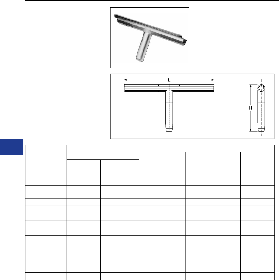
BURNDY®
Blue highlighted items are industry standard and most frequently ordered.
US: 1-800-346-4175 www.burndy.com Canada: 1-800-387-6487
Transmission
TYPE YNT-R-R
Two-Piece Compression T-Tap for
ACAR and Stranded Aluminum
Transmission Lines
Installed with same dies as equivalent full tension
splice. Tap element pre-lled with PENETROX™
joint compound.
* Overlap Crimps.
** For Extra High Voltage (EHV) applications add sufx ”T”
to the catalog number (example: YNT49R49RT).
‡ Wide dies may be used add sufx “W” to the part
number (example: L725W).
Catalog
Number
Conductor (kcmil)
Inches L
Tools, Die Sets
Run and Tap Die
Index Y45* Y46* Y60BHU*‡
ACAR Aluminum
YNT32R32R — 336.4 - 350 15.46 717
S717
P717 L717
YNT34R34R — 397.5 - 447 15.60 719 S719 P719 L719
YNT36R36R — 500 - 556.5 16.29 720 S720 P720 L720
YNT39R39R — 600 - 650 16.69 722 S722 P722 L722
YNT43R43R — 700 - 800 17.48 724 S724 P724 L724
YNT451R451R 4 (7) AWG 795 - 1000 17.60 725 S725 P725 L725
YNT49R49R — 1033.5 - 1272 17.66 727 — — L727
YNT52R52R — 1351.5 - 1510 21.61 728 — — L728
YNT54R54R — 1590 - 1600 21.61 728 — — L728
YNT56R56R 1650 (42/19) 1700 - 1800 23.65 729 — — L729
YNT58R58R — 2000 23.53 — — — L735
YNT59R59R — 2300 23.21 735 — — L735
YNT594R594R 2267 - 2500 2500 24.30 740 — — L740
AAC/ACAR T-Tap
I-42
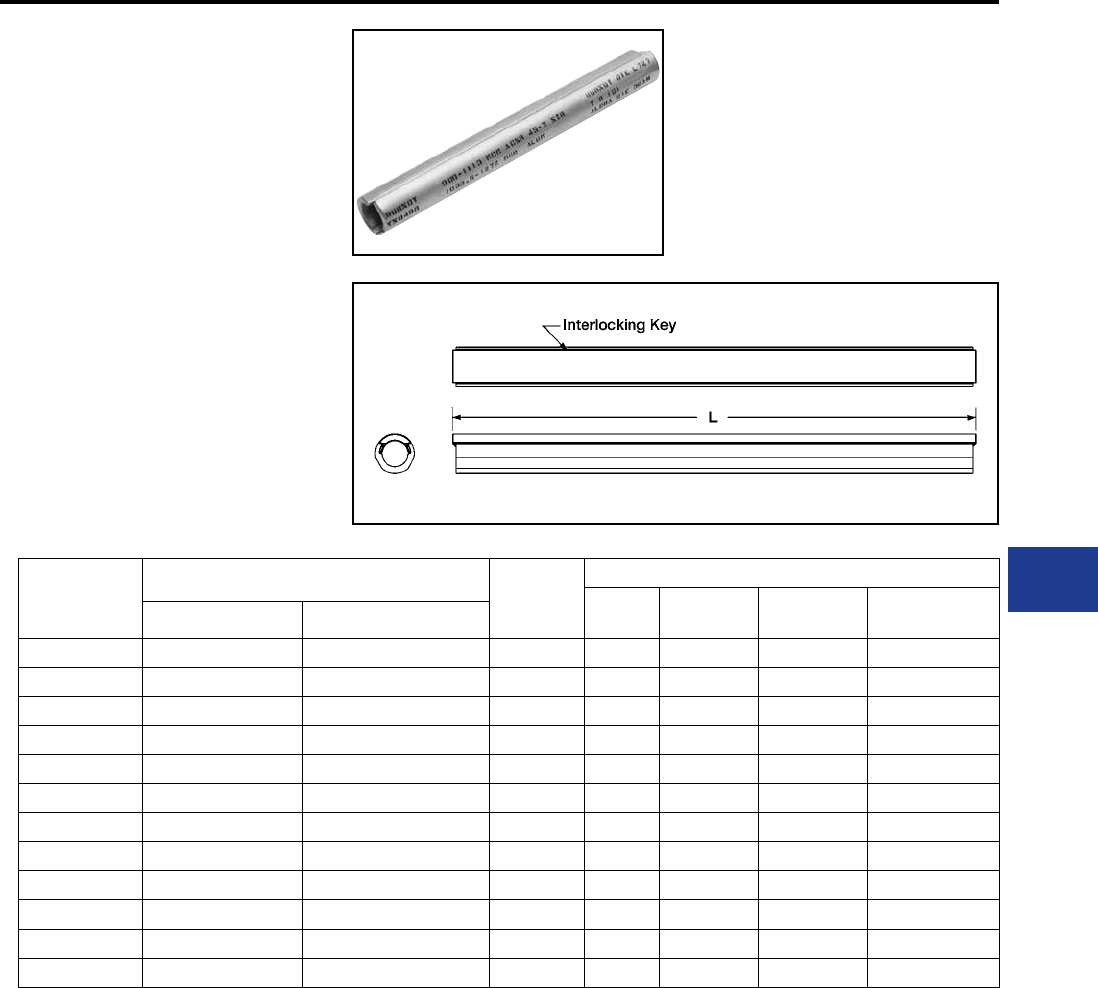
BURNDY®
Blue highlighted items are industry standard and most frequently ordered.
Canada: 1-800-387-6487 www.burndy.com US: 1-800-346-4175
Transmission
TYPE YNU-R
Repair Sleeve for ACAR and
Stranded Aluminum Cable
Two piece repair sleeves for restoring conductivity
to damaged ACAR or Stranded Aluminum Cable
transmission lines. Installed with same dies as
equivalent full tension splice. Use of PENETROX™
joint compound required. For High Voltage and
Extra High Voltage (EHV) Applications.
* Overlap Crimps.
‡ Wide dies may be used, add sufx “W” to part
number (example: L725W).
Catalog
Number
Conductor (kcmil) Inches
L
Tools, Die Sets
Die
Index Y45* Y46* Y60BHU*‡
ACAR Aluminum
YNU32R — 336.4 - 350 14.00 in 717 P717 P717 L717
YNU34R — 397.5 - 477 14.00 in 719 P719 P719 L719
YNU36R — 500 - 556.5 14.00 in 720 P720 P720 L720
YNU39R — 600 - 650 16.00 in 722 P722 P722 L722
YNU43R — 700 - 800 16.00 in 724 P724 P724 L724
YNU451R 850 (37) - 900 (37) 795.5 - 1000 16.00 in 725 P725 P725 L725
YNU49R — 1033.5 - 1200 16.00 in 727 — — L727
YNU54R — 1351.5 - 1600 16.00 in 728 — — L728
YNU56R — 1700 - 800 19.00 in 729 — — L729
YNU59R — 2300 - 2500 19.00 in 735 — — L735
YNU594R 2267 - 2500 2500 20.00 in 740 — — L740
YNU595R 2500 2500 24.60 in — — — L791
AAC/ACAR Repair Sleeve-EHV
I-43
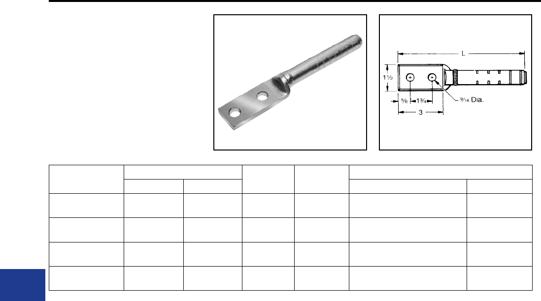
BURNDY®
Blue highlighted items are industry standard and most frequently ordered.
US: 1-800-346-4175 www.burndy.com Canada: 1-800-387-6487
Transmission
TYPE YNA-M-T
Compression Terminal for
Alumoweld and EHS Steel
Compression terminal for joining Alumoweld
and EHS steel to YTW-M-T or YTW-E deadend.
Installed with same dies as equivalent full tension
splice and deadend. Barrel is pre-lled with
PENETROX™ joint compound and capped.
Catalog
Number
Conductor L (IN) Die
Index
Tools Dies and Sets (Number of Crimps)
Alumoweld EHS Steel Y35, Y 750, Y45†, Y46‡‡ Y60BHU*
YNA7M10T 7 #10, 3 #7 5/16" 7 str. 8.50 676 or
721 U676 (4) L721
YNA7M8T 7 #8, 3 #5 3/8" 7 str. 9.81 668 or
723 U668 (7) L723
YNA7M7T 7 #7, 3 #5 7/16" 7 str. 9.95 678 or
726 U678 (10) L726
YNA7M6T 7 #6 1/2" 7 str. 9.80 679 or
726 U679 (11) L789
* Overlap crimps.
† U Die with adapter PT-6515.
‡‡ U Die with adapter PUADP-1.
Steel Terminals
I-44
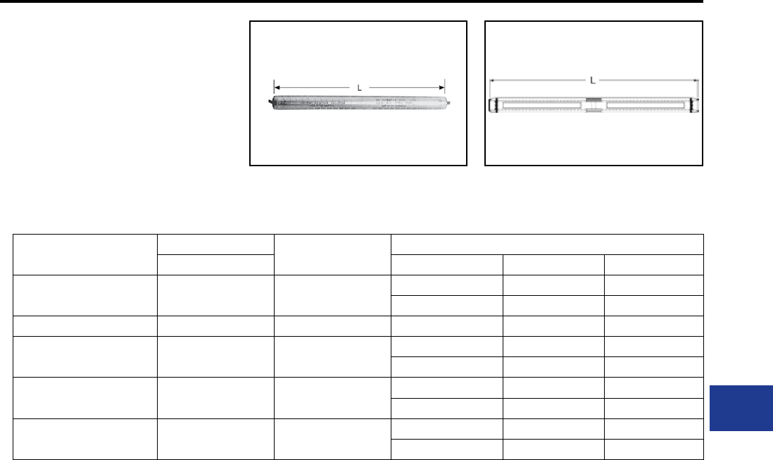
BURNDY®
Blue highlighted items are industry standard and most frequently ordered.
Canada: 1-800-387-6487 www.burndy.com US: 1-800-346-4175
Transmission
TYPE YDS-M-T
Full Tension Sleeve for Alumoweld
Full-tension splice for Alumoweld transm-
ission lines. Five connectors accommodate
eight conductor sizes. Sleeve is pre-lled with
PENETROX™ joint compound and capped.
Catalog Number ††† Conductor L (in) Tools Dies and Sets (Number of Crimps)
Alumoweld Die Index Y35 Y60*
YDS7M10T 7 #10, 3 #7 9.91 676 or U676 (8) —
721 — L721
YDS7M9T 7 #9, 3 #6 10.41 677 U677 (10) —
YDS7M8T 7 #8, 3 #5 12.21 668 or U668 (13) —
723 — L723
YDS7M7T 7 #7 14.56 678 or U678 (19) —
726 — L726
YDS7M6T 7 #6 15.17 679 or U679 (2) —
726 — L726
RUS Accepted
* Overlap crimps.
††† Sleeve is high strength aluminum alloy for optimum
corrosion resistance.
Steel Splices
I-45
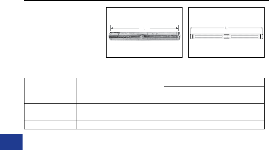
BURNDY®
Blue highlighted items are industry standard and most frequently ordered.
US: 1-800-346-4175 www.burndy.com Canada: 1-800-387-6487
Transmission
TYPE YTS-E
Full Tension Splice for EHS Steel
Full tension splice for EHS steel guy, messenger
or “static” cable. Sleeve is prelled with
PENETROX™ joint compound and capped.
Catalog Number † Accommodates EHS Steel L (in)
Tools, Die Sets
Die Index Y60BHU*
YTS312E 5/16″ 7 Str 11.30 721 L721
YTS375E 3/8″ 7 Str. 10.38 723 L723
YTS438E 7/16″ 7 Str. 11.78 726 L726
YTS500E 1/2″ 7 Str 16.63 789 L789
* Overlap crimps.
† Sleeve is high strength aluminum alloy for optimum
corrosion resistance.
Steel Guy Messenger Splice
I-46
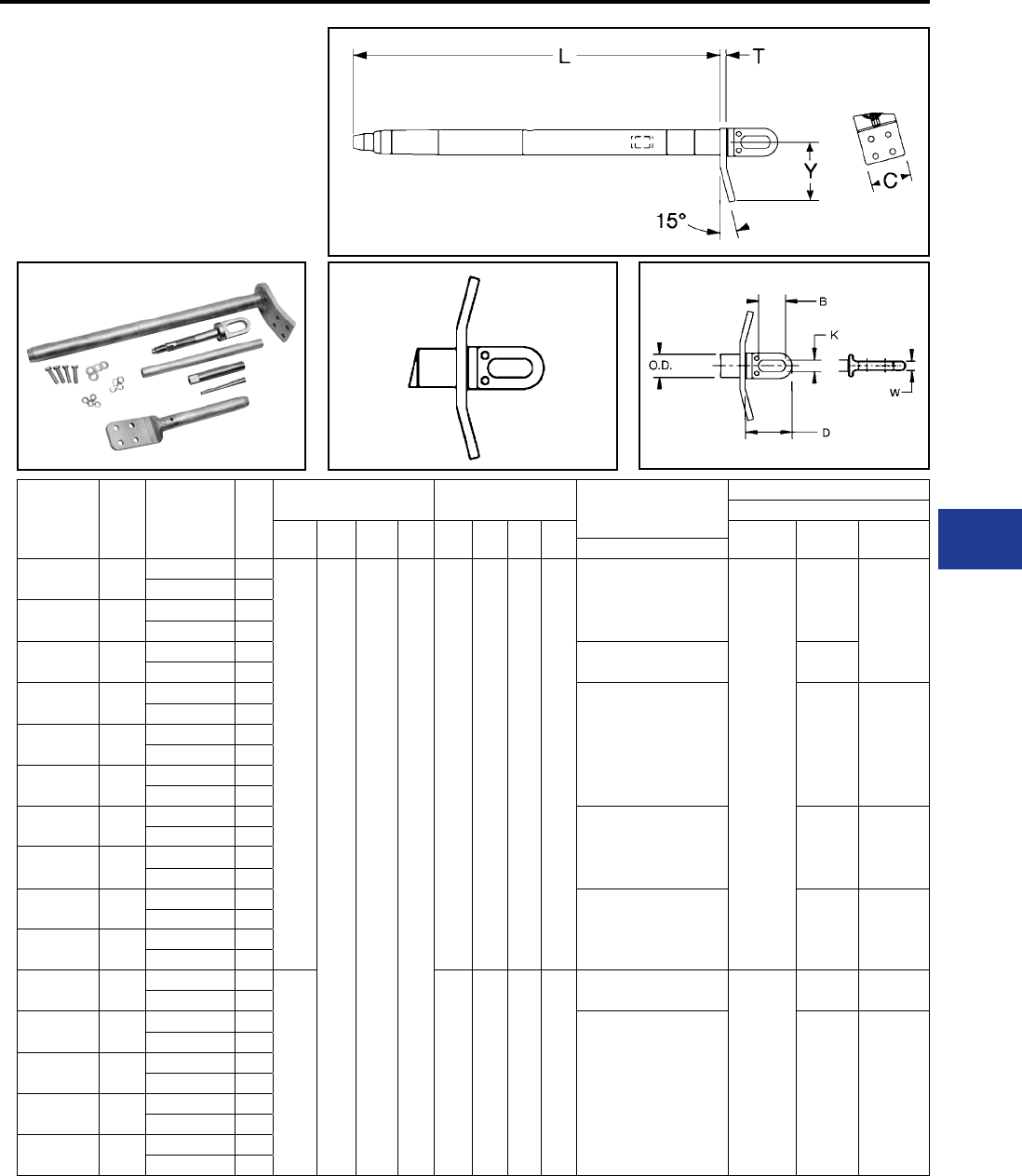
BURNDY®
Blue highlighted items are industry standard and most frequently ordered.
Canada: 1-800-387-6487 www.burndy.com US: 1-800-346-4175
Transmission
Full Tension Deadend Kit
Compression Deadend for
ACCC® Conductor
Full tension Deadends for ACCC® transmission
lines up to and including 230 kV. Standard 15°
NEMA tap pad provides either 0° or 30° tap when
BYNA-RT15HACCC terminal is used.
Conductor
Name
Size
kcmil
Catalog
Number
Kit Assembly
Fig.
No.
Dimensions -
Deadend Body (Fig. 1)
Dimensions -
Steel Eye (Fig. 2A) Kit Components
Installation Tooling
Y60BHU
L T C Y D B K W Die*
Deadend
Die*
Terminal
Inspection
Pin Dia.
Terminal
Linnet 431 5600-1020 1
31.25
[794]
0.62
[16]
4.00
[102]
5.60
[142]
4.5
[114]
2.5
[64]
1.12
[28]
0.62
[16]
BYNA32RT15HACCC
L727W
L717W
0.748
5600-1020D 2
Copenhagen 440 5600-1022 1
5600-1022D 2
Glasgow 473 5600-1044 1BYNA245MRT15HACCC L719W
5600-1044D 2
Casablanca 546 5600-1028 1
BYNA36RT15HACCC L720W 0.892
5600-1028D 2
Hawk 611 5600-1030 1
5600-1030D 2
Lisbon 629 5600-1032 1
5600-1032D 2
Dove 713 5600-1040 1
BYNA39RT15HACCC L722W 0.962
5600-1040D 2
Amsterdam 733 5600-1042 1
5600-1042D 2
Grosbeak 816 5600-1050 1
BYNA43RT15HACCC L724W 1.042
5600-1050D 2
Brussels 839 5600-1052 1
5600-1052D 2
Oslo 627 5600-1026 1
36.19
[919]
5.10
[130]
2.91
[74]
1.26
[32]
0.75
[19]
BYNA39RT15HACCC
L735W
L722W 0.962
5600-1026D 2
Stockholm 913 5600-1054 1
BYNA451RT15HACCC L725W 1.164
5600-1054D 2
Warsaw 1016 5600-1056 1
5600-1056D 2
Drake 1020 5600-1060 1
5600-1060D 2
Dublin 1043 5600-1062 1
5600-1062D 2
Notes:
ACCC is a Registered Trade Mark of CTC Cable Corp.
1. Deadend Assembly consists of Aluminum Body, Steel
Eye and Terminal with mounting hardware.
Figure 1
Figure 2 Figure 2A
ACCC® Deadends
2. Designed for corona free operation up to 230 kV,
contact factory for 345 kV and 500 kV operation.
3. For stainless steel hardware, contact factory.
4. Dimensions in brackets [ ] denotes metric units and are
rounded to nearest whole numbers.
* Overlap crimps.
I-47
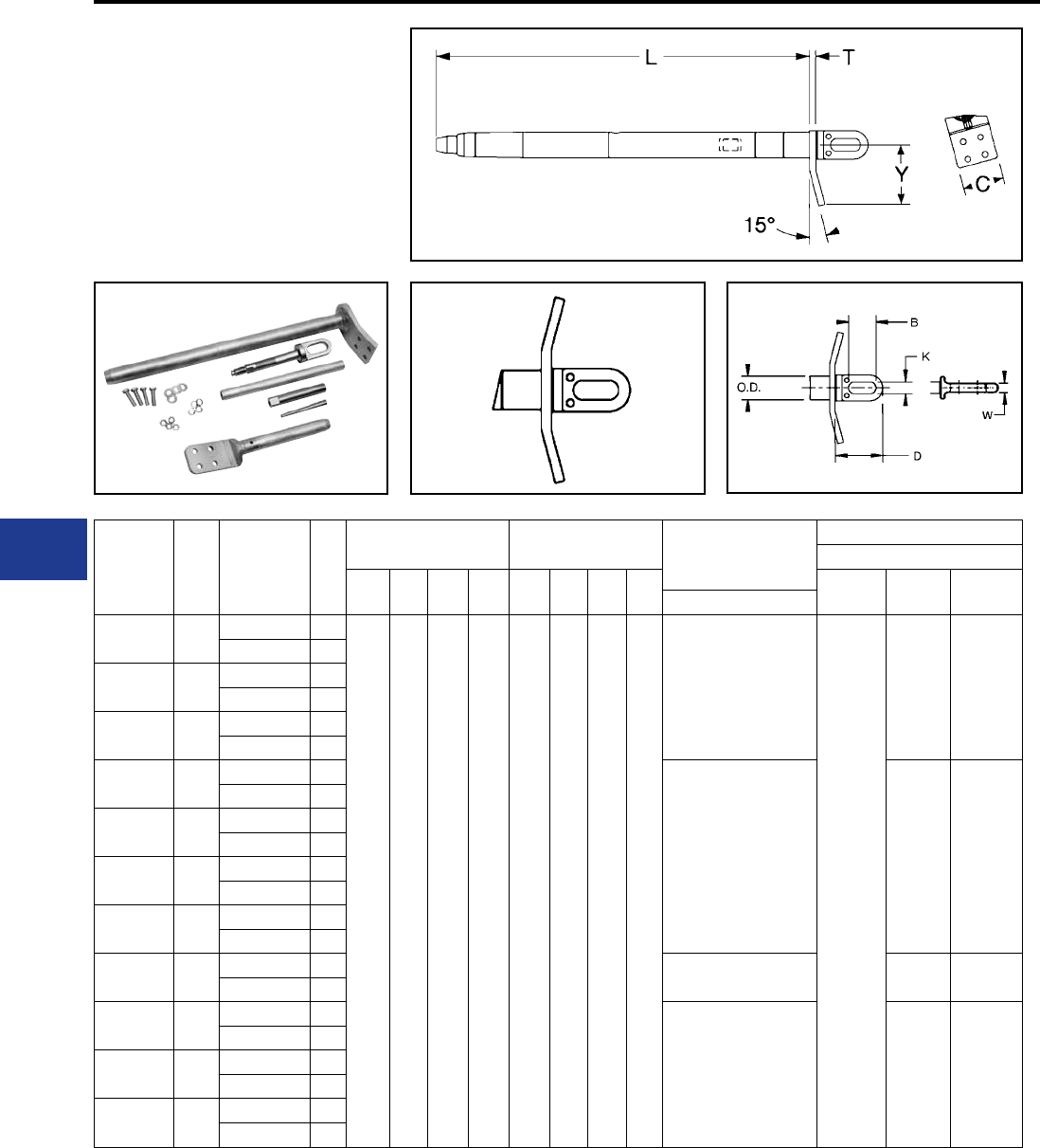
BURNDY®
Blue highlighted items are industry standard and most frequently ordered.
US: 1-800-346-4175 www.burndy.com Canada: 1-800-387-6487
Transmission
Full Tension Deadend Kit
(Continued)
Compression Deadend for
ACCC® Conductor
Notes:
ACCC is a Registered Trade Mark of CTC Cable Corp.
1. Deadend Assembly consists of Aluminum Body, Steel
Eye and Terminal with mounting hardware.
Figure 2 Figure 2A
ACCC® Deadends
2. Designed for corona free operation up to 230 kV,
contact factory for 345 kV and 500 kV operation.
3. For stainless steel hardware, contact factory.
4. Dimensions in brackets [ ] denotes metric units and are
rounded to nearest whole numbers.
* Overlap crimps.
Conductor
Name
Size
kcmil
Catalog
Number
Kit Assembly
Fig.
No.
Dimensions -
Deadend Body (Fig. 1)
Dimensions -
Steel Eye (Fig. 2A) Kit Components
Installation Tooling
Y60BHU
L T C Y D B K W Die*
Deadend
Die*
Terminal
Inspection
Pin Dia.
Terminal
Hamburg 1092 5600-1058 1
36.19
[919]
0.62
[16]
4.00
[102]
5.60
[142]
5.10
[130]
2.91
[74]
1.26
[32]
0.75
[19]
BYNA590MRT15HACCC
L735W
L727W 1.24
5600-1058D 2
Milan 1134 5600-1064 1
5600-1064D 2
Rome 1183 5600-1066 1
5600-1066D 2
Cardinal 1222 5600-1070 1
BYNA49RT15HACCC L727W 1.313
5600-1070D 2
Vienna 1255 5600-1072 1
5600-1072 2
Budapest 1332 5600-1074 1
5600-1074D 2
Prague 1377 5600-1076
5600-1076D
Munich 1461 5600-1078 1BYNA760MRT15HACCC L728W 1.35
5600-1078D 2
London 1512 5600-1079 1
BYNA52RT15HACCC L728W 1.454
5600-1079D 2
Bittern 1572 5600-1080 1
5600-1080D 2
Paris 1620 5600-1082 1
5600-1082D 2
I-48
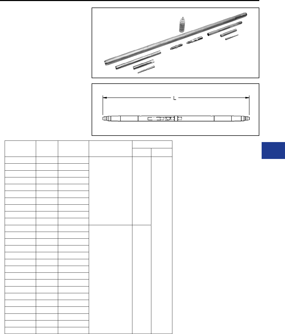
BURNDY®
Blue highlighted items are industry standard and most frequently ordered.
Canada: 1-800-387-6487 www.burndy.com US: 1-800-346-4175
Transmission
Full Tension Splice Kit
Compression Splice
for ACCC® Conductor
Full tension two piece splice for ACCC®
transmission lines up to and including 230 kV.
Conductor
Name
Size
kcmil
Catalog
Number
Dimensions (Inches)
L
Installation Tool
Die* Tool
Linnet 431 5600-2020
60.80
[1544] L727W
Y60BHU
Copenhagen 440 5600-2022
Glasgow 473 5600-2044
Casablanca 546 5600-2028
Hawk 611 5600-2030
Lisbon 629 5600-2032
Dove 713 5600-2040
Amsterdam 733 5600-2042
Grosbeak 816 5600-2050
Brussels 839 5600-2052
Oslo 627 5600-2026
67.00
[1702] L735W
Stockholm 913 5600-2054
Warsaw 1016 5600-2056
Drake 1020 5600-2060
Dublin 1043 5600-2062
Hamburg 1092 5600-2058
Milan 1134 5600-2064
Rome 1183 5600-2066
Cardinal 1222 5600-2070
Vienna 1255 5600-2072
Budapest 1332 5600-2074
Prague 1377 5600-2076
Munich 1461 5600-2078
London 1512 5600-2079
Bittern 1572 5600-2080
Paris 1620 5600-2082
1. Designed for corona free operation up to 230 kV,
contact factory for 345 kV and 500 kV operation.
2. Dimensions in brackets [ ] denotes metric units
and are rounded to nearest whole number.
* Overlap crimps.
ACCC is a Registered Trade Mark of CTC Cable
Corp.
ACCC® Splices
I-49
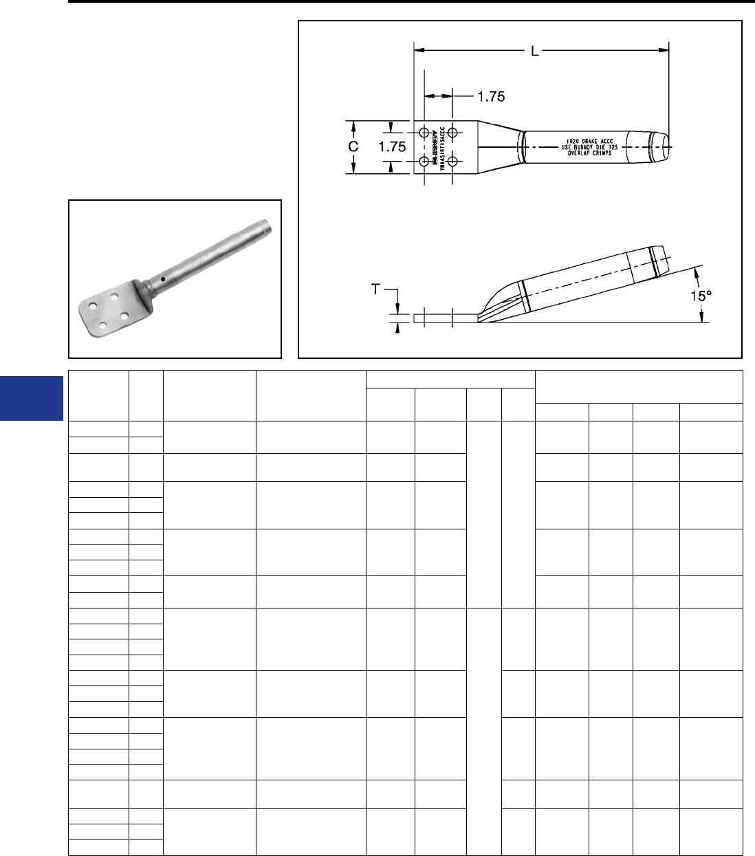
BURNDY®
Blue highlighted items are industry standard and most frequently ordered.
US: 1-800-346-4175 www.burndy.com Canada: 1-800-387-6487
Transmission
TYPES BYNA-RTACCC,
BYNA-RT15ACCC
Compression Terminals
Straight and 15 Degree
for ACCC® Conductor
Compression terminal for ACCC® transmission
lines up to and including 230 kV.
Conductor
Name
Size
kcmil
Straight
Catalog Number
15 Degree
Catalog Number
Dimensions (Inches) Installation Tooling
Straight
L
15 Degree
LC T Die Index Y45* Y46* Y60BHU*
Linnet 431 BYNA32RTACCC BYNA32RT15ACCC 15.50
[393]
15.50
[393]
3.25
[83]
0.50
[13]
717 S717 P717 L717W
Copenhagen 440
Glasgow 473 BYNA245MRTACCC BYNA245MRT15ACCC 15.80
[402]
15.80
[402] 719 S719 P719 L719W
Casablanca 546
BYNA36RTACCC BYNA36RT15ACCC 15.80
[402]
15.80
[402] 720 S720 P720 L720W
Hawk 611
Lisbon 629
Oslo 627
BYNA39RTACCC BYNA39RT15ACCC 16.20
[411]
16.20
[411] 722 S722 P722 L722W
Dove 713
Amsterdam 733
Grosbeak 816 BYNA43RTACCC BYNA43RT15ACCC 16.20
[411]
16.20
[411] 724 S724 P724 L724W
Brussels 839
Stockholm 913
BYNA451RTACCC BYNA451RT15ACCC 15.30
[389]
15.00
[380]
3.22
[82]
0.45
[11] 725 S725 P725 L725W
Warsaw 1016
Drake 1020
Dublin 1043
Hamburg 1092
BYNA590MRTACCC BYNA590MRT15ACCC 15.60
[397]
15.70
[399]
0.52
[13] 727 — — L727W
Milan 1134
Rome 1183
Cardinal 1222
BYNA49RTACCC BYNA49RT15ACCC 15.60
[397]
15.70
[399]
0.52
[13] 727 — — L727W
Vienna 1255
Budapest 1332
Prague 1377
Munich 1461 BYNA760MRTACCC BYNA760MRT15ACCC 17.10
[435]
17.30
[438]
0.71
[18] 728 — — L728W
London 1512
BYNA52RTACCC BYNA52RT15ACCC 17.10
[435]
17.30
[438]
0.71
[18] 728 — — L728W
Bittern 1572
Paris 1620
Notes:
ACCC is a Registered Trade Mark of CTC Cable Corp.
1. To speciy mounting hardware to correspondending
deadend or pad add H to the part number (example:
BYNA451RTHACCC).
ACCC® Terminals
2. To specify stainless steel hardware add sufx SS to
the catalog number (example: BYNA451RTACCCSS).
3. Designed for corona free operation up to 230 kV,
contact factory for 345 kV and 500 kV operation.
4. Dimensions in brackets [ ] denotes metric units and
are rounded to nearest whole numbers.
* Overlap crimps.
I-50
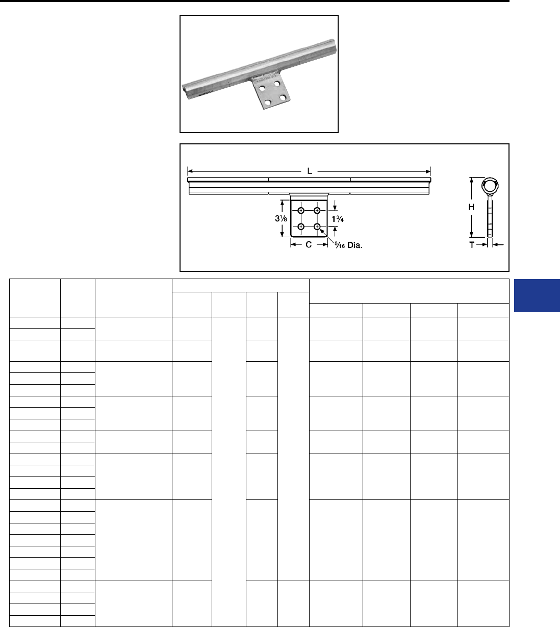
BURNDY®
Blue highlighted items are industry standard and most frequently ordered.
Canada: 1-800-387-6487 www.burndy.com US: 1-800-346-4175
Transmission
TYPE YNTA-RTACCC
Compression T-Tap
for ACCC® Conductor
Two piece compression T-Tap to a NEMA pad for
ACCC® transmission lines up to and including 230
kV.
Conductor
Name
Size
kcmil Catalog Number
Dimensions (Inches)
Installation Tooling
L C H T Die Index Y45* Y46* Y60BHU*
Linnet 431 YNTA32RTACCC 24.92
[633]
4.00
[102]
5.82
[148]
0.56
[14]
717 S717 P717 L717W
Copenhagen 440
Glasgow 473 YNTA245MRTACCC 25.50
[648]
5.93
[150] 719 S719 P719 L719W
Casablanca 546
YNTA36RTACCC 25.50
[648]
6.03
[153] 720 S720 P720 L720WHawk 611
Lisbon 629
Oslo 627
YNTA39RTACCC 26.06
[662]
6.13
[156] 722 S722 P722 L722WDove 713
Amsterdam 733
Grosbeak 816 YNTA43RTACCC 26.28
[667]
6.24
[158] 724 S724 P724 L724W
Brussels 839
Stockholm 913
YNTA451RTACCC 26.38
[670]
6.43
[163] 725 S725 P725 L725W
Warsaw 1016
Drake 1020
Dublin 1043
Hamburg 1092
YNTA49RTACCC 26.36
[669]
6.60
[168] 727 — — L727W
Milan 1134
Rome 1183
Cardinal 1222
Vienna 1255
Budapest 1332
Prague 1377
Munich 1461
YNTA52RTACCC 29.32
[745]
7.00
[178]
0.69
[17] 728 — — L728W
London 1512
Bittern 1572
Paris 1620
ACCC is a Registered Trade Mark of CTC Cable
Corp.
ACCC® T-Tap with Pad
1. Designed for corona free operation up to 230 kV,
contact factory for 345 kV and 500 kV operation.
2. Dimensions in brackets [ ] denotes metric units
and are rounded to nearest whole number.
* Overlap crimps.
I-51
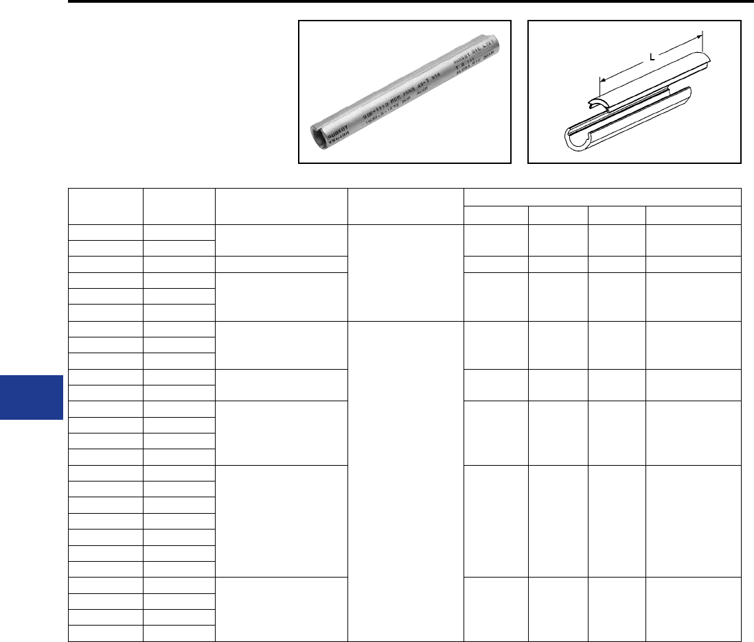
BURNDY®
Blue highlighted items are industry standard and most frequently ordered.
US: 1-800-346-4175 www.burndy.com Canada: 1-800-387-6487
Transmission
TYPE YNU-RACCC
Compression Repair Sleeve
for ACCC® Conductor
Two piece compression repair sleeve for
temporary restoration of conductivity to damaged
ACCC® transmission lines.
Conductor
Name
Size
kcmil Catalog Number Dimensions (Inches)
L
Installation Tooling
Die Index Y45* Y46* Y60BHU*
Linnet 431 YNU32RACCC
22.00
[559]
717 S717 P717 L717W
Copenhagen 440
Glasgow 473 YNU245MRACCC 719 S719 P719 L719W
Casablanca 546
YNU36RACCC 720 S720 P720 L720W
Hawk 611
Lisbon 629
Oslo 627
YNU39RACCC
24.00
[610]
722 S722 P722 L722WDove 713
Amsterdam 733
Grosbeak 816 YNU43RACCC 724 S724 P724 L724W
Brussels 839
Stockholm 913
YNU451RACCC 725 S725 P725 L725W
Warsaw 1016
Drake 1020
Dublin 1043
Hamburg 1092
YNU49RACCC 727 — — L727W
Milan 1134
Rome 1183
Cardinal 1222
Vienna 1255
Budapest 1332
Prague 1377
Munich 1461
YNU52RACCC 728 — — L728W
London 1512
Bittern 1572
Paris 1620
ACCC is a Registered Trade Mark of CTC Cable Corp.
Dimensions in brackets [ ] denotes metric units and are
rounded to nearest whole number.
* Overlap crimps.
ACCC® Repair Sleeves
I-52
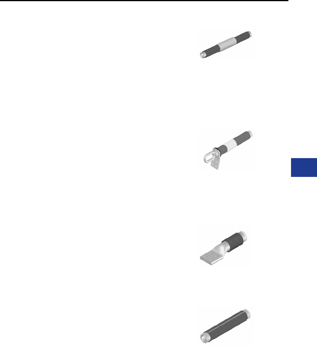
BURNDY®
Blue highlighted items are industry standard and most frequently ordered.
Canada: 1-800-387-6487 www.burndy.com US: 1-800-346-4175
Transmission
IMPLO®
Connections for all common
conductor types including high
temperature applications
IMPLO® connectors consist of a small engineered
energy charge that is pre-wrapped around a
specically designed metallic sleeve. The charge
creates an implosive compression, creating a
permanent high quality connection. The split-
second detonation creates a ash and an air blast
similar to a rework.
Implosive connectors produce a smoother,
stronger and more electrically efcient connection.
The connectors can also signicantly reduce
construction time, resulting in fewer environmental
impacts and lower project costs.
Installation productivity can be greatly increased
as IMPLO® connections require no hydraulic
equipment to connect high voltage conductors,
which can be a cumbersome, time consuming
and expensive process. IMPLO® technology is
more versatile, makes a superior connection and
is faster and easier to install, yielding signicant
savings in construction time and cost.
Multiple IMPLO® connectors can be installed
simultaneously. This is particularly useful in the
deadending of towers, where efciency gains of
up to 60% are easily achievable.
The IMPLO® splice can be pulled through stringing
blocks without damaging the conductor and
without any splice degradation. This enables faster
installation and allows multiple reels to be pulled
in a single run. This versatility gives the project
manager a great deal of lattitude in selecting
locations to situate pulling stations and tensioning
equipment. The management of environmental
concerns is made easier through this versatility
and construction projects can be carried out with
less disruption to the environment.
IMPLO® connections need no equipment for
installation and may be installed in any terrain
and in almost any weather condition. Installation
can be done in the air as well as on the ground.
Creating a virtually void free connection, IMPLO®
connections eliminate the need for oxide inhibitor.
Additionally, the resulting smooth connection
requires no ling and operates corona free.
IMPLO®
Due to the ability to be pulled through stringing
blocks and the ability to swiftly create multiple
deadend connections, installation time savings
up to 60% are achievable versus hydraulic
compression. IMPLO® connectors can be safely
installed on a live line or in close proximity to other
live lines.
Complete compression by the implosion process
virtually eliminates oxide growth and mitigates
moisture egress into the connection. IMPLO®
connections are designed to meet or exceed
the RBS of the conductor. The completed joint is
uniformly smooth, with no sanding or lling. By
providing a fully compressed, uniformly smooth
and straight tting, there is no birdcaging of the
conductor. The process does not bow or elongate
the connector and compression occurs only in the
radial direction. This allows splices to be installed
in close proximity to each other or to other line
hardware.
IMPLO® has more than 35 years of proven eld
application around the world. BURNDY has
experienced and dedicated eld resources for
training and project coordination, including a
logistics team knowledgeable in the needs of the
transmission market. BURNDY has technical
resources dedicated to the advancement of
industry standards including internal testing and
standards qualication capabilities.
IMPLO® connections can accommodate a wide
range of ACSR, ACSS, ACSS/TW, ASC, and
ASC/TW conductors; providing a consistent,
smooth, high quality installation every time with
no tools or dies. Various congurations, tap pad
angles, and eyebolt versions available; 15 degree
tap pad is standard.
IMPLO® Applications
• Deadending, splicing, and terminating high
voltage transmission lines
• Working on or in close proximity to live lines
• New construction
• Maintenance of existing lines
• Substations
• Reconductoring/upgrading existing lines
• Joining steel static wire and guy wire
Full Tension Joints (Splice)
The splice consists
of an aluminum
alloy sleeve with
the energy charge
p r e - w r a p p e d .
These joints are
designed to be installed at the tensioner and pulled
through stringing blocks. Special application charts
for each conductor show the relationship between
the pulling tension, weight span and the allowable
line angle through which the joints may be pulled.
This makes sleeving an integral part of overall
pulling operation, and greatly simplies stringing.
Deadends*
D e a d e n d s
consist of an
aluminum alloy
sleeve with the
energy charge
pre-wrapped and
an oval or round
eyebolt. A 15º NEMA four-hole pad is welded to
the main sleeve. The eyebolt is attached to the
aluminum alloy sleeve and can be freely turned
360º to the desired position relative to the pad prior
to installation.
Jumper Terminal**
Jumper Terminals
consist of an
aluminum sleeve
with the energy
charge pre-wrapped
and a 15º NEMA pad
at one end. Jumper
terminals may be
installed at 0º or 30º take-off angles when matched
to a deadend joint with a 15º NEMA pad.
Repair Sleeve
Repair Sleeves
consist of two
aluminum alloy
half sleeves that
slide together. An
energy charge
pre-wrapped on
a exible plastic sleeve is wrapped around the
Repair Sleeve when installed. Repair Sleeves are
used to repair minor damage to the outer strands
of a conductor, such as damage caused during
construction or wear of spacer. Repair Sleeves
can also be provided with a NEMA four-hole pad.
I-53
BURNDY®
Blue highlighted items are industry standard and most frequently ordered.
US: 1-800-346-4175 www.burndy.com Canada: 1-800-387-6487
Transmission
IMPLO®
Conductor Full Tension Joint
(Splice) Deadend* Jumper
Terminal** Repair Sleeve
Conductor Code Stranding kcmil
Linnet 26/7 336.4
1050 2050 3050 9050
Oriole 30/7 336.4
Chickadee 18/1 397.5
Brant 24/7 397.5
Ibis 26/7 397.5 1050/I 2050/I 3050 9050
Lark 30/7 397.5 1051 2051 3051 9051
Hawk 26/7 477
Dove 26/7 556.5 1052 2052 3051 9052
Hydro One 26/7 585
Rook 24/7 636
1053 2053 3053 9053
Flamingo 24/7 666.6
Stilt 24/7 715.5
Crow 54/7 715.5
Grossbeak 26/7 636
1054 2054 3054 9054Gannet 26/7 666.6
Type 16 Crowsnest - 636
Starling 26/7 715.5
1056 2056 3056 9056
Cuckoo 24/7 795
Condor 54/7 795
Crane 54/7 874.5
Drake 26/7 795 1057 2057 3057 9057
Cardinal TW - 954
Mallard 30/19 795 1058 2058 3058 9058
Ruddy 45/7 900 1059 2059 3059 9059
Rail 45/7 954
Canary 54/7 900 1060 2060 3060 9060
Cardinal 54/7 954
Curlew 54/7 1033.5 1061 2061 3061 9061
Ortolan 45/7 1033.5 1062 2062 3062 9062
Bluejay 54/7 1113
Finch 54/19 1113 1063 2063 3063 9063
Grackle 54/19 1192.5 1064 2064 3064 9064
Bunting 45/7 1192.5
1065 2065 3065 9065Bittern 45/7 1272
Potomac TW 36/7 1272
Pheasant 54/19 1272 1066 2066 3066 9066
Martin 54/19 1351.5
Dipper 45/7 1351.5 1067 2067 3067 9067
Bobolink 45/7 1431
Plover 54/19 1431 1070 2070 3070 9070
Parrot 54/19 1510.5
Nuthatch 45/7 1510.5 1072 2072 3072 9072
Lapwing 45/7 1590
IMPLO®
Connections for ACSR
* The default numbering includes NEMA pad at 15° and oval eye (example: 2050/C). For round eye remove /C sufx after catalog number.
**Standard includes tap pad at 15°, 4-hole NEMA. Contact factory for specials.
I-54
BURNDY®
Blue highlighted items are industry standard and most frequently ordered.
Canada: 1-800-387-6487 www.burndy.com US: 1-800-346-4175
Transmission
Conductor Full Tension Joint
(Splice) Deadend* Jumper
Terminal** Repair Sleeve
Conductor Code Stranding kcmil
Falcon 54/19 1590 1073 2073 3073 9073
Chuckar 84/19 1780 1074 2074 3074 9074
Bluebird 84/19 2156 1075 2075 3075 9075
Kiwi 72/7 2167 1076 2076 3076 9076
Nelson 72/7 1843.3
1077 2077 3077 9077Mockingbird 72/7 2034.5
Hydro One 72/7 1843.2
Seahawk 68/7 1869 1079 2079 3079 9079
Piece River 48/7 623.8 1080 2080 3080 9080
Toutle TW 17/7 795
Thrasher 76/19 2312 1083 2083 3083 9083
Skylark 36/1 1272 1084 2084 3084 9084
Mica-Mica 24/7-26/7E 666.9-648.2 1090 2090 3090 9090
Hornbill 48/7 1590 1094 2094 3094 9094
Tern 45/7 795 1095 2095 3095 9095
Coot 36/1 795 1103 2103 3103 9103
Pelican 18/1 477 1112 2112 3112 9112
Osprey 18/1 556.5
Flicker 24/1 477 1113 2113 3113 9113
Hen 30/7 477 1114 2114 3114 9114
Heron 30/7 500
Peacock 24/7 605
1117 2117 3117 9117
Duck 54/7 605
Goose 54/7 636
Hydro One 54/7 605
Parakeet TW 18/7 556.5
Eagle 30/7 556.5 1118 2118 3118 9118
Squab 26/7 605 1120 2120 3120 9120
Wood Duck 30/7 605
1121 2121 3121 9121
Teal 30/19 605
Scuter 30/7 636
Egret 30/19 636
King Bird 18/1 636
1123 2123 3123 9123Swift 36/1 636
Hydro One 18/1-18/7 583.2
Rogue TW 17/7 954 1124 2124 3124 9124
Red Wing 30/19 715.5 1131 2131 3131 9131
Grand Rapids 22/7 685.4 1133 2133 3133 9133
Macaw 42/7 795
Catbird 36/1 954 1138 2138 3138 9138
Phoenix 42/7 954 1139 2139 3139 9139
Towhee - 954 1140 2140 3140 9140
Snowbird 42/7 1033.5 1141 2141 3141 9141
IMPLO®
Connections for ACSR
(Continued)
* The default numbering includes NEMA pad at 15° and oval eye (example: 2050/C). For round eye remove /C sufx after catalog number.
**Standard includes tap pad at 15°, 4-hole NEMA. Contact factory for specials.
I-55
IMPLO®
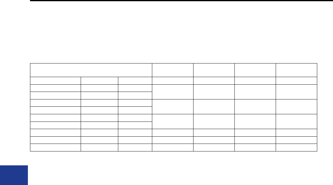
BURNDY®
Blue highlighted items are industry standard and most frequently ordered.
US: 1-800-346-4175 www.burndy.com Canada: 1-800-387-6487
Transmission
Conductor Full Tension Joint
(Splice) Deadend* Jumper
Terminal** Repair Sleeve
Conductor Code Stranding kcmil
4/0 6/1 211.6 1142 2142 3142 9142
Penguin 6/1 211.6
Ostrich 26/7 300 1143 2143 3143 9143
Merlin 18/1 336.4
Patridge 26/7 266.8 1144 2144 3144 9144
Owl 6/7 266.8
Road Runner 76/19 2057 1146 2146 3146 9146
Moa 76/7 1590 1167 2167 3167 9167
Sansum 72/37 1273.5 1190 2190 3190 9190
IMPLO®
Connections for ACSR
(Continued)
* The default numbering includes NEMA pad at 15° and oval eye (example: 2050/C). For round eye remove /C sufx after catalog number.
**Standard includes tap pad at 15°, 4-hole NEMA. Contact factory for specials.
I-56
IMPLO®
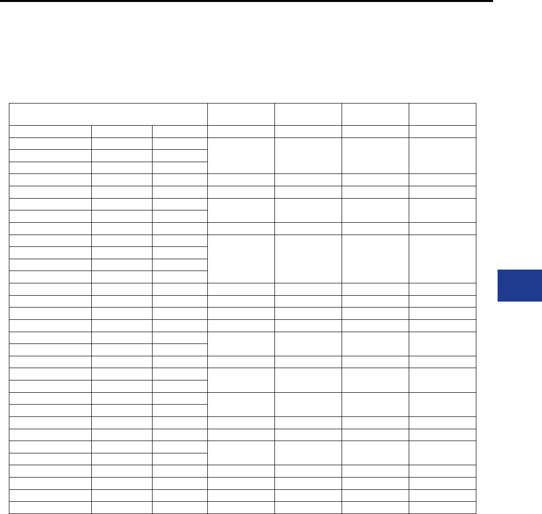
BURNDY®
Blue highlighted items are industry standard and most frequently ordered.
Canada: 1-800-387-6487 www.burndy.com US: 1-800-346-4175
Transmission
Conductor Full Tension Joint
(Splice) Deadend* Jumper
Terminal** Repair Sleeve
Conductor Code Stranding kcmil
Linnet 26/7 336.4
1050/ACSS 2050/ACSS 3050/ACSS 9050/ACSSOriole 30/7 336.4
Ibis 26/7 397.5
Hawk 26/7 477 1051/ACSS 2051/ACSS 3051/ACSS 9051/ACSS
Dove 26/7 556.5 1052/ACSS 2052/ACSS 3052/ACSS 9052/ACSS
Rook 24/7 636 1053/ACSS 2053/ACSS 3053/ACSS 9053/ACSS
Flamingo 24/7 666.6
Grosbeak 26/7 636 1054/ACSS 2054/ACSS 3054/ACSS 9054/ACSS
Starling 26/7 715.5
1056/ACSS 2056/ACSS 3056/ACSS 9056/ACSS
Cuckoo 24/7 795
Condor 54/7 795
Crane 54/7 874.5
Drake 26/7 795 1057/ACSS 2057/ACSS 3057/ACSS 9057/ACSS
Rail 45/7 954 1059/ACSS 2059/ACSS 3059/ACSS 9059/ACSS
Cardinal 54/7 954 1060/ACSS 2060/ACSS 3060/ACSS 9060/ACSS
Curlew 54/7 1033.5 1061/ACSS 2061/ACSS 3061/ACSS 9061/ACSS
Ortolan 45/7 1033.5 1062/ACSS 2062/ACSS 3062/ACSS 9062/ACSS
Bluejay 45/7 1113
Finch 54/19 1113 1063/ACSS 2063/ACSS 3063/ACSS 9063/ACSS
Bunting 45/7 1192.5 1065/ACSS 2065/ACSS 3065/ACSS 9065/ACSS
Bittern 45/7 1272
Pheasant 54/19 1272 1066/ACSS 2066/ACSS 3066/ACSS 9066/ACSS
Martin 54/19 1351.5
Dipper 45/7 1351.5 1067/ACSS 2067/ACSS 3067/ACSS 9067/ACSS
Parrot 54/19 1510.5 1070/ACSS 2070/ACSS 3070/ACSS 9070/ACSS
Nuthatch 45/7 1510.5 1072/ACSS 2072/ACSS 3072/ACSS 9072/ACSS
Lapwing 45/7 1590
Falcon 54/19 1590 1073/ACSS 2073/ACSS 3073/ACSS 9073/ACSS
Chuckar 84/19 1780 1074/ACSS 2074/ACSS 3074/ACSS 9074/ACSS
Bluebird 84/19 2156 1075/ACSS 2075/ACSS 3075/ACSS 9075/ACSS
Kiwi 72/7 2167 1076/ACSS 2076/ACSS 3076/ACSS 9076/ACSS
IMPLO®
Connections for ACSS
Round Strand
* The default numbering includes NEMA pad at 15° and oval eye (example: 2050/C). For round eye remove /C sufx after catalog number.
**Standard includes tap pad at 15°, 4-hole NEMA. Contact factory for specials.
I-57
IMPLO®
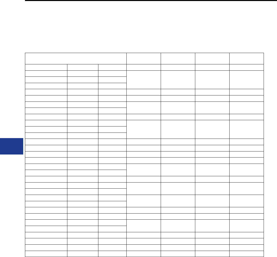
BURNDY®
Blue highlighted items are industry standard and most frequently ordered.
US: 1-800-346-4175 www.burndy.com Canada: 1-800-387-6487
Transmission
Conductor Full Tension Joint
(Splice) Deadend* Jumper
Terminal** Repair Sleeve
Conductor Code Stranding kcmil
Linnet 26/7 336.4
1050/ACSS/TW 2050/ACSS/TW 3050/ACSS/TW 9050/ACSS/TWOriole 30/7 336.4
Ibis 26/7 397.5
Hawk 26/7 477 1051/ACSS/TW 2051/ACSS/TW 3051/ACSS/TW 9051/ACSS/TW
Dove 26/7 556.5 1052/ACSS/TW 2052/ACSS/TW 3052/ACSS/TW 9052/ACSS/TW
Rook 24/7 636 1053/ACSS/TW 2053/ACSS/TW 3053/ACSS/TW 9053/ACSS/TW
Flamingo 24/7 666.6
Grosbeak 26/7 636 1054/ACSS/TW 2054/ACSS/TW 3054/ACSS/TW 9054/ACSS/TW
Starling 26/7 715.5
1056/ACSS/TW 2056/ACSS/TW 3056/ACSS/TW 9056/ACSS/TWCuckoo 24/7 795
Condor 54/7 795
Drake 26/7 795 1057/ACSS/TW 2057/ACSS/TW 3057/ACSS/TW 9057/ACSS/TW
Rail 45/7 954 1059/ACSS/TW 2059/ACSS/TW 3059/ACSS/TW 9059/ACSS/TW
Cardinal 54/7 954 1060/ACSS/TW 2060/ACSS/TW 3060/ACSS/TW 9060/ACSS/TW
Curlew 54/7 1033.5 1061/ACSS/TW 2061/ACSS/TW 3061/ACSS/TW 9061/ACSS/TW
Ortolan 45/7 1033.5 1062/ACSS/TW 2062/ACSS/TW 3062/ACSS/TW 9062/ACSS/TW
Bluejay 45/7 1113
Finch 54/19 1113 1063/ACSS/TW 2063/ACSS/TW 3063/ACSS/TW 9063/ACSS/TW
Bunting 54/19 1192.5 1065/ACSS/TW 2065/ACSS/TW 3065/ACSS/TW 9065/ACSS/TW
Bittern 45/7 1272
Pheasant 54/19 1272 1066/ACSS/TW 2066/ACSS/TW 3066/ACSS/TW 9066/ACSS/TW
Martin 54/19 1351.5
Dipper 45/7 1351.5 1067/ACSS/TW 2067/ACSS/TW 3067/ACSS/TW 9067/ACSS/TW
Parrot 54/19 1510.5 1070/ACSS/TW 2070/ACSS/TW 3070/ACSS/TW 9070/ACSS/TW
Nuthatch 45/7 1510.5 1072/ACSS/TW 2072/ACSS/TW 3072/ACSS/TW 9072/ACSS/TW
Lapwing 45/7 1590
Falcon 54/19 1590 1073/ACSS/TW 2073/ACSS/TW 3073/ACSS/TW 9073/ACSS/TW
Chuckar 84/19 1780 1074/ACSS/TW 2074/ACSS/TW 3074/ACSS/TW 9074/ACSS/TW
Bluebird 84/19 2156 1075/ACSS/TW 2075/ACSS/TW 3075/ACSS/TW 9075/ACSS/TW
Kiwi 72/7 2167 1076/ACSS/TW 2076/ACSS/TW 3076/ACSS/TW 9076/ACSS/TW
IMPLO®
Connections for ACSS/TW
* The default numbering includes NEMA pad at 15° and oval eye (example: 2050/C). For round eye remove /C sufx after catalog number.
**Standard includes tap pad at 15°, 4-hole NEMA. Contact factory for specials.
I-58
IMPLO®
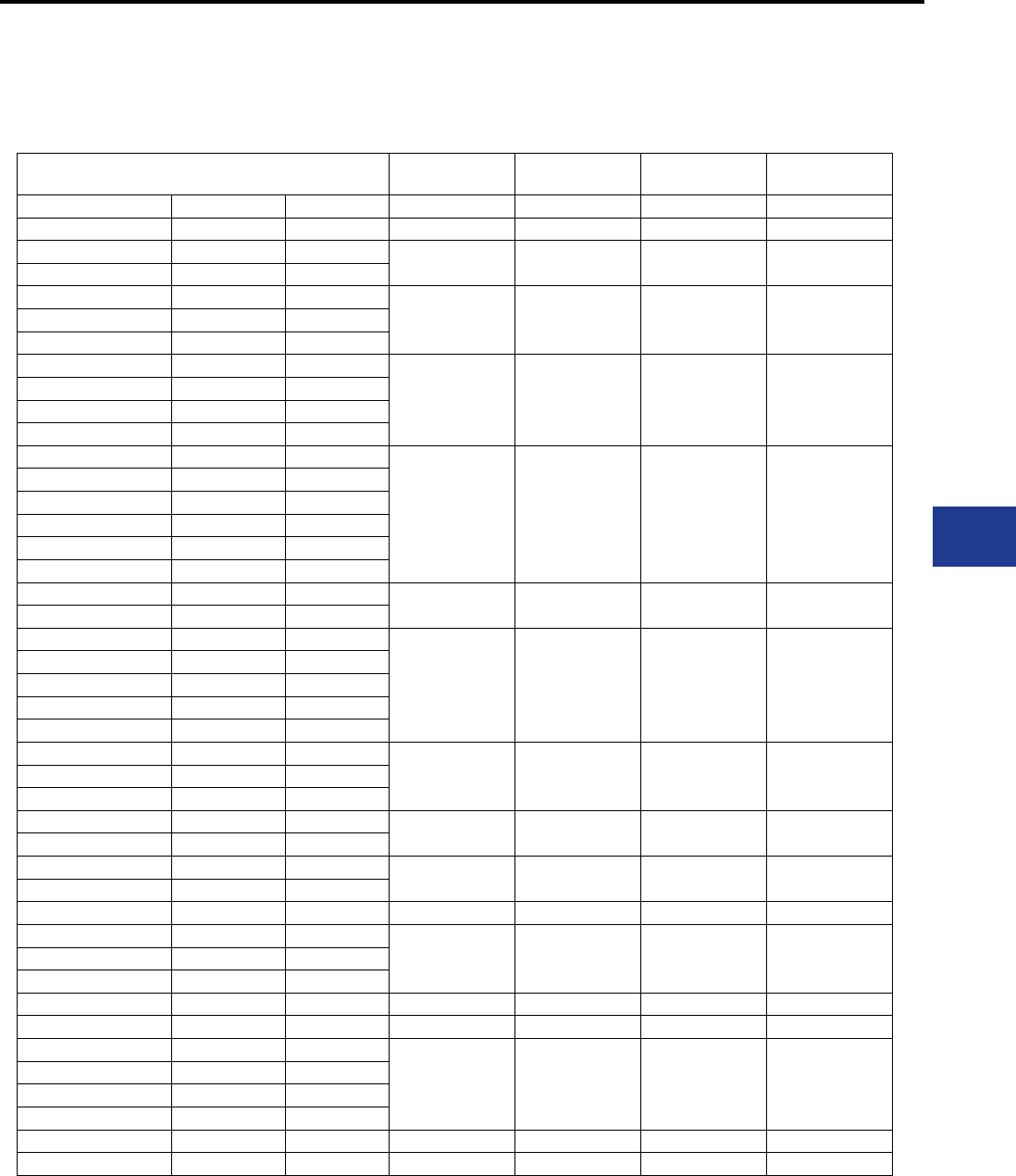
BURNDY®
Blue highlighted items are industry standard and most frequently ordered.
Canada: 1-800-387-6487 www.burndy.com US: 1-800-346-4175
Transmission
Conductor Full Tension Joint
(Splice) Deadend* Jumper
Terminal** Repair Sleeve
Conductor Code Stranding kcmil
Laurel 19 266.8 1179 2179 3179 9179
Tulip 19 336.4 1174 2174 3174 9174
Daffodil 19 350
Canna 19 397.5
1149 2149 3149 9149Cosmos 19 477
Syringa 37 477
Sinnia 19 500
1150 2150 3150 9150
Hyacinth 37 500
Dahlia 19 556.5
Mistletoe 37 556.5
Meadowsweet 37 600
1085 2085 3085 9085
Orchid 37 636
Violet 37 715.5
Nastartium 61 715.5
Arbutus TW 17 795
Baker TW 34 795
Arbutus 37 795 1157 2157 3157 9157
Lilac 61 795
Anemone 37 874.5
1158 2158 3158 9158
Crocus 61 874.5
Magnolia 37 954
Golden Rod 61 954
Greeley 37 927.7
Bluebell 37 1033.5
1086 2086 3086 9086Larkspur 61 1033.5
Marigold 61 1113
Hawthorne 61 1192.5 1093 2093 3093 9093
Narcissus 61 1272
Columbine 61 1351.5 1165 2165 3165 9165
Hood TW 34 1589
Sulphur 61 764mm21165-NZ 2165-NZ 3165-NZ 9165-NZ
Carnation 61 1431
1166 2166 3166 9166Gladiolus 61 1510.5
Coreopsis 61 1590
Jasamine 61 1750 1169 2169 3169 9169
Cowslip 91 2000 1170 2170 3170 9170
Sagebrush 91 2250
1171 2171 3171 9171
Hydro One 91 2303
Lupine 91 2500
Bitterroot 91 2750
Jefferson TW 52 2402 1181 2181 3181 9181
TransAlta 91 3000 1182 2182 3182 9182
IMPLO®
Connections for AAC/AAAC/ASC
* The default numbering includes NEMA pad at 15° and oval eye (example: 2050/C). For round eye remove /C sufx after catalog number.
**Standard includes tap pad at 15°, 4-hole NEMA. Contact factory for specials.
I-59
IMPLO®
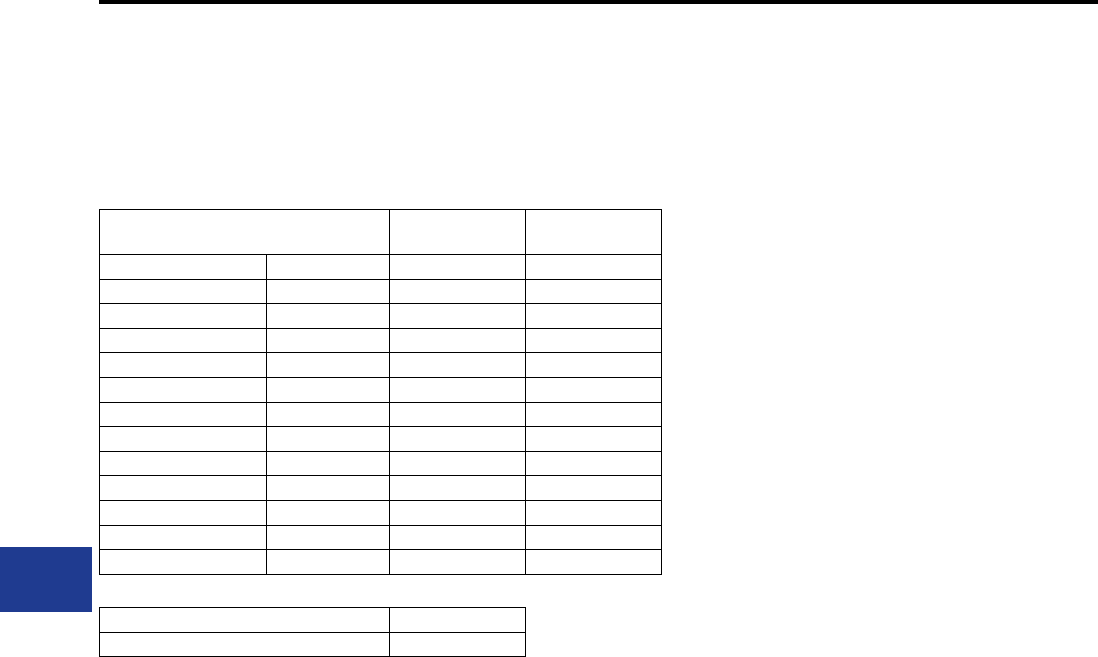
BURNDY®
Blue highlighted items are industry standard and most frequently ordered.
US: 1-800-346-4175 www.burndy.com Canada: 1-800-387-6487
Transmission
Wire Size Full Tension Joint
(Splice) Deadend*
AW HDG
7#10 5/16” 1990 2990
7#9 11/32” 1903 2903
7#8 3/8” 1904 2904
7#7 1991 2991
7/16” 1906 2906
1/2” 1997 2997
7#5 1993 2993
19#9 1995 2995
19#8 5/8” 1994 2994
19#7 1923 2923
19#5 3/4” 1998 2998
37#8 7/8” 1978 2978
IMPLO®
Connections for Static (Sky) Wire
Rebar 1-1/8” 1930
Rebar 1-1/4” to 1-1/8” 1931
* The default numbering includes NEMA pad at 15° and oval eye (example: 2050/C). For round eye remove /C sufx after catalog number.
I-60
IMPLO®
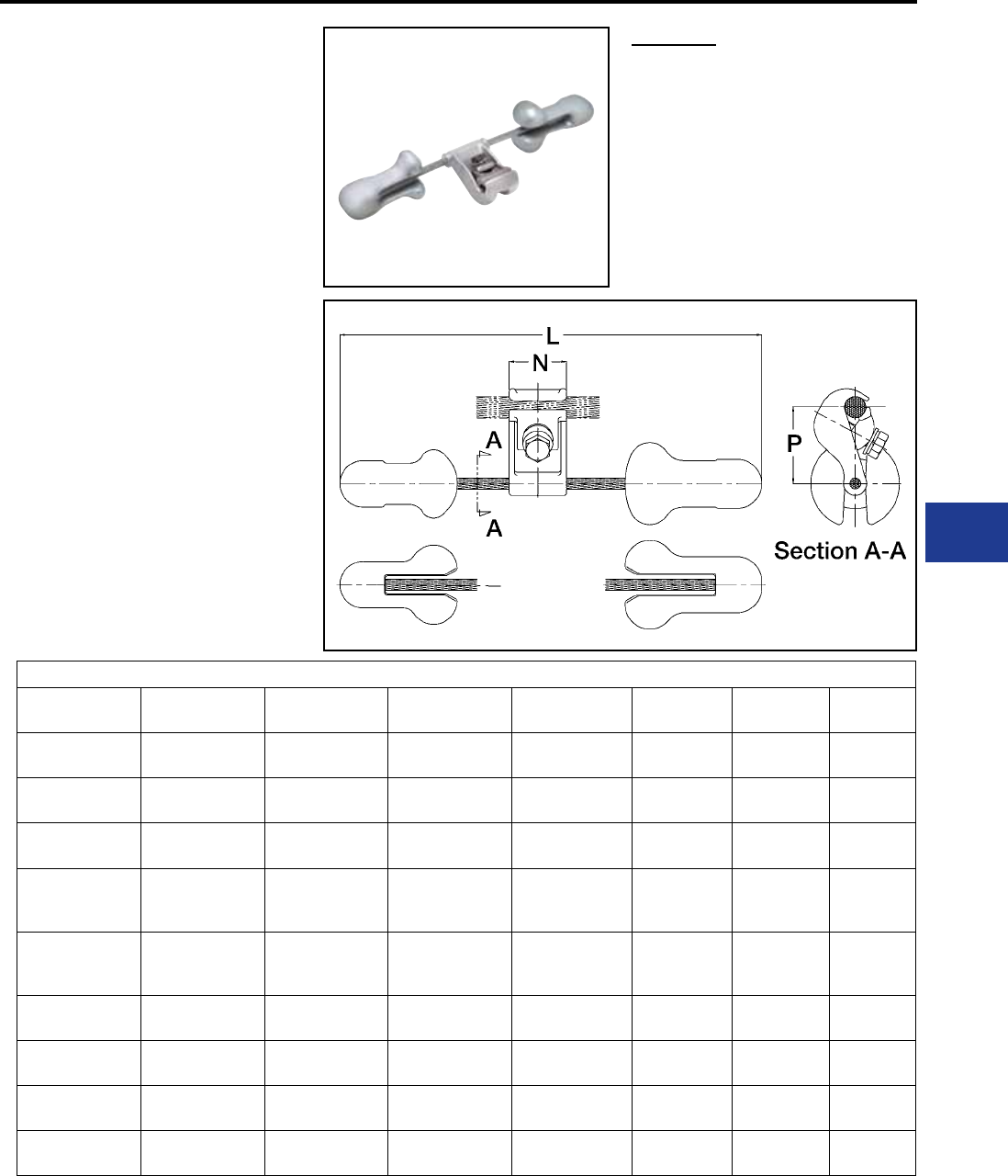
BURNDY®
Blue highlighted items are industry standard and most frequently ordered.
Canada: 1-800-387-6487 www.burndy.com US: 1-800-346-4175
Transmission
TYPE TDM-RG1
Stockbridge Damper
The Stockbridge Damper is designed to enhance
conductor life by lessening potential vibration-
induced fatigue.
Features & Benets
• Clamps designed around common conductor
sizes
◊ Ease of specication
• Single bolt design
◊ Ease of installation
◊ Single wrench installation
• Accurate components assembly represents
greater energy dissipation
◊ Provides extended life for over-
head lines
• Messenger cable and weights have a
corrosion resistant nish
◊ Weight design eliminates water
entrapment
◊ Smooth surfaces and rounded
edges to eliminate possible corona
discharge
Standards
The Stockbridge Dampers meet the follow-
ing standards:
• IEC 61897 Overhead lines—Require-
ments and Test for Stockbridge Aeolian
Vibration Dampers.
• IEEE Std 664-1993 IEEE Guide for
Laboratory Measurement of the Power
Dissipation Characteristics of Aeolian
Vibration Dampers for Single Conductors.
Conductors: ACSR, AAC, ACAR/Static Wires (Galvanized Steel, Alumoweld, Copperweld)
Catalog
Number
Clamp Diameter
Range N P L Wrench Size Tightening
Torque Weight
TDM99RG1 Ø 0.24″ – Ø 0.61″
(6 mm – 15.5 mm)
1.70″
43 mm
2.20″
56 mm
12.20″
310 mm
7/16″
11.17 mm
265 in.-lb.
3.0 daN.m
3.7 lb.
(1.68 kg)
TDM177RG1 Ø 0.59″ – Ø 0.79″
(15 mm – 20 mm)
2.00″
51 mm
3.00″
76 mm
14.40″
365 mm
1/2″
12.70 mm
355 in.-lb.
4.0 daN.m
6.2 lb.
(2.81 kg)
TDM177RG2 Ø 0.71″ – Ø 1.18″
(18 mm – 30 mm)
2.00″
51 mm
3.60″
91 mm
14.40″
365 mm
5/8″
16 mm
530 in.-lb.
6.0 daN.m
6.4 lb.
(2.9 kg)
TDM210RG1
Ø 0.79″ – Ø 1.11″
(20 mm – 28.2
mm)
2.40″
60 mm
3.20″
81 mm
19.70″
500 mm
5/8″
16 mm
530 in.-lb.
6.0 daN.m
9.5 lb.
(4.30 kg)
TDM210RG2
Ø 1.30″ – Ø 1.50″
(33 mm – 38.1
mm)
2.40″
60 mm
3.75″
95 mm
19.70″
500 mm
5/8″
16 mm
530 in.-lb.
6.0 daN.m
9.9 lb.
(4.50 kg)
TDM246RG1 Ø 0.71″ – Ø 1.18″
(18 mm – 30 mm)
2.70″
68 mm
3.60″
91 mm
21.00″
534 mm
5/8″
16 mm
530 in.-lb.
6.0 daN.m
13.2 lb.
(5.99 kg)
TDM330RG1 Ø 1.18″ – Ø 1.26″
(30 mm – 32 mm)
2.70″
68 mm
3.60″
91 mm
21.00″
535 mm
5/8″
16 mm
530 in.-lb.
6.0 daN.m
13.2 lb.
(5.99 kg)
TDM393RG1 Ø 1.26″ – Ø 1.54″
(32 mm – 39 mm)
2.70″
68 mm
3.75″
95 mm
21.00″
534 mm
5/8″
16 mm
530 in.-lb.
6.0 daN.m
13.5 lb.
(6.12 kg)
TDM430RG1 Ø 1.54″ – Ø 1.85″
(39 mm – 47 mm)
2.70″
68 mm
4.09″
104 mm
21.00″
534 mm
5/8″
16 mm
530 in.-lb.
6.0 daN.m
14.0 lb.
(6.35 kg)
For installation point contact factory at numbers below.
Motion Control
I-61
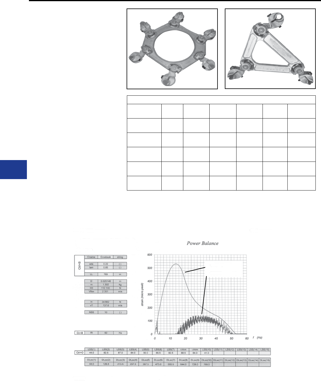
BURNDY®
Blue highlighted items are industry standard and most frequently ordered.
US: 1-800-346-4175 www.burndy.com Canada: 1-800-387-6487
Transmission
Motion Control
TYPE S-D-R-SG
Spacer Damper
Since the 1960’s BURNDY Spacer Dampers have
been used on bundled conductor transmission
lines around the world. Over 850,000 units have
been installed on over 40,000 phase miles of
conductor. Projects have included 2, 3, 4 and 6
bundle arrangements at voltage levels from 230
kV to 800 kV AC and up to +/-600 kV DC.
BURNDY motion control products are engineered
per customer requirements and industry standards.
Our engineering team has the experience and
technology to provide the proper motion control
answers to your bundled conductor transmission
line projects.
Our history of design, testing and eld installation
experience enables us to provide Spacer Damper
products along with placement recommendations
for optimum performance.
Conductors: ACSR, AAC, ACAR
Catalog
Number
Bundle
Size
Conductor
kcmil
Conductor
Diameter Spacing Wrench
Size
Tightening
Torque
S2D451R-SG1 2 795 1.107″
28.1 mm
18″
457 mm
5/8″
16 mm
55 ft.-lb.
74.6 daN.m
S3D451R-SG1 3 795 1.107″
28.1 mm
18″
457 mm
5/8″
16 mm
55 ft.-lb.
74.6 daN.m
S3D55R-SG1 3 1590 1.54″
39 mm
18″
457 mm
5/8″
16 mm
55 ft.-lb.
74.6 daN.m
S4D48R-SG1 4 954 1.196″
30.4 mm
18″
457 mm
5/8″
16 mm
55 ft.-lb.
74.6 daN.m
S6D441R-SG1 6 957 1.06″
26.9 mm
30″ Dia.
762 mm
5/8″
16 mm
55 ft.-lb.
74.6 daN.m
In most cases Spacer Dampers are custom
designed for the specic transmission line require-
ments. Contact the factory for more information.
For installation points per span contact factory.
Conductor placement installation points are
calculated with the recently developed proprietary
BURNDY software.
With spacer dampers
Without spacer dampers
I-62
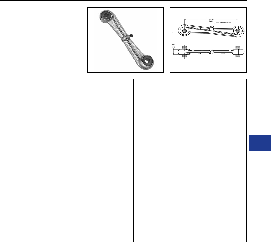
BURNDY®
Blue highlighted items are industry standard and most frequently ordered.
Canada: 1-800-387-6487 www.burndy.com US: 1-800-346-4175
Transmission
TYPE S2GBP-ASG
Rigid Spacers
Since the 1960s, BURNDY has been providing
motion control products for transmission lines.
This rigid spacer line addresses the needs for
many new transmission lines being designed with
twin bundle conductor per phase. BURNDY® rigid
spacers are engineered to perform to customer
and industry standards and carry with them the
design, testing and eld installation experience
to provide the right solution for each transmission
lines. Placement recommendations are provided
for optimum performance on each project. Catalog Number Conductor Min.
Diameter
Conductor Max.
Diameter
Liner
Material
S2GBP451ASG4 1.08 in 1.11 in EPDM
S2GBP451ASG1HT 1.08 in 1.11 in SILICONE
S2GBP47ASG1 1.15 in 1.19 in EPDM
S2GBP47ASG2HT 1.15 in 1.19 in SILICONE
S2GBP48ASG2 1.19 in 1.23 in EPDM
S2GBP48ASG1HT 1.19 in 1.23 in SILICONE
S2GBP52ASG1 1.27 in 1.31 in EPDM
S2GBP52ASG2HT 1.27 in 1.31 in SILICONE
S2GBP51ASG1 1.32 in 1.36 in EPDM
S2GBP51ASG2HT 1.32 in 1.36 in SILICONE
S2GBP463ASG6 1.50 in 1.55 in EPDM
S2GBP463ASG1HT 1.50 in 1.55 in SILICONE
Material:
Clamp Frame : Aluminum Alloy
Shearhead Bolt : Aluminum Alloy; ASTM
B210 Black Anodized
Clamp Liner : See Table
Silicone liner rated to 250° C maximum Designed
for corona free operation to 500 KVAC.
Recommended tightening torque to shear off the
breakaway bolt head: 63 lb-ft
I-63
Motion Control
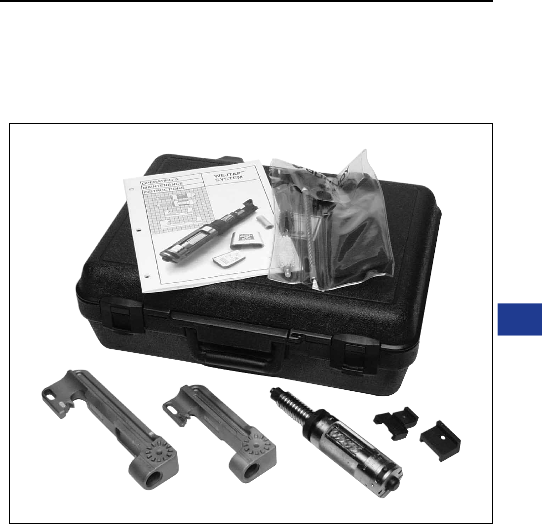
BURNDY®
Blue highlighted items are industry standard and most frequently ordered.
Canada: 1-800-387-6487 www.burndy.com US: 1-800-346-4175
Overhead Distribution and Transmission
Wedge Tap Connectors
THE WEJTAP™
SYSTEM
FOR ELECTRIC UTILITY
DISTRIBUTION AND
TRANSMISSION
CONNECTIONS
J-1
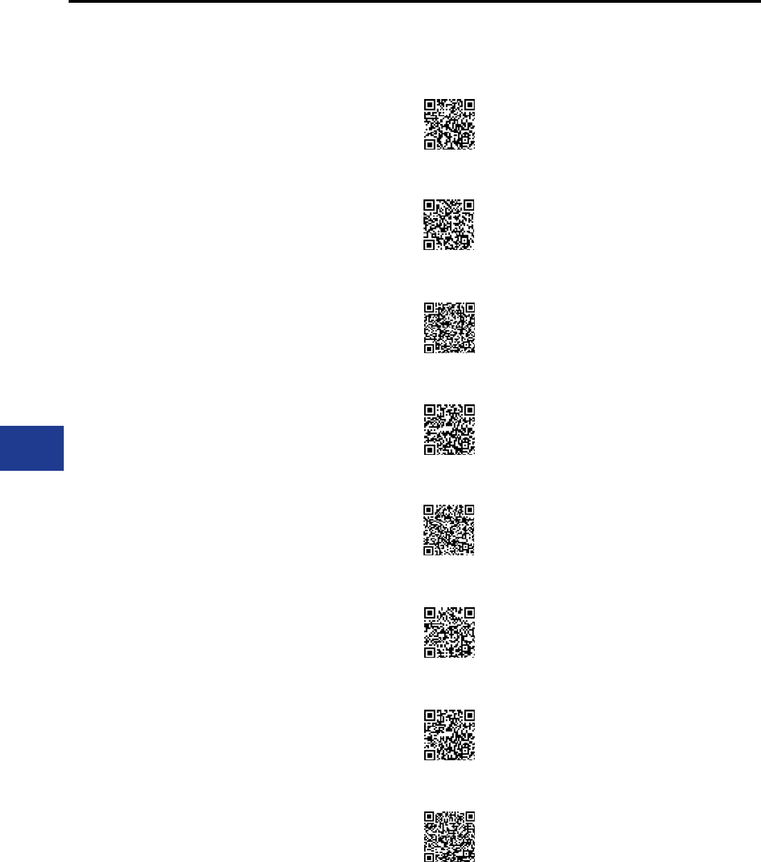
BURNDY®
Blue highlighted items are industry standard and most frequently ordered.
US: 1-800-346-4175 www.burndy.com Canada: 1-800-387-6487
Overhead Distribution and Transmission
Wedge Tap Connectors
TABLE OF CONTENTS
J-2
WEJTAP™ Connection System
WEJTAP™ and Test Data
WEJTAP™ Ordering Information
WEJTAP™ Cover
WEJTAP™ Connector Selection
Chart (by Diameter)
WEJTAP™ Copper WEJTAP™
WEJTAP™ STIRRUP™ and
Power Boosters
WEJTAP™ STIRRUP™
Selection Chart
WEJTAP™ Installation Tools
Installation Tool Accessories
WEJTAP™ POWERLUG™
WEJTAP™ Hotstick Accessories
WEJTAP™ Kit Ordering
Instructions
WEJTAP™ In-Line Disconnect
J-3
J-4
J-5
J-5
J-6 - J-8
J-9, J-10
J-11
J-11
J-12
J-12
J-13
J-14
J-15
J-16
WEJTAP™ Booster Function Video
:55 Seconds
Closing the Breech Video
:22 Seconds
Removal of Booster Video
:27 Seconds
Connector Installation Video
2 min. 19 Seconds
Connector Removal Video
1 min. 57 Seconds
Slow Motion Installation Video
:18 Seconds
WEJTAP™ Tool Cleaning Video
2 min. 50 Sec.
Tightening of Tool Video
:26 Seconds
NEW
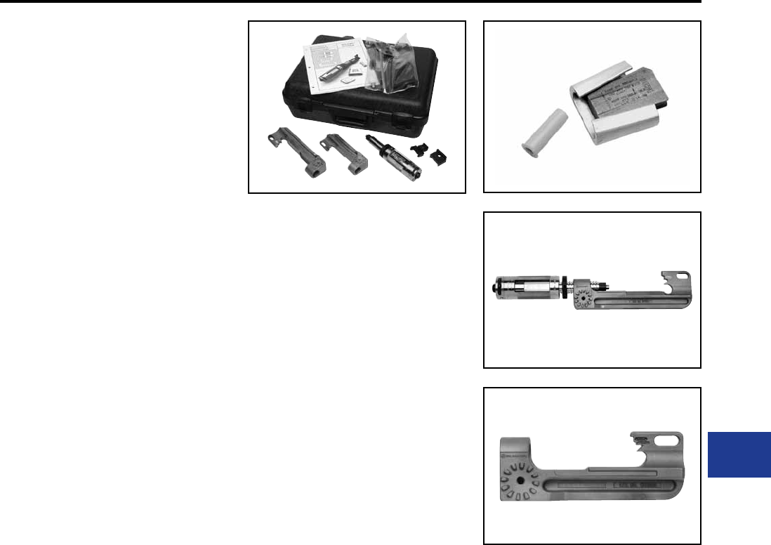
BURNDY®
Blue highlighted items are industry standard and most frequently ordered.
Canada: 1-800-387-6487 www.burndy.com US: 1-800-346-4175
Overhead Distribution and Transmission
Wedge Tap Connectors
BURNDY WEJTAP™
CONNECTION SYSTEM
BURNDY®, a leading manufacturer of quality
electrical connectors for over 70 years, introduces
the WEJTAP™ SYSTEM, a system that adds
further dimension to the existing BURNDY® group
of proven, reliable connection systems.
WEJTAP™ COMPONENTS are designed to
provide a reliable system connection. The system
consists of WEJTAP™ connectors, installation
tools (including a variety of hotline and lineman
accessories) and a unique power-booster.
WEJTAP™ CONNECTORS use an aluminum
alloy wedge that is power-driven between the run
and the tap cables locking them into a “C” shaped
tempered aluminum alloy spring-body. The spring-
body maintains consistent pressure throughout
the life of the connection to ensure reliability
during severe electrical and climatic conditions.
The wedge’s wiping action combined with factory
installed PENTX 1530 provides superior contact
integrity. The wedge is automatically locked onto
the spring-body by a skiving action produced
by a lance at the forward end of the WEJTAP™
installation tool.
The WEJTAP™ TOOL is a one-piece assembly
that consists of a head and power unit. Two
color-coded interchangeable heads accept
all WEJTAP™ connectors and STIRRUP™.
The design of the tool recognizes the need for
simplicity and speed of operation as well as
outstanding safety features such as automatic
gas release vented away from the operator, fast
simple breech loading and fast advance when
engaging the connector assembly. No loose
parts to drop or misplace and a booster ejection
system that provides further safety to the operator.
Fewer simplied hotline devices and handy
lineman accessories complete an outstanding tool
package.
• Large conductor chamfer on ends of wedge
◊ Instant hand or visual identication of
large run grooves. Ensures correct
wedge orientation.
• Color-coded WEJTAP™ connector and booster
packaged together
◊ Easy selection by installer.
• Factory coated grooves with PENTX 1530
◊ Maintains low contact resistance,
assists in protection against climatic
conditions and is compatible with
common insulations.
• One-piece tool
◊ No project delays due to dropped or
lost parts.
• Fewer and improved hotstick accessories
◊ Simplies hotline installation and saves
time.
• Contained booster ejection system
◊ Safe for operator guards against the
booster being ejected in direction of
the installer.
Features and Benets
• Automatic gas release vented away from
operator
◊ Eliminates manual gas venting and
improves safety.
• Simplied loading
◊ Speeds installation — no threads — just
depress safety bar, twist and pull
open — load — push and twist to close
prior to applying connector.
• Acme-type threads
◊ Provides smooth, fast engagement of
tool and connector — saves installer’s
time.
The WEJTAP™ POWER-BOOSTER Patented
is a self-contained device that provides the force
necessary to drive the wedge into direct contact
with the conductors. The booster is activated only
when properly positioned in the tool assembly.
A power cell in the booster is recessed to guard
against premature discharge. The tool/booster
system is designed to activate and deactivate
the booster automatically should the operator
decide to remove the tool from a connector prior
to completing the installation. The deactivated
booster may be safely removed from the tool.
J-3
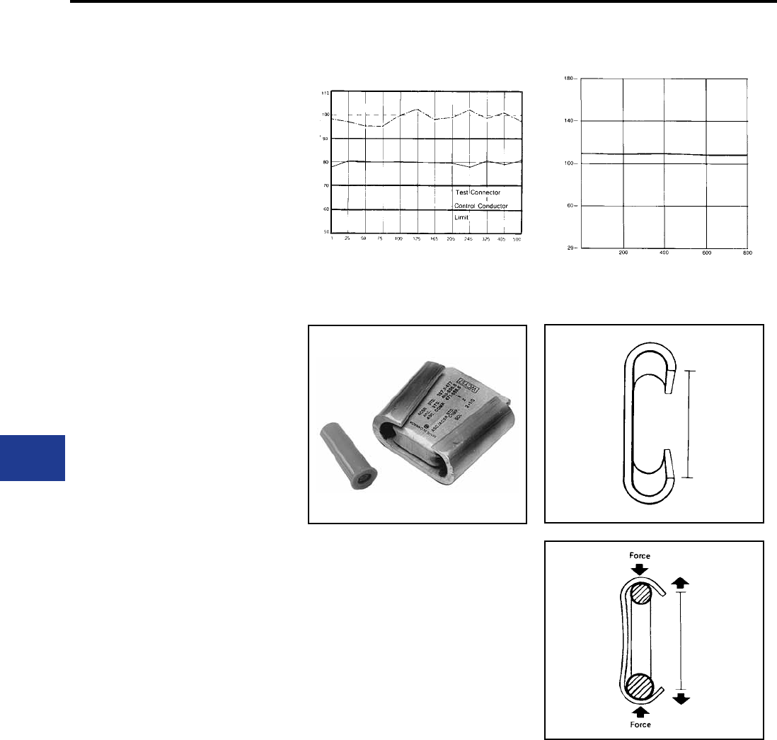
BURNDY®
Blue highlighted items are industry standard and most frequently ordered.
US: 1-800-346-4175 www.burndy.com Canada: 1-800-387-6487
Overhead Distribution and Transmission
Wedge Tap Connectors
WEJTAP™ AND
TEST DATA
WEJTAP™ connectors have been subjected to
extensive tests simulating the most severe service
and weather conditions. In addition. the WEJTAP™
system meets or exceeds the industry standards of
ANSI C119.4 Class 3, NEMA CC3 1973 Class AA,
500 Heat Cycles.
As with all BURNDY
®
connectors, the WEJTAP™
has been designed to operate cooler than the
attached conductors. The WEJTAP™ connectors
have also been subjected to the ASTM B117-73 Salt
Spray Test. The results are shown to the right.
WEJTAP™
C-member bodies are color-coded and the
wedges are marked with nominal conductor run
and tap ranges. WEJTAP™ connector packages
are labeled with a variety of common conductors
with their nominal ranges.
■ WEJTAP™ connector wedges are
marked with nominal ACSR, Aluminum
and Copper concentric standard
conductors.
■ Red WEJTAP™ connector range
Run 8-1/0 Tap 8-2
■ Blue WEJTAP™ connector range
Run 2-300 Tap 6-300
■ Yellow WEJTAP™ connector range
Run 266.8-1590 Tap 6-1590
All WEJTAP™ wedges contain a clearly dened
chamfer on the large end of the run conductor
groove to identify the “large run” groove. Installers
will appreciate the convenience of visual or hand
identication for correct wedge positioning.
WEJTAP™ wedges are driven between the
run and tap conductors and activate the spring
characteristics of the “C” shaped body. This
action maintains contact pressure even when the
connection is subjected to severe climatic and
electrical conditions.
RUS Accepted
ANSI C119.4 - 1986 Heat Cycle Test
Average Temperature Rise vs. Current Cycles
ASTM Salt Spray Test
Average % Relative Resistance vs.
Hours of Salt Spray Exposure
Temperature Rise (Deg. C.)
Detailed test report packages are available upon
request. Hours
Relative Resistance (Percent)
J-4
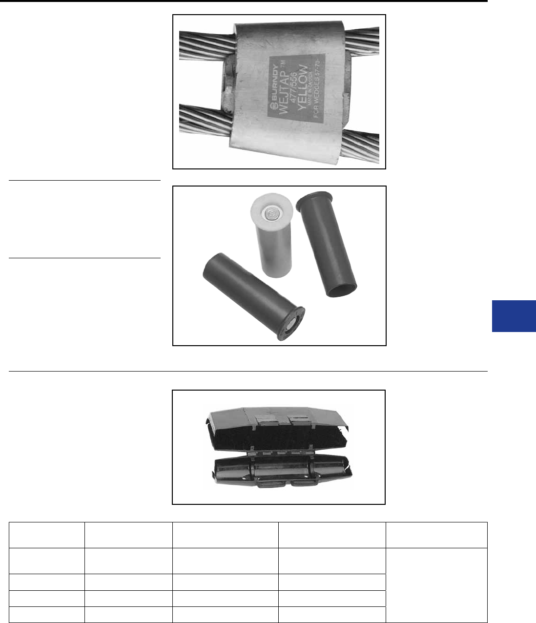
BURNDY®
Blue highlighted items are industry standard and most frequently ordered.
Canada: 1-800-387-6487 www.burndy.com US: 1-800-346-4175
Overhead Distribution and Transmission
Wedge Tap Connectors
WEJTAP™ COVER
WEJTAP™ Covers are installed on WEJTAP™
connectors to prevent them from coming in contact
with other taps or exposed ground points. The
covers are rugged snap-on devices available in
four sizes to cover all connector sizes.
Cover
Catalog Number
WEJTAPTM
Size
Nominal Conductor
Range Run
Nominal Conductor
Range Tap
Cover
Color
WCCR Small Old
Style Red 8-1/0 8-2
Black
Weather
Rated
WCCB Red & Blue 2-300 6-300
WCCSY Small (Yellow) 300-556.50 6-556.50
WCCLY Large (Yellow) 556.50-1033.50 556.5-1033.50
The BURNDY® WEJTAP™ System has a wide
variety of connectors available for many different
conductor ranges.
Color coded boosters and connectors ensure
proper matching during installation.
The BURNDY® Power Booster is designed and
engineered for the highest reliability and safety.
Proven rimre design means misres are almost
nonexistent. Close manufacturing component
tolerances provide maximum resistance to
moisture or submersion.
ORDERING INFORMATION
■ Power boosters may be ordered
separately in boxes of 25.
Red boosters Cat. # WPBRN Box 25
Blue boosters Cat. # WPBBN Box 25
Yellow boosters Cat. # WPBYN Box 25
Select appropriate connector; match with equal
number of color coded boosters (see below).
WPB—Red, Blue, Yellow Boosters
For information about conductors which
are not listed, and for further ordering
information, please contact BURNDY® at
1-800-346-4175.
J-5
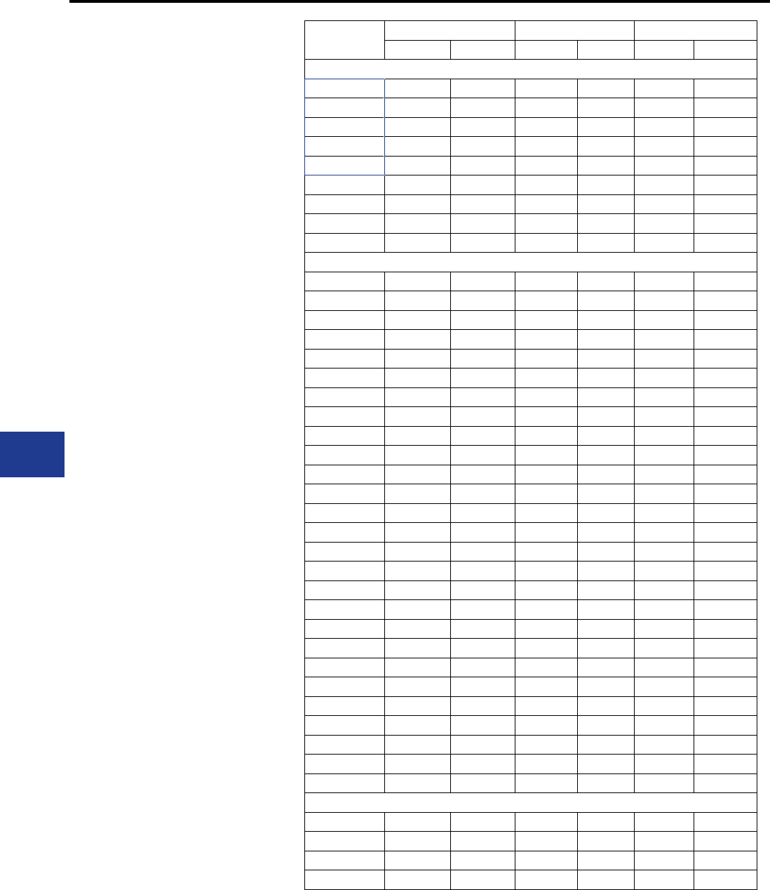
BURNDY®
Blue highlighted items are industry standard and most frequently ordered.
US: 1-800-346-4175 www.burndy.com Canada: 1-800-387-6487
Overhead Distribution and Transmission
Wedge Tap Connectors
BURNDY WEJTAP™
SELECTION CHART
By Diameter
Catalog
Number
Sum of Diameters Run Tap
Max Min Max Min Max Min
Installed with red booster
WCR29 0.723 0.584 0.398 0.257 0.398 0.257
WCR30 0.649 0.516 0.398 0.257 0.325 0.206
WCR31 0.602 0.464 0.398 0.257 0.258 0.162
WCR32 0.530 0.410 0.326 0.204 0.258 0.162
WCR33 0.459 0.331 0.258 0.169 0.230 0.162
WCR34 0.324 0.256 0.162 0.128 0.162 0.128
WCR35 0.560 0.452 0.398 0.257 0.162 0.128
WCR36 0.487 0.387 0.398 0.257 0.162 0.128
WCR37 0.416 0.297 0.258 0.169 0.162 0.128
Installed with blue booster
WCB10 0.795 0.621 0.482 0.316 0.437 0.257
WCB11 0.901 0.763 0.568 0.364 0.457 0.257
WCB12 0.707 0.526 0.568 0.364 0.204 0.162
WCB13 0.761 0.600 0.568 0.364 0.258 0.204
WCB14 0.839 0.690 0.568 0.364 0.398 0.257
WCB15 0.769 0.622 0.568 0.364 0.204 0.162
WCB16 0.823 0.664 0.568 0.364 0.258 0.204
WCB17 0.963 0.804 0.568 0.364 0.464 0.257
WCB18 1.011 0.867 0.568 0.364 0.572 0.364
WCB19 1.068 0.938 0.568 0.364 0.572 0.379
WCB20 1.130 0.975 0.568 0.364 0.572 0.386
WCB21 0.846 0.711 0.650 0.532 0.204 0.162
WCB22 0.900 0.765 0.650 0.532 0.258 0.204
WCB23 0.972 0.818 0.650 0.532 0.330 0.257
WCB24 1.052 0.897 0.650 0.532 0.500 0.324
WCB25 1.104 0.963 0.650 0.532 0.562 0.364
WCB26 1.163 1.015 0.650 0.532 0.562 0.409
WCB27 1.221 1.080 0.650 0.532 0.575 0.460
WCB28 1.284 1.141 0.650 0.532 0.650 0.525
WCB40 0.888 0.762 0.684 0.603 0.204 0.162
WCB41 0.942 0.794 0.684 0.600 0.258 0.204
WCB42 1.011 0.857 0.684 0.600 0.333 0.257
WCB43 1.094 0.936 0.684 0.600 0.500 0.324
WCB44 1.146 1.009 0.684 0.600 0.562 0.364
WCB45 1.204 1.057 0.684 0.600 0.562 0.409
WCB46 1.284 1.119 0.684 0.600 0.592 0.460
WCB47 1.368 1.188 0.684 0.600 0.684 0.600
Installed with yellow booster
WCY48 0.932 0.765 0.750 0.537 0.204 0.162
WCY49 1.012 0.807 0.750 0.537 0.271 0.203
WCY50 1.069 0.860 0.750 0.537 0.355 0.257
WCY51 1.141 0.927 0.750 0.537 0.557 0.324
J-6
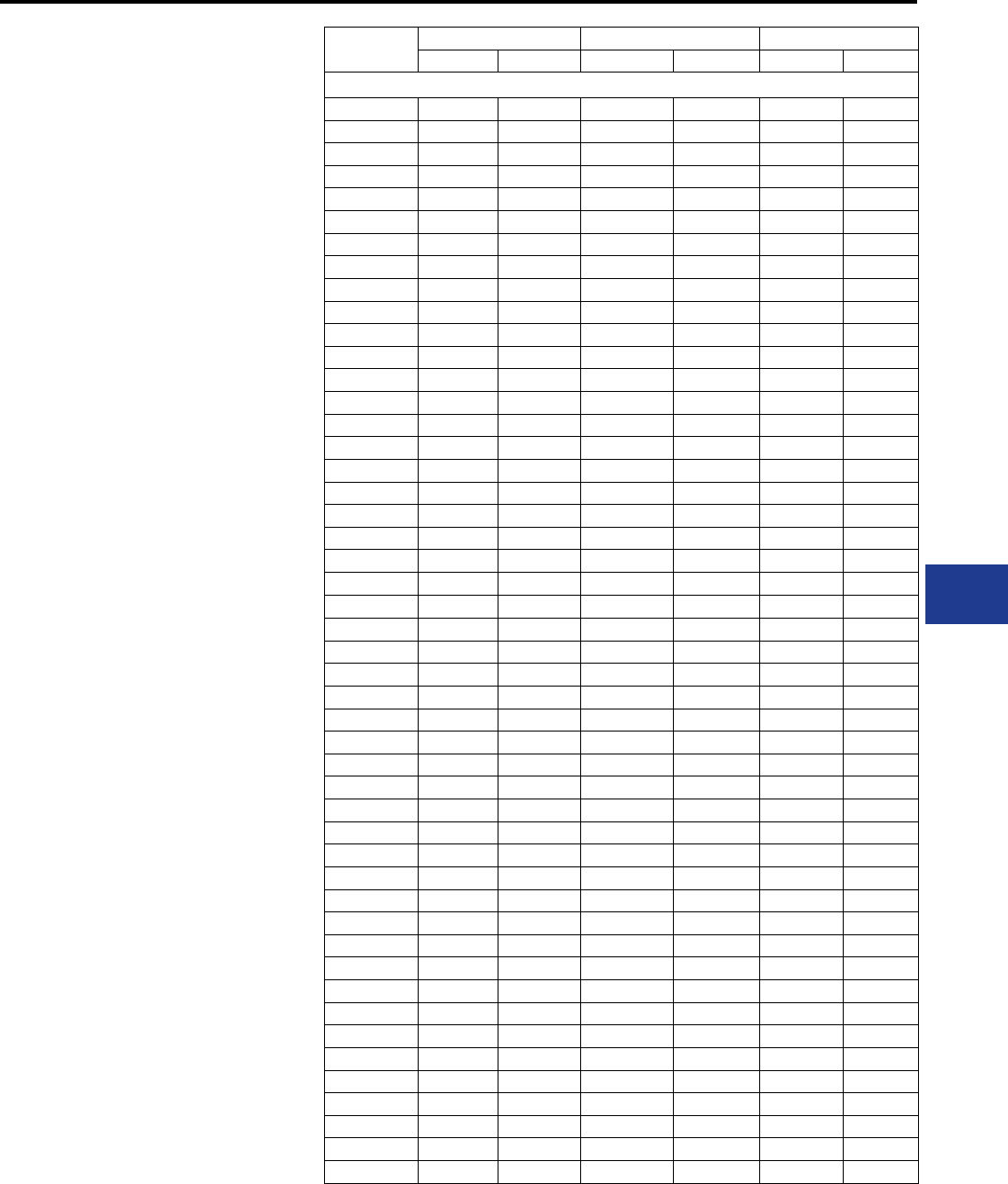
BURNDY®
Blue highlighted items are industry standard and most frequently ordered.
Canada: 1-800-387-6487 www.burndy.com US: 1-800-346-4175
Overhead Distribution and Transmission
Wedge Tap Connectors
BURNDY WEJTAP™
SELECTION CHART
By Diameter
Catalog
Number
Sum of Diameters Run Tap
Max Min Max Min Max Min
Installed with yellow booster
WCY52 1.190 1.001 0.750 0.537 0.588 0.364
WCY53 1.236 1.012 0.750 0.537 0.619 0.409
WCY54 1.302 1.063 0.750 0.537 0.630 0.46
WCY55 1.370 1.140 0.750 0.537 0.714 0.499
WCY56 1.456 1.245 0.750 0.537 0.750 0.524
WCY57 1.190 0.979 0.893 0.666 0.326 0.257
WCY58 1.087 0.931 0.893 0.666 0.258 0.198
WCY59 1.061 0.891 0.893 0.666 0.199 0.162
WCY60 1.854 1.686 0.950 0.722 0.950 0.722
WCY61 1.741 1.524 0.940 0.683 0.940 0.666
WCY62 1.594 1.379 0.940 0.683 0.750 0.573
WCY63 1.500 1.297 0.940 0.683 0.750 0.481
WCY64 1.421 1.216 0.940 0.683 0.650 0.436
WCY65 1.360 1.147 0.940 0.683 0.562 0.382
WCY66 1.305 1.097 0.940 0.683 0.562 0.336
WCY67 1.270 1.054 0.940 0.683 0.450 0.315
WCY68 1.253 1.115 0.940 0.683 0.326 0.257
WCY69 1.187 1.059 0.940 0.683 0.262 0.204
WCY70 1.130 1.013 0.940 0.683 0.204 0.162
WCY71 2.216 2.074 1.133 0.907 1.156 0.947
WCY72 2.133 1.999 1.133 0.907 1.142 0.927
WCY73 2.098 1.946 1.133 0.907 1.142 0.907
WCY74 2.035 1.891 1.133 0.907 1.142 0.858
WCY75 1.969 1.822 1.133 0.889 0.927 0.763
WCY76 1.901 1.741 1.133 0.889 0.900 0.700
WCY77 1.829 1.677 1.133 0.889 0.750 0.575
WCY78 1.750 1.599 1.133 0.889 0.729 0.525
WCY79 1.670 1.526 1.133 0.889 0.722 0.364
WCY80 1.610 1.466 1.133 0.889 0.608 0.364
WCY81 1.555 1.411 1.133 0.889 0.608 0.364
WCY82 1.506 1.362 1.133 0.889 0.436 0.324
WCY83 1.440 1.288 1.133 0.889 0.398 0.257
WCY84 1.369 1.221 1.133 0.889 0.333 0.203
WCY85 1.306 1.158 1.133 0.889 0.258 0.162
WCY86 2.496 2.332 1.250 0.893 1.250 1.000
WCY87 2.418 2.251 1.250 0.893 1.250 0.856
WCY88 2.354 2.194 1.250 0.893 1.211 0.971
WCY89 2.297 2.137 1.250 0.893 1.200 0.923
WCY90 2.238 2.083 1.250 0.893 1.159 0.868
WCY91 2.173 2.013 1.250 0.893 1.130 0.856
WCY92 2.104 1.950 1.250 0.893 0.904 0.720
WCY93 2.029 1.869 1.250 0.893 0.900 0.700
WCY94 1.967 1.831 1.250 0.893 0.750 0.588
WCY95 1.888 1.728 1.250 0.893 0.722 0.525
WCY96 1.811 1.648 1.250 0.893 0.609 0.364
WCY97 1.748 1.591 1.250 0.893 0.598 0.385
WCY98 1.695 1.533 1.250 0.893 0.598 0.364
WCY99 1.644 1.489 1.250 0.893 0.398 0.324
J-7
BURNDY®
Blue highlighted items are industry standard and most frequently ordered.
US: 1-800-346-4175 www.burndy.com Canada: 1-800-387-6487
Overhead Distribution and Transmission
Wedge Tap Connectors
BURNDY WEJTAP™
SELECTION CHART
By Diameter
Catalog
Number
Sum of Diameters Run Tap
Max Min Max Min Max Min
Installed with yellow booster
WCY100 1.572 1.400 1.250 0.893 0.351 0.257
WCY101 1.503 1.343 1.250 0.893 0.261 0.204
WCY102 1.454 1.284 1.250 0.893 0.198 0.162
WCY103 2.604 2.484 1.302 1.242 1.302 1.242
WCY104 2.567 2.407 1.302 1.242 1.265 1.165
WCY105 2.489 2.329 1.302 1.242 1.187 1.087
WCY106 2.418 2.258 1.302 1.242 1.116 1.016
WCY107 2.373 2.213 1.302 1.242 1.071 0.971
WCY108 2.318 2.158 1.302 1.242 1.016 0.916
WCY109 2.255 2.095 1.302 1.242 0.953 0.853
WCY110 2.179 2.019 1.302 1.242 0.877 0.777
WCY111 2.102 1.942 1.302 1.242 0.800 0.700
WCY112 2.044 1.884 1.302 1.242 0.742 0.642
WCY113 1.961 1.801 1.302 1.242 0.659 0.559
WCY114 1.940 1.740 1.350 1.242 0.590 0.498
WCY115 1.863 1.663 1.350 1.242 0.513 0.421
WCY116 1.812 1.612 1.350 1.242 0.462 0.370
WCY117 1.762 1.562 1.350 1.242 0.412 0.320
WCY118 1.703 1.503 1.350 1.242 0.353 0.261
WCY119 1.631 1.431 1.350 1.242 0.281 0.189
WCY120 1.580 1.380 1.350 1.242 0.230 0.138
WCY121 2.844 2.642 1.422 1.314 1.422 1.328
WCY122 2.764 2.562 1.422 1.314 1.342 1.248
WCY123 2.680 2.479 1.422 1.314 1.258 1.164
WCY124 2.596 2.394 1.422 1.314 1.174 1.080
WCY125 2.535 2.333 1.422 1.314 1.113 1.019
WCY126 2.481 2.279 1.422 1.314 1.059 0.965
WCY127 2.426 2.224 1.422 1.314 1.004 0.910
WCY128 2.376 2.174 1.422 1.314 0.954 0.860
WCY129 2.286 2.084 1.422 1.314 0.864 0.770
WCY130 2.216 2.014 1.422 1.314 0.794 0.700
WCY131 2.152 1.950 1.422 1.314 0.730 0.636
WCY132 2.070 1.868 1.422 1.314 0.648 0.554
WCY133 1.990 1.786 1.422 1.314 0.568 0.472
WCY134 1.931 1.729 1.422 1.314 0.509 0.415
WCY135 1.876 1.674 1.422 1.314 0.454 0.360
WCY136 1.831 1.629 1.422 1.314 0.409 0.315
WCY137 1.771 1.569 1.422 1.314 0.349 0.255
WCY138 1.706 1.504 1.422 1.314 0.284 0.190
WCY139 1.664 1.462 1.422 1.314 0.242 0.148
WCY140 3.045 2.090 1.533 1.471 1.547 1.471
WCY145 2.596 2.534 1.533 1.032 1.094 1.032
J-8
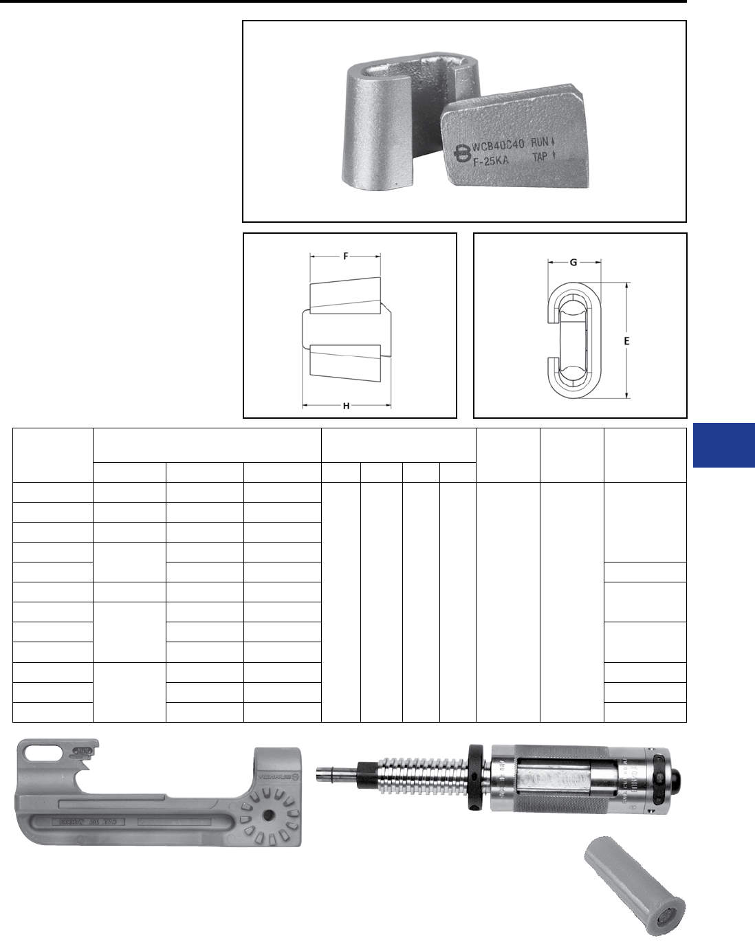
BURNDY®
Blue highlighted items are industry standard and most frequently ordered.
Canada: 1-800-387-6487 www.burndy.com US: 1-800-346-4175
Overhead Distribution and Transmission
Wedge Tap Connectors
WEJTAP™
COPPER WEJTAPTM
CONNECTION SYSTEM
The BURNDY® Copper WEJTAP™ powder
actuated copper connectors are designed for
overhead copper to copper tap applications.
Features include:
• Newly expanded range taking
capabilities
• New larger size connector for #6 - #2
applications
• Uses standard BURNDY® WEJTAP™ tooling
without the need for installation platforms
• Meets latest ANSI C119.4 (2011)
including optional fault current test annex
• Prelled with PENETROX™ E to
improve the performance over the life of the
connection
Catalog
Number
Copper Conductor Dia.
Accommodated (in) Dimensions Tooling
Installation
Booster
Color
Fault Current
Rating (KA)
Run Range Tap Range Sum Range E F G H
WCB4C4 0.162 - 0.258 0.162 - 0.232 0.324 - 0.464
2.40 1.63 1.02 2.05 WTHRB-1S Blue
12.50
WCB2C2 0.258 - 0.368 0.162 - 0.292 0.452 - 0.600
WCB10C2 0.292 - 0.376 0.162 - 0.292 0.524 - 0.665
WCB20C2 0.300 - 0.430 0.162 - 0.292 0.576 - 0.734
WCB20C20 0.300 - 0.414 0.710 - 0.844 25.00
WCB30C2 0.360 - 0.516 0.162 - 0.292 0.622 - 0.775 12.50
WCB40C2
0.375 - 0.538
0.162 - 0.292 0.680 - 0.822
WCB40C20 0.330 - 0.464 0.814 - 0.952 25.00
WCB40C40 0.375 - 0.538 0.936 - 1.072
WCB250C2
0.435 - 0.574
0.162 - 0.292 0.730 - 0.875 12.50
WCB250C20 0.293 - 0.430 0.875 - 1.033 25.00
WCB250C250 0.431 - 0.574 1.033 - 1.150 38.00
J-9

BURNDY®
Blue highlighted items are industry standard and most frequently ordered.
US: 1-800-346-4175 www.burndy.com Canada: 1-800-387-6487
Overhead Distribution and Transmission
Wedge Tap Connectors
BURNDY Catalog Number:
WCB4C4
BURNDY Catalog Number:
WCB40C2
BURNDY Catalog Number:
WCB2C2
BURNDY Catalog Number:
WCB40C20
BURNDY Catalog Number:
WCB10C2
BURNDY Catalog Number:
WCB40C40
BURNDY Catalog Number:
WCB20C2
BURNDY Catalog Number:
WCB250C2
BURNDY Catalog Number:
WCB20C20
BURNDY Catalog Number:
WCB250C20
BURNDY Catalog Number:
WCB30C2
BURNDY Catalog Number:
WCB250C250
RUN TAP
#6 CU SOL
#6 CU STR
#4 CU SOL
#4 CU STR
#2 CU SOL
#6 CU SOL
#6 CU SOL - #6 CU STR
#6 CU SOL - #4 CU SOL
#4 CU STR - #6 CU SOL
#6 CU SOL - #6 CU STR
RUN TAP
4/0 CU STR #6 CU SOL - #2 CU STR
RUN TAP
#2 CU SOL
#2 CU STR
1/0 CU STR
#4 CU SOL - #2 CU SOL
#6 CU SOL - #2 CU STR
#6 CU SOL - #4 CU STR
RUN TAP
3/0 CU STR
4/0 CU STR
1/0 CU STR - 3/0 CU STR
1/0 CU STR - 2/0 CU STR
RUN TAP
#2 CU STR
1/0 CU SOL
1/0 CU STR
#4 CCS* - #2 CU STR
#6 CU SOL - #2 CU STR
#6 CU SOL - #2 CU STR
RUN TAP
4/0 CU STR 4/0 CU SOL - 4/0 CU STR
RUN TAP
1/0 CU STR
2/0 CU STR
#2 CU SOL - #2 CU STR
#6 CU SOL - #2 CU STR
RUN TAP
250 CU STR #6 CU SOL - #2 CU STR
RUN TAP
1/0 CU STR
2/0 CU STR
1/0 CU STR
1/0 CU STR - 2/0 CU STR
RUN TAP
250 CU STR 1/0 CU STR - 2/0 CU STR
RUN TAP
4/0 CU SOL #6 CU SOL - #2 CU STR
RUN TAP
250 CU STR 4/0 CU SOL - 250 CU STR
* Copper Clad Steel
J-10
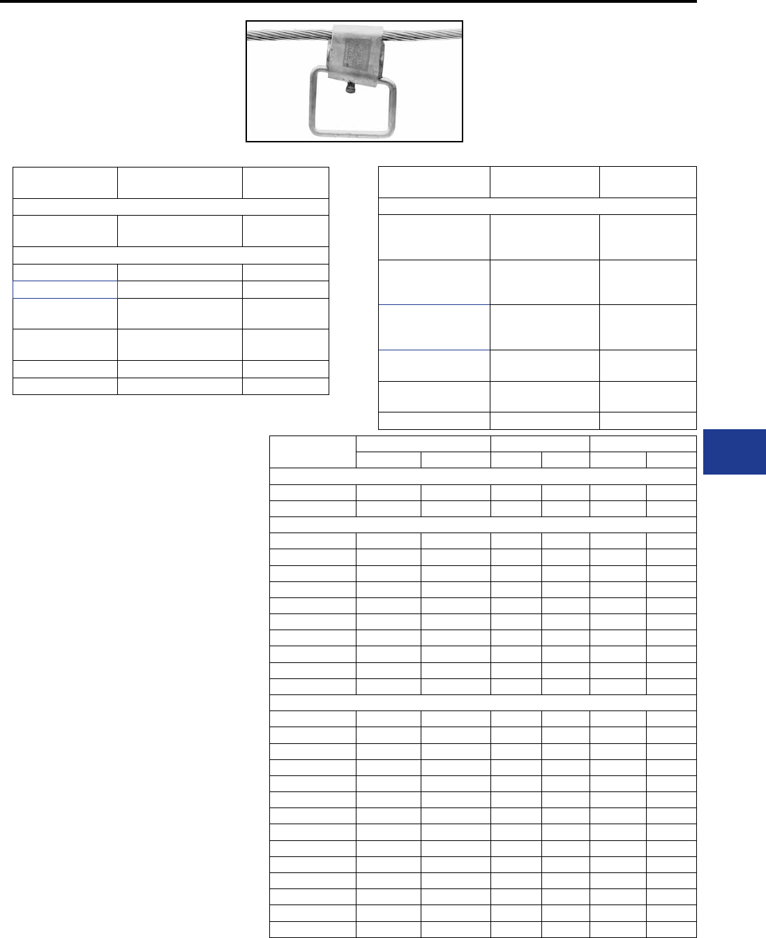
BURNDY®
Blue highlighted items are industry standard and most frequently ordered.
Canada: 1-800-387-6487 www.burndy.com US: 1-800-346-4175
Overhead Distribution and Transmission
Wedge Tap Connectors
WEJTAP™
STIRRUP™ AND
POWER BOOSTERS
(Large) Run Conductor position is identied on all
wedges via a distinct chamfer.
Catalog
Number
Sum of Diameters Run Tap
Max. Min. Max. Min. Max. Min.
Small stirrups
WSS1 0.454 0.412 0.204 0.162 0.250 0.250
WSS2 0.575 0.456 0.325 0.206 0.250 0.250
Medium sized stirrups
WSM1 0.697 0.575 0.447 0.325 0.250 0.250
WSM10 0.887 0.784 0.563 0.460 0.324 0.324
WSM2 0.752 0.615 0.502 0.365 0.250 0.250
WSM3 0.813 0.660 0.563 0.410 0.250 0.250
WSM4 0.938 0.835 0.563 0.460 0.375 0.375
WSM5 0.892 0.787 0.642 0.537 0.250 0.250
WSM6 0.968 0.861 0.642 0.537 0.324 0.324
WSM7 1.008 0.898 0.684 0.574 0.324 0.324
WSM8 0.934 0.824 0.684 0.574 0.250 0.250
WSM9 0.771 0.649 0.447 0.325 0.324 0.324
Large stirrups
WSL1 1.050 0.927 0.726 0.603 0.324 0.324
WSL10 1.479 1.389 1.019 0.929 0.460 0.460
WSL11 1.394 1.304 1.019 0.929 0.375 0.375
WSL12 1.515 1.399 1.140 1.024 0.375 0.375
WSL13 1.600 1.484 1.140 1.024 0.460 0.460
WSL14 1.708 1.606 1.248 1.146 0.460 0.460
WSL2 0.976 0.853 0.726 0.603 0.250 0.250
WSL3 1.186 1.063 0.726 0.603 0.460 0.460
WSL4 1.186 1.046 0.862 0.722 0.324 0.324
WSL5 1.237 1.097 0.862 0.722 0.375 0.375
WSL6 1.322 1.182 0.862 0.722 0.460 0.460
WSL7 1.251 1.170 0.927 0.846 0.324 0.324
WSL8 1.302 1.221 0.927 0.846 0.375 0.375
WSL9 1.387 1.306 0.927 0.846 0.460 0.460
Catalog
Number
Nominal Cable
Range
Bail
Size
Small Red Cable Range 6-2
WSS1
WSS2
6
5, 4, 2 2
Medium Blue Cable Range 1-300
* WSM1 2, 1, 1/0, 2/0 2
WSM2 2/0, 3/0 2
WSM3
WSM4 3/0 - 4/0 2
2/0
WSM5
WSM6 266.8 2
1/0
WSM7 350 1/0
WSM11 266.8 - 336.4 4/0
Catalog
Number
Nominal Cable
Range
Bail
Size
Large Yellow Cable Range 300-1033.5
WSL1
WSL2
WSL3
336.4
1/0
2/0
4/0
WSL4
WSL5
WSL6
397.5 - 477
1/0
2/0
4/0
WSL7
WSL8
WSL9
556.5
1/0
2/0
4/0
WSL10
WSL11 636 4/0
2/0
WSL12
WSL13 795 2/0
4/0
WSL14 1033.5 4/0
QIK Selector - for common ACSR, Aluminum and Copper Conductors
BURNDY WEJTAP™
STIRRUP™
SELECTION CHART
By Diameter
* WSM1 now accepts #2 conductor
J-11
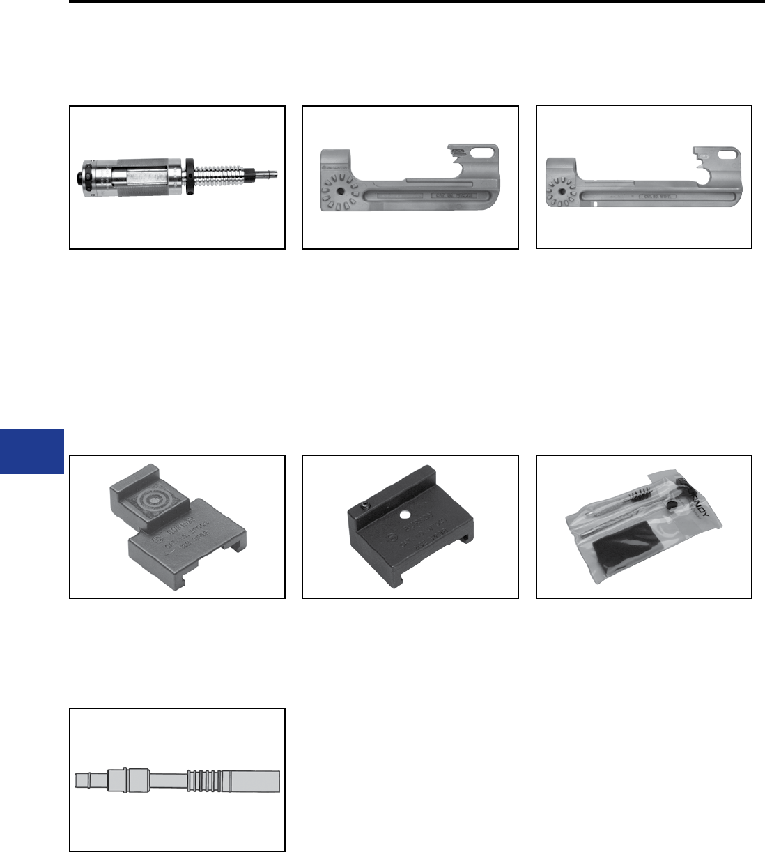
BURNDY®
Blue highlighted items are industry standard and most frequently ordered.
US: 1-800-346-4175 www.burndy.com Canada: 1-800-387-6487
Overhead Distribution and Transmission
Wedge Tap Connectors
WEJTAP™
INSTALLATION
TOOLS
Type WTB Type WTHRB1S Type WTHY1S
The WEJTAP™ patented tool body is a one-piece
assembly basic drive mechanism used to install
WEJTAP™ and STIRRUP™ connectors ranging
from #8 AWG through 1590 kcmil ACSR.
WEJTAP™ removal clip for red type II and medium
(blue coded) tap connectors used with type
WTHRB tool head.
WEJTAP™ removal clip for large (yellow coded)
tap connectors used with type WTHY tool head.
WEJTAP™ tool cleaning/maintenance kit for use
with type WTB tool body.
WEJTAP™ ram replacement assembly.
WEJTAP™ tool head operating platform for small
and medium range (red/blue coded) connectors.
WEJTAP™ tool head operating platform
for medium and large range (yellow coded)
connectors.
WEJTAP™
INSTALLATION TOOL
ACCESSORIES
Type WTOCBR Type WTOCY Type WTCK
Type WTBASY1
J-12
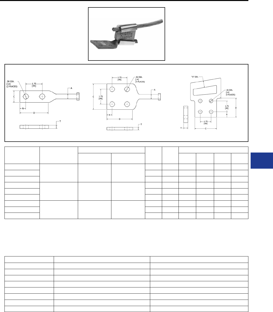
BURNDY®
Blue highlighted items are industry standard and most frequently ordered.
Canada: 1-800-387-6487 www.burndy.com US: 1-800-346-4175
Overhead Distribution and Transmission
Wedge Tap Connectors
WEJTAP™
POWERLUG™
WEJTAP™ POWERLUG™ terminals are made of
cast aluminum alloy for termination of ACSR and
Aluminum conductors.
2 Hole POWERLUG™ 4 Hole POWERLUG™ 4 Hole Flag
Catalog
Number
Tap Groove
for Connector
Selection
Standard Conductor Figure
No.
Holes
in Pad
Dimension
ACSR ASC/AAC C D N T
WCAB30R-2N 4/0 Standard
ACSR
(.563 in OD)
6 Str. - 266.8 6 Str. - 300
1 2 1-1/4 3 5/8 0.34
WCAB30R-4N 2 4 3 3 5/8 0.30
WCBB30R-4N 3 4 3 3 5/8 0.30
WCAY39R-2N 336.4 Standard ACSR
(.721 in OD) 266.8 - 556.5 336.4 - 636
1 2 1-3/4 3 5/8 0.34
WCAY39R-4N 2 4 3 3 5/8 0.30
WCBY39R-4N 3 4 3 3 5/8 0.30
WCAY49R-2N 795 Standard ACSR
(1.108 in OD) 605 - 1033.5 715.5 - 1113
1 2 1-3/4 3-1/2 7/8 0.69
WCAY49R-4N 2 4 3-1/2 3-1/2 7/8 0.69
WCBY49R-4N 3 4 3-1/2 3-1/2 7/8 0.69
NOTE: The recommended connector and booster are ordered separately.
Catalog number is for the POWERLUG™ only. Use the Tap Groove
Connector diameter, along with the application run conductor diameter, to
choose the correct WEJTAPTM connector.
* Electrically, the three smaller conductors are the likely taps, however,
during installation, they are located in the larger run groove due to their
larger aggregate sum.
Connector *Run Groove *Tap Groove
WCY 64 PB Three - 1/0 ACSR (6/1) Diameter = 0.398 One - 4/0 ACSR (6/1) Diameter = 0.563
WCY 65 PB Three - 1/0 ACSR (6/1) Diameter = 0.398 One - 3/0 ACSR (6/1) Diameter = 0.502
WCY 63 PB Three - 2/0 ACSR (6/1) Diameter = 0.447 One - 4/0 ACSR (6/1) Diameter = 0.563
WCB 11 PB Three - #4 stranded Diameter = 0.232 One - 1/0 ACSR (6/1) Diameter = 0.398
WCY 54 PB Three - 1/0 stranded Diameter = 0.368 One - 4/0 stranded Diameter = 0.522
WCY 53 PB Three - 1/0 stranded Diameter = 0.368 One - 3/0 stranded Diameter = 0.464
WCY 64 PB Three - 2/0 stranded Diameter = 0.414 One - 4/0 stranded Diameter = 0.522
WCB 11 PB Three - #4 stranded Diameter = 0.232 One - 1/0 stranded Diameter = 0.368
MULTIPLE CONDUCTOR TAP APPLICATION
c
Fig. 1 Fig. 2 Fig. 3
J-13
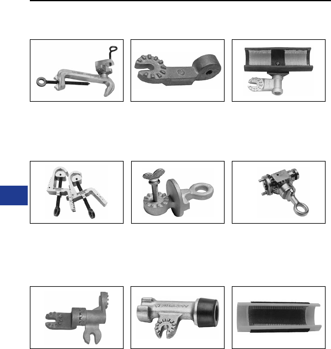
BURNDY®
Blue highlighted items are industry standard and most frequently ordered.
US: 1-800-346-4175 www.burndy.com Canada: 1-800-387-6487
Overhead Distribution and Transmission
Wedge Tap Connectors
WEJTAP™ HOTSTICK
ACCESSORIES
Type WHSCWH
Type WHSPBC
Type WHSSADP
Type WHSWHADP
Type WCHAWAS
Type WHSTA
Type WHSWB
Type WHSGB
Type WHHWB
WEJTAP™ hotstick connector clamp used to
hold the tap connector spring-body and wedge
for installation on energized lines with the shotgun
hotstick.
WEJTAP™ hotstick dual cable clamp used to hold
run and tap conductors in position during hotline
installation. Universal for all applications from #8-
1272 ACSR.
WEJTAP™ hotstick spring loaded 90 degree
adapter, used to attach tool to universal hot-stick
for hotline installations.
WEJTAP™ hotstick angle wedge holder adapter
attaches wedge clamp to universal hotstick for
hotline installation.
WEJTAP™ hotstick angle wedge holder adapter
attaches wedge clamp to universal hotstick for
hotline installation with shotgun stick.
WEJTAP™ hotstick tool (actuator) hammer
attaches to the universal hotstick for striking the
tool actuator button to complete the installation.
WEJTAP™ hotstick wirebrush attaches to
the universal hotstick for cleaning the contact
surface of the line conductor.
WEJTAP™ hotstick breech drive. Geared
shotgun hotstick adapter easily latches to
the breech end of WEJTAP™ installation tool
without disassembly for use on energized lines.
WEJTAP™ hand-held wire brush for cleaning
surface contact areas on non-energized
conductors.
J-14
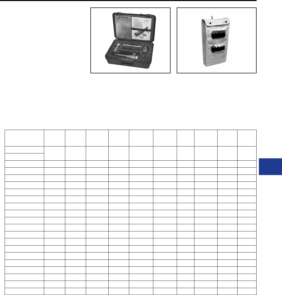
BURNDY®
Blue highlighted items are industry standard and most frequently ordered.
Canada: 1-800-387-6487 www.burndy.com US: 1-800-346-4175
Overhead Distribution and Transmission
Wedge Tap Connectors
WEJTAP™ KIT
ORDERING
INSTRUCTIONS
Type WTCC
(Carrying Case Only)
Type WABAG
WEJTAP™ plastic carrying case. Designed
for rugged use in all weather conditions. It
accommodates WEJTAP™ installation tool,
removal clips, and cleaning kit.
WEJTAP™ accessories bag is designed for
use in carrying installation tool(s), removal clips,
and cleaning kit. Hotstick accessories may
be accommodated as well. Holders for power
boosters are conveniently located on
the outside of the bag.
*Non-Hot
Stick
Power Unit
Hot
Stick
Power Unit
Self-
Firing
Tool
Large
Frame
(Yellows)
Large
Frame
Take Off Clip
Small
Frame
(Red, Blue)
Cleaning
Kit
Small
Frame
Take Off Clip
Molded
Carrying
Case
Canvas
Style
Tool Bag
Component WTBNHS WTB WTBGBW WTHY-1S WTOCY WTHRB-1S WTCK WTOCBR WTCC WABAG
Kit Catalog No.
WT2B2RBYWABAG 2 1 1 1 1 1 1
WT2BRBYWABAG 2 1 1 1 1
WTRBYK 1 1 1 1 1 1 1
WTRBYKNHS 1 1 1 1 1 1 1
WTYK 1 1 1 1
WTYKNHS 1 1 1 1
WTRBK 1 1 1 1 1
WTRBKNHS 1 1 1 1 1
WT2BRBYK 2 1 1 1 1 1 1
WT2B2RBYK 2 1 1 2 1 1 1
WTY 1 1 1
WTRB 1 1 1
WTYWABAG 1 1 1 1 1
WTYKNHSBAG 1 1 1 1 1
WTRBWABAG 1 1 1 1 1
WTRBKNHSBAG 1 1 1 1 1
WTBGBWRBYK 1 1 1 1 1 1 1
WTRBYWABAG 1 1 1 1 1 1 1
WTRBYKNHSGAB 1 1 1 1 1 1 1
* Non-Hotstick power units do not contain features allowing activation with Hotsticks.
They are not upgradeable.
Contact your BURNDY® rep resentative for a WEJTAP™ demonstration
or contact the factory at 1-800-346-4175
J-15
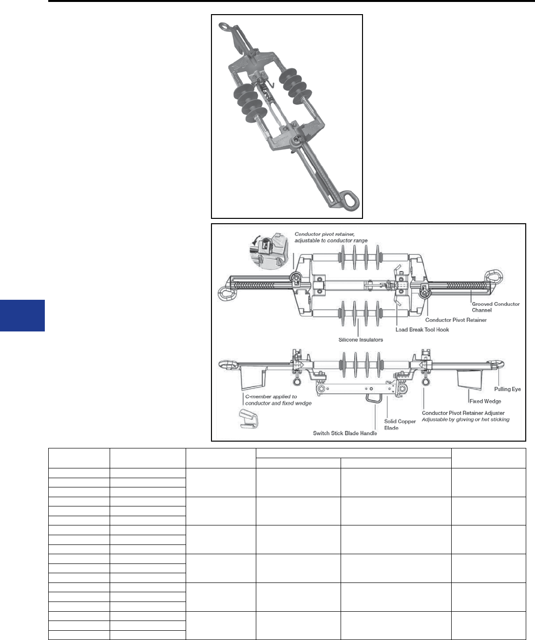
BURNDY®
Blue highlighted items are industry standard and most frequently ordered.
US: 1-800-346-4175 www.burndy.com Canada: 1-800-387-6487
Overhead Distribution and Transmission
Wedge Tap Connectors
WEJTAP™ In-Line Disconnect
The BURNDY® In-Line Disconnect utilizes proven
WEJTAP™ Technology in combination with
industry standard components to provide reliable
performance of switch applications.
Catalog
Number
KV/BIL
Ratings
Conductor
Dia. Range
Common Conductors Replacement
Tap
ACSR AAC
WAD1015 15 kV/110 kV BIL
0.368″ - 0.502″ 1/0 (6/1), 2/0 (6/1),
3/0 (6/1) 1/0, 2/0, 3/0 WADRT 1WAD1029 29 kV/150 kV BIL
WAD1035 35 kV/200 kV BIL
WAD4015 15 kV/110 kV BIL
0.522″ - 0.609″ 4/0 (6/1),
266.8 (18/1)
4/0, 250,
266.8 (7 Str. , 19 Str.),
336 compact
WADRT 1WAD4029 29 kV/150 kV BIL
WAD4035 35 kV/200 kV BIL
WAD336-15 15 kV/110 kV BIL
0.642″ - 0.723″ 266.8 (26/7),
336.4 (18/1, 26/7)
336, 350, 397.5,
477 compact WADRT 2WAD477-15 29 kV/150 kV BIL
WAD556-15 35 kV/200 kV BIL
WAD336-29 15 kV/110 kV BIL
0.741″ - 0.814″
336.4 (30/7),
397.5 (All Str.),
477 (18/1)
477 (19 Str. , 37 Str.),
500 (19 Str. , 37 Str.),
556 compact
WADRT 1WAD336-35 29 kV/150 kV BIL
WAD477-29 35 kV/200 kV BIL
WAD477-35 15 kV/110 kV BIL
0.846″ - 0.883″ 477 (24/7, 26/7, 30/7),
556 (18/1) 556 (19 Str. , 37 Str.) WADRT 2WAD556-29 29 kV/150 kV BIL
WAD556-35 35 kV/200 kV BIL
WAD795-15 * 15 kV/110 kV BIL
0.953″ - 1.040″ 556 (30/7),
795 (36/1) 795 (37 Str. , 61 Str.) WADRT 3WAD795-29 * 29 kV/150 kV BIL
WAD795-35 * 35 kV/200 kV BIL
Voltage:
Current:
Short Circuit:
Strength:
Insulators:
Meets Industry
Standards:
15 kV (110 kV BIL),
29 kV (150 kV BIL),
35 kV (200 kV BIL)
900 Ampere RMS
Momentary Current 40,000
Ampere RMS, Asymmetrical
Three Second Current 25,000
Ampere RMS, Symmetrical
Body 10,000 lbs.
Pulling Eye 6,000 lbs.
Silicone
ANSI C119.4, C37.32
IEEE C37.30, C37.34
CSA C83.71
ASTM B117 Salt Fog
Product Specications
1. Utilizes WEJTAP™ connectors for
securing the switch to the distribution
line in tension applications.
2. Utilizes industry recognized and
proven GST&D Products, LTD. blade
components along with dual Advance
Rubber Products, Inc., Insulators
attached to a BURNDY® designed yoke
plate assembly.
3. WEJTAP™ In-Line Disconnect
designed for use in gloving and hot
stick applications in conjunction with an
industry standard load break tool.
4. Dual insulators minimize the switch
movement during opening and closing
of the blade.
5. Installation steps are minimized. The
switch can be snapped directly on the
line and secured with our conductor
pivot retainer, designed into the switch
frame.
6. WEJTAP™ tooling is used to secure
the “C Member” to the built-in wedge
feature of the frame. Providing reliable
mechanical and electrical performance.
7. The blade is positioned on the switch
to simplify cutting the conductor during
installation.
8. In-Line Disconnect is removable and
reuseable.
9. Other conductor sizes available. Please
contact factory.
J-16
* Contact Factory
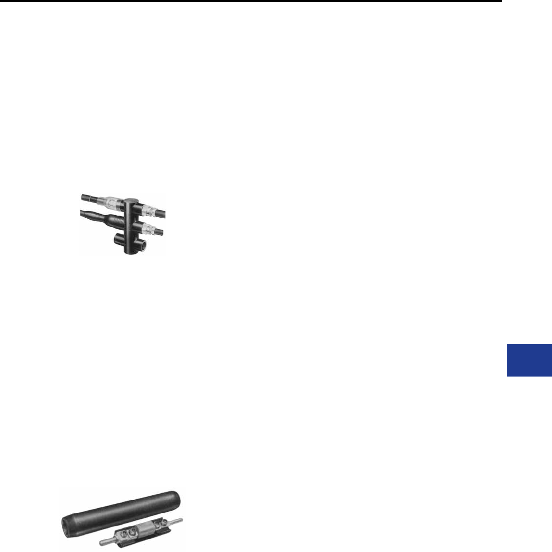
BURNDY®
Blue highlighted items are industry standard and most frequently ordered.
Canada: 1-800-387-6487 www.burndy.com US: 1-800-346-4175
Underground
K-1
Products for Underground Network and Residential Distribution Systems
TABLE OF CONTENTS
K-3
K-4
K-7
K-8
K-9 to
K-31
K-31 to
K-36
K-37
K-37,
K-38
K-39,
K-40
K-41 to
K-58
K-59 to
K-60
Underground Network Distribution
Products
Technical Data:
Underground System Connection and
Protection
Types of BURNDY® Underground
Connectors & Accessories
MOLE™
Multiple Outlet Connectors
Technical Data
How to order your BURNDY® MOLE™
MOLE™ Types
MOLE™ Accessories
HYCRAB™
Technical Data
HYCRAB™ and Accessories
Limiters
Technical Data
Limiters and Accessories
High Capacity Limiter
K-61
K-62
K-62
K-63
K-64
K-65
K-66
K-66
K-67 to K-69
K-70
K-71
K-72
K-73
K-74
K-75
Underground Residential Distribution
Products
MOLE™
Types RDMD-28G, RDMD2858D,
RDMD-28CR
Types RDM-28, RDM-28T
MOLE™ Tap Kits
Types RA6UC-SL, RA6UCR-SL
(URD Street Lighting Tap Kit)
Types RYA-UC, RYA-AC, RYA-UCR,
RYA-ACR
Overhead or Underground Secondary
Connectors
Type BSSBC
Submersible Secondary Connectors
Types BSSBC, BDESS
URD Insulated Splice Kit
Type YS-CG
Y-LOK
HYREDUCER™ Splices
Type YRB-U
Type YRB-T
Submersible Splice Covers
Types BSSI, BTWTC
Service Taps and Terminals
Types K-P-C, YPC-C
Types K6B, K33B
Types F-A, K6A34U, K-P-UC
Power Distribution Blocks
Types BPD, BPD2

BURNDY®
Blue highlighted items are industry standard and most frequently ordered.
US: 1-800-346-4175 www.burndy.com Canada: 1-800-387-6487
Underground
K-2
Products for Underground Network Distribution Systems
TABLE OF CONTENTS
K-9
K-10
K-11
K-12
K-13
K-14
K-15
K-16
K-17
K-18
K-19
K-20
K-21
K-22
K-23
K-24
K-25
K-26
K-27, K-28
K-29
K-30
K-31
K-31
K-32
K-33, K34
K-35
MOLE™
1500 AMP
Type ZM
Type ZMT
Type ZME
Type ZML
Type ZMX
Type ZMK
2000-2500 AMP
Type ZM
Type ZMT
Type ZME
Type ZML
Type ZMX
Type ZMK
3000 AMP
Type ZM
Type ZMT
Type ZME
Type ZML
Type ZMX
Type ZMK
MOLE™ Stud Connectors
Type ZMLDN
Type Z2MLDN
Type ZMDN
Type ZMTDN
MOLE™ Outlet Plugs
Type Z-P
Socket and Nut Assembly
Type Z-NR
MOLE™ Compression Cone
Type Z
MOLE™ Coupler
Type ZMS
K-35
K-36
K-37
K-38
K-41
K-42
K-43
K-43
K-44
K-45
K-46
K-47
K-48
K-48
K-49
K-49
K-50
K-50
K-51
K-52
K-53
K-54
K-54
K-55
K-56
K-56
K-57
K-58
MOLE™ Sleeves
Type CM (NOTAPE™)
Type Z-C (Outlet Insulating Sleeve)
HYCRAB™
Type ZM
Type YNM
Limiters
Type YFS-CR, YFS-CP
Type YFS-CPL
Type YFSR, YFSP
Type YFSP-L
Type YFA-CR, YFA-CP
Type YFA-CPL
Types YFAR, YFAP
Type YFAP-L
Types YFM-CR, YFM-CP
Type YFM-CPL
Types YFMR, YFMP
Type YFMP-L
Type VYFT
Type NYFT
Type LYS
Type LYM
Type LF
Type LYBASE
Type LYS34P2
Type LYS-P5
Type LYM34P3
Type LYS-P6
Network Protector Fuses
Type Y, Z
T-Connector
Type NYT
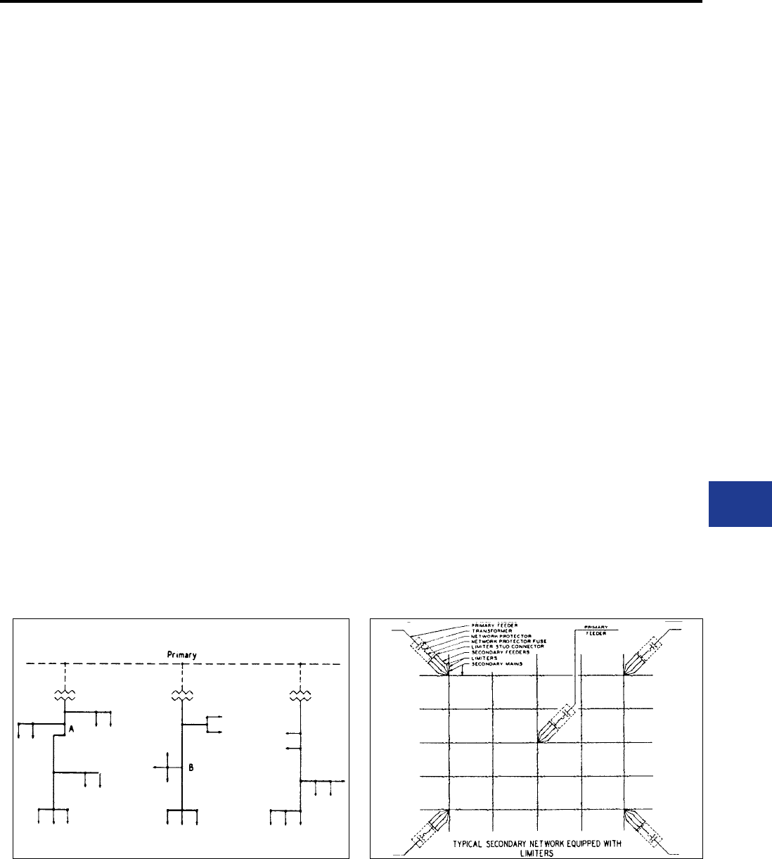
BURNDY®
Blue highlighted items are industry standard and most frequently ordered.
Canada: 1-800-387-6487 www.burndy.com US: 1-800-346-4175
Underground
UNDERGROUND SYSTEM CONNECTION AND PROTECTION
Nowhere in the distribution of electrical power
are the problems of connecting conductors and
equipment against the effects of fault currents
as complex as in underground systems. For
more than 85 years, BURNDY® engineers have
worked closely with utilities to develop devices
for connecting and protecting conductors and
associated equipment in underground systems.
These devices, with their inherent dependability
and economy, have contributed to the rapid growth
of underground systems throughout the country. To
assist utility personnel in more effectively selecting
and applying these devices, the engineering talent
and experience of BURNDY have been pooled
to prepare this technical section, and the catalog
information that follows.
These devices are designed for use in both radial
and network type underground systems. Radial
systems (Fig. 1) distribute power economically
except in high load density areas where a high
degree of service reliability is required.
Network systems (Fig. 2) have become standard
for AC power distribution where load density is
high and service continuity must be assured under
nearly all conditions. The improved equipment and
methods which are described in this catalog have
been designed to meet these secondary network
system requirements and to reduce the cost of
installation and maintenance.
Early Problems in Underground Connections
Despite the many advantages of underground
distribution, a major problem was that of making
dconnections in congested manholes or junction
boxes. The necessary procedure - soldering
conductors, taping joints, and wiping lead covered
cable - was so complex, that it demanded
considerable skill and was time consuming
and costly. This involved procedure had to be
repeated each time a service was added to a
main. When completed, the multiple-branch
joints were excessively bulky and their electrical
and mechanical performance suffered from the
shortcomings of soldered connections.
The installation of underground distribution made
greater strides as those early connection methods
gave way to specialized products and technicques
developed by BURNDY at the request of, and in
close collaboration with, engineers of leading
utilities. These specialized connectors were easier
and more economical to install, more compact, and
more dependable electrically and mechanically.
For installation in conjunction with these
connectors, BURNDY also developed products
to protect the secondary system from the effects
of fault currents. The continuing improvement of
these products based on eld experience and
laboratory research, is contributing to even greater
dependability and economy in underground
distribution.
Design Objectives in Connectors for
Underground
While each of the principal types of equipment
described in the following pages has been
designed to meet particular service requirements,
all have several basic objectives in common:
Reliability: To minimize outages and their serious
consequences in the high load density areas
serviced by underground systems.
Ease of Installation: Compact for easy
installation in the conned space of a manhole and
transformer vaults. Mechanical connections that
eliminate difcult solder joints.
Economy: By reducing the time and skill required
for installation of a dependable, insulated compact
connection.
Versatility: For permitting easier changes,
expansion, and additional services with a minimum
of system shutdown.
Figure 1: Radial Secondary Distribution System Figure 2: Typical Secondary network Equipped with Limiters
K-3
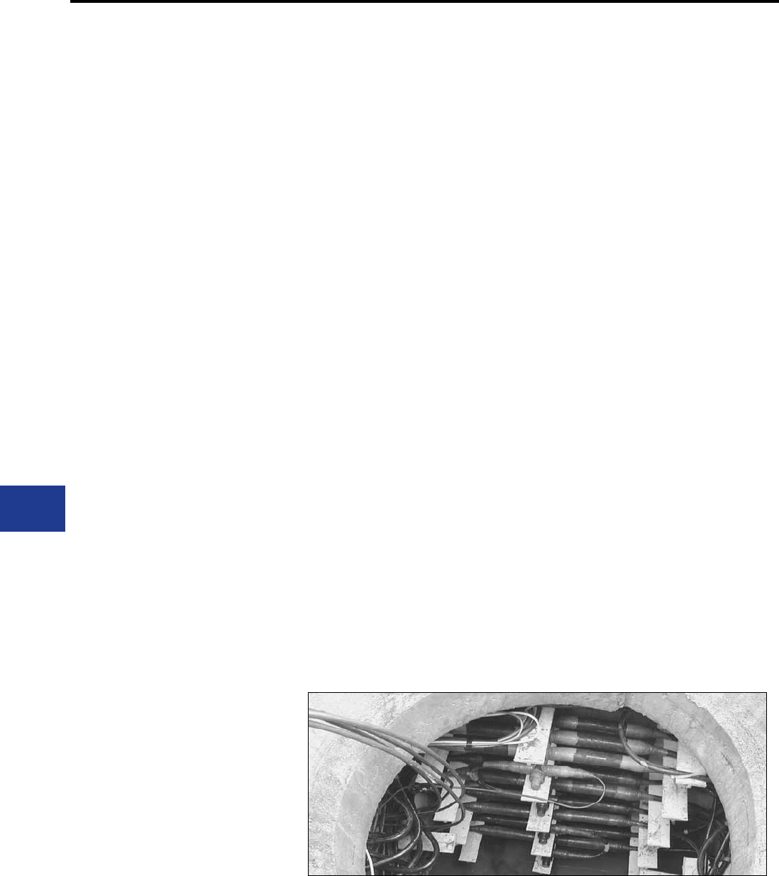
BURNDY®
Blue highlighted items are industry standard and most frequently ordered.
US: 1-800-346-4175 www.burndy.com Canada: 1-800-387-6487
Underground
TYPES OF BURNDY® UNDERGROUND CONNECTORS & ACCESSORIES
The MOLE™ and HYCRAB™
The most popular of the engineered connectors
developed specically for underground manholes
and trasformer vaults are the MOLE™ and
HYCRAB™ that provide for multiple connections at
a single junction point of main, feeder, and service
cables. Pre-insulated to eliminate extensive taping,
these connectors are essentially bus bars with
several cable outlets: mechanical installation of
the MOLE™, and compression installation in the
HYCRAB™.
Limiters and Fuses
To prevent “roasting” of cable insulation, resulting
from fault current, BURNDY has developed cable
limiters that are inserted in each secondary cable
at all junction points. Network protector fuses have
been designed to back up the protector breaker in
teh event of a malfunction during a transformer or
primary cable fault. By coordinating the time current
characteristics of the fuse with those of the cable
limiters, the possibility of limiter blowing on primary
faults is eliminated, which in turn redcuces the fault
nding task. Also, limiter, fuse, and cable insulation
characteristics must be carefully coordinated to
assure isolating a fault on the secondary before it
can cause extensive damage or interrupt service in
other sections of the secondary system.
High Capacity Limiter 200,000 Amperes at 600
Volts
The BURNDY® High Capacity Limiter is designed to
economically protect electrical distribution systems
from teh destructive effect of high energy faults.
The increasing number of 600 volt secondary
network installations for industrial and commercial
applications demand a cable limiter that can safely
interrupt 200,000 amperes (symmetrical available)
and one that will also completely coordinate with
the higher voltage network protector fuses.
Available fault currents as high as 200,000
amperes rms at 600 volts across the fusible
elements have been interrupted during tests on the
BURNDY® High Capacity Limiter. The power factor
during these tests was less than 15%, thereby
imposing the most difcult clearing conditions. No
external disturbance is experienced upon clearing
fault currents from the “oat” value to 200,000
amperes. The quartz ller absorbs the intense
energy generated by interrupting the fault current.
The quartz fuses into tobular fulgurites, with a high
dielectric strength, and forms an insulating barrier
between the melted link sections. This action
prevents restrike of the internal arc. The rugged
glass melamine housing provides a vessel that
completely contains the developed energy.
This carefully developed time-current
characteristcs and rigid manufacturing tolerances
assure proper coordination with the network
protector fuses and the insulation damage
characteristics of 4/0, 250, 350, 500, and 750 kcmil
cable.
The High Capacity Limiter is available in four
variations to accommodate a variety of installation
practices. The Type HYS has cable sockets at both
ends, which allow for indenting to the cable ends
with a hydraulic BURNDY® HYPRESS™. The
HYAO type has an offset lug on one end which
permits back-to-back mounting on bus bar.
For those installations where the BURNDY®
MOLE™ product is used for manhole junctions or
transformer vault buses, the Type HYM permits a
replaceable connection of the limiter directly to the
MOLE outlet at one end and a compression cable
connection at the other.
Modern electrical distribution systems require low
cost protection to safeguard costly equipment
and quickly isolate faults, so that the undamaged
portions of the system may function normally.
BURNDY® High Capacity Limiters assure positive,
economical protection when installed in properly
designed systems.
Compression Connectors
BURNDY® HYDENT™ compression type
connectors, and installation tools, have been
designed for splicing and terminating copper as
well as aluminum underground cables, in both
primary and secondary circuits. BURNDY tools
and dies are custom designed to produce sound
electrical, and mechanical joints on BURNDY
connectors. The use of the BURNDY® Engineered
System with matched tools, connectors and dies,
assures optimum results.
Residential Underground
The trend toward improvement in neighborhood
appearances, and the elimination of storm outages,
tree trimming, etc. has created the need for
residential underground distribution. To meet these
needs, BURNDY offers: Mechanical type pre-
insulated multi-conductor terminal connectors for
submersible transformer locations; and compact
multiconductor connectors for above ground
transformer and enclosures. For service taps,
BURNDY offers: Pre-insulated multi-conductor
compression and mechanical connectors; and
a range taking compression connector for below
grade service. Power pedestals for direct burial,
above ground application, and conduit systems
are offered. Residential Underground Fuse Block
assembly with replaceable fuse for each service
cable is also available.
K-4
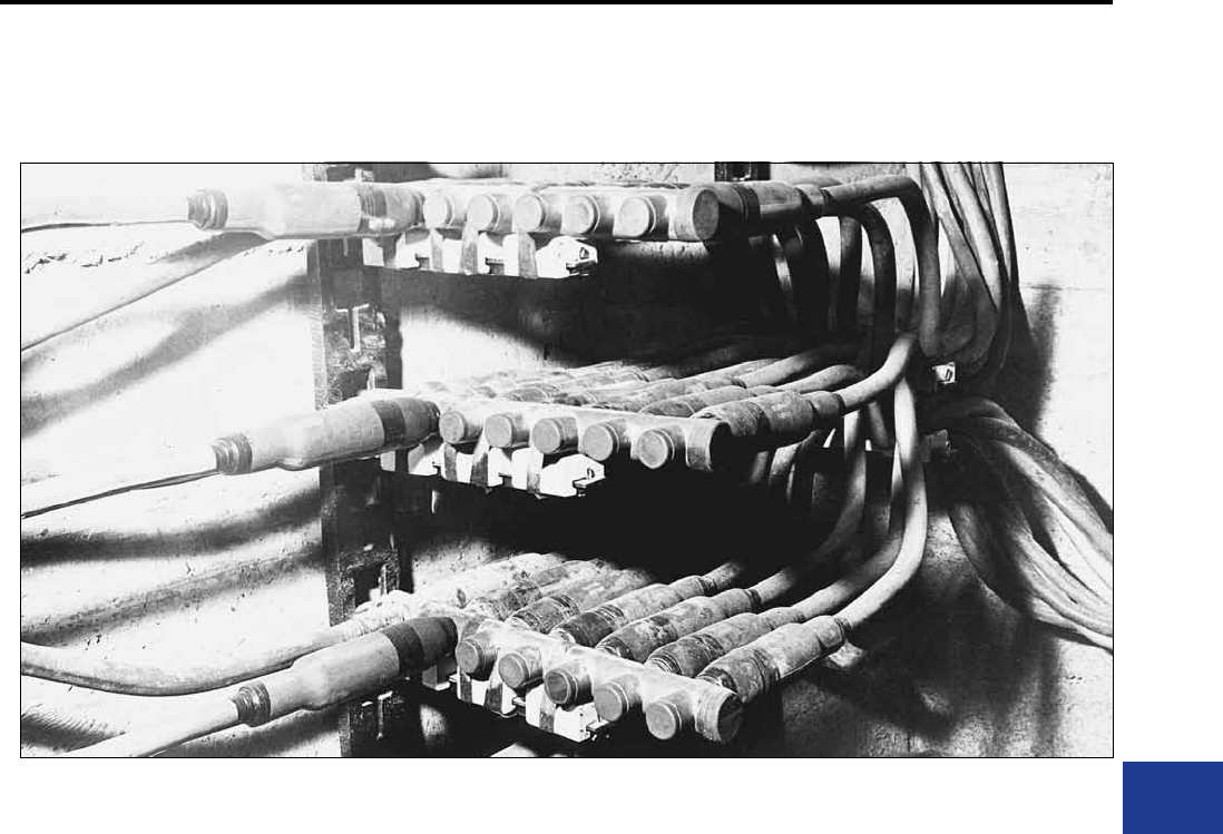
BURNDY®
Blue highlighted items are industry standard and most frequently ordered.
Canada: 1-800-387-6487 www.burndy.com US: 1-800-346-4175
Underground
MULTIPLE OUTLET CONNECTORS
Connectors for Aluminum
For systems where aluminum is used, connectors
especially designed for aluminum conductors
are available in bolted and compression types:
HYCRAB™, HYPLUG™, HYREDUCER™, and
HYSOCKET. Aluminum conductors can be
connected to standard MOLE™ connectors by
using HYPLUG™ adapters.
Multiple Outlet Connectors
The increasing use in modern electrical distribution
systems of junction points where several relatively
large cables must be connected, has brought
about the development of BURNDY® MOLE™ line
equipment to speed up and simplify the making of
such connections. The modern tendency toward
network systems not only in underground utility
practice but also in industrial wiring, has greatly
increased the number of multi-connection joints.
The BURNDY® MOLE™ and HYCRAB™
connectors are insulated bus bars with multiple
connector outlets for service cables, secondary
mains or equipment leads. In the MOLE™,
clamping action secures conductors to the
connector; in the HYCRAB™, connections are
made by indenting with a compression tool. Both
lines of insulated connectors offer the following
basic advantages:
1. Ease of Economy and Installations: The
ease and reduction of time required to make
and insulate dependable multi-connections
greatly reduces the cost of installation. The
compact design makes maximum use of
space and provides for simplied racking.
2. Versatility for System Modication: The
MOLE™ and HYCRAB™ are designed
to accommodate the secondary main and
service cables, and permit easy modication
or later additions. The numerous available
connector congurations permit a wide
variety of arrangements of cables and
equipment connections. The 600 volt rating
of the MOLE™ and HYCRAB™ insulation
provides for efcient operation at all standard
utilization voltages.
3. Efcient, Dependable Performance: The
MOLE™ and HYCRAB™ connectors assure
permanent, high conductivity connections,
good moisture seal, and insulation that
resists the severest condition encountered in
underground installations.
MOLE™ and HYCRAB™ Insulation
The location in vaults and manholes often
exposes these connectors to immersion in water,
chemical, and other contaminants, as well as to
heat from overload or fault currents. The MOLE™
and HYCRAB™ insulations provide electrical,
mechanical, and thermal properties essential
to assure the service continuity of underground
distribution systems.
Recognizing the importance of proper connection
insulation, BURNDY established performance
specications exceeding those of 600 volt cable
insulation.
K-5
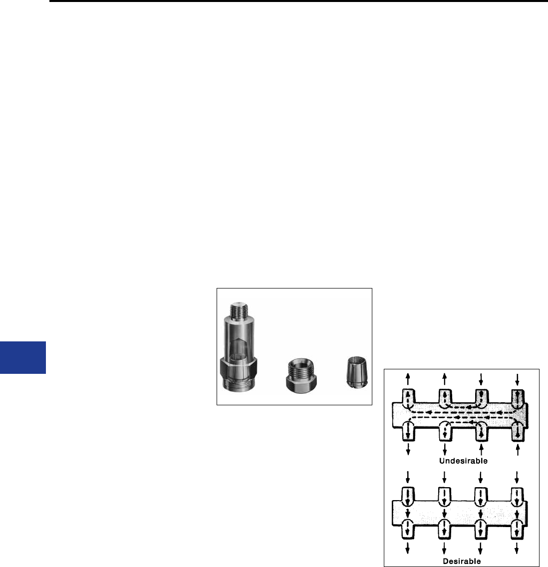
BURNDY®
Blue highlighted items are industry standard and most frequently ordered.
US: 1-800-346-4175 www.burndy.com Canada: 1-800-387-6487
Underground
MULTIPLE OUTLET CONNECTORS (Continued)
The MOLE™ and MOLE™ Accessories
The BURNDY® MOLE™ is a multi-cable
connectors that consists of a pre-insulated
copper bus bar with threaded outlets that permit a
minimum of two cables to be connected by means
of a socket, nut, and cone assembly (Illustration
A). The clamping action of the socket, nut, and
cone assembly on the cable develops high
contact pressures that maintain joint conductivities
greater than 100% of the continuous conductor.
A compression socket that is threaaded into the
MOLE™ insert is also available. The MOLE™
design affords exceptional versatility in four ways:
1. MOLE™ outlets can be plugged-off until
needed for the addition of cables.
2. Installed cables can be easily removed.
3. Cable sizes can be increased by changing
the socket, nut, and cone assembly.
4. The number of outlets may be increased by
joining MOLE™ connectors with a MOLE™
coupler.
Insulation
The copper bus bar insert is encased in a molded
insulating jacket that eliminates crotch taping. The
thickness of the jacket prevents any possibility
of the insert weight to cause the insulation at the
supports to ow away at the high temperatures of
fault conditions.
Ratings
MOLE™ connectors are rated at 1500, 2000,
2500, and 3000 amperes, based on teh maximum
current the insert cross-section can carry. Each
outlet can carry the full rated current of the cable
connected to it.
To avoid exceeding the insert rating, the cables
should be arranged in such a manner that most
current ows directly across the insert. (See
Illustration B.)
Installation
Cables are connected to the MOLE™ by means
of a socket, nut and compression cone assembly.
The socket is threaded into the MOLE™ insert.
The stripped cable end is inserted into nut and
compression cone, and then into the socket where
it is securely clamped by tightening the nut. The
joint is then sealed watertight in one of three ways:
• Taping;
• MOLE™ Outlet Insulating Sleeves, sealed
with a minimum of taping;
• NOTAPE™ MOLE™ Sleeve, sealed to the
cable and MOLE™ insulation by two non-
corrosive hose clamps.
Tests under ooding and other adverse conditions
demonstrate that such joints are impervious to
water.
Accessories
A socket, cone and nut assembly is screwed
into each MOLE™ outlet to which a cable is to
be connected. The socket has a tapered recess
into which the clamping nut forces the cable
into the compression cone. The cone is slotted
to controlled widths and depths for maximum
exibility, and its inside surface is serrated for low
contact resistance and high pullout strength.
A compression socket is available that threads
directly into the MOLE™ outlet and provides a
compression sleeve for connecting the cable with
HYPRESS™ tools.
Plug seal MOLE™ outlets not in use. The MOLE™
is delivered with one-fourth of its outlets sealed
with plugs. Additional plugs may be ordered.
MOLE™ couplers facilitate system expansion by
joining additional MOLE™ connectors to those
already installed. Couplers are easily installed
in end or side outlets of the MOLE™, and make
connections that are effective both electrically and
mechanically.
Illustration A
Illustration B
K-6
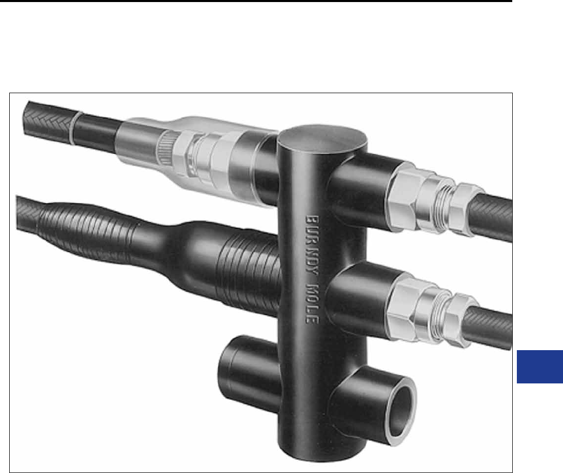
BURNDY®
Blue highlighted items are industry standard and most frequently ordered.
Canada: 1-800-387-6487 www.burndy.com US: 1-800-346-4175
Underground
MULTIPLE OUTLET CONNECTORS (Continued)
K-7
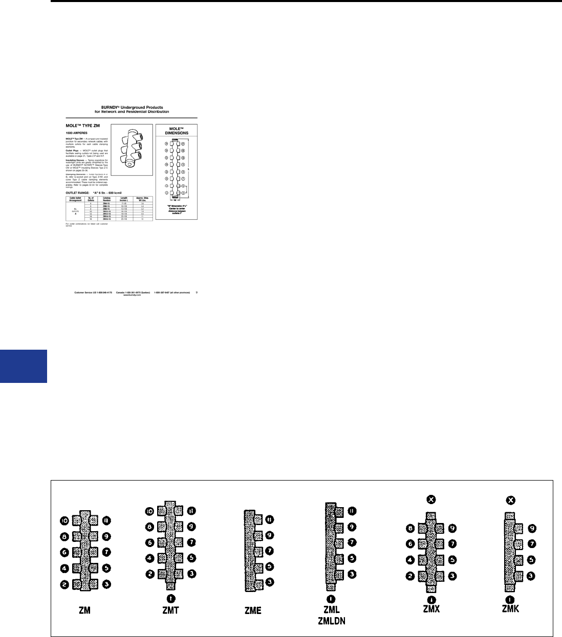
BURNDY®
Blue highlighted items are industry standard and most frequently ordered.
US: 1-800-346-4175 www.burndy.com Canada: 1-800-387-6487
Underground
HOW TO ODER YOUR BURNDY® MOLE™
This MOLE™ connector section is arranged so that all the information necessary for ordering
standard MOLE™ connections in contained on a single page.
MOLE™ Connector listings are arranged by:
Amperes: 1500; 2000-2500; 3000
MOLE™ Type: ZM, ZMT, ZME, etc. within each
ampere grouping
Cable Outlet Ranges:
Symbol “A” = #6 Str. - 600 kcmil; 5/8”
Symbol “B” = #2 Str. - 1000 kcmil; 7/8”
Symbol “C” = 500 - 1500 kcmil; 1-1/8”
Cable Outlet Arrangement:
Depending on ampere group, outlets may be all “A”
or “B” cable size, or may be combinations of sizes;
Outlet #1, “A”: all other outlets “B”, etc. (See sufx
list below.)
Number of Outlets per MOLE™:
From 2 to 16 outlets depending on MOLE™ type
(any number can be supplied).
Catalog Numbers, Dimensions, and Weights.
MOLE™ CONNECTORS ARE ORDERED BY
THE FOLLOWING PROCEDURE:
1. Determine amperage that meets
requirements and located it in the MOLE™
ampere page listings.
2. Choose MOLE™ conguration desired by
Type (ZM, ZME, ZMT, etc.) within ampere
group.
3. Decide of the number of outlets that meets
your requirements.
4. Decide on the cable ranges required for
each outlet.
5. Select cable outlet arrangement for MOLE™
listing: outlet #1, “A”: all other “B”, etc.
EXAMPLE:
Installation load capacity: 2000 amperes
Conguration: outlets on two sides and one end
Cable ranges: end outlet to accommodate a 1000
kcmil cable; other outlets: two 700 kcmil, two 600
kcmil and two 500 kcmil cables
PROCEDURE:
1. Locate 2000 through 2500 ampere MOLE™
groups
2. MOLE™ Type ZMT has outlets on two sides
and one end
3. Cable outlet symbol “B” = #2 Str. - 1000
kcmil. MOLE™ outlet arrangement: Outlet
#1 = “B”, all other outlets = “B”.
4. Catalog Number ZMT7-25B is the correct
number. See other pages for socket and nut
assembly, compression cones and insulating
sleeves.
Sufx List:
A3: Outlet #1 = B; all others = A
A4: Outlet #1 and X = B; all others = A
A7: Outlet #1 and X = C; all others = A
A9: Outlet #1 = C; all others = A
B12: Outlet #1 = A; all others = B
B72: Outlet #1 and X = C; all others = B
B92: Outlet #1 = C; all others = B
K-8
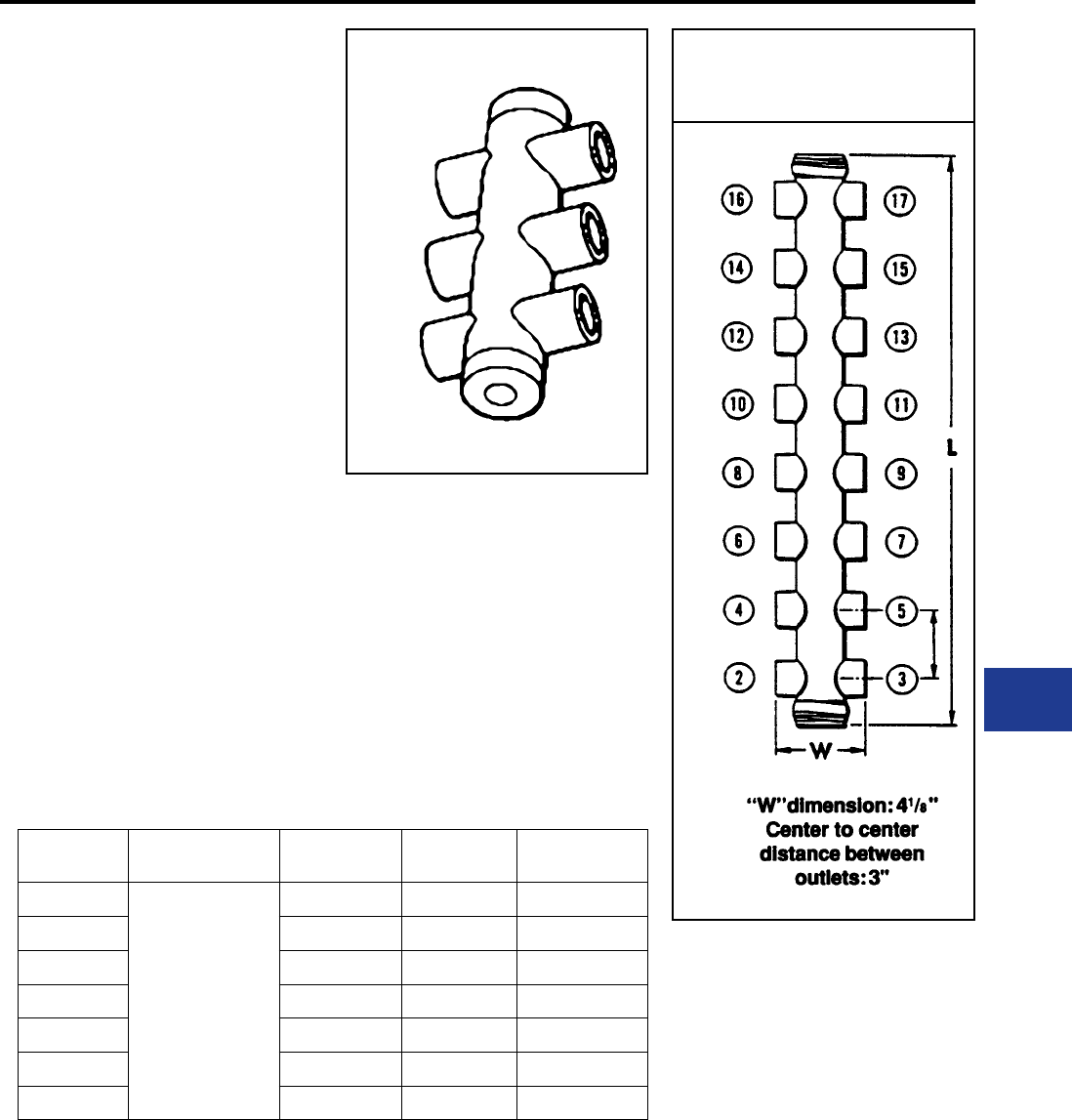
BURNDY®
Blue highlighted items are industry standard and most frequently ordered.
Canada: 1-800-387-6487 www.burndy.com US: 1-800-346-4175
Underground
MOLE™ TYPE ZM
1500 AMPERES
MOLE™ Type ZM — A compact pre-insulated
junction for secondary network cables, with multiple
outlets for each cable clamping elements.
Outlet Plugs — MOLE™ outlet plugs that facilitate
sealing outlets not being used are available, Types
Z-P and K-P, sold separately.
Insulating Sleeves — Taping operations for
watertight joints are greatly simplied by the use of
BURNDY® NOTAPE™ Sleeves Type CM or MOLE™
Insulating Sleeves Type Z-C, sold separately.
Clamping Elements — Outlet Symbols A or B, refer
to socket and nut Type Z-NR, and cone Type Z cable
clamping elements accommodated. These must be
ordered separately.
Catalog
Number
Cable Outlet
Arrangement
No. of
Outlets
Length
Inches L
Approx. Ship
Wt. Lbs.
ZM4-15
All
Outlets
A
4 7-1/8 2.60
ZM6-15 6 10-1/8 4.40
ZM8-15 8 13-1/8 6.20
ZM10-15 10 16-1/8 7.80
ZM12-15 12 19-1/8 9.50
ZM14-15 14 22-1/8 11.00
ZM16-15 16 25-1/8 13.00
For outlet combinations not listed call customer service.
OUTLET RANGE: “A” 6 Str. - 600 kcmil
MOLE™
DIMENSIONS
K-9
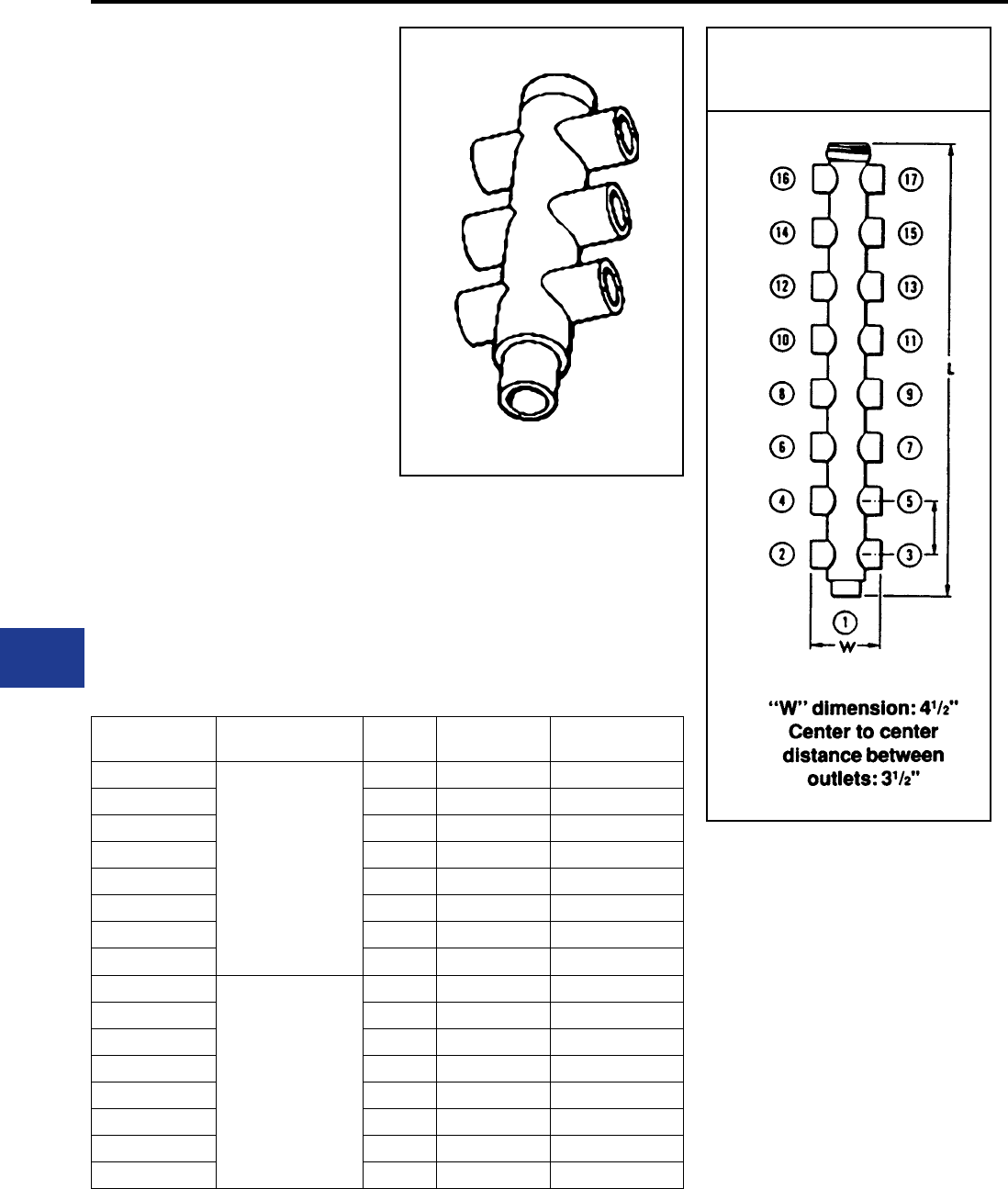
BURNDY®
Blue highlighted items are industry standard and most frequently ordered.
US: 1-800-346-4175 www.burndy.com Canada: 1-800-387-6487
Underground
MOLE™ TYPE ZMT
1500 AMPERES
MOLE™ Type ZMT— A compact pre-insulated
junction for secondary network cables, with
multiple outlets for cable clamping elements.
Future expansion is provided for by an end outlet
which can be joined to an additional MOLE™ by
Type ZMS couplers.
Outlet Plugs — Mole outlet plugs that facilitate
sealing outlets not being used are available
separately, Types Z-P and K-P.
Insulating Sleeves — Taping operations for
watertight joints are greatly simplied by the use
of BURNDY® NOTAPE™ Sleeves Type CM or
MOLE™ Insulating Sleeves Type Z-C are available
separately.
Clamping Elements — Outlet Symbols A or
B, refer to socket and nut Type Z-NR, and cone
Type Z cable clamping elements accommodated.
These must be ordered separately.
Catalog
Number
Cable Outlet
Arrangement
No. of
Outlets
Length
Inches L
Approx. Ship
Wt. Lbs.
ZMT3-15
All
Outlets
A
3 5 1.30
ZMT5-15 5 8 3.00
ZMT7-15 7 11 4.50
ZMT9-15 9 14 6.20
ZMT11-15 11 17 7.90
ZMT13-15 13 20 9.70
ZMT15-15 15 23 12.00
ZMT17-15 17 26 13.00
ZMT3-15A3
Outlet #1
B
All Other
Outlets
A
3 5 1.30
ZMT5-15A3 5 8 3.00
ZMT7-15A3 7 11 4.50
ZMT9-15A3 9 14 6.20
ZMT11-15A3 11 17 7.90
ZMT13-15A3 13 20 9.70
ZMT15-15A3 15 23 12.00
ZMT17-15A3 17 26 13.00
OUTLET RANGE: “A” 6 Str. - 600 kcmil
“B” 2 Str. - 1000 kcmil
For outlet combinations not listed call customer service.
MOLE™
DIMENSIONS
K-10
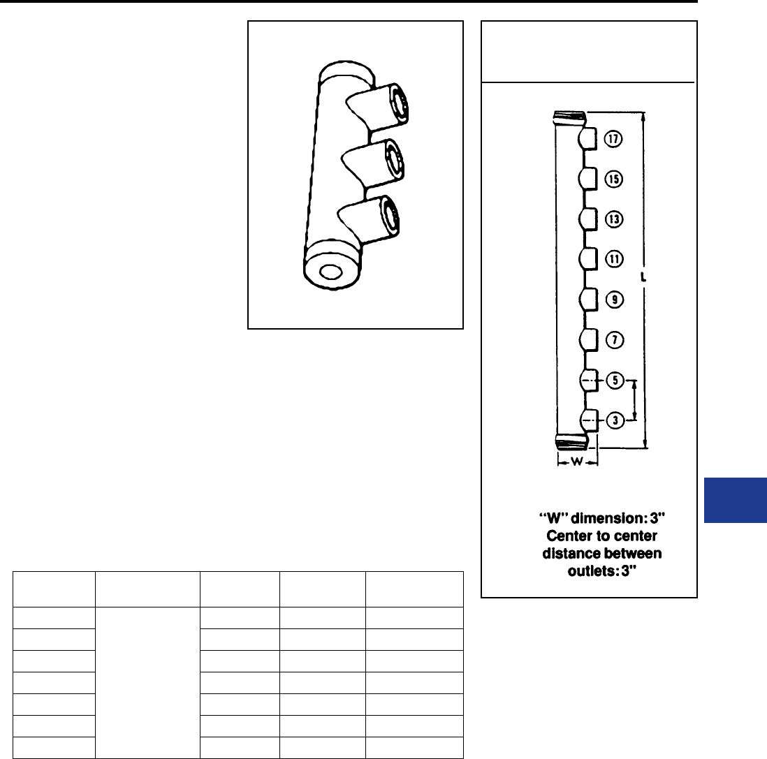
BURNDY®
Blue highlighted items are industry standard and most frequently ordered.
Canada: 1-800-387-6487 www.burndy.com US: 1-800-346-4175
Underground
MOLE™ TYPE ZME
1500 AMPERES
MOLE™ Type ZME — A compact pre-insulated
junction for secondary network cables, with
multiple outlets for cable clamping elements.
Outlet Plugs — Mole outlet plugs that facilitate
sealing outlets not being used are Types Z-P and
K-P, sold separately.
Insulating Sleeves — Taping operations for
watertight joints are greatly simplied by the use
of BURNDY® NOTAPE™ Sleeves Type CM or
MOLE™ Insulating Sleeves Type Z-C are sold
separately.
Clamping Elements— Outlet Symbols A or
B, refer to socket and nut Type Z-NR, and cone
Type Z cable clamping elements accommodated.
These must be ordered separately.
Catalog
Number
Cable Outlet
Arrangement
No. of
Outlets
Length
Inches L
Approx. Ship
Wt. Lbs.
ZME2-15
All
Outlets
A
2 7-1/8 2.50
ZME3-15 3 10-1/8 4.40
ZME4-15 4 13-1/8 6.10
ZME5-15 5 16-1/8 7.70
ZME6-15 6 19-1/8 9.40
ZME7-15 7 22-1/8 11.00
ZME8-15 8 25-1/8 13.00
For outlet combinations not listed call customer service.
OUTLET RANGE: “A” 6 Str. - 600 kcmil
MOLE™
DIMENSIONS
K-11
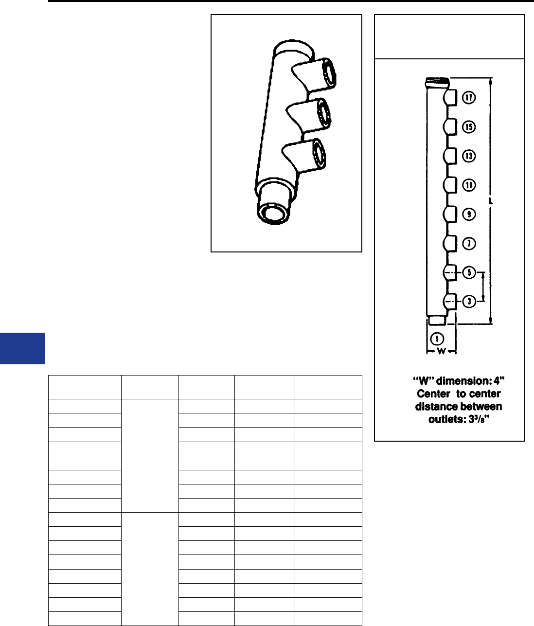
BURNDY®
Blue highlighted items are industry standard and most frequently ordered.
US: 1-800-346-4175 www.burndy.com Canada: 1-800-387-6487
Underground
MOLE™ TYPE ZML
1500 AMPERES
MOLE™ Type ZML — A compact pre-insulated
junction for secondary network cabes, with
multiple outlets for cable clamping elements.
Future expansion is provided for by an end outlet
which can be joined to an additional MOLE™ by
Type ZMS coupler.
Outlet Plugs — MOLE™ outlet plugs that facilitate
sealing outlets not being used are available
separately, Types Z-P and K-P.
Insulating Sleeves — Taping operations for
watertight joints are greatly simplied by the use
of BURNDY® NOTAPE™ Sleeves Type CM or
MOLE™ Insulating Sleeves Type Z-C.
Clamping Elements — Outlet Symbols A or
B, refer to socket and nut Type Z-NR, and cone
Type Z cable clamping elements accommodated.
These must be ordered separately.
MOLE™
DIMENSIONS
Catalog
Number
Cable Outlet
Arrangement
No. of
Outlets
Length
Inches L
Approx. Ship
Wt. Lbs.
ZML2-15
All
Outlets
A
2 5 1.20
ZML3-15 3 8 3.00
ZML4-15 4 11 4.30
ZML5-15 5 14 5.90
ZML6-15 6 17 7.60
ZML7-15 7 20 9.40
ZML8-15 8 23 11.00
ZML9-15 9 26 13.00
ZML2-15A3
Outlet #1
B
All Other
Outlets
A
2 5 1.20
ZML3-15A3 3 8 3.00
ZML4-15A3 4 11 4.30
ZML5-15A3 5 14 5.90
ZML6-15A3 6 17 7.60
ZML7-15A3 7 20 9.40
ZML0-15A3 8 23 11.00
ZML9-15A3 9 26 13.00
For outlet combinations not listed call customer service.
OUTLET RANGE: “A” 6 Str. - 600 kcmil
“B” 2 Str. - 1000 kcmil
K-12
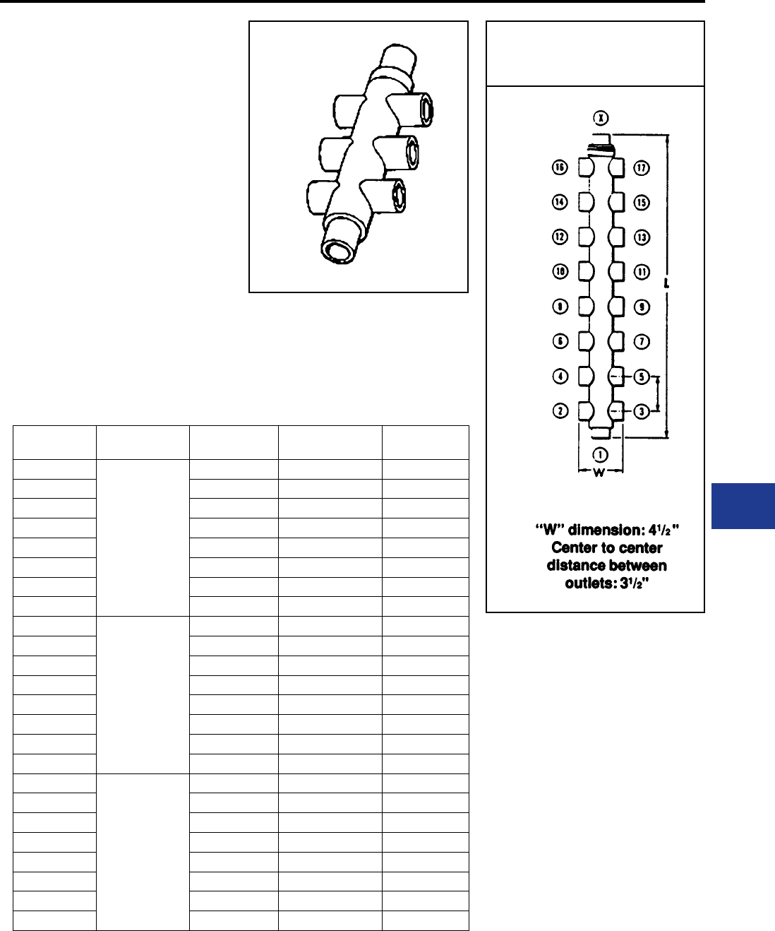
BURNDY®
Blue highlighted items are industry standard and most frequently ordered.
Canada: 1-800-387-6487 www.burndy.com US: 1-800-346-4175
Underground
MOLE™ TYPE ZMX
1500 AMPERES
MOLE™ Type ZMX — A compact pre-insulated
junction for secondary network cables, with
multiple outlets for cable clamping elements.
Future expansion is provided for by an end outlet
which can be joined to an additional MOLE™ by
Type ZMS coupler.
Outlet Plugs — MOLE™ outlet plugs that facilitate
sealing outlets not being used are available, Types
Z-P and K-P, ordered separately.
Insulating Sleeves — Taping operations for
watertight joints are greatly simplied by the use
of BURNDY® NOTAPE™ Sleeves Type CM or
MOLE™ Insulating Sleeves Type Z-C available
separately.
MOLE™
DIMENSIONS
Catalog
Number
Cable Outlet
Arrangement
No. of
Outlets
Length
Inches L
Approx. Ship
Wt. Lbs.
ZMX4-15
All
Outlets
A
4 6.00 1.70
ZMX6-15 6 9.00 3.40
ZMX8-15 8 12.00 5.20
ZMX10-15 10 15.00 6.90
ZMX12-15 12 18.00 8.80
ZMX14-15 14 21.00 11.00
ZMX16-15 16 23.97 12.00
ZMX18-15 18 27.00 14.00
ZMX4-15A4
Outlets
#1 and X
B
All other
Outlets
A
4 6.09 1.70
ZMX6-15A4 6 9.09 3.40
ZMX8-15A4 8 12.00 5.20
ZMX10-15A4 10 15.00 6.90
ZMX12-15A4 12 18.09 8.80
ZMX14-15A4 14 21.00 11.00
ZMX16-15A4 16 24.09 12.00
ZMX18-15A4 18 27.00 14.00
ZMX4-15A3
Outlets
#1 and X
B
All other
Outlets
A
4 6.03 1.7.00
ZMX6-15A3 6 9.03 3.40
ZMX8-15A3 8 12.03 5.20
ZMX10-15A3 10 15.03 6.90
ZMX12-15A3 12 18.00 8.80
ZMX14-15A3 14 21.00 11.00
ZMX16-15A3 16 24.00 12.00
ZMX18-15A3 18 27.00 14.00
OUTLET RANGE: “A” 6 Str. - 600 kcmil
“B” 2 Str. - 1000 kcmil
For outlet combinations not listed call customer service.
Clamping Elements — Outlet Symbols A or B,
refer to socket and nut Type Z-NR, and cone Type
Z cable clamping elements accommodated. These
must be ordered separately.
K-13
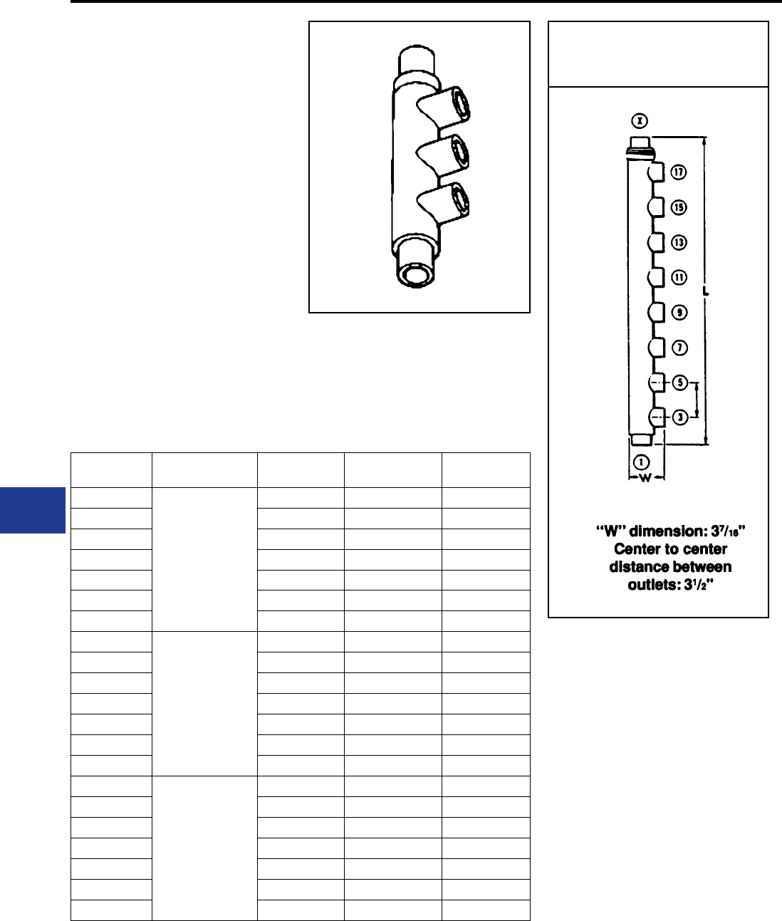
BURNDY®
Blue highlighted items are industry standard and most frequently ordered.
US: 1-800-346-4175 www.burndy.com Canada: 1-800-387-6487
Underground
MOLE™ TYPE ZMK
1500 AMPERES
MOLE™ Type ZMK — A compact pre-insulated
junction for secondary network cables, with
multiple outlets for cable clamping elements.
Future expansion is provided for by an end outlet
which can be joined to an additional MOLE™ by
Type ZMS couplers.
Outlet Plugs — MOLE™ outlet plugs that facilitate
sealing outlets not being used are available, Types
Z-P and K-P, ordered separately.
Insulating Sleeves — Taping operations for
watertight joints are greatly simplied by the use
of BURNDY® NOTAPE™ Sleeves Type CM or
MOLE™ Insulating Sleeves Type Z-C available
separately.
Catalog
Number
Cable Outlet
Arrangement
No. of
Outlets
Length
Inches L
Approx Ship
Weight
ZMK4-15
All
Outlets
A
4 9 3.30
ZMK5-15 5 12 5.00
ZMK6-15 6 15 6.80
ZMK7-15 7 18 8.70
ZMK8-15 8 21 11.00
ZMK9-15 9 24 12.00
ZMK10-15 10 27 14.00
ZMK4-15A4
Outlets
#1 and X
B
All Other
Outlets
A
4 9 3.30
ZMK5-15A4 5 12 5.00
ZMK6-15A4 6 15 6.80
ZMK7-15A4 7 18 8.70
ZMK8-15A4 8 21 11.00
ZMK9-15A4 9 24 12.00
ZMK10-15A4 10 27 14.00
ZMK4-15A3
Outlets
#1 or X
B
All Other
Outlets
A
4 9 3.30
ZMK5-15A3 5 12 5.00
ZMK6-15A3 6 15 6.80
ZMK7-15A3 7 18 8.70
ZMK8-15A3 8 21 11.00
ZMK9-15A3 9 24 12.00
ZMK10-15A3 10 27 14.00
For outlet combinations not listed call customer service.
OUTLET RANGE: “A” 6 Str. - 600 kcmil
“B” 2 Str. - 1000 kcmil
Clamping Elements — Outlet Symbols A or
B, refer to socket and nut Type Z-NR, and cone
Type Z cable clamping elements accommodated.
These must be ordered separately.
MOLE™
DIMENSIONS
K-14
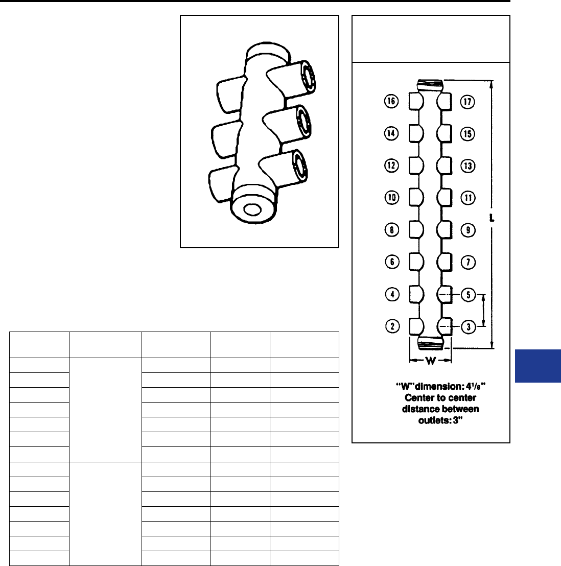
BURNDY®
Blue highlighted items are industry standard and most frequently ordered.
Canada: 1-800-387-6487 www.burndy.com US: 1-800-346-4175
Underground
MOLE™ TYPE ZM
2000-2500 AMPERES
MOLE™ Type ZM — A compact pre-insulated
junction for secondary network cables, with
multiple outlets for cable clamping elements.
Outlet Plugs — MOLE™ outlet plugs that facilitate
sealing outlets not being used are available, Types
Z-P and K-P, ordered separately.
Insulating Sleeves — Taping operations for
watertight joints are greatly simplied by the use
of BURNDY® NOTAPE™ Sleeves Type CM or
MOLE™ Insulating Sleeves Type Z-C available
separately.
Clamping Elements — Outlet Symbols A or
B, refer to socket and nut Type Z-NR, and cone
Type Z cable clamping elements accommodated.
These must be ordered separately.
Catalog
Number
Cable Outlet
Arrangement
No. of
Outlets
Length
Inches L
Approx. Ship
Wt. Lbs.
ZM4-25
All
Outlets
A
4 8 4.40
ZM6-25 6 11-1/2 7.00
ZM8-25 8 15 9.70
ZM10-25 10 18-1/2 13.00
ZM12-25 12 22 14.00
ZM14-25 14 25-1/2 15.00
ZM16-25 16 29 18.00
ZM4-25B
All
Outlets
B
4 8 4.40
ZM6-25B 6 11-1/2 7.00
ZM8-25B 8 15 9.70
ZM10-25B 10 18-1/2 13.00
ZM12-25B 12 22 14.00
ZM14-25B 14 25-1/2 15.00
ZM16-25B 16 29 18.00
OUTLET RANGE: “A” 6 Str. - 600 kcmil
“B” 2 Str. - 1000 kcmil
For outlet combinations not listed call customer service.
MOLE™
DIMENSIONS
K-15
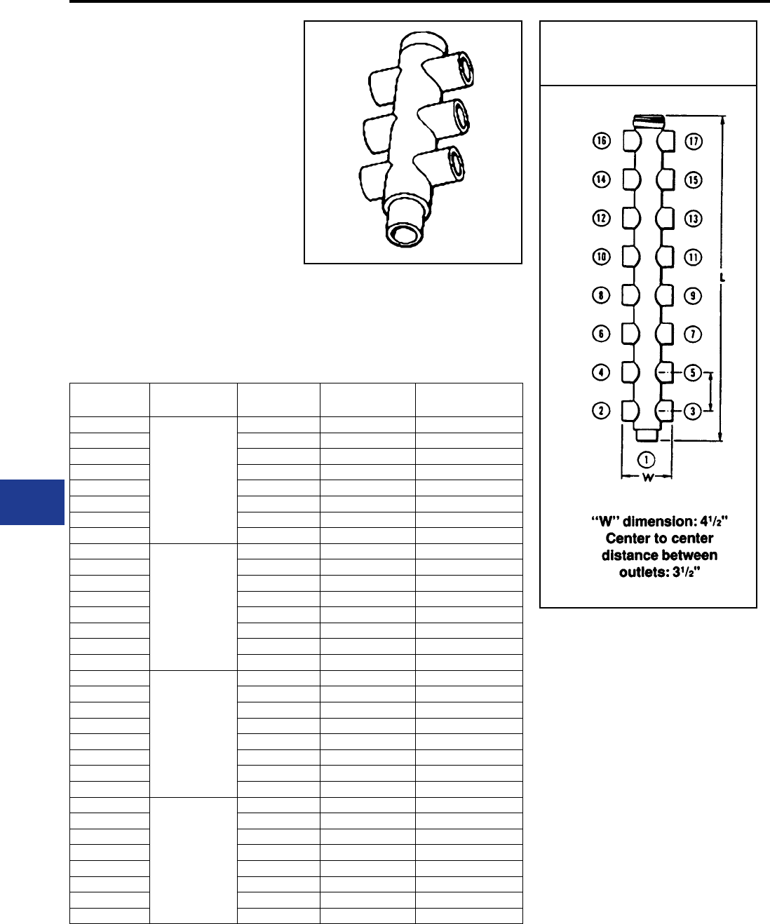
BURNDY®
Blue highlighted items are industry standard and most frequently ordered.
US: 1-800-346-4175 www.burndy.com Canada: 1-800-387-6487
Underground
MOLE™ TYPE ZMT
2000-2500 AMPERES
MOLE™ Type ZMT — A compact pre-insulated
junction for secondary network cables, with
multiple outlets for cable clamping elements.
Future expansion is provided for by an end outlet
which can be joined to an additional MOLE™ by
Type ZMS couplers.
Outlet Plugs — Mole outlet plugs that facilitate
sealing outlets not being used are available
separately, Types Z-P and K-P.
Insulating Sleeves — Taping operations for
watertight joints are greatly simplied by the use
of BURNDY® NOTAPE™ Sleeves Type CM or
MOLE™ Insulating Sleeves Type Z-C are sold
separately.
Catalog
Number
Cable Outlet
Arrangement
No. of
Outlets
Length
Inches L
Approx. Ship
Wt. Lbs.
ZMT3-25
All
Outlets
A
3 5-1/2 1.90
ZMT5-25 5 9 5.80
ZMT7-25 7 12-1/2 8.00
ZMT9-25 9 16 12.00
ZMT11-25 11 19-1/2 14.00
ZMT13-25 13 23 17.00
ZMT15-25 15 26-1/2 18.00
ZMT17-25 17 30 19.00
ZMT3-25A3
Outlet #1
B
All Other
Outlets
A
3 5-1/2 1.90
ZMT5-25A3 5 9 5.80
ZMT7-25A3 7 12-1/2 8.00
ZMT9-25A3 9 16 12.00
ZMT11-25A3 11 19-1/2 14.00
ZMT13-25A3 13 23 17.00
ZMT15-25A3 15 26-1/2 18.00
ZMT17-25A3 17 30 19.00
ZMT3-25B12
Outlet #1
A
All Other
Outlets
B
3 5-1/2 1.90
ZMT5-25B12 5 9 5.80
ZMT7-25B12 7 12-1/2 8.00
ZMT9-25B12 9 16 12.00
ZMT11-25B12 11 19-1/2 14.00
ZMT13-25B12 13 23 17.00
ZMT15-25B12 15 26-1/2 18.00
ZMT17-25B12 17 30 19.00
ZMT3-258
All
Outlets
B
3 5-1/2 1.90
ZMT5-25B 5 9 5.80
ZMT7-25B 7 12-1/2 8.00
ZMT9-25B 9 16 12.00
ZMT11-25B 11 19-1/2 14.00
ZMT13-25B 13 23 17.00
ZMT15-25B 15 26-1/2 18.00
ZMT17-25B 17 30 19.00
Clamping Elements — Outlet Symbols A or
B, refer to socket and nut Type Z-NR, and cone
Type Z cable clamping elements accommodated.
These must be ordered separately.
OUTLET RANGE: “A” 6 Str. - 600 kcmil
“B” 2 Str. - 1000 kcmil
For outlet combinations not listed call customer service.
MOLE™
DIMENSIONS
K-16
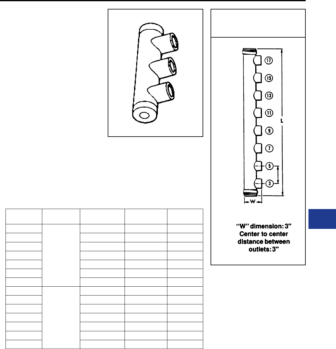
BURNDY®
Blue highlighted items are industry standard and most frequently ordered.
Canada: 1-800-387-6487 www.burndy.com US: 1-800-346-4175
Underground
MOLE™ TYPE ZME
2000-2500 AMPERES
MOLE™ Type ZME — A compact pre-insulated
junction for secondary network cables, with
multiple outlets for cable clamping elements.
Outlet Plugs — Mole outlet plugs that facilitate
sealing outlets not being used are available
separately, Types Z-P and K-P.
Insulating Sleeves — Taping operations for
watertight joints are greatly simplied by the use
of BURNDY® NOTAPE™ Sleeves Type CM
or MOLE™ Insulating Sleeves Type Z-C, sold
separately.
Clamping Elements — Outlet Symbols A or
B, refer to socket and nut Type Z-NR, and cone
Type Z cable clamping elements accommodated.
These must be ordered separately.
Catalog
Number
Cable Outlet
Arrangement
No. of
Outlets
Length
Inches L
Approx. Ship
Wt. Lbs.
ZME2-25
All
Outlets
A
2 8 4.30
ZME3-25 3 11-1/2 6.90
ZME4-25 4 15 9.50
ZME5-25 5 18-1/2 12.00
ZME6-25 6 22 14.00
ZME7-25 7 25-1/2 15.00
ZME8-25 8 29 17.00
ZME2-25B
All
Outlets
B
2 8 4.30
ZME3-25B 3 11-1/2 6.90
ZME4-25B 4 15 9.50
ZME5-25B 5 18-1/2 12.00
ZME6-25B 6 22 14.00
ZME7-25B 7 25-1/2 15.00
ZME8-25B 8 29 17.00
OUTLET RANGE: “A” 6 Str. - 600 kcmil
“B” 2 Str. - 1000 kcmil
For outlet combinations not listed call customer service.
MOLE™
DIMENSIONS
K-17
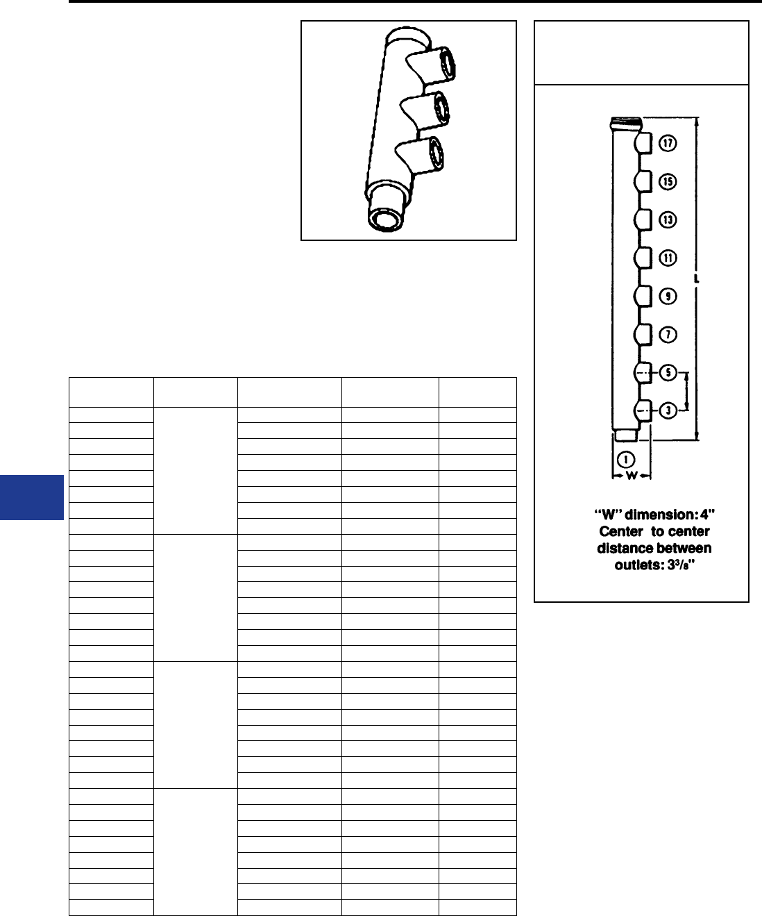
BURNDY®
Blue highlighted items are industry standard and most frequently ordered.
US: 1-800-346-4175 www.burndy.com Canada: 1-800-387-6487
Underground
MOLE™ TYPE ZML
2000-2500 AMPERES
MOLE™ Type ZML — A compact pre-insulated
junction for secondary network cabes, with
multiple outlets for cable clamping elements.
Future expansion is provided for by an end outlet
which can be joined to an additional MOLE™ by
Type ZMS coupler.
Outlet Plugs — MOLE™ outlet plugs that facilitate
sealing outlets not being used are available
seaparately, Types Z-P and K-P.
Insulating Sleeves — Taping operations for
watertight joints are greatly simplied by the use
of BURNDY® NOTAPE™ Sleeves Type CM
or MOLE™ Insulating Sleeves Type Z-C, sold
separately.
Catalog
Number
Cable Outlet
Arrangement
No. of
Outlets
Length
Inches L
Approx Ship
Wt. Lbs.
ZML2-25
All
Outlets
A
2 5-1/2 1.80
ZML3-25 3 9 5.80
ZML4-25 4 12-1/2 7.90
ZML5-25 5 16 12.00
ZML6-25 6 19-1/2 14.00
ZML7-25 7 23 16.00
ZML8-25 8 26-1/2 17.00
ZML9-25 9 30 19.00
ZML2-25A3
Outlet #1
B
All Other
Outlets
A
2 5-1/2 1.80
ZML3-25A3 3 9 5.80
ZML4-25A3 4 12-1/2 7.90
ZML5-25A3 5 16 12.00
ZML6-25A3 6 19-1/2 14.00
ZML7-25A3 7 23 16.00
ZML8-25A3 8 26-1/2 17.00
ZML9-25A3 9 30 19.00
ZML2-25B12
Outlet #1
A
All Others
Outlets
B
2 5-1/2 1.80
ZML3-25B12 3 9 5.80
ZML4-25B12 4 12-1/2 7.90
ZML5-25B12 5 16 12.00
ZML6-25B12 6 19-1/2 14.00
ZML7-25B12 7 23 16.00
ZML8-25B12 8 26-1/2 17.00
ZML9-25B12 9 30 19.00
ZML2-25B
All
Outlets
B
2 5-1/2 1.80
ZML3-25B 3 9 5.80
ZML4-25B 4 12-1/2 7.90
ZML5-25B 5 16 12.00
ZML6-25B 6 19-1/2 14.00
ZML7-25B 7 23 16.00
ZML8-25B 8 26-1/2 17.00
ZML9-25B 9 30 19.00
Clamping Elements — Outlet Symbols A or
B, refer to socket and nut Type Z-NR, and cone
Type Z cable clamping elements accommodated.
These must be ordered separately.
OUTLET RANGE: “A” 6 Str. - 600 kcmil
“B” 2 Str. - 1000 kcmil
For outlet combinations not listed call customer service.
MOLE™
DIMENSIONS
K-18
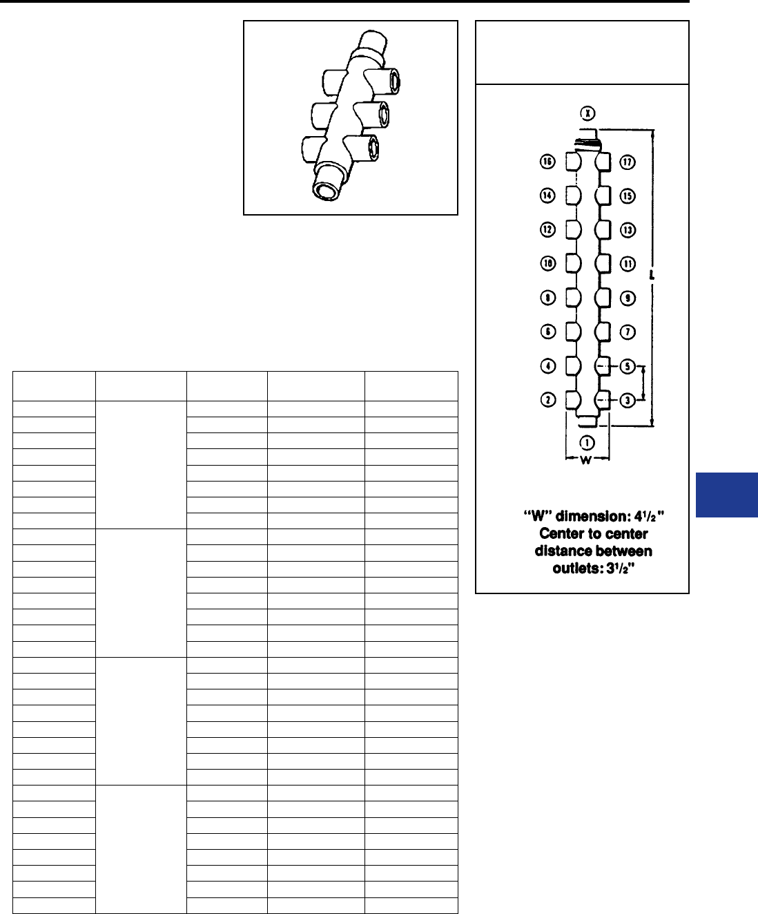
BURNDY®
Blue highlighted items are industry standard and most frequently ordered.
Canada: 1-800-387-6487 www.burndy.com US: 1-800-346-4175
Underground
MOLE™ TYPE ZMX
2000-2500 AMPERES
MOLE™ Type ZMX — A compact pre-insulated
junction for secondary network cables, with
multiple outlets for cable clamping elements. Future
expansion is provided for by an end outlet which
can be joined to an additional MOLE™ by Type
ZMS coupler.
Outlet Plugs — MOLE™ outlet plugs that facilitate
sealing outlets not being used are available
separately, Types Z-P and K-P.
Insulating Sleeves — Taping operations for
watertight joints are greatly simplied by the use
of BURNDY® NOTAPE™ Sleeves Type CM
Catalog
Number
Cable Outlet
Arrangement
No. of
Outlets
Length
Inches L
Approx Ship
Wt. Lbs.
ZMX4-25
All
Outlets
A
4 6-1/2 2.50
ZMX6-25 6 10 6.50
ZMX8-25 8 13-1/2 9.30
ZMX10-25 10 17 12.00
ZMX12-25 12 20-1/2 15.00
ZMX14-25 14 24 17.00
ZMX16-25 16 27-1/2 18.00
ZMX18-25 18 31 19.00
ZMX4-25A4 Outlet
#1 and X
B
All Other
Outlets
A
4 6-1/2 2.50
ZMX6-25A4 6 10 6.50
ZMX8-25A4 8 13-1/2 9.30
ZMX10-25A4 10 17 12.00
ZMX12-25A4 12 20-1/2 15.00
ZMX14-25A4 14 24 17.00
ZMX16-25A4 16 27-1/2 18.00
ZMX18-25A4 18 31 19.00
ZMX4-25B12 Outlet
#1
A
All Other
Outlets
B
4 6-1/2 2.50
ZMX6-25B12 6 10 6.50
ZMX8-25B12 8 13-1/2 9.30
ZMX10-25B12 10 17 12.00
ZMX12-25B12 12 20-1/2 15.00
ZMX14-25B12 14 24 17.00
ZMX16-25B12 16 27-1/2 18.00
ZMX18-25B12 18 31 19.00
ZMX4-25B
All
Outlets
B
4 6-1/2 2.50
ZMX6-25B 6 10 6.50
ZMX8-25B 8 13-1/2 9.30
ZMX10-25B 10 17 12.00
ZMX12-25B 12 20-1/2 15.00
ZMX14-25B 14 24 17.00
ZMX16-25B 16 27-1/2 18.00
ZMX18-25B 18 31 19.00
or MOLE™ Insulating Sleeves Type Z-C, sold
separately.
Clamping Elements — Outlet Symbols A or B,
refer to socket and nut Type Z-NR, and cone Type
Z cable clamping elements accommodated. These
must be ordered separately.
OUTLET RANGE: “A” 6 Str. - 600 kcmil
“B” 2 Str. - 1000 kcmil
For outlet combinations not listed call customer service.
MOLE™
DIMENSIONS
K-19
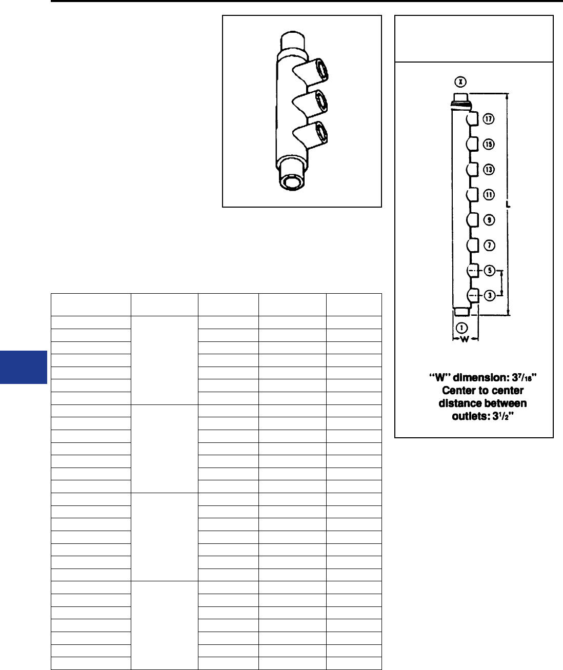
BURNDY®
Blue highlighted items are industry standard and most frequently ordered.
US: 1-800-346-4175 www.burndy.com Canada: 1-800-387-6487
Underground
MOLE™ TYPE ZMK
2000-2500 AMPERES
MOLE™ Type ZMK — A compact pre-insulated
junction for secondary network cables, with
multiple outlets for cable clamping elements.
Future expansion is provided for by an end outlet
which can be joined to an additional MOLE™ by
Type ZMS couplers.
Outlet Plugs — MOLE™ outlet plugs that facilitate
sealing outlets not being used are available
separately, Types Z-P and K-P.
Insulating Sleeves — Taping operations for
watertight joints are greatly simplied by the use
of BURNDY® NOTAPE™ Sleeves Type CM
or MOLE™ Insulating Sleeves Type Z-C, sold
separately.
MOLE™
DIMENSIONS
Clamping Elements — Outlet Symbols A or
B, refer to socket and nut Type Z-NR, and cone
Type Z cable clamping elements accommodated.
These must be ordered separately.
Catalog
Number
Cable Outlet
Arrangement
No. of
Outlets
Length
Inches L
Approx. Ship
Wt. Lbs.
ZMK4-25
All
Outlets
A
4 10 6.30
ZMK5-25 5 13-1/2 9.10
ZMK6-25 6 17 12.00
ZMK7-25 7 20-1/2 15.00
ZMK8-25 8 24 17.00
ZMK9-25 9 27-1/2 18.00
ZMK10-25 10 31 19.00
ZMK4-25A4 Outlet
#1 and X
B
All Other
Outlets
A
4 10 6.30
ZMK5-25A4 5 13-1/2 9.10
ZMK6-25A4 6 17 12.00
ZMK7-25A4 7 20-1/2 15.00
ZMK8-25A4 8 24 17.00
ZMK9-25A4 9 27-1/2 18.00
ZMK10-25A4 10 31 19.00
ZMK4-25B12 Outlet
#1
A
All Other
Outlets
B
4 10 6.30
ZMK5-25B12 5 13-1/2 9.10
ZMK6-25B12 6 17 12.00
ZMK7-25B12 7 20-1/2 15.00
ZMK8-25B12 8 24 17.00
ZMK9-25B12 9 27-1/2 18.00
ZMK10-25B12 10 31 19.00
ZMK4-25B
All
Outlets
B
4 10 6.30
ZMK5-25B 5 13-1/2 9.10
ZMK6-25B 6 17 12.00
ZMK7-25B 7 20-1/2 15.00
ZMK8-25B 8 24 17.00
ZMK9-25B 9 27-1/2 18.00
ZMK10-25B 10 31 19.00
OUTLET RANGE: “A” 6 Str. - 600 kcmil
“B” 2 Str. - 1000 kcmil
For outlet combinations not listed call customer service.
K-20
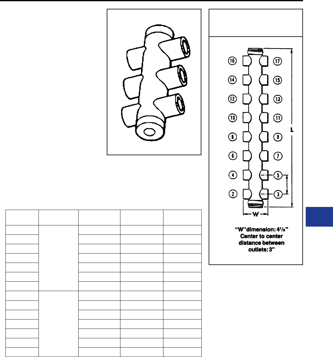
BURNDY®
Blue highlighted items are industry standard and most frequently ordered.
Canada: 1-800-387-6487 www.burndy.com US: 1-800-346-4175
Underground
MOLE™ TYPE ZM
3000 AMPERES
MOLE™ Type ZM — A compact pre-insulated
junction for secondary network cables,with
multiple outlets for cable clamping elements.
Outlet Plugs — MOLE™ outlet plugs that facilitate
sealing outlets not being used are available
separately, Types Z-P and K-P.
Insulating Sleeves — Taping operations for
watertight joints are greatly simplied by the use
of BURNDY® NOTAPE™ Sleeves Type CM
or MOLE™ Insulating Sleeves Type Z-C, sold
separately.
Clamping Elements — Outlet Symbols A or
B, refer to socket and nut Type Z-NR, and cone
Type Z cable clamping elements accommodated.
These must be ordered separately.
Catalog
Number
Cable Outlet
Arrangement
No. of
Outlets
Length
Inches L
Approx. Ship
Wt. Lbs.
ZM4-30
All
Outlets
A
4 6-15/16 6.80
ZM6-30 6 10-5/16 11.00
ZM8-30 8 13-11/16 15.00
ZM10-30 10 17-1/16 20.00
ZM12-30 12 20-7/16 24.00
ZM14-30 14 23-13/16 28.00
ZM16-30 16 27-3/16 33.00
ZM4-30B
All
Outlets
B
4 6-15/16 6.80
ZM6-30B 6 10-5/16 11.00
ZM8-30B 8 13-11/16 15.00
ZM10-30B 10 17-1/16 20.00
ZM12-30B 12 20-7/16 24.00
ZM14-30B 14 23-13/16 28.00
ZM16-30B 16 27-3/16 33.00
MOLE™
DIMENSIONS
OUTLET RANGE: “A” 6 Str. - 600 kcmil
“B” 2 Str. - 1000 kcmil
For outlet combinations not listed call customer service.
K-21
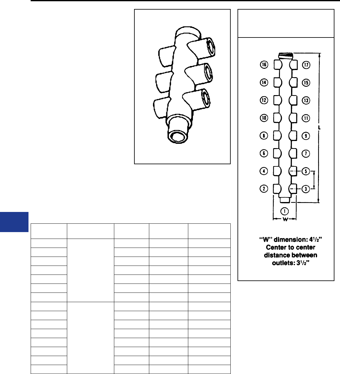
BURNDY®
Blue highlighted items are industry standard and most frequently ordered.
US: 1-800-346-4175 www.burndy.com Canada: 1-800-387-6487
Underground
MOLE™ TYPE ZMT
3000 AMPERES
MOLE™ Type ZMT— A compact pre-insulated
junction for secondary network cables, with
multiple outlets for cable clamping elements.
Future expansion is provided for by an end outlet
which can be joined to an additional MOLE™ by
Type ZMS couplers.
Outlet Plugs — Mole outlet plugs that facilitate
sealing outlets not being used are available
separately, Types Z-P and K-P.
Insulating Sleeves — Taping operations for
watertight joints are greatly simplied by the use
of BURNDY® NOTAPE™ Sleeves Type CM
or MOLE™ Insulating Sleeves Type Z-C, sold
separately.
Clamping Elements — Outlet Symbols A or B,
refer to socket and nut Type Z-NR, and cone
Type Z cable clamping elements accommodated.
These must be ordered separately.
MOLE™
DIMENSIONS
Catalog
Number
Cable Outlet
Arrangement
No. of
Outlets
Length
Inches L
Approx. Ship
Wt. Lbs.
ZMT3-30
All
Outlets
A
3 5-1/2 2.80
ZMT5-30 5 9-1/8 7.40
ZMT7-30 7 12-1/2 12.00
ZMT11-30 11 19-1/4 21.00
ZMT13-30 13 22-5/8 26.00
ZMT15-30 15 26 30.00
ZMT17-30 17 29-3/8 35.00
ZMT3-30B
All
Outlets
B
3 5-1/2 2.80
ZMT5-30B 5 9-1/8 7.40
ZMT7-30B 7 12-1/2 12.00
ZMT9-30B 9 15-7/8 16.00
ZMT11-30B 11 19-1/4 21.00
ZMT13-30B 13 22-5/8 26.00
ZMT15-30B 15 26 30.00
ZMT17-30B 17 29-3/8 35.00
OUTLET RANGE: “A” 6 Str. - 600 kcmil
“B” 2 Str. - 1000 kcmil
For outlet combinations not listed call customer service.
K-22
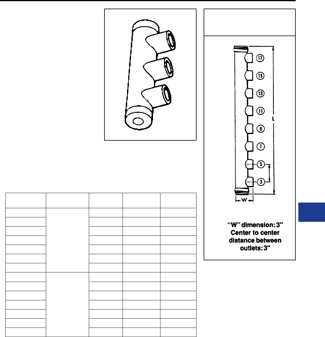
BURNDY®
Blue highlighted items are industry standard and most frequently ordered.
Canada: 1-800-387-6487 www.burndy.com US: 1-800-346-4175
Underground
MOLE™ TYPE ZME
3000 AMPERES
MOLE™ Type ZME — A compact pre-insulated
junction for secondary network cables, with
multiple outlets for cable clamping elements.
Outlet Plugs — Mole outlet plugs that facilitate
sealing outlets not being used are available
separately, Types Z-P and K-P.
Insulating Sleeves — Taping operations for
watertight joints are greatly simplied by the use
of BURNDY® NOTAPE™ Sleeves Type CM
or MOLE™ Insulating Sleeves Type Z-C, sold
separately.
Clamping Elements — Outlet Symbols A or B,
refer to socket and nut Type Z-NR, and cone
Type Z cable clamping elements accommodated.
These must be ordered separately.
Catalog
Number
Cable Outlet
Arrangement
No. of
Outlets
Length
Inches L
Approx. Ship
Wt. Lbs.
ZME230
All
Outlets
A
2 6-15/16 6.50
ZME330 3 10-5/16 11.00
ZME430 4 13-11/16 15.00
ZME530 5 17-1/16 19.00
ZME630 6 20-7/16 24.00
ZME730 7 23-13/16 28.00
ZME830 8 27-3/16 32.00
ZME230B
All
Outlets
B
2 6-15/16 6.80
ZME330B 3 10-5/16 11.00
ZME430B 4 13-11/16 15.00
ZME530B 5 17-1/16 19.00
ZME630B 6 20-7/16 24.00
ZME730B 7 23-13/16 28.00
ZME830B 8 27-3/16 32.00
MOLE™
DIMENSIONS
OUTLET RANGE: “A” 6 Str. - 600 kcmil
“B” 2 Str. - 1000 kcmil
For outlet combinations not listed call customer service.
K-23
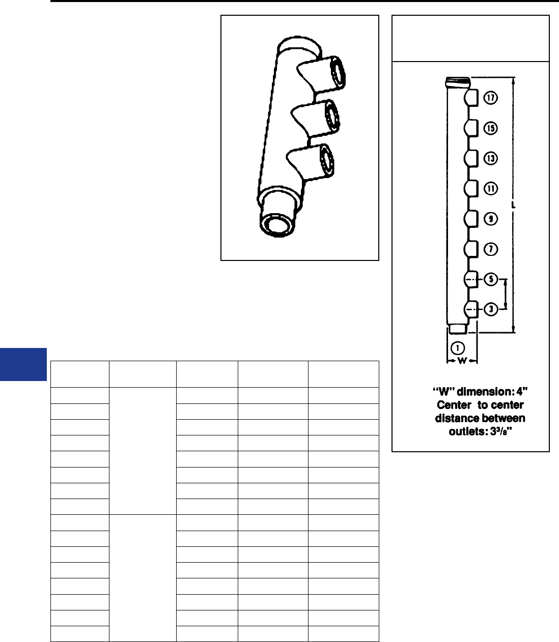
BURNDY®
Blue highlighted items are industry standard and most frequently ordered.
US: 1-800-346-4175 www.burndy.com Canada: 1-800-387-6487
Underground
MOLE™ TYPE ZML
3000 AMPERES
MOLE™ Type ZML — A compact pre-insulated
junction for secondary network cabes, with
multiple outlets for cable clamping elements.
Future expansion is provided for by an end outlet
which can be joined to an additional MOLE™ by
Type ZMS coupler.
Outlet Plugs — MOLE™ outlet plugs that facilitate
sealing outlets not being used are available
separately, Types Z-P and K-P.
Insulating Sleeves — Taping operations for
watertight joints are greatly simplied by the use
of BURNDY® NOTAPE™ Sleeves Type CM
or MOLE™ Insulating Sleeves Type Z-C, sold
separately.
Clamping Elements — Outlet Symbols A or
B, refer to socket and nut Type Z-NR, and cone
Type Z cable clamping elements accommodated.
These must be ordered separately.
MOLE™
DIMENSIONS
Catalog
Number
Cable Outlet
Arrangement
No. of
Outlets
Length
Inches L
Approx. Ship
Wt. Lbs.
ZML2-30
All
Outlets
A
2 5.50 2.70
ZML3-30 3 9.13 7.30
ZML4-30 4 12.50 12.00
ZML5-30 5 15.88 16.00
ZML6-30 6 19.25 21.00
ZML7-30 7 22.63 25.00
ZML8-30 8 26.00 30.00
ZML9-30 9 29.38 35.00
ZML2-30B
All
Outlets
B
2 5.50 2.70
ZML3-30B 3 9.13 7.30
ZML4-30B 4 12.50 12.00
ZML5-30B 5 15.88 16.00
ZML6-30B 6 19.25 21.00
ZML7-30B 7 22.63 25.00
ZML8-30B 8 26.00 30.00
ZML9-30B 9 29.38 35.00
OUTLET RANGE: “A” 6 Str. - 600 kcmil
“B” 2 Str. - 1000 kcmil
For outlet combinations not listed call customer service.
K-24
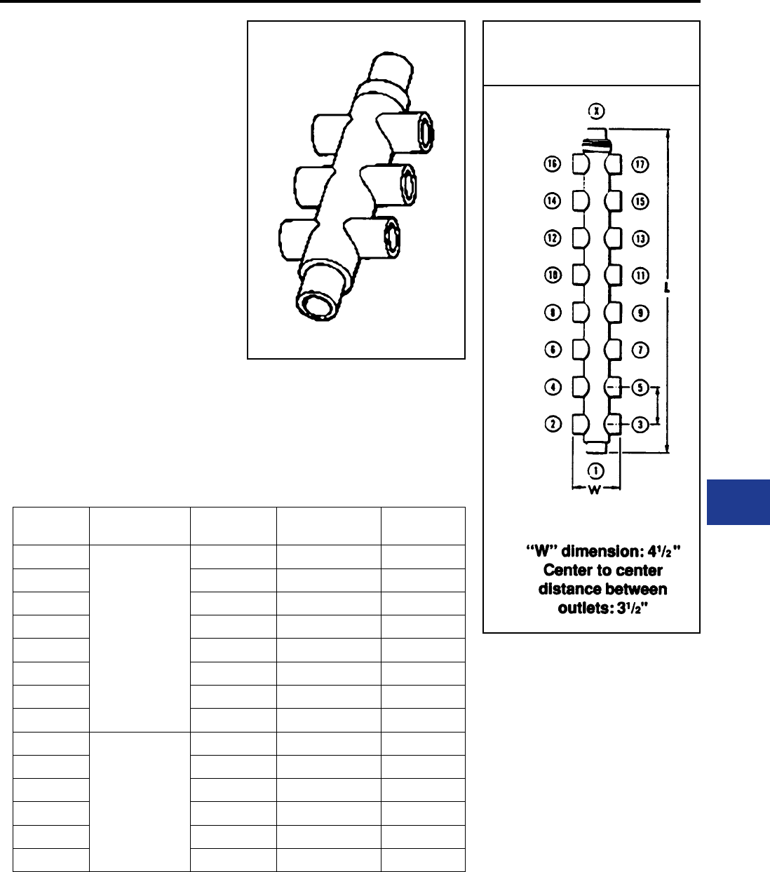
BURNDY®
Blue highlighted items are industry standard and most frequently ordered.
Canada: 1-800-387-6487 www.burndy.com US: 1-800-346-4175
Underground
MOLE™ TYPE ZMX
3000 AMPERES
MOLE™ Type ZMX — A compact pre-insulated
junction for secondary network cables, with
multiple outlets for cable clamping elements.
Future expansion is provided for by an end outlet
which can be joined to an additional MOLE™ by
Type ZMS coupler.
Outlet Plugs — MOLE™ outlet plugs that facilitate
sealing outlets not being used are available
separately, Types Z-P and K-P.
Insulating Sleeves — Taping operations for
watertight joints are greatly simplied by the use
of BURNDY® NOTAPE™ Sleeves Type CM
or MOLE™ Insulating Sleeves Type Z-C, sold
separately.
Clamping Elements — Outlet Symbols A or
B, refer to socket and nut Type Z-NR, and cone
Type Z cable clamping elements accommodated.
These must be ordered separately.
Catalog
Number
Cable Outlet
Arrangement
No. of
Outlets
Length
Inches L
Approx. Ship
Wt. Lbs.
ZMX4-30
All
Outlets
A
4 6.50 3.90
ZMX6-30 6 10.13 8.90
ZMX8-30 8 13.50 13.00
ZMX10-30 10 16.88 18.00
ZMX12-30 12 20.25 23.00
ZMX14-30 14 23.64 27.00
ZMX16-30 16 27.02 31.00
ZMX18-30 18 30.40 35.00
ZMX4-30B
All
Outlets
B
4 6.50 3.90
ZMX6-30B 6 10.13 8.90
ZMX8-30B 8 13.50 13.00
ZMX10-30B 10 16.88 18.00
ZMX14-30B 14 23.64 27.00
ZMX18-30B 18 30.40 35.00
MOLE™
DIMENSIONS
OUTLET RANGE: “A” 6 Str. - 600 kcmil
“B” 2 Str. - 1000 kcmil
For outlet combinations not listed call customer service.
K-25
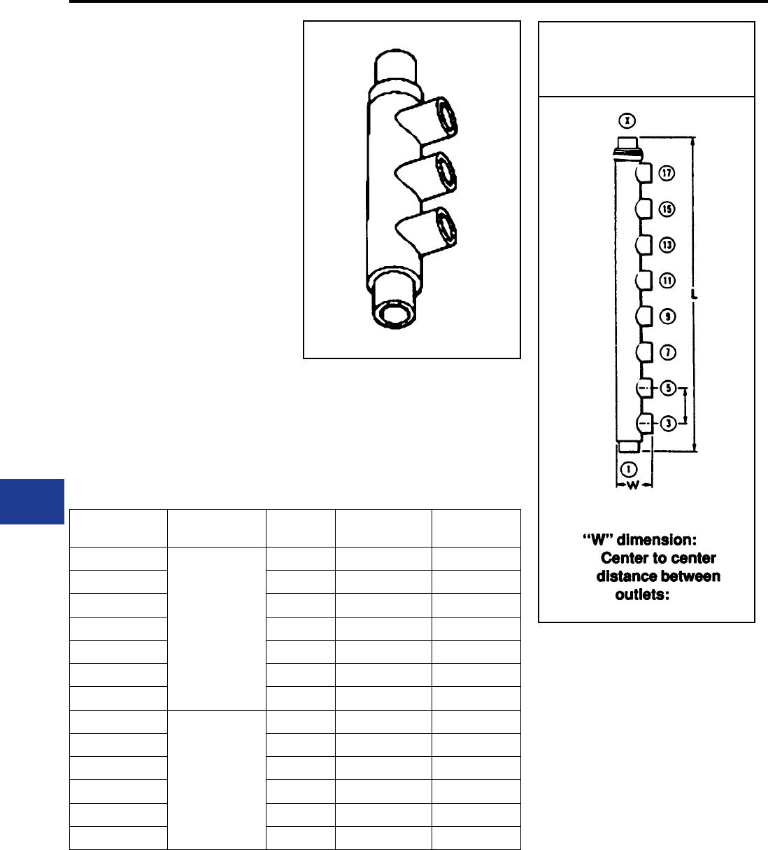
BURNDY®
Blue highlighted items are industry standard and most frequently ordered.
US: 1-800-346-4175 www.burndy.com Canada: 1-800-387-6487
Underground
MOLE™ TYPE ZMK
3000 AMPERES
MOLE™ Type ZMK — A compact pre-insulated
junction for secondary network cables, with
multiple outlets for cable clamping elements.
Future expansion is provided for by an end outlet
which can be joined to an additional MOLE™ by
Type ZMS couplers.
Outlet Plugs — MOLE™ outlet plugs that facilitate
sealing outlets not being used are available
separately, Types Z-P and K-P.
Insulating Sleeves — Taping operations for
watertight joints are greatly simplied by the use
of BURNDY® NOTAPE™ Sleeves Type CM or
MOLE™ Insulating Sleeves Type Z-C, ordered
separately.
Clamping Elements — Outlet Symbols A or
B, refer to socket and nut Type Z-NR, and cone
Type Z cable clamping elements accommodated.
These must be ordered separately.
Catalog
Number
Cable Outlet
Arrangement
No. of
Outlets
Length
Inches L
Approx. Ship
Wt. Lbs.
ZMK430
All
Outlets
A
4 10-1/8 8.80
ZMK530 5 13-1/2 13.00
ZMK630 6 16-7/8 18.00
ZMK730 7 20-1/4 23.00
ZMK830 8 23-5/8 27.00
ZMK930 9 27 31.00
ZMK1030 10 30-3/8 35.00
ZMK430B
All
Outlets
B
4 10-1/4 8.80
ZMK530B 5 13-5/8 13.00
ZMK630B 6 17 18.00
ZMK730B 7 20-3/8 23.00
ZMK830B 8 23-3/4 27.00
ZMK1030B 10 30-1/2 35.00
OUTLET RANGE: “A” 6 Str. - 600 kcmil
“B” 2 Str. - 1000 kcmil
For outlet combinations not listed call customer service.
MOLE™
DIMENSIONS
4"
3 3/8"
K-26
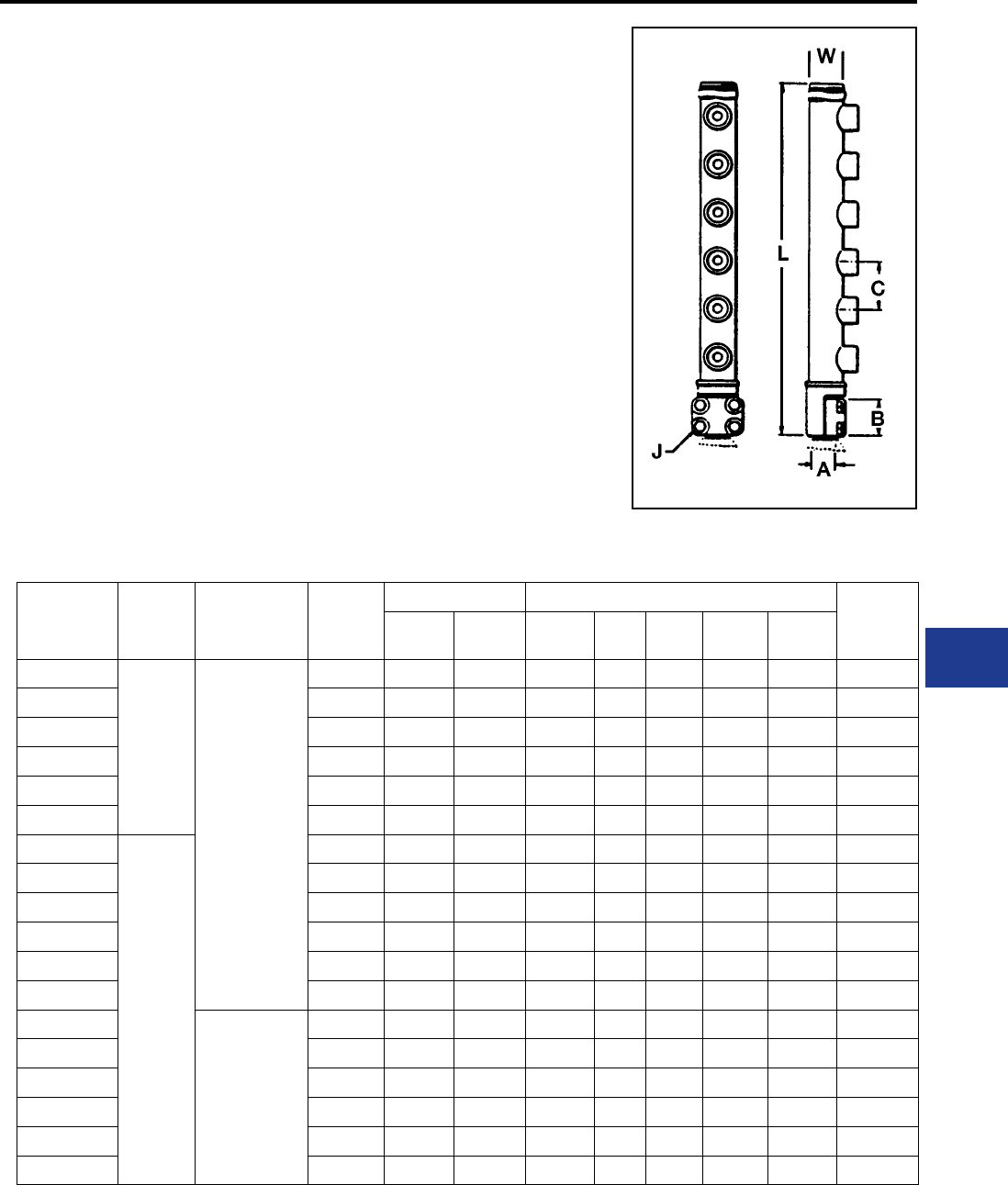
BURNDY®
Blue highlighted items are industry standard and most frequently ordered.
Canada: 1-800-387-6487 www.burndy.com US: 1-800-346-4175
Underground
TYPE ZMLDN
MOLE™ STUD CONNECTOR
For Connecting Copper
Cables to Network Protector
To terminate one or more cables at the studs of
distribution transformers, network protectors or
other apparatus. The body, except for the stud
clamping element is completely insulated. A
separate clamping cap over the stud is provided
that permits easy removal of the MOLE™ Stud
Connector. This permits work to be done on the
Network Protector without unduly disturbing the
cables.
Outlet Plugs — MOLE™ outlet plugs that facilitate
sealing outlets not being used are available
separately, Types Z-P and K-P.
Insulating Sleeves — Taping operations for
watertight joints are greatly simplied by the use
of BURNDY® NOTAPE™ Sleeves Type CM or
MOLE™ Insulating Sleeves Type Z-C, ordered
separately.
Clamping Elements — Outlet Symbols A or
B, refer to socket and nut Type Z-NR, and cone
Type Z cable clamping elements accommodated.
These must be ordered separately.
OUTLET RANGE: “A” 6 Str. - 600 kcmil
“B” 2 Str. - 1000 kcmil
* Can be furnished with more than 6 outlets.
Catalog
Number
Ampere
Capacity
Cable Outlet
Arrangement
* No. of
Outlets
A Dimensions in Inches Approx.
Ship
Wt. Lbs.
Stud
Dia.
Threads
per Inch B C J L W
ZMLDN1-15
1500
All
Outlets
A
1 1-1/2 12 2-11/16 — 1/2 7-3/8 3 4.70
ZMLDN2-15 2 1-1/2 12 2-11/16 3 1/2 10-3/8 3 6.80
ZMLDN3-15 3 1-1/2 12 2-11/16 3 1/2 13-3/8 3 8.80
ZMLDN4-15 4 1-1/2 12 2-11/16 3 1/2 16-3/8 3 11.00
ZMLDN5-15 5 1-1/2 12 2-11/16 3 1/2 19-3/8 3 13.30
ZMLDN6-15 6 1-1/2 12 2-11/16 3 1/2 22-3/8 3 15.50
ZMLDN1-20
2000
1 1-1/2 12 2-11/16 — 1/2 7-7/8 3-7/16 8.50
ZMLDN2-20 2 1-1/2 12 2-11/16 3-1/2 1/2 11-3/8 3-7/16 12.00
ZMLDN3-20 3 1-1/2 12 2-11/16 3-1/2 1/2 14-7/8 3-7/16 14.00
ZMLDN4-20 4 1-1/2 12 2-11/16 3-1/2 1/2 18-3/8 3-7/16 17.00
ZMLDN5-20 5 1-1/2 12 2-11/16 3-1/2 1/2 21-7/8 3-7/16 20.00
ZMLDN6-20 6 1-1/2 12 2-11/16 3-1/2 1/2 25-3/8 3-7/16 23.00
ZMLDN1-20B
All
Outlets
B
1 1-1/2 12 2-11/16 — 1/2 7-7/8 3-7/16 8.50
ZMLDN2-20B 2 1-1/2 12 2-11/16 3-1/2 1/2 11-3/8 3-7/16 12.00
ZMLDN3-20B 3 1-1/2 12 2-11/16 3-1/2 1/2 14-7/8 3-7/16 14.00
ZMLDN4-20B 4 1-1/2 12 2-11/16 3-1/2 1/2 18-3/8 3-7/16 17.00
ZMLDN5-20B 5 1-1/2 12 2-11/16 3-1/2 1/2 21-7/8 3-7/16 20.00
ZMLDN6-20B 6 1-1/2 12 2-11/16 3-1/2 1/2 25-3/8 3-7/16 23.00
K-27
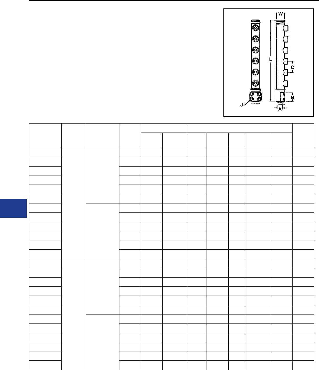
BURNDY®
Blue highlighted items are industry standard and most frequently ordered.
US: 1-800-346-4175 www.burndy.com Canada: 1-800-387-6487
Underground
TYPE ZMLDN
MOLE™ STUD CONNECTOR
(Continued)
OUTLET RANGE: “A” 6 Str. - 600 kcmil
“B” 2 Str. - 1000 kcmil
* Can be furnished with more than 6 outlets. For outlet combinations not listed call customer service.
Catalog
Number
Ampere
Capacity
Cable Outlet
Arrangement
* No. of
Outlets
A Dimensions in Inches Approx.
Ship
Wt. Lbs.
Stud
Dia.
Threads
per Inch B C J L W
ZMLDN1-25
2500
All
Outlets
A
1 3 12 3-1/4 — 5/8 8-27/32 3-7/16 11.80
ZMLDN2-25 2 3 12 3-1/4 3-1/2 5/8 12-11/32 3-7/16 17.00
ZMLDN3-25 3 3 12 3-1/4 3-1/2 5/8 15-27/32 3-7/16 19.50
ZMLDN4-25 4 3 12 3-1/4 3-1/2 5/8 19-11/32 3-7/16 23.70
ZMLDN5-25 5 3 12 3-1/4 3-1/2 5/8 22-27/32 3-7/16 28.00
ZMLDN6-25 6 3 12 3-1/4 3-1/2 5/8 26-11/32 3-7/16 32.00
ZMLDN1-25B
All
Outlets
B
1 3 12 3-1/4 — 5/8 8-27/32 3-7/16 11.80
ZMLDN2-25B 2 3 12 3-1/4 3-1/2 5/8 12-11/32 3-7/16 17.00
ZMLDN3-25B 3 3 12 3-1/4 3-1/2 5/8 15-27/32 3-7/16 19.50
ZMLDN4-25B 4 3 12 3-1/4 3-1/2 5/8 19-11/32 3-7/16 23.70
ZMLDN5-25B 5 3 12 3-1/4 3-1/2 5/8 22-27/32 3-7/16 28.00
ZMLDN6-25B 6 3 12 3-1/4 3-1/2 5/8 26-11/32 3-7/16 32.00
ZMLDN1-30
3000
All
Outlets
A
1 3 12 3-1/4 — 5/8 7-5/8 4 11.50
ZMLDN2-30 2 3 12 3-1/4 3-3/8 5/8 11-1/4 4 16.80
ZMLDN3-30 3 3 12 3-1/4 3-3/8 5/8 14-5/8 4 19.00
ZMLDN4-30 4 3 12 3-1/4 3-3/8 5/8 18 4 23.00
ZMLDN5-30 5 3 12 3-1/4 3-3/8 5/8 21-3/8 4 27.00
ZMLDN6-30 6 3 12 3-1/4 3-3/8 5/8 24-3/4 4 31.00
ZMLDN1-30B
All
Outlets
B
1 3 12 3-1/4 — 5/8 7-5/8 4 11.50
ZMLDN2-30B 2 3 12 3-1/4 3-3/8 5/8 11-1/4 4 16.80
ZMLDN3-30B 3 3 12 3-1/4 3-3/8 5/8 14-5/8 4 19.00
ZMLDN4-30B 4 3 12 3-1/4 3-3/8 5/8 18 4 23.00
ZMLDN5-30B 5 3 12 3-1/4 3-3/8 5/8 21-3/8 4 27.00
ZMLDN6-30B 6 3 12 3-1/4 3-3/8 5/8 24-3/4 4 31.00
K-28
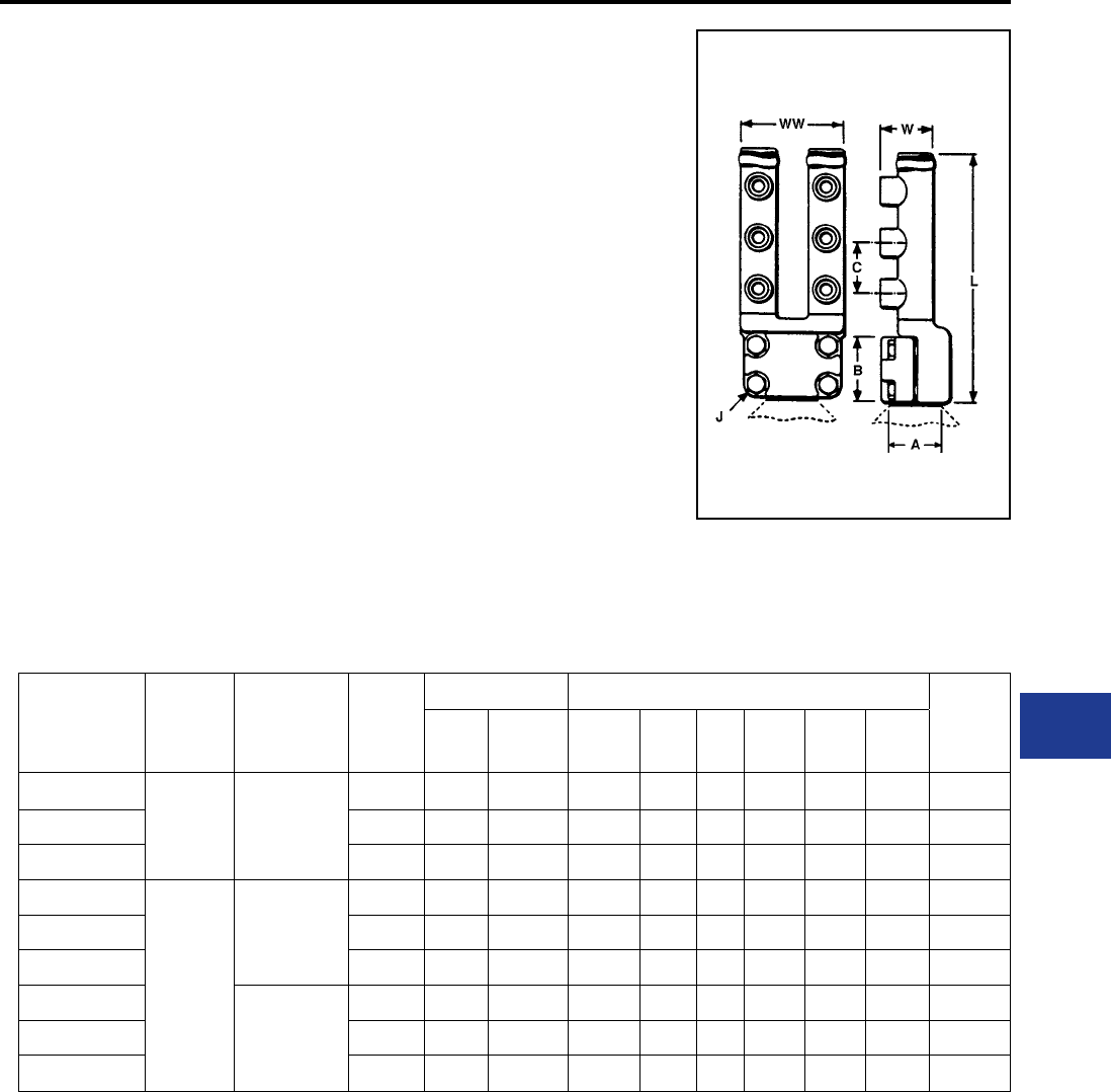
BURNDY®
Blue highlighted items are industry standard and most frequently ordered.
Canada: 1-800-387-6487 www.burndy.com US: 1-800-346-4175
Underground
TYPE Z2MLDN
MOLE™ STUD CONNECTOR
For Connecting Copper Cables to
Network Protector
To terminate two or more cables at the studs of
distribution transformers, network protectors or
other apparatus. The body, except for the stud
clamping element is completely insulated. A
separate clamping cap over the stud is provided
that permits easy removal of the MOLE™ Stud
Connector. This permits work to be done on the
Network Protector without unduly disturbing the
cables.
Outlet Plugs — MOLE™ outlet plugs that facilitate
sealing outlets not being used are available
separately, Types Z-P and K-P.
Insulating Sleeves — Taping operations for
watertight joints are greatly simplied by the use
of BURNDY® NOTAPE™ Sleeves Type CM or
MOLE™ Insulating Sleeves Type Z-C, ordered
separately.
Clamping Elements — Outlet Symbols A or B,
refer to socket and nut Type Z-NR, and cone Type
Z cable clamping elements accommodated. These
must be ordered separately.
Catalog
Number
Ampere
Capacity
Cable Outlet
Arrangement
*No. of
Outlets
A Dimensions in Inches Approx.
Ship
Wt. Lbs
Stud
Dia.
Threads
per Inch B C J L W WW
Z2MLDN2-20 2000
&
Smaller
All
Outlets
A
2 1-1/2 12 2-11/16 — 1/2 8 3 5-3/16 5.80
Z2MLDN4-20 4 1-1/2 12 2-11/16 3 1/2 11 3 5-3/16 9.40
Z2MLDN6-20 6 1-1/2 12 2-11/16 3 1/2 14 3 5-3/16 13.20
Z2MLDN2-30
2500
&
3000
All
Outlets
A
2 3 12 3-1/4 — 5/8 9 3 6-1/2 7.30
Z2MLDN4-30 4 1-1/2 12 3-1/4 3 5/8 12 3 6-1/2 12.50
Z2MLDN6-30 6 3 12 3-1/4 3 5/8 15 3 6-1/2 16.30
Z2MLDN2-30B All
Outlets
B
2 3 12 3-1/4 — 5/8 9 3-1/2 6-1/2 11.20
Z2MLDN4-30B 4 3 12 3-1/4 3-1/2 5/8 12-1/2 3-1/2 6-1/2 16.10
Z2MLDN6-30B 6 3 12 3-1/4 3-1/2 5/8 16 3-1/2 6-1/2 21.30
OUTLET RANGE: “A” 6 Str. - 600 kcmil
“B” 2 Str. - 1000 kcmil
*Can be furnished with more than 6 outlets.For outlet combinations not listed call customer service.
K-29
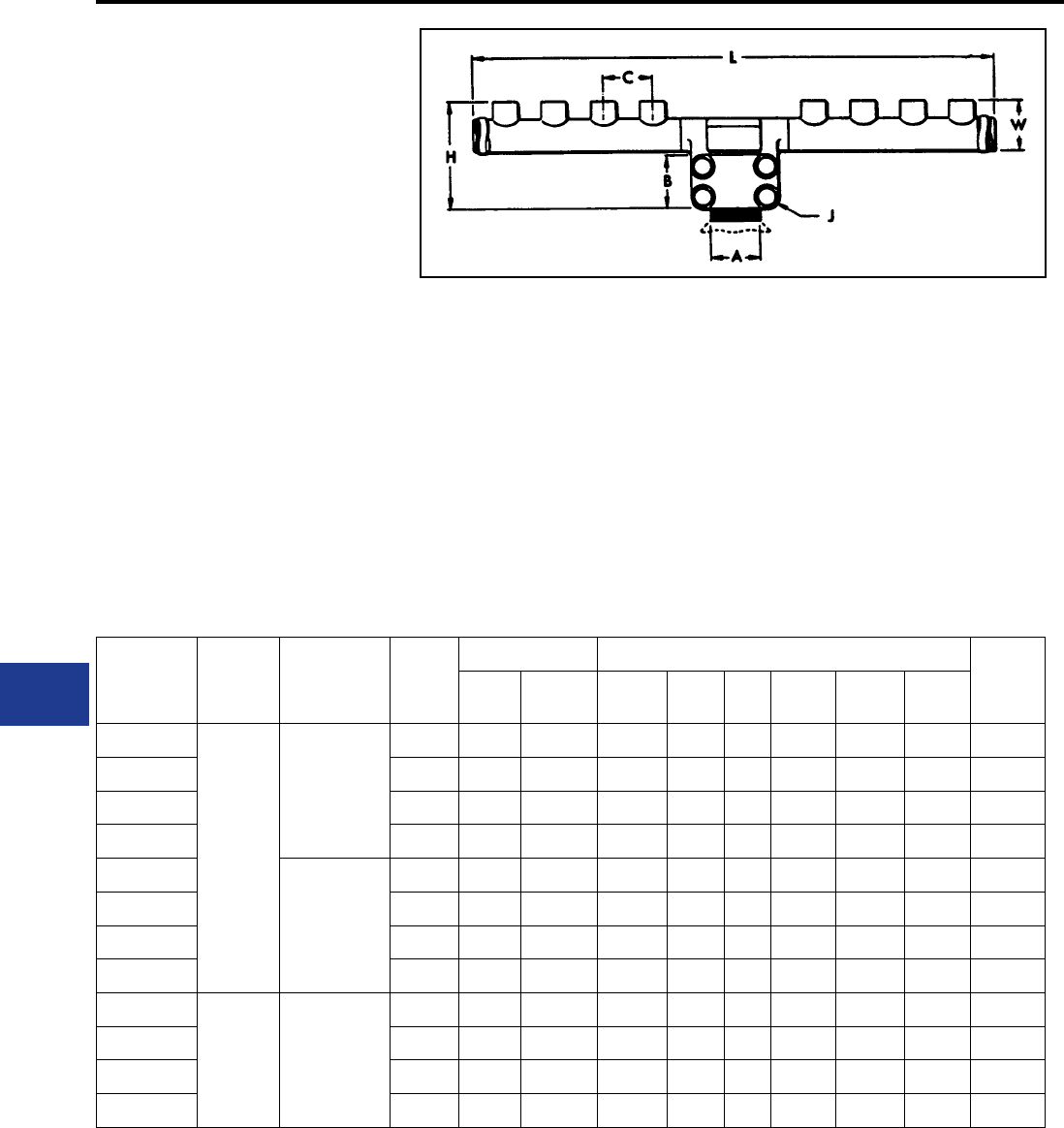
BURNDY®
Blue highlighted items are industry standard and most frequently ordered.
US: 1-800-346-4175 www.burndy.com Canada: 1-800-387-6487
Underground
TYPE ZMDN
MOLE™ STUD CONNECTOR
For Connecting Copper Cables to
Network Protector
To terminate one or more cables at the studs of
distribution transformers, network protectors or
other apparatus. The body, except for the stud
clamping element is completely insulated. A
separate clamping cap over the stud is provided
that permit easy removal of the MOLE™ Stud
Connector. This permits work to be done on the
Network Protector without unduly disturbing the
cables.
Outlet Plugs — MOLE™ outlet plugs that facilitate
sealing outlets not being used are available
separately, Types Z-P and K-P.
Insulating Sleeves — Taping operations for
watertight joints are greatly simplied by the use
of BURNDY® NOTAPE™ Sleeves Type CM or
MOLE™ Insulating Sleeves Type Z-C, ordered
separately.
Clamping Elements — Outlet Symbols A or
B, refer to socket and nut Type Z-NR, and cone
Type Z cable clamping elements accommodated.
These must be ordered separately.
Catalog
Number
Ampere
Capacity
Cable Outlet
Arrangement
*No. of
Outlets
A Dimensions in Inches Approx.
Ship
Wt. Lbs.
Stud
Dia.
Threads
per Inch B C J H L W
ZMDN3-20
2000
&
Smaller
All
Outlets
A
3 1-1/2 12 2-11/16 3-1/2 1/2 8-1/16 11-1/2 3-7/16 14.50
ZMDN4-20 4 1-1/2 12 2-11/16 3-1/2 1/2 8-1/16 15 3-7/16 17.50
ZMDN5-20 5 1-1/2 12 2-11/16 3-1/2 1/2 8-1/16 18-1/2 3-7/16 20.50
ZMDN6-20 6 1-1/2 12 2-11/16 3-1/2 1/2 8-1/16 22 3-7/16 23.50
ZMDN3-20B
All
Outlets
B
3 1-1/2 12 2-11/16 3-1/2 1/2 8-1/16 11-1/2 3-7/16 14.50
ZMDN4-20B 4 1-1/2 12 2-11/16 3-1/2 1/2 8-1/16 15 3-7/16 17.50
ZMDN5-20B 5 1-1/2 12 2-11/16 3-1/2 1/2 8-1/16 18-1/2 3-7/16 20.50
ZMDN6-20B 6 1-1/2 12 2-11/16 3-1/2 1/2 8-1/16 22 3-7/16 23.50
ZMDN3-25
2000
Through
2500
All
Outlets
A
3 3 12 3-1/4 3-1/2 5/8 8-5/8 11-1/2 3-7/16 26.50
ZMDN4-25 4 3 12 3-1/4 3-1/2 5/8 8-5/8 15 3-7/16 20.50
ZMDN5-25 5 3 12 3-1/4 3-1/2 5/8 8-5/8 18-1/2 3-7/16 23.50
ZMDN6-25 6 3 12 3-1/4 3-1/2 5/8 8-5/8 22 3-7/16 26.50
OUTLET RANGE: “A” 6 Str. - 600 kcmil
“B” 2 Str. - 1000 kcmil
*Can be furnished with more than 6 outlets. For outlet combinations not listed call customer service.
For connectors with an odd number of outlets the odd and even split of outlets will be as indicated in the diagram.
Odd Even
K-30
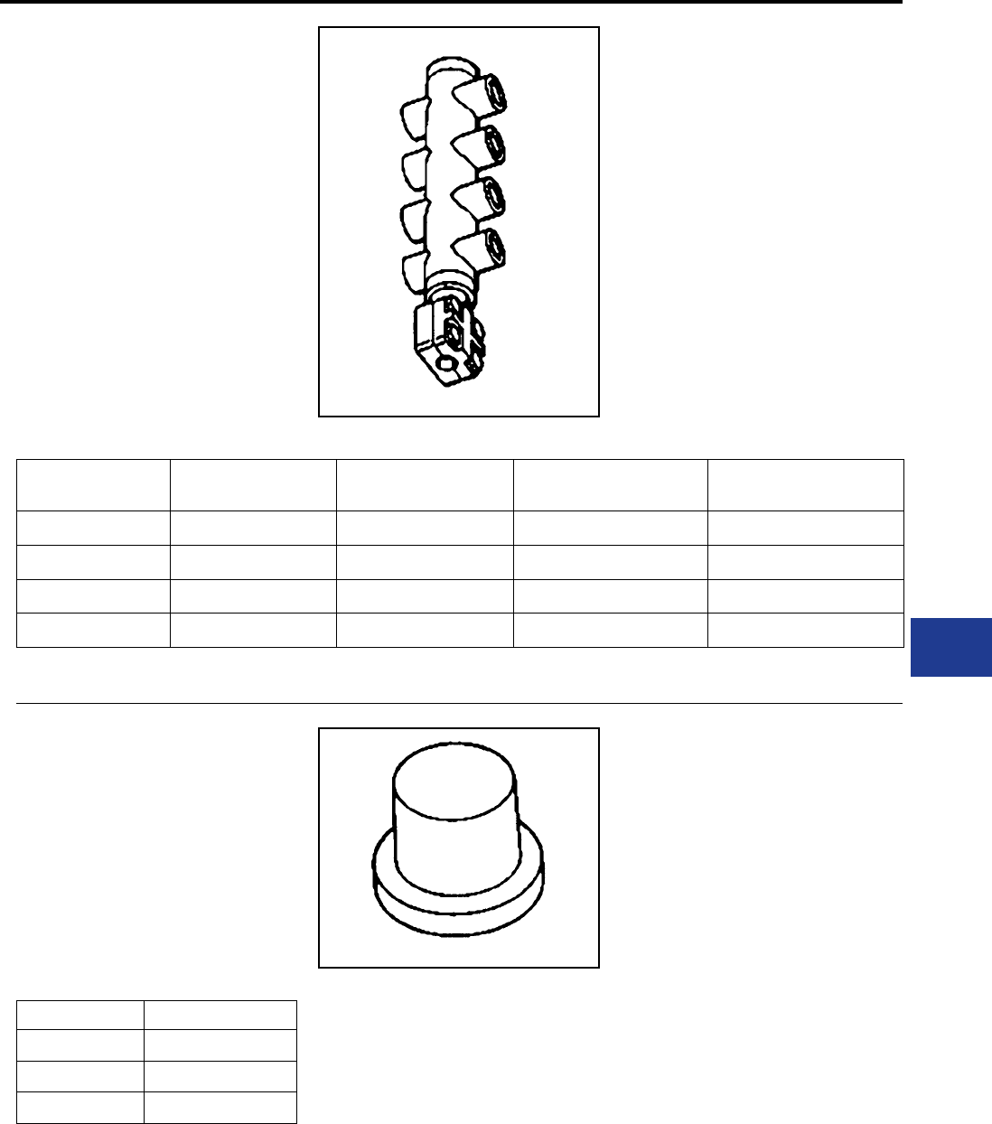
BURNDY®
Blue highlighted items are industry standard and most frequently ordered.
Canada: 1-800-387-6487 www.burndy.com US: 1-800-346-4175
Underground
TYPE ZMTDN
MOLE™ STUD CONNECTOR
For Connecting Copper Cables to
Network Protector
To terminate two or more cables at the studs of
distribution transformers, network protectors or
other apparatus. The body, except for the stud
clamping element is completely insulated. A
separate clamping cap over the stud is provided
that permits easy removal of the MOLE™ Stud
Connector. This permits work to be done on the
Network Protector without unduly disturbing the
cables.
TYPE Z-P
MOLE™ OUTLET PLUGS
These plugs facilitate sealing MOLE™ outlets not
being used.
Catalog Number Used On Outlet Size
Z29P A
Z34P B
Z40P C
Catalog
Number
Ampere
Capacity Number of Outlets Cable Outlet
Arrangement Stud Dia.
ZMTDN815 1500 8 A 1.50"
ZMTDN1015 1500 10 A 1.50"
ZMTDN820 2000-2500 8 A 1.50"
ZMTDN81025 2000-2500 10 A 1.50"
K-31
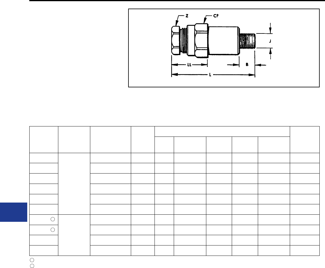
BURNDY®
Blue highlighted items are industry standard and most frequently ordered.
US: 1-800-346-4175 www.burndy.com Canada: 1-800-387-6487
Underground
TYPE Z-NR
SOCKET AND NUT ASSEMBLY
Designed for use with BURNDY® MOLE. With the
use of the proper compression cones, 14 sizes
take a range of cables from No. 6 to 1000 kcmil.
Their compact design lends them to easy effective
taping. Insulating sleeves are available to keep
taping to a minimum.
Catalog
Number
To be Used
in MOLE™
Outlet Size
Maximum Cable
Accommodated
by Socket
Stud
Size
J
Dimensions in Inches Approx.
Ship
Wt. Lbs.
BCF
(Cross Flats) L LL Z
(Cross Flats)
Z28NR
A
4/0 Str. 5/8-18 17/32 1-1/8 3-7/16 1-1/2 7/8 0.72
Z29NR 250 kcmil 5/8-18 17/32 1-3/16 3-9/16 1-5/8 15/16 0.76
Z30NR 300 kcmil 5/8-18 17/32 1-1/4 3-5/8 1-11/16 1 0.80
Z32NR 400 kcmil 5/8-18 17/32 1-3/8 3-5/8 1-11/16 1-1/8 0.90
Z34NR 500 kcmil 5/8-18 17/32 1-1/2 3-11/16 1-3/4 1-1/4 1.20
Z36NR 600 kcmil 5/8-18 17/32 1-1/2 3-13/16 1-7/8 1-5/16 1.40
Z40NRA
B
800 kcmil 5/8-18 17/32 1-13/16 5-17/32 2-1/4 1-1/2 2.40
Z34NRB 500 kcmil 7/8-14 11/16 1-1/2 3-11/16 1-3/4 1-1/4 1.50
Z40NR 800 kcmil 7/8-14 11/16 1-13/16 4-3/8 2-1/4 1-1/2 1.90
Z44NR 1000 kcmil 7/8-14 11/16 1-15/16 6-1/16 2-7/16 1-5/8 2.50
Uses Insulating Sleeve Z104C4434
Uses Insulating Sleeve Z88C3429
2
1
1
2
OUTLET RANGE: “A” 6 Str. - 600 kcmil
“B” 2 Str. - 1000 kcmil
K-32
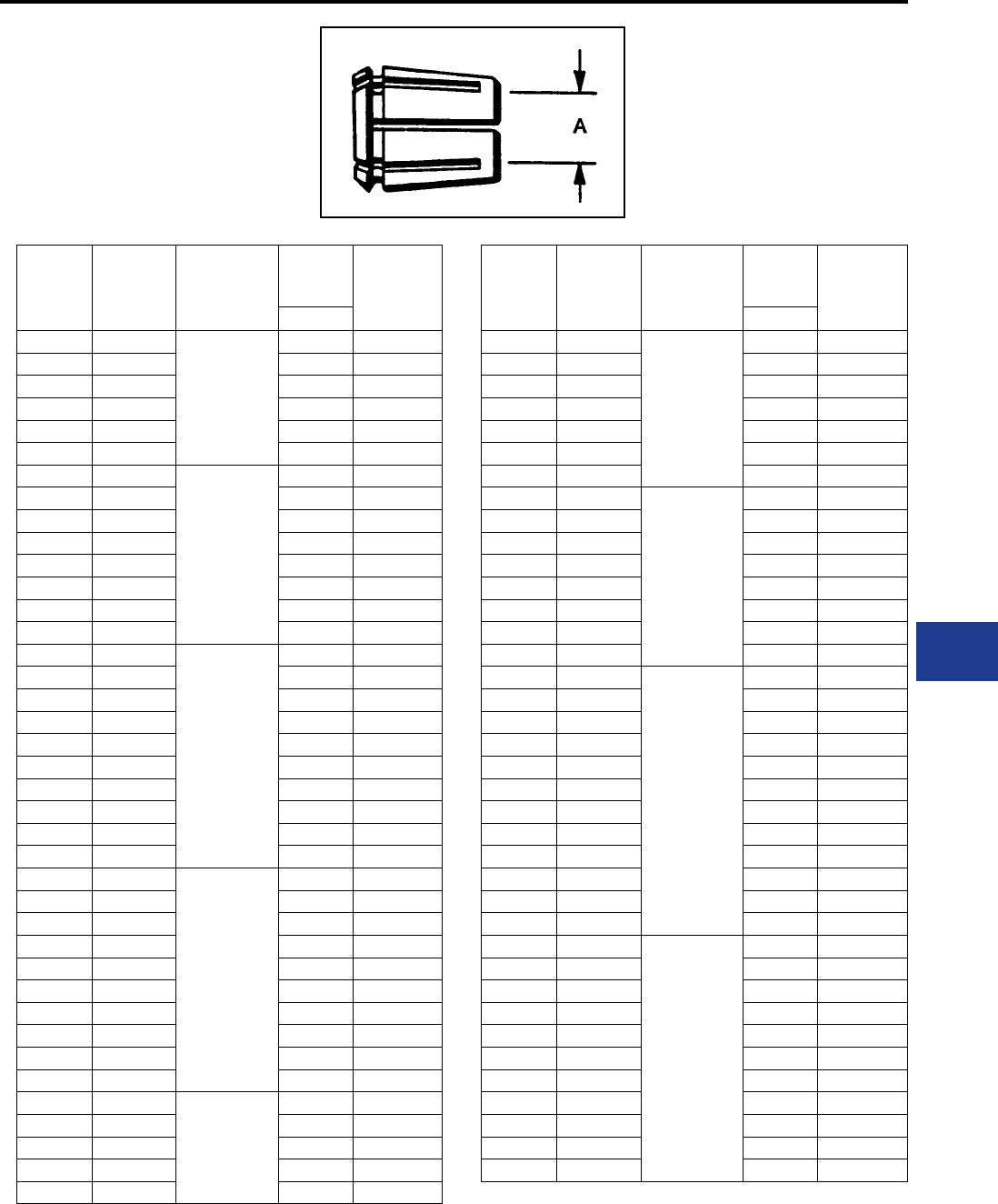
BURNDY®
Blue highlighted items are industry standard and most frequently ordered.
Canada: 1-800-387-6487 www.burndy.com US: 1-800-346-4175
Underground
TYPE Z
MOLE™ COMPRESSION CONE
For use with Socket and Nut assembly the Z
cone is machined to close tolerances to provide
maximum secureness in gripping a wide range of
cable sizes. Annular grooves in the inner barrel of
the cone serve to further accomplish this result.
Catalog
Number Cable Size
For Use with
Socket & Nut
Assembly
AApprox Ship
Weight in
Lbs.
Per C
Inches
Z6C28 #6 Str.
Z28NR
0.18 in 8.00
Z4C28 #4 Str. 0.23 in 7.50
Z2C28 #2 Str. 0.29 in 7.00
Z2528 1/0 Str. 0.37 in 6.00
Z2728 3/0 Str. 0.47 in 4.30
Z2828 4/0 Str. 0.53 in 3.30
Z6C29 #6 Str.
Z29NR
0.18 in 9.50
Z4C29 #4 Str. 0.23 in 9.30
Z2C29 #2 Str. 0.29 in 8.50
Z1C29 #1 Str. 0.33 in 8.00
Z2529 1/0 Str. 0.37 in 7.00
Z2629 2/0 Str. 0.42 in 6.30
Z2829 4/0 Str. 0.53 in 3.80
Z2929 250 kcmil 0.58 in 3.30
Z6C30 #5 Str.
Z30NR
0.18 in 16.00
Z4C30 #4 Str. 0.23 in 15.00
Z2C30 #2 Str. 0.29 in 14.00
Z1C30 #1 Str. 0.33 in 14.00
Z2530 1/0 Str. 0.37 in 13.00
Z2630 2/0 Str. 0.42 in 12.00
Z2730 3/0 Str. 0.47 in 11.00
Z2830 4/0 Str. 0.53 in 9.30
Z2930 250 kcmil 0.58 in 8.00
Z3030 300 kcmil 0.63 in 6.30
Z2C32 #2 Str.
Z32NR
0.29 in 21.00
Z1C32 #1 Str. 0.33 in 20.00
Z2532 1/0 Str. 0.37 in 19.00
Z2632 2/0 Str. 0.42 in 18.00
Z2732 3/0 Str. 0.47 in 17.00
Z2832 4/0 Str. 0.53 in 15.00
Z2932 250 kcmil 0.58 in 14.00
Z3032 300 kcmil 0.63 in 12.00
Z3132 350 kcmil 0.68 in 9.80
Z3232 400 kcmil 0.73 in 8.00
Z2C34 #2 Str.
Z34NR
&
Z34NRB
0.29 in 29.00
Z1C34 #1 Str. 0.33 in 28.00
Z2534 1/0 Str. 0.37 in 27.00
Z2634 2/0 Str. 0.42 in 26.00
Z2734 3/0 Str. 0.47 in 25.00
Catalog
Number Cable Size
For Use with
Socket & Nut
Assembly
AApprox Ship
Weight in
Lbs.
Per C
Inches
Z2834 4/0 Str.
Z34NR
&
Z34NRB
0.53 in 22.00
Z2934 250 kcmil 0.58 in 21.00
Z3034 300 kcmil 0.63 in 19.00
Z3134 350 kcmil 0.69 in 17.00
Z3234 400 kcmil 0.73 in 15.00
Z3334 450 kcmil 0.76 in 13.00
Z3434 500 kcmil 0.81 in 11.00
Z2936 250 kcmil
Z36NR
0.58 in 32.00
Z3036 300 kcmil 0.63 in 30.00
Z3136 350 kcmil 0.69 in 28.00
Z3236 400 kcmil 0.73 in 26.00
Z3336 450 kcmil 0.76 in 23.00
Z3436 500 kcmil 0.81 in 21.00
Z3536 550 kcmil 0.86 in 19.00
Z3636 600 kcmil 0.89 in 17.00
Z2940 250 kcmil
Z40NR
&
Z40NRA
0.58 in 49.00
Z3040 300 kcmil 0.63 in 47.00
Z3140 350 kcmil 0.69 in 44.00
Z3240 400 kcmil 0.73 in 41.00
Z3340 450 kcmil 0.76 in 39.00
Z3440 500 kcmil 0.81 in 36.00
Z3540 550 kcmil 0.86 in 33.00
Z3640 600 kcmil 0.89 in 31.00
Z3740 650 kcmil 0.92 in 29.00
Z3840 700 kcmil 0.97 in 25.00
Z3940 750 kcmil 1.00 in 23.00
Z4040 800 kcmil 1.03 in 21.00
Z3444 500 kcmil
Z44NR
0.81 in 55.00
Z3544 550 kcmil 0.86 in 51.00
Z3644 600 kcmil 0.89 in 49.00
Z3744 650 kcmil 0.92 in 47.00
Z3844 700 kcmil 0.97 in 43.00
Z3944 750 kcmil 1.00 in 40.00
Z4044 800 kcmil 1.03 in 38.00
Z4144 850 kcmil 1.06 in 35.00
Z4244 900 kcmil 1.09 in 32.00
Z4344 950 kcmil 1.12 in 28.00
Z4444 1000 kcmil 1.15 in 24.00
K-33
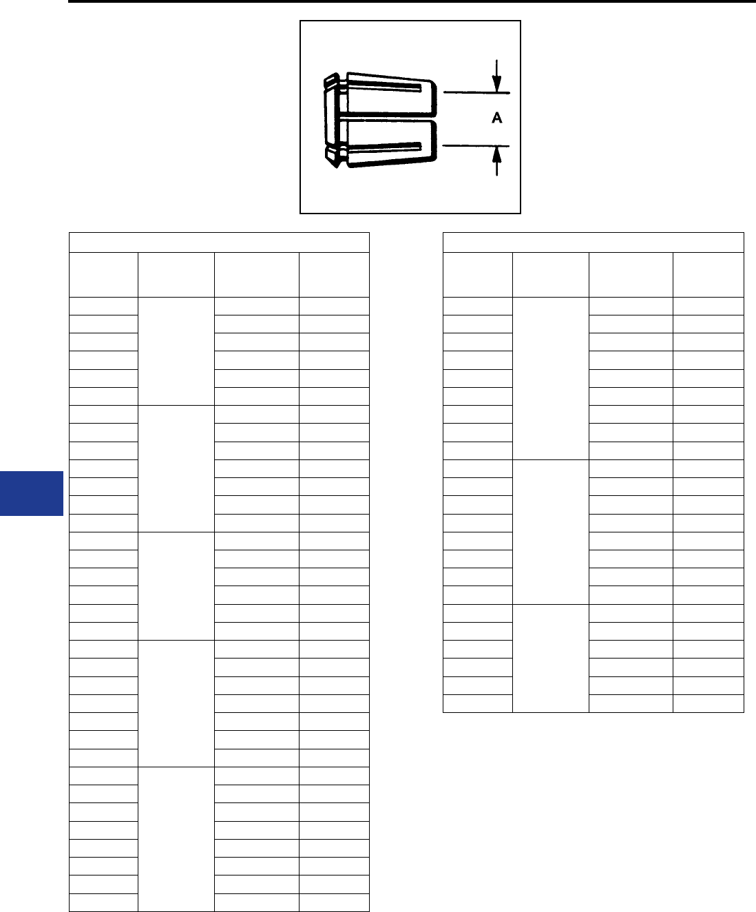
BURNDY®
Blue highlighted items are industry standard and most frequently ordered.
US: 1-800-346-4175 www.burndy.com Canada: 1-800-387-6487
Underground
MOLE™ TYPE Z
COMPRESSION CONE
For Compact Conductor
For use with Socket and Nut assembly the Z
cone is machined to close tolerances to provide
maximum secureness in gripping a wide range of
cable sizes. Annular grooves in the inner barrel of
the cone serve to further accomplish this result.
Compact Stranded Copper Cable
Type Z
Cone
Socket and
Nut
Assembly
Compact
Cable
Size
Nominal
Conductor
Diameter
Z3C28
Z28NR
#3 Str. 0.25
Z2C28 #2 Str. 0.29
Z1C28 #1 Str. 0.32
Z2528 1/0 Str. 0.37
Z2628 3/0 Str. 0.42
Z2728 3/0 Str. 0.47
Z2C29
Z29NR
#2 Str. 0.29
Z1C29 #1 Str. 0.33
Z2529 1/0 Str. 0.37
Z2629 2/0 Str. 0.42
Z2729 3/0 Str. 0.47
Z2829 4/0 Str. 0.52
Z2929 250 kcmil 0.57
Z1C30
Z30NR
#1 Str. 0.32
Z2530 1/0 Str. 0.37
Z2630 2/0 Str. 0.42
Z2730 3/0 Str. 0.47
Z2830 4/0 Str. 0.52
Z2930 250 kcmil 0.57
Z1C32
Z32NR
#1 Str. 0.32
Z2532 1/0 Str. 0.37
Z2632 2/0 Str. 0.42
Z2732 3/0 Str. 0.47
Z2832 4/0 Str. 0.52
Z2932 250 kcmil 0.57
Z3232 400 kcmil 0.73
Z2534
Z34NR
1/0 Str. 0.37
Z2634 2/0 Str. 0.42
Z2734 3/0 Str. 0.47
Z2834 4/0 Str. 0.52
Z2934 250 kcmil 0.57
Z3234 400 kcmil 0.73
Z3334 450 kcmil 0.77
Z3434 500 kcmil 0.81
Compact Stranded Copper Cable
Type Z
Cone
Socket and
Nut
Assembly
Compact
Cable
Size
Nominal
Conductor
Diameter
Z2536
Z36NR
1/0 Str. 0.37
Z2636 4/0 Str. 0.42
Z2736 3/0 Str. 0.47
Z2836 4/0 Str. 0.52
Z2936 250 kcmil 0.57
Z3236 400 kcmil 0.73
Z3336 450 kcmil 0.76
Z3436 500 kcmil 0.81
Z3636 600 kcmil 0.90
Z2640
Z40NR
2/0 Str. 0.42
Z2740 3/0 Str. 0.47
Z2840 4/0 Str. 0.52
Z2940 250 kcmil 0.57
Z3240 400 kcmil 0.73
Z3340 450 kcmil 0.76
Z3440 500 kcmil 0.81
Z3640 600 kcmil 0.90
Z2844
Z44NR
4/0 Str. 0.52
Z2944 250 kcmil 0.57
Z3244 400 kcmil 0.73
Z3344 450 kcmil 0.76
Z3444 500 kcmil 0.81
Z3644 600 kcmil 0.90
K-34
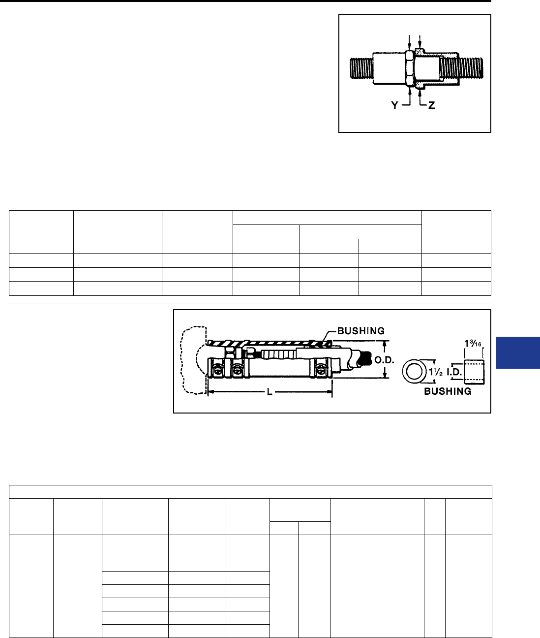
BURNDY®
Blue highlighted items are industry standard and most frequently ordered.
Canada: 1-800-387-6487 www.burndy.com US: 1-800-346-4175
Underground
TYPE ZMS
MOLE™ COUPLER
For Connecting MOLE
A compact, easy-to-tape MOLE™ Coupler for
joining multiple MOLE end-to-end. Allows for
expansion of underground systems by joining
more MOLE to existing MOLE™ installations.
Easily assembled to the end outlets of MOLE™
Types ZMT, ZMX, ZML, and ZMK. Can also be
used in side outlets for other types of MOLE™
MOLE™ Outlet
Size MOLE™ Coupler MOLE™ Coupler
Ampere Capacity
Dimensions in Inches
Approx. Ship
Wt. Lbs.
Overall Length Cross Flats
Y Z
AZMS29 1200 4-21/32 1-3/16 1-3/8 1.30
BZMS34 1600 5-7/32 1-1/2 1-3/4 2.30
CZMS40 2000 5-3/4 1-3/4 2-1/8 3.30
arrangements. The MOLE™ Coupler has a
lock-nut feature which permits pre-positioning
of the added MOLE™, and facilitates training of
new cables. Makes an effective electrical and
mechanical connection.
OUTLET RANGE: “A” (5/8") 6 Str. - 600 kcmil
“B” (7/8") 2 Str. - 1000 kcmil
“C” (1-1/8") 500 - 1500 kcmil
TYPE CM
NOTAPE™ MOLE™ SLEEVE
The BURNDY® NOTAPE™ MOLE™ Sleeve
effectively eliminates the necessity of taping
from the MOLE™ outlet to the insulation of the
incoming cable. The sleeve ts snugly over the
MOLE™ outlet and is held securely in place
by a non-corrosive clamp. Bushings inside
the sleeve are supplied to t closely over the
insulation of the cable. The other end of the
assembly is clamped to the cable insulation. For
rubber insulated cable two clamps are supplied.
OUTLET RANGE: “A” 6 Str. - 600 kcmil
† Diameter over rubber insulation or lead sheath to be specied by customer.
‡ Diameter over lead sheath to be specied by customer.
Bushings must be ordered separately. They are not supplied with
the sleeve. The bushing inside diameter is sized in 64ths.
For oil lled cables a third clamp is provided to
effect an oil-tight joint.
Sleeve & Clamps Bushing
To be
Used Over
Outlet Size
Type of
Cable
Insulation
Cable Range
Accommodated
Catalog No.
Sleeve &
Clamps Only
For Use
Sockets &
Nut Assy
Dimensions
in Inches App. Ship
Wt. Ea. in
Lbs.
Catalog No.
Bushing
Only
I.D.
App. Ship
Wt. Ea. in
Lbs.
L O.D.
A
Rubber or
Rubber-Lead #6 Str. to 600 kcmil CM29L Z28NR to
Z36NR 6-1/4 2-1/4 1.10 CMB-29R † 0.20
Paper-Lead
or
Vanished
Cambric
#6-4/0 Str. CM2829P Z28NR
6-1/4 2-1/4 1.10 CMB-29P ‡ 0.20
#6 AWG-250 kcmil CM2929P Z29NR
#6 AWG-300 kcmil CM3029P Z3ONR
#2 AWG-400 kcmil CM3229P Z32NR
#2 AWG-500 kcmil CM3429P Z34NR
250-600 kcmil CM3629P Z36NR
K-35
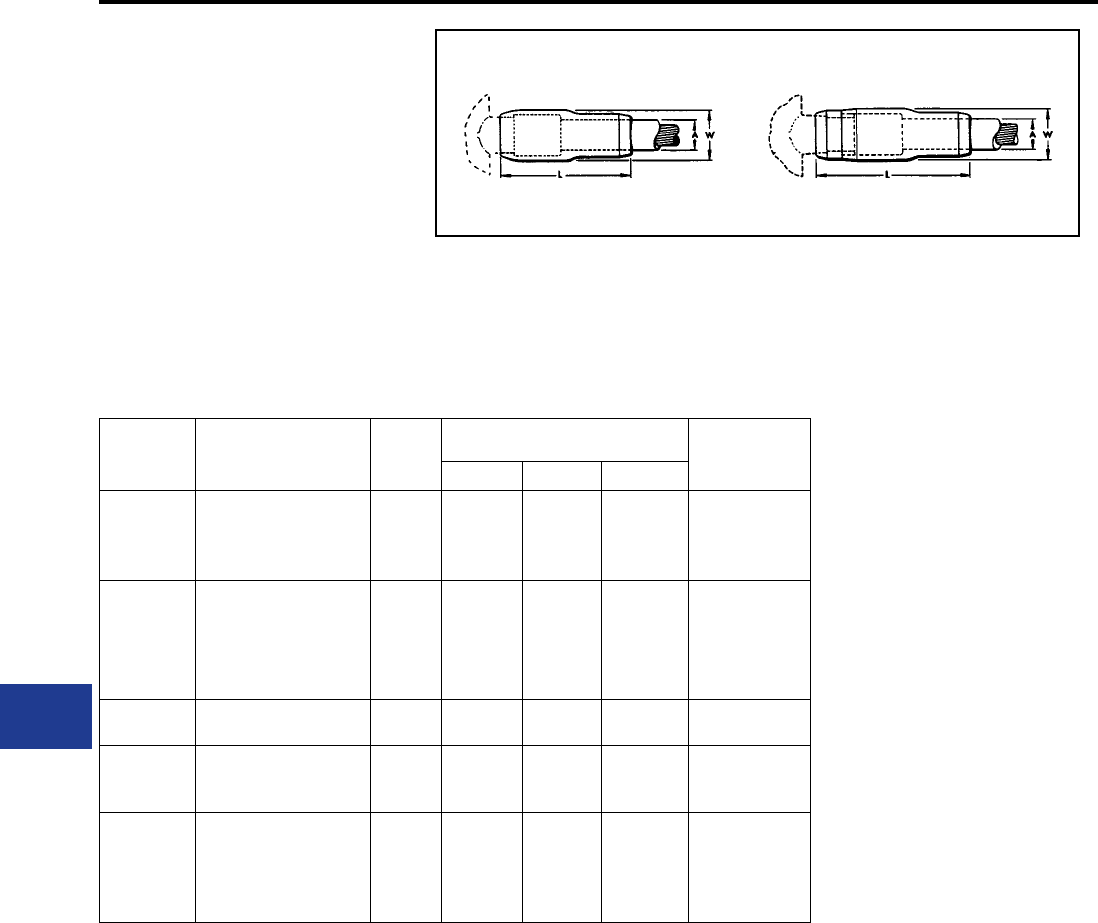
BURNDY®
Blue highlighted items are industry standard and most frequently ordered.
US: 1-800-346-4175 www.burndy.com Canada: 1-800-387-6487
Underground
TYPE Z-C
MOLE™ OUTLET
INSULATING SLEEVE
An effective aid in insulating MOLE™ outlets to
produce a secure watertight joint with a minimum
of taping. Fits over the MOLE™ outlet and over
the maximum outer diameter of insulated cable.
The difference between the I.D. of the standard
sleeve and the O.D. of the cable insulation is taken
up by wrapping the cable with several turns of
rubber tape. The only external taping required to
effectively seal the joint is the small area at each
end of the sleeve.
Catalog
Number
For Use with Socket
and Nut Assemblies Fig. No. Dimensions in Inches Approx. Ship
Wt. in Lbs.
per C
*A (Max.) L W
Z72C3029
Z28NR
Z29NR
Z30NR
1 1-1/8 4-3/4 1-7/8 20
Z88C3429
Z32NR
Z34NR
Z34NRB
Z36NR
1 1-3/8 5-3/16 2-1/8 30
Z104C4034 Z40NR 1 1-5/8 5-13/16 3-5/6 60
Z104C4434 Z44NR
Z40NRA 2 1-5/8 7-3/16 3-5/6 70
Z144C4840
Z45NR
Z46NR
Z47NR
z48NR
2 2-1/4 9-5/16 3-1/2 130
Fig. 1 Fig. 2
* Build up insulation of MOLE™ Joint with rubber tape to equal inner diameter of
Insulating Sleeve, for insulating sleeve with inner diameter other than standard call
customer service.
K-36
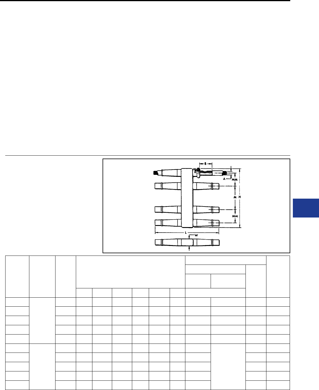
BURNDY®
Blue highlighted items are industry standard and most frequently ordered.
Canada: 1-800-387-6487 www.burndy.com US: 1-800-346-4175
Underground
HYCRAB™ CONNECTORS
One of the most economical devices for connecting
several cables to a common junction point is the
HYCRAB™, which is essentially a bus bar with a
number of compression-type connector outlets,
pre-insulated to eliminate taping. Like the MOLE™,
the HYCRAB™ ts into a limited space, is simple to
rack, and facilitates addigin future cables.
Insert and Insulation
Having an insert similar to that of the MOLE™,
the HYCRAB™, has connector outlets of the
BURNDY® HYDENT™ compression type. These
tubular elements are indented to the cable by
BURNDY® HYPRESS™ installation tools and
dies, designed to compress connector and
cable together with indents of controlled depth.
HYDENT™ compression connections are made
quickly and easily, have relative conductivities
of 100% or higher, are electrically stable, and
mechanically secure.
The HYCRAB™ is insulated by a jacket of molded
rubber to resist prolonged exposure to oil or other
contaminants.
Installation
Insulation ngers are rolled back to expose the
tublar outlets, sufciently spaced to allow for the
convenient operation of BURNDY® HYPRESS™
compression tools. Cable ends are inserted
into the outlets. Each is crimped with one or two
indents, and the ngers are rolled forward again
to cover the outlets. Installation is completed by
taping the short space between the tip of the nger
and cable insulation.
Variations and Accessories
Uninsulated HYCRAB™ connectors for joining
bare neutral cables are available in the same
range of sizes and number of outlets as the
insulated HYCRAB™. By using reducing adapters,
the HYCRAB™ can accommodate service wires
as small as #6, in addition to the 4/0 or 500
kcmil cable sizes for which these connectors are
ordinarily used.
TYPE YM
INSULATED HYCRAB™
A compact insulated crab joint for connecting
underground cables at junction points. Two outlets,
one on either side of the HYCRAB™ body are ready
for immediate use. All other outlets are sealed with
vulcanized rubber plugs which are easily removed
when future installations are made. This unit eliminates
bulky, difcult crotch taping. By using Reducing
Adapters, Type Y-R the HYCRAB™ can be installed
on cable sizes from #6 to 500 kcmil (e.g., use Y3428R
to install 4/0 into YM4-34).
Catalog
Number
Cable Size
A
# of
Outlets
Dimension in Inches
Installation Information
App. Ship
Wt. in
Lbs.
HYPRESS™ & Indentor Die
# of
Indents
Y34A with
Y34PR
Y34BH with
Y34PR
B H L M MM W Nest Die
YM4-28
4/0 Str.
4 2 3-11/16 10-3/16 — 2-3/16 1-1/8 A28D B28D 1 1.80
YM6-28 6 2 7-9/16 10-3/16 3-7/8 2-3/16 1-1/8 A28D B28D 1 3.00
YM8-28 8 2 9-3/4 10-3/16 3-7/8 2-3/16 1-1/8 A28D B28D 1 4.30
YM10-28 10 2 13-1/2 8-3/4 3-1/2 2-1/2 1-1/8 A28D B28D 1 5.50
YM12-28 12 2 16 8-3/4 3-1/2 2-1/2 1-1/8 A28D B28D 1 6.70
YM4-34
500 kcmil
4 2-1/2 4-3/8 12-5/8 — 2-3/8 1-1/2 A34D
No Nest
Die
Required.
Use Indentor
Only.
2 4.50
YM6-34 6 2-1/2 8-5/8 12-5/8 4-1/4 2-3/8 1-1/2 A34D 2 7.00
YM8-34 8 2-1/2 11 12-5/8 4-1/4 2-3/8 1-1/2 A34D 2 11.00
YM10-34 10 2-1/2 14-1/2 12-1/2 3-3/4 2-1/2 1-1/2 A34D 2 15.00
YM12-34 12 2-1/2 17 12-1/2 3-3/4 2-1/2 1-1/2 A34D 2 19.00
K-37
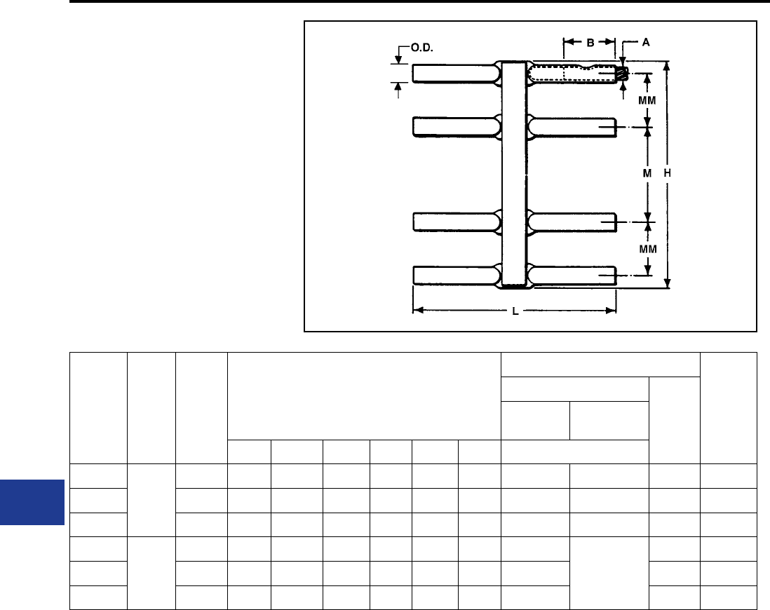
BURNDY®
Blue highlighted items are industry standard and most frequently ordered.
US: 1-800-346-4175 www.burndy.com Canada: 1-800-387-6487
Underground
TYPE YNM
HYCRAB™
For Joining Bare Neutral Cables
A compact uninsulated multiple connector for
joining bare neutral underground cables. For
insulated crab joints, see HYCRAB™, Type YM.
Reducing adapters, Type Y-R, permit the HYCRAB
products listed below to take a full range of cable
sizes from #6 to 500 kcmil. For proper installation,
see table below.
Catalog
Number
Cable
Size A
No. of
Outlets
Dimension in Inches
Installation Information
App.
Ship
Wt. in
Lbs.
HYPRESS™ & Indentor Die
No. of
Indents
Y34A with
Y34PR
Y34BH with
Y34PR
B H L M MM O.D. Nest Die
YNM428
4/0 Str.
4 2 3-3/16 8-3/16 — 2-3/16 11/16 A28D B28D 1 1.00
YNM628 6 3-1/8 7-1/6 8-3/16 3-7/8 2-3/16 11/16 A28D B28D 1 1.80
YNM828 8 2 9-1/4 8-3/16 3-7/8 2-3/16 11/16 A28D B28D 1 2.50
YNM434
500
kcmil
4 2-1/2 3-15/16 10-5/8 — 2-3/8 1-1/16 A34D No Nest Die
Required.
Use Indentor
Only.
2 3.00
YNM634 6 2-1/2 8-3/16 10-5/8 4-1/4 2-3/8 1-1/16 A34D 2 5.00
YNM834 8 2-1/2 10-9/16 10-5/8 4-1/4 2-3/8 1-1/16 A34D 2 7.30
* Bare HYCRAB™ can be furnished to accommodate both 4/0 and 500 kcmil cables.
K-38
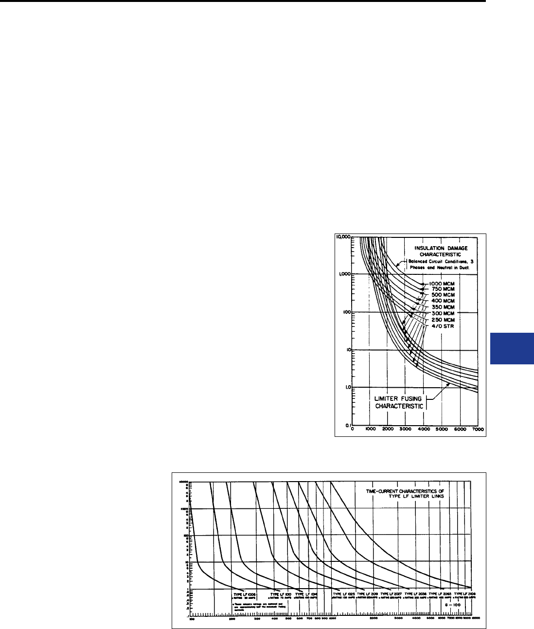
BURNDY®
Blue highlighted items are industry standard and most frequently ordered.
Canada: 1-800-387-6487 www.burndy.com US: 1-800-346-4175
Underground
NETWORK PROTECTION
The primary purpose of network protection is
the controlled interruption of fault currents before
damage occurs to cable insulations and associated
equipment, and the elimination of unnecessary
service interruptions. The limiter and fuses for
network protection are closely associated wtith
the connectors and are equally vital to the safe,
continuous operation of an underground system.
BURNDY has developed protective devices that
have played a major role in reducing underground
system outages and the subsequent expenses
incurred in the loss of service and replacement of
damaged cables. A basic objective has been the
design of limiter-connector combinations that, in
addition to protecting against the effects of fault
currents, economize on both space and installation
costs.
Limiters are designed to protect underground
secondary cable from damage by fault currents of
two principal kinds: high energy arcing faults and
sustained faults. The arcing fault, usually of shorter
duration and lesser intensity, is more common.
While this type of fault may sputter briey and
then clear, some may be sustained long enough to
“roast” the insulation.
A sustained fault occurs when two conductors
come solidly into contact and permit the ow of
heavy short-circuit currents. Without suitable
protection, these fault currents are heavy enough
to damage cable insulation and often produce
combustible fumes accompanied by re and
explosion.
Installed at each end of cable sections, limiters
have time-current characteristics designed to avoid
unnecessary outages. Network protector fuses,
installed in the network protector on the load side
of the breaker, provide back-up protection against
failure of a network protector to open on a primary
fault. Coordinated characteristics of limiters and
fuses provide for fault currents to be interrupted
before they can cause damage, but only under
predetermined time-current conditions, and only
in those parts of the system where interruption is
necessary.
Limiters
Engineered to interrupt the circuit before cables
carrying a fault current are isually damaged,
limiters acto to conne damage to the section of
cable where the fault occurred. The limiters are
designed to prevent unnecessary clearing and will
“hang on” during:
1. Faults with wold clear without damaging
cable insulation
2. Overloads from motor starting, load transfer
because of primary fault, or temporary
overload during fault conditions
3. Overloads from loss of secondary conductors
caused by clearing of other limiters
4. Reverse current ow through the network
protector on primary faults
5. Faults on other secondary cables
For proper proection BURNDY® limiters are
designed with time-current characteristcs
approximating the insulation damage curve of the
cable with which they wll be used. Figure 4 shows
time-current characteristic curves for a range
of standard (250 volt) limiters, superimposed
on insulation damage curves for several cable
sizes. Although the limiter curve crosses the
insulation damage curves, in practice the limiters
will blow before teh insulation can deteriorate. The
insulation damage characteristics represent three
phases equally loaded in a duct. Since low-current
faults seldom affect more than one phase at a
time, the rate of heat generated in the conduit is
much less than for a balanced 3-phase fault, and
the time to reach the damage point is appreciably
longer. Practical experience conrms that limiters
provide protection during low-current, as well as
high-current faults.
Construction
The limiter is essentially a compression-type
electrical connector with its center section
accurately formed to provide a fusible element.
This fusible element is enclosed in a molded
composition shell and the assembly encased in an
insulated sleeve.
Interrupting capacities are as follows:
Standard Limiters: 30,000 amps at 250V
Replaceable-Link Limiters: 20,000 amps at 250V
The protection probably lies in the fact that the fault
impedance reduces the actual fault current to a
value considerably less than calculated.
Replaceable-Link Limiters
Replaceable-link limiters, which provide faster
time-current characteristics (Figure 5), are used in
smaller networks, on teh fringes of larger networks,
at points where radial feeders leave a network, and
for fusing service cables. As its name implies, this
limiter is also distinctive in that its fusible link is
replaceable.
Figure 4: Current - Amperes
Standard 250 Volt Limiters
Figure 5: Current in Amperes Replaceable-link Limiters
K-39
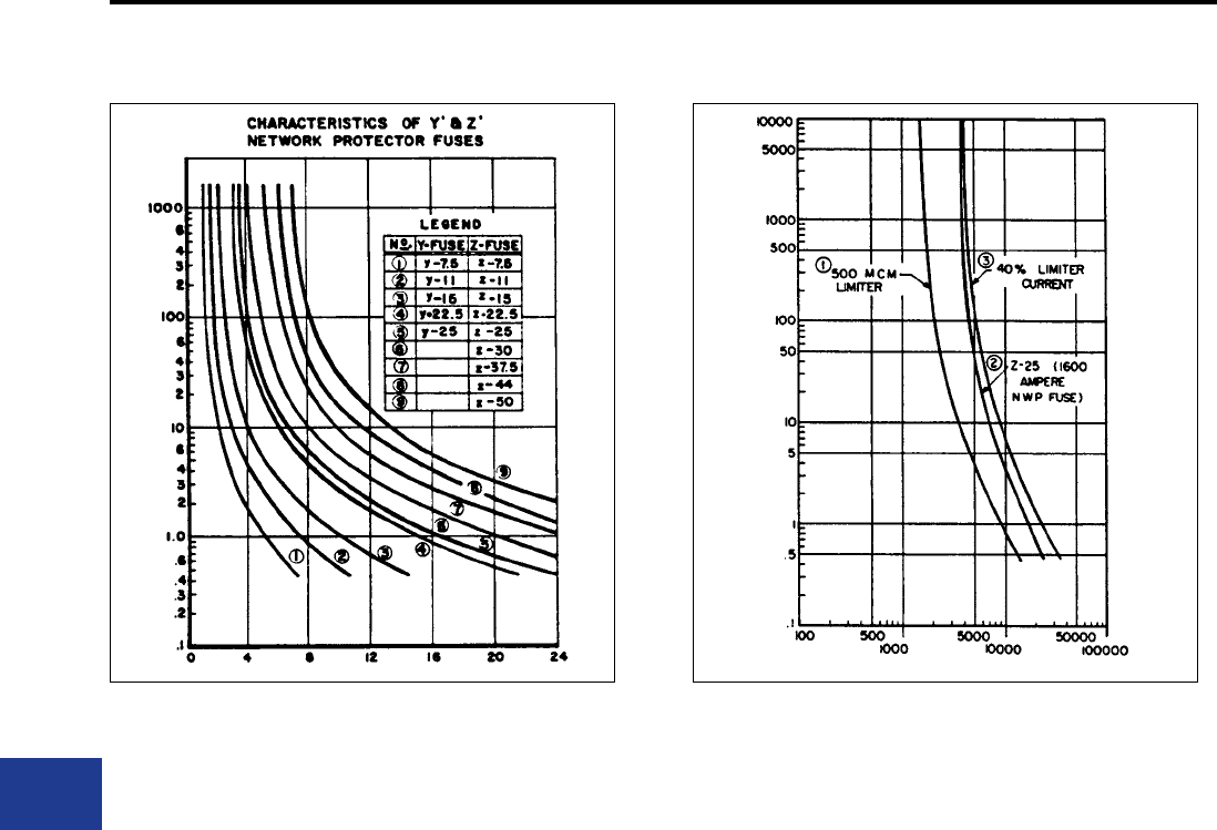
BURNDY®
Blue highlighted items are industry standard and most frequently ordered.
US: 1-800-346-4175 www.burndy.com Canada: 1-800-387-6487
Underground
NETWORK PROTECTION (Continued)
Limiter Variations
The Limiter Lug provides a fusible connection
between a cable and a at surfaced terminal of a
transformer or other apparatus. The Limiter Tap
incorporates a Limiter Lug assembly, modied to
terminate cable to a ring bus. Thie straight Limiter
is made for installation in a single conductor cable.
The Molimiter is a Limiter designed so that one
end is crimped onto a cable and the other ts the
clamping element of a MOLE™ outlet. The Limiter
HYCRAB™ connector is essentially a HYCRAB™
with a fusible section in each of its outlets.
Network Protector Fuses
Type Y and Z Network Protector Fuses provide
back-up protection in case the protector breaker
fails to operate during a primary fault. The fuse
time-current curves (Figure 7), are similar to those
of the limiter, thus permitting correct fuse-limiter
coordination for complete network protection.
Design and Construction
The fusible element for a Type Y or Type Z Fuse
is a tin-plated copper bar with reduced section,
encased in an arc-resistant molded transite
enclosure. One-piece construction eliminates
possibility of joint failure and assures maximum
reliability.
Limiter-Fuse Coordination
To isolate a fault before it can cause extensive
damage, and without interrupting service in other
sections of the network, limiters and fuses must
clear at the proper time and in proper sequence,
depending on teh fault’s location in the primary or
secondary system. When a primary fault occurs,
the fuse should clear before any limiters blow. For
a secondary fault, limiters should clear the fault
before the network protector fuse opens. Failure of
limiters and network protector fuses to function in
proper sequence could cause cascading of other
Fuses, or clearing of secondary faults by Fuses
rather than limiters. Premature blowing of Limiters
not in the faulted section could cause unnecessary
service interruption in sections remote from the
fault.
To assure the coordinated functioning of fuses and
limiters throughout a system, proper rating must
be selected. The four-step “Coordination Study”
(Figure 8) used in a 4-parallel cable feed system
from the protector to the rst secondary junction is
a typical example of how to select proper ratings.
1. Plot the damage characteristic curve f the
cable insulation in the system. Curves for
Class L620 (260° C or 500° F), appear in
Figure 5.
2. Plot the time-current characteristic curve of
the same limiter in Parallel secondary mains,
assuming it carries 40% of total backfeed
current. Allowing for the possibility of unequal
current distribution of secondary mains,
the “40% Cable Limiter Curve” provides a
conservative basis for selection of network
protector fuses.
3. Select a fuse with its time-current
characteristics (Figure 7) lying between the
limiter curves plotted in steps 2 and 3.
This procedure avoids the selection of fuses so
light that they might overheat the network protector
or clear unnecessarily, possibly cascading other
fuses in the network; or so heavy that transformer
secondaries might be damaged or limiters blow
before teh fuse. Proper limiter-fuse coordination,
facilitated by the use of fuses and limiters that are
precisely matched, assures effective protection
without unnecessary interruption.
Figure 7: Amperes in Thosands Figure 8: Current in Amperes
K-40
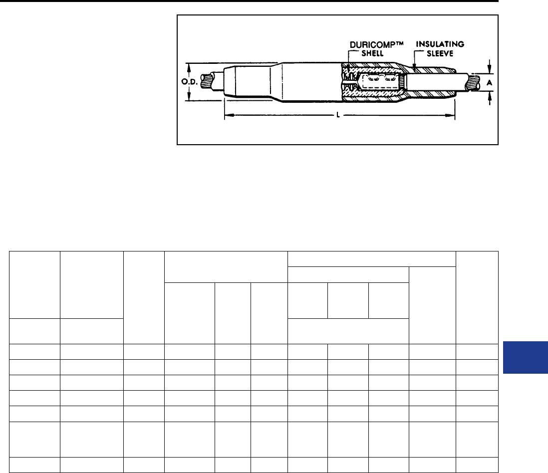
BURNDY®
Blue highlighted items are industry standard and most frequently ordered.
Canada: 1-800-387-6487 www.burndy.com US: 1-800-346-4175
Underground
TYPES YFS-CR AND
YFS-CP
LIMITER ASSEMBLY
With Ceramic Shell
and Rubber Sleeve for
Insulated Cables
The Limiter combines the functions of fuse and
connector. The fusible element which is an integral
part of the connector will clear faults that are great
enough to cause damage to the cable insulation.
However it will not clear on minor overloads of
short duration. Fusing characteristics of the limiter
are shown in technical section. For HYPRESS™
installation, see table below.
For Use on
Rubber
Insulated
Cable
For Use on
Paper Insulated
Cable-Oil Tight
Cable Sockets Cable
Size
Dimensions
in Inches
Installation Information
App. Ship
Wt. in
Lbs.
HYPRESS™ & Indentor Die
Number of
Indents
Max. Cable
Dia. over
Insulation
A
L O.D.
Y34A
with
Y34PR
Y34BH
with
Y34PR
Y44B
with
Y44PR
Catalog
Number
Catalog
Number Nest Die
YFS28CR YSF28CP 4/0 Str. 1 12-3/4 1-15/16 A28D B28D E28D 1 1.40
YFS29CR YFS29CP 250 kcmil 1 12-3/4 1-15/16 A29P B29D E29D 1 1.40
YFS30CR YFS30CP 300 kcmil 1-1/8 13-1/2 2-3/16 A30D B30D E30D 2 2.00
YFS31CR YFS31CP 350 kcmil 1-1/8 13-1/2 2-3/16 A31D B31D E31D 2 2.00
YFS32CR YFS32CP 400 kcmil 1-1/8 13-1/2 2-3/16 A32D B32D E32D 2 2.10
YFS34CR YFS34CP 500 kcmil 1-11/32 15-7/8 2-3/8 A34D
No Nest
Die
Required
E34D 2 2.90
YFS39CR YFS39CP 750 kcmil 1-1/2 15-9/16 2-9/16 — — E39D 2 3.70
For conductor sizes not listed call customer service. To specify a fast acting limiter in any conguration insert an “F”
before the conductor number (e.g., YFSF34CR species a 1/2 thick limiter section).
K-41
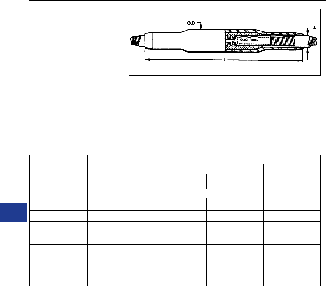
BURNDY®
Blue highlighted items are industry standard and most frequently ordered.
US: 1-800-346-4175 www.burndy.com Canada: 1-800-387-6487
Underground
TYPE YFS-CPL
LONG LIMITER ASSEMBLY
With Ceramic Shell and Rubber
Sleeve for Paper-Lead Cables
The Long Limiter performs the same functions
as the Limiter shown, Types YFS-CR and
YFS-CP. It differs in that it has extra long cable
sockets which are preferred by some for use
on paper insuated cable. The end seams are
sealed to make the sockets oil tight. Fusing
characteristics of the Limiter are shown in
technical section. For proper HYPRESS™
installation, see table below.
Catalog
Number Cable Size
Dimensions in Inches Installation Information
App. Ship
Wt. in Lbs.
Max. Cable Dia.
over Insulation A L O.D.
HYPRESS™ & Indentor Die
Number
of Indents
Y34A with
Y34PR
Y34BH with
Y34PR
Y44B with
Y44PR
Nest Die
YFS28CPL 4/0 Str. 1 12-3/4 1-15/16 A28D B28D E28D 1 1.50
YFS29CPL 250 kcmil 1 12-3/4 1-15/16 A29P B29D E29D 1 1.50
YFS30CPL 300 kcmil 1-1/8 13-1/2 2-3/16 A30D B30D E30D 2 2.20
YFS31CPL 350 kcmil 1-1/8 13-1/2 2-3/16 A31D B31D E31D 2 2.20
YFS32CPL 400 kcmil 1-1/8 13-1/2 2-3/16 A32D B32D E32D 2 2.30
YFS34CPL 500 kcmil 1-11/32 15-7/8 2-3/8 A34D No Nest Die
Required E34D 2 3.20
YFS39CPL 750 kcmil 1-1/2 15-9/16 2-9/16 — — E39D 2 4.10
For conductor sizes not listed call customer service. To specify a fast acting limiter in any conguration insert an “F”
before the conductor number (example: YFSF34CR species and 1/2 thick limiter section).
K-42
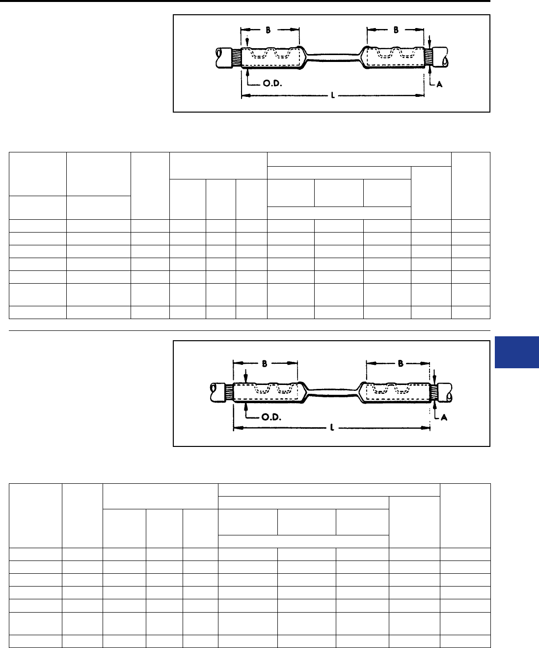
BURNDY®
Blue highlighted items are industry standard and most frequently ordered.
Canada: 1-800-387-6487 www.burndy.com US: 1-800-346-4175
Underground
TYPES YFSR, YFSP
LIMITER
For Use with Limiter Assembly
The Limiter serves the double function of a fuse
and a coupler. The fusible element is an integral
part of the coupler and is closely and carefully
sized to insure excellent performance. Fusing
characteristics of the Limiter are shown in technical
For use on
Rubber
Insulated
Cable
For use on
Paper Insulated
Cable-Oil Tight
Cable Sockets Cable
Size
Dimensions
in Inches
Installation Information
App. Ship
Wt. in
Lbs.
HYPRESS™ & Indentor Die
Number
of
Indents
B L O.D.
Y34A with
Y34PR
Y34BH with
Y34PR
Y44B with
Y44PR
Catalog
Number
Catalog
Number Nest Die
YFSR28 YFSP28 4/0 Str. 1-3/4 in 6-3/8 11/16 A28D B28D E28D 1 0.23
YFSR29 YFSP29 250 kcmil 1-7/8 in 6-3/8 3/4 A29D B29D E29D 1 0.27
YFSR30 YFSP30 300 kcmil 2 in 6-3/4 13/16 A30D B30D E30D 2 0.33
YFSR31 YFSP31 350 kcmil 2 in 6-3/4 7/8 A31D B31D E31D 2 0.37
YFSR32 YFSP32 400 kcmil 2-1/8 in 7 31/32 A32D B32D E32D 2 0.46
YFSR34 YFSP34 500 kcmil 2-7/8 in 8-3/4 1-1/16 A34D No Nest Die
Required E34D 2 0.79
YFSR39 YFSP39 750 kcmil 2-7/8 in 9 1-5/16 — — E39D 2 1.20
section. For proper HYPRESS™ installation, see
table below.
TYPE YFSP-L
LONG LIMITER
For Use with Long Limiter Assembly
The Long Limiter serves the same purpose as
the Limiter shown above but has extra long oil
tight cable sockets which may be preferred by
some for use on paper insulated cables. Similarly
designed to clear on overloads that will damage
the insulation of the cable. Fusing characteristics
Catalog
Number
Cable
Size
Dimensions in Inches Installation Information
App. Ship
Wt. in Lbs.
HYPRESS™ & Indentor Die
Number of
Indents
B L O.D.
Y34A with
Y34PR
Y34BH with
Y34PR
Y44B with
Y44PR
Nest Die
YFSP28L 4/0 Str. 2-15/16 in 8-3/4 11/16 A28D B28D E28D 1 0.34
YFSP29L 250 kcmil 3-1/16 in 8-3/4 3/4 A29D B29D E29D 1 0.40
YFSP30L 300 kcmil 3-3/8 in 9-1/2 13/16 A30D B30D E30D 2 0.50
YFSP31L 350 kcmil 3-3/8 in 9-1/2 7/8 A31D B31D E31D 2 0.58
YFSP32L 400 kcmil 3-3/8 in 9-1/2 31/32 A320 B32D E32D 2 0.68
YFSP34L 500 kcmil 4-3/16 in 11-3/8 1-1/16 A34D No Nest Die
Required E34D 2 1.10
YFSP39L 750 kcmil 4-3/16 in 11-5/8 1-5/16 — — E39D 2 1.60
of the Long Limiter are shown in technical section.
For HYPRESS™ installation, see table below.
For conductor sizes not listed call customer service.
K-43
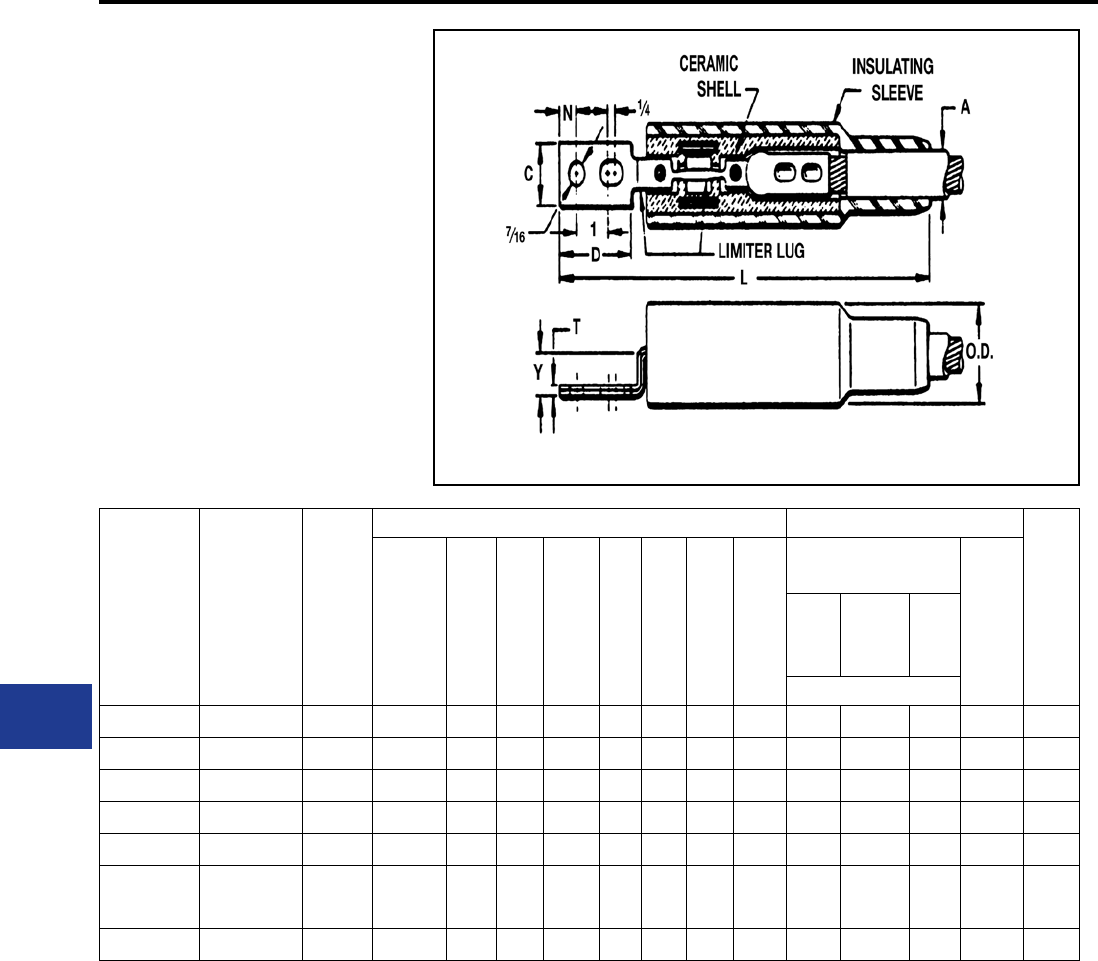
BURNDY®
Blue highlighted items are industry standard and most frequently ordered.
US: 1-800-346-4175 www.burndy.com Canada: 1-800-387-6487
Underground
TYPES YFA-CR, YFA-CP
LIMITER LUG ASSEMBLY
With Ceramic Shell and
Rubber Sleeve
The Limiter Lug combines the functions of terminal
and fuse. The fusible element is an integral part
of the connector and is so designed that it will
clear overloads which are great enough to cause
damage to the cable insulation. Unlike an ordinary
fuse, however, it will not clear on minor overloads
of short duration. Fusing characteristics of the
Limiter Lugs are shown in the technical section.
Component parts shown in the table below may
be purchased separately. For proper HYPRESS™
installation, see table below.
For Use on
Rubber Insul.
Cable
Catalog No.
For use on
Paper Insul.
Cable-Oil Tight
Cable Socket
Catalog No.
Cable
Size
Dimensions in Inches Installation Information
Approx
Ship
Weight
(Max.
Cable
Dia. over
Insul.)
A
C D L N T Y O.D.
HYPRESS™ &
Indentor Die
# of
Indents
Y34A
with
Y34PR
Y34BH
with
Y34PR
Y44B
with
Y44PR
Nest Die
YFA28CR2 YFA28CP-2 4/0 Str. 1.00 1.00 2.19 11.56 0.44 0.14 0.84 2.00 A28D B28D E38D 1 1.20
YFA29CR2 YFA29CP-2 250 kcmil 1.00 1.13 2.19 11.56 0.44 0.16 0.84 2.00 A29D B29D E29D 1 1.20
YFA30CR2 YFA30CP-2 300 kcmil 1.22 1.19 2.31 13.19 0.50 0.16 1.00 2.38 A30D B30D E30D 2 1.80
YFA31CR2 YFA31CP-2 350 kcmil 1.22 1.31 2.31 13.19 0.50 0.19 1.00 2.38 A31D B31D E31D 2 2.20
YFA32CR2 — 400 kcmil 1.22 1.44 2.31 13.19 0.50 0.19 1.00 2.38 A32D B32D E32D 2 2.30
YFA34CR2 YFA34CP-2 500 kcmil 1.34 1.50 2.75 13.63 0.50 0.22 1.00 2.38 A34D
No Nest
Die
Req’d.
E34D 2 2.50
YFA39CR2 YFA39CP-2 750 kcmil 1.50 1.94 2.75 13.63 0.50 0.25 1.00 2.38 — — E39D 2 2.80
For conductor sizes not listed call customer service.
To specify a fast acting limiter in any conguration insert an “F” before the conductor number (example: YFSF34CR
species and 1/2 thick limiter section).
K-44
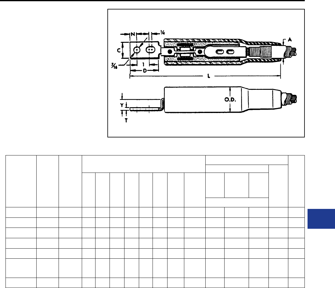
BURNDY®
Blue highlighted items are industry standard and most frequently ordered.
Canada: 1-800-387-6487 www.burndy.com US: 1-800-346-4175
Underground
TYPE YFA-CPL
LONG LIMITER LUG ASSEMBLY
With Ceramic Shell
and Rubber Sleeve —
for Paper-Lead Cables
A Limiter Lug similar to Type YFA-CR or YFACP. In
this case, however, we supply an extra long cable
socket which is sometimes preferred for use on
paper insulated cable. The end seams are sealed
to make sockets oil tight. Fusing characteristics
of the Limiter Lugs are shown in the technical
section. For proper HYPRESS™ installation, see
table below.
Catalog
Number
Cable
Size
(Max.
Cable
Dia. over
Insul.)
A
Dimensions in Inches Installation Information
App.
Wt.
in
Lbs.
HYPRESS™ & Indentor Die
#
of In-
dents
C D L N T Y O.D.
No of
Indents
in Cable
Sockets
Y34A
with
Y34PR
Y34BH
with
Y34PR
Y44B
with
Y44PR
Nest Die
YFA28CPL2 4/0 Str. 1.00 1.00 2.19 11.56 0.44 0.14 0.84 2.00 1 A28D B28D E28D 1 1.20
YFA29CPL2 250 kcmil 1.00 1.09 2.19 11.56 0.44 0.16 0.84 1.75 1 A29D B29D E29D 1 1.30
YFA30CPL2 300 kcmil 1.22 1.19 2.31 13.19 0.50 0.16 1.00 2.38 2 A30D B30D E30D 2 1.90
YFA31CPL2 350 kcmil 1.22 1.28 2.31 13.19 0.50 0.19 1.00 0.88 2 A31D B31D E31D 2 2.30
YFA32CPL2 400 kcmil 1.22 1.44 2.31 13.19 0.50 0.19 1.00 2.38 2 A32D B32D E32D 2 2.40
YFA34CPL2 500 kcmil 1.34 1.50 2.75 13.63 0.50 0.22 1.00 1.06 2 A34D No Next
Die Req’d. E34D 2 2.70
YFA39CPL2 750 kcmil 1.50 1.94 2.75 13.63 0.50 0.25 1.00 2.38 2 — — E39D 2 3.10
For conductor sizes not listed call customer service.
To specify a fast acting limiter in any conguration insert an “F” before the conductor number (e.g., YFSF34CR
species a 1/2 thick limiter section).
K-45
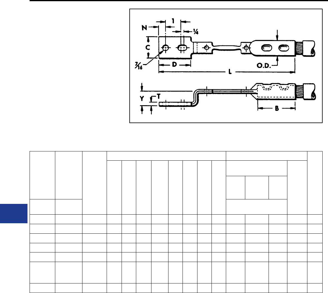
BURNDY®
Blue highlighted items are industry standard and most frequently ordered.
US: 1-800-346-4175 www.burndy.com Canada: 1-800-387-6487
Underground
TYPES YFAR, YFAP
LIMITER LUG
For Use with Limiter Lug Assembly
The Limiter Lug incorporates an accurately
determined fusible section as an integral part with
its terminal end. The fusible section is so selected
that it wil prevent the cable from roasting or damage
from a short circuit, although it will not clear on
minor overloads of short duration not harmful
to cable insulation. For proper HYPRESS™
installation, see table below.
For Use
on
Rubber
Insul.
Cable
For Use
on Paper
Insul.
Cable-Oil
Tight
Cable
Socket
Cable
Size
Dimensions in Inches Installation Information
App.
Wt.
in
Lbs.
B C D L N T Y O.D.
HYPRESS™ &
Indentor Die
No.
of
Indents
Y34A
with
Y34PR
Y34BH
with
Y34PR
Y44B
with
Y44PR
Catalog
No.
Catalog
No. Nest Die
YFAR282 YFAP282 4/0 Str. 1.81 1.00 2.19 8.22 0.44 0.14 0.89 0.70 A28D B28D E28D 1 0.28
YFAR292 YFAP292 250 kcmil 1.81 1.09 2.19 8.22 0.44 0.16 0.91 0.76 A29D B29D E29D 1 0.33
YFAR302 YFAP302 300 kcmil 1.94 1.19 2.31 8.88 0.50 0.16 1.07 0.83 A30D B30D E30D 2 0.42
YFAR312 YFAP312 350 kcmil 1.94 1.28 2.31 8.88 0.50 0.18 1.08 0.89 A31D B31D E31D 2 0.46
YFAR322 YFAP322 400 kcmil 2.06 1.38 2.31 9.12 0.50 0.19 1.10 0.97 A32D B32D E32D 2 0.55
YFAR342 YFAP342 500 kcmil 2.44 1.54 2.75 10.00 0.50 0.23 1.11 0.97 A34D
No
Nest Die
Req’d.
E34D 2 0.83
YFAR392 YFAP392 750 kcmil 2.44 1.91 2.75 10.00 0.50 0.26 1.14 1.34 — — E39D 2 1.20
For conductor sizes not listed call customer service.
K-46
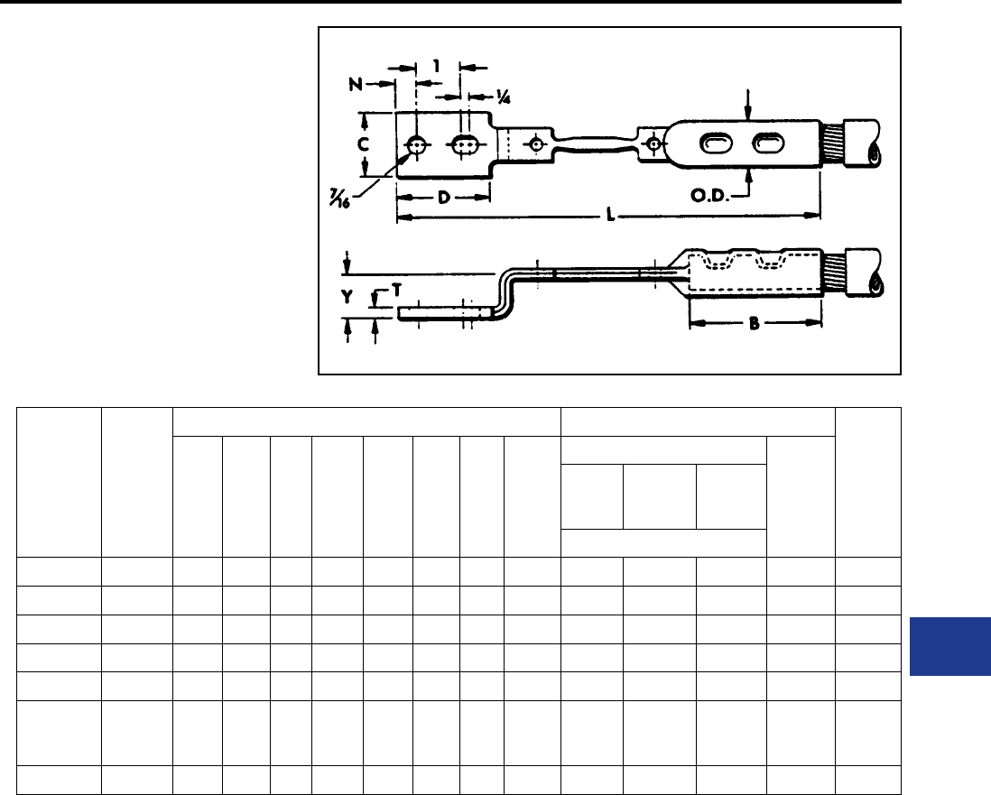
BURNDY®
Blue highlighted items are industry standard and most frequently ordered.
Canada: 1-800-387-6487 www.burndy.com US: 1-800-346-4175
Underground
TYPE YFAP-L
LONG LIMITER LUG
For Use with Limiter Lug Assembly
Similar to Limiter Lug Types YFAR and YFAP,
except that this type provides a long oil tight cable
socket, preferred by some users of paper-insulated
cables. Fusing characteristics shown in technical
section. For HYPRESS™ installation, see table
below.
Catalog
Number
Cable
Size
Dimensions in Inches Installation Information
App.
Wt.
in Lbs.
B C D L N T Y O.D.
HYPRESS™ & Indentor Die
No. of
Indents
Y34A
with
Y34PR
Y34BH
with
Y34PR
Y44B
with
Y44PR
Nest Die
YFAP28L2 4/0 Str. 3.50 1.00 2.19 10.44 0.44 0.14 0.89 0.69 A28D B28D E28D 1 0.36
YFAP29L2 250 kcmil 3.56 1.12 2.18 10.44 0.44 0.16 0.89 0.75 A29D B29D E29D 1 0.42
YFAP30L2 300 kcmil 3.63 1.18 2.31 11.19 0.50 0.16 1.10 0.76 A3OD B3OD E3OD 2 0.52
YFAP31L2 350 kcmil 3.63 1.38 2.31 11.38 0.50 0.18 1.08 0.82 A310 B31D E31D 2 0.58
YFAP32L2 400 kcmil 3.75 1.38 2.31 11.50 0.50 0.19 1.10 0.89 A32D B320 E32D 2 0.70
YFAP34L2 500 kcmil 4.13 1.54 2.75 12.25 0.50 0.23 1.11 0.98 A34D
No
Nest Die
Req’d.
E34D 2 1.00
YFAP39L2 750 kcmil 4.13 1.91 2.75 12.31 0.50 0.27 1.14 1.20 — — E39D 2 1.50
For further information call customer service.
K-47
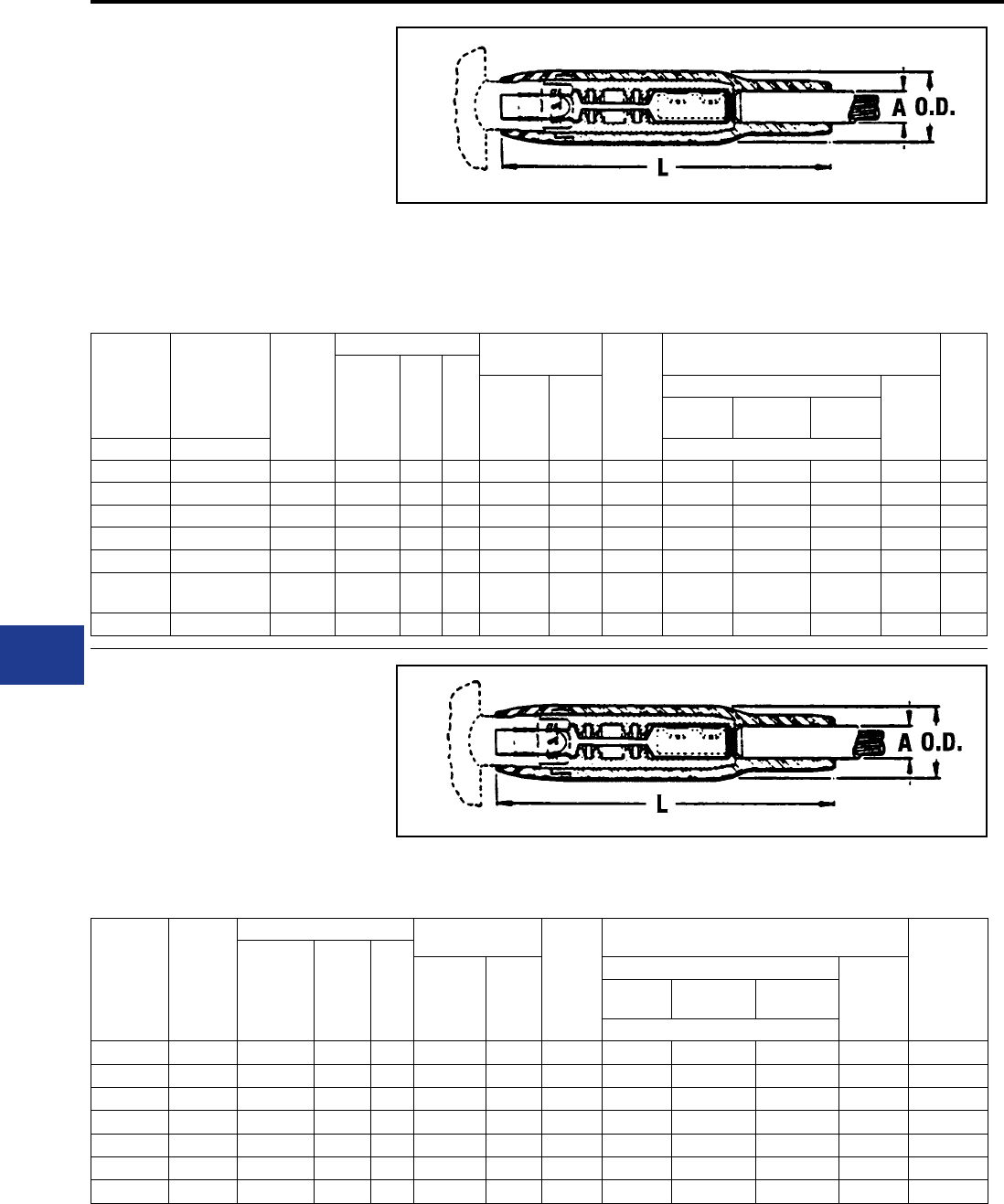
BURNDY®
Blue highlighted items are industry standard and most frequently ordered.
US: 1-800-346-4175 www.burndy.com Canada: 1-800-387-6487
Underground
TYPES YFM-CR, YFM-CP
MOLIMITER™ ASSEMBLY
With Ceramic Shell and
Rubber Sleeve for Insulated Cables
The MOLIMITER™ is used for fusing underground
cables at junction points. The unit is designed for
use with the BURNDY® MOLE™ and provides
Limiter protection for cables. which terminate
at the MOLE™. The cable end is installed in the
MOLIMITER™ cable socket (see Installation
For Use on
Rubber
Insulated
Cable
For Use on
Paper
Insulated
Cable-Oil Tight
Cable Socket
Cable
Size
Dimensions in Inches For Connection
to MOLE™ Use
MOLE™
Outlet
Size
Installation Information
App.
Ship
Wt. in
Lbs.
(Max.
Cable
Dia. Over
Insul.)
A
L O.D. Socket
and Nut
Assembly
Z Cone
HYPRESS™ & Indentor Die No.
of
Indents
Y34A with
Y34PR
Y34BH
with Y34PR
Y44B with
Y44R
Catalog No. Catalog No. Nest Die
YFM28CR YFM28CP 4/0 Str. 1.34 11.69 2.38 Z28NR Z2828 A A28D B28D E28D 1 1.10
YFM29CR YFM29CP 250 kcmil 1.34 11.69 2.38 Z29NR Z2929 A A29D B29D E29D 1 1.10
YFM30CR YFM30CP 300 kcmil 1.34 11.69 2.38 Z30NR Z3030 A A30D B30D E30D 2 1.70
YFM31CR YFM31CP 350 kcmil 1.34 11.69 2.38 Z31NR Z3131 A A31D B31D E31D 2 1.80
YFM32CR YFM32CP 400 kcmil 1.34 11.69 2.38 Z32NR Z3232 A A32D B32D E32D 2 1.90
YFM34CR YFM34CP 500 kcmil 1.34 11.69 2.38 Z34NR Z3434 A A34D No Nest
Die Req’d. E34D 2 2.60
YFM39CR YFM39CP 750 kcmil 1.50 12.19 2.56 Z39NR Z3939 B — — E39D 2 3.40
Information in table below) and then the MOLE™
end is installed in the MOLE™ outlet Socket and
Nut assembly. Any MOLIMITER which has burned
clear may be quickly replaced. For time current
characteristics see the technical section.
TYPE YFM-CPL
LONG MOLIMITER™ ASSEMBLY
With Ceramic Shell and Rubber
Sleeve for Paper-Lead Cables
The Long MOLIMITER™ differs from the standard
MOLIMITER™ only in its extra long cable socket.
This socket, with the end seam sealed oil tight,
is preferred by some for use on paper insulated
Catalog
Number
Cable
Size
Dimensions in Inches For Connection
to MOLE™ Use
MOLE™
Outlet
Size
Installation Information
App. Ship
Wt. in Lbs.
(Max.
Cable Dia.
Over Insul.)
A
L O.D. Socket &
Nut
Assembly
Z Cone
HYPRESS™ & Indentor Die
No. of
Indents
Y34A with
Y34PR
Y34BH with
Y34PR
Y44B with
Y44R
Nest Die
YFM28CPL 4/0 Str. 1.34 11.69 2.38 Z28NR Z2828 A A28D B28D E28D 1 1.00
YFM29CPL 250 kcmil 1.34 11.69 2.38 Z29NR Z2929 A A29D B29D E29D 1 1.00
YFM30CPL 300 kcmil 1.34 11.69 2.38 Z30NR Z3030 A A30D B30D E30D 2 1.70
YFM31CPL 350 kcmil 1.34 11.69 2.38 Z32NR Z3132 A A31D B31D E31D 2 1.70
YFM32CPL 400 kcmil 1.34 11.69 2.38 Z32NR Z3232 A A32D B32D E32D 2 1.80
YFM34CPL 500 kcmil 1.34 11.69 2.38 Z34NR Z3434 A A34D B34D E34D 2 2.50
YFM39CPL 750 kcmil 1.50 12.19 2.56 Z34NRB Z3434 B — — E39D 2 3.20
cables. Time-current characteristics are shown
in the technical section. For proper HYPRESS™
installation, see table below.
For conductor sizes not listed call customer service.
K-48
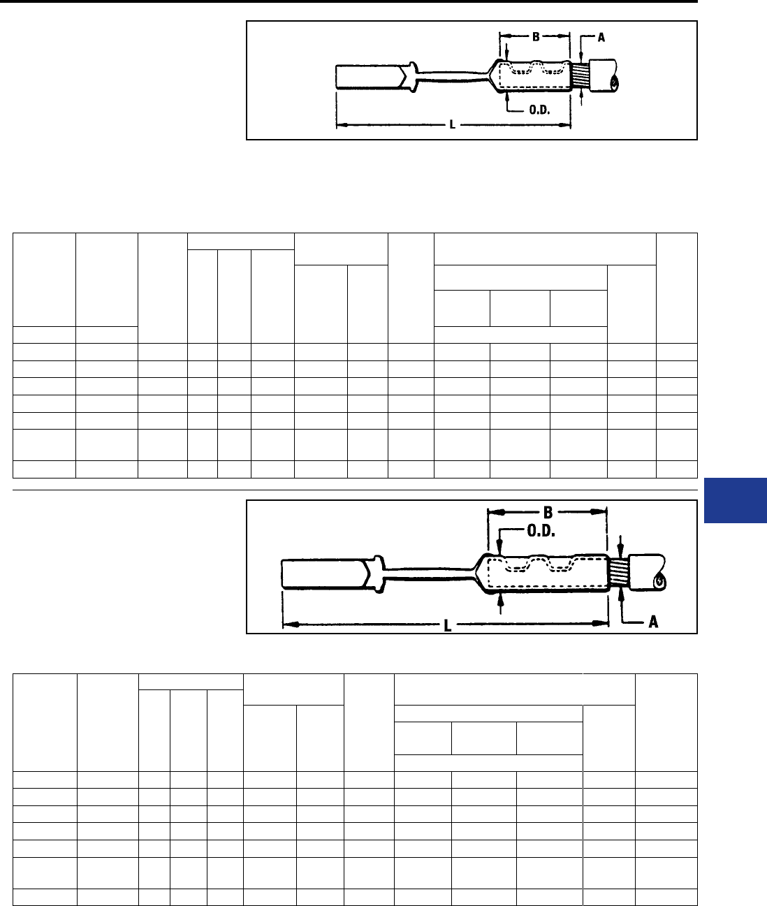
BURNDY®
Blue highlighted items are industry standard and most frequently ordered.
Canada: 1-800-387-6487 www.burndy.com US: 1-800-346-4175
Underground
TYPES YFMR, YFMP
MOLIMITER™
For Use with Long MOLIMITER™
Assembly
The MOLIMITER™ combines an accurately
determined fusible section with both a MOLE™
Socket end and a cable socket. Designed to
clear on overloads that would injure the cable
insulation, the MOLIMITER™ may be easily and
For Use on
Rubber
Insulated
Cable
For Use
on Paper
Insulated
Cable-Oil
Tight Cable
Socket
Cable
Size
A
Dimensions in Inches For Connection to
MOLE™ Use
MOLE™
Outlet
Size
Installation Information
App.
Wt. in
Lbs.
B L O.D. Socket
and Nut
Assembly
Z Cone
HYPRESS™ & Indentor Die
No. of
Indents
Y34A with
Y34PR
Y34BH with
Y34PR
Y44B with
Y44PR
Catalog No. Catalog No. Nest Die
YFMR28 YFMP28 4/0 Str. 1.86 6.28 0.83 Z28NR Z2828 A A28D B28D E28D 1 0.21
YFMR29 YFMP29 250 kcmil 1.88 6.19 0.84 Z29NR Z2929 A A29D B29D E29D 1 0.25
YFMR30 YFMP30 300 kcmil 2.00 6.81 0.96 Z30NR Z3030 A A30D B30D E30D 2 0.31
YFMR31 YFMP31 350 kcmil 2.00 6.94 0.91 Z32NR Z3132 A A31D B31D E31D 2 0.38
YFMR32 YFMP32 400 kcmil 2.14 7.27 0.97 Z32NR Z3232 A A32D B32D E32D 2 0.43
YFMR34 YFMP34 500 kcmil 2.75 8.26 1.13 Z34NR Z3434 A A34D No Nest
Die Req’d. E34D 2 0.79
YFMR39 YFMP39 750 kcmil 2.88 8.75 1.38 Z34NRB Z3434 B — — E39D 2 1.10
quickly replaced. For time current characteristics of
MOLIMITER see the technical section. For proper
HYPRESS™ installation, see table below.
TYPE YFMP-L
LONG MOLIMITER™ ASSEMBLY
For Use with Long MOLIMITER™
Assembly
Similar to Type YFMR and YFMP except for a long
oil tight cable socket preferred by some users of
paper-insulated cable. Fusing characteristics
Catalog No. Cable Size
Dimensions in Inches For Connection to
MOLE™ Use
MOLE™
Outlet
Size
Installation Information
Ship Wt. in
Lbs.
B L O.D. Socket &
Nut
Assembly
Z Cone
HYPRESS™ & Indentor Die
No. of
Indents
Y34A with
Y34PR
Y34BH with
Y34PR
Y44B with
Y44R
Nest Die
YFMP28L 4/0 Str. 3.06 7.25 0.69 Z28NR Z2828 A A28D B28D E28D 1 0.27
YFMP29L 250 kcmil 3.56 7.88 0.75 Z29NR Z2929 A A29D B29D E29D 1 0.32
YFMP30L 300 kcmil 3.67 8.48 0.81 Z30NR Z3030 A A3OD B30D E30D 2 0.39
YFMP31L 350 kcmil 3.69 8.66 0.88 Z32NR Z3132 A A31D B31D E31D 2 0.48
YFMP32L 400 kcmil 3.81 8.66 0.95 Z32NR Z3232 A A32D B32D E32D 2 0.54
YFMP34PL 500 kcmil 4.13 9.44 1.06 Z34NR Z3434 A A34D No Nest
Die Req’d. E34D 2 0.94
YFMP39PL 750 kcmil 4.19 10.38 1.31 Z34NRB Z3434 B — — E39D 2.32 1.30
shown in the technical sections. For proper
HYPRESS™ installation, see table below
For conductor sizes not listed call customer service. To specify a fast acting limiter in any conguration insert an “F” before the conductor number (e.g.YFSF34CR
species a 1/2 thick limiter section).
K-49
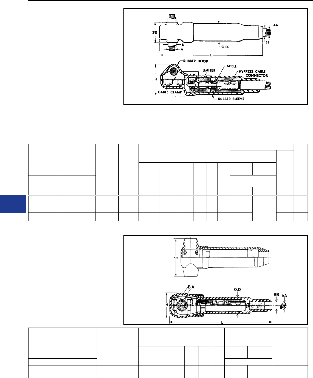
BURNDY®
Blue highlighted items are industry standard and most frequently ordered.
US: 1-800-346-4175 www.burndy.com Canada: 1-800-387-6487
Underground
TYPE VYFT
LIMITER TAP ASSEMBLY
For Insulated Cables
The Limiter Tap is suitable for making Limiter
connections to a cable ring bus in a manhole
or transformer vault. It can be installed on
oilimpregnated, paper insulated, or rubber insulated
cable. Fusing characteristics of the Limiter are the
same as Type YFA shown in the technical section.
The rubber sleeve and insulating hood reduce
taping to a minimum. Catalog Numbers shown
include hoods. If no hood is required, eliminate
one “C” from the Catalog Number. Replaceable
Link Limiter Taps can be ordered. For proper
HYPRESS™ installation, see table below.
Paper-Lead Cables If a long cable socket is
preferred for use on paper insulated cable add
For Use on
Rubber
Insulated
Cable
For Use on
Paper Insulated
Cable-Oil
Tight Cable
Socket
A Run AA Tap
Dimensions in Inches
Installation Information
App.
Ship
Wt. in
Lbs.
HYPRESS™ &
Indentor Die No.
of
Indents
B Max.
Cable
Dia. Over
Insul.
BB Max.
Cable
Dia. Over
Insul.
H L Y O.D.
Y34A with
Y34PR
Y34BH
with Y34PR
Catalog No. Catalog No. Nest Die
VYFT3428CCR VYFT3428CCP 500 kcmil 4/0 Str. 1.09 1.00 4.00 12.19 1.75 1.94 A28D B28D 1 2.20
VYFT3434CCR VYFT3434CCP 500 kcmil 500 kcmil 1.09 1.34 4.00 14.19 1.75 2.38 A34D
No Nest
Die Req’d.
2 3.50
VYFT3934CCR VYFT3934CCP 750 kcmil 500 kcmil 1.31 1.34 4.00 14.19 1.75 2.38 A34D 2 3.70
VYFT4434CCR VYFT4434CCP 1000 kcmil 500 kcmil 1.08 1.34 4.13 14.19 2.09 2.38 A34D 2 4.00
To specify a fast acting limiter in any conguration insert an “F” before the conductor number (e.g., YFSF34CR species a 1/2 thick limiter section).
“L” to the catalog number (e.g., VYFT3428CCP
becomes VYFT3428CCPL).
TYPE NYFT
LIMITER TEE TAP
For Rubber or Paper
Insulated Cables
The NYFT Limiter is similar to Type VYFT except
the run conductor is clamped with a four bolt cap
and the Limiter Tap is removable by means of a
socket and nut assembly. The Limiter current
characteristics are the same as Type YFA shown
in the technical section.
For Use on
Rubber
Insulated
Cable
For Use on
Paper Insulated
Cable-Oil
Tight Cable
Socket
A Run AA Tap
Dimensions in Inches
Installation Information
App.
Ship
Wt. in
Lbs.
HYPRESS™ & Indentor
Die
No. of
Indents
B Max.
Cable Dia.
Over Insul.
BB Max.
Cable Dia.
Over Insul. H L O.D.
Y34A with
Y34PR
Y34BH with
Y34PR
Catalog No. Catalog No. Nest Die
NYFT3434CCR NYFT3434CCP 500 kcmil 500 kcmil 1.89 1.25 2.91 16.78 2.41 A34D No Nest
Die Req’d. 2 2.20
K-50
BURNDY®
Blue highlighted items are industry standard and most frequently ordered.
Canada: 1-800-387-6487 www.burndy.com US: 1-800-346-4175
Underground
TYPE LYS
REPLACEABLE LINK LIMITER
With Ceramic Shell and
Rubber Sleeve for Insulated Cables
The Replaceable Link Limiter incorporates the
functions of both fuse and coupler. For use with
rubber and paper-insulated cable, it is designed
to facilitate rapid and inexpensive replacement
of Limiter Links upon clearing. It also permits, if
desired, the use of a Link rated for a lower ampere
capacity than supplied with our standard Limiter.
For proper HYPRESS™ installation, see table
below.
Catalog
Number
Cable
Size
**
(Max. Cable
Dia. Over
Insul.
Inches) A
Number
of Indents
in Cable
Socket
* Link Supplied Installation Information
App. Ship
Wt. in
Lbs.
HYPRESS™ & Indentor Die
No. of
Indents
Ampere
Capacity
Catalog
Number
Y29B
with
Y29PR
Y34A
with
Y34PR
Y34BH
with
Y34PR
Nest Die
LYS4CC #4 Str. 0.50
1
75A LF1010 D4CL A4CD B4CD
1
2.10
LYS2CC #2 Str.
0.75
100A LF1014 D2CL A2CD B2CD
2.20LYS1CC #1 Str. LF1014 D1CL A1CD B1CD
LYS25C 1/0 Str. 150A LF1025 D25L A25D B25D
LYS26C 2/0 Str. LF1025 D26L A26D B26D 2.30
LYS27C 3/0 Str.
1.00
200A LF2019 D27L A27D B27D
LYS28C 4/0 Str. 250A LF2027 D28L A28D B28D 2.40
LYS29C 250 kcmil LF2027 D29L A29D B29D
LYS30C 300 kcmil
1.25 2
300A LF2038 — A30D B30D
2
2.50
LYS31C 350 kcmil LF2038 — A31D B31D 2.60
LYS32C 400 kcmil
400A LF2065
— A32D B32D 2.70
LYS34C 500 kcmil — A34D No Nest
Die Req’d. 3.10
* Fuse link supplied is selected on the basis of a
minimum blowing current of approximately twice the
NEC rubber insulated cable rating. Refer to Time
Current curves shown and specify if another size is
desired.
** The standard end bushing supplied is for maximum
cable insulation diameters as shown. Compact cable
will require a bushing with a smaller inside diameter
to accommodate the smaller insulation diameter of
the cable. If other than standard bushing is required,
contact customer service.
To specify a fast acting limiter in any conguration insert
a “F” before the conductor number (e.g., YFSF34CR
species a 1/2 thick limiter section).
K-51
BURNDY®
Blue highlighted items are industry standard and most frequently ordered.
US: 1-800-346-4175 www.burndy.com Canada: 1-800-387-6487
Underground
TYPE LYM
REPLACEABLE LINK
MOLIMITER™
With Ceramic Shell and Rubber
Sleeve for Insulated Cables
The Replaceable Link MOLIMITER™ is used to
fuse underground cables at junction points with
the BURNDY® MOLE. The “Replaceable Link”
feature permits the selection of one of several
links. In addition, the replacement of links that have
burned clear is both rapid and inexpensive. For use
with both rubber and paper insulated cables. The
MOLE™ end of the MOLIMITER™ is installed in
the MOLE™ Socket and Nut Assembly, while the
cable socket end is HYPRESS™ installed, see
table below for proper installation.
Catalog
Number
Cable
Size
**
(Max.
Cable
Dia. Over
Insul.
Inches)
A
Number
of
Indents
in Cable
Socket
* Link Supplied
For Connection to
MOLE™ Use Installation Information
App.
Ship
Wt.
in
Lbs.
Socket
& Nut
Assembly
Z Cone
HYPRESS™ & Indentor Die
No.
of
Indents
Ampere
Capacity
Catalog
Number
Y29B
with
Y29PR
Y34A
with
Y34PR
Y34BH
with
Y34PR
Catalog
Number
Catalog
Number Nest Die
LYM2CC 2 Str.
0.75
1
100A LF1014
Z28NR Z2828
D2CL A2CD B2CD
1
2.00
LYM1CC 1 Str. LF1014 D1CL A1CD B1CD
2.10
LYM25C 1/0 Str. 150A LF1025 D25L A25D B25D
LYM26C 2/0 Str. LF1025 D26L A26D B26D
LYM27C 3/0 Str.
1.00
200A LF2019 D27L A27D B27D
LYM28C 4/0 Str. 250A LF2027 D28L A28D B28D
LYM29C 250 kcmil LF2027 Z29NR Z2929 D29L A29D B29D 2.20
LYM30C 300 kcmil
1.25 2
300A LF2038 Z30NR Z3030 — A30D B30D
2
2.30
LYM31C 350 kcmil LF2038 Z32NR Z3132 — A31D B31D 2.50
LYM32C 400 kcmil 400A LF2065 Z32NR Z3232 — A32D B32D 2.60
LYM34C 500 kcmil LF2065 Z34NR Z3434 — A34D B34D 2.90
* Fuse link supplied is selected on the basis of a mini-
mum blowing current of approximately twice the NEC
rubber insulated cable rating. Refer to Time Current
curves shown and specify if another size is desired.
** The standard end bushing supplied is for maximum
cable insulation diameters as shown. Compact cable
will require a bushing with a smaller inside diameter
to accommodate the smaller insulation diameter of
the cable. If other than standard bushing is required,
contact customer service.
K-52
BURNDY®
Blue highlighted items are industry standard and most frequently ordered.
Canada: 1-800-387-6487 www.burndy.com US: 1-800-346-4175
Underground
TYPE LF
LIMITER LINK
For Use with All Replaceable Limiters
Made of pure copper, the Limiter Link is controlled
dimensionally to close tolerances to maintain
accurate fusing chracteristics. Refer to Time-
Current Characteristic curve shown below and
specify rating desired. The Limiter Link is supplied
enclosed in a shell with heatproof chamber to
conne and break the arc created by fusing.
*Catalog Number Ampere Capacity App. Ship Wt. in Lbs.
LF1006 50A 0.08
LF1010 75A 0.08
LF1014 100A 0.08
LF1025 150A 0.08
LF2019 200A 0.09
LF2027 250A 0.09
LF2038 300A 0.11
LF2065 400A 0.12
LF2108 500A 0.15
* For use with LYS and LYM.
Current in Amperes
Time-Current Fusing Characteristics of Type LF Limiter Links
The nominal current ratings of these Limiter Links are approximately one-half the minimum currents required to clear the fuses. The gneral slope
and shape of the curves are similar to those of the time-current curves of the Limiters. The Type LF Limiter Links are made of pure copper with
dimensions carefully controlled in order to maintain accurate fusing characteristics.
K-53
BURNDY®
Blue highlighted items are industry standard and most frequently ordered.
US: 1-800-346-4175 www.burndy.com Canada: 1-800-387-6487
Underground
TYPE LYBASE
LIMITER BASE
For Use with all Replaceable Limiters
A heat resisting, high impact, molded phenolic
base for mounting HYDENT™ Cable lugs or
MOLIMITER™-lugs. The bases are supplied
with bolts tted in place with retaining rings,
enabling the lugs to be easily assembled to
BURNDY® Replaceable Limiter Links. They
may be purchased separately for use with all
Replaceable Limiters.
Catalog Number For Use with App. Ship Wt. in Lbs.
LYBASE LYM 0.32
LYS
TYPE LYS34P2
LIMITER SLEEVE
For Use With Replaceable Limiters
A molded sleeve for insulating the Replaceable
Limiter and MOLIMITER™ assemblies. Similar to
other component parts, the insulating sleeves may
be purchased separately. These sleeves are used
in conjunction with the LYS-P6 bushings.
Catalog Number For Use with App. Ship Wt. in Lbs.
LYS34P2 LYS 1.20
LYM
K-54
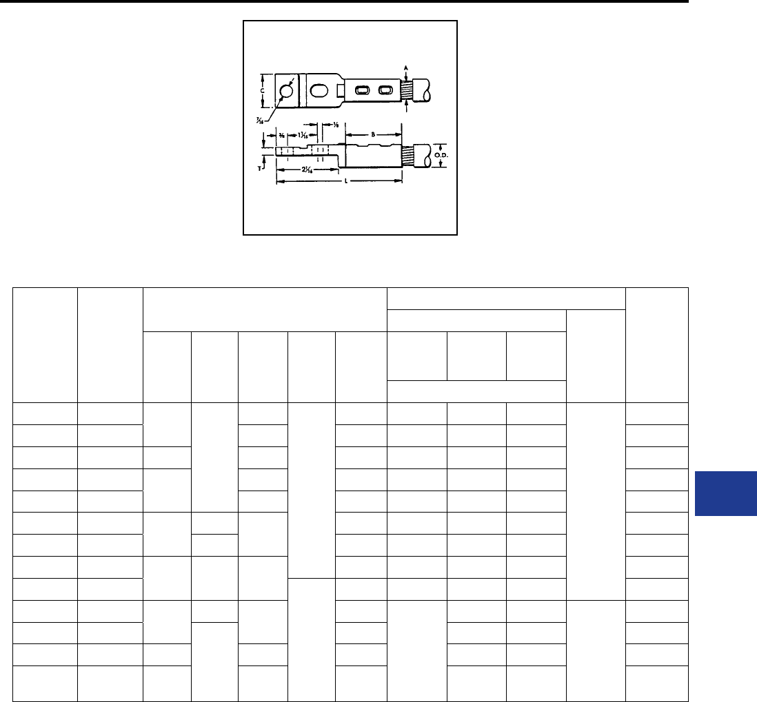
BURNDY®
Blue highlighted items are industry standard and most frequently ordered.
Canada: 1-800-387-6487 www.burndy.com US: 1-800-346-4175
Underground
TYPE LYS-P5
HYLUG™
For Use with Replaceable Limiters
Fabricated of high copper alloy, this
terminal has a sealed cable socket for
use with paper insulated, oil-impregnated
cables as well as rubber-insulated
cables. Tin plated to retard corrosion and
prevent discoloration. The HYLUG™ is
for use with LYS and LYM.
Catalog
Number
Cable
Size A
Dimensions
in Inches
Installation Information
App. Ship
Wt. in
Lbs.
HYPRESS™ & Indentor Die
No. of
Indents
B C L T O.D.
Y29B
with
Y29PR
Y34A
with
Y34PR
Y34B
with
Y34PR
Nest Die
LYS6CP5 #6 Str. 1-1/4
3/4
3-9/16
3/16
5/16 D6CL A6CD B6CD
1
0.16
LYS4CP5 #4 Str. 3-5/8 11/32 D4CL A4CD B4CD 0.16
LYS2CP5 #2 Str. 1-9/32 3-3/4 13/32 D2CL A2CD B2CD 0.17
LYS1CP5 #1 Str. 1-3/8 3-29/32 15/32 D1CL A1CD B1CD 0.20
LYS25P5 1/0 Str. 3-15/16 17/32 D25L A25D B25D 0.22
LYS26P5 2/0 Str. 1-1/2 13/16 4-1/16 9/16 D26L A26D B26D 0.24
LYS27P5 3/0 Str. 29/32 5/8 D27L A27D B27D 0.28
LYS28P5 4/0 Str. 1-5/8 1-1/8 4-3/16 11/16 D28L A28D B28D 0.31
LYS29P5 250 kcmil
1/4
3/4 D29L A29D B29D 0.37
LYS30P5 300 kcmil 21-3/8 4-9/16 13/16
—
A30D B30D
2
0.42
LYS31P5 350 kcmil
1-9/16
7/8 A31D B31D 0.53
LYS32P5 400 kcmil 2-1/8 4-11/16 31/32 A32D B32D 0.61
LYS34P5 500 kcmil 2-1/4 4-13/16 1-1/16 A34D No Nest
Die Req’d. 0.70
K-55
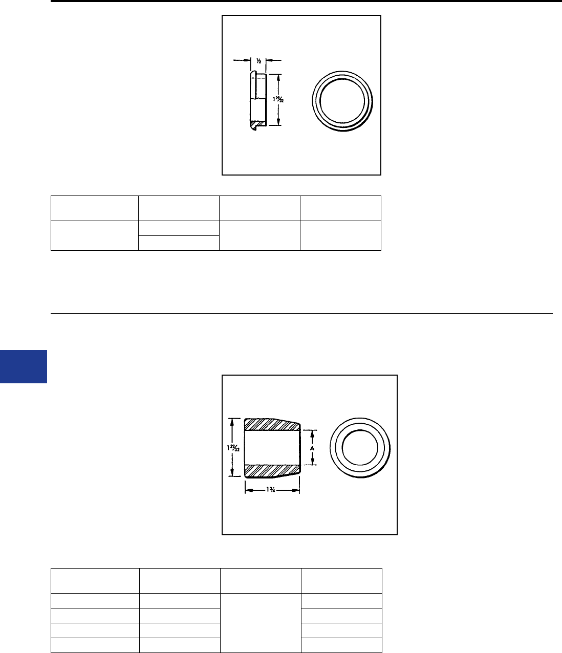
BURNDY®
Blue highlighted items are industry standard and most frequently ordered.
US: 1-800-346-4175 www.burndy.com Canada: 1-800-387-6487
Underground
TYPE LYM34P3
BUSHING
For Use with Replaceable Limiters
Type LYM34P3 is for assembly of Replaceable
MOLIMITERS™ to the MOLE™ outlet. It lls the
space between Limiter sleeve and the MOLE™
outlet to allow easy taping.
Catalog
Number For Use with MOLE™ Outlet
Size
App. Ship Wt.
in Lbs.
LYM34P3 LYM A 0.01
LZM
TYPE LYS-P6
BUSHING
For Use with Replaceable Limiters
The LYS-P6 bushing is designed to t closely over
the cable insulation when used with the LYS34P2
Limiter sleeve. It lls the space between the Limiter
sleeve and cable. The tapered bushing facilitates
taping at installation.
Catalog
Number
(Max. Cable Dia.
Over Insul.) A For Use with App. Ship Wt.
in Lbs.
LYS32P6 1/2
LYS
LYM
0.19
LYS48P6 3/4 0.19
LYS64P6 1 0.16
LYS80P6 1-1/4 0.12
K-56
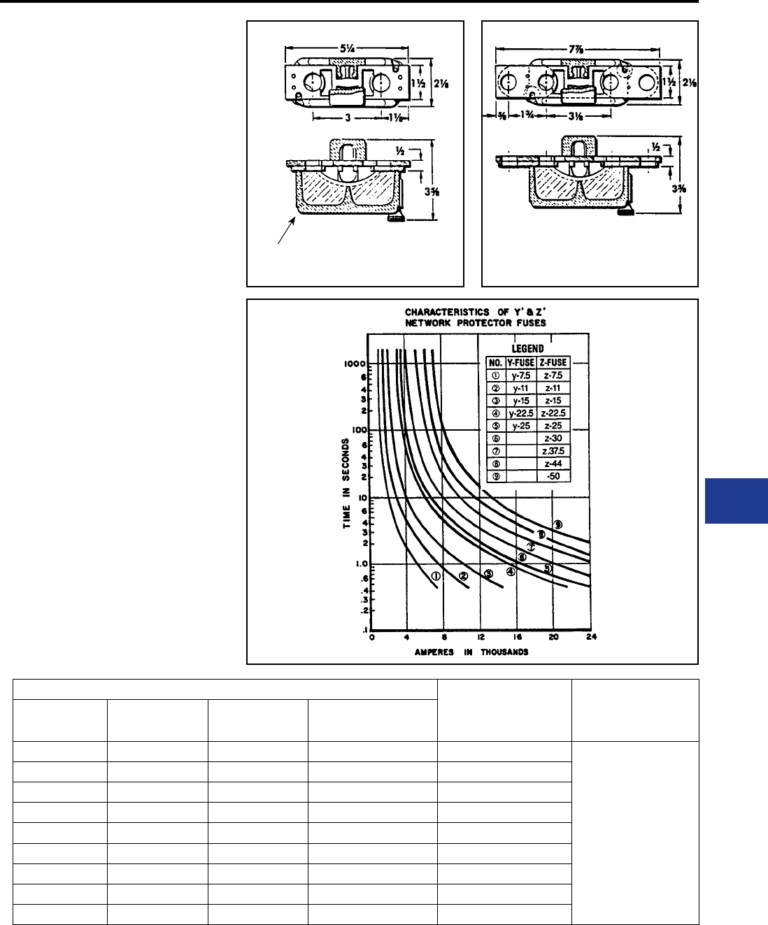
BURNDY®
Blue highlighted items are industry standard and most frequently ordered.
Canada: 1-800-387-6487 www.burndy.com US: 1-800-346-4175
Underground
TYPES Y, Z
NETWORK PROTECTOR FUSES
AND CERAMIC ENCLOSURES
Type Z Network Protector Fuses are designed
to coordinate with teh fusible sections of the
Limiters as well as the Protector characteristic
itself. A Ceramic enclosure is designed especially
to form an arcing chamber for these fuses and
contains no asbestos. The hole spacings in the
tongues of these fuses are such that they will t
standard Network Protectors. See Time Current
characteristic curve below. The Fuse element and
the housing must be purchased separately.
Fuse Designation Catalog Number Transformer
Full Load
(Normal)
Amperes
Ceramic
Enclosure
Y-Fuse
Fig. 1
App. Ship.
Wt. in Lbs.
Z-Fuse
Fig.2
App. Ship.
Wt. in Lbs.
Y-7.5 0.45 Z-7.5 0.95 400
ZH50
Y-11 0.46 Z-11 0.96 600
Y-15 0.48 Z-15 0.98 800
Y-22.5 0.50 Z-22.5 1.00 1200
Y-25 0.63 Z-25 1.13 1333
—0.75 Z-30 1.25 1600
Y-37.5 0.78 Z-37.5 1.28 2000
——Z-44 1.29 2500
Y-50 0.80 Z-50 1.30 3000
ZH50
Enclosure
Figure 1
Type Y-Fuse
Figure 2
Type Z-Fuse
K-57
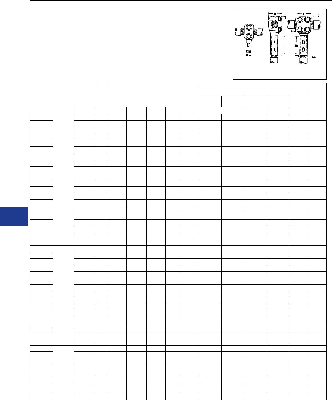
BURNDY®
Blue highlighted items are industry standard and most frequently ordered.
US: 1-800-346-4175 www.burndy.com Canada: 1-800-387-6487
Underground
NYT
T-CONNECTOR
Cable Run — Cable Tap
A “T” connector designed to provide a clamp type
element on the run and a permanent HYPRESS™
connection on the tap. Recommended for use on
ring buses or for applications where occasional
Catalog
Number
Conductor Size Fig.
No.
Dimensions in Inches
Installation Information App.
Ship.
Wt. in
Lbs.
HYPRESS™ and Indentor Die
No. of
Indents
Y29B with
Y29PR
Y34A with
Y34PR
Y34B with
Y34PR
Y44B with
Y44PR
Run A Tap AA B BB H J L Nest Die
NYT282C
4/0 AWG
2/0 AWG 1 1-3/8 1-1/4 1-3/8 3/8 3-3/16 D2CL A2CD B2CD — 1 1.50
NYT2825 1/0 1 1-3/8 1-3/8 1-3/8 3/8 4 D25L A25D B25D — 1 1.50
NYT2826 2/0 AWG 1 1-3/8 1-1/2 1-3/8 3/8 4-1/8 D26L A26D B26D — 1 1.50
NYT2828 4/0 AWG 2 2 1-5/8 1-3/8 3/8 4-5/16 D28L A28D B28D E28D 1 2.20
NYT292C
250 kcmil
2/0 AWG 1 1-3/8 1-1/4 1-7/16 3/8 3-3/16 D2CL A2CD B2CD — 1 1.50
NYT2925 1/0 1 1-3/8 1-3/8 1-7/16 3/8 4-1/16 D25L A25D B25D — 1 1.50
NYT2926 2/0 AWG 1 1-3/8 1-1/2 1-7/16 3/8 4-3/16 D26L A26D B26D — 1 1.50
NYT2928 4/0 AWG 2 2 1-5/8 1-7/16 3/8 4-3/8 D28L A28D B28D E28D 1 2.20
NYT2929 250 kcmil 2 2 1-5/8 1-7/16 3/8 4-7/16 D29L A29D B29D E29D 1 2.20
NYT3125
350 kcmil
1/0 1 1-3/8 1-3/8 1-1/2 3/8 4-1/8 D25L A25D B25D — 1 1.50
NYT3126 2/0 AWG 1 1-3/8 1-1/2 1-1/2 3/8 4-5/16 D26L A26D B26D — 1 1.50
NYT3128 4/0 AWG 2 2 1-5/8 1-1/2 3/8 4-1/2 D28L A28D B28D E28D 1 2.20
NYT3129 250 kcmil 2 2 1-5/8 1-1/2 3/8 4-9/16 D29L A29D B29D E29D 1 2.20
NYT3131 350 kcmil 2 2 2 1-1/2 3/8 5 — A31D B31D E31D 2 2.50
NYT3426
500 kcmil
2/0 AWG 1 1-3/8 1-1/2 1-5/8 3/8 4-7/16 D26L A26D B26D — 1 1.70
NYT3428 4/0 AWG 2 2 1-5/8 1-5/8 3/8 4-5/8 D28L A28D B28D E28D 1 2.50
NYT3429 250 kcmil 2 2 1-5/8 1-5/8 3/8 4-5/8 D29L A29D B29D E29D 1 2.50
NYT3431 350 kcmil 2 2 2 1-5/8 3/8 5-1/16 — A31D B31D E31D 2 2.50
NYT3434 500 kcmil 2 2 2-1/4 1-5/8 3/8 5-3/8 — A34D No Nest
Die Req’d. E34D 2 2.50
NYT3926
750 kcmil
2/0 AWG 1 1-3/8 1-1/2 1-7/8 3/8 4-5/8 D26L A26D B26D — 1 1.70
NYT3928 4/0 AWG 2 2 1-5/8 1-7/8 3/8 4-13/16 D28L A28D B28D E28D 1 2.50
NYT3929 250 kcmil 2 2 1-5/8 1-7/8 3/8 4-13/16 D29L A29D B29D E29D 1 2.50
NYT3931 350 kcmil 2 2 2 1-7/8 3/8 5-1/4 — A31D B31D E31D 2 2.50
NYT3934 500 kcmil 2 2 2-1/4 1-7/8 3/8 5-9/16 — A34D No Nest
Die Req’d E34D 2 2.70
NYT3939 750 kcmil 2 2 2-7/8 1-7/8 3/8 6-1/4 — — — E39D 2 3.00
NYT4426
1000 kcmil
2/0 AWG 1 1-3/8 1-1/2 2-1/8 3/8 4-3/4 D26L A26D B26D — 1 1.70
NYT4428 4/0 AWG 2 2 1-5/8 2-1/8 3/8 4-15/16 D28L A28D B28D E28D 1 2.50
NYT4429 250 kcmil 2 2 1-5/8 2-1/8 3/8 5 D29L A29D B29D E29D 1 2.50
NYT4431 350 kcmil 2 2 2 2-1/8 3/8 5-7/16 — A31D B31D E31D 2 2.50
NYT4434 500 kcmil 2 2 2-1/4 2-1/8 3/8 5-3/4 — A34D No Nest
Die Req’d. E34D 2 2.70
NYT4439 750 kcmil 2 2 2-7/8 2-1/4 3/8 6-3/8 — — — E39D 2 3.00
NYT4444 1000 kcmil 2 2-11/16 3 2-5/16 1/2 7 — — — No Nest
Die Req’d. 2 3.20
NYT4628
1500 kcmil
4/0 AWG 2 2 1-5/8 2-11/16 3/8 5-3/8 D28L A28D B28D E28D 1 4.70
NYT4629 250 kcmil 2 2 1-5/8 2-11/16 3/8 5-7/16 D29L A29D B29D E29D 1 4.70
NYT4631 350 kcmil 2 2 2 2-11/16 3/8 5-7/8 — A31D B31D E31D 2 4.70
NYT4634 500 kcmil 2 2 2-1/4 2-11/16 3/8 6-3/16 — A34D No Nest
Die Req’d. E34D 2 4.70
NYT4639 750 kcmil 2 2 2-7/8 2-11/16 3/8 6-3/4 — — — E39D 2 5.20
NYT4644 1000 kcmil 2 2 3 2-3/4 1/2 7-1/8 — — — No Nest
Die Req’d. 2 7.50
NYT4646 1500 kcmil 2 2-11/16 3-3/16 2-3/4 1/2 7-11/16 — — — C46D 2 8.00
disconnects from the run conductor are desired
without disturbing the tap connection. Tin plated.
For proper installation of tap cable, see table
below.
* Y48B HYPRESS™ with Y48PR indentor.
Figure 1 Figure 2
K-58

BURNDY®
Blue highlighted items are industry standard and most frequently ordered.
Canada: 1-800-387-6487 www.burndy.com US: 1-800-346-4175
Underground
HIGH CAPACITY LIMITER - 200,000 AMPERES AT 600 VOLTS
The BURNDY® High Capacity Limiter is designed to
economically protect electrical distribution systems
from the destructive effect of high energy faults.
The increasing number of 600 volt secondary
network installations for industrial and commercial
applications demand a cable limiter that can safely
interrupt 200,000 amperes (symmetrical available)
and one that will also completely coordinate with
the higher voltage network protector fuses.
Available fault currents as high as 200,000
amperes rms at 600 volts across teh fusible
elements have been interrupted during tests
on the BURNDY® High Capacity Limiter. The
power factor during these tests was less than
15%, thereby imposing the most difcult clearing
conditions. No external disturbance is experienced
upon clearing falt currents from the “oat” value to
200,000 amperes. The quartz tiller absorbs the
intense energy generated by interrupting the fault
current. The quartz fuses into tubular fulgurites,
with a high dielectric strength, and forms an
insulating barrier between the melted link sections.
This action prevents restrike of the internal arc. The
rugged aluminum housing and cast epoxy end
seals provide a vessel that completely contains the
developed energy.
The carefully developed time-current characteristcs
and rigid manufacturing tolerances assure proper
coordination with the network protector fuses and
the insulaiton damage characteristics of 4/0, 250,
350, 500 kcmil and 750 cable.
The High Capacity Limiter is available in four
variations to accommodate a variety of installation
practices. The Type HYS cable sockets at both
ends, which allow for indenting to the cable ends
with a hydraulic BURNDY® HYPRESS™. The
HYA has an off-set lug on one end which permits
back-to-back mounting on bus bar. They HYA also
allows cable to installation with no off-set.
For those installations where BURNDY® MOLE™
connections are used for manhole junctions or
transformer vault buses, the Type HYM permits
a replaceable connection of the limiter director to
the MOLE™ outlet at one end and a compression
cable connection at the other.
Modern electrical distribution systems require low
cost protection to safeguard costly equipment
and quickly isolate faults, so that the undamaged
portions of the system may function normally.
BURNDY® High Capacity Limiters assure positive,
economical protection when installed in properly
designed systems.
NOTE: Today’s fault currents are growing. If you
need higher fault current ratings, please contact
the factory.
K-59
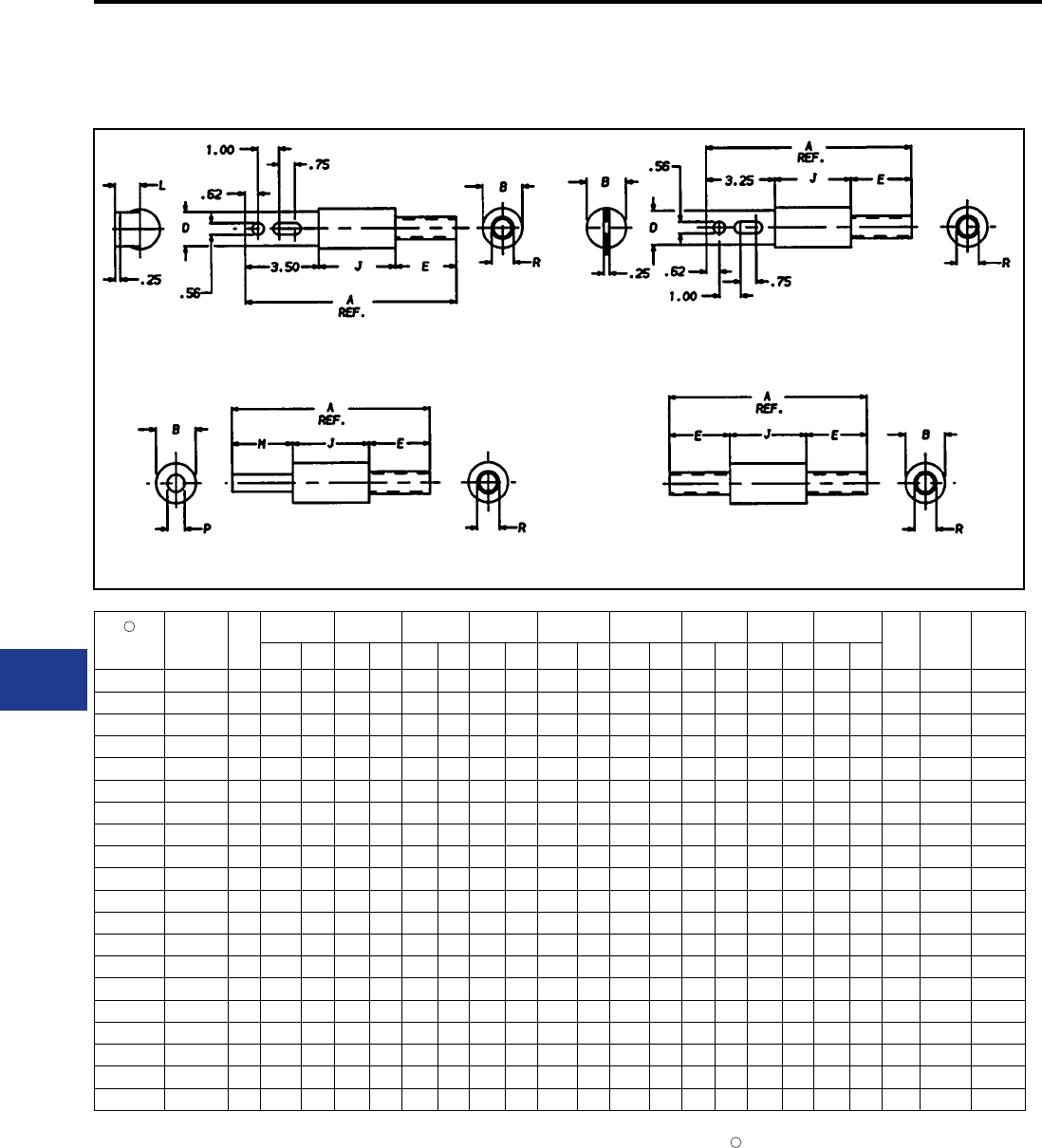
BURNDY®
Blue highlighted items are industry standard and most frequently ordered.
US: 1-800-346-4175 www.burndy.com Canada: 1-800-387-6487
Underground
Catalog
Number
Cable
Size
Fig.
No.
A B D E J L M P R Die
Index Die
No. of
Crimps
per End
In mm In mm In mm In mm In mm In mm In mm In mm In mm
HYAO_28 4/0 1 8.87 225 1.44 37 1.12 28 1.75 44 3.62 92 0.96 24 — — — — 0.68 17 15 U28RT 2
HYAO_29 250 kcmil 1 9.00 229 1.44 37 1.12 28 1.88 48 3.62 92 0.96 24 — — — — 0.75 19 16 U29RT 2
HYAO_31 350 kcmil 1 9.12 232 1.62 41 1.12 28 2.00 51 3.62 92 0.96 24 — — — — 0.88 22 18 U31RT 4
HYAO_34 500 kcmil 1 10.00 254 1.88 48 1.62 41 2.88 73 3.62 92 1.19 30 — — — — 1.05 27 20 U34RT 4
HYAO_39 750 kcmil 1 10.13 257 2.50 64 2.00 51 2.88 73 3.75 95 1.31 33 — — — — 1.32 34 24 U39RT 4
HYA_28 4/0 2 8.62 219 1.44 37 1.12 28 1.75 44 3.62 92 — — — — — — 0.68 17 15 U28RT 2
HYA_29 250 kcmil 2 8.75 222 1.44 37 1.12 28 1.88 48 3.62 92 — — — — — — 0.75 19 16 U29RT 2
HYA_31 350 kcmil 2 8.87 225 1.62 41 1.12 28 2.00 51 3.62 92 — — — — — — 0.88 22 18 U31RT 4
HYA_34 500 kcmil 2 9.75 248 1.88 48 1.62 41 2.88 73 3.62 92 — — — — — — 1.05 27 20 U34RT 4
HYA_39 750 kcmil 2 9.88 251 2.50 64 2.00 51 2.88 73 3.75 95 — — — — — — 1.32 34 24 U39RT 4
HYM_28 4/0 3 7.87 200 1.44 37 — — 1.75 44 3.62 92 — — 2.50 64 0.52 13 0.68 17 15 U28RT 2
HYM_29 250 kcmil 3 8.00 203 1.44 37 — — 1.88 48 3.62 92 — — 2.50 64 0.58 14 0.75 19 16 U29RT 2
HYM_31 350 kcmil 3 8.12 206 1.62 41 — — 2.00 51 3.62 92 — — 2.50 64 0.68 17 0.88 22 18 U31RT 4
HYM_34 500 kcmil 3 9.38 238 1.88 48 — — 2.88 73 3.62 92 — — 2.88 73 0.81 21 1.05 27 20 U34RT 4
HYM_39 750 kcmil 3 9.51 242 2.50 64 — — 2.88 73 3.75 95 — — 2.88 73 1.00 25 1.32 34 24 U39RT 4
HYS_28 4/0 4 7.12 180 1.44 37 — — 1.75 44 3.62 92 — — — — — — 0.68 17 15 U28RT 2
HYS_29 250 kcmil 4 7.38 188 1.44 37 — — 1.88 48 3.62 92 — — — — — — 0.75 19 16 U29RT 2
HYS_31 350 kcmil 4 7.62 194 1.62 41 — — 2.00 51 3.62 92 — — — — — — 0.88 22 18 U31RT 4
HYS_34 500 kcmil 4 9.38 238 1.88 48 — — 2.88 73 3.62 92 — — — — — — 1.05 27 20 U34RT 4
HYS_39 750 kcmil 4 9.51 242 2.50 64 — — 2.88 73 3.75 95 — — — — — — 1.32 34 24 U39RT 4
HIGH CAPACITY LIMITER
200,000 AMPERES AT 600 VOLTS
Offset Bus to Cable
Type HYAO
Figure 1
MOLE™ to Cable
Type HYM
Figure 3
Bus to Cable
Type HYA
Figure 2
Cable to Cable
Type HYS
Figure 4
Notes:
1. For insulated version add sufx “-C” to Catalog
Number (example: HYMS34C).
2. High Capacity Limiter. 200kA interrupting capacity at
600V AC.
3. Cable end utilize dies with Y35, Y39, Y46, Y45, Y750
tools (750 kcmil size units cannot be installed with the
Y35 HYPRESS™).
For fast operating limiter use “F”; for slow or standard
operating limiter use “S” before conductor number
(example: HYMF34 or HYMS34) see Time-Current
Characteristics.
4
4
K-60
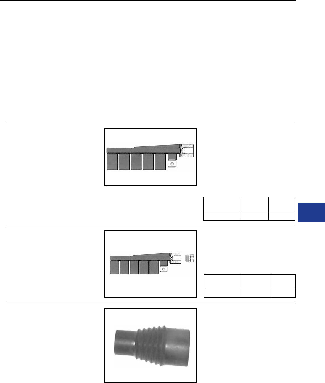
BURNDY®
Blue highlighted items are industry standard and most frequently ordered.
Canada: 1-800-387-6487 www.burndy.com US: 1-800-346-4175
Underground
PRODUCTS FOR UNDERGROUND RESIDENTIAL
DISTRIBUTION SYSTEMS
For over 85 years, BURNDY has pioneered and
produced economical, dependable connectors
and protective devices for urban underground
distribution systems. This extensive experience
has been applied to the development of equipment
for low cost underground distribution systems for
light commercial and residential areas.
Increasing interest by home buyers and developers
has created a need for URD components
comparable in cost with those used in overhead
systems.
Using connectors designed for other purposes,
early URD installations were relatively expensive.
Recognizing the need to reduce installation
costs, BURNDY developed a line of connectors
specically for URD.
These products are shown in this section. They are
the result of a continuing search for new materials
and more efcient production methods to bring
down cost to meet the requirements of low cost
underground construction.
TYPE RDMD-28G
URD STUD MOLE™
The RDMD-28G Stud MOLE™ is a sub-mersible
junction designed to accommodate a range of
copper and aluminum conductors. The Stud
MOLE™ is designed for use on transformers
where a dead front secondary is required. It is
insulated with molded EPT rubber. Mates with
a 5/8"-11 copper stud. A jam nut is supplied with
the MOLE™ to secure and lock it to the stud. It is
available with either four or six outlets. All outlets
Catalog
Number
Number of
Outlets Insulated
RDMD4-28G3 4 Yes
TYPE RDMD-2858D
STUD MOLE™
The RDMD-2858D Stud MOLE™ is identical
to the insulated RDMD-28G except an adapter
is supplied, allowing MOLE™ to be removed
from transformer stud without disconnecting the
individual services.
Catalog
Number
Number of
Outlets Insulated
RDMD4-2858D 4 Yes
TYPE RDMD-28CR
RUBBER INSULATING BOOT
The EPDM rubber force t boot is designed to
provide a completely dead-front and moisture tight
installation when used with either the Type RDMD-
28G3 or Type RDMD-2858D Stud MOLE™.
Bushing end will seal any diameter from 0.875 to
1.125 inch.
Catalog Number : RDMD-28CR
except one have factory installed removable
sealing caps. Tap kits are ordered separately. REA
listed.
Also available without insulation and sealing caps. K-61
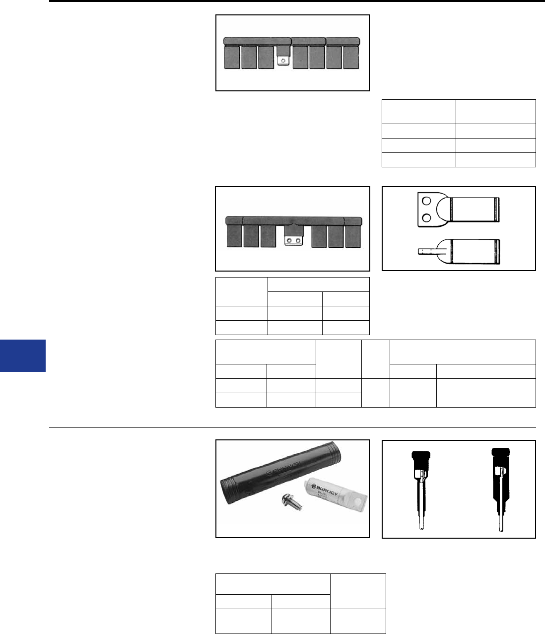
BURNDY®
Blue highlighted items are industry standard and most frequently ordered.
US: 1-800-346-4175 www.burndy.com Canada: 1-800-387-6487
Underground
TYPE RDM-28T
URD MOLE™
For Aluminum and Copper
The RDM-28T MOLE™ is available with ve or
seven outlets. The single hole outlets are the same
size as the RDM-28 series and accommodate
the same RYA-UC or RYA-UCR tap kits. The
larger two-hole outlet accommodates the 500 or
350 kcmil copper cable secondary supplied with
many subsurface transformers. These cables are
extended to a junction point where secondary
mains or services are connected. Tin-plated
copper RYA-C-2 tap kits are used to join the 500
or 350 kcmil copper secondaries to the RDM-28T
MOLE™.
Catalog
Number
Number of Outlets
12 Sol. - 350 350 - 500
RDM5-28T 4 1
RDM7-28T 6 1
TYPE RDM-28
URD MOLE™
For Aluminum or Copper
Type RDM-28 MOLE™ is an economical,
insulated, submersible service junction suitable
for direct burial or for use in enclosures.
Disconnectable joints allow additions of new
services without disturbing previous installations.
Taping is eliminated, heat-shrink or force-t rubber
Catalog
Number
Number of
Outlets
RDM4-28 4
RDM6-28 6
RDM8-28 8
Catalog Number Copper
Conductor
Die
Index
Tools, Die Set, Catalog No.
& (No. of Crimps)
Heat Shrink Force Fit Y34A Y35* Series Y750, 739
RYA31C-2 RYA31CR-2 350 20 A34R (4) U34RT (4)
RYA34C-2 RYA34CR-2 500
*Y35 U Dies with adapter PT6515 can also be used in Y45 series HYPRESSTM . Same number of crimps as Y35.
sleeves insulate each joint. Rubber is used to
insulate the MOLE™ body. Removable sealing
covers are supplied on all outlets but two. REA
listed Tap Kits, including HYLUG™, hardware and
sleeve are ordered separately.
TYPES RA6UC-SL,
RA6UCR-SL
URD STREET LIGHTING TAP KIT
FOR ALUMINUM OR COPPER
URD tap kit for making street lighting taps from
URD MOLE™ types RDM-28 and RDM-28T.
Each kit accommodates 6 str. - 12 sol. Kits include
connector, mounting hardware and insulating
sleeve. Catalog Number Conductor
Heat Shrink Force Fit
RA6UC-SL RA6UCR-SL 6 Str. - 12 Sol.
K-62
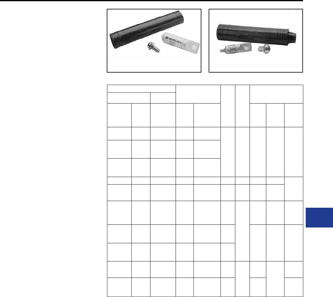
BURNDY®
Blue highlighted items are industry standard and most frequently ordered.
Canada: 1-800-387-6487 www.burndy.com US: 1-800-346-4175
Underground
TYPES RYA-UC, RYA-AC
MOLE™ TAP KITS
For Aluminum or Copper with
Type RDM-28 URD MOLE™
The kit consists of Universal HYLUG™, mounting
hardware and heat-shrink sleeve. The HYLUG™ is
pre-lled with PENETROX™ joint compound and
sealed. Installed with common installation tools,
three die sets install a range of 4 str.- 350 kcmil. The
heatshrink sleeve is lined with a mastic material,
providing a positive seal. Installed with standard
propane torch, or 500°F electric heat gun. Acetylene
heat is too intense and is not recommended.
TYPES RYA-UCR,
RYA-ACR
The kit consists of Universal HYLUG™, mounting
hardware and pre-lubricated forcet rubber sleeve.
The HYLUG™ is pre-lled with PENETROX™ joint
compound and sealed. Installed with common
installation tools, three die sets install a range of
4 str.- 350 MCM. The rubber sleeve has internal
sealing rings that provide a positive moisture
seal by exerting circumferential force on cable
and MOLE™ insulation. Pre-lubricating sleeve
makes installation easier. REA listed. No trimming
required.
TYPES RYA-UC, RYA-AC TYPES RYA-UCR, RYA-ACR
Catalog Number
Conductor
EEI
Die
Index
Die
Index
Tools, Die Set Catalog
Number
& (Number of Crimps)
Heat Shrink Force Fit
Complete
Set
Shrink
Sleeve
Only
Complete
Set Copper Aluminum MD6
Series
Y39,
Y35,
Y750
Series
OUR840
RYA4UC RYAC25 RYA4UCR 2 Sol.-
4 Str.
2 Sol. - 4 Str.
4 Str. Comp
8A
BG
or
5/8-1
or
243
W-BG
(1)
BG3
or
W243
U-BG (1)
UK58-IT
(3)
U243 (1)
XBG
(3)
XNBG
(2)
RYA2UC RYAC25 RYA2UCR 2 Str. -
1/0 Sol.
2 Str. -
1/0 Sol.
2-1 Str. Comp
RYA25UC RYAC25 RYA25UCR 1/0 Str.
1/0 Str. -
2/0 Sol.
1/0 Str. Comp.
RYA2WAC RYAC25 RYA2WACR — 2 Sol. EC-O — BG BG (5) — XBG
(5)
XNBG
(3)
RYA75AC RYAC25 RYA75ACR — 1/0 Sol. EC-O — — — UK58-IT
(5)
RYA26UC RYA31 RYA26UCR 2/0 Str. 2/0 Str.
2/0 Str. Comp. 11
249
or
840
W249
(3)
WK840
(5)
U249 (2)
UK840T
(3)
X249
(6)
X840
(5)
RYA27UC RYA31 RYA27UCR 3/0 Str.
3/0 Str.
3/0 Str. Comp.
4/0 Sol. EC-O
11 W249
(4)
WK840
(7)
U249 (2)
UK840T
(4)
X249
(8)
X840
(7)
RYA28UC RYA31 RYA28UCR 4/0 Str.
4/0 Str.
4/0 Str. - 250
Comp.
11
RYA29UC RYA31 RYA29UCR 250
kcmil
250
250 Comp. 13A 299
or
655
or
705
—U31ART
(2)
U655 (3)
U705 (2)
—
RYA31AC RYA31 RYA31ACR —
300 - 350
300 - 350
Comp.
13A — —
* Overlap Crimps.
** Do not use EEI Die. (11A) to install 4/0 Sol. EC-O.
NOTE: Standard mounting hardware is 3/8" button
head socket cap screw with captive conical washer. For
HEX HEAD bolt with captive conical washer add
“HEX” sufx.
NOTE: Example: RYA4UCR-HEX. For HEX HEAD
bolt and captive at washer add sufx “HEX1”. For
HEX HEAD bolt and non-captive at washer add sufx
“HEX2”. For HEX HEAD bolt and non-captive conical
washer add sufx “HEX3”. For Stainless Steel HEX
HEAD bolt add “HEX355” sufx.
K-63
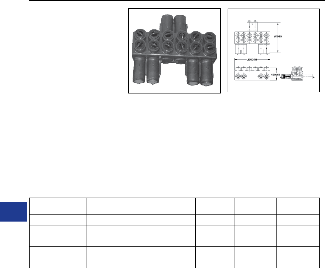
BURNDY®
Blue highlighted items are industry standard and most frequently ordered.
US: 1-800-346-4175 www.burndy.com Canada: 1-800-387-6487
Underground
TYPE BSSBC
OVERHEAD OR UNDERGROUND
SECONDARY CONNECTORS
For Aluminum and Copper
Conductors
Rubber Insulated and dual rated for aluminum and
copper conductors.
Features and Benets
• Meets the performance requirements of
ANSI C119.1, ANSI C119.4 and Western
Underground Committee Guide 2.5
• Fully tested to ANSI C119.4 for Class ‘A’
connectors
• Includes oxide inhibitor
• Supplied with aluminum set screws
• Fabricated from 6061-T6 aluminum alloy for
conductivity and strength
• Each unit is individually wrapped and
labeled for ease of identication and
cleanliness
Catalog Number Number of
Outlets
Wire Range
(Aluminum or Copper) Width Height Length
BSSBC750-2-1 3 2 - 750 8.50 3.07 4.57
BSSBC750-3-1 4 2 - 750 8.50 3.07 6.13
BSSBC750-4-1 5 2 - 750 8.50 3.07 7.69
BSSBC750-4-2 6 2 - 750 8.50 3.07 9.25
BSSBC750-6-2 8 2 - 750 8.50 3.07 10.81
K-64
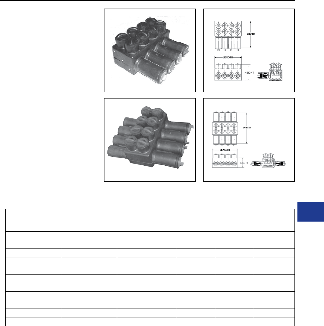
BURNDY®
Blue highlighted items are industry standard and most frequently ordered.
Canada: 1-800-387-6487 www.burndy.com US: 1-800-346-4175
Underground
TYPES BSSBC, BDESS
SUBMERSIBLE SECONDARY
CONNECTORS
For Aluminum and Copper
Conductors
Rubber Insulated and dual rated for aluminum and
copper conductors.
Features and Benets
• Meets the performance requirements of
ANSI C119.1, ANSI C119.4 and Western
Underground Committee Guide 2.5
• Fully tested to ANSI C119.4 for Class ‘A’
connectors
• Includes oxide inhibitor
• Supplied with aluminum set screws
• Fabricated from 6061-T6 aluminum alloy for
conductivity and strength
• Each unit is individually wrapped and
labeled for ease of identication and
cleanliness
Catalog Number* Number of Outlets Wire Range
(Aluminum or Copper) Width Height Length
BSSBC750-3 3 2 - 750 5.42 3.07 4.57
BSSBC750-4 4 2 - 750 5.42 3.07 6.13
BSSBC750-5 5 2 - 750 5.42 3.07 7.69
BSSBC750-6 6 2 - 750 5.42 3.07 9.25
BSSBC750-7 7 2 - 750 5.42 3.07 10.81
BSSBC750-8 8 2 - 750 5.42 3.07 12.37
BDESS750-3 6 2 - 750 8.15 3.07 4.57
BDESS750-4 8 2 - 750 8.15 3.07 6.13
BDESS750-5 10 2 - 750 8.15 3.07 7.69
BDESS750-6 12 2 - 750 8.15 3.07 9.25
BDESS750-7 14 2 - 750 8.15 3.07 10.81
BDESS750-8 16 2 - 750 8.15 3.07 12.31
K-65
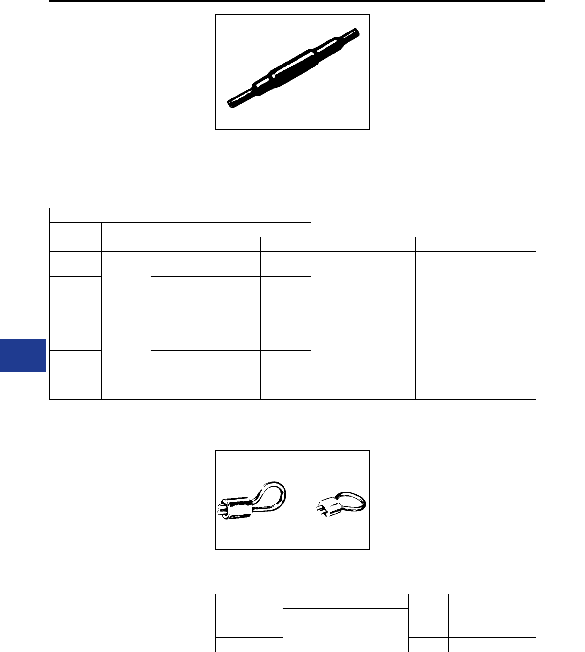
BURNDY®
Blue highlighted items are industry standard and most frequently ordered.
US: 1-800-346-4175 www.burndy.com Canada: 1-800-387-6487
Underground
TYPE YS-CG
URD INSULATED SPLICE KIT
For All Aluminum or Copper/Aluminum
Combinations
Type YS-CG URD insulated splice kit consists of a
standard YSU or YSD LINKIT™ and a heat-shrink
sleeve. Used to splice URD secondary lines up to
600 volts. It is installed with common installation
tools. Heat-shrink sleeve is installed with standard
propane torch, or 500° F electric heat gun.
Acetylene is not recommended.
Catalog Number Conductor
Die Index Tools, Die Set Catalog Number, & (No. of Crimps)
Complete
Splice Kit
Heat Shrink
Sleeve
Both Sides
Aluminum ACSR Copper * MD6 Series Y34A Y35 Series
YS2UCG1
RYAC25
1-2 Str. 2 (6-1, 7-1) 1-2 Str.
BG 243
BG (3)
W-BG (1)**
W243 (2)
—
A243(1)
U-BG(1)**
U243 (1)
YS25UCG1 1/0 Str.
1/0 Comp. 1/0 (6-1) 1/0 Str.
YS26UCG1
RYAC31-1
2/0 Str.
2/0 Comp. 2/0 (6-1) 2/0 Str.
249/840 W249 (4)
W-K840 (7)
A249 (2)
—
U249 (2)
U-K840T (4)
YS27UCG1 3/0 Str.
3/0 Comp. 3/0 (6-1) 3/0 Str.
YS28UCG1 4/0 Str.
4/0 Comp. 4/0 (6-1) 4/0 Str.
YS31ACG1 RYAC31 350
350 Comp. — 350 299/705 — — U299 (2)
U705 (1)
* Use to join copper to aluminum or ACSR not copper to copper.
** Multiple crimp die set makes more than one crimp per compression.
TYPES J1207 & J1592
Y-LOK
For Locking Enclosure
Assembly consists of aluminum-clad steel wire
loop and a compression type aluminum connector.
Installed with BG groove of MD6 or OUR840
Compression Tools. Can also be installed with 5/8
or 5/8-1 grooves.
Catalog Number
Installation Tooling
L C DMD6, OUR840 Y35, Y750, Y46
J1207 WBG
XBG UBG 2.28 0.75 1.00
J1592 2.31 0.75 0.75
J1207 & J1592
Compression Y-LOK installed with BG or 5/8
groove.
K-66
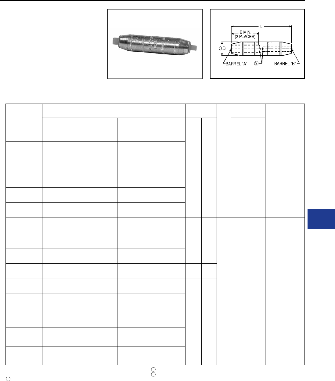
BURNDY®
Blue highlighted items are industry standard and most frequently ordered.
Canada: 1-800-387-6487 www.burndy.com US: 1-800-346-4175
Underground
TYPE YRB-U
HYREDUCER™ SPLICE
For Aluminum to Aluminum and
Aluminum to Copper
Type YRB-U splice is designed for use within
underground systems. Aluminum splices are tin-
plated and recommended for use on Aluminum-
to-Aluminum and Aluminum-to-Copper cables. All
Catalog
Number
Conductor Range Dimensions
O.D.
Wire Strip
Length Die
Index
Color
Code
Barrel “A”
Copper & Aluminum
Barrel “B”
Copper & Aluminum
B
Min. LBarrel
“A”
Barrel
“B”
YRB2U3TTN #2 (.292 Dia.) 7 Str. #3 (.260 Dia.) 7 Str.
1.35
[34]
3.25
[83]
0.65
[17] 1-3/4" 1-3/4" 296 Tan
YRB1CU2TTN #1 (.332 Dia.) 19 Str. or
1/0 Compact (.336 Dia.) 19 Str. #2 (.292 Dia.) 7 Str.
YRB1CU1TTN #1 (.332 Dia.) 19 Str. or
1/0 Compact (.336 Dia.) 19 Str.
#1 (.332 Dia.) 19 Str. or
1/0 Compact (.336 Dia.) 19 Str.
YRB25U3TTN 1/0 (.373 Dia.) 19 Str. or
1/0 Compact (.336 Dia.) 19 Str. #3 (.260 Dia.) 7 Str.
YRB25U2TTN 1/0 (.373 Dia.) 19 Str. or
1/0 Compact (.336 Dia.) 19 Str. #2 (.292 Dia.) 7 Str.
YRB25U25TTN 1/0 (.373 Dia.) 19 Str. or
1/0 Compact (.336 Dia.) 19 Str.
1/0 (.373 Dia.) 19 Str. or
1/0 Compact (.336 Dia.) 19 Str.
YRB27U25TW 3/0 (.470 Dia.) 19 Str. or
3/0 Compact (.423 Dia.) 19 Str.
1/0 (.373 Dia.) 19 Str. or
1/0 Compact (.336 Dia.) 19 Str.
1.53
[39]
3.69
[94]
0.85
[22] 1-1/2" 1-1/2" 298 White
YRB28U3TW 4/0 (.528 Dia.) 19 Str. or
4/0 Compact (.475 Dia.) 19 Str. #3 (.260 Dia.) 7 Str.
YRB28U1TW 4/0 (.528 Dia.) 19 Str. or
4/0 Compact (.475 Dia.) 19 Str.
#1 (.332 Dia.) 19 Str. or
1/0 Compact (.336 Dia.) 19 Str.
YRB28U25TW 4/0 (.528 Dia.) 19 Str. or
4/0 Compact (.475 Dia.) 19 Str.
1/0 (.373 Dia.) 19 Str. or
1/0 Compact (.336 Dia.) 19 Str.
1.53
[39]
3.70
[94]
YRB28U26TW 4/0 (.528 Dia.) 19 Str. or
4/0 Compact (.475 Dia.) 19 Str.
2/0 (.419 Dia.) 19 Str. or
2/0 Compact (.376 Dia.) 19 Str. 1.53
[39]
3.69
[94]
YRB28U28TW 4/0 (.528 Dia.) 19 Str. or
4/0 Compact (.475 Dia.) 19 Str.
4/0 (.528 Dia.) 19 Str. or
4/0 Compact (.475 Dia.) 19 Str.
YRB31U25TW
350 kcmil (.681 Dia.) 37 Str. or 350 kcmil
Compact (.616 Dia.) 19 Str. Al; 37 Str.
Al & Cu
1/0 (.373 Dia.) 19 Str. or
1/0 Compact (.336 Dia.) 19 Str.
2.34
[59]
5.43
[138]
1.11
[28] 2-1/4" 2-1/4" 299 Brown
YRB31U28TW
350 kcmil (.681 Dia.) 37 Str. or 350 kcmil
Compact (.616 Dia.) 19 Str. Al; 37 Str.
Al & Cu
4/0 (.528 Dia.) 19 Str. or
250 kcmil Compact (.520 Dia.) 37 Str.
YRB31U31TW
350 kcmil (.681 Dia.) 37 Str. or 350 kcmil
Compact (.616 Dia.) 19 Str. Al; 37 Str.
Al & Cu
350 kcmil (.681 Dia.) 37 Str. or 350
kcmil Compact (.616 Dia.) 19 Str. Al;
37 Str. Al & Cu
splices have solid center stop for use with oil lled
and non-oil lled cables. The Outside Diameter
is held constant to minimize installation dies and
1 Material: Aluminum.
2 Finish: Electro-tin plated.
Barrels are partially lled with PENETROX™ and sealed.
4 Scratch brushing of all conductors before making installation is recommended.
5 Not for use with Copper-to-Copper applications.
6 Dimensions in brackets [ ] are in millimeters rounded off to the nearest millimeter,
unless otherwise noted and are for reference only.
3
Catalog number PT6515 Adaptor is required to use “U” dies in Y45 series tools.
Catalog number PUADP-1 Adaptor is required to use “U” dies in Y46 series tools.
9 On MY29-3 HYTOOL™ use alum. Index plate settings as follows,
for 1/0 conductor use 1/0 setting. For conductor smaller than 1/0 size use
2/0 setting.
7
8
connectors are prelled with PENETROX™. Rated
up to 35 kV.
K-67
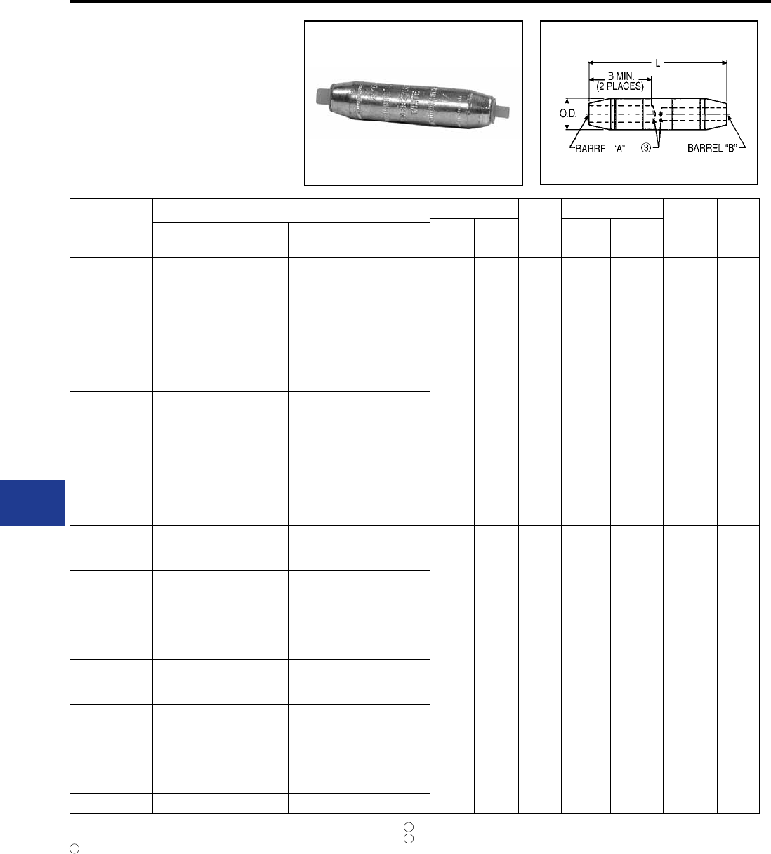
BURNDY®
Blue highlighted items are industry standard and most frequently ordered.
US: 1-800-346-4175 www.burndy.com Canada: 1-800-387-6487
Underground
TYPE YRB-U
HYREDUCER™ SPLICE
(Continued)
For Aluminum to Aluminum and
Aluminum to Copper
Catalog
Number
Conductor Range Dimensions
O.D.
Wire Strip Length
Die
Number
Color
Code
B Min. L Barrel
“A”
Barrel
“B”
Barrel “A”
Copper & Aluminum
Barrel “B”
Copper & Aluminum
YRB34U25TW
500 kcmil (.813 Dia.) 37 Str. or
500 kcmil Compact (.736 Dia.)
19 Str. Al; 37 Str. Al & Cu
1/0 (.373 Dia.) 19 Str.
2.70
[69]
6.00
[152]
1.31
[33] 1-1/8" 1-1/8" 300 Pink
YRB34U28TW
500 kcmil (.813 Dia.) 37 Str. or
500 kcmil Compact (.736 Dia.)
19 Str. Al; 37 Str. Al & Cu
4/0 (.528 Dia.) 19 Str. or
4/0 Compact (.475 Dia.) 19 Str.
YRB34U29TW
500 kcmil (.813 Dia.) 37 Str. or
500 kcmil Compact (.736 Dia.)
19 Str. Al; 37 Str. Al & Cu
250 kcmil (.575 Dia.) 37 Str.
YRB34U30TW
500 kcmil (.813 Dia.) 37 Str. or
500 kcmil Compact (.736 Dia.)
19 Str. Al; 37 Str. Al & Cu
300 kcmil (.630 Dia) 37 Str.
YRB34U31TW
500 kcmil (.813 Dia.) 37 Str. or
500 kcmil Compact (.736 Dia.)
19 Str. Al; 37 Str. Al & Cu
350 kcmil (.681 Dia.) 37 Str. or
350 kcmil Compact (.616 Dia.) 19
Str. Al; 37 Str. Al & Cu
YRB34U34TW
500 kcmil (.813 Dia.) 37 Str. or
500 kcmil Compact (.736 Dia.)
19 Str. Al; 37 Str. Al & Cu
500 kcmil (.813 Dia.) 37 Str. or
500 kcmil Compact (.736 Dia.) 19
Str. Al; 37 Str. Al & Cu
YRB39U31TW
750 kcmil (.998 Dia.) 61 Str. or
750 kcmil Compact (.908 Dia.)
61 Str.
350 kcmil (.681 Dia.) 37 Str. or
350 kcmil Compact (.616 Dia.) 19
Str. Al; 37 Str. Al & Cu
2.87
[73]
6.74
[171]
1.46
[37] 3" 3-11/16" 936 Yellow
YRB39U34TW
750 kcmil (.998 Dia.) 61 Str. or
750 kcmil Compact (.908 Dia.)
61 Str.
500 kcmil (.813 Dia.) 37 Str. or
500 kcmil Compact (.736 Dia.) 19
Str. Al; 37 Str. Al & Cu
YRB39U39TW
750 kcmil (.998 Dia.) 61 Str. or
750 kcmil Compact (.908 Dia.)
61 Str.
750 kcmil (.998 Dia.) 61 Str. or
750 kcmil Compact (.908 Dia.)
61 Str.
YRB44U31TW 1000 kcmil (1.152 Dia.) 61 Str.
350 kcmil (.681 Dia.) 37 Str. or
350 kcmil Compact (.616 Dia.) 19
Str. Al; 37 Str. Al & Cu
YRB44U34TW 1000 kcmil (1.152 Dia.) 61 Str.
500 kcmil (.813 Dia.) 37 Str. or
500 kcmil Compact (.736 Dia.) 19
Str. Al; 37 Str. Al & Cu
YRB44U39TW 1000 kcmil (1.152 Dia.) 61 Str.
750 kcmil (.998 Dia.) 61 Str. or
750 kcmil Compact (.908 Dia.)
61 Str.
YRB44U44TW 1000 kcmil (1.152 Dia.) 61 Str. 1000 kcmil (1.152 Dia.) 61 Str.
1 Material: Aluminum.
2 Finish: Electro-tin plated.
Barrels are partially lled with PENETROX™ and sealed.
4 Scratch brushing of all conductors before making installation is recommended.
5 Not for use with Copper-to-Copper applications.
6 Dimensions in brackets [ ] are in millimeters rounded off to the nearest millimeter,
unless otherwise noted and are for reference only.
3
Catalog number PT6515 Adaptor is required to use “U” dies in Y45 series tools.
Catalog number PUADP-1 Adaptor is required to use “U” dies in Y46 series tools.
9 On MY29-3 HYTOOL™ use alum. Index plate settings as follows,
for 1/0 conductor use 1/0 setting. For conductor smaller than 1/0 size use
2/0 setting.
7
8
K-68
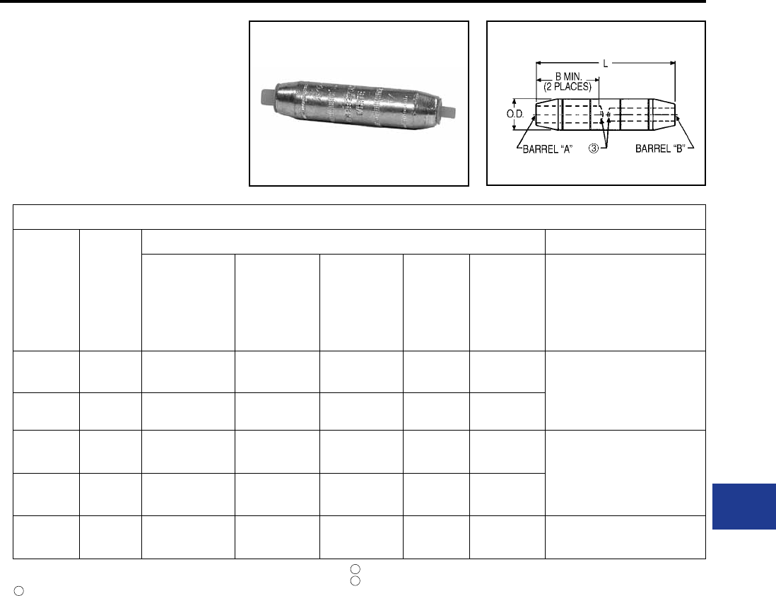
BURNDY®
Blue highlighted items are industry standard and most frequently ordered.
Canada: 1-800-387-6487 www.burndy.com US: 1-800-346-4175
Underground
TYPE YRB-U
HYREDUCER™ SPLICE
(Continued)
For Aluminum to Aluminum and
Aluminum to Copper
Installation (Number of Crimps per End)
Color Code Die Index
Hydraulic Dieless (# of Crimps)
Y35, Y39, Y750,
BAT35, BAT750,
PAT750
Y46 Y45 Y48B Y60BHU
Mechanical:
MY29-3 (1),
MY29011 (1)
Hydraulic:
Y644M (1),
PAT644-18V (1)
Tan 296 U25ART (1) U25ART (1) U25ART (1) C25AR (1) — MY29-3 (1)
MY29-11 (1)
Y644M (1)
PAT644-18V (1)
White 298 U28ART (2) U28ART (2) U28ART (2) C28AR (2) —
Brown 299 U31ART
Overlap Crimp
U31ART
Overlap Crimp
U31ART
Overlap Crimp C31AR (1) L31ART (1)
Y644M (1)
PAT644-18V (1)
Pink 300 U34ART
Overlap Clamp
U34ART
Overlap Clamp
U34ART
Overlap Clamp C34AR (1) L34ART
Yellow 936 U39ART-2 (4) U39ART-2 (4) U39ART-2 (4) C39AR (2) L39ART (2) —
1 Material: Aluminum.
2 Finish: Electro-tin plated.
Barrels are partially lled with PENETROX™ and sealed.
4 Scratch brushing of all conductors before making installation is recommended.
5 Not for use with Copper-to-Copper applications.
6 Dimensions in brackets [ ] are in millimeters rounded off to the nearest millimeter,
unless otherwise noted and are for reference only.
3
Catalog number PT6515 Adaptor is required to use “U” dies in Y45 series tools.
Catalog number PUADP-1 Adaptor is required to use “U” dies in Y46 series tools.
9 On MY29-3 HYTOOL™ use alum. Index plate settings as follows,
for 1/0 conductor use 1/0 setting. For conductor smaller than 1/0 size use
2/0 setting.
7
8
K-69
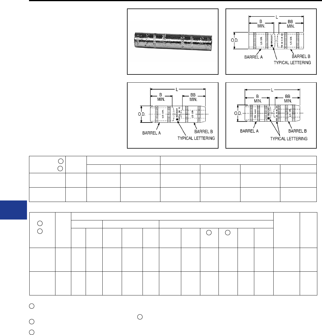
BURNDY®
Blue highlighted items are industry standard and most frequently ordered.
US: 1-800-346-4175 www.burndy.com Canada: 1-800-387-6487
Underground
TYPE YRB-T
HYREDUCER™ SPLICE
For Copper to Copper
Type YRB-T splice is designed for use within
underground systems. Copper splices are tapered
and recommended for use on copper-to-copper
cables.
All splices have solid center stops for use with oil
lled and non-oil lled cables.
The Outside Diameter is held constant to minimize
installation dies. Rated up to 35 kV
Catalog
Number
Figure
No.
Conductor Size Dimensions
Barrel “A” Barrel “B” B Min. BB Min. L O.D.
YRB2825T 2 4/0 (0.53) 1/0 (0.37) 1.16
[29]
1.16
[29]
2.84
[73]
0.69
[18]
YRB3428T 3 500 kcmil 4/0 (0.53) 1.73
[44]
1.73
[44]
4.50
[114]
1.06
[27]
Catalog
Number
Color
Code
Installation Tooling (Number of Crimps)
Dieless
(# of Crimps)
Wire
Strip
Length
Die Information Mechanical Hydraulic
Die
Index Type OUR840 MD7
MD7-34R MD6
Y35, Y39,
Y750,
PAT750
BCT500,
Y500CT Y46 Y45 Y48B Y60BHU
YRB2825T Purple Die 15 Purple
Die Set
X28VT
(4)
X28RT
(4)
X28VT (4) X28VT
(4) U28RT (1) — U28RT
(1) —C28R
(1)
L29ART
(1)
Hydraulic:
Y644M (1)
PAT644M (1)
1-7/32"
YRB3428T Brown
Die
20 or
299
Brown
Die Set — — —
U34ART
(2)
U31ART
(2)
W34VT
(2)
W34RT
(2)
U34RT
(2)
U31ART
(2)
U34RT
(2)
U31ART
(2)
C34R
(1)
C31AR
(1)
L34RT
(1)
Hydraulic:
Y644M (1)
PAT644M (1)
1-13/16"
1 Material: Copper.
For Tin-Plating, add sufx “TN” to the Catalog Number
(example: YRB2825TN). For Hot Tin dipped add sufx
“W” to the catalog number (example: YRB2825TW).
Catalog Number PT6515 Adaptor is required to use
“U” dies in Y45 series tools.
Catalog Number PUADP-1 is required to use “U” dies
in Y46 series tools.
5 Dimensions in brackets [ ] are in millimeters rounded
off to the nearest millimeter, unless otherwise
specied, and are for reference only.
Sufx “TN” and “W” will not be stamped on part.
2
2
2
3
3
4
4
7
7
7
Fig. 1
Fig. 3Fig. 2
K-70
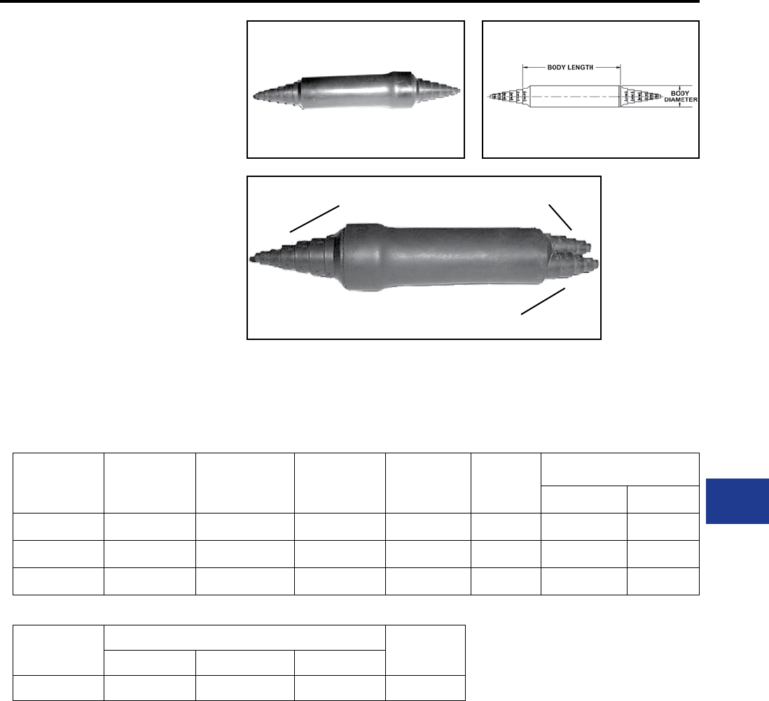
BURNDY®
Blue highlighted items are industry standard and most frequently ordered.
Canada: 1-800-387-6487 www.burndy.com US: 1-800-346-4175
Underground
TYPES BSSI, BTWTC
SUBMERSIBLE SPLICE COVERS
Soft Rubber Covers for Insulating
Features and Benets
• 600 Volt compression splice connections
including those subject to water submersion:
Suitable for direct burial. Ends have stepped
sealing surfaces to accommodate a wide
variety of conductor sizes
• Maintains watertight integrity and full
insulating value in all direct buried,
underground networks, residential and
overhead service joints
• Taping is eliminated and splice preparation
is signicantly reduced
• Meets the performance requirements of
ANSI C119.1, ANSI C119.4 and Western
Underground Committee Guide 2.5
Catalog
Number
Copper
Conductor
Aluminum
Conductor
Cable
Insulation
Body
Length
Body
Diameter
Uncompressed Splice Size
O.D. O.A.L.
BSSI-20 14 - 2/0 14 - 2/0 0.15 - 0.60 4.40 0.84 0.75 3.00
BSSI-500 14 - 500 14 - 500 0.15 - 1.18 5.30 1.25 1.19 4.00
BSSI-500L 14 - 500 14 - 500 0.15 - 1.18 7.70 1.35 1.19 6.00
Catalog
Number
Cable Range Body
Length
D E F
BTWTC500 14 - 500 14 - 250 14 - 250 5.30
NOTE: Covers are supplied without connectors.
K-71
BTWTC500
BSSI style
DE
F
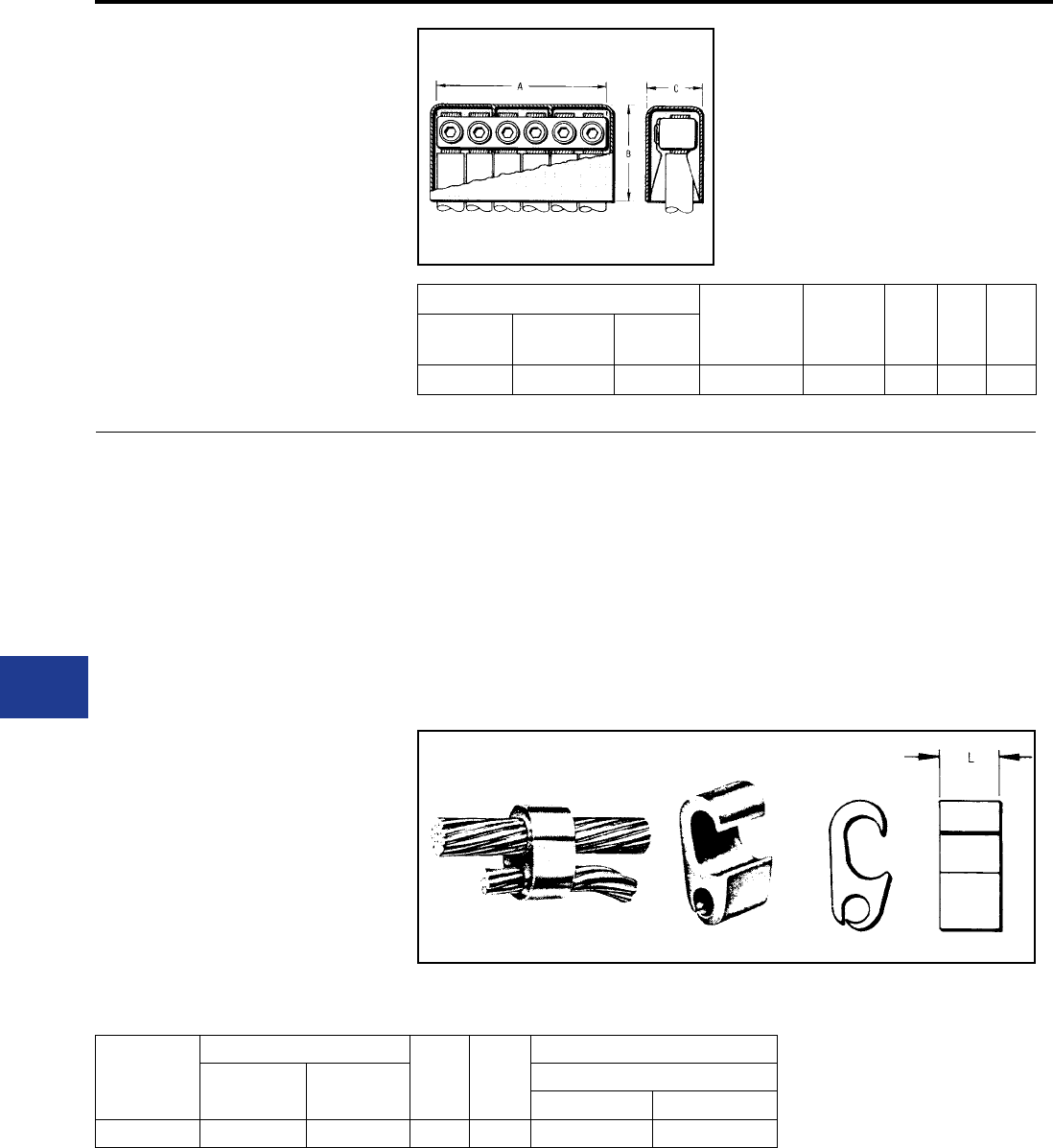
BURNDY®
Blue highlighted items are industry standard and most frequently ordered.
US: 1-800-346-4175 www.burndy.com Canada: 1-800-387-6487
Underground
TYPE K-P-C
URD
URD Service Tap for
Copper Conductors
These compact, wide-range-taking, multiple outlet
connectors are made of high conductivity copper
alloy. Spherical point Allen set screws provide even
clamping forces on conductors up to 4/0 Str. Each
connector is supplied with an insulating cover. The
mechanical clamping elements allow individual
cables to be disconnected without disturbing adjacent
connections.
Catalog Number
Conductor Number
of Outlets A B C
Complete
Assembly
Connector
Only
Cover
Only
K6P28C K6P28 K-PC28 6 Str - 4/0 Str. 6 5-1/8 2-3/4 1-5/8
COMPRESSION SERVICE
TAPS AND TRANSFORMER
TERMINALS
Where compression-type service taps are
required, the wide-range-taking, gure “6” shaped,
tap connectors are recommended. They can
be gripped in a HYPRESS™ and slipped over
the secondary main for easy installation. For
above-grade installation, commercially available
insulating tubes are often used to cover a series of
these taps on each main cable stub. Separation of
run and tap cables simplies taping.
TYPE YPC-C
TIN-PLATED
COPPER CRIMPIT™
For Copper Conductors
Made of tin-plated pure copper this connector
is recommended for copper service taps in
above-grade enclosures or for direct burial. The
streamlined design facilitates taping. The plating
eliminates reaction with insulators.
Catalog
Number
Conductor
LDie
Index
Installation Tooling
Run Tap Y35, Y750, Y46* HYPRESS™
Die Cat. No. (No. of Crimps)
YPC29C26 2/0 Str.-250 4 Str.-2/0 Str. 1.00 D3 U-D3 (1)
* Y46 requires PUADP-1 adapter to use U-dies.
K-72
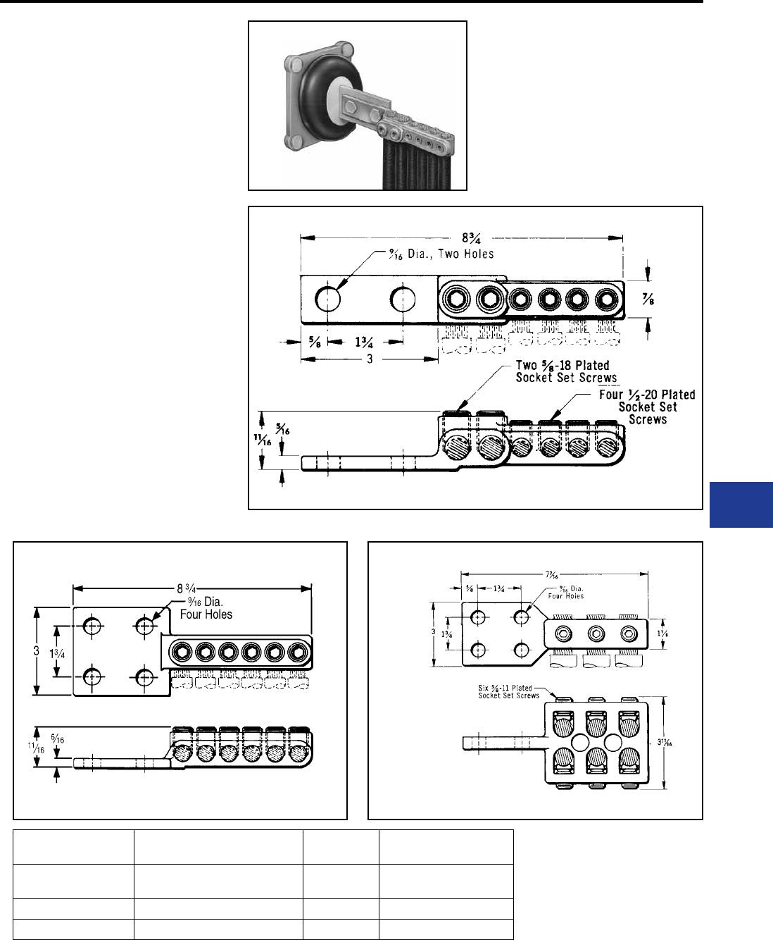
BURNDY®
Blue highlighted items are industry standard and most frequently ordered.
Canada: 1-800-387-6487 www.burndy.com US: 1-800-346-4175
Underground
TYPES K6B AND K33B
URD TRANSFORMER
TERMINALS
For Copper Conductors
These terminals are companion connectors of the
various types and possess the same advantages
of wide conductor range and compactness.
These features simplify cable terminations in
the secondary compartments of pad-mounted
transformers. The design also permits individual
cables to be disconnected without disturbing
adjacent joints.
Made of a high conductivity copper alloy, these
compact range-taking connectors provide
for connecting up to six copper cables at the
transformer terminals. The outlets are equipped
with spherical point, tinplated brass socket set-
screws to provide even clamping forces on the
conductors throughout the cable range.
Where cable sizes exceed 4/0 Str., a pressure bar
is added to assure optimum performance.
Catalog
Number Conductor Fig.
No. NEMA Tongue
K6B2826-2N Two Outlets: #6 - 4/0
Four Outlets: 6 Str. -2/0 1 2-Hole
K6B28-4N Six Outlets: 6 Str. - 4/0 Str. 2 4-Hole
K33B34-4N Six Outlets: 4/0 Str. - 500 3 4-Hole
Fig. 1
Fig. 2 Fig. 3
K-73
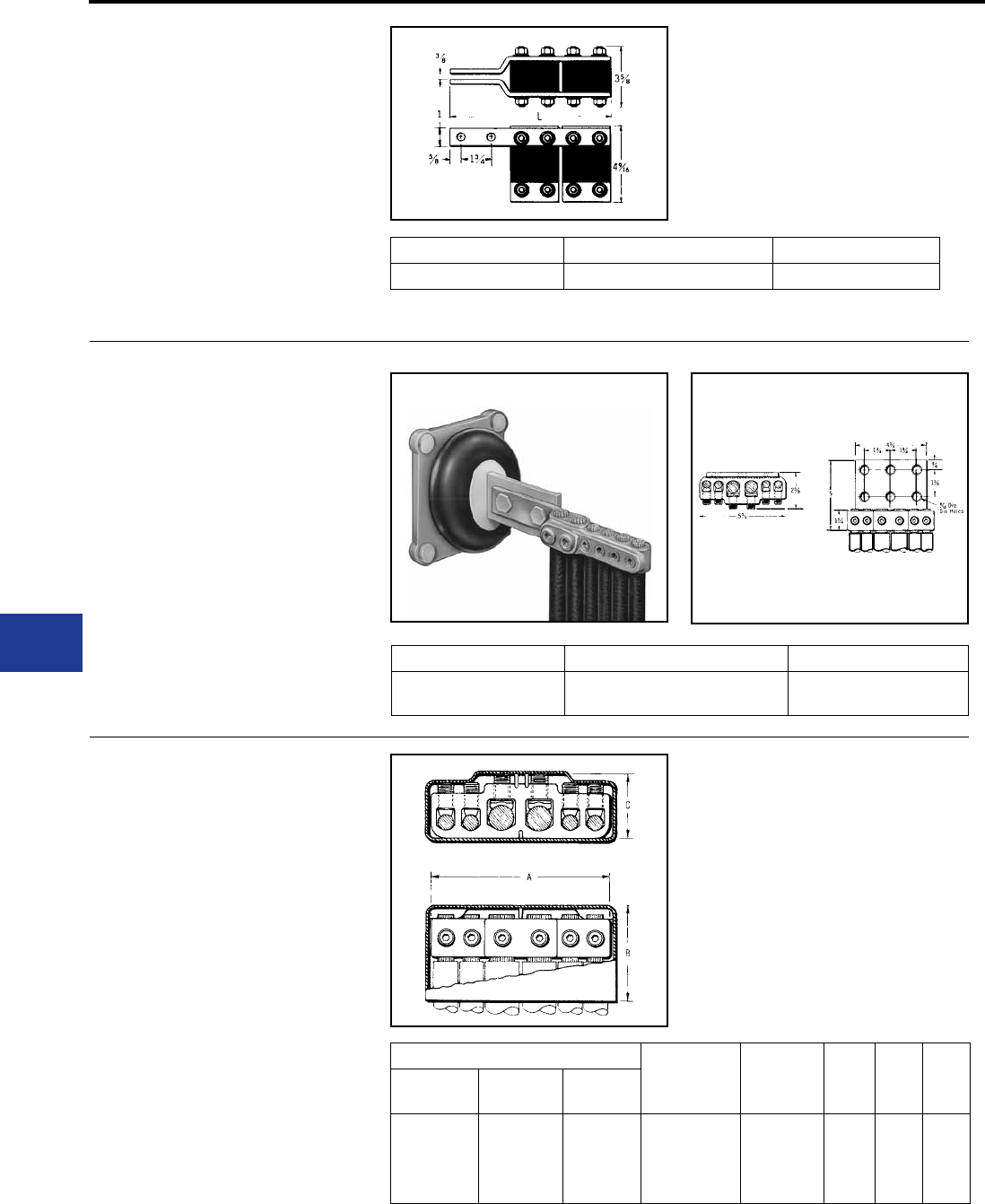
BURNDY®
Blue highlighted items are industry standard and most frequently ordered.
US: 1-800-346-4175 www.burndy.com Canada: 1-800-387-6487
Underground
TYPE F-A
URD FUSED TRANSFORMER
TERMINALS
These Transformer Tap assembles bolt directly to
the secondary terminal pad. They provide for up to
eight cables to be fused directly at the secondary
terminals. This may be all service taps or
combinations of secondary mains and service taps. Catalog Number Number of Fuses L Inches
F22A28 4 6-1/2
Type LF Limiter and HYLUG™ (copper or aluminum). Compression terminals must be ordered separately.
TYPE K6A34U
TRANSFORMER TERMINALS
For Aluminum and
Copper Conductors
Made of aluminum alloy, the massive design
minimizes conductor corrosion due to galvanic
action. Each outlet is pre-lled with PENETROX™
joint compound and sealed. Plated aluminum
socket head pressure screws and aluminum
pressure bars prevent conductor damage. Six hole
pad allows for adjustable positioning on four hole
NEMA spades.
Catalog Number Conductor Number of Outlets
K6A34U-6N Two Outlets 2 Str.-500
Four Outlets 6 Str.-4/0 Str. 6
TYPE K-P-UC
UNIVERSAL URD SERVICE TAP
For Aluminum or Copper
Made of aluminum alloy, the massive design
minimizes conductor corrosion due to galvanic
action. Each outlet is pre-lled with PENETROX™
joint compound and sealed. Plated aluminum
socket head pressure screws and aluminum
pressure bars prevent conductor damage. Each
connector is supplied with an insulating cover.
Catalog Number
Conductor Number of
Outlets A B C
Complete
Assembly
Connector
Only
Cover
Only
K6P34UC K6P34U K6PC34U
Two Outlets
2 Str. - 500
Four Outlets
6 Str.- 4/0 Str.
6 5-3/4 3-1/8 2-1/8
K-74
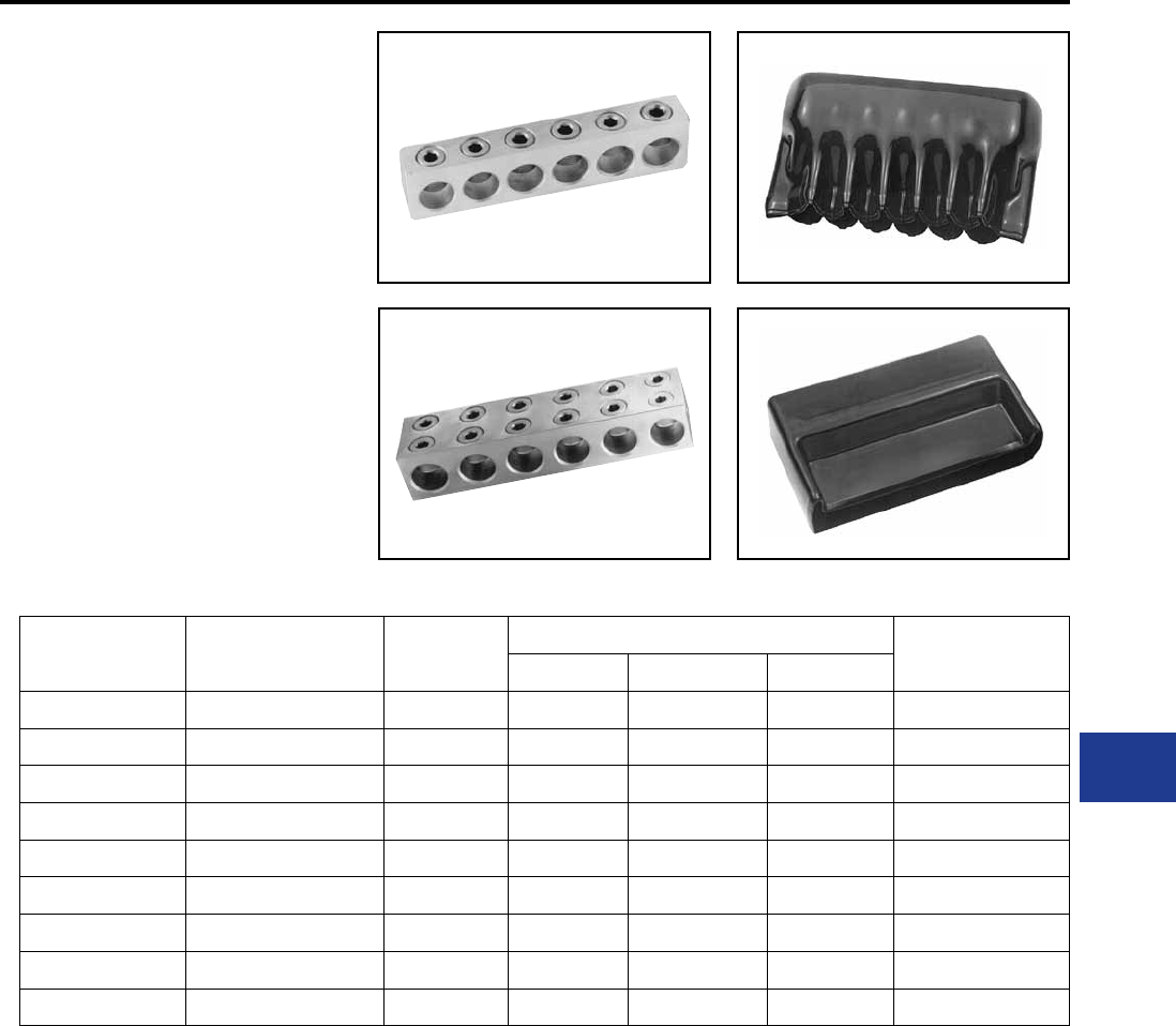
BURNDY®
Blue highlighted items are industry standard and most frequently ordered.
Canada: 1-800-387-6487 www.burndy.com US: 1-800-346-4175
Underground
TYPES BPD & BPD2
POWER DISTRIBUTION
BLOCKS
Dual rated ground pedestal lugs. Rated for 600
volt. Constructed from high strength aluminum
alloy 6061-T6. Connectors are all plated to provide
low contact resistance.
Plastisol covers dielectric strength rating of 120
volts per mil. Nominal thickness is 156 mils. Covers
purchased separately.
Catalog
Number
Wire Range
Aluminum or Copper
Number of
Conductors
Dimensions
Insulating Cover
A B C
BPD-4-350 #6-350 4 3.88 1.38 1.00 BIC-4-350
BPD-6-350 #6-350 6 5.69 1.38 1.00 BIC-6-350
BPD-8-350 #6-350 8 7.50 1.38 1.00 BIC-8-350
BPD-4-500 #2-500 4 4.75 1.63 1.00 BIC-4-500
BPD-6-500 #2-500 6 7.00 1.63 1.00 BIC-6-500
BPD-8-500 #2-500 8 9.25 1.63 1.00 BIC-8-500
BPD2-4-750 #2-750 4 6.56 2.00 2.50 BIC2-4-750
BPD2-6-750 #2-750 6 9.88 2.00 2.50 BIC2-6-750
BPD2-8-750 #2-750 8 13.81 2.00 2.50 BIC2-8-750
BPD
BPD2
BIC
BIC2
K-75
BURNDY®
Blue highlighted items are industry standard and most frequently ordered.
Canada: 1-800-387-6487 www.burndy.com US: 1-800-346-4175
COPPER SUBSTATION
Introduction
Type NAS
Cable to Pad
Type NA
Tube to Flat
Type NAH
Cable to Pad
Type N2AH
Cable to Flat
Type VA
Cable to Flat
Type VVA
Cable to Flat
Type XA
Tube to Flat, Expandable
Type NT
Tube to Tube
Type NSNT
Tube or Cable to Cable
Type NHNT
Tube to Cable
Type VT
Cable to Cable
Type NS
Tube to Tube
Type XP
Tube to Tube
Type UH
Tube
Type UHR
Tube or Cable
Type LH, LHR
Tube or Cable
Type FD
Stud to Flat Bar
Type NDR
Cable, Tube, Flat Bar
Type QGFL
Cable to Flat
Type FCB
Transformer Tap Adapter
Type E-C-G
Transformer Tap Adapter
Type HFBW
Bar Clamp
Type HFB-P1
Bar Clamp Components
Type HFB-N
Tap Pad Adapter
Type NNT
Tube to Tube
Type NNTR
Cable to Cable
Type NNTR
Tube to Cable
TABLE OF CONTENTS
L-3
L-4
L-5
L-6
L-7
L-8
L-9
L-10
L-11
L-12
L-13
L-14
L-15
L-16
L-17
L-17
L-18
L-19
L-20
L-21
L-22
L-22
L-23
L-24
L-24
L-25
L-26
L-27
Substation
Bolted
L-1
BURNDY®
Blue highlighted items are industry standard and most frequently ordered.
US: 1-800-346-4175 www.burndy.com Canada: 1-800-387-6487
Type NS-A
Tube to Tube
Type NA-A
Tube to Flat
Type XA-A
Tube to Flat
Type NAR
Cable to Flat
Type NBC-A
Tube to Flat
Type UHG
Fixed or Rigid Pipe to Base
Type UHKR-A
Tube or Cable
Type LB-A
Pipe End Cap
Type WAS-A
Tube to Pad
Type WASC-A-N
Tube to Pad
Type WG
Stud to Tube
L-28
L-28
L-29
L-30
L-31
L-32
L-33
L-34
L-35
L-36
L-37
Substation
Bolted
L-2
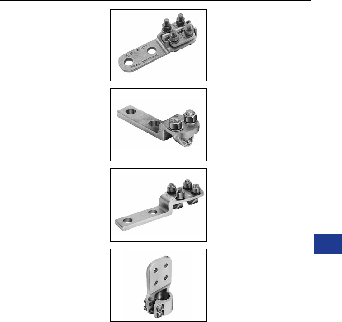
BURNDY®
Blue highlighted items are industry standard and most frequently ordered.
Canada: 1-800-387-6487 www.burndy.com US: 1-800-346-4175
Substation
Bolted
COPPER
SUBSTATION
CONNECTORS
INTRODUCTION
BURNDY® electrical connectors
are designed to be installed with a
minimum of effort, to run cooler than
the conductors being joined and to
provide optimum performance under
all operating conditions.
To achieve this type of performance,
extensive research and development
time is spent by BURNDY®
engineers and scientists to improve
manufacturing techniques, materials
and designs. As these improvements
become available, they are
incorporated into both existing and
new product lines. This continuous
program of product innovation
and improvement insures that, as
new and more critical applications
evolve, high quality connectors from
BURNDY® will be available to meet
the need.
N-Line connectors are two-piece
copper alloy castings assembled
with DURIUM™ (silicon bronze)
hex bolts, nuts and washers. They
are available for connecting tube or
cable.
The Variline incorporates a modied
V-bolt as the clamping element for
heavy-duty applications. This line
is particularly suited for use with
exible and extra exible cables.
Flat pad connectors used to
join cable or tubing terminals to
equipment studs.
A variety of bus supports are also
available for tube or cable. Some
can be adjusted for either a rigid or
slide-t by rotating the clamping cap
180°.
Expansion connectors are used
to absorb the stress imposed on
the bus by settling ground, thermal
expansion and shocks, as in circuit
breaker operations. The exible
elements are at-tinned, copper
braid, with sufcient cross sectional
area to carry the rated current of the
conductors being joined.
L-3
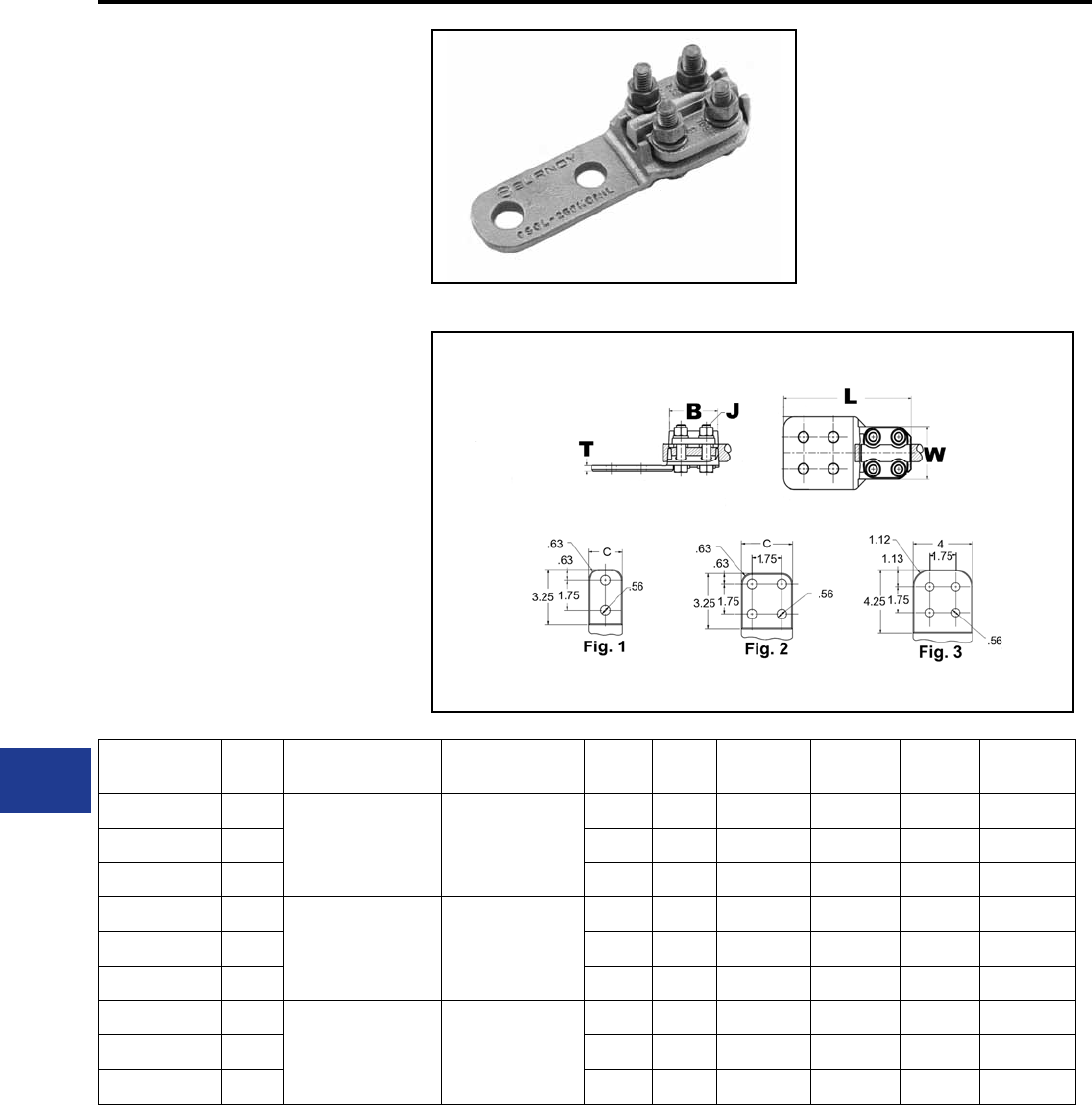
BURNDY®
Blue highlighted items are industry standard and most frequently ordered.
US: 1-800-346-4175 www.burndy.com Canada: 1-800-387-6487
TYPE NAS
BOLTED TERMINALS
For Use On Cable To Pad
High copper alloy reversible cap terminal for
joining a wide range of cable to pads. Tongue is
side formed to provide adequate clearance and
terminal is designed for one- wrench installation.
Material: Copper Alloy
Hardware: DURIUM™ Silicon Bronze
Notes :
• Plated versions: add the required sufx
to the catalog number. -TN for regular tin
plating.
• Please contact factory for other sizes,
combinations and availability.
• See NAH family for heavy duty versions.
Substation
Copper Bolted Terminals | 230 kV
Catalog
Number Fig. # Copper Stranded
Range
Copper Solid
Range BJ
Dia. L C T W
NAS29-2N 1
6 AWG-250 kcmil 6 AWG-4/0 AWG
2.38 3/8 5.62 1.50 0.25 2.00
NAS29-34N 2 2.38 3/8 5.62 3.00 0.25 2.00
NAS29-N — 2.38 3/8 3.88 1.25 0.25 2.00
NAS34-2N 1
1/0 AWG-500 kcmil 1/0 AWG-4/0 AWG
2.38 3/8 5.62 2.00 0.31 2.20
NAS34-34N 2 2.38 3/8 5.62 3.00 0.25 2.20
NAS34-N — 2.38 3/8 4.12 1.50 0.25 2.20
NAS40-2N 1
2/0 AWG-800 kcmil 2/0 AWG-4/0 AWG
2.62 3/8 5.88 2.00 0.38 2.44
NAS40-34N 2 2.62 3/8 5.88 3.00 0.31 2.44
NAS40-44N 3 2.62 3/8 6.88 4.00 0.31 2.44
L-4
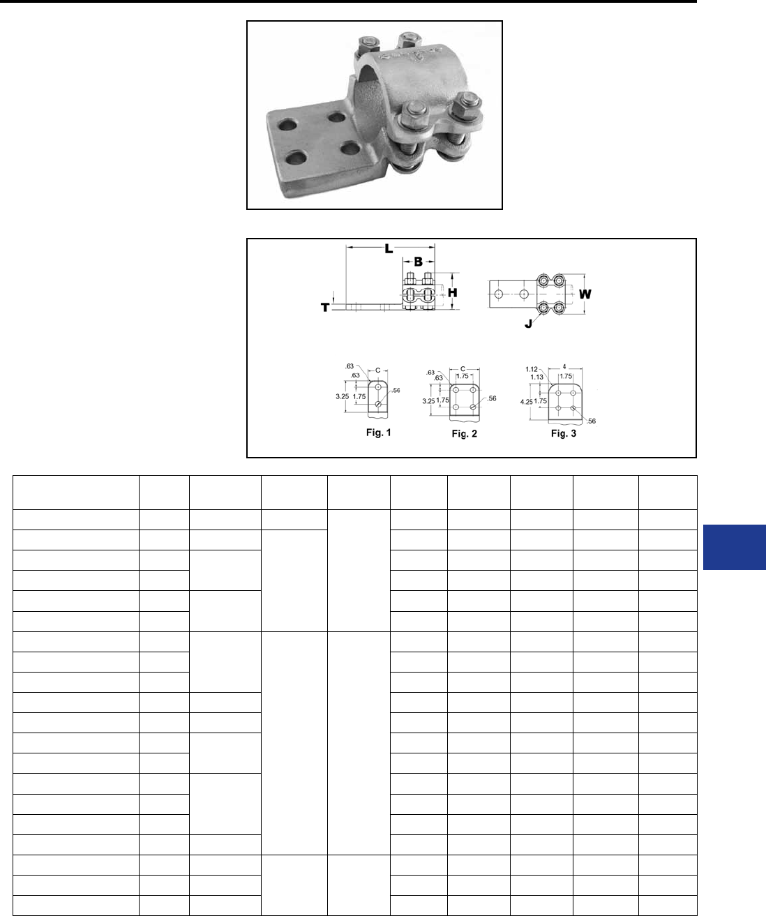
BURNDY®
Blue highlighted items are industry standard and most frequently ordered.
Canada: 1-800-387-6487 www.burndy.com US: 1-800-346-4175
TYPE NA
TERMINAL
For Copper Tube to Flat
High copper alloy terminal for joining copper tube
to a at pad. Letter “N” on end of catalog number
indicates pad drilled to NEMA standards. One-
wrench installation.
Material: Copper Alloy
Hardware: DURIUM™ Silicon Bronze
Notes :
• Plated versions: add the required
sufx to the catalog number. -TN for
regular tin plating.
• Please contact factory for other
sizes, combinations and availability.
Substation
Copper Bolted Terminals | 230 kV
Catalog
Number Fig. # Copper Pipe
(Std or EH) BJ
Dia. L H C T W
NA122N 1 3/8 IPS 1.38
3/8
3.75 1.50 1.50 0.25 2.13
NA132N 1 1/2 IPS
2.00
5.25 1.75 1.50 0.38 2.25
NA142N 13/4 IPS 5.25 2.00 1.63 0.38 2.44
NA144N 2 4.50 2.00 3.13 0.38 2.44
NA152N 11 IPS 5.25 2.06 1.88 0.38 2.75
NA154N 2 5.25 2.06 3.00 0.38 2.75
NA162N 1
1 1/4 IPS
2.69 1/2
5.94 2.56 2.25 0.44 3.50
NA164N 2 5.94 2.56 3.00 0.44 3.50
NA172N 1 5.94 2.75 2.50 0.50 3.94
NA1744NHQ 3 1 1/2 IPS 7.07 3.09 4.00 0.50 3.82
NA174N 2 1 1/4 IPS 5.94 2.75 3.00 0.50 3.94
NA182N 12 IPS 5.94 3.12 2.75 0.50 4.62
NA184N 2 5.94 3.13 3.13 0.50 4.63
NA1944N 3
2 1/2 IPS
7.19 3.74 4.00 0.69 5.24
NA1944NHQ 3 7.09 3.96 4.00 0.75 5.12
NA194N 2 5.94 3.69 3.75 0.69 5.25
NA194N90CG2 2 2 1/2 IPS 6.50 3.62 3.75 0.69 5.25
NA204N 2 3 IPS
3.25 5/8
6.56 4.38 4.38 0.69 6.19
NA214N 2 3 1/2 IPS 6.56 4.94 4.75 0.81 6.81
NA224N 2 4 IPS 6.56 5.50 5.25 0.81 7.44
L-5
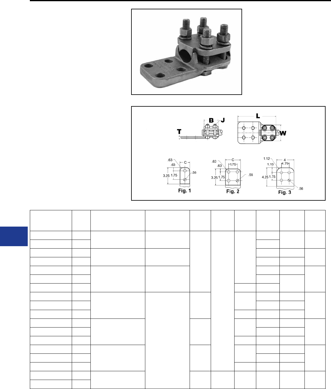
BURNDY®
Blue highlighted items are industry standard and most frequently ordered.
US: 1-800-346-4175 www.burndy.com Canada: 1-800-387-6487
TYPE NAH
BOLTED TERMINALS
For Use On Cable To Pad
High copper alloy terminal for joining a wide range
of cable to equipment pads. Tongue is side formed
to provide adequate clearance and terminal is
designed for one-wrench installation.
Material: Copper Alloy
Hardware: DURIUM™ Silicon Bronze
Notes :
• Plated versions: add the required sufx
to the catalog number. -TN for regular tin
plating.
• Please contact factory for other sizes,
combinations and availability
Substation
Copper Bolted Terminals | 230 kV
Catalog
Number Fig. #
Copper
Stranded
Range
Copper
Solid
Range
BJ
Dia. L C T W
NAH29-2N 16 AWG-250 kcmil 6 AWG-4/0 AWG
2.62
1/2
5.88
1.50 0.25 2.44
NAH29-34N 2 3.00
NAH34-2N 11/0 -500 kcmil 1/0 AWG-4/0 AWG 2.00 0.31 2.56
NAH34-34N 2 3.00 0.25
NAH40-2N 1
2/0 AWG-800 kcmil 3/0 AWG-4/0 AWG
2.00 0.38
2.81NAH40-34N 2 3.00 0.31
NAH404-4N 3 6.88 4.00
NAH44-2N 1
4/0 AWG-1000 kcmil
N/A
2.88 6.12 2.00 0.44
2.88NAH44-34N 2 3.00 0.38
NAH44-44N 3 7.12 4.00 0.31
NAH46-2N 1
1000 kcmil-1500 kcmil 3.06 6.31 2.00 0.50
3.19NAH46-34N 2 3.00 0.41
NAH46-44N 3 7.31 4.00 0.38
NAH48-2N 1
500 kcmil-2000 kcmil 3.25 6.50 2.00 0.69
3.38NAH48-34N 2 3.00 0.50
NAH48-44N 3 7.50 4.00 0.44
NAH48-62N 12000 kcmil-2500 kcmil 3.75 5/8 7.12 3.00 0.63 3.96
NAH486-34N 2
L-6
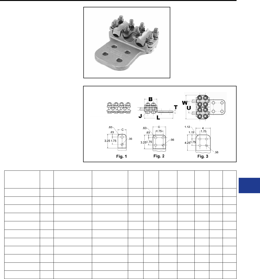
BURNDY®
Blue highlighted items are industry standard and most frequently ordered.
Canada: 1-800-387-6487 www.burndy.com US: 1-800-346-4175
TYPE N2AH
BOLTED TERMINALS
For Two Copper Cables to Flat
High copper alloy reversible cap terminal for
joining a wide range of cable to pads. Tongue is
side formed to provide adequate clearance and
terminal is designed for one wrench installation.
Material: Copper Alloy
Hardware: DURIUM™ Silicon Bronze
Notes :
• Plated versions: add the required sufx
to the catalog number. -TN for regular tin
plating.
• Please contact factory for other sizes,
combinations and availability.
Substation
Copper Bolted Terminals | 230 kV
Catalog
Number Fig. #
Copper
Stranded
Range
Copper
Solid
Range
BJ
Dia. L C T W U
N2AH29-2N 1 6 AWG-250 kcmil 6 AWG-4/0 AWG 2.62 1/2 5.87 1.50 0.32 4.88 2.44
N2AH29-34N 2 6 AWG-250 kcmil 6 AWG-4/0 AWG 2.62 1/2 5.87 3.00 0.32 4.88 2.44
N2AH34-2N 1 1/0 AWG-500 kcmil 1/0 AWG-4/0 AWG 2.62 1/2 5.87 2.00 0.32 5.44 2.88
N2AH34-34N 2 1/0 AWG-500 kcmil 1/0 AWG-4/0 AWG 2.63 1/2 6.13 3.00 0.38 5.40 2.88
N2AH34-44N 3 1/0 AWG-500 kcmil 1/0 AWG-4/0 AWG 2.63 1/2 7.00 4.00 0.38 5.38 2.88
N2AH40-34N 2 2/0 AWG-800 kcmil 2/0 AWG-4/0 AWG 2.63 1/2 5.88 3.00 0.38 5.70 2.92
N2AH44-34N 2 4/0 AWG-1000 kcmil 4/0 AWG 2.88 1/2 6.38 3.00 0.50 6.12 3.12
N2AH44-44N 3 4/0 AWG-1000 kcmil 4/0 AWG 2.88 1/2 7.32 4.00 0.50 6.12 3.12
N2AH44-44NHQ 3 4/0 AWG-1000 kcmil 4/0 AWG 2.88 1/2 7.20 4.00 0.50 6.12 3.12
N2AH46-44N 3 1000 kcmil-1500 kcmil N/A 3.07 1/2 7.46 4.00 0.75 6.50 3.36
N2AH48-44N 3 1000 kcmil-1500 kcmil N/A 3.25 1/2 7.62 4.00 0.75 9.50 4.00
L-7
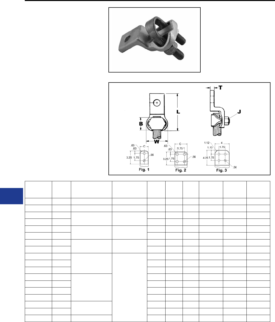
BURNDY®
Blue highlighted items are industry standard and most frequently ordered.
US: 1-800-346-4175 www.burndy.com Canada: 1-800-387-6487
TYPE VA
VARILUG™
For Use On Copper Cable
High copper alloy terminal for joining a wide range
of cable to equipment pads or bar. Particularly
suitable for use on extra exible cable. One-
wrench installation. Type VVA, twin elements
secure joint against vibration and exing.
Particularly recommended for use on extra exible
cables. One-wrench installation.
Material: Bronze Alloy
Hardware: DURIUM™ Silicon Bronze
Notes :
• Plated versions: add the required sufx
to the catalog number. -TN for regular tin
plating.
• Please contact factory for other sizes,
• combinations and availability
• Choose type VVA with twin elements for
additional joint strength against vibration
and exing. Particularly recommended for
use on exible cables.
Substation
VARILUG™ | 230 kV
Catalog
Number * Fig. #
Copper
Stranded
Range
Copper
Solid
Range
C B J
Dia. L T W
VA4C — 8 AWG-4 AWG 8 AWG-4 AWG 0.75 0.69 7/16 2.38 0.22 0.81
VA2C — 8 AWG-2 AWG 8 AWG-2 AWG 0.81 0.81 3/8 2.72 0.25 1.00
VA25 —6 AWG-1/0 6 AWG-1/0 AWG 0.88 0.88 3/8 2.88 0.25 1.19
VA252 — 0.88 0.88 3/8 3.63 0.25 1.19
VA28 —1/0 AWG-4/0 AWG 1/0 AWG-4/0 AWG 1.06 1.09 3/8 2.84 0.31 1.69
VA28-2N 1 1.06 1.09 3/8 4.94 0.31 1.69
VA30 —1/0 AWG-300 kcmil 1/0 AWG-4/0 AWG 1.13 1.09 3/8 3.22 0.31 1.91
VA30-2N 1 1.12 1.09 7/16 5.19 0.31 1.91
VA34 —
300 kcmil-500 kcmil
N/A
1.38 1.31 1/2 3.81 0.38 2.22
VA34-2N 1 1.38 1.31 1/2 5.38 0.38 2.22
VA344 — 1.88 1.31 7/16 4.22 0.38 2.22
VA40 —
500 kcmil-800 kcmil
1.63 1.34 9/16 4.47 0.38 2.63
VA40-2N 1 1.62 1.34 9/16 5.81 0.38 2.62
VA404 — 1.88 1.34 9/16 4.72 0.38 2.63
VA40-4N 2 3.00 1.34 9/16 5.81 0.38 2.62
VA44 —750 kcmil-1000 kcmil 1.88 1.41 5/8 4.78 0.50 2.88
VA444 — 2.13 1.41 5/8 5.16 0.50 2.88
VA462N 1 1000 kcmil-1500 kcmil 2.25 2.00 5/8 6.44 0.56 3.25
* “N” indicates NEMA standard stud holes.
L-8

BURNDY®
Blue highlighted items are industry standard and most frequently ordered.
Canada: 1-800-387-6487 www.burndy.com US: 1-800-346-4175
TYPE VVA
VARILUG™
For Use On Copper Cable
High copper alloy terminal for joining a wide range
of cable to equipment pads or bar. Particularly
suitable for use on extra exible cable. One-
wrench installation.
Material: Bronze Alloy
Hardware: DURIUM™ Silicon Bronze
Notes :
• Plated versions: add the required sufx
to the catalog number. -TN for regular
tin plating
• Please contact factory for other sizes,
combinations and availability
Substation
VARILUG™ | 230 kV
Catalog
Number * Fig. # Copper
Stranded Range
Copper
Solid Range C B J
Dia. L T W
VVA2C — 8 AWG-2 AWG 8 AWG-2 AWG 0.81 0.81 3/8 4.06 0.25 1.00
VVA25 — 6 AWG-1/0 6 AWG-1/0 AWG 0.88 0.88 3/8 4.31 0.25 1.19
VVA25-2 —
1/0 AWG-4/0 AWG
0.88 0.88 3/8 5.06 0.25 1.19
VVA28 —1/0 AWG-4/0 AWG 1.06 1.09 3/8 4.13 0.31 1.69
VVA28-2N 1 1.06 1.09 3/8 6.19 0.31 1.69
VVA30 —
300 kcmil 1/0 AWG-4/0 AWG
1.13 1.09 7/16 4.63 0.31 1.94
VVA30-2N 1 1.13 1.09 7/16 6.56 0.31 1.94
VVA30-4N 2 3.00 1.09 7/16 6.75 0.38 1.91
VVA34 —
300 kcmil-500 kcmil
N/A
1.38 1.31 1/2 5.31 0.38 2.25
VVA34-2N 1 1.30 1.31 1/2 6.88 0.38 2.22
VVA34-4 — 1.88 1.31 7/16 5.75 0.38 2.25
VVA34-4N 2 3.13 1.31 7/16 7.00 0.38 2.38
VVA40 —
500 kcmil-800 kcmil
1.63 1.34 9/16 6.38 0.38 2.63
VVA40-2N 1 1.62 1.34 9/16 7.69 0.38 2.62
VVA40-4N 2 3.00 1.34 9/16 7.69 0.38 2.62
VVA40-4NCG1 — 3.50 0.88 9/16 7.69 0.38 2.62
VVA44-2N 1750 kcmil-1000 kcmil 1.88 1.41 5/8 8.12 0.50 2.88
VVA44-4N 2 3.00 1.41 5/8 8.06 0.50 2.88
VVA46-2N 1
1000 kcmil-1500 kcmil
2.25 2.00 5/8 8.69 0.56 3.25
VVA46-4NCG2 — 3.50 2.00 5/8 8.75 0.56 3.25
VVA46-4NCG4 — 3.50 2.00 5/8 5.50 0.56 3.23
VVA48-2N 1 1500 kcmil-2000 kcmil 2.62 2.25 3/4 9.23 0.62 3.75
* “N” indicates NEMA standard stud holes.
L-9
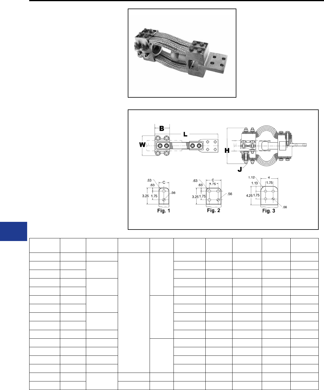
BURNDY®
Blue highlighted items are industry standard and most frequently ordered.
US: 1-800-346-4175 www.burndy.com Canada: 1-800-387-6487
TYPE XA
BOLTED EXPANSION TERMINALS
For Copper Tube to Flat
High copper alloy expansion terminal for tube to at.
Provides for longitudinal movement of tubing. Extra
exible braid carries full load of joint. One-wrench
installation.
Material: Copper Alloy
Hardware: DURIUM™ Silicon Bronze
Notes :
• Plated versions: add the required
sufx to the catalog number. -TN for
regular tin plating.
• Please contact factory for other
sizes, combinations and availability.
• Installation instructions available
upon request.
Substation
Copper Expansion Terminals | 230 kV
Catalog
Number Fig. # Copper Pipe
(Std)
Copper Pipe
(EH) B C J
Dia. L H W
XA132N 1 1/2 IPS
N/A
3.00
1.50 3/8 12.00 3.88 3.06
XA142N 13/4 IPS 1.63 3/8 12.00 4.06 3.13
XA144N 2 3.00 3/8 12.50 4.12 3.12
XA152N 11 IPS 1.88 3/8 12.75 4.31 3.13
XA154N 2 3.00 3/8 12.75 4.31 3.13
XA162N 11 1/4 IPS
3.50
2.25 1/2 14.50 5.81 4.31
XA164N 2 3.00 1/2 14.75 5.81 4.31
XA172N 11 1/2 IPS 2.50 1/2 15.00 6.06 4.31
XA174N 2 3.00 1/2 15.25 6.06 4.31
XA184N 2 2 IPS 3.00 1/2 15.25 7.00 4.62
XA194N 2 2 1/2 IPS
4.00
3.75 1/2 16.13 7.50 5.25
XA204N 2 3 IPS 4.38 5/8 16.69 7.94 6.50
XA214N 2 3 1/2 IPS 4.75 5/8 16.94 8.25 6.81
XA224N 2 4 IPS 5.25 5/8 17.00 9.44 7.44
XA574N 2N/A 1 1/2 IPS 3.50 3.00 1/2 14.38 6.44 4.31
XA594N 2 2 1/2 IPS 4.00 3.75 1/2 14.75 9.56 5.25
L-10
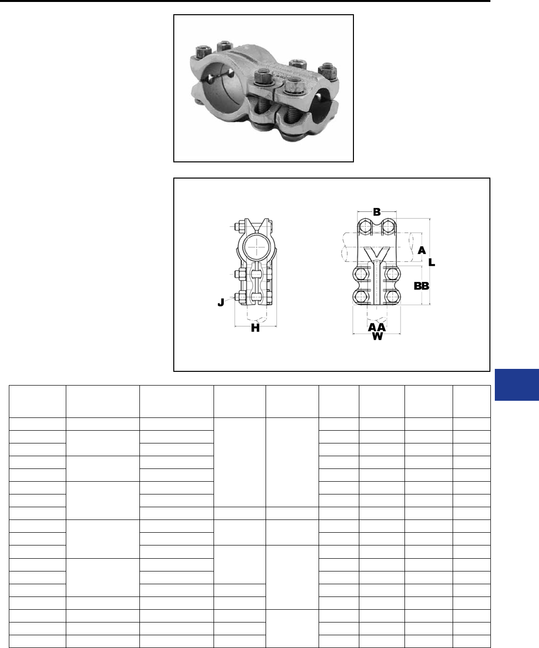
BURNDY®
Blue highlighted items are industry standard and most frequently ordered.
Canada: 1-800-387-6487 www.burndy.com US: 1-800-346-4175
TYPE NT
T-CONNECTORS
For Use On Tube To Tube T
(6 BOLTS)
High copper alloy T-Connector for tubing run and
tap. Slots between bolts provide independent high-
pressure areas of contact. One-wrench instiallation.
Material: Copper Alloy
Hardware: DURIUM™ Silicon Bronze
Notes :
• Plated versions: add the required sufx
to the catalog number. -TN for regular
tin plating.
• Items with -HC sufx have hex head
bolts; items without the sufx can be
either hex head or oval shank head.
Both head styles are one wrench
installation and offer the same clamping
force and functionalities.
• Please contact factory for other sizes,
combinations and availability.
• One-wrench installation.
Substation
Copper Bolted T-Connectors | 230kV
Catalog
Number
A
Run Copper
Pipe
AA
Tap Copper
Pipe
B J
Dia. BB L H W
NT1313 1/2 IPS 1/2 IPS
2.00 3/8
2.00 4.13 1.94 2.44
NT1413 3/4 IPS 1/2 IPS 2.00 4.13 1.94 2.25
NT1414 3/4 IPS 2.00 4.13 1.94 2.44
NT1514 1 IPS 3/4 IPS 2.00 4.38 2.13 2.44
NT1515 1 IPS 2.00 4.44 2.13 2.75
NT1614
1 1/4 IPS
3/4 IPS 2.00 4.75 2.44 2.44
NT1615 1 IPS 2.00 4.75 2.44 2.75
NT1616 1 1/4 IPS 2.69 1/2 2.69 5.69 2.63 3.50
NT1714
1 1/2 IPS
3/4 IPS 2.00 3/8 2.00 5.06 2.69 2.44
NT1715 1 IPS 2.00 5.06 2.69 2.75
NT1717 1 1/2 IPS
2.69
1/2
2.69 6.06 2.75 3.94
NT1816
2 IPS
1 1/4 IPS 2.69 6.56 2.69 3.50
NT1817 1 1/2 IPS 2.69 6.63 3.25 3.94
NT1818 2 IPS 3.06 2.69 6.69 3.31 4.62
NT1919 2 1/2 IPS 2 1/2 IPS 3.63 2.69 7.25 3.88 5.25
NT2020 3 IPS 3 IPS 4.31
5/8
3.25 8.63 4.63 6.19
NT2121 3 1/2 IPS 3 1/2 IPS 4.88 3.25 9.25 5.19 6.81
NT2222 4 IPS 4 IPS 5.44 3.25 9.81 5.75 7.44
L-11
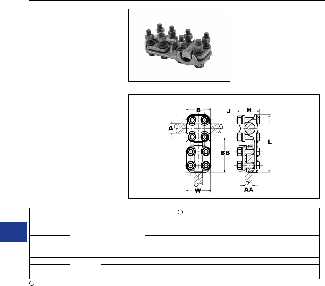
BURNDY®
Blue highlighted items are industry standard and most frequently ordered.
US: 1-800-346-4175 www.burndy.com Canada: 1-800-387-6487
TYPE NSNT
T-CONNECTORS
For Use On Tube Or Cable To
Cable T
High copper alloy reversible T-Connector for
joining a wide range of run and tap cables.
Connector is designed for one-wrench installation.
“S” standard 3/8 in hardware and “H” heavy duty
1/2 in hardware.
Material: Copper Alloy
Hardware: DURIUM™ Silicon Bronze
Notes :
• Plated versions: add the required sufx
to the catalog number. -TN for regular tin
plating.
• Please contact factory for other sizes,
combinations and availability.
• One-wrench installation.
Substation
Copper Bolted T-Connectors | 230kV
1Complete cable range may be accommodated by
reversing cap.
Catalog
Number
A
Pipe Run
A
Cable Run
AA
Cable Tap Range B J
Dia. BB L H W
NSNT1329 1/2 IPS
N/A
6 AWG-250 kcmil 2.00 3/8 2.38 5.08 2.00 1.96
NSNT1429 3/4 IPS 6 AWG-250 kcmil 2.00 3/8 2.38 5.08 2.00 1.96
NSNT1434 1/0 AWG-500 kcmil 2.00 3/8 2.38 5.08 2.10 2.20
NSNT1529 1 IPS 6 AWG-250 kcmil 2.00 3/8 2.38 5.34 2.00 1.96
NSNT1629 1 1/4 IPS 6 AWG-250 kcmil 2.00 3/8 2.38 5.78 2.37 1.96
NSNT2929
—
6 AWG-250 kcmil 6 AWG-250 kcmil 2.38 3/8 2.38 4.60 1.75 1.96
NSNT3429 1/0 AWG-500 kcmil 6 AWG-250 kcmil 2.38 3/8 2.38 4.84 2.00 1.96
NSNT3434 1/0 AWG-500 kcmil 2.38 3/8 2.38 4.84 2.00 2.20
1
L-12
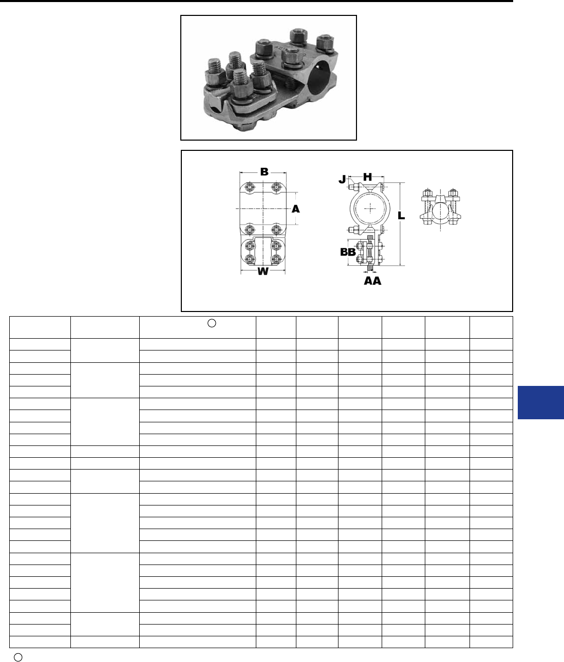
BURNDY®
Blue highlighted items are industry standard and most frequently ordered.
Canada: 1-800-387-6487 www.burndy.com US: 1-800-346-4175
TYPE NHNT
T-CONNECTORS
For Use On TUBE TO CABLE T
High copper alloy reversible T-Connector for
joining a wide range of run pipe and tap cables.
Connector is designed for one-wrench installation.
Material: Copper Alloy
Hardware: DURIUM™ Silicon Bronze
Notes :
• Plated versions: add the required sufx
to the catalog number. -TN for regular tin
plating.
• Please contact factory for other sizes,
combinations and availability.
• One-wrench installation.
Catalog
Number
A
Pipe Run
AA
Cable Tap Range BJ
Dia. BB L H W
NHNT1429 3/4 IPS 6 AWG-250 kcmil 2.25 1/2 2.62 5.82 2.32 2.44
NHNT1434 1/0 AWG-500 kcmil 2.25 1/2 2.62 5.82 2.42 2.56
NHNT1529
1 IPS
6 AWG-250 kcmil 2.25 1/2 2.62 5.92 2.57 2.44
NHNT1534 1/0 AWG-500 kcmil 2.25 1/2 2.62 5.92 2.57 2.56
NHNT1540 2/0 AWG-800 kcmil 2.25 1/2 2.62 5.92 2.60 2.78
NHNT1629
1 1/4 IPS
6 AWG-250 kcmil 2.69 1/2 2.62 6.32 2.57 2.44
NHNT1634 1/0 AWG-500 kcmil 2.69 1/2 2.62 6.32 2.60 2.56
NHNT1640 2/0 AWG-800 kcmil 2.69 1/2 2.62 6.32 2.68 2.78
NHNT1644 4/0 AWG-1000 kcmil 2.69 1/2 2.88 6.58 2.69 2.90
NHNT1729 1 1/2 IPS 6 AWG-250 kcmil 2.69 1/2 2.62 6.76 2.70 2.44
NHNT1734 1 1/2 IPS 1/0 AWG-500 kcmil 2.69 1/2 2.62 6.76 2.70 2.56
NHNT1740 1 1/2 IPS 2/0 AWG-800 kcmil 2.69 1/2 2.62 6.76 2.78 2.78
NHNT1744 4/0 AWG-1000 kcmil 2.69 1/2 2.88 7.02 2.80 2.90
NHNT1829
2 IPS
6 AWG-250 kcmil 2.69 1/2 2.62 7.44 3.06 2.44
NHNT1834 1/0 AWG-500 kcmil 2.69 1/2 2.62 7.44 3.06 2.56
NHNT1840 2/0 AWG-800 kcmil 2.69 1/2 2.62 7.44 3.06 2.78
NHNT1844 4/0 AWG-1000 kcmil 2.69 1/2 2.88 7.70 3.06 2.90
NHNT1846 1000 kcmil-1500 kcmil 2.69 1/2 3.06 7.88 3.23 3.16
NHNT1929
2 1/2 IPS
6 AWG-250 kcmil 2.69 1/2 2.62 8.06 3.64 2.44
NHNT1934 1/0 AWG-500 kcmil 2.69 1/2 2.62 8.06 3.64 2.56
NHNT1940 2/0 AWG-800 kcmil 2.69 1/2 2.62 8.06 3.64 2.78
NHNT1944 4/0 AWG-1000 kcmil 2.69 1/2 2.88 8.32 3.64 2.90
NHNT1946 1000 kcmil-1500 kcmil 2.69 1/2 3.06 8.50 3.64 3.16
NHNT2040 3 IPS 2/0 AWG-800 kcmil 2.69 1/2 2.88 8.69 4.26 2.78
NHNT2044 4/0 AWG-1000 kcmil 2.69 1/2 5.75 8.95 4.26 2.90
NHNT2229 4 IPS 6 AWG-250 kcmil 3.25 1/2 2.63 10.38 4.26 2.50
1
1Complete cable range may be accommodated by
reversing cap.
Substation
Copper Bolted T-Connectors | 230kV
L-13
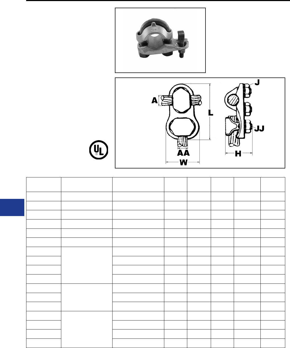
BURNDY®
Blue highlighted items are industry standard and most frequently ordered.
US: 1-800-346-4175 www.burndy.com Canada: 1-800-387-6487
TYPE VT
T-CONNECTORS
For Use On Copper Cable to Cable
High copper alloy T-connector for cable run, cable
tap. V-bolt clamping elements accommodate large
range of cable and are particularly suited for extra
exible cable. One-wrench installation.
Material: Copper Alloy
Hardware: DURIUM™ Silicon Bronze
Notes :
• Plated versions: add the required sufx
to the catalog number. -TN for regular
tin plating.
• Please contact factory for other sizes,
combinations and availability.
• One-wrench installation.
Substation
Copper Bolted T-Connector | 230kV
Catalog
Number
A - Cable
Run Range
AA - Cable
Tap Range
J
Dia.
JJ
Dia. L H W
VT2C2C 8 AWG-2 AWG 8 AWG-2 AWG 5/8 5/8 2.31 1.38 1.00
VT2525 6 AWG-1/0 AWG 6 AWG-1/0 AWG 3/4 3/4 1.37 0.38 0.56
VT2825 1/0 -4/0 AWG 6 AWG-1/0 AWG 3/8 3/4 3.12 1.62 1.25
VT2828 1/0 -4/0 AWG 1/0 -4/0 AWG 3/8 3/8 2.94 0.38 0.31
VT3028 1/0 -300 kcmil 1/0 -4/0 AWG 7/16 3/8 3.19 1.88 1.69
VT4034 500 kcmil-800 kcmil 300 kcmil-500 kcmil 9/16 1/2 4.13 2.56 2.25
VT4430
750 kcmil-1000 kcmil
1/0 -300 kcmil 5/8 7/16 4.25 2.88 1.94
VT4434 300 kcmil-500 kcmil 5/8 1/2 4.38 3.34 2.25
VT4440 500 kcmil-800 kcmil 5/8 9/16 4.75 2.88 2.63
VT4444 750 kcmil-1000 kcmil 5/8 5/8 4.88 2.88 2.88
VT4628
1000 kcmil-1500 kcmil
1/0 -4/0 AWG 5/8 3/8 4.50 3.81 1.69
VT4630 1/0 -300 kcmil 5/8 7/16 4.63 3.81 1.94
VT4640 500 kcmil-800 kcmil 5/8 9/16 5.13 3.81 2.63
VT4830
1500 kcmil-2000 kcmil
1/0 -300 kcmil 3/4 7/16 5.13 4.25 1.94
VT4840 500 kcmil-800 kcmil 3/4 9/16 5.63 4.25 2.63
VT4844 750 kcmil-1000 kcmil 3/4 5/8 5.75 4.25 2.88
VT4848 1500 kcmil-2000 kcmil 3/4 3/4 6.25 4.25 3.75
L-14
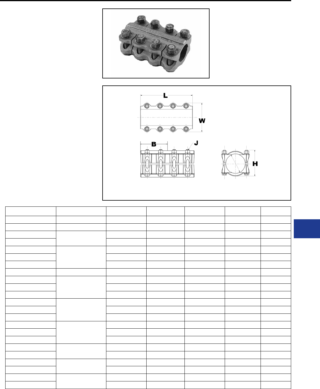
BURNDY®
Blue highlighted items are industry standard and most frequently ordered.
Canada: 1-800-387-6487 www.burndy.com US: 1-800-346-4175
TYPE NS
COUPLERS
For Use On Straight Tube To Tube
High copper alloy coupler for joining equal sizes
of tube end to end. Slots between bolts provide
independent high pressure areas of contact. One-
wrench installation.
Material: Copper Alloy
Hardware: DURIUM™ Silicon Bronze
Notes :
• Plated versions: add the required sufx
to the catalog number. -TN for regular
tin plating.
• W for extra thick tin plating (including
hardware).
• Items with -HC sufx have hex head
bolts; items without the sufx can be
either hex head or oval shank head.
Both head styles are one wrench
installation and offer the same clamping
force and functionalities.
• Please contact factory for sizes,
combinations and availability.
Substation
Copper Bolted Couplers | 230kV
Catalog Number Copper Conductor B J Dia. L H W
NS1212 3/8 IPS 1.50 3/8 3.00 1.44 1.94
NS1313 1/2 IPS 1.63 3/8 3.25 1.69 2.25
NS14148HC 3/4 IPS 2.69 1/2 5.75 2.32 2.81
NS1414HC 2.69 3/8 5.38 2.32 2.81
NS1515
1 IPS
2.13 3/8 4.25 2.13 2.75
NS1515HC 2.69 1/2 5.62 2.32 3.25
NS1515HCHQ 2.69 1/2 5.63 2.36 3.22
NS1616HC 1 1/4 IPS 2.69 1/2 5.75 2.57 3.50
NS1717
1 1/2 IPS
2.88 1/2 5.75 2.75 3.94
NS1717HC 2.69 1/2 5.75 2.81 3.94
NS1717HCHQ 2.69 1/2 5.75 2.61 3.94
NS1818
2 IPS
2.88 1/2 5.75 3.31 4.63
NS1818CG2 2.69 1/2 5.36 3.06 4.62
NS1818HC 2.69 1/2 5.75 3.31 4.62
NS1919
2 1/2 IPS
2.88 1/2 5.75 3.88 5.25
NS1919HC 2.69 1/2 5.75 3.96 5.25
NS1919HCHQ 2.69 1/2 5.75 3.56 5.18
NS2020 3 IPS 3.63 5/8 7.25 4.63 6.19
NS2020HC 3.25 5/8 7.25 4.64 6.19
NS2121 3 1/2 IPS 4.00 5/8 8.00 5.19 6.81
NS2121HC 3.25 5/8 7.25 5.20 6.81
NS2222 4 IPS 4.25 5/8 8.50 5.75 7.44
NS2222HC 3.25 5/8 7.25 5.76 7.44
L-15
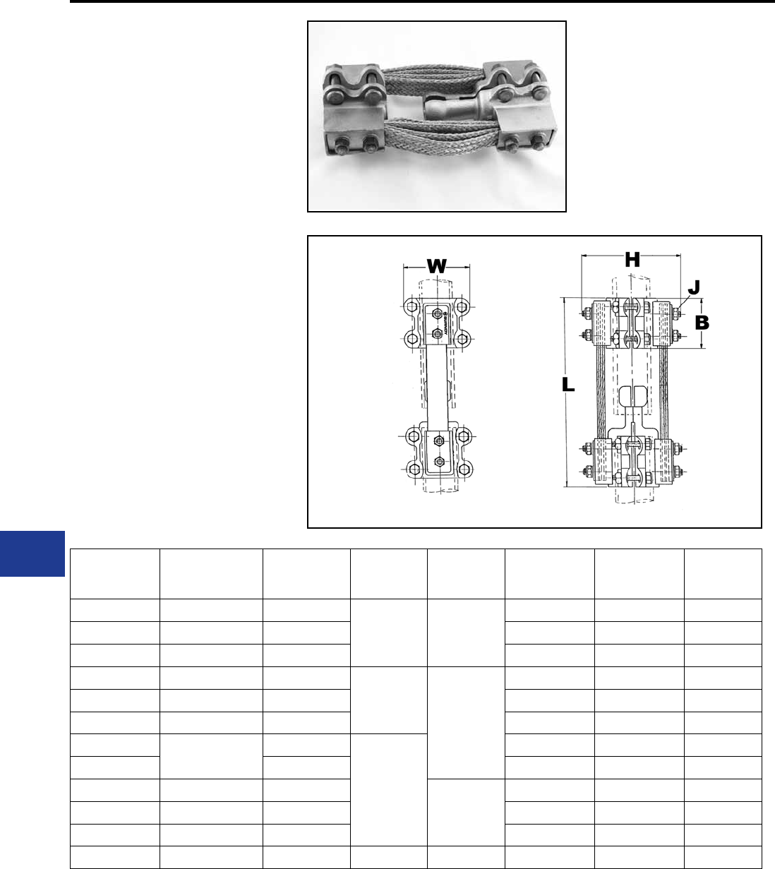
BURNDY®
Blue highlighted items are industry standard and most frequently ordered.
US: 1-800-346-4175 www.burndy.com Canada: 1-800-387-6487
TYPE XP
EXPANSION COUPLERS
For Use On Copper Tube to Tube
High alloy copper expansion coupler for joining equal
size tube on end. Extra exible tinned copper braid
allows longitudinal movement of the tube. Type XP has
alignment guide. One-wrench installation.
Material: Copper Alloy
Hardware: DURIUM™ Silicon Bronze
Notes :
• Items with “-HC” sufx have hex head
bolts; items without the sufx can be
either hex head or oval shank head.
Both head styles are one wrench
installation and offer the same clamping
force and functionalities.
• Installation instructions available upon
request.
• For other sizes or congurations, please
call factory.
Substation
Copper Bolted Expansion Coupler | 230kV
Catalog
Number
Copper
Pipe
Size
Copper
EH Pipe
Size
BJ
Dia. L H W
XP1313 1/2 IPS —
3.00 3/8
8.75 3.88 3.06
XP1414 3/4 IPS — 8.75 4.06 3.13
XP1515 1 IPS — 9.50 4.31 3.13
XP1616 1 1/4 IPS —
3.50
1/2
11.50 5.81 4.31
XP1717 1 1/2 IPS — 12.00 6.44 4.31
XP1818 2 IPS — 12.00 7.00 4.63
XP1919 2 1/2 IPS —
4.00
13.00 8.50 5.25
XP1919HC — 13.00 8.50 5.25
XP2020 3 IPS —
5/8
13.50 7.75 6.50
XP2121 3 1/2 IPS — 13.63 8.00 6.81
XP2222 4 IPS — 13.63 9.06 7.44
XP5656 1 1/4 IPS 1 1/4 IPS 3.50 1/2 11.56 5.82 4.24
L-16
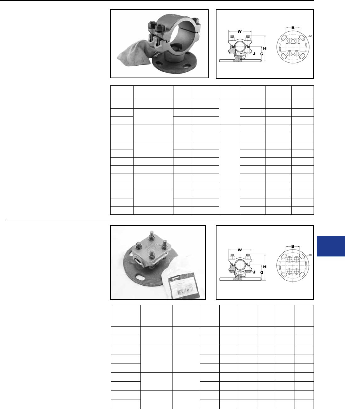
BURNDY®
Blue highlighted items are industry standard and most frequently ordered.
Canada: 1-800-387-6487 www.burndy.com US: 1-800-346-4175
TYPE UH
BUS SUPPORTS
For Use On Copper Tube
High copper alloy bus support for mounting tube
on a post or pedestal type insulator. Single bolt
allows rotation to any angle. Rotate cap 180° for
slip or rigid t. One wrench installation. Supplied
with hardware for mounting to cap of insulator.
Specify base mounting hardware, if required, by
adding sufx “B” to catalog number.
Material: Copper Alloy
Hardware: DURIUM™ Silicon Bronze
Notes :
• One wrench installation
• Specify base mounting hardware, if
required, by adding sufx “-B” to catalog
number.
• For other sizes and availability, please
contact factory.
Substation
Copper Bolted Bus Support | 230kV
Catalog
Number
Copper Pipe
Size BC G J
Dia. B H W
UH143 3/4 IPS 3 2.00
3/8
2.50 2.88 2.63
UH153 1 IPS 3 2.00 2.50 3.00 2.88
UH155 5 2.25 2.50 3.25 2.88
UH163 1 1/4 IPS 3 2.25
1/2
2.69 3.44 3.50
UH165 5 2.38 2.69 3.56 3.50
UH173 1 1/2 IPS 3 2.50 3.00 3.81 3.81
UH175 5 2.50 3.00 3.81 3.81
UH183 2 IPS 3 2.75 3.00 4.31 4.63
UH185 2 IPS 5 2.75 3.00 4.31 4.63
UH193 2 1/2 IPS 3 3.13 3.00 5.00 5.25
UH195 5 3.13 3.00 5.00 5.25
UH203 3 IPS 3 3.63
5/8
3.25 5.81 6.19
UH205 5 3.63 3.25 5.81 6.19
UH225 4 IPS 5 4.50 3.25 7.25 7.50
TYPE UHR
BUS SUPPORTS
For Use On Copper Cable or Tube
High copper alloy bus support clamp for mounting
a wide range of cable or tube on post or pedestal
type insulators. Single bolt allows rotation to any
angle. Supplied with hardware for mounting to cap
of insulator. Specify base mounting hardware, if
required, by adding sufx “-B” to catalog number.
Material: Copper Alloy
Hardware: DURIUM™ Silicon Bronze
Notes :
• One wrench installation
• Specify base mounting hardware, if
required, by adding sufx “-B” to catalog
number
• For other sizes and availability, please
contact factory
* With maximum conductor in place.
Catalog
Number
Copper
Stranded
Range
Copper
Pipe
Size
BC G J
Dia. B H W
UHR133 6 AWG -
500 kcmil
1/8 IPS -
1/2 IPS
3 1.75 3/8 3.63 3.00 2.25
UHR135 5 2.13 3/8 3.63 3.38 2.25
UHR153
4/0 AWG -
1250 kcmil
1/4 IPS -
1 IPS
3 2.00 3/8 3.75 3.50 2.75
UHR153SS 3 2.00 3/8 3.75 3.50 2.75
UHR155 5 2.25 3/8 3.75 3.75 2.75
UHR173 750 kcmil -
2500 kcmil
3/4 IPS -
1 1/2 IPS
3 2.50 1/2 2.88 4.25 3.94
UHR175 5 2.50 1/2 2.88 4.25 3.94
UHR183 N/A 1 1/4 IPS -
2 IPS
3 2.75 1/2 2.81 4.75 4.63
UHR185 5 2.75 1/2 2.81 4.75 4.63
L-17
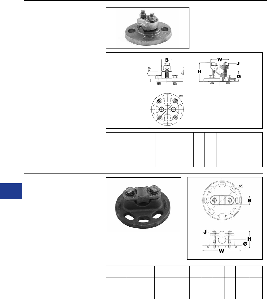
BURNDY®
Blue highlighted items are industry standard and most frequently ordered.
US: 1-800-346-4175 www.burndy.com Canada: 1-800-387-6487
TYPE LH
BUS SUPPORTS
For Use On Copper Cable or Tube
High copper alloy, light duty bus support for
mounting a wide range of cable or tube on post or
pedestal type insulators. One-wrench installation.
Supplied with hardware for mounting to cap of
insulator. Specify base mounting hardware, if
required, by adding sufx “-B” to Catalog No.
Material: Copper Alloy
Hardware: DURIUM™ Silicon Bronze
Notes :
• One wrench installation.
• Specify base mounting hardware, if
required, by adding sufx “-B” to catalog
number.
• For applications requiring heavier duty
product, please see our UH product line.
• For other sizes and availability, please
contact factory.
Substation
Copper Bolted Bus Support | 230kV
Catalog
Number Tube Stranded
Conductor BC G J
Dia. B H W
LH283 N/A 6 AWG-4/0 AWG 3 1.25 3/8 1.69 2.62 4.25
LH343 1/4 IPS -1/2 IPS 2/0 AWG-500 kcmil 3 1.38 3/8 1.38 2.50 4.25
LH453 1/2 IPS-1 IPS 500 kcmil-1250 kcmil 3 1.50 1/2 1.62 3.19 4.44
TYPE LHR
BUS SUPPORTS
For Use On Cable Or Tube To
Insulator
High copper alloy, bus support for mounting a wide
range of cable or tube on post or pedestal type
insulators. One-wrench installation. Supplied with
hardware for mounting to cap of insulator.
Material: Copper Alloy
Hardware: DURIUM™ Silicon Bronze
Notes :
• One wrench installation.
• Specify base mounting hardware, if
required, by adding sufx “-B” to Catalog
Number.
• For applications requiring heavier duty
product, please see our UH product line.
• For other sizes and availability, please
contact factory.
Catalog
Number Tube Stranded
Conductor BC G J
Dia. B H W
LHR293 1/8 IPS-1/4 IPS 8 AWG-250 kcmil 3 1.23 3/8 1.00 2.03 4.25
LHR443 1/4 IPS-3/4 IPS 4/0 AWG-1000
kcmil
3 1.31 3/8 1.38 2.67 4.25
LHR445 5 1.33 3/8 1.00 2.51 6.25
L-18
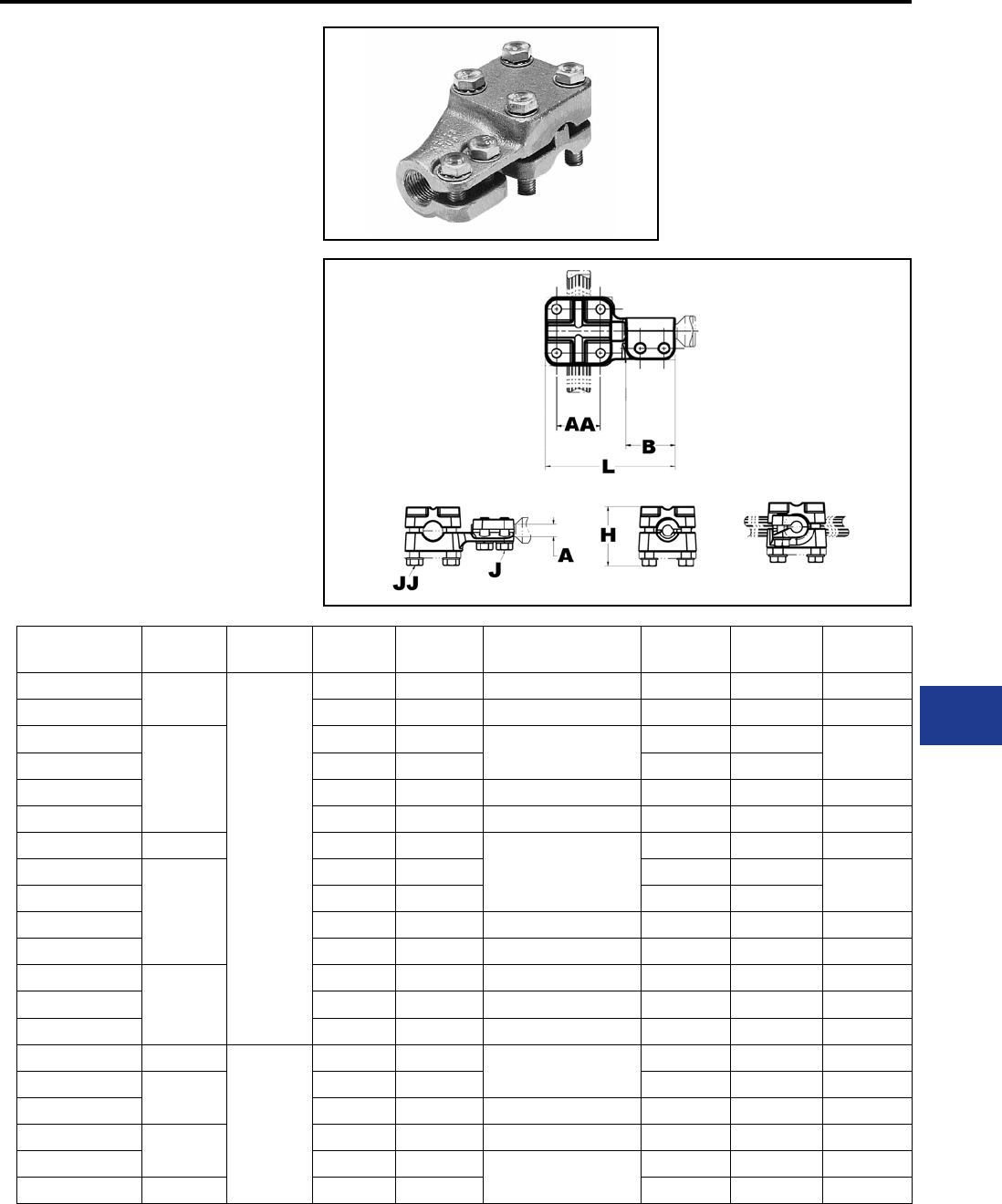
BURNDY®
Blue highlighted items are industry standard and most frequently ordered.
Canada: 1-800-387-6487 www.burndy.com US: 1-800-346-4175
Substation
Copper Bolted Stud Connector | 230kV
TYPE NDR
STUD CONNECTORS
For Copper Cable, Tube, Flat Bar
High copper alloy reversible and rotatable cap stud
connector joins cable, tube and at bar in-line or
at right angles to equipment studs. Accommodates
a wide range of cables or tubes. One-wrench
installation.
Material: Copper Alloy
Hardware: DURIUM™ Silicon Bronze
Notes :
• Plated versions: add the required sufx
to the catalog number. -TN for regular
tin plating
• Please contact factory for other sizes,
combinations and availability
• One-wrench installation.
Catalog
Number
Stud
A
J
Dia.
Threads
per inch BAA
Stranded Cable
JJ
Dia. L H
NDR6334T13 1/2
3/8
13 1.62 6 AWG-500 kcmil 3/8 4.28 2.25
NDR6328T13 13 1.53 6 AWG-4/0 AWG 3/8 3.62 1.75
NDR6434T12
3/4
12 1.53 6 AWG-500 kcmil 3/8 4.09 2.24
NDR6434T16 16 1.53 3/8 4.09
NDR6428T16 16 1.53 6 AWG-4/0 AWG 3/8 3.60 1.74
NDR6444T16 16 1.53 2 AWG-1000 kcmil 1/2 4.66 2.82
NDR64534T14 7/8 14 1.53
6 AWG-500 kcmil
3/8 4.16 1.91
NDR6534T12
1
12 1.53 3/8 3.96 2.24
NDR6534T14 14 1.53 3/8 3.96
NDR6528T14 14 1.53 6 AWG-4/0 AWG 3/8 4.09 1.74
NDR6544T14 14 1.53 2 AWG-1000 kcmil 1/2 4.73 2.82
NDR65534T12
1-1/8
12 1.53 6 AWG-500 kcmil 3/8 3.97 2.24
NDR65528T12 12 1.53 6 AWG-4/0 AWG 3/8 4.12 1.75
NDR65544T12 12 1.53 2 AWG-1000 kcmil 1/2 4.66 2.82
NDR6748T12 1-1/2
1/2
12 2.03 4/0 AWG-2000 kcmil 1/2 5.78 3.25
NDR67548T12 1-3/4 12 2.03 1/2 6.56 2.51
NDR67544T12 12 2.03 2 AWG-1000 kcmil 1/2 6.28 3.12
NDR6848T12 212 2.03 4/0 AWG-2000 kcmil 1/2 6.56 2.82
NDR6844T12 12 2.03 2 AWG-1000 kcmil 1/2 6.12 2.88
NDR68544T12 2-1/4 12 2.50 1/2 6.81 3.12
L-19
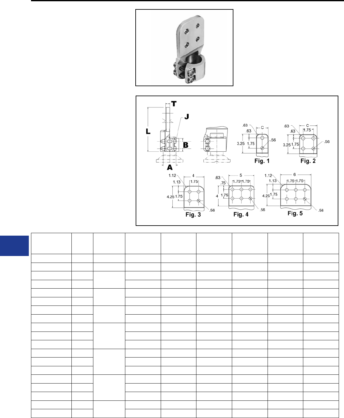
BURNDY®
Blue highlighted items are industry standard and most frequently ordered.
US: 1-800-346-4175 www.burndy.com Canada: 1-800-387-6487
Substation
Copper Bolted Stud Connector | 230kV
TYPE FD
STUD CONNECTORS
For Stud to Flat Bar
High copper alloy stud connector allows bolting
cable and tubing terminals to equipment studs.
Hex head captured bolts provide one-wrench
installation. One pad contact surface is on
centerline of stud. Pad is nished on both sides. All
pads are four hole NEMA drilled.
Material: Copper Alloy
Hardware: DURIUM™ Silicon Bronze
Notes :
• Plated versions: add the required sufx
to the catalog number. -TN for regular
tin plating
• Pad is nished on both sides
• Amperage rating given is for indoor
conditions
• Please contact factory for other sizes,
combinations and availability
• One-wrench installation
Catalog
Number
Fig.
#Stud A Threads per
inch
Nominal
Ampere
Rating
BJ
Dia. L T
FD64C5T16 2 3/4 16 1000 1.75 3/8 5.72 5/16
FD65C6T14 2 1 14 1075 1.75 3/8 5.72 3/8
FD655C6 21-1/8 12 1075 1.75 3/8 5.80 3/8
FD655D6 3 12 1300 1.75 3/8 6.86 3/8
FD66C6 21-1/4 12 1075 1.75 3/8 5.78 3/8
FD66D6 3 12 1300 1.75 3/8 6.84 3/8
FD675C8 21-3/4 12 1100 2.18 1/2 6.32 1/2
FD675D8 3 12 1450 2.18 1/2 7.39 1/2
FD68C8 2
2
12 1100 2.18 1/2 6.35 1/2
FD68D8 3 12 1450 2.18 1/2 7.42 1/2
FD68D12 3 12 2100 2.18 1/2 7.42 3/4
FD685C8 2
2-1/4
12 1100 2.50 1/2 6.71 1/2
FD685D8 3 12 1450 2.50 1/2 7.77 1/2
FD685D12 3 12 2100 2.50 1/2 7.77 3/4
FD69C8 2
2-1/2
12 1100 2.50 1/2 6.77 1/2
FD69D8 3 12 1450 2.50 1/2 8.03 1/2
FD69D12 3 12 2100 2.50 1/2 8.03 3/4
FD70D12 3312 2100 2.88 5/8 8.26 3/4
FD70D16 3 12 3000 2.88 5/8 8.24 1
L-20
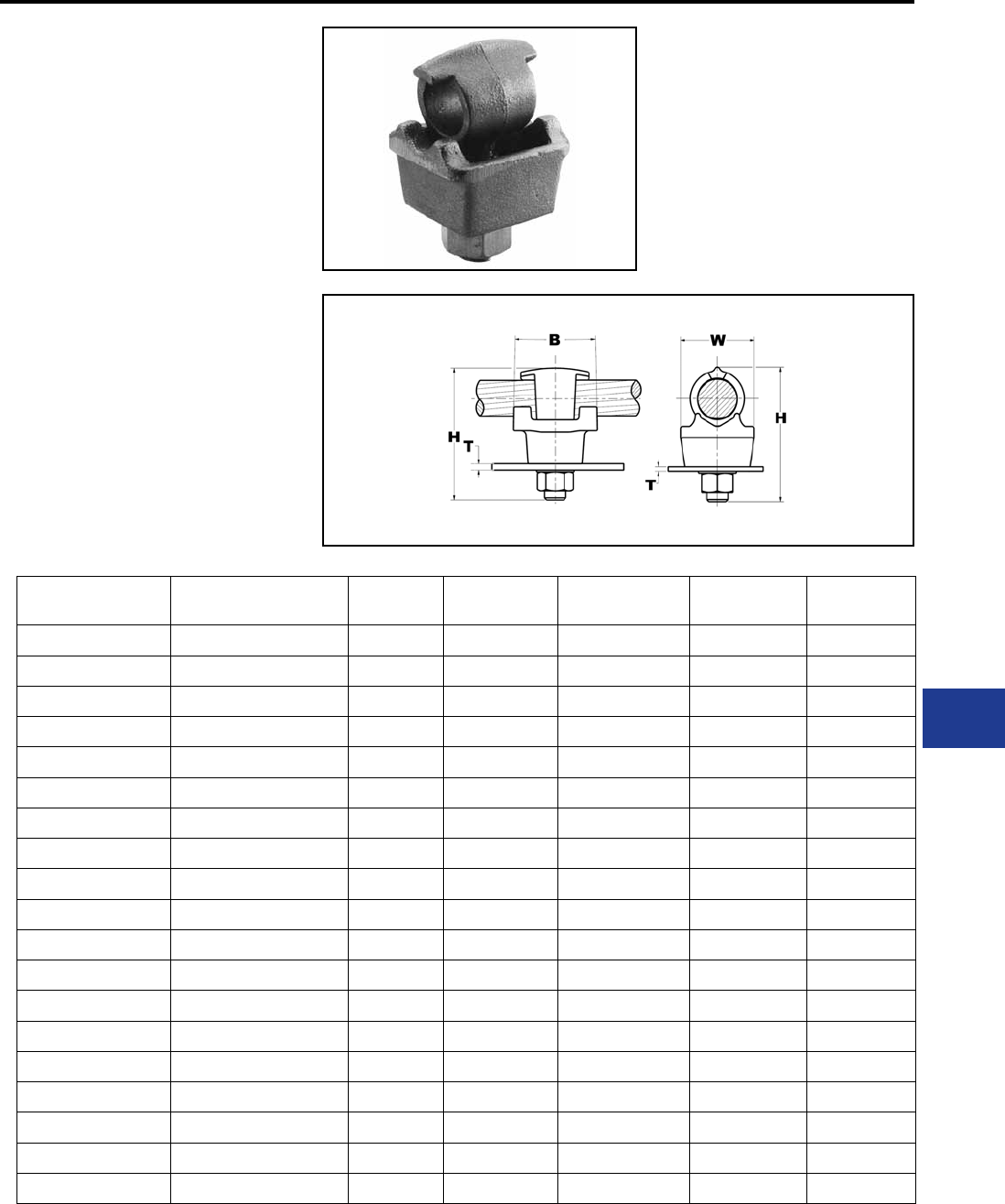
BURNDY®
Blue highlighted items are industry standard and most frequently ordered.
Canada: 1-800-387-6487 www.burndy.com US: 1-800-346-4175
TYPE QGFL
BARTAP™
For Copper Cable to Flat
High copper alloy BARTAP™ for joining a range of
cable to bar or pad. One-wrench installation.
Material: Copper Alloy
Notes :
• Can be installed side by side or in-line
on NEMA drilled bar.
Substation
Copper BARTAP™ | 230kV
Catalog
Number
Copper
Conductor B H J
Dia.
T
(Max) W
QGFL1CB1 #10 Sol-#1 Str 1-1/8 1-7/8 3/8 1/4 1
QGFL1CB1T6 #10 Sol-#1 Str 1-1/8 2-3/8 3/8 3/4 1
QGFL26B1 #8 Sol-#2/0 Str 1-1/4 2-1/8 3/8 1/4 1-1/8
QGFL26B1T6 #8 Sol-#2/0 Str 1-1/4 2-5/8 3/8 3/4 1-1/8
QGFL26B2* #8 Sol-#2/0 Str 1-1/4 2-8/25 1/2 1/4 1-1/8
QGFL26B2T6* #8 Sol-#2/0 Str 1-1/2 2-40/50 1/2 3/4 1-1/8
QGFL29B1* #6 Str-250 kcmil 1-2/5 2-5/8 1/2 1/4 1-3/8
QGFL29B1T6* #6 Str-250 kcmil 1-5/8 3-1/8 1/2 3/4 1-3/8
QGFL31B1* 2 AWG-350 kcmil 1-3/4 2-7/8 1/2 1/4 1-5/8
QGFL31B1T6* 2 AWG-350 kcmil 1-3/4 3-1/4 1/2 3/4 1-5/8
QGFL34B1 1/0 -500 kcmil 2 3-1/8 1/2 1/4 1-3/4
QGFL34B1T6 1/0 -500 kcmil 2 3-5/8 1/2 3/4 1-3/4
QGFL39B1 350 kcmil-750 kcmil 2-1/4 3-1/4 1/2 1/4 1-3/4
QGFL39B1T6 350 kcmil-750 kcmil 2-1/4 3-5/8 1/2 3/4 1-3/4
QGFL44B1 750 kcmil-1000 kcmil 2-1/4 3-3/8 1/2 1/4 2-1/8
QGFL44B1T6 750 kcmil-1000 kcmil 2-1/4 4-1/8 1/2 3/4 2-1/8
QGFL46B1 1000 kcmil-1500 kcmil 2-1/4 4 1/2 1/4 2-1/2
QGFL46B1T6 1000 kcmil-1500 kcmil 2-1/4 4-1/2 1/2 3/4 2-1/2
QGFL48B1 1500 kcmil-2000 kcmil 2-1/4 4-3/4 1/2 1/4 3
L-21
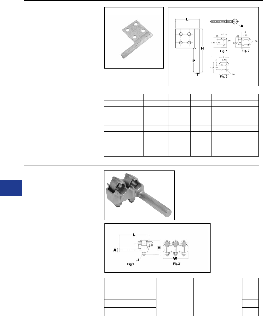
BURNDY®
Blue highlighted items are industry standard and most frequently ordered.
US: 1-800-346-4175 www.burndy.com Canada: 1-800-387-6487
TYPE FCB
TRANSFORMER TAP ADAPTERS
For Use On Copper And
Aluminum
Cast in one piece from copper alloy. Transformer
tap adapter designed to accommodate from 1
to 6 NEMA drilled copper or aluminum terminal
taps from a single secondary transformer outlet.
Tin-plated. Order mounting hardware and tap
terminals separately.
Material: Copper
Notes :
• Plated versions: add the required sufx
to the catalog number. -TN for regular
tin plating
• Please contact factory for other sizes,
combinations and availability
Substation
Transformer Tap Adapter | 230kV
TYPE E-C-G
TAP ADAPTERS
For Use On Copper Cable
Multi-tap, range-taking cast copper alloy connector
designed to take 2, 3 or 4 conductors from a single
secondary transformer outlet.
Material: Copper Alloy
Notes :
• Plated versions: add the required sufx
to the catalog number. -TN for regular
tin plating
• Please contact factory for other sizes,
combinations and availability
Catalog
Number
Number of
Conductors
Conductor
Size
A
Dia. H J L W
E2C34G1 2
1/0 -500
kcmil 0.78 3.88 1/2 6.25
3.50
E3C34G1 3 5.25
E4C34G1 4 6.88
Catalog Number A H P T L
FCB63-2NP300 1/2 5.00 3.00 0.25 3.50
FCB63-4N 1/2 5.25 2.25 0.25 3.75
FCB63-6N 1/2 5.25 2.25 0.25 5.50
FCB64-2NP300 3/4 5.00 3.00 0.25 3.75
FCB64-44NP50 3/4 9.00 5.00 0.25 5.00
FCB644G4 3/4 7.50 4.50 0.25 4.25
FCB64-4N 3/4 5.75 2.75 0.25 4.00
FCB64-6N 3/4 5.75 2.75 0.25 5.75
FCB65-4N 1 7.00 4.00 0.25 4.25
L-22
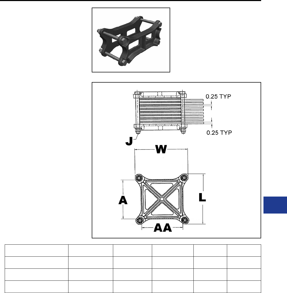
BURNDY®
Blue highlighted items are industry standard and most frequently ordered.
Canada: 1-800-387-6487 www.burndy.com US: 1-800-346-4175
TYPE HFBW
BAR CLAMPS
For Use On Copper Bar
The clamp assembly eliminates the need for
drilling the at bar and may be used in either indoor
and outdoor applications. The open web design
provides a uniform clamping pressure while
minimizing the weight of the connector.
Material: Copper Alloy
Notes :
• Please contact factory for other sizes,
combinations and availability.
Substation
Bar Clamp | 230kV
Catalog Number A AA J Dia. L W
HFB44G30W 4.00 4.00 1/2 5.75 5.75
HFB44G31W 4.00 4.00 1/2 5.75 5.75
HFB44G32W 4.00 4.00 1/2 5.75 5.75
L-23
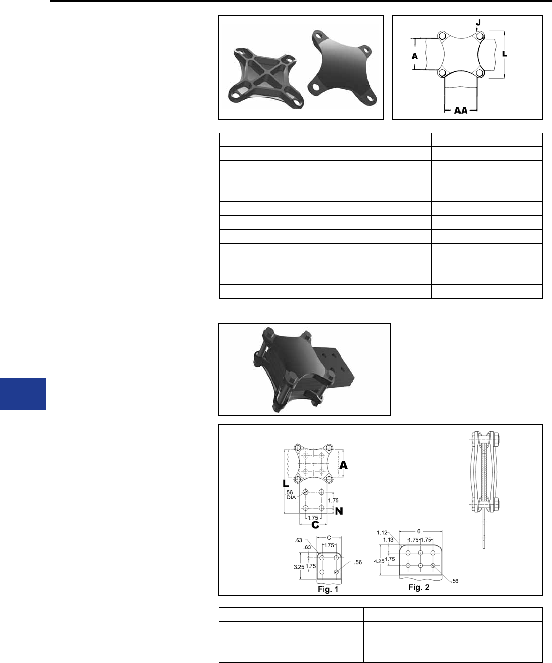
BURNDY®
Blue highlighted items are industry standard and most frequently ordered.
US: 1-800-346-4175 www.burndy.com Canada: 1-800-387-6487
TYPE HFB-P1
BAR CLAMP ASSEMBLY
COMPONENTS
For Use On Copper Bar
To build your own high strength clamp assembly
for multiple at bar using type HFB-P1 bar clamps
and clamping hardware, the following tables have
been provided. The clamp assembly eliminates the
need for drilling the at bar and may be used in
either indoor and outdoor applications.
Material: Copper Alloy
Notes :
• Please contact factory for other sizes,
combinations and availability
Substation
Bar Clamp | 230kV
Catalog Number A AA J Dia. L
HFB22P1 2.00 2.00 3/8 4.38
HFB33P1 3.00 3.00 3/8 4.38
HFB42P1 4.00 2.00 3/8 5.75
HFB44P1 4.00 4.00 1/2 5.75
HFB52P1 5.00 2.00 1/2 6.75
HFB53P1 5.00 3.00 1/2 6.75
HFB54P1 5.00 4.00 1/2 6.75
HFB55P1 5.00 5.00 5/8 7.13
HFB62P1 6.00 2.00 1/2 7.75
HFB63P1 6.00 3.00 1/2 7.75
HFB64P1 6.00 4.00 1/2 7.75
TYPE HFB-N
BAR CLAMP TAP PAD ADAPTERS
For Use On Copper Bar
High conductivity copper, tap pad adapter provides
a NEMA drilled contact pad when assembled to the
HFB-P1 clamps. Tap connections can be made
from copper bus bar(s) without drilling, by bolting
standard mechanical or compression terminal
pads directly to the pre-drilled tap pad adapter.
Material: Copper
Notes :
• Please contact factory for other sizes,
combinations and availability
Catalog Number A C L N
HFB33-4N 3.00 3.00 7.00 0.62
HFB44-4N 4.00 4.00 9.12 1.12
HFB66-6N 6.00 6.00 11.31 1.12
L-24
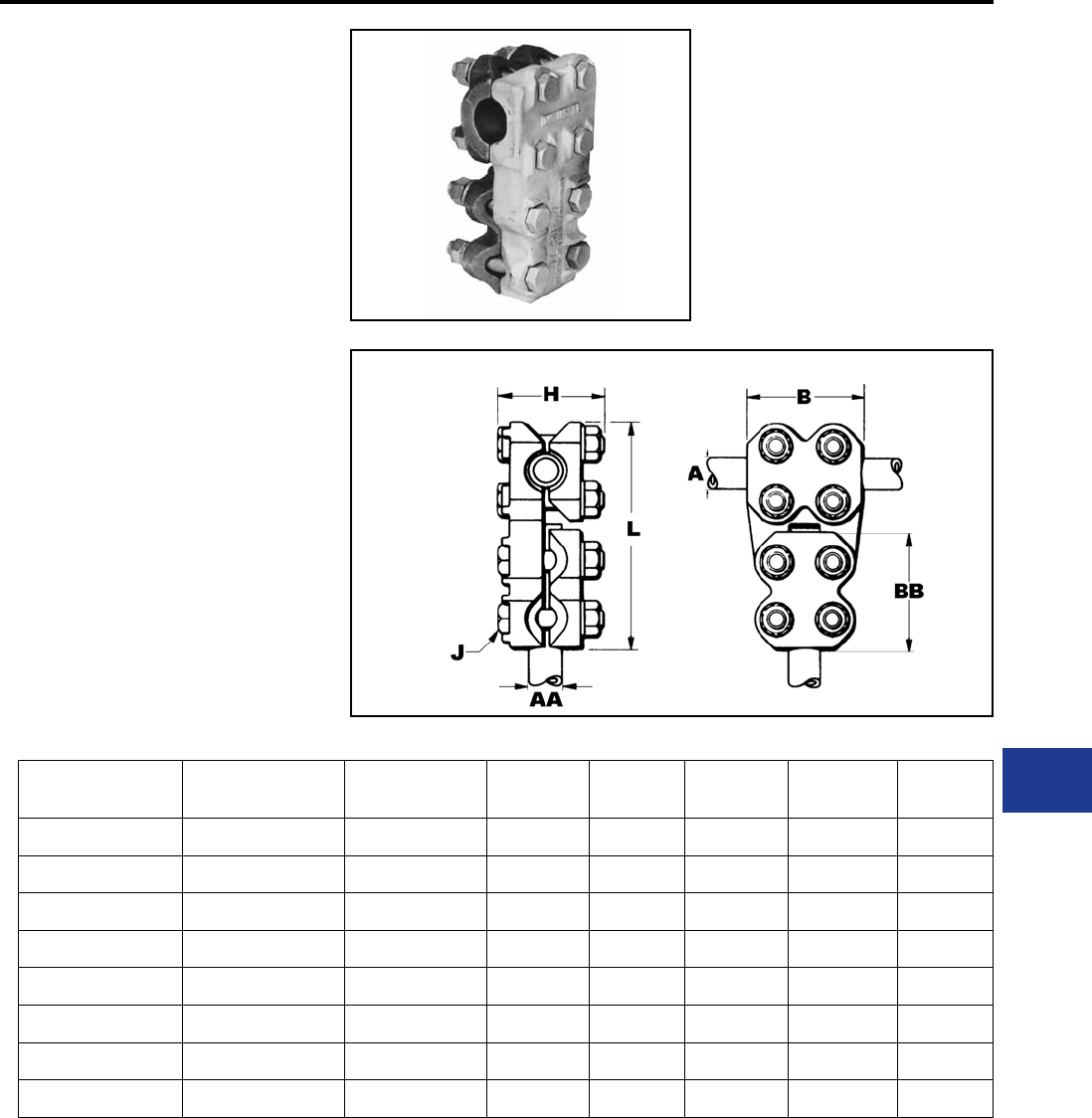
BURNDY®
Blue highlighted items are industry standard and most frequently ordered.
Canada: 1-800-387-6487 www.burndy.com US: 1-800-346-4175
TYPE NNT
T-CONNECTOR
For Aluminum and Copper
Tube to Tube
Aluminum alloy T-Connector for tubing run and tap.
Properly proportioned to permit use on copper-
aluminum conductor combinations. Captured
hex head bolts permit one-wrench installation.
PENETROX™ joint compound recommended on
contact surfaces.
Material: Aluminum Alloy
Hardware: Aluminum Hardware
Notes :
• PENETROX™ A joint compound is
recommended on contact surfaces
• Please contact factory for other sizes,
combinations and availability
• One-wrench installation.
Substation
Aluminum T Connector
Catalog
Number
A - Run
tube
AA - Tap
tube BJ
Dia. BB L H
NNT15A15A 1 IPS 1 IPS 3.50 1/2 3.50 6.81 3.38
NNT16A16A 1 1/4 IPS 1 1/4 IPS 3.75 1/2 3.75 7.44 3.38
NNT17A17A 1 1/2 IPS 1 1/2 IPS 4.00 1/2 4.00 7.88 3.88
NNT18A18A 2 IPS 2 IPS 4.25 5/8 4.25 9.06 4.44
NNT19A19A 2 1/2 IPS 2 1/2 IPS 4.50 5/8 4.50 9.38 4.94
NNT20A20A 3 IPS 3 IPS 5.00 5/8 5.00 10.94 5.44
NNT21A20A 3 1/2 IPS 3 IPS 5.50 5/8 5.00 11.06 5.56
NNT22A22A 4 IPS 4 IPS 6.00 5/8 6.00 12.63 6.19
L-25
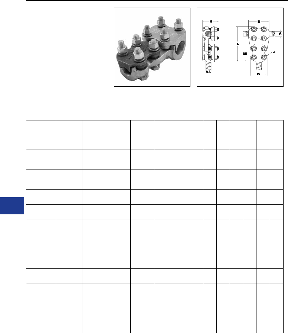
BURNDY®
Blue highlighted items are industry standard and most frequently ordered.
US: 1-800-346-4175 www.burndy.com Canada: 1-800-387-6487
TYPE NNTR
T-CONNECTOR
For Use On CABLE TO CABLE
Aluminum alloy T-Connector for a range of cable
run to range of cable tap. One-wrench installation.
Material: Aluminum Alloy
Hardware: Aluminum Hardware
Notes :
• PENETROX™ A joint compound is
recommended on contact surfaces
• Please contact factory for other sizes,
combinations and availability
• One-wrench installation.
Substation
Aluminum T Connector
Catalog
Number
A - Run Al
Cable A - Run ACSR Cable AA - Tap
Al Cable AA - Tap ACSR Cable B J
Dia. BB L H W
NNTR29A29A 1/0 AWG-
250 kcmil
1/0 (6/1) Raven AWG-
4/0 (6/1) Penquin AWG
1/0 AWG-
250 kcmil
1/0 (6/1) Raven AWG-
4/0 (6/1) Penquin AWG 2.75 1/2 2.75 5.56 2.56 2.50
NNTR32A25A 250 kcmil-
400 kcmil
4/0 (6/1) Penquin AWG-
397.5 (18/1) Chickadee
kcmil
4 AWG-
1/0 AWG
4 (6/1) Swan AWG-
1/0 (6/1) Raven AWG 1.88 1/2 1.88 4.81 2.56 2.28
NNTR32A32A 250 kcmil-
400 kcmil
4/0 (6/1) Penquin AWG-
397.5 (18/1) Chickadee
kcmil
250 kcmil-
400 kcmil
4/0 (6/1) Penquin AWG-
397.5 (18/1) Chickadee
kcmil
3.00 1/2 3.00 5.94 2.56 2.63
NNTR36A29A 350 kcmil-
600 kcmil
336.4 (18/1) Merlin kcmil-
477.0 (18/1) Pelican kcmil
1/0 AWG-
250 kcmil
1/0 (6/1) Raven AWG-
4/0 (6/1) Penquin AWG 3.25 1/2 2.75 5.31 2.56 2.50
NNTR36A36A 350 kcmil-
600 kcmil
336.4 (18/1) Merlin kcmil-
477.0 (18/1) Pelican kcmil
350 kcmil-
600 kcmil
336.4 (18/1) Merlin kcmil-
477.0 (18/1) Pelican kcmil 3.25 1/2 3.25 6.31 2.56 2.75
NNTR42A32A 600 kcmil-
900 kcmil
477.0 (18/1) Pelican kcmil-
795 (54/7) Condor kcmil
250 kcmil-
400 kcmil
4/0 (6/1) Penquin AWG-
397.5 (18/1) Chickadee
kcmil
3.50 1/2 3.00 6.38 3.13 2.63
NNTR42A36A 600 kcmil-
900 kcmil
477.0 (18/1) Pelican kcmil-
795 (54/7) Condor kcmil
350 kcmil-
600 kcmil
336.4 (18/1) Merlin kcmil-
477.0 (18/1) Pelican kcmil 3.50 1/2 3.25 6.63 3.13 2.75
NNTR42A42A 600 kcmil-
900 kcmil
477.0 (18/1) Pelican kcmil-
795 (54/7) Condor kcmil
600 kcmil-
900 kcmil
477.0 (18/1) Pelican kcmil-
795 (54/7) Condor kcmil 3.50 1/2 3.50 6.88 3.13 3.00
NNTR45A45A 900 kcmil-
1250 kcmil
715.5 (54/7) Crow kcmil-
1113 (54/19) Finch kcmil
900 kcmil-
1250 kcmil
715.5 (54/7) Crow kcmil-
1113 (54/19) Finch kcmil 3.75 1/2 3.75 7.31 3.25 3.19
NNTR46A42A 1250 kcmil-
1600 kcmil
1113 (54/19) Finch kcmil-
1431 (54/19) Plover kcmil
600 kcmil-
900 kcmil
477.0 (18/1) Pelican kcmil-
795 (54/7) Condor kcmil 3.75 1/2 3.50 7.25 3.44 3.00
NNTR46A46A 1250 kcmil-
1600 kcmil
1113 (54/19) Finch kcmil-
1431 (54/19) Plover kcmil
1250 kcmil-
1600 kcmil
1113 (54/19) Finch kcmil-
1431 (54/19) Plover kcmil 4.38 5/8 4.38 8.31 3.69 3.75
NNTR48A48A 1500 kcmil-
2000 kcmil
1272 (54/19) Pheasant
kcmil-
1780 (54/19) kcmil
1500 kcmil-
2000 kcmil
1272 (54/19) Pheasant
kcmil-
1780 (54/19) kcmil
4.50 5/8 4.50 8.63 3.81 3.88
L-26
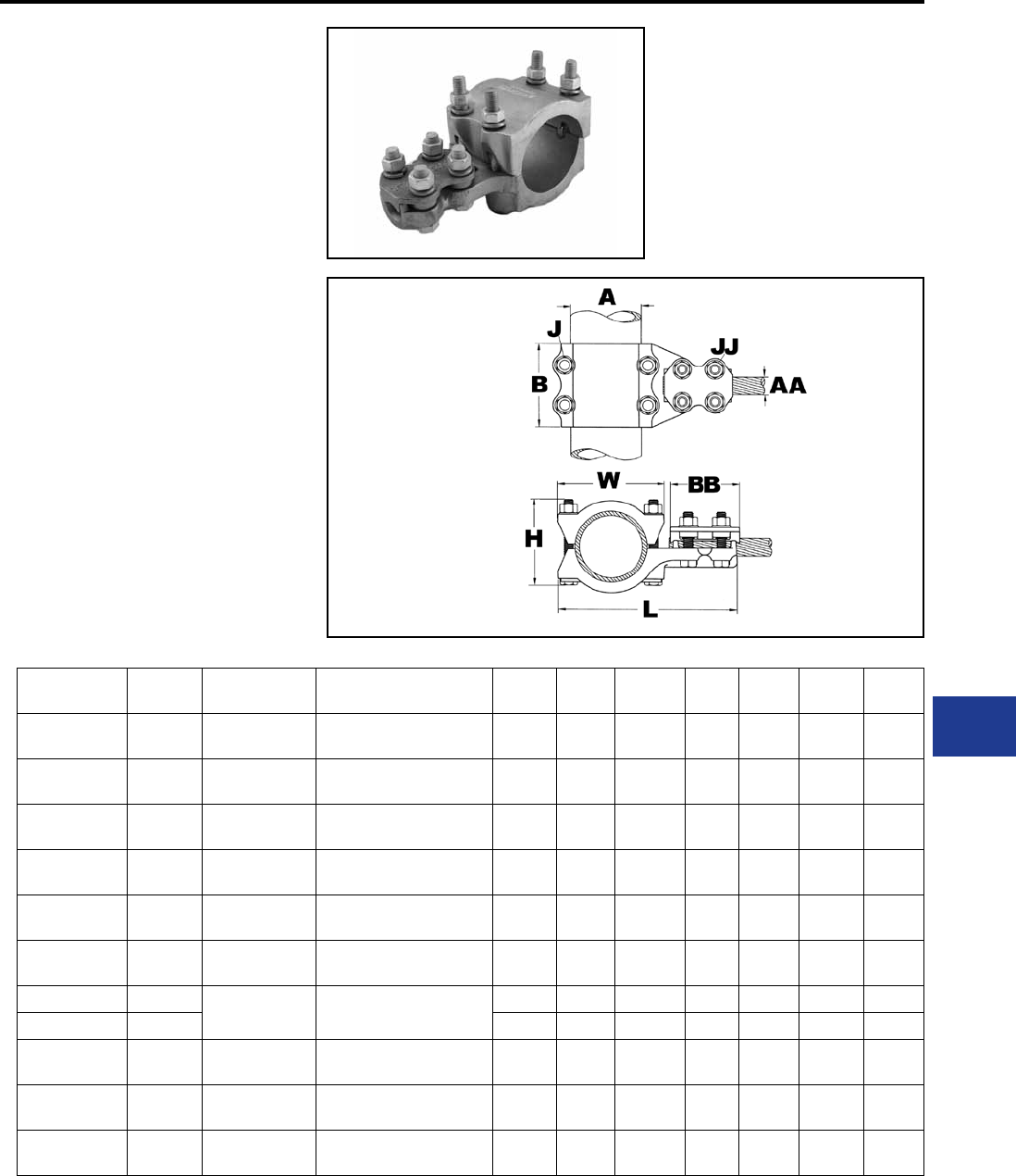
BURNDY®
Blue highlighted items are industry standard and most frequently ordered.
Canada: 1-800-387-6487 www.burndy.com US: 1-800-346-4175
TYPE NNTR
T-CONNECTOR
For Use On TUBE TO CABLE
Aluminum alloy T-Connector for tube run, range
of cable tap. Properly proportioned to permit use
on copper-aluminum combinations. One-wrench
installation. PENETROX™ joint compound
recommended on contact surfaces.
Material: Aluminum Alloy
Hardware: Aluminum Hardware
Notes :
• PENETROX™ A joint compound is
recommended on contact surfaces
• Please contact factory for other sizes,
combinations and availability
• One-wrench installation.
Substation
Aluminum T Connector
Catalog
Number
A - Run
Al Pipe
AA - Tap
Al Cable AA - Tap ACSR Cable B J
Dia. BB L H JJ
Dia. W
NNTR14A29A 3/4 IPS 1/0 AWG-
250 kcmil
1/0 (6/1) Raven AWG-
4/0 (6/1) Penquin AWG 3.25 1/2 2.75 5.81 3.06 0.50 2.50
NNTR15A36A 1 IPS 350 kcmil-
600 kcmil
336.4 (18/1) Merlin kcmil-
477.0 (18/1) Pelican kcmil 3.50 1/2 3.25 6.56 3.31 0.50 2.75
NNTR15A42A 1 IPS 600 kcmil-
900 kcmil
477.0 (18/1) Pelican kcmil-
795 (54/7) Condor kcmil 3.50 1/2 3.50 6.81 3.31 0.50 3.00
NNTR16A29A 1 1/4 IPS 1/0 AWG-
250 kcmil
1/0 (6/1) Raven AWG-
4/0 (6/1) Penquin AWG 3.75 1/2 2.75 6.44 3.31 0.50 2.50
NNTR16A32A 1 1/4 IPS 250 kcmil-
400 kcmil
4/0 (6/1) Penquin AWG-
397.5 (18/1) Chickadee kcmil 3.75 1/2 3.12 6.69 3.31 0.50 2.63
NNTR16A42A 1 1/4 IPS 600 kcmil-
900 kcmil
477.0 (18/1) Pelican kcmil-
795 (54/7) Condor kcmil 3.75 1/2 3.50 7.19 3.31 0.50 3.00
NNTR17A29A 1 1/2 IPS 1/0 AWG-
250 kcmil
1/0 (6/1) Raven AWG-
4/0 (6/1) Penquin AWG
4.00 1/2 2.75 6.69 3.81 0.50 2.50
NNTR18A29A 2 IPS 4.00 1/2 2.75 7.56 4.44 0.50 2.50
NNTR19A42A 2 1/2 IPS 600 kcmil-
900 kcmil
477.0 (18/1) Pelican kcmil-
795 (54/7) Condor kcmil 4.00 5/8 3.50 8.88 5.00 0.63 3.00
NNTR20A32A 3 IPS 250 kcmil-
400 kcmil
4/0 (6/1) Penquin AWG-
397.5 (18/1) Chickadee kcmil 4.00 1/2 3.00 9.00 5.44 0.50 2.63
NNTR22A46A 4 IPS 1250 kcmil-
1600 kcmil
1113 (54/19) Finch kcmil-
1431 (54/19) Plover kcmil 6.00 5/8 4.38 11.25 6.19 0.63 3.75
L-27
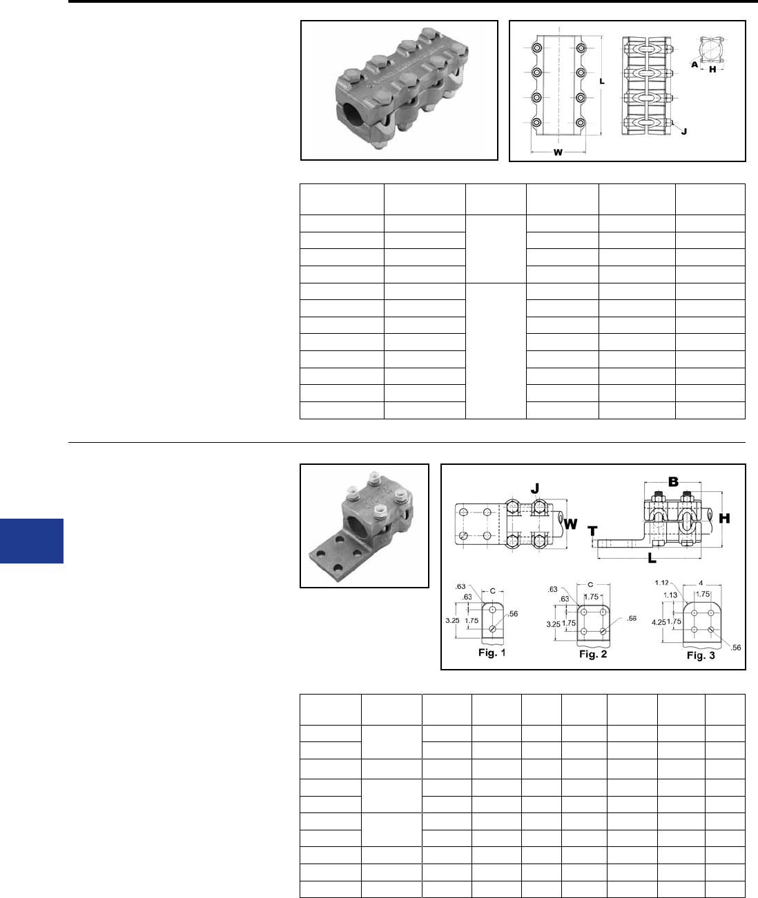
BURNDY®
Blue highlighted items are industry standard and most frequently ordered.
US: 1-800-346-4175 www.burndy.com Canada: 1-800-387-6487
TYPE NS-A
COUPLER
For Use On Aluminum Tube To
Tube
Aluminum alloy coupler for joining equal sizes of
tube end to end. Properly proportioned to permit
use on aluminum-copper conductor combinations.
One-wrench installation. PENETROX™ joint
compound recommended on contact surfaces.
Material: Aluminum Alloy
Hardware: Aluminum Hardware
Notes :
• PENETROX™ A joint compound is
recommended on contact surfaces
• Please contact factory for other sizes,
combinations and availability
Substation
Aluminum Bolted Coupler
Catalog
Number A - tube J
Dia. L H W
NS14A14A 3/4 IPS
1/2
6.75 2.06 2.80
NS15A15A 1 IPS 7.25 2.18 3.06
NS16A16A 1 1/4 IPS 7.75 3.50 3.41
NS17A17A 1 1/2 IPS 8.25 4.00 3.64
NS18A18A 2 IPS
5/8
8.75 4.62 4.50
NS19A19A 2 1/2 IPS 9.31 4.26 5.00
NS20A20A 3 IPS 10.25 5.62 5.63
NS21A21A 3 1/2 IPS 8.00 5.25 6.14
NS22A22A 4 IPS 12.00 5.94 6.62
NS23A23A 4 1/2 IPS 13.25 6.38 7.14
NS24A24A 5 IPS 14.38 6.94 7.70
NS86A86A 6 IPS 16.25 8.04 8.76
TYPE NA-A
TERMINAL
For Use On Tube To Flat
Aluminum alloy terminal for joining copper or
aluminum tube to copper or aluminum pad.
Material: Aluminum Alloy
Hardware: Aluminum Hardware
Notes :
• Properly proportioned to minimize
conductor corrosion due to galvanic
action. When properly used, this
item does not require use of
bimetallic plates. Please ask
BURNDY® Technical Support for
recommendations
• PENETROX™ A joint compound is
recommended on contact surfaces
• Please contact factory for other sizes,
combinations and availability
• One wrench installation
Catalog
Number Al tube B C J
Dia. L H T W
NA15A-2N 1 IPS 3.50 1.88 1/2 6.75 3.38 0.38 3.06
NA15A-4N 3.50 3.00 1/2 6.75 3.38 0.38 3.06
NA16A-2N 1 1/4 IPS 3.75 2.25 1/2 7.00 3.38 0.44 3.40
NA17A-2N 1 1/2 IPS 4.00 2.50 1/2 7.50 3.88 0.50 3.64
NA17A-4N 4.00 3.00 1/2 7.50 3.88 0.50 3.64
NA18A-2N 2 IPS 4.25 2.75 5/8 7.50 4.47 0.50 4.50
NA18A-4N 4.25 3.12 5/8 7.50 4.47 0.50 4.50
NA19A-4N 2 1/2 IPS 4.50 3.75 5/8 7.75 4.97 0.69 5.00
NA20A-4N 3 IPS 5.00 4.38 5/8 8.31 5.47 0.69 5.62
NA22A-4N 4 IPS 6.00 5.25 5/8 9.31 6.22 0.81 6.62
L-28
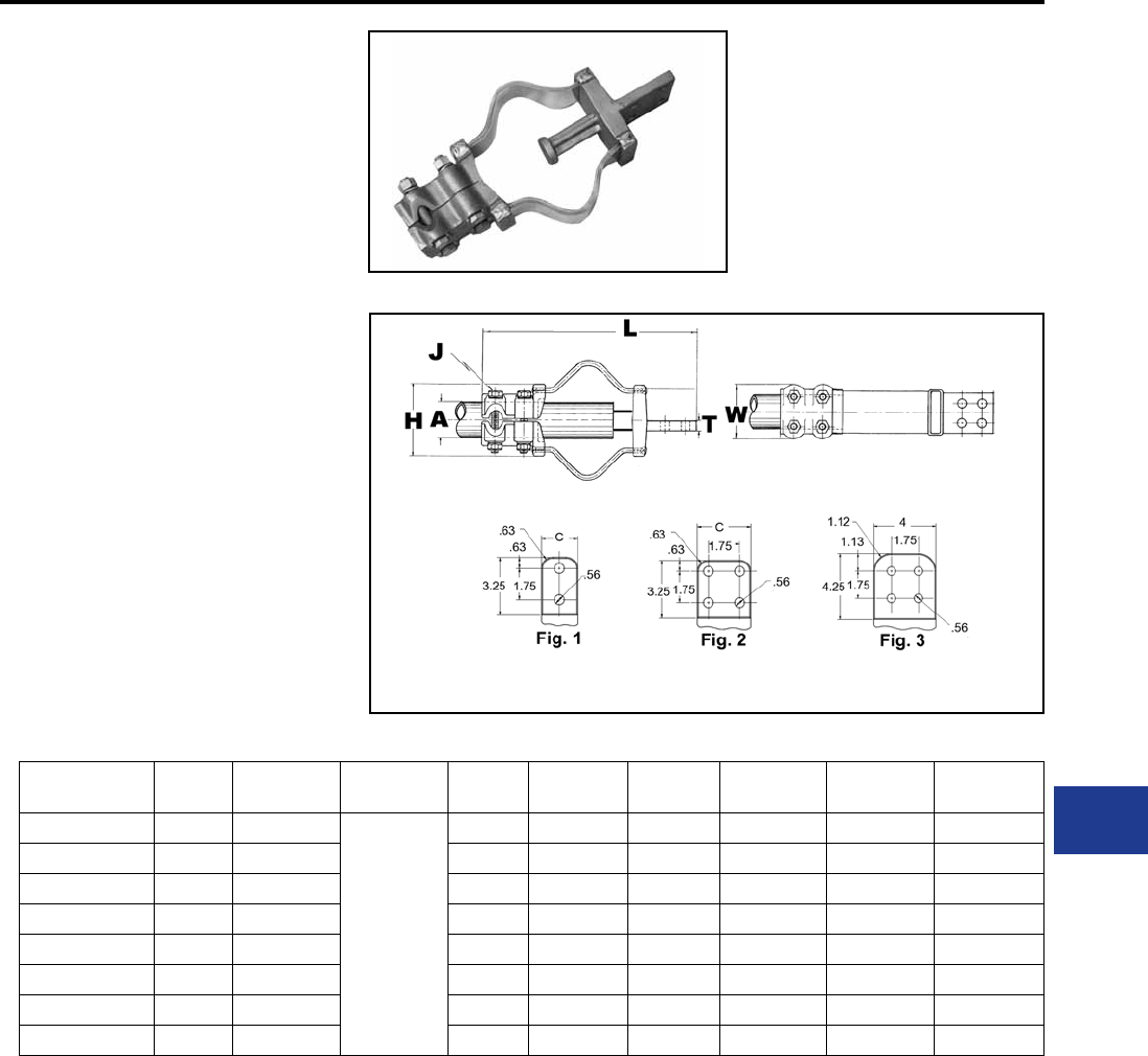
BURNDY®
Blue highlighted items are industry standard and most frequently ordered.
Canada: 1-800-387-6487 www.burndy.com US: 1-800-346-4175
TYPE XA-A
EXPANSION TERMINAL
For Use On Expansion Tube To Flat
Aluminum alloy expansion connector for joining
tube to copper or aluminum bar or equipment pads.
Flexible aluminum straps allow for longitudinal or
lateral movement and carries full current load of the
joint. PENETROX™ joint compound recommended
on contact surfaces. Pad contact surface is on
centerline of conductor.
Material: Aluminum Alloy
Hardware: Aluminum Hardware
Notes :
• PENETROX™ A joint compound is
recommended on contact surfaces
• One side of pad nished on centerline
of tubing. For nished pads on both
sides add sufx “-Q” to catalog number.
Substation
Aluminum Bolted Terminal l 230kV
Catalog
Number * Fig. # Al tube
Schd 40
Al tube
Schd 80 CJ
Dia. L H T W
XA15A-4N 2 1 IPS
N/A
3.00 1/2 13.19 3.70 0.38 3.06
XA16A-4N 2 1 1/4 IPS 3.00 1/2 13.62 4.00 0.44 3.41
XA18A-4N 2 2 IPS 3.12 5/8 15.50 5.26 0.50 4.50
XA19A-4N 2 2 1/2 IPS 3.75 5/8 16.94 5.72 0.69 5.00
XA20A-4N 2 3 IPS 4.38 5/8 18.52 6.80 0.69 5.62
XA21A-4N 2 3 1/2 IPS 4.75 5/8 20.00 7.60 0.81 6.12
XA22A-4N 2 4 IPS 5.25 5/8 21.00 8.16 0.81 6.62
XA24A-4N 2 5 IPS 6.50 5/8 24.15 9.74 0.81 7.69
* Conforms to 4-hole NEMA mounting standards.
L-29
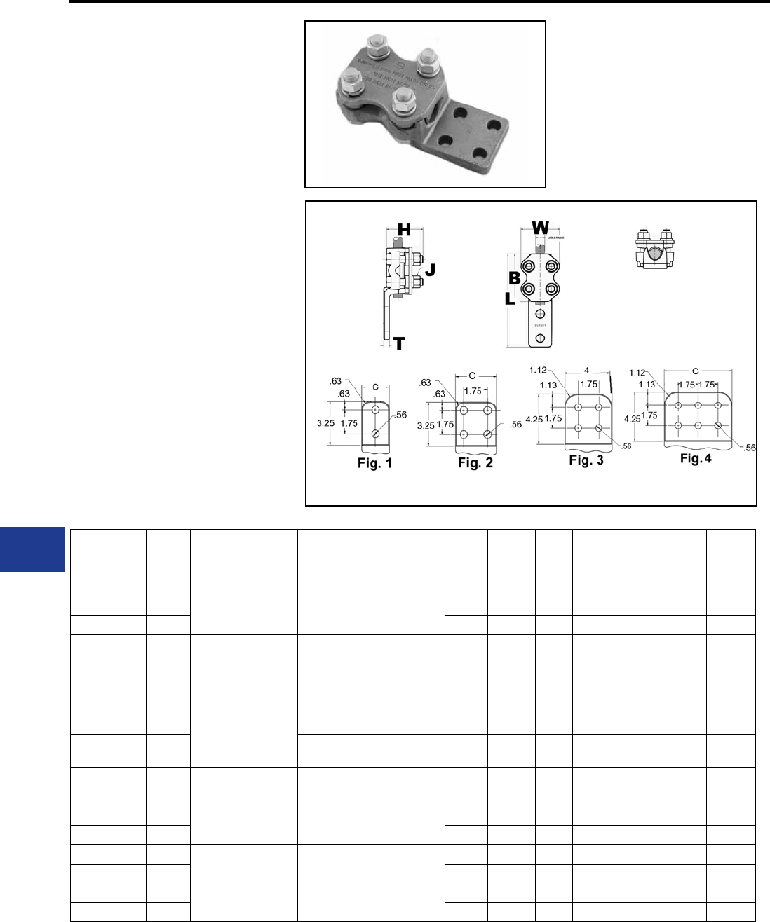
BURNDY®
Blue highlighted items are industry standard and most frequently ordered.
US: 1-800-346-4175 www.burndy.com Canada: 1-800-387-6487
TYPE NAR
TERMINAL
For Use On Cable To Pad
Aluminum alloy bolted type terminal for joining
aluminum cable to copper or aluminum pads.
Drilling in pad conforms to NEMA Standards.
PENETROX™ joint compound recommended on
contact surfaces.
Material: Aluminum Alloy
Hardware: Aluminum Hardware
Notes :
• Properly proportioned to minimize
conductor corrosion due to galvanic
action. When properly used, this item
does not require use of bimetallic plates.
Please ask BURNDY® Technical
Support for recommendations.
• PENETROX™ A joint compound is
recommended on contact surfaces.
• Please contact factory for other sizes,
combinations and availability.
• One-wrench installation.
Substation
Aluminum Bolted Terminal l 230kV
Catalog
Number Fig. # Aluminum Stranded Aluminum ACSR B J
Dia. L H C T W
NAR25A2N 1 4 AWG-1/0 AWG 4 (6/1) Swan AWG-
1/0 (6/1) Raven AWG 2.00 1/2 5.10 2.72 1.25 0.31 2.28
NAR29A2N 21/0 AWG-250 kcmil 1/0 (6/1) Raven AWG-
4/0 (6/1) Penquin AWG
2.75 1/2 6.06 2.75 1.38 0.31 2.50
NAR29A4N 2 2.88 1/2 6.06 2.75 3.00 0.31 3.00
NAR32A2N 2
250 kcmil-400 kcmil
4/0 (6/1) Penquin AWG-
397.5 (30/7) Larkspur kcmil 3.00 1/2 6.31 2.88 1.63 0.38 2.63
NAR32A4N 24/0 (6/1) Penquin AWG-
397.5 (30/7) Larkspur kcmil 3.00 1/2 6.31 2.88 3.00 0.38 3.00
NAR36A2N 2
350 kcmil-600 kcmil
336.4 (30/7) Oriole kcmil-
477. (30/7) Hen kcmil 3.25 1/2 6.63 2.81 1.69 0.38 2.75
NAR36A4N 2336.4 (30/7) Oriole kcmil-
477. (30/7) Hen kcmil 3.25 1/2 6.63 2.81 3.00 0.38 3.00
NAR42A2N 1600 kcmil-900 kcmil 477. (30/7) Hen kcmil-
795 (30/19) Mallard kcmil
3.50 1/2 6.81 3.31 2.00 0.50 3.00
NAR42A4N 2 3.50 1/2 6.81 3.31 3.00 0.50 3.00
NAR45A2N 1900 kcmil-1250 kcmil 715.5 (30/19) Redwing kcmil-
1113 (54/19) Finch kcmil
2.63 1/2 7.12 3.31 2.63 0.50 3.20
NAR45A4N 2 3.75 1/2 7.12 3.31 3.00 0.50 3.20
NAR46A2N 11250 kcmil-1600 kcmil 1113 (54/19) Finch kcmil-
1431 (54/19) Plover kcmil
4.38 5/8 7.69 3.69 2.75 0.56 3.75
NAR46A4N 2 4.38 5/8 7.69 3.69 3.00 0.56 3.75
NAR48A2N 11500 kcmil-2000 kcmil 1272 (54/19) Pheasant kcmil-
1780 (54/19) kcmil
4.50 5/8 7.88 3.94 2.75 0.69 3.88
NAR48A4N 2 4.50 5/8 7.88 3.94 3.00 0.69 3.88
L-30
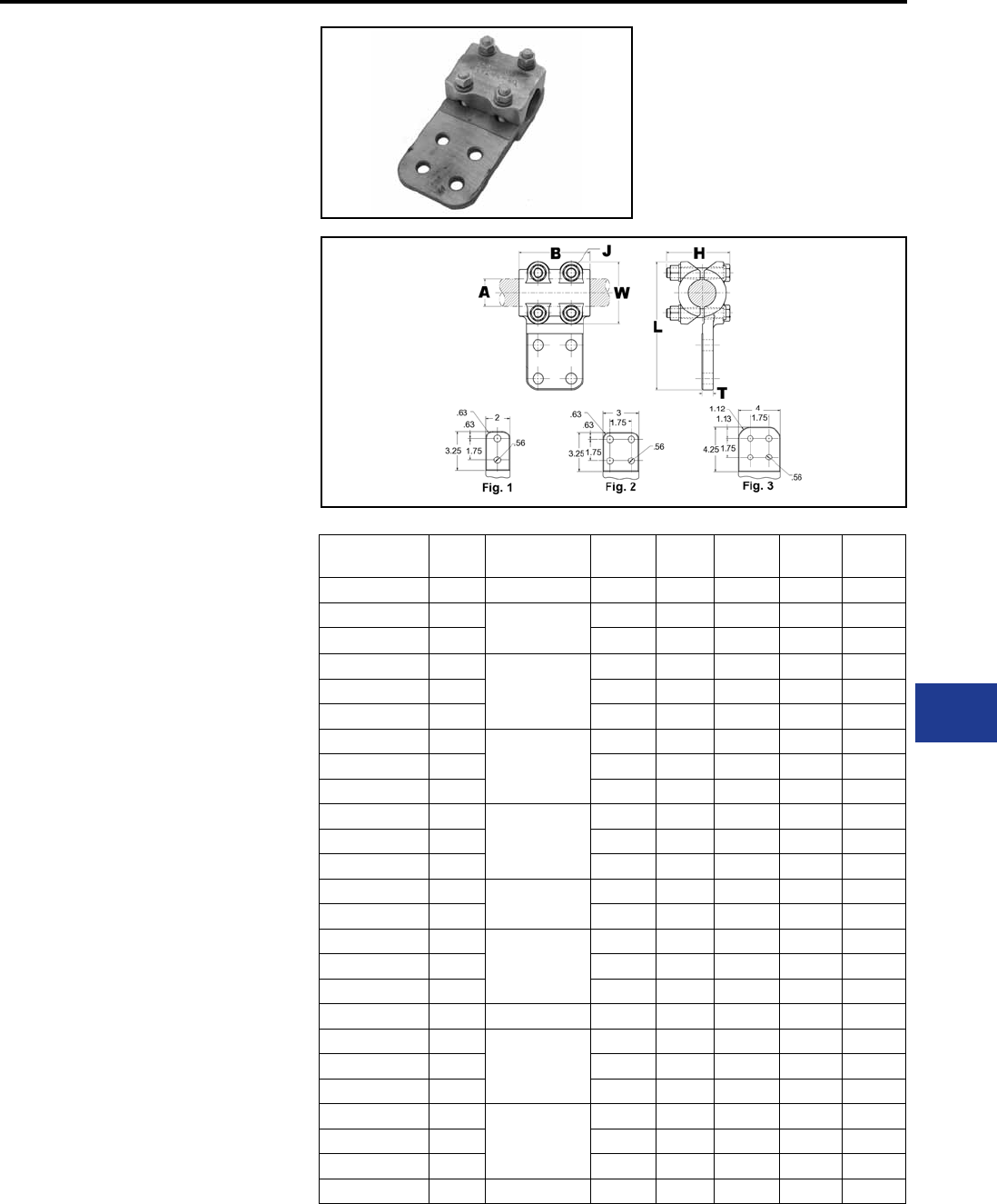
BURNDY®
Blue highlighted items are industry standard and most frequently ordered.
Canada: 1-800-387-6487 www.burndy.com US: 1-800-346-4175
TYPE NBC-A
BOLTED CONNECTOR
For Use On Pipe To Centerline Tap
Pad
Aluminum alloy bolted type terminal for joining
aluminum tube to copper or aluminum pads.
Drilling in pad conforms to NEMA Standards.
PENETROX™ joint compound recommended on
contact surfaces.
Material: Aluminum Alloy
Hardware: Aluminum Hardware
Notes :
• Properly proportioned to minimize
conductor corrosion due to galvanic
action. When properly used, this
item does not require use of
bimetallic plates. Please ask
BURNDY® Technical Support for
recommendations
• PENETROX™ A joint compound is
recommended on contact surfaces
• Please contact factory for other sizes,
combinations and availability
• One-wrench installation.
Substation
Aluminum T Connector
Catalog
Number Fig. # Al tube B J
Dia. L H T
NBC14A2N 1 3/4 IPS 3.25 1/2 6.56 3.50 3/8
NBC15A-2N 11 IPS 3.50 1/2 6.81 3.00 3/8
NBC15A34N 2 3.50 1/2 6.81 3.00 3/8
NBC16A2N 1
1 1/4 IPS
3.75 1/2 7.15 3.25 3/8
NBC16A34N 2 3.75 1/2 7.15 3.25 3/8
NBC16A44N 3 3.75 1/2 8.15 3.25 3/8
NBC17A2N 1
1 1/2 IPS
4.00 1/2 7.39 3.50 3/8
NBC17A34N 2 4.00 1/2 7.39 3.50 3/8
NBC17A44N 3 4.00 1/2 8.39 3.50 3/8
NBC18A2N 1
2 IPS
4.25 5/8 8.25 4.00 3/8
NBC18A34N 2 4.25 5/8 8.25 4.00 3/8
NBC18A-44N 3 4.25 5/8 9.25 4.00 3/8
NBC19A34N 22 1/2 IPS 4.50 5/8 8.75 4.50 1/2
NBC19A44N 3 4.50 5/8 9.75 4.50 1/2
NBC20A2N 1
3 IPS
5.00 5/8 9.37 4.50 1/2
NBC20A34N 2 5.00 5/8 9.37 4.50 1/2
NBC20A-44N 3 5.00 5/8 10.37 4.50 1/2
NBC21A44N 3 3 1/2 IPS 5.50 5/8 10.89 5.00 5/8
NBC22A2N 1
4 IPS
6.00 5/8 10.38 5.50 5/8
NBC22A34N 2 6.00 5/8 10.37 5.50 5/8
NBC22A44N 3 6.00 5/8 11.37 5.50 5/8
NBC24A2N 1
5 IPS
7.00 5/8 12.45 6.00 5/8
NBC24A34N 2 7.00 5/8 12.45 6.00 5/8
NBC24A44N 3 7.00 5/8 13.45 6.00 5/8
NBC86A44N 3 6 IPS 8.00 5/8 13.51 7.25 3/4
L-31
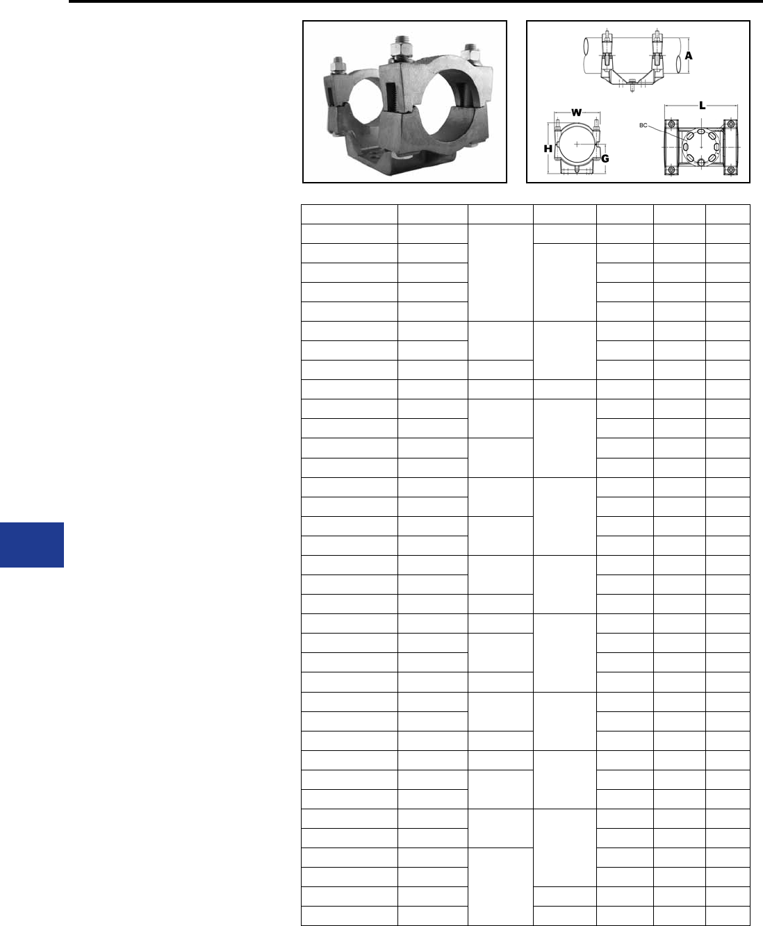
BURNDY®
Blue highlighted items are industry standard and most frequently ordered.
US: 1-800-346-4175 www.burndy.com Canada: 1-800-387-6487
TYPE UHG
BUS SUPPORT
For Use On Fixed Or Rigid Pipe To
Base
Aluminum alloy bus support for mounting tube on
post or pedestal insulators. Properly proportioned to
minimize conductor corrosion due to galvanic action.
Caps are reversible for FIX or RIGID t. One-wrench
installation.Supplied with hardware for mounting to
cap of insulator.
Material: Aluminum Alloy
Hardware: Aluminum Hardware
Notes :
• PENETROX™ A joint compound is
recommended on contact surfaces.
• Specify base mounting hardware, if
required, by adding sufx -B to catalog
number.
• For static clips add “-CH” to Catalog
Number.
Substation
Aluminum Bus Support
Catalog Number A BC G L H W
UHG13A3CH 1/2 IPS
3.00
1.75 7.44 3.09 2.66
UHG14A-3 3/4 IPS
2.00
7.44 3.50 2.94
UHG14A3CH 3/4 IPS 7.44 3.50 2.94
UHG15A-3 1 IPS 7.44 3.88 3.06
UHG15A3CH 1 IPS 7.44 3.88 3.19
UHG15A-5 1 IPS 5.00 2.25
9.82 3.82 3.19
UHG15A5CH 1 IPS 9.82 3.82 3.19
UHG16A3CH 1 1/4 IPS 3.00 7.68 3.79 3.50
UHG16A5CH 1 1/4 IPS 5.00 2.38 10.06 3.94 3.50
UHG17A-3 1 1/2 IPS 3.00
2.50
7.68 4.06 3.66
UHG17A3CH 1 1/2 IPS 7.68 4.06 3.66
UHG17A-5 1 1/2 IPS 5.00 10.06 4.06 3.66
UHG17A5CH 1 1/2 IPS 10.06 4.06 3.66
UHG18A-3 2 IPS 3.00
2.75
7.68 5.25 4.12
UHG18A3CH 2 IPS 7.68 5.25 4.12
UHG18A-5 2 IPS 5.00 10.06 4.61 4.12
UHG18A5CH 2 IPS 10.06 4.61 4.12
UHG19A-3 2 1/2 IPS 3.00 3.12
7.68 5.23 4.62
UHG19A3CH 2 1/2 IPS 7.68 5.23 4.62
UHG19A5CH 2 1/2 IPS 5.00 10.56 5.23 4.62
UHG20A3CH 3 IPS 3.00
3.62
9.25 6.09 5.62
UHG20A-5 3 IPS 5.00 10.56 6.09 5.62
UHG20A5CH 3 IPS 10.56 6.09 5.62
UHG20A7CH 3 IPS 7.00 12.80 8.46 8.46
UHG21A-3 3 1/2 IPS 3.00 4.00
8.18 6.74 6.16
UHG21A3CH 3 1/2 IPS 8.18 6.74 6.16
UHG21A5CH 3 1/2 IPS 5.00 10.56 6.74 6.16
UHG22A3CH 4 IPS 3.00
4.50
8.18 7.50 6.62
UHG22A-5 4 IPS 5.00 11.34 7.50 6.62
UHG22A5CH 4 IPS 11.34 7.50 6.62
UHG24A-3 5 IPS 3.00
5.25
8.68 8.86 7.70
UHG24A3CH 5 IPS 8.68 8.86 7.70
UHG24A-5 5 IPS
5.00
11.56 8.86 7.70
UHG24A5CH 5 IPS 11.56 8.86 7.70
UHG83A5 8 IPS 7.16 11.56 11.84 10.12
UHG86A5CH 6 IPS 5.56 11.56 9.94 8.75
L-32
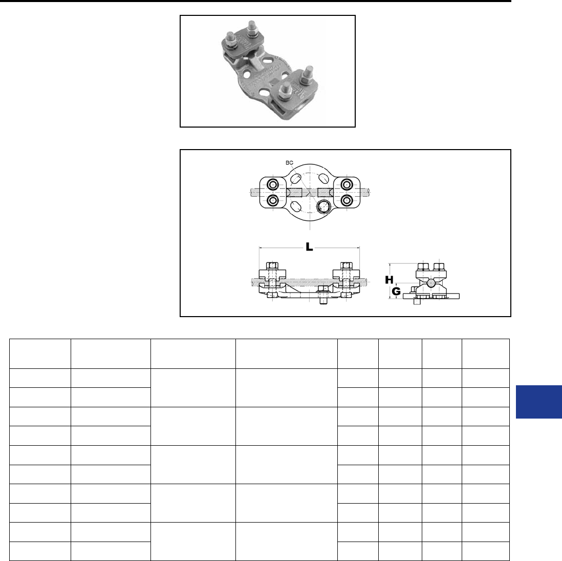
BURNDY®
Blue highlighted items are industry standard and most frequently ordered.
Canada: 1-800-387-6487 www.burndy.com US: 1-800-346-4175
TYPE UHKR-A
BUS SUPPORT
For Use On Cable Or Tube To Base
Aluminum alloy bus support for mounting a wide
range of cable or tube on post or pedestal type
insulators. Supplied with hardware for mounting to
cap of insulator.
Material: Aluminum Alloy
Hardware: Aluminum Hardware
Notes :
• PENETROX™ A joint compound is
recommended on contact surfaces.
• Specify base mounting hardware, if
required, by adding sufx -B to catalog
number.
• Please contact factory for other sizes,
combinations and availability.
Substation
Aluminum Bus Support
Catalog
Number
Tube
Size
Al
Cable
ACSR
Cable BC G * L H
UHKR11A3 1/4 IPS
4 AWG-4/0 AWG 6 (6/1) Turkey AWG-
4/0 (6/1) Penquin AWG
3.00 1.16 7.56 2.63
UHKR11A5 1/4 IPS 5.00 1.16 8.50 2.63
UHKR13A3 3/8 IPS -1/2 IPS
250 kcmil-550 kcmil 266.8 (26/7) Owl kcmil-
477. (30/7) Hen kcmil
3.00 1.32 7.56 3.88
UHKR13A5 3/8 IPS -1/2 IPS 5.00 1.32 8.88 2.88
UHKR14A3 3/4 IPS
600 kcmil-1113 kcmil 556.5 (26/7) Dove kcmil-
1033.5 (54/7) Curlew kcmil
3.00 1.72 7.56 3.56
UHKR14A5 3/4 IPS 5.00 1.53 9.06 3.38
UHKR16A3 1 IPS -1 1/4 IPS
1000 kcmil-2000 kcmil 1113 (54/19) Finch kcmil-
1780 (84/19) Chukar kcmil
3.00 1.97 7.56 4.06
UHKR16A5 1 IPS -1 1/4 IPS 5.00 1.80 9.25 3.88
UHKR17A3 1 1/4 IPS -1 1/2 IPS
2000 kcmil-2500 kcmil 1780 (84/19) Chukar kcmil-
2156 (84/19) Bluebird kcmil
3.00 2.50 8.02 4.62
UHKR17A5 1 1/4 IPS -1 1/2 IPS 5.00 2.50 9.31 4.62
* With maximum conductor in place.
L-33
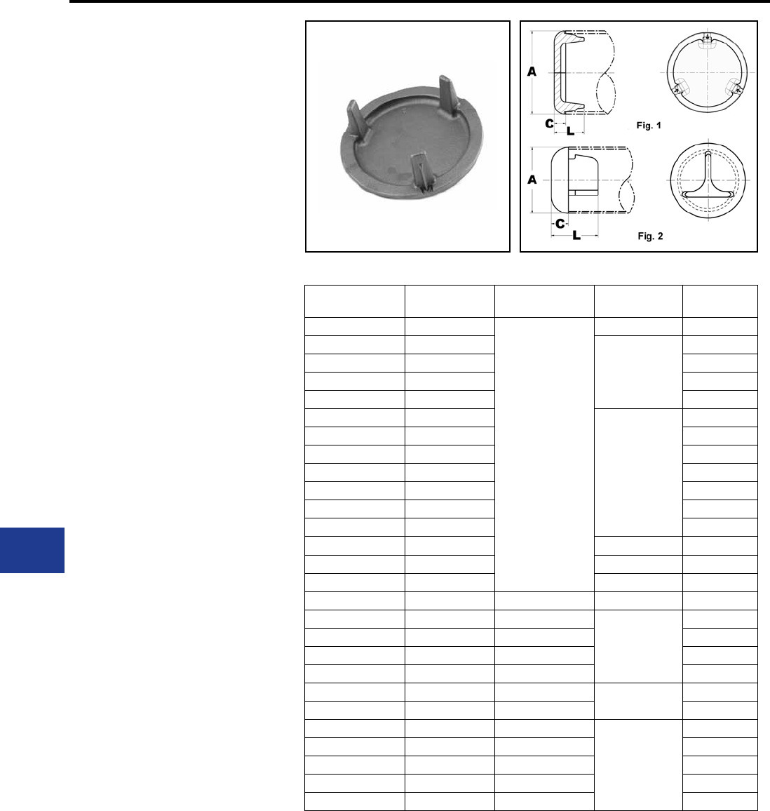
BURNDY®
Blue highlighted items are industry standard and most frequently ordered.
US: 1-800-346-4175 www.burndy.com Canada: 1-800-387-6487
TYPE LB-A
END CAP
For Use On Pipe End Cap
Aluminum alloy end cap for aluminum tube. Driven
into place for a secure t. Seals out moisture,
reduces electrostatic loss and eliminates hazards
created by nesting birds.
Material: Aluminum Alloy
Hardware: Aluminum Hardware
Notes :
• Installation instructions available upon
request.
• Please contact factory for other sizes,
combinations and availability.
Substation
Aluminum End Cap
Catalog Number Al tube
Sch 40
Al tube
Sch 80 C L
LB13A 1/2 IPS
N/A
0.38 1.25
LB14A 3/4 IPS
0.50
1.37
LB15A 1 IPS 1.35
LB16A 1 1/4 IPS 1.35
LB17A 1 1/2 IPS 1.35
LB18A 2 IPS
0.88
2.16
LB19A 2 1/2 IPS 2.24
LB20A 3 IPS 2.29
LB21A 3 1/2 IPS 2.33
LB22A 4 IPS 2.22
LB23A 4 1/2 IPS 2.28
LB24A 5 IPS 2.45
LB83A 8 OD 0.75 2.28
LB86A 6 IPS 0.88 2.57
LB88A 8 IPS 0.75 2.28
LB53A N/A 1/2 IPS 0.38 1.25
LB54A N/A 3/4 IPS
0.50
1.37
LB55A N/A 1 IPS 1.35
LB56A N/A 1 1/4 IPS 1.35
LB57A N/A 1 1/2 IPS 1.35
LB58A N/A 2 IPS 0.88 2.16
LB59A N/A 2 1/2 IPS 2.24
LB90A N/A 3 IPS
0.88
2.29
LB91A N/A 3 1/2 IPS 2.33
LB92A N/A 4 IPS 2.22
LB94A N/A 5 IPS 2.45
LB96A N/A 6 IPS 2.57
L-34
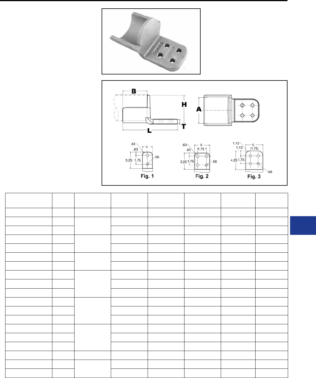
BURNDY®
Blue highlighted items are industry standard and most frequently ordered.
Canada: 1-800-387-6487 www.burndy.com US: 1-800-346-4175
TYPE WAS-A
WELDMENT TERMINAL
CONNECTOR
For Use On Tube To Pad
Aluminum alloy weld type terminal for joining
aluminum tube to copper or aluminum pads.
Drilling in pad conforms to NEMA standards.
PENETROX™ joint compound recommended on
pad contact surfaces.
Material: Aluminum Alloy
Notes :
• Welding to be done by customer
• Before welding scratch brush connector
and conductor contact surface dry, then
apply an oxide inhibitor.
• Tongue nished on one side only. For
tongue nished on both sides, add sufx
“-Q” to catalog number.
Substation
Aluminum Welded Terminal
Catalog Number Fig.
#
Al
Pipe B C L H T
WAS14A-2N 1 3/4 IPS 2.50 2.00 6.50 1.34 19/50
WAS15A-2N 11 IPS 2.75 2.00 6.75 1.80 19/50
WAS15A-34N 2 2.75 3.00 6.75 1.80 19/50
WAS16A-2N 11 1/4 IPS 3.00 2.00 7.00 2.15 19/50
WAS16A34N 2 3.00 3.00 7.00 2.15 19/50
WAS17A-2N 11 1/2 IPS 3.25 2.00 7.25 2.38 11/25
WAS17A-34N 2 3.25 3.00 7.25 2.38 19/50
WAS18A-2N 1
2 IPS
3.50 2.00 7.50 2.84 11/25
WAS18A-34N 2 3.50 3.00 8.62 2.84 19/50
WAS18A44N 3 3.63 4.00 8.62 2.84 1/2
WAS19A-2N 1
2 1/2 IPS
3.63 2.00 7.87 3.32 14/25
WAS19A-34N 2 3.63 3.00 8.87 3.32 1/2
WAS19A-44N 3 3.63 4.00 8.87 3.32 1/2
WAS20A-2N 1
3 IPS
3.67 2.00 8.25 3.98 5/8
WAS20A-34N 2 3.75 3.00 8.25 3.98 31/50
WAS20A-44N 3 3.75 4.00 9.25 3.98 5/8
WAS21A34N 2 3 1/2 IPS 4.25 3.00 8.38 4.51 31/50
WAS22A34N 24 IPS 4.25 3.00 8.38 5.01 3/4
WAS22A-44N 3 4.25 4.00 9.38 5.01 3/4
L-35
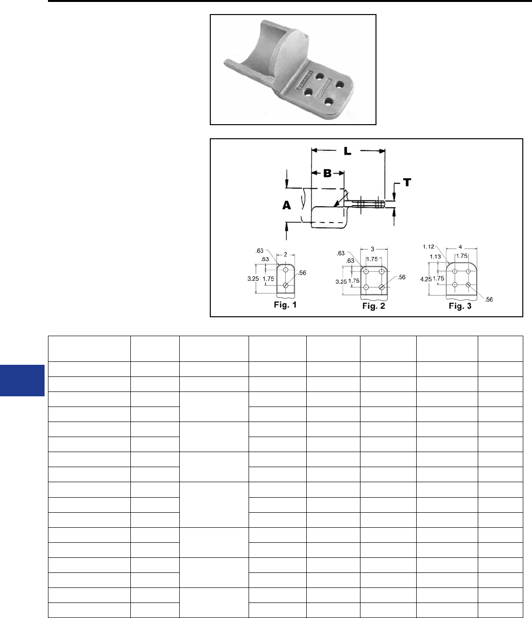
BURNDY®
Blue highlighted items are industry standard and most frequently ordered.
US: 1-800-346-4175 www.burndy.com Canada: 1-800-387-6487
TYPE WASC-A-N
CENTREFORMED WELDEMENT
TERMINAL
For Use On Tube To Pad
Aluminum alloy weldment terminal. Type WASC-
A-N has one contact surface on the center line of
the tube. Holes are NEMA spaced for terminating
aluminum or copper mating pads. PENETROX™
joint compound recommended for use on contact
surfaces.
Material: Aluminum Alloy
Notes :
• Welding to be done by customer
• Before welding scratch brush connector
and conductor contact surface dry, then
apply an oxide inhibitor.
• Tongue nished on one side only. For
tongue nished on both sides, add sufx
“-Q” to catalog number.
Substation
Aluminum Welded Terminal
Catalog
Number
Fig.
#
A-Al
Pipe B L H T W
WASC15A2N 1 1 IPS 2.75 6.69 1.46 19/50 2.00
WASC16A34N 2 1 1/4 IPS 3.00 7.00 1.86 19/50 3.00
WASC17A2N 11 1/2 IPS 3.25 7.31 2.15 7/16 2.54
WASC17A34N 2 3.25 7.31 2.15 11/25 3.00
WASC18A2N 12 IPS 3.50 7.56 2.62 1/2 3.03
WASC18A34N 2 3.50 7.56 2.62 1/2 3.03
WASC19A34N 22 1/2 IPS 3.75 7.88 3.17 14/25 3.67
WASC19A44N 3 3.75 8.88 3.17 14/25 4.00
WASC20A2N 1
3 IPS
4.00 8.13 3.79 31/50 4.29
WASC20A34N 2 4.00 8.13 3.79 31/50 4.29
WASC20A44N 3 4.00 9.13 3.79 31/50 4.29
WASC21A34N 23 1/2 IPS 4.25 8.38 4.28 31/50 4.79
WASC21A44N 3 4.25 9.38 4.28 31/50 4.79
WASC22A34N 24 IPS 4.25 8.38 4.78 3/4 5.29
WASC22A44N 3 4.25 9.38 4.78 3/4 5.29
WASC24A44N 35 IPS 4.25 9.50 5.95 3/4 6.59
WASC24A66N — 4.25 9.50 5.95 3/4 6.59
L-36
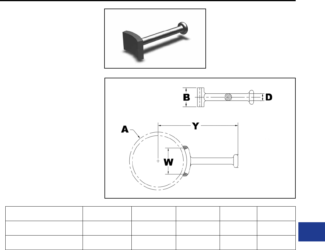
BURNDY®
Blue highlighted items are industry standard and most frequently ordered.
Canada: 1-800-387-6487 www.burndy.com US: 1-800-346-4175
TYPE WG
GROUND STUD
For Use On Stud To Tube
Range-taking weldment stud for grounding aluminum
tube.
Material: Aluminum Alloy
Notes :
• Welding to be done by customer
• Before welding scratch brush connector
and conductor contact surface dry, then
apply an oxide inhibitor.
• Please contact factory for availability.
Substation
Aluminum Welded Ground Stud
Catalog Number Al Pipe B Y D W
WG19A 1 IPS -2 1/2 IPS 3 8.19 0.75 1.32
WG86A 3 IPS -6 IPS 2 10.31 0.75 3.06
L-37

BURNDY®
Blue highlighted items are industry standard and most frequently ordered.
Canada: 1-800-387-6487 www.burndy.com US: 1-800-346-4175
M-1
Substation
Welded/EHV
TABLE OF CONTENTS
Introduction
BURNDY® DESIGN CRITERIA
Cable Connectors
Tubular Bus Connectors
Controlling Corona
Nomogram for Determining
Equivalent
Controlling Corona (continued)
Gradient Calibrator
Formula for Determining Voltage
Gradient
Nomogram for Finding the
Average Conductor-Surface
Voltage-Gradient
Radio Interference Voltage
Effect of Conductor Size on
Testing
Contamination
Conclusion
M-4
M-4
M-4
M-4
M-4
M-5
M-6
M-6
M-7
M-8
M-9
M-9
M-9
M-9
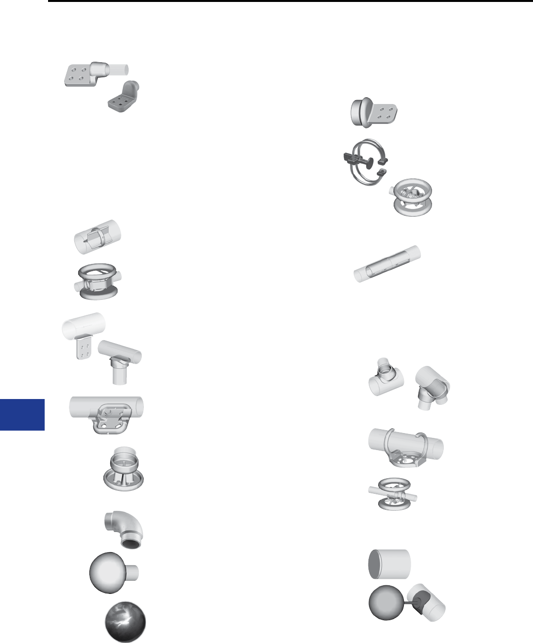
BURNDY®
Blue highlighted items are industry standard and most frequently ordered.
US: 1-800-346-4175 www.burndy.com Canada: 1-800-387-6487
M-2
Substation
Welded/EHV
Welded T-Connectors
Type SWAB-A-N Bus to Pad
Type SWT-A-A Bus to Bus
Type SWT-A-A-75 75° Angle
Type SWAT-A-A-30 30° Angle
Welded Bus Supports
Type SWOH-A Fixed Bus
Support to Insulator
Type SWHRH-A Fixed or Slip Fit
Bus Support to Insulator
Type SWVH-A Vertical
Type SWXHP-A Bus to Bus
Expansion Coupler to Insulator
Miscellaneous
Type SWL-A Bus to Bus Elbow
90°
Type WLB-A Bus to End Cap
Type SCB-A Bus to Corona Bell
Type SWCB-A Ground Stud
Bus to Corona Sphere
Type WSBC Ball Coupler
Welded Terminals
Type SWA-A-N for Cable
Type SWA-A-N for Bus
Type SWAC-A-N for Bus
(Center formed)
Type SWXA-A-NK
Expansion for Bus
(Corona protection 345 kV)
Type SWXA-A-N
Expansion for Bus
(Corona Rings)
Welded Couplers
Type WSLB-A Bus to Bus
Type WS-A Bus to Bus
Type SWXP-A-A
Bus to Bus Expansion
TABLE OF CONTENTS (Continued)
M-11
M-12
M-13
M-14
M-15
M-16
M-17
M-18
M-19
M-20, M-21
M-22
M-23
M-24
M-25
M-26
M-27
M-28
M-29
M-29
M-30
M-31
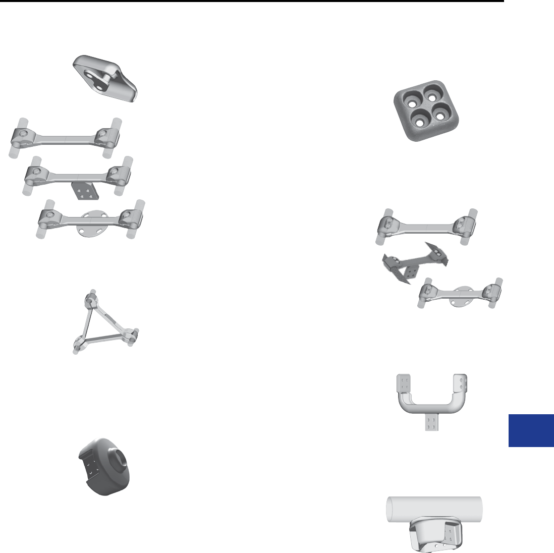
BURNDY®
Blue highlighted items are industry standard and most frequently ordered.
Canada: 1-800-387-6487 www.burndy.com US: 1-800-346-4175
Shielding Caps
Type STS-A-N Bolted 2-Piece
Type STS-A-NCG Bolted 1-Piece
Cable Spacers
Types S2GBP-A Spacer,
S2GBPA-A Terminal Tap,
SH2GBP-A Bus Support
Types S2GBP-AB2 Spacer,
S2GBPA-AB2 Terminal Tap,
SH2GBP-A-B2 Bus Support
Type S3GBP-A Three Cable
Bifurcating Terminal
Type SF2A-NL-EX
Trifurcating Terminal
Type SW3A-A44N8 Coupler
Bus to Trifurcating Terminals
Type SW3AB-A44N8 T-Connector
Bus to Trifurcating Terminals
M-32
M-32
M-33,
M-34
M-35,
M-36
M-37
M-38
M-39
M-40
M-3
TABLE OF CONTENTS (Continued)
Substation
Welded/EHV

BURNDY®
Blue highlighted items are industry standard and most frequently ordered.
US: 1-800-346-4175 www.burndy.com Canada: 1-800-387-6487
M-4
Substation
Welded/EHV
INTRODUCTION
Connectors for use in EHV Substations must
meet essentially the same electrical and
mechanical requirements as those for other
power connectors. However, operations at extra
high voltages imposes an important additional
requirement. They must not produce corona
discharges that interfere with radio reception and
cause energy loss.
Corona forms when the voltage gradient at the
surface of a conducting material exceeds a
critical value and ionizes the surrounding air. For
conductors, the four basic factors that determine
surface voltage gradient are distance from
ground, conductor diameter, phase spacing and
voltage.
In A.C. circuits, there are two basic kinds of
corona. Negative corona forms during the
negative half cycle, and positive corona during
the positive half cycle. Negative corona generally
appears as a glow on conventional conductors
at about 20 kV rms/cm. Its amplitude is relatively
low and cause no signicant radion interference.
Positive corona appears as a plume at above 30
kV rms/cm. Its amplitude is about 50 times higher
than that for negative corona and is the major
cause of radio interference.
BURNDY® EHV connectors are designed so
that under fair weather operation conditions the
voltage gradient at the connector surface will be at
a level that will not cause corona and the resultant
radio interference. (RIV)
BURNDY® DESIGN CRITERIA
Cable Connectors
For reasons of economy, EHV systems using
stranded conductor are generally designed to
operate at voltage gradients close to the negative
corona onset level. It is essential, therefore, that
connectors provide corona-free performance
superior to that of the cable. So our design
criterion calls for the voltage which corona
extinguishes from the connector to be higher
than the voltage at which it extinguishes from
the cable. This criterion is met by eliminating all
projections and by providing smooth contours on
all surfaces. On compression elements, the ends
are especially critical. Carefully designed tapers
are provided to keep the voltage gradient at a
level lower than that on the conductor. Of course,
it is still necessary during installation to smooth
crimped elements.
On accessories, like spacers for bundled lines,
the critical areas are hose at the edges of the
bundle. The bundle itself generally shields those
parts that fall within it. Many projections that would
cause corona on a single conductor line are quiet
when they fall within the shielding inuence of a
bundle. However, those parts that fall at the edges
are carefully nished at the factory to insure
corona-free operation.
Tubular Bus Connectors
Station designers choose tubular bus sizes on
the basis of mechanical rather than electrical
requirements. For instance, stations that only
need 4” IPS to meet electrical and corona
requirements often have 6” IPS as main buses.
The resultant voltage gradient on these buses is
very low, perhaps only 10 kV rms/cm, well below
the corona onset level.
It is impractical therefore, to require that
connectors operate quieter than the bus
regardless of the voltage. Under some
circumstances, it might be impossible to
meet such criteria. In most cases, it would be
prohibitively expensive to do so.
Of course, theoretically optimum connectors
could be designed for each application, based on
the design voltage gradient for individual stations.
However, in most cases even differences as great
as that between 345 and 500 kV don’t have a
meaningful impact on connector costs. So, from a
practical point of view, it is feasible to design most
connectors for 500 kV operation. This makes
it more convenient for the station designers to
select and order connectors.
Bus connectors are designed to provide corona-
free performance under conditions of actual
operation. This is done by calculating the voltage
gradient on the surface of the bus at 500 kV, using
the phase spacing and ground distance typical
for this voltage. Connectors are then designed to
operate corona free when the voltage gradient on
the bus is 10% above this value.
The exceptions to this rule are the exible
expansion connectors. Those designed for 345
kV are self-shielding. Those for 500 kV have
separate shielding rings. Experimental work
on self-shielding 500 kV expansion connectors
indicates that the margin of safety is too small to
justify recommending them for this voltage.
Controlling Corona
Since corona is caused when the voltage gradient
at the surface of a conducting material reaches
a level that causes the surrounding air to break
down, then obviously, the way to prevent corona is
to keep the gradient below this critical level.
From this point of view the connector designer,
this can be accomplished in three ways:
1. By providing generous radii on all outside
surfaces to keep the voltage stresses to a
minimum.
2. By providing shielding rings.
3. By placing the connector within the shielding
inuences of some part of the bus structure.
Since it is impossible for the connector designer to
know the exact conguration of every bus system
where the connectors might be used, the third
approach is not practical. So, for the purposes of
developing a standard line, we concentrate on the
rst two.
Whenever possible, connectors are designed
to be self-shielding. This approach leads
to less costly and less obstrusive designs.
Only in the case of complicated connector
congurations do BURNDY® EHV designs use
corona rings. Examples of such applications
are disconnectable equipment taps, expansion
couplers and equipment terminals which often
have congurations that preclude the use of self-
shielding designs.
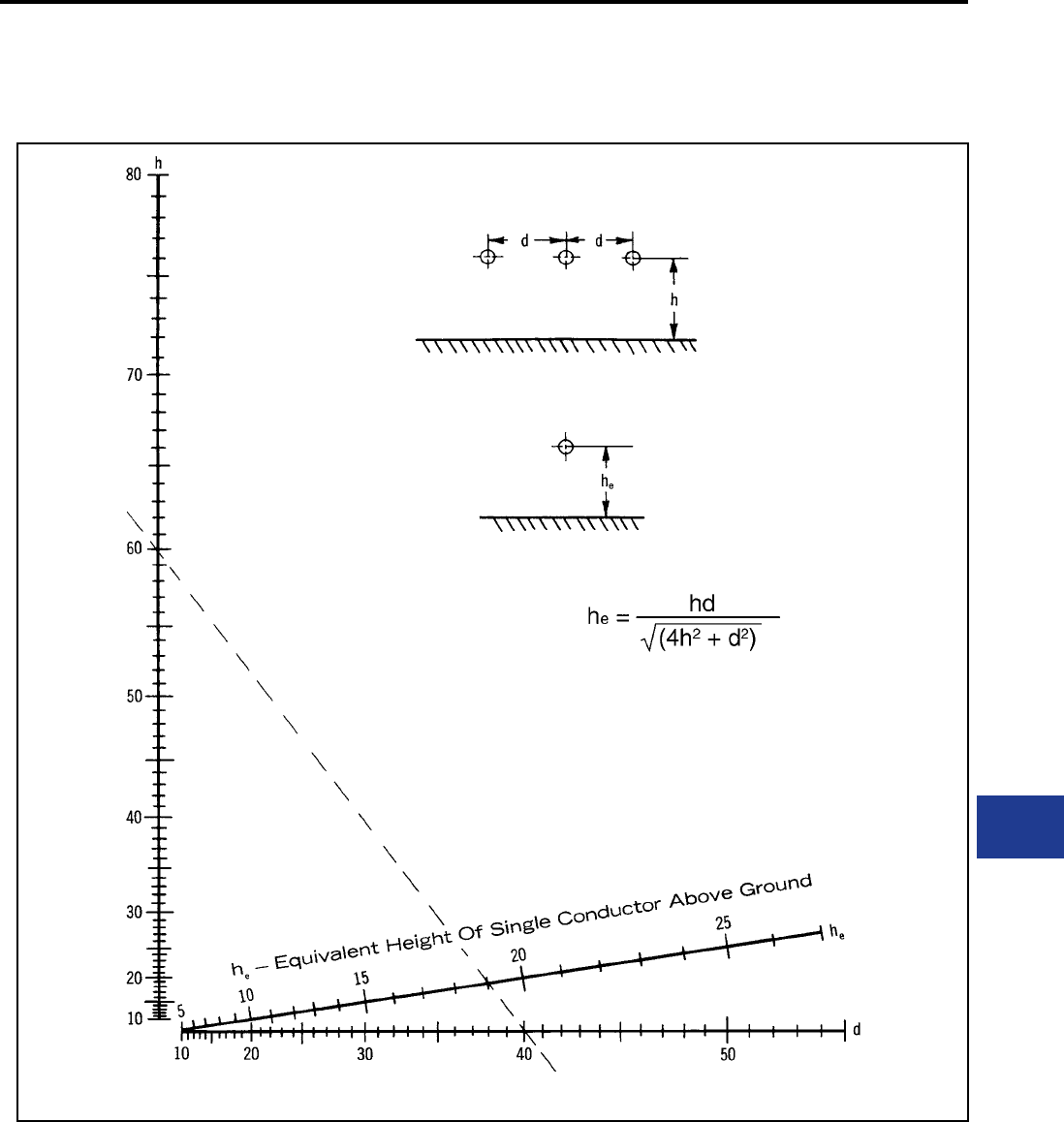
BURNDY®
Blue highlighted items are industry standard and most frequently ordered.
Canada: 1-800-387-6487 www.burndy.com US: 1-800-346-4175
M-5
Substation
Welded/EHV
NOMOGRAM FOR DETERMING THE EQUIVALENT
HEIGHT (he) OF A THREE PHASE LINE
Example:
For a three phase line height, (h), of 60 ft. and a phase spacing, (d), of
40 ft., the equivalent height, (he), is 19 ft.
d - Phase to Phase Spacing
h - Three Phase Line Height Above Ground
Nomogram for determining the equivalent height
of a single conductor line having the same
average voltage of gradient as teh CENTER
conductor of a horizontally spaced three phase
line, with the same line to ground voltage and the
same conductor size. All dimensions measured in
the same units.
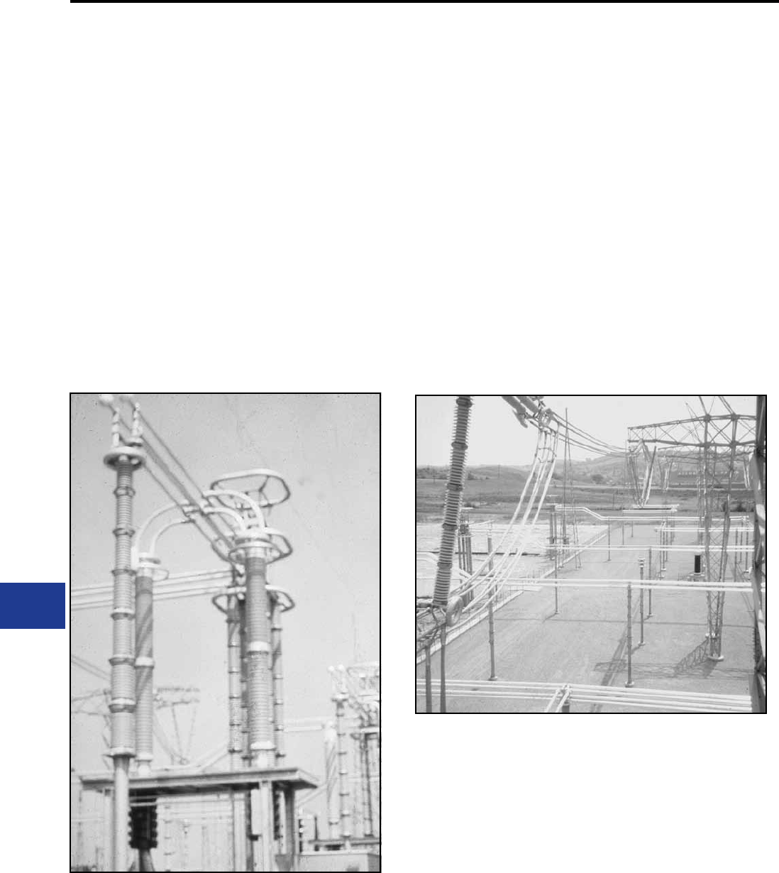
BURNDY®
Blue highlighted items are industry standard and most frequently ordered.
US: 1-800-346-4175 www.burndy.com Canada: 1-800-387-6487
M-6
Substation
Welded/EHV
The use of the laboratory is based on the fact
that it is the surface voltage gradient that causes
corona. Although most systems consist of 3
phase conductors and a ground plane, it is a
rather simple matter to duplicate in the laboratory
the conductor surface voltage gradient as it exists
on any of these phase conductors with a single
conductor and a ground plane.
The formulas and nomograms give this three
phase to single phase equivalency. Because
this conversion is possible, all EHV testing is
done signle phase; and there is no necessity
for 3 phase testing with its high cost in terms of
equipment and space.
Since voltage gradient is the signifcant factor, the
single phase test does not have to be done at the
full voltage of an operation system. By setting up
the test closer to the ground plane, the operation
voltage gradient can be obtained with a lower test
voltage. There is a limit, however, below which the
height cannot be lowered lest corona onset and
ashover occur simultaneously. Generally, the
minimum test height should be about 10 times the
diameter of the test conductor.
GRADIENT CALIBRATOR
Normally the conductor surface voltage gradient
at the extinction of corona in the laboratory is
calculated using the accompanying equations.
However, for test setups involving unusual
conductor congurations, the conductor gradient
cannot be readily calculated. In these cases,
a gradient calibrator may be used. This is a
small sphere mounted on the conductor. It has
previously been calibrated for each conductor
size to establish the surface voltage gradient that
starts positive corona on the sphere. With it tests
can be duplicated in any number of laboratories.
The applied voltages and ground distances
could all be different. But the voltage gradient on
the surface of the conductor when the corona
occurs on the sphere will always be the same.
The calibratory provides a convenient bench
mark for measuring the corona performance of
connectors.
In use, the sphere is mounted on the conductor
in a connector test setup. The voltage is raised
until there is a corona on the sphere. We already
know from previous calibration what the voltage
gradient on the surface of the conductor is at this
point.
BURNDY®
Blue highlighted items are industry standard and most frequently ordered.
Canada: 1-800-387-6487 www.burndy.com US: 1-800-346-4175
M-7
Substation
Welded/EHV
The sphere is removed and the voltage raised
until there is a corona on the connector. Snce the
voltage gradient increases directly with increases
in applied voltage, the gradient on the conductor
at this point can be readily calculated.
It is important to note that the signicant
parameter is the voltage gradient on the surface
of the conductor. It is not necessary to know the
gradient on the connector. The conductor gradient
in any given substation is controlled by its design
parameters and may be calculated using the
following formulae and nomograms. Once the
gradient is known, it is unnecessary to have any
other information to design connectors. As long
as connectors are corona-free at a conductor
voltage gradient higher than that planned for
the conductor, the connector will be corona-free
under fair weather operating conditions.
There may be on occasion be unusual situations
where choice of conductor, station geometry
or clearance problems cause the need for
connectors of special design. Where this is the
case, BURNDY is prepared to design corona-free
devices to operation under such conditions.
Formula for Determining the Voltage Gradient
Notations Used
h = line to ground distance (cm)
r = radius of the individual conductor (cm)
s = conductor spacing in the bundle (cm)
d - phase to phase spacing of the line (cm)
V = line to ground voltage (kV)
Ea = average gradient at the surface of the conductor (kV/cm)
Em = maximum gradient on the surface of a single conductor
he = equivalent single phase line to ground distance (cm)
re = equivalent single conductor radius (cm) of bundled
conductors
n = number of conductors in the bundle
The maximum gradient (Em) occurs on the side facing the ground plane.
The center conductor has a gradient about 5% higher than the outside
conductors. The gradient on the center phase may be calculated using the
formula for the single conductor.
Single phase system and substituting (he) from the following formula or
attached nomograms for the height about the ground (h). For the center phase:
It should be noted that he is somewhat smaller than
The value of “ ” is unity for 1-, 2-, and 3- conductor bundles and
1.12 for 4- conductor bundles.
Bundled Conductor - Three Phase
This case may be reduced to the single bundled conductor case by replacing h with he in the equation. The denition of he is identical to
that given for the single conductor — three phase situation.
BURNDY®
Blue highlighted items are industry standard and most frequently ordered.
US: 1-800-346-4175 www.burndy.com Canada: 1-800-387-6487
M-8
Substation
Welded/EHV
NOMOGRAM FOR FINDING THE AVERAGE CONDUCTOR-SURFACE VOLTAGE-GRADIENT
FROM LINE DIMENSIONS AND VOLTAGE
Example: For a 30 ft. high single phase bus* of
4” diameter, V/E = 30. At 450 kV to ground the
average conductor-surface voltage-gradient is
15 kV RMS/CM.
*For the equivalent single phase height (he) of a
3 phase bus arrangement see the nomogram for
determing the equivalent Height (he) of a three
phase line.
BURNDY®
Blue highlighted items are industry standard and most frequently ordered.
Canada: 1-800-387-6487 www.burndy.com US: 1-800-346-4175
M-9
Substation
Welded/EHV
RADIO INTERFERENCE
VOLTAGE
There is serious question as to whether
measurement of RIV on connectors makes
a meaningful contribution to quieter station
operation.
Under test conditions, there is generally no
signicant indication on the radio noise meter
until the onset of visible positive corona. At this
point, the RIV reading goes into the hundreds
of thousands of microvolts. The effect of this
phenomenon is to provide a visibly discernable
point at which RIV will be excessive. It eliminates
the necessity to make, record and plot RIV
measurements. Where there is no corona, there
is no RIV. So our test criterion calling for no
visible corona insures that there will be no radio
interference generated by the connector under
operating conditions.
EFFECT OF CONDUCTOR
SIZE ON TESTING
Conductor diameter has a signicant effect
on potential corona problems. The larger the
diameter, the lower the surface voltage gradient
for a given test voltage. This means that smaller
conductors produce corona at lower voltages than
larger ones.
Many connector designs have the same basic
conguration for various conductor sizes. The
only difference being the size of the attaching
elements. This is particularly true for many of the
welded type connectors. Where this is the case,
it is often sufcient to test the connector only on
the smallest conductor, since it yields the lowest
corona extinction voltage. When there is any
doubt, each size is tested.
CONTAMINATION
Much work has been done to establish the
relationship between the corona onset voltage for
contaminated as compared to clean hardware.
Experiments in the BURNDY laboratory
indicate that this value can be reduced to half
of the voltage for clean hardware. However, the
relationship varies with the kind of contamination,
atmospheric condition and type of connector.
There have been a number of attempts to
produce articial contamination and atmospheres
in laboratories. However, there is as yet no clearly
established relationship between the corona
performance of hardware contaminated in the
laboratory. Until such a relationship is established,
the only testing that provides comparable data is
on clean hardware under fair weather conditions.
CONCLUSION
For more than 85 years, BURNDY has been
designing connectors for the industry’s most
critical applications. Connectors for EHV are an
outgrowth of this tradition. Whether your need
is for catalog items or special designs, you can
count on electrical, mechanical and corona-free
performance, commensurate with the application.
TYPICAL CURVE

BURNDY®
Blue highlighted items are industry standard and most frequently ordered.
US: 1-800-346-4175 www.burndy.com Canada: 1-800-387-6487
M-10
Substation
Welded/EHV
BURNDY®
Blue highlighted items are industry standard and most frequently ordered.
Canada: 1-800-387-6487 www.burndy.com US: 1-800-346-4175
WELDED TERMINAL
CONNECTOR
SWA-A-N for Cable
Weld type
Application: Cable to Two or Four
Hole Pad (offset
terminal)
EHV RATED: UP TO 550 kV
when used with
shielding caps
Material: Cast 356 Aluminum Alloy
Substation
Welded/EHV
Catalog Number Accommodates “A” Dia. Str. Max.
Dia.
Max.
Dia.
Fig.
No. B L T
Alum. Cable ACSR Cable
SWA44R-44N 700 kcmil thru
874.5 kcmil
605 kcmil thru
874.5 kcmil
26-7
30-19
0.961
[24]
1.085
[28] 31.50
[38]
6.25
[159]
0.50
[13]
SWA48A-44N 2000 kcmil thru
2250 kcmil 2167 kcmil 72-7 1.606
[41]
1.740
[44] 32.62
[67]
7.50
[191]
0.82
[21]
SWA54R-44N 1400 kcmil thru
1600 kcmil
1272 kcmil thru
1510.5 thru 45-7 1.341
[34]
1.470
[37] 32.00
[51]
6.56
[167]
0.56
[14]
SWA58R-44N 1700 kcmil thru
1900 kcmil
1510.5 kcmil thru
1780 kcmil
54-49
54-19
1.471
[37]
1.605
[41] 32.50
[64]
7.25
[184]
0.69
[18]
SWA444A-44N 900 kcmil thru
1100 kmcil
795 kcmil thru
954 kcmil 54-7 1.086
[28]
1.210
[31] 31.75
[44]
6.56
[167]
0.50
[13]
SWA486A-44N 2300 kcmil thru
2500 kcmil
2156 kcmil thru
2300 kcmil
84-19
96-19
1.741
[44]
1.875
[48] 32.62
[67]
7.50
[191]
1.12
[28]
SWA486A-4N 2300 kcmil thru
2500 kcmil
2156 kcmil thru
2300 kcmil
84-19
96-19
1.741
[44]
1.875
[48] 22.62
[67]
6.12
[156]
1.12
[28]
SWA486A-66N 2300 kcmil thru
2500 kcmil
2156 kcmil thru
2300 kcmil
84-19
96-19
1.741
[44]
1.875
[48] 52.62
[67]
7.50
[191]
1.12
[28]
SWA493R-4N 3000 kcmil — 127
169
1.876
[48]
2.05
[52] 23.00
[76]
6.75
[172]
1.00
[25]
NOTES:
1. Dimensions in brackets [ ] are in millimeters.
2. DOES NOT INCLUDE SHIELDING CAPS. For EHV
applications, shielding caps are required. Order
seprately (type) shown on page 32 or ADD SUFFIX
“STS” to catalog number (example: SWA54R-44NSTS),
includes one Type STS shielding cap.
3. One surface of pad nished. For nished pad on both
sides add SUFFIX “Q” to the catalog number (example:
SWA22A-44NQ).
4. For 45 or 90 degree angle add SUFFIX “45” or “90” to
catalog number (example: SWA54R-44N90).
M-11
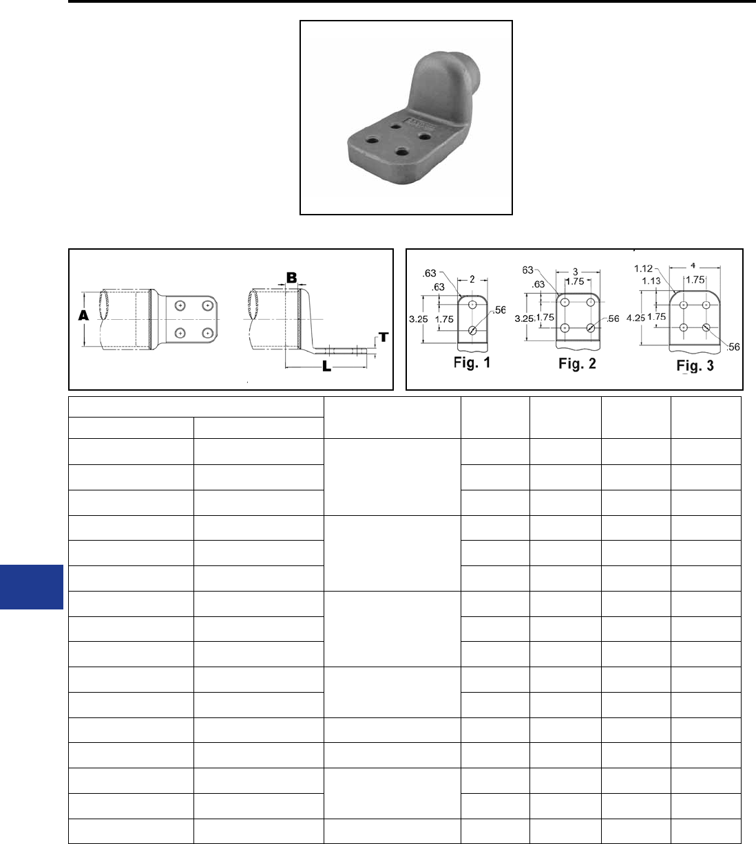
BURNDY®
Blue highlighted items are industry standard and most frequently ordered.
US: 1-800-346-4175 www.burndy.com Canada: 1-800-387-6487
WELDED TERMINAL
CONNECTOR
SWA-A-N
Weld type
Application: Bus to Two or Four Hole
Pad (offset terminal)
EHV RATED: UP TO 550 kV
when used with
Shielding Caps
Material: Cast 356 Aluminum Alloy
Catalog Number Accommodates “A” Dia.
Alum. Tube Fig. B L T
IPS (Sch. 40) EHPS (Sch. 80)
SWA18A-2N SWA58A-2N
2″ (2.375 Dia.)
11.25
[32]
5.88
[149]
0.50
[13]
SWA18A-34N SWA58A-34N 21.25
[32]
5.88
[149]
0.50
[13]
SWA18A-44N SWA58A-44N 31.25
[32]
6.95
[177]
0.50
[13]
SWA19A-2N SWA59A-2N
2-1/2″ (2.875 Dia.)
11.50
[38]
6.36
[162]
0.56
[14]
SWA19A-34N SWA59A-34N 21.50
[38]
6.36
[162]
0.56
[14]
SWA19A-44N SWA59A-44N 31.50
[38]
7.40
[188]
0.56
[14]
SWA20A-2N SWA90A-2N
3″ (3.500 Dia.)
11.75
[44]
6.41
[163]
0.62
[16]
SWA20A-34N SWA90A-34N 21.75
[44]
6.41
[163]
0.62
[16]
SWA20A-44N SWA90A-44N 31.75
[44]
7.46
[189]
0.62
[16]
SWA21A-34N SWA91A-34N
3-1/2″ (4.000 Dia.)
21.75
[44]
6.40
[163]
0.62
[16]
SWA21A-44N SWA91A-44N 31.75
[44]
7.47
[190]
0.62
[16]
SWA22A-44N SWA92A-44N 4″ (4.500 Dia.) 3 2.00
[51]
7.51
[191]
0.75
[19]
SWA23A-44N SWA93A-44N 4-1/2″ (5.000 Dia.) 3 2.00
[51]
7.77
[197]
0.75
[19]
SWA24A-34N SWA94A-34N
5″ (5.563 Dia.)
22.00
[51]
6.80
[173]
0.75
[19]
SWA24A-44N SWA94A-44N 32.00
[51]
7.82
[199]
0.75
[19]
SWA86A-44N SWA96A-44N 6″ (6.625 Dia.) 3 2.50
[64]
7.90
[201]
1.00
[25]
NOTES:
1. Dimensions in brackets [ ] are in millimeters.
2. Conductor smaller than 3 inch bus size not recom-
mended for 550 kV.
3. DOES NOT INCLUDE SHIELDING CAPS. For
EHV applications, shielding caps are required.
Order separately (Type STS) or ADD SUFFIX “STS”
to catalog number (example: SWA22A44NSTS),
includes one shielding cap.
4. One surface of pad nished. For nished pad on
both sides add SUFFIX “Q” to the catalog. number
(example: SWA22A-44NQ).
5. For 45 or 90 degree angle add SUFFIX “45” or
“90” to catalog number (example: SWA22A44N90).
6. For six hole NEMA pad contact factory.
M-12
Substation
Welded/EHV

BURNDY®
Blue highlighted items are industry standard and most frequently ordered.
Canada: 1-800-387-6487 www.burndy.com US: 1-800-346-4175
WELDED TERMINAL
CONNECTOR
SWAC-A-N
Weld type
Application: Bus to Two or Four
Hole Pad (center
formed)
EHV RATED: UP TO 550 kV
when used with
Shielding Caps
Material: Cast 356 Aluminum Alloy
Catalog Number Conductor Fig. No. Dimensions In.
IPS (Sch. 40) EHPS (Sch. 80) IPS A B L T
SWAC18A-2N SWAC58A-2N
2″ 2.38
[60]
11.25
[32]
5.80
[147]
0.50
[13]
SWAC18A-34N SWAC58A-34N 21.25
[32]
5.80
[147]
0.50
[13]
SWAC18A-44N SWAC58A-44N 31.25
[32]
6.86
[174]
0.50
[13]
SWAC19A-2N SWAC59A-2N
2-1/2″ 2.88
[73]
11.50
[38]
6.23
[158]
0.56
[14]
SWAC19A-34N SWAC59A-34N 21.50
[38]
6.23
[158]
0.56
[14]
SWAC19A-44N SWAC59A-44N 31.50
[38]
7.29
[185]
0.56
[14]
SWAC20A-2N SWAC90A-2N
3″ 3.50
[89]
11.75
[44]
6.30
[160]
0.62
[16]
SWAC20A-34N SWAC90A-34N 21.75
[44]
6.30
[160]
0.62
[16]
SWAC20A-44N SWAC90A-44N 31.75
[44]
7.36
[187]
0.62
[16]
SWAC21A-34N SWAC91A-34N
3-1/2″ 4.00
[102]
21.75
[44]
6.30
[160]
0.62
[16]
SWAC21A-44N SWAC91A-44N 31.75
[44]
7.36
[187]
0.62
[16]
SWAC22A-34N SWAC92A-34N
4″ 4.50
[114]
22.00
[51]
6.40
[163]
0.75
[14]
SWAC22A-44N SWAC92A-44N 32.00
[51]
7.40
[188]
0.75
[19]
SWAC23A-34N SWAC93A-34N 4-1/2″ 5.00
[127] 22.00
[51]
6.23
[158]
0.56
[19]
SWAC24A-34N SWAC94A-34N
5″ 5.56
[141]
22.00
[51]
6.68
[170]
0.75
[19]
SWAC24A-44N SWAC94A-44N 32.00
[51]
7.72
[196]
0.75
[19]
SWAC86A-44N SWAC96A-44N 6″ 6.62
[168] 32.50
[64]
7.75
[197]
1.00
[25]
NOTES:
1. Dimensions in brackets [ ] are in millimeters.
2. Conductor smaller than 3 inch bus size not
recommended for 550 kV.
3. DOES NOT INCLUDE SHIELDING CAPS. For
EHV applications, shielding caps are required. Order
separately (Type STS) or ADD SUFFIX “STS” to
Catalog Number (example: SWAC22A44NSTS),
includes two shielding caps.
4. Pad surface nished on both sides of tongue.
5. For six hole NEMA pad contact factory.
M-13
Substation
Welded/EHV
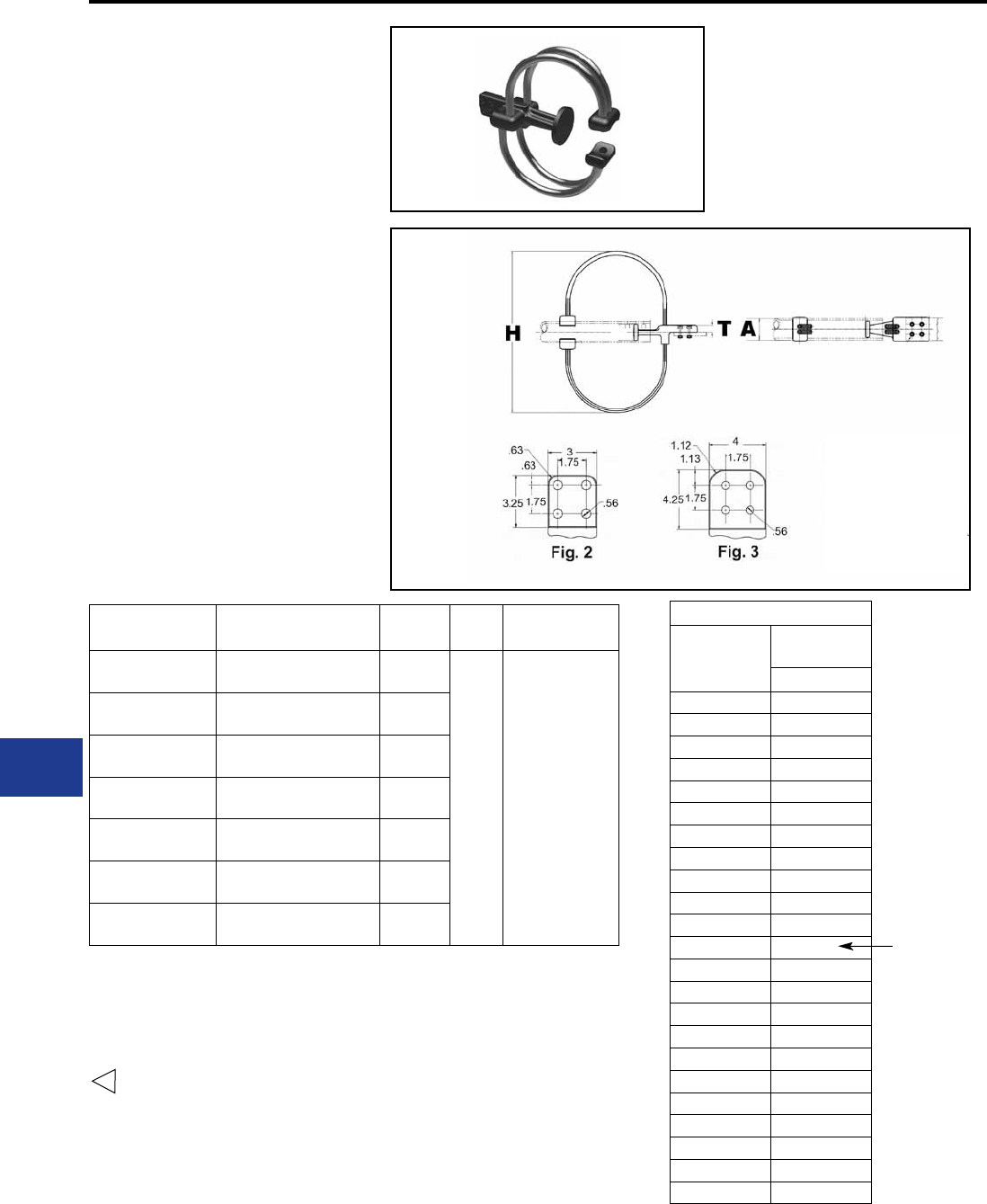
BURNDY®
Blue highlighted items are industry standard and most frequently ordered.
US: 1-800-346-4175 www.burndy.com Canada: 1-800-387-6487
WELDED EXPANSION
TERMINAL CONNECTOR
SWXA-A-NK
Welded type
Application: Bus to Four Hole Pad
(Expansion Terminal
with Corona protection)
EHV RATED: SELF-SHIELDING
UP TO 345 kV
Catalog
Number
Accommodates “A” Dia.
Alum. Tube H T Hardware
Length
SWXA20A-4NK8 3″ IPS (3.500 Dia.) Sch 40 26.38
[670]
1.00
[25] 1/2″-13 X 2-3/4″ LG.
SWXA22A-4NK8 4″ IPS (5.500 Dia.) Sch 40 27.00
[686]
SWXA24A-4NK8 5″ IPS (5.563 Dia.) Sch 40 28.06
[713]
SWXA86A-4NK8 6″ IPS (6.625 Dia.) Sch 40 29.12
[740]
SWXA92A-4NK8 4″ IPS (4.500 Dia.) Sch 80 27.00
[686]
SWXA94A-4NK8 5″ IPS (5.563 Dia.) Sch 80 28.06
[713]
SWXA96A-4NK8 6″ IPS (6.625 Dia.) Sch 80 29.12
[740]
Material:
Straps:
Rings:
Ring mounting:
Base mounting:
Cast 356 Aluminum Alloy
Aluminum Cables
Aluminum Alloy Cable
Aluminum
Galvanized Steel
NOTES:
1. Table is based on 90/ft. max BUS run.
2. Dimensions in brackets [ ] are in millimeters.
3. Shielding caps not required.
4. One side of pad nished. On Centerline of tubing.
For nish pad on both sides add SUFFIX “Q” to catalog
number (example: SWXA22A4NK8Q).
5 Accommodates maximum pad thickness of 1.00″.
Installation Data
Bus
Temp
F°
3" Total
Movement
Z
–20 3.50
–10 3.36
0 3.23
10 3.09
20 2.95
30 2.82
40 2.68
50 2.54
60 2.41
70 2.27
80 2.14
90 2.00
100 1.86
110 1.73
120 1.59
130 1.45
140 1.32
150 1.18
160 1.04
170 0.91
180 0.77
190 0.64
200 0.50
NOMINAL
POSITION
M-14
Substation
Welded/EHV
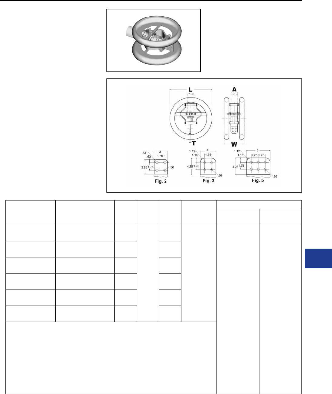
BURNDY®
Blue highlighted items are industry standard and most frequently ordered.
Canada: 1-800-387-6487 www.burndy.com US: 1-800-346-4175
WELDED EXPANSION
TERMINAL CONNECTOR
SWXA-A-N
Welded type
Application: Bus to four or six hole
pad (Expansion Terminal
with Corona Rings)
EHV RATED: SELF-SHIELDING
UP TO 550 kV
Material:
Straps:
Rings:
Ring mounting:
Base mounting:
Cast 356 Aluminum Alloy
Laminated Aluminum
Aluminum Alloy
Aluminum
Galvanized Steel
Catalog
Number
Accommodates
“A” Dia. Alum. Tube T L W Ref. Total
Movement
Installation Data
Bus.
Temp. of Z
SWXA20A-44N 3″ (3.500 Dia.) Sch 40 0.75
[19]
26.00
[660]
13.19
[335]
2.00
[51]
–20
–10
0
10
20
30
40
50
60
70
80
90
100
110
120
130
140
150
160
170
180
190
200
2.50
2.61
2.32
2.21
2.14
2.01
1.95
1.86
1.77
1.68
1.57
1.50
1.41
1.32
1.23
1.14
1.04
0.95
0.86
0.77
0.68
0.59
0.50
SWXA22A-44N 4″ (4.500 Dia.) Sch 40 0.86
[22]
13.87
[352]
SWXA24A-44N 5″ (5.563 Dia.) Sch 40 0.81
[21]
14.50
[368]
SWXA86A-44N 6″ (6.625 Dia.) Sch 40 1.00
[25]
15.50
[394]
SWXA92A-44N 4″ (4.500 Dia.) Sch 80 0.86
[22]
13.87
[352]
SWXA94A-44N 5″ (5.563 Dia.) Sch 80 0.86
[22]
14.50
[368]
NOTES:
1. Table is based on 60/ft. max BUS run.
2. Dimensions in brackets [ ] are in millimeters.
3. Shielding caps not required.
4. One side of pad nished. On Centerline of tubing. For nished pad on both sides add SUFFIX “Q” to
catalog number (example: SWXA22A4NQ).
5. For six hole NEMA pad change the sufx to 66N (example: SWXA22A66N).
M-15
Substation
Welded/EHV
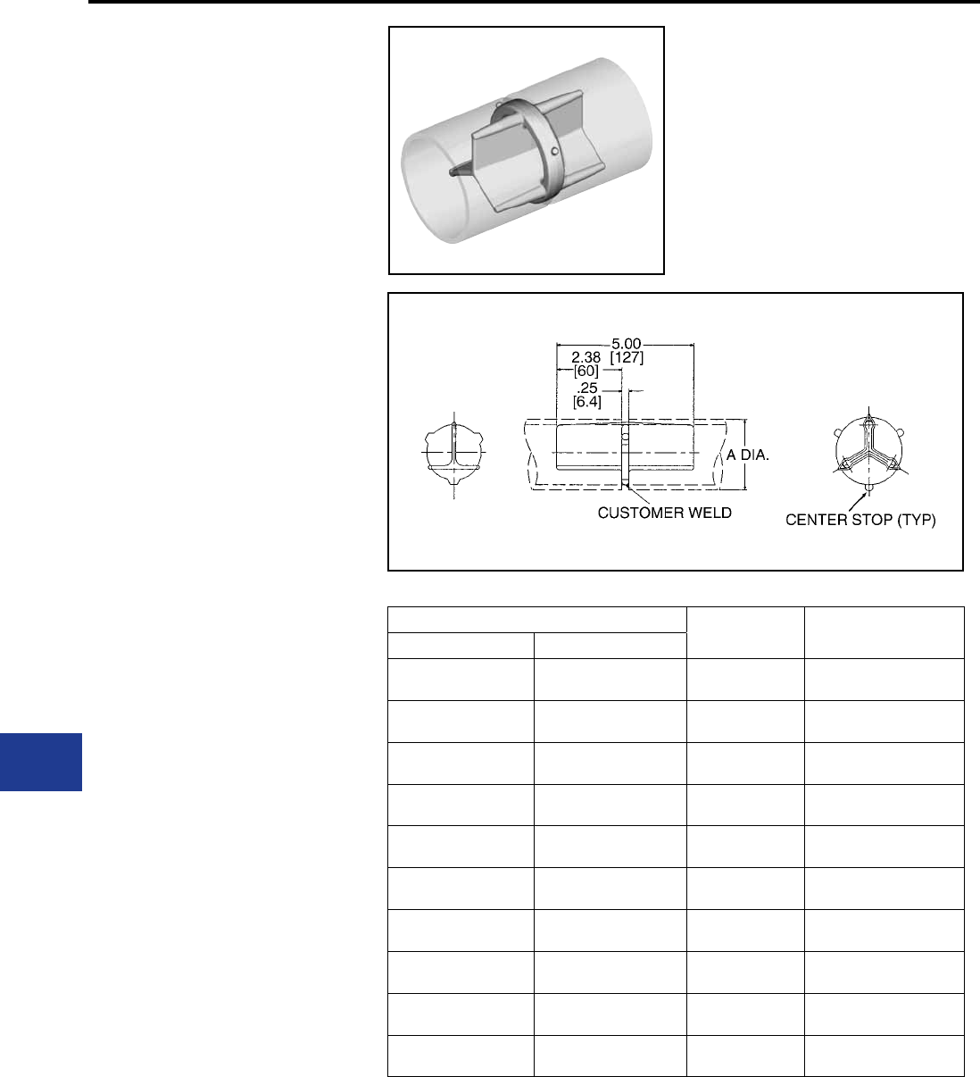
BURNDY®
Blue highlighted items are industry standard and most frequently ordered.
US: 1-800-346-4175 www.burndy.com Canada: 1-800-387-6487
WELDED RIGID
COUPLER
WSLB-A
Weld type
Application: Bus to Bus Coupler
EHV RATED: SELF-SHIELDING
UP TO 550 kV
Material: Cast 356 Aluminum Alloy
Catalog Number OD Conductor Aluminum
Tubing Size
Sch. 40 Sch. 80
WSLB15A WSLB55A 1.32
[34] 1″
WSLB16A WSLB56A 1.66
[42] 1-1/4″
WSLB17A WSLB57A 1.90
[48] 1-1/2″
WSLB18A WSLB58A 2.38
[60] 2″
WSLB19A WSLB59A 2.88
[73] 2-1/2″
WSLB20A WSLB90A 3.50
[89] 3″
WSLB21A WSLB91A 4.00
[102] 3-1/2″
WSLB22A WSLB92A 4.50
[114] 4″
WSLB24A WSLB94A 5.56
[141] 5″
WSLB86A WSLB96A 6.62
[168] 6″
NOTES:
1. Dimensions in brackets [ ] are in millimeters.
2. Conductors smaller than 3 inch bus size are not
recommended for 550 kV.
M-16
Substation
Welded/EHV
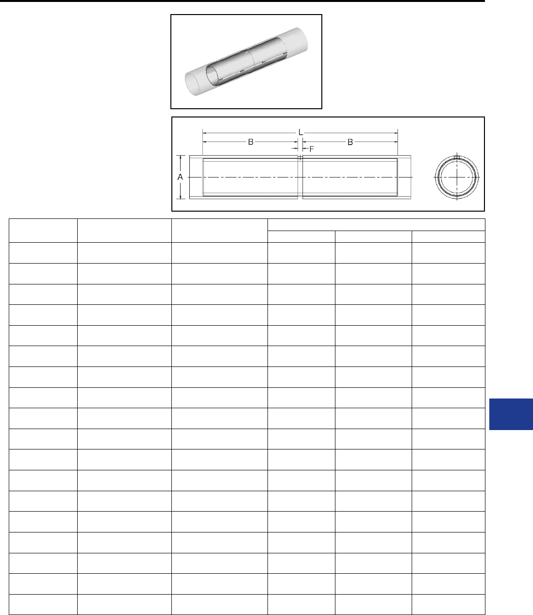
BURNDY®
Blue highlighted items are industry standard and most frequently ordered.
Canada: 1-800-387-6487 www.burndy.com US: 1-800-346-4175
WELDED RIGID
COUPLER
WS-A
Weld type
Application: Bus to Bus Coupler
EHV RATED : SELF-SHIELDING
UP TO 550 kV
Material: Cast 356 Aluminum Alloy
Catalog
Number
Conductor (IPS) “A”
Schedule 40
Conductor (EHPS) “A”
Schedule 80
Dimensions Inches
B F L
WS14A 3/4″ (1.050 Dia.) — 2.13
[54.1]
0.23
[5.8]
4.50
[114.3]
WS15A 1″ (Dia.) — 2.13
[54.1]
0.23
[5.8]
4.50
[114.3]
WS16A 1-1/4″ (1.660 Dia.) — 3.60
[91.4]
0.28
[7.1]
7.50
[190.5]
WS17A 1-1/2″ (1.900 Dia.) — 4.36
[110.7]
0.29
[7.4]
9.00
[228.6]
WS18A 2″ (2.375 Dia.) — 5.88
[149.4]
0.31
[7.9]
12.00
[304.8]
WS19A 2-1/2″ (2.875 Dia.) — 7.31
[185.7]
0.39
[9.9]
15.00
[381.0]
WS20A 3″ (3.500 Dia.) — 8.81
[223.8]
0.44
[11.2]
18.00
[457.2]
WS21A 3-1/2″ (4.000 Dia.) — 8.75
[222.3]
0.47
[11.9]
18.00
[457.2]
WS22A 4″ (4.500 Dia.) — 8.75
[222.3]
0.47
[11.9]
18.00
[457.2]
WS24A 5″ (5.563 Dia.) — 8.75
[222.3]
0.50
[12.7]
18.00
[457.2]
WS58A 6″ (6.625 Dia.) — 8.75
[222.3]
0.56
[14.2]
18.00
[457.2]
WS59A — 2″ (2.375 Dia.) 5.88
[149.4]
0.31
[7.9]
12.00
[304.8]
WS86A — 2-1/2″ (2.875 Dia.) 7.31
[185.7]
0.39
[9.9]
15.00
[381.0]
WS90A — 3″ (3.500 Dia.) 8.81
[223.8]
0.44
[11.2]
18.00
[457.2]
WS91A — 3-1/2″ (4.000 Dia.) 8.75
[222.3]
0.47
[11.9]
18.00
[457.2]
WS92A — 4″ (4.500 Dia.) 8.75
[222.3]
0.47
[11.9]
18.00
[457.2]
WS94A — 5″ (5.563 Dia.) 8.75
[222.3]
0.50
[12.7]
18.00
[457.2]
WS96A — 6″ (6.625 Dia.) 8.75
[222.3]
0.56
[14.2]
18.00
[457.2]
NOTES:
1. Dimensions in brackets [ ] are in millimeters.
2. Conductor smaller than 3 inch bus size not recommended
for 550 kV.
M-17
Substation
Welded/EHV
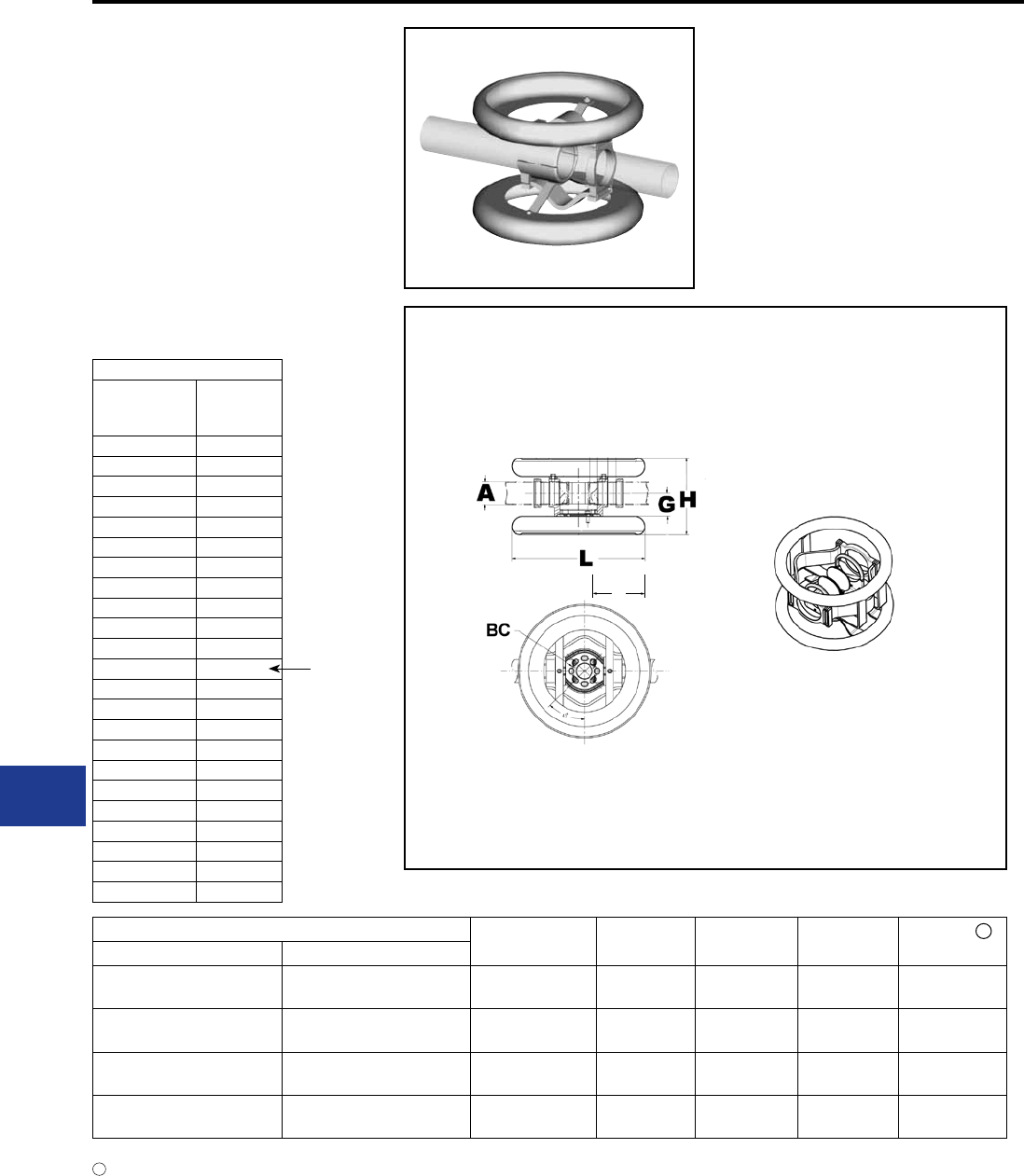
BURNDY®
Blue highlighted items are industry standard and most frequently ordered.
US: 1-800-346-4175 www.burndy.com Canada: 1-800-387-6487
WELDED EXPANSION
COUPLER
SWXP-A-A
Weld type
Application: Bus to Bus Expansion
EHV RATED : SELF-SHIELDING
UP TO 550kV
Catalog Number “A” Dia.
Alum. Tube F H W Total
Movement
Sch. 40 Sch. 80
SWXP20A20A SWXP90A90A 3″ (3.50 Dia.)
[89]
5.25
[133]
22.00
[559]
17.05
[433]
3.00
[76]
SWXP22A22A SWXP92A92A 4″ (4.50 Dia.)
[114]
6.38
[162]
22.00
[559]
18.89
[480]
4.00
[102]
SWXP24A24A SWXP94A94A 5″ (5.50 Dia.)
[141]
7.88
[200]
26.00
[660]
19.25
[489]
4.00
[102]
SWXP86A86A SWXP96A96A 6″ (6.50 Dia.)
[168]
8.88
[226]
26.00
[660]
20.31
[516]
4.00
[102]
Material:
Hardware:
Corona Rings:
Straps:
Cast 356 Aluminum Alloy
Aluminum Alloy
Aluminum Alloy
Laminated Aluminum Strap
1
NOTES:
Maximum movement per end equals one-half of total
movement specied in table. Table is based on 90 ft. bus
run (total) or 45 ft. per end.
2. Dimensions in brackets [ ] are in millimeters.
3. Conductors smaller than 3 inch not recommended for
550 kV.
1
Installation Data
Bus
Temp
F°
3 Total
Movement
Z
–20 0.50
–10 0.64
0 0.77
10 0.91
20 1.04
30 1.18
40 1.32
50 1.45
60 1.59
70 1.73
80 1.86
90 2.00
100 2.14
110 2.27
120 2.41
130 2.54
140 2.68
150 2.82
160 2.95
170 3.09
180 3.23
190 3.36
200 3.50
NOMINAL
POSITION
F
M-18
Substation
Welded/EHV
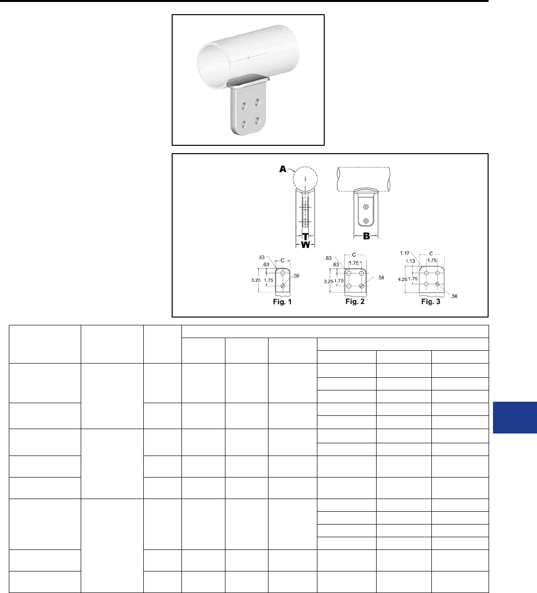
BURNDY®
Blue highlighted items are industry standard and most frequently ordered.
Canada: 1-800-387-6487 www.burndy.com US: 1-800-346-4175
WELDED
T-CONNECTOR
SWAB-A-N
Weld type
Application: Bus to Pad
EHV RATED : UP TO 550 kV
when used with
Shielding Caps
Material: Cast 356 Aluminum Alloy
Catalog
Number
Complete Range
Aluminum Tube Fig. #
Dimensions - Inches
B T W Aluminum IPS Pipe
Nominal A Y
SWAB19A2N 1”
to
2-1/2”
13.00
[76]
0.38
[10]
1.32
[34]
1″ 1.32 [34] 4.45 [113]
1-1/4″ 1.66 [42] 4.67 [119]
1-1/2″ 1.90 [48] 4.80 [122]
SWAB19A-34N 24.00
[102]
0.50
[13]
1.32
[34]
2″ 2.38 [60] 5.08 [129]
2-1/2″ 2.88 [73] 5.32 [135]
SWAB22A2N
2-1/2”
to
4”
13.00
[76]
0.75
[19]
2.40
[61]
2-1/2″ 2.88 [73] 5.25 [133]
3″ 3.50 [89] 5.62 [143]
SWAB22A-34N 24.00
[102]
0.75
[19]
2.40
[61] 3-1/2″
4.00
[102]
5.92
[150]
SWAB22A-44N 34.50
[114]
0.75
[19]
2.40
[61] 4″ 4.50
[114]
6.21
[158]
SWAB86A2N
3”
to
6”
13.00
[76]
1.00
[25]
2.62
[67]
3″ 3.50 [89] 5.58 [142]
3-1/2″ 4.00 [102] 6.08 [154]
4″ 4.50 [114] 6.36 [162]
4-1/2″ 5.00 [127] 6.36 [162]
SWAB86A34N 24.00
[102]
1.00
[25]
2.62
[67] 5″ 5.56
[141]
6.67
[169]
SWAB86A-44N 34.50
[114]
1.00
[25]
2.62
[67] 6″ 6.62
[168]
7.24
[184]
2.00
3.00 4.00
NOTES:
1. Dimensions in brackets [ ] are in millimeters.
2. Conductor smaller than 3 inch bus size not
recommended for 550 kV.
3. DOES NOT INCLUDE SHIELDING CAPS. For
EHV applications, shielding caps are required. Order
separately (Type STS) or ADD SUFFIX “STS” to
Catalog Number (example: SWAB22A44NSTS),
includes two shielding caps.
4. Pad surface nished on both sides of tongue.
5. For six hole NEMA pad contact factory.
M-19
Substation
Welded/EHV
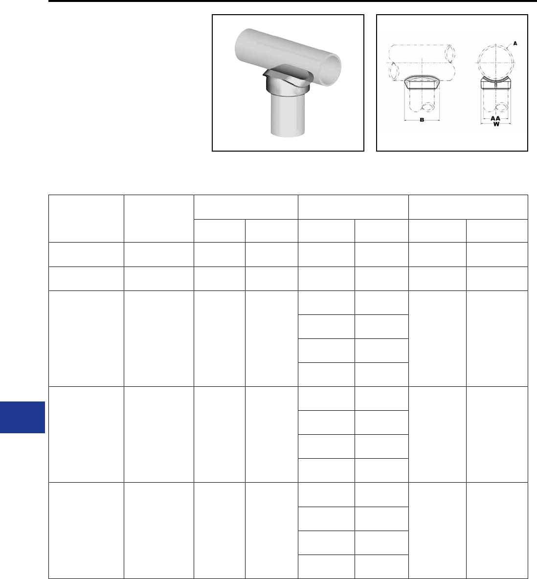
BURNDY®
Blue highlighted items are industry standard and most frequently ordered.
US: 1-800-346-4175 www.burndy.com Canada: 1-800-387-6487
WELDED
T-CONNECTOR
SWT-A-A
Weld Type
Application : Bus to Bus
T-Connector.
EHV RATED : SELF SHIELDING
UP TO 550 kV
Material: Cast 356 Aluminum Alloy
Catalog
Number
Run ‘A’
Aluminum Tube
Tap ‘AA’ Aluminum Tube Run Data Dimensions Inches
Tube AA Nom. Tube A B W
SWT17A17A 1-1/2″ 1/2″ 1.90
[48] 1-1/2″ 1.90
[48]
3.19
[81]
2.64
[67]
SWT19A19A 2 1/2″ 2-1/2″ 2.88
[27] 2-1/2″ 2.88
[73]
4.00
[54]
3.78
[96]
SWT21A14A 2″ To 3-1/2″ 3/4″ 1.05
[28]
2″ 2.38
[60.4]
2.12
[54]
1.75
[44]
2-1/2″ 2.88
[73]
3″ 3.50
[89]
3-1/2″ 4.00
[102]
SWT21A15A 2″ To 3-1/2″ 1″ 1.32
[34]
2″ 2.38
[60.4]
2.38
[60.4]
2.28
[60]
2-1/2″ 2.88
[73]
3″ 3.50
[89]
3-1/2″ 4.00
[102]
SWT21A16A 2″ To 3-1/2″ 1-1/4″ 1.66
[42]
2″ 2.38
[60.4]
2.69
[68]
2.36
[60]
2-1/2″ 2.88
[73]
3″ 3.50
[89]
3-1/2″ 4.00
[102]
NOTES:
1. Dimensions in brackets [ ] are in millimeters.
2. Conductor smaller than 3 inch bus size not
recommended for 550 kV.
M-20
Substation
Welded/EHV
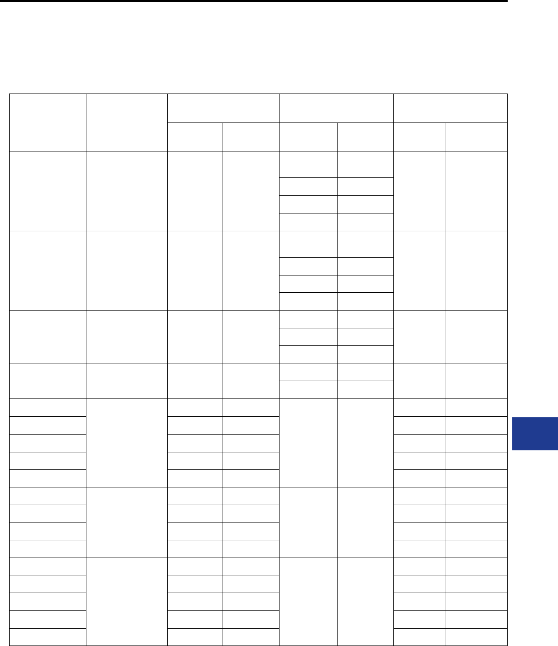
BURNDY®
Blue highlighted items are industry standard and most frequently ordered.
Canada: 1-800-387-6487 www.burndy.com US: 1-800-346-4175
WELDED
T-CONNECTOR
(Continued)
SWT-A-A
Catalog
Number
Run ‘A’
Aluminum Tube
Tap ‘AA’ Aluminum Tube Run Data Dimensions Inches
Tube AA Nom. Tube A B W
SWT21A17A 2″ To 3-1/2″ 1-1/2″ 1.90
[48]
2″ 2.38 [60.4]
3.19
[81]
2.62
[67]
2-1/2″ 2.88 [73]
3″ 3.50 [89]
3-1/2″ 4.00 [102]
SWT21A18A 2″ To 3-1/2″ 2″ 2.38
[60.4]
2″ 2.38 [60.4]
4.00
[102]
3.33
[84]
2-1/2″ 2.88 [73]
3″ 3.50 [90]
3-1/2″ 4.00 [102]
SWT21A19A 2″ To 3-1/2″ 2-1/2″ 2.88
[73]
2-1/2″ 2.88 [73]
4.00
[102]
3.78
[96]
3″ 3.50 [90]
3-1/2″ 4.00 [102]
SWT21A20A 2″ To 3-1/2″ 3″ 3.50
[90]
3″ 3.50 [102] 4.56
[116]
4.52
[115]
3-1/2″ 4.00 [102]
SWT22A18A
4″
2″ 2.38 [60.4]
4″ 4.50
[114]
4.00 [102] 3.50 [102]
SWT22A19A 2-1/2″ 2.88 [73] 4.00 [102] 4.80 [122]
SWT22A20A 3″ 3.50 [102] 4.56 [116] 4.50 [114]
SWT22A21A 3-1/2″ 4.00 [102] 5.50 [140] 5.00 [127]
SWT22A22A 4″ 4.50 [114] 6.00 [152] 5.60 [142]
SWT24A20A
5″
3″ 3.50 [48]
5″ 5.56
[141]
4.72 [102] 3.50 [102]
SWT24A21A 3-1/2″ 4.00 [102] 5.50 [140] 5.00 [127]
SWT24A22A 4″ 4.50 [114] 6.00 [152] 5.60 [142]
SWT24A24A 5″ 5.56 [141] 7.38 [187] 6.84 [174]
SWT86A20A
6″
3″ 3.50 [48]
6″ 6.62
[168]
4.56 [116] 5.00 [127]
SWT86A21A 3-1/2″ 4.00 [102] 5.50 [140] 5.50 [140]
SWT86A22A 4″ 4.50 [114] 6.00 [152] 6.66 [169]
SWT86A24A 5″ 5.56 [141] 7.38 [187] 6.84 [174]
SWT86A86A 6″ 6.62 [168] 8.00 [203] 8.00 [203]
NOTES:
1. Dimensions in brackets [ ] are in millimeters.
2. Conductor smaller than 3 inch bus size not
recommended for 550 kV.
M-21
Substation
Welded/EHV
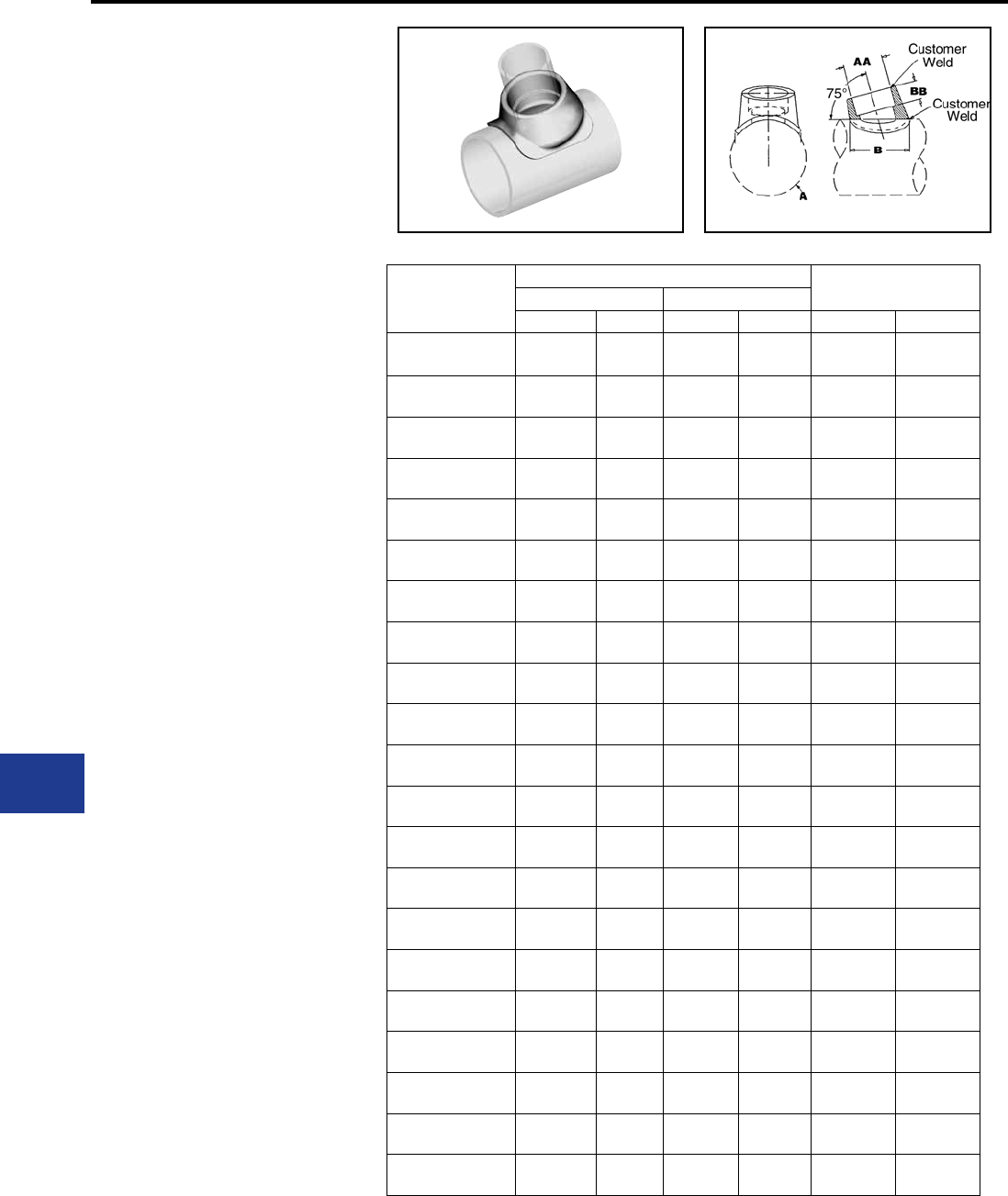
BURNDY®
Blue highlighted items are industry standard and most frequently ordered.
US: 1-800-346-4175 www.burndy.com Canada: 1-800-387-6487
WELDED
T-CONNECTOR
SWT-A-A-75
Weld type
Application : Bus “A” Frame
Connector (75°)
EHV RATED: SELF-SHIELDING
UP TO 550 kV
Material: Cast 356 Aluminum Alloy
Catalog
Number
Aluminum Tube Dimensions In.
Run Tap
Nominal A Nominal AA B BB
SWT18A16A75 2″ 2.38
[60.4] 1-1/4″ 1.66
[42]
2.69
[68]
1.00
[25]
SWT18A17A75 2″ 2.38
[60.4] 1-1/2″ 1.90
[48]
3.19
[81]
1.00
[25]
SWT19A16A75 2-1/2″ 2.88
[73] 1-1/4″ 1.66
[42]
2.69
[68]
1.00
[25]
SWT19A17A75 2-1/2″ 2.88
[73] 1-1/2″ 1.90
[48]
3.19
[81]
1.00
[25]
SWT19A18A75 2-1/2″ 2.88
[73] 2″ 2.38
[60]
4.00
[102]
1.00
[25]
SWT20A17A75 3″ 3.50
[89] 1-1/2″ 1.90
[48]
3.19
[81]
1.00
[25]
SWT20A18A75 3″ 3.50
[89] 2″ 2.38
[60]
4.00
[102]
1.00
[25]
SWT20A19A75 3″ 3.50
[89] 1-1/2″ 2.88
[73]
4.00
[102]
1.38
[35]
SWT21A16A75 3-1/2″ 4.00
[102] 1-1/4″ 1.66
[42]
2.69
[68]
1.00
[25]
SWT21A17A75 3-1/2″ 4.00
[102] 1-1/2″ 1.90
[48]
3.19
[81]
1.00
[25]
SWT21A18A75 3-1/2″ 4.00
[102] 2″ 2.38
[42]
4.00
[68]
1.00
[25]
SWT21A19A75 3-1/2″ 4.00
[102] 1-1/2″ 2.88
[73]
4.00
[68]
1.38
[35]
SWT22A18A75 4″ 4.50
[114] 2″ 2.38
[60]
4.18
[105]
1.00
[25]
SWT22A19A75 4″ 4.50
[114] 1-1/2″ 2.88
[73]
4.00
[102]
1.38
[35]
SWT22A20A75 4″ 4.50
[114] 3″ 3.50
[89]
4.56
[116]
1.38
[35]
SWT24A18A75 5″ 5.56
[141] 2″ 2.38
[60]
4.00
[102]
1.00
[25]
SWT24A19A75 5″ 5.56
[141] 1-1/2″ 2.88
[73]
4.00
[102]
1.38
[35]
SWT24A20A75 5″ 5.56
[141] 3″ 3.50
[89]
4.56
[116]
1.38
[35]
SWT86A20A75 6″ 6.62
[168] 3″ 3.50
[89]
4.56
[116]
1.38
[35]
SWT86A21A75 6″ 6.62
[168] 3-1/2″ 4.00
[102]
5.50
[140]
1.38
[35]
SWT86A22A75 6″ 6.62
[168] 4″ 4.50
[114]
6.00
[152]
1.38
[35]
NOTES:
1. Dimensions in brackets [ ] are in millimeters.
2. Conductor smaller than 3 inch bus size not recommended
for 550 kV.
M-22
Substation
Welded/EHV
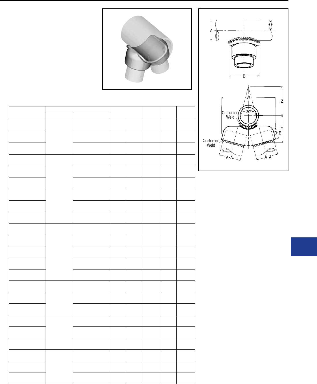
BURNDY®
Blue highlighted items are industry standard and most frequently ordered.
Canada: 1-800-387-6487 www.burndy.com US: 1-800-346-4175
WELDED
V-CONNECTOR
SWAT-A-A-30
Weld type
Application: Bus “A” Frame
Connector (30°)
EHV RATED: SELF-SHIELDING UP
TO 550 kV
Material: Cast 356 Aluminum Alloy
Catalog Number Aluminum I.P.S. B B-B W Y Z
Run “A” Tap “A-A”
SWAT18A16A-30
2″
(2.375 Dia.)
1-1/4" (1.660 Dia.) 3.25
[83]
1.00
[25]
4.81
[122]
3.19
[81]
1.79
[45]
SWAT18A17A-30 1-1/2" (1.900 Dia.) 3.50
[89]
1.00
[25]
5.25
[133]
3.00
[76]
2.34
[59]
SWAT18A18A-30 2" (2.375 Dia.) 4.00
[102]
1.00
[25]
6.38
[160]
3.12
[71]
3.46
[88]
SWAT19A16A-30
2-1/2″
(2.875 Dia.)
1-1/4" (2.375 Dia.) 3.25
[83]
1.00
[25]
4.82
[122]
3.31
[84]
1.74
[44]
SWAT19A17A-30 1-1/2" (1.900 Dia.) 3.50
[89]
1.00
[25]
5.25
[132]
3.28
[83]
2.00
[51]
SWAT19A18A-30 2" (2.375 Dia.) 4.00
[102]
1.00
[25]
6.19
[157]
3.19
[81]
3.04
[77]
SWAT20A17A-30
3″
(3.500 Dia.)
1-1/2" (1.900 Dia.) 3.50
[89]
1.00
[25]
5.12
[130]
3.44
[87]
1.87
[47]
SWAT20A18A-30 2" (2.375 Dia.) 4.00
[102]
1.00
[25]
6.25
[159]
3.50
[89]
2.71
[69]
SWAT20A19A-30 2-1/2" (2.875 Dia.) 4.38
[111]
1.38
[35]
7.19
[183]
3.88
[99]
3.41
[87]
SWAT21A16A-30
3-1/2″
(4.000 Dia.)
1-1/4" (2.375 Dia.) 3.25
[83]
1.00
[25]
5.06
[129]
3.34
[85]
2.07
[53]
SWAT21A17A-30 1-1/2" (1.900 Dia.) 3.50
[89]
1.00
[25]
5.25
[132]
3.44
[87]
1.97
[50]
SWAT21A18A-30 2" (2.375 Dia.) 4.00
[102]
1.00
[25]
6.31
[160]
3.16
[80]
2.68
[68]
SWAT21A19A-30 2-1/2" (2.0875 Dia.) 4.38
[111]
1.38
[35]
7.38
[187]
4.00
[102]
3.09
[78]
SWAT21A20A-30 3" (3.500 Dia.) 5.00
[127]
1.38
[35]
8.38
[213]
4.12
[105]
4.21
[107]
SWAT22A18A-30
4″
(4.500 Dia.)
2" (2.375 Dia.) 4.00
[102]
1.00
[25]
6.50
[165]
3.81
[97]
2.82
[72]
SWAT22A19A-30 2-1/2" (2.875 Dia.) 4.38
[111]
1.38
[35]
7.41
[188]
4.09
[104]
3.13
[80]
SWAT22A20A-30 3" (3.500 Dia.) 5.12
[130]
1.38
[38]
8.62
[219]
4.28
[109]
4.05
[103]
SWAT24A18A-30
5″
(5.563 Dia.)
2" (2.375 Dia.) 4.00
[102]
1.00
[25]
6.50
[165]
3.81
[97]
3.06
[78]
SWAT24A19A-30 2-1/2" (2.875 Dia.) 4.38
[111]
1.38
[35]
7.38
[187]
4.47
[114]
2.87
[73]
SWAT24A20A-30 3" (3.500 Dia.) 2.12
[130]
1.38
[35]
8.62
[219]
4.62
[117]
3.76
[96]
SWAT86A20A-30
6″
(6.625 Dia.)
3" (3.500 Dia.) 5.12
[130]
1.38
[35]
8.69
[221]
4.81
[122]
3.57
[91]
SWAT86A21A-30 3-1/2" (4.000 Dia.) 5.88
[149]
1.38
[35]
9.69
[246]
5.19
[132]
4.11
[104]
SWAT86A22A-30 4" (4.500 Dia.) 6.25
[159]
1.38
[35]
10.62
[270]
5.00
[127]
5.15
[131]
NOTES:
1. Dimensions in brackets [ ] are in millimeters
2. Conductor smaller than 3 inch bus size not
recommended for 550 kV.
M-23
Substation
Welded/EHV
BURNDY®
Blue highlighted items are industry standard and most frequently ordered.
US: 1-800-346-4175 www.burndy.com Canada: 1-800-387-6487
WELDED RIGID BUS
SUPPORT
SWOH-A
Weld type
Application : Fixed Bus Support to
Insulator.
EHV RATED : SELF-SHIELDING
UP TO 550kV—
when used on
Corona free Post
Insulators
Material: Cast 356 Aluminum Alloy
Catalog Number “A” Dia.
Alum. Tube
Bolt Circle
Dia. G K L W
SWOH18A-3 2.37″ (2.375 Dia.)
[60]
3.00
[76] 2.75
[70]
0.56
[14]
5.60
[142]
4.96
[126]
SWOH18A-5 5.00
[127]
0.69
[18]
7.48
[190]
6.76
[172]
SWOH19A-3 2-1/2″ (2.875 Dia.)
[73]
3.00
[76] 3.12
[79]
0.56
[14]
6.06
[154]
5.19
[132]
SWOH19A-5 5.00
[127]
0.69
[18]
7.62
[194]
6.80
[173]
SWOH20A-3 3″ (3.500 Dia.)
[89]
3.00
[76] 3.00
[76]
0.56
[14]
5.78
[147]
4.96
[126]
SWOH20A-5 5.00
[127]
0.69
[18]
7.20
[183]
6.29
[160]
SWOH21A-5 3-1/2″ (4.000 Dia.)
[102]
5.00
[127]
4.00
[102]
0.69
[18]
7.58
[193]
6.76
[172]
SWOH22A-3 4″
[114]
3.00
[76] 4.50
[114]
0.56
[14]
5.82
[148]
4.96
[126]
SWOH22A-5 5.00
[127]
0.69
[18]
7.68
[195]
6.57
[167]
SWOH24A-5 5″
[141]
5.00
[127]
5.00
[127]
0.69
[18]
7.68
[195]
6.57
[167]
SWOH86A-5 6″
[168]
5.00
[127]
5.50
[140]
0.69
[18]
7.68
[195]
6.57
[167]
NOTES:
1. Dimensions in brackets [ ] are in millimeters.
2. “G” dimension conforms to NEMA standards.
3 Cap mounting (galvanized steel) hardware supplied as
standard. For Base Mounting hardware add SUFFIX “B”
to catalog number (example: SWOH22A-5B).
4. Conductors smaller than 3 inch bus size not
recommended for 550 kV.
M-24
Substation
Welded/EHV
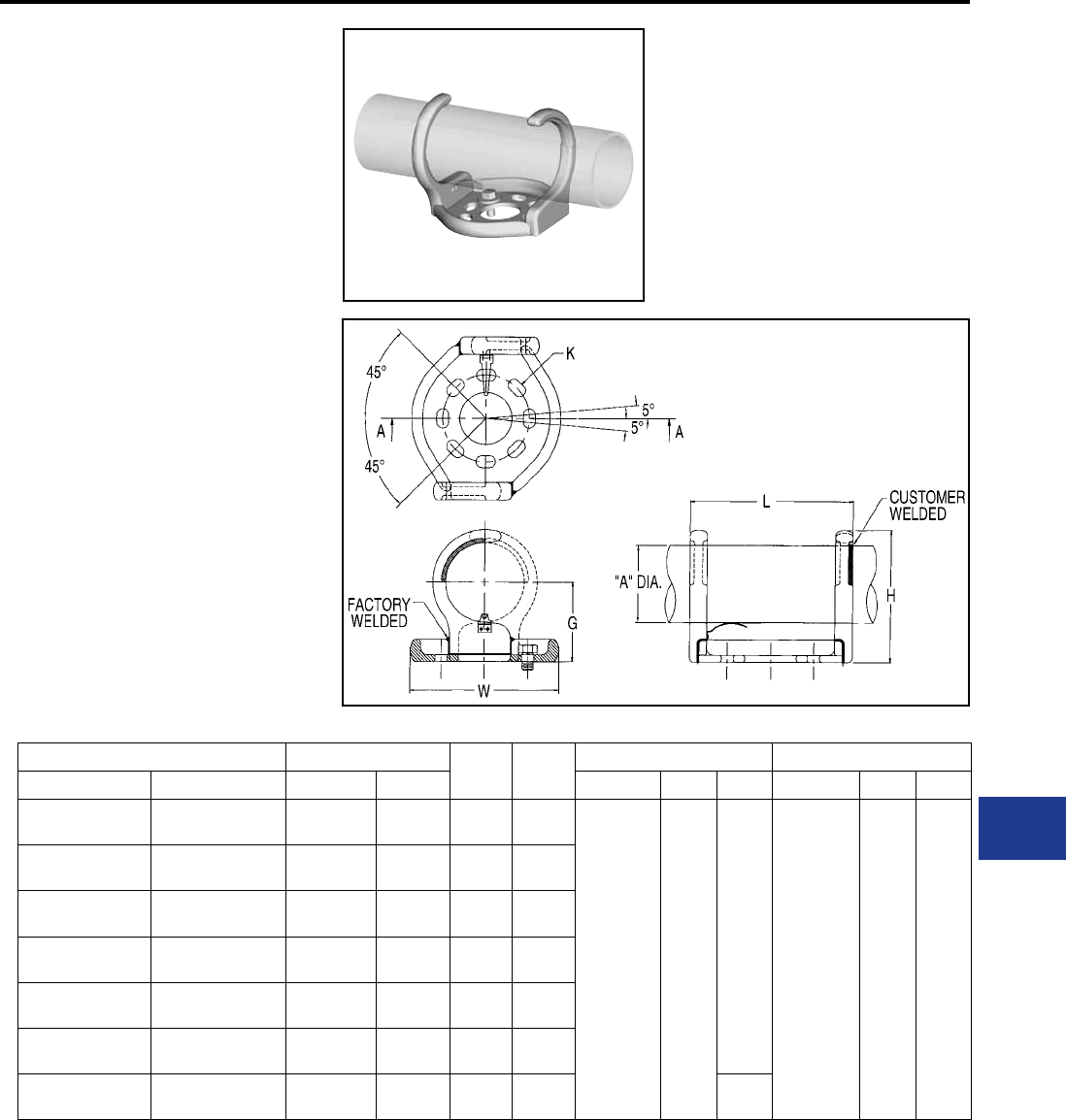
BURNDY®
Blue highlighted items are industry standard and most frequently ordered.
Canada: 1-800-387-6487 www.burndy.com US: 1-800-346-4175
WELDED RIGID OR
SLIP FIT BUS
SUPPORT
SWHRH-A
Welded type
Application: Fixed or Slip Fit Bus
Support to Insulator.
EHV RATED: SELF-SHIELDING
UP TO 550 kV—
When used on
corona free Post
Insulators.
Material: Cast 356 Aluminum Alloy
Catalog Number Aluminum Conductor G H 3″ Bolt Circle 5″ Bolt Circle
3″ Bolt Circle 5″ Bolt Circle IPS/EHPS “A” Dia. K L W K L W
SWHRH18A-3CH SWHRH18A-5CH 2″ 2.38
[60]
2.75
[70]
4.58
[116]
0.56 X 0.75
[14 X 19]
7.76
[197]
6.62
[159] 0.69 X 0.88
[18 X 22]
9.37
[238]
8.61
[219]
SWHRH19A-3CH SWHRH19A-5CH 2-1/2″ 2.88
[73]
3.12
[79]
5.21
[132]
SWHRH20A-3CH SWHRH20A-5CH 3″ 3.50
[89]
3.62
[92]
6.15
[156]
SWHRH21A-3CH SWHRH21A-5CH 3-1/2″ 4.00
[102]
4.00
[102]
6.77
[172]
SWHRH22A-3CH SWHRH22A-5CH 4″ 4.50
[114]
4.50
[114]
7.52
[191]
SWHRH24A-3CH SWHRH24A-5CH 5″ 5.56
[141]
5.00
[127]
8.68
[220]
SWHRH86A-3CH SWHRH86A-5CH 6″ 6.63
[168]
5.50
[140]
9.71
[247]
8.61
[219]
NOTES:
1. Dimensions in brackets [ ] are in millimeters.
2. G dimension conforms to NEMA standards.
3. Cap mounting (galvanized steel) hardware supplied as
standard. For Base mounting hardware add SUFFIX
“B” to catalog number (example: SWHRH22A-5B).
4. Conductors smaller than 3 inch bus size not
recommended for 550 kV.
M-25
Substation
Welded/EHV
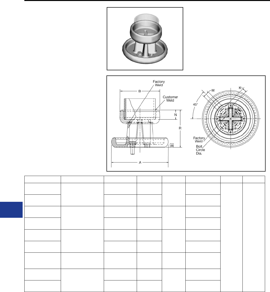
BURNDY®
Blue highlighted items are industry standard and most frequently ordered.
US: 1-800-346-4175 www.burndy.com Canada: 1-800-387-6487
WELDED VERTICAL
BUS SUPPORT
SWVH-A
Weld type
Application: Bus to insulator
(Vertical Position)
EHV RATED: SELF-SHIELDING
UP TO 550 kV
Material: Cast 356 Aluminum Alloy
Hardware: Galvanized Steel
Catalog Number Accommodates Bolt Circle Dia. “A” Dia. “B” Dia. “K” & “M” Slot N R
SWVH19A-5 2-1/2″ IPS (2.88 Dia.)
(73)
Alum. Tube
5″ 8.19
[208] 4.16
[106]
0.69 x 1.12
[18] [28]
1.38
[35]
5.38
[137]
SWVH19A-7 7″ 10.25
[260]
0.81 x 1.44
[21] [37]
SWVH20A-5 3″ IPS (3.50 Dia.)
(89)
Alum. Tube
5″ 8.19
[208] 4.79
[122]
0.69 x 1.12
[18] [28]
SWVH20A-7 7″ 10.25
[260]
0.81 x 1.44
[21] [37]
SWVH22A-5 4″ IPS (4.50 Dia.)
(114)
Alum. Tube
5″ 8.19
[208] 5.79
[147]
0.69 x 1.12
[18] [28]
SWVH22A-7 7″ 10.25
[260]
0.81 x 1.44
[21] [37]
SWVH24A-5
5″ IPS (5.56 Dia.)
(141)
Alum. Tube
5″ 8.19
[208]
6.87
[175]
0.69 x 1.12
[18] [28]
SWVH86A-5 6″ IPS (6.63 Dia.)
(168)
Alum. Tube
5″ 8.19
[208] 7.93
[201]
0.69 x 1.12
[18] [28]
SWVH86A-7 7″ 10.25
[260]
0.81 x 1.44
[21] [37]
NOTES:
1. Dimensions in brackets [ ] are in millimeters.
2. Cap mounting hardware supplied. For base mounted
hardware add SUFFIX “B” to catalog number
(example: SWVH22A5B).
3. Conductors smaller than 3 inch not recommended for
550 kV.
M-26
Substation
Welded/EHV
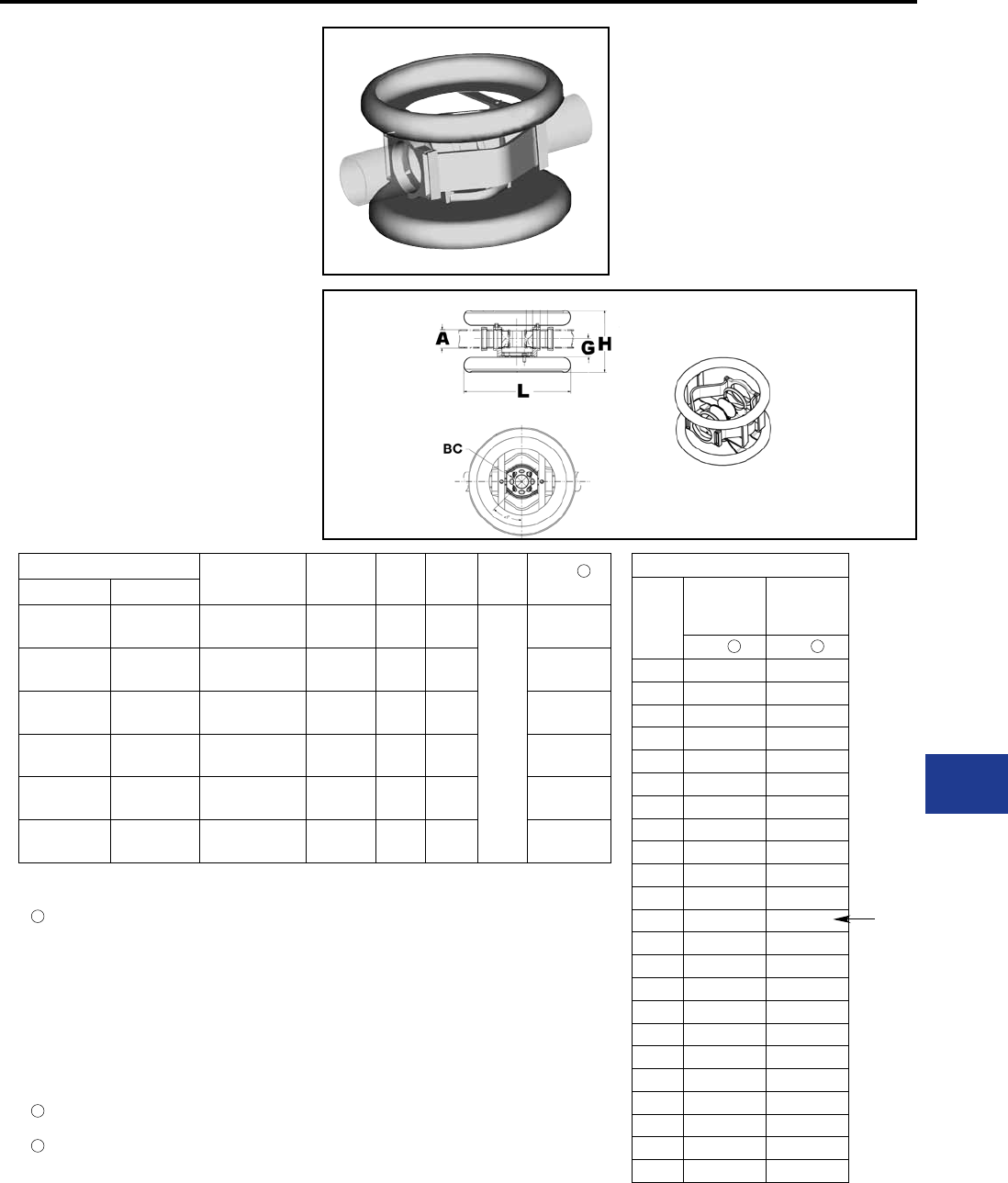
BURNDY®
Blue highlighted items are industry standard and most frequently ordered.
Canada: 1-800-387-6487 www.burndy.com US: 1-800-346-4175
WELDED EXPANSION
BUS SUPPORT
COUPLER
SWXHP-A
Weld type
Application: Bus to Bus Expansion
Coupler to Insulator
EHV RATED: SELF-SHIELDING
up to 550 kV
Material: Cast 356 Aluminum Alloy
Corona Rings: Aluminum Alloy
Straps: Laminated Aluminum Strap
NOTES:
*Conforms to NEMA standards.
1 Maximum movement per end equals one-half of total
movement specied in table.
2. Dimensions in brackets [ ] are in millimeters.
3. Cap mounting hardware supplied (Galvanized Steel).
For base mounted hardware add SUFFIX “B” to catalog
number (example: SWXHP20A5B).
4. Conductors smaller than 3 inch not recommended for
550 kV.
5. Bus support couplers are supplied without bus end
plugs. If end plugs are required, add SUFFIX “EP” to
catalog number (example: SWXHP20A5EP).
6 Table is based on 80 ft. max. bus run (total) or 40 ft. per
end.
7 Table is based on 110 ft. max. bus run (total) or 55 ft. per
end.
Catalog Number “A” Dia. Alum.
Tube
Bolt
Circle Dia. G* H L Total 1
Movement
Sch 40 Sch 80
SWXHP19A-5 SWXHP59A-5 2-1/2″ (2.88 Dia.)
[73]
5.00
[127]
3.12
[79]
12.77
[18]
26.00
[660]
3.00
[76]
SWXHP20A-5 SWXHP90A-5 3″ (3.50 Dia.)
[89]
5.00
[127]
3.62
[92]
13.62
[18]
3.00
[76]
SWXHP21A-5 SWXHP91A-5 3-1/2″ (4.00 Dia.)
[102]
5.00
[127]
4.00
[102]
14.25
[18]
3.00
[76]
SWXHP22A-5 SWXHP92A-5 4″ (4.50 Dia.)
[114]
5.00
[127]
4.50
[114]
14.90
[18]
4.00
[102]
SWXHP24A-5 SWXHP94A-5 5″ (5.56 Dia.)
[141]
5.00
[127]
5.25
[133]
16.31
[18]
4.00
[102]
SWXHP86A-5 SWXHP96A-5 6″ (6.63 Dia.)
[168]
5.00
[127]
5.50
[140]
17.34
[18]
4.00
[102]
Installation Data
Bus
Temp
F°
3" Total
Movement
4" Total
Movement
Z 6Z 7
–20 0.75 0.75
–10 0.82 0.84
0 0.89 0.83
10 0.95 1.02
20 1.02 1.11
30 1.09 1.20
40 1.16 1.29
50 1.23 1.39
60 1.30 1.48
70 1.36 1.57
80 1.43 1.66
90 1.50 1.75
100 1.57 1.84
110 1.64 1.93
120 1.70 2.02
130 1.77 2.11
140 1.84 2.20
150 1.91 2.29
160 1.98 2.39
170 2.05 2.48
180 2.11 2.57
190 2.18 2.66
200 2.25 2.75
NOMINAL
POSITION
M-27
Substation
Welded/EHV
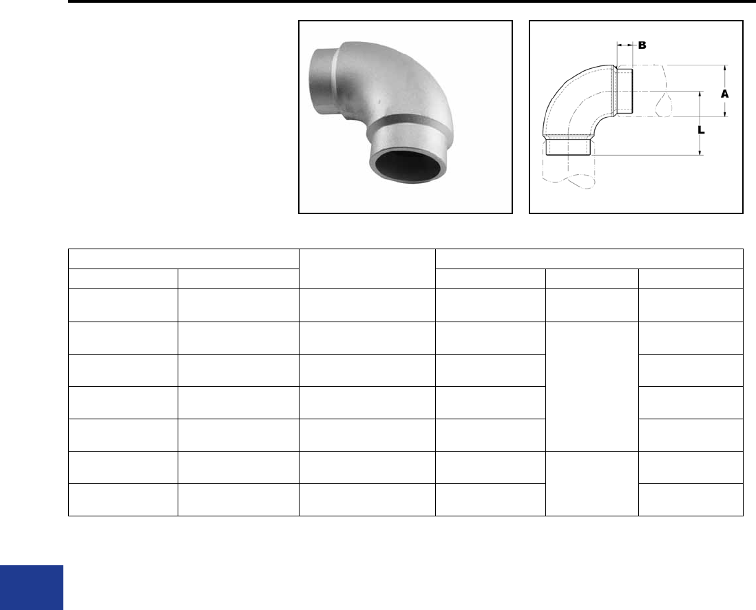
BURNDY®
Blue highlighted items are industry standard and most frequently ordered.
US: 1-800-346-4175 www.burndy.com Canada: 1-800-387-6487
WELDED 90° ELBOW
SWL-A
Application: Bus to Bus Elbow, 90°
EHV RATED: SELF-SHIELDING
UP TO 550 kV
Material: Cast 356 Aluminum Alloy
Catalog Number Conductor
Aluminum Tubing Size
Dimensions In./[mm]
Sch. 40 Sch. 80 A Dia. B L
SWL18A SWL58A 2″ 2.38
[60.4]
1.00
[25]
3.50
[89]
SWL19A SWL59A 2-1/2″ 2.88
[73]
1.38
[35]
3.88
[99]
SWL20A SWL90A 3″ 3.50
[89]
4.68
[119]
SWL21A SWL91A 3-1/2″ 4.00
[102]
5.12
[130]
SWL22A SWL92A 4″ 4.50
[114]
5.63
[143]
SWL24A SWL93A 5″ 5.56
[141] 1.62
[41]
6.16
[156]
SWL86A SWL96A 6″ 6.63
[168]
6.16
[156]
NOTES:
1. Dimensions in brackets [ ] are in millimeters.
2. Conductor smaller than 3 inch bus size not recom-
mended for 550 kV.
3. For 45° angle ADD SUFFIX "45" to catalog number
(example: SWL22A-45).
M-28
Substation
Welded/EHV
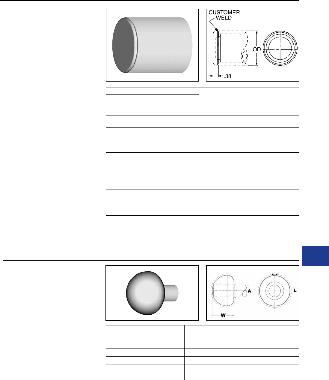
BURNDY®
Blue highlighted items are industry standard and most frequently ordered.
Canada: 1-800-387-6487 www.burndy.com US: 1-800-346-4175
WELDED END PLUG
WLB-A
Weld type
Application : Bus to End Cap, used
with shielded bus
support/expansion
couplers
EHV RATED : UP TO 550 kV
when used with
shielded bus and
expansion
connectors
Material: Cast 356 Aluminum Alloy
Catalog Number O.D. Conductor Aluminum
Tubing Size
Sch. 40 Sch. 80
WLB15A WLB55A 1.32
[34] 1″
WLB16A WLB56A 1.66
[42] 1-1/4″
WLB17A WLB57A 1.90
[48] 1-1/2″
WLB18A WLB58A 2.38
[60] 2″
WLB19A WLB59A 2.88
[73] 2-1/2″
WLB20A WLB90A 3.50
[89] 3″
WLB21A WLB91A 4.00
[102] 3-1/2″
WLB22A WLB92A 4.50
[114] 4″
WLB24A WLB94A 5.56
[141] 5″
WLB86A WLB96A 6.62
[168] 6"
NOTES:
1. Dimensions in brackets [ ] are in millimeters.
2. Conductor smaller than 3 inch bus size not recommended
for 550 kV.
WELDED CORONA
BELL
SCB-A
Weld type
Application: Bus to Corona Bell
EHV RATED: SELF-SHIELDING
UP TO 550 kV
Material: Aluminum Alloy
Catalog Number Accommodates ‘A’ Dia. Aluminum Tube
SCB19A 2-1/2″ (2.875 Dia.)
SCB20A 3″ (3.500 Dia.)
SCB21A 3-1/2″ (4.000 Dia.)
SCB22A 4″ (4.500 Dia.)
SCB24A 5″ (5.563 Dia.)
SCB86A 6″ (6.625 Dia.)
NOTES:
1. For bolted design contact factory.
2. Dimensions in brackets [ ] are in millimeters.
3. Conductor smaller than 3 inch bus size not recommended
for 550 kV.
M-29
Substation
Welded/EHV
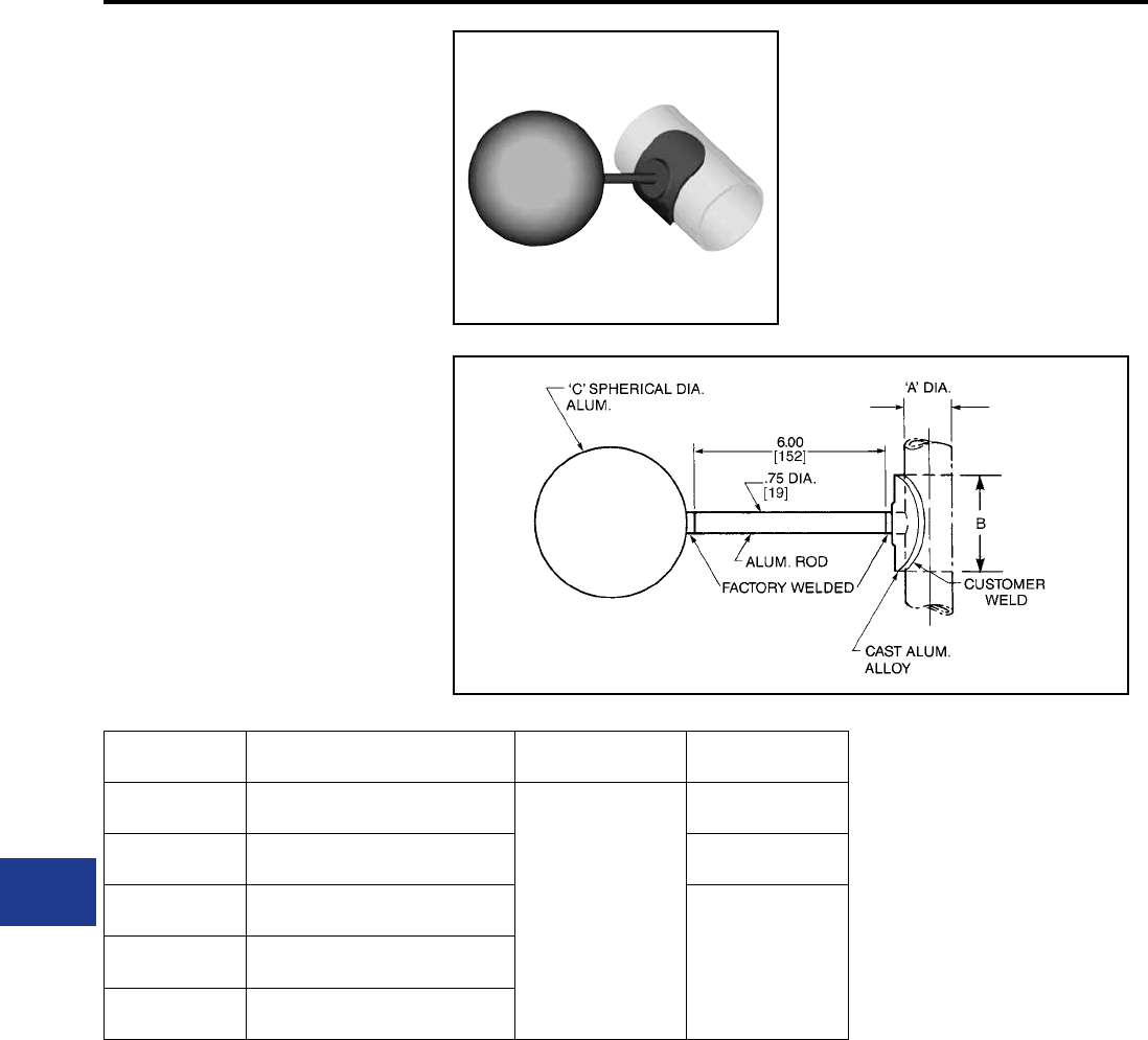
BURNDY®
Blue highlighted items are industry standard and most frequently ordered.
US: 1-800-346-4175 www.burndy.com Canada: 1-800-387-6487
WELDED GROUND
STUD
SWCB-A
Weld type
Application : Bus to corona sphere
EHV RATED : SELF-SHIELDING
UP TO 550 kV
Material: Cast 356 Aluminum Alloy
Corona Sphere: Aluminum Alloy
Catalog
Number ‘A’ Dia. Aluminum Tube ‘C’ Dia. B
SWCB19A 2-1/2″ I.P.S. (2.875 Dia.)
[73]
9.00
[229]
1.50
[38]
SWCB20A 3″ I.P.S. (3.500 Dia.)
[89]
3.00
[76]
SWCB22A 4″ I.P.S (4.500 Dia.)
[114]
4.00
[102]
SWCB24A 5″ I.P.S (5.563 Dia.)
[141]
SWCB86A 6″ I.P.S (6.625 Dia.)
[168]
NOTES:
1. Dimensions in brackets [ ] are in millimeters.
2. Conductor smaller than 3 inch bus size not recommended
for 550 kV.
M-30
Substation
Welded/EHV
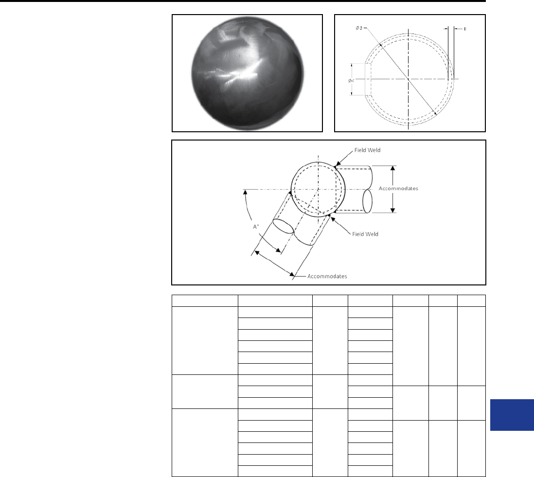
BURNDY®
Blue highlighted items are industry standard and most frequently ordered.
Canada: 1-800-387-6487 www.burndy.com US: 1-800-346-4175
M-31
Substation
Welded/EHV
WELDED SPHERICAL
COUPLER
WSBC-A
Weld type
Application : For Use on Alumininum
Pipe-to-Pipe Connections
EHV RATED : UP TO 500 kV
Aluminum Alloy
streamlined, variable angle
spherical coupler.
Self-shielding at operating
voltages up to 500 kV.
Material: Aluminum Alloy
Notes:
Welding to be done by customer.
Catalog Number Conductor Range Max kV A° Max B C D
WSBC74A
1-1/2” SPS
230
130°
5.00
[127]
1.75
[44]
.31
[8]
2” SPS 115°
2-1/2” SPS 105°
3” SPS 90°
3-1/2” SPS 80°
4” SPS 50°
WSBC83A
3” SPS - 5” SPS
345
90°
6” SPS 60°8.00
[203]
2.75
[70]
.44
[11]
8” OD SPS 40°
WSBC128A
3” SPS
500
140°
3-1/2” SPS 135°
12.00
[305]
2.75
[70]
.38
[10]
4” SPS 130°
5” SPS 120°
6” SPS 100°
8” OD SPS 90°
NOTES:
1. Dimensions in brackets [ ] are in millimeters.
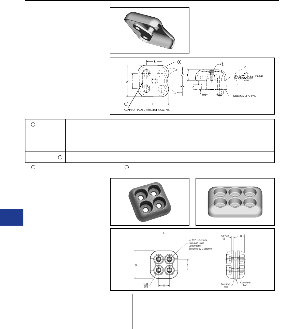
BURNDY®
Blue highlighted items are industry standard and most frequently ordered.
US: 1-800-346-4175 www.burndy.com Canada: 1-800-387-6487
Catalog number includes one pad cap, one adapter plate,
and stainless steel adaptor hardware.
TERMINAL PAD CAP
(Two Piece)
STS-A-N
Bolted type
Application: Pad shielding
EHV RATED : SELF-SHIELDING
UP TO 550 kV
TERMINAL PAD CAP
(One Piece)
STS-A-NCG
Bolted type
Application: Pad shielding
EHV RATED : SELF-SHIELDING
UP TO 550 kV
Material: Cast 356 Aluminum Alloy
Cast 356 Aluminum Alloy
1/4″–20 x 3-3/4″ LG
Stainless Steel Hex Hd. Bolt
and Split Lockwasher
Material:
Hardware:
Catalog
Number E F H L W Maximum Shielded Area
STS33A-4N 1.75
[44]
1.75
[44]
1.25
[32]
3.48
[88]
3.62
[92]
3 X 3
[76] X [76]
STS43A-4N 1.75
[44]
1.75
[44]
1.31
[33]
3.36
[85]
4.50
[114]
4.00 X 3.12
[102 X 79]
STS44A-4N 1.75
[44]
1.75
[44]
1.25
[32]
4.50
[114]
4.62
[117]
4 X 4
[102 X 102]
1
1
2
2Used with YNA451R-T and YNA451R-T15 through
YNA594R-T and YNA594R-T15 compression terminals.
Catalog Number E F H L W Maximum Shielded
Area
STS44A-4NCG2 1.75
[44]
1.75
[44]
1.25
[32]
4.50
[114]
4.50
[114] 4 x 4
STS46A6NCG1 1.75
[44]
1.75
[44]
1.25
[32]
4.50
[114]
6.50
[165] 6 x 4
NOTES:
1. Dimensions in brackets [ ] are in millimeters.
2. Catalog number is for one shielding cap only. If more than
one is required, speciy total quantity.
Substation
Welded/EHV
M-32
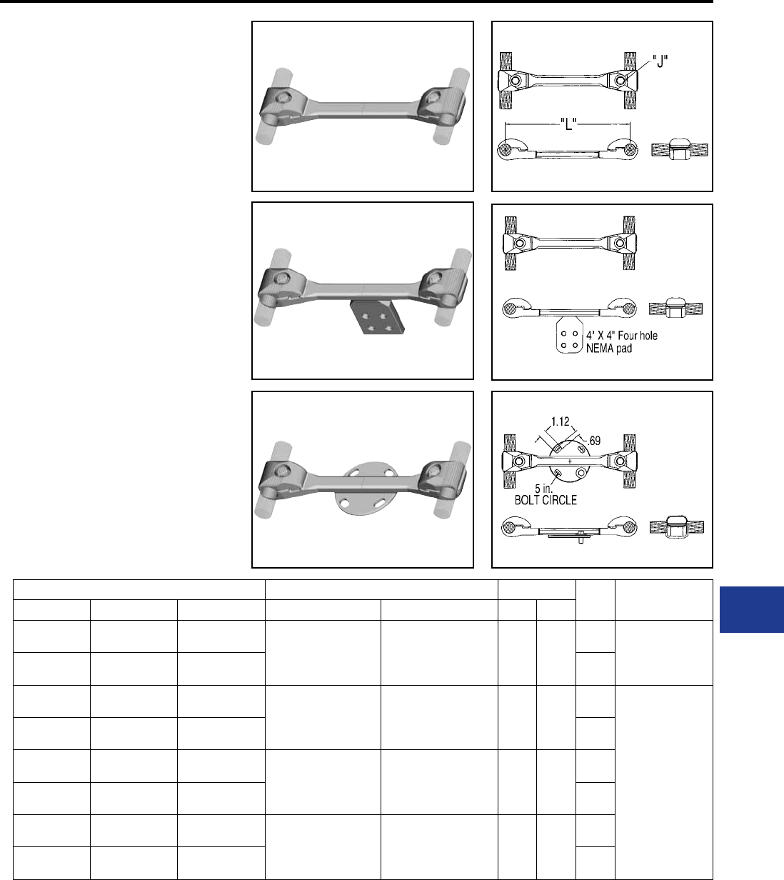
BURNDY®
Blue highlighted items are industry standard and most frequently ordered.
Canada: 1-800-387-6487 www.burndy.com US: 1-800-346-4175
BOLTED BUNDLED
CABLE SPACER
S2GBP-A (Spacer)
S2GBPA-A (Terminal Tap)
SH2GBP-A (Bus Support)
Bolted type
Application: Cable to Cable spacer
(Two Cables), Cable
spacer with four hole
pad, and Cable spacer
to insulator.
EHV RATED: SELF-SHIELDING
UP TO 550 kV
Cast 356 Aluminum Alloy
Aluminum Alloy
Material:
Hardware:
Catalog Number Cable Range Cable Dia. “L” “J” Dia.
Fig. 1 Fig. 2 Fig. 3 AAC ACSR Min. Max.
S2GBP41A S2GBPA41A SH2GBP41A5 795 kcmil 37 Str.
(1.026 Dia.)
874.5 kcmil 61 Str.
(1.077 Dia.)
715 kcmil 24/7 Str.
(1.036 Dia.)
715.5 kcmil 26/7 Str.
(1.051 Dia.)
1.026
[26]
1.092
[28]
18.00
[457] 5/8″–11 X 1-3/4″ LG.
Alum. Alloy
S2GBP41A12 S2GBPA41A12 SH2GBP41A512 12.00
[305]
S2GBP44A S2GBPA44A SH2GBP44A5 954 kcmil 61 Str.
(1.126 Dia.)
795 kcmil 24/7 Str.
(1.092 Dia.)
795 kcmil 54/7 Str.
(1.093 Dia.)
1.092
[28]
1.165
[30]
18.00
[457]
5/8″–11 X 2″ LG.
Alum. Alloy
S2GBP44A12 S2GBPA44A12 SH2GBP44A512 12.00
[305]
S2GBP445A S2GBPA445A SH2GBP445A5 1033.5 kcmil 37 Str.
(1.170 Dia.)
1113 kcmil 61 Str.
(1.216 Dia.)
954 kcmil 45/7 Str.
(1.165 Dia.)
1033.5 kcmil 45/7 Str.
(1.213 Dia.)
1.165
[30]
1.246
[32]
18.00
[457]
S2GBP445A12 S2GBPA445A12 SH2GBP445A512 12.00
[305]
S2GBP45A S2GBPA45A SH2GBP45A5 1192 kcmil 61 Str.
(1.258 Dia.)
1272 kcmil 61 Str.
(1.300 Dia.)
1033.5 kcmil 54/7 Str.
(1.246 Dia.)
1192.5 kcmil 54/19 Str.
(1.333 Dia.)
1.246
[32]
1.382
[35]
18.00
[457]
S2GBP45A12 S2GBPA45A12 SH2GBP45A512 12.00
[305]
NOTES:
1. Dimensions in brackets [ ] are in millimeters.
2. For stainless steel hardware add SUFFIX “SS” to catalog
number (example: S2GBP41ASS).
3. For variations in cable spacing contact factory.
4. For pad rotated 90° on S2GBPA-A add sufx R90 to the
catalog number (example: S2GBPA44AR90).
5. For Bolt Circles other than 5 inch on type SH2GBP-A
contact factory.
6. S2GBPA-A connectors rated 550 kV when used with
type “STS” Shielding Caps. Ordered separately.
Fig. 1 Fig. 1
Fig. 2 Fig. 2
Fig. 3 Fig. 3
Substation
Welded/EHV
M-33
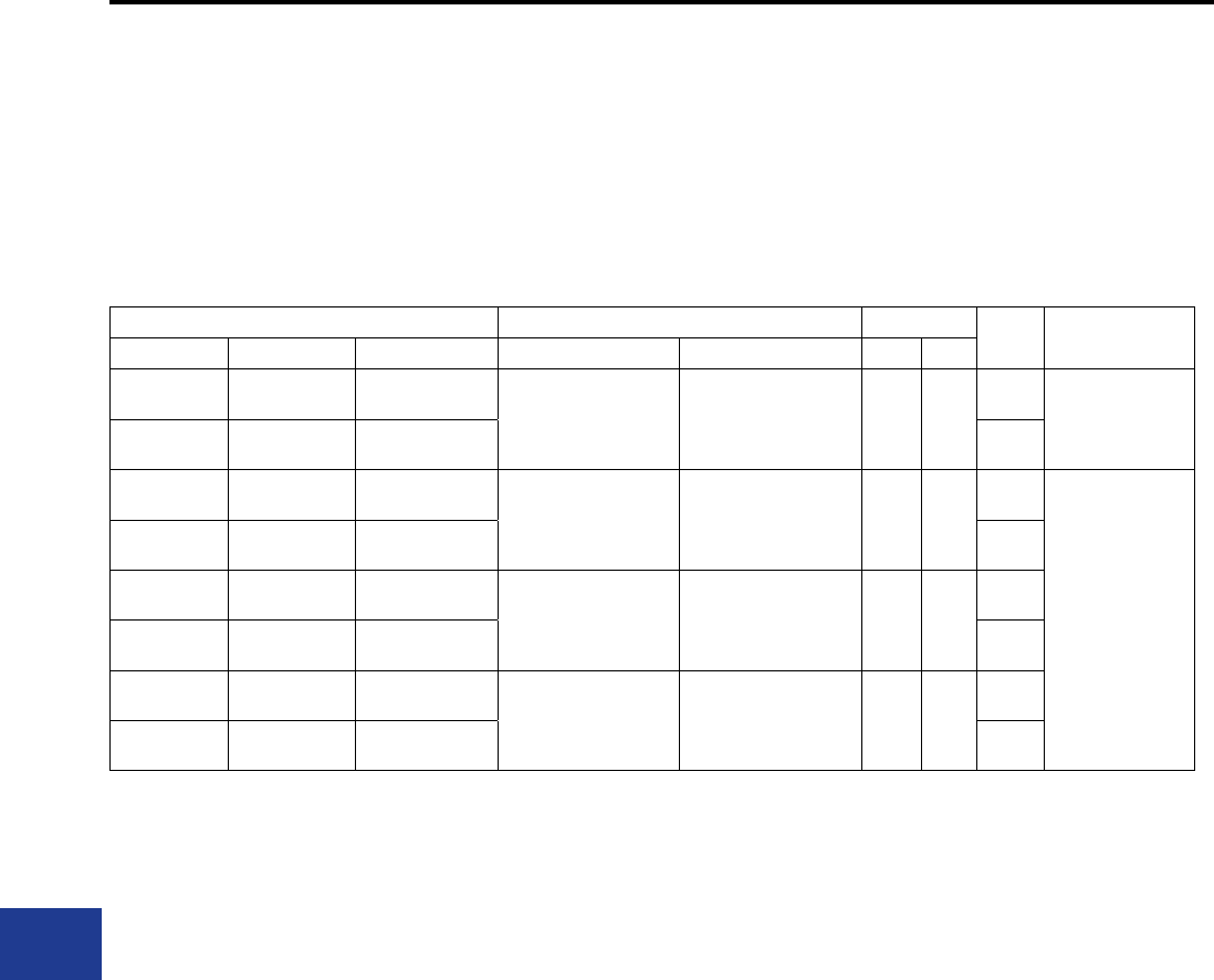
BURNDY®
Blue highlighted items are industry standard and most frequently ordered.
US: 1-800-346-4175 www.burndy.com Canada: 1-800-387-6487
Catalog Number Cable Range Cable Dia. “L” “J” Dia.
Fig. 1 Fig. 2 Fig. 3 AAC ACSR Min. Max.
S2GBP46A S2GBPA46A SH2GBP46A5 1590 kcmil 61 Str.
(1.453 Dia.)
1600 kcmil 127 Str.
(1.454 Dia.)
1272 kcmil 54/19 Str.
(1.382 Dia.)
1431 kcmil 54/19 Str.
(1.465 Dia.)
1.382
[35]
1.504
[38]
18.00
[457] 5/8″–11 X 1-3/4″ LG.
Alum. Alloy
S2GBP46A12 S2GBPA46A12 SH2GBP46A512 12.00
[305]
S2GBP48A S2GBPA48A SH2GBP48A5 1750 kcmil 127 Str.
(1.526 Dia.)
2000 kcmil 91 Str.
(1.630 Dia.)
1590 kcmil 45/7 Str.
(1.502 Dia.)
1750 kcmil 84/19 Str.
(1.602 Dia.)
1.504
[38]
1.632
[41]
18.00
[457]
5/8″–11 X 2″ LG.
Alum. Alloy
S2GBP48A12 S2GBPA48A12 SH2GBP48A512 12.00
[305]
S2GBP483A S2GBPA483A SH2GBP483A5 2000 kcmil 91 Str.
(1.630 Dia.)
2250 kcmil 91 Str.
(1.729 Dia.)
1890 kcmil 84/19 Str.
(1.650 Dia.)
2167 kcmil 72/7 Str.
(1.737 Dia.)
1.632
[41]
1.737
[44]
18.00
[457]
S2GBP483A12 S2GBPA483A12 SH2GBP483A512 12.00
[305]
S2GBP486A S2GBPA486A SH2GBP486A5 2300 kcmil 61 Str.
(1.750 Dia.)
2500 kcmil 127 Str.
(1.823 Dia.)
2167 kcmil 72/7 Str.
(1.737 Dia.)
2156 kcmil 84/19 Str.
(1.762 Dia.)
1.737
[44]
1.824
[46]
18.00
[457]
S2GBP486A12 S2GBPA486A12 SH2GBP486A512 12.00
[305]
BOLTED BUNDLED
CABLE SPACER
(Continued)
S2GBP-A (Spacer)
S2GBPA-A (Terminal Tap)
SH2GBP-A (Bus Support)
NOTES:
1. Dimensions in brackets [ ] are in millimeters.
2. For stainless steel hardware add SUFFIX “SS” to catalog
number (example: S2GBP41ASS).
3. For variations in cable spacing contact factory.
4. For pad rotated 90° on S2GBPA-A add sufx R90 to the
catalog number (example: S2GBPA44AR90).
5. For Bolt Circles other than 5 inch on type SH2GBP-A
contact factory.
6. S2GBPA-A connectors rated 550 kV when used with
type “STS” Shielding Caps. Ordered separately.
Substation
Welded/EHV
M-34
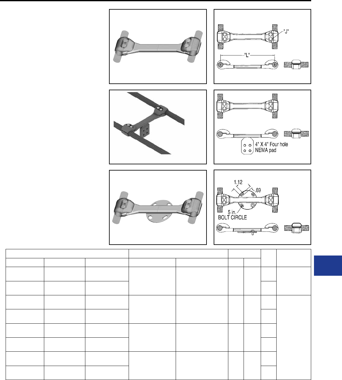
BURNDY®
Blue highlighted items are industry standard and most frequently ordered.
Canada: 1-800-387-6487 www.burndy.com US: 1-800-346-4175
Fig. 1 Fig. 1
Fig. 2 Fig. 2
Fig. 3 Fig. 3
BOLTED BUNDLED
CABLE SPACER
(Two Bolt Clamping)
S2GBP-AB2 (Spacer)
S2GBPA-AB2 (Terminal Tap)
SH2GBP-A-B2 (Bus Support)
Bolted type
Application: Cable to Cable spacer
(Two Cables), Cable
spacer with four hole
pad, and Cable spacer
to insulator.
EHV RATED: SELF-SHIELDING
UP TO 550 kV
Cast 356 Aluminum Alloy
Aluminum Alloy
Material:
Hardware:
Catalog Number Cable Range Cable Dia. “L” “J” Dia.
Fig. 1 Fig. 2 Fig. 3 AAC ACSR Min. Max.
S2GBP41AB2 S2GBPA41AB2 SH2GBP41A5B2 795 kcmil 37 Str.
(1.026 Dia.)
874.5 kcmil 61 Str.
(1.077 Dia.)
715 kcmil 24/7 Str.
(1.036 Dia.)
715.5 kcmil 26/7 Str.
(1.051 Dia.)
1.026
[26]
1.092
[28]
18.00
[457] 5/8″–11 X 1-1/2″
LG.
Alum. Alloy
S2GBP41A12B2 S2GBPA41A12B2 SH2GBP41A512B2 12.00
[305]
S2GBP44AB2 S2GBPA44AB2 SH2GBP44A5B2 954 kcmil 61 Str.
(1.126 Dia.)
795 kcmil 24/7 Str.
(1.092 Dia.)
795 kcmil 54/7 Str.
(1.093 Dia.)
1.092
[28]
1.165
[30]
18.00
[457]
5/8″–11 X 1-3/4″
LG.
Alum. Alloy
S2GBP44A12B2 S2GBPA44A12B2 SH2GBP44A512B2 12.00
[305]
S2GBP445AB2 S2GBPA445AB2 SH2GBP445A5B2 1033.5 kcmil 37 Str.
(1.170 Dia.)
1113 kcmil 61 Str.
(1.216 Dia.)
954 kcmil 45/7 Str.
(1.165 Dia.)
1033.5 kcmil 45/7 Str.
(1.213 Dia.)
1.165
[30]
1.246
[32]
18.00
[457]
S2GBP445A12B2 S2GBPA445A12B2 SH2GBP445A512B2 12.00
[305]
S2GBP45AB2 S2GBPA45AB2 SH2GBP45A5B2 1192 kcmil 61 Str.
(1.258 Dia.)
1272 kcmil 61 Str.
(1.300 Dia.)
1033.5 kcmil 54/7 Str.
(1.246 Dia.)
1192.5 kcmil 54/19 Str.
(1.333 Dia.)
1.246
[32]
1.382
[35]
18.00
[457]
S2GBP45A12B2 S2GBPA45A12B2 SH2GBP45A512B2 12.00
[305]
NOTES:
1. Dimensions in brackets [ ] are in millimeters.
2. For stainless steel hardware add SUFFIX “SS” to catalog
number (example: S2GBP41AB2SS).
3. For variations in cable spacing contact factory.
4. For pad rotated 90° on S2GBPA-AB2 add sufx R90 to the
catalog number (example: S2GBPA44AB2R90).
5. For Bolt Circles other than 5 inch on type SH2GBP-A-B2
contact factory.
6. S2GBPA-B2 connectors rated 550 kV when used with
type “STS” Shielding Caps. Ordered separately.
Substation
Welded/EHV
M-35

BURNDY®
Blue highlighted items are industry standard and most frequently ordered.
US: 1-800-346-4175 www.burndy.com Canada: 1-800-387-6487
BOLTED BUNDLED
CABLE SPACER
(Two Bolt Clamping)
(Continued)
S2GBP-AB2 (Spacer)
S2GBPA-AB2 (Terminal Tap)
SH2GBP-A-B2 (Bus Support)
Catalog Number Cable Range Cable Dia. “L” “J” Dia.
Fig. 1 Fig. 2 Fig. 3 AAC ACSR Min. Max.
S2GBP46AB2 S2GBPA46AB2 SH2GBP46A5B2 1590 kcmil 61 Str.
(1.453 Dia.)
1600 kcmil 127 Str.
(1.454 Dia.)
1272 kcmil 54/19 Str.
(1.382 Dia.)
1431 kcmil 54/19 Str.
(1.465 Dia.)
1.382
[35]
1.504
[38]
18.00
[457] 5/8″–11 X 1-3/4″
LG.
Alum. Alloy
S2GBP46A12B2 S2GBPA46A12B2 SH2GBP46A512B2 12.00
[305]
S2GBP48AB2 S2GBPA48AB2 SH2GBP48A5B2 1750 kcmil 127 Str.
(1.526 Dia.)
2000 kcmil 91 Str.
(1.630 Dia.)
1590 kcmil 45/7 Str.
(1.502 Dia.)
1750 kcmil 84/19 Str.
(1.602 Dia.)
1.504
[38]
1.632
[41]
18.00
[457]
5/8″–11 X 2″
LG.
Alum. Alloy
S2GBP48A12B2 S2GBPA48A12B2 SH2GBP48A512B2 12.00
[305]
S2GBP483AB2 S2GBPA483AB2 SH2GBP483A5B2 2000 kcmil 91 Str.
(1.630 Dia.)
2250 kcmil 91 Str.
(1.729 Dia.)
1890 kcmil 84/19 Str.
(1.650 Dia.)
2167 kcmil 72/7 Str.
(1.737 Dia.)
1.632
[41]
1.737
[44]
18.00
[457]
S2GBP483A12B2 S2GBPA483A12B2 SH2GBP483A512B2 12.00
[305]
S2GBP486AB2 S2GBPA486AB2 SH2GBP486A5B2 2300 kcmil 61 Str.
(1.750 Dia.)
2500 kcmil 127 Str.
(1.823 Dia.)
2167 kcmil 72/7 Str.
(1.737 Dia.)
2156 kcmil 84/19 Str.
(1.762 Dia.)
1.737
[44]
1.824
[46]
18.00
[457]
S2GBP486A12B2 S2GBPA486A12B2 SH2GBP486A512B2 12.00
[305]
NOTES:
1. Dimensions in brackets [ ] are in millimeters.
2. For stainless steel hardware add SUFFIX “SS” to catalog
number (example: S2GBP41AB2SS).
3. For variations in cable spacing contact factory.
4. For pad rotated 90° on S2GBPA-AB2 add sufx R90 to the
catalog number (example: S2GBPA44AB2R90).
5. For Bolt Circles other than 5 inch on type SH2GBP-A-B2
contact factory.
6. S2GBPA-B2 connectors rated 550 kV when used with
type “STS” Shielding Caps. Ordered separately.
Substation
Welded/EHV
M-36
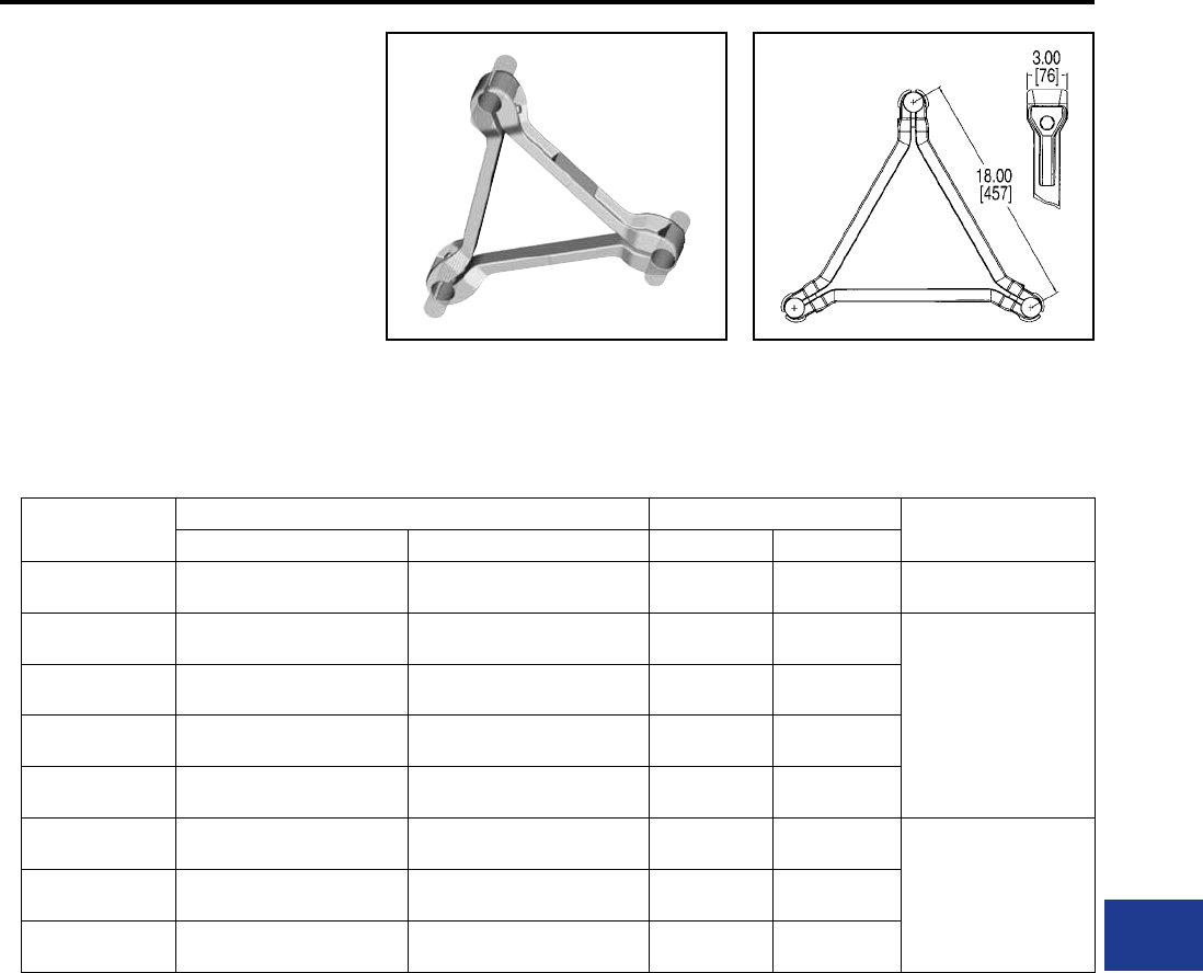
BURNDY®
Blue highlighted items are industry standard and most frequently ordered.
Canada: 1-800-387-6487 www.burndy.com US: 1-800-346-4175
BOLTED BUNDLED
CABLE SPACER
(Three Conductor)
S3GBP-A
Bolted type
Application: Cable to Cable Spacer
(three cables)
EHV RATED: SELF-SHIELDING
UP TO 550 kV
Material: Cast 356 Aluminum Alloy
Hardware: Aluminum Alloy
Catalog Number Cable Range Cable Dia. “J” Dia.
AAC ACSR Min. Max.
S3GBP41A 795 kcmil 37 Str. (1.036 Dia.)
874.5 kcmil 61 Str. (1.077 Dia)
715 kcmil 24/7 Str. (1.036 Dia.)
715.5 kcmil 26/7 Str. (1.051 Dia.)
1.026
[26]
1.092
[28]
5/8’-11 x 1-1/2″ LG.
Alum. Alloy
S3GBP44A 954 kcmil 61 Str. (1.126 Dia.) 795 kcmil 24/7 Str. (1.092 Dia.)
795 kcmil 54/7 Str. (1.093 Dia.)
1.092
[28]
1.165
[30]
5/8’-11 x 1-3/4″ LG.
Alum. Alloy
S3GBP445A 1033.5 kciml 37 Str. (1.170 Dia.)
1113 kcmil 61 Str. (1.216 Dia.)
954 kcmil 45/7 Str. (1.165 Dia.)
1033.5 kcmil 45/7 Str. (1.213 Dia.)
1.165
[30]
1.246
[32]
S3GBP45A 1192 kcmil 61 Str. (1.258 Dia.)
1272 kcmil 61 Str. (1.300 Dia.)
1033.5 kcmil 54/7 Str. (1.246 Dia.)
1192.5 kcmil 54/19 Str. (1.333 Dia.)
1.246
[32]
1.382
[35]
S3GBP46A 1590 kcmil 61 Str. (1.453 Dia.)
1600 kcmil 127 Str. (1.454 Dia.)
1272 kcmil 54/19 Str. (1.382 Dia.)
1431 kcimil 54/19 Str. (1.465 Dia.)
1.382
[35]
1.504
[38]
S3GBP48A 1750 kcmil 127 Str. (1.526 Dia.)
2000 kcmil 91 Str. (1.630 Dia.)
1590 kmcil 47/7 Str. (1.502 Dia.)
1750 kcmil 84/19 Str. (1.602 Dia.)
1.504
[38]
1.632
[41]
“5/8’-11 x 2″ LG.
Alum. Alloy”
S3GBP483A 2000 kmcil 91 Str. (1.630 Dia.)
2250 kcmil 91 Str. (1.729 Dia.)
1890 kcmil 84/19 Str. (1.650 Dia.)
2167 kcmil 72/7 Str. (1.737 Dia.)
1.632
[41]
1.737
[44]
S3GBP486A 2300 kcmil 61 Str. (1.750 Dia.)
2500 kcmil 127 Str. (1.823 Dia.)
2167 kcmil 72/7 Str. (1.737 Dia.)
2156 kcmil 84/19 Str. (1.762 Dia.)
1.737
[44]
1.824
[46]
NOTES:
1. Dimensions in brackets [ ] are in millimeters.
2. For stainless steel hardware add SUFFIX “SS” to
catalog number (example: S3GBP48ASS).
3. For variations in cable spacing contact factory.
4. For four hole straight pad tap or 90° version or bus
support three bundled cable spacer, contact the factory.
Substation
Welded/EHV
M-37
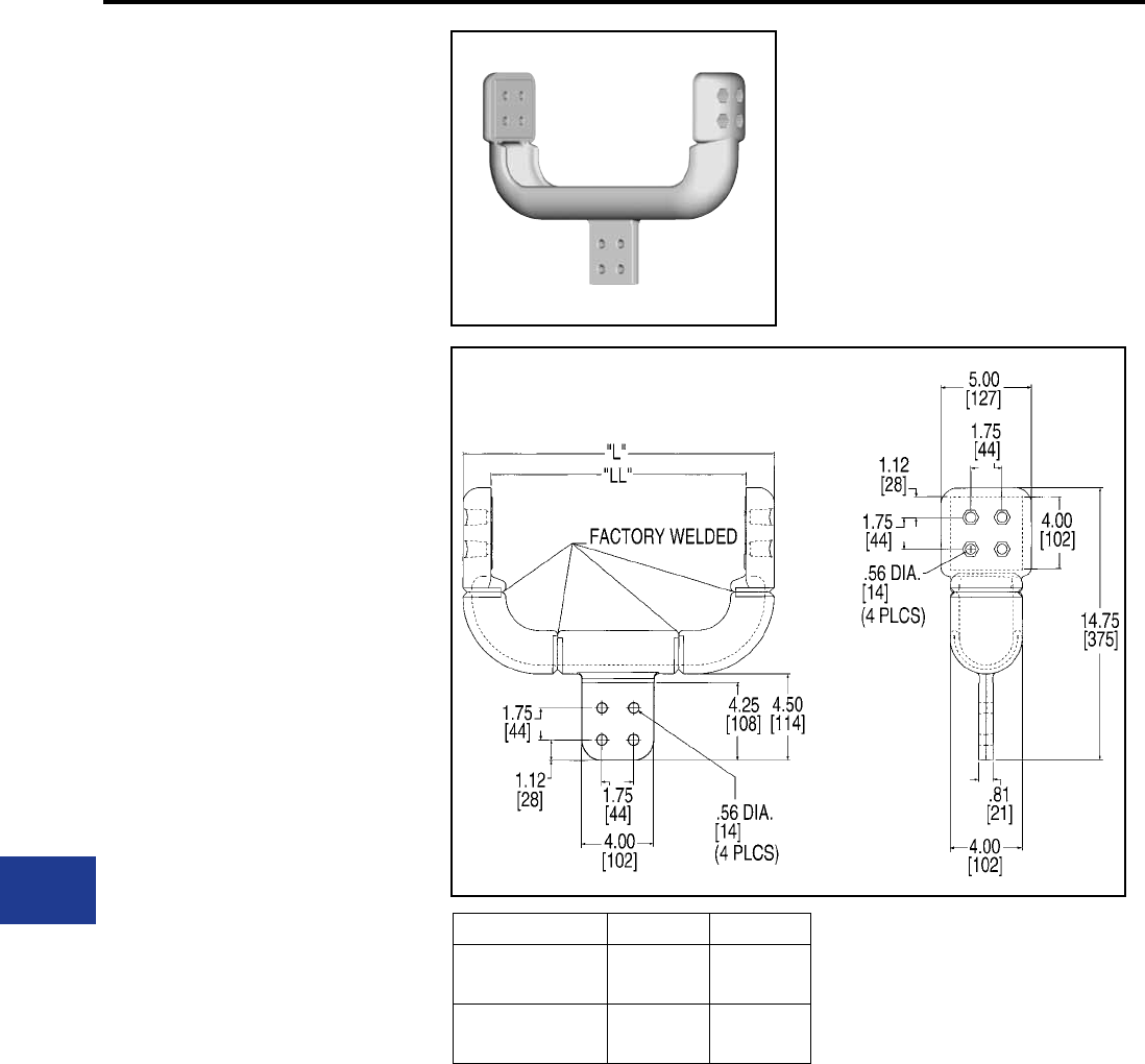
BURNDY®
Blue highlighted items are industry standard and most frequently ordered.
US: 1-800-346-4175 www.burndy.com Canada: 1-800-387-6487
BIFURCATING
TERMINAL
CONNECTOR
SF2A-NL-EX
Bolted type
Application: Four to Six Hole
NEMA Pad to Two
Four Hole NEMA
Recessed Pads
Bifurcating Terminal
EHV RATED: SELF-SHIELDING
UP TO 550 kV
Material: Cast 356 Aluminum Alloy
Catalog Number “L” “LL”
SF2A44NL12EX 17.21
[437]
13.97
[355]
SF2A44NL18EX 21.51
[546]
18.27
[464]
NOTES:
1. Dimensions in brackets [ ] are in millimeters.
2. One surface of pad nished. For nished pad on both
sides add SUFFIX “Q” to the catalog number
(example: SF2A44NL12EXQ).
3. Shielding caps are not required when terminals are
installed within the recessed Housing. Hardware ordered
separately.
4. Shielding caps are required when installing to center
(non recessed) four hole NEMA Pad. Reference STS
type shielding caps. Sold separately.
5. For six hole NEMA pad add “66” to catalog number
(example: SF2A66NL12EX).
Substation
Welded/EHV
M-38
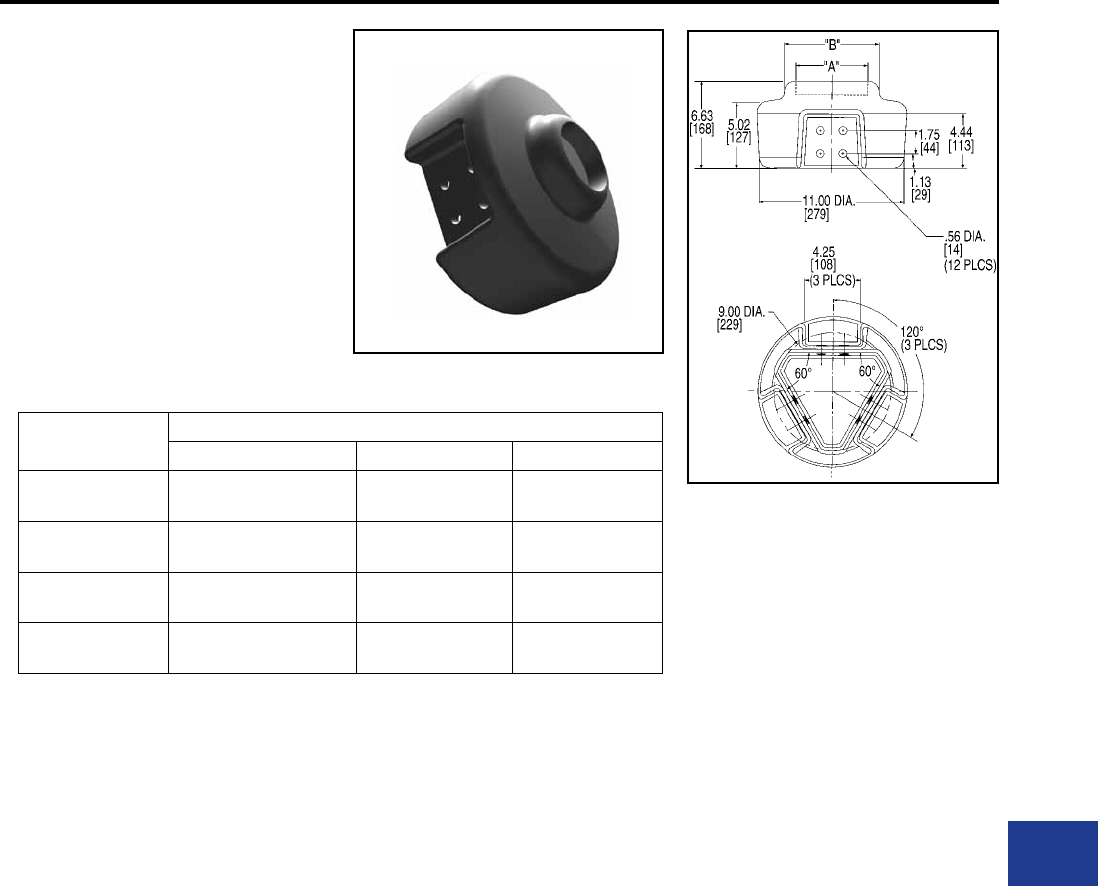
BURNDY®
Blue highlighted items are industry standard and most frequently ordered.
Canada: 1-800-387-6487 www.burndy.com US: 1-800-346-4175
TRIFURCATING COUPLER
CONNECTOR
SW3A-A44N8
Weld type
Application: Bus to Trifurcating
Terminals
EHV RATED: SELF-SHIELDING
UP TO 550 kV
Material: Cast 356 Aluminum Alloy
Catalog Number Accommodates
Alum. Tubing Size “A” Dia. “B” Dia.
SW3A20A44N8 3″
[76]
3.56
[90]
5.06
[129]
SW3A22A44N8 4″
[101]
4.57
[116]
6.09
[155]
SW3A24A44N8 5″
[127]
5.65
[144]
7.16
[182]
SW3A86A44N8 6″
[152]
6.72
[171]
8.00
[203]
NOTES:
1. Dimensions in brackets [ ] are in millimeters.
2. Shielding caps are not required when terminals
are installed within the recessed housing.
Hardware ordered separately.
Substation
Welded/EHV
M-39
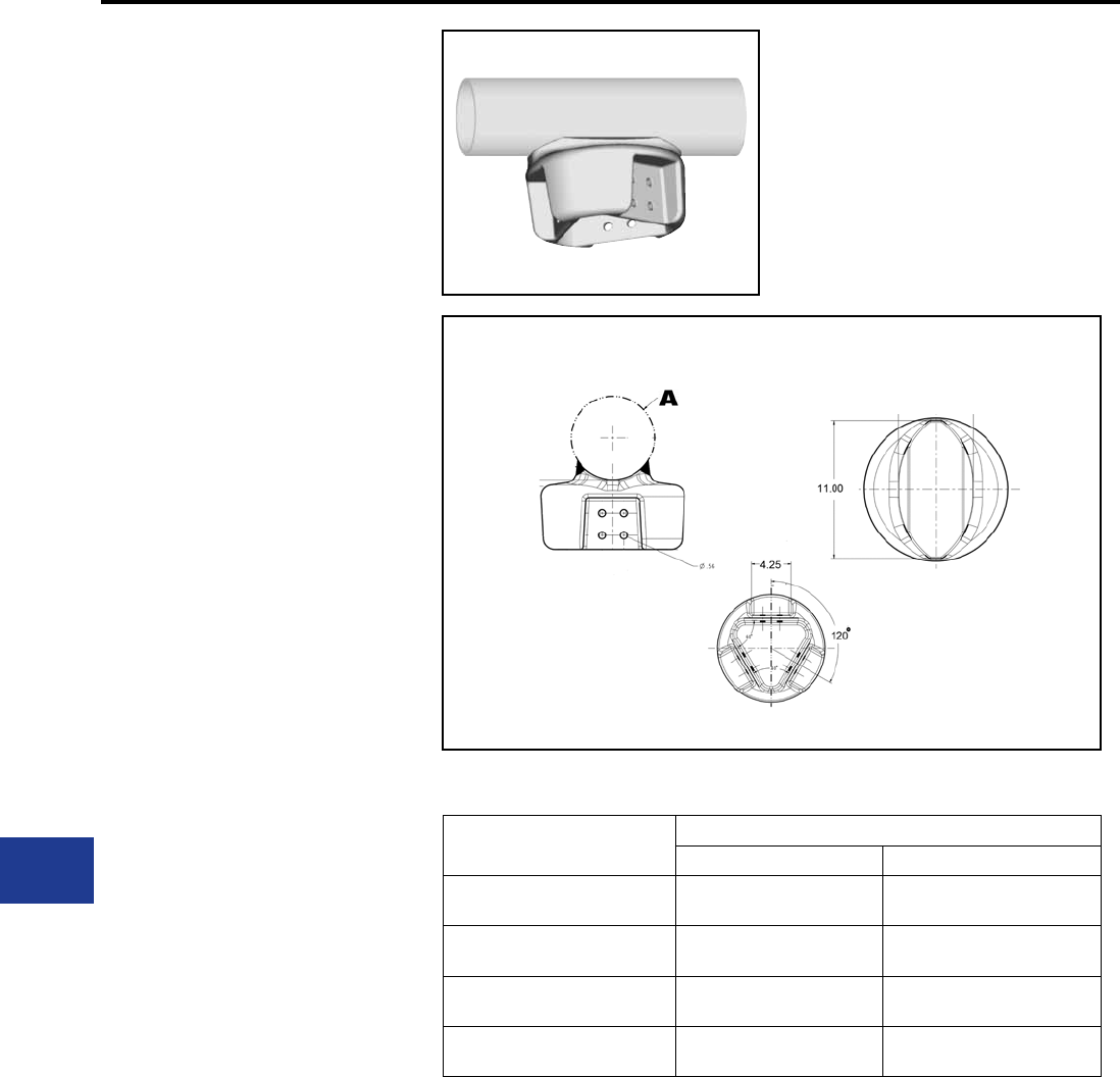
BURNDY®
Blue highlighted items are industry standard and most frequently ordered.
US: 1-800-346-4175 www.burndy.com Canada: 1-800-387-6487
TRIFURCATING TEE
CONNECTOR
SW3AB-A44N8
Weld type
Application: Bus to Trifurcating
Terminals
EHV RATED: SELF-SHIELDING
UP TO 550 kV
Material: Cast 356 Aluminum Alloy
Catalog Number Accommodates
Alum. Tubing Size “A” Dia.
SW3AB20A44N8 3″
[76]
3.50
[89]
SW3AB22A44N8 4″
[101]
4.50
[114]
SW3AB24A44N8 5″
[127]
5.56
[141]
SW3AB86A44N8 6″
[152]
6.62
[168]
NOTES:
1. Dimensions in brackets [ ] are in millimeters.
2. Shielding caps are not required when terminals are
installed within the recessed housing. Hardware ordered
separately.
Substation
Welded/EHV
M-40

BURNDY®
Canada: 1-800-387-6487 www.burndy.com US: 1-800-346-4175
Tooling
N-4
N-5
N-6
N-7
N-8
N-9
N-10
N-11
N-12
N-13
N-14
N-15
N-16
N-17
N-18
N-19
N-20
N-21
N-22
N-23
N-24
N-25
N-26
N-27
N-28
N-29
N-30
N-31
N-32
INTRODUCTION
DIES
12 Ton U Dies
W Dies
U Die Kits
GAUGES
Force Test Gauge
CRIMPERS
BATTERY ACTUATED
PAT46-LI
PAT46-18V
PAT46LW-LI, PAT46LW-18V
PAT750-LI
PAT750XT-18V
PAT750K-LI, PAT750K-18V
PAT644-LI
PAT644XT-18V
PAT81KFT-LI
PAT81KFT-18V
PAT4PC834-LI
PAT4PC834-18V
PAT600-LI
PAT600-18V
PATMD6-LI Series
PATMD6-14V Series
SELF-CONTAINED HYDRAULIC
Y750HSXT, Y750CHSXT
Y35, Y35-2
Y35 Series Accessories
Y39
Y644HSXT
Y81KFT
Y4PC834
Y500CT-HS
TABLE OF CONTENTS
REMOTE HYDRAULIC
Y60BHU
Y60LW
Y46, Y46C
Y45
Y750BHXT, Y750CBHXT
Y35BH
Y39BH
Y644MBH
Y81KFTMBH
Y4PC834MBH
Y34BH
Y29BH
MECHANICAL AND RATCHET
Y10D
Y10-22
YF22-10FL
YF-TOOL
Y8MRB-1
MR8
MRE10-22B, MRE10-22NV
MR15, MR18, MR20
MR4C
Y10MRSA1
Y122CMR
Y1MRTC
M8ND
MRC840, MRC840AL
MY28, MY29 Series
OH25
OUR840
MD6-8
MD7
MD7-34R
MD6 Hotstick Tools
MD6, MD7 Accessories
WIREMIKE
N-33
N-34
N-35
N-36
N-37
N-38
N-39
N-40
N-41
N-42
N-43
N-44
N-45
N-46
N-47
N-48
N-49
N-50
N-51
N-52
N-53
N-54
N-55
N-56
N-57
N-58
N-59
N-60
N-61
N-62
N-63
N-64
N-65
N-66
N-67
N-1

BURNDY®
US: 1-800-346-4175 www.burndy.com Canada: 1-800-387-6487
Tooling
N-68
N-69
N-70
N-71
N-72
N-73
N-74
N-75
N-76
N-77
N-78
N-79
N-80
N-81
N-82
N-83
N-84
N-85
N-86
N-87
OEM - PNEUMATIC
Y6NCP1, Y6NCP1SD
Y29NC
RATCHET TORQUE TOOL
Micro-Adjustable “Click-Type”
CUTTERS
BATTERY ACTUATED
PATHCC10-18V
PATCUT129-LI
PATCUT129ACSR-18V
PATCUT245-LI
PATCUT245CUAL-18V
PATCUT2156-LI
PATCUT2156-18V
PATMDCUT Series
IN-LINE® Pole Cutters
BCC1000CUAL
SELF-CONTAINED HYDRAULIC
YCUT129ACSR
REMOTE HYDRAULIC
RHCC10, RHCC10C
RHCC129ACSR
RHCC245CUAL
MECHANICAL AND RATCHET
MCC600, MCC1000
RCC Series
RWRC516, RWRC916
TABLE OF CONTENTS
HYDRAULIC PUMPS
HP10, HP8, HP6
FP10, FP8, FP6
Y10AC9
EPP10, EPP6
EPAC10, EPAC8, EPAC6
EP10, EP10-2, EP8, EP6
EP10-1HP, EP10-1HP-2
GP10
Hydraulic Hoses
Accessories
LOW PRESSURE HYDRAULIC
IMPACT WRENCHES
ENFORCER® HIW716ENF
HIW716MAG
Auger Bits
REMOTE 12 Ton LPHT Tool
LPHY750XT, LPHY750CXT
HYDRAULIC BREAKERS
HBR40, HBR66
SUBMERSIBLE PUMPS
HTP3, HP3, HP2HV
POLE TAMPERS
HPT-R1 Series Pole Tampers
CHAIN SAWS
HHS Series Hand Chain Saws
HPS Series Pole Chain Saws
HPS-LW Series Pole Chain Saws
N-88
N-89
N-90
N-91
N-92
N-93
N-94
N-95
N-96
N-97
N-98
N-99
N-100, N-101
N-102
N-103
N-104
N-105
N-106
N-106
N-107
N-2

BURNDY®
Canada: 1-800-387-6487 www.burndy.com US: 1-800-346-4175
Tooling
N-108
N-109
N-110
N-111
N-112
N-113
N-114
N-115
N-116
N-117
N-118
N-119
N-120
N-121
N-122
N-123
N-124
HYDRAULIC POWER PACKS
HPP18, HPP18-2, HPP5
LPHT ACCESSORIES
KNOCKOUT SETS
MECHANICAL AND RATCHET
BKOM50125
BKOM152
BKOH2540
BKOW520
BKOR520
HYDRAULIC
BKOS5290
BKOS520
BKOH520A
BKOH540A
BKOF540
BENDERS
HAND BENDERS
B12E, B34E12R, B1E34R
ELECTRIC BENDERS
BEB122
WIRE MANAGEMENT
The SmartCart®
BSC2H
BSC2L
BSCWS40, BSCW80
TABLE OF CONTENTS
N-3

BURNDY®
US: 1-800-346-4175 www.burndy.com Canada: 1-800-387-6487
Tooling
INTRODUCTION
N-4
INSTALLATION TOOLS
The BURNDY® Engineered System features
the most complete line of installation tools in the
electrical industry. Available in various styles:
battery actuated, mechanical, full cycle ratchet, self
contained hydraulic, remote controlled hydraulic,
along with power actuated pumps, hoses and
accessories, BURNDY has the options to suit your
needs. BURNDY tools are designed to integrate
with the complete line of BURNDY connectors.
Whether you’re a small contractor working with
#22 wire or a large utility working with 2500 kcmil
conductor, there is a BURNDY tool available to do
the job.
The benets of the BURNDY® Engineered
System are many, however, probably the most
signicant benet is reliability. There is nothing
more important to the electrical industry today than
reliability. It represents the one area that leads to
economical installations that will endure for the life
of the installation.
TOOL CENTER
An important element of the BURNDY® Engineered
System is the BURNDY Tool Center, located at 150
Burndy Road, Littleton, NH 03561 (800-426-8720).
This center provides advice and information on the
operation, maintenance and repair of BURNDY
tools. The repair center is staffed with specialized
technicians who provide the best possible service
for all BURNDY tools, pumps and accessories.
BURNDY designed and produced the rst self
contained hydraulic compression electrical
connector installation tool in 1934. In our continuing
efforts to provide the highest quality and highest
value connection systems, we offer the current
BURNDY tool policy.
LIMITED WARRANTY
The full line of BURNDY tools are warranted to be
free of defects in materials and workmanship for a
period of ve (5) years from the date of shipment.
If inspection by a certied tool technician shows
the trouble is caused by defective workmanship
or material, BURNDY will repair or (at our option)
replace the tool.
This Warranty does not apply where:
• Repairs or alterations have been made or
attempted by others
• Repairs are required because of normal
wear and tear
• The tool has been abused, misused or
improperly maintained
• The use of any non-BURNDY product has
resulted in damage to the tool
STANDARD LIMITED WARRANTY AND
LIMITATION OF LIABILITY
BURNDY warrants that the goods and services
stated on the face hereof, when furnished to the
Buyer by BURNDY, conform with the current
written specications and drawings (or with those
of the Buyer specically accepted by BURNDY in
writing), and will be free of defects in materials and
workmanship. The sole obligation of BURNDY (and
Buyer’s sole and exclusive remedy) for any breach
of warranty under the foregoing warranty shall be
to repair (at location designated by BURNDY) or,
at the option of BURNDY: To replace FOB the
original point of delivery any goods which are non-
conforming or defective and are so specied by
Buyer in a written certied mail notice to an ofcer
of BURNDY within the applicable warranty period.
BURNDY expressly disclaims any and all express
or implied warranties other than the warranty of its
title to goods and the warranty hereinabove set
forth. Such disclaimer includes, without limitation,
warranty of tness for a particular purpose and
warranty of merchantable quality.
Limitation of Liability: BURNDY will not, under
any circumstances, be liable for the cost of removal
or reinstallation of goods or the cost of disassembly
or reassembly of equipment in connection
therewith, or for loss of the use of Buyer’s
equipment or facilities, or for loss of business
or goodwill or prots, or for cost of inspection or
storage, or for any incidental or consequential
damages of any nature or description whatever
which may arise from the sale of BURNDY goods
to Buyer.
REPAIR POLICY
All non-warranty repaired tools are completely
reconditioned and receive a limited 1-year
warranty. Non-warranty repair returns tools to like
new condition at a maximum cost of 40% of a new
tool. A nominal service charge of $5.00 is applied
to all repairs to cover shop supplies, oil disposal
and other miscellaneous services not covered as
part of the standard repair.
If the decision is made not to repair, a handling
charge of $25.00 will be applied plus return freight
costs.
RETURN PROCEDURE
All tools sent to the BURNDY Tool Center or an
authorized repair center must be accompanied
by a purchase order with detailed bill to and ship
to address authorizing repair. Requests for repair
charges before work is done must be stated on the
purchase order. All tools sent to the BURNDY Tool
Center or an authorized repair center as a warranty
claim must be accompanied by a proof of purchase
such as a BURNDY invoive or invoice from any
BURNDY distributor.
All tools must be shipped at the owner’s expense,
prepaid. BURNDY pays for the return freight, same
surface freight as received. Airfreight returns will
be returned same way collect for non-warranty
repair and prepaid for warranty repairs.
This warranty and repair policy supercedes all previous
policies and is in effect as of January 1, 2005.
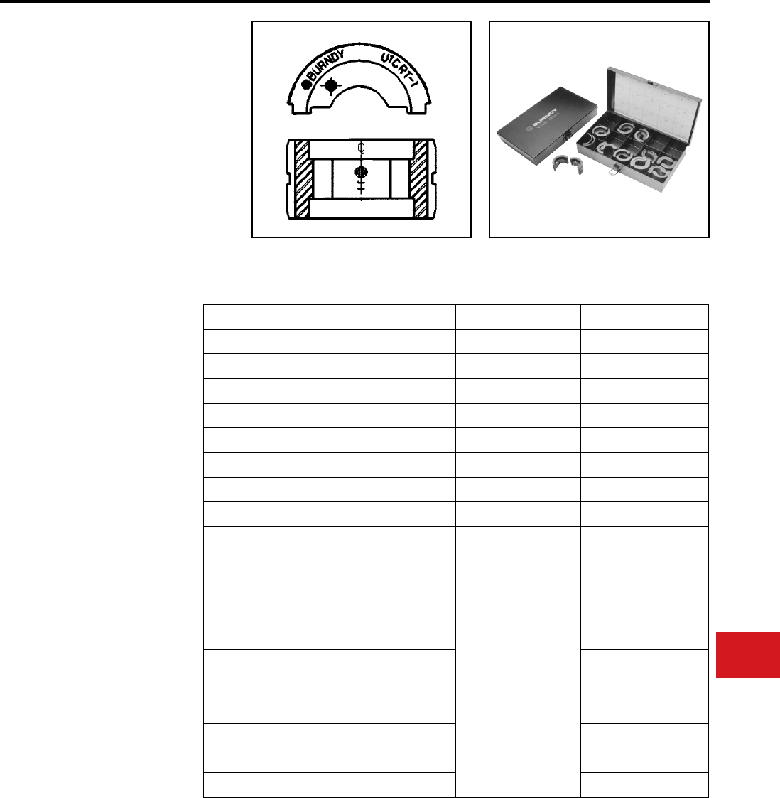
BURNDY®
Canada: 1-800-387-6487 www.burndy.com US: 1-800-346-4175
Tooling
12-TON U DIES*
BURNDY® Die Sets
Fits Y35, Y39, Y750 Series,
PAT750 Series,
PAT46 Series
(with PUADP-1 Adapter)
U die case Part# PT29291, holds up to 15 U dies
or U-Wide die sets.
Wire Size Copper Copper Wide Die** Aluminum
#8 AWG U8CRT U8CRTW U8CABT
#6 AWG U5CRT U5CRTW U6CABT
#4 AWG U4CRT U4CRTW U4CABT
#3 AWG U3CRT U3CRTW N/A
#2 AWG U2CRT U2CRTW U2CABT
#1 AWG U1CRT-1 U1CRT-1W U1CART
1/0 AWG U25RT U25RTW U25ART
2/0 AWG U26RT U26RTW U26ART
3/0 AWG U27RT U27RTW U27ART
4/0 AWG U28RT U28RTW U28ART
250 kcmil U29RT
N/A
U29ART
300 kcmil U30RT U30ART
350 kcmil U31RT U31ART
400 kcmil U32RT U32ART
500 kcmil U34RT U34ART
535 Flex kcmil U38XRT N/A
600 kcmil U36RT U36ART
750 kcmil U39RT U39ART-2
777 Flex U44XRT N/A
* Non-tension U-type 12 ton dies for YA, YS, YA-A, YS-A
style connectors.
** Wide dies are intended for use on long barrel terminals
and splices (YA / YS) only.
NOTE: N/A = not applicable.
Dies
N-5
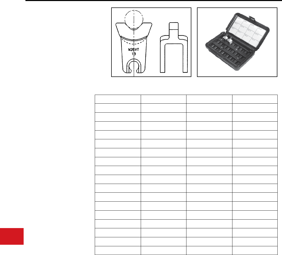
BURNDY®
US: 1-800-346-4175 www.burndy.com Canada: 1-800-387-6487
Tooling
Dies
Wire Size Copper Copper Aluminum
Small #8 W8CVT W8CRT X8CART
#6 W5CVT W5CRT W161
#4 W4CVT W4CRT W162
#3 W3CVT W3CRT N/A
#2 W2CVT W2CRT W239
#1 W1CVT W1CRT-1 W163
1/0 W25VT W25RT W241
2/0 W26VT W26RT W245
3/0 W27VT W27RT W166
4/0 W28VT W28RT W660
250 *W29VT W29RT W249
300 *W30VT W30RT N/A
350 *W31VT W31RT *W31ART
400 *W32VT W32RT N/A
450 W33VT W33RT N/A
500 *W34VT W34RT N/A
Large 600 **W36RT W36RT N/A
W DIES
BURNDY® Die Sets
Fits Tools MD6, MD7,
Y500CTHS, PAT600 Series,
PATMD6 Series
W die case Part# CASEWDIES, holds up to 24
dies
* These sizes (250-500) for Y5000CTHS, MD7-34(R),
BAT500, BCT500HS only.
** For PAT600-18V only.
NOTE: N/A = not applicable.
Suitable for use on YA, YS, YA-A, YS-A type non-tension connectors.
N-6
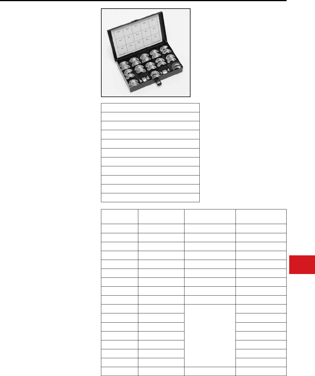
BURNDY®
Canada: 1-800-387-6487 www.burndy.com US: 1-800-346-4175
Tooling
Dies
UDIEKITCU,
UDIEKITCUW,
UDIEKITAL,
UDIEKITHYGRD
BURNDY® U DIE KITS
The UDIEKITCU and UDIEKITAL die kit includes
15 sets of “U” dies, type U-RT and U-ART
respectively, and the PT29291 die case. These
stainless steel color coded dies are for crimping
BURNDY® YA, YS, YA-A and YS-A type HYLUGTM
color coded terminals and splices ranging from #6
AWG through 750 kcmil.
The UDIEKITCUW includes 9 sets of wide
stainless steel, color coded “U” dies are for
crimping BURNDY® long barrel YA type HYLUGTM
and YS type HYLINKTM color coded terminals and
splices ranging from #8 AWG through 4/0 AWG.
The wide “U”dies require only one crimp compared
to two crimps when using standard width dies on
long barrel YA type terminals and YS type splices
up to 4/0 AWG.
The UDIEKITHYGRD kit includes 8 die sets.
Seven dies sets are used to install the BURNDY®
HYGROUND® irreversible compression grounding
connectors, and the U2CABT die set for pre-
crimping 1/2", 5/8" and 3/4" ground rods for
increased rotational resistance.
BURNDY® “U” dies are used in the Y35, Y39, Y750
series, PAT750-18V series, Y46 and PAT46-18V
(with PUDAP-1 adapter) tools.
UDIEKITHYGRD Includes
Catalog Number
UC
UO
U997
PU998
U1011
U1104
U1105
U2CABT (Ground rod pre-crimp die)
PT29291 (Die case)
Wire Size UDIEKITCU
Includes
UDIEKITCUW
Includes
UDIEKITAL
Includes
#8 AWG not in kit U8CRTW not in kit
#6 AWG U5CRT U5CRTW U6CABT
#4 AWG U4CRT U4CRTW U4CABT
#2 AWG U2CRT U2CRTW U2CABT
#1 AWG U1CRT-1 U1CRT-1W U1CART
1/0 AWG U25RT U25RTW U25ART
2/0 AWG U26RT U26RTW U26ART
3/0 AWG U27RT U27RTW U27ART
4/0 AWG U28RT U28RTW U28ART
250 kcmil U29RT
N/A
U29ART
300 kcmil U30RT U30ART
350 kcmil U31RT U31ART
400 kcmil U32RT U32ART
500 kcmil U34RT U34ART
600 kcmil U36RT U36ART
750 kcmil U39RT U39ART-2
Die Case PT29291 PT29291 PT29291
N-7
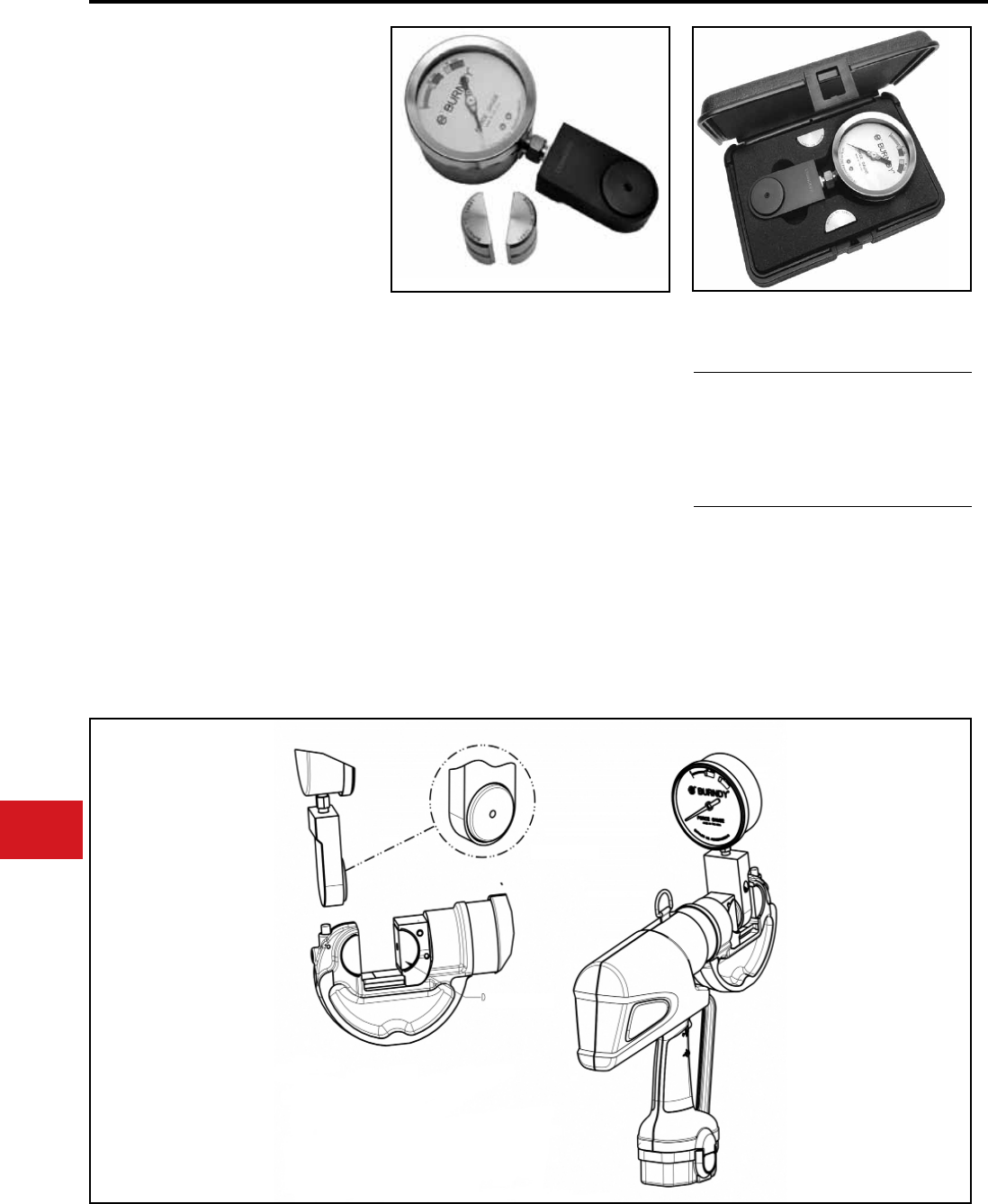
BURNDY®
US: 1-800-346-4175 www.burndy.com Canada: 1-800-387-6487
Tooling
FORCEGAUGE12-15
Force Test Gauge
The BURNDY® FORCEGAUGE12-15 is a force
gauge designed to assure users that their
BURNDY® tool is supplying sufcient force to
crimp connectors properly. This force gauge is a
precision, self-contained load cell which converts
the tool’s output force into a pointer motion on a
calibrated dial. The calibrated dial has two different
green ranges that make it easy to identify the
correct output force for either a 12 ton or 15 ton
output force BURNDY tool. The gauge is designed
to work specically on the BURNDY® PATRIOT®
PAT46 and PAT750 family as well as the Y750 and
Y35 self-contained family of tools. For remote head
tools, BURNDY® recommends the use of our inline
pressure gauge, PT11018.
The FORCEGAUGE12-15 includes two blank
“U” dies, force test gauge, Safety Operating and
Maintenance Instructions (SOMI) and a high
impact molded carry case. The gauge comes with
a 1-year limited warranty.
• Custom “U” die blanks with detent
◊ Provides secure aligned t into the
force gauge
• Accommodates 12 ton or 15 ton tools
◊ Just one gauge can accommodate a larger
family of tools
• Custom Carry Case
◊ Protects the gauge, “U” die blanks
and SOMI in a durable, compact
polymer based case
Features and Benets Specications
For Use On
Gauge
Kit
Length:
Width:
Height:
Weight:
Weight:
8.3"
4.3"
1.5"
2.7 lbs
4.5 lbs
The following series of tools: PAT46*, PAT750,
Y750 and Y35
* The BURNDY® PUADP-1 adaptor will be required
to accommodate the “U” die blanks in the 15 ton
PAT46 tool.
SET SCREW
DIE BLANK
Gauges
N-8
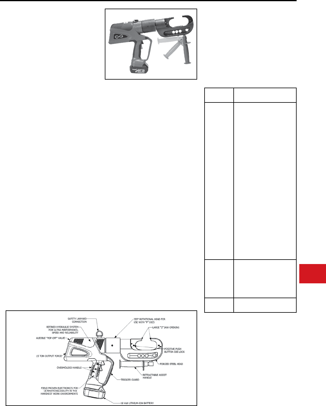
BURNDY®
Canada: 1-800-387-6487 www.burndy.com US: 1-800-346-4175
Tooling
Crimpers — Battery Actuated
PATRIOT® PAT46-LI
18 Volt Lithium-Ion
Battery Actuated Tool
Hydraulic Self-Contained
15-Ton Crimping Tool
The BURNDY® PATRIOT® PAT46-LI Lithium-
Ion tool incorporates the latest engineering
technology with a patented high speed hydraulic
pump. The redesigned eld proven electronics
provides the ultimate reliability in the harshest
work environments. BURNDY® battery actuated
hydraulic tools provide a consistent, reliable
connection every time. The PAT46-LI features the
BURNDY® Y46 tool head, capable of using all “P”
and “U” style dies.
Each PATRIOT® tool uses standard BURNDY®
dies and off-the-shelf connectors available
worldwide. Supplied with a durable high impact
formed carrying case to hold the tool, battery
charger, two 18V Lithium-Ion batteries, tool
retention lanyard and die compartments to hold
both “P” and “U” die sets (dies sold separately).
All BURNDY® PATRIOT® tools are provided with a
5-year limited warranty. All PATRIOT® tools feature
the BURNDY® INFINITY DRIVE® transmission
which has a lifetime warranty.
PAT46C-LI — with rubber covered head is
available.
• The largest BURNDY® battery actuated
crimp tool, providing 15-tons of output
force with a 2" jaw opening
◊ Allows users to install the largest variety
of splices, taps and terminals with one
tool. Also provides easy placement and
removal from continuous conductor
lengths
Features and Benets
FOR USE ON
Output Force:
Total Weight:
Length:
Height:
Width:
Operating Voltage:
Recharge Time:
SPECIFICATIONS
15 tons
(13.6 metric tons)
25.5 lbs. (11.88 kg)
20.77" (52.76 cm)
14.43" (36.65 cm)
3.70" (9.40 cm)
18 V-DC
30 minutes
ACCESSORIES
Cutter Die:
“U” Die Adapter:
Battery:
Chargers:
120V-AC
12/24V-DC
Cat# P15K
Maximum Dia. 1.2"
Cat# PUADP-1
Cat# BAT18VLI
Hi-capacity Li-Ion
(3.0 AH)
Cat# PATCHGR-LI
Cat# PATCHGR-LIDC
• Redesigned eld proven electronics
◊ Provides the ultimate reliability in the
harshest work environments
• Overmolded ergonomic handle
◊ For comfort and improved grip; allows
for one handed operation for advance,
retract and hold
• 18-volt (3.0 AH) Li-Ion batteries
◊ Batteries provide 2.5 times more
charge/discharge cycles than traditional
Ni-Cd batteries and 430% more lifetime
work
◊ Less “down-time” due to high capacity
(3.0 AH), 18 volt Li-Ion battery
◊ No voltage depression (memory issues)
• 30-minute smart charger
◊ Controls current, voltage and
temperature to maximize battery life
◊ Forced air cooling fan cools the battery
by forcing cool air through the battery’s
built-in air vents
• State of the art C-Head crimp design with
355° head rotation
◊ Versatile tool head positioning lets user
get into tight areas easier
• Retractable assist handle under head of
tool for better handling of tool
◊ Allows for better balance of tool and
retractable for getting head into tight
areas
• Durable high impact formed carrying case
◊ Provides superior protection and stores
all accessories
• 1-year warranty on batteries and charger
Features
Connector
Type
Conductor
Range
Copper
#8 AWG str.
1500 kcmil
Code Cable,
Navy Cable,
Flexible and
Extra
Flexible
1/2” - 1”
Ground
Rods
Terminals, grounding:
to 500 kcmil
YGA, YGHA, YGF
Terminals, uninsulated:
#8 to 1500 kcmil:
YA, YA-2N, YA-L, YA-LB,
YA-TC, YA-2LN, YAB-4N,
YAV-L Box, YAV-L, YAV-RS
Box, YAV-RS, YA-TC-FX
Terminals, insulated:
#8 to 2/0
YAEV-L Box, YAEV-L,
YAEV-H, YAEV-RS,
YAEV-RH
Splices:
#8 to 1500 kcmil
YS, YS-T, YS-L, YS-LB, YST,
YSP-T, YGS, YGHS
Taps:
#14 to 1000 kcmil
YH, YCHC
to 4/0 AWG
YC-C
Taps, grounding:
to 500 kcmil
YGHC-C, YGHP-C, YGHR-C
Aluminum
#8 AWG -
1250 kcmil
Code Cables
Terminals:
YA-A, AYP, AYPO
Splices:
YS-A, YS-AT, YRB
Taps:
YFD, YFN, YFO, YFR
ACSR See BURNDY® Overhead
Transmission & Distribution
N-9

BURNDY®
US: 1-800-346-4175 www.burndy.com Canada: 1-800-387-6487
Tooling
Crimpers — Battery Actuated
PATRIOT® PAT46-18V
BATTERY ACTUATED TOOL
Hydraulic Self-Contained
15-Ton Crimping Tool
The BURNDY® PATRIOT® PAT46-18V
incorporates the latest engineering technology
with a patented high speed hydraulic pump.
Our battery actuated hydraulic tool provides a
consistent, reliable connection every time. The
PAT46-18V features the BURNDY® Y46 tool head,
capable of using all “P” and “U” style dies.
Each PATRIOT® tool uses standard BURNDY®
dies and off-the-shelf conn-ectors available
worldwide. Supplied with a durable high impact
formed carrying case to hold the tool, battery
charger, two batteries, tool retention lanyard, and
die compartments to hold both “P” and “U” die sets
(dies sold separately). All BURNDY® PATRIOT®
PAT46 tools are provided with a 5-year limited
warranty. 1-year warranty on battery and charger.
PAT46C-18V — with rubber covered head is
available.
• The largest BURNDY® battery actuated
crimp tool, providing 15-tons of output
force with a 2” jaw opening
◊ Allows users to install the largest variety
of splices, taps and terminals with one
tool. Also provides easy placement and
removal from continuous conductor
lengths
• State of the art C-Head crimp design with
355° head rotation
◊ Versatile tool head positioning lets user
get into tight areas easier
• Retractable assist handle under head of
tool for better handling of tool
◊ Allows for better balance of tool and
retractable for getting head into tight
areas
• Durable high impact formed carrying
case
◊ Provides superior protection and stores
all accessories
• 18-volt Ni-MH battery eliminates voltage
depression (memory issues)
◊ Less “down-time” due to high capacity,
high voltage 18-volt battery
Features and Benets
Output Force:
Weight:
Length:
Height:
Width:
Operating Voltage:
Battery Recharge
Time:
SPECIFICATIONS
15 tons
(13.6 metric tons)
26.2 lbs (11.88 kg)
20.77” (52.76 cm)
14.43” (36.65 cm)
3.70” (9.40 cm)
18 V-DC
< 45 mins.
ACCESSORIES
Cutter Die:
“U” Die Adapter:
Battery:
Chargers:
120V-AC
12/24V-DC
240/250V-AC
Cat# P15K
Die max. 1.2” dia.
Cat# PUADP-1
Cat# BAT18V
Hi-capacity Ni-MH (2.6AH)
Cat# PATCHGR18V
Cat# BCT/PATDCCHGR
Cat# PATCHGR250V
Features
FOR USE ON
Connector
Type
Conductor
Range
Copper
#8 AWG str.
1500 kcmil
Code Cable,
Navy Cable,
Flexible and
Extra
Flexible
1/2” - 1”
Ground
Rods
Terminals, grounding:
to 500 kcmil
YGA, YGHA, YGF
Terminals, uninsulated:
#8 to 1500 kcmil:
YA, YA-2N, YA-L, YA-LB,
YA-TC, YA-2LN, YAB-4N,
YAV-L Box, YAV-L, YAV-RS
Box, YAV-RS, YA-TC-FX
Terminals, insulated:
#8 to 2/0
YAEV-L Box, YAEV-L,
YAEV-H, YAEV-RS,
YAEV-RH
Splices:
#8 to 1500 kcmil
YS, YS-T, YS-L, YS-LB, YST,
YSP-T, YGS, YGHS
Taps:
#14 to 1000 kcmil
YH, YCHC
to 4/0 AWG
YC-C
Taps, grounding:
to 500 kcmil
YGHC-C, YGHP-C, YGHR-C
Aluminum
#8 AWG -
1250 kcmil
Code Cables
Terminals:
YA-A, AYP, AYPO
Splices:
YS-A, YS-AT, YRB
Taps:
YFD, YFN, YFO, YFR
ACSR See BURNDY® Overhead
Transmission & Distribution
N-10
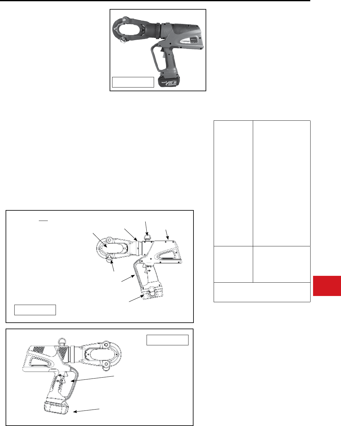
BURNDY®
Canada: 1-800-387-6487 www.burndy.com US: 1-800-346-4175
Tooling
Crimpers — Battery Actuated
PATRIOT® PAT46LW-LI
PATRlOT® PAT46LW-18V
18V Lithium-Ion Battery Crimper
18V Ni-MH Battery Crimper
Hydraulic Self-Contained 15 Ton
Light Weight Crimping Tool
The BURNDY® PAT46LW is a light weight “latch
head” style 15 ton crimping tool designed to
terminate BURNDY® terminals and splices.
The PAT46LW Series incorporates the latest
engineering technology featuring a patented high
speed hydraulic pump for very quick actuation.
The unique eld proven electronics provides
the ultimate reliability in the harshest work
environments.
The PAT46LWLl and PAT46LW18V are capable
of using all BURNDY® “P” and “U” style dies (U
dies require PUADP-1 adapter). Every PAT46LW
tool is supplied with a durable high impact formed
carrying case to hold the tool, battery charger,
two (2) 18 volt batteries (Li-ion or Ni-MH) and tool
retention lanyard.
Features and Benets
FOR USE ON
Output Force:
Total Weight:
Length:
Height:
Operating Voltage:
Battery Recharge
Time:
Head Rotation:
SPECIFICATIONS
15 Tons
16.79 lbs (Li-ion)
17.3 lbs (Ni-MH)
18.65 in (Li-ion)
18.65 in (Ni-MH)
13.75 in (Li-ion)
13.75 in (Ni-MH)
18V-DC
30 minutes (Li-ion)
45 minutes (Ni-MH)
355° (both)
Copper
#8 AWG str.
1500 kcmil
Code Cable,
Navy Cable,
Flexible and
Extra Flexible
1/2” - 1”
Ground Rods
Terminals, grounding: to 500
kcmil
YGA, YGHA, YGF
Terminals, uninsulated: #8 to
1500 kcmil: YA, YA-2N, YA-L,
YA-LB, YA-TC, YA-2LN,YAB-
4N
YAV-L Box, YAV-L, YAV-RS
Box,
YAV-RS, YA-TC-FX
Terminals, insulated: #8 to 2/0
YAEV-L Box, YAEV-L,
YAEV-H,
YAEV-RS, YAEV-RH
Splices: #8 to 1500 kcmil
YS, YS-T, YS-L, YS-LB, YST,
YSP-T, YGS, YGHS
Taps:
YH, YCHC #14 to 1000 kcmil,
YC-C to 4/0 AWG
Taps, grounding: to 500 kcmil
YGHC-C, YGHP-C, YGHR-C
Aluminum
#8 AWG -1250 kcmil
Code Cables
Terminals:
YA-A, AYP, AYPO
Splices:
YS-A, YS-AT, YRB
Taps:
YFD, YFN, YFO, YFR
ACSR
See BURNDY® Overhead Transmission and
Distribution Catalog Module
• New light weight design only 16.79 lbs
(Lithium-Ion) and 17.3 lbs (Ni-MH)
• Available in both Li-ion, and Ni-MH 18-volt
battery technology
• Provides 15-tons of output force with 2” jaw
opening
• Redesigned eld proven electronics
• Overmolded ergonomic handle on Li-ion
version
• Rugged forged latching crimp head with
355° head rotation
• 5 year limited warranty on tool
• Lifetime warranty on INFINITY DRIVE®
• 1-year warranty on batteries and charger
ACCESSORIES
Cutter Die: Cat# P15K
“U” Die Adapter: Cat# PUADP-1
Battery: Cat# BAT18VLI
Hi-capacity (3.0 AH) Li-Ion
Cat# BAT18V
Hi-capacity (2.6 AH) Ni-MH
Li-Ion Chargers:
120V-AC Cat# PATCHGRLI
12/24V-DC Cat# PATCHGR-LIDC
Ni-MH Chargers:
120V-AC Cat# PATCHGR18V
12/24V-DC Cat# BCT/PATDCCHGR
240/250V-AC Cat# PATCHGR250V
Features on both Ni-MH and
Li-Ion Styles:
1. 355° Rotation Head for
use with P and U dies (with
PUADP-1)
2. Large 2” Jaw Opening
3. Audible “Pop Off” Valve
4. Locking Latch Pin
5. Trigger Guard
6. Safety Lanyard Connection
18 Volt Ni-MH Battery
1.
2.
3.
4.
5.
6.
PAT46LW-18V
18 Volt Lithium-Ion Battery
Ergonomically
Balanced
Overmolded Handle
PAT46LW-LI
PAT46LW-LI
N-11
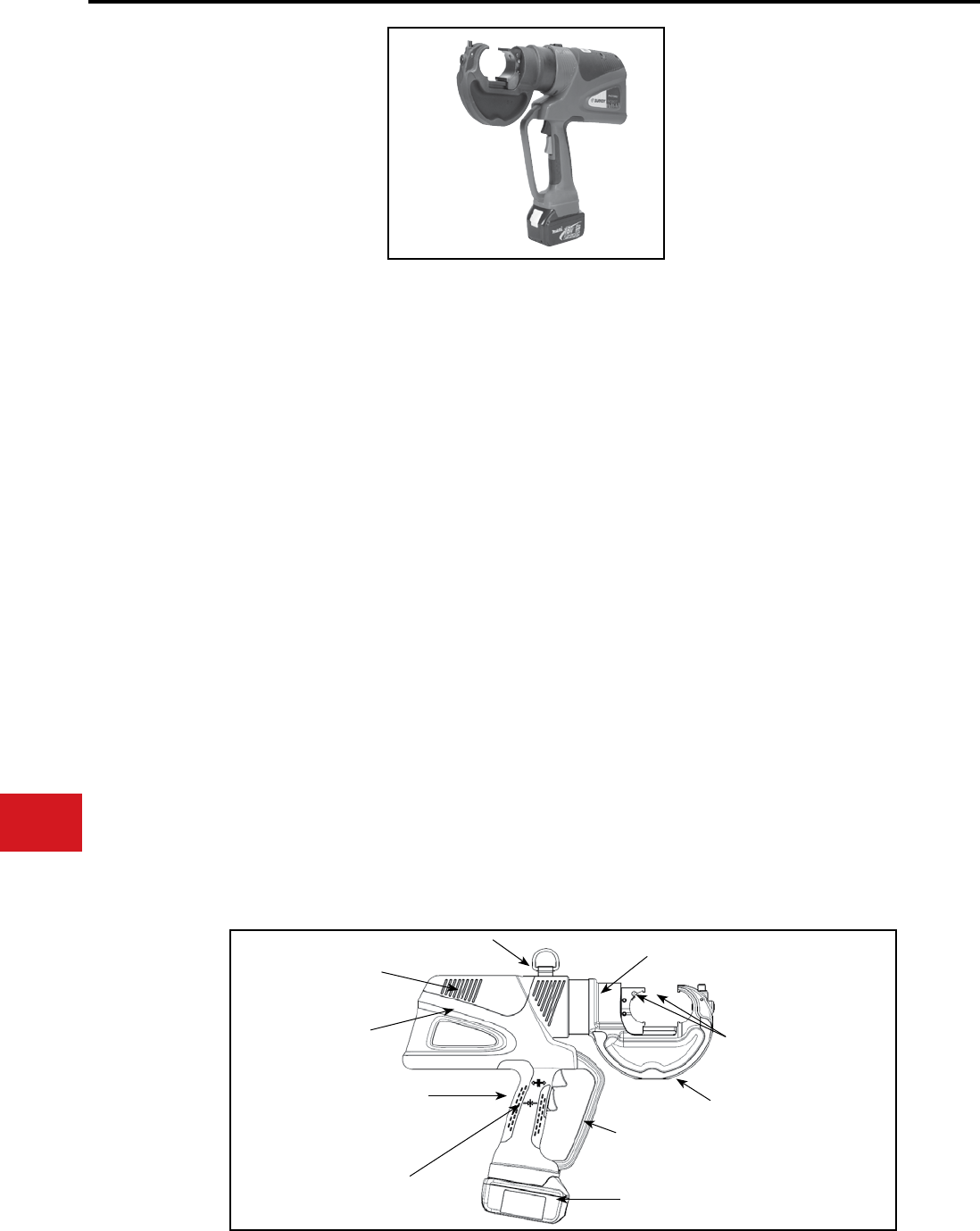
BURNDY®
US: 1-800-346-4175 www.burndy.com Canada: 1-800-387-6487
Tooling
Crimpers — Battery Actuated
PATRIOT®
HIGH PERFORMANCE
PAT750-LI
18 Volt Lithium-Ion
Battery Actuated Tool
Hydraulic Self-Contained
12-Ton Crimping Tool
The BURNDY® PATRIOT® PAT750-LI Lithium-Ion
tool is approximately 25% faster than the previous
models. In addition to faster crimp cycles, the high
performance PAT750-LI has newly designed
electronics that are eld proven to handle the
harshest work environments.
The PAT750-LI incorporates the latest engineering
technology with a rened hydraulic system for ultra
performance, speed and reliability. The redesigned
eld proven electronics provides the ultimate
reliability in the harshest work environments.
All BURNDY® battery actuated hydraulic tools
provide a consistent, reliable connection every
time. The PAT750-LI features the BURNDY® Y750
tool head, capable of using all “U” style dies, and
incorporates a bearing and alignment guide for
use on HYGROUND® and other asymmetrical
connectors. The crimp head rotates 355° for
operation in virtually any position.
Each PATRIOT® tool uses standard BURNDY®
dies and off-the-shelf connectors available
world-wide. Supplied with a durable high impact
formed carrying case to hold the tool, battery
charger, two 18 volt Lithium-Ion batteries,
tool retention lanyard and die compartment to
hold “U” die sets (sold separately). Provided
with a 5-year limited warranty. All PATRIOT®
tools feature the BURNDY® INFINITY DRIVE®
transmission which has a lifetime warranty.
Output Force:
Tool Weight:
Length:
Width:
Height:
Operating Voltage:
Recharge Time:
SPECIFICATIONS
FOR USE ON
Tension Sleeves
Copper #8 sol. - 500 kcmil
Aluminum #8 sol. - 587.2 kcmil
ACSR #4 - 556.5 kcmil
Taps
Copper #14 sol. - 500 kcmil
Aluminum #8 - 500 kcmil
Aerial Cable
Copper #6 - 500 kcmil
Terminals & Splices
Aluminum #8 - 750 kcmil
Copper #8 - 750 kcmil
ACSR #4 - 556 kcmil
HYGROUND®
Copper #8 - 500 kcmil
(cable/ground rod)
Ground Rods 1/2″ - 1″ Diameter
ACCESSORIES
Battery: Cat# BAT18VLI
Hi-capacity (3.0 AH)
Chargers:
120V-AC Cat# PATCHGRLI
12/24V-DC Cat# PATCHGR-LIDC
Lanyard: Cat# PT208620
12 tons
(10.9 metric tons)
15.7 lbs (7.12 kg)
With Battery
15.75 in (40 cm)
3.5 in (8.89 cm)
13.5 in (34.29 cm)
18 V-DC
30 minutes
Features and Benets
Large 1.65″ Jaw Opening
to Accommodate
Asymmetrical Connectors
Field Proven Electronics for
Ultimate Reliability in the
Harshest Work Environments
Rened Hydraulic System
for Ultra Performance,
Speed and Reliability
355° Rotational Head for
Use with “U” Dies
Ergonomically Balanced
Overmolded Handle 12 Ton Output Force
18 Volt Lithium-Ion Battery
Safety Lanyard Connection
Audible “Pop-Off” Valve
Trigger Guard
• Rened hydraulic system for ultra
performance,speed and reliability
• Field proven electronics for ultimate
reliability in the harshest environments
• Over-molded handle for comfort and
improved grip; allows for one-handed
operation for advance, retract and hold
• 18 volt Lithium-Ion batteries provide 2.5
times more charge/discharge cycles than
traditional Ni-Cd batteries and provide
430% more lifetime work
• 30-minute charger controls current, voltage
& temperature to maximize battery life,
forced air cooling fan cools the battery by
forcing cool air through the battery’s built-in
air vents
• State of the art crimping head design, 355°
head rotation lets user get into tight areas
easier
• Allows use of standard BURNDY® dies
already in use
• Ergonomically balanced tool design eases
operation
• Durable high impact formed carrying case
provides superior protection and stores all
accessories
• PAT750C-LI with rubber covered head is
available
• 1-year warranty on batteries and charger
N-12
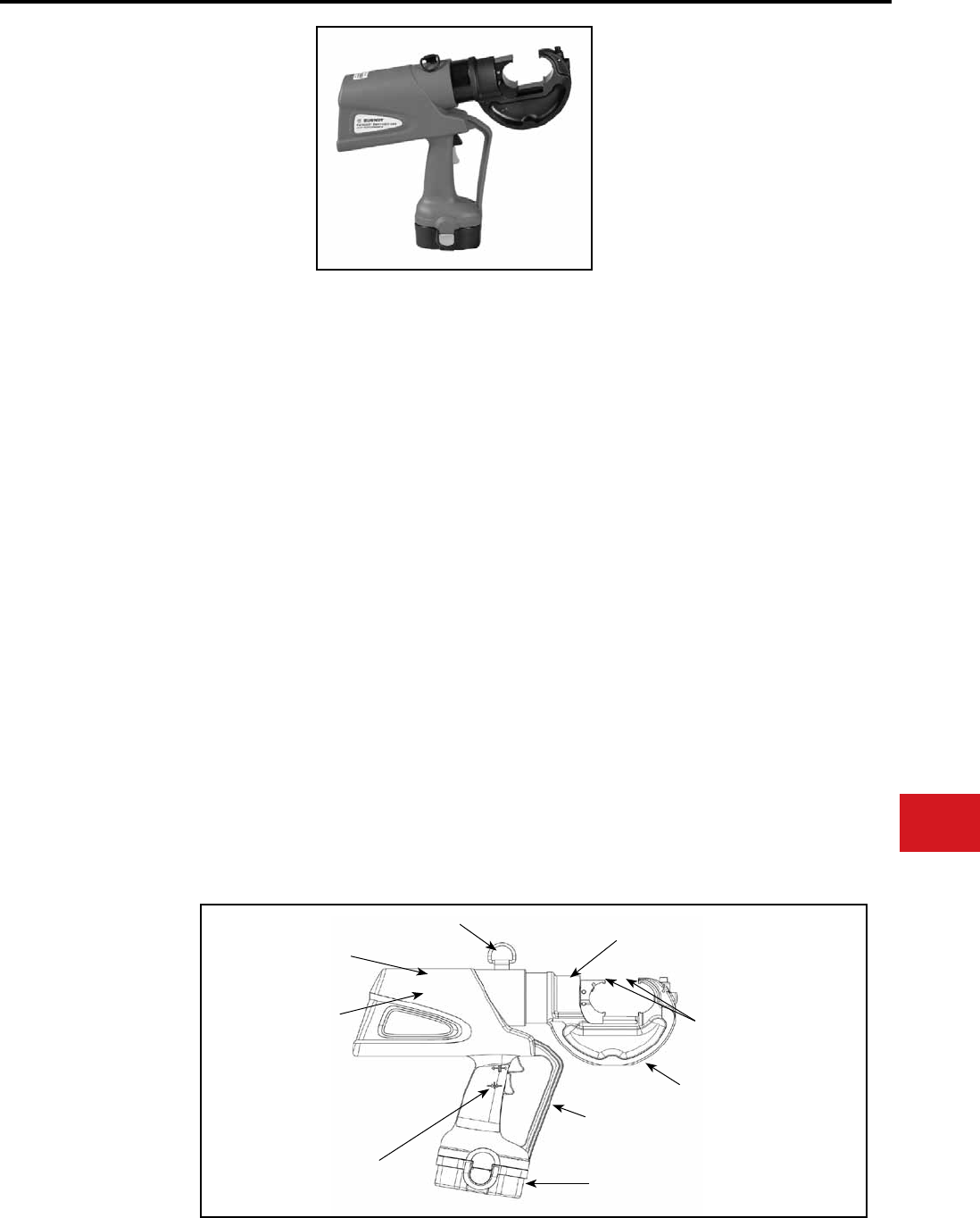
BURNDY®
Canada: 1-800-387-6487 www.burndy.com US: 1-800-346-4175
Tooling
Crimpers — Battery Actuated
PATRIOT®
HIGH PERFORMANCE
PAT750XT-18V
BATTERY ACTUATED TOOL
Hydraulic Self-Contained
12-Ton Crimping Tool
The BURNDY® PATRIOT® High Performance
PAT750XT-18V tool is 25% faster than previous
models. In addition to faster crimp cycles, the High
Performance PAT750XT-18V has newly designed
electronics that are eld proven for ultimate
reliability and proven to handle the harshest work
environments.
The High Performance PAT750XT-18V
incorporates the latest engineering technology with
a rened hydraulic system for ultra performance,
speed and reliability.All PATRIOT® tools feature the
BURNDY® INFINITY DRIVE® transmission which
has a lifetime warranty.
The High Performance PAT750XT-18V features
the BURNDY® Y750 tool head, capable of using
all “U” style dies, and incorporates a bearing and
alignment guide for use on HYGROUND® and
other asymmetrical connectors. Features reliable
head rotation design for operation in virtually any
position. All PATRIOT® battery actuated hydraulic
tools provide a consistent, reliable connection
every time.
Each PATRIOT® tool uses standard BURNDY®
dies and off-the-shelf connectors available
world-wide. Supplied with a durable high impact
formed carrying case to hold the tool, battery
charger, two batteries, tool retention lanyard, and
die compartment to hold “U” die sets. (Dies sold
separately.) All BURNDY® PATRIOT® 18V series
tools are provided with a 5-year limited warranty.
Output Force:
Tool Weight:
Length:
Width:
Height:
Operating Voltage:
Recharge Time:
SPECIFICATIONS
FOR USE ON
Tension Sleeves
Copper #8 sol. - 500 kcmil
Aluminum #8 sol. - 587.2 kcmil
ACSR #4 - 556.5 kcmil
Taps
Copper #14 sol. - 500 kcmil
Aluminum #8 - 500 kcmil
Aerial Cable
Copper #6 - 500 kcmil
Terminals & Splices
Aluminum #8 - 750 kcmil
Copper #8 - 750 kcmil
ACSR #4 - 556 kcmil
HYGROUND®
Copper #8 - 500 kcmil
(cable/ground rod)
Ground Rods 1/2″ - 1″ Diameter
ACCESSORIES
Battery: Cat# BAT18V
Hi-capacity (2.6 AH)
Chargers:
120V-AC Cat# PATCHGR18V
12/24V-DC Cat# BCT/PATDCCHGR
240/250V-AC Cat# PATCHGR250V
Lanyard: Cat# PT208620
12 tons
(10.9 metric tons)
16.5 lbs (7.5 kg)
With Battery
15.75 in (40 cm)
3.5 in (8.89 cm)
13.5 in (34.29 cm)
18 V-DC
< 45 minutes
• Rened hydraulic system for ultra
performance, speed and reliability
• Field proven electronics for ultimate
reliability in the harshest environments
• True one-handed operation for advance,
retract, and hold
• 12 tons of output force for use on virtually all
compression applications
• State of the art crimping head design, 355°
head rotation lets user get into tight areas
easier
• Allows use of standard BURNDY® “U” dies
already in use
• Ergonomically balanced tool design eases
operation and helps lessen fatigue
• Durable high impact formed carrying case
provides superior protection and stores all
accessories
• PAT750CXT-18V — with rubber covered
head is available
• 18 volt Ni-MH battery eliminates voltage
depression (memory issues)
• 1-year warranty on batteries and charger
Features and Benets
Audible “Pop-Off” Valve
Large 1.65″ Jaw Opening
to Accommodate
Asymmetrical Connectors
Field Proven Electronics for
Ultimate Reliability in the
Harshest Work Environments
Rened Hydraulic System
for Ultra Performance,
Speed and Reliability
355° Rotational Head for
Use with “U” Dies
12 Ton Output Force
18 Volt Lithium-Ion Battery
Safety Lanyard Connection
Trigger Guard
N-13
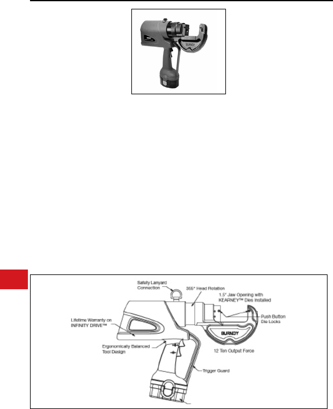
BURNDY®
US: 1-800-346-4175 www.burndy.com Canada: 1-800-387-6487
Tooling
Crimpers — Battery Actuated
PATRIOT®
PAT750K-LI (Li-Ion)
PAT750K-18V (Ni-MH)
BATTERY ACTUATED TOOL
Hydraulic Self-Contained
12-Ton Crimping Tool
The BURNDY® PATRIOT® tools can be operated
with only one hand, making them the most
ergonomic, one-handed battery powered crimping
and cutting tools available in the world today.
The PAT750K series of tools incorporate the
latest engineering technology with the patented
high speed hydraulic pump. Our battery actuated
hydraulic tools provides a consistent, reliable
connection every time. The PAT750K series tools
are capable of using KEARNEY™ WH1 and WH2
and BURNDY® “U” style dies with the KUADP
adapter. The PAT750K head rotates 355° for
operation in virtually any position.
Each PATRIOT® tool uses standard BURNDY®
dies and off-the-shelf connectors available world-
wide. The PAT750K tools are supplied with a
durable high impact formed carrying case to
hold the tool, battery charger, two batteries, tool
retention lanyard, and die compartment to hold
“U” die sets. (Dies sold separately.) All BURNDY®
PATRIOT® series tools are provided with a 5-year
limited warranty.
• True one-handed operation for advance,
retract, and hold
• 12 ton output force
• State of the art crimping head design with
355° rotation
• Positive lock die buttons to secure dies or
die adapter
• Allows use of standard BURNDY® “U” dies
with KUADP adapter, and KEARNEY™
WH1 and WH2 dies
• Smoother, quieter, more efcient tool
operation
• PAT750CK-18V (Ni-MH) with rubber
covered head is available
• Ergonomically balanced tool design to help
lessen operator fatigue
• Durable high impact formed carrying case
• Lifetime warranty on INFINITY DRIVE®
• 1-year warranty on battery and charger
Output Force:
Tool Weight:
Length:
Height:
Width:
Operating Voltage:
Recharge Time:
Features and Benets
SPECIFICATIONS
FOR USE ON
12 tons
(10.9 metric tons)
18.4 lbs (8.3 kg)
With Battery
17.5 in (44.45 cm)
3.5 in (8.89 cm)
13.5 in (34.29 cm)
18 V-DC
<30 minutes (Li-Ion)
< 45 minutes (Ni-MH)
Tension Sleeves :
Taps :
Terminals :
up to 477 ACSR kcmil
through 500 kcmil
up to 1033 kcmil
ACCESSORIES
“U” Die Adapter:
Li-Ion Battery:
Li-Ion Charger:
120V-AC
12/24V-DC
Ni-MH Battery:
Ni-MH Charger:
120V-AC
12/24V-DC
240/250V-AC
Lanyard:
KUADP
BAT18VLI (Li-Ion)
Hi-capacity (3.0 AH)
PATCHGRLI
PATCHGR-LIDC
BAT18V (Ni-MH)
Hi-capacity (2.6 AH)
PATCHGR18V
BCT/PATDCCHGR
PATCHGR250V
PT208620
18 Volt Battery (Li-Ion or Ni-MH)
PAT750K-18V style shown
PAT750K-18V (Ni-MH)
N-14
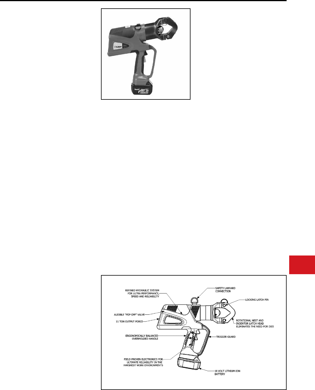
BURNDY®
Canada: 1-800-387-6487 www.burndy.com US: 1-800-346-4175
Tooling
Crimpers — Battery Actuated
Output Force:
Tool Weight:
Length:
Width:
Height:
Operating Voltage:
Recharge Time:
Features and Benets
SPECIFICATIONS
FOR USE ON
11 tons (10 metric tons)
16.3 lbs (7.39 kg)
With Battery
15.6" (39.60 cm)
3.2" (8.10 cm)
14.1" (35.80 cm)
18 V-DC
30 minutes
ACCESSORIES
Copper
#6-1000 kcmil
Aluminum
#6-750 kcmil
Aluminum
#6-750 kcmil
Terminals:
YA-L, YA-2LN, YA,
YA-2N,YA-L-2TC,
YAB-4N, YA-L-TC,
YA-2L, YA-4N
Splices:
YS-L, YS, YS-T
Terminals:
YA-A, YA-A-TN
Splices:
YS-A
HYPLUGTM
AYP, AYPO
Battery:
Chargers:
120V-AC
12/24V-DC
Lanyard:
Cat# BAT18VLI
(3.0 AH) Hi-capacity
Cat# PATCHGR-LI
Cat# PATCHGR-LIDC
Cat# PT208620
PATRIOT®
HIGH PERFORMANCE
PAT644-LI
18 Volt Lithium-Ion
Battery Actuated Tool
Hydraulic Self-Contained
11-Ton Dieless Crimping Tool
The BURNDY® PATRIOT® PAT644-LI Lithium-Ion
tool is approximately 25% faster than the previous
models. In addtion to faster crimp cycles, the high
performance PAT644-LI has newly designed
electronics that are eld proven for ultimate
reliability and proven to handle the harshest work
environments.
The PAT644-LI incorporates the latest engineering
technology with a rened hydraulic system for ultra
performance, speed and reliability. The redesigned
eld proven electronics provides the ultimate
reliabilty in the harshest work environments. All
BURNDY® battery actuated hydraulic tools provide
a consistent, reliable connection every time. The
PAT644-LI features the BURNDY® Y644 dieless
latch head which elimates the need to purchase
and maintain dies. The crimp head rotates 355° for
operation in virtually any position.
The PAT644-LI is supplied with a durable high
impact formed carrying case to hold the tool,
battery charger, two 18 volt Lithium-Ion batteries
and tool retention lanyard. Most BURNDY®
PATRIOT® 18V series tools provided with a 5-year
limited warranty. 1-year warranty on batteries and
charger. All PATRIOT® tools feature the BURNDY®
INFINITY DRIVE® transmission which has a
lifetime warranty.
PAT644-LI Range Taking Capabilities:
Refer to the individual connector pages for detailed
information on the PAT644-LI range taking
capabilities.
• Overmolded handle for comfort and
improved grip; allows for one-handed
operation for advance, retract and hold
• 18-volt Lithium-Ion batteries provide 2.5
times more charge/discharge cycles than
traditional Ni-Cd batteries and provide
430% more life time work
• 30-minute charger controls current, voltage
& temperature to maximize battery life
• Forced air cooling fan cools the battery by
forcing cool air through the battery’s built-in
air vents
• Dieless system elimates the need to
purchase and maintain dies
• Dieless system allows connectors and
splices to become range taking
• State of the art crimping head design, 355°
head rotation lets user get into tight areas
easier
• Ergonomically balanced tool design eases
operation
• Durable high impact formed carrying case
provides superior protection and stores all
accessories N-15
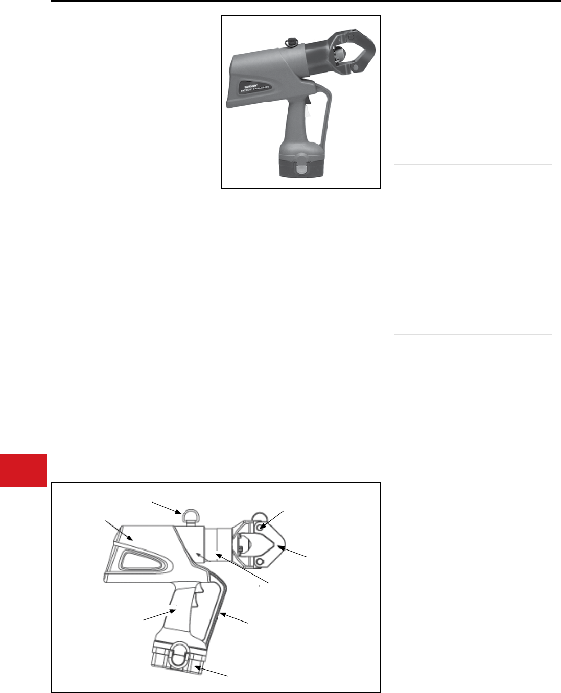
BURNDY®
US: 1-800-346-4175 www.burndy.com Canada: 1-800-387-6487
Tooling
Crimpers — Battery Actuated
PATRIOT®
PAT644XT-18V
BATTERY ACTUATED TOOL
Hydraulic Self-Contained
11 Ton Dieless Crimping Tool
The BURNDY® PATRIOT® series of battery
actuated tools can be operated with only one hand,
which allows the other hand to be free to position
the connector and conductor prior to crimping.
The BURNDY® PATRIOT® PAT644XT-18V
incorporates the latest engineering technology
with patent pending pump, transmission and piston
component designs. Our self-contained hydraulic
tool provides a consistent reliable connection
every time. The PAT644XT-18V features the
BURNDY® Y644 dieless latch head tool which
eliminates the need to purchase and maintain
dies. Features reliable head rotation design for
operation in virtually any position.
Each PATRIOT® tool uses standard BURNDY®
off-the-shelf connectors available world-wide.
Supplied with a durable high impact formed
carrying case to hold the tool, battery charger, two
batteries, and tool retention lanyard. All BURNDY®
PATRIOT® 18V series tools are provided with a
5-year limited warranty.
PAT644XT-18V Range Taking Capabilities:
Please refer to the individual connector pages for
detailed information on the PAT644XT-18V range
taking capabilities.
• Dieless system
• True one-handed operation for
advance,retract, and hold
• 11-ton output force
• State of the art crimping head design, 355°
head rotation
• Audible “pop-off” indicates properly completed
crimps
• Ergonomically balanced tool design
• Durable High Impact Formed carrying case
• Ni-MH battery eliminates voltage depression
(memory issues)
• 1-year warranty on batteries and charger
• Eliminates the need to purchase and
maintain dies
• Easier tool operation.
• Versatile tool head positioning lets user
get into tight areas easier
• Less “down-time” due to high capacity,
high voltage 18 volt battery
Crimp Force:
Tool Weight:
Length:
Height:
Width:
Operating Voltage:
Recharge Time:
Features and Benets
SPECIFICATIONS
• Assures proper crimps with both audible
and visual indicators, leaving no doubt
for the tool user
• Ergonomically balanced tool eases
operation and helps lessen fatigue
• Smoother, quieter, more efcient tool
operation
• Durable high impact formed case
provides superior protection and stores
all accessories
11 tons
(10.9 metric tons)
17 lbs (7.7 kg)
14.9″ (37.8 cm)
14″ (35.6 cm)
3.7″ (9.4 cm)
18 V-DC
< 45 mins.
11 Ton
Output Force
Safety Lanyard
Connection
Ergonomically Balanced
Tool Design
Rotational Nest and
Indentor Latch Head
Eliminates the Need
for Dies
Audible
“Pop Off” Valve
Trigger Guard
Ni-MH 18 Volt Battery
Locking
Latch Pin
FOR USE ON
Copper
#6-1000 kcmil
Aluminum
#6-750 kcmil
Aluminum
#6-750 kcmil
Terminals:
YA-L, YA-2LN, YA,
YA-2N,YA-L-2TC,
YAB-4N, YA-L-TC,
YA-2L, YA-4N
Splices:
YS-L, YS, YS-T
Terminals:
YA-A, YA-A-TN
Splices:
YS-A
HYPLUGTM
AYP, AYPO
ACCESSORIES
Battery:
Chargers:
120V-AC
12/24V-DC
240/250V-AC
Lanyard:
Cat# BAT18V
Hi-capacity Ni-MH
(2.6 AH)
Cat# PATCHGR18V
Cat# BCT/PATDCCHGR
Cat# PATCHGR250V
Cat# PT208620
Features and Benets
(Continued)
N-16
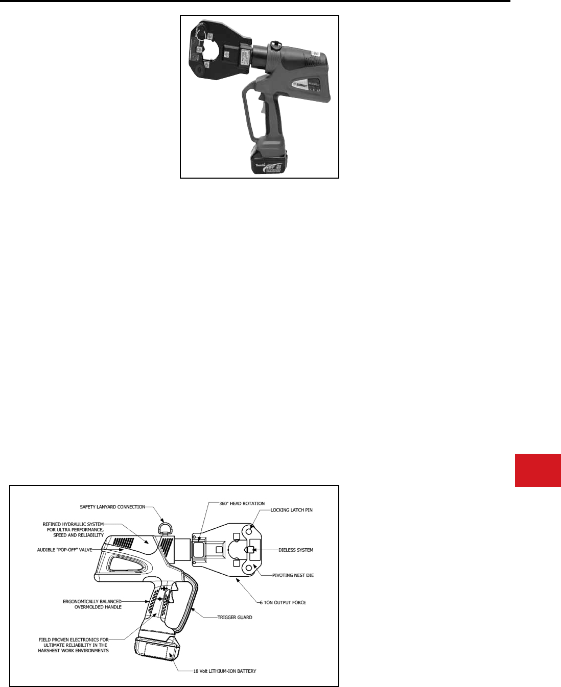
BURNDY®
Canada: 1-800-387-6487 www.burndy.com US: 1-800-346-4175
Tooling
Crimpers — Battery Actuated
4-POINT® PATRIOT®
PAT81KFT-LI
18 Volt Lithium-Ion
Battery Actuated Tool
Hydraulic Self-Contained 6-Ton
4-POINT® Dieless Crimping Tool
The BURNDY® PAT81KFT-LI Lithium-Ion tool
incorporates the latest engineering technology with
a rened hydraulic system for ultra performance,
speed and reliability. The redesigned eld proven
electronics provide the ultimate reliability in the
harshest work environments. All BURNDY® battery
actuated hydraulic tools provide a consistent,
reliable connection every time. The PAT81KFT-
LI features a dieless latch head design which
eliminates the need to purchase and maintain
dies. The crimp head rotates 360° for operation in
virtually any position.
Supplied with durable high impact formed carrying
case to hold tool, battery charger and (2) 18V
Lithium-Ion batteries, and tool retention lanyard.
Provided with 5-year limited warranty on the tool
and 1-year warranty on batteries and charger. All
PATRIOT® tools features the BURNDY® INFINITY
DRIVE® which has a lifetime warranty.
PAT81KFT-LI Range Taking Capabilities:
The PAT81KFT-LI provides range taking
capabilities that are UL Listed and CSA Certied
for copper (code, compact and ex) and aluminum
(code and compact) conductors when used in
conjuction with BURNDY® HYLUGTM terminals
and HYLINKTM splices.
Output Force:
Tool Weight:
Length:
Width:
Height:
Operating Voltage:
Recharge Time:
Features and Benets
SPECIFICATIONS
6 tons
(5.4 metric tons)
13.2 lbs (5.90 kg)
With Battery
15.6" (39.60 cm)
3.2" (8.10 cm)
14.1" (35.8 cm)
18 V-DC
30 minutes
• Rened hydraulic system for ultra
performance, speed and reliability
• Field proven electronics for ultimate
reliability in the harshest environments
• Overmolded handle for comfort and
improved grip; allows for one-handed
operation for advance, retract and hold
• 18-volt Lithium-Ion batteries provide 2.5
times more charge/discharge cycles than
traditional Ni-Cd batteries and provide
430% more lifetime work
• 30-minute charger controls current, voltage
and temperature to maximize battery life
• Forced air cooling fan cools the battery by
forcing cool air through the battery’s built in
air vents
• Dieless system allows connectors and
splices to become range taking
• State of the art crimping head design, 360°
head rotation lets user get into tight areas
easier
• Ergonomically balanced tool design eases
operation and helps lessen fatigue
FOR USE ON
ACCESSORIES
Copper
#8-1000 kcmil
Copper Flex
#8-777.7 kcmil
Flex (750 Nominal)
Aluminum
#8-750 kcmil
Aluminum
#8-750 kcmil
Terminals:
YA, YA-L
Splices:
YS-L, YS, YS-T, Y-R
Terminals:
YA-FX, YAV, YA-L-FX
Splices:
YS, YSV-FXB
Terminals:
YA-A, YA-A-TN
Splices:
YS-A
HYPLUG™
AYP, AYPO
Battery:
Chargers:
120V-AC
12/24V-DC
Lanyard:
Cat# BAT18VLI
(3.0 AH) Hi-capacity
Cat# PATCHGR-LI
Cat# PATCHGR-LIDC
Cat# PT208620
N-17
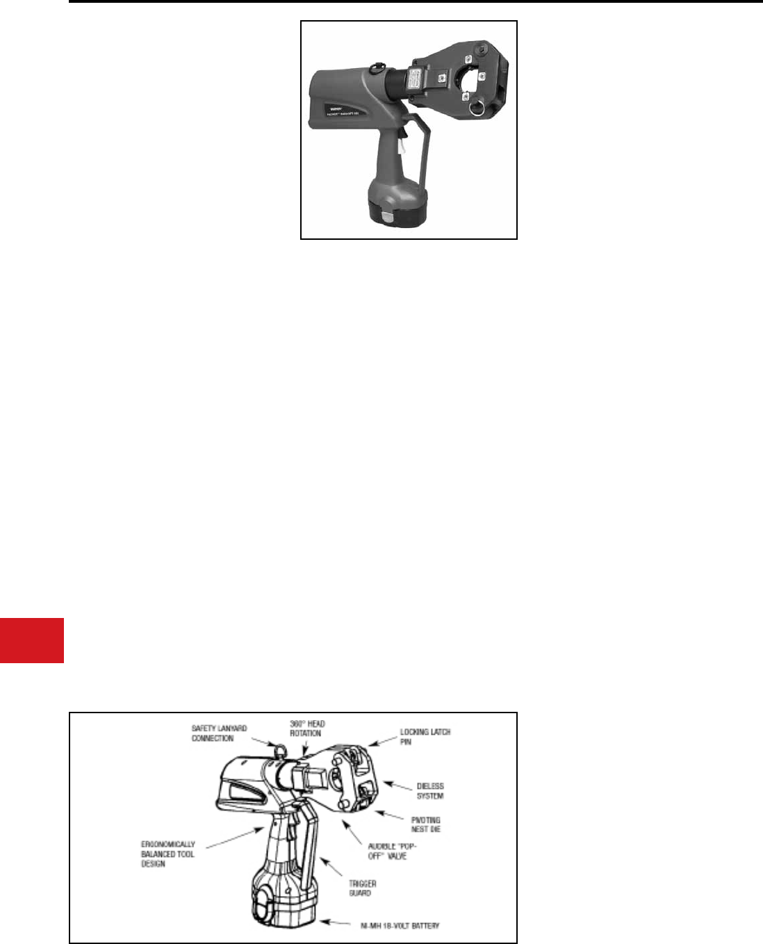
BURNDY®
US: 1-800-346-4175 www.burndy.com Canada: 1-800-387-6487
Tooling
Crimpers — Battery Actuated
4-POINT® PATRIOT®
PAT81KFT-18V
BATTERY ACTUATED TOOL
Hydraulic Self-Contained
Crimping Tool
#8-1000 kcmil Copper HYLUG™ Terminals
and HYLINK™ Splices
#8-750 kcmil Aluminum HYLUG™ Terminals
and HYLINK™ Splices
The BURNDY® PAT81KFT-18V is a battery
powered crimping tool that provides a powerful
6 tons of crimping force. It is compact, fast, easy
to use and incorporates the latest in battery tool
technology. The ergonomic design allows for one
hand operation so that the other is free to position
the connectors and conductor prior to crimping.
The PAT81KFT-18V features a dieless latch head
design which eliminates the need to purchase and
maintain dies. Featuring 360° head rotation, the
PAT81KFT-18V is designed for easy operation in
virtually any position.
The PAT81KFT-18V is supplied with a high impact
carrying case, battery charger, lanyard and two
batteries. The PAT81KFT-18V comes complete
with a 5-year limited warranty on the tool and
1-year limited warranty on the batteries.
PAT81KFT-18V Dieless HYPRESS™ Range
Taking Capabilities: The PAT81KFT-18V
provides range taking capabilities that is UL and
CSA Listed for Copper (Code, Compact and Flex)
and Aluminum (Code and Compact) conductors
when used in conjunction with BURNDY®
HYLUG™ terminals and HYLINK™ splices. See
chart for connector, conductor and range taking
combinations.
• Dieless installation system
• Audible pressure “pop-off” valve and die
embossment providing 360º inspectability
• Battery powered crimp technology
• Advanced high speed pump design
• 360 Degree head rotation
• Versatile tool head positioning lets the user
get into tight areas easier
• Ram holds position when trigger is released
• Mechanical ram release
• Audible pressure “pop-off” value
Output Force:
Tool Weight:
Length:
Height:
Width:
Operating Voltage:
Recharge Time:
Features and Benets
SPECIFICATIONS
FOR USE ON
Copper, Aluminum, Compressed, Compact,
Stranded, Solid and Flex Conductors
Installs Splices, Taps and Terminations:
#8 - 1000 kcmil Copper
(YA, YA-L, YS, YS-L, YS-T, Y-R )
#8 - 777.7 (750 Nominal Flex Wire Size)
kcmil Flex (YA-FX, YAV, YA-L-FX, YS, YSV-FXB)
#8 - 750 kcmil Aluminum (YA-A, YS-A)
#8 - 750 kcmil Aluminum Pin Adapters (AYP,
AYPO)
6 tons (5.4 metric tons)
14 lbs (6.35 kg)
17.6" (447 mm)
13.9" (354 mm)
3.7" (94 mm)
18 V-DC
<45 minutes
ACCESSORIES
Battery:
Chargers:
120V-AC
12/24V-DC
240/250V-AC
Lanyard:
Cat# BAT18V
(2.6 AH) Hi-capacity Ni-MH
Cat# PATCHGR18V
Cat# BCT/PATDCCHGR
Cat# PATCHGR250V
Cat# PT208620
N-18
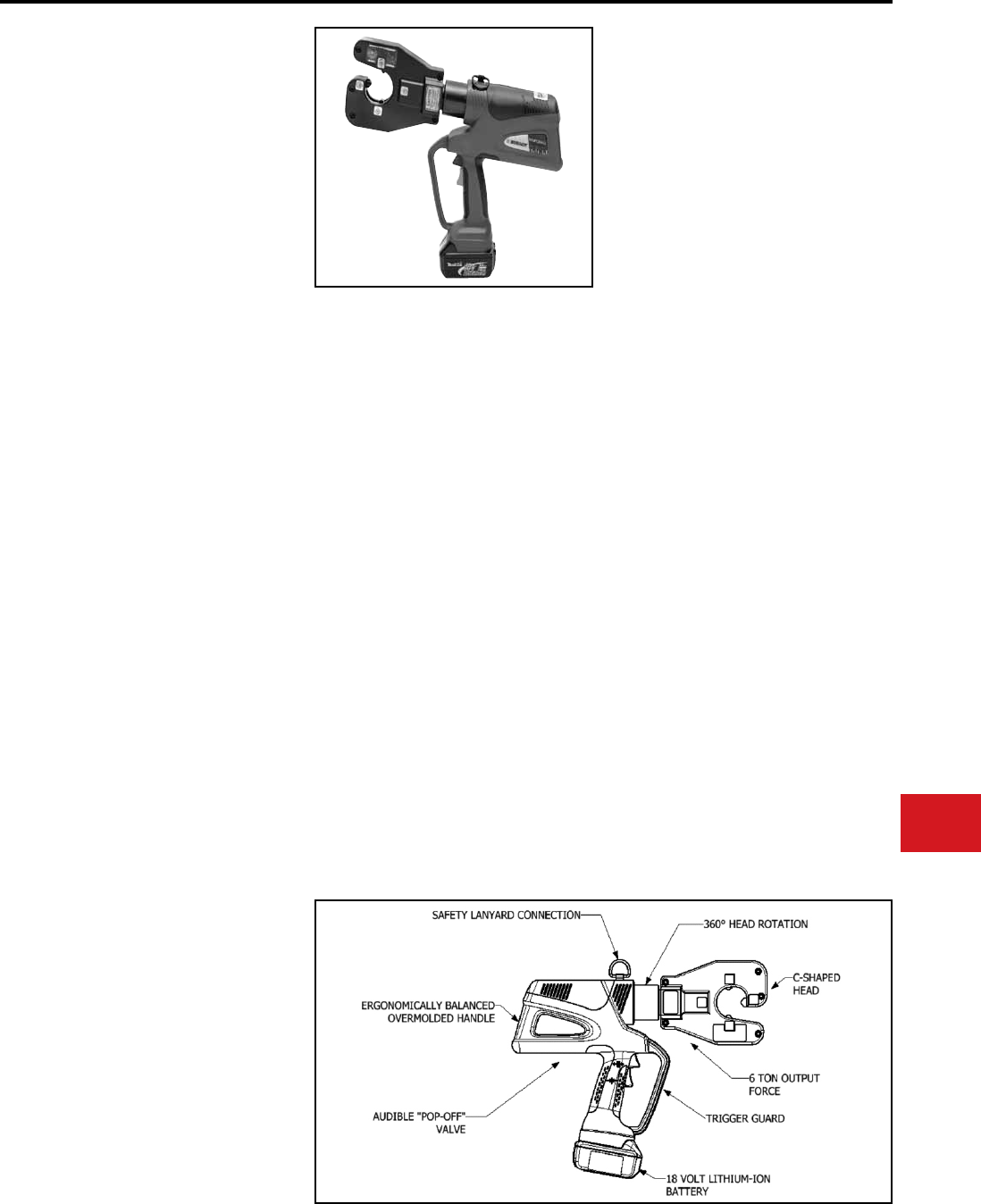
BURNDY®
Canada: 1-800-387-6487 www.burndy.com US: 1-800-346-4175
Tooling
Crimpers — Battery Actuated
4-POINT® PATRIOT®
PAT4PC834-LI
18 Volt Lithium-Ion
Battery Actuated Tool
Hydraulic Self-Contained 6-Ton
4-POINT® Dieless Crimping Tool
The BURNDY® PAT4PC834-LI 4-POINT®
dieless C-head Lithium-Ion tool incorporates
the latest engineering technology with a rened
hydraulic system for ultra performance, speed
and reliability. The redesigned eld proven
electronics provide the ultimate reliability in the
harshest work environments. All BURNDY® batt-
ery actuated hydraulic tools provide a consistent,
reliable connection every time. The PAT4PC834-
LI features a C-shaped head design making it
ideal for crimping in tight areas and can be easily
removed from continuous conductor runs. The
dieless capability of this tool eliminates the need
to purchase and maintain dies. The crimp head
rotates 360° for operation in virtually any position.
The PAT4PC834-LI is supplied with a durable
high impact formed carrying case to hold the
tool, battery charger, two 18 volt Lithium-Ion
batteries and tool retention lanyard. All BURNDY®
PATRIOT® 18V series tools are provided with a
5-year limited warranty on the tool and a 1-year
warranty on batteries and chargers. All PATRIOT®
tools feature the BURNDY® INFINITY DRIVE®
transmission which has a lifetime warranty.
PAT4PC834-LI Range Taking Capabilities:
The PAT4PC834-LI provides range taking
capabilities that are UL and CSA certied for
copper (code, compact and ex) and aluminum
(code and compact) conductors when used in
conjunction with BURNDY® HYLUG™ terminals
and HYLINK™ splices.
Output Force:
Tool Weight:
Length:
Width:
Height:
Operating Voltage:
Recharge Time:
Features and Benets
SPECIFICATIONS
6 ton
(5.4 metric tons)
13 lbs (5.9 kg)
With Battery
15.6" (39.6 cm)
3.2" (8.1 cm)
14.1" (35.8 cm)
18 V-DC
30 minutes
• Rened hydraulic system for ultra performance,
speed and reliability
• Field proven electronics for ultimate reliability in
the harshest environments
• Overmolded handle for comfort and improved
grip; allows for one-handed operation for
advance, retract and hold
• 18-volt Lithium-Ion batteries provide 2.5 times
more charge/discharge cycles than traditional
Ni-Cd batteries and provide 430% more
lifetime work
• 30-minute charger controls current, voltage and
temperature to maximize battery life
• Forced air cooling fan cools the battery by
forcing cool air through the battery’s built in air
vents
• Dieless system eliminates the need to purchase
and maintain dies
• Dieless system allows connectors and splices to
become range taking
• C-shaped head design rotates 360° and allows
for easy removal on continuous conductors
• Ergonomically balanced tool design eases
operation and helps lessen fatigue
FOR USE ON
ACCESSORIES
Copper
#8-1000 kcmil
Copper Flex
#8-777.7 kcmil
Flex (750 Nominal)
Aluminum
#8-750 kcmil
Aluminum
#8-750 kcmil
Terminals:
YA, YA-L
Splices:
YS-L, YS, YS-T, Y-R
Terminals:
YA-FX, YAV, YA-L-FX
Splices:
YS, YSV-FXB
Terminals:
YA-A, YA-A-TN
Splices:
YS-A
HYPLUG™
AYP, AYPO
Battery:
Chargers:
120V-AC
12/24V-DC
Lanyard:
Cat# BAT18VLI
(3.0 AH) Hi-capacity
Cat# PATCHGR-LI
Cat# PATCHGR-LIDC
Cat# PT208620
N-19
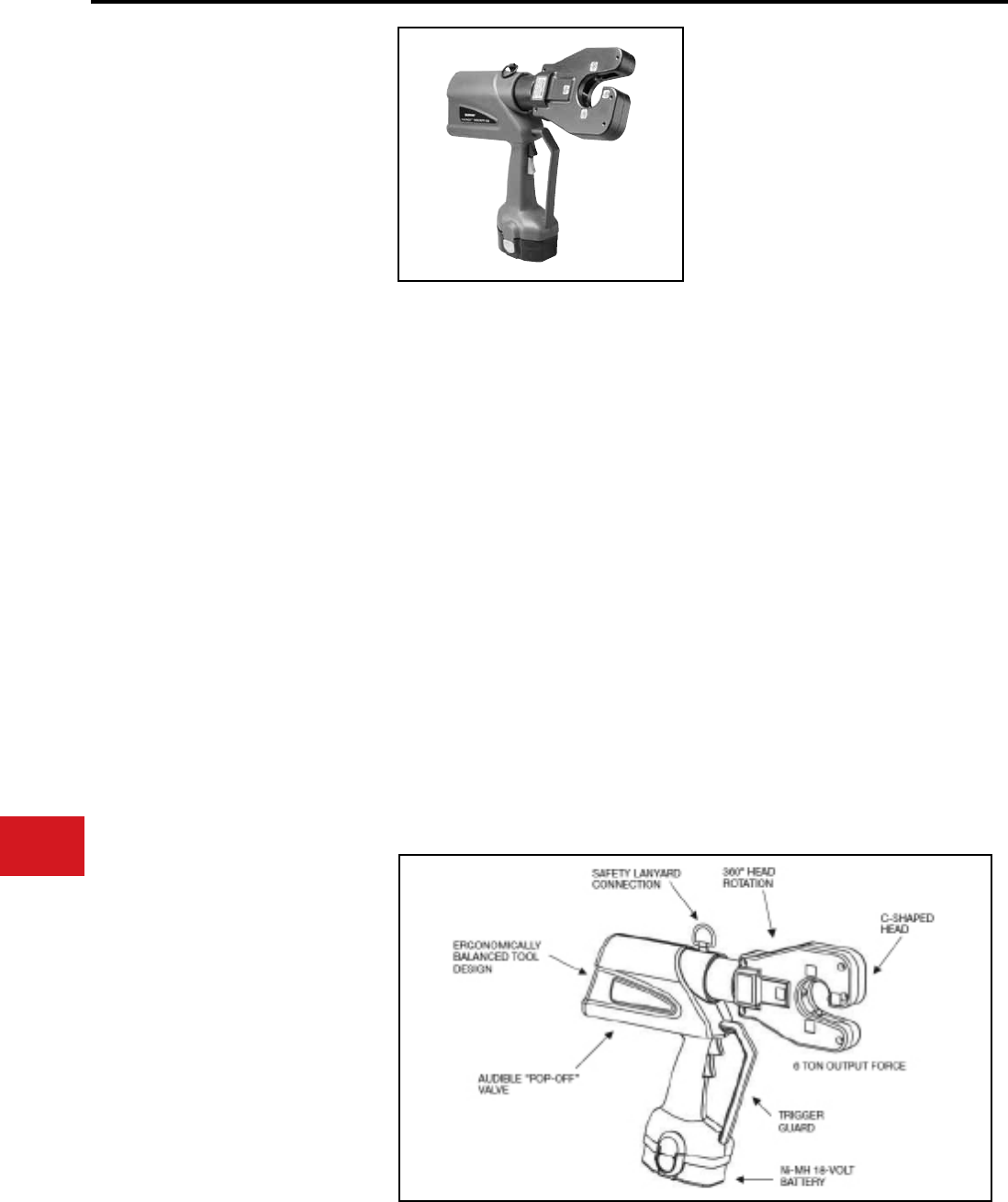
BURNDY®
US: 1-800-346-4175 www.burndy.com Canada: 1-800-387-6487
Tooling
Crimpers — Battery Actuated
4-POINT® PATRIOT®
PAT4PC834-18V
BATTERY ACTUATED TOOL
Hydraulic Self-Contained
6-Ton Dieless Crimping Tool
The BURNDY® PATRIOT® 4-POINT® C-shaped
head dieless HYPRESS™ is a battery actuated
6 ton hydraulic crimping tool for use on a wide
variety of tap, terminate, and splice compression
applications. The dieless capability of this tool
eliminates the need to purchase or maintain
additional dies. It is compact, fast, easy to use and
incorporates the latest in battery tool technology.
The ergonomic design allows for one hand
operation so that the other is free to position the
connector and conductor prior to crimping. The
PAT4PC834-18V incorporates a C-shaped head
design making it ideal for crimping in tight areas
and can be easily removed from continuous
conductor runs. The head rotates 360º and is
mated to a patented rapid advance pump. The
PAT4PC834-18V weighs only 13.8 pounds and
delivers 6 tons of crimping force. The result
allows for easy tap, termination and splicing of
compression connectors.
The PAT4PC834-18V is supplied with a molded
high impact carry case, battery charger, lanyard,
and two batteries. The PAT4PC834-18V comes
with a 5-year limited warranty.
The PAT4PC834-18V provides range taking
capabilities that are UL Listed and CSA Certied
for Copper (Code, Compact and Flex) and
Aluminum (Code and Compact) conductors when
used in conjunction with BURNDY® HYLUG™
terminals and HYLINK™ splices.
• Dieless installation system
• UL Listed and CSA Certied with range
taking capabilities
• C-shaped head Design
• Audible pressure “pop-off” valve and die
embossment providing 360° inspectability
• Handle Trigger release
• Advanced high speed pump design
• 360° head rotation
• Durable high impact formed carrying
case
• 5-year limited warranty
Output Force:
Tool Weight:
Length:
Height:
Width:
Operating Voltage:
Recharge Time:
Features and Benets
SPECIFICATIONS
FOR USE ON
6 ton (5.4 metric tons)
13.85 lbs (6.28 kg)
With Battery
17.6 in (448 mm)
13.9 in (354 mm)
3.7 in (94 mm)
18 V-DC
<45 minutes
Copper, Aluminum, Compressed, Compact,
Stranded, Solid and Flex Conductors
Installs Splices, Taps and Terminations:
#8 - 1000 kcmil Copper
(YA, YA-L)
#8 - 500 kcmil Copper
(YS, YS-T, YS-L, Y-R))
#8 - 777 (750 Nominal Flex Wire Size)
kcmil Flex (YA-FX, YAV, YA-L-FX)
#8 - 535 (500 kcmil nominal ex wire size) kcmil
ex (YS, YS-LB, YSV-FXB)
#8 - 750 kcmil Aluminum (YA-A)
#8 - 350 kcmil Aluminum (YS-A)
#8 - 750 kcmil Aluminum Pin Adapters
(AYP, AYPO)
ACCESSORIES
Battery:
Chargers:
120V-AC
12/24V-DC
240/250V-AC
Lanyard:
Cat# BAT18V
(2.6 AH) Hi-capacity Ni-MH
Cat# PATCHGR18V
Cat# BCT/PATDCCHGR
Cat# PATCHGR250V
Cat# PT208620
N-20
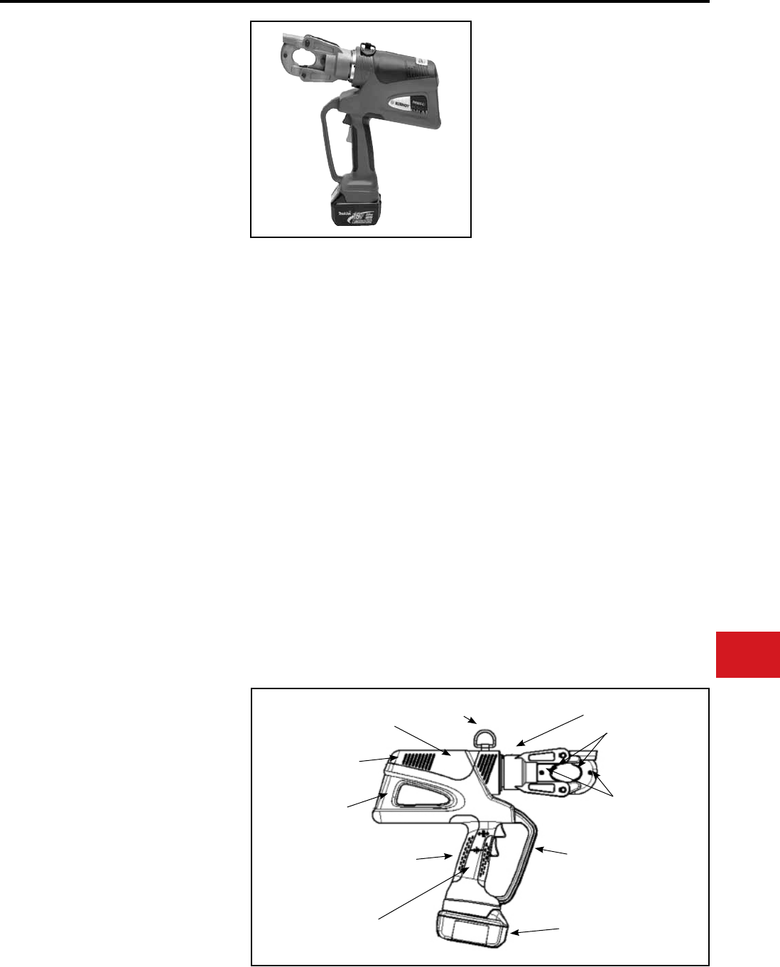
BURNDY®
Canada: 1-800-387-6487 www.burndy.com US: 1-800-346-4175
Tooling
Crimpers — Battery Actuated
PATRIOT® PAT600-LI
18 Volt Lithium-Ion
Battery Actuated Tool
Hydraulic Self-Contained
6-Ton Crimping Tool
The BURNDY® PAT600-LI Lithium-Ion tool
incorporates the latest engineering technology with
a rened hydraulic system for ultra performance,
speed and reliability. The redesigned eld proven
electronics provide the ultimate reliability in the
harshest work environments. All BURNDY® battery
actuated hydraulic tools provide a consistent,
reliable connection every time.
The PAT600-LI battery actuated tool provides
6 tons of crimping force and completes a crimp
in approximately 3 seconds. The PAT600-LI
incorporates a specialized latch style head
with enhanced working stroke and clearance
capabilities. The latch-style head allows
interference-free closure on tap connections up to
the BURNDY® YHD-400 size.
Die selection with the PAT600-LI includes “W”, “X”
and “W-VT” style dies which seat in the permanent
“D3” crimp groove. Installation applications include
#8 AWG to 600 kcmil copper lugs and splices (YA
and YS), #8AWG, to 350 kcmil aluminum lugs and
splices (YA-A and YS-A) and up to 4/0 aluminum
tap connections.
The PAT600-LI is supplied with a durable high
impact formed carrying case to hold the tool,
battery charger, two 18 volt Lithium-Ion batteries
and tool retention lanyard. All BURNDY®
PATRIOT® 18V series tools are provided with a
5-year limited warranty on the tool and a 1-year
warranty on batteries and chargers. All PATRIOT®
tools features the BURNDY® INFINITY DRIVE®
transmission which has a lifetime warranty.
Output Force:
Tool Weight:
Length:
Width:
Height:
Operating Voltage:
Recharge Time:
Features and Benets
SPECIFICATIONS
6 tons (5.4 metric tons)
10.1 lbs (4.5 kg)
With Battery
14.5" (36.8 cm)
3.5" (8.9 cm)
13.7" (34.9 cm)
18 V-DC
30 minutes
• Rened hydraulic system for ultra performance,
speed and reliability
• Field proven electronics for ultimate reliability in
the harshest environments
• Overmolded handle for comfort and improved
grip; allows for one-handed operation for
advance, retract and hold
• 18-volt Lithium-Ion batteries provide 2.5 times
more charge/discharge cycles than traditional
Ni-Cd batteries and provide 430% more
lifetime work
• 30-minute charger controls current, voltage and
temperature to maximize battery life
• Forced air cooling fan cools the battery by
forcing cool air through the battery’s built in air
vents
• Specialized latch design allows interference free
closure on tap connections
• Permanent “D3” crimp grooves accepts “W”, “X”
and “W-VT” dies
• PAT600C-LI with covered head is available
• State of the art crimping head design, 180°
head rotation lets user get into tight areas
easier
• Ergonomically balanced tool design eases
operation and helps lessen fatigue
SAFETY LANYARD
CONNECTION
AUDIBLE “POP-OFF” VALVE
SPRING LOADED DIE
RETAINING PINS
FUNCTIONAL D3
DIE GROOVE
ERGONOMICALLY BALANCED
OVERMOLDED HANDLE
FIELD PROVEN ELECTRONICS FOR
ULTIMATE RELIABILITY IN THE
HARSHEST WORK ENVIRONMENTS
REFINED HYDRAULIC SYSTEM
FOR ULTRA PERFORMANCE,
SPEED AND RELIABILITY
180° HEAD ROTATION
6 TON OUTPUT FORCE
18 VOLT LITHIUM-ION
BATTERY
TRIGGER GUARD
FOR USE ON
Copper
#8-600 kcmil
Copper Flex
#8-350 kcmil Flex
Aluminum
#8-350 kcmil
Terminals:
YA, YA-L
Splices:
YS-L, YS, YS-T, Y-R
Terminals:
YA-FX, YAV, YA-L-FX
Splices:
YS, YSV-FXB
Terminals:
YA-A, YA-A-TN
Splices:
YS-A
ACCESSORIES
Battery:
Chargers:
120V-AC
12/24V-DC
W Die Holder
Lanyard:
Cat# BAT18VLI
(3.0 AH) Hi-capacity
Cat# PATCHGR-LI
Cat# PATCHGR-LIDC
Cat# WDIETREE
Cat# PT208620
N-21
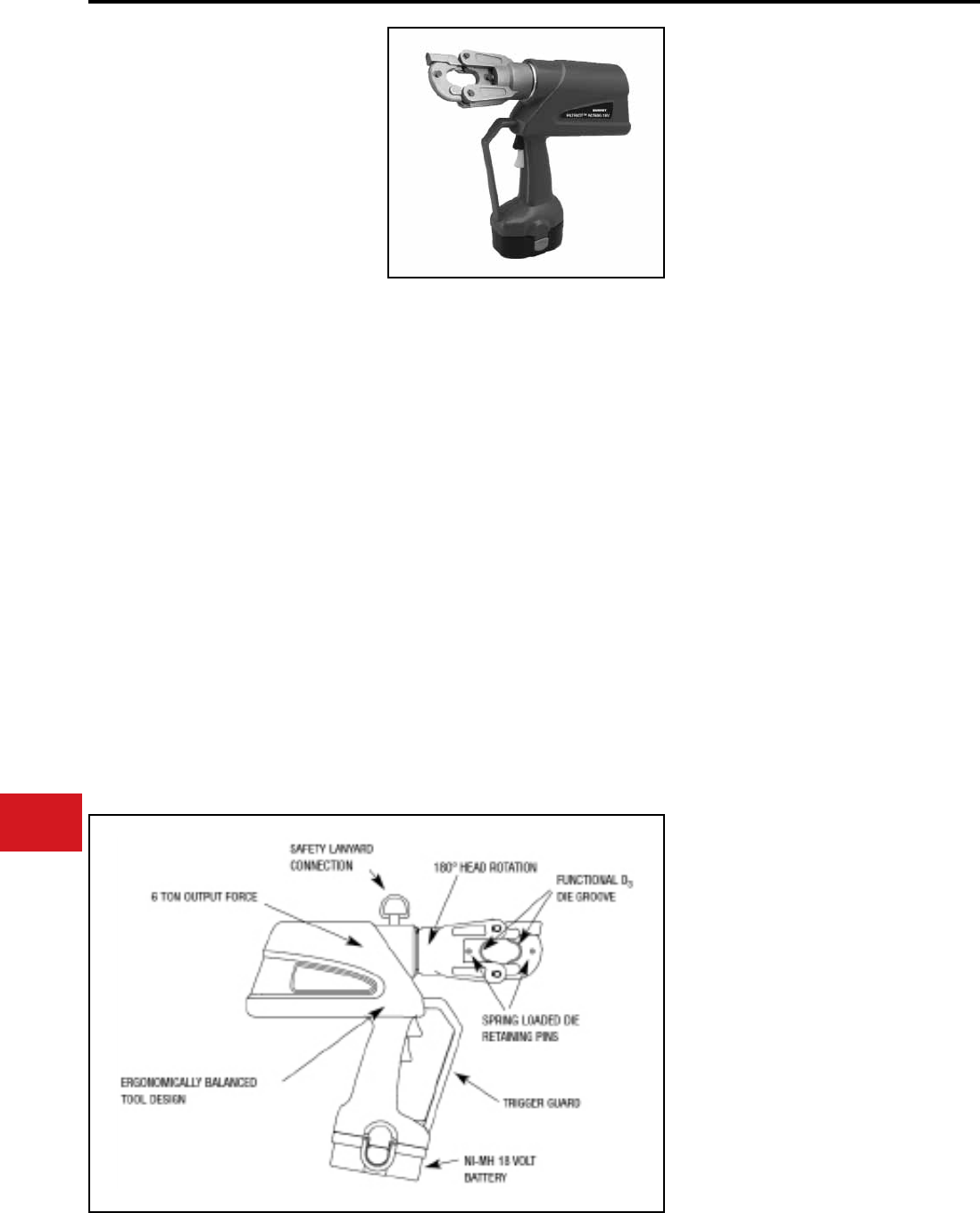
BURNDY®
US: 1-800-346-4175 www.burndy.com Canada: 1-800-387-6487
Tooling
Crimpers — Battery Actuated
PATRIOT® PAT600-18V
BATTERY ACTUATED TOOL
Hydraulic Self-Contained
6-Ton Crimping Tool
The BURNDY® PAT600-18V battery powered
crimping tool provides a powerful 6 tons of crimping
force and completes a crimp in approximately
3 seconds. The PAT600-18V is compact, easy
to use and incorporates the latest in battery tool
technology. The PAT600-18V tool incorporates
a specialized latch style head with enhanced
working stroke and clearance capabilities.
The specialized head allows interference-free
closure on tap connections up to the BURNDY®
YHD-400 size including 350 kcmil aluminum
connectors. Die selection with this tool includes all
BURNDY® “W” and “W-VT” style dies which seat
in the permanent “D3” crimping groove. Installation
applications include #8 AWG to 600 kcmil copper
lugs and splices (YA and YS), #8 AWG to 350
kcmil aluminum lugs and splices (YA-A and YS-
A), and up to 4/0 aluminum tap connections. The
permanent “D3” groove and 180 degree rotatable
head are standard on the PAT600-18V.
Each PAT600-18V tool uses BURNDY® dies and
off-the-shelf connectors available worldwide. The
PAT600-18V comes equipped with a high impact
formed carrying case to hold the tool, a battery
charger and two batteries.The case houses up
to 10 “W” dies (dies purchased separately). The
PAT600-18V uses industry standard batteries and
chargers.The PAT600-18V comes complete with
a 5-year limited warranty and 1-year on batteries
and charger.
• Battery powered crimp technology
• Advance design high speed pump
completes crimp in approximately 3
seconds
• Ergonomic design allows one hand
operation for ram advance and ram
retraction
• Variable speed trigger
• Ram holds position when trigger is
released
• Mechanical ram release
• Specialized latch head design for
enhanced clearance on tap connectors
• 180 degree head rotation
• Uses 18 volt Ni-MH batteries
• Audible pressure “pop-off” valve
• Permanent D3 crimp groove accepts all
“W-Dies”
• PAT600C-18V with covered head is
available
• Durable high impact formed carrying case
• 5-year limited warranty on tool, 1-year on
batteries and charger
Crimp Force:
Tool Weight:
Length:
Width:
Height:
Operating Voltage:
Crimp Time:
Recharge Time:
Features and Benets
SPECIFICATIONS
FOR USE ON
6 tons
(5.4 metric tons)
10.9 lbs (4.9 kg) With
Battery
14.5 in (36.8 cm)
3.5 in (8.9 cm)
13.75 in (34.9 cm)
18 V-DC
Approx. 3 seconds
< 45 minutes
Copper, Aluminum, ACSR. Steel, Copperweld,
Alumoweld, 6201, 5005, Compressed, Compact,
Stranded & Solid
Installs Splices, Taps and Terminations:
#8 - 600 kcmil Copper Stranded
(YA, YA-L, YS, YS-L)
#8 - 350 kcmil Flex
#8 - 350 kcmil Aluminum (YA-A, YS-A)
ACCESSORIES
Battery:
W Die Holder
Chargers:
120V-AC
12/24V-DC
240/250V-AC
Lanyard:
Cat# BAT18V
(2.6 AH) Hi-capacity Ni-MH
Cat# WDIETREE
Cat# PATCHGR18V
Cat# BCT/PATDCCHGR
Cat# PATCHGR250V
Cat# PT208620
N-22
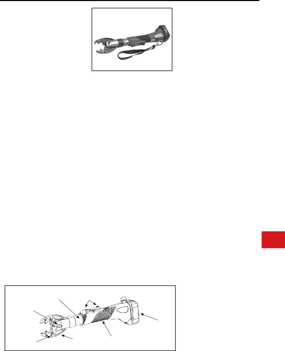
BURNDY®
Canada: 1-800-387-6487 www.burndy.com US: 1-800-346-4175
Tooling
Crimpers — Battery Actuated
PATRIOT® IN-LINE®
HIGH PERFORMANCE
PATMD6-LI SERIES
18 Volt Lithium-Ion
Battery Actuated Tool
Hydraulic Self Contained
6-Ton Crimping Tool
The BURNDY® PATRIOT® High Performance
IN-LINE® series of tools are approximately 80%
faster than previous models. In addition to faster
crimp cycles, the high performance IN-LINE®
PATMD6-LI series is offered with 18 volt Lithium-
Ion technology.
The BURNDY® High Performance IN-LINE® tools
are battery actuated and can be operated with
one hand allowing for advance, retract and hold
functions for easier operation. One hand operation
allows the operator one free hand to position the
connector and conductor while crimping. The
PATMD6-LI series of tools complete a crimp (YS28
4/0 copper cable) in approximately 2 seconds. This
design provides a consistent, reliable connection
every time.
The High Performance IN-LINE® tools feature
interchangeable MD6 series jaws, capable of
using “W” and “X” style dies in the permanent D3
groove. The PATMD6-K-LI accepts KEARNEYTM
type “O” dies and BURNDY® “W” and “X” style
dies with KWADP adapter. When ordering choose
the tool that best suits your crimping needs. The
IN-LINE® tools feature 350° rotatable heads for
operation in virtually any position.
Each High Performance IN-LINE® tool uses
standard BURNDY® dies and off-the-shelf
connectors available world-wide. IN-LINE® tools
are supplied with a durable vinyl tool bag, battery
charger and two batteries.
KEARNEY™ is a registered trademark of
COOPER TECHNOLOGIES COMPANY.
Output Force:
Tool Weight:
Length:
Width:
Height:
Operating Voltage:
Recharge Time:
Features and Benets
SPECIFICATIONS
6 tons
(5.4 metric tons)
7.8 lbs (3.5kg)
With Battery
20.91″ (53.11 cm)
3.69″ (9.37 cm)
5.48″ (13.91 cm)
18 V-DC
30 minutes
• 18 volt Lithium-Ion batteries provide 2.5
times more charge/discharge cycles than
traditional Ni-Cd batteries and provide
430% more lifetime work
• Overmolded handle for comfort and
improved grip even when wearing gloves
• 30-minute battery charger controls current,
voltage and temparature to maximize
battery life
• True, one handed operation for advance,
retract and hold
• Pressure “pop-off” valve indicates
completion of crimp
• Interchangeable scissor action crimp jaws
allow easier access to tight spaces
• Ram holds position when trigger is released
to allow the operator to check alignment
prior to crimping
• Ergonomically balanced tool design helps
lessen operator fatigue
• High capacity 3.0 AH batteries provide more
crimps per charge
• 5-year limited warranty on tool
• Lifetime warranty on INFINITY DRIVE®
• 1-year warranty on batteries and charger
FOR USE ON
Copper, Aluminum, ACSR, Steel, Copperweld,
Alumoweld, 6201, 5005, Compressed, and
Compact conductors
Copper Taps: #10 solid - 2/0 stranded
Aluminum and ACSR Taps: #14 solid - 4/0 ACSR
Stirrups: #6 - 4/0 ACSR
Overhead Full Tension Deadends, Full Tension
Splices and Terminals: #10 stranded - 4/0 ACSR
Installs splices, taps or terminations:
#8 - 500 kcmil Copper Stranded (YA, YA-L, YS, YS-L)
#8 - 350 kcmil Copper Flex
#8 - 350 kcmil Aluminum (YA-A, YS-A)
Interchangeable Jaw Assemblies:
PATJAWSMD6
PATJAWSMD6-8
PATJAWSMD6-6
PATJAWSMD6K
PATJAWSCUT
Jaw Covers:
BG and D3 Grooves
O and D3 Grooves
D3 Groove only (snub-nose)
KEARNEY™ Groove (snub)
Cutter Jaw Set
PATMD6JC, PATMD66JC,
PATMD6KJC
ACCESSORIES
Battery:
Chargers:
120V-AC
12/24V-DC
Cutter Dies:
Cat# BAT18VLI
(3.0 AH) Hi-capacity LI
Cat# PATCHGR-LI
Cat# PATCHGR-LIDC
Cat# W28K
For cutting 4 - 4/0 Copper,
Aluminum and ACSR
PATRIOT® IN-LINE® VARIATIONS:
PATMD6-LI
PATMD6-8-LI
PATMD6-6-LI
PATJMD6-K-LI
BG and D3 Grooves
O and D3 Grooves
D3 Groove only (snub-nose)
KEARNEY™ Groove (snub)
(KEARNEY™ O dies;
BURNDY® W and X with
KWADP adapter)
PATRIOT® IN-LINE® Cut/Crimp Kits:
All with Cutter Jaws, 2 Batteries and Charger
PATMD6LICUTKIT1
PATMD68LICUTKIT1
PATMD66LICUTKIT1
PATMD6LIWCJ
PATMD66LIWCJ
PATMD68LIWCJ
BG & D3 Grooves, hard case
O & D3 Grooves, hard case
D3 Groove (snub), hard case
BG & D3 Grooves, soft case
O & D3 Grooves, soft case
D3 Groove (snub), soft case
Jaw release pin
350° Rotating head
Spring loaded
die retainer
pins
Interchangeable
jaws
Large
overmolded
grip area
Activation & release
triggers
18 Volt
lithium-
ion
battery
N-23
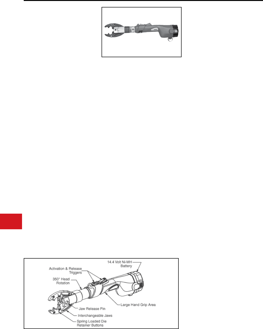
BURNDY®
US: 1-800-346-4175 www.burndy.com Canada: 1-800-387-6487
Tooling
Crimpers — Battery Actuated
PATRIOT® IN-LINE®
PATMD6-14V SERIES
HIGH PERFORMANCE
BATTERY ACTUATED TOOL
Hydraulic Self Contained
6-Ton Crimping Tool
The BURNDY® PATRIOT® High Performance
PATMD6-14V series of tools are approximately 80%
faster than previous models. In addition to faster
crimp cycles, the High Performance PATMD6-14V
series tools have newly designed electronics that
are eld proven for ultimate reliability to handle the
harshest work environments.
The BURNDY® High Performance IN-LINE® tools
are battery actuated and can be operated with
one hand allowing for advance, retract and hold
functions for easier operation. One hand operation
allows the operator one free hand to position
the connector and conductor while crimping.
The High Performance PATMD6-14V series of
tools incorporate a high speed hydraulic pump
generating 6 tons of crimping force and completes
a crimp (YS28 4/0 copper cable) in approximately
2 seconds. This design provides a consistent,
reliable connection every time.
The High Performance IN-LINE® tools feature
interchangable MD6 series jaws, capable of using
“W” and “X” style dies in the permanent D3 groove.
The PATMD6-K-14V accepts KEARNEYTM type
“O” dies and BURNDY® “W” and “X” style dies
with KWADP adapter. The IN-LINE tools feature
350° rotatable heads for operation in virtually any
position.
Each High Performance IN-LINE® tool uses
standard BURNDY® dies and off-the-shelf
connectors available world-wide. IN-LINE® tools
are supplied with carrying case, battery charger,
two batteries and die compartment to hold dies.
(Dies are sold separately.)
• Rened hydraulic system for ultra
performance, speed and reliability.
• Field proven electronics for ultimate reliability in
the harshest environments.
• Pressure “pop-off” valve indicates
completion of crimp.
• Interchangeable scissor action crimp jaws
allow easier access to tight spaces.
• Ram holds position when trigger is
released to allow the operator to check
alignment prior to crimping.
• Large hand grip area allows easier operation
with gloves.
• Ergonomically balanced tool design helps
lessen operator fatigue.
• Durable high impact formed carrying
case.
• High capacity 2.6 AH batteries provide
more crimps per charge.
• 5-year limited warranty on tool.
• Lifetime warranty on INFINITY DRIVE®
• 1-year warranty on batteries and charger
KEARNEYTM is a registered trademark of
COPPER TECHNOLOGIES COMPANY.
Output Force:
Tool Weight:
Length:
Width:
Height:
Operating Voltage:
Recharge Time:
Features and Benets
SPECIFICATIONS
6 tons
(5.4 metric tons)
7.8 lbs (3.5kg)
With Battery
20.91″ (53.11 cm)
3.69″ (9.37 cm)
5.48″ (13.91 cm)
14.4 V-DC
< 45 minutes
Interchangeable Jaw Assemblies:
PATJAWSMD6
PATJAWSMD6-8
PATJAWSMD6-6
PATJAWSMD6K
PATJAWSCUT
Jaw Covers:
BG and D3 Grooves
O and D3 Grooves
D3 Groove only (snub-nose)
KEARNEY™ Groove (snub)
Cutter Jaw Set
PATMD6JC, PATMD66JC,
PATMD6KJC
ACCESSORIES
Battery:
Chargers:
120V-AC
12/24V-DC
240/250V-AC
Cutter Dies:
Cat# BAT14V
(2.6 AH) Hi-capacity Ni-MH
Cat# PATCHGR18V
Cat# BCT/PATDCCHGR
Cat# PATCHGR250V
Cat# W28K
For cutting 4 - 4/0 Copper,
Aluminum and ACSR
FOR USE ON
Copper, Aluminum, ACSR, Steel, Copperweld,
Alumoweld, 6201, 5005, Compressed, and
Compact conductors
Copper Taps: #10 solid - 2/0 stranded
Aluminum and ACSR Taps: #14 solid - 4/0 ACSR
Stirrups: #6 - 4/0 ACSR
Overhead Full Tension Deadends, Full Tension
Splices and Terminals: #10 stranded - 4/0 ACSR
Installs splices, taps or terminations:
#8 - 500 kcmil Copper Stranded (YA, YA-L, YS, YS-L)
#8 - 350 kcmil Copper Flex
#8 - 350 kcmil Aluminum (YA-A, YS-A)
PATRIOT® IN-LINE® VARIATIONS:
PATMD6-14V
PATMD6-8-14V
PATMD6-6-14V
PATJMD6-K-14V
BG and D3 Grooves
O and D3 Grooves
D3 Groove only (snub-nose)
KEARNEY™ Groove (snub)
(KEARNEY™ O dies;
BURNDY® W and X with
KWADP adapter)
N-24
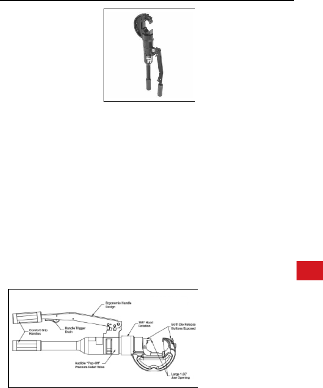
BURNDY®
Canada: 1-800-387-6487 www.burndy.com US: 1-800-346-4175
Tooling
Crimpers — Self-Contained Hydraulic
Y750HSXT AND
Y750CHSXT RUBBER
COVERED HEAD
750 REVOLVER HYPRESS™
Hydraulic Hand Operated Tool
12-Ton Crimp Force
Conductor Range:
#14 - 750 kcmil Cu/Al
#4 - 556.5 kcmil ACSR
The BURNDY® Y750HSXT Series HYPRESS™ is
a wide mouth (1.65″) hand operated hydraulic 12
ton crimping tool for use on virtually all compression
applications. The C-shaped head rotates 355°
relative to the handle and is mated to a patented
rapid advance pump. The Y750HSXT provides
easy tapping, splicing, and terminating of overhead
lines, the full line of HYGROUND® compression
grounding connectors, NEC cable connections,
and N30 - N650 Navy cable connections.
The Y750HSXT accepts all BURNDY® “U” dies for
use on conductor ranges of #14 - 750 kcmil AL/CU
and #4 - 556.5 kcmil ACSR conductors.
The Y750CHSXT HYPRESS™ has a rubber
covered head and handles for tool impact
protection.
Each Y750HSXT uses standard BURNDY® dies
and off-the-shelf connectors available world-
wide. Supplied with a durable high impact formed
carrying case to hold the tool, and die compartment
to hold “U” die sets. (Dies sold separately.) All
BURNDY® Y750HSXT series tools are provided
with a 5-year limited warranty.
• Covers a wide range of applications with
a lightweight, self-contained system and
provides easy tool removal from continuous
conductors with its C-shaped head
• Easy tool positioning with its 355° head
rotation
• Patented rapid advance pump for faster
crimps
• Exposed positive die lock buttons for easy
die change out and die retention
• Handle trigger drain for convenient ram
retraction
• Quality assurance is provided with an
audible “Pop-Off” pressure relief valve
• Comfort grip handles help ease operator
fatigue with continuous use
• Long life expectancy from the company
that provided the industry with the rst self-
contained hydraulic tool in 1934
• Rubber covered head and handles on
Y750CHSXT for tool impact protection
• Supplied with high impact plastic carrying
case
• 5-year limited warranty
Features and Benets
SPECIFICATIONS
FOR USE ON
Force developed:
Weight:
Length:
Height:
Width:
Jaw opening:
12 tons
14.5 lbs (6.6 kg)
23.96″ (608 mm)
2.86″ (78 mm)
8.71″ (222 mm)
1.65″ (42 mm)
• Tension Sleeves
Copper
Aluminum
ACSR
#8 sol. - 500 kcmil
#8 sol. - 556.5 kcmil
#4 - 556.5 kcmil
• Taps
Copper
Aluminum
#14 sol. - 500 kcmil
#8 - 500 kcmil
• Aerial Cable
Copper #6 - 500 kcmil
• Terminals & Splices
Aluminum
Copper
ACSR
#8 - 750 kcmil
#8 - 750 kcmil
#4 - 556 kcmil
• HYGROUND® (Compression Grounding)
Copper
Ground Rods
#8 - 500 kcmil
(cable/ground rod)
1/2″ - 1″ Diameter
ACCESSORIES:
Cat. No. Description
Y750HSCASE Plastic Carrying Case
for Y750HSXT or
Y750CHSXT.
FORCEGAUGE12-15 Force test gauge for
accurate visual reading
of output force.
PT29291 Die Case Steel case for
storage and protection
of “U” dies.
WIREMIKE Provides quick and
easy identication of
commonly used
conductors.
N-25
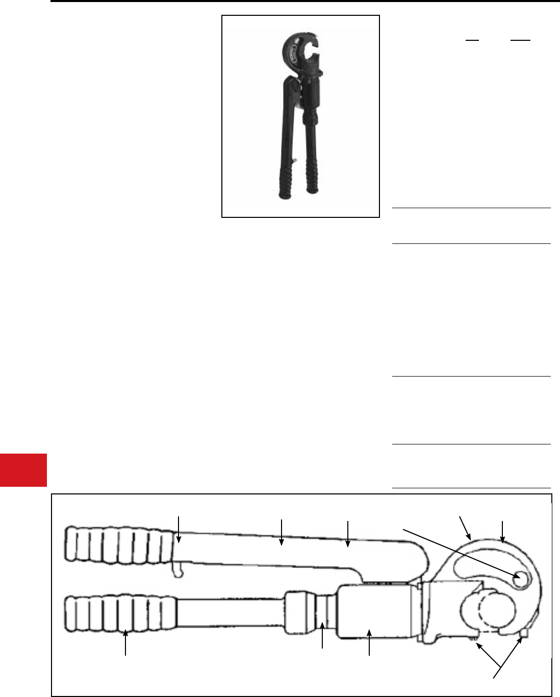
BURNDY®
US: 1-800-346-4175 www.burndy.com Canada: 1-800-387-6487
Tooling
Crimpers — Self-Contained Hydraulic
Y35 AND Y35-2
HYPRESS™
Hand-Operated Hydraulic Tool
The Y35 HYPRESS™ Tool incorporates a
C-shaped, rotatable head for overhead line work
and compression grounding applications. The
hook style head with extensive ram travel provides
for easy tapping and splicing of overhead lines as
well as HYGROUND® compression grounding
systems.
The Y35-2 HYPRESS™ head, body and handles
are covered with 3/16″ rubber for tool impact
protection.
Order the hot-line handle assembly, “U” dies and
accessories separately. 5-year limited warranty.
Force developed:
Operating pressure:
Weight (less case):
Overall length:
Head width:
Molded Covering:
(Continued)
SPECIFICATIONS
FOR USE ON
• Compact “C” shaped head allows easy
placement and removal from continuous
conductor lengths
• Easy to position tool for work with 180° head
rotation
• Versatile and economical-tool works with
all commonly used copper, aluminum and
ACSR conductors from #6 str. to #556.5 26/7
stranding
• Body and handles covered with 3/16″ molded
rubber for tool impact protection
• Easy die change accomplished with push
button die locks
• Quality assurance is provided with automatic
10,000 PSI blow-off pressure release valve for
positive crimping
• Rapid ram advance reduces installation
time by eliminating need to pump handles to
advance ram to connector
• Saves installation time with trigger controlled
return release which returns ram to its preset
starting point
• Long continuous usage is aided with comfort
grip handles
• Compression terminal and splice connectors
are UL Listed and CSA Certied when installed
with recommended die set
• 5-year limited warranty
Features and Benets
Y35
12 tons
10,000 PSI
13 lbs.
23-1/4″
4-3/4″
Body &
Handles
Y35-2
12 tons
10,000 PSI
13-1/2 lbs
24″
6″
Head, Body
and Handles
Copper
#8 str.-500 kcmil
Code Cables
Terminals-grounding
YGH, YGHA, YGF
Splices-grounding
YGS, YGHS
Copper
#8 str.-500 kcmil and up
to 3/4″ ground rod
Taps-grounding
YGHC-C, YGHP-C
YGHR-C
Copper
#8 str.-750 kcmil
Code Cables
N30-N500
Navy Cables
Flexible and
Extra Flex
Terminals Uninsulated
YA, YA-2N, YA-L,
YA-LB
YA-2LN
Terminals Insulated
YAEV-L Box, YAEV-L
YAEV-H, YAEV-RS,
YAEV-RH
Splices To Size
400 kcmil
YS, YS-T, YS-L
YS-LB, YSV-L Box
YSV-L, YSM
Aluminum
#8 str.-750 kcmil
Code Cables
Terminals
YA-A
AYP, AYPO
Splices To Size
350 kcmil
YSA, YRB, YS-AT
ACSR See Burndy Overhead
Transmission and
Distribution Catalog
Module
COMFORT GRIP HANDLES
RUBBER
COVERED
HANDLES
180° HEAD
ROTATION “C” SHAPED HEAD
HOLE FOR LIFTING
EYE
BOTH DIE
RELEASE
BUTTONS
EXPOSED
SHORT
HANDLE
THROW
AUDIBLE
“POP-OFF” PRESSURE
RELIEF VALVE
TRIGGER
CONTROLLED
RAM RELEASE
N-26
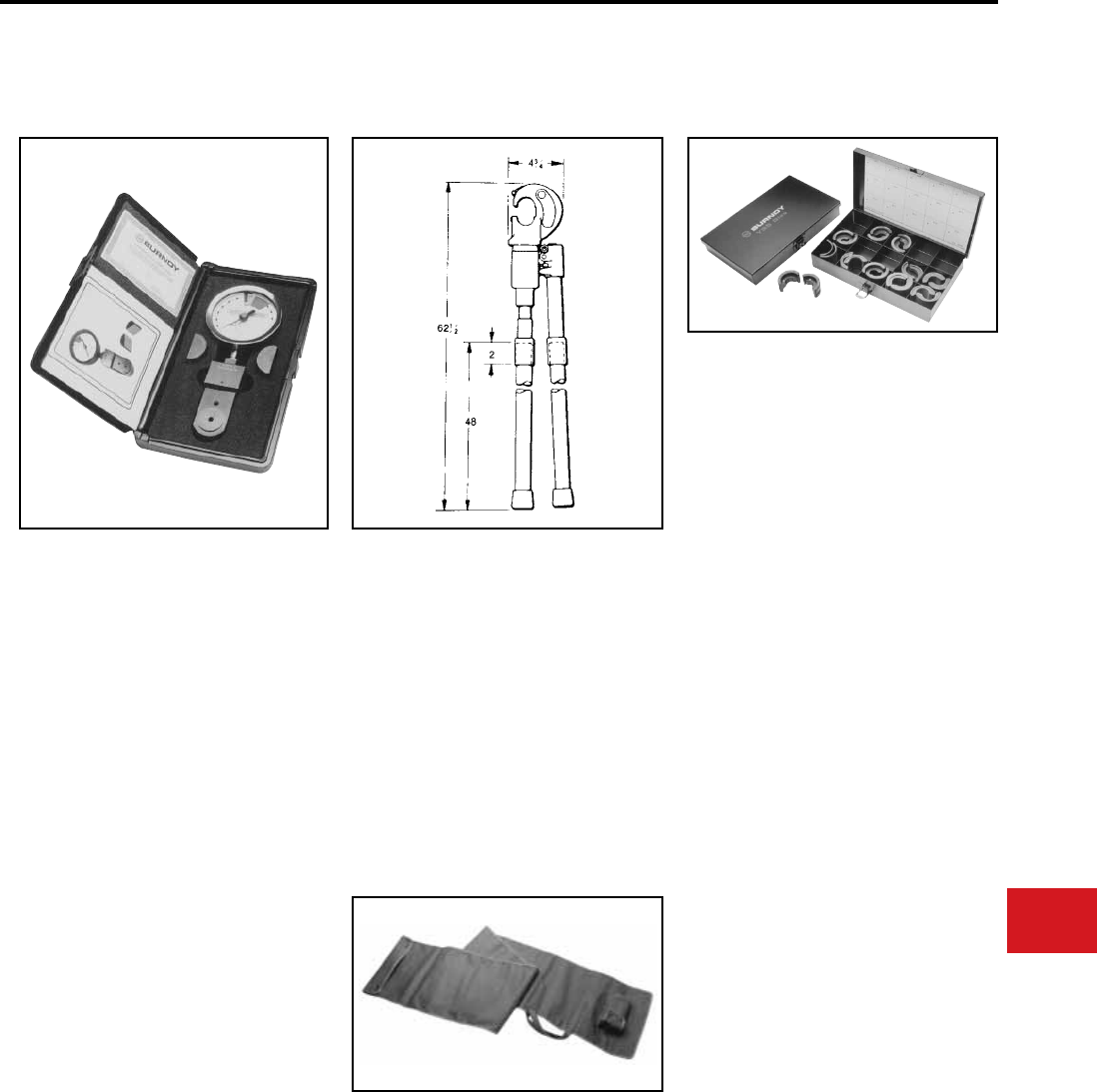
BURNDY®
Canada: 1-800-387-6487 www.burndy.com US: 1-800-346-4175
Tooling
Crimpers — Self-Contained Hydraulic
Y35 SERIES
ACCESSORIES
PT 29279-2
Force Test Gauge
The PT 29279-2 Force Test Gauge is designed
to provide an accurate visual reading of the
output force produced by the hand-hydraulic
Y35, Y35-2, Y39 and Y750 HYPRESS™ tools.
It is not recommended for any remote powered
HYPRESS™ heads such as the Y35BH. The
PT29279-2 Force Test Gauge is factory calibrated
and inspected to very stringent tolerances
providing the customer accuracy and an excellent
means for quality assurance control. Supplied with
padded storage case.
Features and Benets
Cat. No. HH5-RL48
Hot-Line Handle Assembly
The HH5-RL48 is a 48″ long berglass handle
assembly that easily attaches to a standard Y35
HYPRESS™ tool. Rotation of the handles controls
the rapid ram advance and release mechanisms.
The handles are rated at 100KV per foot for ve
minutes. The Catalog Number does not include
the Y35. For factory assembled unit order Catalog
Number Y35-16.
• Easy to read dial
• Provides means for quality assurance
control
• Blank (test) “U” dies are provided for testing
procedure
• Tool output force is applied to load cell for
visual read out of the resulting force on the
dial
• An easy to read operating and maintenance
manual is included Cat. No. PT6733
Hot-Line Tool (Heavy-Duty)
Carrying Bag
The PT6733 is a heavy-duty, adjustable canvas
bag for the storage and protection of hot-line tools.
The bag accommodates 48″ through 72″ variations
of the Y35 and MD6 hot-line tools.
Cat. No. PT29291
Die Case
Steel case designed for storage and protection of
“U” dies used with the Y35 and other BURNDY®
tools. Holds 15 die sets. Length 9-1/2″, width 6″,
height 1-1/2″. Dies sold separately.
Y34A Indentor Adaptor:
To use Y34A indentors in a Y35, Y39,
or Y750 tool.
Cat. No. Y35P3
Seal Repair Kit:
Cat. No. Y35/Y39 REP KIT A
Steel Carrying Cases:
Cat. No. PT2972 for Y35
Cat. No. PT29360 for Y35-2
N-27
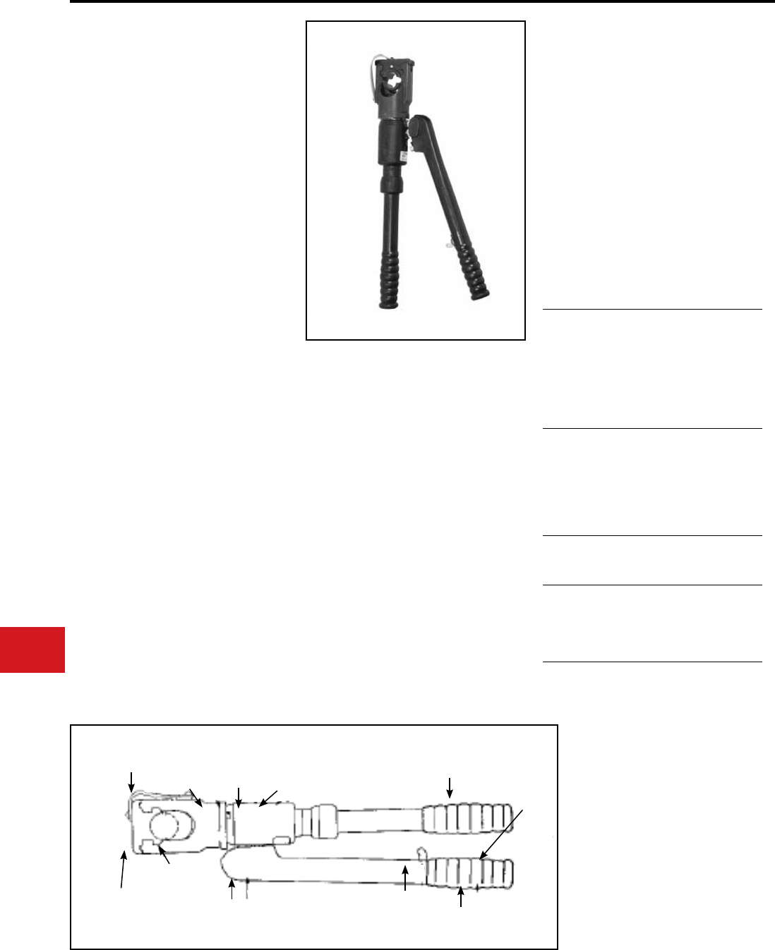
BURNDY®
US: 1-800-346-4175 www.burndy.com Canada: 1-800-387-6487
Tooling
Crimpers — Self-Contained Hydraulic
Y39
HYPRESS™
Hand-Operated Hydraulic Tool
The versatile, lightweight Y39 weighs 13 lbs.
and its small 3-1/8″ wide head rotates 180° for
convenience and exibility. The tool provides 12
tons of crimping power, while its built-in overload
valve automatically releases pressure when the
crimp is completed.
The Y39 is designed for easy die insertion and
removal without ball checks or set screws. Its
rapid ram advance and trigger-controlled release
eliminate unnecessary pumping after every crimp.
5-year limited warranty.
• Rapid ram advance elmininates requirement
for pumping handles to advance ram to
connector
• Trigger release allows ram to return to
preset position
• Long continuous usage is aided with
• comfort grip handles
• Compression terminal, tap and splice
connectors are UL Listed and CSA Certied
when installed with the Y39 tool and
recommended die set
• 5-year limited warranty
• Easy to work in small tight spaces with only
a 3-1/8″ wide compression head and short
handle throw
• Easy to position tool for work with 180°
head rotation
• Versatile and economical tool works on
all commonly used copper and aluminum
conductors from #6 str. to 750 kcmil
• Body and handles covered with 3/16″ rubber
• Easy to locate and hold dies in position with
the positive push button die locks plus die
changing is accomplished easily without ball
checks or set screws
• Easy to remove or lock into position die
holder with recessed spring latch plus
leather strap to prevent loss
• Quality assurance is provided with
automatic 10,000 psi “blow off” pressure
release valve for positive crimping
Features and Benets
SPECIFICATIONS
FOR USE ON
(Continued)
Force developed:
Operating force:
Weight-less case:
Overall length:
Max. head width:
Die accommodation:
12 tons
10,000 PSI
12 lbs
23″
3-1/8″
U-dies
Copper
#6 AWG -750 kcmil str.
Code Cable
N30 - N650 Navy Cable
Flexible and Extra Flexible
Terminals -Uninsulated
YA, YA-L, YA-LB, YGH, YGHA
Splices & Tees - Uninsulated
YS, YS-L, YS-LB, YS-T, YSP-T, YST
Copper- AN or AIR
#6 AWG-#4/0 str. Code Cable
AN6-AN #4/0 Aircraft Cable
Flexible and Extra Flexible
Terminals - Uninsulated
YAV-L Box, YAV-L, YAV-RS Box, YAV-RS
Splices - Uninsulated
YSV-L Box, YSV-L
Copper-Insulated Terminals
#8 AWG - #2/0 str. Code Cable
AN8 - AN #2/0 Aircraft Cable
Flexible and Extra Flexible
Terminals-Insulated
YAEV-L Box, YAEV-L, YAEV-RS Box,
YAEV-RS, YAEV-RH
Copper-Taps
#12 AWG Solid-250 kcmil
Taps: YC-C, YGHC -C, YGHP -C, YGHR -C
Aluminum
#8 AWG-750 kcmil str.
Code Cable
Terminals: YA-A
Splices: YS-A, YS-AT, YRB
Aluminum
#6 str.-500 kcmil
Taps: YFD, YFN, YFO
LEATHER DIE
RETAINER
STRAP 180° HEAD
ROTATION
RUBBER
BODY
COVER
BUILT IN AUTOMATIC
10,000 PSI "BLOW-OFF"
PRESSURE RELEASE
VALVE
RAPID RAM
ADVANCE
HANDLE
SHORT
HANDLE
STROKE
COMFORT GRIP
HANDLES
TRIGGER
CONTROLLED
RAM RELEASE
RUBBER
COVERED
HANDLES
RECESSED
DIE RETAINER
SPRING LATCH
POSITIVE PUSH
BUTTON DIE LOCKS
N-28
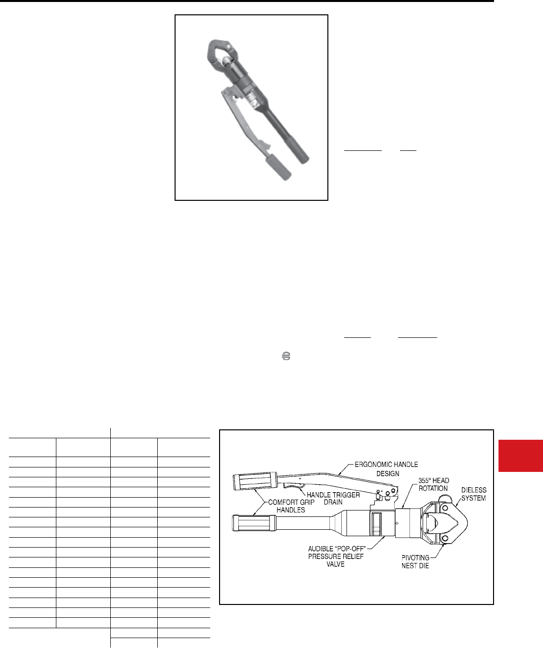
BURNDY®
Canada: 1-800-387-6487 www.burndy.com US: 1-800-346-4175
Tooling
Crimpers — Self-Contained Hydraulic
Y644HSXT
DIELESS HYPRESS™
THE “1” CRIMP
RANGE TAKING TOOL
Hydraulic Hand Operated Tool
11-Ton Crimp Force
#6 - 1000 kcmil Copper
HYLUG™ Terminals and
HYLINK™ Splices
#6 - 750 kcmil Aluminum
HYLUG™ Terminals and
HYLINK™ Splices
The Y644HSXT dieless HYPRESS™ is a hand
operated 11 ton hydraulic crimping tool. Only 1
crimp is required for each wire termination for both
long and standard length barrels on HYLUG™
terminals and HYLINK™ splices.
The Y644HSXT has a latch style head which
provides easy tool removal from continuous
conductor runs. The head rotates 355° relative
to the handles and is mated to a patented rapid
advance pump. The Y644HSXT weighs only 15
pounds and delivers 11 tons of crimping force.
The result is easy terminating and splicing using
BURNDY® HYLUG™ and HYLINK™ terminals
and splices.
• Dieless system, eliminates the need to
purchase and maintain dies
• Patented rapid advance pump for faster
crimps
• Pressure relief “Pop-Off” valve provides
audible indication that crimp is complete
• Handle trigger drain for convenient ram
retraction
• 355° head rotation for versatile tool head
positioning in tight areas
• Easy inspection and positive identication is
provided with the BURNDY® “ ”
• Comfort grip handles help ease fatigue with
continuous use
• Supplied with high impact plastic carrying
case
• 5-year limited warranty
Features and Benets
SPECIFICATIONS
FOR USE ON
Y644HSXT Dieless HYPRESS™ Range Taking Capabilities. The following size
HYDENT™ lugs and two way splices, when crimped with the Y644HSXT Dieless
HYPRESS™ Tool, produce the following UL Listed range taking capabilities, see chart to
the left.
Aluminum Connectors Copper Connectors
Standard
Wire Size
Expanded
Wire Range
Standard
Wire Size
Expanded
Wire Range
#6 AWG #6 AWG #6 AWG #6 AWG
#5 AWG #5-#6 AWG #5 AWG #5-#6 AWG
#4 AWG #4-#6 AWG #4 AWG #4-#6 AWG
#3 AWG #3-#6 AWG #3 AWG #3-#6 AWG
#2 AWG #2-#6 AWG #2 AWG #2-#6 AWG
#1 AWG #1-#2 AWG #1 AWG #1-#2 AWG
1/0 AWG 1/0-#1 AWG 1/0 AWG 1/0-#6 AWG
2/0 AWG 2/0-#1 AWG 2/0 AWG 2/0-#4 AWG
3/0 AWG 3/0-#1 AWG 3/0 AWG 3/0-#2 AWG
4/0 AWG 4/0-#1 AWG 4/0 AWG 4/0-#1 AWG
250 kcmil 250-1/0 AWG 250 kcmil 250-1/0
300 kcmil 300-2/0 AWG 300 kcmil 300-2/0
350 kcmil 350-3/0 AWG 350 kcmil 350-3/0
400 kcmil 400-4/0 AWG 400 kcmil 400-4/0
500 kcmil 500-4/0 AWG 500 kcmil 500-4/0
600 kcmil 600-250 kcmil 600 kcmil 600-250
750 kcmil 750-500 kcmil 750 kcmil 750-500
800 kcmil 800-500
1000 kcmil 1000-750
Output Force:
Tool Weight:
Length:
Height:
Width:
11 tons
15 lbs (5.6 kg)
23.20″ (589 mm)
3.00″ (76 mm)
7.04″ (179 mm)
AWG/kcmil
Size Range
Connector
Type
Copper
#6 - 1000 kcmil
Terminals
YA-L, YA-2LN, YA, YA-FXB
YA-2N, YA-L-2TC, YA-L-FX
YAB-4N, YA-L-TC,
YA-2L, YA-4N, YEV-P-FX,
YE-P, YE-P-FX
Splices
YS-L, YS, YS-T
Aluminum
#6 - 750 kcmil
Terminals
YA-A, YA-A-TN
Splices
YS-A
Aluminum
#6 - 750 kcmil
HYPLUG™
AYP, AYPO
ACCESSORIES
Cat. No. Description
WIREMIKE Provides quick and easy
identication of commonly
used conductors.
Y644HSCASE Plastic carrying case.
N-29
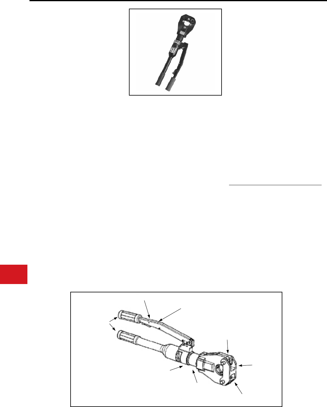
BURNDY®
US: 1-800-346-4175 www.burndy.com Canada: 1-800-387-6487
Tooling
4-POINT® Y81KFT
DIELESS HYPRESS™
Hydraulic Hand Operated
Crimping Tool
#8 – 1000 kcmil Copper HYLUG™
Terminals and HYLINK™ Splices
#8 – 750 kcmil Aluminum HYLUG™
Terminals and HYLINK™ Splices
The Y81KFT 4-POINT® dieless HYPRESS™ is a
hand operated 6 ton hydraulic crimping tool for use
on a wide variety of terminal and splice compression
applications. The Y81KFT incorporates a dieless
latch style head that provides easy tool removal
from continuous conductor runs and eliminates
the need to purchase and maintain dies. The head
rotates 360º relative to the handles and is mated
to a patented rapid advance pump. The Y81KFT
weighs only 12 pounds and delivers 6 tons of
crimping force. The result is easy termination
and splicing using BURNDY® HYLUG™ and
HYLINK™ terminals and splices.
The Y81KFT is supplied with a molded high impact
plastic case and comes complete with a 5-year
limited warranty.
Y81KFT dieless HYPRESS™ Range Taking
Capabilities: The Y81KFT provides range taking
capabilities that is UL Listed and CSA Certied for
Copper (Code, Compact and Flex) and Aluminum
(Code and Compact) conductors when used in
conjunction with BURNDY® HYLUG™ terminals
and HYLINK™ splices. See chart for connector,
conductor and range taking combinations in
section C.
• Dieless installation system
◊ Eliminates the need to purchase and
maintain dies
• UL Listed and CSA Certied with Range
Taking Capabilities
◊ Provides the installer with a UL Listed
and CSA Certied crimps with Range
Taking Capabilities when used in
conjunction with BURNDY® HYLUG™
Terminals and HYLINK™ Splices
• Flip top head design
◊ For easy loading and removal of
installed terminals and splices, saving
time
• Audible pressure “pop-off” valve and die
embossment providing 360º inspectability
◊ Assures proper crimps with both
audible and visual indicators for the
installer
• Handle Trigger release
◊ Convenient ram release located in the
handle
Features and Benets
SPECIFICATIONS
FOR USE ON
Copper, Aluminum, Compressed, Compact,
Stranded, Solid and Flex Conductors.
Installs Splices, Taps and Terminations:
#8 - 1000 kcmil Copper
(YA, YA-L, YS, YS-L, YS-T, Y-R )
#8 - 777.7 (750 Nom. Flex Wire Size) kcmil Flex
(YA-FX, YAV, YA-L-FX, YS, YSV-FXB)
#8 - 750 kcmil Aluminum
(YA-A, YS-A)
#8 - 750 kcmil Aluminium Pin Adapters
(AYP, AYPO)
• Advanced high speed pump design
◊ Provides fast crimps, longer life,
efciency, and reliability
• 360 Degree head rotation
◊ Versatile tool head positioning lets the
user get into tight areas easier
• Durable high impact formed carrying case
◊ Provides tool protection and stores all
accessories
• 5-year limited warranty
◊ Customer satisfaction and support
6 tons (12,000 lbs)
(5450 kg)
12 lbs (5.45 kg)
25.6″ (650 mm)
7.7″ (196 mm)
2.5″ (64 mm)
Output Force:
Weight:
Length:
Height:
Width:
HANDLE TRIGGER DRAIN
ERGONOMIC HANDLE
DESIGN
COMFORT GRIP
HANDLES
LOCKING LATCH PIN
DIELESS
SYSTEM
PIVOTING
NEST DIE
360° HEAD
ROTATION
AUDIBLE “POP-OFF” PRESSURE
RELIEF VALVE
Crimpers — Self-Contained Hydraulic
N-30
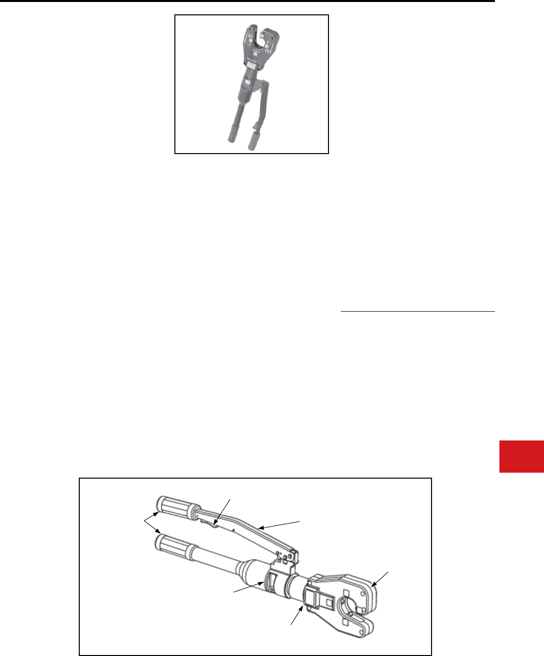
BURNDY®
Canada: 1-800-387-6487 www.burndy.com US: 1-800-346-4175
Tooling
Crimpers — Self-Contained Hydraulic
4-POINT® Y4PC834
DIELESS HYPRESS™
Hydraulic Hand Operated
Crimping Tool
The 4-POINT® C-shaped head dieless
HYPRESS™ is a hand operated 6 ton hydraulic
crimping tool for use on a wide variety of tap,
terminate, and splice compression applications.
The dieless capability of this tool eliminates the
need to purchase or maintain additional dies. The
Y4PC834 incorporates a C-shaped head design
making it ideal for crimping in tight areas and is
easily removed from continuous conductor runs.
The head rotates 360º and is mated to a patented
rapid advance pump. The Y4PC834 weighs only
12 pounds and delivers 6 tons of crimping force.
The result allows for easy tap, termination and
splicing of compression connectors.
The Y4PC834 is supplied with a molded high
impact carry case and comes with a 5-year limited
warranty.
The Y4PC834 provides range taking capabilities
that are UL Listed and CSA Certied for Copper
(Code, Compact and Flex) and Aluminum
(Code and Compact) conductors when used in
conjunction with BURNDY® HYLUG™ terminals
and HYLINK™ splices as listed in section C of the
Master Catalog.
• Dieless installation system
◊ Eliminates the need to purchase and
maintain dies
• UL Listed and CSA Certied with range
taking capabilities
◊ Provides the installer with UL Listed
and CSA Certied crimps when used
in conjunction with BURNDY®
HYLUG™ and HYLINK™ compression
connectors
• C-shaped head design
◊ For easily removing tool from
continuous run conductors – simply
slide the opening of the head off the
conductor. Also ideal for use in tight or
constraint spaces
• Audible pressure “pop-off” valve and die
embossment providing 360° inspectability
◊ Assures proper cimps with both audible
and visual indicators for the installer
• Handle Trigger release
◊ Convenient ram release located in the
handle
Output Force:
Weight:
Length:
Height:
Width:
Features and Benets
SPECIFICATIONS
FOR USE ON
Copper, Aluminum, Compressed, Compact,
Stranded, Solid and Flex Conductors
Installs Splices, Taps and Terminations
#8 – 1000 kcmil Copper (YA, YA-L)
#8 – 500 kcmil Copper (YS, YS-T, YS-L, Y-R)
#8 – 777 (750 Nominal Flex Wire Size) kcmil
Flex ((YA-FX, YAV, YA-L-FX)
#8 – 535 (500 kcmil nominal ex wire size)
kcmil ex (YS, YS-LB, YSV-FXB)
#8 – 750 kcmil Aluminum (YA-A)
#8 – 350 kcmil Aluminum (YS-A)
#8 – 750 kcmil Aluminum Pin Adaptors (AYP,
AYPO)
6 Tons (5.4 metric tons)
11.85 lbs (5.38 kg)
25.6″ (651 mm)
7.7″ (196 mm)
2.5″ (64mm)
• Advanced high speed pump design
◊ Provides fast crimps, longer life,
efciency, and reliability
• 360° head rotation
◊ Versatile tool head positioning lets the
user get into tight areas easier
• Durable high impact formed carrying
case
◊ Provides tool protection and stores all
accessories
• 5-year limited warranty
◊ Customer satisfaction and support
COMFORT
GRIP HANDLES
HANDLE TRIGGER
DRAIN
AUDIBLE “POP-OFF”
PRESSURE RELIEF
VALVE
360° HEAD
ROTATION
C-SHAPED
HEAD
ERGONOMIC HANDLE
DESIGN
N-31
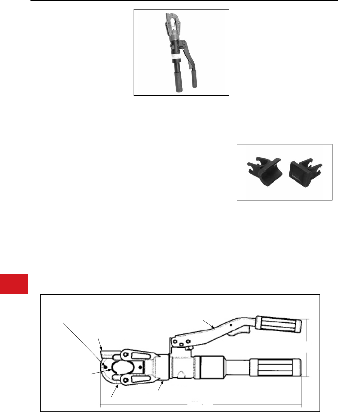
BURNDY®
US: 1-800-346-4175 www.burndy.com Canada: 1-800-387-6487
Tooling
Crimpers — Self-Contained Hydraulic
Y500CT-HS
L’IL CRIMP™
6-Ton Hydraulic Crimp Tool
The BURNDY® Y500CT-HS HYPRESS™
connector installation tool provides 6 U.S.
Short tons of force in a compact and easy to
use, hand-held hydraulic tool. The Y500CT-HS
incorporates a specialized latch style head with
a generous working stroke for a wide variety of
crimping applications. The specialized head allows
interference-free closures on tap connectors
up to the BURNDY® YHD-400 size. The head is
tted onto a lightweight tool body with handles
that are ergonomically designed to provide slip-
free grip and easier crimping. The tool features
a patented high speed ram advance mechanism
that minimizes crimp cycle time along with an
ergonomic trigger drain mechanism that allows
the ram to return to the preset position. The tool
accommodates all BURNDY® “X”, “W”, and “W-
VT” style dies that seat in the permanent “D3”
crimping groove. Installation applications include
#6 AWG to 500 kcmil copper lugs and splices,
#6 AWG to 350 AWG aluminum lugs and splices,
and up to 4/0 aluminum tap connections. The
permanent “D3” groove and 180 degree rotatable
head are standard on the Y500CT-HS.
Each Y500CT-HS HYPRESS™ tool uses
BURNDY® dies and off-the-shelf connectors
that are available worldwide. The Y500CTHS
HYPRESS™ comes equipped with a durable
metal carry case to hold the tool and a multitude
of die sets.
• Lightweight latch head design
◊ Provides enhanced clearance for tap
connectors
• 180° head rotation
◊ Versatile tool head allowing user crimp
access into tight spaces
• Ergonomic handle design
◊ Easier operation, helping reduce
fatigue
• Audible pressure “pop-off” valve
◊ Indicates properly completed crimp
• Permanent “D3” crimp groove accepts all
BURNDY® “W” and “X” dies
◊ Standard die design with proven
performance
• Durable metal carrying case
◊ Provides superior protection and
stores all accessories
• High speed ram advance
◊ Provides faster crimps
• Handle trigger drain
◊ Convenient ram retraction
• 5-year limited warranty
◊ Customer satisfaction and technical
support
Output Force:
Tool Weight:
Total Strokes:
Height:
Length:
Features and Benets
SPECIFICATIONS
FOR USE ON
Copper, Aluminum, ACSR, Steel, Copperweld,
Alumoweld, 6201, 5005, Compressed, Compact,
Stranded & Solid conductors
Installs splices, taps, or terminations:
#8 - 500 kcmil Copper Str.
#8 - 350 kcmil Flex
#8 - 350 AWG Aluminum
6 tons (5.4 metric tons)
7.8 lbs (3.5 kg)
7 (w/o connector)
6.0″ (152 mm)
17.6″ (447 mm)
RANGE TAKING DIES
WDC4500: #4-500 Cu Str.
#2-4/0 Cu Flex
UL and CSA for use on YA and YS series.
Also for use on YAV and YSV series.
WDA8300: #8-300 Al
#6-400 Cu Str.
#2-4/0 Cu Flex
UL and CSA for use on YA, YS, YA-A, and YS-A
series. Also for use on YAV and YSV series.
LATCH HEAD RELEASE
FUNCTIONAL
D3 DIE GROOVE
SPECIALIZED LATCH DESIGN
160° ROTATABLE HEAD
ERGONOMIC
HANDLE DESIGN
17.6
[447]
6.0
[152]
Features
SPRING LOADED DIE RETAINING PINS
N-32
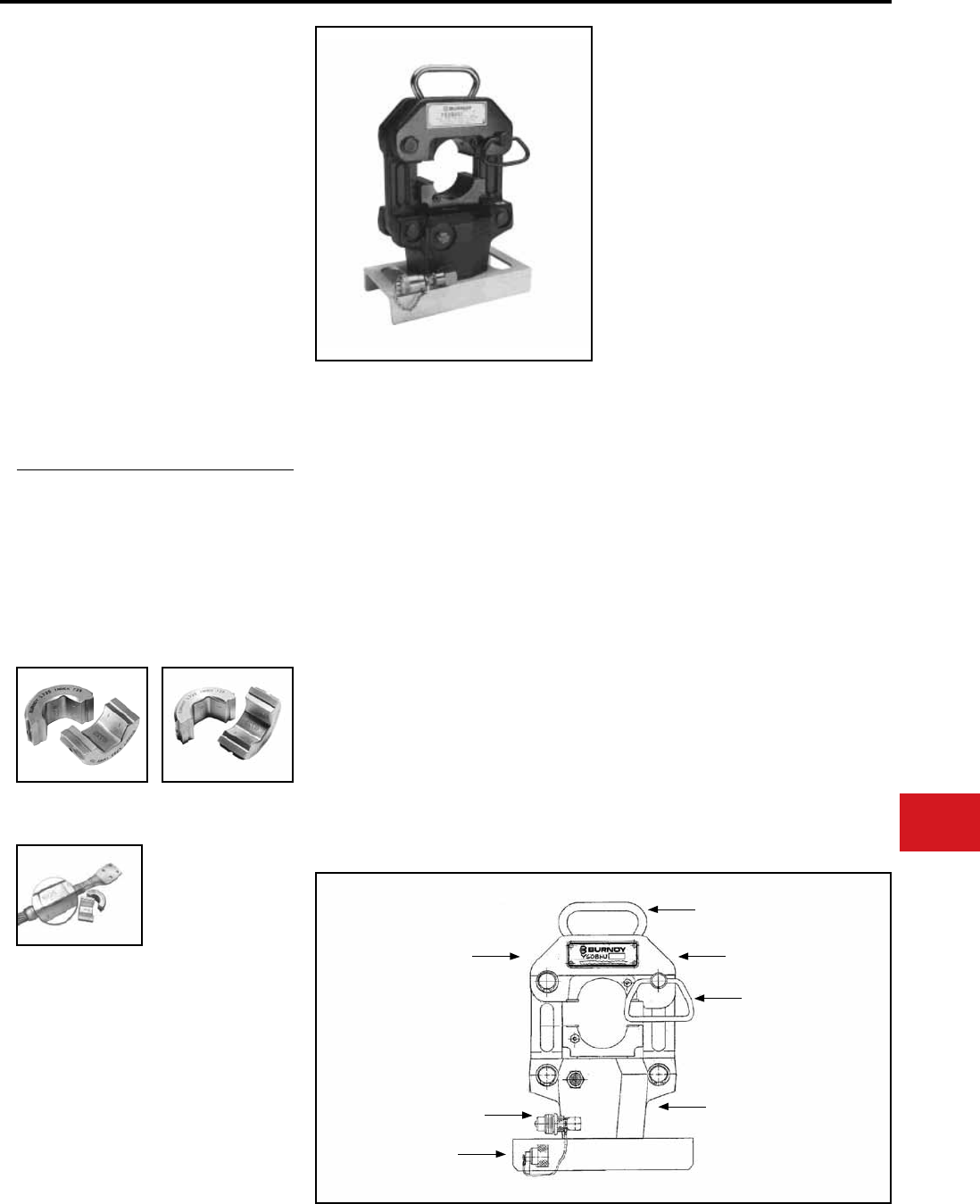
BURNDY®
Canada: 1-800-387-6487 www.burndy.com US: 1-800-346-4175
Tooling
Crimpers — Remote Hydraulic
Y60BHU
HYPRESS™
60 Ton Remote
Power Operated Hydraulic Tools
Single Hydraulic Tool Design
The Y60BHU HYPRESS™, single acting is
designed to provide fast, easy operation plus
a durable and substantially longer design
life expectancy. Y60BHU HYPRESS™ tool
accommodates “L” dies. The “L” dies are designed
for copper and aluminum code cables and aerial
conductor sizes through 2500 kcmil and will
accommodate ACSR through 2156 (84/19) str.
5-year limited warranty. • Easy to carry with heavy duty handle
• Easy to remove splices with nest that pivots
open
• Safety and security is provided with captive
locking pin for nest die
• Long life expectancy (50,000 cycles) with
heavy duty steel frame
• Fast easy die changing and secure die
positioning with positive die release locking
pins
• Protected male coupler with captive cap
• Stability is provided with sturdy steel base
• Easy, less costly repairs with fewer parts
that are easily accessible (example: Bottom
die holder)
• 5-year limited warranty
Features and Benets
SPECIFICATIONS
FOR USE ON
Copper
300 kcmil-2000 kcmil
Str. Code Cable
Terminals
YA, YA-2N, YAB-4N, YA-L, YA-2LN, YA-LB
Splices
YS, YST, YS-L, YS-T, YSP-T
Aluminum
250 kcmil-2000 kcmil
Str. Code Cable
Terminals
YA-A
Splices
YS-A, YS-AT
Transmission and Distribution Connectors
Tension Sleeves:
Copper: 1/0 str. - 1000 kcmil
Aluminum: 1/0 str. - 2300 kcmil
ACSR: 1/0 - 2156 (84/19 str.) kcmil
Aerial:
Copper: 4/0 str. - 2500 kcmil
Aluminum: 3/0 str. - 2500 kcmil
YTS, YTN, YNS, YNA, YNT, YNTA, YNU,
YDS, YDN, YCS, YCA, YCU
Force devoloped:
Operating pressure:
Hydraulic oil:
Life expectancy:
Height:
Weight (less case):
Shipping weight:
60 tons
10,000 PSI
BURNDY® ALFLUID™
50,000 cycles min.
16.62″
70 lbs
97 lbs
TYPE “L” DIES
For Use With Y60BHU and
Y60LW
BURNDY® offers two types of “L” dies. Our
standard width L dies (example: L735).
Wider “L” dies with Indicia marks example: L735W).
Indicia marks on the die provide the installer with
the start location for
the next overlap crimp
consistently on aluminum
connector surfaces.
Reduces the number of
crimps and installation
time.
L717W
L720W
L724W
L727W
L729W
The following dies are available in this series:
HEAVY DUTY HANDLE
POSITIVE PUSH BUTTON
DIE LOCKS AND DIE RELEASE
CAPTIVE LOCKING
PIN AND HANDLE
FOR TOOL NEST
HEAVY DUTY
STEEL FRAME
NEST HINGE ALLOWS
FULLY OPEN POSITIONING
10,000 PSI MALE
COUPLER AND COVER
STURDY STEEL BASE
L719W
L722W
L725W
L728W
L735W
N-33
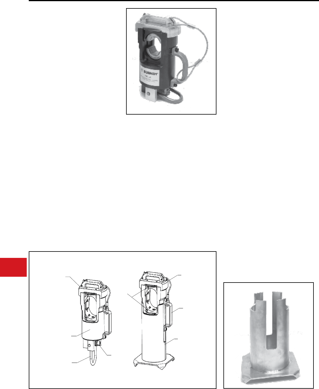
BURNDY®
US: 1-800-346-4175 www.burndy.com Canada: 1-800-387-6487
Tooling
Crimpers — Remote Hydraulic
Y60LW
HYPRESSTM
60 Ton Remote
Power Operated Hydraulic Tools
Single Acting Light Weight Hydraulic Tool
The Y60LW is a single acting, light weight 60 ton
HYPRESS™ designed to install transmission and
distribution connectors and sleeves. The Y60LW
accommodates the same “L” dies used in the
BURNDY® Y60BHU. The “L” dies are designed
for copper and aluminum code cables, ACSR and
aerial conductors. This tool is designed to be light
weight and portable for easy maneuverability and
will operate from any 10,000 psi hydraulic source
with the proper oil capacity. The Y60LW comes
with stand and carrying case (for head only).
• Portable, light weight design of less than
43 lbs.
• 60 tons of crimp force at 10,000 psi
operating pressure
• Large jaw opening to accommodate copper
and aluminum code cables, ACSR and
aerial conductor
• Single acting ram with heavy duty return
spring
• Removable die cap is easily rotated allowing
quick removal of splice connectors
Output Force:
Tool Weight:
Height:
Width:
Warranty:
Features and Benets
SPECIFICATIONS
FOR USE ON
60 Tons
43 lbs
12.93 in (without stand)
8.06 in (without stand)
5 Year Limited
Copper
300 kcmil-2000 kcmil
Str. Code Cable
Terminals
YA, YA-2N, YA-4N, YA-L, YA-2LN, YA-LB
Splices
YS, YST, YS-L, YS-T, YSP-T
Aluminum
250 kcmil-2000 kcmil
Str. Code Cable
Terminals
YA-A
Splices
YS-A, YS-AT
Transmission and Distribution Connectors
Tension Sleeves:
Copper: 1/0 Str.-1000 kmcil
Aluminum: 1/0 Str.-2300 kcmil
ACSR: 1/0 Str.-2156 (84/19 str.)
Aerial:
Copper: 4/0 Str.-2500 kcmil
Aluminum: 3/0 Str.-2500 kcmil
YTS, YTN, YNS, YNA, YNT, YNTA, YNU,
YDS, YDN, YCS, YCA, YCU
POSITIVE
LOCKING
CAP
HEAVY DUTY
RETRACTION SPRING
HEAVY DUTY
HOISTING LOOP
10,000 PSI
COUPLER
43 LB LIGHT
WEIGHT DESIGN
PUSH BUTTON
DIE LOCKS
CAP
LANYARD
CARRY
HANDLE
STURDY BASE
STAND
• Upper die cap securely locks to a positive
detent position for safe operation
• Fast easy die changing and secure die
positioning with positive die release locking
pins
• Die holders accommodate BURNDY “L”
dies (shell conguration)
• Strong, replaceable die retainers for ultimate
life
• Easy to carry with side lift handle
• Upper die cap lanyard cable enables a free
hand for positioning work piece
• Heavy duty hoisting loop
• Base stand included (and also available as
an accessory)
• Protected male coupler with captive cap
• 5-year limited warranty
Y60LW head
Y60LW stand
N-34
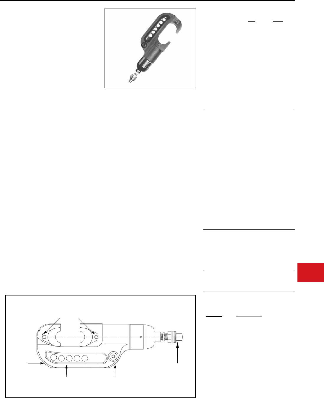
BURNDY®
Canada: 1-800-387-6487 www.burndy.com US: 1-800-346-4175
Tooling
Crimpers — Remote Hydraulic
Y46 AND Y46C
HYPRESS™
15-Ton Force Remote Operated
Hydraulic Tool—10,000 PSI
The Y46 standard tool and Y46C rubber covered
tools are lightweight, compact and versatile with
installation dies for both circumferential and nest-
indentor types. Accessories include “U”-die adapter,
a cable cutting die for 1.2” diameter non-steel
conductors, plus a lifting eye and universal hot-
stick adapter for overhead line construction. 5-year
limited warranty.
• Compact “C” shaped head allows easy
placement and removal from continuous
conductor lengths
• Versatile and economical HYPRESS™
tools work on all commonly used copper
and aluminum products
• Dies and adapters lock into or remove
from tool head easily with the positive push
button die locks
• Safety, strength and high quality is provided
with strong forged steel and precision
machined components
• Excellent for HYGROUND® compression
grounding applications through 1” ground
rods and up to 500 kcmil taps, terminals and
splices
• Compression terminal, splice and tap
connectors are UL Listed and CSA Certied
when installed with the Y46 and Y46C
HYPRESS™ and recommended die set
• Y46C has a permanently molded head
of 3/16” rubber and includes a separate
molded rubber boot to cover the lower
HYPRESS™ body and hydraulic coupler for
impact protection
• 5-year limited warranty
Force Developed:
Operating pressure:
Jaw opening:
Maximum Width:
Overall Length:
Weight (less case):
Molded covering:
Features and Benets
SPECIFICATIONS
FOR USE ON
Y46
15 tons
10,000 PSI
2″
4-1/2″
15″
16 lbs.
No
Y46C
15 tons
10,000 PSI
2″
4-3/4″
21-3/4″
(inc. boot)
17-1/2 lbs
Yes
Copper
#8 AWG Str.
1500 kcmil
Code Cable
Navy Cables
Flexible and
Extra Flexible
1/2”-1” Ground
Rods
Terminals-Grounding to 500 kcmil
YGA, YGHA, YGF
Terminals-Uninsulated #8 to 1500
kcmil
YA, YA-2N, YA-L,
YA-LB, YA-TC, YA-2LN,YAB-4N,
YAV-L Box, YAV-L, YAV-RS Box,
YAV-RS, YA-TC-FX
Terminals-Insulated #8 to 2/0
YAEV-L Box, YAEV-L, YAEV-H,
YAEV-RS, YAEV-RH
Splices #8 to 1500 kcmil
YS, YS-T, YS-L, YS-LB, YST,
YSP-T, YGS, YGHS
Taps
YH, YCHC #14 to 1000 kcmil
YC-C to 4/0 AWG
Taps-Grounding to 500 kcmil
YGHC-C, YGHP-C, YGHR-C
Aluminum
#8 AWG-
1250 kcmil
Code Cables
Terminals
YA-A, AYP, AYPO
Splices
YS-A, YS-AT, YRB
Taps
YFD, YFN, YFO, YFR
ACSR See Burndy Overhead
Transmission and
Distribution Catalog Module
P15K
PUADP-1
PT10128
Y46-2
Cutter die max. 1.2″ dia.
“U”- die adapter
Universal hotstick adapter - Y46
Same as Y46 with Female
coupler
ACCESSORIES
FORGED
STEEL
BODY
STRONG
REINFORCED
BACK
PRECISION
MACHINED STEEL
COMPONENTS
MALE QUICK
DISCONNECT
10,000 PSI
HYDRAULIC FITTING
POSITIVE
PUSH
BUTTON
DIE LOCK
LARGE 2”
JAW
OPENING
Cat. No. Description:
Y46
N-35
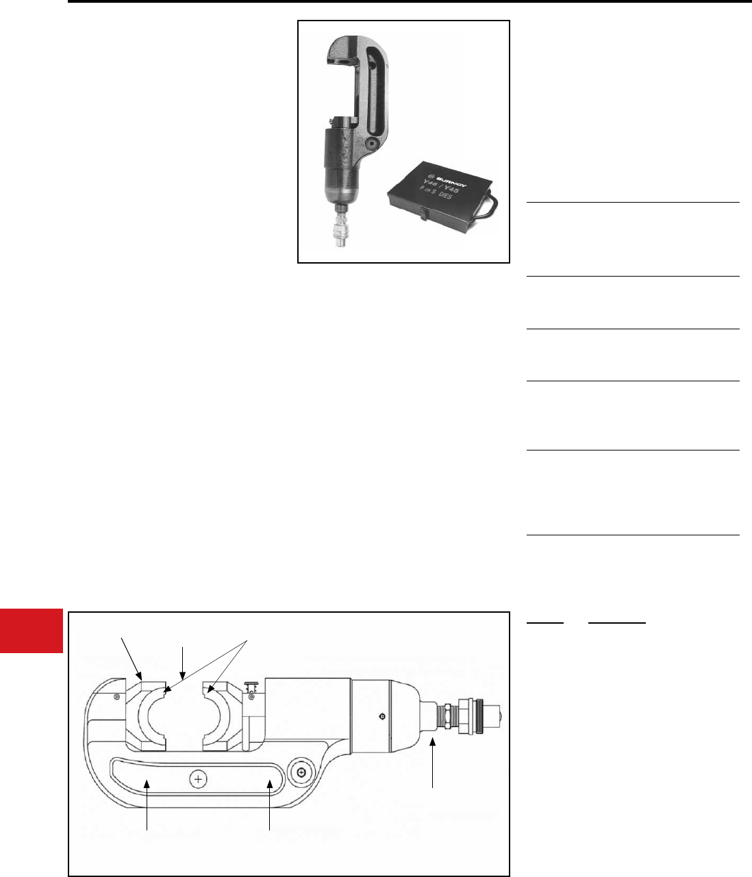
BURNDY®
US: 1-800-346-4175 www.burndy.com Canada: 1-800-387-6487
Tooling
Y45
HYPRESS™
15-Ton Remote Power Operated
Hydraulic Tool—10,000 PSI
The Y45 Series is designed for remote hydraulic
operation. A C-shaped head design provides easy
installation of tap and splice connectors. The hook
style head with extensive ram travel operates
easily on large distribution and transmission
conductors. Together with accessories, the Y45
Series tooling may be used on overhead lines. The
small light-weight head design is very adaptable
for work in underground trenches and manholes.
Uses standard BURNDY® “S” Dies.
Cat. No. PT6515 is required to use “U” type dies
in all Y45 variations. Order Head, Hose, Pump,
Dies, and accessories separately. 5-year limited
warranty.
• Easy connector installation and tool removal
from line conductors with the open C-shaped
head
• Easily lifted into working position using lifting
eye
• Easy die changing plus secure die alignment is
provided with the positive die lock buttons
• Long life expectancy is provided with fully
protected ram and die buttons
• Rapid assembly and disassembly is provided
with the quick disconnect hydraulic coupler
• Rugged design provides long life expectancy
• 5-year limited warranty
Operating pressure:
Output Force:
Weight (less case):
Maximum Width:
Maximum Height:
Features and Benets
SPECIFICATIONS
FOR USE ON
10,000 PSI
15 tons
15-3/4 lbs
7-1/4″
14-1/4″
PT6515
PT6545
ACCESSORIES:
Tension
Sleeves
Copper
Aluminum
ACSR
#8 sol.-500 kcmil
#6 sol.-954 kcmil
#4 -795 (26/7)
kcmil
Taps Aluminum
ACSR
#14-954 (18/1) ACSR
#6-795 (54/7) kcmil
Aerial Cable
Connectors
Copper
Aluminum
#6 str.-1500 kcmil
#4 str.-1000 kcmil
HYGROUND®
Compression
Grounding
Copper #6-500 kcmil
1/2″ - 1″ ground rods
Code Cable
Terminals
and Splices
Taps
Copper
Aluminum
Copper
Aluminum
#8-1500 kcmil
#8-1000 kcmil
#14-1000 kcmil
#14-900 kcmil
Adapter for use with “U” die sets.
Die carrying case for “S” and “P”
type dies. Holds eight (8) die sets.
(Dies sold separately).
Cat. No. Description:
PT6545
LARGE JAW OPENING U DIES
C-SHAPED HOOK
STYLE HEAD
HEAVY DUTY REINFORCED
FORGED STEEL BODY
QUICK DISCONNECT
HYDRAULIC FITTING
PT6515 U DIE
ADAPTER
Crimpers — Remote Hydraulic
N-36
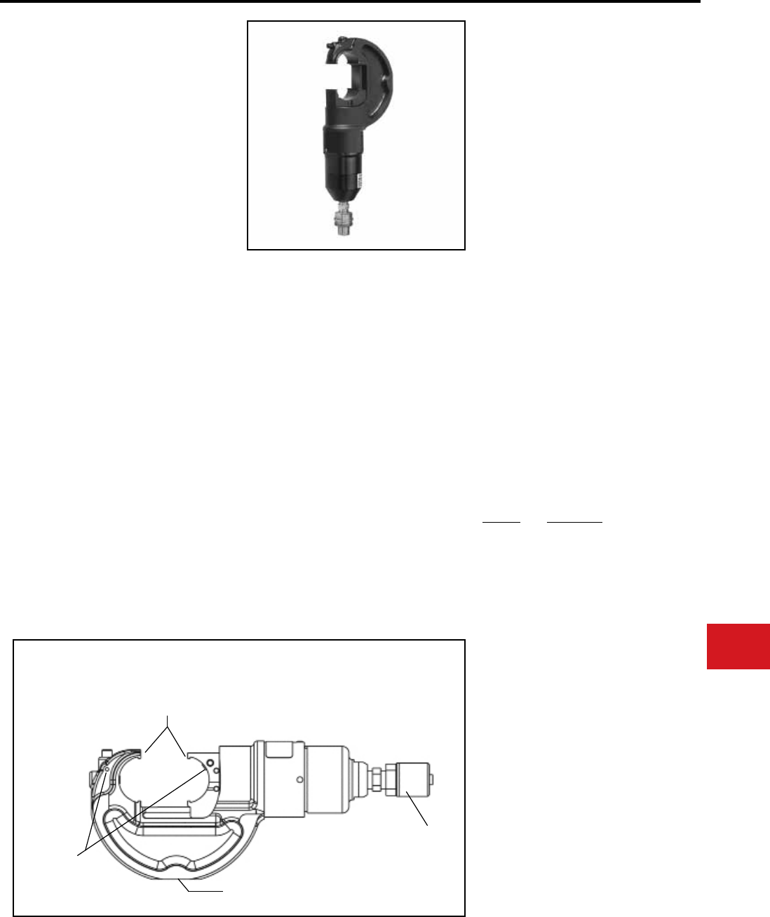
BURNDY®
Canada: 1-800-387-6487 www.burndy.com US: 1-800-346-4175
Tooling
Y750BHXT AND
Y750CBHXT RUBBER
COVERED HEAD
HYPRESS™
12-Ton Remote Power Operated
Hydraulic Tool
Conductor Range:
#14 - 750 kcmil Al/Cu
#4 - 556.5 kcmil ACSR
12 ton remote power operated hydraulic tool. The
Y750BHXT HYPRESS™ incorporates a wide
mouth (1.65″) C-shaped head for all compression
applications. The hook style head provides for
easy tapping, splicing, and terminating of overhead
lines as well as the full range of HYGROUND®
compression grounding system connectors, NEC
cable connections and N30 - N650 Navy cable
applications.
All standard BURNDY® “U” dies t the Y750BHXT
and Y750CBHXT HYPRESS™. Dies and
accessories sold separately.
The Y750CBHXT has a permanently molded
rubber covered head and includes a separate
rubber molded boot that covers the lower body and
hydraulic tting for tool impact protection. The tool
comes with a 5-year limited warranty.
• Covers a wide range of applications and
provides easy tool removal from continuous
conductors with its C-shaped head (1.65″
opening)
• Easy die change out and retention with
exposed positive die lock buttons
• Uses all standard BURNDY® U-dies
• Y750CBHXT provides molded rubber
covering on head, body and hose ttings
• Hot stick adapter sold separately
• Innitely rotatable head, so hydraulic
couplers won’t easily loosen
• 5-year limited warranty
Operating pressure:
Force developed:
Jaw opening:
Length:
Weight:
Head width:
Features and Benets
SPECIFICATIONS
FOR USE ON
• Tension Sleeves
Copper #8 sol - 500 kcmil
Aluminum #6 sol. - 556.5 kcmil
ACSR #4 - 556.5 kcmil
• Taps
Copper #14 solid - 500 kcmil
Aluminum #6 - 500 kcmil
• Aerial Cable
Copper #6 - 500 kcmil
• Terminals and Splices
Aluminum #8 - 750 kcmil
Copper #8 - 750 kcmil
ACSR #4 - 556 kcmil
• HYGROUND® (Compression Grounding)
Copper #6 - 500 kcmil
(cable/ground rod)
Ground Rods 1/2″ - 1″ Diameter
10,000 PSI
12 tons
1.65″ (42 mm)
12.8″ (325 mm)
10.3 lbs (4.7 kg)
5.2″ (132 mm)
ACCESSORIES
Cat. No. Description
PT29402-1 Adjustable head grip for joining
head to universal hot sticks.
PT29279-2 Force test gauge for accurate
visual reading of output force.
PT29291 Die case
Steel case for storage and
protection of "U" dies.
WIREMIKE Provides quick and easy
identication of commonly used
conductors.
FEATURES
▼
▼
C-SHAPED HEAD
▼
▼
BOTH DIE RELEASE
BUTTONS EXPOSED
▼
▼
LARGE 1.65" JAW OPENING
TO ACCOMMODATE
ASYMMETRICAL CONNECTORS
QUICK DISCONNECT
HYDRAULIC FITTING
REMOTE HEAD FOR USE
WITH "U" STYLE DIES
Crimpers — Remote Hydraulic
N-37
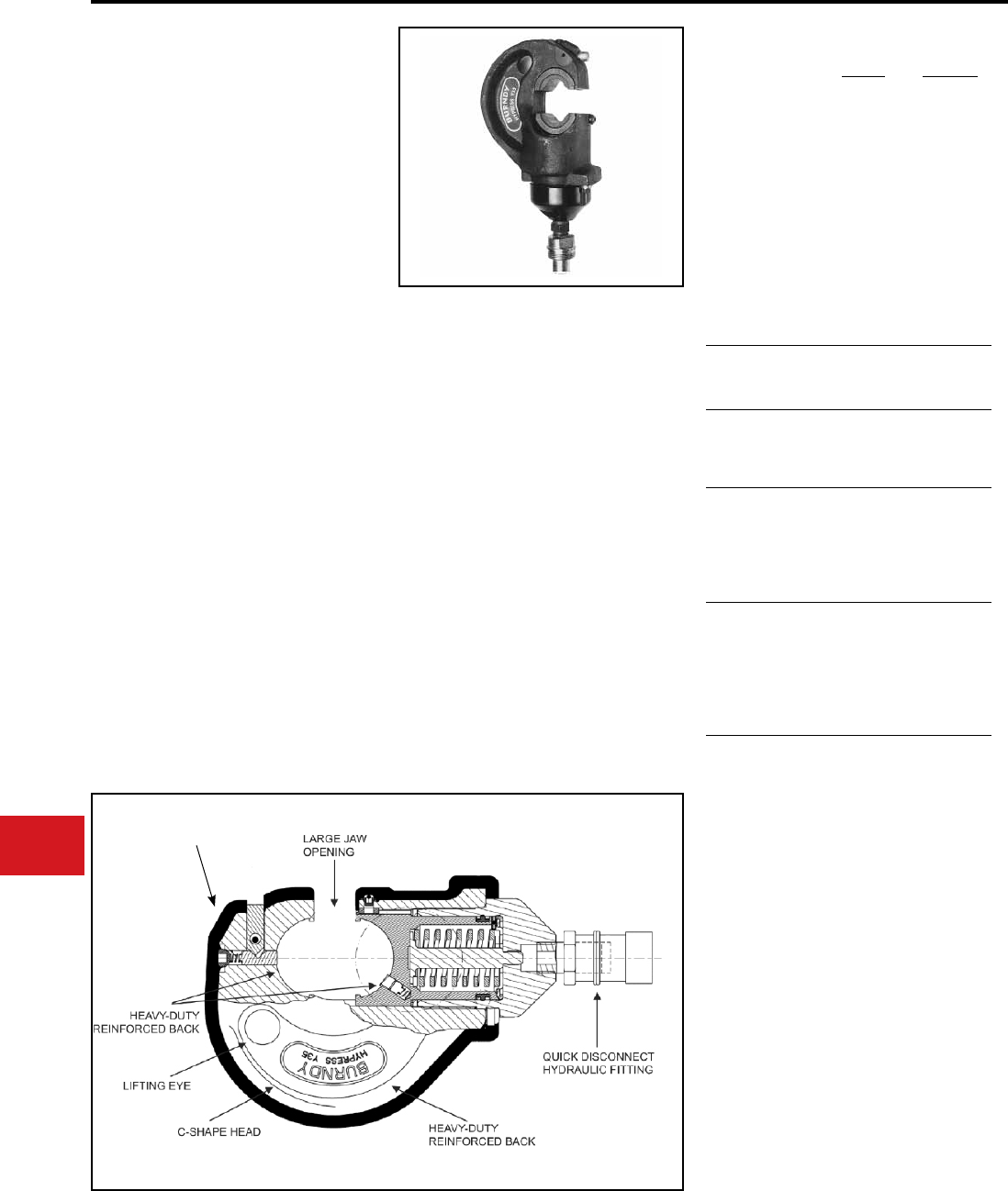
BURNDY®
US: 1-800-346-4175 www.burndy.com Canada: 1-800-387-6487
Tooling
Crimpers — Remote Hydraulic
Y35BH HYPRESS™
10,000 PSI
REMOTE POWER OPERATED
COMPRESSION TOOL
The Y35BH series remote head is designed for
remote power operation and incorporates the
same C-shaped head as the Y35. The hook style
head with extensive ram travel provides for easy
tapping and splicing of overhead lines as well as
HYGROUND® compression grounding systems.
Uses all standard BURNDY® “U” dies.
The remote power operated Y35 heads are
available covered with 3/16″ molded rubber for tool
impact protection.
Order head, hose, pump, dies and accessories
separately. The product comes with 5-year limited
warranty.
• Easy tool removal from line conductor
after compression taps are installed with
the open “C” shaped head
• Easily lifted into working position using
the lifting eye
• Easy die changing plus secure die
alignments provided with the positive die
lock buttons
• Uses all standard BURNDY® “U” dies
• Long life expectancy is provided with
heavy duty reinforced back
• Mates with all universal type Hot-stick
tooling
• Rapid assembly and disassembly is
provided with the quick disconnect
hydraulic tting
• Type Y35BH-4 head is covered with 3/16″
molded rubber
• 5-year limited warranty
Operative pressure:
Jaw opening:
Force Developed:
Weight(less case):
Maximum width:
Maximum height:
Molded covering:
Features and Benets
SPECIFICATIONS
FOR USE ON
Tension
Sleeves
Copper
Aluminium
ACSR
#8 Sol.-500 kcmil
#6 Sol.-636 kcmil
#4 -556.5 (26/7)
Taps
Aerial Cable
Connectors
Copper
Aluminium
#14-556.5 ACSR
(18/1)
#6 Sol.-636 kcmil
#4 -556.5 (26/7)
Code
Conductors
Copper
Aluminium
#8 Str.-750 kcmil
terminals
- 400 kcmil splices
#6 Str.-750 kcmil
terminals
- 400 kcmil splices
HYGROUND®
Compression
Grounding
Copper
(cable/cable)
Copper
(cable/grd. rod)
Ground Rods
#6-500 kcmil
#6-500 kcmil
1/2 in - 3/4 in
Y35BH
10,000 PSI
.95 in
12 tons
8 lbs
4-3/4 in
9-1/4 in
—
Y35BH-4
10,000 PSI
.95 in
12 tons
9 lbs
6 in
10-1/2 in
Yes
Y35BH Variations:
Y35BH Head Only
Y35H Includes the Y35BH HYPRESS™
head, PT29402-1 universal
hot-stick adapter, and steel
carrying case.
Y35B Includes the Y35BH HYPRESS™
head, PT91 steel reinforced
hydraulic hose and an FP10 foot
pump in a steel carrying case.
Note: NOT for use on energized
conductors.
Y35BH-4 Permanent Molded Rubber Head.
The Y35BH-4 is covered with
3/16″ molded rubber for tool impact
protection (not insulation)
Molded rubber head
Y35BH-4 only
N-38
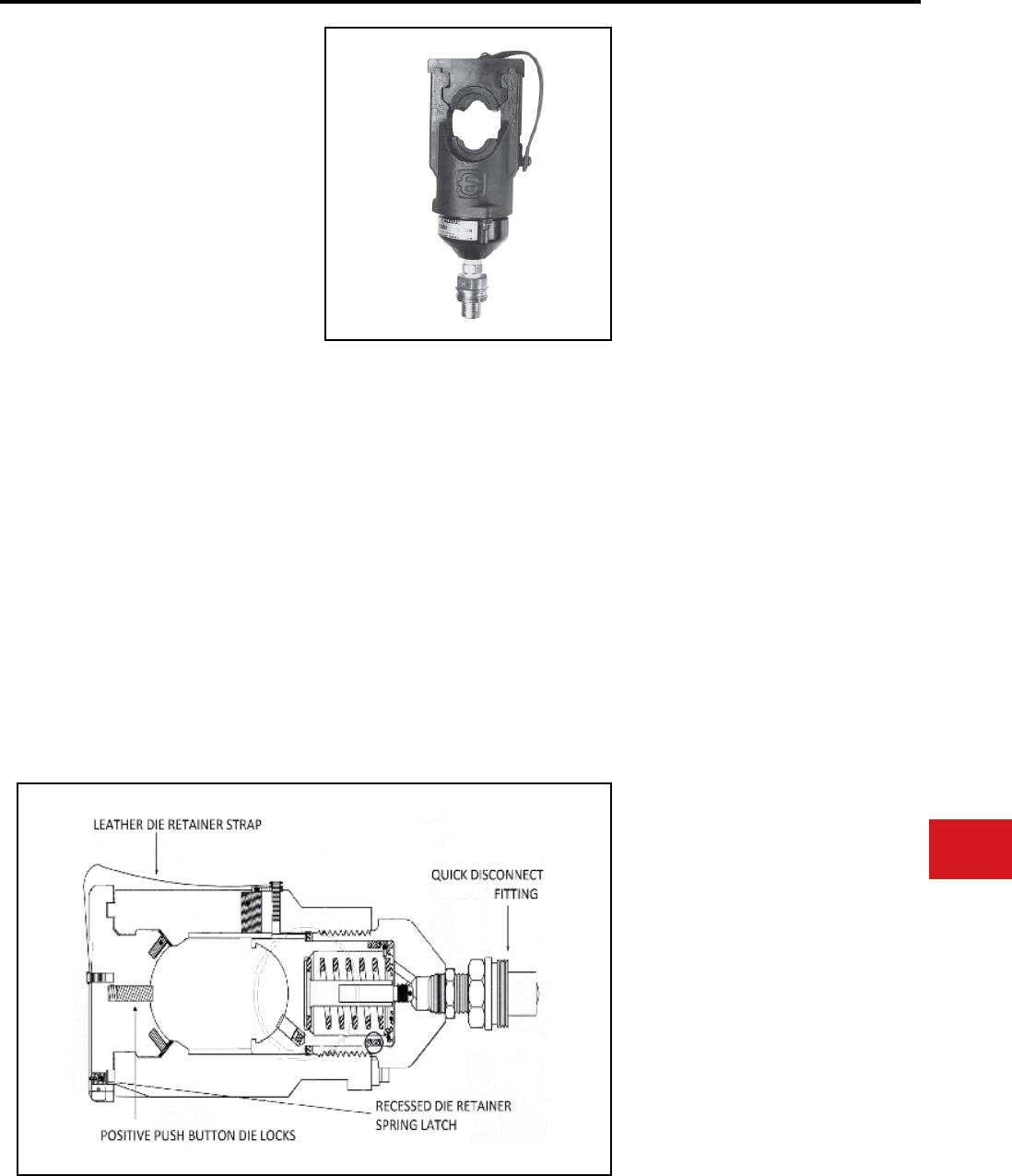
BURNDY®
Canada: 1-800-387-6487 www.burndy.com US: 1-800-346-4175
Tooling
Crimpers — Remote Hydraulic
Y39BH HYPRESS™
10,000 PSI
REMOTE POWER OPERATED
COMPRESSION TOOL
The Y39BH Remote Head is designed for remote
power operation and incorporates the same small
head as the Y39. Convenient die holder with
recessed spring latch makes it easy to remove
or lock into position. Dies are located and held in
position with positive push button die locks. Dies
sold separately. Uses all standard BURNDY® “U”
dies. 5-year limited warranty.
• Easy to work in small tight spaces with only a
3-1/8″ wide compression head.
• Easy to locate and hold dies in position with
the positive push button die locks plus die
changing is accomplished easily without ball
checks or set screws.
• Easy to remove or lock into position die holder
with recessed spring latch plus leather strap to
prevent loss.
• Compression terminal, tap and splice
connectors are UL Listed and CSA Certied
when installed with the Y39 tool and
recommended die set.
• Uses all standard BURNDY® “U” dies.
• Very versatile tool that is able to work with
10,000 PSI pumps.
• 5-year limited warranty.
Operating pressure:
Force developed:
Weight:
Maximum head Width:
Minimum Height:
Features and Benets
SPECIFICATIONS
FOR USE ON
COPPER
#6 AWG - 750 kcmil str.
Code Cable
N30-N650 Navy Cable
Flexible and Extra Flexible
Terminals—Uninsulated
YA, YA-L, YA-LB, YGH, YGHA
Splices and Tees—Uninsulated
YS, YS-L, YS-LB, YS-T, YSP-T, YST
COPPER-AN or AIR
#6 AWG - 4/0 str. Code Cable
AN6-AN 4/0 Aircraft Cable
Flexible and Extra Flexible
Terminals—Uninsulated
YAV-L Box, YAV-L, YAV-RS Box, YAV-RS
Splices and Tees—Uninsulated
YSV-L Box, YSV-L
COPPER-INSULATED TERMINALS
#8-AWG - 2/0 str. Code Cable
AN8-AN 2/0 Aircraft Cable
Flexible and Extra Flexible
Terminals—Insulated
YAEV-L Box, YAEV-L, YAEV-RS Box,
YAEV-RS, YAEV-RH
COPPER - TAPS
#12 AWG Solid - 250 kcmil
Taps—YC-C, YGHC-C, YGHP-C, YGHR-C,
YH, YCHC
ALUMINUM
#8 AWG - 750 kcmil str.
Code Cable
Terminals—YA-A
Splices—YS-A, YS-AT, YRB
ALUMINUM
#6 str. - 500 kcmil
Taps—YFD, YFN, YFO
10,000 PSI
12 tons
6-1/2 lbs
3-1/8″
9-1/8″
N-39
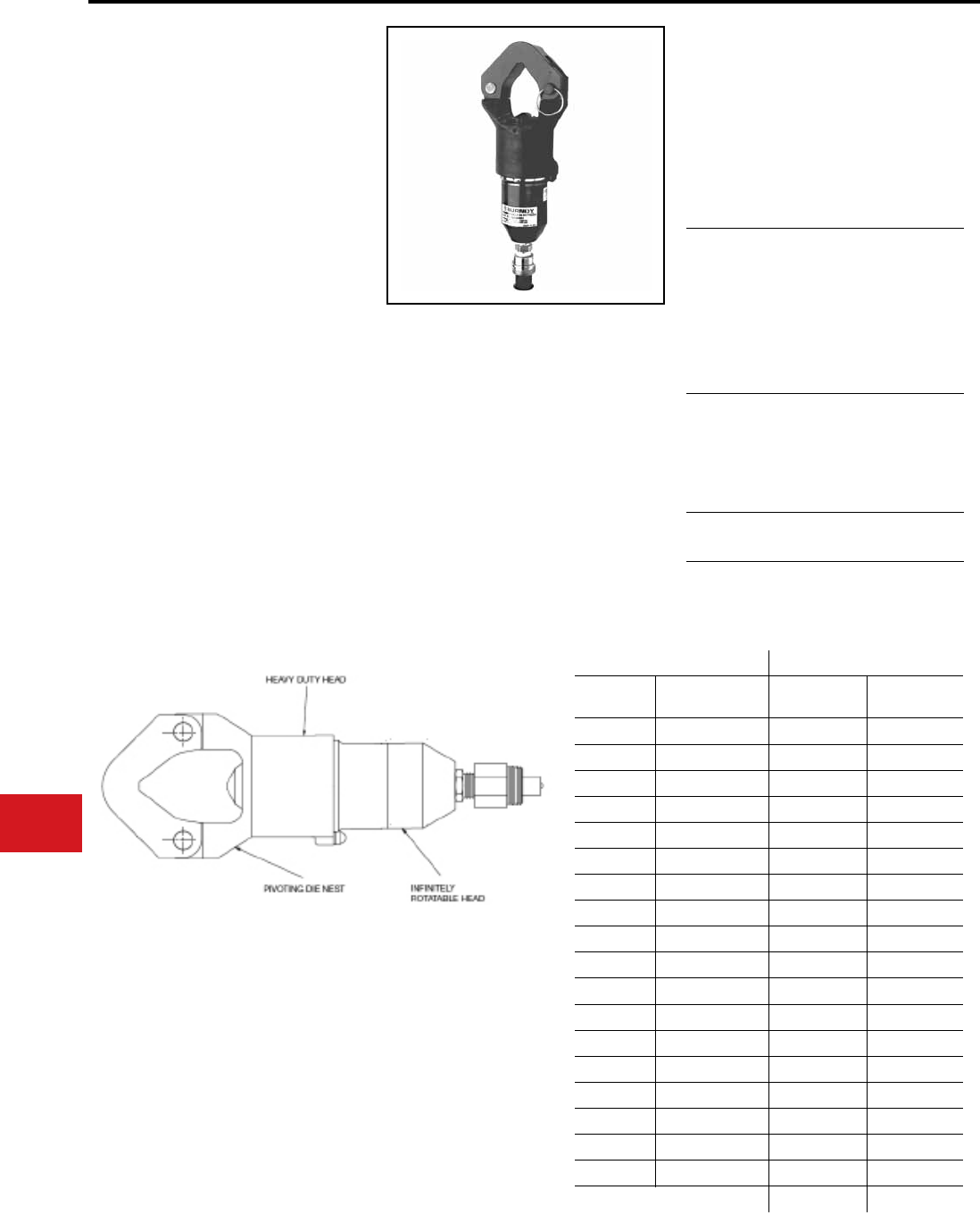
BURNDY®
US: 1-800-346-4175 www.burndy.com Canada: 1-800-387-6487
Tooling
Crimpers — Remote Hydraulic
Y644MBH
DIELESS HYPRESS™
REMOTE OPERATED HYDRAULIC
TOOL - 10,000 PSI
The “1” Crimp-Range Taking 11-Ton Force
Hydraulic Remote Tool for #6 - 1000 kcmil Copper
& Aluminum HYLUG™ Terminals and HYLINK™
Splices.
The “1” Crimp Type Y644MBH Dieless
HYPRESS™ Remote Tool, crimps 195 different
copper and aluminum HYLUG™ terminals and
HYLINK™ splices, which cover the breadth of 38
code conductor sizes and 15 Navy cable sizes.
Only one (1) crimp is required for each wire
termination for both long and standard length
barrels on BURNDY HYLUG™ and HYLINK™
connectors throughout the entire conductor range.
The Y644MBH dieless remote head tool operates
on 10,000 psi hydraulic pressure and develops
an output force of 11 tons, the same as the self-
contained Y644HSXT Dieless HYPRESS™.
5-year limited warranty.
• Dieless system, eliminates the need to
purchase and maintain dies
• Latch head design
• Range taking Dieless design
• Easy tool positioning with its innitely rotatable
head
• Easy inspection and positive identication is
provided with the BURNDY® logo
• Heavy duty head
• 5-year limited warranty
Features and Benets
SPECIFICATIONS
FOR USE ON
Force developed:
Operating pressure:
Head width:
Overall Length:
Weight (less case):
11 tons
10,000 PSI
3.93″
12″
9-1/2 lbs
Copper
#6-1000 kcmil
Terminals
YA-L, YA-2LN, YA,
YA-2N, YA-L-2TC,
YAB-4N, YA-L-TC,
YA-2L, YA-4N
Splices
YS-L, YS-T, YS
Aluminum
#6-1000 kcmil
Terminals
YA-A, YA-A-TN
Splices
YS-A
Aluminum
#6-750 kcmil
HYPLUG™
AYP, AYPO
The chart tbelow shows the HYDENT™ lugs and two way splices,
when crimped with the Y644MBH Dieless HYPRESS™ Tool, produce
the following range taking capabilites.
Aluminum Connectors Copper Connectors
Standard
Wire Size
Expanded
Wire Range
Standard
Wire Size
Expanded
Wire Range
#6 AWG #6 AWG #6 AWG #6 AWG
#5 AWG #5-#6 AWG #5 AWG #5-#6 AWG
#4 AWG #4-#6 AWG #4 AWG #4-#6 AWG
#3 AWG #3-#6 AWG #3 AWG #3-#6 AWG
#2 AWG #2-#6 AWG #2 AWG #2-#6 AWG
#1 AWG #1-#2 AWG #1 AWG #1-#2 AWG
1/0 AWG 1/0-#1 AWG 1/0 AWG 1/0-#6 AWG
2/0 AWG 2/0-#1 AWG 2/0 AWG 2/0-#4 AWG
3/0 AWG 3/0-#1 AWG 3/0 AWG 3/0-#2 AWG
4/0 AWG 4/0-#1 AWG 4/0 AWG 4/0-#1 AWG
250 kcmil 250-1/0 AWG 250 kcmil 250-1/0
300 kcmil 300-2/0 AWG 300 kcmil 300-2/0
350 kcmil 350-3/0 AWG 350 kcmil 350-3/0
400 kcmil 400-4/0 AWG 400 kcmil 400-4/0
500 kcmil 500-4/0 AWG 500 kcmil 500-4/0
600 kcmil 600-250 kcmil 600 kcmil 600-250
750 kcmil 750-500 kcmil 750 kcmil 750-500
1000 kcmil 1000-750 kcmil 800 kcmil 800-500
1000 kcmil 1000-750
N-40
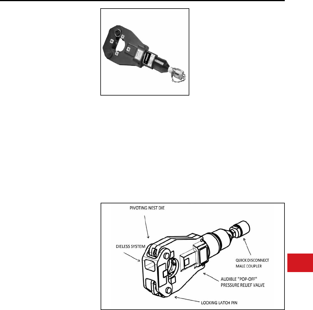
BURNDY®
Canada: 1-800-387-6487 www.burndy.com US: 1-800-346-4175
Tooling
Crimpers — Remote Hydraulic
4-POINT®
Y81KFTMBH
DIELESS HYPRESS™
Remote Operated
Dieless Hydraulic Tool-10,000 PSI
#8 - 1000 kcmil Copper
HYLUG™ Terminals and
HYLINK™ Splices
#8 - 750 kcmil Aluminum
HYLUG™ Terminals and
HYLINK™ Splices
The Y81KFTMBH 4-POINT® dieless HYPRESS™
is a remote powered 6 ton hydraulic crimping tool
for use on a wide variety of terminal and splice
compression applications. The Y81KFTMBH
incorpo-rates a dieless latch style head that
provides easy tool removal from continuous
conductor runs and eliminates the need to
purchase and maintain dies. The Y81KFTMBH
dieless remote head tool operates on 10,000
psi hydraulic pressure and develops an output
force of 6 tons, the same as the self contained
Y81KFTMBH. The result is easy termination
and splicing using BURNDY® HYLUG™ and
HYLINK™ terminals and splices.
The Y81KFTMBH is supplied with a canvas bag
and quick connect ttings and comes complete
with a 5-year limited warranty.
Y81KFTMBH dieless HYPRESS™ Range Taking
Capabilities: The Y81KFTMBH provides range
taking capabilities that is UL Listed and CSA
Certied for Copper (Code, Compact and Flex)
and Aluminum (Code and Compact) conductors
when used in conjunction with BURNDY®
HYLUG™ terminals and HYLINK™ splices. See
chart for connector, conductor and range taking
combinations.
• Dieless installation system
• UL Listed and CSA Certied with Range
Taking Capabilities
• Flip top head design for easy loading and
removal of installed terminals and splices,
saving time
• Incorporates Parker type quick connect
couplers
• Audible pressure “pop-off” valve and die
embossment providing 360° inspectability
• 5-year limited warranty on tool
Output Force:
Weight:
Overall Length:
Head Width:
Operating Pressure:
Features and Benets
SPECIFICATIONS
FOR USE ON
• Copper, Aluminum, Compressed, Compact,
Stranded, Solid and Flex Conductors
• Installs Splices, Taps and Terminations:
#8 - 1000 kcmil Copper
(YA, YA-L, YS, YS-L, YS-T, Y-R )
#8 - 777.7 (750 Nominal Flex Wire Size) kcmil Flex
(YA-FX, YAV, YA-L-FX, YS, YSV-FXB)
#8 - 750 kcmil Aluminum
(YA-A, YS-A)
#8 - 750 kcmil Aluminium Pin Adapters
(AYP, AYPO)
6 tons (12,000 lbs)
(5.4 metric tons)
8.5 lbs l(3.86 kg)
13.9 in (354 mm)
5.4 in (138 mm)
10,000 PSI
(68.9 MPa)
N-41
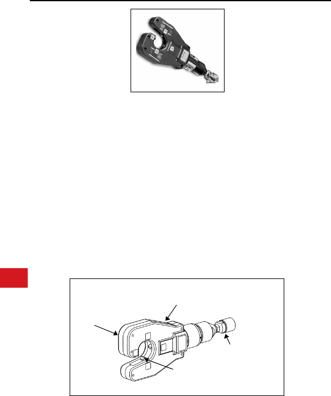
BURNDY®
US: 1-800-346-4175 www.burndy.com Canada: 1-800-387-6487
Tooling
Crimpers — Remote Hydraulic
4-POINT®
Y4PC834MBH
DIELESS HYPRESS™
Remote Operated
Dieless Hydraulic Tool - 10,000 PSI
The Y4PC834MBH 4-POINT® C-head dieless
HYPRESS™ is a remote powered 6 ton hydraulic
crimping tool for use on a wide variety of tap,
terminate, and splice compression applications.
The dieless capability of this tool eliminates the
need to purchase or maintain additional dies. The
Y4PC834MBH incorporates a C-shaped head
design making it ideal for crimping in tight areas and
is easily removed from continuous conductor runs.
The head rotates 360º and is mated to a patented
rapid advance pump. The Y4PC834MBH weighs
only 8.35 pounds and delivers 6 tons of crimping
force. The result allows for easy tap, termination
and splicing of compression connectors.
The Y4PC834MBH is supplied with a canvas bag,
quick connect ttings and comes with a 5-year
limited warranty.
The Y4PC834MBH provides range taking
capabilities that are UL Listed and CSA Certied for
Copper (Code, Compact and Flex) and Aluminum
(Code and Compact) conductors when used in
conjunction with BURNDY® HYLUG™ terminals
and HYLINK™ splices as listed in Section C of
Master Catalog.
• Dieless installation system
◊ Eliminates the need to purchase and
maintain dies
• UL Listed and CSA Certied with range taking
capabilities
◊ Provides the installer with a UL Listed
and CSA Certied crimps when used
in conjunction with BURNDY HYLUG™
and HYLINK™ compression connectors
• C-shaped head design
◊ For easily removing tool from continuous
run conductors–Simply slide
the opening of the head off the conductor
Also ideal for use in tight or constrained
spaces
• Visual 360° inspectability
◊ Assures proper crimps with visual
indicators for the installer
• 5-year limited warranty
Output Force:
Weight:
Length:
Width:
Features and Benets
SPECIFICATIONS
FOR USE ON
• Copper, Aluminum, Compressed,
Compact, Stranded, Solid and Flex
Conductors
• Installs Splices, Taps and Terminations:
#8 - 1000 kcmil Copper (YA, YA-L)
#8 - 500 kcmil Copper (YS, YS-T, YS-L, Y-R)
#8 - 777 (750 Nominal Flex Wire Size) kcmil Flex
(YA-FX, YAV, YA-L-FX)
#8 - 535 (500 kcmil nom. ex wire size) kcmil ex
(YS, YS-LB, YSV-FXB)
#8 - 750 kcmil Aluminum (YA-A)
#8 - 350 kcmil Aluminum (YS-A)
#8 - 750 kcmil Aluminum Pin Adaptors
(AYP, AYPO).
6 tons
(5.4 metric tons)
8.35 lbs (3.7kg)
3.9 in
5.4 in (178 mm)
360 HEAD ROTATION
SO HYDRALIC COUPLERS
WON'T LOOSEN
C-SHAPED
HEAD
FOUR POINTS OF
CONTACT ON EACH
CONNECTION
MALE QUICK
DISCONNECT 10,000 PSI
HYDRAULIC COUPLER
N-42
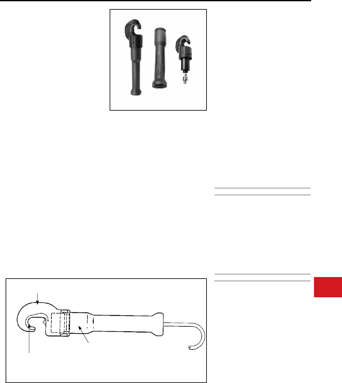
BURNDY®
Canada: 1-800-387-6487 www.burndy.com US: 1-800-346-4175
Tooling
Crimpers — Remote Hydraulic
Y34BH
HYPRESS™
Remote Operated
Hydraulic Tool-10,000 PSI
9 ton remote power operated hydraulic tool. The
Y34BH HYPRESS™ tool is designed for remote
hydraulic power operation. Its new 10,000 PSI
operating pressure makes it easily adaptable to
most remote power systems. Its small C-shaped
head is light-weight, compact and with a relatively
large jaw opening ideally suited for NETWORK
UNDERGROUND systems.
The tool comes standard with permanent molded
head with 3/16″ rubber and includes a separate
molded rubber boot that covers the lower body
and hydraulic coupler for tool impact protection.
Together, with other BURNDY® hydraulic
accessories, the Y34BH HYPRESS™ tool may
be used on lines. The Y34BH-1 has a ten foot
non-conductive 10,000 PSI hose attached at
the factory. The Y34BH Series tool has a 5-year
limited warranty.
• Allows for easy placement and removal from
continuous conductor lengths
• Long life
• Fast ram retraction
• Molded rubber covering on head, body,
and hose ttings
• Standard operating pressure
• Ease in handling
• Greater reliability
• Reduced tool life cycle cost
• 5-year limited warranty
• Head and body rubberized
• Accommodates “B” dies
Operating pressure:
Jaw opening:
Maximum force generated:
Head Length:
Overall dimesions:
Total weight:
Features and Benets
SPECIFICATIONS
FOR USE ON
• Copper: #4-500 kcmil str.
Welding Cable: 350 kcmil
N40 to N500 Navy Cable
Flexible and Extra Flexible
#4 to 4/0 Aircraft Cable
HYLUG™: Terminals-Uninsulated
HYLINK™: Splices and Uninsulated
• HYCRAB™: BURNDY® Network connector
System.
Copper: #4-500 kcmil str.
Aluminum: #6-300 kcmil
10,000 PSI
1-1/2″
9 tons
11-1/2″
16-3/4″
(incl.boot)
Approx. 8 lbs.
B4CD
B1CD
B26D
B26D
B27D
B29D
B30D
B31D
B32D
No die req’d.
Y34PA
Y34PA
Y34PA
Y34PR-5
Y34PR-5
Y34PR-5
Y34PR-5
Y34PR-5
Y34PR-5
Y34PR-11
#6 Str.
#4 Str.
#2 Str.
#1 Str.
1/0 Str.
2/0 Str.
3/0 Str.
4/0 Str.
250 kcmil
300 kcmil
Nest Indentor Aluminum
Installation Die Max. Conductor
B4CD
B2CD
B1CD
B25D
B26D
B27D
B28D
B29D
B30D
B31D
No die req’d.
Y34PR
Y34PR
Y34PR
Y34PR
Y34PR
Y34PR
Y34PR
Y34PR
Y34PR
Y34PR
Y34PR
#4 Str.
#2 Str.
#1 Str.
1/0 Str.
2/0 Str.
3/0 Str.
4/0 Str.
250 kcmil
300 kcmil
350 kcmil
500 kcmil
MOLDED RUBBER
COVERING
HEAVY DUTY
RETURN SPRING
OPERATES ON
STANDARD
10,000 PSI PUMPS
COMPACT “C” SHAPED
FORGED HEAD
MOLDED RUBBER BOOT
ACCOMMODATES
“B” DIES
LIGHTWEIGHT
DESIGN
Nest Indentor Aluminum
Installation Die Max. Conductor
N-43
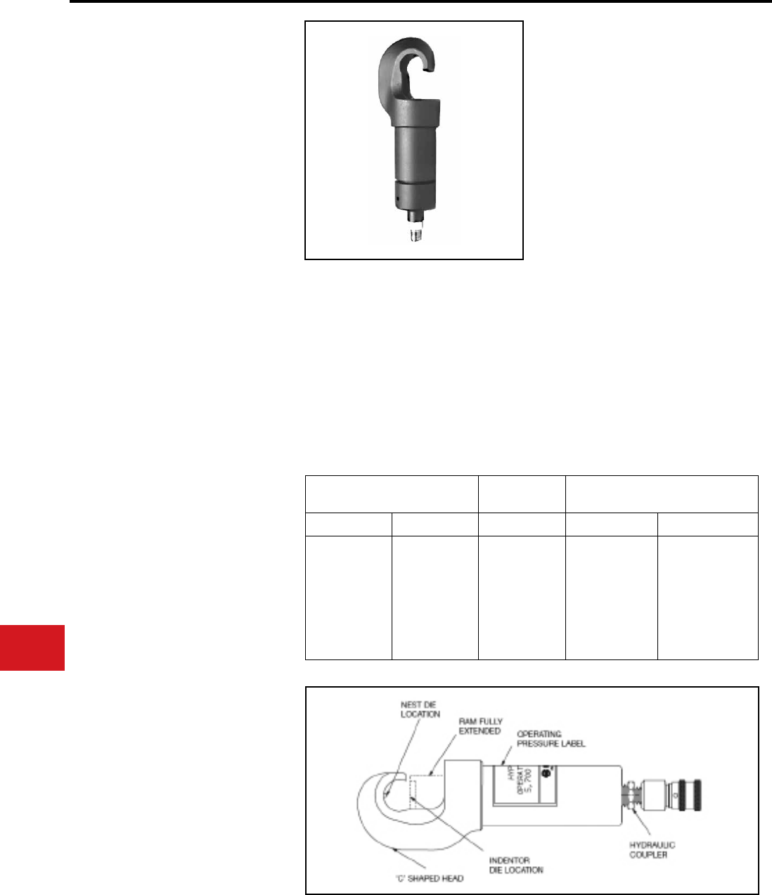
BURNDY®
US: 1-800-346-4175 www.burndy.com Canada: 1-800-387-6487
Tooling
Crimpers — Remote Hydraulic
Y29BH
HYPRESS™
Remote Operated
Hydraulic Tool-6,000 PSI
4.5 Ton remote power operated hydraulic tool.
The Y29BH HYPRESS™ tool is designed for
remote hydraulic power operation. Its small, “C”
shaped head is lightweight, designed for use
in conned areas, where visibility and space is
limited. Accommodates D- (series) nest dies and
Y29- (series) indentor dies, for use with code or ex
connector/conductor applications. Ideal for OEM
applications. Dies sold separately. The Y29BH has
a 5-year limited warranty. • Easy placement/removal on continuous
conductor lengths
• Lightweight, portable head design
• Installs a wide variety of lugs and splices
• Ideal for AN, Flex and Code conductor
terminations
• Hydraulic coupler
• "C" shaped head
• 5-year limited warranty
Operating Pressure:
Height:
Length:
Head width:
Jaw Opening:
Weight:
Output Force:
Crimp Type:
Features and Benets
SPECIFICATIONS
FOR USE ON
Copper #8 - 4/0 AWG, Code/Flex
Nylon Insulated Lugs
(Connectors meet MIL-T-7928 requirements)
• YAEV-L, YAEV-H, YAEV-RS, YAEV-RH
Non-Insulated Lugs
(Connectors meet MIL-T-7928 requirements)
• YAV-L, YAV-R, YAV-RS
Non-Insulated Splices
(Type YSV-L connectors UL Listed, CSA Certifed)
• YSM, YSV-L
Uninsulated
Connectors
Maximum
Conductor
Insulated
Connectors
NEST IND. SIZE NEST IND
DV8L-1
DV6L
DV4L
DV2L
DV1L
DV25L
DV26L
Y29PL
Y29PL
Y29PL
Y29PL
Y29PL
Y29PL
Y29PL
#8 AWG
#6 AWG
#4 AWG
#2 AWG
#1 AWG
1/0 AWG
2/0 AWG
DEV8L
DEV6L
DEV4L
DEV2L
DEV1L
DEV25L
DEV26L
Y29PLE-1
Y29PLE-1
Y29PLE-1
Y29PLE
Y29PLE
Y29PLE
Y29PLE
6,000 PSI
3″
10.75″ (Including
coupler tting)
1.15″
1.2″
5 lbs
4.5 tons (9000 lbs)
Nest/Indentor
N-44
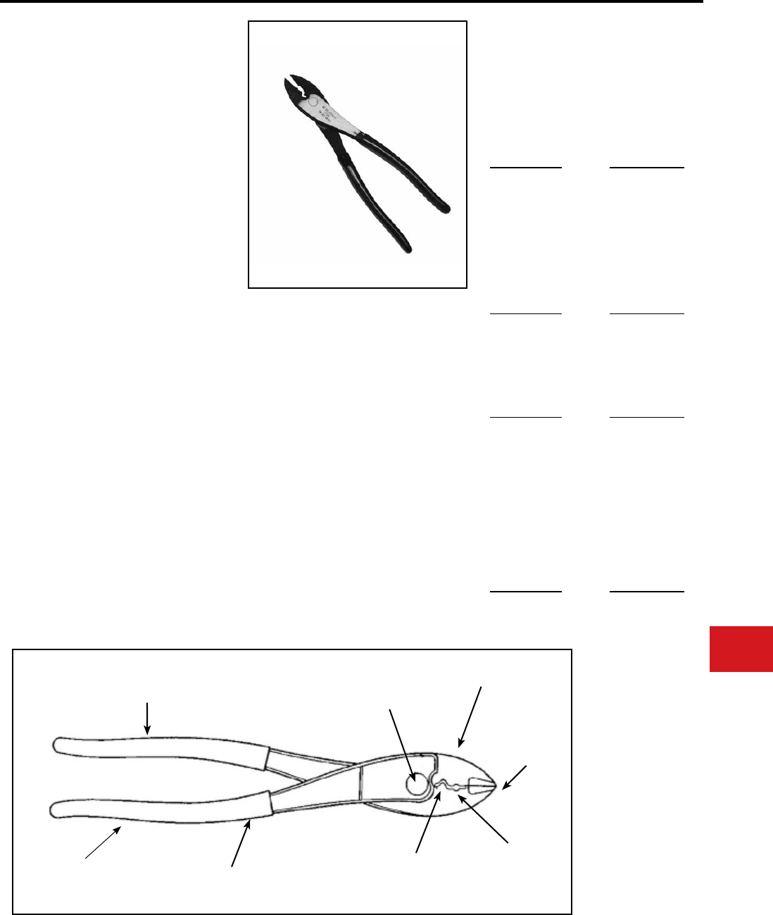
BURNDY®
Canada: 1-800-387-6487 www.burndy.com US: 1-800-346-4175
Tooling
Crimpers — Mechanical and Ratchet
Y10D
HYTOOL™
Two Tools in One —
#22-10 AWG Nylon Insulated Connectors,
#22-10 AWG Uninsulated Connectors
Hand-held plier type tool that will install #10 - 22
AWG nylon insulated and uninsu-lated terminals
and splices, with a precision machined wire cutter
for aluminum and copper wire in the nose of the
tool. Long handles provide greater mechanical
advantage. 5-year limited warranty.
Length:
Weight:
SPECIFICATIONS
FOR USE ON
• Easy wire cutting with precision machined
cutting blade
• Save time, money and lower installed costs
with one tool for both nylon insulated and
uninsulated (bare) connectors
• Easy tool operation out of the carton. No
need to break in the tool prior to actual
usage
• A heavy duty forged steel tool, that has
a rust resistant nish will provide a long
durable life
Features and Benets
* Conductor crimp only.
9-3/4″
13.5 oz
#10-22 AWG Nylon Insulated Terminals
Box Cat. Types Bulk Cat. Types
TN
TN-F
YAE-N BOX
YAE-N-F BOX
YAE-Z BOX
YAEV BOX
YAES
YAES-E
YAE-N
YAE-N-F
YAE-Z
YAEV
#10-22 AWG Nylon Insulated Splices
Box Cat. Types Bulk Cat. Types
SN
SNM
YSE-H BOX *
YSE-HN *
YSES
YSE-H *
#10-22 AWG Uninsulated (Bare) Terminals
Box Cat. Types Bulk Cat. Types
T
T-F
YAV BOX
YAV-T-F BOX
YAV-H BOX *
YAV-H-F BOX *
YAV-Z BOX
YAD
YAD-F
YAV
YAV-T-F
YAV-H *
YAV-H-F *
YAV-Z
#10- 22 AWG Uninsulated (Bare) Splices
Box Cat. Types Bulk Cat. Types
YSV BOX
YSV-H BOX *
YSV
YSV-H *
COMFORT
GRIP HANDLES READY TO USE
LUBRICATED PIVOT
HEAVY DUTY
FORGED STEEL
PRECISION
MACHINED
WIRE CUTTER
LONG HANDLES
FOR GREATER
MECHANICAL
ADVANTAGE
RUST RESISTANT FINISH
#22-10
UNINSULATED
(BARE)
#22-10
NYLON
INSULATED
• Easier crimping on #22-10 bare and nylon
insulated connectors because of the longer
handles that provides greater mechanical
advantage*
• Comfort grip handles t hands comfortably
helping make the tool easy to use
• Terminals and splice connectors are UL
Listed and CSA Certied when installed
with the Y10D HYTOOL™
• 5-year limited warranty
N-45
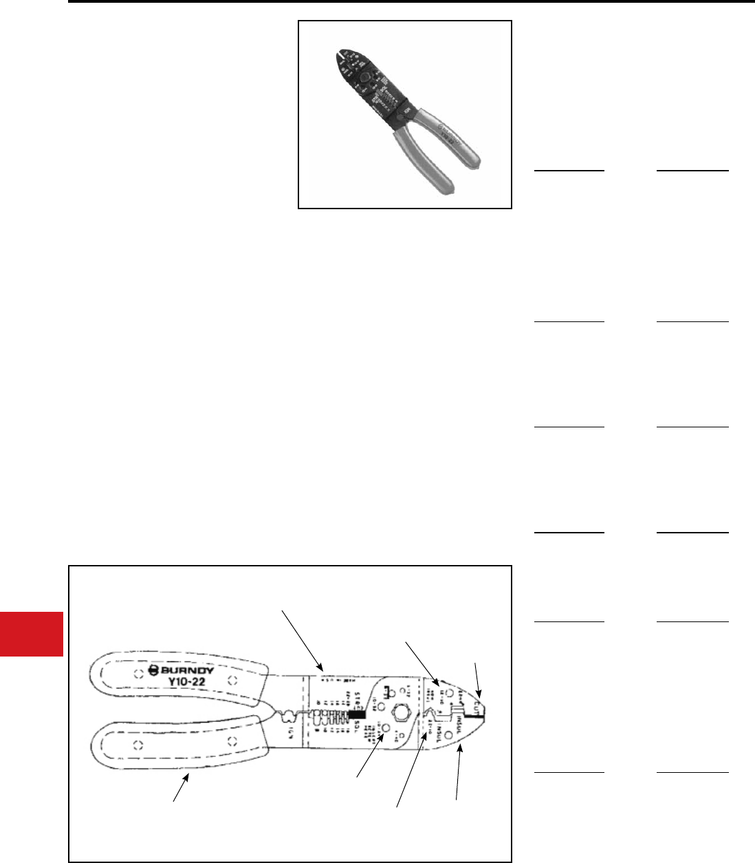
BURNDY®
US: 1-800-346-4175 www.burndy.com Canada: 1-800-387-6487
Tooling
Crimpers — Mechanical and Ratchet
Y10-22
HYTOOL™
#22-10 AWG Insulated Connectors,
#22-10 AWG Uninsulated Connectors
Hand-held plier type tool to install #10-22 AWG
insulated and uninsulated terminals and splices
with a wire cutter in the nose of the tool. Will strip
#10-22 AWG wire and cut common size mild steel
and non-ferrous screws. 5-year limited warranty.
• Easy wire cutting with anvil type wire cutter
design
• Crimps full range of insulated terminals and
splices #22-10 AWG
• Cut off dies for common size mild steel and
non-ferrous screws
• Crimps full range of uninsulated terminals
and splices #22-10 AWG
• Full range insulation strippers for wire sizes
#22-10. One step stripping
• Comfort grip handles t hands comfortably
helping make the tool easy to use
• 5-year limited warranty
Features and Benets
SPECIFICATIONS
Length:
Weight:
8-5/8″
11 oz
* Conductor crimp only
FOR USE ON
#10-22 AWG Nylon Insulated Terminals
Box Cat. Types Bulk Cat. Types
TN
TN-F
YAE-N BOX
YAE-N-F BOX
YAE-Z BOX
YAEV BOX
YAES
YAES-F
YAE-N
YAE-N-F
YAE-Z
YAEV
#10-22 AWG Nylon Insulated Splices
Box Cat. Types Bulk Cat. Types
SN
SNM
YSE-H BOX *
YSE-HN *
YSES
YSE-H *
#10-22 AWG Vinyl Insulated Terminals
Box Cat. Types Bulk Cat. Types
TP
TP-F
TP-Z
BA
BA-EF
BA-EZ
#10-22 AWG Vinyl Insulated Splices
Box Cat. Types Bulk Cat. Types
SP BS
#10-22 AWG Uninsulated (Bare) Terminals
Box Cat. Types Bulk Cat. Types
T
T-F
YAV BOX
YAV-T-F BOX
YAV-H-F BOX *
YAV-Z BOX
YAD
YAD-F
YAV
YAV-T-F
YAV-H-F *
YAV-Z
#10-22 AWG Uninsulated (Bare) Splices
Box Cat. Types Bulk Cat. Types
YSV BOX
YSV-H BOX *
YSV
YSV-H *
One step Individually
Sized Wire Stripes
Screw and
Bolt Cutters
#12-10 Insulated
Color Code Yellow
Wire Cutter
Comfort Grip
Plastic Handles
#22-10
Uninsulated
#22-14 Insulated
Color Code
Red & Blue
N-46
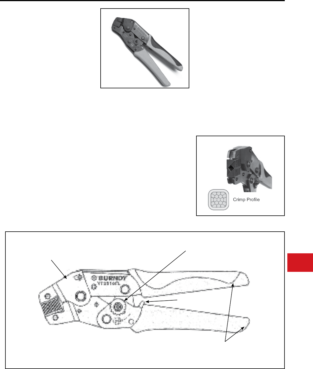
BURNDY®
Canada: 1-800-387-6487 www.burndy.com US: 1-800-346-4175
Tooling
Crimpers — Mechanical and Ratchet
TYPE YF22-10FL
HYTOOL™
Dieless, Front Load,
Range-Taking, Ratchet Tool
YF22-10FL Range-Taking Ratchet Tool
for installing #22 - #10 AWG
Insulated and Uninsulated Ferrules
The YF22-10FL ergonomic full cycle ratchet tool
provides a complete positive crimp each time.
The ergonomic comfort grip handles reduce
operator fatigue during continuous use. Once
started, the ratchet mechanism does not allow
the handles to be opened until the full ratcheting
cycle is completed, unless the operator actuates
the emergency release lever. This provides for a
complete crimp before a ferrule can be removed
from the tool. Range-taking to accommodate
ferrules from #22- #10 AWG. Each tool comes
complete with a 5-year limited warranty.
• Ergonomic hand tool for crimping insulated
and uninsulated ferrules
• Overmolded comfort grip handles reduce
fatigue during continuous use
• Full cycle ratchet mechanism to assure
properly crimped connections
• Dieless crimping eliminates the need for
multiple die grooves or stocking of extra
die sets
• Front load crimping position is ideal for
use in tight spaces, such as panels and
enclosures
• Ratchet mechanism ensures a full crimp
cycle
• Ratchet release lever can be actuated in the
event of a misalignment
• 5-year limited warranty
Features and Benets
SPECIFICATIONS
FOR USE ON
#22 - #10 AWG Insulated and Uninsulated
Ferrules
BURNDY Connector Family Type YF and YF-UI
Wire End Ferrules
Output Force:
Tool Weight:
Length:
Width:
Warranty:
1600 lbs
0.82 lbs
7.75 in
2.32 in
Limited 5 Years
High Strength Steel
Alloy Frame
Full-Cycle Ratchet
Mechanism
Ratchet Release Lever
Overmolded Comfort
Grip Hancles
N-47
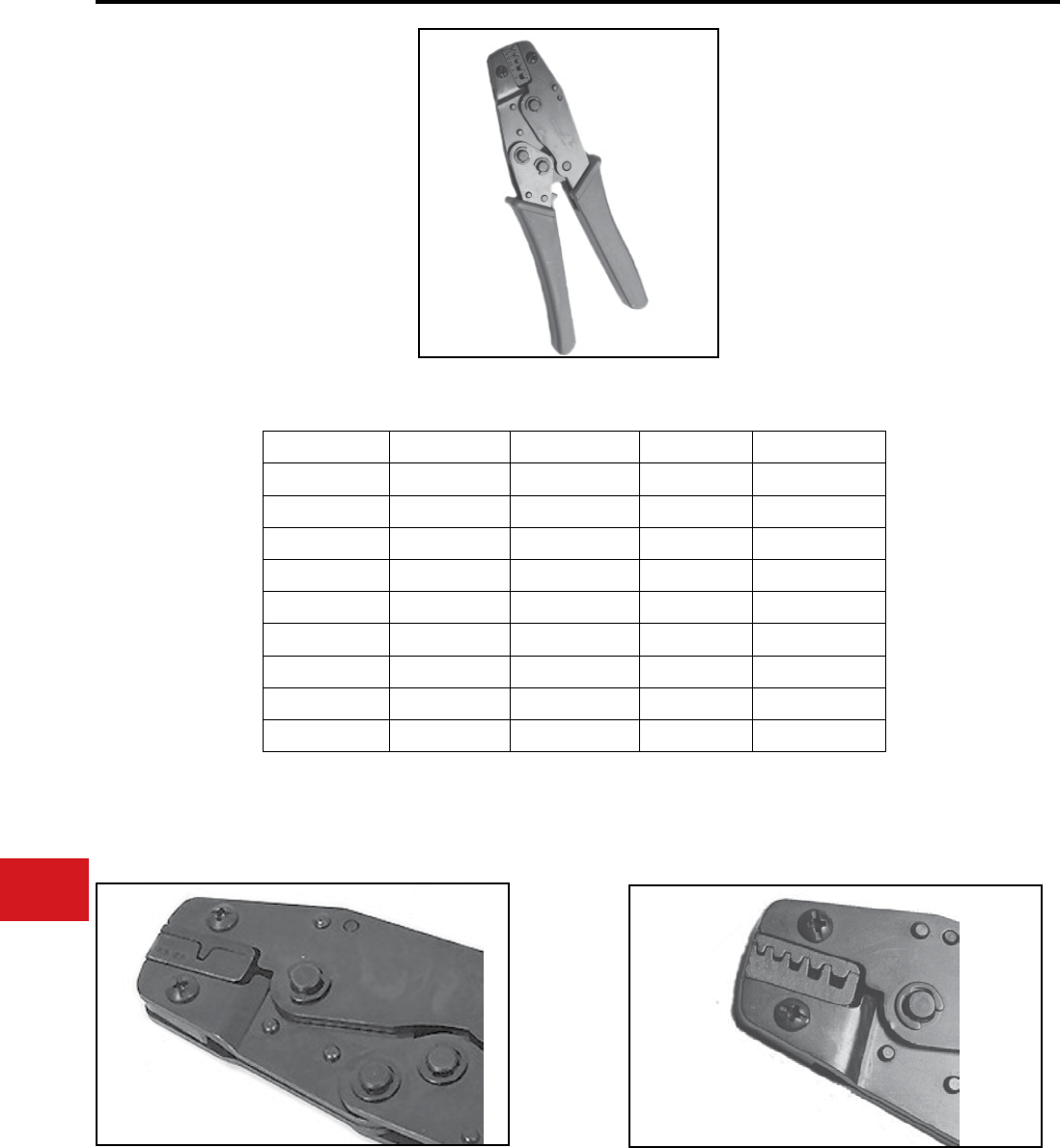
BURNDY®
US: 1-800-346-4175 www.burndy.com Canada: 1-800-387-6487
Tooling
Crimpers — Mechanical and Ratchet
YF-TOOL
Installation Ratchet Tool
for Bare and Insulated
Ferrules
For Use On Copper Ferrules
These tools have been specically designed
to work with both the insulated and uninsulated
ferrules type YF. Unless otherwise noted, the tools
have a trapezoidal crimp type.
• Ergonomic handle design to help ease installer
fatigue
• Release mechanism
• Low handle force required
Features and Benets
Catalog Number Capacity Crimp Prole Weight Handle Color
YF3206TOOL 32-6 AWG Square 1.10 lbs Black/Orange
YF2610TOOL 26-10 AWG Trapezoidal 1.02 lbs Blue
YF2214TOOL 22-14 AWG Trapezoidal 1.05 lbs Red
YF2210TOOL 22-10 AWG Trapezoidal 1.05 lbs Red
YF1006TOOL 10-6 AWG Trapezoidal 1.05 lbs Red
YF0801TOOL 8-1 AWG Trapezoidal 1.80 lbs Red
YF0401TOOL 4-1 AWG Trapezoidal 1.50 lbs Red/Blue
YF1/03/0TOOL 1/0-3/0 kcmil Trapezoidal 1.80 lbs Red
YF4/0250TOOL 4/0-250 kcmil Trapezoidal 1.80 lbs Red
YF2214TOOL has one groove to accept 22-14 AWG range YF2610TOOL, YF2210TOOL, and YF1006TOOL have multiple
grooves for range capacity
N-48
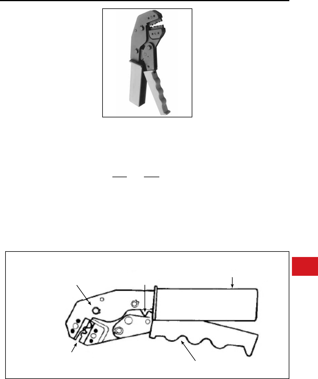
BURNDY®
Canada: 1-800-387-6487 www.burndy.com US: 1-800-346-4175
Tooling
Crimpers — Mechanical and Ratchet
Y8MRB-1
HYTOOL™
#22-8 AWG
Hand-held full cycle ratchet tool for #8-22 AWG
uninsulated terminals and splices. Full cycle
feature builds in reliability and removes the human
factor from the nished installation. 5-year limited
warranty.
• One tool to accommodate #22-8 AWG
• Lightweight
• Full cycle ratchet for positive crimping
• Inspection (PG) gauges available to check
each groove
Groove Gauge#
#18 PG395-1
#14 PG396-1
#10 PG397-1
# 8 PG398-1
• Each indentor has its own identifying mark for
inspectability
• Jaw opening orientation, molded nger and
palm grips and the easy reach frame minimize
user fatigue
Length:
Weight:
Features and Benets
SPECIFICATIONS
FOR USE ON
9-1/2″
1.21 lbs
BOX CAT. TYPES BULK CAT. TYPES
Uninsulated Terminals
T
T-F
YAV BOX
YAV-L BOX
YAV-T-F BOX
YAV-Z BOX
YAD
YAD-F
YAV
YAV-L
YAV-T-F
YAV-Z
Uninsulated Splices
YSV BOX
YSV-L BOX
YSV
YSV-L
FULL CYCLE
RATCHET
MECHANISM
EMERGENCY
RELEASE
COMFORT GRIPS
STEEL
BODY
MOLDED FINGER GRIPS
NEST/INDENTORS
SIZE RANGE
#22-8 AWG
N-49
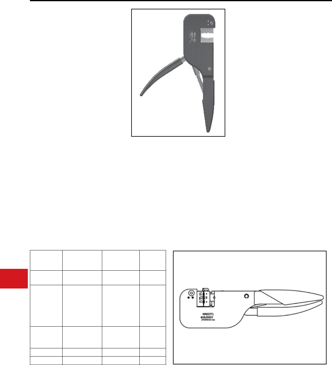
BURNDY®
US: 1-800-346-4175 www.burndy.com Canada: 1-800-387-6487
Tooling
Crimpers — Mechanical and Ratchet
MR8
HYTOOL™
Full Cycle Ratchet Hand Tools
The HYTOOL™ Types MR8 series incorporates
a full cycle ratchet mechanism that provides a
complete, positive crimp each time. Once started
the ratchet mechanism does not allow the handles
to be opened until after the full ratcheting cycle is
completed. This provides for a completed crimp
before a connector can be removed from the tool.
The MR8 series of tools are specically designed
with the ratchet mechanism completely inside the
body of the tool without a path to reach and defeat
the mechanism. This permits the tools to be used
in the most critical applications including nuclear-
class 1E terminations, heavy duty industrial, utility
generation, OEM, aircraft, and other applications
where a dependable electrical termination is
needed. 5-year limited warranty. • Lightweight aluminum permits easier
continuous usage
• One tool to accommodate #22-10 AWG
• Easy groove identication with color-coded
dies
• Long life expectancy with fully protected ratchet
mechanism
• Easy one-hand tool operation with long handle
length for greater mechanical advantage
• 5-year limited warranty
Features and Benets
SPECIFICATIONS
FOR USE ON
Length:
Weight:
10-1/2″
1-1/2 lbs
Tool
AWG
Size
Range
Box
Catalog
Types
Bulk
Catalog
Types
MR8-1A #10-22 AN
Copper Cable INSULUG™ YAE
MR8-9Q
#8-18 AN
Copper Cable
#10-22 AWG
Sol. Cable
#8-22 Str. AWG
Cable
YAV BOX
YSV BOX
T
T-F
YAV, YSV,
YAD,
YAD-F
MR8-33S-1
MR8-33T-1
#10-18
MIL-W-5086
Str.
YSE BOX
YSE-H BOX
YSE
YSE-H
MR8-G96 #14-22 TP BA
MR8-G98 #10-22 YAV, T YAD, YAV
LONG HANDLES
PROVIDE GREATER
MECHANICAL ADVANTAGE
ADJUSTABLE STOP
FOR TERMINALS
LOWERS FOR SPLICES
COLOR CODED
DIE GROOVES
FULLY PROTECTED
RATCHET MECHANISM
N-50
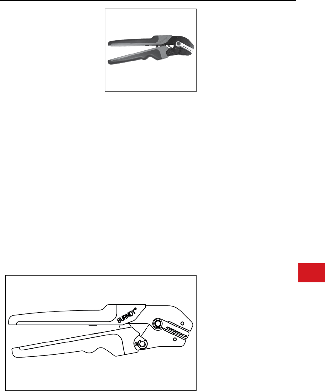
BURNDY®
Canada: 1-800-387-6487 www.burndy.com US: 1-800-346-4175
Tooling
Crimpers — Mechanical and Ratchet
MRE10-22B, MRE10-22NV
HYTOOL™
Ergonomic Full Cycle Ratchet
Hand Tools
MRE10-22B - #10 - #22
Uninsulated Terminals and Splices
MRE10-22NV - #10 - #22
Nylon and Vinyl insulated
Terminals and Splices
The MRE10-22B and MRE10-22NV ergonomic
full cycle ratchet tools provide a complete positive
crimp each time. The ergonomic comfort grip
handles reduce operator fatigue during continuous
use. Once started, the ratchet mechanism does
not allow the handles to be opened until the full
ratcheting cycle is completed, unless the operator
actuates the emergency release lever. This
provides for a completed crimp before a connector
can be removed from the tool. The MRE10-22B
crimps uninsulated (bare) terminals and splices
ranging from #10 AWG - #22 AWG; the MRE10-
22NV crimps nylon and vinyl terminals and splices
ranging from #10 AWG - #22 AWG. The dies are
color coded and stamped with the conductor size
to provide an easy match of the die and proper
BURNDY® terminal or splice. Each tool comes
complete with a 5-year limited warranty.
• Ergonomic hand tools for crimping insulated
and uninsulated terminals and splices
• Overmolded comfort grip handles reduce
fatigue during continuous use
• Easy groove identication with color coded
dies
• Full cycle ratchet tool to assure properly
crimped connections
• Emergency release mechanism allows tool
to open in case of misalignment or mistaken
die choice
• Stop plate ensures proper location of
terminals for consistent reliable connection
every time
• UL Listed/CSA Certied connections
when used with recommended BURNDY®
terminals and splices
• Two tools accommodate nylon, vinyl and
uninsulated terminals and splices #22 AWG
- #10 AWG
• 5-year limited warranty
Features and Benets
SPECIFICATIONS
FOR USE ON
MRE10-22B for uninsulated (bare)
terminals and splices #22-#10 AWG
BURNDY® Connector Family:
T- (YAD-), T-F (YAD-F), YAV-, YAV-H, YAV-R,
YAV-T-F, YAV-H-F, YAV-Z, YSV, YSV-H
Die Inspection Gauges: **
#22 - #14 AWG: PG-403-2R
#12 - #10 AWG: PG-403-1R
MRE10-22NV for nylon and vinyl insulated
terminals and splices #22 - #10 AWG
BURNDY® Connector Family:
TP- (BA-), TP-F (BA-EF), TP-Z (BAEZ), TP-LF
(BA-EL), SP (BS), TN- (YAES-), TN-F (YAES-F),
SNM* (YSES)*, YAE-N-, YAE-N-F, YAE-Z,
YSE-HN, YSE-H, YAEV-
(*excludes #10 size)
Die Inspection Gauges:**
#22 - #18 AWG (Red): PG-406-1
#16 - #14 AWG (Blue): PG-407-1
#12 - #10 AWG (Yellow): PG-408-1
**Die inspection Gauges are sold separately
Length:
Weight:
Width:
Warranty:
10.5 in
1.3 lbs
3 in
5 Year Limited Warranty
SPRING LOADED
HANDLES
HIGH STRENGTH
STEEL ALLOY FRAME CONNECTOR
STOP PLATE
COLR CODED
DIE GROOVES
FULL CYCLE
RATCHET MECHANISM
OVERMOLDED COMFORT
GRIP HANDLES
N-51
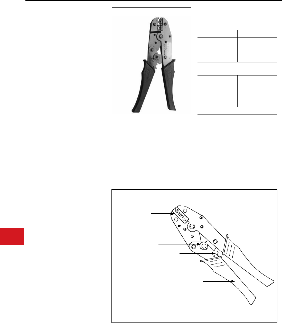
BURNDY®
US: 1-800-346-4175 www.burndy.com Canada: 1-800-387-6487
Tooling
Crimpers — Mechanical and Ratchet
MR15, MR18, MR20
HYTOOL™
Full Cycle Ratchet Hand Tools
The Types MR15, MR18 and MR20 series
HYTOOL™ incorporate a full cycle ratchet
mechanism that provides a complete, positive crimp
each time. Once started the ratchet mechanism
does not allow the handles to be opened until after
the full ratcheting cycle is completed, unless the
user actuates the emergency release lever. This
provides for a completed crimp before a connector
can be removed from the tool.
• UL Listed for use with BURNDY®
connectors
• Fully ratcheted tool to assure properly
crimped connections
• Easy groove indentication with color coded
dies
• Maximum crimping comfort grips
• Compact, narrow nose to work in conned
areas
• 5-year limited warranty
Features and Benets
FOR USE ON (Wire Range 22-10 AWG)
Length:
Weight:
Open:
Closed:
Wire Range:
8.86″
1.10 lbs.
5.90″
2.50″
#22-10 AWG
SPECIFICATIONS
MR15,
MR18,
MR20
MR15 Vinyl Insulated
Terminals and Splices
Vinyl Terminals Vinyl Splices
TP
TP-F
TP-Z
TP-LF
BA
BA-EF
BA-EZ
BA-EL
SP BS
MR18 Nylon Insulated
Terminals and Splices
Nylon Terminals Nylon Splices
TN
TN-F
YAES
YAES-F
SN
SNM
YSE-HN
YSES
MR20 Uninsulated Terminals and Splices
Terminals Splices
T
T-F
YAV
YAD
YAV-T-F
YAD-F
YAV-H*
YAV-H-F*
YSV
YSV-H*
*Conductor crimps only.
PERMANENT DIE SETS
HEAVY DUTY FORGED
STEEL FRAME
FULL CYCLE
RATCHET MECHANISM
EMERGENCY RELEASE
COMFORT GRIP HANDLES
N-52
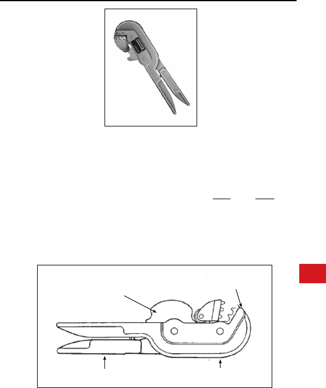
BURNDY®
Canada: 1-800-387-6487 www.burndy.com US: 1-800-346-4175
Tooling
Crimpers — Mechanical and Ratchet
MR4C
FULL CYCLE
RATCHET HAND TOOL
For #9-4 AWG Uninsulated
Terminals and Splices
Hand-held full cycle ratchet tool for #9-4 AWG
uninsulated terminals and splices. Full cycle
feature builds in reliability and removes the human
factor from the completed installation. Long
handles provide greater leverage. 5-year limited
warranty.
• High strength aluminum body
• Fully protected ratchet mechanism
• Reinforced heavy duty back
• Long handles provide greater mechanical
advantages
• Lightweight aluminum permits easier
continuous usage
• One tool to accommodate #9-4 AWG
• Inspection (PG) gauges available to check
each groove.
Length:
Weight:
Features and Benets
SPECIFICATIONS
FOR USE ON
Terminals
Splices
11-3/4″
2-1/4 lbs
YAV-L
YA-L
YSV
YSM
YS-L
Groove
9-8
6
4
Gauge#
PG121-1
PG125-1
PG133-1
• Spring loaded indentor jaw holds connector in
groove prior to crimping or ratchet engaging
• 5-year limited warranty
FULL CYCLE
RATCHET
MECHANISM
LONG HANDLES REINFORCED
HEAVY DUTY
ALUM. BACK
SPRING LOADED
INDENTOR HOLDS
CONNECTOR
Features N-53
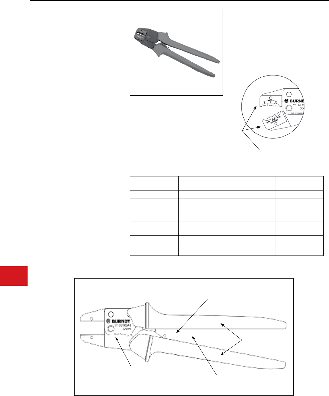
BURNDY®
US: 1-800-346-4175 www.burndy.com Canada: 1-800-387-6487
Tooling
Crimpers — Mechanical and Ratchet
TYPE Y10MRSA1
Ergonomic Full Cycle Ratchet
Hand Tool for J-Dies
#22-10 AWG Terminals and Splices
The Y10MRSA1 compression hand tool is
specically designed to accommodate BURNDY®
J-Dies from #22 - #10 AWG for use on both bare
and insulated connectors. J-Dies offer a positive
connection with terminations exceeding SAE
Pullout specications.
The Y10MRSA1 produces the same crimp prole
as the Y6NCP1 pneumatic OEM tool making this
tool a perfect choice for customers wanting a hand
tool to match their production tooling. 5-year limited
warranty.
• UL Listed connections when using
BURNDY UL Listed connectors
• Ergonomic design requires less handle
force reducing user fatigue
• Compact, narrow nose, scissor action and
lightweight at only 1.3 lbs
• Full cycle ratchet mechanism provides
complete positive crimp every time
• Emergency release lever in case of
misalignment or incorrect die choice
Features and Benets
Features and Benets (cont.)
SPECIFICATIONS
FOR USE ON
• Different die inserts accommodate a
range of Small HYDENTTM terminals and
HYSPLICETM splices (see table below for
details)
• High-strength steel frame with rubber
covered handles for longevity and comfort
Weight:
Length:
Width:
Warranty:
1.3 lbs
10.75 in
3.08 in
5 Year Limited
Warranty
Die Set
(Sold Separately)
Connector Series
(#22 - #10 AWG)
Insulation
Type
J1022NC1 YAE, YAE-N,YAE-N-F, YAE-Z Nylon
J1022NC2 YAEV, YAEV-L
YAEV-H, YAEV-RH,YAEV-RS Nylon
J1022NC3 TN, YAES,TN-F, YAES-F, SN, YSE-HN Nylon
J1022NC4 TP, BA, TP-F, BA-EF, TP-Z, BA-EZ,
TP-LF, BA-EL, SP, BS Vinyl
J1022NC5
T, YAD, T-F, YAD-F, YAV, YAV-L, YAV-H,
YAV-R, YAV-RS, YAV-T-F, YAV-H-F, YAV-Z
YSV, YSV-H, YSV-L
Bare*
*wire barrel only
COMFORT GRIP
HANDLES
FULL-CYCLE
RATCHET
MECHANISM
EMERGENCY
RELEASE LEVER
SCISSOR-ACTION
JAWS
J-DIES
(sold separately)
N-54
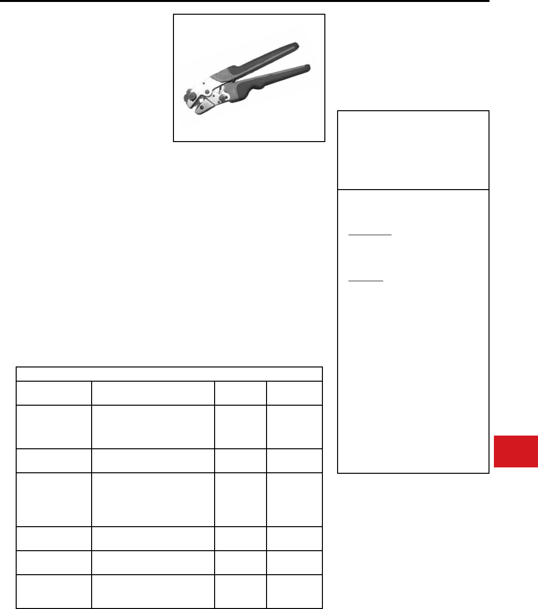
BURNDY®
Canada: 1-800-387-6487 www.burndy.com US: 1-800-346-4175
Tooling
Crimpers — Mechanical and Ratchet
Type Y122CMR mechanical full cycle ratchet
HYTOOL™ will accommodate copper
compression HYDENT™ connectors for #12
through #2 code conductor, #12 through #2 Class
I exible strand copper conductor, and #2 solid.
The die index is embossed on the crimped
connector for permanent inspectability.
The dies are color coded and stamped with the
conductor size to provide an easy match of
the die and proper BURNDY terminal or splice.
A ratchet mechanism assures the tool must
complete a full cycle before releasing.
The Y122CMR ergonomic full cycle ratchet tools
provide a complete positive crimp each time.
The ergonomic comfort grip handles reduce
operator fatigue during continuous use. Each
tool comes complete with a 5-year limited
warranty.
Y122CMR
HYTOOL™
Ergonomic Full Cycle Ratchet
Hand Tools
#12 – #2 Copper HYDENT™
Terminals and Splices
Y122CMR
Wire Range: #12-#2 AWG Class B
#12-#2 Class I Flex
#2 Solid & #3 Stranded
Y122CMRKIT
Kit Contains:
Y122CMR Full-cycle Ratchet Tool
Sturdy Metal Carrying Case
Terminals:
YAV102TC14,
YAZV10TC14,
YAZV102TC14,
YAZ8CTC14,
YAZ8C2TC38,
YAZ6CTC14,
YAZ6C2TC14,
YAZV6C2TC14FX,
YAZ6C2TC38,
YAZ6C2TC38SLBOX500,
YAZ4C2TC38,
YAZ3C2TC14,
YAZ3C2TC38SLBOX500,
YAZ2C2TC38,
YAZV2C2TC14FX,
YAZ2C2TC38SLBOX500
SPECIFICATIONS
Length: 10.5”
Height: 3”
Width: 1”
Weight: 1.3 lbs
Features and Benets
• Ergonomic hand tools for crimping insulated
and uninsulated terminals and splices
• Overmolded comfort grip handles reduce
fatigue during continuous use
• Easy groove identication with color coded
dies
• Full cycle ratchet tool to assure properly
crimped connections
• Emergency release mechanism allows tool
to open in case of misalignment or mistaken
die choice
• UL Listed/CSA Certied connections
when used with recommended BURNDY ®
terminals and splices
• 5-year limited warranty
Cu Lug and Splice Connectors
Copper Wire Size Connector Catalog Types Die Index #
(Color) # of Crimps
#12 - #10 AWG
YAV10-
YAV102TC-
YAZV10TC-
YAZV102TC-
(Yellow) 2
# 8 AWG
Code
YAZ8C-
YAZ8C- 49 (Red) 2
#6 AWG
Code & Flex
YAZ6C-
YAV6C-
YAZ6C-
YAZ6C-
YAZ6C-
7 (Blue) 2
#4 AWG
Code & Flex YAZ4C- 8 (Gray) 2
#3 AWG
#2 Sol.
YAZ3C-
YAZ3C- 9 (White) 2
#2 AWG
Code & Flex
YAZ2C-
YAZV2C-
YAZ2C-
10 (Brown) 2
Die Index Number Embossment on Connector after Crimp for inspection verication
N-55
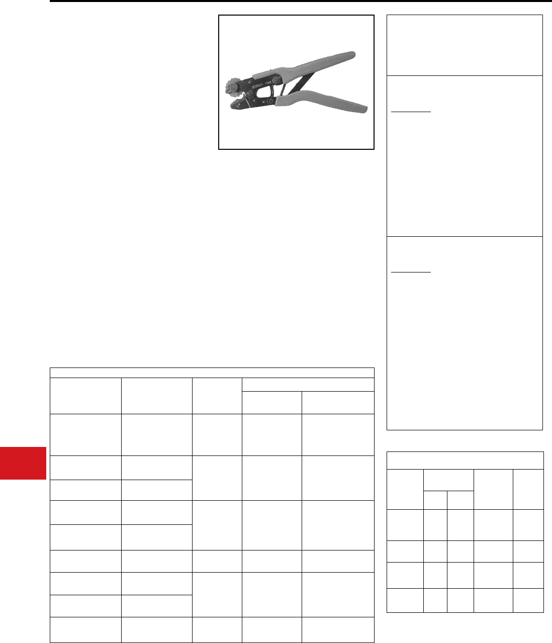
BURNDY®
US: 1-800-346-4175 www.burndy.com Canada: 1-800-387-6487
Tooling
Crimpers — Mechanical and Ratchet
Y1MRTC
HYTOOL™
#8 – #1 Copper HYDENT™
Terminals, Splices, and #6 – #6
Thin-Wall C-Taps
Type Y1MRTC mechanical full cycle ratchet
HYTOOL™ will accommodate copper
compression HYDENT™ connectors for #8
through #1 code conductor, #8 through #2 Class I
exible strand copper conductor, and #2 solid. The
color coded die wheel rotates to provide a proper
match of the die and color coded connector. The
die index is embossed on the crimped connector
for permanent inspectability. A ratchet mechanism
assures the tool must complete a full cycle before
releasing.
• Rotating die is color coded to match color
coded connectors.
• Die index embossment allows permanent
inspectability of installed connectors to
insure consistently reliable and dependable
connections.
• Molded comfort grips reduce fatigue during
continuous use.
• Ratchet mechanism assures a complete crimp
every time.
• Emergency release mechanism allows tool
to be removed from connector in case of
mistaken die choice or to reposition tool.
• 5-year limited warranty.
Length:
Height:
Width:
Weight:
Features and Benets
SPECIFICATIONS
FOR USE ON
Y1MRTC
Wire Range: #8-#1 AWG Class B,
#8-#2 Class I Flex.
#2 Solid & #3 Stranded
Y1MRKIT
Kit Contains:
Y1MRTC Full-cycle Ratchet Tool
Sturdy Metal Carrying Case
Terminals:
YA8CL, YA8CL1, YA6CL,
YAV6CLTC14FX, YA4CL,
YAV4CLTC516FX, YA2CL,
YAV2CLTC516FX, YA1CL
Splices:
YS8CL, YS6CL, YS4CL,
YS2CL, YS1CL
Y1MRTCKIT
Kit Contains:
Y1MRTC Full-cycle Ratchet Tool
Sturdy Metal Carrying Case
Terminals:
YA8CL2TC14 YA8CL2TC38
YA6C2TC38 YA6CL2TC14
YA6CL2TC14E1 YA6CL2TC14E2
YA6CL2TC38 YAV6CL2TC14E2FX
YAV6CL2TC14FX YA4CL2TC14
YA4CL2TC38 YA3C2TC38
YA2C2TC38 YA2CL2TC38
YA2CL2TC14
Thin-Wall C-Taps:
YC4L12
Cu Lug and Splice Connectors
Copper
Wire Size
Connector
Catalog
Types
Die
Index #
(Color)
# of Crimps Per Barrel Length
Std Long
#8 AWG
Code & Flex
YA8C-
YS8C-
YAV8C-
YSV8C-
49
(Red) 1 2
#6 AWG
Code
YA6C-
YS6C- 7
(Blue) 1 2
#6 AWG
Code & Flex
YAV6C-
YSV6C-
#4 AWG
Code
YA4C-
YS4C- 8
(Grey) 2 4
#4 AWG
Code & Flex
YAV4C-
YSV4C-
#3 AWG
#2 Sol.
YA3C-
YS3C-
9
(White) 2 4
#2 AWG
Code
YA2C
YS2C- 10**
(Brown) 2 4
#2 AWG
Code & Flex
YAV2C-
YSV2C-
#1 AWG
Code
YA1C-
YS1C-
11**
(Green) 2 4
** Die Index 10 (Brown Die) and 11 (Green Die) use the same die wheel crimp groove.
Die Index Number Embossment on Connector after Crimp for inspection verication.
9.875″
2.72″ (closed)
.73″
1.7 lbs.
Cu C-Tap Connectors
Catalog
Number
Wire Size
Cu Str. AWG Die Index #
(Color)
# of
Crimps
Run Tap
YC10L12
14
12
10
16-14
16-14
16
49
(Red) 1
YC8L12 10
8
10
12
7
(Blue) 1
YC6L12 8
6
10-8
12-10
8
(Grey) 1
YC4L12 6
5,4
8-6
12-8
10
(Brown) 2
N-56
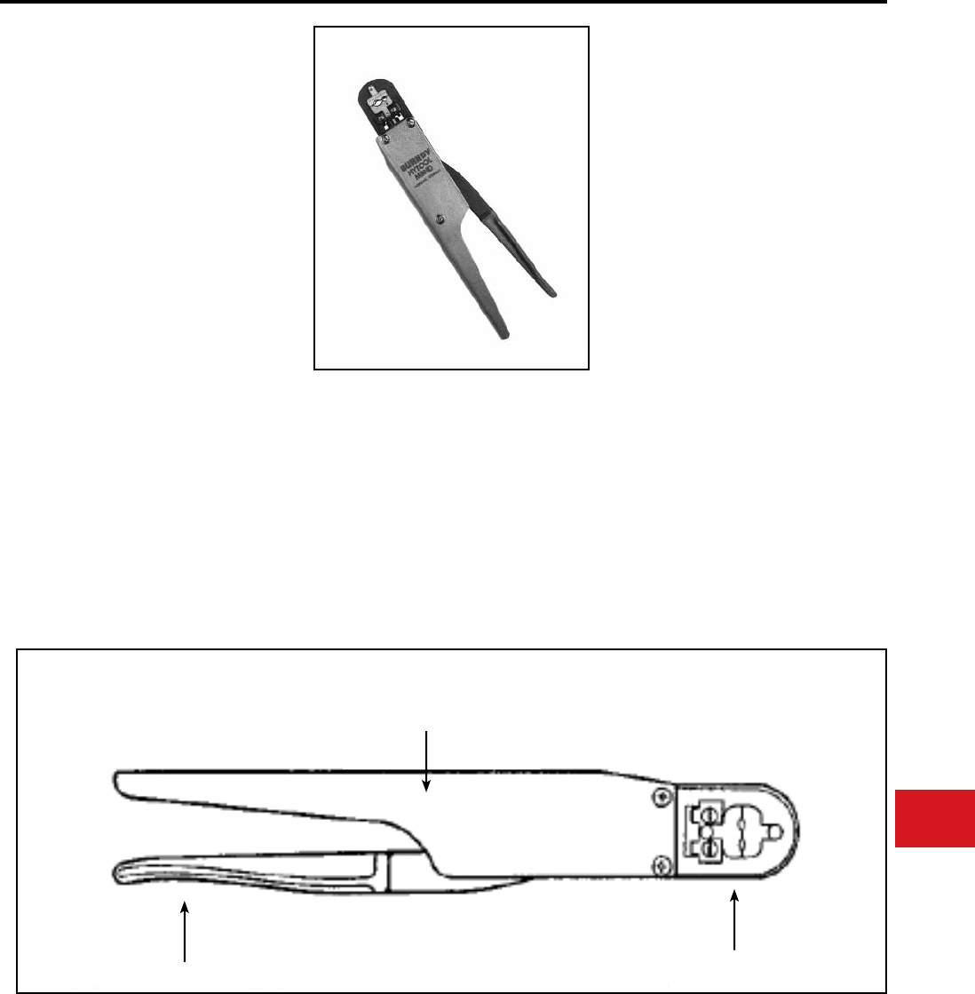
BURNDY®
Canada: 1-800-387-6487 www.burndy.com US: 1-800-346-4175
Tooling
Crimpers — Mechanical and Ratchet
M8ND
HYTOOL™
Full Cycle Ratchet Hand Tool
#8-26 AWG Terminals and Splices
Hand-held full cycle ratchet tool for #8-26 AWG
terminals and splices. Full cycle feature builds in
reliability and removes the human element from
the completed installation. Long handles provide
greater leverage. 5-year limited warranty.
• Fully protected ratchet mechanism
• Reinforced heavy duty back
• Long handles provide greater mechanical
advantages
• Uses all standard BURNDY® “N” dies
• Easy groove identication with color coded dies
• 5-year limited warranty
Length:
Width:
Features and Benets
SPECIFICATIONS
FOR USE ON
YAD
YAD-F
YAE
YAE-F
YAE-Z
YAES
YAEV-H
YAEV-L
YAV
YAV-F
YAV-H
YAV-H-F
10-3/4″
1-3/4″
BA-E
BA-EF
BA-ES
BA-EZ
BA-EL
Terminals
Splices
YSV
YSV-H
YSM
YRV-L
FULL CYCLE
RATCHET
MECHANISM
LONG COMFORTABLE HANDLE
*REMOVABLE DIE SETS
Not Included
N-57
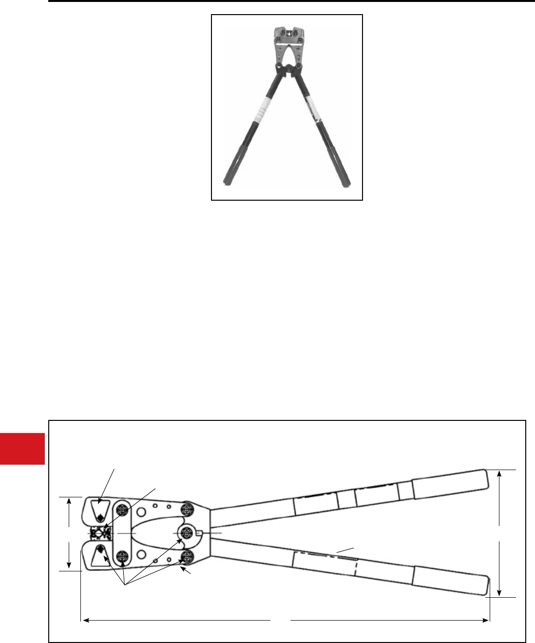
BURNDY®
US: 1-800-346-4175 www.burndy.com Canada: 1-800-387-6487
Tooling
Crimpers — Mechanical and Ratchet
• Comfort grip handles
◊ Aids in prevention of hand slippage,
reduces fatigue during continuous use
• Heat treated steel jaws
◊ Reduces jaw buckling and misalignment
under heavy loading
• Approximately 9000 crimp cycle life
◊ Lasts longer than imitations and will
still be working when others have worn
out
• Multiple grip selections on rotatable die wheels
◊ No lost dies, 9 position color-coded
rotatable die wheels
Length:
Height:
Weight:
Features and Benets
SPECIFICATIONS
FOR USE ON
MRC840
MRC840AL
26″
8″
8-1/4 lbs
#8 - 4/0 AWG Copper
Terminals and Splices
(YA, YA-L, YS, YS-L)
#8 - 4/0 AWG Aluminum
Terminals and Splices
(YA-A,YS-A)
• High strength fasteners
◊ Increase tool life by reducing tool wear
• Plated jaws
◊ Provide enhanced corrosion protection
• Engraved crimp groove
(Die index number)
◊ Die index embossment allows
permanent inspectability of installed
connectors to ensure consistently
reliable and dependable connections
MRC840 AND
MRC840AL
HYTOOL™
Hand-Operated Tool
#8 - 4/0 AWG Non-Insulated
Copper and Aluminum
Terminals and Splices
The MRC840 Mechanical Rotating Crimp Tool will
accommodate copper compres-sion BURNDY®
copper compression YA and YS series of
HYLUGTM and HYLINKTM terminals and splices
from #8 - 4/0 AWG stranded copper conductor.
The MRC840AL Mechanical Rotating Crimp tool
for Aluminum HYLUGTM and HYLINKTM terminals
and splices from #8 - 4/0 AWG aluminum and
copper conductors. Butting steel jaw and over
center cam action assure full crimp force.
The rotatable die wheel is color-coded and
stamped with the conductor size to provide an
easy match of the die and color-coded BURNDY®
HYDENT™ terminals and splices. YA, YS,
YA-A and YS-A series of copper and aluminum
terminals and splices are UL Listed when installed
with these tools. Each tool comes complete with a
5-year limited warranty.
SPRING LOADED MECHANISM LOCKS DIE
WHEEL INTO POSITION, PRESS MECHANISM
TO RELEASE, ROTATE DIE WHEEL,
TO DESIRED CRIMP GROOVE
COLOR CODED ROTATABLE DIE WHEEL
MARKED WITH AWG SIZES
JAWS, STEEL
INSTALLATION CHART
OIL LOCATIONS
TYPICAL
5.0
[127]
26.0
[660]
8.0
[203]
N-58
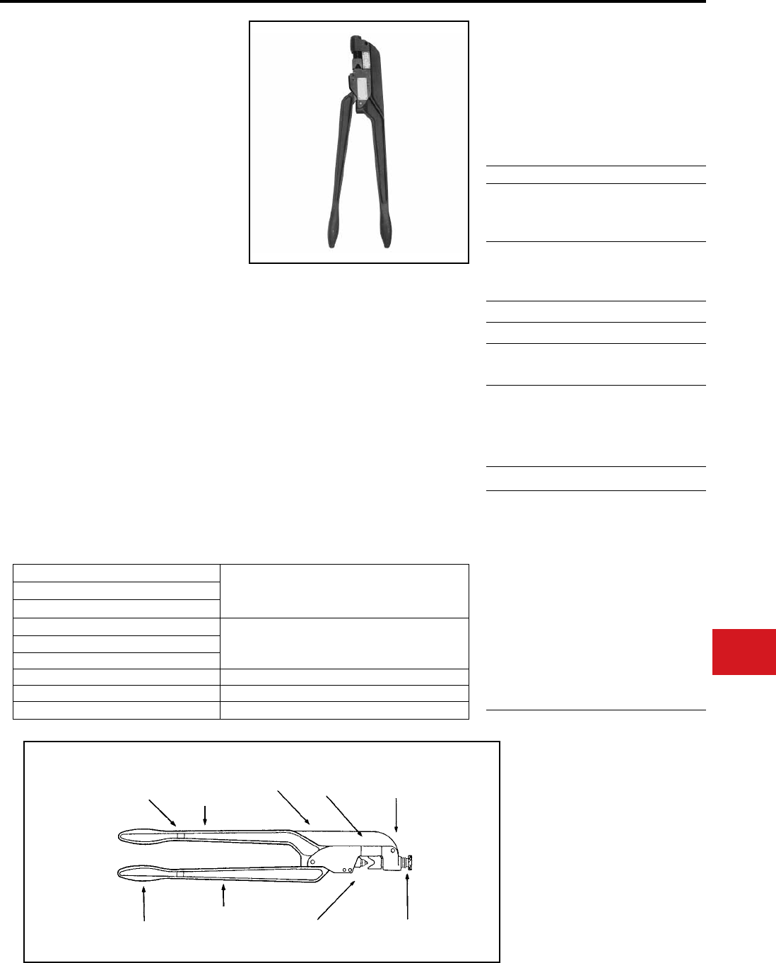
BURNDY®
Canada: 1-800-387-6487 www.burndy.com US: 1-800-346-4175
Tooling
Crimpers — Mechanical and Ratchet
MY28, MY29 Series
DIELESS HYTOOL™
#8 Str. through 250 kcmil Copper,
#8 Str. through 4/0 str. Aluminum
Conductors
• Save on capital investment with the type MY
HYTOOL™ that accommodates a wide range
of connector/conductor combinations from #8
str.-250 kcmil
• Save time, money, and lower installed cost
with the original dieless MY tool design. No
separate dies required to purchase or to lose
• Fast and easy tool setting for the connector/
conductor combination simply by aligning the
white scribe on the nest die with the wire size
on the gauge for proper crimping results
• Easy to adjust nest die with knurled steel knob
and machine threads
• Quality tool with precision machines indentor,
component parts and tool body
• Fast, medium and high volume crimping is
easily accomplished by bench mounting the
type MY tool in the BMY-BCH-MT bench
mount adapter. A single bolt holds the MY
HYTOOL™ securely using the 0.31 dia.
mounting hole in the bench mount adapter
Length:
Weight:
Depth:
Width:
Features and Benets
SPECIFICATIONS
FOR USE ON
22.65″
8 lbs approx.
4.86″
1.12″
TOOL CONNECTORS
MY29-3
MY29-3C
MY29-3CF
Copper-YA, YA-L, YS-L
Aluminum-YA-A, YS-A
MY29-11
MY29-11C
Copper-YA, YA-L, YS
YAV-FX
YS-L, YAV-L, YSV-L
MY28 YAV-L, YSV-L
MY28-4 YAV-A-L, YSV-A-L, YAV-A-R
MY28-6 YAE-L, YAEV-RS, YAEV-H,
YAEV-RH
BMY-BCH-MT Bench Mount Adapter
MY29 UNIVERSAL KIT Contents:
MY29-11
YA8CLBOX
YAV6CLTC14FX
YAV4CLTC516FX
YAV2CLTC516FX
YAV1CLTC38FX
YAV25LTC38FX
YAV26LTC516FX
YAV27LTC12FX
YAV28LTC12FX
YA29LBOX
CASE
1 EA
50 EA
50 EA
50 EA
50 EA
50 EA
10 EA
10 EA
10 EA
10 EA
10 EA
1 EA
ACCESSORIES
MY29-3 #8 str.-250 kcmil Copper commercial (code) cable
30 Navy-250 Navy Copper Navy Cable
#8 str.-4/0 str. Aluminum commercial (code) cable
MY29-3C (covered handles)
MY29-3CF (fully covered)
MY29 UNIVERSAL KIT #8 str.-250 kcmil Copper commercial (code) cable
30 Navy-250 Navy Copper Navy cable
#8 str.-4/0 str. Flexible copper mine machine cable
MY29-11
MY29-11C (covered handles)
MY28 #8 str.-4/0 str. Copper aircraft cable
MY28-4 #8 str.-4/0 str. Aluminum aircraft cable
MY28-6 (nylon covered connector) #8 str.-2/0 str. Copper aircraft cable (exible)
• High quality rugged tool design manufactured
from heavy duty forged steel with strong
reinforced back and handles
• Covered handles available on the MY29-3C,
MY29-11C and MY29-3CF HYTOOL™
• Comfort grip handles for long periods of usage
• Compression terminals and splices are UL
Listed and CSA Certied when installed with
type MY HYTOOL™
• 5-year limited warranty
TWO-PLY COVERED
HANDLES ON MY29-3C
AND MY29-11C DESIGNS
HEAVY DUTY
FORGED STEEL
BACK BODY
AND HANDLES
STRONG
REINFORCED
FORGED STEEL
BACK
SETTING
PLATE
.31" DIA.HOLE
FOR BENCH
MOUNTING
OPERATIONS.
COMFORT GRIPS
EXTRA STRONG
HEAVY DUTY
REINFORCED
HANDLES
INDENTOR DIE KNURLED STEEL
ADJUSTING KNOB
N-59
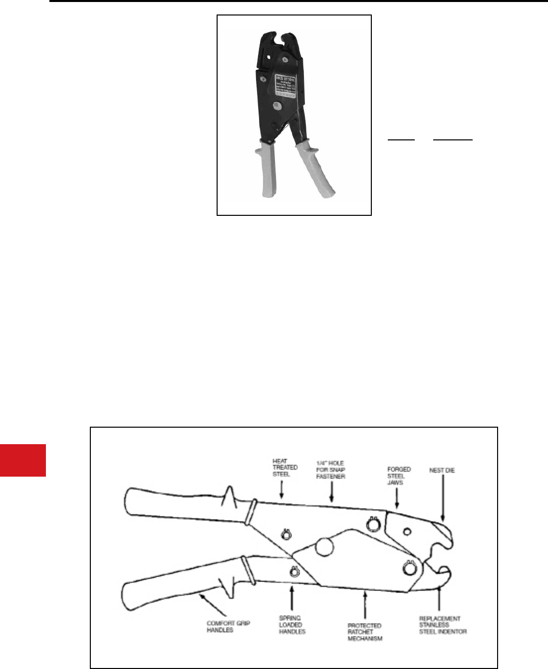
BURNDY®
US: 1-800-346-4175 www.burndy.com Canada: 1-800-387-6487
Tooling
Crimpers — Mechanical and Ratchet
OH25
HYTOOL™
One-Hand Operation,
Dieless, Full Cycle Ratchet Tool
Installs Service Entrance
Splice Connectors
Conductor range: #10 through 1/0
The OH25 incorporates a full cycle ratchet and cam
mechanism allowing an easy, one-hand crimping
operation. The ratchet mechanism provides for
properly completed crimps every time before the
tool can be removed from the connection. The
OH25 is designed to install 5/8″ INSULINK™ and
LINKIT™ service entrance connectors with only
(1) crimp per connector end, speeding installation
time. The single crimp covers the complete contact
area, eliminating possible overlapping or failure to
make the proper number of crimps. 5-year limited
warranty.
• One crimp speeds installation
• No dies to lose
• Long dependable life with forged steel jaws
and stainless steel indentor
• Convenient hole to hang tool
• Protection of internal parts provides long life
• Ratchet mechanism provides proper crimp and
uniform quality installations
• Easy one-hand tool operation with spring
loaded comfort grip handles
• Proven reliable with years of dependable
service
• 5-year limited warranty
Handle force:
Max force developed:
Weight:
Length:
Features and Benets
SPECIFICATIONS
FOR USE ON
• 5/8″ Service Entrance Sleeves
• INSULINK™ Type ES (insulated) #10 through
1/0 str.
• LINKIT™ type YSU (bare) #8 through 1/0 str.
• 5/8″ neutral tension sleeves HYSPLICE™
types YS-S, YCS-R, YDS-AT #4 through 1/0
• AYP HYPLUG™ #6-1/0 str.
50 lbs max.
6,000 lbs
2 lbs. 11 oz
12-1/4″
ACCESSORIES
Cat. No. Description
PT4583 Leather Holster
PT8504 No-Go Gauge
The PT8504 NO-GO Gauge
is used to check the OH25
HYTOOL™ crimp dimensions
N-60
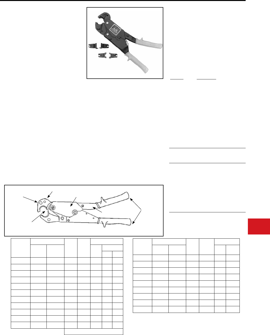
BURNDY®
Canada: 1-800-387-6487 www.burndy.com US: 1-800-346-4175
Tooling
Crimpers — Mechanical and Ratchet
OUR840
840 POPPER™ HYTOOL™
One-Handed Operation, Overhead/
Underground, Full Cycle Ratchet Tool
Installs a Range of Connectors
(Taps, Splices, Terminals)
The OUR840 incorporates a full cycle ratchet
and cam mechanism allowing an easy, one hand
crimping action. Designed for low maintenance
operation. The OUR840 has a ve (5) year limited
warranty. The ratchet mechanism provides for
properly completed crimps every time before the
tool can be removed from the connection. With nest
and indentor dies, it will install 5/8″ INSULINK™
and LINKIT™ service entrance connectors with
only one (1) crimp per end. With the use of reduced
handle force “X” dies, additional splices, taps, and
terminals can be properly installed. The die inserts
snap into the permanent groove easily with one
hand and lock securely in the tool with the spring
loaded positive lock die retainer buttons. Tool
operation is simple:
A. Slip the tool over the connector
B. The rst few strokes grip the connector
C. Stroke until automatic tool release
signies a completed compression
• Allows proper crimping of sleeves and
terminations in crimping underground
applications
• Proper crimps are assured with butting surface
inspection and full cycle ratchet mechanism
• Uses reduced handle force “X” dies
• One tool for most service applications
• Improved service through redesign and
improvement of many internal parts
• Easier tool operation is provided with mini
strokes and anti-slip grips
• Nest and indenter dies available
• W28K cutter die permits use of OUR840 tool
as a cable cutter. Conductor range: #4-4/0
ACSR, Aluminum and Copper
• UL Listed connections when color coded “X”
dies are used on BURNDY® connectors
Max. Crimp Force:
Max Handle Force:
Weight:
Length:
Features and Benets
SPECIFICATIONS
FOR USE ON
Copper Conductors from #8 AWG to 250 kcmil
Aluminum Conductors from #8 AWG to 4/0 AWG
X-Dies
Catalog
Number
Die
Index
Recommended
“W” Die Crimp
Ratio
XNBG
XBG
X161
X241
X245
X247
X249
X660
X840
XOH25
BG
BG
161
241
245
247
249
660
840
-
2*
2
3*
2
2
2
2
2
1
OH 25 Equiv.
* Overlap crimps
•“W” Dies with a die index listed above are not recommended
for the OUR840. Since the standard “W” Dies are wider than
the “X” Dies, additional crimps are required depending on the
connector and the die index.
8,000 lbs
8 lbs. approx.
2 lbs. 14 oz.
13″
SELECTED APPLICATIONS
ACCESSORIES
Cat. No. Description
PT4583 Leather Holster:
• Top grain cowhide saddle
leather
• Large grommet
(Order Separately)
OUR840-WC Metal carrying case
with die tray:
• Holds one (1) OUR840 and
up to eleven (11) “X” dies.
Dies Sold Separately
OUR840 Dies:
Copper
Conductor
Copper Connector
Color
Code Die
OUR-840
HYLUG™
Terminal
HYLINK™
Splice
Die
Index
# Crimps
Std. Long
#8 AWG Str. YA8C- YS8C- Red X8CRT 49 1 2
#6 AWG Str. YA6C- YS6C- Blue X5CRT 7 1 2
#5 AWG Str. YA5C- YS5C- Blue X5CRT 7 1 2
#4 AWG Str. YA4C- YS4C- Gray X4CRT 8 1 2
#2 AWG Str. YA2C- YS2C- Brown X2CRT 10 1 2
#1 AWG Str. YA1C- YS1C- Green X1CRT 11 1 2
1/0 AWG Str. YA25- YS25- Pink X25RT 12 2 4
2/0 AWG Str. YA26- YS26- Black X26RT 13 2 4
3/0 AWG Str. YA27- YS27- Orange X27RT 14 3 6
4/0 AWG Str. YA28- YS28- Purple X28RT 15 3 6
250 kcmil YA29- YS29- Yellow X29RT 16 4 8
W-VT Dies may be substituted
Aluminum
Conductor
Aluminum Connector Color
Code Die
OUR-840
HYLUG™
Terminal
HYLINK™
Splice
Die
Index
#
Crimps
#8 AWG Str. YA8CA- YS8CA- Blue X8CART 374 2
#6 AWG Str. YA6CA- YS6CA- Gray X5CART 346 2
#4 AWG Str. YA4CA- YS4CA- Green X4CART 375 3
#2 AWG Str. YA2CA- YS2CA- Pink X2CART 348 4
#1 AWG Str. YA1CA- YS1CA- Gold X1CART 471 3
1/0 AWG Str. YA25A- YS25A- Tan X25ART 296 4
2/0 AWG Str. YA26A- YS26A- Olive X26ART 297 4
3/0 AWG Str. YA27A- YS27A- Ruby X27ART 467 4
4/0 AWG Str. YA28A- YS28A- White X28ART 298 6
Spring loaded
positive lock
die retainer
buttons
1/4 hole
for snap
fastener
Butting surfaces
provide visual check
for tool adjustment
Rugged, protected
ratchet mechanism
Spring loaded
handle
Heat treated steel construction
Comfort grip
handles
N-61
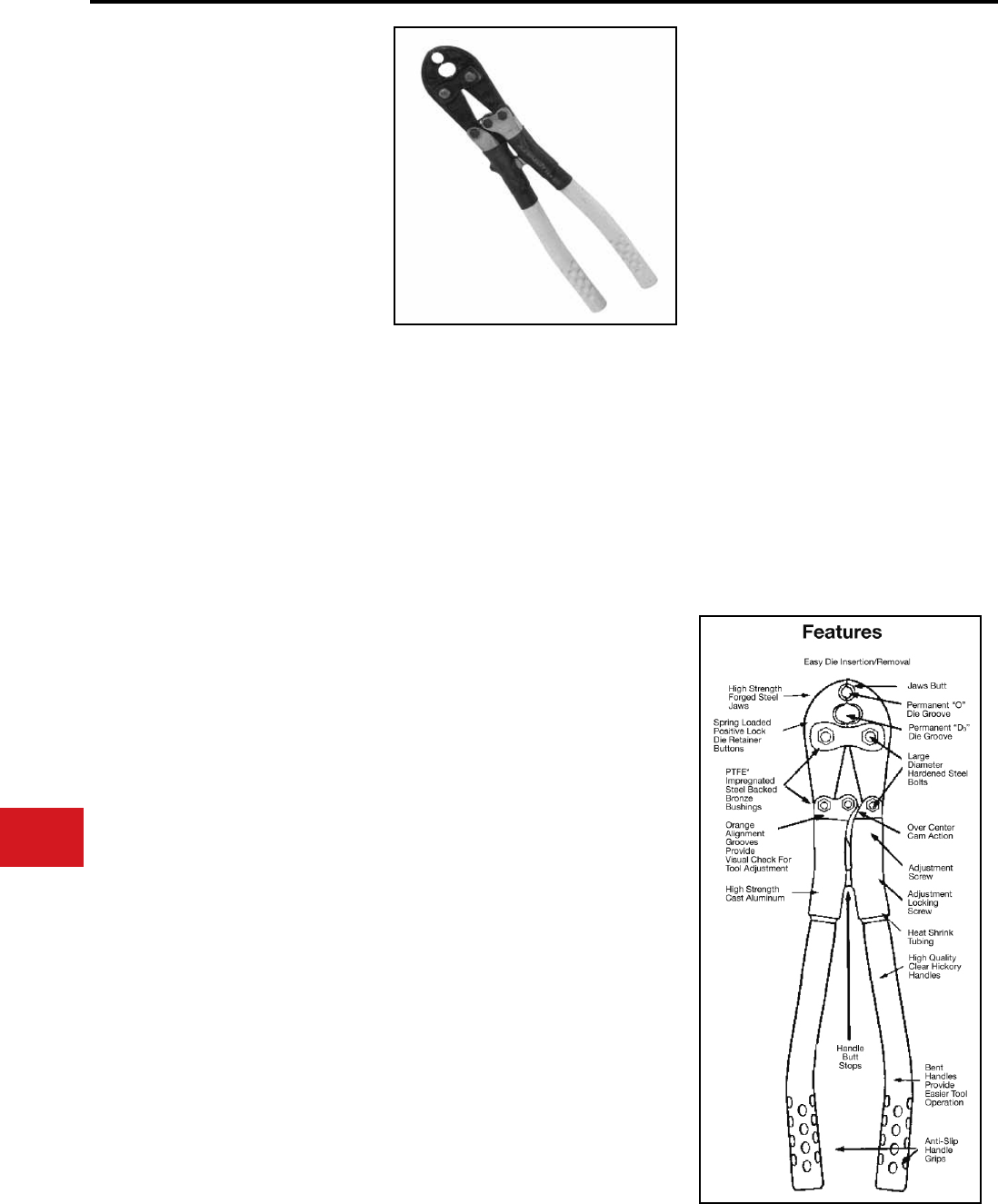
BURNDY®
US: 1-800-346-4175 www.burndy.com Canada: 1-800-387-6487
Tooling
Crimpers — Mechanical and Ratchet
MD6-8
HYTOOL™
Hand-Operated Tool
Installs full range of connectors (taps,
splices, terminals): #14 through 4/0
Applications: Full Tension and
Non-Tension
The MD6-8 installs almost all of the line, pole and
house connections in the BURNDY Compression
Connector Program with only one (1) extra die
set (W-BG). The tool has two (2) permanent
die grooves, “O” and “D3” for distribution tap
connectors. The “D3” groove also serves as a seat
for die inserts to install additional splices, taps and
terminal connectors. The die inserts snap into the
D3 groove easily with one hand and lock securely
in the tool with the spring loaded positive lock die
retainer buttons.
The MD6 series of tools have a ve (5) year
warranty and are designed to provide over 90,000
reliable crimps installing full-tension and non-
tension connectors.
The MD6-K accepts KEARNEY™ type “O” dies
and BURNDY® “W” and “X” dies with the KWADP
adapter.
KEARNEY™ is a registered trademark of
COOPER TECHNOLOGIES COMPANY.
• Proper crimps are assured with butting steel
jaws
• Increased strength and greater bearing area
is provided with larger steel bolts
• Fast, easy, one-hand die insertion
• No lost dies with spring loaded positive lock
die retainer buttons
• Over 90,000 crimps provided with Teon
impregnated steel backed bronze bushings
• Full crimp force assured with over center
cam action
• Easy tool adjustment with allen wrench
• Operator protection provided with butt stops
and heat shrink tubing
• Long life expectancy provided with select
clear hickory handles and lightweight high
strength aluminum alloy castings
• Easier tool operation is provided with bent
handles and anti-slip grips
Crimp Force:
Length:
Weight:
Features and Benets
SPECIFICATIONS
FOR USE ON
• Copper, Aluminum, ACSR, Copperweld,
Alumoweld, Steel, 6201 5005, Compressed
and compact conductors
• Copper Taps: #10 sol. - 2/0 str.
• Aluminum, ACSR Taps: #14 sol. - 4/0 ACSR
• Stirrups: #6 ACSR - 4/0 ACSR
• Overhead Full Tension Deadend, Full Tension
Splices, Non Tension Splices, and Terminals
Conductor Range: #10 str. - 4/0 ACSR
• Code conductor connectors: #6 - 4/0 str.
Copper and Aluminum
9,000 lbs
25-3/8″
6 lbs
Quality Unsurpassed!
Life cycle tested under full operating forces
for over 90,000 cycles successfully without
adjustment or any parts replacement.
To Check Tool Adjustment
Simply close the tool handles until the jaws initially
butt. When the orange alignment grooves are in
line, the tool is in correct adjustment.
MD6 Standard MD6 with permanent
“BG” (5/8) and “D3” grooves.
Installs CABLELOK CRIMPIT™
and HYCRIMP™ Tap Connectors
with one additional die insert
(W-O). All other tool features and
connector ranges are the same as
the MD6-8 described above.
MD6-4 Standard MD6 with permanent
“BG” (5/8) and “D3” grooves and
straight berglass handles 24” long.
Fiberglass rated at 100 kV per foot
for 5 minutes.
MD6-14 Standard MD6 with permanent
“BG” (5/8) and “D3” grooves and
straight berglass handles 19" long
including bent aluminum grips.
Fiberglass rated at 100 kV per foot
for 5 minutes.
MD6-12 Standard MD6-8 jaws with
permanent “O” and “D3” grooves
and straight berglass handles 24”
long. Fiberglass rated at 100 kV per
foot for 5 minutes.
MD6-6 “Snub-Nose” variation of MD6
has a permanent “D3” groove in
jaw. Recommended for use where
space for tool jaw is limited.
MD6-37 Permanent 161, 162, 163, 171
dies in the jaw (J, M & P, T & X).
MD6-38 Permanent K, BG, C, dies in
the jaw.
MD6-K “Snub-Nose” permanent
KEARNEY™ groove.
MD6 Tool Variations
N-62
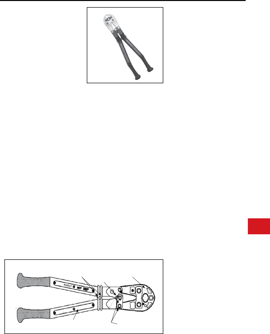
BURNDY®
Canada: 1-800-387-6487 www.burndy.com US: 1-800-346-4175
Tooling
Crimpers — Mechanical and Ratchet
MD7 POSI-PRESS™
HYTOOL™
Hand-Operated Tool
Installs full range of connectors, (taps,
splices, terminals):
#14 AWG through 4/0 AWG
Applications: Full-Tension and Non-
Tension
The MD7 POSI-PRESS™ HYTOOL™ is a
composite polymer handle installation tool that
requires no adjustment for the life of the tool. This
assures users of the MD7 tool, that all connections
installed with the MD7 POSI-PRESS™ HYTOOL™
are consistent and reliable over the life of the tool.
This new technology tool provides a visual wear
indicator that makes verication of the tool’s
condition easy to determine. Once the tool has
worn beyond its useful life, it can be returned to
the BURNDY® Tool Repair Center for re-tting at
a fraction of the price of a new tool.
The MD7 series of tooling has a 5 year warranty
and is designed to provide over 99,000 reliable
crimps installing both full-tension and non-tension
connectors.
The MD7-8 POSI-PRESS™ HYTOOL™ installs
almost all of the line, pole, and house connection in
the BURNDY® Compression Connector Program
with only one (1) extra die set (W-BG). The MD7-8
tool has two (2) permanent die grooves, “O” and
D3” for distribution tap connectors. For other tool
versions, see the MD7 Tool Variations sections
below. The “D3” groove also serves as a seat for
die inserts to install splices, taps, and terminal
connectors. The die inserts snap into the “D3”
groove easily with only one hand, and lock securely
in the tool with the spring loaded, positive lock, die
retainer buttons. Handles have been tested at 100
kV per foot for 5 minutes.
Features and Benets
• Ergonomically designed, one-piece,
composite polymer handles
• Comfort grip handles
• Time-proven steel jaw designs
• No tool adjustment required
• 99,000 crimp/cycle life
• Positive lock, spring loaded die retainer
buttons
• Permanent “D3” die groove
• PTFE impregnated steel/bronze bushings
and stainless steel pins
• Electroless nickel plated jaws and jaw links
• Easier tool operation due to unique handle
design, and anti-slip grips
• Improves operation by preventing slipping
• Proper crimps are assured with butting jaws
• Provides reliable and consistent crimps
every time
• Lasts up to 6 times longer than cheap
imitations, and will still be working when
others have long since worn out
• No lost dies and one-hand die insertion
• Allows use of the complete line of
BURNDY® “W” and “X” die inserts
• Increases life of tool by reducing tool wear
• 5-year limited warranty
SPECIFICATIONS
FOR USE ON
• Copper, Aluminum, ACSR, Copperweld,
Alumoweld, Steel, 6201, 5005
Compressed and compact conductors
• Copper Taps: #10 sol. - 2/0 str.
• Aluminum, ACSR Taps: #14 sol.
- 4/0 ACSR
• Stirrups: #6 ACSR - 4/0 ACSR
• Overhead Full Tension Deadend, Full
Tension Splices, Non Tension Splices,
and Terminals Conductor Range:
#10 str. - 4/0 ACSR
• Code conductor connectors: #6 - 4/0 str.
Copper and Aluminum
Crimp Force:
Length:
Width:
Weight:
9,000 lbs
60 lbs Handle Force
25″
8″ (at handle end)
4-1/2″ (at jaw end)
7 lbs
Unsurpassed Quality that no one else can
match!
Life cycle tested under the full range of operating
forces for over 99,000 cycles successfully without
failure or any parts replacement.
MD7 Tool Variations
MD7-8 MD7 with permanent “O” and “D3”
grooves. Installs almost all of the line,
pole, and house connections in the
BURNDY® Compression Connector
Program with only one (1) extra die
set (W-BG).
MD7-6 “Snub-Nose” variation of MD7 has a
permanent “D3” groove jaw. Accepts
the full-line of BURNDY® “W” and “X”
die inserts. Recommended for use
where space for tool jaw is limited.
MD7 Standard MD7 with permanent “BG”
(5/8) and “D3” grooves. Installs
CABLELOK™ CRIMPIT™ and
HYCRIMP™ Tap connectors with
one (1) additional die insert (W-O).
All other tool features and connector
ranges are the same as the MD7-8.
Comfort grip design with
checked surface and ergonomic
handle ends provide a positive
slip-free grip
Reinforced polymer composite handles tested
for 100kV per foot for 5 minutes when new and
properly cleaned
Blank insert provided for
personalizing tool for identication
and inventory purposes.
High strength stainless steel pins
resist corrosion and help provide
long tool life
Handle butt stops
Indicator
Spring loaded positive
lock die retainer
buttons
N-63
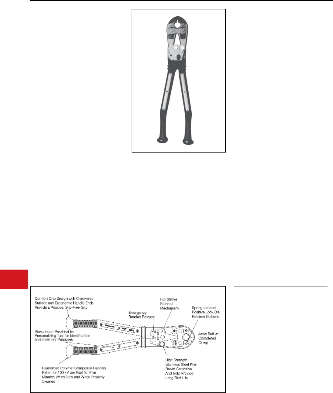
BURNDY®
US: 1-800-346-4175 www.burndy.com Canada: 1-800-387-6487
Tooling
Crimpers — Mechanical and Ratchet
MD7-34R POSI-PRESS™
HYTOOL™
Hand-Operated Full Cycle
Ratchet Tool
The MD7-34R POSI-PRESS™ HYTOOL™ has a
full stroke ratchet that assures the user has cycled
the tool completely for a consistent crimp every
time. The tool handles are manufactured from a
new reinforced composite polymer that requires
no adjustment for the life of the tool. This new tool
design assures users that all connections installed
with the MD7-34R are consistent and reliable
over the life of the tool. A visual wear indicator
provides easy verication of the tool’s condition.
An emergency ratchet release allows tool removal
in case of mistaken die choice or to reposition
tool. The MD7-34R crimps color coded lugs and
splices for #8-500 kcmil class B code conductor
and #8-350 kcmil Cu Flex conductor. It will also
crimp thin wall C-Taps from #12 - 3/0 AWG class
B code conductor. The color coded W-VT dies
snap into the jaw grooves easily with only one
hand and lock securely into the tool with the spring
loaded, positive lock, die retainer buttons. The die
index number is engraved in the crimping groove
to emboss the nished connection. This makes
inspection and verication of proper installation an
easy process. Due to the one piece handle design,
if the tool ever wears beyond it’s useful life, it can
be returned to the BURNDY® Tool Repair Center
for retting at a fraction of the price of a new tool.
A rubber covered version, the MD7-34R-C, is
available.
FOR USE ON
• Copper Lugs and Splices #8-500 kcmil
Types YA, YA-L, YA-L-TC, YA-L-NT,
YS-L, YS, YST, YA-TC
• Copper Lugs and Splices #8-350 kcmil
Flex. Types YAV-L-TC-FX, YA-LB,
YA-TC-FXB, YSV-L, YAV-L-NT-FX,
YAV-L-FX, YAV-FXB
• Copper Battery Lugs #8-350 kcmil Flex
Types YAG-TC-LD
• Thin wall C-taps #12 - 3/0 AWG
Types YC-L
Features and Benets
• Full Stroke Ratchet Mechanism
• Ergonomically designed, one piece,
composite polymer handles
• Comfort grip handles
• Time-proven forged steel jaw designs
• No tool adjustment required
• Positive lock, spring loaded die retainer
buttons
• PTFE impregnated steel/bronze bushings
and stainless steel pins
• Color Coded Dies
• Die index embossed on nished connection
• Handle of reinforced composite polymer
• Easier tool operation due to unique handle
design, and anti-slip grips
• Grips and handle knobs improve operation
by preventing slipping
SPECIFICATIONS
Crimp Force:
Length:
Width:
Jaw Covering:
Handle Material:
Warranty:
9,000 lbs
26″
8″ (at handles)
4-1/2″ (at jaws)
EPDM Rubber
(MD7-34RC)
Reinforced composite
polymer
5 year Limited Warranty
MD7-34 Tool Variations
MD7-34R #8-500 Cu HYDENT™, Full
Stroke Ratchet
MD7-34R-KIT1 MD7-34R, metal carrying
case and all dies for #8-500
kcmil Cu HYDENT™ and
C-Taps
MD7-34 Supplied without the ratchet
mechanism
MD7-34-KIT1 MD7-34, metal carrying
case, and all dies for #8-500
kcmil Cu HYDENT™ and
C-Taps for #12 - 3/0 AWG.
• Butting jaws assure proper crimps
• Wear indicator allows instant inspection of
calibration
• Full cycle ratchet assures complete
consistent crimp
• High grade hardware increases tool life and
durability
• Allows use of complete line of BURNDY®
W-VT, W-RT and X-RT series dies
• Color Coded dies simplify selection of
correct connector and die combinations
• Die index embossment on crimp provides
easy inspection and quality assurance
• 99,000 crimps without needing adjustment
• 5-year limited warranty
N-64
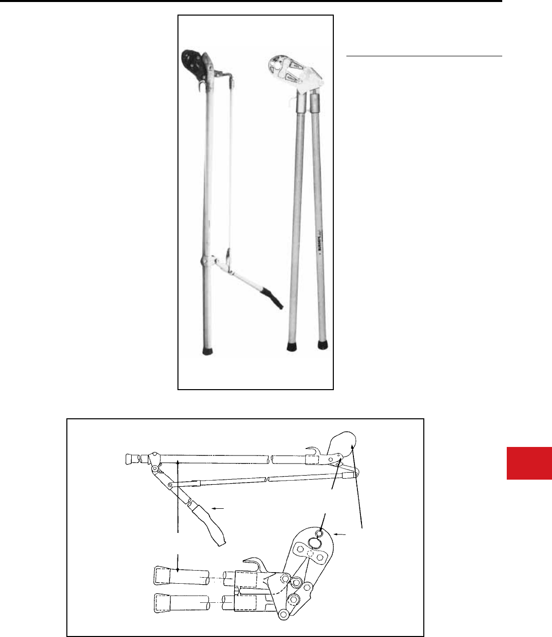
BURNDY®
Canada: 1-800-387-6487 www.burndy.com US: 1-800-346-4175
Tooling
Crimpers — Mechanical and Ratchet
MD6 HOTSTICK
TOOLS
The MD6 Type Hotstick tools incorporate either
a pantograph toggle action handle or straight
handles. They use standard MD6 Type jaws so that
they will do everything the standard MD6 will do
only they can be used for energized installations.
The berglass handles are rated at 100 kV per foot
for 5 minutes. 5-year limited warranty.
• The MD6-HS type Hot-Line Tool incorporates
a pantograph, toggle-action design to install
connectors with the same handle force as the
standard MD6-type tooling
• Angled head and lightweight makes connector
installation easier
• Supplied with MD6, MD6-6, and MD6-8 jaw
variations
• The MD6-AH type Hot-Line Tool incorporates
an angled head to make hard to reach hot-line
connections easier
• Straight 48″ berglass handles rated at 100 kV
per foot for ve minutes
• 5-year limited warranty
MD6HS60
MD6HS72
MD6-6HS60
MD6-6HS72
MD6-8HS60
MD6-8HS72
MD6-AH48
MD6-8AH48
Features and Benets
SPECIFICATIONS
FOR USE ON
• Copper, Aluminum, ACSR, Copperweld,
Alumoweld, Steel, 6201, 5005, Compressed
and compact conductors
• Copper Taps: #10 sol. - 2/0 str.
• Aluminum, ACSR Taps: #14 sol. - 4/0 ACSR
• Stirrups: #6 ACSR - 4/0 ACSR
• Overhead Full Tension Deadend, Full Tension
Splices, Non Tension Splices, and Terminals
Conductor Range: #10 str. - 4/0 ACSR
• Code conductor connectors: #6 - 4/0 str.
Copper and Aluminum
60″
72″
60″
72″
60″
72″
48″
48″
15.5
16.5
15.5
16.5
15.5
16.5
13.75
13.75
Cat. No.
Handle
Length Weight/Lbs.
FIBERGLASS
HANDLES
TOGGLE
ACTION
HANDLE
ANGLED
HEAD
STD MD6
JAWS
N-65
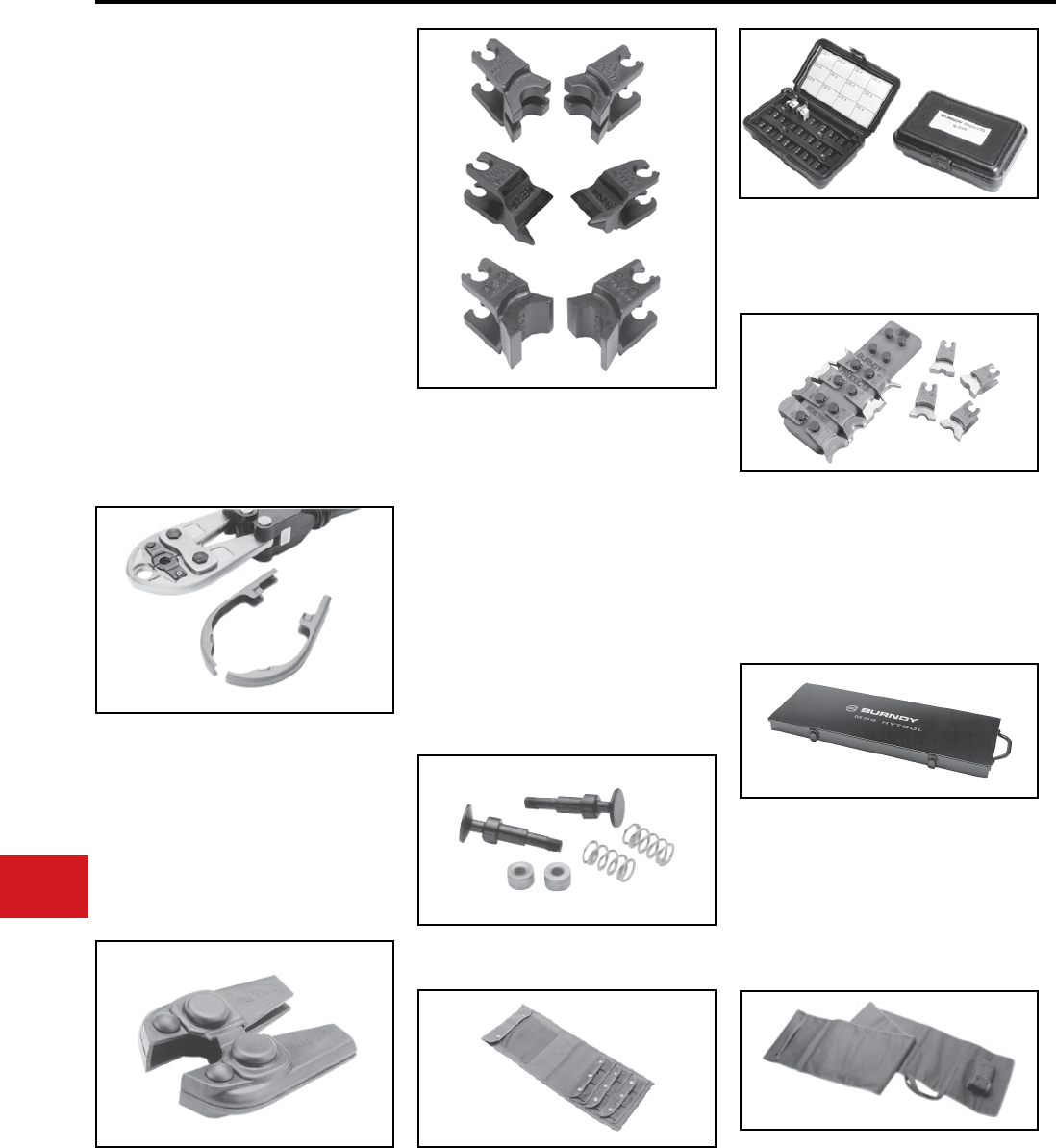
BURNDY®
US: 1-800-346-4175 www.burndy.com Canada: 1-800-387-6487
Tooling
Crimpers — Mechanical and Ratchet
MD6/MD7
TOOLING ACCESSORIES
Dies for Special Applications
(See present installation tool index in
reference section for complete W-Die listing.)
Cat. # W-BG
The W-BG die is a double groove die set requiring
only one (1) crimp per end on service entrance
sleeves and only 1/2 the number of crimps on other
5/8" sleeves.
Cat. # W-28K
The W-28K cutter die permits use of MD6/MD7
type tools as a cable cutter. Conductor range:
4-4/0 ACSR, Aluminum or Copper.
Protective Jaw Covers
Cat. # MD6-CP1
The laminated vinyl covers, are provided for the
MD6/MD7 HYTOOL™ to avoid damage. Compact
in size, the covers snap easily into place over the
jaw edges without obstructing vision.
The MD6-CP1 ts all MD6/MD7 tool variations
except the Snub-Nose MD6-6/MD7-6 type design.
Supplied as a set.
Cat. # PT6744
The semi-rigid Neoprene cover, a nonconductive
material, is provided for the MD6-6 “Snub-Nose”
HYTOOL™ to avoid damage. Fits all MD6-6 Snub-
Nose variations.
Non-Bowing Dies
Cat. # W-687 and W-702
The Non-Bowing die sets install one-piece,
full-tension UNISPLICE™ sleeves on ACSR
conductors without bowing.
UNISPLICE™ ONE-PIECE SLEEVES:
W-687 Installs: #4 ACSR 6/1, 7/1-
YDS4RL and YDS4RLY
#2 ACSR 6/1-YDS2RL
and YDS2RLY
W-702 Installs: #2 ACSR 7/1-YDS021RL
and YDS021RLY
1/0 ACSR-YDS25RL
and YDS25RLY
Cat. # PT4931-1
Die Button Repair Kit
Cat. # PT4925
Canvas Bag
The PT4925 is a sturdy canvas bag for protecting
the MD6/MD7 tools with or without rubber covers
plus up to (9) die sets. Dies purchased separately.
Cat. # CASEWDIES
Compact Die Case
Compact die case for (12) “W” or “X” die sets.
Dies purchased separately.
Cat. # WDIETREE
W Die Holder
This innovative W-Die Holder replaces the stand-
ard metal carrying case designed for BURNDY®
W-Dies. Its straight forward design allows for easy
insertion of the W-Dies onto the holder, providing
greater exibility and secure storage.
Cat. # PT4952-1
Steel Carrying Case
The PT4952-1 steel carrying case provides stor-
age and protection for the MD6 tools with or with-
out rubber covers plus up to (18) die sets. Tool and
die sets not included. Fits MD6, MD6-6, MD6-8,
MD6-14, MD6-37, MD6-38, MD7 and MD7-6.
Cat. # PT6733
Hot-Line Tool Carrying Bag
The PT6733 is a heavy-duty, adjustable canvas
bag for the storage and protection of Hot-Line
Tools. The bag accommodates 48, 60 and 72
variations of the MD6 and Y35 Hot-Line Tools.
N-66
BURNDY®
Canada: 1-800-387-6487 www.burndy.com US: 1-800-346-4175
Tooling
Crimpers — Mechanical and Ratchet
• Provides quick and easy identication of
commonly used conductors (ACSR, stranded
and solid AWG)
• Provides quick and easy identication of IPS
tubing and rigid conduit
• Provides quick and easy identication of thinwall
conduit
• Measures I.D. and O.D. of tubing
• Provides easy conversion of information
• Strong, durable, long lasting, high quality
stainless steel wire mike
• Convenient size makes it easy to carry
• Available with your company name and logo.
Customer must supply camera ready artwork.
Contact BURNDY® for details. Minimum order
required
Features and Benets
FOR USE ON
• ACSR: #6 - 336.4 (26/7) str.
• Stranded: #18 str. - 2,000 kcmil
• Solid: #20 sol. - 4/0 sol.
• IPS Tubing (Cu/Al) & Rigid conduit:
1/4″ - 2-1/2″
• Tubing sizes: 3-1/8″ inside max. 2-15/16″ outside
max.
• Thinwall conduit: 3/8″- 2-1/2″
WIREMIKE™
RK194-2
The wire mike is a useful instrument designed for
measuring ACSR, stranded and solid conductors,
I.P.S. tubing, rigid and thinwall conduit, plus inside
and outside dimensions of tubing and pipe sizes. A
ruler is also included.
N-67
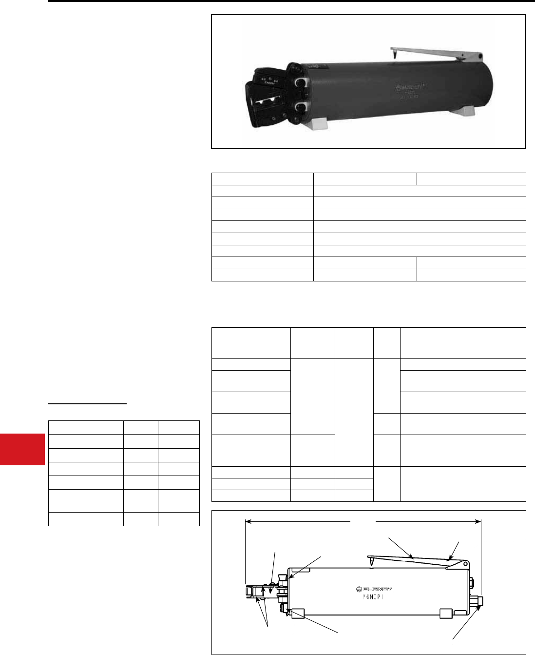
BURNDY®
US: 1-800-346-4175 www.burndy.com Canada: 1-800-387-6487
Tooling
Y6NCP1, Y6NCP1SD
PNEUMATIC OEM TOOL
The BURNDY® Y6NCP1 and Y6NCP1SD
pneumatic tools are designed for OEMs seeking
medium volume production tooling for crimping
loose-piece terminals and splices. The tools
offer a UL Listed connection for a wide variety of
BURNDY® connectors.
With a 360° rotatable head, the Y6NCP1 and
Y6NCP1SD are the perfect handheld presses
for remote operation in conned work areas.
Additionally they can be easily congured into a
bench-mount design for prolonged, steady use.
Both tools come with a 1-year limited warranty.
Features and Benets
Tool Specications
Die Specications
ACCESSORIES
• UL Listed connections when using BURNDY
UL Listed connectors
◊ Provide installer condence
• Built-in safety features
◊ Ensures safe set-up
◊ Prevents accidental actuation
• 360° rotating head
◊ Ease of use in confined areas
• J-dies provide high pull-out force
◊ Reliable crimp performance
• SD-dies use an industry-standard die envelope
◊ Dies fit in a wide variety of tools
Y6NCP1
(J-dies & Y2CNC
purchased separately)
Y6NCP1SD
(SD-dies) Range Type
Applicable
Connectors
J1022NC1
BECNVSD
(die set
included) #22 - #10
Nylon
YAE, YAE-N, YAE-N-F, YAE-Z
J1022NC2 YAEV, YAEV-L, YAEV-H
YAEV-RH, YAEV-RS
J1022NC3 TN, YAES, TN-F, YAES-F
SN, YSE-HN
J1022NC4 Vinyl TP, BA,TP-F, BA-EF, TP-Z, BA-EZ
TP-LF, BA-EL, SP, BS
J1022NC5
BECBSD
(die set
included)
Bare
T, YAD, T-F, YAD-F, YAV, YAV-L
YAV-H, YAV-R, YAV-RS, YAV-T-F
YAV-H-F, YAV-Z, YSV, YSV-H, YSV-L
Y2CNC w/ J8CNC - #8
Bare YA, YAV
YS & YSV
Y2CNC w/ J6CNC - #6
Y2CNC w/ J4CNC - #4
Cable Sizes #22 - #4 AWG #22 - #10 AWG
Length: 12.88"
Diameter: 2.55"
Weight: 4.4 lbs.
Air Pressure: 90-110 PSI
Crimp Motion: Scissor Action
Safety Shield: Yes
Pull out Force: Exceeds MIL Spec/SAE* Exceeds UL 486A/B
Dies: J-dies SD-dies1
Y6NCP1 Y6NCP1SD
* Excludes YAES-TN terminals with #12 AWG wire.
1 SD-die crimp proles are identical to the MRE1022B and MRE1022NV crimp proles.
Pneumatic crimp tool
Tool Case
1/8" NPT air hose
Crimp head for J-dies
J-dies
Crimp head for
SD-dies
SD-dies
Tool Supplied With
Y6NCP1 Y6NCP1SD
Foot Switch :
Bench Mount
Unit:
Crimp heads
for J-dies:
for SD-dies:
Y6NCP1FTSW
Y6NCP1BMNT
J6NCP1CH
SD10NCP1CH
See table for Die Specications
12.88″
CONTROL TRIGGER
SAFETY GUARDS
CRIMP HEAD
SAFETY PIN
AIR HOSE FITTING
CRIMP HEAD
RELEASE KNOB
LOCKOUT SWITCH
OEM — Pneumatic
N-68
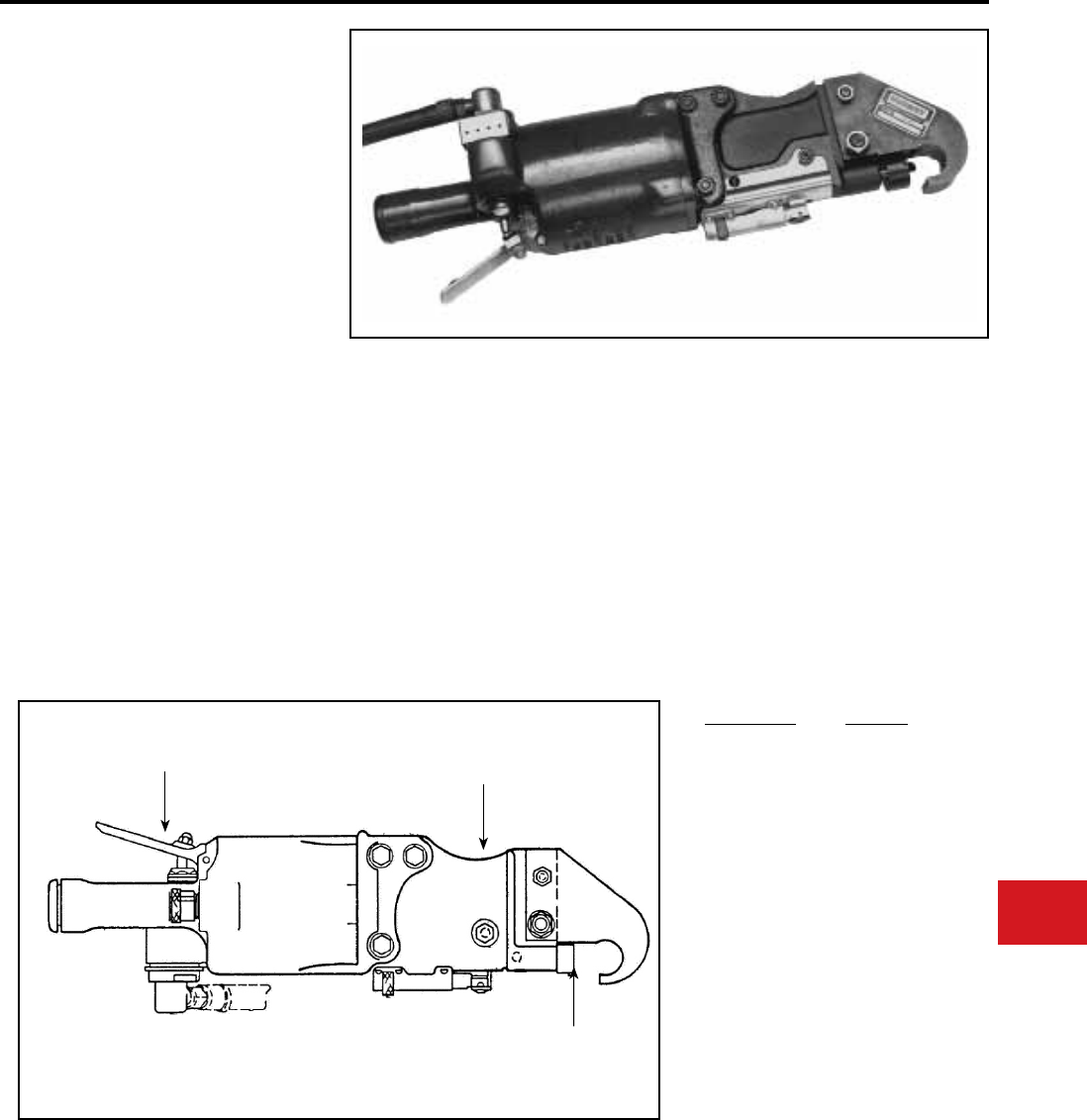
BURNDY®
Canada: 1-800-387-6487 www.burndy.com US: 1-800-346-4175
Tooling
OEM — Pneumatic
Y29NC
PNEUMATIC HYPRESS™
The Y29NC Pneumatic HYPRESS™ operates
on 85-100 PSI and will install insulated and
uninsulated terminals from #8-2/0 copper. Uses
DV type nest with Y29 type indentor.
• Portable or bench mountable
• Adjustable blow off valve to ensure proper
indenting force
• Uses DV type nest with Y29 type indentor
• Hand operated
• 5-year limited warranty
Weight:
Length:
Air line pressure:
Features and Benets SPECIFICATIONS
FOR USE ON
Wire Range: #8–2/0 Cu
YAEV-L, YAEV-H, YAEV-RS, YAEV-RH, YAV-L,
YAV-R, YAV-RS, YSV-L, YSM
12-1/2 lbs
17-1/2″
85 - 100 PSI
HAND ACTUATOR
STEEL CONSTRUCTION
REMOVABLE DIE SETS
Nest/Indenter Die Index
DV8L/Y29PL
DV8L/Y29PL
DV6LY29PL
D6CL/Y29PL
DV4L/Y29PL
D3CL/Y29PR
DV2CL/Y29PL
DV1L/Y29PR
DV25L/Y29PR
D26L/Y29PR
DV26L/Y29PR
DV8L/Y29PL
38/631
6/631
39/632
7
40/633
9
41/634
42
43
13
44
49
N-69
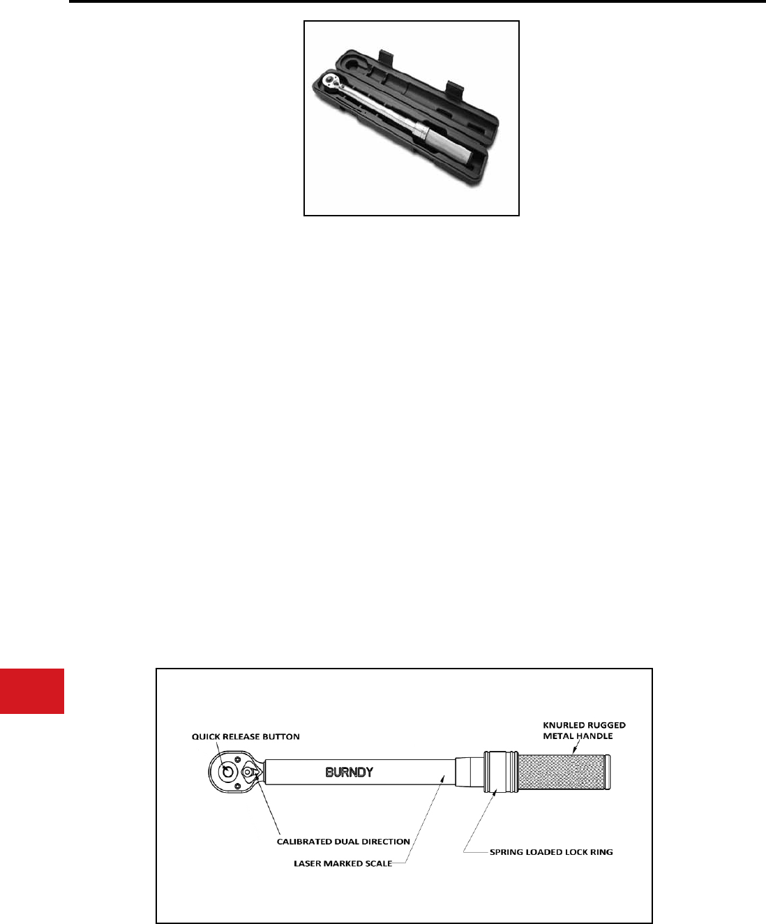
BURNDY®
US: 1-800-346-4175 www.burndy.com Canada: 1-800-387-6487
Tooling
Adjustable — Ratchet Torque Tool
Micro-Adjustable “Click-Type”
Torque Wrenches
The BURNDY® micro-adjustable torque
wrenches, when used with BURNDY® mechanical
connectors at the specied torque value, produces
a consistent, quality connection.
The BURNDY® series of torque tools are
professional grade and easy to operate. All
wrenches incorporate an easy-to-read scale
measured in inch pounds (in-lb) that can be easily
matched to the recommended torque of each of
our mechanical connector products. To set the
desired torque, simply pull down the lock ring and
turn the handle to the desired torque setting. Once
set, the lock ring secures the torque setting. When
the desired torque is reached, an impulse can be
felt through the handle and an audible “click” can
be heard.
All of the BURNDY® torque wrenches are
calibrated for use in both directions. Each wrench
is individually serialized with matching certicate of
calibration traceable to N.I.S.T. and comes with a
rugged plastic case for protection.
BURNDY® offers two torque wrench sizes each
with a 3/8” drive and quick release button. The
BTW30150 is designed to be used with all
BURNDY® connectors requiring torque values
from 30 to 150 in-lbs. The BTW150750 is for
connections requiring 150 to 750 in-lbs. The
BTW1575F12 is designed for applications requiring
a 1/2" Drive and torque values from 15 to 75 ft-lbs.
Torque wrenches carry a 1 year limited warranty.
• Ratcheting, calibrated, dual direction
provides ease of use in the eld
• Positive lock with spring-loaded pull-down
lock ring assures the user that the torque
setting is properly engaged and secure
• Scale settings on tool correspond to
connector torque ratings (in-lb) to save time
with fast, accurate and easy-to-set values
• Quick release button for interchanging
sockets with ease
• Lightly knurled handle offers an ergonomic,
non-slip grip
• Rugged metal handle withstands the rigors
of professional use
• Micro-adjustable design minimizes the need
for several wrenches
• Individually serialized and calibrated to offer
user condence that the torque wrench will
provide the required torque
• Made in the USA
Features and Benets
SPECIFICATIONS
FOR USE ON
SERVIT®, OKLIP™, VERSITAP™, SCRULUG™,
LAY-IN QIKLUG™, VARITAP™, VARILUG™,
Universal Terminals, UNITAP™, POLYTAP™,
BARTAP™, Type BIPC, Terminal Blocks,
U-BLOK™, SPEC-BLOK™, and VERSIPOLE™
Part Number:
Torque Range:
Length:
Weight:
Drive:
Part Number:
Torque Range:
Length:
Weight:
Drive:
BTW30150
30 - 150 in-lbs
10.15"
0.90 lbs
3/8"
BTW150750
150 - 750 in-lbs
16.00"
2.50 lbs
3/8"
Accuracy: ±4% clockwise ±6% CCW
of indicated value CW, from 20% to 100% of full
scale
Applicable Standards: ASME B107.14M-1994
and ISO 6789
Calibration: Calibration traceable to N.I.S.T.
Part Number:
Torque Range:
Length:
Weight:
Drive:
BTW1575F12
15 - 75 ft-lbs
16.00"
2.50 lbs
1/2"
N-70
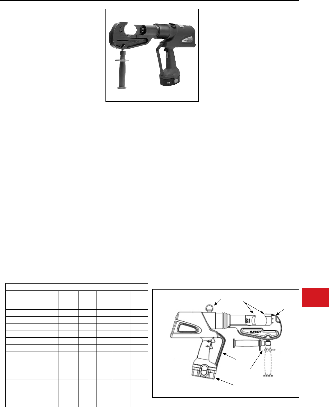
BURNDY®
Canada: 1-800-387-6487 www.burndy.com US: 1-800-346-4175
Tooling
Rened Hydraulic System
for Ultra Performance,
Speed and Reliability
Safety Lanyard
Connection Interchangeable
Blades
Forged Steel
Head
Field Proven Electronics
for Ultimate Reliability
in the Harshest Work
Environments
Trigger Guard
18 Volt Ni-MH Battery
Retractable Assist
Handle
11 Ton Output Force
Cutters — Battery Actuated
PATRIOT®
PATHCC10-18V SERIES
BATTERY ACTUATED TOOL
Hydraulic Self-Contained Cutter
The BURNDY® PATHCC10-18V series C-head
cutter is an innovative compact and mobile cutting
tool that allows users to interchange different
cutting blades customized for their application.
With a “C”-shaped style head and large opening,
it’s easy to scoop and cut without the need to
open or close a latch. The tool head swivels
355° and comes with a retractable assist handle
to help maneuver the cutting head into position.
The PATHCC10-18V blade alignment technology
ensures a clean cut and maximum blade life.
The PATHCC10-18V series tool accommodates
four different interchangea-ble blade types:
HCCACSR, HCCSOL, HCCCUAL, and
HCCGUY. The PATHCC10-18V series tool comes
in a variety of options to include a covered head
version (PATHCC10C-18V), and the ability to order
the tool with specic blades only. See the table for
individual catalog numbers.
The PATHCC10-18V series cutters operate on 18-
volt Ni-MH batteries. Each tool comes equipped
with an impact resistant formed carrying case
along with a tool retention lanyard, battery charger
and two batteries. The carrying case also has pre-
formed pockets to house all four blade types. The
PATHCC10-18V series tools are provided with
a 5-year limited warranty (excluding blades) and
a lifetime power-train warranty on the INFINITY
DRIVE® transmission. The batteries and charger
are provided with a 1-year limited warranty.
Features and Benets
SPECIFICATIONS
FOR USE ON
ACCESSORIES
Each BURNDY HCC blade kit is designed
specically for the material it is intended to cut.
Each blade is made from high strength tool steel
and then hardened to ensure a long life. Each
blade kit comes complete with screws and wrench
for installation.
• Specialized reinforced C-Head designed
for easy and efcient cable cutting for
both eld and OEM applications
• Interchangeable precision cutting blades
optimized for cutting Copper/Aluminum,
ACSR, EHS Guy Strand and Ground Rod/
Rebar
• Battery and remote head platforms
• Available in covered head versions
• High strength steel cylinder for durability and
long life
• Many part number options offered including
the ability to order the tool with all blades or
specic blades only
• 5-year limited warranty on tool (excluding
blades)
Tool Weight :
Length :
Width :
Height :
Operating Voltage :
Recharge Time :
Cu/Al Cable :
ACSR/ACSS :
Ground Rod :
Rebar
:
Soft Steel Bolts :
Std & EHS Guy :
Blades:
20.4 lbs
21.4 in
3.7 in
12.8 in
18 V-DC
<45 minutes
up to 1.5"
up to 1590 kcmil
up to 5/8"
up to 1/2"
up to 5/8"
up to 9/16"
HCCCUAL Cu/Al Blades
HCCACSR ACSR/ACSS Blades
HCCGUY GUY Blades
HCCSOL Rebar/Ground Rod Blades
Replacement
Battery:
Chargers:
120V-AC
12/24V-DC
240/250V-AC
Cat# PATCHGR18V
Cat# BCT/PATDCCHGR
Cat# PATCHGR250V
Tool Provided with Following Components
Catalog Number Covered
Head
ACSR
Blade
Set
CUAL
Blade
Set
SOL
Blade
Set
GUY
Blade
Set
PATHCC1018V Х Х Х Х
PATHCC10C18V Х Х Х Х Х
PATHCC10ACSR18V Х
PATHCC10CUAL18V Х
PATHCC10SOL18V Х
PATHCC10GUY18V Х
PATHCC10CACSR18V Х Х
PATHCC10CCUAL18V Х Х
PATHCC10CSOL18V Х Х
PATHCC10CGUY18V Х
HCCACSR (blades only) Х Х
HCCCUAL (blades only) Х
HCCGUY (blades only) Х
HCCSOL (blades only) Х
Cat# BAT18V
(2.6AH) Hi-capacity
N-71
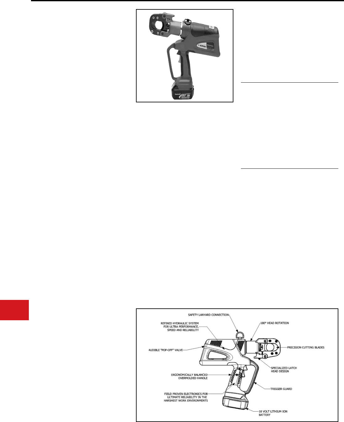
BURNDY®
US: 1-800-346-4175 www.burndy.com Canada: 1-800-387-6487
Tooling
Cutters — Battery Actuated
PATRIOT®
PATCUT129-LI
18 Volt Lithium-Ion
Battery Actuated Cutter
Hydraulic Self-Contained
Cutting Tool
The BURNDY® PATRIOT® PATCUT129-LI
Lithium-Ion tool incorporates the latest engineering
technology with a rened hydraulic system for ultra
performance, speed and reliability. The redesigned
eld proven electronics provide the ultimate
reliability in the harshest work environments. All
BURNDY® battery actuated hydraulic tools provide
a consistent cut every time.
The PATCUT129-LI battery powered cutting tool
is compact, fast, easy to use and incorporates the
latest in battery tool technology. The ergonomic
design allows one hand operation so that other
is free to manipulate the conductor in the proper
cutting position. The PATCUT129-LI incorporates
a specialized latch-style cutting head that allows
interference-free closure for mid-span cuts. The
cutter head rotates 180 degrees to allow users
to get into tight areas easier. The PATCUT129-LI
is capable of cutting up to 1.29" diameter copper
and aluminum cable, 1113 ACSR, 5/8" ground
rods, 1/2" rebar, 5/8" diameter soft steel bolts up to
1/2" standard guy strand and up to 3/8" EHS guy
strand.
The PATCUT129-LI is supplied with a durable
high impact formed carrying case to hold the tool,
battery charger, two 18 volt Lithium-Ion batteries
and tool retention lanyard. The PATCUT129-LI is
provided with a 5-year limited warranty (excluding
blades) and 1-year on batteries and charger. All
PATRIOT® tools feature the BURNDY® INFINITY
DRIVE® transmission which has a lifetime
warranty.
Features and Benets
SPECIFICATIONS
ACCESSORIES
• Rened hydraulic system for ultra performance,
speed and reliability
• Field proven electronics for ultimate reliability in
the harshest environments
• Overmolded handle for comfort and improved
grip; allows for one-handed operation for
advance, retract and hold
• Specialized latch head design for interference
free closure for mid-span cuts
• 18-volt Lithium-Ion batteries provide 2.5 times
more charge/discharge cycles than traditional
Ni-Cd batteries and provide 430% more
lifetime work
• 30 minute charger controls current, voltage and
temperature to maximize battery life
• Forced air cooling fan cools the battery by
forcing cool air through the battery’s built-in
air vents
• 180° head rotation allows user to get into tight
areas easier
• Ergonomically balanced tool design eases
operation and lessens fatigue
Tool Weight:
Length:
Width:
Height:
Operating Voltage:
Recharge Time:
10.2 lbs (4.6 kg)
With Battery
14.5" (36.8 cm)
3.5" (8.9 cm)
13.5" (34.3 cm)
18 V-DC
30 minutes
FOR USE ON
Copper & Aluminum Cable :
ACSR
:
Ground Rod
:
Rebar
:
Soft Steel Bolts
:
Standard Guy Strand
:
EHS Guy Strand
:
Up to 1.29"
Up to 1113
Up to 5/8"
Up to 1/2"
Up to 5/8"
Up to 1/2"
Up to 3/8"
• Battery:
• Chargers:
• Replacement Blades:
• Lanyard:
120V-AC
12/24V-DC
Cat# PATCHGR-LI
Cat# PATCHGR-LIDC
Cat# PT10037388
(Moving Blade)
Cat# PT10037384
(Fixed Blade)
Cat# PT208620
Cat# BAT18VLI
(3.0 AH) Hi-capacity
N-72
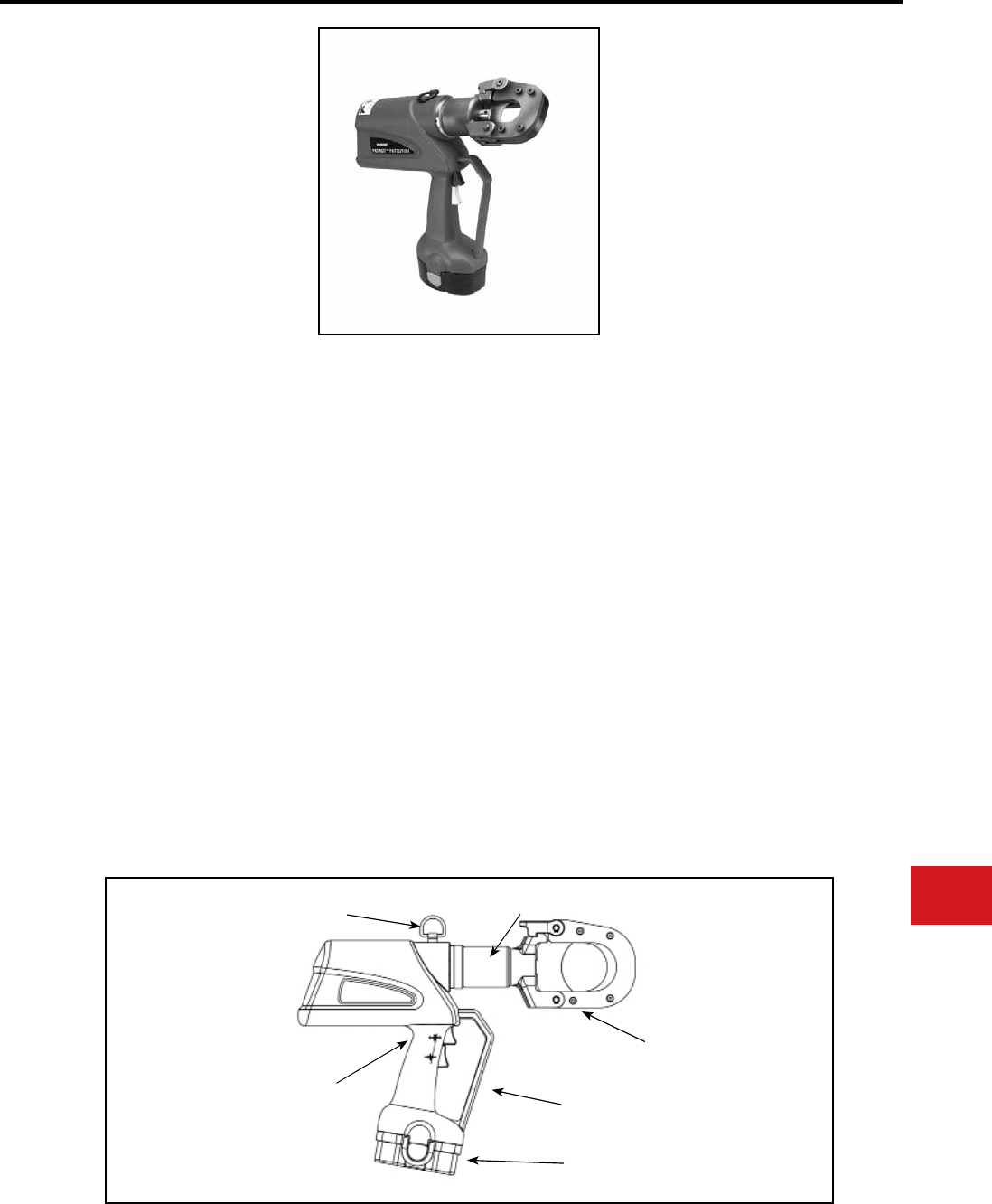
BURNDY®
Canada: 1-800-387-6487 www.burndy.com US: 1-800-346-4175
Tooling
Cutters — Battery Actuated
PATRIOT®
PATCUT129ACSR-18V
BATTERY ACTUATED TOOL
Hydraulic Self-Contained Cutter
The BURNDY® PATCUT129ACSR-18V battery
powered cutting tool is compact, fast, easy
to use and incorporates the latest in battery
tool technology. The ergonomic design allows
one hand operation so that the other is free to
manipulate the conductor in the proper cutting
position. The PATCUT129ACSR-18V incorporates
a specialized latch style cutting head that allows
interference-free closure for mid-span cuts. The
cutter head rotates 180 degrees to allow users to
get into tight areas easier. The PATCUT129ACSR-
18V is capable of cutting up to 1.29″ diameter
copper and aluminum cable, 1113 ACSR, 5/8″
ground rod, 1/2″ rebar, 5/8″ diameter soft steel
bolts, up to 1/2″ standard guy strand, and up to
3/8″ EHS guy strand.
The PATCUT129ACSR-18V operates on industry
standard 18-volt Ni-MH batteries that eliminate
voltage depression or “memory” issues. The
PATCUT129ACSR-18V comes equipped with a
high impact formed carrying case to hold the tool,
a tool retention lanyard, a battery charger and two
batteries. The PATCUT129ACSR-18V is provided
with a 5-year limited warranty (excluding blades)
and 1-year on batteries and charger.
• Battery powered cutting technology
• Advance design high-speed pump
completes tough cuts faster
• Specialized latch head design
• Ergonomic design allows one hand
operation
• 180 degree head rotation
• Mechanical ram release
• Operates on 18 volt Ni-MH batteries
• Durable high impact formed carrying case
• 5-year limited warranty on tool (excluding
blades) and 1 year on batteries and charger
Tool Weight:
Length:
Height:
Width:
Operating Voltage:
Recharge Time:
Features and Benets
SPECIFICATIONS
FOR USE ON
Copper Cable
Aluminum Cable
ACSR
Ground Rod
Rebar
Soft Steel Bolts
Standard Guy Strand
EHS Guy Strand
11 lbs
14.5″
13.5″
3.5″
18 V-DC
< 45 mins.
ACCESSORIES
SAFETY LANYARD
CONNECTION
180◦ HEAD ROTATION
PRECISION CUTTING
BLADES
TRIGGER GUARD
Ni - MH 18 VOLT
BATTERY
ERGONOMICALLY
BALANCED TOOL
DESIGN
• Lanyard:
• Battery:
• Charger:
120V-AC
12/24V-DC
240/250V-AC
• Replacement Blades:
Cat# PT208620
Cat# BAT18V
(2.6 AH) Hi-capacity
Cat# PATCHGR18V
Cat# BCT/PATDCCHGR
Cat# PATCHGR250V
Cat# PT10037388
(Moving Blade)
Cat# PT10037384
(Fixed Blade)
: up to 1.29″
: up to 1.29″
: up to 1113 ACSR
: up to 5/8″
: up to 1/2″
: up to 5/8″
: up to 1/2″
: up to 3/8″
N-73
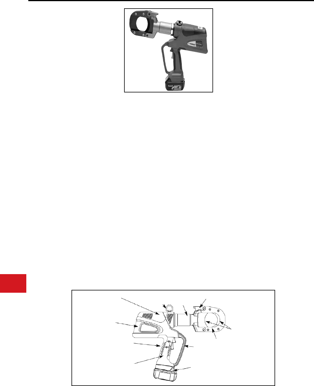
BURNDY®
US: 1-800-346-4175 www.burndy.com Canada: 1-800-387-6487
Tooling
Cutters — Battery Actuated
PATRIOT®
PATCUT245-LI
18 Volt Lithium-Ion
Battery Actuated Cutter
Hydraulic Self-Contained
Cutting Tool
The BURNDY® PATRIOT® PATCUT245-LI
Lithium-Ion tool incorporates the latest engineering
technology with a rened hydraulic system for ultra
performance, speed and reliability. The redesigned
eld proven electronics provide the ultimate
reliability in the harshest work environments. All
BURNDY® battery actuated hydraulic tools provide
a consistent cut every time.
The PATCUT245-LI battery powered cutting tool
is compact, fast, easy to use and incorporates the
latest in battery tool technology. The ergonomic
design allows one hand operation so that the other
is free to manipulate the conductor in the proper
cutting position. The PATCUT245-LI incorporates
a specialized latch style cutting head that allows
interference-free closure for mid-span cuts. The
cutter head rotates 180 degrees to allow users to
get into tight areas easier. The PATCUT245-LI is
capable of cutting up to 2.45" diameter copper and
aluminum cable.
The PATCUT245-LI is supplied with a durable
high impact formed carrying case to hold the tool,
battery charger, two 18 volt Lithium-Ion batteries
and tool retention lanyard. The PATCUT245-LI is
provided with a 5-year limited warranty (excluding
blades) and 1-year on batteries and charger. All
PATRIOT® tools feature the BURNDY® INFINITY
DRIVE® transmission which has a lifetime
warranty.
SPECIFICATIONS
FOR USE ON
Tool Weight:
Length:
Width:
Height:
Operating Voltage:
Recharge Time:
13.7 lbs (6.2 kg) With
Battery
18.1" (45.9 cm)
3.5″ (8.9 cm)
13.5″ (34.3 cm)
18 V-DC
30 minutes
Copper and
Aluminum Cable: Up to 2.45" O.D
For Copper and Aluminum cable only. Do not
cut steel, ground rod, rebar or guy wire.
Features and Benets
• Rened hydraulic system for ultra performance,
speed and reliability
• Field proven electronics for ultimate reliability in
the harshest environments
• Overmolded handle for comfort and improved
grip; allows for one-handed operation for
advance, retract and hold
• Specialized latch head design for interference
free closure for mid-span cuts
• 18-volt Lithium-Ion batteries provide 2.5 times
more charge/discharge cycles than traditional
Ni-Cd batteries and provide 430% more
lifetime work
• 30 minute charger controls current, voltage and
temperature to maximize battery life
• Forced air cooling fan cools the battery by
forcing cool air through the battery’s built-in
air vents
• 180° head rotation allows user to get into tight
areas easier
• Ergonomically balanced tool design eases
operation and lessens fatigue
ACCESSORIES
• Battery:
• Chargers:
• Replacement Blades:
• Lanyard:
120V-AC
12/24V-DC
Cat# PATCHGR-LI
Cat# PATCHGR-LIDC
Cat# BAT18VLI
(3.0 AH) Hi-capacity
Cat# PT10038657
(Moving Blade)
Cat# PT10040663
(Fixed Blade)
Cat# PT208620
Field-Proven Electronics for
Ultimate Reliability in the
Harshest Work Environments
Rened Hydraulic System for
Ultra Performance, Speed
and Reliability
6 Ton Output Force
Ergonomically Balanced
Overmolded Handle
180° Head
Rotation
Specialized Latch Head Design
Precision Cutting Blades
2.45" Cutting Capacity
Trigger
Guard
18 Volt Lithium-Ion
Battery
Safety Lanyard
Connection
N-74
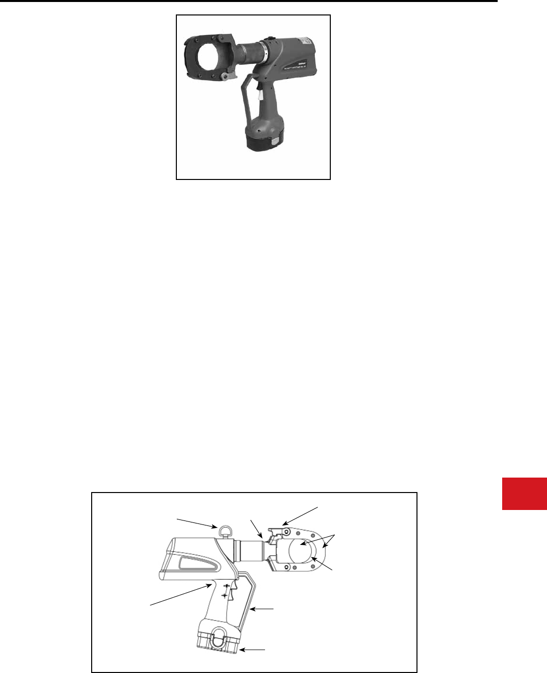
BURNDY®
Canada: 1-800-387-6487 www.burndy.com US: 1-800-346-4175
Tooling
Cutters — Battery Actuated
PATRIOT®
PATCUT245CUAL-18V
BATTERY ACTUATED TOOL
Hydraulic Self-Contained Cutter
The BURNDY® PATCUT245CUAL-18V battery
powered cutting tool is compact, fast, easy
to use and incorporates the latest in battery
tool technology. The ergonomic design allows
one hand operation so that the other is free to
manipulate the conductor in the proper cutting
position. The PATCUT245CUAL-18V incorporates
a specialized latch style cutting head that allows
interference-free closure for mid-span cuts. The
cutter head rotates 180 degrees to allow users to
get into tight areas easier. The PATCUT245CUAL-
18V is capable of cutting up to 2.45″ diameter
copper and aluminum cable.
The PATCUT245CUAL-18V operates on industry
standard 18-volt Ni-MH batteries that eliminate
voltage depression or “memory” issues. The
PATCUT245CUAL-18V comes equipped with a
high impact formed carrying case to hold the tool,
a tool retention lanyard, a battery charger and two
batteries. The PATCUT245CUAL-18V is provided
with a 5-year limited warranty (excluding blades)
and 1-year on batteries and charger.
Tool Weight:
Length:
Width:
Height:
Operating Voltage:
Recharge Time:
Features and Benets
SPECIFICATIONS
FOR USE ON
For Copper and Aluminum cable only. Do not
cut steel, ground rod, rebar, or guy wire.
• Battery powered cutting technology
• Advance design high-speed pump
completes tough cuts faster
• Specialized latch head design
• Ergonomic design allows one hand
operation
• 180 degree head rotation
• Mechanical ram release (no battery power
consumption)
• Operates on 18 volt Ni-MH batteries
• Durable high impact formed carrying case
14.5 lbs (5.4 kg)
With Battery
18″ (45.7 cm)
3.75″ (9.5 cm)
14.75″ (37.5 cm)
18 V-DC
< 45 mins.
ACCESSORIES
SAFETY LANYARD
CONNECTION
180◦ HEAD
ROTATION
PRECISION CUTTING
BLADES
TRIGGER GUARD
ERGONOMICALLY
BALANCED TOOL
DESIGN
18 VOLT Ni-MH
BATTERY
SPECIALIZED LATCH
HEAD DESIGN
2.45" CUTTING
CAPACITY
• Carrying Case: Cat# PT10044980
• Lanyard: Cat# PT208620
• Battery:
Cat# BAT18V
(2.6 AH) Hi-capacity
• Charger:
120V-AC
12/24V-DC
240/250V-AC
Cat# PATCHGR18V
Cat# BCT/PATDCCHGR
Cat# PATCHGR250V
• Replacement Blades:
Cat# PT10038657
(Moving Blade)
Cat# PT10040663
(Fixed Blade)
Up to 2.45″ O.D
(62.2 mm)
Copper and
Aluminum Cable :
N-75
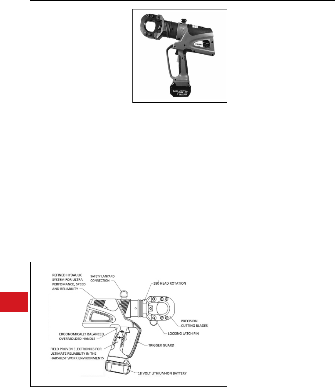
BURNDY®
US: 1-800-346-4175 www.burndy.com Canada: 1-800-387-6487
Tooling
Cutters — Battery Actuated
PATRIOT®
PATCUT2156-LI
18 Volt Lithium-Ion
Battery Actuated Cutter
Hydraulic Self-Contained
Cutting Tool
The BURNDY® PATRIOT® PATCUT2156-LI
cutting tool incorporates the latest engineering
technology with a rened hydraulic system for ultra
performance, speed and reliability.
The PATCUT2156-LI battery powered cutting tool
is a compact, fast and versatile tool capable of
cutting a variety of cable types and materials. The
ergonomic design allows one hand operation so
that the other is free to manipulate the conductor in
the proper cutting position. All BURNDY® battery
actuated hydraulic tools provide a consistent cut
every time.
The PATCUT2156-LI is supplied with a durable
high impact formed carrying case to hold the tool,
battery charger, two 18V Lithium-Ion batteries and
tool retention lanyard.
The PATCUT2156-LI is provided with a 5-year
limited warranty and a 1-year warranty on batteries
and charger. All PATRIOT® tools feature the
BURNDY® INFINITY DRIVE® transmission which
has a lifetime warranty. Blades excluded.
• Durable hardened steel blades for
optimum cutting and increased life
• Battery powered cutting technology
for easy tool operation and portability
• Advance design high-speed pump
completes tough cuts faster and
provides longer life, efciency, and
reliability
• Specialized latch head design for
interference free closure for mid-span cuts
• Ergonomic design allows one hand
operation allowing user one hand free to
manipulate material to be cut
• 180 degree head rotation provides
versatile head positioning allows user to get
into tight areas easier
• Mechanical ram release with reliability and no
battery power consumption
Features and Benets
Tool Weight:
Length:
Width:
Height:
Operating Voltage:
Recharge Time:
15.5 lbs
16.47"
,./ 3.27"
13.46"
18V-DC
30 mins
SPECIFICATIONS
• CU and AL Cable:
• ACSR:
• Ground Rod:
• Rebar:
• Soft Steel Bolts:
• Standard Guy Strand:
• EHS Guy Strand:
FOR USE ON
Up to 2.0"
Up to 2156
Up to 3/4"
Up to 5/8"
Up to 3/4"
Up to 9/16"
Up to 9/16"
PATCUT2156-LI
PATCUT2156-LIDC
PATCUT2156-LILCB
PART NUMBERS
18V with 110V Charger
18V with DC Charger
Less Batteries & Charger
Battery:
Chargers:
120V-AC
12/24V-DC
Replacement
Blades:
Lanyard:
ACCESSORIES
Cat# BAT18VLI
(3.0 AH) Hi-capacity
Cat# PATCHGR-LI
Cat# BCT/PATCHGR-LIDC
Cat# CUT200BLMVBL
(Movable Blade)
Cat# CUT200BLSTA
(Stationary Blade)
Cat# PT208620
N-76
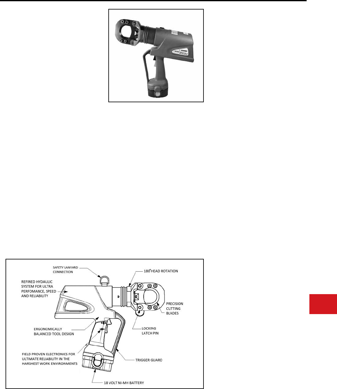
BURNDY®
Canada: 1-800-387-6487 www.burndy.com US: 1-800-346-4175
Tooling
Cutters — Battery Actuated
PATRIOT®
PATCUT2156-18V
18 Volt Ni-MH
Battery Actuated Cutter
Hydraulic Self-Contained
Cutting Tool
The BURNDY® PATRIOT® PATCUT2156-18V
cutting tool incorporates the latest engineering
technology with a rened hydraulic system for ultra
performance, speed and reliability.
The PATCUT2156-18V battery powered cutting
tool is a compact, fast and versatile tool capable of
cutting a variety of cable types and materials. The
ergonomic design allows one hand operation so
that the other is free to manipulate the conductor
in the proper cutting position. All BURNDY® battery
actuated hydraulic tools provide a consistent cut
every time.
The PATCUT2156-18V is supplied with a durable
high impact formed carrying case to hold the tool,
battery charger, two 18V Ni-MH batteries and tool
retention lanyard.
The PATCUT2156-18V is provided with a 5-year
limited warranty and a 1-year warranty on batteries
and charger. All PATRIOT® tools feature the
BURNDY® INFINITY DRIVE® transmission which
has a lifetime warranty. Blades excluded.
Features and Benets
• Durable hardened steel blades for optimum
cutting and increased life
• Battery powered cutting technology for easy
tool operation and portability
• Advance design high-speed pump completes
tough cuts faster and provides longer life,
efciency, and reliability
• Specialized latch head design for interference
free closure for mid-span cuts
• Ergonomic design allows one hand operation
allowing user one hand free to manipulate
material to be cut
• 180 degree head rotation provides versatile
head positioning allows user to get into tight
areas easier
• Mechanical ram release with reliability and no
battery power consumption
Tool Weight:
Length:
Width:
Height:
Operating Voltage:
Recharge Time:
16.3 lbs
16.52"
3.27"
13.29"
18V-DC
< 45 mins
SPECIFICATIONS
• CU and AL Cable:
• ACSR:
• Ground Rod:
• Rebar:
• Soft Steel Bolts:
• Standard Guy Strand:
• EHS Guy Strand:
FOR USE ON
Up to 2.0"
Up to 2156
Up to 3/4"
Up to 5/8"
Up to 3/4"
Up to 9/16"
Up to 9/16"
PATCUT2156-18V
PATCUT2156-18VDC
PATCUT2156-18V250V
PART NUMBERS
18V with 110V Charger
18V with DC Charger
18V with 250V Charger
Battery:
Chargers:
120V-AC
12/24V-DC
240/250V-AC
Replacement
Blades:
Lanyard:
ACCESSORIES
Cat# BAT18V
(2.6 AH) Hi-capacity
Cat# PATCHGR18V
Cat# BCT/PATDCCHGR
Cat# PATCHGR250V
Cat# CUT200BLMVBL
(Movable Blade)
Cat# CUT200BLSTA
(Stationary Blade)
Cat# PT208620
N-77
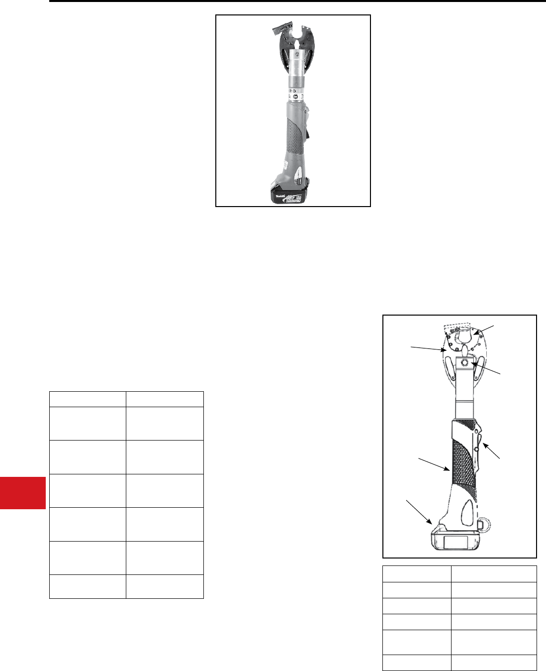
BURNDY®
US: 1-800-346-4175 www.burndy.com Canada: 1-800-387-6487
Tooling
Cutters — Battery Actuated
Interchangeable Jaw Assemblies:
PATJAWSMD6
PATJAWSMD6-8
PATJAWSMD6-6
PATJAWSMD6K
PATJAWSCUT
Jaw Covers:
BG and D3 Grooves
O and D3 Grooves
D3 Groove only (snub-nose)
KEARNEY™ Groove (snub)
Cutter Jaw Set
PATMD6JC, PATMD66JC,
PATMD6KJC
PATRIOT® IN-LINE® Cut/Crimp Kits:
All with Cutter Jaws, 2 Batteries and Charger
PATMD6LICUTKIT1
PATMD68LICUTKIT1
PATMD66LICUTKIT1
PATMD6LIWCJ
PATMD66LIWCJ
PATMD68LIWCJ
BG & D3 Grooves, hard case
O & D3 Grooves, hard case
D3 Groove (snub), hard case
BG & D3 Grooves, soft case
O & D3 Grooves, soft case
D3 Groove (snub), soft case
PATRIOT® IN-LINE®
PATMDCUT Series
Li-lon or Ni-MH powered styles
Battery Actuated Tool
Hydraulic Self-Contained
Cutter
The BURNDY® IN-LINE® tools are battery
actuated and can be operated with one hand
allowing for advance, retract and hold functions for
easier operation. One hand operation allows the
operator one free hand to position the connector
and conductor while crimping. The PATRIOT®
PATMDCUT series of tools incorporate a hydraulic
pump generating considerable cutting force. This
design provides a consistent, reliable cut every
time.
The PATRIOT® tool features interchange-able
MD6 series jaw assemblies, capable of both
cutting and crimping (using “W” and “X” style dies).
When ordering choose the tool that best suits
your cutting and crimping needs. The IN-LINE®
tools feature 350° rotatable jaw assemblies for
operation in virtually any position.
The PATRIOT® IN-LINE® cutter tools are supplied
with a durable high strength carry bag, battery
charger and two batteries.
• Plenty of output force for reliable cuts on an
array of conductor sizes
• Interchangeable scissor action jaws crimp or cut
with the same tool
• Ram holds position when trigger is released
to allow the operator to check alignment prior
to cut
• Large hand grip area allows easier operation
with gloves
• Ergonomically balanced tool design helps
lessen operator fatigue
• High capacity 3.0 AH batteries provide more
cuts/crimps per charge
• Actuated blade guide automatically closes for
easy positioning on cable and allows large
diameter cable to be cut
• One set of blades to cut all specied materials
• 5-year limited warranty on tool; 1-year on
batteries and charger
Features and Benets
Max. Cutting Capacity:
Tool Weight:
Length:
Height:
Width:
8 lbs
22 in
5 in
2.7 in
Catalog Number Description
PATMDCUTLI
Tool with ACSR
Blades, 120V AC Li-lon
Charger
PATMDCUTLIDC
Tool with ACSR
Blades,12V DC Li-lon
Charger
PATMDCUT14V*
Tool with ACSR
Blades, 120V AC
Ni-MH Charger
PATMDCUT14VDC*
Tool with ACSR
Blades, 12V DC Ni-MH
Charger
PATMDCUT14V250V*
Tool with ACSR
Blades, 250V AC
Ni-MH Charger
PATMDCUTACSRKIT Repalceable ACSR
Blades ONLY
Catalog Number Description
BAT18VLI Battery, 18V Li-lon
PATCHGRLI Charger, 110 VAC for LI
PATCHGLIDC Charger, 12 VDC for LI
PT10074020 Strap, Wrist, IN-LINE®
Tool
PATMDCUTSOMI User Manual (SOMI)
Copper
500 kcmil (0.93" [24 mm] Max.
Insulation Dia.)
Aluminum
636 kcmil Orchid
(0.93" [24 mm] Max. Insulation Dia.)
ACSR
556.5 kcmil Dove 26/7
(0.93" [24 mm] Max. Dia.)
Guy Strand (EHS)
3/8" Dia. [10 mm]
Copper Weld / AlumaWeld
3/8" Dia. [10 mm]
(approx. #4 AWG depending on
stranding)
Rebar
3/8" Dia. [10 mm]
* 14.4 Ni-MH battery powered also
available; not featured on this sheet; subtle
differences between the platforms exist;
Contact Customer Service for information.
Interchangeable
Jaws
Jaw
Release
Pin
Large Hand
Grip Area
18 Volt Li-ion
Battery
Replaceable
Cutting Blades
Activation
& Release
Triggers
N-78
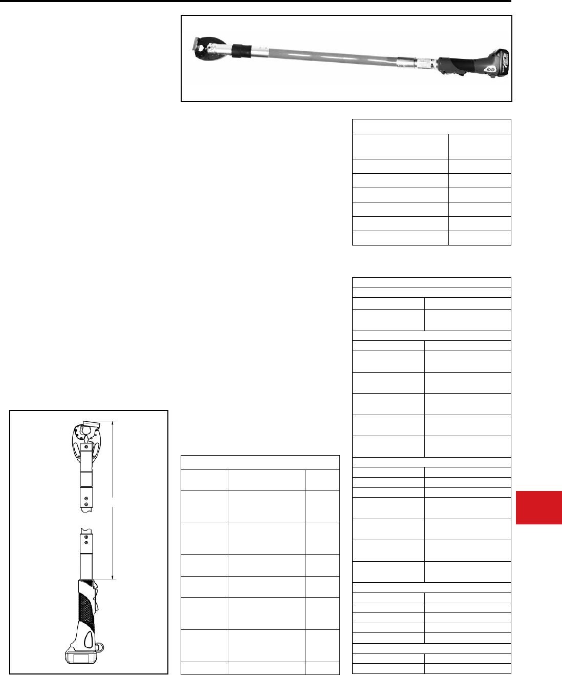
BURNDY®
Canada: 1-800-387-6487 www.burndy.com US: 1-800-346-4175
Tooling
Cutters — Battery Actuated
Features and Benets
PATRIOT® IN-LINE®
POLE CUTTERS
Li-ION or Ni-MH
Battery Actuated Cutter
Hydraulic Self-Contained
Cutting Tool
The BURNDY® IN-LINE® pole cutters are battery
actuated hydraulic self contained cable cutters
for cutting operations at heights. The PATRIOT®
PATMDCUT series of tools incorporates a
hydraulic pump generating considerable cutting
force providing a consistent and reliable cut every
time.
This PATRIOT® tool features interchangeable
MD6 series jaw assemblies, capable of both
cutting and crimping (using “W” and “X” style dies).
The IN-LINE® tools features, 350˚ rotatable jaw
assemblies for operation in virtually any position.
The PATRIOT® IN-LINE® cutter tools are supplied
with battery charger and two batteries (crimp jaws
are sold separately). All PATRIOT® IN-LINE® pole
cutters are provided with a 5-year limited warranty;
1 year on batteries and charger.
Cutting Capacity
Material Wire Range Life
(cuts)
CU
500 kcmil
(.93” [24 mm] Max.
Insulation Dia.)
500
AL
636 kcmil Orchid
(.93” [24 mm] Max.
Insulation Dia.)
500
ACSR 556.5 kcmil Dove 26/7
(.93” [24 mm] Max Dia.) 200
GUY St
(EHS) 3/8” Dia. [10 mm] 150
CopperWeld
3/8” Dia. [10 mm]
(approx. #4 AWG
depending on stranding)
150
AlumaWeld
3/8” Dia. [10 mm]
(approx. #4 AWG
depending on stranding)
150
Rebar 3/8” Dia. [10 mm] 300
Accessories
Blades
Catalog Number Description
PATMDCUTACSRKIT Blades, Cutter, ACSR
Replacable
Jaw
Catalog Number Description
PATJAWSCUT Cutter Jaw Set,
includes ACSR blades
PATJAWSMD6 Crimp Jaw, “BG” and “D3”
Grooves
PATJAWSMD68 Crimp Jaw, “O” and “D3”
Grooves
PATJAWSMD66 Crimp Jaw, SNUB, “D3”
Grooves
PATJAWSMD6K Crimp Jaw, SNUB,
KEARNEY Groove
Power Source
Catalog Number Description
BAT18VLI Battery, 18V LI-ION
BAT14V Battery, 14V Ni-MH
PATCHGRLI Charger, 120 VAC
(for LI-ION Battery)
PATCHGLIDC Charger, 12 VDC
(for LI-ION Battery)
PATCHGR18V Charger, 111 VAC
(for Ni-MH Battery)
BCT/PATDCCHGR Charger, 12 VDC
(for Ni-MH Battery)
Other
Catalog Number Description
PATMD6JC Cover Kit, MD6, MD68 Jaw
PATMD66JC Cover Kit, MD66 Jaw
PATMD6KJC Cover Kit, MD6K Jaw
PT10074020 Strap, Wrist (In-Line)
Documentation
Catalog Number Description
PATMDCUTSOMI User Manual (SOMI)
Product Variations
Catalog Number Length
(inches) (A)
PATMDCUT48LLI 48”
PATMDCUT60LLI 60”
PATMDCUT72LLI 72”
PATMDCUT48LNMH 48”
PATMDCUT60LNMH 60”
PATMDCUT72LNMH 72”
• Plenty of output force for reliable cuts on an array
of conductor sizes
• Interchangeable scissor action jaws allow to
crimp or cut with the same tool
• The ram holds position when the trigger is
released, allowing the operator to check
alignment prior to the cut
• Large hand grip area allows easier operation with
gloves
• Ergonomically balanced tool design helps to
lessen operator fatigue
• Available in varying lengths (40 in, 60 in and 72 in)
• High capacity 3.0 AH (Li-ION) or 2.6 AH (Ni-MH)
batteries provide more cuts/crimps per charge
• Actuated blade guide, automatically closes
for easy positioning on cable and allows large
diameter cable to be cut
• One set of blades to cut all specied materials
• 5-year limited warranty on tool and 1 year on
batteries and charger
AN-79
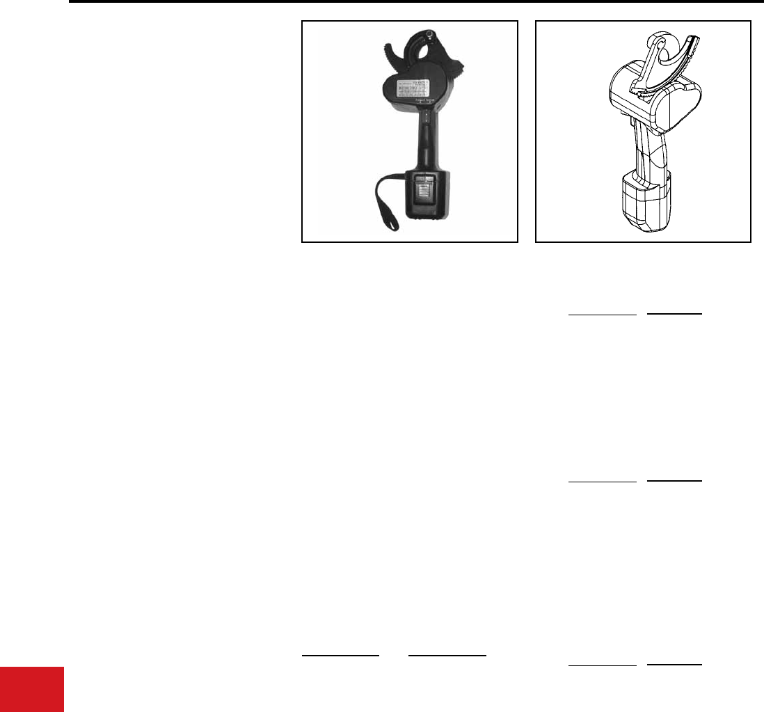
BURNDY®
US: 1-800-346-4175 www.burndy.com Canada: 1-800-387-6487
Tooling
Cutters — Battery Actuated
BCC1000CUAL
BATTERY ACTUATED
CABLE CUTTER
Battery Actuated Cable Cutter
The BURNDY® BCC1000CUAL is a 12 V-DC
battery actuated cable cutter capable of cutting up
to 750 kcmil hard drawn copper cable, and up to
1000 kcmil soft drawn copper and up to 2″ O.D.
aluminum cable. DO NOT CUT STEEL or ACSR.
The BCC1000CUAL comes with battery powered
cutting tool, sealed nickel cadmium 12V battery,
120V AC charger, carrying case, and wrist loop
which provides added security when making cuts
overhead.
The BURNDY® BCC1000CUAL is designed to cut
copper and aluminum cables in a limited amount
of space. The BCC1000CUAL makes fast reliable
cuts without stress to the user. Just squeeze the
trigger and it will cut through your toughest copper
and aluminum cables. The BCC1000CUAL has a
three-way switch (forward, reverse, and neutral)
which allows the user to make partial cuts, back off
cables, or make adjustments during cutting.
The battery charge time is approximately 1 hour for
a fast charge (80%), 4 to 6 hours for a quick charge,
and 14 to 16 hours for a standard charge (100%).
The 12V battery can be recharged approximately
1,000 times.
The BCC1000CUAL (excluding cutting blades)
is warranted to be free of defects in material and
workmanship for a period of 90 days, except in the
case of abuse or modication.
• Hook head design
• Three-way switch
• Hardened steel blades
• Ergonomic design
• Wrist loop
• Simplies conductor cutting and allows working
in tight spaces
• Allows backing off cable, partial cuts, and
adjusting during cutting
• Helps ensure consistent cuts and longer blade
life
• Prevents hand/wrist injury
• Withstands rugged use, resists oil and solvents
• Added security when cutting cables overhead
Cutting Tool
Specications
Drive Unit:
Dimensions:
Weight:
Cutting Capacity:
Battery
Specications
Battery Type:
Voltage:
Rated Capacity:
Charge Time:
Dimensions:
Weight:
Battery Charger
Specications
Input Voltage:
Input Frequency:
Input Current:
Dimensions:
Weight:
Features and Benets SPECIFICATIONS
FOR USE ON
Maximum conductors accommodated:
750 kcmil hard drawn copper
1000 kcmil soft drawn copper
1000 kcmil aluminum
Description
12 V-DC Motor
4″ L X 4.5″ W X 14.5″ H
6 lbs
1000 kcmil soft drawn
copper, 750 kcmil hard
drawn copper and up to
2″ O.D. aluminum
Description
Sealed nickel cadmium
12 V-DC
1.2 A/hr.
Fast, approx. 1 hour
Quick, 4-6 hours
Standard, 14-16 hours
2.75″ L X 2.7″ W X 4.75″
1.4 lb
Description
120 V-AC
60 Hz
110/120V
5.7″ L X 3″ W X 2.8″ H
2.2 lbs
Catalog Number
BCCBAT12V
BCCCHGR
BCCCASE
RP50RP03
RP50RP02
Item Description
Battery
Charger
Carrying Case
Moving Blade
Fixed Blade
ACCESSORIES
N-80
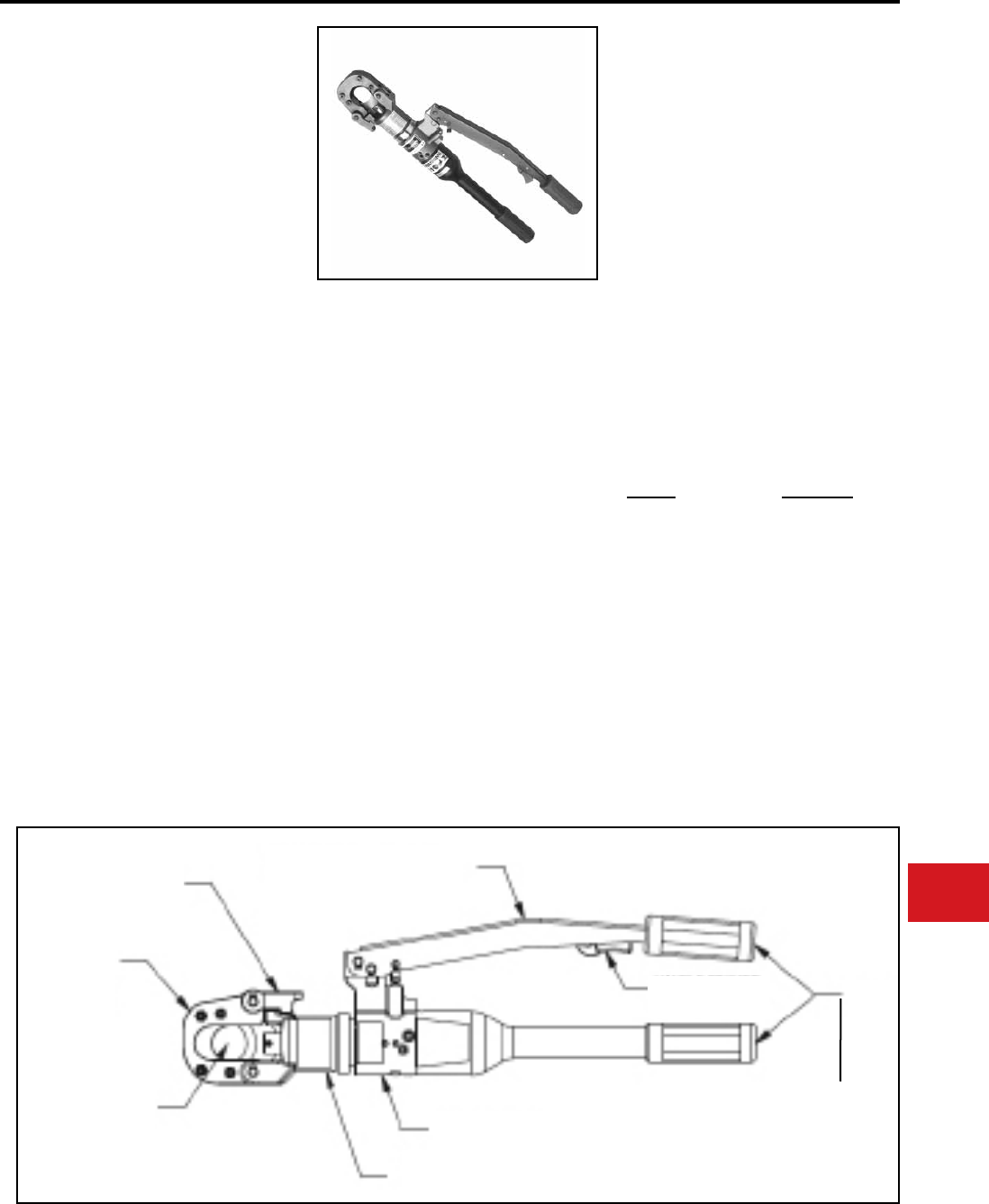
BURNDY®
Canada: 1-800-387-6487 www.burndy.com US: 1-800-346-4175
Tooling
Cutters — Self-Contained Hydraulic
YCUT129ACSR
HYDRAULIC HAND
OPERATED CUTTER
The BURNDY® YCUT129ACSR incor-
porates a specialized latch style cutting
head that allows interference-free closure
for mid-span cuts. The cutter head rotates
180 degrees to allow users to get into
tight areas easier. The YCUT129ACSR
weighs only 11.4 pounds, yet delivers 7
tons of cutting force. The YCUT129ACSR
with its hardened steel blades is capable
of cutting up to 1.29″ diameter bare or
insulated copper and aluminum cable,
1113 ACSR, 5/8″ ground rod, 1/2″ rebar
and 5/8″ diameter soft steel bolts 1/2″
standard guy strand and up to 3/8″ EHS
guy strand.
The YCUT129ACSR comes equipped
with a high impact formed carrying case
to hold the tool and accessories. The
BURNDY® YCUT129ACSR is provided
with a 5-year limited warranty (excluding
blades).
• Patented rapid advance pump for faster cuts
with less hand strokes
• Specialized latch head design; Interference
free closure on mid-span cuts
• Handle trigger drain for convenient blade
retraction
• Hardened steel blades with the ability to cut
ACSR, ground rods, rebar and guy wire
• Comfort grip handles to help ease fatigue
with continuous use
• 180-degree head rotation allows for
versatile head positioning to get into tight
areas easier
• Durable high impact formed carrying case
to provide for tool protection and to store
accessories
• 5-year limited warranty on tool (excluding
blades)
Force Developed:
Tool Weight:
Length:
Height:
Width:
Features and Benets
SPECIFICATIONS
FOR USE ON
Copper Cable:
Aluminum Cable:
ACSR:
Ground Rod:
Rebar:
Soft Steel Bolts:
Standard Guy Strand:
EHS Guy Strand:
7 U.S. short tons
11.4 lbs (5.1 kg)
22.4″ (56.9 cm)
6.6″ (16.8 cm)
2.5″ (6.4 cm)
ACCESSORIES
Cat. No. Description
PT10024162
Replacement Blades:
PT10037388
PT10037384
Carrying Case
Moving Blade
Fixed Blade
up to 1.29″
up to 1.29″
up to 1113 ACSR
up to 5/8″
up to 1/2″
up to 5/8″
up to 1/2″
up to 3/8″
SPECIALIZED
LATCH HEAD
DESIGN
PRECISION
CUTTING
BLADES
1.29" CUTTING
CAPACITY
180 HEAD DESIGN
PATENTED RAPID
ADVANCE PUMP
HANDLE TRIGGER
DRAIN
COMFORT
GRIP HANDLES
ERGONOMIC HANDLE DESIGN
N-81
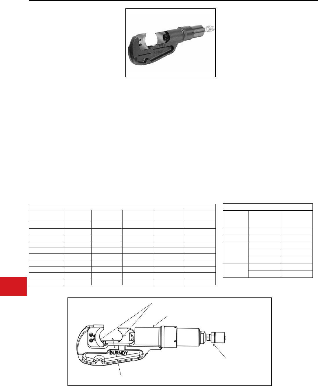
BURNDY®
US: 1-800-346-4175 www.burndy.com Canada: 1-800-387-6487
Tooling
Cutters — Remote Hydraulic
RHCC10
RHCC10C
10,000 PSI Remote
Cable Cutter
Remote Power Operated
Hydraulic Cable Cutter
The BURNDY® RHCC10 series C-head cutter is an
innovative compact cutting tool that allows users to
interchange different cutting blades customized for
their application.
With a “C”-shaped style head and large opening,
it’s easy to scoop and cut without the need to open
or close a latch. The RHCC10 blade alignment
technology ensures a clean cut and maximum
blade life. The RHCC10 series tool accommodates
four (4) different interchangeable blade types to
cut Copper/Aluminum, ACSR/ACSS, EHS Guy
and Rebar. The RHCC10 series tool comes in
a variety of options including the ability to order
the tool with specic blades only as well as a
covered head version (RHCC10C). The RHCC10
and RHCC10C are provided wth a 5-year limited
warranty (excluding blades).
Features and Benets
SPECIFICATIONS
FOR USE ON
ACCESSORIES
• Specialized reinforced C-Head designed for
easy and efcient cable cutting for both eld
and OEM applications
• Interchangeable precision cutting blades
optimized for cutting Copper/Aluminum,
ACSR/ACSS, EHS Guy Strand and Ground
Rod/Rebar
• Durable canvas carrying bag provides tool
protection and stores all accessories
• High strength steel cylinder for durability and
long life
• 5-year limited warranty on tool (excluding
blades)
Operating Pressure:
Tool Weight:
Length:
Width:
Cu/Al Cable :
ACSR/ACSS
:
Ground Rod :
Rebar :
Soft Steel Bolts :
Std & EHS Guy :
Blades
:
10,000 PSI (700 bar)
13.2 lbs (6 kg)
17.58" (447 mm)
4.70" (119 mm)
up to 1.5"
up to 1590 kcmil
up to 5/8"
up to 1/2"
up to 5/8"
up to 9/16"
HCCCUAL
HCCACSR
HCCGUY
HCCSOL
Replacement
Hot Stick
Canvas Bag : MINBAG
Components Each Tool is Provided With
Catalog
Number
Covered
Tool
ACSR Blade
Set
CUAL Blade
Set
SOL Blade
Set
GUY Blade
Set
RHCC10 Х Х Х Х
RHCC10C Х Х Х Х Х
RHCC10ACSR Х
RHCC10CUAL Х
RHCC10SOL Х
RHCC10GUY Х
RHCC10CACSR Х Х
RHCC10CCUAL Х Х
RHCC10CSOL Х Х
RHCC10CGUY Х Х
Adapter : PT10128
Blade Table
Blade
Catalog
Number
Cutting
Material Max. O.D.
HCCACSR ACSR/ACSS 1590 kcmil
HCCCUAL CU & AL 1.5" (38 mm)
HCCSOL
Ground Rod 5/8" (16 mm)
Rebar 1/2" (13 mm)
Soft Steel Bolts 5/8" (16 mm)
HCCGUY Std. Guy Wire 9/16" (14 mm)
EHS Guy Wire 9/16" (14 mm)
Precision Cutting Blades
High Strength Steel
Cylinder
Quick Disconnect
Hydraulic Fitting
1.50" Cutting
Capacity
N-82
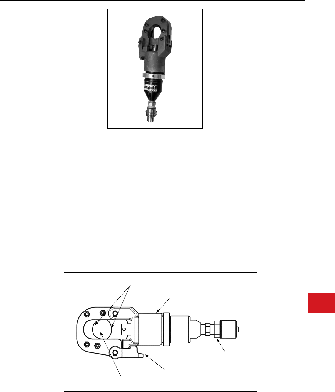
BURNDY®
Canada: 1-800-387-6487 www.burndy.com US: 1-800-346-4175
Tooling
Cutters — Remote Hydraulic
RHCC129ACSR
10,000 PSI Remote Cable
Cutter
Remote Power Operated
Hydraulic Cable Cutter
The BURNDY® RHCC129ACSR remote hydraulic
cable cutter incorporates a specialized latch style
cutting head that allows interference-free closure
for mid-span cuts. The RHCC129ACSR with its
precision cutting blades is capable of cutting up
to 1.29″ diameter bare or insulated copper and
aluminum cable, 1113 ACSR, 5/8″ ground rod, 1/2″
rebar, 5/8″ diameter soft steel bolts, 1/2″ standard
guy strand, and up to 3/8″ EHS guy strand.
The RHCC129ACSR is provided with a 5-year
limited warranty (excluding blades). • Specialized latch head design - interference
free closure for mid-span cuts
• Precision cutting blades for clean cuts
on Cu/Al, ACSR, ground rods, rebar, guy
strand, and soft steel bolts
• High strength steel cylinder for durability and
long life
• Lightweight ergonomic design allows one
hand operation; user has one hand free to
manipulate material to be cut
• Durable canvas carrying bag provides tool
protection and stores all accessories
• 5-year limited warranty on tool (excluding
blades)
Operating Pressure:
Tool Weight:
Length:
Width:
Features and Benets
SPECIFICATIONS
FOR USE ON
Copper Cable:
Aluminum Cable:
ACSR:
Ground Rod:
Rebar:
Soft Steel Bolts:
Standard Guy Strand:
EHS Guy Strand:
up to 1.29″
up to 1.29″
up to 1113 ACSR
up to 5/8″
up to 1/2″
up to 5/8″
up to 1/2″
up to 3/8″
10,000 PSI
(700 bar)
5.85 lbs (2.65 kg)
11.25″ (286 mm)
3.7″ (94 mm)
Canvas Bag:
Replacement Blades:
Hot Stick Adapter:
Cat# PT10043890
Cat# PT10037388
(Moving Blade)
Cat# PT10037384
(Fixed Blade)
Cat# RHCCHSA
ACCESSORIES
PRECISION CUTTING BLADES
HIGH STRENGTH
STEEL CYLINDER
QUICK DISCONNECT
HYDRAULIC FITTING
SPECIALIZED LATCH
HEAD DESIGN
1.29 CUTTING
CAPACITY
N-83
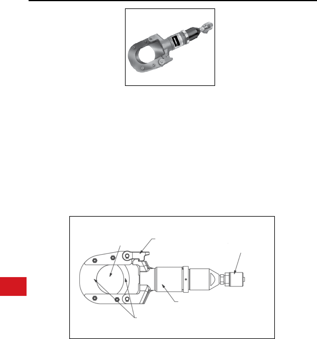
BURNDY®
US: 1-800-346-4175 www.burndy.com Canada: 1-800-387-6487
Tooling
Cutters — Remote Hydraulic
RHCC245CUAL
10,000 PSI Remote Cable
Cutter
Remote Power Operated
Hydraulic Cable Cutter
The BURNDY® RHCC245CUAL remote hydraulic
cable cutter incorporates a specialized latch style
cutting head that allows interference-free closure
for mid-span cuts. The RHCC245CUAL with its
precision cutting blades is capable of cutting up to
2.45″ diameter copper and aluminum cable.
The RHCC245CUAL is provided with a 5-year
limited warranty (excluding blades).
• Specialized latch head design; interference
free closure for midspan cuts
• Precision cutting blades for clean cuts on
copper and aluminum cable
• High strength steel body for durability and
long life
• Lightweight ergonomic design allows one
hand operation allows user to have one hand
free to manipulate material to be cut
• Durable canvas carrying bag provides tool
protection and stores all accessories
• 5-year limited warranty on tool (excluding
blades)
Operating Pressure:
Tool Weight:
Length:
Width:
SPECIFICATIONS
FOR USE ON
Copper & Aluminum:
2.45″ O.D. (62 mm)
10,000 PSI
(700 bar)
8.3 lbs (3.8 kg)
14.8″ (376 mm)
4.75″ (121 mm)
ACCESSORIES
Features and Benets
Canvas Bag:
Replacement
Blades:
Cat# PT10054094
Cat# PT10038657
(Moving Blade)
Cat# PT10040663
(Fixed Blade)
2.45" Cutting
Capacity Specialized Latch
Head Design Quick Disconnect
Hydraulic Fitting
High Strength
Steel Cylinder
Precision Cutting Blades
N-84
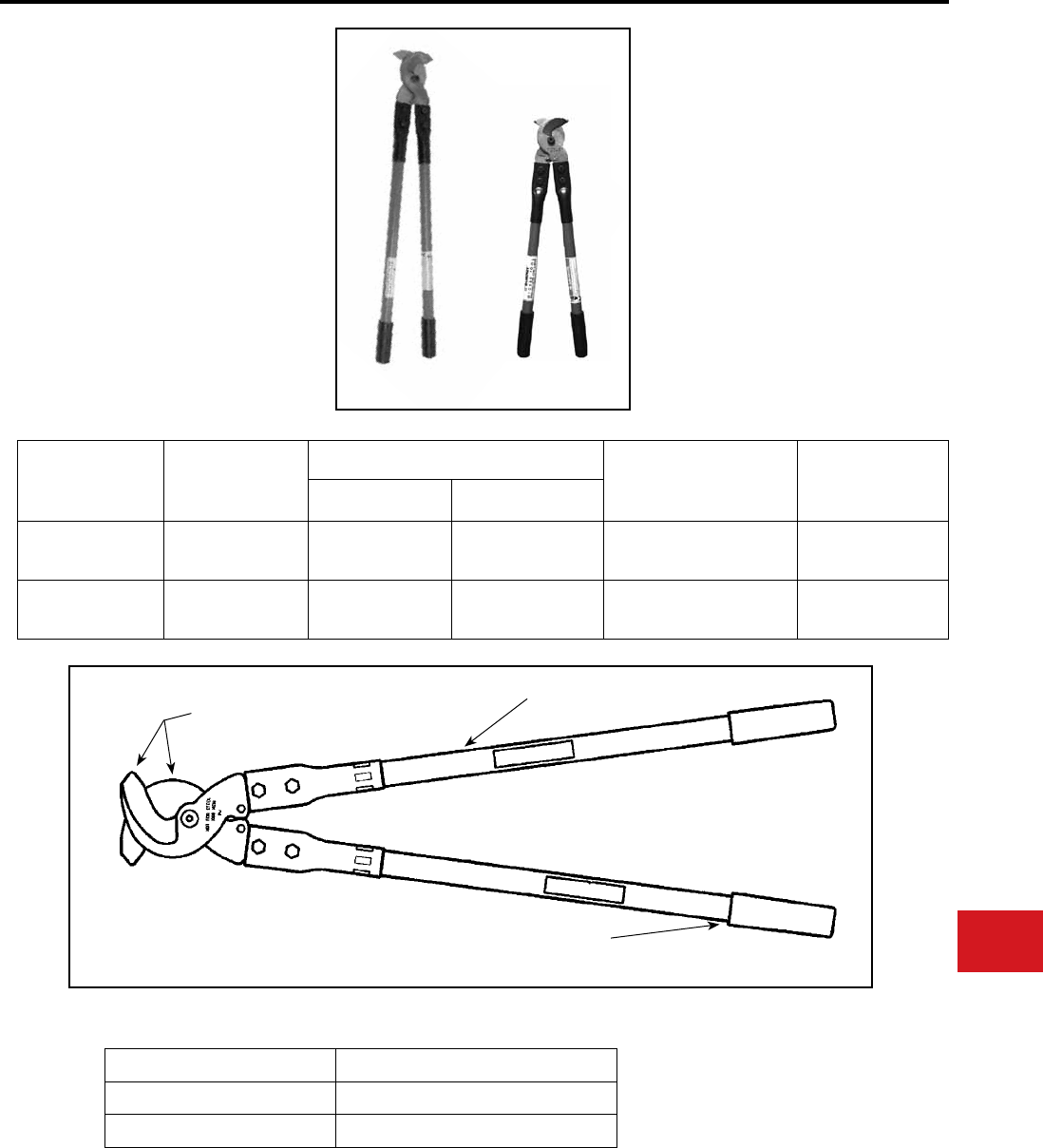
BURNDY®
Canada: 1-800-387-6487 www.burndy.com US: 1-800-346-4175
Tooling
Cutters — Mechanical and Ratchet
MCC600, MCC1000
MANUAL CABLE CUTTERS
The MCC series cable cutters are precision cable
cutters incorporating high leverage shear type
design capable of cutting up to 1000 kcmil copper
and aluminum cables.
Rugged steel blades and berglass construction
provide cutting ease, long life and minimum cable
distortion.
The MCC series cable cutters are warranted to be
free from defects in material (excluding blades) and
workmanship for one year.
Features and Benets
• High quality design and construction
• Rugged high quality steel blades
• Fiberglass handles with soft grips
• Easy cutting with minimal cable distortion
• Excellent cutting edge performance
• Provides comfortable tool operation and long
life
Catalog
Number Overall Length
Max. Capacity Max.
Insulation
Diameter WeightCopper Aluminum
MCC600 21"
[533 mm] 600 kcmil 600 kcmil 1.31"
[33 mm]
3.5 lbs.
[1.5 kg]
MCC1000 32"
[813 mm] 1000 kcmil 1000 kcmil 1.90"
[48 mm]
9.0 lbs.
[4.0 kg]
Replacement Blades
Catalog Number Description
MCC600BLADESET Replacement Blades for MCC600
MCC1000BLADESET Replacement Blades for MCC1000
MCC600MCC1000
REPLACEABLE
BLADES
HANDLES
HANDLE GRIPS N-85
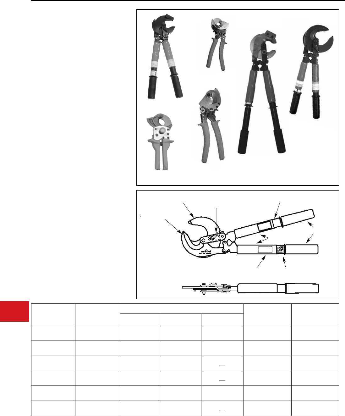
BURNDY®
US: 1-800-346-4175 www.burndy.com Canada: 1-800-387-6487
Tooling
Cutters — Mechanical and Ratchet
TYPES RCC336, RCC556,
RCC600E, RCC750HD,
RCC954ACSR1K, RCC1000
Ratchet Cable Cutters
The RCC series cable cutters are precision high
quality tools designed to cut up to 954 ACSR and
1000 kcmil copper and alumin-um. The tools are
equipped with rugged steel blades and a precision
bi-directional ratchet mechanism for positive
blade control, including where applicable, a fast
action thumb slide collar for rapid blade advance
and rugged berglass or non-slip grip handles.
RCC600E and RCC750HD have cushion grip
covered steel handles.
The RCC series cable cutters are warranted to be
free from defects in material (excluding blades) and
workmanship for one year.
For replacement blades, consult factory for
details.
• Patented high strength steel blades
• Quick release, bi-directional ratchet
mechanism
• Rapid blade advance
• Easy cutting with minimal cable distortion
• Excellent cutting edge performance
• Provides comfortable tool operation and
long life
RCC556
RCC336
RCC750HD
Catalog
Number
Overall Length
in / mm
Max. Capacity Max. Insulation
Diameter in / mm
Weight
lbs. / kgCopper Aluminum ACSR
RCC336 10.50" / 267 mm 350 kcmil
[177 mm]
500 kcmil
[253 mm]
336 kcmil
[18.31mm] 0.74" / 18.8 mm 1.20 lbs. / 0.50 kg
RCC556 20.00" / 508 mm 500 kcmil
[26.70 mm]
500 kcmil
[26.70 mm]
556 kcmil
[23.55mm] 1.25" / 31.75 mm 4.50 lbs. / 2.00 kg
RCC600E 10.50" / 267 mm 600 kcmil
[26.70 mm]
600 kcmil
[26.70 mm] 1.05" / 26.60 mm 1.32 lbs. / 0.40 kg
RCC750HD 10.50" / 267 mm 750 kcmil
[29.36 mm]
750 kcmil
[29.36 mm] 1.62" / 41.15 mm 2.43 lbs. / 1.10 kg
RCC954ACSR1K 22.75" / 578 mm 1000 kcmil
[33.27 mm]
1000 kcmil
[33.27 mm]
954 kcmil
[30.38 mm] 1.38" / 35.05 mm 6.50 lbs. / 2.95 kg
RCC1000 20.00" / 508 mm 1000 kcmil
[33.27 mm]
1000 kcmil
[33.27 mm] 2.38" / 60.32 mm 4.50 lbs. / 2.00 kg
RCC1000
Features and Benets
RCC600E RCC954ACSR1K
MOVEABLE JAW
STATIONARY JAW
DIRECTION LEVER
OPEN/CLOSE INDICATOR
WARNING LABEL
HANDLE GRIPS
COVER
PRODUCT LABEL RAPID ADVANCE FEATURE
N-86
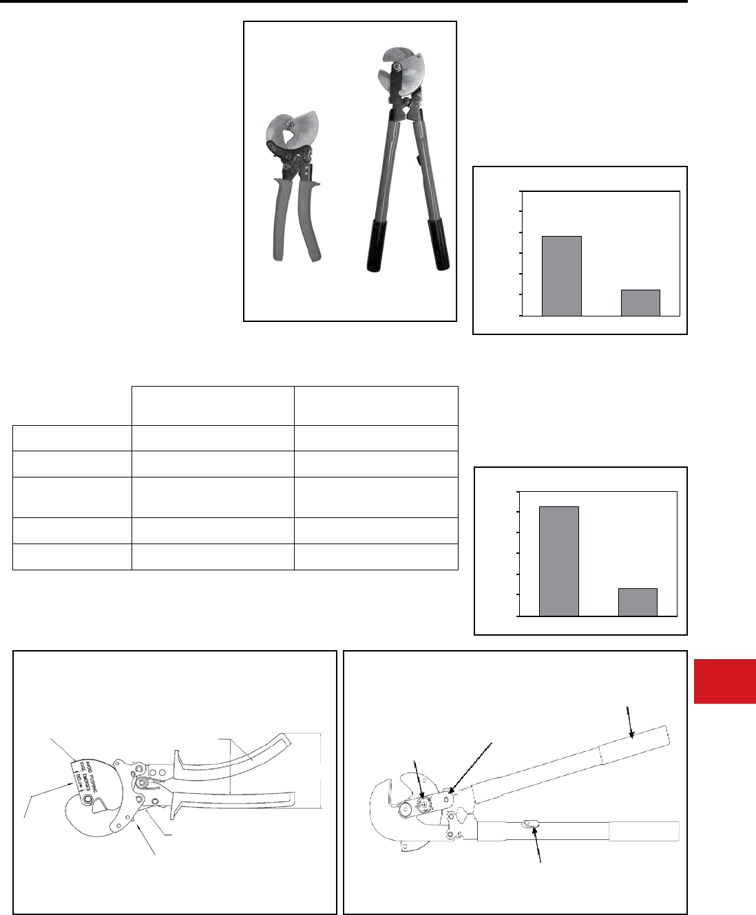
BURNDY®
Canada: 1-800-387-6487 www.burndy.com US: 1-800-346-4175
Tooling
Cutters — Mechanical and Ratchet
RWRC516, RWRC916
Ratchet Wire Rope Cutter
The BURNDY® RWRC516 and RWRC916 wire
rope cutters are premium precision tools designed
to cut exible, multi-stranded steel and stainless
steel wire rope.
Tightly guided high strength steel blades prevent
wire entrapment between the blades. The blade
geometry captures the wire to produce a clean
cut while preserving the circular shape of the wire
bundle.
The tool employs a ratchet mechanism for precise
control and signicantly reduced handle force as
compared to scissor or compound action designs.
The handle grips are made of non-slip material and
are designed for operator comfort.
Weight:
Length:
Cutting Capacity
Mild Steel:
Stainless Steel:
Weight:
Length:
Cutting Capacity
Mild Steel:
Stainless Steel:
SPECIFICATIONS
RWRC516
RWRC916
120 lbs.
10.0"
5/16″ dia
1/4″ dia
4.35 lbs.
20.0"
9/16″ dia
1/2″ dia
RWRC516 RWRC916
Ratcheting Feature Yes Yes
Blade Material Hardened Steel Hardened Steel
Emergency Release Disengagement from Ratchet Reverse Operation with
Forward/Reverse Switch
Rapid Blade Advance Yes Yes
Quickblade Reset Push Blade Through Cycle Reverse Operation
RWRC516 RWRC916
1/4″ Dia. Wire Rope
Handle Force
Non-ratchet Design RWRC516
150
125
100
75
50
25
0
Handle Force
1/4″ Dia. Wire Rope
Non-ratchet Design RWRC916
150
125
100
75
50
25
0
PUSH BLADE
THROUGH TO
RESET
LOCKING LEVER (REVERSE SIDE)
MOVABLE JAW COMFORT GRIP
HANDLES
CLOSED POSITION
BLADE GUIDE
FORWARD / REVERSE
SWITCH
RATCHET MECHANISM
COMFORT-GRIP HANDLES
RAPID BLADE ADVANCE SWITCH
RWRC516 RWRC916
N-87
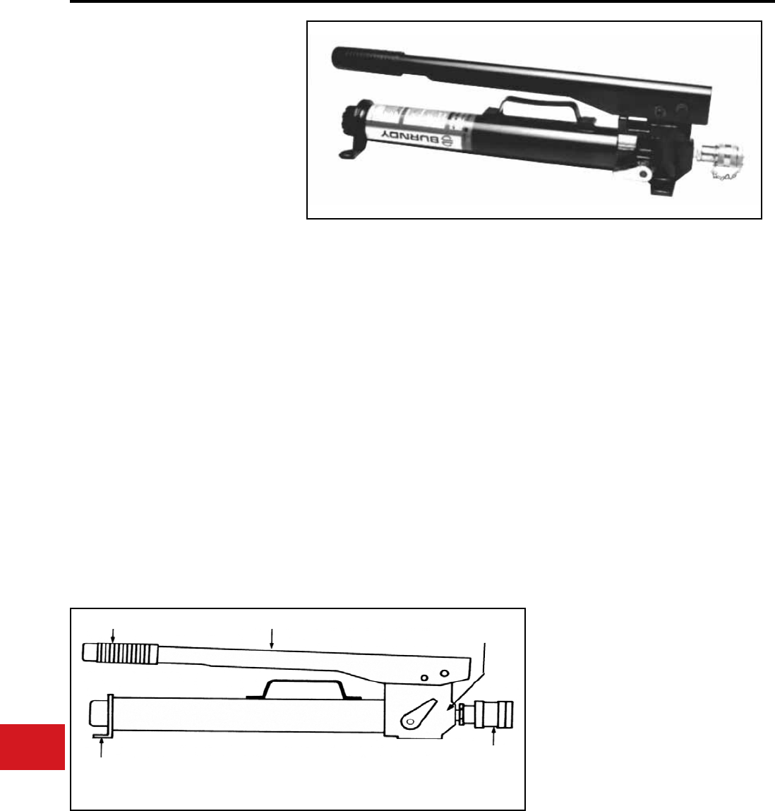
BURNDY®
US: 1-800-346-4175 www.burndy.com Canada: 1-800-387-6487
Tooling
Hydraulic Pumps
HP10, HP8 AND HP6
HP Series Manual
Hydraulic Hand Pumps
Hydraulic Output Pressures
of 10,000 PSI, 8,800 PSI, and
6,000 PSI
Hand pumps are designed to match the output
pressure requirements of HYPRESS™ heads
and cutters. Each pump is equipped with a built-
in, factory set pressure release valve with audible
click to signal completion of crimp cycle. • Durable, long life expectancy
• Easy to transport and move tool around job site
with built in handle
• Maximum mechanical advantage provided with
long handle
• Solid tool base provided with sturdy broad leg
stabilizers
• Save time with quick disconnect hydraulic tting
• High quality crimps provided with built-in, factory
set pressure release valve and audible click to
signal completion of crimp
• 5-year limited warranty
Reservoir volume:
Length:
Width:
Weight:
Closed height:
Height:
(with handle open)
Features and Benets SPECIFICATIONS
FOR USE ON
1-1/8 qts.
24-3/4″
5″
18 lbs
6-3/4″
20″
HP10 10,000 Y34BH, Y35BH, Y35BH-4,
Y750BHXT, Y750CBHXT,
Y39BH, Y45, Y46C, Y46,
Y60BHU, Y60 LW,
RHCC Series Cutters
HP8 8,800 Y48BH
HP6 6,000 Y29BH, Y35-L
ACCESSORIES
Cat# BP10PADKIT Extended leg pad
stablilizers
(w/hardware)
HANDLE GRIP LONG ARM
STURDY LEG STABILIZERS LIGHTWEIGHT RUGGED
DESIGN PORTABLE
HANDLE
QUICK
DISCONNECT
HYDRAULIC
FITTING
BUILT-IN FACTORY
SET PRESSURE
RELIEF VALVE
N-88
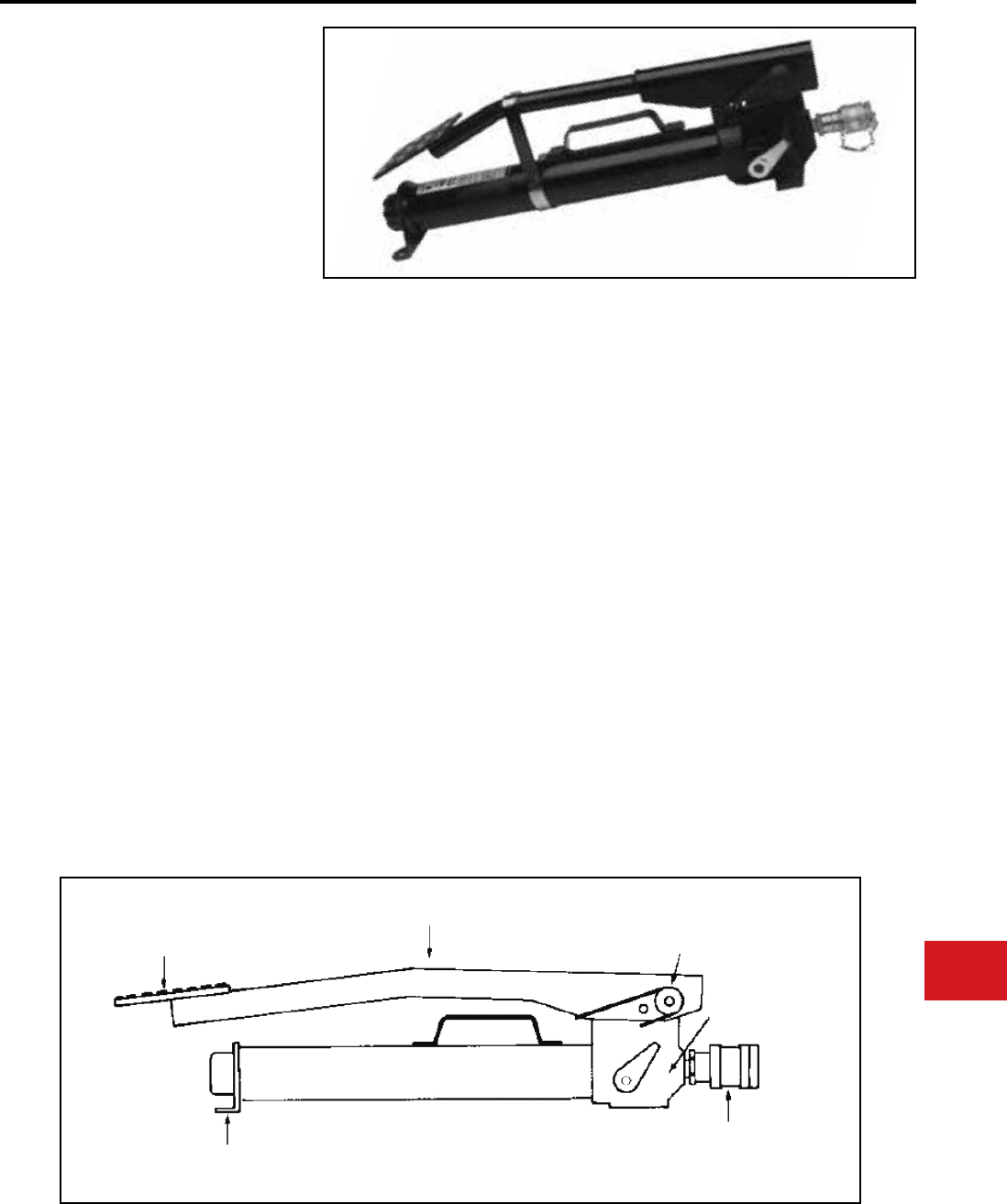
BURNDY®
Canada: 1-800-387-6487 www.burndy.com US: 1-800-346-4175
Tooling
Hydraulic Pumps
FP10, FP8 AND FP6
FP Series Manual
Hydraulic Foot Pumps
Hydraulic Output Pressures
of 10,000 PSI, 8,800 PSI, and
6,000 PSI
Foot pumps are designed to match the output
pressure requirements for use with all HYPRESS™
heads and cutters. Each pump is equipped with a
built-in, factory set pressure release valve with
audible click to signal completion of a crimp cycle. • Easy to lift and carry.
• Durable. Long life expectancy.
• Easy to transport and move tool around job site
with built in handle.
• Easy operation provided with spring assisted
return arm.
• Maximum mechanical advantage provided with
long arm extending beyond pump body.
• Quality, heavy duty foot pad provided with
diamond plate steel.
• Solid tool base provided with sturdy broad leg
stabilizers.
• Time saving quick disconnect hydraulic tting.
• High quality crimps provided with factory set
pressure release valve with audible click to signal
completion of crimp.
• 5-year limited warranty.
• Diamond plate steel foot pad.
• Long arm, Spring loaded arm.
• Built-in factory set pressure relief valve.
• Quick disconnect hydraulic tting.
• Lightweight rugged design - portable.
• Sturdy leg stabilizers.
Features and Benets SPECIFICATIONS
FOR USE ON
Reservoir volume:
Length:
Width:
Weight:
Closed height:
Height:
(with handle open)
1-1/8 qts.
24-3/4″
5″
19 lbs
6-1/2″
17″
FP10 10,000 Y34BH, Y35BH, Y35BH-4,
Y750BHXT, Y39BH,Y45,
Y46C, Y46, Y60BHU,
Y60LW, Y750CBHXT,
RHCC Series Cutters
FP8 8,800 Y48BH
FP6 6,000 Y35-L, Y29BH
ACCESSORIES
Cat# BP10PADKIT Extended leg pad
stablilizers
(w/hardware)
DIAMOND PLATE
STEEL FOOT PAD
LONG ARM
STUDY LEG
STABILIZERS
LIGHTWEIGHT
RUGGED DESIGN
PORTABLE
QUICK
DISCONNECT
HYDRAULIC
FITTING
BUILT-IN
FACTORY SET
PRESSURE
RELIEF VALVE
SPRING
LOADED ARM
N-89
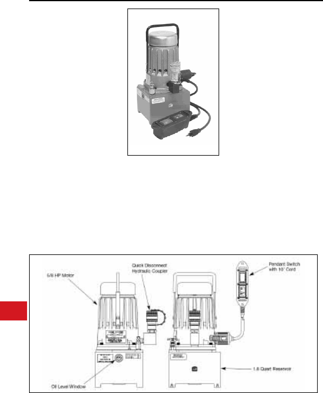
BURNDY®
US: 1-800-346-4175 www.burndy.com Canada: 1-800-387-6487
Tooling
Hydraulic Pumps
Y10AC9
Electric Hydraulic Pump
Hydraulic Output Pressure of
10,000 PSI
The Y10AC9 electric hydraulic pump is for use
with all HYPRESS™ heads and cutters requiring
10,000 PSI operating pressure.The Y10AC9 is
equipped with a built-in, factory set pressure relief
valve. An audible “pop” and recycling of the pump
as well as relaxing of the hose signal completion of
the crimping/cutting cycle. Pump is supplied with a
durable hand-held electric pendant switch.
• Sealed electric pendant switch; easy
operation with durable remote pendant
switch with 10-foot cord
• 5-year limited warranty
Features and Benets
SPECIFICATIONS
FOR USE ON
The BURNDY® Y10AC9OEM is an additional
electric hydraulic pump offering that comes
equipped with a foot switch and “jog-and-hold”
feature. Keep both hands on the connection with
the Y10AC9OEM pump kit. For further details
please contact customer service.
Motor:
Maximum current
draw:
Reservoir Volume:
Height:
Base:
Weight:
115V-AC 50/60 Hz
5/8 HP, 10,000 rpm
11 amp
1.61 quarts
14.38″
6.5″ Χ 8.25″
28 lbs (with oil)
YAC-CASE Steel carrying case with
handle and locking latch.
YAC-FC Foot Control.
Y34BH, Y35BH, Y35BH4, Y39BH, Y45, Y46,
Y46C, Y750BHXT, Y750CBHXT, Y644MBH,
Y4PC834MBH, Y81KFTMBH, Y60BHU,
RHCC129ACSR, RHCC245CUAL
ACCESSORIES
• Lightweight, small size; easy to lift, carry
and transport tool around job site with
lightweight body and handle
• Factory set relief valve; high quality crimps
are achieved with built-in, factory set
pressure relief valve and audible recycling of
pump to signal completion of crimp cycle
• 100,000 (+) life cycles; long durable life
expectancy with light weight cast aluminum
reservoir body
• Convenient 115V AC electric powered motor
• Saves time with quick disconnect hydraulic
tting
N-90
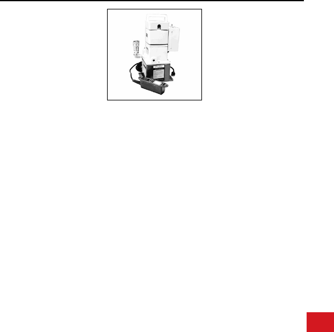
BURNDY®
Canada: 1-800-387-6487 www.burndy.com US: 1-800-346-4175
Tooling
Hydraulic Pumps
EPP10 AND EPP6
EPP Series
Electric/Hydraulic Pump
Hydraulic Output Pressures
of 10,000 PSI and 6,000 PSI
The lightweight and durable EPP10 electric/
hydraulic pump is for use with all BURNDY®
HYPRESS™ remote heads and cutters requiring
10,000 PSI operating pressure. Both the EPP10
and the EPP6 are equipped with a built-in, factory
set pressure relief valve. An audible “pop” and
recycling of the pump and relaxing of the hose,
signals completion of the crimping/cutting cycle.
Both pumps are supplied with a durable hand-held
electric pendant switch, for remote operation of the
unit, and have a manual selection switch mounted
for operation of the unit at the pump. The operator
can select which method is best suited for the
application.
An optional carry/shipping case can be ordered.
All EPP Series pumps have been life cycle
tested to over 100,000 cycles without failure, and
are warranted to be free of defects in materials
and workmanship for 5-years when properly
maintained and operated.
Features and Benets
SPECIFICATIONS
FOR USE ON
• Lightweight
• Small size
• Factory set relief valve
• 100,000 (+) life cycles
• Sealed electric pendant switch
• High quality crimps are achieved with built in,
factory set pressure release valve and audible
recycling of pump to signal completion of crimp
cycle
• Easy to lift, carry and transport tool around job
site with lightweight body and handle
• Convenient 115 V-AC electric powered motor
• Durable remote pendent switch
• Easy operation controlled with pendent switch,
or manual switch
• Saves time with quick disconnect hydraulic
tting
• Long durable life expectancy with lightweight
cast aluminum reservoir body
• 5-year limited warranty.
Motor:
Maximum
Current Draw:
Reservoir Volume:
Height:
Base:
Weight:
115V-AC/60 Hz
1/2 HP @ 3450 RPM
12.5 amperes
2 quarts
16″
6″ Χ 8″
30 lbs
EPP10 10,000 Y34BH, Y35BH,
Y35BH-4, Y39BH,
Y45, Y46, Y46C,
Y60BHU, Y60LW,
Y644MBH,
Y750BHXT,
Y750CBHXT,
RHCC Series Cutters
EPP6 6,000 Y35L, Y29BH
ACCESSORIES
Cat. No. EPPCASE-1
Steel carrying case with handle and locking latch.
N-91
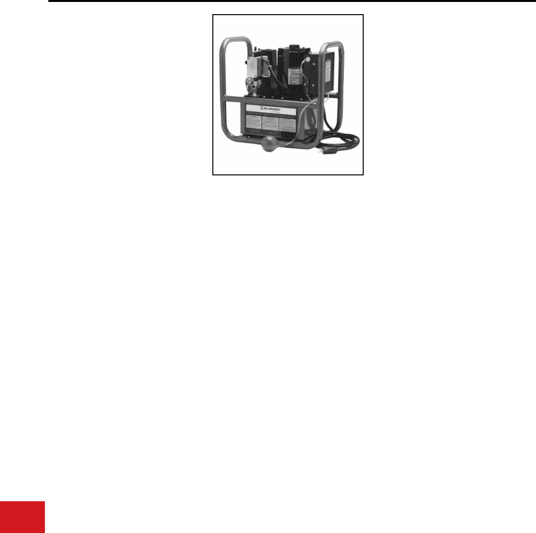
BURNDY®
US: 1-800-346-4175 www.burndy.com Canada: 1-800-387-6487
Tooling
Hydraulic Pumps
EPAC10, EPAC8 AND EPAC6
EPAC Series
Electric/Hydraulic Pump,
Air Control
Hydraulic Output Pressures
of 10,000 PSI, 8,800 PSI, and
6,000 PSI
The EPAC10, EPAC8, and EPAC6 electrically
driven hydraulic pumps feature exclusive
automatic or manual “Jog and Hold” operation
control provided by a unique air control switch,
which provides the safest operation method of
any pump available. All EPAC’s are remotely
controlled by an improved air control switch which
electrically isolates the operator from the unit, and
can be operated by either hand or foot activation.
A three (3) position toggle switch mounted on the
control box allows the operator to select either full
automatic, off, or manual operation.
The automatic mode advances the remote tool into
a “hold” position without crimping the connector
so the operator can inspect the orientation
before completing the crimp. Once the crimp is
completed, the pump automatically turns the pump
off, allowing the retraction of the remote tool and
resets itself for the next operation.
The manual position allows the operator to jog
the tool forward without the tool ram retracting.
To retract the tool prior to completing the crimp,
turn the control switch to “off,” the pump will stop
and the tool will retract. In the manual mode the
pump advances only while the control is being
depressed. To complete a crimp, squeeze and
hold the air control switch until the pump reaches
the pre-set pressure and shuts off.
The EPAC Series of electrically driven hydraulic
pumps incorporate a heavy-duty roll cage design
that is both rugged and portable. All EPAC Series
pumps have been life cycle tested to over 100,000
cycles without failure, and are warranted to be free
of defects in material and workmanship for 5 years
when properly maintained and operated.
Features and Benets
SPECIFICATIONS
FOR USE ON
• Roll cage
• 3 position switch and control box
• Factory set output pressure
• Quick disconnect hydraulic
coupler
• Oil level window
• 8 quart reservoir
• Permits nal inspection of
connector before completing
crimp cycle
• Extra supply hydraulic uid
8-quart reservoir
• Full automatic or manual “Jog and
Hold” cycles
• Operator safety with power loss
“smart
• circuit” freezes unit in event of
power disruption
• Method of operation desired is
permitted with 3-position selection
switch
• Safety is provided against
hazardous shock with airbulb
actuator and air line
• Saves time with quick disconnect
hydraulic tting
• Windows allows easy inspection
of proper oil level
• High quality crimps are achieved
with built-in factory set pressure
release valve
• 5-year limited warranty
Motor:
Maximum
Current draw:
Reservoir Volume:
Height:
Base:
Dry Weight:
1/2 HP 115/230V-AC,
60 Cycle
10 amperes
8 quarts max.
2 quarts min.
17-1/2″
11-3/4″Χ 18-1/2″
68 lbs
(82 lbs. with max. fluid)
(1/2 Hp @ 3450 RPM)
EPAC10 10,000 Y34BH, Y35BH
EPAC-8 8,800 Y48BH
EPAC-6 6,000 Y35L, Y29BH
N-92
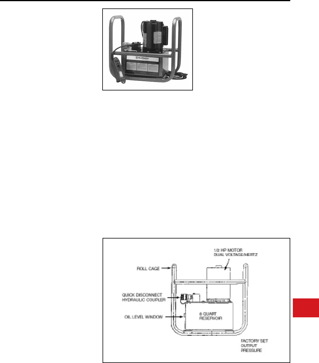
BURNDY®
Canada: 1-800-387-6487 www.burndy.com US: 1-800-346-4175
Tooling
Hydraulic Pumps
EP10, EP10-2, EP8,
AND EP6
EP SERIES ELECTRIC/
HYDRAULIC PUMPS
Hydraulic Output Pressures of 10,000
PSI, 8,800 PSI, and 6,000 PSI
Electrically driven hydraulic pumps are supplied
with a durable, hand-held electric pendent switch
that remotely controls the pump and matches the
output requirements of all HYPRESS™ remote
heads and cutters. Each pump is equipped with
a built-in, factory set, pressure relief valve. An
audible “pop” and recycling of the pump and
relaxing of the hose, signals completion of the
crimping cutting cycle.
All EP series pumps are supplied with 115/230 -
220/230 voltage, 60/50 hertz, 1/2 horse power
motor and can be wired for use with any electric
power source worldwide. A three prong, grounded
plug is wired standard on the units. All EP Series
pumps have been life cycle tested to over 100,000
cycles without failure, and are warranted to be
free of defects in materials and workmanship for
5-years when properly maintained and operated.
• 1/2 HP motor
• Dual voltage/hertz
• Roll cage
• Quick disconnect hydraulic coupler
• Oil level window
• 8 quart reservoir
• Factory set output pressure
• Provides fast sure pump action plus a long
life expectancy
• It’s portable. Roll cage allows easy moving
on the job site
• Durable 1/2 HP dual voltage motor
• Extra supply of hydraulic uid with 8 quart
reservoir
• Saves time with quick-disconnect hydraulic
tting
• Easy operator control is provided with
remote pendent switch
SPECIFICATIONS
FOR USE ON
Features and Benets
Motor:
(EP**-2 versions):
Current draw:
Reservoir Volume:
Height:
Base:
Dry Weight:
1/2 HP 115/230 V-AC,
60 Cycle
1/2 HP 220/230 V-AC,
50 Cycle
10 amperes
8 quarts max.,
2 quarts min.
17-1/2″
11-3/4″ Χ 18-1/2″
68 lbs
(86 lbs. with max. fluid)
(1/2 Hp @ 3450 RPM)
EP10
AND
EP10-2
10,000 Y34BH, Y35BH,
Y35BH-4, Y39BH,
Y45, Y46, Y46-C,
Y60BHU, Y60LW,
Y750BHXT, Y750CBHXT,
RHCC Series Cutters
EP8 8,800 Y48BH
EP6 6,000 Y35L, Y29BH
• Easy inspection of proper oil level is
provided by see through window
• High quality crimps are achieved with
built-in, factory set, pressure release valve
and audible recycling of pump which signals
completion of crimp
• 5-year limited warranty
N-93
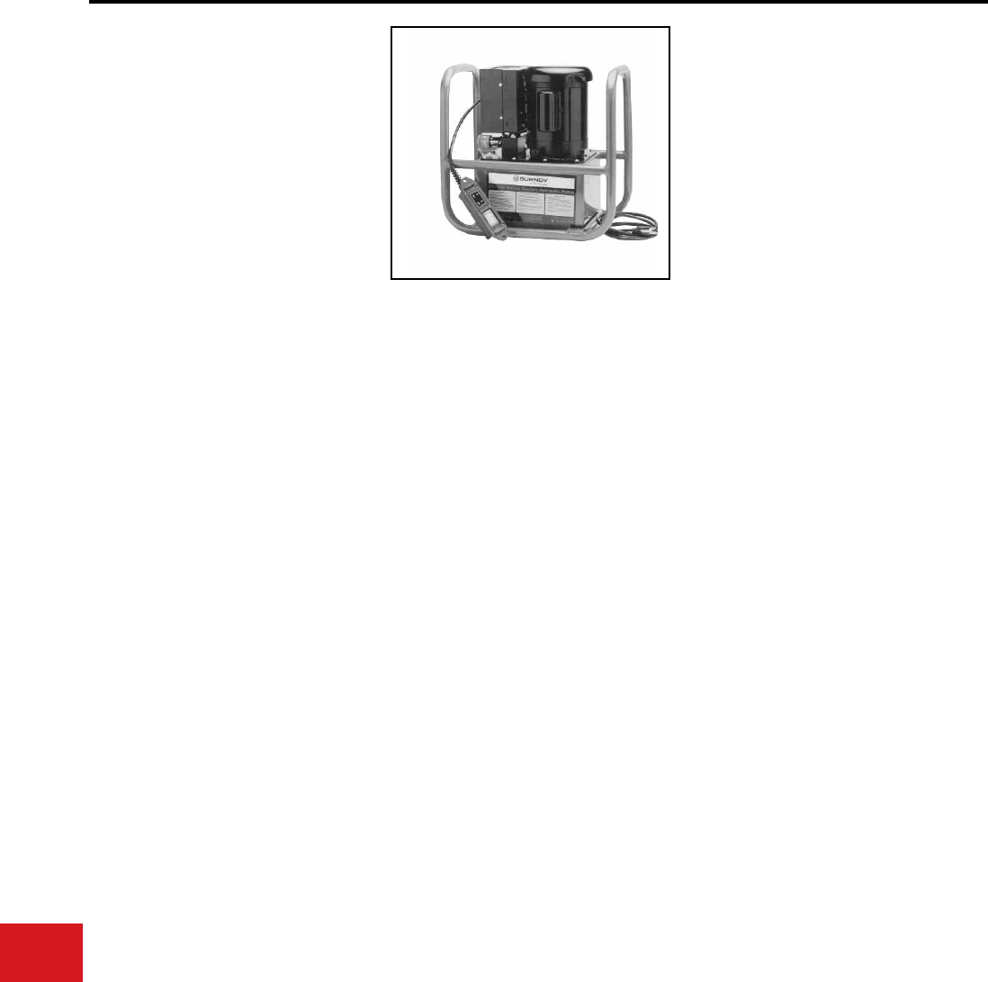
BURNDY®
US: 1-800-346-4175 www.burndy.com Canada: 1-800-387-6487
Tooling
Hydraulic Pumps
EP10-1HP AND
EP10-1HP-2
EP-1HP SERIES ELECTRIC/
HYDRAULIC PUMPS
Hydraulic Output Pressures
of 10,000 PSI
Heavy duty electrically driven hydraulic pumps
are supplied with a durable, handheld electric
pendent switch that remotely controls the
pump and matches the output requirements
of all HYPRESS™ remote heads and cutters.
Each pump is equipped with a built-in, factory
set, pressure relief valve. An audible “pop” and
recycling of the pump and relaxing of the hose,
signals completion of the crimping/cutting cycle.
All EP-1HP series pumps are supplied with 115/230
- 220/230 voltage, 60/50 hertz, 1 horsepower
motors and can be wired for use with any electric
power source worldwide. A three prong, grounded
plug is wired standard on the units. All EP-1HP
Series pumps have been life cycle tested to over
100,000 cycles without failure, and are warranted
to be free of defects in materials and workmanship
for 5-years when properly maintained and
operated.
Features and Benets
SPECIFICATIONS
FOR USE ON
• Heavy duty design
• Roll cage
• Quick disconnect hydraulic coupler
• Oil level window
• 8 quart reservoir
• Factory set output pressure
• 1 HP motor dual voltage/hertz
• Provides fast sure pump action plus a long
life expectancy
• Its portable roll cage allows easy moving on
the job site
• Strong durable motor provided with (1) H.P.
dual voltage design
• Extra supply of hydraulic uid with 8 quart
reservoir
• Saves time with quick-disconnect hydraulic
tting
• Easy operator control is provided with
remote pendant switch
• Easy inspection of proper oil level is
provided by see through window
• High quality crimps are achieved with
built-in, factory set, pressure release valve
and audible recycling of pump which signals
completion of crimp
• 5-year limited warranty
Motor:
(EP**-2 versions):
Maximum
Current draw:
Reservoir Volume:
Height:
Base:
Dry Weight:
1 HP 115/230V-AC,
60 cycle
1/2 HP 220/230V-AC,
50 cycle
10 amps
8 quarts max.,
2 quarts min.
17-1/2″
11-3/4″ Χ 18-1/2″
68 lbs
(86 lbs with max. fluid)
(1/2 Hp @ 3450 RPM)
EP10-1HP
AND
EP10-1HP-2
10,000 Y34BH, Y35BH,
Y35BH-4, Y39BH,
Y45, Y46, Y46-C,
Y60BHU,
Y750BHXT,
Y750CBHXT, RHCC
Series Cutters
N-94
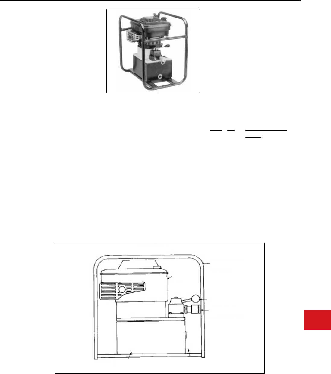
BURNDY®
Canada: 1-800-387-6487 www.burndy.com US: 1-800-346-4175
Tooling
Hydraulic Pumps
GP10
GP Series Gasoline Engine
Driven Hydraulic Pump
Hydraulic Output Pressures
of 10,000 PSI
The GP series gasoline engine driven hydraulic
pump is a heavy-duty design that is rugged and
portable. Supplied with a 4 H.P. engine, the pump
operates all BURNDY® remote compression
heads and cable cutters.
All GP style pumps have a built-in, factory pre-
set, automatic pressure release overload valve
with a denite pulsing and recycling to signal the
completion of a crimp. The manual control valve
allows user to “Jog and Hold” due to the unique
check valve design that keeps pressure in the
output line until retracted.
Features and Benets
SPECIFICATIONS
FOR USE ON
• Heavy duty gasoline engine
• Sturdy steel roll cage design
• Manual control valve
• Quick disconnect hydraulic coupler
• 8 quart reservoir
• Oil level inspection window
• Portable pump with sturdy steel roll cage
• Durable heavy-duty 4 H.P. engine for all
HYPRESS™ applications and long life
expectancy
• Manual control valve permits easy control
of crimping or cutting operations
• Fast hose assembly with quick disconnect
pressure matched hydraulic couplers
• Ample hydraulic capacity with (8) quart
reservoir
• 5-year limited warranty
Engine:
Reservoir Volume:
Pump height:
Pump width:
Pump length:
Overall height:
Overall width:
Overall length:
Pump and motor
Dry Weight:
Overall dry weight:
4 H.P., 4 cycle
2 gallons (8 qts.)
19-3/4″
13″
18″
22-1/4″
16″
21″
64-1/4 lbs
77-3/4 lbs
Pump PSI Hydraulic Tools and
Cutters
GP10 10,000 Y34BH, Y35BH, Y35BH-4,
Y39BH, Y45, Y46, Y46C,
Y60BHU, Y60BHU-D
Y750BHXT, Y750CBHXT,
RHCC Series Cutters
HEAVY-DUTY
GASOLINE
ENGINE
STURDY STEEL ROLL
CAGE DESIGN
MANUAL CONTROL VALVE
QUICK DISCONNECT
HYDRAULIC COUPLER
OIL LEVEL
INSPECTION WINDOW
8 QUART
RESERVOIR
N-95
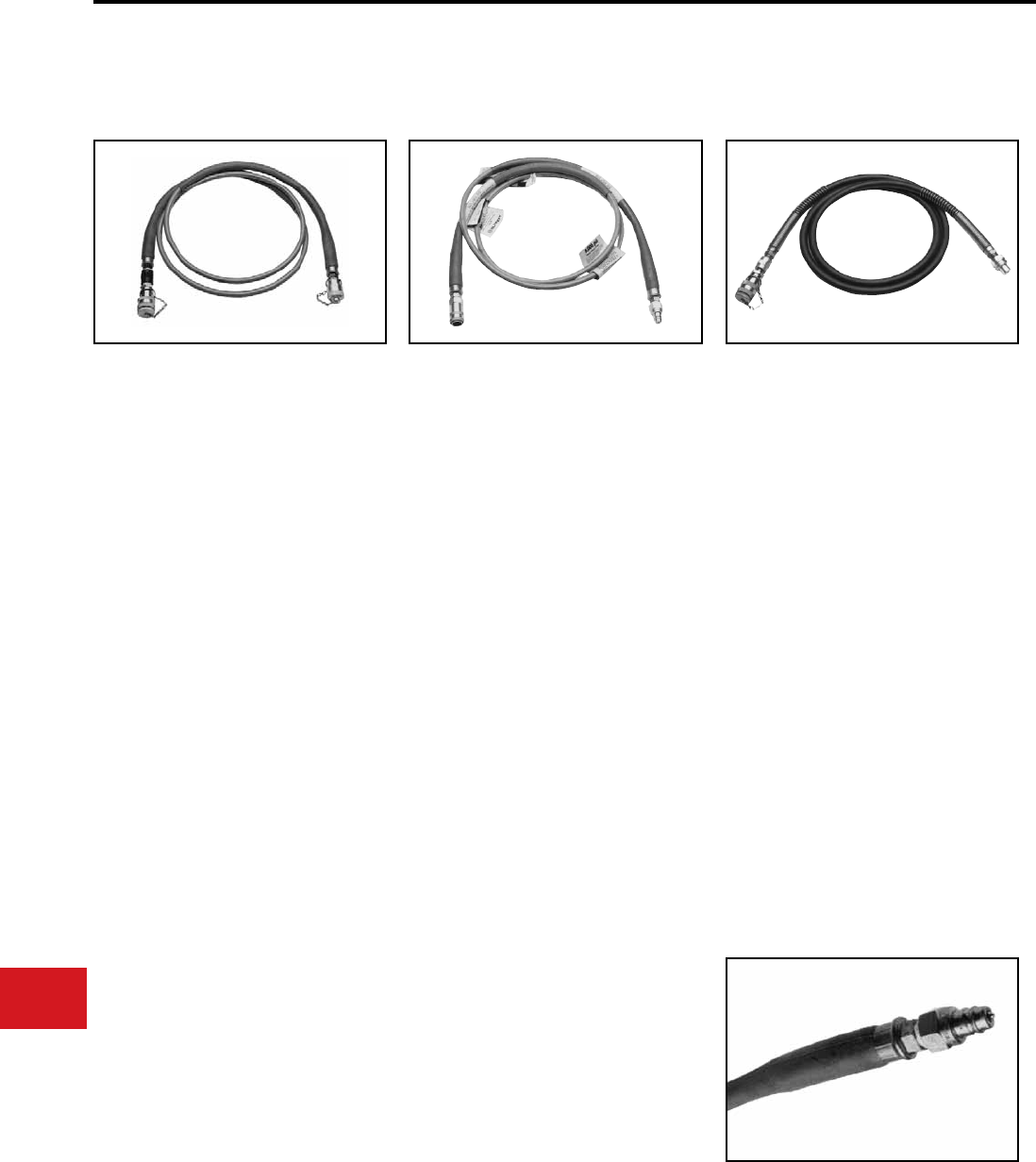
BURNDY®
US: 1-800-346-4175 www.burndy.com Canada: 1-800-387-6487
Tooling
Hydraulic Pumps
HYDRAULIC HOSES
NON CONDUCTIVE HOSES* NON CONDUCTIVE HOSES* CONDUCTIVE HOSES*
Cat. No. Description
PT 29900-10 10′ - 3/16″ diameter - non
conductive hose with stack-
able couplers (male/female)
- orange
PT 29900-15 15′ - 3/16″ diameter - non
conductive hose with stack-
able couplers (male/female)
- orange
PT 29900-25 25′ - 3/16″ diameter - non
conductive hose with stack-
able couplers (male/female)
- orange
PT 29901-10 10′ - 1/4″ diameter - non
conductive hose with stack-
able couplers (male/female)
- orange
PT 29901-15 15′ - 1/4″ diameter - non
conductive hose with stack-
able couplers (male/female)
- orange
PT 29901-25 25′ - 1/4″ diameter - non
conductive hose with stack-
able couplers (male/female)
- orange
10,000 PSI
Note: 1/4″ diameter hose provides higher
ow rate for faster ram movement.
* For proper care and maintenance of
hydraulic hoses, consult the “Hydraulic Hose
Care” manual, Form No. 7828
6,000 PSI 10,000 PSI
Cat. No. Description
PT 29902-10 10′ - non conductive hose
with stackable couplers
(male/female) - orange
PT 29902-15 15′ - non conductive hose
with stackable couplers
(male/female) - orange
PT 29902-25 25′ - non conductive hose
with stackable couplers
(male/female) - orange
PT 29074-1 Non conductive hose
carrying
bag
* For proper care and maintenance of
hydraulic hoses, consult the “Hydraulic Hose
Care” manual, Form No. 7828
Cat. No. Description
PT 91 8′ - steel braided hose
with steel spring reinforced
ends. Stackable couplers
(male/female) - Black. No
electrical rating. DO NOT
use on energized conductor.
8,000 PSI
Cat. No. Description
PT 76 8′ - steel braided hose
with steel spring reinforced
ends. Stackable couplers
(male/female) - Black. No
electrical rating. DO NOT
use on energized conductor.
Do not attempt to repair or recouple the hose yourself!
* For proper care and maintenance of
hydraulic hoses, consult the “Hydraulic Hose
Care” manual, Form No. 7828
N-96
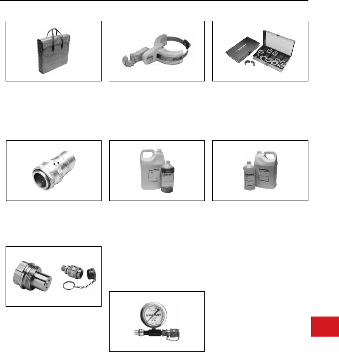
BURNDY®
Canada: 1-800-387-6487 www.burndy.com US: 1-800-346-4175
Tooling
Hydraulic Pumps
ACCESSORIES
PT 29074-1
Insulated hose carrying bag
Designed to provide protection and cleanliness of
non-conductive hoses. Accommodates 100 ft. of
non-conductive coiled to 17-1/2″ O.D. and 3-3/4″
wide. Maximum carrying capacity: 10 lbs.
PT 29402-1 (for Y35BH)
PT 10128 (for Y46)
Adjustable Head Grip For joining HYPRESS™
heads to universal hot sticks
DIE CASES
PT 29291
(Y750, Y35/Y39) die case for “U” -type die sets
PT 6545
(Y45 and Y46) die case for “S” and “P” -type die
sets
PT 29091 (male)
PT 29214-1 (female)
Replacement Coupler 6,000 PSI operating
pressure
PT 94 (male)
PT 93 (female)
Replacement Coupler 10,000 PSI operating
pressure
HYFLUID™
HYFLUID™ QT.
HYFLUID™ GAL.
(available in quart and gallon size containers)
Hydraulic uid for BURNDY® HYPRESS™
hand operated tools:
Y35 and Y35-2 HYPRESS™ tools
Y39 HYPRESS™ tool
Y750 REVOLVER HYPRESS™ tools
ALFLUID™
ALFLUID™ QT.
ALFLUID™ GAL.
(available in quart and gallon size containers)
Use ALFLUID™ in hand operated tools during
extended use below 32 degrees.
All weather HYDRAULIC uid for BURNDY®
pumps:
HP hand pump
FP foot pump
GP gasoline pump
EPP electric pump
PT 11018
In-line Pressure Gauge 10,000 PSI operating
pressure for hydraulic pumps
N-97
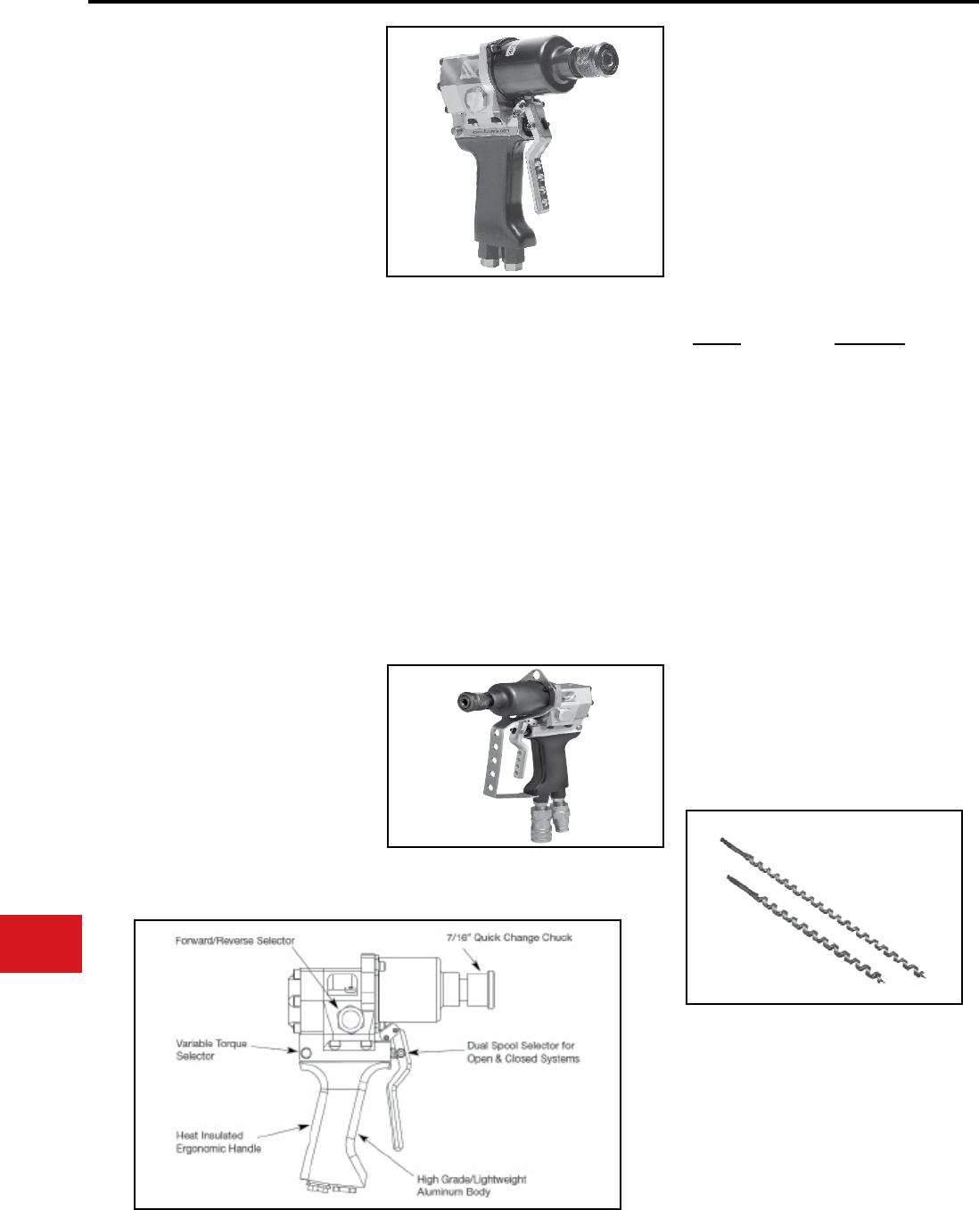
BURNDY®
US: 1-800-346-4175 www.burndy.com Canada: 1-800-387-6487
Tooling
Low Pressure Hydraulic
ENFORCER®
HIW716ENF
HYDRAULIC IMPACT WRENCH
VARIABLE TORQUE
7/16″ Quick Chuck
When it comes to drilling holes or tightening and
loosening hardware the ENFORCER® hydraulic
impact wrench (Catalog Number HIW716ENF)
provides a powerful punch with 515 ft-lbs of torque
that is unsurpassed in the 7/16″ series of low
pressure wrenches. Utilizing the very latest in CNC
machining technology and superior materials,
BURNDY® is proud to provide one of the toughest,
lightweight wrenches ever offered in this class.
The ENFORCER® wrench comes with a 7/16″ tri-
ball quick chuck with a wide ange that will provide
a secure hold on all standard 7/16″ hex drive bits
and accessories. The adjustable torque selector
allows users to choose between a low setting of
200 ft-lbs and high setting of 515 ft-lbs of output
torque. The dual acting spool allows the user to
change from Open to Closed center operating
circuits. In addition to our standard ve year limited
warrany, the ENFORCER™ wrench comes with a
full one-year unlimited warranty on the shaft seal.
The ENFORCER® wrench comes equipped with
an internal safety relief valve to protect the tool
against hydraulic pressure spikes. This regulates
pressure to the motor, and therefore allows
excessive ow (ow which is beyond that which
is required to do the work) to bypass back to the
return side of the circuit.
• Industry exclusive torque selector; dual
torque selector spool allows users to switch
between 200 and 515 ft-lb torque settings
• 7/16″ Tri-ball quick chuck; allows users
to quickly change bits, sockets or other
hardware adaptors
• CNC Machined billet aluminum; provides
superior strength, reliability and makes for
the lightest tool in its class. Also provides for
tighter tolerancing to ensure higher quality
• Cartridge style valves; provides for greater
accuracy and more economical servicing
• Dual spool operation; allows tool to be
used in either an OPEN or CLOSED center
hydraulic system
Features and Benets
SPECIFICATIONS
ACCESSORIES
Chuck Type:
Optimal Pressure:
Flow Range:
Optimal Flow Range:
Operation:
Torque:
Weight:
Length:
Height:
Width:
7/16″ Quick Chuck
750-2000 PSI
4-12 GPM
4-8 GPM
Open/Closed option
515 ft-lbs
5.95 lbs
7.80″
8.90″
3.10″
Cat. No. Description
HIW716ENFTGKIT Trigger guard
assembly kit
HIW716ENFTG
HIW716ENF wrench
provided with a
factory installed
HIW716ENFTGKIT
LPHTADPMMOP66
Male to male adaptor
for use with couplers
listed below *(Qty. 2)
LPHTHTMANOSE66
Male coupling 3/8″
NPT *(Qty. 1) per tool
Qty. 2 per hose
LPHTHTMABODY66
Female coupling 3/8″
NPT *(Qty. 1) per tool
Qty. 2 per hose
LPHTHOSNCR66668 3/8″ X 8 Ft. hose set
*(Qty. 1)
*(Recommended quantity for use with HIW716ENF)
The picture above shows the HIW716ENF model
with trigger guard, adaptors and couplers as listed
under Accessories.
See our complete line of Auger Bits.
N-98
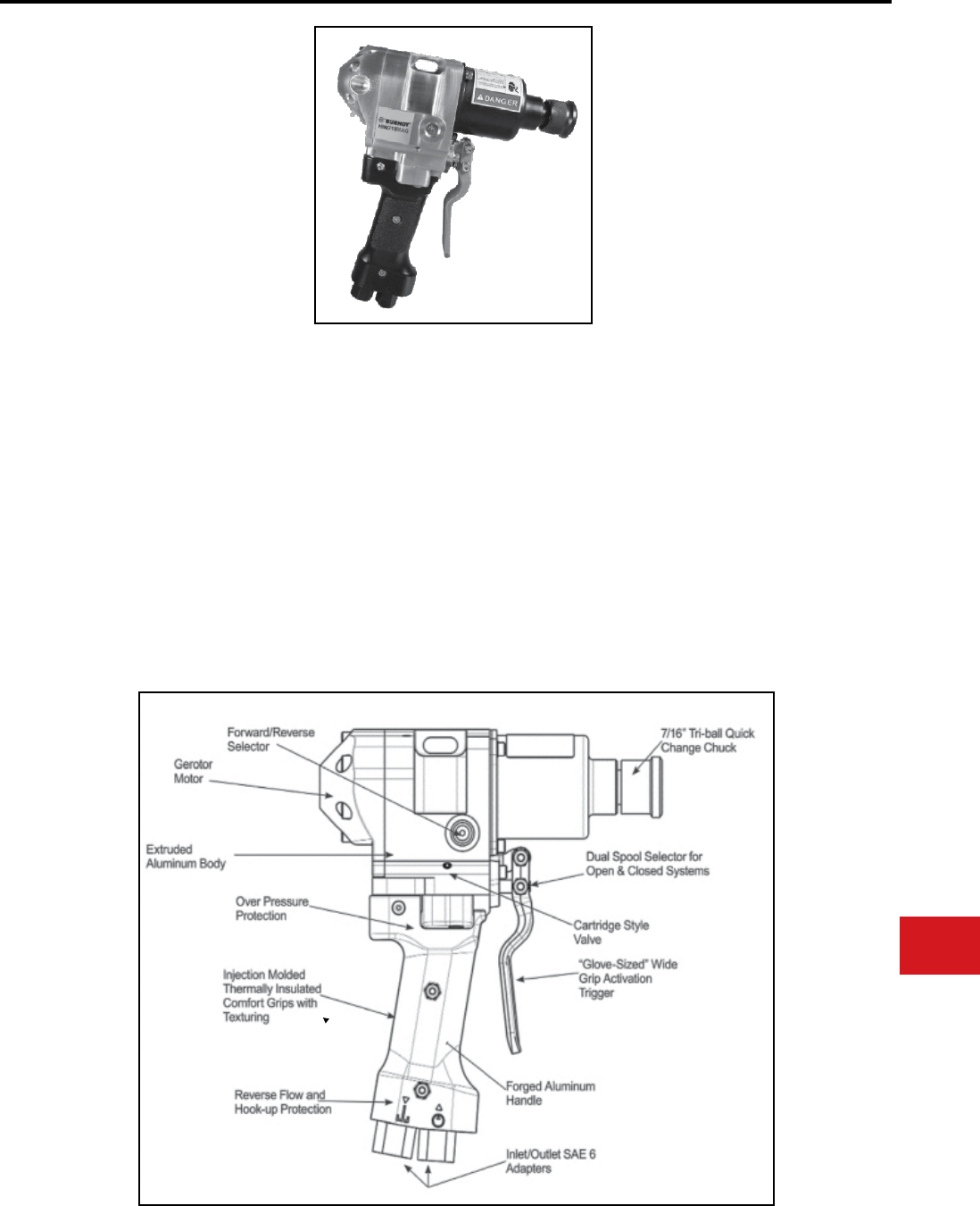
BURNDY®
Canada: 1-800-387-6487 www.burndy.com US: 1-800-346-4175
Tooling
Low Pressure Hydraulic
HIW716MAG
MAG Series - Machined
Aluminum, Gerotor Design
The BURNDY® low pressure hydraulic impact
wrench MAG Series (Machined Aluminum,
Gerotor) is specically designed for linemen
and contractors needing power, reliability and
enhanced ergonomics.
Chuck Type:
Opt. Pressure:
Flow Range:
Opt. Flow Range:
Weight:
Torque:
Height:
Width:
Length:
Features and Benets
SPECIFICATIONS
7/16" Tri-ball Quick Chuck
1,000 - 2,250 PSI
4 - 12 GPM
4 - 8 GPM
7.6 lbs
550 ft-lbs
9.60"
3.60"
9.00"
ACCESSORIES
LPHTADPMM71612
7/16" Quick Chuck to 1/2" Square Drive adaptor
LPHTADPMMOP66 (2 required)
SAE #6 to 3/8" NPT male-to-male adaptor
LPHTHTMANOSE66
3/8" Male Coupler (at face) with 3/8" NPT
(female thread)
LPHTHTMABODY66
3/8" Female Coupler (at face) with 3/8" NPT
(female thread)
LPHTHOSNCR66668
8', 3/8" NPT, 3/8" NPT Non-Conductive Hose
LPHTADPSMOP66 (2 required) SAE swivel
• Aircraft grade extruded aluminum body and
forged handle
• CNC machined parts
• Frictionless gerotor motor
• BURNDY 5-year limited warranty
• Injection molded replaceable comfort grips
• Glove-sized handle and activation trigger
• Reduced handle-to-trigger distance
• Over 550 ft-lbs of torque @ 2000 psi & 5 gpm
• Reverse ow and hook-up prevention
• Dual spool selector for Open and Closed Center
use
• Pressure relief valve
• Cartridge style valve
N-99
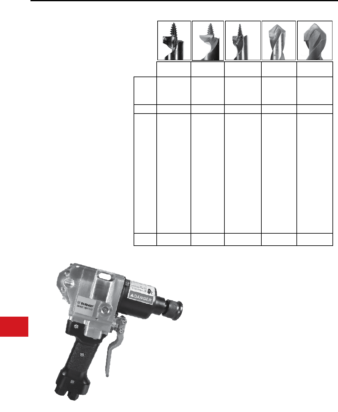
BURNDY®
US: 1-800-346-4175 www.burndy.com Canada: 1-800-387-6487
Tooling
Auger Bits
Drilling Solutions
Auger Bits
Auger Bits for Wood,
Fiberglass, Composite Poles
When it comes to drilling holes in wood, berglass
or composite materials, the BURNDY line of drilling
bits can meet the challenge.
Each bit is designed for specic application
requirements. This results in superior performance
enabling the job to get done right the rst time.
These auger bits, when coupled with the high
performance BURNDY impact wrenches, provide
the end user with an “Engineered System” of
unparalleled reliability and performance – the
hallmark of BURNDY products.
Design Selection Chart
HIW716MAG
*Approximate comparison of # holes drilled/bit
DOMINATOR RAZOR ELIMINATOR™ HOLLOW
CORE
SOLID
CORE
Treated Wood Treated Wood Treated Wood Fibreglass
Composite
Fibreglass
Composite
TIP Hardened Steel Hardened Steel Carbide Tip Carbide Tip Carbide Tip
Single ute
Aggressive lead
screw
Very fast drilling
Cuts hardest of
woods
Self-feeding
Single ute
Aggressive lead
screw
Added “spur”
Fast drilling
Extra clean
holes
No re-drilling
required
Self feeding
Carbide tip
Single ute
Patented cutting
geometry
Fast drilling
Very clean holes
Easy fastener
insertion
Lowest cost/hole
drilled
Can be refur-
bished
Specialized short
ute
“Solid” body
design
Carbide Tip
Engineered
cutting tip
Designed for
berglass
Cuts quickly and
cleanly
No splinters
No melting
Drill both holes
at once
Can be re-
sharpened
Specialized long
ute
“Fluted” body
design
Carbide Tip
Engineered
cutting tip
Designed for
berglass
Cuts quickly and
cleanly
No splinters
No melting
Removes debris
quickly
Drill both holes at
once
Can be re-
sharpened
HOLES* 100+ 100+ 2000+ 500+ 500+
Features and Benets Material
Drilled
N-100
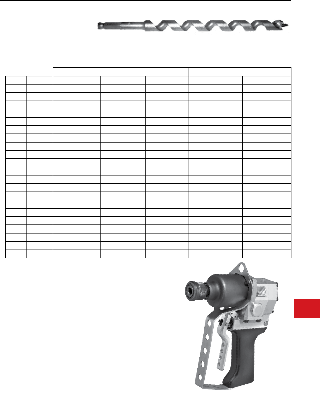
BURNDY®
Canada: 1-800-387-6487 www.burndy.com US: 1-800-346-4175
Tooling
Auger Bits
Auger Bit Part Number Chart
TREATED WOOD FIBERGLASS/COMPOSITE
OAL DIA DOMINATOR RAZOR ELIMINATOR™ HOLLOW CORE SOLID CORE
8” 9/16” LPHTBIT9168R
12” 9/16” LPHTBIT91612HC
12” 11/16” LPHTBIT111612HC LPHTBIT111612SC
12” 13/16” LPHTBIT131612HC LPHTBIT131612SC
12” 1 1/8” LPHTBIT11812HC
18” 11/16” LPHTBIT111618HC
18” 13/16” LPHTBIT131618HC LPHTBIT131618SC
18” 1/2” LPHTBIT1218
18” 9/16” LPHTBIT91618R
18” 5/8” LPHTBIT5818D LPHTBIT5818R
18” 11/16” LPHTBIT111618D LPHTBIT111618R LPHTBIT111618
18” 3/4” LPHTBIT3418D LPHTBIT3418R
18” 13/16” LPHTBIT131618D LPHTBIT131618R LPHTBIT131618
18” 7/8” LPHTBIT7818D
18” 15/16” LPHTBIT151618D LPHTBIT151618R LPHTBIT151618
24” 5/8” LPHTBIT5824D
24” 11/16” LPHTBIT111624D LPHTBIT111624R
24” 3/4” LPHTBIT3424D
24” 13/16” LPHTBIT131624D LPHTBIT131624R LPHTBIT131624
24” 15/16” LPHTBIT151624D LPHTBIT151624R
24” 1 1/8” LPHTBIT11824D LPHTBIT11824R
Other styles and sizes are available on request
HIW716ENFTG
Drilling Solutions
Auger Bits
Auger Bits for Wood,
Fiberglass, Composite Poles
N-101
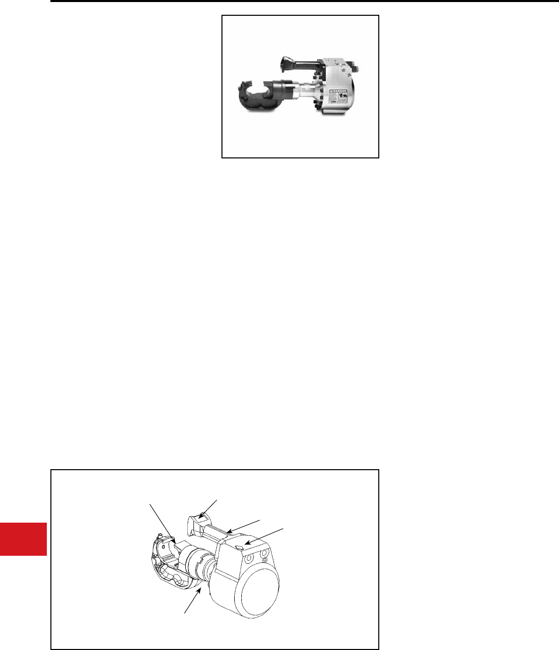
BURNDY®
US: 1-800-346-4175 www.burndy.com Canada: 1-800-387-6487
Tooling
Low Pressure Hydraulic
KOMPRESSOR™
LPHY750XT AND
LPHY750CXT
Remote Operated 12 Ton
Low Pressure Hydraulic
Compression Tool
The BURNDY® LPHY750XT KOMPRESSOR™
is a lightweight, compact, low pressure, hydraulic
12 ton crimping tool. The LPHY750XT is double
acting for hydraulic ram advance and retract. The
KOMPRESSOR™ also has an industry exclusive
spring back-up for ram retraction in case of loss
of hydraulic pressure. The LPHY750XT comes
equipped with an ergonomic handle designed for
better balance, which helps lessen fatigue to the
operator.
The LPHY750XT KOMPRESSOR™ features
the BURNDY® 750XT tool head with a 1.65″ jaw
opening capable of using all industry standard
BURNDY® “U” dies. The LPHY750XT has an
industry exclusive visual crimp indicator to assure
the operator of a properly completed crimp. The
LPHY750XT also has an audible crimp indicator.
The LPHY750XT is powered directly from open
center or closed center hydraulic tool circuits
present on most utility line trucks or can be
operated from individual low-pressure hydraulic
power units. The LPHY750XT can be switched
from open center to closed center operation with a
simple external adjustment. The LPHY750XT does
not require any additional tooling such as boosters,
intensiers, or hand controls in the bucket. The tool
has a 5-year limited warranty.
• LPHY750CXT covered version available.
• Visual and audible crimp indicator assures
properly completed crimps with 12 tons of
force
• Covers a wide range of applications with its
1.65″ jaw opening
• 350° head rotation for versatile tool head
positioning allowing the user to get into tight
areas easier
• Uses all standard BURNDY® “U” dies
• Operates on open center or closed center
hydraulic systems
• Ergonomic handle design for better balance
and helps lessen fatigue
• Double acting tool for hydraulic ram advance
and retraction
• Spring back up for ram retraction if hydraulic
system shuts down
• 5-year limited warranty
Features and Benets
SPECIFICATIONS
ACCESSORIES
Hoses:
Cat No. LPHTHOSNCR66668OP
Direct connect 8′ non-conductive hose set
Cat No. LPHTHOSNCR666610OP
Direct connect 10′ non-conductive hose set
*Cat No. LPHTHOSNCR66668
8′ non-conductive hose set
*Cat No. LPHTHOSNCR666610
10′ non-conductive hose set
Hydraulic Fittings:
Cat No. LPHTHTMANOSE66
Male coupler 3/8″ HTMA
Cat No. LPHTHTMABODY66
Female coupler 3/8″ HTMA
Cat No. LPHTADPSMFOP66
Swivel Adapter
*These hoses are used with the
LPHTADPSMFOP66 swivel adapter.
Flow Rate:
Operating Pressure:
Force Developed:
Weight:
Overall Length:
Width:
Jaw Opening:
Max. Back Pressure:
Crimp Time:
3 - 9 GPM
(11 - 34 LPM)
1,500 - 2,500 PSI
(103 - 172 BAR)
12 Tons
21 lbs (9.5 kg)
20.65″ (524 mm)
15″ (381 mm)
1.65″ (42 mm)
250 PSI (17 BAR)
Approximately
2 seconds
FOR USE ON
• Tension Sleeves
Copper #8 sol - 500 kcmil
Aluminum #8 sol - 587.2 kcmil
ACSR #4 - 556.5 kcmil
• Taps
Copper #14 sol - 500 kcmil
Aluminum #8 sol - 500 kcmil
• Aerial Cable
Copper #6 - 500 kcmil
• Terminals and Splices
Copper #8 - 750 kcmil
Aluminum #8 - 750 kcmil
ACSR #4 - 556.5 kcmil
• HYGROUND®
Copper #8 - 500 kcmil
Ground Rods 1/2″ - 1″ diameter
Large 1.65″ Jaw
Opening
Activation
Trigger
Ergonomically Balanced
tool and Handle Design
Visual Crimp
Indicator
Internal Ram Retraction
Backup Spring
N-102
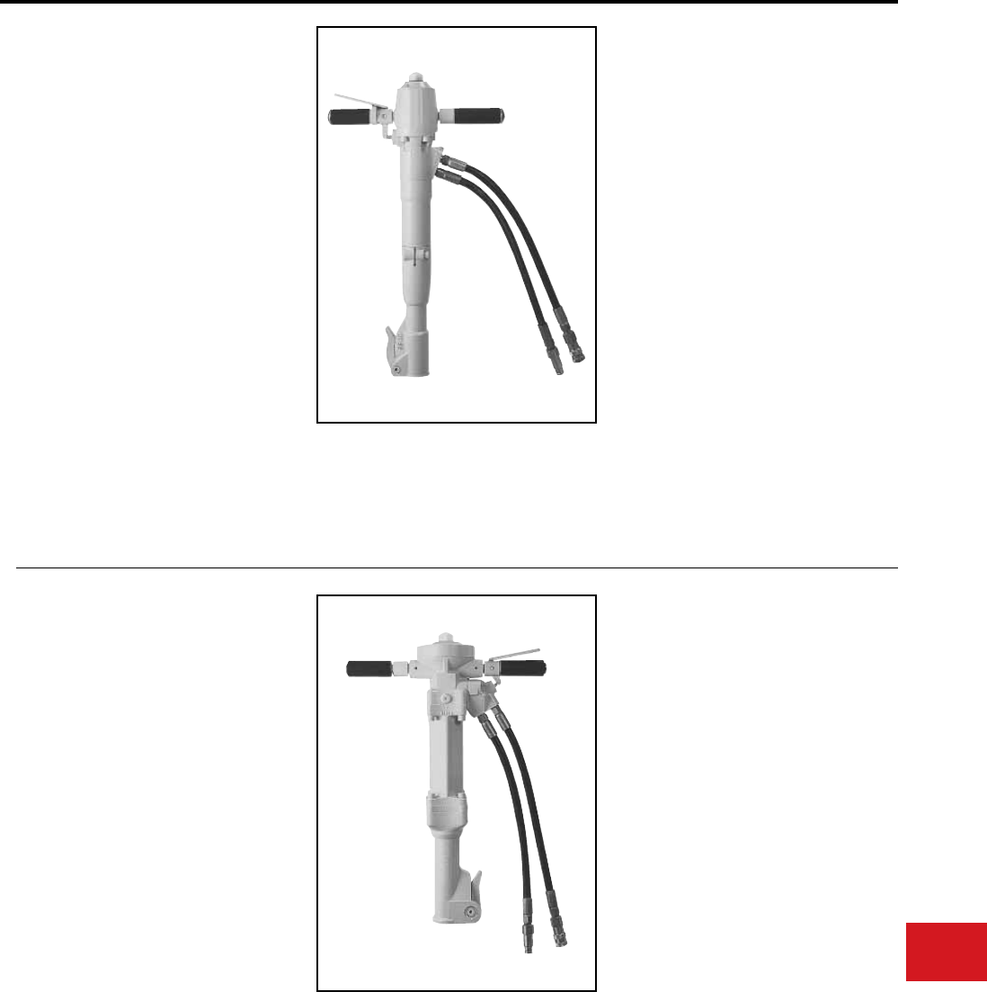
BURNDY®
Canada: 1-800-387-6487 www.burndy.com US: 1-800-346-4175
Tooling
Low Pressure Hydraulic
HBR40
HYDRAULIC BREAKER
Light and Medium Duty
• Light to Medium Duty breakers powerful
enough for most breaking applications
• Control trigger built into handle
• Provided with 18″ braided whip hoses (order
HTMA couplers separately)
• Standard tool attachment mechanism allows
use of all standard tool bits
• No compressed air exploding into atmosphere
spreading dirt, dust and noise
• Hydraulic cushioning of return stroke reduces
operator shock and fatigue
• Hand grips at comfortable working height
• Hydraulic operation provides continuous
lubrication of all moving parts
• 5-year limited warranty
Flow:
Optimum Flow:
Pressure:
Max. Back Pressure:
Weight:
Length:
Tool Steel Capacity:
Performance:
Whip Hoses:
Features and Benets
SPECIFICATIONS
HBR66
HYDRAULIC BREAKER
Medium and Heavy Duty
• Medium to Heavy Duty breakers suitable for
extended periods of operation
• Control trigger built into handle
• Provided with 18″ braided whip hoses (order
HTMA couplers separately)
• Standard tool attachment mechanism allows
use of all standard tool bits
• No compressed air exploding into atmosphere
spreading dirt, dust and noise
• Hydraulic cushioning of return stroke reduces
operator shock and fatigue
• Hand grips at comfortable working height
• Hydraulic operation provides continuous
lubrication of all moving parts
• 5-year limited warranty
Features and Benets
4-7 GPM
(15-27 LPM)
4 GPM (15 LPM)
1200-2000 PSI
(85-140 BAR)
150 psi (11 BAR)
40-48 lbs
25″
1″ x 4-1/4″
(1500 BPM) 45-55 lb.
class breakers
18″ with 3/8″ NPT
ttings
Flow:
Optimum Flow:
Pressure:
Max. Back Pressure:
Weight:
Length:
Tool Steel Capacity:
Performance:
Whip Hoses:
SPECIFICATIONS
4-7 GPM
(15-27 LPM)
4 GPM (15 LPM)
1200-2000 psi
(85-140 BAR)
150 psi (11 BAR)
50-67 lbs.
27″ to 35″
1-1/4″ x 6″
60-80 lb. class series
18″ with 3/8″ NPT
ttings
N-103
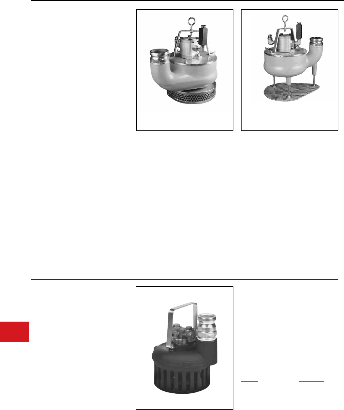
BURNDY®
US: 1-800-346-4175 www.burndy.com Canada: 1-800-387-6487
Tooling
Low Pressure Hydraulic
HTP3, HP3
3″ SUBMERSIBLE PUMPS
The HP3 and HTP3 hydraulic submersible pumps
are designed to reliably pump large volumes of
liquids and solids (per specications). HP and
HTP models are durable and offer a very high
performance-to-weight ratio. These pumps
are self-lubricating, utilizing the hydraulic uid
in a closed loop to ensure consistent, reliable
lubrication. The units can be run dry as they do
not require water for cooling purposes whether
submersed or not.
The high output and compact nature of these
pumps make them ideal for pumping out vaults,
trenches, ditches, ponds, tanks, pools, etc. in
a multitude of industries including agriculture,
construction, mining, utilities, public works,
departments of transportation, and more.
• Totally submersible
• Pumps solids without blockage or damage
• Self lubricating design
• Cast aluminum pump body
• Double-sealed hydraulic motor shaft protects
hydraulic source from water
• Thumb screw secured lid so cover is easy to
remove without special tools
• Provided with whip hoses
• High impact, abrasion resistant liner
• 5-year limited warranty
Features and Benets
SPECIFICATIONS
HP3
Flow:
Pressure:
Weight:
Pump capacity:
Operation:
Discharge size:
Maximum lift:
Motor:
SPECIFICATIONS
7-10 GPM
(27-38 LPM)
1000-2000 PSI
(70-140 BAR)
36 lbs (16.34 kg)
750 GPM (2800 LPM)
Open/Closed center
3″ outlet
(3″ Male Cam-Lock)
50 ft. (21.34 m)
Gear Motor
HTP3
Flow:
Pressure:
Max. Back pressure:
Weight:
Pump capacity:
Operation:
Discharge size:
Motor:
Diameter:
Maximum lift:
Ports:
7-10 GPM
(27-38 LPM)
1000-2000 PSI
(70-140 BAR)
250 PSI (17 BAR)
40 lbs (18.16 kg)
500 GPM (1900 LPM)
Open/Closed center
3″ outlet
(3″ Male Cam-Lock)
Gear Motor
12″ (30.5 cm)
40 ft. (18.29 m)
1/2″ X 14 (#8) NPT (F)
3″ Submersible Pump
HP3
3″ Submersible Pump
HTP3
Cat. No.
HOSE325
HOSE350
Description
25 ft. long hose
50 ft. long hose
ACCESSORIES
HP2HV
(HIGH VOLUME)
2″ SUBMERSIBLE PUMPS
• Totally submersible
• Self lubricating design
• Lightweight cast aluminum pump body
• Built-in lifting handle/eye
• Self-priming pump
• Provided with whip hoses
• Unit can run dry without damage
• HP2HV adaptable to either 2″ or 2-1/2″
discharge
• 5-year limited warranty
Features and Benets
SPECIFICATIONS
Flow:
Pressure:
Weight:
Pump Capacity:
Operation:
Maximum Lift:
Motor:
4-9 GPM
1000-2000 PSI
(70-140 BAR)
13 lbs
340 GPM
Open/Closed center
80 GPM @ 70 ft
Gerotor Motor
Cat. No.
HP2CAMLOCKHOSESET
HOSE2
Description
HOSE SET KIT
25 ft. long hose
ACCESSORIES
N-104
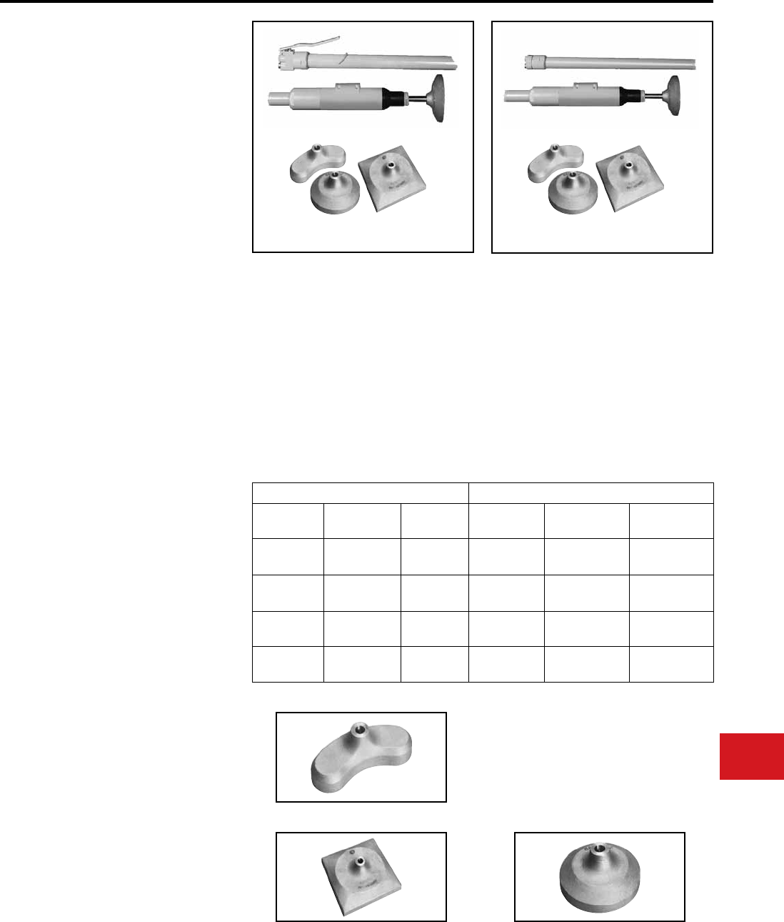
BURNDY®
Canada: 1-800-387-6487 www.burndy.com US: 1-800-346-4175
Tooling
Low Pressure Hydraulic
HPTR1 Series
POLE TAMPERS
The HPT hydraulic pole tampers are designed to
provide trouble-free service for compacting around
poles, posts, footings and other objects.
The pole tamper operates best on a ow rate of
4 gal/min. operating pressure. Force of blow, and
frequency of blow will be a function of the ow
rate provided. A minimum of 1000 lb/in2 operating
pressure is essential in order to obtain the
maximum output performance.
The unique patented valving of the HPT pole
tamper provides low maintenance, long life and
superior handling characteristics because there
is no mechanical impacting of the ram within
the tamper. The oil reverses the stroke before
bottoming out, preventing the tamper from
hammering itself when running free between
compaction strokes.
These features provide unexcelled compaction
while virtually eliminating kick-back to the
operator’s hand.
Tamper shoes sold separately.
• Available with or without On/Off control valve
• Patented valving prevents impacting of the ram
within the tamper
• Stroke amplitude of 1-5/8″
• Stroke frequency of 1375 blows/min is ideal for
compacting around poles, posts, footings, and
other objects
• Interchangeable heavy duty tamper shoes
allows for exibility
• 5-year limited warranty
Flow:
Pressure:
Max. Back Pressure:
Operation:
Stroke Amplitude:
Stroke Frequency:
Tool Ports:
Features and Benets SPECIFICATIONS
Pole Tamper With On/Off Valve Pole Tamper With No On/Off Valve
4-10 GPM
(15-38 LPM)
1000–2000 PSI
(70–140 BAR)
250 PSI (17 BAR)
Open/Closed center
1-5/8″
1375 per minute
#6 SAE O-Ring (F)
ACCESSORIES
With On/Off Valve No On/Off Valve
Catalog
Number
Overall
Length
Weight
(Approx.)
Catalog
Number
Overall
Length
Weight
(Approx.)
HPT-60-R1 60″
(152 cm)
29 lbs.
(13 kg) HPT-59-R1 59″
(150 cm)
26 lbs.
(12 kg)
HPT-72-R1 72″
(183 cm)
30 lbs.
(14 kg) HPT-71-R1 71″
(180 cm)
28 lbs.
(13 kg)
HPT-84-R1 84″
(213 cm)
32 lbs.
(15 kg) HPT-83-R1 83″
(211 cm)
31 lbs.
(14 kg)
HPT-96-R1 96″
(244 cm)
34 lbs.
(15.4 kg) _ _ _
Cat # TS-KD:Kidney shoe, 3″ x 8″
(7.6 x 20.3 cm)
Cat # TS-RD:Round show, 6″ dia.
(15.2 cm dia.)
Cat # TS-SQ:Square shoe, 8″ x 8″
(20.3 x 20.3 cm)
Whip Hoses must be ordered separately.
Cat # LPWHPKITD
Tamper shoes must be ordered separately.
Kidney Shoe
Square Shoe Round Shoe
N-105
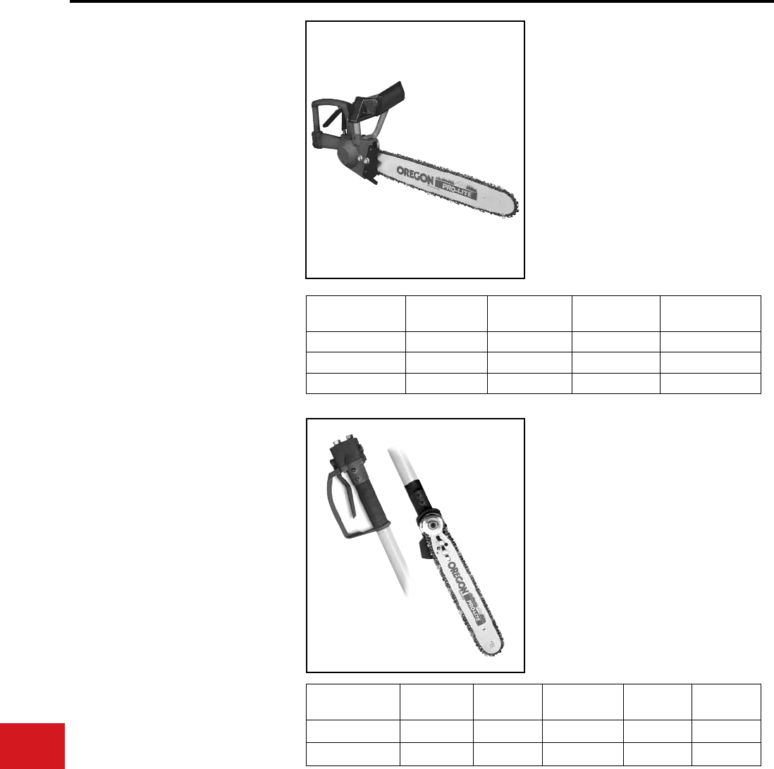
BURNDY®
US: 1-800-346-4175 www.burndy.com Canada: 1-800-387-6487
Tooling
Low Pressure Hydraulic
HHS SERIES
HAND CHAIN SAWS
The lightweight Hydraulic Hand-held Chain Saw
was designed for the ease of handling, balance
and dependability. A Gerotor motor provides the
hand-held chain saw with a high level of torque and
horsepower for long and trouble-free operation.
The handle remains cooler because no hydraulic
uid ows through the grip. An automatic chain
oiler is another feature of the saw. In addition, the
guide bar contains a nose sprocket for improved
cutting performance and reduced wear of the
guide bar. The saws are furnished with a .325″
pitch anti-kick back chain. The dual spool trigger
design enables operation of the tool on both open-
center and closed-center systems.
• Gerotor type motor has lifetime warranty
• Supplied with .325″ pitch anti-kickback chain
for maximum safety
• Dual action spool quickly and easily changes
from Open to Closed center operation
• Automatic, adjustable chain oiler enables
longer running time without damage to chain/
bar due to lack of lubrication
• Low RPM and high torque – minimizes saw
kickback
• Choice of 13″, 16″ or 20″ bars
• 5-year limited warranty
Features and Benets
HHS & HPS
Flow:
Pressure:
Operation:
Motor:
Chain:
Tool ports:
Max. Back pressure:
SPECIFICATIONS
5-8 GPM
(19-30 LPM)
1000-2000 PSI
(70-140 BAR)
Open/Closed center
Gerotor
.325″
pitch anti-kick-back
#6 SAE O-Ring (F)
250 PSI (17 BAR)
Catalog
Number
Overall
Length
Bar
Length
Cutting
Capacity
Weight
(Approx.)
HHS-O/C-B13 24″ 15-1/2″ 13″ 7-1/2 lbs
HHS-O/C-B16 27″ 18-1/2″ 16″ 8 lbs
HHS-O/C-B20 30″ 22-1/2″ 20″ 8-1/2 lbs
HPS SERIES
POLE CHAIN SAWS
The HPS hydraulic pole saws are designed for
safety, convenience and function. The berglass
extension provides lightweight strength reducing
operator fatigue. The trigger guard helps to prevent
accidental motor start. The high speed, high
performance Gerotor motor enables these pole
saws to tackle the toughest of pruning or clearing
jobs. Pole chain saw models have a disk next to the
sprocket to lessen the danger of a poorly adjusted
chain from coming off the sprocket. In addition, the
guide bar contains a self-lubricating oiling system
to help reduce wear and increase performance.
Non-conducting berglass poles tested to meet
OSHA regulation 1910.269.
Catalog
Number
Overall
Length
Bar
Length
Bar
Length
Cutting
Capacity
Weight
(Approx.)
HHS-O/C-4-B13 76″ (6′4″) 48″ (4′) 15-1/2″ 13″ 9 lbs
HHS-O/C-5-B13 88″ (7′4″) 60″ (5′) 15-1/2″ 13″ 9-1/2 lbs
• Gerotor motor has lifetime warranty
• Dual action spool quickly and easily changes
from Open to Closed center operation
• Automatic, adjustable chain oiler enables
longer running time without damage to chain/
bar due to lack of lubrication
Features and Benets
• 0.325″ pitch anti-kick back chain supplied
standard
• Low RPM and high torque –– minimize saw
kickback
• 5-year limited warranty
N-106
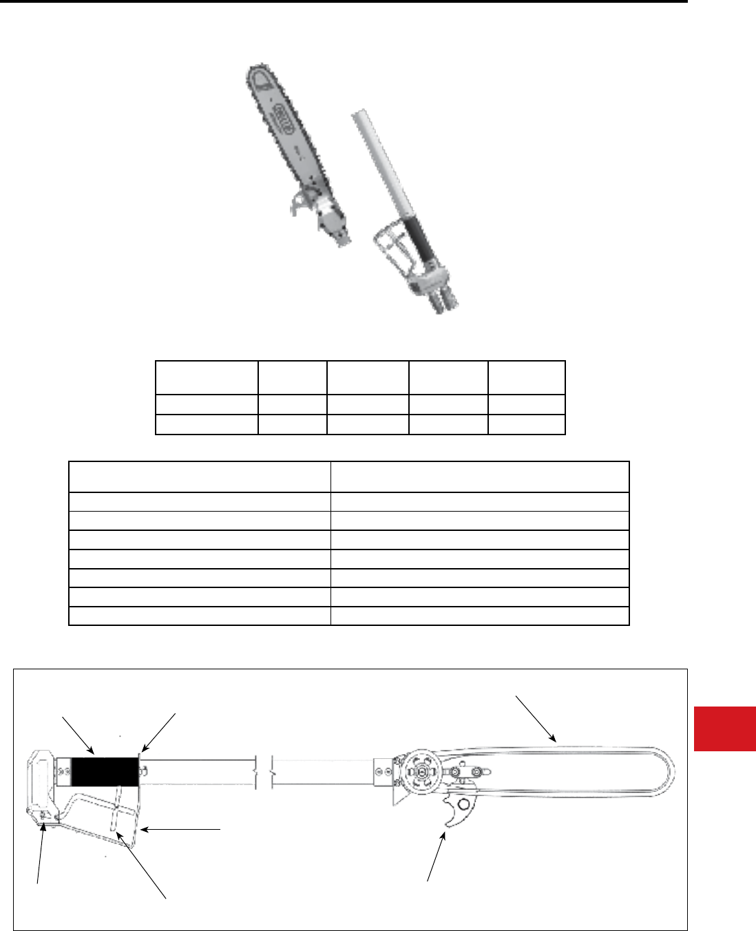
BURNDY®
Canada: 1-800-387-6487 www.burndy.com US: 1-800-346-4175
Tooling
Low Pressure Hydraulic
The HPS-LW Series of low pressure hydraulic pole
saws offers users both a rugged and ergonomi-
cally balanced tool for tree trimming operations in
the most demanding environments. This series in-
corporates all the features required for operational
user safety and long term reliability in the eld.
The unique body and handle are CNC machined
from solid aircraft grade aluminum billet. This re-
sults in a highly repeatable and manufacturable
design with very tight tolerances contributing to
increased performance, efciency and long term
reliability in the eld.
The HPS-LW series come with a 5-year limited
warranty.
HPS-LW SERIES
POLE CHAIN SAWS
Catalog
Number
Overall
Length
Pole
Diameter
Cutting
Capacity
Weight
(Approx.)
HPS1371LW 71” 1.312” 13” 8.0 lbs
HPS1383LW 83” 1.312” 13” 8.2 lbs
Flow: 4 - 8 GPM
(16-30 LPM)
Pressure: 1,000 - 2,000 psi
(70-140 BAR)
Operation: Open/Closed center
Motor: Gear
Chain: .325” pitch anti-kickback
Pressure Port: #6 SAE O ring
Return Port: #6 SAE O ring
SPECIFICATIONS
Features Benets
Aircraft grade solid Aluminum body and handle Rugged material for long term use
CNC Machined body and handle Repeatable performance, minimized leaking
Cartridge style valve Eliminates “wear” to handle body reducing material and labor costs
Dual Open Center and Closed Center settings Match truck circuits
External bar oiler Increased saw use and chain/bar longevity
2-stage safety trigger, anti-kickback chain, “anti-slip” grip Increased user protection for additional safety
Hook feature Ease of branch clearing
Anti-Slip Grip
.325” Anti-Kick Back Chain
Branch Hook
Cartridge
Style Valve Trigger Safety
Latch
Trigger Guard
Trigger Guard Clamp
N-107
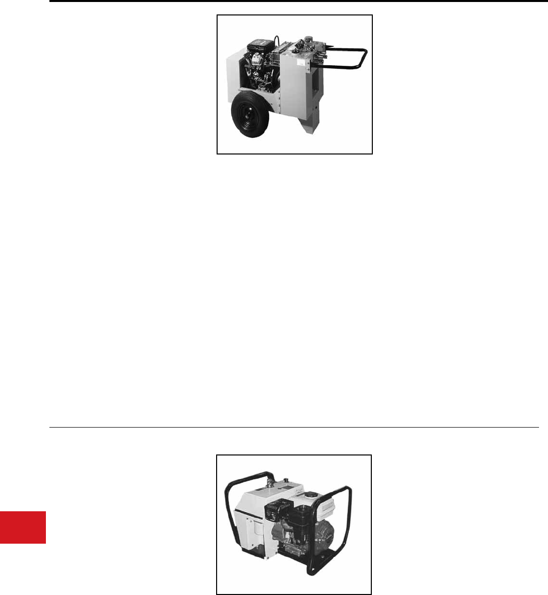
BURNDY®
US: 1-800-346-4175 www.burndy.com Canada: 1-800-387-6487
Tooling
Low Pressure Hydraulic
HPP18, HPP18-2
HYDRAULIC POWER PACK
Cat # HPP18 (Single Circuit)
Cat # HPP18-2 (Dual Circuit)
The HPP18-2 Hydraulic Power Pack is designed to
provide hydraulic ow and pressure for operation
of HTMA Type I and Type II hydraulic tools. The
power pack is equipped with an 18 HP gas engine.
The power packs are all equipped with air-to-oil
coolers with suction fan mounted to the power shaft
on the engine. The fuel and hydraulic systems are
self-contained with the required reservoir, ltration
and level indicators.
The hydraulic system consists of a hydraulic
system uid reservoir; lter assembly, single
(HPP18) or tandem pump (HPP18-2), and a wide
variety of ow controls. The lter element is a “spin
on” type element for easy replacement. The lter
housing has a pressure bypass valve to divert uid
directly to the tank in the event of a restricted lter.
Only the hydraulic pumps are called out in the parts
section of this manual. Pressure hoses from the
pumps are connected directly to a control module,
which contains a relief valve, a ow control valve,
and pressure and return ports. 5 gallon hydraulic
reservoir for cooler oil operation.
• Briggs & Stratton 18 HP VANGUARD gas
engine (twin OHV cylinders)
• Integral oil cooling system with fully
shrouded fan and changeable oil lter
• Fold away locking handle for easy job site
portability
• Electronic ignition with key start, 12 Volt
battery
• Features manual choke and an adjustable
throttle mechanism with lock/adjustment
• Variable GPM output valve provides uid
ow from 1-10 GPM @ 2,000 psi (HPP18
only)
• HPP18-2 is a dual circuit unit: (1) 10 GPM or
(2) 5 GPM
• HPP18-2 has the ability to operate two (2) 5
GPM tools simultaneously or one (1) tool up
to 10 GPM
Features and Benets
SPECIFICATIONS
Output/Flow:
Dry Weight:
Length:
Width:
Height:
Motor:
1 @ 2,000 PSI @ 1-10 GPM
(138 Bar @ 0-38 LPM)
233 lbs (105.6 kg)
35″ (88.9 cm)
29″ (73.6 cm)
32″ (81.2 cm)
18 HP @ 3500 RPM
HPP18
HPP18-2
Output/Flow:
Dry Weight:
Length:
Width:
Height:
Motor:
2 @ 2,000 PSI @ 5 GPM or
1@ 2,000 PSI @ 10 GPM
233 lbs (105.6 kg)
35″ (88.9 cm)
29″ (73.6 cm)
32″ (81.2 cm)
18 HP @ 3500 RPM
HPP5
HYDRAULIC POWER PACK
• Honda 5.5 HP engine with recoil start
for reliability, ease of use and minimal
maintenance
• Lightweight and compact, weighing only
83 lbs. Easily transported and can be
picked up by one person
• Air blast oil cooler/radiator system with
thermostatic control, prevents overheating
of the hydraulic oil
Features and Benets
SPECIFICATIONS
• Built with a robust stainless steel frame
and wheel kit, provides outstanding
protection during use and transport
• Operating controls are basic and easy
to use
Engine:
Operating Pressure:
Flow:
Dry Weight:
Fuel Tank Capacity:
Hyd. Oil Capacity:
Length:
Width:
Height:
Honda 5.5 HP recoil start
1450 PSI
5.4 GPM
83 lbs
1 gallon
1.25 gallons
20″
17″
18″
N-108
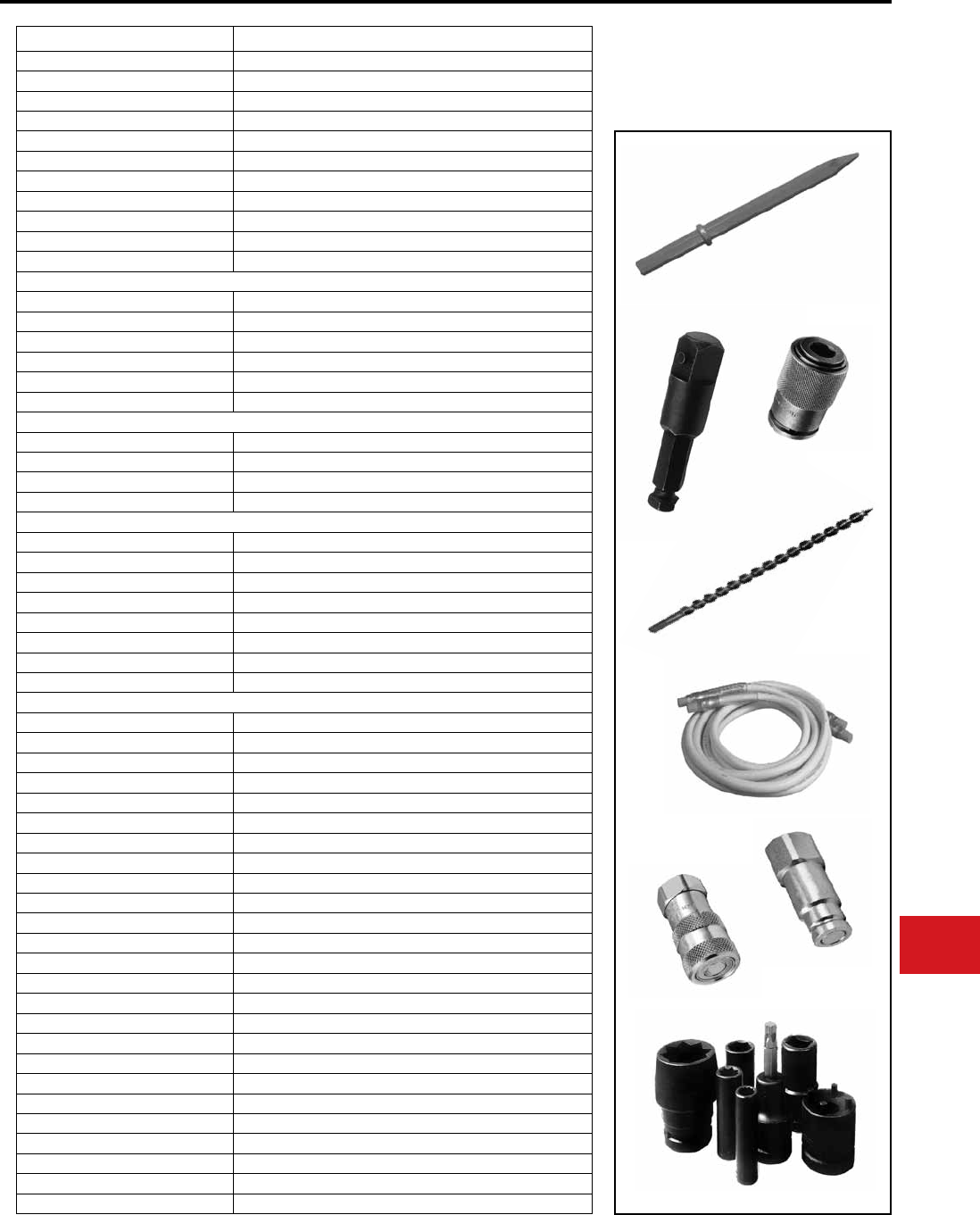
BURNDY®
Canada: 1-800-387-6487 www.burndy.com US: 1-800-346-4175
Tooling
Low Pressure Hydraulic Accessories
This is a generic sample of the more than 200
accessory items available.If you do not see what
you are looking for, call us at BURNDY and we will
get it for you: 1-800-346-4175.
Catalog Number Description
LPHT3CHISEL11418 3″ Chisel, 1-1/4″ hex, 18″ Long
LPHTASPHALTCUT118 Asphalt Cutter, 1-1/8″ hex
LPHTCLAYSPADE118 Clay Spade, 1-1/8″ hex
LPHTGRDVR11458 Ground Rod Driver, 1-1/4″ hex, 5/8″ Rod
LPHTGRDVR11858 Ground Rod Driver, 1-1/8″ hex, 5/8″ Rod
LPHTMOILPT118 Moil Point, 1″ hex, 18″ Long
LPHTMOILPT11814 Moil Point, 1-1/8″ hex, 14″ Long
LPHTNARCHISEL11814 Narrow Chisel, 1-1/8″ hex, 14″ Long
LPHTADPMM71612 7/16″ Quick Chuck Adaptor X 1/2″ Square
HIW71612TGKIT Trigger Guard for HIW-716
LPHTADPMMOP66 ADP Male/Male SAE #6, 3/8 NPT (2 required per tool)
Auger Bits (call for many additional options)
LPHTBIT111618D 11/16″ X 18″ Long X 7/16 QC; Dominator
LPHTBIT111624D 11/16″ X 24″ Long X 7/16 QC; Dominator
LPHTBIT131618D 13/16″ X 18″ Long X 7/16 QC; Dominator
LPHTBIT131624D 13/16″ X 24″ Long X 7/16 QC; Dominator
LPHTBIT151618D 15/16″ X 18″ Long X 7/16 QC; Dominator
LPHTBIT151624D 15/16″ X 24″ Long X 7/16 QC; Dominator
Hoses (call for many additional options) red or orange
LPHTHOSNCR666610 Hose - Insulated, 10 ft., 3/8 NPT, 3/8 NPT
LPHTHOSNCR66668 Hose - Insulated, 8 ft., 3/8 NPT, 3/8 NPT
LPHTHOSNCR66668OP Hose - Insulated, 8 ft., SAE #6, 3/8 NPT
LPHTHOSNCR666610OP Hose - Insulated, 10 ft., SAE #6, 3/8 NPT
Couplers (call for many additional options)
LPHTDRIPBODY66 Dripless Body - 3/8 Body, 3/8 NPT
LPHTDRIPBODY88 Dripless Body - 1/2 Body, 1/2 NPT
LPHTDRIPNOSE66 Dripless Nose - 3/8 Body, 3/8 NPT
LPHTDRIPNOSE88 Dripless Nose - 1/2 Body, 1/2 NPT
LPC38S 3/8, 3/8 NPT Flush Face Coupler Set - Body & Nose
LPC12S 3/8, 1/2 NPT Flush Face Coupler Set - Body & Nose
LPHTHTMADUSTCAPF HTMA Dust Cap - Body
LPHTHTMADUSTCAPM HTMA Dust Cap - Nose
Sockets
LPHTSOC121/118 Dual Socket - 1/2″ Drive X 1″ X 1-1/8″
LPHTSOC121316/1516 Dual Socket - 1/2 Drive X 13/16″ & 15/16″
LPHTSOC121 Socket - 1/2″ Drive X 1″
LPHTSOC121116 Socket - 1/2″ Drive X 11/16″
LPHTSOC12112 Socket - 1/2″ Drive X 1-1/2″
LPHTSOC12114 Socket - 1/2″ Drive X 1-1/4″
LPHTSOC12118 Socket - 1/2″ Drive X 1-1/8″
LPHTSOC121188PT Socket - 1/2″ Drive X 1-1/8″, 8 Point
LPHTSOC1212 Socket - 1/2″ Drive X 1/2″
LPHTSOC12128PT Socket - 1/2″ Drive X 1/2″, 8 Point
LPHTSOC121316 Socket - 1/2″ Drive X 13/16″
LPHTSOC1213168PT Socket - 1/2″ Drive X 13/16″, 8 Point
LPHTSOC12138 Socket - 1/2″ Drive X 1-3/8″
LPHTSOC1215168PT Socket - 1/2″ Drive X 15/16″, 8 Point
LPHTSOC121716 Socket - 1/2″ Drive X 1-1/16″
LPHTSOC1217168PT Socket - 1/2″ Drive X 1-1/16″, 8 Point
LPHTSOC1218PT Socket - 1/2″ Drive X 1″, 8 Point
LPHTSOC1234 Socket - 1/2″ Drive X 3/4″
LPHTSOC12348PT Socket - 1/2″ Drive X 3/4″, 8 Point
LPHTSOC1258 Socket - 1/2″ Drive X 5/8″
LPHTSOC12588PT Socket - 1/2″ Drive X 5/8″, 8 Point
LPHTSOC1278 Socket - 1/2″ Drive X 7/8″
LPHTSOC12788PT Socket - 1/2″ Drive X 7/8″, 8 Point
LPHTSOC12916 Socket - 1/2″ Drive X 9/16″
HIW12SOCSET Socket Set - 1/2″ Drive DP IMP 6 Point
N-109
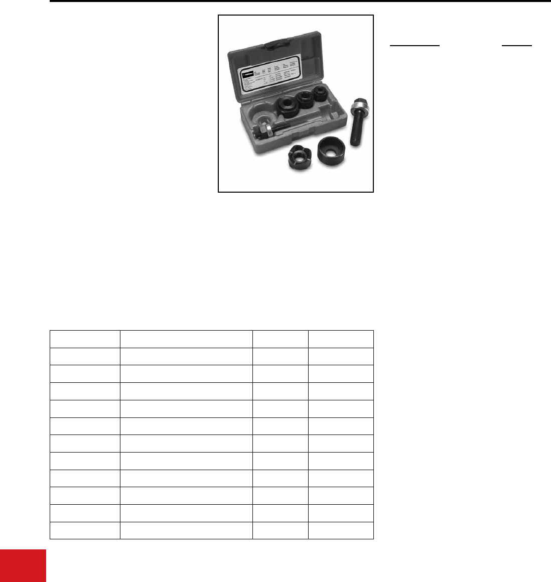
BURNDY®
US: 1-800-346-4175 www.burndy.com Canada: 1-800-387-6487
Tooling
Knockouts — Mechanical and Ratchet
BKOM50125
KNOCKOUT SET
For 1/2″– 1-1/4″ Conduit Size
The BURNDY® Knockout Set is designed to punch
holes for 1/2″ – 1-1/4″ conduit in distribution boxes,
electrical panels and troughs.
The Knockout Set is provided with a 1-year limited
warranty.
• Four-point design allows slug to drop
automatically without splitting
• Punches up to 10-gauge mild steel
• Set includes the four most popular sizes
of punches and dies packed in a sturdy
storage case
• 1-year limited warranty
Description Weight
1/2″ - 1-1/4″ Knockout Set 3 lbs
Features and Benets
BKOM50125 SPECIFICATIONS
ACCESSORIES
Components for the kit listed above can be
purchased separately.
Catalog Number Description Hole Weight
BKP500B 1/2″ Punch 7/8″ 0.4 lb.
BKD500B 1/2″ Die 7/8″ 1 lb.
BKP750B 3/4″ Punch 1 - 3/32″ 0.4 lb.
BKD750B 3/4″ Die 1 - 3/32″ 1 lb.
BKP1000B 1″ Punch 1 - 11/32″ 1 lb.
BKD1000B 1″ Die 1 - 11/32″ 1 lb.
BKP1250B 1 - 1/4″ Punch 1 - 11/16″ 2 lb.
BKD1250B 1 - 1/4″ Die 1 - 11/16″ 2 lb.
BKSB50B 1/2″ Bearing & Drive Screw - 1 lb.
BKS752B 3/4″ - 2″ Bearing & Drive Screw - 1 lb.
BK88004 Storage Case - 1.5 lb.
SET INCLUDES
N-110
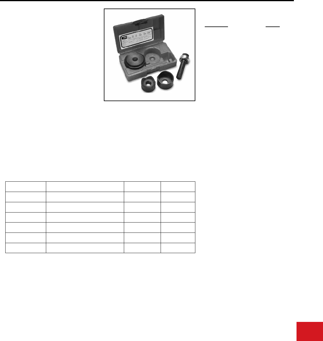
BURNDY®
Canada: 1-800-387-6487 www.burndy.com US: 1-800-346-4175
Tooling
Knockouts — Mechanical and Ratchet
BKOM152
KNOCKOUT SET
For 1-1/2″ – 2″ Conduit Size
The BURNDY® Knockout Set is designed to punch
holes for 1-1/2″ – 2″ conduit in distribution boxes,
electrical panels and troughs.
The Knockout Set is provided with a 1-year limited
warranty.
• Four-point design allows slug to drop
automatically without splitting
• Punches up to 10-gauge mild steel
• Durable storage case
• 1-year limited warranty
Features and Benets
BKOM152 SPECIFICATIONS
Description Weight
1-1/2″ - 2″ Knockout Set 4 lbs
ACCESSORIES
Components for the kit listed above can be
purchased separately.
Catalog Number Description Hole Weight
BKP1500B 1 - 1/2″ Punch 1 - 15/16″ 2 lb.
BKD1500B 1 - 1/2″ Die 1 - 15/16″ 2 lb.
BKP2000B 2″ Punch 2 - 3/8″ 2 lb.
BKD2000B 2″ Die 2 - 3/8″ 2 lb.
BKS752B 3/4″ - 2″ Bearing & Drive Screw — 1 lb.
BK88001 Storage Case — 1.5 lb.
SET INCLUDES
N-111
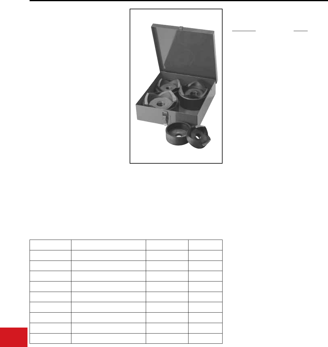
BURNDY®
US: 1-800-346-4175 www.burndy.com Canada: 1-800-387-6487
Tooling
Knockouts — Mechanical and Ratchet
BKOH2540
ASSORTED KNOCKOUT KIT
For 2-1/2″ – 4″ Conduit Size
The BURNDY® Assorted Knockout Kit is designed
to punch holes for 2-1/2″ – 4″ conduit in distribution
boxes, electrical panels and troughs.
The Knockout Kit is provided with a 1-year limited
warranty.
• Expand capability of 1/2″ – 2″ sets
• Four-point design allows slug to drop
automatically without splitting
• Punches up to 10-gauge mild steel
• Packed in metal storage case
• 1-year limited warranty
Features and Benets
BKOH2540 SPECIFICATIONS
Description Weight
2-1/2″ - 4″ Knockout Set 22 lbs
ACCESSORIES
Components for the kit listed above can be
purchased separately.
Catalog Number Description Hole Weight
BKP2500 2 - 1/2″ Punch 2 - 7/8″ 3 lb.
BKD2500 2 - 1/2″ Die 2 - 7/8″ 3 lb.
BKP3000 3″ Punch 3 - 1/2″ 4 lb.
BKD3000 3″ Die 3 - 1/2″ 4 lb.
BKP3500 3 - 1/2″ Punch 4″ 4 lb.
BKD3500 3 - 1/2″ Die 4″ 4 lb.
BKP4000 4″ Punch 4 - 1/2″ 4 lb.
BKD4000 4″ Die 4 - 1/2″ 4 lb.
BK88008 Metal Storage Case - 5 lb.
SET INCLUDES
N-112
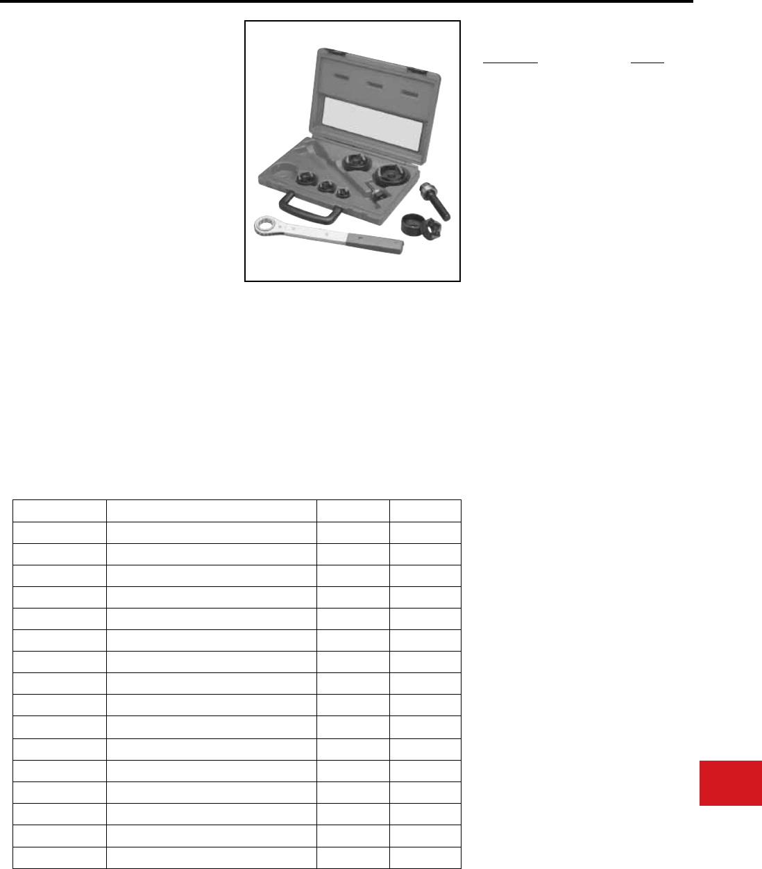
BURNDY®
Canada: 1-800-387-6487 www.burndy.com US: 1-800-346-4175
Tooling
Knockouts — Mechanical and Ratchet
BKOW520
KNOCKOUT SET WITH
RATCHET WRENCH
For 1/2″ – 2″ Conduit
The BURNDY® Knockout Set with Ratchet
Wrench is designed to punch holes for 1/2″ – 2″
conduit in distribution boxes, electrical panels
and troughs.
The Knockout Set with Ratchet Wrench is provided
with a 1-year limited warranty.
• Four-point design allows slug to drop
automatically without splitting
• Punches up to 10-gauge mild steel
• Set includes ratchet wrench, six sizes of
punches and dies, and two drive screws; all
packaged in a rugged storage case
• 1-year limited warranty
Features and Benets
BKOW520 SPECIFICATIONS
Description Weight
1/2″- 2″ Knockout Set with
Ratchet wrench (BKW52)
12 lbs
ACCESSORIES
Components for the kit listed above can be
purchased separately.
Catalog Number Description Hole Weight
BKP500B 1/2″ Punch 7/8″ 0.4 lb.
BKD500B 1/2″ Die 7/8″ 1 lb.
BKP750B 3/4″ Punch 1 - 3/32″ 0.4 lb.
BKD750B 3/4″ Die 1 - 3/32″ 1 lb.
BKP1000B 1″ Punch 1 - 11/32″ 1 lb.
BKD1000B 1″ Die 1 - 11/32″ 1 lb.
BKP1250B 1 - 1/4″ Punch 1 - 11/16″ 2 lb.
BKD1250B 1 - 1/4″ Die 1 - 11/16″ 2 lb.
BKP1500B 1 - 1/2″ Punch 1 - 15/16″ 2 lb.
BKD1500B 1 - 1/2″ Die 1 - 15/16″ 2 lb.
BKP2000B 2″ Punch 2 - 3/8″ 2 lb.
BKD2000B 2″ Die 2 - 3/8″ 2 lb.
BKW52 Hand Ratchet Wrench - 1 lb.
BKSB50B 1/2″ Bearing & Drive Screw - 1 lb.
BKS752B 3/4″ - 2″ Bearing & Drive Screw - 1 lb.
BK88007 Storage Case - 1.5 lb.
SET INCLUDES
N-113
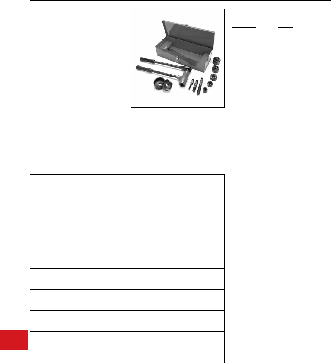
BURNDY®
US: 1-800-346-4175 www.burndy.com Canada: 1-800-387-6487
Tooling
Knockouts — Mechanical and Ratchet
BKOR520
QUICK HAND RATCHET
KNOCKOUT SET
For 1/2″ - 2″ Conduit
The BURNDY
®
Hand Ratchet Knockout Set is
designed to punch holes for 1/2″ – 2″ conduit
in distribution boxes, electrical panels and
troughs.
The Hand Ratchet Knockout Set is provided with a
1-year limited warranty.
• Four-point design allows slug to drop
automatically without splitting
• Smooth operating ratchet handles up to
10-gauge mild steel or 12-gauge stainless steel
• 1-year limited warranty
Description
1/2" - 2" Quick
Hand Ratchet
Knockout Set
Features and Benets
BKOR520 SPECIFICATIONS
Weight
16 lbs
ACCESSORIES
Components for kit listed above can be
purchased separately.
Catalog Number Description Hole Weight
BKP500B 1/2" Punch 7/8" 0.4 lb.
BKD500B 1/2" Die 7/8" 1 lb.
BKP750B 3/4" Punch 1-3/32" 0.4 lb.
BKD750B 3/4" Die 1-3/32" 1 lb.
BKP1000B 1" Punch 1-11/32" 1 lb.
BKD1000B 1" Die 1-11/32" 1 lb.
BKP1250B 1-1/4" Punch 1-11/16" 2 lb.
BKD1250B 1-1/4" Die 1-11/16" 2 lb.
BKP1500B 1-1/2" Punch 1-15/16" 2 lb.
BKD1500B 1-1/2" Die 1-15/16" 2 lb.
BKP2000B 2" Punch 2-3/8" 2 lb.
BKD2000B 2" Die 2-3/8" 2 lb.
BKOR14 Ratchet ― 12 lb.
BKOR50 1/2" Screw Adapter ― 0.4 lb.
BKOR75125 3/4"- 1-1/4" Screw Adapter ― 1 lb.
BKOR152 1-1/2" - 2" Screw Adapter ― 1 lb.
BK88020 Metal Storage Case ― 4 lb.
SET INCLUDES
N-114
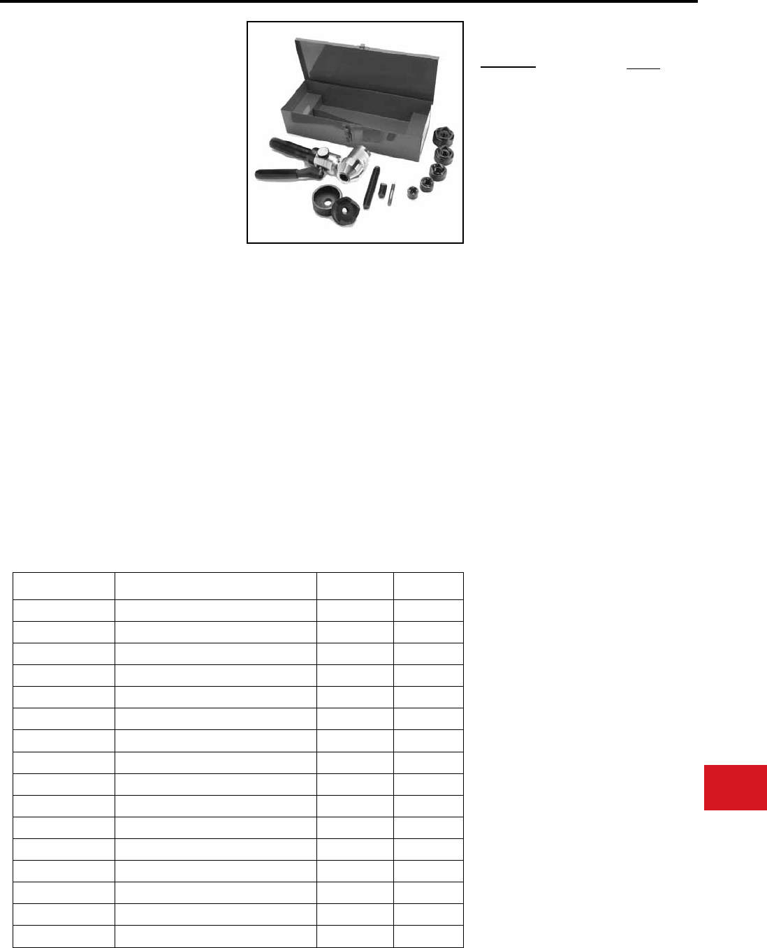
BURNDY®
Canada: 1-800-387-6487 www.burndy.com US: 1-800-346-4175
Tooling
Knockouts — Hydraulic
BKOS5290
SELF-CONTAINED HYDRAULIC
360° KNOCKOUT SET
For 1/2″ – 2″ Conduit
The BURNDY® Self-Contained 360° Knockout Set
is designed to punch holes for 1/2″ – 2″ conduit in
distribution boxes, electrical panels and troughs.
The self-contained 360° Knockout Set is provided
with a 1-year limited warranty.
• Right-angle head swivels 360° for exible
punching in tight work spaces
• Punches up to 2″ conduit sizes, up to
10-gauge mild steel or 12-gauge stainless
steel
• No cumbersome “spacers” required
• Compact, lightweight size: 7-1/2 pounds and
13" in length
• Operating pressure rated at 10,000 psi
• Set includes the most popular drawstuds,
punches, and dies for punching holes for
1/2″ to 2″ conduit; all packed in a sturdy
storage case
• 1-year limited warranty
Features and Benets
BKOS5290 SPECIFICATIONS
Description
1/2" - 2" Self-Contained
Hydraulic Knockout Set
- head swivels 360°
Weight
7-1/2 lbs
ACCESSORIES
Components for kit listed above can be
purchased separately.
BKLP6K1 Seal Repair Kit
Catalog Number Description Hole Weight
BKP500B 1/2″ Punch 7/8″ 0.4 lb.
BKD500B 1/2″ Die 7/8″ 1 lb.
BKP750B 3/4″ Punch 1-3/32″ 0.4 lb.
BKD750B 3/4″ Die 1-3/32″ 1 lb.
BKP1000B 1″ Punch 1-11/32″ 1 lb.
BKD1000B 1″ Die 1-11/32″ 1 lb.
BKP1250B 1-1/4″ Punch 1-11/16″ 2 lb.
BKD1250B 1-1/4″ Die 1-11/16″ 2 lb.
BKP1500B 1-1/2″ Punch 1-15/16″ 2 lb.
BKD1500B 1-1/2″ Die 1-15/16″ 2 lb.
BKP2000B 2″ Punch 2-3/8″ 2 lb.
BKD2000B 2″ Die 2-3/8″ 2 lb.
BKLP6 Hydraulic Driver ― 10 lb.
BKPR7520 Drawstud ― 1 lb.
BKPS50 Drawstud ― 0.2 lb.
BKSA50 Drawstud Adapter ― 0.3 lb.
SET INCLUDES
N-115
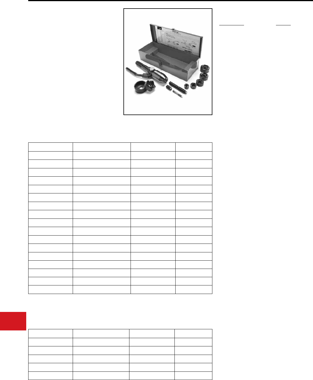
BURNDY®
US: 1-800-346-4175 www.burndy.com Canada: 1-800-387-6487
Tooling
Knockouts — Hydraulic
BKOS520
SELF-CONTAINED
HYDRAULIC KNOCKOUT SET
For 1/2″ – 2″ Conduit
The BURNDY® Self-Contained Hydraulic Knockout
Set is designed to punch holes for 1/2″ – 2″ conduit
in distribution boxes, electrical panels and troughs.
The Self-Contained Hydraulic Knockout Set is
provided with a 1-year limited warranty.
Optional 2-1/2″ and 3″ punch and die available.
• Hydraulic driver punches up to 10-gauge mild
steel or 12-gauge stainless steel
• Four-point design allows slug to drop
automatically without splitting
• Lightweight and easy to use
• Hydraulic driver operates in any position
• 1-year limited warranty
Features and Benets
BKOS520 SPECIFICATIONS
Description
1/2″ - 2″ Self-Contained
Hydraulic Set
Weight
14 lbs
Catalog Number Description Hole Weight
BKP500B 1/2" Punch 7/8" 0.4 lb.
BKD500B 1/2" Die 7/8" 1 lb.
BKP750B 3/4" Punch 1-3/32" 0.4 lb.
BKD750B 3/4" Die 1-3/32" 1 lb.
BKP1000B 1" Punch 1-11/32" 1 lb.
BKD1000B 1" Die 1-11/32" 1 lb.
BKP1250B 1-1/4" Punch 1-11/16" 2 lb.
BKD1250B 1-1/4" Die 1-11/16" 2 lb.
BKP1500B 1-1/2" Punch 1-15/16" 2 lb.
BKD1500B 1-1/2" Die 1-15/16" 2 lb.
BKP2000B 2" Punch 2-3/8" 2 lb.
BKD2000B 2" Die 2-3/8" 2 lb.
BKLP2 Hydraulic Driver ― 10 lb.
BKPR7520 Drawstud ― 1 lb.
BKPS50 Drawstud ― 0.2 lb.
BKSA50 Drawstud Adapter ― 0.3 lb.
BK88020 Metal Storage Case ― 4.1lb.
SET INCLUDES
Catalog Number Description Hole Weight
BKP2500 2-1/2" Punch 2-7/8" 3 lb.
BKD2500 2-1/2" Die 2-7/8" 3 lb.
BKP3000 3" Punch 3-1/2" 4 lb.
BKD3000 3" Die 3-1/2" 4 lb.
BKLP2K1 Seal Repair Kit ― ―
ACCESSORIES
Components for the kit listed above can be purchased separately. Additional accessories, not included in
kit, are listed below.
N-116

BURNDY®
Canada: 1-800-387-6487 www.burndy.com US: 1-800-346-4175
Tooling
Knockouts — Hydraulic
BKOH520A
HYDRAULIC KNOCKOUT SET
For 1/2″ - 2″ Conduit
The BURNDY® Hydraulic Knockout Set is designed
to punch holes for 1/2″ – 2″ conduit in distribution
boxes, electrical panels and troughs. Provided with
hand pump.
The Hydraulic Knockout Set is provided with a
1-year limited warranty.
• Four-point design allows slug to drop
automatically without splitting
• Punches up to 10-gauge mild steel or 12-gauge
stainless steel
• Hand-powered hydraulic pump
• Assortment of punches, dies and accessories
• Includes metal storage case
(11-1/8″ x 18-3/4″ x 6-1/4″)
• Competitor’s punches and dies are
interchangeable
• 1-year limited warranty
Features and Benets
BKOH520A SPECIFICATIONS
Description
1/2″ - 2″ Hydrualic
Knockout Set with
BPH2 Hand Pump
Weight
31 lbs
ACCESSORIES
Components for kit listed above can be
purchased separately.
Catalog Number Description Hole Weight
BKP500B 1/2" Punch 7/8" 0.4 lb.
BKD500B 1/2" Die 7/8" 1 lb.
BKP750B 3/4" Punch 1-3/32" 0.4 lb.
BKD750B 3/4" Die 1-3/32" 1 lb.
BKP1000B 1" Punch 1-11/32" 1 lb.
BKD1000B 1" Die 1-11/32" 1 lb.
BKP1250B 1-1/4" Punch 1-11/16" 2 lb.
BKD1250B 1-1/4" Die 1-11/16" 2 lb.
BKP1500B 1-1/2" Punch 1-15/16" 2 lb.
BKD1500B 1-1/2" Die 1-15/16" 2 lb.
BKP2000B 2" Punch 2-3/8" 2 lb.
BKD2000B 2" Die 2-3/8" 2 lb.
BPH20 Hand Pump ― 2 speed ― 5 lb.
BKPR7540 Drawstud for 3/4" - 4" Punches & Dies ― 2.5 lb.
BKPS50* Stainless Steel Drawstud, 3/8" dia. ― 0.2 lb.
BKC3540** Converter ― 0.4 lb.
BCH1211 12-ton Hydraulic Cylinder ― 0.6 lb.
BH864 6' Rubber Hose Coupler 2 lb.
BCM5 Metal Case ― 11 lb.
BKOH520A SET INCLUDES
* Must be used with 1/2" punch and die.
**Must be used with 3-1/2"– 4" punch and die. N-117
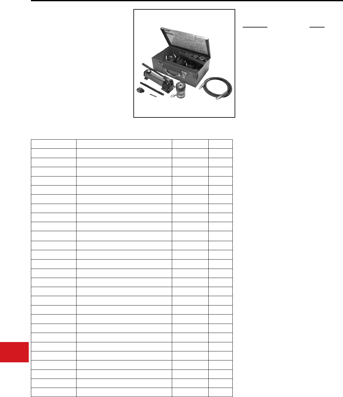
BURNDY®
US: 1-800-346-4175 www.burndy.com Canada: 1-800-387-6487
Tooling
Knockouts — Hydraulic
BKOH540A
HYDRAULIC KNOCKOUT SET
For 1/2″ – 4″ Conduit
The BURNDY® Hydraulic Knockout Set is designed
to punch holes for 1/2″ – 4″ conduit in distribution
boxes, electrical panels and troughs. Provided with
hand pump.
The Hydraulic Knockout Set is provided with a
1-year limited warranty.
• Four-point design allows slug to drop
automatically without splitting
• Punches up to 10-gauge mild steel or
12-gauge stainless steel
• Hand–powered hydraulic pump
• Assortment of punches, dies and accessories
• Includes metal storage case
(11-1/8″ x 18-3/4″ x 6-1/4″ )
• Competitor’s punches and dies are
interchangeable
• 1-year limited warranty
Features and Benets
BKOH540A SPECIFICATIONS
ACCESSORIES
Description Weight
1/2″ - 4″ Hydraulic Knockout Set
with BPH20 Hand Pump
50 lbs
Components for the kit listed above can be
purchased separately.
Catalog Number Description Hole Weight
BKP500B 1/2" Punch 7/8" 0.4 lb.
BKD500B 1/2" Die 7/8" 1 lb.
BKP750B 3/4" Punch 1 - 3/32" 0.4 lb.
BKD750B 3/4" Die 1 - 3/32" 1 lb.
BKP1000B 1" Punch 1 - 11/32" 1 lb.
BKD1000B 1" Die 1 - 11/32" 1 lb.
BKP1250B 1 - 1/4" Punch 1 - 11/16" 2 lb.
BKD1250B 1 - 1/4" Die 1 - 11/16" 2 lb.
BKP1500B 1 - 1/2" Punch 1 - 15/16" 2 lb.
BKD1500B 1 - 1/2" Die 1 - 15/16" 2 lb.
BKP2000B 2" Punch 2 - 3/8" 2 lb.
BKD2000B 2" Die 2 - 3/8" 2 lb.
BKP2500 2"- 1/2" Punch 2 - 7/8" 3 lb.
BKD2500 2"- 1/2" Die 2 - 7/8" 3 lb.
BKP3000 3" Punch 3 - 1/2" 4 lb.
BKD3000 3" Die 3 - 1/2" 4 lb.
BKP3500 3"- 1/2" Punch 4" 4 lb.
BKD3500 3"- 1/2" Die 4" 4 lb.
BKP4000 4" Punch 4 - 1/2" 4 lb.
BKD4000 4" Die 4 - 1/2" 4 lb.
BPH20 Hand Pump - 2 speed -5 lb.
BKPR7540 Drawstud for 3/4" - 4" Punches & Dies - 2.5 lb.
BKPS50* Stainless steel Drawstud, 3/4" dia. - 0.2 lb.
BKC3540** Converter - 0.4 lb.
BCH1211 12 - ton Hydraulic Cylinder - 0.6 lb.
BH864 6' Rubber Hose Coupler - 2 lb.
BCM5 Metal Case - 11 lb.
SET INCLUDES
* Must be used with 1/2″ punch and die.
** Must be used with 3-1/2″ - 4″ punch and die.
N-118
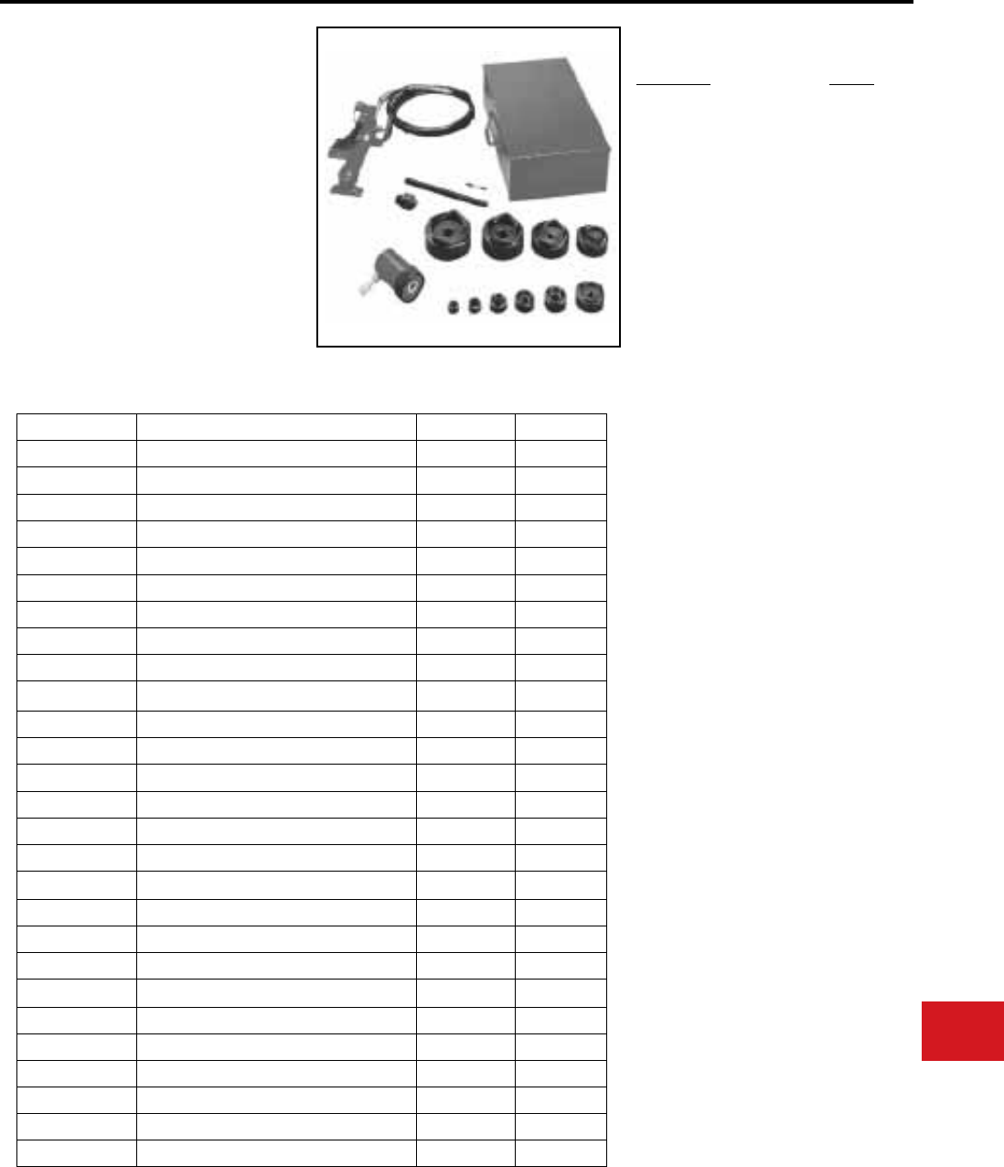
BURNDY®
Canada: 1-800-387-6487 www.burndy.com US: 1-800-346-4175
Tooling
Knockouts — Hydraulic
BKOF540
HYDRAULIC KNOCKOUT SET
For 1/2″ – 4″ Conduit
The BURNDY® Hydraulic Knockout Set is designed
to punch holes for 1/2″ – 4″ conduit in distribution
boxes, electrical panels and troughs. Provided with
foot pump.
The Hydraulic Knockout Set is provided with a
1-year limited warranty.
• Four-point design allows slug to drop
automatically without splitting
• Punches up to 10-gauge mild steel or
12-gauge stainless steel
• Foot–powered hydraulic pump
• Assortment of punches, dies and accessories
• Includes metal storage case
(11-1/8″ x 18-3/4″ x 6-1/4″ )
• Competitor’s punches and dies are
interchangeable
• 1-year limited warranty
Features and Benets
BKOF540 SPECIFICATIONS
ACCESSORIES
Description Weight
1/2″ - 4″ Hydraulic Knockout
Set with BPF65 Foot Pump
50 lbs
Components for the kit listed above can be
purchased separately.
Catalog Number Description Hole Weight
BKP500B 1/2″ Punch 7/8″ 0.4 lb.
BKD500B 1/2″ Die 7/8″ 1 lb.
BKP750B 3/4″ Punch 1 - 3/32″ 0.4 lb.
BKD750B 3/4″ Die 1 - 3/32″ 1 lb.
BKP1000B 1″ Punch 1 - 11/32″ 1 lb.
BKD1000B 1″ Die 1 - 11/32″ 1 lb.
BKP1250B 1 - 1/4″ Punch 1 - 11/16″ 2 lb.
BKD1250B 1 - 1/4″ Die 1 - 11/16″ 2 lb.
BKP1500B 1 - 1/2″ Punch 1 - 15/16″ 2 lb.
BKD1500B 1 - 1/2″ Die 1 - 15/16″ 2 lb.
BKP2000B 2″ Punch 2 - 3/8″ 2 lb.
BKD2000B 2″ Die 2 - 3/8″ 2 lb.
BKP2500 2″- 1/2″ Punch 2 - 7/8″ 3 lb.
BKD2500 2″- 1/2″ Die 2 - 7/8″ 3 lb.
BKP3000 3″ Punch 3 - 1/2″ 4 lb.
BKD3000 3″ Die 3 - 1/2″ 4 lb.
BKP3500 3″- 1/2″ Punch 4″ 4 lb.
BKD3500 3″- 1/2″ Die 4″ 4 lb.
BKP4000 4″ Punch 4 - 1/2″ 4 lb.
BKD4000 4″ Die 4 - 1/2″ 4 lb.
BPF65 Foot Pump - 2 speed -5 lb.
BKPR7540 Drawstud for 3/4″ - 4″ Punches & Dies - 2.5 lb.
BKPS50* Stainless steel Drawstud, 3/4″ dia. - 0.2 lb.
BKC3540** Converter - 0.4 lb.
BCH1211 12 - ton Hydraulic Cylinder - 0.6 lb.
BH864 6′ Rubber Hose Coupler - 2 lb.
BCM5 Metal Case - 11 lb.
SET INCLUDES
* Must be used with 1/2" punch and die.
** Must be used with 3-1/2" - 4" punch and die.
N-119
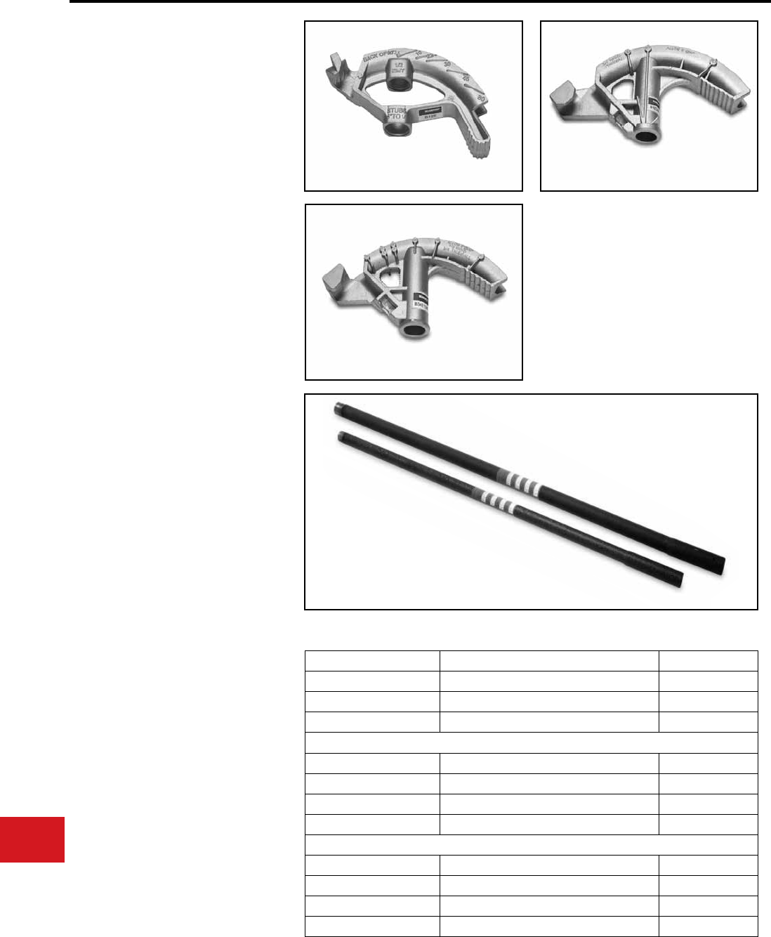
BURNDY®
US: 1-800-346-4175 www.burndy.com Canada: 1-800-387-6487
Tooling
B12E, B34E12R, B1E34R
CONDUIT HAND BENDERS
The BURNDY® Aluminum Hand Bender is
designed to bend EMT and Rigid conduit. The size
range is 1/2″- 1″ EMT.
The conduit hand bender is provided with a 5-year
limited warranty.
• All models include embossment with sight
lines for 10º, 22º, 30º, 45º, 60º and 90º
• Industry standard markings — 30º bend
when handle is straight up
• The non-slip foot pedal is contoured
allowing more foot room
• 3/4″ and 1″ bender heads have levels which
makes aligning easy
• Designed with a channel to bend conduit
back if you have an over-bend
• 5-year limited warranty
Features and Benets
B12E B1E34R
B34E12R
Bender Part Number Description Weight
B12E 1/2″ EMT (bender head only) 0.90 lbs
B34E12R 3/4″ EMT - 1/2″ RIGID (bender head only) 1.80 lbs
B1E34R 1″ EMT - 3/4″ RIGID (bender head only) 3.55 lbs
Bender Part Number Description Weight
H12E Handle for 1/2″ bender 3.65 lbs
H34E12R Handle for 3/4″ bender 3.65 lbs
H1E34R Handle for 1″ bender 5.45 lbs
Bender Part Number Description Weight
BHA12E 1/2″ EMT bender with handle 4.55 lbs
BHA34E12R 3/4″ EMT - 1/2″ RIGID bender with handle 5.45 lbs
BHA1E34R 1″ EMT - 3/4″ RIGID bender with handle 9 lbs
Handles
Benders — Hand Benders
N-120
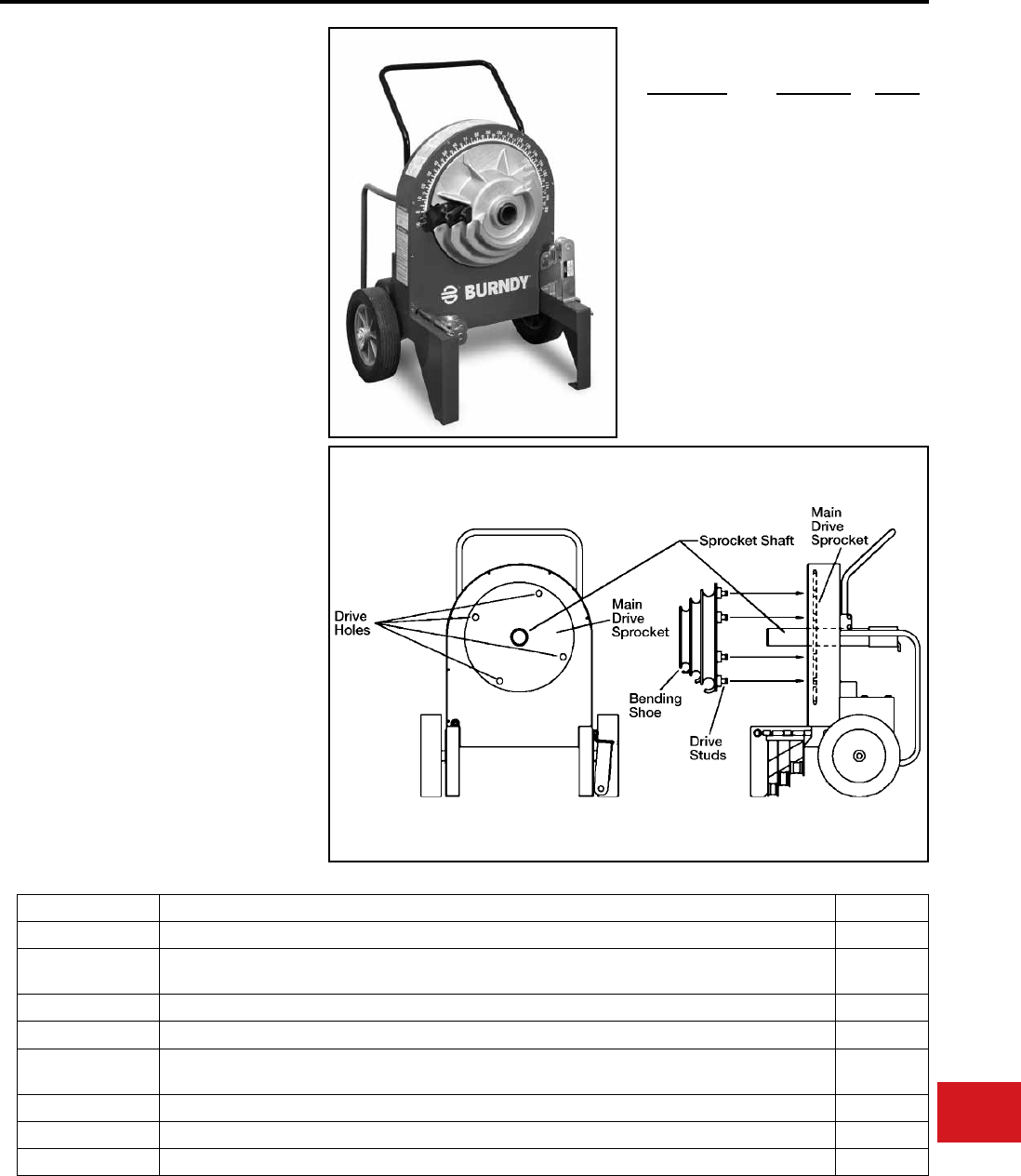
BURNDY®
Canada: 1-800-387-6487 www.burndy.com US: 1-800-346-4175
Tooling
Benders — Electric Benders
BEB122
ELECTRIC CONDUIT BENDER
For 1/2″ - 2″ Conduit and Pipe
The BURNDY® BEB122 electric conduit bender is
designed to bend 1/2″ - 2″ rigid conduit, IMC, EMT
and 2″ PVC coated conduit. The BEB122 bender
assists the electrical contractor on larger jobs and
will save time and labor.
The BEB122 electrical bender is provided with a
2-year limited warranty.
• The electric bender is available for Rigid,
EMT, IMC or PVC. Bender can also be
purchased without shoes
• Shoes and roller supports interchange with
the Gardner Bender® GB2555, Greenlee®
555 and Current Tools® 77 series (Only
exception is using the Greenlee® four
groove rigid shoe #00571, you must use
roller support #00936)
• Reliable electrical system that offers ease of
repairs (does not contain any circuit boards)
• Proudly “Made in the USA”
• Maximum schedule 40 conduit
• Will produce 180 degree bends in a single
cycle
• Limit stop control for bend angle settings
• Operates on 115-120VAC 60Hz
• Built in bend angle protractor bends 90
degrees quickly and efciently
• 2-year limited warranty
Features and Benets
ACCESSORIES
Part Number Description Weight
BEB122 Electric Bender Power Unit only, without shoes and roller supports 270 lbs
BEB122RIG Electric Bender with shoes and roller supports for 1/2″ through 2″ RIGID conduit schedule 40 pipe and
1/2″ through 1-1/4″ IMC conduit
365 lbs
BEB122EMT* Electric Bender with shoes and roller supports for 1/2″ through 2″ EMT conduit 430 lbs
BEB122PVC* Electric Bender with shoes and roller supports for 1/2″ through 2″ PVC coated RIGID conduit 365 lbs
122RIG Shoes and roller supports only, for bending 1/2″ thru 2 RIGID conduit, 1/2″ through 1-1/4″ IMC conduit and
1/2″ through 2″ Schedule 40 pipe
74 lbs
122EMT* Shoes and roller supports only, for bending 1/2″ through 2″ EMT (thinwall) 160 lbs
122IMC* Shoes and roller supports only, for bending 1-1/2″ and 2″ IMC 127 lbs
122PVC* Shoes and roller supports only, for bending 1/2″ through 2″ 40 mil PVC coated RIGID 110 lbs
* Shoes and roller supports come with
BEBSHOECASE metal box
Part Number Description Weight
BEBSHOECASE Metal storage
box
36 lbs
N-121
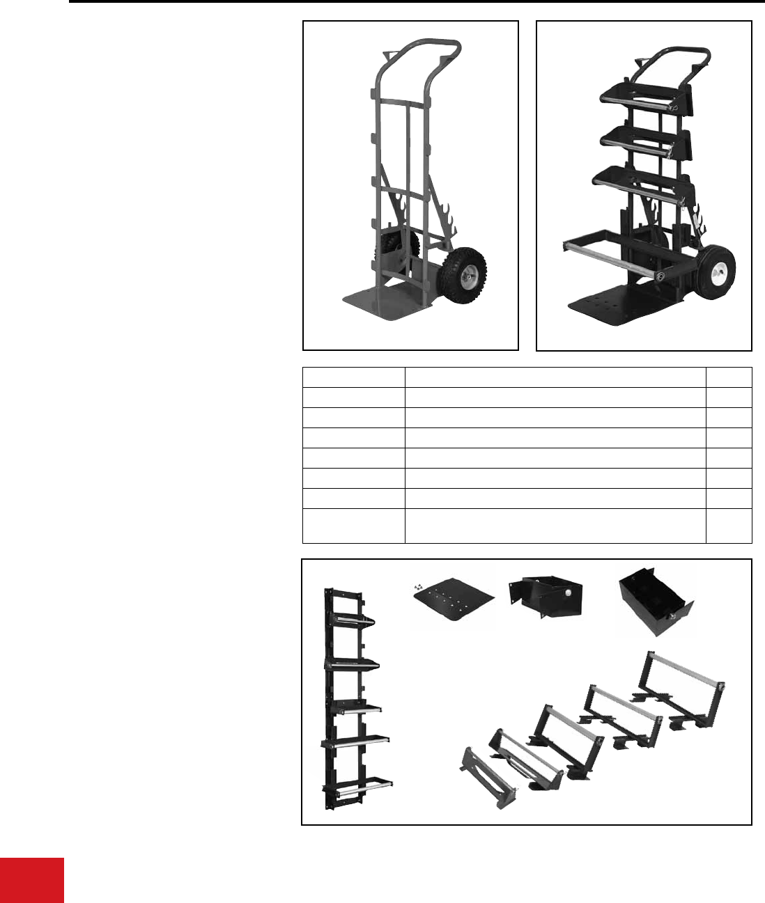
BURNDY®
US: 1-800-346-4175 www.burndy.com Canada: 1-800-387-6487
Tooling
Wire Management — The SmartCart®
BSC2H
The SmartCart®
2-Wheel Heavy Duty Cart
The SmartCart® is a versatile wire management
system consisting of 2 wheeled carts, various
modular wire racks for carrying spools of wire
and wall storage units to organize and store
racks with wire when not in use. The SmartCart®
wire management system will assist the electrical
contractor with wire installations, improves wire
storage, and saves time and labor.
Heavy duty carts are rated for 600 lbs capacity.
The SmartCart® is provided with a 1-year limited
warranty.
Features and Benets
ACCESSORIES
• Order as standard conguration or
customize to your needs with various size
racks
• Two holders provided for up to 1″ conduit
benders
• Built-in tray to hold sh tapes and tools
• Handles are pre-dimpled for mounting
material tool boxes (MTB and MTX)
• Cart base plate is pre-punched to
accommodate mounting of the extension
base plate with built-in wire guide
• Spools are easily changed by placing rack
on its side, removing hitch pin and shaft, roll-
out and roll-in desired new spool
• Motionless vise attached to the back of cart
for cutting 1/2″, 3/4″ and 1″ conduit
BSC2H BSC2HA1B1FEBP
Catalog Number Description Weight
BSC2H 2-Wheel Heavy Duty without racks 37 lbs
BSC2H5A 2-Wheel Heavy Duty with (5) R17A racks 62 lbs
BSC2H3A2B 2-Wheel Heavy Duty with (3) R17A racks and (2) R22B racks 64 lbs
BSC2H5B 2-Wheel Heavy Duty with (5) R22B racks 67 lbs
BSC2H1C2DEBP 2-Wheel Heavy Duty with (1) R17C rack, (2) R25D racks and (1) EBP 86 lbs
BSC2H2C1DEBP 2-Wheel Heavy Duty with (2) R17C racks, (1) R25D rack and (1) EBP 82 lbs
BSC2H2A1B1FEBP 2-Wheel Heavy Duty with (2) R17A racks (1) R22B rack (1) R24F rack
and (1) EBP
81 lbs
EBP Extension Base Plate with built-in
wire guide
MTB Material Tool Box
11″ L X 6″ W X 5″ D
MTX Material Tool Box (MTB) with Divid-
ers 6-Pockets:
3-5/8″ L X 3″ W X 3″ D
R17A 17″ wide rack for 7-1/2″ diameter
spools with 1/2″ EMT spindles
R22B 22″ wide rack for 7-1/2″
diameter spools with 1/2″ EMT
spindles
R17C* 17″ wide rack for 12″ diameter
spools with 1″ EMT spindles
R25D* 25″ wide rack for 12″ diameter
spools with 1″ EMT spindles
R24F* 24″ wide rack for 2-16″ diameter
reels with 1″ EMT spindles
BSCWS40 40″ Wall Wire Reel Storage System
BSCWS80 80″ Wall Wire Reel Storage System
*Note: The R17C, R25D, and R24F racks are designed for oversized reels. The Extension
Base Plate (EBP) is required when used on The SmartCart®.
BSCWS80
EBP
MTB MTX
R17A R22B
R17C*
R25D*
R24F*
Shown with racks,
sold separately
N-122
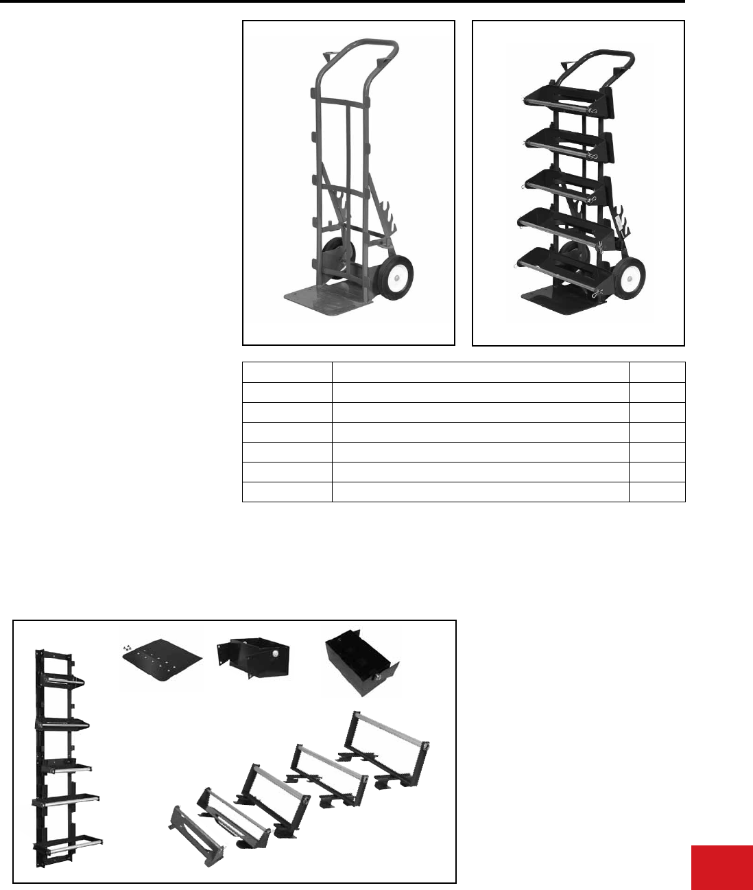
BURNDY®
Canada: 1-800-387-6487 www.burndy.com US: 1-800-346-4175
Tooling
Wire Management — The SmartCart®
BSC2L
The SmartCart®
2-Wheel Light Duty Cart
The SmartCart® is a versatile wire management
system consisting of 2 wheeled carts, various
modular wire racks for carrying spools of wire
and wall storage units to organize and store
racks with wire when not in use. The SmartCart®
wire management system will assist the electrical
contractor with wire installations, improves wire
storage, and saves time and labor.
Light duty carts are rated for 300 lbs capacity.
The SmartCart® is provided with a 1-year limited
warranty.
Features and Benets
• Order as standard conguration or
customize to your needs with various size
racks
• Two holders provided for up to 1″ conduit
benders
• Built-in tray to hold sh tapes and tools
• Handles are pre-dimpled for mounting
material tool boxes (MTB and MTX)
• Cart base plate is pre-punched to
accommodate mounting of the extension
base plate with built-in wire guide
• Spools are easily changed by placing rack
on its side, removing hitch pin and shaft, roll-
out and roll-in desired new spool
• Motionless vise attached to the back of cart
for cutting 1/2″, 3/4″ and 1″ conduit
Catalog Number Description Weight
BSC2L 2-Wheel Light Duty without racks 37 lbs
BSC2L5A 2-Wheel Light Duty with (5) R17A racks 62 lbs
BSC2L3A2B 2-Wheel Light Duty with (3) R17A racks and (2) R22B racks 64 lbs
BSC2L5B 2-Wheel Light Duty with (5) R22B racks 67 lbs
BSC2L1C2DEBP 2-Wheel Light Duty with (1) R17C rack, (2) R25D racks and (1) EBP 86 lbs
BSC2L2C1DEBP 2-Wheel Light Duty with (2) R17C racks, (1) R25D rack and (1) EBP 82 lbs
ACCESSORIES
BSC2L BSC2L3A2B
BSCWS80
EBP
MTB MTX
R17A R22B
R17C*
R25D*
R24F*
Shown with racks,
sold separately
EBP Extension Base Plate with built-in
wire guide
MTB Material Tool Box
11″ L X 6″ W X 5″ D
MTX Material Tool Box (MTB) with Divid-
ers 6-Pockets:
3-5/8″ L X 3″ W X 3″ D
R17A 17″ wide rack for 7-1/2″ diameter
spools with 1/2″ EMT spindles
R22B 22″ wide rack for 7-1/2″
diameter spools with 1/2″ EMT
spindles
R17C* 17″ wide rack for 12″ diameter
spools with 1″ EMT spindles
R25D* 25″ wide rack for 12″ diameter
spools with 1″ EMT spindles
R24F* 24″ wide rack for 2-16″ diameter
reels with 1″ EMT spindles
BSCWS40 40″ Wall Wire Reel Storage System
BSCWS80 80″ Wall Wire Reel Storage System
*Note: The R17C, R25D, and R24F racks are designed for oversized reels. The Extension
Base Plate (EBP) is required when used on The SmartCart®.
N-123
BURNDY®
US: 1-800-346-4175 www.burndy.com Canada: 1-800-387-6487
Tooling
Wire Management — The SmartCart®
BSCWS40 AND
BSCWS80
The SmartCart®
Wall Wire Reel Storage System
The BSCWS40, 40″ high and BSCWS80, 80″ high
Wall Wire Reel Storage Systems are designed to
work in a van, panel truck or shop and handles all
2 wheel SmartCart® racks.
Provides a time saving advantage by storing wire
on racks which can be easily moved to 2 wheel
carts for transporting and wire pulling.
Sizes:
40″ high, 17″ wide, 2-3/4″ deep
80″ high, 17″ wide, 2-3/4″ deep
The SmartCart® is provided with a 1-year
limited warranty.
Modular Racks for
2 Wheel Carts
(sold separately)
R17A 17″ wide rack for 7-1/2″ diameter
spools with 1/2″ EMT spindles
R22B 22″ wide rack for 7-1/2″ diameter
spools with 1/2″ EMT spindles
R17C* 17″ wide rack for 12″ diameter
spools with 1″ EMT spindles
R25D* 25″ wide rack for 12″ diameter
spools with 1″ EMT spindles
R24F* 24″ wide rack for 2-16″ diameter
reels with 1″ EMT spindles
*Note: The R17C, R25D, and R24F racks are
designed for oversized reels. The Extension Base
Plate (EBP) is required when used on The
SmartCart®.
Shown with racks,
sold separately
BSCWS80
BSCWS40
Shown with racks,
sold separately
R17A R22B
R17C*
R25D*
R24F*
N-124

BURNDY®
Canada: 1-800-387-6487 www.burndy.com US: 1-800-346-4175
Reference
Introduction
Basic Connection Principles
Hardware Data
DURIUM™ Steel/Aluminum Tightening
Torques
DURIUM™ Hex Bolts Data
UL Tightening Torque UL486
Recommended Clamping on Bolted
Connectors
Cable Data (Tables)
Copper Cable
Copper Tube
Solid Copper Wire
Compact Stranded Copper Cable
Stranded Copper Cable
Flexible Copper Stranded Cable
Aluminum and ACSR Cable
Aluminum Tube
Aluminum 1350 Cable Bare -
Classes AA and A
Aluminum 1350 Cable Bare - Class B
ACSR Cable
High Strength ACSR Cable
Compact Aluminum 1350 Cable
Aluminimum Alloy 5005 Cable
Aluminum 6201 Cable
Aluminum Alloy 8000 Series “O”
Temper Cable
Compact ACSR Cable
ACSR/TW Cable (Trap Wire)
AAC/TW Cable
(All Aluminum Trap Wire)
ACAR Cable
SSAC Cable
Steel Conductors
Copperweld Cable
Copperweld - Copper Cable
Galvanized Steel Cable
Aluminum Coated Steel Cable
TABLE OF CONTENTS
O-2 to O-5
O-6
O-6
O-7, O-8
O-9
O-10
O-11
O-11
O-12, O-13
O-14, O-15
O-16
O-17
O-18
O-19
O-20
O-21
O-22
O-22
O-23, O-24
O-25
O-25, O-26
O-26
O-27
O-27, O-28
O-29
O-29, O-30
O-31
O-32
O-32
O-33, O-34
O-35
O-36, O-37
O-38 to O-48
O-49
O-49
O-50
O-51
O-52 to O-99
Terminal Stud Size Chart
AWG vs. Metric Wire Sizes
Inches - Millimeters
Conversion Chart
BURNDY Conductor Numbering
System
Present Installation Tool Index
Color Coding for Overhead
Conectors
Color Coding for AL/CU
Connectors
Color Coding for Copper
Lugs and Splices
Product/Trade Name Index
Alpha-Numeric Index
O-1

BURNDY®
US: 1-800-346-4175 www.burndy.com Canada: 1-800-387-6487
Reference
Introduction - Basic Electrical Connection Principles:
Basic Factors:
The basic factors which inuence the design and
performance of pressure wire connections are as
follows:
1. Creep
2. Surface Oxide
3. Corrosion
A fourth factor, known as thermal effects, is also a
consideration, but due to the technical nature and
length of this topic, it will not be discussed in this
publication.
At the outset it should be pointed out that these
factors give rise to much more difcult problems
in connections involving aluminum conductors
than those encountered in copper to copper
connections.
Creep (Cold Flow)
Creep is the cold ow of the metal under pressure
and it continues until the pressure reduces to a
value at which any further creep is negligible.
Creep properties depend on the particular metal
or alloy and on its hardness; alloys having less
creep than pure metals, and harder metals
have less creep than soft metals. In a typical
connection, the conductors are generally of pure
metal and often of soft temper and therefore,
subject to considerable creep. In addition, the
condition is further exaggerated when aluminum
is the conductor as compared to copper, since its
creep rate is many times that of copper.
Effect of Creep: Figure 2 shows typical curves
of total contact resistance plotted against total
contact force. Curve A shows how the contact
resistance continually decreases with increasing
contact force. When the full contact force F1 is
reached, the contact resistance reaches the low
value of R1. In general, the full tightening force on
a connector greatly exceeds the maximum force
for which there is no appreciable creep. Therefore,
the force will gradually settle down to a value after
which there will be no further signicant creep.
Fortunately, however, the resistance does not
climb back up along curve A, the tightening curve,
but instead it follows a new curve B, the relaxing
curve, along which the resistance changes very
little until the force relaxes to a value such as F2.
Admittedly, the point of “no appreciable creep”
is difcult to dene. For pure metals, especially
in the soft state, there is always some creep,
even at very low pressures at room temperature.
However, we do know that the pressure required
to produce the same creep rate is several times
greater for copper than for aluminum. Thus, to
permit the same contact force F2 for aluminum
and copper, the contact area A required for
aluminum can be expected to be considerably
greater than that required for copper. This
explains why the contact areas for connectors for
aluminum must be considerably greater than for
copper and why many light duty connectors for
copper are entirely inadequate for aluminum, even
when specially plated and when recommended
compounds are used on the contact surfaces.
Relaxation: Relaxation of pressure due to creep,
or for any other reason, would be a much more
difcult factor in a pressure connection were it not
for the relationship of contact pressure to contact
resistance on the relaxation curve as shown
in Figure 2. It is frequently observed that some
time after the bolts of a clamp type connector
are tightened, the bolt tensions are relaxed
appreciably. The question arises as to whether it
is necessary to retighten the bolts to the original
torque value. In a properly designed connector,
retightening is unnecessary since the contact
resistance should increase very little due to the
relaxation of pressure, as shown by the relaxation
curve of Figure 2.
This fact is largely responsible for the successful
operation of a compression connector. The
application of the compression tool applies very
high pressure, establishing very low contact
resistance. The removal of the compression
tool releases a very large proportion of this
pressure, and creep further relaxes this pressure.
Fortunately, the contact resistance increases very
little due to this pressure relaxation.
Contact Force: The previous analysis shows
that the total contact force largely determines the
contact resistance. Thus, to achieve the desired
low value of contact resistance, the proper size
and number of bolts in a clamp type connector
must be supplied, and the compression tool
must apply the proper force to a compression
connector. In addition, the connector must be
designed with sufcient structural strength,
contact area, and resilience, to assure that the
contact force cannot relax beyond the point where
contact resistance begins to rise appreciably, as
shown in Figure 2.
Surface Oxide
The contact of pure metallic surfaces cannot
be assured in practical connections. Surface
contamination must be expected, especially
surface oxidation. These surface lms are
insulators as far as contact resistance is
concerned, and they must be broken to achieve
metal to metal contact to make an adequate
electrical connection. The difculty of breaking
the lm depends on the nature of the lm, its
thickness, and the metal on which it is formed.
Copper oxide is generally broken down by
reasonably low values of contact pressure. Unless
the copper is badly oxidized, good contact can be
obtained with very little or no cleaning.
Silver oxide is even more easily broken down
by the contact pressure; and since silver oxide
forms less readily at elevated temperatures, silver
contact surfaces are preferred over copper when
used for high temperatures. For this reason,
it is considered good practice to silver plate
copper contact surfaces that must operate at
temperatures over 200˚ C.
On the other hand, aluminum oxide is a hard,
tenacious, high resistance lm that forms very
rapidly on the surface of aluminum exposed to air.
In fact, it is the toughness of this lm that gives
aluminum its good corrosion resistance. The
oxide lm that forms after more than a few hours
is too thick and tough to permit a low resistance
contact without cleaning. The aluminum oxide
lm is transparent so that even the bright and
clean appearance of an aluminum connector is no
assurance that the low contact resistance can be
attained without cleaning.
In addition to the necessity for cleaning the oxide
from aluminum, the surface should be covered
with a good connector compound to prevent
the oxide from reforming. Common practice
is to clean the surface with a wire brush or
emery cloth. The compound should be applied
immediately after cleaning, or the compound
should be put on rst and the surface scraped
through the compound. Present practice is to
scratch brush dry and to apply the compound
immediately thereafter. This allows a more
thorough job of cleaning the conductor.
Contact Compounds: Petrolatum or No-
Oxid are good contact surface compounds for
aluminum, but BURNDY® PENETROX™ A, a
petroleum type compound containing zinc dust,
has the additional advantage of assisting in the
Figure 2
O-2

BURNDY®
Canada: 1-800-387-6487 www.burndy.com US: 1-800-346-4175
Reference
breaking down of the contact resistance. How this
is accomplished is not certain, but it appears that
the zinc particles of PENETROX™ A probably
act as current bridges in the breaks in the oxide
lm. For more complete information about the
PENETROX™ line of compounds, refer to the
Accessories section of this catalog.
Interstrand Resistance: The high contact
resistance due to the oxide on the strands of
an aluminum cable may be responsible for a
poor distribution of current among the strands
on the cable. Thus, the outer strands may carry
much more than their share of the current and
overheating of the cable may result. Tests have
shown that even on new cable this effect of
interstrand resistance can be considerable unless
a good contact compound is used. The clamping
action tends to break down the oxide and force
the compound between the strands. This is
particularly true of compression connectors due to
the very high unit pressures developed.
The most effective way to break down interstrand
resistance of aluminum cable is to use
compression connectors lled with a compound
having zinc particles. Then, when the end of the
cable is inserted in the connector, the compound
is forced between the strands where it very
effectively breaks down the interstrand resistance
upon applicaton of the compressive force.
Plating Aluminum: Plating the contact surfaces
of aluminum connectors will prevent the formation
of aluminum oxide. Electro-tin, cadmium and
zinc platings have been used for this purpose.
However, the use of a plated aluminum conductor,
does not make it less necessary to scratch brush
the aluminum conductor, nor does it reduce the
need for a good contact compound. Additional
problems are introduced due to the plating on
aluminum which render it of very doubtful value
over the proper use of base aluminum. This will be
more fully discussed later.
Corrosion
The electrical conductivity and mechanical
strength of an electrical connection must remain
stable under the deteriorating inuences of the
environment. This deterioration is corrosion. It
is the electrolytic action of moisture and other
elements of the atmosphere in conjunction with
the metals of the connection. If the conductors
and connectors are of copper or a corrosion
resistant copper alloy, corrosion is usually a minor
factor. However, it is a very vital factor if aluminum
is involved.
If moisture can be kept away from the connection,
corrosion will not be a factor. The electrical
connection of a high voltage splice on insulated
cable is generally free from corrosion since
the taping may be used to avoid corrosion on
bare cable, provided it excludes moisture. It is
difcult to get a good tape seal to the conductor
itself, especially on stranded cable. If moisture
does penetrate the taping, it will not dry out as
readily as if the joint were untaped. Various
plastic materials are available today for covering
low voltage connections or for bare conductor
connections on high voltage. Unless such
coverings are completely moisture-proof, it is
better to rely on installation with a good contact
compound, using a connector designed to resist
corrosion.
Galvanic Action: Whenever dissimilar metals
are in the presence of an electrolyte, a difference
in electric potential is developed. One metal
becomes the cathode and receives a positive
charge. The other becomes the anode and
receives a negative charge. When these metals
are in contact, an electrical current will ow, as in
the case of any short-circuited electric cell. This
electrolytic action causes an attack of the anodic
metal, leaving the cathodic metal unharmed.
The extent of the attack is proportional to the
strength of the electrolytic current, which in turn
is proportional to the electric potential difference
developed.
The magnitude of the potential difference
generated between two dissimilar metals can
be seen by the position of these metals in the
electrolytic series. Figure 3 is such a series. When
two metals are in contact in an electrolyte, the one
higher up in this series is the anode, the corroded
metal, while the one lower is the cathode, the
protected metal. The further apart the metals are
in this series, the greater the electrolytic potential
difference, and the greater the attack to the
anodic metal.
Note that copper and aluminum are quite far
apart in the series, copper being cathodic and
aluminum anodic. Hence, when aluminum
and copper are in contact in an electrolyte,
the aluminum can be expected to be severely
attacked.
Crevice Corrosion: Electrolytic attack can also
occur between like metals due to a phenomenon
known as oxygen concentration cell or crevice
corrosion. Since oxygen is necessary for
corrosive action, a variation in the concentration of
oxygen where a metal is exposed to an electrolyte
will generate a difference of potential, and cause
a corrosive attack in the oxygen starved area.
Thus, since an electrolyte in a deep crevice
is freely exposed to the air at the outside, the
concentration of oxygen will be greatest at the
mouth of the crevice. Then corrosion can be
expected to occur in the crevice remote from the
surface. Crevice corrosion can be prevented if
the crevice is lled with a compound to exclude
moisture. Thus, within the contact groove of an
aluminum connector containing an aluminum
conductor, there will be numerous crevices in
which corrosion will take place unless a good
connector compound is applied during installation.
Copper, being a more noble metal, appears to be
much less subject to crevice corrosion.
Corrosion Testing: The effectiveness of an
electrical connection to resist corrosion can
be tested in the laboratory under conditions
designed to greatly accelerate the natural
corrosive conditions of actual service. The most
widely accepted means is the standard salt spray
chamber. In this chamber the specimens are
placed in a salt fog made by atomizing a 20% salt
solution at 100˚ F.
BURNDY, as well as other manufacturers and
utility companies, have done a great deal of
testing and a considerable area of agreement
has been reached. There are, however, minor
differences in recommended practices. The
problem is concerned with aluminum and
aluminum to copper connections since the effect
of corrosion on copper to copper connections is
far less serious. Let us study the recommended
practices.
Aluminum to Aluminum Connections: For
joining aluminum to aluminum conductors,
there is little disagreement that an aluminum
bodied connector is the proper choice, since
this obviously elimates the galvanic corrosion of
dissimilar metals. However, even in this case, care
must be taken to prevent crevice corrosion and to
select an alloy of aluminum for the connector body
that is free from cracking due to stress corrosion.
Aluminum to Copper Connections: Similarly,
for joining aluminum to copper conductors,
an aluminum bodied connector is the best
choice since it prevents galvanic corrosion of
the aluminum conductor, the most vulnerable
element to attack in the connection. Realizing
this, BURNDY initiated a research program aimed
at nding the best way to make an aluminum
Introduction - Basic Electrical Connection Principles: (continued)
O-3

BURNDY®
US: 1-800-346-4175 www.burndy.com Canada: 1-800-387-6487
Reference
connector suitable for joining aluminum to copper
conductors.
This led to the evolution of the “Massive Anode
Principle” of connector design for joining
conductors of dissimilar metal. On the basis of
this principle, properly designed, all-aluminum
connectors became available for universal use
in joining aluminum to aluminum or aluminum to
copper conductors.
Massive Anode Principle: By making the
aluminum connector massive in comparison to
the copper conductor, when the copper conductor
emerges from the connector, the electrolytic
current density over the exposed face of the
aluminum connector is greatly reduced. This is
schematically represented in Figure 4. Since the
rate of corrosion is directly related to the current
density on the surface of the anodic material, the
relatively large face of the aluminum connector
will suffer only minor attack.
In addition, because the aluminum connector
body is massive in the region where the corrosion
occurs, the small loss of metal caused by
corrosion is insignicant, even after long periods
of service. Furthermore, the connector design
should be such that clamping bolts, and areas of
high stress which provide structural strength, are
not in the regions subject to galvanic attack.
The effectiveness of this theory has been amply
demonstrated in salt spray corrosion tests in
which the connectors were subject to 1,000 hours
in the salt spray fog with only minor corrosive
pitting adjacent to the copper conductor, as seen
in Figure 5. In addition, the aluminum conductor
was completely protected, and the joint resistance
remained virtually unchanged. The test involved
a wide variety of sizes and types of connectors
showing the effectiveness for small service
connectors as well as large power connectors.
Figure 6 shows a large all aluminum clamp type
T connector installed on 3-1/2” diameter copper
run and 750 kcmil aluminum tap. The gure
shows this connector which was opened up after
1,400 hours of the salt spray test. Note that the
contact surfaces are bright and clean and the only
evidence is minor pitting along the faces adjacent
to the copper.
*It should be empasized that a good compound
should be used on the contact surfaces whether
aluminum or copper is used in an aluminum
connector.
Position of Conductor: A properly designed
aluminum connector for joining aluminum to
copper must provide adequate separation
between the conductors to prevent electrolytic
attack on the aluminum conductor. Even then, it is
good practice to install
the aluminum conductor above the copper
conductor if possible. This will prevent pitting of
the aluminum conductor due to copper salts being
washed over the aluminum.
Plated Aluminum Connectors: Plating has
been used as a means to make an aluminum
connector suitable for copper conductor. Such
platings as copper, zinc, tin and cadmium have
been used. The plating of aluminum is much
more critical than plating a more noble metal
such as copper. In addition, a preplate, usually of
copper or brass, must be applied, thus introducing
numerous metals and further possibilities for
galvanic corrosion.
To be effective in reducing galvanic corrosion
between the copper conductor and the aluminum
connector, the plated metal must be closer in the
Electrolytic Series to copper than is aluminum. It
must therefore, be cathodic to aluminum. Since
porosity and minor scratches are always present,
galvanic action can be expected in the presence
of moisture, resulting in attack of the aluminum
under the plating. Corrosion tests reveal attack in
the form of a mottled appearance and aking of
the plating.
In addition, the presence of plated metal can
cause galvanic attack of the aluminum conductor,
thus reducing the protection offered to this
conductor in an aluminum connector.
Cleaning and the Use of Compound: It should
be emphasized that when aluminum connectors
or conductors are involved, proper cleaning of
the aluminum and the use of a good connector
compound, such as BURNDY PENETROX™ A,
are essential for trouble-free service. BURNDY,
as well as other manufacturers, provide the
contact grooves with a coating to make it
unnecessary to clean the connectors, but in
all cases the aluminum conductor should be
LESS NOBLE (ANODIC)
Magnesium
Magnesium alloys
Zinc
Aluminum 1100
Cadmium
Aluminum 2024-T4
Steel or Iron
Cast Iron
Chromium Iron (Active)
Ni-Resist
Type 304 Stainless (Active)
Type 316 Stainless (Active)
Lead Tin Solders
Lead
Tin
Nickel (Active)
Inconel
Brasses
Copper
Bronzes
Copper-Nickel alloys
Monel
Silver Solder
Nickel (Passive)
Inconel (Passive)
Chromium-Iron (Passive)
Type 304 Stainless (Passive)
Type 316 Stainless (Passive)
Silver
Titanium
Graphite
Gold
Platinum
MORE NOBLE (CATHODIC)
–
Figure 3
Figure 4
Introduction - Basic Electrical Connection Principles: (continued)
O-4
BURNDY®
Canada: 1-800-387-6487 www.burndy.com US: 1-800-346-4175
Reference
cleaned by means such as scratch brushing,
and immediately coated with the connector
compound.
To simplify the application of the compound, and
to assure its use, almost all BURNDY aluminum
connectors, except the large clamp type
substation connectors, are supplied factory lled
with PENETROX™ compound. For the tubular
compression connectors, the tubular barrels are
sufciently lled with PENETROX™ and capped.
For other types, the contact grooves are lled with
PENETROX™ and enclosed in plastic packaging
in a process called ‘stripsealing’.
Clamp vs. Compression: In general, a
compression connection can be expected to be
more corrosion resistant than a clamp connection.
The high pressures applied to a compression
connector more effectively seal the contact
against the penetration of moisture. The tubular
sleeve of a compression connector has no side
openings such as exist in clamp connectors
between the clamping members. On the other
hand, the clamp connector can be made more
corrosion resistant if the conductor grooves
conform more closely with the conductor contour.
Thus a clamp connector made to accommodate a
wide range of conductor sizes cannot be expected
to be as corrosion resistant as one designed for
one specic conductor size. Nevertheless, the
differences in effectiveness of various designs
can be minimized if a good contact compound is
used.
Figure 5
Negligible Corosion of Severe Salt Spray on
Compression Connector Joining Aluminum to
Copper.
Figure 6
Large Aluminum Bolted Connector Joining
Copper Run to Aluminum Tap After Severe Salt
Spray Test.
Introduction - Basic Electrical Connection Principles: (continued)
O-5
BURNDY®
US: 1-800-346-4175 www.burndy.com Canada: 1-800-387-6487
Reference
Recommended Tightening Torque
The hardware used in connectors must be compatible
with the connector material, have high mechanical
strength and be corrosion resistant.
Copper alloy connectors have hardware made of
DURIUM™, which is the BURNDY trade name for
silicon bronze alloy ASTMB99. This material was rst
introduced by BURNDY in 1927 for use in outdoor
construction and today is the standard throughout the
industry.
Aluminum connectors generally have aluminum alloy
hardware. The bolts are 2024T4 and anodized to resist
corrosion. The nuts are 6061T6, which is resistant to
corrosion and does not require anodizing. Bolts are
lubricated to eliminate galling and to provide consistent
clamping forces.
The size material for clamping hardware are selected
to provide the required force when tightened to the
recommended torque. To reduce or greatly exceed
the recommended torque can adversely affect the
performance of the connector.
Steel Hardware
Bolt Size Recommended Torque
(Inch Pounds)
1/4 - 20 80
5/16 - 18 180
3/8 - 16 240
1/2 - 13 480
5/8 - 11 660
3/4 - 10 1050
Aluminum Hardware
Bolt Size Recommended Torque
(Inch Pounds)
1/2 - 13 300
5/8 - 11 480
3/4 - 10 650
HARDWARE DATA
DURIUM™ (Silicon Bronze)
Hexagonal Bolt Data
DURIUM™ (Silicon Bronze) Hardware
Catalog Number
Series*
“A” Bolt
Size “B” “C” “D” Recommended
Torque (in-lb)**
Min. Breaking
Force (lb)
Min. Shearing Force
(lb)
25X_ _ _HEB 1/4 - 20 7/16 .50 .16 80 1,780 990
31X_ _ _ HEB 5/16 - 18 1/2 .56 .21 180 2,930 1,640
38X_ _ _ HEB 3/8 - 16 9/16 .65 .24 240 4,350 2,430
50X_ _ _ HEB 1/2 - 13 3/4 .87 .32 480 7,950 4,460
62X_ _ _HEB 5/8 - 11 15/16 1.08 .40 660 12,700 7,100
75X_ _ _HEB 3/4 - 10 1-1/8 1.30 .48 1050 17,510 10,540
*_ _ _ is substituted for bolt length; Consult sales representative for available lengths
**These torque values develop maximum bolt preload
This drawing is based on BURNDY engineering specication
O-6
BURNDY®
Canada: 1-800-387-6487 www.burndy.com US: 1-800-346-4175
Reference
Recommended Termination Hardware
HARDWARE DATA (continued)
Recommended Tightening Torque per UL486A & UL486B
Table 21 - Tightening torque for screws
Test Conductor Size
Installed in Connector
Tightening Torque, N●m (lbf-in)
Slotted Head No. 10 and Larger* Hexagonal Head - External Drive Socket Wrench
Slot Width - 1.2mm
(.047 in) or Less and
Slot Length - 6.4mm
(1/4 in.) or less
Slot Width - Over 1.2mm
(.047 in) or Slot Length -
Over 6.4mm (1/4 in.) Split-Bolt Connectors Other Connectors
AWG or
kcmil mm2A B A B A B A B
30 - 10 .05 - 5.3 1.7 (15) 2.3 (20) 2.8 (25) 4.0 (35) 7.3 (65) 9.0 (80) 6.8 (60) 8.5 (75)
8 8.4 2.3 (20) 2.8 (25) 3.4 (30) 4.5 (40) 7.3 (65) 9.0 (80) 6.8 (60) 8.5 (75)
6 - 4 13.2 - 21.2 2.8 (25) 4.0 (35) 4.0 (35) 5.1 (45) 15.3 (135) 18.6 (165) 10.2 (90) 12.4 (110)
3 26.7 2.8 (25) 4.0 (35) 4.5 (40) 5.6 (50) 25.4 (225) 31.1 (275) 14.1 (125) 16.9 (150)
2 33.6 3.4 (30) 4.5 (40) 4.5 (40) 5.6 (50) 25.4 (225) 31.1 (275) 14.1 (125) 16.9 (150)
1 42.4 - - 4.5 (40) 5.6 (50) 25.4 (225) 31.1 (275) 14.1 (125) 16.9 (150)
1/0 - 2/0 53.5 - 67.4 - - 4.5 (40) 5.6 (50) 35.6 (315) 43.5 (385) 16.9 (150) 20.3 (180)
3/0 - 4/0 85.0 - 107.2 - - 4.5 (40) 5.6 (50) 45.2 (400) 56.5 (500) 22.6 (200) 28.2 (250)
250 - 350 127 - 177 - - 4.5 (40) 5.6 (50) 62.1 (550) 73.4 (650) 28.2 (250) 36.7 (325)
400 203 - - 4.5 (40) 5.6 (50) 76.3 (675) 93.2 (825) 28.2 (250) 36.7 (325)
500 253 - - 4.5 (40) 5.6 (50) 76.3 (675) 93.2 (825) 33.9 (300) 42.4 (375)
600 - 750 304 - 380 - - 4.5 (40) 5.6 (50) 90.4 (800) 113.0 (1000) 33.9 (300) 42.4 (375)
800 - 1000 406 - 508 - - 4.5 (40) 5.6 (50) 111.7 (900) 124.3 (1100) 45.2 (400) 56.5 (500)
1250 - 2000 635 - 1000 - - - - 111.7 (900) 124.3 (1100) 56.5 (500) 67.8 (600)
* For values of slot width or length not corresponding to those specied, select the largest torque value associated with the conductor size.
Slot width is the nominal design value. Slot length shall be measured at the bottom of the slot.
O-7
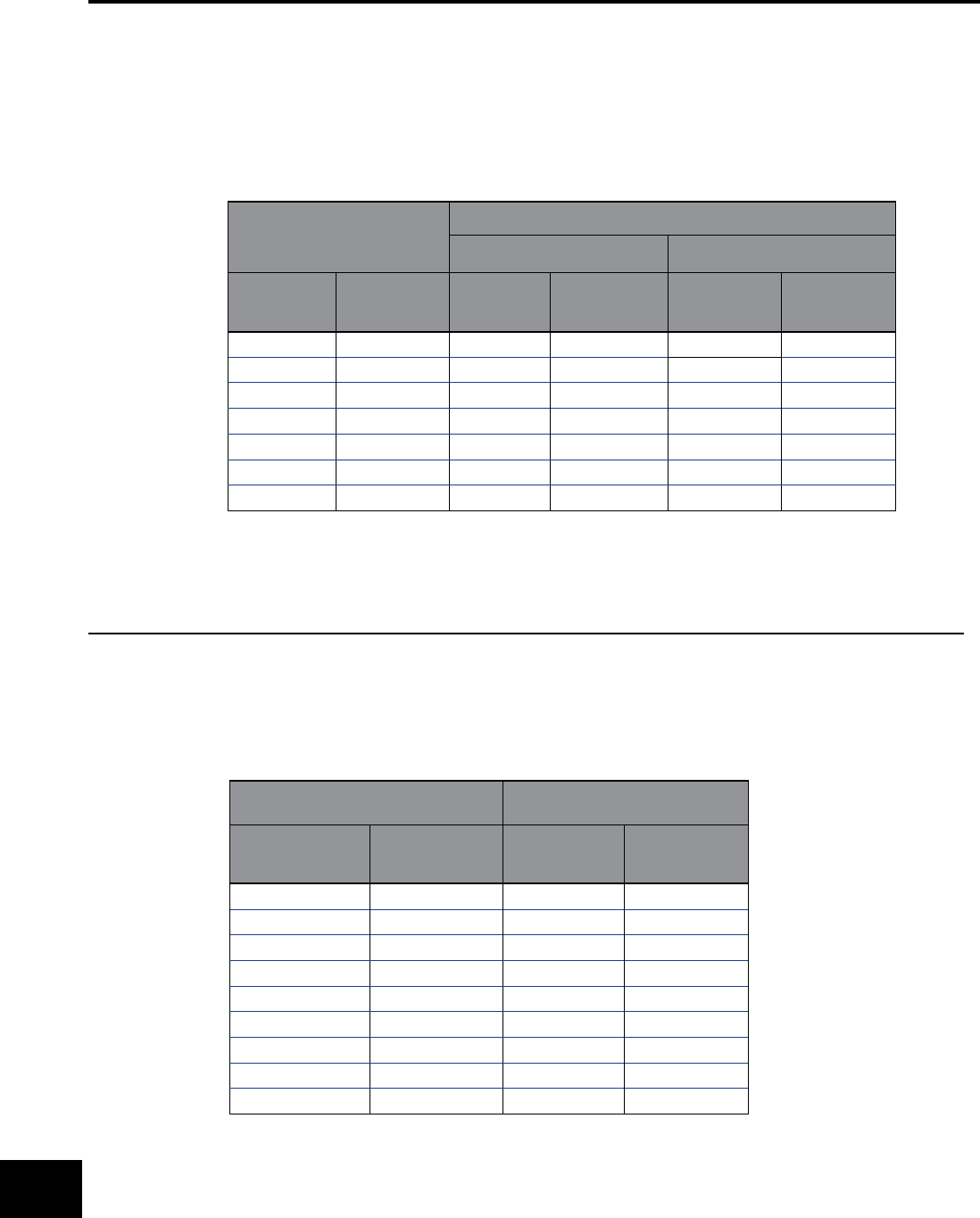
BURNDY®
US: 1-800-346-4175 www.burndy.com Canada: 1-800-387-6487
Reference
Recommended Tightening Torque per UL486A & UL486B
Table 22 - Tightening torque for slotted head screws smaller than No. 10 intended for use
with 8 AWG (8.4 mm2) or smaller conductors
Slot Length of Screw*
Tightening Torque, N●m (lbf-in)
Slot Width of Screw Smaller than
1.2 mm (.047 in.)b
Slot Width of Screw 1.2mm
(.047 in.) and larger**
mm inch A B A B
Less than 4 Less than 5/32 0.68 (6) 0.79 (7) 0.79 (7) 1.0 (9)
4 5/32 0.68 (6) 0.79 (7) 1.1 (10) 1.4 (12)
4.8 3/16 0.68 (6) 0.79 (7) 1.1 (10) 1.4 (12)
5.6 7/32 0.68 (6) 0.79 (7) 1.1 (10) 1.4 (12)
6.4 1/4 0.79 (7) 1.0 (9) 1.1 (10) 1.4 (12)
7.1 9/32 - - 1.4 (12) 1.7 (15)
Above 7.1 Above 9/32 - - 1.8 (16) 2.3 (20)
* For slot lengths of intermediate values, select torques pertaining to next shorter slot length.
Also see Table 21 for screws with multiple tightening means.
Slot length shall be measured at the bottom of the slot.
** Slot width is the nominal design value
Recommended Tightening Torque per UL486A & UL486B
Table 23 - Tightening torque for screws with recessed allen or square drives
Socket Width
Across Flats*
Tightening Torque, N●m
(lbf-in)
mm inch A B
3.2 1/8 4.0 (35) 5.1 (45)
4.0 5/32 9.0 (80) 11.3 (100)
4.8 3/16 11.3 (100) 13.6 (120)
5.6 7/32 13.6 (120) 16.9 (150)
6.4 1/4 16.9 (150) 25.4 (225)
7.9 5/16 25.4 (225) 33.9 (300)
9.5 3/8 33.9 (300) 45.2 (400)
12.7 1/2 45.2 (400) 56.6 (500)
14.3 9/16 56.6 (500) 67.8 (600)
* See Table 21 for screws with multiple tightening means
HARDWARE DATA (continued)
O-8
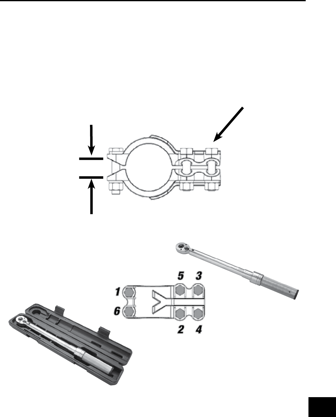
BURNDY®
Canada: 1-800-387-6487 www.burndy.com US: 1-800-346-4175
Reference
HARDWARE DATA (continued)
1. Nuts need to be tightened up to 30% of expected torque.
2. A check needs to be done to ensure the clamping elements are even.
3. Tightening has to follow a sequence (1-6) as shown below. As a general rule, the torque has to be applied to the nut. For ease of installation
most connectors are designed for one wrench installation. A torque wrench is recommended when tightening the nut to ensure the proper
torque is applied.
When installing a bolted connector, an appropriate sequence needs to be followed.
INSTALLATION INSTRUCTIONS:
Tightened up to 30%
Even clamping elements
check
BURNDY offers three sizes of professional grade torque wrenches, catalog
number BTW30150 to be used on connectors requiring 30-150 in-lbs., the
BTW150750, designed for 150-750 in-lbs., and the BTW1575F12, designed for
15 - 75 ft-lbs. These micro-adjustable “click-type” torque wrenches feature an
easy-to-read scale that can be easily matched to the recommended torque of
each of our mechanical connector products. Calibration traceable to N.I.S.T.
Recommended Clamping on Bolted Connectors:
O-9
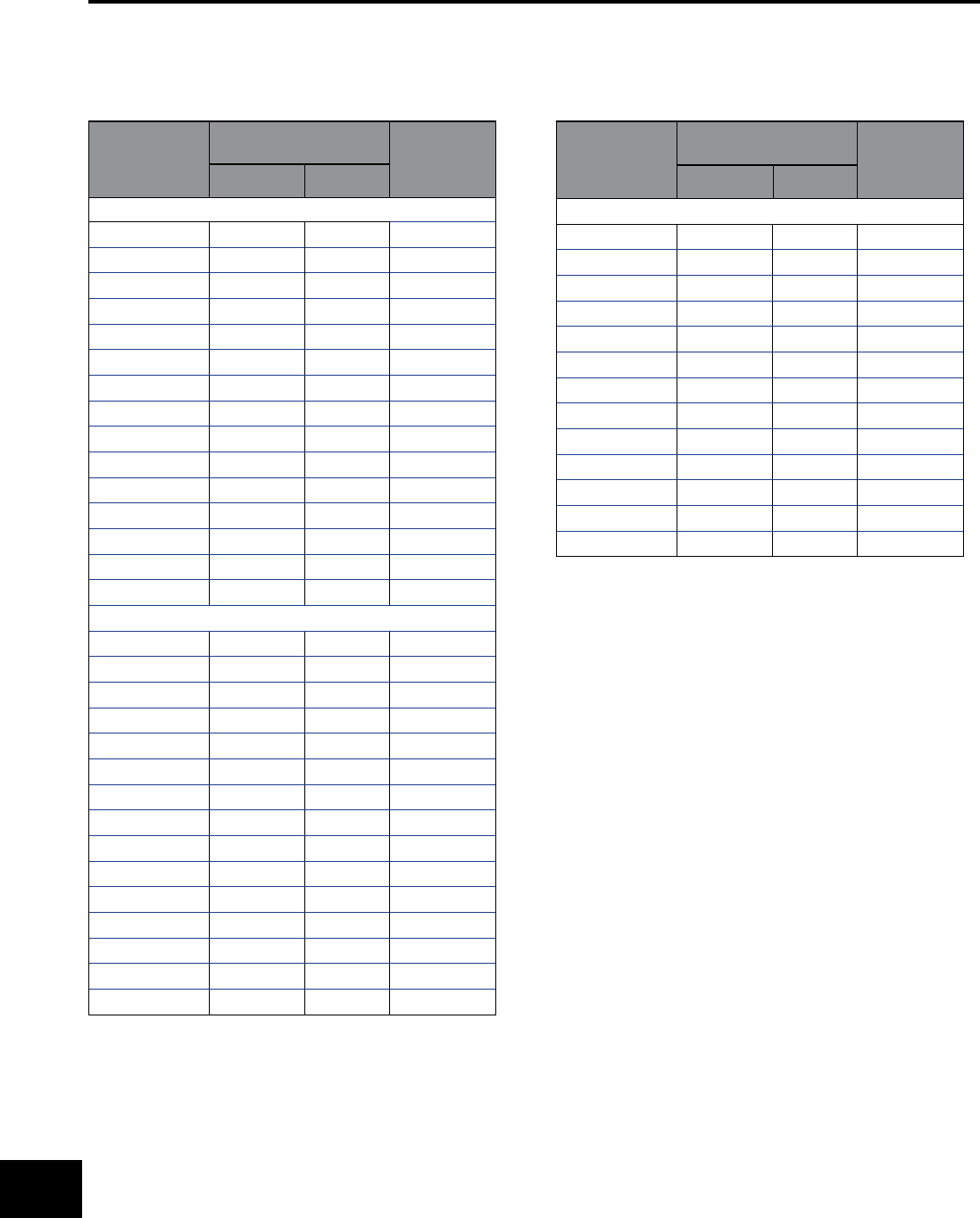
BURNDY®
US: 1-800-346-4175 www.burndy.com Canada: 1-800-387-6487
Reference
CABLE DATA
COPPER TUBE (BUS)
Size of Tube
IPS
Diameter of Tube
(Inches) Wall
Thickness
(Inches)
Outside Inside
STANDARD PIPE SIZES
1/4” 0.540 0.375 0.082
3/8” 0.675 0.494 0.090
1/2” 0.840 0.625 0.107
3/4” 1.050 0.822 0.114
1” 1.315 1.062 0.126
1-1/4” 1.660 1.368 0.146
1-1/2” 1.900 1.600 0.150
2” 2.375 2.062 0.156
2-1/2” 2.875 2.500 0.187
3” 3.500 3.062 0.219
3-1/2” 4.000 3.500 0.250
4” 4.500 4.000 0.250
4-1/2” 5.000 4.500 0.250
5” 5.563 5.063 0.250
6” 6.625 6.125 0.250
EXTRA HEAVY PIPE SIZES
1/4” 0.540 0.294 0.123
3/8” 0.675 0.421 0.127
1/2” 0.840 0.542 0.149
3/4” 1.050 0.736 0.157
1” 1.315 0.951 0.182
1-1/4” 1.660 1.272 0.194
1-1/2” 1.900 1.494 0.203
2” 2.375 1.933 0.221
2-1/2” 2.875 2.315 0.280
3” 3.500 2.892 0.304
3-1/2” 4.000 3.358 0.321
4” 4.500 3.818 0.341
4-1/2” 5.000 4.250 0.375
5” 5.563 4.813 0.375
6” 6.625 5.751 0.437
DOUBLE EXTRA HEAVY PIPE SIZES
1/2” 0.840 0.252 0.294
3/4” 1.050 0.434 0.308
1” 1.315 0.599 0.358
1-1/4” 1.660 0.896 0.382
1-1/2” 1.900 1.100 0.400
2” 2.375 1.503 0.436
2-1/2” 2.875 1.771 0.552
3” 3.500 2.300 0.600
3-1/2” 4.000 2.728 0.636
44.500 3.152 0.674
4-1/2” 5.000 3.580 0.710
5” 5.563 4.063 0.750
6” 6.625 4.897 0.864
Size of Tube
IPS
Diameter of Tube
(Inches) Wall
Thickness
(Inches)
Outside Inside
Tube dimensions (excepting wall thickness of double extra heavy) taken
from A.S.T.M. Specication B42-33.
Tubular values based on a density of 0.322 pound per cubic inch.
* Conductivity of 98% I.A.C.S. at 20˚ C or 68˚ F
O-10
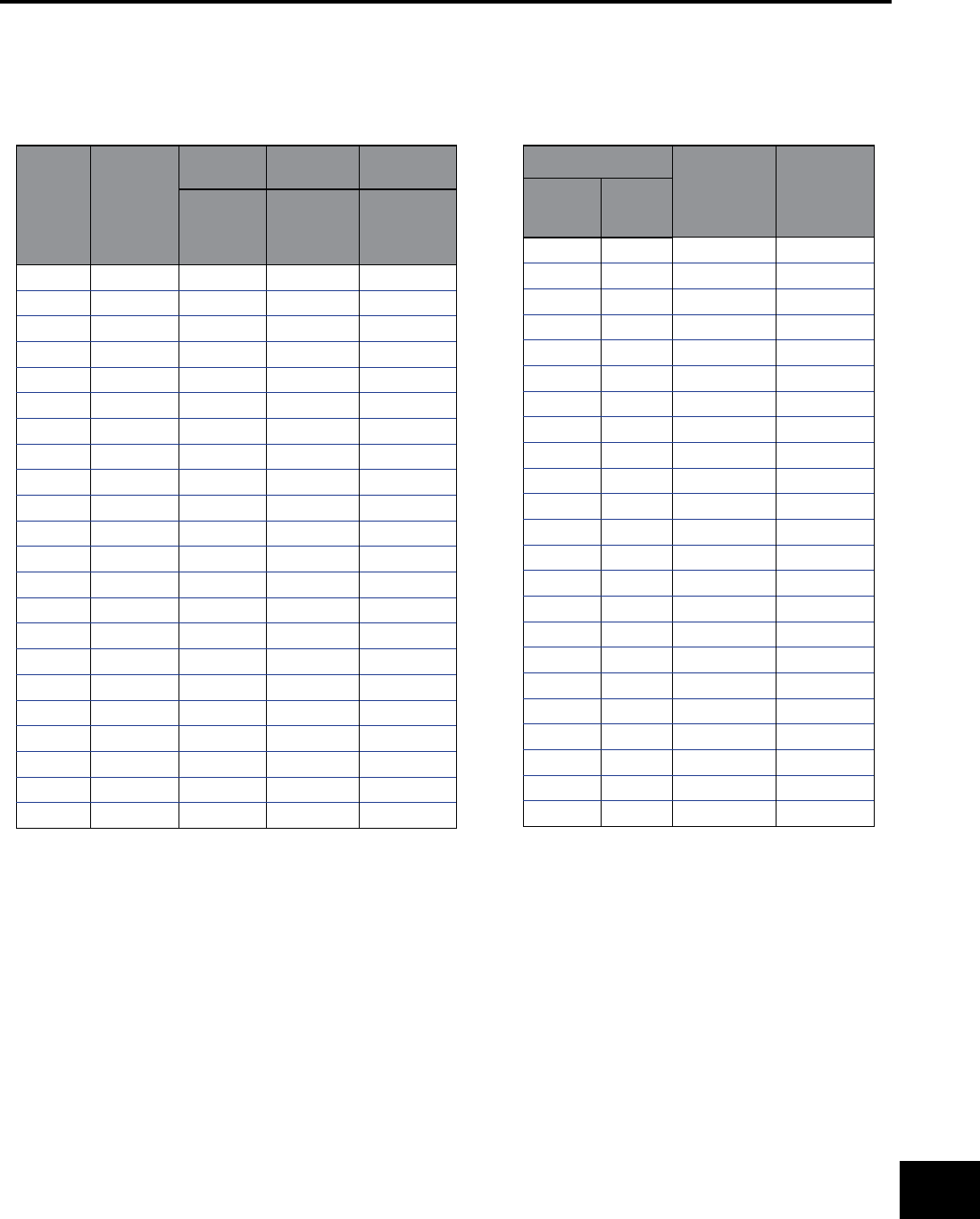
BURNDY®
Canada: 1-800-387-6487 www.burndy.com US: 1-800-346-4175
Reference
CABLE DATA (continued)
SOLID COPPER WIRE (ASTM B1, B2, & B3)
Size
AWG
(Solid)
Wire Dia
(Inch)
Hard
Drawn
Medium
Drawn Soft Drawn
Normal
Breaking
Load
(Pounds)
Minimum
Breaking
Load
(Pounds)
Elongation
in 10 in.
% Min.
18 .040 85.8 67.6 25
17 .045 107.5 84.7 25
16 .050 135.2 106.2 25
15 .057 170.0 133.0 25
14 .064 213.8 166.6 25
13 .071 268.2 208.0 25
12 .080 337.0 261.6 25
11 .090 422.5 327.6 25
10 .101 529.2 410.4 25
9.114 661.0 514.2 30
8.128 826.0 643.9 30
7.144 1,030.0 806.6 30
6.162 1,280.0 1,010.0 30
5.181 1,591.0 1,265.0 30
4.204 1,970.0 1,584.0 30
3.229 2,439.0 1,984.0 30
2.257 3,003.0 2,450.0 30
1.289 3,688.0 3,024.0 30
1/0 .324 4,519.0 3,730.0 35
2/0 .364 5,518.0 4,599.0 35
3/0 .409 6,722.0 5,667.0 35
4/0 .460 8,143.0 6,980.0 35
COMPACT STRANDED COPPER CABLE
(ASTM SPEC. B496)
Conductor Size
Number of
Wires
Conductor
Dia (in)
KCMIL AWG
1000 6111.060
900 6110.999
800 6110.938
750 6110.908
700 6110.877
650 6110.845
600 6110.813
550 6110.775
500 3720.736
450 3720.700
400 3720.659
350 3720.616
300 3720.570
250 3720.520
4/0 1930.475
3/0 1930.423
2/0 1930.376
1/0 1930.336
11930.299
27 0.268
47 0.213
67 0.169
87 0.134
1 58 Wires Minimum
2 35 Wires Minimum
3 18 Wires Minimum
O-11
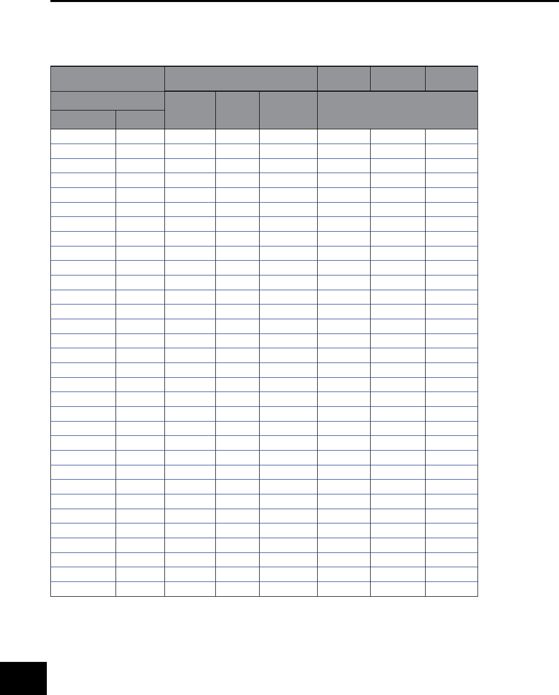
BURNDY®
US: 1-800-346-4175 www.burndy.com Canada: 1-800-387-6487
Reference
CABLE DATA (continued)
STRANDED COPPER WIRE (ASTM B8 EXCLUDING BREAKING LOADS)
Size A.S.T.M. Strandings Hard
Drawn
Medium
Drawn
Soft
Drawn
Stranded Class No. of
Wires
Cable
Diameter
(Inches)
Minimum Breaking Load
(Pounds)
Circular Mils AWG
1,022 20 B 7 0.036 50.0 40.67 32.1
1,624 18 B 7 0.045 79.0 63.91 51.0
2,583 16 B 7 0.057 124.7 100.4 81.1
4,107 14 B 7 0.072 197.1 157.7 124.2
6,530 12 B 7 0.091 311.1 247.7 197.5
10,380 10 B 7 0.116 491.7 388.9 314.0
13,090 9 B 7 0.130 618.2 487.4 395.9
16,510 8 B 7 0.146 777.2 610.7 499.2
20,820 7 B 7 0.164 977.1 765.2 629.5
26,250 6 B 7 0.184 1,288.0 958.6 793.8
33,100 5 B 7 0.206 1,542.0 1,201.0 1,001.0
41,740 4 AA 3 0.254 1,879.0 1,465.0 1,213.0
41,740 4 B&A 7 0.232 1,938.0 1,505.0 1,262.0
52,630 3 AA 3 0.285 2,359.0 1,835.0 1,530.0
52,630 3 B&A 7 0.260 2,433.0 1,885.0 1,592.0
66,370 2 AA 3 0.320 2,913.0 2,299.0 1,929.0
66,370 2 B&A 7 0.292 3,045.0 2,361.0 2,007.0
83,690 1 AA 3 0.360 3,621.0 2,879.0 2,432.0
83,690 1 A 7 0.328 3,804.0 2,958.0 2,432.0
83,690 1 B 19 0.332 3,899.0 3,037.0 2,531.0
105,500 1/0 A&A 7 0.368 4,752.0 3,705.0 3,067.0
105,500 1/0 - 12 0.390 4,841.0 3,755.0 3,191.0
105,500 1/0 B 19 0.373 4,901.0 3,805.0 3,191.0
133,100 2/0 A&A 7 0.414 5,926.0 4,640.0 3,867.0
133,100 2/0 - 12 0.438 6,048.0 4,703.0 3,867.0
133,100 2/0 B 19 0.419 6,152.0 4,765.0 4,024.0
167,800 3/0 A&A 7 0.464 7,366.0 5,812.0 4,876.0
167,800 3/0 - 12 0.492 7,556.0 5,890.0 4,876.0
167,800 3/0 B 19 0.470 7,698.0 5,970.0 5,074.0
211,600 4/0 A&A 7 0.522 9,154.0 7,278.0 6,149.0
211,600 4/0 - 12 0.522 9,483.0 7,378.0 6,149.0
211,600 4/0 B 19 0.528 9,617.0 7,479.0 6,149.0
O-12
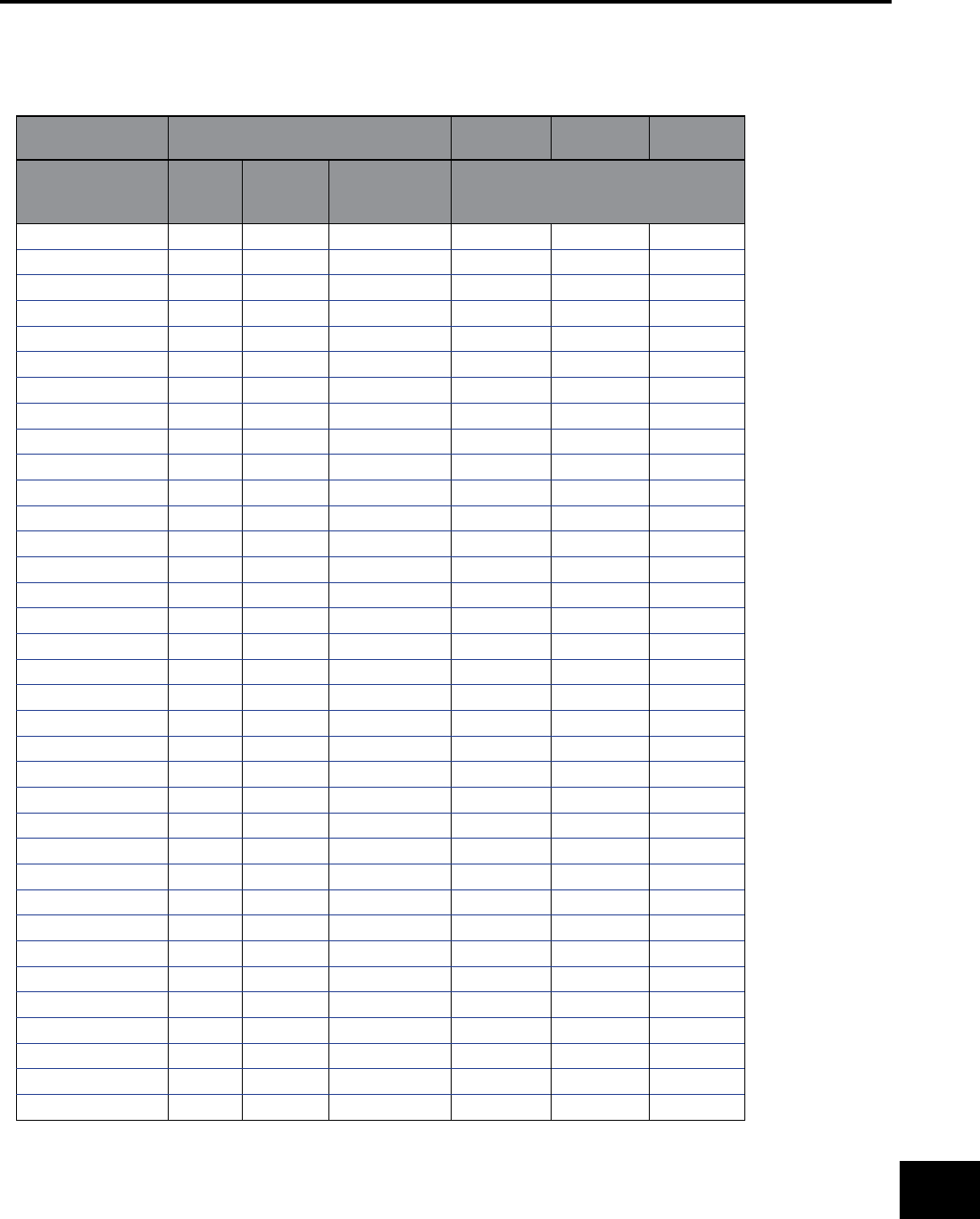
BURNDY®
Canada: 1-800-387-6487 www.burndy.com US: 1-800-346-4175
Reference
STRANDED COPPER WIRE (ASTM B8 EXCLUDING BREAKING LOADS continued)
Size A.S.T.M. Strandings Hard
Drawn
Medium
Drawn
Soft
Drawn
Circular Mils Class No. of
Wires
Cable
Diameter
(Inches)
Minimum Breaking Load
(Pounds)
250 kcmil AA 12 0.600 11,130 8,717 7,265
250 kcmil A 19 0.574 11,360 8,986 7,265
250 kcmil B 37 0.575 11,560 8,952 7,559
300 kcmil AA 12 0.657 13,170 10,390 8,718
300 kcmil A 19 0.628 13,510 10,530 8,718
300 kcmil B 37 0.630 13,870 10,740 9,071
350 kcmil AA 12 0.710 15,140 12,040 10,170
350 kcmil A 19 0.679 15,590 12,200 10,170
350 kcmil B 37 0.681 16,060 12,450 10,580
400 kcmil A&AA 19 0.726 17,810 13,950 11,620
400 kcmil B 37 0.728 18,320 14,140 11,620
450 kcmil AA 19 0.770 19,750 15,590 13,080
450 kcmil B&A 37 0.772 20,450 15,900 13,080
500 kcmil AA 19 0.811 21,950 17,320 14,530
500 kcmil B&A 37 0.813 22,510 17,550 14,530
600 kcmil A&AA 37 0.891 27,020 21,060 17,440
600 kcmil B 61 0.893 27,530 21,350 18,140
700 kcmil AA 37 0.963 31,170 24,410 20,340
700 kcmil B&A 61 0.964 31,820 24,740 20,340
750 kcmil AA 37 0.997 33,400 26,150 21,790
750 kcmil B&A 61 0.998 34,090 26,510 21,790
800 kcmil AA 37 1.029 35,120 27,710 23,250
800 kcmil B&A 61 1.031 36,360 28,270 23,250
900 kcmil AA 37 1.092 39,510 31,170 26,150
900 kcmil B&A 61 1.094 40,520 31,590 26,150
1000 kcmil AA 37 1.151 43,830 34,400 29,060
1000 kcmil B&A 61 1.152 45,030 35,100 29,060
1250 kcmil A 61 1.288 55,670 43,590 36,320
1250 kcmil B 91 1.289 56,280 43,880 36,320
1500 kcmil A 61 1.411 65,840 51,950 43,590
1500 kcmil B 91 1.412 67,540 52,650 43,590
1750 kcmil A 91 1.526 77,930 61,020 50,850
1750 kcmil B 127 1.526 78,800 61,430 50,850
2000 kcmil A 91 1.630 87,790 69,270 58,120
2000 kmcil B 127 1.632 90,050 70,210 58,120
CABLE DATA (continued)
O-13
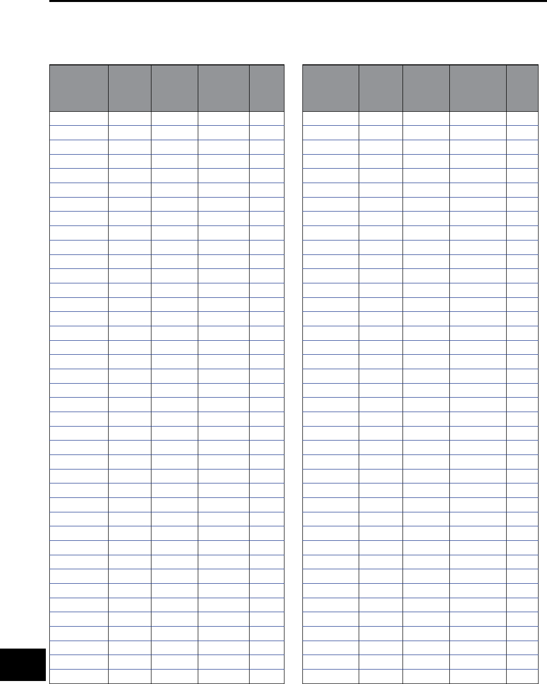
BURNDY®
US: 1-800-346-4175 www.burndy.com Canada: 1-800-387-6487
Reference
CABLE DATA (continued)
FLEXIBLE COPPER STRANDED CABLE
Conductor
Size kcmil
or B & S G
(AWG)
#
Strands
Strand
Diameter
Nominal
Diameter Class
841 .0201 .156 I
849 .0184 .166 G
8133 .0111 .167 H
8168 .010 .157 K
8420 .0063 .162 M
749 .0206 .185 G
752 .0201 .185 I
7133 .0125 .188 H
7210 .010 .179 K
7532 .0063 .196 M
649 .0231 .208 G
663 .0201 .207 I
6133 .0140 .210 H
6266 .010 .210 K
6665 .0063 .215 M
549 .0260 .234 G
584 .0201 .235 I
5133 .0158 .237 H
5336 .010 .235 K
5836 .0063 .240 M
449 .0292 .263 G
4105 .0201 .263 I
4133 .0177 .266 .H
4420 .010 .272 K
41064 .0063 .269 M
349 .0328 .295 G
3133 .0199 .299 I
3133 .0201 .291 H
3532 .010 .304 K
31323 .0063 .305 M
249 .0368 .331 G
2133 .0223 .335 I
2161 .0201 .319 H
2665 .010 .338 K
21666 .0063 .337 M
1133 .0251 .377 G
1210 .0201 .367 I
1259 .018 .378 H
1836 .010 .397 K
12107 .0063 .376 M
Conductor
Size kcmil
or B & S G
(AWG)
#
Strands
Strand
Diameter
Nominal
Diameter Class
1/0 133 .0282 .423 I
1/0 259 .0202 .424 G
1/0 266 .0201 .441 H
1/0 1064 .010 .451 K
1/0 2646 .0063 .423 M
2/0 133 .0316 .474 G
2/0 259 .0227 .477 I
2/0 342 .0201 .500 H
2/0 1323 .010 .470 K
2/0 3325 .0063 .508 M
3/0 133 .0355 .533 G
3/0 259 .0255 .536 I
3/0 418 .0201 .549 H
3/0 1666 .010 .533 K
3/0 4256 .0063 .576 M
4/0 133 .0399 .599 G
4/0 259 .0286 .601 I
4/0 532 .0201 .613 H
4/0 2107 .010 .627 K
4/0 5320 .0063 .645 M
250 259 .0311 .650 G
250 427 .0242 .653 I
250 637 .0201 .682 .H
250 2499 .010 .682 K
250 6384 .0063 .713 M
300 259 .0340 .714 G
300 427 .0265 .716 I
300 735 .0201 .737 H
300 2989 .010 .768 K
300 7581 .0063 .768 M
350 259 .0368 .773 G
350 427 .0286 .772 I
350 882 .0201 .800 H
350 3458 .010 .809 K
350 8806 .0063 .825 M
400 259 .0393 .825 G
400 427 .0306 .826 I
400 980 .0201 .831 H
400 3990 .010 .878 K
400 10101 .0063 .901 M
O-14
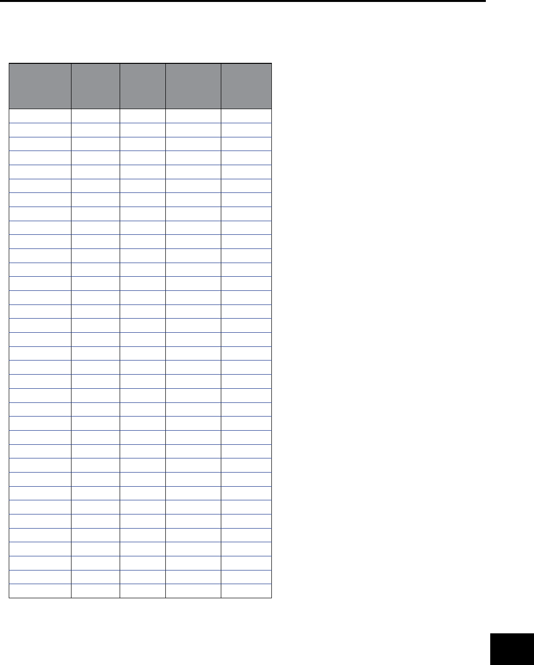
BURNDY®
Canada: 1-800-387-6487 www.burndy.com US: 1-800-346-4175
Reference
FLEXIBLE COPPER STRANDED CABLE (continued)
Conductor
Size kcmil
or B & S G
(AWG)
# Strands Strand
Diameter
Nominal
Diameter Class
450 259 .0417 .876 I
450 427 .0325 .878 G
450 1127 .0201 .894 H
450 4522 .010 .933 K
450 11396 .0063 .940 M
500 259 .0439 .922 G
500 427 .0342 .923 I
500 1225 .0201 .941 H
500 5054 .010 .988 K
500 12691 .0063 .997 M
600 427 .0375 1.013 G
600 703 .0292 1.022 I
600 1470 .0201 1.027 H
600 5985 .010 1.125 K
600 14945 .0063 1.084 M
700 427 .0405 1.094 G
700 703 .0316 1.106 I
700 1729 .0201 1.194 H
700 6916 .010 1.207 K
700 17507 .0063 1.183 M
800 427 .0433 1.169 G
800 703 .0337 1.180 I
800 1995 .0201 1.290 .H
800 7980 .010 1.305 K
800 20069 .0063 1.256 M
900 427 .0459 1.239 G
900 703 .0358 1.253 I
900 2261 .0201 1.372 H
900 9065 .010 1.323 K
900 22631 .0063 1.331 M
1000 427 .0484 1.307 G
1000 703 .0377 1.320 I
1000 2527 .0201 1.427 H
1000 10101 .010 1.419 K
1000 25193 .0063 1.404 M
CABLE DATA (continued)
O-15
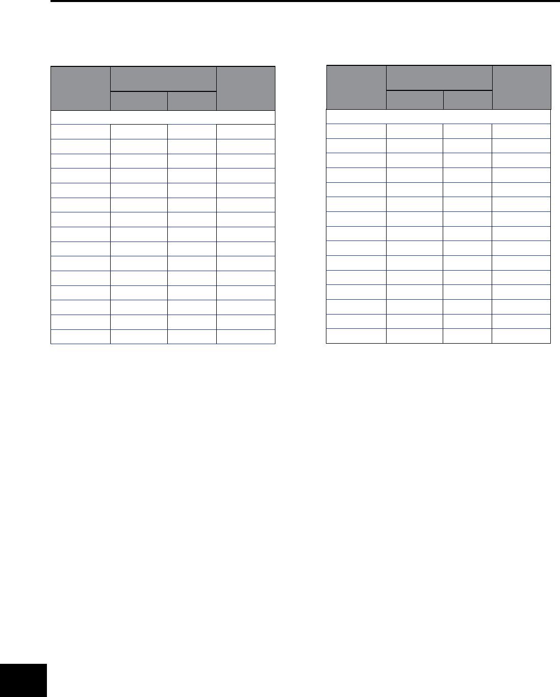
BURNDY®
US: 1-800-346-4175 www.burndy.com Canada: 1-800-387-6487
Reference
CABLE DATA (continued)
ALUMINUM TUBE
Size of Tube
IPS
Diameter of Tube
(Inches) Wall
Thickness
(Inches)
Outside Inside
STANDARD PIPE SIZES
1/4” 0.540 0.364 0.088
3/8” 0.675 0.493 0.091
1/2” 0.840 0.622 0.109
3/4” 1.050 0.824 0.113
1” 1.315 1.049 0.133
1-1/4” 1.660 1.380 .0.140
1-1/2” 1.900 1.610 0.145
2” 2.375 2.067 0.154
2-1/2” 2.875 2.469 0.203
3” 3.500 3.068 0.213
3-1/2” 4.000 3.548 0.226
4” 4.500 4.026 0.237
4-1/2” 5.000 4.506 0.247
5” 5.563 5.047 0.258
6” 6.625 6.065 0.280
EXTRA HEAVY PIPE SIZES
1/4” 0.540 0.302 0.119
3/8” 0.675 0.423 0.126
1/2” 0.840 0.546 0.147
3/4” 1.050 0.742 0.154
1” 1.315 0.957 0.179
1-1/4” 1.660 1.278 0.191
1-1/2” 1.900 1.500 0.200
2” 2.375 1.939 0.218
2-1/2” 2.875 2.323 0.276
3” 3.500 2.900 0.300
3-1/2” 4.000 3.364 0.318
4” 4.500 3.826 0.337
4-1/2” 5.000 4.290 0.355
5” 5.563 4.813 0.375
6” 6.625 5.761 0.432
Size of Tube
IPS
Diameter of Tube
(Inches) Wall
Thickness
(Inches)
Outside Inside
O-16

BURNDY®
Canada: 1-800-387-6487 www.burndy.com US: 1-800-346-4175
Reference
ALUMINUM 1350 CABLE
BARE-CLASSES AA AND A - Hard Drawn
Cable Code
Word
Size (circular
mils or AWG)
Copper Equivalent
based on equal D.C.
resistance, Cu 97%
Al 61%
# of Wires Cable Dia.
(inches)
Ultimate Strength
(pounds)
Peachbell 6 8 7 0.184 528
Rose 4 6 7 0.232 826
Lily 3 5 7 0.260 1022
Iris 2 4 7 0.292 1266
Pansy 1 3 7 0.328 1537
Poppy 1/0 2 7 0.368 1865
Aster 2/0 1 7 0.414 2350
Phlox 3/0 1/0 7 0.464 2845
Oxlip 4/0 2/0 7 0.522 3590
Daisy 266800 3/0 7 0.586 4525
Laurel 266800 3/0 19 0.593 4800
Tulip 336400 4/0 19 0.666 5940
Canna 397500 250000 19 0.724 6880
Cosmos 477000 300000 19 0.793 8090
Syringa 477000 300000 37 0.795 8600
Dahlia 556500 350000 19 0.856 9440
Mistletoe 556500 350000 37 0.858 9830
Orchid 636000 400000 37 0.918 11240
Violet 715500 450000 37 0.974 12640
Nasturtium 715500 450000 61 0.975 13150
Arbutus 795000 500000 37 1.026 13770
Lilac 795000 500000 61 1.028 14330
Anemone 874500 550000 37 1.077 14830
Crocus 874500 550000 61 1.078 15760
Magnolia 954000 600000 37 1.124 16180
Goldenrod 954000 600000 61 1.126 16860
Bluebell 1033500 650000 37 1.170 17530
Larkspur 1033500 650000 61 1.172 18260
Marigold 1113000 700000 61 1.216 19660
Narcissus 1272000 800000 61 1.300 22000
Carnation 1431000 900000 61 1.379 24300
Coreopsis 1590000 1000000 61 1.454 27000
Dogwood 1590000 1000000 91 1.454 28100
CABLE DATA (continued)
O-17

BURNDY®
US: 1-800-346-4175 www.burndy.com Canada: 1-800-387-6487
Reference
CABLE DATA (continued)
ALUMINUM 1350 CABLE
BARE-CLASS B
Size
(circular mils or
AWG)
Copper Equivalent based
on equal D.C. resistance,
Cu 97% Al 61%
# of
Wires
Cable Dia.
(inches)
Ultimate
Strength
(pounds)
Hard Drawn
Minimum
Ultimate
Strength
(pounds)
3/4 Hard
Minimum
Ultimate
Strength
(pounds)
Inter Temper
250000 157300 37 0.575 4860 3338 2946
300000 188800 37 0.629 5831 4005 3534
350000 220200 37 0.681 6680 4673 4123
400000 251500 37 0.728 7352 5341 4713
450000 283000 37 0.772 8110 6007 5301
500000 314500 37 0.813 9012 6675 5890
550000 346000 61 0.855 10490 7344 6480
600000 377000 61 0.893 11450 8010 7068
650000 409000 61 0.929 11940 8678 7657
700000 440000 61 0.964 12860 9346 8247
750000 472000 61 0.998 13510 10010 8835
800000 503000 61 1.031 14410 10680 9424
900000 566000 61 1.094 15900 12010 10600
1000000 629000 61 1.152 17670 13350 11780
1100000 692000 91 1.209 20210 14680 12950
1200000 755000 91 1.263 21630 16020 14130
1250000 786000 91 1.289 22530 16690 14720
1300000 818000 91 1.315 23430 17350 15310
1400000 880000 91 1.364 24750 18700 16500
1500000 943000 91 1.412 26500 20020 17670
1600000 1006000 127 1.459 28840 21360 18850
1700000 1069000 127 1.504 30630 22690 20020
1750000 1101000 127 1.526 31530 23350 20610
1800000 1132000 127 1.548 32450 24030 21210
1900000 1195000 127 1.590 33570 25360 22380
2000000 1258000 127 1.632 35340 26700 23560
2500000 1570000 127 1.824 43300 33380 29460
3000000 1890000 169 1.998 53010 40050 35340
3500000 2200000 169 2.158 60610 46730 41230
O-18

BURNDY®
Canada: 1-800-387-6487 www.burndy.com US: 1-800-346-4175
Reference
CABLE DATA (continued)
ACSR
Cable Code
Word
Size
(circular mils or
AWG)
No. Alum
Strands
No. Steel
Strands
Complete
Cable Dia.
(inches)
Steel Core Dia.
(inches)
Copper Equivalent
based on equal D.C.
resistance,
Cu 97% Al 61%
Ultimate Strength
(pounds)
Turkey 6 6 1 0.198 0.0661 8 1170
Thrush 5 6 1 0.223 0.0743 7 1460
Swan 4 6 1 0.250 0.0834 6 1830
Swanate 4 7 1 0.257 0.1029 6 2288
Swallow 3 6 1 0.281 0.0937 5 2250
Sparrow 2 6 1 0.316 0.1052 4 2790
Sparate 2 7 1 0.325 0.1299 4 3525
Robin 1 6 1 0.355 0.1182 3 3480
Raven 1/0 6 1 0.398 0.1327 2 4280
Quail 2/0 6 1 0.447 0.1490 1 5345
Pigeon 3/0 6 1 0.502 0.1672 1/0 6675
Penguin 4/0 6 1 0.563 0.1878 2/0 8420
Waxwing 266800 18 1 0.609 0.1217 3/0 7100
Owl 266800 26 7 0.633 0.2109 3/0 9645
Patridge 266800 26 7 0.642 0.2364 3/0 11250
Ostrich 300000 26 7 0.680 0.2505 188700 12650
Merlin 336400 18 1 0.684 0.1367 4/0 8950
Linnet 336400 26 7 0.721 0.2655 4/0 14050
Oriole 336400 30 7 0.741 0.3177 4/0 17040
Chickadee 397500 18 1 0.743 0.1486 250000 10400
Brant 397500 24 7 0.771 0.2575 250000 14690
Ibis 397500 26 7 0.783 0.2883 250000 16190
Lark 397500 30 7 0.806 0.3453 250000 19980
Pelican 477000 18 1 0.814 0.1628 300000 12300
Flicker 477000 24 7 0.846 0.2820 300000 17200
Hawk 477000 26 7 0.858 0.3162 300000 19430
Hen 477000 30 7 0.883 0.3783 300000 23300
Parakeet 556500 24 7 0.914 0.3045 350000 19850
Dove 556500 26 7 0.927 0.341 350000 22400
Eagle 556500 30 7 0.953 0.409 350000 27200
Peacock 605000 24 7 0.953 0.318 380500 21500
Squab 605000 26 7 0.966 0.356 380500 24100
Teal 605000 30 19 0.994 0.426 380500 30000
Rook 636000 24 7 0.977 0.326 400000 22600
Grosbeak 636000 26 7 0.990 0.365 400000 25000
Egret 636000 30 19 1.019 0.437 400000 31500
Flamingo 666600 24 7 1.000 0.333 419000 23700
Crow 715500 54 7 1.036 0.345 450000 26300
Starling 715500 26 7 1.051 0.387 450000 28100
Redwing 715500 30 19 1.081 0.463 450000 34600
Condor 795000 54 7 1.093 0.364 500000 28500
O-19
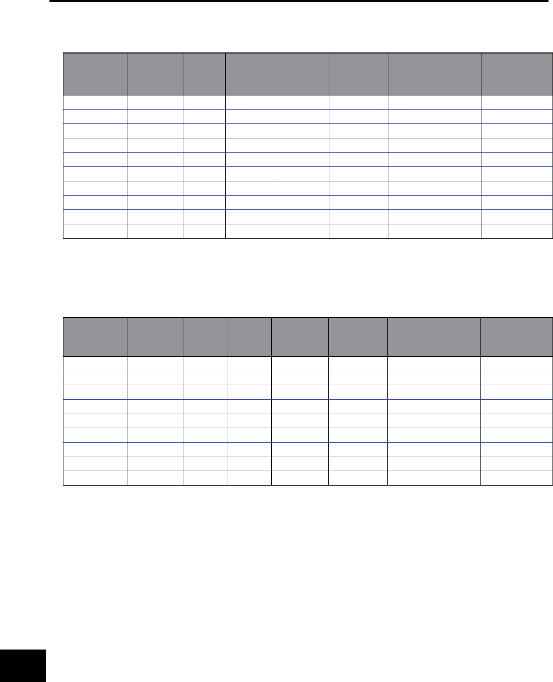
BURNDY®
US: 1-800-346-4175 www.burndy.com Canada: 1-800-387-6487
Reference
CABLE DATA (continued)
ACSR (continued)
Cable Code
Word
Size
(circular mils
or AWG)
No. Alum
Strands
No. Steel
Strands
Complete
Cable Dia.
(inches)
Steel Core Dia.
(inches)
Copper Equivalent
based on equal D.C.
resistance,
Cu 97% Al 61%
Ultimate Strength
(pounds)
Drake 795000 26 7 1.108 0.408 500000 31200
Mallard 795000 30 19 1.140 0.489 500000 38400
Crane 874500 54 7 1.146 0.382 550000 31400
Canary 900000 54 7 1.162 0.387 566000 32300
Cardinal 954000 54 7 1.196 0.399 600000 34200
Curlew 1033500 54 7 1.246 0.415 650000 37100
Finch 1113000 54 19 1.293 0.431 700000 40200
Pheasant 1272000 54 19 1.382 0.461 800000 44800
Plover 1431000 54 19 1.465 0.489 900000 50400
Falcon 1590000 54 19 1.545 0.515 100000 56000
HIGH STRENGTH ACSR
Cable Code
Word
Size
(circular mils
or AWG)
No. Alum
Strands
No. Steel
Strands
Complete
Cable Dia.
(inches)
Steel Core Dia.
(inches)
Copper Equivalent
based on equal D.C.
resistance,
Cu 97% Al 61%
Ultimate Strength
(pounds)
Grouse 80000 8 1 0.367 0.1670 50310 5200
Petrel 101800 12 7 0.461 0.2763 64160 9860
Minorca 110800 12 7 0.481 0.2883 69700 10730
Leghorn 134600 12 7 0.530 0.3177 84600 12920
Guinea 159000 12 7 0.576 0.3453 100000 15200
Dotterel 176900 12 7 0.607 0.3642 111200 16440
Dorking 190800 12 7 0.631 0.3783 120000 17730
Cochin 211300 12 7 0.663 0.3981 132900 19640
Brahma 203200 16 9 0.714 0.4885 127800 27500
O-20

BURNDY®
Canada: 1-800-387-6487 www.burndy.com US: 1-800-346-4175
Reference
COMPACT ALUMINUM 1350 CABLE (ASTM B400) EXTRA HARD
Conductor Size
Class No. of Wires Cable Diameter
(Inches)
Breaking Strength
(pounds)
kcmil AWG
1000 B 6111.060 17700
900 B 6110.999 15900
800 B 6110.938 14400
750 B 6110.908 13500
700 B 6110.877 12900
650 B 6110.845 11900
600 B 6110.813 11500
556 AA 1930.780 9750
550 B 6110.775 10500
500 B 3720.736 9110
500 AA 1930.736 8760
477 AA 1930.722 8360
450 B 3720.700 8200
400 B 3720.659 7440
397 AA, A 1930.659 7110
350 B 3720.616 6760
350 A 1930.616 6390
336 A 1930.603 6150
336 AA 7 0.603 5960
300 B 3720.570 5890
300 A 1930.570 5480
300 AA 7 0.570 5430
266 A 1930.537 4970
266 AA 7 0.537 4830
250 B 3720.520 4910
250 A 1930.520 4660
250 AA 7 0.520 4520
4/0 B 1930.475 4020
4/0 AA, A 7 0.475 3830
3/0 B 1930.423 3310
3/0 AA, A 7 0.423 3040
2/0 B 1930.376 2670
2/0 AA, A 7 0.376 2510
1/0 B 1930.336 2160
1/0 AA, A 7 0.336 1990
1 B 1930.299 1740
1 AA, A 7 0.299 1640
2 AA, A, B 7 0.268 1350
3 A, B 7 0.238 1090
4 A, B 7 0.213 .881
6 A, B 7 0.169 .563
8 A, B 7 0.134 .312
1 58 Wires Minimum
2 35 Wires Minimum
3 18 Wires Minimum
CABLE DATA (continued)
O-21
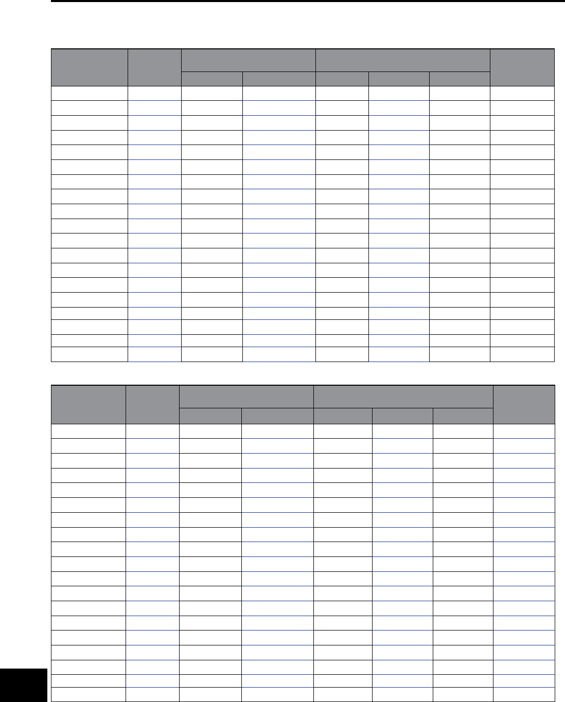
BURNDY®
US: 1-800-346-4175 www.burndy.com Canada: 1-800-387-6487
Reference
CABLE DATA (continued)
ALUMINUM ALLOY 5005 CABLE (ASTM B397)
Conductor Size
cmil
Number of
Wires
Approx. Aluminum 1350 Size
having Equivalent Resistance
Size & Stranding of ACSR
with Equal Diameter Rated Strength
(pounds)
cmil AWG cmil AWG Stranding
927200 37 795000 - 795000 - 26/7 23900
740800 37 636000 - 636000 - 26/7 19300
652400 19 556500 - 556500 - 26/7 16200
587200 19 506500 - 506500 - 18/1 14600
559500 19 477000 - 477000 - 26/7 13900
503600 19 435500 - 435500 - 18/1 12500
465400 19 397500 - 397500 - 26/7 12200
419400 19 362000 - 362000 - 18/1 11200
394500 19 336400 - 336400 - 26/7 10500
355100 19 306400 - 306400 - 18/1 9600
312800 19 266800 - 266800 - 26/7 8450
281400 19 242900 - 242900 - 18/1 7610
246900 7 211600 4/0 211600 4/0 6/1 6330
195700 7 167800 3/0 167800 3/0 6/1 5020
155400 7 133100 2/0 133100 2/0 6/1 4280
123300 7 105600 1/0 105600 1/0 6/1 3440
77470 7 66360 2 66360 2 6/1 2200
48690 7 41740 4 41740 4 6/1 1430
30580 7 26240 6 26240 6 6/1 922
ALUMINUM ALLOY 6201 CABLE (ASTM B399)
Conductor Size
cmil
Number of
Wires
Approx. Aluminum 1350 Size
having Equivalent Resistance
Size & Stranding of ACSR
with Equal Diameter Rated Strength
(pounds)
cmil AWG cmil AWG Stranding
1439200 61 1272000 - 1272000 - 54/7 46800
1348800 61 1192500 - 1192500 - 54/7 43900
1259600 61 1113000 - 1113000 - 54/7 41000
1165100 61 1033500 - 1033500 - 54/7 37900
1077400 61 954000 - 954000 - 54/7 35000
927200 37 795000 - 795000 - 26/7 30500
740800 37 636000 - 636000 - 26/7 24400
652400 19 556500 - 556500 - 26/7 21900
559500 19 477000 - 477000 - 26/7 18800
465400 19 397500 - 397500 - 26/7 15600
394500 19 336400 - 336400 - 26/7 13300
312800 19 266800 - 266800 - 26/7 11000
246900 7 211600 4/0 211600 4/0 6/1 8560
195700 7 167800 3/0 167800 3/0 6/1 6790
155400 7 133100 2/0 133100 2/0 6/1 5390
123300 7 105600 1/0 105600 1/0 6/1 4460
77470 7 66360 2 66360 2 6/1 2800
48690 7 41740 4 41740 4 6/1 1760
30580 7 26240 6 26240 6 6/1 1110
O-22
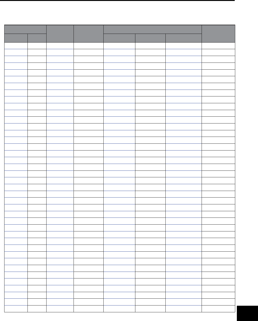
BURNDY®
Canada: 1-800-387-6487 www.burndy.com US: 1-800-346-4175
Reference
ALUMINUM ALLOY 8000 SERIES “O” TEMPER CABLE ASTM B801)
Conductor Size Number of
Wires† Class
Conductor Diameter (inches) Min. Breaking
Strength (pounds)
kcmil AWG Conventional Compressed Compact
1000 127 D 1.153 1.119 1.060 6010
1000 91 C 1.153 1.118 1.060 6010
1000 61 B, A 1.152 1.117 1.060 6010
900 127 D 1.095 1.062 0.999 5400
900 91 C 1.093 1.060 0.999 5400
900 61 B, A 1.093 1.060 0.999 5400
800 127 D 1.032 1.001 0.938 4800
800 91 C 1.032 1.001 0.938 4800
800 61 B, A 1.031 1.000 0.938 4800
750 127 D 0.998 0.968 0.908 4500
750 91 C 0.999 0.969 0.908 4500
750 61 B, A 0.998 0.938 0.908 4500
700 127 D 0.965 0.936 0.877 4200
700 91 C 0.965 0.936 0.877 4200
700 61 B, A 0.964 0.935 0.877 4200
650 127 D 0.930 0.902 0.845 3900
650 91 C 0.930 0.902 0.845 3900
650 61 B 0.929 0.901 0.845 3900
650 37 A 0.928 0.900 0.845 3950
600 127 D 0.893 0.866 0.813 3600
600 91 C 0.893 0.866 0.813 3600
600 61 B 0.893 0.866 0.813 3600
600 37 A 0.891 0.864 0.813 3640
556 127 D 0.861 0.835 0.780 3340
556 91 C 0.860 0.834 0.780 3340
556 61 B 0.860 0.834 0.780 3340
556 37 A 0.858 0.832 0.780 3380
550 127 D 0.855 0.829 0.775 3300
550 91 C 0.855 0.829 0.775 3300
550 61 B 0.855 0.829 0.775 3300
550 37 A 0.853 0.827 0.775 3340
500 91 D 0.815 0.791 0.736 3000
500 61 C 0.815 0.791 0.736 3000
500 37 B, A 0.813 0.789 0.736 3040
477 91 D 0.796 0.772 0.722 2860
477 61 C 0.796 0.772 0.722 2860
477 37 B, A 0.795 0.771 0.722 2900
450 91 D 0.773 0.750 0.700 2700
450 61 C 0.773 0.750 0.700 2700
450 37 B, A 0.772 0.749 0.700 2730
CABLE DATA (continued)
O-23

BURNDY®
US: 1-800-346-4175 www.burndy.com Canada: 1-800-387-6487
Reference
CABLE DATA (continued)
Conductor Size Number of
Wires† Class Conductor Diameter (inches) Min. Breaking
Strength
(pounds)
kcmil AWG Conventional Compressed Compact
400 91 D 0.729 0.707 0.659 2400
400 61 C 0.729 0.707 0.659 2400
400 37 B, A 0.728 0.706 0.659 2430
397 91 D 0.727 0.705 0.659 2390
397 61 C 0.726 0.704 0.659 2390
397 37 B 0.725 0.703 0.659 2410
397 19 A 0.724 0.702 0.659 2470
350 91 D 0.682 0.661 0.616 2100
350 61 C 0.681 0.661 0.616 2100
350 37 B 0.681 0.661 0.616 2130
350 19 A 0.679 0.659 0.616 2170
336 61 C 0.669 .0649 0.603 2020
336 37 B 0.668 0.648 0.603 2040
336 19 A 0.666 0.646 0.603 2090
300 61 C 0.631 0.612 0.570 1800
300 37 B 0.630 0.611 0.570 1820
300 19 A 0.629 0.610 0.576 1860
266 61 C 0.595 0.577 0.537 1600
266 37 B 0.594 0.576 0.537 1620
266 19 A 0.593 0.575 0.537 1660
250 61 C 0.576 0.559 0.520 1500
250 37 B 0.575 0.558 0.520 1520
250 19 A 0.574 0.557 0.520 1550
4/0 37 C 0.529 0.513 0.475 1280
4/0 19 B 0.528 0.512 0.475 1310
4/0 7 A 0.522 0.506 0.475 1360
3/0 37 C 0.471 0.457 0.423 1020
3/0 19 B 0.470 0.456 0.423 1040
3/0 7 A 0.464 0.450 0.423 1070
2/0 19 B 0.419 0.406 0.376 826
2/0 7 A 0.414 0.402 0.376 853
1/0 19 B 0.373 0.362 0.336 655
1/0 7 A 0.368 0.357 0.336 676
1 19 B 0.332 0.322 0.229 519
2 7 B, A 0.292 0.283 0.268 425
3 7 B, A 0.260 0.252 0.238 337
4 7 B, A 0.232 0.225 0.213 267
6 7 B, A 0.184 0.178 0.169 168
8 7 B, A 0.146 0.142 0.134 106
ALUMINUM ALLOY 8000 SERIES “O” TEMPER CABLE (ASTM B801) Continued
† For compact-stranded constructions, the number of wires may be reduced as follows:
19-Wire Constructions - 18 Wires Minimum 37-Wire Constructions - 35 Wires Minimum
61-Wire Constructions - 58 Wires Minimum 91-Wire Constructions - 87 Wires Minimum
127-Wire Constructions - 122 Wires Minimum
O-24
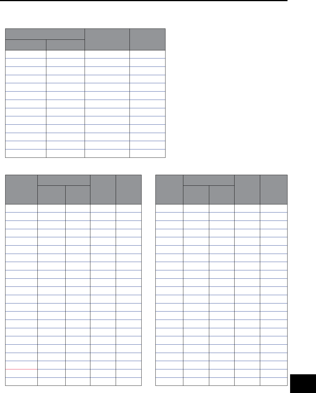
BURNDY®
Canada: 1-800-387-6487 www.burndy.com US: 1-800-346-4175
Reference
COMPACT ACSR (ASTM B401)
Conductor Size Cable Diameter
(Inches)
Breaking
Strength
(pounds)
kcmil AWG
336.4 0.628 8260
266.8 0.559 6540
4/0 0.517 7420
3/0 0.461 5880
2/0 0.410 4880
1/0 0.365 3980
1 0.326 3290
2 0.298 3260
2 0.290 2640
3 0.258 2130
4 0.236 2160
4 0.229 1760
6 0.182 1120
ACSR/TW (TRAP WIRE) CABLE (ASTM B779)
Conductor
Size
kcmil
Stranding Nominal
Diameter
(inches)
Rated
Strength
(pounds)
No.
Aluminum
Wires
No. Steel
Wires
336.4 14 1 0.63 8600
405.1 14 1 0.68 10200
477.0 18 7 0.78 17200
477.0 18 7 0.79 19400
556.5 18 7 0.84 20000
556.5 20 7 0.85 22600
565.3 20 7 0.86 22900
571.7 18 7 0.85 20600
636.0 27 1 0.85 13500
636.0 18 7 0.89 22900
636.0 20 7 0.91 25400
664.8 20 7 0.93 26600
666.6 20 7 0.91 24000
762.8 20 7 0.99 30500
768.2 20 7 0.98 27700
768.9 27 1 0.93 16400
795.0 17 7 0.96 21000
795.0 18 7 0.98 25900
795.0 20 7 0.99 28200
795.0 20 7 1.01 31800
946.7 35 7 1.08 29600
954.0 30 7 1.05 23700
Conductor
Size
kcmil
Stranding Nominal
Diameter
(inches)
Rated
Strength
(pounds)
No.
Aluminum
Wires
No. Steel
Wires
954.0 32 7 1.06 25900
954.0 20 7 1.08 33500
957.2 32 7 1.06 26000
959.6 22 7 1.11 37000
966.2 21 7 1.09 34000
1033.5 30 7 1.09 25700
1033.5 32 7 1.10 28100
1033.5 21 7 1.13 36300
1113.0 30 7 1.13 27500
1113.0 33 7 1.14 30000
1113.0 38 19 1.19 39100
1158.0 33 7 1.17 31600
1158.4 25 7 1.20 39600
1168.1 30 7 1.16 28900
1192.5 30 7 1.17 29500
1192.5 33 7 1.18 32400
1192.5 38 19 1.22 41900
1233.6 38 19 1.25 42900
1257.1 35 7 1.21 34200
1272.0 30 7 1.20 31400
1272.0 35 7 1.22 34600
1272.0 39 19 1.26 44100
CABLE DATA (continued)
O-25
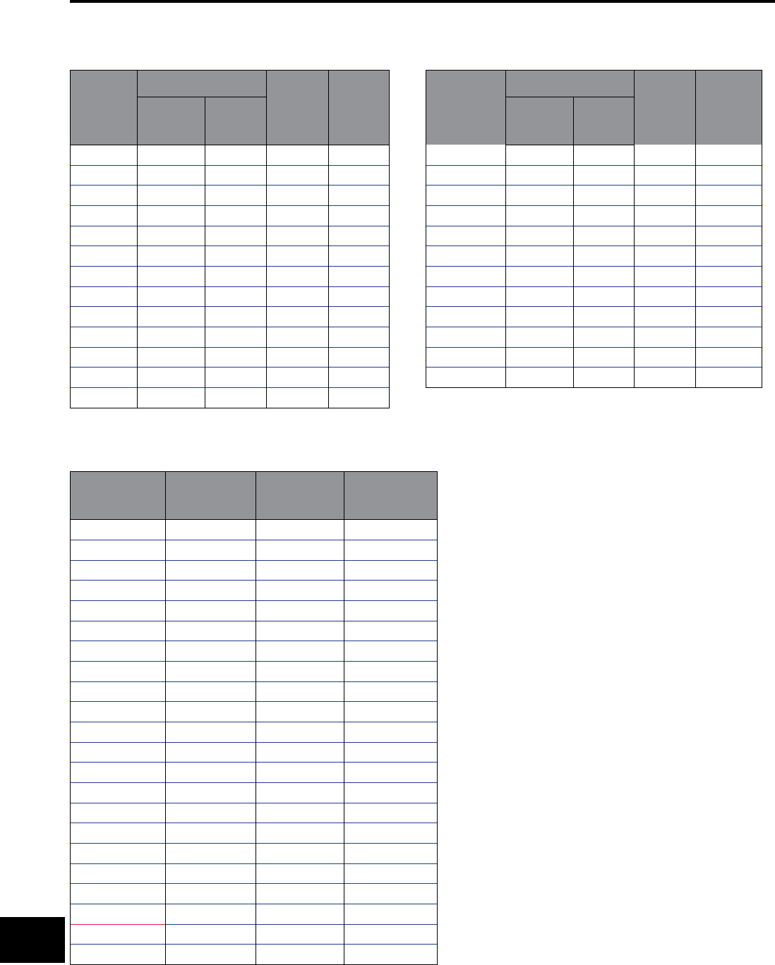
BURNDY®
US: 1-800-346-4175 www.burndy.com Canada: 1-800-387-6487
Reference
CABLE DATA (continued)
ACSR/TW (TRAP WIRE) Continued
Conductor
Size
kcmil
Stranding Nominal
Diameter
(inches)
Rated
Strength
(pounds)
No.
Aluminum
Wires
No. Steel
Wires
1334.6 39 19 1.29 46300
1351.5 35 7 1.26 36700
1351.4 39 19 1.30 46800
1359.7 36 7 1.26 36900
1372.5 30 7 1.25 33400
1431.0 36 7 1.29 38900
1431.0 39 19 1.34 49600
1433.6 39 19 1.34 49700
1455.3 36 7 1.30 39200
1467.8 33 7 1.29 35800
1533.3 39 19 1.38 53200
1557.4 36 7 1.35 41900
1569.0 33 7 1.33 38200
Conductor
Size
kcmil
Stranding Nominal
Diameter
(inches)
Rated
Strength
(pounds)
No.
Aluminum
Wires
No. Steel
Wires
1590.0 36 7 1.36 42200
1590.0 42 19 1.41 55100
1622.0 39 19 1.42 57500
1657.4 36 7 1.39 44000
1730.6 39 19 1.47 59400
1758.6 37 19 1.47 34600
1780.0 37 19 1.45 50700
1926.9 42 19 1.55 65300
1949.6 42 7 1.50 51900
2153.8 64 19 1.60 61100
2156.0 64 19 1.61 61100
2627.3 64 19 1.76 74500
AAC/TW (ALL ALUMINUM TRAP WIRE) (ASTM B778)
Conductor Size
kcmil
Nominal
Diameter
(inches)
Number of
Wires
Rated Strength
(pounds)
336.4 0.612 17 6220
397.5 0.661 17 7230
477.0 0.720 17 8530
500.0 0.736 17 8940
556.5 0.775 17 9950
600.0 0.803 17 10700
636.0 0.825 17 11400
700.0 0.864 17 12500
750.0 0.893 17 13400
795.0 0.919 17 13900
900.0 0.990 31 15800
954.0 1.018 31 16700
1000.0 1.041 31 17500
1033.5 1.057 31 18100
1113.0 1.095 31 19500
1192.5 1.132 31 20900
1272.0 1.168 31 22300
1351.5 1.202 31 23700
1431.0 1.236 31 24600
1590.0 1.315 49 27300
1750.0 1.377 49 30000
2000.0 1.468 49 34300
O-26
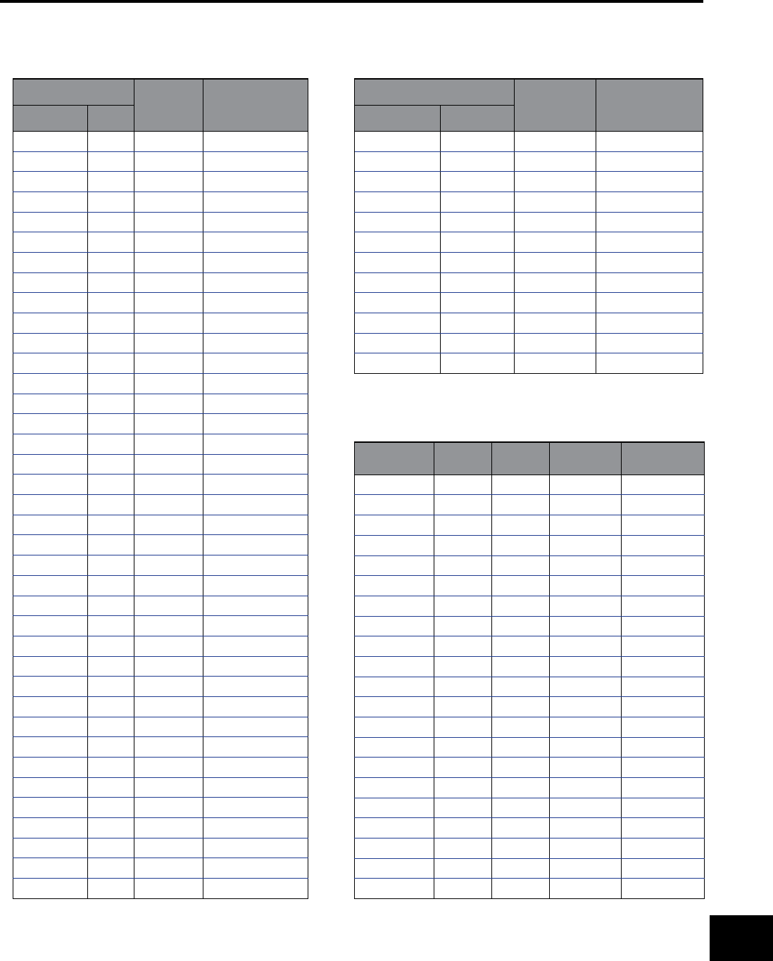
BURNDY®
Canada: 1-800-387-6487 www.burndy.com US: 1-800-346-4175
Reference
ACAR CABLE (ASTM B524)
Conductor Size Number of
Wires
Nominal Outside
Diameter (inches)
kcmil AWG
2000 91 1.630
2000 61 1.630
1900 61 1.588
1800 61 1.546
1750 61 1.525
1700 61 1.502
1600 61 1.458
1500 61 1.411
1400 61 1.364
1300 61 1.314
1300 37 1.312
1250 61 1.288
1250 37 1.287
1200 61 1.263
1200 37 1.261
1100 61 1.209
1100 37 1.207
1000 61 1.152
1000 37 1.151
950 37 1.121
900 37 1.092
850 37 1.061
800 37 1.029
750 37 0.997
700 37 0.962
650 37 0.928
600 37 0.891
600 19 0.888
550 37 0.853
550 19 0.850
500 37 0.813
500 19 0.811
450 19 0.770
400 19 0.726
350 19 0.678
300 19 0.628
250 19 0.574
246.9 7 0.563
Conductor Size Number of
Wires
Nominal Outside
Diameter (inches)
kcmil AWG
4/0 7 0.522
195.7 7 0.502
3/0 7 0.464
155.4 7 0.447
2/0 7 0.414
123.3 7 0.398
1/0 7 0.368
77.4 7 0.316
2 7 0.292
48.6 7 0.250
4 7 0.232
30.5 7 0.198
CABLE DATA (continued)
SSAC CABLE
Size AWG or
kcmil
# Alum
Strands
# Steel
Strands
Conductor
Diameter
Rated Strength
(pounds)
266.8 22 7 .622 6030
266.8 24 7 .633 7410
266.8 26 7 .642 8880
266.8 30 7 .660 11700
300.0 26 7 .680 9970
336.4 20 7 .692 5990
336.4 22 7 .701 7610
336.4 24 7 .710 9340
336.4 26 7 .720 11200
336.4 30 7 .741 14800
397.5 20 7 .752 7090
397.5 22 7 .762 8990
397.5 24 7 .772 11000
397.5 26 7 .783 13000
397.5 30 7 .806 17500
477.0 20 7 .823 8490
477.0 22 7 .834 10800
477.0 24 7 .846 13000
477.0 26 7 .858 15600
477.0 30 7 .883 21000
500.0 30 7 .904 22000
O-27
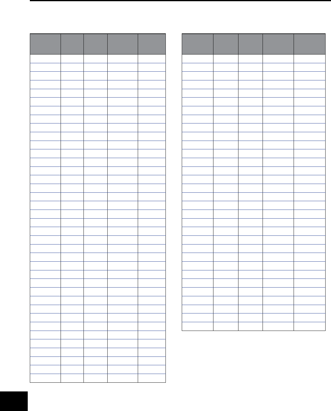
BURNDY®
US: 1-800-346-4175 www.burndy.com Canada: 1-800-387-6487
Reference
CABLE DATA (continued)
SSAC CABLE (Continued)
Size
AWG or
kcmil
# Alum
Strands
# Steel
Strands
Conductor
Diameter
Rated
Strength
(pounds)
556.5 20 7 .890 9910
556.5 22 7 .901 12600
556.5 24 7 .914 15200
556.5 26 7 .927 18200
556.5 30 7 .953 24500
605.0 24 7 .953 16500
605.0 26 7 .966 19700
605.0 30 7 .994 26000
605.0 30 19 .994 26600
636.0 20 7 .951 11300
636.0 22 7 .963 14100
636.0 24 7 .977 17300
636.0 26 7 .990 20700
636.0 30 7 1.019 27400
636.0 30 19 1.019 28000
666.6 24 7 1.000 18200
666.6 26 7 1.104 21700
715.5 24 7 1.036 19500
715.5 26 7 1.051 23300
715.5 30 19 1.081 30800
795.0 42 7 1.055 11800
795.0 20 7 1.063 14200
795.0 45 7 1.063 14200
795.0 22 7 1.077 17700
795.0 24 7 1.092 21700
795.0 54 7 1.092 21700
795.0 26 7 1.108 25900
795.0 30 19 1.140 34300
900.0 45 7 1.131 15800
900.0 54 7 1.162 24600
954.0 42 7 1.155 14200
954.0 20 7 1.185 16700
954.0 45 7 1.165 16700
954.0 48 7 1.175 19700
954.0 24 7 1.196 26000
954.0 54 7 1.196 26000
954.0 30 19 1.248 41100
1033.5 42 7 1.203 15400
Size
AWG or
kcmil
# Alum
Strands
# Steel
Strands
Conductor
Diameter
Rated
Strength
(pounds)
1033.5 45 7 1.212 18100
1033.5 48 7 1.222 21300
1033.5 54 7 1.245 28200
1113.0 42 7 1.248 16300
1113.0 45 7 1.259 19500
1113.0 48 7 1.269 23000
1113.0 54 19 1.293 30400
1192.5 42 7 1.292 17500
1192.5 45 7 1.302 20900
1192.5 48 7 1.313 24600
1192.5 54 19 1.338 32600
1272.0 42 7 1.334 18700
1272.0 45 7 1.345 22300
1272.0 48 7 1.357 26200
1272.0 54 19 1.382 34100
1351.5 42 7 1.376 19900
1351.5 45 7 1.386 23700
1351.5 48 7 1.398 27900
1351.5 54 19 1.424 36200
1431.0 42 7 1.415 21000
1431.0 45 7 1.427 25100
1431.0 48 7 1.439 29500
1431.0 54 19 1.465 38400
1510.5 45 7 1.466 26500
1510.5 54 19 1.505 40500
1590.0 42 7 1.492 23400
1590.0 45 7 1.504 27900
1590.0 48 7 1.517 32200
1590.0 54 19 1.545 42600
1780.0 84 19 1.602 35400
1869.0 68 7 1.603 21500
2034.5 72 7 1.681 27200
O-28
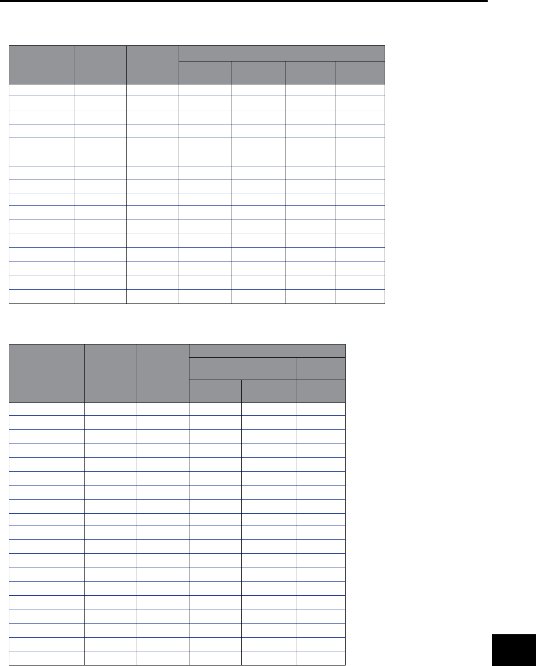
BURNDY®
Canada: 1-800-387-6487 www.burndy.com US: 1-800-346-4175
Reference
SOLID COPPERWELD CABLE (ASTM B227)
Conductor Size
(AWG)
Nominal
Diameter
(inches)
Circular
Mils
Minimum Breaking Load (pounds)
Grade 40
HS Grade 40 EHS Grade 30
HS
Grade 30
EHS
4 0.2043 41740 3540 - 3934 4671
5 0.1819 33090 2937 - 3249 3911
- 0.1650* 27230 2779 - 2779 3367
6 0.1620 26240 2679 - 2679 3246
7 0.1443 20820 2207 - 2207 2681
8 0.1285 16510 1816 - 1816 2205
- 0.1280* 16380 1802 - 1802 2188
9 0.1144 13090 1491 - 1491 1790
- 0.1040* 10820 1283 1325 1283 1487
10 0.1019 10380 1231 - 1231 1460
12 0.0808 6530 774 - 774 918
- 0.0800* 6400 759 - 759 900
- 0.0640* 4096 485 - 485 576
18 0.0403 1624 193 - 193 228
- 0.0390* 1521 180 - 180 214
20 0.0320 1024 121 - 121 144
* These diameters are often employed by purchasers for communication lines BUT are not in the American
Wire Gauge (B&S Wire Gauge) series, as are the other diameter listed.
STRANDED COPPERWELD CABLE (ASTM B228)
Nominal Diameter†
(inch) Size AWG‡
Circular
Mils
Diameter*
(inch)
Breaking Load (pounds)**
High Strength Extra High
Strength
40%
Cond.
30%
Cond. 30% Cond.
7/8 (19 No. 5) 628900 .910 50240 55570 66910
13/16 (19 No. 6) 498800 .810 41600 45830 55530
23/32 (19 No. 7) 395500 .721 34390 37740 45850
27/32 (19 No. 8) 313700 .642 28380 31040 37690
9/16 (19 No. 9) 248800 .572 23390 25500 30610
5/8 (7 No. 4) 292200 .613 22310 24780 29430
9/16 (7 No. 5) 231700 .546 18510 20470 24650
1/2 (7 No. 6) 183800 .486 15330 16890 20460
7/16 (7 No. 7) 145700 .433 12670 13910 16890
3/8 (7 No. 8) 115600 .385 10460 11440 13890
11/32 (7 No. 9) 91650 .343 8616 9393 11280
5/16 (7 No. 10) 72680 .306 7121 7758 9196
3 No. 5 99310 .392 8373 9262 11860
3 No. 6 78750 .349 6934 7639 9754
3 No. 7 62450 .311 5732 6291 7922
3 No. 8 49530 .277 4730 5174 6282
3 No. 9 39280 .247 3898 4250 5129
3 No. 10 31150 .220 3221 3509 4160
3 No. 12 19590 .174 2236 - -
† The designation “inch” is the
approximate diameter in proper fraction
of an inch.
‡ The designation AWG is a combination
of the number of wires each of the
American Wire Gauge size indicated by
“No.”
* Diameter of circumscribing.
** Breaking loads of 7-wire and 19-wire
conductors are taken as 90% of the sum
of the breaking loads of individual wires;
breaking load of 3-wire conductors is
taken as 95% of the sum of the breaking
loads of the individual wires.
CABLE DATA (continued)
O-29
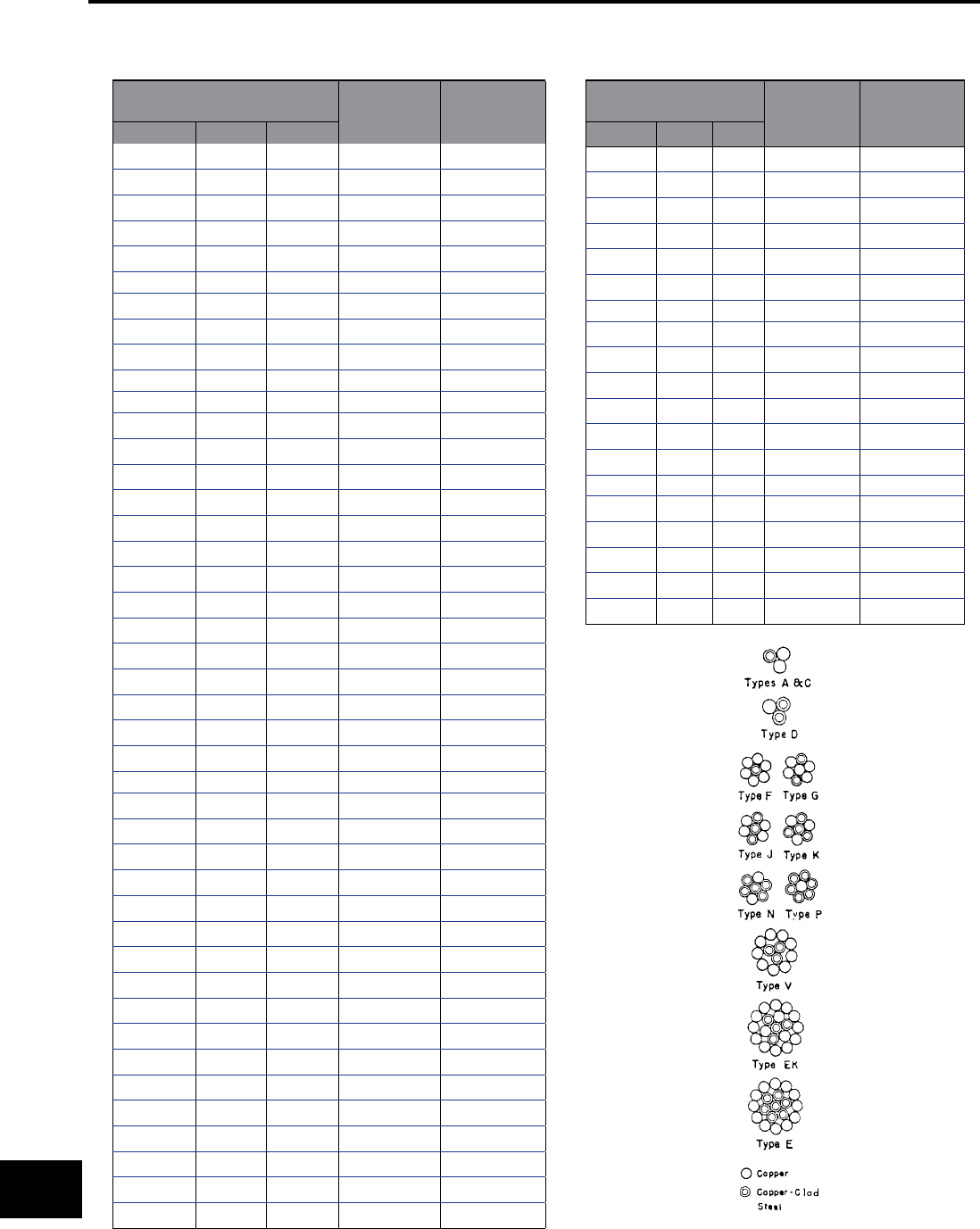
BURNDY®
US: 1-800-346-4175 www.burndy.com Canada: 1-800-387-6487
Reference
CABLE DATA (continued)
COPPERWELD-COPPER CABLE (ASTM B229)
Conductor size Hard Drawn
Copper Equivalent
Nom. Dia. of
Conductor
(inches)
Min. Breaking
Load (pounds)
cmil AWG Type
350000 - E 0.788 32420
350000 - EK 0.735 23850
350000 - V 0.754 23480
300000 - E 0.729 27770
300000 - EK 0.680 20960
300000 211600 V 0.698 20730
250000 - E 0.666 23920
250000 - EK 0.621 17840
250000 - V 0.637 17420
4/0 E 0.613 20730
211600 4/0 G 0.583 15640
211600 4/0 EK 0.571 15370
211600 4/0 V 0.586 15000
211600 4/0 F 0.550 12290
167800 3/0 E 0.545 16800
167800 3/0 J 0.555 16170
167800 3/0 G 0.519 12860
167800 3/0 EK 0.509 12370
167800 3/0 V 0.522 12200
167800 3/0 F 0.490 9980
133100 2/0 K 0.534 17600
133100 2/0 J 0.494 13430
133100 2/0 G 0.463 10510
133100 2/0 V 0.465 9846
133100 2/0 F 0.436 8094
105600 1/0 K 0.475 14490
105600 1/0 J 0.440 10970
105600 1/0 G 0.412 8563
105600 1/0 F 0.388 6536
83690 1 N 0.464 15410
83690 1 K 0.423 11900
83690 1 J 0.392 9000
83690 1 G 0.367 6956
83690 1 F 0.346 5266
66360 2 P 0.462 16870
66360 2 N 0.413 12680
66360 2 K 0.377 9730
66360 2 J 0.349 7322
66360 2 A 0.366 5876
66360 2 G 0.327 5626
66360 2 F 0.308 4233
55620 3 P 0.411 13910
52620 3 N 0.368 10390
Conductor size Hard
Drawn Copper Equivalent
Nom. Dia. of
Conductor
(inches)
Min. Breaking
Load (pounds)
cmil AWG Type
52620 3 K 0.336 7910
52620 3 J 0.311 5955
52620 3 A 0.326 4810
41740 4 P 0.366 11420
41740 4 N 0.328 8460
41740 4 D 0.348 7340
41740 4 A 0.290 3938
33090 5 P 0.326 9311
33090 5 D 0.310 6035
33090 5 A 0.258 3193
26240 6 D 0.276 4942
26240 6 A 0.230 2585
26240 6 C 0.225 2143
20820 7 D 0.246 4022
20820 7 A 0.223 2754
16510 8 D 0.219 3256
16510 8 A 0.199 2233
16510 8 C 0.179 1362
11750 9 D 0.174 1743
O-30
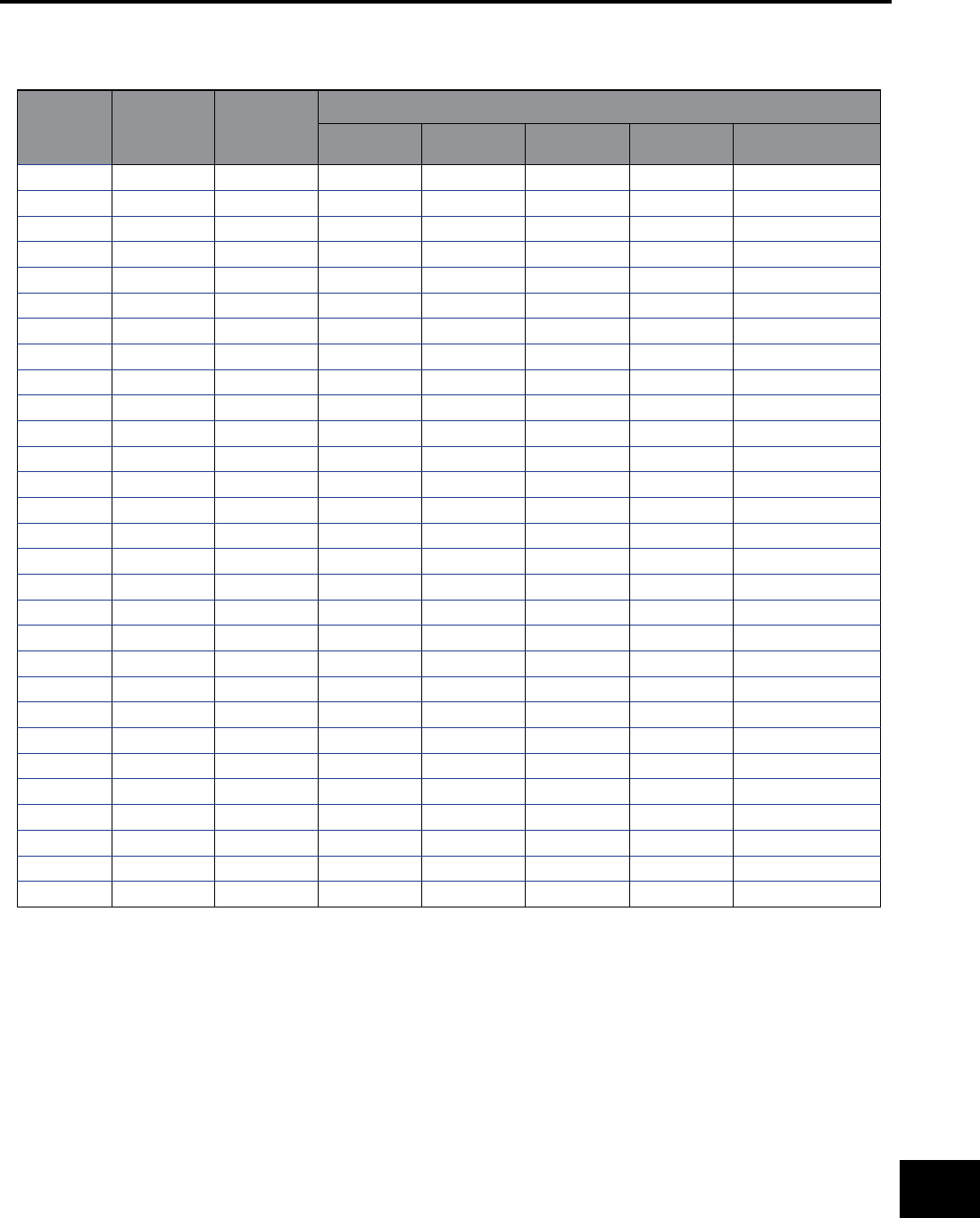
BURNDY®
Canada: 1-800-387-6487 www.burndy.com US: 1-800-346-4175
Reference
GALVANIZED STEEL CABLE (ASTM A475)
inches Nom. Dia. of
Strand (mm)
Number of
Wires in
Strand
Minimum Breaking Load (pounds)
Utilities Grade Common
Grade
Siemens-
Martin Grade
High-Strength
Grade
Extra High-Strength
Grade
1/8 3.18 7 - 540 910 1330 1830
5/32 3.97 7 - 870 1470 2140 2940
3/16 4.76 7 - 1150 1900 2850 3990
3/16 4.76 7 2400 - - - -
7/32 5.56 3 - 1400 2340 3500 4900
7/32 5.56 7 - 1540 2560 3850 5400
1/4 6.35 3 3150 1860 3040 4730 6740
1/4 6.35 3 4500 - - - -
1/4 6.35 7 - 1900 3150 4750 6650
9/32 7.14 3 - 2080 3380 5260 7500
9/32 7.14 7 4600 2570 4250 6400 8950
5/16 7.94 3 6500 2490 4090 6350 9100
5/16 7.94 7 - 3200 5350 8000 11200
5/16 7.94 7 6000 - - - -
3/8 9.52 3 8500 3330 5560 8360 11800
3/8 9.52 7 11500 4250 6950 10800 15400
7/16 11.11 7 18000 5700 9350 14500 20800
1/2 12.70 7 25000 7400 12100 18800 26900
1/2 12.70 19 - 7620 12700 19100 26700
9/16 14.29 7 - 9600 15700 24500 35000
9/16 14.29 19 - 9640 16100 24100 33700
5/8 15.88 7 - 11600 19100 29600 42400
5/8 15.88 19 - 11000 18100 28100 40200
3/4 19.05 19 - 16000 26200 40800 58300
7/8 22.22 19 - 21900 35900 55800 79700
1 25.40 9 - 28700 47000 73200 104500
1 25.40 37 - 28300 46200 71900 102700
1-1/8 28.58 37 - 36000 58900 91600 130800
1-1/4 31.75 37 - 44600 73000 113600 162200
CABLE DATA (continued)
O-31
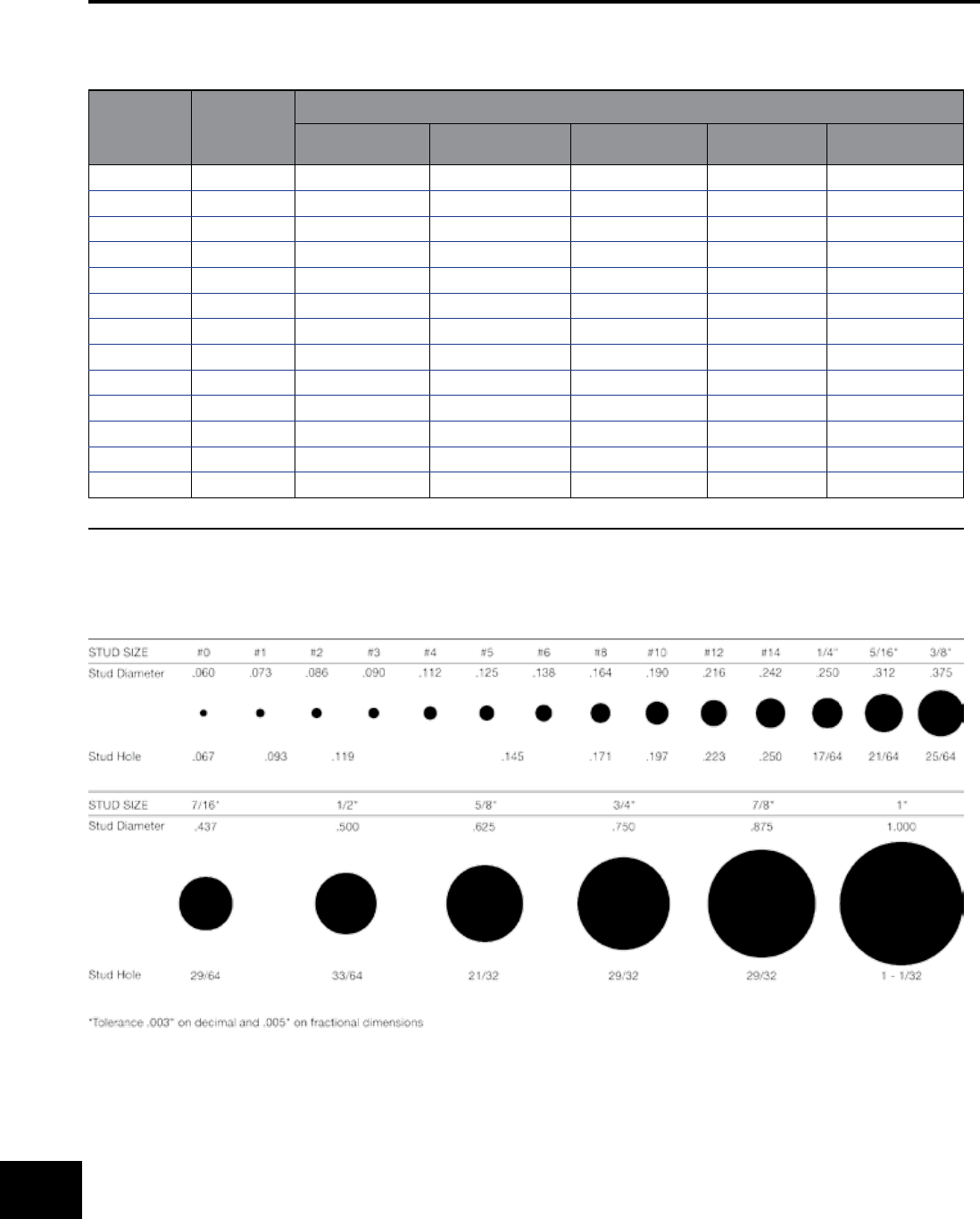
BURNDY®
US: 1-800-346-4175 www.burndy.com Canada: 1-800-387-6487
Reference
CABLE DATA (continued)
ALUMINUM-COATED STEEL CABLE (ASTM A474)
Nom. Dia.
of Strand
(inches)
Number of
Wires in
Strand
Minimum Breaking Strength (pounds)
Utilities Grade* Common Grade Siemens-Martin
Grade
High-Strength
Grade
Extra High-Strength
Grade
3/16 7 1150 1900 2850
3/16 7 2400
1/4 3 3150
1/4 3 4500
1/4 7 1900 3150 4750 6650
9/32 7 4600
5/16 3 6500
5/16 7 3200 5350 8000 11200
5/16 7 6000
3/8 3 8500
3/8 7 11500 4250 6950 10800 15400
7/16 7 18000 5350 9350 14500 20800
1/2 7 25000 7400 12100 18800 26900
* The Utilities Grade is used principally by communications and power and light industries.
TERMINAL STUD SIZE CHART*
O-32

BURNDY®
Canada: 1-800-387-6487 www.burndy.com US: 1-800-346-4175
Reference
Circ.
Mils
Equivalent
Circ. Mils AWG Size Metric Wire
Size (mm)
Number of
Strands
Wire Dia. per Strand Approx. Overall Diameter
inches mm inches mm
- 937 - .50 1 .032 .813 .032 .81
1020 - 20 - 7 .0121 .307 .036 .91
- 1480 - .75 1 .039 .091 .039 .99
1620 - 18 - 1 .0103 1.02 .040 1.02
1620 - 18 - 7 .0152 .386 .046 1.16
- 1974 - 1.0 1 .045 1.14 .045 1.14
- 1974 - 1.0 7 .017 .422 .061 1.30
2580 - 16 - 1 .0503 1.29 .051 1.29
2580 - 16 - 7 .0192 .468 .058 1.46
- 2960 - 1.5 1 .055 1.40 .055 1.40
- 2960 - 1.5 7 .021 5.33 .063 1.60
4110 - 14 - 1 .0641 1.63 .064 1.63
4110 - 14 - 7 .0242 .615 .073 1.84
- 4934 - 2.5 1 .071 1.80 .071 1.80
- 4934 - 2.5 7 .027 6.66 .081 2.06
6530 - 12 - 1 .0308 2.05 .081 2.05
6530 - 12 - 7 .0305 .775 .092 2.32
- 7894 - 4 1 .089 2.26 .089 2.26
- 7894 - 4 7 .034 .864 .102 2.59
10380 - 10 - 1 .1019 2.59 .102 2.59
10380 - 10 - 7 .0355 .978 .116 2.93
- 11840 - 6 1 .109 2.77 .109 2.77
- 11840 - 6 7 .042 .107 .126 3.21
13000 - 9 - 1 .1144 2.91 .114 2.91
13090 - 9 - 7 .0432 1.10 .130 3.30
16510 - 8 - 1 .1285 3.26 .128 3.25
16510 - 8 - 7 .0486 1.23 .146 3.70
- 19740 - 10 1 .141 3.58 .141 3.58
- 19740 - 10 7 .054 1.37 .162 4.12
20520 - 7 - 1 .1443 3.67 .144 3.67
20520 - 7 - 7 .0545 1.38 .164 4.15
26240 - 6 - 1 .162 4.11 .162 4.11
26240 - 6 - 7 .0612 1.55 .184 4.66
- 31580 - 16 7 .008 1.73 .204 5.13
33090 - 5 - 7 .0688 1.75 .206 5.24
41740 - 4 - 7 .0772 1.96 .232 5.88
- 49340 - 25 7 .085 2.16 .255 6.48
- 49340 - 25 19 .052 1.32 .260 6.60
52620 - 3 - 7 .0867 2.20 .260 6.61
66300 - 2 - 7 .0974 2.47 .292 7.42
- 69070 - 35 7 .100 2.54 .300 7.62
- 69070 - 35 19 .001 1.55 .305 7.75
AWG VS. METRIC WIRE SIZES
O-33

BURNDY®
US: 1-800-346-4175 www.burndy.com Canada: 1-800-387-6487
Reference
Circ.
Mils
Equivalent Circ.
Mils AWG Size Metric Wire
Size (mm)
Number of
Strands
Wire Dia. per Strand Approx. Overall Diameter
inches mm inches mm
83690 - 1 - 19 .0064 1.50 .332 8.43
- 98680 - 50 19 .073 1.85 .365 9.27
105000 - 1/0 - 19 .0745 1.59 .373 9.46
133100 - 2/0 - 19 .0837 2.13 .419 10.6
- 138100 - 70 19 .086 2.18 .430 10.9
167800 - 3/0 - 19 .094 2.59 .470 11.9
167800 - 3/0 - 36 .0673 1.71 .471 12.0
- 187500 - 95 19 .101 2.57 .505 12.8
- 187500 - 95 37 .072 1.83 .504 12.5
211600 - 4/0 - 19 .1055 2.89 .528 13.4
- 237.8 kcmil - 120 37 .081 2.06 .567 14.4
250 kcmil - - - 37 .0822 2.07 .575 14.6
300 kcmil - - 150 37 .090 2.29 .630 16.0
350 kcmil - - - 37 .0973 2.47 .681 17.3
- 365.1 kcmil - 185 37 .100 2.54 .700 17.8
400 kcmil - - - 37 .104 2.64 .728 18.5
- 473.6 kcmil - 240 37 .114 2.90 .798 20.3
- 473.6 kcmil - 240 61 .089 2.26 .801 20.3
500 kcmil - - - 37 .1162 2.95 .813 20.7
500 kcmil - - - 61 .0905 2.30 .814 20.7
- 592.1 kcmil - 300 61 .099 2.51 .891 22.6
600 kcmil - - - 61 .0992 2.52 .893 22.7
700 kcmil - - - 61 .1071 2.72 .964 24.5
750 kcmil - - - 6 .1109 2.82 .998 25.4
750 kcmil - - - 91 .0908 2.31 .998 25.4
- 789.4 kcmil - 400 61 .114 2.90 1.026 26.1
800 kcmil - - - 61 .1145 2.91 1.031 26.2
800 kcmil - - - 91 .0938 2.38 1.032 26.2
1000 kcmil 986.8 kcmil - 500 61 .1280 3.25 1.152 28.3
1000 kcmil - - - 91 .1048 2.66 1.153 29.3
- 1233.7 kcmil - 625 91 .117 2.97 1.287 32.7
1250 kcmil - - - 91 .1172 2.93 1.289 32.7
1250 kcmil - - - 127 .0992 2.52 1.200 32.8
1500 kcmil - - - 91 .1284 3.26 1.412 36.9
1500 kcmil - - - 127 .1087 2.76 1.413 36.9
- 1578.8 kcmil - 800 91 .132 3.35 1.452 36.9
- 1973.5 kcmil - 1000 91 .147 3.73 1.617 41.1
2000 kcmil - - - 127 .1255 3.19 1.632 41.5
2000 kcmil - - - 169 .1088 2.76 1.632 41.5
AWG VS. METRIC WIRE SIZES (continued)
O-34
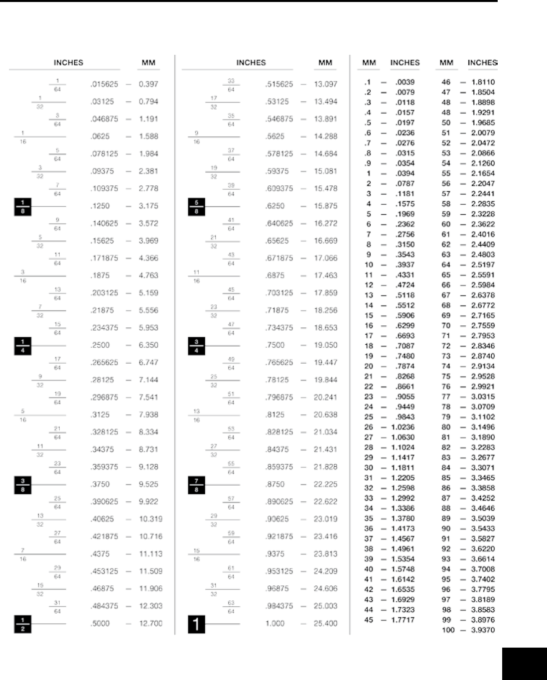
BURNDY®
Canada: 1-800-387-6487 www.burndy.com US: 1-800-346-4175
Reference
Circ.
Mils
Equivalent Circ.
Mils AWG Size Metric Wire
Size (mm)
Number of
Strands
Wire Dia. per Strand Approx. Overall Diameter
inches mm inches mm
83690 - 1 - 19 .0064 1.50 .332 8.43
- 98680 - 50 19 .073 1.85 .365 9.27
105000 - 1/0 - 19 .0745 1.59 .373 9.46
133100 - 2/0 - 19 .0837 2.13 .419 10.6
- 138100 - 70 19 .086 2.18 .430 10.9
167800 - 3/0 - 19 .094 2.59 .470 11.9
167800 - 3/0 - 36 .0673 1.71 .471 12.0
- 187500 - 95 19 .101 2.57 .505 12.8
- 187500 - 95 37 .072 1.83 .504 12.5
211600 - 4/0 - 19 .1055 2.89 .528 13.4
- 237.8 kcmil - 120 37 .081 2.06 .567 14.4
250 kcmil - - - 37 .0822 2.07 .575 14.6
300 kcmil - - 150 37 .090 2.29 .630 16.0
350 kcmil - - - 37 .0973 2.47 .681 17.3
- 365.1 kcmil - 185 37 .100 2.54 .700 17.8
400 kcmil - - - 37 .104 2.64 .728 18.5
- 473.6 kcmil - 240 37 .114 2.90 .798 20.3
- 473.6 kcmil - 240 61 .089 2.26 .801 20.3
500 kcmil - - - 37 .1162 2.95 .813 20.7
500 kcmil - - - 61 .0905 2.30 .814 20.7
- 592.1 kcmil - 300 61 .099 2.51 .891 22.6
600 kcmil - - - 61 .0992 2.52 .893 22.7
700 kcmil - - - 61 .1071 2.72 .964 24.5
750 kcmil - - - 6 .1109 2.82 .998 25.4
750 kcmil - - - 91 .0908 2.31 .998 25.4
- 789.4 kcmil - 400 61 .114 2.90 1.026 26.1
800 kcmil - - - 61 .1145 2.91 1.031 26.2
800 kcmil - - - 91 .0938 2.38 1.032 26.2
1000 kcmil 986.8 kcmil - 500 61 .1280 3.25 1.152 28.3
1000 kcmil - - - 91 .1048 2.66 1.153 29.3
- 1233.7 kcmil - 625 91 .117 2.97 1.287 32.7
1250 kcmil - - - 91 .1172 2.93 1.289 32.7
1250 kcmil - - - 127 .0992 2.52 1.200 32.8
1500 kcmil - - - 91 .1284 3.26 1.412 36.9
1500 kcmil - - - 127 .1087 2.76 1.413 36.9
- 1578.8 kcmil - 800 91 .132 3.35 1.452 36.9
- 1973.5 kcmil - 1000 91 .147 3.73 1.617 41.1
2000 kcmil - - - 127 .1255 3.19 1.632 41.5
2000 kcmil - - - 169 .1088 2.76 1.632 41.5
INCHES & MILLIMETERS CONVERSION CHART
O-35
BURNDY®
US: 1-800-346-4175 www.burndy.com Canada: 1-800-387-6487
Reference
BURNDY CONDUCTOR NUMBERING SYSTEM - © BURNDY ENGINEERING CO., INC., 1940
Outside
Dia. IN
Outside
Dia. MM
STR. CABLE SOL. WIRE AREA MM2
Copper
Cable
ACSR PIPE SIZE CONDUCTOR TUBE & ROD SERVIT
NO.
Cat.
No. Size Cat.
No. Size Cat.
No. Cable Size Cat.
No. ST D Cat No. Ex Hvy Cat.
No. Dia.
.102 2.594 10W 10 5.261 KS90
.114 2.896 9W 9 6.634
.116 2.946 10 C 10 5.261
.125 3.175 60 1/8
.129 3.277 8W 8 8.366 KS15
.130 3.302 9 C 9 6.634
.144 3.658 7W 7 10.550
.146 3.708 8 C 8 8.366
.158 4.013 8R 8
.162 4.115 6W 6 13.300 KS17
.164 4.166 7 C 7 10.550
.176 4.470 7R 7
.182 4.597 5W 5 16.770
.184 4.648 6 C 6 13.300
.198 5.029 6R 6
.204 5.182 4W 4 21.150 KS20
.206 5.258 5 C 5 16.770
.223 5.664 5R 5
.229 5.817 3W 3 26.670
.232 5.867 4 C 4 21.150
.250 6.350 4R 461 1/4
.258 6.553 2W 2 33.630 KS22
.260 6.629 3 C 3 2.6670
.281 7.137 3R 3
.289 7.344 1W 1 42.410
.292 7.394 2 C 2 33.630 KS23
.316 8.026 2R 2
.325 8.255 75 1/0 53.480
.332 8.382 1 C 1 42.410
.355 9.017 1R 1
.365 9.274 76 2/0 67.430
.372 9.474 25 1/0 53.480 KS25
.375 9.525 62 3/8
.398 10.109 25R 1/0
.405 10.287 10 1/8 50 1/8
.410 10.414 77 3/0 85.030
.419 10.617 26 2/0 67.430 KS26
.447 11.354 26R 2/0
.460 11.684 78 4/0 107.200
.470 11.938 27 3/0 85.030
.500 12.700 63 1/2
.502 12.725 27R 3/0
.528 13.414 28 4/0 107.200 KS28
.540 13.716 11 1/4 51 1/4
.563 14.326 28R 4/0
.575 14.605 29 250 127.000
.630 16.002 30 300 152.000
.633 16.078 29R 266,800
.642 16.307 30R 266,800
.675 17.145 12 3/8 52 3/8
.680 17.272 31R 300,000
.681 17.297 31 350 177.000 KS31
.721 18.313 32R 336,400
.728 18.494 32 400 203.000
.741 18.824 33R 336,400
.750 19.050 64 3/4
.772 19.609 33 450 228.000
.783 19.888 34R 397,500
.806 20.472 35R 397,500
.813 20.676 34 500 253.000
.840 21.336 13 1/2 53 1/2
.855 21.717 35 550 279.000 KS34
.858 21.742 36R 477,000
.883 22.428 37R 477,000
.893 22.682 36 600 304.000
.904 22.962 38R 500,000
.927 23.546 39R 556,500
.929 23.597 37 650 329.000
.953 24.206 40R 556,500
.953 24.206 41R 605,000
.964 24.486 38 700 355.000
.977 24.714 42R 636,000
.998 25.349 39 750 380.000 KS39
1.000 25.400 43R 666,600 65 1
O-36
BURNDY®
Canada: 1-800-387-6487 www.burndy.com US: 1-800-346-4175
Reference
BURNDY CONDUCTOR NUMBERING SYSTEM (continued)
1.031 26.187 40 800 405.000
1.036 26.314 44R 715,500
1.050 26.670 14 54
1.062 26.975 41 850 431.000
1.094 27.762 42 900 456.000 45R 795,000
1.123 28.524 43 950 481.000
1.146 29.108 46R 874,000
1.152 29.264 44 1000 507.000 KS44
1.162 29.515 47R 900,000
1.196 30.378 48R 954,000
1.209 30.709 444 1100 557.000
1.246 31.648 49R 1,033,500
1.250 31.750 66 1
1.263 32.080 448 1200 608.000
1.289 32.744 45 1250 633.000
1.293 32.817 50R 1,113,000
1.315 33.404 452 1300 15 155 1
1.338 33.960 51R 1,192,500
1.364 34.646 456 1400 709.000
1.382 35.103 52R 1,272,000
1.412 35.865 46 1500 760.000
1.424 36.170 53R 1,351,500
1.459 37.059 464 1600 811.000
1.465 37.214 54R 1,431,000
1.500 38.100 67 1-1/2
1.504 38.202 468 1700 861.000
1.506 38.252 55R 1,510,500
1.526 38.786 47 1750 866.000
1.545 39.218 56R 1,590,000
1.548 39.319 472 1800 912.000
1.590 40.386 476 1900 963.000
1.632 41.427 48 2000 1013.00
1.660 42.164 16 156 1
1.729 43.917 483 2250 1140.000
1.824 46.330 486 2500 1267.000
1.900 48.260 17 1-1/2 57 1-1/2
1.914 48.616 490 2750 1393.000
1.988 50.495 493 3000 1520.000
2.000 50.800 68 2
2.375 60.325 18 258 2
2.500 63.500 69 2-1/2
2.875 73.025 19 2-1/2 59 2-1/2
3.000 76.200 70 3
3.500 88.900 20 390 371 3-1/2
4.000 101.600 21 3-1/2 91 3-1/2 72 4
4.500 114.300 22 492 473 4-1/2
5.000 127.000 23 4-1/2 93 4-1/2 74 5
5.563 141.300 24 594 5
6.063 154.000 85 5-1/2 95 5-1/2
6.625 168.275 86 696 6
7.625 193.675 87 797 7
8.625 219.075 88 898 8
Outside
Dia. IN
Outside
Dia. MM
STR. CABLE SOL. WIRE AREA MM2
Copper
Cable
ACSR PIPE SIZE CONDUCTOR TUBE & ROD SERVIT
NO.
Cat.
No. Size Cat.
No. Size Cat.
No. Cable Size Cat.
No. ST D Cat No. Ex Hvy Cat.
No. Dia.
O-37
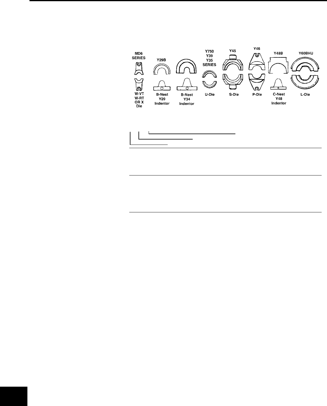
BURNDY®
US: 1-800-346-4175 www.burndy.com Canada: 1-800-387-6487
Reference
PRESENT INSTALLATION TOOL INDEX
This chart provides a cross-reference between
die index numbers marked on BURNDY® COM-
PRESSION CONNECTORS and the CORRE-
SPONDING DIE SETS used with the various
BURNDY® INSTALLATION TOOLS. This is the
only way to have a complete connections with
the BURNDY® ENGINEERED SYSTEM.
A die index number has been assigned to each
required groove conguration. A prex letter is
used to indicate the specic installation tool for
which the die has been designed, as shown.
CHART III
A - ALUMINUM
B - INDENTOR NEST (USED WITH INDENTOR DIE # Y34P**)
R - ROUND DIE (CIRCUMFERENTAL)
T - TWIN DIE (BOTH HALVES)
CHART II
12 - #12
10 - #10
8C - # 8
6C - # 6
5C - # 5
4C - #4
3C - #3
2C - #2
1C - #1
25 - 1/0
26 - 2/0
27 - 3/0
28 - 4/0
29 - 250 MCM
30 - 300 MCM
31 - 350 MCM
32 - 400 MCM
34 - 500 MCM
36 - 600 MCM
39 - 750 MCM
44 - 1000 MCM
OR INDEX
i.e., U312
312 Die Index
CHART I
U 34 ART
A - Y34A
B - Y34BH
C - Y48B
E - Y44B
F - Y486RB
G - Y34C
L - Y60B
P - Y46
S - Y45
U - Y35
W - MD-6/OUR840
X - OUR840/MD-6
TOOL TYPE (CHART I)
WIRE SIZE (CHART II) OR INDEX
USE CHART (CHART III)
O-38
BURNDY®
Canada: 1-800-387-6487 www.burndy.com US: 1-800-346-4175
Reference
PRESENT INSTALLATION TOOL INDEX (continued)
DIE DIELESS TOOLS INSTALLATION TOOLING USING DIES
GROOVE MECH. HYD. DIE INFORMATION MECHANICAL HYDRAULIC
BURNDY EEI MR, MY Y644 TYPE COLOR MD6 OUR840 Y29BY35Y39 Y750Y45Y46-Y60 Ser.
ADIE SET U-A U-A U-A U-A U-A
BG DIE SET Perm. GR
W-BG
X-BG
X-NBG U-BG U-BG U-BG U-BG U-BG
CDIE SET BROWN W-C U-C U- U-C U-C U-C
DDIE SET U-D U-D U-D U-D U-D
D3 DIE SET BLUE U-YFD U-YFD U-YFD U-YFD U-YFD
Perm. GR U-D3 U-D3 U-D3 U-D3 U-D3
EDIE SET U-E U-E U-E U-E U-E
FDIE SET U-F U-F U-F U-F U-F
HDIE SET U-H U-H U-H U-H U-H
K-1/4 DIE SET WK14
K-5/16 DIE SET WK516 UK516T UK526T UK516T UK516T UK516T
K-3/8 DIE SET WK38 UK38T UK38T UK38T UK38T UK38T
K-1/2 DIE SET WK12
K-9/16 DIE SET WK916 UK916T UK916T UK916T UK916T UK916T
K-19/32 DIE SET WK1932
K-5/8-1 DIE SET UK581T UK581T UK581T UK581T UK581T
K-11/16 DIE SET WK1116 UK1116T UK1116T UK1116T UK1116T UK1116T
K-3/4 DIE SET UK34T UK34T UK34T UK34T UK34T
K-1 DIE SET UK1T UK1T UK1T UK1T UK1T
K-1-5/16 DIE SET UK1516T UK1516T UK1516T UK1516T UK1516T
K-635 DIE SET WK737 UK737T UK737T UK737T UK737T UK737T
K-747 DIE SET WK747
K-781 DIE SET WK781
K-840 DIE SET W-K840 U-K840 U-K840 U-K840 U-K840 U-K840
KB DIE SET WKB UKBT UKBT UKBT UKBT UKBT
KBKT DIE SET UKBKTT UKBKTT UKBKTT UKBKTT UKBKTT
KC DIE SET UKCT UKCT UKCT UKCT UKCT
KK DIE SET WKK
KR DIE SET YELLOW P-YFR
S-KR P-KR
KT DIE SET WKT
KU DIE SET UKUT UKUT UKUT UKUT UKUT
LDIE SET W-L U-L U-L U-L U-L U-L
L80 DIE SET U32XRT U32XRT U32XRT U32XRT U32XRT
L99 DIE SET PINK U38XRT U38XRT U38XRT U38XRT U38XRT
L115 DIE SET YELLOW U44XRT U44XRT U44XRT U44XRT U44XRT
MDIE SET U-M U-M U-M U-M U-M
NDIE SET RED U-YFN U-YFN U-YFN U-YFN U-YFN
U-N U-N U-N U-N U-N
ODIE SET
GREEN U-YFO U-YFO U-YFO U-YFO U-YFO
Perm. GR
W-O U-O U-O U-O U-O U-O
QDIE SET W-Q
Cat. No. Y35P3 Adaptor is required to use “Y34PR” type
indentors with “U” type nest dies in Y35 and Y750 series.
Cat. No. PT6515 Adaptor is required to use “U” type dies
in Y45 series.
-Cat. No. PUADP-1 Adaptor is required to use “U” type
dies in Y46 series.
The MD6-6R2 ratchet tool is required on these sizes.
The standard MD6 or MD6R ratchet tools will not work.
Also pneumatic version Y29NC. O-39
BURNDY®
US: 1-800-346-4175 www.burndy.com Canada: 1-800-387-6487
Reference
PRESENT INSTALLATION TOOL INDEX (continued)
DIE DIELESS TOOLS INSTALLATION TOOLING USING DIES
GROOVE MECH. HYD. DIE INFORMATION MECHANICAL HYDRAULIC
BURNDY EEI MR, MY Y644 TYPE COLOR MD6 OUR840 Y29B
Y35
Y39 Y750
Y45
Y46
-
Y60
Ser.
RDIE SET U-R U-R U-R U-R U-R
TDIE SET S-T
ZDIE SET S-Z
7
94
MR4C
MY29-3
MY29-11
1
CRIMP
DIE SET BLUE W5CRT X5CRT U5CRT U5CRT U5CRT U5CRT U5CRT
NEST D6CL U6CD-1 U6CD-1 U6CD-1 U6CD-1 U6CD-1
INDENTOR Y29PR Y34PR Y34PR Y34PR Y34PR Y34PR
8
95
MR4C
MY29-3
MY29-11
1
CRIMP
DIE SET GRAY W4CRT X4CRT U4CRT U4CRT U4CRT U4CRT U4CRT
NEST D4CL U4CD-1 U4CD-1 U4CD-1 U4CD-1 U4CD-1
INDENTOR Y29PR Y34PR Y34PR Y34PR Y34PR Y34PR
9
96
MY29-3
MY29-11
1
CRIMP
DIE SET WHITE W3CRT X3CRT U3CRT U3CRT U3CRT U3CRT U3CRT
NEST D3CL U3CD-1 U3CD-1 U3CD-1 U3CD-1 U3CD-1
INDENTOR Y29PR Y34PR Y34PR Y34PR Y34PR Y34PR
10
97
MY29-3
MY29-11
1
CRIMP
DIE SET BROWN W2CRT X2CRT U2CRT U2CRT U2CRT U2CRT U2CRT
NEST D2CL U2CD-1 U2CD-1 U2CD-1 U2CD-1 U2CD-1
INDENTOR Y29PR Y34PR Y34PR Y34PR Y34PR Y34PR
11
98
MY29-3
MY29-11
1
CRIMP
DIE SET GREEN W1CRT-1 X1CRT-1 U1CRT-1 U1CRT-1 U1CRT-1 U1CRT-1 U1CRT-1
NEST D1CL U1CD-1 U1CD-1 U1CD-1 U1CD-1 U1CD-1
INDENTOR Y29PR Y34PR Y34PR Y34PR Y34PR Y34PR
12
99
MY29-3
MY29-11
1
CRIMP
DIE SET PINK W25RT X25RT U25RT U25RT U25RT U25RT U25RT
NEST D25L U25D-1 U25D-1 U25D-1 U25D-1 U25D-1
INDENTOR Y29PL Y34PR Y34PR Y34PR Y34PR Y34PR
13
100
MY29-3
MY29-11
1
CRIMP
DIE SET BLACK W26RT X26RT U26RT U26RT U26RT U26RT U26RT
NEST D26L U26D-1 U26D-1 U26D-1 U26D-1 U26D-1
INDENTOR Y29PR Y34PR Y34PR Y34PR Y34PR Y34PR
14
101
MY29-3
MY29-11
1
CRIMP
DIE SET ORANGE W27RT X27RT U27RT U27RT U27RT U27RT U27RT
NEST D27L U27D-1 U27D-1 U27D-1 U27D-1 U27D-1
INDENTOR Y29PR Y34PR Y34PR Y34PR Y34PR Y34PR
15 MY29-3
MY29-11
1
CRIMP
DIE SET PURPLE W28RT X28RT U28RT U28RT U28RT U28RT U28RT
NEST D28L U28D-1 U28D-1 U28D-1 U28D-1 U28D-1
INDENTOR Y29PR Y34PR Y34PR Y34PR Y34PR Y34PR
16 MY29-3
MY29-11
1
CRIMP
DIE SET YELLOW W29RTX29RT U29RT U29RT U29RT U29RT U29RT
NEST D29L U29D-1 U29D-1 U29D-1 U29D-1
INDENTOR Y29PR Y34PR Y34PR Y34PR Y34PR
17 1
CRIMP
DIE SET WHITE W30RTU30RT U30RT U30RT U30RT U30RT L30RT
NEST U30D-1 U30D-1 U30D-1 U30D-1
INDENTOR Y34PR Y34PR Y34PR Y34PR
18 1
CRIMP
DIE SET RED W31RTU31RT U31RT U31RT U31RT U31RT L31RT
NEST U31D-1 U31D-1 U31D-1 U31D-1
INDENTOR Y34PR Y34PR Y34PR Y34PR
19 1
CRIMP
DIE SET BLUE W32RTU32RT U32RT U32RT U32RT U32RT L32RT
NEST U32D-1 U32D-1 U32D-1 U32D-1
INDENTOR Y34PR Y34PR Y34PR Y34PR
Cat. No. Y35P3 Adaptor is required to use “Y34PR” type
indentors with “U” type nest dies in Y35 and Y750 series.
Cat. No. PT6515 Adaptor is required to use “U” type dies
in Y45 series.
-Cat. No. PUADP-1 Adaptor is required to use “U” type
dies in Y46 series.
The MD6-6R2 ratchet tool is required on these sizes.
The standard MD6 or MD6R ratchet tools will not work.
Also pneumatic version Y29NC.
O-40
BURNDY®
Canada: 1-800-387-6487 www.burndy.com US: 1-800-346-4175
Reference
PRESENT INSTALLATION TOOL INDEX (continued)
DIE DIELESS TOOLS INSTALLATION TOOLING USING DIES
GROOVE MECH. HYD. DIE INFORMATION MECHANICAL HYDRAULIC
BURNDY EEI MR, MY Y644 TYPE COLOR MD6 OUR840 Y29B
Y35
Y39 Y750
Y45
Y46
-
Y60
Ser.
20 1
CRIMP
DIE SET BROWN W34RTU34RT U34RT U34RT U34RT U34RT L34RT
NEST U34D-1 U34D-1 U34D-1 U34D-1
INDENTOR Y34PR Y34PR Y34PR Y34PR
21 1
CRIMP
DIE SET YELLOW U35RT U35RT U35RT U35RT
NEST
INDENTOR
22 1
CRIMP
DIE SET GREEN U36RT U36RT U36RT U36RT L36RT
NEST P36D
INDENTOR P44PR
23 1
CRIMP
DIE SET ORANGE U37RT U37RT U37RT U37RT
NEST
INDENTOR
24 1
CRIMP
DIE SET BLACK U39RT U39RT S39RT P39RT L39RT
NEST P39D
INDENTOR P44PR
25 1
CRIMP
DIE SET ORANGE S40RT P40RT
NEST P40D
INDENTOR P44PR
26 1
CRIMP
DIE SET GOLD
NEST
INDENTOR
27 1
CRIMP
DIE SET WHITE S44RT P44RT L44RT
NEST P44D
INDENTOR P44PR
29
DIE SET YELLOW P45RT L45RT
NEST
INDENTOR
30
DIE SET ORANGE
NEST
INDENTOR
31
DIE SET GREEN S46RT P46RT L46RT
NEST No Nest
INDENTOR P44PR
33
DIE SET GRAY L47RT
NEST
INDENTOR
34
DIE SET BROWN L48RT
NEST
INDENTOR
38
MR4C
MR8G98
MR89Q
MY28
Y8MRB-1
NEST DV8L UV8L UV8L UV8L UV8L UV8L
INDENTOR Y29PL Y34PL Y34PL Y34PL Y34PL Y34PL
Cat. No. Y35P3 Adaptor is required to use “Y34PR” type
indentors with “U” type nest dies in Y35 and Y750 series.
Cat. No. PT6515 Adaptor is required to use “U” type dies
in Y45 series.
-Cat. No. PUADP-1 Adaptor is required to use “U” type
dies in Y46 series.
The MD6-6R2 ratchet tool is required on these sizes.
The standard MD6 or MD6R ratchet tools will not work.
Also pneumatic version Y29NC. O-41
BURNDY®
US: 1-800-346-4175 www.burndy.com Canada: 1-800-387-6487
Reference
PRESENT INSTALLATION TOOL INDEX (continued)
DIE DIELESS TOOLS INSTALLATION TOOLING USING DIES
GROOVE MECH. HYD. DIE INFORMATION MECHANICAL HYDRAULIC
BURNDY EEI MR, MY Y644 TYPE COLOR MD6 OUR840 Y29B
Y35
Y39 Y750
Y45
Y46
-
Y60
Ser.
39 MR4C
MY28
1
CRIMP
NEST DV6L UV6L UV6L UV6L UV6L UV6L
INDENTOR Y29PL Y34PLA Y34PLA Y34PLA Y34PLA Y34PLA
40 MR4C
MY28
NEST DV4L UV4L UV4L UV4L UV4L UV4L
INDENTOR Y29PL Y34PLA Y34PLA Y34PLA Y34PLA Y34PLA
41 MY28 NEST DV2L UV2; UV2; UV2; UV2; UV2;
INDENTOR Y29PL Y34PLA Y34PLA Y34PLA Y34PLA Y34PLA
42 MY28 NEST DV1L UV1L UV1L UV1L UV1L UV1L
INDENTOR Y29PL Y34PLA Y34PLA Y34PLA Y34PLA Y34PLA
43 MY28 NEST DV25L UV25L UV25L UV25L UV25L UV25L
INDENTOR Y29PL Y34PA Y34PA Y34PA Y34PA Y34PA
44 MY28 NEST DV26L UV26L UV26L UV26L UV26L UV26L
INDENTOR Y29PL Y34PA Y34PA Y34PA Y34PA Y34PA
45 MY28 NEST UV27L UV27L UV27L UV27L UV27L
INDENTOR Y34PA Y34PA Y34PA Y34PA Y34PA
46 MY28 NEST UV28L UV28L UV28L UV28L UV28L
INDENTOR Y34PA Y34PA Y34PA Y34PA Y34PA
49 DIE SET RED W8CRT X8CRT U8CRT U8CRT U8CRT U8CRT U8CRT
161 DIE SET W161 X-161 U161 U161 U161 U161 U161
162 DIE SET W162 W162 U162 U162 U162 U162 U162
163 505 DIE SET W163 W163 U163 U163 U163 U163 U163
164 275 DIE SET W164 U164 U164 U164 U164 U164
165 205
287 339 DIE SET W165 X-165 U165/
U205
U165/
U205
U165/
U205
U165/
U205
U165/
U205 L165
166 206
459 DIE SET W166 U166/
U459
U166/
U459
U166/
U459
U166/
U459
U166/
U459 L166
167 207
211 256
568
DIE SET W167 U167/
U568
U167/
U568
U167/
U568
U167/
U568
U167/
U568 L167
168 208 DIE SET U168 U168 U168 U168 U168 L168
169 DIE SET U169 U169 U169 U169 U169 L169
170 306 DIE SET U170 U170 U170 U170 U170 L170
171 DIE SET W161 U171 U171 U171 U171 U171
193 DIE SET U193 U193 U193 U193 U193 L193
202 DIE SET U202 U202 U202 U202 U202
203 DIE SET U203 U203 U203 U203 U203
204 DIE SET U204 U204 U204 U204 U204
205 165
287 339 DIE SET W165 X-165 U165/
U205
U165/
U205
U165/
U205
U165/
U205
U165/
U205 L165
206 166
459 DIE SET W166 U166/
U459
U166/
U459
U166/
U459
U166/
U459
U166/
U459 L166
207 167
211 256
568
DIE SET W167 U167/
U568
U167/
U568
U167/
U568
U167/
U568
U167/
U568 L167
208 168 DIE SET U168 U168 U168 U168 U168 L168
209 DIE SET U209 U209 U209 U209 U209 L209
210 DIE SET U210 U210 U210 U210 U210 L210
Cat. No. Y35P3 Adaptor is required to use “Y34PR” type
indentors with “U” type nest dies in Y35 and Y750 series.
Cat. No. PT6515 Adaptor is required to use “U” type dies
in Y45 series.
-Cat. No. PUADP-1 Adaptor is required to use “U” type
dies in Y46 series.
Also pneumatic version Y29NC.
O-42
BURNDY®
Canada: 1-800-387-6487 www.burndy.com US: 1-800-346-4175
Reference
PRESENT INSTALLATION TOOL INDEX (continued)
DIE DIELESS TOOLS INSTALLATION TOOLING USING DIES
GROOVE MECH. HYD. DIE INFORMATION MECHANICAL HYDRAULIC
BURNDY EEI MR, MY Y644 TYPE COLOR MD6 OUR840 Y35
Y39 Y750
Y45
Y46
-
Y60
Ser.
211 167
256 568 DIE SET W167 U167/
U568
U167/
U568
U167/
U568
U167/
U568
U167/
U568 L167
236 DIE SET W236 U236 U236 U236 U236 U236
237 DIE SET W237 X-237 U237 U237 U237 U237 U237
238 DIE SET W238 U238 U238 U238 U238 U238
239 DIE SET W239 X-239 U239 U239 U239 U239 U239
240 DIE SET RED W240 U240 U240 U240 U240 U240
241 DIE SET W241 X-241 U241 U241 U241 U241 U241
242 244 3S/4S DIE SET W242 U242 U242 U242 U242 U242 L242
243 DIE SET W243 U243 U243 U243 U243 U243 L243
244 242 3S/4S DIE SET W242 U242 U242 U242 U242 U242 L242
245 9A DIE SET W245 X-245 U245 U245 U245 U245 U245 L245
246 248 5S DIE SET W248 U248 U248 U248 U248 U248 L248
247 DIE SET W247 X-247 U247 U247 U247 U247 U247 L247
248 246 5S DIE SET W248 U248 U248 U248 U248 U248 L248
249 11A DIE SET W249 X-249 U249 U249 U249 U249 U249 L249
250 DIE SET U250 U250 U250 U250 U250 L250
251 12A DIE SET RED W251 U251 U251 U251 U251 U251 L251
252 DIE SET U252 U252 U252 U252 U252 L252
253 DIE SET U253 U253 U253 U253 U253 L253
254 DIE SET S254 P254 L254
255 DIE SET U255 U255 U255 U255 U255 L255
256 167
207 211
568
DIE SET W167 U167/
U567
U167/
U567
U167/
U567
U167/
U567
U167/
U567 L167
257 DIE SET U257 U257 U257 U257 U257 L257
259 DIE SET U259 U259 U259 U259 U259
260 DIE SET L260
261 318 15A DIE SET U261 U261 U261 U261 U261 L261
263 DIE SET U263 U263 U263 U263 U263
267 DIE SET U267 U267 U267 U267 U267 L267
275 164 DIE SET W164 U164 U164 U164 U164 U164
276 DIE SET U276 U276 U276 U276 U276
285 DIE SET U285 U285 U285 U285 U285
287 165
205 339 DIE SET W165 U165/
U205
U165/
U205
U165/
U205
U165/
U205
U165/
U205 L165
292 578 DIE SET S292 P292 L292
293 294 DIE SET S293 P293 L293
296 MY29-3 1
CRIMP
DIE SET TAN X25ART U25ART U25ART U25ART U25ART
NEST P27D
INDETOR P34PR5
297 MY29-3 1
CRIMP
DIE SET OLIVE X26ART U26ART U26ART U26ART U26ART
NEST P29D
INDENTOR P34PR5
Cat. No. Y35P3 Adaptor is required to use “Y34PR” type
indentors with “U” type nest dies in Y35 and Y750 series.
Cat. No. PT6515 Adaptor is required to use “U” type dies
in Y45 series.
-Cat. No. PUADP-1 Adaptor is required to use “U” type
dies in Y46 series. O-43
BURNDY®
US: 1-800-346-4175 www.burndy.com Canada: 1-800-387-6487
Reference
PRESENT INSTALLATION TOOL INDEX (continued)
DIE DIELESS TOOLS INSTALLATION TOOLING USING DIES
GROOVE MECH. HYD. DIE INFORMATION MECHANICAL HYDRAULIC
BURNDY EEI MR, MY Y644 TYPE COLOR MD6 OUR840 Y35
Y39 Y750
Y45
Y46
-Y60 Ser.
298 MY29-3 1
CRIMP
DIE SET WHITE X28ART U28ART U28ART U28ART U28ART U28ART L28ART
NEST P31D
INDENTOR Y45PR5
299 1
CRIMP
DIE SET BROWN U31ART U31ART U31ART U31ART U31ART L31ART
NEST P35D
INDENTOR P48PR1
300 1
CRIMP
DIE SET PINK U34ART U34ART U34ART U34ART U34ART L34ART
NEST P39D
INDENTOR P49PR1
301 1
CRIMP
DIE SET RED S39ART P39ART L39ART
NEST P45D
INDENTOR P48PR1
302 1
CRIMP
DIE SET BROWN S44ART P44ART L44ART
NEST No Nest
INDENTOR P48PR1
303 DIE SET GRAY U42ART U42ART U42ART U42ART U42ART
304 DIE SET U304 U304 U304 U304 U304 L304
305 341 DIE SET U305 U305 U305 U305 U305 L305
306 170 DIE SET U170 U170 U170 U170 U170 L170
308 DIE SET U308 U308 U308 U308 U308
313 DIE SET U313 U313 U313 U313 U313 L313
314 376 DIE SET L314
316 DIE SET U316 U316 U316 U316 U316 L316
317 426 DIE SET U317 U317 U317 U317 U317 L317
318 261 DIE SET U261 U261 U261 U261 U261 L261
319 DIE SET S319 P319 L319
320 DIE SET S320 P320 L320
321 DIE SET U321 U321 U321 U321 U321 L321
322 DIE SET U322 U322 U322 U322 U322
324 1
CRIMP
DIE SET RED U29ART U29ART U29ART U29ART U29ART L29ART
NEST P32D
INDENTOR P34PR5
326 538 DIE SET U33RT U33RT U33RT U33RT U33RT
327 14A DIE SET U327 U327 U327 U327 U327 L327
328 DIE SET L328
329 DIE SET U329 U329 U329 U329 U329
331 DIE SET U331 U331 U331 U331 U331
339 165
205 287 DIE SET X-339 U165/
U205
U165/
U205
U165/
U205
U165/
U205
U165/
U205
341 305 DIE SET U305 U305 U305 U305 U305 L305
342 DIE SET S342 P342 L342
344 DIE SET L344
345 DIE SET L345
Cat. No. Y35P3 Adaptor is required to use “Y34PR” type
indentors with “U” type nest dies in Y35 and Y750 series.
Cat. No. PT6515 Adaptor is required to use “U” type dies
in Y45 series.
-Cat. No. PUADP-1 Adaptor is required to use “U” type
dies in Y46 series.
The MD6-6R2 ratchet tool is required on these sizes.
The standard MD6 or MD6R ratchet tools will not work.
O-44
BURNDY®
Canada: 1-800-387-6487 www.burndy.com US: 1-800-346-4175
Reference
PRESENT INSTALLATION TOOL INDEX (continued)
DIE DIELESS TOOLS INSTALLATION TOOLING USING DIES
GROOVE MECH. HYD. DIE INFORMATION MECHANICAL HYDRAULIC
BURNDY EEI MR, MY Y644 TYPE COLOR MD6 OUR840 Y35
Y39 Y750
Y45
Y46
-Y60 Ser.
346 1 CRIMP DIE SET GRAY X6CART U6CABT U6CABT U6CABT U6CABT U6CABT
348 1 CRIMP DIE SET PINK X2CART U2CABT U2CABT U2CABT U2CABT U2CABT
350 DIE SET U350 U350 U350 U350 U350 L350
352 DIE SET S352 P352 L352
373 DIE SET U373 U373 U373 U373 U373
374 MY29-3 DIE SET BLUE X8CART U8CABT U8CABT U8CABT U8CABT U8CABT
375 MY29-3 1 CRIMP DIE SET GREEN X4CART U4CABT U4CABT U4CABT U4CABT U4CABT
376 314 DIE SET L314
400 DIE SET PURPLE U38RT U38RT U38RT U38RT U38RT
403 DIE SET U403 U403 U403 U403 U403
419 DIE SET S419 P419 L419
422 DIE SET L422
426 317 DIE SET U317 U317 U317 U317 U317
459 166 DIE SET U166/459 U166/459 U166/459 U166/459 U166/459
467 MY29-3 1 CRIMP
DIE SET RUBY X27ART U27ART U27ART U27ART U27ART U27ART
NEST P30D
INDENTOR P34PR5
468 DIE SET U468 U468 U468 U468 U468
469 DIE SET S469 P469 L469
470 1 CRIMP
DIE SET BLUE U30ART U30ART U30ART U30ART U30ART L30ART
NEST P34D
INDENTOR P48PR1
471 MY29-3 1 CRIMP
DIE SET GOLD X1CART U1CART U1CART U1CART U1CART U1CART
NEST
INDENTOR
472 1 CRIMP
DIE SET GREEN U32ART U32ART U32ART U32ART U32ART L32ART
NEST P35D
INDENTOR P48PR1
473 1 CRIMP
DIE SET BLACK U36ART U36ART U36ART U36ART U36ART L36ART
NEST P44D
INDENTOR P48PR1
474 1 CRIMP
DIE SET GOLD S40ART P40ART L40ART
NEST
INDENTOR
478 1 CRIMP
DIE SET BLUE L46ART
NEST
INDENTOR
479 DIE SET RED L48ART
490 547 DIE SET U490 U490 U490 U490 U490 L490
495 DIE SET L495
505 163 DIE SET W163 U163 U163 U163 U163 U163 L163
Cat. No. Y35P3 Adaptor is required to use “Y34PR” type
indentors with “U” type nest dies in Y35 and Y750 series.
Cat. No. PT6515 Adaptor is required to use “U” type dies
in Y45 series.
-Cat. No. PUADP-1 Adaptor is required to use “U” type
dies in Y46 series.
The MD6-6R2 ratchet tool is required on these sizes.
The standard MD6 or MD6R ratchet tools will not work.
Hexagonal crimp O-45
BURNDY®
US: 1-800-346-4175 www.burndy.com Canada: 1-800-387-6487
Reference
PRESENT INSTALLATION TOOL INDEX (continued)
DIE DIELESS TOOLS INSTALLATION TOOLING USING DIES
GROOVE MECH. HYD. DIE INFORMATION MECHANICAL HYDRAULIC
BURNDY EEI MR, MY Y644 TYPE COLOR MD6 OUR840 Y35
Y39 Y750
Y45
Y46
-Y60 Ser.
511 MY29-3 NEST
INDENTOR
512 MY29-3 NEST
INDENTOR
513 MY29-3 NEST
INDENTOR
514 MY29-3 NEST
INDENTOR
515 MY29-3 NEST
INDENTOR
516 MY29-3 NEST
INDENTOR
517 MY29-3 NEST
INDENTOR
518 MY29-3 NEST
INDENTOR
519 MY29-3 NEST
INDENTOR
520 MY29-3 NEST
INDENTOR
538 326 DIE SET U33RT U33RT U33RT U33RT U33RT
547 490 DIE SET U490 U490 U490 U490 U490 L490
552 DIE SET U552 U552 U552 U552 U552
568 167
207 211
256
DIE SET W167 U167/
U568
U167/
U568
U167/
U568
U167/
U568
U167/
U568
575 DIE SET L575
576 DIE SET L576
578 292 DIE SET S292 P292 L292
579 DIE SET S579 P579 L579
587 DIE SET L47ART
607 DIE SET U607 U607 U607 U607 U607
608 DIE SET U608 U608 U608 U608 U608 608
609 DIE SET U609 U609 U609 U609 U609
627 DIE SET L627
642 DIE SET U642 U642 U642 U642 U642 L642
643 DIE SET U643 U643 U643 U643 U643
647DIE SET L45ART
648 DIE SET L648
654 DIE SET PURPLE U654 U654 U654 U654 U654 L654
655 13A DIE SET U655 U655 U655 U655 U655
658 DIE SET U658 U658 U658 U658 U658
659 DIE SET W659 U659 U659 U659 U659 U659
660 DIE SET W660 X-660 U660 U660 U660 U660 U660
667 DIE SET L667
668 DIE SET U668 U668 U668 U668 U668
Cat. No. Y35P3 Adaptor is required to use “Y34PR” type
indentors with “U” type nest dies in Y35 and Y750 series.
Cat. No. PT6515 Adaptor is required to use “U” type dies
in Y45 series.
-Cat. No. PUADP-1 Adaptor is required to use “U” type
dies in Y46 series.
Die 302 recommended for 1.84 O.D. barrel.
O-46
BURNDY®
Canada: 1-800-387-6487 www.burndy.com US: 1-800-346-4175
Reference
PRESENT INSTALLATION TOOL INDEX (continued)
DIE DIELESS TOOLS INSTALLATION TOOLING USING DIES
GROOVE MECH. HYD. DIE INFORMATION MECHANICAL HYDRAULIC
BURNDY EEI MR, MY Y644 TYPE COLOR MD6 OUR840 Y35
Y39 Y750
Y45
Y46
-Y60 Ser.
676 DIE SET U676 U676 U676 U676 U676
677 DIE SET U677 U677 U677 U677 U677 L677
678 DIE SET U678 U678 U678 U678 U678
679 DIE SET U679 U679 U679 U679 U679
684 DIE SET L684
687 DIE SET W687 X-687
690 1S DIE SET W690 U690 U690 U690 U690 U690
691 2S DIE SET W691 U691 U691 U691 U691 U691
692 4S DIE SET W692 U692 U692 U692 U692 U692
693 6A DIE SET W693 U693 U693 U693 U693 U693
694 10A DIE SET W694 U694 U694 U694 U694 U694
702 DIE SET W702
705 DIE SET U705 U705 U705 U705 U705
717DIE SET S717 P717 L717/
L717W
718DIE SET L718
719DIE SET S719 P719 L719/
L719W
720DIE SET S720 P720 L720/
L720W
721DIE SET L721
722DIE SET S722 P722 L722/
L722W
723DIE SET L723
724DIE SET S724 P724 L724/
L724W
725DIE SET S725 P725 L725/
L725W
726DIE SET L726
727DIE SET L727/
L727W
728DIE SET L728/
L728W
729DIE SET L729/
L729W
735DIE SET L735/
L735W
740DIE SET L740
786 DIE SET U786 U786 U786 U786 U786
788 DIE SET U788 U788 U788 U788 U788
789 DIE SET L789
9361 CRIMP DIE SET YELLOW U39ART-2 U39ART-2 U39ART-2 U39ART-2 U39ART-2 L39ART-2
997 DIE SET ORANGE U997 U997 U997 U997 U997
998 DIE SET PU998 S998 P998
999 DIE SET S999 P999
1011 DIE SET U1011 S1011 P1011
1012 DIE SET S1012
Cat. No. Y35P3 Adaptor is required to use “Y34PR” type
indentors with “U” type nest dies in Y35 and Y750 series.
Cat. No. PT6515 Adaptor is required to use “U” type dies
in Y45 series.
-Cat. No. PUADP-1 Adaptor is required to use “U” type
dies in Y46 series.
Hexagonal crimp
O-47

BURNDY®
US: 1-800-346-4175 www.burndy.com Canada: 1-800-387-6487
Reference
PRESENT INSTALLATION TOOL INDEX (continued)
DIE DIELESS TOOLS INSTALLATION TOOLING USING DIES
GROOVE MECH. HYD. DIE INFORMATION MECHANICAL HYDRAULIC
BURNDY EEI MR, MY Y644 TYPE COLOR MD6 OUR840 Y35
Y39 Y750
Y45
Y46
-Y60 Ser.
1013 MY29-11 NEST UV8L UV8L UV8L UV8L UV8L
INDENTOR Y34PL Y34PL Y34PL Y34PL Y34PL
1014 MY29-11 NEST U6CD1 U6CD1 U6CD1 U6CD1 U6CD1
INDENTOR Y34PR Y34PR Y34PR Y34PR Y34PR
1015 MY29-11 NEST U4CD1 U4CD1 U4CD1 U4CD1 U4CD1
INDENTOR Y34PR Y34PR Y34PR Y34PR Y34PR
1016 MY29-11 NEST U3CD1 U3CD1 U3CD1 U3CD1 U3CD1
INDENTOR Y34PR Y34PR Y34PR Y34PR Y34PR
1017 MY29-11 NEST U2CD1 U2CD1 U2CD1 U2CD1 U2CD1
INDENTOR Y34PR Y34PR Y34PR Y34PR Y34PR
1018 MY29-11 NEST U1CD1 U1CD1 U1CD1 U1CD1 U1CD1
INDENTOR Y34PR Y34PR Y34PR Y34PR Y34PR
1019 MY29-11 NEST U25D1 U25D1 U25D1 U25D1 U25D1
INDENTOR Y34PR2 Y34PR2 Y34PR2 Y34PR2 Y34PR2
1020 MY29-11 NEST U26D1 U26D1 U26D1 U26D1 U26D1
INDENTOR Y34PR2 Y34PR2 Y34PR2 Y34PR2 Y34PR2
1021 MY29-11 NEST U27D1 U27D1 U27D1 U27D1 U27D1
INDENTOR Y34PR2 Y34PR2 Y34PR2 Y34PR2 Y34PR2
1022 MY29-11 NEST U28D1 U28D1 U28D1 U28D1 U28D1
INDENTOR Y34PR2 Y34PR2 Y34PR2 Y34PR2 Y34PR2
1023 MY29-11 NEST U29D1 U29D1 U29D1 U29D1 U29D1
INDENTOR Y34PR2 Y34PR2 Y34PR2 Y34PR2 Y34PR2
1024 NEST U30D1 U30D1 U30D1 U30D1 U30D1
INDENTOR Y34PR2 Y34PR2 Y34PR2 Y34PR2 Y34PR2
1025 NEST U31D1 U31D1 U31D1 U31D1 U31D1
INDENTOR Y34PR2 Y34PR2 Y34PR2 Y34PR2 Y34PR2
1026 NEST U32D1 U32D1 U32D1 U32D1 U32D1
INDENTOR Y34PR2 Y34PR2 Y34PR2 Y34PR2 Y34PR2
1027 NEST U34D1 U34D1 U34D1 U34D1 U34D1
INDENTOR Y34PR2 Y34PR2 Y34PR2 Y34PR2 Y34PR2
1028 NEST P36D
INDENTOR Y48PR1
1029 NEST P38D
INDENTOR P48PR1
1030 NEST P39D
INDENTOR P48PR1
1031 NEST P40D
INDENTOR P48PR1
1032 NEST P44D
INDENTOR P48PR1
1102 DIE SET WHITE P1102
1103 DIE SET BLUE P1103
1104 DIE SET BROWN U1104 P1104
1105 DIE SET U1105 P1105
2000 NEST U27B U27B U27B U27B
INDENTOR Y34PR15 Y34PR15 Y34PR15 Y34PR15
O-48
BURNDY®
Canada: 1-800-387-6487 www.burndy.com US: 1-800-346-4175
Reference
COLOR CODING FOR OVERHEAD CONNECTORS
Color Code Wire Dia. per Strand
Str. Compact Sol. ACSR
Brown 10 8
Green 8 6
Blue 5, 6 4 6
Orange 3, 4 #2 2 4
Red 1-19, 2 1/0 1 2
Yellow 1/0 2/0 1/0, 1
Gray 2/0 3/0 2/0
Black 3/0 4/0 3/0
Pink 4/0 266, 300 4/0
Red 250
White 266
Blue 300 350 266.8 (26/7, 18/1)
Brown 336
Green 350, 397, 400 336.4 (26/7, 18/1)
Gray 450
Pink 500 477 (18/1)
Green 556
Purple 600
Yellow 556.5 (24/7, 26/7)
Blue 650
Red 700
Yellow 750
Orange 800
White 900
Brown 1000
COLOR CODING FOR AL/CU CONNECTORS
Color Code Str. Color Code Str.
Blue 8 Blue 300
Gray 6 Brown 350
Green 4 Green 400
Pink 2 Pink 500
Gold 1 Black 600
Tan 1/0 Yellow 700/750
Olive 2/0 Red 700/750
Ruby 3/0 Brown 1000
White 4/0 Blue 1500
Red 250 Red 2000
NOTE: This chart is only intended as a
guide. For specific applications, refer to
the catalog page of the connector.
NOTE: This chart is only intended as a
guide. For specific applications, refer to
the catalog page of the connector.
O-49
BURNDY®
US: 1-800-346-4175 www.burndy.com Canada: 1-800-387-6487
Reference
COLOR CODING FOR COPPER LUGS AND SPLICES
Color Code Code Size Flex Cable
Str. Sol.
Red 8 6 8
Blue 6 6
Blue 5
Gray 4 4
White 3 2
Brown 2 2
Green 1 1
Pink 1/0 1/0
Black 2/0 2/0
Orange 3/0 3/0
Purple 4/0 4/0
Yellow 250 4/0 and 250
White 300 250
Red 350 313.1
Blue 400 373.7
Brown 500 444.4
Green 600
Pink 700 535.3
Purple 600
Black 750 646
Yellow 777.7
Orange 800
White 1000
Yellow 1111
Green 1500
Brown 2000
NOTE: This chart is only intended as a
guide. For specific applications, refer to
the catalog page of the connector.
O-50

BURNDY®
Canada: 1-800-387-6487 www.burndy.com US: 1-800-346-4175
Reference
BURNDY® REGISTERED AND TRADE NAMES
4-POINT®
BONDIT®
BURNDY®
BURNDYWeld®
ENFORCER®
GRIDMAX®
HYGROUND®
IMPLO®
INFINITY DRIVE®
IN-LINE®
PATRIOT®
SERVIT®
The SmartCart®
There is Only One IMPLO®
Connecting Power to Your World™
Registered Name Registered/Trade Name Catalog
Section
4-POINT®
ALFLUID™
BARTAP™
BONDIT®
BURNDYWeld®
CABELOK™
CLIPIT™
CRIMPIT™
DURIUM™
ENFORCER®
FASTAP™
FINGRIP™
FLEXITAP™
GRIDLOK™
GRIDMAX®
GROUNDLINK™
GROUNDMAX™
HYCRAB™
HYCRIMP™
HYDENT™
HYFLUID™
HYGRID™
HYGROUND®
HYLINK™
HYLUG™
HYPLUG™
HYPRESS™
HYREDUCER™
HYSEALPLUG™
HYSEALUG™
HYSPLICE™
HYSTACK™
HYTAIL™
HYTAP™
HYTEE™
HYTOOL™
IMPLO®
INFINITY DRIVE®
IN-LINE®
INSULUG™
KA-LUG™
KOMPRESSOR™
L’IL CRIMP™
LINEMAN ASSIST™
LOKTAP™
MOLE™
MOLIMITER™
NOTAPE™
OKLIP™
OKLIP™
N
N
A, E, L
E
E
H
H
C, E, H
D
N
H
B
A
E
E
E
E
K
H
B, C
N
E
E
B, C, E
B, C, E, H
C, H
N
B, C, K
H
H
C, H
C
E
C, E
H
N
I
N
N
B
A
N
N
H
H
A, K
K
K
A
H
PATRIOT®
PENETROX™
POLYTAP™
POPPER™
POSI-PRESS™
POWERLUG™
QIKLINK™
QIKLITE®
QIKLUG™
QIKTAP™
SCRULUG™
SERVIT POST™
SERVIT®
SPEC-BLOK™
STIRRUP™
STIRRUP™
STUDBUG™
SUPER-CLAMP™
TAPIT™
The SmartCart®
TRITAP™
U-BLOK™
UNIGROUND™
UNIRAP™
UNISPLICE™
UNITAP™
VARILUG™
VARITAP™
VERSILUG™
VERSIPOLE™
VERSITAIL™
VERSITAP™
VINYLUG™
VISEIT™
VISI-SHRINK™
WEEB™
WEJTAP™
WIREMIKE™
N
F
A
N
N
J
A
E
A, E
B
A
E
A, H
A
H
J
E
E
H
N
A
A
E
G
H
A
L
A
A
A
E
A, H
B
H
F
E
J
N
Registered/Trade Name Catalog
Section
O-51

BURNDY®
US: 1-800-346-4175 www.burndy.com Canada: 1-800-387-6487
Reference
O-52
ALPHA-NUMERIC INDEX BY CATALOG NUMBER
Catalog Number Page #
15
25
32
45
65
90
115
150
200
250
500
1050
1051
1052
1053
1054
1056
1057
1058
1059
1060
1061
1062
1063
1064
1065
1066
1067
1070
1072
1073
1074
1075
1076
1077
1079
1080
1083
1084
1085
1086
1090
1093
1094
1095
1103
1112
1113
1114
1117
1118
1120
1121
1123
1124
1131
1133
1138
1139
1140
1141
1142
1143
1144
1146
1149
1150
1157
1158
1165
1166
1167
1169
1170
1171
1174
1179
1181
1182
1190
1903
1904
1906
1923
1930
1931
1978
1990
1991
1993
1994
1995
1997
1998
2050
2051
2052
2053
2054
2056
2057
2058
2059
2060
2061
2062
2063
2064
2065
2066
2067
2070
2072
2073
2074
2075
2076
2077
2079
2080
2083
2084
2085
2086
2090
2093
2094
2095
2103
2112
2113
2114
2117
2118
2120
2121
2123
2124
2131
2133
2138
2139
2140
2141
2142
2143
2144
2146
2149
2150
2157
2158
2165
2166
2167
2169
2170
2171
2174
2179
2181
2182
2190
2903
2904
2906
2923
2978
2990
2991
2993
2994
2995
2997
2998
3050
3051
3053
3054
3056
3057
3058
3059
3060
3061
3062
3063
3064
3065
3066
3067
3070
3072
3073
3074
3075
3076
3077
3079
3080
3083
3084
3085
3086
3090
3093
3094
3095
3103
3112
3113
3114
3117
3118
3120
3121
3123
3124
3131
3133
3138
3139
3140
3141
3142
3143
3144
3146
3149
3150
3157
3158
3165
3166
3167
3169
3170
3171
3174
3179
3181
3182
3190
9050
9051
9052
9053
9054
9056
9057
9058
9059
9060
9061
9062
9063
9064
9065
9066
9067
E-74
E-74
E-74
E-74
E-74
E-74
E-74
E-74
E-74
E-74
E-74
I-54
I-54
I-54
I-54
I-54
I-54
I-54
I-54
I-54
I-54
I-54
I-54
I-54
I-54
I-54
I-54
I-54
I-54
I-54
I-55
I-55
I-55
I-55
I-55
I-55
I-55
I-55
I-55
I-59
I-59
I-55
I-59
I-55
I-55
I-55
I-55
I-55
I-55
I-55
I-55
I-55
I-55
I-55
I-55
I-55
I-55
I-55
I-55
I-55
I-55
I-56
I-56
I-56
I-56
I-59
I-59
I-59
I-59
I-59
I-59
I-56
I-59
I-59
I-59
I-59
I-59
I-59
I-59
I-56
I-60
I-60
I-60
I-60
I-60
I-60
I-60
I-60
I-60
I-60
I-60
I-60
I-60
I-60
I-54
I-54
I-54
I-54
I-54
I-54
I-54
I-54
I-54
I-54
I-54
I-54
I-54
I-54
I-54
I-54
I-54
I-54
I-54
I-55
I-55
I-55
I-55
I-55
I-55
I-55
I-55
I-55
I-59
I-59
I-55
I-59
I-55
I-55
I-55
I-55
I-55
I-55
I-55
I-55
I-55
I-55
I-55
I-55
I-55
I-55
I-55
I-55
I-55
I-55
I-56
I-56
I-56
I-56
I-59
I-59
I-59
I-59
I-59
I-59
I-56
I-59
I-59
I-59
I-59
I-59
I-59
I-59
I-56
I-60
I-60
I-60
I-60
I-60
I-60
I-60
I-60
I-60
I-60
I-60
I-60
I-54
I-54
I-54
I-54
I-54
I-54
I-54
I-54
I-54
I-54
I-54
I-54
I-54
I-54
I-54
I-54
I-54
I-54
I-55
I-55
I-55
I-55
I-55
I-55
I-55
I-55
I-55
I-59
I-59
I-55
I-59
I-55
I-55
I-55
I-55
I-55
I-55
I-55
I-55
I-55
I-55
I-55
I-55
I-55
I-55
I-55
I-55
I-55
I-55
I-56
I-56
I-56
I-56
I-59
I-59
I-59
I-59
I-59
I-59
I-56
I-59
I-59
I-59
I-59
I-59
I-59
I-59
I-56
I-54
I-54
I-54
I-54
I-54
I-54
I-54
I-54
I-54
I-54
I-54
I-54
I-54
I-54
I-54
I-54
I-54
Catalog Number Page # Catalog Number Page # Catalog Number Page #

BURNDY®
Canada: 1-800-387-6487 www.burndy.com US: 1-800-346-4175
Reference
O-53
9070
9072
9073
9074
9075
9076
9077
9079
9080
9083
9084
9085
9086
9090
9093
9094
9095
9103
9112
9113
9114
9117
9118
9120
9121
9123
9124
9131
9133
9138
9139
9140
9141
9142
9143
9144
9146
9149
9150
9157
9158
9165
9166
9167
9169
9170
9171
9174
9179
9181
9182
9190
1050/ACSS
1050/ACSS/TW
1050/I
1051/ACSS
1051/ACSS/TW
1052/ACSS
1052/ACSS/TW
1053/ACSS
1053/ACSS/TW
1054/ACSS
1054/ACSS/TW
1056/ACSS
1056/ACSS/TW
1057/ACSS
1057/ACSS/TW
1059/ACSS
1059/ACSS/TW
1060/ACSS
1060/ACSS/TW
1061/ACSS
1061/ACSS/TW
1062/ACSS
1062/ACSS/TW
1063/ACSS
1063/ACSS/TW
1065/ACSS
1065/ACSS/TW
1066/ACSS
1066/ACSS/TW
1067/ACSS
1067/ACSS/TW
1070/ACSS
1070/ACSS/TW
1072/ACSS
1072/ACSS/TW
1073/ACSS
1073/ACSS/TW
1074/ACSS
1074/ACSS/TW
1075/ACSS
1075/ACSS/TW
1076/ACSS
1076/ACSS/TW
115CI
115Q
1165-NZ
122EMT
122IMC
122PVC
122RIG
145PTAG
150Q
15CI
15CP
15Q
1PBS1/0
1PBS2
1PBS250
1PBS350
1PBS500
1PL2/02
1PL2/03
1PL2502
1PL2503
1PL3502
1PL42
1PL43
1PL44
1PL6002
1PLD2/02
1PLD2/03
1PLD2/04
1PLD2/06
1PLD2502
1PLD2503
1PLD2504
1PLD2506
1PLD3502
ALPHA-NUMERIC INDEX BY CATALOG NUMBER (Continued)
I-54
I-54
I-55
I-55
I-55
I-55
I-55
I-55
I-55
I-55
I-55
I-59
I-59
I-55
I-59
I-55
I-55
I-55
I-55
I-55
I-55
I-55
I-55
I-55
I-55
I-55
I-55
I-55
I-55
I-55
I-55
I-55
I-55
I-56
I-56
I-56
I-56
I-59
I-59
I-59
I-59
I-59
I-59
I-56
I-59
I-59
I-59
I-59
I-59
I-59
I-59
I-56
I-57
I-58
I-54
I-57
I-58
I-57
I-58
I-57
I-58
I-57
I-58
I-57
I-58
I-57
I-58
I-57
I-58
I-57
I-58
I-57
I-58
I-57
I-58
I-57
I-58
I-57
I-58
I-57
I-58
I-57
I-58
I-57
I-58
I-57
I-58
I-57
I-58
I-57
I-58
I-57
I-58
I-57
I-58
E-74
E-71
I-59
N-121
N-121
N-121
N-121
G-11
E-71
E-74
E-74
E-71
A-60
A-60
A-60
A-60
A-60
A-60
A-60
A-60
A-60
A-60
A-60
A-60
A-60
A-60
A-60
A-60
A-60
A-60
A-60
A-60
A-60
A-60
A-60
1PLD3503
1PLD3504
1PLD3506
1PLD3508
1PLD43
1PLD44
1PLD6002
1PLD6003
1PLD6004
1PLD6005
1PLD6006
1PLD6008
1PLO2/02
1PLO2502
1PLO3502
1PLO42
1PLO6002
200Q
2050/ACSS
2050/ACSS/TW
2050/I
2051/ACSS
2051/ACSS/TW
2052/ACSS
2052/ACSS/TW
2053/ACSS
2053/ACSS/TW
2054/ACSS
2054/ACSS/TW
2056/ACSS
2056/ACSS/TW
2057/ACSS
2057/ACSS/TW
2059/ACSS
2059/ACSS/TW
2060/ACSS
2060/ACSS/TW
2061/ACSS
2061/ACSS/TW
2062/ACSS
2062/ACSS/TW
2063/ACSS
2063/ACSS/TW
2065/ACSS
2065/ACSS/TW
2066/ACSS
2066/ACSS/TW
2067/ACSS
2067/ACSS/TW
2070/ACSS
2070/ACSS/TW
2072/ACSS
2072/ACSS/TW
2073/ACSS
2073/ACSS/TW
2074/ACSS
2074/ACSS/TW
2075/ACSS
2075/ACSS/TW
2076/ACSS
2076/ACSS/TW
2165-NZ
250Q
25CHENBOX
25CI
25CP
25FWBOX
25FWSS
25HSSN
25NWBOX
25Q
25SWBOX
25SWSSLT
25x100HEBBOX
25x125HEBBOX
25x150HEBBOX
25x200HEBBOX
25x250HEBBOX
25x300HEBBOX
25x50HEBBOX
25x62HEBBOX
25x75HEBBOX
3050/ACSS
3050/ACSS/TW
3051/ACSS
3051/ACSS/TW
3052/ACSS
3052/ACSS/TW
3053/ACSS
3053/ACSS/TW
3054/ACSS
3054/ACSS/TW
3056/ACSS
3056/ACSS/TW
3057/ACSS
3057/ACSS/TW
3059/ACSS
3059/ACSS/TW
3060/ACSS
3060/ACSS/TW
3061/ACSS
3061/ACSS/TW
3062/ACSS
3062/ACSS/TW
3063/ACSS
3063/ACSS/TW
3065/ACSS
3065/ACSS/TW
3066/ACSS
3066/ACSS/TW
3067/ACSS
3067/ACSS/TW
3070/ACSS
3070/ACSS/TW
3072/ACSS
3072/ACSS/TW
3073/ACSS
3073/ACSS/TW
3074/ACSS
3074/ACSS/TW
3075/ACSS
3075/ACSS/TW
3076/ACSS
3076/ACSS/TW
3165-NZ
31CHENBOX
31CHGSN
31FWBOX
31NWBOX
31SWBOX
A-60
A-60
A-60
A-60
A-60
A-60
A-60
A-60
A-60
A-60
A-60
A-60
A-60
A-60
A-60
A-60
A-60
E-71
I-57
I-58
I-54
I-57
I-58
I-57
I-58
I-57
I-58
I-57
I-58
I-57
I-58
I-57
I-58
I-57
I-58
I-57
I-58
I-57
I-58
I-57
I-58
I-57
I-58
I-57
I-58
I-57
I-58
I-57
I-58
I-57
I-58
I-57
I-58
I-57
I-58
I-57
I-58
I-57
I-58
I-57
I-58
I-59
E-71
D-3
E-74
E-74
D-3
D-6
D-6
D-3
E-71
D-3
D-6
D-2
D-2
D-2
D-2
D-2
D-2
D-2
D-2
D-2
I-57
I-58
I-57
I-58
I-57
I-58
I-57
I-58
I-57
I-58
I-57
I-58
I-57
I-58
I-57
I-58
I-57
I-58
I-57
I-58
I-57
I-58
I-57
I-58
I-57
I-58
I-57
I-58
I-57
I-58
I-57
I-58
I-57
I-58
I-57
I-58
I-57
I-58
I-57
I-58
I-57
I-58
I-59
D-3
D-5
D-3
D-3
D-3
Catalog Number Page # Catalog Number Page # Catalog Number Page # Catalog Number Page #

BURNDY®
US: 1-800-346-4175 www.burndy.com Canada: 1-800-387-6487
Reference
O-54
31x100HEBBOX
31x125HEBBOX
31x150HEBBOX
31x175HEBBOX
31x200HEBBOX
31x250HEBBOX
31x300HEBBOX
31x50HEBBOX
31x62HEBBOX
31x75HEBBOX
32CI
32CP
32Q
38CHENBOX
38FWBOX
38FWSS
38HGSN
38HGSN009
38HSSN
38NWBOX
38NWGS
38SWBOX
38SWSSMD
38x100HEBBOX
38x125HEBBOX
38x125HGSB
38X125HSSB
38x150HEBBOX
38x175HEBBOX
38x200HEBBOX
38x225HEBBOX
38x225HGSB
38x225HSSB
38x250HEBBOX
38x250HSSB
38x275HEBBOX
38x275HGSB
38x275HSSB
38x300HEBBOX
38x325HEBBOX
38x350HEBBOX
38x400HEBBOX
38x450HEBBOX
38x500HEBBOX
38x50HEBBOX
38x62HEBBOX
38x75BWSS
38x75HEBBOX
38x81FWGS
38x88HEBBOX
3S
3U
44CHENBOX
44FWBOX
44NWBOX
44SWBOX
44x150HEBBOX
44x200HEBBOX
45CI
45CP
45Q
4S
4U
500Q
50CHENBOX
50FWABOX
50FWBOX
50FWSS
50HANBOX
50HGSN
50HSSN
50NWBOX
50NWGS
50SWALBOX
50SWBOX
50SWSSMD
50x100HEBBOX
50x100HGSB
50x106BWSS
50x106FWGS
50x125HEBBOX
50x150HABBOX
50x150HEBBOX
50x150HGSB
50x175HABBOX
50x175HEBBOX
50x200HABBOX
50x200HEBBOX
50x200HGSB
50x200HSSB
50x225HABBOX
50x225HEBBOX
50x250HABBOX
50x250HEBBOX
50x250HSSB
50x275HABBOX
50x275HEBBOX
50x300HABBOX
50x300HEBBOX
50x300HSSB
50x325HABBOX
50x325HEBBOX
50x350HABBOX
50x350HEBBOX
50x375HABBOX
50x375HEBBOX
50x400HABBOX
50x400HEBBOX
50x425HABBOX
50x450HABBOX
50x450HEBBOX
50x500HABBOX
50x500HEBBOX
50x550HABBOX
50x550HEBBOX
50x600HEBBOX
50x75HEBBOX
5600-1020
5600-1020D
5600-1022
5600-1022D
5600-1026
5600-1026D
5600-1028
5600-1028D
5600-1030
5600-1030D
5600-1032
5600-1032D
5600-1040
5600-1040D
5600-1042
5600-1042D
5600-1044
5600-1044D
5600-1050
5600-1050D
5600-1052
5600-1052D
5600-1054
5600-1054D
5600-1056
5600-1056D
5600-1058
5600-1058D
5600-1060
5600-1060D
5600-1062
5600-1062D
5600-1064
5600-1064D
5600-1066
5600-1066D
5600-1070
5600-1070D
5600-1072
5600-1074
5600-1074D
5600-1076
5600-1076D
5600-1078
5600-1078D
5600-1079
5600-1079D
5600-1080
5600-1080D
5600-1082
5600-1082D
5600-2020
5600-2022
5600-2026
5600-2028
5600-2030
5600-2032
5600-2040
5600-2042
5600-2044
5600-2050
5600-2052
5600-2054
5600-2056
5600-2058
5600-2060
5600-2062
5600-2064
5600-2066
5600-2070
5600-2072
5600-2074
5600-2076
5600-2078
5600-2079
5600-2080
5600-2082
62CHENBOX
62FWABOX
62FWBOX
62FWSS
62HANBOX
62HGSN
62HSSN
62NWBOX
62NWGS
62SWALBOX
62SWBOX
62SWSSMD
62x100HEBBOX
62X100HGSB
62x125HEBBOX
62x150HEBBOX
62x175HABBOX
62x175HEBBOX
62x175HGSB
62x200HABBOX
62x200HEBBOX
62x225HABBOX
62x225HEBBOX
62x250HABBOX
62x250HEBBOX
62x275HEBBOX
62x300HABBOX
62x300HEBBOX
62x300HSSB
62x325HEBBOX
62x350HABBOX
62x350HEBBOX
62x400HABBOX
62x400HEBBOX
62x450HABBOX
62x450HEBBOX
62x500HABBOX
62x500HEBBOX
62x550HABBOX
62x600HABBOX
62x600HEBBOX
65CI
65CP
65Q
75NWGS
75X125HGSB
9050/ACSS
9050/ACSS/TW
9051/ACSS
9051/ACSS/TW
9052/ACSS
9052/ACSS/TW
9053/ACSS
9053/ACSS/TW
9054/ACSS
9054/ACSS/TW
9056/ACSS
9056/ACSS/TW
9057/ACSS
9057/ACSS/TW
9059/ACSS
9059/ACSS/TW
9060/ACSS
9060/ACSS/TW
9061/ACSS
9061/ACSS/TW
ALPHA-NUMERIC INDEX BY CATALOG NUMBER (Continued)
D-2
D-2
D-2
D-2
D-2
D-2
D-2
D-2
D-2
D-2
E-74
E-74
E-71
D-3
D-3
D-6
D-5
D-5
D-6
D-3
D-5
D-3
D-6
D-2
D-2
D-5
D-6
D-2
D-2
D-2
D-2
D-5
D-6
D-2
D-6
D-2
D-5
D-6
D-2
D-2
D-2
D-2
D-2
D-2
D-2
D-2
D-7
D-2
D-5
D-2
A-41
A-41
D-3
D-3
D-3
D-3
D-2
D-2
E-74
E-74
E-71
A-41
A-41
E-71
D-3
D-4
D-3
D-6
D-4
D-5
D-6
D-3
D-5
D-4
D-3
D-6
D-2
D-5
D-7
D-5
D-2
D-4
D-2
D-5
D-4
D-2
D-4
D-2
D-5
D-6
D-4
D-2
D-4
D-2
D-6
D-4
D-2
D-4
D-2
D-6
D-4
D-2
D-4
D-2
D-4
D-2
D-4
D-2
D-4
D-4
D-2
D-4
D-2
D-4
D-2
D-2
D-2
I-47
I-47
I-47
I-47
I-47
I-47
I-47
I-47
I-47
I-47
I-47
I-47
I-47
I-47
I-47
I-47
I-47
I-47
I-47
I-47
I-47
I-47
I-47
I-47
I-47
I-47
I-48
I-48
I-47
I-47
I-47
I-47
I-48
I-48
I-48
I-48
I-48
I-48
I-48
I-48
I-48
I-48
I-48
I-48
I-48
I-48
I-48
I-48
I-48
I-48
I-48
I-49
I-49
I-49
I-49
I-49
I-49
I-49
I-49
I-49
I-49
I-49
I-49
I-49
I-49
I-49
I-49
I-49
I-49
I-49
I-49
I-49
I-49
I-49
I-49
I-49
I-49
D-3
D-4
D-3
D-6
D-4
D-5
D-6
D-3
D-5
D-4
D-3
D-6
D-2
D-5
D-2
D-2
D-4
D-2
D-5
D-4
D-2
D-4
D-2
D-4
D-2
D-2
D-4
D-2
D-6
D-2
D-4
D-2
D-4
D-2
D-4
D-2
D-4
D-2
D-4
D-4
D-2
E-74
E-74
E-71
D-5
D-5
I-57
I-58
I-57
I-58
I-57
I-58
I-57
I-58
I-57
I-58
I-57
I-58
I-57
I-58
I-57
I-58
I-57
I-58
I-57
I-58
Catalog Number Page # Catalog Number Page # Catalog Number Page # Catalog Number Page #

BURNDY®
Canada: 1-800-387-6487 www.burndy.com US: 1-800-346-4175
Reference
O-55
ALPHA-NUMERIC INDEX BY CATALOG NUMBER (Continued)
9062/ACSS
9062/ACSS/TW
9063/ACSS
9063/ACSS/TW
9065/ACSS
9065/ACSS/TW
9066/ACSS
9066/ACSS/TW
9067/ACSS
9067/ACSS/TW
9070/ACSS
9070/ACSS/TW
9072/ACSS
9072/ACSS/TW
9073/ACSS
9073/ACSS/TW
9074/ACSS
9074/ACSS/TW
9075/ACSS
9075/ACSS/TW
9076/ACSS
9076/ACSS/TW
90CI
90Q
9165-NZ
AGSKIT2
AGSKIT250
ALFLUIDGAL
ALFLUIDQT
AMS-0
AMS-1000
AMS-2
AMS-250
AMS-350
AMS-4/0
AMS-500
AMS-750
ASA1000U
ASA250U
ASA800U
AYP1
AYP1/0
AYP2
AYP250
AYP350
AYP4
AYP500
AYP6
AYP750
AYPO2/0
AYPO250
AYPO3/0
AYPO300
AYPO350
AYPO4/0
AYPO400
AYPO500
AYPO600
AYPO750
B-106
B106-32
B106-37
B106-41
B-107
B107-32
B-1208
B-1212
B-1215
B-1216
B-1218
B-1219
B-1220
B-1221
B-1222
B-1223
B-1224
B-1225-H
B-1226-H
B-1228-H
B-1270
B-1271
B-1272
B-1273
B-1274
B-1275
B-1276
B-1277
B-1278
B-1279
B-1280
B-1281
B-1282
B-1283
B-1284
B-1285
B-1286
B-1287
B-1288
B-1289
B-1290
B-1291
B-1292
B-1293
B-1294
B-1295
B-1296
B-1297
B-1298
B-1299
B12E
B-1300
B-1301
B-1302
B-1303
B-1304
B-1305
B-1306
B-1307
B-1308
B-1309
B-1310
B-1311
B-1313
B-1314
B-1315
B-1316
B-1317
B-1318
B-1319
B-1320
B-1321
B-1322
B-1323
B-1324
B-1325
B-1326
B-1327
B-1328
B-1329
B-1330
B-1331
B-1332
B-1333
B-1334
B-1335
B-1336
B-1581
B-1582
B-1583
B-1584
B-1586
B-1587
B-1588
B-1589
B-1593
B-1594
B-1595
B-1596
B-1597
B-1601
B-1602
B-1603
B-1604
B-1605
B-1606
B-1610
B-1611
B-1613
B-1614
B-1615
B-1616
B-1617
B-1618
B-1619
B-1620
B-1626
B-1627
B-1628
B-1629
B-1630
B-1631
B-1632
B-1633
B-1634
B-1635
B-1636
B-1637
B-1638
B-1639
B-1640
B-1641
B-1642
B1643
B-1644
B-1645
I-57
I-58
I-57
I-58
I-57
I-58
I-57
I-58
I-57
I-58
I-57
I-58
I-57
I-58
I-57
I-58
I-57
I-58
I-57
I-58
I-57
I-58
E-74
E-71
I-59
A-33
A-33
N-97
N-97
A-32
A-32
A-32
A-32
A-32
A-32
A-32
A-32
C-142
C-142
C-142
C-149
C-149
C-149
C-149
C-149
C-149
C-149
C-149
C-149
C-149
C-149
C-149
C-149
C-149
C-149
C-149
C-149
C-149
C-149
E-101
E-102
E-102
E-102
E-101
E-102
E-80
E-85
E-90
E-90
E-90
E-90
E-90
E-90
E-90
E-90
E-90
E-90
E-90
E-90
E-79
E-79
E-79
E-79
E-79
E-79
E-79
E-79
E-79
E-79
E-79
E-79
E-79
E-79
E-79
E-79
E-79
E-79
E-79
E-79
E-79
E-79
E-79
E-79
E-79
E-79
E-79
E-79
E-79
E-79
N-120
E-79
E-79
E-79
E-79
E-79
E-79
E-79
E-79
E-79
E-79
E-79
E-80
E-80
E-80
E-80
E-80
E-80
E-80
E-80
E-80
E-80
E-80
E-80
E-80
E-80
E-80
E-80
E-80
E-80
E-80
E-80
E-80
E-80
E-80
E-80
E-80
E-83
E-83
E-83
E-83
E-83
E-83
E-83
E-83
E-83
E-83
E-83
E-83
E-83
E-83
E-83
E-83
E-83
E-83
E-83
E-83
E-83
E-92
E-92
E-92
E-92
E-92
E-92
E-92
E-92
E-91
E-91
E-91
E-91
E-91
E-91
E-91
E-91
E-91
E-91
E-91
E-91
E-91
E-91
E-91
E-91
E-91
E-91
E-91
E-91
B-1646
B-1648
B-1649
B-1650
B1E34R
B-205
B-206
B-207
B-208
B-2084
B-209
B-210
B-211
B-213
B-214
B-215
B2154
B-2155
B-2156
B-2157
B-2158
B-2159
B-2160
B-2161
B-2162
B-2163
B-2164
B-2165
B-2189
B-2199
B-2200
B-221
B-223
B-2235
B-224
B-225
B-226
B-227
B-228
B-229
B-230
B-231
B-232
B-2320
B-234
B-235
B-236
B-237
B-238
B-239
B-240
B-241
B-242
B-243
B-244
B-245
B-2450
B-246
B-247
B-2476
B-2477
B-2478
B-248
B-2480
B-2480-S
E-91
E-91
E-91
E-91
N-120
E-75
E-75
E-75
E-75
E-85
E-75
E-75
E-75
E-75
E-75
E-75
E-83
E-83
E-83
E-83
E-83
E-83
E-83
E-83
E-83
E-83
E-83
E-83
E-90
E-87
E-87
E-76
E-76
E-85
E-76
E-76
E-76
E-76
E-76
E-76
E-76
E-76
E-76
E-85
E-76
E-76
E-76
E-76
E-76
E-76
E-76
E-76
E-76
E-76
E-76
E-76
E-85
E-76
E-76
E-89
E-89
E-89
E-76
E-89
E-89
Catalog Number Page # Catalog Number Page # Catalog Number Page # Catalog Number Page #

BURNDY®
US: 1-800-346-4175 www.burndy.com Canada: 1-800-387-6487
Reference
O-56
B-2482
B-2483
B-2484
B-2486
B-2487
B-2488
B-249
B-2490
B-2491
B-2493
B-2494
B-2495
B-2497
B-2498
B-250
B-2506
B-2507
B-2509
B-251
B-2510
B-2511
B-252
B-253
B-254
B-2540
B-2542
B-255
B-2558
B-256
B-2566
B-2567
B-2568
B-257
B-258
B-2583
B-2583-S
B-259
B-260
B-261
B-262
B-263
B-264
B-265
B-266
B-267
B-268
B-2687
B-2689
B-269
B-2690
B-2691
B-2692
B-2693
B-2694
B-2695
B-2696
B-2697
B-2698
B-2699
B-270
B-2700
B-2701
B-2702
B-2703
B-2704
B-2705
B-2706
B-2707
B-2708
B-2709
B-2710
B-2711
B-2712
B-2713
B-2714
B-2715
B-2716
B-2717
B-2718
B-2719
B-2747
B-2751
B-2752
B-2753
B-2754
B-2755
B-2756
B-2757
B-2761
B-2781
B-280
B-282
B-283
B-284
B-285
B-286
B-287
B-288
B-289
B-290
B-291
B-293
B-294
B-295
B-296
B-297
B-298
B2D12
B2D12N
B2E12
B2E12N
B2F12
B2F12N
B2G12N
B-333
B34E12R
B370320-01
B370320-02
B370320-03
B38-0101-00
B38-0135-01
B38-0302-00
B38-0302-02
B38-0303-00
B38-0304-00
B38-0305-00
B38-0306-00
B38-0307-00
B38-0308-00
B38-0309-00
ALPHA-NUMERIC INDEX BY CATALOG NUMBER (Continued)
E-89
E-89
E-89
E-89
E-89
E-89
E-76
E-89
E-89
E-89
E-89
E-89
E-89
E-89
E-76
E-87
E-87
E-87
E-76
E-85
E-87
E-76
E-76
E-76
E-90
E-87
E-76
E-85
E-76
E-84
E-92
E-92
E-76
E-76
E-89
E-89
E-76
E-76
E-76
E-76
E-76
E-76
E-76
E-76
E-76
E-76
E-78
E-78
E-76
E-78
E-78
E-78
E-78
E-78
E-78
E-78
E-78
E-78
E-78
E-76
E-78
E-78
E-78
E-78
E-78
E-78
E-78
E-78
E-78
E-78
E-78
E-78
E-78
E-78
E-78
E-78
E-78
E-78
E-78
E-78
E-78
E-78
E-78
E-78
E-78
E-78
E-78
E-78
E-92
E-90
E-76
E-76
E-76
E-76
E-76
E-76
E-76
E-76
E-76
E-76
E-76
E-76
E-76
E-76
E-76
E-76
E-76
E-56
E-56
E-56
E-56
E-56
E-56
E-56
E-76
N-120
E-74
E-74
E-74
E-104
E-103
E-104
E-104
E-104
E-104
E-104
E-103, E-104
E-104
E-104
E-104
B38-0315-00
B38-0330-00
B38-3662-01
B38-3662-02
B38-3662-03
B38-3662-04
B38-3662-05
B38-3662-06
B38-3922-00
B38412900
B38412905
B3D12
B3D12N
B3E12
B3E12N
B3F12
B3F12N
B3G12
B3G12N
B40-0106-75
B40-0106-76
B40-0106-77
B40-0106-78
B40-0319-01
B40-0319-03
B40-3657-00
B40-4431-00
B-423
B-424
B-425
B-426
B-427
B-428
B-429
B-430
B-431
B-432
B-433
B-434
B-435
B-436
B-437
B-438
B-439
B-440
B-441
B-442
B-443
B-444
B-445
B-446
B-447
B-448
B-449
B-450
B-451
B-452
B-453
B-454
B-455
B-456
B-457
B-458
B-459
B-460
B-461
B-462
B-463
B-464
B-465
B-466
B-467
B-468
B-469
B-470
B-471
B-472
B-483
B-485
B-486
B-487
B-488
B-489
B-490
B-491
B-492
B-493
B-495
B-496
B-497
B-498
B-499
B4D12
B4D12N
B4E12
B4E12N
B4F12
B4F12N
B4G12N
B-500
B-501
B-502
B-5021
B-503
B-504
B-505
B-506
B-5065
B-507
B-508
B-509
B-510
B-511
B-513
B-5294
B-5321
B-5330
B-5331
B-5332
B-5333
B-5334
B-5335
B-5336
B-5337
B-5338
B-5340
B-5341
B-5342
B-5351
B-5352
E-103
E-103
E-105
E-105
E-105
E-105
E-105
E-105
E-103, E-104
E-103
E-103
E-56
E-56
E-56
E-56
E-56
E-56
E-56
E-56
E-101
E-102
E-102
E-102
E-103
E-103
E-101
E-102
E-77
E-77
E-77
E-77
E-77
E-77
E-77
E-77
E-77
E-77
E-77
E-77
E-77
E-77
E-77
E-77
E-77
E-77
E-77
E-77
E-77
E-77
E-77
E-77
E-77
E-77
E-77
E-77
E-77
E-77
E-77
E-77
E-77
E-77
E-77
E-77
E-77
E-77
E-77
E-77
E-77
E-77
E-77
E-77
E-77
E-77
E-77
E-77
E-77
E-77
E-77
E-77
E-77
E-77
E-77
E-77
E-77
E-77
E-77
E-77
E-81
E-81
E-81
E-81
E-81
E-56
E-56
E-56
E-56
E-56
E-56
E-56
E-81
E-81
E-81
E-76
E-81
E-81
E-81
E-81
E-88
E-81
E-81
E-81
E-81
E-81
E-81
E-84
E-83
E-85
E-88
E-85
E-85
E-85
E-85
E-85
E-85
E-85
E-80
E-85
E-80
E-85
E-85
Catalog Number Page # Catalog Number Page # Catalog Number Page # Catalog Number Page #

BURNDY®
Canada: 1-800-387-6487 www.burndy.com US: 1-800-346-4175
Reference
O-57
ALPHA-NUMERIC INDEX BY CATALOG NUMBER (Continued)
B-5353
B-5359
B-5361
B-5362
B-5363
B-537
B-538
B-5380
B-5389
B-539
B-5390
B-540
B-541
B-5416
B-5419
B-542
B-5428
B-543
B-5432
B-544
B-545
B-546
B-547
B-5475
B-548
B-549
B-550
B-551
B-5513
B-5515
B-5517
B-552
B-553
B-555
B-5555
B-5556
B-556
B-5560
B-5561
B-557
B-5573
B-5574
B-558
B-559
B-560
B-5604
B-561
B-5618
B-562
B-5623
B-5624
B-5625
B-5626
B-5627
B-5629
B-563
B-5630
B-5631
B-5632
B-5634
B-5635
B-5636
B-5637
B-5638
B-5639
E-85
E-90
E-90
E-90
E-90
E-82
E-82
E-84
E-90
E-82
E-84
E-82
E-82
E-84
E-92
E-82
E-85
E-82
E-78
E-82
E-82
E-82
E-82
E-76
E-82
E-82
E-82
E-82
E-84
E-84
E-85
E-82
E-82
E-82
E-84
E-84
E-82
E-85
E-84
E-82
E-85
E-76
E-82
E-82
E-82
E-85
E-82
E-79
E-82
E-75
E-75
E-75
E-75
E-80
E-80
E-82
E-80
E-80
E-80
E-80
E-80
E-80
E-80
E-80
E-80
B-564
B-5640
B-5642
B-5644
B-5645
B-5652
B-5659
B-566
B-5660
B-5667
B-5668
B-567
B-5676
B-5677
B-5679
B-5680
B-5682
B-5684
B-5686
B-5688
B-569
B-5698
B-5699
B-570
B-5702
B-5709
B-571
B-572
B-5722
B-573
B-5732
B-5734
B-5738
B-574
B-5746
B-575
B-5767
B-577
B-5777
B-578
B-579
B-5803
B-5807
B-5820
B-5821
B-5830
B-5833
B-585
B-5850
B-5857
B-586
B-587
B-5877
B-588
B-588-S
B-589
B-590
B-5904
B-591
B-5910
B-592
B-593
B-5935
B-594
B-5940
B-5943
B-595
B-596
B-5961
B-5963
B-5972
B-598
B-599
B-5992
B-600
B-6002
B-6003
B-602
B-6025
B-603
B-604
B-6046
B-6048
B-605
B-6051
B-6060
B-6061
B-6067
B-6072
B-6114
B-616
B-6165
B-617
B-618
B-619
B-620
B-6208
B-621
B-622
B-624
B-625-H
B-626-H
B-628
B-629
B-630
B-631
B-644
B-645
B-646
B-647
B-648
B-649
B-650
B-652
B-653
B-654
B-6552
B-6630
B-6766
B-6906
B-7075
B-7146
B-7192
B-7500
B-7501
B-7502
B-7503
B-7504
B-7505
B-7506
B-7507
B-7508
B-7509
B-7510
B-7511
B-7512
B-7513
B-7514
B-7515
B-7520
B-7521
B-7522
B-7523
B-7528
B-7529
B-7530
B-7531
B-7588
B-7589
B-7590
B-7591
B-7592
B-7593
B-7594
B-7595
B-7596
B-7597
B-7598
B-7599
B-7600
B-7601
B-7602
B-7603
B-7604
B-7605
B-7606
B-7607
B-7608
B-7609
B-7610
B-7611
B-7612
B-7613
B-7614
B-7615
B-7616
B-7617
B-7618
B-7619
B-7620
B-7621
B-7622
B-7623
B-7624
B-7625
B-7626
B-7627
B-7628
B-7629
B-7630
B-7631
B-7632
B-7633
B-7634
B-7635
E-82
E-85
E-80
E-80
E-80
E-80
E-80
E-82
E-83
E-85
E-80
E-82
E-80
E-85
E-80
E-80
E-80
E-80
E-80
E-80
E-82
E-84
E-84
E-82
E-85
E-79
E-82
E-82
E-84
E-82
E-84
E-84
E-84
E-82
E-84
E-82
E-85
E-82
E-84
E-82
E-82
E-84
E-84
E-84
E-84
E-84
E-84
E-89
E-84
E-84
E-89
E-89
E-84
E-89
E-89
E-89
E-89
E-84
E-89
E-92
E-89
E-89
E-84
E-89
E-84
E-80
E-89
E-89
E-84
E-84
E-84
E-89
E-89
E-84
E-89
E-85
E-84
E-88
E-84
E-88
E-88
E-80
E-84
E-88
E-85
E-92
E-92
E-92
E-92
E-87
E-88
E-84
E-88
E-88
E-88
E-88
E-85
E-88
E-88
E-88
E-88
E-88
E-87
E-87
E-87
E-87
E-87
E-87
E-87
E-87
E-87
E-87
E-87
E-87
E-87
E-87
E-80
E-83
E-85
E-83
E-87
E-87
E-88
E-93
E-93
E-93
E-93
E-93
E-93
E-93
E-93
E-93
E-93
E-93
E-93
E-93
E-93
E-93
E-93
E-93
E-93
E-93
E-93
E-93
E-93
E-93
E-93
E-94
E-94
E-94
E-94
E-94
E-94
E-94
E-94
E-94
E-94
E-94
E-94
E-94
E-94
E-94
E-94
E-94
E-94
E-94
E-94
E-94
E-94
E-94
E-94
E-94
E-94
E-94
E-94
E-94
E-94
E-94
E-94
E-95
E-95
E-95
E-95
E-95
E-95
E-95
E-95
E-95
E-95
E-95
E-95
E-95
E-95
E-95
E-95
Catalog Number Page # Catalog Number Page # Catalog Number Page # Catalog Number Page #

BURNDY®
US: 1-800-346-4175 www.burndy.com Canada: 1-800-387-6487
Reference
O-58
B-7636
B-7637
B-7638
B-7639
B-7640
B-7641
B-7642
B-7643
B-7644
B-7645
B-7646
B-7647
B-7648
B-7649
B-7650
B-7651
B-7652
B-7653
B-7654
B-7655
B-7656
B-7657
B-7658
B-7659
B-7708
B-7709
B-7710
B-7711
B-7712
B-7713
B-7714
B-7715
B-7716
B-7717
B-7718
B-7719
B-7720
B-7721
B-7722
B-7723
B-7724
B-7725
B-7726
B-7727
B-7728
B-7729
B-7730
B-7731
B-7732
B-7733
B-7734
B-7735
B-7736
B-7737
B-7738
B-7739
B-7884
B-7885
B-7886
B-7887
B-7888
B-7889
B-7890
B-7891
B-7892
B-7893
B-7894
B-7895
B-7896
B-7897
B-7898
B-7899
B-7900
B-7901
B-7902
B-7903
B-7904
B-7905
B-7906
B-7907
B-7908
B-7909
B-7910
B-7911
B-7912
B-7913
B-7914
B-7915
B-7916
B-7917
B-7918
B-7919
B-7920
B-7921
B-7922
B-7923
B-8011
B-8027
B-8165
B-8214
B-8294
B-8359
B-8379
B-8381
B-8402
B-8403
B-8410
B-8413
B-8414
B-8415
B-8423
B-8428
B-8434
B-8435
B-8441
B-8442
B-8451
B-8452
B-8454
B-8461
B-8512
B-8718
B-8726
B-8802
B-8833
B-8882
B-9021
B-9029
B-9233
B-9233-S
B-9253
BA10E10M
BA10E14M
BA10E38M
BA10E516
BA10E6M
BA10E8M
BA10EF10
BA10EF10M
BA10EF6
BA10EF6M
BA10EF8
BA10EF8M
BA10EL10
BA10EL10M
BA10EL6
BA10EL6M
BA10EL8
BA10EL8M
BA10EZ10
BA10EZ6
BA10EZ8
BA14E10M
BA14E14M
BA14E38
BA14E4M
BA14E516M
BA14E6L
BA14E6LM
BA14E6M
BA14E8M
BA14EF10
BA14EF10M
BA14EF2
BA14EF6
BA14EF8
BA14EF8M
BA14EL10
BA14EL10M
BA14EL8
BA14EL8M
BA14EZ10
BA14EZ2
BA14EZ6
BA14EZ8
BA16E10M
BA16E14M
BA16E38M
BA16E4M
BA16E6M
BA16E8M
BA16EF10
BA16EF10M
BA16EF2
BA16EF2M
BA16EF6
BA16EF6M
BA16EF8
BA16EF8M
BA16EL10
BA16EL10M
BA16EL6
BA16EL6M
BA16EL8
BA16EL8M
BA16EZ10
BA16EZ2
BA16EZ6
BA16EZ8
BA-200
BA-201
BA-202
BA-203
BA-204
BA-205
BA-207
BA-208
BA-209
BA-211
BA-212
BA-213
BA-214
BA-215
BA-240
BAT14V
BAT18V
BAT18VLI
BB024L
BB024L6T14
BB024L9T14
BB048L
BB048L6T14
BB048L9T14
BB067L
BB067L6T14
BB067L9T14
BB077L
BB154L
BB226L
BB300L
BBB-14210A
BBB-14224B
BBB-14410C
BBB-14410D
BBB-14412E
BBB-14412F
BBB-14416G
BBB-14416H
BBB-14420J
BBB412UD
BBB-424-UD
BBB-HR19
BBB-VR36
BC25
BC28
BC2C
BCC1000CUAL
BCCBAT12V
BCCCASE
BCCCHGR
BCH1211
BCM5
BCT/PATCHGR-LIDC
BCT/PATDCCHGR
BD12
BD12N
BD18
BD18N
BD24
BD24N
ALPHA-NUMERIC INDEX BY CATALOG NUMBER (Continued)
E-95
E-95
E-95
E-95
E-95
E-95
E-95
E-95
E-95
E-95
E-95
E-95
E-95
E-95
E-95
E-95
E-95
E-95
E-95
E-95
E-95
E-95
E-95
E-95
E-96
E-96
E-96
E-96
E-96
E-96
E-96
E-96
E-96
E-96
E-96
E-96
E-96
E-96
E-96
E-96
E-96
E-96
E-96
E-96
E-96
E-96
E-96
E-96
E-96
E-96
E-96
E-96
E-96
E-96
E-96
E-96
E-97
E-97
E-97
E-97
E-97
E-97
E-97
E-97
E-97
E-97
E-97
E-97
E-97
E-97
E-97
E-97
E-97
E-97
E-97
E-97
E-97
E-97
E-97
E-97
E-97
E-97
E-97
E-97
E-97
E-97
E-97
E-97
E-97
E-97
E-97
E-97
E-97
E-97
E-97
E-97
E-85
E-85
E-90
E-85
E-85
E-92
E-88
E-88
E-81
E-81
E-88
E-88
E-81
E-81
E-88
E-85
E-82
E-82
E-82
E-82
E-85
E-82
E-82
E-85
E-90
E-90
E-85
E-85
E-89
E-80
E-89
E-90
E-89
E-89
E-92
B-8
B-8
B-8
B-8
B-8
B-8
B-28
B-28
B-28
B-28
B-28
B-28
B-33
B-33
B-33
B-33
B-33
B-33
B-42
B-42
B-42
B-8
B-8
B-8
B-8
B-8
B-33
B-33
B-8
B-8
B-28
B-28
B-28
B-28
B-28
B-28
B-33
B-33
B-33
B-33
B-42
B-42
B-42
B-42
B-8
B-8
B-8
B-8
B-8
B-8
B-28
B-28
B-28
B-28
B-28
B-28
B-28
B-28
B-33
B-33
B-33
B-33
B-33
B-33
B-42
B-42
B-42
B-42
E-105
E-105
E-105
E-105
E-105
E-105
E-105
E-105
E-105
E-105
E-105
E-105
E-105
E-105
E-105
N-24, N-79
N-10, N-20, N-73
N-9, N-21, N-72
E-52
E-54
E-54
E-52
E-54
E-54
E-52
E-54
E-54
E-52
E-52
E-52
E-52
E-68
E-68
E-68
E-68
E-68
E-68
E-68
E-68
E-68
E-68
E-68
E-68
E-68
H-69
H-69
H-69
N-80
N-80
N-80
N-80
N-117, N-119
N-117, N-119
N-76
N-10, N-20, N-71
E-55
E-55
E-55
E-55
E-55
E-55
Catalog Number Page # Catalog Number Page # Catalog Number Page # Catalog Number Page #

BURNDY®
Canada: 1-800-387-6487 www.burndy.com US: 1-800-346-4175
Reference
O-59
BD6T14
BD9T14
BDA-11-2/0-1
BDA-112-350
BDA-11-500
BDA-14-2/0-1
BDA-16-350
BDA-16-500
BDA-212-500
BDA-22-350
BDA-22-500
BDA-24-500
BDA-26-350
BDA-26-500
BDALHC112350
BDALHC11500
BDALHC16350
BDALHC16500
BDALHC212500
BDALHC22350
BDALHC22500
BDALHC22600
BDALHC24500
BDALHC26350
BDALHC26500
BDALHCEB
BDAMHC112/0
BDAMHC11350
BDAMHC14500
BDAMHC162/0
BDAMHC162500
BDAMHC222/0
BDAMHC262/0
BDAMHCEB
BDASHC112/01
BDASHC142/01
BDASHCEB
BDB-11-2/0-1
BDB-11-2/0-2
BDB-11-2/0-3
BDB-112-350-1
BDB-112-350-2
BDB-112-350-3
BDB-11-350-1
BDB-11-350-2
BDB-11-350-3
BDB-11-500-1
BDB-11-500-2
BDB-11-500-3
BDB-14-500-1
BDB-14-500-2
BDB-14-500-3
BDB-16-2/0-1
BDB-16-2/0-2
BDB-16-2/0-3
BDB-162-500-1
BDB-162-500-2
BDB-162-500-3
BDB-16-350-1
BDB-16-350-2
BDB-16-350-3
BDB-16-500-1
BDB-16-500-2
BDB-16-500-3
BDB-212-500-1
BDB-212-500-2
BDB-212-500-3
BDB-22-2/0-1
BDB-22-2/0-2
BDB-22-2/0-3
BDB-22-350-1
BDB-22-350-2
BDB-22-350-3
BDB-22-500-1
BDB-22-500-2
BDB-22-500-3
BDB-24-500-1
BDB-24-500-2
BDB-24-500-3
BDB-26-2/0-1
BDB-26-2/0-2
BDB-26-2/0-3
BDB-26-350-1
BDB-26-350-2
BDB-26-350-3
BDB-26-500-1
BDB-26-500-2
BDB-26-500-3
BDBLHC1123501
BDBLHC1123502
BDBLHC1123503
BDBLHC115001
BDBLHC115002
BDBLHC115003
BDBLHC163501
BDBLHC163502
BDBLHC163503
BDBLHC165001
BDBLHC165002
BDBLHC165003
BDBLHC2125001
BDBLHC2125002
BDBLHC2125003
BDBLHC223501
BDBLHC223502
BDBLHC223503
BDBLHC225001
BDBLHC225002
BDBLHC225003
BDBLHC226001
BDBLHC226002
BDBLHC226003
BDBLHC245001
BDBLHC245002
BDBLHC245003
BDBLHC263501
BDBLHC263502
BDBLHC263503
BDBLHC265001
BDBLHC265002
BDBLHC265003
BDBLHCCOVER
BDBMHC112/01
BDBMHC112/02
BDBMHC112/03
BDBMHC113501
BDBMHC113502
BDBMHC113503
BDBMHC145001
BDBMHC145002
ALPHA-NUMERIC INDEX BY CATALOG NUMBER (Continued)
E-54
E-54
A-53
A-51
A-51
A-53
A-51
A-51
A-51
A-51
A-51
A-51
A-51
A-51
A-49
A-49
A-49
A-49
A-49
A-49
A-49
A-50
A-50
A-49
A-50
A-50
A-48
A-48
A-48
A-48
A-48
A-48
A-48
A-48
A-47
A-47
A-47
A-53
A-53
A-53
A-52
A-52
A-52
A-53
A-53
A-53
A-53
A-53
A-53
A-52
A-52
A-52
A-52
A-52
A-52
A-52
A-52
A-52
A-52
A-52
A-52
A-52
A-52
A-52
A-52
A-52
A-52
A-53
A-53
A-53
A-53
A-53
A-53
A-53
A-53
A-53
A-52
A-52
A-52
A-52
A-52
A-52
A-52
A-52
A-52
A-52
A-52
A-52
A-49
A-49
A-49
A-49
A-49
A-49
A-49
A-49
A-49
A-49
A-49
A-49
A-49
A-49
A-49
A-49
A-49
A-49
A-49
A-49
A-49
A-50
A-50
A-50
A-50
A-50
A-50
A-49
A-49
A-49
A-50
A-50
A-50
A-50
A-48
A-48
A-48
A-48
A-48
A-48
A-48
A-48
BDBMHC145003
BDBMHC162/01
BDBMHC162/02
BDBMHC162/03
BDBMHC1625001
BDBMHC1625002
BDBMHC1625003
BDBMHC222/01
BDBMHC222/02
BDBMHC222/03
BDBMHC262/01
BDBMHC262/02
BDBMHC262/03
BDBMHCCOVER
BDBSHCCOVER
BDC-11-2/0-1
BDC-14-2/0-1
BDCSHC112/01
BDCSHC142/01
BDESS750-3
BDESS750-4
BDESS750-5
BDESS750-6
BDESS750-7
BDESS750-8
BDSC1
BDSC5
BDT1
BDTIBB
BE12
BE12N
BE18
BE18N
BE24
BE24N
BEB122
BEB122EMT
BEB122PVC
BEB122RIG
BEBSHOECASE
BECBSD
BECNVSD
BF12
BF12N
BF18
BF18N
BF24
BF24N
BG12
BG12N
BG18
BG18N
BG24
BG24N
BGBL-1/0
BGBL-250
BGBL-4
BGBL4SS
BGM3050
BGM3100
BGM640044
BGM64006
BGM640066
BGM640068
BH864
BHA12E
BHA1E34R
BHA34E12R
BHSG1100
BIBD2/0-10
BIBD2/010MT
BIBD2/0-12
BIBD2/012MT
BIBD2/0-14
BIBD2/0-2
BIBD2/0-3
BIBD2/0-4
BIBD2/04MT
BIBD2/0-5
BIBD2/0-6
BIBD2/06MT
BIBD2/0-8
BIBD2/08MT
BIBD250-10
BIBD25010MT
BIBD250-12
BIBD25012MT
BIBD250-14
BIBD250-2
BIBD250-3
BIBD250-4
BIBD2504MT
BIBD250-5
BIBD250-6
BIBD2506MT
BIBD250-8
BIBD2508MT
BIBD350-10
BIBD35010MT
BIBD350-12
BIBD35012MT
BIBD350-14
BIBD350-2
BIBD350-3
BIBD350-4
BIBD3504MT
BIBD350-5
BIBD350-6
BIBD3506MT
BIBD350-8
BIBD3508MT
BIBD4-2
BIBD4-3
BIBD4-4
BIBD4-5
BIBD4-6
BIBD4-8
BIBD600-10
BIBD60010MT
BIBD600-12
BIBD60012MT
BIBD600-14
BIBD600-2
BIBD600-3
BIBD600-4
BIBD6004MT
BIBD600-5
BIBD600-6
BIBD6006MT
BIBD600-8
A-48
A-48
A-48
A-48
A-48
A-48
A-48
A-48
A-48
A-48
A-48
A-48
A-48
A-48
A-47
A-53
A-53
A-47
A-47
K-65
K-65
K-65
K-65
K-65
K-65
F-5
F-5
E-41
E-42
E-55
E-55
E-55
E-55
E-55
E-55
N-121
N-121
N-121
N-121
N-121
N-68
N-68
E-55
E-55
E-55
E-55
E-55
E-55
E-55
E-55
E-55
E-55
E-55
E-55
A-13
A-13
A-13
A-13
E-100
E-100
E-100
E-100
E-100
E-100
N-117, N-119
N-120
N-120
N-120
F-15
A-58
A-59
A-58
A-59
A-58
A-58
A-58
A-58
A-59
A-58
A-58
A-59
A-58
A-59
A-58
A-59
A-58
A-59
A-58
A-58
A-58
A-58
A-59
A-58
A-58
A-59
A-58
A-59
A-58
A-59
A-58
A-59
A-58
A-58
A-58
A-58
A-59
A-58
A-58
A-59
A-58
A-59
A-58
A-58
A-58
A-58
A-58
A-58
A-58
A-59
A-58
A-59
A-58
A-58
A-58
A-58
A-59
A-58
A-58
A-59
A-58
Catalog Number Page # Catalog Number Page # Catalog Number Page # Catalog Number Page #

BURNDY®
US: 1-800-346-4175 www.burndy.com Canada: 1-800-387-6487
Reference
O-60
BIBD6008MT
BIBD750-10
BIBD750-12
BIBD750-14
BIBD750-2
BIBD750-3
BIBD750-4
BIBD750-6
BIBD750-8
BIBS2/0-10
BIBS2/010MT
BIBS2/0-12
BIBS2/012MT
BIBS2/0-14
BIBS2/0-3
BIBS2/0-4
BIBS2/04MT
BIBS2/0-5
BIBS2/0-6
BIBS2/06MT
BIBS2/0-8
BIBS2/08MT
BIBS250-10
BIBS25010MT
BIBS250-12
BIBS25012MT
BIBS250-14
BIBS250-3
BIBS250-4
BIBS2504MT
BIBS250-5
BIBS250-6
BIBS2506MT
BIBS250-8
BIBS2508MT
BIBS350-10
BIBS35010MT
BIBS350-12
BIBS35012MT
BIBS350-14
BIBS3502DB
BIBS350-3
BIBS3503DB
BIBS350-4
BIBS3504DB
BIBS3504MT
BIBS350-5
BIBS3505DB
BIBS350-6
BIBS3506DB
BIBS3506MT
BIBS350-8
BIBS3508MT
BIBS4-3
BIBS4-4
BIBS4-5
BIBS4-6
BIBS4-8
BIBS5003DB
BIBS5004DB
BIBS5005DB
BIBS5006DB
BIBS600-10
BIBS60010MT
BIBS600-12
BIBS60012MT
BIBS600-14
BIBS600-3
BIBS600-4
BIBS6004MT
BIBS600-5
BIBS600-6
BIBS6006MT
BIBS600-8
BIBS6008MT
BIBS750-10
BIBS750-12
BIBS750-14
BIBS750-3
BIBS750-4
BIBS750-6
BIBS750-8
BIC2-4-750
BIC2-6-750
BIC2-8-750
BIC-4-350
BIC-4-500
BIC-6-350
BIC-6-500
BIC-8-350
BIC-8-500
BIPC1/0-2
BIPC350-350
BIPC350-4/0
BIPC4/0-1/0
BIPC4/0-6
BIPC500-4/0
BISR1/0
BISR1-DB
BISR2
BISR250
BISR250-DB
BISR3/0-DB
BISR350
BISR4-DB
BISR500
BIT2/0
BIT250
BIT350
BIT4
BIT600
BIT750
BITO2/0
BITO250
BITO350
BITO4
BITO600
BITO750
BK88001
BK88004
BK88007
BK88008
BK88020
BKC3540
BKD1000B
BKD1250B
BKD1500B
BKD2000B
BKD2500
BKD3000
BKD3500
BKD4000
BKD500B
BKD750B
BKLP2
BKLP2K1
BKLP6
BKOF540
BKOH2540
BKOH520A
BKOH540A
BKOM152
BKOM50125
BKOR14
BKOR152
BKOR50
BKOR520
BKOR75125
BKOS520
BKOS5290
BKOW520
BKP1000B
BKP1250B
BKP1500B
BKP2000B
BKP2500
BKP3000
BKP3500
BKP4000
BKP500B
BKP750B
BKPR7520
BKPR7540
BKPS50
BKS752B
BKSA50
BKSB50B
BKW52
BMY-BCH-MT
BP10PADKIT
BPC1000
BPC1125
BPC1187
BPC1250
BPC1375
BPC1500
BPC1687
BPC1875
BPC2000
BPC2375
BPC2500
BPC312
BPC3500
BPC375
BPC437
BPC500
BPC562
BPC625
BPC687
BPC750
BPC843
BPC875
BPD2-4-750
BPD2-6-750
BPD2-8-750
BPD-4-350
BPD-4-500
BPD-6-350
BPD-6-500
BPD-8-350
BPD-8-500
BPF65
BPH20
BPTE14-750
BPTE20-1000
BPTE22-750
BPTE26-500
BS10
BS14
BS16
BS-2006
BS-2007
BS-2008
BS-2009
BS-2010
BS-2011
BS-2012
BS-2013
BS-2014
BS-2015
BS-2016
BS-2017
BS-2018
BS-2019
BS-2020
BS-2021
BS-2024
BS-2025
BS-2026
BS-2027
BS-2028
BS-2029
BS-2030
BS-2031
BS-2032
BS-2033
BS-2034
BS-2068
BS-2069
BS-2070
BS-2105
BS-2106
BS-2107
BS-2108
BS-2109
BS-2110
BSC1000
BSC1125
BSC1375
BSC1500
BSC1875
BSC2000
BSC2375
BSC2500
BSC25002.5
BSC2H
BSC2H1C2DEBP
BSC2H2A1B1FEBP
BSC2H2C1DEBP
BSC2H3A2B
ALPHA-NUMERIC INDEX BY CATALOG NUMBER (Continued)
A-59
A-58
A-58
A-58
A-58
A-58
A-58
A-58
A-58
A-57
A-59
A-57
A-59
A-57
A-57
A-57
A-59
A-57
A-57
A-59
A-57
A-59
A-57
A-59
A-57
A-59
A-57
A-57
A-57
A-59
A-57
A-57
A-59
A-57
A-59
A-57
A-59
A-57
A-59
A-57
A-34
A-57
A-34
A-57
A-34
A-59
A-57
A-34
A-57
A-34
A-59
A-57
A-59
A-57
A-57
A-57
A-57
A-57
A-34
A-34
A-34
A-34
A-57
A-59
A-57
A-59
A-57
A-57
A-57
A-59
A-57
A-57
A-59
A-57
A-59
A-57
A-57
A-57
A-57
A-57
A-57
A-57
K-75
K-75
K-75
K-75
K-75
K-75
K-75
K-75
K-75
A-39
A-39
A-39
A-39
A-39
A-39
A-56
A-36
A-56
A-56
A-36
A-36
A-56
A-36
A-56
A-56
A-56
A-56
A-56
A-56
A-56
A-56
A-56
A-56
A-56
A-56
A-56
N-111
N-110
N-113
N-112
N-114, N-116
N-117, N-119
N-110
N-110
N-111
N-111
N-112
N-112
N-112
N-112
N-110
N-110
N-116
N-116
N-115
N-119
N-112
N-117
N-118
N-111
N-110
N-114
N-114
N-114
N-114
N-114
N-116
N-115
N-113
N-110
N-110
N-111
N-111
N-112
N-112
N-112
N-112
N-110
N-110
N-115
N-117
N-115
N-110
N-115
N-110
N-113
N-59
N-88, N-89
F-12
F-12
F-12
F-12
F-12
F-12
F-12
F-12
F-12
F-12
F-12
F-12
F-12
F-12
F-12
F-12
F-12
F-12
F-12
F-12
F-12
F-12
K-75
K-75
K-75
K-75
K-75
K-75
K-75
K-75
K-75
N-119
N-117, N-118
A-62
A-62
A-62
A-62
B-47
B-47
B-47
E-86
E-86
E-86
E-86
E-86
E-86
E-86
E-86
E-86
E-86
E-86
E-86
E-86
E-86
E-86
E-86
E-86
E-86
E-86
E-86
E-86
E-86
E-86
E-86
E-86
E-86
E-86
E-86
E-86
E-86
E-86
E-86
E-86
E-86
E-86
E-86
F-11
F-11
F-11
F-11
F-11
F-11
F-11
F-11
F-11
N-122
N-122
N-122
N-122
N-122
Catalog Number Page # Catalog Number Page # Catalog Number Page # Catalog Number Page #

BURNDY®
Canada: 1-800-387-6487 www.burndy.com US: 1-800-346-4175
Reference
O-61
ALPHA-NUMERIC INDEX BY CATALOG NUMBER (Continued)
BSC2H5A
BSC2H5B
BSC2L
BSC2L1C2DEBP
BSC2L2C1DEBP
BSC2L3A2B
BSC2L5A
BSC2L5B
BSC687
BSCWS40
BSCWS80
BSD2050
BSD2050N
BSD2050Y
BSSBC750-2-1
BSSBC750-3
BSSBC750-3-1
BSSBC750-4
BSSBC750-4-1
BSSBC750-4-2
BSSBC750-5
BSSBC750-6
BSSBC750-6-2
BSSBC750-7
BSSBC750-8
BSSI-20
BSSI-500
BSSI-500L
BTW150750
BTW1575F12
BTW30150
BTWTC500
BULF10HS
BULF10P
BULF14HS
BULF14N
BULF14NG
BULF14P
BULF18HS
BULF18N
BULF18NG
BULF18P
BULM10P
BULM14HS
BULM14N
BULM14NG
BULM14P
BULM18HS
BULM18N
BULM18NG
BULM18P
BWB680AG
BWB680IG
BWTE21-1000
BWTE21-500
BWTE21-750
BYNA245MRT15ACCC
BYNA245MRT15HACCC
BYNA245MRTACCC
BYNA32R15HHT
BYNA32R15HT
BYNA32RHT
BYNA32RT15ACCC
BYNA32RT15HACCC
BYNA32RT15HHT
BYNA32RT15HT
BYNA32RTACCC
BYNA32RTHT
BYNA34R15HHT
BYNA34R15HT
BYNA34RHT
BYNA34RT15HHT
BYNA34RT15HT
BYNA34RTHT
BYNA36R15HHT
BYNA36R15HT
BYNA36RHT
BYNA36RT15ACCC
BYNA36RT15HACCC
BYNA36RT15HHT
BYNA36RT15HT
BYNA36RTACCC
BYNA36RTHT
BYNA39R15HHT
BYNA39R15HT
BYNA39RHT
BYNA39RT15ACCC
BYNA39RT15HACCC
BYNA39RT15HHT
BYNA39RT15HT
BYNA39RTACCC
BYNA39RTHT
BYNA43R15HHT
BYNA43R15HT
BYNA43RHT
BYNA43RT15ACCC
BYNA43RT15HACCC
BYNA43RT15HHT
BYNA43RT15HT
BYNA43RTACCC
BYNA43RTHT
BYNA451R15HHT
BYNA451R15HT
BYNA451RHT
BYNA451RT15ACCC
BYNA451RT15HACCC
BYNA451RT15HHT
BYNA451RT15HT
BYNA451RTACCC
BYNA451RTHT
BYNA49R15HHT
BYNA49R15HT
BYNA49RHT
BYNA49RT15ACCC
BYNA49RT15HACCC
BYNA49RT15HHT
BYNA49RT15HT
BYNA49RTACCC
BYNA49RTHT
BYNA52R15HHT
BYNA52R15HT
BYNA52RHT
BYNA52RT15ACCC
BYNA52RT15HACCC
BYNA52RT15HHT
BYNA52RT15HT
BYNA52RTACCC
BYNA52RTHT
BYNA56R15HHT
BYNA56R15HT
BYNA56RHT
BYNA56RT15HHT
BYNA56RT15HT
BYNA56RTHT
BYNA58R15HHT
BYNA58R15HT
BYNA58RHT
BYNA58RT15HHT
BYNA58RT15HT
BYNA58RTHT
BYNA590MRT15ACCC
BYNA590MRT15HACCC
BYNA590MRTACCC
BYNA59R15HHT
BYNA59R15HT
BYNA59RHT
BYNA59RT15HHT
BYNA59RT15HT
BYNA59RTHT
BYNA760MRT15ACCC
BYNA760MRT15HACCC
BYNA760MRTACCC
BYNS32RHT
BYNS32RTHT
BYNS34RHT
BYNS34RTHT
BYNS36RHT
BYNS36RTHT
BYNS39RHT
BYNS39RTHT
BYNS43RHT
BYNS43RTHT
BYNS451RHT
BYNS451RTHT
BYNS49RHT
BYNS49RTHT
BYNS52RHT
BYNS52RTHT
BYNS56RHT
BYNS56RTHT
BYNS58RHT
BYNS58RTHT
BYNS59RHT
BYNS59RTHT
C-11B
C-11CSH-1
C-11CSH-2
C-11CSH-3
C11CSLH12
C-11D
C11HD4/0DB
C-11JA
C-11JPT
C11K16D
C11K17D
C-11LH-1
C-11LH-2
C-11LH-3
C-11N
C-22
C-22D
C22HD4/0DB
C-22JA
C-22JPT
C-22LH-1
C-22LH-2
C-22LH-3
C-4
C-4JA
C-4JPT
C-4LH-1
C-4LH-2
C-4LH-3
C-5
C-6
C-61
C-66
C-6D
C-7
C-8
CASEWDIES
CCD
CCFBG-FR
CCFD-FR
CCFDXFR
CCFDX-FR
CCFN-FR
CCFO-FR
CCFR-FR
CCN
CCNL
CCO
CFAD
CFAD-FR
CFAN
CFAN-FR
CFANL
CFANL-FR
CFAO-FR
CFAR
CFAR-FR
CFBG-FR
CFD-FR
CFN-FR
CFO-FR
CFR-FR
CH10C
CH10M
CH11C
CH11M
CH12C
CH12M
CH14C
CH14M
CH16C
CH16M
CH18C
CH18M
CH24C
CH24L
CH2C
CH2M
CH3C
CH3M
CH4C
CH4M
CH5C
CH5M
CH6C
CH6M
N-122
N-122
N-123
N-123
N-123
N-123
N-123
N-123
F-11
N-122
N-122
E-62
E-62
E-62
K-64
K-65
K-64
K-65
K-64
K-64
K-65
K-65
K-64
K-65
K-65
K-71
K-71
K-71
N-70
N-70
N-70
K-71
B-83
B-82
B-83
B-82
B-83
B-82
B-83
B-82
B-83
B-82
B-80
B-81
B-80
B-81
B-80
B-81
B-80
B-81
B-80
E-70
E-70
A-61
A-61
A-61
I-50
I-47
I-50
I-16, I-17
I-22
I-22
I-50
I-47
I-18, I-19
I-23
I-50
I-23
I-16, I-17
I-22
I-22
I-18, I-19
I-23
I-23
I-16, I-17
I-22
I-22
I-50
I-47
I-18, I-19
I-23
I-50
I-23
I-16, I-17
I-22
I-22
I-50
I-47
I-18, I-19
I-23
I-50
I-23
I-16, I-17
I-22
I-22
I-50
I-47
I-18, I-19
I-23
I-50
I-23
I-16, I-17
I-22
I-22
I-50
I-47
I-18, I-19
I-23
I-50
I-23
I-16, I-17
I-22
I-22
I-50
I-48
I-18, I-19
I-23
I-50
I-23
I-16, I-17
I-22
I-22
I-50
I-48
I-18, I-19
I-23
I-50
I-23
I-16, I-17
I-22
I-22
I-18, I-19
I-23
I-23
I-16, I-17
I-22
I-22
I-18, I-19
I-23
I-23
I-50
I-48
I-50
I-16, I-17
I-22
I-22
I-18, I-19
I-23
I-23
I-50
I-48
I-50
I-24
I-25
I-24
I-25
I-24
I-25
I-24
I-25
I-24
I-25
I-24
I-25
I-24
I-25
I-24
I-25
I-24
I-25
I-24
I-25
I-24
I-25
E-43
E-47
E-47
E-47
E-47
E-43
E-45
E-45
E-43
E-44
E-44
E-47
E-47
E-47
E-43
E-43
E-43
E-45
E-45
E-43
E-47
E-47
E-47
E-43
E-45
E-43
E-47
E-47
E-47
E-43
E-46
E-46
E-46
E-46
E-46
E-43
N-66
H-26
C-135
C-131, C-135
C-131
C-135
C-131, C-135
C-131, C-135
C-131, C-135
H-26
H-26
H-26
C-155
C-155
C-155
C-155
C-155
C-155
C-155
C-155
C-155
C-135
C-131, C-135
C-131, C-135
C-131, C-135
C-131, C-135
G-19
G-19
G-19
G-19
G-19
G-19
G-19
G-19
G-19
G-19
G-19
G-19
G-19
G-19
G-19
G-19
G-19
G-19
G-19
G-19
G-19
G-19
G-19
G-19
Catalog Number Page # Catalog Number Page # Catalog Number Page # Catalog Number Page #

BURNDY®
US: 1-800-346-4175 www.burndy.com Canada: 1-800-387-6487
Reference
O-62
CH7C
CH7M
CH8C
CH8M
CH9C
CH9M
CL1/0-14TN
CL250-516TN
CL3/0-516TN
CL50-1
CL50-1TN
CL50-1TNBULK
CM2829P
CM2929P
CM29L
CM3029P
CM3229P
CM3429P
CM3629P
CP2525
CP2626
CP26A26A
CP27A27A
CP2828
CP28A28A
CP2929
CP29A29A
CP2C2C
CP30A30A
CP31A31A
CP32A32A
CP3434
CP34A34A
CP37A37A
CPB10
CPB12
CPB14
CPB16-5/8
CPB21-1/4
CPB6
CPB8
CPT10
CPT12
CPT16
CPT6
CPT8
CT110200SSBB
CT110200SSBB0
CT110200SSBC
CT110200SSBC0
CT110300SSBC
CT110300SSBC0
CT110300SSBL
CT110300SSBL0
CT110325SSBB
CT110325SSBB0
CT110325SSBC
CT110325SSBC0
CT110350SSBC
CT110350SSBC0
CT110350SSBL
CT110350SSBL0
CT110400SSBC
CT110400SSBC0
CT110400SSBL
CT110400SSBL0
CT110500SSBC
CT110500SSBC0
CT110500SSBL
CT110500SSBL0
CT110600SSBC
CT110600SSBC0
CT110600SSBL
CT110600SSBL0
CT110800SSBC
CT110800SSBC0
CT110800SSBL
CT110800SSBL0
CT120200D
CT120200D0
CT120200L
CT120200L0
CT120200L0UG
CT120300D
CT120300D0
CT120300L
CT120300L0
CT120300SSBC
CT120300SSBC0
CT120300SSBL
CT120300SSBL0
CT120350SSBC
CT120350SSBC0
CT120350SSBL
CT120350SSBL0
CT120400C0UG
CT120400D
CT120400D0
CT120400D00
CT120400L
CT120400L0
CT120400L00
CT120400L0UG
CT120400LUG
CT120400MH14D
CT120400MH14D0
CT120400MH14L
CT120400MH14L0
CT120400SSBC
CT120400SSBC0
CT120400SSBL
CT120400SSBL0
CT120500CUG
CT120500D0UG
CT120500SSBC
CT120500SSBC0
CT120500SSBL
CT120500SSBL0
CT120800L
CT120800L0
CT120900D
CT120900D00
CT120900L
CT120900L00
CT120900LUG
CT1751100Q
CT1751100Q0
CT1751100Q0UG
CT1751100QUG
CT1751400QUG
ALPHA-NUMERIC INDEX BY CATALOG NUMBER (Continued)
G-19
G-19
G-19
G-19
G-19
G-19
A-14, E-31
A-14, E-31
A-14, E-31
A-14, E-31
A-14, E-31
E-31
K-35
K-35
K-35
K-35
K-35
K-35
K-35
H-13
H-13
H-11
H-11
H-13
H-11
H-13
H-11
H-13
H-11
H-11
H-11
H-13
H-11
H-11
A-45
A-45
A-45
A-45
A-45
A-45
A-45
A-45
A-45
A-45
A-45
A-45
G-14
G-14
G-14
G-14
G-14
G-14
G-14
G-14
G-14
G-14
G-14
G-14
G-14
G-14
G-14
G-14
G-14
G-14
G-14
G-14
G-14
G-14
G-14
G-14
G-14
G-14
G-14
G-14
G-14
G-14
G-14
G-14
G-7
G-7
G-7
G-7
G-8
G-7
G-7
G-7
G-7
G-14
G-14
G-14
G-14
G-14
G-14
G-14
G-14
G-8
G-5, G-7
G-7
G-5
G-5, G-7
G-7
G-5
G-8
G-8
G-12
G-12
G-12
G-12
G-14
G-14
G-14
G-14
G-8
G-8
G-14
G-14
G-14
G-14
G-7
G-7
G-5
G-5
G-5
G-5
G-8
G-7
G-7
G-8
G-8
G-8
CT175400Q
CT175400Q0UG
CT175500Q
CT175500Q0
CT175600Q
CT175600Q0
CT175600Q00
CT175600Q0UG
CT175600QUG
CT175900Q
CT175900Q0
CT175900Q00
CT175900Q0UG
CT18075C
CT18075C0
CT18075C00
CT18075C0UG
CT18075CUG
CT18075FLC
CT18075IDC
CT18075M
CT18075M0
CT18075M00
CT18075M0UG
CT18075MH4C
CT18075MH4C0
CT18075MH4M
CT18075MUG
CT18100SSBC
CT18100SSBC0
CT18100SSBM
CT18100SSBM0
CT18125C
CT18125C0
CT18125M
CT18125M0
CT18200C
CT18200C0
CT18200C0UG
CT18200M
CT18200M0
CT18200MUG
CT18200SSBC
CT18200SSBC0
CT18200SSBM
CT18200SSBM0
CT2501000Q
CT2501000Q0
CT2501000RQ
CT2501000RQ0
CT2501200Q
CT2501200Q0
CT2501200RQ0
CT250200RQ
CT250200RQ0
CT250500RQ
CT250500RQ0
CT250600Q
CT250600Q0
CT250600RQ
CT250600RQ0
CT250800Q
CT250800Q0
CT250800Q0UG
CT250800RQ
CT250800RQ0
CT30125C
CT30125C0
CT30125C00
CT30125C0UG
CT30125CUG
CT30125M
CT30125M0
CT30125M00
CT30125MH8C
CT30125MH8C0
CT30125MH8M
CT30125MUG
CT40137SSBC
CT40137SSBC0
CT40137SSBM
CT40137SSBM0
CT40200C
CT40200C0
CT40200CUG
CT40200M
CT40200M0
CT40200MUG
CT40200SSBC
CT40200SSBC0
CT40200SSBD
CT40200SSBD0
CT40300C
CT40300C0
CT40300M
CT40300M0
CT40300SSBC
CT40300SSBC0
CT40300SSBD
CT40300SSBD0
CT40400C
CT40400C0
CT40400C0UG
CT40400M
CT40400M0
CT40400SSBC
CT40400SSBC0
CT40400SSBD
CT40400SSBD0
CT50137EPRC
CT50137EPRC0
CT50137RC
CT50137RC0
CT50175C
CT50175C0
CT50175C00
CT50175C0UG
CT50175CUG
CT50175ID2L
CT50175ID3L
CT50175IDC
CT50175M
CT50175M0
CT50175M00
CT50175M0UG
CT50175MH10C
CT50175MH10C0
CT50175MH10C0UG
CT50175MH10CUG
CT50175MH10M
G-5
G-8
G-7
G-7
G-5, G-7
G-7
G-5
G-8
G-8
G-5, G-7
G-7
G-5
G-8
G-5, G-6
G-6
G-5
G-8
G-8
G-11
G-5, G-11
G-5, G-6
G-6
G-5
G-8
G-12
G-12
G-12
G-8
G-13
G-13
G-13
G-13
G-6
G-6
G-6
G-6
G-6
G-6
G-8
G-6
G-6
G-8
G-13
G-13
G-13
G-13
G-7
G-7
G-10
G-10
G-7
G-7
G-10
G-10
G-10
G-10
G-10
G-7
G-7
G-10
G-10
G-7
G-7
G-8
G-10
G-10
G-5, G-6
G-6
G-5
G-8
G-8
G-5, G-6
G-6
G-5
G-12
G-12
G-12
G-8
G-13
G-13
G-13
G-13
G-6
G-6
G-8
G-6
G-6
G-8
G-13
G-13
G-13
G-13
G-6
G-6
G-6
G-6
G-13
G-13
G-13
G-13
G-6
G-6
G-8
G-6
G-6
G-13
G-13
G-13
G-13
G-10
G-10
G-10
G-10
G-5, G-6
G-6
G-5
G-8
G-8
G-5, G-11
G-5, G-11
G-5, G-11
G-5, G-6
G-6
G-5
G-8
G-12
G-12
G-9
G-9
G-12
Catalog Number Page # Catalog Number Page # Catalog Number Page # Catalog Number Page #

BURNDY®
Canada: 1-800-387-6487 www.burndy.com US: 1-800-346-4175
Reference
O-63
ALPHA-NUMERIC INDEX BY CATALOG NUMBER (Continued)
CT50175MH10M0
CT50175MUG
CT50175RC
CT50175RC0
CT50175SSBC
CT50175SSBC0
CT50175SSBD
CT50175SSBD0
CT50200SSBB
CT50200SSBB0
CT50200SSBC
CT50200SSBC0
CT50250EPRC
CT50250EPRC0
CT50250SSBB
CT50250SSBB0
CT50250SSBC
CT50250SSBC0
CT50300C
CT50300C0
CT50300C00
CT50300C0UG
CT50300CUG
CT50300M
CT50300M0
CT50300M00
CT50300M0UG
CT50300MH10C0UG
CT50300MH10GUG
CT50300MUG
CT50300SSBB
CT50300SSBB0
CT50300SSBC
CT50300SSBC0
CT50400C
CT50400C0
CT50400C00
CT50400C0UG
CT50400CUG
CT50400IDC
CT50400M
CT50400M0
CT50400M00
CT50400MH10C
CT50400MH10C0
CT50400MH10M0
CT50400RC
CT50400RC0
CT50425SSBB
CT50425SSBB0
CT50425SSBC
CT50425SSBC0
CTASST
CTB075AA4C
CTB075RA4C
CTB075RA4CUG
CTB075RA4M
CTB075S4C
CTB125AA4C
CTB125RA2C
CTB125RA4C
CTB125RA4CUG
CTB125RA4D
CTB125RA4DUG
CTB125RA4L
CTB125S2C
CTB125S4C
CTB150AA4C
CTB150RA4B
CTB150RA4C
CTB150S4B
CTH30200C
CTH50175C
CTH50175M
CTHS120400M
CTHS140125M
CTHS18075M
CTHS50300M
CTHS50400M
CTHS50700M
CTSS100100FC304C
CTSS100100FC316C
CTSS100200FC304C
CTSS100200FC316C
CTSS100300FC304C
CTSS100300FC316C
CTSS100400FC304C
CTSS100400FC316C
CTSS100500FC304C
CTSS100500FC316C
CTSS100600FC304C
CTSS100600FC316C
CTSS100800FC304C
CTSS100800FC316C
CTSS225100304C
CTSS225100316C
CTSS225200304C
CTSS225200316C
CTSS225300304C
CTSS225300316C
CTSS225400304C
CTSS225400316C
CTSS225500304C
CTSS225500316C
CTSS225600304C
CTSS225600316C
CTSS250200FC304L
CTSS250200FC316L
CTSS250200PC304L
CTSS250200PC316L
CTSS250300FC304L
CTSS250300FC316L
CTSS250300PC304L
CTSS250300PC316L
CTSS250400FC304L
CTSS250400FC316L
CTSS250400PC304L
CTSS250400PC316L
CTSS250500FC304L
CTSS250500FC316L
CTSS250500PC304L
CTSS250500PC316L
CTSS250600FC304L
CTSS250600FC316L
CTSS250600PC304L
CTSS250600PC316L
CTSS250700FC304L
CTSS250700FC316L
CTSS250700PC304L
CTSS250700PC316L
CTSS250800FC304L
CTSS250800FC316L
CTSS250800PC304L
CTSS250800PC316L
CTSS450200FC304L
CTSS450200FC316L
CTSS450200PC304L
CTSS450200PC316L
CTSS450300FC304L
CTSS450300FC316L
CTSS450300PC304L
CTSS450300PC316L
CTSS450400FC304L
CTSS450400FC316L
CTSS450400PC304L
CTSS450400PC316L
CTSS450500FC304L
CTSS450500FC316L
CTSS450500PC304L
CTSS450500PC316L
CTSS450600FC304L
CTSS450600FC316L
CTSS450600PC304L
CTSS450600PC316L
CTSS450700FC304L
CTSS450700FC316L
CTSS450700PC304L
CTSS450700PC316L
CTSS450800FC304L
CTSS450800FC316L
CTSS450800PC304L
CTSS450800PC316L
CTSS500200304L
CTSS500200316C
CTSS500300304L
CTSS500300316C
CTSS500400304L
CTSS500400316L
CTSS500500304L
CTSS500500316L
CTSS500600304L
CTSS500600316L
CTSS500700304L
CTSS500700316L
CTSS500750304L
CTSS500750316L
CTSS500800304L
CTSS500800316L
CTSS675200FC304Q
CTSS675200FC316Q
CTSS675200PC304Q
CTSS675200PC316Q
CTSS675300FC304Q
CTSS675300FC316Q
CTSS675300PC304Q
CTSS675300PC316Q
CTSS675400FC304Q
CTSS675400FC316Q
CTSS675400PC304Q
CTSS675400PC316Q
CTSS675500FC304Q
CTSS675500FC316Q
CTSS675500PC304Q
CTSS675500PC316Q
CTSS675600FC304Q
CTSS675600FC316Q
CTSS675600PC304Q
CTSS675600PC316Q
CTSS675700FC304Q
CTSS675700FC316Q
CTSS675700PC304Q
CTSS675700PC316Q
CTSS675800FC304Q
CTSS675800FC316Q
CTSS675800PC304Q
CTSS675800PC316Q
CTSS700200304L
CTSS700200316L
CTSS700300304L
CTSS700300316L
CTSS700400304L
CTSS700400316L
CTSS700500304L
CTSS700500316L
CTSS700600304L
CTSS700600316L
CTSS700700304L
CTSS700700316L
CTSS700800304L
CTSS700800316L
CTSS900
CTSS900200304L
CTSS900200316L
CTSS900300304L
CTSS900300316L
CTSS900400304L
CTSS900400316L
CTSS900500304L
CTSS900500316L
CTSS900600304L
CTSS900600316L
CTSS900700304L
CTSS900700316L
CTSS900800304L
CTSS900800316L
CTT50
CTZ120400D
CTZ120400L
CTZ18075C
CTZ30200C
CTZ50175C
CUSA442NTC
CUSA442TC38
CUT200BLMVBL
CUT200BLSTA
CUW26RE-1
CUW30A-E
CUW32R-E
CUW34-E
CUW361R-E
CUW391A-E
CUW44-E
CZ-11
D26L/Y29PR
D3CL/Y29PR
D6CL/Y29PL
DUW28
DUW28A
DUW31
DUW34
G-12
G-8
G-10
G-10
G-13
G-13
G-13
G-13
G-13
G-13
G-13
G-13
G-10
G-10
G-13
G-13
G-13
G-13
G-5, G-6
G-6
G-5
G-8
G-8
G-5, G-6
G-6
G-5
G-8
G-9
G-9
G-8
G-13
G-13
G-13
G-13
G-5, G-6
G-6
G-5
G-8
G-8
G-5
G-5, G-6
G-6
G-5
G-12
G-12
G-12
G-10
G-10
G-14
G-14
G-14
G-14
G-26
G-18
G-18
G-9
G-18
G-18
G-18
G-18
G-18
G-9
G-18
G-9
G-18
G-18
G-18
G-18
G-18
G-18
G-18
G-15
G-15
G-15
G-16
G-16
G-16
G-16
G-16
G-16
G-22
G-23
G-22
G-23
G-22
G-23
G-22
G-23
G-22
G-23
G-22
G-23
G-22
G-23
G-20
G-21
G-20
G-21
G-20
G-21
G-20
G-21
G-20
G-21
G-20
G-21
G-22
G-23
G-24
G-25
G-22
G-23
G-24
G-25
G-22
G-23
G-24
G-25
G-22
G-23
G-24
G-25
G-22
G-23
G-24
G-25
G-22
G-23
G-24
G-25
G-22
G-23
G-24
G-25
G-22
G-23
G-24
G-25
G-22
G-23
G-24
G-25
G-22
G-23
G-24
G-25
G-22
G-23
G-24
G-25
G-22
G-23
G-24
G-25
G-22
G-23
G-24
G-25
G-22
G-23
G-24
G-25
G-20
G-21
G-20
G-21
G-20
G-21
G-20
G-21
G-20
G-21
G-20
G-21
G-20
G-21
G-20
G-21
G-22
G-23
G-24
G-25
G-22
G-23
G-24
G-25
G-22
G-23
G-24
G-25
G-22
G-23
G-24
G-25
G-22
G-23
G-24
G-25
G-22
G-23
G-24
G-25
G-22
G-23
G-24
G-25
G-20
G-21
G-20
G-21
G-20
G-21
G-20
G-21
G-20
G-21
G-20
G-21
G-20
G-21
G-26
G-20
G-21
G-20
G-21
G-20
G-21
G-20
G-21
G-20
G-21
G-20
G-21
G-20
G-21
G-26
G-15
G-15
G-15
G-15
G-15
C-142
C-142
N-76, N-77
N-76, N-77
H-71
H-71
H-71
H-70
H-71
H-71
H-70
E-44
N-69
N-69
N-69
H-70
H-71
H-70
H-70
Catalog Number Page # Catalog Number Page # Catalog Number Page # Catalog Number Page #

BURNDY®
US: 1-800-346-4175 www.burndy.com Canada: 1-800-387-6487
Reference
O-64
DUW44
DUW44A
DUW44A-E
DV1L/Y29PR
DV25L/Y29PR
DV26L/Y29PR
DV2CL/Y29PL
DV4L/Y29PL
DV6LY29PL
DV8L/Y29PL
E2C34G1
E3C34G1
E4C34G1
EA25
EA28
EA28-2N
EA2C
EA34
EA34-2N
EBP
EP10
EP10-1HP
EP10-1HP-2
EP10-2
EP6
EP8
EPAC10
EPAC-6
EPAC-8
EPP10
EPP6
EPPCASE-1
ES25A25A
ES25A2W
ES25A4W
ES25R25R
ES25R2R
ES25R2W
ES25R4W
ES25R6W
ES2R2R
ES2R2W
ES2R4W
ES2R6W
ES2R8W
ES2W2W
ES2W4W
ES2W6W
ES2W8W
ES4W4W
ES4W6W
ES4W8W
ES6W6W
ES6W8W
ES8W8W
F22A28
FCB63-2NP300
FCB63-4N
FCB63-6N
FCB64-2NP300
FCB64-44NP50
FCB644G4
FCB64-4N
FCB64-6N
FCB65-4N
FD64C5T16
FD655C6
FD655D6
FD65C6T14
FD66C6
FD66D6
FD675C8
FD675D8
FD685C8
FD685D12
FD685D8
FD68C8
FD68D12
FD68D8
FD69C8
FD69D12
FD69D8
FD70D12
FD70D16
FL1025X03B
FL1025X03D
FL1425X03B
FL1425X03D
FL1825X03B
FL1825X03D
FLN1025X03D
FLN1425X03D
FLN1825X03D
FORCEGAUGE12-15
FP10
FP6
FP8
FQN10M25X03B
FQN10M25X03D
FQN14M18X02D
FQN14M25X03B
FQN14M25X03D
FQN18M18X02D
FQN18M25X03B
FQN18M25X03D
FQP10F25X03D
FQP14F11X03D
FQP14F18X02D
FQP14F25X03D
FQP18F11X03D
FQP18F18X02D
FQP18F25X03D
FT3B4/0
FT3B500
FT4B4/0
FT4B500
GA25H26
GAR1126
GAR1129
GAR114C
GAR1426
GAR1429
GAR1434
GAR144C
GAR1526
GAR1529
GAR1534
GAR154C
GAR1626
GAR1629
GAR1634
GAR164C
GAR1726
GAR1729
GAR1734
GAR174C
GAR1826
GAR1829
GAR1834
GAR184C
GAR1926
GAR1929
GAR1934
GAR194C
GAR2026
GAR2029
GAR2034
GAR204C
GAR2126
GAR2129
GAR2134
GAR214C
GAR2226
GAR2229
GAR2234
GAR224C
GAR2426
GAR2429
GAR2434
GAR244C
GAR3902
GAR3902-BU
GAR3902TC
GAR3903
GAR3903-BU
GAR3903TC
GAR3904
GAR3904-BU
GAR3904TC
GAR3905
GAR3905-BU
GAR3905TC
GAR3906
GAR3906-BU
GAR3906TC
GAR3907
GAR3907-BU
GAR3907TC
GAR3908
GAR3908-BU
GAR3908TC
GAR3909
GAR3909-BU
GAR3909TC
GAR6426
GAR6429
GAR6434
GAR644C
GAR644C-RB
GAR8629
GAR8634
GB26
GB29
GB34
GB4C
GBL30N
GBM26
GBM29
GBM34
GBM4C
GC15A
GC18A
GC22A
GC2525CT
GC2626
GC2626CT
GC2929
GC2929CT
GC3434
GC4C4C
GCB63T13G1
GCL30
GCM26
GCM29
GCM30
GCM34
GCM4C
GCRT1/0
GD1526
GD1529
GD1626
GD1629
GD1726
GD1729
GD1734
GD174C
GD1826
GD1829
GD1834
GD184C
GD1926
GD1929
GD1934
GD194C
GD2026
GD2029
GD2034
GD204C
GD2126
GD2129
GD2134
GD214C
GD2226
GD2229
GD2234
GD224C
GG15-1
GG16-1
GG17-1
GG17-15
GG18-1
GG18-15
GG18-2
GG19-2
GG19-25
GG20-2
GG20-25
GG20-3
GG21-2
GG21-25
ALPHA-NUMERIC INDEX BY CATALOG NUMBER (Continued)
H-70
H-71
H-71
N-69
N-69
N-69
N-69
N-69
N-69
N-69
A-19, H-40, L-22
A-19, H-40, L-22
A-19, H-40, L-22
A-12
A-12
A-12
A-12
A-12
A-12
N-122, N-123
N-93
N-94
N-94
N-93
N-93
N-93
N-92
N-92
N-92
N-91
N-91
N-91
H-45
H-45
H-45
H-45
H-45
H-45
H-45
H-45
H-45
H-45
H-45
H-45
H-45
H-45
H-45
H-45
H-45
H-45
H-45
H-45
H-45
H-45
H-45
K-74
A-37, L-22
A-37, L-22
A-37, L-22
L-22
A-37, L-22
L-22
A-37, L-22
A-37, L-22
A-37, L-22
L-20
L-20
L-20
L-20
L-20
L-20
L-20
L-20
L-20
L-20
L-20
L-20
L-20
L-20
L-20
L-20
L-20
L-20
L-20
B-74
B-74
B-74
B-74
B-74
B-74
B-74
B-74
B-74
N-8, N-25
N-89
N-89
N-89
B-67
B-67
B-67
B-67
B-67
B-67
B-67
B-67
B-64
B-64
B-64
B-64
B-64
B-64
B-64
A-41
A-41
A-41
A-41
E-64
E-34
E-34
E-34
E-34
E-34
E-34
E-34
E-34
E-34
E-34
E-34
E-34
E-34
E-34
E-34
E-35
E-35
E-35
E-35
E-35
E-35
E-35
E-35
E-35
E-35
E-35
E-35
E-35
E-35
E-35
E-35
E-35
E-35
E-35
E-35
E-35
E-35
E-35
E-35
E-35
E-35
E-35
E-35
E-36
E-36
E-37
E-36
E-36
E-37
E-36
E-36
E-37
E-36
E-36
E-37
E-36
E-36
E-37
E-36
E-36
E-37
E-36
E-36
E-37
E-36
E-36
E-37
E-34
E-34
E-34
E-34
E-36
E-35
E-35
E-57
E-57
E-57
E-57
E-57
E-57
E-57
E-57
E-57
E-48
E-48
E-48
E-59
E-57
E-59
E-57
E-59
E-57
E-57
E-61
E-57
E-57
E-57
E-57
E-57
E-57
E-51
E-38
E-38
E-38
E-38
E-38
E-38
E-38
E-38
E-38
E-38
E-38
E-38
E-38
E-38
E-38
E-38
E-38
E-38
E-38
E-38
E-38
E-38
E-38
E-38
E-38
E-38
E-38
E-38
E-49
E-49
E-49
E-49
E-49
E-49
E-49
E-49
E-49
E-49
E-49
E-49
E-49
E-49
Catalog Number Page # Catalog Number Page # Catalog Number Page # Catalog Number Page #

BURNDY®
Canada: 1-800-387-6487 www.burndy.com US: 1-800-346-4175
Reference
O-65
GG21-3
GG21-35
GG22-2
GG22-25
GG22-3
GG22-4
GG24-2
GIE2CG3
GIE4CG3
GIE4CG3P5
GIE4CG3P7
GIE4CG4
GIE4CG4P5
GIE4CG4P7
GK1126
GK1129
GK114C
GK1426
GK1429
GK1434
GK1526
GK1529
GK1626
GK1629
GK1726
GK1729
GK1826
GK1829
GK1926
GK1929
GK6426
GK6429
GK6434
GK644C
GKA25
GKA25SB
GKA28
GKA28SB
GKA4C
GKA8C
GL2626
GL2929
GL3434
GL4C4C
GP10
GP1126
GP1129
GP114C
GP1426
GP1429
GP1434
GP144C
GP1526G1
GP1629
GP164C
GP1726
GP1726G1
GP1726RT
GP1826
GP184C
GP2026
GP2226
GP6426
GP6429
GP6434
GP644C
GP64526G1
GP654CG1
GQ26-1
GQ2626
GQ29-1
GQ2929
GRC12
GRC34
GRC58
GRF4C-3
GRF4C-4
GRL3
GRL4
GRL5
GRL6
GROUNDMAX
GROUNDTAB1/2
GROUNDTAB3/8
GSTUD14HY
GSTUD34HY
GSTUD38HY
GSTUD916HY
GX2626
GX264C
GX2926
GX2929
GX294C
GX3426
GX3429
GX3434
GX344C
GX4C4C
GXP1828RF
GZ26-12
GZ26-38
GZ26-58
GZ29-12
GZ29-38
GZ29-58
GZ4C-12
GZ4C-38
GZ4C-58
H12E
H1E34R
H34E12R
HBR40
HBR66
HCCACSR
HCCCUAL
HCCGUY
HCCSOL
HFB22P1
HFB33-4N
HFB33P1
HFB42P1
HFB44-4N
HFB44G30W
HFB44G31W
HFB44G32W
HFB44P1
HFB52P1
HFB53P1
HFB54P1
HFB55P1
ALPHA-NUMERIC INDEX BY CATALOG NUMBER (Continued)
E-49
E-49
E-49
E-49
E-49
E-49
E-49
E-60
E-60
E-60
E-60
E-60
E-60
E-60
E-40
E-40
E-40
E-40
E-40
E-40
E-40
E-40
E-40
E-40
E-40
E-40
E-40
E-40
E-40
E-40
E-40
E-40
E-40
E-40
E-30
E-30
E-30
E-30
E-30
E-30
E-58
E-58
E-58
E-58
N-95
E-39
E-39
E-39
E-39
E-39
E-39
E-39
E-67
E-39
E-39
E-39
E-67
E-67
E-39
E-39
E-39
E-39
E-39
E-39
E-39
E-39
E-67
E-67
E-50
E-50
E-50
E-50
E-51
E-51
E-51
E-66
E-66
E-51
E-51
E-51
E-51
E-98
E-18
E-18
E-24
E-24
E-24
E-24
E-50
E-50
E-50
E-50
E-50
E-50
E-50
E-50
E-50
E-50
E-65
E-58
E-58
E-58
E-58
E-58
E-58
E-58
E-58
E-58
N-120
N-120
N-120
N-103
N-103
N-71, N-82
N-71, N-82
N-71, N-82
N-71, N-82
A-21, L-24
A-22, L-24
A-21, L-24
A-21, L-24
A-22, L-24
L-23
L-23
L-23
A-21, L-24
L-24
L-24
L-24
L-24
HFB62P1
HFB63P1
HFB64P1
HFB66-6N
HFB66P1
HFB88P1
HH5-RL48
HHS-O/C-4-B13
HHS-O/C-5-B13
HHS-O/C-B13
HHS-O/C-B16
HHS-O/C-B20
HIW12SOCSET
HIW71612TGKIT
HIW716ENF
HIW716ENFTG
HIW716ENFTGKIT
HIW716MAG
HOSE2
HOSE325
HOSE350
HP10
HP2CAMLOCKHOSESET
HP2HV
HP3
HP6
HP8
HPP18
HPP18-2
HPP5
HPS1371LW
HPS1383LW
HPT-59-R1
HPT-60-R1
HPT-71-R1
HPT-72-R1
HPT-83-R1
HPT-84-R1
HPT-96-R1
HS_100FR
HS_100FR100
HS_100T300PF
HS_100T48PF
HS_112FR
HS_112FR100
HS_116T300PF
HS_116T48PF
HS_12FR
HS_12FR250
HS_12T300PF
HS_12T48PF
HS_14FR
HS_14FR250
HS_14T300PF
HS_14T48PF
HS_150T48PF
HS_18FR
HS_18FR250
HS_18T300PF
HS_18T48PF
HS_200FR
HS_200FR100
HS_200T48PF
HS_316T300PF
HS_316T48PF
HS_332T300PF
HS_332T48PF
HS_34FR
HS_34FR250
HS_34T300PF
HS_34T48PF
HS_38FR
HS_38FR250
HS_38T300PF
HS_38T48PF
HSB100T6PF7
HSB110H48PF5
HSB110H6PF5
HSB110H9PF5
HSB11612T6PF14
HSB116T6PF26
HSB12T6PF10
HSB14T6PF14
HSB150H12PF3
HSB150H48PF5
HSB150H9PF3
HSB18T6PF20
HSB200H12PF2
HSB200H48PF2
HSB200H9PF2
HSB316T6PF18
HSB332T6PF24
HSB34H48PF5
HSB34H6PF10
HSB34H9PF10
HSB34T6PF8
HSB35H3PF25
HSB35H48PF5
HSB35H6PF25
HSB38100T6PF8
HSB38T6PF12
HSC100FR
HSC100FR100
HSC112FR
HSC112FR100
HSC12FR
HSC12FR250
HSC14FR
HSC14FR250
HSC18FR
HSC18FR250
HSC200FR
HSC200FR100
HSC34FR
HSC34FR250
HSC38FR
HSC38FR250
HSIC10-500FR
HSIC200FR
HSIC30-1000FR
HSIC350FR
HSIC4-40FR
HSIC8-1FR
HSKIT
HSM100T6PF7
HSM116T6PF26
HSM12T6PF10
HSM14T6PF14
HSM18T6PF20
HSM316T6PF18
L-24
A-21, L-24
L-24
A-22, L-24
A-21
A-21
N-27
N-106
N-106
N-106
N-106
N-106
N-109
N-109
N-98
N-98
N-98
N-99
N-104
N-104
N-104
N-88
N-104
N-104
N-104
N-88
N-88
N-108
N-108
N-108
N-107
N-107
N-105
N-105
N-105
N-105
N-105
N-105
N-105
F-14
F-14
F-8
F-7
F-14
F-14
F-8
F-7
F-14
F-14
F-8
F-7
F-14
F-14
F-8
F-7
F-7
F-14
F-14
F-8
F-7
F-14
F-14
F-7
F-8
F-7
F-8
F-7
F-14
F-14
F-8
F-7
F-14
F-14
F-8
F-7
F-6
F-9
F-9
F-9
F-6
F-6
F-6
F-6
F-9
F-9
F-9
F-6
F-9
F-9
F-9
F-6
F-6
F-9
F-9
F-9
F-6
F-9
F-9
F-9
F-6
F-6
F-13
F-13
F-13
F-13
F-13
F-13
F-13
F-13
F-13
F-13
F-13
F-13
F-13
F-13
F-13
F-13
F-10
F-10
F-10
F-10
F-10
F-10
B-91
F-6
F-6
F-6
F-6
F-6
F-6
Catalog Number Page # Catalog Number Page # Catalog Number Page # Catalog Number Page #

BURNDY®
US: 1-800-346-4175 www.burndy.com Canada: 1-800-387-6487
Reference
HSM332T6PF24
HSM34T6PF8
HSM38T6PF12
HTP3
HYA_28
HYA_29
HYA_31
HYA_34
HYA_39
HYAO_28
HYAO_29
HYAO_31
HYAO_34
HYAO_39
HYFLUIDGAL
HYFLUIDQT
HYM_28
HYM_29
HYM_31
HYM_34
HYM_39
HYS_28
HYS_29
HYS_31
HYS_34
HYS_39
J1022NC1
J1022NC2
J1022NC3
J1022NC4
J1022NC5
J1207
J1592
J278
J279
J280
J295
J4CNC
J6CNC
J6NCP1CH
J8CNC
K10P4CG1
K11A30U
K11A34U-2
K11A36U-2
K11A39U-2
K12P4CG1
K12P6C3P1/0CAG1
K13P4CAG1
K14P4CG1
K14P6C5P1/0CAG1
K15P4CAG1
K16P6C5P1/0CAG1
K174P4CG1
K21A36U-2
K22A36U-2
K22A39U-2
K2A25U
K2A26U
K2A29U
K2A31U
K2A31U-2N
K2A36U
K2A36U-2N
K2A40U
K2A40U-2N
K2A44U
K2A44U-2N
K2C15
K2C15B1
K2C17
K2C17B1
K2C20
K2C20B1
K2C22
K2C22B1
K2C23
K2C23B1
K2C25
K2C25B1
K2C26
K2C26B1
K2C28
K2C28B1
K2C28G3
K2C31
K2C31B1
K2C34
K2C34B1
K2P4CAG1
K33B34-4N
K3A25U-2
K3A25U-4
K3A26U-2N
K3A27U-2N
K3A27U-4N
K3A29U-2N
K3A29U-4N
K3A2U-2
K3A2U-4
K3A31U-2N
K3A31U-4N
K3A36U-2N
K3A36U-4N
K3A40U-4N
K3P4CAG1
K4A29U-4N
K4A31U-4N
K5P6C2P1/0CAG1
K6A34U-6N
K6A34U-8
K6B2826-2N
K6B28-4N
K6P28
K6P28C
K6P34U
K6P34UC
K6P4CG1
K6PC34U
K8A34U-10
K8P4CG1
K9P4CAG1
KA25
KA25-2TC38
KA25U
KA25UAR
KA26U
KA26UAR
KA28
KA29U
KA2U
KA30226U
KA30U
KA30UAR
KA31U
KA31UAR
KA34
KA34U
KA36229U
KA36U
KA36U-2N
KA36UAR
KA39229U
KA40U
KA40U-2N
KA44U
KA44U-2N
KA4C
KA4UAR
KA6U
KA8C
KAG1MTGBRKT
KAU-KIT1
KAU-KIT2
KAU-KIT3
KAU-KIT4
KC15
KC15B1
KC17
KC17B1
KC20
KC20B1
KC22
KC22B1
KC23
KC23B1
KC25
KC25B1
KC26
KC26B1
KC28
KC28B1
KC28G3
KC31
KC31B1
KC34
KC34B1
KCKF23
KCKF25
KCKF28
KK3A36U-2N
KK3A36U-4N
KK3A40U-2N
KK3A40U-4N
KK3A44U-2N
KK3A44U-4N
KK4A36U-4N
KK4A40U-4N
KK6A31U-8
KK6A34U-8
KK6A44U-12
KK8A31U-10
KK8A34U-10
KK8A39U-10
KK8A39U-12
KK8A44U-14
KKA31U-2N
KLU125
KLU125TP
KLU175
KLU175TP
KLU225
KLU225TP
KLU25
KLU25TP
KLU300
KLU300TP
KLU35
KLU35TP
KLU400
KLU400TP
KLU70
KLU70TP
KPA25
KPA28
KPA34
KPA4C
KPA4CUP
KPA8C
KPA8CUP
KPB4CG1
K-PC28
KPU29A26AC
KPU29A29AC
KPU34A26AC
KPU34A34AC
KPU39A26AC
KPU39A39AC
KS15
KS17
KS17-3
KS20
KS20-3
KS22
KS22-3
KS23
KS25
KS26
KS27
KS29
KS31
KS34
KS39
KS44
KS90
KSA1/0
KSA2
KSA2/0
KSA350
KSA4
KSA4/0
KSA500
KSA6
KSU17
KSU20
KSU22
KSU23
KSU25
KSU26
KSU27
ALPHA-NUMERIC INDEX BY CATALOG NUMBER (Continued)
F-6
F-6
F-6
N-104
K-60
K-60
K-60
K-60
K-60
K-60
K-60
K-60
K-60
K-60
N-97
N-97
K-60
K-60
K-60
K-60
K-60
K-60
K-60
K-60
K-60
K-60
N-54, N-68
N-54, N-68
N-54, N-68
N-54, N-68
N-54, N-68
K-66
K-66
E-63
E-63
E-63
E-63
N-68
N-68
N-68
N-68
A-31
A-27
A-27
A-27
A-27
A-31
A-30
A-30
A-31
A-30
A-30
A-30
A-31
A-27
A-27
A-27
A-25
A-25
A-25
A-25
A-25
A-25
A-25
A-25
A-25
A-25
A-25
E-27
E-27
E-27
E-27
E-27
E-27
E-27
E-27
E-27
E-27
E-27
E-27
E-27
E-27
E-27
E-27
E-27
E-27
E-27
E-27
E-27
A-30
K-73
A-26
A-26
A-26
A-26
A-26
A-26
A-26
A-26
A-26
A-26
A-26
A-26
A-26
A-26
A-30
A-27
A-27
A-30
K-74
A-28
K-73
K-73
K-72
K-72
K-74
K-74
A-31
K-74
A-28
A-31
A-30
A-12
A-12
A-23
A-24
A-23
A-24
A-12
A-23
A-23
A-23
A-23
A-24
A-23
A-24
A-12
A-23
A-23
A-23
A-23
A-24
A-23
A-23
A-23
A-23
A-23
A-12
A-24
A-23
A-12
A-30
A-29
A-29
A-29
A-29
E-27
E-27
E-27
E-27
E-27
E-27
E-27
E-27
E-27
E-27
E-27
E-27
E-27
E-27
E-27
E-27
E-27
E-27
E-27
E-27
E-27
E-28
E-28
E-28
A-26
A-26
A-26
A-26
A-26
A-26
A-27
A-27
A-28
A-28
A-28
A-28
A-28
A-28
A-28
A-28
A-23
A-11
A-11
A-11
A-11
A-11
A-11
A-11
A-11
A-11
A-11
A-11
A-11
A-11
A-11
A-11
A-11
A-10
A-10
A-10
A-10
A-10
A-10
A-10
E-30
K-72
A-38
A-38
A-38
A-38
A-38
A-38
A-3, E-29, H-4
A-3, E-29, H-4
A-3, H-4
A-3, E-29, H-4
A-3, H-4
A-3, E-29, H-4
A-3, H-4
A-3, E-29, H-4
A-3, E-29, H-4
A-3, E-29, H-4
A-3, E-29, H-4
A-3, E-29, H-4
A-3, E-29, H-4
A-3, E-29, H-4
A-3, H-4
A-3, H-4
A-3, H-4
A-5
A-5
A-5
A-5
A-5
A-5
A-5
A-5
A-4, H-5
A-4, H-5
A-4, H-5
A-4, H-5
A-4, H-5
A-4, H-5
A-4, H-5
O-66
Catalog Number Page # Catalog Number Page # Catalog Number Page # Catalog Number Page #

BURNDY®
Canada: 1-800-387-6487 www.burndy.com US: 1-800-346-4175
Reference
ALPHA-NUMERIC INDEX BY CATALOG NUMBER (Continued)
KSU29
KSU31
KSU34
KUADP
KVS26
KVS26A
KVS28
KVS28A
KVS31
KVS31A
KVS34
KVS34A
KVS40
KVS40A
KVS44
KVS44A
KVSU26
KVSU28
KVSU31
KVSU34
KVSU40
KVSU44
KVSW26
KVSW28
KVSW31
KVSW34
KVSW40
KVSW44
L717W
L719W
L720W
L722W
L724W
L725W
L727W
L728W
L729W
L735W
LB13A
LB14A
LB15A
LB16A
LB17A
LB18A
LB19A
LB20A
LB21A
LB22A
LB23A
LB24A
LB53A
LB54A
LB55A
LB56A
LB57A
LB58A
LB59A
LB83A
LB86A
LB88A
LB90A
LB91A
LB92A
LB94A
LB96A
LF1006
LF1010
LF1014
LF1025
LF2019
LF2027
LF2038
LF2065
LF2108
LH283
LH343
LH453
LHR293
LHR443
LHR445
LPC12S
LPC38S
LPHT3CHISEL11418
LPHTADPMM71612
LPHTADPMMOP66
LPHTADPSMFOP66
LPHTADPSMOP66
LPHTASPHALTCUT118
LPHTBIT111612HC
LPHTBIT111612SC
LPHTBIT111618
LPHTBIT111618D
LPHTBIT111618HC
LPHTBIT111618R
LPHTBIT111624D
LPHTBIT111624R
LPHTBIT11812HC
LPHTBIT11824D
LPHTBIT11824R
LPHTBIT1218
LPHTBIT131612HC
LPHTBIT131612SC
LPHTBIT131618
LPHTBIT131618D
LPHTBIT131618HC
LPHTBIT131618R
LPHTBIT131618SC
LPHTBIT131624
LPHTBIT131624D
LPHTBIT131624R
LPHTBIT151618
LPHTBIT151618D
LPHTBIT151618R
LPHTBIT151624D
LPHTBIT151624R
LPHTBIT3418D
LPHTBIT3418R
LPHTBIT3424D
LPHTBIT5818D
LPHTBIT5818R
LPHTBIT5824D
LPHTBIT7818D
LPHTBIT91612HC
LPHTBIT91618R
LPHTBIT9168R
LPHTCLAYSPADE118
LPHTDRIPBODY66
LPHTDRIPBODY88
LPHTDRIPNOSE66
LPHTDRIPNOSE88
LPHTGRDVR11458
LPHTGRDVR11858
LPHTHOSNCR666610
LPHTHOSNCR666610OP
LPHTHOSNCR66668
LPHTHOSNCR66668OP
LPHTHTMABODY66
LPHTHTMADUSTCAPF
LPHTHTMADUSTCAPM
LPHTHTMANOSE66
LPHTMOILPT118
LPHTMOILPT11814
LPHTNARCHISEL11814
LPHTSOC121
LPHTSOC121/118
LPHTSOC121116
LPHTSOC12112
LPHTSOC12114
LPHTSOC12118
LPHTSOC121188PT
LPHTSOC1212
LPHTSOC12128PT
LPHTSOC121316
LPHTSOC121316/1516
LPHTSOC1213168PT
LPHTSOC12138
LPHTSOC1215168PT
LPHTSOC121716
LPHTSOC1217168PT
LPHTSOC1218PT
LPHTSOC1234
LPHTSOC12348PT
LPHTSOC1258
LPHTSOC12588PT
LPHTSOC1278
LPHTSOC12788PT
LPHTSOC12916
LPHY750CXT
LPHY750XT
LPWHPKITD
LSC1/0
LSC1/0-1
LSC556
LSC556-1
LYBASE
LYM1CC
LYM25C
LYM26C
LYM27C
LYM28C
LYM29C
LYM2CC
LYM30C
LYM31C
LYM32C
LYM34C
LYM34P3
LYS1CC
LYS1CP5
LYS25C
LYS25P5
LYS26C
LYS26P5
LYS27C
LYS27P5
LYS28C
LYS28P5
LYS29C
LYS29P5
LYS2CC
LYS2CP5
LYS30C
LYS30P5
LYS31C
LYS31P5
LYS32C
LYS32P5
LYS32P6
LYS34C
LYS34P2
LYS34P5
LYS48P6
LYS4CC
LYS4CP5
LYS64P6
LYS6CP5
LYS80P6
M20
M30
M40
M50
M60
M70
M80
M8ND
M90
MCC1000
MCC1000BLADESET
MCC600
MCC600BLADESET
MD6
MD6-12
MD6-14
MD6-37
MD6-38
MD6-4
MD6-6
MD6-6HS60
MD6-6HS72
MD6-8
MD6-8AH48
MD6-8HS60
MD6-8HS72
MD6-AH48
MD6-CP1
MD6HS60
MD6HS72
MD6-K
MD7
MD7-34
MD7-34-KIT1
MD7-34R
MD7-34R-C
MD7-34R-KIT1
MD7-6
MD7-8
MINBAG
MK7
MK9
MK9SST
A-4, H-5
A-4, H-5
A-4, H-5
N-15
A-6, H-6
A-7, H-8
A-6, H-6
A-7, H-8
A-6, H-6
A-7, H-8
A-6, H-6
A-7, H-8
A-6, H-6
A-7, H-8
A-6, H-6
A-7, H-8
A-6, H-7
A-6, H-7
A-6, H-7
A-6, H-7
A-6, H-7
A-6, H-7
A-7, H-6
A-7, H-6
A-7, H-6
A-7, H-6
A-7, H-6
A-7, H-6
N-33
N-33
N-33
N-33
N-33
N-33
N-33
N-33
N-33
N-33
L-34
L-34
L-34
L-34
L-34
L-34
L-34
L-34
L-34
L-34
L-34
L-34
L-34
L-34
L-34
L-34
L-34
L-34
L-34
L-34
L-34
L-34
L-34
L-34
L-34
L-34
L-34
K-53
K-51, K-53
K-51, K-52, K-53
K-51, K-52, K-53
K-51, K-52, K-53
K-51, K-52, K-53
K-51, K-52, K-53
K-51, K-52, K-53
K-53
L-18
L-18
L-18
L-18
L-18
L-18
N-109
N-109
N-109
N-99, N-109
N-98, N-109
N-102
N-99
N-109
N-101
N-101
N-101
N-101, N-109
N-101
N-101
N-101, N-109
N-101
N-101
N-101
N-101
N-101
N-101
N-101
N-101
N-101, N-109
N-101
N-101
N-101
N-101
N-101, N-109
N-101
N-101
N-101, N-109
N-101
N-101, N-109
N-101
N-101
N-101
N-101
N-101
N-101
N-101
N-101
N-101
N-101
N-101
N-109
N-109
N-109
N-109
N-109
N-109
N-109
N-102, N-109
N-102, N-109
N-98, N-109
N-102, N-109
N-98, N-102
N-109
N-109
N-98, N-102
N-109
N-109
N-109
N-109
N-109
N-109
N-109
N-109
N-109
N-109
N-109
N-109
N-109
N-109
N-109
N-109
N-109
N-109
N-109
N-109
N-109
N-109
N-109
N-109
N-109
N-109
N-109
N-102
N-102
N-105
H-19
H-19
H-19
H-19
K-54
K-52
K-52
K-52
K-52
K-52
K-52
K-52
K-52
K-52
K-52
K-52
K-56
K-51
K-55
K-51
K-55
K-51
K-55
K-51
K-55
K-51
K-55
K-51
K-55
K-51
K-55
K-51
K-55
K-51
K-55
K-51
K-55
K-56
K-51
K-54
K-55
K-56
K-51
K-55
K-56
K-55
K-56
H-69
H-69
H-69
H-69
H-69
H-69
H-69
N-57
H-69
N-85
N-85
N-85
N-85
N-62
N-62
N-62
N-62
N-62
N-62
N-62
N-65
N-65
N-62
N-65
N-65
N-65
N-65
N-66
N-65
N-65
N-62
N-63
N-64
N-64
N-64
N-64
N-64
N-63
N-63
N-82
G-26
G-26
G-26 O-67
Catalog Number Page # Catalog Number Page # Catalog Number Page # Catalog Number Page #

BURNDY®
US: 1-800-346-4175 www.burndy.com Canada: 1-800-387-6487
Reference
MR15
MR18
MR20
MR4C
MR8-1A
MR8-33S-1
MR8-33T-1
MR8-9Q
MR8-G96
MR8-G98
MRC840
MRC840AL
MRE10-22B
MRE10-22NV
MTB
MTX
MY28
MY28-4
MY28-6
MY29-11
MY29-11C
MY29-3
MY29-3C
MY29-3CF
MY29UNIVERSALKIT
N2AH29-2N
N2AH29-34N
N2AH34-2N
N2AH34-34N
N2AH34-44N
N2AH40-34N
N2AH44-34N
N2AH44-44N
N2AH44-44NHQ
N2AH46-44N
N2AH48-44N
NA122N
NA132N
NA142N
NA144N
NA152N
NA154N
NA15A-2N
NA15A-4N
NA162N
NA164N
NA16A-2N
NA172N
NA1744NHQ
NA174N
NA17A-2N
NA17A-4N
NA182N
NA184N
NA18A-2N
NA18A-4N
NA1944N
NA1944NHQ
NA194N
NA194N90CG2
NA19A-4N
NA204N
NA20A-4N
NA214N
NA224N
NA22A-4N
NAH29-2N
NAH29-34N
NAH34-2N
NAH34-34N
NAH40-2N
NAH40-34N
NAH404-4N
NAH44-2N
NAH44-34N
NAH44-44N
NAH46-2N
NAH46-34N
NAH46-44N
NAH48-2N
NAH48-34N
NAH48-44N
NAH48-62N
NAH486-34N
NAR25A2N
NAR29A2N
NAR29A4N
NAR32A2N
NAR32A4N
NAR36A2N
NAR36A4N
NAR42A2N
NAR42A4N
NAR45A2N
NAR45A4N
NAR46A2N
NAR46A4N
NAR48A2N
NAR48A4N
NAS29-2N
NAS29-34N
NAS29-N
NAS34-2N
NAS34-34N
NAS34-N
NAS40-2N
NAS40-34N
NAS40-44N
NBC14A2N
NBC15A-2N
NBC15A34N
NBC16A2N
NBC16A34N
NBC16A44N
NBC17A2N
NBC17A34N
NBC17A44N
NBC18A2N
NBC18A34N
NBC18A-44N
NBC19A34N
NBC19A44N
NBC20A2N
NBC20A34N
NBC20A-44N
NBC21A44N
NBC22A2N
NBC22A34N
NBC22A44N
NBC24A2N
ALPHA-NUMERIC INDEX BY CATALOG NUMBER (Continued)
N-52
N-52
N-52
N-53
N-50
N-50
N-50
N-50
N-50
N-50
N-58
N-58
N-51
N-51
N-122, N-123
N-122, N-123
N-59
N-59
N-59
N-59
N-59
N-59
N-59
N-59
N-59
L-7
L-7
L-7
L-7
L-7
L-7
L-7
L-7
L-7
L-7
L-7
L-5
L-5
L-5
L-5
L-5
L-5
L-28
L-28
L-5
L-5
L-28
L-5
L-5
L-5
L-28
L-28
L-5
L-5
L-28
L-28
L-5
L-5
L-5
L-5
L-28
L-5
L-28
L-5
L-5
L-28
L-6
L-6
L-6
L-6
L-6
L-6
L-6
L-6
L-6
L-6
L-6
L-6
L-6
L-6
L-6
L-6
L-6
L-6
L-30
L-30
L-30
L-30
L-30
L-30
L-30
L-30
L-30
L-30
L-30
L-30
L-30
L-30
L-30
L-4
L-4
L-4
L-4
L-4
L-4
L-4
L-4
L-4
L-31
L-31
L-31
L-31
L-31
L-31
L-31
L-31
L-31
L-31
L-31
L-31
L-31
L-31
L-31
L-31
L-31
L-31
L-31
L-31
L-31
L-31
NBC24A34N
NBC24A44N
NBC86A44N
NDR6328T13
NDR6334T13
NDR6428T16
NDR6434T12
NDR6434T16
NDR6444T16
NDR64534T14
NDR6528T14
NDR6534T12
NDR6534T14
NDR6544T14
NDR65528T12
NDR65534T12
NDR65544T12
NDR6748T12
NDR67544T12
NDR67548T12
NDR6844T12
NDR6848T12
NDR68544T12
NHNT1429
NHNT1434
NHNT1529
NHNT1534
NHNT1540
NHNT1629
NHNT1634
NHNT1640
NHNT1644
NHNT1729
NHNT1734
NHNT1740
NHNT1744
NHNT1829
NHNT1834
NHNT1840
NHNT1844
NHNT1846
NHNT1929
NHNT1934
NHNT1940
NHNT1944
NHNT1946
NHNT2040
NHNT2044
NHNT2229
NNT15A15A
NNT16A16A
NNT17A17A
NNT18A18A
NNT19A19A
NNT20A20A
NNT21A20A
NNT22A22A
NNTR14A29A
NNTR15A36A
NNTR15A42A
NNTR16A29A
NNTR16A32A
NNTR16A42A
NNTR17A29A
NNTR18A29A
L-31
L-31
L-31
L-19
L-19
L-19
L-19
L-19
L-19
L-19
L-19
L-19
L-19
L-19
L-19
L-19
L-19
L-19
L-19
L-19
L-19
L-19
L-19
L-13
L-13
L-13
L-13
L-13
L-13
L-13
L-13
L-13
L-13
L-13
L-13
L-13
L-13
L-13
L-13
L-13
L-13
L-13
L-13
L-13
L-13
L-13
L-13
L-13
L-13
L-25
L-25
L-25
L-25
L-25
L-25
L-25
L-25
L-27
L-27
L-27
L-27
L-27
L-27
L-27
L-27
NNTR19A42A
NNTR20A32A
NNTR22A46A
NNTR29A29A
NNTR32A25A
NNTR32A32A
NNTR36A29A
NNTR36A36A
NNTR42A32A
NNTR42A36A
NNTR42A42A
NNTR45A45A
NNTR46A42A
NNTR46A46A
NNTR48A48A
NS1212
NS1313
NS14148HC
NS1414HC
NS14A14A
NS1515
NS1515HC
NS1515HCHQ
NS15A15A
NS1616HC
NS16A16A
NS1717
NS1717HC
NS1717HCHQ
NS17A17A
NS1818
NS1818CG2
NS1818HC
NS18A18A
NS1919
NS1919HC
NS1919HCHQ
NS19A19A
NS2020
NS2020HC
NS20A20A
NS2121
NS2121HC
NS21A21A
NS2222
NS2222HC
NS22A22A
NS23A23A
NS24A24A
NS86A86A
NSNT1329
NSNT1429
NSNT1434
NSNT1529
NSNT1629
NSNT2929
NSNT3429
NSNT3434
NT1313
NT1413
NT1414
NT1514
NT1515
NT1614
NT1615
L-27
L-27
L-27
L-26
L-26
L-26
L-26
L-26
L-26
L-26
L-26
L-26
L-26
L-26
L-26
L-15
L-15
L-15
L-15
L-28
L-15
L-15
L-15
L-28
L-15
L-28
L-15
L-15
L-15
L-28
L-15
L-15
L-15
L-28
L-15
L-15
L-15
L-28
L-15
L-15
L-28
L-15
L-15
L-28
L-15
L-15
L-28
L-28
L-28
L-28
L-12
L-12
L-12
L-12
L-12
L-12
L-12
L-12
L-11
L-11
L-11
L-11
L-11
L-11
L-11
O-68
Catalog Number Page # Catalog Number Page # Catalog Number Page # Catalog Number Page #

BURNDY®
Canada: 1-800-387-6487 www.burndy.com US: 1-800-346-4175
Reference
ALPHA-NUMERIC INDEX BY CATALOG NUMBER (Continued)
NT1616
NT1714
NT1715
NT1717
NT1816
NT1817
NT1818
NT1919
NT2020
NT2121
NT2222
NYFT3434CCP
NYFT3434CCR
NYT2825
NYT2826
NYT2828
NYT282C
NYT2925
NYT2926
NYT2928
NYT2929
NYT292C
NYT3125
NYT3126
NYT3128
NYT3129
NYT3131
NYT3426
NYT3428
NYT3429
NYT3431
NYT3434
NYT3926
NYT3928
NYT3929
NYT3931
NYT3934
NYT3939
NYT4426
NYT4428
NYT4429
NYT4431
NYT4434
NYT4439
NYT4444
NYT4628
NYT4629
NYT4631
NYT4634
NYT4639
NYT4644
NYT4646
OH25
OUR840
OUR840-WC
P15K
P8A
PAT46-18V
PAT46C-18V
PAT46C-LI
PAT46-LI
PAT46LW-18V
PAT46LW-LI
PAT4PC834-18V
PAT4PC834-LI
PAT600-18V
PAT600C-18V
PAT600C-LI
PAT600-LI
PAT644-LI
PAT750CK-18V
PAT750C-LI
PAT750CXT-18V
PAT750K-18V
PAT750K-LI
PAT750-LI
PAT750XT-18V
PAT81KFT-18V
PAT81KFT-LI
PATCHGLIDC
PATCHGR18V
PATCHGR250V
PATCHGRLI
PATCHGR-LI
PATCHGR-LIDC
PATCUT129ACSR-18V
PATCUT129-LI
PATCUT2156-18V
PATCUT2156-18V250V
PATCUT2156-18VDC
PATCUT2156-LI
PATCUT2156-LIDC
PATCUT2156-LILCB
PATCUT245CUAL-18V
PATCUT245-LI
PATHCC1018V
PATHCC10ACSR18V
PATHCC10C18V
PATHCC10CACSR18V
PATHCC10CCUAL18V
PATHCC10CGUY18V
PATHCC10CSOL18V
PATHCC10CUAL18V
PATHCC10GUY18V
PATHCC10SOL18V
PATJAWSCUT
PATJAWSMD6
PATJAWSMD6-6
PATJAWSMD6-8
PATJAWSMD6K
PATJMD6-K-14V
PATJMD6-K-LI
PATMD6-14V
PATMD6-6-14V
PATMD66JC
PATMD6-6-LI
PATMD66LICUTKIT1
PATMD66LIWCJ
PATMD6-8-14V
PATMD6-8-LI
PATMD68LICUTKIT1
PATMD68LIWCJ
PATMD6JC
PATMD6KJC
PATMD6-LI
PATMD6LICUTKIT1
PATMD6LIWCJ
PATMDCUT14V
PATMDCUT14V250V
PATMDCUT14VDC
PATMDCUT48LLI
PATMDCUT48LNMH
PATMDCUT60LLI
PATMDCUT60LNMH
PATMDCUT72LLI
PATMDCUT72LNMH
PATMDCUTACSRKIT
PATMDCUTLI
PATMDCUTLIDC
PATMDCUTSOMI
PENA1/2
PENA13-4
PENA13-55GAL
PENA13-5GAL
PENA13-8
PENA13CARTRIDGE
PENA13-GAL
PENA13-QT
PENA-4
PENA-55GAL
PENA-5GAL
PENACARTRIDGE
PENA-GAL
PENA-QT
PENE-4
PENE-55GAL
PENE-5GAL
PENE-8
PENE-GAL
PENE-QT
PENHT1LB
PENHT-4
PENHT-8
PENHTGAL
PG1025X03D
PG121-1
PG125-1
PG133-1
PG1425X03D
PG1825X03D
PG-406-1
PG-407-1
PG-408-1
PGHS1425X03D
PGHS1825X03D
PGN1025X03B
PGN1025X03D
PGN1425X03B
PGN1425X03D
PGN1825X03B
PGN1825X03D
PGP1025X03B
PGP1025X03D
PGP1425X03B
PGP1425X03D
PGP1825X03B
PGP1825X03D
PT10024162
PT10037384
PT10037388
PT10038657
PT10040663
PT10043890
PT10044980
PT10054094
PT10074020
PT10128
PT11018
PT208620
PT29074-1
PT29091
PT29214-1
PT29279-2
PT29291
PT29360
PT2972
PT29900-10
PT29900-15
PT29900-25
PT29901-10
PT29901-15
PT29901-25
PT29902-10
PT29902-15
PT29902-25
PT4583
PT4925
PT4931-1
PT4952-1
PT6515
PT6545
PT6733
PT6744
PT76
PT8504
PT91
PT93
PT94
PTV10
PTV14
PTV18
PU998
PUADP-1
Q10F11X02D
Q10F18X02D
Q10F25X03B
Q10F25X03D
Q10M25X03D
Q14F11X02B
Q14F11X02D
Q14F18X02B
Q14F18X02D
Q14F25X03B
Q14F25X03D
Q14M18X02B
Q14M18X02D
Q14M25X03B
Q14M25X03D
Q18F11X02D
Q18F18X02B
Q18F18X02D
Q18F25X03B
Q18F25X03D
Q18M11X02D
Q18M18X02B
Q18M18X02D
Q18M25X03B
Q18M25X03D
Q2A1C-2
Q2A26-2N
L-11
L-11
L-11
L-11
L-11
L-11
L-11
L-11
L-11
L-11
L-11
K-50
K-50
K-58
K-58
C-138, K-58
K-58
C-138, K-58
K-58
K-58
C-138, K-58
K-58
K-58
K-58
K-58
K-58
K-58
C-138, K-58
C-138, K-58
C-138, K-58
K-58
C-138, K-58
K-58
K-58
C-138, K-58
K-58
C-138, K-58
K-58
K-58
K-58
C-138, K-58
C-138, K-58
C-138, K-58
K-58
C-138, K-58
K-58
K-58
K-58
K-58
K-58
K-58
C-138, K-58
N-60
N-61
N-61
N-9, N-12, N-35
F-4
N-10
N-10
N-9
N-9
N-11, N-12
N-11, N-12
N-20
N-19
N-22
N-22
N-21
N-21
N-16
N-15
N-13
N-14
N-15
N-15
N-13
N-14
N-18
N-17
N-78, N-79
N-10, N-20, N-79
N-10, N-22, N-75
N-11, N-78, N-79
N-9, N-17, N-74
N-15, N-21, N-74
N-73
N-72
N-77
N-77
N-77
N-76
N-76
N-76
N-75
N-74
N-71
N-71
N-71
N-71
N-71
N-71
N-71
N-71
N-71
N-71
N-23, N-78, N-79
N-23, N-78, N-79
N-23, N-78, N-79
N-24, N-78, N-79
N-23, N-78, N-79
N-24
N-23
N-24
N-24
N-23, N-78, N-79
N-23
N-23, N-78
N-23, N-78
N-24
N-23
N-23, N-78
N-23, N-78
N-23, N-24, N-79
N-23, N-78, N-79
N-23
N-23, N-78
N-23, N-78
N-78
N-78
N-78
N-79
N-79
N-79
N-79
N-79
N-79
N-78, N-79
N-78
N-78
N-78, N-79
F-4
F-4
F-4
F-4
F-4
F-4
F-4
F-4
F-4
F-4
F-4
F-4
F-4
F-4
F-4
F-4
F-4
F-4
F-4
F-4
F-4
F-4
F-4
F-4
B-71
N-53
N-53
N-53
B-71
B-71
N-51
N-51
N-51
B-71
B-71
B-73
B-73
B-73
B-73
B-73
B-73
B-72
B-72
B-72
B-72
B-72
B-72
N-81
N-72, N-74, N-83
N-72, N-73, N-83
N-75, N-84
N-75, N-84
N-83
N-75
N-84
N-78, N-79
N-35, N-82, N-97
N-97
N-13, N-20, N-76
N-96, N-97
N-97
N-97
N-27, N-37
N-7, N-25, N-97
N-27, N-37, N-97
N-27
N-96
N-96
N-96
N-96
N-96
N-96
N-96
N-96
N-96
N-60, N-61
N-66
N-66
N-66
N-36
N-36, N-97
N-27, N-66
N-66
N-96
N-60
N-96
N-97
N-97
B-84
B-84
B-84
N-7
N-9, N-11, N-35
B-61
B-61
B-61
B-61
B-60
B-61
B-61
B-61
B-61
B-61
B-61
B-60
B-60
B-60
B-60
B-61
B-61
B-61
B-61
B-61
B-60
B-60
B-60
B-60
B-60
A-16
A-16 O-69
Catalog Number Page # Catalog Number Page # Catalog Number Page # Catalog Number Page #

BURNDY®
US: 1-800-346-4175 www.burndy.com Canada: 1-800-387-6487
Reference
ALPHA-NUMERIC INDEX BY CATALOG NUMBER (Continued)
Q2A28-2N
Q2A28-4N
Q2A31-2N
Q2A31-4N
Q2A34-2N
Q2A34-4N
Q2A40-2N
Q2A40-4N
Q2A44-4N
Q2A46-4N
Q2B28-2N
Q2B31-2N
Q2B40-4N
Q3A28-2N
Q3A28-4N
Q3A31-2N
Q3A31-4N
Q3A34-2N
Q3A34-4N
Q3A40-4N
Q3A44-4N
Q3A46-4N
QA1C-2B
QA1C-B
QA26-2B
QA26-B
QA28-2B
QA28-2N
QA28-B
QA31-2B
QA31-2N
QA31-B
QA34-2B
QA34-2N
QA34-4B
QA34-B
QA40-2N
QA40-B
QA44-2N
QA44-4N
QA44-B
QA46-2N
QA46-B
QA4C-2B
QA4C-B
QA8C-2B
QA8C-B
QB1C
QB26
QB28
QB31-2N
QB4C
QB8C
QDA1C
QDA26
QDA28
QDA31
QDA34
QDA40
QDA4C
QDA8C
QGFL1CB1
QGFL1CB1T6
QGFL26B1
QGFL26B1T6
QGFL26B2
QGFL26B2T6
QGFL29B1
QGFL29B1T6
QGFL31B1
QGFL31B1T6
QGFL34B1
QGFL34B1T6
QGFL39B1
QGFL39B1T6
QGFL44B1
QGFL44B1T6
QGFL46B1
QGFL46B1T6
QGFL48B1
QIKLITE
QIKLITEKIT
QIKSTIK
QN10F18X02B
QN10F18X02D
QN10F25X03B
QN10F25X03D
QN10M25X03D
QN14F11X02B
QN14F11X02D
QN14F18X02B
QN14F18X02D
QN14F25X03B
QN14F25X03D
QN14M18X02B
QN14M18X02D
QN14M25X03B
QN14M25X03D
QN18F11X02B
QN18F11X02D
QN18F18X02B
QN18F18X02D
QN18F25X03B
QN18F25X03D
QN18M18X02B
QN18M18X02D
QN18M25X03B
QN18M25X03D
QP10F18X02B
QP10F18X02D
QP10F25X03B
QP10F25X03D
QP10F38X05D
QP10M25X03D
QP14F11X02D
QP14F18X02B
QP14F18X02D
QP14F25X03B
QP14F25X03D
QP14M11X02D
QP14M18X02B
QP14M18X02D
QP14M25X03B
QP14M25X03D
QP18F11X02D
QP18F18X02B
QP18F18X02D
QP18F25X03B
QP18F25X03D
QP18M11X02D
QP18M18X02B
QP18M18X02D
QP18M25X03B
QP18M25X03D
QPX2828
QPX2828-Y
QPX282C
QPX282C-Y
QPX2C2C
QPX2C2C-Y
QPX3428
QPX3428-Y
QPX342C
QPX342C-Y
QPX3434
QPX3434-Y
QPX4428
QPX442C
QPX4434
QPX4444
QPX4444-Y
QQA1C
QQA1C-2
QQA26
QQA26-2
QQA28
QQA28-2N
QQA31
QQA31-2N
QQA34
QQA34-2N
QQA40-2N
QQA40-4N
QQA44-2N
QQA44-4N
QQA4C
QQA4C-2
QQA8C
QQA8C-2
QR1C
QR26
QR28
QR31
QR34
QR40
QR4C
R17A
R17C
R22B
R24F
R25D
RA6UCR-SL
RA6UC-SL
RCC1000
RCC336
RCC556
RCC600E
RCC750HD
RCC954ACSR1K
RDM4-28
RDM5-28T
RDM6-28
RDM7-28T
RDM8-28
RDMD-28CR
RDMD4-2858D
RDMD4-28G3
RGC39G1
RGC44G1
RHCC10
RHCC10ACSR
RHCC10C
RHCC10CACSR
RHCC10CCUAL
RHCC10CGUY
RHCC10CSOL
RHCC10CUAL
RHCC10GUY
RHCC10SOL
RHCC129ACSR
RHCC245CUAL
RHCCHSA
RK141-2
RK141ABOX100
RK142-2
RK142ABOX100
RK149-2
RK150-2
RK151-2
RK152-2
RK153-2
RK194-2
RK225-2
RK226-2
RK227-2
RP50RP02
RP50RP03
RWRC516
RWRC916
RYA25UC
RYA25UCR
RYA26UC
RYA26UCR
RYA27UC
RYA27UCR
RYA28UC
RYA28UCR
RYA29UC
RYA29UCR
RYA2UC
RYA2UCR
RYA2WAC
RYA2WACR
RYA31
RYA31AC
RYA31ACR
RYA31C-2
RYA31CR-2
RYA34C-2
RYA34CR-2
RYA4UC
RYA4UCR
RYA75AC
RYA75ACR
RYAC25
RYAC31
RYAC31-1
S2D451R-SG1
S2GBP41A
S2GBP41A12
A-16
A-16
A-16
A-16
A-16
A-16
A-16
A-16
A-16
A-16
A-17
A-17
A-17
A-16
A-16
A-16
A-16
A-16
A-16
A-16
A-16
A-16
A-15
A-15
A-15
A-15
A-15
A-15
A-15
A-15
A-15
A-15
A-15
A-15
A-15
A-15
A-15
A-15
A-15
A-15
A-15
A-15
A-15
A-15
A-15
A-15
A-15
A-17
A-17
A-17
A-17
A-17
A-17
A-18
A-18
A-18
A-18
A-18
A-18
A-18
A-18
A-37, E-64, L-21
A-37, E-64, L-21
A-37, E-64, L-21
A-37, E-64, L-21
A-37, E-64, L-21
A-37, E-64, L-21
A-37, E-64, L-21
A-37, E-64, L-21
A-37, E-64, L-21
A-37, E-64, L-21
A-37, E-64, L-21
A-37, E-64, L-21
A-37, E-64, L-21
A-37, E-64, L-21
A-37, E-64, L-21
A-37, E-64, L-21
A-37, E-64, L-21
A-37, E-64, L-21
A-37, E-64, L-21
E-71
E-71
E-71
B-66
B-66
B-66
B-66
B-65
B-66
B-66
B-66
B-66
B-66
B-66
B-65
B-65
B-65
B-65
B-66
B-66
B-66
B-66
B-66
B-66
B-65
B-65
B-65
B-65
B-63
B-63
B-63
B-63
B-63
B-62
B-63
B-63
B-63
B-63
B-63
B-62
B-62
B-62
B-62
B-62
B-63
B-63
B-63
B-63
B-63
B-62
B-62
B-62
B-62
B-62
A-8, H-14
A-9
A-8, H-14
A-9
A-8, H-14
A-9
A-8, H-14
A-9
A-8, H-14
A-9
A-8, H-14
A-9
A-8, H-14
A-8, H-14
A-8, H-14
A-8, H-14
A-9
A-15
A-15
A-15
A-15
A-15
A-15
A-15
A-15
A-15
A-15
A-15
A-15
A-15
A-15
A-15
A-15
A-15
A-15
A-18
A-18
A-18
A-18
A-18
A-18
A-18
N-122, N-124
N-122, N-124
N-122, N-124
N-122, N-124
N-122, N-124
K-62
K-62
N-86
N-86
N-86
N-86
N-86
N-86
K-62
K-62
K-62
K-62
K-62
K-61
K-61
K-61
E-63
E-63
N-82
N-82
N-82
N-82
N-82
N-82
N-82
N-82
N-82
N-82
N-83
N-84
N-83
B-92
B-92
B-92
B-92
A-40
A-40
A-40
A-40
A-40
N-67
A-40
A-40
A-40
N-80
N-80
N-87
N-87
K-63
K-63
K-63
K-63
K-63
K-63
K-63
K-63
K-63
K-63
K-63
K-63
K-63
K-63
K-63
K-63
K-63
K-62
K-62
K-62
K-62
K-63
K-63
K-63
K-63
K-63
K-66
K-66
I-62
M-33
M-33
O-70
Catalog Number Page # Catalog Number Page # Catalog Number Page # Catalog Number Page #

BURNDY®
Canada: 1-800-387-6487 www.burndy.com US: 1-800-346-4175
Reference
ALPHA-NUMERIC INDEX BY CATALOG NUMBER (Continued)
S2GBP41A12B2
S2GBP41AB2
S2GBP445A
S2GBP445A12
S2GBP445A12B2
S2GBP445AB2
S2GBP44A
S2GBP44A12
S2GBP44A12B2
S2GBP44AB2
S2GBP451ASG1HT
S2GBP451ASG4
S2GBP45A
S2GBP45A12
S2GBP45A12B2
S2GBP45AB2
S2GBP463ASG1HT
S2GBP463ASG6
S2GBP46A
S2GBP46A12
S2GBP46A12B2
S2GBP46AB2
S2GBP47ASG1
S2GBP47ASG2HT
S2GBP483A
S2GBP483A12
S2GBP483A12B2
S2GBP483AB2
S2GBP486A
S2GBP486A12
S2GBP486A12B2
S2GBP486AB2
S2GBP48A
S2GBP48A12
S2GBP48A12B2
S2GBP48AB2
S2GBP48ASG1HT
S2GBP48ASG2
S2GBP51ASG1
S2GBP51ASG2HT
S2GBP52ASG1
S2GBP52ASG2HT
S2GBPA41A
S2GBPA41A12
S2GBPA41A12B2
S2GBPA41AB2
S2GBPA445A
S2GBPA445A12
S2GBPA445A12B2
S2GBPA445AB2
S2GBPA44A
S2GBPA44A12
S2GBPA44A12B2
S2GBPA44AB2
S2GBPA45A
S2GBPA45A12
S2GBPA45A12B2
S2GBPA45AB2
S2GBPA46A
S2GBPA46A12
S2GBPA46A12B2
S2GBPA46AB2
S2GBPA483A
S2GBPA483A12
S2GBPA483A12B2
S2GBPA483AB2
S2GBPA486A
S2GBPA486A12
S2GBPA486A12B2
S2GBPA486AB2
S2GBPA48A
S2GBPA48A12
S2GBPA48A12B2
S2GBPA48AB2
S3D451R-SG1
S3D55R-SG1
S3GBP41A
S3GBP445A
S3GBP44A
S3GBP45A
S3GBP46A
S3GBP483A
S3GBP486A
S3GBP48A
S4D48R-SG1
S6D441R-SG1
SC2
SC2/0
SC4
SCB19A
SCB20A
SCB21A
SCB22A
SCB24A
SCB86A
SD10NCP1CH
SF2A44NL12EX
SF2A44NL18EX
SH2GBP41A5
SH2GBP41A512
SH2GBP41A512B2
SH2GBP41A5B2
SH2GBP445A5
SH2GBP445A512
SH2GBP445A512B2
SH2GBP445A5B2
SH2GBP44A5
SH2GBP44A512
SH2GBP44A512B2
SH2GBP44A5B2
SH2GBP45A5
SH2GBP45A512
SH2GBP45A512B2
SH2GBP45A5B2
SH2GBP46A5
SH2GBP46A512
SH2GBP46A512B2
SH2GBP46A5B2
SH2GBP483A5
SH2GBP483A512
SH2GBP483A512B2
SH2GBP483A5B2
SH2GBP486A5
SH2GBP486A512
SH2GBP486A512B2
SH2GBP486A5B2
SH2GBP48A5
SH2GBP48A512
SH2GBP48A512B2
SH2GBP48A5B2
M-35
M-35
M-33
M-33
M-35
M-35
M-33
M-33
M-35
M-35
I-63
I-63
M-33
M-33
M-35
M-35
I-63
I-63
M-34
M-34
M-36
M-36
I-63
I-63
M-34
M-34
M-36
M-36
M-34
M-34
M-36
M-36
M-34
M-34
M-36
M-36
I-63
I-63
I-63
I-63
I-63
I-63
M-33
M-33
M-35
M-35
M-33
M-33
M-35
M-35
M-33
M-33
M-35
M-35
M-33
M-33
M-35
M-35
M-34
M-34
M-36
M-36
M-34
M-34
M-36
M-36
M-34
M-34
M-36
M-36
M-34
M-34
M-36
M-36
I-62
I-62
M-37
M-37
M-37
M-37
M-37
M-37
M-37
M-37
I-62
I-62
A-3, H-5
A-3, H-5
A-3, H-5
M-29
M-29
M-29
M-29
M-29
M-29
N-68
M-38
M-38
M-33
M-33
M-35
M-35
M-33
M-33
M-35
M-35
M-33
M-33
M-35
M-35
M-33
M-33
M-35
M-35
M-34
M-34
M-36
M-36
M-34
M-34
M-36
M-36
M-34
M-34
M-36
M-36
M-34
M-34
M-36
M-36
SN10
SN10B
SN14
SN14B
SN18
SN18B
SP10
SP14
SP16
STKIT08
STKIT15
STS33A-4N
STS43A-4N
STS44A-4N
STS44A-4NCG2
STS46A6NCG1
SW3A20A44N8
SW3A22A44N8
SW3A24A44N8
SW3A86A44N8
SW3AB20A44N8
SW3AB22A44N8
SW3AB24A44N8
SW3AB86A44N8
SWA18A-2N
SWA18A-34N
SWA18A-44N
SWA19A-2N
SWA19A-34N
SWA19A-44N
SWA20A-2N
SWA20A-34N
SWA20A-44N
SWA21A-34N
SWA21A-44N
SWA22A-44N
SWA23A-44N
SWA24A-34N
SWA24A-44N
SWA444A-44N
SWA44R-44N
SWA486A-44N
SWA486A-4N
SWA486A-66N
SWA48A-44N
SWA493R-4N
SWA54R-44N
SWA58A-2N
SWA58A-34N
SWA58A-44N
SWA58R-44N
SWA59A-2N
SWA59A-34N
SWA59A-44N
SWA86A-44N
SWA90A-2N
SWA90A-34N
SWA90A-44N
SWA91A-34N
SWA91A-44N
SWA92A-44N
SWA93A-44N
SWA94A-34N
SWA94A-44N
SWA96A-44N
SWAB19A2N
SWAB19A-34N
SWAB22A2N
SWAB22A-34N
SWAB22A-44N
SWAB86A2N
SWAB86A34N
SWAB86A-44N
SWAC18A-2N
SWAC18A-34N
SWAC18A-44N
SWAC19A-2N
SWAC19A-34N
SWAC19A-44N
SWAC20A-2N
SWAC20A-34N
SWAC20A-44N
SWAC21A-34N
SWAC21A-44N
SWAC22A-34N
SWAC22A-44N
SWAC23A-34N
SWAC24A-34N
SWAC24A-44N
SWAC58A-2N
SWAC58A-34N
SWAC58A-44N
SWAC59A-2N
SWAC59A-34N
SWAC59A-44N
SWAC86A-44N
SWAC90A-2N
SWAC90A-34N
SWAC90A-44N
SWAC91A-34N
SWAC91A-44N
SWAC92A-34N
SWAC92A-44N
SWAC93A-34N
SWAC94A-34N
SWAC94A-44N
SWAC96A-44N
SWAT18A16A-30
SWAT18A17A-30
SWAT18A18A-30
SWAT19A16A-30
SWAT19A17A-30
SWAT19A18A-30
SWAT20A17A-30
SWAT20A18A-30
SWAT20A19A-30
SWAT21A16A-30
SWAT21A17A-30
SWAT21A18A-30
SWAT21A19A-30
SWAT21A20A-30
SWAT22A18A-30
SWAT22A19A-30
SWAT22A20A-30
SWAT24A18A-30
SWAT24A19A-30
SWAT24A20A-30
SWAT86A20A-30
SWAT86A21A-30
SWAT86A22A-30
B-48
B-49
B-48
B-49
B-48
B-49
B-47
B-47
B-47
B-90
B-90
M-32
M-32
M-32
M-32
M-32
M-39
M-39
M-39
M-39
M-40
M-40
M-40
M-40
M-12
M-12
M-12
M-12
M-12
M-12
M-12
M-12
M-12
M-12
M-12
M-12
M-12
M-12
M-12
M-11
M-11
M-11
M-11
M-11
M-11
M-11
M-11
M-12
M-12
M-12
M-11
M-12
M-12
M-12
M-12
M-12
M-12
M-12
M-12
M-12
M-12
M-12
M-12
M-12
M-12
M-19
M-19
M-19
M-19
M-19
M-19
M-19
M-19
M-13
M-13
M-13
M-13
M-13
M-13
M-13
M-13
M-13
M-13
M-13
M-13
M-13
M-13
M-13
M-13
M-13
M-13
M-13
M-13
M-13
M-13
M-13
M-13
M-13
M-13
M-13
M-13
M-13
M-13
M-13
M-13
M-13
M-13
M-23
M-23
M-23
M-23
M-23
M-23
M-23
M-23
M-23
M-23
M-23
M-23
M-23
M-23
M-23
M-23
M-23
M-23
M-23
M-23
M-23
M-23
M-23 O-71
Catalog Number Page # Catalog Number Page # Catalog Number Page # Catalog Number Page #

BURNDY®
US: 1-800-346-4175 www.burndy.com Canada: 1-800-387-6487
Reference
ALPHA-NUMERIC INDEX BY CATALOG NUMBER (Continued)
SWCB19A
SWCB20A
SWCB22A
SWCB24A
SWCB86A
SWHRH18A-3CH
SWHRH18A-5CH
SWHRH19A-3CH
SWHRH19A-5CH
SWHRH20A-3CH
SWHRH20A-5CH
SWHRH21A-3CH
SWHRH21A-5CH
SWHRH22A-3CH
SWHRH22A-5CH
SWHRH24A-3CH
SWHRH24A-5CH
SWHRH86A-3CH
SWHRH86A-5CH
SWL18A
SWL19A
SWL20A
SWL21A
SWL22A
SWL24A
SWL58A
SWL59A
SWL86A
SWL90A
SWL91A
SWL92A
SWL93A
SWL96A
SWOH18A-3
SWOH18A-5
SWOH19A-3
SWOH19A-5
SWOH20A-3
SWOH20A-5
SWOH21A-5
SWOH22A-3
SWOH22A-5
SWOH24A-5
SWOH86A-5
SWT17A17A
SWT18A16A75
SWT18A17A75
SWT19A16A75
SWT19A17A75
SWT19A18A75
SWT19A19A
SWT20A17A75
SWT20A18A75
SWT20A19A75
SWT21A14A
SWT21A15A
SWT21A16A
SWT21A16A75
SWT21A17A
SWT21A17A75
SWT21A18A
SWT21A18A75
SWT21A19A
SWT21A19A75
SWT21A20A
SWT22A18A
SWT22A18A75
SWT22A19A
SWT22A19A75
SWT22A20A
SWT22A20A75
SWT22A21A
SWT22A22A
SWT24A18A75
SWT24A19A75
SWT24A20A
SWT24A20A75
SWT24A21A
SWT24A22A
SWT24A24A
SWT86A20A
SWT86A20A75
SWT86A21A
SWT86A21A75
SWT86A22A
SWT86A22A75
SWT86A24A
SWT86A86A
SWVH19A-5
SWVH19A-7
SWVH20A-5
SWVH20A-7
SWVH22A-5
SWVH22A-7
SWVH24A-5
SWVH86A-5
SWVH86A-7
SWXA20A-44N
SWXA20A-4NK8
SWXA22A-44N
SWXA22A-4NK8
SWXA24A-44N
SWXA24A-4NK8
SWXA86A-44N
SWXA86A-4NK8
SWXA92A-44N
SWXA92A-4NK8
SWXA94A-44N
SWXA94A-4NK8
SWXA96A-4NK8
SWXHP19A-5
SWXHP20A-5
SWXHP21A-5
SWXHP22A-5
SWXHP24A-5
SWXHP59A-5
SWXHP86A-5
SWXHP90A-5
SWXHP91A-5
SWXHP92A-5
SWXHP94A-5
SWXHP96A-5
SWXP20A20A
SWXP22A22A
SWXP24A24A
SWXP86A86A
SWXP90A90A
SWXP92A92A
SWXP94A94A
SWXP96A96A
T10-10
T1010BF
T10-10F
T1010LF
T10-12
T10-14
T10-14F
T10-38
T10-516
T10-6
T106BF
T10-6F
T106LF
T10-8
T108BF
T10-8F
T108LF
T14-10
T1410BF
T14-10F
T1410LF
T14-14
T14-14F
T14-38
T14-4
T14-516
T14-6
T146BF
T14-6F
T146LF
T14-8
T148BF
T14-8F
T148LF
T1610BF
T1610LF
T166BF
T166LF
T168BF
T168LF
T18-10
T18-10F
T18-14
T18-14F
T18-38
T18-4
T18-516
T18-6
T18-6F
T18-8
T18-8F
TBPT10
TBPT12
TBPT6
TBPT8
TDM177RG1
TDM177RG2
TDM210RG1
TDM210RG2
TDM246RG1
TDM330RG1
TDM393RG1
TDM430RG1
TDM99RG1
TFV3B12V2
TFV3B18V2
TFV3B6V2
TFV3BLU12
TFV3BLU18
TMH261
TMH261SS
TMH262
TMH262SS
TMH263
TMH263SS
TMH264
TMH264SS
TMH265
TMH265SS
TMH266
TMH267
TMH267SS
TMH268
TMH268SS
TMH269
TMH269SS
TMH270
TMH270SS
TMH271
TMH271SS
TMH272
TMH272SS
TMH289
TMH294
TMH294SS
TMH295
TMH295SS
TMH322SS
TMH332
TMH69
TMH69SS
TN10-10
TN1010BF
TN10-10F
TN10-10LF
TN10-12
TN10-14
TN10-14F
TN10-38
TN10-516
TN10-6
TN106BF
TN10-6F
TN10-6LF
TN10-8
TN108BF
TN10-8F
TN10-8LF
TN14-10
TN1410BF
TN14-10F
TN14-10LF
TN14-14
TN14-14F
TN14-38
TN14-4
TN14-516
TN14-6
TN146BF
TN14-6F
M-30
M-30
M-30
M-30
M-30
M-25
M-25
M-25
M-25
M-25
M-25
M-25
M-25
M-25
M-25
M-25
M-25
M-25
M-25
M-28
M-28
M-28
M-28
M-28
M-28
M-28
M-28
M-28
M-28
M-28
M-28
M-28
M-28
M-24
M-24
M-24
M-24
M-24
M-24
M-24
M-24
M-24
M-24
M-24
M-20
M-22
M-22
M-22
M-22
M-22
M-20
M-22
M-22
M-22
M-20
M-20
M-20
M-22
M-21
M-22
M-21
M-22
M-21
M-22
M-21
M-21
M-22
M-21
M-22
M-21
M-22
M-21
M-21
M-22
M-22
M-21
M-22
M-21
M-21
M-21
M-21
M-22
M-21
M-22
M-21
M-22
M-21
M-21
M-26
M-26
M-26
M-26
M-26
M-26
M-26
M-26
M-26
M-15
M-14
M-15
M-14
M-15
M-14
M-15
M-14
M-15
M-14
M-15
M-14
M-14
M-27
M-27
M-27
M-27
M-27
M-27
M-27
M-27
M-27
M-27
M-27
M-27
M-18
M-18
M-18
M-18
M-18
M-18
M-18
M-18
B-5
B-37
B-27
B-32
B-5
B-5
B-27
B-5
B-5
B-5
B-37
B-27
B-32
B-5
B-37
B-27
B-32
B-5
B-37
B-27
B-32
B-5
B-27
B-5
B-5
B-5
B-5
B-37
B-27
B-32
B-5
B-37
B-27
B-32
B-37
B-32
B-37
B-32
B-37
B-32
B-5
B-27
B-5
B-27
B-5
B-5
B-5
B-5
B-27
B-5
B-27
A-42
A-42
A-42
A-42
I-61
I-61
I-61
I-61
I-61
I-61
I-61
I-61
I-61
G-17
G-17
G-17
G-17
G-17
D-8
D-8
D-8
D-8
D-8
D-8
D-8
D-8
D-8
D-8
D-8
D-8
D-8
D-8
D-8
D-8
D-8
D-8
D-8
D-8
D-8
D-8
D-8
D-8
D-8
D-8
D-8
D-8
D-8
D-8
D-8
D-8
B-9
B-39
B-29
B-34
B-9
B-9
B-29
B-9
B-9
B-9
B-39
B-29
B-34
B-9
B-39
B-29
B-34
B-9
B-39
B-29
B-34
B-9
B-29
B-9
B-9
B-9
B-9
B-39
B-29
O-72
Catalog Number Page # Catalog Number Page # Catalog Number Page # Catalog Number Page #

BURNDY®
Canada: 1-800-387-6487 www.burndy.com US: 1-800-346-4175
Reference
ALPHA-NUMERIC INDEX BY CATALOG NUMBER (Continued)
TN14-6G1
TN14-6LF
TN14-8
TN148BF
TN14-8F
TN14-8LF
TN18-10
TN1810BF
TN18-10F
TN18-10LF
TN18-14
TN18-14F
TN18-38
TN18-4
TN184F
TN18-516
TN18-6
TN186BF
TN18-6F
TN18-6G1
TN18-6LF
TN18-8
TN188BF
TN18-8F
TN18-8LF
TN20-2F
TN20-6F
TP10-10
TP1010BF
TP10-10F
TP10-10LF
TP10-10Z
TP10-12
TP10-14
TP10-38
TP10-516
TP10-6
TP106BF
TP10-6F
TP10-6LF
TP10-6Z
TP10-8
TP108BF
TP10-8F
TP10-8LF
TP10-8Z
TP14-10
TP1410BF
TP14-10F
TP14-10LF
TP14-10Z
TP14-14
TP14-2F
TP14-2Z
TP14-38
TP14-4
TP14-516
TP14-6
TP146BF
TP14-6F
TP14-6LF
TP14-6Z
TP14-8
TP148BF
TP14-8F
TP14-8LF
TP14-8Z
TP16-10
TP1610BF
TP16-10F
TP16-10LF
TP16-10Z
TP16-14
TP16-2F
TP16-2Z
TP16-38
TP16-4
TP16-516
TP16-6
TP166BF
TP16-6F
TP16-6LF
TP16-6Z
TP16-8
TP168BF
TP16-8F
TP16-8LF
TP16-8Z
TS-KD
TS-RD
TS-SQ
TTV10
TTV14
TTV18
TWT1
TWT2
U1011
U1104
U1105
U1CART
U1CRT-1
U1CRT-1W
U25ART
U25RT
U25RTW
U26ART
U26RT
U26RTW
U27ART
U27RT
U27RTW
U28ART
U28RT
U28RTW
U29ART
U29RT
U2CABT
U2CRT
U2CRTW
U30ART
U30RT
U31ART
U31RT
U32ART
U32RT
U34ART
U34RT
U36ART
U36RT
U38XRT
U39ART-2
U39RT
U3CRT
U3CRTW
U44XRT
U4CABT
U4CRT
U4CRTW
U5CRT
U5CRTW
U6CABT
U8CABT
U8CRT
U8CRTW
U997
UB101
UB1027
UB1028
UB1029
UB1030
UB1031
UB1032
UB1033
UB104
UB105
UB106
UB107
UB124
UB178
UB187
UB199
UB204
UB222
UB224
UB230
UB232
UB236
UB242
UB244
UB249
UB254
UB257
UB258
UB260
UB261
UB262
UB263
UB264
UB266
UB267
UB268
UB269
UB271
UB275
UB282
UB291
UB293
UB294
UB300
UB302
UB306
UB310
UB311
UB314
UB315
UB317
UB318
UB319
UB328
UB336
UB344
UB354
UB357
UB358
UB383
UB384
UB390
UB392
UB399
UB400
UB416
UB422
UB425
UB436
UB437
UB464
UB540
UC
UC25R2R
UC25R2RS
UC2834
UC28R
UC28RS
UC2W28-L
UC2W30
UC3040
UC32R
UC32RS
UC33R
UC3444
UC4W28
UC4W28CONKIT
UC6W25
UC6W25CONKIT
UC8W26-L
UCCOVER1BOX25
UCG25R
UCG25R2R
UCG25R2RS
UCG25RS
UCG28R
UCG28RS
UCG32R
UCG32RS
UCK-1UL
UCK-2UL
UCK-3UL
UCT26RS
UCT32RS
UCTCOVER
UCU28AC
UDIEKITAL
UDIEKITCU
UDIEKITCUW
UDIEKITHYGRD
UGS350ULDB
UGSKIT2
UGSKIT250
UGSKIT8
UH143
B-9
B-34
B-9
B-39
B-29
B-34
B-9
B-39
B-29
B-34
B-9
B-29
B-9
B-9
B-29
B-9
B-9
B-39
B-29
B-9
B-34
B-9
B-39
B-29
B-34
B-29
B-29
B-8
B-38
B-28
B-33
B-42
B-8
B-8
B-8
B-8
B-8
B-38
B-28
B-33
B-42
B-8
B-38
B-28
B-33
B-42
B-8
B-38
B-28
B-33
B-42
B-8
B-28
B-42
B-8
B-8
B-8
B-8
B-38
B-28
B-33
B-42
B-8
B-38
B-28
B-33
B-42
B-8
B-38
B-28
B-33
B-42
B-8
B-28
B-42
B-8
B-8
B-8
B-8
B-38
B-28
B-33
B-42
B-8
B-38
B-28
B-33
B-42
N-105
N-105
N-105
B-75
B-75
B-75
G-26
G-26
N-7
N-7
N-7
N-5, N-7
N-5, N-7
N-5, N-7
N-5, N-7
N-5, N-7
N-5, N-7
N-5, N-7
N-5, N-7
N-5, N-7
N-5, N-7
N-5, N-7
N-5, N-7
N-5, N-7
N-5, N-7
N-5, N-7
N-5, N-7
N-5, N-7
N-5, N-7
N-5, N-7
N-5, N-7
N-5, N-7
N-5, N-7
N-5, N-7
N-5, N-7
N-5, N-7
N-5, N-7
N-5, N-7
N-5, N-7
N-5, N-7
N-5, N-7
N-5
N-5, N-7
N-5, N-7
N-5
N-5
N-5
N-5, N-7
N-5, N-7
N-5, N-7
N-5, N-7
N-5, N-7
N-5, N-7
N-5
N-5
N-5, N-7
N-7
D-9
D-9
D-9
D-9
D-9
D-9
D-9
D-9
D-9
D-9
D-9
D-9
D-9
D-9
D-9
D-9
D-9
D-9
D-9
D-9
D-9
D-9
D-9
D-9
D-9
D-9
D-9
D-9
D-9
D-9
D-9
D-9
D-9
D-9
D-9
D-9
D-9
D-9
D-9
D-9
D-9
D-9
D-9
D-9
D-9
D-9
D-9
D-9
D-9
D-9
D-9
D-9
D-9
D-9
D-9
D-9
D-9
D-9
D-9
D-9
D-9
D-9
D-9
D-9
D-9
D-9
D-9
D-9
D-9
D-9
D-9
D-9
N-7
H-16
H-16
H-13
H-16
H-16
H-10
H-13
H-13
H-16
H-16
H-16
H-13
H-13
H-18
H-13
H-18
H-10
H-18
H-16
H-16
H-16
H-16
H-16
H-16
H-16
H-16
H-10
H-10
H-10
H-17
H-17
H-18
A-38
N-7
N-7
N-7
N-7
A-35
A-33
A-33
A-35
L-17 O-73
Catalog Number Page # Catalog Number Page # Catalog Number Page # Catalog Number Page #

BURNDY®
US: 1-800-346-4175 www.burndy.com Canada: 1-800-387-6487
Reference
UH153
UH155
UH163
UH165
UH173
UH175
UH183
UH185
UH193
UH195
UH203
UH205
UH225
UHG13A3CH
UHG14A-3
UHG14A3CH
UHG15A-3
UHG15A3CH
UHG15A-5
UHG15A5CH
UHG16A3CH
UHG16A5CH
UHG17A-3
UHG17A3CH
UHG17A-5
UHG17A5CH
UHG18A-3
UHG18A3CH
UHG18A-5
UHG18A5CH
UHG19A-3
UHG19A3CH
UHG19A5CH
UHG20A3CH
UHG20A-5
UHG20A5CH
UHG20A7CH
UHG21A-3
UHG21A3CH
UHG21A5CH
UHG22A3CH
UHG22A-5
UHG22A5CH
UHG24A-3
UHG24A3CH
UHG24A-5
UHG24A5CH
UHG83A5
UHG86A5CH
UHKR11A3
UHKR11A5
UHKR13A3
UHKR13A5
UHKR14A3
UHKR14A5
UHKR16A3
UHKR16A5
UHKR17A3
UHKR17A5
UHR133
UHR135
UHR153
UHR153SS
UHR155
UHR173
UHR175
UHR183
UHR185
UO
UP34R
UP45R
UP45R36R
UW25R
UW2R
VA25
VA252
VA28
VA28-2N
VA2C
VA30
VA30-2N
VA34
VA34-2N
VA344
VA34-4N
VA40
VA40-2N
VA404
VA40-4N
VA44
VA444
VA462N
VA4C
VG1
VG2
VG3
VG4
VG5
VP2828
VP3030
VP3430
VP3434
VP4030
VP4040
VP4440
VP4646
VT2525
VT2825
VT2828
VT2C2C
VT3025
VT3028
VT3030
VT3425
VT3428
VT3430
VT3434
VT4034
VT4040
VT4425
VT4428
VT4430
VT4434
VT4440
VT4444
VT4628
VT4630
VT4640
VT4830
VT4834
ALPHA-NUMERIC INDEX BY CATALOG NUMBER (Continued)
L-17
L-17
L-17
L-17
L-17
L-17
L-17
L-17
L-17
L-17
L-17
L-17
L-17
L-32
L-32
L-32
L-32
L-32
L-32
L-32
L-32
L-32
L-32
L-32
L-32
L-32
L-32
L-32
L-32
L-32
L-32
L-32
L-32
L-32
L-32
L-32
L-32
L-32
L-32
L-32
L-32
L-32
L-32
L-32
L-32
L-32
L-32
L-32
L-32
L-33
L-33
L-33
L-33
L-33
L-33
L-33
L-33
L-33
L-33
L-17
L-17
L-17
L-17
L-17
L-17
L-17
L-17
L-17
N-7
H-68
H-68
H-68
H-12
H-12
A-20, L-8
L-8
A-20, L-8
A-20, L-8
A-20, L-8
A-20, L-8
A-20, L-8
A-20, L-8
A-20, L-8
L-8
A-20
A-20, L-8
A-20, L-8
L-8
A-20, L-8
L-8
L-8
L-8
L-8
H-9
H-9
H-9
H-9
H-9
H-12
H-12
H-12
H-12
H-12
H-12
H-12
H-12
A-19, H-15, L-14
A-19, H-15, L-14
A-19, H-15, L-14
A-19, H-15, L-14
A-19, H-15, L-14
L-14
A-19, H-15
A-19, H-15
A-19, H-15
A-19, H-15
A-19, H-15
L-14
A-19, H-15
A-19, H-15
A-19, H-15
L-14
L-14
L-14
L-14
L-14
L-14
L-14
L-14
A-19, H-15
VT4840
VT4844
VT4848
VVA25
VVA25-2
VVA28
VVA28-2N
VVA2C
VVA30
VVA30-2N
VVA30-4N
VVA34
VVA34-2N
VVA34-4
VVA34-4N
VVA40
VVA40-2N
VVA40-4N
VVA40-4NCG1
VVA44-2N
VVA44-4N
VVA46-2N
VVA46-4NCG2
VVA46-4NCG4
VVA48-2N
VYFT3428CCP
VYFT3428CCR
VYFT3434CCP
VYFT3434CCR
VYFT3934CCP
VYFT3934CCR
VYFT4434CCP
VYFT4434CCR
W161
W162
W163
W166
W1CRT-1
W1CVT
W239
W241
W245
W249
W25RT
W25VT
W26RT
W26VT
W27RT
W27VT
W28K
W28RT
W28VT
W29RT
W29VT
W2CRT
W2CVT
W30RT
W30VT
W31ART
W31RT
W31VT
W32RT
W32VT
W33RT
W33VT
W34RT
W34VT
W36RT
W3CRT
W3CVT
W4CRT
W4CVT
W5CRT
W5CVT
W660
W-687
W-702
W8CRT
W8CVT
WAD1015
WAD1029
WAD1035
WAD336-15
WAD336-29
WAD336-35
WAD4015
WAD4029
WAD4035
WAD477-15
WAD477-29
WAD477-35
WAD556-15
WAD556-29
WAD556-35
WAD795-15
WAD795-29
WAD795-35
WAS14A-2N
WAS15A-2N
WAS15A-34N
WAS16A-2N
WAS16A34N
WAS17A-2N
WAS17A-34N
WAS18A-2N
WAS18A-34N
WAS18A44N
WAS19A-2N
WAS19A-34N
WAS19A-44N
WAS20A-2N
WAS20A-34N
WAS20A-44N
WAS21A34N
WAS22A34N
WAS22A-44N
WASC15A2N
WASC16A34N
WASC17A2N
WASC17A34N
WASC18A2N
WASC18A34N
WASC19A34N
WASC19A44N
WASC20A2N
WASC20A34N
WASC20A44N
WASC21A34N
WASC21A44N
WASC22A34N
L-14
L-14
L-14
A-20, L-9
L-9
A-20, L-9
A-20, L-9
A-20, L-9
A-20, L-9
A-20, L-9
L-9
A-20, L-9
A-20, L-9
L-9
A-20, L-9
A-20, L-9
A-20, L-9
A-20, L-9
L-9
L-9
L-9
L-9
L-9
L-9
L-9
K-50
K-50
K-50
K-50
K-50
K-50
K-50
K-50
N-6
N-6
N-6
N-6
N-6
N-6
N-6
N-6
N-6
N-6
N-6
N-6
N-6
N-6
N-6
N-6
N-23, N-24, N-66
N-6
N-6
N-6
N-6
N-6
N-6
N-6
N-6
N-6
N-6
N-6
N-6
N-6
N-6
N-6
N-6
N-6
N-6
N-6
N-6
N-6
N-6
N-6
N-6
N-6
N-66
N-66
N-6
N-6
J-16
J-16
J-16
J-16
J-16
J-16
J-16
J-16
J-16
J-16
J-16
J-16
J-16
J-16
J-16
J-16
J-16
J-16
L-35
L-35
L-35
L-35
L-35
L-35
L-35
L-35
L-35
L-35
L-35
L-35
L-35
L-35
L-35
L-35
L-35
L-35
L-35
L-36
L-36
L-36
L-36
L-36
L-36
L-36
L-36
L-36
L-36
L-36
L-36
L-36
L-36
O-74
Catalog Number Page # Catalog Number Page # Catalog Number Page # Catalog Number Page #

BURNDY®
Canada: 1-800-387-6487 www.burndy.com US: 1-800-346-4175
Reference
ALPHA-NUMERIC INDEX BY CATALOG NUMBER (Continued)
WASC22A44N
WASC24A44N
WASC24A66N
W-BG
WCAB30R-2N
WCAB30R-4N
WCAY39R-2N
WCAY39R-4N
WCAY49R-2N
WCAY49R-4N
WCB10
WCB10C2
WCB11
WCB11PB
WCB12
WCB13
WCB14
WCB15
WCB16
WCB17
WCB18
WCB19
WCB20
WCB20C2
WCB20C20
WCB21
WCB22
WCB23
WCB24
WCB25
WCB250C2
WCB250C20
WCB250C250
WCB26
WCB27
WCB28
WCB2C2
WCB30C2
WCB40
WCB40C2
WCB40C20
WCB40C40
WCB41
WCB42
WCB43
WCB44
WCB45
WCB46
WCB47
WCB4C4
WCBB30R-4N
WCBY39R-4N
WCBY49R-4N
WCCB
WCCLY
WCCR
WCCSY
WCHAWAS
WCR29
WCR30
WCR31
WCR32
WCR33
WCR34
WCR35
WCR36
WCR37
WCY100
WCY101
WCY102
WCY103
WCY104
WCY105
WCY106
WCY107
WCY108
WCY109
WCY110
WCY111
WCY112
WCY113
WCY114
WCY115
WCY116
WCY117
WCY118
WCY119
WCY120
WCY121
WCY122
WCY123
WCY124
WCY125
WCY126
WCY127
WCY128
WCY129
WCY130
WCY131
WCY132
WCY133
WCY134
WCY135
WCY136
WCY137
WCY138
WCY139
WCY140
WCY145
WCY48
WCY49
WCY50
WCY51
WCY52
WCY53
WCY53PB
WCY54
WCY54PB
WCY55
WCY56
WCY57
WCY58
WCY59
WCY60
WCY61
WCY62
WCY63
WCY63PB
WCY64
WCY64PB
WCY65
WCY65PB
WCY66
WCY67
WCY68
WCY69
WCY70
WCY71
WCY72
WCY73
WCY74
WCY75
WCY76
WCY77
WCY78
WCY79
WCY80
WCY81
WCY82
WCY83
WCY84
WCY85
WCY86
WCY87
WCY88
WCY89
WCY90
WCY91
WCY92
WCY93
WCY94
WCY95
WCY96
WCY97
WCY98
WCY99
WDA8300
WDC4500
WDIETREE
WG19A
WG86A
WHHWB
WHSCWH
WHSGB
WHSPBC
WHSSADP
WHSTA
WHSWB
WHSWHADP
Wiley PV Solutions
WIREMIKE
WLB15A
WLB16A
WLB17A
WLB18A
WLB19A
WLB20A
WLB21A
WLB22A
WLB24A
WLB55A
WLB56A
WLB57A
WLB58A
WLB59A
WLB86A
WLB90A
WLB91A
WLB92A
WLB94A
WLB96A
WS14A
WS15A
WS16A
WS17A
WS18A
WS19A
WS20A
WS21A
WS22A
WS24A
WS58A
WS59A
WS86A
WS90A
WS91A
WS92A
WS94A
WS96A
WSBC128A
WSBC74A
WSBC83A
WSL1
WSL10
WSL11
WSL12
WSL13
WSL14
WSL2
WSL3
WSL4
WSL5
WSL6
WSL7
WSL8
WSL9
WSLB15A
WSLB16A
WSLB17A
WSLB18A
WSLB19A
WSLB20A
WSLB21A
WSLB22A
WSLB24A
WSLB55A
WSLB56A
WSLB57A
WSLB58A
WSLB59A
WSLB86A
WSLB90A
WSLB91A
WSLB92A
WSLB94A
WSLB96A
WSM1
WSM10
WSM11
WSM2
L-36
L-36
L-36
N-66
J-13
J-13
J-13
J-13
J-13
J-13
J-6
J-9
J-6
J-13
J-6
J-6
J-6
J-6
J-6
J-6
J-6
J-6
J-6
J-9
J-9
J-6
J-6
J-6
J-6
J-6
J-9
J-9
J-9
J-6
J-6
J-6
J-9
J-9
J-6
J-9
J-9
J-9
J-6
J-6
J-6
J-6
J-6
J-6
J-6
J-9
J-13
J-13
J-13
J-5
J-5
J-5
J-5
J-14
J-6
J-6
J-6
J-6
J-6
J-6
J-6
J-6
J-6
J-8
J-8
J-8
J-8
J-8
J-8
J-8
J-8
J-8
J-8
J-8
J-8
J-8
J-8
J-8
J-8
J-8
J-8
J-8
J-8
J-8
J-8
J-8
J-8
J-8
J-8
J-8
J-8
J-8
J-8
J-8
J-8
J-8
J-8
J-8
J-8
J-8
J-8
J-8
J-8
J-8
J-8
J-6
J-6
J-6
J-6
J-7
J-7
J-13
J-7
J-13
J-7
J-7
J-7
J-7
J-7
J-7
J-7
J-7
J-7
J-13
J-7
J-13
J-7
J-13
J-7
J-7
J-7
J-7
J-7
J-7
J-7
J-7
J-7
J-7
J-7
J-7
J-7
J-7
J-7
J-7
J-7
J-7
J-7
J-7
J-7
J-7
J-7
J-7
J-7
J-7
J-7
J-7
J-7
J-7
J-7
J-7
J-7
J-7
N-32
N-32
N-21, N-22, N-66
L-37
L-37
J-14
J-14
J-14
J-14
J-14
J-14
J-14
J-14
E-32, E-33
N-25, N-37, N-67
M-29
M-29
M-29
M-29
M-29
M-29
M-29
M-29
M-29
M-29
M-29
M-29
M-29
M-29
M-29
M-29
M-29
M-29
M-29
M-29
M-17
M-17
M-17
M-17
M-17
M-17
M-17
M-17
M-17
M-17
M-17
M-17
M-17
M-17
M-17
M-17
M-17
M-17
M-31
M-31
M-31
J-11
J-11
J-11
J-11
J-11
J-11
J-11
J-11
J-11
J-11
J-11
J-11
J-11
J-11
M-16
M-16
M-16
M-16
M-16
M-16
M-16
M-16
M-16
M-16
M-16
M-16
M-16
M-16
M-16
M-16
M-16
M-16
M-16
M-16
J-11
J-11
J-11
J-11 O-75
Catalog Number Page # Catalog Number Page # Catalog Number Page # Catalog Number Page #

BURNDY®
US: 1-800-346-4175 www.burndy.com Canada: 1-800-387-6487
Reference
WSM3
WSM4
WSM5
WSM6
WSM7
WSM8
WSM9
WSS1
WSS2
WT2B2RBYK
WT2B2RBYWABAG
WT2BRBYK
WT2BRBYWABAG
WTB
WTBASY1
WTBGBWRBYK
WTCK
WTHRB1S
WTHY1S
WTOCBR
WTOCY
WTRB
WTRBK
WTRBKNHS
WTRBKNHSBAG
WTRBWABAG
WTRBYK
WTRBYKNHS
WTRBYKNHSGAB
WTRBYWABAG
WTY
WTYK
WTYKNHS
WTYKNHSBAG
WTYWABAG
X161
X241
X245
X247
X249
X660
X840
X8CART
XA132N
XA142N
XA144N
XA152N
XA154N
XA15A-4N
XA162N
XA164N
XA16A-4N
XA172N
XA174N
XA184N
XA18A-4N
XA194N
XA19A-4N
XA204N
XA20A-4N
XA214N
XA21A-4N
XA224N
XA22A-4N
XA24A-4N
XA574N
XA594N
XBG
XNBG
XOH25
XP1313
XP1414
XP1515
XP1616
XP1717
XP1818
XP1919
XP1919HC
XP2020
XP2121
XP2222
XP5656
Y10-22
Y10AC9
Y10D
Y10MRSA1
Y-11
Y122CMR
Y-15
Y1MRKIT
Y1MRTC
Y1MRTCKIT
Y-22.5
Y-25
Y281CR
Y2825R
Y2826R
Y2827R
Y282CR
Y284CR
Y284WR
Y286CR
Y2928R
Y29BH
Y29NC
Y2CNC
Y3025R
Y3026R
Y3027R
Y3028R
Y302CR
Y304CR
Y3126R
Y3128R
Y3129R
Y3425R
Y3426R
Y3427R
Y3428R
Y3429R
Y342CR
Y3430R
Y3431R
Y3432R
Y34A
Y34BH
Y35
Y35/Y39REPKITA
Y35-2
Y35B
Y35BH
Y35BH-4
Y35H
Y35P3
Y-37.5
Y39
Y3934R
Y3936R
Y39BH
Y4439R
Y45
Y46
Y46-2
Y46C
Y4PC834
Y4PC834MBH
Y-50
Y500CT-HS
Y60BHU
Y60LW
Y644HSCASE
Y644HSXT
Y644MBH
Y6NCP1
Y6NCP1BMNT
Y6NCP1FTSW
Y6NCP1SD
Y-7.5
Y750BHXT
Y750CBHXT
Y750CHSXT
Y750HSCASE
Y750HSXT
Y81KFT
Y81KFTMBH
Y8MRB-1
YA10A-TN
YA12A-TN
YA15ALKIT
YA1C
YA1C-2L
YA1C-2LN
YA1C2N
YA1C2NU
YA1C2TC14
YA1C2TC14E2
YA1C2TC38
YA1CA1
YA1CL2
YA1CL2NT14
YA1CL2NT14E2
YA1CL-2TC14
YA1CL-2TC14E2
YA1CL-2TC38
YA1CL4-BOX
YA1CL6-BOX
YA1C-LB
YA1CL-BOX
YA1CLNT10
YA1CLNT14
YA1CN
YA1CTC10
YA1CTC14
YA1CTC38
YA25
YA25-2L
YA25-2LN
YA252N
YA252NTC38
YA252NU
YA252TC14
YA252TC14E2
YA252TC38
YA252TC516
YA25A1
YA25A1S60T516E
YA25A3
YA25A3N69T38E
YA25A5
YA25A7
YA25A9
YA25L2-BOX
YA25L2NT14
YA25L2NT14E1
YA25L-2TC14
YA25L-2TC14E1
YA25L-2TC14E2
YA25L-2TC38
YA25L4-BOX
YA25L4TCG1
YA25L6-BOX
YA25-LB
YA25L-BOX
YA25LN50T14E
YA25LN64T516E
YA25LNT10
YA25LNT14
YA25LNT38
YA25LNT516
YA25N
YA25TC10
YA25TC38
YA26
YA26-2L
YA26-2LH89
YA26-2LN
YA262N
YA262NU
YA262TC14
YA262TC14E2
YA262TC38
YA26A1
YA26A13N100T516E
YA26A3
YA26A5
YA26A6
YA26A6N100T38E
YA26L2-BOX
YA26L2NT14
YA26L2NT14E1
YA26L-2TC14
YA26L-2TC14E1
YA26L-2TC14E2
YA26L-2TC38
YA26L4TCG1
YA26L60
YA26L6-BOX
YA26-LB
YA26L-BOX
YA26LN50T14E
ALPHA-NUMERIC INDEX BY CATALOG NUMBER (Continued)
J-11
J-11
J-11
J-11
J-11
J-11
J-11
J-11
J-11
J-15
J-15
J-15
J-15
J-12
J-12
J-15
J-12
J-12
J-12
J-12
J-12
J-15
J-15
J-15
J-15
J-15
J-15
J-15
J-15
J-15
J-15
J-15
J-15
J-15
J-15
N-61
N-61
N-61
N-61
N-61
N-61
N-61
N-6
L-10
L-10
L-10
L-10
L-10
L-29
L-10
L-10
L-29
L-10
L-10
L-10
L-29
L-10
L-29
L-10
L-29
L-10
L-29
L-10
L-29
L-29
L-10
L-10
N-61
N-61
N-61
L-16
L-16
L-16
L-16
L-16
L-16
L-16
L-16
L-16
L-16
L-16
L-16
N-46
N-90
N-45
N-54
K-57
N-55
K-57
N-56
N-56
N-56
K-57
K-57
C-112
C-112
C-112
C-112
C-112
C-112
C-112
C-112
C-112
N-44
N-69
N-68
C-112
C-112
C-112
C-112
C-112
C-112
C-112
C-112
C-112
C-112
C-112
C-112
C-112
C-112
C-112
C-112
C-112
C-112
N-27
N-43
N-26
N-27
N-26
N-38
N-38
N-38
N-38
N-27
K-57
N-28
C-112
C-112
N-39
C-112
N-36
N-35
N-35
N-35
N-31
N-42
K-57
N-32
N-33
N-34
N-29
N-29
N-40
N-68
N-68
N-68
N-68
K-57
N-37
N-37
N-25
N-25
N-25
N-30
N-41
N-49
C-143
C-143
C-17
C-28
C-35
C-35
C-41
C-19
C-41
C-41
C-41
C-144
C-22
C-38
C-38
C-35
C-35
C-35
C-22
C-22
C-55
C-22
C-25
C-25
C-28
C-28
C-28
C-28
C-28
C-35
C-35
C-41
C-41
C-19
C-41
C-41
C-41
C-41
C-144
C-107
C-144
C-107
C-146
C-146
C-144
C-22
C-38
C-38
C-35
C-35
C-35
C-35
C-22
C-85
C-22
C-55
C-22
C-107
C-107
C-25
C-25
C-25
C-25
C-28
C-28
C-28
C-29
C-36
H-41
C-36
C-41
C-19
C-41
C-41
C-41
C-144
C-107
C-146
C-146
C-144
C-107
C-22
C-38
C-38
C-36
C-36
C-36
C-36
C-85
C-22
C-22
C-55
C-22
C-107
O-76
Catalog Number Page # Catalog Number Page # Catalog Number Page # Catalog Number Page #

BURNDY®
Canada: 1-800-387-6487 www.burndy.com US: 1-800-346-4175
Reference
YA26LNT10
YA26LNT14
YA26LNT38
YA26LNT516
YA26N
YA26TC14
YA26TC516
YA27
YA27-2LN
YA272N
YA272NU
YA272TC14E2
YA272TC38
YA27A1
YA27A10S76T516E
YA27A3
YA27A5
YA27A7
YA27L2NT14
YA27L2NT38
YA27L2NT516
YA27L-2TC14E2
YA27L-2TC38
YA27L3
YA27L4-BOX
YA27L4TCG1
YA27-LB
YA27L-BOX
YA27LNT14
YA27LNT38
YA27LNT516
YA28
YA28-2LH114
YA28-2LH115
YA28-2LN
YA282N
YA282NTC38
YA282NU
YA282TC14E2
YA282TC38
YA28A1
YA28A14N100T516E
YA28A1N100T38E
YA28A3
YA28A5
YA28A7
YA28L2
YA28L2NT14
YA28L2NTC516
YA28L-2TC14E1
YA28L-2TC14E2
YA28L-2TC38
YA28L-2TC38E2
YA28L3
YA28L4-BOX
YA28L4TCG1
YA28L56
YA28-LB
YA28L-BOX
YA28LNT14
YA28LNT38
YA28LNT516
YA28TC38
YA29
YA29-2LH91
YA29-2LN
YA292N
YA292NU
YA292TC38
YA292TC58E16
YA29A1
YA29A3
YA29A5
YA29A9
YA29L2
YA29L2NT38
YA29L2NT38E16
YA29L-2TC38
YA29L4
YA29L4TCG1
YA29L7
YA29-LB
YA29L-BOX
YA29LENT38
YA29LENT516
YA29LNT38
YA29LTC78
YA2C
YA2C-2L
YA2C-2LN
YA2C2N
YA2C2NTC38
YA2C2NU
YA2C2TC14
YA2C2TC14E2
YA2C2TC38
YA2C2TC38E2
YA2C2TC38E6
YA2C2TC38SL
YA2C2TC38SLBOX500
YA2C2TC516E2
YA2CA1
YA2CA1S91T516E
YA2CA3
YA2CA5
YA2CA5S53T14E
YA2CA9
YA2CL2-BOX
YA2CL2NT14
YA2CL2NT14E1
YA2CL2NT14E2
YA2CL-2TC14
YA2CL-2TC14E1
YA2CL-2TC14E2
YA2CL-2TC38
YA2CL-2TC516
YA2CL4-BOX
YA2CL6-BOX
YA2C-LB
YA2CL-BOX
YA2CLNT10
YA2CLNT14
YA2CLNT516
YA2CN
YA2CTC10
YA2CTC14
YA2CTC38
YA30
YA30-2LH85
YA30-2LN
ALPHA-NUMERIC INDEX BY CATALOG NUMBER (Continued)
C-25
C-25
C-25
C-25
C-29
C-29
C-29
C-29
C-36
C-41
C-19
C-41
C-41
C-144
C-107
C-144
C-146
C-146
C-38
C-38
C-38
C-36
C-36
C-22
C-22
C-85
C-55
C-22
C-26
C-26
C-26
C-29
H-41
H-41
C-36
C-41
C-41
C-19
C-41
C-41
C-144
C-107
C-107
C-144
C-146
C-146
C-23
C-38
C-36
C-36
C-36
C-36
C-36
C-23
C-23
C-85
C-23
C-55
C-23
C-26
C-26
C-26
C-29
C-29
H-41
C-36
C-41
C-19
C-41
C-41
C-144
C-146
C-146
C-144
C-23
C-38
C-38
C-36
C-23
C-85
C-23
C-55
C-23
C-26
C-26
C-26
C-23
C-28
C-35
C-35
C-41
C-41
C-19
C-41
C-41
C-41
C-41
C-41
C-81
C-81
C-41
C-144
C-107
C-144
C-144
C-107
C-146
C-22
C-38
C-38
C-38
C-35
C-35
C-35
C-35
C-35
C-22
C-22
C-55
C-22
C-25
C-25
C-25
C-28
C-28
C-28
C-28
C-29
H-41
C-36
YA302N
YA302N-FXB
YA302NU
YA302TC38
YA30A1
YA30A1N131T12E
YA30A3
YA30A5
YA30A6
YA30A6N100T38E
YA30A9N100T516E
YA30L
YA30L1
YA30L24
YA30L24N100T38E
YA30L27
YA30L28
YA30-L2NTC-FX
YA30L-2TC-38
YA30-L2TC38-FX
YA30-L2TC516-FX
YA30L7
YA30-LB
YA30LN
YA30LNT14
YA30LNT38
YA30LNT516FX
YA30L-TC12-FX
YA30L-TC34-FX
YA30L-TC38-FX
YA30L-TC516-FX
YA30L-TC58-FX
YA30N
YA30-TC12-FXB
YA31
YA31-2LH90
YA31-2LN
YA312N
YA312N-FXB
YA312NU
YA312TC14E2
YA312TC38
YA312TC38-FXB
YA31A1
YA31A11N100T516E
YA31A3
YA31A5
YA31A9N100T38E
YA31L
YA31L11
YA31L2NT38
YA31L2NT38E16
YA31L2NT38FX
YA31L-2NTC516
YA31-L2NTC-FX
YA31L-2TC12
YA31-L2TC12-FX
YA31L-2TC14E2
YA31L-2TC38
YA31-L2TC38-FX
YA31L36
YA31L4TCG1
YA31L7
YA31-LB
YA31LNT12
YA31L-NT12-FX
YA31LNT38
YA31L-TC12-FX
YA31L-TC14-FX
YA31L-TC34-FX
YA31L-TC38-FX
YA31L-TC516-FX
YA31L-TC58-FX
YA31-TC12-FXB
YA32
YA32-2L
YA32-2LN
YA322N
YA322N-FXB
YA322NU
YA322TC38
YA322TC38-FXB
YA32A1
YA32A3
YA32A5
YA32A8N106T516E
YA32A9
YA32L
YA32L1
YA32L14
YA32L2NT38FX
YA32-L2NTC-FX
YA32L-2TC38
YA32L-2TC38E5
YA32-L2TC38-FX
YA32-LB
YA32LN
YA32LNT12
YA32LNT38
YA32LNT38FX
YA32LNT516FX
YA32L-TC100-FX
YA32L-TC12-FX
YA32L-TC38-FX
YA32L-TC58-FX
YA32LTC78
YA32N
YA32-TC12-FXB
YA33
YA33-2LN
YA332N
YA33L
YA33N
YA34
YA34-2L
YA34-2LH110
YA34-2LH111
YA34-2LN
YA342LNN119T12E
YA342LNN131T12E
YA342N
YA342N-FXB
YA342NU
YA342TC14E2
YA342TC38
YA342TC38-FXB
YA34A1
YA34A3
YA34A3N131T12E
YA34A5
C-42
C-69
C-19
C-42
C-144
C-108
C-146
C-146
C-144
C-108
C-107
C-23
C-23
C-23
C-107
C-23
C-23
C-62
C-36
C-62
C-62
C-23
C-55
C-23
C-26
C-26
C-52
C-50
C-50
C-50
C-50
C-50
C-29
C-59
C-29
H-41
C-36
C-42
C-69
C-19
C-42
C-42
C-69
C-144
C-108
C-146
C-146
C-108
C-23
C-23
C-39
C-39
C-64
C-36
C-62
C-36
C-62
C-36
C-36
C-62
C-23
C-85
C-23
C-55
C-26
C-50, C-52
C-26
C-50
C-50
C-50
C-50
C-50
C-50
C-59
C-29
C-36
C-36
C-42
C-70
C-19
C-42
C-70
C-144
C-146
C-146
C-108
C-144
C-23
C-23
C-23
C-64
C-62
C-36
C-36
C-62
C-55
C-23
C-26
C-26
C-52
C-52
C-50
C-50
C-50
C-50
C-23
C-29
C-59
C-29
C-37
C-42
C-23
C-29
C-29
C-37
H-41
H-41
C-37
C-107
C-107
C-42
C-70
C-19
C-42
C-42
C-70
C-144
C-146
C-108
C-146 O-77
Catalog Number Page # Catalog Number Page # Catalog Number Page # Catalog Number Page #

BURNDY®
US: 1-800-346-4175 www.burndy.com Canada: 1-800-387-6487
Reference
YA34A7N131T12E
YA34A8N131T38E
YA34L
YA34L20
YA34L2NT12E1
YA34L2NT38
YA34L2NT38E16
YA34L2NT38FX
YA34-L2NTC38-FX
YA34-L2NTC-FX
YA34L-2TC12
YA34-L2TC12-FX
YA34L-2TC14E2
YA34L-2TC38
YA34-L2TC38-FX
YA34-L2TC516-FX
YA34L37
YA34L6
YA34L6N131T12E
YA34L8
YA34L9
YA34-LB
YA34LNT12
YA34LNT38
YA34L-TC12-FX
YA34L-TC38-FX
YA34L-TC516-FX
YA34L-TC58-FX
YA34N
YA34-TC12-FXB
YA35
YA35-2L
YA35-2LN
YA352N
YA35L
YA35N
YA36
YA36-2LN
YA362N
YA362NFXB
YA362NU
YA362TC38
YA36A1
YA36A3
YA36A3N131TD12E
YA36A3N131TD38E
YA36A5
YA36A9N131TD12E
YA36L
YA36L11
YA36L2ENT38E10FX
YA36L2NNT
YA36L2NT38FX
YA36-L2NTC-FX
YA36L-2TC38
YA36-L2TC38-FX
YA36-LB
YA36LNT12
YA36LNT38
YA36L-TC12-FX
YA36L-TC58-FX
YA36LTC78
YA36N
YA36-TC12-FXB
YA36-TC58-FXB
YA37
YA37-2L
YA37-2LN
YA372N
YA37L
YA37L1
YA37N
YA38
YA382-FXBG2
YA382-FXBG3
YA38-2L
YA38-2LN
YA382N
YA382N-FXB
YA382TC38
YA382TC38-FXB
YA38L
YA38L2ENT38FX
YA38L2NNTFX
YA38L2NT38FX
YA38-L2NTC-FX
YA38L-2TC12
YA38-L2TC12-FX
YA38L-2TC38
YA38-L2TC38-FX
YA38-L2TC516-FX
YA38-LB
YA38LNT12FX
YA38LNTM20FX
YA38L-TC12-FX
YA38L-TC38-FX
YA38L-TC516-FX
YA38L-TC58-FX
YA38N
YA38-TC12-FXB
YA38-TC58-FXB
YA39
YA392ENNT
YA39-2L
YA39-2LN
YA392LNN131T12E
YA392N
YA392NT38
YA392NU
YA392TC38
YA39A1
YA39A1N131TD12E
YA39A3
YA39A34
YA39A5
YA39A5N131TD12E
YA39A7
YA39AM2
YA39L
YA39L2
YA39L2NT12E1
YA39L2NT38
YA39L2NT38E16
YA39-L2NTC-FX
YA39L-2TC12E3
YA39L-2TC38
YA39-L2TC38E10-FX
YA39L-2TC58
YA39L6
YA39L6N131T12E
YA39L9
YA39-LB
YA39LNT12
YA39LNT38
YA39LNT58
YA39N
YA3C
YA3C-2L
YA3C2N
YA3C2NU
YA3C2TC14
YA3C2TC14E2
YA3C2TC38
YA3C2TC38E2
YA3C2TC38-FXB
YA3C2TC38SL
YA3C2TC38SLBOX500
YA3C2TC516-FXB
YA3CL
YA3CL-2TC14
YA3CL-2TC38
YA3C-LB
YA3CLNT14
YA3CLNT516
YA3CN
YA3CTC14
YA3CTC38
YA40
YA40-2L
YA40-2LN
YA402N
YA402N-FXB
YA402NU
YA40A1
YA40A3
YA40L
YA40L2NNTFX
YA40-L2NTC-FX
YA40L-2TC38
YA40-L2TC38-FX
YA40-LB
YA40LENT12FX
YA40L-TC12-FX
YA40L-TC38-FX
YA40L-TC516-FX
YA40L-TC58-FX
YA40-TC58-FXB
YA41
YA41-2L
YA412N
YA41L
YA41N
YA42A1
YA42A3
YA42A5
YA42A7
YA44
YA44-2L
YA44-2LN
YA442N
YA442N-FXB
YA442NU
YA442TC38
YA442TC38-FXB
YA444N
YA444NU
YA44A1
YA44A3
YA44L
YA44L2
YA44L23
YA44L2NNTFX
YA44L2NNTFXSL
YA44L2NT38FX
YA44L-2NTC12E24
YA44-L2NTC-FX
YA44L-2TC12
YA44-L2TC12E3-FX
YA44-L2TC12-FX
YA44-L2TC38-FX
YA44-L2TC58-FX
YA44-LB
YA44LNT12FX
YA44LNT38FX
YA44L-TC12-FX
YA44L-TC58-FX
YA44N
YA44-TC58-FXB
YA45
YA452N
YA452NU
YA4532N
YA453L
YA454N
YA454NU
YA45A5^^
YA45L
YA45L2NT38FX
YA46
YA462N
YA462N-FXB
YA462NU
YA464N
YA464NU
YA46A3
YA46A5
YA46L
YA46N
YA46-TC58-FXB
YA47
YA472N
YA472NU
YA474N
YA47N
YA48
YA482N
YA482NU
YA484N
YA4864N
YA48A3
YA48L
YA48N
YA4C
YA4C-2L
YA4C-2LN
YA4C2N
YA4C2NU
YA4C2TC14
YA4C2TC14E2
YA4C2TC38
ALPHA-NUMERIC INDEX BY CATALOG NUMBER (Continued)
C-108
C-108
C-23
C-23
C-39
C-39
C-39
C-64
C-62
C-62
C-37
C-62
C-37
C-37
C-62
C-62
C-23
C-23
C-107
C-23
C-23
C-55
C-26
C-26
C-50
C-50
C-50
C-50
C-29
C-59
C-29
C-37
C-37
C-42
C-23
C-29
C-29
C-37
C-42
C-70
C-19
C-42
C-144
C-146
C-108
C-108
C-146
C-108
C-23
C-23
C-64
C-39
C-64
C-62
C-37
C-62
C-55
C-26
C-26
C-50
C-50
C-23
C-29
C-59
C-59
C-30
C-37
C-37
C-42
C-24
C-24
C-30
C-30
C-70
C-70
C-37
C-37
C-42
C-70
C-42
C-70
C-24
C-64
C-64
C-64
C-62
C-37
C-62
C-37
C-62
C-62
C-55
C-52
C-52
C-50
C-50
C-50
C-50
C-30
C-59
C-59
C-30
C-42
C-37
C-37
C-107
C-42
C-42
C-20
C-42
C-144
C-108
C-144
C-144
C-146
C-108
C-146
C-146
C-24
C-24
C-39
C-39
C-39
C-62
C-37
C-37
C-62
C-37
C-24
C-107
C-24
C-55
C-26
C-26
C-26
C-30
C-28
C-35
C-40
C-18
C-40
C-40
C-40
C-40
C-68
C-81
C-81
C-68
C-22
C-35
C-35
C-55
C-25
C-25
C-28
C-28
C-28
C-30
C-37
C-37
C-42
C-70
C-20
C-144
C-146
C-24
C-64
C-62
C-37
C-62
C-55
C-52
C-50
C-50
C-50
C-50
C-59
C-30
C-37
C-42
C-24
C-30
C-144
C-144
C-146
C-146
C-30
C-37
C-37
C-42
C-70
C-20
C-42
C-70
C-47
C-20
C-144
C-146
C-24
C-24
C-24
C-64
C-80
C-64
C-39
C-62
C-37
C-62
C-62
C-62
C-62
C-55
C-52
C-52
C-50
C-50
C-30
C-59
C-30
C-42
C-20
C-42
C-24
C-47
C-20
C-146
C-24
C-64
C-30
C-42
C-70
C-20
C-47
C-20
C-146
C-146
C-24
C-30
C-59
C-30
C-42
C-20
C-47
C-30
C-30
C-42
C-20
C-47
C-47
C-146
C-24
C-30
C-27
C-35
C-35
C-40
C-18
C-40
C-40
C-40
O-78
Catalog Number Page # Catalog Number Page # Catalog Number Page # Catalog Number Page #

BURNDY®
Canada: 1-800-387-6487 www.burndy.com US: 1-800-346-4175
Reference
ALPHA-NUMERIC INDEX BY CATALOG NUMBER (Continued)
YA4CA1
YA4CA3
YA4CA6
YA4CL1-BOX
YA4CL-2TC14
YA4CL-2TC14E1
YA4CL-2TC14E2
YA4CL-2TC38
YA4CL-2TC516
YA4CL3-BOX
YA4CL4-BOX
YA4CL6-BOX
YA4C-LB
YA4CL-BOX
YA4CLNT10
YA4CN
YA4CTC10
YA4CTC38
YA5C
YA5C-2L
YA5C2N
YA5C2NU
YA5CL
YA5C-LB
YA5CN
YA5CTC14FXB
YA6C
YA6C-2L
YA6C-2L51
YA6C-2L52
YA6C-2LN
YA6C2N
YA6C2NU
YA6C2TC14
YA6C2TC14E1
YA6C2TC14E2
YA6C2TC38
YA6C2TC38E2
YA6C2TC38E6
YA6C2TC38SL
YA6C2TC38SLBOX500
YA6CA1
YA6CA3
YA6CL1-BOX
YA6CL-2TC10
YA6CL-2TC14
YA6CL-2TC14E
YA6CL-2TC14E1
YA6CL-2TC14E2
YA6CL2TC14E2SL
YA6CL-2TC38
YA6CL-2TC516
YA6CL-2TC516E2
YA6CL3-BOX
YA6CL4-BOX
YA6CL-6
YA6CL-BOX
YA6CLNT6
YA6CN
YA6CTC10
YA6CTC38
YA6CTC516
YA6CTC8
YA8C-2LN
YA8C2NU
YA8C2TC14
YA8C2TC14E2
YA8C2TC14E2-FXB
YA8C2TC38
YA8C2TC38-FXB
YA8CA1
YA8CA3
YA8CA3S56T14E
YA8CL1-BOX
YA8C-L1-BOX
YA8CL2-BOX
YA8C-L2-BOX
YA8C-L2TC10
YA8CL-2TC10E2
YA8C-L2TC14
YA8C-L2TC14E1
YA8C-L2TC14E2
YA8C-L2TC38
YA8CL3-BOX
YA8C-L3-BOX
YA8CL4-BOX
YA8C-L4-BOX
YA8C-LB
YA8CL-BOX
YA8CLNT6
YA8CLNT8
YA8CTC10
YA8CTC14
YA8C-TC14-FXB
YA8CTC38
YA-A-KIT1
YA-AKIT2
YA-AKIT3
YAB25-2LH70
YAB25-2LH71
YAB2C-2LH74
YAB2C2LH75
YAB344N
YAB364N
YAB394N
YAB4C-2LH72
YAC-CASE
YAC-FC
YAD10-10
YAD1010F
YAD10-14
YAD1014F
YAD10-14M
YAD10-38
YAD10-38M
YAD10-516
YAD10-516M
YAD10-6
YAD106F
YAD10-8
YAD108F
YAD10-8M
YAD14-10
YAD1410F
YAD14-10M
YAD14-14
YAD1414F
YAD14-14M
YAD14-38
YAD14-38M
YAD14-4
YAD14-516
YAD14-6
YAD146F
YAD14-6M
YAD14-8
YAD148F
YAD14-8M
YAD18-10
YAD1810F
YAD18-10M
YAD18-14
YAD1814F
YAD18-14M
YAD18-38
YAD18-4
YAD18-4M
YAD18-516
YAD18-6
YAD186F
YAD18-6M
YAD18-8
YAD188F
YAD18-8M
YAD1CM10E38
YAD1CM12E12
YAD1CM16E58
YAD1CM20E34
YAD1CM6E14
YAD1CM8E516
YAD25M10E38
YAD25M12E12
YAD25M16E58
YAD25M20E34
YAD25M6E14
YAD25M8E516
YAD26M10E38
YAD26M12E12
YAD26M16E58
YAD26M20E34
YAD26M6E14
YAD26M8E516
YAD27M10E38
YAD27M12E12
YAD27M16E58
YAD27M20E34
YAD27M8E516
YAD28M10E38
YAD28M12E12
YAD28M16E58
YAD28M20E34
YAD28M6E14
YAD28M8E516
YAD2CM10E38
YAD2CM12E12
YAD2CM16E58
YAD2CM20E34
YAD2CM6E14
YAD2CM8E516
YAD30M10E38
YAD30M12E12
YAD30M16E58
YAD30M20E34
YAD31M10E38
YAD31M12E12
C-143
C-143
C-143
C-22
C-35
C-35
C-35
C-35
C-35
C-22
C-22
C-22
C-55
C-22
C-25
C-28
C-27
C-28
C-27
C-35
C-40
C-18
C-21
C-55
C-27
C-58
C-27
C-34
C-34
C-34
C-35
C-40
C-18
C-40
C-40
C-40
C-40
C-40
C-40
C-81
C-81
C-143
C-143
C-21
C-34
C-34
C-34
C-34
C-34
C-80
C-35
C-35
C-35
C-21
C-21
C-21
C-21
C-25
C-27
C-27
C-27
C-27
C-27
C-34
C-18
C-40
C-40
C-68
C-40
C-68
C-143
C-143
C-107
C-21
C-48
C-21
C-48
C-34, C-60
C-34
C-34, C-60
C-34, C-60
C-34, C-60
C-34, C-60
C-21
C-48
C-21
C-48
C-55
C-21, C-48
C-25
C-25
C-27
C-27
C-58
C-27
C-147
C-147
C-147
H-41
H-41
H-41
H-41
C-47
C-47
C-47
H-41
N-90
N-90
B-5
B-27
B-5
B-27
B-5
B-5
B-5
B-5
B-5
B-5
B-27
B-5
B-27
B-5
B-5
B-27
B-5
B-5
B-27
B-5
B-5
B-5
B-5
B-5
B-5
B-27
B-5
B-5
B-27
B-5
B-5
B-27
B-5
B-5
B-27
B-5
B-5
B-5
B-5
B-5
B-5
B-27
B-5
B-5
B-27
B-5
B-6
B-6
B-6
B-6
B-6
B-6
B-6
B-6
B-6
B-6
B-6
B-6
B-7
B-7
B-7
B-7
B-7
B-7
B-7
B-7
B-7
B-7
B-7
B-7
B-7
B-7
B-7
B-7
B-7
B-6
B-6
B-6
B-6
B-6
B-6
B-7
B-7
B-7
B-7
B-7
B-7
YAD31M16E58
YAD31M20E34
YAD33M10E38
YAD33M12E12
YAD33M16E58
YAD33M20E34
YAD36M10E38
YAD36M12E12
YAD36M16E58
YAD36M20E34
YAD4CM10E38
YAD4CM12E12
YAD4CM16E58
YAD4CM20E34
YAD4CM5E10
YAD4CM6E14
YAD4CM8E516
YAD6CM10E38
YAD6CM12E12
YAD6CM5E10
YAD6CM6E14
YAD6CM8E516
YAD8CM10E38
YAD8CM12E12
YAD8CM16E58
YAD8CM4E8
YAD8CM5E10
YAD8CM6E14
YAD8CM8E516
YAE10N
YAE10N11
YAE10N110BFBOX
YAE10N110LFBOX
YAE10N111BFBOX
YAE10N111LFBOX
YAE10N112BFBOX
YAE10N112LFBOX
YAE10N11BOX
YAE10N11M
YAE10N2
YAE10N2BOX
YAE10N2M
YAE10N3
YAE10N3BOX
YAE10N3M
YAE10N4
YAE10N4BOX
YAE10N4M
YAE10N5
YAE10N5BOX
YAE10N5M
YAE10N79
YAE10N79BOX
YAE10N80FBOX
YAE10N81FBOX
YAE10N82FBOX
YAE10N83FBOX
YAE10NBOX
YAE10NM
YAE12N
YAE12N1
YAE12N1BOX
YAE12N1M
YAE12N2
YAE12N2BOX
B-7
B-7
B-7
B-7
B-7
B-7
B-7
B-7
B-7
B-7
B-6
B-6
B-6
B-6
B-6
B-6
B-6
B-6
B-6
B-6
B-6
B-6
B-6
B-6
B-6
B-6
B-6
B-6
B-6
B-11
B-11
B-40
B-35
B-40
B-35
B-40
B-35
B-11
B-11
B-11
B-11
B-11
B-11
B-11
B-11
B-11
B-11
B-11
B-11
B-11
B-11
B-11
B-11
B-30
B-30
B-30
B-30
B-11
B-11
B-11
B-11
B-11
B-11
B-11
B-11 O-79
Catalog Number Page # Catalog Number Page # Catalog Number Page # Catalog Number Page #

BURNDY®
US: 1-800-346-4175 www.burndy.com Canada: 1-800-387-6487
Reference
YAE12N2M
YAE12N7
YAE12N7BOX
YAE12N7M
YAE12N9
YAE12N9BOX
YAE12N9M
YAE12NBOX
YAE12NM
YAE12Z2
YAE12Z2BOX
YAE12Z3
YAE12Z3BOX
YAE12Z4
YAE12Z4BOX
YAE14N
YAE14N1
YAE14N107BFBOX
YAE14N107LFBOX
YAE14N108BFBOX
YAE14N108LFBOX
YAE14N109BFBOX
YAE14N109LFBOX
YAE14N1BOX
YAE14N1M
YAE14N2
YAE14N2BOX
YAE14N2M
YAE14N3
YAE14N3BOX
YAE14N3M
YAE14N4
YAE14N43
YAE14N43BOX
YAE14N43M
YAE14N4BOX
YAE14N4M
YAE14N76F
YAE14N76FBOX
YAE14N77F
YAE14N77FBOX
YAE14N77FM
YAE14N78F
YAE14N78FBOX
YAE14N78FM
YAE14NBOX
YAE14NM
YAE14Z2
YAE14Z2BOX
YAE14Z3
YAE14Z3BOX
YAE14Z4
YAE14Z4BOX
YAE18G43F
YAE18G43FBOX
YAE18G43FM
YAE18N
YAE18N104BFBOX
YAE18N104LFBOX
YAE18N105BFBOX
YAE18N105LFBOX
YAE18N106BFBOX
YAE18N106LFBOX
YAE18N15
YAE18N15BOX
YAE18N15M
YAE18N2
YAE18N21
YAE18N21BOX
YAE18N21M
YAE18N24
YAE18N24BOX
YAE18N24M
YAE18N26
YAE18N26BOX
YAE18N26M
YAE18N2BOX
YAE18N2M
YAE18N3
YAE18N3BOX
YAE18N3M
YAE18N56F
YAE18N56FBOX
YAE18N57F
YAE18N57FBOX
YAE18N57FM
YAE18N58FBOX
YAE18N60F
YAE18N60FBOX
YAE18N60FM
YAE18NBOX
YAE18NM
YAE18Z1
YAE18Z1BOX
YAE18Z2
YAE18Z2BOX
YAE18Z3
YAE18Z3BOX
YAE18Z4
YAE18Z4BOX
YAE22G12
YAE22G12BOX
YAE22G13
YAE22G13BOX
YAE22G13M
YAE22G14
YAE22G14BOX
YAE22G15
YAE22G15BOX
YAE22G16
YAE22G16BOX
YAE22G16M
YAE22G18
YAE22G18BOX
YAE22G18M
YAE22N65F
YAE22N65FBOX
YAE22N65FM
YAE22N66F
YAE22N66FBOX
YAE22N66FM
YAE22Z1
YAE22Z1BOX
YAE22Z2
YAE22Z2BOX
YAE22Z3
YAE22Z3BOX
YAEBAF1CNTN
YAEBAF1CNTNOEM
YAEBAF1CPTN
ALPHA-NUMERIC INDEX BY CATALOG NUMBER (Continued)
B-11
B-11
B-11
B-11
B-11
B-11
B-11
B-11
B-11
B-43
B-43
B-43
B-43
B-43
B-43
B-11
B-11
B-40
B-35
B-40
B-35
B-40
B-35
B-11
B-11
B-11
B-11
B-11
B-11
B-11
B-11
B-11
B-11
B-11
B-11
B-11
B-11
B-30
B-30
B-30
B-30
B-30
B-30
B-30
B-30
B-11
B-11
B-43
B-43
B-43
B-43
B-43
B-43
B-30
B-30
B-30
B-11
B-40
B-35
B-40
B-35
B-40
B-35
B-11
B-11
B-11
B-11
B-11
B-11
B-11
B-11
B-11
B-11
B-11
B-11
B-11
B-11
B-11
B-11
B-11
B-11
B-30
B-30
B-30
B-30
B-30
B-30
B-30
B-30
B-30
B-11
B-11
B-43
B-43
B-43
B-43
B-43
B-43
B-43
B-43
B-10
B-10
B-10
B-10
B-10
B-10
B-10
B-10
B-10
B-10
B-10
B-10
B-10
B-10
B-10
B-30
B-30
B-30
B-30
B-30
B-30
B-43
B-43
B-43
B-43
B-43
B-43
C-12
C-12
C-12
YAEBAF1CPTNOEM
YAEBAF25NTN
YAEBAF25NTNOEM
YAEBAF25PTN
YAEBAF25PTNOEM
YAEBAF26NTN
YAEBAF26NTNOEM
YAEBAF26PTN
YAEBAF26PTNOEM
YAEBAF27NTN
YAEBAF27NTNOEM
YAEBAF27PTN
YAEBAF27PTNOEM
YAEBAF28NTN
YAEBAF28NTNOEM
YAEBAF28PTN
YAEBAF28PTNOEM
YAEBAF2CNTN
YAEBAF2CNTNOEM
YAEBAF2CPTN
YAEBAF2CPTNOEM
YAEBAS1CNTN
YAEBAS1CNTNOEM
YAEBAS1CPTN
YAEBAS1CPTNOEM
YAEBAS25NTN
YAEBAS25NTNOEM
YAEBAS25PTN
YAEBAS25PTNOEM
YAEBAS26NTN
YAEBAS26NTNOEM
YAEBAS26PTN
YAEBAS26PTNOEM
YAEBAS27NTN
YAEBAS27NTNOEM
YAEBAS27PTN
YAEBAS27PTNOEM
YAEBAS28NTN
YAEBAS28NTNOEM
YAEBAS28PTN
YAEBAS28PTNOEM
YAEBAS2CNTN
YAEBAS2CNTNOEM
YAEBAS2CPTN
YAEBAS2CPTNOEM
YAEBAS4CNTN
YAEBAS4CNTNOEM
YAEBAS4CPTN
YAEBAS4CPTNOEM
YAEBAS6CNTN
YAEBAS6CNTNOEM
YAEBAS6CPTN
YAEBAS6CPTNOEM
YAES10K11
YAES10K11T1
YAES10K12
YAES10K13
YAES10K14
YAES10K56
YAES10K57
YAES10K58
YAES10N11
YAES10N11F
YAES10N12
YAES10N12F
YAES10N13
YAES10N14
YAES10N56
YAES10N56F
YAES10N57
YAES10N57F
YAES10N58
YAES14K10
YAES14K53
YAES14K54
YAES14K6
YAES14K7
YAES14K8
YAES14K9
YAES14N10
YAES14N52
YAES14N53
YAES14N53F
YAES14N54
YAES14N54F
YAES14N6
YAES14N6F
YAES14N7
YAES14N8
YAES14N8F
YAES14N9
YAES18K1
YAES18K2
YAES18K3
YAES18K4
YAES18K49
YAES18K5
YAES18K50
YAES18N1
YAES18N1F
YAES18N2
YAES18N3
YAES18N3F
YAES18N4
YAES18N48
YAES18N49
YAES18N49F
YAES18N5
YAES18N50
YAES18N50F
YAEV10
YAEV10BOX
YAEV10-L36
YAEV10-L36BOX
YAEV10-T11
YAEV10-T11BOX
YAEV10-T2
YAEV10-T2BOX
YAEV10-T3
YAEV10-T3BOX
YAEV10-T4
YAEV10-T4BOX
YAEV10-T7
YAEV10-T7BOX
YAEV14
YAEV14BOX
YAEV18
YAEV18BOX
YAEV1C-H
YAEV1C-H1
C-12
C-12
C-12
C-12
C-12
C-12
C-12
C-12
C-12
C-12
C-12
C-12
C-12
C-12
C-12
C-12
C-12
C-12
C-12
C-12
C-12
C-11
C-11
C-11
C-11
C-11
C-11
C-11
C-11
C-11
C-11
C-11
C-11
C-11
C-11
C-11
C-11
C-11
C-11
C-11
C-11
C-11
C-11
C-11
C-11
C-11
C-11
C-11
C-11
C-11
C-11
C-11
C-11
B-14
B-14
B-14
B-14
B-14
B-14
B-14
B-14
B-9
B-29
B-9
B-29
B-9
B-9
B-9
B-29
B-9
B-29
B-9
B-14
B-14
B-14
B-14
B-14
B-14
B-14
B-9
B-9
B-9
B-29
B-9
B-29
B-9
B-29
B-9
B-9
B-29
B-9
B-14
B-14
B-14
B-14
B-14
B-14
B-14
B-9
B-29
B-9
B-9
B-29
B-9
B-9
B-9
B-29
B-9
B-9
B-29
B-19
B-19
B-19
B-19
B-19
B-19
B-19
B-19
B-19
B-19
B-19
B-19
B-19
B-19
B-19
B-19
B-19
B-19
B-21
B-21
O-80
Catalog Number Page # Catalog Number Page # Catalog Number Page # Catalog Number Page #

BURNDY®
Canada: 1-800-387-6487 www.burndy.com US: 1-800-346-4175
Reference
ALPHA-NUMERIC INDEX BY CATALOG NUMBER (Continued)
YAEV1C-H2
YAEV1C-H3
YAEV1C-L
YAEV1C-L1
YAEV1C-L2
YAEV1C-L3
YAEV1C-RH
YAEV1C-RH2
YAEV1C-RS
YAEV1C-RS2
YAEV25-H
YAEV25-H1
YAEV25-H2
YAEV25-H3
YAEV25-H4
YAEV25-L
YAEV25-L1
YAEV25-L2
YAEV25-L3
YAEV25-L4
YAEV25-RH
YAEV25-RS
YAEV26-H
YAEV26-H1
YAEV26-H12
YAEV26-H2
YAEV26-H3
YAEV26-L
YAEV26-L1
YAEV26-L2
YAEV26-L3
YAEV26-RH
YAEV26-RS
YAEV2C-H
YAEV2C-H1
YAEV2C-H2
YAEV2C-H3
YAEV2C-H4
YAEV2C-L
YAEV2C-L1
YAEV2C-L2
YAEV2C-L3
YAEV2C-L4
YAEV2C-RH
YAEV2C-RH1
YAEV2C-RS
YAEV2C-RS1
YAEV4C-H
YAEV4C-H2
YAEV4C-H3
YAEV4C-H4
YAEV4C-H5
YAEV4C-L
YAEV4C-L2
YAEV4C-L3
YAEV4C-L4
YAEV4C-L5
YAEV4C-RH
YAEV4C-RH2
YAEV4C-RS
YAEV4C-RS2
YAEV6C-H
YAEV6C-H1
YAEV6C-H10
YAEV6C-H2
B-21
B-21
B-20
B-20
B-20
B-20
B-25
B-25
B-24
B-24
B-22
B-22
B-22
B-22
B-22
B-20
B-20
B-20
B-20
B-20
B-25
B-24
B-22
B-22
B-22
B-22
B-22
B-20
B-20
B-20
B-20
B-25
B-24
B-21
B-21
B-21
B-21
B-21
B-20
B-20
B-20
B-20
B-20
B-25
B-25
B-24
B-24
B-21
B-21
B-21
B-21
B-21
B-20
B-20
B-20
B-20
B-20
B-25
B-25
B-24
B-24
B-21
B-21
B-21
B-21
YAEV6C-H4
YAEV6C-L
YAEV6C-L1
YAEV6C-L10
YAEV6C-L2
YAEV6C-L4
YAEV6C-RH
YAEV6C-RH1
YAEV6C-RS
YAEV6C-RS1
YAEV8C-H
YAEV8C-H1
YAEV8C-H14
YAEV8C-H2
YAEV8C-H3
YAEV8C-H4
YAEV8C-L
YAEV8C-L1
YAEV8C-L14
YAEV8C-L14BOX
YAEV8C-L1BOX
YAEV8C-L2
YAEV8C-L2BOX
YAEV8C-L3
YAEV8C-L3BOX
YAEV8C-L4
YAEV8C-L4BOX
YAEV8C-LBOX
YAEV8C-RH
YAEV8C-RH1
YAEV8C-RS
YAEV8C-RS1
YAFW10HS
YAFW10N
YAFW10NG
YAFW10P
YAFW14HS
YAFW14N
YAFW14NG
YAFW14P
YAFW18HS
YAFW18N
YAFW18NG
YAFW18P
YAFX15CLKIT
YAG18TC516LD
YAG1CL-2NTC-LD
YAG1CL-2TC14E1-LD
YAG1CL-2TC14E2-LD
YAG1CL-2TC14-LD
YAG1CL-2TC38-LD
YAG1CL-2TC516-LD
YAG1CLTC10LD
YAG1CLTC12FX
YAG1CLTC12LD
YAG1CLTC14FX
YAG1CLTC14LD
YAG1CLTC38FX
YAG1CLTC38LD
YAG1CLTC516FX
YAG1CLTC516LD
YAG25L-2NTC-LD
YAG25L-2TC12E1-LD
YAG25L-2TC14E2-LD
YAG25L-2TC14-LD
YAG25L-2TC38-LD
YAG25L-2TC516E2-LD
YAG25L-2TC516-LD
YAG25LTC12FX
YAG25LTC12LD
YAG25LTC14FX
YAG25LTC14LD
YAG25LTC38FX
YAG25LTC38LD
YAG25LTC516FX
YAG25LTC516LD
YAG26L-2NTC-LD
YAG26L-2TC14E2-LD
YAG26L-2TC14-LD
YAG26L-2TC38-LD
YAG26L-2TC516-LD
YAG26LTC10LD
YAG26LTC12FX
YAG26LTC12LD
YAG26LTC14FX
YAG26LTC14LD
YAG26LTC34LD
YAG26LTC38FX
YAG26LTC38LD
YAG26LTC516FX
YAG26LTC516LD
YAG26LTC58LD
YAG27L-2NTC-LD
YAG27L-2TC14E2-LD
YAG27L-2TC14-LD
YAG27L-2TC38-LD
YAG27L-2TC516-LD
YAG27LTC10LD
YAG27LTC12FX
YAG27LTC12LD
YAG27LTC14FX
YAG27LTC14LD
YAG27LTC38FX
YAG27LTC38LD
YAG27LTC516FX
YAG27LTC516LD
YAG28L-2NT38-LD
YAG28L-2NTC-LD
YAG28L-2TC12E1-LD
YAG28L-2TC12-LD
YAG28L-2TC14E2-LD
YAG28L-2TC14-LD
YAG28L-2TC38-LD
YAG28L-2TC516-LD
YAG28LTC12FX
YAG28LTC12LD
YAG28LTC14FX
YAG28LTC14LD
YAG28LTC38FX
YAG28LTC38LD
YAG28LTC516FX
YAG28LTC516LD
YAG28LTC516N66LD
YAG28LTC58LD
YAG29L-2NT38-LD
YAG29L-2NTC-LD
YAG29L-2TC12E1-LD
YAG29L-2TC12-LD
YAG29L-2TC14E2-LD
YAG29L-2TC14-LD
YAG29L-2TC38-LD
YAG29L-2TC516-LD
YAG29LTC12FX
YAG29LTC12LD
YAG29LTC34LD
YAG29LTC38FX
YAG29LTC38LD
YAG29LTC516LD
YAG29LTC58FX
YAG2CL-2NTC-LD
YAG2CL-2TC14E1-LD
YAG2CL-2TC14E2-LD
YAG2CL-2TC14-LD
YAG2CL-2TC38-LD
YAG2CL-2TC516-LD
YAG2CLTC10LD
YAG2CLTC12FX
YAG2CLTC12LD
YAG2CLTC14FX
YAG2CLTC14LD
YAG2CLTC38FX
YAG2CLTC38LD
YAG2CLTC516FX
YAG2CLTC516LD
YAG30L-2NTC-LD
YAG30L-2TC12-LD
YAG30L-2TC38-LD
YAG30LTC12FX
YAG30LTC34LD
YAG30LTC38FX
YAG30LTC58FX
YAG30LTC58LD
YAG31L-2NTC38-LD
YAG31L-2NTC-LD
YAG31L-2TC12-LD
YAG31L-2TC38-LD
YAG31LNT12LD
YAG31LTC12FX
YAG31LTC12LD
YAG31LTC14FX
YAG31LTC14LD
YAG31LTC34LD
YAG31LTC38FX
YAG31LTC38LD
YAG31LTC516FX
YAG31LTC516LD
YAG31LTC58FX
YAG31LTC58LD
YAG32L-2NTC-LD
YAG32L-2TC38-LD
YAG32LTC12FX
YAG32LTC12LD
YAG32LTC38LD
YAG32LTC58FX
YAG32LTC58LD
YAG34L-2NT38-LD
YAG34L-2NTC-LD
YAG34L-2TC12-LD
YAG34L-2TC38-LD
YAG34L-2TC516-LD
YAG34LNT516N66LD
YAG34LTC12FX
YAG34LTC12LD
YAG34LTC38FX
YAG34LTC38LD
B-21
B-20
B-20
B-20
B-20
B-20
B-25
B-25
B-24
B-24
B-21
B-21
B-21
B-21
B-21
B-21
B-20
B-20
B-20
B-20
B-20
B-20
B-20
B-20
B-20
B-20
B-20
B-20
B-25
B-25
B-24
B-24
B-79
B-78
B-79
B-78
B-79
B-78
B-79
B-78
B-79
B-78
B-79
B-78
C-17
C-73
C-77
C-77
C-77
C-77
C-77
C-77
C-73
C-53
C-73
C-53
C-73
C-53
C-73
C-53
C-73
C-77
C-77
C-77
C-77
C-77
C-77
C-77
C-53
C-74
C-53
C-74
C-53
C-74
C-53
C-74
C-77
C-77
C-77
C-77
C-77
C-74
C-53
C-74
C-53
C-74
C-74
C-53
C-74
C-53
C-74
C-74
C-77
C-77
C-77
C-77
C-77
C-74
C-53
C-74
C-53
C-74
C-53
C-74
C-53
C-74
C-77
C-77
C-77
C-77
C-77
C-77
C-77
C-77
C-54
C-74
C-54
C-74
C-54
C-74
C-54
C-74
C-74
C-74
C-77
C-77
C-77
C-77
C-77
C-77
C-77
C-77
C-54
C-74
C-74
C-54
C-74
C-74
C-54
C-76
C-76
C-76
C-76
C-76
C-76
C-73
C-53
C-73
C-53
C-73
C-53
C-73
C-53
C-73
C-78
C-78
C-78
C-54
C-74
C-54
C-54
C-74
C-78
C-78
C-78
C-78
C-74
C-54
C-74
C-54
C-74
C-74
C-54
C-74
C-54
C-74
C-54
C-74
C-78
C-78
C-54
C-74
C-74
C-54
C-74
C-78
C-78
C-78
C-78
C-78
C-75
C-54
C-75
C-54
C-75 O-81
Catalog Number Page # Catalog Number Page # Catalog Number Page # Catalog Number Page #

BURNDY®
US: 1-800-346-4175 www.burndy.com Canada: 1-800-387-6487
Reference
ALPHA-NUMERIC INDEX BY CATALOG NUMBER (Continued)
YAG34LTC516FX
YAG34LTC516LD
YAG34LTC516N66LD
YAG34LTC58FX
YAG34LTC58LD
YAG36L-2NTC-LD
YAG36L-2TC38-LD
YAG36LTC12LD
YAG36LTC38FX
YAG36LTC58LD
YAG38L-2NT38-LD
YAG38L-2NTC-LD
YAG38L-2TC12-LD
YAG38L-2TC38-LD
YAG38L-2TC516-LD
YAG38LTC12FX
YAG38LTC12LD
YAG38LTC38FX
YAG38LTC38LD
YAG38LTC516FX
YAG38LTC516LD
YAG38LTC58LD
YAG39L-2NTC-LD
YAG40L-2NNT-LD
YAG40L-2NTC-LD
YAG40L-2TC38-LD
YAG40LTC12FX
YAG40LTC12LD
YAG40LTC14FX
YAG40LTC38FX
YAG40LTC38LD
YAG40LTC516FX
YAG40LTC516LD
YAG40LTC58LD
YAG44L-2NTC-LD
YAG44L-2TC12E3-LD
YAG44L-2TC12-LD
YAG44L-2TC38-LD
YAG44L-2TC58-LD
YAG44LTC12FX
YAG44LTC12LD
YAG44LTC38FX
YAG44LTC516FX
YAG44LTC58LD
YAG4CL-2NT10E1-LD
YAG4CL-2NT10-LD
YAG4CL-2NTC-LD
YAG4CL-2TC14E1-LD
YAG4CL-2TC14E2-LD
YAG4CL-2TC14-LD
YAG4CL-2TC38-LD
YAG4CL-2TC516-LD
YAG4CLNT10LD
YAG4CLTC10LD
YAG4CLTC12FX
YAG4CLTC12LD
YAG4CLTC14FX
YAG4CLTC14LD
YAG4CLTC38FX
YAG4CLTC38LD
YAG4CLTC516FX
YAG4CLTC516LD
YAG6CL-2NTC-LD
YAG6CL-2TC10E2-LD
YAG6CL-2TC10E4-LD
YAG6CL-2TC10E-LD
YAG6CL-2TC10-LD
YAG6CL-2TC14E1-LD
YAG6CL-2TC14E2-LD
YAG6CL-2TC14-LD
YAG6CL-2TC38-LD
YAG6CL-2TC516-LD
YAG6CLTC10LD
YAG6CLTC12FX
YAG6CLTC12LD
YAG6CLTC14FX
YAG6CLTC14LD
YAG6CLTC38FX
YAG6CLTC38LD
YAG6CLTC516FX
YAG6CLTC516LD
YAG8CL-2TC10-LD
YAG8CL-2TC14E1-LD
YAG8CL-2TC14E2-LD
YAG8CL-2TC14-LD
YAG8CL-2TC38-LD
YAG8CLTC10LD
YAG8CLTC12FX
YAG8CLTC12LD
YAG8CLTC14FX
YAG8CLTC14LD
YAG8CLTC38LD
YAG8CLTC516FX
YAG8CLTC516LD
YAGB25LTC12FX
YAGB25LTC12FXOEM
YAGB25LTC14FX
YAGB25LTC14FXOEM
YAGB25LTC38FX
YAGB25LTC38FXOEM
YAGB25LTC516FX
YAGB25LTC516FXOEM
YAGB26LTC12FX
YAGB26LTC12FXOEM
YAGB26LTC14FX
YAGB26LTC14FXOEM
YAGB26LTC38FX
YAGB26LTC38FXOEM
YAGB26LTC516FX
YAGB26LTC516FXOEM
YAGB28LTC12FX
YAGB28LTC12FXOEM
YAGB28LTC14FX
YAGB28LTC14FXOEM
YAGB28LTC38FX
YAGB28LTC38FXOEM
YAGB28LTC516FX
YAGB28LTC516FXOEM
YAGB2CLTC10FX
YAGB2CLTC10FXOEM
YAGB2CLTC12FX
YAGB2CLTC12FXOEM
YAGB2CLTC14FX
YAGB2CLTC14FXOEM
YAGB2CLTC38FX
YAGB2CLTC38FXOEM
YAGB2CLTC516FX
YAGB2CLTC516FXOEM
YAGB4CLTC10FX
YAGB4CLTC10FXOEM
YAGB4CLTC12FX
YAGB4CLTC12FXOEM
YAGB4CLTC14FX
YAGB4CLTC14FXOEM
YAGB4CLTC38FX
YAGB4CLTC38FXOEM
YAGB4CLTC516FX
YAGB4CLTC516FXOEM
YAGB6CLTC10FX
YAGB6CLTC10FXOEM
YAGB6CLTC12FX
YAGB6CLTC12FXOEM
YAGB6CLTC14FX
YAGB6CLTC14FXOEM
YAGB6CLTC38FX
YAGB6CLTC38FXOEM
YAGB6CLTC516FX
YAGB6CLTC516FXOEM
YAIT1210Y
YAIT1814B
YAIT2218R
YAK25A-2G1
YAK25A-2G2
YAK28A-2G1
YAK28A-2G2
YAK29A-2G1
YAK2CA2G1
YAK2CA2G2
YAK311A-2G1
YAK311A-2G2
YAK31A-2G1
YAK31A-2G2
YAK34A-2G1
YAK34A-2G2
YAK-361A-2G1
YAK-361A-2G2
YAK39A-2G1
YAK39A-2G2
YAK44A-2NG7
YAK44A-2NG8
YALB102M10
YALB102M12
YALB102M4
YALB102M5
YALB102M6
YALB102M8
YALB10M10
YALB10M12
YALB10M4
YALB10M5
YALB10M6
YALB10M8
YALB1202M10
YALB1202M12
YALB1202M14
YALB1202M16
YALB1202M20
YALB1202M8
YALB120F2M10
YALB120F2M12
YALB120F2M14
YALB120F2M16
YALB120F2M20
YALB120F2M8
YALB120FM10
C-54
C-75
C-75
C-54
C-75
C-78
C-78
C-75
C-54
C-75
C-78
C-78
C-78
C-78
C-78
C-54
C-75
C-54
C-75
C-54
C-75
C-75
C-78
C-78
C-78
C-78
C-54
C-75
C-54
C-54
C-75
C-54
C-75
C-75
C-78
C-78
C-78
C-78
C-78
C-54
C-75
C-54
C-54
C-75
C-76
C-76
C-76
C-76
C-76
C-76
C-76
C-76
C-73
C-73
C-53
C-73
C-53
C-73
C-53
C-73
C-53
C-73
C-76
C-76
C-76
C-76
C-76
C-76
C-76
C-76
C-76
C-76
C-73
C-53
C-73
C-53
C-73
C-53
C-73
C-53
C-73
C-76
C-76
C-76
C-76
C-76
C-73
C-53
C-73
C-53
C-73
C-73
C-53
C-73
C-13
C-13
C-13
C-13
C-13
C-13
C-13
C-13
C-13
C-13
C-13
C-13
C-13
C-13
C-13
C-13
C-13
C-13
C-13
C-13
C-13
C-13
C-13
C-13
C-13
C-13
C-13
C-13
C-13
C-13
C-13
C-13
C-13
C-13
C-13
C-13
C-13
C-13
C-13
C-13
C-13
C-13
C-13
C-13
C-13
C-13
C-13
C-13
C-13
C-13
C-13
C-13
C-13
C-13
B-75
B-75
B-75
H-77
H-77
H-77
H-77
H-77
H-77
H-77
H-77
H-77
H-77
H-77
H-77
H-77
H-77
H-77
H-77
H-77
H-77
H-77
C-96
C-96
C-96
C-96
C-96
C-96
C-90
C-90
C-90
C-90
C-90
C-90
C-97
C-97
C-97
C-97
C-97
C-97
C-105
C-105
C-105
C-105
C-105
C-105
C-101
YALB120FM12
YALB120FM14
YALB120FM16
YALB120FM20
YALB120FM8
YALB120M10
YALB120M12
YALB120M14
YALB120M16
YALB120M20
YALB120M8
YALB1502M10
YALB1502M12
YALB1502M14
YALB1502M16
YALB1502M20
YALB1502M8
YALB150F2M10
YALB150F2M12
YALB150F2M14
YALB150F2M16
YALB150F2M20
YALB150F2M8
YALB150FM10
YALB150FM12
YALB150FM14
YALB150FM16
YALB150FM20
YALB150FM8
YALB150M10
YALB150M12
YALB150M14
YALB150M16
YALB150M20
YALB150M8
YALB162M10
YALB162M12
YALB162M4
YALB162M5
YALB162M6
YALB162M8
YALB16M10
YALB16M12
YALB16M4
YALB16M5
YALB16M6
YALB16M8
YALB1852M10
YALB1852M12
YALB1852M14
YALB1852M16
YALB1852M20
YALB1852M8
YALB185F2M10
YALB185F2M12
YALB185F2M14
YALB185F2M16
YALB185F2M20
YALB185F2M8
YALB185FM10
YALB185FM12
YALB185FM14
YALB185FM16
YALB185FM20
YALB185FM8
C-101
C-101
C-101
C-101
C-101
C-91
C-91
C-91
C-91
C-91
C-91
C-97
C-97
C-97
C-97
C-97
C-97
C-105
C-105
C-105
C-105
C-105
C-105
C-101
C-101
C-101
C-101
C-101
C-101
C-91
C-91
C-91
C-91
C-91
C-91
C-96
C-96
C-96
C-96
C-96
C-96
C-90
C-90
C-90
C-90
C-90
C-90
C-97
C-97
C-97
C-97
C-97
C-97
C-106
C-106
C-106
C-106
C-106
C-106
C-102
C-102
C-102
C-102
C-102
C-102
O-82
Catalog Number Page # Catalog Number Page # Catalog Number Page # Catalog Number Page #

BURNDY®
Canada: 1-800-387-6487 www.burndy.com US: 1-800-346-4175
Reference
ALPHA-NUMERIC INDEX BY CATALOG NUMBER (Continued)
YALB185M10
YALB185M12
YALB185M14
YALB185M16
YALB185M20
YALB185M8
YALB2402M10
YALB2402M12
YALB2402M14
YALB2402M16
YALB2402M20
YALB240F2M10
YALB240F2M12
YALB240F2M14
YALB240F2M16
YALB240F2M20
YALB240FM10
YALB240FM12
YALB240FM14
YALB240FM16
YALB240FM20
YALB240M10
YALB240M12
YALB240M14
YALB240M16
YALB240M20
YALB252M10
YALB252M12
YALB252M5
YALB252M6
YALB252M8
YALB25M10
YALB25M12
YALB25M5
YALB25M6
YALB25M8
YALB3002M10
YALB3002M12
YALB3002M14
YALB3002M16
YALB3002M20
YALB300F2M10
YALB300F2M12
YALB300F2M14
YALB300F2M16
YALB300F2M20
YALB300FM10
YALB300FM12
YALB300FM14
YALB300FM16
YALB300FM20
YALB300M10
YALB300M12
YALB300M14
YALB300M16
YALB300M20
YALB352M10
YALB352M12
YALB352M5
YALB352M6
YALB352M8
YALB35M10
YALB35M12
YALB35M5
YALB35M6
YALB35M8
YALB4002M12
YALB4002M14
YALB4002M16
YALB4002M20
YALB400F2M12
YALB400F2M14
YALB400F2M16
YALB400F2M20
YALB400FM12
YALB400FM14
YALB400FM16
YALB400FM20
YALB400M12
YALB400M14
YALB400M16
YALB400M20
YALB5002M12
YALB5002M16
YALB5002M20
YALB500F2M12
YALB500F2M16
YALB500F2M20
YALB500FM12
YALB500FM16
YALB500FM20
YALB500M12
YALB500M16
YALB500M20
YALB502M10
YALB502M12
YALB502M14
YALB502M16
YALB502M6
YALB502M8
YALB50F2M10
YALB50F2M12
YALB50F2M14
YALB50F2M16
YALB50F2M6
YALB50F2M8
YALB50FM10
YALB50FM12
YALB50FM14
YALB50FM16
YALB50FM6
YALB50FM8
YALB50M10
YALB50M12
YALB50M14
YALB50M16
YALB50M6
YALB50M8
YALB6302M12
YALB6302M16
YALB6302M20
YALB630F2M12
YALB630F2M16
YALB630F2M20
YALB630FM12
YALB630FM16
YALB630FM20
YALB630M12
YALB630M16
YALB630M20
C-91
C-91
C-91
C-91
C-91
C-91
C-98
C-98
C-98
C-98
C-98
C-106
C-106
C-106
C-106
C-106
C-102
C-102
C-102
C-102
C-102
C-92
C-92
C-92
C-92
C-92
C-96
C-96
C-96
C-96
C-96
C-90
C-90
C-90
C-90
C-90
C-98
C-98
C-98
C-98
C-98
C-106
C-106
C-106
C-106
C-106
C-102
C-102
C-102
C-102
C-102
C-92
C-92
C-92
C-92
C-92
C-96
C-96
C-96
C-96
C-96
C-90
C-90
C-90
C-90
C-90
C-98
C-98
C-98
C-98
C-106
C-106
C-106
C-106
C-102
C-102
C-102
C-102
C-92
C-92
C-92
C-92
C-98
C-98
C-98
C-106
C-106
C-106
C-102
C-102
C-102
C-92
C-92
C-92
C-96
C-96
C-96
C-96
C-96
C-96
C-105
C-105
C-105
C-105
C-105
C-105
C-101
C-101
C-101
C-101
C-101
C-101
C-90
C-90
C-90
C-90
C-90
C-90
C-98
C-98
C-98
C-106
C-106
C-106
C-102
C-102
C-102
C-92
C-92
C-92
YALB702M10
YALB702M12
YALB702M14
YALB702M16
YALB702M6
YALB702M8
YALB70F2M10
YALB70F2M12
YALB70F2M14
YALB70F2M16
YALB70F2M6
YALB70F2M8
YALB70FM10
YALB70FM12
YALB70FM14
YALB70FM16
YALB70FM6
YALB70FM8
YALB70M10
YALB70M12
YALB70M14
YALB70M16
YALB70M6
YALB70M8
YALB952M10
YALB952M12
YALB952M14
YALB952M16
YALB952M20
YALB952M8
YALB95F2M10
YALB95F2M12
YALB95F2M14
YALB95F2M16
YALB95F2M20
YALB95F2M8
YALB95FM10
YALB95FM12
YALB95FM14
YALB95FM16
YALB95FM20
YALB95FM8
YALB95M10
YALB95M12
YALB95M14
YALB95M16
YALB95M20
YALB95M8
YASG6CL-2TC14E2-FX
YASV6CL-2TC14E2-FX
YASV6CL-2TC14E2-FX-60
YATW10HS
YATW10N
YATW10NG
YATW10P
YATW14HS
YATW14N
YATW14NG
YATW14P
YATW18HS
YATW18N
YATW18NG
YATW18P
YAV0252M3
YAV0252M4
YAV0252M5
YAV0252M6
YAV0252M8
YAV025M3
YAV025M4
YAV025M5
YAV025M6
YAV025M8
YAV062M10
YAV062M4
YAV062M5
YAV062M6
YAV062M8
YAV06M10
YAV06M4
YAV06M5
YAV06M6
YAV06M8
YAV10
YAV102M10
YAV102M12
YAV102M4
YAV102M5
YAV102M6
YAV102M8
YAV10-2TC10
YAV102TC1090SL
YAV10-2TC14
YAV10-2TC14E1
YAV10-2TC14E2
YAV10-2TC38
YAV10BOX
YAV10-H25BOX
YAV10-H3BOX
YAV10-HBOX
YAV10-HF
YAV10-HFBOX
YAV10L36
YAV10-L36BOX
YAV10M10
YAV10M12
YAV10M4
YAV10M5
YAV10M6
YAV10M8
YAV10-R
YAV10-R3BOX
YAV10R-BOX
YAV10T11
YAV10-T11BOX
YAV10T2
YAV10T21F
YAV10-T21FBOX
YAV10T23F
YAV10-T23FBOX
YAV10-T2BOX
YAV10T3
YAV10-T3BOX
YAV10T4
YAV10-T4BOX
YAV10T7
YAV10-T7BOX
YAV1202M10
YAV1202M12
YAV1202M14
C-97
C-97
C-97
C-97
C-97
C-97
C-105
C-105
C-105
C-105
C-105
C-105
C-101
C-101
C-101
C-101
C-101
C-101
C-91
C-91
C-91
C-91
C-91
C-91
C-97
C-97
C-97
C-97
C-97
C-97
C-105
C-105
C-105
C-105
C-105
C-105
C-101
C-101
C-101
C-101
C-101
C-101
C-91
C-91
C-91
C-91
C-91
C-91
C-79
C-79
C-79
B-77
B-76
B-77
B-76
B-77
B-76
B-77
B-76
B-77
B-76
B-77
B-76
C-93
C-93
C-93
C-93
C-93
C-87
C-87
C-87
C-87
C-87
C-93
C-93
C-93
C-93
C-93
C-87
C-87
C-87
C-87
C-87
B-15
C-93
C-93
C-93
C-93
C-93
C-93
C-34
C-83
C-34
C-34
C-34
C-34
B-15, C-21
B-18
B-18
B-18
B-45
B-45
B-15
B-15
C-87
C-87
C-87
C-87
C-87
C-87
B-23
B-23, C-21
C-21
B-15
B-15
B-15
B-44
B-44
B-44
B-44
B-15, C-21
B-15
B-15, C-21
B-15
B-15, C-21
B-15
B-15
C-94
C-94
C-94 O-83
Catalog Number Page # Catalog Number Page # Catalog Number Page # Catalog Number Page #

BURNDY®
US: 1-800-346-4175 www.burndy.com Canada: 1-800-387-6487
Reference
ALPHA-NUMERIC INDEX BY CATALOG NUMBER (Continued)
YAV1202M16
YAV1202M20
YAV1202M8
YAV120F2M10
YAV120F2M12
YAV120F2M14
YAV120F2M16
YAV120F2M20
YAV120F2M8
YAV120FM10
YAV120FM12
YAV120FM14
YAV120FM16
YAV120FM20
YAV120FM8
YAV120M10
YAV120M12
YAV120M14
YAV120M16
YAV120M20
YAV120M8
YAV12G2
YAV12-G2BOX
YAV12G3
YAV12-G3BOX
YAV14
YAV14BOX
YAV14-H1BOX
YAV14-H2BOX
YAV14-H32F
YAV14-H32FBOX
YAV14-H34F
YAV14-H34FBOX
YAV14-H56F
YAV14-H56FBOX
YAV14-HBOX
YAV14-HF
YAV14-HFBOX
YAV14L33
YAV14-L33BOX
YAV14L36
YAV14-L36BOX
YAV14-R
YAV14-RL33
YAV14T1
YAV14-T1BOX
YAV14T2
YAV14-T2BOX
YAV14T3
YAV14T32F
YAV14-T32FBOX
YAV14T34F
YAV14-T34FBOX
YAV14-T3BOX
YAV14T5
YAV14-T5BOX
YAV14-Z5
YAV14-Z5BOX
YAV14-Z6
YAV14-Z6BOX
YAV1502M10
YAV1502M12
YAV1502M14
YAV1502M16
YAV1502M20
YAV1502M8
YAV150F2M10
YAV150F2M12
YAV150F2M14
YAV150F2M16
YAV150F2M20
YAV150F2M8
YAV150FM10
YAV150FM12
YAV150FM14
YAV150FM16
YAV150FM20
YAV150FM8
YAV150M10
YAV150M12
YAV150M14
YAV150M16
YAV150M20
YAV150M8
YAV162M10
YAV162M12
YAV162M4
YAV162M5
YAV162M6
YAV162M8
YAV16M10
YAV16M12
YAV16M4
YAV16M5
YAV16M6
YAV16M8
YAV18
YAV1852M10
YAV1852M12
YAV1852M14
YAV1852M16
YAV1852M20
YAV1852M8
YAV185F2M10
YAV185F2M12
YAV185F2M14
YAV185F2M16
YAV185F2M20
YAV185F2M8
YAV185FM10
YAV185FM12
YAV185FM14
YAV185FM16
YAV185FM20
YAV185FM8
YAV185M10
YAV185M12
YAV185M14
YAV185M16
YAV185M20
YAV185M8
YAV18BOX
YAV18-H19F
YAV18-H19FBOX
YAV18-H21F
YAV18-H21FBOX
YAV18-H6F
YAV18-H6FBOX
YAV18-HBOX
YAV18L33
YAV18-L33BOX
YAV18-R
YAV18T1
YAV18T19F
YAV18-T19FBOX
YAV18-T1BOX
YAV18T21F
YAV18-T21FBOX
YAV18T4
YAV18-T4BOX
YAV18T5
YAV18-T5BOX
YAV1C2N-FXB
YAV1C2TC38-FXB
YAV1C-L
YAV1C-L1
YAV1C-L1BOX
YAV1C-L2
YAV1C-L2BOX
YAV1CL2NT14FX
YAV1CL2NT516FX
YAV1C-L2NTC-FX
YAV1C-L2TC14E1-FX
YAV1C-L2TC14E2-FX
YAV1C-L2TC14-FX
YAV1C-L2TC38-FX
YAV1C-L2TC516-FX
YAV1C-L3
YAV1C-L3BOX
YAV1C-LBOX
YAV1CL-TC10-FX
YAV1CL-TC12-FX
YAV1CL-TC14-FX
YAV1CL-TC38-FX
YAV1CL-TC516-FX
YAV1C-RS1
YAV1C-RS2
YAV1C-TC10-FXB
YAV1C-TC516-FXB
YAV2402M10
YAV2402M12
YAV2402M14
YAV2402M16
YAV2402M20
YAV240F2M10
YAV240F2M12
YAV240F2M14
YAV240F2M16
YAV240F2M20
YAV240FM10
YAV240FM12
YAV240FM14
YAV240FM16
YAV240FM20
YAV240M10
YAV240M12
YAV240M14
YAV240M16
YAV240M20
YAV252M10
YAV252M12
YAV252M5
YAV252M6
YAV252M8
YAV252TC14E2-FXB
YAV252TC14-FXB
YAV252TC38-FXB
YAV25-L
YAV25-L1
YAV25-L1BOX
YAV25-L2
YAV25-L2BOX
YAV25L2NT14E1FX
YAV25L2NT14FX
YAV25L2NT516FX
YAV25-L2NTC-FX
YAV25-L2TC12E1-FX
YAV25-L2TC14E2-FX
YAV25-L2TC14-FX
YAV25-L2TC38-FX
YAV25-L2TC516E2-FX
YAV25-L2TC516-FX
YAV25-L3
YAV25-L3BOX
YAV25-L4
YAV25-L4BOX
YAV25L4TC14FXG1
YAV25-LBOX
YAV25LNT14FX
YAV25LNT38FX
YAV25LNT516FX
YAV25L-TC12-FX
YAV25L-TC14-FX
YAV25L-TC38-FX
YAV25L-TC516-FX
YAV25M10
YAV25M12
YAV25M5
YAV25M6
YAV25M8
YAV25-RS
YAV25-RS3
YAV25-TC10-FXB
YAV25-TC12-FXB
YAV25-TC38-FXB
YAV25-TC516-FXB
YAV262N-FXB
YAV262NTC38-FXB
YAV262TC14E2-FXB
YAV262TC14-FXB
YAV262TC38-FXB
YAV26-L
YAV26-L1
YAV26-L12
YAV26-L12BOX
YAV26-L1BOX
YAV26-L2
YAV26-L2BOX
YAV26L2NT14FX
YAV26L2NT38FX
YAV26L2NT516FX
YAV26-L2NTC-FX
YAV26-L2TC12E1-FX
YAV26-L2TC14E2-FX
YAV26-L2TC14-FX
YAV26-L2TC38E10-FX
YAV26-L2TC38-FX
YAV26-L2TC516-FX
YAV26-L3
YAV26-L3BOX
C-94
C-94
C-94
C-103
C-103
C-103
C-103
C-103
C-103
C-99
C-99
C-99
C-99
C-99
C-99
C-88
C-88
C-88
C-88
C-88
C-88
B-15
B-15
B-15
B-15
B-15
B-15
B-18
B-18
B-45
B-45
B-45
B-45
B-45
B-45
B-18
B-45
B-45
B-15
B-15
B-15
B-15
B-23
B-23
B-15
B-15
B-15
B-15
B-15
B-44
B-44
B-44
B-44
B-15
B-15
B-15
B-45
B-45
B-45
B-45
C-94
C-94
C-94
C-94
C-94
C-94
C-103
C-103
C-103
C-103
C-103
C-103
C-99
C-99
C-99
C-99
C-99
C-99
C-88
C-88
C-88
C-88
C-88
C-88
C-93
C-93
C-93
C-93
C-93
C-93
C-87
C-87
C-87
C-87
C-87
C-87
B-15
C-94
C-94
C-94
C-94
C-94
C-94
C-103
C-103
C-103
C-103
C-103
C-103
C-100
C-100
C-100
C-100
C-100
C-100
C-89
C-89
C-89
C-89
C-89
C-89
B-15
B-45
B-45
B-45
B-45
B-45
B-45
B-18
B-15
B-15
B-23
B-15
B-44
B-44
B-15
B-44
B-44
B-15
B-15
B-15
B-15
C-69
C-69
B-17
B-17
B-17
B-17
B-17
C-63
C-63
C-61
C-61
C-61
C-61
C-61
C-61
B-17
B-17
B-17
C-49
C-49
C-49
C-49
C-49
B-23
B-23
C-58
C-58
C-94
C-94
C-94
C-94
C-94
C-104
C-104
C-104
C-104
C-104
C-100
C-100
C-100
C-100
C-100
C-89
C-89
C-89
C-89
C-89
C-93
C-93
C-93
C-93
C-93
C-69
C-69
C-69
B-17
B-17
B-17
B-17
B-17
C-63
C-63
C-63
C-61
C-61
C-61
C-61
C-61
C-61
C-61
B-17
B-17
B-17
B-17
C-85
B-17
C-51
C-51
C-51
C-49
C-49
C-49
C-49
C-87
C-87
C-87
C-87
C-87
B-23
B-23
C-59
C-59
C-59
C-59
C-69
C-69
C-69
C-69
C-69
B-17
B-17
B-17
B-17
B-17
B-17
B-17
C-63
C-63
C-63
C-61
C-61
C-61
C-61
C-61
C-61
C-61
B-17
B-17
O-84
Catalog Number Page # Catalog Number Page # Catalog Number Page # Catalog Number Page #

BURNDY®
Canada: 1-800-387-6487 www.burndy.com US: 1-800-346-4175
Reference
ALPHA-NUMERIC INDEX BY CATALOG NUMBER (Continued)
YAV26L4TC14FXG1
YAV26-LBOX
YAV26LNT12FX
YAV26LNT38FX
YAV26LNT516FX
YAV26L-TC10-FX
YAV26L-TC12-FX
YAV26L-TC14-FX
YAV26L-TC34-FX
YAV26L-TC38-FX
YAV26L-TC516-FX
YAV26L-TC58-FX
YAV26-RS
YAV26-RS3
YAV26-TC12-FXB
YAV26-TC38-FXB
YAV272N-FXB
YAV272TC14E2-FXB
YAV272TC38-FXB
YAV27-L
YAV27-L1
YAV27-L15
YAV27-L15BOX
YAV27-L1BOX
YAV27-L2NTC-FX
YAV27-L2TC14-FX
YAV27-L2TC38-FX
YAV27L4TC14FXG1
YAV27-LBOX
YAV27LNT12FX
YAV27L-TC10-FX
YAV27L-TC12-FX
YAV27L-TC14-FX
YAV27L-TC38-FX
YAV27L-TC516-FX
YAV27-RS
YAV27-TC12-FXB
YAV282N-FXB
YAV282NT38-FXB
YAV282NTC38-FXB
YAV282TC14E2-FXB
YAV282TC38-FXB
YAV28-L
YAV28-L12
YAV28-L12BOX
YAV28-L13
YAV28-L13BOX
YAV28-L14
YAV28-L14BOX
YAV28L2ENT14FX
YAV28L2NT38FX
YAV28-L2NTC-FX
YAV28-L2TC12E1-FX
YAV28-L2TC12-FX
YAV28-L2TC14E2-FX
YAV28-L2TC14-FX
YAV28-L2TC38-FX
YAV28-L2TC516-FX
YAV28L4TC14FXG1
YAV28-LBOX
YAV28LNT12FX
YAV28LNT38FX
YAV28LNT516FX
YAV28L-TC12-FX
YAV28L-TC14-FX
YAV28L-TC34-FX
YAV28L-TC38-FX
YAV28L-TC516-FX
YAV28L-TC58-FX
YAV28-RS
YAV28-TC12-FXB
YAV28-TC38-FXB
YAV292N-FXB
YAV292NT38-FXB
YAV292NTC38-FXB
YAV292TC14E2-FXB
YAV292TC38-FXB
YAV29L2NT38FX
YAV29-L2NTC-FX
YAV29-L2TC12E1-FX
YAV29-L2TC12-FX
YAV29-L2TC14E2-FX
YAV29-L2TC14-FX
YAV29-L2TC38-FX
YAV29-L2TC516-FX
YAV29L-TC12-FX
YAV29L-TC14-FX
YAV29L-TC34-FX
YAV29L-TC38-FX
YAV29L-TC516-FX
YAV29L-TC58-FX
YAV2C2N-FXB
YAV2C2TC14E1-FXB
YAV2C2TC14E2-FXB
YAV2C2TC14-FXB
YAV2C2TC38-FXB
YAV2C2TC516-FXB
YAV2C-L
YAV2C-L1
YAV2C-L1BOX
YAV2C-L2
YAV2C-L2BOX
YAV2CL2NT10FX
YAV2CL2NT14E1FX
YAV2CL2NT14FX
YAV2C-L2NTC-FX
YAV2C-L2TC14E1-FX
YAV2C-L2TC14E2-FX
YAV2C-L2TC14-FX
YAV2CL2TC14FXSL
YAV2C-L2TC38-FX
YAV2CL2TC38FXSL
YAV2C-L2TC516-FX
YAV2C-L4
YAV2C-L4BOX
YAV2CL4TC14FXG1
YAV2C-LBOX
YAV2CLNT14FX
YAV2CLNT516FX
YAV2CL-TC10-FX
YAV2CL-TC12-FX
YAV2CL-TC14-FX
YAV2CL-TC38-FX
YAV2CL-TC516-FX
YAV2C-RS
YAV2C-RS1
YAV2C-RS2
YAV2C-TC10-FXB
YAV2C-TC516-FXB
YAV3002M10
YAV3002M12
YAV3002M14
YAV3002M16
YAV3002M20
YAV300F2M10
YAV300F2M12
YAV300F2M14
YAV300F2M16
YAV300F2M20
YAV300FM10
YAV300FM12
YAV300FM14
YAV300FM16
YAV300FM20
YAV300M10
YAV300M12
YAV300M14
YAV300M16
YAV300M20
YAV352M10
YAV352M12
YAV352M5
YAV352M6
YAV352M8
YAV35M10
YAV35M12
YAV35M5
YAV35M6
YAV35M8
YAV3C2NFXB
YAV4002M12
YAV4002M14
YAV4002M16
YAV4002M20
YAV400F2M12
YAV400F2M14
YAV400F2M16
YAV400F2M20
YAV400FM12
YAV400FM14
YAV400FM16
YAV400FM20
YAV400M12
YAV400M14
YAV400M16
YAV400M20
YAV4C2N-FXB
YAV4C2TC14E2-FXB
YAV4C2TC14-FXB
YAV4C2TC38-FXB
YAV4C2TC516-FXB
YAV4C-L
YAV4C-L2
YAV4C-L2BOX
YAV4CL2NT10E1FX
YAV4CL2NT10FX
YAV4CL2NT14FX
YAV4C-L2NTC-FX
YAV4C-L2TC14E1-FX
YAV4C-L2TC14E2-FX
YAV4C-L2TC14-FX
YAV4CL2TC14FXSL
YAV4C-L2TC38-FX
YAV4CL2TC38FXSL
YAV4C-L2TC516-FX
YAV4C-L3
YAV4C-L3BOX
YAV4C-L4
YAV4C-L4BOX
YAV4C-L5
YAV4C-L5BOX
YAV4C-LBOX
YAV4CLNT10FX
YAV4CL-TC10-FX
YAV4CL-TC12-FX
YAV4CL-TC14-FX
YAV4CL-TC38-FX
YAV4CL-TC516-FX
YAV4C-RS
YAV4C-RS2
YAV4C-RS3
YAV4C-RS4
YAV4C-TC10-FXB
YAV4C-TC14-FXB
YAV4C-TC516-FXB
YAV5002M12
YAV5002M16
YAV5002M20
YAV500F2M12
YAV500F2M16
YAV500F2M20
YAV500FM12
YAV500FM16
YAV500FM20
YAV500M12
YAV500M16
YAV500M20
YAV502M10
YAV502M12
YAV502M14
YAV502M16
YAV502M6
YAV502M8
YAV50F2M10
YAV50F2M12
YAV50F2M14
YAV50F2M16
YAV50F2M6
YAV50F2M8
YAV50FM10
YAV50FM12
YAV50FM14
YAV50FM16
YAV50FM6
YAV50FM8
YAV50M10
YAV50M12
YAV50M14
YAV50M16
YAV50M6
YAV50M8
YAV6302M12
YAV6302M16
YAV6302M20
YAV630F2M12
YAV630F2M16
YAV630F2M20
YAV630FM12
YAV630FM16
YAV630FM20
C-85
B-17
C-51
C-51
C-51
C-49
C-49
C-49
C-49
C-49
C-49
C-49
B-23
B-23
C-59
C-59
C-69
C-69
C-69
B-17
B-17
B-17
B-17
B-17
C-61
C-61
C-61
C-85
B-17
C-51
C-49
C-49
C-49
C-49
C-49
B-23
C-59
C-69
C-69
C-69
C-69
C-69
B-17
B-17
B-17
B-17
B-17
B-17
B-17
C-63
C-63
C-61
C-61
C-61
C-61
C-61
C-61
C-61
C-85
B-17
C-51
C-51
C-51
C-49
C-49
C-49
C-49
C-49
C-49
B-23
C-59
C-59
C-69
C-69
C-69
C-69
C-69
C-64
C-61
C-61
C-61
C-61
C-61
C-61
C-61
C-49
C-49
C-49
C-49
C-49
C-49
C-68
C-68
C-68
C-68
C-68
C-68
B-16
B-16
B-16
B-16
B-16
C-63
C-63
C-63
C-60
C-60
C-60
C-60
C-80
C-60
C-80
C-60
B-16
B-16
C-85
B-16
C-51
C-51
C-48
C-48
C-48
C-48
C-48
B-23
B-23
B-23
C-58
C-58
C-95
C-95
C-95
C-95
C-95
C-104
C-104
C-104
C-104
C-104
C-100
C-100
C-100
C-100
C-100
C-89
C-89
C-89
C-89
C-89
C-93
C-93
C-93
C-93
C-93
C-87
C-87
C-87
C-87
C-87
C-68
C-95
C-95
C-95
C-95
C-104
C-104
C-104
C-104
C-100
C-100
C-100
C-100
C-89
C-89
C-89
C-89
C-68
C-68
C-68
C-68
C-68
B-16
B-16
B-16
C-63
C-63
C-63
C-60
C-60
C-60
C-60
C-80
C-60
C-80
C-60
B-16
B-16
B-16
B-16
B-16
B-16
B-16
C-51
C-48
C-48
C-48
C-48
C-48
B-23
B-23
B-23
B-23
C-58
C-58
C-58
C-95
C-95
C-95
C-104
C-104
C-104
C-100
C-100
C-100
C-89
C-89
C-89
C-93
C-93
C-93
C-93
C-93
C-93
C-103
C-103
C-103
C-103
C-103
C-103
C-99
C-99
C-99
C-99
C-99
C-99
C-88
C-88
C-88
C-88
C-88
C-88
C-95
C-95
C-95
C-104
C-104
C-104
C-100
C-100
C-100 O-85
Catalog Number Page # Catalog Number Page # Catalog Number Page # Catalog Number Page #

BURNDY®
US: 1-800-346-4175 www.burndy.com Canada: 1-800-387-6487
Reference
YAV630M12
YAV630M16
YAV630M20
YAV6C2N-FXB
YAV6C2TC14E2-FXB
YAV6C2TC14-FXB
YAV6C2TC38-FXB
YAV6C-L
YAV6C-L1
YAV6C-L10
YAV6C-L10BOX
YAV6C-L1BOX
YAV6C-L2
YAV6C-L2BOX
YAV6C-L2NTC-FX
YAV6C-L2TC10E2-FX
YAV6C-L2TC10E4-FX
YAV6C-L2TC10E9-FX
YAV6C-L2TC10-FX
YAV6CL2TC10FX90SL
YAV6C-L2TC14E1-FX
YAV6C-L2TC14E2-FX
YAV6C-L2TC14-FX
YAV6C-L2TC38-FX
YAV6C-L2TC516-FX
YAV6C-L4
YAV6C-L4BOX
YAV6C-LBOX
YAV6CL-TC10-FX
YAV6CL-TC12-FX
YAV6CL-TC14-FX
YAV6CL-TC34-FX
YAV6CL-TC38-FX
YAV6CL-TC516-FX
YAV6C-RS
YAV6C-RS1
YAV6C-RS2
YAV6C-RS4
YAV6C-TC10-FXB
YAV6C-TC14-FXB
YAV702M10
YAV702M12
YAV702M14
YAV702M16
YAV702M6
YAV702M8
YAV70F2M10
YAV70F2M12
YAV70F2M14
YAV70F2M16
YAV70F2M6
YAV70F2M8
YAV70FM10
YAV70FM12
YAV70FM14
YAV70FM16
YAV70FM6
YAV70FM8
YAV70M10
YAV70M12
YAV70M14
YAV70M16
YAV70M5
YAV70M6
YAV70M8
YAV8C-L
YAV8C-L1
YAV8C-L1BOX
YAV8C-L2
YAV8C-L2BOX
YAV8C-L3
YAV8C-L3BOX
YAV8C-L4
YAV8C-L4BOX
YAV8C-LBOX
YAV8C-RS
YAV8C-RS1
YAV8C-RS3
YAV952M10
YAV952M12
YAV952M14
YAV952M16
YAV952M20
YAV952M8
YAV95F2M10
YAV95F2M12
YAV95F2M14
YAV95F2M16
YAV95F2M20
YAV95F2M8
YAV95FM10
YAV95FM12
YAV95FM14
YAV95FM16
YAV95FM20
YAV95FM8
YAV95M10
YAV95M12
YAV95M14
YAV95M16
YAV95M20
YAV95M8
YAV9CL36
YAV9C-L36BOX
YAV9CT4
YAV9C-T4BOX
YAV9CT9
YAV9C-T9BOX
YAZ1C-2N
YAZ1C-2TC14
YAZ1C-2TC14E2
YAZ1C-2TC38
YAZ1CTC12
YAZ1CTC14
YAZ1CTC38
YAZ25-2N
YAZ25-2NTC38
YAZ25-2TC14
YAZ25-2TC14E1
YAZ25-2TC14E2
YAZ252TC14E3
YAZ25-2TC38
YAZ25-2TC516
YAZ25-2TC516E6
YAZ254TC38E1G1
YAZ254TCG1
YAZ25TC12
YAZ25TC14
YAZ25TC38
YAZ25TC516
ALPHA-NUMERIC INDEX BY CATALOG NUMBER (Continued)
C-89
C-89
C-89
C-68
C-68
C-68
C-68
B-16
B-16
B-16
B-16
B-16
B-16
B-16
C-60
C-60
C-60
C-60
C-60
C-80
C-60
C-60
C-60
C-60
C-60
B-16
B-16
B-16
C-48
C-48
C-48
C-48
C-48
C-48
B-23
B-23
B-23
B-23
C-58
C-58
C-94
C-94
C-94
C-94
C-94
C-94
C-103
C-103
C-103
C-103
C-103
C-103
C-99
C-99
C-99
C-99
C-99
C-99
C-88
C-88
C-88
C-88
C-88
C-88
C-88
B-16
B-16
B-16
B-16
B-16
B-16
B-16
B-16
B-16
B-16
B-23
B-23
B-23
C-94
C-94
C-94
C-94
C-94
C-94
C-103
C-103
C-103
C-103
C-103
C-103
C-99
C-99
C-99
C-99
C-99
C-99
C-88
C-88
C-88
C-88
C-88
C-88
B-15
B-15
B-15
B-15
B-15
B-15
C-44
C-44
C-44
C-44
C-32
C-32
C-32
C-45
C-45
C-45
C-45
C-45
C-45
C-45
C-45
C-45
C-86
C-86
C-32
C-32
C-32
C-32
YAZ26-2N
YAZ26-2TC14
YAZ262TC14E1
YAZ26-2TC14E2
YAZ26-2TC38
YAZ262TC38E16
YAZ264TC38E1G1
YAZ264TCG1
YAZ26TC12
YAZ26TC14
YAZ26TC38
YAZ27-2N
YAZ27-2TC14E2
YAZ27-2TC38
YAZ27TC12
YAZ27TC38
YAZ28-2N
YAZ28-2NTC38
YAZ28-2TC14E2
YAZ28-2TC38
YAZ284TCG1
YAZ28TC12
YAZ28TC38
YAZ29-2N
YAZ29-2TC38
YAZ294TCG1
YAZ29TC12
YAZ29TC38
YAZ2C-2N
YAZ2C-2NTC38
YAZ2C-2TC10E2
YAZ2C-2TC14
YAZ2C-2TC14E1
YAZ2C-2TC14E2
YAZ2C-2TC38
YAZ2C-2TC38E2
YAZ2C-2TC38E6
YAZ2C2TC38SL
YAZ2C2TC38SLBOX500
YAZ2C-2TC516E2
YAZ2C2TC516E7
YAZ2CTC12
YAZ2CTC14
YAZ2CTC38
YAZ30-2N
YAZ30-2TC38
YAZ302TC38FX
YAZ30TC12
YAZ30TC38
YAZ30TC38FX
YAZ31-2N
YAZ312NTCFX
YAZ31-2TC14E2
YAZ312TC14E2FX
YAZ31-2TC38
YAZ312TC38FX
YAZ314TCG1
YAZ31TC12
YAZ31TC38
YAZ31TC38FX
YAZ32-2N
YAZ32-2TC38
YAZ322TC38FX
YAZ32TC12
YAZ32TC38
YAZ32TC38FX
YAZ33-2N
YAZ33TC12
YAZ34-2N
YAZ342NT38FX
YAZ342NTCFX
YAZ34-2TC14E2
YAZ342TC14E2FX
YAZ34-2TC38
YAZ342TC38FX
YAZ34NT38FX
YAZ34TC12
YAZ34TC12FX
YAZ34TC38
YAZ34TC38FX
YAZ35-2N
YAZ35TC12
YAZ36-2N
YAZ36-2TC38
YAZ362TC38FX
YAZ36TC12
YAZ36TC38
YAZ36TC38FX
YAZ37-2N
YAZ37TC12
YAZ382ENT38FX
YAZ38-2N
YAZ382NNTFX
YAZ382NT38FX
YAZ382NTCFX
YAZ382TC38FX
YAZ38NT12FX
YAZ38NT38FX
YAZ38TC12
YAZ38TC12FX
YAZ38TC38FX
YAZ39-2N
YAZ39-2NNT
YAZ39-2NT38
YAZ39-2TC38
YAZ39NT12
YAZ39TC12
YAZ39TC38
YAZ3C-2N
YAZ3C-2TC14
YAZ3C-2TC14E2
YAZ3C-2TC38
YAZ3C-2TC38E2
YAZ3C2TC38SL
YAZ3C2TC38SLBOX500
YAZ3CTC12
YAZ3CTC14
YAZ3CTC38
YAZ40-2N
YAZ402NTCFX
YAZ40TC12
YAZ41-2N
YAZ41TC12
YAZ44-2N
YAZ442NT38FX
YAZ44-2TC38
YAZ44TC12
YAZ44TC38
YAZ45-2N
YAZ453-2N
C-45
C-45
C-45
C-45
C-45
C-45
C-86
C-86
C-32
C-32
C-32
C-45
C-45
C-45
C-32
C-32
C-45
C-45
C-45
C-45
C-86
C-32
C-32
C-45
C-45
C-86
C-32
C-32
C-44
C-44
C-44
C-44
C-44
C-44
C-44
C-44
C-44
C-82
C-82
C-44
C-44
C-32
C-32
C-32
C-45
C-45
C-66
C-32
C-32
C-57
C-45
C-67
C-45
C-67
C-45
C-67
C-86
C-32
C-32
C-57
C-45
C-45
C-67
C-32
C-32
C-57
C-46
C-33
C-46
C-67, C-71
C-67
C-46
C-67
C-46
C-67
C-57
C-33
C-57
C-33
C-57
C-46
C-33
C-46
C-46
C-67
C-33
C-33
C-57
C-46
C-33
C-72
C-46
C-67, C-72
C-67, C-72
C-67
C-67
C-57
C-57
C-33
C-57
C-57
C-46
C-46
C-46
C-46
C-33
C-33
C-33
C-44
C-44
C-44
C-44
C-44
C-82
C-82
C-32
C-32
C-32
C-46
C-67
C-33
C-46
C-33
C-46
C-67, C-72
C-46
C-33
C-33
C-46
C-46
O-86
Catalog Number Page # Catalog Number Page # Catalog Number Page # Catalog Number Page #

BURNDY®
Canada: 1-800-387-6487 www.burndy.com US: 1-800-346-4175
Reference
ALPHA-NUMERIC INDEX BY CATALOG NUMBER (Continued)
YAZ453TC12
YAZ45TC12
YAZ46-2N
YAZ46TC12
YAZ47-2N
YAZ47TC12
YAZ48-2N
YAZ48TC12
YAZ4C-2N
YAZ4C-2TC10-E2
YAZ4C-2TC14
YAZ4C-2TC14E2
YAZ4C-2TC38
YAZ4CTC12
YAZ4CTC14
YAZ4CTC38
YAZ5C-2N
YAZ5CTC12
YAZ6C-2N
YAZ6C-2TC10E2
YAZ6C-2TC14
YAZ6C-2TC14E1
YAZ6C-2TC14E2
YAZ6C-2TC38
YAZ6C2TC38E16
YAZ6C-2TC38E2
YAZ6C-2TC38E6
YAZ6C2TC38SL
YAZ6C2TC38SLBOX500
YAZ6CTC12
YAZ6CTC14
YAZ6CTC38
YAZ8C-2TC10
YAZ8C2TC1090SL
YAZ8C-2TC10E2
YAZ8C2TC10E2FX
YAZ8C2TC10FX
YAZ8C2TC10SL
YAZ8C-2TC14
YAZ8C-2TC14E1
YAZ8C2TC14E1FX
YAZ8C-2TC14E2
YAZ8C2TC14E2FX
YAZ8C2TC14FX
YAZ8C-2TC38
YAZ8C2TC38FX
YAZ8CTC10
YAZ8CTC14
YAZ8CTC38
YAZV10-2TC14
YAZV102TC14E1
YAZV10-2TC14E2
YAZV102TC14SL
YAZV10TC14
YAZV1C2TC14E1FX
YAZV1C2TC14E2FX
YAZV1C2TC14FX
YAZV1C2TC38FX
YAZV1C2TC516E6FX
YAZV1C2TC516FX
YAZV1CTC14FX
YAZV1CTC38FX
YAZV1CTC516FX
YAZV252NT14FX
YAZV252NTCFX
YAZV252TC14E2FX
YAZV252TC14FX
YAZV252TC14FXSL
YAZV252TC14FXSLBOX500
YAZV252TC38FX
YAZV252TC38FXSL
YAZV252TC38FXSLBOX500
YAZV25TC12FX
YAZV25TC14FX
YAZV25TC38FX
YAZV262NTCFX
YAZV262TC14E2FX
YAZV262TC14FX
YAZV262TC14FXSL
YAZV262TC14FXSLBOX500
YAZV262TC38E6FX
YAZV262TC38FX
YAZV262TC38FXSL
YAZV262TC38FXSLBOX500
YAZV26TC12FX
YAZV26TC14FX
YAZV26TC38FX
YAZV272TC14E2FX
YAZV272TC38FX
YAZV27TC38FX
YAZV282NT38FX
YAZV282NTCFX
YAZV282TC14E2FX
YAZV282TC14FXSL
YAZV282TC14FXSLBOX500
YAZV282TC38FX
YAZV282TC38FXSL
YAZV282TC38FXSLBOX500
YAZV28NT38FX
YAZV28TC12FX
YAZV28TC38FX
YAZV292NT516FX
YAZV29NT516FX
YAZV2C2NT14E2FX
YAZV2C2NTCFX
YAZV2C2TC14E2FX
YAZV2C2TC14FX
YAZV2C2TC14FXSL
YAZV2C2TC14FXSLBOX500
YAZV2C2TC38FX
YAZV2C2TC38FXSL
YAZV2C2TC38FXSLBOX500
YAZV2CTC12FX
YAZV2CTC14FX
YAZV2CTC38FX
YAZV4C2NT14E2FX
YAZV4C2TC14E2FX
YAZV4C2TC14FX
YAZV4C2TC14FXSL
YAZV4C2TC14FXSLBOX500
YAZV4C2TC38E2-FX
YAZV4C2TC38FX
YAZV4C2TC38FXSL
YAZV4C2TC38FXSLBOX500
YAZV4CTC14FX
YAZV4CTC38FX
YAZV6C2TC10E2FX
YAZV6C2TC10FX90SL
YAZV6C2TC14E1FX
YAZV6C2TC14E2FX
C-33
C-33
C-46
C-33
C-46
C-33
C-46
C-33
C-44
C-44
C-44
C-44
C-44
C-31
C-31
C-31
C-43
C-31
C-43
C-43
C-43
C-43
C-43
C-43
C-43
C-43
C-43
C-82
C-82
C-31
C-31
C-31
C-43
C-82
C-43
C-65
C-65
C-82
C-43
C-43
C-65
C-43
C-65
C-65
C-43
C-65
C-31, C-56
C-31, C-56
C-31, C-56
C-43
C-65
C-43
C-83
C-31
C-66
C-66
C-66
C-66
C-66
C-66
C-56
C-56
C-56
C-71
C-66
C-66
C-66
C-84
C-84
C-66
C-84
C-84
C-57
C-57
C-57
C-66
C-66
C-66
C-84
C-84
C-66
C-66
C-84
C-84
C-57
C-57
C-57
C-66
C-66
C-57
C-71
C-66
C-66
C-84
C-84
C-66
C-84
C-84
C-57
C-57
C-57
C-66, C-71
C-57
C-71
C-65
C-65
C-65
C-84
C-84
C-65
C-84
C-84
C-56
C-56
C-56
C-71
C-65
C-65
C-83
C-83
C-65
C-65
C-83
C-83
C-56
C-56
C-65
C-83
C-65
C-65
YAZV6C2TC14FX
YAZV6C2TC14FXSL
YAZV6C2TC14FXSLBOX500
YAZV6C2TC38E2FX
YAZV6C2TC38E6FX
YAZV6C2TC38FX
YAZV6C2TC38FXSL
YAZV6C2TC38FXSLBOX500
YAZV6CTC14FX
YAZV6CTC38FX
YBA15ALKIT
YBA25A
YBA26A
YBA27A
YBA28A
YBA29
YBA29A
YBA30A
YBA31A
YBA31FX
YBA32A
YBA32FX
YBA34A
YBA34FX
YBA36A
YBA36FX
YBA36FX58
YBA38FX
YBA39
YBA39A
YBA42A
YBA44A
YBA44FX
YBA44FX58
YBAFX15CLKIT
YBAV25FX14
YBAV26FX14
YBAV27FX14
YBAV28FX
YBM1C-L
YBM1C-L3
YBM25-L
YBM25-L1
YBM25-L2
YBM26-L
YBM28-1/4
YBM2C-L
YBM2C-L1
YBM2C-L2
YBM4C-L
YBM4C-L1
YBM4C-L2
YBM4C-L4
YBM6C-L
YBM6C-L2
YBM6C-L3
YBM6C-L9
YBM8C
YBM8C-T2
YBM8CT4
YC10C10
YC1L12
YC1U1
YC25A2
YC25A25
YC25A4
YC25L12
YC26A25
YC26A26
YC26C2
YC26C26
YC26L12
YC27L12
YC28A2
YC28A25
YC28A26
YC28A28
YC28C2
YC28C26
YC28C28
YC28U26
YC2A2
YC2A4
YC2C2
YC2C4
YC2L12
YC33R26
YC33R26U
YC3L12
YC4A4
YC4A6
YC4C4
YC4C6
YC4C8
YC4L12
YC4U1
YC6L12
YC8C8
YC8L12
YCA25-2N
YCA25R-2N
YCA25RL-2N
YCA26-2N
YCA26R-2N
YCA26RL-2N
YCA27-2N
YCA27R-2N
YCA27RL-2N
YCA28-2N
YCA28R-2N
YCA28RL-2N
YCA29-2N
YCA2R-2N
YCA2RL-2N
YCA30-2N
YCA30R-2N
YCA31-2N
YCA321R-2N
YCA321RL-2N
YCA32-2N
YCA33R-2N
YCA34-2N
YCA35R-2N
YCA361R-2N
YCA37R-2N
YCA391A-2N
YCA39-2N
YCA39R-2N
YCA43R-2N
YCA441A-4N
C-65
C-83
C-83
C-65
C-65
C-65
C-83
C-83
C-56
C-56
C-17
C-16
C-16
C-16
C-16
C-14
C-16
C-16
C-16
C-14
C-16
C-14
C-16
C-14
C-16
C-15
C-15
C-15
C-15
C-16
C-16
C-16
C-15
C-15
C-17
C-14
C-14
C-14
C-14
B-26
B-26
B-26
B-26
B-26
B-26
B-26
B-26
B-26
B-26
B-26
B-26
B-26
B-26
B-26
B-26
B-26
B-26
B-26
B-26
B-26
C-130, H-21
C-129
H-25
H-22
H-22
H-22
C-129
H-22
H-22
C-130, H-21
C-130, H-21
C-129
C-129
H-22
H-22
H-22
H-22
C-130, H-21
C-130, H-21
C-130, H-21
H-25
H-22
H-22
C-130, H-21
C-130, H-21
C-129
H-22
H-25
C-129
H-22
H-22
C-130, H-21
C-130, H-21
C-130, H-21
C-129
H-25
C-129
C-130, H-21
C-129
H-73
H-75
H-74
H-73
H-75
H-74
H-73
H-75
H-74
H-73
H-75
H-74
H-73
H-75
H-74
H-73
H-75
H-73
H-75
H-74
H-73
H-75
H-73
H-75
H-75
H-75
H-76
H-73
H-75
H-76
H-76 O-87
Catalog Number Page # Catalog Number Page # Catalog Number Page # Catalog Number Page #

BURNDY®
US: 1-800-346-4175 www.burndy.com Canada: 1-800-387-6487
Reference
YCA44A2NG2
YCA451A-4N
YCA45R-2N
YCA48R-4N
YCA4R-2N
YCA4RL-2N
YCAB28-4N
YCAB32-4N
YCAB34-4N
YCAB39-4N
YCAB44-4N
YCAK25R-4N
YCAK28A-2G1
YCAK28R-4N
YCAK29A-2G1
YCAK30R-4N
YCAK31A-2G1
YCAK31AG1
YCAK321R-4N
YCAK33R-4N
YCAK34A-2G3
YCAK35R-4N
YCAK361A-4N
YCAK361R-4N
YCAK36A-2G1
YCAK37R-4N
YCAK391A-4N
YCAK39A-2G2
YCAK39R-4N
YCAK43R-4N
YCAK44A-2G2
YCAK453R-4N
YCAK45R-4N
YCB1U1
YCB25R
YCB26R
YCB27R
YCB28R
YCB28U26
YCB2R
YCB321R
YCB33R
YCB33R26U
YCB35R
YCB361R
YCB38R26U
YCB4U1
YCHC29TC2
YCHC29TC29
YCHC2TC2
YCHC34TC2
YCHC34TC29
YCHC34TC34
YCHC39TC2
YCHC39TC31
YCHC39TC39
YCHC44TC44
YCHC8TC8
YCR25RG6
YCR2625
YCR26RG2
YCR26RG3
YCR2725
YCR27RG5
YCR27RG6
YCR2825
YCR28RG5
YCR28RG6
YCR28RG7
YCR28RG8
YCR291RG2
YCR291RG3
YCR291RG4
YCR291RG5
YCR30RG4
YCR30RG6
YCR30RG7
YCR32RG1
YCR32RG2
YCR32RG3
YCR32RG4
YCR32RG5
YCR32RG6
YCR32RG7
YCS25
YCS25R
YCS25RL
YCS26
YCS26A
YCS26R
YCS26RL
YCS27
YCS27R
YCS28
YCS28A
YCS28R
YCS28RL
YCS29
YCS2R
YCS30
YCS301A
YCS30R
YCS31
YCS311A
YCS32
YCS321R
YCS321RL
YCS331A
YCS33R
YCS34
YCS341RL
YCS351A
YCS35R
YCS361A
YCS361R
YCS37R
YCS39
YCS391A
YCS39R
YCS43R
YCS44
YCS453R
YCS45R
YCS4R
YCT2626
YCT2828
YCU25A
YCU25R
YCU26R
YCU27R
YCU28A
YCU28R
YCU291A
YCU2CA
YCU2R
YCU301A
YCU30R
YCU321R
YCU4R
YCU4RG1
YCUT129ACSR
YD28REP2
YDS011R
YDS011RP1
YDS021R
YDS021RE
YDS021REP1
YDS021RL
YDS021RLY
YDS021RP1
YDS1C
YDS1C-3
YDS1R
YDS1RP1
YDS1RP2
YDS1W
YDS25
YDS250E
YDS251R
YDS251RP1
YDS25AT
YDS25F
YDS25R
YDS25REP2
YDS25RL
YDS25RLY
YDS25RP1
YDS25RP2
YDS26
YDS261R
YDS261RP1
YDS26AT
YDS26F
YDS26R
YDS26RL
YDS26RLY
YDS26RP1
YDS26RP2
YDS27
YDS271R
YDS271RP1
YDS27AT
YDS27R
YDS27RE
YDS27RL
YDS27RLY
YDS27RP1
YDS27RP2
YDS28
YDS28AT
YDS28F
YDS28R
YDS28RE
YDS28RL
YDS28RLY
YDS28RP1
YDS28RP2
YDS29
YDS291AT
YDS291R
YDS291RP1
YDS29AT
YDS2C
YDS2C-3
YDS2CA
YDS2F
YDS2KT
YDS2RE
YDS2REP2
YDS2RL
YDS2RLY
YDS2W
YDS2WA
YDS30
YDS301AT
YDS30LT
YDS30R
YDS30RP1
YDS30RP2
YDS31
YDS311AT
YDS312E
YDS312H
YDS31AT
YDS32
YDS321R
YDS321RL
YDS321RLY
YDS321RP1
YDS326R
YDS32LT
YDS32R
YDS32RP2
YDS331AT
YDS33R
YDS33RP1
YDS34
YDS341RL
YDS34R
YDS34RP2
YDS351AT
YDS35R
YDS35RP1
YDS361AT
YDS361R
YDS361RL
YDS361RP1
YDS36LT
YDS36R
YDS36RP2
YDS375H
YDS37RP1
YDS39
YDS391AT
YDS392R
YDS39RP1
YDS3C-3
YDS3K10
YDS3K5
YDS3K6
ALPHA-NUMERIC INDEX BY CATALOG NUMBER (Continued)
H-76
H-76
H-76
H-76
H-75
H-74
H-73
H-73
H-73
H-73
H-73
H-75
H-78
H-75
H-78
H-75
H-78
H-78
H-75
H-75
H-78
H-75
H-75
H-75
H-78
H-75
H-76
H-78
H-75
H-76
H-78
H-76
H-76
H-38
H-37
H-37
H-37
H-37
H-38
H-37
H-37
H-37
H-38
H-37
H-37
H-38
H-38
C-131
C-131
C-131
C-131
C-131
C-131
C-131
C-131
C-131
C-131
C-131
H-52
H-51
H-52
H-52
H-51
H-52
H-52
H-51
H-52
H-52
H-52
H-52
H-52
H-52
H-52
H-52
H-52
H-52
H-52
H-52
H-52
H-52
H-52
H-52
H-52
H-52
H-53
H-48, H-49
H-50
H-53
H-51
H-49
H-50
H-53
H-49
H-53
H-51
H-49
H-50
H-53
H-49
H-53
H-51
H-49
H-53
H-51
H-53
H-49
H-50
H-51
H-49
H-53
H-50
H-51
H-49
H-51
H-49
H-49
H-53
H-51
H-49
H-49
H-53
H-49
H-49
H-49
H-31
H-31
H-53
H-54
H-54
H-54
H-53
H-54
H-53
H-53
H-54
H-53
H-54
H-54
H-54
H-54
N-81
H-64
H-60
H-60
H-59
H-64
H-64
H-62
H-61
H-59
H-53, H-57
H-57
H-59
H-59
H-59
H-58
H-57
H-64
H-60
H-60
H-48, H-56, H-63
H-66
H-59
H-64
H-62
H-61
H-59, H-64
H-59
H-57
H-60
H-60
H-56
H-66
H-59
H-62
H-61
H-59, H-64
H-59
H-57
H-60
H-60
H-56, H-63
H-59
H-64
H-62
H-61
H-59, H-64
H-59, H-60, H-64
H-57
H-56, H-63
H-66
H-59
H-64
H-62
H-61
H-59, H-64
H-59
H-57
H-56
H-59
H-59
H-56
H-53, H-57
H-57
H-56, H-63
H-66
H-66
H-64
H-64
H-62
H-61
H-53, H-58
H-56
H-57
H-56
H-63
H-59
H-59
H-59
H-57
H-56, H-63
H-64
H-64
H-56
H-57
H-59
H-62
H-61
H-59
H-59
H-63
H-59
H-59
H-56, H-63
H-59
H-59
H-57
H-63
H-59
H-59, H-60
H-56
H-59
H-59
H-56
H-59, H-64
H-55, H-63
H-59, H-64
H-63
H-59
H-59, H-60
H-64
H-59
H-57
H-56
H-60
H-60
H-57
H-65
H-65
H-65, H-66
O-88
Catalog Number Page # Catalog Number Page # Catalog Number Page # Catalog Number Page #

BURNDY®
Canada: 1-800-387-6487 www.burndy.com US: 1-800-346-4175
Reference
YDS3K7
YDS3K8
YDS3W
YDS40R
YDS41RP2
YDS42R
YDS431AT
YDS43R43RS
YDS43R45RS
YDS43RP1
YDS43RP2
YDS44
YDS44RP2
YDS451R34RS
YDS451R49RS
YDS451RP1
YDS45R45RS
YDS45RP1
YDS45RP2
YDS49R
YDS49RP1
YDS49RP2
YDS4C
YDS4CA
YDS4KT
YDS4RL
YDS4RLY
YDS4W
YDS4WA
YDS500H
YDS50R
YDS6C
YDS6CA
YDS6KT
YDS6W
YDS6WA
YDS6WK
YDS75
YDS76
YDS78
YDS7K5
YDS7K6
YDS7K7
YDS7M10T
YDS7M6T
YDS7M7T
YDS7M8T
YDS7M9T
YDS8KT
YDS8W
YDS8WG1
YDS8WK
YDSR25RL
YDSR26RL
YDSR27RL
YDSR28RL
YDSR2RL
YDSR321RL
YDSR341RL
YDSR4RL
YE1WAG1
YE25-LH97
YE25R-25
YE26-LH88
YE26-LH89
YE26R-60
YE27R-60
YE28-LH128
YE28R-60
YE29P31X109
YE29P41X82
YE29P46X92
YE29P50X100
YE2C-LH128
YE2C-LH129
YE2R-25
YE2WAG5
YE30P46X92
YE30P46X92FX
YE30P50X100
YE30P50X100FX
YE30P55X110
YE30R-60
YE31-LH96
YE31P41X82FX
YE31P50X100
YE31P51X102FX
YE31P55X110
YE31P59X118
YE32P51X102FX
YE32P55X110
YE32P55X110FX
YE32P59X118
YE32P63X126
YE32R-60
YE34-LH119
YE34-LH120
YE34P51X102FX
YE34P55X110FX
YE34P59X118
YE34P59X118FX
YE34P63X126
YE34P71X142
YE361R-60
YE36P59X118FX
YE36P63X126
YE36P67X134FX
YE36P71X142
YE36P78X156
YE38P59X118FX
YE38P67X134FX
YE38P71X142FX
YE39P71X142
YE39P78X156
YE39P87X174
YE39R-60
YE40P67X134FX
YE40P71X142FX
YE40P78X156FX
YE44P78X156FX
YE44P87X174FX
YE4R-25
YE6R-25
YEV1CP23X75FX
YEV1CP26X75FX
YEV1CP29X75FX
YEV25P26X75FX
YEV25P29X75FX
YEV25P33X75FX
YEV26P29X75FX
ALPHA-NUMERIC INDEX BY CATALOG NUMBER (Continued)
H-65
H-65
H-58
H-60
H-59, H-60
H-60
H-56
H-60
H-60
H-60
H-60
H-57
H-59, H-60
H-60
H-60
H-60
H-60
H-60
H-60
H-60
H-60
H-60
H-53, H-57
H-48, H-56
H-66
H-62
H-61
H-53, H-58
H-48, H-56
H-64
H-60
H-53, H-57
H-56
H-66
H-53, H-58
H-56
H-65
H-58
H-58
H-58
H-65
H-65
H-65
H-66, I-45
H-66, I-45
H-66, I-45
H-66, I-45
H-66, I-45
H-66
H-53, H-58
H-58
H-65
H-55
H-55
H-55
H-55
H-55
H-55
H-55
H-55
H-42
H-42
H-42
H-42
H-42
H-42
H-42
H-42
H-42
C-141
C-141
C-140
C-139
H-42
H-42
H-42
H-42
C-141
C-140
C-140
C-139
C-139
H-42
H-42
C-141
C-141
C-139
C-140
C-139
C-140
C-141
C-139
C-140
C-139
H-42
H-42
H-42
C-141
C-140
C-141
C-139
C-140
C-139
H-42
C-140
C-141
C-139
C-140
C-139
C-141
C-140
C-139
C-141
C-140
C-139
H-42
C-141
C-140
C-139
C-140
C-139
H-42
H-42
C-141
C-140
C-139
C-141
C-140
C-139
C-141
YEV26P33X75FX
YEV26P37X75FX
YEV27P33X75FX
YEV27P37X75FX
YEV27P41X82FX
YEV28P37X75FX
YEV28P41X75FX
YEV28P46X92FX
YEV2CP20X75FX
YEV2CP23X75FX
YEV2CP26X75FX
YEV4CP16X75FX
YEV4CP20X75FX
YF0112ID
YF0112IT
YF0112IW
YF0116ID
YF0116IT
YF0116IW
YF0120ID
YF0120IT
YF0120IW
YF0122ID
YF0122IT
YF0122IW
YF0122UI
YF0125ID
YF0125IT
YF0125IW
YF0125UI
YF0130ID
YF0130IT
YF0130IW
YF0132UI
YF0215UI
YF0216ID
YF0216IT
YF0216IW
YF0218ID
YF0218IT
YF0218IW
YF0220UI
YF0222ID
YF0222IT
YF0222IW
YF0225ID
YF0225IT
YF0225IW
YF0225UI
YF0232UI
YF0401TOOL
YF0412ID
YF0412IT
YF0412IW
YF0412UI
YF0415ID
YF0415IT
YF0415IW
YF0415UI
YF0416ID
YF0416IT
YF0416IW
YF0418ID
YF0418IT
YF0418IW
YF0418UI
YF0420UI
YF0422ID
YF0422IT
YF0422IW
YF0425ID
YF0425IT
YF0425IW
YF0425UI
YF0432UI
YF0612ID
YF0612IT
YF0612IW
YF0612UI
YF0615UI
YF0618ID
YF0618IT
YF0618IW
YF0618UI
YF0625UI
YF0801TOOL
YF0812ID
YF0812IT
YF0812IW
YF0812UI
YF0815ID
YF0815IT
YF0815IW
YF0815UI
YF0818ID
YF0818IT
YF0818IW
YF0818UI
YF1/03/0TOOL
YF1006TOOL
YF1010ID
YF1010IT
YF1010IW
YF1010UI
YF1012ID
YF1012IT
YF1012IW
YF1012UI
YF1015UI
YF1018ID
YF1018IT
YF1018IW
YF1018UI
YF1209ID
YF1209IT
YF1209IW
YF1209UI
YF1210ID
YF1210IT
YF1210IW
YF1212ID
YF1212IT
YF1212IW
YF1212UI
YF1215UI
YF1218ID
YF1218IT
YF1218IW
YF1218UI
YF1407UI
C-140
C-139
C-141
C-140
C-139
C-141
C-140
C-139
C-141
C-140
C-139
C-141
C-139
B-88
B-88
B-88
B-88
B-88
B-88
B-88
B-88
B-88
B-88
B-88
B-88
B-86
B-88
B-88
B-88
B-86
B-88
B-88
B-88
B-86
B-86
B-88
B-88
B-88
B-88
B-88
B-88
B-86
B-88
B-88
B-88
B-88
B-88
B-88
B-86
B-86
N-48
B-88
B-88
B-88
B-86
B-88
B-88
B-88
B-86
B-88
B-88
B-88
B-88
B-88
B-88
B-86
B-86
B-88
B-88
B-88
B-88
B-88
B-88
B-86
B-86
B-88
B-88
B-88
B-86
B-86
B-88
B-88
B-88
B-86
B-86
N-48
B-88
B-88
B-88
B-86
B-88
B-88
B-88
B-86
B-88
B-88
B-88
B-86
N-48
N-48
B-88
B-88
B-88
B-85
B-88
B-88
B-88
B-85
B-85
B-88
B-88
B-88
B-85
B-88
B-88
B-88
B-85
B-88
B-88
B-88
B-88
B-88
B-88
B-85
B-85
B-88
B-88
B-88
B-85
B-85 O-89
Catalog Number Page # Catalog Number Page # Catalog Number Page # Catalog Number Page #

BURNDY®
US: 1-800-346-4175 www.burndy.com Canada: 1-800-387-6487
Reference
YF1408ID
YF1408IT
YF1408IW
YF1408UI
YF1410ID
YF1410IT
YF1410IW
YF1410UI
YF1412ID
YF1412IT
YF1412IW
YF1412UI
YF1418ID
YF1418IT
YF1418IW
YF1418UI
YF1606ID
YF1606IT
YF1606IW
YF1607UI
YF1608ID
YF1608IT
YF1608IW
YF1608UI
YF1610ID
YF1610IT
YF1610IW
YF1610UI
YF1612ID
YF1612IT
YF1612IW
YF1612UI
YF1615ID
YF1615IT
YF1615IW
YF1618ID
YF1618IT
YF1618IW
YF1618UI
YF1806ID
YF1806IT
YF1806IW
YF1806UI
YF1808ID
YF1808IT
YF1808IW
YF1808UI
YF1810ID
YF1810IT
YF1810IW
YF1810UI
YF1812ID
YF1812IT
YF1812IW
YF1812UI
YF1818ID
YF1818IT
YF1818IW
YF2/020ID
YF2/022UI
YF2/025ID
YF2/025UI
YF2/027ID
YF2/032UI
YF2006IT
YF2006IW
YF2006UI
YF2008ID
YF2008IT
YF2008IW
YF2010ID
YF2010IT
YF2010IW
YF2010UI
YF2012ID
YF2012IT
YF2012IW
YF2012UI
YF2018ID
YF2018IT
YF2018IW
YF2205ID
YF2205IT
YF2205IW
YF2206ID
YF2206IT
YF2206IW
YF2206UI
YF2208ID
YF2208IT
YF2208IW
YF2208UI
YF22-10FL
YF2210ID
YF2210IT
YF2210IW
YF2210TOOL
YF2210UI
YF2212ID
YF2212IT
YF2212IW
YF2212UI
YF2214TOOL
YF2405UI
YF2406IT
YF2406IW
YF2407UI
YF2408IT
YF2408IW
YF25025ID
YF25027ID
YF25032ID
YF25032UI
YF25038ID
YF25040UI
YF2605UI
YF2606ID
YF2606IT
YF2606IW
YF2607UI
YF2608ID
YF2608IT
YF2608IW
YF2610TOOL
YF2806IT
YF2806IW
YF2807UI
YF2808IT
YF2808IW
YF3/025ID
YF3/025UI
YF3/030ID
YF3/030UI
YF3/032UI
YF3206TOOL
YF35032UI
YF35040UI
YF4/0250TOOL
YF4/027ID
YF4/030ID
YF4/032ID
YF4/032UI
YF4/034ID
YF4/034UI
YF4/040UI
YFA28CP-2
YFA28CPL2
YFA28CR2
YFA29CP-2
YFA29CPL2
YFA29CR2
YFA30CP-2
YFA30CPL2
YFA30CR2
YFA31CP-2
YFA31CPL2
YFA31CR2
YFA32CPL2
YFA32CR2
YFA34CP-2
YFA34CPL2
YFA34CR2
YFA39CP-2
YFA39CPL2
YFA39CR2
YFAP282
YFAP28L2
YFAP292
YFAP29L2
YFAP302
YFAP30L2
YFAP312
YFAP31L2
YFAP322
YFAP32L2
YFAP342
YFAP34L2
YFAP392
YFAP39L2
YFAR282
YFAR292
YFAR302
YFAR312
YFAR322
YFAR342
YFAR392
YFD-365
YFM28CP
YFM28CPL
YFM28CR
YFM29CP
YFM29CPL
YFM29CR
YFM30CP
YFM30CPL
YFM30CR
YFM31CP
YFM31CPL
YFM31CR
YFM32CP
YFM32CPL
YFM32CR
YFM34CP
YFM34CPL
YFM34CR
YFM39CP
YFM39CPL
YFM39CR
YFMP28
YFMP28L
YFMP29
YFMP29L
YFMP30
YFMP30L
YFMP31
YFMP31L
YFMP32
YFMP32L
YFMP34
YFMP34PL
YFMP39
YFMP39PL
YFMR28
YFMR29
YFMR30
YFMR31
YFMR32
YFMR34
YFMR39
YFN-540
YFO-140
YFR-865
YFS28CPL
YFS28CR
YFS29CP
YFS29CPL
YFS29CR
YFS30CP
YFS30CPL
YFS30CR
YFS31CP
YFS31CPL
YFS31CR
YFS32CP
YFS32CPL
YFS32CR
YFS34CP
YFS34CPL
YFS34CR
YFS39CP
YFS39CPL
YFS39CR
YFSP28
YFSP28L
YFSP29
YFSP29L
YFSP30
YFSP30L
YFSP31
YFSP31L
ALPHA-NUMERIC INDEX BY CATALOG NUMBER (Continued)
B-87
B-87
B-87
B-85
B-87
B-87
B-87
B-85
B-87
B-87
B-87
B-85
B-87
B-87
B-87
B-85
B-87
B-87
B-87
B-85
B-87
B-87
B-87
B-85
B-87
B-87
B-87
B-85
B-87
B-87
B-87
B-85
B-87
B-87
B-87
B-87
B-87
B-87
B-85
B-87
B-87
B-87
B-85
B-87
B-87
B-87
B-85
B-87
B-87
B-87
B-85
B-87
B-87
B-87
B-85
B-87
B-87
B-87
B-88
B-86
B-88
B-86
B-88
B-86
B-87
B-87
B-85
B-87
B-87
B-87
B-87
B-87
B-87
B-85
B-87
B-87
B-87
B-85
B-87
B-87
B-87
B-87
B-87
B-87
B-87
B-87
B-87
B-85
B-87
B-87
B-87
B-85
N-47
B-87
B-87
B-87
N-48
B-85
B-87
B-87
B-87
B-85
N-48
B-85
B-87
B-87
B-85
B-87
B-87
B-88
B-88
B-88
B-86
B-88
B-86
B-85
B-87
B-87
B-87
B-85
B-87
B-87
B-87
N-48
B-87
B-87
B-85
B-87
B-87
B-88
B-86
B-88
B-86
B-86
N-48
B-86
B-86
N-48
B-88
B-88
B-88
B-86
B-88
B-86
B-86
K-44
K-45
K-44
K-44
K-45
K-44
K-44
K-45
K-44
K-44
K-45
K-44
K-45
K-44
K-44
K-45
K-44
K-44
K-45
K-44
K-46
K-47
K-46
K-47
K-46
K-47
K-46
K-47
K-46
K-47
K-46
K-47
K-46
K-47
K-46
K-46
K-46
K-46
K-46
K-46
K-46
C-154
K-48
K-48
K-48
K-48
K-48
K-48
K-48
K-48
K-48
K-48
K-48
K-48
K-48
K-48
K-48
K-48
K-48
K-48
K-48
K-48
K-48
K-49
K-49
K-49
K-49
K-49
K-49
K-49
K-49
K-49
K-49
K-49
K-49
K-49
K-49
K-49
K-49
K-49
K-49
K-49
K-49
K-49
C-154
C-154
C-154
K-42
K-41
K-41
K-42
K-41
K-41
K-42
K-41
K-41
K-42
K-41
K-41
K-42
K-41
K-41
K-42
K-41
K-41
K-42
K-41
K-43
K-43
K-43
K-43
K-43
K-43
K-43
K-43
O-90
Catalog Number Page # Catalog Number Page # Catalog Number Page # Catalog Number Page #

BURNDY®
Canada: 1-800-387-6487 www.burndy.com US: 1-800-346-4175
Reference
ALPHA-NUMERIC INDEX BY CATALOG NUMBER (Continued)
YFSP32
YFSP32L
YFSP34
YFSP34L
YFSP39
YFSP39L
YFSR28
YFSR29
YFSR30
YFSR31
YFSR32
YFSR34
YFSR39
YFTW0614D
YFTW0614T
YFTW0614W
YFTW0814D
YFTW0814T
YFTW0814W
YFTW1014D
YFTW1014T
YFTW1014W
YFTW1212D
YFTW1212T
YFTW1212W
YFTW1410D
YFTW1410T
YFTW1410W
YFTW1413D
YFTW1413T
YFTW1413W
YFTW1608D
YFTW1608T
YFTW1608W
YFTW1612D
YFTW1612T
YFTW1612W
YFTW1808D
YFTW1808T
YFTW1808W
YFTW1810D
YFTW1810T
YFTW1810W
YFTW2008D
YFTW2008T
YFTW2008W
YFTW2010D
YFTW2010T
YFTW2010W
YFTW2208D
YFTW2208T
YFTW2208W
YG14B2TC2C2C
YG14B2TC2C6C
YG14BTC28
YGA25-2N
YGA26-2N
YGA28-2N
YGA29-2N
YGA2C-2N
YGA2C-2TC38
YGA34-2N
YGA6C-2N
YGA6C-2TC38E2G1
YGA6C-TC10
YGA6C-TC14
YGA6C-TC516
YGA8C-2N
YGA8C-TC10
YGA8C-TC14
YGA8C-TC516
YGC6C6
YGC6C8
YGC8C8
YGF29-2N
YGF29-4N
YGF34-2N
YGF34-4N
YGHA25-2N
YGHA26-2N
YGHA27-2N
YGHA28-2N
YGHA29-2N
YGHA2C-2N
YGHA31-2N
YGHA34-2N
YGHC26C2
YGHC26C26
YGHC29C26
YGHC29C29
YGHC2C2
YGHC34C26
YGHC34C29
YGHC34C34
YGHP29C2
YGHP29C26
YGHP29C29
YGHP29C6W6W
YGHP2C2
YGHP2C6W6W
YGHP34C2
YGHP34C26
YGHP34C29
YGHP34C34
YGHP58C2W-2
YGHP58C2W-2TN
YGHR26C100
YGHR26C12
YGHR26C34
YGHR26C58
YGHR29C100
YGHR29C12
YGHR29C34
YGHR29C58
YGHR34C100
YGHR34C34
YGHR34C58
YGHR58C2W-3
YGHS25
YGHS26
YGHS27
YGHS28
YGHS29
YGHS2C
YGHS31
YGHS34
YGIBS28-338-2N
YGIBS28-400-2N
YGIBS28-462-2N
YGIBS28-550-2N
YGIBS28-613-2N
YGIBS28-675-2N
YGIBS34-338-2N
YGIBS34-400-2N
YGIBS34-462-2N
YGIBS34-550-2N
YGIBS34-675-2N
YGIBW28-1000-2N
YGIBW28-338-2N
YGIBW28-400-2N
YGIBW28-462-2N
YGIBW28-550-2N
YGIBW28-613-2N
YGIBW28-675-2N
YGIBW28-750-2N
YGIBW34-338-2N
YGIBW34-400-2N
YGIBW34-462-2N
YGIBW34-550-2N
YGIBW34-613-2N
YGIBW34-675-2N
YGL29C2
YGL29C29
YGL2C2
YGL34C2
YGL34C29
YGL34C34
YGLR29C100
YGLR29C12
YGLR29C34
YGLR29C58
YGLR34C100
YGLR34C12
YGLR34C34
YGLR34C58
YGS25
YGS26
YGS28
YGS29
YGS2C
YGS34
YGS6C
YGS8C
YGT275
YH2929
YH2929WC
YH2929WCC
YH292C
YH292CWC
YH292CWCC
YH298C
YH298CWC
YH298CWCC
YH2C2C
YH2C2CWC
YH2C2CWCC
YH3429
YH3429WC
YH3429WCC
YH3434
YH3434WC
YH3434WCC
YH3931
YH3931WC
YH3931WCC
YH3939
YH3939WC
YH3939WCC
YH4429
YH4429WC
YH4429WCC
YH4434
YH4434WC
YH4434WCC
YH4444
YH4444WC
YH4444WCC
YH6C6C
YH6C6CWC
YH6C6CWCC
YH8C8C
YH8C8CWC
YH8C8CWCC
YHD200
YHD-200
YHD200J1444
YHD250
YHD-250
YHD250J1444
YHD-3
YHD300
YHD-300
YHD300J1496
YHD350
YHD-350
YHD350J1496
YHD-4
YHD-400
YHD-5
YHD-6
YHD-7
YHN-450
YHN500
YHN-500
YHN500J1496
YHN-525
YHN-550
YHN-600
YHO-1
YHO-10
YHO100
YHO-100
YHO100J1444
YHO125
YHO-125
YHO150
YHO-150
YHO150J1444
YHO-2
YHR-700
YHR-750
YHR-800
YHR-850
YHR-900
YHR-950
YHSA10K10
YHSA10K10BF
YHSA10K10F
YHSA10K10FRK
YHSA10K10LF
K-43
K-43
K-43
K-43
K-43
K-43
K-43
K-43
K-43
K-43
K-43
K-43
K-43
B-89
B-89
B-89
B-89
B-89
B-89
B-89
B-89
B-89
B-89
B-89
B-89
B-89
B-89
B-89
B-89
B-89
B-89
B-89
B-89
B-89
B-89
B-89
B-89
B-89
B-89
B-89
B-89
B-89
B-89
B-89
B-89
B-89
B-89
B-89
B-89
B-89
B-89
B-89
E-26
E-26
E-26
E-17
E-17
E-17
E-17
E-17
E-17
E-17
E-17
E-17
E-17
E-17
E-17
E-17
E-17
E-17
E-17
E-12
E-12
E-12
E-21
E-21
E-21
E-21
E-16
E-16
E-16
E-16
E-16
E-16
E-16
E-16
E-11
E-11
E-11
E-11
E-11
E-11
E-11
E-11
E-9
E-9
E-9
E-9
E-9
E-9
E-9
E-9
E-9
E-9
E-10
E-10
E-14
E-14
E-14
E-14
E-14
E-14
E-14
E-14
E-14
E-14
E-14
E-15
E-19
E-19
E-19
E-19
E-19
E-19
E-19
E-19
E-23
E-23
E-23
E-23
E-23
E-23
E-23
E-23
E-23
E-23
E-23
E-23
E-23
E-23
E-23
E-23
E-23
E-23
E-23
E-23
E-23
E-23
E-23
E-23
E-23
E-7
E-7
E-7
E-7
E-7
E-7
E-8
E-8
E-8
E-8
E-8
E-8
E-8
E-8
E-20
E-20
E-20
E-20
E-20
E-20
E-20
E-20
E-25
C-132, C-134
C-132, C-134
C-132, C-134
C-132, C-134
C-132, C-134
C-132, C-134
C-132, C-134
C-132, C-134
C-132, C-134
C-132, C-134
C-132, C-134
C-132, C-134
C-132, C-134
C-132, C-134
C-132, C-134
C-132, C-134
C-132, C-134
C-132, C-134
C-132, C-134
C-132, C-134
C-132, C-134
C-132, C-134
C-132, C-134
C-132, C-134
C-132, C-134
C-132, C-134
C-132, C-134
C-132, C-134
C-132, C-134
C-132, C-134
C-132, C-134
C-132, C-134
C-132, C-134
C-132, C-134
C-132, C-134
C-132, C-134
C-132, C-134
C-132, C-134
C-132, C-134
H-38
H-28
H-39
H-38
H-28
H-39
H-30
H-38
H-28
H-39
H-38
H-28
H-39
H-30
H-28
H-30
H-30
H-30
H-29
H-38
H-29
H-39
H-29
H-29
H-29
H-30
H-30
H-38
H-28
H-39
H-30
H-28
H-38
H-28
H-39
H-30
H-29
H-29
H-29
H-29
H-29
H-29
B-12
B-41
B-31
B-31
B-36 O-91
Catalog Number Page # Catalog Number Page # Catalog Number Page # Catalog Number Page #

BURNDY®
US: 1-800-346-4175 www.burndy.com Canada: 1-800-387-6487
Reference
YHSA10K10RK
YHSA10K12
YHSA10K12RK
YHSA10K14
YHSA10K14FRK
YHSA10K14RK
YHSA10K38
YHSA10K38RK
YHSA10K516
YHSA10K6
YHSA10K6BF
YHSA10K6F
YHSA10K6LF
YHSA10K8
YHSA10K8BF
YHSA10K8F
YHSA10K8FRK
YHSA10K8LF
YHSA14K10
YHSA14K10BF
YHSA14K10F
YHSA14K10FRK
YHSA14K10LF
YHSA14K10RK
YHSA14K14
YHSA14K14FRK
YHSA14K14RK
YHSA14K38
YHSA14K38RK
YHSA14K516
YHSA14K6
YHSA14K6BF
YHSA14K6F
YHSA14K6FRK
YHSA14K6LF
YHSA14K8
YHSA14K8BF
YHSA14K8F
YHSA14K8FRK
YHSA14K8LF
YHSA14K8RK
YHSA18K10
YHSA18K10BF
YHSA18K10F
YHSA18K10FRK
YHSA18K10LF
YHSA18K10RK
YHSA18K14
YHSA18K14RK
YHSA18K38
YHSA18K38RK
YHSA18K516
YHSA18K516RK
YHSA18K6
YHSA18K6BF
YHSA18K6F
YHSA18K6FRK
YHSA18K6LF
YHSA18K6RK
YHSA18K8
YHSA18K8BF
YHSA18K8F
YHSA18K8FRK
YHSA18K8LF
YHSA18K8RK
YHSFQ10F25X03
YHSFQ10F25X03RK
YHSFQ14F25X03
YHSFQ14F25X03RK
YHSFQ18F25X03
YHSFQ18F25X03RK
YHSQ10F25X03
YHSQ10F25X03RK
YHSQ10M25X03
YHSQ10M25X03RK
YHSQ14F11X02D
YHSQ14F18X02D
YHSQ14F25X03
YHSQ14F25X03RK
YHSQ14M25X03
YHSQ14M25X03RK
YHSQ18F11X02D
YHSQ18F18X02D
YHSQ18F25X03
YHSQ18F25X03RK
YHSQ18M250X03RK
YHSQ18M25X03
YHSS10
YHSS10RK
YHSS14
YHSS14RK
YHSS18
YHSS18RK
YKA25R-2N
YKA26-2N
YKA26R-2N
YKA27R-2N
YKA28-2N
YKA28R-2N
YKA2C-2N
YKA2R-2N
YKA30-2N
YKA30R-2N
YKA321R-2N
YKA33R-2N
YKA34-2N
YKA34CA-2N
YKA361R-2N
YKA37R-2N
YKA391A-2N
YKA44-2N
YKA6C-2N
YM10-28
YM10-34
YM12-28
YM12-34
YM4-28
YM4-34
YM6-28
YM6-34
YM8-28
YM8-34
YNA32R
YNA32R15
YNA32R15H
YNA32RT
YNA32RT15
YNA32RT15H
YNA34R
YNA34R15
ALPHA-NUMERIC INDEX BY CATALOG NUMBER (Continued)
B-12
B-12
B-12
B-12
B-31
B-12
B-12
B-12
B-12
B-12
B-41
B-31
B-36
B-12
B-41
B-31
B-31
B-36
B-12
B-41
B-31
B-31
B-36
B-12
B-12
B-31
B-12
B-12
B-12
B-12
B-12
B-41
B-31
B-31
B-36
B-12
B-41
B-31
B-31
B-36
B-12
B-12
B-41
B-31
B-31
B-36
B-12
B-12
B-12
B-12
B-12
B-12
B-12
B-12
B-41
B-31
B-31
B-36
B-12
B-12
B-41
B-31
B-31
B-36
B-12
B-70
B-70
B-70
B-70
B-70
B-70
B-69
B-69
B-68
B-68
B-69
B-69
B-69
B-69
B-68
B-68
B-69
B-69
B-69
B-69
B-68
B-68
B-59
B-59
B-59
B-59
B-59
B-59
H-34
H-36
H-34
H-34
H-36
H-34
H-36
H-34
H-36
H-34
H-34
H-34
H-36
H-34
H-34
H-34
H-34
H-36
H-36
K-37
K-37
K-37
K-37
K-37
K-37
K-37
K-37
K-37
K-37
I-9, I-37
I-9, I-37
I-3, I-31, I-32
I-10, I-38
I-10, I-38
I-5
I-9
I-9
YNA34R15H
YNA34RT
YNA34RT15
YNA34RT15H
YNA36R
YNA36R15
YNA36R15H
YNA36RT
YNA36RT15
YNA36RT15H
YNA39R
YNA39R15
YNA39R15H
YNA39RT
YNA39RT15
YNA39RT15H
YNA43R
YNA43R15
YNA43R15H
YNA43RT
YNA43RT15
YNA43RT15H
YNA451R
YNA451R15
YNA451R15H
YNA451RT
YNA451RT15
YNA451RT15H
YNA49R
YNA49R15
YNA49R15H
YNA49RT
YNA49RT15
YNA49RT15H
YNA52R
YNA52R15
YNA52R15H
YNA52RT
YNA52RT15
YNA52RT15H
YNA54R
YNA54R15
YNA54R15H
YNA54RT
YNA54RT15
YNA54RT15H
YNA56R
YNA56R15
YNA56R15H
YNA56RT
YNA56RT15
YNA56RT15H
YNA58R
YNA58R15
YNA58R15H
YNA58RT
YNA58RT15
YNA58RT15H
YNA594R
YNA594R15
YNA594R15H
YNA594RT
YNA594RT15
YNA594RT15H
YNA59R
YNA59R15
YNA59R15H
YNA59RT
YNA59RT15
YNA59RT15H
YNA7M10T
YNA7M6T
YNA7M7T
YNA7M8T
YNM428
YNM434
YNM628
YNM634
YNM828
YNM834
YNS32R
YNS32RT
YNS34R
YNS34RT
YNS36R
YNS36RT
YNS39R
YNS39RT
YNS43R
YNS43RT
YNS451R
YNS451RT
YNS49R
YNS49RT
YNS52R
YNS52RT
YNS54R
YNS54RT
YNS56R
YNS56RT
YNS58R
YNS58RT
YNS594R
YNS594RT
YNS59R
YNS59RT
YNT32R32R
YNT32R32RHT
YNT34R34R
YNT34R34RHT
YNT36R36R
YNT36R36RHT
YNT39R39R
YNT39R39RHT
YNT43R43R
YNT43R43RHT
YNT451R451R
YNT451R451RHT
YNT49R49R
YNT49R49RHT
YNT52R52R
YNT52R52RHT
YNT54R54R
YNT56R56R
YNT56R56RHT
YNT58R58R
YNT58R58RHT
YNT594R594R
YNT59R59R
YNT59R59RHT
I-3
I-10
I-10
I-5
I-9
I-9
I-3, I-31, I-32
I-10, I-38
I-10, I-38
I-5, I-6, I-30
I-9, I-37
I-9, I-37
I-3, I-29, I-32
I-10, I-38
I-10, I-38
I-5, I-6, I-30
I-9, I-37
I-9, I-37
I-3, I-29, I-32
I-10, I-38
I-10, I-38
I-5, I-6, I-30
I-9, I-37
I-9, I-37
I-3, I-31, I-32
I-10, I-38
I-10, I-38
I-5, I-6, I-30
I-9
I-9
I-3
I-10, I-38
I-10, I-38
I-5, I-6, I-30
I-9, I-37
I-9, I-37
I-3, I-29, I-32
I-10, I-38
I-10, I-38
I-5, I-6, I-30
I-37
I-37
I-29, I-31, I-32
I-38
I-38
I-30
I-9, I-37
I-9, I-37
I-3, I-4, I-31
I-10, I-38
I-10, I-38
I-5, I-6, I-30
I-9, I-37
I-9, I-37
I-3, I-4, I-32
I-10, I-38
I-10, I-38
I-5, I-6, I-30
I-37
I-37
I-29, I-31, I-32
I-38
I-38
I-30
I-9, I-37
I-9, I-37
I-4, I-29, I-31
I-10, I-38
I-10, I-38
I-5, I-6, I-30
I-44
I-44
I-44
I-44
K-38
K-38
K-38
K-38
K-38
K-38
I-11, I-39
I-12, I-40
I-11, I-39
I-12, I-40
I-11, I-39
I-12, I-40
I-11, I-39
I-12, I-40
I-11, I-39
I-12, I-40
I-11, I-39
I-12, I-40
I-11, I-39
I-12, I-40
I-11, I-39
I-12, I-40
I-39
I-40
I-11, I-39
I-12, I-40
I-11, I-39
I-12, I-40
I-39
I-40
I-11, I-39
I-12, I-40
I-13, I-42
I-26
I-13, I-42
I-26
I-13, I-42
I-26
I-13, I-42
I-26
I-13, I-42
I-26
I-13, I-42
I-26
I-13, I-42
I-26
I-13, I-42
I-26
I-42
I-13, I-42
I-26
I-13, I-42
I-26
I-42
I-13, I-42
I-26
O-92
Catalog Number Page # Catalog Number Page # Catalog Number Page # Catalog Number Page #

BURNDY®
Canada: 1-800-387-6487 www.burndy.com US: 1-800-346-4175
Reference
ALPHA-NUMERIC INDEX BY CATALOG NUMBER (Continued)
YNTA245MRTACCC
YNTA32R
YNTA32RHT
YNTA32RTACCC
YNTA34R
YNTA34RHT
YNTA36R
YNTA36RHT
YNTA36RTACCC
YNTA39R
YNTA39RHT
YNTA39RTACCC
YNTA43R
YNTA43RHT
YNTA43RTACCC
YNTA451R
YNTA451RHT
YNTA451RTACCC
YNTA49R
YNTA49RHT
YNTA49RTACCC
YNTA52RTACCC
YNTA54R
YNTA54RHT
YNTA56R
YNTA56RHT
YNTA58R
YNTA58RHT
YNTA594R
YNTA59R
YNTA59RHT
YNU245MRACCC
YNU32R
YNU32RACCC
YNU32RHT
YNU34R
YNU34RHT
YNU36R
YNU36RACCC
YNU36RHT
YNU39R
YNU39RACCC
YNU39RHT
YNU43R
YNU43RACCC
YNU43RHT
YNU451R
YNU451RACCC
YNU451RHT
YNU49R
YNU49RACCC
YNU49RHT
YNU52RACCC
YNU54R
YNU54RHT
YNU56R
YNU56RHT
YNU58R
YNU58RHT
YNU594R
YNU595R
YNU59R
YNU59RHT
YOT3434
YOU32R
YOU33R
YOU35R
YOU361R
YOU37R
YOU39R
YOU41R
YOU421R
YOU43R
YOU44R
YOU453R
YOU45R
YOU48R
YOU49R
YP25U25
YP26AU2
YP27AU2
YP27AU26
YP27AU4
YP28C28
YP28U2
YP28U26
YP28U28
YP29C26
YP2C2
YP2U3
YPC26R8U
YPC28R28A
YPC28U26
YPC28U28
YPC28U4
YPC29C26
YPC2A8U
YPC33R26U
YPC33R28R
YPC33R33R
YPC36A32
YPC36A36
YPC38R26U
YPC40A32
YPC40A36
YPC40A40
YQE-91
YR2C2WT
YRA1CU-1
YRA25A-1
YRA25U
YRA26U
YRA27U
YRA28U
YRA4CU-1
YRA6CU-1
YRA8CU-1
YRAL1CU
YRAL4CU
YRB1CU1TTN
YRB1CU2TTN
YRB25U2
YRB25U25TTN
YRB25U2TTN
YRB25U3TTN
YRB27U25
YRB27U25TW
YRB27U26
YRB2825T
YRB28U1TW
YRB28U25TW
YRB28U26
YRB28U26TW
YRB28U28TW
YRB28U3TW
YRB29U28
YRB2U3TTN
YRB2U4
YRB31U25TW
YRB31U28
YRB31U28TW
YRB31U29
YRB31U31TW
YRB3428T
YRB34U25TW
YRB34U28TW
YRB34U29TW
YRB34U30TW
YRB34U31
YRB34U31TW
YRB34U34TW
YRB36U31
YRB36U34
YRB39U31TW
YRB39U34
YRB39U34TW
YRB39U36
YRB39U39TW
YRB44U31TW
YRB44U34TW
YRB44U39TW
YRB44U44TW
YRV2CV6C-L
YRV4CV6C-L
YRV6CV10-L
YRV6CV8C-L
YRV8CV10-L
YRV8CV14-L
YS10WAG1
YS12AG1
YS1C
YS1CA1
YS1C-LB
YS1C-LBOX
YS1C-T
YS25
YS25A1
YS25AT
YS25FXLTCKITC
YS25-LB
YS25-LBOX
YS25LTCKITC
YS25-T
YS25UCG1
YS26
YS26A1
YS26AT
YS26FXLTCKITC
YS26-LB
YS26-LBOX
YS26LTCKITC
YS26-T
YS26UCG1
YS27
YS27A1
YS27AT
YS27-LB
YS27-LBOX
YS27UCG1
YS28
YS28A1
YS28AT
YS28-LB
YS28-LBOX
YS28LTCKITC
YS28-T
YS28UCG1
YS29
YS29A1
YS29AT
YS29FXLTCKITC
YS29-LB
YS29-LBOX
YS29-T
YS2C
YS2CA1
YS2CAT
YS2CFXLTCKITC
YS2C-LB
YS2C-LBOX
YS2CLTCKITC
YS2C-T
YS2UCG1
YS30
YS30A1
YS30AT
YS30-FXB
YS30-L
YS30-LB
YS30-T
YS31
YS31A1
YS31ACG1
YS31AT
YS31-FXB
YS31-L
YS31LTCKITC
YS31-T
YS32
YS32A1
YS32-FXB
YS32-L
YS32-LB
YS34
YS34A1
YS34AT
YS34-FXB
YS34FXLTCKITC
YS34-L
YS34-LB
YS34LTCKITC
YS34-T
YS36
YS36A1
YS36-FXB
YS36-L
YS38-FXB
YS38FXLTCKITC
YS38-L
YS38-LB
I-51
I-14, I-41
I-27
I-51
I-14, I-41
I-27
I-14, I-41
I-27
I-51
I-14, I-41
I-27
I-51
I-14, I-41
I-27
I-51
I-14, I-41
I-27
I-51
I-14, I-41
I-27
I-51
I-51
I-14, I-41
I-27
I-14, I-41
I-27
I-14, I-41
I-27
I-41
I-14, I-41
I-27
I-52
I-15, I-43
I-52
I-28
I-15, I-43
I-28
I-15, I-43
I-52
I-28
I-15, I-43
I-52
I-28
I-15, I-43
I-52
I-28
I-15, I-43
I-52
I-28
I-15, I-43
I-52
I-28
I-52
I-15, I-43
I-28
I-15, I-43
I-28
I-15
I-28
I-43
I-43
I-15, I-43
I-28
H-31
H-54
H-54
H-54
H-54
H-54
H-54
H-54
H-54
H-54
H-54
H-54
H-54
H-54
H-54
H-23
H-23, H-38
H-23
H-23, H-38
H-23, H-38
H-21
H-23
H-23, H-38
H-23
H-21
H-21
H-23, H-38
H-25
H-24
H-24, H-38
H-24
H-24, H-38
K-72
H-25
H-24, H-38
H-24
H-24
H-24
H-24
H-24
H-24
H-24
H-24
B-92
C-111
H-78
H-78
H-78
H-78
H-78
H-78
H-78
H-78
H-78
H-78
H-78
K-67
K-67
C-153
K-67
K-67
K-67
C-153
K-67
C-153
K-70
K-67
K-67
C-153
K-67
K-67
K-67
C-153
K-67
C-153
K-67
C-153
K-67
C-153
K-67
K-70
K-68
K-68
K-68
K-68
C-153
K-68
K-68
C-153
C-153
K-68
C-153
K-68
C-153
K-68
K-68
K-68
K-68
K-68
B-58
B-58
B-58
B-58
B-58
B-58
C-150
C-150
C-111
C-150
C-113, C-114
C-110
C-116
C-111
C-150
C-152
C-118
C-113, C-114
C-110
C-118
C-116
K-66
C-111
C-151
C-152
C-118
C-113, C-114
C-110
C-118
C-116
K-66
C-111
C-151
C-152
C-113, C-114
C-110
K-66
C-111
C-151
C-152
C-113, C-115
C-110
C-118
C-116
K-66
C-111
C-151
C-152
C-118
C-113, C-115
C-110
C-116
C-111
C-150
C-152
C-118
C-113, C-114
C-110
C-118
C-116
K-66
C-111
C-151
C-152
C-117
C-110
C-113, C-115
C-116
C-111
C-151
K-66
C-152
C-117
C-110
C-118
C-116
C-111
C-151
C-117
C-110
C-113, C-115
C-111
C-151
C-152
C-117
C-118
C-110
C-113, C-115
C-118
C-116
C-111
C-151
C-117
C-110
C-117
C-118
C-110
C-113, C-115 O-93
Catalog Number Page # Catalog Number Page # Catalog Number Page # Catalog Number Page #

BURNDY®
US: 1-800-346-4175 www.burndy.com Canada: 1-800-387-6487
Reference
YS39
YS39A1
YS39AM1
YS39AT
YS39-L
YS39LTCKITC
YS39-T
YS3C
YS3C-L
YS3C-LB
YS40-FXB
YS42A1
YS44
YS44A1
YS44AT
YS44-FXB
YS44FXLTCKITC
YS44-L
YS45A1
YS46
YS46A1
YS47A1
YS48
YS483A1
YS48A1
YS4C
YS4CA1
YS4CFXLTCKITC
YS4C-LB
YS4C-LBOX
YS4C-T
YS5C
YS5C-LB
YS5C-LBOX
YS6C
YS6CA1
YS6CFXLTCKITC
YS6C-LBOX
YS6C-T
YS8C
YS8CA1
YS8C-FXB
YS8CFXLTCKITC
YS8C-L-BOX
YSA25R-2N
YSA26R-2N
YSA28R-2N
YSA2R-2N
YSA30R-2N
YSA321R-2N
YSA37R-2N
YSCM104
YSCM133
YSCM167
YSCM17
YSCM212
YSCM231
YSCM27
YSCM42
YSCM66
YSCM80
YSD25R25R
YSD26R25R
YSD26R26R
YSD26R2R
YSD26R2W
YSD27R25R
YSD27R26R
YSD27R27R
YSD27R2R
YSD27R2W
YSD28R25R
YSD28R26R
YSD28R27R
YSD28R28R
YSD28R2R
YSD28R2W
YSE10
YSE10-BOX
YSE10HHS
YSE10HN
YSE14H
YSE14H-BOX
YSE14HHS
YSE14HN
YSE18H
YSE18H-BOX
YSE18HHS
YSE18HN
YSES10K
YSES14K
YSES18K
YSF28CP
YSH2929
YSH3429
YSH3434
YSH3931
YSH3939
YSHG3429
YSHG3434
YSHG3931
YSHG4429
YSM10
YSM14
YSM18
YSM1C
YSM25
YSM26
YSM27
YSM28
YSM2C
YSM4C
YSM6C
YSM8C
YSP1C-T
YSP25-T
YSP26-T
YSP28-T
YSP29-T
YSP2C-T
YSP30-T
YSP31-T
YSP34-T
YSP39-T
YSP4C-T
YSR10CFX12CLTCKITC
YSR10CFX14CLTCKITC
YSR25FX2CFXLTCKITC
YSR25FX4CFXLTCKITC
YSR25FX6CFXLTCKITC
YSR25FX8CFXLTCKITC
YSR26FX25FXLTCKITC
YSR26FX2CFXLTCKITC
YSR26FX4CFXLTCKITC
YSR26FX6CFXLTCKITC
YSR2825FXLTCKITC
YSR282CFXLTCKITC
YSR284CFXLTCKITC
YSR286CFXLTCKITC
YSR28FX25FXLTCKITC
YSR28FX26FXLTCKITC
YSR28FX28LTCKITC
YSR28FX2CFXLTCKITC
YSR28FX4CFXLTCKITC
YSR29FX25FXLTCKITC
YSR29FX28LTCKITC
YSR29FX2CFXLTCKITC
YSR2CFX4CFXLTCKITC
YSR2CFX6CFXLTCKITC
YSR2CFX8CFXLTCKITC
YSR3125FXLTCKITC
YSR3126FXLTCKITC
YSR3128FXLTCKITC
YSR3128LTCKITC
YSR3129FXLTCKITC
YSR312CFXLTCKITC
YSR314CFXLTCKITC
YSR316CFXLTCKITC
YSR32FX28FXLTCKITC
YSR32FX29FXLTCKITC
YSR3425FXLTCKITC
YSR3426FXLTCKITC
YSR3428FXLTCKITC
YSR3428LTCKITC
YSR3429FXLTCKITC
YSR3431LTCKITC
YSR3434FXLTCKITC
YSR34FX25FXLTCKITC
YSR34FX26FXLTCKITC
YSR34FX28FXLTCKITC
YSR34FX28LTCKITC
YSR34FX29FXLTCKITC
YSR34FX2CFXLTCKITC
YSR34FX31LTCKITC
YSR34FX4CFXLTCKITC
YSR34FX6CFXLTCKITC
YSR38FX26FXLTCKITC
YSR38FX28FXLTCKITC
YSR38FX28LTCKITC
YSR38FX29FXLTCKITC
YSR38FX29LTCKITC
YSR38FX30LTCKITC
YSR38FX31LTCKITC
YSR38FX34FXLTCKITC
YSR38FX34LTCKITC
YSR3928FXLTCKITC
YSR3928LTCKITC
YSR3929FXLTCKITC
YSR3929LTCKITC
YSR3930LTCKITC
YSR3931LTCKITC
YSR3934FXLTCKITC
YSR3934LTCKITC
YSR3938FXLTCKITC
YSR3939LTCKITC
YSR44FX28FXLTCKITC
YSR44FX28LTCKITC
YSR44FX29FXLTCKITC
YSR44FX29LTCKITC
YSR44FX30LTCKITC
YSR44FX31LTCKITC
YSR44FX34FXLTCKITC
YSR44FX34LTCKITC
YSR44FX38FXLTCKITC
YSR44FX39LTCKITC
YSR4CFX10CLTCKITC
YSR4CFX6CFXLTCKITC
YSR4CFX8CFXLTCKITC
YSR6CFX10CLTCKITC
YSR6CFX14CLTCKITC
YSR6CFX8CFXLTCKITC
YSR8CFX10CLTCKITC
YSR8CFX14CLTCKITC
YSS2R
YSS4R
YSS6R
YSS6RG2
YST2525
YST2626
YST2825
YST2828
YST282C
YST2929
YST2C2C
YST3131
YST3428
YST3434
YST3939
YST4C4C
YSU25A25A
YSU25R25R
YSU25R2R
YSU25R2W
YSU25R4W
YSU25R6W
YSU2R2R
YSU2R2W
YSU2R4W
YSU2R6W
YSU2R8W
YSU2W2W
YSU2W4W
YSU2W6W
YSU2W8W
YSU4W4W
YSU4W6W
YSU4W8W
YSU6W6W
YSV10
YSV1014-G2
YSV10BBOX
YSV10BOX
YSV10H
YSV10-HBOX
YSV1214-G1
YSV14
YSV1418
YSV14BBOX
YSV14BOX
YSV14H
ALPHA-NUMERIC INDEX BY CATALOG NUMBER (Continued)
C-111
C-151
C-151
C-152
C-110
C-118
C-116
C-111
C-110
C-113, C-114
C-117
C-151
C-111
C-151
C-152
C-117
C-118
C-110
C-151
C-111
C-151
C-151
C-111
C-151
C-151
C-111
C-150
C-118
C-113, C-114
C-110
C-116
C-111
C-113, C-114
C-110
C-111
C-150
C-118
C-110
C-116
C-111
C-150
C-117
C-118
C-110
H-35
H-35
H-35
H-35
H-35
H-35
H-35
B-57, C-109
B-57, C-109
B-57, C-109
B-57, C-109
B-57, C-109
B-57, C-109
B-57, C-109
B-57, C-109
B-57, C-109
B-57, C-109
H-47
H-47
H-47
H-47
H-47
H-47
H-47
H-47
H-47
H-47
H-47
H-47
H-47
H-47
H-47
H-47
B-50
B-50
B-51
B-48
B-50
B-50
B-51
B-48
B-50
B-50
B-51
B-48
B-52
B-52
B-52
K-41
C-136
C-136
C-136
C-136
C-136
E-13
E-13
E-13
E-13
B-56
B-56
B-56
B-56
B-56
B-56
B-56
B-56
B-56
B-56
B-56
B-56
C-116
C-116
C-116
C-116
C-116
C-116
C-116
C-116
C-116
C-116
C-116
C-122, C-128
C-122, C-128
C-122, C-127
C-122, C-127
C-122, C-127
C-122, C-127
C-121, C-127
C-121, C-127
C-121, C-127
C-121, C-127
C-121, C-127
C-121, C-127
C-121, C-127
C-121, C-127
C-121, C-126
C-121, C-126
C-121, C-126
C-121, C-126
C-121, C-127
C-121, C-126
C-121, C-126
C-121, C-126
C-122, C-128
C-122, C-128
C-122, C-128
C-121, C-126
C-121, C-126
C-120, C-125
C-121, C-125
C-120, C-125
C-121, C-126
C-121, C-126
C-121, C-126
C-120, C-125
C-120, C-125
C-120, C-124
C-120, C-124
C-120, C-124
C-120, C-124
C-120, C-124
C-120, C-124
C-120, C-124
C-120, C-125
C-120, C-125
C-120, C-125
C-120, C-125
C-120, C-124
C-120, C-125
C-120, C-124
C-120, C-125
C-120, C-125
C-120, C-124
C-120, C-124
C-120, C-124
C-120, C-124
C-120, C-124
C-120, C-124
C-120, C-124
C-119, C-124
C-119, C-124
C-119, C-123
C-119, C-123
C-119, C-123
C-119, C-123
C-119, C-123
C-119, C-123
C-119, C-123
C-119, C-123
C-119, C-123
C-119, C-123
C-119, C-123
C-119, C-123
C-119, C-123
C-119, C-123
C-119, C-123
C-119, C-123
C-119, C-123
C-119, C-123
C-119, C-123
C-119, C-123
C-122, C-128
C-122, C-128
C-122, C-128
C-122, C-128
C-122, C-128
C-122, C-128
C-122, C-128
C-122, C-128
H-48
H-48
H-48
H-48
C-137
C-137
C-137
C-137
C-137
C-137
C-137
C-137
C-137
C-137
C-137
C-137
H-46
H-46
H-46
H-46
H-46
H-46
H-46
H-46
H-46
H-46
H-46
H-46
H-46
H-46
H-46
H-46
H-46
H-46
H-46
B-53
B-58
B-46
B-53
B-55
B-55
B-58
B-53
B-58
B-46
B-53
B-55
O-94
Catalog Number Page # Catalog Number Page # Catalog Number Page # Catalog Number Page #

BURNDY®
Canada: 1-800-387-6487 www.burndy.com US: 1-800-346-4175
Reference
YSV14-HBOX
YSV18
YSV18BBOX
YSV18BOX
YSV18H
YSV18-HBOX
YSV1C-FXB
YSV1CL
YSV1C-LBOX
YSV25-FXB
YSV25L
YSV25-LBOX
YSV26-FXB
YSV26L
YSV26-LBOX
YSV27-FXB
YSV27L
YSV27-LBOX
YSV28-FXB
YSV28L
YSV28-LBOX
YSV2C-FXB
YSV2CL
YSV2C-LBOX
YSV4C-FXB
YSV4CL
YSV4C-LBOX
YSV6C-FXB
YSV6CL
YSV6C-LBOX
YSV8CL
YSV8C-LBOX
YTA25R-2N
YTA26-2N
YTA26R-2N
YTA27R-2N
YTA28-2N
YTA28R-2N
YTA2C-2N
YTA2R-2N
YTA321R-2N
YTA33R-2N
YTA34-2N
YTA361R-2N
YTA37R-2N
YTA391A-2N
YTA39R-2N
YTA43R-2N
YTS301A
YTS301AT
YTS311A
YTS311AT
YTS312E
YTS32AR
YTS32ART
YTS32R33RS
YTS32R34RS
YTS32R34RSHT
YTS32RT33RS
YTS32RT33RSHT
YTS32RT34RS
YTS32RT34RSHT
YTS331A
YTS331AT
YTS34R34RS
YTS34R34RSHT
YTS34RT34RS
YTS34RT34RSHT
YTS351A
YTS351AT
YTS361A
YTS361AT
YTS36R362RS
YTS36R362RSHT
YTS36R36RS
YTS36R36RSHT
YTS36RT362RS
YTS36RT362RSHT
YTS36RT36RS
YTS36RT36RSHT
YTS375E
YTS391A
YTS391AT
YTS39A
YTS39AR
YTS39ART
YTS39AT
YTS39R43RS
YTS39R43RSHT
YTS39RT43RS
YTS39RT43RSHT
YTS431A
YTS431AT
YTS438E
YTS43R43RS
YTS43R43RSHT
YTS43RT43RS
YTS43RT43RSHT
YTS445A
YTS445AT
YTS451A
YTS451AR
YTS451ART
YTS451AT
YTS451R449RS
YTS451R449RSHT
YTS451R48RS
YTS451R48RSHT
YTS451RT449RS
YTS451RT449RSHT
YTS451RT48RS
YTS451RT48RSHT
YTS457A
YTS457AT
YTS463A
YTS463AT
YTS47A
YTS47AT
YTS484A
YTS484AT
YTS486A
YTS486AT
YTS48A
YTS48AR
YTS48ART
YTS48AT
YTS48R481RS
YTS48R481RSHT
YTS48R48RS
YTS48R48RSHT
ALPHA-NUMERIC INDEX BY CATALOG NUMBER (Continued)
B-55
B-53
B-46
B-53
B-55
B-55
C-117
B-54
B-54
C-117
B-54
B-54
C-117
B-54
B-54
C-117
B-54
B-54
C-117
B-54
B-54
C-117
B-54
B-54
C-117
B-54
B-54
C-117
B-54
B-54
B-54
B-54
H-33
H-35
H-33
H-33
H-35
H-33
H-35
H-33
H-33
H-33
H-35
H-33
H-33
H-33
H-33
H-33
I-33
I-35
I-33
I-35
I-46
I-34
I-36
I-7
I-7
I-20
I-8
I-21
I-8
I-21
I-33
I-35
I-7
I-20
I-8
I-21
I-33
I-35
I-33
I-35
I-7
I-20
I-7
I-20
I-8
I-21
I-8
I-21
H-65, I-46
I-33
I-35
I-33
I-34
I-36
I-35
I-7
I-20
I-8
I-21
I-33
I-35
H-65, I-46
I-7
I-20
I-8
I-21
I-33
I-35
I-33
I-34
I-36
I-35
I-7
I-20
I-7
I-20
I-8
I-21
I-8
I-21
I-33
I-35
I-33
I-35
I-33
I-35
I-33
I-35
I-33
I-35
I-33
I-34
I-36
I-35
I-7
I-20
I-7
I-20
YTS48RT481RS
YTS48RT481RSHT
YTS48RT48RS
YTS48RT48RSHT
YTS49AR
YTS49ART
YTS49R483RS
YTS49R483RSHT
YTS49R48RS
YTS49R48RSHT
YTS49RT483RS
YTS49RT483RSHT
YTS49RT48RS
YTS49RT48RSHT
YTS500E
YTS51AR
YTS51ART
YTS52R48RS
YTS52R48RSHT
YTS52R521RS
YTS52R521RSHT
YTS52R59RS
YTS52R59RSHT
YTS52RT48RS
YTS52RT48RSHT
YTS52RT521RS
YTS52RT521RSHT
YTS52RT59RS
YTS52RT59RSHT
YTS54959RSHT
YTS549R521RS
YTS549R521RSHT
YTS549R549RS
YTS549R549RSHT
YTS549R59RS
YTS549RT521RS
YTS549RT521RSHT
YTS549RT549RS
YTS549RT549RSHT
YTS549RT59RS
YTS549RT59RSHT
YTS55AR
YTS55ART
YTS56R59RS
YTS56R59RSHT
YTS56RT59RS
YTS56RT59RSHT
YTS58R48RS
YTS58R48RSHT
YTS58RT48RS
YTS58RT48RSHT
YTS592AR
YTS592ART
YTS59AR
YTS59ART
YTS59R521RS
YTS59R521RSHT
YTS59R59RS
YTS59R59RSHT
YTS59RT521RS
YTS59RT521RSHT
YTS59RT59RS
YTS59RT59RSHT
YTTAG388
YTU25R25R
YTU25R4W
YTU26R26R
YTU27R27R
YTU28R28R
YTU30R30R
YTU321R26R
YTU321R27R
YTU321R28R
YTU321R2R
YTU321R321R
YTU33R26R
YTU33R28R
YTU33R33R
YTW301A
YTW301A331AEK
YTW301AD
YTW301AD331AEK
YTW301ADT
YTW301ADT331AEK
YTW301AT
YTW301AT331AEK
YTW311A
YTW311A331AEK
YTW311AD
YTW311AD331AEK
YTW311ADT
YTW311ADT331AEK
YTW311AT
YTW311AT331AEK
YTW32R
YTW32R33REK
YTW32R33REKHT
YTW32R34REK
YTW32R34REKHT
YTW32RD
YTW32RD33REK
YTW32RD33REKHT
YTW32RD34REK
YTW32RD34REKHT
YTW32RDHT
YTW32RDT
YTW32RDT33REK
YTW32RDT33REKHT
YTW32RDT34REK
YTW32RDT34REKHT
YTW32RDTHT
YTW32RHT
YTW32RT
YTW32RT33REK
YTW32RT33REKHT
YTW32RT34REK
YTW32RT34REKHT
YTW32RTHT
YTW331A
YTW331A331AEK
YTW331AD
YTW331AD331AEK
YTW331ADT
YTW331ADT331AEK
YTW331AE
YTW331AT
YTW331AT331AEK
YTW33RE
YTW33REHT
YTW34R
I-8
I-21
I-8
I-21
I-34
I-36
I-7
I-20
I-7
I-20
I-8
I-21
I-8
I-21
I-46
I-34
I-36
I-7
I-20
I-7
I-20
I-7
I-20
I-8
I-21
I-8
I-21
I-8
I-21
I-20
I-7
I-20
I-7
I-20
I-7
I-8
I-21
I-8
I-21
I-8
I-21
I-34
I-36
I-7
I-20
I-8
I-21
I-7
I-20
I-8
I-21
I-34
I-36
I-34
I-36
I-7
I-20
I-7
I-20
I-8
I-21
I-8
I-21
E-25
H-32
H-32
H-32
H-32
H-32
H-32
H-32
H-32
H-32
H-32
H-32
H-32
H-32
H-32
I-29
I-29
I-31
I-31
I-32
I-32
I-30
I-30
I-29
I-29
I-31
I-31
I-32
I-32
I-30
I-30
I-3
I-3
I-16
I-3
I-16
I-4
I-4
I-17
I-4
I-17
I-17
I-6
I-6
I-19
I-6
I-19
I-19
I-16
I-5
I-5
I-18
I-5
I-18
I-18
I-29
I-29
I-31
I-31
I-32
I-32
I-29, I-30, I-32
I-30
I-30
I-3, I-5, I-6
I-16, I-17, I-19
I-3 O-95
Catalog Number Page # Catalog Number Page # Catalog Number Page # Catalog Number Page #

BURNDY®
US: 1-800-346-4175 www.burndy.com Canada: 1-800-387-6487
Reference
YTW34R34REK
YTW34R34REKHT
YTW34RD
YTW34RD34REK
YTW34RD34REKHT
YTW34RDHT
YTW34RDT
YTW34RDT34REK
YTW34RDT34REKHT
YTW34RDTHT
YTW34RE
YTW34REHT
YTW34RHT
YTW34RT
YTW34RT34REK
YTW34RT34REKHT
YTW34RTHT
YTW351A
YTW351A351AEK
YTW351AD
YTW351AD351AEK
YTW351ADT
YTW351ADT351AEK
YTW351AE
YTW351AT
YTW351T351AEK
YTW361A
YTW361A39AEK
YTW361AD
YTW361AD39AEK
YTW361ADT
YTW361ADT39AEK
YTW361AT
YTW361AT39AEK
YTW362RE
YTW362REHT
YTW36R
YTW36R362REK
YTW36R362REKHT
YTW36R36REK
YTW36R36REKHT
YTW36RD
YTW36RD362REK
YTW36RD362REKHT
YTW36RD36REK
YTW36RD36REKHT
YTW36RDHT
YTW36RDT
YTW36RDT362REK
YTW36RDT362REKHT
YTW36RDT36REK
YTW36RDT36REKHT
YTW36RDTHT
YTW36RE
YTW36REHT
YTW36RHT
YTW36RT
YTW36RT362REK
YTW36RT362REKHT
YTW36RT36REK
YTW36RT36REKHT
YTW36RTHT
YTW391A
YTW391A431AEK
YTW391AD
YTW391AD431AEK
YTW391ADT
YTW391ADT431AEK
YTW391AT
YTW391AT431AEK
YTW39A
YTW39A39AEK
YTW39AD
YTW39AD39AEK
YTW39ADT
YTW39ADT39AEK
YTW39AE
YTW39AT
YTW39AT39AEK
YTW39R
YTW39R43REK
YTW39R43REKHT
YTW39RD
YTW39RD43REK
YTW39RD43REKHT
YTW39RDHT
YTW39RDT
YTW39RDT43REK
YTW39RDT43REKHT
YTW39RDTHT
YTW39RHT
YTW39RT
YTW39RT43REK
YTW39RT43REKHT
YTW39RTHT
YTW431A
YTW431A431AEK
YTW431AD
YTW431AD431AEK
YTW431ADT
YTW431ADT431AEK
YTW431AE
YTW431AT
YTW431AT431AEK
YTW43R
YTW43R43REK
YTW43R43REKHT
YTW43RD
YTW43RD43REK
YTW43RD43REKHT
YTW43RDHT
YTW43RDT
YTW43RDT43REK
YTW43RDT43REKHT
YTW43RDTHT
YTW43RE
YTW43REHT
YTW43RHT
YTW43RT
YTW43RT43REK
YTW43RT43REKHT
YTW43RTHT
YTW445A
YTW445A463AEK
YTW445AD
YTW445AD463AEK
YTW445ADT
YTW445ADT463AEK
YTW445AT
YTW445AT463AEK
YTW451A
YTW451A463AEK
YTW451AD
YTW451AD463AEK
YTW451ADT
YTW451ADT463AEK
YTW451AT
YTW451AT463AEK
YTW451R
YTW451R45REK
YTW451R45REKHT
YTW451R481REK
YTW451R481REKHT
YTW451R48REK
YTW451R48REKHT
YTW451RD
YTW451RD45REK
YTW451RD45REKHT
YTW451RD481REK
YTW451RD481REKHT
YTW451RD48REK
YTW451RD48REKHT
YTW451RDHT
YTW451RDT
YTW451RDT45REK
YTW451RDT45REKHT
YTW451RDT481REK
YTW451RDT481REKHT
YTW451RDT48REK
YTW451RDT48REKHT
YTW451RDTHT
YTW451RHT
YTW451RT
YTW451RT45REK
YTW451RT45REKHT
YTW451RT481REK
YTW451RT481REKHT
YTW451RT48REK
YTW451RT48REKHT
YTW451RTHT
YTW457A
YTW457A463AEK
YTW457AD
YTW457AD463AEK
YTW457ADT
YTW457ADT463AEK
YTW457AT
YTW457AT463AEK
YTW45RE
YTW45REHT
YTW463A
YTW463A463AEK
YTW463AD
YTW463AD463AEK
YTW463ADT
YTW463ADT463AEK
YTW463AE
YTW463AT
YTW463AT463AEK
YTW47A
YTW47A47AEK
YTW47AD
YTW47AD47AEK
YTW47ADT
YTW47ADT47AEK
YTW47AE
YTW47AT
YTW47AT47AEK
YTW481RE
YTW481REHT
YTW483RE
YTW483REHT
YTW484A
YTW484A484AEK
YTW484AD
YTW484AD484AEK
YTW484ADT
YTW484ADT484AEK
YTW484AE
YTW484AT
YTW484AT484AEK
YTW486A
YTW486A486AEK
YTW486AD
YTW486AD486AEK
YTW486ADT
YTW486ADT486AEK
YTW486AE
YTW486AT
YTW486AT486AEK
YTW48A
YTW48A484AEK
YTW48AD
YTW48AD484AEK
YTW48ADT
YTW48ADT484AEK
YTW48AT
YTW48AT484AEK
YTW48R
YTW48R481REK
YTW48R481REKHT
YTW48R48REK
YTW48R48REKHT
YTW48RD
YTW48RD481REK
YTW48RD481REKHT
YTW48RD48REK
YTW48RD48REKHT
YTW48RDHT
YTW48RDT
YTW48RDT481REK
YTW48RDT481REKHT
YTW48RDT48REK
YTW48RDT48REKHT
YTW48RDTHT
YTW48RE
YTW48REHT
YTW48RHT
YTW48RT
YTW48RT481REK
YTW48RT481REKHT
YTW48RT48REK
YTW48RT48REKHT
YTW48RTHT
YTW49R
YTW49R483REK
YTW49R483REKHT
YTW49R50REK
YTW49R50REKHT
YTW49RD
ALPHA-NUMERIC INDEX BY CATALOG NUMBER (Continued)
I-3
I-16
I-4
I-4
I-17
I-17
I-6
I-6
I-19
I-19
I-4, I-5, I-6
I-16, I-17, I-19
I-16
I-5
I-5
I-18
I-18
I-29
I-29
I-31
I-31
I-32
I-32
I-29, I-30, I-32
I-30
I-30
I-29
I-29
I-31
I-31
I-32
I-32
I-30
I-30
I-3, I-4, I-6
I-16, I-18, I-19
I-3
I-3
I-16
I-3
I-16
I-4
I-4
I-17
I-4
I-17
I-17
I-6
I-6
I-19
I-6
I-19
I-19
I-3, I-4, I-6
I-16, I-17, I-19
I-16
I-5
I-5
I-18
I-5
I-18
I-18
I-29
I-29
I-31
I-31
I-32
I-32
I-30
I-30
I-29
I-29
I-31
I-31
I-32
I-32
I-29, I-30, I-32
I-30
I-30
I-3
I-3
I-16
I-4
I-4
I-17
I-17
I-6
I-6
I-19
I-19
I-16
I-5
I-5
I-18
I-18
I-29
I-29
I-31
I-31
I-32
I-32
I-29, I-31, I-32
I-30
I-30
I-3
I-3
I-16
I-4
I-4
I-17
I-17
I-6
I-6
I-19
I-19
I-3, I-4, I-5
I-16, I-18, I-19
I-16
I-5
I-5
I-18
I-18
I-29
I-29
I-31
I-31
I-32
I-32
I-30
I-30
I-29
I-29
I-31
I-31
I-32
I-32
I-30
I-30
I-3
I-3
I-16
I-3
I-16
I-3
I-16
I-4
I-4
I-17
I-4
I-17
I-4
I-17
I-17
I-6
I-6
I-19
I-6
I-19
I-6
I-19
I-19
I-16
I-5
I-5
I-18
I-5
I-18
I-5
I-18
I-18
I-29
I-29
I-31
I-31
I-32
I-32
I-30
I-30
I-3, I-5, I-6
I-16, I-17, I-18
I-29
I-29
I-31
I-31
I-32
I-32
I-29, I-31, I-32
I-30
I-30
I-29
I-29
I-31
I-31
I-32
I-32
I-29, I-30, I-32
I-30
I-30
I-3, I-5, I-6
I-16, I-17, I-19
I-3, I-4, I-5
I-16, I-17, I-19
I-29
I-29
I-31
I-31
I-32
I-32
I-30, I-31, I-32
I-30
I-30
I-29
I-29
I-31
I-31
I-32
I-32
I-29, I-30, I-32
I-30
I-30
I-29
I-29
I-31
I-31
I-32
I-32
I-30
I-30
I-3
I-3
I-16
I-3
I-16
I-4
I-4
I-17
I-4
I-17
I-17
I-6
I-6
I-19
I-6
I-19
I-19
I-3, I-4, I-6
I-16, I-17, I-19
I-16
I-5
I-5
I-18
I-5
I-18
I-18
I-3
I-3
I-16
I-3
I-16
I-4
O-96
Catalog Number Page # Catalog Number Page # Catalog Number Page # Catalog Number Page #

BURNDY®
Canada: 1-800-387-6487 www.burndy.com US: 1-800-346-4175
Reference
ALPHA-NUMERIC INDEX BY CATALOG NUMBER (Continued)
YTW49RD483REK
YTW49RD483REKHT
YTW49RD50REK
YTW49RD50REKHT
YTW49RDHT
YTW49RDT
YTW49RDT483REK
YTW49RDT483REKHT
YTW49RDT50REK
YTW49RDT50REKHT
YTW49RDTHT
YTW49RHT
YTW49RT
YTW49RT483REK
YTW49RT483REKHT
YTW49RT50REK
YTW49RT50REKHT
YTW49RTHT
YTW50RE
YTW50REHT
YTW521RE
YTW521REHT
YTW52R
YTW52R50REK
YTW52R50REKHT
YTW52R521REK
YTW52R521REKHT
YTW52R56REK
YTW52R56REKHT
YTW52RD
YTW52RD50REK
YTW52RD50REKHT
YTW52RD521REK
YTW52RD521REKHT
YTW52RD56REK
YTW52RD56REKHT
YTW52RDHT
YTW52RDT
YTW52RDT50REK
YTW52RDT50REKHT
YTW52RDT521REK
YTW52RDT521REKHT
YTW52RDT56REK
YTW52RDT56REKHT
YTW52RDTHT
YTW52RHT
YTW52RT
YTW52RT50REK
YTW52RT50REKHT
YTW52RT521REK
YTW52RT521REKHT
YTW52RT56REK
YTW52RT56REKHT
YTW52RTHT
YTW549R
YTW549R521REK
YTW549R521REKHT
YTW549R549REK
YTW549R549REKHT
YTW549R56REK
YTW549R56REKHT
YTW549RD
YTW549RD521REK
YTW549RD521REKHT
YTW549RD549REK
YTW549RD549REKHT
YTW549RD56REK
YTW549RD56REKHT
YTW549RDHT
YTW549RDT
YTW549RDT521REK
YTW549RDT521REKHT
YTW549RDT549REK
YTW549RDT549REKHT
YTW549RDT56REK
YTW549RDT56REKHT
YTW549RDTHT
YTW549RE
YTW549REHT
YTW549RHT
YTW549RT
YTW549RT521REK
YTW549RT521REKHT
YTW549RT549REK
YTW549RT549REKHT
YTW549RT56REK
YTW549RT56REKHT
YTW549RTHT
YTW56R
YTW56R590REK
YTW56R590REKHT
YTW56RD
YTW56RD590REK
YTW56RD590REKHT
YTW56RDHT
YTW56RDT
YTW56RDT590REK
YTW56RDT590REKHT
YTW56RDTHT
YTW56RE
YTW56REHT
YTW56RHT
YTW56RT
YTW56RT590REK
YTW56RT590REKHT
YTW56RTHT
YTW58R
YTW58R58REK
YTW58R58REKHT
YTW58RD
YTW58RD58REK
YTW58RD58REKHT
YTW58RDHT
YTW58RDT
YTW58RDT58REK
YTW58RDT58REKHT
YTW58RDTHT
YTW58RE
YTW58REHT
YTW58RHT
YTW58RT
YTW58RT58REK
YTW58RT58REKHT
YTW58RTHT
YTW590RE
YTW590REHT
YTW591RE
YTW591REHT
YTW59R
YTW59R591REK
YTW59R591REKHT
YTW59R59REK
YTW59R59REKHT
YTW59RD
YTW59RD591REK
YTW59RD591REKHT
YTW59RD59REK
YTW59RD59REKHT
YTW59RDHT
YTW59RDT
YTW59RDT591REK
YTW59RDT591REKHT
YTW59RDT59REK
YTW59RDT59REKHT
YTW59RDTHT
YTW59RE
YTW59REHT
YTW59RHT
YTW59RT
YTW59RT591REK
YTW59RT591REKHT
YTW59RT59REK
YTW59RT59REKHT
YTW59RTHT
Z104C4034
Z104C4434
Z-11
Z144C4840
Z-15
Z1C28
Z1C29
Z1C30
Z1C32
Z1C34
Z-22.5
Z-25
Z2528
Z2529
Z2530
Z2532
Z2534
Z2536
Z2628
Z2629
Z2630
Z2632
Z2634
Z2636
Z2640
Z2728
Z2729
Z2730
Z2732
Z2734
Z2736
Z2740
Z2828
Z2829
Z2830
Z2832
Z2834
Z2836
Z2840
Z2844
Z28NR
Z2929
Z2930
Z2932
Z2934
Z2936
Z2940
Z2944
Z29NR
Z29P
Z2C28
Z2C29
Z2C30
Z2C32
Z2C34
Z2MLDN2-20
Z2MLDN2-30
Z2MLDN2-30B
Z2MLDN4-20
Z2MLDN4-30
Z2MLDN4-30B
Z2MLDN6-20
Z2MLDN6-30
Z2MLDN6-30B
Z-30
Z3030
Z3032
Z3034
Z3036
Z3040
Z30NR
Z3132
Z3134
Z3136
Z3140
Z3232
Z3234
Z3236
Z3240
Z3244
Z32NR
Z3334
Z3336
Z3340
Z3344
Z3434
Z3436
Z3440
Z3444
Z34NR
Z34NRB
Z34P
Z3536
Z3540
Z3544
Z3636
Z3640
Z3644
Z36NR
Z-37.5
Z3740
Z3744
Z3840
Z3844
Z3940
Z3944
I-4
I-17
I-4
I-17
I-17
I-6
I-6
I-19
I-6
I-19
I-19
I-16
I-5
I-5
I-18
I-5
I-18
I-18
I-3, I-5, I-6
I-16, I-17, I-19
I-3, I-5, I-6
I-16, I-17, I-18
I-3
I-3
I-16
I-3
I-16
I-3
I-16
I-4
I-4
I-17
I-4
I-17
I-4
I-17
I-17
I-6
I-6
I-19
I-6
I-19
I-6
I-19
I-19
I-16, I-18
I-5
I-5
I-18
I-5
I-18
I-5
I-18
I-18
I-3
I-3
I-16
I-3
I-16
I-3
I-16
I-4
I-4
I-17
I-4
I-17
I-4
I-17
I-17
I-6
I-6
I-19
I-6
I-19
I-6
I-19
I-19
I-3, I-5, I-6
I-16, I-17, I-19
I-16
I-5
I-5
I-18
I-5
I-18
I-5
I-18
I-18
I-3
I-3
I-16
I-4
I-4
I-17
I-17
I-6
I-6
I-19
I-19
I-3, I-4, I-5, I-6
I-16, I-18, I-19
I-16
I-5
I-5
I-18
I-18
I-3
I-3
I-16
I-4
I-4
I-17
I-17
I-6
I-6
I-19
I-19
I-3, I-4, I-6
I-16, I-17, I-19
I-16
I-5
I-5
I-18
I-18
I-3, I-5, I-6
I-16, I-17, I-18
I-3, I-4, I-5
I-16, I-17, I-19
I-3
I-3
I-16
I-3
I-16
I-4
I-4
I-17
I-4
I-17
I-17
I-6
I-6
I-19
I-6
I-19
I-19
I-3, I-4, I-5
I-16, I-17, I-19
I-16
I-5
I-5
I-18
I-5
I-18
I-18
K-36
K-36
K-57
K-36
K-57
K-34
K-33, K-34
K-33, K-34
K-33, K-34
K-33
K-57
K-57
K-33, K-34
K-33, K-34
K-33, K-34
K-33, K-34
K-33, K-34
K-34
K-34
K-33, K-34
K-33, K-34
K-33, K-34
K-33, K-34
K-34
K-34
K-33, K-34
K-34
K-33, K-34
K-33, K-34
K-33, K-34
K-34
K-34
K-33
K-33, K-34
K-33, K-34
K-33, K-34
K-33, K-34
K-34
K-34
K-34
K-32, K-35
K-33, K-34
K-33, K-34
K-33, K-34
K-33, K-34
K-33, K-34
K-33, K-34
K-34
K-32, K-35
K-31
K-33, K-34
K-33, K-34
K-33
K-33
K-33
K-29
K-29
K-29
K-29
K-29
K-29
K-29
K-29
K-29
K-57
K-33
K-33
K-33
K-33
K-33
K-32
K-33
K-33
K-33
K-33
K-33, K-34
K-33, K-34
K-33, K-34
K-33, K-34
K-34
K-32, K-35
K-33, K-34
K-33, K-34
K-33, K-34
K-34
K-33, K-34
K-33, K-34
K-33, K-34
K-33, K-34
K-32, K-35
K-32
K-31
K-33
K-33
K-33
K-33, K-34
K-33, K-34
K-33, K-34
K-32, K-35
K-57
K-33
K-33
K-33
K-33
K-33
K-33 O-97
Catalog Number Page # Catalog Number Page # Catalog Number Page # Catalog Number Page #

BURNDY®
US: 1-800-346-4175 www.burndy.com Canada: 1-800-387-6487
Reference
Z3C28
Z3ONR
Z4040
Z4044
Z40NR
Z40NRA
Z40P
Z4144
Z4244
Z4344
Z-44
Z4444
Z44NR
Z4C28
Z4C29
Z4C30
Z-50
Z6C28
Z6C29
Z6C30
Z-7.5
Z72C3029
Z88C3429
ZH50
ZM10-15
ZM10-25
ZM10-25B
ZM10-30
ZM10-30B
ZM12-15
ZM12-25
ZM12-25B
ZM12-30
ZM12-30B
ZM14-15
ZM14-25
ZM14-25B
ZM14-30
ZM14-30B
ZM16-15
ZM16-25
ZM16-25B
ZM16-30
ZM16-30B
ZM4-15
ZM4-25
ZM4-25B
ZM4-30
ZM4-30B
ZM6-15
ZM6-25
ZM6-25B
ZM6-30
ZM6-30B
ZM8-15
ZM8-25
ZM8-25B
ZM8-30
ZM8-30B
ZMDN3-20
ZMDN3-20B
ZMDN3-25
ZMDN4-20
ZMDN4-20B
ZMDN4-25
ZMDN5-20
ZMDN5-20B
ZMDN5-25
ZMDN6-20
ZMDN6-20B
ZMDN6-25
ZME2-15
ZME2-25
ZME2-25B
ZME230
ZME230B
ZME3-15
ZME3-25
ZME3-25B
ZME330
ZME330B
ZME4-15
ZME4-25
ZME4-25B
ZME430
ZME430B
ZME5-15
ZME5-25
ZME5-25B
ZME530
ZME530B
ZME6-15
ZME6-25
ZME6-25B
ZME630
ZME630B
ZME7-15
ZME7-25
ZME7-25B
ZME730
ZME730B
ZME8-15
ZME8-25
ZME8-25B
ZME830
ZME830B
ZMK10-15
ZMK10-15A3
ZMK10-15A4
ZMK10-25
ZMK10-25A4
ZMK10-25B
ZMK10-25B12
ZMK1030
ZMK1030B
ZMK4-15
ZMK4-15A3
ZMK4-15A4
ZMK4-25
ZMK4-25A4
ZMK4-25B
ZMK4-25B12
ZMK430
ZMK430B
ZMK5-15
ZMK5-15A3
ZMK5-15A4
ZMK5-25
ZMK5-25A4
ZMK5-25B
ALPHA-NUMERIC INDEX BY CATALOG NUMBER (Continued)
K-34
K-35
K-33
K-33
K-32
K-32
K-31
K-33
K-33
K-33
K-57
K-33
K-32
K-33
K-33
K-33
K-57
K-33
K-33
K-33
K-57
K-36
K-36
K-57
K-9
K-15
K-15
K-21
K-21
K-9
K-15
K-15
K-21
K-21
K-9
K-15
K-15
K-21
K-21
K-9
K-15
K-15
K-21
K-21
K-9
K-15
K-15
K-21
K-21
K-9
K-15
K-15
K-21
K-21
K-9
K-15
K-15
K-21
K-21
K-30
K-30
K-30
K-30
K-30
K-30
K-30
K-30
K-30
K-30
K-30
K-30
K-11
K-17
K-17
K-23
K-23
K-11
K-17
K-17
K-23
K-23
K-11
K-17
K-17
K-23
K-23
K-11
K-17
K-17
K-23
K-23
K-11
K-17
K-17
K-23
K-23
K-11
K-17
K-17
K-23
K-23
K-11
K-17
K-17
K-23
K-23
K-14
K-14
K-14
K-20
K-20
K-20
K-20
K-26
K-26
K-14
K-14
K-14
K-20
K-20
K-20
K-20
K-26
K-26
K-14
K-14
K-14
K-20
K-20
K-20
ZMK5-25B12
ZMK530
ZMK530B
ZMK6-15
ZMK6-15A3
ZMK6-15A4
ZMK6-25
ZMK6-25A4
ZMK6-25B
ZMK6-25B12
ZMK630
ZMK630B
ZMK7-15
ZMK7-15A3
ZMK7-15A4
ZMK7-25
ZMK7-25A4
ZMK7-25B
ZMK7-25B12
ZMK730
ZMK730B
ZMK8-15
ZMK8-15A3
ZMK8-15A4
ZMK8-25
ZMK8-25A4
ZMK8-25B
ZMK8-25B12
ZMK830
ZMK830B
ZMK9-15
ZMK9-15A3
ZMK9-15A4
ZMK9-25
ZMK9-25A4
ZMK9-25B
ZMK9-25B12
ZMK930
ZML0-15A3
ZML2-15
ZML2-15A3
ZML2-25
ZML2-25A3
ZML2-25B
ZML2-25B12
ZML2-30
ZML2-30B
ZML3-15
ZML3-15A3
ZML3-25
ZML3-25A3
ZML3-25B
ZML3-25B12
ZML3-30
ZML3-30B
ZML4-15
ZML4-15A3
ZML4-25
ZML4-25A3
ZML4-25B
ZML4-25B12
ZML4-30
ZML4-30B
ZML5-15
ZML5-15A3
ZML5-25
ZML5-25A3
ZML5-25B
ZML5-25B12
ZML5-30
ZML5-30B
ZML6-15
ZML6-15A3
ZML6-25
ZML6-25A3
ZML6-25B
ZML6-25B12
ZML6-30
ZML6-30B
ZML7-15
ZML7-15A3
ZML7-25
ZML7-25A3
ZML7-25B
ZML7-25B12
ZML7-30
ZML7-30B
ZML8-15
ZML8-25
ZML8-25A3
ZML8-25B
ZML8-25B12
ZML8-30
ZML8-30B
ZML9-15
ZML9-15A3
ZML9-25
ZML9-25A3
ZML9-25B
ZML9-25B12
ZML9-30
ZML9-30B
ZMLDN1-15
ZMLDN1-20
ZMLDN1-20B
ZMLDN1-25
ZMLDN1-25B
ZMLDN1-30
ZMLDN1-30B
ZMLDN2-15
ZMLDN2-20
ZMLDN2-20B
ZMLDN2-25
ZMLDN2-25B
ZMLDN2-30
ZMLDN2-30B
ZMLDN3-15
ZMLDN3-20
ZMLDN3-20B
ZMLDN3-25
ZMLDN3-25B
ZMLDN3-30
ZMLDN3-30B
ZMLDN4-15
ZMLDN4-20
ZMLDN4-20B
ZMLDN4-25
ZMLDN4-25B
ZMLDN4-30
ZMLDN4-30B
K-20
K-26
K-26
K-14
K-14
K-14
K-20
K-20
K-20
K-20
K-26
K-26
K-14
K-14
K-14
K-20
K-20
K-20
K-20
K-26
K-26
K-14
K-14
K-14
K-20
K-20
K-20
K-20
K-26
K-26
K-14
K-14
K-14
K-20
K-20
K-20
K-20
K-26
K-12
K-12
K-12
K-18
K-18
K-18
K-18
K-24
K-24
K-12
K-12
K-18
K-18
K-18
K-18
K-24
K-24
K-12
K-12
K-18
K-18
K-18
K-18
K-24
K-24
K-12
K-12
K-18
K-18
K-18
K-18
K-24
K-24
K-12
K-12
K-18
K-18
K-18
K-18
K-24
K-24
K-12
K-12
K-18
K-18
K-18
K-18
K-24
K-24
K-12
K-18
K-18
K-18
K-18
K-24
K-24
K-12
K-12
K-18
K-18
K-18
K-18
K-24
K-24
K-27
K-27
K-27
K-28
K-28
K-28
K-28
K-27
K-27
K-27
K-28
K-28
K-28
K-28
K-27
K-27
K-27
K-28
K-28
K-28
K-28
K-27
K-27
K-27
K-28
K-28
K-28
K-28
O-98
Catalog Number Page # Catalog Number Page # Catalog Number Page # Catalog Number Page #

BURNDY®
Canada: 1-800-387-6487 www.burndy.com US: 1-800-346-4175
Reference
ALPHA-NUMERIC INDEX BY CATALOG NUMBER (Continued)
ZMLDN5-15
ZMLDN5-20
ZMLDN5-20B
ZMLDN5-25
ZMLDN5-25B
ZMLDN5-30
ZMLDN5-30B
ZMLDN6-15
ZMLDN6-20
ZMLDN6-20B
ZMLDN6-25
ZMLDN6-25B
ZMLDN6-30
ZMLDN6-30B
ZMS29
ZMS34
ZMS40
ZMT11-15
ZMT11-15A3
ZMT11-25
ZMT11-25A3
ZMT11-25B
ZMT11-25B12
ZMT11-30
ZMT11-30B
ZMT13-15
ZMT13-15A3
ZMT13-25
ZMT13-25A3
ZMT13-25B
ZMT13-25B12
ZMT13-30
ZMT13-30B
ZMT15-15
ZMT15-15A3
ZMT15-25
ZMT15-25A3
ZMT15-25B
ZMT15-25B12
ZMT15-30
ZMT15-30B
ZMT17-15
ZMT17-15A3
ZMT17-25
ZMT17-25A3
ZMT17-25B
ZMT17-25B12
ZMT17-30
ZMT17-30B
ZMT3-15
ZMT3-15A3
ZMT3-25
ZMT3-258
ZMT3-25A3
ZMT3-25B12
ZMT3-30
ZMT3-30B
ZMT5-15
ZMT5-15A3
ZMT5-25
ZMT5-25A3
ZMT5-25B
ZMT5-25B12
ZMT5-30
ZMT5-30B
K-27
K-27
K-27
K-28
K-28
K-28
K-28
K-27
K-27
K-27
K-28
K-28
K-28
K-28
K-35
K-35
K-35
K-10
K-10
K-16
K-16
K-16
K-16
K-22
K-22
K-10
K-10
K-16
K-16
K-16
K-16
K-22
K-22
K-10
K-10
K-16
K-16
K-16
K-16
K-22
K-22
K-10
K-10
K-16
K-16
K-16
K-16
K-22
K-22
K-10
K-10
K-16
K-16
K-16
K-16
K-22
K-22
K-10
K-10
K-16
K-16
K-16
K-16
K-22
K-22
ZMT7-15
ZMT7-15A3
ZMT7-25
ZMT7-25A3
ZMT7-25B
ZMT7-25B12
ZMT7-30
ZMT7-30B
ZMT9-15
ZMT9-15A3
ZMT9-25
ZMT9-25A3
ZMT9-25B
ZMT9-25B12
ZMT9-30B
ZMTDN1015
ZMTDN81025
ZMTDN815
ZMTDN820
ZMX10-15
ZMX10-15A3
ZMX10-15A4
ZMX10-25
ZMX10-25A4
ZMX10-25B
ZMX10-25B12
ZMX10-30
ZMX10-30B
ZMX12-15
ZMX12-15A3
ZMX12-15A4
ZMX12-25
ZMX12-25A4
ZMX12-25B
ZMX12-25B12
ZMX12-30
ZMX14-15
ZMX14-15A3
ZMX14-15A4
ZMX14-25
ZMX14-25A4
ZMX14-25B
ZMX14-25B12
ZMX14-30
ZMX14-30B
ZMX16-15
ZMX16-15A3
ZMX16-15A4
ZMX16-25
ZMX16-25A4
ZMX16-25B
ZMX16-25B12
ZMX16-30
ZMX18-15
ZMX18-15A3
ZMX18-15A4
ZMX18-25
ZMX18-25A4
ZMX18-25B
ZMX18-25B12
ZMX18-30
ZMX18-30B
ZMX4-15
ZMX4-15A3
ZMX4-15A4
ZMX4-25
ZMX4-25A4
ZMX4-25B
ZMX4-25B12
ZMX4-30
ZMX4-30B
ZMX6-15
ZMX6-15A3
ZMX6-15A4
ZMX6-25
ZMX6-25A4
ZMX6-25B
ZMX6-25B12
ZMX6-30
ZMX6-30B
ZMX8-15
ZMX8-15A3
ZMX8-15A4
ZMX8-25
ZMX8-25A4
ZMX8-25B
ZMX8-25B12
ZMX8-30
ZMX8-30B
K-10
K-10
K-16
K-16
K-16
K-16
K-22
K-22
K-10
K-10
K-16
K-16
K-16
K-16
K-22
K-31
K-31
K-31
K-31
K-13
K-13
K-13
K-19
K-19
K-19
K-19
K-25
K-25
K-13
K-13
K-13
K-19
K-19
K-19
K-19
K-25
K-13
K-13
K-13
K-19
K-19
K-19
K-19
K-25
K-25
K-13
K-13
K-13
K-19
K-19
K-19
K-19
K-25
K-13
K-13
K-13
K-19
K-19
K-19
K-19
K-25
K-25
K-13
K-13
K-13
K-19
K-19
K-19
K-19
K-25
K-25
K-13
K-13
K-13
K-19
K-19
K-19
K-19
K-25
K-25
K-13
K-13
K-13
K-19
K-19
K-19
K-19
K-25
K-25
O-99
Catalog Number Page # Catalog Number Page # Catalog Number Page #
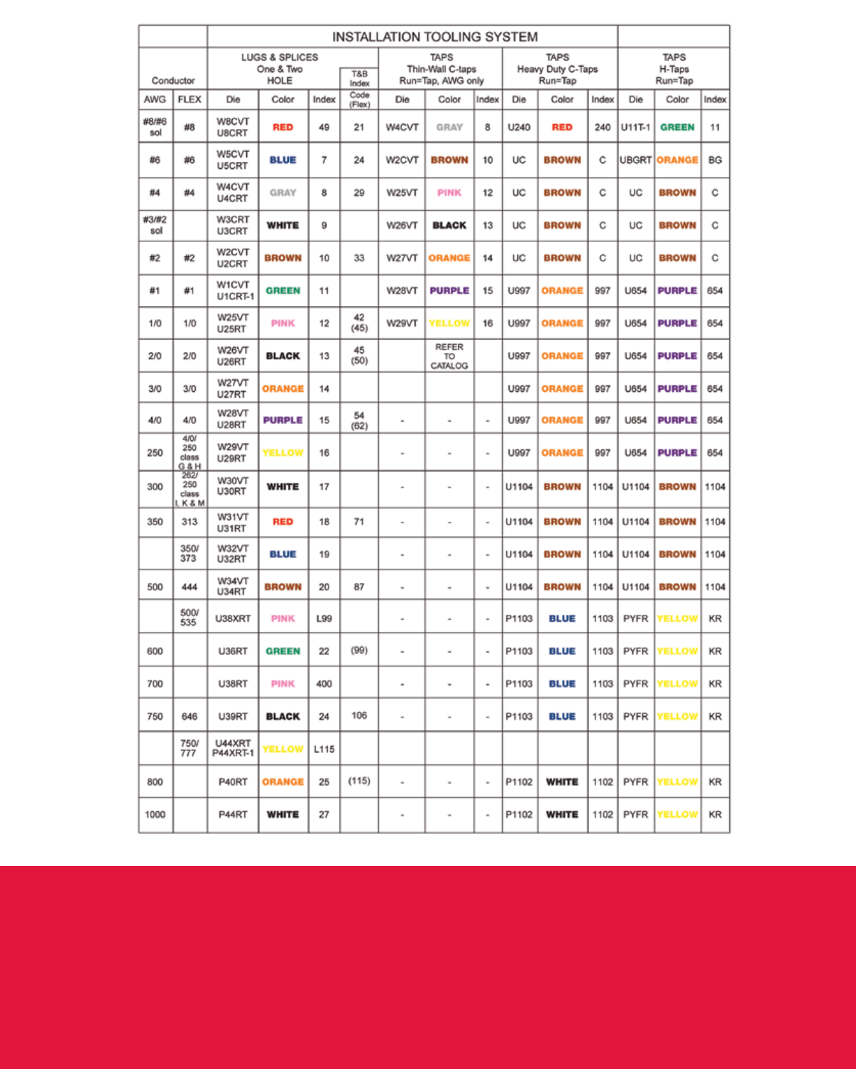

www.burndy.com | 1-800-346-4175
Customer Service Department
7 Aviation Park Drive
Londonderry, NH 03053
1-800-346-4175
1-800-451-4956 (Technical Services)
1-603-647-5299 (International)
Canada
1-800-361-6975 (Quebec)
1-800-387-6487 (All other provinces)
Mexico
011-52-722-265-4400
Brazil
011-55-11-5515-7225
Tool Service Center
Littleton Industrial Park
Littleton, NH 03561
1-800-426-8720
© BURNDY LLC, 2013
Dies and
connectors
Tools Safe, easy and
inspectable connection
+=
Trust the BURNDY® Engineered System
The BURNDY® Engineered System of coordinating dies, connectors and tools are always
designed to work together and engineered to meet stringent, accepted quality standards.
Item # 591717
