17403 89551 Catalog
140649-Catalog 140649-Catalog 140649-Catalog B2 unilog cesco-content
2016-07-04
: Pdf 89551-Catalog 89551-Catalog B1 unilog
Open the PDF directly: View PDF ![]() .
.
Page Count: 22
- Table of Contents
- Safety Switches
- General Duty Safety Switches
- Heavy Duty Safety Switches
- Heavy Duty Safety Switches-Special
- Double Throw Safety Switches-Fusible and Non-Fusible
3-1
© 2007 Schneider Electric
All Rights Reserved
3SAFETY SWITCHES
Table of Contents
Section 3
Safety Switches
General Duty, p. 3-2
Light Duty, p. 3-2
Heavy Duty, p. 3-4
Double Throw, p. 3-14
General Duty
Fusible & Non-Fusible 3-2
Application Data and Dimensions 3-3
Standards:
•UL 98 Enclosed and Dead Front Switches.
UL Listed under File E2875.
•NEMA Standards Publication KS1. Enclosed Switches.
Light Duty
Fusible 3-2
Application Data and Dimensions 3-3
Standards:
•UL 98 Enclosed and Dead Front Switches.
UL Listed under File E2875.
•NEMA Standards Publication KS1. Enclosed Switches.
Heavy Duty
Fusible 3-4
Non-Fusible 3-6
Special Application Enclosures 3-7
Accessories 3-9
Application Data and Dimensions 3-12
Standards:
•UL 98 Enclosed and Dead Front Switches.
UL Listed under File E2875 and E154828.
•NEMA Standards Publication KS1. Enclosed Switches.
Double Throw
Fusible and Non-Fusible 3-14
Application Data 3-17
Dimensions 3-18
Accessories 3-20
Standards:
•UL 98 Enclosed and Dead Front Switches.
UL Listed under File E2875 (unless otherwise noted).
•NEMA Standards Publication KS1 Enclosed Switches (applies to Type DT and
DTU series F only).
New!
3-2 © 2007 Schneider Electric
All Rights Reserved
www.schneider-electric.us
3SAFETY SWITCHES
General Duty Safety
Switches
Light Duty
Class 3130
General Duty—Up To 100 kA Short Circuit Current Rating With Proper Current Limiting Fusing
General duty safety switches are designed for residential and commercial applications where economy is a prime
consideration. Typical loads are lighting, air conditioning, and appliances. They are suitable for use as service
equipment when equipped with a factory-installed neutral assembly or a field-installed service grounding kit.
General duty safety switches are UL Listed, File E2875, and meet or exceed the NEMA Standard KS1.
400 and 600 A general duty switches (NEMA 1 only) will accept Class J fuses and are UL Listed for use on systems with up
to 100 kA available fault current. 600 A requires Class J fuse kit—GDJK600 (page 3-3). 400 A requires moving load base.
Class T 400–800 A general duty safety switches use 300 Vac Class T fuses and are UL Listed for use on systems with
up to 100 kA available fault current.
aBolt-on hubs—Refer to page 3-9.
bWhen installed, this kit rejects all but Class R fuses. When installed with this kit and Class R fuses, the switch is UL Listed for use on systems with up to
100 kA available fault current.
cFor corner grounded delta systems only. Use switching poles for ungrounded conductors.
dIf corner grounded delta, use outer switching poles for ungrounded conductors.
eFor 200% neutral, order (1) additional neutral kit SN20A at $133. and (1) neutral jumper kit SN20NI at $18.40.
fBolt-on hubs—Refer to page 3-9.
gEnclosed molded case switch—Refer to 1-22.
hIncludes factory-installed grounding kit.
iNot service entrance rated—Refer to page 1-19 for more information.
jIncludes factory-installed neutral.For service equipment use or when neutral is required, order part number SN0610 at $71.00.
kSuitable for use as service equipment, requires field installation of neutral assembly SN20A at $133.00.
lIf corner grounded delta, install neutral and use outer switching poles for ungrounded conductors.
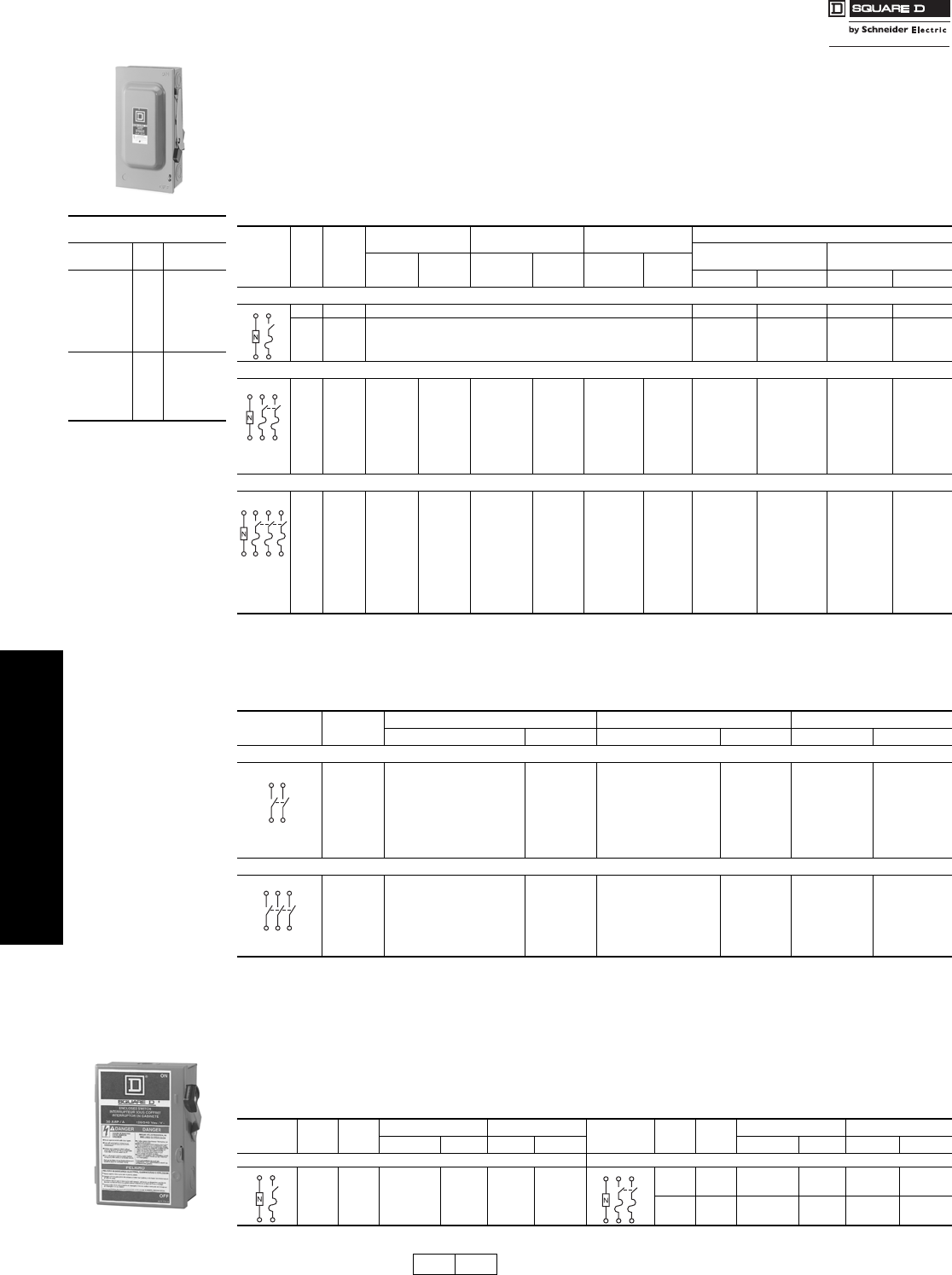
Light Duty—Visible Blades 10 kA Short Circuit Current Rating
The Square D light duty enclosed switch is ideal for home applications in disconnecting power to workshops, hobby
rooms, furnaces and garages.
mFor single phase hp rating, use two switching poles.
nDE1A Discount Schedule.
UL Listed Short Circuit
Withstand Rating
Switch
Type
Fuse
Class
Short Circuit
Rating
Fusible
Plug 10 kA
H10 kA
K10 kA
J100 kA
R100 kA
T100 kA
Non-Fusiblea
H10 kA
K10 kA
J100 kA
R100 kAb
T100 kA
aThe UL Listed short-circuit
current rating for Square D
general duty, not fusible
switches is based on the
switch being used in
conjunction with fuses.
Evaluation of non-fusible
switches in conjunction
with molded case circuit
breakers has not been
performed. If a UL Listed
short-circuit current rating
is required, this non-fusible
switch must be replaced
with a Square D general
duty fusible safety switch
equipped with the
appropriate class and size
fusing. The UL Listed
short-circuit current rating
of the fusible switch is
typically as follows: when
used with Class H & K
fuses—10,000 A, Class R
and J fuses—100,000 A.
Consult the wiring diagram
of the switch to verify the
UL Listed short-circuit
current rating.
b50 kA for 60 A non-fusible
switch.
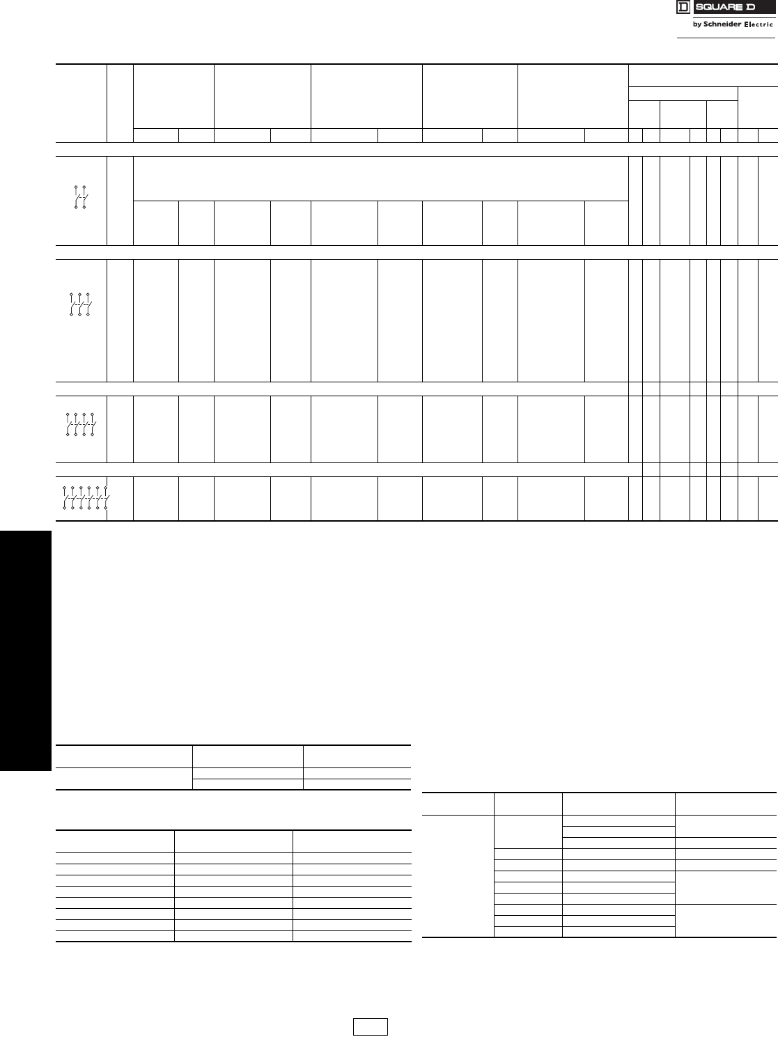
Table 3.1: Fusible
System A Fuse
NEMA 1
Indoor
NEMA 3Ra
Rainproof
Class R Fuse Kits
Field-Installableb
Horsepower Ratings
Std. (Fast Acting
One-Time Fuses)
Max. (Dual Element
Time-Delay Fuses)
Cat. No. $ Price Cat. No. $ Price Cat. No. $ Price 1Ø 3Ø 1Ø 3Ø
2 Wire (1 Blade and Fuseholder, 1 Neutral)—120 Vac
30 Plug Use Light Duty Device for This Application (see below) — — — —
30 Cart. Use 3 Wire Devices for this application. — — — —
3 Wire (2 Blades and Fuseholders, 1 Neutral)—120/240 Vac (Plug), 240 Vac (Cart.) Maximum
30 Plug D211N 60.00 D211NRB 118.00 — — 1-1/2 — 3 —
30 Cart. D221N 81.00 D221NRB 125.00 DRK30 17.10 1-1/2 3 c37-1/2c
60 Cart. D222N 137.00 D222NRB 217.00 RFK03H 17.00 37-1/2c10 15c
100 Cart. D223N 284.00 D223NRB 320.00 RFK10 31.80 7-1/2 15 c15 30c
200 Cart. D224Ne589.00 D224NRBe800.00 HRK1020 31.80 15 25c—60c
400 Cart. D225N 1703.00 D225NR 2306.00 DRK40 74.00 ————
600 Cart. D226N 3406.00 D226NR 4379.00 DRK600 74.00 ————
4 Wire (3 Blades and Fuseholders, 1 Neutral)—240 Vac Maximum
30 Cart. D321N 125.00 D321NRB 195.00 DRK30 17.10 1-1/2 3 3 7-1/2
60 Cart. D322N 217.00 D322NRB 294.00 RFK03H 17.00 37-1/2d10 15d
100 Cart. D323N 376.00 D323NRB 544.00 RFK10 31.80 7-1/2 15d15 30d
200 Cart. D324Ne801.00 D324NRBe974.00 HRK1020 31.80 15 25d—60d
400 Cart. D325N 2075.00 D325NR 2595.00 DRK40 74.00 — 50 — 125
400 Class T D325NT 1996.00 D325NTR 2494.00 —— — 50 — —
600 Cart. D326N 3882.00 D326NR 5251.00 DRK600 74.00 — 75 — 150
600 Class T D326NT 3732.00 D326NTR 5046.00 —— — 75 — —
800 Class T T327N 6481.00 T327NR 8292.00 — — — 100 — —
Table 3.2: Non-Fusible
System A NEMA 1 Indoor NEMA 3R Rainproof fHorsepower Ratings (Max.)
Cat. No. $ Price Cat. No. $ Price 1Ø 3Ø
2 Wire (2 Blades)—240 Vac Maximum
30 — — DU221RBk118.00 3—
60 — — DU222RBk235.00 10 —
60 QO260NATSgh 107.00 QO200TR ghi 107.00 10 —
100 QO2000NSgh 184.00 QO2000NRBgi 225.00 20 —
200 Use 3P Switch — Use 3P Switch — — —
400 Use 3P Switch — Use 3P Switch — — —
600 Use 3P Switch — Use 3P Switch — — —
3 Wire (3 Blades)—240 Vac Maximum
30 DU321k103.00 DU321RBk195.00 37-1/2
60 DU322k137.00 DU322RBk295.00 10 15
100 DU323j318.00 DU323RBj544.00 15 30
200 DU324k589.00 DU324RBk974.00 15 60l
400 DU325k1465.00 ———125
600 DU326l2794.00 ———150
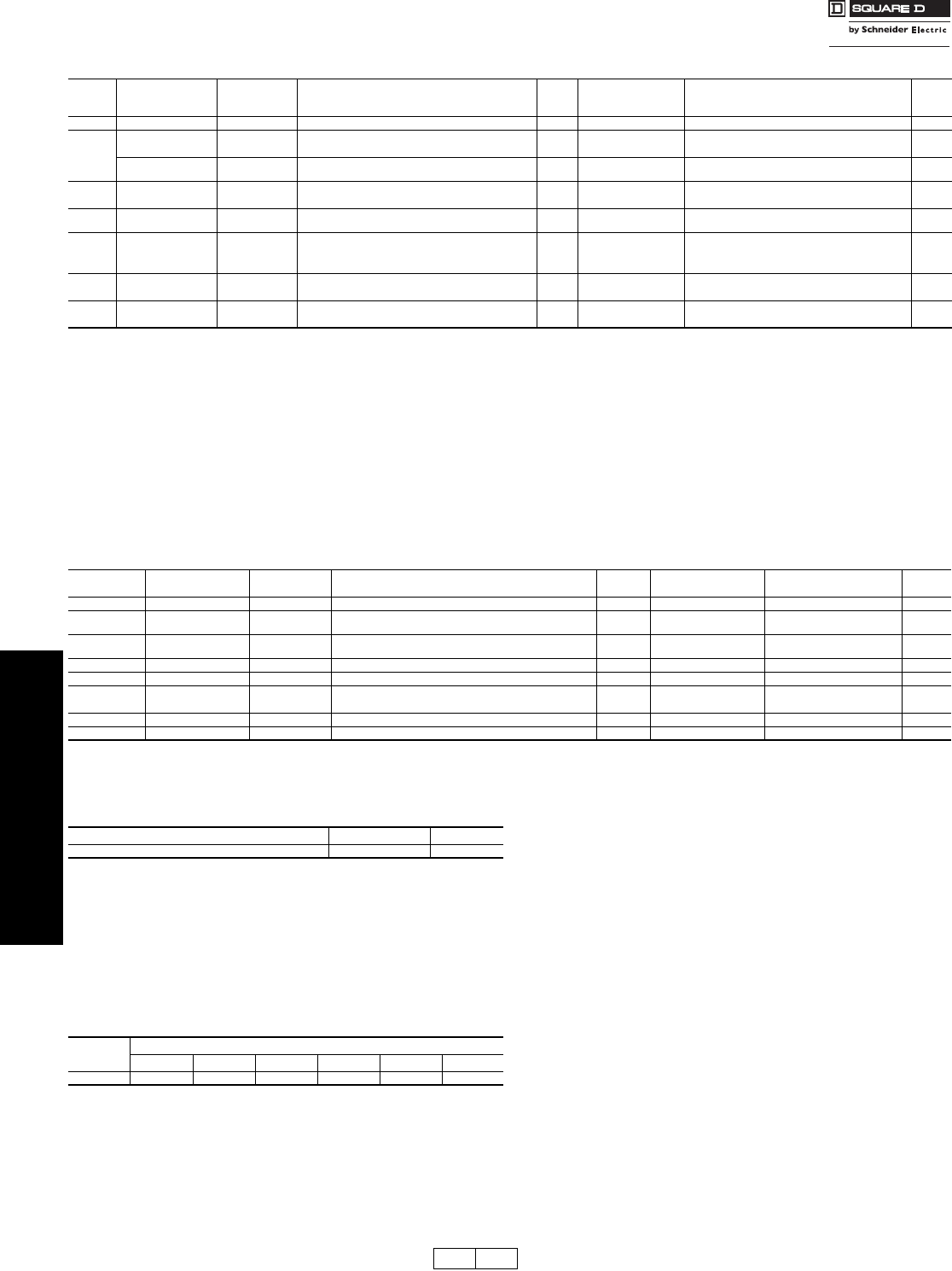
Table 3.3: Fusible
System Rating
(A) Fuse NEMA 1 Indoor Horsepower Ratings System A Fuse NEMA 1 Indoor Horsepower Ratings
Cat. No. n$ Price Std. Max. Cat. No. n$ Price Std. Max.
2 Wire (1 Blade and Fuseholder, 1 Neutral)—120 Vac 3 Wire (2 Blades and Fuseholders, 1 Neutral)—120/240 Vac
30 Plug L111N $35.90 1/2 2
30 Plug L211N 47.80 1-1/2 m3 m
30 Cart. L221N 65.00 1-1/2 m3 m
L211N
DE1A DE2A Discount
Schedule Modified
4/16/09

www.schneider-electric.us
3SAFETY SWITCHES
© 2007 Schneider Electric
All Rights Reserved 3-3
General Duty Safety Switches Accessories, Lug Data and Dimension
Class 3130
Field-Installable Electrical Interlock Kits
Electrical interlocks for Series F 100–200 A general duty safety switches
and Series F 60 A fusible general duty safety switches are available in
kit form for field installation. Each kit contains instructions for proper field
mounting. A pivot arm operates from switch mechanism, breaking the
control circuit before the main switch blades break. Switches with
electrical interlocks installed are UL Listed.
aElectrical interlock kit catalog numbers with -1 suffix indicates one normally open and one
normally closed contact; -2 indicates two normally open and two normally closed contacts.
Kits are UL Listed.
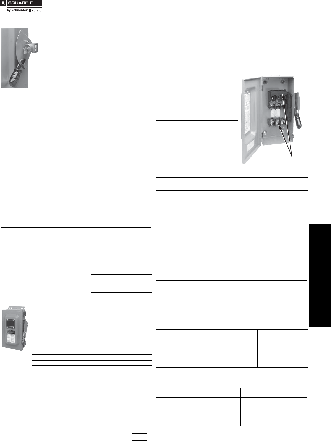
Field-Installable Fuse Puller Kits
Kit consists of three fuse pullers as required for a 3P, fusible, 60 and 100
A general duty switch. Kits can be installed in 60 and 100 A Series F
switches.
b30–100 A switches suitable for 60oC or 75oC conductors. 200–800 A switches suitable for
75oC conductors.
c30–100 A switches suitable for 60oC or 75oC conductors. 200–800 A switches suitable for 75oC conductors.
Table 3.4: Electrical Interlock Kit
Switch Rating
(A)
Electrical Interlock Kit
Cat. No.a$ Price
Fusible Series F 60 EIK031 or
EIK032 145.00
Series F 100–200 EIK1 or
EIK2 207.00
Table 3.5: Field-Installable Class J Fuse Kit
The kit consists of three Class J fuse adapters as
required for a 3P, fusible 600 A general duty switch.
Kit can be installed in 600 A series E3 switches only
(NEMA 1).
Switch Rating
(A)
Class J Kit
Cat. No. $ Price
600 A Series E3 GDJK600 195.00
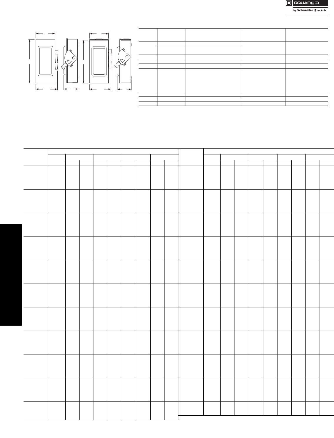
H
D
W/H
W
Description Cat. No. $ Price
Series F 60 A Fuse Puller Kit FPK03 20.00
Series F 100 A Fuse Puller Kit FPK0610 28.40
Table 3.6: Field-Installable Service Grounding Kits
Switch Rating (A) Cat. No. $ Price Wire Size (AWG)
30 PK3GTA1 7.60
(2) 12 Cu or
(2) 10 Al or
(1) 4 Al/Cu Max.
Series E 60 PK3GTA1 7.60
(2) 12 Cu or
(2) 10 Al or
(1) 4 Al/Cu Max.
Series F 60 GTK03 7.60
(2) 12 Cu or
(2) 10 Al or
(1) 4 Al/Cu Max.
100 GTK0610 12.60 (2) 1/0 Al/Cu Max.
200 PKOGTA2 36.80 (2) 2/0 Al/Cu Max.
400 PKOGTA2 36.80 (2) 2/0 Al/Cu Max.
600 (Two Required) Per Lug
800 PKOGTA3 82.00 (6) 3/0 Al/Cu Max.
Table 3.7: Terminal Lug Data b
Rating
(A)
Conductors
Per Phase
Wire Range
Wire Bending Space Per NEC Table 312.6
AWG/kcmil
Lug Wire Range
AWG/kcmil
30 1 12–6 (Al) or 14–6 (Cu) 12–6 (Al) or 14–6 (Cu)
60 1 10–3 (Al) or 14–3 (Cu) 10–2 (Al) or 14–2 (Cu)
100 1 12–1 (Al) or 14–1 (Cu) 12–1/0 (Al) or 14–1/0 (Cu)
200 1 6 –250 (Al/Cu) 6 –300 (Al/Cu)
400
NEMA 1
1
or
2
1/0 –600 (Al/Cu)
or
1/0 –300 (Al/Cu)
(1) 1/0 –750 (Al/Cu)
or
(2) 1/0 –300 (Al/Cu)
400
NEMA 3R 2 1/0–250 (Al/Cu)
(1) 1 –600 (Al/Cu)
or
(2) 1/0 –250 (Al/Cu)
600 2 4 –500 (Al/Cu) 4 –600 (Al/Cu)
800 3 3/0 –500 (Al/Cu) 3/0 –500 (Al/Cu)
Table 3.8: Field-Installable Lug Kit
Kit consists of three line, three load, and two neutral lugs as required for a
3P 400 A or 600 A general duty switch. Kit can be installed on 400 or 600 A
Series E3 switches. This kit applicable to NEMA 1 enclosures only.
Switch Rating
(A)
Lug Kit
Cat. No.
Wire Range/NEC 312.6
AWG/kcmil
Lug Wire Range per Lug
AWG/kcmil $ Price
400 or 600 A
Series E3 GD4060LK
(1) 1/0–600 or
(2) 1/0–500 or
(4) 1/0–250
(2) 1/0–600 or
(4) 1/0–250 269.00
Table 3.9: Approximate Dimensions
Cat. No. Series HWW/HD
Std.
Pack Cat. No. Series HWW/HD
Std.
Pack
in. mm in. mm in. mm in. mm in. mm in. mm in. mm in. mm
L111N E2 7.63 194 5.00 127 6.13 156 4.00 102 1 D325NTRcE1 30.63 778 21.38 543 22.25 565 10.13 257 1
L211N E2 7.63 194 5.00 127 6.13 156 4.00 102 1 D326NcE3 49.13 1248 24.00 610 24.88 632 8.88 226 1
L221N E2 7.63 194 5.00 127 6.13 156 4.00 102 1 D326NTcE3 49.13 1248 24.00 610 24.88 632 8.88 226 1
D211NcE3 9.25 235 6.75 171 7.25 184 3.63 92 5 D326NRcE1 49.13 1248 24.75 629 25.13 638 8.88 226 1
D211NRBcE2 9.63 245 7.25 184 7.75 197 3.75 95 5 D326NTRcE1 49.13 1246 24.75 629 25.13 638 8.88 226 1
D221NcE3 9.25 235 6.75 171 7.25 184 3.63 92 5 DU221RBcE2 9.63 245 7.25 184 7.75 197 3.75 95 5
D221NRBcE3 9.63 245 7.25 184 7.75 197 3.75 95 5 DU222RBcE1 9.63 245 7.25 184 7.75 197 3.75 95 5
D222N F1 14.63 372 6.50 165 7.45 189 4.88 124 1 DU321cE2 9.25 235 6.75 171 7.25 184 3.63 92 5
D222NRB F1 14.88 378 6.63 168 7.45 189 4.88 124 1 DU321RBcE2 9.63 245 7.25 184 7.75 197 3.75 95 5
D223N F3 17.50 445 8.50 216 10.50 267 6.50 165 1 DU322cE1 9.25 235 6.75 171 7.25 184 3.63 92 5
D223NRB F3 17.50 445 8.50 216 10.50 267 6.50 165 1 DU322RBcE1 9.63 245 7.25 184 7.75 197 3.75 95 5
D224N F1 29.00 737 17.25 438 19.00 483 8.25 210 1 DU323 F3 17.50 445 8.50 216 10.50 267 6.50 165 1
D224NRB F1 29.25 743 17.25 438 19.00 483 8.25 210 1 DU323RB F3 17.50 445 8.50 216 10.50 267 6.50 165 1
D225N E3 45.12 1146 24.00 610 24.88 632 8.88 226 1 DU324 F1 29.00 737 17.25 438 19.00 483 8.25 210 1
D225NR E1 30.63 778 21.38 543 22.25 565 10.13 257 1 DU324RB F1 29.25 743 17.25 438 19.00 483 8.25 210 1
D226NcE3 49.13 1248 24.00 610 24.88 632 8.88 226 1 DU325cE3 45.12 1146 24.00 610 24.88 632 8.88 226 1
D226NRcE1 49.13 1248 24.75 629 25.13 638 8.88 226 1 DU326cE3 49.13 1248 24.00 610 24.88 632 8.88 226 1
D321NcE3 9.25 235 6.75 171 7.25 184 3.63 92 5 QO200TRcG3 6.50 165 4.63 118 — — 3.88 99 5
D321NRBcE3 9.63 245 7.25 184 7.75 197 3.75 95 5 QO260NATScE2 9.25 235 4.88 124 — — 3.25 83 1
D322N F1 14.63 372 6.50 165 7.45 189 4.88 124 1 QO2000NRBcE1 14.00 356 7.75 197 — — 4.50 114 1
D322NRB F1 14.88 378 6.63 168 7.45 189 4.88 124 1 QO2000NScE1 13.38 340 6.13 156 — — 3.50 89 1
D323N F3 17.50 445 8.50 216 10.50 267 6.50 165 1 T327NcE1 49.13 1248 24.00 610 24.88 632 8.88 226 1
D323NRB F3 17.50 445 8.50 216 10.50 267 6.50 165 1 T327NRcE1 49.13 1248 24.75 629 25.13 638 8.88 226 1
D324N F1 29.00 737 17.25 438 19.00 483 8.25 210 1 D325NTRcE1 30.63 778 21.38 543 22.25 565 10.13 257 1
D324NRB F1 29.25 743 17.25 438 19.00 483 8.25 210 1 D326NcE3 49.13 1248 24.00 610 24.88 632 8.88 226 1
D325NcE3 45.12 1146 24.00 610 24.88 632 8.88 226 1 D326NTcE3 49.13 1248 24.00 610 24.88 632 8.88 226 1
D325NTcE3 45.12 1146 24.00 610 24.88 632 8.88 226 1 D326NRcE1 49.13 1248 24.75 629 25.13 638 8.88 226 1
D325NRcE1 30.63 778 21.38 543 22.25 565 10.13 257 1
DE1 DE3A Discount
Schedule
www.schneider-electric.us
3SAFETY SWITCHES
3-4 © 2007 Schneider Electric
All Rights Reserved
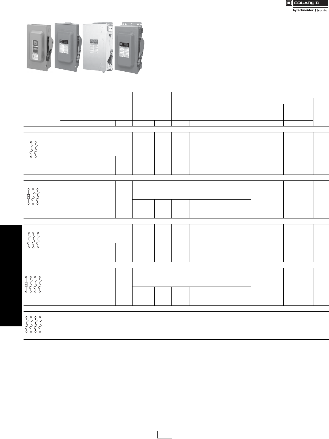
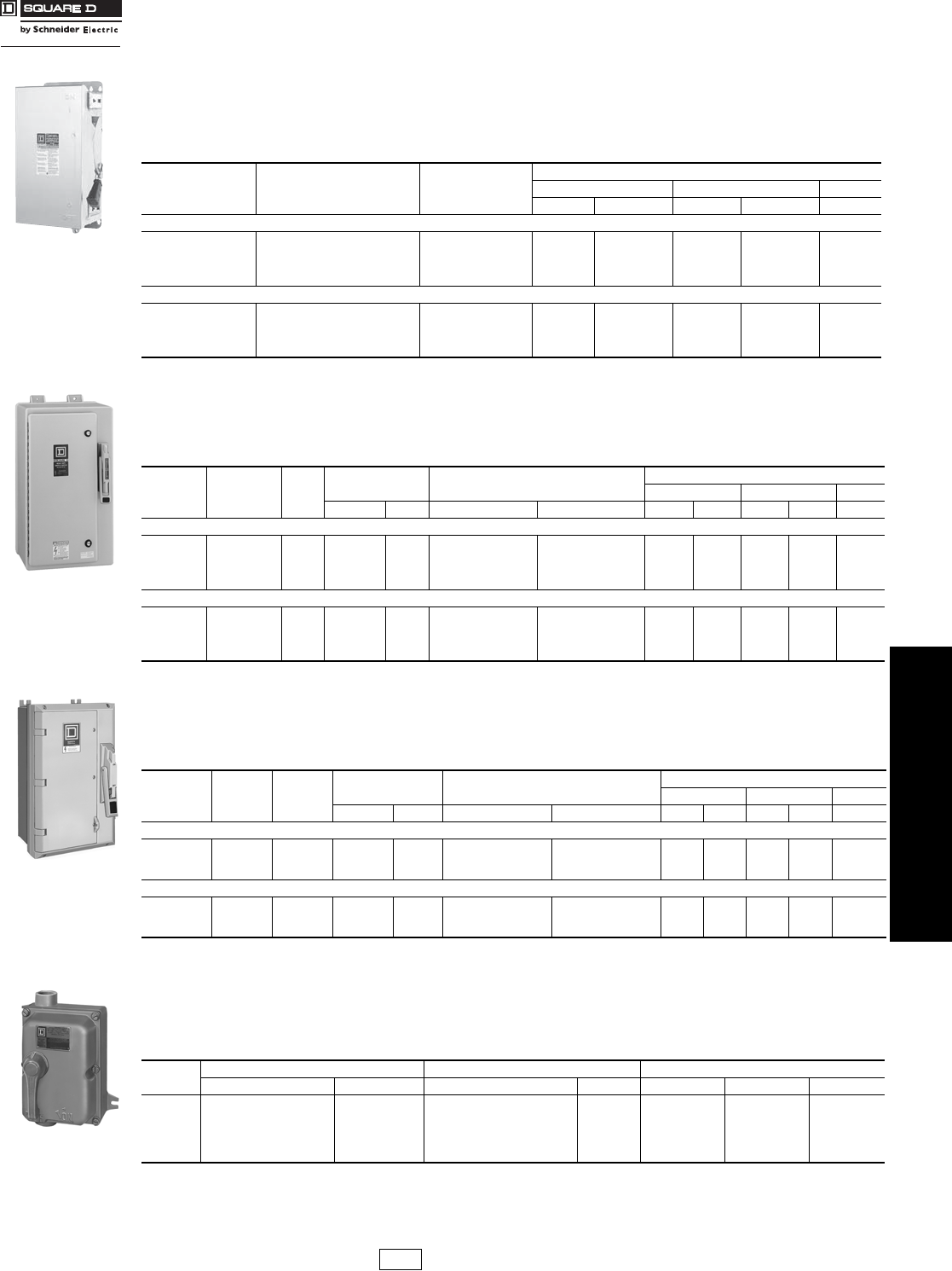
Heavy Duty Safety Switches 240 Volt
Class 3110
Visible blade heavy duty safety switches are designed for application where maximum
performance and continuity of service are required. All heavy duty safety switches
feature quick-make, quick-break operating mechanism, a dual cover interlock and a
color coded indicator handle. They are suitable for use as service equipment when
equipped with a field- or factory-installed neutral assembly or equipment grounding kit,
unless a 600Y/347 V or 480 Y/277 V, 1000 A or greater, solidly grounded WYE system
is used, per NEC 215-10. Heavy duty safety switches are UL Listed (except as noted),
File E2875 & 154828 and meet or exceed the NEMA Standard KS1. For UL Listed short
circuit current ratings, see page 3-6.
Dimensions: NEMA 1 and 3R . . . . . . . . . . . . . . . . . . . . . . . . . . . . . page 3-12
Dimensions: NEMA 4, 4X and 5 Stainless and NEMA 12 . . . . . . . page 3-13
Accessories: . . . . . . . . . . . . . . . . . . . . . . . . . . . . . . . . pages 3-9 through 3-11
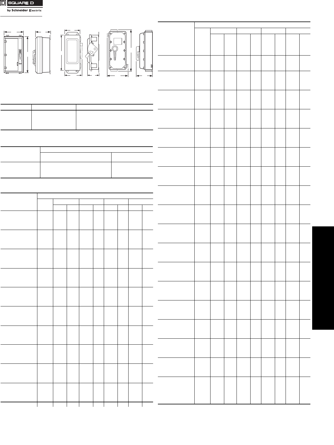
NEMA 1 NEMA 3R NEMA 4, 4X and 5
Stainless Steel
NEMA 12
Table 3.10: 240 Volt—Single Throw Fusible
System Amperes
NEMA 1
Indoor
NEMA 3R
Rainproof
(Bolt-on Hubs,
page 3-9)
NEMA 4, 4X, 5, a
304 Stainless Steel (for
316 stainless, see
page 3-7) Dust tight,
Watertight, Corrosion
Resistant (Watertight
Hubs, page 3-9)
NEMA 12K
With
Knockouts
(Watertight Hubs,
page 3-9)
NEMA
12, 3R b
Without
Knockouts
(Watertight Hubs,
page 3-9)
Horsepower Ratings c
240 Vac
250 Vdcd
Std.
(Using Fast
Acting,
One Time Fuses)
Max.
(Using Dual
Element, Time
Delay Fuses)
Cat. No. $ Price Cat. No. $ Price Cat. No. $ Price Cat. No. $ Price Cat. No. $ Price 1Ø 3Ø 1Ø 3Ø
2 Wire (2 Blades and Fuseholders)—240 Vac, 250 Vdc
30
Use 3 Wire Devices
For 2 Wire Applications
H221DS 1298.00 H221A 336.00 H221AWK 315.00 1-1/2 3 e37-1/2e5
30 ————H2212AWKf392.00 1-1/2 —3—5
60 H222DS 1558.00 — — H222AWK 431.00 37-1/2e10 15 e10
100 H223DS 3396.00 H223A 672.00 H223AWK 632.00 7-1/2 15 e15 30 e20
200 H224DS 4640.00 H224A 1158.00 H224AWK 1095.00 15 25 e—60 e40
400 H225 1819.00 H225R 2589.00 H225DS 9654.00 — — H225AWK 2775.00 — — — — 50
600 H226 3616.00 H226R 4854.00 H226DS 13848.00 — — H226AWK 4362.00 — 75 e—200 e50
800 H227 5639.00 H227Rg7655.00 — — — — H227AWK 6883.00 50 —50 —50
1200 H228 7788.00 H228Rg10324.00 — — — — H228AWK 10543.00 50 —50 —50
3 Wire (2 Blades and Fuseholders, 1 Neutral)—240 Vac, 250 Vdc
30 H221N 157.00 H221NRB 298.00
Use 2 Wire Devices,
Field-Installable Solid Neutral Assemblies
Order Separately See page 3-10.
1-1/2 3 e37-1/2 e5
60 H222N 314.00 H222NRB 561.00 37-1/2e10 15 e10
100 H223N 477.00 H223NRB 724.00 7-1/2 15 e15 30 e20
200 H224N 859.00 H224NRB 1041.00 15 25 e—60 e40
400 H225N 2061.00 H225NR 2830.00 H225NDS 9858.00 — — H225NAWK 2869.00 — 50 e—125 e50
600 H226N 3879.00 H226NR 5118.00 H226NDS 14054.00 — — H226NAWK 4624.00 — 75 e—200 e50
800 H227N 6711.00 H227NRg8144.00 — — — — H227NAWK 8225.00 50 —50 —50
1200 H228N 8281.00 H228NRg11110.00 — — — — H228NAWK 11456.00 50 —50 —50
3 Wire (3 Blades and Fuseholders)—240 Vac, 250 Vdc
30
Use 4 Wire Devices
For 3 Wire Applications
H321DS 1366.00 H321A 426.00 H321AWK 403.00 1-1/2 3 3 7-1/2 5
60 H322DS 1688.00 H322A 609.00 H322AWK 576.00 3 7-1/2 10 15 10
100 H323DS 3564.00 H323A 941.00 H323AWK 887.00 7-1/2 15 15 30 20
200 H324DS 4997.00 H324A 1360.00 H324AWK 1284.00 15 25 —60 40
400 H325 2283.00 H325R 2650.00 H325DS 9974.00 — — H325AWK 2835.00 — 50 —125 50
600 H326 4113.00 H326R 5524.00 H326DS 14266.00 — — H326AWK 4910.00 — 75 —200 50
800 H327 7637.00 H327Rg9899.00 — — — — H327AWK 9685.00 50 100 50 250 50
1200 H328 9678.00 H328Rg12485.00 — — — — H328AWK 11633.00 50 100 50 250 50
4 Wire (3 Blades and Fuseholders, 1 Neutral)—240 Vac, 250 Vdc
30 H321N 209.00 H321NRB 370.00
Use 3 Wire Devices,
Field-Installable Solid Neutral Assemblies
Order Separately. See page 3-10
1-1/2 3 3 7-1/2 5
60 H322N 352.00 H322NRB 594.00 3 7-1/2 10 15 10
100 H323N 561.00 H323NRB 852.00 7-1/2 15 15 30 20
200 H324N 967.00 H324NRB 1165.00 15 25 —60 40
400 H325N 2525.00 H325NR 2881.00 H325NDS 10214.00 — — H325NAWK 3090.00 — 50 —125 50
600 H326N 4346.00 H326NR 5748.00 H326NDS 14506.00 — — H326NAWK 5171.00 — 75 —200 50
800 H327N 8126.00 H327NRg10375.00 — — — — H327NAWK 10586.00 50 100 50 250 50
1200 H328N 10209.00 H328NRg13139.00 — — — — H328NAWK 13343.00 50 100 50 250 50
4 Wire (4 Blades and Fuseholders)
30
Use 600 Vac Devices. See page 3-5.
60
100
200
400
600
aComplete rating is NEMA 3, 3R, 4, 4X, 5 and 12. For NEMA 3R applications, remove drain screw from bottom endwall.
bAlso suitable for NEMA 3R application by removing drain screw from bottom endwall.
cRefer to page 7-31 for additional motor application data. The starting current of motors of more than standard horsepower may require the use of fuses with appropriate time delay
characteristics.
dFor switching dc, use two switching poles.
eFor corner grounded delta systems only and with neutral assembly installed. Use switching poles for ungrounded conductors.
f60 ampere switch with 30 ampere fuse spacing and clips. Must use 60 A enclosure accessories including electrical interlocks.
gSuitable for NEMA 5 applications with drain screw installed.
DE1 Discount
Schedule
www.schneider-electric.us
3SAFETY SWITCHES
© 2007 Schneider Electric
All Rights Reserved 3-5
Heavy Duty Safety
Switches
600 Volt
Class 3110
Class H Fuse Provisions:
Fusible Square D 30 through 600 A heavy duty safety switches accept Class H fuses as standard. With Class H fuses
installed, the switch is UL Listed for use on systems with up to 10 kA available fault current.
Class R Fuse Provisions:
Fusible Square D 30–600 A heavy duty safety switches will accept Class R fuses as standard. A field-installable rejection kit is available which,
when installed, rejects all but Class R fuses. With the installation of the rejection kit and Class R fuses, the switch is UL Listed for use on systems
with up to 200 kA available fault current. See Class R fuse kits on page 3-9.
Class J Fuse Provisions:
Provisions for installing Class J fuses are included in 30 through 400 A 600 Volt, and 100 through 400 A 240 Volt,
fusible heavy duty safety switches. Conversion to Class J fuse spacing requires relocating the load side fuse base
assembly from the standard Class H fuse location to an alternate position as marked in the enclosure. With Class J
fuses installed, the switch is UL Listed for use on systems with up to 200 kA available fault current. Switches rated
600 A, 240 or 600 Volt, require the addition of an adapter kit, H600J at $304. One kit per 3P switch.
Class L Fuse Provisions:
Fusible 800 A and 1200 A safety switches use Class L bolt-in fuses and are rated for use on systems with up to 200 kA
at 600 Vac maximum. 1200 A switches accept class L fuses from 601–1200 A, 800 A switches accept class L fuses
from 601–800 A.
Dimensions: NEMA 1 and 3R . . . . . . . . . . . . . . . . . . . . . . . . . . . . .page 3-12
Dimensions: NEMA 4, 4X and 5 . . . . . . . . . . . . . . . . . . . . . . . . . . .page 3-13
Accessories: . . . . . . . . . . . . . . . . . . . . . . . . . . . . . . . .pages 3-9 through 3-11
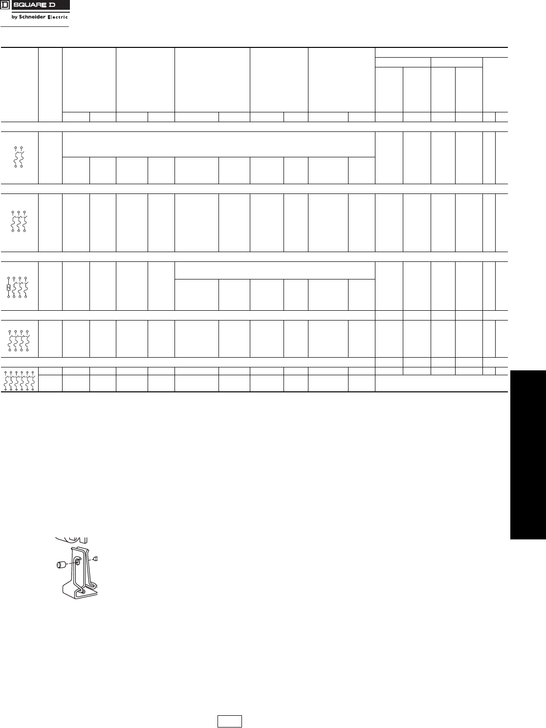
Table 3.11: 600 Volts—Single Throw Fusible
System Amperes
NEMA 1
Indoor
NEMA 3R
Rainproof
(Bolt-on Hubs,
page 3-9)
NEMA 4, 4X, 5a
304 Stainless Steel
(for 316 stainless, see
page 3-7) Dust tight,
Watertight, Corrosion
Resistant
(Watertight Hubs, page 3-9)
NEMA 12K
With Knockouts
(Watertight Hubs,
page 3-9)
NEMA 12, 3Rb
Without Knockouts
(Watertight Hubs,
page 3-9)
Horsepower Ratingsc
480 Vac 600 Vac
dce
Std.
(Using
Fast
Acting,
One Time
Fuses)
Max.
(Using
Dual
Element,
Time
Delay
Fuses)
Std.
(Using
Fast
Acting,
One
Time
Fuses)
Max.
(Using
Dual
Element,
Time
Delay
Fuses)
Cat. No. $ Price Cat. No. $ Price Cat. No. $ Price Cat. No. $ Price Cat. No. $ Price 3Ø 3Ø 3Ø 3Ø 250 600
2 Wire (2 Blades and Fuseholders)—600 Vac, 600 Vdc
30
Use 3 Wire Devices
For 2 Wire Applications
— —————
60 — —————
100 — —————
200 — —————
400 H265 2804.00 H265R 3616.00 H265DS 9974.00 — — H265AWK 3350.00 100d250 d——50 50
600 H266 4435.00 H266R 7124.00 H266DS 14266.00 — — H266AWK 4894.00 150d400 d——50 50
800 H267 6910.00 H267Rg10923.00 — — — — H267AWK 10184.00 — — — — 50 50
1200 H268 9713.00 H268Rg11994.00 — — — — H268AWK 12029.00 — — — — 50 50
3 Wire (3 Blades and Fuseholders)—600 Vac, 600 Vdc e
30 H361 352.00 H361RB 599.00 H361DS 1680.00 H361A 676.00 H361AWK 637.00 5157-1/220515
30 H3612f411.00 H3612RBf699.00 — — H3612A f690.00 H3612AWKf651.00 5157-1/220—15
60 H362 425.00 H362RB 703.00 H362DS 1847.00 H362A 698.00 H362AWK 656.00 15 30 15 50 —30
100 H363 792.00 H363RB 1096.00 H363DS 3662.00 H363A 1084.00 H363AWK 1026.00 25 60 30 75 —50
200 H364 1138.00 H364RB 1506.00 H364DS 5123.00 H364A 1696.00 H364AWK 1600.00 50 125 60 150 40 50
400 H365 3034.00 H365R 3688.00 H365DS 10214.00 — — H365AWK 3641.00 100 250 125 350 50 50
600 H366 5099.00 H366R 7266.00 H366DS 14056.00 — — H366AWK 6135.00 150 400 200 500 50 50
800 H367 8879.00 H367R g11000.00 — — — — H367AWK 10901.00 200 500 250 500 50 50
1200 H368 11671.00 H368Rg13339.00 — — — — H368AWK 13137.00 200 500 250 500 50 50
4 Wire (3 Blades and Fuseholders, 1 Neutral)—600 Vac, 600 Vdce
30 H361N 411.00 H361NRB 657.00 Use 3 Wire Devices Field-Installable Solid Neutral
Assemblies. Order Separately. See page 3-10
5157-1/220—15
60 H362N 473.0 H362NRB 756.00 15 30 15 50 —30
100 H363N 852.00 H363NRB 1158.00 25 60 30 75 —50
200 H364N 1246.00 H364NRB 1605.00 H364NDS 5247.00 H364NA 1810.00 H364NAWK 1705.00 50 125 60 150 40 50
400 H365N 3265.00 H365NR 3843.00 H365NDS 10445.00 — — H365NAWK 3882.00 100 250 125 350 50 50
600 H366N 5346.00 H366NR 7369.00 H366NDS 14748.00 — — H366NAWK 6400.00 150 400 200 500 50 50
800 H367N 9362.00 H367NRg11470.00 — — — — H367NAWK 11502.00 200 500 250 500 50 50
1200 H368N 12076.00 H368NRg13995.00 — — — — H368NAWK 13880.00 200 500 250 500 50 50
4 Wire (4 Blades and Fuseholders)—600 Vac, 600 Vdch2Ø 2Ø 2Ø 2Ø
30 H461 609.00 — — H461DS 1958.00 — — H461AWK 743.00 7-1/2 20 10 25 5 15
60 H462 710.00 — — H462DS 2046.00 — — H462AWK 838.00 15 40 20 50 10 30
100 H463 1185.00 — — H463DS 5563.00 — — H463AWK 1288.00 25 50 30 75 20 30
200 H464 1971.00 — — H464DS 8397.00 — — H464AWK 2148.00 50 —50 —40 50
400 H465 4140.00 — — — — — — H465AWK 4538.00 100 250 125 350 50 50
600 H466 6736.00 — — — — — — — — 150 400 200 500 50 50
6 Wire (6 Blades and Fuseholders)—600 Vac h3Ø 3Ø 3Ø 3Ø
100 —— — —H663DS 17309.00 — — H663AWK 3408.00 25 60 30 75 ——
200 —— — —H664DS 23595.00 — — H664AWK 8148.00 For applications requiring motor disconnect
capability, use electrical interlock. Refer to page 3-9.
aComplete rating is NEMA 3, 3R, 4, 4X, 5 and 12.
bAlso suitable for NEMA 3R application by removing drain screw from bottom endwall.
cRefer to page 7-35 for additional motor application data. The starting current of motors of more than standard horsepower may require the use of fuses with appropriate time delay
characteristics.
dFor corner grounded delta systems only and with neutral assembly installed. Use switching poles for ungrounded conductors.
eOn 3P devices, use two outside poles for switching dc.
f60 A switch with 30 A fuse spacing and clips. Must use 60 A enclosure accessories including electrical interlocks.
gSuitable for NEMA 5 applications with drain screw installed.
hNot suitable for use as service equipment.
Class R Fuse
DE1 Discount
Schedule
www.schneider-electric.us
3SAFETY SWITCHES
3-6 © 2007 Schneider Electric
All Rights Reserved
Heavy Duty Safety Switches
UL Listed Maximum Short Circuit Current Ratings—AC only
NOTE: Consult the wiring diagram of the switch to verify the
UL Listed short circuit current rating.
mOn 600 V, 200 A switches, 100,000 A max. on corner grounded delta when protected by
Class J or R fuses.
Any brand of circuit breaker or fuse not exceeding the ampere rating of
the switch may be used in conjunction with an non-fused safety switch
when there is up to 10 kA short circuit current available. (See table
below.)
Above 10, kA—When applied on systems with greater than 10 kA short
circuit current available, the UL Listed short circuit current rating for
Square D non-fused switches is based upon the switch being used in
conjunction with fuses or Square D circuit breakers or Mag-Gard motor
circuit protectors.
Table 3.12: 600 Volt—Single Throw Non-Fusible
System Rating
(A)
NEMA 1
Indoor
NEMA 3R
Rainproof
(Bolt-on Hubs, page 3-9)
NEMA 4, 4X, 5 a
304 Stainless Steel
(for 316 stainless, see
page 3-7)
Dust tight, Watertight
Corrosion Resistant
(Watertight Hubs, page 3-9)
NEMA 12K
With
Knockouts
(Watertight Hubs,
page 3-9)
NEMA 12, 3Rb
Without
Knockouts
(Watertight Hubs,
page 3-9)
Horsepower Ratings
(Max.) c
Volts ac
dcd
240 480 600
Cat. No. $ Price Cat. No. $ Price Cat. No. $ Price Cat. No. $ Price Cat. No. $ Price 1Ø 3Ø 1Ø 3Ø 1Ø 3Ø 250 600
2 Wire (2 Blades)—600 Vac, 600 Vdc
30
Use 3 Wire Devices
For 2 Wire Applications
—— — ——— — —
60 —— — ——— — —
100 —— — ——— — —
200 —— — ——— — —
400 HU265 1833.00 HU265R 2509.00 HU265DS 8541.00 — — HU265AWK 2141.00 — — — — — — 50 50
600 HU266 3264.00 HU266R 5022.00 HU266DS 12303.00 — — HU266AWK 3605.00 — — — — — — 50 50
800 HU267 4978.00 HU267Re8589.00 — — — — HU267AWK 8638.00 50 —50 —50 —— 50
1200 HU268 6817.00 HU268Re11595.00 — — — — HU268AWK 11681.00 50 —50 ——— 50 50
3 Wire (3 Blades)—600 Vac, 600 Vdc
30 HU361 186.00 HU361RB 325.00 HU361DS 1413.00 HU361A 459.00 HU361AWK 431.00 5 10 7-1/2 20 10 30 5 15
30 HU361EIf425.00 HU361RBEIf564.00 HU361DSEIf1653.00 HU361AEIf698.00 HU361AWKEIf671.00 5 10 7-1/2 20 10 30 5 15
30 HU3612g246.00 HU3612RBg425.00 — — HU3612Ag473.00 HU3612AWKg444.00 5 10 7-1/2 20 10 30 5 15
60 HU362 325.00 HU362RB 584.00 HU362DS 1680.00 HU362A 583.00 HU362AWK 555.00 10 20 25 50 30 60 10 30
60 —— — —HU362DSEIf1981.00 — — — — 10 20 25 50 30 60 10 30
100 HU363 522.00 HU363RB 817.00 HU363DS 3401.00 HU363A 843.00 HU363AWK 796.00 20 40 40 75 40 100 20 50
200 HU364 806.00 HU364RB 990.00 HU364DS 4640.00 HU364A 1131.00 HU364AWK 1069.00 15 60 50 125 50 150 40 50
400 HU365 1869.00 HU365R 2560.00 HU365DS 9529.00 — — HU365AWK 2682.00 — 125 —250 —350 50 50
600 HU366 3328.00 HU366R 5122.00 HU366DS 12708.00 — — HU366AWK 4474.00 — 200 —400 —500 50 50
800 HU367 6652.00 HU367R e8700.00 — — — — HU367AWK 8731.00 50 250 50 500 50 500 50 50
1200 HU368 8947.00 HU368R e11911.00 — — — — HU368AWK 11960.00 50 250 50 500 50 500 50 50
4 Wire (4 Blades)—600 Vac, 600 Vdc k2Ø 3Ø 2Ø 3Ø 2Ø 3Ø
30 HU461h551.00 — — HU461DS 1724.00 — — HU461AWKi610.00 10 10 20 20 25 30 10j15j
60 HU462h609.00 — — HU462DS 2018.00 — — HU462AWK 672.00 20 20 40 50 50 60 10 30
100 HU463h1098.00 — — HU463DS 4934.00 — — HU463AWK 1194.00 30 40 50 75 50 75 20 30
200 HU464h1599.00 — — HU464DS 7496.00 — — HU464AWK 1888.00 50 60 50 125 50 150 40 50
400 HU465 3467.00 — — — — — — HU465AWK 3781.00 — 125 — 250 — 350 50 50
600 HU466 6048.00 — — — — — — — — — 200 — 400 — 500 50 50
6 Wire (6 Blades)—600 Vack3Ø 3Ø 3Ø
30 —— — —HU661DS 7935.00 — — HU661AWKl2238.00 — 10 —20 —30 ——
60 —— — —HU662DS 8836.00 — — HU662AWKl2589.00 — 20 —50 —60 ——
100 —— — —HU663DS 13762.00 — — HU663AWKl3195.00 — 40 —75 —75 ——
200 —— — —HU664DS 18877.00 — — HU664AWKl7025.00 — 60 —125 —150 ——
aComplete rating is NEMA 3, 3R, 4, 4X, 5 and 12.
bAlso suitable for NEMA 3R application by removing drain screw from bottom endwall.
cRefer to page 7-32 for additional motor application data.
dFor switching dc, use two switching poles.
eSuitable for NEMA 5 applications with drain screw installed.
fSwitches with EI suffix are stocked with factory-installed electrical interlocks with one normally open and one normally closed contact.
gUse 60 A enclosure accessories, including electrical interlocks.
hNo knockouts are provided.
iCheck series number on switch for correct accessory. See page 3-13.
jHU461AWK (Series E1) is rated 5 hp@250 Vdc, 10 hp@600 Vdc.
kNot suitable for use as service equipment.
lOne enclosure for NEMA 1, 3, 3R or 12 applications. UL Listed.
Table 3.13: Fusible Safety Switches
For the short circuit current rating, refer to the table below.
Heavy Duty
Safety Switch Type
UL Listed
Fuse Class
UL Listed Short Circuit
Current Ratings
Fusible H, K 10 kA
R, J, L 200 kAm
Table 3.14: Maximum I2t and Ip Ratings of Heavy Duty Switchesn
Switch Rating
(A)
Max. I2t Rating
(Amp2 sec.)
Max Ip Rating
(A)
30 50,000 14,000
60 200,000 26,000
100 500,000 32,000
200 2,000,000 50,000
400 6,000,000 75,000
600 12,000,000 100,000
800 10,000,000 80,000
1200 15,000,000 120,000
nPer UL 489, Table 7.12, page 7-11.
Table 3.15: Non-Fusible Safety Switches
Heavy Duty Safety
Switch Type
Switch Rating
(A) o
Fuse or Circuit Breaker
Typep
UL Listed Short Circuit
Current Rating
Non-Fused
Switches
All
Any Brand Circuit Breaker Up to 10 kA
H, K
R,T,J.L 200 kA
30–100 FA 14 kA
30–100 FH 18 kA
200 KA
22 kA400 LA
600 MA
200 KH
25 kA400 LH
600 MH
oApplies to NEMA 1, 3R, 4X stainless, 12 switches.
pAmpere rating of fuse or circuit breaker not to exceed switch ampere rating.
DE1 Discount
Schedule Modified
4/17/09
www.schneider-electric.us
3SAFETY SWITCHES
© 2007 Schneider Electric
All Rights Reserved 3-7
Heavy Duty Safety
Switches–Special
Applications
Class 3110
316 Grade Stainless Steel—NEMA 3, 3R, 4, 4X, 5, 12
Type 316 stainless steel enclosure safety switches offer superior corrosion resistance to a wider range of chemicals than Type
304 stainless switches. Type 316 better resists chloride and is often used in marine, waste treatment and transportation
applications. Use watertight hubs from page 3-9. Equipment grounding lugs are supplied as standard.
(For Type 304 stainless switches see pages 3-4–3-6.)
Fiberglass Reinforced Polyester Enclosures—NEMA 4X
Fiberglass reinforced polyester enclosures are watertight, corrosion resistant, and impervious to windblown dust, rain, and
splashing liquid. The molded fiberglass is extremely stable in a wide range of operating temperatures and can withstand
heavy impact. Switches are furnished with hubs (page 3-13) and equipment grounding lugs. UL Listed.
Krydon® Enclosures—NEMA 4X
Krydon enclosures are compression molded of fiberglass reinforced polyester, specially formulated to withstand attack from
almost any corrosive atmosphere found in the toughest industrial application. Switches are furnished with hubs
(page 3-13) and equipment grounding lugs. UL Listed.
NEMA 7 and 9
An enclosed automatic molded case switch for use in Divisions 1 and 2 of the following: Class I, Groups C and D; Class II,
Groups E, F and G; or Class III, Hazardous Locations as defined in NEC® Article 500. Furnished with threaded conduit
openings in both top and bottom endwall (page 3-13). Suitable for use as service equipment and listed as “Raintight’’ for
outdoor applications. UL Listed, and CSA Certified. Equipment grounding lugs supplied as standard.
aStd.—Using fast acting one time fuses. Max.—Using dual element time delay fuses.
bFor switching dc use two switching poles.
cFor EI Kit information and pricing refer to page 3-9.
dNot suitable for use as service equipment.
eElectrical interlock not available. For auxiliary switches, refer to page 7-4 for catalog number suffix and price adder (e.g. H60XFA1212).
fIncludes PKDB1, breather and drain kit, required for rainproof application—NEMA 7 only.
gNot UL Listed or CSA Certified due to wire bending space requirements.
Table 3.16: 3P 600 Vac, 600 Vdc
Amperes Cat. No $ Price
Horsepower Ratings– 3Øa
480 Vac 600 Vac 600 Vdcb
Std. Max. Std. Max. Max.
Fusible
30 H361SS 2296.00 5157-1/22015
60 H362SS 2528.00 15 30 15 50 30
100 H363SS 5041.00 25 60 30 75 50
200 H364SS 7061.00 50 125 60 150 50
Non-Fusible
30 HU361SS 1932.00 — 20 —30 15
60 HU362SS 2296.00 — 50 —60 30
100 HU363SS 4686.00 — 75 —100 50
200 HU364SS 6415.00 — 125 —150 50
Table 3.17: 3P 600 Vac, 600 Vdc
Amperes Cat. No. $ Price Class R Fuse Kits Electrical Interlock Kits
Field-Installable Cat. No. c
Horsepower Ratings– 3Øa
480 Vac 600 Vac 600 Vdcb
Cat. No. $ Price 1 NO/1 NC Contact 2 NO/2 NC Contacts Std. Max. Std. Max. Max.
Fusible
30 H361DF 2380.00 RFK06 17.00 9999TC10 9999TC20 5 15 7-1/2 20 15
60 H362DF 2645.00 RFK06H 17.00 9999TC10 9999TC20 15 30 15 50 30
100 H363DF 5075.00 RFK10 31.80 9999TC10 9999TC20 25 60 30 75 50
200 H364DFd6486.00 HRK1020 31.80 9999R8 9999R9 50 125 60 150 50
Non-Fusible
30 HU361DF 2268.00 — — 9999TC10 9999TC20 —20 —30 15
60 HU362DF 2521.00 — — 9999TC10 9999TC20 —50 —60 30
100 HU363DF 4827.00 — — 9999TC10 9999TC20 —75 —100 50
200 HU364DFd6463.00 — — 9999R8 9999R9 —125 ——50
Table 3.18: 3P, 600 Vac, 600 Vdc
Amperes Cat. No. $ Price Class R Fuse Kits Electrical Interlock Kits
Field-Installable Cat. No. c
Horsepower Ratings– 3Øa
480 Vac 600 Vac 600 Vdcb
Cat. No. $ Price 1 NO/1 NC Contact 2 NO/2 NC Contacts Std. Max. Std. Max. Max.
Fusible
30 H361DX 2774.00 RFK06 17.00 9999TC10 9999TC20 5 15 71⁄220 15
60 H362DX 3084.00 RFK06H 17.00 9999TC10 9999TC20 15 30 15 50 30
100 H363DX 5905.00 RFK10 31.80 9999TC10 9999TC20 25 60 30 75 50
Non-Fusible
30 HU361DX 2640.00 — — 9999TC10 9999TC20 —20 —30 15
60 HU362DX 2937.00 — — 9999TC10 9999TC20 —50 —60 30
100 HU363DX 5625.00 — — 9999TC10 9999TC20 —75 —100 50
Table 3.19: 3P, Non-Fusible, 600 Vac, 250 Vdc Maximum, Short Circuit Rating 10 kA AIR
Amperes Enclosed Molded Case SwitchfSolid Neutral Assembly Horsepower Ratings—3Ø
Cat. No.g$ Price Cat. No. $ Price 240 Vac 480 Vac 600 Vacb
60 H60XFA 1714.00 100SNA 95.00 15 30 50
60 H60XFA1212 1924.00 100SNA 95.00 15 30 50
100 H100XFA 2030.00 100SNA 95.00 30 60 75
100 H100XFA1212 2191.00 100SNA 95.00 30 60 75
225 H225XKAg4258.00 225SNA 126.00 60 125 150
H362SS
H363DF
H361DX
H60XFA
DE1 Discount
Schedule
3-8 © 2007 Schneider Electric
All Rights Reserved
www.schneider-electric.us
3SAFETY SWITCHES
Heavy Duty Safety
Switches
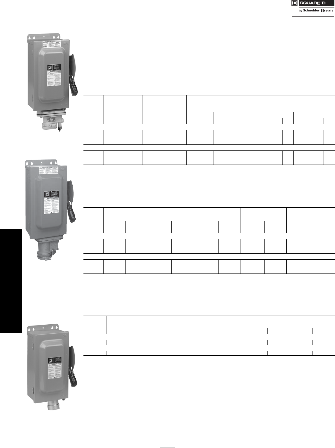
Special Applications—Receptacle Switches
Class 3110
Receptacle Switches
Interlocked Receptacle Switches are furnished with a factory-installed 3 Phase 4 Wire Appleton Powertite®,
Crouse-Hinds Style 2 Arktite®, or Hubbellock® receptacle. The fourth wire is connected to the switch equipment
grounding terminal and is not a neutral termination. Interlocking linkage between the receptacle and switch
mechanism prevents insertion or removal of the plug while the switch is in the “ON’’ position or insertion of any
plug other than specified. Grounding lugs are included.
Appleton Powertite Receptacle
•Devices are UL Listed and CSA Certified, suitable for use as service equipment.
•Receptacles are epoxy powder coated over copper-free cast aluminum and NEMA 3, 3R, 4, 4X and 12 rated. Appleton receptacles
are UL Classified for use with the Crouse-Hinds plugs listed below.
•Short circuit rating: 10 kA when used in conjunction with Class H or K fuses; 200 kA when used in conjunction with Class R or J fuses.
aReceptacle UL Listed for use with “Appleton ACP or CPH” plugs; UL Classified for use with Crouse-Hinds “APJ” Arktite plugs listed on this page.
bStd.—Using fast acting one time fuses. Max.—Using dual element time delay fuses.
cFor switching dc, use two switching poles.
Crouse-Hinds Arktite Receptacle
•UL Listed, suitable for use as service equipment.
•Short circuit rating: 10 kA when used in conjunction with Class H or K fuses; 200 kA when used in conjunction with Class R or J fuses.
dStd.—Using fast acting one time fuses. Max.—Using dual element time delay fuses.
Hubbellock Receptacle
•UL Listed, suitable for use as service equipment.
•Short circuit rating: 10 kA.
Note: The Hubbellock receptacle switch utilizes the Square D interlocked plug SD12781 only available from Square D.
eStd.—Using fast acting one time fuses. Max.—Using dual element time delay fuses.
fHubbell plug is furnished with a Kellems grip for 1-1/2 in. to 1-21/64 in. cable diameter.
Accessories . . . . . . . . . . . . . . . . . . . . . . . . . . . . . . . pages 3-9 through 3-11.
Amperes
NEMA 1
NEMA
3, 3R, 4, 4X, 5, 12
304 Stainless Steel
Enclosure
NEMA 12, 3R Use With Plug aHorsepower
Ratings–3Øb
Cat. No. $ Price Cat. No. $ Price Cat. No. $ Price Cat. No. $ Price 480 Vac 600 Vac 250 Vdcc
Std. Max. Std. Max. Std. Max.
Fusible—3P, 600 Vac, 250 Vdc
30 H361WA 1384.00 H361DSWA 2934.00 H361AWA 1526.00 ACP3034BC 823.00 5157-1/220 5—
60 H362WA 1608.00 H362DSWA 3112.00 H362AWA 1672.00 ACP6034BC 863.00 15 30 15 50 10 —
100 H363WA 2459.00 H363DSWA 5645.00 H363AWA 2505.00 ACP1034CD 1285.00 25 60 30 75 20 —
Non-Fusible—3P, 600 Vac, 250 Vdc
30 HU361WA 1262.00 HU361DSWA 2667.00 HU361AWA 1384.00 ACP3034BC 823.00 — 20 —30 —5
60 HU362WA 1537.00 HU362DSWA 2941.00 HU362AWA 1571.00 ACP6034BC 863.00 — 50 —60 —10
100 HU363WA 2102.00 HU363DSWA 5340.00 HU363AWA 2231.00 ACP1034CD 1285.00 — 75 —100 —20
Table 3.20:
Amperes
NEMA 1
NEMA 3, 3R, 4, 4X, 5, 12
304 Stainless Steel
Enclosure
NEMA 12, 3R Use With Plug Horsepower
Ratings–3Ød
Cat. No. $ Price Cat. No. $ Price Cat. No. $ Price Cat. No. $ Price 480 Vac 600 Vac
Std. Max. Std. Max.
Fusible—3P, 600 Vac Maximum
30 H361WC 1426.00 H361DSWC 4251.00 H361AWC 1570.00 APJ3485 823.00 5157-1/220
60 H362WC 1834.00 H362DSWC 5166.00 H362AWC 1897.00 APJ6485 863.00 15 30 15 50
100 H363WC 4003.00 H363DSWC 9884.00 H363AWC 4058.00 APJ10487 1285.00 — 60 —75
Non-Fusible—3P, 600 Vac Maximum
30 HU361WC 1301.00 HU361DSWC 3925.00 HU361AWC 1424.00 APJ3485 823.00 — 20 —30
60 HU362WC 1756.00 HU362DSWC 4916.00 HU362AWC 1785.00 APJ6485 863.00 — 50 —60
100 HU363WC 3499.00 HU363DSWC 9350.00 HU363AWC 3629.00 APJ10487 1285.00 — 60 —100
Table 3.21:
Amperes
NEMA 1 NEMA 12 Use With Plug Horsepower Ratings—3Øe
Cat. No. $ Price Cat. No. $ Price Cat. No. $ Price 480 Vac 600 Vac
Std. Max. Std. Max.
Fusible—3P, 600 Vac Maximum
60 H362WH 1567.00 H362AWH 1639.00 SD12781f406.00 15 30 15 50
Non-Fusible—3P, 600 Vac Maximum
60 HU362WH 1491.00 HU362AWH 1540.00 SD12781f406.00 — 50 —60
H362AWA
Interlocked Receptacle
Switch with Appleton
Powertite Receptacle
H362AWC
Interlocked Receptacle
Switch with Crouse-Hinds
H362AWH
Interlocked Receptacle
Switch with Hubbell
Hubbellock Receptacle
DE1 Discount
Schedule
www.schneider-electric.us
3SAFETY SWITCHES
© 2007 Schneider Electric
All Rights Reserved 3-9
Heavy Duty Safety Switches–Special Accessories
Electrical Interlock Kits
Electrical interlocks for heavy duty 30–1200 A safety switches are
available factory-installed or in kit form for field installation. Each kit
contains instructions for proper field mounting. A pivot arm operates
from switch mechanism, breaking the control circuit before the main
switch blades break. Switches with electrical interlocks installed are UL
Listed. For factory-installed electrical interlocks add EI (for one contact)
or EI2 (for two contacts) suffix to catalog number.
aSee page 3-7 for electrical interlocks on NEMA 4X fiberglass reinforced polyester and
Krydon®.
bElectrical interlock kit catalog numbers with 1 suffix indicates one normally open and one
normally closed contact; 2 indicates two normally open and two normally closed contacts.
Kits are UL Listed.
cHU461AWK uses EK3061 or EK3062.
dThe following series -F5–F7 devices use EIK-1,2: H3612, H3612A, H3612AWK,
H3612RB, H461, H461DS, H461AWK, HU461, HU461DS, HU661DS, HU661AWK,
H361AWA, H361AWC, HU361AWA and HU361AWC.
eH362WA, HU362WA, H362WC, H362AWA, HU362AWA, H362AWC, HU362AWC, and
H2212AWK use EIK1 or EIK2 electric interlock.
fSingle pole single throw interlock kits are rated 1⁄2 hp @ 110 and 220 Vac.
Class R Fuse Kits
When installed, this kit rejects all but Class R fuses. Kits are available for
field installation. For factory installation, add “CLR’’ suffix to catalog
number.
gH221-2AWK uses RFK06 Class R fuse kit.
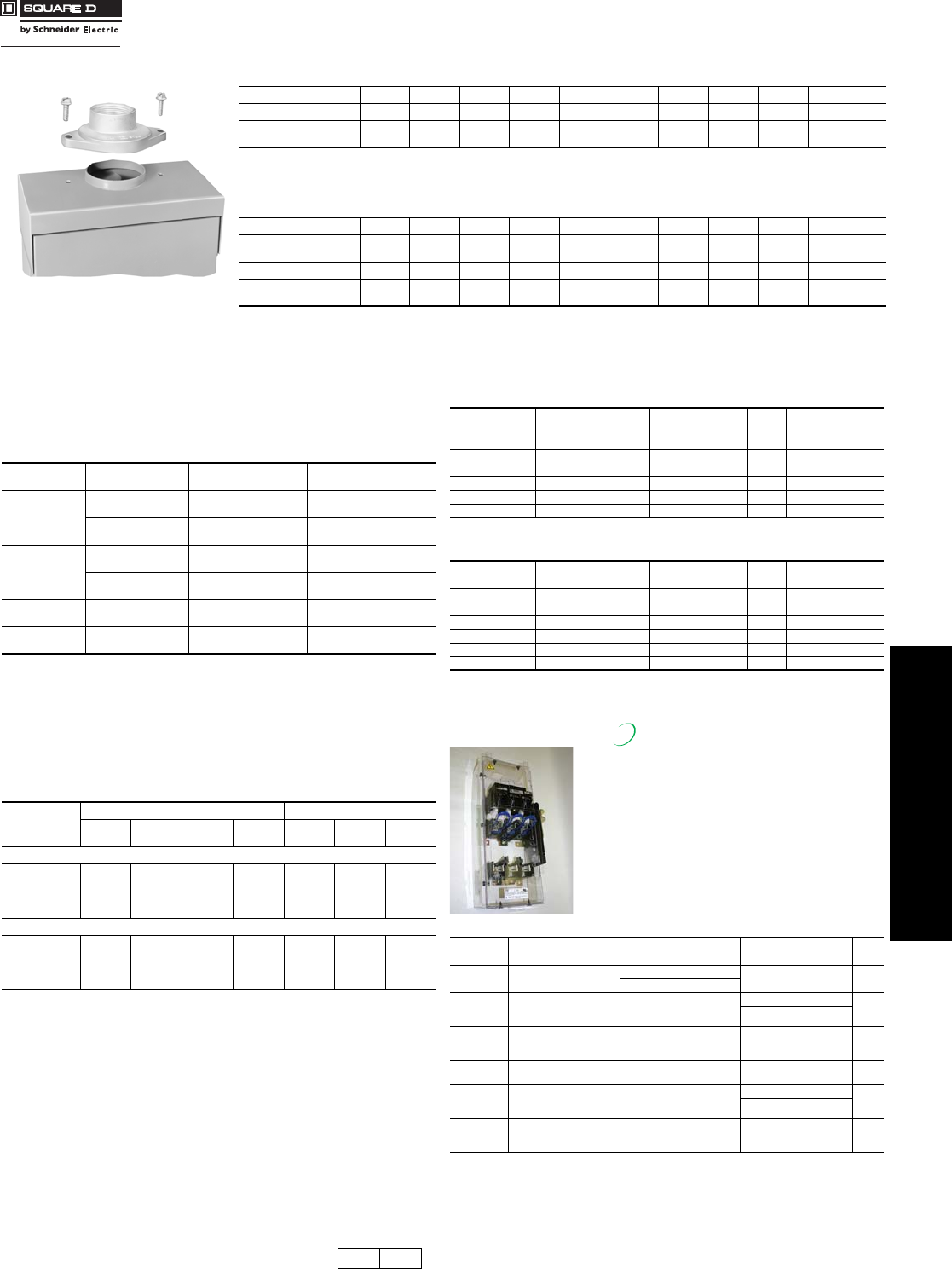
Internal Barrier Kits
Internal Barrier Kits provide an additional
barrier that helps prevent accidental contact with
live parts. Field-installed transparent barriers do
not restrict visual inspection of the switch.
Barriers provide IEC529 IP2X “finger safe”
protection when door of enclosed disconnect
switch is open. Convenient door allows use of
test probes without accessing fuses and
replacement of fuses without removing barrier.
Barrier can also be used with the skirt kit to
enclose a panel mounted Type 9422 disconnect.
jRequires arc shield on 240 V switches be changed to 600 V arc suppressor.
Rainproof Bolt-On Hubs—For Use On NEMA 3R Enclosure
Conduit Size 3/4 11-1/41-1/222-1/233-1/24Closing Cap
Hub Cat. No. B075 B100 B125 B150 B200 B250 B300 B350 B400 BCAP
$ Price Each 22.20 22.20 22.20 22.20 40.90 68.00 124.00 200.00 245.00 2.50
(DE1A)
Note: NEMA 3R rainproof enclosures with Cat. No. ending in RB have a bolt-on closing cap factory-installed. Order bolt-on hubs separately
from table above. For more details see page 1-13. Hubs through size 21⁄2 can be directly installed on RB devices. Devices requiring 3"
or larger hubs must have holes cut in the field. Gaskets are provided on 3" and larger hubs.
Note: All hubs are UL Listed for indoor and rainproof applications and suitable for use with conduit having ANSI standard taper pipe thread.
Watertight Hubs—For Use On NEMA 4, 4X and 5 Stainless Steel and NEMA 12 Enclosures
Conduit Trade Size 1/2 3/4 1 1-1/4 1-1/2 2 2-1/22 3 3-1/2 4
Standard-Zinc
Hub Cat. No. H050 H075 H100 H125 H150 H200 H250 H300 H350 H400
Zinc $ Price Each 20.70 30.00 31.40 36.00 55.00 80.00 92.00 118.00 188.00 254.00
Chrome Plated
Hub Cat. No. H050CP H075CP H100CP H125CP H150CP H200CP ——— —
RB Hub
Table 3.22: Electrical Interlock Kit a
Switch Rating
(A)
Series Number
(See pages 3-12, 3-13)
Electrical Interlock Kit
Cat. No.b$ Price Factory-Installed
$ Price
30
F1, F5–F7 EIK031c d145.00 239.00
EIK032c d
F3 EIK1 207.00 301.00
EIK2
60
F1-F3
F5–F7 (600 V)
EIK1 207.00 301.00
EIK2
F4
F5–F6 (240 V)
EIK031e145.00 239.00
EIK032e
100–200 F2–F7 EIK1 207.00 301.00
EIK2
400–1200 E1–E4 EIK40601 355.00 449.00
EIK40602
Table 3.23: Electrical Interlock Contact Ratingsf
Interlock Type
AC - 50 or 60 Hz DC
Volts Make Break Cont. Volts Make &
Break Cont.
Cat. No. ending with a 1 utilize a 9007A01 limit switch.
1 NO/1 NC
CONTACT
120 40 A 15 A 15 A 115 0.50 A 15 A
240 20 A 10 A 15 A 230 0.25 A 15 A
480 10 A 6 A 15 A ———
600 8 A 5 A 15 A 600 0.05 A 15 A
Cat. No. ending with a 2 utilize a 9007C03 limit switch.
2 NO/2 NC
CONTACTS
120 30 A 3.0 A 10 A 115 1.0 A 10 A
240 15 A 1.5 A 10 A 230 0.30 A 10 A
480 7.5 A 0.75 A 10 A ———
600 6.0 A 0.60 A 10 A 600 0.10 A 10 A
Table 3.24: Class R Fuse Kits—240 V (one kit per 3P switch)
Switch Rating
(A)
Series Number
(See pages 3-12, 3-13)
Class R Fuse Kit
Cat. No. $ Price Factory-Installed
$ Price
30 F5–F7 RFK03Lg17.00 130.00
60 F1, F2, F3 RFK06 17.00 130.00
60 F4–F7 RFK03H 17.00 130.00
100 F2–F7 RFK10 31.80 154.00
200 F5–F6 HRK1020 31.80 154.00
400–600 E HRK4060 74.00 240.00
Table 3.25: Class R Fuse Kits—600 V (one kit per 3P switch)
Switch Rating
(A)
Series Number
(See pages 3-12, 3-13)
Class R Fuse Kit
Cat. No. $ Price Factory-Installed
$ Price
30hF1, F5–F7 RFK03Hi17.00 130.00
30 hF3 RFK06 17.00 130.00
60 hF1–F7 RFK06H i17.00 130.00
100 hF2–F7 RFK10 31.80 154.00
200 F5–F6 HRK1020 31.80 154.00
400–600 E2–E4 HRK4060 74.00 240.00
hSee page 3-7 for Class R Fuse Kits in NEMA 4X Fiberglass Reinforced Polyester and
Krydon switches.
iThe following series -F5–F7 devices use RFK06: H3612, H3612A, H3612AWK,
H3612RB, H461, H461DS, H461AWK, H361AWA and H361AWC.
Cat. No. Description Safety Switch Application
(F Series Only)
9422 Type T
Disconnect Application $ Price
SS03 Interior Barrier for 30 A
Safety Switchj
600 Vac – 30 A NA 100.
240 Vac – 60 A
SS06
Interior Barrier for 60 A
Safety Switch, 30 or
60 A 9422 Switch
600 Vac – 60 A
600 Vac – 30 A
110.
600 Vac – 60 A
SS10
Interior Barrier for 100 A
Safety Switch or
100 A 9422 Switch
600 Vac – 100 A 600 Vac – 100 A 130.
SS20 Interior Barrier for 200 A
Safety Switch 600 Vac – 200 A NA 150.
SS0306SK
Skirt Kit to Enclose 30 or
60A 9422 Switch
(requires SS06)
NA
600 Vac – 30 A
150.
600 Vac – 60 A
SS10SK
Skirt Kit to Enclose 100 A
9422 Switch
(requires SS10)
NA 600 Vac – 100 A 170.
New!
DE1 DE1A Discount
Schedule Modified
4/16/09
www.schneider-electric.us
3SAFETY SWITCHES
3-10 © 2007 Schneider Electric
All Rights Reserved
Heavy Duty Safety Switches Accessories
Class 3110
Note: Neutrals cannot be installed in 4P, 6P, or NEMA 4X fiberglass reinforced polyester safety
switches.
aThe following series -F5–F6 devices use SN0610(C): H-361-2, H-361-2RB, H-361-2A and
H-361-2AWK.
bFor 200% neutral, order (2) neutral kits and (1) SN20NI neutral jumper kit. Price $18.40.
(2) 350 Max. Al/Cu.
Equipment Grounding Kits
Equipment grounding kits are field-installable and UL Listed in 30–1200
A heavy duty switches. For factory installation of equipment grounding
kit, add suffix GL to standard Cat. No. (Example: H361GL).
Price = Switch + Kit Price.
NOTE: Kits are factory-installed standard in 30–200 A series F
NEMA 4-4X-5 (stainless) and 12, and in all NEMA 30–200 A
Series F 4–6P switches.
Note: Shipped in quantities of 6.
Special Paint
UL Listed heavy duty switches are available painted with special safety
colors. Special colors available include: safety red, safety orange, safety
yellow, safety green, safety blue, safety purple, black and white.
All colors comply with OSHA Standard 1910.144 and ANSI Specification
Z535.1 for marking physical hazards.
A minimum quantity of 10 is required. To order, add suffix SP to
standard Cat. No. Specify color on order.
Phenolic Legend Plate
Available engraved and mounted on all heavy duty safety switches,
except NEMA 7 and 9. Legend engraved in 1/4 in. high white letters on
black background. Customer must provide legend. UL Listed.
To order, add suffix NP to standard Cat. No. Example: H363-NP
Price adder per legend plate—$111.00
Neutral Assemblies—Field-Installable Neutral Assemblies For Fusible and Non-Fusible 240 and 600 Volt Safety Switches
Switch
Rating
(A)
Series Number
(Seepages 3-12, 3-13)
Standard
Neutral Kit
Cat. No.
Terminal Data
AWG/kcmil .rice Optional Copper Only
Neutral Kit Cat. No.
Terminal Data
AWG/kcmil $ Price
30 F1, F5–F6 SN03a(3) 2 Max. Al/Cu 55.00 SN03C a(3) 6 Max. Cu 68.00
60
F1–F3,
F5–F6 (600 V) SN0610 (2) 1/0 Max. Al/Cu 71.00 SN0610C (2) 1/0 Max. Cu 76.00
(2) 2 Max. Al/Cu (2) 6 Max. Cu
F4,
F5–F6 (240 V) SN03a(3) 2 Max. Al/Cu 55.00 SN03Ca(3) 6 Max. Cu 68.00
100 F2–F6 SN0610 (2) 1/0 Max. Al/Cu 71.00 SN0610C (2) 1/0 Max. Cu 76.00
(2) 6 Max. Al/Cu (2) 6 Max. Cu
200bF5–F6 SN20A (2) 250 Max. Al/Cu
(1) 1/0 Max. Al/Cu 133.00 SN20C (2) 250 Max. Cu
(1) 1/0 Max. Cu 164.00
400 & 600 E1–E4 H600SN (4) 750 Max. Al/Cu
(1) 300 Max. Al/Cu 218.00 H600SNC
(2) 600 Max. Cu
301.00(2) 350 Max. Cu
(1) 250 Max. Cu
800 E2–E4 H800SNE4 (6) 750 Max. Al/Cu 502.00 — — —
(2) 350 Max. Al/Cu
1200 E2–E4 H1200SNE4 (8) 750 Max. Al/Cu 689.00 — — —
(2) 350 Max. Al/Cu
Equipment Grounding Kits—Field- or Factory-Installable Equipment Grounding Kits–240 and 600 V
Switch Rating
(A)
Series Number
(See pages 3-12, 3-13)
Standard
Cat. No.
Terminal Data
AWG/kcmil $ Price Optional Copper Only
Cat. No.
Terminal Data
AWG/kcmil $ Price
30 F1, F5–F7 GTK03 c(2) 12 Cu or (2) 10 Al or (1) 4 Max. Al/Cu 7.60 GTK03Cc(1) 6 Max. Cu 8.90
60dF1–F3d,
F5–F7 (600 V) GTK0610 d(2) 2/0 Max. Al/Cu 12.60 GTK0610Cd(2) 4 Max. Cu 15.10
60 F4,
F5–F6 (240 V) GTK03 (2) 12 Cu or (2) 10 Al or (1) 4 Max. Al/Cu 7.60 GTK03C (1) 6 Max. Cu 8.90
100 F2–F7 GTK0610 (2) 2/0 Max. Al/Cu 12.60 GTK0610C (2) 4 Max. Cu 15.10
200 F5–F7 PKOGTA2 (2) 2/0 Max. Al/Cu 36.80 PKOGTC2 (2) 4 Max. Cu 38.90
400 & 600 E2–E4 PKOGTA2e(2) 2/0 Max. Al/Cu 36.80 PKOGTC3 (4) 1/0 Max. Cu 71.00f
(2 Required)
800 E2–E4 PKOGTA7 (4) 350 Max. Al/Cu 132.00f———
1200 E2–E4 PKOGTA8 (8) 350 Max. Al/Cu 135.00f———
cThe following series -F5–F6 devices use GTK0610(C): H-361-2 and H-361-2RB
d4- and 6-pole 30 A F Series.
eTwo required if grounding conductors are run in parallel.
fPE1A Discount Schedule
Table 3.26: Square D Gray Paint
Description Cat. No. $ Price
16 oz. Aerosol Paint Can, Square D Gray Paint PK49SP 26.00 ea.
Price Adder Each Switch
Quantity $ Price
30 A 60 A 100 A 200 A 400 A 600 A
10 161.00 185.00 289.00 319.00 758.00 1867.00
DE1 PE1A Discount
Schedule
www.schneider-electric.us
3SAFETY SWITCHES
© 2007 Schneider Electric
All Rights Reserved 3-11
Heavy Duty Safety Switches
Class 3110
Key Interlock Systems
Factory-installed only on heavy duty safety
switches and double throw safety switches.
Interlocks are used to prevent the authorized
operator from making an unauthorized operation.
Not available on hazardous location devices
(NEMA 7/9) or fiberglass reinforced polyester
(NEMA 4X).
The key interlock system is a simple and easy
method of applying individual key interlock units
and assemblies to the above equipment so as to
require operation in a predetermined sequence.
UL Listed.
Quoting:
Contact Square D for Cat. No., availability, and pricing prior to quoting a job.
Ordering:
Order cannot be released for production until the following information
has been provided:
•End User—Company name, address
•Function of each lock (e.g., switch to be locked open with key removed, key
held when switch is closed)
•Existing Equipment—if switch is to be interlocked with equipment already on
site, provide brand of existing lock and key number
•Other New Equipment—if switch is to be interlocked with new equipment not
yet installed at the site, then provide contact person and phone number so that
locks may be coordinated
•Additional information may be required upon order entry
•Schneider Electric locks supplied unless otherwise specified.
Use these suffixes on switch Cat. Nos.:
•KI = 1 lock per switch
•KI2 = 1 lock with 2 cylinders (2 keys) per switch
•KIKI = 2 separate locks per switch
aPrices do not apply when more than three devices are interlocked, as these schemes
normally require more than one key assembly per device.
Lock-On Provisions
Lock-off provisions are standard on all heavy duty safety switches.
Provision for one 3⁄8 in. hasp padlock is available factory-installed on
NEMA 1, 3R, 4-4X-5 stainless steel and 12 switches. This modification
will allow the switch to be locked in the “ON’’ position. UL Listed.
Cover Viewing Window
Optional cover viewing window is positioned over the
blades to allow visual verification of “ON-OFF’’ status.
Available on 30 through 1200 A heavy duty switches, all
NEMA Types. (Not available on NEMA 4X fiberglass
reinforced polyester, Krydon® enclosures, or NEMA 7
and 9 devices.)
Factory-installed only: add “VW’’ suffix to the Cat. No.
See table below for price adder.
Copper Only Lug Kits
Heavy duty safety switches are supplied standard with Al lugs, which
accept both Cu and Al wires. For field installation of copper-only lug kits,
order kits below. For factory installation of copper only lugs, add suffix
SLC to standard Cat. No. Note: NEMA 12, 12K and stainless steel
switches with factory-installed lugs bear the UL Marine Listed manifest
for use on vessels over 65 feet long. NEMA 12, 12K and stainless steel
switches using field-installed copper only lug kits are UL Marine Listed,
but do not bear the marine manifest.
bOne kit includes all phase line/load lugs for a
3-pole switch.
Double Lug Kits
200 A heavy duty F-series switches are
supplied standard with lugs listed on
page 3-12 (one wire per phase). For
lugs that accept two wires per phase
and neutral, order the following kit:
NOTE: Not UL Listed.
cKit contains 3 lugs. For double lugs for line and load, order 2 kits.
Table 3.31: 800 and 1200 A Compression Lug Kits–
Field- Installable (See page 3-12 for 100–600 A
switches)
Series E4 800 and 1200 A safety switches are equipped as standard
with mechanical lugs. Alternate compression lug kits are available for
field installation and are UL Listed. Each kit consists of VCEL07512H1
Versa-Crimp® Compression Lugs and lug landing connectors capable of
converting line and load side of one switch pole or neutral.
Order one field-installable kit per pole or neutral per table below.
Example: 3-pole, 3 wire requires (3) kits; 3-pole, 4 wire requires (4) kits.
Note: For terminal lug data, refer to table below.
Table 3.32: Factory-Installed
Series E4 800 and 1200 A safety switches are available with factory-
installed VCEL-075-12H1 Versa-Crimp compression lug kits (above).
For factory installation add suffix LK to standard Cat. No. (Example:
H367LK) and use price adder from table below based on system type.
Note: For terminal Lug data refer to table below.
Table 3.27: Price Adder Per Lock a
Switch Type $ Price
30–1200 A Heavy Duty 1370.00
30–600 A Double Throw 1325.00
Table 3.28: Price Adder Per Each Switch
Safety Switch
Rating $ Price
To order, add suffix SPLO to standard
Cat. No. Example: H364-SPLO 30–1200 A 103.00
Table 3.29: Price Adder Per Switch—UL Listed
Amperes 2 and 3-Pole 4 and 6-Pole
30–200 A 25.00 50.00
400–1200 A 1531.00 —
Table 3.30: Kits – Wire size (page 3-13)
Switch
(A)
Lug Kit
Cat. No.b
Kit
$ Price
Factory-Installed
Adder per Switch
30 CL0306F 46.30 149.
60 CL0306F 46.30 149.
100 CL10F 106.00 287.
200 CL20F 176.00 478.
400 CL40F 366.00 993.
600 CL60F 595.00 1617.
800 — — —
1200 — — —
Switch
(A)
Lug Kit
Cat. No. Kit $ Pricec
Lug wire range
per phase and neutral
AWG/kcmil
Switch wire range
per phase and neutral
AWG/kcmil
200 AL20DTF 106.00 (2) 6 –300 Cu/Al (2) 6 –250 Cu/Al
Switch
Amperes
Lug Kit
Cat. No.
$ Price Per
Pole or Neutral
800 H8LKE2 595.00
1200 H12LKE2 739.00
Switch
Amperes System Factory-Installed
$ Price Adder Per Switch
800
2 Wire 1404.00
3 Wire 1981.00
4 Wire 2559.00
1200
2 Wire 1727.00
3 Wire 2464.00
4 Wire 3204.00
Table 3.33: Terminal Lug Data—800 and 1200 A Compression
Lugs
Switch
Amperes
Conductors
Per Phase
Compression Lug (VCEL-075-12H1)
Wire Range
800
(3) Line 500–750 kcmil (Al)
and or
(3) Load 500 kcmil (Cu)
1200
(4) Line 500–750 kcmil (Al)
and or
(4) Load 500 kcmil (Cu)
Al/Cu to Cu Only
DE1 Discount
Schedule
www.schneider-electric.us
3SAFETY SWITCHES
3-12 © 2007 Schneider Electric
All Rights Reserved
Heavy Duty Safety Switches NEMA Type 1 and 3R—Dimensions, Lug Data
Class 3110
a30–100 A switches suitable for 60°C or 75°C conductors. 200–1200 A switches suitable for 75oC conductors.
bFor NEMA 1 and R3 only.
cHU461AWK— 14–6 AWG (Cu).
dH60XFA— 14–6 AWG (Cu).
eH225XKA— 4 AWG–300 kcmil (Cu).
fMax. wire range 600 Al/Cu on NEMA 4-4X Stainless and NEMA 12.
gOrder two PK516KN mounting kits ($5.80 each. Lexington Order Point) when installing VCEL030516H1 lugs.
Only one kit is required on 2-Pole switches.
hSee page 3-11, 800 and 1200 A compression lug kits for additional information.
Table 3.34: Terminal Lug Data (NEMA 1, 3R, 4, 4X, 5, 7, 9, 12)a
Rating
(A)
Conductors
Per Phase
and Neutral
Wire Range Wire Bending Space
Per NEC Table 312.6
AWG/kcmil
Lug Wire Range
AWG/kcmil
Optional Versa-Crimp®
Compression Lug
Field-Installableb
30c
1 12–6 (Al) or 14–6 (Cu) 12–2 (Al)
or
14–2 (Cu)
—
2 14–10 (Cu) solid or 14–10 (Cu)
stranded
60d1 14–3 (Al) or 14–3 (Cu) 12–2 (Al) or 14–2 (Cu) —
100 1 12–1/0 (Al) or 14–1/0 (Cu) 12–1/0 (Al) or 14–1/0 (Cu) VCEL02114S1
200e1 6–250 (Al/Cu) 6–300 (Al/Cu) VCEL030516H1
400
VCEL07512H1
1 1/0–750 (Al/Cu)f 1/0–750 (Al/Cu) or
or or and VCEL030516H1g
2 1/0–300 (Al/Cu) 1/0–300 (Al/Cu) and
VCEL05012H1
600 2 3/0–500 (Al/Cu) 3/0–500 (Al/Cu) VCEL05012H1
800 3 3/0–750 (Al/Cu) 3/0–750 (Al/Cu) H8LKE2h
1200 4 3/0–750 (Al/Cu) 3/0–750 (Al/Cu) H12LKE2h
H
W/H D
W
H
W/H D
W
Typical NEMA 1 Typical NEMA 3R
Cat. No.
Approximate Dimensions
Cat. No.
Approximate Dimensions
Series HWDW/H Series HWDW/H
in. mm in. mm in. mm in. mm in. mm in. mm in. mm in. mm
H221N F5 14.60 371 6.50 165 4.88 124 7.55 192 H364, N F5 29.00 737 17.13 435 8.25 210 18.50 470
H221NRB F5 14.88 378 6.63 168 4.88 124 7.55 192 H364RB, NRB F5 29.25 743 17.25 438 8.50 216 18.63 473
H222N F5 14.60 371 6.50 165 4.88 124 7.55 192 H365, N E4 50.25 1276 27.63 702 10.13 257 27.63 702
H222NRB F5 14.88 378 6.63 168 4.88 124 7.55 192 H365R, NR E4 50.31 1278 27.88 708 10.13 257 27.88 708
H223N F5 21.25 540 8.50 216 6.38 162 10.50 267 H366, N E4 50.25 1276 27.63 702 10.13 257 27.63 702
H223NRB F5 21.25 540 8.50 216 6.38 162 10.50 267 H366NR, R E4 50.31 1278 27.88 708 10.13 257 27.88 708
H224N F5 29.00 737 17.13 435 8.25 210 18.50 470 H367, N E4 69.13 1756 36.62 930 17.75 451 36.62 930
H224NRB F5 29.25 743 17.25 438 8.50 216 18.63 473 H367NR, R E4 69.13 1756 36.62 930 17.75 451 36.62 930
H225, N E4 50.25 1276 27.63 702 10.13 257 27.63 702 H368, N E4 69.13 1756 36.62 930 17.75 451 36.62 930
H225NR, R E4 50.31 1278 27.88 708 10.13 257 27.88 708 H368NR, R E4 69.13 1756 36.62 930 17.75 451 36.62 930
H226, N E4 50.25 1276 27.63 702 10.13 257 27.63 702 H461 F5 20.50 521 14.75 375 6.85 174 16.13 410
H226NR, R E4 50.31 1278 27.88 708 10.13 257 27.88 708 H462 F5 20.50 521 14.75 375 6.85 174 16.13 410
H227, N E4 69.13 1756 36.62 930 17.75 451 36.62 930 H463 F5 20.50 521 14.75 375 6.85 174 16.13 410
H227NR, R E4 69.13 1756 36.62 930 17.75 451 36.62 930 H464 F5 29.00 737 23.25 591 8.75 222 24.88 632
H228, N E4 69.13 1756 36.62 930 17.75 451 36.62 930 H465 E4 50.25 1276 33.88 861 10.13 257 33.88 861
H228NR, R E4 69.13 1756 36.62 930 17.75 451 36.62 930 H466 E4 50.25 1276 33.88 861 10.13 257 33.88 861
H265 E4 50.25 1276 27.63 702 10.13 257 27.63 702 HU265 E4 50.25 1276 27.63 702 10.13 257 27.63 702
H265R E4 50.31 1278 27.88 708 10.13 257 27.88 708 HU265R E4 50.31 1278 27.88 708 10.13 257 27.88 708
H266 E4 50.25 1276 27.63 702 10.13 257 27.63 702 HU266 E4 50.25 1276 27.63 702 10.13 257 27.63 702
H266R E4 50.31 1278 27.88 708 10.13 257 27.88 708 HU266R E4 50.31 1278 27.88 708 10.13 257 27.88 708
H267 E4 69.13 1756 36.62 930 17.75 451 36.62 930 HU267 E4 69.13 1756 36.62 930 17.75 451 36.62 930
H267R E4 69.13 1756 36.62 930 17.75 451 36.62 930 HU267R E4 69.13 1756 36.62 930 17.75 451 36.62 930
H268 E4 69.13 1756 36.62 930 17.75 451 36.62 930 HU268 E4 69.13 1756 36.62 930 17.75 451 36.62 930
H268R E4 69.13 1756 36.62 930 17.75 451 36.62 930 HU268R E4 69.13 1756 36.62 930 17.75 451 36.62 930
H321N F5 14.60 371 6.50 165 4.88 124 7.55 192 HU361 F5 14.60 371 6.50 165 4.88 124 7.55 192
H321NRB F5 14.88 378 6.63 168 4.88 124 7.55 192 HU361RB F5 14.88 378 6.63 168 4.88 124 7.55 192
H322N F5 14.60 371 6.50 165 4.88 124 7.55 192 HU361WA F6 18.19 462 9.00 229 6.81 173 10.50 267
H322NRB F5 14.88 378 6.63 168 4.88 124 7.55 192 HU361WC F6 18.19 462 9.00 229 6.81 173 10.50 267
H323N F5 21.25 540 8.50 216 6.38 162 10.50 267 HU362 F5 17.50 445 9.00 229 6.38 162 10.50 267
H323NRB F5 21.25 540 8.50 216 6.38 162 10.50 267 HU362RB F5 17.50 445 9.00 229 6.38 162 10.50 267
H324N F5 29.00 737 17.13 435 8.25 210 18.50 470 HU362WA F6 18.19 462 9.00 229 6.81 173 10.50 267
H324NRB F5 29.25 743 17.25 438 8.50 216 18.63 473 HU362WC F6 16.75 425 9.00 229 7.00 178 10.50 267
H325, N E4 50.25 1276 27.88 708 10.13 257 27.88 708 HU362WH F5 18.19 462 9.00 229 6.81 173 10.50 267
H325R, NR E4 50.31 1278 27.88 708 10.13 257 27.88 708 HU363 F5 21.25 540 8.50 216 6.38 162 10.50 267
H326, N E4 50.25 1276 27.63 702 10.13 257 27.63 702 HU363RB F5 21.25 540 8.50 216 6.38 162 10.50 267
H326R, NR E4 50.31 1278 27.88 708 10.13 257 27.88 708 HU363WA F6 21.85 462 9.00 229 6.81 173 10.50 267
H327, N E4 69.13 1756 36.62 930 17.75 451 36.62 930 HU363WC F6 21.85 555 9.00 229 6.81 173 10.50 267
H327R, NR E4 69.13 1756 36.62 930 17.75 451 36.62 930 HU364 F5 29.00 737 17.13 435 8.25 210 18.50 470
H328, N E4 69.13 1756 36.62 930 17.75 451 36.62 930 HU364RB F5 29.25 743 17.25 438 8.50 216 18.63 473
H328R, NR E4 69.13 1756 36.62 930 17.75 451 36.62 930 HU365 E4 50.25 1276 27.63 702 10.13 257 27.63 702
H361, N F5 14.60 371 6.50 165 4.88 124 7.55 192 HU365R E4 50.31 1278 27.88 708 10.13 257 27.88 708
H361-2 F5 17.50 445 9.00 229 6.38 162 10.50 267 HU366 E4 50.25 1276 27.63 702 10.13 257 27.63 702
H361NRB, RB F5 14.88 378 6.63 168 4.88 124 7.55 192 HU366R E4 50.31 1278 27.88 708 10.13 257 27.88 708
H361WA F6 18.19 462 9.00 229 6.81 173 10.50 267 HU367 E4 69.13 1756 36.62 930 17.75 451 36.62 930
H361WC F6 18.19 462 9.00 229 6.81 173 10.50 267 HU367R E4 69.13 1756 36.62 930 17.75 451 36.62 930
H362, N F5 17.50 445 9.00 229 6.38 162 10.50 267 HU368 E4 69.13 1756 36.62 930 17.75 451 36.62 930
H362NRB, RB F5 17.50 445 9.00 229 6.38 162 10.50 267 HU368R E4 69.13 1756 36.62 930 17.75 451 36.62 930
H362WA F6 18.19 462 9.00 229 6.81 173 10.50 267 HU461 F5 20.50 521 14.75 375 6.85 174 16.13 410
H362WC F6 16.75 425 9.00 229 7.00 178 10.50 267 HU462 F5 20.50 521 14.75 375 6.85 174 16.13 410
H362WH F5 18.19 462 9.00 229 6.81 173 10.50 267 HU463 F5 20.50 521 14.75 375 6.85 174 16.13 410
H363, N F5 21.25 540 8.50 216 6.38 162 10.50 267 HU464 F5 29.00 737 23.25 591 8.75 222 24.88 632
H363NRB, RB F5 21.25 540 8.50 216 6.38 162 10.50 267 HU465 E4 50.25 1276 33.88 861 10.13 257 33.88 861
H363WA F6 21.85 462 9.00 229 6.81 173 10.50 267 HU466 E4 50.25 1276 33.88 861 10.13 257 33.88 861
H363WC F6 21.85 555 9.00 229 6.81 173 10.50 267
www.schneider-electric.us
3SAFETY SWITCHES
© 2007 Schneider Electric
All Rights Reserved 3-13
Heavy Duty Safety Switches
Class 3110
NEMA Type 4, 4X, 5, 7, 9 and 12
Table 3.35: Optional Copper Only Lug Kits —
(See page 3-11 for pricing. See page 3-12 for terminal lug data for the series switches listed in the
dimension table below.)
Rating (A) Optional Lug Kit Cat. No.aLug Wire Range Per Phase AWG/kcmil
30–60 CL0306F (1) 14–8 Cu solid or 14–4 Cu strand
100 CL10F (1) 14–8 Cu solid or 14–1/0 Cu strand
200 CL20F (1) 6–250 Cu
400 CL40F (1) 1–600 Cu plus (1) 6–250 Cu
600 CL60F (2) 4–350 Cu
aOne kit includes all phase line/load lugs for a 3-pole switch.
Table 3.36: Conduit Provisions —
NEMA 4X Fiberglass Reinforced Polyester and Krydon, NEMA 7 and 9
Rating
(A)
Top and Bottom Endwall
NEMA 4X Fiberglass
Reinforced Polyester and KrydonbNEMA 7 and 9c
30 3/4 in. —
60 1-1/4 in. 3/4 in.
100 2 in. 1-1/4 in.
200 2-1/2 in. 2-1/2 in.
bHubs and hub drilling templates are provided for field installation.
cThreaded conduit opening.
Cat. No.
Approximate Dimensions
Series HWDW/H
in. mm in. mm in. mm in. mm
H60XFA E1 15.93 405 9.87 251 6.96 177 9.87 251
H100XFA E1 15.93 405 9.87 251 6.96 177 9.87 251
H221AWK, A F6 14.60 371 6.63 168 4.96 125 7.55 192
H221DS F6 14.93 379 7.22 183 5.11 130 8.67 220
H221-2AWK F6 16.50 419 9.00 229 7.00 178 10.50 267
H222AWK, A F6 14.60 371 6.63 168 4.96 125 7.55 192
H222DS F6 14.93 379 7.22 183 5.11 130 8.67 220
H223AWK, A F6 20.50 521 9.00 229 7.00 178 10.50 267
H223DS F6 20.82 529 9.36 238 6.97 177 11.25 286
H224A,AWK F6 29.00 737 17.25 438 8.75 216 18.63 473
H224DS F6 29.00 737 17.75 451 8.88 226 19.25 489
H225AWK, DS E4 46.25 1175 26.25 667 10.13 259 26.25 667
H225NAWK, NDS E4 46.25 1175 26.25 667 10.13 259 26.25 667
H225XKA C2 22.56 573 10.88 276 7.75 197 10.88 276
H226AWK, DS E4 46.25 1175 26.25 667 10.13 259 26.25 667
H226NAWK, NDS E4 46.25 1175 26.25 667 10.13 259 26.25 667
H227AWK, NAWK E4 69.13 1756 36.62 930 17.75 451 36.62 930
H228AWK, NAWK E4 69.13 1756 36.62 930 17.75 451 36.62 930
H265AWK, DS E4 46.25 1175 26.25 667 10.13 259 26.25 667
H266AWK, A, DS E4 46.25 1175 26.25 667 10.13 259 26.25 667
H267AWK, NAWK E4 69.13 1756 36.62 930 17.75 451 36.62 930
H268AWK, NAWK E4 69.13 1756 36.62 930 17.75 451 36.62 930
H321AWK, A F6 14.60 371 6.63 168 4.96 125 7.55 192
H321DS F6 14.93 379 7.22 183 5.11 130 8.67 220
H322AWK, A F6 14.60 371 6.63 168 4.96 125 7.55 192
H322DS F6 14.93 379 7.22 183 5.11 130 8.67 220
H323AWK, A F6 20.50 521 9.00 229 7.00 178 10.50 267
H323DS F6 20.82 529 9.36 238 6.97 177 11.25 286
H324A,AWK F6 29.00 737 17.25 438 8.75 216 18.63 473
H324DS F6 29.00 737 17.75 451 8.88 226 19.25 489
H325AWK, DS E4 46.25 1175 26.25 667 10.13 259 26.25 667
H325NAWK, NDS E4 46.25 1175 26.25 667 10.13 259 26.25 667
H326AWK, DS E4 46.25 1175 26.25 667 10.13 259 26.25 667
H326NAWK, NDS E4 46.25 1175 26.25 667 10.13 259 26.25 667
H327AWK, NAWK E4 69.13 1756 36.62 930 17.75 451 36.62 930
H328AWK, NAWK E4 69.13 1756 36.62 930 17.75 451 36.62 930
H361AWA F7 16.50 419 9.00 229 7.00 178 10.50 267
H361AWC F7 16.50 419 9.00 229 7.00 178 10.50 267
H361AWK, A F6 14.60 371 6.63 168 4.96 125 7.55 192
H361DS F6 14.93 379 7.22 183 5.11 130 8.67 220
H361DSWA F7 16.87 428 8.92 227 5.11 130 10.81 275
H361DSWC F7 16.87 428 8.92 227 5.11 130 10.79 274
H361DF F1 16.50 419 11.00 279 8.80 224 11.00 279
H361DX F1 19.40 493 11.40 290 8.60 218 11.40 290
H361SS F6 14.93 379 7.22 183 5.11 130 8.67 220
H361-2AWK, A F6 16.50 419 9.00 229 7.00 178 10.50 267
H362AWA F7 16.50 419 9.00 229 7.00 178 10.50 267
H362AWC F7 16.50 419 9.00 229 7.00 178 10.50 267
H362AWH F6 16.50 419 9.00 229 7.00 178 10.50 267
H362AWK, A F6 16.50 419 9.00 229 7.00 178 10.50 267
H362DS F6 16.87 428 8.92 227 6.97 177 10.81 275
H
WD
Typical NEMA 4X
Fiberglass Reinforced
Polyester and Krydon®
H
W/H D
W
Typical NEMA 4, 4X, 5, 12,
12K (Stainless has flat front)
H
WD
Typical NEMA 7, 9
H362DSWA F7 16.87 428 8.92 227 5.11 130 10.81 275
H362DSWC F7 16.87 428 8.92 227 5.11 130 10.79 274
H362DF F1 16.50 419 11.00 279 8.80 224 11.00 279
H362DX F1 19.40 493 11.40 290 8.60 218 11.40 290
H362SS F6 16.87 428 8.92 227 6.97 177 10.81 275
H363AWA F7 20.50 521 9.00 229 7.00 178 10.50 267
H363AWC F7 20.50 521 9.00 229 7.00 178 10.50 267
H363AWK, A F6 20.50 521 9.00 229 7.00 178 10.50 267
H363DS F6 20.82 529 9.36 238 6.97 177 11.25 286
H363DSWA F7 20.82 529 9.36 238 6.97 177 11.25 286
H363DSWC F7 20.82 529 9.36 238 6.97 177 11.25 286
H363DF F1 24.80 630 13.70 348 12.00 305 13.70 348
H363DX F1 25.25 641 11.40 290 8.60 218 11.40 290
H363SS F6 20.82 529 9.36 238 6.97 177 11.25 286
H364A,AWK F6 29.00 737 17.25 438 8.75 216 18.63 473
H364DS,NDS F6 29.00 737 17.75 451 8.88 226 19.25 489
H364NA,NAWK F6 29.00 737 17.25 438 8.75 216 18.63 473
H364DF E1 31.30 795 26.30 668 11.80 300 26.30 668
H364SS F6 29.00 737 17.75 451 8.88 226 19.25 489
H365AWK, DS E4 46.25 1175 26.25 667 10.13 259 26.25 667
H365NAWK, NDS E4 46.25 1175 26.25 667 10.13 259 26.25 667
H366AWK, DS E4 46.25 1175 26.25 667 10.13 259 26.25 667
H366NAWK, NDS E4 46.25 1175 26.25 667 10.13 259 26.25 667
H367AWK, NAWK E4 69.13 1756 36.62 930 17.75 451 36.62 930
H368AWK, NAWK E4 69.13 1756 36.62 930 17.75 451 36.62 930
H461AWK F6 20.50 521 14.75 375 6.80 173 16.13 410
H461DS F6 20.82 529 15.08 383 6.97 177 16.85 428
H462AWK F6 20.50 521 14.75 375 6.80 173 16.13 410
H462DS F6 20.82 529 15.08 383 6.97 177 16.85 428
H463AWK F6 20.50 521 14.75 375 6.80 173 16.13 410
H463 DS F6 20.82 529 15.08 383 6.97 177 16.85 428
H464AWK F6 29.00 737 23.25 591 8.75 222 24.88 632
H464DS F6 29.00 737 23.75 603 8.88 226 25.25 641
H465AWK E4 46.25 1175 32.50 826 10.13 259 32.50 826
H663AWK F6 20.50 521 14.75 375 6.80 173 16.13 410
H663DS F6 20.82 529 15.08 383 6.97 177 16.85 428
H664AWK F6 29.00 737 23.25 591 8.75 222 24.88 632
H664DS F6 29.00 737 23.75 603 8.88 226 25.25 641
HU265AWK, DS E4 46.25 1175 26.25 667 10.13 259 26.25 667
HU266AWK, DS E4 46.25 1175 26.25 667 10.13 259 26.25 667
HU267AWK E4 69.13 1756 36.62 930 17.75 451 36.62 930
HU268AWK E4 69.13 1756 36.62 930 17.75 451 36.62 930
HU361AWA F7 16.50 419 9.00 229 7.00 178 10.50 267
HU361AWC F7 16.50 419 9.00 229 7.00 178 10.50 267
HU361AWK, A F6 14.60 371 6.63 168 4.96 125 7.55 192
HU361DS F6 14.93 379 7.22 183 5.11 130 8.67 220
HU361DSWA F7 16.87 428 8.92 227 5.11 130 10.81 275
HU361DSWC F7 16.87 428 8.92 227 5.11 130 10.79 274
HU361DF F1 16.50 419 11.00 279 8.80 224 11.00 279
HU361DX F1 19.40 493 11.40 290 8.60 218 11.40 290
HU361SS F6 14.93 379 7.22 183 5.11 130 8.67 220
HU362AWA F7 16.50 419 9.00 229 7.00 178 10.50 267
HU362AWC F7 16.50 419 9.00 229 7.00 178 10.50 267
HU362AWH F6 16.50 419 9.00 229 7.00 178 10.50 267
HU362AWK, A F6 16.50 419 9.00 229 7.00 178 10.50 267
HU362DS F6 16.87 428 8.92 227 6.97 177 10.81 275
HU362DSWA F7 16.87 428 8.92 227 5.11 130 10.81 275
HU362DSWC F7 16.87 428 8.92 227 5.11 130 10.79 274
HU362DF F1 16.50 419 11.00 279 8.80 224 11.00 279
HU362DX F1 19.40 493 11.40 290 8.60 218 11.40 290
HU362SS F6 16.87 428 8.92 227 6.97 177 10.81 275
HU363AWA F7 20.50 521 9.00 229 7.00 178 10.50 267
HU363AWC F7 20.50 521 9.00 229 7.00 178 10.50 267
HU363AWK, A F6 20.50 521 9.00 229 7.00 178 10.50 267
HU363DS F6 20.82 529 9.36 238 6.97 177 11.25 286
HU363DSWA F7 20.82 529 9.36 238 6.97 177 11.25 286
HU363DSWC F7 20.82 529 9.36 238 6.97 177 11.25 286
HU363DF F1 24.80 630 13.70 348 12.00 305 13.70 348
HU363DX F1 25.25 641 11.40 290 8.60 218 11.40 290
HU363SS F6 20.82 529 9.36 238 6.97 177 11.25 286
HU364A,AWK F6 29.00 737 17.25 438 8.75 216 18.63 473
HU364DF E1 31.30 795 26.30 668 11.80 300 26.30 668
HU364DS F6 29.00 737 17.75 451 8.88 226 19.25 489
HU364SS F6 29.00 737 17.75 451 8.88 226 19.25 489
HU365AWK, DS E4 46.25 1175 26.25 667 10.13 259 26.25 667
HU366AWK, DS E4 46.25 1175 26.25 667 10.13 259 26.25 667
HU367AWK E4 69.13 1756 36.62 930 17.75 451 36.62 930
HU368AWK E4 69.13 1756 36.62 930 17.75 451 36.62 930
HU461AWK E1 16.63 422 9.88 251 6.13 156 11.00 279
HU461DS F6 20.82 529 15.08 383 6.97 177 16.85 428
HU462AWK F6 20.50 521 14.75 375 6.80 173 16.13 410
HU462DS F6 20.82 529 15.08 383 6.97 177 16.85 428
HU463AWK F6 20.50 521 14.75 375 6.80 173 16.13 410
HU463DS F6 20.82 529 15.08 383 6.97 177 16.85 428
HU464AWK F6 29.00 737 23.25 591 8.75 222 24.88 632
HU464DS F6 29.00 737 23.75 603 8.88 226 25.25 641
HU465AWK E4 46.25 1175 32.50 826 10.13 259 32.50 826
HU661AWK F6 20.50 521 14.75 375 6.80 173 16.13 410
HU661DS F6 20.82 529 15.08 383 6.97 177 16.85 428
HU662AWK F6 20.50 521 14.75 375 6.80 173 16.13 410
HU662DS F6 20.82 529 15.08 383 6.97 177 16.85 428
HU663AWK F6 20.50 521 14.75 375 6.80 173 16.13 410
HU663DS F6 20.82 529 15.08 383 6.97 177 16.85 428
HU664AWK F6 29.00 737 23.25 591 8.75 222 24.88 632
HU664DS F6 29.00 737 23.75 603 8.88 226 25.25 641
Cat. No.
Approximate Dimensions
Series HWDW/H
in. mm in. mm in. mm in. mm
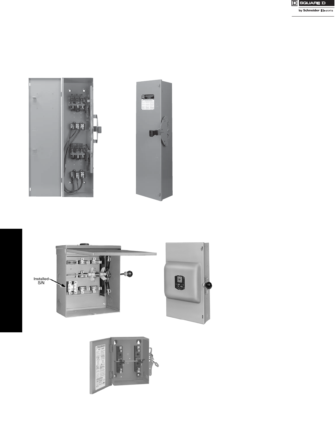
www.schneider-electric.us
3SAFETY SWITCHES
3-14 © 2007 Schneider Electric
All Rights Reserved
Double Throw Safety Switches—Fusible and Non-Fusible
Class 3140
30–100 A Types DT, DTU (Series F)
30 (Series T4), 200–600 A Types 82,000 and 200 A DTU (Series E, A)
Field-Installable Accessories:
—Neutral
—Electrical Interlock
—Grounding Terminals
•Fusible (DT) and non-fusible (DTU) switches available.
•Manually operated switch suitable for use in accordance with
article 702 of the NEC, ANSI/NFPA 70
•Standards: U:L 98, NEMA KS1, CSA, and NOM
•Modular design—switch handle, lock-plate, switch mechanism;
line and load bases are field replaceable
•UL Listed short circuit current ratings up to 200 kA
(using Class R, J, or T fuses—see table for rating)
•Load make/break rated
•Meets NEMA hp ratings
•Dual cover interlock
•May be padlocked ON (I) or OFF (O)
•Lock-off accepts up to three padlocks
•Side-opening door
•Quick make / quick break mechanism
•Meets NEMA requirements as heavy duty switch
•Field-installable electrical interlock kits
•Field-installable neutral assembly kits (2P and 3P
switches)
•UL Listed as suitable for use as service equipment
•Supplied as standard for switching one load between two power
sources, and may be field-converted to switch on power source
between two loads.
•Non-fusible
•Designed for manual transfer of loads from one supply
to another
•UL Listed switches are suitable for use in accordance
with Arcticle 702 of the National Electrical Code, ANSI /
NFPA 70.
•All 82,000 and DTU double throw switches are
continuous dute rated for their nameplate
ampere rating
•The 82,000 and DTU (Series E, A) switches are load
make/break rated
•UL Listed as suitable for use as service equipment
•Horsepower rated only as footnoted.
30–100 A DT, DTU (Series F)
NEMA 1
DTU (Series E) 200 A
NEMA 3R 82,000 Line
NEMA 1
92251
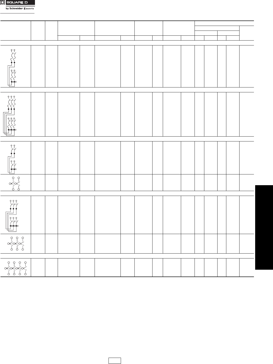
www.schneider-electric.us
3SAFETY SWITCHES
© 2007 Schneider Electric
All Rights Reserved 3-15
Double Throw Safety Switches 240 Volt
Class 3140
600 V Double Throw . . . . . . . . . . . . . . . . . . . . . . . . . . . . . . . . . . . . .page 3-16
Application Data. . . . . . . . . . . . . . . . . . . . . . . . . . . . . . . . page 3-17
Dimensions: 30–100 A (Series F) . . . . . . . . . . . . . . . . . . . . . . . . . page 3-18
Dimensions: 30, 200–600 A (Series E, T4, A) . . . . . . . . . . . . . . . page 3-19
Accessories . . . . . . . . . . . . . . . . . . . . . . . . . . . . . . . . . . . . . . . . . . . page 3-20
System Rating
(A)
Current
Series
NEMA 1 NEMA 3R NEMA 4,4X,5
304 Stainless Steel
NEMA 12
Gasketed
Horsepower Ratings ab
240 Vac
250 VdccStd. Max.
Cat. No. $ Price Cat. No. $ Price Cat. No. $ Price Cat. No. $ Price 1Ø 3Ø 1Ø 3Ø
Table 3.37: Fusible—2P, 240 Vac—250 Vdc
100 F DT223 1586.00 DT223RB 2037.00 ——— —7.515d15 30 d20
3P, 240 Vac—250 Vdc
30 F DT321 1097.00 DT321RB 1477.00 ————1.5 e3d3 e7.5 d5
60 F DT322 1313.00 DT322RB 1741.00 ————3 e7.5 d10 e15 d10
100 F DT323 2069.00 DT323RB 2483.00 ——— —7.5 e15d15 e30d20
Table 3.38: Non-Fusible—2P, 240 Vac—250 Vdc
60 F DTU222 641.00 ————————10—10 f
100 F DTU223 914.00 DTU223RB 898.00 ——— ———15—20 f
30 T4 92251 g390.00 ———————————
200 E 82254 1210.00 DTU224NRB gh 1451.00 ——H82254 3114.00 15 — — — —
—— — — — — — — — —15——— —
400 A 82255 g3900.00 82255R g5810.00 ——H82255g6890.00 ———— —
3P, 240 Vac—250 Vdc
30 F DTU321 536.00 ———————3 d5 e10 d5 f
60 F DTU322 746.00 ————————10 e15 d10 f
100 F DTU323 1176.00 DTU323RB 1302.00 ——— ———15 e30 d20 f
30 T4 92351 g458.00 ———————————
200 E 82354 g1709.00 DTU324NRB gh 2003.00 ——H82354 gi 3605.00 —15—— —
200 E DTU324N gh 1865.00 ———————15———
400 A 82355 g5360.00 82355R g8692.00 ——H82355 g7810.00 ———— —
600 A DTU326 8370.00 DTU326R 9260.00 — — — — — 125 — — 50
4P, 240 Vac
30 T4 92451 g635.00 ———————————
200 E 82454k3456.00 82454Rk5011.00 ——H82454j4519.00 —15j—— —
400 A 82455 7670.00 82455R 10800.00 ——H82455 10650.00 ———— —
600 A DTU426 13570.00 DTU426R 13730.00 — — — — — 125 — — 50
aRefer to page 7-31 for additional motor application data. The starting current of motors or more than standard horsepower may require the use of fuses with appropriate time delay
characteristics.
bStd.—Using fast acting one time fuses. Max.—Using dual element time delay fuses.
cFor switching dc, use two switching poles.
dIf used on corner grounded delta systems, install neutral and use outer switching pole for ungrounded conductors.
eUse outer switching poles.
fMaximum rating.
g240 Vac only
hNeutral included with device.
iSuitable for use as service equipment.
jHp rating applies only to H82454.
k250 V dc rated.
Line
Line
Load
Line
Line
Load
Line
Line
Load
Line
Line
Load
DE1 Discount
Schedule
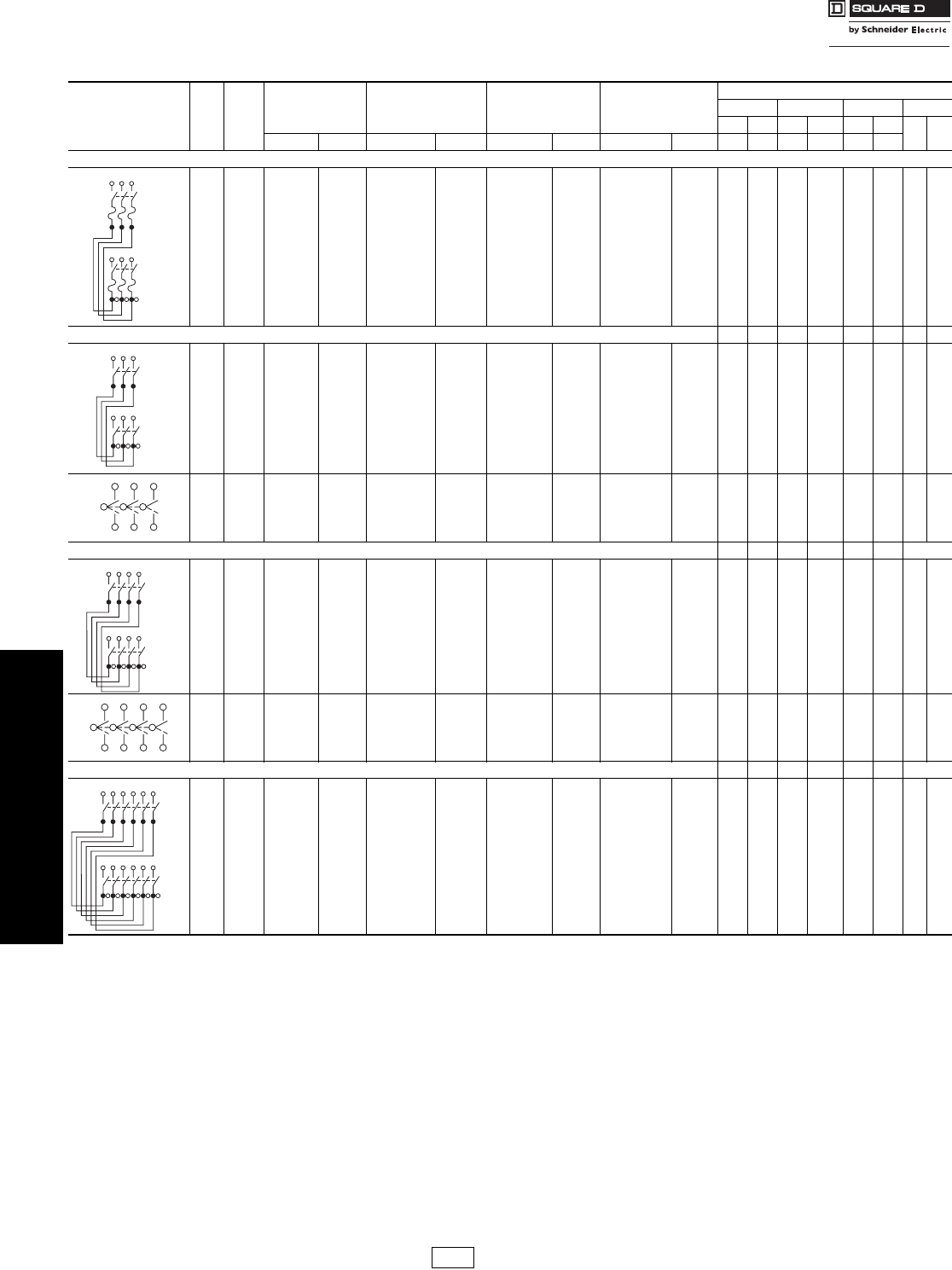
www.schneider-electric.us
3SAFETY SWITCHES
3-16 © 2007 Schneider Electric
All Rights Reserved
Double Throw Safety Switches 600 V
Class 3140
240 V Double Throw . . . . . . . . . . . . . . . . . . . . . . . . . . . . . . . . . . . . page 3-15
Application Data . . . . . . . . . . . . . . . . . . . . . . . . . . . . . . . . . . . . . . . . page 3-17
Dimensions: 30–100 A (Series F) . . . . . . . . . . . . . . . . . . . . . . . . . . page 3-18
Dimensions: 30, 200–600 A (Series E, T4, A) . . . . . . . . . . . . . . . . page 3-19
Accessories . . . . . . . . . . . . . . . . . . . . . . . . . . . . . . . . . . . . . . . . . . . page 3-20
Table 3.39: 600 V Double Throw Safety Switches
System Rating
(A)
Current
Series
NEMA 1 NEMA 3R NEMA 4,4X,5
304 Stainless Steel
NEMA 12
Gasketed
Horsepower Ratings ao
240 Vac 480 Vac 600 Vac Vdcb
std max std max std max 250 600
Cat. No. $ Price Cat. No. $ Price Cat. No. $ Price Cat. No. $ Price 3Ø 3Ø 3Ø b3Øb3Ø 3Ø
Fusible 3P, 600 Vac—600 Vdc
30 F DT361 1344.00 DT361RB 1785.00 —— — ———5157.520515
60 F DT362 1407.00 DT362RB 2090.00 — — — — — — 15 30 15 50 — 30
100 F DT363 2457.00 DT363RB 2951.00 — — — — — — 25 60 30 75 — 50
Non-Fusible 3P, 600 Vac—600 Vdc 1Ø d3Ø b1Ø d3Ø b1Ø d3Ø
30 F DTU361 586.00 DTU361RB 1029.00 — — — — 5 10 7.5 20 10 30 5 15
60 F DTU362 836.00 DTU362RB 1363.00 DTU362DS 4204.00 DTU362AWK p2423.00 10 20e25 50 g30 60 g10 30
100 F DTU363 1357.00 DTU363RB 2283.00 DTU363DS 6276.00 DTU363AWK p2596.00 20 40h40 75 hi 40 75 h20 50
200 E 82344j1855.00 82344RB j3912.00 82344DSjr 7610.00 H82344ljq 5002.00 ———15 k————
400 A 82345 n5475.00 82345R m8760.00 82345DS m10450.00 H82345 n8070.00 ————————
600 A DTU366 n9260.00 DTU366R n13200.00 ——DTU366AWKn14450.00 —125— 250 —35050—
Non-Fusible 4P, 600 Vac—600 Vdc 2Ø 3Ø 2Ø 3Ø 2Ø 3Ø
60 F DTU462 2023.00 Use NEMA 12 —DTU462DS 4455.00 DTU462AWK p2789.00 20 20 40 50 50 60 10 30
100 F DTU463 2567.00 —DTU463DS 6652.00 DTU463AWK p4082.00 30 40 50 75 50 75 20 30
200 E 82444 n4095.00 82444R n 5420.00 82444DS n10070.00 H82444 lj 4762.00 ————————
400 A 82445 m8385.00 82445R m11200.00 ——H82445 m11230.00 ————————
600 A DTU466 n13570.00 DTU466R n15650.00 — — — — —125— 250 —35050—
Non-Fusible 6P, 600 Vac—600 Vdc 1Ø 3Ø 1Ø 3Ø 1Ø 3Ø
60 F — — — — — — DTU662AWK p5649.00 —20— 50 —601030
100 F — — — — — — DTU663AWK p8490.00 —40— 75 —752050
aRefer to page 7-31 for additional motor application data. The starting current of motors or more than
standard horsepower may require the use of fuses with appropriate time delay characteristics.
bIf used on corner grounded delta systems, install neutral and use outer switching pole for ungrounded
conductors.
cFor switching dc, use two switching poles.
dUse outer switching poles.
eMaximum Hp is 15 for corner grounded delta systems.
fMaximum Hp is 30 for corner grounded delta systems.
gUse 75oC #4 Cu or #2 Al conductors only.
hUse 75oC #1 Cu conductors only.
iMaximum Hp is 60 for corner grounded delta systems.
j480 Vac maximum only, 250Vdc.
kStandard Hp rating.
lNot suitable for use as service equipment.
m600 Vac max.
n250 V dc rated.
oStd.—Using fast acting one time fuses. Max.—Using dual element time delay
fuses.
(Non-fusible switches have max rating unless noted.)
pComplete rating on switch is NEMA 3R or 12.
For 3R applications, remove drain screw from bottom endwall.
qH82 ... and H92 ... devices are NEMA 12 only, intended for use indoors only.
rNot UL Listed.
Line
Line
Load
Line
Line
Load
Line
Line
Load
Line
Line
Load
DE1 Discount
Schedule Modified
4/16/09
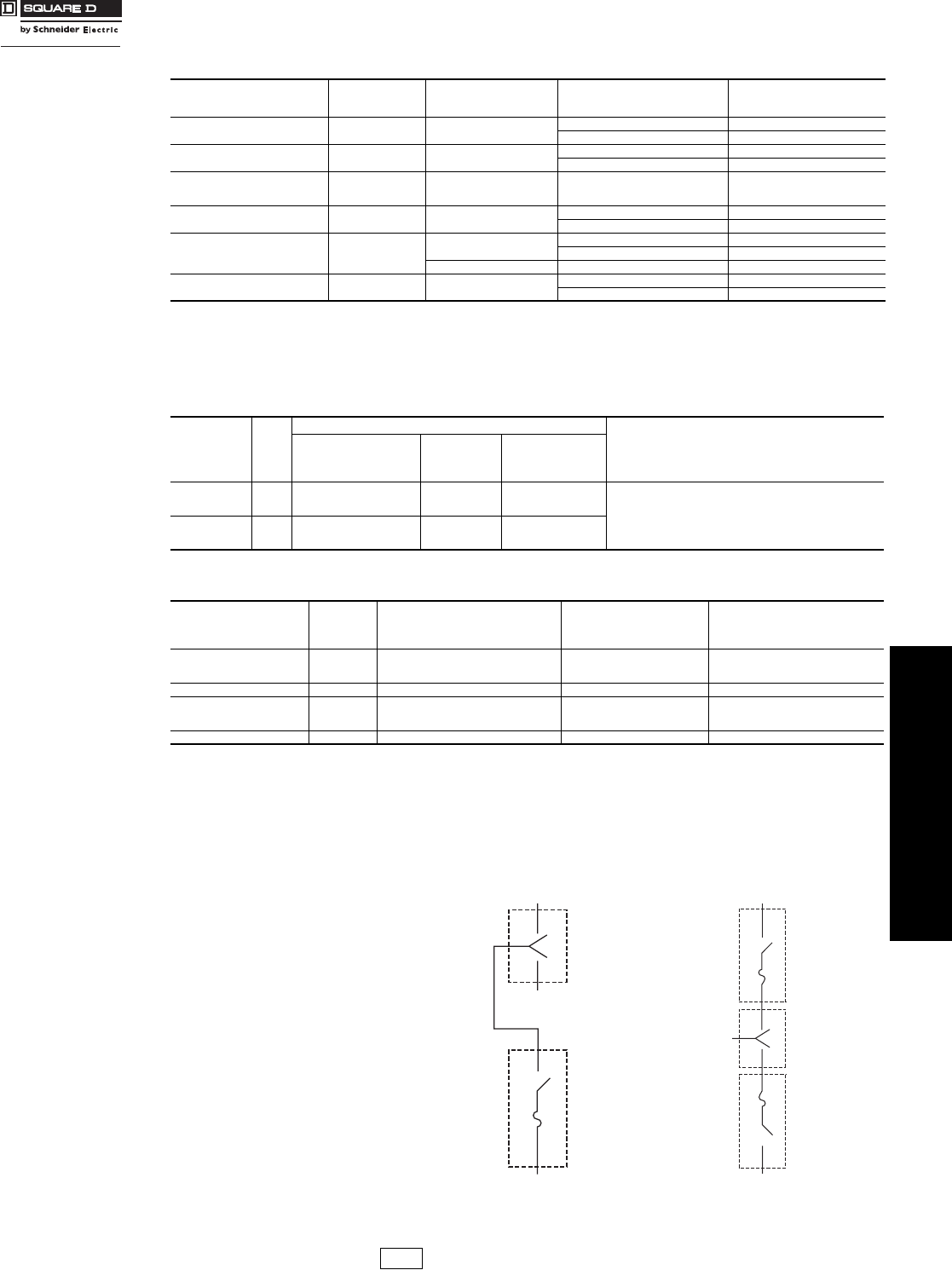
www.schneider-electric.us
3SAFETY SWITCHES
© 2007 Schneider Electric
All Rights Reserved 3-17
Double Throw Safety
Switches
Application Data
Class 3140
aRating applies to AC only. The UL Listed short circuit current rating for non-fusible switches is based on the switch being used in conjunction with the
corresponding fuse type. Evaluation of non-fusible switches in conjunction with molded case circuit breakers has not been performed.
bThe DTU361 and DTU361RB are also suitable for use on a circuit capable of delivering not more than
(A) 18 kA, 600 Vac maximum when protected by Type FH circuit breaker rated 30 A maximum or
(B) 14 kA, 600 Vac maximum when protected by Type FA circuit breaker rated 30 A maximum.
cAny brand of circuit breaker or fuse not exceeding the ampere rating of the switch may be used ahead of a non-fused safety switch when there is up to
10 kA short circuit current available.
d400 A 82,000 switch is only 10 kA.
eThomas and Betts catalog numbers.
fVersa-Crimp® catalog numbers.
g200–600 A switches suitable for 75oC conductors.
h30 A switches suitable for 60oC or 75oC conductors.
iVersa-Crimp® catalog numbers.
240 V Double Throw . . . . . . . . . . . . . . . . . . . . . . . . . . . . . . . . . . . . .page 3-15
600 V Double Throw . . . . . . . . . . . . . . . . . . . . . . . . . . . . . . . . . . . . page 3-16
Dimensions: 30–100 A (Series F) . . . . . . . . . . . . . . . . . . . . . . . . . page 3-18
Dimensions: 30, 200–600 A (Series E, T4, A). . . . . . . . . . . . . . . . .page 3-19
Accessories . . . . . . . . . . . . . . . . . . . . . . . . . . . . . . . . . . . . . . . . . . . .page 3-20
Situations Requiring
Fuses
30–100 A Type DT
(Series F):
Select DT switches from
pages 3-15, 3-16, which
have provisions for
accepting fuses.
30, 200–600 A Type
82,000 (Series E, T4, A),
all DTU devices:
Use the non-fusible
double throw switches
from pages 3-15, 3-16 in
conjunction with standard
fused devices, and install
them according to the
diagram 1 or 2.
Non-Fusible
D/T Switch
Line
Line
Load
Fusible
Single
Throw
Switch or
Circuit
Breaker
Diagram 1
Non-Fusible
D/T Switch
Line
Line
Fusible
Single
Throw
Switch or
Circuit
Breaker
Fusible
Single
Throw
Switch or
Circuit
Breaker
Load
Diagram 2
Table 3.40: UL Listed Short Circuit Current Ratings
Switch Type Ampere Rating Vol tage
Rating
UL Listed
Fuse Class
Short Circuit
Current Rating a
(A)
Type D T
(Series F) 30–100 A 240 V or
600 V
H, K 10,000
R, J 200,000
Type DTU b
(Series F) 30–100 A 240 V or
600 V
H or K 10,000 c
R, J or T 200,000
DTU224NRB and
DTU324NRB
(Series E)
200 A 240 V H, K 10,000 c
DTU324N
(Series E) 200 A 240 V H, K 10,000 c
R, J 100,000
Type 82,000 all 240 V H, K 10,000 c
R, J 100,000 d
600 V H, K 10,000 c
Type DTU (A series) 600 A 240 V or 600 V H, K 10,000
R, J, T 100,000
Table 3.41: Terminal Lug Data for Type DT, DTU (Series F) Double Throw Safety Switches
Switch
Wires
per
Phase
NEMA 1, 3R, 4, 4X, 12
Optional Copper Only Lug
Wire Range
Wire Bending Space
Per NEC Table 373-6
AWG/kcmil
Standard Lug
Wire Range
AWG/kcmil
Optional
Compression Lug
Field-Installable
30–60 A
Type DT, DTU
(Series F)
1
12–2 Al
or
14–2 Cu
12–2 Al
or
14–2 Cu
C10-14,
D8-14,
or E6-14 eSee pages 3-11 and 3-13 for appropriate kit.
Order 2 kits per switch.
100 A
Type DT, DTU
(Series F)
1
12–1/0 Al
or
14–1/0 Cu
12–1/0 Al
or
14–1/0 Cu
VCEL02114S1 f
Table 3.42: Terminal Lug Data for Types 82,000 and for A and E-Series DTU devices g
Switch
Wires
per
Phase
Wire Range
Wire Bending Space
Per NEC Table 373-6
AWG/kcmil
Lug Wire Range
AWG/kcmil
Optional
Compression Lugs
Field-Installable
30 A (Series T4) h1 14–8 Al/Cu
12–2 Al
or
14–2 Cu
—
200 1 6–300 Al/Cu 6–300 Al/Cu VCEL030516H1 i
400
1
or
2
1/0–600 Al/Cu
or
1/0–300 Al/Cu
1/0–600 Al/Cu —
600 2 250–500 Al/Cu 250–500 Al/Cu —
DE1 Discount
Schedule
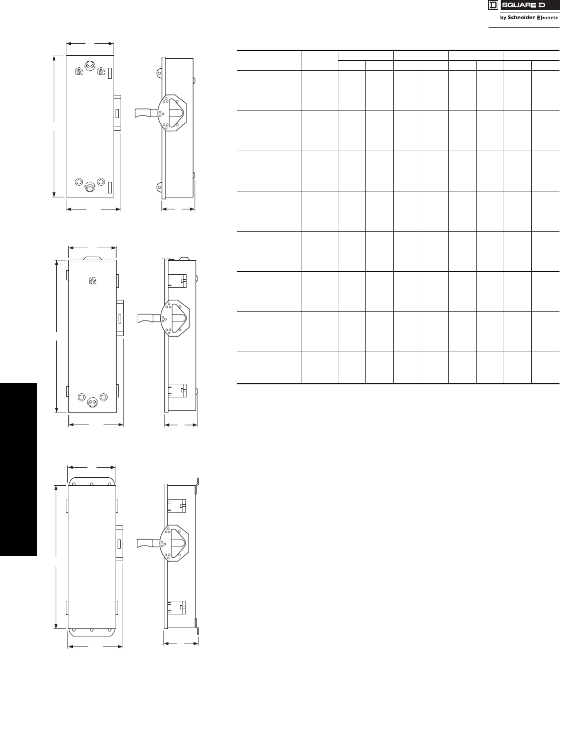
www.schneider-electric.us
3SAFETY SWITCHES
3-18 © 2007 Schneider Electric
All Rights Reserved
Double Throw Safety Switches Dimensions—Series F Devices
Class 3140
240 V Double Throw . . . . . . . . . . . . . . . . . . . . . . . . . . . . . . . . . page 3-15
600 V Double Throw . . . . . . . . . . . . . . . . . . . . . . . . . . . . . . . . . . . . page 3-16
Application Data . . . . . . . . . . . . . . . . . . . . . . . . . . . . . . . . . . . . . page 3-17
Dimensions: 30, 200–600 A (Series E, T4, A) . . . . . . . . . . . . . . . . page 3-19
Accessories . . . . . . . . . . . . . . . . . . . . . . . . . . . . . . . . . . . . . . . . . . . page 3-20
Table 3.43: 30–100 A Type DT, DTU (Series F)—Approximate Dimensions
Cat. No. Series HWW/HD
in. mm in. mm in. mm in. mm
DT223 F5 38.00 965 9.88 251 11.13 283 6.75 171
DT223RB F5 38.00 965 6.87 174 8.12 206 6.60 168
DT321 F5 38.00 965 10.25 260 11.50 292 6.75 171
DT321RB F5 38.00 965 10.25 260 11.80 300 6.60 168
DT322 F5 38.00 965 10.25 260 11.50 292 6.75 171
DT322RB F5 38.00 965 10.25 260 11.80 300 6.60 168
DT323 F5 38.00 965 9.88 251 11.13 283 6.75 171
DT323RB F5 38.00 965 6.87 174 8.12 206 6.60 168
DT361 F5 38.00 965 10.25 260 11.50 292 6.75 171
DT361RB F5 38.00 965 10.25 260 11.80 300 6.60 168
DT362 F5 38.00 965 10.25 260 11.50 292 6.75 171
DT362RB F5 38.00 965 10.25 260 11.80 300 6.60 168
DT363 F5 38.00 965 9.88 251 11.13 283 6.75 171
DT363RB F5 38.00 965 6.87 174 8.12 206 6.60 168
DTU222 F5 29.94 760 10.25 260 11.96 304 6.93 176
DTU223 F5 29.94 760 10.25 260 11.96 304 6.93 176
DTU223RB F5 30.50 775 10.25 260 11.96 304 6.93 176
DTU321 F5 29.94 760 10.25 260 11.96 304 6.93 176
DTU322 F5 29.94 760 10.25 260 11.96 304 6.93 176
DTU323 F5 29.94 760 10.25 260 11.96 304 6.93 176
DTU323RB F5 30.50 775 10.25 260 11.96 304 6.93 176
DTU361 F5 29.94 760 10.25 260 11.96 304 6.93 176
DTU361RB F5 30.50 775 10.25 260 11.96 304 6.93 176
DTU362 F5 29.94 760 10.25 260 11.96 304 6.93 176
DTU362AWK F6 29.94 760 10.25 260 11.96 304 6.93 176
DTU362DS F6 30.26 769 10.25 260 11.50 292 7.12 181
DTU362RB F5 30.50 775 10.25 260 11.96 304 6.93 176
DTU363 F5 29.94 760 10.25 260 11.96 304 6.93 176
DTU363AWK F6 29.94 760 10.25 260 11.96 304 6.93 176
DTU363DS F6 30.26 769 10.25 260 11.50 292 7.12 181
DTU363RB F5 30.50 775 10.25 260 11.96 304 6.93 176
DTU462 F5 29.94 760 10.25 260 11.96 304 6.93 176
DTU462AWK F6 30.26 769 15.50 394 16.75 425 7.12 181
DTU462DS F6 30.26 769 15.50 394 16.75 425 7.12 181
DTU463 F5 29.94 760 10.25 260 11.96 304 6.93 176
DTU463AWK F6 30.26 769 15.50 394 16.75 425 7.12 181
DTU463DS F6 30.26 769 15.50 394 16.75 425 7.12 181
DTU662AWK F6 30.26 769 15.50 394 16.75 425 7.12 181
DTU663AWK F6 30.26 769 15.50 394 16.75 425 7.12 181
W
W/H D
H
NEMA 1
W
W/H D
H
NEMA 4, 4X, 5 and 12
W
W/H D
H
NEMA 3R
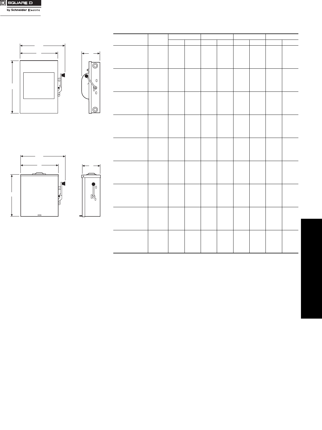
www.schneider-electric.us
3SAFETY SWITCHES
© 2007 Schneider Electric
All Rights Reserved 3-19
Double Throw Safety Switches Dimensions—Series E, T4 Devices
Class 3140
240 V Double Throw . . . . . . . . . . . . . . . . . . . . . . . . . . . . . . . . . . . . page 3-15
600 V Double Throw . . . . . . . . . . . . . . . . . . . . . . . . . . . . . . . . . . . . page 3-16
Application Data . . . . . . . . . . . . . . . . . . . . . . . . . . . . . . . . . . . . . . . .page 3-17
Dimensions: 30–100 A (Series F) . . . . . . . . . . . . . . . . . . . . . . . . . . page 3-18
Accessories. . . . . . . . . . . . . . . . . . . . . . . . . . . . . . . . . . . . . . . . . . . . page 3-20
Table 3.44: 30, 200–600 A Types 82,000 and E-Series DTU devices, NEMA 1 and
3R—Approximate Dimensions
Cat. No. Series HWW/HD
in. mm in. mm in. mm in. mm
DTU224NRB E1 32.50 826 20.63 524 24.00 610 10.63 270
82254 E1 30.88 784 15.75 400 19.63 499 9.75 248
82254NW E1 30.88 784 20.00 508 23.88 607 11.75 298
82344 E2 30.88 784 20.00 508 23.88 607 11.75 298
82344RB E1 32.50 826 20.63 524 24.00 610 10.63 270
82354 E1 30.88 784 20.00 508 23.88 607 11.75 298
92251 T4 10.00 254 8.00 203 9.75 248 4.75 121
82344DS E1 30.88 784 20.00 508 23.88 607 11.75 298
DTU324N E1 32.50 826 24.50 622 26.25 667 10.63 270
DTU324NRB E1 32.50 826 24.50 622 26.25 667 10.63 270
H82344 E2 32.50 826 24.50 622 26.25 667 10.63 270
H82444 E2 32.50 826 30.21 767 33.61 854 10.63 270
H82454 E3 32.50 826 30.21 767 33.61 854 10.63 270
82454 E3 38.00 965 29.62 753 33.02 839 10.63 270
82444 E3 38.00 965 29.62 753 33.02 839 10.63 270
82454R E3 38.00 965 29.62 753 33.02 839 10.63 270
82444R E3 38.00 965 29.62 753 33.02 839 10.63 270
H82254 E3 32.50 826 24.50 622 26.25 667 10.63 270
H82354 E3 32.50 826 24.50 622 26.25 667 10.63 270
82444DS E3 38.00 965 29.62 753 33.02 839 10.63 270
82255 A1 38.50 978 26.10 663 29.51 750 10.63 270
82255R A1 39.00 991 26.62 676 30.02 763 10.63 270
82345 A1 38.50 978 26.10 663 29.51 750 10.63 270
82345DS A1 39.00 991 26.62 676 30.02 763 10.63 270
82345R A1 39.00 991 26.62 676 30.02 763 10.63 270
82355 A1 38.50 978 26.10 663 29.51 750 10.63 270
82355R A1 39.00 991 26.62 676 30.02 763 10.63 270
82445 A1 38.50 978 30.10 765 33.50 851 10.63 270
82445R A1 39.00 991 30.21 767 33.61 854 10.63 270
82455 A1 38.50 978 30.10 765 33.50 851 10.63 270
82455R A1 39.00 991 30.21 767 33.61 854 10.63 270
H82255 A1 39.00 991 26.62 676 30.02 763 10.63 270
H82345 A1 39.00 991 26.62 676 30.02 763 10.63 270
H82355 A1 39.00 991 26.62 676 30.02 763 10.63 270
H82445 A1 39.00 991 30.21 767 33.61 854 10.63 270
H82455 A1 39.00 991 30.21 767 33.61 854 10.63 270
DTU326 A1 63.31 1608 23.66 601 24.46 621 8.88 226
DTU426 A1 63.31 1608 27.00 686 27.80 706 8.88 226
DTU366 A1 63.31 1608 23.66 601 24.46 621 8.88 226
DTU466 A1 63.31 1608 27.00 686 27.80 706 8.88 226
DTU326R A1 63.76 1619 23.66 601 24.46 621 8.88 226
DTU426R A1 63.76 1619 27.00 686 27.80 706 8.88 226
DTU366R A1 63.76 1619 23.66 601 24.46 621 8.88 226
DTU466R A1 63.76 1619 27.00 686 27.80 706 8.88 226
DTU366AWK A1 63.76 1619 23.66 601 24.46 621 8.88 226
W
W/H
D
H
NEMA 1
W
H
D
W/H
DTU—200 A
NEMA 3R
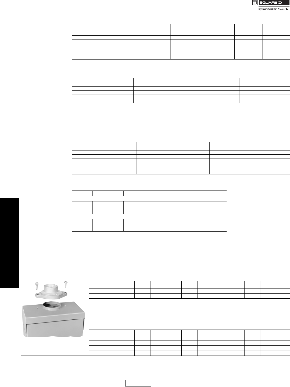
3-20 © 2007 Schneider Electric
All Rights Reserved
www.schneider-electric.us
3SAFETY SWITCHES
Double Throw Safety
Switch
Accessories
Class 3140
aFor Type 82,000 switches, neutral is available factory-installed on 2P and 3P double throw switches. Not UL Listed. To order, add suffix N to the standard
catalog number and add the above price to the list price of the switch. For DTU switches, neutral is factory-installed in standard device and is UL Listed.
bNeutral assembly catalog number DT200N can be added to 4P Type 82000 switches in the field.
cElectrical interlock kit catalog numbers with “1” suffix indicate one normally open and normally closed contact; “2” indicates two normally open and two
normally closed contacts. See page 3-9 for electrical interlock ratings.
d30–100 A Type DT, DTU (Series F) switches contain (2) separate switching mechanisms. Each mechanism will accept an electrical interlock. Some
applications may therefore require (2) electrical interlocks.
e30–100A Type DT, DTU (Series F) switches with factory-installed electrical interlocks installed are UL Listed and interlocks are furnished with 2 N.O. /2
N.C. contacts installed in both “ON” positions. To order, add suffix EI to standard catalog number.
fElectrical interlock EK400DTU2 can be added to 4-pole Type 82000 switches in the field.
gType 82000 and DTU switches are available with electrical interlock factory-installed only. Not UL listed. Electrical interlocks are furnished with 2
N.O./N.C. contacts and are installed in both “ON” positions. To order, add suffix EI to standard switch catalog number.
Key Interlock Systems
For factory-installed key interlocks, refer to page 3-11.
Phenolic Legend Plate
For factory-installed phenolic legend plates, refer to page 3-10.
Lock-On Provisions—UL Listed
30–100 A type DT, DTU (Series F) and type 92,000 included on standard device.
Type 82,000 and 200 A DTU (Series E) available factory-installed. Add SPLO to catalog number and add $273. to list price.
240 V Double Throw . . . . . . . . . . . . . . . . . . . . . . . . . . . . . . . . . . . . page 3-15
600 V Double Throw . . . . . . . . . . . . . . . . . . . . . . . . . . . . . . . . . . . . page 3-16
Application Data . . . . . . . . . . . . . . . . . . . . . . . . . . . . . . . . . . . . . . . . page 3-17
Dimensions: 30–100 A (Series F) . . . . . . . . . . . . . . . . . . . . . . . . . . page 3-18
Dimensions: 30, 200–600 A (Series E, T4, A) . . . . . . . . . . . . . . . . page 3-19
Table 3.45: Neutral Assembly
Switch
Field-Installed
Standard Neutral Kit
Cat. No.
Terminal
Data
AWG/kcmil
$ Price
Field-Installed
Copper only
Neutral Kit Cat. No.
Terminal
Data
AWG/kcmil
$ Price
30–100 A Type DT, DTU (Series F) (2- and 3-pole switches only) SN0310 14–1/0 Al/Cu 76.00 SN0310C 14–1/0 Cu 80.00
30 A (Series T4) (2- and 3-pole switches only) aa605.00 ———
200 A Type 82000 and DTU (Series E) baa740.00 ———
400 A Type 82000 DT400N (1) 4–600kcmil or
(2) 1/0–250kcmil 70.00 ———
600 A Type DTU (Series A) DT600NKD 250–500kcmil 301.00 ———
Table 3.46: Electrical Interlocks
Switch Field-Installed Electrical Interlock Kit Cat. No. c$ Price Factory-Installed
$ Price Adder Per Switch
30–100 A Type DT, DTU (Series F) EIK1, EIK2 d207.00 603.00e
200 A Type 82000 and DTU (Series E) fg—742.00e
400 A Type 82000 EK400DTU2 173.00 —
600 A Type DTU (Series A) DS200EK2D 292.00 —
Table 3.47: Service Grounding Kit (Required for service equipment use.)
Switch Field-Installed Service Grounding Lug Kit Cat. No. Terminal Data
AWG/kcmil $ Price
30–100 A Type DT, DTU (Series F) Included Included std.
30 A Type 92,000 DT30SG (4) 14–4 Cu/Al 19.60
200 A Type 82000 and DTU (Series E) DT100SG (3) 14–1/0 Cu/Al 20.00
400 A Type 82000 PKOGTA2
(2 required)
(4) 10–2/0 Cu or
(4) 6–2/0 Al 36.80
600 A Type 82000 (Series A) DS468GKD 6–250kcmil 206.00
Table 3.48: Class R Fuse Kits
When installed, this kit rejects all but Class R fuses. Kits are available for field installation.
For factory installation, add “CLR” suffix to catalog number.
Switch Series Number Class R Fuse Kit Cat. No. $ Price Factory-Installed $ Price
Class R Fuse Kits—240 V (two kits per 3P switch)
30 A F5 RFK03 16.30 260.00
60 A F5 RFK06 17.00 260.00
100 A F5 RFK10 31.80 260.00
Class R Fuse Kits—600 V (two kits per 3P switch)
30 A F5 RFK06 17.00 260.00
60 A F5 RFK06H 17.00 260.00
100 A F5 RFK10 31.80 260.00
Table 3.49: Rainproof Bolt-On Hubs—For Use On NEMA 3R Enclosures
Conduit Size 3/4 1 1-1/4 1-1/2 2 2-1/2 3 3-1/2 4 Closing
Cap
Hub Cat. No. B075 B100 B125 B150 B200 B250 B300 B350 B400 BCAP
$ Price Eachh22.20 22.20 22.20 22.20 40.90 68.00 124.00 200.00 245.00 2.50
Note: NEMA 3R rainproof enclosures with catalog number ending in RB have a bolt-on closing cap factory-installed. Order bolt-on hubs separately
from table above. For more details see page 1-13. Hubs through size 2-1/2 in. can be directly installed on RB devices. Devices requiring 3
in. or larger hubs must have holes cut in the field. Gaskets are provided on 3 in. and larger hubs.
Note: All hubs are UL Listed for indoor and rainproof applications and suitable for use with conduit having ANSI standard taper pipe thread.
hSee Discount Schedule.
Table 3.50: Watertight Hubs—For Use On NEMA 4, 4X and 5 Stainless Steel and NEMA 12
Enclosures
Conduit Trade Size 1/23/4 11-1/41-1/222-1/233-1/24
Standard-Zinc Hub Cat. No. H050 H075 H100 H125 H150 H200 H250 H300 H350 H400
Zinc $ Price Each 20.70 30.00 31.40 36.00 55.00 80.00 92.00 118.00 188.00 254.00
Chrome Plated Hub Cat. No. H050CP H075CP H100CP H125CP H150CP H200CP ————
Chrome Plated $ Price Each 27.10 37.60 42.90 44.60 64.00 91.00 ————
“RB Hub”
DE1 DE1A Discount
Schedule Modified
4/16/09
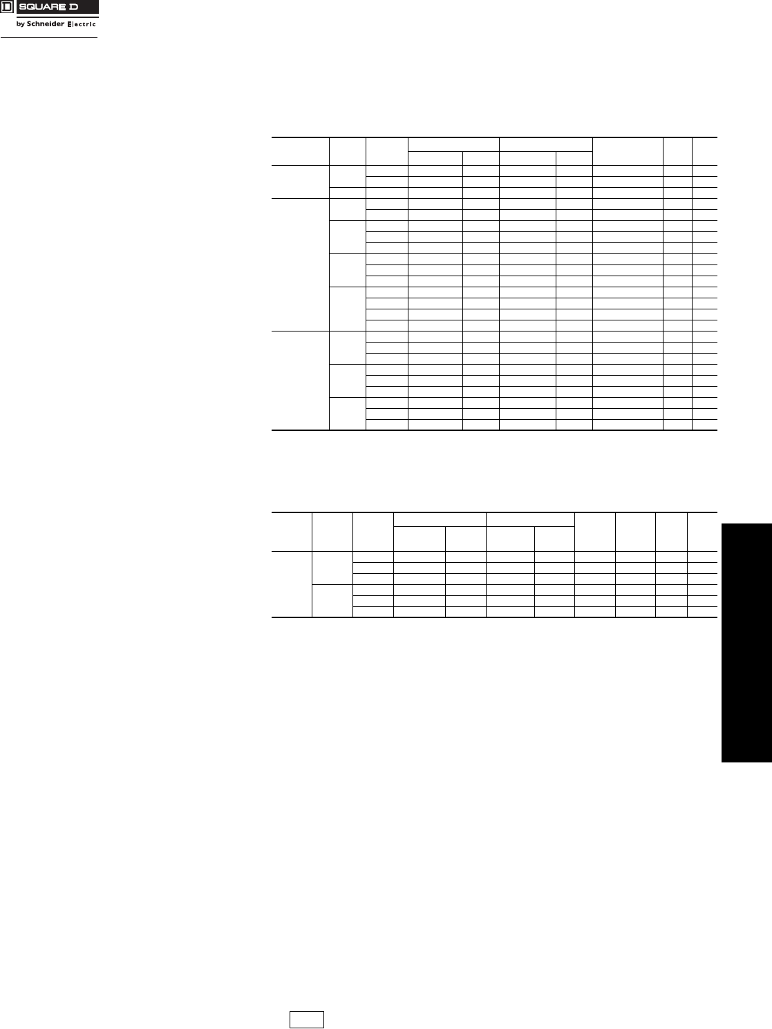
www.schneider-electric.us
3SAFETY SWITCHES
© 2007 Schneider Electric
All Rights Reserved 3-21
Heavy Duty Safety Switches MD50 Motor Disconnect Switches
Class 3110
The MD50 Motor Disconnect Switch’s IEC309-2 pin and sleeve technology merged with a
durable mechanical interlock features provide safe, quick and reliable mating of mobile and
fixed motors to power connections. The mechanical interlock prevents the making or
breaking under load of plug connected equipment. The plug must be inserted before the
power can be turned “ON”. The plug can not be removed until the power is turned “OFF”.
Grounding and conduit Hub included.
NOTE: Auxiliary Contact’s ordering information;
20 and 30 Amps non-fused, ME2030AUX
60 A and 100 Amps non-fused, ME80AUX, ME20
aUL98 Listed.
NOTE: Auxiliary Contact’s ordering information;
30 Amps fused, ME30FDAUX
60 Amps fused, ME60FDAUX
Type J Fuses
Table 3.51: Non-Fusible
System Amperes Voltage NEMA 4X and 12 Use With Plug Horse Power
Rating Phase Wire
Size
Cat No. $ Price Cat. No. $ Price
2-Pole 3-Wires 30 125 MD330MI4 823.86 ME330P4W 142.79 2 1 12–8
250 MD330MI6 832.86 ME330P6W 142.79 5 1 12–8
60 250 MD360MI6 1091.69 ME360P6W 234.71 10 1 6–2
3-Pole 4-Wires
20 250 MD420MI9 787.50 ME420P9W 108.17 7.5 3 12–8
480 MD420MI7 787.50 ME420P7W 108.17 15 3 12–8
30
250 MD430MI9 762.14 ME430P9W 157.21 10 3 12–8
480 MD430MI7 762.14 ME430P7W 157.21 20 3 12–8
600 MD430MI5 889.97 ME430P5W 157.21 20 3 12–8
60
250 MD460MI9 1040.45 ME460P9W 229.33 20 3 6–2
480 MD460MI7 1040.45 ME460P7W 229.33 40 3 6–2
600 MD460MI5 1307.06 ME460P5W 229.33 50 3 6–2
100
125/250 MD4100MI12 1181.88 ME4100P12 310.10 125 V 5, 250 V 15 1 6–1/0
240 MD4100MI9 1415.05 ME4100P9 310.10 25 3 6–1/0
480 MD4100MI7 1273.79 ME4100P7 310.10 50 3 6–1/0
600 MD4100MI5 1415.05 ME4100P5 310.10 50 3 6–1/0
4-Pole 5-Wires
30
Y120/208 MD530MI9 821.85 ME530P9W 194.71 7.5 3 12–8
Y277/480 MD530MI7 887.59 ME530P7W 194.71 20 3 12–8
Y347/600 MD530MI5 887.59 ME530P5W 194.71 20 3 12–8
60
Y120/208 MD560MI9 1084.91 ME560P9W 272.60 20 3 6–2
Y277/480 MD560MI7 1139.16 ME560P7W 272.60 40 3 6–2
Y347/600 MD560MI5 1301.90 ME560P5W 272.60 50 3 6–2
100
Y120/208 MD5100MI9 1415.05 ME5100P9 373.56 25 3 6–1/0
Y277/480 MD5100MI7 1415.05 ME5100P7 373.56 50 3 6–1/0
Y347/600 MD5100MI5 1415.05 ME5100P5 373.56 50 3 6–1/0
Table 3.52: Fusiblea
System Amperes Voltage
NEMA 4X and 12 Use With Plug Horse
Power
Rating
Horse
Power
Rating
Max.
Phase Wire
Size
Cat. No. $ Price Cat. No. $ Price
3-Pole
4-Wires
30
250 MD430MIF9 1087.54 ME430P9W 157.21 37.5318–8
480 MD430MIF7 1368.77 ME430P7W 157.21 5 15 3 18–8
600 MD430MIF5 1196.12 ME430P5W 157.21 7.5 20 3 18–8
60
250 MD460MIF9 1342.07 ME460P9W 229.33 7.5 15 3 14–4
480 MD460MIF7 1419.09 ME460P7W 229.33 15 30 3 14–4
600 MD460MIF5 1415.05 ME460P5W 229.33 15 30 3 14–4
DE1 Discount
Schedule Modified
4/16/09

3-22 © 2007 Schneider Electric
All Rights Reserved
www.schneider-electric.us
3SAFETY SWITCHES
