Gavita EL2 Master Controller EN V1.2 906121 Instructions
2018-07-04
: Pdf 906121 Instructions 906121_Instructions product s
Open the PDF directly: View PDF ![]() .
.
Page Count: 36
User manual
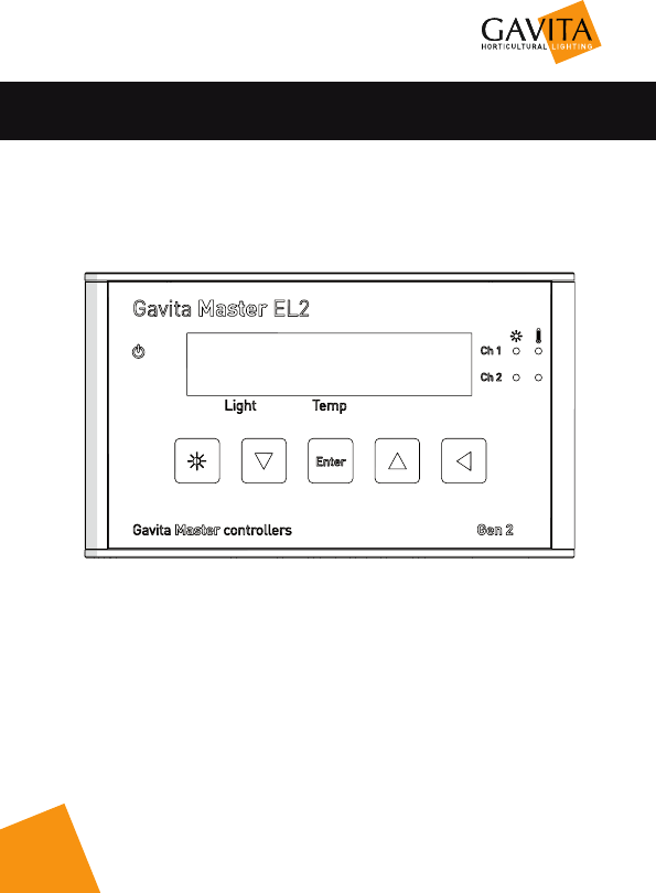
Gavita Master Controller EL2


3
User manual
Gavita Master controller EL2
Dear customer,
Congratulations on the purchase of your Gavita Master controller EL2.
This manual contains all the information necessary to install, use and maintain the
Gavita Master controller EL2. Please read and understand this manual completely
before installing and using the product.
Consult the index at the start of this manual to locate information relevant to you.
In this manual, the Gavita Master controller EL2 will be referred to as “the
controller”.
This is the original manual, keep it in a safe location!

4
Table of content
1. Introduction 7
1.1. Product description 7
1.2. Glossary of Terminology 7
1.3. Used symbols 7
2. Product specifications 8
2.1. General product information 8
2.2. Technical specifications 8
2.3. Environment 8
2.4. Components 9
2.5. Controls 10
2.6. Indications 10
2.7. Connections 11
2.8. Accessories 12
2.9. Compatible ballasts and fixtures 13
3. Safety guidelines and measures 13
4. Installing the controller 14
4.1. Preparations 14
4.2. Setting up the controller 17
4.3. Connecting a temperature shutdown-, sensor failure- or power-off alarm 20
4.4. Connecting auxiliary equipment using the External Contactor Module (ECM) 20
4.5. Controlling auxiliary equipment 21
4.6. Calibrating the temperature sensor(s) 22
4.7. Setting the sunrise and sunset period 22
5. Using the controller 24
5.1. Activating or deactivating lights 24
5.2. Setting light intensity 24
5.3. Reading the default screen 25
5.4. Show system time and temperature settings 25
5.5. Interpreting LED signals 26
5.5.1. Green light (A) 26
5.5.2. Blue light (C/D) 26
5.5.3. Red light (E/F) 26
5.6. Error messages and solutions 26
5.6.1. Sensor disconnected 26
5.6.2. Sensor failure 27
5.6.3. Controller Overload 27
5.6.4. Auto-dim 27
5.6.5. Temp Alarm 27
5.7. After a power loss 28

5
5.8. Reading the log 28
5.9. View the firmware version on the controller 28
5.10. Reset to factory settings 28
6. Maintenance and Repair 29
7. Environment and Disposal 29
8. Warranty 29

7
1. Introduction
1.1. Product description
The Gavita Master controller EL2 is a dual channel light controller. Each
of the controller’s two channels can control up to 40 (250*) Gavita e-series
fixtures or ballasts. It is possible to use those channels to control fixtures in
two completely independent rooms, or to control up to 80 (500*) fixtures in
one room.
With an External Contact Module (ECM) auxiliary equipment can be
controlled. Up to two ECMs can be connected. An alarm can be connected to
go off at temperature shutdown or power outage. These devices need to be
purchased separately.
* When using a repeater bus fixture or ballast. Check the specifications of your
fixture for more information.
1.2. Glossary of Terminology
Cage clamp Wire clamp
Ballast A ballastis a device intended to ignite and power
HID lamps
Complete fixture A ballast integrated with a reflector and lamp
1.3. Used symbols
The following icons will be used throughout the manual:
Warning! A warning indicates severe damage to the user and/or product may
occur when a procedure is not carried out as described.
Caution! A caution sign indicates problems may occur if a procedure is not
carried out as described.
Note/Example: A note or example provides tips and addition information to
the user.
8
2. Product specifications
2.1. General product information
Product name Master Controller EL2
Product code 41.00.XX.XX
Producer Gavita International bv
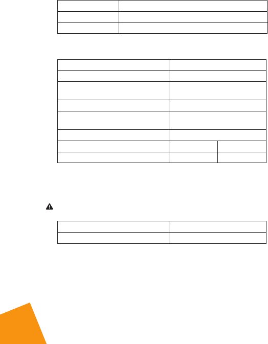
2.2. Technical specifications
Controller dimensions (LxWxH) 110 x 21 x 65 mm
Weight 115 gram
Power supply Adapter: 100V-240V AC 50/60hz -
15V DC (1000mA)
Maximum control voltage 11.5V
Maximum voltage/current alarm
contacts (NO/NC) 13,5V/50mA
Maximum cable length per port 100m (328ft) / 250m (820ft)*
Maximum number of ballasts per port 40 250*
Total number of ballasts per controller 80 500*
* When using a repeater bus fixture or ballast
2.3. Environment
Warning! The product may not be exposed to moisture, condensing humidity,
contamination or dust.
Temperature range 0-35 OC / 32 - 95 OF
Operating humidity (non-condensing) <80%
9
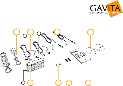
2.4. Components
EFG
III
A
I
B C D
H
A. Gavita Master controller EL2
I. Mounting plate
B. 2x Countersunk screw
C. 2x Plug
D. Manual
E. 120-240V AC - 15V DC power adapter (1000mA)
F. 2x Controller cable (5m/16ft)
I. RJ (6P4C) plug (connect to ballasts)
II. RJ (4P4C) plug (connect to controller)
G. 2x Temperature sensor with cable (5m/16ft)
H. 2x Hood
10
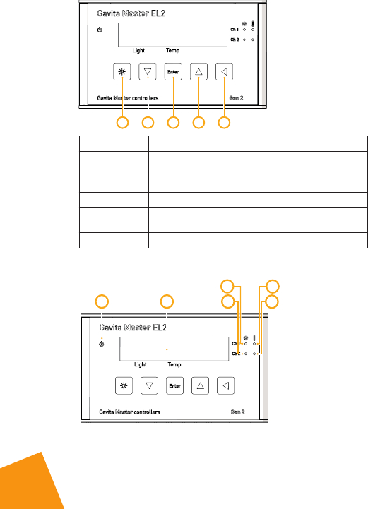
2.5. Controls
A EDCB
Key Function
A Quick-key View output level
B Down Navigate down in menu / decrease value
Press and hold to scroll / decrease smoothly
C Enter Go to menu / confirm
D Up Navigate up in menu / increase value
Press and hold to scroll / increase smoothly
E Back Navigate back in menu / cancel / reset
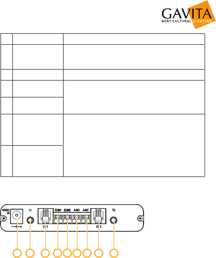
2.6. Indications
AB
C
D
E
F
11
Signal Function
APower
A burning green light indicates controller is active.
A blinking green light indicates a power
interruption has occured during operation.
B Display Displays status, warnings and controller menu.
C Light CH1 A burning blue light indicates the port is active.
Blue light off indicates the port is inactive.
D Light CH2
ETemperature
warning CH1
A burning red light indicates the auto-dim
temperature has been exceeded in the past.
A blinking red light indicates the auto-dim
temperature threshold is currently exceeded. The
corresponding output channels are being dimmed.
A fast blinking red light indicates the shutdown
temperature threshold has been exceeded.
All output channels have been shut down.
FTemperature
warning CH2
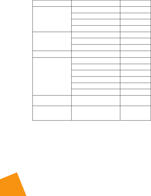
2.7. Connections
AEDCB F G H I
A. 15V DC input
B. 3,5 mm jack main temperature sensor (T1)
C. RJ (4P4C) channel 1 port for controlling up to 40 ballasts
D. Cage clamp connector ECM1 (output is active when main channel is on)
E. Cage clamp connector ECM2 (output is active when main channel is off)
F. Cage clamp alarm Normally Open (potential free contact)
G. Cage clamp alarm Normally Closed (potential free contact)
H. RJ (4P4C) channel 2 port for controlling up to 40 ballasts
I. 3,5 mm jack auxiliary temperature sensor (T2)
12
2.8. Accessories
Accessories are not included, they have to be bought separately. Visit
the website of Gavita International: www.gavita.com for the latest Gavita
products.
Part Variants Product code
Interconnect cable
RJ (6P4C) - RJ (6P4C)
2 ft / 0,60 m 43.50.00.08
5 ft / 1.5 m - standard cable 43.50.00.04
8 ft / 2.4 m 43.50.00.09
10 ft / 3.0 m 43.50.00.10
Controller cable
RJ (4P4C) - RJ (6P4C)
5 ft / 1.5 m 43.50.00.11
16 ft / 5 m - standard cable 43.50.00.12
25 ft / 7.5 m 43.50.00.13
Universal adapter 100V-240V AC 50/60hz 42.02.03.08
External Contactor
Module (ECM)
(with 10 ft / 3 m cable)
US version 120V 15A 42.00.12.20
US version 240V 15A 42.00.24.20
UK version 240V 13A 42.00.24.11
EU version 230V 16A 42.00.23.10
AUS version 240V 10A 42.00.24.60
CH version 240V 10A 42.00.23.12
ECM controller cable
3m/10 ft 10 ft / 3.0 m standard cable 42.03.01.15
Temperature sensor
(with 5 m cable - 3.5
mm mini jack plug)
16 ft / 5.0 m cable length -
standard 42.50.00.14
2.9. Compatible ballasts and fixtures
Ballasts and fixtures are not included, they have to be bought separately.
Visit the website of Gavita International: www.gavita.com for the latest Gavita
products.

13
The Gavita Master controller EL2 is compatible with all Gavita e-series
ballasts and fixtures.
3. Safety guidelines and measures
Warning! Keep the controller away from fire, excessive heat, water, dust and
contamination.
Warning! The Gavita Master controller EL2 may only be used to control
compatible Gavita e-series ballasts. Do not connect the controller to other
products as this may be dangerous and may cause malfunctions in the
connected equipment. Doing so will void the warranty.
Warning! The ECM channels of the Gavita Master controller EL2 may only be
connected to Gavita ECMs. Do not connect the controller to other products as
this may lead to malfunctions or damage and can be dangerous. Doing so will
void the warranty.
Warning! Do not open or disassemble the controller, it contains no
serviceable parts. Opening the controller will void its warranty.
Warning! Make sure the signal wires do not touch the reflectors. The
reflectors get very hot.
14
4. Installing the controller
4.1. Preparations
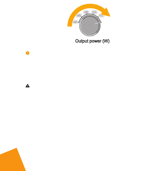
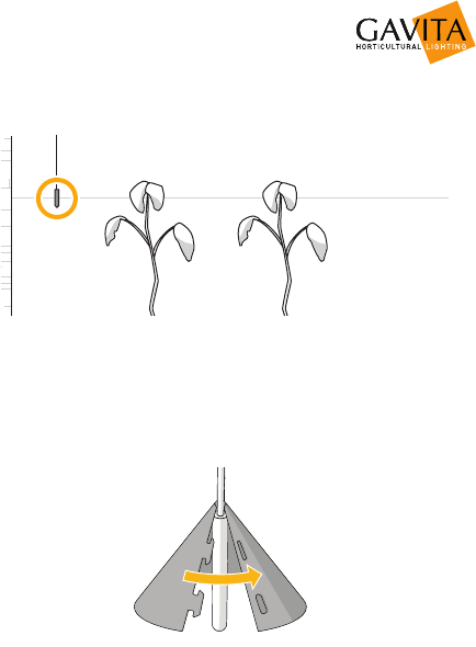
1. Mount the fixtures or ballasts as per your lighting plan. Interconnect them as
described in the manual of the fixture or ballast. Make sure the rotary knob
on all ballasts is set to “EXT” (external control). Connect the ballasts or
fixtures to the mains.
EXT
Each of the controller’s two channels can control up to 40 (250*) Gavita e-series
fixtures or ballasts. It is possible to use those channels to control fixtures in two
separate rooms, or to control up to 80 (500*) fixtures in one room. Channel 2 then
operates in “follow” mode.
* When using a repeater bus fixture or ballast. Check the specifications of your
fixture for more information.
Warning! The controller may only be connected to compatible Gavita e-series
remote ballasts and complete fixtures.
15
2. Find a suitable place for the temperature sensor and the controller. Hang the
sensor between the plants on average canopy height and preferably not
against the wall. Do not position it in direct airflow.
Average canopy height
Wall
Sensor
If you are using another climate control system, hang it close to the sensor of
that system. If necessary, the sensor cable may be lengthened an extra 5
meter with a standard 3.5 mm jack extension cable. A sensor with a cable
length of 30 meter is also available.
3. Cover the temperature sensor from the light. Use the hood supplied with the
controller and fold it around the sensor. Direct light cast upon the sensor will
disrupt temperature measurements.

16
4. Take the controller and remove the mounting plate from the body carefully.
Affix the mounting plate to a wall using the countersunk screws. Remount the
controller on the mounting plate.
5. If necessary, shorten the RJ cables. You’ll need an RJ crimp tool. Cut the
cables to the desired length. Strip 8mm of the outer insulation, but leave the
inner insulation intact. Push the four wires into the middle four openings of
the RJ plug. Crimp the plug on the wire with an RJ crimp tool.
17
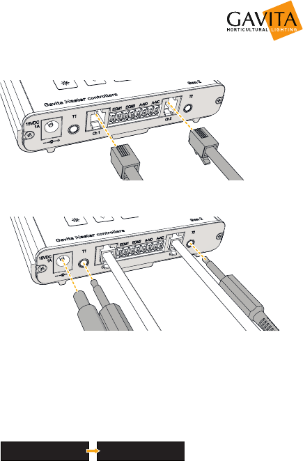
6. Connect the lamp control cables to the controller. Connect the 4P4C end to
the controller, and the 6P6C end to the fixture. The lamps will not ignite yet.
7. Connect the power input and the temperature probes. The display will light
up, and you can continue to set up the controller.
4.2. Setting up the controller
1. The display lights up when the controller is connected to power. It will ask you
to set time and date first. Choose between 12 and 24 hour mode and press
enter to confirm. Set time and date using the arrow keys and press enter to
confirm. If you want to change this later, open the menu and select system
time.
24 HOUR
15:11
DD/MM/YY
05/07/17
FORMAT

18
2. If desired, change the language by pressing enter to open the menu, and
select language. Press enter again to save your choice.
SYSTEM TIME
LANGUAGE
LANGUAGE
ENGLISH
3. By default, temperature is displayed in 0C. If you want to change to 0F, press
enter to open the menu, and select temp probe. Select units and change to
0F. Press enter to confirm.
CHANNEL 2
TEMP PROBE
TEMP UNITS
o
C
4. Press enter to open the menu and select channel 1. Select display mode and
use the arrow keys to select the nominal power of your fixtures. Alternatively,
select 100% to always display power output as a percentage.
LOGS
CHANNEL 1
ECM CONFIG
DISPLAY MODE
DISPLAY W or %
100%
This setting determines how power output is displayed when pressing the key
and does not affect the working of the controller. It is for your reference only.
5. In the channel 1 menu, select output level. Set the desired light intensity and
press enter to confirm.
LOGS
CHANNEL 1
OUTPUT MODE
OUTPUT LEVEL
OUTPUT LEVEL
100%
New lamps need to run at nominal power for at least 100 hours to ensure
they don’t fail prematurely.
6. In the channel 1 menu, select light cycle. Set the time to switch the light on
and the time to switch the light off. Press enter to confirm.
LOGS
CHANNEL 1
OUTPUT LEVEL
LIGHT CYCLE
ON
OFF
06:00
20:00
7. In the channel 1 menu, select set temp levels to set night, day, auto-dim and
shutdown temperature levels.
LOGS
CHANNEL 1
LIGHT CYCLE
SET TEMP LEVELS
DAY
AUTO-DIM
27.5C
30.0C
19
Auto-dim & shutdown: if the temperature rises above the set treshold, the lamps
will firstly be dimmed and, if the temperature continues to rise, shut down to
prevent crop damage.
8. Set channel 2 mode. Channel 2 can either follow the settings of channel 1,
invert them or operate completely independent. Open the menu and select
ch2 mode.
TEMP PROBE
CH2 MODE
CH2 MODE
FOLLOW MAIN
• Select follow main if all fixtures are located in one room or two identical
rooms.
• Select independent or inverse if the fixtures of channel 2 are located in
a different room.
If channel 2 is set to “independent” or “inverse” mode, it needs a temperature
sensor and fans of its own. Follow the steps in paragraph 4.1 and connect the
temperature sensor to jack input T2 on the controller. Select channel 2 in the
menu and repeat steps 3 to 9 in this paragraph to program channel 2.
9. New lamps need to run for at least 100 hours at nominal power to ensure
they do not fail prematurely. Select output level in both channel menus and
set to 100% . Select output mode in both channel menus and set to on.
LOGS
CHANNEL 1
OUTPUT MODE
OUTPUT LEVEL
OUTPUT MODE
ON
10. After this minimum period of 100 hours, browse to output mode in the
channel menus and set to auto. If channel 2 is set to follow mode, only
channel 1 needs to be set to auto. The controller will now operate as
programmed.
LOGS
CHANNEL 1
OUTPUT MODE
OUTPUT LEVEL
OUTPUT MODE
AUTO
11. Check the status LEDs of the ballasts or fixtures. Consult the manual of the
fixture for the meaning of the codes and possible solutions to errors. Check
the controller display. If it indicates an overload, recheck your RJ cables.
20
4.3. Connecting a temperature shutdown-, sensor failure- or
power-off alarm
Temperature shutdowns and power outages will always be logged. Access the log
by opening the menu and selecting logs.
The controller will remember its settings after a power outage. Time and date are
kept for approximately 40 hours. After this period, you’ll need to set this again.
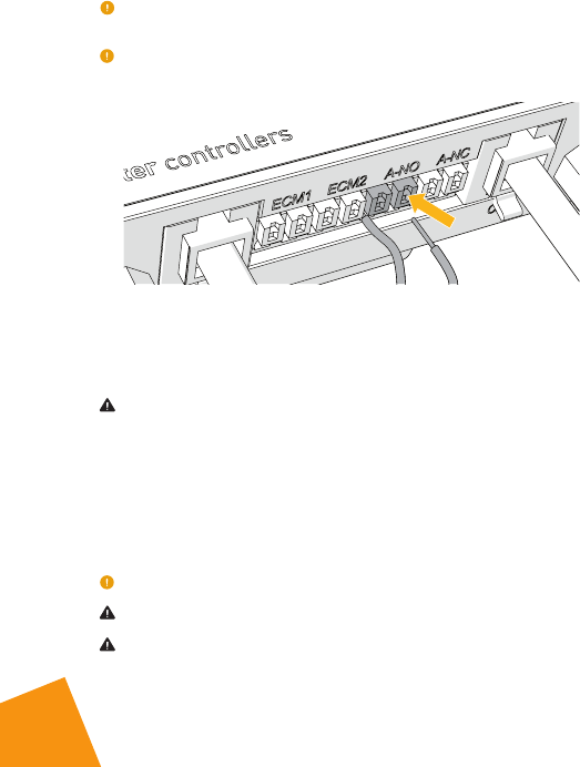
The controller has two pairs of cage clamps marked A-NC (normally closed)
and A-NO (normally open). When a temperature shutdown, sensor failure
or power failure occurs the “A-NC” contact opens and the “A-NO” contact
closes. Both pairs of clamps may be connected to a third party alarm
installation or text messaging module.
Warning! The alarm contacts are rated for a maximum of 13,5V/50mA.
4.4. Connecting auxiliary equipment using the External
Contactor Module (ECM)
If you want to use the controller to control for example a CO source, a light
or watering unit, or a heater, you’ll need an External Contactor Module or
ECM. You can control up to two ECMs. ECM1 follows channel 1, ECM2 follows
channel 2.
ECM2 is inverse to ECM1 if channel 2 is set to follow or inverse mode.
Warning! Never connect more than one ECM to one set of cage clamps.
Warning! ECMs can handle equipment with a resistive load (AC1) of up to
16A. The maximum allowable current can be limited by the local situation.
21
Warning! To prevent over-current, always determine the maximum allowable
current for your cabling before connecting a load to the ECM.
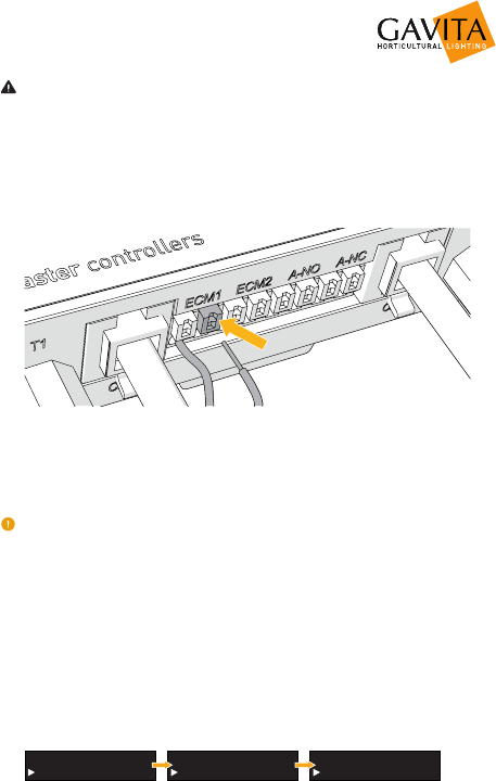
1. Strip the endings of the signal cable 8mm. Finish them with cable end
sleeves. A cable of up to 20 meters may be used.
2. Press the spring pins above the contact openings of the cage clamps to open
them.
3. Insert the endings of the signal cable into the desired cage clamp set of the
controller.
4. Release the spring pins to lock the wires in place.
5. Connect the cable to the cage clamps of the ECM.
Consult the ECM manual to learn how to connect the ECM to auxiliary equipment.
4.5. Controlling auxiliary equipment
Auxiliary equipment can be activated either during lights-on period (day) or
lights-off (night).
1. Set the ECM for channel 1. Press enter to open the menu and select channel
1.
2. Select ecm config.
3. Select day to activate the ECM during lights-on, or select night to activate it
during lights-off.
LOGS
CHANNEL 1
SUNRISE/SUNSET
ECM CONFIG
ECM ON DURING
DAY

22
Example: a CO source, light or watering unit may be activated during lights-
on periods. A heater may be activated during lights-off periods.
Channel 2 can only be set if it operates in independent mode. If it operates in
follow mode, the setting of channel 1 will be followed. If it operates in inverse
mode, the setting of channel 1 will be inversed.
4.6. Calibrating the temperature sensor(s)
If necessary, the temperature measured by the Gavita controller can be
adjusted to match the temperature measured by another system in the room.
1. Press enter to open the menu and select temp probe.
2. Press enter to leave the temp units setting unchanged.
3. Set calibrate to YES.
CHANNEL 2
TEMP PROBE
TEMP UNITS
O
C
CALIBRATE
YES
4. Choose between T1 and T2 and press enter to select the temperature value
you wish to adjust.
T1:
T2:
25.0C
25.0C
5. Adjust the temperature to the desired value and press enter to confirm your
choice.
The calibrated temperature values are stored in the internal memory of the
controller. Resetting the controller will restore these values (see paragraph 5.9).
4.7. Setting the sunrise and sunset period
To allow crops to adjust to either a lights-on or lights-off period, a sunrise
and sunset period may be set. During this period, the light intensity increases
from 50 percent to up to the desired intensity. By default, both periods are set
to 15 minutes.
1. Press enter to open the menu and select the channel you want to change the
sunrise/sunset period for.

23
2. Select sunrise/sunset.
LOGS
CHANNEL 1
SUNRISE/SUNSET
ECM CONFIG
RAMP UP
RAMP DOWN
15
15
• Set ramp up time (0-30 min) to simulate sunrise.
• Set ramp down time (0-30 min) to simulate sunset.
24
5. Using the controller
5.1. Activating or deactivating lights
1. Press enter to open the menu and select channel 1 or channel 2.
Channel 2 can only be set if it operates in independent mode.
2. Select output mode.
LOGS
CHANNEL 1
OUTPUT MODE
OUTPUT LEVEL
OUTPUT MODE
AUTO
Each channel can be set to three output modes:
AUTO Run the programmed light cycle
ON Lights are on, temperature safety settings apply
OFF Lights are off
3. Press enter to confirm.
When the lights are activated, a blue light burns.
Warning! When replacing lamps, always disconnect them from the mains.
Simply switching them off is not sufficient.
5.2. Setting light intensity
1. Press the key and select the channel of which you want to alter the
intensity.
2. Use the arrow keys to set the intensity.
CH1:
CH2:
75%
100%
You can use this setting to boost your lamps to a maximum of 115%.
By default, power is displayed as a percentage. You can set the controller to
instead display the power output in Watts. Press enter to open the menu and
select channel 1 or channel 2. Select display mode and use the arrow keys to
25
select the nominal power of your fixtures. This setting determines how power
output is displayed when pressing the key and does not affect the working of
the controller. It is for your reference only.
LOGS
CHANNEL 1
ECM CONFIG
DISPLAY MODE
DISPLAY W or %
750
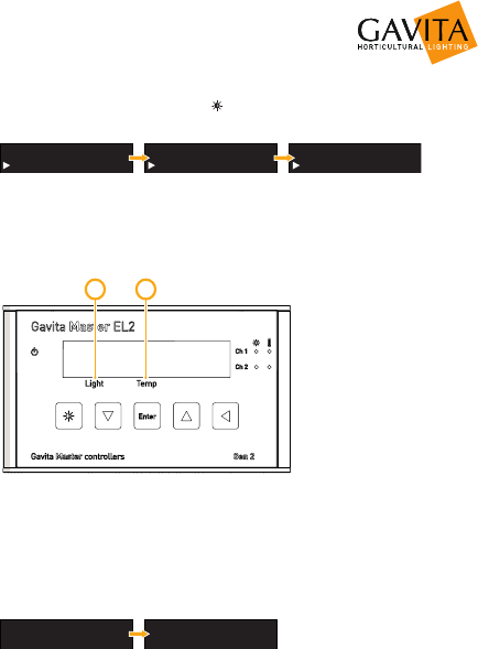
5.3. Reading the default screen
The default screen displays whether or not the lights are activated, and at
what power they are running (A). The measured temperatures are also shown
(B).
AB
5.4. Show system time and temperature settings
1. Press an arrow key in the default screen to show system time and date.
2. Press an arrow key again to show the highest and lowest registered
temperatures.
DATE
14/07/17
TIME
11:48
H:30.0C
H:30.6C
L:23.4C
L:23.8C
26
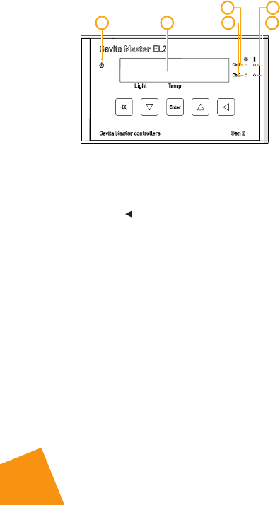
5.5. Interpreting LED signals
AB
C
D
E
F
5.5.1. Green light (A)
A burning green light indicates the controller is functioning.
A blinking green light indicates the power has been interrupted.
After a power failure the blinking green indicator must be reset. Hold the
back button for three seconds to reset the indicator.
5.5.2. Blue light (C/D)
A burning blue light indicates the ballasts connected to channel 1 and/or
channel 2 are activated.
A blinking blue light indicates an overload in the channel.
When a blue light is off, it indicates the connected ballasts are deactivated.
5.5.3. Red light (E/F)
A blinking red light indicates the auto-dim temperature is exceeded.
A fast blinking red indicates the shutdown temperature has been exceeded.
A burning red light indicates the auto-dim temperature has been exceeded
in the past.
5.6. Error messages and solutions
5.6.1. Sensor disconnected
The message “Sensor removed” appears when one or two temperature
sensors are not plugged in. All devices connected to the controller are

27
deactivated. Plug in the missing sensor to resolve.
5.6.2. Sensor failure
If the message “sensor failure” appears, the sensor is defect. All devices
connected to the controller are deactivated. The controller must be reset.
• Replace the temperature sensor
• Hold the back button for 3 seconds to reset the message.
5.6.3. Controller Overload
If the message “controller overload” appears, one of the channels of the
controller has been overloaded. The blue led indicator behind the overloaded
channel will also start flashing. An overload may occur when the wiring
of one of the channels has short circuited. All devices connected to the
controller will be deactivated.
• Check which channel indicates the overload.
• Search for faulty wiring or contacts and replace it.
• Hold the back button for 3 seconds to reset the message.
5.6.4. Auto-dim
When the auto-dim temperature has been exceeded, the message “auto dim”
will appear on the display next to the corresponding channel. The red light
will also flash. The flashing will continue until the temperature drops half a
degree Celsius/ 0.9 degrees Fahrenheit below the auto-dim temperature for
at least 30 seconds.
A burning red light indicates the auto-dim temperature has been exceeded
in the past.
• To resolve a burning red light, hold the back button for three seconds
to reset the warning.
5.6.5. Temp Alarm
When the shutdown temperature has been exceeded, the message “Temp
alarm” will appear on the display and the red light will flash rapidly. All
devices connected to the controller are deactivated. The controller must be
reset;
• Ensure the temperature of the room is below the shutdown
temperature. If the temperature is still above shutdown temperature,
the controller cannot be reset
• Hold the back button for three seconds to reset the controller.

28
5.7. After a power loss
If power is restored within 40 hours, the controller will resume its program
as set by the user. If power takes longer than 40 hours to be restored, the
controller loses time and date settings. It will therefore set all outputs to
“off” until time and date are set again. When set, the controller resumes its
program.
5.8. Reading the log
Auto-dim, shutdown and power loss events are logged in the controllers
memory. For each channel, the high and low temperatures are kept as well.
To access the log, press enter to open the menu and select logs.
5.9. View the firmware version on the controller
Your reseller or Gavita International bv may request the firmware version of
your controller to check for compatibility with (future) Gavita products.
1. Press enter to open the menu and select info.
2. The firmware version is displayed.
GAVITA -- EL2
©2017 v2.12
LANGUAGE
INFO
5.10. Reset to factory settings
1. Press enter to open the menu and select factory reset.
2. Select yes and press enter to confirm. All settings are reset to their factory
defaults.
29
6. Maintenance and Repair
Warning! Do not open or disassemble the controller, it contains no
serviceable parts. Opening the controller will void its warranty.
Warning! Do not use acids, solvents, abrasives or other aggressive
substances to clean the controller as this may cause damage.
The controller is maintenance free. It may be cleaned with a soft dry cloth.
Please contact your reseller in case of controller malfunction.
7. Environment and Disposal
ATTENTION: THIS PRODUCT CONTAINS A BATTERY.
MUST BE DISPOSED OF PROPERLY.
The symbol on the material, accessories or packaging
indicates that this product may not be discarded as household
waste. Dispose of the equipment through a recycling center
that handles electronics and electrical appliances within
the EU and in other European countries which use separate
collection systems for used electronics and electrical
appliances. By disposing of the equipment in the proper
way, you will be helping to prevent possible risks to the environment and
public health, which might otherwise be caused by improper handling of the
discarded equipment. Recycling of materials contributes to the conservation
of natural resources. Therefore, please do not dispose of your old electronics
and electrical appliances via household waste.
8. Warranty
Gavita International bv warrants the mechanical and electronic components
of their product to be free of defects in material and workmanship if used
under normal operating conditions for a period of three (3) years from the
original date of purchase. If the product shows any defects within this period
and that defect is not due to user error or improper use Gavita International
bv shall, at its discretion, either replace or repair the product using suitable
new or reconditioned products or parts. In case Gavita International bv
decides to replace the entire product, this limited warranty shall apply to the
replacement product for the remaining initial warranty period, i.e. three (3)
years from the date of purchase of the original product. For service return the
product to your shop with the original sales receipt.

30

31

32
33

34
35

Gavita International bv
Oosteinderweg 127
1432 AH Aalsmeer
The Netherlands
Tel : +31(0)297-380 450
Fax : +31(0)297-380 451
E : info@gavita.com
W : www.gavita.com
For more information, or to download documents, contact:
Manual: EL2 controller
Changes reserved - Version 18/06
