Carlon 2005 Master Catalog 92443
2014-10-22
: Pdf 92443-Catalog 92443-Catalog Batch9 unilog
Open the PDF directly: View PDF ![]() .
.
Page Count: 322 [warning: Documents this large are best viewed by clicking the View PDF Link!]

Boreable Multi-Gard
®
Trenchless
Raceway
Bore-Gard
®
Trenchless Raceway
Carflex
®
Liquidtight Fittings
Carflex
®
Liquidtight Flexible
Nonmetallic Tubing
Carflex
®
Omni Connectors
Carflex
®
Pre-Wired Liquidtight Whips
Carflex
®
X-Flex
™
Flexible
Nonmetallic Tubing
Cement
Chimes
Circuit Safe
®
JIC Enclosures
Circuit Safe
®
NEMA Enclosures
CordGrips
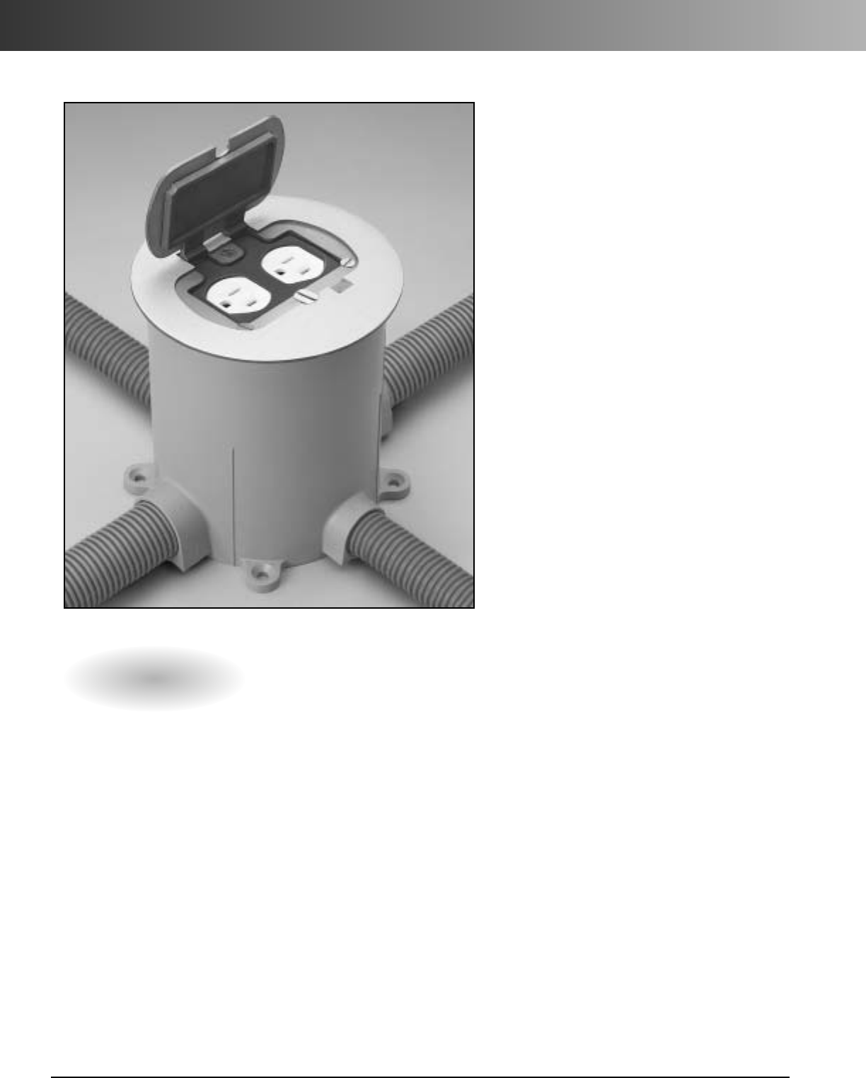
Curved Lid J-Box
ENT Boxes and Fittings
Flex-Plus
®
Blue
™
ENT
Floor Box Systems
Hal-Free Riser-Gard
®
High Density Polyethylene (HDPE)
Himeline
®
Enclosures
Intra-Gard
®
Multi-Cell Raceway
In-Use Weatherproof Covers
Junction Boxes
Multi-Gard
®
Multi-Cell Raceway
P&C
®
Duct - Types EB and DB
P&C
®
Duct Fittings and Sweeps
P&C Flex
®
Corrugated
Flexible Conduit
Plenum-Gard
®
Flexible Raceway
PV-Mold
®
Pole Riser System
Riser-Gard
®
Flexible Raceway
Schedule 40 & 80 Conduit
Schedule 40 & 80 Fittings
Schedule 40 & 80
Special/Standard Elbows
Slack and Splice Enclosures
Slip Meter Risers
Snap-Loc
®
Spacers
Snap-N-Stac
™
Spacers
Split Duct
Structured Cable Management Systems
Telephone Duct – Types B, C and D
Telephone Duct Fittings and Sweeps
Utility Conduit, Fittings,
and Elbows
Weatherproof Covers and
Lighting Systems
Wire Handling Products
Wire-Safe
®
Wireway and
Wiring Trough
Zip Box
®
Blue
™
Switch/Outlet Boxes
Carlon
®
Master Catalog

Carlon
®
eConnect
(www.carloneconnect.com)
An on-line order tracking website designed exclusively for Carlon
distributor partners. Carlon eConnect provides easy, secured
access to ‘real-time’ information from our SAP Business Enterprise
System. It’s available 24 hours a day, and is designed to improve
the efficiency of order information flow.
Functions include
•
Quick list of recent orders
•
Search for orders
•
Price and availability
•
Electronic pricing files
•
Order entry
Carlon
®
EDI
•
850 - Purchase orders
•
855 - PO acknowledgements
•
856 - Ship notice
•
810 - Invoices
Carlon
®
eCommerce Capabilities

www.carlon.com 1
Electrical Products
Carflex
®
Liquidtight Flexible Tubing and Fittings........... 3
Chimes ................................................................................ 15
Electrical Nonmetallic Tubing (ENT),
Boxes and Fittings ......................................................... 19
Floor Boxes and Covers..................................................... 33
Curved Lid J-Box................................................................. 47
Weatherproof Covers, Lampholders & Fixtures............ 51
Wire Handling Products.................................................... 57
Wire Safe
®
Wireway And Wiring Trough ...................... 61
Zip Box
®
Blue™Outlet and Switch Boxes ....................... 69
Low Voltage Premise Products
Plenum-Gard
®
..................................................................... 88
Riser-Gard
®
.......................................................................... 90
Hal-Free Riser-Gard
®
.......................................................... 92
General Purpose................................................................. 93
Structured Cable Management Systems .....................
103
Enclosures
Circuit-Safe
®
NEMA ......................................................... 112
Circuit-Safe
®
JIC................................................................ 122
Himeline
®
HE.................................................................... 137
Himeline
®
HS .................................................................... 140
Himeline
®
HP.................................................................... 144
Himeline
®
HLA/HLS.......................................................... 150
Himeline
®
HLP.................................................................. 154
Slack and Splice................................................................ 156
Table of Contents
Conduit
Schedule 40 & 80 Conduit..............................................
168
Schedule 40 & 80 Elbows ...............................................
170
Schedule 40 & 80 Fittings...............................................
174
Conduit Bodies.................................................................
179
Junction Boxes .................................................................
181
FS Boxes ............................................................................
181
Utility Conduit, Fittings & Elbows.................................
190
P&C Duct...........................................................................
192
Telephone Duct ...............................................................
202
P&C Flex ............................................................................
209
PV-Mold ............................................................................
211
Slip Meter Risers ..............................................................
215
Split Duct ..........................................................................
217
Cement ...............................................................................221
Spacers ..............................................................................
225
Outside Plant Products
Bore-Gard
®
and Boreable Multi-Gard
®
Raceway.......
231
Multi-Gard
®
Multi-Cell Raceway...................................
237
Intra-Gard
®
Multi-Cell Raceway....................................
261
High Density Polyethylene (HDPE) Conduit................
269
Cable and Installation Accessories................................
295
Index
Product Category............................................................
301
PartNumber.....................................................................
302

www.carlon.com
2
www.carlon.com 3
Carlon
®
Carflex
®
Liquidtight Flexible Tubing
Carflex
®
Carflex
®
X-Flex
™
Fittings
Cord Grips
Pre-Wired Whips
Features
Coils Reels
Applications
•Control and motor
• Air conditioning and heating
• Computer power distribution
• Machine tools
• Console wiring
• Transformer connections
• Outdoor lighting
Custom Orders
• Available in black and gray.
Consult factory for custom
colors.
•Custom cut lengths available;
consult factory for details.
• Nonconductive and noncorrosive
• Lightweight for easy handling,
transportation, and installation
• Crush, abrasion, and strain resistant
• Provides superior wire protection
• Smooth interior ideal for pulling cable
• No jagged edges
• Maintains internal I.D. even in tight
radius bends
• Type LFNC-B
• Resistant to oil, acid, ozone,
and alkaline
• UL Listed for use as indicated in
Article 356 of the 2002 NEC; and
Section 12-1300 of the 2002
Canadian Electrical Code, Part 1.
• UL Listed for outdoor use
• UL Listed for sunlight resistant
• Trade sizes 1/2", 3/4", and 1"
are UL Listed for direct bury
• Sequentially marked
footage
•Suitable for use at conduit
temperatures of 80°C dry,
60°C wet and 60°C oil
resistant as required by
section 15-6 of ANSI/NFPA
79-1985 and UL 1660.
Note: Liquidtight flexible
conduits, metallic and non-
metallic, in contrast to rigid
PVC conduit and electrical
nonmetallic tubing, does
not have wire temperature
limitations. Any temperature
rated wire (for example, 90°
wire) can be used as long as
the temperatureconditions
marked on the conduit are
not exceeded. UL Listed
conduits that are not marked
are limited to a maximum
temperature of 60°C wet or dry.
*Joint listed UL/CSA
Approved product
available
E79553
www.carlon.com
4
Carflex
®
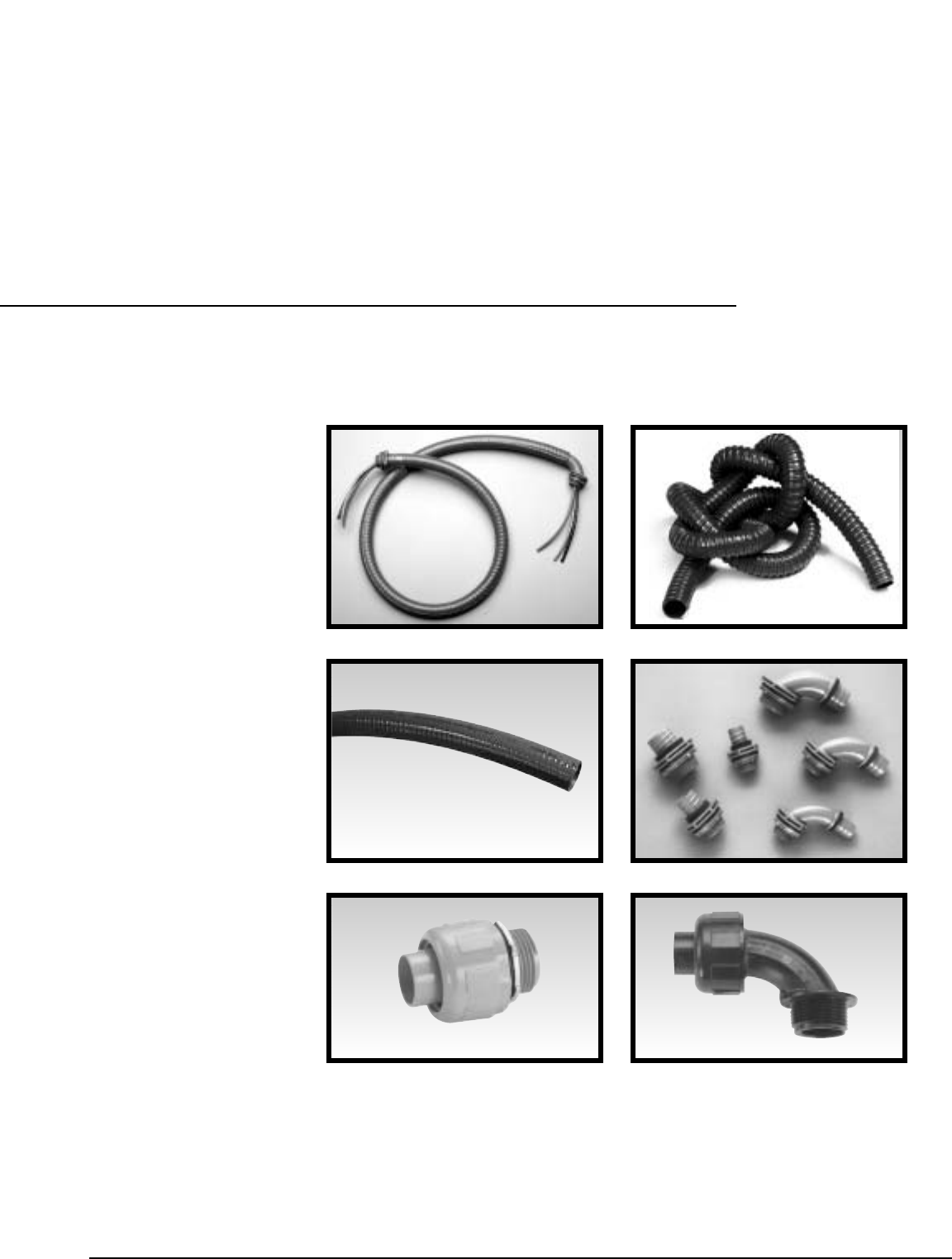
Liquidtight Flexible Conduit
Carflex
Liquidtight Flexible Nonmetallic Conduit provides
superior wire protection in harsh, damp environments. Carflex
Conduit is nonconductive, noncorrosive, and resistant to oil, acid,
ozone, and alkaline. Carflex Conduit is strong and lightweight,
and because it weighs 50% less than metallic systems, it’s easy
to handle, transport and install. Carflex is ideal for industrial, air
conditioning, heating, and outdoor lighting applications.
Part Nom. Size Std. Ctn. Std. Ctn.
No. (in.) Qty. (ft.) Wt. (lbs.)
15004-100 3/8" 100 11.70
15005-50 1/2" 50 6.50
15005-100* 1/2" 100 13.00
15005BK-100* 1/2" 100 13.00
15007-100* 3/4" 100 18.00
15008-100* 1" 100 28.00
15009-100 1-1/4" 100 37.60
15010-50 1-1/2" 50 22.55
15010-100 1-1/2" 100 47.80
15011-050 2" 50 34.10
Standard color Grey
Part Nom. Size Std. Ctn. Std. Ctn.
No. (in.) Qty. (ft.) Wt. (lbs.)
15004-001 3/8" 1000 145.0
15005-001 1/2" 1000 157.0
15005BK-001 1/2" 1000 157.0
15007-001 3/4" 1000 212.0
15008-500 1" 500 155.0
15009-200 1-1/4" 200 100.0
15010-150 1-1/2" 150 95.7
15011-100 2" 100 94.6
Standard color Grey
www.carlon.com 5
Carflex
®
X-Flex™Flexible Conduit
Specifications
Coils
(Available in Black only)
Part Nom. Size Std. Ctn. Std. Ctn.
No. (in.) Qty. Wt. (lbs.)
*15104-100 3/8" 100 9.09
*15105-100 1/2" 100 10.01
*15107-100 3/4" 100 13.91
*15108-100 1" 100 18.25
*15109-100 1-1/4" 100 27.65
*15110-100 1-1/2" 100 38.00
*15111-050 2" 50 24.22
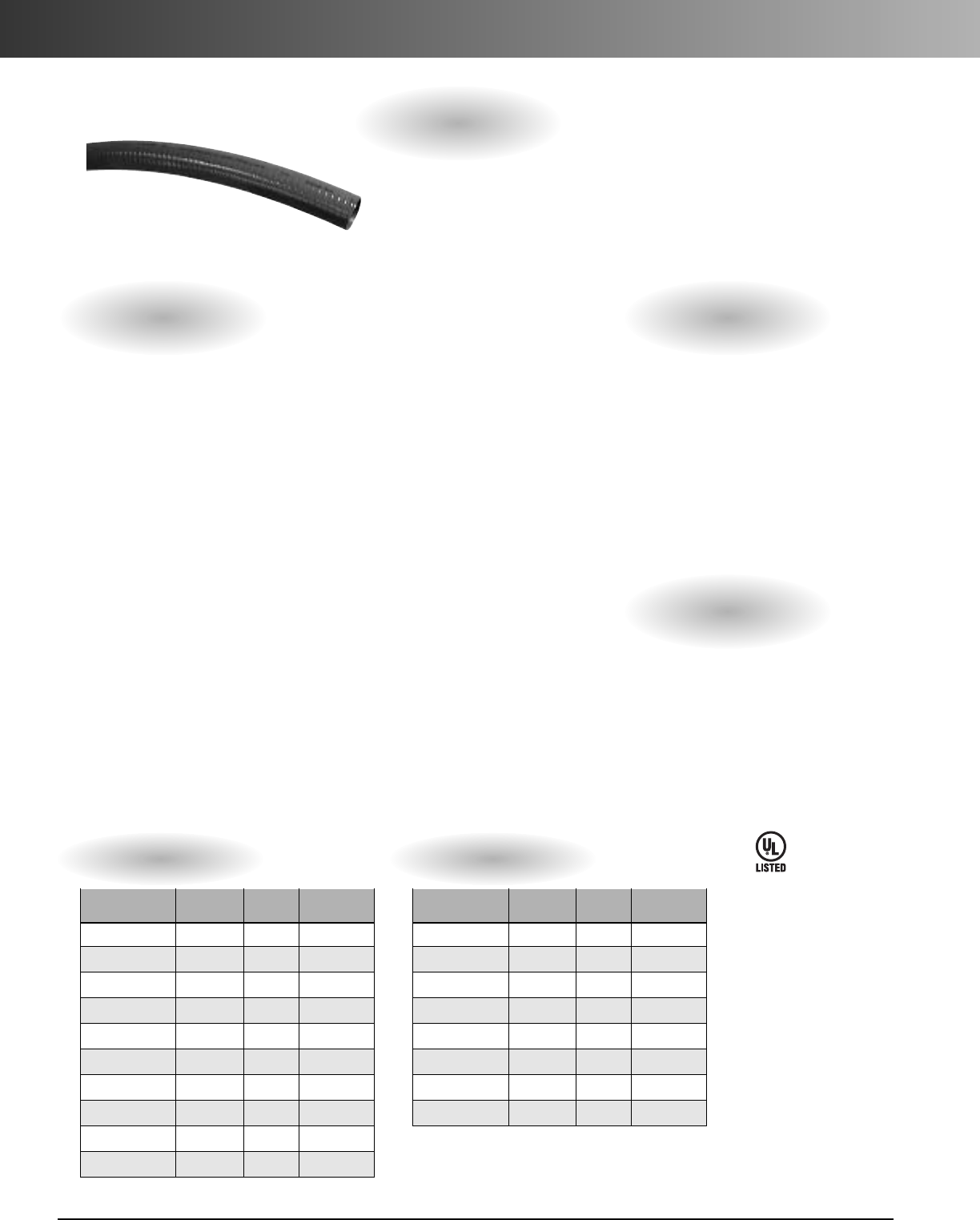
Carflex X-Flex
Extra Flexible Nonmetallic Conduit is
ideal for applications requiring extra strength and flexibility
such as robotics, and repetitive flexing arms. Carflex X-Flex is
nonconductive, noncorrosive, and resistant to oil, acid, ozone,
and alkaline. It’s designed for use with standard Carflex fittings
providing a complete nonmetallic system. Carflex X-Flex is
lightweight for easier handling, transportation, and installation.
Features Applications
•Extra strong and flexible to withstand repetitive
motions
•Nonconductive and noncorrosive
•Resistant to oil, acid, ozone, and alkaline
• Lightweight for easy handling, transportation,
and installation
•Crush, abrasion, and strain resistant
•Provides superior wire protection
•Smooth interior ideal for pulling cable
• No jagged edges
•Rated for continuous use at 60°C (140°F) ambient
•Repetitive Flexing Arms
•Robotics
•Machine Tools
•Automatic/Moving Machinery
•Control and motor
LR88170
Where noted by
E80040
Where noted by *
www.carlon.com
6
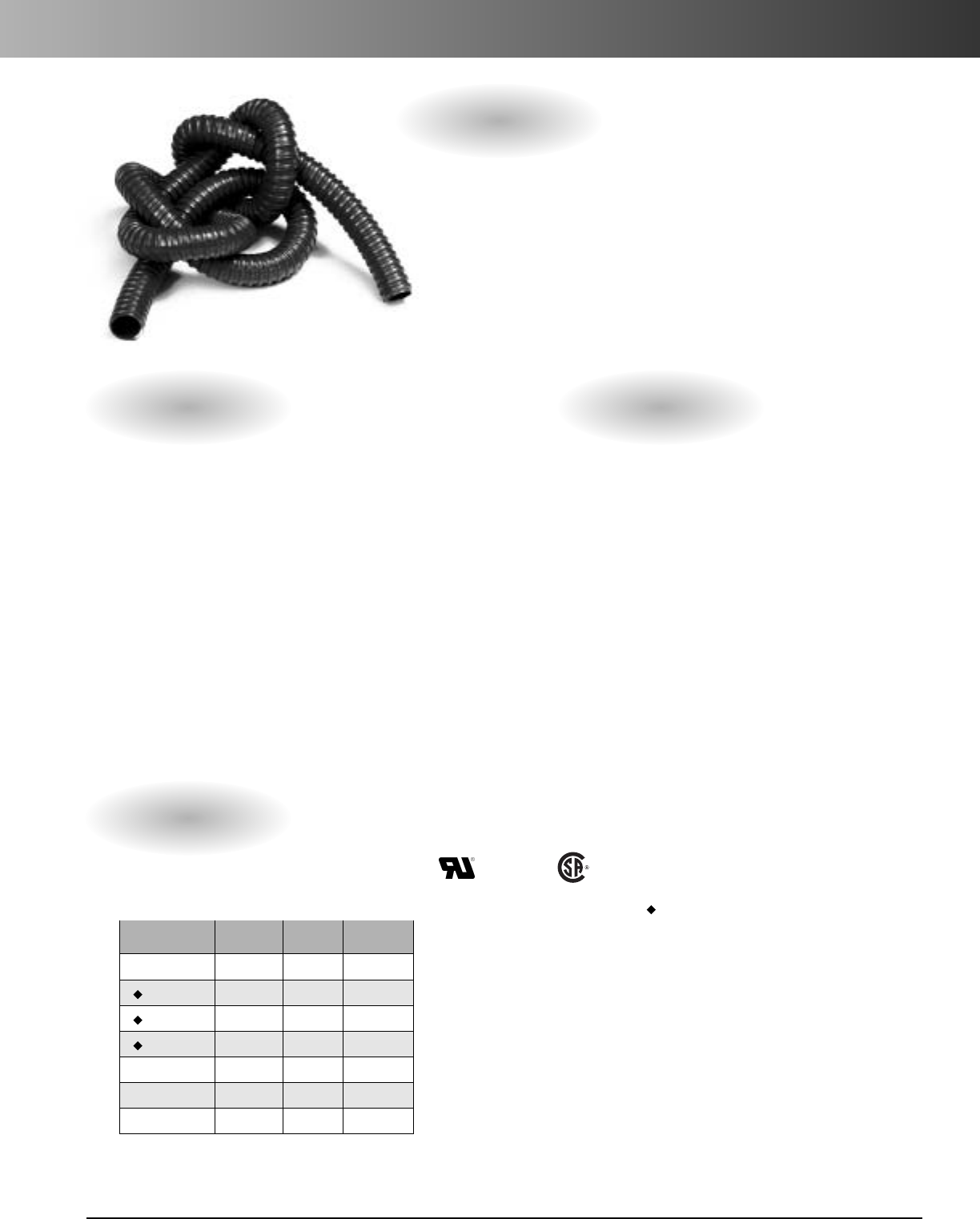
Carflex
®
Liquidtight Fittings
Straight Fittings
•For use with Carflex®conduit and Carflex®X-Flex™conduit
Features
•Nonconductive and Noncorrosive
• Resistant to oil, acid, ozone, and alkaline
•Easy to install
• Nitrile rubber “O” ring for a liquidtight
termination
• Temperatures up to 225°F(107°C)
•Meets UL Standard 514B
Specifications
Part Size Std. Ctn. Std. Ctn. A B C D E Refer to
No. (in.) Qty. Wt. (lbs.) (inches) (inches) (inches) (inches) (inches) Image
LT43C 3/8 50 3.6 .55 .75 1.60 1.30 1.40 1, 2
LT43C-CAR 3/8 15 1.4 .55 .75 1.60 1.30 1.40 1, 2
LT43D-NEW 1/2 50 4.2 .56 .91 1.62 1.30 1.40 1, 2
LT43E-NEW 3/4 50 6.6 .56 .91 1.88 1.61 1.71 1, 2
LT43F 1 25 5.5 .70 1.00 2.20 1.90 2.04 1, 2
LT43G 1-1/4 5 1.5 .71 1.16 2.50 2.17 3, 4
LT43H 1-1/2 5 2.0 .75 1.36 2.78 2.43 3, 4
LT43J 2 5 2.5 1.00 1.45 3.33 3, 4
Com-
pression
Nut
Sealing
Ring Ferrule Fitting
Body ORing Plastic
Locknut
Fitting
Body Extended
Threads
Com-
pression
Nut
Nitrile
Rubber
O-Ring
Metal
Locknut
Image 1 Image 2 Image 3 Image 4
E32447
LT43C-CAR, LT43D-NEW, LT43E-NEW, LT43F LT43G, LT43H LT43J
Assembly
Assembly
www.carlon.com 7
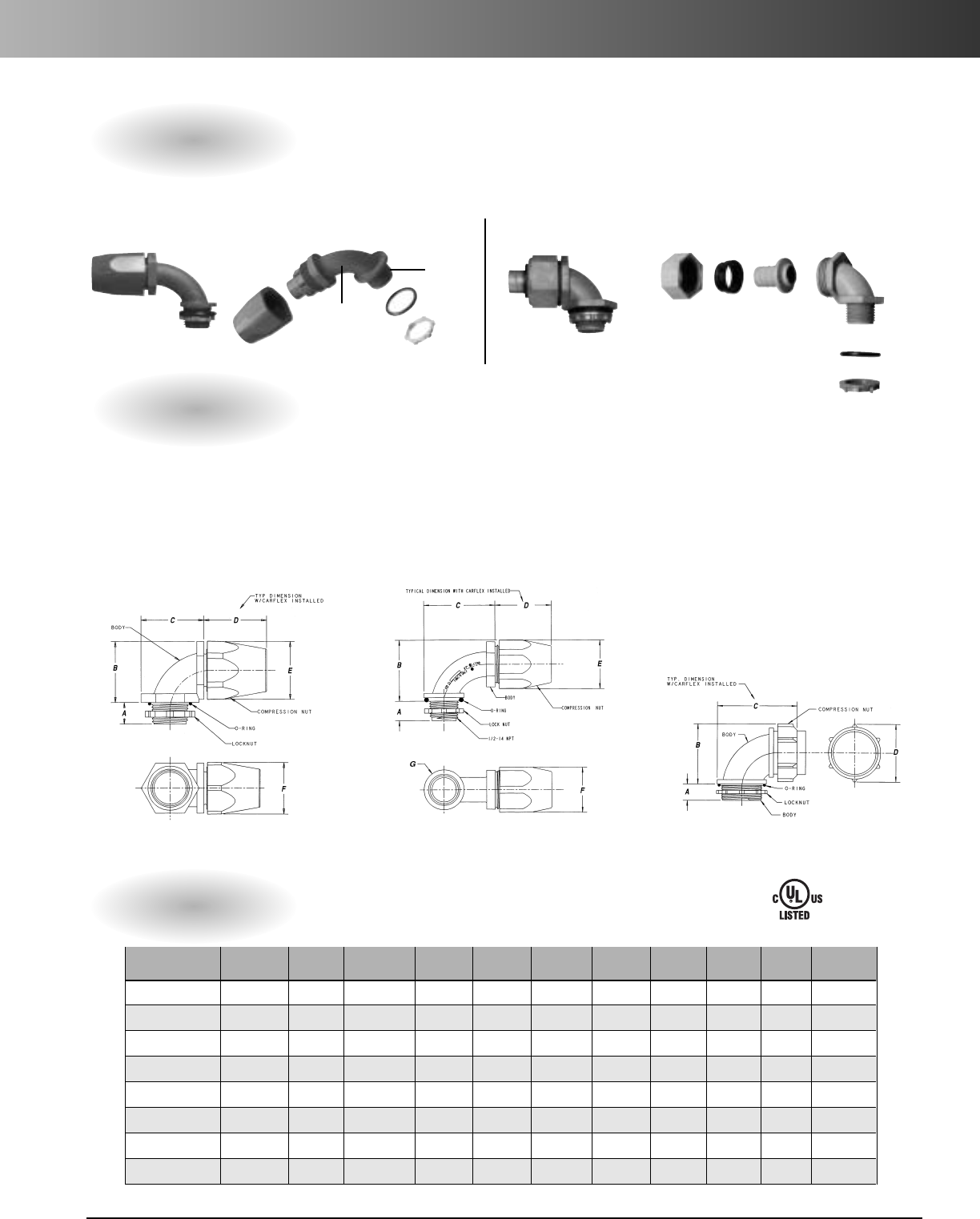
Carflex®Liquidtight Fittings
90° Fittings
•For use with Carflex®conduit and Carflex®X-Flex™conduit
Features
•Nonconductive and Noncorrosive
• Resistant to oil, acid, ozone, and alkaline
•Easy to install
• Nitrile rubber “O” ring for a liquidtight
termination
•Temperatures up to 225°F (107°C)
• Meets UL Standard 514B
Specifications
Part Size Std. Ctn. Std. Ctn. A B C D E F G Refer to
No.(in.) Qty. Wt. (lbs.) (inches) (inches) (inches) (inches) (inches) (inches) (inches) Image
LT20C 3/8 50 4.9 .56 1.44 1.44 1.56 1.39 1.26 3, 4
LT20C-CAR 3/8 15 1.8 .56 1.44 1.44 1.56 1.39 1.26 3, 4
LT20D-NEW 1/2 50 4.9 .56 1.76 2.05 1.62 1.40 1.30 1.15 1, 2
LT20E-NEW 3/4 50 8.0 .56 2.04 2.35 1.88 1.71 1.61 1.50 1, 2
LT20F 125 6.9 .70 2.01 2.01 2.26 2.04 1.90 3, 4
LT20G 1-1/4 5 1.9 .75 2.50 3.55 2.48 3, 4
LT20H 1-1/2 5 2.2 .75 2.80 3.98 2.77 3, 4
LT20J 2 5 3.4 .94 3.48 4.56 3.33 3, 4
Com-
pression
Nut
Sealing
Ring Ferrule Fitting
Body
ORing
Plastic
Locknut
Extended
Threads
Nitrile
Rubber
O-Ring
Metal
Locknut
Fitting
Body
Com-
pression
Nut
Image 1 Image 2 Image 3 Image 4
E32447
LT20C-CAR, LT20F-NEW LT20D-NEW, LT20E-NEW LT20G, LT20H, LT20J
Assembly Assembly
www.carlon.com
8
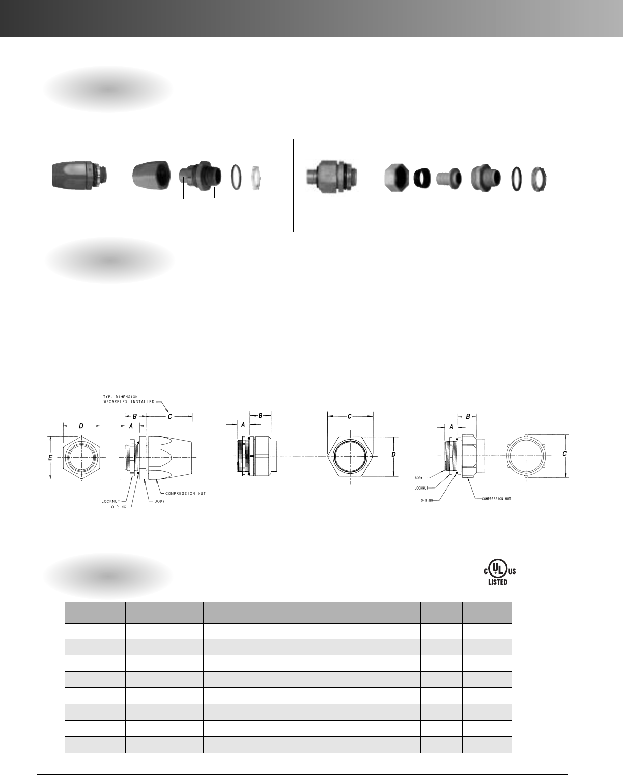
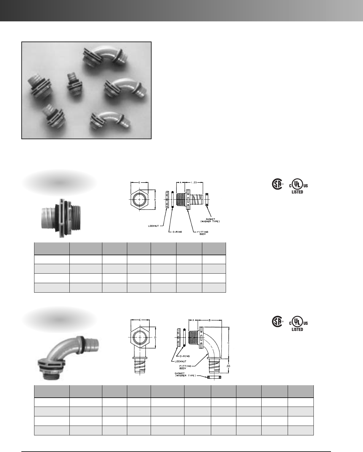
Carflex
®
One-Piece Liquidtight Fittings
Straight Fittings
Part Trade Size Std. Ctn. Std. Ctn. A D E
No. (in.) Qty. Wt. (lbs.) (inches) (inches) (inches)
LN43DA 1/2-14 NPT 100 2.8 0.56 1.34 1.19
LN43EA 3/4-14 NPT 50 2.2 0.56 1.63 1.44
LN43FA 1 - 111/2NPT 25 3 0.69 1.99 1.75
LN43FA-CAR 1-111/2NPT 15 10.69 1.99 1.75
90° Fittings
Part Trade Size Std. Ctn. Std. Ctn. Thread A B C D E
No. (in.) Qty. Wt. (lbs.) Size (inches) (inches) (inches) (inches) (inches)
LN20DA 1/2-14 NPT 100 4.3 1/2-14 NPT 0.56 1.50 1.99 1.34 1.19
LN20EA 3/4-14 NPT 50 3.1 3/4-14 NPT 0.56 1.73 2.25 1.63 1.44
LN20FA1-111/2NPT 25 3.2 1-111/2NPT 0.69 1.86 2.58 1.99 1.75
LN20FA-CAR 1 - 111/2NPT 10 1 1-111/2NPT 0.69 1.86 2.58 1.99 1.75
Unique Design
The simple, one piece body design of the Carflex One Piece
Liquidtight Nonmetallic Fitting requires no disassembly of
components for installation. The system is so strong that
there is no need for a compression nut.
PVC Construction
PVC construction of the fitting and locknut provides unparal-
leled protection from water, oil and dust. Totally nonmetallic,
the system is nonconductive and will not corrode or rust.
Temperatures up to 140°F (60°C)
E32447
LR201397
E32447
LR201397
www.carlon.com 9
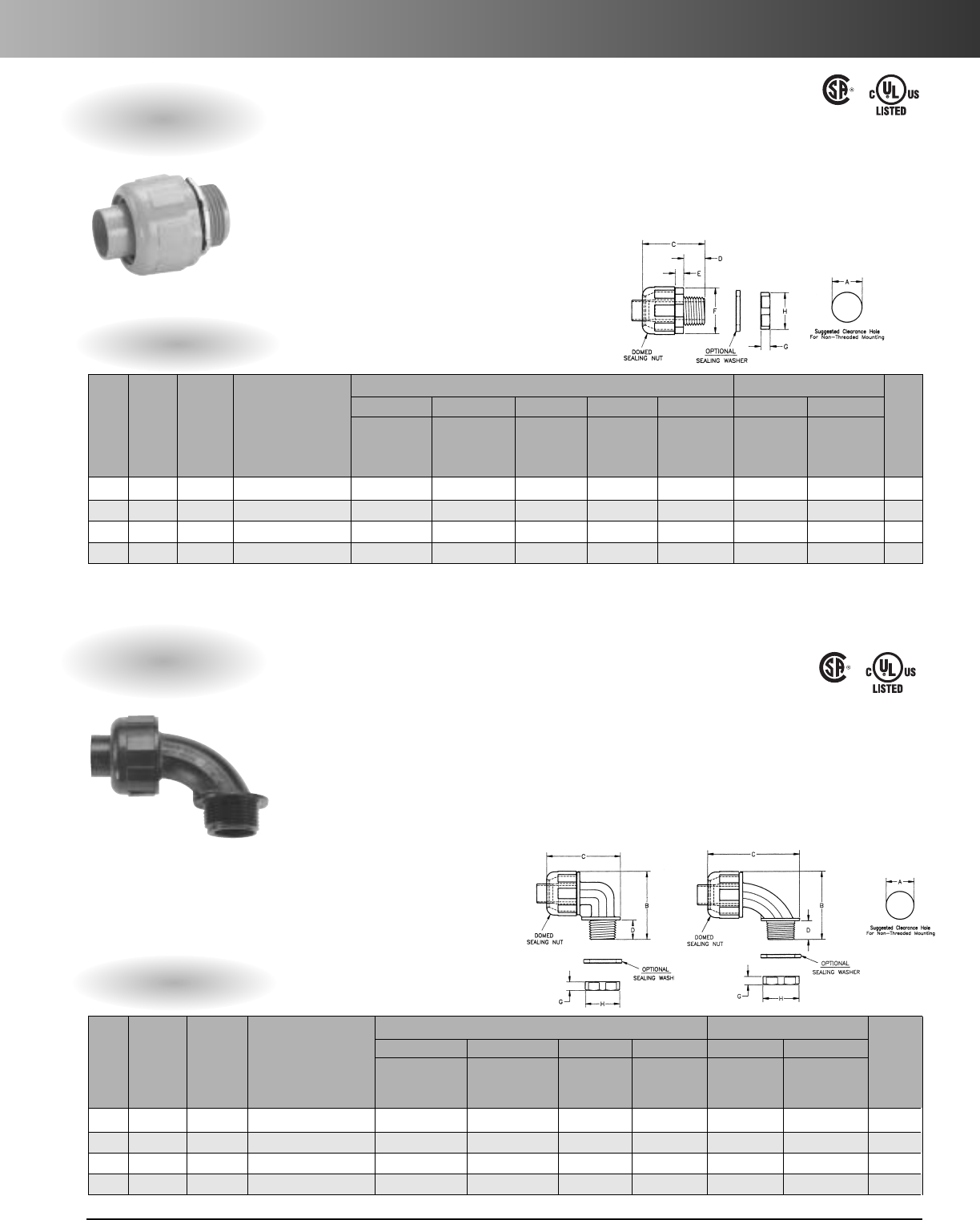
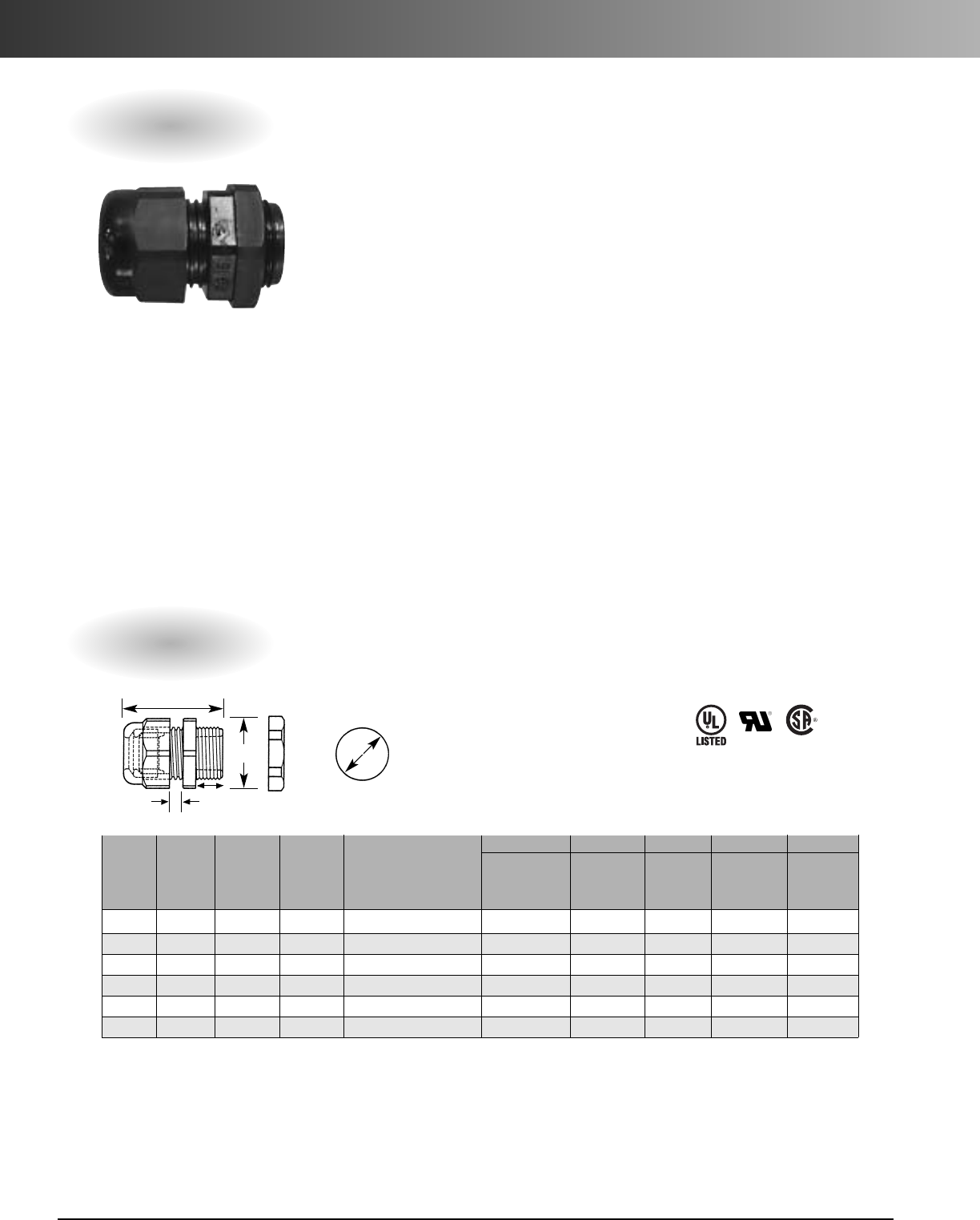
Carlon®Carflex®Omni Connectors
1" 3/8" to 3/4"
ACDEFGH
Wrenching
Part Part Clearance Max O.A. Thread Nut
Wrenching
Wrenching Std.
No. No. Hole Length Length Thickness Flats Thickness Flats Ctn.
Size Black Gray* Description in. (mm) in. (mm) in. (mm) in. (mm) in. (mm) in. (mm) in. (mm) Qty.
3/8" LT38 LT38G Straight L/T Fitting .875 (22.2) 2.000 (50.8) .625 (15.9) .250 (6.3) 1.328 (33.7) .266 (6.7) 1.062 (26.9) 50
1/2" LT50 LT50G Straight L/T Fitting .875 (22.2) 2.000 (50.8) .625 (15.9) .250 (6.3) 1.328 (33.7) .266 (6.7) 1.062 (26.9) 50
3/4" LT75 LT75G Straight L/T Fitting 1.109 (28.2) 2.031 (51.6) .625 (15.9) .250 (6.3) 1.562 (39.7) .266 (6.7) 1.312 (33.3) 25
1" LT100 LT100G Straight L/T Fitting 1.375 (34.9) 2.250 (57.1) .781 (19.8) .250 (6.3) 1.875 (47.6) .266 (6.7) 1.625 (41.3) 20
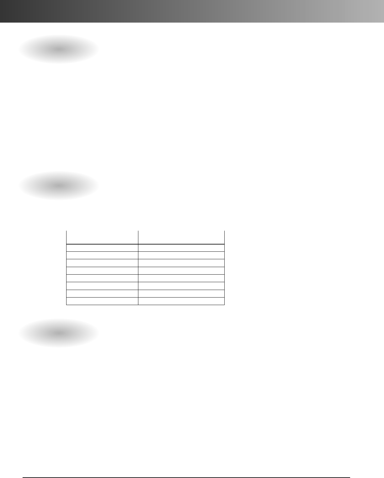
Body & Sealing Unit Locking Nut
ABCDGH
Part Part Clearance Max O.A. Max O.A. Thread Wrenching Std.
No. No.Hole Height Length Length Thickness Flats Carton
Size Black Gray Description in. (mm) in. (mm) in. (mm) in. (mm) in. (mm) in. (mm) Qty.
3/8" LT938 LT938G 90 degree L/T Fitting .875 (22.2) 1.98 (50.3) 2.91 (73.9) .52 (13.2) .27 (6.8) 1.06 (26.9) 25
1/2" LT950 LT950G 90 degree L/T Fitting .875 (22.2) 1.98 (50.3) 2.91 (73.9) .52 (13.2) .27 (6.8) 1.06 (26.9) 25
3/4"LT975 LT975G 90 degree L/T Fitting 1.109 (28.2) 2.29 (58.2) 3.17 (80.5) .52 (13.2) .27 (6.8) 1.31 (33.3) 20
1" LT9100 LT9100G 90 degree L/T Fitting 1.375 (34.9) 2.84 (72.1) 3.18 (80.8) .78 (19.8) .27 (6.8) 1.61 (40.9) 10
Body & Sealing Unit Locking Nut
*Gray connectors provided with assembled o-ring and metal locknuts. Black connectors provided with nylon locknuts only.
Straight Features
•Available in sizes 3/8" through 1" conduit and
tubing.
•All nylon construction resists salt water, weak acids,
gasoline, alcohol, oil, grease and common solvents.
• No disassembly required.
• No threading of the conduit or tubing required to
install.
•Complete Conduit/connector system is reusable.
• Suitable for indoor/outdoor use.
• Lower installed cost.
• Black connectors provided with nylon locknut.
• Gray connectors provided with
assembled O-ring and metal locknuts.
• Protection class IP 68 per DIN 40050 up to 70 psi
(5bar) water pressure.
• Molded of type 6/6 nylon. ASTM D-4066-PA 111;
flammability classification 94V-2.
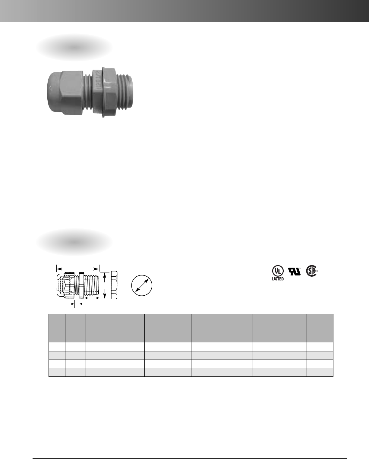
90° Features
E32447
LR201397
E32447
LR201397
Specifications
Specifications
•Available in sizes 3/8" through 1"
conduit and tubing.
• Smooth internal surfaces for easier
wire installation around corner angles.
• All nylon construction resists salt
water, weak acids, gasoline, alcohol,
oil, grease and common solvents.
• No disassembly required.
•No threading of the conduit or tubing
required to install.
• Complete conduit/connector system is
reusable.
•Use of a sealing washer may be
required for wet locations.
• Suitable for indoor/outdoor use.
• Lower installed cost.
• Black connectors provided with nylon locknut,
packed separately.
• Gray connectors provided with assembled O-ring and metal locknuts.
• Protection class IP 68 per DIN 40050 up to 70 psi (5 bar) water
pressure.
•Molded of type 6/6 nylon. ASTM D-4066-PA 111; flammability
classification 94V-2.
www.carlon.com
10
Technical Data
Carflex Fittings Installation Instructions
LT43C-CAR, LT43F thru J, LT20C-CAR, LT20F thru J.
1. Cut the end of the Carflex conduit or Carflex®
X-Flex™tubing square.
2. Install compression nut and sealing gland ring over the
end of the conduit or tubing.
3. Insert the ferrule end of the fitting into the conduit using
aclockwise twisting action.
4. Screw fitting body into compression nut.
5. When installation is completed, use a wrench,
tighten compression nut one-quarter (1/4) turn past
hand-tight. Do not over tighten fitting.
*To prevent damage to conductors, conduit and
fittings, do not twist Carflex during installation.
CarflexLiquidtight Conduit Technical Information
1. There shall be no more than the equivalent of four (4) quarter (90°) bends (360° total)
between pull points, conduit bodies, and boxes.
2. The radius of the curve of the center of the conduit or tubing shall not be less than
that shown in the table below:
UL Listed for use as indicated in Article 356 of the
National Electrical Code
•Cellular Metal Floor Raceways, Connections to
Cabinets & Wall Outlets
• Class I, Div. 2, Hazardous Location
• Class II, Div. 1, Hazardous Location
•Class III, Div.1, Hazardous Location
• Computer Room Raised Floor
• Concealed Locations
• Intrinsically Safe Systems
• Lighting Fixtures, Connection to Electric Discharge
Fixture
•Nonmetallic Boxes
• RV Engine Generator
• Swimming Pool Pump Motor
•Tap Conductors (Fixture Whips)
•Underfloor Raceway, Connection to Cabinets &
Wall Outlets
• Wireway, Extensions from Wireways, Wiring
Methods
–Agricultural Buildings,Flexible Connections
–Electric Signs, 1000 Volts, Nominal, or Less
–Electric Signs, Over 1000 Volts (per Section
600.32(A)(1)
–Floating Buildings
–Marinas and Boatyards
–Service Entrance Conductors
• Wiring on Buildings, Outside Branch Circuits &
Feeders
LT43D-New, LT43E-New, LT20D-New, LT20E-New.
1. Cut the end of the Carflex conduit or Carflex®
X-Flex™tubing square.
2. Install compression nut over the end of the conduit or
tubing.
3. Insert the ferrule end of the fitting into the conduit using
aclockwise twisting action.
(Be sure conduit
is fully inserted to the bottom of the fitting shoulder).
4. Screw compression nut onto fitting body.
5. Use a wrench, and tighten compression nut one (1) full
turn past hand-tight. Do not over tighten fitting.
*To prevent damage to conductors, conduit and
fittings, do not twist Carflex during installation.
SIZE OF CONDUIT RADIUS TO CENTER OF CONDUIT
OR TUBING OR TUBING
Inches Metric Desgr. Inches (mm)
3/8(14) 4 (101.6)
1/2(16) 4 (101.6)
3/4(21) 4 1/2(114.3)
1 (27) 5 3/4(146.0)
11/4(35) 7 1/4(184.1)
11/2(41) 8 1/4(209.5)
2 (53) 9 1/2(241.3)
www.carlon.com 11
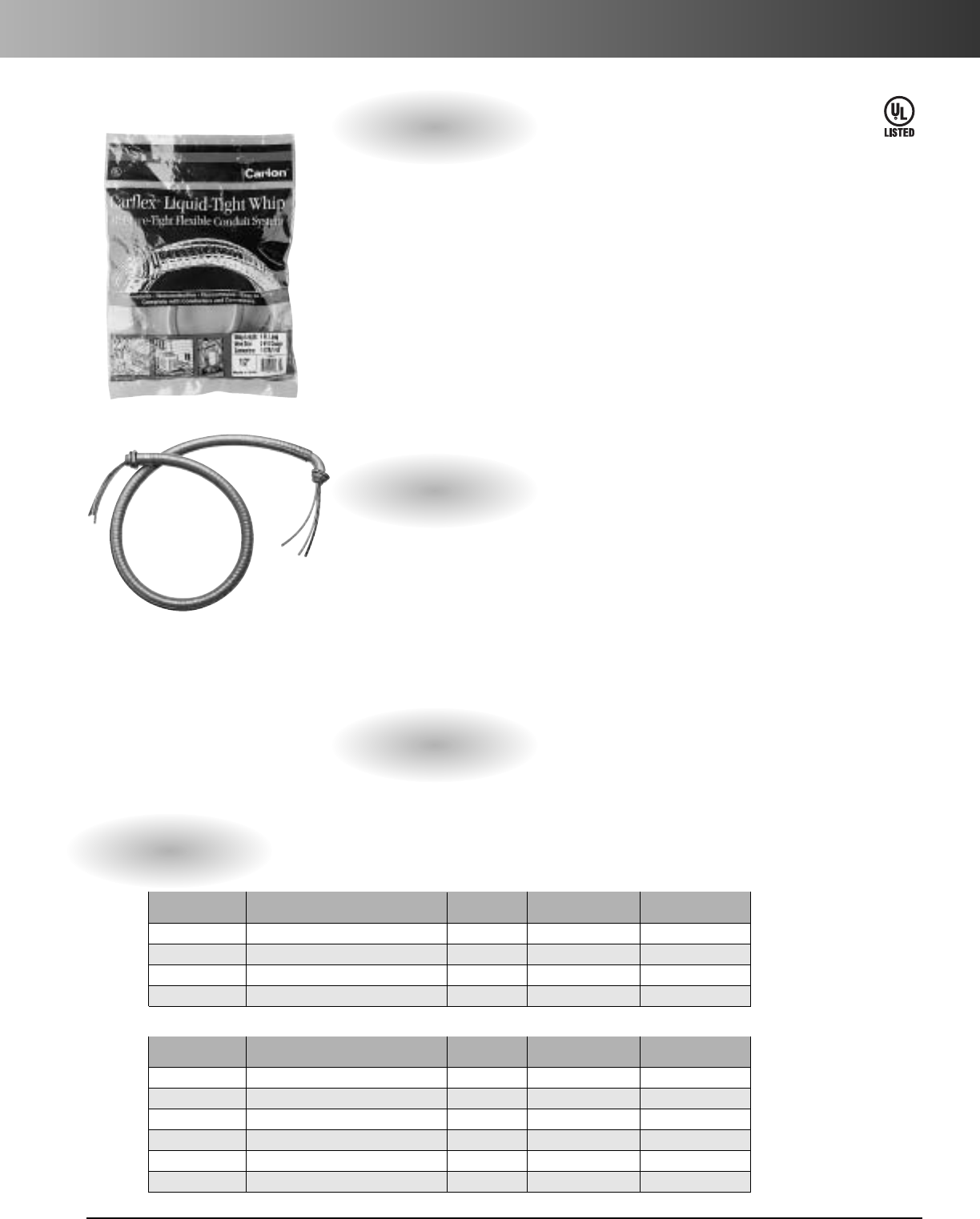
Carflex®Pre-Wired Liquidtight Whips
Specifications
Features
Part Wire Size Standard Carton Standard Carton
Number Description (Gauge) Quantity Weight (lbs.)
WCD4 1/2" Carflex Whip - 4 foot 10 6 (poly bag) 10.6
WCD6 1/2" Carflex Whip - 6 foot 10 6 (poly bag) 15.8
WCE4 3/4" Carflex Whip - 4 foot 8 6 (poly bag) 12.4
WCE6 3/4" Carflex Whip - 6 foot 8 6 (poly bag) 15.8
Part WireSize Standard Carton Standard Carton
Number Description (Gauge) Quantity Weight (lbs.)
WCD3124 1/2" Carflex Whip - 4 foot 12 20 (bulk pack) 32.4
WCD3126 1/2" Carflex Whip - 6 foot 12 20 (bulk pack) 47.9
WCD3104 1/2" Carflex Whip - 4 foot 10 20 (bulk pack) 35.2
WCD3106 1/2" Carflex Whip - 6 foot 10 20 (bulk pack) 52.8
WCE3084 3/4" Carflex Whip - 4 foot 8 15 (bulk pack) 30.9
WCE3086 3/4" Carflex Whip - 6 foot 8 15 (bulk pack) 39.6
Carflex®Liquidtight Whip
assemblies save
the customer time and hassle of having to hunt for the needed
components. Our moisture tight, nonmetallic, flexible conduit
system is ideal for installing swimming pool motors, hot tubs,
spas, air conditioners, pumps, outdoor lighting and more.
Unlike plastic coated metal conduit, the Carlon®Carflex system
has no metal core to fatigue, rust, or corrode. The Carflex system
has no sharp edges or burrs to cut into the wire insulation. Metal
conduit is subject to fatigue and penetration of moisture.
The Carflex Liquidtight Whip assembly is complete with Carflex
moisture tight conduit, wire, one straight fitting, and one 90°
fitting.
All this makes for quick and trouble free installation.
•Designed for easy installation
• Will not rust or corrode
• Can be used for many commercial
and residential applications.
• Many applications such as; swim-
ming pool filters, hot tub spas, air
conditioners, pumps, etc.
•Available in 1/2" and 3/4"
diameters
•Available in 4' and 6' lengths
• Each kit contains (1) straight and
(1) 90° fitting
•Complete with (3) 8, 10 or 12
gauge wires
E155504
Custom Orders
Also available in special configurations including different fitting
combinations, wire types and sizes, and metal fitting variations.
Consult factory for details.
www.carlon.com
12
Carlon
®
Cord Grips – Straight PG Hubs
Specifications
Straight PG Hubs
Features
•New threads on body prevent skipping, speed
installation.
•PG hub threads are steel conduit per DIN 40430.
• Six sizes for cable, tubing, etc.: PG07, PG09, PG11,
PG13.5, PG16, and PG21.
• All nylon construction with TPE gland resists salt
water, weak acids, gasoline, alcohol, oil, grease
and common solvents.
• Suitable for NEMA type 4 and 6 enclosures.
• Locknuts are included.
• Working temperatures: -22°F (-30ºC) to 212°F
(100°C). For short periods to 302°F (150°C).
• Protection Class IP68 per DIN 40050 up to 70 psi
(5 Bar) water pressure.
ABCDE
Straight Diameter of Wrenching
Part Std. Std. Cable or Wire Clearance Max O.A. Thread Nut Wrenching
Size No.Ctn. Ctn. Accommodated Hole Length Length Thickness Flats
(PG) Black Qty.Wt. in. (mm) in. (mm) in. (mm) in. (mm) in. (mm) in. (mm)
PG07 LH07 100 1.3 .114-.250 (2.9-6.4) .492 (12.5) 1.17 (29.7) .33 (8.4) .22 (5.6) .59 (15.0)
PG09 LH09 100 2.0 .181-.312 (4.6-7.9) .599 (15.2) 1.30 (33.0) .34 (8.6) .20 (5.1) .75 (19.1)
PG11 LH11 100 2.6 .230-.395 (5.8-10.0) .733 (18.6) 1.46 (37.1) .39 (9.9) .20 (5.1) .86 (21.8)
PG13.5 LH13 100 3.1 .170-.470 (4.3-11.9) .804 (20.4) 1.53 (38.9) .41 (10.4) .20 (5.1) .95 (24.1)
PG16 LH16 50 2.1 .230-.546 (5.8-13.9) .886 (22.5) 1.66 (42.2) .45 (11.4) .23 (5.8) 1.05 (26.7)
PG21 LH21 50 3.2 .450-.709 (11.4-18.0) 1.115 (28.3) 1.87 (47.5) .52 (13.2) .23 (5.8) 1.30 (33.0)
ASuggested
Clearance Hole
For Nonthreaded
Mounting
B
E
C
D
Patented 4,900,068
Carlon®recommends using the smallest maximum diameter fitting that will suit your application.
E51579 LR93876
www.carlon.com 13
Carlon
®
Cord Grips – Straight NPT Hubs
Specifications
Straight NPT Hubs
Features
•New threads on body prevent skipping, speed
installation.
•Four sizes for cable, tubing, etc. with diameters of
3/8", 1/2", 3/4" and 1".
• All nylon construction with TPE gland resists salt
water, weak acids, gasoline, alcohol, oil, grease
and common solvents.
• Suitable for NEMA type 4 and 6 enclosures.
• Locknuts are included.
• Working temperatures: -22°F (-30°C) to 212°F
(100°C). For short periods to 302°F (150ºC).
• Protection Class IP68 per DIN 40050 up to 70 psi
(5 Bar) water pressure.
ABCDE
Straight Straight Diameter of Wrenching
Part Part Std. Std. Cable or Wire Clearance Max O.A. Thread Nut Wrenching
Size No. No. Ctn. Ctn. Accommodated Hole Length Length Thickness Flats
(NPT) Black Gray Qty. Wt. in. (mm) in. (mm) in. (mm) in. (mm) in. (mm) in. (mm)
3/8" LH38 LH38G 100 1.9 .181-.312 (4.6-7.9) .670 (17.0) 1.49 (37.8) .53 (13.5) .20 (5.1) .75 (19.1)
1/2" LH50 LH50G 100 2.9 .170-.470 (4.3-11.9) .875 (22.2) 1.72 (43.7) .62 (15.7) .20 (5.1) .95 (24.1)
3/4" LH75 LH75G 50 2.7 .450-.709 (11.4-18.0) 1.068 (27.1) 1.97 (50.0) .63 (16.0) .23 (5.8) 1.30 (33.0)
1" LH100 LH100G 25 2.6 .590-1.000 (15.0-25.4) 1.375 (35.0) 2.42 (61.5) .78 (19.8) .28 (7.1) 1.66 (42.2)
Patented 4,900,068
Carlon®recommends using the smallest maximum diameter fitting that will suit your application.
E51579 LR93876
ASuggested
Clearance Hole
For Nonthreaded
Mounting
B
E
C
D

www.carlon.com
14

www.carlon.com 15
Contractor Kits
Plug-In Chime
Extend-A-Chime
Accessories
Carlon
®
Chimes
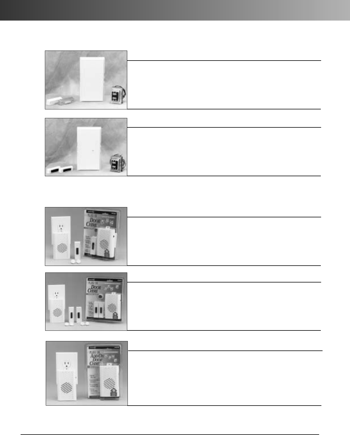
Wireless Plug-In Door Chimes
Plug-In Chimes
Sound Options Available:
•Ding Dong • Dong • Westminster Chime • 12 Days of Christmas
•Hail, Hail, The Gang’sAll Here • My Country ‘Tis of Thee
RC3253 Plug-In Add-On Door Chime
•Six different selectable sounds
•Includes two buttons
•Different sounds for front,
back & other doors
RC3252 Plug-In Door Chime
RC3250 Plug-In Door Chime
Contractor Kits
Door Chimes & Buttons
CK221RP Chime Kit with 2 Buttons
•Includes one contemporary
white chime, two push
buttons and one transformer
•Medium volume level
• Easy to install
CK225 Chime Kit with 2 Lighted Buttons
•Two-note tone designates front
entrance, one-note designates
second entrance
•120V AC input
•16V AC 10VA output
• 3-year limited warranty
• Six different selectable sounds
• Different sounds for front, back
&other doors
• Adjustable volume control
• 32 changeable codes reduce inter-
ference
•Range: 150 ft.
• 5-year warranty
•Adjustable volume control
• 32 changeable codes reduce
interference
•Range: 150 ft.
• 5-year warranty
• Use with existing Dimango
doorbells
•Six different selectable sounds
for front, back & other doors
•Adjustable volume control
• 32 changeable codes reduce
interference
•Works with Dimango products:
RC3200, RC3250, RC3252,
RC3260, RC3304,
RC3306, RC3410, RC3610, &
RC3720
•Range: 150 ft.
• 5-year warranty
• Includes one contemporary
white chime, two lighted push
buttons and one transformer
•Medium volume level
•Easy to install
• Two-note tone designates front
entrance, one-note designates sec-
ond entrance
•120V AC input
•16V AC 10VA output
• 3-year limited warranty
www.carlon.com
16
Carlon®Chimes
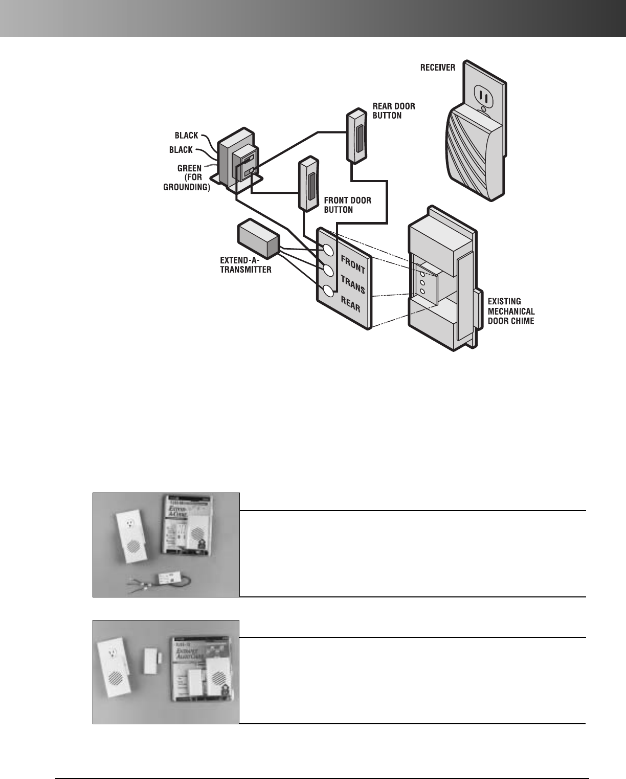
Extend-A-Chime™
1. Connect Extend-A-Chime™transmitter to existing mechanical door chime.
2. Press existing doorbell button.
3. Existing doorbell rings and sends signal to Extend-A-Chime™
.
4. Extend-A-Chime™rings.
5. Extend-A-Chime™may be placed anywhere user wants to hear doorbell ring:
•Laundry Room • Garage • Work Shop • Deck
RC3200 Plug-In Extend-A-Chime™
RC3260 Plug-In Entrance Alert Chime
Here’s How They Work:
•Use with existing doorbell
• Six different selectable sounds
• 32 changeable codes reduce
interference
•Safe & easy to install
• 21/4"speaker provides
excellent sound quality
•Range: 150 ft.
• 5-year warranty
• Chime sounds when door is
opened
•Six different sound options
• Ideal for small shops and
businesses, or homes with
small children
• 32 changeable codes reduce
interference
•Sound set at button
•Range: 150 ft.
• 5-year warranty
www.carlon.com 17
Extend-A-Chime™
Batteries
Transmitters
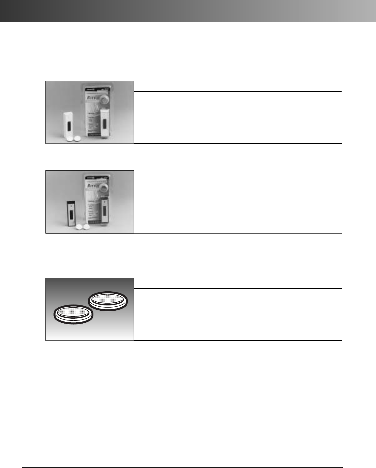
RC3395 3-Volt Button Cell Batteries
RC3311 Black Door Chime Button
RC3301 White Door Chime Button
•Works with all 3200, 3300,
3400 & 3600 series and 3720
• Long-life button battery
included
•Weatherproof – use indoors or
out
•Button works from -30˚ to + 130˚F
•Range: 150 ft.
• 5-year warranty
• Works with all 3200, 3300,
3400 & 3600 series and 3720
• Long-life button battery
included
•Weatherproof – use indoors or
out
•Button works from -30˚ to + 130˚F
•Range: 150 ft.
• 5-year warranty
• Use in buttons RC3301,
RC3311 and RC3321
• Two batteries per card
•Size CR2032 lithium battery
•Range: N/A
www.carlon.com
18
Accessories
www.carlon.com 19
ENT Tubing
Adapters
& Couplings
Mud Box
Assemblies
Stub Downs
Outlet and
Switch Boxes
Carlon
®
Flex-Plus
®
Blue
™
Electrical Nonmetallic
Tubing (ENT) and Accessories
www.carlon.com
20
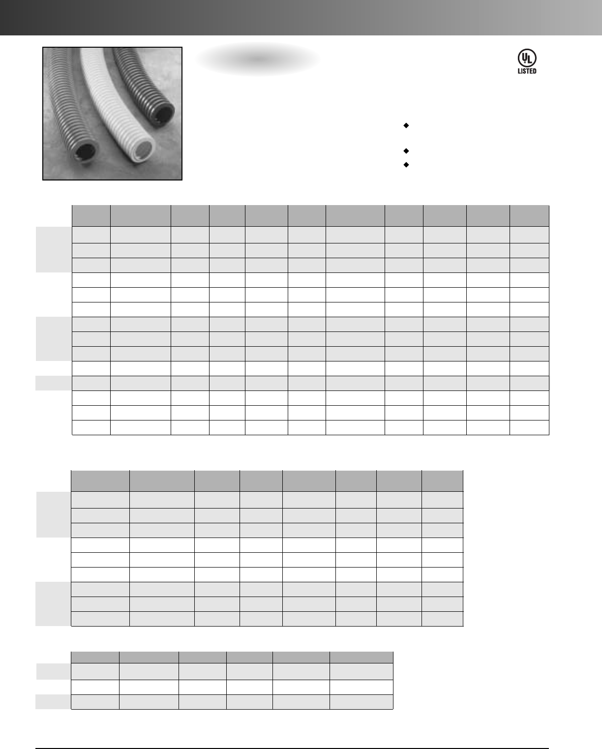
Flex-Plus®Blue™ENT
Nom. Nom. Pull Min. Bend Coil Length Wt. per
Color Part No. I.D. O.D. Tape Radius (ft.) 100 ft. (lbs.)
Blue 12005-200 .56 .84 Empty 6" 200 10
Yellow 12005Y-200 .56 .84 Empty 6" 200 10
Red 12005R-200 .56 .84 Empty 6" 200 10
Blue 12007-100 .76 1.05 Empty 6" 100 14
Yellow 12007Y-100 .76 1.05 Empty 6" 100 14
Red 12007R-100 .76 1.05 Empty 6" 100 14
Blue 12008-100 1.00 1.315 Empty 6" 100 22
Yellow 12008Y-100 1.00 1.315 Empty 6" 100 22
Red 12008R-100 1.00 1.315 Empty 6" 100 22
StandardStock – Coils
1"
1/2"
3/4"
Nom. Nom. Pull Min. Bend Reel Size Reel Type Reel Reel Wt. Wt. per
Color Part No. I.D. O.D. Tape Radius (F x W) (W=Wood) Length (lbs.) 100 ft. (lbs.)
Blue 12005AK-001 .56 .84 Empty 6" 36" x 24" W 1500 40 10
Yellow 1205AKY-001 .56 .84 Empty 6" 36" x 24" W 1500 40 10
Red 1205AKR-001 .56 .84 Empty 6" 36" x 24" W 1500 40 10
Blue 12007AA-001 .76 1.05 Empty 6" 36" x 24" W 1000 40 14
Yellow 1207AAY-001 .76 1.05 Empty. 6" 36" x 24" W 1000 40 14
Red 1207AAR-001 .76 1.05 Empty 6" 36" x 24" W 1000 40 14
Blue 12008-750 1.00 1.315 Empty 6" 36" x 24" W 750 40 20
Yellow 12008Y-750 1.00 1.315 Empty 6" 36" x 24" W 750 40 20
Red 12008R-750 1.00 1.315 Empty 6" 36" x 24" W 750 40 20
Blue 12009-750 1.402 1.66 Empty 7" 48" x 32" W 750 90 19
Blue 12010-750 1.554 1.90 Empty 81/4"48" x 32" W750 90 39
Blue 12011-500 2.030 2.375 Empty 91/2" 48" x 32" W 500 90 32
Red 12011R-500 2.030 2.375 Empty 91/2"48" x 32" W 500 90 32
Yellow 12011Y-500 2.030 2.375 Empty 91/2"48" x 32" W500 90 32
1"
2"
11/4"
1/2"
3/4"
11/2"
Standard Stock – Reels
Options:
•Sizes 1/2"through 2"
•Colors:
Yellow color for communication
circuits and signaling cable
Red color for fire alarm circuits
Blue color for power circuits
•Packaging: Coils or Reels
NOTE: The solid blue color of ENT conduit is a registered trademark of Carlon.
ENT may show color deterioration in direct sunlight over an extended period of time. It is suggested that all ENT products not be
stored outside. Since this product is not intended for use outdoors, it should not be exposed to extended periods of direct sunlight.
Color Part No. Nom. I.D. Nom. O.D. Std. Ctn. Qty. Std. Ctn. Wt. (lbs.)
Blue 12005-UPC .56 .84 10 ft. 1.02
Blue 12007-UPC .76 1.05 10 ft. 1.46
Blue 12008-010 1.00 1.315 10 ft. 2.93
10 ft. Lengths
1"
1/2"
3/4"
*1-1/4" - 2" available in yellow & red, made to order; consult factory.
Flex-Plus
®
Blue™ENT
isanonmetallic flexible raceway for use
in walls, floors, and non-plenum ceilings.
It’s lightweight, hand bendable, and free
from sharp edges, which reduces
installation time and saves money.
See pages 31–32 for technical
information.
E73317
www.carlon.com 21
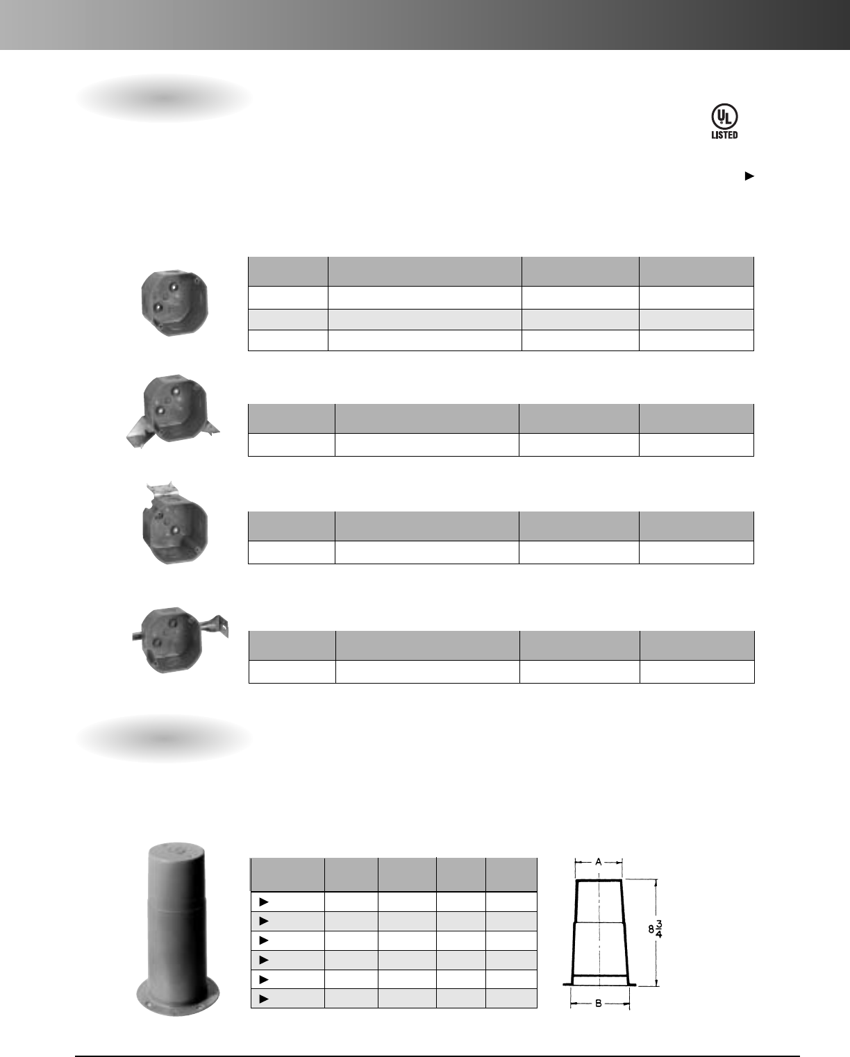
ENT Accessories
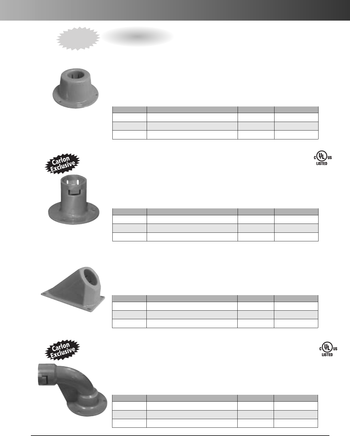
Vertical Stub Down
Carlon Vertical Stub Downs
are designed to provide a quick, easy connection to a wood deck or transition
from slab-to-slab using Carlon’s “Quick Connect” snap-in design…simply snap the ENT in place. The integral snaps
provide a secure mount – preventing the ENT from pulling out while maintaining the ability for easy removal of the
fitting once the deck is removed. All in a concrete tight application. The underside of this fitting provides ample
room to attach a Carlon coupling to the ENT to continue the run. Carlon Vertical Stub Downs are manufactured out
of a highly engineered thermoplastic material to provide extra strength and durability, and are available in sizes
1/2", 3/4" and 1".
Vertical Stub Down Transition Adapter
CARLON NONMETALLIC EXCLUSIVE…Carlon Vertical Stub Down Transition Adapters
like our
Vertical Stub Downs, provide a means to transition from ENT to another wire management product where code
requires other wire management means i.e. “area of physical damage” [ref. NEC 362.12(10)]. The integral snaps
provide a secure mount – preventing the ENT from slipping or pulling out, while the deck mount flange has a
threaded port allowing connection to other conduit system using a terminal adapter. Carlon Vertical Stub Down
Transition Adapters are manufactured out of polycarbonate material to provide extra strength and durability. They’re
concrete tight, and available in sizes 1/2", 3/4" and 1".
Stub Downs
45° Stub Down
Carlon 45 Degree Stub Downs
are designed to allow a smooth transition from cross deck ENT runs to vertical
applications. The integral snaps provide a secure mount – preventing the ENT from slipping or pulling out- but also
allow the stub to easily be removed. The underside of this fitting provides ample room to attach a Carlon coupling to
the ENT to continue the run. Carlon 45 Degree Stub Downs are manufactured out of a highly engineered thermoplastic
material to provide extra strength and durability. They’re concrete tight, and available in sizes 1/2", 3/4" and 1".
90°Stub Down Transition Adapter
CARLON NONMETALLIC EXCLUSIVE…Carlon 90 Degree Stub Downs
are designed to allow a smooth
transition from cross deck ENT runs to vertical applications where code requires other wire management means,i.e.
“area of physical damage” [ref. NEC 362.12(10)]. The integral snaps provide a secure mount – preventing the ENT
from slipping or pulling out, while the deck mount flange has a threaded port allowing connection to any conduit
system using a terminal adapter.Carlon 90 Degree Stub Downs are manufactured out of polycarbonate material to
provide extra strength and durability. They’re concrete tight, and available in sizes 1/2", 3/4" and 1".
Part. No. Size Std. Ctn. Qty. Std. Ctn. Wt. lbs.
A230D 1/2"Female ENT to NPSC (Female) 25 2.0
A230E 3/4" Female ENT to NPSC (Female) 25 2.4
A230F 1" Female ENT to NPSC (Female) 25 3.3
Part. No. Size Std. Ctn. Qty. Std. Ctn. Wt. lbs.
A220D 1/2" 25 1.8
A220E 3/4" 25 2.0
A220F 1" 25 2.6
Patent Pending
Part. No. Size Std. Ctn. Qty. Std. Ctn. Wt. lbs.
A200D 1/2"Female ENT to NPSC (Female) 50 2.3
A200E 3/4"Female ENT to NPSC (Female) 50 2.8
A200F 1" Female ENT to NPSC (Female) 50 3.9
Part. No. Size Std. Ctn. Qty. Std. Ctn. Wt. lbs.
A210D 1/2" 50 3.8
A210E 3/4" 50 3.7
A210F 1" 50 4.8
Patent Pending
NEW
E86720
E86720
www.carlon.com
22
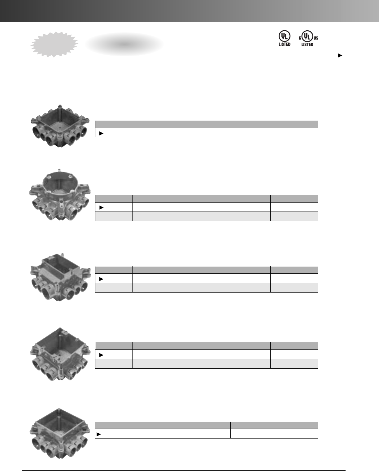
ENT Accessories
Carlon Mud Box Assemblies are available in five unique styles…blank, ceiling ring, one-gang, two-gang
and 4 square. All Mud Box Assemblies are manufactured out of polycarbonate material to provide extra strength
and durability, are concrete tight, and have twelve integral connectors…two-1", six-3/4", and four-1/2". Using our
new ENT Reducers, this product will meet ANY jobsite application.
Mud Box Base with Blank Cover
Mud Box with Ceiling Ring
•Threaded brass inserts for fan (#10-32 screws) and fixture (#8-32 screws) mountings
•Listed for fixture support up to 50 lbs. • Listed for ceiling fans up to 35 lbs.
Mud Boxwith One-Gang Ring
Mud Boxwith Two-Gang Ring
Mud Box with 4 Square Ring
•4Square Ring not for luminaries.
Mud Box Assemblies
Part. No. Size Std. Ctn. Qty. Std. Ctn. Wt. lbs.
A863BC Mud Box w/ Blank Cover 24 12.3
Patent Pending
Part. No. Size Std. Ctn. Qty. Std. Ctn. Wt. lbs.
A863CF Mud Box w/ Ceiling Ring 24 15.5
A863CFG Mud Box w/ Ceiling Ring & Ground Lug 24 16.1
Patent Pending
Part. No. Size Std. Ctn. Qty. Std. Ctn. Wt. lbs.
A863S Mud Box w/ One-Gang Ring 24 16.8
A863SG Mud Box w/ One-Gang Ring & Ground Lug 24 16.2
Patent Pending
Part. No.Size Std. Ctn. Qty. Std. Ctn. Wt. lbs.
A863D Mud Box w/ Two-Gang Ring 24 15.8
A863DG Mud Box w/ Two-Gang Ring & Ground Lug 24 16.6
Patent Pending
Part. No.Size Std. Ctn. Qty. Std. Ctn. Wt. lbs.
A863-4SQ Mud Box w/ 4 Inch Square Ring 24 15.2
Patent Pending
Except where noted by
NEW
E42728 E42728
www.carlon.com 23
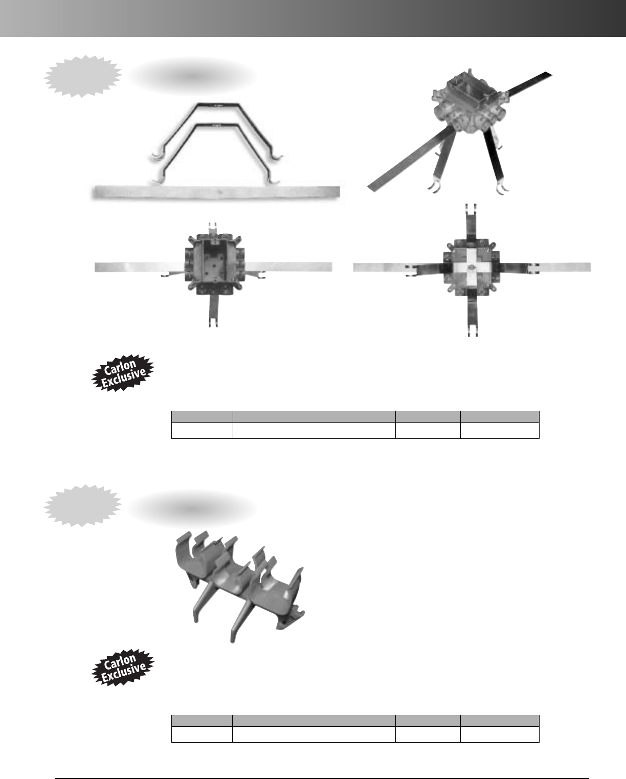
ENT Accessories
Mounting Brackets
CARLON EXCLUSIVE…The Carlon ENT Mounting Bracket is specifically designed for use with Carlon
ENT Mud Box Assemblies in vertical concrete walls where one- or two-gang boxes are needed. The stainless steel
spring-loaded mechanism provides a secure outlet box between concrete forms while the soft steel strap allows for
the outlet box to be secured to rebar. The bracket combination assures a straight box opening and a concrete tight
fit. Mud Box not included.
ENT Bridge
CARLON EXCLUSIVE…The Carlon ENT Bridge is designed to support long ENT runs in concrete pour
applications.This makes pulling wire/cable a snap.Installation is easy…simply mount the ENT bridge,using nails
or screws,to the wood deck mounting and snap the ENT into place.The bridge is designed to hold the conduit in
place while minimizing dips in the conduit over long runs. The Carlon ENT Bridge is manufactured out of a highly
engineered thermoplastic material to provide extra strength and durability,and can accommodate ENT sizes
1⁄2", 3⁄4", and 1".
Front View Back View
Part. No.Size Std. Ctn. Qty. Std. Ctn. Wt. lbs.
A863MB Mud Box Mounting Kit 1 .98
Patent Pending
Part. No.Size Std. Ctn. Qty. Std. Ctn. Wt. lbs.
A293DEF ENT Bridge 50 9.0
Patent Pending
NEW
NEW
www.carlon.com
24
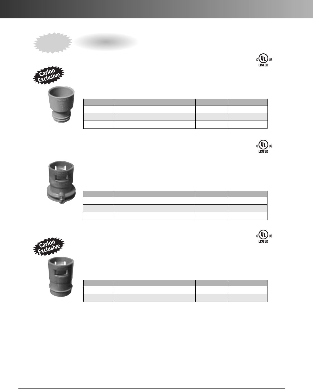
ENT Accessories
Male ENT to Schedule 40 & 80 PVC Conduit
CARLON EXCLUSIVE…Carlon Male ENT to Schedule 40 & 80 PVC Conduit Transition Adapters
are designed to connect PVC conduit to Carlon Flex-Plus®Blue™ENT boxes and fittings. Simply solvent cement the
PVC adapter to the PVC conduit and snap the adapter into the Carlon’s “Quick Connect” snap-in connector on the box
or fitting. Carlon Male ENT to Schedule 40 & 80 Adapters are concrete tight and available in sizes 1/2", 3/4" and 1".
ENT to EMT
Carlon ENT to EMT Transition Adapters
are designed to easily transition from Carlon Flex-Plus®Blue™ENT
to EMT using Carlon’s “Quick Connect” snap-in design. The EMT is held securely in place using the small screw
provided. This helps prevent the EMT from slipping/shifting out of the adapter. All ENT to EMT adapters are
manufactured out of polycarbonate material to provide extra strength and durability. They’re concrete tight, and
available in sizes 1/2", 3/4" and 1".
Reducers
CARLON EXCLUSIVE…Carlon ENT Reducers
are designed to provide an easy transition from 1" Carlon ENT
to 3/4" ENT or from 3/4" Carlon ENT to 1/2" ENT. They’re concrete tight, and manufactured out of polycarbonate
material to provide extra strength and durability.Carlon ENT Reducers provide flexibility while on the jobsite by
minimizing the need to carry size specific boxes and fittings. Carlon ENT Reducers provide the versatility to convert
Carlon fittings and boxes to many different sizes and configurations.
Transition Adapters
Part. No. Size Std. Ctn. Qty. Std. Ctn. Wt. lbs.
A273DE 3/4"to 1/2" 100 3.2
A273EF 1" to 3/4" 100 2.4
Part. No. Size Std. Ctn. Qty. Std. Ctn. Wt. lbs.
A245D 1/2"ENT to 1/2"EMT 100 3.4
A245E 3/4"ENT to 3/4"EMT 100 4.1
A245F 1" ENT to 1" EMT 100 5.4
Part. No. Size Std. Ctn. Qty. Std. Ctn. Wt. lbs.
A263D 1/2"ENT to 1/2"Sch. 40 100 2.4
A263E 3/4"ENT to 3/4"Sch. 40 100 3.2
A263F 1" ENT to 1" Sch. 401 100 4.5
NEW
Patent Pending
Patent Pending
E32447
E86720
E86720
www.carlon.com 25
ENT Accessories
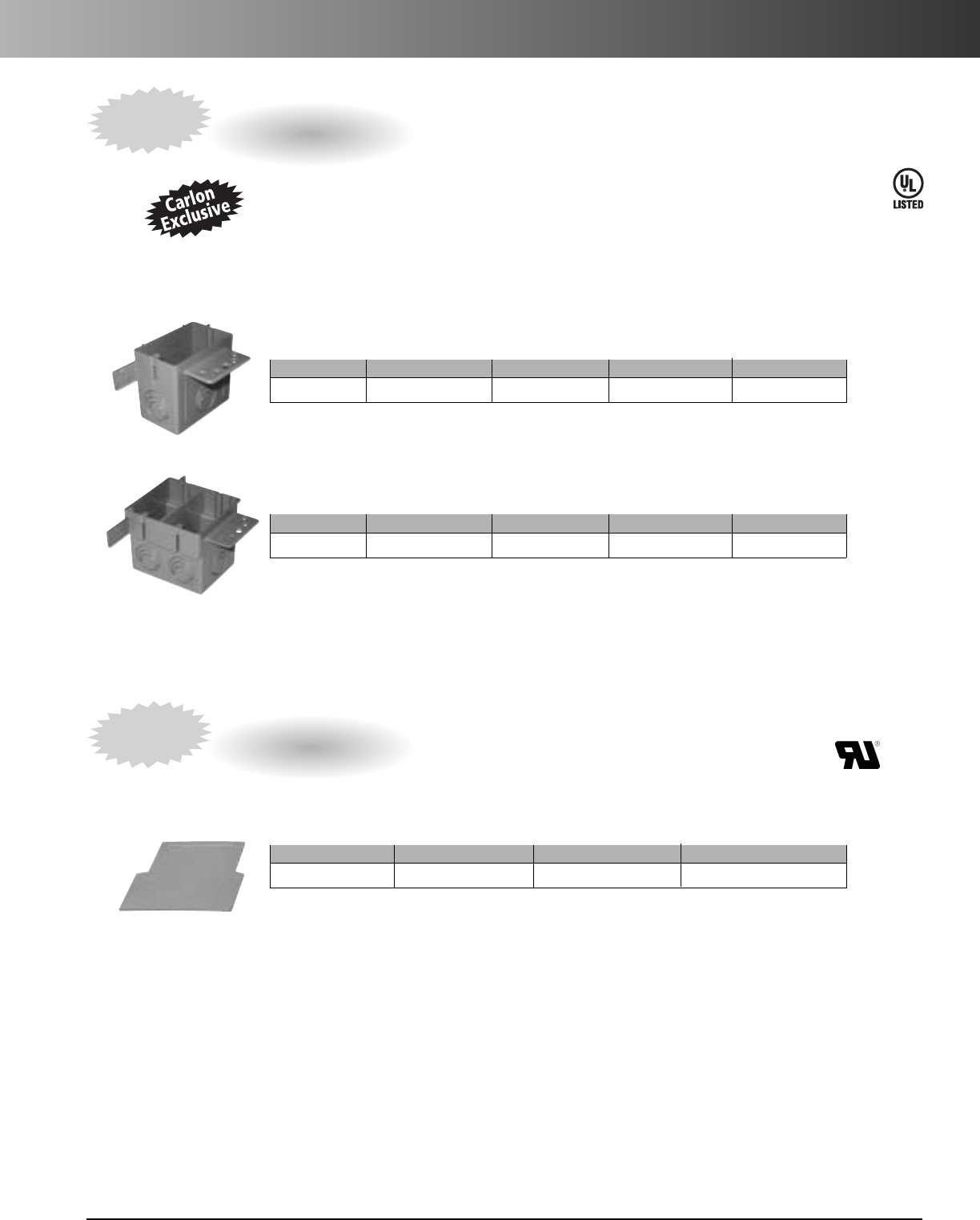
Carlon ENT Outlet and Switch Boxes with Eccentric Knockouts
are designed to allow selective ENT
openings – 1/2", 3/4" and 1" – based on application needs. They provide the largest capacity available in the
market today - 22 cu. in. Single Gang, and 38 cu. in. Double Gang – and can be mounted to wood or steel studs.
Carlon ENT Outlet and Switch Boxes with Eccentric Knockouts are manufactured out of a highly engineered
thermoplastic material to provide extra strength and durability, and are available in single gang and double gang
styles. Note: The double gang version is also a 4 square box.
Outlet and Switch Boxes - Eccentric Knockouts
Single Gang – 22 cu. in.
Part. No. Size Capacity Cu. in. Std. Ctn. Qty. Std. Ctn. Wt. lbs.
A122 Single-Gang 22 25 6.8
Patent Pending
Carlon ENT Outlet Box Divider
is specifically designed for applications where a combined high and low voltage
closed back box is needed such as placement in a fire-rated wall. Just slip the divider into place, to give you the split
box you need. The Carlon ENT Outlet Box Divider is UL Recognized for use with Carlon A122 & A238 boxes only.
Outlet Box Divider
Part. No. Size Std. Ctn. Qty. Std. Ctn. Wt. lbs.
A238DIV –50 1.87
Combination Two Gang/Four Square Box – 38 cu. in.
Part. No.Size Capacity Cu. in. Std. Ctn. Qty. Std. Ctn. Wt. lbs.
A238 Two-Gang 38 25 8.9
Patent Pending
NEW
NEW
E42728
www.carlon.com
26
ENT Accessories
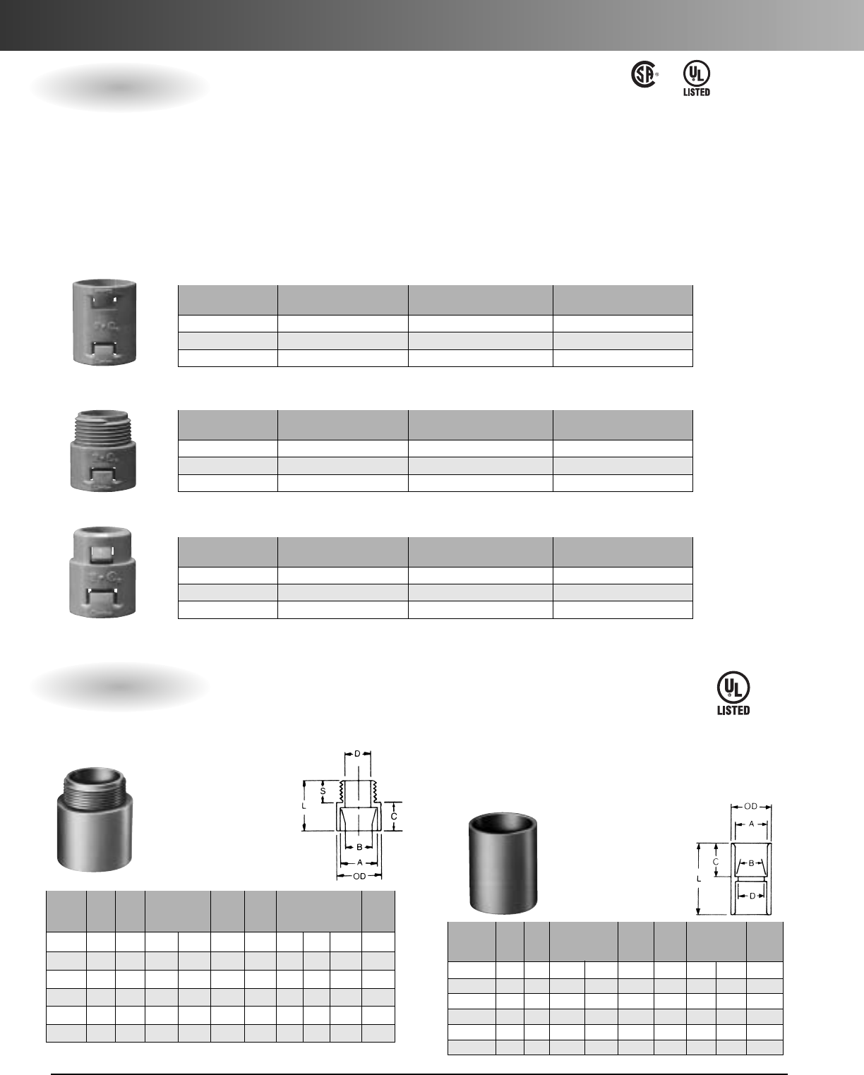
Male Terminal Adapters
For adapting nonmetallic
conduits to boxes,
threaded fittings,metallic
systems. Male threads
on one end, socket end
on other.
Std. Std.
Part Ctn. ABMin. Max. C S L
Ctn. Wt.
No. Size Qty. Typical D OD Typical (lbs.)
E943D 1/2150 .852 .836 .597 11/85/89/16 15/16 2.8
E943E 3/4125 1.064 1.046 .800 111/32 3/49/16 13/83.5
E943F 1 50 1.330 1.310 1.018 15/8111/16 125/32 3
E943G 11/450 1.677 1.655 1.332 21/32 13/4115/16 4
E943H 11/225 1.918 1.894 1.566 2 5/32 13/16 3/421/16 2.5
E943J 2 50 2.393 2.369 2.000 2 21/32 13/16 3/421/87
Std. Std.
Part Ctn. A B Min. Max. C L Ctn.
No.Size Qty.Typical D OD Typical
Wt. (lbs.)
E940D 1/2150 .852 .836 .728 17/64 11/16 11/24.1
E940E 3/4100 1.064 1.046 .840 15/16 3/415/84.4
E940F 1 50 1.330 1.310 1.210 15/815/16 2 3.5
E940G 11/430 1.677 1.655 1.535 163/64 121/83.5
E940H 11/225 1.918 1.894 1.755 215/64 11/823/83.9
E940J 2 30 2.393 2.369 2.190 247/64 13/16 21/25.25
All socket fittings should be attached Using Carlon solvent cement. Using
Carlon fittings with Carlon nonmetallic conduit insures system integrity.
StandardCouplings
Socket type for
joining nonmetallic
conduit.
•
Carlon one piece ENT Quick Connect Couplings, Threaded Adapters
and Snap-In Terminator Adapters are suitable for damp locations.
Quick Connect Couplings and Threaded Adapters are concrete-tight
when used with Carlon ENT.
•
All Schedule 40 fittings are compatible with ENT when using ENT
cement.
•
Schedule 40 fittings are recommended for use with Carlon 11/4" –
2" Flex-Plus Blue ENT.
•
Use of ENT Blue Quick-Set Cement is required. See page 31 for details.
•
When One Piece Quick Connect Snap-In Terminator Adapters are
installed in a concrete application, Carlon’s flat sealing washers must
be used on the box connection ends.
Standard Carton Standard Carton
Part. No. Size Quantity Weight (lbs.)
A240D 1/2" 150 2.90
A240E 3/4" 100 3.00
A240F 1" 50 2.30
Couplings
StandardCarton Standard Carton
Part. No. Size Quantity Weight (lbs.)
A243D 1/2" 150 2.55
A243E 3/4"100 2.30
A243F 1" 50 2.00
Threaded Adapters
StandardCarton StandardCarton
Part. No. Size Quantity Weight (lbs.)
A253D 1/2"150 2.70
A253E 3/4" 100 2.90
A253F 1" 50 2.30
Snap-In Adapters
LR92248 E86720
E32447
Quick Connect Adapters & Couplings
Rigid Nonmetallic Conduit Adapters and Couplings
www.carlon.com 27
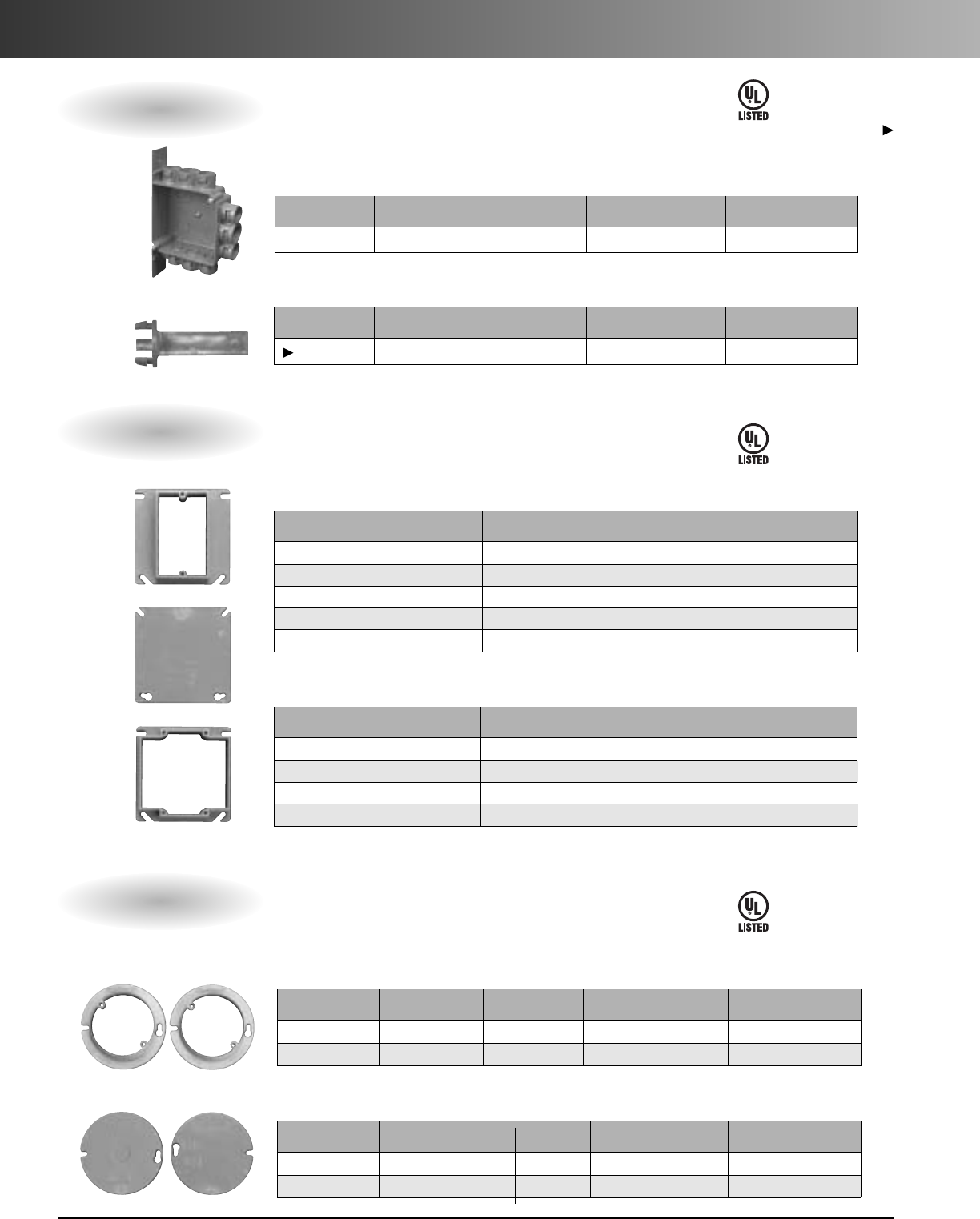
ENT Accessories
•Suitable for masonry walls • Meets NEMA OS-2
StandardCarton StandardCarton
Part. No. Description Quantity Weight (lbs.)
A58381D 3 x 21/4x3 (1/2" KO’s) 25 4.6
A58381E 3 x 21/4x3 (
3/4"KO’s) 25 4.6
Single Gang – 16 cu. in.
Standard Carton Standard Carton
Part. No. Description Quantity Weight (lbs.)
A52151D 4 x 4 x 11/2(1/2"KO’s) 100 22.6
A52151E 4 x 4 x 11/2(3/4"KO’s) 100 22.6
A521DE 4 x 4 x 11/2(1/2" & 3/4"KO’s) 100 22.6
4InchSquare – 20 cu. in.
Standard Carton Standard Carton
Part. No. Description Quantity Weight (lbs.)
A52171D 4 x 4 x 23/8(1/2"KO’s) 25 7.6
A52171E 4 x 4 x 23/8(3/4"KO’s) 25 7.6
A5217DE 4x4x23/8(1/2" & 3/4" KO’s) 25 7.6
4InchSquare – 30.3 cu. in.
E42728
Quick Connect Outlet and Switch Boxes
E42728 LR31146
21/2"& 4" Mud Boxes and Covers
Base Rings
Listed for use with ceiling fans up to
35 lbs. and for fixture support
upto 50 lbs.
Part. Std. Ctn. Std. Ctn.
No. Size Qty. Wt.
A861 Without ground lug 10 2.5
CA861G With ground lug 10 2.0
Covers
Part. Std. Ctn. Std. Ctn.
No. Size Qty. Wt.
A862D 21/2"Deep (1/2"KO’s) 10 2.5
A862E 21/2"Deep (3/4"KO’s) 10 2.1
A864D 4" Deep (1/2"KO’s) 10 2.9
A864E 4" Deep (3/4"KO’s) 10 2.9
A864F 4" Deep (1" KO’s) 10 3.0
www.carlon.com
28
ENT Accessories
Standard Carton Standard Carton
Part. No. Description Quantity Weight (lbs.)
A5329DE
4x4x1
3/4(1/2"&3/4"KO’s)
50 14.8
4Inch Square – 24.75 cu. in. ENT Box with Adapters
Standard Carton Standard Carton
Part. No. Description Quantity Weight (lbs.)
A540DS
For use with 1/2"Knockout
100 2.1
Box Back Wall Support
Standard Carton Standard Carton
Part. No. Rise Cu. in. Quantity Weight (lbs.)
A410 1/2"3.5 100 7.7
A411 5/8" 4.2 50 4.6
A412 3/4"5.0 50 5.1
A413 1" 6.6 40 5
A414 11/4" 8.1 30 4.4
Single Gang
Standard Carton Standard Carton
Part. No. Rise Cu. in. Quantity Weight (lbs.)
A400 Blank - 100 7.7
A420 1/2"6.1 75 5.0
A421 5/8" 7.4 50 4.2
A422 3/4" 8.8 50 4.8
Two Gang
E42728
E42728
Except where noted by
E42728
Standard Carton Standard Carton
Part. No. Rise Cu. in. Quantity Weight (lbs.)
A471 1/2" 3.2 100 3.3
A472 3/4" 4.0 100 3.7
Round Plaster Rings
•Suitable for fixture support
StandardCarton Standard Carton
Part. No. Rise Cu. in. Quantity Weight (lbs.)
E460R-CAR Blank - 35 2.2
A470D Blank with 1/2"KO - 100 4.7
Round Blank Covers
ENT Box with Adapters
ENT Box Extenders
Round Covers for Octagon Ceiling Boxes
www.carlon.com 29
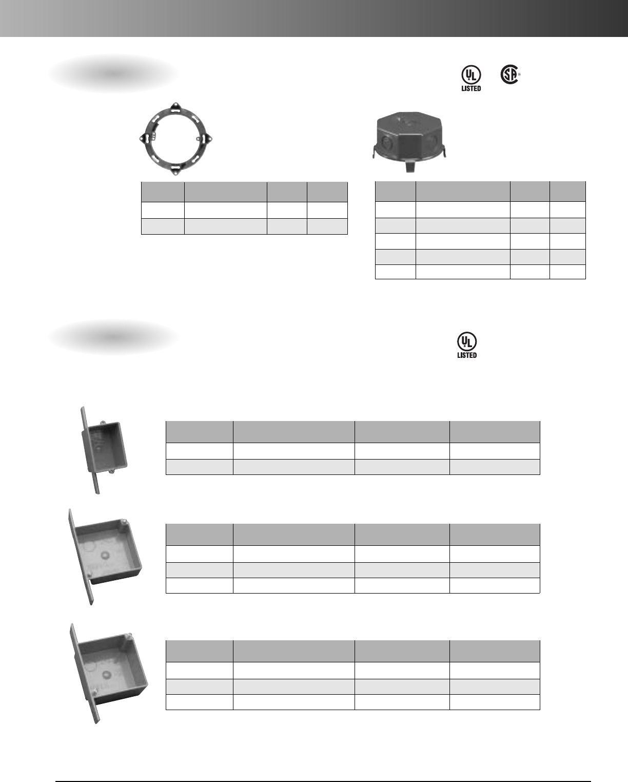
ENT Accessories
•Carlon ceiling boxes and round plaster rings are produced from a special high heat
resistant engineered plastic material developed specifically for fixture support.
•Listed for fixture support up to 50 lbs.
Standard Carton Standard Carton
Part. No. Description Quantity Weight (lbs.)
A615D
4-21/8"Deep (1/2"KO’s)
50 6.4
A615E
4-21/8"Deep (3/4"KO’s)
50 6.4
A615DE
4-21/8"Deep (1/2" & 3/4"KO’s)
50 6.4
Ceiling Box – 20.5 cu. in.
Standard Carton Standard Carton
Part. No. Description Quantity Weight (lbs.)
A615DJ
4-21/8"Deep (1/2"KO’s)
50 18.7
Ceiling Box with J Mount – 20.5 cu. in.
E42728
StandardCarton StandardCarton
Part. No. Description Quantity Weight (lbs.)
A615DL
4-21/8"Deep (1/2"KO’s)
50 6.4
Ceiling Boxwith L Bracket – 20.5 cu. in.
Ceiling Boxwith Adjustable Hanger Bar – 20.5 cu. in.
Adjust from 141/4"to 231/4"
StandardCarton StandardCarton
Part. No. Description Quantity Weight (lbs.)
A615DH
4-21/8"Deep (1/2" KO’s)
25 13.6
Except where
noted by
HOLFORM nonmetallic concrete sleeve forms are the easy way to form holes in concrete. They install
in seconds with nails, screws or staples and are easily removed. Concrete will not adhere to them.
HOLFORMS are adjustable to any slab thickness.
Min. Std. Std.
O.D. Ctn. Ctn.
Part No. A B Qty. Wt. (lbs.)
E92CSH 11/213/420 3
E92CSJ 2213/32 25 6
E92CSL 3 313/32 25 8
E92CSN 4 413/32 18 8
E92CSP 5513/32 15 8
E92CSR 6 613/32 12 8
Quick Connect 4" Octagon Ceiling Boxes
HOLFORM™Concrete Sleeves
www.carlon.com
30
ENT Accessories
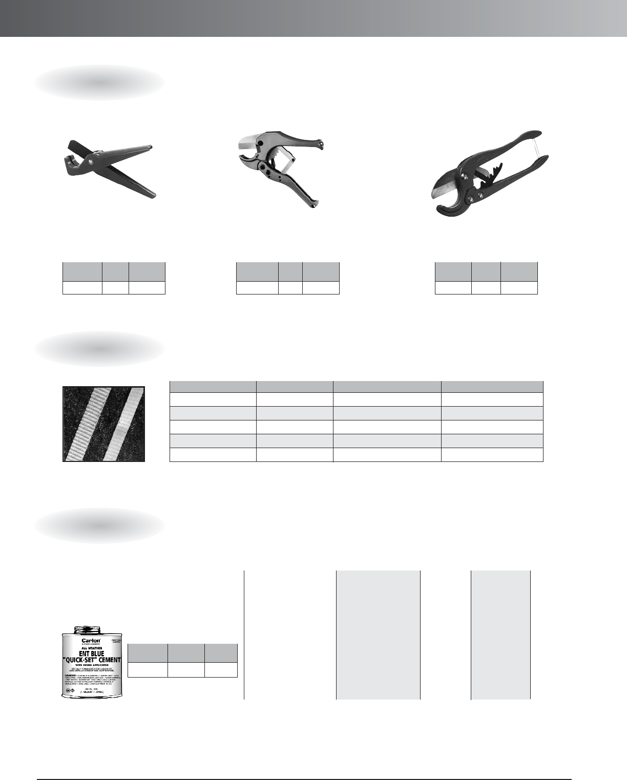
Std.
Part No. Size Ctn. Qty.
CC120B 8" 10
Std.
Part No. Size Ctn. Qty.
CC125 9" 12
Std.
Part No. Size Ctn. Qty.
CC122 171/2"1
Hand held cutter makes fast square, smooth
field cuts on conduit, sizes
1
/
2
" through 1
1
/
4
".
Produces burr-free cut with no shavings.
Fits into pocket or pouch.
For clean cuts of conduit, sizes
1
/
2
" through 2".
For fast, smooth field cuts of
1
/
2
" through 1" Flex-Plus
®
Blue
™
ENT.
Small Cutter Medium Cutter Large Cutter
All-Weather ENT Blue
“Quick-Set” Solvent
Cement with brush
*
Recommended for use
with Flex-Plus
®
Blue
™
ENT
(Electrical Nonmetallic
Tubing), Riser-Gard
®
,
P&C Flex
®
, and Carlon
PVC fittings.
Up through 4" diameter.
Recommended pipe
application and sizes
10˚-30˚F
4-5 minutes
30˚-50˚F
3-4 minutes
50˚-70˚F
1-2 minutes
70˚-90˚F
1
/
2
-1
1
/
2
minutes
2 hrs.
350 psi
16 hrs.
800 psi
72 hrs.
1,500 psi
Set-up time
(Evaporation Rate) Lap Shear
@ 73˚F
Recommended
installation
temperature
4˚ to 100˚F
Viscosity at
75˚ as
manufactured
400-700 cps
Part Std.
No. Size Ctn. Qty.
VC9992 Quart 12
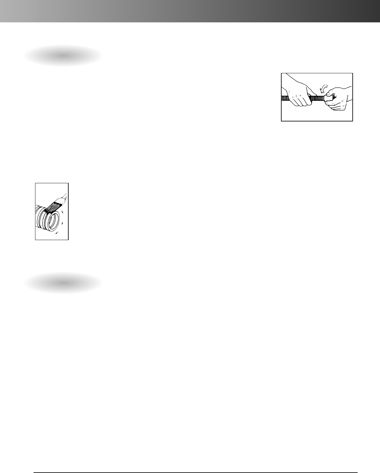
Other tapes are available. Consult your sales service location for additional information.
Part. No. Size Tensile Strength Reel Lengths
TL14505 1/2"12
50 lbs. 5,000 ft.
TL14510 1/2" 1250 lbs. 10,000 ft.
TL38203 5/8" 1800 lbs. 3,000 ft.
TL38265 5/8" 1800 lbs. 6,500 ft.
TL38210 5/8" 1800 lbs. 10,000 ft.
ENT cement required for use with ENT
PVC Conduit Cutters
Tape
Prelubricated, woven polyester tape made from low friction, high abrasion resistant yarns
providing a low coefficient of friction. Tape is printed with sequential footage markings for
accurate measurements.
Carlon
®
Cement
(MSDS sheets available at www.carlon.com)
*Meets ASTM D2564
www.carlon.com 31
ENT Technical Information
1.1 Electrical Nonmetallic Tubing (ENT), is designed to replace EMT, flexible metal conduit or other raceway or
cable systems, for installation in accordance with Article 362 of the National Electrical Code, other applicable
sections of the Code, and local codes.
1.2 Any ENT used shall meet the requirements of UL Standard UL 1653 and shall be listed by Underwriters
Laboratories, Inc., as suitable for its intended purpose.
1.3 ENT shall be recognized by a National Evaluation Report for use in 1-hour and 2-hour rated construction.
1.4 Penetration of fire rated walls, floors or ceilings shall use classified Through-Penetration Firestop Systems
described in the current Underwriters Laboratories Fire Resistance Directory.
1.5 Fittings and outlet boxes shall be designed for use with ENT and listed by Underwriters Laboratories. All
fittings, boxes and accessories shall be from one manufacturer.
1.6 Only Carlon ENT Blue cement recommended specifically for use with ENT shall be used.
1.7 Unless indicated differently on drawings, ENT systems shall be color coded: BLUE for branch and feeder circuit
wiring, YELLOW for communications, and RED for fire alarm and emergency systems.
1.8 ENT, fittings, and accessories shall be manufactured by Carlon.
1. Cut ENT square and cleanly.
2. Insert end into fitting, making sure two (2) full
corrugations are snapped into fitting beyond
flexible tabs (2 clicks).
3. ENT should be tied to rebar at 2-3 foot intervals
to prevent flotation. Keep ENT straight. Small
deflections over a long run may accumulate
significant degrees of bend which will affect
conductor installation. Suitable materials
include wire, tie wraps, and tape.
4. When using UL solvent weld fittings for
concrete tight performance:
A. Do not use chemical primer or cleaner.
B. Apply a light, uniform coat of cement
labeled for use with ENT on the coupling
and ENT.
C. Do not use a dauber.
D. Brush excess cement out of ENT grooves.
E. Promptly insert ENT
into fitting while
cement is wet, until
the stop is reached,
and give a quarter
turn.
F. Do not disturb until
joint is set.
Concrete Encasement Guidelines
Specifications

www.carlon.com
32
ENT Technical Information
•UL recognizes the use of PVC RNC cement type fittings with all sizes of ENT
• ENT rated for 90 deg C conductors
• One piece ENT Coupling, Threaded Terminator and RNC Transition Fitting are rated concrete tight
without tape by UL
• Recognized for use in 2-hour fire resistive nonload bearing and load bearing wall assemblies
• Recognized for use in 1-hour fire resistive nonload bearing wall assemblies
• Recognized for use in a fire resistive ceiling assembly (up to 3 hours)
• Recognized for Through-Penetration Firestop systems as classified by UL to meet BOCA, SBCCI and ICBO codes.
• Conductors easily push through the raceway (up to approximately 50 feet)*
• For use in buildings in accordance with NEC Article 362
• Approved for installations of a one and two hour fire rated wall assembly and up to a three hour rated
floor/ceiling assembly
• Outside Diameters meet IPS Dimensions
• Storage -4°F to 158°F
• Handling -4°F to 104°F
Features
Approved Uses:
Typical Applications:
•Concrete slab – NEC Article 362
• Walls - wood stud, masonry and metal stud – NEC Article 362.
• Ceilings - permanent or dropped (free air only) – NEC Article 362.
• Exposed – NEC Article 362
• Public Assembly – NEC Section 518.4, in nonfire rated and certain five rated structures
• Prewired – NEC Article 362
• Classified by UL 1479 for Through Penetration Firestop Systems in UL Guide Category XHEZ and current
UL Fire Resistance Directory
• Three hour rated floor/ceiling assemble
• Raised Floors – NEC Section 645.5(D)(2)
•Exposed or concealed in building above three floors when a fire sprinkler system is installed in accordance with
NFPA 13 – NEC Section 362.10(2)
•For use in residential attics up to 3 feet above the bottom of the ceiling joist.
• Residential: Low or high rise – multi or single family
• Commercial: Low or high rise – office, retail, hotel/motel, restaurant, etc.
• Nursing Homes/Hospitals in nonpatient care areas only
•Schools, classrooms, dormitories, offices
•Fire Alarm Systems
• Recreational vehicles and parks
• Solar Photovoltaic systems
• Marinas and boatyards
• Other uses per the current NEC
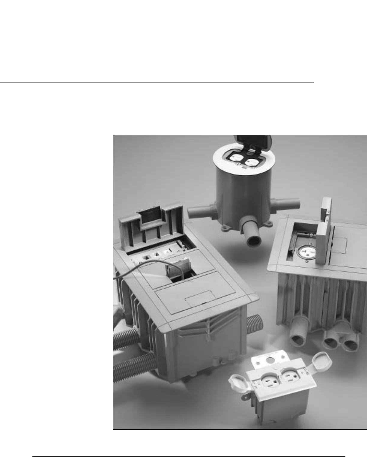
www.carlon.com 33
Round Floor Boxes
1-, 2-, and 3-Gang
Rectangular
Floor Boxes
Residential
Floor Boxes
Brass Covers
Nonmetallic Covers
Carlon
®
Floor Boxes and Covers
www.carlon.com
34
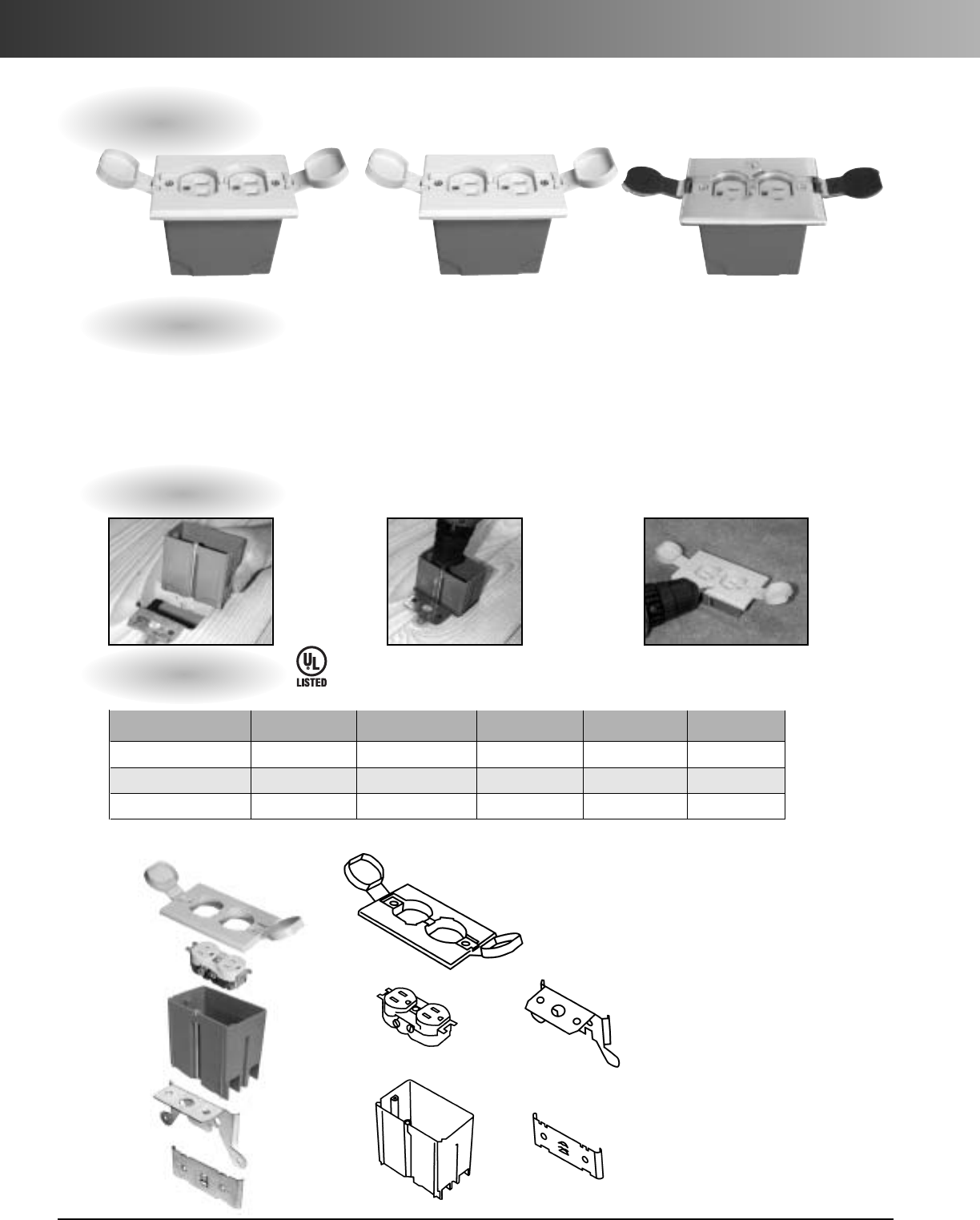
Rectangular Floor Boxes
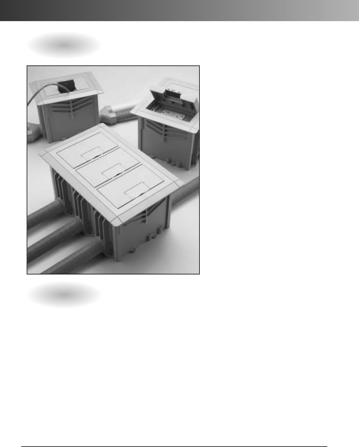
Carlon
®
Rectangular Floor Box
Systems – three-way power, data,
and communications plus easy
double or triple ganging, too.
Compared to metal boxes, Carlon
rectangular floor boxes cost less and
install faster to save you money on
every job. Three-in-one power, data,
and communications capability cuts
installation time and cost even more,
while simple two- and three-gang
modularity gives you the flexibility,
installation ease, and cost-savings no
other nonmetallic boxes can match.
The covers attach without the use of
fasteners, providing a professional,
clean installation as well as preserving
the aesthetic life of the product. Take
acloser look at all our rectangular
floor box systems offer you.
Features
•Covers require no adjusting collar.Two screws
assure a flush, secure installation.
•Nonmetallic PVC construction, watertight gasket,
and corrosion-resistant hardware assure long life
and reliable performance even in harsh and/or
corrosive environments.
•One consistent box depth simplifies ordering time
and reduces inventory.
•Saves time and money on installations with
simple saw cut to floor level.
•Concrete tight and suitable for any on grade/
below grade application; concrete or wood
sub-floor construction approved.
•Convenient cubic inch capacity markings
on inside allow for easy inspection.
•PVC molded ports and reducer plugs
included.
•Accepts 1/2", 3/4", and 1" conduit, tubing
or raceway.
•Rectangular sides are drillable.
•For tile and carpet applications.
•Cover options include solid brass or
thermoplastic (brown, slate,and caramel).
•UL scrub water tested.
*U.S.Patent 5,866,845
1-, 2-, and 3-Gang
www.carlon.com 35
Rectangular Floor Boxes
Installation
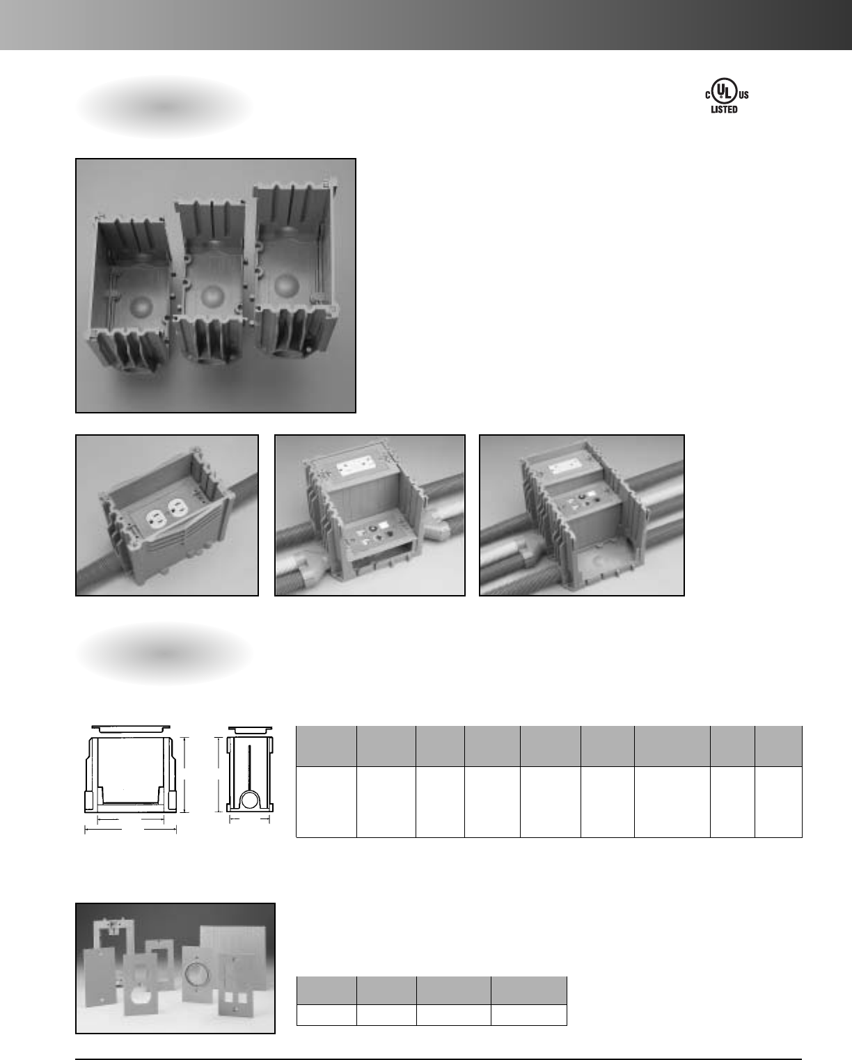
Specifications
With our rectangular boxes, one SKU is all
you ever need. Simply remove appropriate
sides and slide boxes together to create
two- or three-gang boxes for on-the-job
flexibility no competitor offers.
Activation kit provides components to accommodate all standard power, data, and
communications devices plus a divider to separate power from data and communications –
all in a single SKU. Device yokes can be adjusted to store excess cord in the box.
6.00"
5.50"
7.46"
6.00"
3.25"
Rectangular Floor Box
Activation Kit
Internal Min.
Part Volume Concrete Reducer Std. Std. Ctn.
No.Material Size (cu. in.) Depth Hubs Plugs Ctn. Qty. Wt. lbs.
E976RFB PVC 1-Gang 97.4 3 1/2" (2) 1" (2) 1" x 3/4" 3 6.92
(2) 3/4" x 1/2"
(16.8 per
inch of
Depth)
Part Std. Std.
No.Material Ctn. Qty. Ctn. Wt. (lbs.)
E976AK2 PVC 3 2.47
E42728
www.carlon.com
36
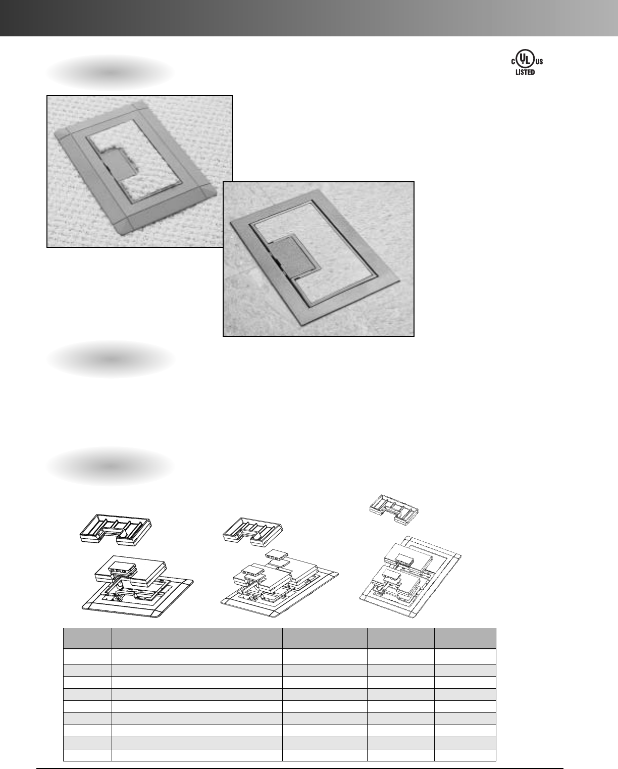
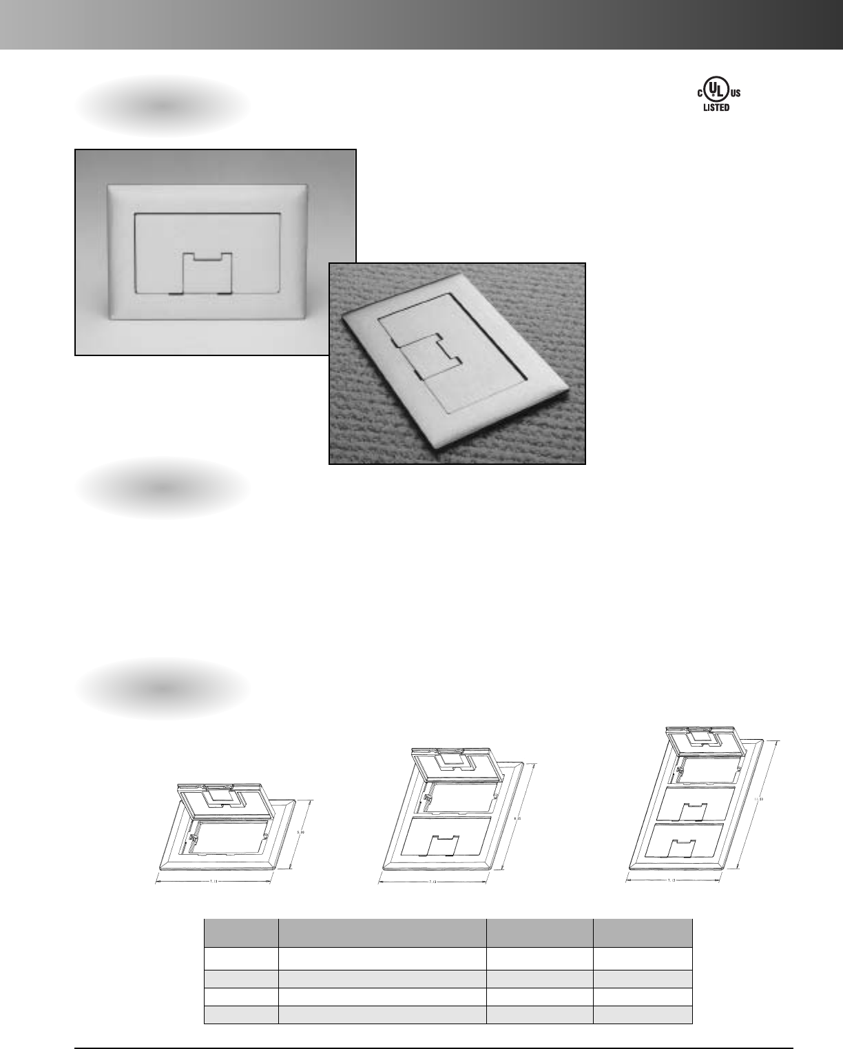
Rectangular Floor Box Covers – Nonmetallic
On-the-job flexibility extends to our rectangular box covers. Each
one-, two-, or three-gang cover is suitable for any wiring application
and can be used with any floor surface. Nonmetallic covers are even
field reversible for tile or carpet. Double door feature allows easy
access to the device and helps keep stray cords organized.
1-, 2-, and 3-Gang Nonmetallic
Specifications
Rectangular Floor Box Covers – Nonmetallic
Part Dimensions Std. Std.
No. Description (W x L) Ctn. Qty. Ctn. Wt. (lbs.)
E9761B Brown Single-Gang Cover/Carpet Flange 7.13" x 5.00" 3 1.7
E9762B Brown Double-Gang Cover/Carpet Flange 7.13" x 8.25" 98.5
E9763B Brown Triple-Gang Cover/Carpet Flange 7.13" x 11.50" 67.5
E9761C Caramel Single-Gang Cover/Carpet Flange 7.13" x 5.00" 3 1.7
E9762C Caramel Double-Gang Cover/Carpet Flange 7.13" x 8.25" 98.5
E9763C Caramel Triple-Gang Cover/Carpet Flange 7.13" x 11.50" 67.5
E9761S Slate Single-Gang Cover/Carpet Flange 7.13" x 5.00" 3 1.7
E9762S Slate Double-Gang Cover/Carpet Flange 7.13" x 8.25" 98.5
E9763S Slate Triple-Gang Cover/Carpet Flange 7.13" x 11.50" 67.5
Features
•High impact resistant thermoplastic
•Field reversible for tile or carpet
•Gasketed for a watertight seal
•Double door design
•For tile and carpet applications
•UL scrub water tested
E42728
*U.S. Patent 5,866,845
Carlon Rectangular Floor
box covers do not require
aseparate carpet flange.
The carpet flange is part
of the cover and may
be removed for tile
application.
www.carlon.com 37
Rectangular Floor Box Covers – Brass
Carlon®Brass rectangular Floor Box Covers add a classic touch to
all floor box installations and are particularly suited for use in high-
traffic areas because of the resistance to wear.The gasket gives a
watertight seal, and the light lacquer finish provides extra protection.
1-, 2-, and 3-Gang Solid Brass
Features
•Rugged solid brass construction.
•Brushed finish coated with a light
lacquer for protection.
•Rectangular brass covers include
acord door.
•Gasketed for watertight applications.
•Rectangular brass covers allow for single,
duplex, GFCI receptacles, and low voltage.
•For tile and carpet applications.
•UL scrub water tested.
Specifications
Rectangular Floor Box Covers – Brass
Part Std. Std.
No. Description Ctn. Qty. Ctn. Wt. (lbs.)
E9761BR Brass Single-Gang Cover 3 6.8
E9762BR Brass Double-Gang Cover 3 9.9
E9763BR Brass Triple-Gang Cover 3 12.1
E976AK2 Rectangular Floor Box Activation Kit 3 1.3
E42728
E9761BR E9762BR E9763BR
*U.S. Patent 6,265,662
www.carlon.com
38
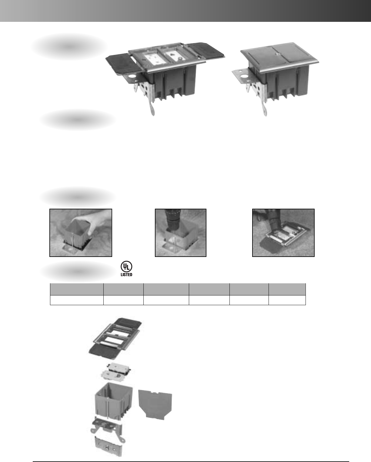
Round Floor Boxes
Carlon
®
Round Floor Box Systems –
three-way versatility for power,
data, and communications.
Carlon round floor boxes give you
the same cost-saving advantages
over metal boxes as our rectangular
boxes. By letting you combine
power, data, and communications in
the same box, you can dramatically
reduce your installation time and
cost compared to other nonmetallic
boxes. In addition, multi-use covers
mean fewer SKUs to deal with and
greater jobsite flexibility to increase
your savings further.Take a closer
look at all their advantages for
yourself.
Features
•Nonmetallic PVC construction, watertight
gasket, and corrosion-resistant hardware
assure long life and reliable performance
even in harsh and/or corrosive environments.
•Brass and an assortment of nonmetallic
covers are available for a variety of
applications.
•The same box depth simplifies ordering and
reduces inventory.
•For tile and carpet applications.
•Concrete tight and suitable for any on
grade/below grade application; concrete or
wood floor construction approved.
•Y-connector (E972Y) allows you to feed parallel
runs of 3/4"conduit or to feed in/out from the
same side for increased wiring flexibility and
faster installation.
•PVC molded ports and reducer plugs included.
•Accepts 1/2", 3/4", and 1" conduit, tubing or
raceway.
•UL scrub water tested.
www.carlon.com 39
Round Floor Boxes
Specifications
Round Floor Box
Accessories
Multi-Service Divider Kit
Internal Min.
Part Volume Concrete Reducer Std. Std. Ctn.
No. (cu. in.) Depth Hubs Plugs Ctn. Qty. Wt. lbs.
E971FB 90.0 3 1/2" (2) 1" and (2) 1" x 3/4"and 10 15.6
(2) 3/4" (2) 3/4" x 1/2"
(15.5 per
inch of
Depth)
6.11"
4.00"
6.44"
O.25"
5.03"
6.00"
4.00"
Multi-service divider kit for separate power, data, and
communications compartments provides unbeatable
flexibility and money-saving installation speed.
For use with nonmetallic boxes only.
The 3/4" Y Fitting provides for in and out service from a
single 1" port, and allows for two 3/4" parallel conduit
runs to adapt into a single conduit body port.
Part Std. Std.
No. Ctn. Qty. Ctn. Wt. (lbs.)
E973K 10 3
3/4"YFitting
Part Std. Std.
No. Ctn. Qty. Ctn. Wt. (lbs.)
E972Y 10 2.1
Reducer Plugs
Part Std. Std.
No. Size Ctn. Qty. Ctn. Wt. (lbs.)
E971C 3/4" x 1/2" 100 2.1
E971D 1" x 3/4" 100 3.2
E42728
Where
noted by
Carlon Round Floor Boxes allow for various thickness of concrete pours.
Trim out is easy – just use a handsaw to cut off box at desired height to
accommodate carpet, tile, or other flooring. Carlon leveling ring guarantees a
level top every time, even if the box is tipped slightly during the pouring process.
www.carlon.com
40
Round Floor Box Covers – Nonmetallic
Nonmetallic Covers Features
•High impact resistant thermoplastic
•Compatible with standard NEMA Duplex,
and 1 1/4"NPS receptacles
•Drill points (3/8") provided for low voltage
cable pass throughs
• 1 1/4"NPS plugs may be modified to accept
smaller fittings (3/8", 1/2", and 3/4")
•For tile and carpet applications
•UL scrub water tested
Part Std. Std.
No.Color Description Ctn. Qty.Ctn. Wt. (lbs.)
E97DSI Ivory Duplex Cover 10 5.2
E97DSC Caramel Duplex Cover 10 5.7
E97DST Taupe Duplex Cover 10 5.7
E97DSS Slate Duplex Cover 10 5.6
E97DSB Brown Duplex Cover 10 5.8
Duplex Covers
Part Std. Std.
No.Color Description Ctn. Qty. Ctn. Wt. (lbs.)
E97SSRB Brown NPS Cover 10 3.8
E97SSRC Caramel NPS Cover 10 3.8
E97SSRS Slate NPS Cover 10 3.8
11/4"NPS Covers
Caramel Slate Ivory
Taupe Brown
Part Std. Std.
No. Devices Ctn. Qty. Ctn. Wt. (lbs.)
E97ABR2 One-Piece Metal Cover Adapter 10 3.3
Metal Cover Adapter Ring
Part Std. Std.
No. Color Ctn. Qty. Ctn. Wt. (lbs.)
E97CCR Clear 10 1.2
Clear Cover Carpet Ring
E42728
U.S. Patent 6,450,353
www.carlon.com 41
Round Floor Box Covers – Brass
Part Std. Std.
No. Devices Ctn. Qty. Ctn. Wt. (lbs.)
E97BR2D Duplex and Two Data Ports 5 9.2
Two Door Dual Service
(Divider Kit included)
Part Std. Std.
No. Devices Ctn. Qty. Ctn. Wt. (lbs.)
E97BR2 Duplex 5 7
Two Door
Brass Covers Features
•Screws concealed under doors
•Rugged solid brass construction
•Brushed finish coated with a light lacquer for protection
•Resistance to wear – suited for high traffic areas
•Gasketed for watertight applications
•Available in four styles – Single Door, Two Door, NPS Opening,
and Two Door Dual Service
•For tile and carpet applications
•UL scrub water tested
E42728
Part Std. Std.
No. Devices Ctn. Qty. Ctn. Wt. (lbs.)
E97BR GFCI and Duplex 57
Single Door
Part Std. Std.
No. Devices Ctn. Qty. Ctn. Wt. (lbs.)
E97BRG 1 1/4" Outlet and Single Receptacle 5 7.5
NPS Opening
NEW!
NEW!
U.S. Patent 6,179,634
Specifications
Adjustable Residential Floor Boxes
One-Gang
Installation
Nonmetallic (White) Nonmetallic (Ivory) Brass
Cover
Receptacle
Box
New Work
Bracket
Old Work
Bracket
Kit includes:
*Note: Brass cover includes ground
lug and wire
E42728
*U.S. Patent 5,289,934
Mounting Hardware:
Ivory/White Cover:
•Two (2) 6-32x1 flat head machine
screws
•Four (4) #6 1-1/4 self-tapping flat
head screws
•Two (2) #6 1-5/8 drywall screws
•One (1) cover plug
Brass Cover:
•Two (2) 6-32x1 brass plated flat
head machine screws
• Four (4) #6 1-1/4 self-tapping flat
head screws
•Two (2) #6 1-5/8 drywall screws
Features
•Ideal for home offices and entertainment rooms
•UL listed Floor Box
•UL scrub water tested
•2hour floor fire classification
•Adjusts to most finished floor heights (From 0" to 13/4")
•20 cubic in. capacity
•Available with nonmetallic or brass cover
• Complete assembly includes box, duplex receptacle, cover,
molded-in cable clamps, mounting bracket and mounting hardware
Part Cubic Std. Ctn. Std. Ctn.
Number Size Cover In. Qty. Wt. (lbs.)
B121BFBRW One-Gang White 20 8 7.02
B121BFBR One-Gang Ivory 20 8 7.02
B121BFBB One-Gang Brass 20 8 14.50
Screw in to
adjust to
height of
flooring or
carpet
Beautiful
flush fit
every
time!
Install
clip over
subfloor.
www.carlon.com
42
www.carlon.com 43
Adjustable Residential Floor Boxes
Specifications
Two-Gang
Installation
Kit includes:
E42728
Features
•Ideal for home offices and entertainment rooms
•UL listed Floor Box
•UL scrub water tested
•2hour floor fire classification
•Adjusts to most finished floor heights (From 0" to 13/4")
•Dual voltage capability
•34 cubic in. capacity
•Complete assembly includes box, cover, dual voltage divider,
molded-in cable clamps, mounting bracket and mounting hardware
(Note: Devices not included)
Part Cubic Std. Ctn. Std. Ctn.
Number Size Cover In. Qty. Wt. (lbs.)
B234BFBB Two-Gang Brass 34 4 9.976
Screw in to
adjust to
height of
flooring or
carpet
Beautiful
flush fit
every
time!
Install
clip over
subfloor.
•One (1) New Work Bracket
•One (1) Old Work Bracket
•One (1) 34 cubic in. UL Listed Floor Box
•One (1) Dual Voltage Divider
• One (1) UL Listed Brass Floor Cover
• Four (4) #6-32x1" flat head machine
screws
•Four (4) #6x1-1/4" flat head self-
tapping screws
• Two (2) #6x1-5/8" square drive trim
head screws
•Green ground wire
•Installation instructions
(Devices not
included)
www.carlon.com
44
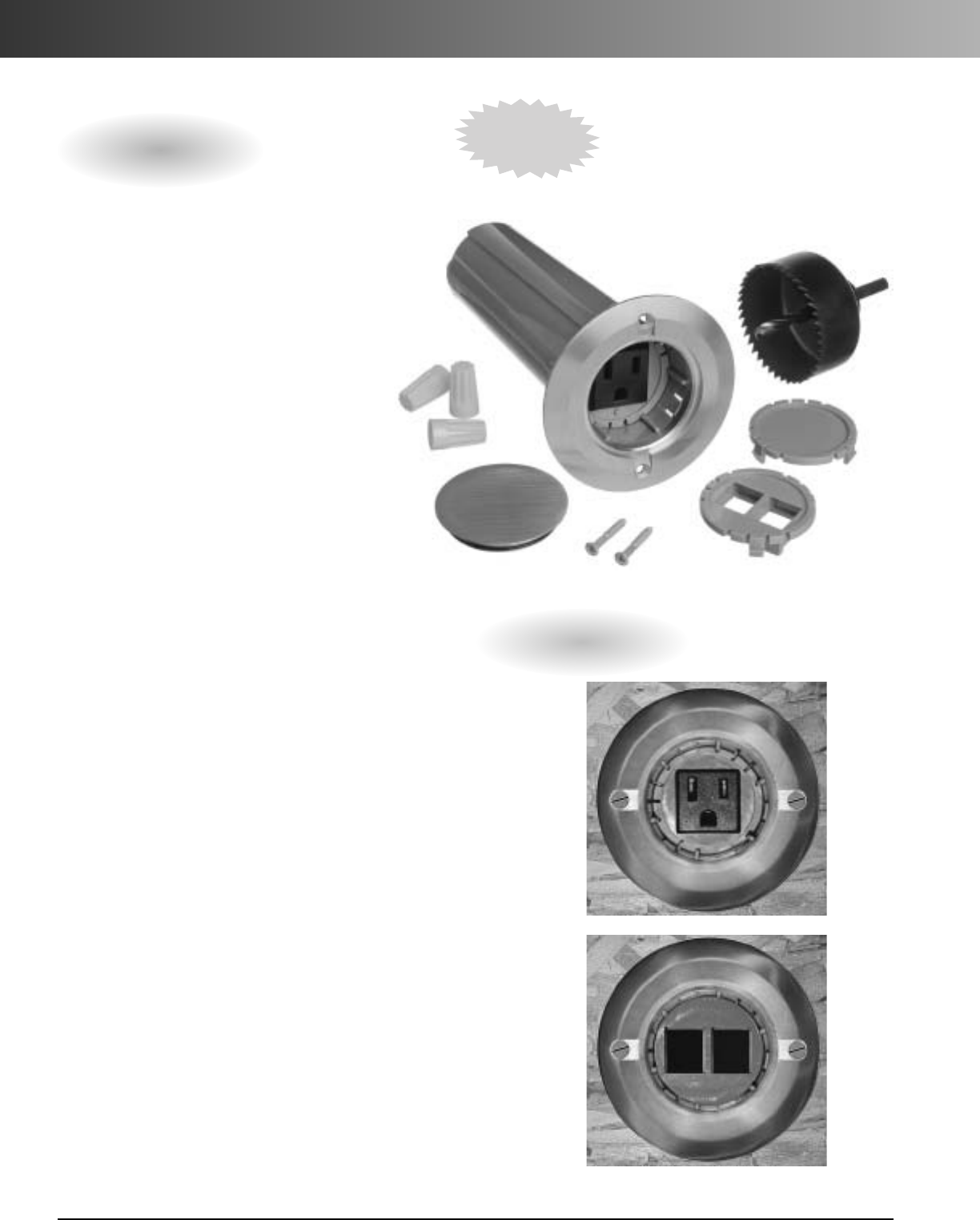
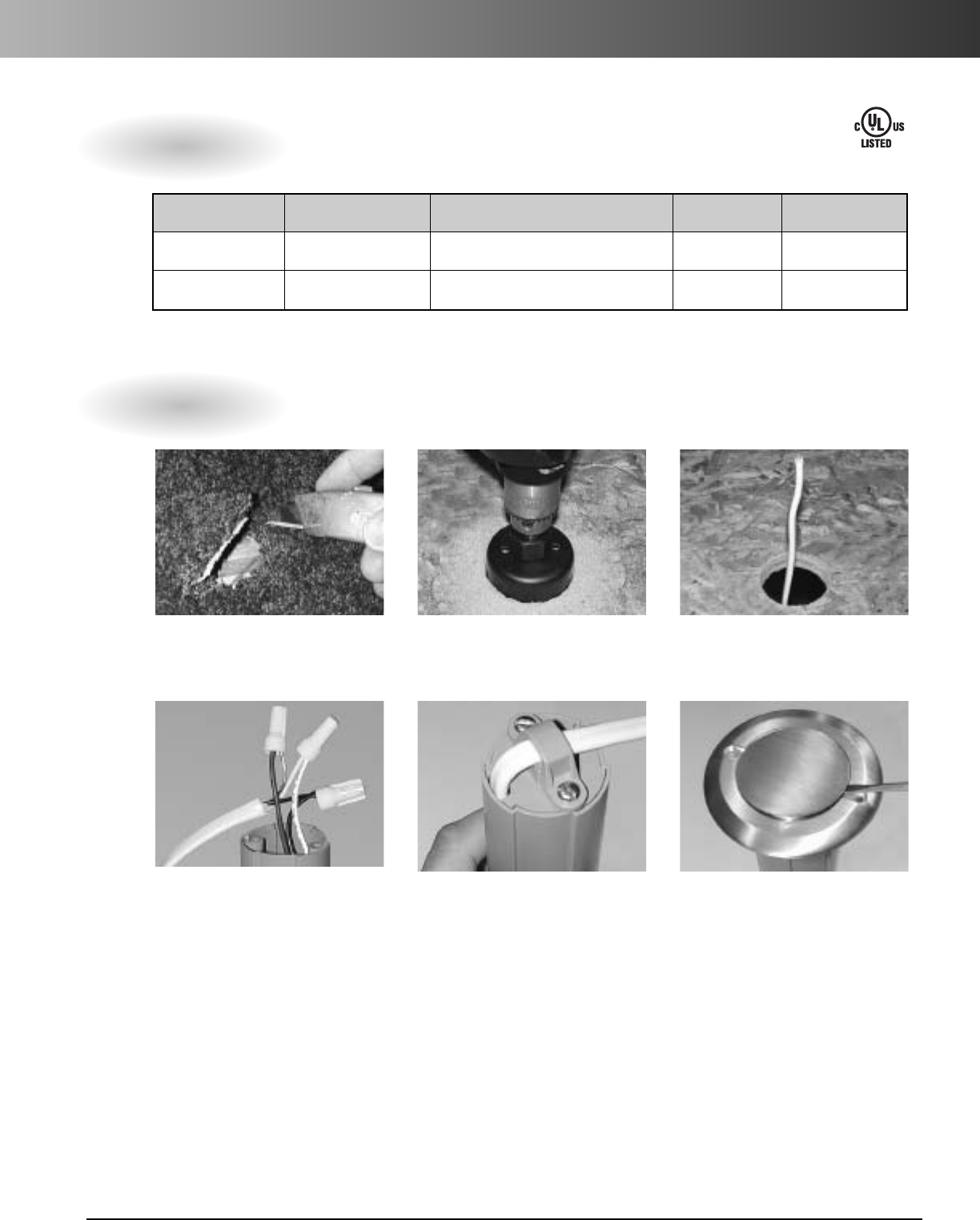
Drop-in Floor Box
Features:
•Single hole installation
•Solid brass cover has a light lacquer finish to resist
wear - Ideal for high traffic areas
•Accommodates high and low voltage applications
•Includes single gang grounded receptacle, low voltage
telephone/cable plate (data jacks not included), and
blank plate for custom installations
•Eliminates the need for extension cords
•Superior aesthetics - Ideal for home offices and
entertainment rooms
•C-UL-US Listed Nonmetallic Outlet Box
The Carlon Drop-In Floor Box with Brass Cover
combines many of the same features in our
existing Floor Box line with the strength,
durability and style necessary to accommodate
today’s residential electrical/telecommunica-
tion needs.
The Carlon Drop-In Floor Box is the fastest
easiest way for contractors to put a floor
socket anywhere they need it! It's designed
to accommodate high and low voltage
applications and comes complete with
everything needed for installation -
Floor box,
Brass Cover, hole saw, wired receptacle,
two-hole low voltage plate, blank plate,
mounting screws, and wirenuts.
Note: The Drop-In Floor Box is available with
or without a hole saw.
Installed:
NEW!
Carlon
®
Drop-In Floor Box
www.carlon.com 45
Drop-in Floor Box
Specifications
Installation
Part Number UPC Code Description Std. Carton Qty. Std. Carton Wt. (lbs.)
E971FBDI 034481186601 Drop-In Floor Box w/Hole Saw 5 6.5
E971FBDIB 034481189459 Drop-In Floor Box without Hole Saw 20 17.6
1. Cut 2-3/8" hole through carpeting
before using hole saw. 2. Drill hole in floor using hole saw.3. Pull romex through floor.
4. Connect receptacle wires to romex. Be
sure to match wire color(s). 5. Secure wire clamp on bottom of
tube. 6. Brass cover snaps into place. Use a
small screwdriver to pry open brass
cover to plug in appliance.
E42728

www.carlon.com
46
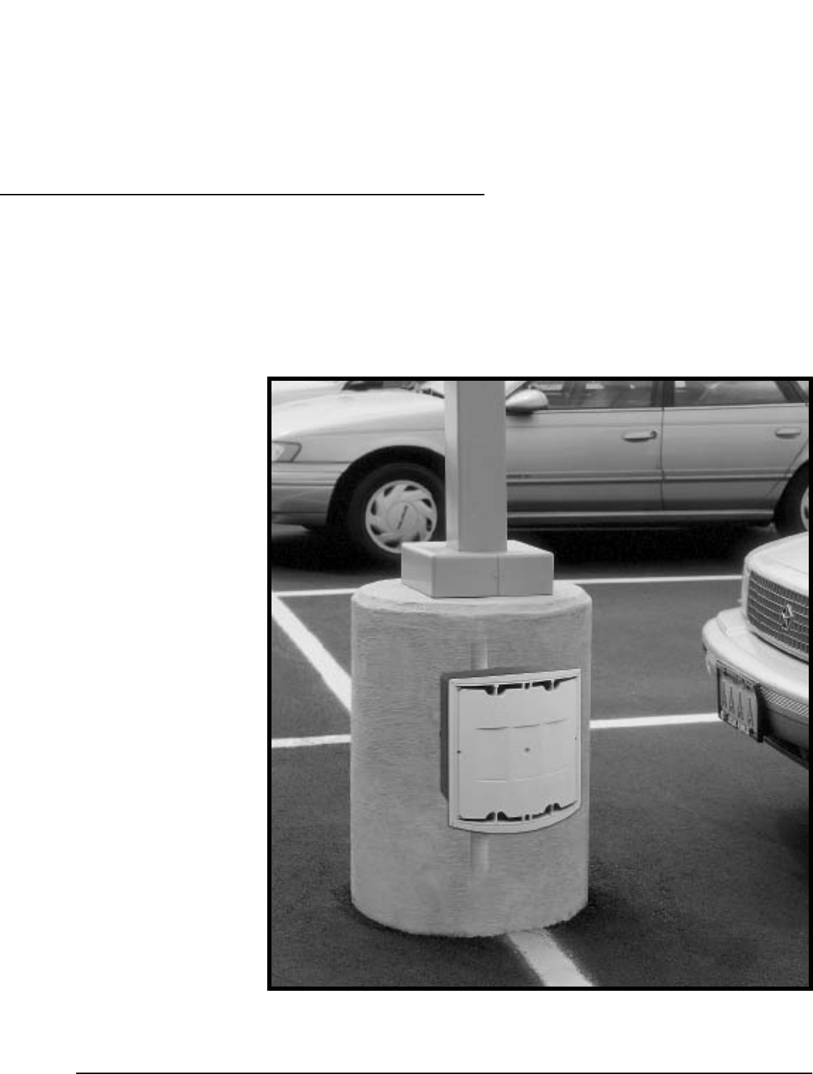
www.carlon.com 47
To give you a
better way to
install parking
lot lights,
we started at
the bottom.
Carlon
®
Nonmetallic
Curved Lid J-Box
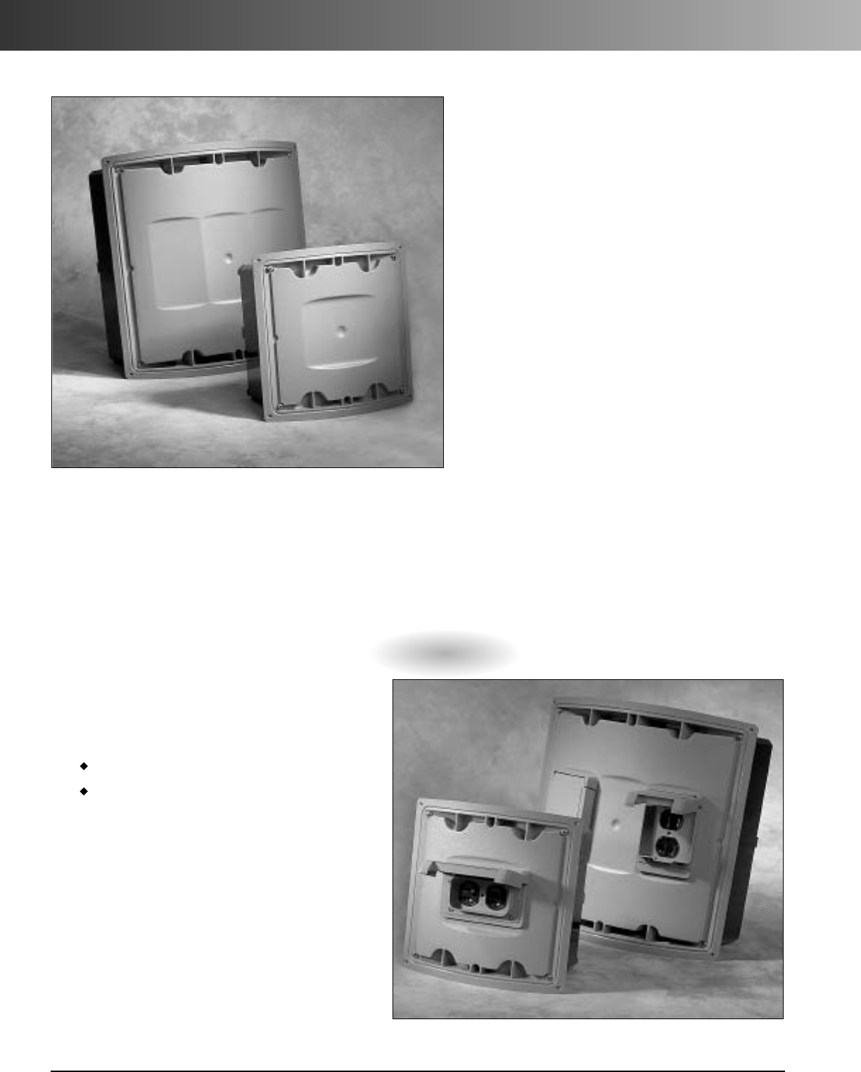
www.carlon.com
48
Curved Lid J-Box
Anyone who’s worked with parking lot light poles
knows the problem. Those tiny integral hand holes
for electrical wiring can really slow a project down.
But now there’s a better answer for shopping centers,
car dealerships, sports arenas, office complexes, or
anywhere you need pole lighting for large parking
lot areas – the Carlon nonmetallic curved lid J-Boxes.
Carlon curved lid J-Boxes are listed in accordance
with UL 50 specifications for Electrical Enclosures as
well as NEMA 1, 2, 3, 3R, 3S, 4, 4X, 12, 13 ratings.
They are available in sizes 8"x8" or 12"x12".
Both the base and lid are made from PVC to
eliminate rust and corrosion and are supplied with
tamper-resistant screws.
Designed specifically for use with 24" diameter
concrete piers, J-Boxes are installed, along with all
necessary conduit and fittings, when piers are
poured. This gives installers a giant junction box
at the base of every pole to ease wiring, facilitate
circuit management, and provide easy post-
installation maintenance. Just take a closer look,
and you’ll see why our nonmetallic J-Boxes are a
better choice for you.
Features
•NEMA 1, 2, 3, 3R, 3S, 4, 4X, 12, 13
•UL Listed and CSA Certified
• Paintable lid
•Dividers available to separate high and low
voltage, and can be retrofitted into existing
applications
•Lids provide locations to mount weatherproof
covers:
8" x 8" - One location
12" x 12" - Three locations
•Nonconductive and noncorrosive
•Designed for a 24" radius concrete pier
NOTE: The J-Box can also be installed in
concrete piers from 18" to 36" in
diameter. Contact your Carlon Sales
Rep for installation details.
Install Carlon
®
Weatherproof Covers
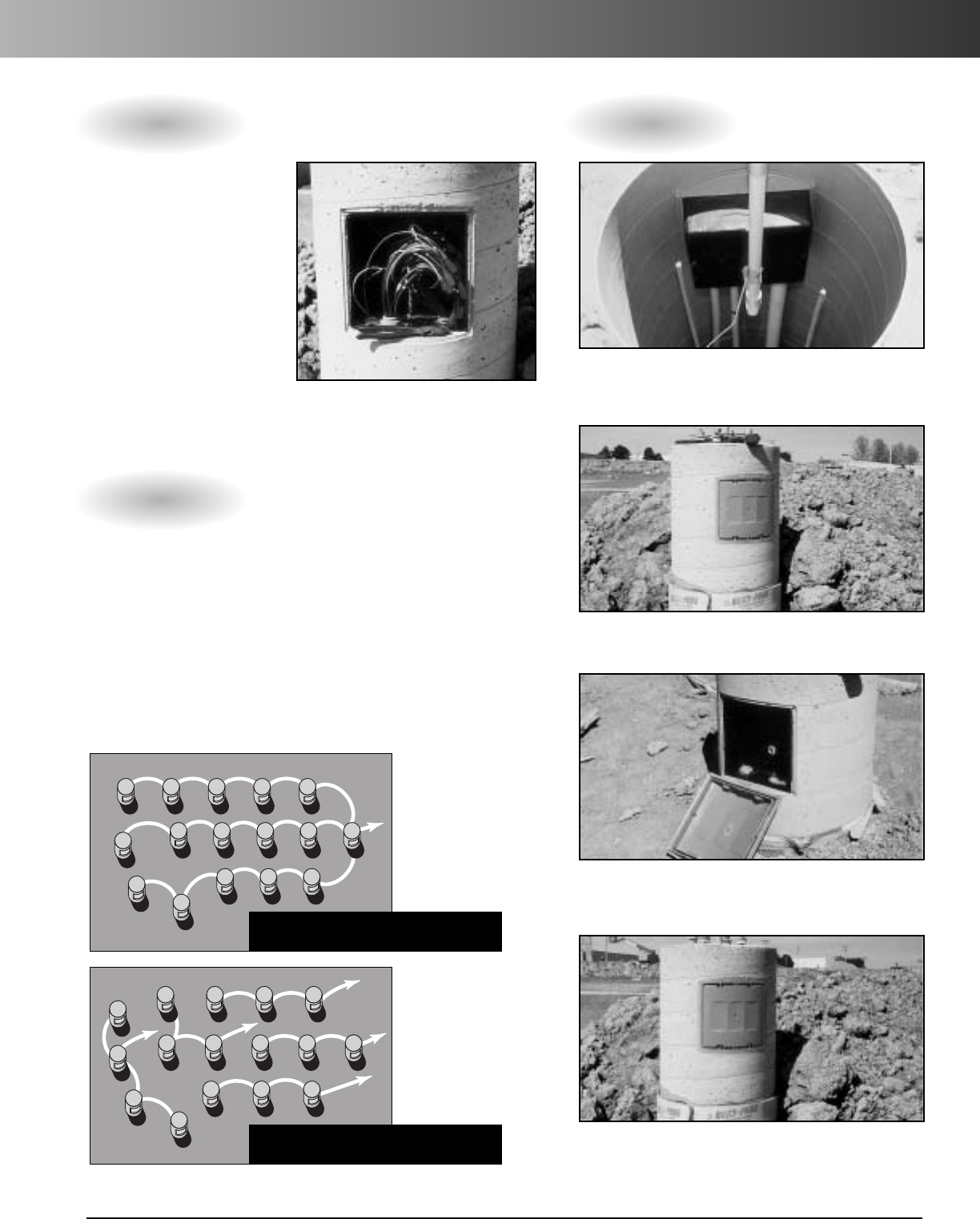
www.carlon.com 49
Curved Lid J-Box Installation and Wiring
Faster, easier wiring for greater productivity. Easy to Install
More flexibility, fewer home runs,
and easier maintenance, too.
Once your J-Boxes are
installed, you can speed
projects along by pre-
wiring before poles arrive.
Or you can install poles
first and use them to
mount cable pulling
equipment – a particular
advantage for long,
difficult wire pulls. Of
course, all the extra hand
room our J-Boxes offer makes splicing much easier and faster than
working through cramped pole access holes.
Extra room also gives you splicing space for options like zone lighting
or to reduce the number of home runs, which can lower trenching
and associated materials costs by up to 30%. In addition, the box
lids provide locations to mount receptacles and weatherproof
covers for even more flexibility. For easy maintenance, fixture
protection can be placed at the base, and if need be, poles can
even be removed and replaced in the middle of the circuit without
affecting overall lighting.
1. J-Box, with all conduit and fittings placed as desired,
is temporarily attached to the concrete form – base
and lid inside.
2. Remove formafter concrete has been poured
and allowed to cure.
3. Pop off the J-Box lid, leaving an 8" x 8" x 4"
or 12" x 12" x 4" access area, depending on
the J-Box selected.
4. After wiring is completed, the lid is replaced to
complete the installation.
Site Lighting Plan
Without
J-BOX
Site Lighting Plan
With
J-BOX
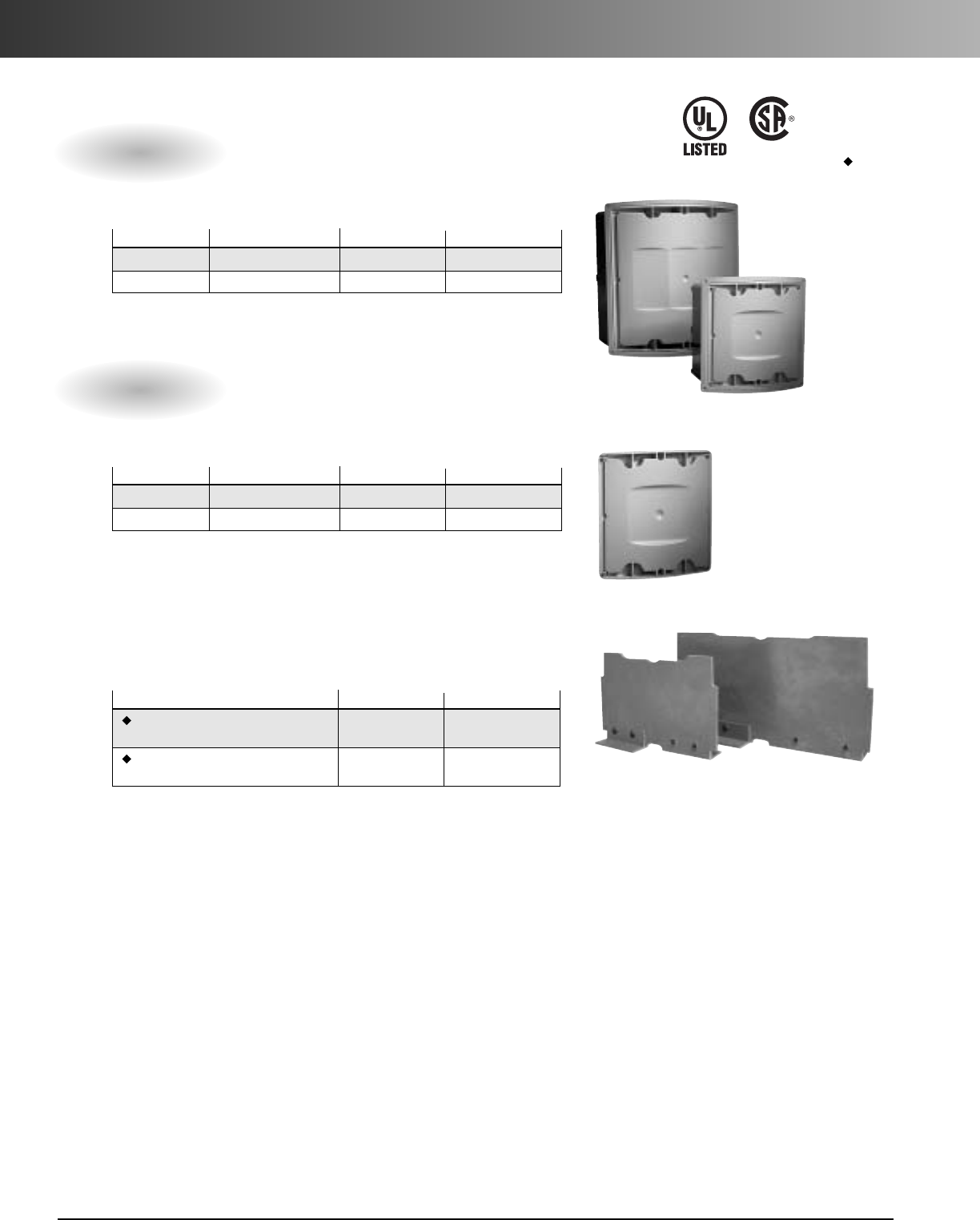
www.carlon.com
50
Curved Lid J-Box
The National Electrical Code (NEC) allows electrical conductors to share an
outlet box when the conductors and communication cables are separated by a
barrier within the box.
Part No. Size Std. Ctn. Qty. Std.
Ctn Wt.(lbs.)
E88C24
8"x 8"x 4"
6 28.3
E1212C24 12"x 12"x 4" 2 9.7
J-Box Assemblies
Part No. Size Std. Ctn. Qty. Std.
Ctn Wt.(lbs.)
E88L24
8"x 8"
1 2.1
E1212L24 12"x 12" 1 2.3
Replacement Lids
Part No. Std. Ctn. Qty. Std.
Ctn Wt. (lbs.)
E88DIV 6 2.1
(For use with Part No. E88C24)
E1212DIV 2 2.3
(For use with Part No. E1212C24)
Dividers
J-Box Dividers are used to separate high and low
voltage devices, and solvent cement into place
E54381 LR31146
Specifications
Accessories
Except where
noted by
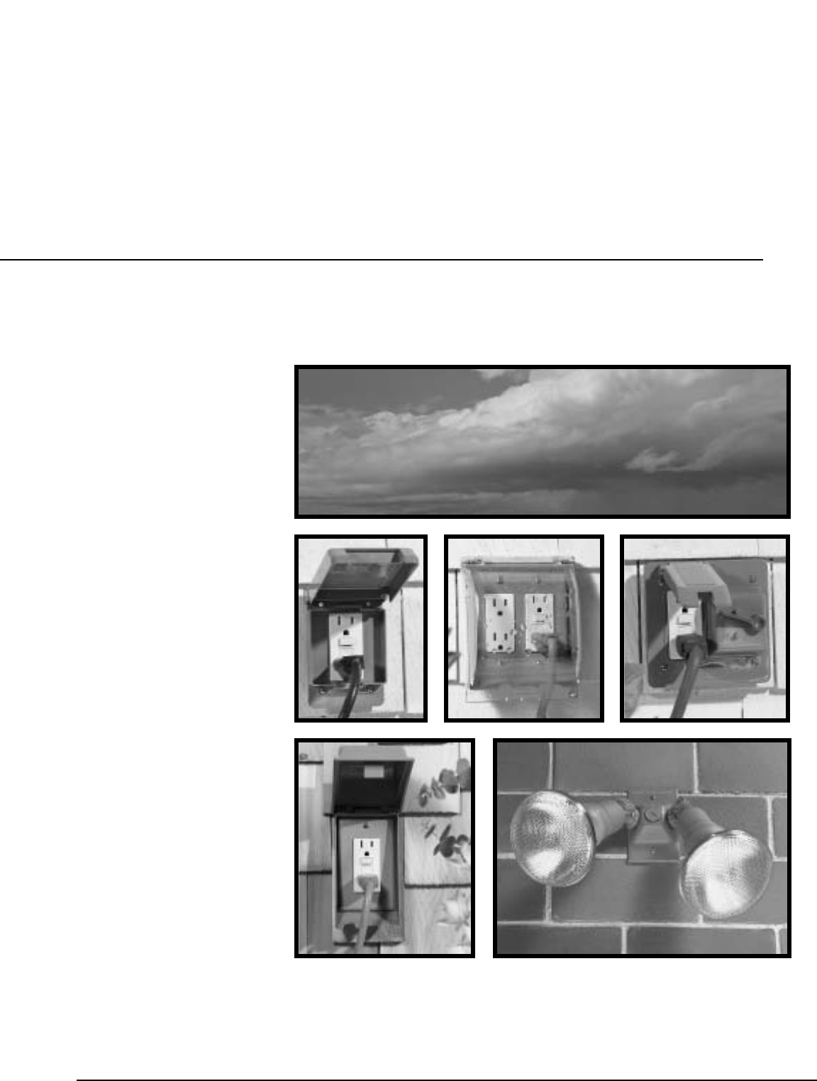
www.carlon.com 51
Weatherproof Covers
In-Use Weatherproof
Covers
Lamp Holders
Weatherproof Fixture
“T” Boxes
Carlon
®
Weatherproof
Covers, Lampholders and Fixtures
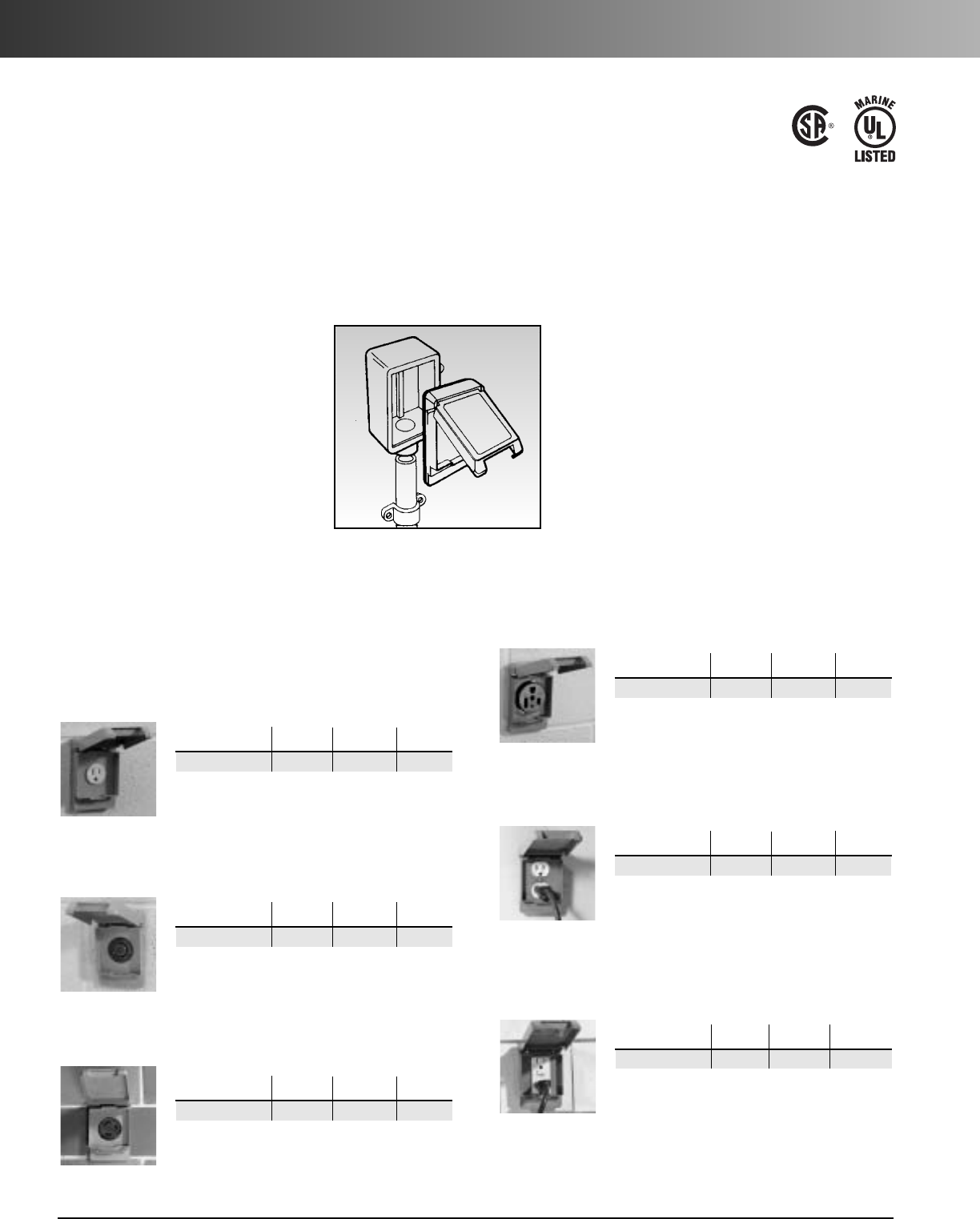
www.carlon.com
52
Weatherproof Covers
Single Gang Covers
15 AMP Receptacle Cover
For 15 amp or other single receptacles under 1.375" diameter.
Std. Std. Ctn.
Part No. Color Ctn. Qty. Wt. (lbs.)
E98SRCN-CAR Grey 10 2.1
30 AMP Receptacle Cover
For 30 amp or other single receptacles under 1.750" diameter.
Std. Std. Ctn.
Part No. Color Ctn. Qty. Wt. (lbs.)
E98G30N-CAR Grey 10 2.1
50 AMP Receptacle Cover
For 50 amp or other single receptacles under 2.250" diameter.
Std. Std. Ctn.
Part No. Color Ctn. Qty. Wt. (lbs.)
E98G5FN-CAR Grey 10 2
Duplex Receptacle Cover
For single gang duplex receptacle applications.
Std. Std. Ctn.
Part No.Color Ctn. Qty. Wt. (lbs.)
E98GDRN-CAR Grey 10 2
GFI Receptacle Cover
For GFI receptacle applications. Device opening dimensions:
2.63" H x 1.31" W.
Std. Std. Ctn.
Part No. Color Ctn. Qty. Wt. (lbs.)
E98GFCN-CAR Grey 10 2
20 AMP Receptacle Cover
For 20 amp or other single receptacles under 1.625" diameter.
Std. Std. Ctn.
Part No. Color Ctn. Qty. Wt. (lbs.)
E98G20N Grey 20 4.1
Carlon
®
weatherproof covers are rain-tight and drip-proof
when the cover is closed. They are intended for wet
environments and offer protection to outdoor electrical
devices. They may be mounted to Type FS boxes or a
smooth, flat nonporous surface. Lids snap-off for easy
access to top screw holes.
Features
•
Nonconductive
•
Nonmetallic
•
Noncorrosive
•
Durable
•
Paintable
•
Easy to install
Installation Instructions
•
Turn off power when installing electrical devices.
•
Place gasket on top of outlet box.
•
Fasten cover to outlet box with enclosed screws.
This cover must be installed in accordance with the
National Electrical Code (NEC) and local
codes.
These covers can be mounted to Type FS
boxes, or a smooth, flat nonporous mounting
surface. (Use 1/4"bead RTV type, silicone,
neoprene, urethane, or polyurethane caulking
between gasket and mounting surface on
non-box mountings.)
E42728
LR31146
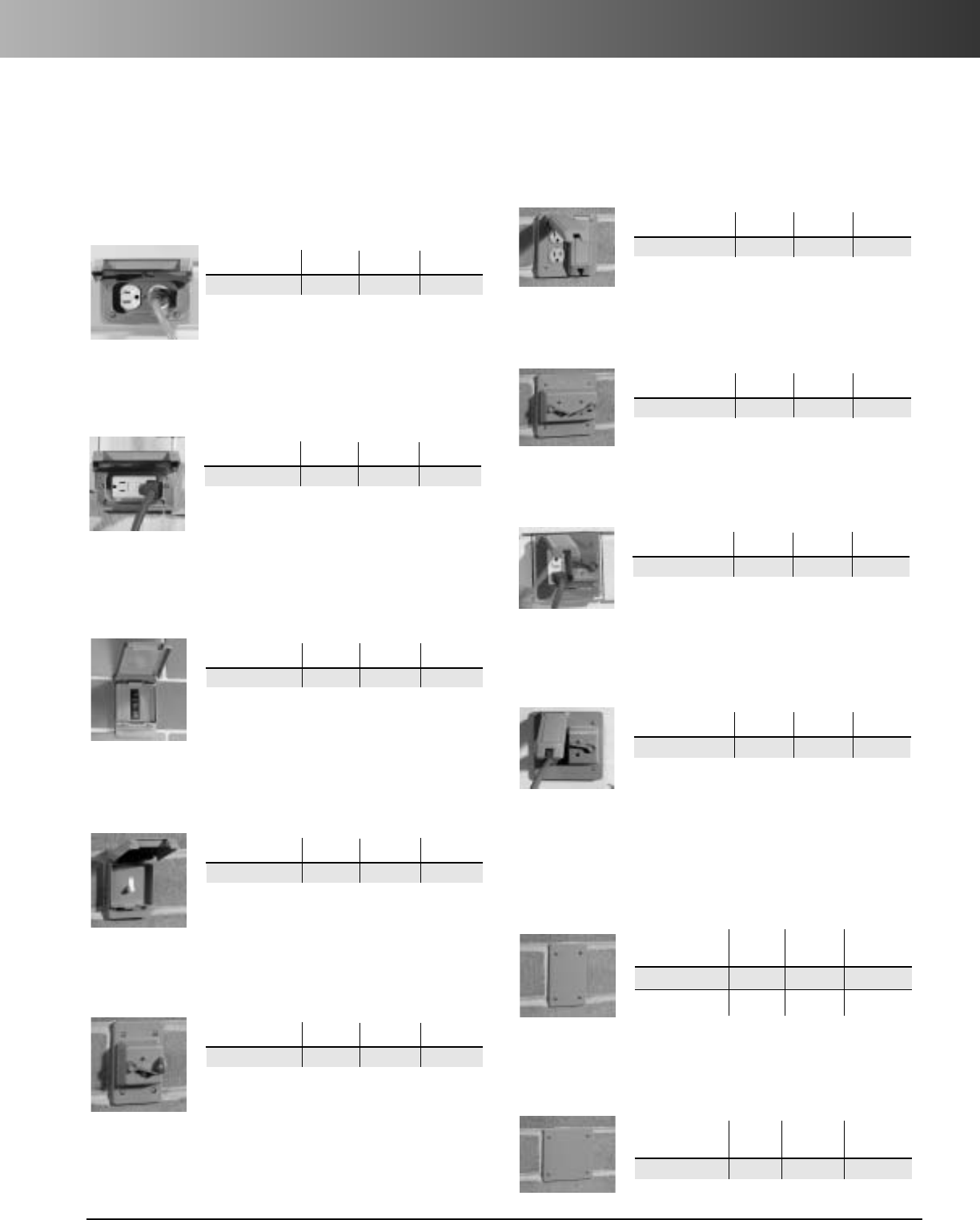
www.carlon.com 53
Weatherproof Covers
Two Gang Covers
Double Duplex
For two gang duplex receptacle applications.
Std. Std. Ctn.
Part No. Color Ctn. Qty. Wt. (lbs.)
E9G2DDN-CAR Grey 10 2.3
Combination Toggle/GFI Cover
For two gang GFI and weatherproof toggle switch applications.
Std. Std. Ctn.
Part No. Color Ctn. Qty. Wt. (lbs.)
E9G2GTN-CAR Grey 5 1.3
Combination Toggle
/
Duplex Receptacle Cover
For two gang duplex receptacles, and weatherproof
toggle switch applications.
Std. Std. Ctn.
Part No. Color Ctn. Qty. Wt. (lbs.)
E9G2DSN-CAR Grey 10 1.3
Double Toggle Cover
For two gang weatherproof toggle switch applications.
Std. Std. Ctn.
Part No. Color Ctn. Qty. Wt. (lbs.)
E9G2SSN Grey 6 3.2
Single Gang Covers
Duplex Receptacle Cover –
Horizontal Mount
For single gang duplex receptacle applications.
Std. Std. Ctn.
Part No. Color Ctn. Qty. Wt. (lbs.)
E98DHGN-CAR Grey 10 3.9
Circuit Breaker Cover
For circuit breaker applications up to 4 single poles. Device
opening dimensions: 2.845"H x 2.265"W.
Std. Std. Ctn.
Part No. Color Ctn. Qty. Wt. (lbs.)
E98GCBN Grey 20 3.9
Single Switch Cover
For single switches.
Std. Std. Ctn.
Part No. Color Ctn. Qty. Wt. (lbs.)
E98SSCN-CAR Grey 10 2.1
Toggle Switch Cover
For single weatherproof toggle switch applications.
Std. Std. Ctn.
Part No. Color Ctn. Qty. Wt. (lbs.)
E98TSCN-CAR Grey 5 1.1
GFI Horizontal Cover
For GFI receptacle applications. Device opening dimensions:
2.63"W x 1.31"H.
Std. Std. Ctn.
Part No. Color Ctn. Qty. Wt. (lbs.)
E98GHGN-CAR Grey 10 1.9
Blank Covers
Single Gang Cover
Fits Carlon®single gang FS boxes.Supplied with stainless steel
mounting screws and gasket.
Std. Std. Ctn.
Part No. Color Ctn. Qty. Wt. (lbs.)
E980CN-CAR Grey 12 1.60
E980CM-CAR White 12 1.60
TwoGang Cover
Fits Carlon®two gang FS boxes and other nonmetallic and
metallic FS boxes.Supplied with stainless steel mounting
screws and gasket.
Std. Std. Ctn.
Part No. Color Ctn. Qty. Wt. (lbs.)
E9802CN-CAR Grey 10
2.17
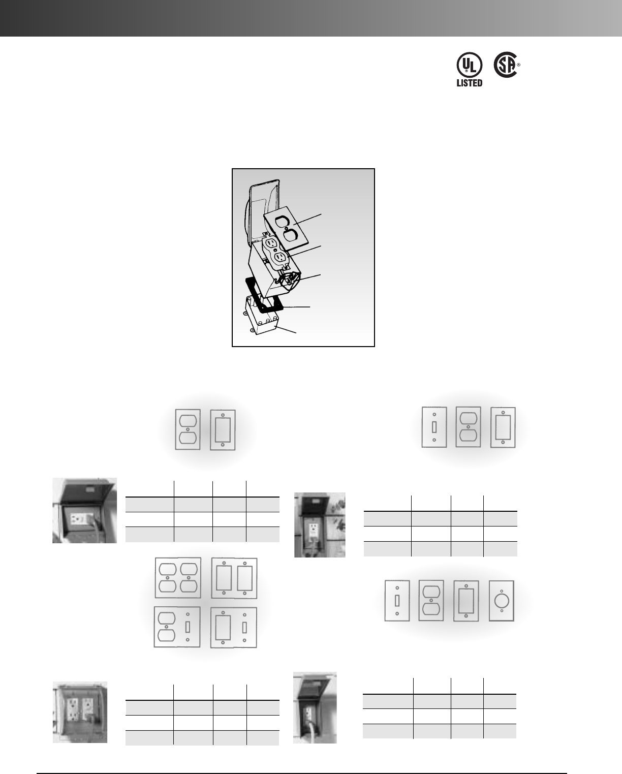
www.carlon.com
54
In-Use Weatherproof Covers
Carlon
®
In-Use Weatherproof covers are intended for wet
locations that require protection for electrical devices while
in-use. And because of their strength and durability they can
be used year round without rusting or fading.
Features
•
NEMA Type 3R Rated
•
Meets NEC article 406.8(B)
while in use
•
Tamper resistant
•
Paintable
•
Nonmetallic
•
Nonconductive
•
Noncorrosive
Installation Instructions
This Cover can be mounted to an FS type box intended for
wet locations, or a smooth, flat mounting surface.
Installation of wiring devices and
this Cover by an electrician or
individual that has a basic
understanding of electrical wiring
is also recommended.
This cover must be installed in
accordance with the National
Electrical Code (NEC) and local codes.
The Cover complies with NEC
article 406.8(B) for outdoors, and
subrule 26-706 of the Canadian
Electrical Code.
Device
Cover
Plate
Electrical
Device
Cover
Assembly
Cover Gasket
Outlet Box
In-Use Weatherproof Covers – NEMA Type 3R Rated
Single Gang
Horizontal
Includes: one duplex
receptacle plate, one GFI
receptacle plate, one cover, one base with gasket and screws.
Std. Std. Ctn.
Part No. Color Ctn. Qty. Wt. (lbs.)
E9UHGRN Grey 4 2.1
E9UHWRN White 4 2.2
E9UHCRN Clear 42.0
Double Gang
Includes: double
duplex receptacle
plate, double GFI
receptacle plate,
combination duplex
and toggle plate,
combination GFI and
toggle plate, one cover, one base with gasket and screws.
Std. Std. Ctn.
Part No. Color Ctn. Qty. Wt. (lbs.)
E9U2GRN Grey 6 4.2
E9U2WRN White 6 4.3
E9U2CRN Clear 6 4.1
Single Gang
Vertical
Includes: one switch plate,
one duplex receptacle plate,
one GFI receptacle plate, one
cover, one base with gasket and screws.
Std. Std. Ctn.
Part No.Color Ctn. Qty. Wt. (lbs.)
E9UVGRN Grey 12 5.2
E9UVWRN White 12 5.3
E9UVCRN Clear 12 5.0
Single Gang
Vertical
Deep
Includes: one switch plate, one duplex receptacle plate,
one GFI receptacle plate,*one single receptacle plate,
one cover, one base with gasket and screws.
Std. Std. Ctn.
Part No. Color Ctn. Qty. Wt. (lbs.)
E9UDVGRN Grey 8 5.8
E9UDVWRN White 8 5.8
E9UDVCRN Clear 8 8.6
*1.60" diameter – fits 20 amp twistlock or standard 30 amp
receptacle.
E42728
LR31146
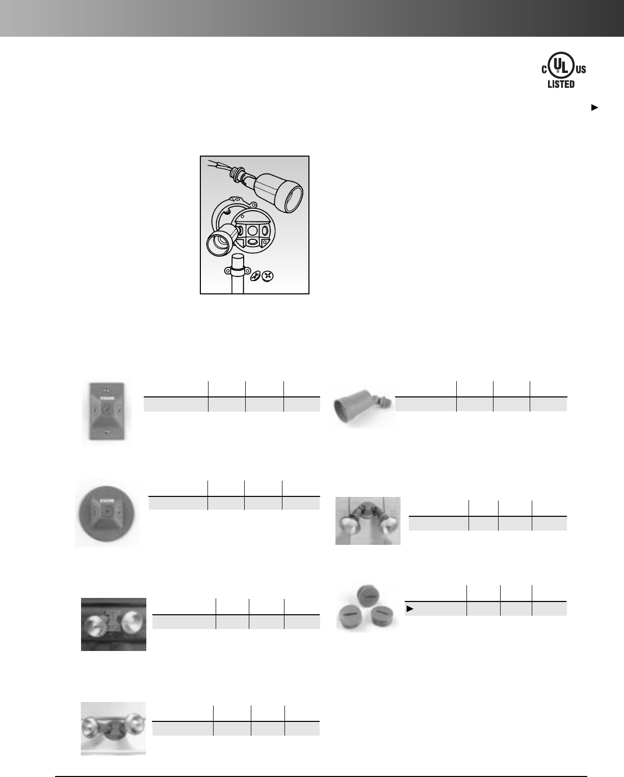
www.carlon.com 55
Lampholders
Lampholders
Rectangular Lampholder Cover
Std. Std. Ctn.
Part No. Color Wt. (lbs.) Ctn. Qty.
P7901W-CAR White .9 12
Round Lampholder Cover
Std. Std. Ctn.
Part No. Color Wt. (lbs.) Ctn. Qty.
P7801W-CAR White 1.6 16
Carlon
®
Nonmetallic Lampholders are ideal for outdoor
residential or commercial applications. Our lampholders are
nonconductive and safe for wet or damp locations. Available
in white, they will compliment any exterior.
Features
•
Nonmetallic
•
Nonconductive
•
Easy to install
•
Paintable
•
Durable
•
Rust proof
Installation Instructions
1. Turn off electricity before starting.
2. Bring power leads into the outlet box and connect
using proper wire nuts or insulation materials.
3. Use drill or nail to knock out holes on lampholder
cover that align with outlet box. When completed,
be sure visual perimeter of weatherproof gasket is even
to assure proper seal.
4. Floodlight lampholders can be positioned using
two different adjustments. Loosen locknut to turn
lampholder assembly to desired position. Tighten
locknut. Then depress pushbutton to adjust lampholder
to final position.
No-Tool-Lampholder with Gasket
Std. Std. Ctn.
Part No. Color Ctn. Qty. Wt. (lbs.)
P8001W-CAR White 24 5.5
Two Lampholders
with Rectangular Cover
Std. Std. Ctn.
Part No. Color Ctn. Qty. Wt. (lbs.)
P8005W-CAR White 63.8
No-Tool-Lampholder with
Round Cover Kit
Std. Std. Ctn.
Part No. Color Ctn. Qty. Wt. (lbs.)
P8060W-CAR White 6 5.8
Two Lampholders
with Round Cover
Std. Std. Ctn.
Part No. Color Ctn. Qty. Wt. (lbs.)
P8010W-CAR White 6 3.9
Closure Plugs
Std. Std. Ctn.
Part No. Color Ctn. Qty.Wt. (lbs.)
P7701W-CAR White 30 1.3
E70380
E183934
Except where noted by
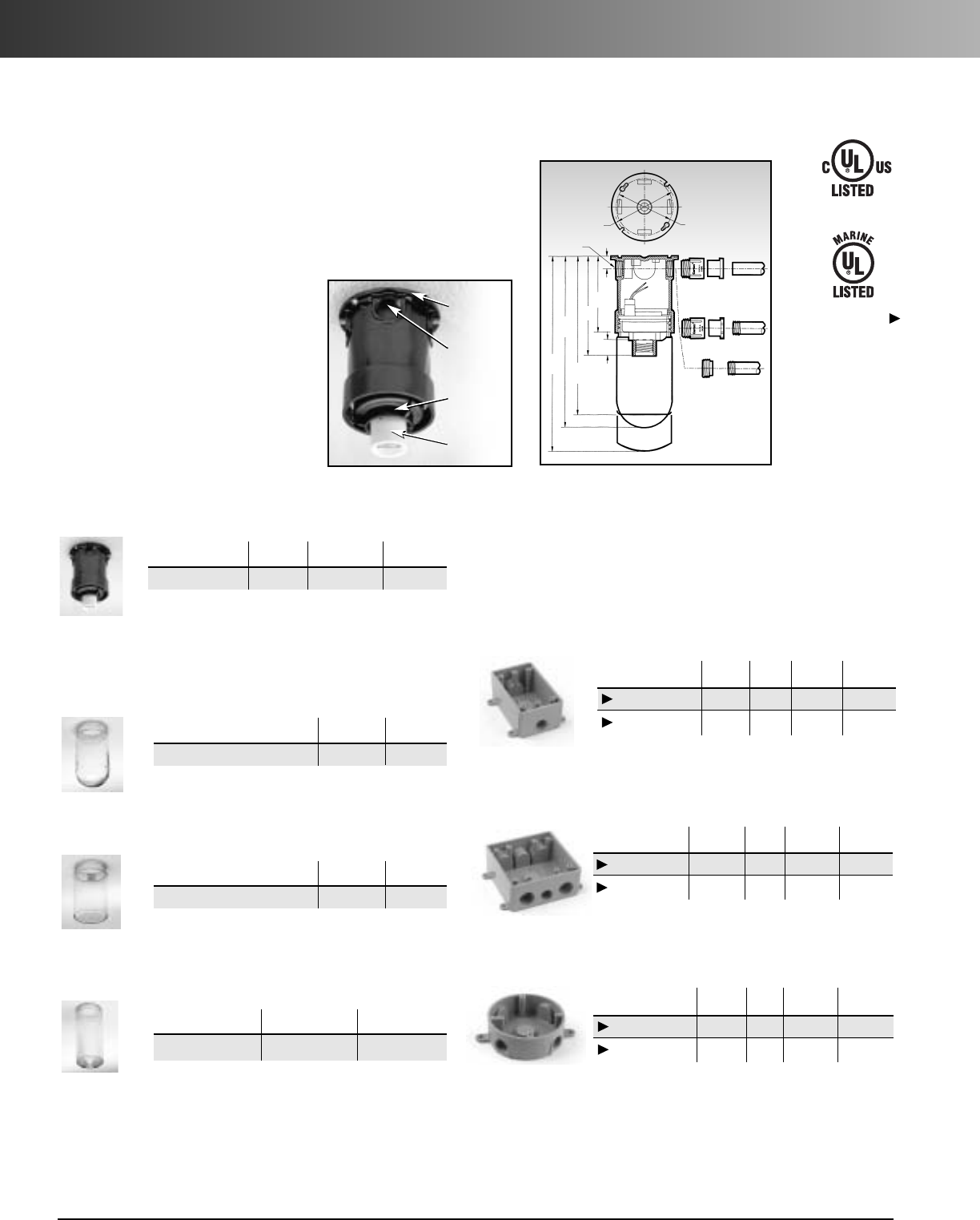
www.carlon.com
56
Weatherproof Fixture and “T” Boxes
Carlon
®
Nonmetallic Weatherproof Fixture is designed for indoor or outdoor
use and is suitable for damp, wet or corrosive environments. The one-piece
design offers a 20.25 cu. in. wiring capacity and is approved for 60° AWG
wire with the use of a 150 watt lamp. It will accommodate 8 no. 12 AWG
through branch circuit conductors and is approved for through branch wiring.
Features
•
Nonmetallic - corrosive resistant
•
Ceramic socket - long life
•
Silicone gasket
•
Drill point located on back
•
Approved for dwellings
•
Junction box approved
3.80 B.C.
(96.5)
for #8 screws
E943E
Adapter
3/4"NPT
Threaded
Ports
4PLCS. Optional 1/2"PVC Reducer to 1/2"PVC Conduit
Optional 1/2"PVC or Steel Reducer
to1/2"Steel Conduit
E950ED
Reducer
E9842D
Threaded
Adapter
E943E
Adapter
1/2"Steel
Adapter
1/2"Steel
Conduit
1/2"Steel
Conduit
1/2"PVC
Conduit
3.50 B.C.
(88.9)
for #8 screws
.77"
(19.6)
.97"
(24.6)
10.50"
(266.7)
960GLB
12"
(304.8)
960GFL 9.75"
(247.6)
960PGL Globes
not
includ-
ed
6.09"
(154.7)
4.67"
(118.6)
Universal
Mounting
Base
3
/
4
"
Threaded
Hubs
Twist-On/
Lock-On
Socket
Assembly
Ceramic
Screw Shell
Weatherproof Lighting Globes
Fixture Base
Hub Std. Ctn. Std. Ctn.
Part No. Size Qty Wt. (lbs.)
E962E 3/4" 6 4.5
Rippled Polycarbonate Globe
Std. Std. Ctn.
Part No. Ctn. Qty. Wt. (lbs.)
E960GFL 6 4.9
Clear Glass Globe
Std. Std. Ctn.
Part No. Ctn. Qty. Wt. (lbs.)
E960GLB (Clear Glass) 6 6.6
Std. Std. Ctn.
Part No. Ctn. Qty. Wt. (lbs.)
E960PGL(Clear Plastic) 66.6
Clear Polycarbonate Globe
Carlon
®
Weatherproof “T” Boxes are for use with nonmetallic
wiring systems only. Can be used with Carlon Par Lamp Holders.
Weatherproof “T” Boxes
Single Gang “T” Box
With three 1/2"threaded holes. Mounting feet included.
Std. Std. Ctn.
Part No. Color Size Ctn. Qty. Wt. (lbs.)
*E381D-CAR Grey 1/2"10 2.3
*E381DW-CAR White 1/2"10 1.8
Std. Std. Ctn.
Part No. Color Size Ctn. Qty. Wt. (lbs.)
*E382DE Grey 1/2"63.6
*E382DEW White 1/2" 6 3.6
Std. Std. Ctn.
Part No. Color Size Ctn. Qty. Wt. (lbs.)
*E365D-CAR Grey 1/2" 10 1.2
*E365DW-CAR White 1/2"10 1.2
Double Gang “T” Box
With three 1/2" and four 3/4"threaded holes. Mounting feet included.
Round “T” Box
With five 1/2"threaded holes.Mounting feet included.
*E381D-CAR, E365D-CAR and E382DE are for use with nonmetallic
wiring systems only.
E183934
E42728
Where noted by

www.carlon.com 57
Kaddies
Karts
Dispensers
Carlon
®
Wire Handling Products
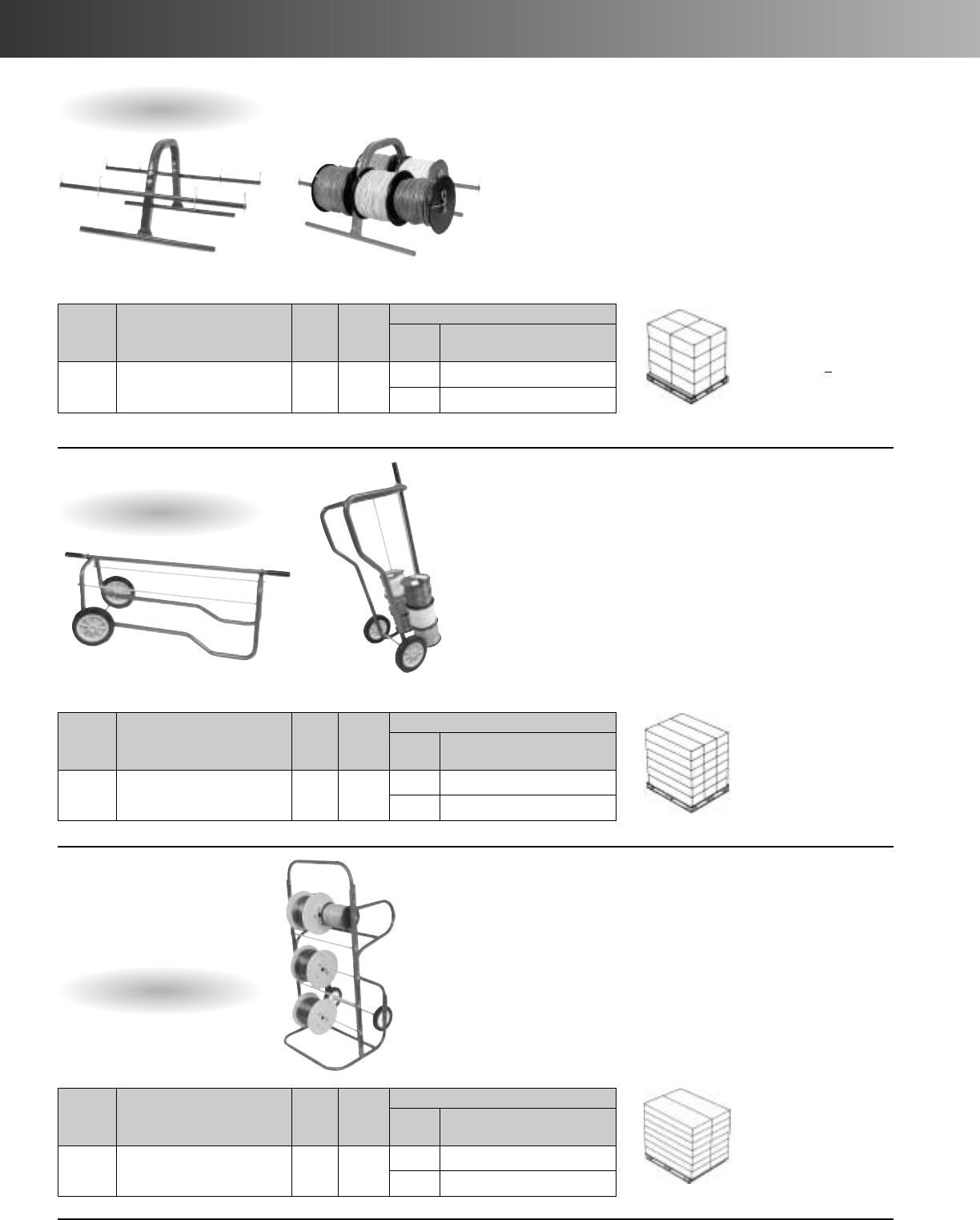
www.carlon.com
58
Kaddies and Karts
Wire Kaddy™
•Dispense small quantities of spooled wire.
• Convenient hand carrying design.
• Constructed of steel tubing with premium powder coat finish.
• 3/8" hitch pin clip allows easy spool changes.
Shipping/Storage:
•4units per master
• 64 pieces per pallet
(16 masters)
• More than 4 times
more product than
the competition
•Lower freight costs
Shipping/Storage:
•2units per master
• 36 pieces per pallet
(18 masters)
•Lower freight costs
WireHandling Kart™
•Dispense quantities of spooled wire.
• Constructed of steel tubing with premium powder coat finish.
• 3/8" hitch pin clip allows easy spool changes.
Shipping/Storage:
•14 pieces per pallet
•Lower freight costs
Multi-Purpose
WireKart
•Built-in wire guide on handle
allows horizontal dispensing.
•Large 8" heavy-duty wheels
with adjustable axle position.
• Designed to pass through a
28" opening.
• Dispense large quantities of spool wire.
• Heavy-duty construction with premium
powder coat finish.
•5wire spool axles.
• 3/8" hitch pin clip allows easy
spool changes.
Part No. Dimensions Std. Ctn.
Qty. Std. Ctn.
Wt. (lbs.)
CAPACITY
Qty. of
Spools Spool
Dimensions
WK7001 22.75"L x 14"W x 11"H 425 87" diameter x 5" wide
47" diameter x 6"-10" wide
Part No. Dimensions Std. Ctn.
Qty. Std. Ctn.
Wt. (lbs.)
CAPACITY
Qty. of
Spools Spool
Dimensions
WK7101 44.25"L x 16"W x 17.5"H 247 12 7" diameter x 5" wide
67" diameter x 6"-10" wide
Part No. Dimensions Std. Ctn.
Qty.Std. Ctn.
Wt. (lbs.)
CAPACITY
Qty. of
Spools Spool
Dimensions
WK7103 25"L x 28"W x 55"H 158.6 62500' – up to 16" diameter
15 500' – 7" diameter x 5" wide
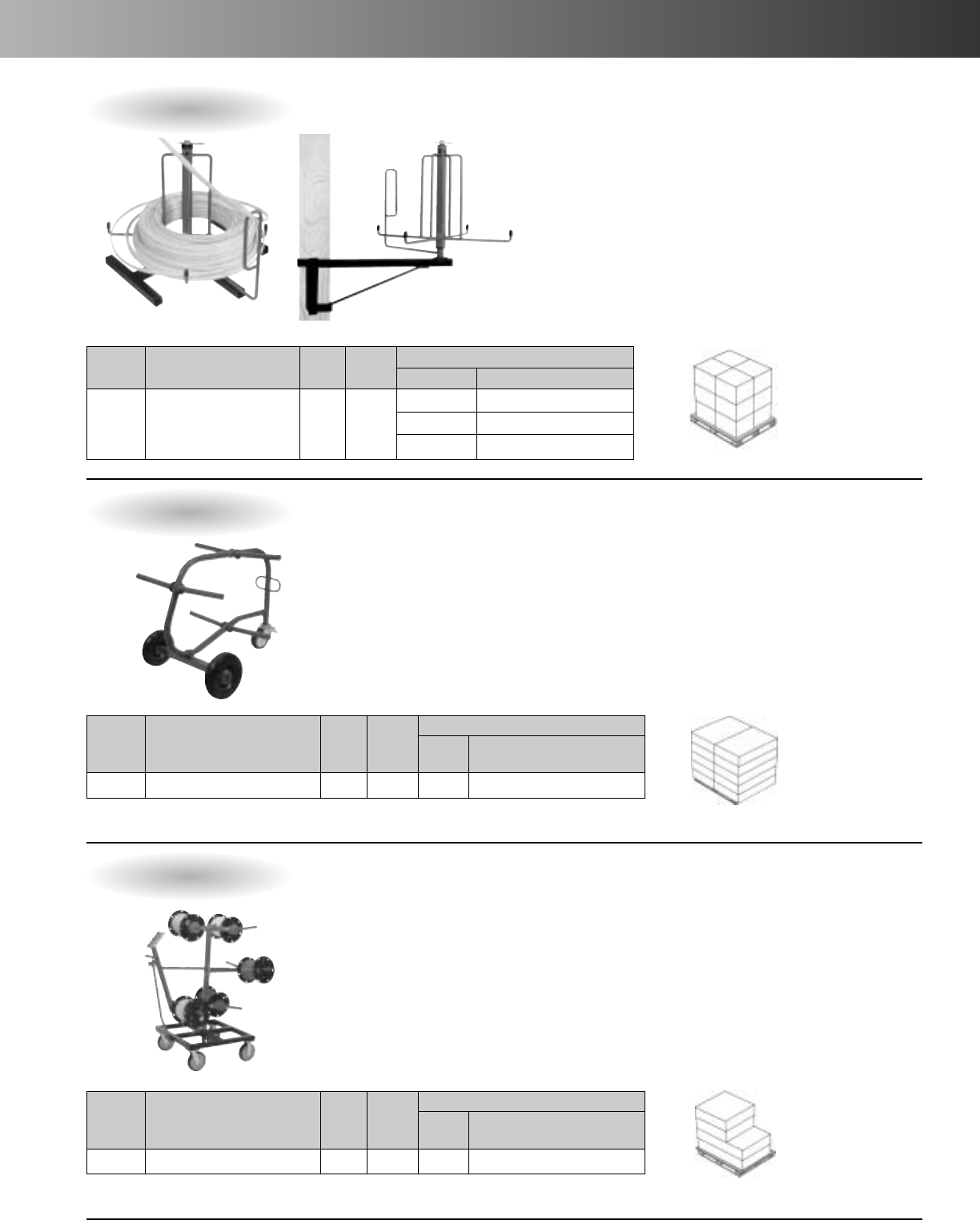
www.carlon.com 59
Dispensers
Cable Dispenser
•Two mounting styles in one product
vscompetitive offering.
•Floor, or stud mount
• Smoothly dispense coils of armored cable or NM-B.
• Swivel eyelet prevents tangles while paying out.
• Wide base for stability.
• Easy assembly, no tools required.
Shipping/Storage:
•3units per master
• 36 pieces per pallet
(12 masters)
Shipping/Storage:
•10 pieces per pallet
•Lower freight costs
6Reel Wire Dispenser
•Dispense large quantities of spool wire.
• Heavy-duty construction with premium
powder coat finish.
•6angled spindles keep reels in place
without locking.
• Built in wire guide.
•2fixed wheels, 1locking swivel wheel.
• Designed to pass through a 30" opening.
Shipping/Storage:
•Each unit shipped
in 2 cartons
•2pieces per pallet
10 Reel Wire Dispenser
•All-steel construction
• Premium powder coated finish
• Easy loading, dispensing and changing
of spooled wire
• Adjustable wire guide
• Two fixed and two swivel locking casters
for stability
•Angled spindles keep spools in place
during use
• 360° rotating reel frame
•Fits through a 36" door opening
• Heavy duty
• Easy assembly
Part No. Dimensions Std. Ctn.
Qty. Std. Ctn.
Wt. (lbs.)
CAPACITY
Coil Dimensions Spool Dimensions
WK7203 15.5"H x 19"W 345.5 Inside 5.50" min, inside coil dia.
Outside 17" max. outside coil dia.
Max. Weight 50 lbs.
Part No. Dimensions Std. Ctn.
Qty.Std. Ctn.
Wt. (lbs.)
CAPACITY
Qty. of
Spools Spool
Dimensions
WK7202 50"L x 32"W x 57.5"H 1190 10 2500' – up to 18" diameter
Part No. Dimensions Std. Ctn.
Qty. Std. Ctn.
Wt. (lbs.)
CAPACITY
Qty. of
Spools Spool
Dimensions
WK7201 44"L x 29"W x 33"H 180 62500' – up to 18" diameter
floor mount stud mount

www.carlon.com
60

www.carlon.com 61
Tough on the job,
easy on you.
Carlon
®
Wire Safe
®
Wireway And Wiring Trough
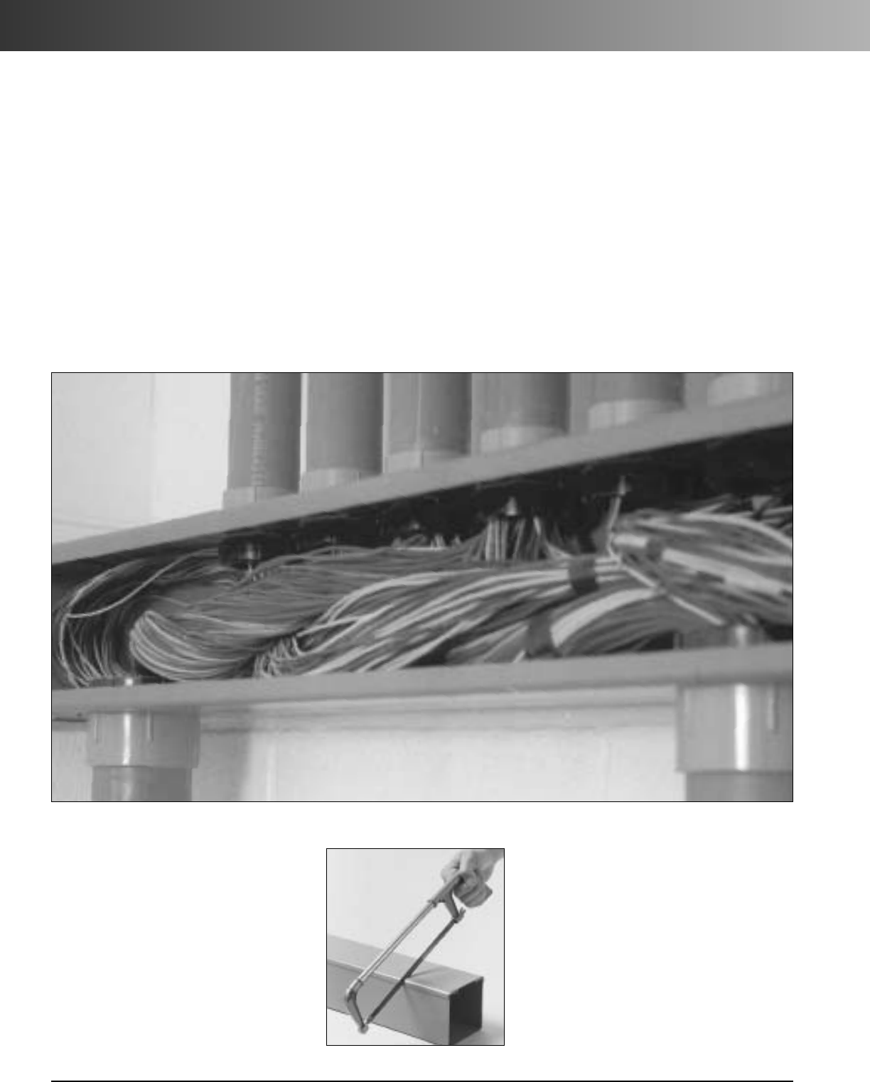
www.carlon.com
62
Wire-Safe
®
Wireway and Wiring Trough
Easy To
Cut And Assemble.
Wireway and trough can be cut easily and
cleanly with either a hacksaw or fine tooth
saw to make field fabrication a snap.And it’s
equally easy to couple components either
with Carlon primer and PVC cement or
nonmetallic push rivets.
No wires to pull, no hard-to-work-with
metal components.
Carlon®leads the way with the world’s broadest line of nonmetallic wiring management products designed for
easier installation, greater performance, and lower installed cost. That includes our Carlon®Wire Safe®wireway,
wiring trough, and fittings. It’s the perfect solution for containing electrical, electronic, and communication wire and
cable. That’s because it’s easy to install, provides durable protection, and eliminates the need to pull conductors, too.
Just compare it point for point against the competition, and you’ll see why it’s the best alternative for you.
Rugged Yet
Lightweight.
UV stabilized, high-impact resistant PVC
provides a strong, durable,non-corrosive,
non-conductive housing for wire and
cable. At the same time, components are
so light and easy to handle that installa-
tion can be done by one person.
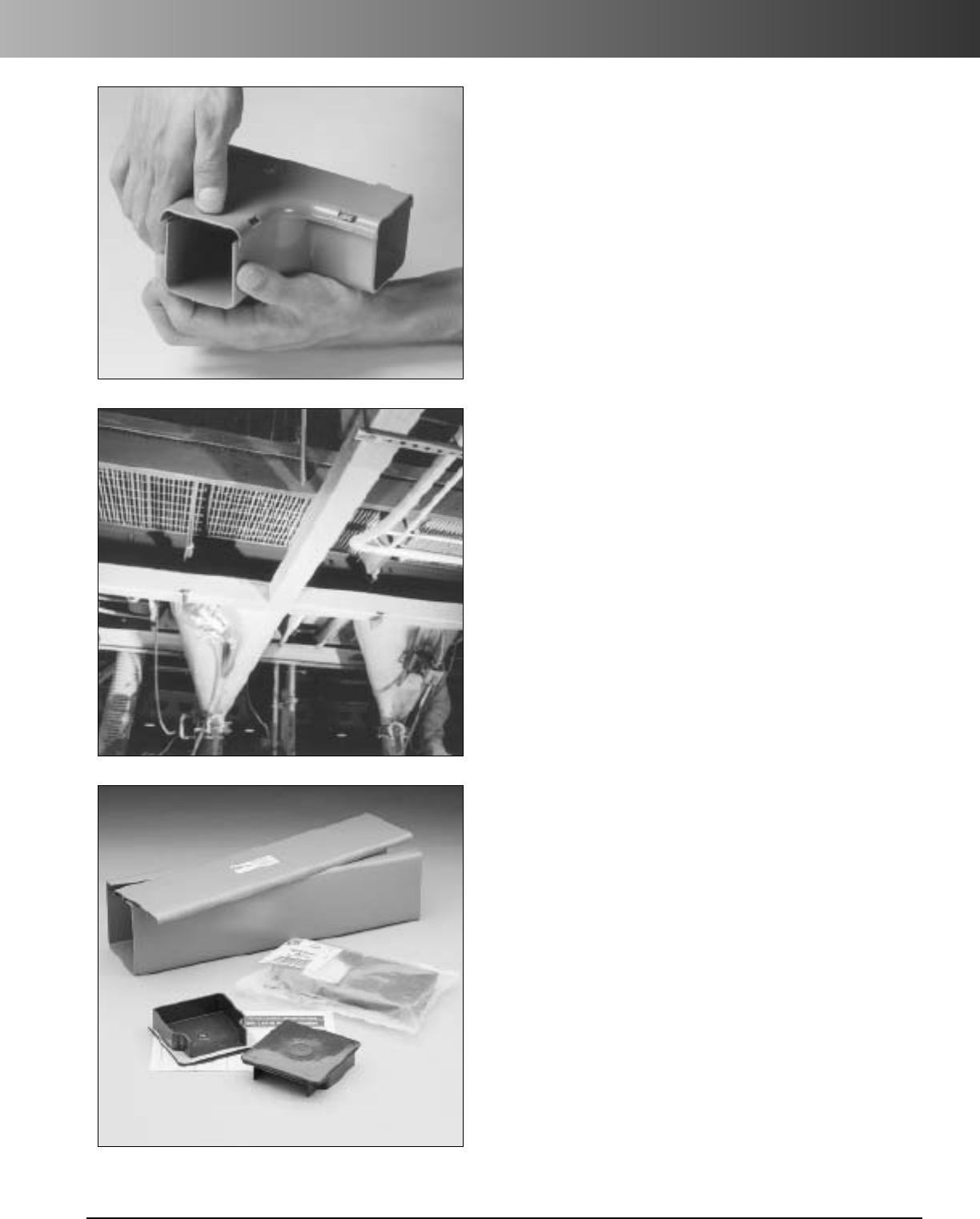
www.carlon.com 63
Wire-Safe
®
Wireway and Wiring Trough
Improved NEMA 12
Wireway End Caps.
No Wires To Pull.
Once your wireway or trough is installed, just lay your wire
and cable in, pop the cover on, and you’re done. It’s as easy
as that, and that’s a lot easier than pulling wire or cable.
Easy To Rewire.
"Clip-on" cover design allows easy access for adding or
removing wire and cable after initial installation.
Application Flexibility.
Wireway and trough are suitable for a wide range of applica-
tions from the most demanding commercial and industrial
uses including food service companies and chemical plants
to communication and computer facilities.Both wireway and
trough can be used on walls, ceilings, or across supports.
Our new wireway end caps are now made with pre-installed
adhesive backed gaskets. This new design makes them easier
to use and also qualifies them for a NEMA 12 rating.
A Complete
Nonmetallic System.
Both wireway and trough are available in 2" x 2", 3" x 3",
4" x 4" and 6" x 6" dimensions. Wireway comes cut in easy-to-
use 10' lengths for larger jobs, and for tighter spaces, we offer
specific lengths of wiring trough to fit distances of 1' to 10'.
Both can be used with our nonmetallic enclosures, conduit, and
fittings to create a total nonmetallic wire and cable management
system far superior to metal counterparts.
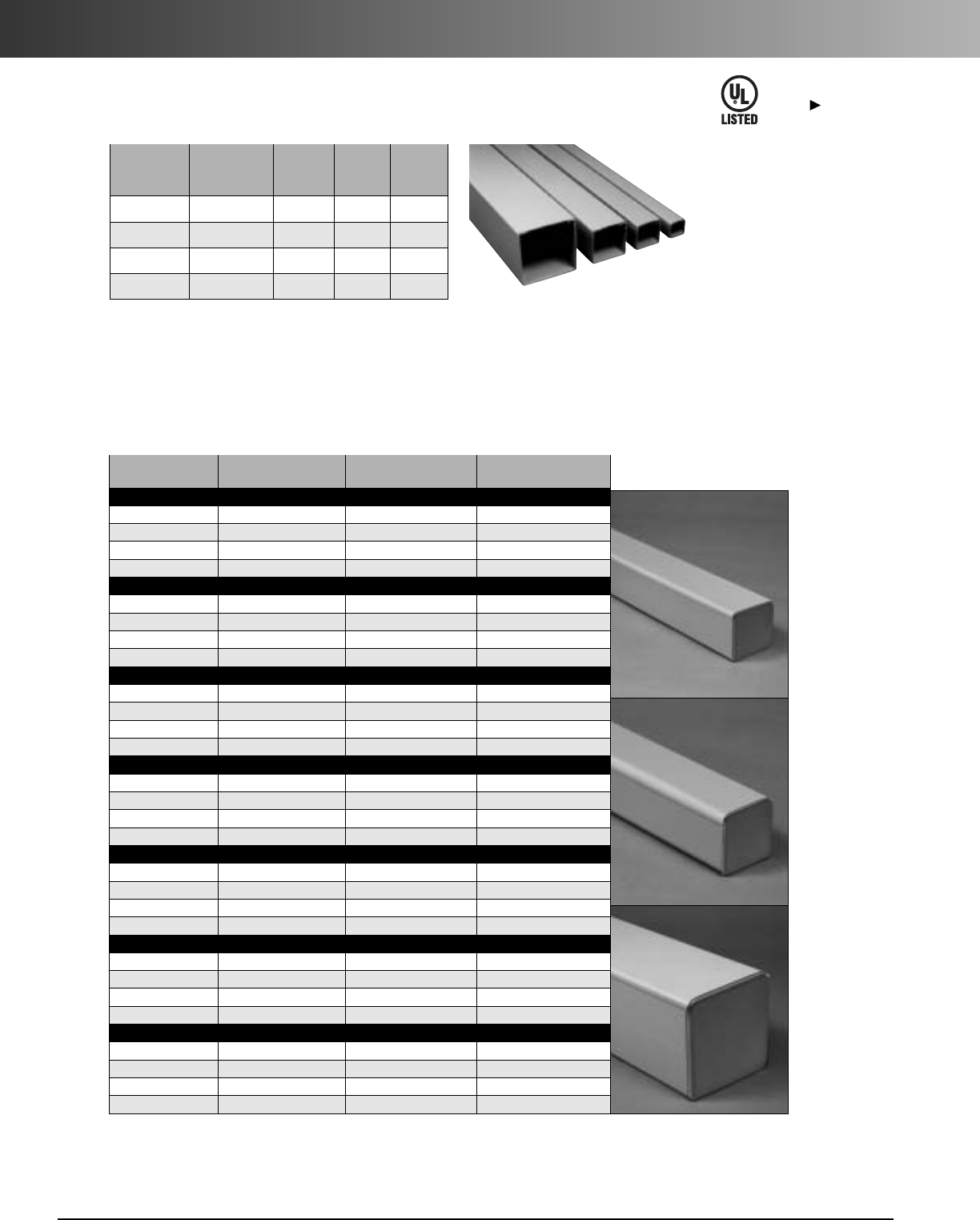
www.carlon.com
64
Wire-Safe
®
Wireway and Wiring Trough
Wiresafe
®
Wireway
Outside Std. Wt.
Part Nominal Ctn. (lbs.)
No. Dimensions Length Qty. per 10'
17011 2 x 2 10' 1 4.7
17013 3 x 3 10' 1 11.2
17015 4 x 4 10' 1 11.2
17017 6 x 6 10' 1 21.4
Wiresafe
®
Wiring Trough
Except where
noted by
E151021
All wiring trough is made to order and is supplied with a pair of end caps.
Part Outside Nominal Standard Wt./Lbs.
Number Dimensions Carton Qty. Each
12" Trough
18111 2 x 2 1 0.6
18113 3 x 3 1 1.0
18115 4 x 4 1 1.4
18117 6 x 6 1 3.1
24" Trough
18211 2x2 1 1.1
18213 3x3 1 1.8
18215 4x4 1 2.6
18217 6 x 6 1 5.3
36" Trough
18311 2 x 2 1 1.5
18313 3 x 3 1 2.6
18315 4 x 4 1 3.7
18317 6x6 1 7.4
48" Trough
18411 2 x 2 1 2.0
18413 3 x 3 1 3.3
18415 4x4 1 4.8
18417 6 x 6 1 9.6
60" Trough
18511 2 x 2 1 2.5
18513 3 x 3 1 4.1
18515 4 x 4 1 5.9
18517 6 x 6 1 11.7
72" Trough
18611 2 x 2 1 2.9
18613 3 x 3 1 4.9
18615 4 x 4 1 7.1
18617 6x6 1 13.8
120" Trough
18011 2x2 1 4.8
18013 3 x 3 1 8.1
18015 4 x 4 1 11.6
18017 6 x 6 1 22.4
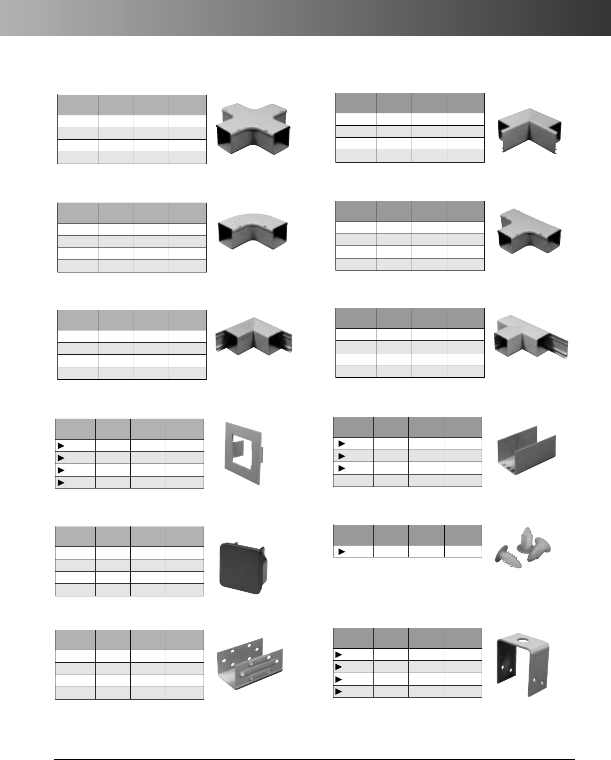
www.carlon.com 65
Wiresafe®Fittings
Wiresafe
®
Fittings
Std. Ctn. Wt. (lbs.)
Part No. Size Qty. ea.
* EGFCJ 2 x 2 1 0.5
* EGFCL 3 x 3 1 1.3
† EGFCN 4 x 4 1 1.7
† EGFCR 6 x 6 1 4.8
Flat Cross (Clip-on Cover)
Std. Ctn. Wt. (lbs.)
Part No. Size Qty. ea.
* EGLIJ 2 x 2 1 0.3
†EGLIL 3 x 3 1 0.7
† EGLIN 4 x 4 1 1.1
† EGLIR 6 x 6 1 3.0
90° Bend Internal Cover (Clip-on Cover)
Std. Ctn. Wt. (lbs.)
Part No. Size Qty. ea.
* EGLFJ 2 x 2 1 0.3
* EGLFL 3 x 3 1 0.6
† EGLFN 4 x 4 1 1.1
† EGLFR 6 x 6 1 3.3
90° Bend Flat Cover (Clip-on Cover)
Std. Ctn. Wt. (lbs.)
Part No. Size Qty. ea.
* EGTFJ 2 x 2 1 0.4
* EGTFL 3 x 3 1 0.9
† EGTFN 4 x 4 1 1.4
† EGTFR 6 x 6 1 3.8
Tee Flat Cover (Clip-on Cover)
Std. Ctn. Wt. (lbs.)
Part No. Size Qty. ea.
* EGLEJ 2 x 2 1 0.3
†EGLEL 3x3 1 0.8
†EGLEN 4 x 4 1 1.2
† EGLER 6 x 6 1 3.3
90° Bend External Cover (Clip-on Cover)
Std. Ctn. Wt. (lbs.)
Part No. Size Qty. ea.
† EGTEJ 2 x 2 1 0.4
†EGTEL 3x3 1 0.9
† EGTEN 4 x 4 1 1.4
† EGTER 6 x 6 1 3.8
Tee External Cover (Clip-on Cover)
Std. Ctn. Wt. (lbs.)
Part No. Size Qty. ea.
EGFJ 2 x 2 10 1.1
EGFL 3x3 10 1.4
EGFN 4x4 10 2.2
EGFR 6 x 6 10 3.0
Flange
Std. Ctn. Wt. (lbs.)
Part No. Size Qty. ea.
EGCIJ 2 x 2 1O 1.3
EGCIL 3x3 1O 2.2
EGCIN 4 x 4 1O 2.5
–6x6 N/A N/A
Internal Coupling
Std. Ctn. Wt. (lbs.)
Part No. Size Qty. ea.
* EGSEJ 2 x 2 10 Pair 0.6
* EGSEL 3 x 3 10 Pair 0.9
* EGSEN 4 x 4 10 Pair 1.6
†† EGSER 6 x 6 10 Pair 5.0
End Cap (UL NEMA 12 Rated)
Std. Ctn. Wt. (lbs.)
Part No. Size Qty. ea.
EGPR N/A 200 0.4
Push Rivets
Std. Ctn. Wt. (lbs.)
Part No.Size Qty. ea.
EGCEJ 2 x 2 10 1.3
EGCEL 3x3 10 2.2
EGCEN 4 x 4 10 2.5
EGCER 6 x 6 10 7.8
External Coupling
Std. Ctn. Wt. (lbs.)
Part No. Size Qty. ea.
EGSBJ 2x2 10 0.9
EGSBL 3 x 3 10 1.3
EGSBN 4 x 4 10 1.9
EGSBR 6x6 10 2.8
Hangers
*Molded fitting–couplings not needed
†Fabricated fitting–order couplings separately
†† No coupling is required for 6" fabricated end cap

www.carlon.com
66
Wire-Safe
®
Wireway and Wiring Trough Installation
Installation Instructions
Description. Carlon Wire Safe wireway and wiring troughs are manufactured from extruded PVC. The standard color is
gray. The wireway consists of a base channel that is formed to receive a “clip-on” cover. Wiring troughs include a pair of
ready-to-install end caps.
Cover Installation and Removal. The cover can be installed by exerting hand pressure along its front face in such a
manner as to engage and clip projections on the side walls of the base channel.The cover can be removed by inserting a tool
(i.e., a screwdriver shaft) into one end of the wireway enclosure and exerting pressure against the underside of the cover,
which is then “peeled off” from the base.
Wireway Fittings. Fittings enable the wireway to be positioned around corners and enable tees and crosses to be created
without detracting from the protective characteristics. Interconnecting pieces can be assembled using couplings and rivets or
cement as necessary.
Molded fittings do not require couplings since they fit on the exterior of the wireway. However, primer and solvent cement are
needed. See cementing instructions.
Fabricated fittings do require internal or external couplings, and these must be ordered separately. To install fittings, a 9/32"
diameter hole should be drilled in the wireway to match the external coupling hole. A push rivet should be used to connect the
two pieces. To connect an internal coupling to the inside of a fitting, use Carlon Quick-Set Clear Cement.
Applications. These systems are designed for use in commercial and industrial areas. They may be used for the contain-
ment of electrical wiring/cables for power and lighting circuits and also communication and computer facilities. They are suit-
able for mounting on the surface of walls or ceilings or suspended across
suitably positioned supports. Ambient temperatures should not exceed 1220F.
Engineering Specifications
Code Approvals.
Carlon's Wire Safe Wireway and Wiring Trough is recognized by the current National Electrical Code, Article 378, for
nonmetallic wireways.It is UL Listed for electrical wiring up to 600 volts. UL File Numbers: UL E151021.
Specification for Carlon Wire Safe Wireway and Wiring Trough.
The wireway and wiring troughs shall be Carlon Wire Safe Wireway and Wiring Trough.
The Carlon Wire Safe Wireway and Wiring Trough shall provide protection for electrical, low voltage, data and communication wiring or cables.
The Carlon Wire Safe Wireway and Wiring Trough shall be listed and installed per the NEC Article 378 for nonmetallic wireways.
The Carlon Wire Safe Wireway and Wiring Trough shall be manufactured from gray precision extruded Polyvinyl Chloride (PVC) meeting UL 94 V-O
requirements and shall be suitable for field painting.
The Carlon Wire Safe Wireway and Wiring Trough shall include base, cover, fittings, etc.
The Carlon Wire Safe Wireway and Wiring Trough shall provide all fittings required to form a complete, integrated surface raceway system.
End caps shall be gasketed and shall have a NEMA Type 12 rating.
The Carlon Wire Safe Wireway and Wiring Trough shall provide raceway with the following cross sectional areas:
1. 2x2-3.165 in.2(20.4 cm2)3. 4x4-13.694 in.2(88 cm2)
2. 3x3-7.378 in.2(47 cm2)4. 6x6-31.871 in.2(205 cm2)
Fittings.
Internal and external elbow shall be a fitting cover that snaps onto the main base.Flat elbows and flat tees shall be a fitting cover
that snaps on to the main base.End caps shall be gasketed and NEMA Type 12 rated.
Installation.
Install in accordance with the manufacturer’s instructions, NFPA 70 and NECA standard.
Install base,cover, fittings, accessories, etc., as necessary for a complete system.
1. Mark the surface upon which the wireway is to be mounted.
2. Measure, run, and identify position of fittings.
3. Remove cover from wireway, starting at one end, with a peeling
action (use of a screwdriver or similar lever is recommended).
4. Drill mounting holes through base at 60" centers maximum. Two
rows of mounting holes should be drilled, adjacent to each wall of
the wireway in order to evenly distribute the load.
5. The holes in the wireway should be drilled oversize to allow for
expansion. Washers should be mounted under the head of the
mounting device,which should not be tightened to its full extent.
6. Mount the wireway using screws or bolts.
7. Affix the wireway cover by aligning it to the wireway base and
then pressing it into its engaged position, starting at one end.
8. The cover should be made to overlap the base joint in order to
improve rigidity of the joint.
Installation.
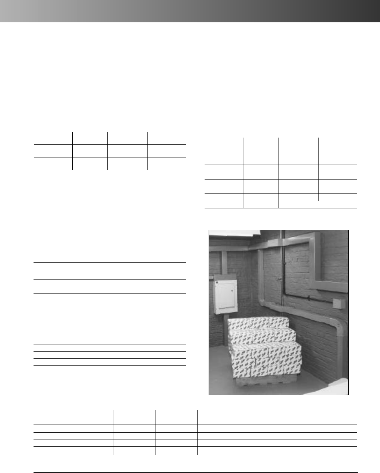
www.carlon.com 67
Wire-Safe
®
Wireway and Wiring Trough Cementing
Cementing Instructions
1. Make a square cut using a miter box or precisely marked
line on the wireway to provide a smooth connection.
2. Make certain surfaces to be bonded are free of dirt, dust,
etc., by wiping them clean with a rag, and by removing
sawcut burrs with a knife or rasp.
3. With a dauber, place a coating of Carlon Clear Primer on
the wireway and its mating parts. Thoroughly coat the
surfaces to be mated.
4. Allow the Carlon Clear Primer a few seconds to soften the
PVC surface (the time may need to be adjusted, depending
upon the temperature).
5. Apply a complete coating of Carlon Quick-Set Clear
Cement to matching ends that will be joined.
6. Hold the parts in position by exerting pressure on the
surfaces with clamps.
7. Allow 15 minutes or more before removing clamps.
Part Standard Standard Standard
Number Size Carton Qty. Carton Wt.
VC9984 1/2 Pint 10 6.0 lbs.
Dauber Top
VC9983 Pint 24 30.0 lbs.
Dauber Top
VC9982 Quart 12 29.0 lbs.
Dauber Top
VC9981P Gallon 6 53.0 lbs.
Pour Top
PVC Homopolymer (ASTM F1784) minimum cell class 12354B
Specific Gravity (ASTM D792) 1.46
Thermal Conductivity (ASTM C177) 1.3 Btu/hr./ft.2/0F/in.
Heat Deflection Temperature
@264 psi (ASTM D648) 700C
Tensile Strength (ASTM D638) 6000 psi
Flammability (UL 94) V-O
Dimensions
Outside Outside Inside Inside Inside Wireway Cover Wt./Ft.
Nominal Size (in.) Actual Size (in.) Height (in.) Width (in.) Area (in.2) Thickness (in.) Thickness (in.) (lb./ft.)
2x2 1.97 x 1.97 1.8 1.79 3.31 0.09 .08 0.6
3x3 2.96 x 2.96 2.8 2.76 7.94 0.10 .08 0.85
4x4 3.94 x 3.94 3.75 3.72 14.39 0.11 .08 1.48
6x6 5.91 x 5.91 5.67 5.67 13.48 0.12 .12 2.29
Size Crush Strength1(lbs.) Impact Strength2(ft.-lbs.)
2x2 650 40
3x3 500 30
4x4 500 40
6x6 600 50
Physical Properties
1. Load on 6" long sample just prior to wall buckling; fully recoverable.
2. Five lb. weight with 1-1/4" dia. face at 730F.
All information represents typical values and does not represent a minimum performance specification.
All Weather Quick-Set Clear Cement
Part Standard Standard Standard
Number Size Carton Qty. Carton Wt.
VC9903 Pint 24 25.0 lbs.
Dauber Top
VC9902 Quart 12 24.0 lbs.
Dauber Top
Cement and primer not needed for end caps.
Clear Primer
Materials
Expansion And Contraction
Wireway will expand or contract with variations in temperatures.
Tocompensate for this expansion and contraction, during instal-
lation leave 0.25" gap at joint,glue only one side of internal cou-
pling, or use external coupling with push rivets. All mounting
holes should be drilled oversize, and fasteners should not be
tightened fully to allow for expansion and contraction.

www.carlon.com
68
Wire-Safe
®
Wireway and Wiring Trough Specifications
Area of Conductor (sq. in.)
AB C D Wire Safe Wireway Size and Maximum Number of Conductors Allowed
RFH-2, RH, TF, TFN, (Areas shown are 20% of the full interior cross sectional area of the wireway.)
Conductor Size RHH, ***RHW, THW, THHN, XHHW, 2x2 (0.6 in.2) 3x3 (1.5 in.2) 4x4 (2.7 in.2) 6x6 (6.4 in.2)
AWG-MCM ***SF-2 †TW THWN ††ZW A B C D A B C D A B C D A B C D
18 .0167 .0088 .0062 – 36 68 96 – 89 170 241 – 161 306 435 – 383 727 1032 –
6 .0196 .0109 .0079 – 31 55 76 – 76 137 189 – 137 247 341 – 326 587 810 –
14 .0230 .0135 .0087 – 26 44 69 – 65 111 172 – 117 200 310 – 278 474 735 –
14 *.0327 – – – 18 – – – 45 – – – 82 – – – 195 – – –
14 – †.0206 – .0131 – 29 – 46 – 72 – 114 – 131 – 206 – 310 – 488
12 .0278 .0172 .0117 – 21 35 51 – 53 87 128 – 97 156 230 – 230 372 547 –
12 *.0384 – – – 16 – – – 39 – – – 70 – – – 166 – – –
12 – †.0252 – .0167 – 24 – 36 – 59 – 89 – 107 – 161 – 253 – 383
10 .0460 .0222 .0184 – 13 27 33 – 32 67 81 – 58 121 146 – 139 288 347 –
10 – .0311 – .0216 – 19 – 28 – 48 – 69 – 86 – 125 – 205 – 296
8 .0845 .0471 .0373 – 7 13 16 – 17 31 40 – 31 57 72 – 75 135 171 –
8 – †.0598 – .0456 – 10 – 13 – 25 – 32 – 45 – 59 – 107 – 140
6 .1238 .0819 .0519 .0625 4 7 11 10 12 18 28 24 21 32 52 43 51 78 123 102
4.1605 .1087 .0845 .0845 4 6 7 7 9 13 17 17 16 24 31 31 39 58 75 75
3.1817 .1263 .0995 .0995 3 5 6 6 8 11 15 15 14 21 27 27 35 50 64 64
2 .2067 .1473 .1182 .1182 3 4 5 5 7 10 12 12 13 18 22 22 30 43 54 54
1.2715 .2027 .1590 .1590 2 3 4 4 5 7 9 9 9 13 16 16 23 31 40 40
1/0 .3107 .2367 .1893 .1893 2 2 3 3 4 6 7 7 8 11 14 14 20 27 33 33
2/0 .3578 .2781 .2265 .2265 1 2 2 2 4 5 6 6 7 9 11 11 17 23 28 28
3/0 .4151 .3288 .2715 .2715 1 1 2 2 3 4 5 5 6 8 9 9 15 19 23 23
4/0 .4840 .3904 .3278 .3278 1 1 1 1 3 4 4 4 5 6 8 8 13 16 19 19
250 .5917 .4877 .4026 .4026 1 1 1 1 2 3 3 3 4 5 6 6 10 13 15 15
300 .6837 .5581 .4669 .4669 – 1 1 1 2 2 3 3 3 4 5 5 9 11 13 13
350 .7620 .6291 .5307 .5307 – – 1 1 1 2 2 2 3 4 5 5 8 10 12 12
400 .8365 .6969 .5931 .5931 – – 1 1 1 2 2 2 3 3 4 4 7 9 10 10
500 .9834 .8316 .7163 .7163 – – – – 1 1 2 2 2 3 3 3 6 7 8 8
600 1.1940 1.0261 .8791 .9043 – – – – 1 1 1 1 2 2 3 3 5 6 7 7
700 1.3355 1.1575 1.0011 1.0297 – – – – 1 1 1 1 2 2 2 2 4 5 6 6
750 1.4082 1.2252 1.0623 1.0936 – – – – 1 1 1 1 1 2 2 2 4 5 6 5
800 1.4784 1.2908 1.1234 1.1499 – – – – 1 1 1 1 1 2 2 2 4 4 5 5
900 1.6173 1.4208 1.2449 1.2668 – – – – – 1 1 1 1 1 2 2 3 4 5 5
1000 1.7530 1.5482 1.3623 1.3893 – – – – – – 1 1 1 1 1 1 3 4 4 4
1250 2.2062 1.9532 – 1.7671 – – – – – – – – 1 1 – 1 2 3 – 3
1500 2.5475 2.2751 – 2.0612 – – – – – – – – 1 1 – 1 2 2 – 3
1750 2.8832 2.5930 – 2.3779 – – – – – – – – – 1 – 1 2 2 – 2
2000 3.2079 2.9013 – 2.6590 – – – – – – – – – – – 1 1 2 – 2
* Dimensions of RHH and RHW.
*** Dimensions of RHH and RHW without outer covering are the same as
THW No. 18 through No. 10, solid as well as No. 8 and larger, stranded.
†Dimensions of THW in sizes No. 14 through No. 8. No. 6 THW and larger
aresame dimension as TW.
†† No. 14 through No. 2.
NOTES: 1) The ampacities of the conductors shall be reduced as shown in
the table at right.
2) Refer to the National Electrical Code for ambient temperature
correction factors.
Number of
ConductorsNumber of
Conductors
Column A – Percent of Values In
Tables as Adjusted for Ambient
Temperature if Necessary
Column B** – Percent of Values In
Tables as Adjusted for Ambient
Temperature if Necessary
4through 6 80 4through 6 80
7through 9 70 7 through 9 70
10 through 24* 70 10 through 20 50
25 through 42* 60 21 through 30 45
43 and above* 50 31 through 40 40
41 through 60 35
*These factors include the effects of a load diversity of 50 percent. ** No diversity.
Wirefill Chart
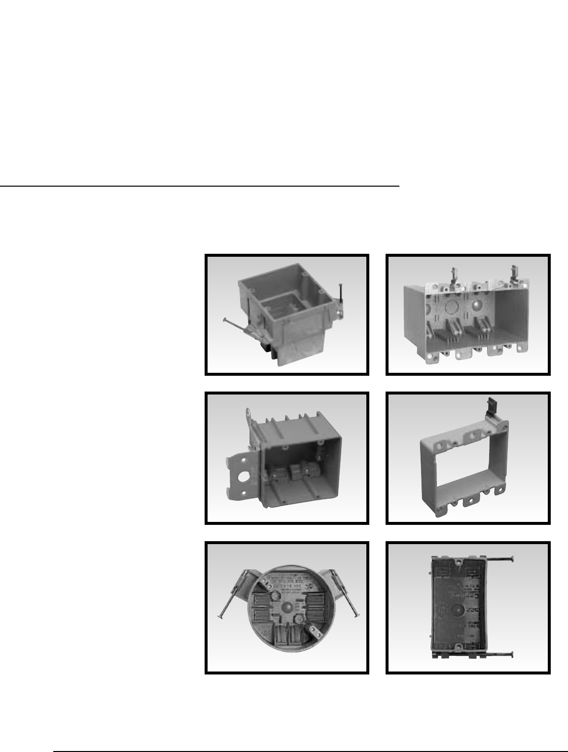
www.carlon.com 69
Adjustable
Single Gang
2, 3, 4 Gang
Old Work
Ceiling Boxes
SuperBlue
™
Covers
Carlon
®
Zip Box
®
Blue™
Switch and Outlet Boxes

www.carlon.com
70
Zip Box®Blue™Switch and Outlet Boxes
CarIon
®
Zip Box
®
Blue™
nonmetallic switch and outlet boxes – the contractor’s choice for easy
installation. Carlon has long been the leader with the world’s broadest line of nonmetallic, nonconductive wiring
management products designed for easier installation, greater performance, and lower installation cost. And that
includes our full line of Zip Box®Blue™nonmetallic switch and outlet boxes. Designed for use with nonmetallic
sheathed cable in accordance with Article 314 of the National Electrical Code®, they make fast work of any residential
or light commercial application. Take a closer look, and you’ll see more reasons why they’re the right choice for you.
Features
•UL Listed, File No. E42728, for use as indicated in
Article 314 of the NEC.
•UL Classified for fire resistance, File No. R8326.
Reference UL Electrical Construction Equipment
Directory,in product category QBWY or the UL
Fire Resistance Directory, for two-hours or less
classification period.
•UL Classified for fire resistance Category CEYY, in a two-
hour fire resistive wall within the same partition cavity on
opposite sides of the wall. Requires the use of mineral wool
batt insulation on putty pad when separation is less than 24".
•Refer to International Building Code Section 712.3.2 Exception
2for other separation options in fire resistive wall assemblies.
•UL Classified Report, File No. R8326, covers use in two-hour
or less fire resistive wall and floor-ceiling assembly.
Understanding Zip Box
®
Blue™Part Numbers
First Second Third Fourth Fourth or Sixth
Position Position Position Position Fifth Position Position
()
B-Zip Box Gang Size Available cubic inches Securing Methods Grounding Features
BH-SuperBlue 1,2,3, or 4 (ml) within the box
and/or and/or
For Example:
B 1 1 8
A
(B=Zip Box Blue, 1=single gang, 18 =cubic inch (295 ml) capacity, A=Nail On.)
A=Nail On
B=3/8" – 5/8"
(9.5mm – 15.9mm)
Wallboard Bracket for
Wood or Steel Studs
H=14 1/4" – 23 1/2"
(362mm – 596.9mm)
Adjustable Bar Hanger
K=18 1/4" – 26 3/4"
(463.6mm – 679.5mm)
Adjustable Bar Hanger
L=Metal “L” Bracket for Ceilings
P=Standard Nail On Box
w/ Grounding Lug
R=Old Work Box, includes
Integral Clamps
S=Screw On
G=Grounding Lug
included
P=Grounding Lug
included
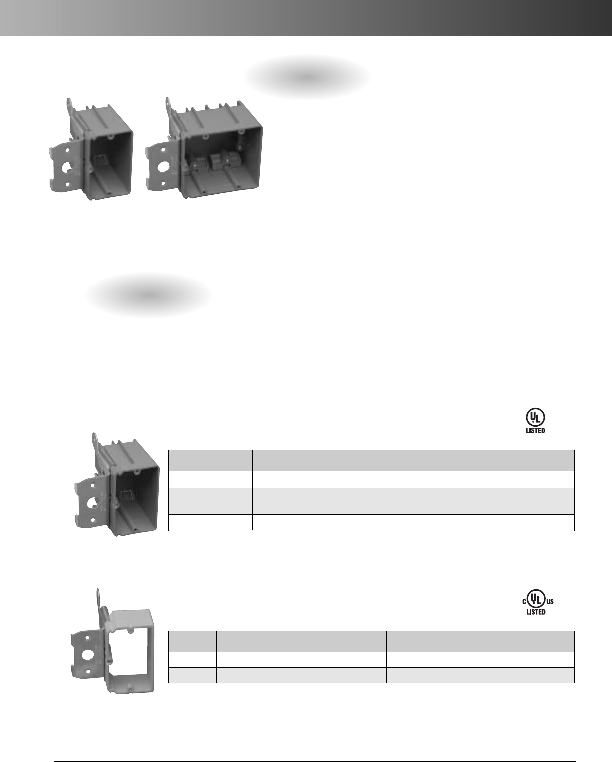
www.carlon.com 71
Adjust-A-Box™Adjustable Zip Boxes and Brackets
The Carlon Adjust-A-Box
features a patented
design that allows the box to be adjusted to most wall thicknesses
with the turn of a screw. To install, simply clip the bracket onto the
stud, secure with two screws to ensure the box won’t move, then turn
the adjustment screw clockwise or counterclockwise, and adjust the
box flush with the wall covering.
The Adjust-A-Box is available in one- and two-gang versions, and
by removing the box from the bracket the one-gang can easily be
upgraded to a two-gang, an ideal feature for old work applications.
The Carlon Adjust-A-Box achieves professional results every time.
Features
•Adjusts to any wall thickness
•Ideal for new work or retrofit applications
•Available in backed box or backless bracket
designer
•One- and two-gang versions
•Upgrades made easy
•Nonmetallic and durable
•UL Listed
•Meets NEMA OS-2
• 13/4"Adjustability
High Voltage
Volume Std. Ctn. Std. Ctn.
Part No. (cu. in.) Description Size Qty. Wt. (lbs.)
B121ADJ 21 Single Gang Adjustable Wall Box 3 7/8"W x3
3/4"H x3
3/8"D 24 10
B234ADJC 34 Double Gang Adjustable Wall Box 5 5/8"W x35/8"H x3"D 16 8.5
w/ Range Knockout
B234ADJ 34 Double Gang Adjustable Wall Box 5 5/8"W x 3 5/8"H x 3"D 16 8.5
Low Voltage
Std. Ctn. Std. Ctn.
Part No. Description Size Qty. Wt. (lbs.)
SC100ADJC Single Gang Adjustable Backless Bracket 3 7/8"W x33/4"H 24 7.5
SC100ADJC Double Gang Adjustable Backless Bracket 5 5/8"W x 3 5/8"H 20 6.9
E42728
E216492
B121ADJ
SC100ADJC
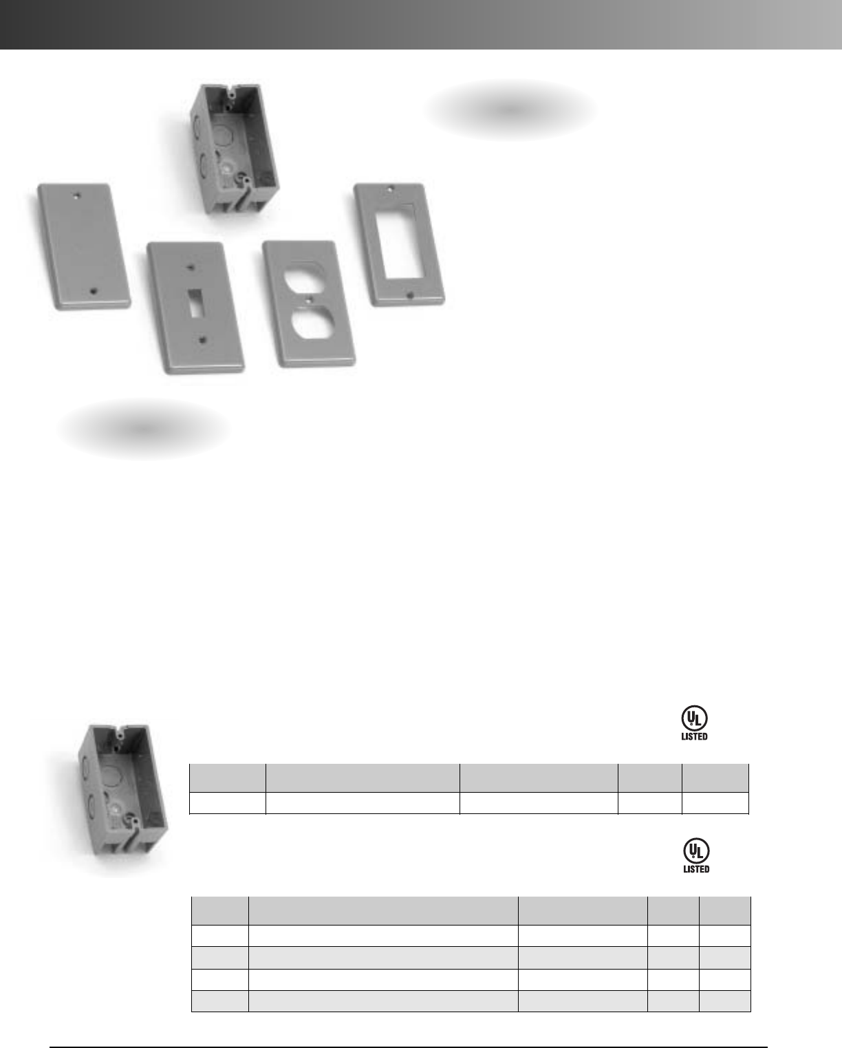
www.carlon.com
72
Handy Box and Covers
Features
• Flexible, can be used for many applications
• Thermoplastic construction that will not rust or
conduct electricity
• Built in cable clamps to hold wire firmly in place
• Six knockouts for easier wiring
• Four cover styles – blank, toggle switch, duplex
receptacle,and GFCI
•UL Listed (E42728) and two hour fire classified
for walls and ceilings
The Carlon Handy Box
is a non-
metallic switch and outlet box specifically designed
for use with nonmetallic conduit systems and
nonmetallic sheathed cabling.
Unlike metal boxes, the Carlon Handy Box has two
integral cable clamps. These clamps hold nonmetallic
cable firmly in place without the need for separate
clamps... simply push the wire into the clamp-opening,
and the cable is held securely in place. The Carlon
Handy Box also comes with six 1/2"knockouts on the
sides and back for easier wiring and a variety of
mounting options.
The Carlon Handy Box is constructed out of a
thermoplastic material, which resists rust and corrosion.
The Carlon Handy Box can be used with most wiring
devices including ground fault circuit interrupters
(GFCI). The Handy Box is designed to accept standard
metal covers or the NEW Carlon nonmetallic Handy
Box covers.
The Carlon Handy Box covers are made from a
durable polycarbonate material for extra strength and
durability. They’re available in four styles including a
duplex receptacle,toggle switch, ground fault circuit
interrupter (GFCI), and a blank cover (the blank cover
has a molded-in 1/2" knockout in the center).
Corrosion resistant stainless screws are provided with
each cover.
Box
Std. Ctn. Std. Ctn.
Part No. Description Size Qty. Wt. (lbs.)
B112HB Handy Box – Single Gang 1 7/8"x4" x21/8" 50 10.96
E42728
Covers
Std. Ctn. Std. Ctn.
Part No. Description Size Qty. Wt. (lbs.)
HB1BL Single Gang Nonmetallic Cover – Blank .25" x4.30" x2.38" 25 1.0
HB1SW Single Gang Nonmetallic Cover – Toggle Switch .25" x4.30" x2.38" 25 1.0
HB1DP Single Gang Nonmetallic Cover – Duplex Receptacle .25" x4.30" x2.38" 25 1.0
HB1GF Single Gang Nonmetallic Cover – GFCI Cover .25" x4.30" x2.38" 25 1.0
E42728
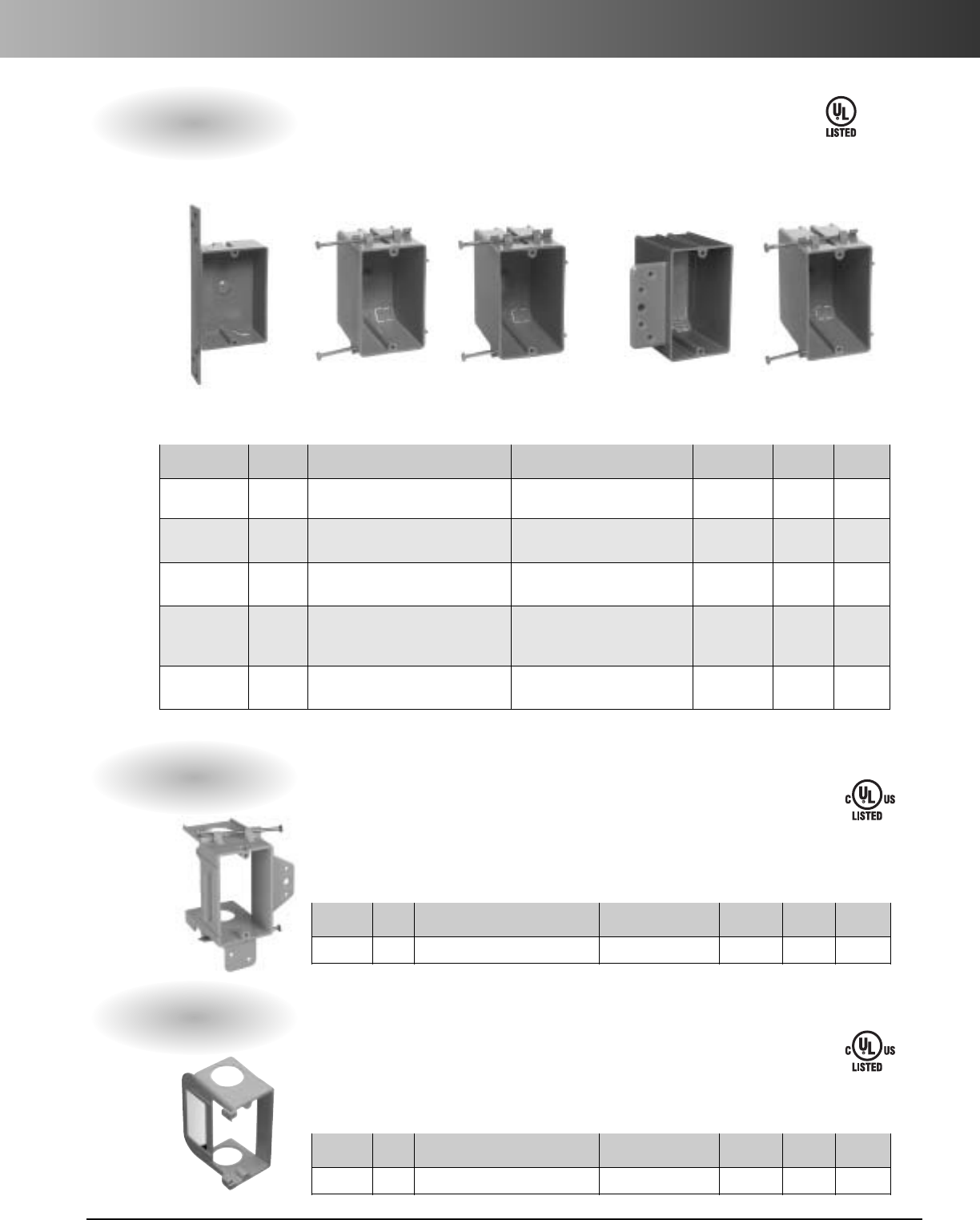
www.carlon.com 73
Single Gang Switch/Outlet Boxes – Nonmetallic
Switch/Outlet Boxes
E42728
Volume Std. Ctn. Std. Ctn.
Part No. (cu. in.) Description Size Knockouts Qty. Wt. (lbs.)
B108B-UPC 8 Single Gang Bracketed Shallow Box 1 1/4"D x23/8"W x35/8"L – 25 3
•B118A 18 Single Gang with captive nails 2 7/8"D x 2 1/4"W x 3 3/4"L 4 100 22
(2 each end)
•B120A-UPC 20 Single Gang with captive nails 3 1/4"D x 2 1/4"W x 3 7/8"L 4 100 24
(2 each end)
•B118B-UPC 18 Single Gang with bracket for 3/8"2
15/16"D x 2 1/4"W x 3 3/4"L 4 50 10
to 5/8"wallboard – steel & wood (2 each end)
stud mounting
•B122A-UPC 22 Single Gang with captive nails 31/2"D x21/4"W x33/4"L 4 100 25
(2 each end)
Vol. Std. Ctn. Std. Ctn.
Part No.cu. in. Description Size Knockouts Qty. Wt. (lbs.)
SC100A – Single Gang Backless Bracket 2.32" W x3.73"L – 24 7.5
Vol. Std. Ctn. Std. Ctn.
Part No.cu. in. Description Size Knockouts Qty. Wt. (lbs.)
SC100SC – Single Gang Add-On Bracket 1.80" W x3.68"L – 24 2.3
Low Voltage Backless Bracket
This low voltage bracket provides a low voltage outlet next to a previously
installed high voltage outlet. Great for both new construction and rework, it
attaches easily to most electrical boxes,and is designed to fit a standard two-
gang faceplate.Resi-Rings accept 3/4"Resi-Gard only
E216492
E216492
B108B-UPC B118A B120A-UPC B118B-UPC B122A-UPC
Open-backed to easily accommodate the bend radiuses required for low voltage
cabling and deep devices such as volume controls,and is designed to fit a standard
one-gang faceplate. It also features an easy nail-on mounting or screw-in bracket,
while the hard shell provides increased durability and no racking. Resi-Rings accept
3/4", 1", and 11/4"Resi-Gard.
Low Voltage Add-On Bracket
•Suitable for masonry walls
Single Gang
•Meets NEMA OS-2
•UL Listed to UL 514C
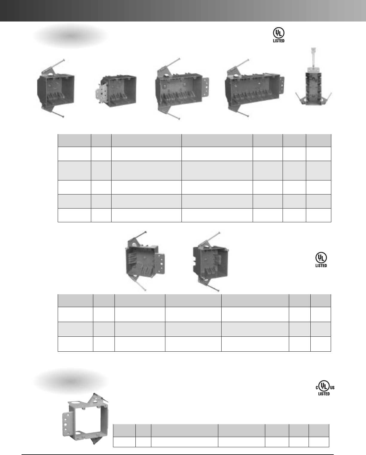
www.carlon.com
74
2-, 3-, 4-Gang and 4" Square Switch/Outlet Boxes – Nonmetallic
Switch/Outlet Boxes
E42728
Volume Integral Std. Ctn. Std. Ctn.
Part No. (cu. in.) Description Size Clamps Qty. Wt. (lbs.)
•B232A-UPC 32 Two Gang with captive nails 3"D x 4"W x 3 3/4"L 8 50 16
(4 each side)
B232B-UPC 32 Two Gang with bracket for 3"D x 4"W x 3 3/4"L 8 50 20
3/8"to 5/8"wallboard – steel (4 each side)
or wood stud mounting
•B344AB 44 Three Gang with captive nails 2 11/16"D x 3 3/4"W x 5 5/8"L 12 30 14
and bracket support (6 each side)
•B455A-UPC 55 Four Gang with captive nails 2 1/2"D x 3 7/10"W x 7 3/5"L 16 25 14
and bracket support (8 each side)
•B455AH 55
Four Gang with captive nails,
21/2"D x 3 7/10"W x 7 3/5"L 16 25 18
bracket support, and Hanger Bar
(8 each side)
Volume Std. Ctn. Std. Ctn.
Part No. (cu. in.) Description Size Integral Clamps Qty. Wt. (lbs.)
•B418A-UPC 18 Four Square 1 5/8"D x 4"W x 4"L 10 75 19
with captive nails (3 top, 3 bottom, 2 each side)
•B432A-UPC 32 Four Square 25/8"D x 4"W x 4"L 10 50 16
with captive nails (3 top, 3 bottom, 2 each side)
•B432AR-UPC 32 Four Square 25/8"D x 4"W x 4"L 10 83
with captive nails (3 top,3bottom, 2 each side)
B418A-UPC B432A-UPC
Low Voltage Backless Bracket
E216492
Open-backed to easily accommodate the bend radiuses required for low voltage cabling
and deep devices such as volume controls,and is designed to fit a standard two-gang
faceplate. It also features an easy nail-on mounting or screw-in bracket, while more hard
shell provides increased durability and no racking. Accepts 3/4"Resi-Gard only.
Two-Gang Three-Gang Four-Gang
4" Square
•Suitable for masonry walls
•Suitable for masonry walls
Vol. Std. Ctn. Std. Ctn.
Part No.cu. in. Description Size Knockouts Qty. Wt. (lbs.)
SC200A –Two Gang Backless Bracket 5.35" W x3.81"L – 24 7.7
•Meets NEMA OS-2
•UL Listed to UL 514C
B232A-UPC B232B-UPC B344AB B455A-UPC B455AH
E42728
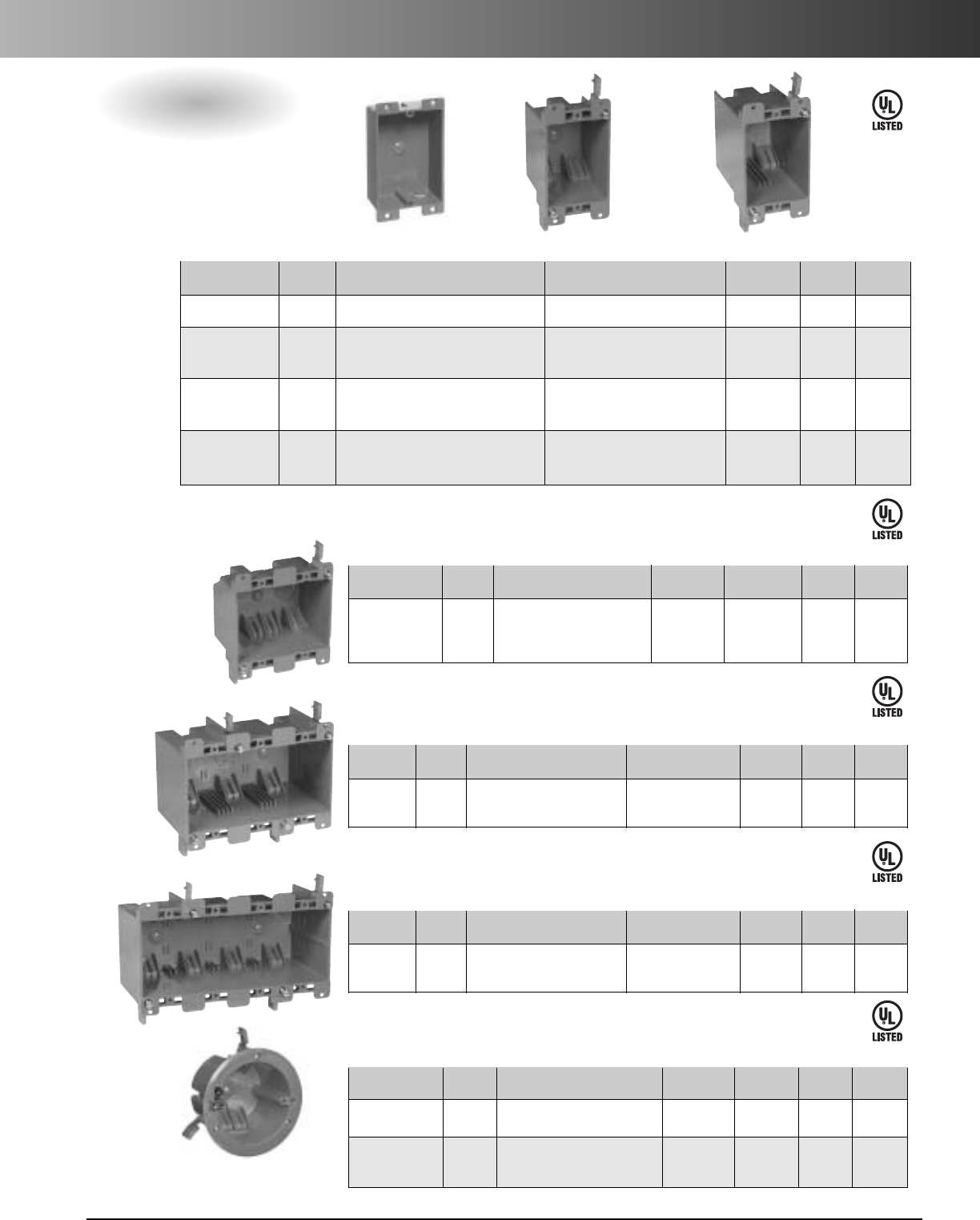
www.carlon.com 75
Old Work Switch/Outlet Boxes – Nonmetallic
Old Work Boxes
E42728
E42728
E42728
E42728
Volume Integral Std. Ctn. Std. Ctn.
Part No. (cu. in.) Description Size Clamps Qty. Wt. (lbs.)
†B108R-UPC 8 Single Gang Flanged Shallow Box 1 1/4"D x 2 3/8"W x 3 5/8"L – 25 3
•†B114R-UPC 14 Single Gang Old Work Wall Case 2 3/4"Dx2
1/4"Wx4
1/8"L 4 50 10
2Zip-Mount™retainers and
(2 each end)
mounting ears
•†B114RR-UPC 14 Single Gang Old Work Wall Case 2 3/4"D x 2 1/4"W x 4 1/8"L 4 25 5
2Zip-Mount™retainers and
(2 each end)
mounting ears
•†B120R 20 Single Gang with captive nails 3 5/8"D x 2 5/16"W x 4 1/8"L 4 50 12
2Zip-Mount™retainers and
(2 each end)
mounting ears
B108R-UPC B114R-UPC B120R
•Suitable for masonry walls
†Not UL Classified for Fire Resistance
One-Gang
Volume Integral Std. Ctn. Std. Ctn.
Part No. (cu. in.) Description Size Clamps Qty. Wt. (lbs.)
•†B225R-UPC 25 Two-Gang Old Work Case 2 3/4"D x 6 30 8
2Zip-Mount™retainers 3 1/8"W x
(3 each side)
and mounting flanges 3 15/16"L
•Suitable for masonry walls
†Not UL Classified for Fire Resistance
Two-Gang
Volume Integral Std. Ctn. Std. Ctn.
Part No. (cu. in.) Description Size Clamps Qty. Wt. (lbs.)
•†B355R 55 Three Gang Old Work Box 3.69"D x 6 6 3
with mounting ears 2.79"W x 5.72"L
•Suitable for masonry walls
†Not UL Classified for Fire Resistance
Three-Gang
E42728
Volume Integral Std. Ctn. Std. Ctn.
Part No. (cu. in.) Description Size Clamps Qty. Wt. (lbs.)
•†B468R 68 Four Gang Old Work Box 3.56"D x 8 6 4.03
with mounting ears 2.89"W x 7.57"L
•Suitable for masonry walls
†Not UL Classified for Fire Resistance
Four-Gang
Volume Integral Std. Ctn. Std. Ctn.
Part No.(cu. in.) Description Size Clamps Qty. Wt. (lbs.)
†B618R-UPC 18 Round Old Work Case 41/4"Dia. 4100 24
3Zip-Mount™retainers
†B618RP-UPC 18 Round Old Work Case 4 1/4"Dia. 4 100 26
3Zip-Mount™retainers
& Ground Lug
†Not UL Classified for Fire Resistance or used for Fixture Support in the Ceiling.
Round Old Work Box
•Meets NEMA OS-2
•UL Listed to UL 514C
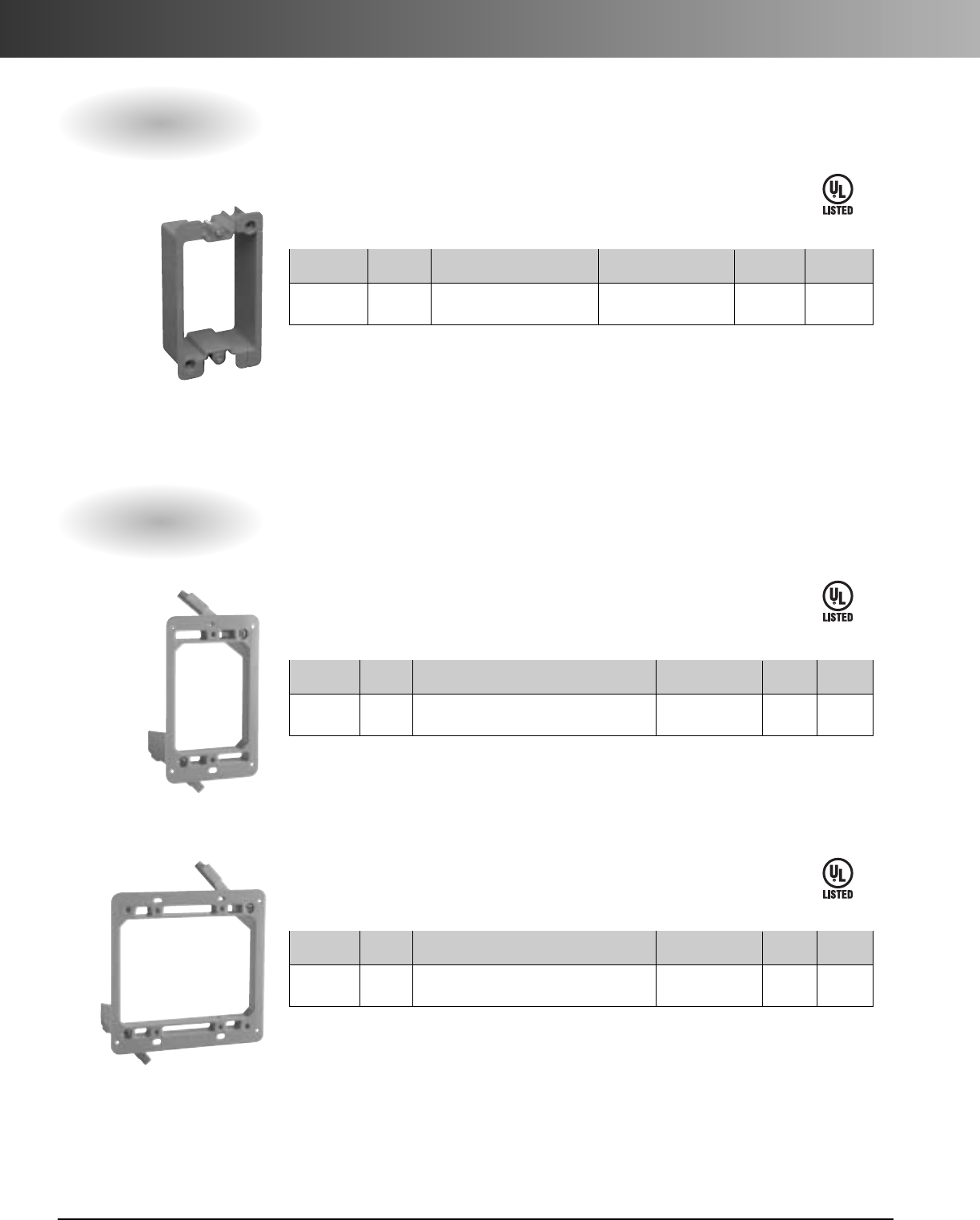
www.carlon.com
76
Old Work Switch/Outlet Boxes – Nonmetallic
E42728
E216492
E216492
Old Work Backless Brackets
Volume Std. Ctn. Std. Ctn.
Part No. (cu. in.) Description Size Qty. Wt. (lbs.)
B1EXTB N/A Single Gang Box Extender 2 1/4"x 3 1/4"25 3
Box Extender
Low Voltage Old Work Brackets
Volume Std. Ctn. Std. Ctn.
Part No. (cu. in.) Description Size Qty. Wt. (lbs.)
†SC100RR N/A Single Gang Backless Old Work Bracket 2 1/4" x 3 1/4" 12 1.4
†Not UL Classified for Fire Resistance
Single Gang
Volume Std. Ctn. Std. Ctn.
Part No. (cu. in.) Description Size Qty. Wt. (lbs.)
†SC200RR N/A Two-Gang Backless Old Work Bracket 3.92" x 4.00" 6 .9
†Not UL Classified for Fire Resistance
Two-Gang
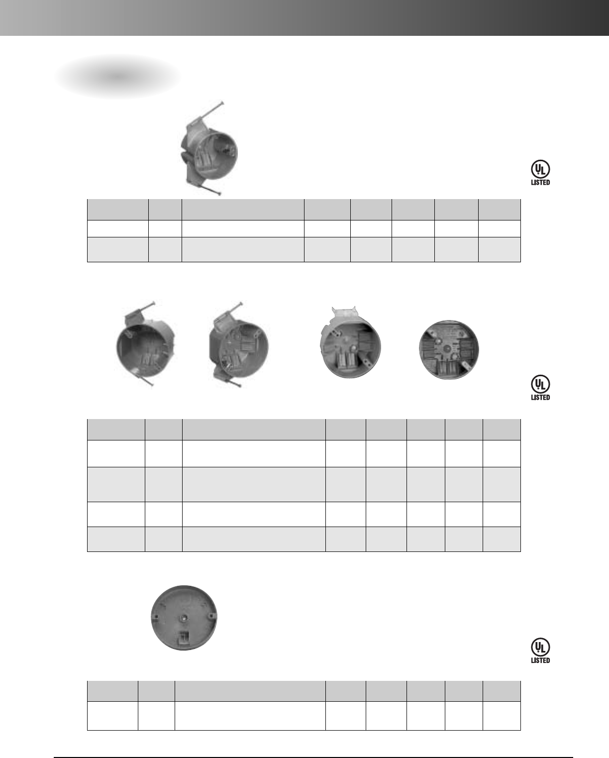
www.carlon.com 77
Ceiling Boxes – Nonmetallic
Ceiling Boxes
All ceiling boxes are produced from a high heat-resistant material
developed specifically for fixture support applications.
E42728
E42728
E42728
Volume Integral Std. Ctn. Std. Ctn.
Part No. (cu. in.) Description Diameter Depth Clamps Qty. Wt. (lbs.)
•B518A-UPC 18 Ceiling Box with captive nails 3" 2 3/4"4 75 19
•B518P-UPC 18 Ceiling Box with captive nails 3" 2 3/4"4 75 20
Ground lug and screw attached
•Listed for fixture support up to 50 lbs.
3/0
B518P-UPC
Volume Integral Std. Ctn. Std. Ctn.
Part No. (cu. in.) Description Diameter Depth Clamps Qty. Wt. (lbs.)
•B520A-UPC 20 Ceiling Box with captive nails 4" 2 1/4" 6 75 18
Fixture spacing for 2 3/4"and 3"
•B520P-UPC 20 Ceiling Box with captive nails 4" 2 1/4" 6 75 18
Ground lug and screw attached
Fixture spacing for 2 3/4"and 3 1/2"
•B620L-UPC 20 Ceiling Box with metal L bracket 4" 21/4"6100 31
Fixture spacing for 2 3/4"and 3 1/2"
•B720-SHK 20 Ceiling Box Outlet Box 4" 2 1/4"6 18 5
with mounting screws
•Listed for fixture support up to 50 lbs.
3/0 - 4/0 Combination
B520A-UPC B520P-UPC B620L-UPC B720-SHK
35 lbs. maximum fan weight
Volume Integral Std. Ctn. Std. Ctn.
Part No. (cu. in.) Description Diameter Depth Clamps Qty. Wt. (lbs.)
•B708-SHK 8Shallow Ceiling Fan Outlet Box 4" 5/8"118 3
with mounting screws
•Listed for fixture support up to 50 lbs.
4/0
35 lbs. maximum fan weight
•Meets NEMA OS-2
•UL Listed to UL 514C
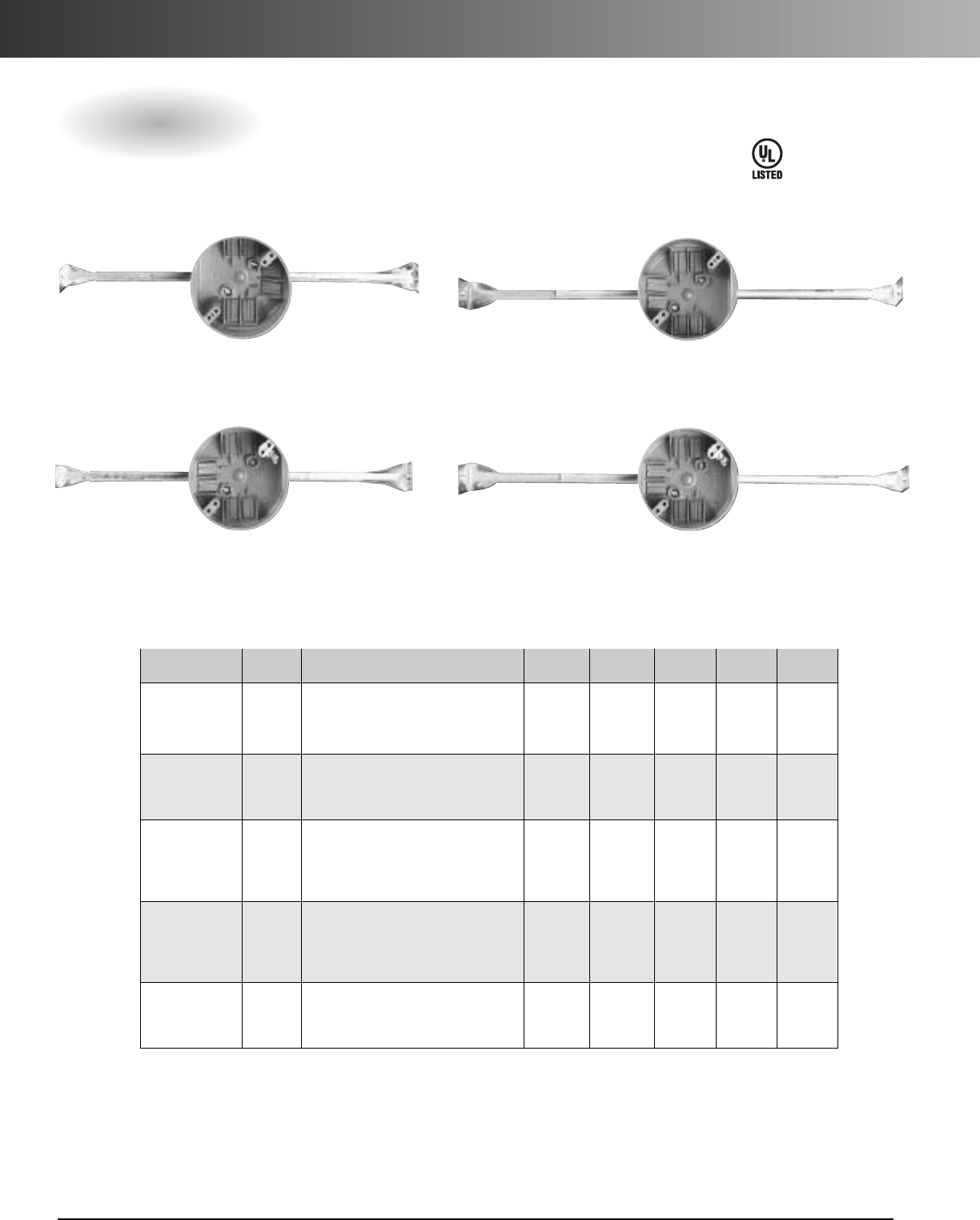
www.carlon.com
78
Ceiling Boxes – Nonmetallic
E42728
Ceiling Boxes with Bar Hanger
Volume Integral Std. Ctn. Std. Ctn.
Part No. (cu. in.) Description Diameter Depth Clamps Qty. Wt. (lbs.)
•B620H-UPC 20 Ceiling Box with 141/4" - 231/2"4" 2 1/4" 6 75 43
adjustable bar hanger
Fixture spacing for 23/4"and 31/2"
•B620K 20 Ceiling Box with 18 1/4" - 26 3/4"4" 2 1/4" 6 75 46
adjustable bar hanger
Fixture spacing for 23/4"and 31/2"
•B620HG-UPC 20 Ceiling Box with 141/4" - 231/2"4" 2 1/4"6 75 44
adjustable bar hanger
Ground lug and screw attached
Fixture spacing for 23/4"and 31/2"
•B620KG-UPC 20 Ceiling Box with 18 1/4" - 26 3/4"4" 2 1/4" 6 75 46
adjustable bar hanger
Ground lug and screw attached
Fixture spacing for 23/4"and 31/2"
•B620DC 20 Ceiling Box with 24" 4" 2 1/4" 6 16 10
T-Grid bar hanger
Fixture spacing for 23/4"and 31/2"
•Listed for fixture support up to 50 lbs.
3/0 - 4/0 Combination
B620H-UPC B620K
B620HG-UPC B620KG-UPC
•Meets NEMA OS-2
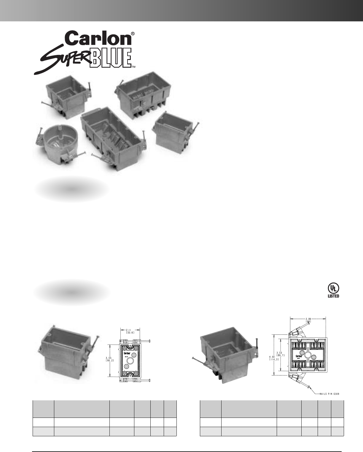
www.carlon.com 79
SuperBlue™Hard Shell Switch/Outlet Boxes – Nonmetallic
Wall Boxes
Two Gang
Single Gang
Std. Std.
Part Ctn. Ctn.
No. Description Capacity Depth Qty. Wt.
BH122A Single Gang 22 cu. in. 3.63 100 31.3
BH122S Single Gang with Screws 22 cu. in. 3.63 100 31.3
Std. Std.
Part Ctn. Ctn.
No. Description Capacity Depth Qty. Wt.
BH235A Two Gang 35 cu. in. 3.50 48 21.3
BH235S Two Gang with Screws 35 cu. in. 3.50 48 21.3
The Carlon®SuperBlue™Hard Shell Boxes
combine the features of the hard shell thermoset
box and the thermoplastic PVC style box to create
a“new” rigid nonmetallic wiring box. Molded out
of specially formulated thermoplastic material,
Carlon SuperBlue boxes are so strong they won’t
crack or break, even in extreme environments. So
rigid, they resist flexing and hold their shape even
under the worst conditions.
They provide the largest wirefill capacity in their
class, and come with molded-in nailing flanges as
well as molded-in clamps to make installation
faster. Carlon SuperBlue boxes are lightweight,
noncorrosive and nonconductive. They are
designed to nest inside one another so they take
up less shelf space and are easier to transport to
job sites.
•Lightweight
•Noncorrosive and nonconductive
• Nest inside one another
• UL Listed to UL 514C
• UL Classified for two hour or
less fire wall assemblies
• Meets NEMA OS-2
E42728
Features
•Largest wirefill capacity in
their class
• Won’t crack or break in
extreme environments
• Resist flexing
• Hold their shape
• Molded-in flanges and clamps
• Faster installation
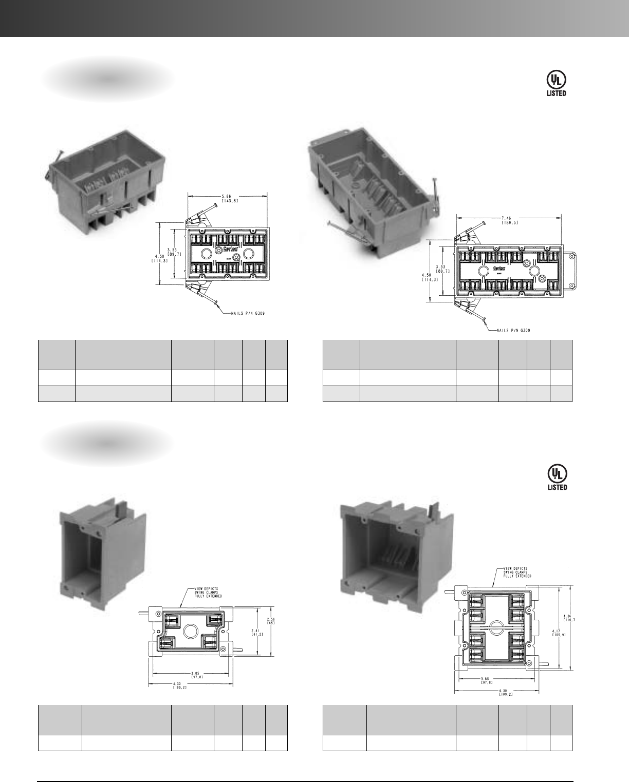
www.carlon.com
80
SuperBlue™Hard Shell Switch/Outlet Boxes – Nonmetallic
Three Gang Four Gang
Single Gang Old Work Two Gang Old Work
Wall Boxes
Old Work Boxes
E42728
E42728
Std. Std.
Part Ctn. Ctn.
No. Description Capacity Depth Qty. Wt.
BH353A Three Gang 53 cu. in. 3.50 24 14.0
BH353S Three Gang with Screws 53 cu. in. 3.50 24 14.0
Std. Std.
Part Ctn. Ctn.
No. Description Capacity Depth Qty. Wt.
BH464A Four Gang 64 cu. in. 3.18 24 17.4
BH464S Four Gang with Screws 64 cu. in. 3.18 24 17.4
Std. Std.
Part Ctn. Ctn.
No. Description Capacity Depth Qty. Wt.
†BH118R Single Gang Old Work 18 cu. in. 3.64 36 10.9
†Not UL Classified for Fire Resistance
Std. Std.
Part Ctn. Ctn.
No. Description Capacity Depth Qty. Wt.
†BH234R Two Gang Old Work 34 cu. in. 3.59 18 7.71
†Not UL Classified for Fire Resistance
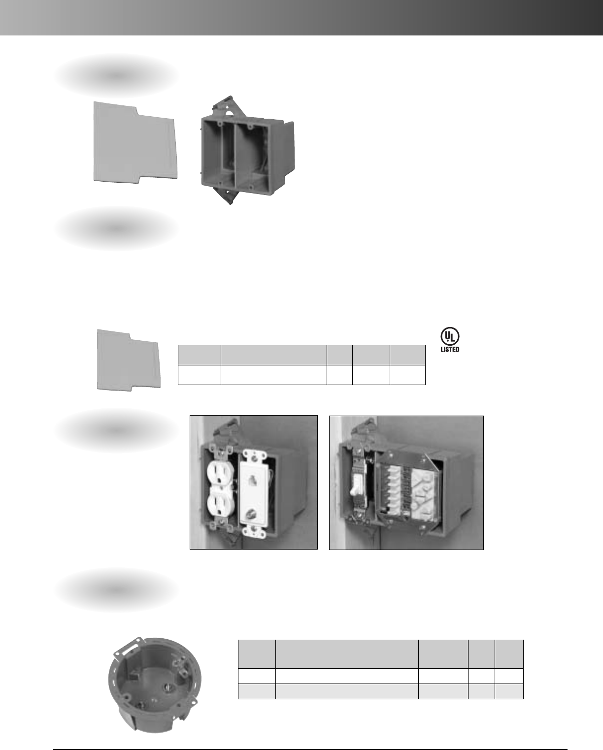
www.carlon.com 81
SuperBlue™Low Voltage Divider Plate
Low Voltage Divider Plate
Carlon SuperBlue boxes are easily divided into both high
and low voltage use. Just insert the Low Voltage Divider
Plate, and you’re ready to go!
The National Electrical Code allows electrical
conductors to share an outlet box when the
conductors and signaling or communication
cables are separated by a barrier within the box.
Features
Installation
•Transforms a high voltage box into an accepted
high and low voltage box
•Orange color signifies low voltage installations
•Designed to be used with Carlon’s 2-, 3-, and
4- gang SuperBlue Boxes
•UL Listed
•Noncorrosive and nonconductive
•Great for situations requiring a high/low voltage
fire-classified box
Part Std. Ctn. Std. Ctn.
No. Description cu. in. Qty. Wt.
SCDIV Low Voltage Divider Plate - 50 2.2
E42728
Ceiling Box
3/0 Round Old Work Box
Std. Std.
Part Ctn. Ctn.
No. Description Capacity Qty. Wt.
BH614R 3/0 Round Old Work Box 14 cu. in. 20 5.0
BH614RP Four Gang with Screws w/Ground Lug 14 cu. in. 20 5.0
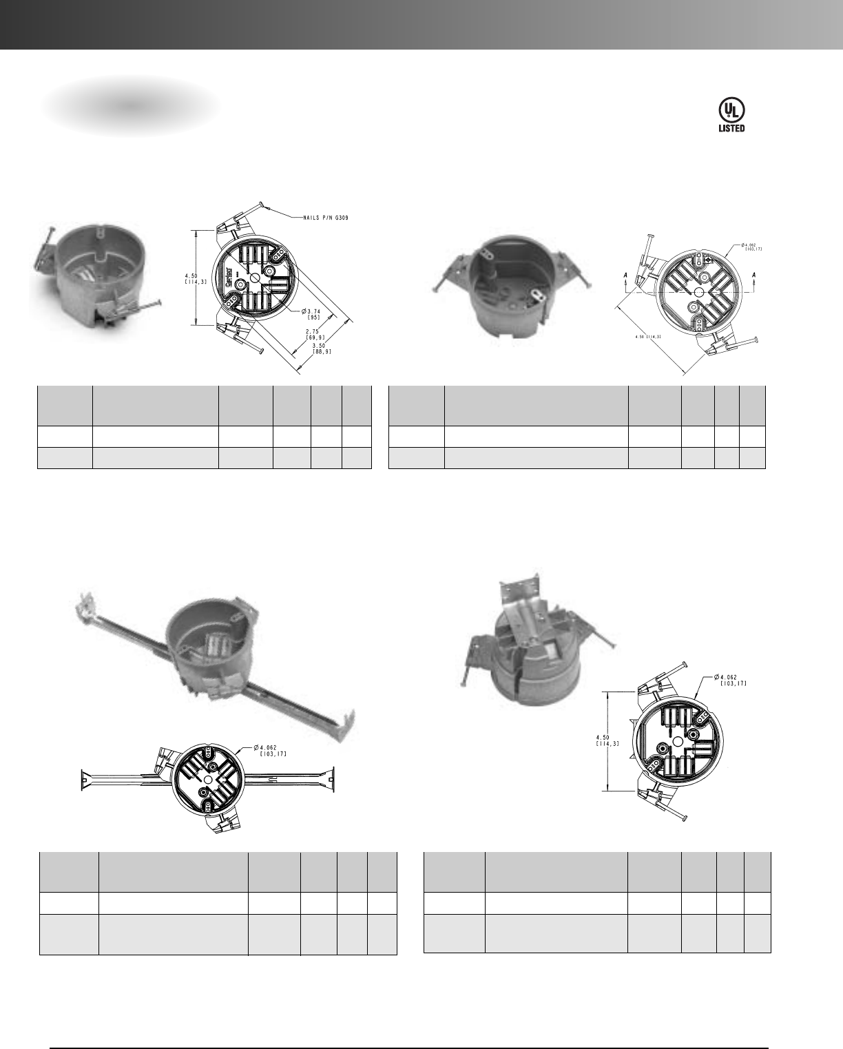
www.carlon.com
82
SuperBlue™Ceiling Boxes –Nonmetallic
3/0 - 4/0 Combination Ceiling Boxes
Ceiling Box Ceiling Box with Grounding Lug
Ceiling Box with Hanger Bar
*Hanger Bar adjusts from 11 1/2"to 18 1/2"Ceiling Fan Box
Std. Std.
Part Ctn. Ctn.
No. Description Capacity Depth Qty. Wt.
•BH525H Ceiling Box with Hanger Bar 25 cu. in. 2.95 20 13.2
•BH525HP Ceiling Box with Hanger Bar 25 cu. in. 2.95 20 13.2
with Grounding Lug
Std. Std.
Part Ctn. Ctn.
No. Description Capacity Depth Qty. Wt.
•BH525L Ceiling Fan Box with Nails 25 cu. in. 3.06 24 12.2
•BH525LP Ceiling Fan Box with 25 cu. in. 3.06 24 12.2
Grounding Lug with Nails
E42728
Std. Std.
Part Ctn. Ctn.
No. Description Capacity Depth Qty. Wt.
•BH525A Ceiling Box 25 cu. in. 3.00 48 16.3
•BH525S Ceiling Box with Screws 25 cu. in. 3.00 48 16.3
•Listed for fixture support up to 50 lbs.
Std. Std.
Part Ctn. Ctn.
No. Description Capacity Depth Qty. Wt.
•BH525P Ceiling Box with Grounding Lug 25 cu. in. 3.00 24 9.4
•BH525SP
Ceiling Box w/Grounding Lug w/Screws
25 cu. in. 3.00 24 9.4
•Listed for fixture support up to 50 lbs.
•Listed for fixture support up to 50 lbs. •Listed for fan support up to 35 lbs. and fixture support up to 50 lbs.
Listed for fan support up to 35 lbs.
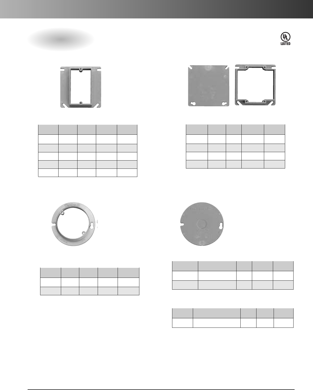
www.carlon.com 83
Switch/Outlet Covers –Nonmetallic
Covers
Cu. Std. Std. Ctn.
Part No. Rise in. Ctn. Qty. Wt. (lbs.)
A410 1/2" 3.5 100 8.0
A411 5/8" 4.2 50 6.0
A412 3/4" 5.0 50 6.0
A413 1" 6.6 40 5.0
A414 11/4" 8.1 30 5.0
Single-Gang – Covers
Cu. Std. Std. Ctn.
Part No. Rise in. Ctn. Qty. Wt. (lbs.)
A400 Blank – 100 9.0
A420 1/2" 6.1 75 6.0
A421 5/8" 7.4 50 4.2
A422 3/4" 8.8 50 4.8
Two-Gang – Covers
Vol. Std. Std. Ctn.
Part No. Rise (cu. in.) Ctn. Qty. Wt. (lbs.)
A471 1/2" 3.2 100 3.3
A472 5/8" 4.0 100 3.8
Round Plaster Ring
Listed for fixture support up to 50 lbs.
Vol. Std. Std. Ctn.
Part No.Rise (cu. in.) Ctn. Qty. Wt. (lbs.)
A470D Blank with 1/2"KO – 100 4.7
E460R-CAR Blank – 35 2.2
Round Blank Cover
Vol. Std. Std. Ctn.
Part No. Rise (cu. in.) Ctn. Qty. Wt. (lbs.)
CPC4 WH White Ceiling Box Cover – 12 1.3
Ceiling Box Cover – White
E42728
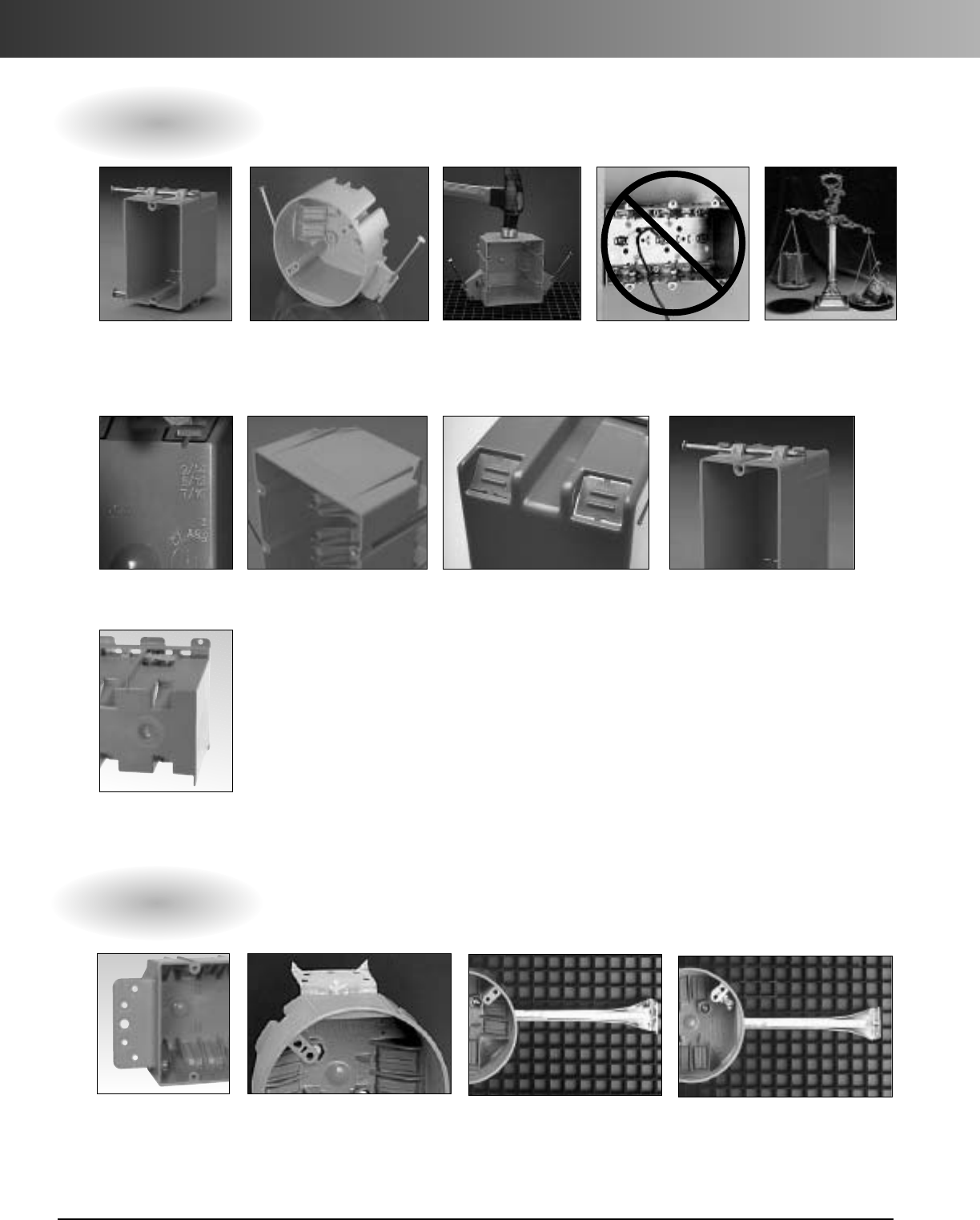
www.carlon.com
84
Zip Box
®
Features
Carlon Trademark
Blue Color Nonconductive...no
need to ground box LightweightCeiling boxes with
special engineered high
heat resistant material for
fixture support
High Impact
PVC Wall Boxes
Engraved NEC
Wire Fill Leveling Guides Clean Easy Knockout
(Single Gang Only) Pre-installed Angled Nails
Integral Clamps
(Multi-Gang Boxes)
General Features
Special Nail-on and Bracket Boxes
Type B Type L Type H Type K
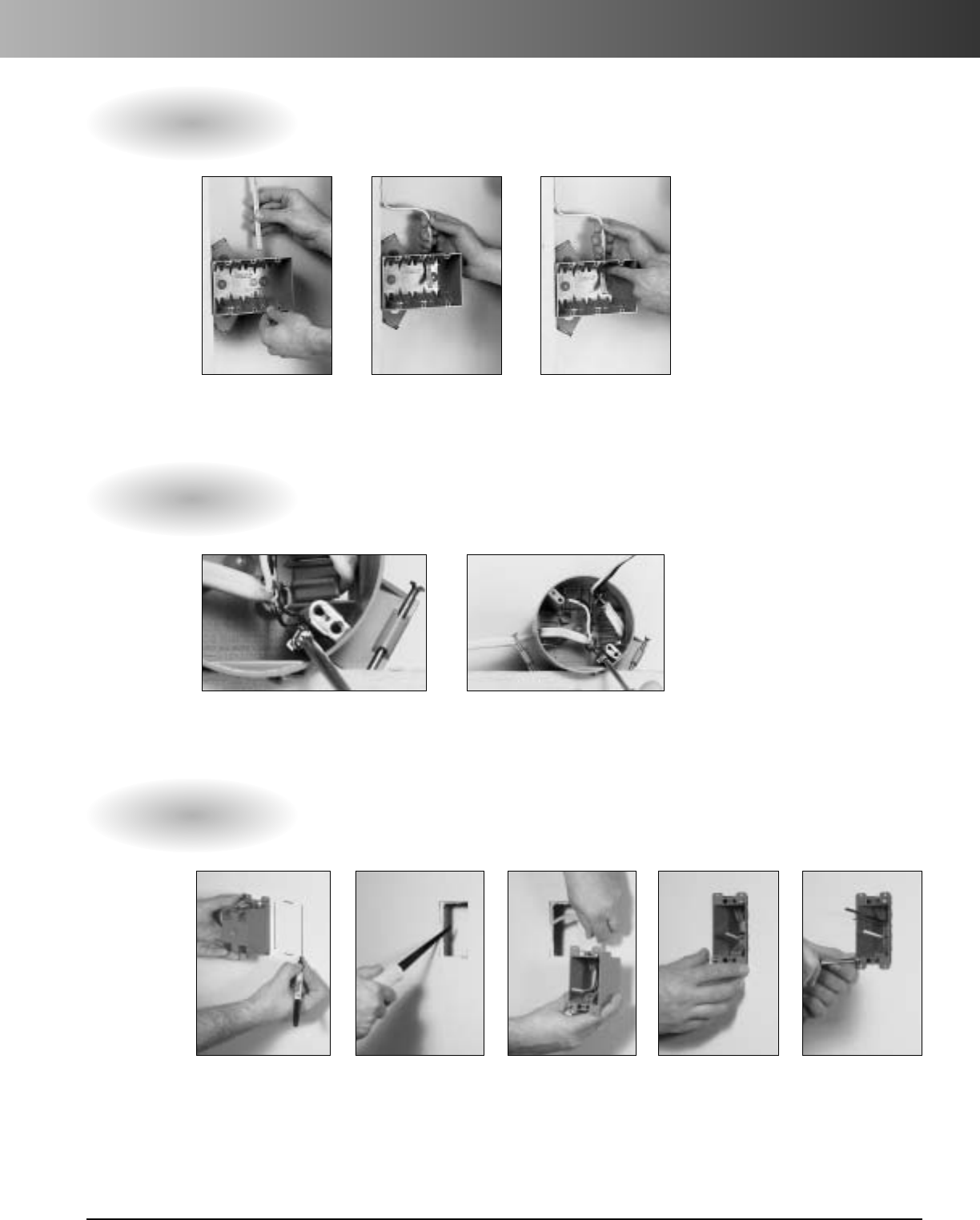
www.carlon.com 85
Zip Box
®
Installation
Zip Clamp™
Easy to wire, simply...
Grounding Lugs
(No need to ground box itself) Easy to wire...
Old Work Boxes
Easy to rework, simply...
Align Wire Push Through Secure Clamp
Pre-installed Lugs Make Grounding Connection
Trace Box Cut on Lines Place Box in Wall Secure Box in Wall
Insert Wires

www.carlon.com
86

Plenum-Gard
®
Riser-Gard
®
Hal-Free
Riser-Gard
®
General
Purpose
Carlon
®
Flexible
Raceway Systems
www.carlon.com 87
www.carlon.com
88
Plenum-Gard
®
Plenum-Gard isaUL Listed non-
metallic corrugated flexible conduit
for use in Plenum, Riser and General
Purpose applications.
Plenum-Gard is manufactured from
PVDF resin, which is extremely
durable and resistant to abrasion
and mechanical damage before/after
cable installation.
Plenum-Gard is listed to UL 2024 in
accordance with the National Electrical
Code for Plenum, Riser, General
Purpose, and other cabling optical fiber
/telecommunication applications as
defined in Articles 725, 770, 800 and 820.
Important: Installed cables must be
plenum rated and the UL Listing
must be printed on the product.
Abandoned cables MUST be
removed (Reference NEC).
UL Standard 2024 Value
Maximum Flame Propagation 5 ft.
Max. Peak Optical Smoke Density 0.5
Max. Average Optical Smoke Density 0.15
E151168
FT-6 Rated
Min. Reel Wt. per
Pull Size Reel Reel Wt. 100 ft.
Color Part No. Tape (F x W) Type Length (lbs.) (lbs.)
Orange CE4X1-1000 Empty 36" x 24" W 1000 35 8
Orange CE4X1-1000S Empty 36" x 24" W 1000 35 8
Orange CF4X1C-500 900 lb. 36" x 24" W 500 35 10
Orange CF4X1C-1000 900 lb. 48" x 32" W 1000 90 10
Orange CF4X1C-1500 900 lb. 48" x 32" W 1500 90 10
Orange CF4X1C-5200 900 lb. 66" x 41" W 5200 265 10
Orange CF4X1C-6500 900 lb. 72" x 41" W 6500 302 10
Orange CF4X1C-8000 900 lb. 82" x 41" W 8000 375 10
Orange CG4X1C-500 900 lb. 36" x 24" W 500 35 16
Orange CG4X1C-900 900 lb. 48" x 32" W 900 90 16
Orange CG4X1C-1600 900 lb. 48" x 46" W 1600 105 16
Orange CG4X1C-3200 900 lb. 66" x 41" W 3200 265 16
Orange CG4X1C-6500 900 lb. 96" x 41" W 6500 700 16
Orange CG4X1-900S Empty 48" x 32" W 900 90 16
Orange CH4X1C-350 900 lb. 48" x 32" W 350 90 20
Orange CH4X1C-1200 900 lb. 48" x 46" W 1200 105 20
Orange CH4X1C-4000 900 lb.82" x 41" W 4000 375 20
Orange CJ4X1C-225 900 lb.48" x 32" W 225 90 23
Orange CJ4X1C-700 900 lb. 48" x 46" W 700 105 23
Orange CJ4X1C-2000 900 lb. 82" x 41" W 2000 375 23
Orange CJ4X1C-2800 900 lb. 82" x 41" W 2800 375 23
1"
2"
11/4"
3/4"
11/2"
StandardStock – Reels
•Storage -4°F to 158°F
•Handling -4°F to 104°F
• No UV protection (not suitable for outdoor use)
• Do NOT store outside
W = Wood
Applications: Plenum, Riser,
and General Purpose
Technical Info:
NEW
1/2"& 3/4"
with tape
www.carlon.com 89
Plenum-Gard
®
Features:
Specifications
•For use in Plenum areas per
Articles 725, 770, 800 and 820.
•Sizes 1/2"through 2"
•Pre-installed pull tape available
insizes 1/2"through 2"
•Outside Diameters meet IPS
Dimensions
•UL Listed raceway meeting UL 2024
•Footage sequentially marked
•Single peak design
Custom Orders
How to Build a Part Number
Position 1 Position 2 Position 3 Position 4 Position 5 Position 6 Position 7
Product Size Configuration Wall Color Pull Line Length
C=Plenum-Gard D = 1/2"4=Corrugated X = Standard 1 = Orange C = 900 lb. Tape Example
E = 3/4" 2 = Black -1000 = Feet
F=1" 3 = Gray -1000S = 1000 Feet Split
G=11/4" 4 = White
H=11/2" 5 = Blue
J=2" 7 = Yellow
8 = Red
Pull Coil Wt. per
Color Part No. Tape Length (ft.) 100 ft. (lbs.)
Orange CE4X1-350* Empty 350 8
Orange CF4X1C-100* 900 lb. 100 10
Orange CF4X1C-250* 900 lb. 250 10
Orange CF4X1-250 Empty 250 10
Orange CF4X1-250S* Empty 250 10
Orange CG4X1C-200* 900 lb. 200 16
Orange CH4X1C-150* 900 lb. 150 20
Orange CJ4X1C-100* 900 lb. 100 23
Standard Stock – Coils
1"
2"
11/4"
3/4"
11/2"
* Overnight Shippable
I.D. Min. Max. Min. Bend
Size Min. Ref. O.D. O.D. Radius
1/2" .60 .815 .835 2"
3/4" .74 1.025 1.045 2"
1" 1.00 1.292 1.312 3"
11/4"1.35 1.630 1.650 3"
11/2"1.50 1.868 1.888 4"
2" 2.00 2.329 2.349 4"
•Custom Orders are not returnable
•Custom lengths are available in
minimum order quantities of 1000 ft.
•Custom color runs are available in
minimum order quantities of 10,000 ft.
Options:
•Color: Black, Blue, Gray, Red, White and Yellow
•Two,three, or four way parallel
•Split Duct
•Custom print line
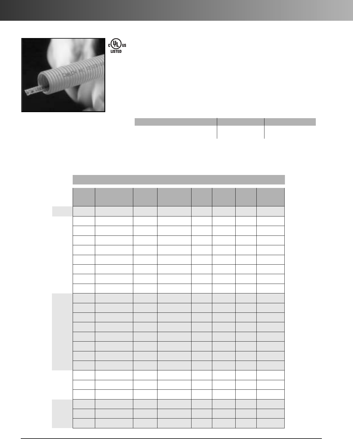
www.carlon.com
90
Riser-Gard
®
Riser-Gard is a nonmetallic
flexible raceway for use in Riser
and General Purpose applications.
Riser-Gard is UL Listed and is
available with tape pre-installed.
Riser-Gard is listed to UL 2024
Standard for Riser Applications
or optical fiber/communications
raceways.
UL Listed to 2024 Test Method Maximum Value
Maximum Flame Propagation UL 2024 6.0 ft.
Maximum Air Temperature at 12 ft. UL 2024 372°F
Reel Reel Product
Pull Size Reel Reel Wt. Wt. per
Color Part No. Tape (F x W) Type Length (lbs.) 100 ft. (lbs.)
Orange DE4X1-1000 Empty 36" x 24" W1000 35 9
Orange DF4X1C-500R 900 lb.42" x 24" W500 50 14
Orange DF4X1C-1000 900 lb.48" x 32" W1000 90 14
Orange DF4X1C-1500 900 lb. 48" x 32" W 1500 90 14
Orange DF4X1C-2700 900 lb. 48" x 46" W 2700 105 14
Orange DF4X1C-5200 900 lb. 66" x 41" W 5200 265 14
Orange DF4X1C-6500 900 lb. 72" x 41" W 6500 302 14
Orange DF4X1C-7000 900 lb. 72" x 45" S 7000 148 14
Orange DF4X1C-9400 900 lb. 84" x 45" S 9400 199 14
Orange DG4X1C-900 900 lb. 48" x 32" W 900 90 17
Orange DG4X1C-500R 900 lb. 42" x 24" W 500 50 17
Orange DG4X1C-1500 900 lb. 48" x 46" W 1500 105 17
Orange DG4X1C-1600 900 lb. 48" x 46" W 1600 105 17
Orange DG4X1C-3200 900 lb. 66" x 41" W 3200 265 17
Orange DG4X1C-4500 900 lb. 72" x 45" S 4500 148 17
Orange DG4X1C-5600 900 lb. 84" x 46" W 5600 600 17
Orange DG4X1C-6500 900 lb. 96" x 45" S 6500 220 17
Orange DH4X1C-1200 900 lb.48" x 46" W 1200 105 22
Orange DH4X1C-4000 900 lb. 82" x 45" S 4000 193 22
Orange DH4X1C-4500 900 lb.84" x 45" S 4500 199 22
Orange DJ4X1C-700 900 lb. 48" x 46" W 700 105 26
Orange DJ4X1C-2000 900 lb. 82" x 41" W 2000 375 26
Orange DJ4X1C-2800 900 lb. 84" x 45" S 2800 199 26
1"
2"
11/4"
3/4"
11/2"
StandardStock – Reels
•Storage -4°F to 158°F
•Handling -4°F to 104°F
• No UV protection (not suitable for outdoor use)
• Do NOT store outside
W = Wood, S = Steel
Riser-Gard is listed to UL 2024 in accor-
dance with the National Electrical Code per
Articles 725, 770, 800 and 820 for Riser,
General Purpose, and other cabling optical
fiber/telecommunication applications.
Riser-Gard is suitable for use in vertical
runs in a shaft or between floors, as well
as areas other than the plenum.
Important: Installed cables must be
of suitable rating for the application.
E151168
FT-4 Rated
Applications: Riser and General Purpose
Technical Info:
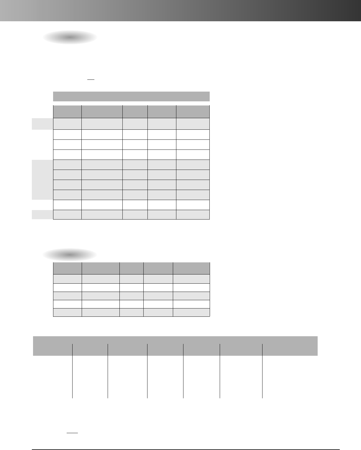
www.carlon.com 91
Riser-Gard
®
Features:
•For use in Riser and General Purpose areas per
Articles 725, 770, 800 and 820 of the NEC.
•Riser-Gard is also suitable for direct burial.
Not approved for exposed applications.
NOTE: UL has not evaluated Riser-Gard for this
application.
•UL Listed Raceway meeting UL 2024
•Available in sizes 3/4" through 2"
•Pull tape can be factory
pre-installed in 1" through 2"
•Outside Diameters meet IPS
Dimensions
•Footage sequentially marked
Custom Orders
How to Build a Part Number
Position 1 Position 2 Position 3 Position 4 Position 5 Position 6 Position 7
Product Size Configuration Wall Color Pull Line Length
D = Riser-Gard E = 3/4"4=Corrugated X=Standard 1=Orange C=900 lb.Tape Example
F=1" 2 = Black -1000 = Feet
G=11/4" 3 = Gray -1000S = 1000 Feet Split
H=11/2" 4 = White
J=2" 5 = Blue
7 = Yellow
8 = Red
Pull Coil Product Wt. per
Color Part No. Tape Length (ft.) 100 ft. (lbs.)
Orange DE4X1-350* Empty 350 9
Orange DF4X1C-250* 900 lb. 250 14
Orange DF4X1C-500 900 lb. 500 14
Orange DF4X1-250S* Empty 250 14
Orange DG4X1-200 Empty 200 17
Orange DG4X1C-200* 900 lb. 200 17
Orange DG4X1C-500 900 lb. 500 17
Orange DG4X1-200S* Empty 200 17
Orange DH4X1C-150* 900 lb. 150 22
Orange DJ4X1C-100* 900 lb.100 26
Standard Stock – Coils
1"
2"
11/4"
3/4"
11/2"
*Overnight Shippable
Specifications
I.D. Min. Max. Min. Bend
Size Min. Ref. O.D. O.D. Radius
3/4".74 1.025 1.075 6"
1" .98 1.290 1.340 6"
11/4"1.31 1.640 1.690 7"
11/2" 1.54 1.880 1.930 8 1/4"
2" 2.00 2.350 2.400 9 1/2"
•Custom Orders are not returnable
•Custom lengths are available in
minimum order quantities of 1000 ft.
•Custom color runs are available in
minimum order quantities of 10,000 ft.
Options:
•Color: Black, Blue, Gray, Red, White and Yellow
•Two, three, or four way parallel
•Split Duct
•Custom print line
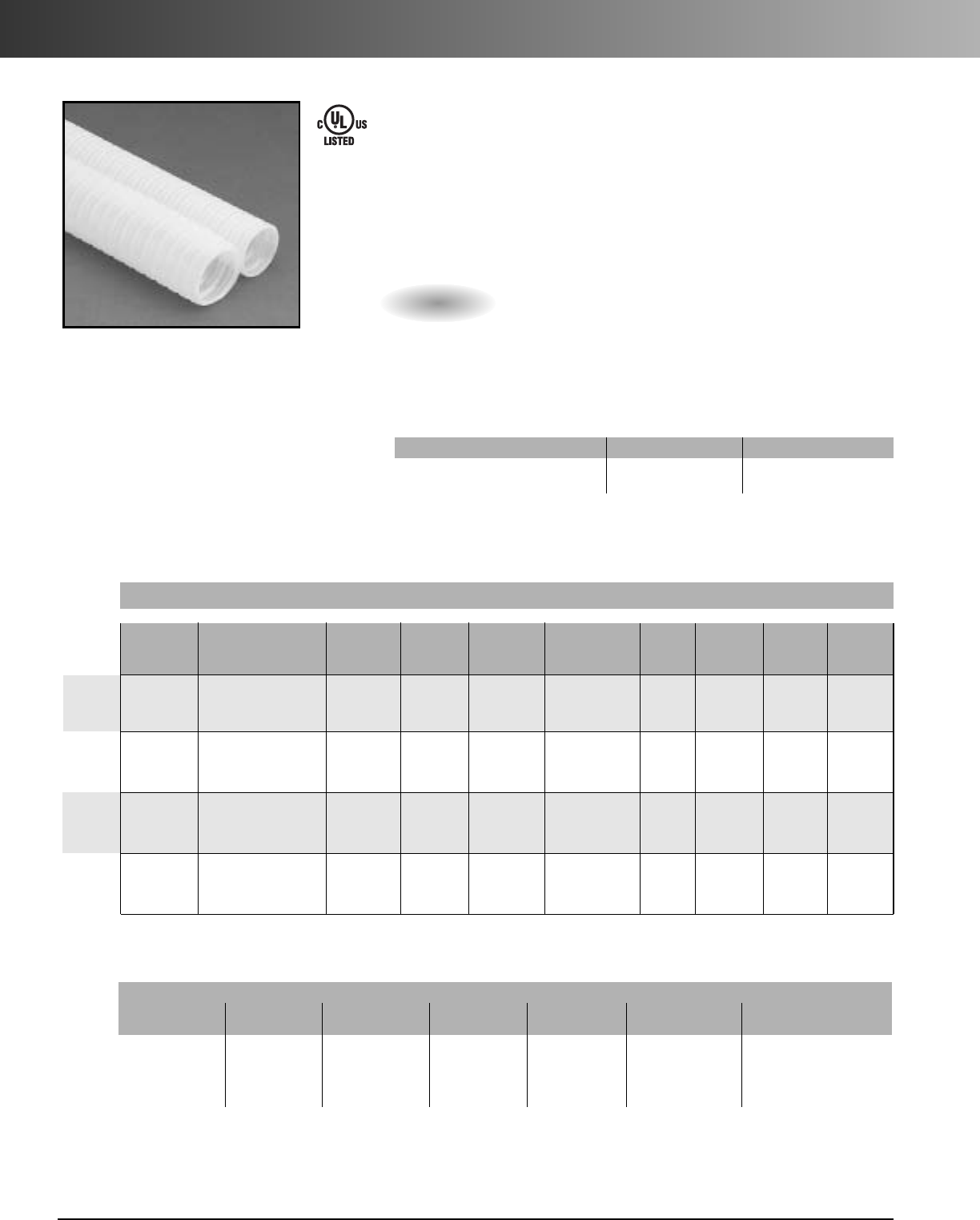
www.carlon.com
92
Hal-Free Riser-Gard
®
Features:
Hal-Free Riser-Gard is listed to UL
2024 in accordance with
NEC
Articles 725, 770, 800 and 820.
Custom lengths and split ducts
are available upon request.
Hal-Free Riser-Gard is available
in white only.
UL Listed to 2024 Test Method Maximum Value
Maximum Flame Propagation UL 2024 3'6"
Maximum Air Temperature UL 2024 387°F
Custom Orders
How to Build a PartNumber
Position 1 Position 2 Position 3 Position 4 Position 5 Position 6 Position 7
Product Size Configuration Wall Color Pull Line Length
H=Hal-Free F = 1" 4 = Corrugated X = Standard 4 = White C = 900 lb. Tape Example
Riser-Gard G=11/4"-1000 = Feet
H=11/2"-1000S = 1000 Feet Split
J=2"
•Free from halogen elements
•Compliant with NEC Articles 725,
770, 800 and 820
•Available in sizes 1" through 2"
•Available in white only
•Sequentially marked footage
Hal-Free Riser-Gard isahalogen free
nonmetallic flexible raceway for use in
riser and general purpose applications.
In the event of a fire, this product will
not release halogen elements into the
air, which makes it ideal for applications
in tunnels, laboratories and high-tech
environments.
E143102
FT-4 Rated
Applications: Riser and General
Purpose
•Custom orders not returnable
•Custom lengths available in minimum order quantities of 1000 ft.
Technical Info:
•Storage and Handling -4°F to 150°F
• No UV protection (not suitable for outdoor use)
•Do NOT store outside
Reel Reel Wt. per
Part Nom. Nom. Pull Reel Reel Length Weight 100 ft.
Color No. I.D. O.D. Tape Size Type (feet) (lbs.) (lbs.)
White HF4X4C-5000 1.049 1.365 900 lb. 72" x 41" W 5000 302 7.3
White HG4X4C-4000 1.250 1.550 900 lb. 72" x 41" W 4000 302 9.2
White HH4X4C-2000 1.500 1.850 900 lb. 66" x 41" W 2000 265 12.0
White HJ4X4C-2000 2.000 2.425 900 lb. 82" x 41" W 2000 375 20.8
StandardStock – Reels
1"
2"
11/4"
11/2"
W=Wood
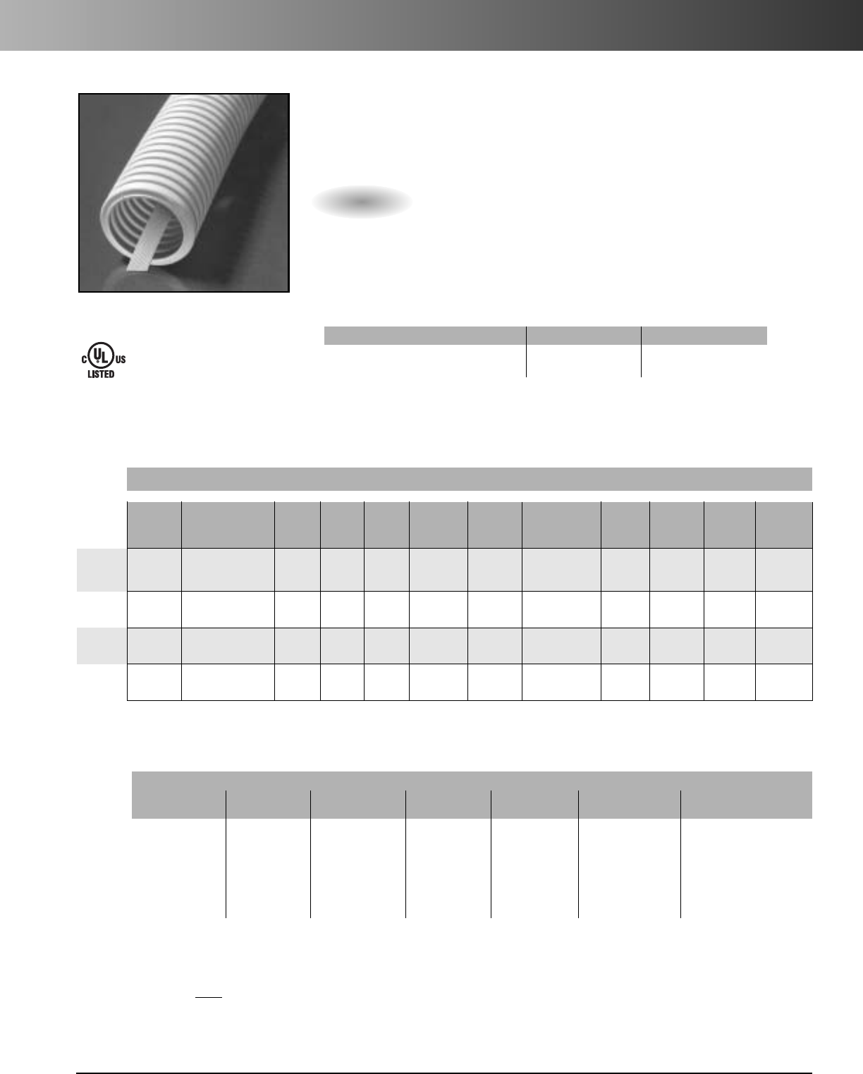
www.carlon.com 93
General Purpose
General Purpose is nonmetallic
flexible raceway for use in General
Purpose applications only. It is UL
Listed and available with tape
pre-installed.
UL Listed to 2024 Test Method Maximum Value
Maximum Flame Propagation UL 2024 6.0 ft.
Maximum Air Temperature at 12 ft. UL 2024 372°F
•Storage -4°F to 158°F
•Handling -4°F to 104°F
• No UV protection (not suitable for outdoor use)
•Do not store outside
General Purpose raceway is listed to
UL2024
in accordance with
the National Electrical
Code per Articles 725, 770, 800 and 820 for
General Purpose and other cabling optical
fiber/telecommunication applications.
E151168
FT-1 Rated
Applications: General Purpose
Technical Info:
I.D. Min. Reel Reel Product
Min. Min. Max. Pull Bend Size Reel Reel Wt. Wt. per
Color Part No. Ref. O.D. O.D. Tape Radius (F x W) Type Length (lbs.) 100 ft. (lbs.)
Orange BF4X1B-8000 .98 1.29 1.34 1130 lb. 6" 82" x 41" W 8000 375 14
Orange BG4X1B-5600 1.31 1.64 1.69 1130 lb. 7" 72" x 41" W 5600 302 17
Orange BH4X1B-4500 1.54 1.88 1.93 1130 lb. 81/4" 82" x 41" W 4500 375 22
Orange BJ4X1B-8000 2.00 2.35 2.40 1130 lb. 91/2"82" x 41" W2000 375 26
1"
2"
11/4"
11/2"
Standard Stock – Reels
W = Wood
Features:
•For use in General Purpose areas per
Articles 725, 770, 800 and 820 of the NEC.
•Available in sizes 3/4" through 2"
•Pull tape can be factory
pre-installed in 1" through 2"
•Outside Diameters meet IPS Dimensions
•Footage sequentially marked
Custom Orders
How to Build a PartNumber
Position 1 Position 2 Position 3 Position 4 Position 5 Position 6 Position 7
Product Size Configuration Wall Color Pull Line Length
B=General Purpose F = 1" 4 = Corrugated X = Standard 1 = Orange B = 1130 lb. Tape Example
G=11/4"2 = Black -1000 = Feet
H=11/2" 3 = Gray
J=2" 4 = White
5 = Blue
7 = Yellow
8 = Red
•Custom Orders are not returnable
•Custom lengths are available in
minimum order quantities of 1000 ft.
•Custom color runs are available in
minimum order quantities of 10,000 ft.
Options:
•Color: Black, Blue, Gray, Red, White and Yellow
•Two,three,or four way parallel
•Split Duct
•Custom print line
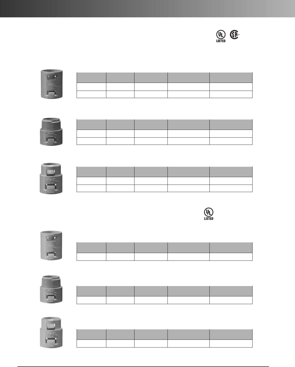
www.carlon.com
94
Flexible Raceway Accessories
•For use with Riser-Gard®and General Purpose
Nonmetallic Adapters & Couplings
•For use with Plenum-Gard®
Nonmetallic Adapters & Couplings
Standard Carton Standard Carton
Part. No. Size Color Quantity Weight (lbs.)
SCA240E 3/4" Orange 25 .783
SCA240F 1" Orange 20 .972
Couplings
StandardCarton Standard Carton
Part. No. Size Color Quantity Weight (lbs.)
SCA243E 3/4" Orange 100 2.30
SCA243F 1" Orange 50 2.00
Threaded Adapters
Standard Carton Standard Carton
Part. No. Size Color Quantity Weight (lbs.)
SCA253E 3/4"Orange 100 2.90
SCA253F 1" Orange 50 2.30
Snap-In Adapters
Standard Carton Standard Carton
Part. No. Size Color Quantity Weight (lbs.)
A340F 1" Orange 50 2.50
Couplings
Standard Carton Standard Carton
Part. No. Size Color Quantity Weight (lbs.)
A343F 1" Orange 50 1.55
Couplings
Standard Carton Standard Carton
Part. No. Size Color Quantity Weight (lbs.)
A353F1" Orange 50 3.00
Couplings
LR31146
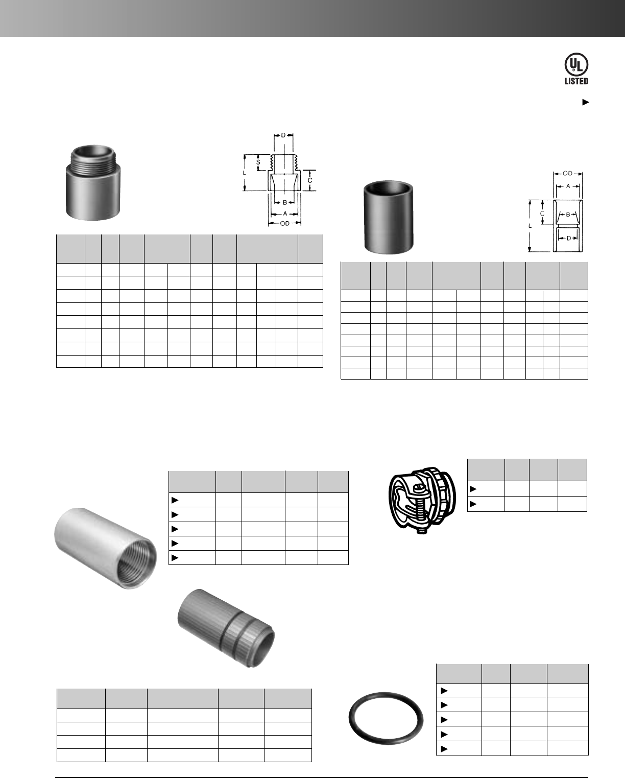
www.carlon.com 95
Flexible Raceway Accessories
Duct O.D. Std. Std. Ctn.
Part. No. Size Range Ctn. Qty. Wt. (lbs.)
P75 3/4" .91 – 1.08 10 12
P100 1" 1.21 – 1.41 100 25
P125 1 1/4" 1.44 – 1.68 100 28
P150CPLR 1 1/2" 1.80 – 2.02 100 35
P200 2" 2.31 – 2.48 50 19
Universal Aluminum Couplings
•For use with Plenum-Gard
®
, Riser-Gard
®
, Hal-Free Riser-Gard
®
,
and General Purpose
Male Terminal Adapters
For adapting nonmetallic
conduits to boxes,
threaded fittings, metallic
systems. Male threads
on one end, socket end
on other.
All socket fittings should be attached Using Carlon solvent cement. Using
Carlon fittings with Carlon nonmetallic conduit insures system integrity.
Standard Couplings
Socket type for
joining nonmetallic
conduit.
Where a waterproof termination is required into any enclosure
(metallic or nonmetallic), install the neoprene washer over the
threads of a terminal adapter before inserting into the enclosure.
Use a standard locknut or threaded bushing to secure the assembly.
Washers Flat Sealing Washer
E32447
Except where noted by
Nonmetallic Adapters and Couplings
•For use with Riser-Gard®and General Purpose
Metallic Adapters and Couplings
Self-threading, which draws
each end of the conduit into
the center of the coupler.
Terminating
Connector
•For use with Plenum-Gard®and
Hal-Free Riser-Gard
®
Part Nom. O.D. Std. Ctn. Std. Ctn.
No. Size Range Qty. Wt.
TC100 1"
.91 – 1.08
12 50
TC125 1
1
/
4
" 1.495 – 1.70 12 52
TC150 1
1
/
2
" 1.80 – 2.00 12 56
TC200 2" 2.31 – 2.52 12 58
Std. Std.
Part Ctn. A B Min. Max. C T L
Ctn. Wt.
No. Size Qty. Color Typical D OD Typical (lbs.)
E943E 3/4125 Gray 1.064 1.046 .800 111/32 3/49/16 13/83.5
E943F 1 50 Gray 1.330 1.310 1.018 15/8111/16 125/32 3
E943G 11/450 Gray 1.677 1.655 1.332 21/32 13/4115/16 4
E943H 11/225 Gray 1.918 1.894 1.566 2 5/32 13/16 3/421/16 2.5
E943J 2 50 Gray 2.393 2.369 2.000 221/32 13/16 3/421/87
SCE943G 11/450 Orange 1.677 1.655 1.332 21/32 13/4115/16 4
SCE943H 11/225 Orange 1.918 1.894 1.566 2 5/32 13/16 3/421/16 2.5
SCE943J 2 50 Orange 2.393 2.369 2.000 221/3213/163/421/87
Std. Std.
Part Ctn. A B Min. Max. C L Ctn.
No. Size Qty. Color Typical D OD Typical
Wt. (lbs.)
E940E 3/4100 Gray 1.064 1.046 .840 15/16 3/415/84.4
E940F 1 50 Gray 1.330 1.310 1.210 15/815/16 2 3.5
E940G 11/430 Gray 1.677 1.655 1.535 163/64 1 21/83.5
E940H 11/225 Gray 1.918 1.894 1.755 215/64 11/823/83.9
E940J 2 30 Gray 2.393 2.369 2.190 247/64 13/16 21/25.25
SCE940G 11/430 Orange 1.677 1.655 1.535 163/64 1 21/83.5
SCE940H 11/225 Orange 1.918 1.894 1.755 215/64 11/823/83.9
SCE940J 2 30 Orange 2.393 2.369 2.190 247/64 13/16 21/25.25
Std. Ctn. Std. Ctn.
Part No.Size Qty. Wt. (lbs.)
E943EW 3/4" 125 .45
E943FW 1" 100 .46
E943GW 11/4"50 .44
E943HW 11/2"50 .45
E943JW 2" 25 .42
Std. Ctn. Std. Ctn.
Part. No. Size Qty. Wt. (lbs.)
E147E 3/4"1.7
E147F 1" 25 1.5
Metallic Terminal Adapter
•For use with Plenum-Gard®
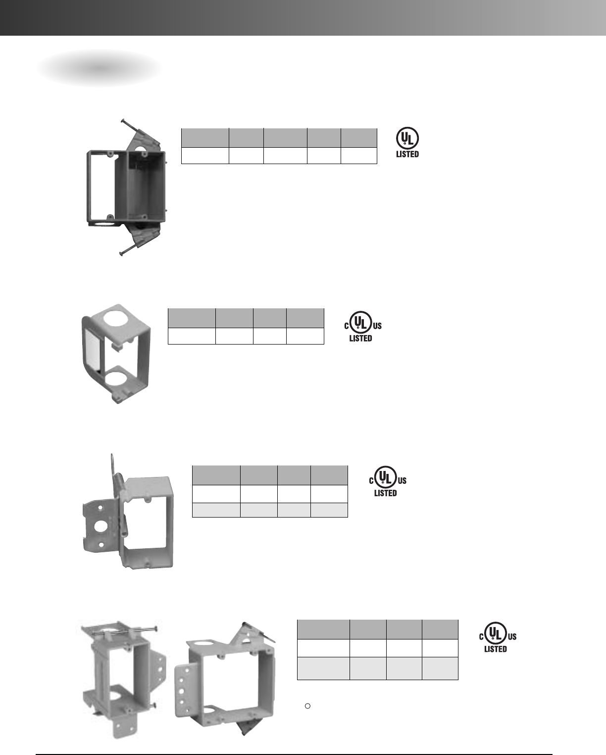
www.carlon.com
96
Flexible Raceway Accessories
Std. Std. Ctn.
Part No. Size Ctn. Qty. Wt. (lbs.)
SC100ADJC 1-Gang 24 7.5
SC200ADJC 2-Gang 20 6.9
Std. Std. Ctn.
Part No. Size Volume Ctn. Qty. Wt. (lbs.)
SC200DV 1-Gang 20.5 cu. in. 16 6.4
Std. Std. Ctn.
Part No. Size Ctn. Qty. Wt. (lbs.)
SC100SC 1-Gang 24 2.3
SC200DV
SC100ADJC
SC100SC
E42728
E216492
E216492
*U.S. Patent D463,376
*U.S. Patent D459,312
U.S. Patent 6,710,245
*U.S. Patent 5,289,934
Dual Voltage Box/Bracket*
Low Voltage Add-On Bracket*
Low Voltage Adjustable Brackets*
SC100A
E216492
Low Voltage Brackets*
SC200A
Std. Std. Ctn.
Part No. Size Ctn. Qty. Wt. (lbs.)
SC100A 1-Gang 24 5.3
SC200A 2-Gang 24 7.7
(3/4" Resi-Rings)
*U.S. Patent D457,140
D462,664
*Lamson & Sessions
D
Low Voltage Boxes & Brackets
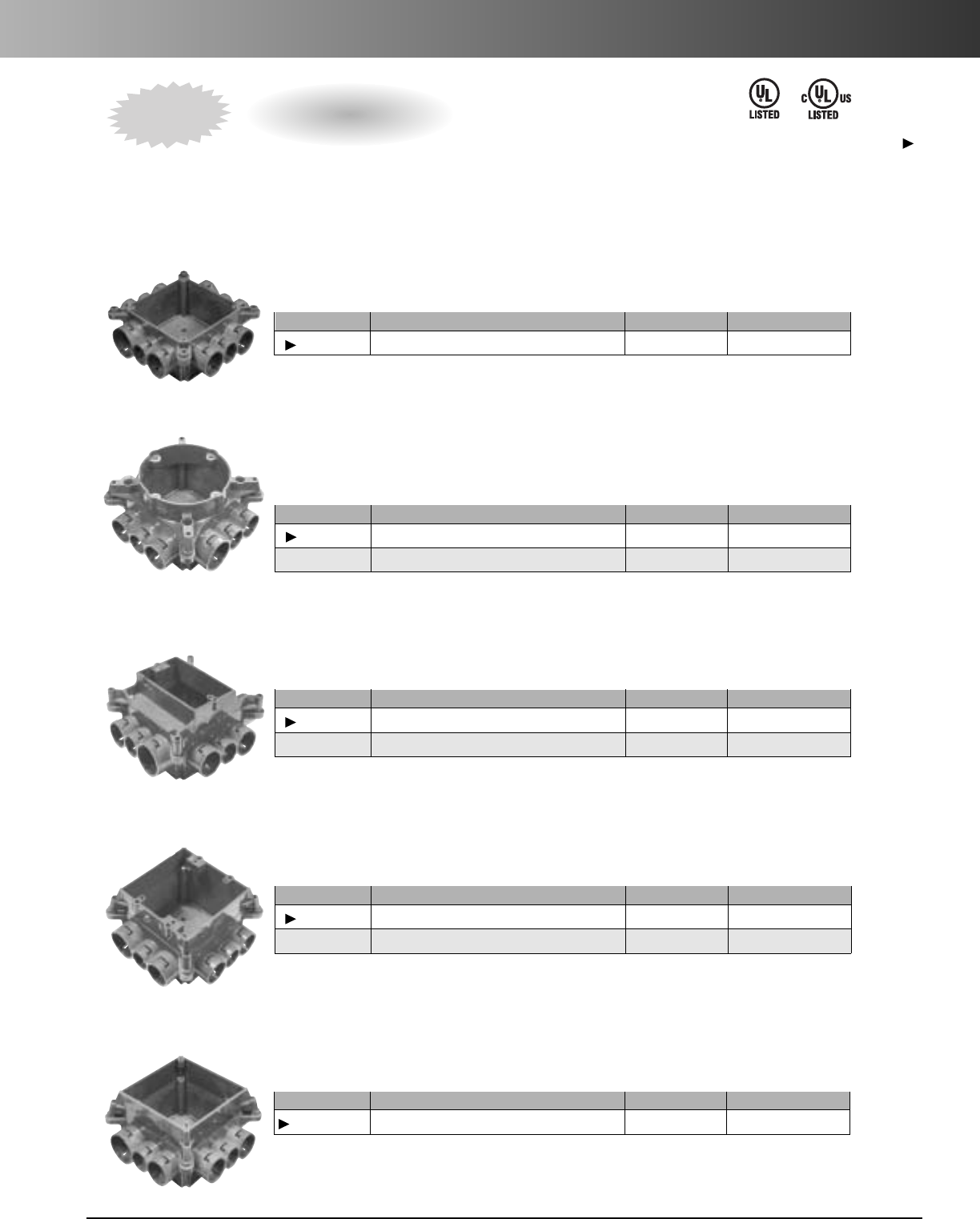
www.carlon.com 97
Flexible Raceway Accessories
Carlon Mud Box Assemblies are available in five unique styles…blank, ceiling ring, one-gang, two-gang
and 4 square. All Mud Box Assemblies are manufactured out of polycarbonate material to provide extra strength
and durability, are concrete tight, and have twelve integral connectors…two-1", six-3/4", and four-1/2". Using our
new ENT Reducers, this product will meet ANY jobsite application.
Mud Box Base with Blank Cover
Mud Box with Ceiling Ring
•Threaded brass inserts for fan (#10-32 screws) and fixture (#8-32 screws) mountings
•Listed for fixture support up to 50 lbs. • Listed for ceiling fans up to 35 lbs.
Mud Boxwith One-Gang Ring
Mud Boxwith Two-Gang Ring
Mud Box with 4 Square Ring
• 4 Square Ring not for luminaries.
Mud Box Assemblies
Part. No. Size Std. Ctn. Qty. Std. Ctn. Wt. lbs.
A863BC Mud Box w/ Blank Cover 24 12.3
Patent Pending
Part. No. Size Std. Ctn. Qty. Std. Ctn. Wt. lbs.
A863CF Mud Box w/ Ceiling Ring 24 15.5
A863CFG Mud Box w/ Ceiling Ring & Ground Lug 24 16.1
Patent Pending
Part. No. Size Std. Ctn. Qty. Std. Ctn. Wt. lbs.
A863S Mud Box w/ One-Gang Ring 24 16.8
A863SG Mud Box w/ One-Gang Ring & Ground Lug 24 16.2
Patent Pending
Part. No.Size Std. Ctn. Qty. Std. Ctn. Wt. lbs.
A863D Mud Box w/ Two-Gang Ring 24 15.8
A863DG Mud Box w/ Two-Gang Ring & Ground Lug 24 16.6
Patent Pending
Part. No.Size Std. Ctn. Qty. Std. Ctn. Wt. lbs.
A863-4SQ Mud Box w/ 4 Inch Square Ring 24 15.2
Patent Pending
Except where noted by
NEW
E42728 E42728
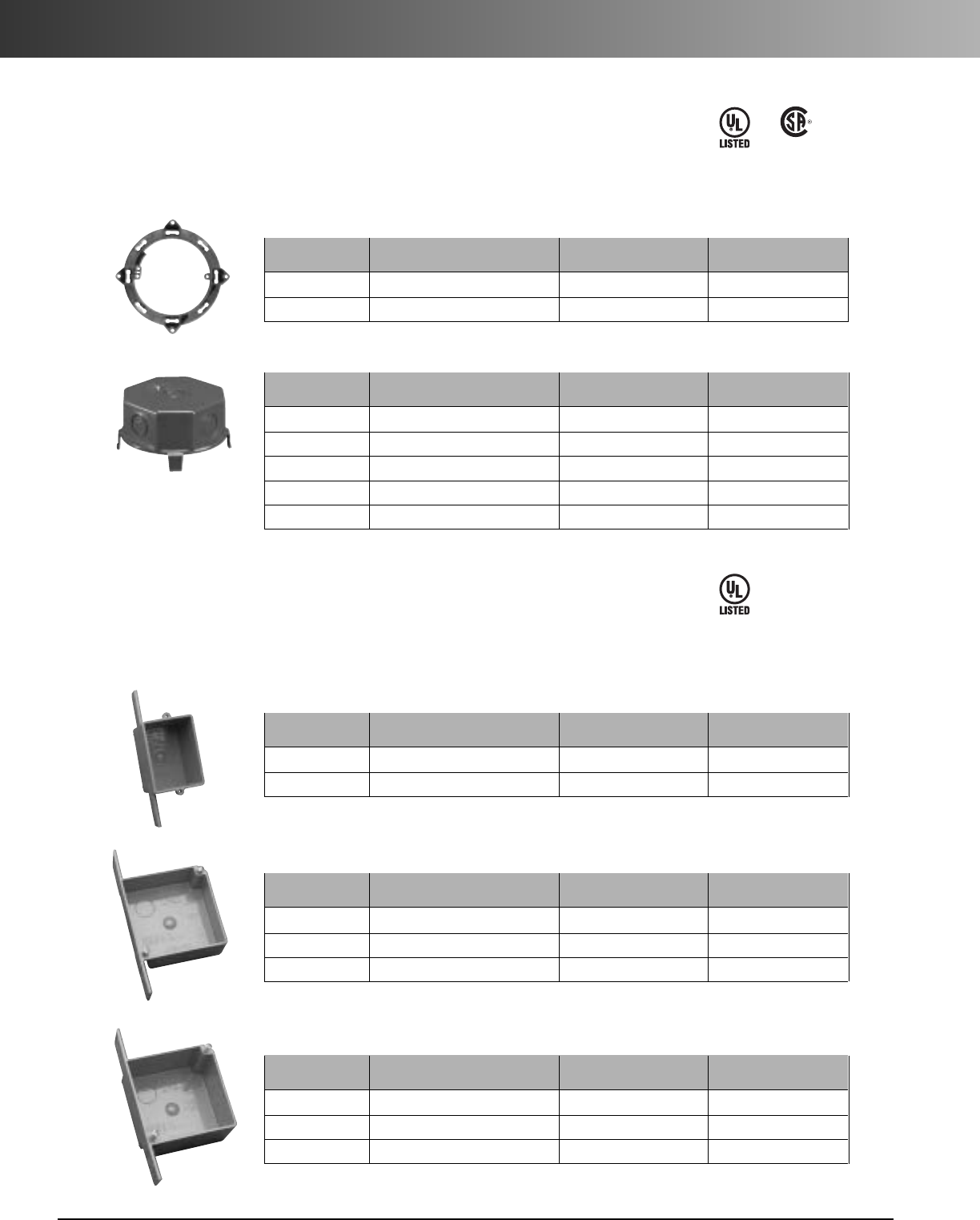
www.carlon.com
98
Flexible Raceway Accessories
•For use with Riser-Gard®and General Purpose
21/2"&4"Mud Boxes with Covers
Standard Carton Standard Carton
Part. No. Description Quantity Weight (lbs.)
A861 Without ground lug 10 2.5
CA861G With ground lug 10 2.0
Base Rings
Listed for use with ceiling fans up to 35 lbs. and for fixture support up to 50 lbs.
•For use with Riser-Gard®and
General Purpose
•Suitable for masonry walls
•Meets NEMA OS-2
QuickConnect Outlet and Switch Boxes
Standard Carton Standard Carton
Part. No. Description Quantity Weight (lbs.)
A58381D 3 x 21/4x3 (
1/2"KO’s) 25 4.6
A58381E 3 x 21/4x3 (
3/4"KO’s) 25 4.6
Single Gang – 16 cu. in.
Standard Carton Standard Carton
Part. No. Description Quantity Weight (lbs.)
A52151D 4x4x1
1/2(1/2" KO’s) 100 22.6
A52151E 4 x 4 x 11/2(3/4"KO’s) 100 22.6
A521DE 4 x 4 x 11/2(1/2" & 3/4"KO’s) 100 22.6
TwoGang – 20 cu. in.
Standard Carton Standard Carton
Part. No. Description Quantity Weight (lbs.)
A52171D 4 x 4 x 23/8(1/2"KO’s) 25 7.6
A52171E 4x4x2
3/8(3/4" KO’s) 25 7.6
A5217DE 4 x 4 x 23/8(1/2" & 3/4"KO’s) 25 7.6
TwoGang – 30.3 cu. in.
Standard Carton Standard Carton
Part. No. Description Quantity Weight (lbs.)
A862D 21/2"Deep (1/2"KO’s) 10 2.5
A862E 21/2"Deep (3/4"KO’s) 10 2.1
A864D 4" Deep (1/2"KO’s) 10 2.9
A864E 4" Deep (3/4"KO’s) 10 2.9
A864F 4" Deep (1" KO’s) 10 3.0
Covers
E42728 LR31146
E42728
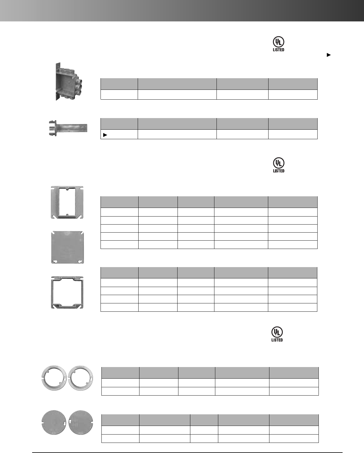
www.carlon.com 99
Flexible Raceway Accessories
•For use with Riser-Gard®and General Purpose
ENT Box with Adapters
Standard Carton Standard Carton
Part. No. Description Quantity Weight (lbs.)
A5329DE
4x4x1
3/4(1/2" & 3/4"KO’s)
50 14.8
Two Gang – 24.75 cu. in. ENT Box with Adapters
Standard Carton Standard Carton
Part. No. Description Quantity Weight (lbs.)
A540DS
For use with 1/2"Knockout
100 2.1
Box Back Wall Support
•For use with Riser-Gard®and General Purpose
ENT Box Extenders
StandardCarton Standard Carton
Part. No. Rise Cu. in. Quantity Weight (lbs.)
A410 1/2" 3.5 100 7.7
A411 5/8"4.2 50 4.6
A412 3/4" 5.0 50 5.1
A413 1" 6.6 40 5
A414 11/4" 8.1 30 4.4
Single Gang
Standard Carton Standard Carton
Part. No. Rise Cu. in. Quantity Weight (lbs.)
A400 Blank - 100 7.7
A420 1/2" 6.1 75 5.0
A421 5/8" 7.4 50 4.2
A422 3/4" 8.8 50 4.8
Two Gang
E42728
E42728
Except where noted by
•For use with Riser-Gard®and General Purpose
Round Covers for Octagon Ceiling Boxes
E42728
Standard Carton Standard Carton
Part. No. Rise Cu. in. Quantity Weight (lbs.)
A471 1/2"3.2 100 3.3
A472 3/4" 4.0 100 3.7
Round Plaster Rings
•Suitable for fixture support
Standard Carton Standard Carton
Part. No. Rise Cu. in. Quantity Weight (lbs.)
E460R-CAR Blank - 35 2.2
A470D Blank with 1/2" KO-100 4.7
Round Blank Covers
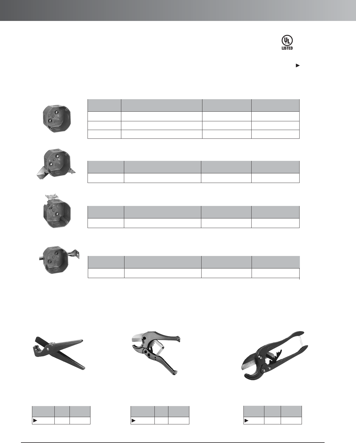
www.carlon.com
100
Flexible Raceway Accessories
Std.
Part No. Size Ctn. Qty.
CC120B 8" 10
Std.
Part No. Size Ctn. Qty.
CC125 9" 12
Std.
Part No. Size Ctn. Qty.
CC122 171/2"1
PVC Conduit Cutters
Hand held cutter makes fast square, smooth
field cuts on conduit from
1
/
2
" through 1
1
/
4
".
Produces burr-free cut with no shavings. Fits
into pocket or pouch.
For clean cuts of conduit
1
/
2
"
through 2".
For fast, smooth field cuts of
1
/
2
" through 1" Riser-Gard
®
and Plenum-Gard.
Small Cutter Medium Cutter Large Cutter
• For use with Riser-Gard®and General Purpose
• Carlon ceiling boxes and round plaster rings are produced from a special high heat
resistant engineered plastic material developed specifically for fixture support.
• LIsted for fixture support up to 50 lbs.
Quick Connect 4"Octagon Ceiling Boxes
Standard Carton Standard Carton
Part. No. Description Quantity Weight (lbs.)
A615D
4 - 21/8" Deep (1/2" KO’s)
50 6.4
A615E
4 - 21/8" Deep (3/4" KO’s)
50 6.4
A615DE
4 - 21/8" Deep (1/2" & 3/4" KO’s)
50 6.4
Ceiling Box – 20.5 cu. in.
Standard Carton Standard Carton
Part. No. Description Quantity Weight (lbs.)
A615DJ
4 - 21/8" Deep (1/2" KO’s)
50 18.7
Ceiling Box with J Mount – 20.5 cu. in.
E42728
Standard Carton Standard Carton
Part. No. Description Quantity Weight (lbs.)
A615DL
4 - 21/8" Deep (1/2" KO’s)
50 6.4
Ceiling Box with L Bracket – 20.5 cu. in.
Ceiling Box with Adjustable Hanger Bar – 20.5 cu. in.
Adjust from 141/4" to 231/4"
Standard Carton Standard Carton
Part. No. Description Quantity Weight (lbs.)
A615DH
4 - 21/8" Deep (1/2" KO’s)
25 13.6
Except where
noted by
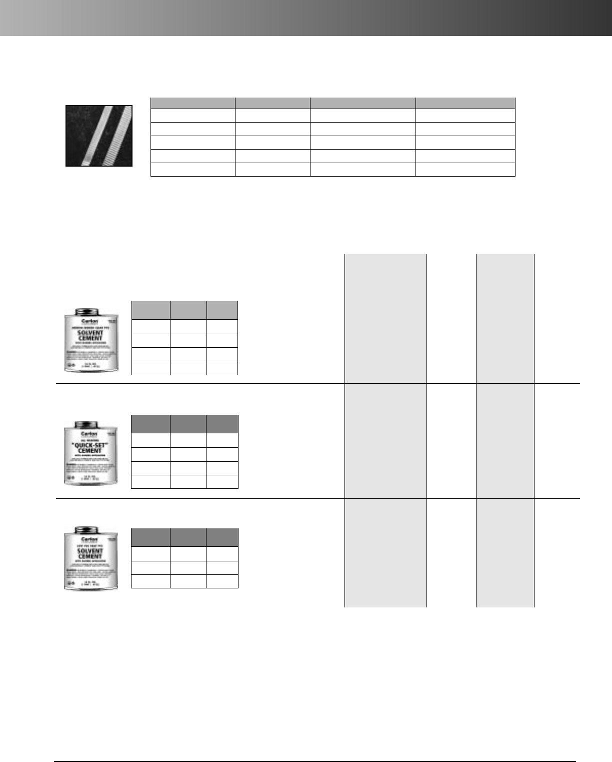
www.carlon.com 101
Flexible Raceway Accessories
Carlon
®
Cement
(MSDS sheets available at www.carlon.com)
*Meets ASTM D2564
Medium Bodied Clear PVC Solvent Cement
with dauber*
All-Weather “Quick-Set”
Clear Solvent Cement
with dauber*
Low VOC Gray PVC Solvent
Cement
with dauber*
Part Std.
No. Size Ctn. Qty.
VC9964 1/2Pint 10
VC9963 Pint 24
VC9962 Quart 12
VC9961P Gallon 6
Recommended for all grades
and types of Carlon PVC
conduit, duct, wireway and
fittings, except Flex-Plus
®
Blue
™
ENT (Electrical
Nonmetallic Tubing.)
Up through 6" diameter.
Recommended for all
grades and types of Carlon
PVC conduit, duct, wireway
and fittings, except Flex-
Plus
®
Blue
™
ENT (Electrical
Nonmetallic Tubing.)
Up through 6" diameter.
Recommended for all
grades and types of Carlon
PVC conduit, duct, wireway
and fittings, except Flex-
Plus
®
Blue
™
ENT (Electrical
Nonmetallic Tubing.)
Up through 6" diameter.
VOC emission of 490
grams/liter per the Bay and
South Coast test method.
Recommended pipe
application and sizes
10˚-30˚F Not recommended
30˚-50˚F
5-6 minutes
50˚-70˚F
3-4 minutes
70˚-90˚F
1-2 minutes
10˚-30˚F
4-5 minutes
30˚-50˚F
3-4 minutes
50˚-70˚F
1-2 minutes
70˚-90˚F
1
/
2
-1
1
/
2
minutes
10˚-30˚F
Not recommended
30˚-50˚F
5-6 minutes
50˚-70˚F
3-4 minutes
70˚-90˚F
1-2 minutes
2hrs.
350 psi
16 hrs.
800 psi
72 hrs.
1,500 psi
2hrs.
350 psi
16 hrs.
800 psi
72 hrs.
1,500 psi
2hrs.
350 psi
16 hrs.
800 psi
72 hrs.
1,500 psi
Set-up time
(Evaporation Rate) Lap Shear
@73˚F
Recommended
installation
temperature
40˚ to 100˚F
-5˚ to 100˚F
40˚ to 100˚F
Viscosity at
75˚ as
manufactured
500-900 cps
400-700 cps
500-900 cps
Part Std.
No. Size Ctn. Qty.
VC9984 1/2Pint 10
VC9983 Pint 24
VC9982 Quart 12
VC9981P Gallon 6
Part Std.
No. Size Ctn. Qty.
VC9LV4 1/2Pint 10
VC9LV3 Pint 24
VC9LV2 Quart 12
Other ropes and tapes are available. Consult your sales service location for additional information.
Prelubricated, woven polyester tape made from low friction, high abrasion resistant yarns providing a low coefficient of friction.
Tape is printed with sequential footage markings for accurate measurements.
Tape
Part. No. Size Tensile Strength Reel Lengths
TL14505 1/2"12
50 lbs. 5,000 ft.
TL14510 1/2"1250 lbs. 10,000 ft.
TL38203 5/8"1800 lbs. 3,000 ft.
TL38265 5/8"1800 lbs. 6,500 ft.
TL38210 5/8"1800 lbs. 10,000 ft.
www.carlon.com
102
Innerduct Guide
Carlon
®
Innerduct Guide
W
HERE IS
I
NNERDUCT BEING USED
?
Plenum
General
Purpose &
Riser
•Must be
UL Listed
•Plenum cable
must be
installed
•Color: Industry
standard=orange
•Pull tape
pre-installed
in sizes 1/2"
through 2"
•Plenum-Gard®
product
numbers:
1/2" CD4X1C
3/4" CE4X1C
1" CF4X1C
11/4" CG4X1C
11/2" CH4X1C
2" CJ4X1C
INSIDE THE
BUILDING
•Must be UL
Listed
•Riser rated
cable must be
used in riser
applications
•Color: Industry
standard=orange
•
Riser-Gard
®
product numbers:
3/4" DE4X1C
1" DF4X1C
11/4" DG4X1C
11/4" DH4X1C
2" DJ4X1C
•
General Purpose
product numbers:
1" BF4X1B
11/4" BG4X1B
11/4" BH4X1B
2" BJ4X1B
Pulled
into a
Conduit
Plowed or
Trenched
•HDPE True
sized duct
recommended
1.00" ID or
1.25" ID
•Corrugated
(Riser-Gardand
HDPE) duct for
newer conduit
runs & shorter
distance pulls
•HDPE Solidwall
for older conduit
runs & longer
distance pulls
OUTSIDE THE
BUILDING
•HDPE SDR sized
duct recommended
(11/4"or larger)
•HDPE SDR 13 wall
thickness for non-
rocky soil conditions
•HDPE SDR 11 wall
thickness for rocky
conditions
•
Riser-Gard
approved for direct
bury applications
but NOTexposed
applications
NOTE:
•Aerial HDPE for
exposed applications
Specifying and installing UL Listed innerducts with the anticipation of future upgrades provides the building owner
with a low cost solution for the removal of abandoned cables.
Options
•Color
•Striping
•Factory installed pull lines
•Segmented or paralleled reels
•Pre-lubricated duct
Note:
•HDPE innerduct will not meet code

Section
www.carlon.com 103
Carlon
®
Structured Cable
Management Systems
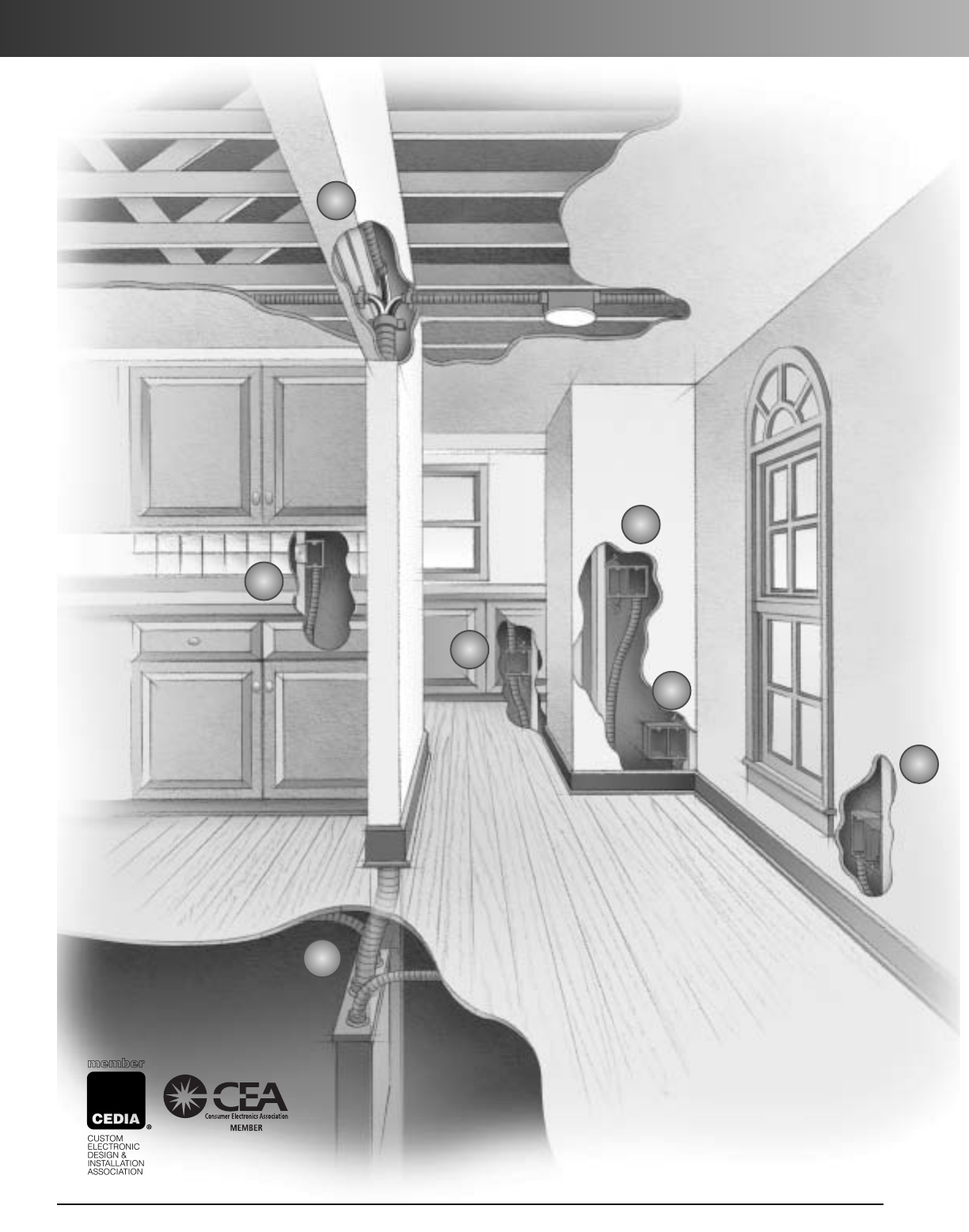
Structured Cable Management Systems
Cable management
systems that make
installation faster
and better.
www.carlon.com
104
5.
5.
3.
3.
5.
5.
4.
4.
1.
1.
6.
6.
2.
2.
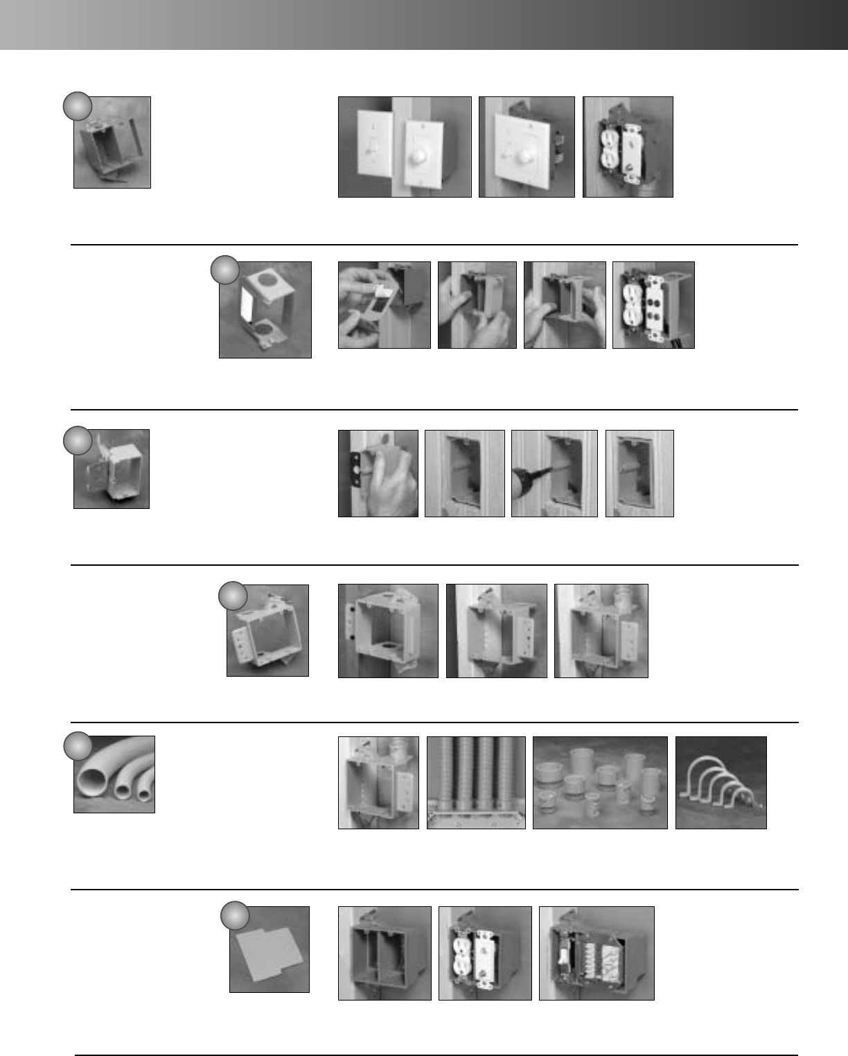
www.carlon.com 105
Structured Cable Management Systems
Dual Voltage Box/Bracket
Here’s a smart alternative where you would
normally use separate high and low voltage
boxes. Designed to fit a standard two-gang
faceplate, this component combines an
electrical box and low voltage bracket into
asingle unit for fast, easy installation.
Noalignment tools are required, and easy nail-on mounting provides
precise placement and a professional finished appearance. Resi-Rings
accept
3
/
4
"Resi-Gard only . . . . . . . . . . . . . . . . . . . . . . . . . . SC200DV
Low Voltage Adjustable Brackets
Our Low Voltage Adjustable Brackets are the
perfect solution for tile,paneling, or stucco. A
bracket allows for quick, easy stud mounting,
and a turn of the screw adjusts to any wall
thickness. It’s great for retrofit/ installation
upgrades. Replace the single-gang bracket with a two-gang bracket, or
switch services to a high-voltage Adjust-A-Box
™
...SC100ADJC (shown)
SC200ADJC
Resi-Gard
®
Flexible Raceway
And Fittings
Available in 5 sizes from
3
/
4
"to 2", with
factory installed pull tape in sizes 1" to 2",
our Resi-Gard Flexible Raceway provides a
main chase from the main distribution panel
to a secondary hub in the attic or basement. Ideal for easy access to add
cable or service upgrades, or leave empty for future expansion
. . . . . . . . . . . . . . . . . . . . . . . . . . . . . . . . . .See page 100 for part numbers
Low Voltage Add-On
Bracket
This low voltage bracket provides a low
voltage outlet next to a previously
installed high voltage outlet. Great for
both new construction and rework, it
attaches easily to most electrical boxes,
and is designed to fit a standard two-
gang faceplate. Resi-Rings accept
3
/
4
"
Resi-Gard only . . . . . . . . . . . . .SC100SC
Low Voltage Brackets
Here’sthe fast installation choice where
only low voltage is required. Designed to
fit a standard one- or two-gang faceplate,
these low voltage brackets feature an easy
nail-on mounting or screw-in bracket, while
ahard shell provides increased durability
and no racking. SC100A – Accepts 3/4", 1", and 1-1/4" Resi-Gard
SC200A (shown) – Accepts 3/4" Resi-Gard only
Low Voltage Divider Plate
For applications where a combined
high and low voltage closed back box
is needed, such as placement in a fire-
rated wall, we offer our Carlon
SuperBlue™ two-, three-, and four-gang
wiring boxes with a slip-in-place divider
to give you the split box you need for
the low voltage outlet . . . . . . . . SCDIV
Why waste time mounting, then
trying to line up separate high
voltage and low voltage boxes,
and still end up with something
not quite right? Our Dual Voltage
Box/Bracket lets you do it all in
one fast, easy step with perfect
alignment every time.
Attaching the Add-On
Bracket is a “snap.” You
just remove the back of the
double-sided tape (1),
clip the bracket in place (2),
and press on the bracket to
secure it against the box
(3). Allows for the
installation of most decora
style yoke plates
Our Low Voltage Brackets are open-
backed to easily accommodate the bend
radiuses required for low voltage cabling
and deep devices such as volume
controls, while molded-in ports make it
easy to connect flexible raceway for
future-proofing. Or you can use them to
tie off cable to the bracket. They can
also be attached to wood or steel studs.
What could be easier than converting
one of our Carlon SuperBlue boxes for
both high and low voltage use? Just
slip the divider into place, and you’re
ready to go. Great for situations
requiring a dual voltage fire-rated box.
Our Low Voltage Adjustable
Brackets simplify installation with
tile, paneling, or stucco to save you
time and effort. Just use the
quick-mount bracket to clip it to
the stud (1), add a screw for extra
support if you want it (2), then use
the adjustment screw to accommo-
date wall thickness (3). Also
available in a two-gang version.
1. 2. 3.
Our complete line of quick-connect couplings, adapters, cable clips, conduit clamps, and solvent cement make for quick, easy
professional installation of Resi-Gard Flexible Raceway.
1. 2. 3.
1.
1.
2.
2.
3.
3.
4.
4.
5.
5.
6.
6.
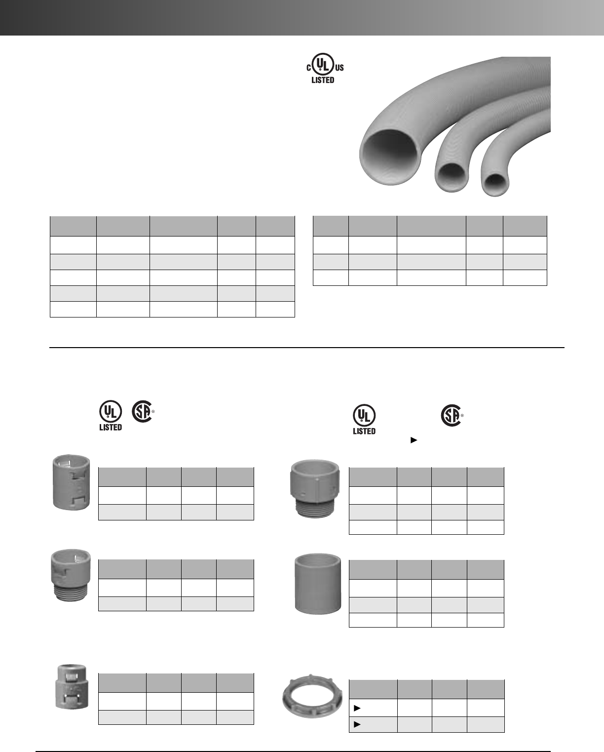
www.carlon.com
106
SCMS – Resi-Gard and Fittings
Acomplete line of Carlon one-piece quick connect couplings, threaded adapters, and snap-in
terminator adapters are available for quick, easy professional installation of Resi-Gard Flexible
Raceway.
Ideal for providing a main chase from the main distribution
panel to a secondary hub in the attic or basement, Resi-Gard
nonmetallic flexible raceway is available in 3/4"to 2"
diameter sizes with factory installed pull tape in sizes 1" to
2". The raceway is hand bendable, lightweight and easily
cut to length to reduce scrap. Bright orange color clearly
signifies a low voltage installation.
Resi-Gard
®
Fittings
Std. Std. Ctn.
Part No. Size Ctn. Qty. Wt. (lbs.)
SCA240E 3/4" 25 .783
SCA240F 1" 20 .972
Quick Connect Coupling
Std. Std. Ctn.
Part No. Size Ctn. Qty. Wt. (lbs.)
SCA243E 3/4" 25 .633
SCA243F 1" 20 .778
Quick Connect Threaded Adapter
Std. Std. Ctn.
Part No. Size Ctn. Qty. Wt. (lbs.)
SCA253E 3/4"25 .783
SCA253F 1" 20 .918
Quick Connect Snap-In Adapter
Std. Std. Ctn.
Part No. Size Ctn. Qty. Wt. (lbs.)
SCE943G 11/4"50 3
SCE943H 11/2" 25 2.5
SCE943J 2" 50 6.8
Male Terminal Adapter
*
Std. Std. Ctn.
Part No. Size Ctn. Qty. Wt. (lbs.)
SCE940G 11/4" 30 3.5
SCE940H 11/2"25 3.9
SCE940J 2" 30 5.2
Standard Couplings
*
Standard Length Coils
Resi-Gard
®
Flexible Raceway
Pull Part Coil Prod. Wt.
Size Tape No. Length (lbs.) Coil
3/4" Empty* SCE4X1-100 100 11.5
1" 900 lbs. SCF4X1C-100 100 17.9
11/4"900 lbs. SCG4X1C-100 100 21.5
11/2"900 lbs. SCH4X1C-50 50 11.2
2" 900 lbs. SCJ4X1C-50 50 13.4
*Must be cemented to Resi-Gard®Flexible Raceway
using ONLYResi-Gard Solvent Cement
E86720 E32447
E151168
FT-1
Standard Length Reels
*
Pull Part Reel Prod. Wt.
Size Tape No. Length (lbs.) Reel
3/4" Empty SCE4X1-1000 1000 115.0
1" 900 lbs. SCF4X1C-1500 1500 268.5
2" 900 lbs. SCJ4X1C-500 500 133.5
LR92248
*Made to order
Except where
noted by LR31146
*If installing own tape, a lubricated polyester is recommended.
Std. Std. Ctn.
Part No.Size Ctn. Qty. Wt. (lbs.)
LT9LE 3/4" 700 4
LT9LF 1" 600 4
PVC Lock Nut
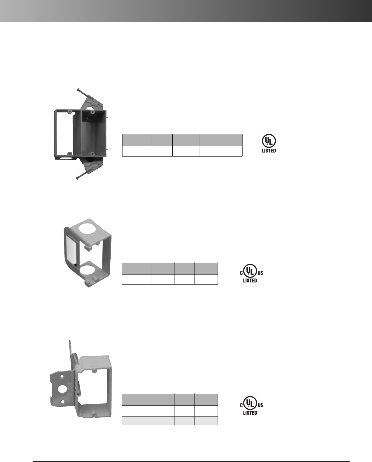
www.carlon.com 107
SCMS – Boxes and Brackets
Structured Cabling Boxes and Brackets
Carlon’s new and innovative family of Structured Cabling Boxes and Brackets for all your installation requirements.
Std. Std. Ctn.
Part No. Size Ctn. Qty. Wt. (lbs.)
SC100ADJC 1-Gang 24 7.5
SC200ADJC 2-Gang 20 6.9
Std. Std. Ctn.
Part No. Size Volume Ctn. Qty. Wt. (lbs.)
SC200DV 1-Gang 20.5 cu. in. 16 6.4
Std. Std. Ctn.
Part No. Size Ctn. Qty. Wt. (lbs.)
SC100SC 1-Gang 24 2.3
SC200DV
SC100ADJC
SC100SC
E42728
E216492
E216492
*U.S. Patent D463,376
*U.S. Patent D459,312
U.S. Patent 6,710,245
*U.S. Patent 5,289,934
Dual Voltage Box/Bracket*
•Dual Voltage Capability
•Accepts a two-gang face plate.
•3/4” Resi-Rings
•Backless Design accommodates
large/deep low voltage devices.
• Eliminates cutting the backs off
Electrical Boxes.
•Accommodates bend radius require-
ments for low voltage cabling.
• Provides ample space for installation.
Features:
LowVoltage Add-On Bracket*
•Dual Voltage Capability accommodates
high and low voltage devices in the
same box.
• Accepts a two-gang face plate.
• Attaches to virtually any nonmetallic
electrical box as long as there’s a side
for the tape to stick to.
•3/4" Resi-Rings
• Allows for the installation of most
decora style yoke plates
Features:
LowVoltage Adjustable Brackets*
•Accommodates varying finished wall thicknesses –
ideal for wood paneling, tile or stucco walls.
•With the turn of a screw, adjust to any wall thickness.
• Steel Mounting Bracket provides a secure mount.
•Backless Design accommodates large/deep low
voltage devices.
• Eliminates cutting the backs off Electrical Boxes.
• Accommodates bend radius requirements
for low voltage cabling.
•Provides ample space for installation.
• Removable Bracket and Interchangeable
Mounting Bracket – upgrade from a one-gang
to a two-gang anytime.
Features:

Std. Std. Ctn.
Part No. Size Ctn. Qty. Wt. (lbs.)
SC100A 1-Gang 24 5.3
SC200A 2-Gang 24 7.7
(3/4" Resi-Rings)
*U.S. Patent D457,140
D462,664
*Lamson & Sessions
D
www.carlon.com
108
SCMS – Boxes and Brackets
Std. Std. Ctn.
Part No. Size Ctn. Qty. Wt. (lbs.)
SC100RR 1-Gang 12 1.4
SC200RR 2-Gang 6 .9
Std. Std. Ctn.
Part No. Size Ctn. Qty. Wt. (lbs.)
SCA410 1-Gang 20 1.54
Std. Std. Ctn.
Part No. Ctn. Qty. Wt. (lbs.)
SCDIV 50 2.2
SC100A
SCDIV
E216492
E216492
For use with Carlon®SuperBlue™boxes
only (Refer to pages 79-81)
Low Voltage Brackets*
•Backless Design accommodates large/deep low
voltage devices.
•Eliminates cutting the backs off Electrical Boxes.
• Accommodates bend radius requirements for
low voltage cabling.
• Provides ample space for installation.
•Breakaway Drywall Support Flange provides
easy alignment for 1/2" drywall.
• Mount Flange for steel stud application
• Screw mount option
• Resi-Rings with Concentric Knockouts
•Accepts 3/4", 1", and 1-1/4" Resi-Gard.
• Horizontal Mounting Bracket
• Bracket can be mounted horizontally on wood
or steel studs.
•Breakaway Vertical Mounting Flange
• Breakaway feature allows the use of the Low
Voltage Add-On Bracket.
Features:
One-Gang Low Voltage Bracket:
LowVoltage
Divider Plate
Mud Ring
(4" sq. 1/2"Raised Cover)
Old WorkBrackets
•Rectangular Flange for faster/easier installation.
• Chamfered Corners – Prevents Racking.
•Shallow Bracket – Less material, easier to work with.
• Marking hole for wall opening.
• Thinner Flange for less protrusion on the wall.
• SINGLE GANG ONLY – Clamps stop at center
point to prevent the bracket from twisting or
bending out of the wall.
Features:
SC200A
U.S. Patent No. 6,812,405
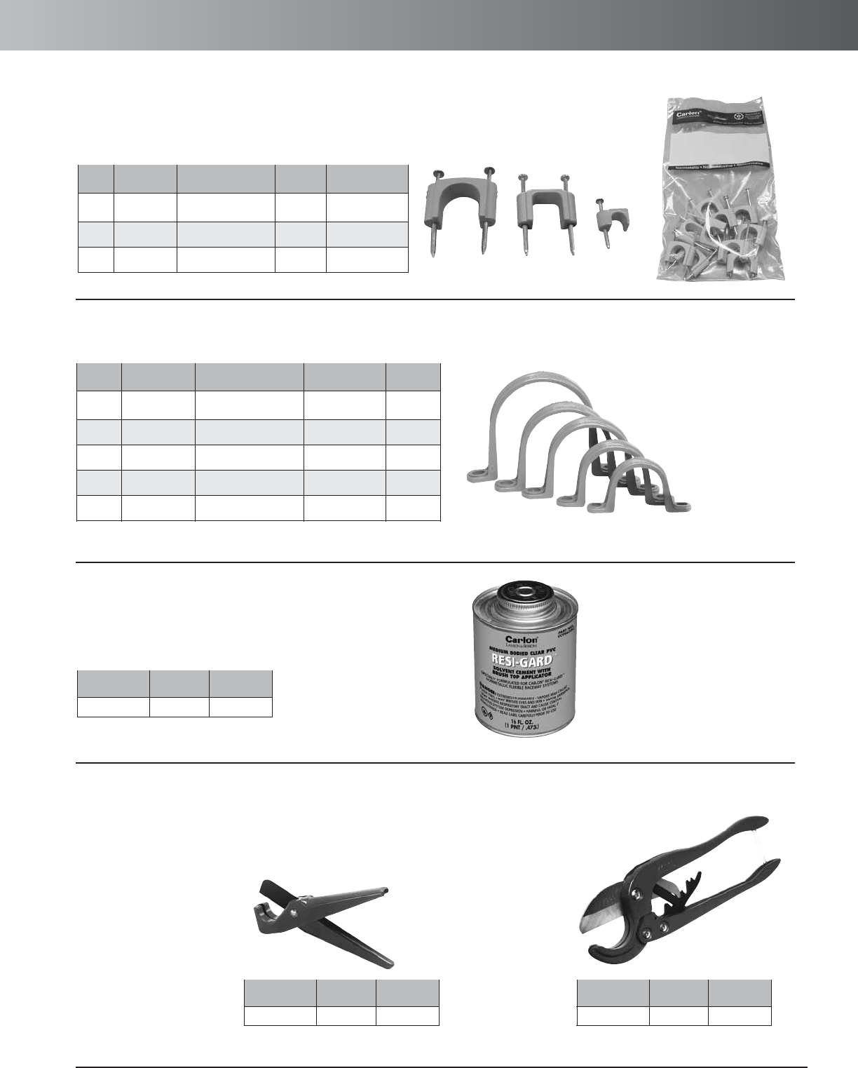
www.carlon.com 109
SCMS – Accessories
Resi-Gard
®
Solvent Cement
Std. Std. Ctn.
Part No. Ctn. Qty. Wt. (lbs.)
VC9963SC 24 28.6
Resi-Gard
®
Cutters
Std.
Part No. Size Ctn. Qty.
CC120B 8" 10
Std.
Part No. Size Ctn. Qty.
CC122 171/2"1
Cable Clips
Standard Std. Ctn. Std. Ctn.
Size Part No. Bag Quantity Wt. (lbs.) Qty.
1/4" SC14CC 1 ea. 2.23 10 Bags of 100
1/2" SC12CC 1 ea. 2.31 10 Bags of 25
3/4" SC34CC 1 ea. 2.96 20 Bags of 10
Conduit Clamps
Standard Std. Std. Ctn.
Size Part No. Bag Quantity Ctn. Qty. Wt. (lbs.)
3/4" SCE977EC 1 ea. 20 Bags of 5 1.5
1" SCE977FC 1 ea. 12 Bags of 5 1.3
11/4" SCE977GC 1 ea. 8 Bags of 5 1.1
11/2" SCE977HC 1 ea. 6 Bags of 5 1.0
2" SCE977JC 1 ea. 6 Bags of 5 1.5
For clean cuts
of conduit 1/2"
through 2".
For fast, smooth field
cuts of 1/2" through 1"
innerduct.
Small Cutter Large Cutter
(Equals one bag
of 100 Clips
(Equals one bag
of 25 Clips
(Equals one bag
of 10 Clips
(Equals one bag
of 5 Clamps
(Equals one bag
of 5 Clamps
(Equals one bag
of 5 Clamps
(Equals one bag
of 5 Clamps
(Equals one bag
of 5 Clamps
NOTE: Each clamp requires 2 screws, 2 nuts, and/or 2 bolts
SC34CC SC12CC SC14CC
Carlon’s cable clips with pre-installed nails provide fast and easy
installation for either a single cable, 2-3 cables, or 1 bundled cable.
Carlon’s orange conduit clamps are designed to secure Resi-Gard raceway or bundled cable.
Resi-Gard Solvent Cement is ideal for easy, tight installation of all
Resi-Gard flexible nonmetallic raceway and fittings and accessories.
Available in pint sizes with convenient brush top applicator.
Carlon’s Kwikcut Cutter is ideal for fast, smooth field cuts for up to 1" diameter Resi-Gard
nonmetallic flexible raceway. Carlon’s Large PVC Cutter is ideal for cuts up to 2" diameter
nonmetallic rigid and flexible raceway.
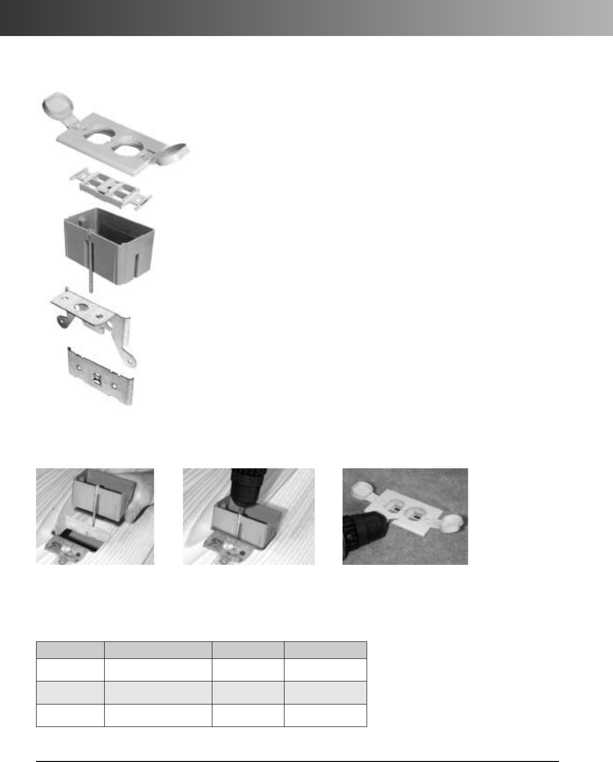
www.carlon.com
110
SCMS – Adjustable Floor Brackets
The Carlon Low Voltage Adjustable Floor Bracket is specifically designed for the low voltage,
structured cabling market…
the floor bracket is industry standard orange to identify low
voltage applications, the open design provides the space needed for low voltage bend
radius requirements, and the Leviton QuickPort®Quad 106®Insert provides up to four
low voltage outlet ports.
The Carlon Low Voltage Adjustable Floor Bracket is ideal for any
residential or commercial low voltage application.
The floor bracket also features a patented screw design allowing it to be adjusted to most
finished floor heights by simply turning the screw clockwise or counterclockwise and adjust-
ing flush to the floor.
The floor bracket kit comes complete with a nonmetallic (white or ivory) or brass cover, a
Leviton QuickPort Quad 106 Insert, new work and old work metal mounting brackets, and
mounting screws.
Carlon Structured Cable Management Systems…Your Total Systems
Solution!
Features:
•White, Ivory, or Brass Cover
•Orange – Identifies Low Voltage Installations
•Open Design Floor Bracket – Accommodates Low Voltage Bend Radius Requirements
•Patented Adjustable Screw – Bracket Adjusts to Most Finished Floor Depths
•Leviton QuickPort Quad 106 Insert – Install up to 4 Low Voltage Inserts
•Two-Door Design
•C-UL-US Listed
Low Voltage Adjustable Floor Bracket w/ Cover
Install clip over subfloor. Screw in to adjust to height
of flooring or carpet. Beautiful flush fit every time!
Installation:
Specifications:
Part No. Cover Std. Ctn. Qty. Std. Ctn. Wt. (lbs.)
SC100FBWC Nonmetallic – White 8 5.62
SC100FBVC Nonmetallic – Ivory 8 5.62
SC100FBBC Brass 8 13.78
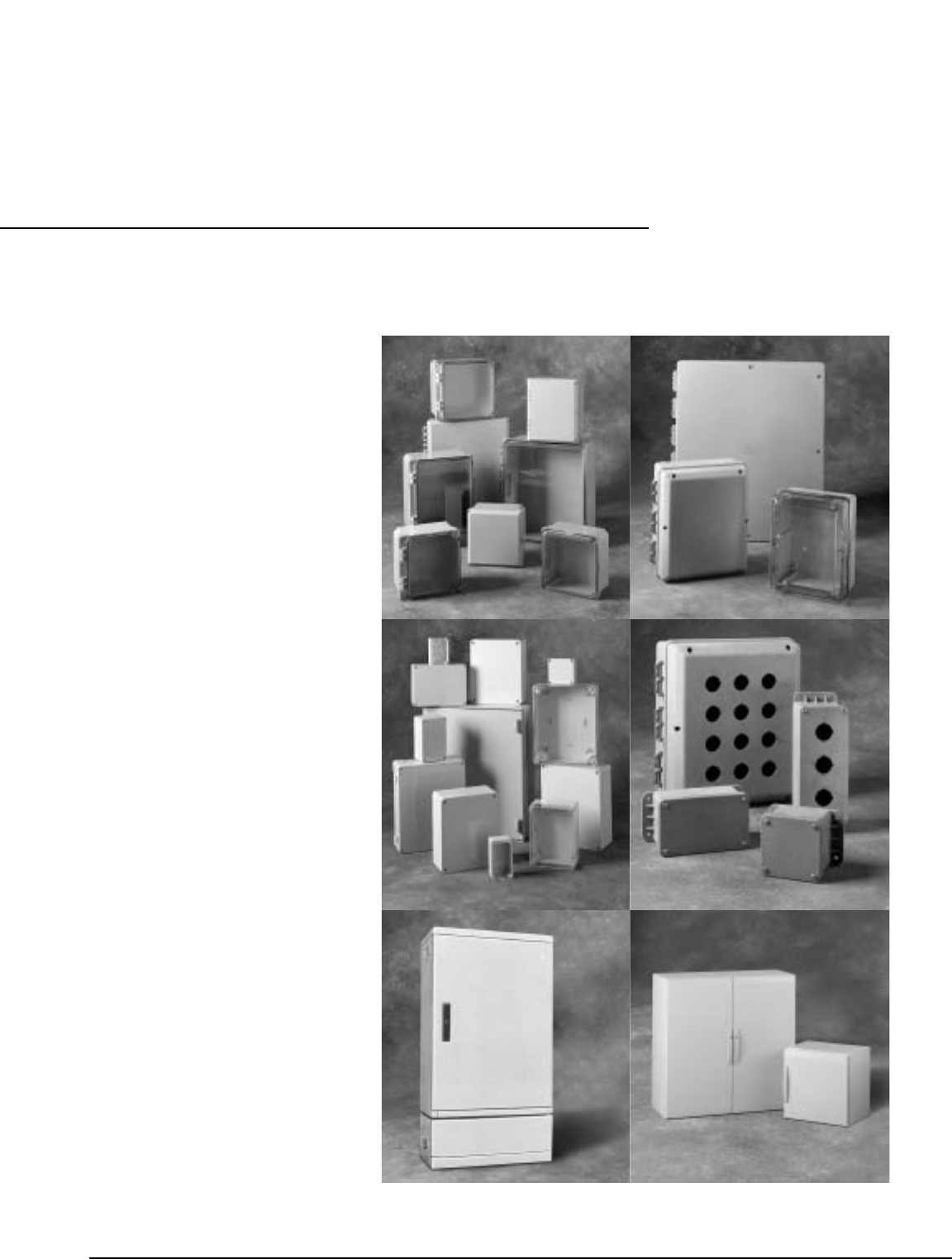
www.carlon.com 111
Carlon
®
Nonmetallic Enclosures
Circuit Safe
®
NEMA
Circuit Safe
®
JIC
Himeline
®
HE
Himeline
®
HS
Himeline
®
HP
Himeline
®
HLA/HLS
Himeline
®
HLP
Slack and Splice
Enclosures
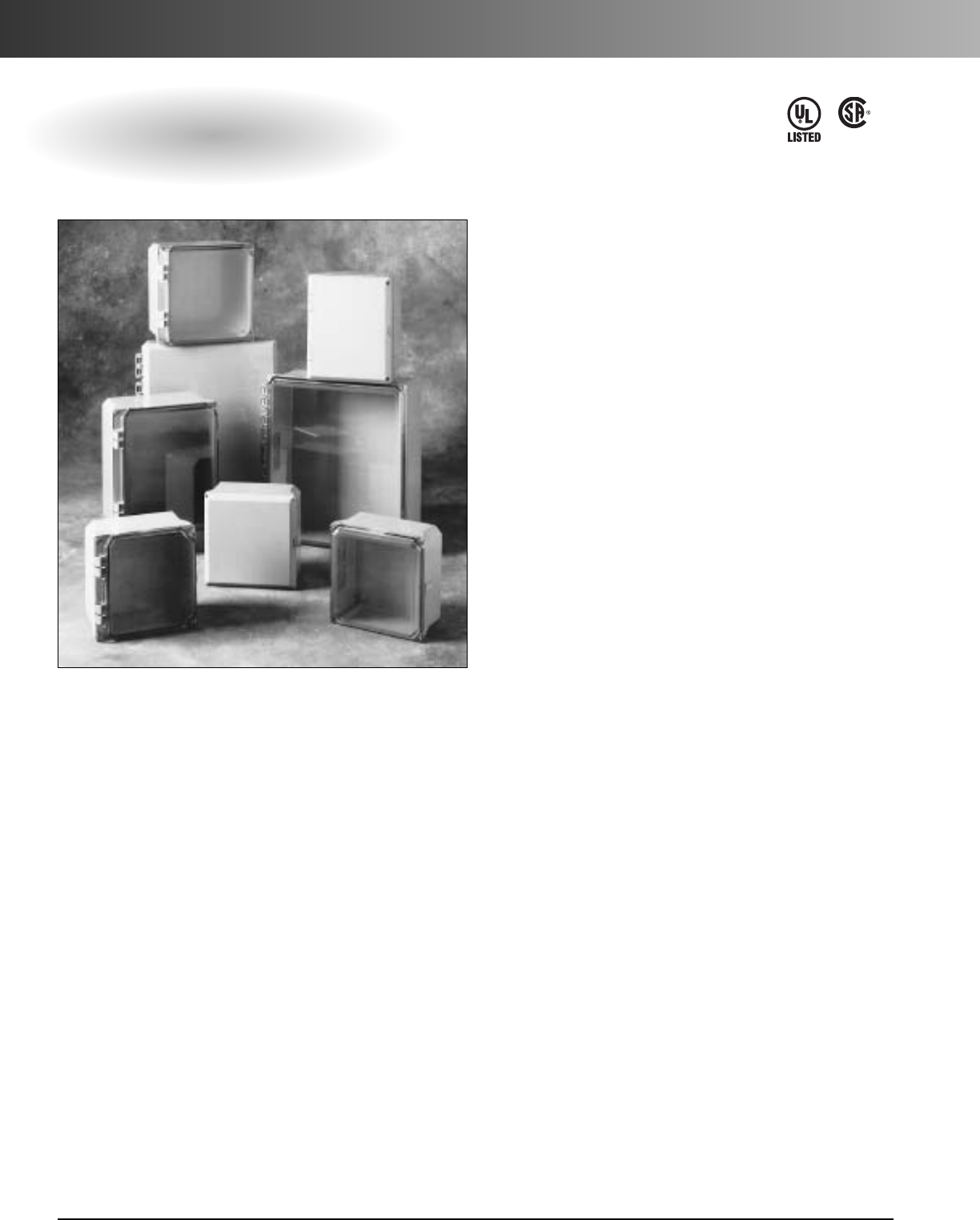
www.carlon.com
112
Circuit Safe®NEMA Enclosures
Circuit Safe NEMA Enclosures
LR96563
E110981
Manufactured from polycarbonate material (bodies and
covers), Carlon®NEMA enclosures deliver high temper-
ature stability (-30° F to 230° F ), exceptional corrosion
resistance, and greater performance than traditional
steel and stainless steel enclosures. Less than half the
weight of metal enclosures, they‘re also easier to
machine without fear of fracture and easier to install,
while offering both a lower installed cost and longer
service life. In addition, these attractive enclosures offer
molded-in features not found in metal enclosures along
with no rough edges, sharp corners, or burrs. Rated for
use in all NEMA Type 1, 2, 3, 3S, 3X, 3SX, 4, 4X, 12,
and 13 environments, Carlon NEMA enclosures meet
or exceed both UL and CSA requirements. They are
available in 10 different styles and 11 sizes from 6 x 4
x4to16 x 14 x 6 with screw or hinged design, clear
or opaque covers, and quick-release latches.
Features
•Captive stainless steel cover screws.
•Brass inserts for cover, mounting flanges and panel
mounting screws.
•Back panel provisions accept standard size
panels.
•Dove tailed corners for mounting panels or swing
out panels at any depth. (Use optional adjustable
back panel kit or swing out panel kit.)
•Oil resistant continuous gasket.
•Removable nonmetallic mounting rails included with
factory assembled units.
•Tapered edge keeps liquids away from door opening.
•Ultraviolet stabilized for outdoor use.
•Optional steel or PVC back panels available.
Applications
•Junction boxes
•Terminal block enclosures
•Motor control housings
•Instrument cases
•Electronic equipment cases
•Splice and pull boxes
•Pushbutton housings
Standards
•Meets NEMA Type
1, 2, 3, 3S, 3X, 3SX, 4, 4X, 12, 13
•Per UL 50, enclosures for electrical equipment.
•CSA certified as indicated.
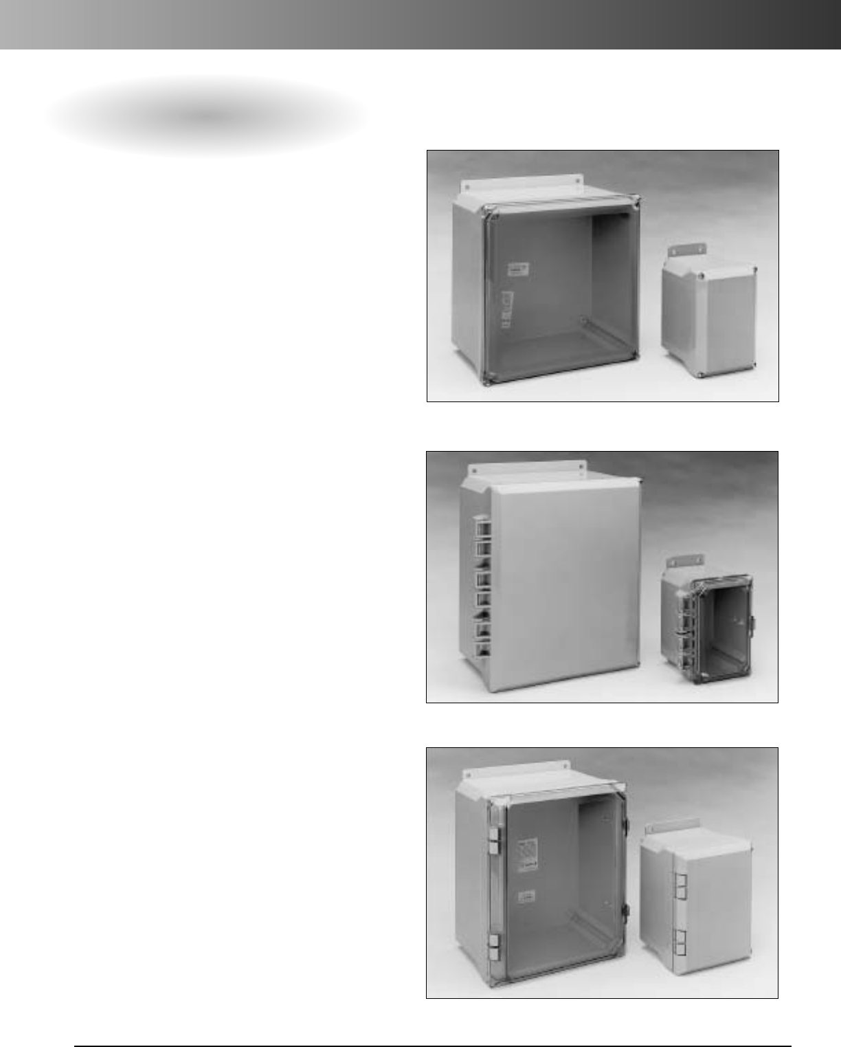
www.carlon.com 113
Circuit Safe®NEMA Enclosures
NEMA Enclosure Styles
Screw Cover
Circuit Safe®NEMA enclosures are
available in three different cover
options and a wide range of sizes.
From our screw cover style enclosures
to our hidden hinge cover style
enclosures to our external hinge cover
style enclosures, Carlon has a Circuit
Safe NEMA enclosure to meet your
application-specific need.
Styles
•Screw Cover
•External Hinge
•Hidden Hinge
Cover Color Options
•Opaque
•Clear
Material
•Polycarbonate (Bases and Lids)
External Hinge Cover
Hidden Hinge Cover
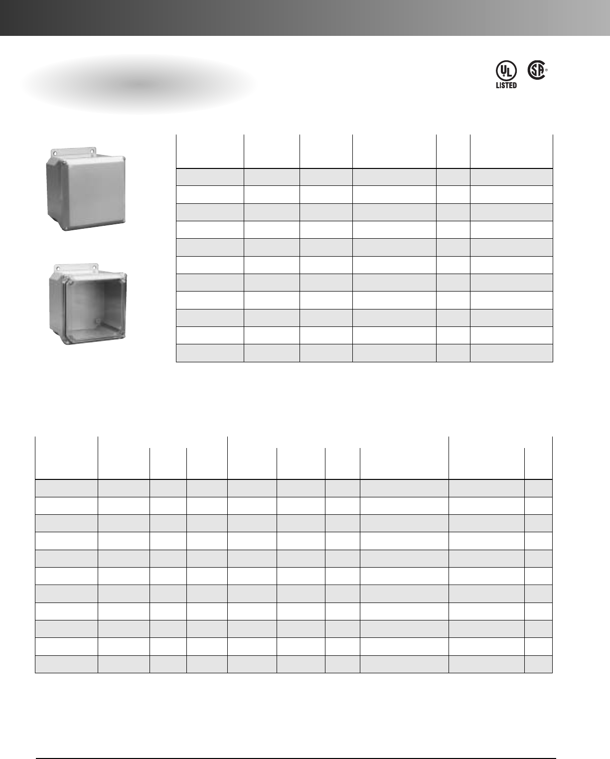
www.carlon.com
114
Circuit Safe®NEMA Enclosures
Screw-On Cover
Meets NEMA 1, 2, 3, 3S, 3X, 3SX, 4, 4X, 12
LR96563
E110981
Opaque Clear Back Std. Std. Ctn.
Cover Cover Panels** Ctn. Wt. (lbs.)
Size Assembly* Assembly* Steel/PVC Qty. Opaque/Clear
6x4x4 NS644 NV644 JP64 / JP64P 1 Opa 1.8 / Clr 1.9
6x6x4 NS664 NV664 JP66 / JP66P 1 Opa 2.4 / Clr 2.4
8x6x4 NS864 NV864 JP86 / JP86P 1 Opa 2.9 / Clr 2.8
8x8x4 NS884 NV884 JP88 / JP88P 1 Opa 3.2 / Clr 3.3
10 x 8 x 4 NS1084 NV1084 JP108 / JP108P 1 Opa 4.0 / Clr 3.9
10 x 8 x 6 NS1086 NV1086 JP108 / JP108P 1 Opa 4.6 / Clr 4.5
10 x 10 x 6 NS10106 NV10106 JP1010 / JP1010P 1 Opa 5.3 / Clr 4.9
12 x 10 x 6 NS12106 NV12106 JP1210 / JP1210P 1 Opa 6.1 / Clr 5.2
12 x 12 x 6 NS12126 NV12126 JP1212 / JP1212P 1 Opa 6.8 / Clr 6.1
14 x 12 x 6 NS14126 NV14126 JP1412 / JP1412P 1 Opa 7.4 / Clr 7.0
16 x 14 x 6 NS16146 NV16146 JP1614 / JP1614P 1 Opa 9.2 / Clr 8.1
EnclosureBase* EnclosureLids Back Panels**
Std. Std. Ctn. Std. Std. Ctn. Std.
Enclosure Part Ctn. Wt. Opaque Clear Ctn . Wt. Steel /PVC Ctn
Size Nos. Qty. (lbs.) Lids Lids Qty. (lbs.) Part Nos. Qty.
6x4x4 NP644B 18 21 NS64L NV64L 16 Opa 6.4 / Clr 5.7 JP64 / JP64P 1
6x6x4 NP664B 12 17 NS66L NV66L 12 Opa 6.2 / Clr 5.7 JP66 / JP66P 1
8x6x4 NP864B 12 18 NS86L NV86L 9 Opa 6 / Clr 4.4 JP86 / JP86P 1
8x8x4 NP884B 14 28 NS88L NV88L 18 Opa 14 / Clr 11.2 JP88 / JP88P 1
10 x 8 x 4 NP1084B 12 26 NS108L NV108L 12 Opa 13 / Clr 11 JP108 / JP108P 1
10 x 8 x 6 NP1086B 8 23 NS108L NV108L 12 Opa 13 / Clr 11 JP108 / JP108P 1
10 x 10 x 6 NP1010B 620 NS1010L NV1010L 11 Opa 14 / Clr 12 JP1010 / JP1010P 1
12 x 10 x 6 NP1210B 6 23 NS1210L NV1210L 12 Opa 15 / Clr 15 JP1210 / JP1210P 1
12 x 12 x 6 NP1212B 522 NS1212L NV1212L 10 Opa 15 / Clr 14 JP1212 / JP1212P 1
14 x 12 x 6 NP1412B 5 24 NS1412L NV1412L 5 Opa 9 / Clr 9 JP1412 / JP1412P 1
16 x 14 x 6 NP1614B 431 NS1614L NV1614L 5 Opa 11 / Clr 11 JP1614 / JP1614P 1
Opaque Cover
Clear Cover
*Mounting rails are not included. See “Mounting Rails” listed in the Enclosure Accessories section.
** Order back panels separately.
Factory Assembled
Individual Components
*Kitted Enclosures include body, lid and mounting rail kit.
** Order back panels separately.
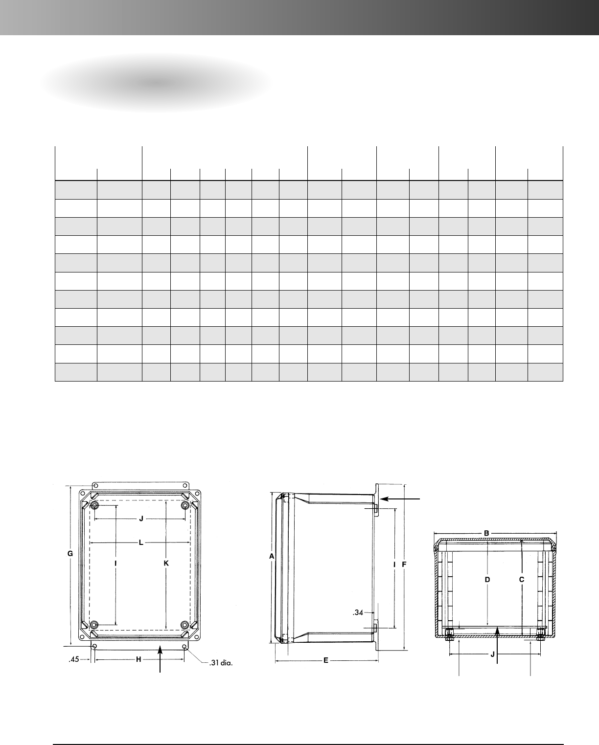
www.carlon.com 115
Circuit Safe®NEMA Enclosures
Screw-On Cover
Enclosure With
Enclosure Mounting Panel Mounting
Back Panel Back Panel**
Clear Lid Opaque Lid Enclosure Size Hole Spacing Hole Spacing Size Part Nos.
Part Nos.* Part Nos.* A B C D E F G H I J K L Steel PVC
NV644 NS644 6.40 4.40 4.49 3.98 5.13 7.69 6.75 2.00 4.25 2.25 4.88 2.88 JP64 JP64P
NV664 NS664 6.40 6.40 4.49 3.98 5.13 7.69 6.75 4.00 4.25 4.25 4.88 4.88 JP66 JP66P
NV864 NS864 8.40 6.40 4.49 3.98 5.13 9.69 8.75 4.00 6.25 4.25 6.75 4.88 JP86 JP86P
NV884 NS884 8.40 8.40 4.49 3.98 5.13 9.69 8.75 6.00 6.25 6.25 6.75 6.88 JP88 JP88P
NV1084 NS1084 10.40 8.40 4.49 3.98 5.13 11.69 10.75 6.00 8.25 6.25 8.75 6.88 JP108 JP108P
NV1086 NS1086 10.40 8.40 6.49 5.98 7.13 11.69 10.75 6.00 8.25 6.25 8.75 6.88 JP108 JP108P
NV10106 NS10106 10.40 10.40 6.49 5.98 7.13 11.69 10.75 8.00 8.25 8.25 8.75 8.88 JP1010 JP1010P
NV12106 NS12106 12.40 10.40 6.49 5.98 7.13 13.69 12.75 8.00 10.25 8.25 10.75 8.88 JP1210 JP1210P
NV12126 NS12126 12.40 12.40 6.49 5.98 7.13 13.69 12.75 10.00 10.25 10.25 10.75 10.88 JP1212 JP1212P
NV14126 NS14126 14.40 12.40 6.49 5.98 7.13 15.69 14.75 10.00 12.25 10.25 12.75 10.88 JP1412 JP1412P
NV16146 NS16146 16.40 14.40 6.49 5.98 7.13 17.69 16.75 12.00 14.25 12.25 14.75 12.88 JP1614 JP1612P
Specifications
* Packaged-To-Order Enclosures include body, lid and mounting rail kit.
** Order back panels separately. (10/32 –3/8Back Panel screws not supplied.)
Mounting Rail
Mounting Rail
Back Panel
(order
separately) .19
.44
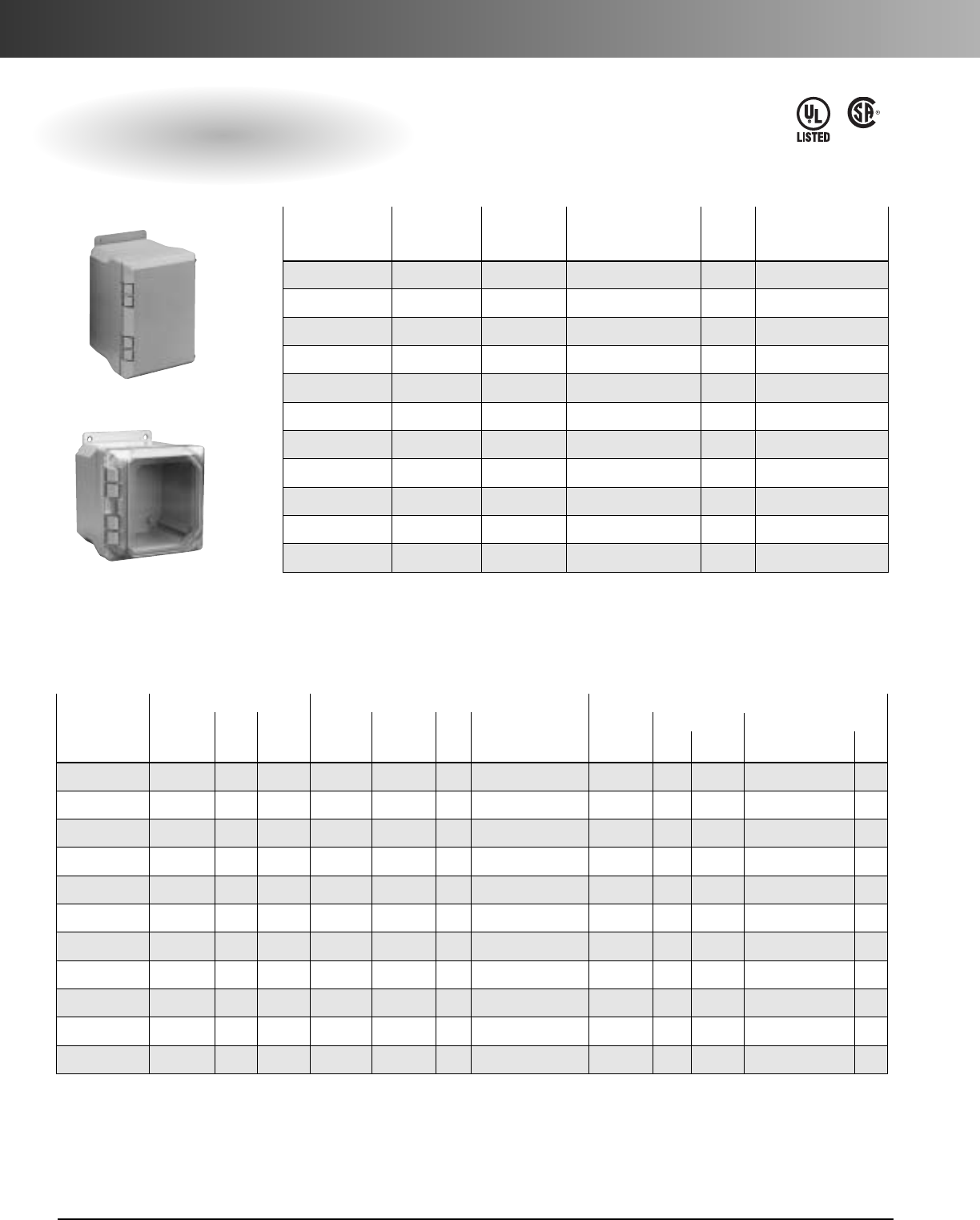
www.carlon.com
116
Circuit Safe®NEMA Enclosures
Hidden Hinge Cover
Meets NEMA 1, 2, 3, 3S, 3X, 3SX, 4, 4X, 12
LR96563
E110981
Opaque Clear Back Std. Std. Ctn.
Cover Cover Panels** Ctn. Wt. (lbs.)
Size Assembly* Assembly* Steel/PVC Qty. Opaque/Clear
6x4x5(y) NH644 NI644 JP64 / JP64P 1 Opa 2.2 / Clr 2.8
6x6x5 NH664 NI664 JP66 / JP66P 1 Opa 2.7 / Clr 3.2
8x6x5 NH864 NI864 JP86 / JP86P 1 Opa 3.3 / Clr 3.8
8x8x5 NH884 NI884 JP88 / JP88P 1 Opa 3.8 / Clr 3.8
10 x 8 x 5 NH1084 NI1084 JP108 / JP108P 1 Opa 4.0 / Clr 4.5
10 x 8 x 7 NH1086 NI1086 JP108 / JP108P 1 Opa 5.2 / Clr 5.1
10 x 10 x 7 NH10106 NI10106 JP1010 / JP1010P 1 Opa 5.7 / Clr 5.8
12 x 10 x 7 NH12106 NI12106 JP1210 / JP1210P 1 Opa 6.9 / Clr 6.1
12 x 12 x 7 NH12126 NI12126 JP1212 / JP1212P 1 Opa 7.7 / Clr 7.2
14 x 12 x 7 NH14126 NI14126 JP1412 / JP1412P 1 Opa 8.3 / Clr 7.9
16 x 14 x 7 NH16146 NI16146 JP1614 / JP1614P 1 Opa 10.1 / Clr 9.6
Enclosure Base* Enclosure Lids Collars Back Panels**
Std. Std. Ctn. Opaque Clear Std. Std. Ctn. Std. Std. Ctn. Std.
EnclosurePart Ctn. Wt. Lids Lids Ctn . Wt. Part Ctn. Wt. Steel /PVC Ctn
Size Nos. Qty. (lbs.) Part Nos. Part Nos. Qty. (lbs.) Nos. Qty. (lbs.) Part Nos. Qty.
6x4x5(y) NP644B 18 21 NH64L NI64L 16 Opa 6.8 / Clr 6.3 NH64C 16 6 JP64 / JP64P 1
6x6x5 NP664B 12 17 NH66L NI66L 12 Opa 6.8 / Clr 6.3 NH66C 12 5 JP66 / JP66P 1
8x6x5 NP864B 12 18 NH86L NI86L 9 Opa 6.3 / Clr 5.7 NH86C 9 4 JP86 / JP86P 1
8x8x5 NP884B 14 28 NH88L NI88L 18 Opa 16 / Clr 15 NH88C 9 3.6 JP88 / JP88P 1
10 x 8 x 5 NP1084B 12 26 NH108L NI108L 12 Opa 13 / Clr 12 NH108C 12 7.8 JP108 / JP108P 1
10 x 8 x 7 NP1086B 823 NH108L NI108L 12 Opa 13 / Clr 12 NH108C 12 7.8 JP108 / JP108P 1
10 x 10 x 7 NP1010B 6 20 NH1010L NI1010L 11 Opa 14 / Clr 13 NH1010C 11 7.5 JP1010 / JP1010P 1
12 x 10 x 7(z) NP1210B 623 NH1210L NI1210L 12 Opa 17 / Clr 6 NH1210C 12 8 JP1210 / JP1210P 1
12 x 12 x 7(z) NP1212B 5 22 NH1212L NI1212L 10 Opa 17 / Clr 16 NH1212C 12 7.7 JP1212 / JP1212P 1
14 x 12 x 7(z) NP1412B 524 NH1412L NI1412L 5 Opa 10 / Clr 10 NH1412C 5 4.7 JP1412 / JP1412P 1
16 x 14 x 7(z) NP1614B 4 31 NH1614L NI1614L 5 Opa 13 / Clr 12 NH1614C 5 5.6 JP1614 / JP1614P 1
Opaque Cover
Clear Cover
*Mounting rails are not included. See “Mounting Rails” listed in the Enclosure Accessories section.
** Order back panels separately.
(y) 6 x 4 x 5 enclosures are not available with quick-release latches.
(z) Sizes 12 x 10 and larger require two (2) latches per enclosure.
Factory Assembled
Individual Components
*Packaged-To-Order Enclosures (except NI1084) include body, lid and mounting rail kit.
** Order back panels separately.
(y) 6 x 4 x 5 size not available with quick-release latches.
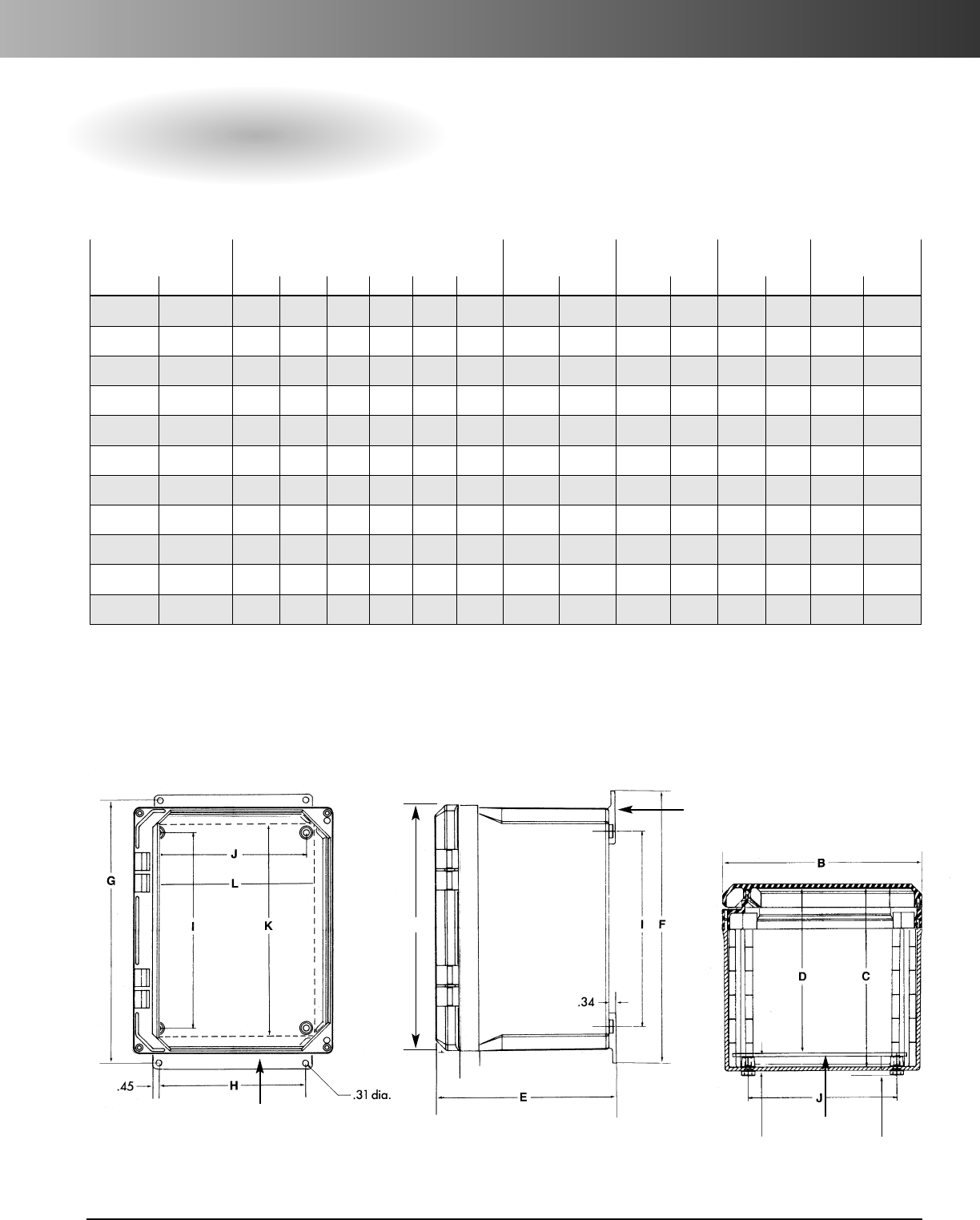
www.carlon.com 117
Circuit Safe®NEMA Enclosures
Hidden Hinge Cover
Enclosure With
Enclosure Mounting Panel Mounting
Back Panel Back Panel**
Opaque Lid Clear Lid Enclosure Size Hole Spacing Hole Spacing Size Part Nos.
Part Nos.* Part Nos.* A B C D E F G H I J K L Steel PVC
NH644 NI644 6.40 4.40 5.30 4.79 5.94 7.69 6.75 2.00 4.25 2.25 4.88 2.88 JP64 JP64P
NH664 NI664 6.40 6.40 5.30 4.79 5.94 7.69 6.75 4.00 4.25 4.25 4.88 4.88 JP66 JP66P
NH864 NI864 8.40 6.40 5.30 4.79 5.94 9.69 8.75 4.00 6.25 4.25 6.75 4.88 JP86 JP86P
NH884 NI884 8.40 8.40 5.30 4.79 5.94 9.69 8.75 6.00 6.25 6.25 6.75 6.88 JP88 JP88P
NH1084 NI1084 10.40 8.40 5.30 4.79 5.94 11.69 10.75 6.00 8.25 6.25 8.75 6.88 JP108 JP108P
NH1086 NI1086 10.40 8.40 7.30 6.79 7.94 11.69 10.75 6.00 8.25 6.25 8.75 6.88 JP108 JP108P
NH10106 NI10106 10.40 10.40 7.30 6.79 7.94 11.59 10.75 8.00 8.25 8.25 8.75 8.88 JP1010 JP1010P
NH12106 NI12106 12.40 10.40 7.30 6.79 7.94 13.69 12.75 8.00 10.25 8.25 10.75 8.88 JP1210 JP1210P
NH12126 NI12126 12.40 12.40 7.30 6.79 7.94 13.69 12.75 10.00 10.25 10.25 10.75 10.88 JP1212 JP1212P
NH14126 NI14126 14.40 12.40 7.30 6.79 7.94 15.69 14.75 10.00 12.25 10.25 12.75 10.88 JP1412 JP1412P
NH16146 NI16146 16.40 14.40 7.30 6.79 7.94 17.69 16.75 12.00 14.25 12.25 14.75 12.88 JP1614 JP1612P
Specifications
* Packaged-To-Order Enclosures (except NI1084) include body, lid and mounting rail kit.
** Order back panels separately. (10/32 –3/8Back Panel screws not supplied.)
Mounting Rail
A
Back Panel
(order
separately) .19
.44
Mounting Rail
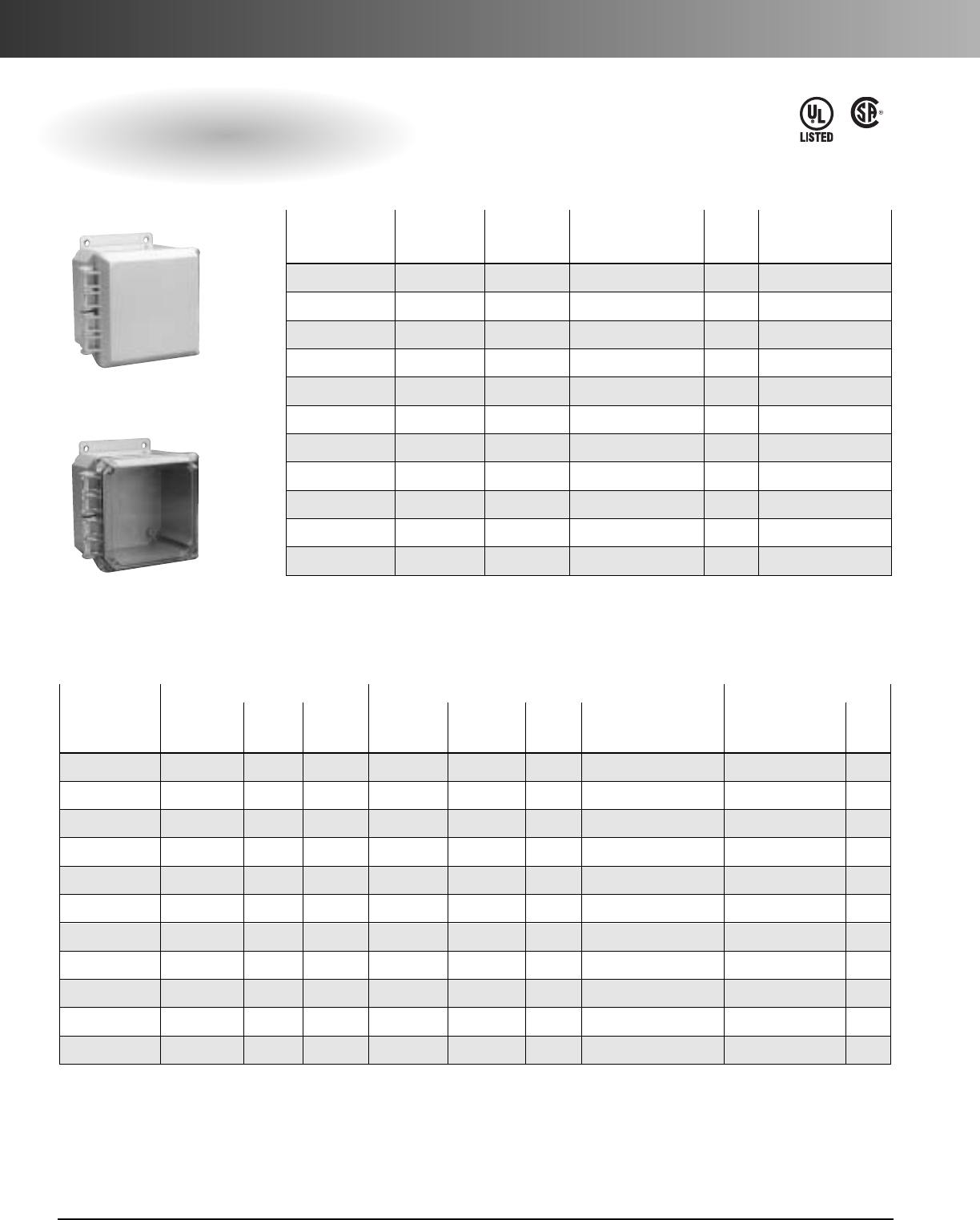
www.carlon.com
118
Circuit Safe®NEMA Enclosures
External Hinge Cover
Meets NEMA 1, 2, 3, 3S, 3X, 3SX, 4, 4X, 12
LR96563
E110981
Opaque Clear Back Std. Std. Ctn.
Cover Cover Panels** Ctn. Wt. (lbs.)
Size Assembly* Assembly* Steel/PVC Qty. Opaque/Clear
6x4x4(y) NJ644 NC644 JP64 / JP64P 1 Opa 1.9 / Clr 2
6x6x4 NJ664 NC664 JP66 / JP66P 1 Opa 2.4 / Clr 2.4
8x6x4 NJ864 NC864 JP86 / JP86P 1 Opa 2.9 / Clr 2.9
8x8x4 NJ884 NC884 JP88 / JP88P 1 Opa 3.3 / Clr 3.3
10 x 8 x 4 NJ1084 NC1084 JP108 / JP108P 1 Opa 4 / Clr 4
10 x 8 x 6 NJ1086 NC1086 JP108 / JP108P 1 Opa 4.6 / Clr 4.7
10 x 10 x 6 NJ10106 NC10106 JP1010 / JP1010P 1 Opa 5.6 / Clr 5.3
12 x 10 x 6 NJ12106 NC12106 JP1210 / JP1210P 1 Opa 6.3 / Clr 5.8
12 x 12 x 6 NJ12126 NC12126 JP1212 / JP1212P 1 Opa 6.9 / Clr 6.6
14 x 12 x 6 NJ14126 NC14126 JP1412 / JP1412P 1 Opa 7.7 / Clr 7
16 x 14 x 6 NJ16146 NC16146 JP1614 / JP1614P 1 Opa 8.2 / Clr 8
Enclosure Base* Enclosure Lids Back Panels**
Std. Std. Ctn. Std. Std. Ctn. Std.
EnclosurePart Ctn. Wt. Opaque Clear Ctn . Wt. Steel /PVC Ctn
Size Nos. Qty. (lbs.) Lids Lids Qty. (lbs.) Part Nos. Qty.
6x4x4(y) NL644B 18 29 NJ64L NC64L 16 Opa 6.4 / Clr 4.2 JP64 / JP64P 1
6x6x4 NL664B 12 18 NJ66L NC66L 12 Opa 5.0 / Clr 5.9 JP66 / JP66P 1
8x6x4 NL864B 8 14 NJ86L NC86L 9 Opa 6 / Clr 5.3 JP86 / JP86P 1
8x8x4 NL884B 14 28 NJ88L NC88L 18 Opa 15 / Clr 13.5 JP88 / JP88P 1
10 x 8 x 4 NL1084B 12 32 NJ108L NC108L 12 Opa 13 / Clr 11.7 JP108 / JP108P 1
10 x 8 x 6 NL1086B 8 15 NJ108L NC108L 12 Opa 13 / Clr 11.7 JP108 / JP108P 1
10 x 10 x 6 NL1010B 6 20 NJ1010L NC1010L 11 Opa 14 / Clr 13 JP1010 / JP1010P 1
12 x 10 x 6(z) NL1210B 6 24 NJ1210L NC1210L 12 Opa 14 / Clr 15 JP1210 / JP1210P 1
12 x 12 x 6(y) NL1212B 5 21.8 NJ1212L NC1212L 10 Opa 16 / Clr 14 JP1212 / JP1212P 1
14 x 12 x 6(y) NL1412B 4 19 NJ1412L NC1412L 5 Opa 10 / Clr 9 JP1412 / JP1412P 1
16 x 12 x 6(y) NL1614B 4 31 NJ1614L NC1614L 5 Opa 13.5 / Clr 12 JP1614 / JP1614P 1
Opaque Cover
Clear Cover
*Mounting rails are not included. See “Mounting Rails” listed in the Enclosure Accessories section.
** Order back panels separately.
(z) Sizes 12 x 10 and larger require two (2) latches per enclosure.
(y) Quick-release latch not available in 6 x 4 x 4 size.
Factory Assembled
Individual Components
* Packaged-To-Order Enclosures include body,lid and mounting rail kit.
** Order back panels separately.
(y) Quick-release latch not available in 6 x 4 x 4 size.
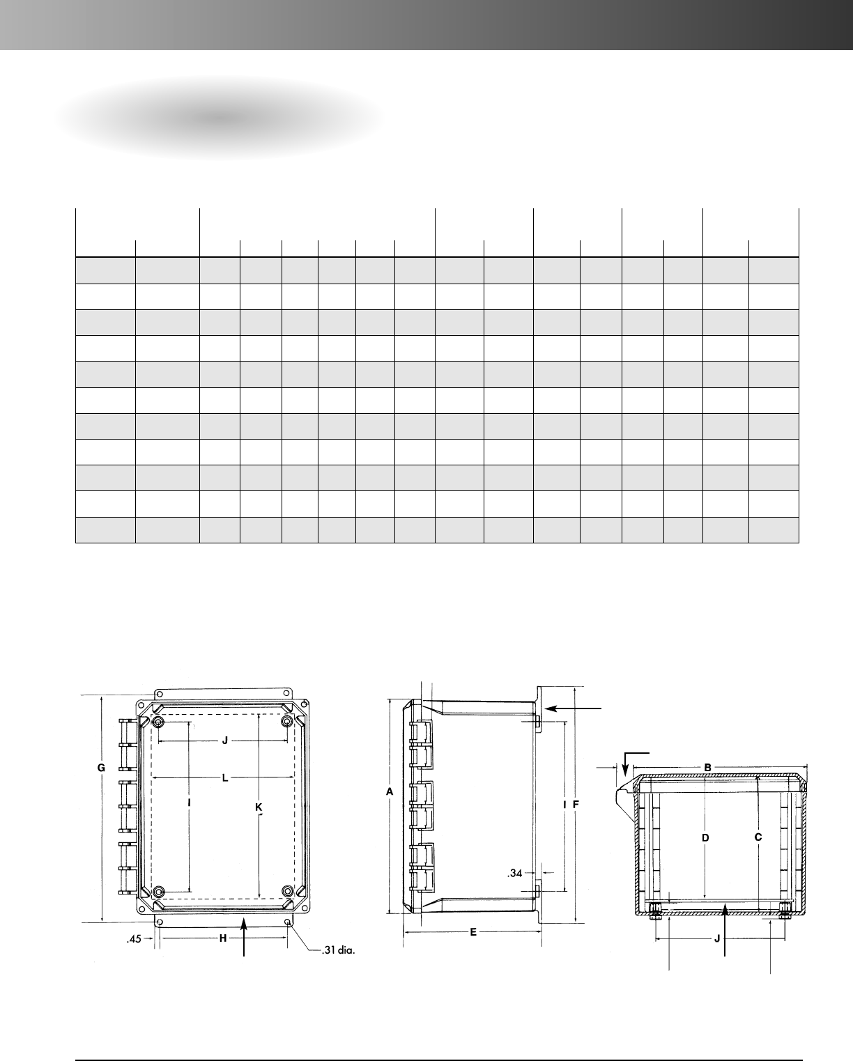
www.carlon.com 119
Circuit Safe®NEMA Enclosures
External Hinge Cover
Enclosure With
Enclosure Mounting Panel Mounting
Back Panel Back Panel**
Clear Lid Opaque Lid Enclosure Size Hole Spacing Hole Spacing Size Part Nos.
Part Nos.* Part Nos.* A B C D E F G H I J K L Steel PVC
NC644 NJ644 6.40 4.40 4.49 3.98 5.13 7.69 6.75 2.00 4.25 2.25 4.88 2.88 JP64 JP64P
NC664 NJ664 6.40 6.40 4.49 3.98 5.13 7.69 6.75 4.00 4.25 4.25 4.88 4.88 JP66 JP66P
NC864 NJ864 8.40 6.40 4.49 3.98 5.13 9.69 8.75 4.00 6.25 4.25 6.75 4.88 JP86 JP86P
NC884 NJ884 8.40 8.40 4.49 3.98 5.13 9.69 8.75 6.00 6.25 6.25 6.75 6.88 JP88 JP88P
NC1084 NJ1084 10.40 8.40 4.49 3.98 5.13 11.69 10.75 6.00 8.25 6.25 8.75 6.88 JP108 JP108P
NC1086 NJ1086 10.40 8.40 6.49 5.98 7.13 11.69 10.75 6.00 8.25 6.25 8.75 6.88 JP108 JP108P
NC10106 NJ10106 10.40 10.40 6.49 5.98 7.13 11.69 10.75 8.00 8.25 8.25 8.75 8.88 JP1010 JP1010P
NC12106 NJ12106 12.40 10.40 6.49 5.98 7.13 13.69 12.75 8.00 10.25 8.25 10.75 8.88 JP1210 JP1210P
NC12126 NJ12126 12.40 12.40 6.49 5.98 7.13 13.69 12.75 10.00 10.25 10.25 10.75 10.88 JP1212 JP1212P
NC14126 NJ14126 14.40 12.40 6.49 5.98 7.13 15.69 14.75 10.00 12.25 10.25 12.75 10.88 JP1412 JP1412P
NC16146 NJ16146 16.40 14.40 6.49 5.98 7.13 17.69 16.75 12.00 14.25 12.25 14.75 12.88 JP1614 JP1614P
Specifications
Mounting Rail
Mounting Rail
Back Panel
(order
separately) .19
.44
* Packaged-To-Order Enclosures; include body, lid and mounting rail kit.
** Order back panels separately. (10/32 –3/8Back Panel screws not supplied.)
.88
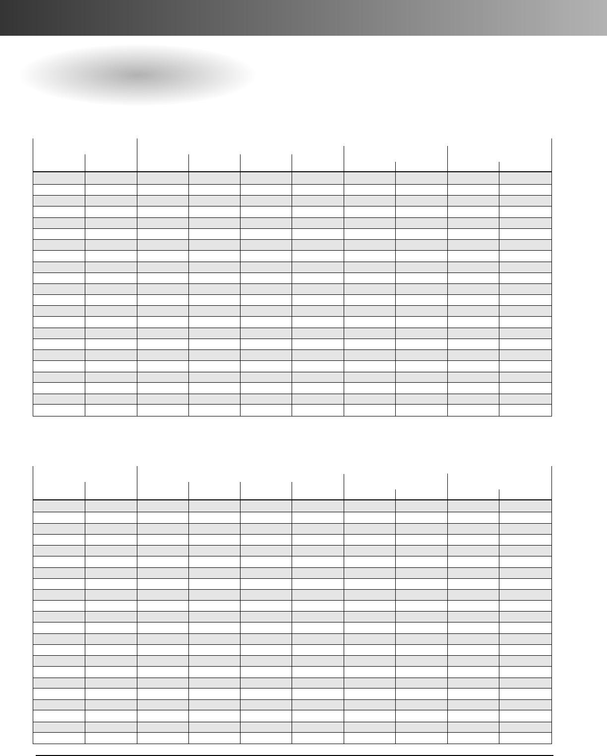
www.carlon.com
120
Section
Quick Reference
Complete Enclosures Individual Components
(no Panel or Latches) Latches
Opaque Clear Back Panels (Qty. needed)
Lid Lid Body Lid Collar Mtg. Rails Steel PVC Steel PVC
NS644 NP644B NS64L N/A NMK4V JP64 JP64P N/A N/A
NV644 NP644B NV64L N/A NMK4V JP64 JP64P N/A N/A
NS664 NP664B NS66L N/A NMK6V JP66 JP66P N/A N/A
NV664 NP664B NV66L N/A NMK6V JP66 JP66P N/A N/A
NS864 NP864B NS86L N/A NMK6V JP86 JP86P N/A N/A
NV864 NP864B NV86L N/A NMK6V JP86 JP86P N/A N/A
NS884 NP884B NS88L N/A NMK8V JP88 JP88P N/A N/A
NV884 NP884B NV88L N/A NMK8V JP88 JP88P N/A N/A
NS1084 NP1084B NS108L N/A NMK8V JP108 JP108P N/A N/A
NV1084 NP1084B NV108L N/A NMK8V JP108 JP108P N/A N/A
NS1086 NP1086B NS108L N/A NMK8V JP108 JP108P N/A N/A
NV1086 NP1086B NV108L N/A NMK8V JP108 JP108P N/A N/A
NS10106 NP1010B NS1010L N/A NMK10V JP1010 JP1010P N/A N/A
NV10106 NP1010B NV1010L N/A NMK10V JP1010 JP1010P N/A N/A
NS12106 NP1210B NS1210L N/A NMK10V JP1210 JP1210P N/A N/A
NV12106 NP1210B NV1210L N/A NMK10V JP1210 JP1210P N/A N/A
NS12126 NP1212B NS1212L N/A NMK12V JP1212 JP1212P N/A N/A
NV12126 NP1212B NV1212L N/A NMK12V JP1212 JP1212P N/A N/A
NS14126 NP1412B NS1412L N/A NMK12V JP1412 JP1412P N/A N/A
NV14126 NP1412B NV1412L N/A NMK12V JP1412 JP1412P N/A N/A
NS16146 NP1614B NS1614L N/A NMK14V JP1614 JP1614P N/A N/A
NV16146 NP1614B NV1614L N/A NMK14V JP1614 JP1614P N/A N/A
Screw-On Cover Style
Complete Enclosures Individual Components
(no Panel or Latches) Latches
Opaque Clear Back Panels (Qty. needed)
Lid Lid Body Lid Collar Mtg. Rails Steel PVC Steel PVC
NJ644 NL644B NJ64L N/A NMK4V JP64 JP64P SSLS (1) NPL1S (1)
NC644 NL644B NC64L N/A NMK4V JP64 JP64P SSLS (1) NPL1S (1)
NJ664 NL664B NJ66L N/A NMK6V JP66 JP66P SSLS (1) NPL1S (1)
NC664 NL664B NC66L N/A NMK6V JP66 JP66P SSLS (1) NPL1S (1)
NJ864 NL864B NJ86L N/A NMK6V JP86 JP86P SSLS (1) NPL1S (1)
NC864 NL864B NC86L N/A NMK6V JP86 JP86P SSLS (1) NPL1S (1)
NJ884 NL884B NJ88L N/A NMK8V JP88 JP88P SSLS (1) NPL1S (1)
NC884 NL884B NC88L N/A NMK8V JP88 JP88P SSLS (1) NPL1S (1)
NJ1084 NL1084B NJ108L N/A NMK8V JP108 JP108P SSLS (1) NPL1S (1)
NC1084 NL1084B NC108L N/A NMK8V JP108 JP108P SSLS (1) NPL1S (1)
NJ1086 NL1086B NJ108L N/A NMK8V JP108 JP108P SSLS (1) NPL1S (1)
NC1086 NL1086B NC108L N/A NMK8V JP108 JP108P SSLS (1) NPL1S (1)
NJ10106 NL1010B NJ1010L N/A NMK10V JP1010 JP1010P SSLS (1) NPL1S (1)
NC10106 NL1010B NC1010L N/A NMK10V JP1010 JP1010P SSLS (1) NPL1S (1)
NJ12106 NL1210B NJ1210L N/A NMK10V JP1210 JP1210P SSLS (2) NPL1S (2)
NC12106 NL1210B NC1210L N/A NMK10V JP1210 JP1210P SSLS (2) NPL1S (2)
NJ12126 NL1212B NJ1212L N/A NMK12V JP1212 JP1212P SSLS (2) NPL1S (2)
NC12126 NL1212B NC1212L N/A NMK12V JP1212 JP1212P SSLS (2) NPL1S (2)
NJ14126 NL1412B NJ1412L N/A NMK12V JP1412 JP1412P SSLS (2) NPL1S (2)
NC14126 NL1412B NC1412L N/A NMK12V JP1412 JP1412P SSLS (2) NPL1S (2)
NJ16146 NL1614B NJ1614L N/A NMK14V JP1614 JP1614P SSLS (2) NPL1S (2)
NC16146 NL1614B NC1614L N/A NMK14V JP1614 JP1614P SSLS (2) NPL1S (2)
External Hinge Cover Style
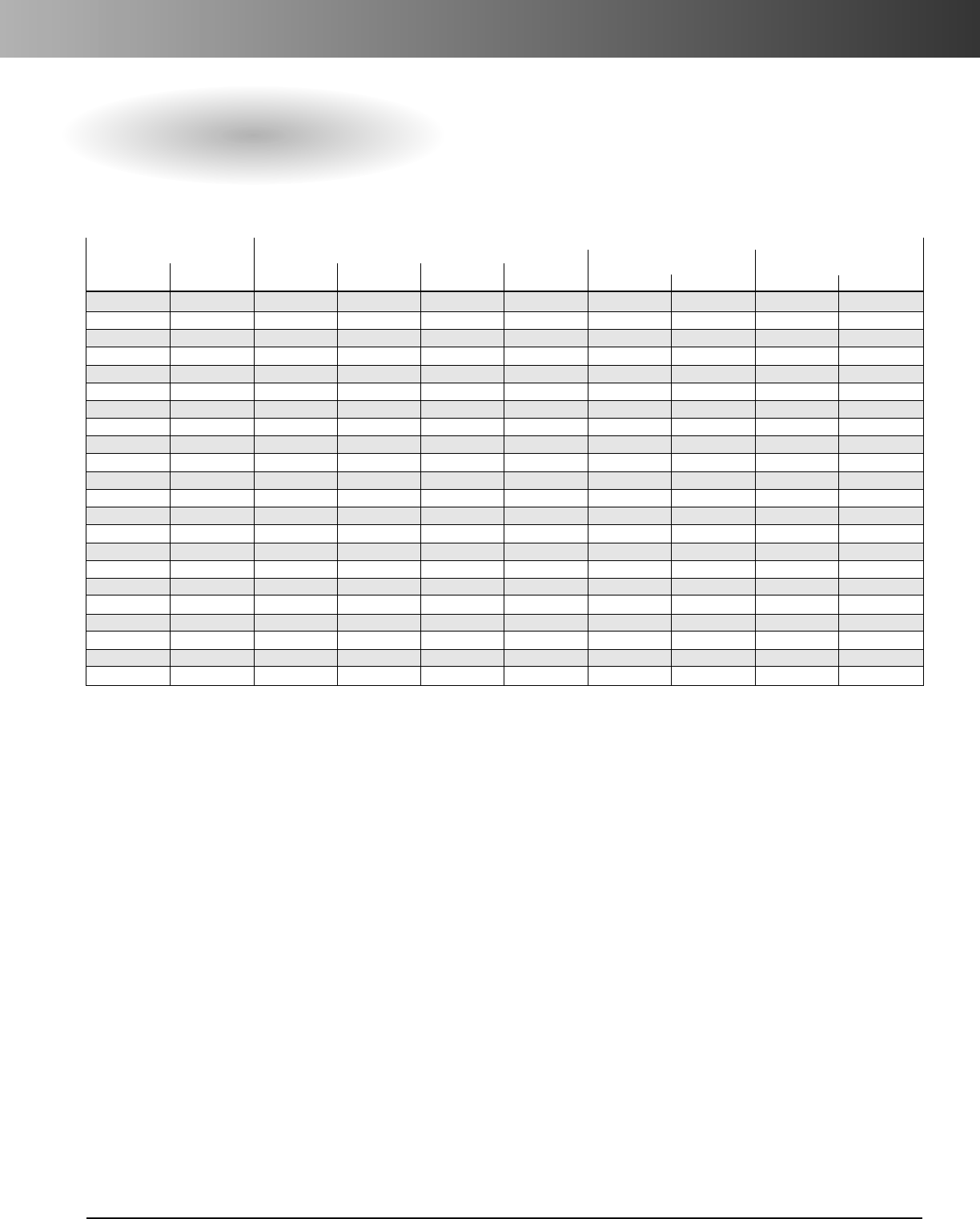
www.carlon.com 121
Circuit Safe®NEMA Enclosures
Quick Reference
Complete Enclosures Individual Components
(no Panel or Latches) Latches
Opaque Clear Back Panels (Qty. needed)
Lid Lid Body Lid Collar Mtg. Rails Steel PVC Steel PVC
NH644 NP644B NH64L NH64C NMK4V JP64 JP64P SSLL (1) NPL1L (1)
NI644 NP644B NI64L NH64C NMK4V JP64 JP64P SSLL (1) NPL1L (1)
NH664 NP664B NH66L NH66C NMK6V JP66 JP66P SSLL (1) NPL1L (1)
NI664 NP664B NI66L NH66C NMK6V JP66 JP66P SSLL (1) NPL1L (1)
NH864 NP864B NH86L NH86C NMK6V JP86 JP86P SSLL (1) NPL1L (1)
NI864 NP864B NI86L NH86C NMK6V JP86 JP86P SSLL (1) NPL1L (1)
NH884 NP884B NH88L NH88C NMK8V JP88 JP88P SSLL (1) NPL1L (1)
NI884 NP884B NI88L NH88C NMK8V JP88 JP88P SSLL (1) NPL1L (1)
NH1084 NP1084B NH108L NH108C NMK8V JP108 JP108P SSLL (1) NPL1L (1)
NI1084 NP1084B NI108L NH108C NMK8V JP108 JP108P SSLL (1) NPL1L (1)
NH1086 NP1086B NH108L NH108C NMK8V JP108 JP108P SSLL (1) NPL1L (1)
NI1086 NP1086B NI108L NH108C NMK8V JP108 JP108P SSLL (1) NPL1L (1)
NH10106 NP1010B NH1010L NH1010C NMK10V JP1010 JP1010P SSLL (1) NPL1L (1)
NI10106 NP1010B NI1010L NH1010C NMK10V JP1010 JP1010P SSLL (1) NPL1L (1)
NH12106 NP1210B NH1210L NH1210C NMK10V JP1210 JP1210P SSLL (2) NPL1L (2)
NI12106 NP1210B NI1210L NH1210C NMK10V JP1210 JP1210P SSLL (2) NPL1L (2)
NH12126 NP1212B NH1212L NH1212C NMK12V JP1212 JP1212P SSLL (2) NPL1L (2)
NI12126 NP1212B NI1212L NH1212C NMK12V JP1212 JP1212P SSLL (2) NPL1L (2)
NH14126 NP1412B NH1412L NH1412C NMK12V JP1412 JP1412P SSLL (2) NPL1L (2)
NI14126 NP1412B NI1412L NH1412C NMK12V JP1412 JP1412P SSLL (2) NPL1L (2)
NH16146 NP1614B NH1614L NH1614C NMK14V JP1614 JP1614P SSLL (2) NPL1L (2)
NI16146 NP1614B NI1614L NH1614C NMK14V JP1614 JP1614P SSLL (2) NPL1L (2)
Hidden Hinge Cover Style
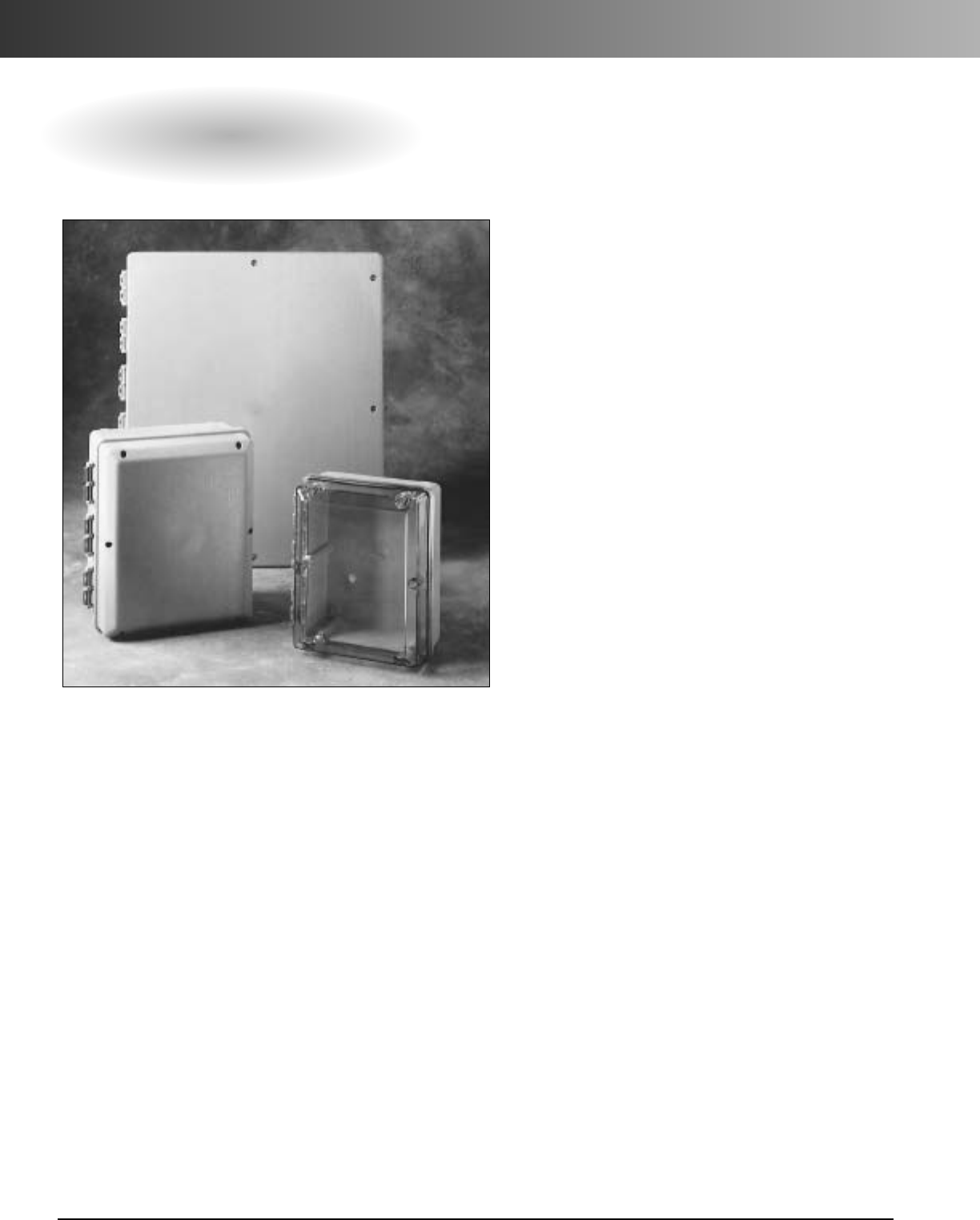
www.carlon.com
122
Circuit Safe®JIC Enclosures
Circuit Safe JIC Enclosures
Manufactured from structural foam thermoplastic, Carlon®
Circuit Safe®JIC enclosures provide high impact strength
to eliminate dents and deformations along with high
dielectric strength, excellent weathering capabilities, and
excellent resistance to a wide range of corrosive agents,
acids, alkalines, and salts. These UL approved and CSA
recognized enclosures also withstand wet and dirty
environments, while their thick wall construction make
them a particularly good choice wherever condensation
is a concern. Rated for use in Type 1, 3, 3S, 3X, 3SX, 4,
4X, 12, and 13 environments, Carlon Circuit Safe JIC
enclosures are suited for virtually all indoor/outdoor
industrial, MRO, and OEM applications. They are available
in 10 sizes from 6 x 6 x 5 through 30 x 24 x 12 with a
choice of screw or hinged design, opaque covers, or clear
polycarbonate covers which protect devices from hostile
environments while allowing monitoring of instrumenta-
tion and/or electrical functions.
Features
•Hinge caps make covers captive.
•Nonmetallic molded-in hinges on hinged models.
•No rough corners, sharp edges, or burrs.
•Nonconductive — eliminates danger of electrical
shock.
•Lid design provides greater usable internal
volume.
•Ample interior space for ease of wiring.
•Fully gasketed.
•Ultraviolet stabilized for outdoor use.
Applications
•Instrument case.
•Junction and terminal boxes.
•Control and switching enclosures.
•Splice and pull boxes.
•Starter, pushbutton, and transformer housings.
•Meter and transformer cabinets.
Standards
•Meets NEMA Types 1, 3, 3S, 3X, 3SX, 4, 4X,
12, 13 as indicated.
•UL Listed per UL 50, enclosures for electrical
equipment.
•CSA certified.
•JIC compliance.
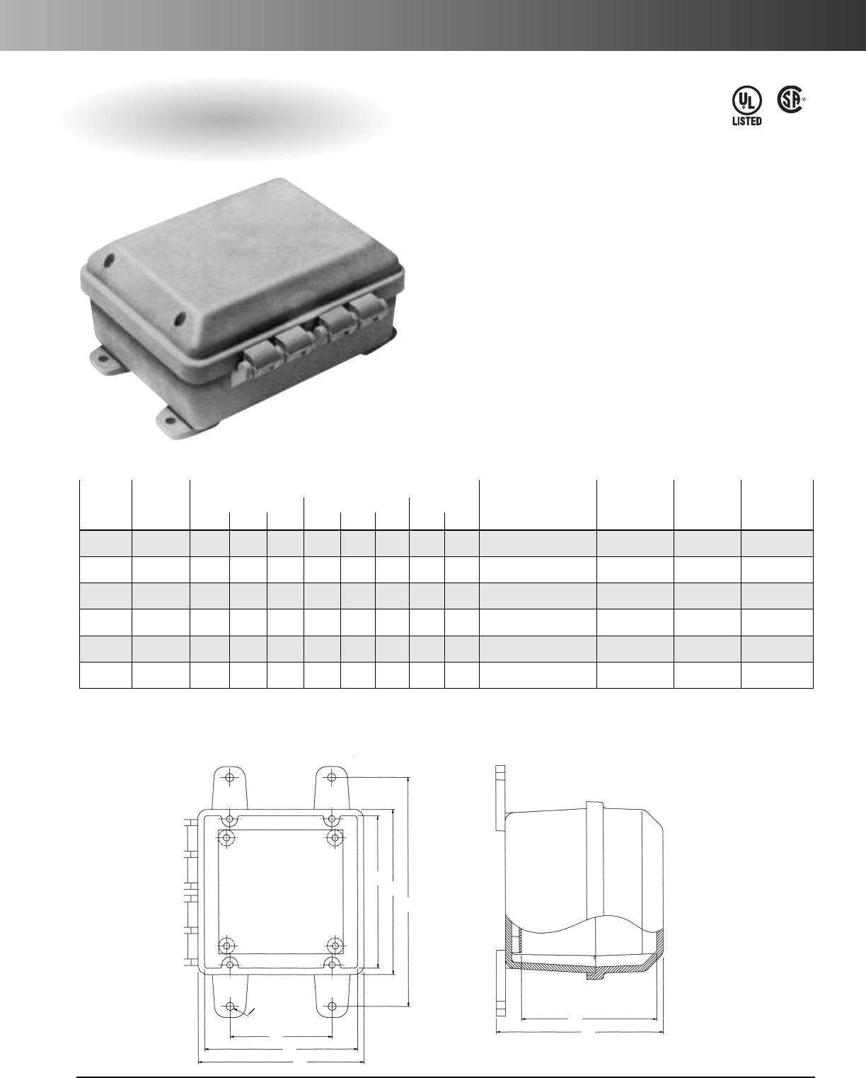
www.carlon.com 123
Circuit Safe®JIC Enclosures
Hinged Cover
Meets NEMA 1, 3, 3S, 3X, 3SX, 4, 4X, 12, 13
Opaque Clear
Dimensions Std. Ctn.
Back Panel*
Std. Ctn.
Cover Cover External Internal Mounting Qty. (lbs.) Part Nos. Panel Qty. (lbs.)
Part Nos. Part Nos. A B C D E F G H Opaque/Clear Steel/PVC Size Steel/PVC
CJ665 CC665 6.50 6.50 6.69 6.00 6.00 5.45 9.00 4.00 1 (Opa 3.5) / 1 (Clr 3.1) JP66/JP66P 4.88 x 4.88 1 (1.0) / 1 (0.3)
CJ863 CC863 8.50 6.50 4.49 8.00 6.00 3.25 11.00 4.00 1 (Opa 2.8) / 1 (Clr 3.1) JP86/JP86P 6.75 x 4.88 1 (1.0) / 1 (0.78)
CJ1085 CC1085 10.50 8.50 6.69 10.00 8.00 5.45 13.00 6.00 1 (Opa 5.2) / 1 (Clr 5.2) JP108/JP108P 8.75 x 6.88 1 (1.5) / 1 (0.7)
CJ12106 CC12106 12.50 10.50 7.69 12.00 10.00 6.45 15.00 8.00 1 (Opa 7.1) / 1 (Clr 8.4) JP1210/JP1210P 10.75 x 8.88 1 (2.0) / 1 (1.2)
CJ14126 CC14126 14.50 12.50 7.72 14.00 12.00 6.48 17.00 10.00 1 (Opa 9.0) / 1 (Clr 8.6) JP1412/JP1412P 12.75 x 10.88 1 (3.2) / 1 (1.7)
CJ16147 CC16147 16.50 14.50 8.46 16.00 14.00 7.22 19.00 12.00 1 (Opa 10.6) / 1 (Clr 11.9) JP1614/JP1614P 14.75 x 12.88 1 (4.7) / 1 (2.3)
Factory Assembled
*Order back panels separately.
Enclosures shipped with mounting feet, hinge caps and screws.
For factory installed pad lockable latch, consult Customer Service for price and delivery.
DA
G
H
E
B
O.312
TYP F
C
Features
•Nonmetallic mounting feet and all mounting
hardware included.
•White painted 14 gauge steel or 1/4"PVC back
panel (order separately).
•304 (18-8) stainless steel screws (10-32 / 11/8").
•Lid design provides greater usable internal volume.
•Completely nonmetallic hinges.
•Brass screw inserts.
• Temperature Range: -30° to 230°F
•Material: polycarbonate molded base and cover.
LR31146
E54381
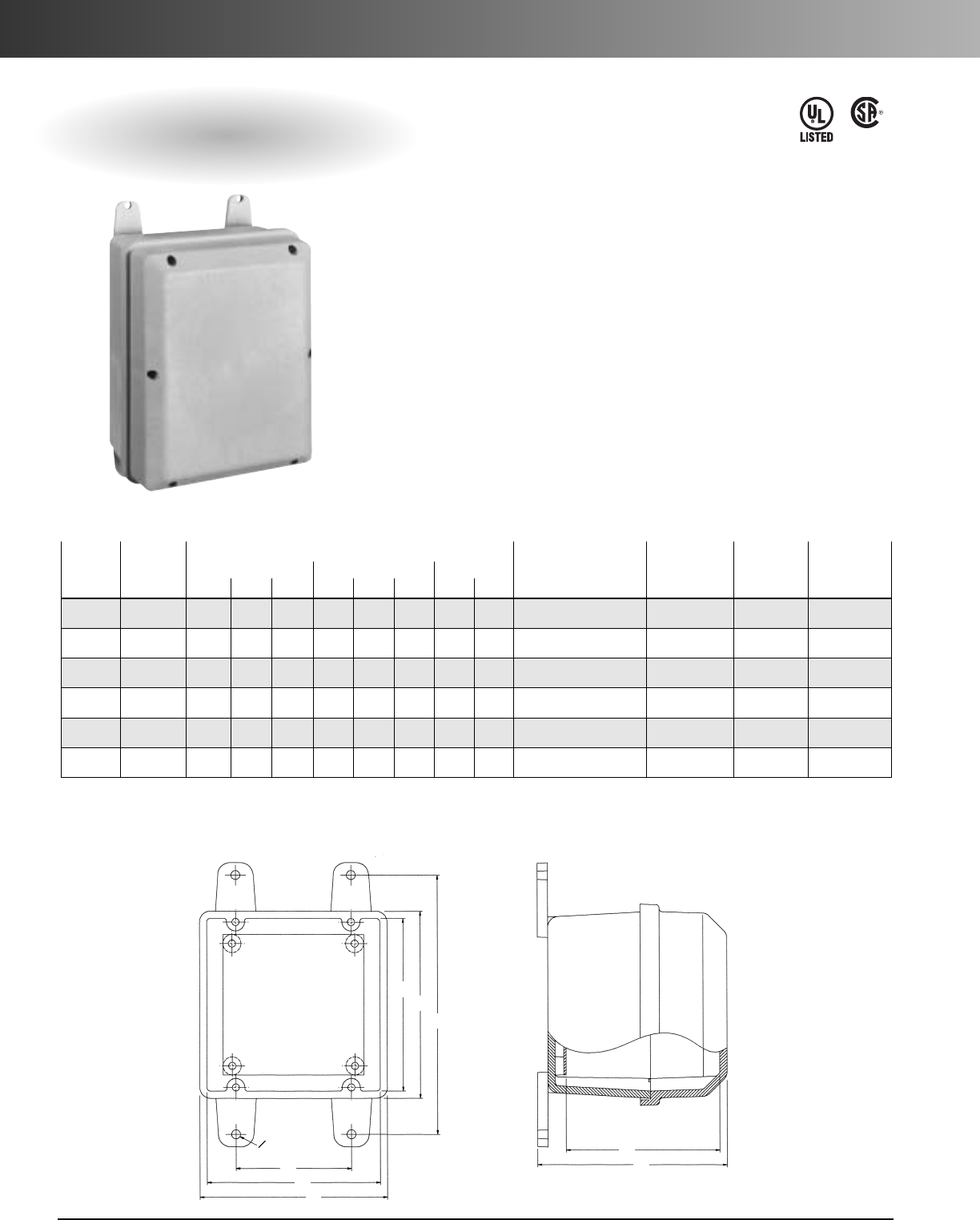
www.carlon.com
124
Circuit Safe®JIC Enclosures
Screw-On Cover
Meets NEMA 1, 3, 3S, 3X, 3SX, 4, 4X, 12, 13
Opaque Clear
Dimensions Std. Ctn.
Back Panel*
Std. Ctn.
Cover Cover External Internal Mounting Qty. (lbs.) Part Nos. Panel Qty. (lbs.)
Part Nos. Part Nos. A B C D E F G H Opaque/Clear Steel/PVC Size Steel/PVC
CS665 CV665 6.50 6.50 6.69 6.00 6.00 5.45 9.00 4.00 1 (Opa 2.7) / 1 (Clr 2.9) JP66/JP66P 4.88 x 4.88 1 (1.0) / 1 (0.3)
CS863 CV863 8.50 6.50 4.49 8.00 6.00 3.25 11.00 4.00 1 (Opa 2.9) / 1 (Clr 2.9) JP86/JP86P 6.75 x 4.88 1 (1.0) / 1 (0.4)
CS1085 CV1085 10.50 8.50 6.69 10.00 8.00 5.45 13.00 6.00 1 (Opa 5.0) / 1 (Clr 5.0) JP108/JP108P 8.75 x 6.88 1 (1.5) / 1 (0.7)
CS12106 CV12106 12.50 10.50 7.69 12.00 10.00 6.45 15.00 8.00 1 (Opa 6.5) / 1 (Clr 7.2) JP1210/JP1210P 10.75 x 8.88 1 (2.0) / 1 (1.2)
CS14126 CV14126 14.50 12.50 7.72 14.00 12.00 6.48 17.00 10.00 1 (Opa 8.0) / 1 (Clr 8.8) JP1412/JP1412P 12.75 x 10.88 1 (3.2) / 1 (1.7)
CS16147 CV16147 16.50 14.50 8.46 16.00 14.00 7.22 19.00 12.00 1 (Opa 11.5) / 1 (Clr 10.8) JP1614/JP1614P 14.75 x 12.88 1 (4.7) / 1 (2.3)
Factory Assembled
*Order back panels separately.
Enclosures shipped with mounting feet and panel mounting hardware.
Features
•Nonmetallic mounting feet and all mounting
hardware included.
•304 (18-8) stainless steel screws (10-32 / 11/8").
•Brass screw inserts.
•Clear polycarbonate cover available.
•White painted 14 gauge steel or 1/4"PVC back
panel (order separately).
•Lid design provides greater usable internal volume.
• Temperature Range: -30° to 230°F
•Material: polycarbonate molded base and cover.
LR31146
E54381
D
A
G
H
E
B
O.312
TYP F
C
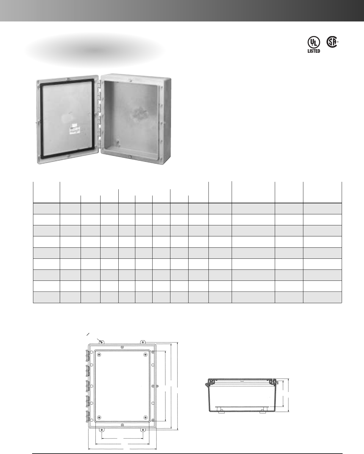
www.carlon.com 125
Circuit Safe®JIC Enclosures
Medium Hinged Cover
Meets NEMA 1, 3, 3S, 3X, 3SX, 4, 4X, 12, 13
Dimensions Std.
Back Panel*
Std. Ctn.
Part External Internal Mounting
Ctn.
Part Nos. Panel Qty. (lbs.)
Nos.* A B C D E F G H Qty. (lbs.) Steel/PVC Size Steel/PVC
C2016A4 20.50 16.50 8.36 17.25 13.25 6.28 21.26 10.00 1 (15.1) NP2016/NP2016P 17 x 13.25 1 (7.0) / 1 (6.1)
C2016B4 20.50 16.50 10.36 17.25 13.25 8.28 21.26 10.00 1 (17.2) NP2016/NP2016P 17 x 13.25 1 (7.0) / 1 (6.1)
C2016C4 20.50 16.50 12.36 17.25 13.25 10.28 21.26 10.00 1 (19.7) NP2016/NP2016P 17 x 13.25 1 (7.0) / 1 (6.1)
C2420A4 24.50 20.50 8.36 21.25 17.25 6.28 25.26 14.00 1 (21.5) NP2420/NP2420P 21 x 17 1 (10.4) / 1 (4.7)
C2420B4 24.50 20.50 10.36 21.25 17.25 8.28 25.26 14.00 1 (24) NP2420/NP2420P 21 x 17 1 (10.4) / 1 (4.7)
C2420C4 24.50 20.50 12.36 21.25 17.25 10.28 25.26 14.00 1 (24.9) NP2420/NP2420P 21 x 17 1 (10.4) / 1 (4.7)
C3024A4 30.50 24.50 8.36 27.25 21.25 6.28 31.26 18.00 1 (28.4) NP3024/NP3024P 27 x 21 1 (18.0) / 1 (9.8)
C3024B4 30.50 24.50 10.36 27.25 21.25 8.28 31.26 18.00 1 (31.4) NP3024/NP3024P 27 x 21 1 (18.0) / 1 (9.8)
C3024C4 30.50 24.50 12.36 27.25 21.25 10.28 31.26 18.00 1 (33.8) NP3024/NP3024P 27 x 21 1 (18.0) / 1 (9.8)
Factory Assembled
*Enclosure only available with opaque hinged cover.
Enclosures shipped with mounting feet, hinge caps and screws.
**Order back panels separately.
For factory installed pad lockable latch, consult Customer Service for price and delivery.
Features
•Nonmetallic mounting feet and all mounting
hardware included.
•White painted 14 gauge steel or 1/4"PVC back
panel (order separately).
•304 (18-8) stainless steel screws (10-32 / 11/8").
•Completely nonmetallic hinges.
•Brass screw inserts.
• Temperature Range: -40° to 185°F
•Material: NORYL base and cover.
LR31146
E54381
D
A
G
O.312
TYP
FC
H
B
E
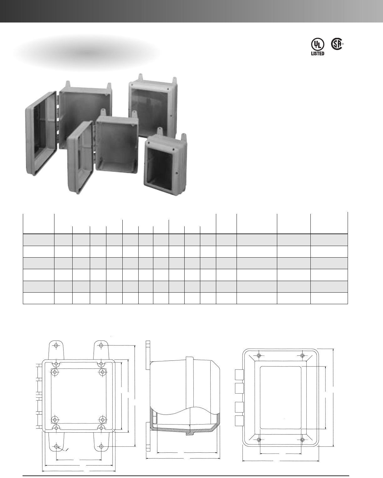
www.carlon.com
126
Circuit Safe®JIC Enclosures
Hinged Window Cover
Meets NEMA 1, 3, 3S, 3X, 3SX, 4, 4X, 12, 13
Features
•Nonmetallic mounting feet and all mounting
hardware included.
•304 (18-8) stainless steel screw (10-32 / 11/8").
•White painted 14 gauge steel or 1/4"PVC back
panel (order separately).
•Completely nonmetallic hinges.
•Lid design provides greater usable internal volume.
•Brass screw inserts.
•Material: polycarbonate molded base and cover.
Note: Window material 1/8"thick clear polycarbonate is
permanently bonded to the cover.
LR31146
E54381
Dimensions Std. Ctn.
Back Panel*
Std. Ctn.
Part External Internal Mounting Qty. Part Nos. Panel Qty. (lbs.)
Nos. A B C D E F G H J K (lbs.) Steel/PVC Size Steel/PVC
J665W 6.50 6.50 6.69 6.00 6.00 5.45 9.00 4.00 4.70 4.70 1 (3.1) JP66/JP66P 4.88 x 4.88 1 (1.0) / 1 (0.3)
J863W 8.50 6.50 4.49 8.00 6.00 3.25 11.00 4.00 4.70 4.70 1 (3.2) JP86/JP86P 6.75 x 4.88 1 (1.0) / 1 (0.78)
J1085W 10.50 8.50 6.69 10.00 8.00 5.45 13.00 6.00 8.70 6.70 1 (5.6) JP108/JP108P 8.75 x 6.88 1 (1.5) / 1 (0.7)
J12106W 12.50 10.50 7.69 12.00 10.00 6.45 15.00 8.00 10.70 8.70 1 (7.4) JP1210/JP1210P 10.75 x 8.88 1 (2.0) / 1 (1.2)
J14126W 14.50 12.50 7.72 14.00 12.00 6.48 17.00 10.00 12.70 10.70 1 (9) JP1412/JP1412P 12.75 x 10.88 1 (3.2) / 1 (1.7)
J16147W 16.50 14.50 8.46 16.00 14.00 7.22 19.00 12.00 14.70 12.70 1 (9.3) JP1614/JP1614P 14.75 x 12.88 1 (4.7) / 1 (2.3)
Factory Assembled
Enclosures shipped with mounting feet, hinge caps and screws.
*Order back panels separately.
For factory installed pad lockable quick-release latch, consult Customer Service for price and delivery.
D
A
G
H
E
B
F
C
O.312
TYP
J
A
K
B
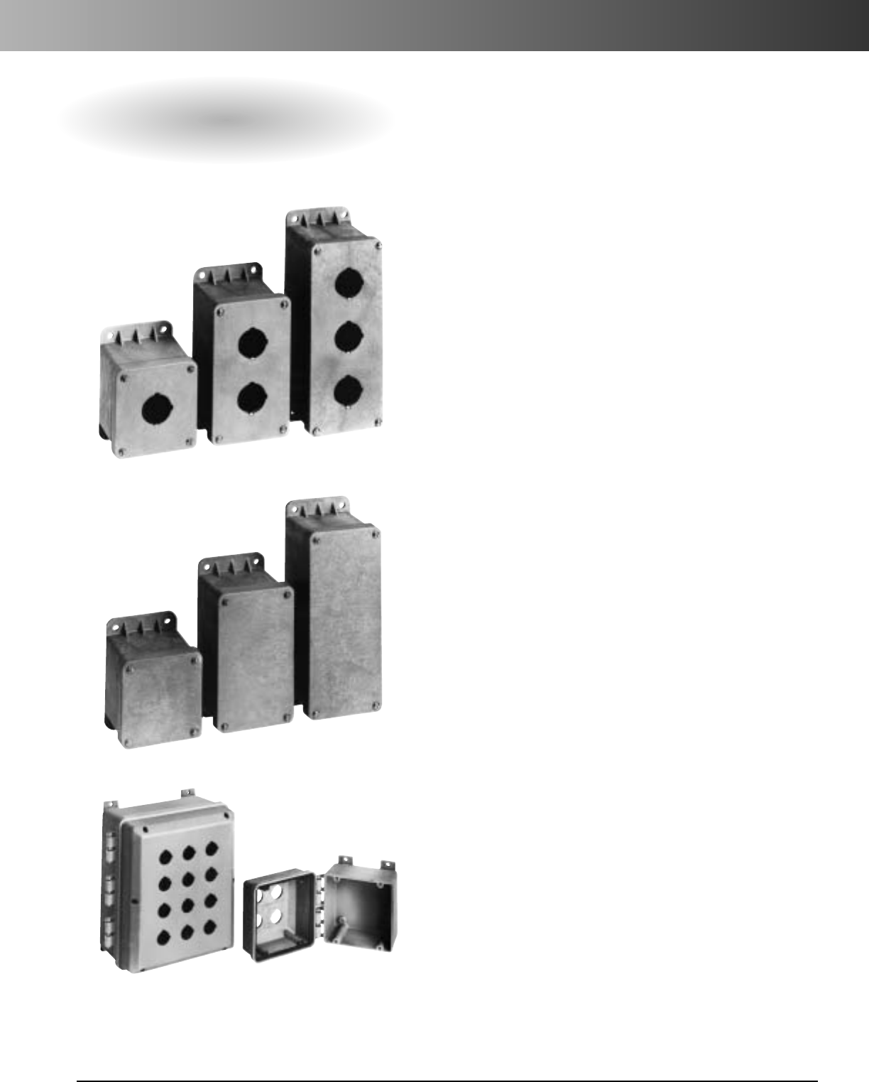
www.carlon.com 127
Circuit Safe®Pushbutton Enclosures
Circuit Safe Pushbutton Enclosures
Circuit Safe®nonmetallic pushbutton enclosures are
molded from engineered thermoplastic material
that is resistant to most corrosive agents. Whether
predrilled 1-2-3 hole enclosures, blank cover
enclosures or enclosures with multiple hole
openings, Carlon's pushbutton enclosure series
offers high impact strength, chemical resistance,
high dielectric strength and excellent durability
for the correct application.
Features
•Engineered thermoplastic base and cover.
•304 stainless steel screws.
•Brass screw inserts.
•High-impact strength.
•Temperature range from -40° F to 185° F.
Applications
•Standard oil-tight pushbuttons, switches and
pilot lights.
•Conduit entries.
•Junction boxes.
•MRO and OEM applications.
Standards
•Standards vary by product.
•Screw cover pushbutton enclosures with 1-2-3
hole openings are Listed per UL 50 for
industrial controls.
•Narrow profile blank screw cover enclosures are
listed per UL 50 for industrial controls and meets
NEMA Type 1, 3, 3S, 3X, 3SX, 4, 4X, 12, and 13.
•Nonmetallic hinged cover enclosures with
multiple hole openings are UL Listed.
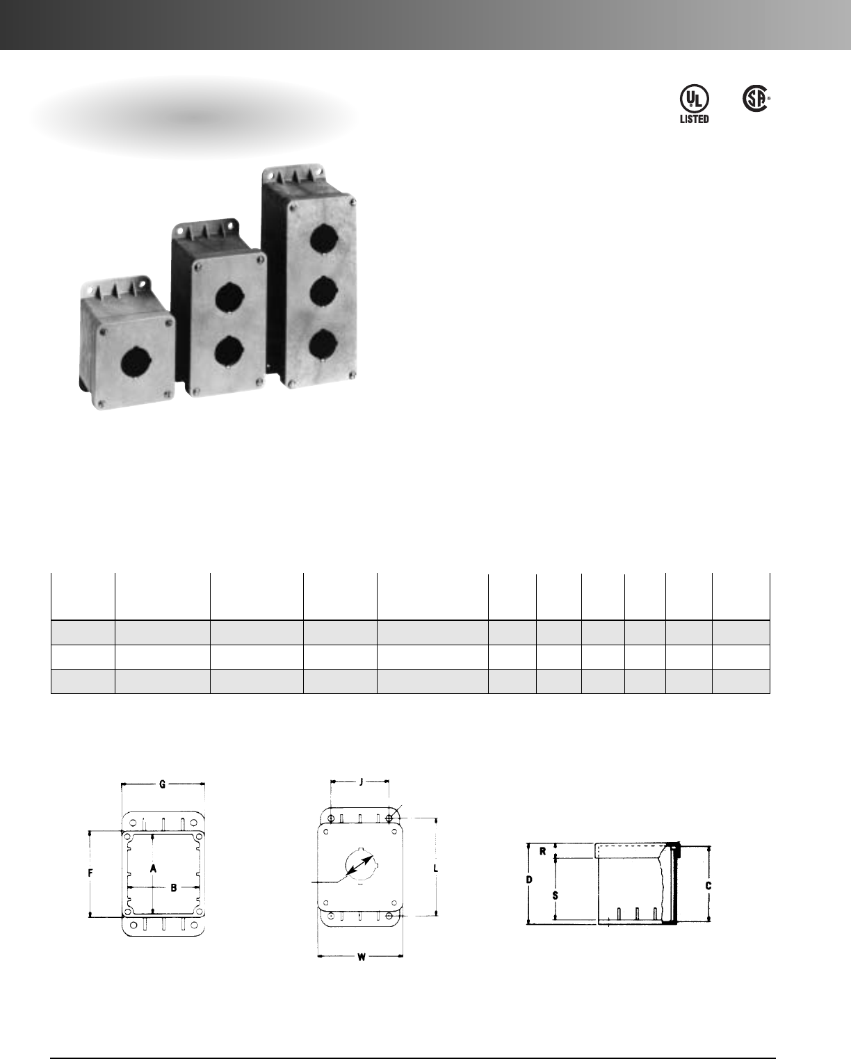
www.carlon.com
128
Circuit Safe®Pushbutton Enclosures
Screw Cover Enclosures with 1-2-3 Hole Openings
UL Listed per UL 50 for Industrial Controls
30.5 mm Pushbutton Enclosures
LR31146
Features
•30.5 mm keyed pushbutton holes.*
•Material: nylon base and cover.
•Integrally molded mounting flange.
Overall Outside
Part Inside Box Size Mounting Including Mounting Pieces/ Weight
Nos. Style A x B x C L x J Bracket H x W x D F G R S Pkg. (lbs.)/Unit
CP100N One Opening 3.13 x 2.81 x 3 4 x 2.38 4.88 x 3.50 x 3.38 3.38 3.25 .63 2.5 12 8.90
CP200N Two Openings 5.38 x 2.81 x 3 6.25 x 2.38 7.13 x 3.50 x 3.38 5.63 3.25 .63 2.5 8 11.25
CP300N Three Openings 7.38 x 2.81 x 3 8.50 x 2.38 9.38 x 3.50 x 3.38 7.88 3.25 .63 2.5 6 7.60
Wall mount pushbutton enclosures are molded
from gray, engineered thermoplastic material
that is resistant to most corrosive agents.
Universal pushbutton holes are designed to
accommodate all standard oil-tight pushbuttons,
switches and pilot lights. A grounding plate is
included on the cover. Auxiliary devices must be
rated for appropriate NEMA applications.
•Brass screw inserts.
•304 (18-8) stainless screws (8-32 / 3/8").
•Temperature range from - 40˚F to 185˚F.
E54381
1.210 Dia.
1/4 Dia. Mtg. Hole
*22 mm Pushbutton holes available upon request.
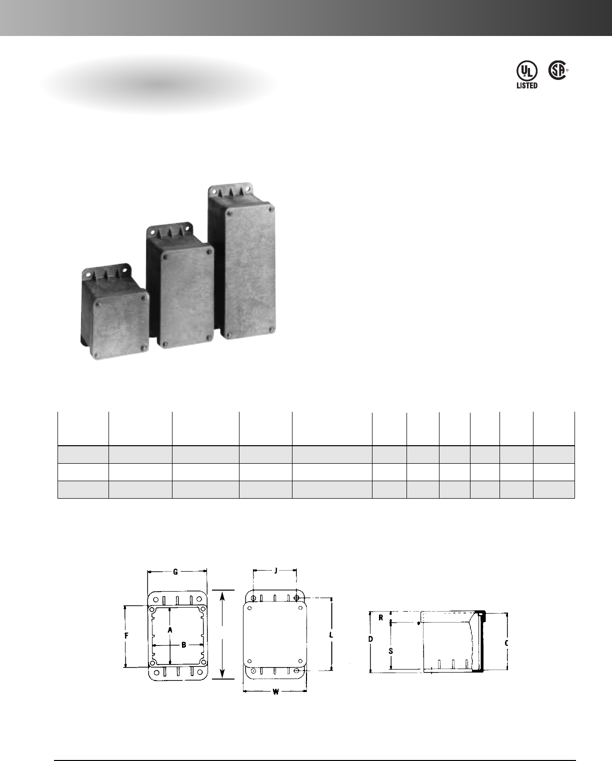
www.carlon.com 129
Circuit Safe®Pushbutton Enclosures
Narrow Profile Blank Screw Cover Enclosures for
Small Instrumentation and Control Applications
UL Listed per UL 50 for Industrial Controls
Meets NEMA 1, 3, 3S, 3X, 3SX, 4, 4X, 12, 13
LR31146
E54381
Blank cover enclosures can be easily drilled with a
standard hole saw for conduit entries and pushbut-
tons. Wall mount enclosures are molded from gray,
engineered thermoplastic material and are resistant
to most corrosive agents.
Features
•Brass screw inserts.
•Material: nylon base and cover.
•Integrally molded mounting flange.
•304 (18-8) stainless screws (10-32 / 3/8").
•Temperature range from - 40˚F to 185˚F.
Blank Screw Cover Enclosures*
Overall Outside
Part Inside Box Size Mounting Including Mounting Pieces/ Weight
Nos. Style A x B x C L x J Bracket H x W x D F G R S Pkg. (lbs.)/Unit
CP100NB Blank Cover 3.13 x 2.81 x 3 4 x 2.38 4.88 x 3.50 x 3.38 3.38 3.25 .63 2.5 12 9.60
CP200NB Blank Cover 5.38 x 2.81 x 3 6.25 x 2.38 7.13 x 3.50 x 3.38 5.63 3.25 .63 2.5 8 8.8
CP300NB Blank Cover 7.38 x 2.81 x 3 8.50 x 2.38 9.38 x 3.50 x 3.38 7.88 3.25 .63 2.5 6 8.20
*Special openings or positionings available on request.
H
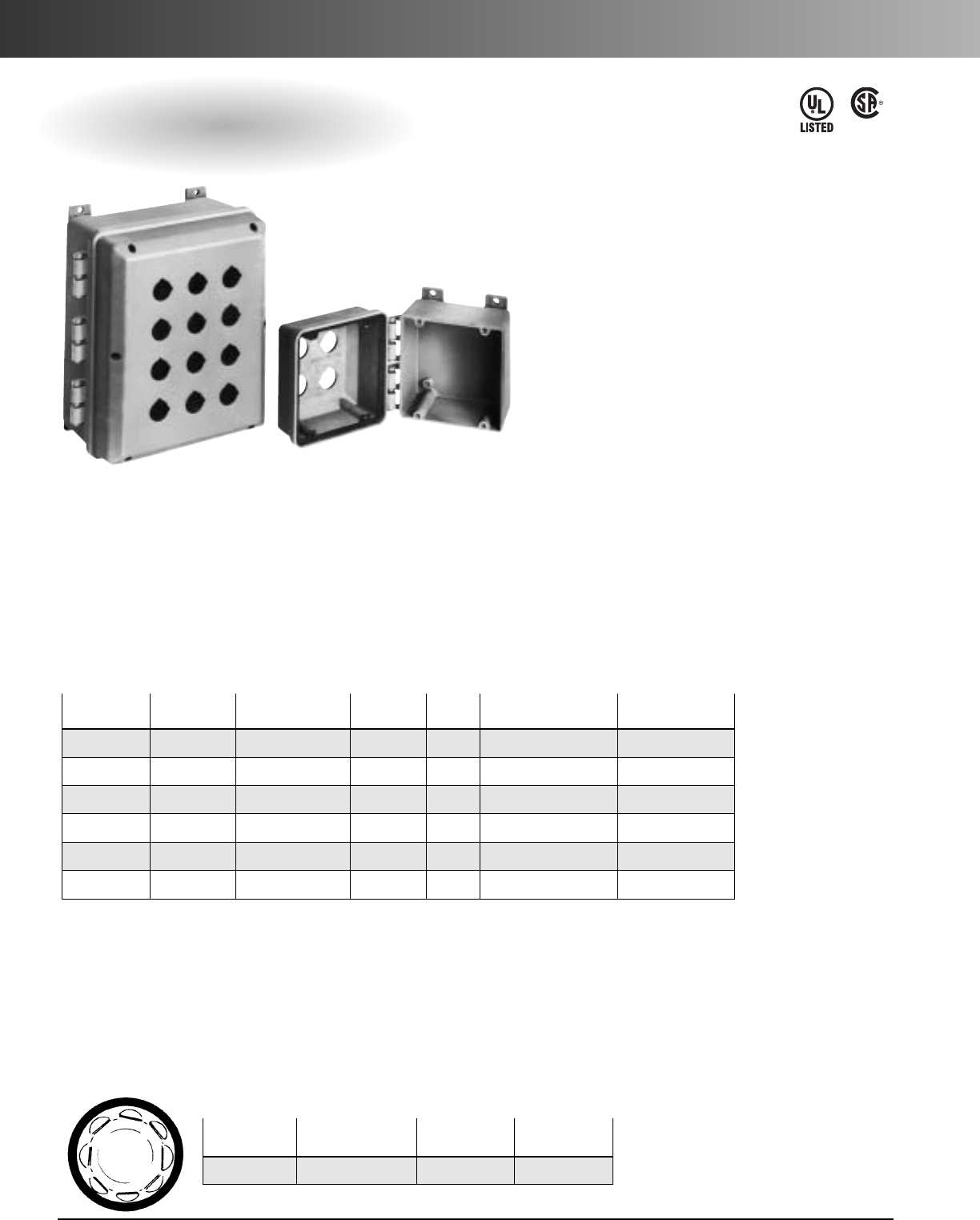
www.carlon.com
130
Circuit Safe®Pushbutton Enclosures
Hinged Cover Enclosures with Multiple Hole Openings
Screw Cover Pushbutton Enclosures With Multiple 30.5 mm Openings*
LR31146
E54381
Features
•Nonmetallic mounting feet and all mounting
hardware included.
•White painted 14 gauge steel or 11/8"PVC back
panel (order separately).
•Material: engineered thermoplastic base and cover.
Part Inside Panel Size
Nos. Openings Box size Weight Qty. Part Nos. Steel/PVC
J665P 4 6 x 6 x 5.88 2.42 1 JP66 / JP66P 4.88 x 4.88
J863P 6 8 x 6 x 3.63 1.86 1 JP86 / JP86P 6.75 x 4.88
J1085P 9 10 x 8 x 5.88 3.59 1 JP108 / JP108P 8.75 x 6.88
J12106P 12 12 x 10 x 6.88 4.29 1 JP1210 / JP1210P 10.75 x 8.88
J14126P 20 14 x 12 x 6.88 7.19 1 JP1412 / JP1412P 12.75 x 10.88
J16147P 25 16 x 14 x 7.63 11.20 1 JP1614 / JP1614P 14.75 x 12.88
For enclosures larger than 25 position, please call Customer Service.
*All Circuit Safe pushbutton enclosures are furnished with standard hole dimensions: 17/32"diameter with keyways at 12 o’clock and 3 o’clock.
Special openings or positionings available on request.
Gasketed Pushbutton Hole Plug
Part StandardStandard
Number Size Carton Qty. Weight (lbs.)
CP900 Standard PB hole 100 2.0
Accessories
Made from engineered thermoplastic material,
these enclosures are ideal for applications
that require high-impact strength, chemical
resistance, high dielectric strength, and excellent
weathering capabilities, including indoor/
outdoor industrial, MRO, and OEM applications.
Nonmetallic hinges are an integral part of
the mold. Hinge caps make cover captive
and removable cover allows for easy field
adjustment. Auxiliary devices must be rated
for appropriate NEMA applications.
•304 stainless steel screws.
•Brass screw inserts.
•Lid design provides greater usable volume.
•Completely nonmetallic hinges.
•Temperature range from - 40˚F to 185˚F.
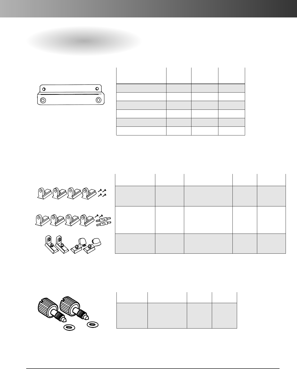
www.carlon.com 131
Circuit Safe®Enclosure Accessories
Circuit Safe
®
NEMA Accessories
Part Std. Ctn. Std. Ctn.
Product Numbers Description Qty. Wt. (lbs.)
Panel Adjuster NBPADJ2 4 panel adjusters 10 kits 2.07
Kit 4#10-32 screws
to mount panel
180° Swing Out NBPSWG 4 panel adjusters 10 kits 2.68
Panel Kit 2 hinges
2#10-32 screws
to mount panel
Swing Out Panel NBPSWG2 2 hinged adjusters 10 kits 1.80
Adjuster Kit 2 panel adjusters
4#10-32 screws
Panel Adjuster Kits
Mounting Rails*
*Mounting rails can be mounted on long or short side of enclosure.
Does not apply to 16" enclosure.
#10-32 Panel Thumb Screws
Used on internal hinge door only.
Part Std. Ctn. Std. Ctn.
Number Description Qty. Wt. (lbs.)
NBPTSK 2 #10-32 10 kits 1.2
thumb screws
2nonmetallic
washers
Mounting Std.
Rail Kits Size Ctn. Weight
Part Number (in.) Qty. (lbs.)
NMK4V 4 25 5
NMK6V 6 24 7.7
NMK8V 8 24 10.25
NMK10V 10 20 13.26
NMK12V 12 20 11.4
NMK14V 14 25 17.76

www.carlon.com
132
Circuit Safe®Enclosure Accessories
Circuit Safe
®
NEMA Accessories
Part Std. Ctn. Std. Ctn.
Product Numbers Description Qty. Wt. (lbs.)
Nonmetallic NPL1L Quick-Release Latch Kit 25 2.00
Quick-Release for use with hidden
Latch Kit hinge enclosure
for NH & NI Series
Nonmetallic NPL1S Quick-Release Latch Kit 25 2.00
Quick-Release for use with external
Latch Kit hinge enclosure for
NJ & NC Series
304 Stainless Steel SSLL Quick-Release Latch Kit 25 4.27
Quick-Release for use with hidden
Latch Kit hinge enclosure for
NH & NI Series
304 Stainless Steel SSLS Quick-Release Latch Kit 25 3.41
Quick-Release for use with external
Latch Kit hinge enclosure for
NJ & NC Series
Latch Kits
For NEMA hinged enclosures.
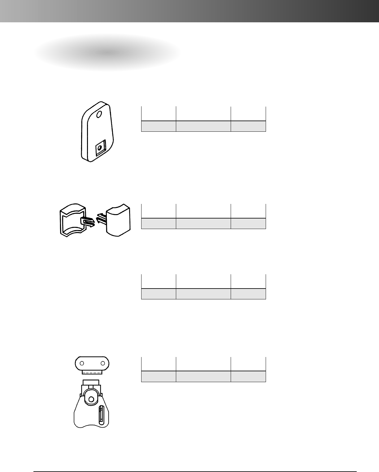
www.carlon.com 133
Circuit Safe®Enclosure Accessories
Circuit Safe
®
JIC Accessories
Mounting Feet
For Circuit Safe Enclosures – Type CC, CJ, CS, CV, J
Part Std. Ctn. Std. Ctn.
No. Qty. Wt. (lbs.)
CJB159* As required 0.04
*CJB159 nonmetallic mounting feet provide 1/4" standoff and may be
used to mount enclosures in horizontal or vertical mode. They are
shipped with all Circuit Safe JIC enclosures. No screws are provided
when mounting feet are ordered separately.
Hinge Caps*
For Circuit Safe Enclosures – Type CC, CJ, J
Part Std. Ctn. Std. Ctn.
No. Qty. Wt. (lbs.)
CH100R As required 0.03
*For Circuit Safe enclosures to secure covers to bases.
Shipped as standard with hinge cover enclosure.
JIC Installation Kits*
Part Std. Ctn. Std. Ctn.
No. Qty. Wt. (lbs.)
CH208 1Kit 0.25
*Installation kit is included as standard equipment with all JIC
enclosures. Information listed here for purposes of additional purchase
only. Kit includes 4 mounting feet, 8 hinge caps, and 8 screws.
JIC Latch Kits*
Part Std. Ctn. Std. Ctn.
No. Qty. Wt. (lbs.)
CJTL 1Kit 0.25
Stainless steel. Kit includes latch and keeper.
*Factory installed. Consult customer service for price and delivery.
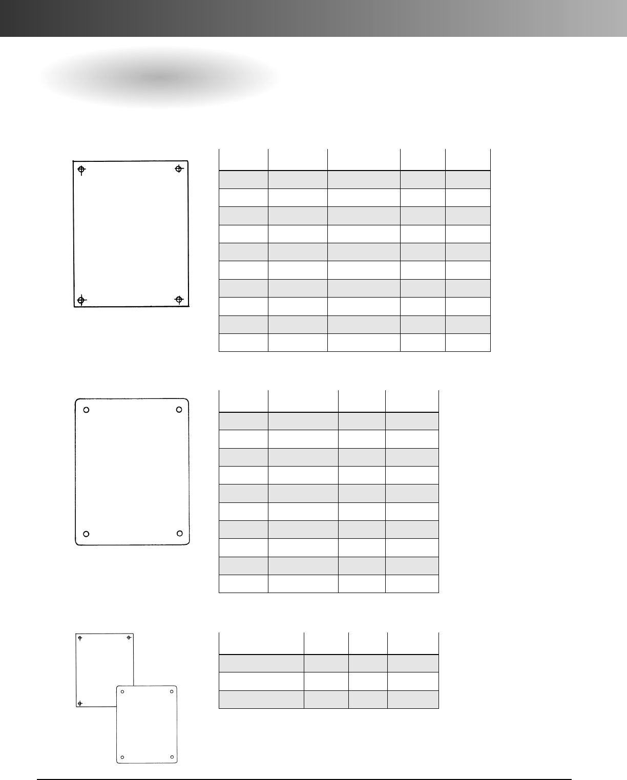
www.carlon.com
134
Circuit Safe®Enclosure Accessories
Circuit Safe
®
NEMA and JIC Accessories
Steel Back Panels*
Steel back panels are white painted 14 gauge steel.
Part Thickness Size Std. Ctn. Std. Ctn.
Nos. (in.) (in.) Qty. Wt. (lbs.)
JP64 14 gauge 4.88 x 2.88 1 0.6
JP66 14 gauge 4.88 x 4.88 1 1.0
JP86 14 gauge 6.75 x 4.88 1 1.0
JP88 14 gauge 6.75 x 6.88 1 1.2
JP108 14 gauge 8.75 x 6.88 1 1.5
JP1010 14 gauge 8.75 x 8.88 1 2.3
JP1210 14 gauge 10.75 x 8.88 1 2.7
JP1212 14 gauge 10.75 x 10.88 1 3.5
JP1412 14 gauge 12.75 x 10.88 1 3.8
JP1614 14 gauge 14.75 x 12.88 1 4.7
PVC Back Panels*
PVC back panels are made from 1/4"PVC and meet UL94 V-O.
Part Size Std. Ctn. Std. Ctn.
Nos. (in.) Qty. Wt. (lbs.)
JP64P 47⁄8x27⁄81 0.3
JP66P 47⁄8x47⁄81 0.3
JP86P 63⁄4x47⁄81 0.4
JP88P 63⁄4x67⁄81 0.5
JP108P 83⁄4x87⁄81 0.7
JP1010P 83⁄4x87⁄81 0.9
JP1210P 103⁄4x 10⁷⁄811.2
JP1212P 103⁄4x10⁷⁄81 1.5
JP1412P 123⁄4x 10⁷⁄811.7
JP1614P 143⁄4x127⁄81 2.3
Medium NEMA Back Panels*
Part Nos. Size Std. Ctn. Std. Ctn.
Steel/PVC (in.) Qty. Wt. (lbs.)
NP2016 / NP2016P 17 x 13 1 7.0 / 6.125
NP2420 / NP2420P 21 x 17 1 10.4 / 4.71
NP3024 / NP3024P 27 x 21 1 18.0 / 9.781
*Circuit Safe NEMA enclosures are not shipped with back panels which must be ordered separately.
All accessories can be factory installed. Consult Customer Service for price and delivery.
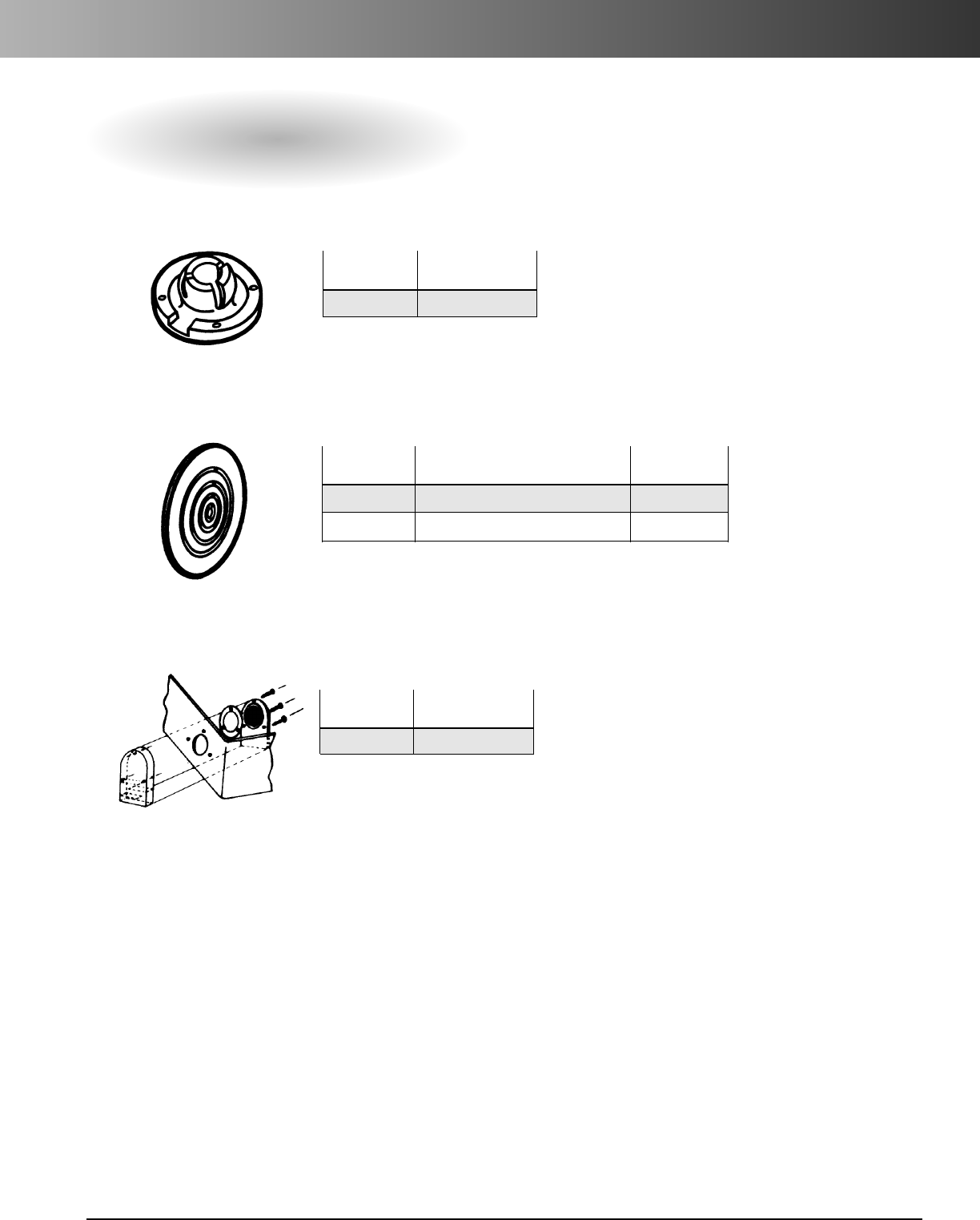
www.carlon.com 135
Circuit Safe®Enclosure Accessories
Circuit Safe
®
NEMA and JIC Accessories
Draining Device*
For 3R Rating and condensation build-up.
Air Vents*
NEMA 1 Rated only.
EnclosureVentilator*
Allows any size enclosure to breathe, yet remains watertight.
Part Standard
Number Carton Qty.
HPVEA9 1
Part Standard
Number Carton Qty.
HVM27 1
Part Standard
Numbers Style Carton Qty.
HPVM25 For fitting outside of all enclosures 1
HPVM35 For fitting inside of all enclosures 1
*Factory installation available.
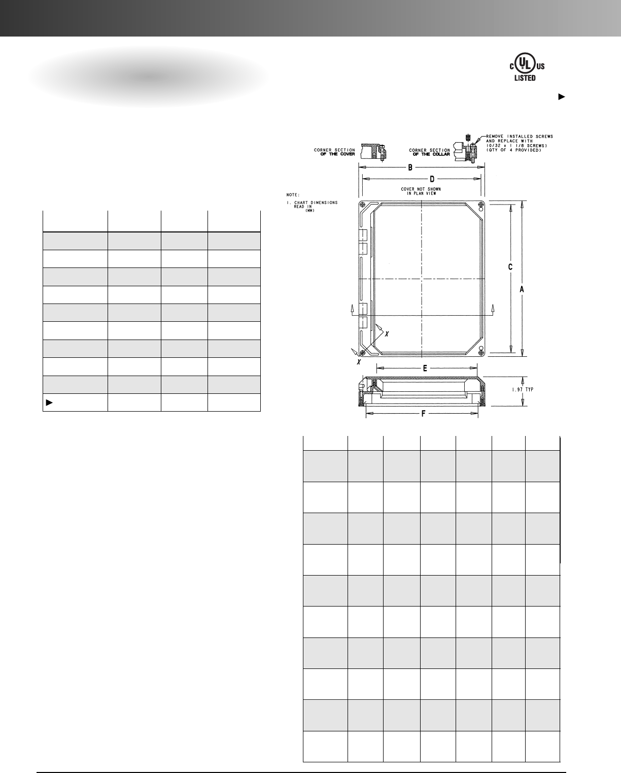
www.carlon.com
136
Circuit Safe®Enclosure Accessories
Window Kits
NEMA 4X Rated
Window kits are easily field-installed.
Nonmetallic construction and double gaskets
ensure environmental integrity. For circuit
breaker and other surface mounted instruments.
E110981
Except where noted by
Features
•High-impact strength.
•Excellent weathering capabilities.
•High dielectric strength.
•Corrosion resistant.
•Suitable for indoor and outdoor use.
•Fully gasketed.
•Extended temperature range -30˚F to 230˚F.
•Lightweight.
Standards
•UL Listed and meets NEMA Type 4X with the
exception of NI1614W. All sizes are NEMA
Type 12 rated.
Applications
•Instrument case.
•Junction and terminal boxes.
•Control and switching enclosures
•Meter and transformer cabinets.
•Small device enclosures.
Part Size Std. Ctn. Std. Ctn.
Nos.* (in.) Qty. Wt. (lbs.)
NI64W 6 x 4 1 .8
NI66W 6 x 6 1 .9
NI86W 8 x 6 1 1.17
NI88W 8 x 8 1 1.4
NI108W 10 x 8 1 1.5
NI1010W 10 x 10 1 1.82
NI1210W 12 x 10 1 2.12
NI1212W 12 x 12 1 2.65
NI1412W 14 x 12 1 2.67
NI1614W 16 x 14 1 3.10
All window kits can be factory installed to Carlon®enclosures.
Consult factory for price and delivery.
*Non-stock factory order only – consult Customer Service.Size A B C D E F
NI64W 6.42 4.41 5.92 3.92 2.72 3.80
(163.1) (112.0) (150.4) (99.6) (69.1) (96.5)
NI66W 6.42 6.42 5.92 5.92 4.72 5.80
(163.1) (163.1) (150.4) (150.4) (119.9) (147.3)
NI86W 8.42 6.42 7.92 5.92 4.72 5.80
(213.9) (163.1) (201.2) (150.4) (119.9) (147.3)
NI88W 8.42 8.42 7.92 7.92 6.72 7.80
(213.9) (213.9) (201.2) (201.2) (170.7) (198.1)
NI108W 10.42 8.42 9.92 7.92 6.72 7.80
(264.7) (213.9) (252.0) (201.2) (170.7) (198.1)
NI1010W 10.42 10.42 9.92 9.92 8.72 9.80
(264.7) (264.7) (251.9) (251.9) (221.5) (248.9)
NI1210W 12.42 10.42 11.92 9.92 8.72 9.80
(315.5) (264.7) (302.7) (251.9) (221.5) (248.9)
NI1212W 12.42 12.42 11.92 11.92 10.72 11.80
(315.5) (315.5) (302.7) (302.7) (272.3) (299.7)
NI1412W 14.42 12.42 13.92 11.92 10.72 11.80
(366.3) (315.5) (353.6) (302.7) (272.3) (299.7)
NI1614W 16.42 14.42 15.92 13.92 12.72 13.80
(417.1) (366.3) (404.4) (353.6) (323.1) (350.5)
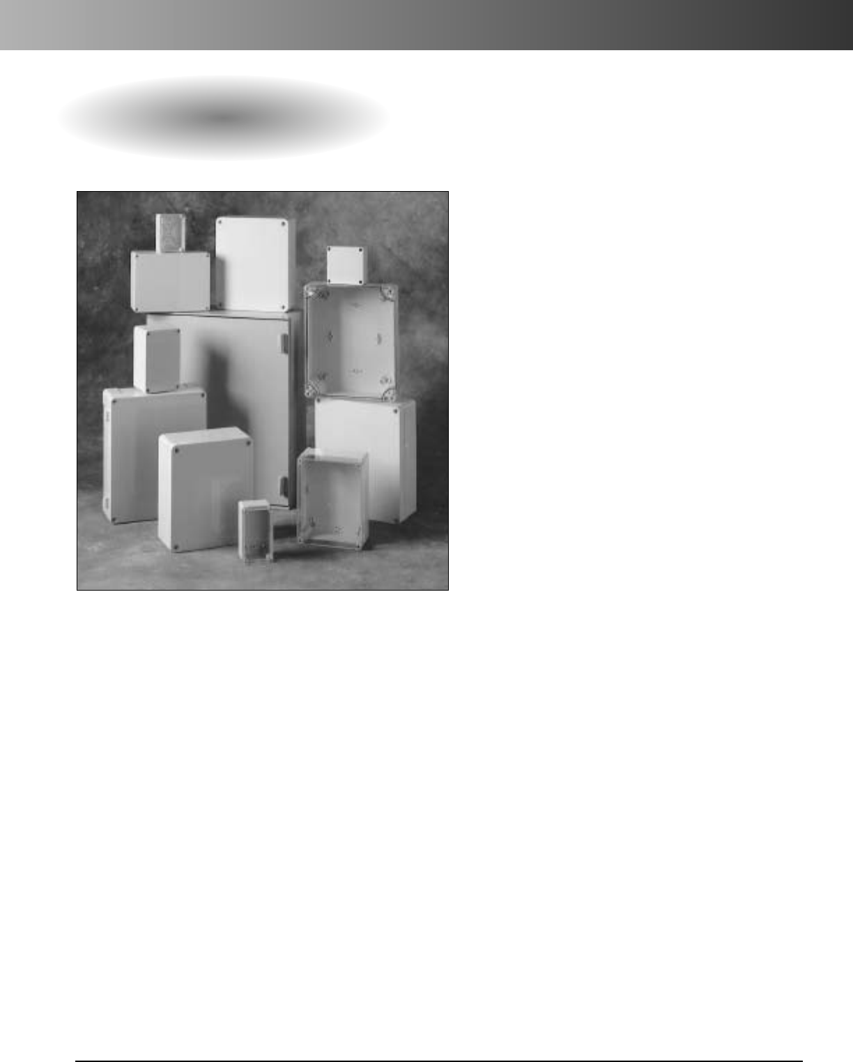
www.carlon.com 137
Himeline®Enclosures
Himeline Enclosures HE, HS, HP, HLA/HLS Series
Carlon®Himeline®enclosures are the ideal alternative to
expensive stainless steel enclosures. They have excellent
corrosion resistant properties; are impervious to sunlight,
dirt, and moisture. Available in four series (HE, HS, HP,
and HLA/HLS), with sizes ranging from 4 x 3 x 2 through
50 x 40 x 17, these enclosures offer choices that include
double doors, clear or opaque covers, hinged and screw
versions, single or three point closure mechanisms,
4X windows, DIN rail mounting, and adjustable depth
door in door option that allow you to customize your
enclosures by separating power from communications.
Features
•High-impact strength.
•High dielectric strength.
•Suitable for indoor and outdoor use.
•Fully gasketed.
•Lightweight.
Applications
•Instrument case.
•Junction and terminal boxes.
•Control and switching enclosures.
•Meter and transformer cabinets.
•Small device enclosures.
Standards
•Meets NEMA and IP standards as indicated in
appropriate section.
•UL Listed as indicated.
•CSA certified as indicated.
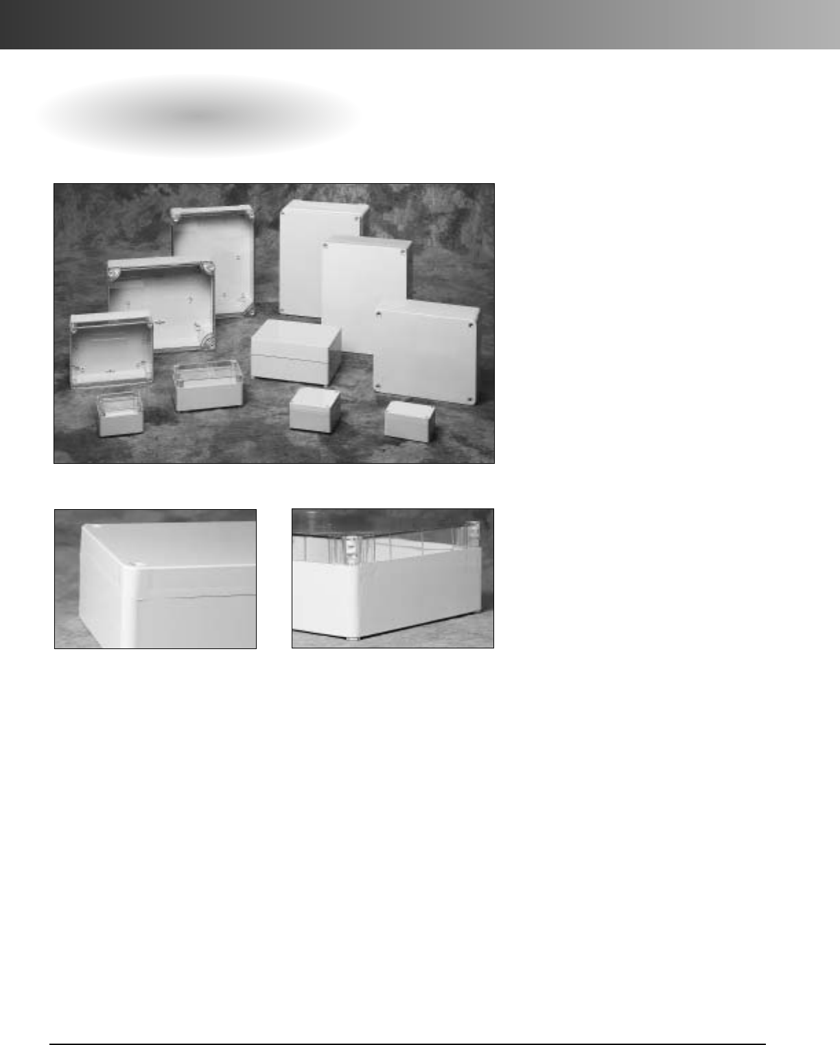
www.carlon.com
138
Himeline®Enclosures – HE Series
HE Series
(Small Electronic Enclosures/Insulated Industrial Boxes – Except Hinged Boxes)
Lid Options
Features
•Hidden hinges open 185°
for easy access.
•M8x18 screws for back panel
mounting (included).
•Sealing gasket on all models.
•Mounting plate available for
specific sizes.
•Hinged versions available (factory
installed).
*For more information
contact your Carlon Sales Representative.
•Optional internal/external hinges.
•Enclosures attach directly or with
wall brackets.
Material
•Opaque – lids and bases - PVC
•Clear – lids and bases - polycarbonate
Standards
•NEMA 4X Rated.
•Meets IP 55.
Opaque low lid. “BASIC” model. Transparent low lid. “C” models.
Carlon®Himeline®HE Series Enclosures are small Electronic
Enclosures/Insulated Industrial Boxes ranging in size from
4x3x2to 13 x 11x 4. They have a high-impact, high dielectric
resistance, and are lightweight, fully gasketed and suitable for
indoor and outdoor applications. The HE Series Enclosures meet
IP 55 and are NEMA 4X Rated. All these features combined
make these enclosures the ideal alternative to expensive
stainless steel enclosures.
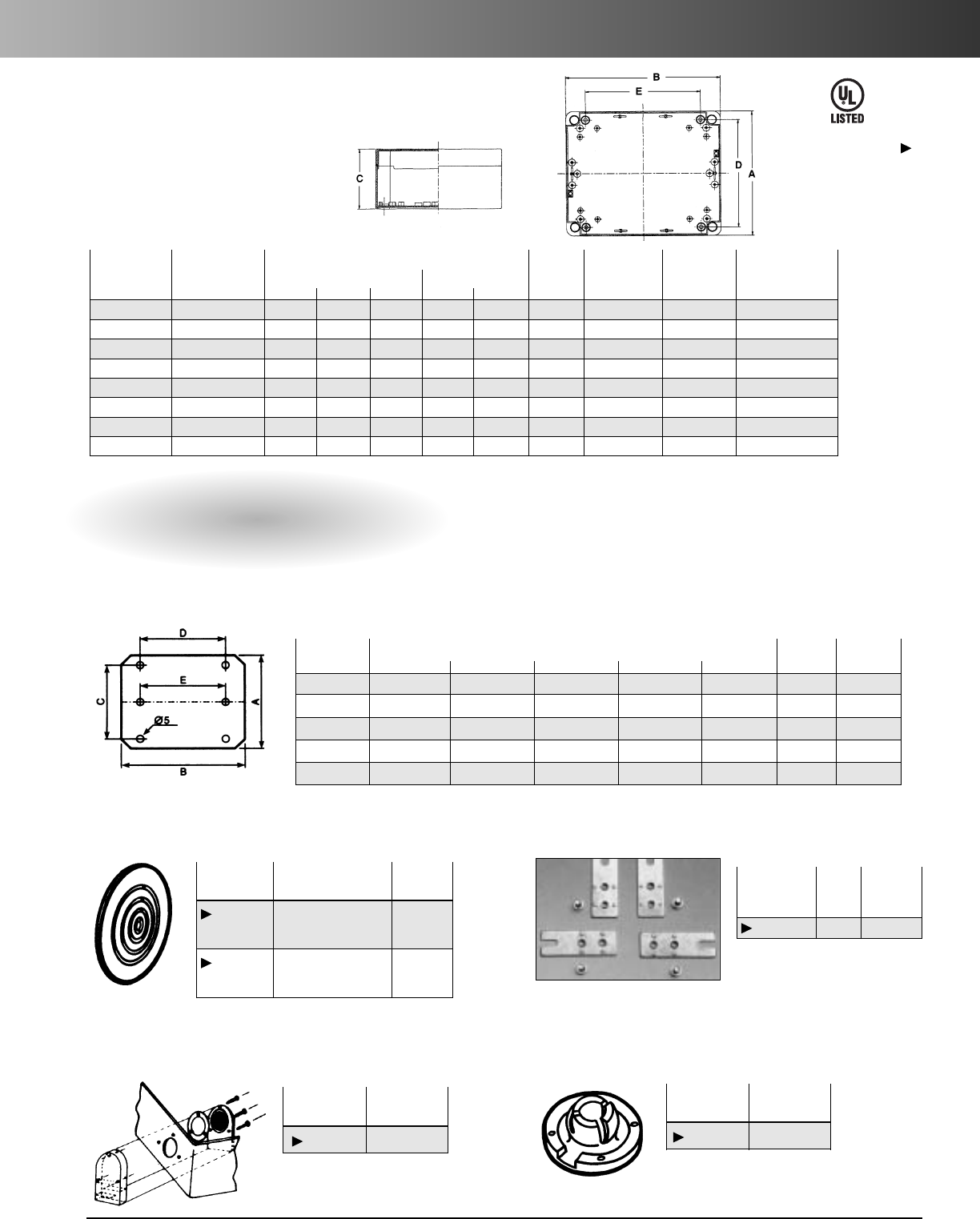
www.carlon.com 139
Himeline®Enclosures – HE Series
E54381
Except where noted by
Opaque Clear Dimensions Std. Std.
Cover Cover External Internal Ctn. Ctn. Unit Locking
Assembly Assembly A B C D E Qty. Wt. (lbs.) Wt. (lbs.) Screw Type
HE432 HE432C 4.33 2.96 2.29 4.14 2.76 5 1.1 5.2 Stainless Steel
HE443 HE443C 4.14 4.14 2.60 3.90 3.90 6 3.1 7.5 Stainless Steel
HE533 HE533C 5.32 2.92 2.84 5.12 2.72 5 2.4 6.3 Stainless Steel
HE743 HE743C 6.70 4.14 3.23 6.46 3.90 2 1.2 12.4 Polyamide
HE974 HE974C 8.66 6.62 4.18 8.43 6.38 1 1.1 – Polyamide
HE1194 – 10.63 8.66 4.14 7.48 9.81 1 2.7 – Polyamide
HE12105 HE1210C 12.33 9.97 4.53 11.82 9.45 1 3.0 – Polyamide
HE14114 HE1411C 13.78 11.02 4.14 12.92 10.16 1 4.0 – Polyamide
Wall Mounting Bracket
Mounting Plates
To be fitted directly into the boxes with self-tapping screws included in the
standardsupply.Made of zinc coated steel, 1.5 mm thick.
Std. Std.
Part Ctn. Ctn. Wt.
Number Qty. (lbs.)
HEWMB 1 .35
Part Dimensions Std.Ctn. Std.
Ctn.
Number A B C D E Qty.
Wt.
(lbs.)
EMP743 3.74 (95) 6.15 (156) 5.12 (130) 10 10
EMP974 6.15 (156) 8.07 (205) 5.12 (130) 5.91 (150) 10 8.5
EMP1194 8.19 (208) 10.16 (258) 6.34 (161) 8.70 (221) 10 13
EMP1210 9.26 (235) 11.62 (295) 6.15 (156) 8.51 (216) 5 4.1
EMP1411 9.85 (250) 12.60 (320) 8.27 (210) 9.85 (250) 5 3
Draining Device*
For 3R Rating and condensation build-up.
Air Vents*
NEMA 1 Rated only.
Enclosure Ventilator*
Allows any size enclosure to breathe, yet remains watertight.
*Factory installation available.
Part Std.
Number Ctn. Qty.
HVM27 1
Part Std.
Number Ctn. Qty.
HPVEA9 1
Part Std.
Numbers Style Ctn. Qty.
HPVM25 For fitting outside 1
of all enclosures
HPVM35 For fitting inside 1
of all enclosures
Accessories
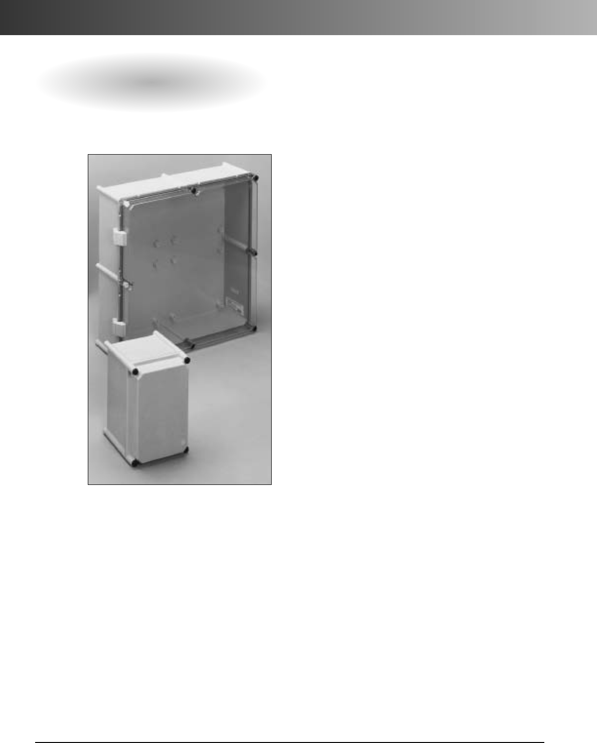
www.carlon.com
140
Himeline®Enclosures – HS Series
HS Series Screw-On Fastened and Hinged Cover Enclosures
• Meets NEMA 1, 3, 3S, 4, 4X, 12, 13
• Meets IP 65
Himeline
®
HS Series enclosures are designed
for use as junction boxes, terminal wiring
boxes, instrument and control housings, and
small device enclosure applications. Molded
under high pressure, Himeline HS Series
enclosures provide high-impact strength,
chemical resistance, high dielectric strength,
and excellent weathering capabilities.
Features
•Standard slotted locking screw.
•High impact strength.
•Chemical resistance.
•High dielectric strength.
•Excellent weathering capabilities.
•Sealing gasket on all models.
Applications
•Junction boxes.
•Terminal wiring boxes.
•Instrument and control housings.
•Small device enclosure applications.
•Indoor or outdoor use.
•Sunlight resistant.
Standards
•Meets NEMA 1, 3, 3S, 4, 4X, 12, 13 standards
as indicated.
•UL Listed per UL 50, enclosures for electrical
equipment.
•CSA certified.
•Meets IP 65.
•UL Listed (E54381).
Material
•Opaque/Clear Lid – Polycarbonate
•Base – Fiberglass Reinforced Polyester
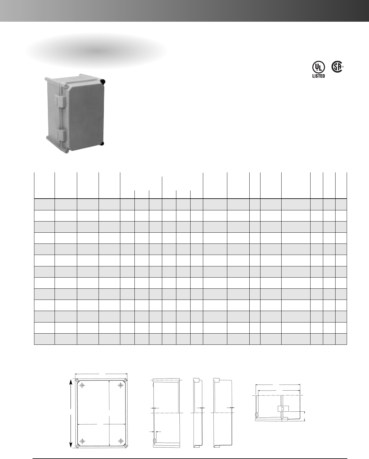
www.carlon.com 141
Himeline®Enclosures – HS Series
HS Series Screw-On Fastened and Hinged Cover Enclosures
Opaque Clear
Opaque
Clear Opaque
Wt.
Clear
Wt.
Back
Screw-On Screw-On Hinged Hinged (lbs.) each (lbs.) each Panel Std.
Cover Cover Cover Cover External Internal Screw/ Screw/ Std. Part Dimensions Thick- Wt. Ctn.
Part Nos. Part Nos. Part Nos. Part Nos. A B C D E F Hinged Hinged Pkg. Nos. H x W ness (lbs.) Qty.
HS7A7 HS7A7C HH7A7 HH7A7C 10.63 7.09 7.09 6.26 9.80 6.54 10.7 / 7 10.9 / 6.2 4 HS7ABP 5.51 x 9.05 .08 1.1 1
HS11A7 HS11A7C HH11A7 HH11A7C 10.63 10.63 7.09 9.80 9.80 6.54 15.2 / 8.5 14 / 8 4 HS11ABP 9.05 x 9.05 .08 1.7 1
HS11B7 HS11B7C HH11B7 HH11B7C 14.17 10.63 7.09 9.80 13.35 6.54 17 / 4 18 / 4 4 HS11BBP 9.05 x 12.60 .08 2.4 1
HS11C7 HS11C7C HH11C7 HH11C7C 21.26 10.63 7.09 9.80 20.43 6.54 13 / 13 12.5 / 13 2 HS11CBP 9.05 x 19.68 .08 3.9 1
HS15C7 HS15C7C HH15C7 HH15C7C 21.26 14.17 7.09 13.35 20.43 6.54 17.7 / 11 18 / 11 2 HS15CBP 12.60 x 19.68 .08 6.6 1
HS21C7 HS21C7C HH21C7 HH21C7C 21.26 21.26 7.09 20.43 20.43 6.54 12.5 / 13 12 / 13 1 HS21CBP 19.68 x 19.68 .08 8.8 1
HS11A9 HS11A9C HH11A9 HH11A9C 10.63 10.63 9.06 9.80 9.80 8.47 15 / 4 16.6/5 4 HS11ABP 9.05 x 9.05 .08 1.7 1
HS11B9 HS11B9C HH11B9 HH11B9C 14.17 10.63 9.06 9.80 13.35 8.47 20 / 6 19 / 6 4 HS11BBP 9.05 x 12.60 .08 2.5 1
HS11C9 HS11C9C HH11C9 HH11C9C 21.26 10.63 9.06 9.80 20.43 8.47 14 / 9 14 / 9 2 HS11CBP 9.05 x 19.68 .08 3.9 1
HS15C9 HS15C9C HH15C9 HH15C9C 21.26 14.17 9.06 13.35 20.43 8.47 18.5 / 11 19 / 11 2 HS15CBP 12.60 x 19.68 .08 6.6 1
HS21C9 HS21C9C HH21C9 HH21C9C 21.26 21.26 9.06 20.43 20.43 8.47 13 / 14 14 / 14 1 HS21CBP 19.68 x 19.68 .08 8.8 1
HS15D9 HS15D9C HH15D9 HH15D9C 28.35 14.17 9.06 13.35 27.52 8.47 13 / 13 13 / 13 1 HS15DBP 12.60 x 26.77 .10 9.5 1
HS21D9 HS21D9C HH21D9 HH21D9C 28.35 21.26 9.06 20.43 27.52 8.47 18 / 18 17 / 18 1 HS21DBP 19.68 x 26.77 .10 15.5 1
Specifications
Features
•Molded under high pressure.
•High impact strength.
•Chemical resistance.
•High dielectric strength.
•Excellent weathering capabilities.
•Clear cover available.
B
D
E
C
F
Placement of part P/N HSEH Hinge
Kit at top and bottom of long side
of HH Series enclosures.
2.00
.08
.08.09
.47
A
LR701839
E54381
Back panels and mounting feet must be ordered separately.
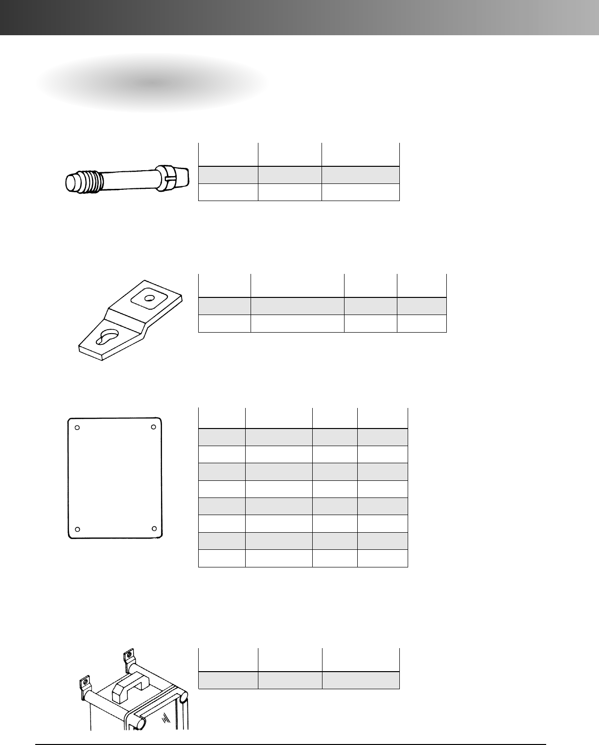
www.carlon.com
142
Himeline®Enclosures – HS Series
Accessories
Thumb Screws
–For Himeline HS Enclosures
Part Standard Standard
Numbers Carton Qty. Carton Wt. (lbs.).
HSTS4 4 0.1
HSTS6 6 0.15
Nonmetallic Carrying Handle
Converts enclosures to portable units for meters and portable power.
Part Standard Standard
Numbers Carton Qty. Carton Wt. (lbs.).
HSCH 1 0.2
Mounting Feet
–For Himeline HS Enclosures
Part Std. Std. Ctn.
Numbers Description Ctn. Qty. Wt. (lbs.)
HSMFZ Zinc dichromated Steel 4/set 0.2
HSMFSS 304 Stainless Steel 4/set 0.2
Back Panels
– For Himeline HS Enclosures* Metal back panels are white painted 14 gauge steel.
Part Size Std. Ctn. Std. Ctn.
Nos. (in.) Qty. Wt. (lbs.)
HS7ABP 5.51 x 9.05 1 1.2
HS11ABP 9.05 x 9.05 1 2.0
HS11BBP 9.05 x 12.60 1 2.7
HS11CBP 9.05 x 19.68 1 4.3
HS15CBP 12.60 x 19.68 1 7.1
HS21CBP 19.68 x 19.68 1 9.6
HS15DBP 12.60 x 26.77 1 10.2
HS21DBP 19.68 x 26.77 1 16.6
*Himeline HS enclosures are not shipped with back panels. Order separately.
PVC back panels available upon request. Consult Customer Service.
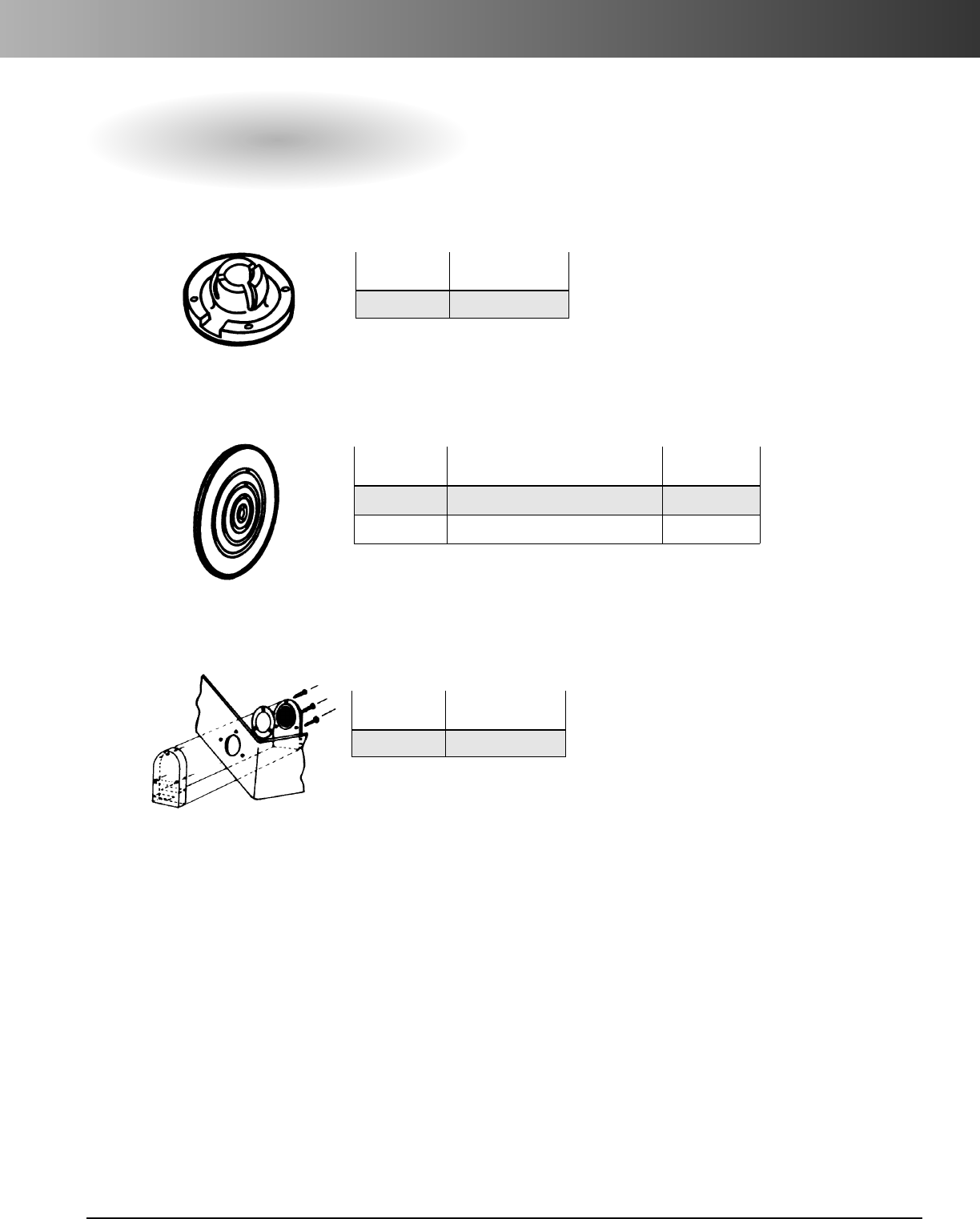
www.carlon.com 143
Himeline®Enclosures – HS Series
Accessories
Draining Device*
For 3R Rating and condensation build-up.
Air Vents*
NEMA 1 Rated only.
Enclosure Ventilator*
Allows any size enclosure to breathe, yet remains watertight.
Part Standard
Number Carton Qty.
HPVEA9 1
Part Standard
Number Carton Qty.
HVM27 1
Part Standard
Numbers Style Carton Qty.
HPVM25 For fitting outside of all enclosures 1
HPVM35 For fitting inside of all enclosures 1
*Factory installation available.
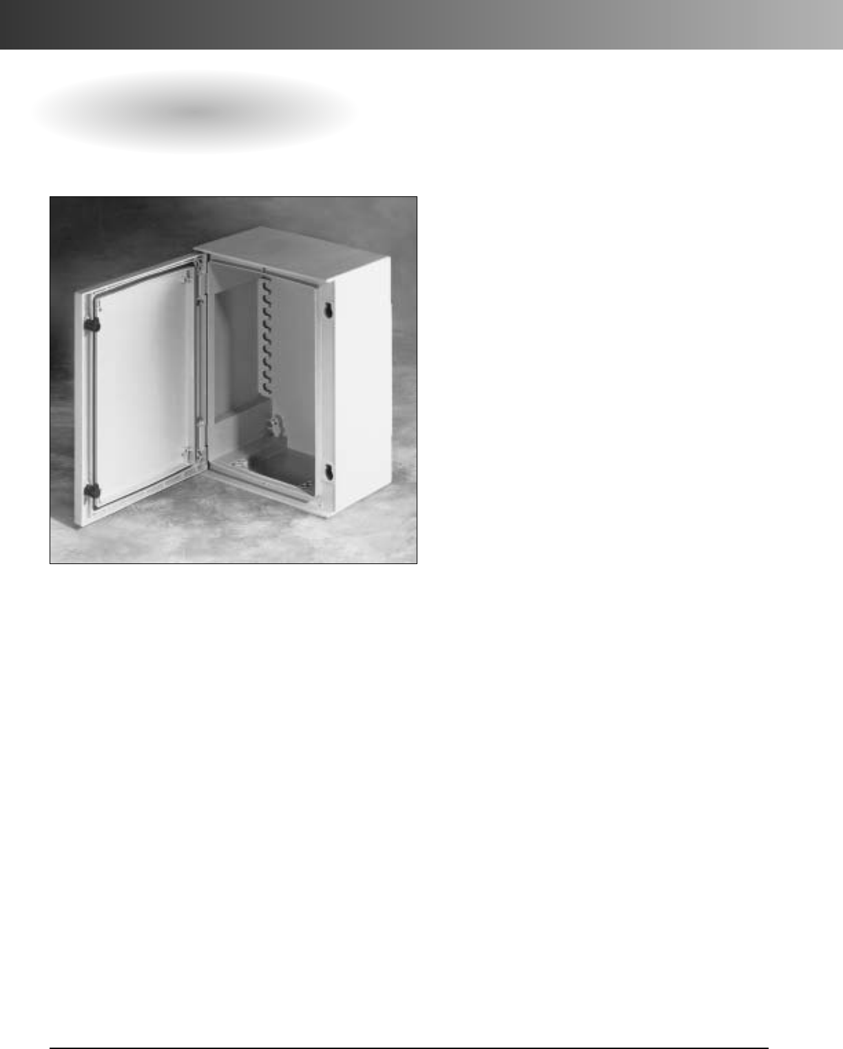
www.carlon.com
144
Himeline®Enclosures – HP Series (Fiber Reinforced Polyester)
HP Series Enclosures with Hinged Quick-Release Cover
• Meets NEMA 1, 3, 3S, 4, 4X, 12, 13
• Meets IP 66
Himeline®HP Series enclosures for medium sized devices
and equipment provide superior performance as junction
and terminal wiring boxes, and instrument and control
housing applications.
For indoor/outdoor industrial, MRO, and OEM applica-
tions. HP Series enclosures are resistant to corrosion,
sunlight, chemicals, dirt, and moisture. Temperature
range from -58° F to 320° F.
Features
•Projections for affixing cover mounted panel.
•Door locking mechanism convertible to key lock.
•M8x18 studs for back panel mounting (included).
•Hidden hinges open 185° for easy access.
•Multipositional DIN rail fixing components.
•Removable stainless steel hinge pins.
•Single piece construction.
•Opaque or tempered glass window option.
•Steel, nonmetallic & slotted back panels
available.
•External & internal venting available.
•Hinged variable height inner panel option.
•Quick lock 1/4-turn entry.
•Underside grid pattern on inner door panel.
•Self-positioning panel depth adjusters.
•Pole mounting kit.
•Pedestal mounting capability.
• Sunlight resistant.
Applications
•Junction boxes.
•Terminal wiring boxes.
•Instrument and control housing.
• Indoor or outdoor use.
Standards
•NEMA Type 1, 3, 3S, 4, 4X, 12, 13.
•UL Listed per UL 50, enclosures for electrical
equipment.
•CSA certified.
•Meets IP 66.
Material
•Lids/Bases – Fiberglass reinforced polyester.
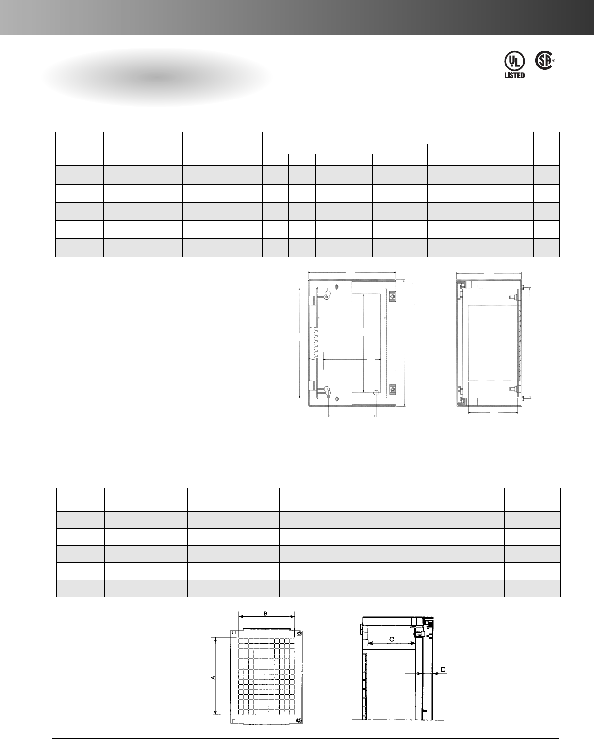
www.carlon.com 145
Himeline®Enclosures – HP Series (Fiber Reinforced Polyester)
HP Series Enclosures with Hinged Quick-Release Cover
LR701839
E54381
Enclosure With
Std.
Enclosure With
Std. Window Dimensions Std.
Opaque Cover
Ctn. Wt.
Clear
Ctn. Wt. Dimension External Internal Mounting Window Ctn.
Part Nos. (lbs.) Window* (lbs.) (H x W) (in.) A B C D E F G H J K Qty.
HP1612B 11.04 HC1612B 12.5 11 x 7.87 16.93 12.99 7.87 14.96 10.24 6.61 14.76 5.91 11.02 7.87 1
HP2016B 16.80 HC2016B 17.2 14.96 x 11.81 20.87 16.93 7.87 18.90 14.17 6.61 18.70 9.84 14.96 11.81 1
HP2416C 21.13 HC2416C 24.12 18.89 x 11.81 25.47 17.17 9.84 22.83 14.17 8.35 22.64 9.84 18.90 11.81 1
HP3020D 32.28 HC3020D** 36.02 22.83 x 15.74 29.41 21.10 11.81 26.77 18.11 10.28 26.57 13.78 22.83 15.75 1
HP3325D 39.00 HC3325D** 43.12 26.77 x 19.68 33.35 25.04 11.81 30.71 22.05 10.28 30.51 17.72 26.77 19.69 1
Specifications
*HC Enclosures are IP 65 Rated. Clear window is glass.
** This series of enclosures come standard with body, lid and mounting rail kit.
•Internal fiberglass reinforced polyester door assembly.
•Grid pattern on the inside for quicker positioning of equipment.
•Quick locking 1/4-turn entry.
Hinged Internal Door
C
G
F
A
H
B
E
J
K
D
Depth with back
panel installed
Part A B C D Std. Ctn. Std. Ctn.
Numbers in. (mm) in. (mm) in. (mm) in. (mm) Qty. Wt. (lbs.)
PID1612 12.40 (315) 18.07 (205) 5.98 (152) 1.02 (26) 1 2.05
PID2016 16.34 (415) 12.00 (305) 5.98 (152) 1.02 (26) 1 3.15
PID2416 20.28 (515) 12.00 (305) 7.64 (194) 1.26 (32) 1 4.50
PID3020 24.21 (615) 15.94 (405) 9.61 (244) 1.26 (32) 1 6.50
PID3325 28.15 (715) 19.88 (505) 9.61 (244) 1.26 (32) 1 8.45
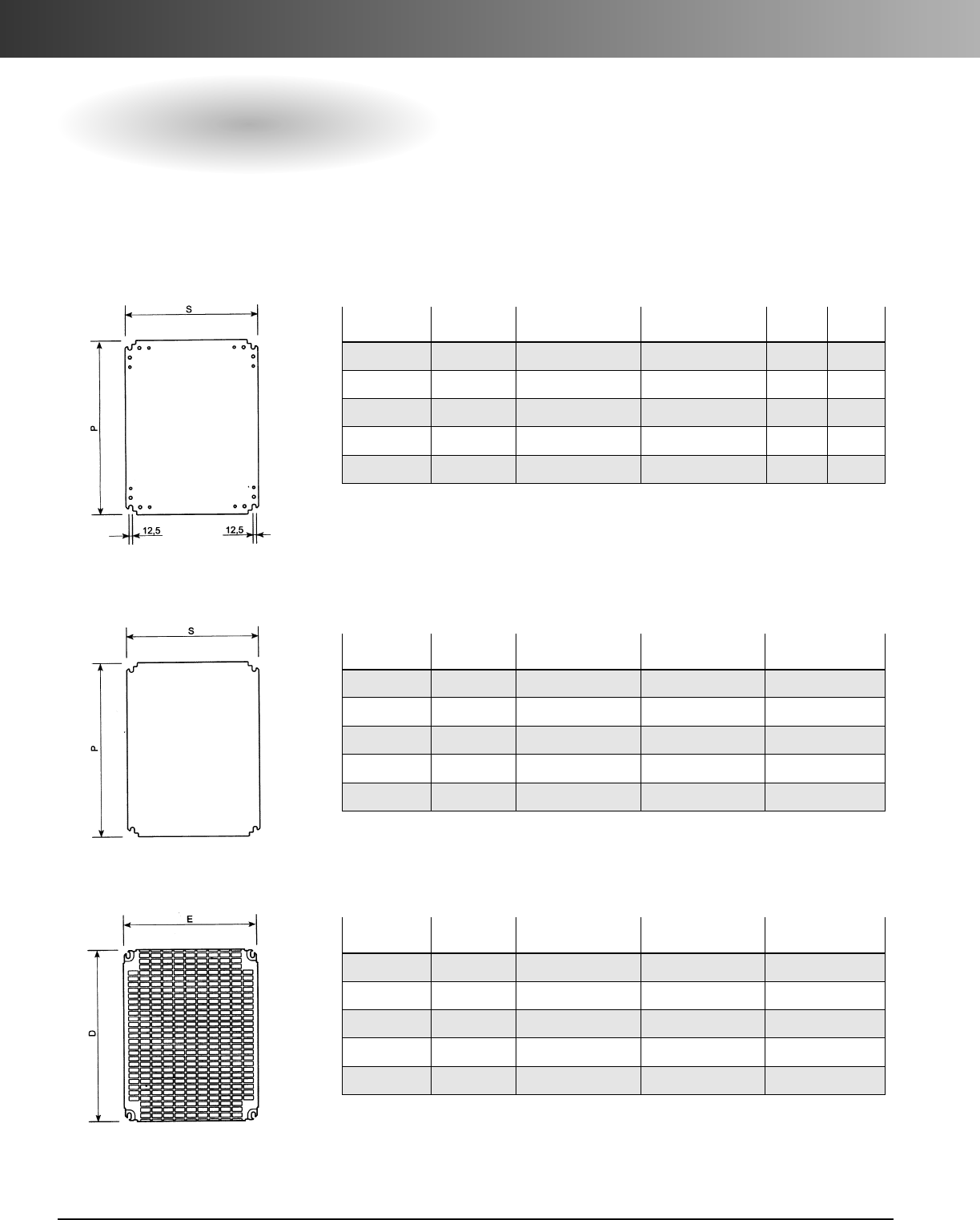
www.carlon.com
146
Himeline®Enclosures – HP Series
Accessories
Steel Back Panels
Steel back panels are white painted 14 gauge steel.
To Fit Part Thickness Weight P S
Enclosures Numbers in. (mm) lbs. (kg) in. in.
HP1612B PMM1612 .079 (2) 3.10 (1.6) 14.37 9.84
HP2016B PMM2016 .079 (2) 6.15 (2.5) 18.30 13.78
HP2416C PMM2416 .079 (2) 8.0 (3.1) 22.24 13.78
HP3020D PMM3020 .079 (2) 12.04 (4.6) 26.18 17.72
HP3325D PMM3325 .118 (3) 20.0 (9.9) 30.11 21.65
ToFit Part Weight P S
Enclosures Numbers lbs. (kg) in. (mm) in. (mm)
HP1612B PMB1612 1.10 (0.5) 14.37 (365) 9.84 (250)
HP2016B PMB2016 2.65 (1.2) 18.30 (465) 13.78 (350)
HP2416C PMB2416 3.09 (1.4) 22.24 (565) 13.78 (350)
HP3020D PMB3020 4.63 (2.1) 26.18 (665) 17.72 (450)
HP3325D PMB3325 6.62 (3.0) 30.11 (765) 21.65 (550)
To Fit Part Weight D E
Enclosures Numbers lbs. (kg) in. (mm) in. (mm)
HP1612B PMR1612 1.54 (0.7) 13.74 (349) 9.8 (251)
HP2016B PMR2016 2.87 (1.3) 17.72 (450) 13.82 (351)
HP2416C PMR2416 3.53 (1.6) 21.85 (555) 13.82 (351)
HP3020D PMR3020 5.07 (2.3) 25.39 (645) 17.76 (451)
HP3325D PMR3325 7.06 (3.2) 29.53 (750) 21.69 (551)
PVC Insulating Back Panels
PVC back panels are made from 1/4"PVC and meet UL94 V-O.
Slotted Back Panels
Zinc dichromated coated steel plates perforated for addition of electrical circuitry.
Refer to the Enclosure Accessories section for back panel accessories.
Back Panels Dimensions
Acomplete range of plates, which can be directly fixed to the enclosure supports or to the adjustable depth supports.
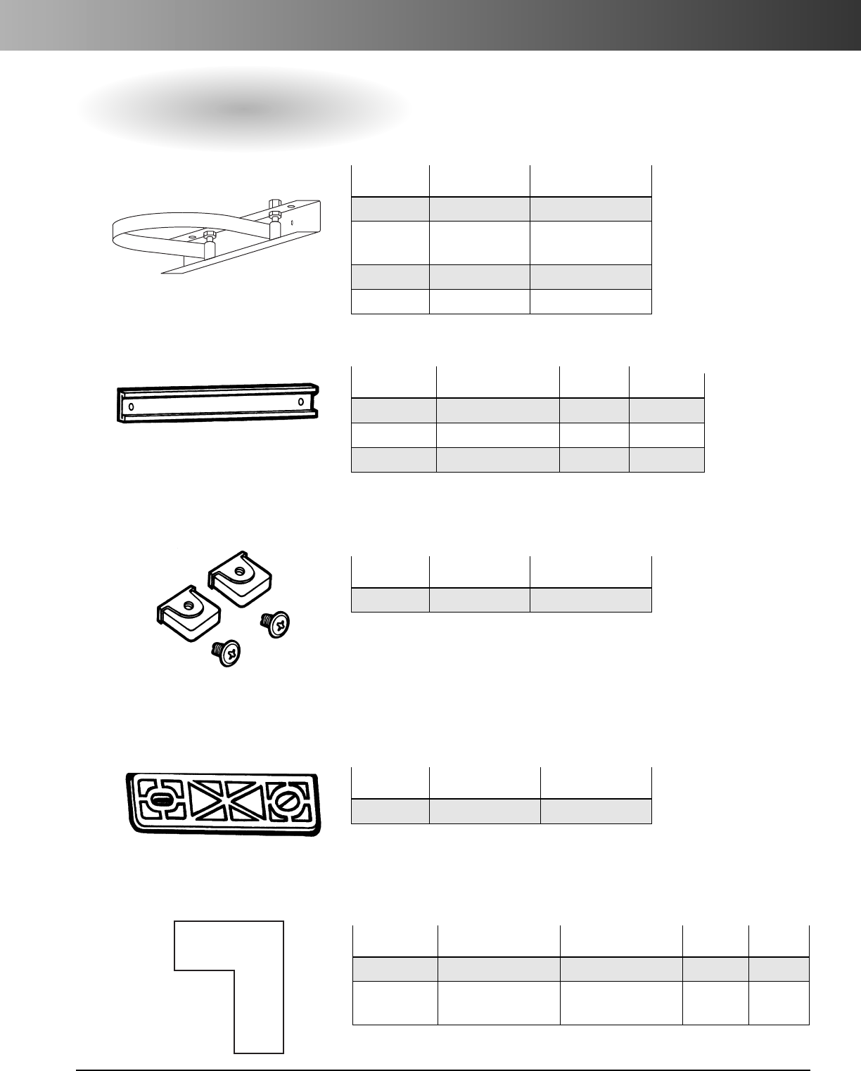
www.carlon.com 147
Himeline®Enclosures – HP Series
Accessories
Blanking Grommet
To close off openings on enclosure backs.
35 mm Symmetrical DIN Rail
Rail Mounting Insert
Wall Mounting Set (includes brass inserts and installation tools)
Pole Mounting Set
Part To Fit Standard Carton
Numbers To Enclosures Quantity
HPPF300 HP1612B 1
HPPF400 HP2016B 1
HP2416C
HPPF500 HP3020D 1
HPPF600 HP3325D 1
Part StandardCarton
Number Features Quantity
HPRFK Fits all enclosures 1
Part Standard Carton Standard Carton
Number Quantity Weight (lbs.)
HPWMF 4 0.1
Part To Fit To Width Std. Ctn.
Numbers Enclosures (in.) Qty.
HPCO300 HP1612B 11.02 1
HPCO400 HP2016B, HP2416C 14.96 1
HPCO500 HP3020D 18.90 1
Part Fits Std. Ctn. Std. Ctn.
NumbersEnclosure Sizes Description Qty. Wt. (lbs.)
HPBNGB 16 x 12 and 20 x 16 Blanking Grommet Set of 4 1.00
HPBNGC 24 x 16, 30 x 20 Blanking Grommet Set of 4 1.00
and 33 x 25
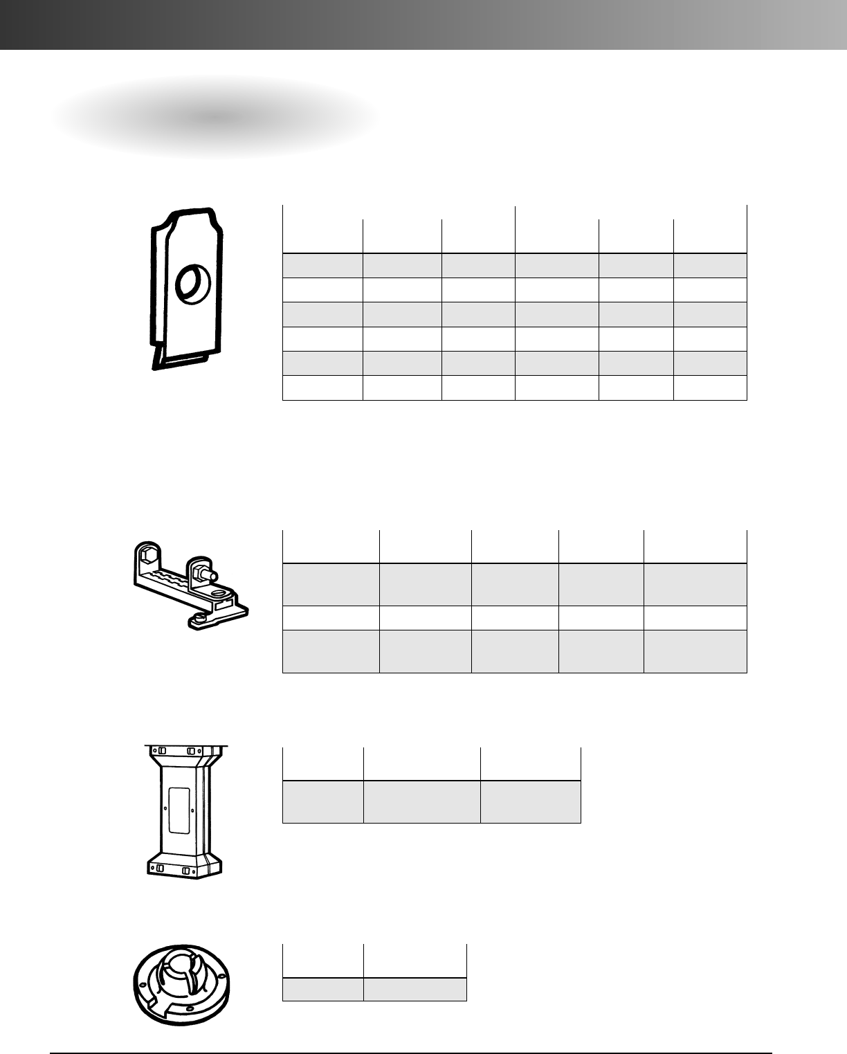
www.carlon.com
148
Himeline®Enclosures – HP Series
Accessories
Draining Device*
For 3R Rating and condensation build-up.
Part Standard
Number Carton Qty.
HPVEA9 1
Part To Fit Standard
Number ToEnclosures Carton Qty.
HPSFS1 HP2016B 1
HP2416C
To Fit Part A B Standard Carton
Enclosures Numbers in./mm in./mm Quantity
HP1612B & HPLM200 5.98/152 3.90/99 1 set of 4
HP2016B HPLM200
HP2416C HPLM250 8.07/205 4.13/105 1 set of 4
HP3020D & HPLM300 10.04/255 8.07/205 1 set of 4
HP3325D HPLM300
FIXING NUT FIXING BOLT WITH WASHER
Part Type Std. Ctn. Part Length Std. Ctn.
Numbers Of Thread Qty. Numbers (in.) Qty.
HPFA4 M4 100 HPFB104 .39 100
HPFA4 M4 100 HPFB164 .63 100
HPFA5 M5 100 HPFB125 .47 100
HPFA5 M5 100 HPFB185 .71 100
HPFA6 M6 100 HPFB126 .47 100
HPFA6 M6 100 HPFB186 .71 100
*Factory installation available.
Fixing Accessories For Slotted Plates
For slotted back panels, see page 34
Back Panel Depth Adjustable Supports
Supports designed to fit 7.87" (200 mm), 9.84" (250 mm), 11.81" (300 mm) and 13.78" (350 mm) deep enclosures.
Self-positioning slots allow for adjustment every .49" (12.5 mm). Made of zinc dichromated coated steel.
Pedestal Mount
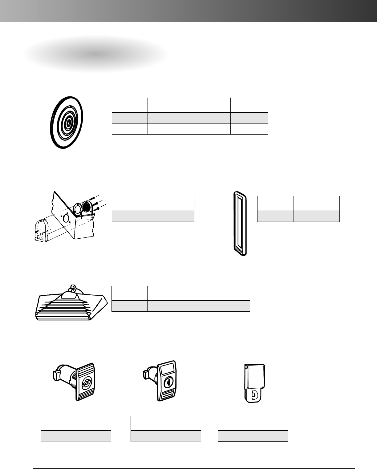
www.carlon.com 149
Himeline®Enclosures – HP Series
Accessories
Air Vents*
NEMA 1 Rated only.
Enclosure Ventilator*
Allows any size enclosure to
breathe, yet remains watertight.
Part Standard
Number Carton Qty.
HVM27 1
Part Standard
Numbers Style Carton Qty.
HPVM25 For fitting outside of all enclosures 1
HPVM35 For fitting inside of all enclosures 1
Locks
For Himeline HP Enclosures
Replacement Door Lock Cylinder Key Lock (Keyed Alike) Padlocking Service
Replacement Standard Handle
Part Standard
Number Carton Qty.
HPBU 1
Coupling Frame
For Himeline HP Enclosures
HP3020D and HP3325D
Part Std.
Number Ctn. Qty.
HPRLA 1
For replacement handle,order HPRSH.
Part Std.
Number Ctn. Qty.
HPTPLM 1
For replacement key, order HPRKO.
Part Std.
Number Ctn. Qty.
HPPLH 1
Part Standard Carton Standard Carton
Number Quantity Weight (lbs.)
HPRSH 1 0.05
*Factory installation available.
*Factory installation available.
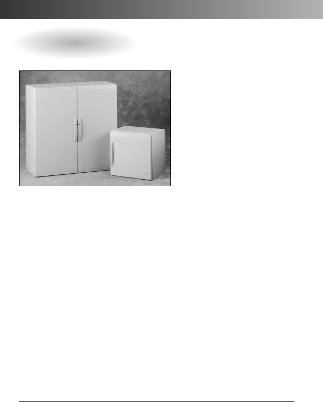
www.carlon.com
150
Himeline®Enclosures – HLA/HLS Series (Fiber Reinforced Polyester)
HLA/HLS Series Enclosures
Carlon®Himeline®HLA/HLS Series Enclosures are large Fiber
Reinforced Polyester Cabinets ranging in sizes 20 x 20 x 17
to 50 x 40 x 17 and 20 x 20 x 12 to 50 x 40 x 12, respectively.
They have operating temperatures of -50° to 150° C and can
accommodate large devices and equipment for a wide range
of applications including junction and terminal wiring boxes,
instruments, and control housings. They are ideal for
indoor/outdoor industrial, MRO and OEM applications, and
offer superior strength and high resistance to corrosion,
moisture, dust, oil and UV light, enabling them to withstand
the harshest of environments.
The HLA/HLS Series Enclosures are fitted with a watertight
gasket and are available in one-and two-door configurations.
These cabinets have a closed top and bottom and the two-door
version includes a central upright to maintain rigidity.
To maintain the watertight seal, the locking mechanism is
positioned outside the gasketed area. A wide variety of
accessories are available such as steel and nonmetallic back
panels, self-positioning panel depth adjusters, and ventilator
kits.
Carlon Enclosures…the ideal alternative to expensive
stainless steel enclosures.
Features
•Fiber reinforced polyester.
•Temperature range of -58° to 302° F
(-50° to 150° C).
•Indoor/outdoor applications.
•Superior strength.
•High resistance to harsh environments.
•Watertight gasket seal.
•One- and two-door configurations.
•Locking mechanism and hinge are outside
gasketed area.
•Floor or wall mounted.
Applications
•Contain large devices and equipment.
•Junction and terminal wiring boxes.
•Instrument and control housings.
Standards
•IP 65 Rating (Single door versions only)
•4/4X Rated (Single door versions only)
•UL Listed
•CSA Certified
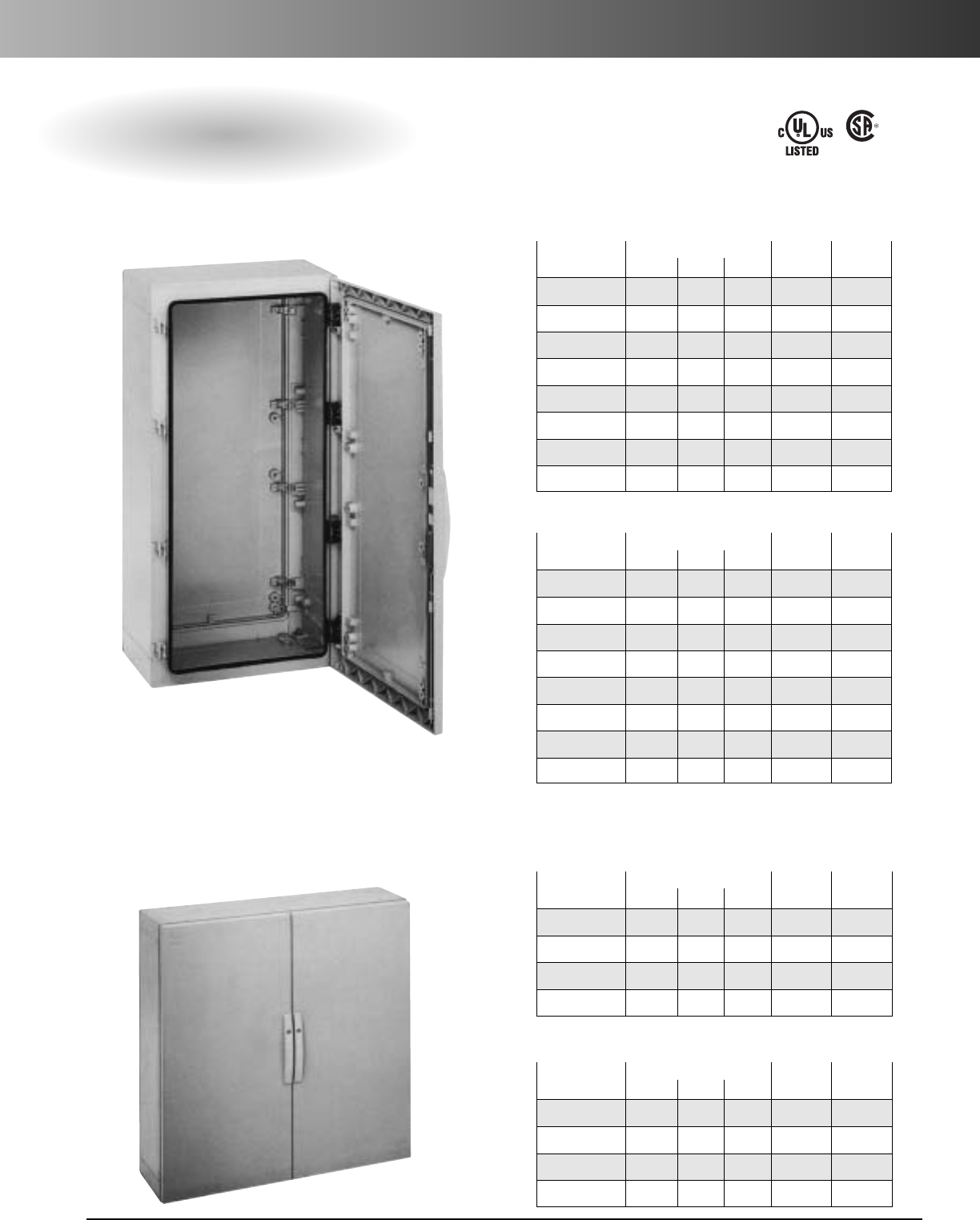
www.carlon.com 151
Himeline®Enclosures – HLA/HLS Series (Fiber Reinforced Polyester)
HLA/HLS Series Single and Double Hinged Cover
Enclosures with Latches
LR96563
E54381
One Door NEMA Types 1, 2, 3, 3R, 4, 4X, 5, 12, 13
Two Door NEMA Types 1, 2, 12, 13
Dimensions Std. Ctn. Std. Ctn.
Part No. H W D Qty. Wt.
HLA2020 20 20 17 1 38.3
HLA2030 20 30 17 1 53.9
HLA3020 30 20 17 1 53.9
HLA3030 30 30 17 1 60.7
HLA4020 40 20 17 1 63.1
HLA4030 40 30 17 1 81.0
HLA5020 50 20 17 1 78.7
HLA5030 50 30 17 1 96.7
HLA One Door (17" Deep)
Dimensions Std. Ctn. Std. Ctn.
Part No. H W D Qty. Wt.
HLS2020 20 20 12 1 29.8
HLS2030 20 30 12 1 40.59
HLS3020 30 20 12 1 49.5
HLS3030 30 30 12 1 55.1
HLS4020 40 20 12 1 56.81
HLS4030 40 30 12 1 61.7
HLS5020 50 20 12 1 67.56
HLS5030 50 30 12 1 76.83
HLS One Door (12" Deep)
Dimensions Std. Ctn. Std. Ctn.
Part No. H W D Qty. Wt.
HLA30402 30 40 17 1 81.0
HLA40402 40 40 17 1 114.7
HLA40502 40 50 17 1 135.0
HLA50402 50 40 17 1 135.0
HLA Two Door (17" Deep)
Dimensions Std. Ctn. Std. Ctn.
Part No. H W D Qty. Wt.
HLS30402 30 40 12 1 62.57
HLS40402 40 40 12 1 87.59
HLS40502 40 50 12 1 104.28
HLS50402 50 40 12 1 104.28
HLS Two Door (12" Deep)
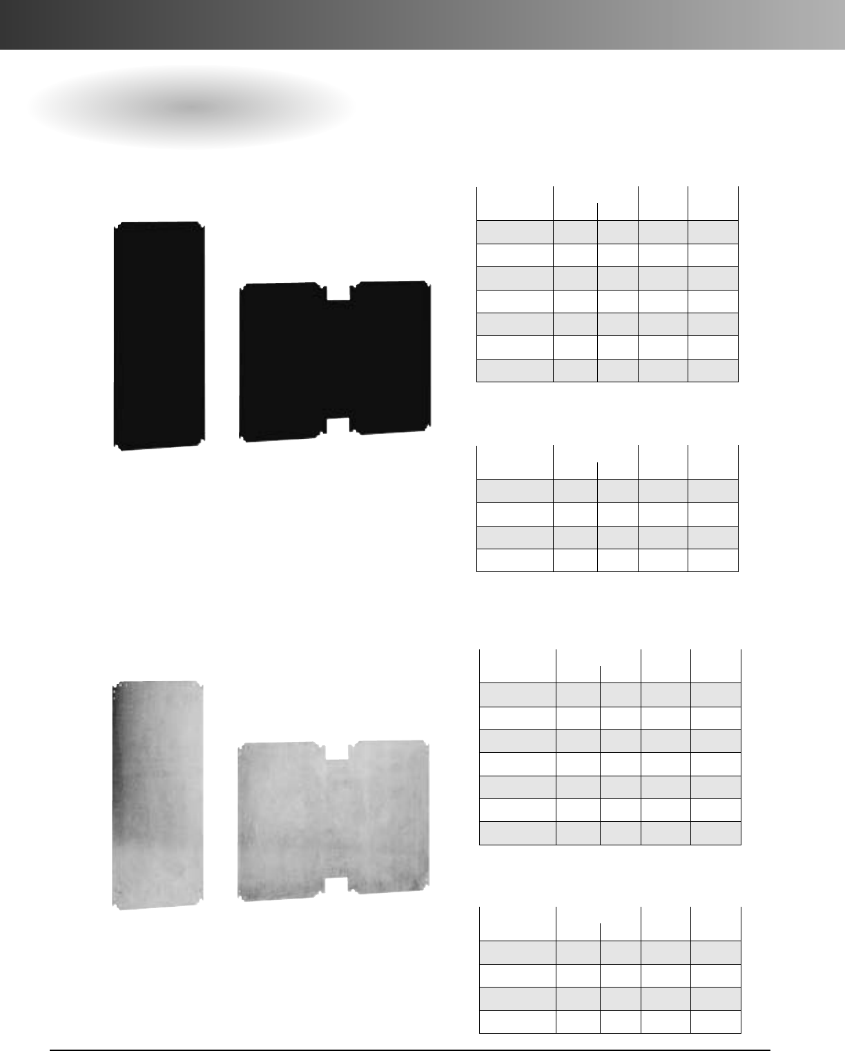
www.carlon.com
152
Himeline®Enclosures – HLA/HLS Series (Fiber Reinforced Polyester)
Accessories
Dimensions Std. Ctn. Std. Ctn.
Part No. H W Qty. Wt.
LP2020BP 15.4 14.8 1 2.1
LP3020BP* 25.2 14.8 1 3.0
LP3030BP 25.2 24.6 1 6.3
LP4020BP 35.0 14.8 1 5.2
LP4030BP 35.0 24.6 1 8.8
LP5020BP 44.3 14.8 1 6.7
LP5030BP 44.3 24.6 1 11.2
Nonmetallic Thermosetting Plastic (Bakelite)
Metal – Galvanized Steel
One Door
Dimensions Std. Ctn. Std. Ctn.
Part No. H W Qty. Wt.
LP30402BP 25.2 34.4 1 8.8
LP40402BP 35.0 34.4 1 12.3
LP40502BP 35.0 44.3 1 16.1
LP50402BP 44.3 34.4 1 16.1
Two Door
*Use Back Panel LP3020BP for Enclosures HLA2030,
HLA3020, HLS2030 and HLS3020
Dimensions Std. Ctn. Std. Ctn.
Part No. H W Qty. Wt.
LA2020BP 15.4 14.8 1 5.6
LA3020BP* 25.2 14.8 1 8.6
LA3030BP 25.2 24.6 1 17.6
LA4020BP 35.0 14.8 1 14.6
LA4030BP 35.0 24.6 1 24.3
LA5020BP 44.3 14.8 119.4
LA5030BP 44.3 24.6 1 31.9
One Door
Dimensions Std. Ctn. Std. Ctn.
Part No. H W Qty. Wt.
LA30402BP 25.2 34.4 1 24.1
LA40402BP 35.0 34.4 1 33.8
LA40502BP 35.0 44.3 143.4
LA50402BP 44.3 34.4 1 43.7
Two Door
*Use Back Panel LA3020BP for Enclosures HLA2030,
HLA3020, HLS2030 and HLS3020
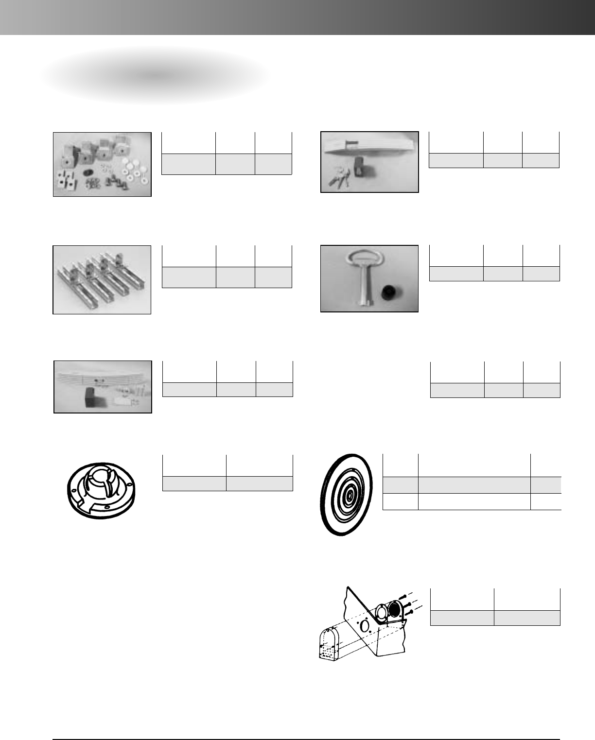
www.carlon.com 153
Himeline®Enclosures – HLA/HLS Series (Fiber Reinforced Polyester)
Accessories
Std. Ctn. Std. Ctn.
Part No. Qty. Wt. (lbs.)
HLAMFSS 1 ea. .6
(set of 4)
Std. Ctn. Std. Ctn.
Part No. Qty. Wt. (lbs.)
HLATEL 1 ea. .41
Std. Ctn. Std. Ctn.
Part No. Qty. Wt. (lbs.)
HLABPA4 1 ea. .31
(set of 4)
Mounting Feet Replacement Handle with Cylinder Key Lock
Std. Ctn. Std. Ctn.
Part No. Qty. Wt. (lbs.)
HLATD 1 ea. .21
Standard Replacement Bar Lock with Key
Panel Adjuster Kit
Std. Ctn. Std. Ctn.
Part No. Qty. Wt. (lbs.)
HLAPAD 1ea. .61
Padlock Device
Std. Ctn.
Part No. Qty.
HPVEA9 1
Draining Device*
Std. Ctn. Std. Ctn.
Part No. Qty. Wt. (lbs.)
HLAHAN 1.40
For 3R Rating and condensation build-up.
*Factory installation available.
Std. Ctn.
Part No. Style
Wt. (lbs.)
HPVM25
For fitting outside of all enclosures
1
HPVM35
For fitting inside of all enclosures
1
Std. Ctn.
Part No. Qty.
HVM27 1
EnclosureVentilator*
Allows any size enclosure to breathe, yet
remains watertight.
NEMA 1 Rated only.
Replacement Handle with Push Button
Air Vents*
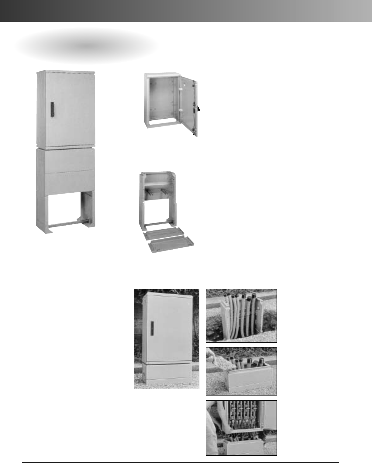
www.carlon.com
154
Himeline®Distribution Enclosures
Distribution Enclosure and Pedestal
Carlon
®
Distribution Enclosures
and Pedestals are designed to
accommodate all types of
electrical equipment for electrical
distribution applications. The
enclosure may be directly installed
on the ground or on top of a
pedestal, and the pedestal
is approved for direct bury appli-
cations. Both are manufactured
using fiber reinforced polyester to
provide high impact resistance
and allow effortless modifications.
And each have an IP-43 Self-
Ventilated and IP-54 Watertight
rating and a temperature range of
-58°Fto 302°F.
Features
•High impact resistance
• Nonconductive and noncorrosive.
• Fits all type of electrical equipment
• IP-43 Self-Ventilated.
•IP-54 Watertight.
•One and two door configurations.
• Install directly on the ground or on a pedestal.
• Removable inner hinges for great access.
•Doors open 180°
Features
•Can be direct buried.
• Nonconductive and noncorrosive
• Detachable upper front for easy access.
• High impact resistance.
• Auxiliary outlet on the side.
• IP-43 Self-Ventilated.
•IP-54 Watertight.
•Floor or wall mountable.
Enclosure
Pedestal
Applications
Material
•Fiberglass Reinforced Polyester
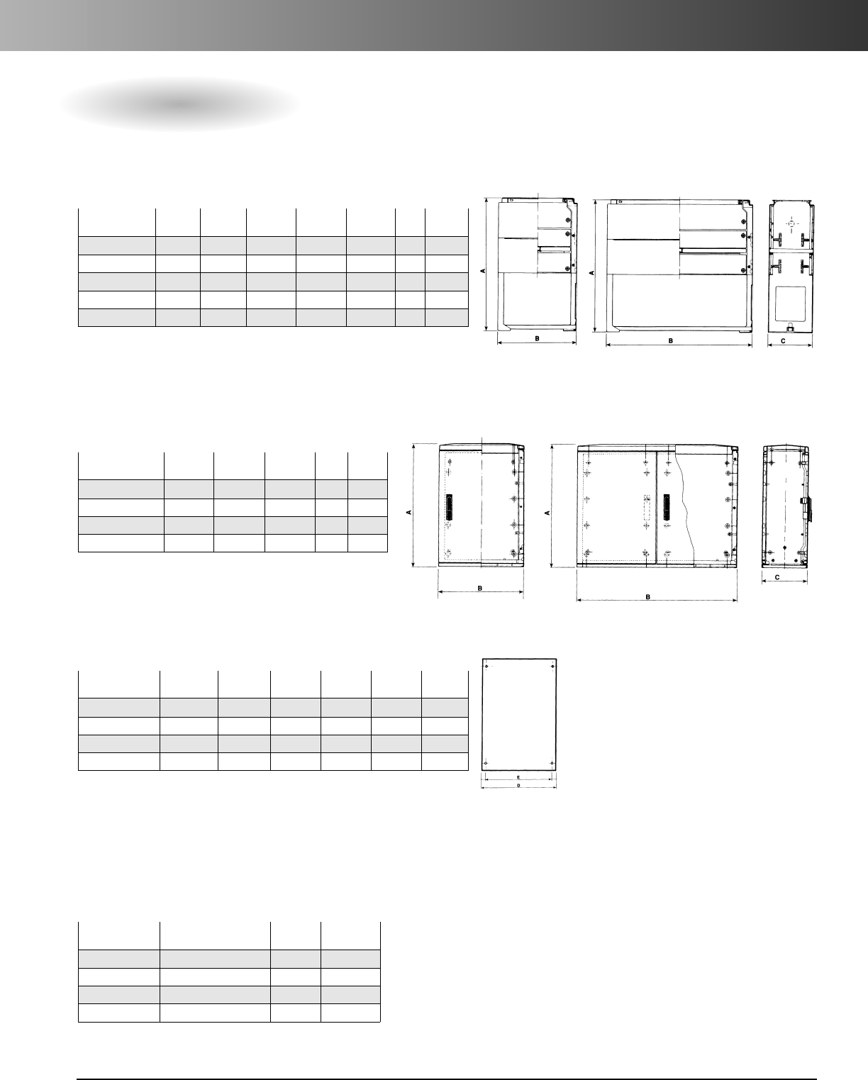
www.carlon.com 155
Himeline®Distribution Enclosures
Distribution Enclosure and Pedestal
Part No. of No. of A B C Ctn. Wt.
No. Doors Locks Height Width Depth Qty. (lbs.)
HLP3318 1 1 33.46 18.31 12.60 1 40.79
HLP3323 1 1 33.46 23.23 12.60 1 48.50
HLP3331 1 1 33.46 30.91 12.60 1 55.12
HLP33442 2 1 33.46 43.90 12.60 1 77.16
HLP33442L 2 2 33.46 43.90 12.60 1 77.16
Enclosures
Part
#of Plates
Thick- Carton Weight
No. per Encl. D E ness Qty. (lbs.)
LA1412BP 1 14.02 11.97 .20 1 4.41
LA1816BP 2 17.64 15.59 .20 1 11.02
LA1916BP 1 18.94 16.89 .20 1 6.00
LA2725BP 1 26.61 24.57 .20 1 8.38
Mounting Plates
Part
Size
Carton Weight
No.H x WxD Qty. (lbs.)
HLP3318G 33 x 18 x 12 1 2.2
HLP3323G 33 x 23 x 12 12.2
HLP3331G 33 x 31 x 12 1 2.2
HLP3344G 33 x 44 x 12 12.2
Gasket
Part A B C Ctn. Weight
No. Height Width Depth Qty. (lbs.)
HLPED3318 35.43 18.31 12.20 1 33.10
HLPED3323 35.43 23.23 12.20 1 37.48
HLPED3331 35.43 30.91 12.20 1 44.10
HLPED33442 35.43 43.90 12.20 1 55.12
Pedestals
Specifications
Accessories

www.carlon.com
156
Slack and Splice Enclosures
Slack and Splice Enclosures
Carlon’sstate-of-the-art modification
capabilities allow for design of Slack and
Splice Enclosures to meet specific application
requirements.
Features
•Slack and Splice Enclosures provide maximum
protection of slack fiber and splice unit assemblies.
• Eliminates need for difficult aerial and vault splicing.
• Stores adequate slack fiber to facilitate splicing at
ground level work station.
• Enclosure sized to maintain minimum required
radius of fiber optic cable.
• Splice tube to accommodate industry standard
splice and tray assemblies (Splice enclosure only).
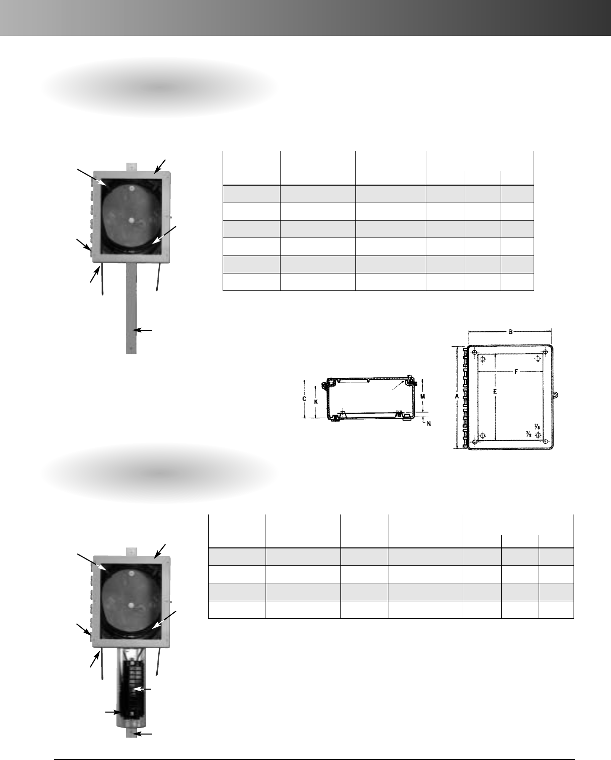
www.carlon.com 157
Slack and Splice Enclosures
Slack Enclosures
Splice Enclosures
Inside Box Dimensions
Part Box Size Opening
Number A x B x C E x F K M N
SLK11 30 x 24 x 111/2271/4x21 1/4101/410 1/21
SLK12 30 x 24 x 91/227 1/4x21 1/481/481/21
SLK21 24 x 20 x 111/2211/4x171/410 1/410 1/21
SLK22 24 x 20 x 91/2211/4x17 1/481/481/21
SLK31 20 x 16 x 111/2171/4x 131/4101/4101/21
SLK32 20 x 16 x 91/217 1/4x13 1/410 1/410 1/21
Inside Box Dimensions
Part Box Size Tube Opening
Number A x B x C Size E x F K M N
SPL111 30 x 24 x 111/210" 271/4x 211/4101/4101/21
SPL122 30 x 24 x 9 1/28" 271/4x21 1/481/481/21
SPL211 24 x 20 x 111/210" 211/4x 171/4101/4101/21
SPL222 24 x 20 x 9 1/28" 211/4x171/481/481/21
1/4"Thick
UL Approved Gasket
Structural
Foam
Thermoplastic
Enclosure
Slack
Fiber
Optic
Cable
Weatherproof
Split Cable
Grommets
Hinged
Cover for
Easy
Access
Cable
Retainer
Clips
Weatherproof
Splice Tube
Splice Closure
(Not Included)
Aluminum
Channel for
Pole or Vault
Wall Mounting
Structural
Foam
Thermoplastic
Enclosure
Slack
Fiber
Optic
Cable
Weatherproof
Split Cable
Grommets
Hinged
Cover for
Easy
Access
Cable
Retainer
Clips
Aluminum
Channel for
Pole or Vault
Wall Mounting
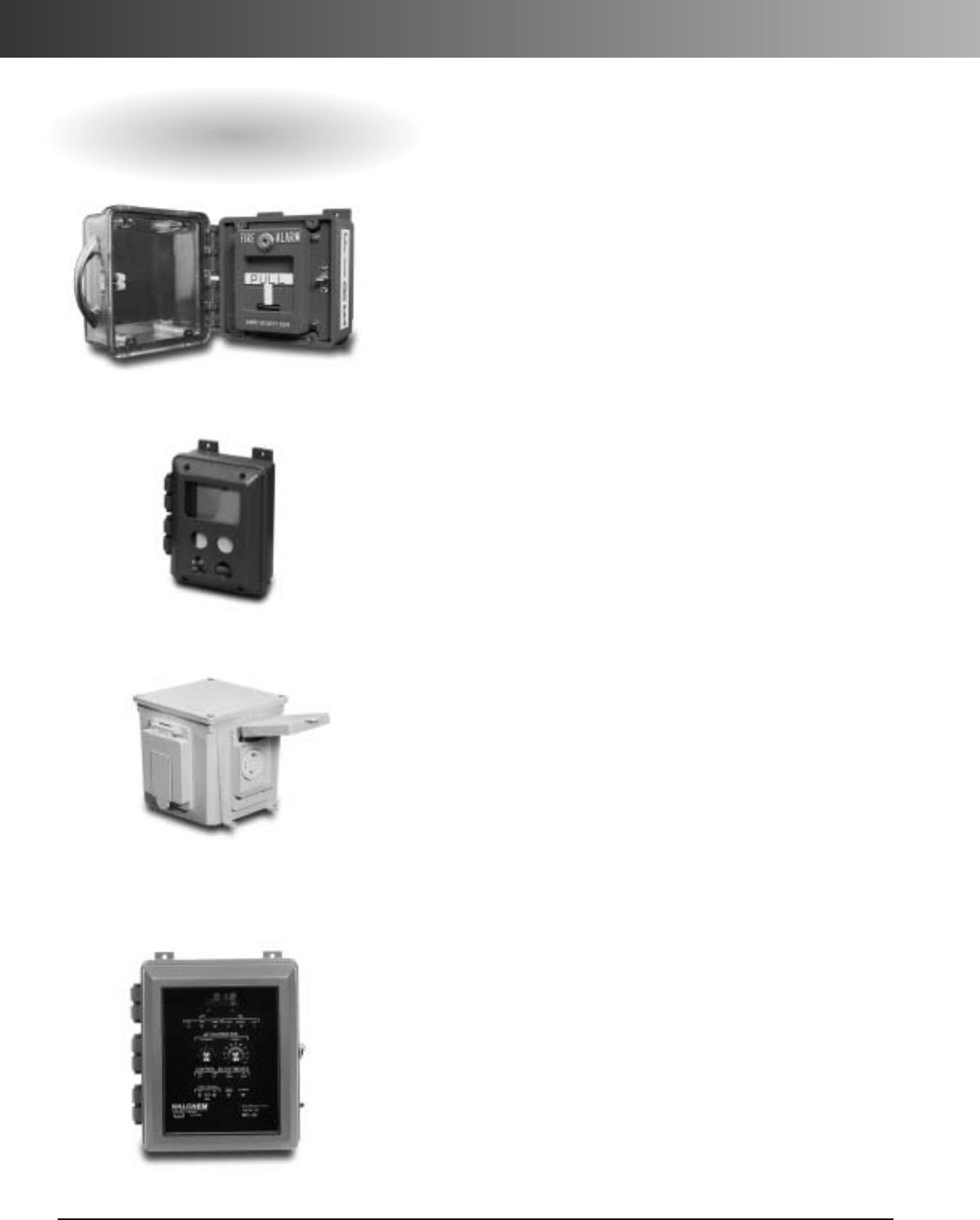
www.carlon.com
158
Enclosures Factory Modifications
For All Enclosures
Color Molded Enclosures
All Circuit Safe®enclosures can be molded in a variety of
colors. Minimum quantities for single shipment or releases
against blanket orders are required.
Painted/Silkscreened Enclosures
All enclosures can be painted, interior and exterior, or by
special request. Enclosure covers can also be silkscreened on
request.
EMI/RFI Protection
For applications where Radio Frequency Interference is a
factor, the interior can be coated with an acrylic base paint
with a nickel filler. Windows can be covered with fine copper
mesh.
Other Modifications Available
Our factory is capable of modifying any of our enclosures to
acustomer’sspecifications. Factory’scapabilities include:
• Precision milling of button holes, windows, and pockets
for keypad installations.
• Hole tapping.
•Ventilators.
•Mounting bosses.
• Access windows.
• Hinged windows.
• Mounted in use weatherproof covers.
• Handles for portable units.
•Latches.
•Enclosure coolers.
• Cylinder locking systems.
• And more!
Painted JIC enclosure with painted back panel. Installed
clear cover with handle and quick-release latch.
Molded junction box painted with addition of
mounted in-use weatherproof cover.
Painted JIC enclosure with pocket installed in cover
for control pad.
Color molded JIC unit with addition of window
and pushbuttons.

www.carlon.com 159
Enclosures General Information
NEMA Types – Definitions Pertaining to Nonhazardous Locations
Enclosures for Electrical Equipment
An enclosure is a surrounding case constructed to provide protection from accidental contact with the
enclosed equipment and to provide protection to the enclosed equipment from specified environmental
conditions. A brief description of the more common types of enclosures used by the electrical industry follows.
Type 1 Enclosure: Intended for indoor use primarily to provide protection against contact with enclosed
equipment and a degree of protection against falling dirt.
Type 2 Enclosure: Intended for indoor use primarily to provide a degree of protection against limited
amounts of falling water and dirt.
Type 3 Enclosure: Intended for outdoor use primarily to provide a degree of protection against
wind-blown dust, rain, sleet and external ice formation.
Type 3R Enclosure: Intended for outdoor use primarily to provide a degree of protection against falling
rain, sleet and external ice formation.
Type 3S Enclosure: Intended for outdoor use primarily to provide a degree of protection against
wind-blown dust, rain, and sleet, and to provide for operation of external mechanism
when ice laden.
Type 3X Enclosure: Intended for outdoor use primarily to provide a degree of protection against
wind-blown dust, rain, sleet, external ice formation, and corrosion.
Type 3SX Enclosure: Intended for outdoor use primarily to provide a degree of protection against
wind-blown dust, rain, sleet, and corrosion,and to provide for operation of external
mechanism when ice laden.
Type 4 Enclosure: Intended for indoor or outdoor use primarily to provide a degree of protection against
wind-blown dust and rain, splashing water and hose-directed water.
Type 4X Enclosure: Intended for indoor or outdoor use primarily to provide a degree of protection against
corrosion, wind-blown dust and rain, splashing water and hose-directed water.
Type 6 Enclosure: Intended for indoor or outdoor use primarily to avoid a degree of protection against
contact with enclosed equipment, falling dirt, hose-directed water, entry of water
during occasional temporary submersion at a limited depth and external ice formation.
Type 6P Enclosure: Intended for indoor or outdoor use primarily to provide a degree of protection against
contact with enclosed equipment, falling dirt, hose-directed water, entry of water
during prolonged submersion at a limited depth and external ice formation.
Type 12 Enclosure: Intended for indoor use primarily to provide a degree of protection against dust,
falling dirt and dripping noncorrosive liquids.
Type 13 Enclosure: Intended for indoor use primarily to provide a degree of protection against dust,
spraying of water, oil and noncorrosive coolant.
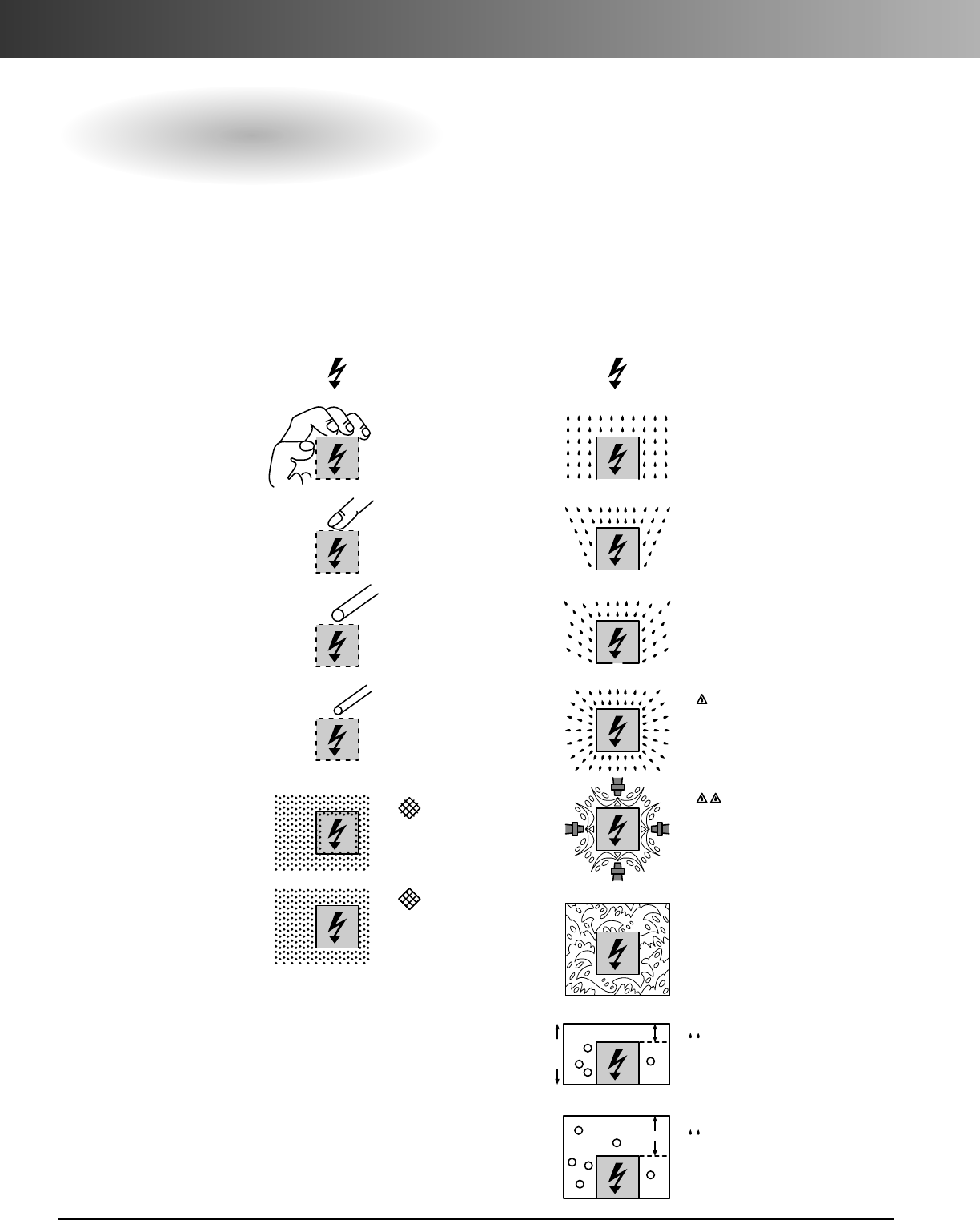
www.carlon.com
160
Enclosures General Information
International Standards IP Protection Classification Data
The letters IP followed by three characteristic numbers symbolize the degree of protection.
1
2
3
4
5
6
0
Protected against
solid bodies larger
than 50 mm (for
example acciden-
tally touching with
the hand)
T
No protection
Protected against
solid bodies larger
than 12 mm (for
example a finger)
Protected against
solid bodies larger
than 2.5 mm (tools,
wires)
Protected against
solid bodies larger
than 1 mm (fine
tools, small wires)
Protected against
dust (no harmful
deposits)
Complete protection
against dust
1
2
3
4
5
6
7
0
Protected against
vertical water drops
(condensation)
T
No protection
Protected against
water drops at up to
15°from the vertical
Protected against
rain at up to 60°
from the vertical
Protected against
water splashing from
all directions
Protected against
water sprayed from
ahose from all
directions
Protected against
water projections
similar to sea wave
splashes
Protected against
effects of prolonged
immersion under
pressure
Protected against
the effect of
immersion
15 cm mini
1
m
8
...m
m
First Digit
Protection Against Solid Bodies
Second Digit
Protection Against Liquids
TestTest
No protection No protection
Protection against
vertical water drops
condensation
Protected against
water drops at up to
15°from the vertical
Protected against
water splashing from
all directions
Protected against
water sprayed from a
hose from all directions
Protected against
water projections
similar to sea wave
splashes
Protected against
the effector
immersion
Protected against
effects of prolonged
immersion under
pressure
Protected against
rain at up to 60°
from the vertical
Protection against
solid bodies larger than
50 mm (for example
accidentally touching
with the hand)
Protection against
solid bodies larger
than 12 mm (for
example a finger)
Protection against
solid bodies larger
than 2.5 mm (tools,
wires)
Protection against
solid bodies larger
than 1 mm (tools,
small wires)
Protection against
dust (no harmful
deposits)
Complete protection
against dust
IP IP
0 0
1
2
3
4
5
6
1
2
3
4
5
6
7
8
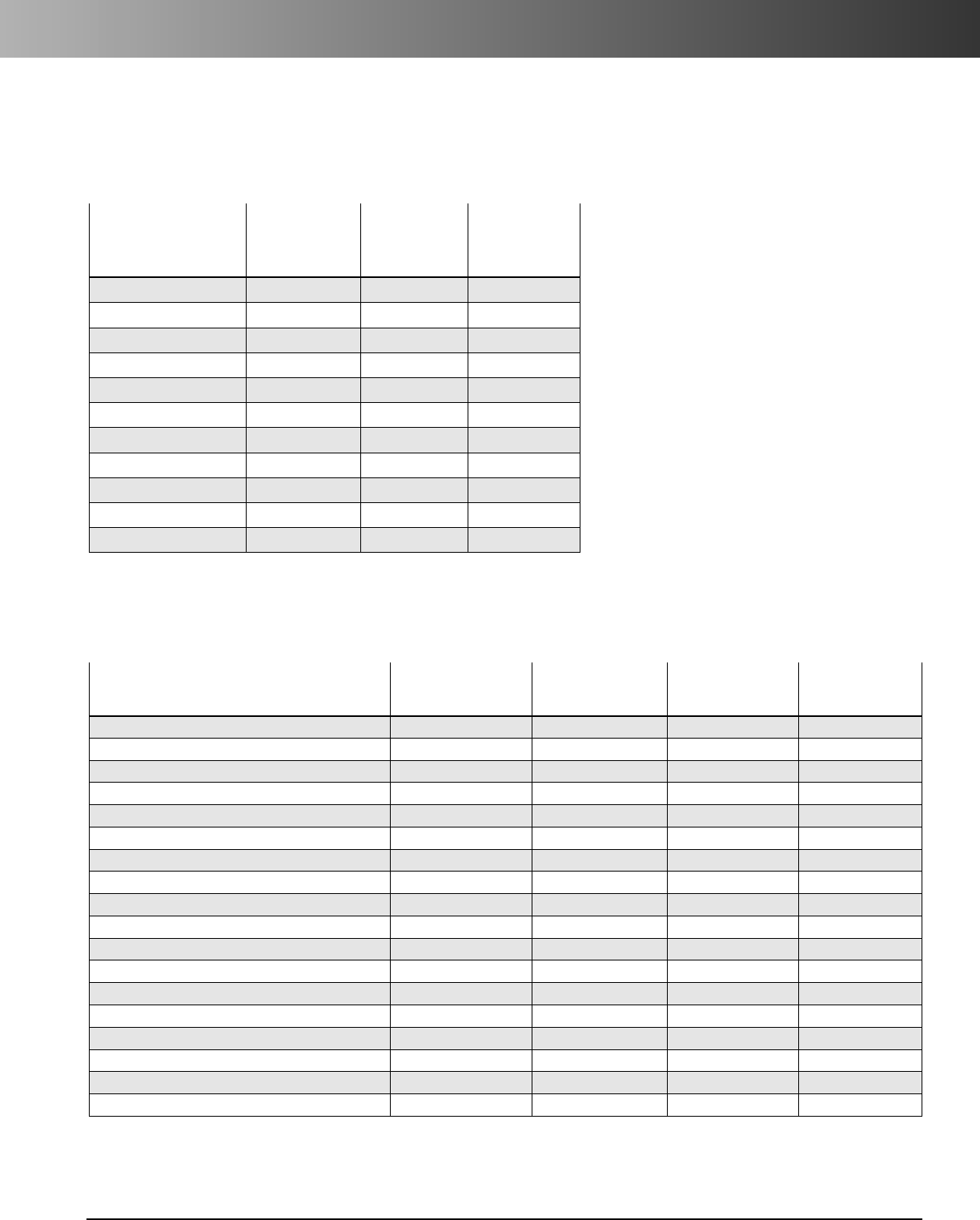
www.carlon.com 161
Enclosures General Information
Clearance Holes For Carflex®Fittings or PVC Male Terminal Adapters
Engineering Properties Of Enclosures
Carflex Fittings &
PVC Male Terminal Nominal Actual Actual
Adapters Size Size Size
Trade Sizes (in.) (in.) (mm)
1⁄2.875 .879 22.4
3⁄41.093 1.107 28.2
1 1.344 1.357 34.6
11⁄41.813 1.699 43.2
11⁄21.938 1.949 49.6
2 2.375 2.413 61.5
21⁄22.875 2.914 74.0
3 3.5 3.539 89.8
31⁄24 4.044 102.7
4 4.5 4.544 115.4
55.625 5.675 143.7
Opaque Clear
Test Polycarbonate Polycarbonate
Property Method Covers & Boxes Cover FRP
Thermal And Mechanical
Temperature Range (°F) - -30° to 230° -30° to 230° -58° to 320°
Specific Gravity (oz./in3)ASTM D792 1.20 1.20 1.79
Thermal Conductivity (BTU•in/hr•ft2•°F) ASTM D177 1.35 1.35 1.68
Heat Deflection Temperature @ 264 PSI (°F) ASTM D648 265 260 392
Tensile Strength (PSI) ASTM D638 8,800 9,000 13,000
Flexural Strength (PSI) ASTM D790 13,500 14,000 19,000
Compressive Strength @ 10% Deformation (PSI) ASTM D695 12,500 12,500 24,000
Impact Strength IZOD Notched (ft.lbs./in.) ASTM D256 12 12 12
Water Absorption – 24 hrs. @ 73°F (%) ASTM D570 0.15 0.15 0.17
Electrical
Dielectric Strength (VOLTS/MIL.) ASTM D149 380 380 467
Dielectric Constant ASTM D150
60 Hz 3.0 3.0 -
100 Hz ---
106 2.96 2.96 -
Volume Resistivity @ 73°F (OHM-CM) ASTM D257 >1016 >1016 2.0 x 10¹⁵
Arc Resistance (SEC) ASTM D495 120 120 200+
www.carlon.com
162
Enclosures General Information
Chemical Resistance Data
Environmental Resistance Table:
E–Excellent, G–Good, L–Limited, U–Unsatisfactory
IMPORTANT: These environmental resistance ratings are based upon tests where the specimens were placed in complete submergence in the reagent listed. Ratings
listed in this chart apply to a 48-Hour exposure period. (The information in this chart is to be used ONLY as a guide in selecting equipment for appropriate
chemical compatibility. Before permanent installation, test the equipment with the chemicals and under the specific conditions of your application.)
Acetaldehyde U L - -
Acetamide U U - -
Acetate Solvent U - - U
Acetic Acid U G E E
Acetic Acid 20% U E E E
Acetic Acid 80% L G E E
Acetic Acid, Glacial U G E E
Acetic Anhydride U U E U
Acetone UU UU
Acetyl Bromide U - - -
Acetyl Chloride (dry) LU-U
Acetylene E U - -
Acrylonitrile G U - -
Adipic Acid E - - -
Alcohols:Amyl E G - L
Alcohols:Benzyl U - - U
Alcohols:Butyl E E - E
Alcohols:Diacetone G--E
Alcohols:Ethyl L G - E
Alcohols:Hexyl E- -E
Alcohols:Isobutyl E - - E
Alcohols:Isopropyl E E - E
Alcohols:Methyl E G -E
Alcohols:Octyl - - - E
Alcohols:Propyl E - - E
Aluminum Chloride E E E E
Aluminum Chloride 20% E E - E
Aluminum Fluoride E - - E
Aluminum Hydroxide EG -E
Aluminum Nitrate G E - -
Aluminum Potassium Sulfate 10%
EE-E
Aluminum Potassium Sulfate 100%
EE -E
Aluminum Sulfate EEEE
Amines UU-U
Ammonia 10% G U - E
Ammonia Nitrate G - - E
Ammonia, anhydrous E U - G
Ammonia, liquid EU L-
Ammonium Acetate E - - -
Ammonium Bifluoride E - - E
Ammonium Carbonate E - L E
Ammonium Caseinate -- -E
Ammonium Chloride E E E E
Ammonium Hydroxide E U L E
Ammonium Nitrate E - L E
Ammonium Oxalate E E - -
Ammonium Persulfate E - - E
Ammonium Phosphate, Dibasic E E - E
Ammonium Phosphate, Monobasic
E- -E
Ammonium Phosphate, Tribasic E - - E
Ammonium Sulfate EE EE
Ammonium Sulfite E - E E
Amyl Acetate U U L U
Amyl Alcohol EGLL
Amyl Chloride U - U U
Aniline LUUU
Aniline Hydrochloride G U - -
Antifreeze E--E
Antimony Trichloride E E E E
Aqua Regia (80% HCl, 20% HNO3)
LU-U
Aromatic Hydrocarbons U - - U
Arsenic Acid E E - E
Arsenic Salts E - - -
Asphalt E U - -
Barium Carbonate E E E E
Barium Chloride E E E E
Barium Cyanide U - - -
Barium Hydroxide E U U E
Barium Nitrate EU -E
Barium Sulfate G U E E
Barium Sulfide E-EE
Beer E E - E
Beet Sugar Liquids E - - E
Benzaldehyde U U U G
Benzene L U L U
Benzene Sulfonic Acid E U E E
Benzoic Acid E G - G
Benzol -U-G
Benzonitrile - E - -
Benzyl Chloride -- -U
Bleaching Liquors E - - -
Borax (Sodium Borate) E - - E
Boric Acid E-EE
Bromine L L - E
Butadiene L U - U
Butane L U - U
Butanol (Butyl Alcohol) L G - E
Butyl Amine U U - U
Butyl Ether E- -U
Butyl Phthalate - U - E
Butylacetate UU UG
Butylene E U - -
Butyric Acid GU-U
Calcium Bisulfate -U--
Calcium Bisulfide E - - E
Calcium Bisulfite G U - E
Calcium Carbonate EL EE
Calcium Chlorate G-E-
Calcium Chloride L - E E
Calcium Hydroxide G U U E
Calcium Hypochlorite G U L E
Calcium Nitrate EE EE
Calcium Oxide G - - E
Calcium Sulfate G E E E
Calgon - - - E
Cane Juice E - - -
Carbolic Acid (Phenol) U U - U
Carbon Bisulfide U - L -
Carbon Dioxide (dry) E - - E
Carbon Dioxide (wet) E - - E
Carbon Disulfide UU -U
Carbon Monoxide E - - E
Carbon Tetrachloride U U E U
Carbon Tetrachloride (dry) ---U
Carbon Tetrachloride (wet) - - - U
Carbonated Water E - - E
Carbonic Acid E E - E
Catsup E--E
Chloric Acid E - - U
Chlorine (dry) U- -G
Polycarbonate
FRP
Circuit Safe NEMA (Fiberglass Reinforced
Circuit Safe JIC Polyester)
Noryl
PVC
Himeline HE - Himeline HS - Bases Circuit
Himeline HE -
Clear Cover w/Base
Himeline HP Safe
Opaque Cover Himeline HS - Himeline HLA/HLS Medium
Chemical
w/Base
Opaque w/Clear Lids
Himeline HLP JIC
Polycarbonate
FRP
Circuit Safe NEMA (Fiberglass Reinforced
Circuit Safe JIC Polyester)
Noryl
PVC
Himeline HE - Himeline HS - Bases Circuit
Himeline HE -
Clear Cover w/Base
Himeline HP Safe
Opaque Cover Himeline HS - Himeline HLA/HLS Medium
Chemical
w/Base
Opaque w/Clear Lids
Himeline HLP JIC
www.carlon.com 163
Enclosures General Information
Chemical Resistance Data
Environmental Resistance Table:
E–Excellent, G–Good, L–Limited, U–Unsatisfactory
IMPORTANT: These environmental resistance ratings are based upon tests where the specimens were placed in complete submergence in the reagent listed. Ratings
listed in this chart apply to a 48-Hour exposure period. (The information in this chart is to be used ONLY as a guide in selecting equipment for appropriate
chemical compatibility. Before permanent installation, test the equipment with the chemicals and under the specific conditions of your application.)
Chlorine Water E - E L
Chlorine, Anhydrous Liquid U L - G
Chloroacetic Acid G U - -
Chlorobenzene (Mono) U U U U
Chlorobromomethane U - - -
Chloroform U U - U
Chlorosulfonic Acid U L - U
Chocolate Syrup - E - E
Chromic Acid 10% E G E E
Chromic Acid 30% E L - U
Chromic Acid 5% EG -E
Chromic Acid 50% U U - U
Chromium Salts E - - -
Citric Acid G E E E
Citric Oils - - - E
Clorox® (Bleach) E - - E
Copper Chloride E - - E
Copper Cyanide EU-E
Copper Fluoborate E - - -
Copper Nitrate EU -E
Copper Sulfate >5% E E - E
Copper Sulfate 5% E E - E
Cresols U U UU
Cresylic Acid U U - -
Cupric Acid E E - E
Cyclohexane U G - U
Cyclohexanone U U - U
Detergents E E - E
Diacetone Alcohol U U - -
Dichlorobenzene U U - -
Dichloroethane UU -E
Diesel Fuel E E - U
Diethyl Ether UU--
Diethylamine UU--
Diethylene Glycol L G - E
Dimethyl Aniline U U U U
Dimethyl Formamide U U - U
Diphenyl Oxide U---
Dyes G - - E
Epsom Salts (Magnesium Sulfate) E E - E
Ethane E - - -
Ethanol LG -E
Ethanolamine U - - E
Ether U - L U
Ethyl Acetate U U L E
Ethyl Benzoate U U - E
Ethyl Chloride UU LU
Ethyl Ether U - U U
Ethylene Bromide U U - -
Ethylene Chloride U U - U
Ethylene Chlorohydrin UU E-
Ethylene Diamine U E - U
Ethylene Dichloride U U U U
Ethylene Glycol EGEE
Ethylene Oxide U L - E
Fatty Acids E G - E
Ferric Chloride E E E E
Ferric Nitrate EEEE
Ferric Sulfate E E E E
Ferrous Chloride E U E E
Ferrous Sulfate E E E E
Fluoboric Acid E - - E
Fluorine U L - -
Fluosilicic Acid U E - E
Formaldehyde 100% E E - E
Formaldehyde 40% E E E E
Formic Acid E E L E
Freon 113 G G - U
Freon 12 E - - U
Freon 22 E - - G
Freon TF G - - -
Freon® 11 E - - G
Fuel Oils E G - G
Furan Resin E - - -
Furfural U U L U
Gallic Acid G - - E
Gasoline (high-aromatic) E E - G
Gasoline,leaded, ref. G E E G
Gasoline,unleaded L E - U
Gelatin G- -E
Glucose E E E E
Glue, P.V.A. L - - -
Glycerin E E EE
Glycolic Acid G - - -
Grease E - - -
Heptane L G E G
Hexane G U U G
Hydraulic Oil (Petro) E - - -
Hydraulic Oil (Synthetic) E- --
Hydrazine - U - -
Hydrobromic Acid 100% E - - G
Hydrobromic Acid 20% G - - G
Hydrochloric Acid 100% UU-E
Hydrochloric Acid 20% EGEE
Hydrochloric Acid 37% G U L E
Hydrochloric Acid, Dry Gas E - - E
Hydrocyanic Acid G - - E
Hydrocyanic Acid (Gas 10%) EG -L
Hydrofluoric Acid 100% L U - U
Hydrofluoric Acid 20% G U - L
Hydrofluoric Acid 50% G U - U
Hydrofluoric Acid 75% L U - U
Hydrofluosilicic Acid 100% G - - G
Hydrofluosilicic Acid 20% E - - G
Hydrogen Gas E E - E
Hydrogen Peroxide 10% E E - E
Hydrogen Peroxide 100% E E - E
Hydrogen Peroxide 30% E E E E
Hydrogen Peroxide 50% E E E -
Hydrogen Sulfide (aqua) G E - E
Hydrogen Sulfide (dry) E- --
Hydroquinone G - - -
Hydroxyacetic Acid 70% U - - -
Ink L---
Iodine E - - L
Iodine (in alcohol) E---
Iodoform E - - -
Isooctane EG-U
Isopropyl Acetate U U - -
Isopropyl Ether GU --
Polycarbonate
FRP
Circuit Safe NEMA (Fiberglass Reinforced
Circuit Safe JIC Polyester)
Noryl
PVC
Himeline HE - Himeline HS - Bases Circuit
Himeline HE -
Clear Cover w/Base
Himeline HP Safe
Opaque Cover Himeline HS - Himeline HLA/HLS Medium
Chemical
w/Base
Opaque w/Clear Lids
Himeline HLP JIC
Polycarbonate
FRP
Circuit Safe NEMA (Fiberglass Reinforced
Circuit Safe JIC Polyester)
Noryl
PVC
Himeline HE - Himeline HS - Bases Circuit
Himeline HE -
Clear Cover w/Base
Himeline HP Safe
Opaque Cover Himeline HS - Himeline HLA/HLS Medium
Chemical
w/Base
Opaque w/Clear Lids
Himeline HLP JIC

www.carlon.com
164
Enclosures General Information
Chemical Resistance Data
Environmental Resistance Table:
E–Excellent, G–Good, L–Limited, U–Unsatisfactory
IMPORTANT: These environmental resistance ratings are based upon tests where the specimens were placed in complete submergence in the reagent listed. Ratings
listed in this chart apply to a 48-Hour exposure period. (The information in this chart is to be used ONLY as a guide in selecting equipment for appropriate
chemical compatibility. Before permanent installation, test the equipment with the chemicals and under the specific conditions of your application.)
Isotane E - - -
Jet Fuel (JP3, JP4, JP5) L E - U
Kerosene E U - U
Ketones U U - U
Lacquer Thinners U G - U
Lacquers U U - U
Lactic Acid G G E E
Lard E E - E
Lead Acetate G - - E
Lead Nitrate E - - E
Lead Sulfamate GE--
Lime G - - -
Linoleic Acid E - - -
Lithium Chloride U G - -
Lithium Hydroxide - U - -
Lubricants G E - L
Lye: Ca(OH)2 Calcium Hydroxide G U - E
Lye: KOH Potassium Hydroxide G U - E
Lye: NaOH Sodium Hydroxide E U - E
Magnesium Bisulfate EE --
Magnesium Carbonate G E E E
Magnesium Chloride G E E E
Magnesium Hydroxide E E GE
Magnesium Nitrate E E - E
Magnesium Oxide - - - -
Magnesium Sulfate (Epsom Salts) E E E E
Maleic Acid E - - E
Malic Acid E - - -
Manganese Sulfate LE -E
Mayonnaise U - - -
Melamine U- --
Mercuric Chloride (dilute) E E - E
Mercuric Cyanide E---
Mercurous Nitrate EE-E
Mercury E U - E
Methane G - - -
Methanol (Methyl Alcohol) E G L E
Methyl Acetate UU --
Methyl Acetone U - - -
Methyl Alcohol 10% E G - E
Methyl Bromide U - - -
Methyl Butyl Ketone E U - -
Methyl Cellosolve U U - -
Methyl Chloride U U - U
Methyl Dichloride E - - -
Methyl Ethyl Ketone U U E U
Methyl Isobutyl Ketone U U - U
Methyl Isopropyl Ketone U U - U
Methyl Methacrylate E - - -
Methylamine U - - -
Methylene Chloride UU UU
Mineral Spirits E L - E
Monochloroacetic acid - U - -
Monoethanolamine U--E
Morpholine - U - U
Motor oil GE-E
Naphtha E G E U
Naphthalene U--U
Natural Gas E - - -
Nickel Chloride E E - E
Nickel Nitrate E U - E
Nickel Sulfate E E - E
Nitrating Acid (<15% HNO3) U - - -
Nitrating Acid (>15% H2SO4) U - - -
Nitrating Acid (_1% Acid) U - - -
Nitrating Acid (_15% H2SO4) U - - -
Nitric Acid (20%) E G G G
Nitric Acid (50%) G G - G
Nitric Acid (5-10%) E E - E
Nitric Acid (Concentrated) G L - G
Nitrobenzene UULU
Nitromethane G U - U
Nitrous Acid E - - -
Nitrous Oxide E - - -
Oils:Aniline U - - U
Oils:Citric G E - E
Oils:Creosote L - - U
Oils:Diesel Fuel (20, 30, 40, 50) G - - U
Oils:Fuel (1, 2, 3, 5A, 5B,6) EG-E
Oils:Hydraulic Oil (Petro) E - - -
Oils:Hydraulic Oil (Synthetic) E - - -
Oils:Mineral G G - E
Oils:Olive L E -E
Oils:Orange L L - -
Oils:Pine U E - -
Oils:Rosin L - - -
Oils:Silicone E - - E
Oils:Transformer G - - -
Oils:Turbine E - - -
Oleic Acid L - E E
Oleum 100% U- -E
Oleum 25% U - - -
Oxalic Acid (cold) G-EE
Ozone GE--
Palmitic Acid G - - -
Paraffin G E - E
Pentane E E - -
Perchloric Acid L - - -
Perchloroethylene L U - U
Petrolatum G - - -
Petroleum - - - U
Phenol (10%) LG LU
Phenol (Carbolic Acid) U U - U
Phosphoric Acid (>40%) G E - E
Phosphoric Acid (crude) G E - E
Phosphoric Acid (molten) U - - -
Phosphoric Acid (_40%) G E - E
Phosphoric Acid Anhydride - U - -
Phosphorus E - - -
Phosphorus Trichloride U L - -
Photographic Developer EE -E
Photographic Solutions E E - E
Phthalic Anhydride U E - -
Picric Acid UU--
Potash (Potassium Carbonate) E - L E
Potassium Bicarbonate E- -E
Potassium Bromide E E - E
Potassium Chlorate EE-E
Potassium Chloride E E E E
Potassium Chromate E - E E
Polycarbonate
FRP
Circuit Safe NEMA (Fiberglass Reinforced
Circuit Safe JIC Polyester)
Noryl
PVC
Himeline HE - Himeline HS - Bases Circuit
Himeline HE -
Clear Cover w/Base
Himeline HP Safe
Opaque Cover Himeline HS - Himeline HLA/HLS Medium
Chemical
w/Base
Opaque w/Clear Lids
Himeline HLP JIC
Polycarbonate
FRP
Circuit Safe NEMA (Fiberglass Reinforced
Circuit Safe JIC Polyester)
Noryl
PVC
Himeline HE - Himeline HS - Bases Circuit
Himeline HE -
Clear Cover w/Base
Himeline HP Safe
Opaque Cover Himeline HS - Himeline HLA/HLS Medium
Chemical
w/Base
Opaque w/Clear Lids
Himeline HLP JIC

www.carlon.com 165
Enclosures General Information
Chemical Resistance Data
Environmental Resistance Table:
E–Excellent, G–Good, L–Limited, U–Unsatisfactory
IMPORTANT: These environmental resistance ratings are based upon tests where the specimens were placed in complete submergence in the reagent listed. Ratings
listed in this chart apply to a 48-Hour exposure period. (The information in this chart is to be used ONLY as a guide in selecting equipment for appropriate
chemical compatibility. Before permanent installation, test the equipment with the chemicals and under the specific conditions of your application.)
Potassium Cyanide Solutions E - - E
Potassium Dichromate E E - E
Potassium Ferricyanide E - E E
Potassium Ferrocyanide E - E E
Potassium Hydroxide (Caustic Potash)
EU LE
Potassium Hypochlorite G - - -
Potassium Iodide E - - -
Potassium Nitrate E E E E
Potassium Oxalate - - - -
Potassium Permanganate E E E E
Potassium Sulfate EE EE
Potassium Sulfide E - - E
Propane (liquefied) E L - E
Propylene G - - -
Propylene Glycol L G - -
Pyridine U U - G
Pyrogallic Acid E - - -
Resorcinal LG--
Rosins L - - -
Salicylic Acid G E - -
Salt Brine (NaCl saturated) E E - E
Sea Water E E - E
Silicone E E -E
Silver Bromide - - - E
Silver Nitrate E E - E
Soap Solutions E E - E
Soda Ash (see Sodium Carbonate) E E - E
Sodium Acetate G E E E
Sodium Aluminate - - - E
Sodium Benzoate G E - -
Sodium Bicarbonate EE EE
Sodium Bisulfate E E - E
Sodium Bisulfite EE-E
Sodium Borate (Borax) EE-E
Sodium Bromide G - E E
Sodium Carbonate E E - E
Sodium Chlorate EE EE
Sodium Chloride EEEE
Sodium Chromate - E - E
Sodium Cyanide E - - E
Sodium Ferrocyanide E - E E
Sodium Fluoride E- -E
Sodium Hydrosulfite L - - -
Sodium Hydroxide (20%) E E U E
Sodium Hydroxide (50%) E U U E
Sodium Hydroxide (80%) E U U E
Sodium Hypochlorite (<20%) EL LE
Sodium Hypochlorite (100%) G - - E
Sodium Metaphosphate E - - -
Sodium Metasilicate E - - -
Sodium Nitrate E- UE
Sodium Perborate E - - E
Sodium Peroxide G E - -
Sodium Polyphosphate E--E
Sodium Silicate E - - E
Sodium Sulfate EEEE
Sodium Sulfide E U U E
Sodium Sulfite E-EE
Sodium Tetraborate E - - E
Sodium Thiosulfate (hypo) E U - E
Stannic Chloride E E - E
Stannic Fluoborate - - - E
Stannous Chloride E - - E
Stearic Acid G E - E
Stoddard Solvent L E - U
Styrene U U - E
Sulfate (Liquors) G - - -
Sulfur Chloride L - - E
Sulfur Dioxide E- -E
Sulfur Dioxide (dry) E E - E
Sulfur Hexafluoride G---
Sulfur Trioxide E - - U
Sulfur Trioxide (dry) E - - U
Sulfuric Acid (<10%) E E E E
Sulfuric Acid (10-75%) E G U E
Sulfuric Acid (75-100%) U U - E
Sulfuric Acid (cold concentrated) U - - E
Sulfuric Acid (hot concentrated) UU -U
Sulfurous Acid E - - E
Tallow - - - E
Tannic Acid E L - E
Tanning Liquors E - - E
Tartaric Acid E- EE
Tetrachloroethane L - - U
Tetrachloroethylene U U - U
Tetrahydrofuran U U L U
Tin Salts E - - -
Toluene (Toluol) U U - U
Trichloroacetic Acid G U - -
Trichloroethane L U - U
Trichloroethylene U - U U
Trichloropropane - - - U
Tricresylphosphate U--E
Triethylamine G--G
Trisodium Phosphate E - - E
Turpentine U U E U
Urea UU LE
Uric Acid E- --
Varnish U - - U
Vinegar G E E E
Vinyl Acetate U - - -
Vinyl Chloride U - - -
Water, Acid, Mine G G - -
Water, Deionized E - - E
Water, Distilled E E - E
Water, Fresh G E - E
Water, Salt G E - E
Whiskey & Wines E E - E
White Liquor (Pulp Mill) E - - E
White Water (Paper Mill) E - - U
Xylene UU EG
Zinc Chloride G E E E
Zinc Hydrosulfite - - - E
Zinc Sulfate EEEE
Polycarbonate
FRP
Circuit Safe NEMA (Fiberglass Reinforced
Circuit Safe JIC Polyester)
Noryl
PVC
Himeline HE - Himeline HS - Bases Circuit
Himeline HE -
Clear Cover w/Base
Himeline HP Safe
Opaque Cover Himeline HS - Himeline HLA/HLS Medium
Chemical
w/Base
Opaque w/Clear Lids
Himeline HLP JIC
Polycarbonate
FRP
Circuit Safe NEMA (Fiberglass Reinforced
Circuit Safe JIC Polyester)
Noryl
PVC
Himeline HE - Himeline HS - Bases Circuit
Himeline HE -
Clear Cover w/Base
Himeline HP Safe
Opaque Cover Himeline HS - Himeline HLA/HLS Medium
Chemical
w/Base
Opaque w/Clear Lids
Himeline HLP JIC

www.carlon.com
166

www.carlon.com 167
Carlon
®
Conduit,
Fittings and Accessories
Schedule 40 & 80
Conduit
Schedule 40 & 80
Elbows
Junction Boxes
FS Boxes
Utility Conduit,
Fittings & Elbows
P&C Duct
Telephone Duct
P&C Flex
PV-Mold
Slip Meter Risers
Split Duct
Cement
Spacers
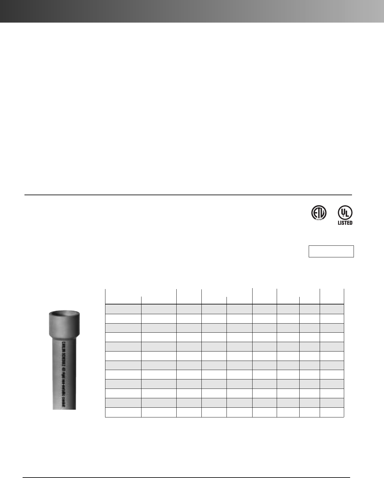
www.carlon.com
168
Rigid Nonmetallic Conduit – Schedule 40
Carlon
®
Rigid Nonmetallic Conduit (RNC), Fittings & Accessories
Carlon
®
manufactures the most complete line of nonmetallic
conduits and fittings in the electrical industry. Carlon
Schedule 40 and Schedule 80 conduits are designed for use
aboveground and underground as described in the National
Electrical Code. Specify only Carlon conduits and fittings to
insure raceway system integrity.
Features
Ease of Installation
Nonmetallic conduits are 1/4to 1/5
the weight of metallic systems, can be installed in less than
half the time, and are easily fabricated on the job.
Safety
Nonmetallic conduits are nonconductive, assuring a
safe system.
Impact Resistant
Carlon Schedule 40 and Schedule 80
nonmetallic conduits are resistant to sunlight and are listed
for exposed or outdoor usage. The use of expansion fittings
allows the system to expand and contract with temperature
variations.
Corrosion Resistant
Carlon conduits and fittings are
nonmetallic and will not rust or corrode.
Carlon nonmetallic Schedule 40 and Schedule 80 conduits
and elbows are manufactured to NEMA TC-2, Federal
specification WC1O94A and UL 651 specifications. Fittings
are manufactured to NEMA TC-3, Federal specification
WC1094A and UL514B. Both conduit and fittings carry
respective UL or ETL Listings and UL or ETL labels.
Part No. Std. Crate Qty. Wt. Per Dimensions
10' 20'
Nom. Size
10' 20' 100' O.D. I.D. Wall
49005-010 1/2" 6000' 17 .840 .622 .109
49007-010 49007-020 3/4" 4400' 8800' 23 1.050 .824 .113
49008-010 49008-020 1" 3600' 7200' 34 1.315 1.049 .133
49009-010 49009-020 11/4" 3300' 6600' 46 1.660 1.380 .140
49010-010 49010-020 11/2" 2250' 4500' 55 1.900 1.610 .145
49011-010 49011-020 2" 1400' 2800' 73 2.375 2.067 .154
49012-010 49012-020 21/2" 930' 1860' 124 2.875 2.469 .203
49013-010 49013-020 3" 880' 1760' 163 3.500 3.068 .216
49014-010 49014-020 31/2" 630' 1260' 196 4.000 3.548 .226
49015-010 49015-020 4" 570' 1140' 232 4.500 4.026 .237
49016-010 49016-020 5" 380' 760' 315 5.563 5.047 .258
49017-010 49017-020 6" 260' 520' 409 6.625 6.065 .280
With Integral Bell*
Schedule 40PVC Rigid Nonmetallic Conduit (RNC).
(Heavy Wall EPC)
Listed for underground applications encased in concrete or direct burial. Also for use in
exposed or concealed applications aboveground.
•
Sunlight resistant
•
Rated for use with 90˚C conductors
•
Superior weathering characteristics
Schedule 40 Heavy Wall
Rigid nonmetallic conduit is normally supplied in standard 10' lengths, with one belled end per length. For specific requirements, it may be
produced in lengths shorter or longer than 10', with or without belled ends.
E35297
ETL Listed
to UL 651 in
compliance
to the NEC
Use RNC Fittings with Schedule 40
and Schedule 80 Conduit.
Notes:
1. Special fittings and conduit sizes will be quoted on request.
2. DON’T FORGET TO ORDER CEMENT.
3. Carlon reserves the right to ship to the nearest unitized quantity.
RUS Listed
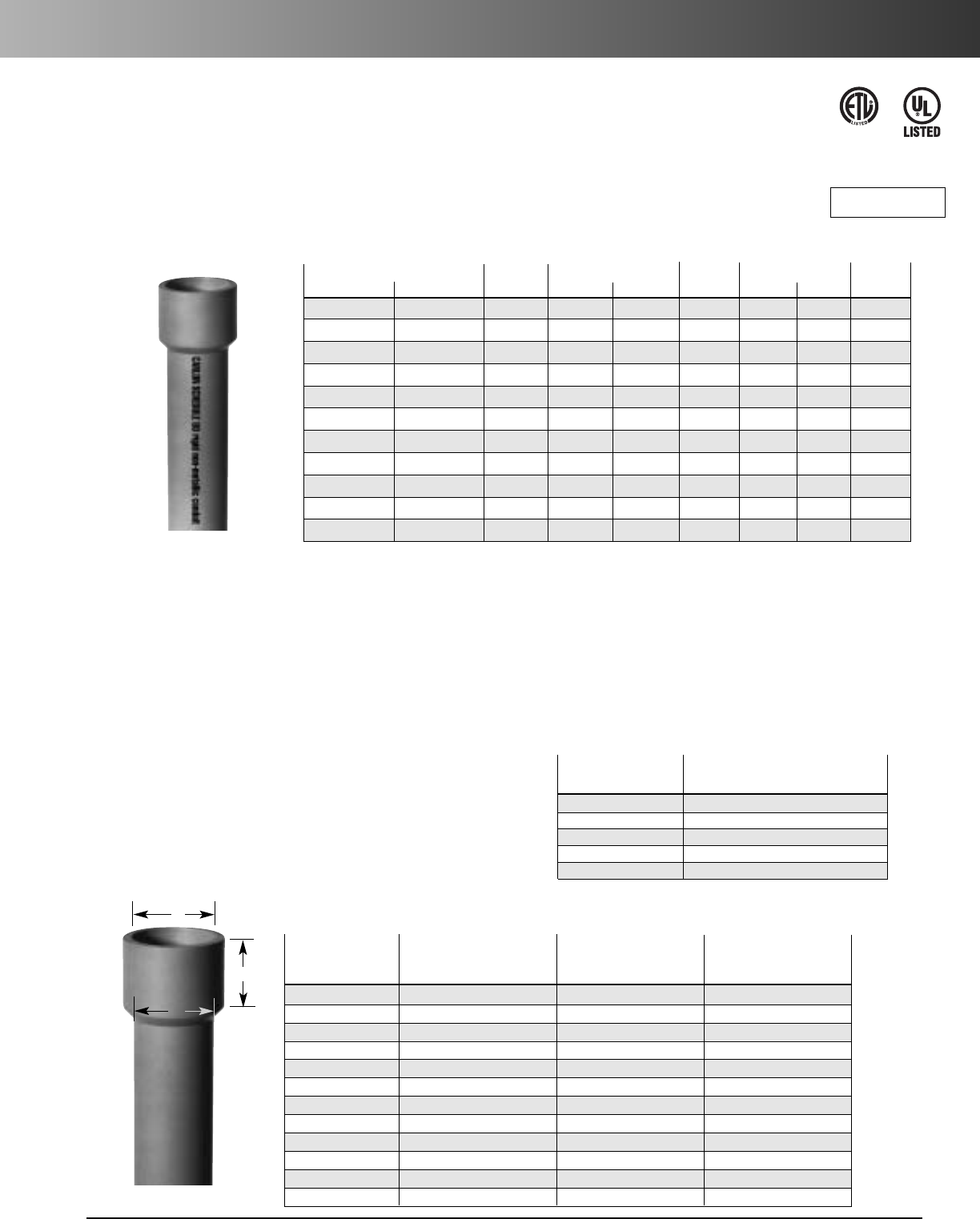
www.carlon.com 169
Rigid Nonmetallic Conduit – Schedule 80
Part No. Std. Crate Qty.Wt. Per Dimensions
10' 20'
Nom. Size
10' 20' 100' O.D. I.D. Wall
49405-010 49405-020 1/2" 6000' 12000' 21 .840 .546 .147
49407-010 49407-020 3/4" 4400' 8000' 30 1.050 .742 .154
49408-010 49408-020 1" 3600' 7200' 44 1.315 .957 .179
49409-010 49409-020 11/4" 3300' 6600' 60 1.660 1.278 .191
49410-010 49410-020 11/2" 2250' 3600' 72 1.900 1.500 .200
49411-010 49411-020 2" 1400' 2800' 101 2.375 1.939 .218
49412-010 49412-020 21/2" 930' 1880 154 2.875 2.323 .276
49413-010 49413-020 3" 880' 1760' 210 3.500 2.900 .300
49415-010 49415-020 4" 570' 1140' 308 4.500 3.826 .337
49416-010 – 5" 380' – 428 5.563 4.813 .375
49417-010 49417-020 6" 260' 520' 588 6.625 5.761 4.32
With Integral Bell*
Use RNC Fittings with Schedule 40
and Schedule 80 Conduit.
Notes:
1. Special fittings and conduit sizes will be quoted on request.
2. DON’T FORGET TO ORDER CEMENT.
3. Carlon reserves the right to ship to the nearest unitized quantity.
Schedule 80 PVC Rigid Nonmetallic Conduit (RNC)
(Extra Heavy Wall EPC-80)
Listed for use in aboveground and belowground applications that are subject to physical damage.
•
Sunlight resistant
•
Rated for use with 90˚C conductors
•
Superior weathering characteristics
•
For use in areas subject to physical damage
Schedule 80 Extra Heavy Wall
Rigid nonmetallic conduit is normally supplied in standard 10' lengths, with one belled end per length. For specific requirements, it may be
produced in lengths shorter or longer than 10', with or without belled ends.
Supportof Carlon Rigid Nonmetallic Conduit
in Aboveground Installations
Table 352.30(B) NEC shows the support requirements for Schedule
40 and Schedule 80 rigid PVC nonmetallic conduit.
Plastic conduit should always be installed away from steam lines,
etc. Support straps should allow for lineal movement caused by
expansion and contraction.
Maximum ambient temperature is 122°F (50°C).
Table 352.30(B), NEC
Trade Maximum Spacing Between
Size Supports (feet)
1/2- 1 3
11/4- 2 5
21/2- 3 6
31/2-57
68
Acceptable Dimensions in Inches of Integral Bell per UL 651
ABC
Trade At Entrance (in.) At Bottom (in.) Nominal Bell
Size
Maximum Minimum Maximum Minimum
Depth (in.)
1/20.860 0.844 0.844 0.828 1.375
3/41.074 1.054 1.056 1.036 1.500
1 1.340 1.320 1.320 1.300 1.750
11/41.689 1.665 1.667 1.643 1.875
11/21.930 1.906 1.906 1.882 2.750
2 2.405 2.381 2.381 2.357 3.250
21/22.905 2.875 2.883 2.853 3.250
3 3.530 3.500 3.507 3.477 3.875
31/24.065 3.965 4.007 3.977 3.875
44.565 4.465 4.506 4.476 4.625
5 5.643 5.543 5.583 5.523 5.625
66.708 6.608 6.644 6.584 6.375
A
B
C
E35297
ETL Listed
to UL 651 in
compliance
to the NEC
RUS Listed
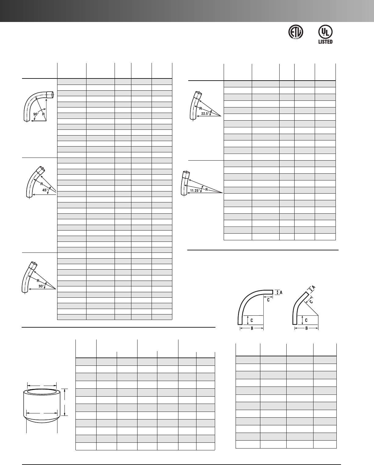
www.carlon.com
170
Rigid Nonmetallic Conduit – Schedule 40 Elbows
Plain Belled Plain Belled
End End End Std. End Std.
Item Part No. Part No. Size Ctn. Qty. Ctn. Qty.
90° Elbow UA9AD UA9ADB 1/2" 50 50
UA9ADR-CAR UA9ADB 1/2" 25 50
UA9AE UA9AEB 3/4" 25 25
UA9AFR-CTN UA9AFB-CTN 1" 25 25
UA9AG UA9AGB 11/4" 20 20
UA9AH UA9AHB 11/2" 25 25
UA9AJ UA9AJB 2" 20 20
UA9AJ-CAR UA9AJB 2" 5 20
UA9AK-CAR UA9AKB-CAR 21/2" 10 10
UA9AL UA9ALB-CAR 3" 1 5
UA9AM UA9AMB 31/2"1 20
UA9AN UA9ANB 4" 1 1
UA9AP UA9APB 5" 1 1
UA9AR UA9ARB 6" 1 1
45° Elbow UA7AD UA7ADB 1/2" 50 50
UA7AE UA7AEB 3/4" 25 25
UA7AER-CAR UA7AEB 3/4" 15 25
UA7AF UA7AFB 1" 20 20
UA7AF-CAR UA7AFB 1" 15 20
UA7AG UA7AGB 11/4" 20 20
UA7AH UA7AHB 11/2" 20 20
UA7AJ UA7AJB 2" 20 20
UA7AJ-CAR UA7AJB-CAR 2" 4 4
UA7AK UA7AKB 21/2" 20 20
UA7AK-CAR UA7AKB-CAR 21/2" 5 5
UA7AL-CAR UA7ALB 3" 5 25
UA7AL-CAR UA7ALB-CAR 3" 5 10
UA7AM UA7AMB 31/2"1 20
UA7AN UA7ANB 4" 1 20
UA7AP UA7APB 5" 1 1
UA7AR UA7ARB 6" 1 1
30° Elbow UA6AD UA6ADB 1/2" 50 50
UA6AE UA6AEB 3/4" 25 25
UA6AF UA6AFB 1" 25 1
UA6AG UA6AGB 11/4" 20 20
UA6AH UA6AHB 11/2" 25 1
UA6AJ UA6AJB 2" 20 20
UA6AK UA6AKB 21/2" 10 20
UA6AL UA6ALB 3" 1 1
UA6AM UA6AMB 31/2"1 1
UA6AN UA6ANB 4" 1 1
UA6AP UA6APB 5" 1 1
UA6AR UA6ARB 6" 1 1
Schedule 40 Elbows
Standard Radius
Available in plain and integral belled end for use with nonmetallic solvent weld fittings.
Plain Belled
Plain End
Belled End
End End Std. Std.
Item Part No. Part No. Size Ctn. Qty. Ctn. Qty.
221/2° Elbow UA5AD – 1/2"1 –
UA5AE – 3/4"1 –
UA5AF – 1" 1 –
UA5AG – 11/4"1 –
UA5AH – 11/2"1 –
UA5AJ UA5AJB 2" 25 1
UA5AK – 21/2"20 –
UA5AL UA5ALB 3" 5 1
UA5AM – 31/2"1 –
UA5AN UA5ANB 4" 1 1
UA5AP UA5APB 5" 1 1
UA5AR UA5ARB 6" 1 1
111/4° Elbow UA3AD – 1/2"1 –
UA3AE – 3/4"1 –
UA3AF – 1" 1 –
UA3AG – 11/4"1 –
UA3AH – 11/2"1 –
UA3AJ – 2" 1 –
UA3AK – 21/2"1 –
UA3AL – 3" 1 –
UA3AM – 31/2"1–
UA3AN UA3ANB 4" 1 1
UA3AP – 5" 1 –
UA3AR – 6" 1 –
ABC
Min. Min.
Size (Radius)
1/2" .840 4" 11/2"
3/4" 1.050 41/2"1
1/2"
1" 1.315 53/4"1
7/8"
11/4" 1.660 71/4"2"
11/2" 1.900 81/4"2"
2" 2.375 91/2"2"
21/2" 2.875 101/2"3"
3" 3.500 13" 31/8"
31/2" 4.000 15" 31/4"
4" 4.500 16" 33/8"
5" 5.563 24" 35/8"
6" 6.625 30" 33/4"
ABC
Trade At Entrance At Bottom Socket Depth
Size Max. Min. Max. Min. Max. Min.
1/2".860 0.844 0.844 0.828 1.500 0.652
3/4" 1.074 1.054 1.056 1.036 1.500 0.719
1" 1.340 1.320 1.320 1.300 1.875 0.875
11/4"1.689 1.665 1.667 1.643 2.000 0.938
11/2" 1.930 1.906 1.906 1.882 2.000 1.062
2" 2.405 2.381 2.381 2.357 2.000 1.125
21/2" 2.905 2.875 2.883 2.853 3.000 1.469
3" 3.530 3.500 3.507 3.477 3.125 1.594
31/2"4.065 3.965 4.007 3.977 3.250 1.687
4" 4.565 4.465 4.506 4.476 3.375 1.750
5" 5.643 5.543 5.583 5.523 3.625 1.937
6" 6.708 6.608 6.644 6.584 3.750 2.125
Standard Radius Elbow
Dimensions
A
C
B
Integral
Belled End
Dimensions
90°
Elbow 45°
Elbow
E35297
ETL Listed
to UL 651 in
compliance
to the NEC
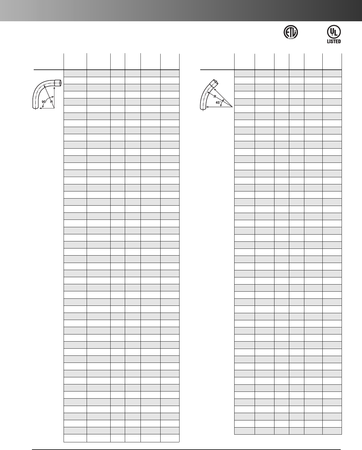
www.carlon.com 171
Rigid Nonmetallic Conduit – Schedule 40 Elbows
Schedule 40 Elbows
Special Radius
*Consult factory for additional sizes/configurations
Plain Belled
Plain End
Belled End
End End Nom. Radius Std. Std.
Segment Part No. Part No. Diam. (in.) Ctn. Qty. Ctn. Qty.
90° Elbow UA9CF UA9CFB 1" 18" 1 1
UA9DF UA9DFB 1" 24" 1 1
UA9EF UA9EFB 1" 30" 1 1
UA9FF – 1" 36" 1 –
UA9HF – 1" 48" 1 –
UA9CG UA9CGB 11/4" 18" 1 1
UA9DG UA9DGB 11/4" 24" 1 1
UA9EG UA9EGB 11/4" 30" 1 1
UA9FG UA9FGB 11/4" 36" 1 1
UA9HG – 11/4" 48" 1 –
UA9CH UA9CHB 11/2" 18" 1 1
UA9DH UA9DHB 11/2" 24" 1 1
UA9EH UA9EHB 11/2" 30" 1 1
UA9FH UA9FHB 11/2" 36" 1 1
UA9HH – 11/2" 48" 1 –
UA9CJ UA9CJB 2" 18" 1 1
UA9DJ UA9DJB-UPC 2" 24" 1 1
UA9EJ UA9EJB 2" 30" 1 1
UA9FJ-UPC UA9FJB 2" 36" 1 1
UA9HJ UA9HJB 2" 48" 1 1
UA9JJ – 2" 72" 1 –
UA9CK UA9CKB 21/2" 18" 1 1
UA9DK UA9DKB-UPC 21/2" 24" 1 1
UA9EK UA9EKB 21/2" 30" 1 1
UA9FK-UPC UA9FKB 21/2" 36" 1 1
UA9HK UA9HKB 21/2" 48" 11
UA9CL UA9CLB 3" 18" 1 1
UA9DL UA9DLB-UPC 3" 24" 1 1
UA9EL UA9ELB 3" 30" 1 1
UA9FL UA9FLB 3" 36" 1 1
UA9HL UA9HLB 3" 48" 1 1
UA9IL – 3" 60" 1 –
UA9DM UA9DMB 31/2" 24" 1 1
UA9EM UA9EMB 31/2" 30" 1 1
UA9FM UA9FMB 31/2"36" 11
UA9HM UA9HMB 31/2" 48" 1 1
– UA9CNB 4" 18" – 1
UA9DN UA9DNB 4" 24" 1 1
UA9EN UA9ENB 4" 30" 1 1
UA9FN UA9FNB 4" 36" 1 1
UA9HN UA9HNB 4" 48" 1 1
UA9IN UA9INB 4" 60" 1 1
UA9JN – 4" 72" 1 1
UA9EP UA9EPB 5" 30" 1 1
UA9FP UA9FPB 5" 36" 1 1
UA9HP UA9HPB 5" 48" 1 1
UA9IP UA9IPB 5" 60" 1 1
UA9FR UA9FRB 6" 36" 1 1
UA9HR UA9HRB 6" 48" 1 1
UA9IR UA9IRB 6" 60" 1 1
– UA9TRB 6" 180" – 1
UA9HT –8" 48" 1 1
Plain Belled
Plain End Belled End
End End Nom. Radius Std. Std.
Segment Part No. Part No. Diam. (in.)
Ctn. Qty. Ctn. Qty.
45° Elbow UA7CF – 1" 18" 1 –
UA7DF – 1" 24" 1 –
UA7EF – 1" 30" 1 –
UA7FF – 1" 36" 1 –
UA7HF – 1" 48" 1 –
UA7CG – 11/4" 18" 1 –
UA7DG – 11/4" 24" 1 –
UA7EG – 11/4" 30" 1 –
UA7FG – 11/4" 36" 1 –
UA7HG – 11/4" 48" 1 –
UA7CH – 11/2" 18" 1 –
UA7DH – 11/2"24" 1 –
UA7EH – 11/2" 30" 1 –
UA7FH UA7FHB 11/2" 36" 1 1
UA7HH – 11/2" 48" 1 –
– UA7BJB 2" 12" – 1
UA7CJ UA7CJB 2" 18" 1 1
UA7DJ UA7DJB 2" 24" 1 1
UA7EJ UA7EJB 2" 30" 1 1
UA7FJ UA7FJB 2" 36" 1 1
UA7HJ UA7HJB 2" 48" 1 1
UA7SJ – 2" 150" 1 –
UA7CK – 21/2" 18" 1 –
UA7DK UA7DKB 21/2" 24" 1 1
UA7EK – 21/2" 30" 1 –
UA7FK UA7FKB 21/2" 36" 1 1
UA7HK – 21/2" 48" 1 –
UA7CL UA7CLB 3" 18" 1 1
UA7DL UA7DLB 3" 24" 1 1
UA7EL UA7ELB 3" 30" 1 1
UA7FL UA7FLB 3" 36" 1 1
– UA7HLB 3" 48" – 1
UA7DM – 31/2" 24" 1 –
UA7EM – 31/2" 30" 1 –
UA7FM –31/2"36" 1–
UA7DN UA7DNB 4" 24" 1 1
UA7EN UA7ENB 4" 30" 1 1
UA7FN UA7FNB 4" 36" 1 1
UA7HN UA7HNB 4" 48" 1 1
–UA7NNB 4" 120" –1
UA7SN UA7SNB 4" 150" 1 –
UA7EP UA7EPB 5" 30" 1 1
UA7FP UA7FPB 5" 36" 1 1
UA7HP UA7HPB 5" 48" 11
– UA7IPB 5" 60" – 1
– UA7NPB 5" 120" – 1
– UA7SPB 5" 150" – 1
UA7FR UA7FRB 6" 36" 1 1
UA7HR UA7HRB 6" 48" 1 1
UA7FT – 8" 36" 1 –
UA7HT –8" 48" 1–
E35297
ETL Listed to UL 651 in
compliance to the NEC
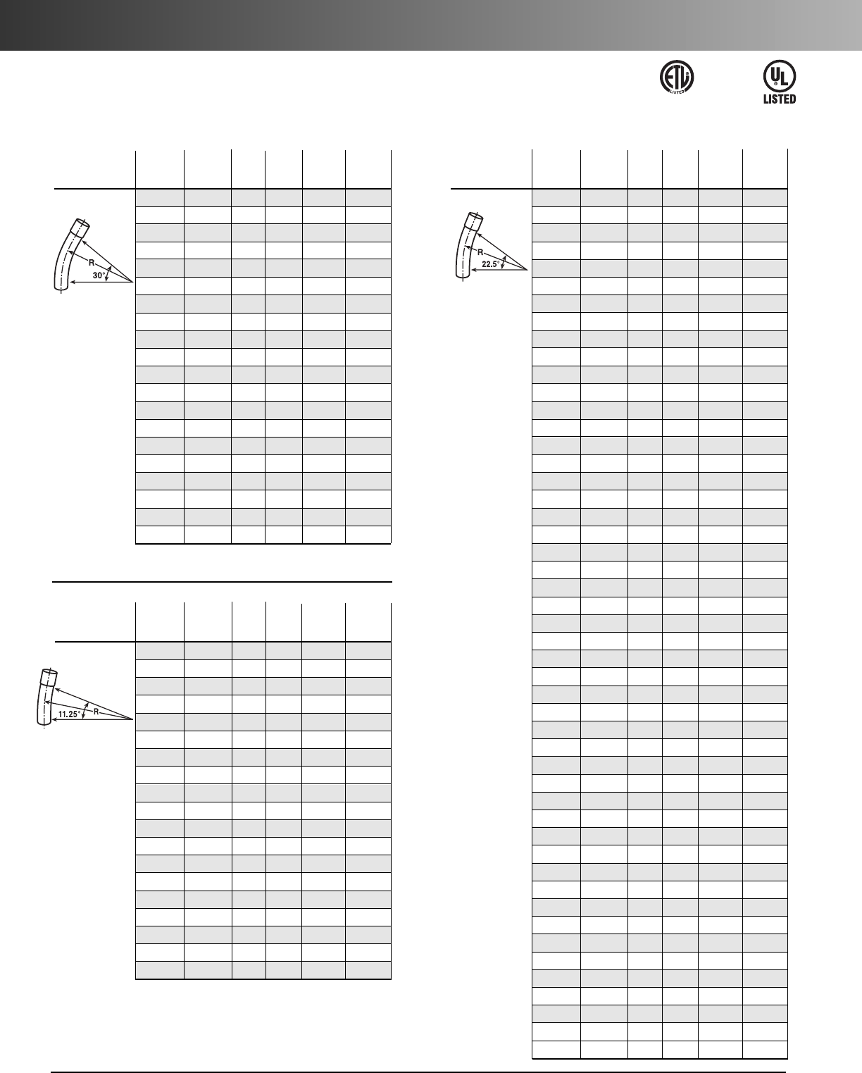
www.carlon.com
172
Rigid Nonmetallic Conduit – Schedule 40 Elbows
Schedule 40 Elbows
Special Radius
*Consult factory for additional sizes/configurations
Plain Belled
Plain End Belled End
End End Nom. Radius Std. Std.
Segment Part No. Part No. Diam. (in.)
Ctn. Qty. Ctn. Qty.
30° Elbow UA6CJ – 2" 18" 1 –
UA6DJ UA6DJB 2" 24" 1 1
UA6FJ UA6FJB 2" 36" 1 1
UA6HJ UA6HJB 2" 48" 1 1
UA6CK – 21/2" 18" 1 –
UA6DK – 21/2" 24" 1 –
UA6CL – 3" 18" 1 –
UA6DL UA6DLB 3" 24" 1 1
UA6FL UA6FLB 3" 36" 1 1
UA6HL UA6HLB 3" 48" 1 1
UA6DM – 31/2"24" 1 –
UA6FM – 31/2" 36" 1 –
UA6HM – 31/2" 48" 1 –
UA6DN – 4" 24" 1 –
UA6FN UA6FNB 4" 36" 1 1
UA6HN UA6HNB 4" 48" 1 1
UA6FP UA6FPB 5" 36" 1 1
UA6HP UA6HPB 5" 48" 1 1
UA6FR UA6FRB 6" 36" 1 1
UA6HR UA6HRB 6" 48" 1 1
Plain Belled
Plain End Belled End
End End Nom. Radius Std. Std.
Segment Part No. Part No. Diam. (in.)
Ctn. Qty. Ctn. Qty.
111/4° Elbow UA3DJ UA3DJB 2" 24" 1 25
UA3FJ UA3FJB 2" 36" 1 1
UA3HJ – 2" 48" 1 –
UA3HK – 21/2" 48" 1 –
UA3DL UA3DLB 3" 24" 1 1
UA3FL UA3FLB 3" 36" 1 1
UA3HL – 3" 48" 1 –
UA3DM – 31/2" 24" 1 –
UA3HM – 31/2" 48" 1 –
UA3DN UA3DNB 4" 24" 1 1
UA3FN UA3FNB 4" 36" 1 1
– UA3SNB 4" 150" – 1
UA3HN UA3HNB 4" 48" 1 1
UA3FP UA3FPB 5" 36" 1 1
UA3HP – 5" 48" 1 –
– UA3UPB 5" 240" – 1
UA3FR UA3FRB 6" 36" 1 1
UA3HR – 6" 48" 1 –
UA3FT – 8" 36" 1 –
Plain Belled
Plain End
Belled End
End End Nom. Radius Std. Std.
Segment Part No. Part No. Diam. (in.)
Ctn. Qty. Ctn. Qty.
221/2°Elbow UA5FF – 1" 36" 1 –
UA5FG – 11/4" 36" 1 –
UA5FH UA5FHB 11/2" 36" 1 1
UA5CJ UA5CJB 2" 18" 1 1
UA5DJ UA5DJB 2" 24" 1 25
UA5EJ UA5EJB 2" 30" 1 1
UA5FJ UA5FJB 2" 36" 1 1
UA5HJ – 2" 48" 1 –
UA5VJ – 2" 300" 1 –
UA5CK – 21/2" 18" 1 –
UA5DK – 21/2"24" 1 –
UA5EK – 21/2" 30" 1 –
UA5FK – 21/2" 36" 1 –
UA5HK – 21/2" 48" 1 –
– UA5CLB 3" 18" 1 1
UA5DL UA5DLB 3" 24" 1 1
UA5EL UA5ELB 3" 30" 1 1
UA5FL UA5FLB 3" 36" 1 1
UA5HL – 3" 48" 1 –
UA5VL – 3" 300" 1 –
UA5DM – 31/2" 24" 1 –
UA5EM – 31/2" 30" 1 –
UA5FM – 31/2" 36" 1 –
UA5HM – 31/2" 48" 1 –
UA5DN UA5DNB 4" 24" 1 1
UA5EN UA5ENB 4" 30" 1 1
UA5FN UA5FNB 4" 36" 1 1
UA5HN UA5HNB 4" 48" 1
UA5IN – 4" 60" 1 –
UA5JN – 4" 72" 1 –
UA5SN UA5SNB 4" 150" 1
– UA5UNB 4" 240" – 1
– UA5VNB 4" 300" – 1
– UA5DPB 5" 24" 1 1
UA5EP UA5EPB 5" 30" 1 1
UA5FP UA5FPB 5" 36" 1 1
UA5HP UA5HPB 5" 48" 1 1
UA5IP – 5" 60" 1 –
UA5SP – 5" 150" 1 –
– UA5UPB 5" 240" – 1
– UA5VPB 5" 300" – 1
UA5FR UA5FRB 6" 36" 1 1
UA5HR UA5HRB 6" 48" 1 1
UA5IR – 6" 60" 1 –
UA5RR – 6" 144" 1 –
UA5SR – 6" 150" 1 –
UA5VR – 6" 300" 1 –
UA5FT – 8" 36" 1 –
UA5HT – 8" 48" 1 –
E35297
ETL Listed to UL 651 in
compliance to the NEC
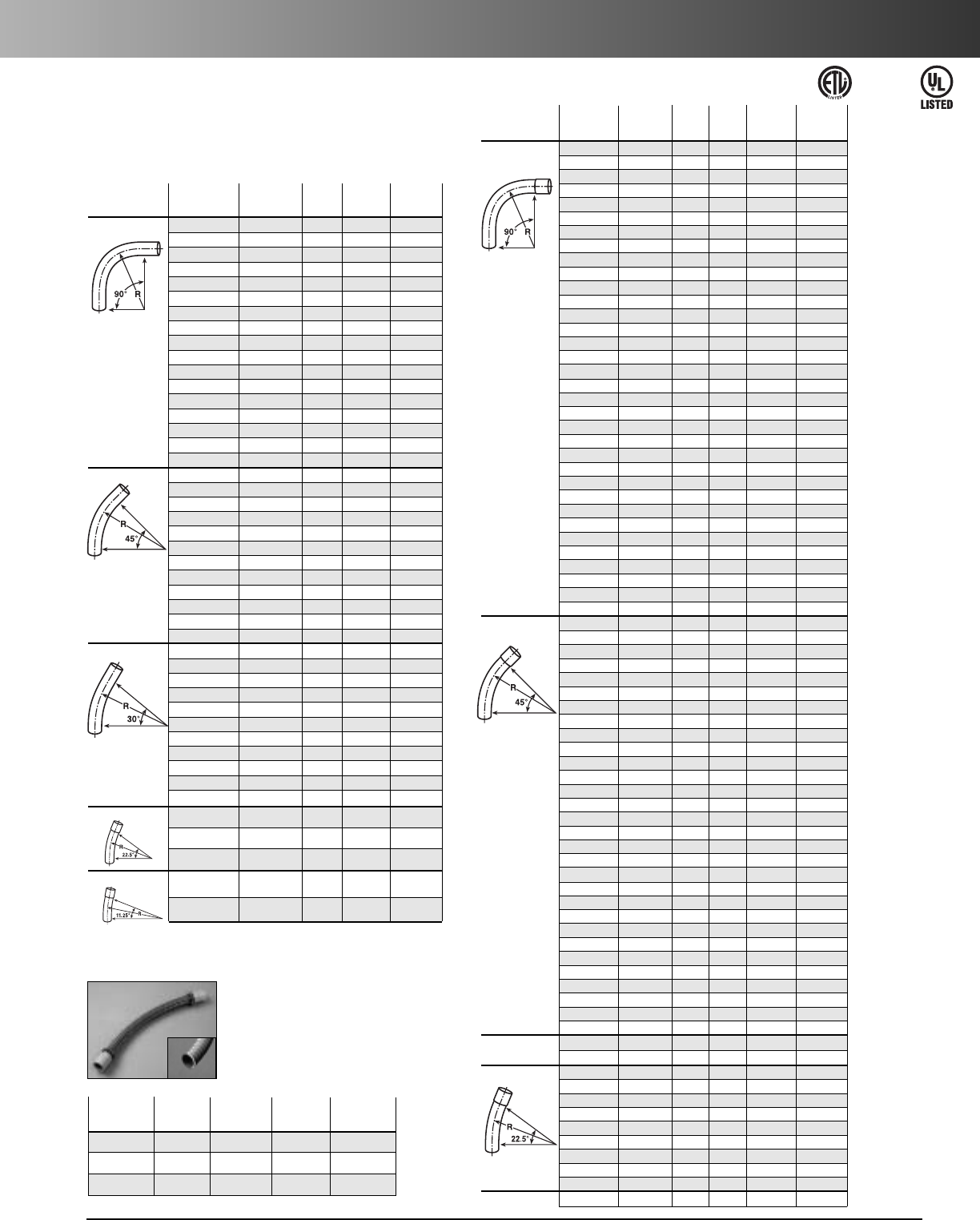
www.carlon.com 173
Rigid Nonmetallic Conduit – Schedule 80 Elbows
Schedule 80 Elbows
Standard Radius
Available in plain end only for use with nonmetallic solvent weld fittings.
Special Radius
Plain Belled
Plain End
Belled End
End End Nom. Radius Std. Std.
Segment Part No. Part No. Diam. (in.) Ctn. Qty. Ctn. Qty.
90° Elbow
UB9CF – 1" 18" 1 –
UB9DF – 1" 24" 1 –
UB9FF – 1" 36" 1 –
UB9HF – 1" 48" 1 –
UB9CG – 1
1
/
4
"18" 1 –
UB9DG – 1
1
/
4
" 24" 1 –
UB9FG – 1
1
/
4
" 36" 1 –
UB9HG – 1
1
/
4
" 48" 1 –
UB9CH – 1
1
/
2
"18" 1 –
UB9DH
-UPC
UB9DHB 1
1
/
2
" 24" 1 1
UB9FH – 1
1
/
2
" 36" 1 –
UB9HH – 1
1
/
2
" 48" 1 –
UB9CJ – 2" 18" 1 –
UB9DJ-UPC UB9DJB 2" 24" 1 1
UB9FJ UB9FJB 2" 36" 1 1
UB9HJ – 2" 48" 1 –
UB9CK – 2
1
/
2
"18" 1 –
UB9DK-UPC UB9DKB 2
1
/
2
" 24" 1 1
UB9FK UB9FKB 2
1
/
2
" 36" 1 1
UB9HK – 2
1
/
2
" 48" 1 –
UB9CL – 3" 18" 1 –
UB9DL UB9DLB 3" 24" 1 1
UB9FL UB9FLB 3" 36" 1 1
UB9HL – 3" 48" 1 –
UB9DN UB9DNB 4" 24" 1 1
UB9FN UB9FNB 4" 36" 1 1
UB9HN UB9HNB 4" 48" 1 1
UB9NN – 4" 120" 1 –
UB9FP – 5" 36" 1 –
UB9HP – 5" 48" 1 –
UB9IP – 5" 60" 1 –
UB9FR – 6" 36" 1 –
UB9HR – 6" 48" 1 –
UB9IR – 6" 60" 1 –
45° Elbow
UB7CF – 1" 18" 1 –
UB7DF – 1" 24" 1 –
UB7FF – 1" 36" 1 –
UB7HF – 1" 48" 1 –
UB7DG – 1
1
/
4
" 24" 1 –
UB7FG – 1
1
/
4
" 36" 1 –
UB7HG – 1
1
/
4
" 48" 1 –
UB7CH – 1
1
/
2
" 18" 1 –
UB7DH UB7DHB 1
1
/
2
" 24" 1 1
UB7FH – 1
1
/
2
" 36" 1 –
UB7HH –1
1
/
2
" 48" 1 –
UB7CJ – 2" 18" 1 –
UB7DJ UB7DJB 2" 24" 1 1
UB7FJ UB7FJB 2" 36" 1 1
UB7HJ – 2" 48" 1 –
UB7DK UB7DKB 2
1
/
2
"24" 1 1
UB7FK – 2
1
/
2
" 36" 1 –
UB7HK – 2
1
/
2
" 48" 1 –
UB7CL –3" 18" 1–
UB7DL UB7DLB 3" 24" 1 1
UB7FL UB7FLB 3" 36" 1 1
UB7HL –3" 48" 1 –
UB7DN UB7DNB 4" 24" 1 1
UB7FN UB7FNB 4" 36" 1 1
UB7HN – 4" 48" 1 –
UB7FP – 5" 36" 1 –
UB7HP – 5" 48" 1 –
UB7FR –6" 36" 1 –
UB7HR –6" 48" 1 –
UB7IR – 6" 60" 1 –
30° Elbow
UB6FN – 4" 36" 1 –
UB6FR – 6" 36" 1 –
22
1
/
2
° Elbow
– UB5DHB 1
1
/
2
" 24" – 20
–UB5DJB 2" 24" –20
– UB5FJB 2" 36" – 25
– UB5DKB 2
1
/
2
" 24" – 15
UB5DL UB5DLB 3" 24" 1 10
– UB5FLB 3" 36" – 1
UB5DN UB5DNB 4" 24" 15
–UB5FNB 4" 36" –1
UB5FP – 5" 36" 1 –
11
1
/
4
° Elbow
UB3FP – 5" 36" 1 –
Plain End Belled End
Plain End Belled End Std. Ctn. Std. Ctn.
Item Part No. Part No. Size Qty. Qty.
90° Elbow
UB9AD –
1
/
2
"50 –
UB9AD-CAR –
1
/
2
"25 –
UB9AE –
3
/
4
"25 –
UB9AE-CAR –
3
/
4
"15 –
UB9AF – 1" 25 –
UB9AF-CAR – 1" 10 –
UB9AG – 1
1
/
4
"20 –
UB9AG-CAR – 1
1
/
4
"5 –
UB9AH – 1
1
/
2
"25 –
UB9AH-CAR – 1
1
/
2
"5 –
UB9AJ – 2" 20 –
UB9AJ-CAR – 2" 5 –
UB9AK-CAR – 2
1
/
2
"10 –
UB9AL-CAR – 3" 5 –
UB9AN – 4" 1 –
UB9AP UB9APB 5" 1 1
UB9AR 6" 1 –
45° Elbow
UB7AD –
1
/
2
"50 –
UB7AE-UPC –
3
/
4
"25 –
UB7AF-UPC – 1" 20 –
UB7AG – 1
1
/
4
"20 –
UB7AH – 1
1
/
2
"20 –
UB7AH-CAR –1
1
/
2
"5–
UB7AJ-UPC – 2" 20 –
UB7AK – 2
1
/
2
"20 –
UB7AL –3"1–
UB7AN – 4" 1 –
UB7AP UB7APB 5" 1 1
UB7AR –6"1–
30° Elbow
UB6AD –
1
/
2
" 50 –
UB6AE –
3
/
4
"25 –
UB6AF – 1" 25 –
UB6AG–1
1
/
4
"5–
UB6AH –1
1
/
2
" 25 –
UB6AJ – 2" 20 –
UB6AK – 2
1
/
2
"1 –
UB6AL –3"1–
UB6AN –4"1–
UB6AP –5"1–
UB6AR – 6" 1 –
22
1
/
2
° Elbow
UB5AL – 3" 5 –
UB5AN –4" 1–
UB5AP UB5APB 5" 11
11
1
/
4
°Elbow
UB3AL – 3" 1 –
UB3AR – 6" 1 –
Flexible PVC Elbows
Std. Std. Ctn. Length
Part Ctn. Wt. Fully
No. Size Qty. (lbs.) Assembled
UAFAD
1
/
2
" 8 1.6 8.5"
UAFAE
3
/
4
" 6 1.9 9.6"
UAFAF 1" 6 2.4 11.9"
•UL listed for exposed and direct burial applications
in accordance with Article 356 of 2002 NEC
•0° - 90° bending and offset applications
•O-ring seal for moisture tight connections
•Maintains round shape throughout bend
•Sunlight resistant
•Non-corrosive – all PVC and Neoprene material
•Fully assembled and ready to use
E35297
ETL Listed to
UL 651 in
compliance
to the NEC
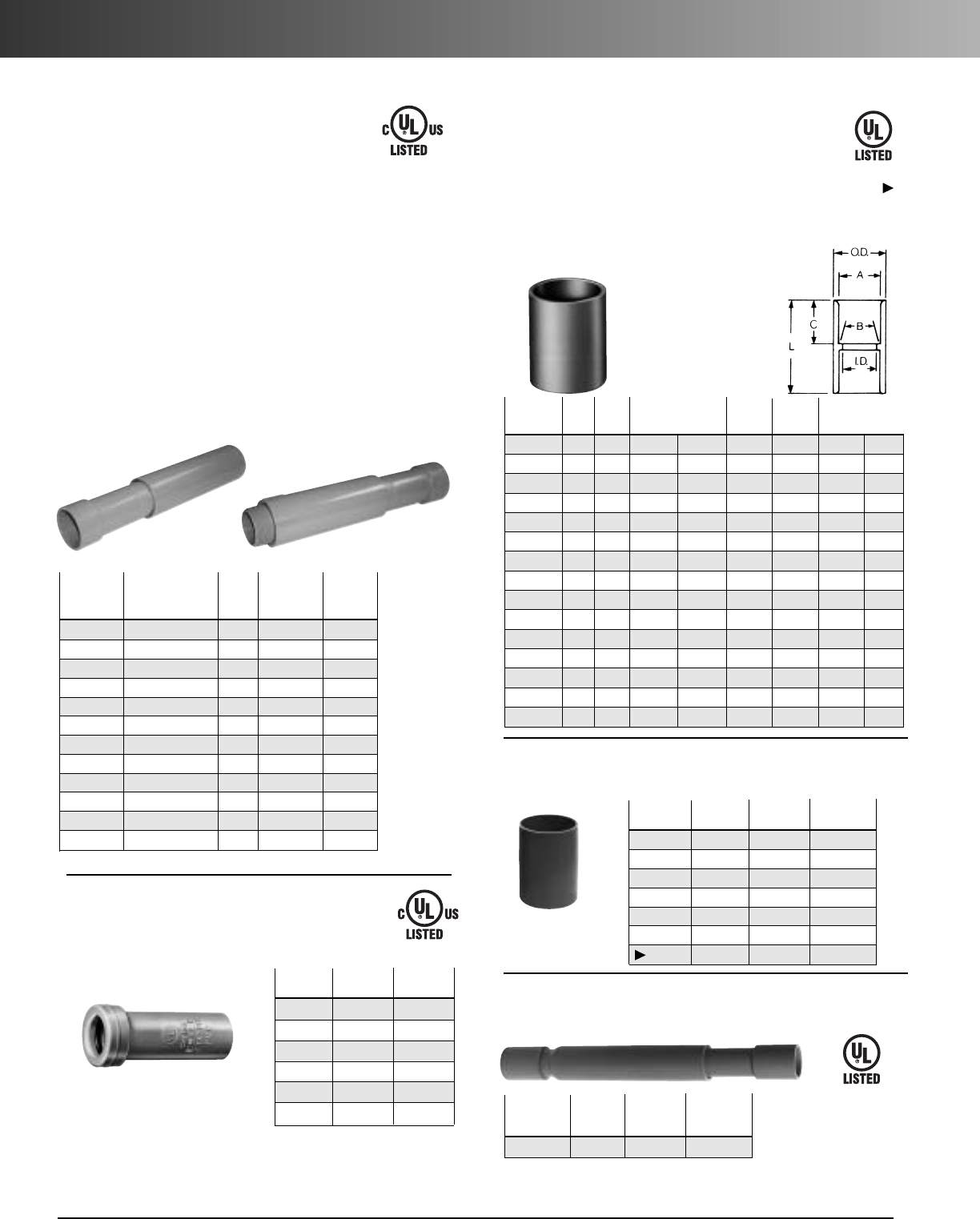
www.carlon.com
174
Rigid Nonmetallic Conduit – Couplings
Std.
Part
Ctn.
A
BCL
No. Size
Qty.
Typical
I.D. O.D. Typical
E940D 1/2150 .852 .836 .728 17/64 11/16 11/2
E940E 3/4100 1.064 1.046 .840 15/16 3/415/8
E940F 1 50 1.330 1.310 1.210 15/815/16 2
E940G 11/430 1.677 1.655 1.535 163/64 1 21/8
E940H 11/225 1.918 1.894 1.755 215/64 11/823/8
E940J 2 30 2.393 2.369 2.190 247/64 13/16 21/2
E940K 21/220 2.890 2.868 2.688 35/16 133/64 33/16
E940K-CAR 21/24 2.890 2.868 2.688 35/16 133/64 33/16
E940L 3 25 3.515 3.492 3.375 331/32 13/4313/32
E940L-CAR 3 5 3.515 3.492 3.375 331/32 13/4313/32
E940M 31/220 4.015 3.992 3.780 49/16 13/435/8
E940N 4 15 4.515 4.491 4.265 53/32 125/32 33/4
E940N-CAR 4 5 4.515 4.491 4.265 53/32 125/32 33/4
E940P 5 8 5.593 5.553 5.097 61/415/16 41/16
E940R 6 5 6.658 6.614 6.115 71/223/16 45/8
All socket fittings should be attached Using Carlon
solvent cement. Using Carlon fittings with Carlon
nonmetallic conduit insures system integrity.
Standard Couplings
Socket type for
joining nonmetallic
conduit.
Special Long Line Couplings
Std. Std. Ctn.
Part No.Size Ctn. Qty. Wt. (lbs.)
E941H 11/240 9
E941J 2 25 8
E941K 21/215 8
E941L 315 14
E941N 410 15
E941PF 5412
E941RF 6521
Long Line
Couplings
Couplings
E32447
Except where noted by
Short Expansion Couplings
(Expands to a maximum of 2")
Std.
Part No.Size Ctn. Qty.
E955D 1/240
E955E 3/440
E955F 1 25
E955G 11/415
E955H 11/210
E955J 2 6
E32447
E33447
Expansion Fittings
(For Use with Schedule 40 & 80 Conduit)
E945 series expansion fittings are designed to
compensate for length changes due to temperature
variations in exposed conduit runs.
Coupling Male Terminal Travel
End Adapter End Std. Length
Part No. Part No. Size Ctn. Qty. (in.)
E945D E945DX 1/220 4"
E945E E945EX 3/415 4"
E945F E945FX 1 10 4"
E945G E945GX 11/454"
E945H E945HX 11/254"
E945J E945JX 2 15 8"
E945K E945KX 21/210 8"
E945L E945LX 3 10 8"
E945M E945MX 31/258"
E945N E945NX 4 5 8"
E945P E945PX 5 1 8"
E945R E945RX 6 1 8"
Male terminal
adapter end
Coupling end
Fabricated Expansion Couplings
Std. Travel
Part Ctn. Length
No. Size Qty. (in.)
E945KXL 21/210 12
•EXCLUSIVE Molded in Mid-point
indicator on the piston.
•EXCLUSIVE 2" Expansion Fitting
with an 8" travel distance.
•Two-piece molded design with
lubricated seals for easier move-
ment for the life of the product.
•Ridges on the fitting for easier
installation (Sizes 2" through
6" only).
•Male terminal Adapter End design
(1/2" – 2" NPT Threads, and
21/2"–6" NPSC Threads).
•Two O-Rings to prevent leakage.
•Can be installed vertically or
horizontally.
E33447
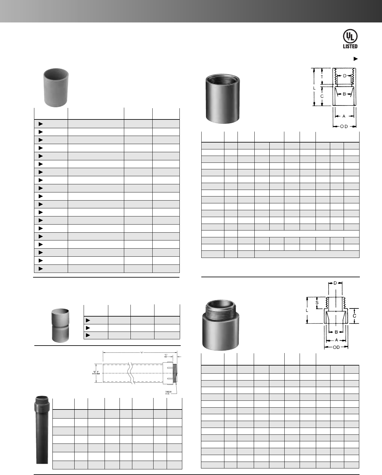
www.carlon.com 175
Rigid Nonmetallic Conduit – Adapters
Part Std. ABMin. Max. C S L
No.Size
Ctn. Qty.
Typical DOD Typical
E943D 1/2150 .852 .836 .597 11/85/89/16 15/16
E943E 3/4125 1.064 1.046 .800 111/32 3/49/16 13/8
E943F 1 50 1.330 1.310 1.018 15/8111/16 125/32
E943G 11/450 1.677 1.655 1.332 21/32 13/4115/16
E943H 11/225 1.918 1.894 1.566 2 5/32 13/16 3/421/16
E943J 2 50 2.393 2.369 2.000 2 21/32 13/16 3/421/8
E943K 21/225 2.890 2.868 2.376 35/16 13/47/827/8
E943K-CAR 21/252.890 2.868 2.376 35/16 13/47/827/8
E943L 3 45 3.515 3.492 2.954 4 115/16 7/831/16
E943L-CAR 35 3.515 3.492 2.954 4 115/16 7/831/16
E943M 31/230 4.015 3.992 3.440 41/227/16 17/837/16
E943N 4 20 4.515 4.491 3.940 53/32 23/87/831/2
E943N-CAR 4 20 4.515 4.491 3.940 53/32 23/87/831/2
E943P 5 5 5.593 5.553 4.815 61/421/313
15/16
E943R 6 10 6.658 6.614 5.860 71/223/813
3/8
Male Terminal Adapters
For adapting nonmetallic
conduits to boxes, threaded
fittings, metallic systems.
Male threads on one end,
socket end on other.
Part
Std.
A
B Min. Max. C T L
No. Size
Ctn. Qty.
Typical
D OD Typical
E942D 1/2150 .852 .836 .620 17/64 11/16 3/419/16
E942E 3/4100 1.064 1.046 .822 15/16 13/16 3/415/8
E942F 1 50 1.330 1.310 1.046 15/815/16 7/8115/16
E942G 11/430 1.677 1.655 1.377 163/64 17/82
E942H 11/225 1.918 1.894 1.607 25/32 11/87/827/32
E942J 2 30 2.393 2.369 2.064 247/64 13/16 12
5/16
E942K 21/220 2.890 2.868 2.450 311/32 15/811/8215/16
E942K-CAR 21/24 2.890 2.868 2.450 311/32 15/811/8215/16
E942L 3 25 3.515 3.492 3.000 331/32 13/411/831/16
E942L-CAR 3 3 3.515 3.492 3.000 331/32 13/411/831/16
E942M 31/220 4.015 3.992 3.500 41/217/811/831/4
E942N 4 15 4.515 4.491 4.000 51/64 21
1/8313/64
E942N-CAR 4 7 4.515 4.491 4.000 51/64 21
1/8313/64
E942NX9
*
4 15
E942P 5 8 5.593 5.553 5.047 61/4115/16 11/16 33/16
E942R 6 6 6.658 6.614 6.055 71/421/811/16 33/8
E942RX
*
66(Call for information)
Female Adapters
For adapting nonmetallic
conduits to threaded
fittings, metallic systems.
Female threads on one end,
socket end on other.
*
Long Line Adapter
Adapters
(Call for information)
Special Schedule 40 Swedge Couplings
*Consult factory for additional sizes
Std. Std. Ctn.
Part No. Size Ctn. Qty. Wt. (lbs.)
E442K 21/220 13
E442R 6 6 27
E442T 8 2 17
Risers
Schedule 40
Part ABC Thread
Std.
Std. Ctn.
No. Size
(Length)
(Min.) Size
Ctn. Qty. Wt. (lbs.)
E954HX 11/280.00 1.567 .950
11/2
"
NPT
1 3.8
E954J 260.00 2.024 .825
2"
NPT
13.7
E954JX 280.00 2.024 .825
2"
NPT
15.0
E954K 21/260.00 2.418 .812
21/2"
NPSC
16.0
E954KX 21/280.00 2.418 .812 2
1/2"
NPSC
1 8.4
E954L 3 60.00 3.012 .798
3"
NPSC
1 8.7
E954LX 3 80.00 3.012 .798
3"
NPSC
1 11.0
Std. Std. Ctn.
Part No. Size Ctn. Qty. Wt. (lbs.)
E948H 11/225 6
E948J 2 25 5
E948K 21/225 16
E948L 3 25 13
E948N 4 10 8
E948P 5 14 33
E948R 6 6 16
E948JR 2" (6" long) 15 8
E948JS 2" (Sch. 40 Split Duct) 25 6
E948L12 3" (12" long) 1 1
E948L6 3" (6" long) 15 15
E948LS 3" (Sch. 40 Split Duct) 25 17
E948N12 4" (12" long) 10 28
E948N7 4" (7" long) 15 25
E948NS 4" (Sch. 40 Split Duct) 10 15
E948PS 5" (Sch. 40 Split Duct) 1 2
E948R10 6" (10" long) 6 25
E948R12 6" (12" long) 6 25
E948RS 6" (Sch. 40 Split Duct) 1 2
Couplings
Sleeve Coupling
(For Repair Work)
NoInternal Stop
E32447
Except where noted by
Special Long Line Couplings —
Sleeve Couplings
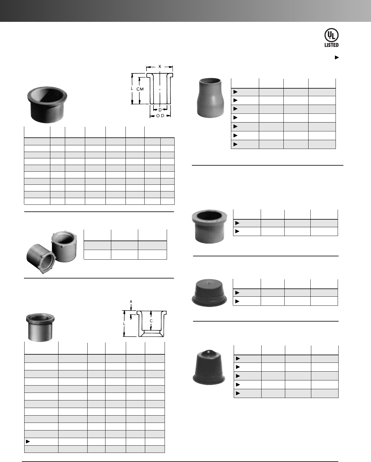
www.carlon.com
176
Rigid Nonmetallic Conduit – Fittings & Accessories
Part
Std. Ctn.
L
AC
No. Size
Qty.
Typical Typical Typical
E950ED 3/4" x1/2"100 15/32 13/64 11/32
E950FD-CAR 1" x 1/2"251
11/32 3/16 57/64
E950FE 1" x 3/4"100 111/32 3/16 11/64
E950GE-CAR 11/4" x 3/4"10 115/32 3/16 11/64
E950GF 11/4"x1" 50 115/32 3/16 19/64
E950HF-CAR 11/2"x1" 10 119/32 3/16 19/64
E950HG-CAR 11/2"x11/4" 10 119/32 3/16 117/64
E950JG-CAR 2" x 11/4"10 1
3/47/32 117/64
E950JH-CAR 2" x 11/2"10 1
3/47/32 125/64
E950KJ-CAR 21/2" x 2" 10 25/32 3/8127/64
E950LJ-CAR 3" x 2" 10 21/81/417/8
E950LK 3" x 21/2"25 1
15/16 1/4111/16
E950NL 4" x 3" 25 23/45/16 115/16
Reducer Bushings
For connecting different sizes
of conduit. Bell x Spigot.
Reducer Plugs
Std. Std. Ctn.
Part No. Size Ctn. Qty. Wt. (lbs.)
E971C 3/4" x 1/2" 100 2
E971D 1" x 3/4" 100 3
Plugs (Polyethylene)
Std. Std. Ctn.
Part No. Size Ctn. Qty. Wt. (lbs.)
P258H 11/2"50 2
P258K 21/2" 25 1.5
Plugs with Pull Tabs (Polyethylene)
Std. Std. Ctn.
Part No. Size Ctn. Qty. Wt. (lbs.)
P258JT 2 60 3
P258LT 3 30 3
P258NT 4 48 8
P258PT 5 30 6
P258RT 6 30 9
Reducers
Plugs
E32447
Except where noted by
Part Std.
Ctn.
Min
OD Max CM L
No. Size
Qty.
D Typical
X Typical
E996D 1/2100 .662 .840 17/64 23/32 27/32
E996E 3/4100 .824 1.050 121/64 25/32 29/32
E996F 1 100 1.049 1.315 15/861/64 13/32
E996G 11/450 1.380 1.660 131/32 11/16 11/4
E996H 11/250 1.610 1.900 213/64 13/16 13/8
E996J 2 25 2.067 2.375 229/32 11/417/16
E996K-CAR 21/210 2.469 2.875 37/16 17/8115/16
E996L 3 20 3.068 3.500 41/822
1/16
E996L-CAR 3 5 3.068 3.500 41/82 2 1/16
E996N 4 10 4.026 4.500 51/821/221/4
Box Adapters for
Enclosures
Adapts nonmetallic
conduit to all electrical
enclosures by inserting
adapter through knockout
and cementing into Carlon
couplings.
Threaded Adapters
Std.
Part No. Size Ctn. Qty.
E9842D 11/225
E9842E 23/425
1 Fits 3/4" sockets 2 Fits 1" sockets
Fabricated Reducers
Std. Std. Ctn.
Part No. Size Ctn. Qty. Wt. (lbs.)
E952KJ 21/2"x 2" 48 28
E952LJ 3" x 2" 36 21
E952LK 3" x 21/2"36 31
E952NL 4" x 3" 15 23
E952NM 4" x 31/2"15 25
E952PN 5" x 4" 12 26
E952RP 6" x 5" 10 31
Fabricated
Reducers
(Male x Male)
Reducers
Adapters
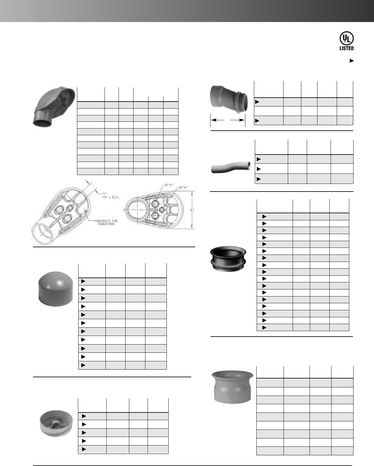
Caps
Service Entrance Caps
Std.
Ctn. Dimensions (in.)
Part No. Size Qty. F G H
E998D 1/25 .45 .45 –
E998E 3/420 .45 .45 –
E998E-CAR 3/45.45 .45 –
E998F 1 15 .59 .58 –
E998F-CAR 1 5 .59 .58 –
E998G-CAR 11/45 .74 .71 .50
E998H-CAR 11/25 .74 .71 .50
E998J-CAR 2 5 .83 .78 .56
E998K-UPC 21/22 1.70 1.31 1.00
E998L 3 2 1.70 1.31 1.00
E998N 4 2 2.25 1.88 1.31
www.carlon.com 177
Rigid Nonmetallic Conduit – Fittings & Accessories
End Bells
Offset
Std.
Std. Ctn. Qty.
Part No. Size Ctn. Qty. Wt. (lbs.)
E994DR-CAR 1/225 3
E994ER-CAR 3/415 2
E994F 1 50 12
End
Bells
Std. Std.
Ctn. Ctn.
Part No. Size Qty. Wt. (lbs.)
E997F 1 50 1
E997F-CAR 1 15 1
E997G 11/435 1
E997G-CAR 11/415 1
E997H 11/230 1
E997H-CAR 11/210 1
E997J 2 40 1
E997J-CAR 2 10 1
E997K 21/230 2
E997K-CAR 21/210 2
E997L 3 50 2
E997L-CAR 3 10 2
E997M 31/240 10
E997N 4 30 11
E997P 5 15 10
E997R 6 10 7.4
E997T 8 3 14.55
Part Std. Std.
No. Size
Ctn. Qty. Wt. (lbs.)
E949J5 2" x 5" 50 10
E949J6 2" x 6" 25 12
E949JN 2" x 4" 25 7
E949JX 2" x 8" 12 7
E949LR 3" x 6" 20 21
E949N5 4" x 5" 20 2
E949NR 4" x 6" 15 21
E949R5 6" x 5" 12 27
E949RX 6" x 8" 6 17
Fabricated End Bells
Schedule 40
Meter Offset
Std.
Part Ctn.
No. Size Qty. Offset A
E995G 11/415 0.758 4.230
E995G-CTN 11/46 0.758 4.230
E995J 2 8 0.684 4.270
Offsets
E32447
Except where noted by
End Caps
Std. Std.
Ctn. Ctn.
Part No. Size Qty. Wt. (lbs.)
E958D 1/2100 3
E958E 3/4100 4
E958F 1 75 5
E958G 11/440 4
E958H 11/230 4
E958J 2 25 5
E958K 21/210 4
E958L 3 10 5
E958N 4517
E958P 5 5 11
E958R 6513
PVC Riser Caps
Std. Std.
Ctn. Ctn.
Part No. Size Qty. Wt. (lbs.)
E935J 2 25 9
E935L 3 25 18
E935N 4 25 18
E935P 5 25 35
E935R 610 13
A
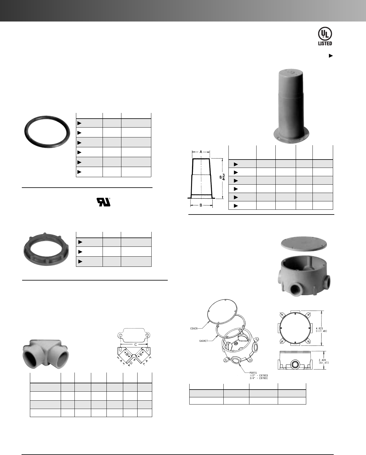
www.carlon.com
178
Rigid Nonmetallic Conduit – Fittings & Accessories
Flat Sealing Washer
Part No. Size Std. Ctn. Qty.
E943DW 1/2125
E943EW 3/4125
E943FW 1 100
E943GW 11/450
E943HW 11/250
E943JW 2 25
Part No. Size Std. Ctn. Qty.
LT9LD 1/21200
LT9LE 3/4700
LT9LF 1 600
PVC Lock Nut
HOLFORM nonmetallic concrete
sleeve forms are the easy way to
form holes in concrete. They
install in seconds with nails,
screws or staples and are easily
removed. Concrete will not
adhere to them. HOLFORMS are
adjustable to any slab thickness.
Where a waterproof termination is required into any
enclosure (metallic or nonmetallic), install the neoprene
washer over the threads of a terminal adapter before
inserting into the enclosure. Use a standard locknut or
threaded bushing to secure the assembly.
Std. A B C D
Part No. Size Ctn. Qty. Typical Typical Typical Typical
E990D 1/275 .852 .836 2.187 .718
E990
DR-CAR
1/225 .852 .836 2.187 .718
E990E 3/450 1.064 1.046 2.531 .781
E990
ER-CAR
3/420 1.064 1.046 2.531 .781
Gasket included.
HOLFORM™
Concrete Sleeves
Min. Std. Std.
O.D. Ctn. Ctn.
Part No. A B Qty. Wt. (lbs.)
E92CSH 11/213/420 3
E92CSJ 2 213/3225 6
E92CSL 3 313/32 25 8
E92CSN 4 413/3218 8
E92CSP 5 513/3215 8
E92CSR 6 613/32 12 8
Access
Pull Elbows
Pull Elbows
Sleeves
Washers
Lock Nuts
E32447
Except where noted by
Conduit Bodies
Part No. Size
Vol.
Cu. In.
Std. Ctn. Qty.
E970CD
1
/
2
15.16 15
E970CE
3
/
4
15.16 15
Type X with
Cover
Four knock-out type socket
openings, 90° spacing. Available
with 1/2” or 3/4” socket outlets.
Includes cover and gasket.
Supplied with 4 stainless steel cover screws.Diameter 41/8"
,Thickness 1/4"
.
*Not designed for use with wiring devices or light fixtures.
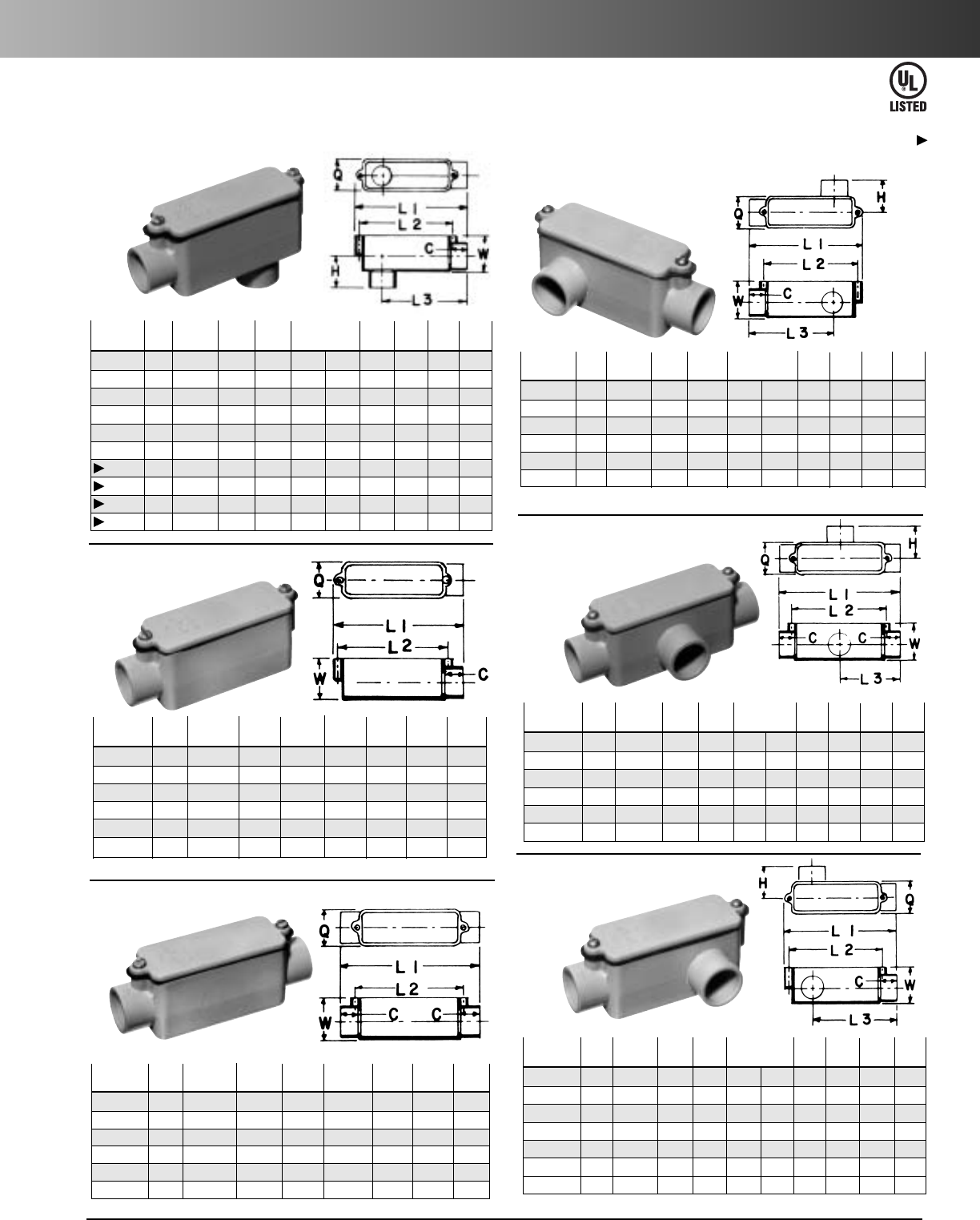
www.carlon.com 179
Rigid Nonmetallic Conduit – Conduit Bodies
Part Std. C
Max. L2 L3 Max Max Max. Vol.
No.
Size
Ctn. Qty.
Typical
L1 Typical H Q W
Cu. In.
E986D-CAR
1
/
2
10
11
/
16
4
5
/
16
3
7
/
32
3
1
/
16
1
5
/
16
1
11
/
32
1
1
/
2
4.0
E986E-CAR
3
/
4
10
29
/
32
6
9
/
32
5
9
/
32
4
25
/
32
1
25
/
32
1
3
/
4
2
1
/
32
12.0
E986F-CAR
110
29
/
32
6
9
/
32
5
9
/
32
4
25
/
32
1
25
/
32
1
3
/
4
2
1
/
32
12.0
E986G-CAR
1
1
/
4
51
3
/
32
7
31
/
32
6
13
/
32
62
5
/
16
2
1
/
2
2
3
/
4
32.0
E986H-CAR
1
1
/
2
51
3
/
32
7
31
/
32
6
13
/
32
62
5
/
16
2
1
/
2
2
3
/
4
32.0
E986J
2101
5
/
32
9
31
/
32
8
13
/
32
7
1
/
4
2
9
/
16
3
5
/
32
3
15
/
32
63.0
E986K
2
1
/
2
41
5
/
8
14
7
/
8
13
1
/
4
11
31
/
32
3
3
/
4
4
11
/
32
4
5
/
8
210.
E986L
3 4 1
5
/
8
14
7
/
8
13
1
/
4
11
31
/
32
3
3
/
4
4
11
/
32
4
5
/
8
210.
E986M
3
1
/
2
41
25
/
32
17
23
/
32
15
7
/
8
14
17
/
64
4
7
/
16
5
11
/
32
5
21
/
32
390.
E986N
4 4 1
25
/
32
17
23
/
32
15
7
/
8
14
17
/
64
4
7
/
16
5
11
/
32
5
21
/
32
390.
Conduit Bodies
Type LB
Part
Std. Vol.
No. Size
Ctn. Qty.
C
L1 L2 Q W
Cu. In.
E988D-CAR
1
/
2
5
11
/
16
4
5
/
16
3
1
/
2
1
11
/
32
1
1
/
2
4.0
E988E
3
/
4
20
29
/
32
6
11
/
32
5
9
/
32
1
3
/
4
2
1
/
32
12.0
E988F-CAR
110
29
/
32
6
11
/
32
5
9
/
32
1
3
/
4
2
1
/
32
12.0
E988G-CAR
1
1
/
4
51
3
/
32
86
13
/
32
2
1
/
2
2
3
/
4
32.0
E988H-CAR
1
1
/
2
51
3
/
32
86
13
/
32
2
1
/
2
2
3
/
4
32.0
E988J
251
5
/
32
9
15
/
32
8
13
/
32
3
5
/
32
3
15
/
32
63.0
Type E
Part
Std.
C
Max. L2 Max Max. Vol.
No. Size
Ctn. Qty.
Typical
L1 Typical Q W
Cu. In.
E987D-CAR
1
/
2
10
11
/
16
4
11
/
16
3
1
/
2
1
11
/
32
1
1
/
2
4.0
E987E-CAR
3
/
4
10
29
/
32
6
7
/
8
5
32
/
64
1
3
/
4
2
1
/
32
12.0
E987F-CAR
110
29
/
32
6
7
/
8
5
9
/
32
1
3
/
4
2
1
/
32
12.0
E987G-CAR
1
1
/
4
51
3
/
32
8
21
/
32
6
13
/
32
2
1
/
2
2
3
/
4
32.0
E987H-CAR
1
1
/
2
41
3
/
32
8
21
/
32
6
13
/
32
2
1
/
2
2
3
/
4
32.0
E987J
2151
5
/
32
10
5
/
16
8
13
/
32
3
5
/
32
3
15
/
32
63.0
Type C
Part
Std.
C
Max. L2 L3
Max. Max. Max.
Vol.
No. Size
Ctn. Qty.
Typical
L1 Typical H Q W
Cu. In.
E985D-CAR
1
/
2
10
11
/
16
4
5
/
16
3
7
/
32
3
1
/
16
1
5
/
16
1
11
/
32
1
1
/
2
4.0
E985E-CAR
3
/
4
10
29
/
32
6
9
/
32
5
9
/
32
4
25
/
32
1
25
/
32
1
3
/
4
2
1
/
32
12.0
E985F-CAR
110
29
/
32
6
9
/
32
5
9
/
32
4
25
/
32
1
25
/
32
1
3
/
4
2
1
/
32
12.0
E985G-CAR
1
1
/
4
51
3
/
32
7
31
/
32
6
13
/
32
62
5
/
16
2
1
/
2
2
3
/
4
32.0
E985H-CAR
1
1
/
2
51
3
/
32
7
31
/
32
6
13
/
32
62
5
/
16
2
1
/
2
2
3
/
4
32.0
E985J
2101
5
/
32
9
9
/
32
8
13
/
32
7
1
/
4
2
9
/
16
3
5
/
32
3
15
/
32
63.0
Type LR
Part
Std.
C
Max. L2 L3
Max Max Max.
Vol.
No. Size
Ctn.Qty.
Typical
L1 Typical H Q W
Cu. In.
E983D-CAR
1
/
2
10
11
/
16
4
11
/
16
3
7
/
32
2
11
/
32
1
5
/
16
1
11
/
32
1
1
/
2
4.0
E983E-CAR
3
/
4
10
29
/
32
6
7
/
8
5
9
/
32
4
7
/
16
1
25
/
32
1
3
/
4
2
1
/
32
12.0
E983F
1 20
29
/
32
6
7
/
8
5
9
/
32
3
7
/
16
1
25
/
32
1
3
/
4
2
1
/
32
12.0
E983G
1
1
/
4
10 1
3
/
32
8
21
/
32
6
13
/
32
4
21
/
64
2
5
/
16
2
1
/
2
2
3
/
4
32.0
E983H-CAR
1
1
/
2
41
3
/
32
8
21
/
32
6
13
/
32
4
21
/
64
2
5
/
16
2
1
/
2
2
3
/
4
32.0
E983J
210 1
5
/
32
10
5
/
16
8
13
/
32
5
5
/
32
2
9
/
16
3
5
/
32
3
15
/
16
63.0
Type T
Part
Std.
C
Max. L2 L3 Max Max Max. Vol.
No. Size
Ctn. Qty.
Typical
L1 Typical H Q W
Cu. In.
E984D-CAR
1
/
2
10
11
/
16
4
5
/
16
3
7
/
32
3
1
/
16
1
5
/
16
1
11
/
32
1
1
/
2
4.0
E984E-CAR
3
/
4
82
29
/
32
6
9
/
32
5
9
/
32
4
25
/
32
1
25
/
32
1
3
/
4
2
1
/
32
12.0
E984F-CAR
110 2
29
/
32
6
9
/
32
5
9
/
32
4
25
/
32
1
25
/
32
1
3
/
4
2
1
/
32
12.0
E984G-CAR
1
1
/
4
51
3
/
32
7
31
/
32
6
13
/
32
62
5
/
16
2
1
/
2
2
3
/
4
32.0
E984H-CAR
1
1
/
2
51
3
/
32
7
31
/
32
6
13
/
32
62
5
/
16
2
1
/
2
2
3
/
4
32.0
E984J
2101
5
/
32
9
9
/
32
8
13
/
32
7
1
/
4
2
9
/
16
3
5
/
32
3
15
/
32
63.0
E984J-CAR
231
5
/
32
9
9
/
32
8
13
/
32
7
1
/
4
2
9
/
16
3
5
/
32
3
15
/
32
63.0
Type LL
E42728
Except where noted by
• Hubs are not threaded • Textured lids • Foam-in-place gasket
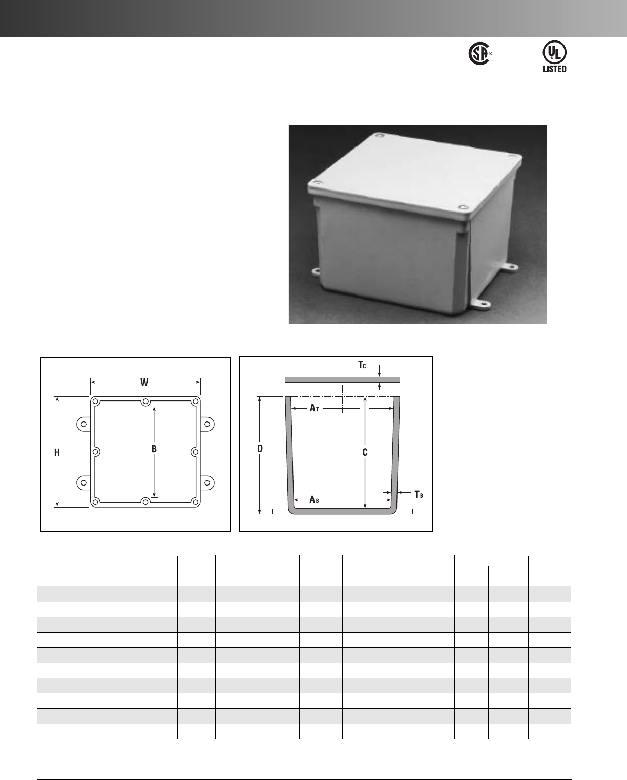
www.carlon.com
180
Rigid Nonmetallic Conduit – Junction Boxes
Molded Nonmetallic Junction Boxes
6P Rated
It’s another first from Carlon
®
- the first nonmetallic
junction boxes UL Listed with a NEMA 6P rating per
Section 314.29, Exception of the National Electrical Code.
Manufactured from PVC or PPO thermoplastic molding
compound and featuring foam-in-place gasketed lids
attached with stainless steel screws, these rugged
enclosures offer all the corrosion resistance and physical
properties you need for direct burial applications.
Type 6P enclosures are intended for indoor or outdoor
use, primarily to provide a degree of protection against
contact with enclosed equipment, falling dirt, hose-
directed water, entry of water during prolonged
submersion at a limited depth, and external ice
formation.
• All Carlon Junction Boxes
are UL Listed and maintain
a minimum of a NEMA Type
4/4x Rating.
• Parts numbers with an
asterisk (*) are UL Listed and
maintain a NEMA Type 6P
Rating and Type 4/4X Rating.
E42728
Except where noted
by †
Size in Std.
Material Std.
Inches Ctn. Min
Min. Min. Min. Ta Tc Thermo- Ctn.
Part No. H x W x D
Qty.
ATABB C PVC plastic Wt. (Lbs.)
E989NNJ-CAR* 4 x 4 x 2 53
11/16 35/8N/A 2.160 .155 X3
E987N-CAR* 4 x 4 x 4 5 311/16 31/2N/A 4 .160 .155 X 4
†
E989NNR-CAR* 4 x 4 x 6 43
11/16 33/8N/A 6.160 .200 X 5
E989PPJ-CAR* 5 x 5 x 2 4 411/16 41/2N/A 2 .110 .150 X 3
E987R-CAR* 6 x 6 x 4 2 6 55/8N/A 4 .190 .190 X 3
E989RRR-UPC* 6 x 6 x 6 8 55/853/8N/A 6 .160 .150 X 14
E989N-CAR 8 x 8 x 4 1 8 8 N/A 4 .185 .190 X 2
E989SSX-UPC 8 x 8 x 7 27
21/32 75/16 N/A 7.160 .150 X 6
E989UUN 12 x 12 x 4 3 115/8111/2111/84 .160 .150 X 12
E989R-UPC 12 x 12 x 6 2 1115/16 117/8117/16 6 .265 .185 X 10
Typical
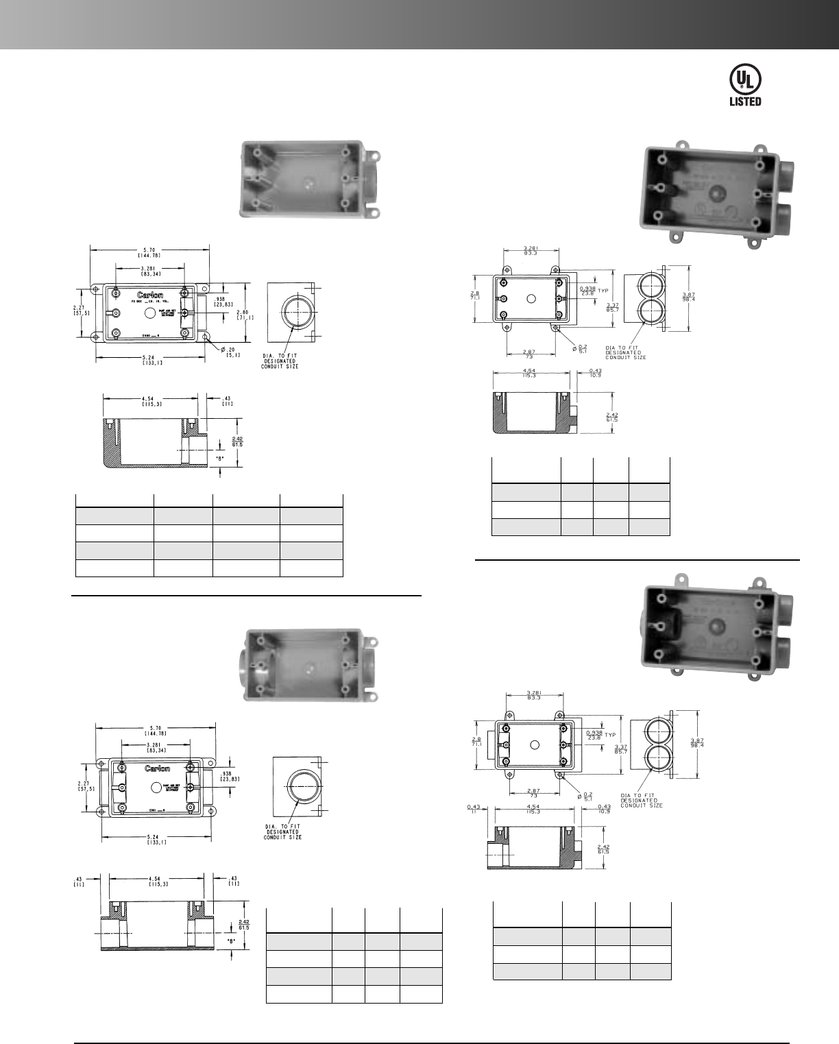
www.carlon.com 181
Rigid Nonmetallic Conduit – Switch Boxes
Type FSE
Single Gang FS Boxes
Part No. Size
Vol.
Cu. In.
Std. Ctn. Qty.
E980DFN
1
/
2
19 10
E980EFN
3
/
4
19 10
E980FFN 1 19 18
E980FFN-CAR 1 19 10
All sizes take standard covers
and accessories or devices.
Integral mounting feet
provide easy mounting.
For dead-end terminations.
Type FSC
All sizes take standard covers
and accessories or devices.
Detachable mounting feet
provide easy mounting.
For through terminations.
Part
Vol. Std.
No. Size
Cu. In.
Ctn. Qty.
E981DFN
1
/
2
19 15
E981EFN
3
/
4
19 15
E981FFN 1 19 18
E981FFN-CAR 119 10
E42728
Type FSS
All sizes take standard covers
and accessories or devices.
Detachable mounting feet
provide easy mounting.
For multiple
dead-end circuit
terminations or
where additional
support is required
in stub-up
applications.
Type FSCC
All sizes take standard covers
and accessories or devices.
Detachable mounting feet
provide easy mounting.
For multiple
through circuit
terminations
or where
additional
support is
required in
stub-up
applications.
Part
Vol. Std.
No. Size
Cu. In.
Ctn. Qty.
E979DFN-CAR
1
/
2
19 10
E979EFN-CAR
3
/
4
19 10
E979FFN 1 19 15
Part
Vol. Std.
No. Size
Cu. In.
Ctn. Qty.
E982DFN
1
/
2
19 10
E982EFN
3
/
4
19 10
E982FFN-CTN 1 19 8
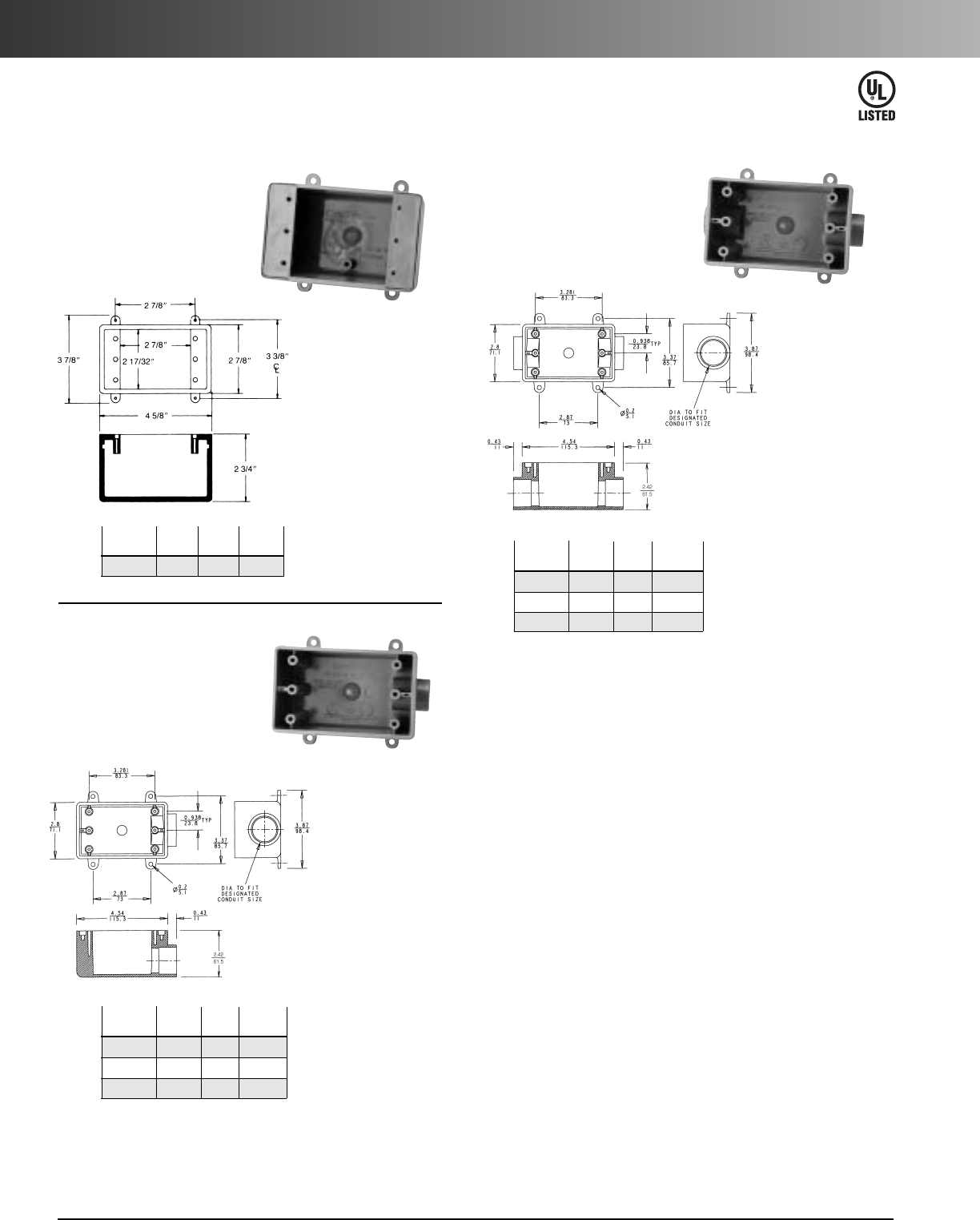
www.carlon.com
182
Rigid Nonmetallic Conduit – Switch Boxes
Single Gang FD Deep Device Boxes
Type FD
All sizes take standard
covers and accessories or
devices. Integral mounting feet
provide easy mounting.
For terminations
where hub
requirements
vary according to
application –
hubs easily made
with flared wood
bit or hole saw.
Part
Vol. Std.
No. Size
Cu. In.
Ctn.Qty.
E9801 N/A 25 10
For dead-end
terminations where
large devices or
additional wiring
capacity is required.
Type FDE
All sizes take standard covers
and accessories or devices.
Integral mounting feet
provide easy mounting.
Part
Vol. Std.
No. Size
Cu. In.
Ctn. Qty.
E9801DN
1
/
2
25 10
E9801EN
3
/
4
25 10
E9801FN 1 25 10
Part
Vol. Std.
No. Size
Cu. In.
Ctn. Qty.
E9811DN
1
/
2
25 10
E9811EN
3
/
4
25 10
E9811FN 1 25 10
Type FDC
All sizes take standard covers
and accessories or devices.
Integral mounting feet
provide easy mounting.
For through
terminations where
large devices or
additional wiring
capacity is required.
E42728
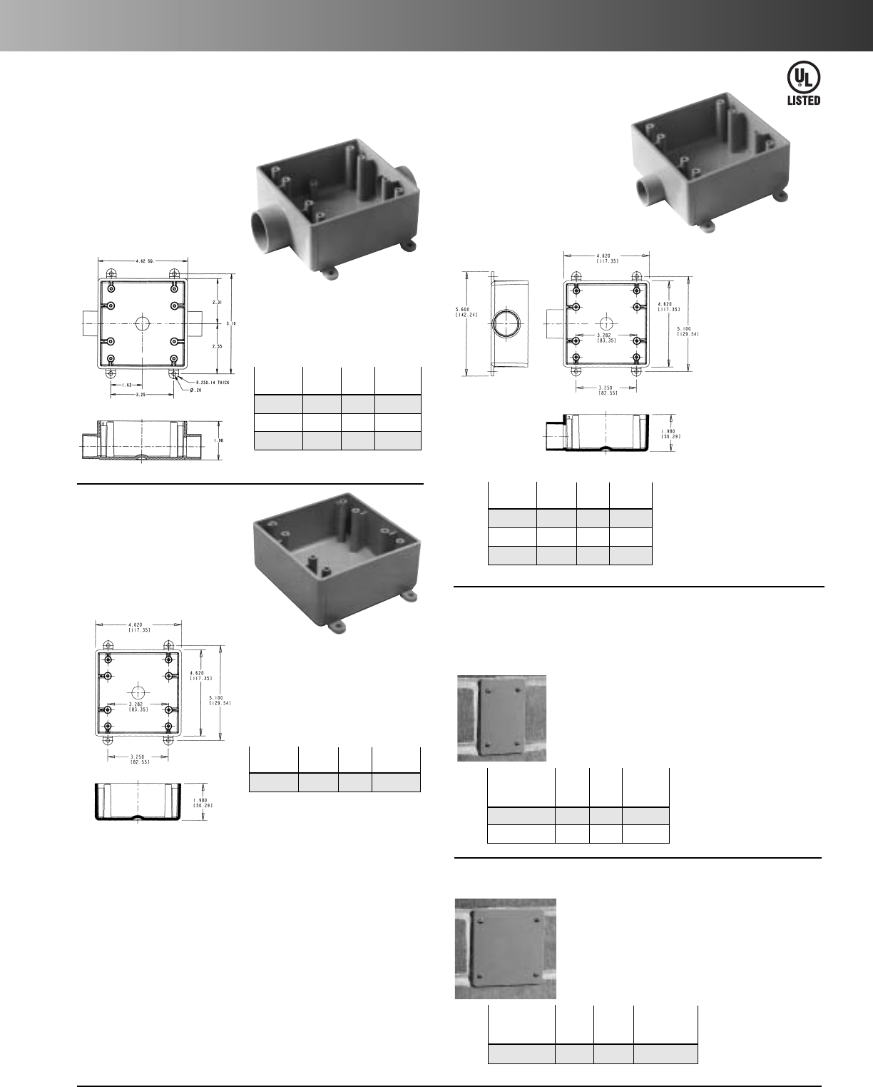
www.carlon.com 183
Rigid Nonmetallic Conduit – Switch Boxes & Covers
Two Gang FS Boxes
Type 2FSC
Part
Vol. Std.
No. Size
Cu. In.
Ctn. Qty.
E9812D
1
/
2
32 10
E9812E
3
/
4
32 10
E9812F 1 32 10
All sizes take standard covers
and accessories or devices.
Integral mounting feet
provide easy mounting.
For through terminations
where two devices or
additional wiring capacity
is required.
Type FS
Part
Vol. Std.
No. Size
Cu. In.
Ctn. Qty.
E9802 N/A 32 10
All sizes take standard covers
and accessories or devices.
Integral mounting feet
provide easy mounting.
For terminations where hub
requirements vary according
to application - hubs easily
made with flared wood bit
or hole saw.
Type 2FSE
Part
Vol. Std.
No. Size
Cu. In.
Ctn. Qty.
E9802D
1
/
2
32 10
E9802E
3
/
4
32 10
E9802F 1 32 10
All sizes take standard covers
and accessories or devices.
Integral mounting feet
provide easy mounting.
For dead-end
terminations
where two
devices or
additional
wiring capacity
is required.
Blank Covers
Std. Std.
Part
Ctn. Ctn.
No. Color
Qty.
Wt. (lbs.)
E980CN-CAR Gray 12 1.60
E980CM-CAR White 12 1.60
Fits Carlon®single gang
FS boxes. Supplied with
stainless steel mounting
screws and gasket.
Single Gang
Std. Std.
Part
Ctn. Ctn.
No. Color
Qty.
Wt. (lbs.)
E9802CN-CAR Gray 10 2.17
Fits Carlon®two gang FS boxes,other
nonmetallic and metallic FS boxes.
Supplied with stainless steel mounting
screws and gasket.
Two Gang
E42728
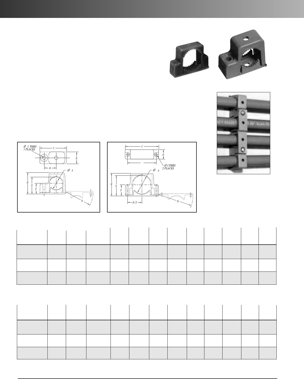
www.carlon.com
184
Rigid Nonmetallic Conduit – Support Straps
B
Size:
inches Std. Std. Ctn.
Part No. (mm) Ctn. Qty. Wt. (lbs.) A B C D F G H J R
E978DC-CAR 1/2" 40 1 0.80 .75 1.63 0.75 .59 .99 1.36 .21 1.67
(16) (20.3) (1.90) (41.4) (19.1) (14.9) (25.1) (34.5) (5.33) (42.4)
E978EC-CAR 3/4" 40 3 1.00 .88 1.92 0.75 .70 1.20 1.57 .21 1.96
(21) (25.4) (22.4) (48.7) (19.1) (17.8) (30.4) (39.9) (5.33) (49.8)
E978FC-CAR 1" 30 4 1.20 1.02 2.17 0.75 .83 1.43 1.84 .21 2.22
(27) (30.5) (25.9) (55.1) (19.1) (21.1) (36.3) (46.7) (5.33) (56.3)
Single Mount
Single Mount Double Mount
Snap Strap
®
Conduit
Support Straps
Carlon’s Snap Strap
®
offers a unique support strap designed especially
for the installation of PVC conduit. Also usable for installations of rigid
steel. This high strength, nonmetallic clamp allows conduit to expand
and contract freely, eliminating the bowing commonly seen from the
expansion and contraction of conduit caused by varying temperature
changes. Finished installations have a neat, attractive appearance on
exposed applications.
To be used in accordance with conduit spacing requirements per the
NEC, Section 352.30. This part is not supplied with screws.
• UV inhibited for use in direct sunlight
Size:
inches Std. Std. Ctn.
Part No. (mm) Ctn. Qty. Wt. (lbs.) A B C D F G H J R
E978GC-CAR 11/4" 15 4 1.66 2.75 3.23 1.00 .95 1.78 2.15 .218 3.28
(35) (42.16) (69.9) (82.0) (25.4) (24.1) (45.2) (54.61) (5.54) (83.3)
E978HC-CAR 11/2" 15 5 1.92 3.05 3.53 1.00 1.08 2.04 2.40 .218 3.58
(41) (48.77) (77.5) (89.7) (25.4) (27.4) (51.8) (60.96) (5.54) (90.9)
E978JC-CAR 2" 10 5 2.34 3.50 4.00 1.00 1.31 2.48 2.86 .218 4.06
(53) (59.44) (88.9) (101.6) (25.4) (33.3) (63.0) (72.64) (5.54) (103.1)
Double Mount
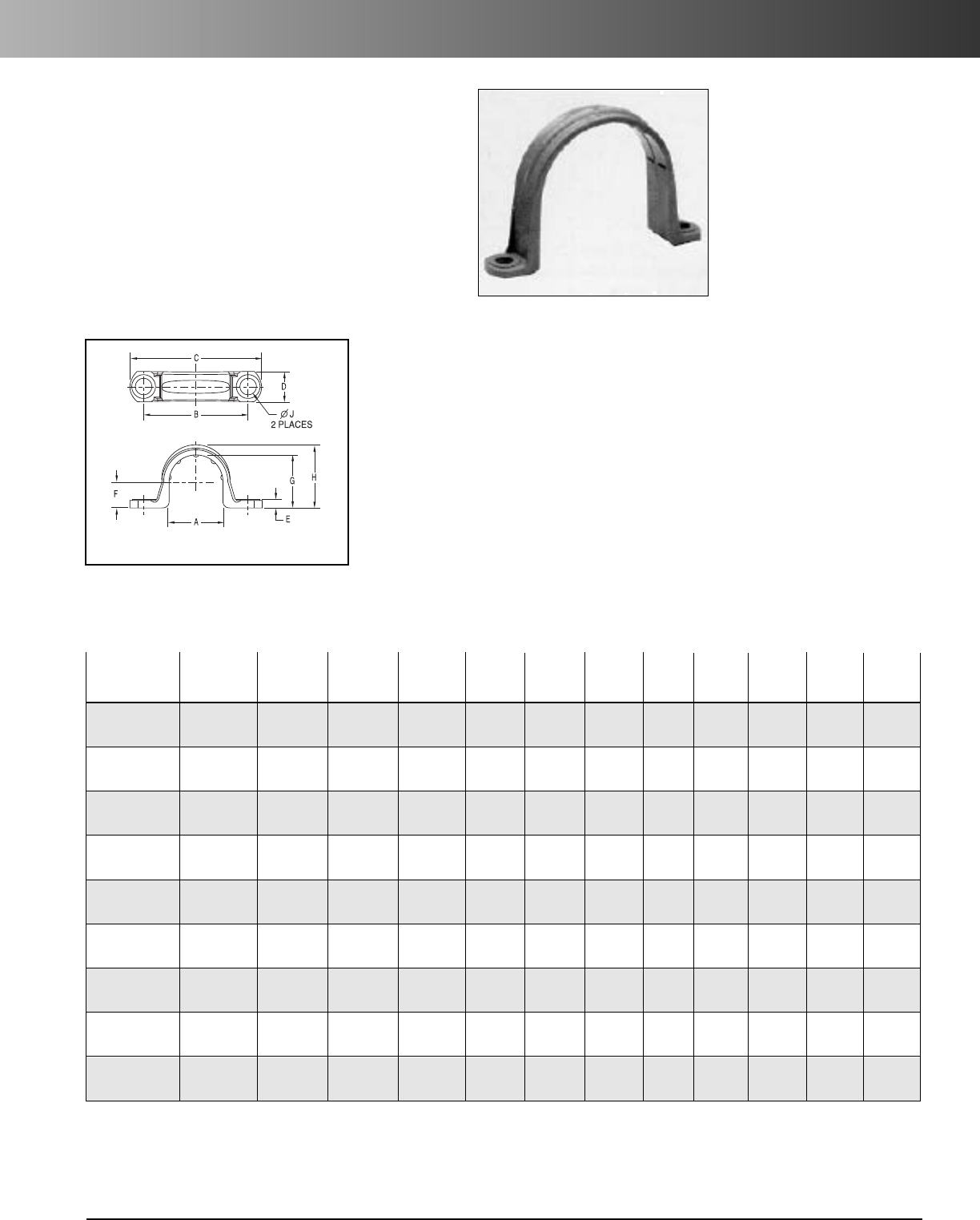
www.carlon.com 185
Rigid Nonmetallic Conduit – Clamps
Conduit Clamps
Conduit Clamp
Size: Std. Std.
Part inches Ctn. Ctn. Wt.
No. (mm) Qty. (lbs.) A B C D E F G H J
E977DC 1/2" 100 1.2 0.892 1.71 2.16 0.50 .14 .42 .866 1.04 .260
(16) (22.6) (43.4) (54.8) (12.7) (3.5) (10.6) (21.9) (26.4) (6.6)
E977EC 3/4" 100 1.4 1.102 1.97 2.40 0.50 .14 .525 1.076 1.255 .260
(21) (27.9) (50.0) (60.9) (12.7) (3.5) (13.3) (27.3) (31.8) (6.6)
E977FC 1" 100 2 1.39 2.25 2.81 0.594 .14 .658 1.342 1.574 .260
(27) (35.3) (57.1) (71.3) (15.0) (3.5) (16.7) (34.0) (39.9) (6.6)
E977GC 11/4" 50 5 1.714 2.68 3.28 .64 .15 .83 1.687 1.89 .320
(35) (43.5) (68.0) (83.3) (16.2) (3.8) (21.0) (42.8) (48.0) (8.1)
E977HC 11/2"50 61.92 2.82 3.44 .70 .15 .97 1.93 2.12 .312
(41) (48.7) (71.6) (87.3) (17.7) (3.8) (24.6) (49.0) (53.8) (7.9)
E977JC 2" 25 4.5 2.54 3.54 4.18 .76 .16 1.05 2.29 2.49 .315
(53) (64.5) (89.9) (106.1) (19.3) (4.0) (26.6) (58.1) (63.2) (8.0)
E977KC-CAR 21/2" 25 1.4 2.86 4.50 5.46 1.00 .20 1.43 2.86 3.12 .36
(63) (72.6) (114.3) (138.7) (25.4) (5.08) (36.3) (72.6) (79.2) (9.14)
E977LC-CAR 3" 20 1.4 3.47 5.00 6.00 1.00 .20 1.74 3.48 3.70 .36
(78) (88.2) (127.0) (152.4) (25.4) (5.08) (44.3) (88.4) (94.0) (9.14)
E977NC-CAR 4" 15 12.2 4.366 6.15 7.20 1.00 .20 2.32 4.50 4.70 .36
(103) (110.9) (156.2) (182.9) (25.4) (5.08) (58.8) (114.3 (119.4) (9.14)
Nonmetallic Clamps
Nonmetallic clamps offer the same chemical resistance
as Carlon nonmetallic conduits for a complete, corrosion
resistant system.
To be used in accordance with conduit spacing
requirements per the NEC, Section 352.30.
• UV inhibited for use in direct sunlight
*Note: Some clamp applications require 2 screws,2 nuts and 2 washers.
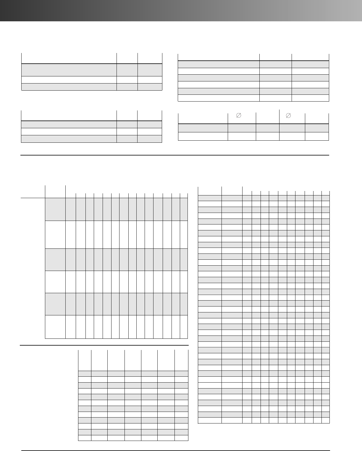
www.carlon.com
186
Rigid Nonmetallic Conduit – Technical Information
Typical Properties of Conduit Raw Material Compound
Wire Fill
Conductor
Type
Size
Trade Size
Letters
AWG, MCM
1/23/41 1
1/411/2221/2331/2441/4568
14 13 24 39 69 94 154
12 10 18 29 51 79 114 164
10 6 11 18 32 44 73 194 160
8 3 5 9 19 22 36 51 71 106 136
6 1 4 6 11 15 26 37 57 76 98 125 154
4 1 2 4 7 9 16 22 35 47 60 75 94 137 236
3 1 1 3 6 8 13 19 29 39 51 64 90 116 201
2 1 1 3 5 7 11 16 25 33 43 54 67 97 169
1 1 1 3 5 9 12 18 25 32 49 59 72 125
1/0 1 1 3 4 7 10 15 21 27 33 42 61 105
2/0 1 1 2 3 6 8 13 17 22 28 35 51 88
3/0 1 1 1 3 5 7 11 14 18 23 29 42 73
4/0 1 1 1 2 4 6 9 12 15 19 24 35 61
250 1 1 1 3 4 7 10 12 16 20 28 49
300 1 1 1 3 4 6 8 11 13 17 24 42
350 1 1 1 2 3 5 7 9 12 15 21 37
400 1 1 1 3 5 6 8 10 13 19 33
500 1 1 1 2 4 5 7 9 11 16 27
600 1 1 1 1 3 4 5 7 9 13 22
700 1 1 1 3 4 5 6 8 11 19
750 1 112346 7 11 19
6 1 3 5 9 13 21 30 47 63 81 102 128 185 320
600 1 1 1 1 3 4 5 7 9 13 22
700 1 1 1 3 4 5 6 7 11 19
750 11 1234 6 71018
Thermal
ASTM Typical
Test Values
Co-efficient of Thermal Expansion-inch/inch/°F D696 3.38 x 10
-5
(properties @ 73.4°F)
Heat Distortion °F at 264 psi D648 160°F
Thermal Conductivity BTU (hr.) (ft.) (°F/in.) N/A 1.3
Electrical
ASTM Typical
Test Values
Dielectrical Strength volts/mil D149 1100
Dielectric Constant 60 CPS @ 30°C D150 4.00
Power Factor 60 CPS @ 30°C D150 1.93
Mechanical
ASTM Test Typical Values
Specific Gravity D792 1.43 - 1.6
Tensile Strength (psi) @ 73.4°F D638 5,000-6,500
Izod Impact ft lbs./in. of notch D256 0.65 - 1.5
Flexural Strength (psi) D790 12,500
Compressive Strength (psi) D695 9,000
Hardness (Durometer D) D2240 85
Impedance
(Volts lost per ampere per 100 feet)
3 90% 80% 1 90% 80%
P.F. P.F. P.F. P.F.
Steel Conduit .0118 .0123 .0136 .0142
Schedule 40
®
.0105 .0106 .0121 .0122
Using 250 KCmil Cu. conductor. comparable values for other conductor sizes.
THWN
THHN
FEP
(14 thru 2)
FEPB
(14 thru 8)
PFA
(14 thru 4/0)
PFAH
(14 thru 4/0)
Z
(14 thru 4/0)
XHHW
(4 thru
500MCM)
XHHW
Maximum number of conductors in Schedule 80 PVC conduit
(Based on Table 1, Chapter 9 of the NEC)
Conductor Size
Trade Size
AWG, MCM 1/23/41 11/411/222
1/2345
# 14 THW 4 8 13 24 34 57 82 128
THHN 10 19 33 58 81 135 194 0
12 THW 3 6 11 20 28 47 67 105 183
THHN 8 14 24 43 60 100 144 0
10 THW 3 5 9 16 22 37 54 85 148
THHN 59 15 27 38 64 92 143
8THW 12 4 8 11 19 28 44 77 121
THHN 1 4 7 13 18 31 45 70 123 195
6 THW 1 1 3 6 8 14 20 32 56 88
THHN 1 3 5 9 13 22 32 50 88 140
4 THW 0 1 2 4 6 10 15 24 42 66
THHN 1 1 3 6 8 13 20 31 54 86
3 THW 0 1 1 4 5 9 13 20 36 57
THHN 1 1 2 5 7 11 17 26 46 73
2THW 0 1 1 3 4 8 11 17 31 49
THHN 1 1 1 4 5 9 14 22 38 61
1 THW 0 1 1 1 3 5 8 13 22 35
THHN 0 1 1 3 4 7 10 16 28 45
0 THW 0 0 1 1 2 4 7 11 19 30
THHN 01 1 2 3 6 8 13 24 38
00 THW 0 0 1 1 1 4 6 9 16 26
THHN 0 1 1 1 3 5 7 11 20 32
000 THW 0 0 1 1 1 3 5 8 14 22
THHN 001 124691626
0000 THW 0 0 1 1 1 3 4 6 11 18
THHN 0 0 1 1 1 3 5 8 14 22
250 THW 0 0 0 1 1 1 3 5 9 14
THHN 000112461118
300 ThW 0 0 0 1 1 1 3 4 8 13
THHN 0 0 0 1 1 1 3 5 9 15
350 THW 0 0 0 1 1 1 2 4 7 11
THHN 0 0 0 1 1 1 3 4 8 13
400 THW 0 0 0 0 1 1 1 3 6 10
THHN 0 0 0 1 1 1 2 4 7 12
500 THW 000 011 1358
THHN 0 0 0 0 1 1 1 3 6 10
600 THW 0 0 0 0 0 1 1 1 4 7
THHN 0 0 0 0 1 1 1 3 5 8
700 THW 000 001 1136
Carlon Carlon Inter-
Schedule 40
®
Schedule 80
®
Electrical mediate Rigid
Rigid Rigid Metallic Metal Metal
Nom. Nonmetallic Nonmetallic Tubing Conduit Conduit
Size Conduit Conduit Aluminum (EMT) (IMC) (RMC)
1/218 22 27 30 57 79
3/423 29 36 46 78 105
135 43 53 66 112 153
11/448 60 70 96 114 201
11/257 72 86 112 176 246
2 76 100 116 142 230 334
21/2125 153 183 230 393 527
3164 212 239 270 483 690
31/2198 288 350 561 831
4 234 310 340 400 625 982
5 317 431 465
Not Made Not Made
1344
6412 592 612
Not Made Not Made
1770
Weight
Comparison
Carlon Schedule 40
®
rigid nonmetallic
conduit compared to
other rigid conduit in
pounds per 100 feet
(approx.)
Maximum number of conductors in Schedule 40 PVC conduit
(Based on Table 1, Chapter 9 of the NEC)
B
B
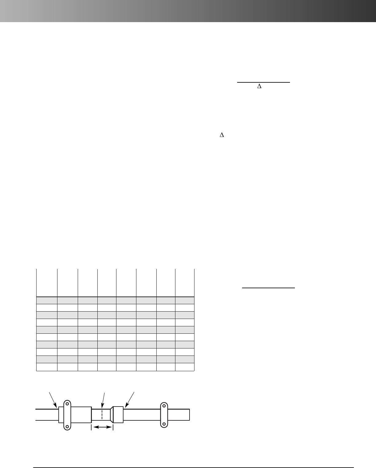
www.carlon.com 187
Rigid Nonmetallic Conduit – Expansion and Contraction
Temperature Considerations for
Rigid Nonmetallic Conduit
Compensation for Linear
Expansion
Expansion and Contraction
Like all construction materials, PVC will expand or contract with
variations in temperatures. The coefficient of linear expansion in PVC
conduit is 3.38 x 10
-5
in./in./°F as compared to 1.2 x 10
-5
for aluminum
and 0.6 x 10
-5
for steel. An expansion coupling is needed whenever
the change in length due to temperature variation will exceed
1
/
2
in.
Add 30°F to the estimated temperature range when conduit is
installed in direct sunlight to allow for radiant heating.
An expansion coupling consists of two sections of conduit, one
telescoping inside another. When installing expansion couplings,
alignment of piston and barrel is important. Be sure to mount
expansion joint level for best performance.
For a vertical run, the expansion coupling must be installed close to
the top of the run with the barrel jointing down, in order that rain
water does not run into the opening. The lower end of the conduit
run must be secured at the bottom so that any length change due to
temperature variation will result in an upward movement.
Expansion Characteristics of PVC Rigid Nonmetallic Conduit
Coefficient of Thermal Expansion = 3.38 x 10⁻⁵ in./in./°F
Length Length Length Length
Change in Change in Change in Change in
Temperature inches per Temperature inches per Temperature inches per Temperature inches per
Change in 100 Ft. of Change in 100 Ft. of Change in 100 Ft. of Change in 100 Ft. of
Degrees F PVC Conduit Degrees F PVC Conduit Degrees F PVC Conduit Degrees F PVC Conduit
5 0.2 55 2.2 105 4.2 155 6.3
10 0.4 60 2.4 110 4.5 160 6.5
15 0.6 65 2.6 115 4.7 165 6.7
20 0.8 70 2.8 120 4.9 170 6.9
25 1.0 75 3.0 125 5.1 175 7.1
30 1.2 80 3.2 130 5.3 180 7.3
35 1.4 85 3.4 135 5.5 185 7.5
40 1.6 90 3.6 140 5.7 190 7.7
45 1.8 95 3.8 145 5.9 195 7.9
50 2.0 100 4.1 150 6.1 200 8.1
The expansion joint must be installed to allow both expansion and
contraction of the conduit run. The correct piston opening for any
installation condition should use the following formula:
Determine the Piston Opening
O= E
T max - T installed
T
[]
Where:
O = Piston opening (in.)
T max = Maximum anticipated temperature of conduit (°F)
T inst. = Temperature of conduit at time of installation (°F)
T=
Total change in temperature of conduit (°F)
E=
Expansion allowance built into each expansion
coupling (in.)
380 ft. of conduit is to be installed on the outside of a building
exposed to the sun in a single straight run. It is expected that the
conduit will vary in temperature from 0°F in the winter to 140°F in
the summer (this includes the 30°F for radiant heating from the
sun.) The installation is to be made at a conduit temperature of 90°F.
From the table, a 140°F temperature change will cause a 5.7 in.
length change in 100 ft. of conduit. The total change for this
example is 5.7" x 3.8 = 21.67" which should be rounded to 22".
The number of expansion couplings will be 22"x coupling range
(4" for Carlon trade sizes
1
/
2
" through 1-
1
/
2
", and 8" for sizes 2"
through 6".) If the E945D coupling is used, the number will be 22"x
4 = 5.50 which should be rounded to 6. The coupling should be
placed at 62 ft. intervals (380 x 6). the proper piston setting at the
time of installation is calculated as explained above.
Example
O= 4.0 = 1.4 in.
140 - 90
140
[]
Insert the piston into the barrel to the maximum depth. Place a mark
on the piston at the end of the barrel. To properly set the piston, pull
the piston out of the barrel to correspond to the 2.1 in. calculated
above. See drawing at lower left.
Summary
1. Anticipate expansion and contraction of PVC conduit in
aboveground, exposed installation.
2. Use an expansion coupling when length change due to
temperature variation will exceed 1/2".
3. PVC conduit expands 4.1" for each 100 feet of run and a 100°F
temperature change.
4. Align expansion coupling with the conduit run to prevent binding.
5. Follow the instructions to set the piston opening.
6. Rigidly fix the outer barrel of the expansion coupling so it cannot
move. Mount the conduit connected to the piston loosely enough
to allow the conduit to move as the temperature changes.
Solvent Weld Solvent Weld
Maximum Depth Mark
Piston Opening
Pipe strap
should be anchored
tightly to barrel
Pipe strap
mounted loosely to
allow movement

www.carlon.com
188
Rigid Nonmetallic Conduit – Technical Information
Corrosion Resistance of Carlon Schedule 40
and Schedule 80 PVC Conduit and Fittings
Carlon Schedule 40 and Schedule 80 are generally
acceptable for use in environments containing the chemicals
below. These environmental resistance ratings are based
upon tests where the specimens were placed in complete
submergence in the reagent listed. Schedule 40 and
Schedule 80 can be used in many process areas where
chemicals not on this list are manufactured or used because
worker safety requirements dictate that any air presence or
splashing be at a very low level.
If there are any questions for specific suitability in a
given environment, prototype samples should be
tested under actual conditions.
Acetic Acid O-20%
Acetic Acid 20-30%
Acetic Acid 3O-60%
Acetic Acid 80%
Acetic Acid – Glacial
Acetic Acid Vapors
Acetylene
Adipic Acid
Alum
Aluminum Chloride
Aluminum Fluoride
Aluminum Hydroxide
Aluminum Oxychloride
Aluminum Nitrate
Aluminum Sulfate
Ammonia-Dry Gas
Ammonium Bifluoride
Ammonium Carbonate
Ammonium Chloride
Ammonium Hydroxide 28%
Ammonium Metaphosphate
Ammonium Nitrate
Ammonium Persulfate
Ammonium Phosphate – Neutral
Ammonium Sulfate
Ammonium Sulfide
Ammonium Thiocyanate
Amyl Alcohol
Anthraquinone
Anthraquinonesulfonic Acid
Antimony Trichloride
Aqua Regia
Arsenic Acid 80%
Arylsulfonic Acid
Barium Carbonate
Barium Chloride
Barium Hydroxide
Barium Sulfate
Barium Sulfide
Beet – Sugar Liquor
Benzine Sulfonic Acid 10%
Benzoic Acid
Bismuth Carbonate
Black Liquor (Paper Industry)
Bleach – 12.5% Active CL2
Borax
Boric Acid
Brine
Breeder Pellets – Dane. Fish
Bromic Acid
Bromine – Water
Butane
Butadiene
Butyl Alcohol
Butyl Phenol
Butylene
Butyric Acid
Calcium Bisulfite
Calcium Carbonate
Calcium Chlorate
Calcium Chloride
Calcium Hydroxide
Calcium Hypochlorite
Calcium Nitrate
Calcium Sulfate
Carbonic Acid
Carbon Dioxide Gas – Wet
Carbon Dioxide – Aqueous
Solution
Carbon Monoxide
Caustic Potash
Caustic Soda
Chloracatic Acid
Chloral Hydrate
Chlorine Gas (Dry)
Chlorine Gas (Moist)
Chlorine Water
Chlorosulfonic Acid
Chrome Alum
Chromic Acid 10%
Chromic Acid 30%
Chromic Acid 40%
Chromic Acid 50%
Citric Acid
Copper Chloride
Copper Cyanide
Copper Fluoride
Copper Nitrate
Copper Sulfate
Cottonseed Oil
Cresylic Acid 50%
Crude Oil – Sour
Crude Oil – Sweet
Demineralized Water
Dextrin
Dextrose
Diglycolic Acid
Disodium Phosphate
Ethyl Alcohol
Ethylene Glycol
Fatty Acids
Ferric Chloride
Ferric Nitrate
Ferric Sulfate
Ferrous Chloride
Ferrous Sulfate
Fluorine Gas – Wet
Fluorine Gas – Dry
Fluoroboric Acid
Fluorosilicic Acid
Formaldehyde
Formic Acid
Fructose
Gallic Acid
Gas – Coke Oven
Gas – Natural (Dry)
Gas – Natural (Wet)
Gasoline – Sour
Gasoline – Refined
Glucose
Glycerine (Glycerol)
Glycol
Glycolic Acid
Green Liquor (Paper Industry)
Heptane
Hexanol, Tertiary
Hydrobromic Acid 20%
Hydrochloric Acid 0% - 25%
Hydrochloric Acid 25% - 40%
Hydrocyanic Acid or
Hydrogen Cyanide
Hydrofluoric Acid 10%
Hydrofluorosilicic Acid
Hydrogen Phosphide
Hydrogen Sulfide – Dry
Hydrogen Sulfide –
Aqueous Solution
Hydroquinone
Hydroxylamine Sulfate
Iodine
Kerosene
Lactic Acid 28%
Lauric Acid
Lauryl Chloride
Lauryl Sulfate
Lead Acetate
Lime Sulfur
Linoleic Acid
Linseed Oil
Lubricating Oils
Magnesium Carbonate
Magnesium Chloride
Magnesium Hydroxide
Magnesium Nitrate
Magnesium Sulfate
Maleic Acid
Malic Acid
Mercuric Chloride
Mercuric Cyanide
Mercurous Nitrate
Mercury
Methyl Sulfate
Methylene Chloride
Mineral Oils
Naphthalene
Nickel Chloride
Nickel Nitrate
Nitric Acid,Anydrous
Nitric Acid 20%
Nitric Acid 40%
Nitric Acid 60%
Nitrobenzene
Nitrous Oxide
Oils and Fats
Oils – Petroleum – (See Type)
Oleic Acid
Oxalic Acid
Palmitic Acid 10%
Perchloric Acid 10%
Phenylhydrazine Hydrochloride
Phosgene, Gas
Phosphoric Acid – 0-25%
Phosphoric Acid – 25-50%
Phosphoric Acid – 50-85%
Photographic Chemicals
Plating Solutions
Potassium Bicarbonate
Potassium Bichromate
Potassium Borate
Potassium Bromide
Potassium Carbonate
Potassium Chloride
Potassium Chromate
Potassium Cyanide
Potassium Dichromate
Potassium Ferricyanide
Potassium Ferrocyanide
Potassium Fluoride
Potassium Hydroxide
Potassium Nitrate
Potassium Perborate
Potassium Perchlorite
Potassium Permanganate 10%
Potassium Persulfate
Potassium Sulfate
Propane
Propyl Alcohol
Silicic Acid
Silver Cyanide
Silver Nitrate
Silver Plating Solutions
Sodium Acetate
Sodium Arsenite
Sodium Benzoate
Sodium Bicarbonate
Sodium Bisulfate
Sodium Bisulfite
Sodium Bromide
Sodium Chlorate
Sodium Chloride
Sodium Cyanide
Sodium Dichromate
Sodium Ferricyanide
Sodium Ferrocyanide
Sodium Fluoride
Sodium Hydroxide
Sodium Hypochlorite
Sodium Nitrate
Sodium Nitrite
Sodium Sulfate
Sodium Sulfide
Sodium Sulfite
Sodium Thiosulfate (Hypo)
Stannic Chloride
Stannous Chloride
Stearic Acid
Sulfur
Sulfur Dioxide – Gas Dry
Sulfur Trioxide
Sulfuric Acid – 0-10%
Sulfuric Acid – 10-75%
Sulfuric Acid – 75-90%
Sulfurous Acid
Tannic Acid
Tanning Liquors
Tartaric Acid
Titanium Tetrachloride
Triethanolamine
Trimethyl Propane
Trisodium Phosphate
Turpentine
Urea
Vinegar
Whiskey
White Liquor (Paper Industry)
Wines
Zinc Chloride
Zinc Chromate
Zinc Cyanide
Zinc Nitrate
Zinc Sulfate
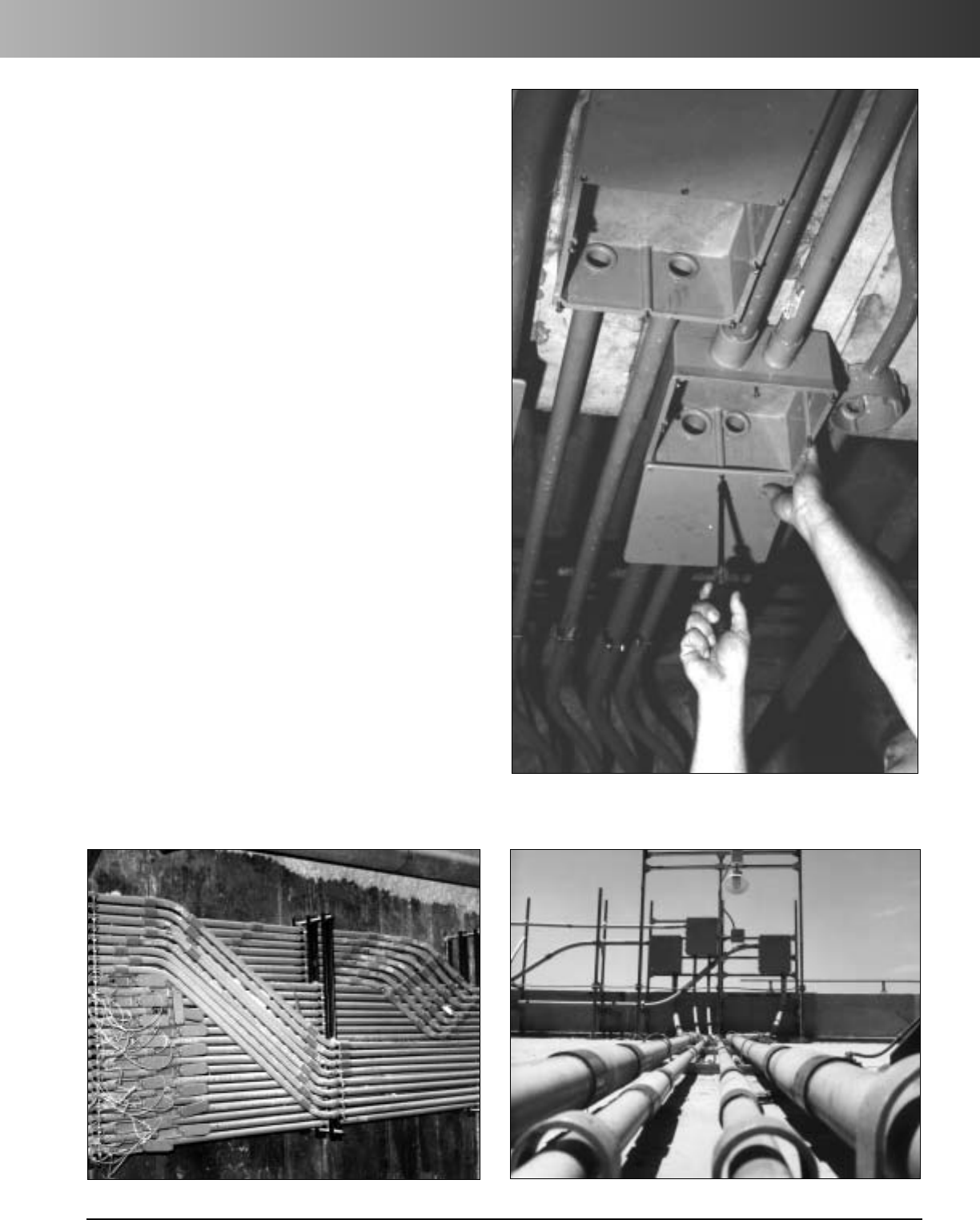
www.carlon.com 189
Rigid Nonmetallic Conduit – Specification Format
A. The Carlon rigid nonmetallic conduit system shall be installed
as indicated on the drawings and as specified herein.
B. All wiring shall be installed in Carlon rigid nonmetallic conduit.
All conduit shall be secured by means of proper fittings. All
fittings shall be Carlon.
C. Carlon outlet boxes, fittings and junction boxes shall be used
for all outlets, pull boxes and junction points. (Lighting fixtures
shall not be supported or hung from PVC junction boxes but be
supported in position by other means.)
D. Exposed conduits shall be mounted securely by suitable
hangers or straps with the maximum spacing of points of
supports not greater than indicated by Section 352.30 of the
NEC.
E. Except where embedded in concrete or direct buried, Carlon
conduit shall be supported to permit adequate lineal
movement to allow for expansion and contraction of conduit
due to temperature change.
F. For aboveground installations where temperature change in
excess of 14°C (25°F) is anticipated, expansion joints shall
be installed. See Table 352.44(A) NEC for expansion
characteristics.
G. Proper care shall be taken when field bending is employed
to maintain the internal diameter and wall thickness of the
conduit.
Suggested Format for
Specifying Carlon Nonmetallic
Conduit, Conduit Fittings and
Junction Boxes
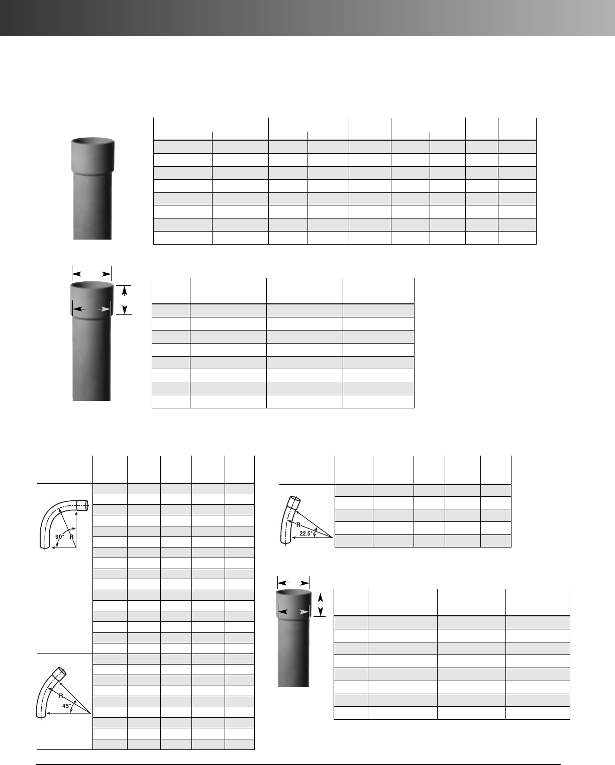
www.carlon.com
190
Rigid Nonmetallic Conduit – Utility Non-UL Listed
Part No. Std. Crate Qty. Dimensions Wt. Per
20' 10' 20' 10'
Nom. Size
O.D. I.D. Wall 100'
59610-020 59610-010 4500' 2250' 1/2" 1.900 1.610 .145 56
59611-020 59611-010 2800' 1400' 2" 2.375 2.067 .154 75
59612-020 59612-010 1860' 930' 21/2" 2.875 2.469 .203 124
59613-020 59613-010 1760' 880' 3" 3.500 3.068 .216 172
59615-020 59615-010 1140' 570' 4" 4.500 4.026 .237 244
59616-020 59616-010 760' 380' 5" 5.563 5.047 .258 331
59617-020 59617-010 520' 260' 6" 6.625 6.065 .280 430
59618-020 59618-010 300' 150' 8" 8.625 7.981 .322 647
Heavy Wall Rigid Schedule 40 Utility Conduit
• Rated for 90°C conductors or cable
• For direct earth burial and concrete encasement, specifically designed for the power utility specifications.
With Integral Bell*
*Limited geographical area
AB C
Trade At Entrance At Bottom Nominal Bell
Size
Maximum Minimum Maximum Minimum
Depth
11/21.926 1.916 1.911 1.901 2.750
2 2.405 2.395 2.386 2.376 3.250
21/22.911 2.901 2.887 2.877 3.250
3 3.543 3.533 3.513 3.503 3.875
4 4.549 4.539 4.514 4.504 3.875
5 5.619 5.609 5.578 5.568 4.625
6 6.692 6.682 6.641 6.631 5.625
8 8.692 8.682 8.614 8.631 6.375
Non-UL Listed
Deep Socket Schedule 40 Utility Elbows
with Integral Belled Ends
Dimensions in Inches of Utility Conduit Integral Bells
Std.
Part
Nom. Radius Std. Ctn. Ctn. Wt.
Segment No.
Diameter (in.) Qty. (lbs.)
90° Elbow UC9BHB 11/2" 12" 20 25.00
UC9DHB 11/2" 24" 1 2.13
UC9FHB 11/2"36" 1 3.05
UC9BJB 2" 12" 11.44
UC9DJB 2" 24" 1 2.82
UC9FJB 2" 36" 1 4.14
UC9HJB 2" 48" 1 5.15
UC9DKB 21/2"24" 15.00
UC9FKB 21/2" 36" 1 7.15
UC9DLB 3" 24" 1 6.57
UC9FLB 3" 36" 1 9.15
UC9DNB 4" 24" 110.59
UC9FNB 4" 36" 1 13.64
UC9HNB 4" 48" 1 17.72
UC9FRB 6" 36" 1 25.80
UC9HRB 6" 48" 132.24
45° Elbow UC7FHB 11/2" 36" 1 1.74
UC7FJB 2" 36" 1 2.07
UC7CKB 21/2"18" 1 2.27
UC7FKB 21/2" 36" 1 4.12
UC7FLB 3" 36" 1 5.00
UC7FNB 4" 36" 1 8.15
UC7HNB 4" 48" 1 9.36
UC7HRB 6" 48" 1 17.19
UC7ITB 8" 60" 1 33.00
Std.
Nom. Radius Std. Ctn. Ctn. Wt.
Segment Part No. Diameter (in.) Qty. (lbs.)
221/2° Elbow UC5CKB 21/2" 18" 1 1.45
UC5FKB 21/2" 36" 1 2.49
UC5FNB 4" 36" 1 5.18
UC5FRB 6" 36" 1 11.82
UC5HNB 4" 48" 1 5.57
A
BC
ABC
Trade At Entrance At Bottom Nominal Bell
Size
Max. Min. Max. Min. Max. Min.
11/21.926 1.916 1.900 1.888 2.750 2.500
22.405 2.395 2.381 2.357 2.875 2.625
21/22.911 2.901 2.875 2.861 3.125 2.875
33.543 3.533 3.500 3.484 3.125 2.875
4 4.549 4.539 4.500 4.482 3.750 3.500
5 5.619 5.609 5.563 5.543 4.250 4.000
6 6.692 6.682 6.625 6.603 5.250 5.000
88.692 8.682 8.641 8.631 6.250 6.000
Dimensions in Inches of Utility Elbows Bells
A
BC
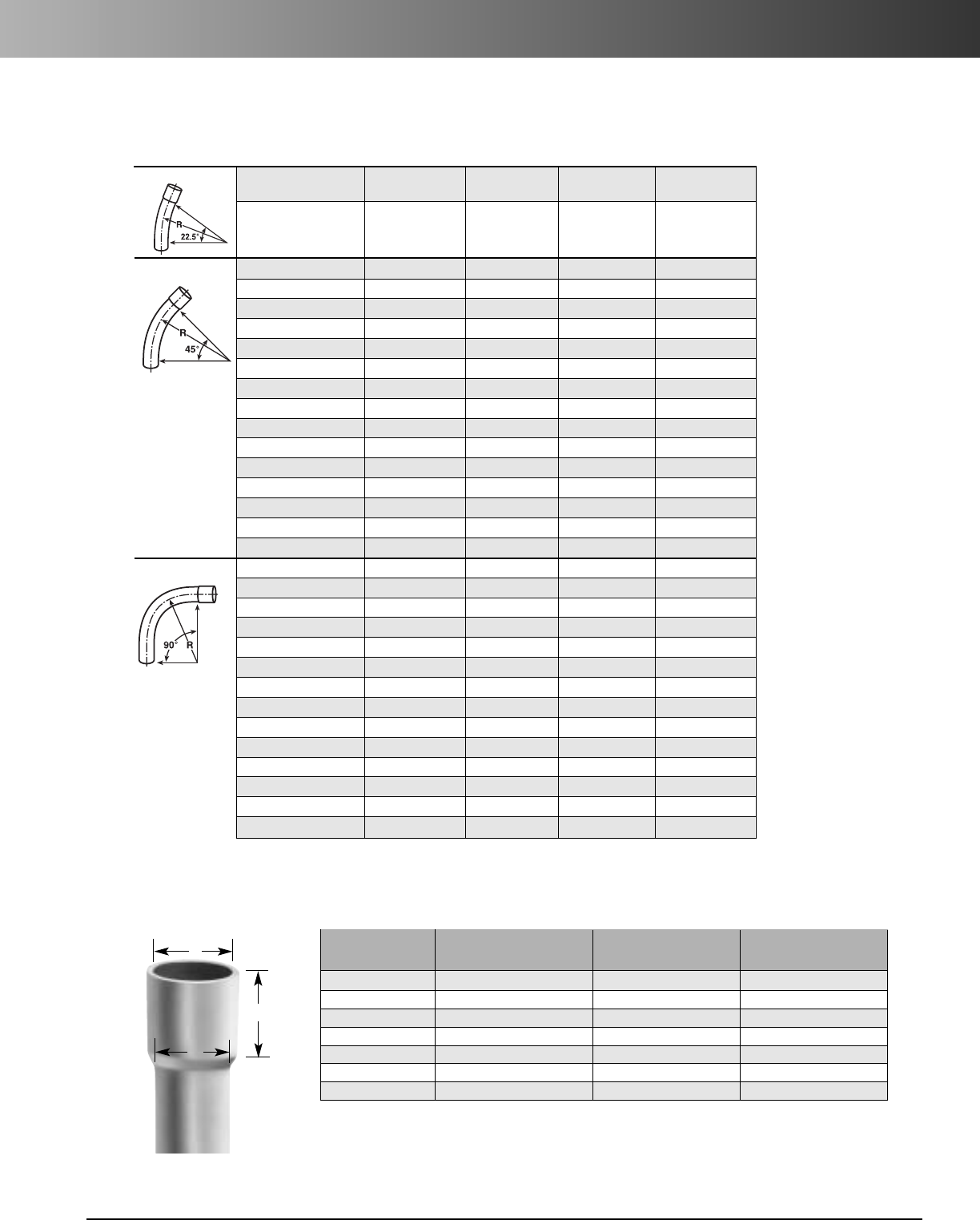
www.carlon.com 191
Rigid Nonmetallic Conduit – Utility Non-UL Listed
Elbows – Long Belled
221/2°Elbow Part Nom. Radius Std. Ctn. Std. Ctn.
Number Diameter (In.) Qty. Wt. (lbs.)
UC5FRBLB 6" 36 1 9.6
45° Elbow UC7CJBLB 2" 18 1 1.3
UC7DJBLB 2" 24 1 1.4
UC7DLBLB 3" 24 1 5.0
UC7DNBLB 4" 24 1 5.8
UC7DPBLB 5" 24 1 8.5
UC7FJBLB 2" 36 1 2.2
UC7FLBLB 3" 36 1 5.2
UC7FNBLB 4" 36 1 7.8
UC7FPBLB 5" 36 1 11.1
UC7FRBLB 6" 36 1 9.6
UC7HJBLB 2" 48 1 2.8
UC7HLBLB 3" 48 1 6.6
UC7HNBLB 4" 48 1 9.7
UC7HPBLB 5" 48 1 13.7
UC7HRBLB 6" 48 1 18.1
90° Elbow UC7CJBLB 2" 18 1 1.3
UC7DJBLB 2" 24 1 1.4
UC7DLBLB 3" 24 1 5.0
UC7DNBLB 4" 24 1 5.8
UC7DPBLB 5" 24 1 8.5
UC7FJBLB 2" 36 1 2.2
UC7FLBLB 3" 36 1 5.2
UC7FNBLB 4" 36 1 7.8
UC7FPBLB 5" 36 1 11.1
UC7FRBLB 6" 36 1 9.6
UC7HJBLB 2" 48 1 2.8
UC7HNBLB 4" 48 1 9.7
UC7HPBLB 5" 48 1 13.7
UC7HRBLB 6" 48 1 18.1
ABC
Trade At Entrance (in.) At Bottom (in.) Nominal Bell
Size
Maximum Minimum Maximum Minimum
Depth (in.)
1 - 11/2" 1.924 1.912 1.900 1.888 2 3/4"
2" 2.399 2.387 2.375 2.363 3 1/4"
2 - 21/2"2.897 2.883 2.875 2.861 31/4"
3" 3.523 3.507 3.500 3.484 4"
4" 4.524 4.506 4.500 4.482 4 3/4"
5" 5.603 5.583 5.563 5.543 5 3/4"
6" 6.669 6.647 6.625 6.603 6 1/4"
A
BC
Non-UL Listed
Integral Belled End Dimensions
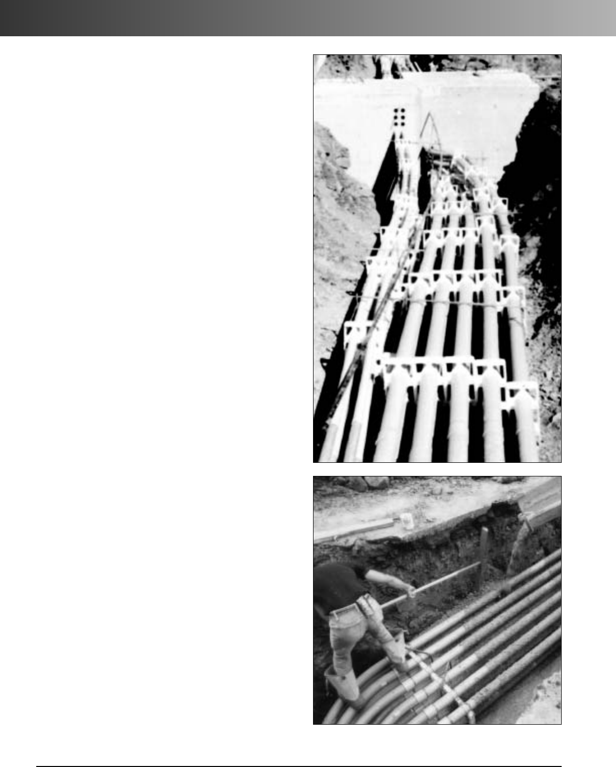
www.carlon.com
192
P&C®Duct
Carlon
®
P&C
®
Duct
Carlon P&C (Power & Communications) Duct and fittings are
designed and formulated specifically for concrete encased
and direct burial applications of power utility primaries,
secondaries, street lighting and distribution systems. Carlon
P&C Duct complies with NEMA Standard TC-6 & 8, and ASTM
F-512 for utility duct. Both EB and DB duct are rated for use
with 90°C conductors. P&C Duct fittings comply with NEMA
TC-9 Standard.
Carlon Telephone Duct complies with NEMA TC-10. Bellcore
CAO 8546, GT8343, and other applicable telephone standards.
Advantages:
•
Manufactured for high modulus C-250 compound
•
High impact strength
•
Excellent structural strength
•
Superior load bearing
•
Multiple duct banks can be pre-assembled and lowered
into trench
•
No special cutting or tapering devices required
•
Provides easy bending around obstructions minimizing the
need for special angle couplings and sweeps
•
Superior aging and weathering characteristics
Features:
•
Heat resistant
•
Fire resistant
•
Conforms to NEMA Standard TC-6 & 8 and ASTM Standard
F-512 for utility duct*
•
Carlon P&C Duct Type EB-20 is ETL Listed
•
Low coefficient of expansion
•
Continuous rigid control
•
Smooth inner wall and smooth transition between joints
Engineering Features:
Chemical Inertness resists water absorption and is totally
immune to galvanic or electrolytic attacks.
Solvent Cemented Joints provide leakproof duct runs
tested at 25 psi. This type of joint eliminates the need for
costly mechanical rodding procedure. Carlon P&C Duct
can be rodded pneumatically.
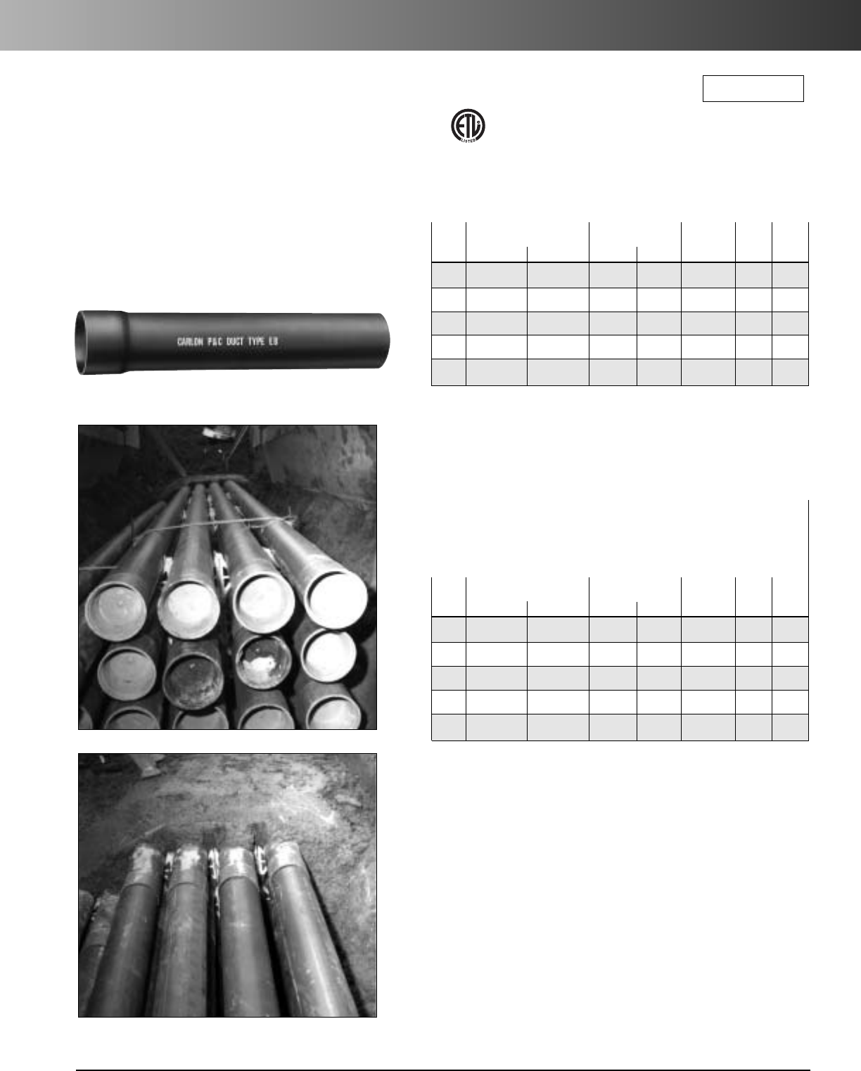
www.carlon.com 193
P&C®Duct – Type EB
Carlon
®
P&C
®
Duct
Type EB
Carlon nonmetallic P&C Duct Type EB is manufactured
from Carlon’s exclusive high modulus C-600 compound,
developed especially for power and communications
applications, and is designed for use in concrete encased
installations. Type EB is rated for 90°C Cable.
P&C Duct Type EB-20
Meets NEMA Standard TC-6 & 8
EB-20/ASTM F-512
Approx.
Nom. Part Number Std. Crate Qty.
Wt.
per *Min.
Size 10' 20' 10' 20' 100 ft. O.D. Wall
2 – 48711-020 – 2,800 36 2.375 .060
3 – 48713-020 – 2,000 59 3.500 .061
4 48715-010 48715-020 570 1,140 98 4.500 .082
5 48716-010 48716-020 380 760 148 5.563 .103
6 48717-010 48717-020 260 520 212 6.625 .125
*Min. wall thickness relates to 500,000 modulus
**Special order item
Note: One belled end per 20' length
*Min. wall thickness relates to 500,000 modulus
Note: One belled end per 20' length
Use DB Sweeps with EB Duct.
RUS Listed
ETL Listed
to UL 651A in
compliance
to the NEC
P&C Duct Type EB-35 Heavy Wall
Meets NEMA Standard TC-6 & 8
EB-35/ASTM F-512
Approx.
Nom. Part Number Std. Crate Qty.
Wt.
per *Min.
Size 10' 20' 10' 20' 100 ft. O.D. Wall
2 – 68711-020 – 2,800 39 2.375 .060
3 – 68713-020 – 2,000 72 3.500 .076
4 – 68715-020 – 1,140 116 4.500 .100
5 68716-010 68716-020 380 760 177 5.563 .126
6– 68717-020** – 520 251 6.625 .152
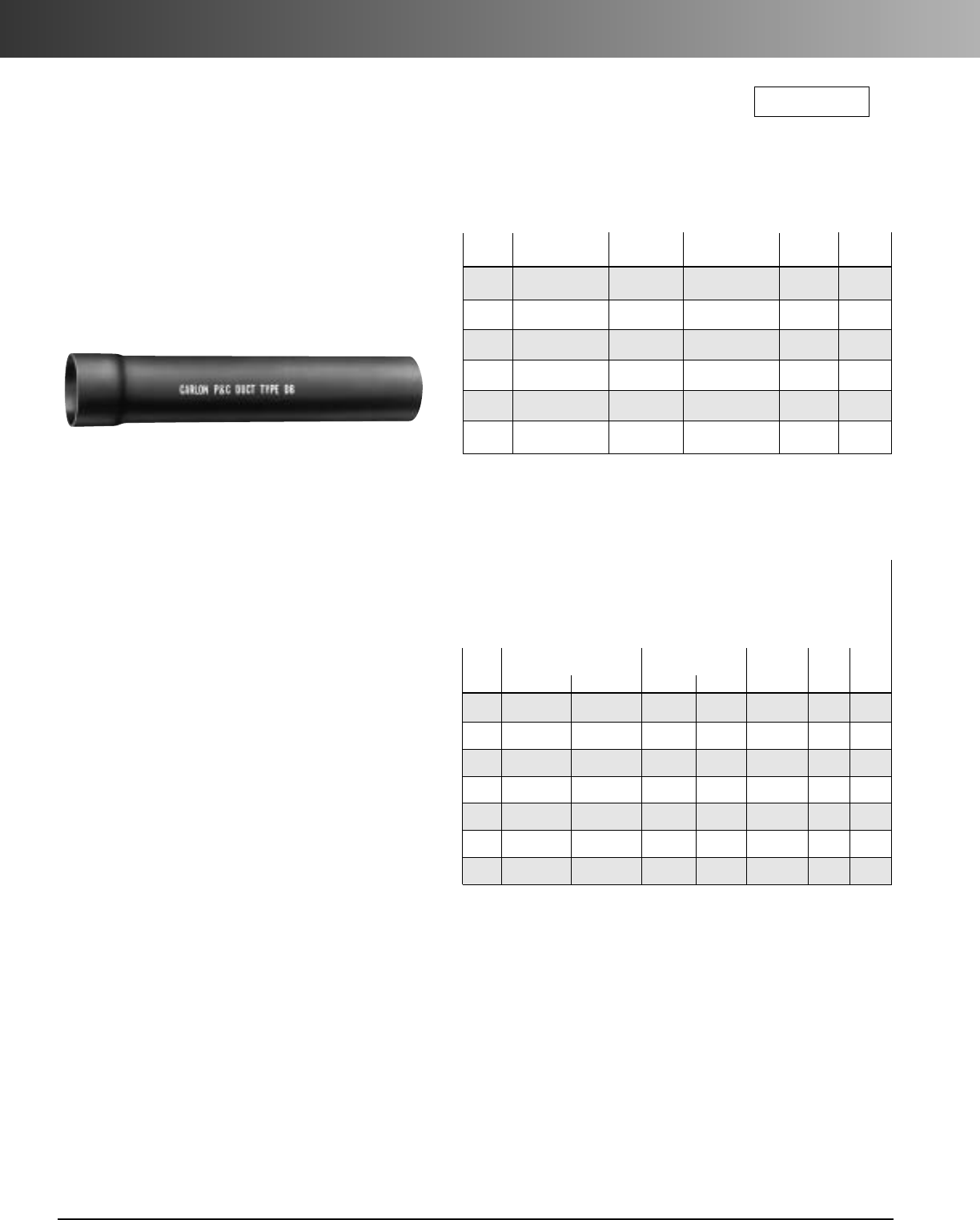
www.carlon.com
194
P&C®Duct – Type DB
Trenching:
Trench should be graded true and free from stones and
soft spots. Backfill should also be free of stones and be
firmly tamped around the sides of the conduit, to develop
maximum supporting strength. Tamping on top of the
conduit is not recommended.
Backfill:
In rocky soil where it is impossible to have an even trench
bottom, a selected backfill should be put in before laying
the conduit. Selected backfill (not tamped) at least 6" over
the top of the conduit is recommended. After final backfill
is placed, tamping may be used to finish the grade.
The method of direct burial varies with soil condition,
load conditions, and engineering preferences. A common
practice is to lay one tier at a time, backfill, and repeat
with the desired spacing of ducts being made as ducts
are layered.
Many companies have used the heavier wall Type DB-120
in a duct-to-duct formation. Where limited loads occur, this
type of installation has proven satisfactory.
Carlon
®
P&C
®
Duct
Type DB
Carlon nonmetallic P&C Duct Type DB is manufactured
from Carlon’s exclusive high modulus C-600 compound,
developed especially for power and communications
applications, and is designed for use in direct burial
or concrete encased installations. Type DB is rated for
90°C Cable.
P&C Duct Type DB-60
Meets NEMA Standard TC-6 & 8
DB-60/ASTM F-512
Nom. Part Std.
Approx. Wt.
*Min.
Size Number Crate Qty. per 100 ft. O.D. Wall
2 48811-020 2,800 38 2.375 .060
348813-020 2,000 81 3.500 .092
3
1/2
48814-020 2,000 108 4.000 .107
4 48815-020 1,140 133 4.500 .121
5 48816-020 760 202 5.563 .152
648817-020 520 288 6.625 .182
*Min. wall thickness relates to 500,000 modulus
Note: One belled end per 20' length
RUS Listed
*Min. wall thickness relates to 500,000 modulus
Note: One belled end per 20' length
P&C Duct Type DB-120 Heavy Wall
Meets NEMA Standard TC-6 & 8
DB-120/ASTM F-512
Approx.
Nom. Part Number Std. Crate Qty.
Wt.
per *Min.
Size 10' 20' 10' 20' 100 ft. O.D. Wall
1 – 48808-020 – 8,000 18 1.315 .060
11/2– 48810-020 – 4,500 28 1.900 .060
2 – 68811-020 – 2,800 47 2.375 .077
3 – 68813-020 – 2,000 99 3.500 .118
4 – 68815-020 – 1,140 165 4.500 .154
5 – 68816-020 – 760 251 5.563 .191
6 68817-010 68817-020 260 520 356 6.625 .227
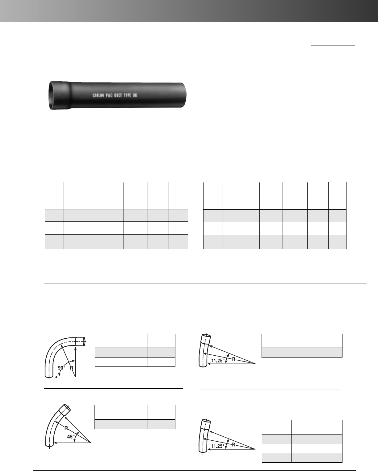
www.carlon.com 195
P&C®Duct – Special California Type DB-100
Carlon Special California Rigid Nonmetallic
DB-100 P&C
®
Duct & Sweeps
Carlon DB-100 nonmetallic P&C Duct Type DB is
manufactured to
NEMA Standard TC-6 & 8 and
to
specifications that exist within the State of California,
and is designed for use in direct burial or concrete
encased installations. Rated for use with 90°C cable.
Std. Ctn.
Part No.Size Qty.
PE9HN 4" 1
PE9HP 5" 1
90° Sweep – 48" Radius
Std. Ctn.
Part No. Size Qty.
PE7SP 5" 1
Std. Ctn.
Part No. Size Qty.
PE3SP 5" 1
45° Sweep – 150" Radius
11
1
/
4
° Sweep – 150" Radius
Std. Ctn.
Part No. Size Qty.
PE3SNS 4" 1
PE3SPS 5" 1
PE3SRS 6" 1
11
1
/
4
° Sweep – 150" Radius
(Segmented sweeps)
P&C Duct Type DB-100
Meets NEMA Standard TC-6 & 8
and ASTM F-512
Approx.
Std.
Wt.
Nom. Part Crate per *Min.
Size Number Qty. 100 ft. O.D. Wall
4 68915-020 1,140 154 4.500 .155
5 68916-020 760 237 5.563 .192
6 68917-020 520 337 6.625 .229
P&C Duct Type DB-100
DWP Approved
Meets NEMA Standard TC-6 & 8
and ASTM F-512
Approx.
Std.
Wt.
Nom. Part Crate per *Min.
Size Number Qty. 100 ft. O.D. Wall
3 68913D-020 2,000 95 4.500 .155
4 68915D-020 1,140 156 5.563 .192
5 68916D-020 760 237 6.625 .229
*Min. wall thickness relates to 500,000 modulus
Note: One belled end per 20' length
*Min. wall thickness relates to 500,000 modulus
DB-100 Sweeps – Belled
*Consult factory for additional sizes
RUS Listed
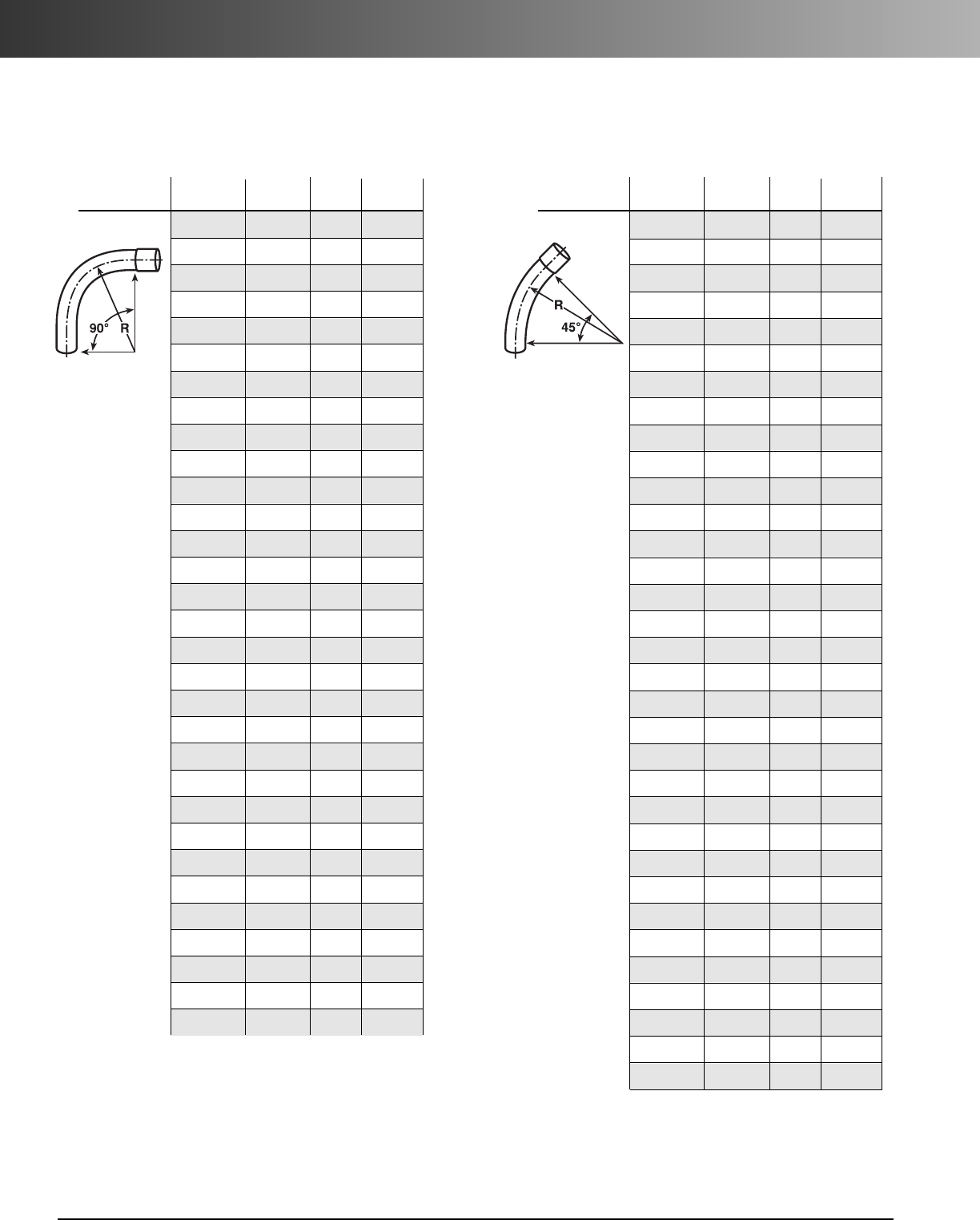
www.carlon.com
196
P&C®Duct – DB-60 Sweeps
DB-60 Sweeps
*Consult factory for additional sizes/configurations
Radius Std.
Segment Part No. Size (in.) Ctn. Qty.
90° Sweep PF9CH 11/2" 18" 1
PF9CJ 2" 18" 1
PF9CL 3" 18" 1
PF9CN 4" 18" 1
PF9DF 1" 24" 1
PF9DH 11/2" 24" 1
PF9DJ 2" 24" 1
PF9DL 3" 24" 1
PF9DN 4" 24" 1
PF9DP 5" 24" 1
PF9FF 1" 36" 1
PF9FJ 2" 36" 1
PF9FL 3" 36" 1
PF9FN 4" 36" 1
PF9FP 5" 36" 1
PF9FR 6" 36" 1
PF9HL 3" 48" 1
PF9HN 4" 48" 1
PF9HP 5" 48" 1
PF9HR 6" 48" 1
PF9IL 3" 60" 1
PF9IN 4" 60" 1
PF9IP 5" 60" 1
PF9IR 6" 60" 1
PF9SH 11/2" 150" 1
PF9SJ 2" 150" 1
PF9SL 3" 150" 1
PF9SR 6" 150" 1
PF9VL 3" 300" 1
PF9VN 4" 300" 1
PF9VP 5" 300" 1
Radius Std.
Segment Part No. Size (in.) Ctn. Qty.
45° Sweep PF7CF 1" 18" 1
PF7CH 11/2" 18" 1
PF7CJ 2" 18" 1
PF7CL 3" 18" 1
PF7DF 1" 24" 1
PF7DH 11/2" 24" 1
PF7DJ 2" 24" 1
PF7DL 3" 24" 1
PF7DN 4" 24" 1
PF7FF 1" 36" 1
PF7FH 11/2" 36" 1
PF7FJ 2" 36" 1
PF7FL 3" 36" 1
PF7FN 4" 36" 1
PF7FP 5" 36" 1
PF7FR 6" 36" 1
PF7HJ 2" 48" 1
PF7HL 3" 48" 1
PF7HN 4" 48" 1
PF7HP 5" 48" 1
PF7HR 6" 48" 1
PF7IL 3" 60" 1
PF7IP5" 60" 1
PF7NN 4" 120" 1
PF7SH 11/2" 150" 1
PF7SJ 2" 150" 1
PF7SL 3" 150" 1
PF7SN 4" 150" 1
PF7SP 5" 150" 1
PF7SR 6" 150" 1
PF7VN 4" 300" 1
PF7VP 5" 300" 1
PF7VR 6" 300" 1
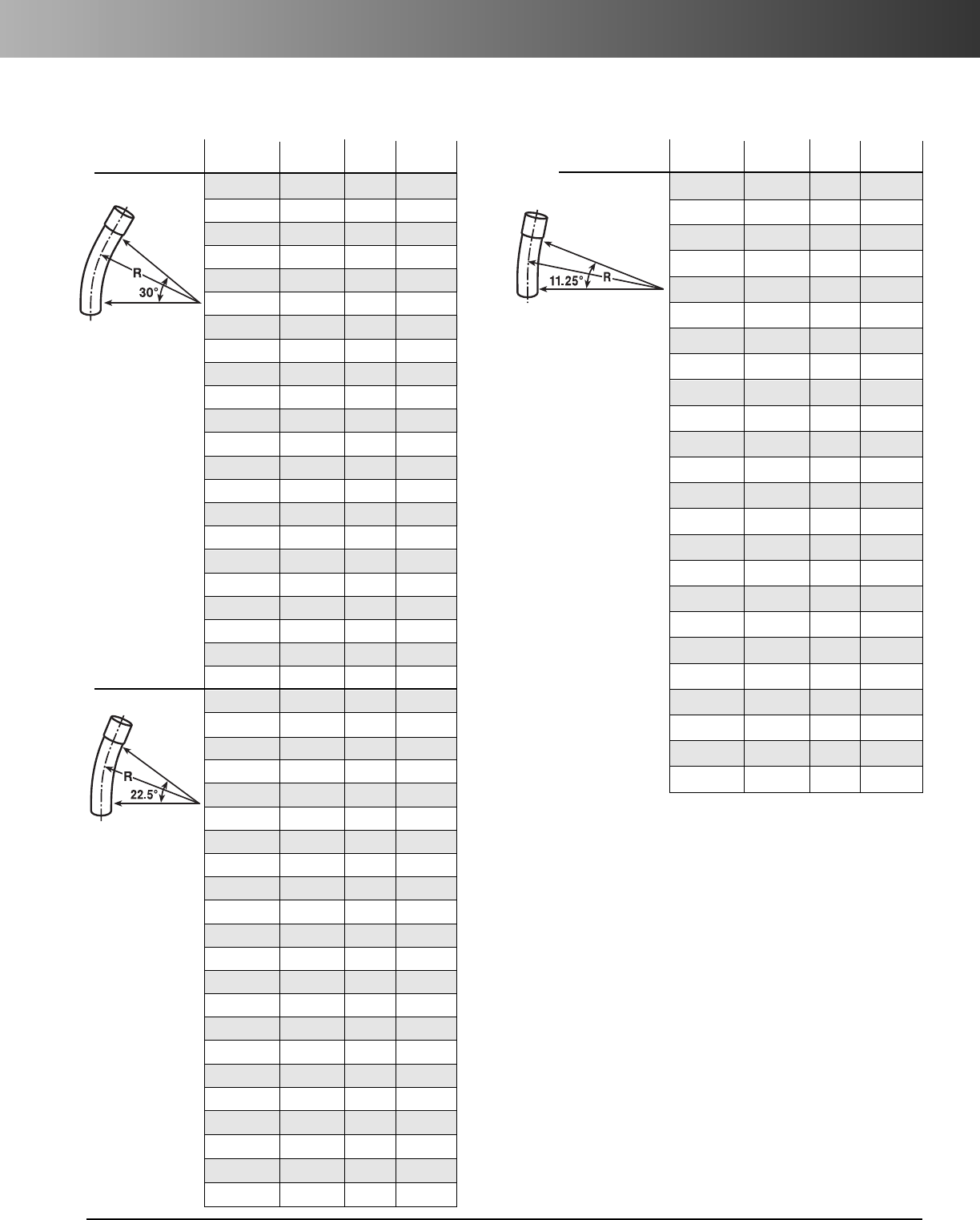
www.carlon.com 197
P&C®Duct – DB-60 Sweeps
DB-60 Sweeps
*Consult factory for additional sizes/configurations
Radius Std.
Segment Part No. Size (in.) Ctn. Qty.
30° Sweep
PF6CJ 2" 18" 1
PF6CL 3" 18" 1
PF6DL 3" 24" 1
PF6DN 4" 24" 1
PF6DP 5" 24" 1
PF6CH 1
1
/
2
" 30" 1
PF6FJ 2" 36" 1
PF6FL 3" 36" 1
PF6FN 4" 36" 1
PF6FR 6" 36" 1
PF6HJ 2" 48" 1
PF6HN 4" 48" 1
PF6HP 5" 48" 1
PF6HR 6" 48" 1
PF6IN 4" 60" 1
PF6IP 5" 60" 1
PF6SJ 2" 150" 1
PF6SN 4" 150" 1
PF6SP 5" 150" 1
PF6VJ 2" 300" 1
PF6VN 4" 300" 1
PF6VR 6" 300" 1
221/2° Sweep PH5DL 3" 24" 1
PF5DN 4" 24" 1
PF5DP 5" 24" 1
PF5FF 1" 36" 1
PF5FL 3" 36" 1
PF5FN 4" 36" 1
PF5FP 5" 36" 1
PF5FR 6" 36" 1
PF5HL 3" 48" 1
PF5HN 4" 48" 1
PF5HR 6" 48" 1
PF5IJ 2" 60" 1
PF5IL 3" 60" 1
PF5IP 5" 60" 1
PF5IR 6" 60" 1
PF5SL 3" 150" 1
PF5SN 4" 150" 1
PF5SP 5" 150" 1
PF5SR 6" 150" 1
PF5VN 4" 300" 1
PF5VP 5" 300" 1
PF5VR 6" 300" 1
Radius Std.
Segment Part No. Size (in.) Ctn. Qty.
111/4° Sweep
PF3CJ 2" 18" 1
PF3CL 3" 18" 1
PF3DF 1" 24" 1
PF3DH 1
1
/
2
" 24" 1
PF3DP 5" 24" 1
PF3FJ 2" 36" 1
PF3FL 3" 36" 1
PF3FN 4" 36" 1
PF3FP 5" 36" 1
PF3FR 6" 36" 1
PF3HL 3" 48" 1
PF3HN 4" 48" 1
PF3HP 5" 48" 1
PF3HR 6" 48" 1
PF3IJ 2" 60" 1
PF3IR 6" 60" 1
PF3SJ 2" 150" 1
PF3SN 4" 150" 1
PF3SP 5" 150" 1
PF3SR 6" 150" 1
PF3VJ 2" 300" 1
PF3VL 3" 300" 1
PF3VN 4" 300" 1
PF3VP 5" 300" 1
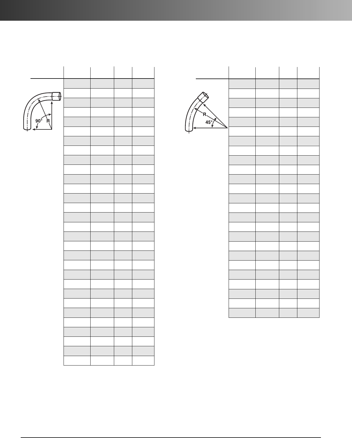
www.carlon.com
198
P&C®Duct – DB-120 Sweeps
DB-120 Sweeps
*Consult factory for additional sizes/configurations
Radius Std.
Segment Part No. Size (in.) Ctn. Qty.
90° Sweep PH9CJ 2" 18" 1
PH9CL 3" 18" 1
PH9CN 4" 18" 1
PH9DJ 2" 24" 1
PH9DL 3" 24" 1
PH9DN 4" 24" 1
PH9DP 5" 24" 1
PH9FJ 2" 36" 1
PH9FL 3" 36" 1
PH9FN 4" 36" 1
PH9FP 5" 36" 1
PH9FR 6" 36" 1
PH9HJ 2" 48" 1
PH9HL 3" 48" 1
PH9HN 4" 48" 1
PH9HP 5" 48" 1
PH9HR 6" 48" 1
PH9IJ 2" 60" 1
PH9IL 3" 60" 1
PH9IN 4" 60" 1
PH9IR 6" 60" 1
PH9OJ 2" 66" 1
PH9SJ 2" 150" 1
PH9SL 3" 150" 1
PH9SN 4" 150" 1
PH9SP 5" 150" 1
PH9SR 6" 150" 1
PH9VN 4" 300" 1
PH9VP 5" 300" 1
PH9VR 6" 300" 1
Radius Std.
Segment Part No. Size (in.) Ctn. Qty.
45° Sweep PH7CJ 2" 18" 1
PH7CL 3" 18" 1
PH7CN 4" 18" 1
PH7DJ 2" 24" 1
PH7DL 3" 24" 1
PH7DN 4" 24" 1
PH7DP 5" 24" 1
PH7FJ 2" 36" 1
PH7FL 3" 36" 1
PH7FN 4" 36" 1
PH7FP 5" 36" 1
PH7FR 6" 36" 1
PH7HJ 2" 48" 1
PH7HL 3" 48" 1
PH7HN 4" 48" 1
PH7HP 5" 48" 1
PH7HR 6" 48" 1
PH7IJ 2" 60" 1
PH7IL 3" 60" 1
PH7IP 5" 60" 1
PH7IR 6" 60" 1
PH7SJ 2" 150" 1
PH7SN 4" 150" 1
PH7SP 5" 150" 1
PH7SR 6" 150" 1
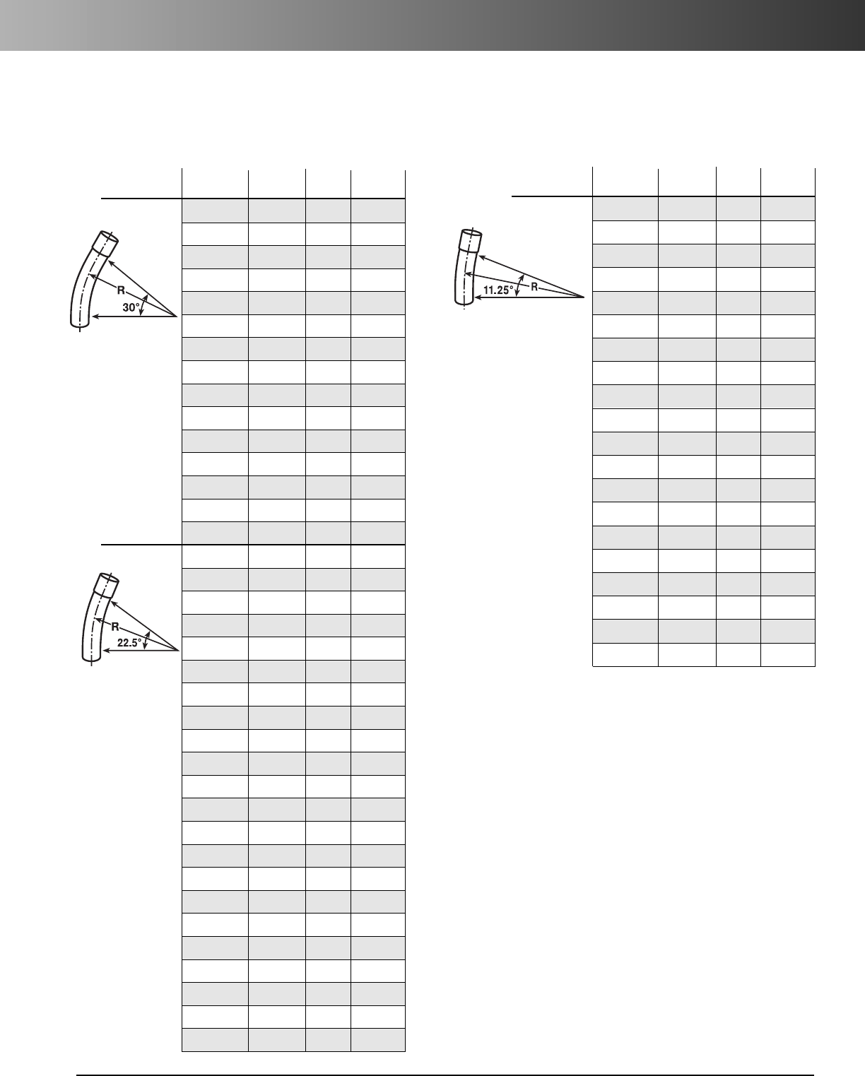
www.carlon.com 199
P&C®Duct – DB-120 Sweeps
Radius Std.
Segment Part No. Size (in.) Ctn. Qty.
30° Sweep
PH6CJ 2" 18" 1
PH6CL 3" 18" 1
PH6CN 4" 18" 1
PH6DJ 2" 24" 1
PH6DN 4" 24" 1
PH6DP 5" 24" 1
PH6FJ 2" 36" 1
PH6FL 3" 36" 1
PH6FN 4" 36" 1
PH6FP 5" 36" 1
PH6FR 6" 36" 1
PH6HN 4" 48" 1
PH6HR 6" 48" 1
PH6IN 4" 60" 1
PH6SL 3" 150" 1
22
1/2
° Sweep
PH5CJ 2" 18" 1
PH5CL 3" 18" 1
PH5CN 4" 18" 1
PH5DJ 2" 24" 1
PH5DL 3" 24" 1
PH5DP 5" 24" 1
PH5FJ 2" 36" 1
PH5FL 3" 36" 1
PH5FN 4" 36" 1
PH5FP 5" 36" 1
PH5HL 3" 48" 1
PH5HN 4" 48" 1
PH5HP 5" 48" 1
PH5HR 6" 48" 1
PH5IJ 2" 60" 1
PH5IL 3" 60" 1
PH5IR 6" 60" 1
PH5SN 4" 150" 1
PH5SP 5" 150" 1
PH5SR 6" 150" 1
PH5VJ 2" 300" 1
PH5VN 4" 300" 1
DB-120 Sweeps
*Consult factory for additional sizes/configurations
Note: For Nom. Diameter of 1": use 1" DB-60 Sweeps
For Nom. Diameter of 1
1
/
2
": use 1
1
/
2
" DB-60 Sweeps
Radius Std.
Segment Part No. Size (in.) Ctn. Qty.
11
1/4
° Sweep
PH3CJ 2" 18" 1
PH3CN 4" 18" 1
PH3DJ 2" 24" 1
PH3DN 4" 24" 1
PH3DP 5" 24" 1
PH3FJ 2" 36" 1
PH3FL 3" 36" 1
PH3FN 4" 36" 1
PH3FP 5" 36" 1
PH3FR 6" 36" 1
PH3HN 4" 48" 1
PH3IN 4" 60" 1
PH3IP 5" 60" 1
PH3IR 6" 60" 1
PH3SJ 2" 150" 1
PH3SL 3" 150" 1
PH3SN 4" 150" 1
PH3SP 5" 150" 1
PH3SR 6" 150" 1
PH3VR 6" 300" 1
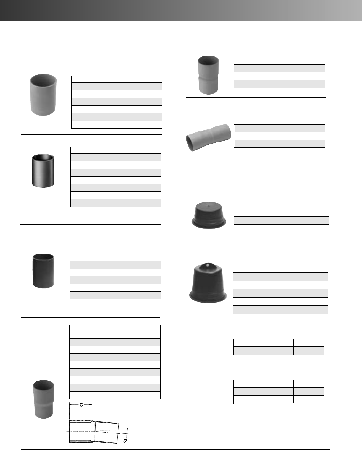
www.carlon.com
200
P&C®Duct Fittings
Part No. Size Std.
Ctn. Qty.
E940H 11/2"25
E940J 2" 30
E940K 21/2"20
E240L 3" 30
E240N 4" 15
E240P 5" 20
E240RF 6" 5
Part No. Size Std.
Ctn. Qty.
E941H 11/2" 40
E941J 2" 25
E941K 21/2"15
E241L 3" 15
E241N 4" 10
Long Line Coupling
*Consult factory for additional sizes
Part No. Size Std.
Ctn. Qty.
E200J 2" 30
E200L 3" 25
E200M 31/2"20
E200N 4" 15
E200P 5" 8
E200R 6" 5
Couplings
(Use same type fittings for Type EB and DB)
Part No. Size Std.
Ctn. Qty.
E2440NF 4" 15
E2440PF 5" 10
E2440RF 6" 5
5° Angle Coupling BxB
(Bell x Bell)
Std.
Part No. Size C
Ctn. Qty.
E244J 2" 2.13 15
E244L 3" 3.25 5
E244NF 4" 3.50 15
E244NF5 (short) 4" 1.87 25
E244PF 5" 4.13 10
E244PF5 (short) 5" 2.00 20
E244RF 6" 5.13 5
E244RF5 (short) 6" 2.25 10
5° Angle
Coupling
BxS
(Bell x Spigot)
Part Std.
No. Size
Ctn. Qty.
P258H 11/2" 50
P258K 21/2"50
Plug
Part Std.
No. Size
Ctn. Qty.
P258JT 2" 60
P258LT 3" 30
P258NT 4" 48
P258PT 5" 30
P258RT 6" 30
Plug with Pull Tab
Part No. Size Std.
Ctn. Qty.
E245J 2" 20
E245N 4" 10
E245P 5" 10
E245R 6" 5
5° Angle Coupling BxB (Swedged)
Plugs
Coupling
Sleeve Coupling (for repair work)
No internal stop
Part No. Size Std.
Ctn. Qty.
E242J 2" 48
Swedge Coupling
Part No. Size Std.
Ctn. Qty.
E2440N5 4" 15
E2440P5 5" 20
5° Angle Coupling S x S
*Sizes 1
1
/
2
"- 2
1
/
2
" order part numbers E940_
*Sizes 1
1
/
2
"- 2
1
/
2
" order part numbers E941_
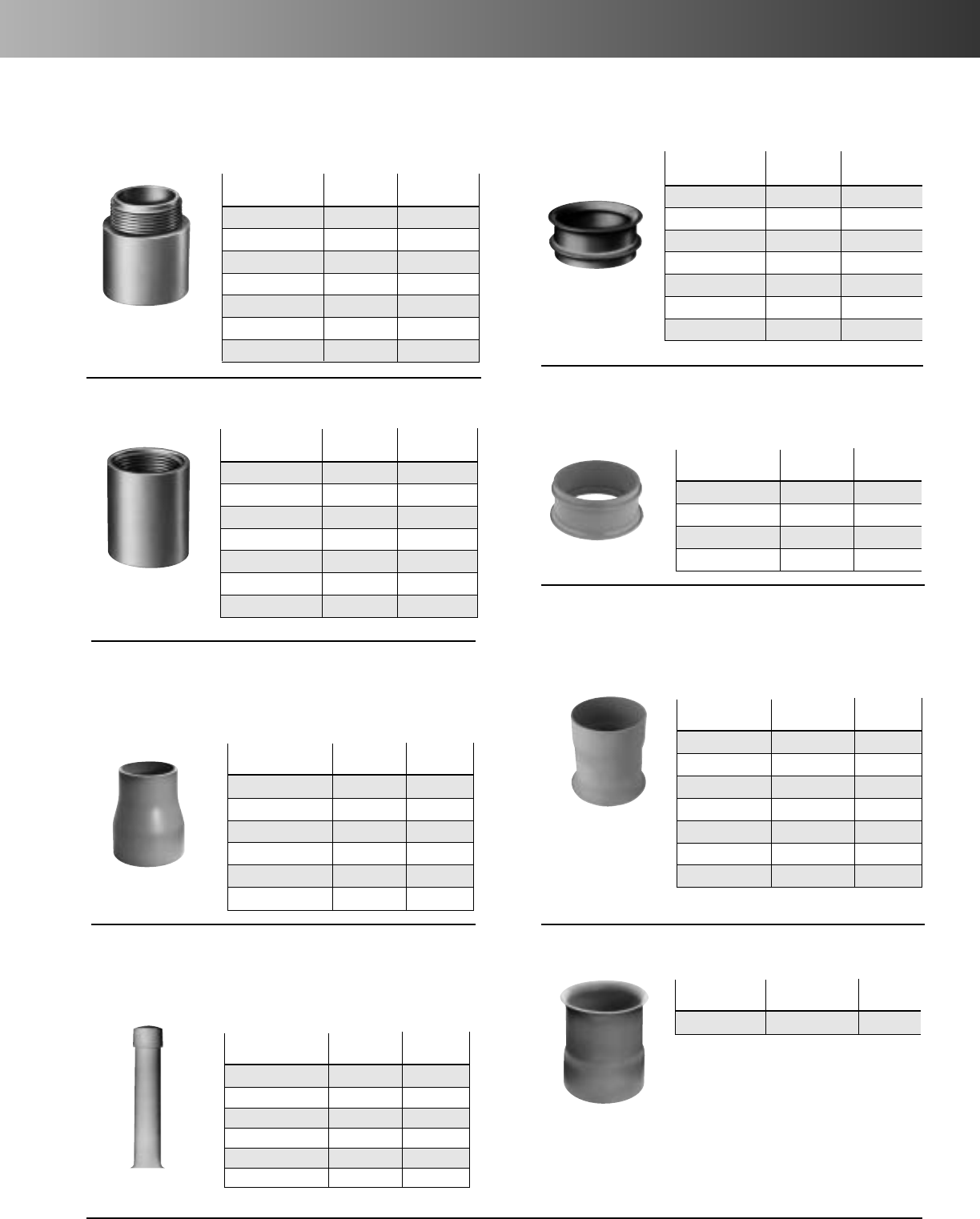
www.carlon.com 201
P&C®Duct Fittings
Part Std.
No. Size
Ctn. Qty.
E943F 1" 50
E943H 11/2"25
E943J 2" 50
E943L-CAR 3" 5
E943N-CAR 4" 5
E943P 5" 5
E943R 6" 10
Male Adapter
Part Std.
No. Size
Ctn. Qty.
E942F 1" 50
E942H 11/2"25
E942J 2" 30
E942L-CAR 3" 3
E942N-CAR 4" 7
E942P 5" 8
E942R 6" 6
Female Adapter
Part Std.
No. Size
Ctn. Qty.
E997F-CAR 1" 15
E997H-CAR 11/2"10
E997J-CAR 2" 10
E997L-CAR 3" 10
E997N 4" 30
E997P 5" 15
E997R 6" 10
End Bell
Part Std.
No. Size
Ctn. Qty.
E297J 2" 40
E297L 3" 50
E297N 4" 30
E297P 5" 15
Molded End Bell
(For use with P&C Duct only)
Part Std.
No. Size
Ctn. Qty.
E297JN 2" x 4" 25
E297LR 3" x 6" 20
E297NT 4" x 10" 15
E297PS 5" x 8" 10
E297PT 5" x 10" 10
E297RF 6" x 5" 10
E297RT 6" x 10" 6
Fabricated End Bell
(For use with P&C Duct only)
*Consult factory for additional sizes
Part Std.
No. Size
Ctn. Qty.
E252LJ 3"x 2" 50
E252NJS 4"x 2" 25
E252NL 4"x 3" 25
E252PN 5"x 4" 20
E252RNS 6"x 4" 6
E252RP 6"x 5" 10
Swedge Reducer (Male x Male)
Part Std.
No.Size
Ctn. Qty.
E297RR 6"(6" long) 10
Long Length End Bell P&C Duct
Part Std.
No. Size
Ctn. Qty.
E299JM 2" x 42" 1
E299JP 2" x 56" 1
E299JR 2" x 78" 1
E299LF 3" x 36" 1
E299LR 3" x 60" 1
E299NX7 4" x 84" 1
Cable Marker
Adapters
Reducers
End Bells
Markers
Note: for manhole terminations
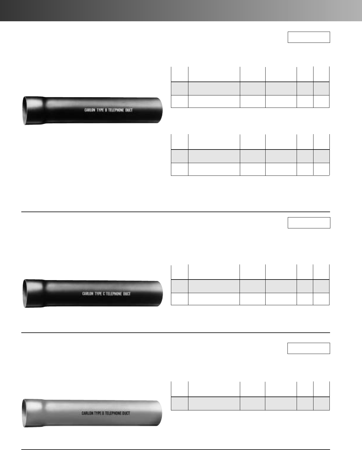
www.carlon.com
202
Telephone Duct – Type B, C & D
Telephone Duct Type B
Carlon®Telephone Duct Type B is designed for use in
concrete encased installations. Type B duct meets the
requirements of NEMA TC-10 and conforms to Bellcore
CAO8546.
Telephone Duct Type B
Nom. Part Std.
Approx. Wt.
*Min.
Size Number Crate Qty. per 100 ft. O.D. Wall
4" 68315-020 (Grey) 1260 100 4.350 .090
4" 68315W-020 (White) 1260 100 4.350 .095
Telephone Duct Type D
Nom. Part Std.
Approx. Wt.
*Min.
Size Number Crate Qty. per 100 ft. O.D. Wall
4" 68615-020 (White) 1260 150 4.350 .160
Telephone Duct Type B Heavy Wall
Nom. Part Std.
Approx. Wt.
*Min.
Size Number Crate Qty. per 100 ft. O.D. Wall
4" 68415-020 (Grey) 1260 100 4.350 .100
4" 68415W-020 (White) 1260 100 4.350 .100
* Estimated min. wall to meet performance criteria (500,000 modulus
compound
NOTE:
One Belled End per 20' length (for concrete encasement only)
Telephone Duct Type C
Carlon®Telephone Duct Type C is designed for direct bur-
ial or concrete encased applications. Type C duct complies
with NEMA Standard TC-10 and Bellcore CAO8546.
Telephone Duct Type C
One belled end per 20' length
Nom. Part Std.
Approx. Wt.
*Min.
Size Number Crate Qty. per 100 ft. O.D. Wall
4" 68515-020 (Grey) 1260 151 4.350 .150
4" 68515W-020 (White) 1260 151 4.350 .150
* Estimated min. wall to meet performance criteria
Telephone Duct Type D
White Only (Carlon®Telephone Duct Type D is designed
to be used in exposed applications.)
* Estimated min. wall to meet performance criteria
RUS Listed
RUS Listed
RUS Listed
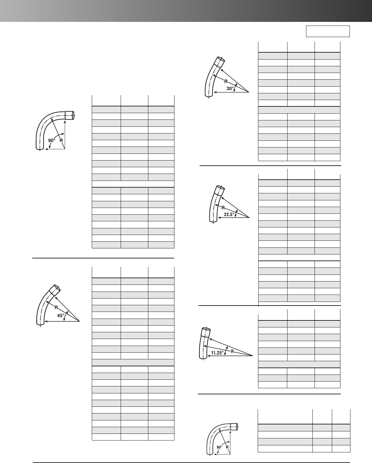
www.carlon.com 203
Telephone Duct Sweeps
Telephone Duct Sweeps Manufactured
from Heavy Wall “C” Duct
• Size: 4 inches.
• Each sweep is furnished with a belled end.
• Straight end length 3".
E-Bends – Riser Ells
Part No. Bend Std. Ctn.
(Gray) Radius Qty.
TP9CN 1'6" 1
TP9DN 2' 1
TP9FN 3' 1
TP9HN 4' 1
TP9IN 5' 1
TP9JN 6' 1
TP9MN 9' 1
TP9NN 10' 1
TP9SN 12'6" 1
TP9TN 15' 1
TP9UN 20' 1
(White):
TW9DN 2' 1
TW9FN 3' 1
TW9HN 4' 1
TW9IN 5' 1
TW9JN 6' 1
TW9MN 9' 1
TW9NN 10' 1
TW9SN 12'6" 1
TW9TN 15' 1
90° Sweep
Part No. Bend Std. Ctn.
(Gray) Radius Qty.
TP5DN 2' 1
TP5FN 3' 1
TP5HN 4' 1
TP5IN 5' 1
TP5JN 6' 1
TP5MN 9' 1
TP5RN 12' 1
TP5SN 12'6" 1
TP5TN 15' 1
TP5UN 20' 1
TP5VN 25' 1
(White):
TW5DN 2' 1
TW5FN 3' 1
TW5HN 4' 1
TW5JN 6' 1
TW5MN 9' 1
TW5SN 12'6" 1
22
1
/
2
° Sweep
Part No. Bend Std. Ctn.
Gray Radius Qty.
TP6FN 3' 1
TP6HN 4' 1
TP6JN 6' 1
TP6NN 10' 1
TP6RN 12' 1
TP6SN 12'6" 1
TP6TN 15' 1
(White):
TW6FN 3' 1
TW6HN 4' 1
TW6JN 6' 1
TW6MN 9' 1
TW6NN 10' 1
TW6RN 12' 1
TW6SN 12'6" 1
TW6TN 15' 1
30° Sweep
Part No. Bend Std. Ctn.
(Gray) Radius Qty.
TP3DN 2' 1
TP3FN 3' 1
TP3HN 4' 1
TP3IN 5' 1
TP3JN 6' 1
TP3SN 12'6" 1
(White):
TW3DN 2' 1
TW3FN 3' 1
TW3HN 4' 1
11
1
/
4
° Sweep
Std.
Part No. Bend Ctn.
(Gray Only) Radius Qty.
TA9ENT (Belled End) 2' 6" 1
TA9FN (Plain End) 3' 1
TA9FNT (Belled End) 3' 1
TA9FNTL (Belled End-Long) 3' 1
90° Sweep
Part No. Bend Std. Ctn.
(Gray) Radius Qty.
TP7DN 2' 1
TP7FN 3' 1
TP7HN 4' 1
TP7ON 4'6" 1
TP7IN 5' 1
TP7JN 6' 1
TP7MN 9' 1
TP7NN 10' 1
TP7RN 12' 1
TP7SN 12'6" 1
TP7TN 15' 1
TP7UN 20' 1
(White):
TW7DN 2' 1
TW7FN 3' 1
TW7HN 4' 1
TW7ON 4'6" 1
TW7IN 5' 1
TW7JN 6' 1
TW7MN 9' 1
TW7NN 10' 1
TW7RN 12' 1
TW7SN 12'6" 1
TW7TN 15' 1
45° Sweep
RUS Listed
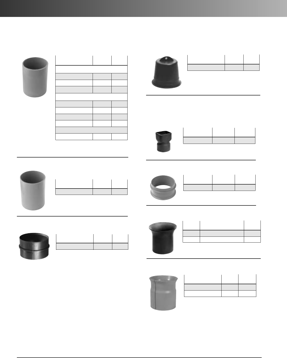
www.carlon.com
204
Telephone Duct Fittings & Accessories
Internal Stop
Part Std.
No. Size
Ctn. Qty.
E908N 4" 25
Molded Coupling
Part Std.
No. Size
Ctn. Qty.
E914N 4" 15
5° Angle Coupling
Part Std.
No. Size
Ctn. Qty.
For Repair Work:
E900N 4"x 6" 25
E900NU 4"x 12" 10
E900NW (White) 4"x 6" 25
Split Sleeve Couplings:
E900NS 4" 25
E900NS8 (White) 4"x 8" 15
E900NSW (White) 4" 25
E900PS 5" 15
For Type D Duct Applications Only:
E900DN (White) 4" 25
Part Std.
No. Size
Ctn. Qty.
P258 NTB 4" 50
Plug with Pull Tab
Part Std.
No. Size
Ctn. Qty.
E903N 4" Sq. 4
Square to Round
Part Std.
No. Size
Ctn. Qty.
E917N 4" 10
Molded End Bell
Part Std.
No. Size
Ctn. Qty.
E907N 4" (5" long, 5.5" flare) 10
E907NY 4" (9" long, 5.75" flare) 1
Straight End Bell
Plugs
End Bells
Couplings
Part Std.
No. Size
Ctn. Qty.
E9098NS 4" 1
E9098PS 5" 1
Split End Bell (PVC)
(Designed for use with a coupling.)
Sleeve Coupling
No internal stop
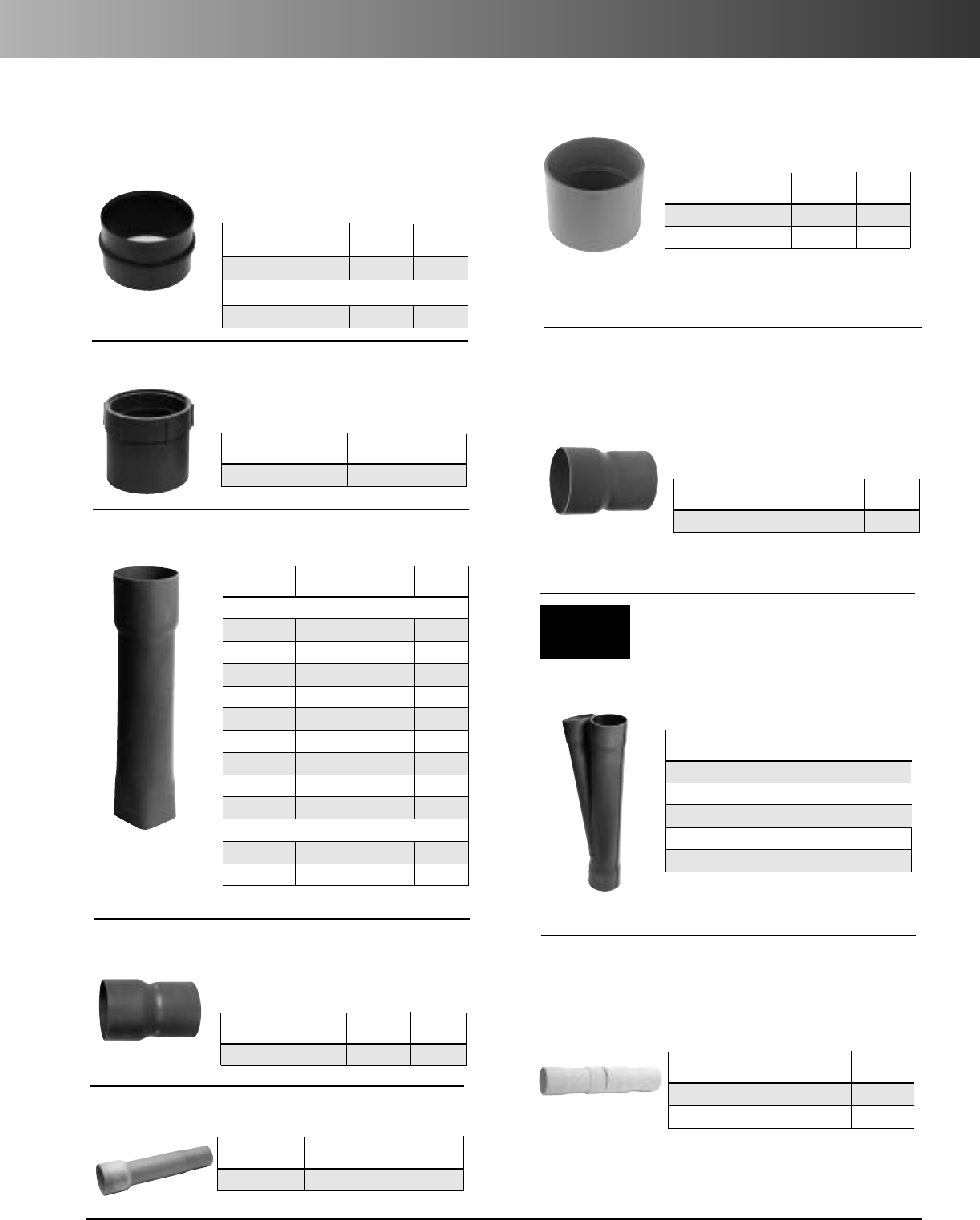
www.carlon.com 205
Telephone Duct Fittings & Accessories
Adapts Telephone Duct to Fiber
Transite MCD
Part Std.
No. Size
Ctn. Qty.
E901N 4" 24
Split:
E901NS 4" 24
Internal Adapter
Adapts threaded metal pipe to
Telephone Duct
Part Std.
No. Size
Ctn. Qty.
E902N 4" 10
Female Adapter
Adapts Telephone Duct to Cast Iron
Bends
Part Std.
No. Size
Ctn. Qty.
E906N 4" 1
Cast Iron Adapter
Adapts Telephone Duct to
P&C Duct (IPS)
Part Std.
No. Size
Ctn. Qty.
E908NM 4" to 31/2" 15
P&C Duct
®
Reducer
Square Clay Tile Adapter
Adapts Telephone Duct to
P&C Duct (IPS)
Part Std.
No. Size
Ctn. Qty.
E913N 4" 15
E913NF 4" 15
P&C Duct
®
Adapter
For starting lateral runs:
Part Std.
No. Size
Ctn. Qty.
E916N 4" 1
E916NW (White) 4" 1
Split:
E916NS 4" 1
E916NSW (White) 4" 5
Wye Branch
Part Std.
No. Size
Ctn. Qty.
E923NM 4" to 31/4"10
Round Clay Tile Adapter
Part Std.
No. Size
Ctn. Qty.
E905N 4" 5
E905NL (Long) 4" 1
Expansion Joint - Type D
Reducers
Adapters
Wyes
Expansion Joints
Part Std.
No. Size
Ctn. Qty.
Adapts Clay to Telephone Duct:
E904M 31/4" to 4"x 18" 10
E904M12 31/4" to 4"x 12" 10
E904M8 31/4" to 4"x 81/2" 12
E904MM 31/2" to 31/2"x 18" 12
E904MX 3" to 4"x 18" 10
E904N 31/2" to 4"x 18" 10
E904N12 31/2" to 4"x 12" 12
E904N24 31/2" to 4"x 24" 10
E904N8 31/2" to 4"x 8" 10
Split Square Adapter:
E904MS 31/4" x 4" 10
E904NS 31/2" to 4"x 18" 10
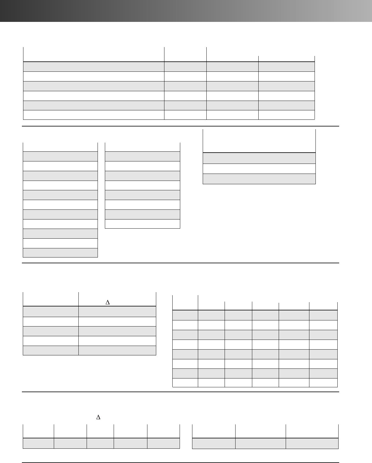
www.carlon.com
206
P&C®Duct and Telephone Duct – Specification
Physical Properties of P&C
®
Duct by ASTM Test Methods
Typical Values
Property ASTM No. P&C®Duct Telephone Duct
Tensile strength, psi D638 4,800 4,800
Modulus of elasticity in tension, psi D638 500,000 500,000
Flexural strength, psi D790 11,000 11,000
Deflection temp under load at 265 psi deg. C D648 72°C 72°C
Coefficient of thermal expansion in/in/°F D696 3.30 x 10⁻⁵ 3.30 x 10⁻⁵
Coefficient of static friction .20 .20
Minimum Impact Resistance at 0°C (32°F) ft •lbf
Nominal Conduit Series
Size EB-20 EB-35 DB-60 DB-100 DB-120
1––– – 10
11/2– – 10 – 15
2 20 20 20 – 25
3 20 30 40 45 50
31/220 35 50 60 65
425 40 60 70 80
5 30 55 85 100 110
6 40 75 120 135 150
Performance Properties of P&C Duct as Indicated per NEMA Standard TC-6 & 8 and ASTM F-512
Pipe Stiffness lb/in/in
Minimum Pipe Stiffness
Conduit Series (F/ y), all sizes
EB-20 20
EB-35 35
DB-60 60
DB-100 100
DB-120 120
Minimum Impact Resistance at 32°C
B-Duct C-Duct D-Duct
ft. lb. ft. lb. ft. lb.
25 50 50
Performance Properties of Telephone Duct as Indicated per NEMA Standard TC-10
Pipe Stiffness F/ y lb/in/in
Nominal
Size B-Duct HWB C-Duct D-Duct
All 30 40 120 120
Collapse Pressure of
Telephone Duct Materials (PSI)
Type B Duct – 9.2
Type C Duct – 36.6
Type D Duct – 36.6
2" EB-20 – 11.2
2" EB-35 – 11.2
2" DB-60 – 11.2
2" DB-120 – 26.6
3" EB-20 – 6.6
3" EB-35 – 8.2
3" DB-60 – 15.2
3" DB-120 – 34.0
4" EB-20 – 6.7
4" EB-35 – 9.2
4" DB-60 – 17.0
4" DB-120 – 36.6
5" EB-20 – 5.9
5" EB-35 – 10.3
5" DB-60 – 18.9
5" DB-120 – 38.2
6" EB-20 – 6.1
6" EB-35 – 11.2
6" DB-60 – 19.6
6" DB-120 – 38.0
Collapse Pressure of P&C Duct Materials (PSI)

www.carlon.com 207
P&C®Duct and Telephone Duct – Installation
Typical Installation Practices for P&C
®
Duct Type EB
and Telephone Duct Type B
Trenching:
Whenever possible the walls of the trench for P&C Duct should
act as forms for concrete encasement. The trench should be
made no wider than necessary to provide the nominal size
concrete thickness.
Duct Spacing:
Duct spacing, both vertical and horizontal, is accomplished
with the use of Carlon PVC Snap-Loc
®
Spacers.
Recommended interval between spacer assemblies is 8 to 10
feet.
Terminating:
For smooth cable pulling and properly engineered terminations
into manholes, Carlon P&C Duct end bells should be used.
Concrete:
The concrete used with P&C Duct should be 3/8" aggregate
with a nominal compressive strength of 2,500 lbs. per square
inch. The slump should be at the upper end of the range,
preferably 7 to 8 inches.It should have just enough slump to
flow to the bottom of the formation and yet not be so wet as
to cause the ducts to float. In placing concrete around P&C
Duct, adjust the delivery chute so the fall of the concrete into
the trench is minimal. Use a splash board to divert the flow of
concrete away from the trench sides and avoid dislodging soil
and stones.
Pressure Grouting:
This technique is used for ducts in a casing or bored
construction. Hydraulic pressure exceeding 25 psi is
common and thus dictates the use of a P&C Duct Type
DB-120 or a Schedule 40
®
product. (See collapse pressure
chart). Hydraulic pressure from grouting is a function of the
line pressure at the nozzle and back pressure created by
pumping. If the exhaust nozzle isn’t withdrawn properly, the
back pressure will rapidly build and equal the line pressure.
Depending on the type casing and pumping distance, line
pressures will go up to 90 psi.
Hydraulic Pressure:
The primary consideration for duct selection is the height
of the duct bank. Since concrete exerts a force of 1.03 psi
per foot of height, to determine the correct duct selection,
consider the following examples:
1. 16 way duct bank, 5" conduit, 4 x 4 configuration with
3" separation, and 3" concrete cover
Concrete Height – 4 x 5.563" + 4 x 3 =
22.5 + 12" = 34.2"
Hydraulic Pressure – (34.2"/12) x 1.03 = 2.9 psi
In this instance the maximum force on the bottom
ducts would be 2.9 psi, therefore, 5" EB-20 would be a
satisfactory choice.
2. 16 way duct bank, 5" conduit, 8 x 2 configuration with
3" separation, and 3" concrete cover.
Concrete Height – 8 x 5.563" + 8 x 3 =
44.5 + 24" = 68.5"
Hydraulic Pressure — (68.5"/12) x 1.03 = 5.9 psi
In this instance the hydraulic force is equal to the
theoretical collapse pressure of 5" EB-20, therefore,
the use of 5" EB-35 or DB-60 would be a satisfactory
choice.
Another alternative would be to use a sequential
pour technique.Pour approximately 1/2the height,
allow the concrete to set-up, and then pour the
remaining distance. Using this method, 5" EB-20
would be satisfactory, since the hydraulic pressure
has been reduced by 50%.
RUS Listed
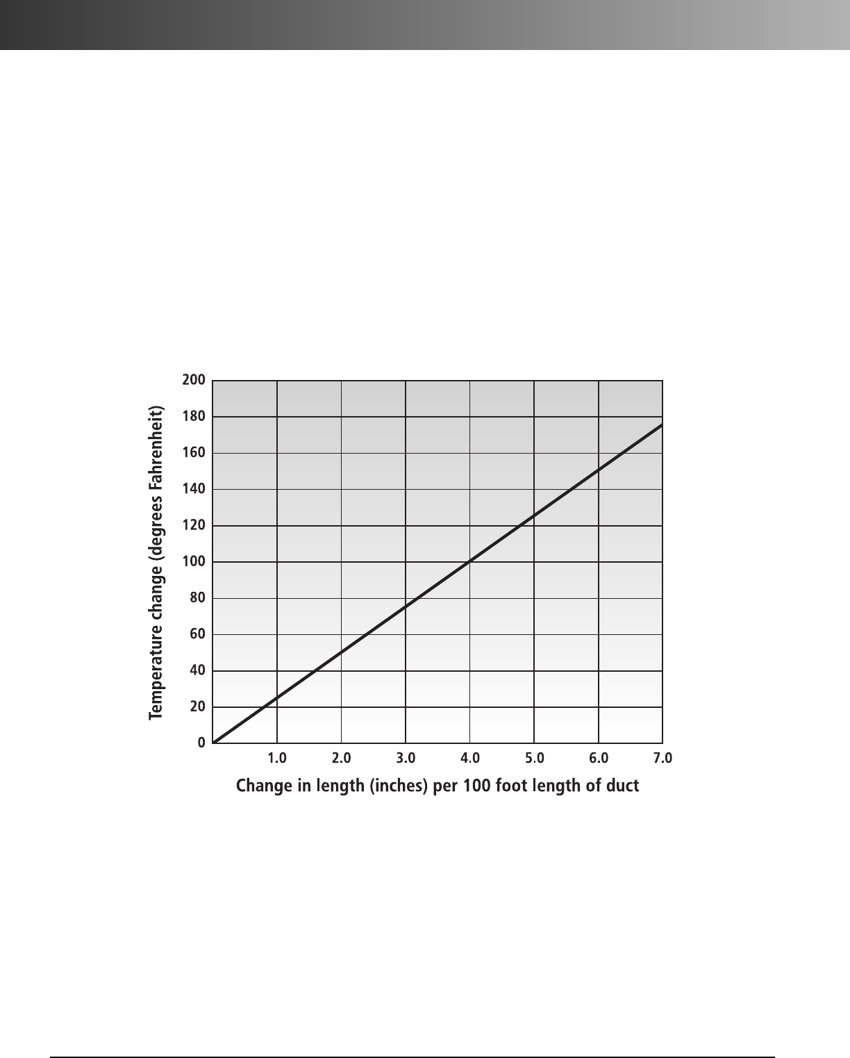
www.carlon.com
208
P&C®Duct and Telephone Duct – Expansion & Contraction
Expansion & Contraction
When duct temperature variations are anticipated during the
installation of Carlon P&C®Duct and Telephone Duct, allow
extra duct footage at each tie-in for contraction. Terminated
duct runs should be covered with backfill from tie-in point
toward the end of the duct run. If the trench must be left
open, don’t terminate the run. All plastic duct may expand
or contract as concrete is poured and cured. When placing
concrete encasement, always encase from one end of the duct
section toward the other end of the section, to allow the free
end to move. Never encase from each end of the section
toward the center.
The coefficient of thermal expansion of Carlon P&C Duct
and Telephone Duct is 3.30 x 10⁻⁵ in/in/°F. The following chart
indicates what expansion or contraction can be expected at
various temperature changes.
Type D Telephone Duct is designated specifically for use
in bridge crossings and exposed applications.Using the
expansion/contraction chart, calculate the number of expan-
sion joints required. Expansion joints provide a 6" allowance
for expansion/contraction. Utilize one expansion
joint for each 100 feet of exposed length for most installations.
The duct should be free to move during expansion/contraction;
the barrel should be securely clamped and the piston should
be aligned properly with the barrel for easy movement.
Bridge Crossings and Exposed Applications
Expansion/Contraction Chart
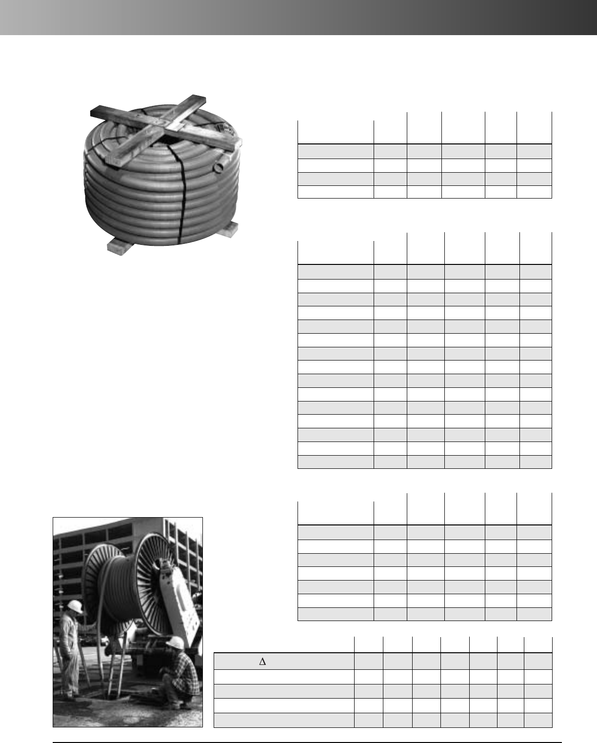
www.carlon.com 209
P&C Flex®
Carlon
®
P&C Flex
®
Corrugated Flexible Conduit
Carlon P&C Flex nonmetallic corrugated flexible conduit
is designed specifically for power and communications
applications when protecting or replacing cable. Produced
to IPS dimensions, Carlon P&C Flex is grey in color and
formulated for sunlight resistance.
The corrugated design of P&C Flex provides maximum
flexibility for easy handling and installation. It is perfect
for a wide range of applications from underground
residential communication raceway to under bridge or
roadway conduit. P&C Flex provides adaptability in the
field since it may be used with existing conduits,
couplings, adapters, end bells and plugs in virtually any
configuration.
• Storage: -4°F to 158°F
• Handling: -4°F to 104°F
Performance Properties
1" 11/4"1
1/2"2"2
1/2" 3" 4"
Stiffness F/ y at 5% deflection 500 200 200 200 130 130 90
Impact Strength (Ft./Lbs.) 72° 40 40 50 50 70 120 140
Impact Strength (Ft./Lbs.) 32° 8 8 15 25 35 60 60
Minimum Bending Radius (inches) 66 7 8 12 15 18
Conduit Tensile Strength 300 400 500 700 1000 1500 2000
Round Wooden Reel
Std. Std. Ctn.
Part Ctn. Wt./Reel
No. Size Qty. (lbs.) I.D. O.D.
11810-250 1 1/2" 250 Ft. 78.5 1.570 1.900
11810T-250 (Tape) 1 1/2" 250 Ft. 110.0 1.570 1.900
11811-250 2" 250 Ft. 129.5 2.045 2.375
11811T-250 (Tape) 2" 250 Ft. 131.5 2.045 2.375
Detectable Tape
Std. Std. Ctn.
Part Ctn. Wt./Reel
No. Size Qty. (lbs.) I.D. O.D.
11808D-2700 1" 2700 ft. 500 1.000 1.315
11808D-5200 1" 5200 ft. 1144 1.000 1.315
11809D-4500 1-1/4" 4500 ft. 927 1.340 1.660
11810D-4500 1-1/2" 4500 ft. 1148 1.570 1.900
11811D-2500 2" 2500 ft. 1005 2.045 2.875
11813D-1200 3" 1200 ft. 1122 3.068 3.500
11815D-800 4" 800 ft. 1007 4.026 4.500
Edge Brace Reel
Std. Std. Ctn.
Part Ctn. Wt./Reel
No. Size Qty. (lbs.) I.D. O.D.
11808-5200 1" 5200 Ft. 1144 1.000 1.315
11809-4500 11/4" 4500 Ft. 927 1.340 1.660
11810-4500 11/2" 4500 Ft. 1148 1.570 1.900
11810T-2300 (Tape) 11/2"2300 Ft. 405 1.570 1.900
11811-700 2" 700 Ft. 280 2.045 2.375
11811-1100 2" 1100 Ft. 270.60 2.045 2.375
11811-2500 2" 2500 Ft. 1005 2.045 2.375
11812-250 21/2" 250 Ft. 172 2.469 2.875
11812AG-001 21/2"1300 Ft. 658 2.469 2.875
11813-250 3" 250 Ft. 248 3.068 3.500
11813-500 3" 500 Ft. 193 3.068 3.500
11813-750 3" 750 Ft. 724 3.068 3.500
11813-1200 3" 1200 Ft. 1122 3.068 3.500
11815-250 4" 250 Ft. 323.5 4.026 4.500
11815-800 4" 800 Ft. 811 4.026 4.500
Non-UL Listed
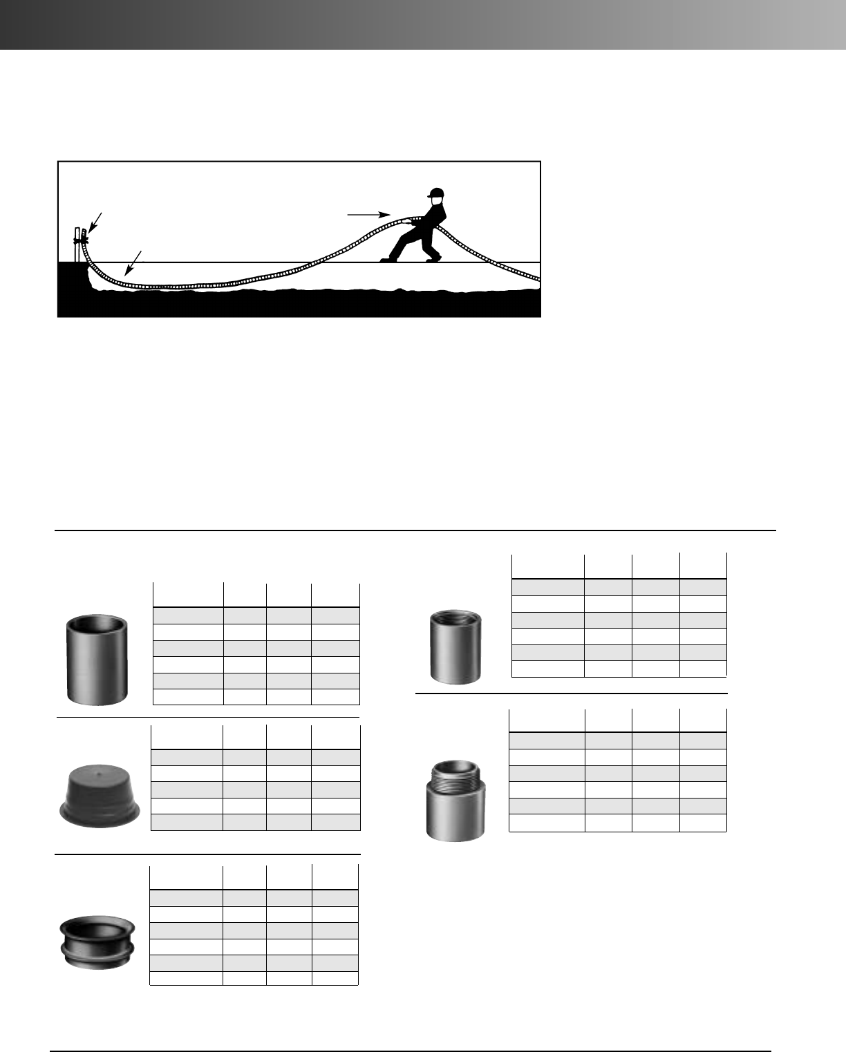
www.carlon.com
210
P&C Flex®Installation & Fittings
Part Std. Std.
Ctn.
No. Size
Ctn. Qty. Wt. (lbs.)
E940H 11/2"25 4
E940J 2" 30 5
E940K-CAR 2 1/2"4 2
E940L-CAR 3" 5 3
E940M 31/2" 20 13
E940N-CAR 4" 5 4
Couplings
Part Std. Std.
Ctn.
No. Size
Ctn. Qty. Wt. (lbs.)
P258H 1
1
/
2
"50 2
P258JT 2" 60 3
P258K 2
1
/
2
"25 2
P258LT 3" 30 3
P258NT 4" 48 8
Plugs
1. Trenching
Trench should be graded true and free from stones or soft
spots. Backfill should also be free of stones and be firmly
tamped around the sides of the conduit, to develop maximum
supporting strength. Tamping on top of the conduit is not
recommended.
2.Backfill
In rocky soil where it is impossible to have an even trench
bottom, a selected backfill should be put in before laying the
conduit. Selected backfill (not tamped) at least 6" over the
top of the conduit is recommended. After
final backfill is placed, taming may be used
to finish the grade.
3. Duct Placement
Duct may be unreeled directly into trench or
along side trench and subsequently placed
in trench. After placing in trench, secure one
end and stretch it by hand to take up the
slack. Spot backfill to hold in position. Do
not use mechanical stretching equipment.
4. Changes in Direction
Avoid unnecessary turns, dips, or changes in direction. Keep bends as gradual
as possible to assure ease of cable pull-in after duct installation.
5. Pneumatic Rodding
All commonly used vacuum or pressure can be used to rod P&C Flex. The line
carrier (mouse, puck, rocket) should be soft, flexible material designed to fit
snugly into duct without interference.
6. Mechanical Rodding
All commonly used mechanical rodding equipment can be used to rod P&C
Flex. The tip should have a ball-type arrangement to keep rod from catching in
the convolutions on the inside of duct.
P&C Flex
®
Conduit Fittings
Part Std. Std.
Ctn.
No. Size
Ctn. Qty. Wt. (lbs.)
E997H-CAR 11/2" 10 .9
E997J-CAR 2" 10 1.2
E997K-CAR 21/2"10 1.9
E997L-CAR 3" 10 2.1
E997M 31/2" 40 10.2
E997N 4" 30 10.7
Bell Ends
(Schedule 40)
Part Std. Std.
Ctn.
No. Size
Ctn. Qty. Wt. (lbs.)
E942H 11/2"25 3
E942J 2" 30 6
E942K-CAR 21/2" 4 1.4
E942L-CAR 3" 3 1.5
E942M 31/2"20 12
E942N-CAR 4" 7 5
Female
Adapters
Part Std. Std.
Ctn.
No. Size
Ctn. Qty. Wt. (lbs.)
E943H 11/2"25 3
E943J 2" 57
E943K-CAR 21/2" 5 1.2
E943L-CAR 3" 5 2
E943M 31/2"30 14
E943N-CAR 4" 5 3
Terminal
Adapters
P&C Flex
®
Corrugated Flexible Conduit Installation
Techniques
STRETCH DUCT IN ONE DIRECTION
AWAY FROM SECURED END
SPOT BACKFILL
KEEP BENDS AS GRADUAL
AS POSSIBLE
SECURE END
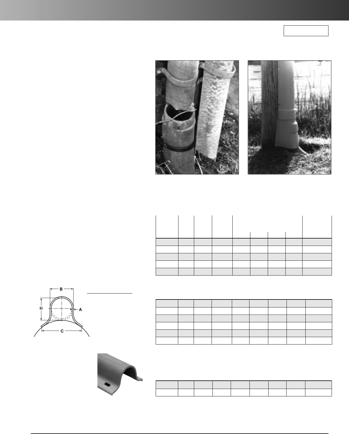
www.carlon.com 211
PV-Mold®
Carlon
®
PV-Mold
®
Nonmetallic Pole Riser System
RUS Listed
Carlon PV-Mold is a nonmetallic pole riser
system designed to protect communications
power cable installed on poles.
Features:
• Meets or exceeds requirements outlined
in the National Electric Safety Code
(NESC).
• Designed in accordance with NEMA
TC-19 specifications.
• Ultraviolet, cold temperature and
corrosive atmosphere resistant.
• Schedule 40 wall meets Schedule 80 PVC
conduit impact requirements per NEMA
TC-19.
• No grounding required.
• Belled end fits over each added section
or conduit.
• Flame retardant.
• Requires no maintenance.
• PV-Mold acts as an insulator against
electrical shock.
• Interchangeable parts and accessories to
match the needs of specific requirements.
Steel U-Guard requires
grounding strapping and
does not have belled ends.
PV-Mold has belled ends, flanged
design and does not require
grounding.
Flanged Overall Length
10 Feet, Including Bell
Size Depth of Bell
1" 2 - 21/4"
11/2" 2 - 21/4"
2" 2 - 21/4"
3" 3 - 31/4"
4" 4 - 41/4"
5" 4 - 41/2"
6" 5 - 51/2"
Slots are 1/2" from side to side,
and allow for expansion and
contraction.
Slot Dimensions: for sizes 2"
through 6" are 5/16" wide, 3/4"
long.
Slot Dimensions: for 1" and
11/2" are 3/16" wide, 3/4" long.
Slot Spacing: 18" from center,
beginning 6" from end.
Actual Impact
Std. Std. @ 0˚C
Part Ctn. Ctn. Dimensions 20 Pound
No. Size Qty.
Wt. (lbs.)
ABCH Tup
59208N 1" 294 1059 0.100" 15/8"2
3/8"1
5/8" 40 Ft.-Lbs.
59211N 2" 136 726 0.100" 23/8" 41/2" 23/8"100 Ft.-Lbs.
59213N 3" 66 761 0.150" 31/2"6"3
1/2" 110 Ft.-Lbs.
59215N 4" 65 910 0.150" 41/2" 61/2" 41/2"110 Ft.-Lbs.
59216N 5" 30 515 0.150" 51/2" 71/2" 51/2"110 Ft.-Lbs.
Standard Duty
59411N 2" 136 1549 0.218" 23/8"41/2"23/8"300 Ft.-Lbs.
59413N 3" 66 1495 0.300" 31/2"6" 31/2"525 Ft.-Lbs.
Extra Heavy Duty Schedule 80
59010N 11/2" 200 1142 0.145" 129/32"3
1/2"1
29/32" 100 Ft.-Lbs.
59011N 2" 136 1214 0.154" 2 3/8"4
1/2"2
3/8" 150 Ft.-Lbs.
59013N 3" 66 937 0.216" 31/2"6"3
9/32" 150 Ft.-Lbs.
59015N 4" 65 1621 0.237" 41/2"6
1/2"4
1/2" 260 Ft.-Lbs.
59016N 5" 30 870 0.258" 51/2"7
1/2"5
1/2" 260 Ft.-Lbs.
59017N 6" 30 1160 0.280" 65/8"8
3/4"6
5/8" 260 Ft.-Lbs.
Heavy Duty Schedule 40
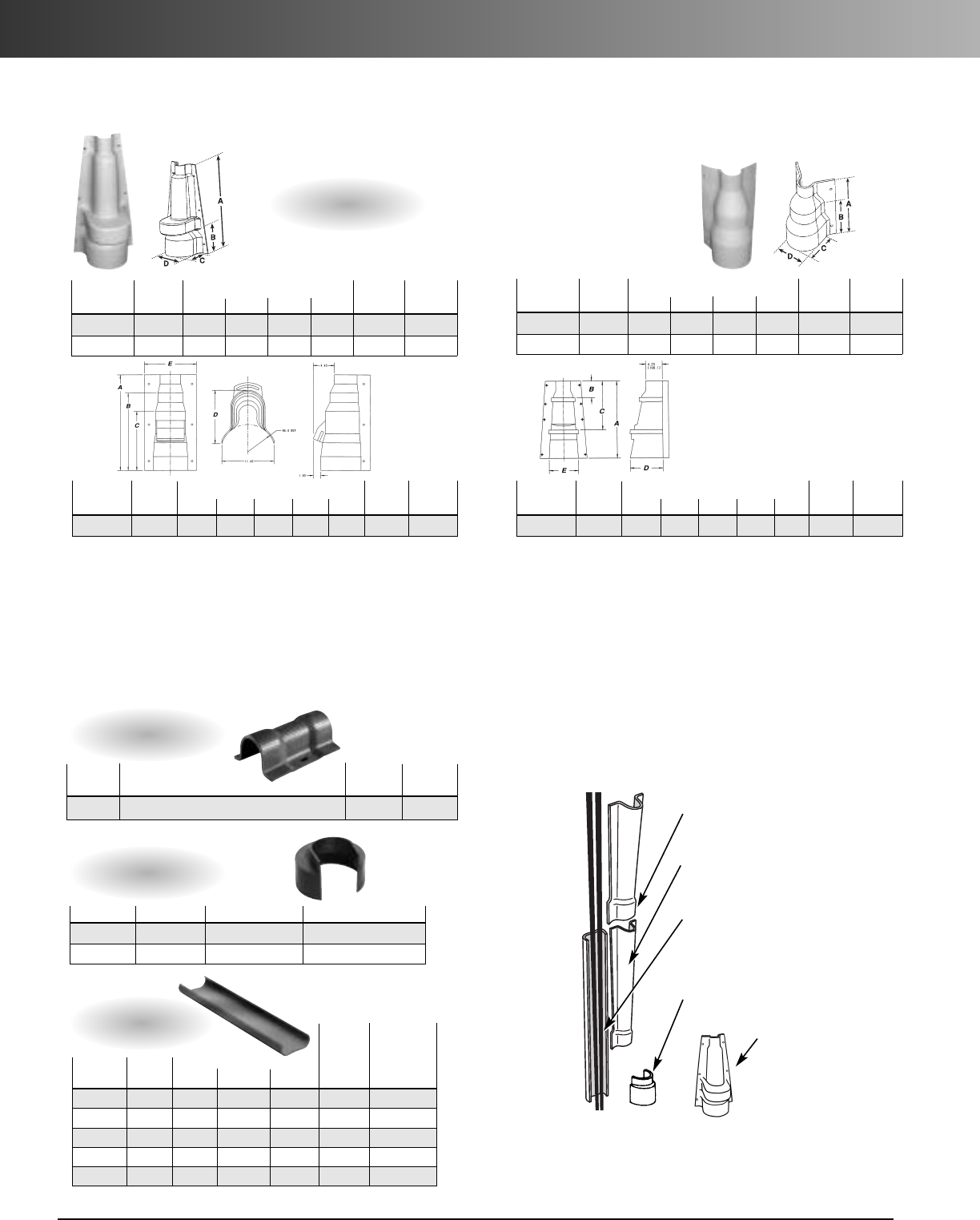
www.carlon.com
212
PV-Mold®Installation & Fittings
PV-Mold
®
System Accessories
Polyethylene Vented Boots and Adapters
Installation is easy with PV-Mold pole risers:
1. Install ventilator or duct to riser fittings at the base of the pole.
2. Nail backing plate sections to the surface of the pole.
Three nail holes are provided in each section. Place the “U”
sections over the cable and backing plate, with belled end at
the bottom, and attach using
1
/
4
" lag bolts.
Flanged
Exclusive Bell End
For easy and quick installation.
(No additional coupler required.)
10' Lengths
Safe and light for easy handling during
installation.
Backing Plate
Provides cable isolation from the pole.
Two Riser Fittings Available
Duct to riser fitting
Adapts duct to PV-Mold.
Ventilator Fitting
Used for a “chimney”
effect to cool cable and
increase ampacity.
Part No. Size Std. Ctn. Qty. Std. Ctn. Wt. (lbs.)
E939NL 4" x 3" 15 5.6
E939N 4" x 4" 15 5.3
Duct to Riser Fitting
Part Std. Ctn. Std.
Ctn
No. Size/Description Qty.
Wt.(lbs.)
E966JJ
2"x 2" Sch. 80 Double Belled Coupling
10 9
Couplings
Std.
Std. Ctn.
Part Dimensions Ctn. Wt.
No. Size A B C Qty.(lbs.)
59111 2" 1/16"13/16"2
1/8" 1 1.2
59113 3" 1/16"1
5/16"3
1/8" 1 1.5
59115 4" 1/16"1
5/16"4
1/8" 1 3.0
59116 5" 1/16"1
3/4"5
1/4" 1 3.1
59117 6" 1/16"1
5/8"6
1/16" 1 4.2
Backing
Plate
Part Dimensions Std.Ctn. Std.Ctn.
No. Size A B C D Qty. Wt. (lbs.)
E939JN 2" x 4" 11.00 6.75 5.88 5.07 8 10.57
E939NR 4" x 6" 11.00 6.75 7.08 7.13 6 8.00
Adapters
Part Dimensions
Std.Ctn. Std.Ctn
.
No. Size A B C D E
Qty. Wt. (lbs.)
E939NRT 4" x 6" 19.75 4.25 12.50 8.50 7.40 1 5
Part Dimensions
Std.Ctn. Std.Ctn
.
No. Size A B C D E
Qty. Wt. (lbs.)
E938NRR 4" x 6" 20.87 16.57 12.87 11.68 11.43 1 7
Part Dimensions Std.Ctn. Std.Ctn.
No. Size A B C D Qty. Wt. (lbs.)
E938JR 2" x 6" 20.50 5.38 6.14 6.88 4 13.58
E938NT 4" x 8" 21.00 15.00 11.31 9.76 4 16.67
Vented Boots
Note:
1. A field cut may be needed to accommodate different boot or adapter to Carlon
U-Mold size combinations.
2. Recommendation: 2 sets of mounting holes per boot/fitting. To add mounting holes,
use a 3/8" drill bit and drill out where needed.
3. When 3" or smaller conduit is being used, it’s recommended that the bottom (largest
section) of the boot or adapter section be buried 2" to 3" below ground surface.
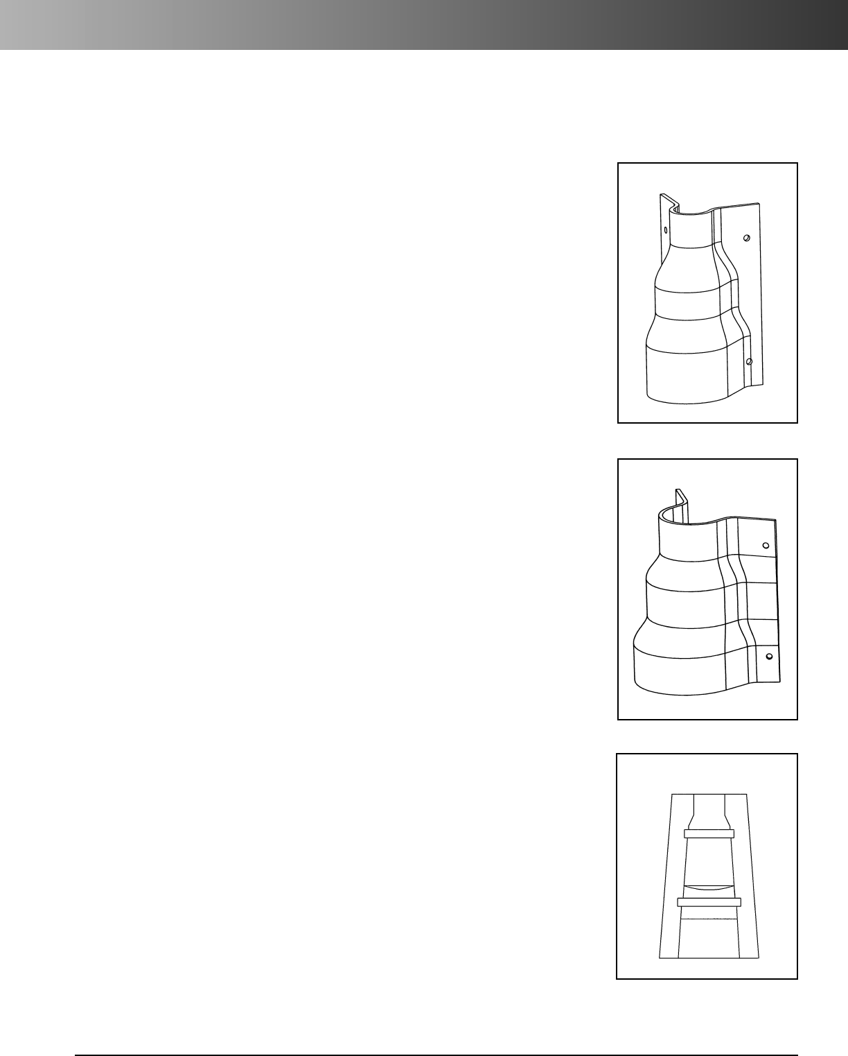
www.carlon.com 213
PV-Mold®Installation Instructions
For Adapters (E939JN, E939NR, E939NRT)
E939JN
To transition from 4" Conduit to 2" PV-Mold
Place Adapter over conduit, attach to pole using the top and bottom mounting
holes, place PV-Mold over top section of Adapter and secure PV-Mold to pole.
To transition from 4" Conduit to 3" PV-Mold
Measure 6.3" up from bottom (large end) of adapter and cut.
Assemble to pole as described above.
To transition from 3" Conduit to 2" PV-Mold*
Measure 4.75" up from bottom (large end) of adapter and cut.
Assemble to pole as described above.
E939NR
To transition from 5" Conduit to 4" PV-Mold
Place Adapter over conduit, attach to pole using the top and bottom mounting
holes, place PV-Mold over top section of Adapter and secure PV-Mold to pole.
To transition from 6" Conduit to 5" PV-Mold
Measure 7.25" up from bottom (large end) of adapter and cut.
Assemble to pole as described above.
To transition from 5" Conduit to 5" PV-Mold*
Measure 4.5" down from the top of adapter and cut.
Assemble to pole as described above.
*For these transitions it is not necessary to cut the Adapter if desired. If the
Adapter is not modified, it is recommended that the bottom 3" of the Adapter
be buried below grade.
E939NRT
To transition from 6” Conduit to 4” PV Mold
Place Adapter over conduit and attach to pole using the top and bottom mounting
holes.Place PV Mold over top section of Adapter and secure PV Mold to pole
To transition from 6” Conduit to 5” PV Mold
Measure 5.25” down from the top of the adapter and cut.
Assemble to pole as described above.
To transition from 6” Conduit to 6” PV Mold
Measure 9.5” up from the bottom of the adapter and cut.
Assemble to pole as described above.
E939JN
E939NR
Field Installation Instructions for
Carlon PV-Mold Adapters
E939NRT
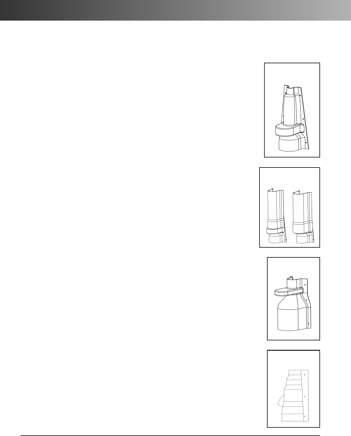
www.carlon.com
214
PV-Mold®Installation Instructions
For Vented Boots (E938JR, E938NT, E938NRR)
E938JR
To transition from 6" or smaller Conduit to 2" PV-Mold
Place Vented Boot over conduit, attach to pole using the top and bottom mounting holes, place
PV-Mold over top section of Vented Boot and secure PV-Mold to pole.
It is recommended that for conduit sizes smaller than 6" the bottom 3" of the Boot be buried
below grade.
To transition from 6" or smaller Conduit to 3" and larger PV-Mold
For 3" PV-Mold:
Measure 3.75" from the TOP of the Boot and cut. Place the Boot over the
Conduit and attach to the pole. Place belled end of PV-Mold over the top end of the boot and
secure.
For 4" and 5" PV-Mold:
Measure 12" up from the BOTTOM of the Boot and cut. Place the
Boot over the conduit and attach to the pole. Place the Belled end of the PV-Mold AGAINST the
top edge of the vent protrusion and secure to the pole.
For 6" PV-Mold:
Measure 12" up from the BOTTOM of the Boot and cut. Place the Boot over
the conduit and attach to the pole. Place the Belled end of the PV-Mold OVER the vent protru-
sion and secure to the pole.
E938NT
To transition from 6" to 8" Conduit to 4" PV Mold
Place Boot over conduit and attach to the pole using the mounting holes. Place PV Mold over
top section of Vented Boot and secure to the pole.
It is recommended that for conduit sizes smaller than 8", the bottom 3" of the boot be buried
below grade.
The E938NT can also be used to transition multiple smaller conduits to PV Mold.
ADDITIONAL PV-MOLD COMPONENTS
To transition directly from conduit to PV-Mold use Duct to Riser Fittings
E939NL Transitions 4" Conduit to 3" PV-Mold
E939N Transitions 4" Conduit to 4" PV-Mold
When additional insulation is required between the pole and cables, use PV-Mold Backing Plates:
E938JR
E938NT
59111 2"
59113 3" 59115 4"
59116 5" 59117* 6"
*Indicates non-stock factory Made-to-order items
5 inch 6 inch
Field Installation Instructions for
Carlon PV-Mold Vented Boots
E938NRR
E938NRR
To transition from 6" or smaller conduit to 4" PV Mold
Place Vented Boot over conduit and attach to pole using the top and bottom mounting holes.
Place PV Mold over top section of Vented Boot and secure PV Mold to pole
To transition from 6" or smaller conduit to 5" PV Mold
Measure 4.125" down from the top of the vented boot and cut.
Assemble to pole as described above.
To transition from 6" or smaller conduit to 6" PV Mold
Measure 8.25" down from the top of the vented boot and cut.
Assemble to pole as described above.
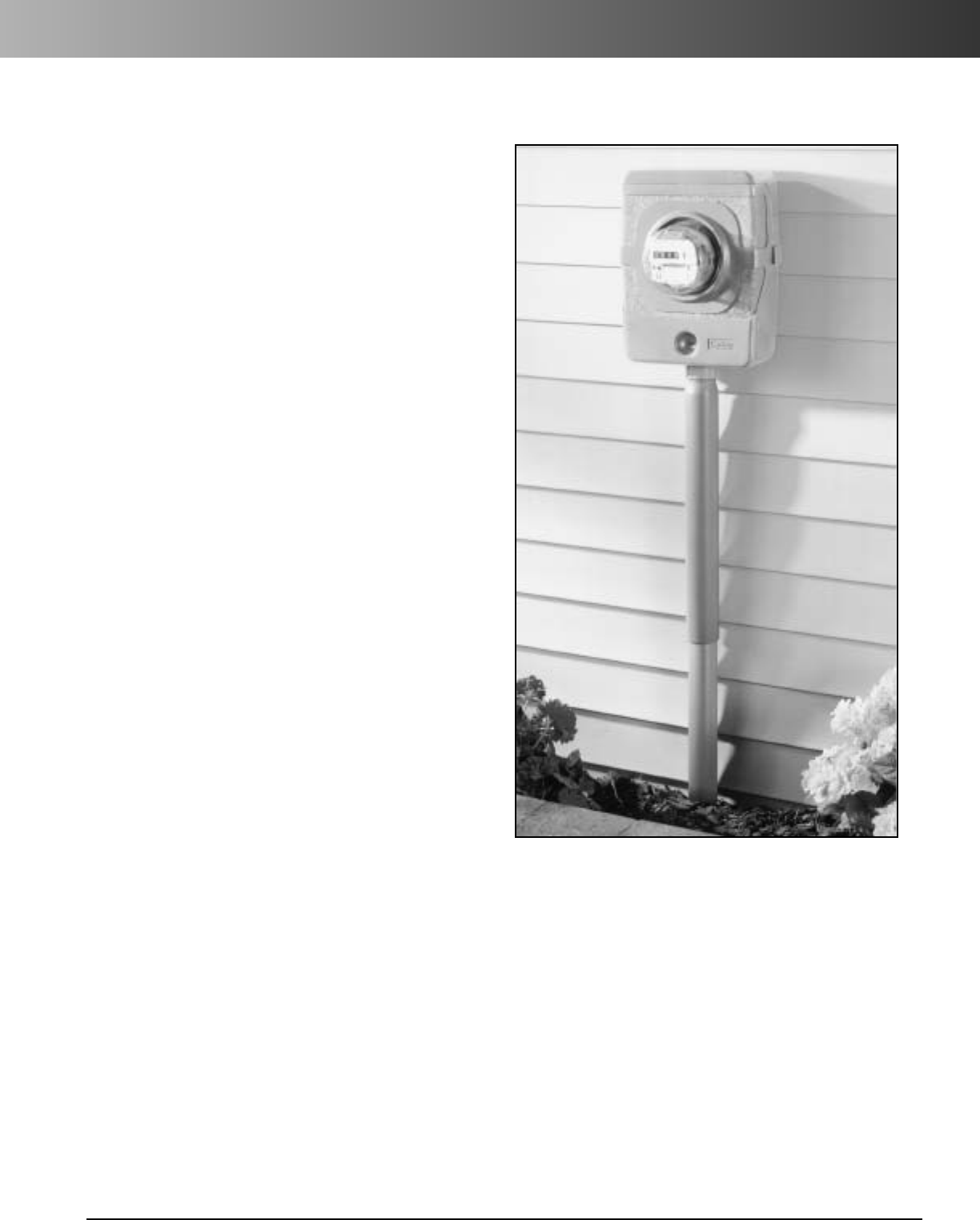
www.carlon.com 215
Slip Meter Risers
Carlon®Slip Meter Risers are designed for use
in electrical service entrance applications. They
provide solutions for applications requiring a
non-rigid connection, with incoming service
conduit diameters ranging from 2" to 4".
The Slip Meter Risers are fitted with a terminal
adapter for easy installation at the service
entrance location, and provide a low-cost
method to comply with NEC 300.5(J), which
requires protection for buried cables in areas
subject to ground movement due to frost or
trench settling.
• Designed to provide faster and easier
underground service entrance installations.
• Provides cable protection from ground
movement.
• Accommodates incoming service conduit
diameters ranging from 2" to 4".
• Fitted with Terminal Adapters for easy installing.
• Allows ground water in raceway system to drain.
• Complies with NEC 300.5(J)
Features:
Slip Meter Risers
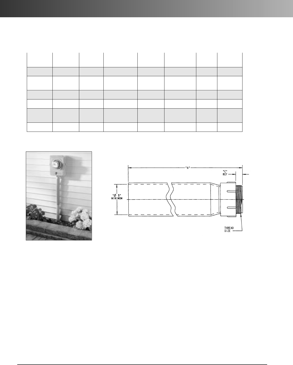
www.carlon.com
216
Slip Meter Risers
Std. Std.
Part A B Thread Carton Carton
Number Size Length (Minimum) C Size Qty. Wt. (lbs.)
E954JXX 2" 24.00 2.024 .825 2" NPT 20 46
E954JXS 2" 24.00 2.024 .825 2" NPT 1 2.2
(split)
E954KXX 2 1/2" 24.00 2.418 .812 21/2" NPSC 10 28
E954LXX 3" 24.00 3.012 .798 3" NPSC 10 35
E954LXS 3" 24.00 3.012 .798 3" NPSC 10 36
(split)
E954NXX 4" 24.00 5.060 .773 4" NPSC 5 23
Article 300 Wiring Methods
(J) Ground Movement. Where direct buried
conductors, raceways, or cables are subject to
movement by settlement or frost, direct buried
conductors, raceways, or cables shall be arranged
to prevent damage to the enclosed conductors or
to equipment connected to the raceways.
(FPN): This section recognizes “S” loops in
underground direct burial to raceway transitions,
expansion joints in raceway risers to fixed equipment,
and, generally,the provision of flexible connections to
equipment subject to settlement or frost heaves.
Slip Meter Riser Specifications
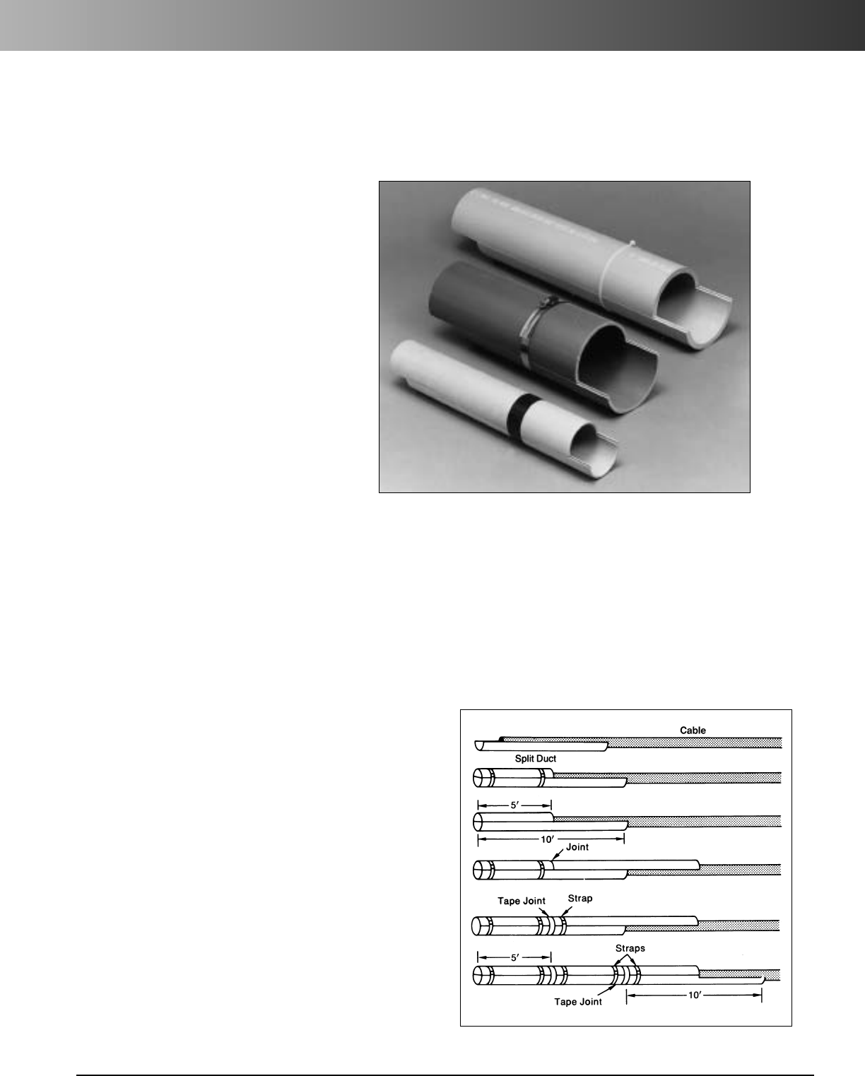
www.carlon.com 217
Split Duct
Carlon Split Duct is the fast and easy way
to repair broken ductwork without the costly
cutting and resplicing of your conductors.
Our unique tongue-and-groove design leads
the industry in providing a strong, rigid
solution for duct repair situations.
The interlocking design allows the split duct
sections to be staggered and butted together.
Joints may be sealed with tape and reinforced
with plastic or metallic straps to produce a
rigid, stable unit.
Manufactured from a compound designed
specifically for power and telecommunications
applications, Carlon Split Duct exhibits
superior impact strength and ultraviolet
resistance.
Available in 2" through 6" diameters, this
product line also contains couplings and
sweeps necessary to complete the system.
Carlon
®
Split Duct
The fast and easy method of installing duct around existing
cable for repair and temporary installations.
Recommended Installation Procedure
1. Place one 10-foot Split Duct section under cable.
2. In order to stagger joints, saw another section in half (about 5 feet
long).
3. Place 5-foot sectIon over cable and snap the two sections together.
4. Place strap about one foot from the end and another strap about a
foot from the joint where the ends of the top sections will butt.
5. Place another 10-foot Split Duct section over the open half of the
bottom section, butt the ends tightly together and snap the sections
together.
6. Place a length of tape around both sections of the Split Duct to cover
the butted joint.
7. Place a strap about one foot beyond the taped joint.
8. Lay another length of Split Duct underneath cable, butt together, tape
the butted joint and strap one foot on each side of the joint.
9. Repeat procedure.
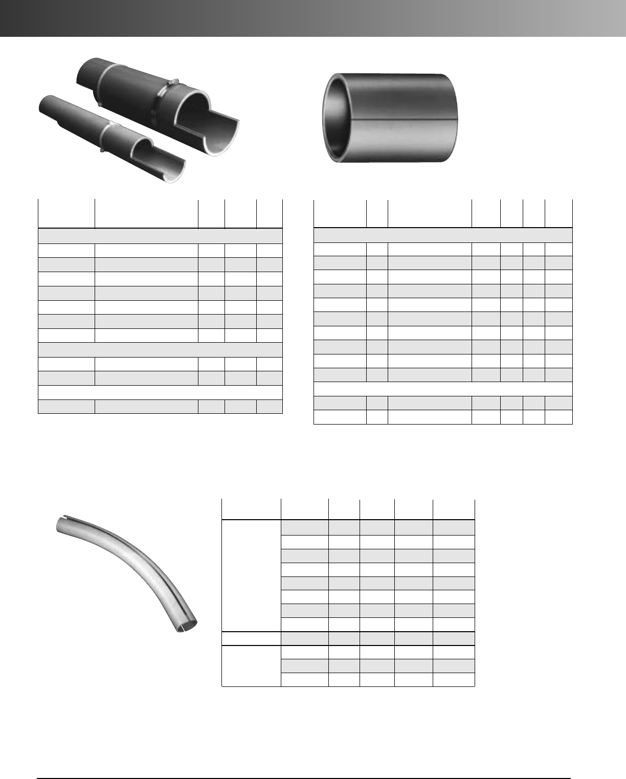
www.carlon.com
218
Split Duct
Split Duct
Split Sleeve Coupling
For joining Split Duct
to existing duct.
Split Duct
Sweeps
Split Duct
Std. Std.
Part Ctn. Ctn.
Number Description Qty.
Wt.(lbs.)
O.D.
Schedule 40
49011SD-010 2" Schedule 40 Split Duct 700 564 2.375
49012SD-010 21/2" Schedule 40 Split Duct 460 572 2.875
49013SD-010 3" Schedule 40 Split Duct 500 857 3.500
49014SD-010 31/2" Schedule 40 Split Duct 290 569 4.000
49015SD-010 4" Schedule 40 Split Duct 290 701 4.500
49016SD-010 5" Schedule 40 Split Duct 230 751 5.563
49017SD-010 6" Schedule 40 Split Duct 130 548 6.625
Schedule 80
49411SD-010 2" Schedule 80 Split Duct 700 749 2.375
49415SD-010 4" Schedule 80 Split Duct 290 922 4.500
C Duct
68515SD-010 4" C Duct Split Duct 320 614 4.350
Split Sleeve Coupling
Split Duct Sweeps
Two 45° Elbows may be segmented for 90°.
Nom. Radius Std.Ctn. Std. Ctn.
Segment Part No. Size (in.) Qty. Wt. (lbs.)
45° Sweep
UA7DJSD 2"
24" 1 1.4
UA7FJSD
2" 36" 1 2.1
UA7FLSD 3" 36" 1 4.7
UA7HJSD 2" 48" 1 2.7
UA7HLSD 3" 48" 1 6.1
UA7IJSD 2" 60" 1 3.2
UA7ILSD 3" 60" 1 7.2
UA7INSD 4" 60" 1 10.2
221/2°Sweep
UA5INSD 4" 60" 1 6.1
111/4° Sweep
UA3IJSD 2" 60" 1 1
UA3ILSD 3" 60" 1 3.6
UA3INSD 4" 60" 1 5.1
Std. Std.
Part
Ctn.
Ctn. Wt.
Number
Size
Description length Split
Qty.
(
lbs.)
Schedule 40 and 80
E200JS6 2" Split Coupling 6" 1 25 9
E200KS7 2
1
/
2
" Split Coupling 7" 1 25 21
E200LS7 3" Split Coupling 7" 1 25 17
E200LSS 3" Split Coupling 6.5" 2 25 10
E200MS8 3
1
/
2
" Split Coupling 8" 1 25 20
E200NS8 4" Split Coupling 8" 1 15 16
E200NSS 4" Split Coupling 6" 2 25 17
E200PS8 5" Split Coupling 8" 1 15 25
E200PS9 5" Split Coupling 9" 1 8 12
E200RS1 6" Split Coupling 10" 1 6 17
C Duct
E900NS8
(White)
4" C Duct Split Coupling 8" 1 15 19
E900NSW
(White)
4" C Duct Split Coupling 6" 1 25 24
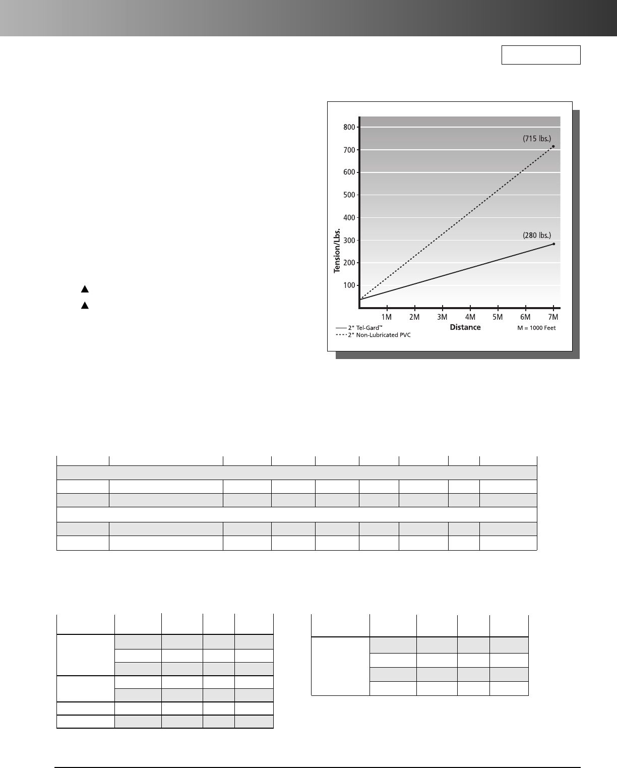
www.carlon.com 219
Tel-Gard™Pre-Lubricated Conduit
Carlon
®
Tel-Gard
™
Pre-Lubricated Conduit
Carlon offers factory applied lubricant, field tested and
proven. Increase the pulling distance – reduce the cost... and
the mess. Designed specifically for copper, coax and fiber optic
cabling.
Tel-Gard is pre-lubricated at the factory to ensure a consistent
and even coating compared to field applied lubricant.
Features:
•
Entire duct run is thoroughly lubricated
•
Applied lubricant exceeds Bellcore minimum
co-efficient of friction requirements using
TR-TSY-000356 test procedure using MDPE FO cable
Non-lubricated .31
Tel-Gard™ Pre-lubricated .068
•
Reduce risk of pulling tension damage to cable
•
Increase pulling distance between pull points
•
Reduce expense of field applying lubricant
•
Will not evaporate, enhancing repullability
•
Will not stress crack cable
•
Compatible with other field applied lubricants if mixed
Calculated using MDPE F/O cable (Wgt.= .11 lbs./ft.)
Tel-Gard™Prelubricated PVC Conduit
Tel-Gard™Prelubricated PVC Bends
Type C – White
Nom. Radius Std.
Segment Part No. Size (in.) Ctn. Qty.
90° Sweep TW9DNL 4" 24" 1
TW9FNL 4" 36" 1
TW9HNL 4" 48" 1
45° Sweep TW7DNL 4" 24" 1
TW7FNL 4" 36" 1
30° Sweep TW6TNL 4" 180" 1
221/2° Sweep TW5DNL 4" 24" 1
Nom. Radius Std.
Segment Part No. Size (in.) Ctn. Qty.
90°Sweep PH9DJL 2" 24" 1
PH9FJL 2" 36" 1
PH9DLL 3" 24" 1
PH9FNL 4" 36" 1
DB120 – Grey
RUS Listed
Part No Description Nom. Size Min. I.D. Max O.D. Stiffness Wgt. per 100
Length
Std. Crate Qty.
C-Duct Meets NEMA TC-10
68515WL-020 Type C Direct Bury White 4" 4.020 4.350 120 145 20' 1260'
68515PL-020 Type C Direct Bury Grey 4" 4.020 4.350 120 145 20' 1260'
59810L-020 Type High Performance DB Grey 11/2" 1.657 1.900 600 40 20' 3600'
59813L-020 Type High Performance DB Grey 3" 3.136 3.500 310 123 20' 2000'
High Performance Exceeds NEMA TC-6 & 8
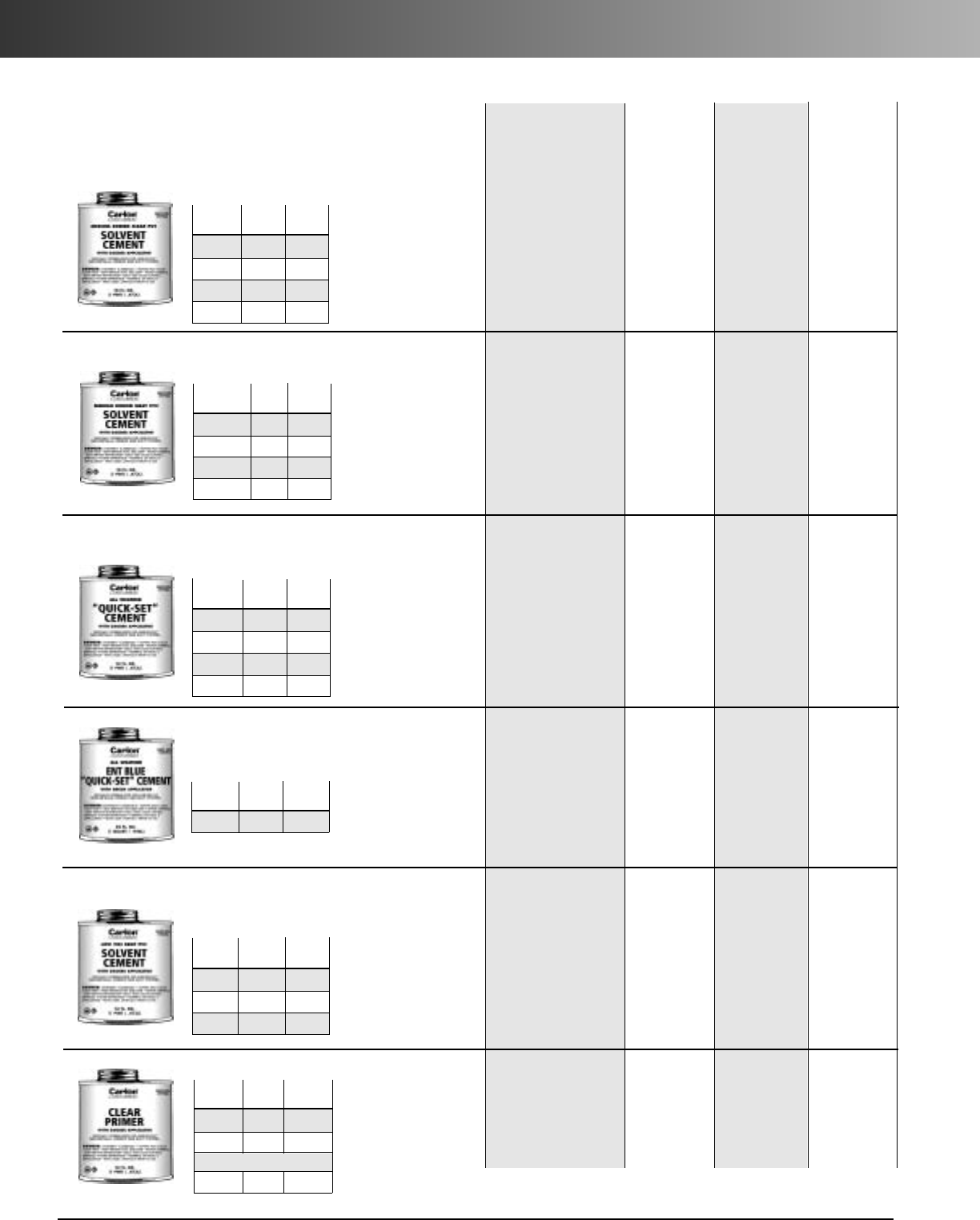
www.carlon.com
220
Cement
Carlon
®
Cement
Medium Bodied Clear
PVC Solvent
Cement
with dauber
Medium Bodied Gray PVC
Solvent
Cement
with dauber*
All-Weather “Quick-Set”
Clear Solvent Cement
with dauber*
All-Weather
ENT
Blue
“Quick-Set” Solvent
Cement
with brush*
Low VOC Gray PVC
Solvent
Cement
with
dauber*
Clear Primer
with dauber
Part Std.
No. Size Ctn. Qty.
VC9964 1/2Pint 10
VC9963 Pint 24
VC9962 Quart 12
VC9961P Gallon 6
Part Std.
No. Size Ctn.Qty.
VC9924-24 1/2Pint 24
VC9923 Pint 24
VC9922 Quart 12
VC9941P Gallon 6
Part Std.
No. Size Ctn. Qty.
VC9984 1/2Pint 10
VC9983 Pint 24
VC9982 Quart 12
VC9981P Gallon 6
Part Std.
No. Size Ctn. Qty.
VC9992 Quart 12
*Meets ASTM D2564
*No daubers for gallon cans
Recommended for all grades
and types of Carlon PVC
conduit, duct, wireway and
fittings, except Flex-Plus®
Blue™ENT (Electrical
Nonmetallic Tubing.)
Up through 6" diameter.
Recommended for all
grades and types of Carlon
PVC conduit, duct, wireway
and fittings, except Flex-
Plus®Blue™ENT (Electrical
Nonmetallic Tubing.)
Up through 6" diameter.
Recommended for all
grades and types of Carlon
PVC conduit, duct, wireway
and fittings, except Flex-
Plus®Blue™ENT (Electrical
Nonmetallic Tubing.)
Up through 6" diameter.
Recommended for all
grades and types of Carlon
PVC conduit, duct, wireway
and fittings,except Flex-
Plus®Blue™ENT (Electrical
Nonmetallic Tubing.)
Up through 6" diameter.
VOC emission of 490
grams/liter per the Bay and
South Coast test method.
Required for use
with Flex-Plus®Blue™
ENT (Electrical
Nonmetallic Tubing),
Riser-Gard®, P&C Flex®,
and Carlon PVC fittings.
Up through 4" diameter.
Recommended for use
with Carlon cement and
all types and sizes of
Carlon WireSafe®
wireway.
Recommended pipe
application and sizes
10˚-30˚F Not recommended
30˚-50˚F
5-6 minutes
50˚-70˚F
3-4 minutes
70˚-90˚F
1-2 minutes
10˚-30˚F Not recommended
30˚-50˚F
5-6 minutes
50˚-70˚F
3-4 minutes
70˚-90˚F
1-2 minutes
10˚-30˚F
4-5 minutes
30˚-50˚F
3-4 minutes
50˚-70˚F
1-2 minutes
70˚-90˚F
1/2-11/2minutes
10˚-30˚F
4-5 minutes
30˚-50˚F
3-4 minutes
50˚-70˚F
1-2 minutes
70˚-90˚F
1/2-11/2minutes
10˚-30˚F
Not recommended
30˚-50˚F
5-6 minutes
50˚-70˚F
3-4 minutes
70˚-90˚F
1-2 minutes
N/A
2 hrs.
350 psi
16 hrs.
800 psi
72 hrs.
1,500 psi
2 hrs.
350 psi
16 hrs.
800 psi
72 hrs.
1,500 psi
2 hrs.
350 psi
16 hrs.
800 psi
72 hrs.
1,500 psi
2 hrs.
350 psi
16 hrs.
800 psi
72 hrs.
1,500 psi
2 hrs.
350 psi
16 hrs.
800 psi
72 hrs.
1,500 psi
N/A
Set-up time
(Evaporation Rate)
5˚ to 100˚F N/A
Lap Shear
@ 73˚F
Part Std.
No. Size Ctn. Qty.
VC9LV4 1/2Pint 10
VC9LV3 Pint 24
VC9LV2 Quart 12
Recommended
installation
temperature
40˚ to 100˚F
40˚ to 100˚F
-5˚ to 100˚F
4˚ to 100˚F
40˚ to 100˚F
Viscosity at
75˚ as
manufactured
500-900 cps
500-900 cps
400-700 cps
400-700 cps
500-900 cps
(MSDS sheets available at www.carlon.com )
Part Std.
No. Size Ctn. Qty.
VC9903 Pint 24
VC9902 Quart 12
Purple:
VC9932 Quart 12
www.carlon.com 221
Cement
Average number of joints per can
Pipe size 1/2Pint Pint Quart Gallon
1/2 140 275 550 2,200
3/490 180 360 1,440
1 70 140 280 1,120
11/450 100 200 800
11/237 75 150 600
2 20 40 80 320
21/217 35 70 280
3 15 30 60 240
31/213 27 54 216
4 12 25 50 200
59 19 38 150
6 6 12 24 95
Average shelf-life of all Carlon cement is 24 months (unopened
cans stored below 80˚F.)
All Carlon cements are specially formulated to be used with
Carlon PVC products, and do not require primers when parts are
clean of dirt and moisture.
Cementing PVC Conduit:
1. Make square saw cut with fine
tooth saw.
2. Deburr and round inside edge
of the cut end.
3. Clean socket ID and spigot OD
of dirt and moisture.
4. Apply a uniform coat of
cement to spigot end and
push onto socket bottom,
rotating 1/4turn.
5. Allow time to set before
disturbing. This will depend
upon temperature.
Cementing PVC Conduit
for Submerged Areas
Requiring Air or Water
Tightness:
1. Follow the procedure to the
left for cementing conduit.
2. Test workmanship by
conducting a low pressure air
(3.0 - 5.0 psi) test after system
is installed and cemented
joints are set.
3. Plug and block ends to
prevent movement prior to
pressurization.
4. Check for leaks with soap
solution.
5. Even low pressure air can
cause high thrust loads and
caution must be observed.
Cementing ENT for
Concrete -Tight
Applications:
1. Use Carlon Socket tight
fittings or couplings.
2.
Do not
use chemical primer
or cleaner.
3. Apply a light uniform coat of
cement, labeled for use with
ENT.
4.
A brush
shall be used to
apply the cement.
5. Brush excess cement out of
ENT grooves
6. Promptly insert ENT into
fitting while cement is wet,
until the fitting stop is
reached, and give 1/4turn.
7. Do not disturb until the joint
is set.
Cement Joints
Carlon nonmetallic products
are joined by means of
solvent cement joints. Sizes
1/2" through 11/2" should be
cut square (using a fine tooth
handsaw) and deburred. For
sizes 2" through 6" a miter
box or similar saw guide
should be utilized to keep the
material steady. After cutting
and deburring, wipe ends
clean of dust, dirt and
shavings.
Joining process as follows: Be
sure that conduit end is clean
and dry. Apply coat of Carlon
Solvent Cement (use dauber)
to end of conduit, the length
of the socket to be attached.
Push conduit firmly into fitting
while rotating conduit slightly about one-quarter turn to
spread cement evenly. Allow joint to set approximately
10 minutes.
Carlon recommends the use of Carlon cement for
proper solvent cement joints. Since this cement is
prepared particularly for our product compounds and
tolerances, we cannot guarantee joints assembled with
cement materials supplied by other manufacturers.
Regular grade grey solvent cement will accommodate
most application situations being of a general purpose
nature. In situations requiring an extremely fast-setting
joint, (low temperature or difficult installation
conditions) Carlon All Weather Quick-Set Cement is
recommended. Standard grade clear cement is recom-
mended for noncritical utility applications where gap
filling and leak testing are not required.
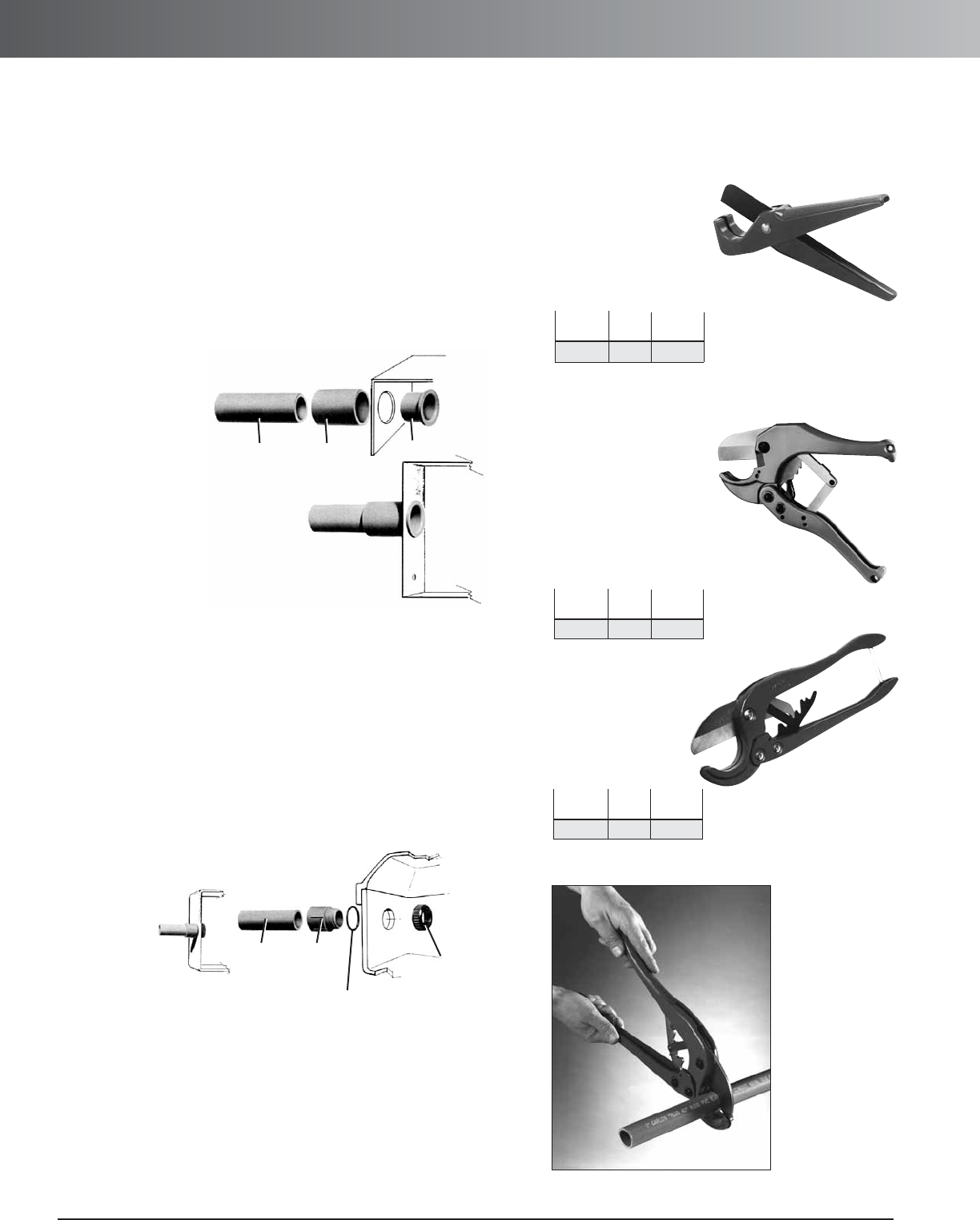
www.carlon.com
222
Conduit Termination, Cutting and Joining
Fittings and Adapters for
Terminating Carlon Schedule 40
and Schedule 80 Rigid Conduit
Terminating Carlon Schedule 40 and Schedule 80 rigid conduit is
quick and easy utilizing either of the methods indicated below.
Terminations may be made in any electrical box or enclosure using
standard size knock-outs or drilled holes.
Method 2. Separable Termination
PVC Conduit Cutters
Small Cutter
For fast, smooth field
cuts of 1/2" through 1"
Schedule 40 and 80
rigid conduit, Flex-Plus
®
Blue™ENT, and Carflex
®
liquidtight flexible nonmetallic conduit.
Medium Cutter
Hand held cutter
makes fast square,
smooth field cuts on
Schedule 40 and 80
conduit from 1/2" through 11/4".
Produces burr-free cut with no shavings.
Fits into pocket or pouch.
PVC Cutter
For clean cuts of
conduit 1/2"
through 2".
PVC
Conduit E940
Coupling
E996
Box Adapter
PVC
Conduit E943
Terminal
Adapter
E943_W
Flat Washer or
“O” Ring
Locknut
or Bushing
Apply solvent cement to shoulder and shank of box adapter and
insert through knock-out from inside the enclosure. Push coupling
over the shank of the box adapter, tight against the enclosure wall.
Rotate the coupling about one-half turn while installing, and hold
in position for a few seconds to permit setting of solvent cement.
The coupling is now ready for the conduit to be installed. Only the
shoulder of the box adapter extends inside the enclosure.
Method 1. Permanent Termination
If watertight construction is required, place flat washer over the
threads of the terminal adapter, securely against the shoulder.
Insert the adapter threads through knock-out and secure using
either a standard locknut or threaded bushing. If watertight
construction is not required, eliminate flat washer.
Std.
Part No. Size Ctn. Qty.
CC120B 8" 10
Std.
Part No. Size Ctn. Qty.
CC125 9" 12
Std.
Part No. Size Ctn. Qty.
CC122 171/2"1
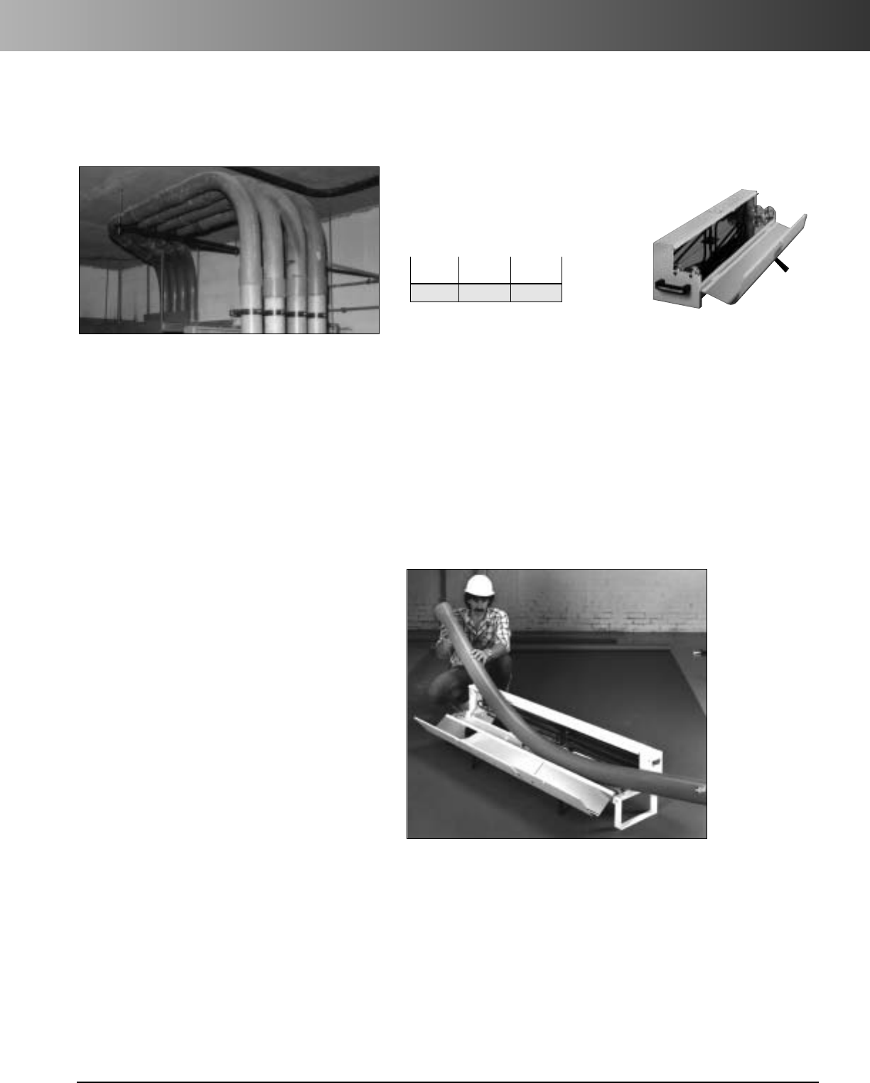
www.carlon.com 223
EZ BEND™Conduit Bending Equipment
EZ BEND™Conduit
Bending Equipment
For field bending of small and large diameter
nonmetallic conduit, the easy answer is Carlon EZ
BEND*conduit bending equipment.
• Lightweight • Portable
• Fast, Simple and Safe • Less expensive than
• Includes complete factory bends
instructions and a
convenient bending chart
Field Bending Rigid Nonmetallic Conduit
1. Heating
Conduit section to be bent must be heated evenly over
the entire length of the curve. Carlon offers EZ BEND
electric heaters designed specifically for the purpose,in
sizes to accommodate all conduit diameters. These
devices employ infra-red heat energy which is most
quickly absorbed by the conduit. Small sizes are ready to
bend after a few seconds,while larger diameters require
two or three minutes, or more, depending on conditions.
The use of torches or other flame-type devices is not
recommended. PVC conduit exposed to excessively high
temperatures may take on a brownish color. Sections
showing evidence of such scorching should be discarded.
2. Forming The Bend
1
/
2
" thru 1
1
/
2
" Diameters – When properly heated the
conduit is very flexible and can be shaped to almost any
configuration. The conduit is then cooled by sponging
with water, and the bend is ready to install.
2" and Larger Diameters – Larger sizes of conduits
and ducts require internal support to prevent “crimping”
or deforming during the bending process. Bending plugs
are inserted in each end of the conduit section before
heating. The plugs expand to provide an airtight seal.
(Note: Carlon does not offer bending plugs.)
Minimum practice
is required to
master the three
steps in bending
nonmetallic
conduits and
ducts.
EZ BEND™Conduit Bender, Jr.
A practical, convenient portable conduit bender for
1
/
2
" through 2" diameter
nonmetallic conduit allows bends up to 14" radius and to 90° elbows. The EZ
BEND Conduit Bender, Jr. is a timesaving, easy-to-carry unit featuring a brack-
et to store the power cord, a carrying handle, and a clasped cover. The unit
operates on a standard 20 amp, 120 V circuit.
Dimensions: 7
1
/
2
" x 8
1
/
2
" x 31"
Operating Temperature: 180° - 200°F
*
EZ BEND is a registered trademark of Bradshaw Manufacturing, Inc.
Std. Std. Ctn.
Part No. Ctn. Qty. Wt. (lbs.)
G280J 1 14
Carlon’s EZ BEND Conduit Bending Equipment is designed with the
electrical contractor in mind. The completely portable and fully encased
EZ BEND benders and plug kits can be transported from job to job
without damage or harm to the equipment. Additionally, the heavy
duty construction and integrity of Carlon’s EZ BEND Conduit Bending
Equipment ensures that it will last for years to come.
3. Cooling
As the conduit is heated, the retained air expands, and the increased internal
pressure allows the conduit to be bent without deforming. The conduit must
be cooled before the plugs are removed. For an immediate cool and set,
sponge with cold water.
Special Bends
For “blind” bends or for compound turns in a conduit run, the heated conduit
may be solvent cemented in place while still flexible.
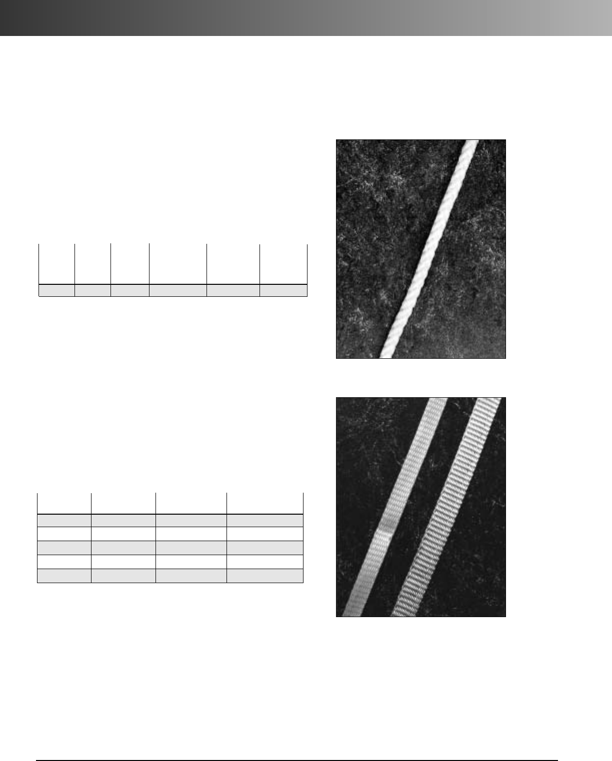
www.carlon.com
224
Rope & Tape
Rope
(Conduit Pulling Lines for Conductors or Fiber Optics)
Tape
Prelubricated, woven polyester tape made from low friction,
high abrasion resistant yarns providing a low coefficient of
friction. Tape is printed with sequential footage markings for
accurate measurements.
Part Tensile Reel
No. Size Strength Lengths
TL14505 1/2" 1250 lbs. 5,000 ft.
TL14510 1/2" 1250 lbs. 10,000 ft.
TL38203 5/8" 1800 lbs. 3,000 ft.
TL38265 5/8" 1800 lbs. 6,500 ft.
TL38210 5/8"1800 lbs.10,000 ft.
This rope is constructed of polyethylene over
polyester, designed specifically for fiber-optic pulling.
The polyethylene jacket gives the “slippery” feel that
gives less drag in pulling through conduit. Available in
standard 5,000 foot and 10,000 foot reels.
White Diamond Braid Rope
Recommended Approximate Std.
Working Avg. Ctn.
Part Reel Load Tensile Wt.
No. Length Diameter (lbs.) (lbs.) (lbs.)
SB14105 5,000 ft. 1/4" 260 1700 100
Other ropes and tapes are available. Consult your sales
service location for additional information.
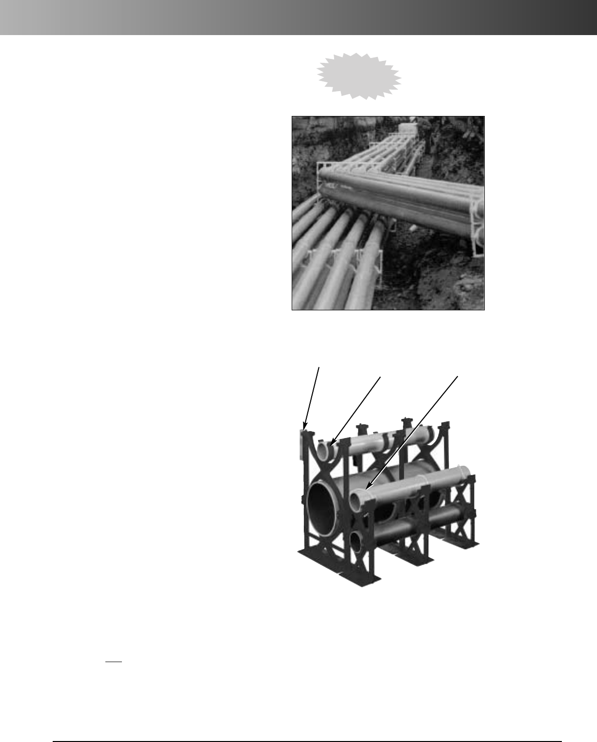
www.carlon.com 225
Snap-Loc Spacers
Carlon Snap-Loc duct spacers provide stability,
consistent separation and relieve direct stress for
duct materials encased in concrete, and direct
bury applications.
Carlon Snap-Loc Spacers provide:
• A side dovetail rail and groove design
allowing for side-by-side interchangeability
of conduit spacer sizes while maintaining
horizontal stability.
• Locking key ways incorporated into
intermediate spacers eliminate the need for
costly top spacers in each size. The locking
key ways provide for the use of a beaded
strap that secures the top section of conduit.
• 1" and 2" Snap-Loc Reducers allow fixturing
of 1" or 2" conduit inside larger spacers.
• The Snap-Loc Rebar Holder provides
stabilization on large banks of spacers.
Nonmetallic Snap-Loc Spacers are designed
specifically for use with nonmetallic duct, with
maximum O.D. dimensions as specified in
NEMA TC-2, TC-6 & 8, TC-10 and ASTM F512.
The innovative vertical and horizontal
interlocking Snap-Loc design has tapered
joining slots with maximum tolerances for
easy job site assembly.
Carlon
®
Snap-Loc
®
Spacers
Rebar Holder Snap-Loc®
Reducer Beaded Strap &
Locking Key Way
IMPORTANT:
1. The use of duct spacers for direct burial may result in excessive point deflections unless proper
design engineering is applied, such as the proper compaction of the appropriate backfill material.
2. Carlon is NOTresponsible for Snap-Loc Spacers used in direct bury applications... design engineers
and contractors are responsible for the design of the installation.
NEW!
8" Spacers
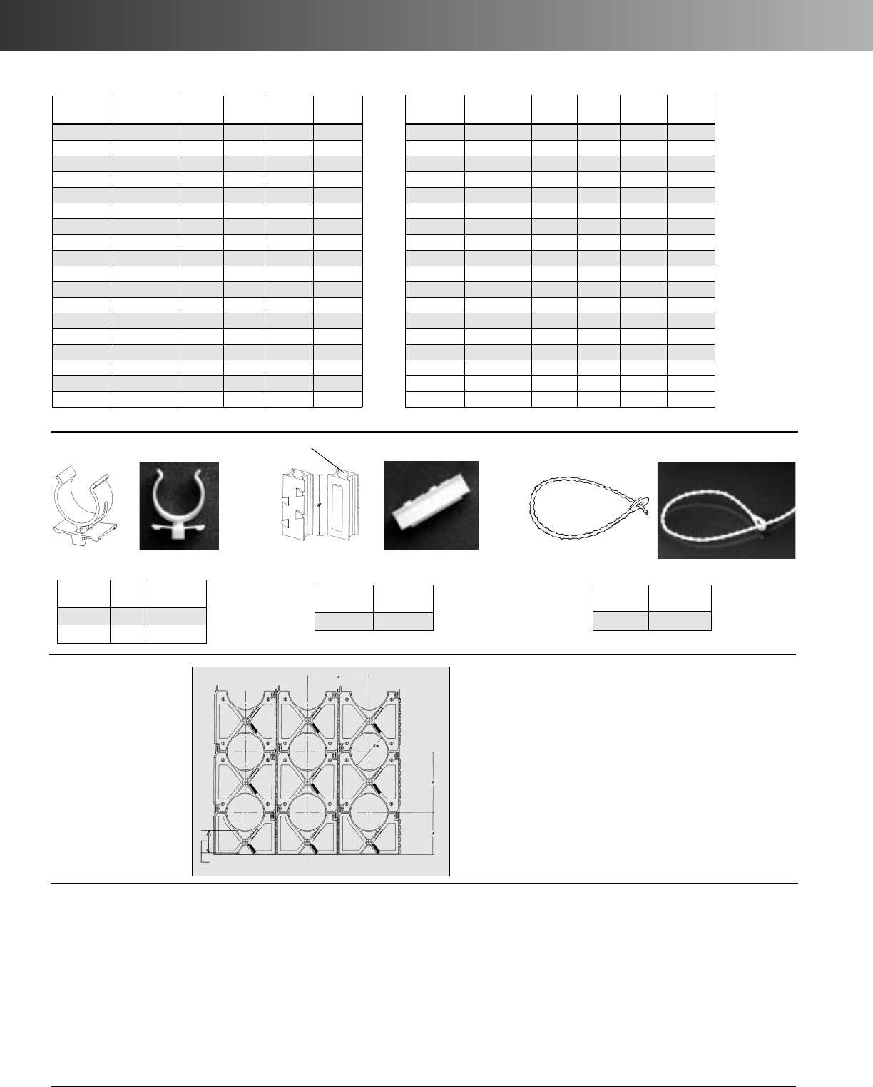
www.carlon.com
226
Snap-Loc Spacers
Specifications
Dimensions – Base Spacers
Std.
Part No. Size* A C D (Dia.) Ctn. Qty.
S288JHN 2x11/24.25 4.12 2.50 100
S288JJN 2x2 4.25 4.62 2.50 100
S288JLN 2x3 4.25 5.62 2.50 100
S288LHN 3x11/24.81 5.25 3.63 90
S288LJN 3x2 4.81 5.75 3.63 80
S288LLN 3x3 4.81 6.75 3.63 60
S288NFN 4x1 5.31 5.75 4.63 70
S288NHN 4x11/25.31 6.25 4.63 50
S288NJN 4x2 5.31 6.75 4.63 50
S288NLN 4x3 5.31 7.75 4.63 60
S288PHN 5x11/25.84 7.31 5.69 50
S288PJN 5x2 5.84 7.81 5.69 60
S288PLN 5x3 5.84 8.81 5.69 50
S288RHN 6x11/26.38 8.38 6.75 50
S288RJN 6x2 6.38 8.88 6.75 50
S288RLN 6x3 6.38 9.88 6.75 40
S288SHN 8x11/27.38 10.30 8.75 30
S288SJN 8x2 7.38 10.76 8.75 30
Dimensions – Intermediate Spacers
Std.
Part No. Size* B C D (Dia.) Ctn. Qty.
S289JHN 2x11/23.88 4.12 2.50 120
S289JJN 2x2 4.38 4.62 2.50 100
S289JLN 2x3 5.38 5.62 2.50 80
S289LHN 3x11/25.01 5.25 3.63 100
S289LJN 3x2 5.51 5.75 3.63 80
S289LLN 3x3 6.51 6.75 3.63 60
S289NFN 4x1 5.51 5.75 4.63 70
S289NHN 4x11/26.01 6.25 4.63 60
S289NJN 4x2 6.51 6.75 4.63 60
S289NLN 4x3 7.51 7.75 4.63 50
S289PHN 5x11/27.07 7.31 5.69 50
S289PJN 5x2 7.57 7.81 5.69 50
S289PLN 5x3 8.57 8.81 5.69 30
S289RHN 6x11/28.14 8.38 6.75 50
S289RJN 6x2 8.64 8.88 6.75 40
S289RLN 6x3 9.64 9.88 6.75 30
S289SHN 8x11/210.14 10.30 8.75 30
S289SJN 8x2 10.64 10.76 8.75 30
B
C
A
Suggested Specification
(Duct) (Conduit) bank shall be encased in concrete with at least
three inches of concrete at the top and bottom and two inches on
each side. A horizontal and vertical separation between the ducts
of ____* inches shall be maintained by installing Carlon high
impact spacers with horizontal and vertical locking intervals of
____** feet.
*Standard Separations of 1", 11/2", 2", and 3" are available.
**Preferred interval between spacer assemblies is 8 to 10 feet.
3" Standard for all Base Spacers
*First number indicates trade size of duct, second number indicates separation between conduits or ducts.
Accessories
Std.
Part No. Size Ctn. Qty.
S287F 1" 100
S287J 2" 100
The Spacers and Rebar Holder are designed with a dovetail tongue and groove
feature for easy installation.
If required to permanently fix the position of a group of Spacers and/or Rebar
Holder, the following are recommended procedures:
1. Use Carlon Quick-set Cement glue during assembly or spot glue after assembly
to secure.
2. During assembly, deform the edge of the tongue or groove portion of the dove-
tail slide with a pair of pliers or similar tool. This deformation will create an
interference, restricting movement.
3. An assembled system may be wired together for additional support.
Installation note
Snap-Loc
®
Reducer
Std.
Part No. Ctn. Qty.
S258RH 100
Rebar Holder
Std.
Part No. Ctn. Qty.
S28612 100
Beaded Strap
15" in length
Hole Dia. = .688 min.
.750 max.
IMPORTANT:
1. The use of duct spacers for direct burial may result
in excessive point deflections unless proper design
engineering is applied, such as the proper com-
paction of the appropriate backfill material.
2. Carlon is not responsible for Snap-Loc Spacers used
in direct bury applications... design engineers and
contractors are responsible for the design of the
installation.
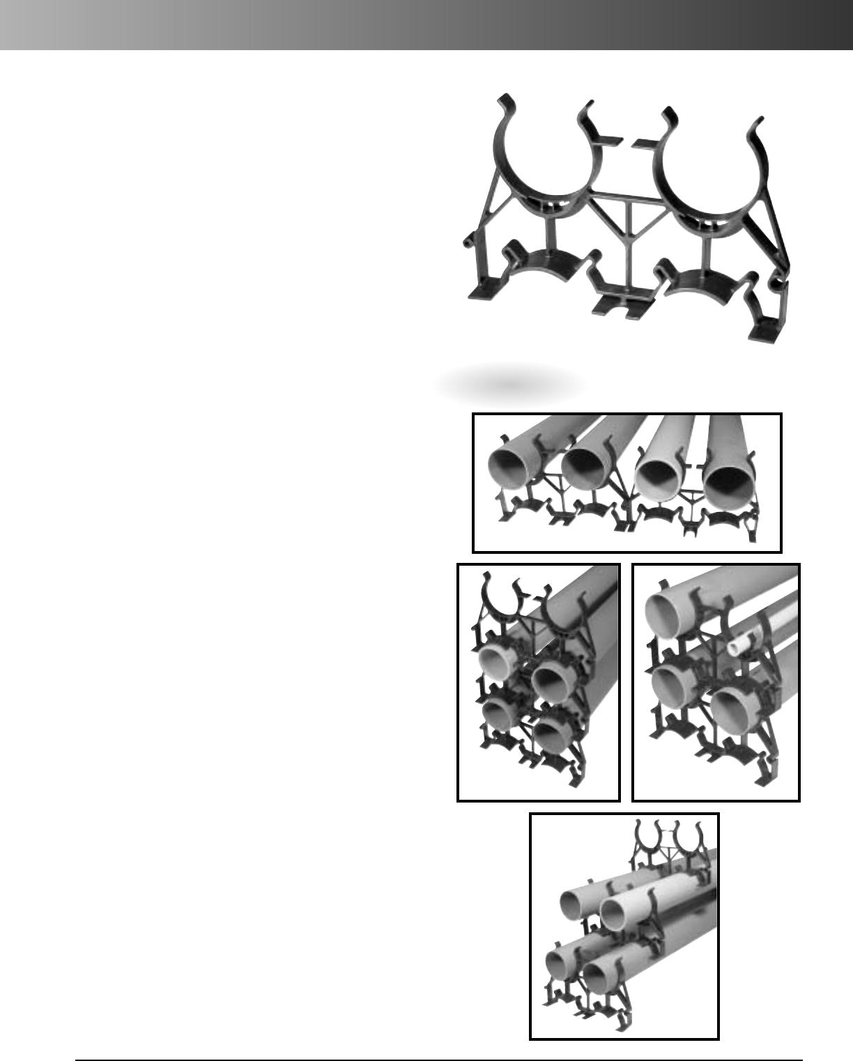
www.carlon.com 227
Installations
Carlon®Snap-N-Stac™Combo Underground Duct
Spacers are specifically designed to replace the
two-piece base and intermediate spacer system, by
combining the conventional base and intermediate
spacer into a single unit!
Manufactured out of highly engineered thermoplastic
material, Snap-N-Stac Spacers are strong, durable and
able to withstand the rigors of concrete construction.
They feature an innovative horizontal and EXCLUSIVE
Vertical locking system and can be used as either a base
or intermediate spacer.
Carlon Snap-N-Stac Spacers are available in duct
sizes 2", 4" and 6" and can be installed horizontally,
vertically or turned up-right for unique duct bank
configurations.
This NEW one-piece design makes underground
duct bank installations faster and easier than the
conventional two-piece system– saving material
and labor costs.
Carlon®Snap-N-Stac Combo Spacers...The IDEAL
Solution for Underground Duct Bank Installations.
Carlon
®
Snap-N-Stac
™
Combo Spacers
Features:
• Conventional Base and Intermediate Spacer in a Single Unit!
• EXCLUSIVE Vertical Locking System
• Horizontal Locking System
• Installs Horizontally or Turned Upright
• Molded-In Rebar Holder
• Available in 2", 4" or 6" Duct Sizes
• Reducer to Accommodate Smaller Duct Sizes
• Can Be Used as Either an Intermediate or Base Spacer
• Spacers Interlock Horizontally Regardless of Size
• Nonmetallic, Noncorrosive, Nonconductive
• Strong and Durable
• Easy to Handle
• Fast Installation
Vertical
Interlocking With Reducer
Free Standing
Horizontal Locking
Patent Pending
Snap-N-Stac™Combo Spacers
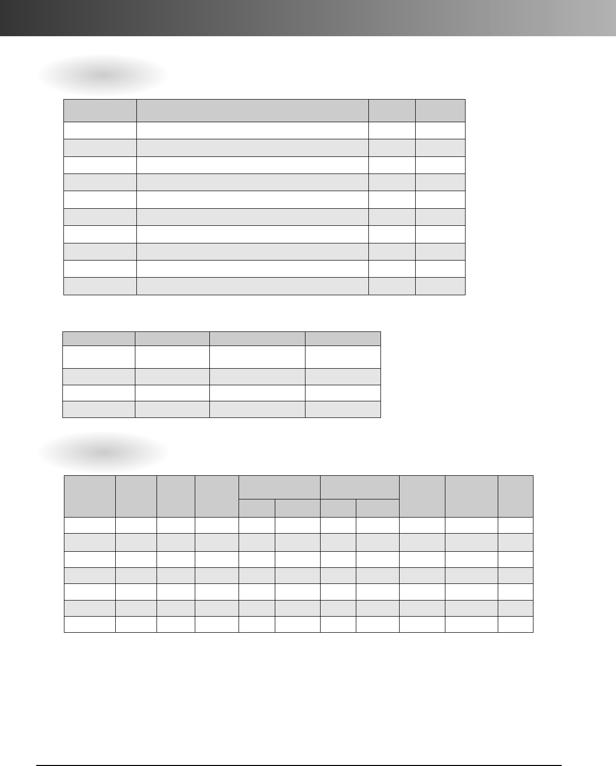
www.carlon.com
228
Snap-N-Stac™Combo Spacers
Specifications
Technical Information
Part Number Description Std. Carton
Qty. Std. Carton
Wt. (lbs.)
SP2W20-2 2" Two-Way Snap-N-Stac Spacer - 2" Separation 56 28.5
SP2W30-2 2" Two-Way Snap-N-Stac Spacer - 3" Separation 4023.8
SP4W15-2 4" Two-Way Snap-N-Stac Spacer - 1-1/2" Separation 26 18.3
SP4W20-2 4" Two-Way Snap-N-Stac Spacer - 2" Separation 24 18.8
SP4W30-2 4" Two-Way Snap-N-Stac Spacer - 3" Separation 20 17.6
SP6W20-2 6" Two-Way Snap-N-Stac Spacer - 2" Separation 12 12.8
SP6W30-2 6" Two-Way Snap-N-Stac Spacer - 3" Separation 12 14.1
S287F 1" Snap-Loc Reducer 100 2.1
S287J 2" Snap-Loc Reducer 100 4.8
S28612 Beaded Strap 100 0.4
Part Number Duct Size Duct OD
Horizontal
Duct
Positions
Duct-To-Duct
Spacing Center-To-Center
Spacing Bottom of
Trench to
Bottom of
Duct
Bottom of
Trench to
Center of
Bottom Duct Overall
LengthVertical Horizontal Vertical Horizontal
SP2W20-2 2" 2.375 2 2 2 4.38 4.38 3.13 4.25 8.75
SP2W30-2 2" 2.375 2 3 3 5.38 5.38 4.13 5.25 10.75
SP4W15-2 4" 4.5 2 1.5 1.5 6 6 3.38 5.56 12
SP4W20-2 4" 4.5 2 2 2 6.5 6.5 3.88 6.06 13
SP4W30-2 4" 4.5 2 3 3 7.5 7.5 4.88 7.06 15
SP6W20-2 6" 6.625 2 2 2 8.62 8.62 4.13 7.38 17.25
SP6W30-2 6" 6.625 2 3 3 9.62 9.62 5.13 8.38 19.25
How to Interpret the Part Number
Position 1 Position 2 Position 3 Position 4
Product Type Duct Size Duct-To-Duct Spacing -
Horizontal and Vertical Horizontal Duct
Positions
SP = Spacer 2W = 2" Width 15 = 1-1/2" 2 = Two
4W = 4" Width 20 = 2"
6W = 6" Width 30 = 3"
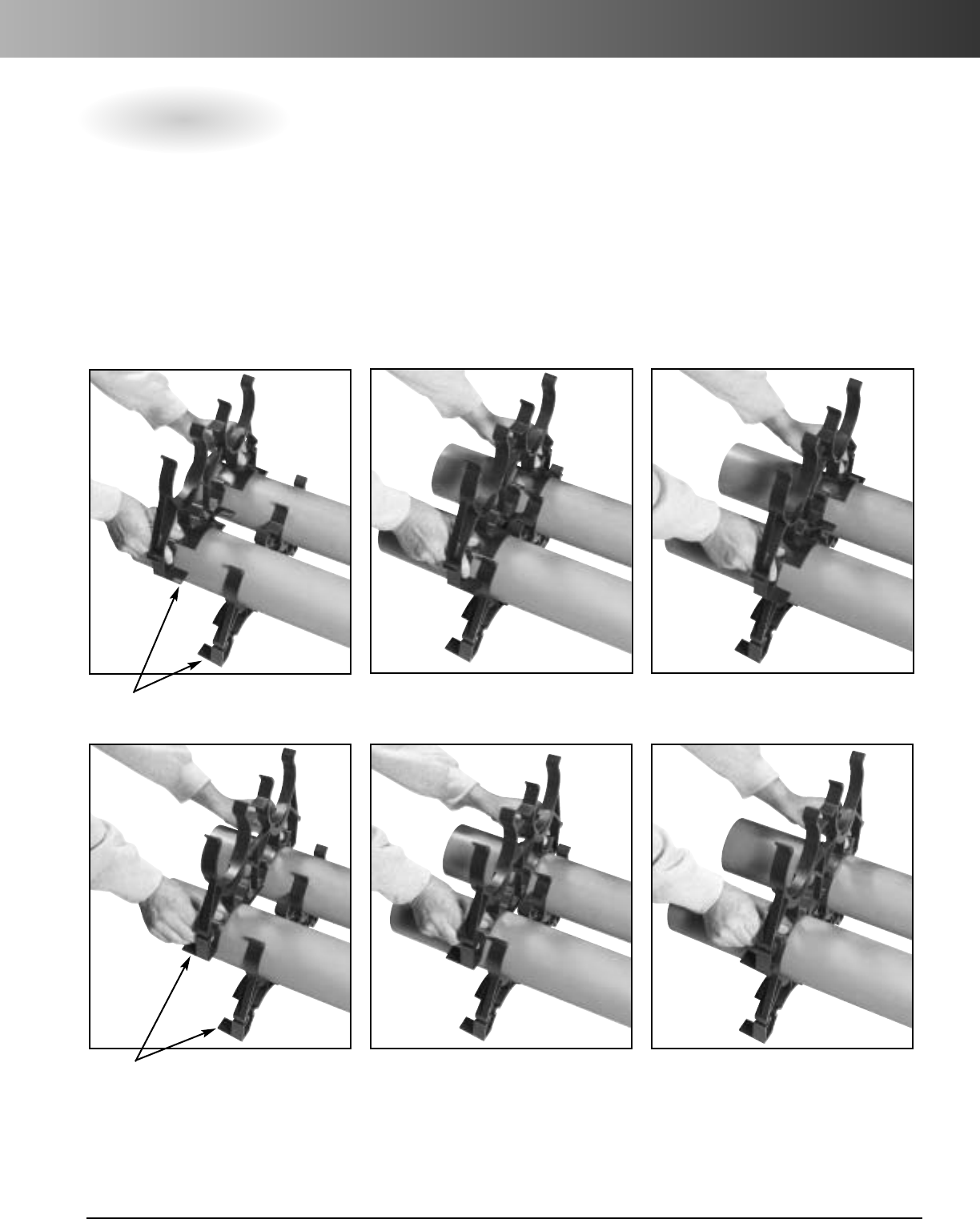
www.carlon.com 229
Snap-N-Stac™Combo Spacers – Installation
Installation Instructions
IMPORTANT:
1. Snap-N-Stac Spacers should be used in concrete encased applications only.
2. The use of duct spacers for direct burial may result in excessive point deflections unless proper design engineering is
applied, such as the proper compaction of the appropriate backfill material.
3. Carlon is NOT responsible for Snap-N-Stac Spacers used in direct bury applications…design engineers and contractors
are responsible for the design of the installation.
Vertical Interlocking
Slide spacers together “Feet Facing Feet.”
Feet Facing
Feet Opposite
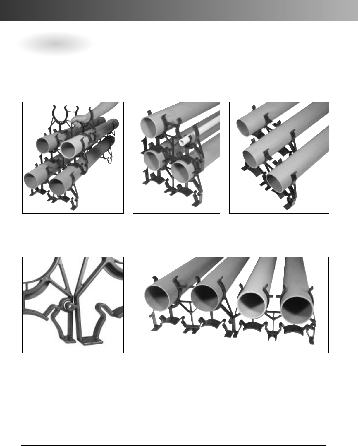
www.carlon.com
230
Snap-N-Stac™Combo Spacers – Installation
Transition To Various Duct Sizes
Install spacers side-by-side by inserting the male adapter into the female adapter.
Note: All Snap-N-Stac spacers are designed to interlock horizontally, regardless of size.
Vertical Free Standing
If spacers are installed using free standing
method, it is recommended to install the
spacer on the upper row mid-way between
the two spacers on the bottom row.
Reducer
1" & 2" Snap-Loc Reducers allow
fixturing of 1" and 2" conduit
inside of larger spacers.
Modifications
Odd numbers of ducts are
accommodated by staggering
two-way spacers.
Installation Instructions
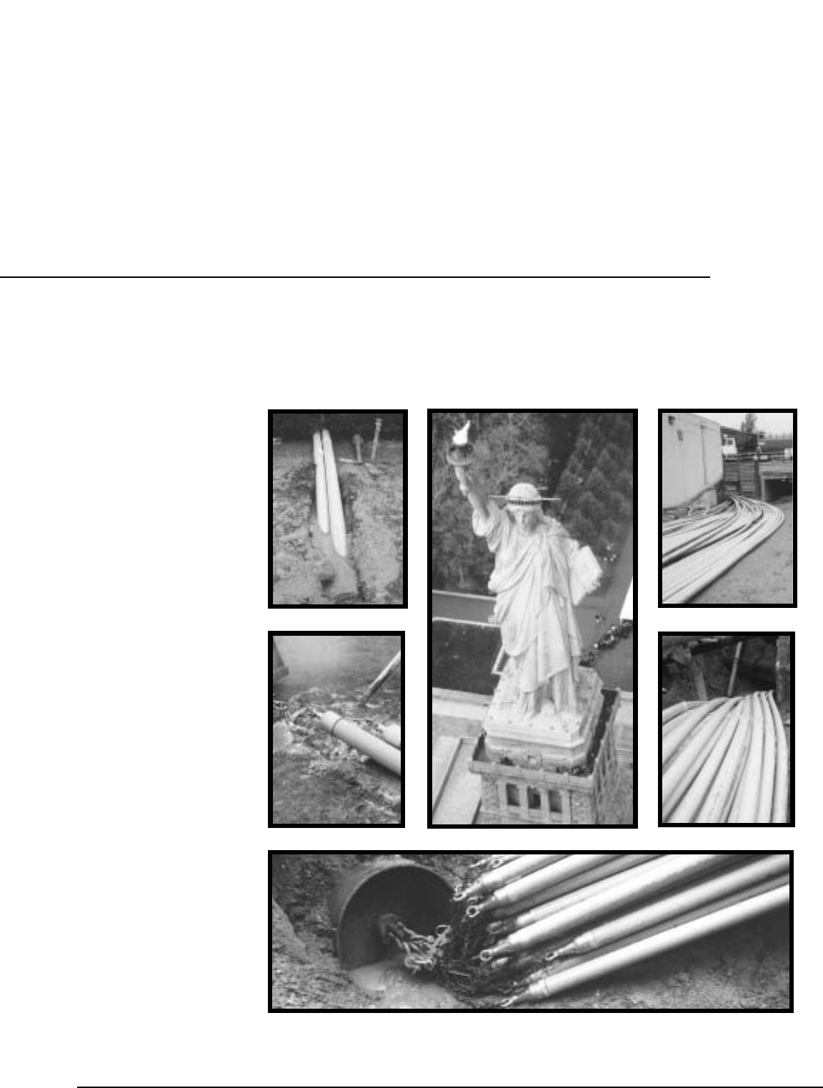
www.carlon.com 231
Bore-Gard
Schedule 40
Bore-Gard
Schedule 80
Boreable
Multi-Gard
Type 40
Carlon
®
Bore-Gard
®
and
Boreable Multi-Gard
®
Raceway
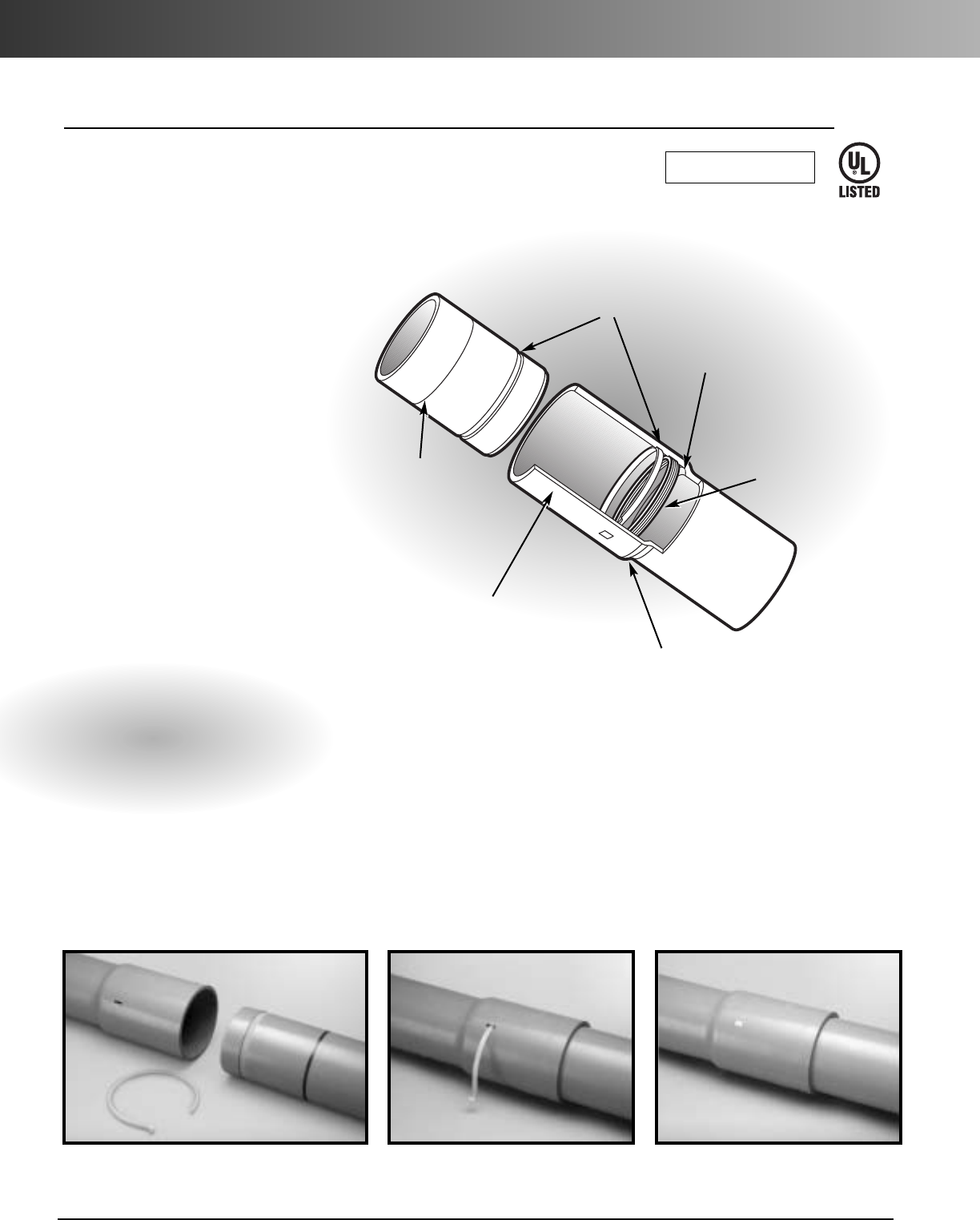
www.carlon.com
232
Bore-Gard
®
Trenchless Raceway
Locking ring enables fast,
cement-free assembly. Slide locking ring into the joint.
Carlon’s PVC Bore-Gard conduit
eliminates the costly problems of
HDPE pipe on a reel such as reel
handling, fusion welding, uncoiling
and wasted pipe, safety hazards and
additional job site labor.
Bore-Gard is designed and proven to
meet the rigorous requirements of
horizontal directional drilling for
electrical and datacom applications
and is available in Heavywall Schedule
40 or Extra Heavywall Schedule 80
conduit.
The unique design incorporates a
water-tight seal and locking ring that
enables fast, cement-free assembly,
strong enough for 1000 foot bores.
Short lengths of 10 and 20 feet fit into
the tightest spaces and can be
easily transported to the job site.
Simplify trenchless installations and
lower your costs with Bore-Gard.
Features:
•
Easy to handle 10 and 20 foot lengths
•
For bores up to 1000 feet
•
Fast easy assembly
•
Strong water-tight joints without cement
•
Fits standardrigid nonmetallic conduit
fittings
Fully assembled, the locking ring
provides strong water-tight joints
without cement.
Carlon
®
Bore-Gard
®
Trenchless Raceway
Insertion
depth indicator
tells at a glance
if pipe ends are
inserted to the
correct depth.
The belled end will
not snag when pulled
into a bore.
Heavy walls and deep
insertion make the joint
immune to the effects of
normal bending.
Precision engineered design has matching grooves
and nylon locking strap to provide a secure connection.
Triple-lobed
gasket designed to
provide ease of
assembly and a
watertight seal.
Positive stop automatically
aligns strap grooves.
•
All nonmetallic construction
•
Superior crush and stiffness over HDPE
•
Eliminates the need for chains and backing plate installation
•
Type: Schedule 40 - Heavywall Schedule 80 - Extra Heavywall
•
Sizes: Schedule 40 - 3", 4", 5", & 6" Schedule 80 - 3" & 4"
RUS Listed
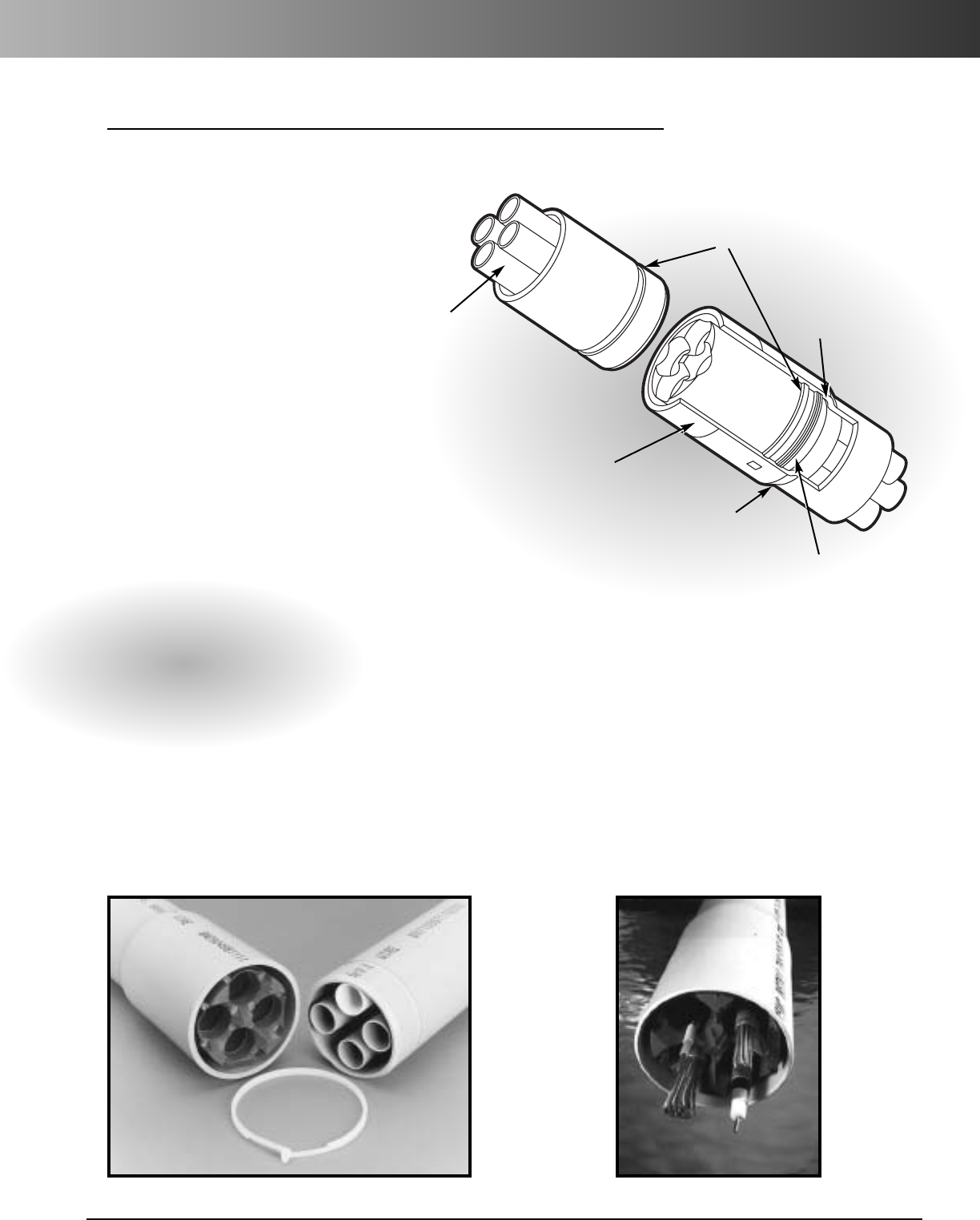
www.carlon.com 233
Boreable Multi-Gard
®
Carlon’s PVC Boreable Multi-Gard
conduit combines a strong boreable
outerduct with the convenience of
aMulti-Cell conduit.
Boreable Multi-Gard utilizes leading
technology from Carlon’s PVC
Bore-Gard
®
Trenchless Raceway,
offering a field-proven design.
Bores up to 500 feet can be
achieved without labor-intensive
operations. Lengths of 20 feet fit
into tight spaces often encountered
on underground boring job sites.
Experience the strength and
convenience of Carlon Boreable
Multi-Gard.
The belled end
will not snag
when pulled
into a bore.
Heavy walls and deep
insertion make the joint
immune to the effects of
normal bending.
Precision engineered design has
matching grooves and nylon locking
strap to provide a secure connection.
Triple-lobed gasket
designed to provide
ease of assembly
and a watertight seal.
Positive stop
automatically aligns
strap grooves.
Factory installed
innerducts
eliminate post
bore
installations.
Factory installed
innerducts
provide immediate
post bore cable
installation
Carlon
®
Boreable Multi-Gard
®
Features:
•
Withstands pulling and bending
forces of directional drilling
•
Fast assembly
•
Eliminates labor related to
gluing and screwing joints
together
•
For bores up to 500 feet
•
Innerducts: 3-way or 4-way
•
Easy to handle 20 foot lengths
•
Type: Type 40 PVC outerduct
•
Size: 4"
•
Prelubricated innerducts
Designed to
meet all your
cable needs.
•
Strong water-tight joints
without cement
•
Fits standard Schedule 40
fittings
•
Compatible with Multi-
Gard Type 40 PVC products

www.carlon.com
234
Bore-Gard
®
Statue of Liberty
Carlon®Bore-Gard®was
the product of choice
when additional
conduit was considered
necessary for future
utilities and cables on
Liberty Island.
Horizontal Directional
Drilling was the
preferred method of
installation because
it minimized any
disruption to the
island’s pristine
environment.
Bore-Gard is a PVC
trenchless raceway
specifically designed for
Horizontal Directional
Drilling. Bore-Gard is
seal rated for 75psi,
keeping drilling fluid
and underground water
out. It has a strong,
cement-free joint,
making installations
fast and easy. It comes
in convenient 10 ft.
and 20 ft. lengths and
is strong enough for
1000 ft. bores.
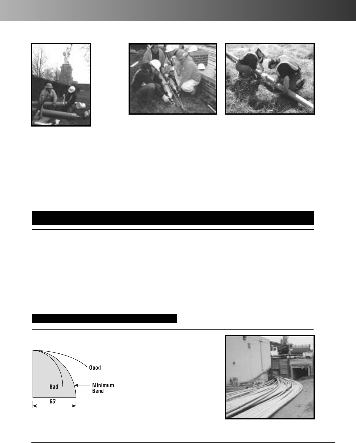
www.carlon.com 235
Bore-Gard
®
/Boreable Multi-Gard
®
Assembly
Minimum Bend Radius:
Turns in a
bore path should be made gradually.
Bore-Gard and Boreable Multi-Gard have
aminimum bend radius of 65'. Bending
morethan this recommended limit will
stress the joint. The drawing below
illustrates the 65' bend radius. Toobtain
a90°turnyou will require65' of forward
distance in any directional plane.
Note: Successful directional drilling, reaming and pipe installation are influenced by numerous factors
including the reamed diameter, pull rate, fluid chemistry, fluid flow rate, drill rod diameter, soil
conditions, equipment performance and condition, and operator experience. All manufacturers’
equipment recommendations and training should be followed for successful drilling results.
Bore-Gard
®
Assembly
Boreable Multi-Gard
®
Assembly
Bend Radius for Bore-Gard
®
& Boreable Multi-Gard
®
1. Position Boreable Multi-Gard with the
print line facing up.
2. Remove plastic locking strap and set it
aside.
3. Seal off lead end to keep out drilling fluid.
4. Attach 4" Kellems Grip over lead end.
Note: Internal pulling eye cannot be used
due to innerduct interference.
5. The installer should use appropriate
instrumentation to insure that the maxi-
mum pull rating is not exceeded.
6. Take next piece of Boreable Multi-Gard
and insert spigot end into belled end of
the first piece until the insertion line is no
longer visible.
N
OTE: Innerducts need to be aligned
beforeinsertion
7. Slide the plastic locking strap into slot
on the side of the bell. Push strap in
completely. It is not necessary to remove
or cover the handle on the strap.
8. Repeat with remaining sections as space
allows.
9.
Pull into bored hole. Terminate into man holes.
10. Boreable Multi-Gard is now ready for duct
proofing and cable installation.
For more information on Carlon’s Multi-Gard®System, request catalog number 2B21.
8. Slide the plastic locking strap into slot
on the side of the bell. Push the strap in
completely. It is not necessary to remove
or cover the handle on the strap.
9. Repeat with remaining sections as space
allows.
10. Bore-Gard is now ready for installation.
1. Position Bore-Gard with the print line
facing up.
2. Remove plastic locking strap and set it
aside.
3. Remove end caps. On first stick only, trim
spigot end of Bore-Gard at the groove
before attaching the pulling eye/gripping
attachment.
4. Insert pulling eye into spigot end of
Bore-Gard.
5. Tighten pulling eye so that it expands
against the interior of the conduit. Use
of sleeve over O.D. of conduit is
recommended.
6. The installer should use appropriate
instrumentation to insure that maximum
pull rating is not exceeded.
7. Take next piece of Bore-Gard (10' or 20')
and insert spigot end into belled end of
the first piece until the insertion line is no
longer visible.
For additional information on the Bore-Gard
®
line of products, request Frequently Asked Questions about Bore-Gard, BGFAQ; Bore-Gard Technical Reference Guide, BGTRG;
Ten Reasons to Buy Bore-Gard, BG10REA and the Bore-Gard six minute Video, BGVID. All of these materials are available direct from Carlon or from your local Carlon representative.
Tighten pulling eye so that it expands
against interior of the conduit.
Trim spigot
end before
attaching
pulling eye.
Bore-Gard is flexible enough to be pulled
around a building.
Attach the next piece of Bore-Gard.
www.carlon.com
236
Bore-Gard
®
/Boreable Multi-Gard
®
Specifications
BG340SP-010 3" Sch. 40 Bore-Gard 10 9'6" 3.50 3.0 350 56 19,600 164 65 20 75 7,000 1,225 1,000
BG340SP-020 3" Sch. 40 Bore-Gard 20 19'6" 3.50 3.0 700 28 19,600 164 65 20 75 7,000 1,225 1,000
BG440SP-010 4" Sch. 40 Bore-Gard 10 9'6" 4.50 4.0 260 56 14,560 234 65 40 75 8,700 1,075 900
BG440SP-020 4" Sch. 40 Bore-Gard 20 19'6" 4.50 4.0 520 28 14,560 234 65 40 75 8,700 1,075 900
BG540SP-010 5" Sch. 40 Bore-Gard 10 9'6" 5.56 5.0 230 40 9,200 317 65 60 75 11,300 950 850
BG540SP-020 5" Sch. 40 Bore-Gard 20 19'6" 5.56 5.0 460 20 9,200 317 65 60 75 11,300 950 850
BG640SP-010 6" Sch. 40 Bore-Gard 10 9'6" 6.625 6.0 200 40 8,000 418 65 80 75 14,000 950 850
BG640SP-020 6" Sch. 40 Bore-Gard 20 19'6" 6.625 6.0 400 20 8,000 418 65 80 75 14,000 950 850
Part No.
Bore-Gard
®
Specifications
*U.S. Patent 6,789,629
Description
Overall
Length (ft.)
Dimensions
O.D.(in.)
Lay
Length
Dimensions
I.D.(in.)
Pkg.Qty.
(ft./bundle)
Bundles per
Truckload
Feet per
Truckload
Wt. per
100 ft. (lbs.)
Min. Bend
Radius (ft.)
Insertion
Force (lbs.)
Joint Pull
Rating (lbs.)
Seal
Pressure
Rating
(P.S.I.)
Typical Crush lbs.
(@ 30%
deflection)
UL Std. 651 &
NEMA TC2 Min.
Crush (lbs.)
MFSS3B-020 3-way Boreable Multi-Gard 20 4.50 1.50 520 28 14,560 561 65 75 5000
MFSS4B-020 4-way Boreable Multi-Gard 20 4.50 1.19 520 28 14,560 565 65 75 5000
Part No.
Steel Mesh Grip part no. MAG4 is recommended to be used as pulling attachment for Boreable Multi-Gard®.
Description
Length
(ft.)
Dimensions
O.D.(in.)
Innerduct
Dimensions
I.D.(in.)
Pkg.Qty.
(ft./bundle)
Bundles per
Truckload
Feet per
Truckload
Wt. per
100 ft. (lbs.)
Min. Bend
Radius (ft.)
Maximum
Pull Rating
(lbs.)
Seal
Pressure
Rating (P.S.I.)
Except where noted by Except where noted by
†
BG3PE 3" Pulling Eye 10"x 4"x 4" 8 Carton
BG4PE 4" Pulling Eye 17"x 6"x 6" 26 Carton
BG5PE 5" Pulling Eye 16"x 73/4"x 73/4" 37 Crate
BG6PE 6" Pulling Eye 191/2"x 81/4"x 81/4" 63 Crate
Part No.
Pulling Eyes
These high-quality pulling eyes have a permanent outer sleeve and a seal on pipe O.D.
Description Package
Dimensions (in.) Package
Weight (lbs.) Package
Type
Accessories
Schedule 40
•RUS Listed
BG480SP-010 4" Sch. 80 Bore-Gard 10 9'6" 4.50 3.8 260 56 14,560 308 65 40 75 12,000 2,000 2,000
BG480SP-020 4" Sch. 80 Bore-Gard 20 19'6" 4.50 3.8 520 28 14,560 308 65 40 75 12,000 2,000 2,000
BG380SP-010 3" Sch. 80 Bore-Gard 10 9'6" 3.50 2.8 350 56 19,600 210 65 20 75 10,000 2,000 2,000
BG380SP-020 3" Sch. 80 Bore-Gard 20 19'6" 3.50 2.8 700 28 19,600 210 65 20 75 10,000 2,000 2,000
Part No.
Description
Overall
Length (ft.)
Lay
Length
Dimensions
O.D.(in.)
Dimensions
I.D.(in.)
Pkg.Qty.
(ft./bundle)
Bundles per
Truckload
Feet per
Truckload
Wt. per
100 ft. (lbs.)
Min. Bend
Radius (ft.)
Insertion
Force (lbs.)
Joint Pull
Rating (lbs.)
Seal
Pressure
Rating
(P.S.I.)
Typical Crush lbs.
(@ 30%
deflection)
UL Std. 651 &
NEMA TC2 Min.
Crush (lbs.)
Schedule 80
•RUS Listed
Boreable Multi-Gard
®
Specifications
3" GSUP3 1HBOR3 1
4" GSUP 1HBOR 1
5" GSUP5 1HBOR5 1
6" GSUP6 1HBOR6 1
Size Part No. Std. Ctn.
Qty. Part No.Std. Ctn.
Qty.
Locking Straps Gaskets
†
†
†
†
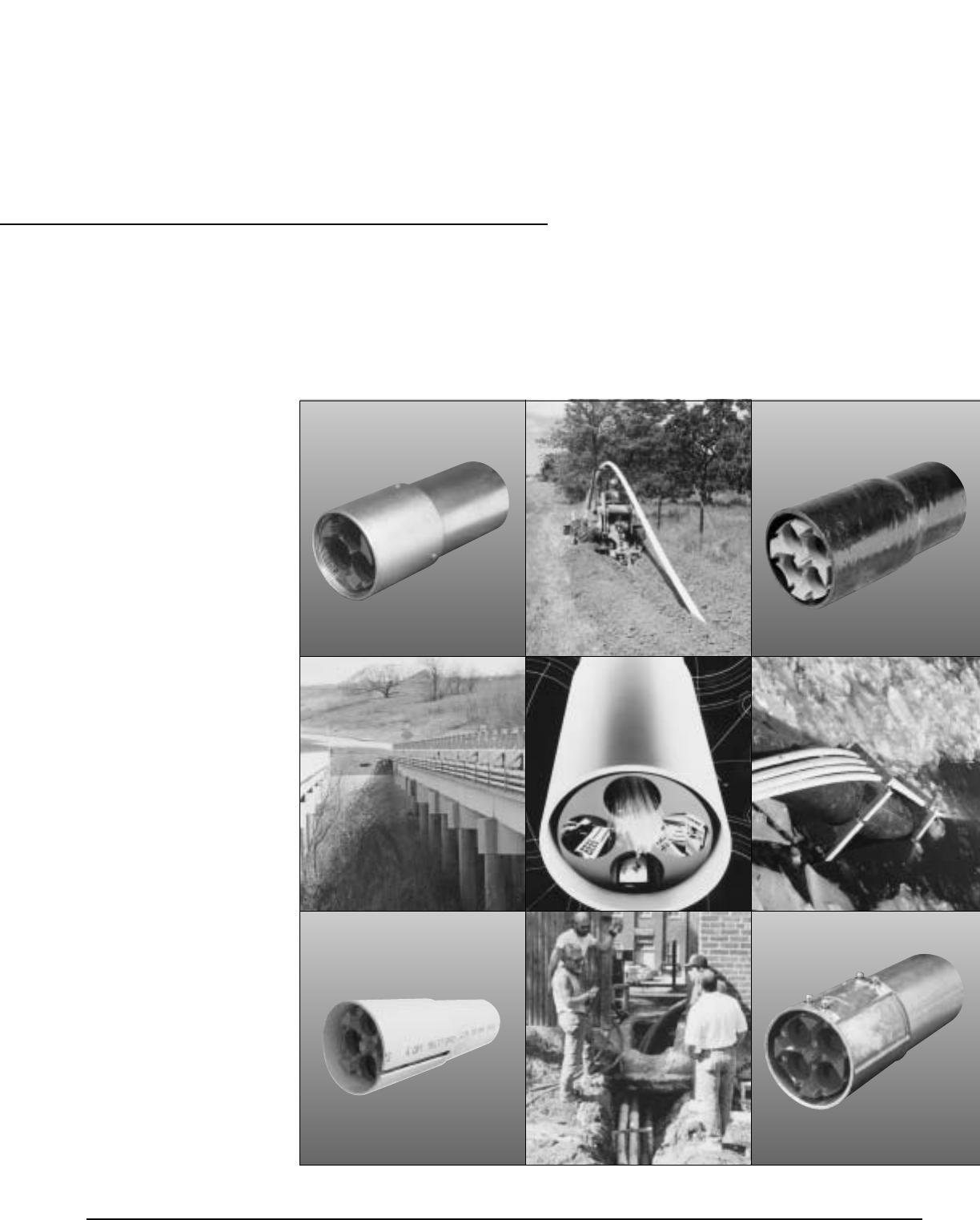
Carlon
®
Multi-Gard
®
Multi-Cell Raceway
PVC
Fiberglass
Galvanized Steel
PVC-Coated
Galvanized Steel
EMT – Electrical
Metallic Tubing
www.carlon.com 237
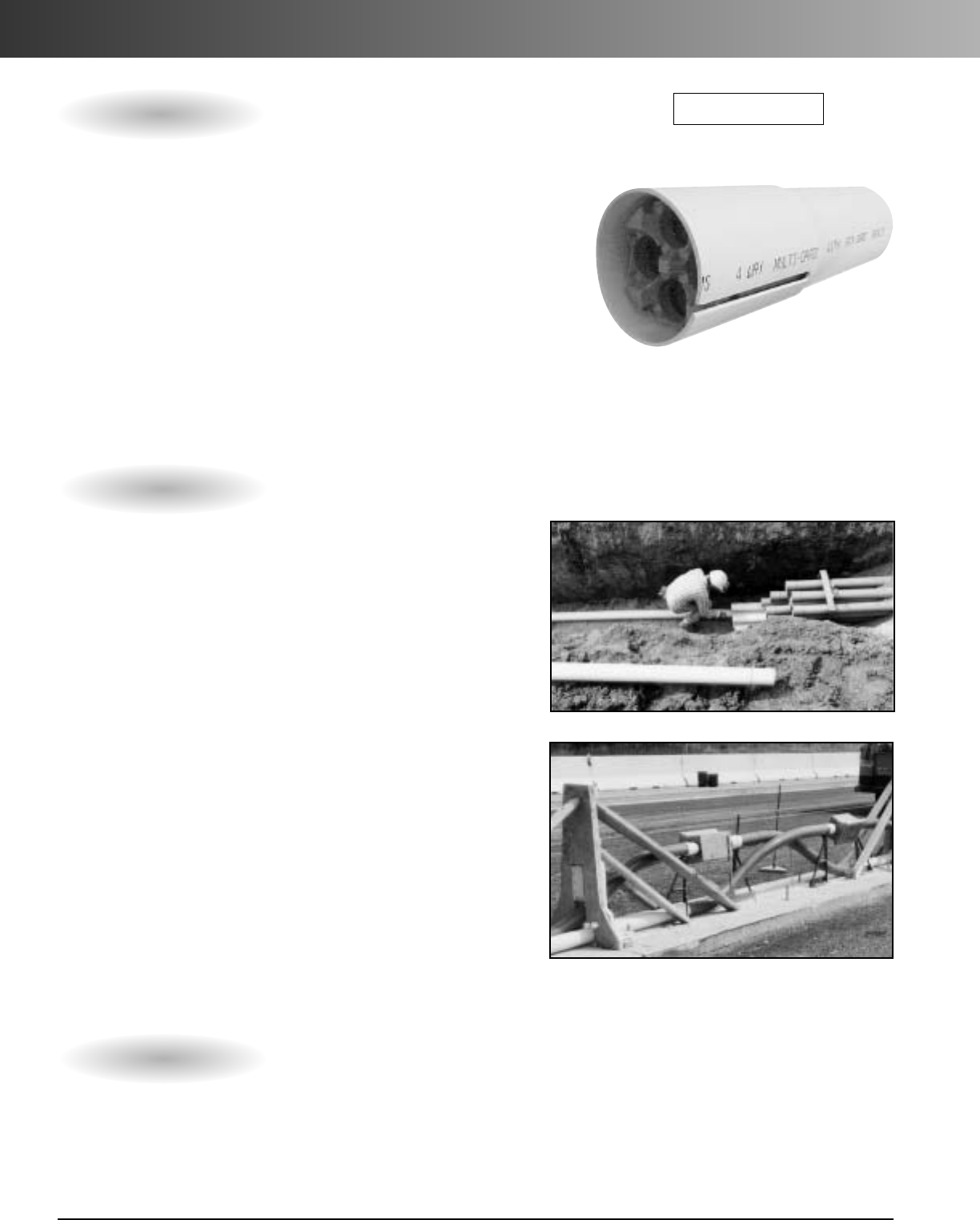
www.carlon.com
238
Multi-Gard
®
PVC
Carlon
®
Multi-Gard PVC
Features
Multi-Gard PVC is a multi-cell raceway system specifically
designed for use in direct bury and concrete encased
applications. Multi-Gard PVC is available in Type C, Type 40
and Type 80 outer shells with 3-way or 4-way innerduct
configurations. Multi-Gard PVC is manufactured in convenient
20ft. lengths for easy handling and transportation, and is ideal
for jetting or pulling cable.
Applications: Outdoor Direct Bury and Concrete Encasement
Wall Types: Type C, Schedule 40 and Schedule 80
Innerducts: 3-Way 11/2"or 4-Way 11/4"
Installation
Method: Trenching, Plowing, Concrete Encased
NOTE: Always install Bell End onto Spigot End
RUS Listed
•Pre-lubricated innerducts provide very low
coefficient of friction for easy pulls, and PVC innerducts
expand and contract at the same rate as outerduct.
• Anti-reversing gaskets on coupling body allow for easy
joining. Eliminates need for cementing joints.
• Jettable using high speed air blowing systems.
• O-ring gasket at base of bell reduces risk of water
entering system.
• Inward tapering holes on coupling body give quick and
easy innerduct alignment.
• Print line on outer duct states “Install Print Line Up” to
keep system straight during installation.
•Marked innerduct and marked hole on coupling body
ensure proper innerduct alignment and allow crews to
work from opposite directions.
• 6" deep bell provides strong joint for field bends.
•Internal spacers maintain straight innerduct path.
• End caps are provided on each 20 ft. section.
• Staging materials to job site is simplified.
• Patented flexible bends allow changes in direction.
Technical Information
•Joint Tensile: Approx. 500 lbs. (for reference only)
• 3,500 ft. maximum for Jetting
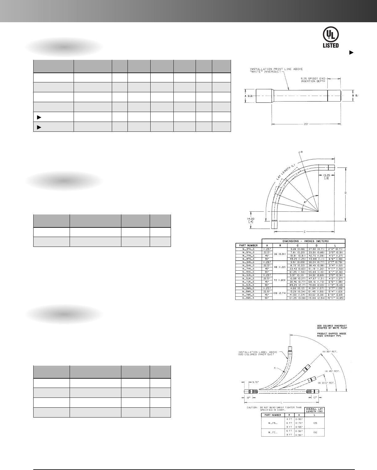
www.carlon.com 239
Multi-Gard
®
PVC
20' Lay Length PVC Multi-Cell With Bell
Part Bell Outerduct Innerduct Innerduct Pkg. Wt. per
No. Description (A) (B) O.D. I.D. Qty. 100 ft.
MXSS4S-020 4-Way Type C 4.67 4.35 1.31 1.19 1060' 245
MXSS3S-020 3-Way Type C 4.67 4.35 1.66 1.50 1060' 256
MFSS4S-020 4-Way Type 40 5.00 4.50 1.31 1.19 960' 338
MFSS3S-020 3-Way Type 40 5.00 4.50 1.66 1.50 960' 348
MDSS4S-020 4-Way Type 80 5.50 4.75 1.31 1.19 760' 450
MDSS3S-020 3-Way Type 80 5.50 4.75 1.66 1.50 760' 460
Standard Multi-Gard supplied with grey and one white tracer innerduct.
Custom Orders: *Custom innerduct colors available upon request
*Minimum order quantity required
*Custom orders non-returnable, non-refundable and non-cancelable
PVC Multi-Cell Fixed Bends With Bell
Part Innerduct Pkg.
No. Description I.D. Qty.
M___N4S 4-Way Fixed Bend 1.19 1
M___N3S 3-Way Fixed Bend 1.50 1
Pos. 1 Pos. 2 Pos. 3 Pos. 4 Pos. 5 Pos. 6 Pos. 7
Product Outerduct Degree(A) Radius(R) O.D. Innerducts
Innerduct Wall Type
M=Multi-Cell X = Type C 3 = 111/4F = 3ft. N = 4" 4 = 4-Way S = Smooth
F = Type 40 5=221/2H = 4ft. 3 = 3-Way
D = Type 80 7 = 45˚ J = 6ft.
9=90˚ M = 9ft.
Multi-Gard fixed bends use the same coupling design as straight sections.
All bends are provided with engineered plastic innerducts to avoid rope
burn-through. These fixed bends are jettable.
PVC Multi-Cell Flexible Bends With Bell
Part Innerduct Pkg.
No. Description I.D. Qty.
M_F_44-Way Flexible Bend 1.19 1
M_F_3 3-Way Flexible Bend 1.50 1
M_F_4J 4-Way Flexible Bend 1.19 1
M_F_3J 3-Way Flexible Bend 1.50 1
Pos. 1 Pos. 2 Pos. 3 Pos. 4 Pos. 5 Pos. 6
Product Outerduct Bell Description Degree and Radius Innerducts
M=Multi-Cell X = Type C F=Flexible B=126" (Length) 4 = 4-Way J = Jettable
F = Type 40 4' x 90˚ 3 = 3-Way
D = Type 80 C = 192" (Length)
6' x 90˚
Multi-Gard flexible bends use a patented design capable of a 4' minimum bend
radius and use the same coupling design as straight sections and fixed bends.
All bends are provided with an exclusive, patented engineered plastic innerducts
to avoid rope burn-through. NOTE: After positioning the bend in its application,
it is necessary to cut off the excess innerduct material flush to pipe and deburr
both the I.D.and O.D. of the innerduct to remove snags.
Except where noted by
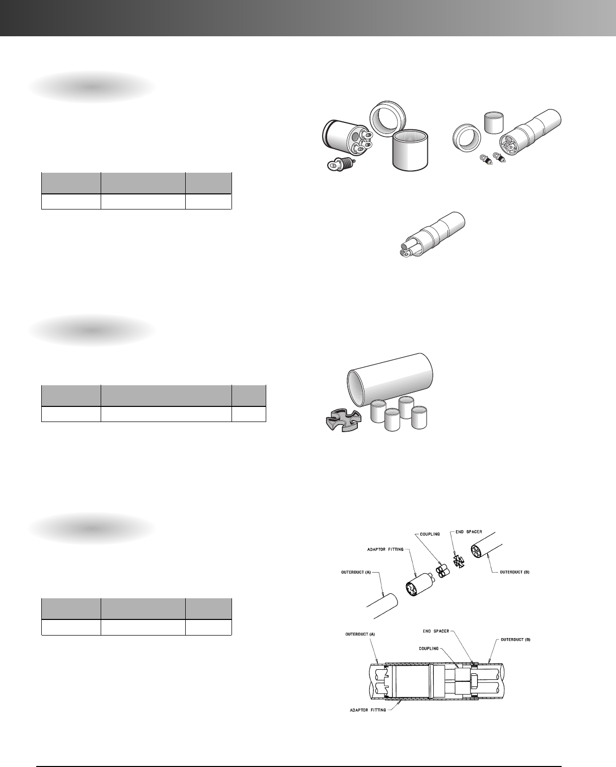
www.carlon.com
240
Multi-Gard
®
PVC – Accessories
Terminators
Part Pkg.
No. Description Qty.
M_T__ Terminator 1
Pos. 1 Pos. 2 Pos. 3 Pos. 4 Pos. 5
Product Outerduct Description Type Innerducts
M=Multi- X = Type C T = Terminator 1 = Standard w/ plugs 3 = 3-Way
Cell F = Schedule 40 2 = Pass-through w/ plugs 4 = 4-Way
D=Schedule 80 6 = Enclosure Termin. w/ plugs
9=Jetting Termin. w/ plugs
Termination kits allow for sealing inner and outerducts. Each kit con-
tains innerduct sealing plugs with rope tie. Standard terminators allow
for end terminations, and pass-through (jet-through) terminators allow
for bridging innerducts across a vault to allow for unassisted pulling
(or jetting) of cable through the vault. Box terminators allow end
terminations into above ground cabinets.
Transition Adapters
Part Pkg.
No.Description Qty.
M_A__ Transition Adapter 1
Pos. 1 Pos. 2 Pos. 3 Pos. 4 Pos. 5
Product Outerduct (A) Description Outerduct (B) Innerducts
M=Multi-Cell X = Type C PVC A = Adapter E = EMT 3 = 3-Way
F=Schedule 40 PVC R = Galv. Steel 4 = 4-Way
D = Schedule 80 PVC B = F/G BR
H=F/G HW
S=F/G Std.
F=Schedule 40 PVC
D=Schedule 80 PVC
X = Type C PVC
P=PVC-Coated Steel
Transition adaptors allow different outerducts to be coupled
together while maintaining same innerduct.
Part numbers configured from smaller duct to larger duct.
Standard
Standard
Pass-through
MT14
–
MT23
–
MCC4
–
M A 4
––
Jet-through
MT93
–
Couplings
Part Pkg.
No. Description Qty.
M_CC_Standard Sleeve Coupling 1
Pos. 1 Pos. 2 Pos. 3 Pos. 4 Pos. 5
Product Outerduct Description Type Innerducts
M=Multi- X = Type C C=Standard Coupling C = Coupling 3 = 3-Way
Cell F = Schedule 40 4 = 4-Way
D=Schedule 80
Couplings are provided in standard sleeve for joining two uninstalled
plain ends and slip couplings for male/male connections and repair of
unoccupied Multi-Gard. PVC expansion couplings are listed on page 227.
•Spigot to Spigot
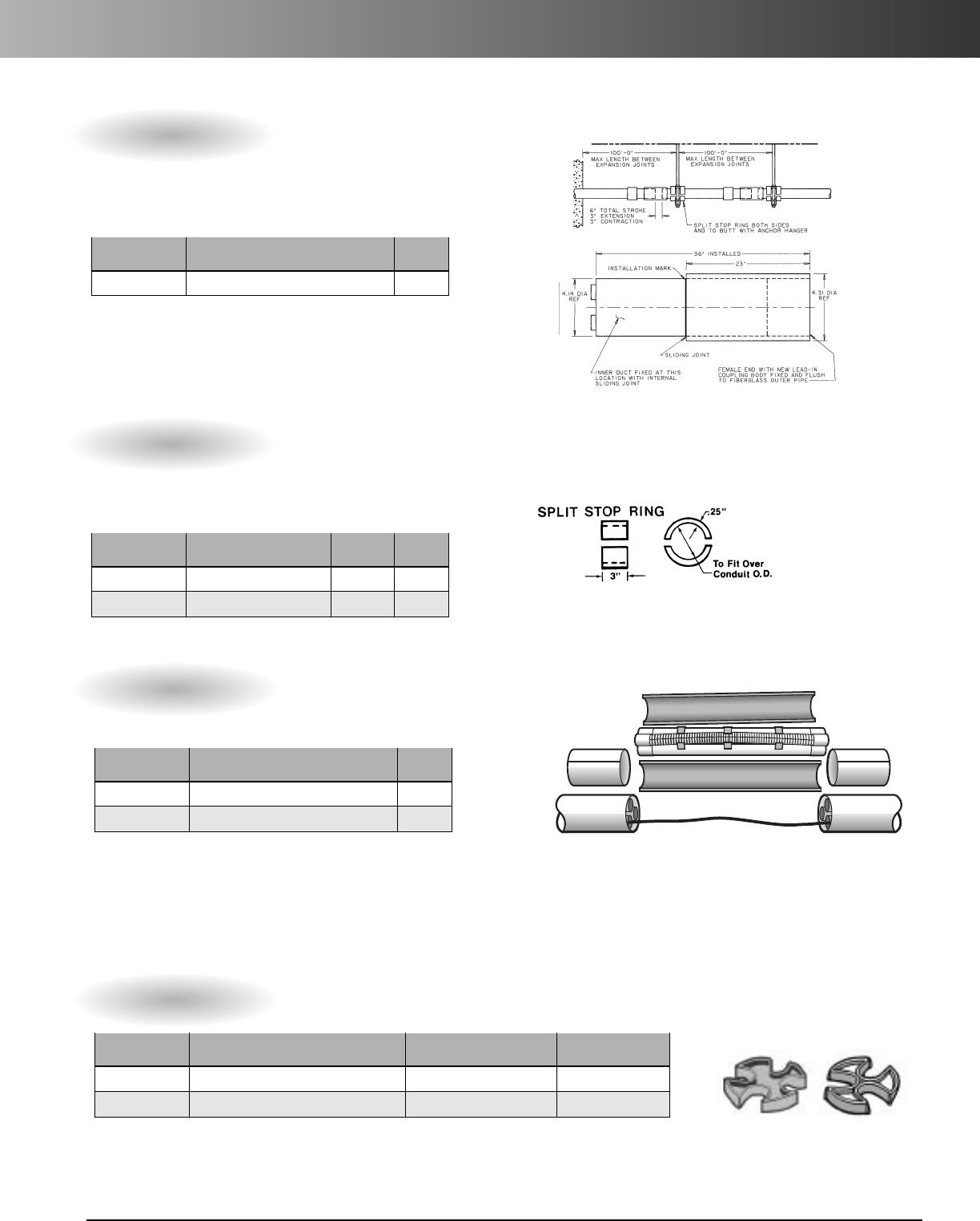
www.carlon.com 241
Multi-Gard
®
PVC – Accessories
Repair Kits – 10 Ft.
Part Pkg.
No. Description Qty.
M_R_4S 4-Way 10 ft. Repair - Cable installed 1
M_R_3S 3-Way 10 ft. Repair - Cable installed 1
Repair kits allow for Multi-Gard repair without disrupting a live cable.
MR3
––
Expansion Joints
Part Pkg.
No. Description Qty.
M_EC_Expansion Joint 1
Pos. 1 Pos. 2 Pos. 3 Pos. 4 Pos. 5
Product Outerduct Description Type Innerducts
M=Multi-Cell X = Type C PVC E = Expansion Joint C = Coupling 4 = 4-Way
F=Schedule 40 PVC 3 = 3-Way
D=Schedule 80 PVC
Expansion Joints allow for thermal expansion and contraction of
outerduct. Fiberglass expansion joints are recommended every 150 feet
onbridge crossing applications.
*Must use Split Stop Rings with Expansion Joints
Split Stop Ring
Part Pkg. Wt.
No. Description Qty. ea.
MFSSR Schedule 40 Split Ring 1 .51
MDSSR Schedule 80 Split Ring 1 .73
Use split stop rings on either side of support anchors
to keep Multi-Gard stationary.
*Must use Split Stop Rings with Expansion Joints
Pos. 1 Pos. 2 Pos. 3 Pos. 4 Pos. 5 Pos. 6
Product Outerduct Description No. of Cables Innerducts Innerduct Wall Type
M=Multi-Cell X = Type C R = Repair 1 = 1 Cable 4 = 4-Way S = Smoothwall
F=Schedule 40 2 = 2 Cables 3 = 3-Way
3=3Cables
4=4Cables
Spare Spacers
Part Std. Ctn. Std. Ctn.
No.Description Qty. Wt.
MAES4 4-way end spacers 1 ea. = 5 spacers 3.5
MAES3 3-way end spacers 1 ea. = 5 spacers .6
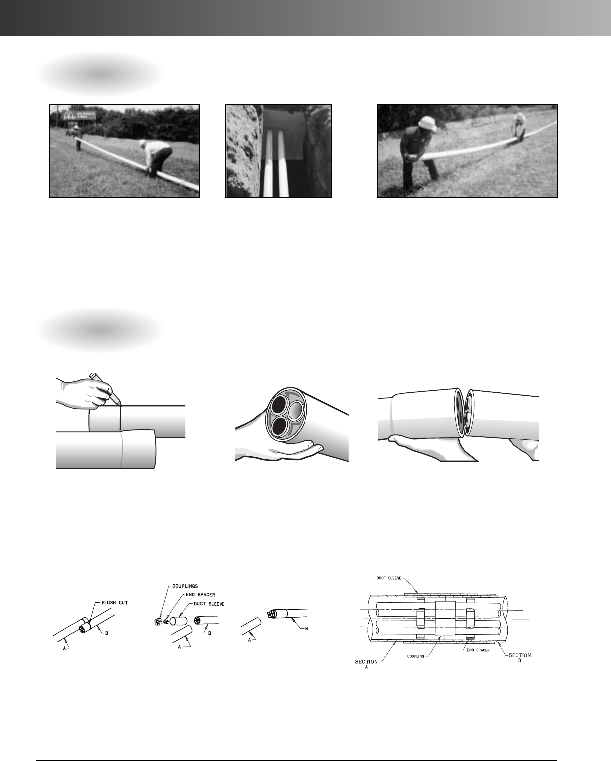
www.carlon.com
242
Multi-Gard
®
PVC – Assembly/ Field Cuts
Assembly
Field Cuts
1.
Distribute Multi-gard sections along
the sides of the trench with male ends
pointing towards starting vault entrance.
2.
Remove protective cap and
install Multi-Gard terminator on
male end. Install first section
into vault opening or enclosure
making sure the print line is on
the top stating “INSTALL PRINT
LINE UP.” (See next page for
terminations.)
2. Asparespacer may be
installed to align the innerducts
if they seem loose.
2.Align innerducts on Multi-Gardsection “A”with
couplings on section “B”. Solvent cement each coupling
for air tight seal and push until both ends are flush.
Apply solvent cement to both ends of Multi-Gardand
slide sleeve until it is centered on both sections.
3.
Each consecutive 20' section can now be
placed by inserting the male end into the gas-
keted belled end 1/2" to the gasket depth. Make
sure the print line is upright. (If not, rotate the
outer duct until it is.) Now push the sections
together with a firm push until belled end seats
against insertion line.
3. Raise both ends and align the innerducts
on the male end into the coupling body on
the female end. Lower both ends and the
innerducts will automatically return to their
original position as the joints areforced
together.
Joining Male and Female Ends
Joining Two Male Ends
1. Lay the Multi-Gardsections side by
side and mark the male end at the
base of the bell on the female end.
Make a straight cut using
astandardcarpenter saw.
1. Flush cut Multi-Gardsections “A”+“B”as shown in figure1. Slide
outerduct sleeve over Multi-Gardsection “B”as shown in figure#2.
Insert end spacer into Multi-Gard plain end (chamfer side in) as
shown in figure #2. Press couplings onto innerducts of Multi-Gard
section “B”as shown in figure#3.
FIGURE 1 FIGURE 2 FIGURE 3
MCC4
–
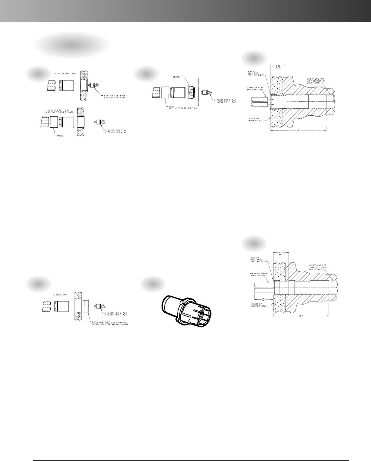
www.carlon.com 243
Multi-Gard
®
PVC – Terminations
Standard Terminators (Type 1) allow
Multi-Gard to be terminated into a
standard pre-cast termination.
1. Remove watertight plugs in order to
assure total insertion of the Multi-Gard
innerducts.
2. Install terminators into male end of
Multi-Gardto full depth.
3. Replace watertight plugs into the
terminator and tighten.
4. Insertprepared male end into the
pre-cast terminator with print line facing
upward. Solvent cement into place.
5. Use shim enclosed for terminator
requiring a connection of Type C
(4.35 O.D.) into a Type 40 (4.50 O.D.)
termination.
Use a Type 6 Enclosure Terminator at
entrances into metal or non-metallic
enclosures above ground.
1. Remove watertight plugs in order to
assure total insertion of the Multi-Gard
innerducts.
2. Install terminators into male end of
Multi-Gardto full depth.
3. Replace watertight plugs into the
terminator and tighten.
4. Install threaded adapter over end of
Multi-Gard using solvent cement. Insert
adapter through enclosure hole and
provide 4" locking ring.
5. Use shim enclosed for terminator
requiring a connection of type C (4.35
O.D.) termination.
The pass-through terminator is designed to
allow for continuous ducts through the vault
or hand hole for cable pulling.
1. Install terminator into vault following steps
1through 5 for standard Type 1 terminator.
2. Cut innerduct of pass through kit 10" longer
than the width of the manhole. Add spacers
as needed.
3. Upon completion, remove the watertight
plugs and install innerducts to traverse
manhole/handhole by cutting to length
inserting into one side of handhole and
raising or bowing center of innerduct span
to insertinto the pass-through terminator
on the opposite side. (See pass-through kits
on page 276.)
Use a Type 1 Standard Terminator also at an
entrance where a pre-cast terminator is not
available or a knockout is used:
1. Insert the male end section of Multi-Gard
4inches past the inside wall of the vault
with print line facing upward.
2. Remove the protective cap from the male
end of the Multi-Gard.
3. Remove the watertight plugs and insert
the terminator to full depth.
4. Install bell fitting over the end of
Multi-Gardusing solvent cement, and
replace plugs.
5. Slide Multi-Gard section until bell fitting is
flush with inside, and then seal entrance as
required by job specifications.
Use the jet terminator for jetting operations.
1. Remove watertight plugs in order to assure
to total insertion.
2. Apply standardgrade solvent cement
(VC9962) to male end of Multi-Gard. Install
jet terminator to insertion line.
3. Replace watertight plugs into terminator
and tighten.
4. Apply standard grade solvent cement to
terminator male end and insert into pre-cast
bell end. (Install PVC bell fitting in kit if pre-
cast bell end is not available).
5. Use shim enclosed for terminator requiring
aconnection of Type C (4.35" O.D.) into a
Type 40 (4.50" O.D.) termination.
6. Measure between ends of terminators on
opposite ends of vault, and cut innerduct to
length.
7. Solvent cement each coupling into place or
use mechanical coupling rated for use with
high speed air blowing systems.
Use split plugs for sealing Multi-Gard cells
where cable has been installed.
(See page 274)
Terminations
1. 3. 5.
4.
2.
6.

www.carlon.com
244
Multi-Gard
®
PVC – Installation
All PVC Trenching installation allows
Multi-Gard to be placed in the trench
one section at a time or over the
trencher for continuous feed.
Open trenching with Type C Multi-Gard
is recommended for direct burial or
concrete encased applications.
• Install one section at a time.
• Multiple-cells are installed as soon
as product is placed.
• Economical installation with
installation speed as fast as the
trencher.
•Easy installation with standard
equipment.
•Gasketed coupling body prevents
conduit pulling apart during
installation.
•Industry standard outer duct in
Type C is suitable for direct burial.
• Type 40 outershell and Type 80
outershell are available where
extra protection is necessary.
• Spacers inside outershell allow
PVC innerduct internal movement
allowing for more flexibility.
Paved Areas In paved areas, the surface should be carefully
cut to prevent unnecessary excessive width at the top of the
trench and help reduce the amount of surface to be repaved.
Trench Width For economical operation, particularly where
paving is involved, the trench width should be no greater than is
needed to provide adequate working space. Generally, this
dimension is controlled by the types of excavating equipment
used. As a minimum, the trench must be 5 inches wider than the
width of the conduit structure where backfill will be used and 3
inches wider where concrete encasement will be used.
Individual job specifications will dictate trench width.
Trench Bed Grade and level the trench bed. Where neces-
sary, provide sand and/or other granular backfill as bedding
material so the conduit will be evenly supported over the length
of each section.
Assembly On Top Of The Trench After preparing the
trench, the Multi-Gard can be assembled on top of the ground
outside of the trench by following the directions described on
page 5. Once joined together, the Multi-Gard can then be laid
gently into the trench. Backfill according to the job specifications.
Trench Feeding Multi-Gard Using Rollers This
procedure involves assembling the Multi-Gard above the
ground. After the first four or five lengths are assembled, place
on top of the trenching machine. The remainder of the duct can
be attached to the first section and assembled ahead of the
trencher on the ground directly above the intended place for the
trench. As the trencher advances forward, the Multi-Gard will
lay itself into the trench behind. Once placed in the trench,
backfill according to the job specification.
Trenching
Features Procedures
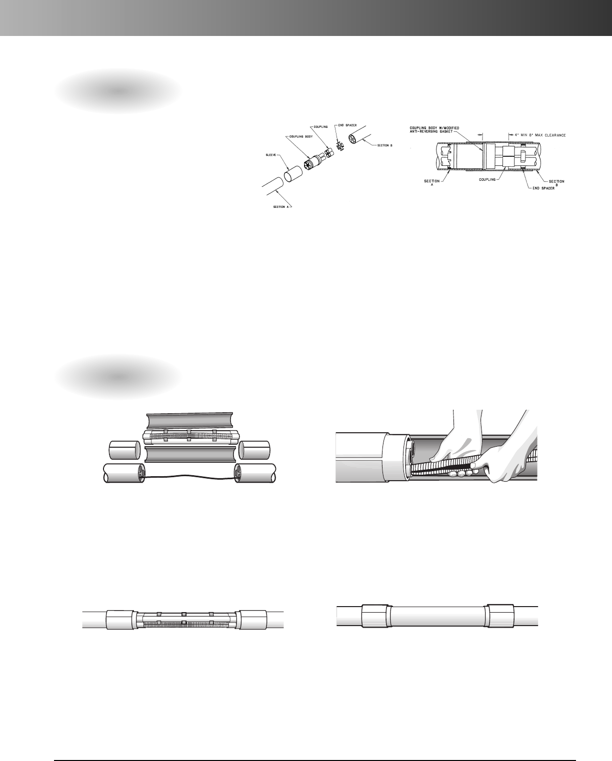
www.carlon.com 245
Multi-Gard
®
PVC – Repairs
Repairing Vacant Multi-Gard
Repairing Multi-Gard Containing Cable(s)
1. Cut out the damaged section
and insert a belled short section
(4" shorter than damaged
section) of Multi-Gard onto
either one of the ends (section A).
2. Apply 2" of cement on ends
of spigots of coupling body,
press couplings onto spigots.
3. Slide innerduct sleeve over
Multi-Gard plain end (section A).
Insert end spacer into Multi-
Gard plain end (section B).
1.
Carefully cut out damaged section up to 10
feet. Larger sections can be accommodated
using multiple repair kits.
3.
Install corrugated innerduct and remaining
smooth innerduct into couplings by raising in
the center and guiding them into their respec-
tive openings. Install the spacers to evenly
support the innerduct.
4.
Lay one piece of split duct under the
repaired section. Install the other piece of split
duct onto the first piece and strap or tape in
place. Apply cement onto each end and slide
the slip sleeves until centered on both sections.
Backfill according to job specifications.
2.
Install the 4" split sleeve couplings over
the existing Multi-Gard. Slide the smaller split
couplings onto the individual innerduct, fitting
the cable into the split coupling. Repeat this
process on opposite side. Carefully insert the
cable(s) into the split corrugated innerduct.
4. Insert female end of slip coupling
into Multi-Gard plain end (section A).
Align sections A and B. Apply cement
to couplings. Slide slip coupling back
onto innerducts in Multi-Gard
(section B) until seated.
5. Apply cement to both
plain ends of Multi-Gard
and slide sleeve until
centered on both sections.
M SC4
–
Slip Coupling
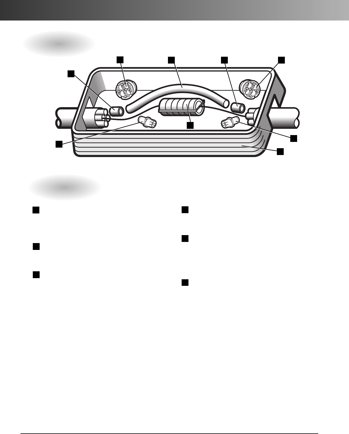
www.carlon.com
246
Multi-Gard
®
PVC – Repair Kits
Repair Kits
Repairing Multi-Gard with Damaged Cables
E940F PVC Coupling
Couples PVC innerduct with solvent cement
for empty cells (standard grade qt. cement
#VC9962).
MAFPG7 Fiber Optic Simplex Plug
(cable O.D. range .57 - .65) Seals innerduct
with cable installed.
MAQPG2 Quadplex Plug (4 holes each)
Seals outershell and innerduct
1
2
3
4
5
Repair Kit Instructions:
1.
Dig around break area enough to allow vault to
drop over the repair area and rest level when the
mouseholes have been cut away for the duct.
2.
Cut away and remove outer shell and any
damaged inner-ducts, being careful to protect
any exposed cables.
3.
Cut back the outer duct to allow approximately
6
"
of inner-duct exposed.
4.
Install the splice case per manufacturer’sor
customer’s specifications, allowing enough cable
slack so no tension is felt.
2
1
3413
2
5
6
6
48808DK PVC Pass-through Kit
(4 x 20' lengths) 20 foot lengths can be cut to
length for continuous empty innerduct.
Underground Vault & Lid needed
Choose size & construction based on dimensions
of splice cases and weight requirements. (Allow
12" on either side of splice for bending
innerduct)
Splice Case
5.
Install the quad plugs (Item #3) and single
plugs (Item #2) in duct containing cable.
6.
Install pass-through ducts (Item #4) with
coupling (Item #1) sealing with solvent cement.
7.
Set the enclosure base over the entire package
and place cover on enclosure.
8.
Refill hole as required.
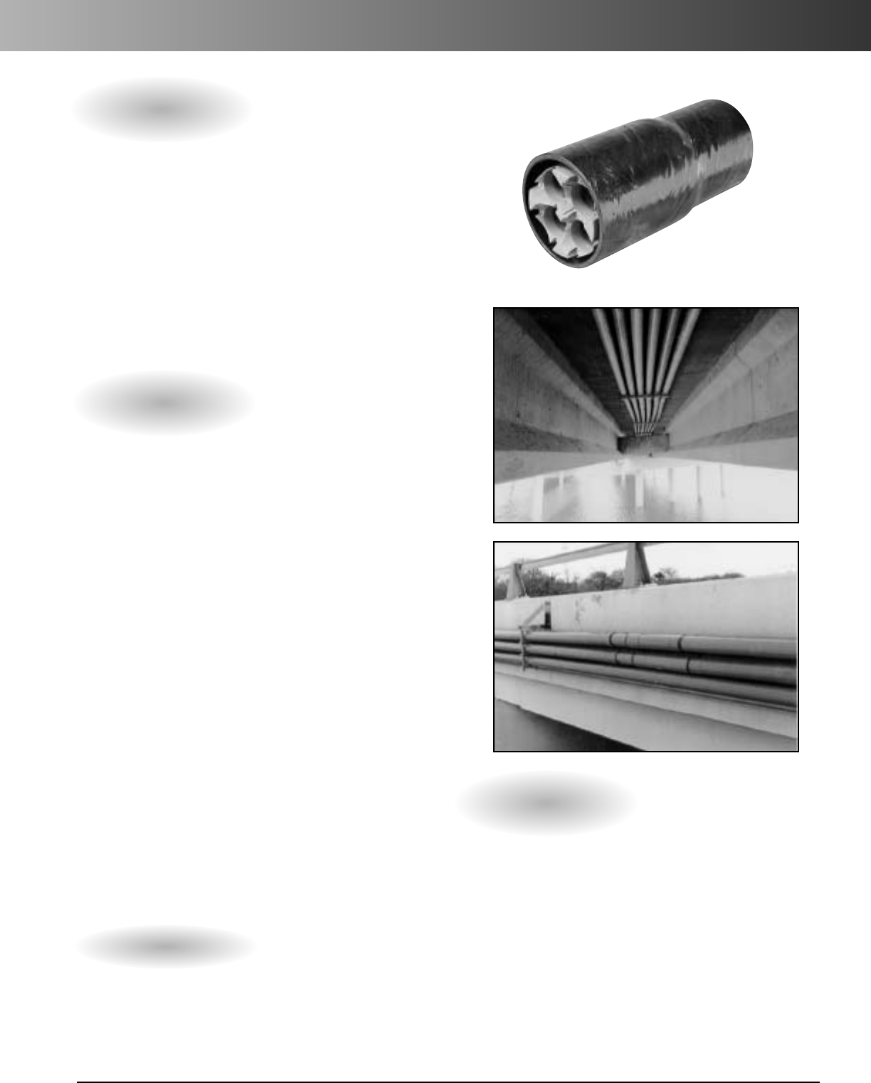
www.carlon.com 247
Multi-Gard
®
Fiberglass
Multi-Gard is a multi-cell raceway manufactured in 20 ft.
lengths with pre-installed, pre-lubricated innerducts.
The pre-installed innerduct design feature eliminates the
need of pulling innerducts through existing pipe, which
saves valuable time and money.
Applications: Outdoor (UV Resistant) Bridge Crossings,
Areas Subject to Physical Damage
Wall Types: Standard, Heavy or Bullet Resistant
Innerducts: PVC 3-Way
11/2"
or 4-Way
11/4"
•Pre-lubricated PVC innerducts reduce coefficient
of friction for easy cable pulling.
•Anti-reversing gaskets on coupling body allow
easy push in – hard to pull out sealing system.
•O-ring gasket at base of bell reduces risk of water
entering system.
•Inward tapering holes on coupling body give quick
and easy innerduct alignment.
•Marked innerduct and marked hole on coupling
body ensure proper innerduct alignment.
•Deep bell provides strong joint.
•Internal spacers keep innerducts straight.
•Staging materials to job site is simplified.
•Standard Wall .070" provides basic mechanical
and UV protection.
•Heavy Wall .090" provides enhanced mechanical
protection where physical abuse might be
experienced.
•Bullet Resistant .250" provides heavy duty
protection.
•Lightweight construction for easy handling.
Carlon
®
Multi-Gard
®
Fiberglass
Features
1. Place plain end of one 20' section into gasketed
coupling body 1/2" to the gasket depth of
another 20' section.
2. Check for alignment and apply epoxy to outside
of plain end.
3. Push sections together with a firm push by hand
until plain end seats fully into belled end.
Assembly Instructions
Technical Information
•Joint Tensile: Approx. 500 lbs. (for reference only)
• 3,500 ft. Maximum for Jetting
•20' overall stick length
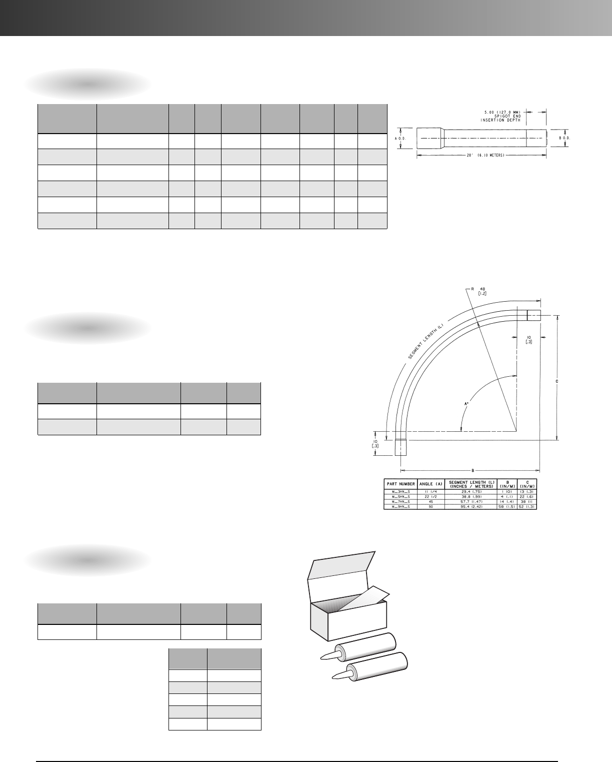
www.carlon.com
248
Multi-Gard
®
Fiberglass
20' Overall Length Fiberglass Multi-Cell With Bell
Wall Bell Outerduct Innerduct Innerduct Wt. per
Part Thick- (A) (B) Dim. Dim. Pkg. 100 ft.
No. Description ness Dim. Dim. O.D. I.D. Qty. (lbs.)
MSSS4S-020 4-Way Standard .070 4.31 4.14 1.31 1.19 1140' 240
MSSS3S-020 3-Way Standard .070 4.31 4.14 1.66 1.50 1140' 253
MHSS4S-020 4-Way Heavy Wall .090 4.39 4.18 1.31 1.19 1140' 338
MHSS3S-020 3-Way Heavy Wall .090 4.39 4.18 1.66 1.50 1140' 340
MBSS4S-020 4-Way Bullet Res. .250 5.00 4.25 1.31 1.19 1140' 450
MBSS3S-020 3-Way Bullet Res. .250 5.00 4.25 1.66 1.50 1140' 450
Standard Multi-Gard supplied with grey and one white tracer innerduct.
Custom Orders: *Custom innerduct colors available upon request
*Minimum order quantity required
*Custom orders non-returnable, non-refundable and non-cancelable
Fiberglass Multi-Cell Fixed Bends with Bell
Part Innerduct Pkg.
No. Description I.D. Qty.
M__HN4S 4-Way Fixed Bend 1.19 I.D. 1
M__HN3S 3-Way Fixed Bend 1.50 I.D. 1
Pos. 1 Pos. 2 Pos. 3 Pos. 4 Pos. 5 Pos. 6 Pos. 7
Product Outerduct Degree (A) Radius O.D. Innerducts Innerduct Wall Type
M=Multi-Cell S = Standard 3 = 111/4˚ H = 4 ft. N = 4" 4 = 4-Way S = Smoothwall
H=Heavy wall 5 = 221/2˚ 3 = 3-Way
B=Bullet Res. 7 = 45˚
9=90˚
Multi-Gard fixed bends use the same coupling design as straight
sections. All bends are provided with engineered plastic innerducts
to avoid rope cut-through into adjacent innerducts.
Epoxy Kits
Part Pkg. Wt.
No. Description Qty. ea.
MA30EK 30 oz. w/mixing tip 1 2.50
Apply epoxy to plain end and bell before insertion for a water
tight joint and to avoid joint pull-out.
Pipe # Joints per
Size 30 oz. Kit
2" 30
3" 24
4" 18
5" 12
6" 10
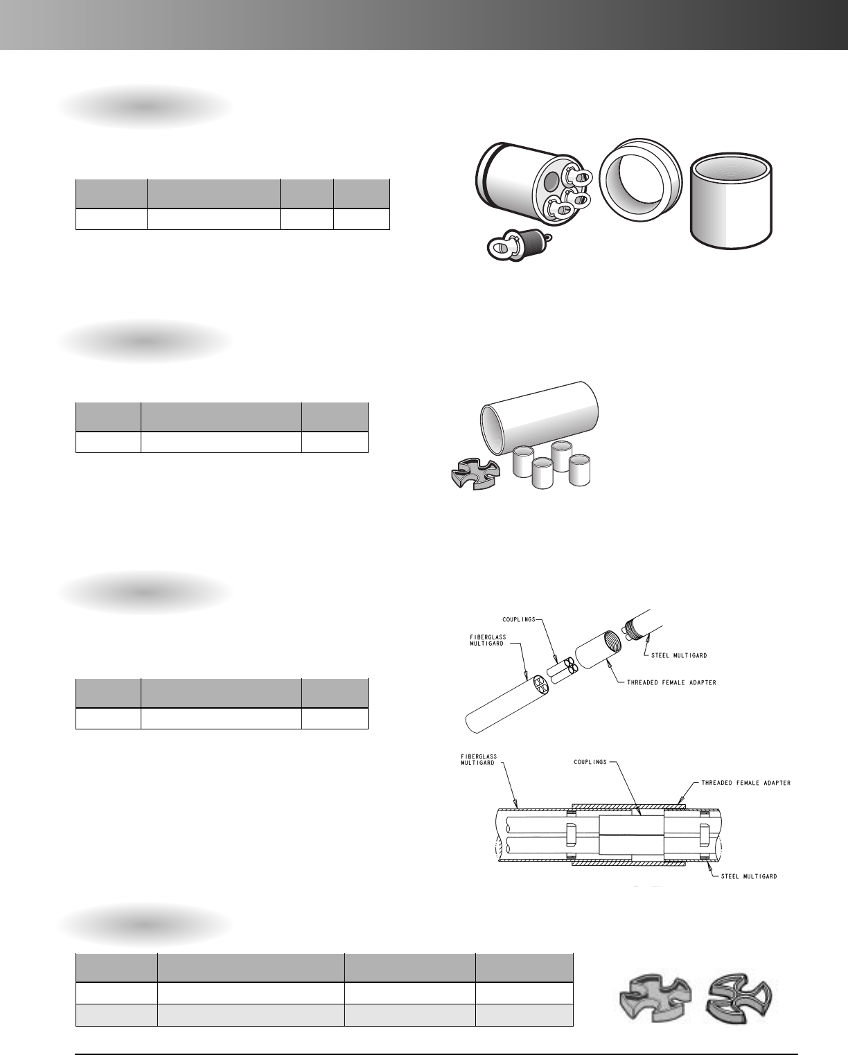
www.carlon.com 249
Multi-Gard
®
Fiberglass – Accessories
Standard
Standard
MXT14
MCC4
–
MAR4
–
Terminators
Pkg. Wt.
Part No. Description Qty. Ea
MXT1_Terminator 1 1.5
Pos. 1 Pos. 2 Pos. 3 Pos. 4 Pos. 5
Product Outerduct Description Type Innerducts
M=Multi-Cell X = Standard T = Terminator 1 = Standard w/ plugs 3 = 3-Way
4 = 4-Way
Termination kits allow for sealing inner and outerducts. Each kit contains
innerduct sealing plugs with tie rope. Standard terminators allow for end
terminations.
Couplings
Pkg.
Part No. Description Qty.
M_CC_Standard Sleeve Coupling 1
Pos. 1 Pos. 2 Pos. 3 Pos. 4 Pos. 5
Product Outerduct Description Type Innerducts
M=Multi-Cell S = Std. wall .070 C = Standard C = Coupling 3 = 3-Way
H=Hvy. wall .090 4 = 4-Way
B=B. res. .250
Couplings are provided in standard sleeve for joining two uninstalled
plain ends and slip couplings for repair of unoccupied Multi-Gard.
Transition Adapters
Pkg.
Part No. Description Qty.
M_A__ Transition Adapters 1
Pos. 1 Pos. 2 Pos. 3 Pos. 4 Pos. 5
Product Outerduct Description Outerduct Innerducts
M=Multi-Cell X = Type C PVC A = Adapter E = EMT 3 = 3-Way
F=Schedule 40 PVC R=Galv. Steel 4 = 4-Way
D=Schedule 80 PVC B = F/G BR
H = F/G HW
S=F/G Std.
F = Sch. 40 PVC
D=Sch. 80 PVC
X = Type C PVC
P=PVC Coated Steel
•Spigot to Spigot
Transition adapters allow different outerducts to be coupled
together while maintaining same innerduct.
(See PVC section for transitioning to PVC Multi-Gard.)
SpareSpacers
Part Std. Ctn. Std. Ctn.
No. Description Qty. Wt.
MAES4 4-way end spacers 1 ea. = 5 spacers 3.5
MAES3 3-way end spacers 1ea. =5spacers .6
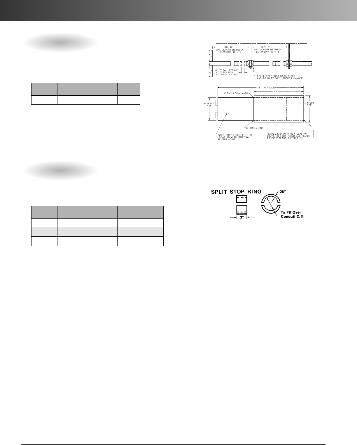
www.carlon.com
250
Multi-Gard
®
Fiberglass – Accessories
Split Stop Ring
Pkg. Wt.
Part No. Description Qty. Ea
MSSR Standard Wall Split Ring 1 .50
MSSRH Heavy Wall Split Ring 1 .50
MBSSR Bullet Resistant Split Ring 1 1.75
Use split stop rings on either side of support anchors
to keep Multi-Gard stationary.
*Must use Split Stop Rings with Expansion Joints
Expansion Joints
Pkg.
Part No. Description Qty.
M_EC_Expansion Joints 1
Expansion Joints allow for thermal expansion and contraction of
outerduct. Fiberglass expansion joints are recommended every 150
feet on bridge crossing applications.
*Must use Split Stop Rings with Expansion Joints
Pos. 1 Pos. 2 Pos. 3 Pos. 4 Pos. 5
Product Outerduct Description Type Innerducts
M=Multi-Cell S = Standard E = Expansion C = Coupling 4 = 4-Way
H=Heavy Wall 3 = 3-Way
B=Bullet Res.
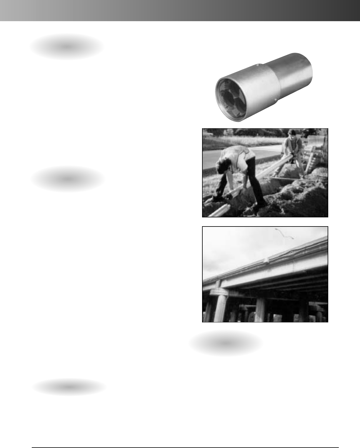
www.carlon.com 251
Multi-Gard
®
Galvanized Steel/PVC-Coated
Steel Multi-Gard is a multi-celled raceway system
designed for bridge applications and other areas
requiring heavy duty protection. Steel Multi-Gard
is manufactured in 10 ft. lengths with pre-installed,
pre-lubricated, smoothwall PVC innerducts.
Applications: Areas subject to physical
damage – vandalism & crush.
Bridge crossings
Innerducts: PVC 3-Way
11/2"
or 4-Way
11/4"
•Pre-lubricated PVC innerducts for very low
co-efficient of friction and lay straight for long pulls.
• Pre-installed reverse spin coupling allows coupling
Multi-Gard together without turning pipe.
•3set screws keep coupling from backing off,
before and after installation.
•Standard sweeps and terminators.
• Patented flexible bend.
• Conforms to NEC Article 300.22 and NFPA90A for
installation of communication cables inside buildings.
• All bends have “cut-through” resistant innerducts in
bends to avoid rope cutting into adjacent occupied
innerduct.
•Accessories such as pull line and line blowing kits
available.
•Gasketed coupling body and PVC innerducts
are designed to handle jetting equipment or line
blowing.
Carlon
®
Multi-Gard
®
Galvanized Steel/PVC-Coated
Features
1. Remove cap and loosen set screws on coupling.
Spin back to allow for insertion.
2. Insert male into female end and spin
coupling forward to bottom out.
3. Check for alignment of marked innerduct and
marked hole.
4. Tighten set screws.
Assembly Instructions
Technical Information
•Joint Tensile: Approx. 500 lbs. (for reference only)
• 3,500 ft. Maximum for Jetting
• 10 ft. lay lengths standard

www.carlon.com
252
Multi-Gard
®
Galvanized Steel
10' Lay Length – Steel Multi-Celled with Spin Coupling
Part Coupling Outerduct Innerduct Innerduct Pkg. Wt. per
No. Description O.D. Dim. Dim. O.D. Dim. I.D. Qty. 100 ft.
MRSS4S-010 4-Way Galvanized Steel 5.00 4.50 1.315 1.19 170 1130
MRSS3S-010 3-Way Galvanized Steel 5.00 4.50 1.660 1.50 170 1130
MPSS4S-010 4-Way PVC Coated Steel 5.00 4.50 1.315 1.19 170 1200
MPSS3S-010 3-Way PVC Coated Steel 5.00 4.50 1.660 1.50 170 1200
Standard Multi-Gard supplied with grey and one white tracer innerduct.
Galvanized Steel Multi-Cell Fixed Bends With Spin Coupling
Part Innerduct Pkg.
No. Description I.D. Qty.
MR_HN4S 4-Way Fixed Bends 1.19 1
MR_HN3S 3-Way Fixed Bends 1.50 1
Pos. 1 Pos. 2 Pos. 3 Pos. 4 Pos. 5 Pos. 6 Pos. 7
Product Outerduct Degree(A) Radius(R) O.D. Innerducts Innerduct Wall Type
M=Multi-Cell R=Galvanized 3 = 111/4˚H=4ft. N = 4" 4 = 4-Way S = Smooth
Steel 5 = 221/2˚ F = 3 ft. 3 = 3-Way
P=PVC Coated 7=45˚
Steel 9=90˚
Multi-Gard fixed bends use the same coupling design as straight sections. All bends are
provided with engineered plastic innerducts to avoid rope cut-through into adjacent innerducts.
PVC Coated Flexible Steel Bends With Spin Coupling
Part Innerduct
No.Description I.D.
MRFB4 4-Way Flexible Bend 1
MRFB3 3-Way Flexible Bend 1
Multi-Gard flexible bends use a patented design capable of a 4' minimum bend
radius and use the same coupling design as straight sections and fixed bends. All
bends are provided with engineered plastic innerducts to avoid rope cut-through
into adjacent innerducts. NOTE: After positioning the bend in its application, it is
necessary to cut off the excess innerduct material flush to pipe and deburr both
the I.D.and O.D. of the innerduct to remove snags.
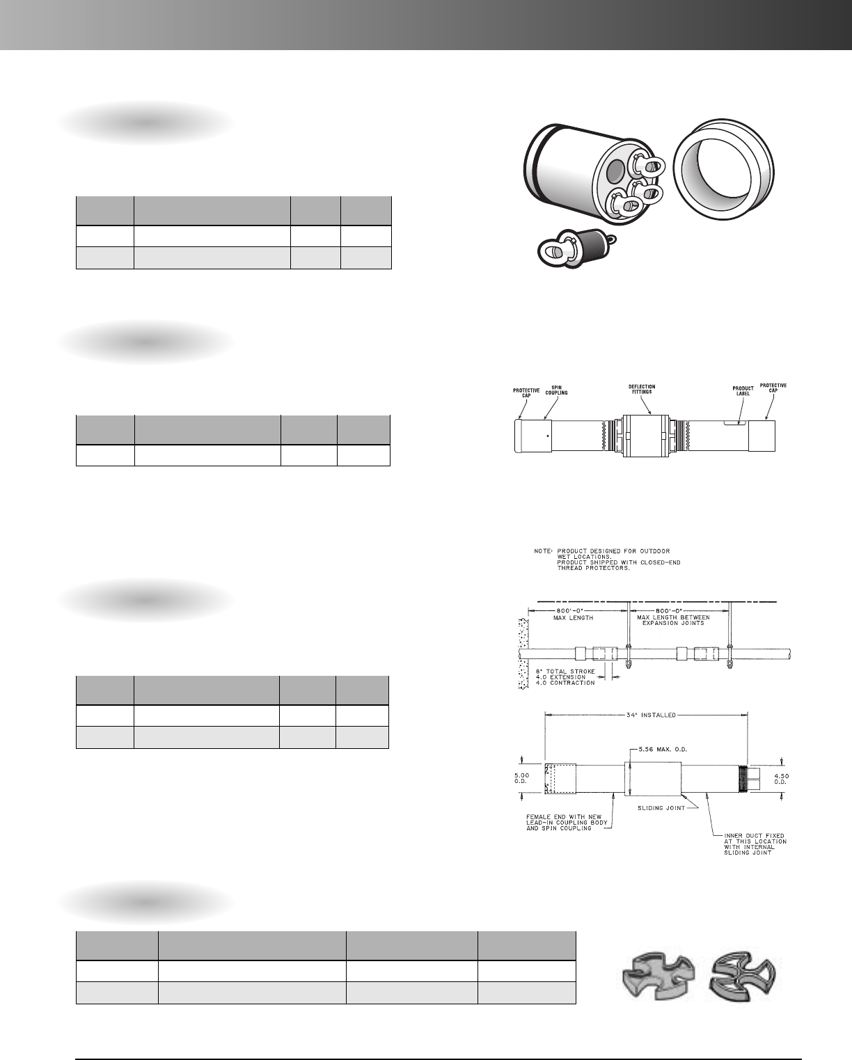
www.carlon.com 253
Multi-Gard
®
Galvanized Steel – Accessories
MFT14
Terminators Galvanized Steel
Pkg. Wt.
Part No. Description Qty. Ea.
MFT14 4-Way Standard Terminator GS 1 1.5
MFT13 3-Way Standard Terminator GS 1 1.5
Termination kits allow for sealing inner and outerducts. Each kit
contains innerduct sealing plugs with rope tie. Standard terminators
allow for end terminations.
Deflection Joint
Pkg. Wt.
Part No. Description Qty. Ea.
MROS_Deflection Joint 1 25 lbs.
Pos. 1 Pos. 2 Pos. 3 Pos. 4 Pos. 5
Product Outerduct Description Outerduct Innerduct
M = Multi-Cell R=Galv. Steel O=Offset/ S=Standard 4 = 4-Way
Deflection 3 = 3-Way
Couplings are provided in standard sleeve for joining two
uninstalled plain ends and slip couplings for repair of unoccupied
Multi-Gard.
Expansion Joints
Pkg.Wt.
Part No.Description Qty. Ea.
MREC4 4-Way 8" Stroke 1 42
MREC3 3-Way 8" Stroke 1 42
Expansion Joints allow for thermal expansion and contraction of
outerduct. Steel expansion joints are recommended every 150 feet
on bridge crossing applications.
Spare Spacers
Part Std. Ctn. Std. Ctn.
No. Description Qty. Wt.
MAES4 4-way end spacers 1 ea. = 5 spacers 3.5
MAES3 3-way end spacers 1 ea. = 5 spacers .6
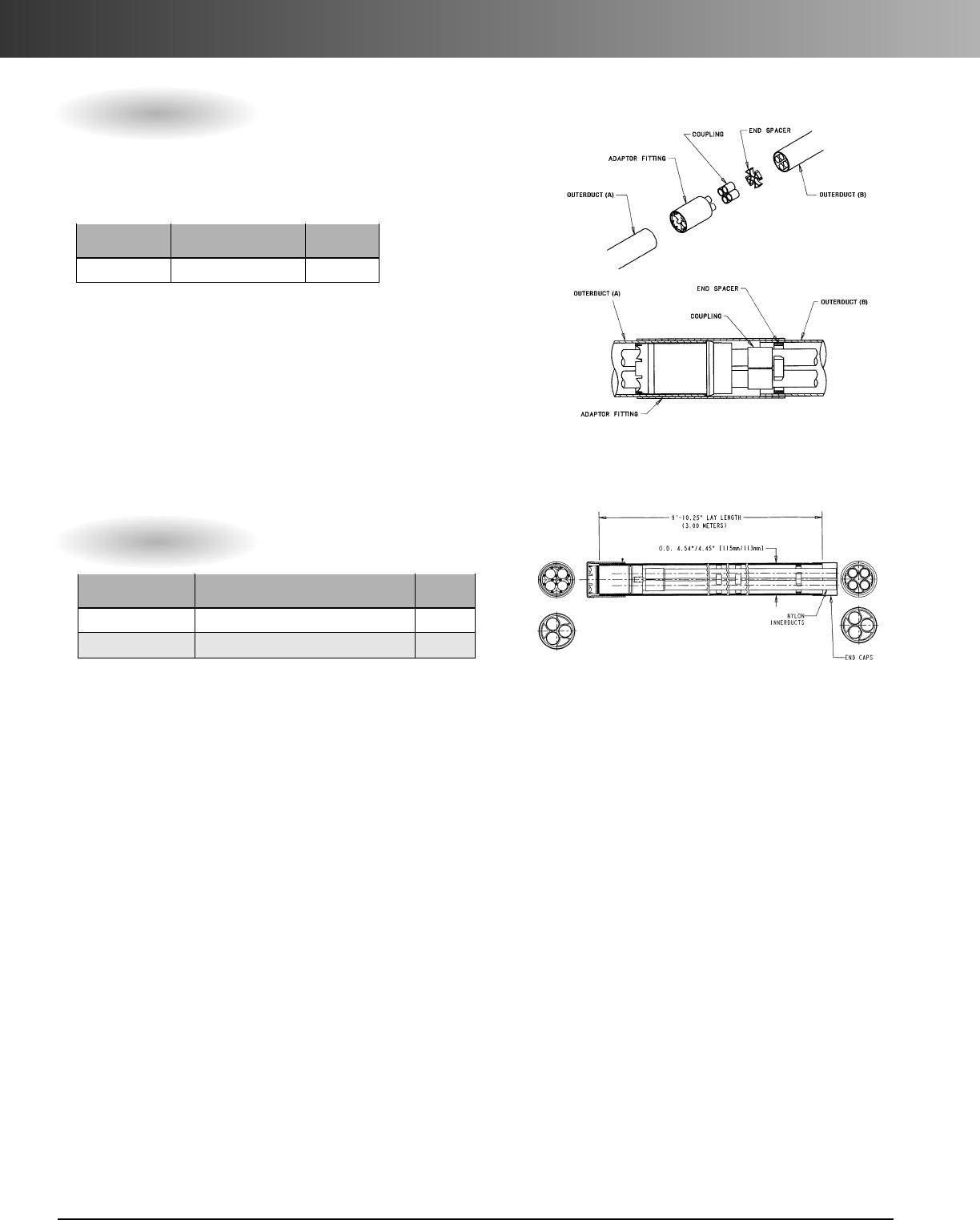
www.carlon.com
254
Multi-Gard
®
Galvanized Steel – Accessories
Transition Adapters
Part Pkg.
No. Description Qty.
M_A__ Transition Adapter 1
Pos. 1 Pos. 2 Pos. 3 Pos. 4 Pos. 5
Product Outerduct (A) Description Outerduct (B) Innerducts
M=Multi-Cell X = Type C PVC A = Adapter E = EMT 3 = 3-Way
F=Schedule 40 PVC R = Galv. Steel 4 = 4-Way
D=Schedule 80 PVC B = F/G BR
H = F/G HW
S=F/G Std.
F=Schedule 40 PVC
D=Schedule 80 PVC
X = Type C PVC
P=PVC Coated Steel
•Spigot to Spigot
Transition adaptors allow different outerducts to be coupled
together while maintaining same innerduct.
Part numbers configured from smaller duct to larger duct.
Field Bendable Sweeps
M A 4
––
Pkg.
Part No. Description Qty.
MRSS4SFB-010 4-Way Field Bendable Sweep - 10 ft. 1
MRSS3SFB-010 3-Way Field Bendable Sweep - 10 ft. 1
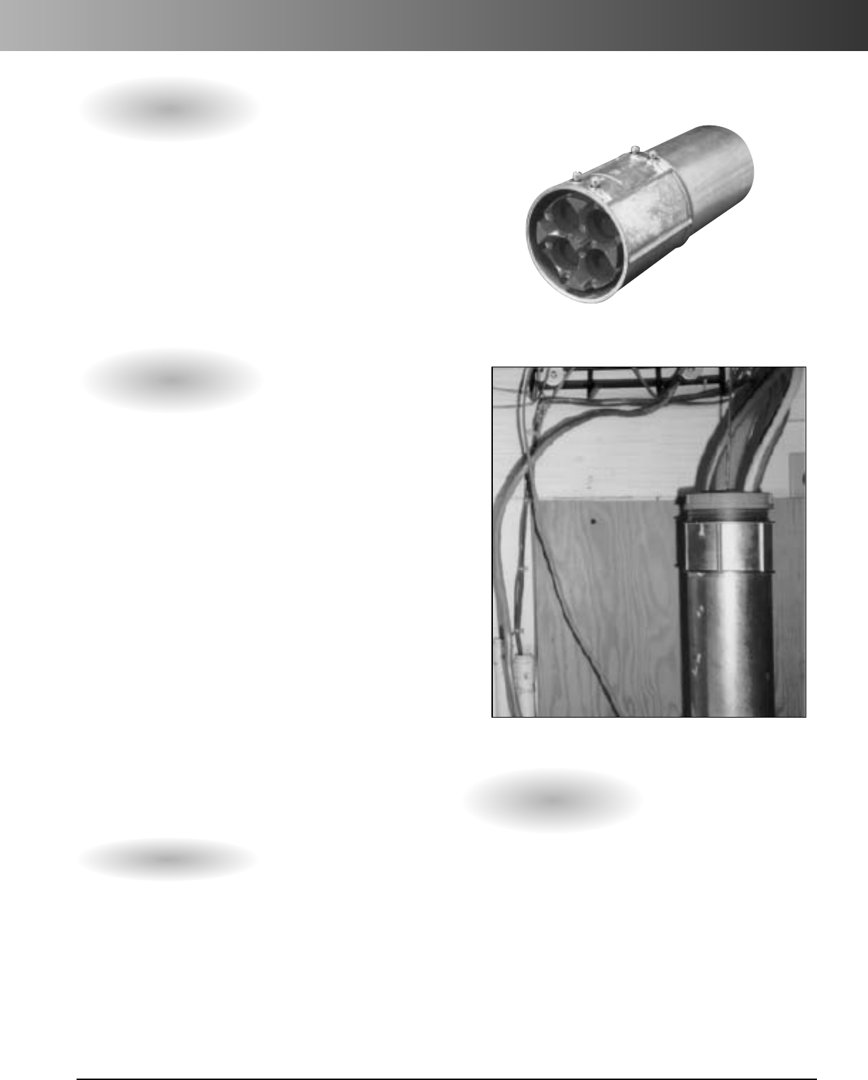
www.carlon.com 255
Multi-Gard
®
EMT
Multi-Gard EMT is a multi-cell conduit system
for use inside buildings. It has pre-installed
PVC innerducts, comes in 10 ft. lengths, and
has a gasketed coupling body.
Applications: Indoor – Inside Buildings
Innerducts: 3-Way
11/2"
or 4-Way
11/4"
•10' lengths with set screw couplings.
• Standard sweeps and terminators
• Transition adapters available such as
EMT to Type C Multi-Gard.
• PVC innerducts lay straight for longer pulls.
• PVC innerducts are pre-lubricated for longer pulls.
• All metallic components are UL Listed and conform
to meet NEC Article 300.22 and NFPA90A for
installation of communication cables inside buildings.
• All bends have “cut through” resistant innerducts to
avoid rope cutting into adjacent occupied innerduct.
• Accessories such as line blowing kits and pull line
available.
Carlon
®
Multi-Gard
®
EMT
Features
1. Remove cap and loosen set screws on open end
of coupling.
2. Insert male end of conduit into female coupling,
checking for alignment of marked innerduct into
marked hole.
3. Tighten set screws.
AssemblyInstructions
Technical Information
•Joint Tensile: Approx. 500 lbs. (for reference only)
• 3,500 ft. Maximum for Jetting
• 10 ft. lay lengths standard
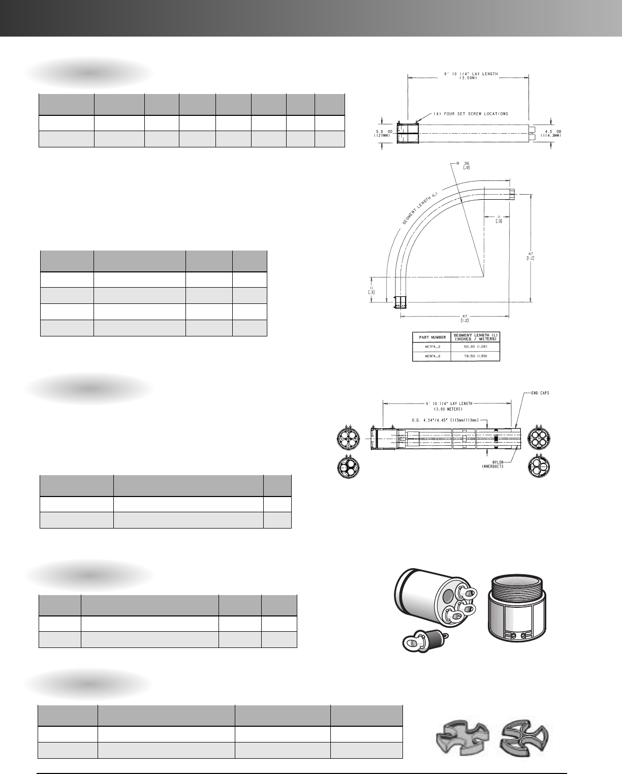
www.carlon.com
256
Multi-Gard
®
EMT
10' Lay Length EMT Multi-Cell with Set Screw Coupling
Part Outerduct Outerduct Innerduct Innerduct Pkg. Wt. per
No. Description Dim. O.D. Dim. I.D. Dim. O.D. Dim. I.D. Qty. 100 ft.
MESS4S-010 4-Way 4.50 4.33 1.32 1.19 170' 555
MESS3S-010 3-Way 4.50 4.33 1.66 1.50 170' 555
Fixed Bends EMT Multi-Cell with Set Screw Coupling
Part Pkg. Wt. Ea.
No. Description Qty. (lbs.)
ME9FN4S 4-Way 90˚x36" Radius 1 39
ME7FN4S 4-Way 45˚x36" Radius 1 20
ME9FN3S 3-Way 90˚x36" Radius 1 39
ME7FN3S 3-Way 45˚x36" Radius 1 20
Multi-Gard fixed bends use the same coupling design as straight
sections. All bends are provided with engineered plastic innerducts
to avoid rope cut-through into adjacent innerducts.
Terminators for EMT Multi-Gard
Part Pkg. Wt. Ea.
No. Description Qty. (lbs.)
MET64 4-Way Standard Enclosure Terminator 1 2.5
MET63 3-Way Standard Enclosure Terminator 1 2.5
Field Bendable Sweeps
Pkg.
Part No. Description Qty.
MESS4SFB-010 4-Way EMT Field Bendable Sweep - 10 ft. 1
MESS3SFB-010 3-Way EMT Field Bendable Sweep - 10 ft. 1
Spare Spacers
Part Std. Ctn. Std. Ctn.
No.Description Qty. Wt.
MAES4 4-way end spacers 1 ea. = 5 spacers 3.5
MAES3 3-way end spacers 1 ea. = 5 spacers .6
Multi-Gard flexible bends use a patented design capable of a 4' minimum
bend radius and use the same coupling design as straight sections and fixed
bends. All bends are provided with engineered plastic innerducts to avoid rope
cut-through into adjacent innerducts. NOTE: After positioning the bend in its
application, it is necessary to cut off the excess innerduct material flush to
pipe and deburr both the I.D. and O.D. of the innerduct to remove snags.
www.carlon.com 257
Multi-Gard
®
Performance Specifications
PVC Fiberglass Steel
Type C Type 40 Type 80 SW HW BR EMT GRC
Min. stiffness lb/in/in at 72˚ F 100 370 Crush 2000 40 90 N/A N/A N/A
Min. O.D. 4.35" 4.50" 4.75" 4.14" 4.18" 4.50" 4.50" 4.50"
Impact values ft/lbs. at 72˚ F 100 220 525 50 80 N/A N/A N/A
Max. joint insertion force 80 lbs. 80 lbs. 80 lbs. 80 lbs. 80 lbs. 80 lbs. 80 lbs. 80 lbs.
Max. joint separation force 200 lbs. 200 lbs. 200 lbs. 200 lbs. 200 lbs. 200 lbs. Mechanical Mechanical
Min. joint water infiltration 11 PSI 11 PSI 11 PSI N/A N/A N/A N/A N/A
Min. lay length 20' 20' 20' 20' 20' 20' 10' 10'
Flexible bend min. radius 4' 4' 4' 4' 4' 4' 4' 4'
4-way 3-way
Min. stiffness lb/in/in at 122˚ F 170 140
Air burst pressure rating 200 PSI 200 PSI
COF requirements TSY-356 Pass .06 - .09 Pass .06 - .09
Cut-through testing TSY-356 (in bends) Pass 100 min. Pass 100 min.
1.01 SCOPE:
Multiple Celled raceway systems, such as Multi-Gard
manufactured by Carlon Telecom Systems (1-800-3-CARLON),
utilizing prelubricated PVC innerducts for installation of voice, data,
video, and other low voltage cabling. Different outershells are
provided for routing cabling through direct bury, concrete encased,
normal above ground, and heavy duty above ground applications.
1.02
SYSTEM DESCRIPTION: Industry standard communication out-
erducts and innerducts meeting the performance requirements
of this specification. Fixed and flexible bends allow for changes in
direction. A gasketed coupling mechanism shall be provided with
self-aligning tapered holes in straight sections, bends, and
terminators for field assembly without lubricant.
2.01 MATERIALS
A. Outerducts
1. PVC outerduct shall have print line
stating “INSTALL PRINTLINE UP”
and be available in the following:
a. Type C U.L. listed for direct burial
and concrete encasement.
b. Type 40 U.L. listed for direct burial
and concrete encasement.
c. Type 80 for heavy traffic direct
burial and physical abuse above
ground.
2. Fiberglass reinforced epoxy shall be
available in the following:
a. .070 Standard Wall for basic
mechanical and UV protection
above ground.
b. .090 Heavy Wall provides enhanced
mechanical protection where phys-
ical abuse might be experienced.
c. .250 Bullet Resistant provides
heavy duty protection.
B. Outerduct Performance Requirements
Part 1 General
Part 2 Product
1. Innerducts in straight lengths shall be Prelubricated PVC. One
white innerduct shall be under the print line with other
innerducts being gray. Multi-Cell can be assembled from
different directions without “mirror” effect. Multi-colored
innerducts may also be provided (3-cell white/gray/orange)
(4-cell white/gray/orange/green).
D. Innerduct Performance Requirements
C. Innerducts
2.
Innerducts in all bends shall not cut through when subjected to a 1/4"
polyprolene rope pulled at 100 ft/min at 450 lb. tension for 100 minutes
tested in accordance with Bellcore TR-TSY-000356 procedures.
3. Anon-cemented spacer system shall hold the 4-cell innerducts
in a square configuration and 3-cell innerducts in a triangular
configuration.
3. Galvanized steel shall be available in the following:
a. Type 40 Hot dipped inside and out for above
ground applications such as bridge abutment
walls. Threads shall be on both ends. Spin
Coupling shall have 3 set screws set 120˚ apart
to stabilize coupling. Threads shall be coated
with Zinc Oxide metalizing.
b. U.L. listed EMT outershell and couplings for
inside building applications including Plenums,
Risers, and General Purpose areas.

www.carlon.com
258
Multi-Gard
®
Performance Specifications
Feature Multi-Gard
Pre-lubricated PVC Innerducts Yes
Assembles without lubricant Yes
Type C, Type 40, Type 80 Yes
Fiberglass in .070, .090, .250 Yes
EMT for Inside Building Yes
Galvanized Steel with Reverse Spin Coupling/PVC Coated Galvanized Yes
Flexible Sweeps capable of 4' bend radius Yes
Engineering Assistance Yes
Local Training and Assistance Yes
20 Foot Lay Lengths Yes
Local Stock Yes
U.L. Listed Yes
Recommended for Boring Yes
Watertight Yes
Holds 120 PSI for Jetting Yes
No Solvent Cement Required Yes
(Except in Boring and Jetting Applications)
Pulling Planner for Pull Point location Yes
Drawings on Disk Yes
Multi-Gard®Gards Your Networks!
B. Accessories
1.Slip couplings to allow male/male connections.
2.Termination kits for vaults, handholes, enclosures,
pass-through and jet-through applications.
3. Repair kits for future repair of empty or occupied duct.
PVC Fiberglass Steel
Type C Type 40 Type 80 SW HW BR GRC EMT
Fixed bend radius available 3', 4', 6', 9' 3', 4', 6', 9' 3', 4', 6', 9' 4' 4' 4' 4' 3'
Flexible bend 10' 1/2"length 4' x 90˚ 4' x 90˚ 4' x 90˚
Use GRC Use GRC Use GRC
4' x 90˚ (12') Use GRC
Flexible bend 16' length 9' x 90˚ 9' x 90˚ 9' x 90˚
Use GRC Use GRC Use GRC
4' x 90˚ (12') Use GRC
2.03 BENDS AND ACCESSORIES
A. Bends
3.01 DELIVERY, STORAGE, HANDLING
A. All materials shall be furnished by same manufacturer.
B. Local personal field support shall be available.
C. Product application assistance shall be provided by
manufacturer as needed.
4. Drop kits for future dropping of empty or occupied duct.
5. Line blowing kits with missiles.
6. 1700 lb. Slick braid rope, 1130 lb. poly rope, twisted blow line, and
1250 lb. polyester woven tape.
D. All flexible bends must be shipped in protective shipping
containers.
E. Manufacturer shall supply installation instructions.
Part 3 General
www.carlon.com 259
Multi-Gard
®
Cost Comparison Chart
1. Eliminates the need to place innerducts into an empty con-
duit. Multi-Gard contains factory installed innerducts.
2. Multi-Gard factory pre-installed PVC innerducts provide a
straight path for the placement of cable.
3. Reduced installation cost. The cost of installing innerducts is
eliminated and innerduct waste is eliminated.
4. Multi-Gard prelubrication formula provides the lowest coeffi-
cient of friction available.
5. The Multi-Gard gasketed coupler system eliminates cement-
ing sections except when boring or jetting.
6. Multi-Gard patented fixed bends and flexible bends incorpo-
rate “cut-through” resistant innerducts. Pre-installed engi-
neered plastic innerducts prevent pull lines from cutting into
the innerduct sidewall when pulling around bends. Bends
containing HDPE or PVC innerducts do not have the same
resistance to cut-through.
7. Open the trench just once. Multi-Gard allows customers addi-
tional cells to upgrade their Telecom Network System.
8. Multi-Gard factory installed innerducts allow more innerducts
to be placed inside the 4" conduit (4 x 1.19" and 3 x 1.50").
When placing innerducts you are limited to (3 x 1.25" or 2 x
1.5") on many systems.
9. Multi-Gard factory installed innerducts avoid the risk of
“neckdown”
.Neck-down occurs when innerducts are pulled
past their tensile strength, causing the plastic to stretch out.
10. All material arrives on the job site at the same time! Crews
can begin assembly without waiting for additional material to
deliver. After installing Multi-Gard there are no empty reels to
return or dispose.
Cost of Raceway and Pulling 3 x 1.25" Innerducts
4" Conduit Type C 5,300' .75 per ft. 3975 same for both
90˚ x 48" 2 15.00 each 30 same for both
Pull Boxes 5 300.00 each 1500 50.00 /ea. 250
Terminators 8 25.00 each 200 same for both
Plugs 24 2.00 each 48 same for both
Pulling Eyes 3 60.00 each 180 10.00 ea. 30
Pulling Harness 1 60.00 each 60 10.00 ea. 10
Innerduct 16,000 .30 per ft. 4800 16,000' x .25 /ft. 4000
Lubricant 16,000 .02 per ft. 320 2.00 per 100 ft. 320
Cement 10 qt. 4.00 qt. 40 5,300 20' = 265 x .25 /ea. 66
Reel Disposal 3 25.00 each 75 10.00 /ea. 30
Mid. Assist. Equip. 2 x 8 hrs. 100.00 hr. 800 5,300 x .10 /ft. 530
12028 5236 17264
Material Qty. Cost Total Labor Cost Total
800' 1500'
1500' 1500'
800'
4500'
PASS-THROUGH
Cost of Multi-Gard with 3 x 1.5" Innerducts or 4 x 1.19" Innerducts Pre-installed
Multi-Gard®Type C 5,300 2.50 per ft. 13250 same
90 x 48" 2 75.00 each 150
Pull Boxes 3 300.00 each 900 50 /ea. 150
Term. w/ Plugs 2 35.00 each 70 same
Term. Pass Thru 4 60.00 each 240 same
Pre-Lubricant Included N/C -0- -0-
Mid. Assist. Equip. Not Required N/C 5300 x .10 /ft. 530
14610 680 15290
Material Qty. Cost Total Labor Cost Total
*Carlon can also help determine handhole/manhole placement with
Pull-Gard™cable pulling software.Call 1-800-322-7566.
Multi-Gard Saves You Money! Multi-Gard®vs. Conduit and Pulled Innerduct Cost Comparison
Additional Benefits of Using Multi-Gard:

www.carlon.com
260
And The Winner Is...
Amajor telephone company sponsored a competition
to compare and evaluate the two leading multi-cell
conduit systems currently available in the communications
industry.
Under the supervision of the telephone company, an
independent contractor was hired to install the two
multi-cell conduit systems meeting standard installation
requirements. Additionally, a consultant was retained by
the telephone company to monitor the test pulls and
prepare a product evaluation for each multi-cell conduit
system.
The following information was compiled from the
consultant’sreport. Values stated were derived from
actual field measurements or calculated from field
measurements.
Carlon’s multi-cell conduit system, Multi-Gard®, offered
smooth wall PVC innerducts with factory applied silicone
lining. The competitor’s multi-cell conduit system offered
alongitudinal ribbed polyethylene, silicone lined innerduct
product.
The installation layout selected for the trial consisted
of a 4,900-foot section that included numerous horizontal
and vertical directional changes, eight manholes, and a
road bore. Additionally, record-breaking rainfall made the
competition even more intense.
The cable selected for the trial consisted of a six pair,
copper cable with a low density polyethylene jacket. This
particular cable was selected because it is approximately
the same weight and diameter as many fiber-optic cables.
The low density polyethylene jacket placed the evaluation
under the worst possible coefficient of friction conditions.
Carlon’s Multi-Gard system successfully completed
the trial pull with the test cable. The competitor’s system
could not.
A 1/4" composite rope (braided polyethylene over
braided polyester) was blown into the innerduct of
Carlon’sMulti-Gard. The force required to pull the rope
through the 4,900 feet was 27 pounds. This force was
measured after the rope rested in the flooded innerduct
for more than 10 hours.
The test cable required a maximum pull force of 440
pounds to complete the 4,900 feet trial. At 4,173 feet into
the pull, the cable jacket yielded and the pull came to a
stop. The basket grip was re-installed on the cable and
only 267 pounds of force was required to start the cable
moving.
Using the values measured and the tension forecasting
software provided by the consultant, the coefficient of
friction was calculated as follows:
Pull Rope .09
Test Cable .18
Cable B .13
Just One More Example Of How You Can
’t Beat The System!
Multi-Gard
®
Multi-Cell Conduit System
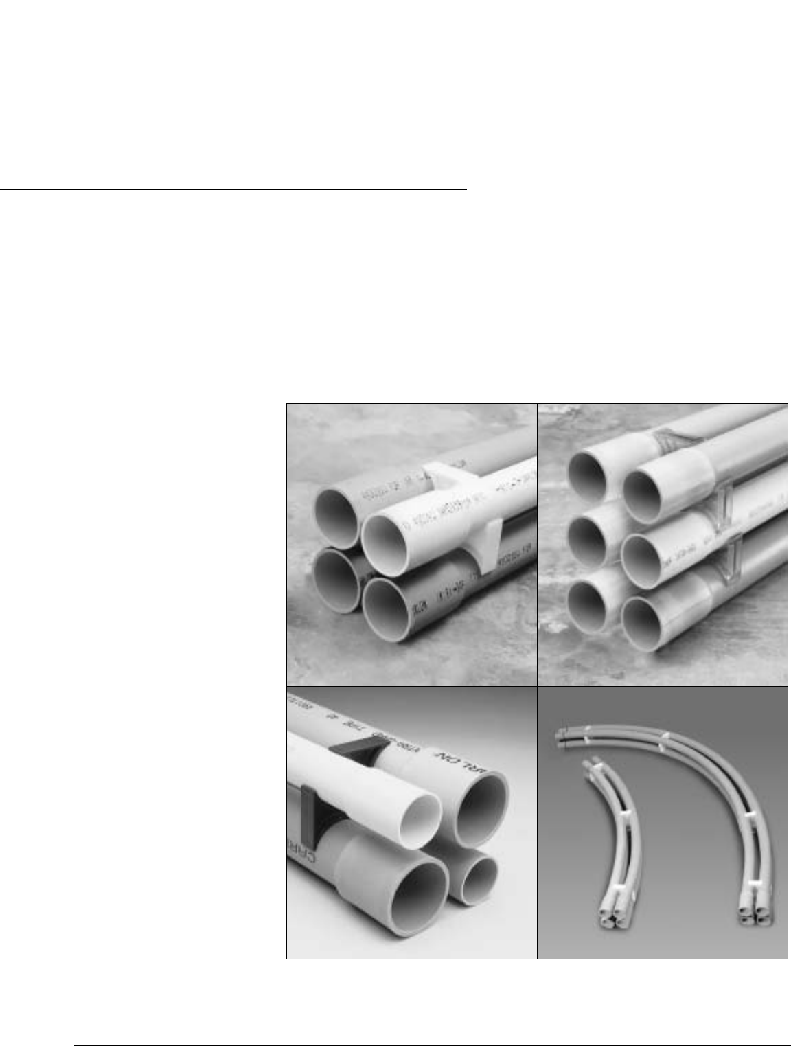
www.carlon.com 261
Carlon
®
Intra-Gard
®
Multi-Cell Raceway
4-Way Intra-Gard
®
6-Way Intra-Gard
®
Hybrid Intra-Gard
®
Accessories
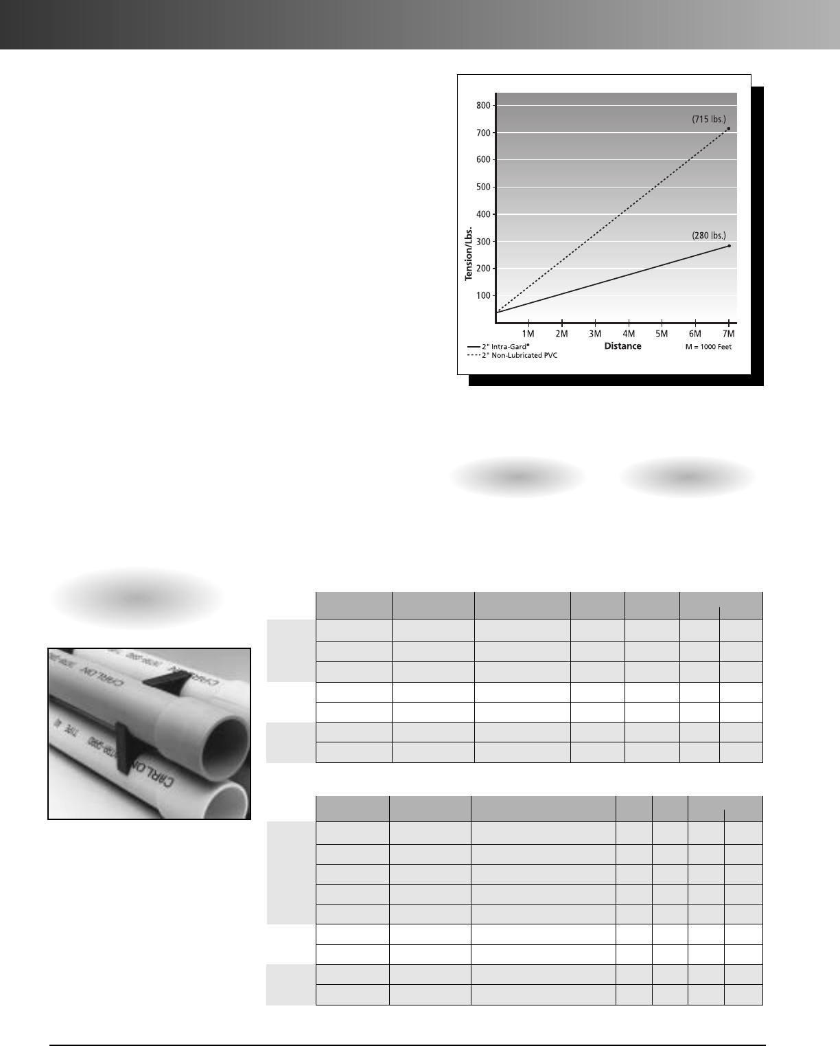
www.carlon.com
262
4-Way, 6-Way & Hybrid Intra-Gard®
Carlon®Intra-Gard®is a multi-cell raceway system used
in direct bury and concrete encased applications. Intra-
Gard ducts are pre-lubricated, eliminating the need for
field applied lubricants and reducing the coefficient of
friction, thus allowing for longer cable pulls.
Intra-Gard is available in Type C and Schedule 40 wall
types and is manufactured with extended length bell
ends to facilitate assembly and ensure joint integrity.
Factory installed spacers provide proper spacing and
alignment throughout the system. And for precise 20'
lay lengths, Intra-Gard is supplied in 20'3" sticks.
Schedule 40
•Direct bury
•Concrete encased
Type C
•Concrete encased
•Direct bury
Applications
Features:
•Pre-lubricated ducts – reduces coefficient of friction,
thus allowing longer cable pulls
•Meets Bellcore GR356-CORE coefficient of friction requirements
•Schedule 40 and Type C wall types
•Factory installed spacers
•Multiple color configurations available for easy duct identification
•Extended length bell ends available on request
•Standard colors – white and grey
4-Way Intra-Gard
Maximum Minimum Wall Thickness
Wall type Part Number Color O.D. I.D. Min. Max.
Schedule 40
I
4SFG-020 1White, 3 Grey 1.67 1.34 .13 .15
Schedule 40
I
4SFGG-020 1White, 3 Green 1.67 1.34 .13 .15
Type C
I
4SXG-020 1 White, 3 Grey 1.67 1.46 .08 .10
Schedule 40
I
41540-020 1 White, 3 Grey 1.91 1.57 .15 .17
Type C
I
415C-020 1 White, 3 Grey 1.90 1.66 .10 .12
Schedule 40
I
42240-020 1 White, 3 Grey 2.38 2.02 .15 .17
Type C
I
422C-020 1 White, 3 Grey 2.38 2.16 .08 .11
11/4"
11/2"
2"
Standard - Two Color
Max. Min. Wall Thickness
Wall type Part Number Color O.D. I.D. Min. Max.
Schedule 40
I
4SFGB-020 Grey,White,Red & Orange 1.67 1.34 .13 .15
Schedule 40
I
4SFGA-020 Orange, Green, Blue & Yellow 1.67 1.34 .13 .15
Schedule 40
I
4SFG6-020 Green, Yellow, Red & Black 1.67 1.34 .13 .15
Schedule 40
I
4SFG4-020 Grey, White, Green & Orange 1.67 1.34 .13 .15
Schedule 40
I
4SFG5-020 Grey, White, Blue & Orange 1.67 1.34 .13 .15
Schedule 40
I
41540MC-020 Grey, White, Blue & Orange 1.91 1.57 .15 .17
Type C
I
415CMC-020 Grey, White, Blue & Orange 1.90 1.66 .10 .12
Schedule 40
I
42240MC-020 Grey, White, Blue & Orange 2.38 2.02 .15 .17
Type C
I
422CMC-020 Grey, White, Blue & Orange 2.38 2.16 .08 .11
11/4"
11/2"
2"
Multi-Color Options
Calculated using MDPE F/O cable (Wgt.= .11 lbs./ft.)
www.carlon.com 263
4-Way, 6-Way & Hybrid Intra-Gard
®
6-Way Intra-Gard
Maximum Minimum Wall Thickness
Wall type Part Number Color O.D. I.D. Min. Max.
Schedule 40
I
6SFG-020 1 White, 5 Grey 1.67 1.34 .13 .15
Type C
I
6SXG-020 1 White, 5 Grey 1.67 1.46 .08 .10
Schedule 40
I
62240-020 1 White, 5 Grey 2.38 2.02 .15 .17
Type C
I
622C-020 1 White, 5 Grey 2.38 2.16 .08 .11
11/4"
2"
4-Way Hybrid 2" & 11/4"
Wall type Part Number Color
Schedule 40
I
41240-020 1White,3Grey
Type C
I
412C-020 1White,3Grey
Standard - Two Color
Wall type Part Number Color
Schedule 40
I
41240MC-020 Grey, White, Blue & Orange
Type C
I
412CMC-020 Grey,White,Blue & Orange
Multi-Color Options
Wall Thickness
Wall Type Max. O.D. Min. I.D. Min. Max.
Schedule 40 1.67 1.34 .13 .15
Type C 1.67 1.46 .08 .10
Schedule 40 2.38 2.02 .15 .17
Type C 2.38 2.16 .08 .11
11/4"
2"
Specifications
Standard - Two Color
Unloading
When unloading Intra-Gard from the delivery truck,
mechanical equipment should be used. If possible,
distribute the Intra-Gard along the route of the
trench site as it is unloaded.
Shipping Quantities
All products within the Intra-Gard®system are
supplied with protective dust caps, ensuring
system reliability for current and future cable
installations.
Type Pallet Qty. Truck Load
4-way 11/4" 1,200 ft. 14,400 ft.
4-way 11/2"1,200 ft. 14,400 ft.
4-way 2" 1,200 ft. 14,400 ft.
6-way 11/4" 720 ft. 8640 ft.
6-way 2" 720 ft. 8640 ft.
4-way Hybrid 2"x 11/4"1,200 ft. 14,400 ft.
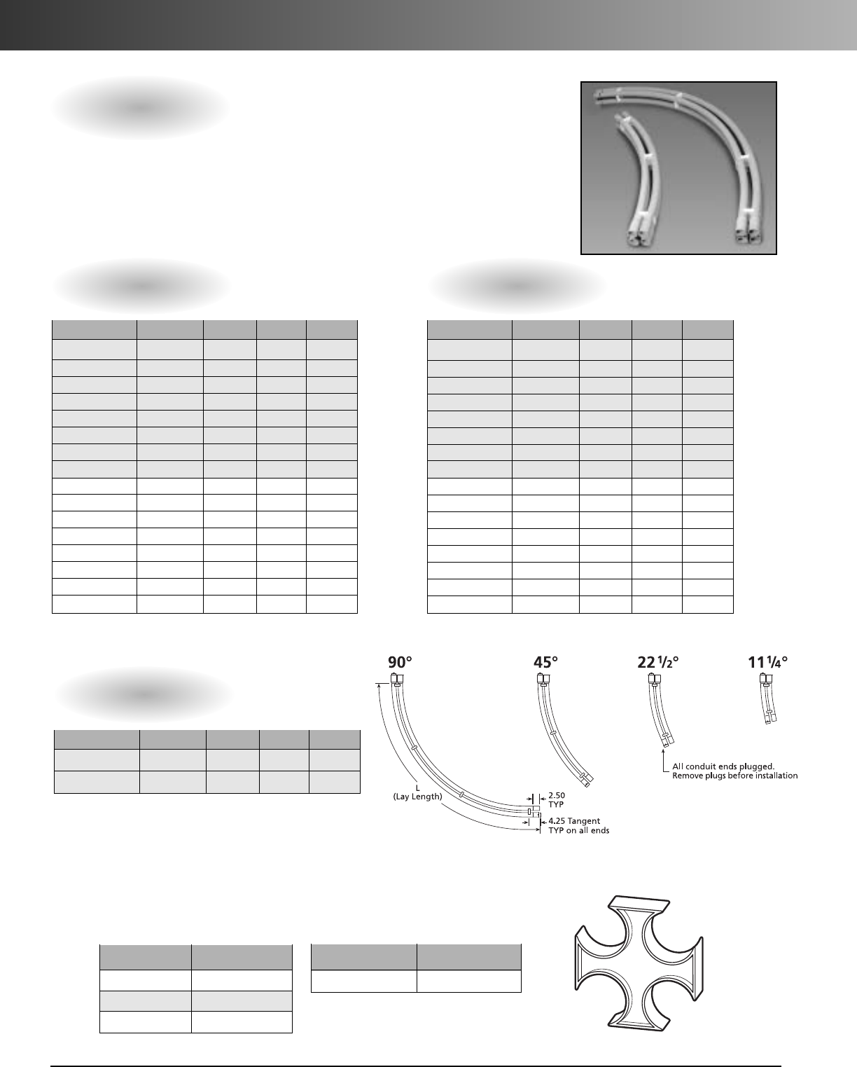
www.carlon.com
264
Intra-Gard
®
Accessories
Fixed Elbows
Intra-Gard®elbows are available in 3' and 4' radii and 111/4°, 221/2°, 45°
and 90° angles of curvature. They are manufactured with system
compatible bell and spigot ends, are pre-lubricated, grey in color, and
shipped with dust caps.
4-Way - 1
1
/
4
"
Hybrid – 2" & 11/4"
6-Way - 11/4"
4-Way
Nom. Size Part No.
11/4"
I
4
I
SG
11/2"
I
4
I
SG15
2"
I
4
I
SH
Hybrid
Nom. Size Part No.
2" & 11/4"
I
4H
I
SG
Wall Type Part No. Angle Radius Length
Schedule 40
I
F9HG4 90° 48" 81"
Schedule 40
I
F9FG4 90° 36" 81"
Schedule 40
I
F7HG4 45° 48" 43"
Schedule 40
I
F7FG4 45° 36" 43"
Schedule 40
I
F5HG4 221/2° 48" 26"
Schedule 40
I
F5FG4 221/2° 36" 26"
Schedule 40
I
F3HG4 111/4° 48" 15"
Schedule 40
I
F3FG4 111/4° 36" 15"
Type C
I
X9HG4 90° 48" 81"
Type C
I
X9FG4 90° 36" 81"
Type C
I
X7HG4 45° 48" 43"
Type C
I
X7FG4 45° 36" 43"
Type C
I
X5HG4 221/2° 48" 26"
Type C
I
X5FG4 221/2° 36" 26"
Type C
I
X3HG4 111/4° 48" 15"
Type C
I
X3FG4 111/4° 36" 15"
Wall Type Part No. Angle Radius Length
Schedule 40
I
F9HG6 90° 48" 81"
Schedule 40
I
F9FG6 90° 36" 81"
Schedule 40
I
F7HG6 45° 48" 43"
Schedule 40
I
F7FG6 45° 36" 43"
Schedule 40
I
F5HG6 221/2° 48" 26"
Schedule 40
I
F5FG6 221/2° 36" 26"
Schedule 40
I
F3HG6 111/4° 48" 15"
Schedule 40
I
F3FG6 111/4° 36" 15"
Type C
I
X9HG6 90° 48" 81"
Type C
I
X9FG6 90° 36" 81"
Type C
I
X7HG6 45° 48" 43"
Type C
I
X7FG6 45° 36" 43"
Type C
I
X5HG6 221/2° 48" 26"
Type C
I
X5FG6 221/2° 36" 26"
Type C
I
X3HG6 111/4° 48" 15"
Type C
I
X3FG6 111/4° 36" 15"
Wall Type Part No. Angle Radius Length
Schedule 40
I
4129040 90° 36" 39"
Schedule 40
I
4124540 45° 36" 67"
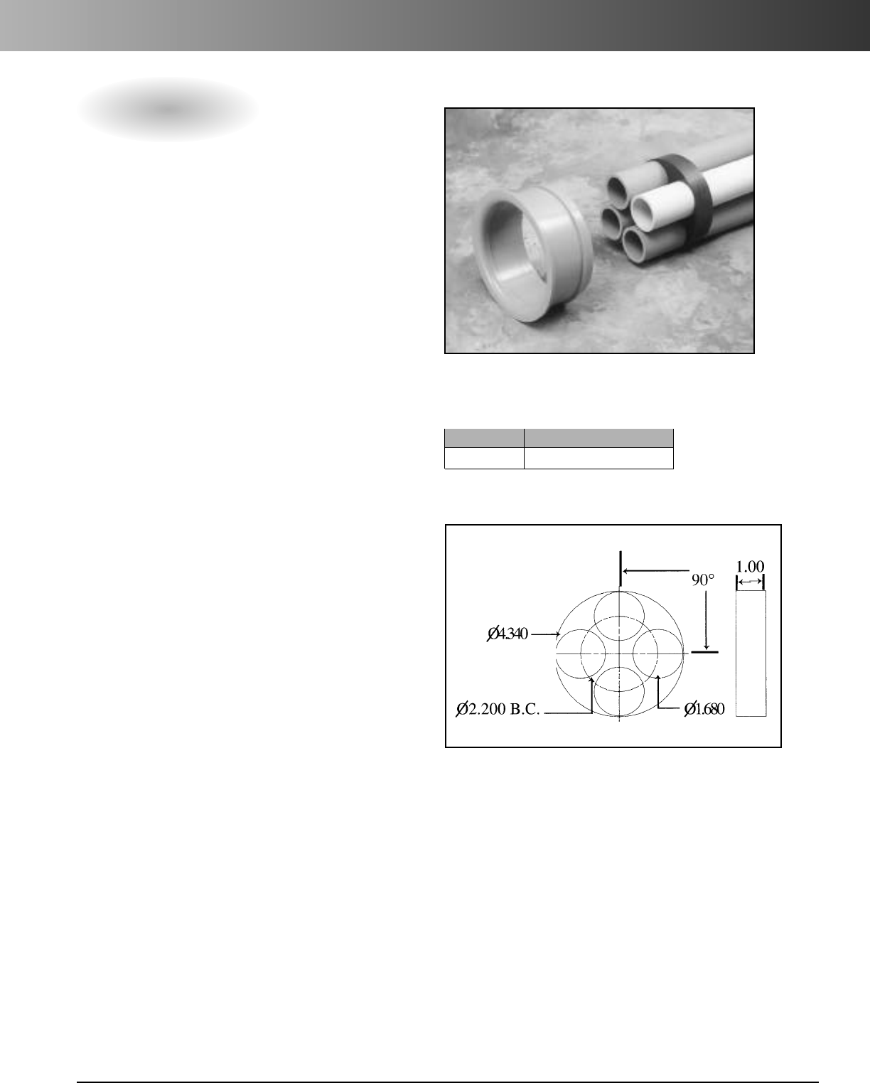
www.carlon.com 265
Intra-Gard
®
Accessories
End Bell Terminator Ring
Manhole Terminator or Handhole Entrance
At the manhole or handhole entrance, the
ideal termination procedure is to use
commercially available industry standard
Type C duct end bell (4.35") precast into the
manhole or handhole wall. To properly seal
the Intra-Gard®at its termination points,
Intra-Gard manhole terminator rings are
available as a 1" thick disk designed to
properly space the innerducts and fit into a
4.35" O.D. (Part #IRS4 .)
1.
Start by removing the protective caps from
the male ends of the pipes and then align
the ducts with the Intra-Gard terminator
spacer ring and insert spigot ends through
holes provided.
2.
Insert prepared male end into the precast
terminator. The terminator should be solvent
cemented into the precast terminator or
sealed around outside of the entrance as
required by the job specifications.
3.
Duct plugs should be used (MAEPG3)
after installation on empty ducts to avoid
water and dust infiltration.
Other Type Entrances
1.
Where a knockout is used, the procedure
starts with inserting the male end of the
section of pipe four inches past the inside
wall of the manhole or handhole. Remove
the protective caps from the ends of the
pipe,insert terminator and align the ducts
with Intra-Gard terminator ring. Seal
around entrance as required by the job
specifications.
2.
Apass through terminator may be secured
into wall of manhole or handhole either
directly into precast terminator or grout in
place if knockout is used.
Upon completion of conduit placement,
install ducts to traverse manhole/handhole
by cutting to length, inserting into one side
of handhole, and raising or bowing center of
duct span to insert in the pass through
terminator on the other side.
3.
Pass through application may be accom-
plished by installing a long line coupling
(E600G) onto each duct entering the vault.
Couplings should then be solvent cemented
onto each remaining duct of Intra-Gard.
Part No. Description
I
RS4 4-Way 11/4" Terminator Ring
*Manhole terminator sold separately
Terminator Ring
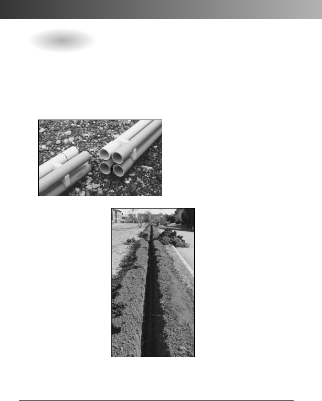
www.carlon.com
266
Intra-Gard
®
Installation
Duct Proofing
Use appropriate seal-off kit
(Reference pg. 9 for Line
Blowing Kits). For maximum
line blowing potential, use
air compressor at 175 CFM
(125 PSI Max.)
1.
Slide pull line through
opening in threaded
nozzle end of seal-off.
Attach blowing missile
to pull line.
2.
Insert blowing missile
into individual duct and
insert threaded end of
seal-off into duct to
assure minimal air loss.
3.
Attach seal-off to air
compressor with air
release lever in off
position. Hold seal off
firmly in hands.
4.
Open lever quickly
making sure slight tension
is on to prevent pull line
from packing. CAUTION
SHOULD BE EXERCISED
AT THE EXIT POINT FOR
MISSILE TO AVOID INJURY.
Blow pull line in all ducts
to ensure no blockages are
present.
Installation Instructions
When handling Intra-Gard®, care must be taken to avoid
striking the ends against hard surfaces. This can cause damage
from impact or crushing of the end of the conduit.
Assembly In Trench
1.
In the trench, set the first layer of ducts by inserting the male
ends into the female ends on the sections previously placed.
Remove the protective caps as the sections of pipe are about to
be joined together, and make sure the matching colors are aligned.
2.
Athin coating of Carlon
Quick Set Cement should
be applied to the inside
surface of the sockets
lightly enough to pre-
vent the formation of a
bead of cement at the
interior shoulder of the
sockets. Then, apply in
the same manner to the
spigot ends of the con-
duits to the depth of the
socket.
3.
Immediately after apply-
ing the coat of cement
to the conduit, insert the
spigot ends into the
sockets.

www.carlon.com 267
Intra-Gard
®
Field Cuts
Joining a Male/Female Connection
1.
The pipes should be laid side by side and the
male end marked at the base of the bell on the
female end.
2.
Make a straight through cut on the male end
using a standard carpenter’s saw. Deburr the
ends of the cut pipe.
3.
Apply Carlon Quick Set Cement in a thin uni-
form coating to the inside surface of the sock-
ets and raise both ends and align the ducts on
the male ends to the bells on the female end.
4.
Once the ducts are aligned with their sockets,
lower both of the pipes. The ducts will be auto-
matically returned to their original position as
the joints are forced together.
Field Cuts
Repairing Damaged Intra-GardThat Is Vacant
1.
Cut out damaged section making a flush cut on
both sides and deburr all pipes.
2.
Measure damaged section and new section
wIth a socket and measure from base of socket
and cut flush. Intra-Gard couplings are installed
onto the individual ducts of the section in the
ground.
3.
Install new section in trench by first applying
Carlon Quick Set Cement and pushing sockets
onto either spigot ends.
4.
Line up ducts with couplings and raise or bow
center of duct span, apply cement and slip
ducts into couplings.
Repairing Intra-Gard
®
Once Installed
Joining Two Male Ends
1.
The pipes should be laid side by side, marked and flush cut
to butt up against each other. Deburr the ends of the cut
pipe and install a spare spacer if needed, and use standard
couplings.
2.
Place each individual coupling onto ducts using Carlon
Quick Set Cement.
3.
Lift sections to align each coupling with other ducts.
4.
Lower both sections to a level position.
Repair sections may use a standard 20' length of
lntra-Gard with sockets and cut to length.
Repairing Intra-Gard Housing a Cable
1.
Carefully cut out the damaged section of the Intra-Gard.
2.
Where cable is installed, slide the split couplings onto
each individual duct, fitting the cable into the grooved
coupling passage. Repeat the process on the other side.
3.
Carefully insert the cable into the split duct. Push the
split duct into the split coupling at both ends. Wrap all
slit areas with sealing tape or shrink wrap, etc. as rec-
ommended by specifier to seal out water.
4.
Install stop coupling onto other vacant ducts with
Carlon Quick Set Cement and install the ducts into the
other openings of the couplings with cement.
5.
Ensure the duct system is straight and even before
encasing in soil.
Carlon
®
Intra-Gard
®
Quote Request
Date: Needed By: Destination:
Customer: Account Number:
Rep Agency: Market: Power Telecommunication
Total Quantity Feet: Target Price:
Competitors Price:
Quoted Price:
Quoted Terms: Freight Terms:
Valid Until: Quoted By:
4-Way Intra-Gard
Wall type Part No. Qty.
Schedule 40 I4SFG-020
Schedule 40 I4SFGG-020
Type C I4SXG-020
Schedule 40 I41540-020
Type C I415C-020
Schedule 40 I42240-020
Type C I422C-020
1
1
/
4
"
1
1
/
2
"
2"
Standard - Two Color
6-Way Intra-Gard
Wall type Part No. Qty.
Schedule 40 I6SFG-020
Type C I6SXG-020
Schedule 40 I62240-020
Type C I622C-020
1
1
/
4
"
2"
Standard - Two Color
Wall type Part No. Qty.
Schedule 40 I4SFGB-020
Schedule 40 I4SFGA-020
Schedule 40 I4SFG6-020
Schedule 40 I4SFG4-020
Schedule 40 I4SFG5-020
Schedule 40 I41540MC-020
Type C I415CMC-020
Schedule 40 I42240MC-020
Type C I422CMC-020
1
1
/
4
"
1
1
/
2
"
2"
Multi-Color Options
Accessories
Part No. Angle Radius Qty.
IF9HG4 90° 48"
IF9FG4 90° 36"
IF7HG4 45° 48"
IF7FG4 45° 36"
IF5HG4 221/2° 48"
IF5FG4 221/2° 36"
IF3HG4 111/4° 48"
IF3FG4 111/4° 36"
Part No. Angle Radius Qty.
IX9HG4 90° 48"
IX9FG4 90° 36"
IX7HG4 45° 48"
IX7FG4 45° 36"
IX5HG4 221/2° 48"
IX5FG4 221/2° 36"
IX3HG4 111/4° 48"
IX3FG4 111/4° 36"
Fixed Elbows - 4 Way 11/4"
Schedule 40
Wall type Part No. Angle Radius Qty.
Schedule 40 I4129040 90° 36"
Schedule 40 I4124540 45° 36"
Fixed Elbows - Hybrid 2" & 11/4"
4-Way Hybrid 2" & 11/4"
Intra-Gard
Wall type Part No. Qty.
Schedule 40 I41240-020
Type C I412C-020
Standard - Two Color
Pull Line
Spacers
Part No. Qty. Part No. Qty. Part No. Qty.
Part No.Qty.Part No.Qty.Part No.Qty.
Plugs
Warning Tape
Line Blowing Accessories
Cutters
Wall type Part No. Qty.
Schedule 40 I41240MC-020
Type C I412CMC-020
Multi-Color Options
NOTE: Please fill in desired part number and quantities.
Type C
Part No. Angle
Radius
Qty.
IF9HG6 90°48"
IF9FG6 90°36"
IF7HG6 45°48"
IF7FG6 45° 36"
IF5HG6 221/2° 48"
IF5FG6 221/2°36"
IF3HG6 111/4°48"
IF3FG6 111/4°36"
Fixed Elbows - 6 Way 11/4"
Schedule 40
Part No. Angle
Radius
Qty.
IX9HG6 90°48"
IX9FG6 90°36"
IX7HG6 45°48"
IX7FG6 45° 36"
IX5HG6 221/2° 48"
IX5FG6 221/2°36"
IX3HG6 111/4°48"
IX3FG6 111/4°36"
Type C
Fax completed Quote Request to your Local Carlon Representative.Visit www.carlon.com to locate a Carlon Representative.
www.carlon.com
268
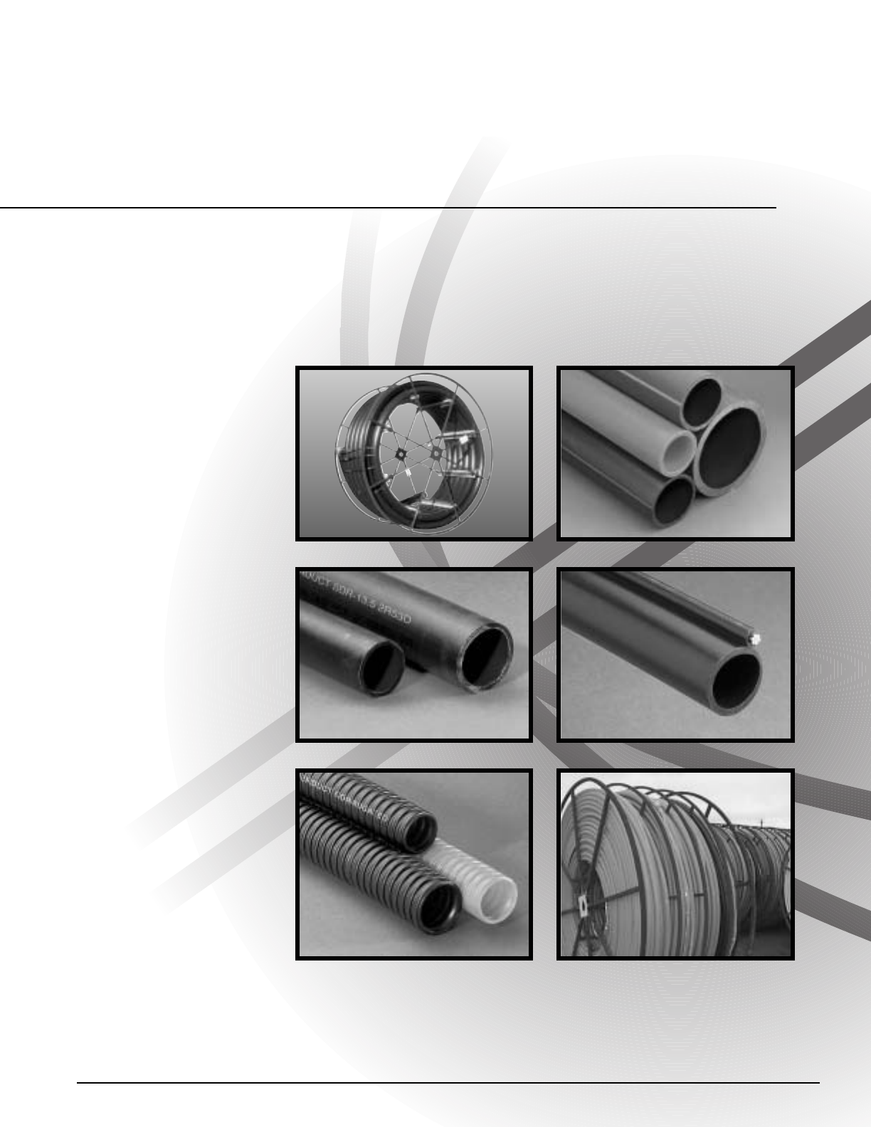
Telecommunication,
Electrical, and
Power Utility
Solutions:
Smooth Wall
Ribbed Wall
UL Listed
Micro-Gard™Mini-Duct
Aerial
Aerial Figure 8
Corrugated
Toneable
Accessories
Carlon
®
High Density Polyethylene
(HDPE) Conduit
www.carlon.com 269
MEMBER
Plastics Pipe Institute (PPI)
www.plasticpipe.org
www.carlon.com
270
Smoothwall HDPE Conduit
Smooth Interior Wall
Applications: Underground (direct bury),
or placed inside existing duct (innerduct)
Installation methods: Plowing,
open/continuous trench, directional boring
or pulled through existing conduits.
Smoothwall HDPE
is a
nonmetallic
flexible raceway manufactured
from High
Density Polyethylene (HDPE) for use in
underground and innerduct applications.
Smoothwall offers superior protection,
increases pathways of existing duct systems,
allows extra channels for future cabling
needs, and is ideal for jetting cable.
Available in a wide range of sizes, colors,
and options, Carlon HDPE is the only cable
management system you need.
Smoothwall Options
•Sizes 1/2"- 16"
•Multiple colors and stripes
•Factory installed pull lines
•Sequentially marked footage
•Up to four colors of equal
lengths paralleled or
segmented on one reel
•Pre-lubricated option
•Toneable Duct – copper
conductor within the
wall of duct. Used to
locate buried conduit.
(see page 274)
Smoothwall is ideal
for jetting cable
Open Trench
Directional Boring
Reference Plastics Pipe Institute PE Pipe Handbook for installation
and engineering recommendations. (www.plasticpipe.org)
www.carlon.com 271
Solidwall HDPE Conduit
How to Build a Part Number:
Product Size Type Wall Options Splits Color Stripes Tape Length
A=HDPE 2 = 1/2" C = Smooth/Smooth 4
=
SCH 40 N = None 1 = 1 Way Single A = Black NN = None A = Empty 1500
3=3/4" 5
=
SCH 80 D
=
Lube Duct 2
=
2Way Segmented B
=
Blue 3A
=
Black Stripes B
=
1130 lbs. Polyester Tape (Equals 1500 Feet)
5
=
1" 6
=
SDR 11 3
=
3Way Segmented C
=
Brown 3B
=
Blue Stripes C
=
1250 lbs. Polyester Tape
6
=
1-1/4" 9
=
SDR 13.5 4
=
4Way Segmented D
=
Buff 3C
=
Brown Stripes D
=
1500 lbs. Polyester Tape
9
=
1-1/2" 13
=
SDR 15.5 5
=
2Way Parallel E
=
Grey 3D
=
Buff Stripes E
=
1800 lbs. Polyester Tape
13
=
2" 14
=
SDR 17 6
=
3Way Parallel F
=
Green 3E
=
Grey Stripes G
=
200 lbs. Polyester Tape
14
=
2-1/2" 16
=
SDR 21 7
=
4Way Parallel G
=
Lilac 3F
=
Green Stripes J
=
2500 lbs. Polyester Tape
15
=
3" 22
=
SDR 7 12 = 2 Way Compart H
=
Lt. Green 3G
=
Lilac Stripes K
=
400 lbs. Detect. Polyester Tape
16
=
4" 24
=
SDR 9 13 = 3 Way Compart J
=
Orange 3H
=
Lt. Green Stripes T
=
1250 lbs. Poly Metric Tape
17
=
4.75" 26
=
SIDR 11.5 14 = 4 Way Compart K
=
Red 3J
=
Orange Stripes V
=
1250 lbs. Detectable 22G Poly Tape
18
=
5" 27
=
SIDR 11.5 True L
=
Terra Cotta 3K
=
Red Stripes
22
=
6" 29
=
SIDR 15 M
=
White 3L
=
Terra Cotta Stripes
23
=
7" 34
=
SIDR 7 N
=
Yellow 3M
=
White Stripes
24
=
8" 36
=
SIDR 9 3N
=
Yellow Stripes
25
=
10" 37
=
SIDR 9 True
26
=
12" 42
=
TC-7A
27
=
14" 45
=
True 11
28
=
16" 46
=
True 9
Standard Length – Reels and Coils
Pull Tape Reel
Polyester Reel Length Wt./Ea.
Color Part No. Type Wall Woven Size (ft.) (lbs.)
Orange A5C6N1JNNA7000 S/S SDR 11 Empty 72x45x24 7000 1517
Orange A5C6N1JNNB7000 S/S SDR 11 1130 lb. 72x45x24 7000 1576
Orange A5C9N1JNNB250 S/S SDR 13.5 1130 lb. Coil 250 42
Orange A5C9N1JNNB500 S/S SDR 13.5 1130 lb. Coil 500 84
Orange A5C9N1JNNB1800 S/S SDR 13.5 1130 lb. 48x30x24 1800 382
Orange A5C9N1JNNA7000 S/S SDR 13.5 Empty 72x45x24 7000 1278
Orange A5C9N1JNNB7000 S/S SDR 13.5 1130 lb. 72x45x24 7000 1337
Orange A6C6N1JNNA5000 S/S SDR 11 Empty 82x45x30 5000 1742
Orange A6C6N1JNNB5000 S/S SDR 11 1130 lb. 82x45x30 5000 1784
Orange A6C9N1JNNB250 S/S SDR 13.5 1130 lb. Coil 250 66
Orange A6C9N1JNNB500 S/S SDR 13.5 1130 lb. Coil 500 132
Orange A6C9N1JNNC2500 S/S SDR 13.5 1250 lb. 66x45x30 2500 793
Orange A6C9N1JNNA5000 S/S SDR 13.5 Empty 82x45x30 5000 1481
Orange A6C9N1JNNB5000 S/S SDR 13.5 1130 lb. 82x45x30 5000 1523
Orange A6C9N1JNNA8000 S/S SDR 13.5 Empty 96x45x32 8000 2271
Orange A6C9N1JNNB8000 S/S SDR 13.5 1130 lb. 96x45x32 8000 2338
Orange A9C6N1JNNA5000 S/S SDR 11 Empty 96x45x32 5000 2246
Orange A9C9N1JNNA5000 S/S SDR 13.5 Empty 96x45x32 5000 1904
Orange A9C9N1JNNB5000 S/S SDR 13.5 1130 lb. 96x45x32 5000 1946
1"
1
1
/
4
"
1
1
/
2
"
Standard Length – Reels and Coils
Pull Tape Reel
Polyester Reel Length Wt./Ea.
Color Part No. Type Wall Woven Size (ft.) (lbs.)
Orange A13C4N1JNNC2500 S/S Sch 40 1250 lb.82x45x40 2500 1410
Grey A13C6N1ENNA4000 S/S SDR 11 Empty 96x45x32 4000 2747
Black A13C6N1ANNA4000 S/S SDR 11 Empty 96x45x32 4000 2747
Orange A13C6N1JNNA4000 S/S SDR 11 Empty 96x45x32 4000 2747
Black 3 RD A13C9N1A3KA4000 S/S SDR 13.5 Empty 96x45x32 4000 2319
Black A13C9N1ANNA4000 S/S SDR 13.5 Empty 96x45x32 4000 2319
Orange A13C9N1JNNA4000 S/S SDR 13.5 Empty 96x45x32 4000 2319
Black A15C9N1ANNA1000 S/S SDR 13.5 Empty 96x45x68 1000 1364
Orange A15C9N1JNNA1000 S/S SDR 13.5 Empty 96x45x68 1000 1364
Black A16C6N1ANNA766 S/S SDR 11 Empty 102x45x68 766 2022
Orange A16C6N1JNNA766 S/S SDR 11 Empty 102x45x68 766 2022
Black A16C9N1ANNA766 S/S SDR 13.5 Empty 102x45x68 766 1727
Orange A16C9N1JNNA766 S/S SDR 13.5 Empty 102x45x68 766 1727
Orange A16C26N1JNNC700 S/S SIDR 11.5 1250 lb. 102x45x68 700 1746
Grey A17C9N1ENNA700 S/S SDR 13.5 Empty 102x45x68 700 2171
Orange A17C9N1JNNA700 S/S SDR 13.5 Empty 102x45x68 700 2171
Grey A18C9N1ENNA480 S/S SDR 13.5 Empty 114x45x85 480 1842
Black A18C9N1ANNA480 S/S SDR 13.5 Empty 114x45x85 480 1842
Grey A22C9N1ENNA450 S/S SDR 13.5 Empty 120x45x85 450 2296
Black A22C6N1ANNA450 S/S SDR 11 Empty 120x45x85 450 2669
Black A22C9N1ANNA450 S/S SDR 13.5 Empty 120x45x85 450 2296
2"
3"
4"
43
/
4"
5"
6"
*Custom Orders are not returnable
*Custom lengths are available in minimum order quantities specified on page 294
Custom Orders
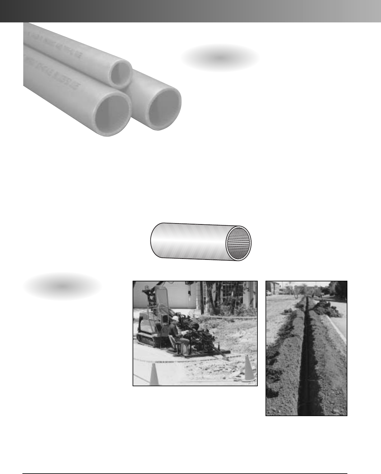
ID Ribbed Interior Wall
Applications: Underground (direct bury),
or placed inside existing duct (innerduct)
Installation methods: Plowing,
open/continuous trench, directional boring
or pulled through existing conduits.
ID Ribbed Wall HDPE
is a
non-
metallic flexible raceway manufactured
from
High Density Polyethylene (HDPE) for use in
underground and innerduct applications.
Ribbed Wall offers superior protection,
increases pathways of existing duct systems,
allowing extra channels for future cabling
needs. Available in a wide range of sizes,
colors, and options, Carlon HDPE is the only
cable management system you need.
Ribbed Wall Options
•Sizes 1/2"- 6"
•Multiple colors and
stripes
•Factory installed pull lines
•Sequentially marked
footage
•Up to four colors of equal
lengths paralleled or
segmented on one reel
•Pre-lubricated
•Toneable Duct – copper
conductor within the wall
of duct. Used to locate
buried conduit.
(see page 274)
Ribbed Wall is ideal for pulling
or jetting cable. Interior ribs
reduce surface contact with
cable during installation.
www.carlon.com
272
ID Ribbed Wall HDPE Conduit
Open Trench
Directional Boring

www.carlon.com 273
ID Ribbed Wall HDPE Conduit
How to Build a Part Number:
Product Size Type Wall Options Splits Color Stripes Tape Length
A=HDPE 2 = 1/2" B = Smooth Out/Ribbed In 4 = SCH 40 N = None 1 = 1 Way Single A = Black NN = None A = Empty 1500
3=3/4" 5 = SCH 80 D
=
Lube Duct 2
=
2Way Segmented B
=
Blue 3A
=
Black Stripes B = 1130 lbs. Polyester Tape (Equals 1500 Feet)
5=1" 6 = SDR 11 3
=
3Way Segmented C
=
Brown 3B
=
Blue Stripes C = 1250 lbs. Polyester Tape
6=1-1/4" 9 = SDR 13.5 4
=
4Way Segmented D
=
Buff 3C
=
Brown Stripes D = 1500 lbs. Polyester Tape
9=1-1/2" 13 = SDR 15.5 5
=
2Way Parallel E
=
Grey 3D
=
Buff Stripes E = 1800 lbs. Polyester Tape
13 = 2" 14 = SDR 17 6
=
3Way Parallel F
=
Green 3E
=
Grey Stripes G = 200 lbs. Polyester Tape
14 = 2-1/2" 16 = SDR 21 7
=
4Way Parallel G
=
Lilac 3F
=
Green Stripes J = 2500 lbs. Polyester Tape
15 = 3" 22 = SDR 7 12 = 2 Way Compart H
=
Lt. Green 3G
=
Lilac Stripes K = 400 lbs. Detect Polyester Tape
16 = 4" 24 = SDR 9 13 = 3 Way Compart J
=
Orange 3H
=
Lt. Green Stripes T = 1250 lbs. Poly Metric Tape
17 = 4.75" 26 = SIDR 11.5 14 = 4 Way Compart K
=
Red 3J
=
Orange Stripes V = 1250 lbs. Detectable 22G Poly Tape
18 = 5" 27 = SIDR 11.5 True L
=
Terra Cotta 3K
=
Red Stripes
22 = 6" 29 = SIDR 15 M
=
White 3L
=
Terra Cotta Stripes
34 = SIDR 7 N
=
Yellow 3M
=
White Stripes
36 = SIDR 9 3N
=
Yellow Stripes
37 = SIDR 9 True
42 = TC-7A
45 = True 11
46 = True 9
*Custom Orders are not returnable
*Custom lengths are available in minimum order quantities specified on page 294
Custom Orders
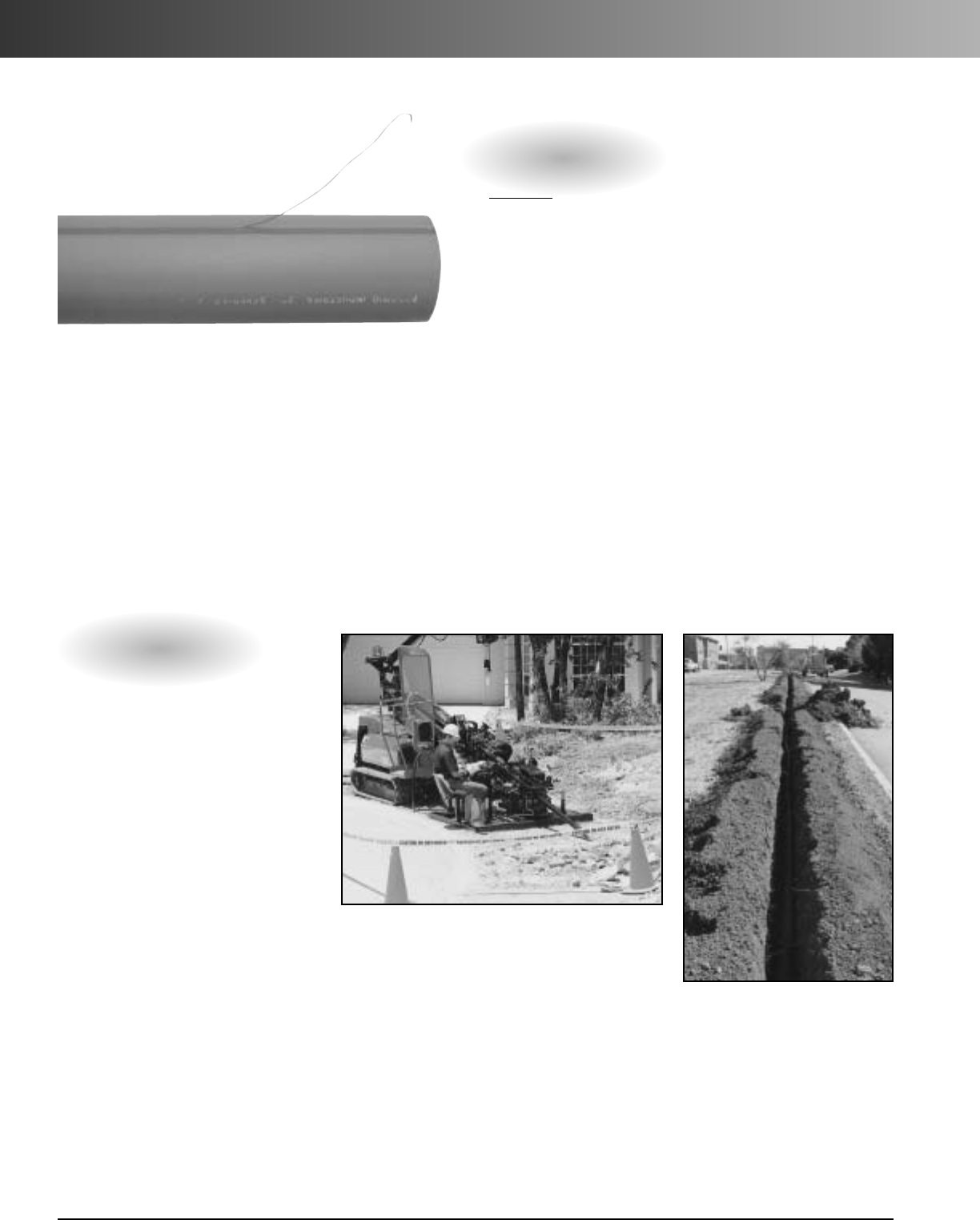
www.carlon.com
274
Toneable HDPE Conduit
Toneable HDPE Duct
incorporates a
patented design using bare solid copper conductor
wire within the duct wall underneath a LDPE or
HDPE stripe providing easy access to the conductor
wire for grounding and coupling applications.
Allows detectability and toning isolation of empty
duct structures as well as ducts with dielectric fiber
installations using conventional transmission,
receiving, and locating equipment.
Standard metal and nonmetallic coupling
methods allow conduit detectability and non-
metallic toneable pressure couplings allow
detection/toning isolation of conduit.
Complete system of conduit and couplings
provides the solution to finding buried occupied
or non-occupied conduits.
Toneable Options
• Industry standard conduit
sizes 1/2"– 4"
• Solid bare copper tone
wire
•Use Conventional
locating devices
• Tone wire easily
accessible for coupling
and grounding
•Standard/compression
couplings available
(page 292)
• Allows isolation tone
and/or detection
• Suitable for direct bury,
bore, trench
applications
• Single color stripe option
Application: Underground (direct bury)
Installation methods: Plowing, directional
boring, or open/continuous trench.
Open Trench
Directional Boring
Reference Plastics Pipe Institute PE Pipe Handbook for installation
and engineering recommendations. (www.plasticpipe.org)
*Patent Pending
www.carlon.com 275
Toneable HDPE Conduit
AWG #18 Solid Bare Copper #22 Solid Bare Copper
Resistivity 6.39 OHMS per 1,000 ft. 16.2 OHMS per 1,000 ft.
Elongation 10% min. 32% min.
Minimum Wall .12 inches .14 inches
Thickness
How to Build a Part Number:
Product Size Type Wall Options Splits Color Stripe (one) Tape Length
A=HDPE 2 = 1/2" B = Smooth Out/ 4 = SCH 40 J = Toneable/18G 1 = 1 Way Single A = Black NN = None A = Empty 1500
3=3/4" Ribbed In 5=SCH 80 G = Toneable/22G 2 = 2 Way Segmented B = Blue 1A = Black Stripe B = 1130 lbs. (Equals 1500 Feet)
5=1" C = Smooth/ 6 = SDR 11 3 = 3 Way Segmented C = Brown 1B = Blue Stripe Polyester Tape
6=1-1/4" Smooth 9 = SDR 13.5 4 = 4 Way Segmented D = Buff 1C = Brown Stripe C = 1250 lbs.
9=1-1/2" 5=2Way Parallel E = Grey 1D = Buff Stripe Polyester Tape
13 = 2" 6 = 3 Way Parallel F = Green 1E = Grey Stripe D = 1500 lbs.
14 = 2-1/2" 7 = 4 Way Parallel G = Lilac 1F = Green Stripe Polyester Tape
15 = 3" 12 = 2 Way Compart H = Lt. Green 1G = Lilac Stripe E = 1800 lbs.
16 = 4" 13 = 3 Way Compart J = Orange 1H = Lt. Green Stripe Polyester Tape
14 = 4 Way Compart K = Red 1J = Orange Stripe G = 200 lbs.
L = Terra Cotta 1K = Red Stripe Polyester Tape
M = White 1L = Terra Cotta Stripe J = 2500 lbs.
N = Yellow 1M = White Stripe Polyester Tape
1N = Yellow Stripe T = 1250 lbs. Poly
Metric Tape
Conductor Data
Specifications
*Custom Orders are not returnable
*Custom reel lengths are available in minimum order quantities of 25,000 ft. or min. set up charge
Custom Orders
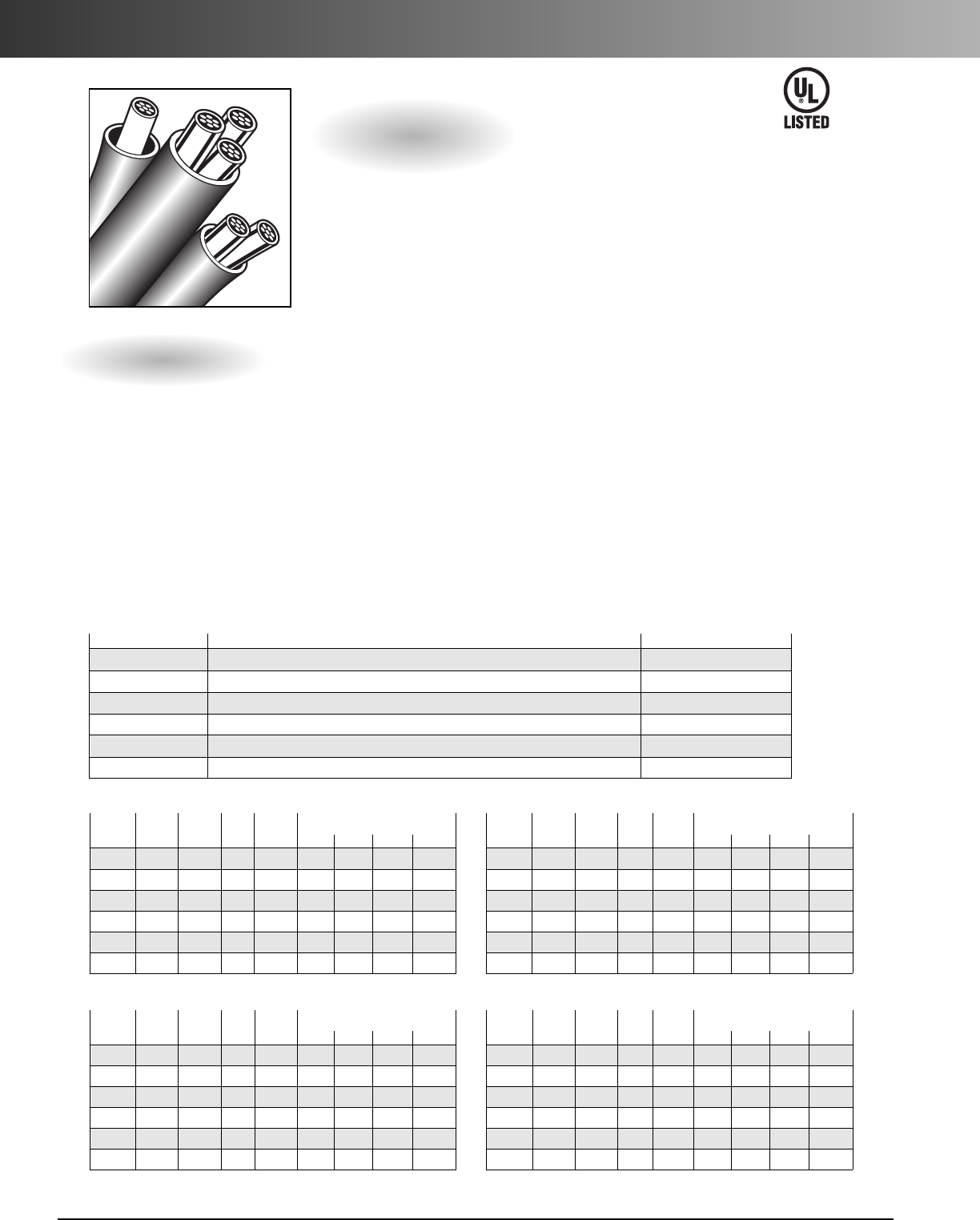
www.carlon.com
276
Cable In Duct HDPE Conduit
•Cables preinstalled in HDPE - eliminating
the need to pull cables.
• Standard wall thicknesses of TC7 Type A,
TC7 Type B (SDR 13.5), Schedule 40 and
Schedule 80
• UL Listed duct assembly (upon request)
Conduit
Nom. Nom. Nom. Min. Wt/ Max Cable Diameter*
Size OD ID Wall 100 Ft. 1 2 3 4
1" 1.315 1.165 .075 12.64 0.842 0.456 0.422 0.366
1-1/4" 1.660 1.460 .100 21.19 1.057 0.572 0.530 0.459
1-1/2" 1.900 1.670 .115 27.89 1.210 0.654 0.607 0.526
2" 2.375 2.085 .145 43.93 1.512 0.818 0.758 0.657
2-1/2" 2.875 2.469 .203 73.69 1.792 0.969 0.899 0.778
3" 3.500 3.068 .216 96.37 2.228 1.205 1.117 0.968
TC7 Type A
Conduit
Nom. Nom. Nom. Min. Wt/ Max Cable Diameter*
Size OD ID Wall 100 Ft. 1 2 3 4
1" 1.315 1.049 .133 21.68 0.749 0.405 0.376 0.325
1-1/4" 1.660 1.380 .140 29.31 0.990 0.535 0.497 0.430
1-1/2" 1.900 1.610 .145 35.00 1.158 0.626 0.581 0.503
2" 2.375 2.067 .154 46.92 1.490 0.806 0.747 0.647
2-1/2" 2.875 2.469 .203 74.00 1.783 0.964 0.894 0.774
3" 3.500 3.040 .216 97.31 2.213 1.197 1.110 0.961
Conduit
Nom. Nom. Nom. Min. Wt/ Max Cable Diameter*
Size OD ID Wall 100 Ft. 1 2 3 4
1" 1.315 1.121 .097 16.05 0.810 0.438 0.406 0.352
1-1/4" 1.660 1.414 .123 25.68 1.024 0.554 0.513 0.445
1-1/2" 1.900 1.618 .141 33.70 1.172 0.634 0.588 0.509
2" 2.375 2.023 .176 52.58 1.467 0.793 0.736 0.637
2-1/2" 2.875 2.449 .213 76.41 1.755 0.949 0.880 0.762
3" 3.500 2.982 .259 114.04 2.158 1.167 1.082 0.937
Conduit
Nom. Nom. Nom. Min. Wt/ Max Cable Diameter*
Size OD ID Wall 100 Ft. 1 2 3 4
1" 1.315 .957 .179 27.66 0.682 0.369 0.342 0.296
1-1/4" 1.660 1.278 .191 38.11 0.914 0.494 0.459 0.397
1-1/2" 1.900 1.500 .200 46.30 1.075 0.581 0.539 0.467
2" 2.375 1.939 .218 64.08 1.393 0.753 0.699 0.605
2-1/2" 2.875 2.323 .276 97.59 1.668 0.902 0.837 0.724
3" 3.500 2.900 .300 130.92 2.085 1.128 1.046 0.906
Schedule 40
TC7 SDR 13.5 Type B Schedule 80
3.0 Product
Description
Polyethylene duct extruded as
coilable tubing for use as a
single or multiple raceway
assembly.
The conduit assembly may be
direct buried, encased in con-
crete and used as innerducts.
2.0 Material
Carlon duct is manufactured from a
suitable thermoplastic polymer conforming
to the minimum standard of PE334470E/C
as defined in ASTM D3350. (see table 1)
Carlon
®
High Density
Polyethylene
duct is manufactured
in the following configuration:
Smoothwall –Smooth Interior and
Smooth Exterior wall.
1.0 General
Carlon HDPE Power Cable In Duct is manufactured to the following various
industry standards and specifications for dimensional requirements.
ASTM F 2160 Solid Wall High Density Polyethylene (HDPE) Conduit Based
on Controlled Outside Diameter (OD).
ASTM D 3485 Standard specification for Smoothwall Coilable Polyethylene
(PE) Conduit (duct) for preassembled wire and cable.
ASTM D 3035 Polyethylene (PE) Plastic Pipe (SDR) Based on Controlled
Outside Diameter.
NEMA TC-7 Smooth Wall Coilable Polyethylene Electrical Plastic Conduit.
UL 651B Continuous length HDPE
Table 1 – Resin Properties
The resin properties shall meet or exceed the values listed below for HDPE.
ASTM Test Description Values HDPE
D-1505 Density g/CM3.941 - .955
D-1238 Melt Index, g/10 min Condition E .05 - .50
D-790 Flexural Modulus, MPa (PSI) 80,000 min.
D-638 Tensile strength at yield (psi) 3000 min.
D-1693 Environmental Stress Crack Resistance Condition B,F10 96 hrs. min.
D-746 Brittleness Temperature -75˚C
The number of conductors and cables shall not exceed that permitted by the percentage fill specified in Table 1, Chapter 9 of the National Electrical Code.
•Manufactured in accordance to NEC
Articles 352 and 354.
• Conduit sequentially marked
• Prelubricated during assembly process
• Conforms to electrical industry
specifications
Assembly
Upon Request
Features
Specifications
www.carlon.com 277
Micro-Gard™Mini-Duct HDPE Conduit
Features & Benefits
Description ASTM Test method
Typical Values
HDPE English Units SI Units
Density D4883 – 0.944 g/cc
Melt Index D1238 – 12.5 g/10 min.
Flexural Modulus D790 120,000 psi 827 Mpa
Tensile Strength at yield (2 in/min) D638 3300 psi 22.8 Mpa
Tensile Strength at break (2 in/min) D638 4500 psi 31.0 Mpa
Environmental Stress Crack Resistance (Condition C) D1693 >2000 hrs >2000 hrs
Brittleness Temperature D746 <-180° F <-118° C
Nominal Size
O.D.xI.D.Outside Diameter
Tolerance Wall Thickness & Tolerance Inside Diameter
Minimum Standard
Weight
mm inch +/- mm +/- inch mm +/- inch mm inch lbs./100 ft.
10 / 8 0.394 x 0.315 0.1 0.004 1+0/-0.1 0.039 +0/-0.004 7.9 0.312 1.77
12 / 10 0.472 x 0.394 0.1 0.004 1+0/-0.1 0.039 +0/-0.004 9.9 0.390 2.08
16 / 12 0.630 x 0.472 0.1 0.004 2+0/-0.1 0.078 +0/-0.004 11.9 0.470 5.59
Dimension and Performance Notes:
10 / 8 mm size recommended for jetting.
12 / 10 mm size recommended for jetting or pulling.
•10 mm, 12 mm, and 16 mm sizes
• Low coefficient of friction for easy jetting or pulling of cable
• High tensile strength material allows for longer pulling distances, reducing installation costs
• Variety of stripes for identification and paralleling available - makes product easier to install
• Sequential footage markings
• Pre-installed pull line optional (10 mm ID and larger)
• High burst pressure rated material for jetting installation
• UV-formulated material for outside storage conditions
• System includes: Duct, Couplings, Terminations, Pulling Eyes, Pulling Harness and Cutters
Specifications
Resin properties shall meet or exceed the values listed below for high density polyethylene (HDPE):
Mini-Duct Dimensions
Nominal Size
O.D. x I.D. Bend Radius
Minimum Safe Tensile Pull
Maximum
Sustained
Pressure
Maximum Burst Pressure
Minimum
Crush
Strength ≤
4% O.D. Sliding
Coefficient
of Friction
mm inch mm inch lbs Newtons psi BAR psi BAR lbs kg
10 / 8 0.394 x 0.315 200 7.88 128 569 316 22 700 48 200 90
≤0.10
12 / 10 0.472 x 0.394 240 9.45 195 867 388 27 900 62 300 136
16 / 12 0.630 x 0.472 320 12.60 371 1650 450 31 1000 68.9 500 226
Mini-Duct Performance
Micro-Gard™
mini-ducts are designed to be jetted or pulled into conduit
and used in micro-cable installation.
RUS Listed
www.carlon.com
278
Micro-Gard™Mini-Duct HDPE Conduit
Maximum Number of Mini-Ducts per Conduit & Wall
Conduit Size 16mm 12mm 10mm
3/4" 0 1 2
1" 1 2 4
11/4" 2 4 6
11/2" 3 5 8
2" 5 9 13
SDR 13.5
Conduit Size 16mm 12mm 10mm
3/4" 0 1 2
1" 1 2 3
11/4" 2 4 5
11/2" 3 5 7
2" 4 8 11
SDR 11
Conduit Size 16 mm 12 mm 10 mm
3/4" 0 1 2
1" 1 2 3
11/4" 2 4 6
11/2" 3 5 8
2" 5 9 13
Schedule 40
Conduit Size 16 mm 12 mm 10 mm
3/4" 0 1 1
1" 1 1 2
11/4" 2 3 5
11/2" 2 4 7
2" 4 8 12
Schedule 80
Micro-Gard
™
PartNumber Configuration:
Product Size Type Wall Options *Splits Color **Stripes Pull Line Length
M=Micro-Gard 51 = 10/8 mm
54 = 12/10 mm
58 = 16/12 mm
C=Smooth / Smooth 3=Standard D=Pre-Lubricated 1=1Duct
5=2Ducts
6=3Ducts
7=4Ducts
8=5Ducts
A = Black NN = None
3B = Blue
3C = Buff
3E = Gray
3F = Green
3G = Lilac
3J = Orange
3K = Red
3M = White
3N = Yellow
A=Empty
Z = ***600 lb. Polyester
Woven Tape
5000 = 5000 ft.
* Paralleled
** Stripes on Black only
*** 10 mm ID and larger
Single Duct: One size of mini-duct on a single reel
Parallel Duct: Same size mini-duct, in a mix of 2 to 5 duct configurations, on a single reel.
Note: Tocalculate parallel-duct footage, deduct 3% per duct from the single-duct footage.
Packaging Configuration
Micro-Gard™mini-ducts are shipped on disposable wooden reels:
Nominal
Size (mm)
Reel Size: 35" Flange x 32" Outer Width
Part Number Description Single
Duct (ft) Single Duct
(meter) Total
Weight (lbs)
10 / 8 M51C3D1A3J13000 10/8 MM MICRO PE S/S BLK 3 ORG PL 13,000 3,962 285
12 / 10 M54C3D1A3J9000 12/10 MM MICRO PE S/S BLK 3 ORG PL 9,000 2,743 242
16 / 12 M58C3D1A3J5000 16/12 MM MICRO PE S/S BLK 3 ORG PL 5000 1,524 335
RUS Listed
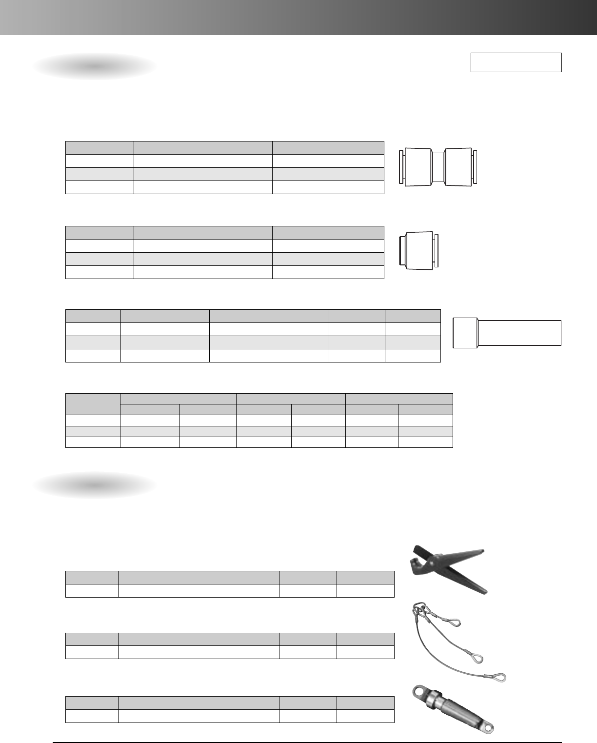
www.carlon.com 279
Micro-Gard™Mini-Duct HDPE Conduit – Accessories
Part No. Description Std. Pkg. Qty. Wt. Ea. (lbs.)
MPCC10 10 mm O.D. Push-On Coupling 5 0.12
MPCC12 12 mm O.D. Push-On Coupling 5 0.15
MPCC16 16 mm O.D. Push-On Coupling 5 0.25
Micro-Gard push-on couplings and end caps allow each end of Micro-Gard to be easily pushed into place. No tools
required. Push-on couplings and end caps can be used multiple times while maintaining original performance.
Couplings
Part No. Description Std. Ctn. Qty. Wt. Ea. (lbs.)
CC120B Duct Cutter – 10mm to 16mm diameter 10 3.51
Duct Cutters
•Nylon handles and high grade steel blade allow single or multiple cuts with simple squeeze and rotate
method for 10 - 16 mm sizes.
• All fittings are designed to reduce risk of restriction at coupling or termination point.
Part No.Description Std. Ctn. Qty. Wt. Ea. (lbs.)
MAPH6 2to 6-way Adjustable Pulling Harness 10.27
Multiple Micro-Gard Pulling Harness:
Each 2-Duct segment is detachable.
Part No. Description Std. Ctn. Qty. Wt. Ea. (lbs.)
MAPE1012 Universal Pulling Eye 1 0.13
Multiple Micro-Gard Pulling Eye
Part No. Description Std. Pkg. Qty. Wt. Ea. (lbs.)
MPEC10 10 mm O.D. Push-On End Cap 5 0.065
MPEC12 12 mm O.D. Push-On End Cap 5 0.090
MPEC16 16 mm O.D. Push-On End Cap 5 0.150
End Caps
Part No. Description Conduit Application Std. Pkg. Qty. Wt. Ea. (lbs.)
MPPC8 8mm O.D. Plug Cap Use with 10 mm O.D. Conduit 5 0.040
MPPC10 10 mm O.D. Plug Cap Use with 12 mm O.D. Conduit 5 0.055
MPPC12 12 mm O.D. Plug Cap Use with 16 mm O.D. Conduit 5 0.090
Plug Caps
(Not for pressure seals)
Couplings & End Caps
All Micro-Gard™Couplings and End Caps meet or exceed the following performance specifications:
Conduit Size
Pull-Out Sustained Pressure Quick Burst
lb kg PSI BAR PSI BAR
10 / 8 146 66 125 8.6 175 12
12 / 10 139 63 125 8.6 175 12
16 / 12 175 79 125 8.6 175 12
Cutters & Pulling Devices
RUS Listed
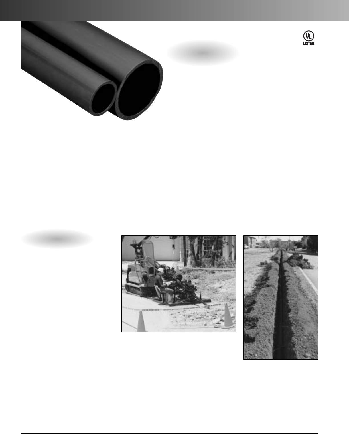
Applications: Applications: Underground
(direct bury), or placed inside existing duct
(innerduct). Ideal for use in parking lots,
traffic lights, etc.
Installation methods: Plowing, open/
continuous trench, directional boring or
pulled through existing conduit.
UL Listed HDPE
is a
nonmetallic
flexible raceway manufactured
from High
Density Polyethylene (HDPE), offering a
protective pathway for cables and wires,
and is used in underground or innerduct
applications.
UL Listed HDPE conduit is compliant with
the 2005 NEC Articles 300 and 353 (2002
NEC Articles 300 and 352), and is listed to
UL 651B. Its high tensile strength-to-weight
ratio, superior crush resistance, and low
coefficient of friction when installing cable
makes it ideal for directional boring.
*Refer to UL 651B standards/specifications
for dimensional requirements.
UL Listed Options
•Wall type/sizes:
Schedule 40 1" – 4"
Schedule 80 2" – 6"
EPEC-B (SDR 13.5) 2" – 6"
•Multiple colors and stripes
•Sequentially marked footage
•Available in smoothwall only
•Available with pre-installed
conductors as nonmetallic
underground conduit with
conductors (NUCC) per
Article 354 of the 2002 NEC,
UL File 195593.
•Conforms to NEMA TC-7
Smoothwall Coilable PE
Electrical Plastic Conduit
E191470
www.carlon.com
280
UL Listed HDPE Conduit
Open Trench
Directional Boring
Reference Plastics Pipe Institute PE Pipe Handbook for installation
and engineering recommendations. (www.plasticpipe.org)
5"
6"
www.carlon.com 281
UL Listed HDPE Conduit
How to Build a Part Number:
Product Size Type Wall Options Splits Color Stripes Tape Length
U=UL Listed 5 = 1" C = Smooth/Smooth 4 = SCH 40 N = None 1 = 1 Way Single A = Black NN = None A = EMPTY 1500
6=1-1/4" 1" – 4" D
=
Lube Duct 2
=
2Way Segmented B
=
Blue 3A
=
Black Stripes B = 1130 lbs. Polyester Tape (Equals 1500 Feet)
9=1-1/2" 5 = SCH 80 3
=
3Way Segmented C
=
Brown 3B
=
Blue Stripes C = 1250 lbs. Polyester Tape
13 = 2" 2" – 6" 4
=
4Way Segmented D
=
Buff 3C
=
Brown Stripes D = 1500 lbs. Polyester Tape
15 = 3" 9 = SDR 13.5 5
=
2Way Parallel E
=
Grey 3D
=
Buff Stripes E = 1800 lbs. Polyester Tape
16 = 4" 2" – 6" 6
=
3Way Parallel F
=
Green 3E
=
Grey Stripes G = 200 lbs. Polyester Tape
18 = 5" 7
=
4Way Parallel G
=
Lilac 3F
=
Green Stripes J = 2500 lbs. Polyester Tape
22 = 6" 12 = 2 Way Compart H
=
Lt. Green 3G
=
Lilac Stripes K = 400 lbs. Detect Polyester Tape
13 = 3 Way Compart J
=
Orange 3H
=
Lt. Green Stripes T = 1250 lbs. Poly Metric Tape
14 = 4 Way Compart K
=
Red 3J
=
Orange Stripes V = 1250 lbs. Detectable 22G Poly Tape
L
=
Terra Cotta 3K
=
Red Stripes
M
=
White 3L
=
Terra Cotta Stripes
N
=
Yellow 3M
=
White Stripes
3N
=
Yellow Stripes
*Custom Orders are not returnable
*Custom lengths are available in minimum order quantities specified on page 294
Custom Orders
Standard Length – Reels and Coils
Pull Tape Reel/Coil
Wt./E
Polyester Reel Length
a
Color Part No. Type Wall Woven Size (ft.)
(lbs.)
Grey U5C4N1ENNB250 S/S Sch 40 1130 lb. Coil 250 53
Grey U5C4N1ENNB500 S/S Sch 40 1130 lb. Coil 500 106
Grey U5C4N1ENNB1800 S/S Sch 40 1130 lb. 48 x 30 x 24 1800 461
Grey U5C4N1ENNB7000 S/S Sch 40 1130 lb. 72 x 45 x 24 7000 1647
Grey U6C4N1ENNB250 S/S Sch 40 1130 lb. Coil 250 72
Grey U6C4N1ENNB500 S/S Sch 40 1130 lb. Coil 500 143
Grey U6C4N1ENNB1400 S/S Sch 40 1130 lb. 48 x 45 x 30 1400 401
Grey U6C4N1ENNB5000 S/S Sch 40 1130 lb. 82 x 45 x 30 5000 1641
Grey U9C4N1ENNB5000 S/S Sch 40 1130 lb. 96 x 45 x 30 5000 1948
Grey U13C6N1ENNA4000 S/S SDR 13.5 Empty 96 x 45 x 32 4000 2319
Grey U15C9N1ENNA1000 S/S SDR 13.5 Empty 96 x 45 x 68 1000 1364
Grey U16C9N1ENNA766 S/S SDR 13.5 Empty 102 x 45 x 68 766 1727
Grey U16C9N1ENNA1000 S/S SDR 13.5 Empty 114 x 45 x 68 1000 2193
Grey U18C9N1ENNA480 S/S SDR 13.5 Empty 114 x 45 x 68 480 1842
Grey U22C9N1ENNA450 S/S SDR 13.5 Empty 120 x 45 x 85 450 2296
2"
3"
4"
1"
1
1
/
4
"
1
1
/
2
"
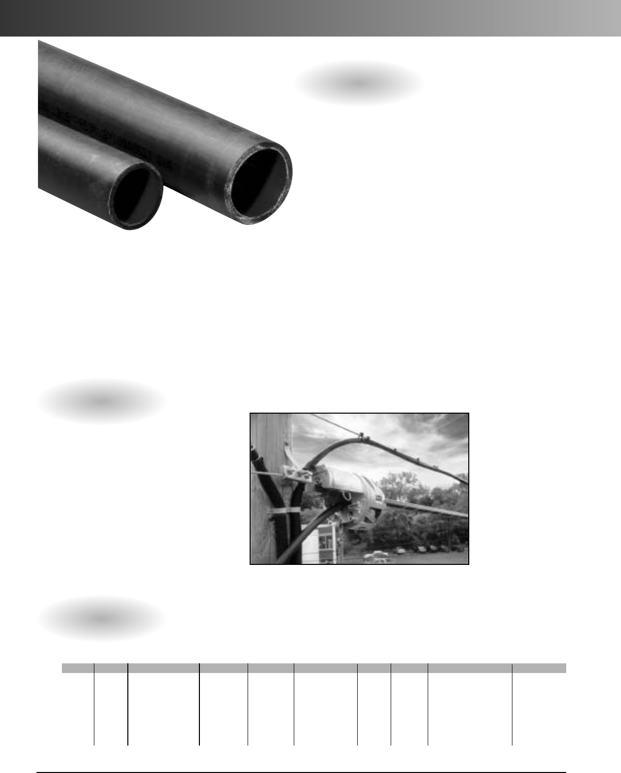
www.carlon.com
282
Aerial HDPE Conduit
Aerial HDPE
is a nonmetallic flexible raceway
manufactured from High Density Polyethylene (HDPE)
with a carbon black additive to provide U.V. protection
in aerial environments.
Aerial duct offers superior cable protection against
damage caused by rodents, projectile objects such as
rocks and gun pellets, and harsh weather conditions.
And because of its strength and durability, it can with-
stand the expansion and contraction caused by
seasonal weather changes.
•HDPE: ASTM 1248 Type III
Grade P34
Category 5 Class C
•Ultraviolet: Minimum 2% carbon black
Applications: Aerial environments. Used
when rocky terrain makes buried duct
difficult, or in plant/campus environments
expecting frequent changes.
Installation method: Designed to be
lashed to existing support strands.
Aerial Options
•Sizes 1"– 2"
•Wall Type: SDR 13.5, SDR 11,
and corrugated
•Factory installed tape
•Solidwall or corrugated
•Pre-lubricated option
•Sequentially marked footage
Aerial Lashing:
Aerial Duct is lashed
to existing cable
supportwireusing
cable lashing
equipment.
How to Build a Part Number:
Product Size Type Wall Options Splits Color Stripes Tape Length
E = Aerial 5 = 1" B = Smooth Out/Ribbed In 2 = None - Corr N = None 1 = 1 Way Single A = Black NN = None A = Empty 1500
6=1-1/4" C = Smooth/Smooth 6 = SDR 11 D
=
Lube Duct 2
=
2Way Partitioned B = 1130 lbs. Polyester Tape (Equals 1500 Feet)
9=1-1/2" D = Corrugated 9 = SDR 13.5 3
=
3Way Partitioned C = 1250 lbs. Polyester Tape
13 = 2" 4
=
4Way Partitioned D = 1500 lbs. Polyester Tape
5
=
2Way Parallel E = 1800 lbs. Polyester Tape
6
=
3Way Parallel J = 2500 lbs. Polyester Tape
7
=
4Way Parallel T = 1250 lbs. Poly Metric Tape
*Custom Orders are not returnable
*Custom lengths are available in minimum order quantities specified on page 294
Custom Orders
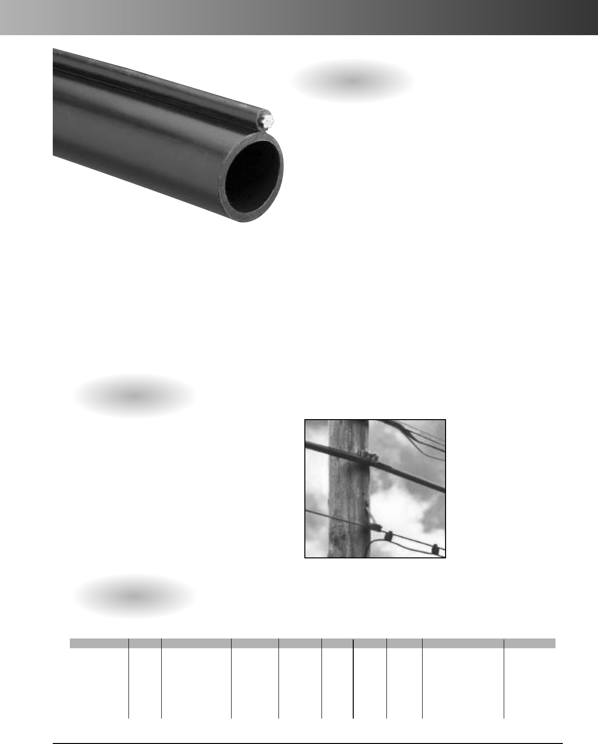
www.carlon.com 283
Aerial Figure-8 HDPE Conduit
6.6M 1/4" Extra high strength strand
Class A galvanized with flooding compound
10.0M 3/8" Extra high strength strand
Class A galvanized with flooding compound
Applications: Aerial environments. Used
when rocky terrain makes buried duct
difficult, or in plant/campus environments
expecting frequent changes.
Installation method: Attaches directly
to pole using a 3-bolt mounting clamp.
Strand
HDPE Aerial Figure-8
is a
nonmetallic flexible
raceway with a Class A galvanized support strand. It’s
manufactured from High Density Polyethylene (HDPE),
which contains a carbon black additive to provide U.V.
protection in aerial environments.
Figure-8 duct offers superior cable protection against
damage caused by rodents, projectile objects such as
rocks and gun pellets, and harsh weather conditions
with a one-step installation process. And because of its
strength and durability, it can withstand the expansion
and contraction caused by seasonal weather changes.
•HDPE: ASTM 1248 Type III
Grade P34
Category 5 Class C
•Ultraviolet: Minimum 2% carbon black
•Product Weight:
6.6M Figure 8 .429 lbs/ft
10.0M Figure 8 .507 lbs/ft
•Spans/Tensile Strength:
6.6M: 225 ft. 6740 lbs.
10M: 500 ft. 15,400 lbs.
Aerial Figure-8 Options
•Size 11/4"
•Wall Type: SIDR 9 True
•6.6M or 10.0M strands
• Factory installed tape
•Pre-installed Cable-In-Conduit
•Ribbed or smooth interior walls
•Pre-lubricated option
•Sequentially marked footage
Aerial Hanging:
Figure-8 Duct has a
choice of two integrated
mounting strands that
attach directly to poles
using 3-bolt mounting
clamps, and Carlon
stripping/cutting tools.
How to Build a Part Number:
Product Size Type Wall Options Splits Color Stripes Tape Length
S=Figure 8 - 6.6mm 6 = 1-1/4" B = Smooth Out/Ribbed In 37 = SIDR 9 True N = None 1 = 1 Way A = Black NN = None A = Empty 2500
T=Figure 8 - 10mm C = Smooth/Smooth D
=
Lube Duct Single B = 1130 lbs. Polyester Tape (Equals 2500 Feet)
C=1250 lbs.Polyester Tape
D=1500 lbs. Polyester Tape
E = 1800 lbs. Polyester Tape
J = 2500 lbs. Polyester Tape
T = 1250 lbs. Poly Metric Tape
*Custom Orders are not returnable
*Custom lengths are available in minimum order quantities of 1000 ft. or min. set up charge
Custom Orders
NOTE: Standard Lengths 2500 ft. and 5000 ft.
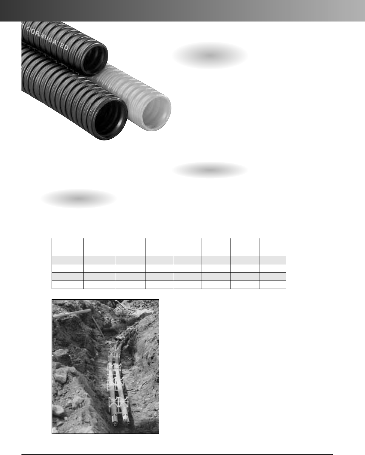
Stiffness
Min. Wt/ (5%) Min Bend Pull
Nom. Size Nom. ID Nom. OD Wall 100 Ft. lb/in/in Radius Tensile
1" 1.049 1.340 .035 10.6 65 14" 261 lbs.
1-1/4" 1.250 1.565 .035 11.2 108 5" 319 lbs.
1-1/2" 1.500 1.825 .035 18.0 83 6" 384 lbs.
2" 2.000 2.425 .035 20.8 70 5-1/2" 493 lbs.
Specifications
Applications: Placed inside
existing ducts (innerduct).
Installation method: Pulled
through existing conduit.
Installation
temperature range: -20°F to 122°F
Handling: -20°Fto 104°F
Corrugated HDPE
is manufactured from
High Density Polyethylene (HDPE) and is intended
for innerduct applications. It’s ideal for pulls under
1000 ft. and is designed to reduce surface contact
when pulling cable. And because this product is
lightweight and offers maximum flexibility, installa-
tion in small or restricted locations is made easier.
HDPE corrugated duct is available in sizes 1"
through 2" and is offered in a variety of colors.
Custom options are also available to satisfy the
requirements of most installations.
PE Corrugated Options
Pulled through existing conduits
www.carlon.com
284
Corrugated HDPE Conduit
•Sizes 1" through 2"
•Sequentially marked footage
•Multiple colors and stripes
•Factory installed pull tape
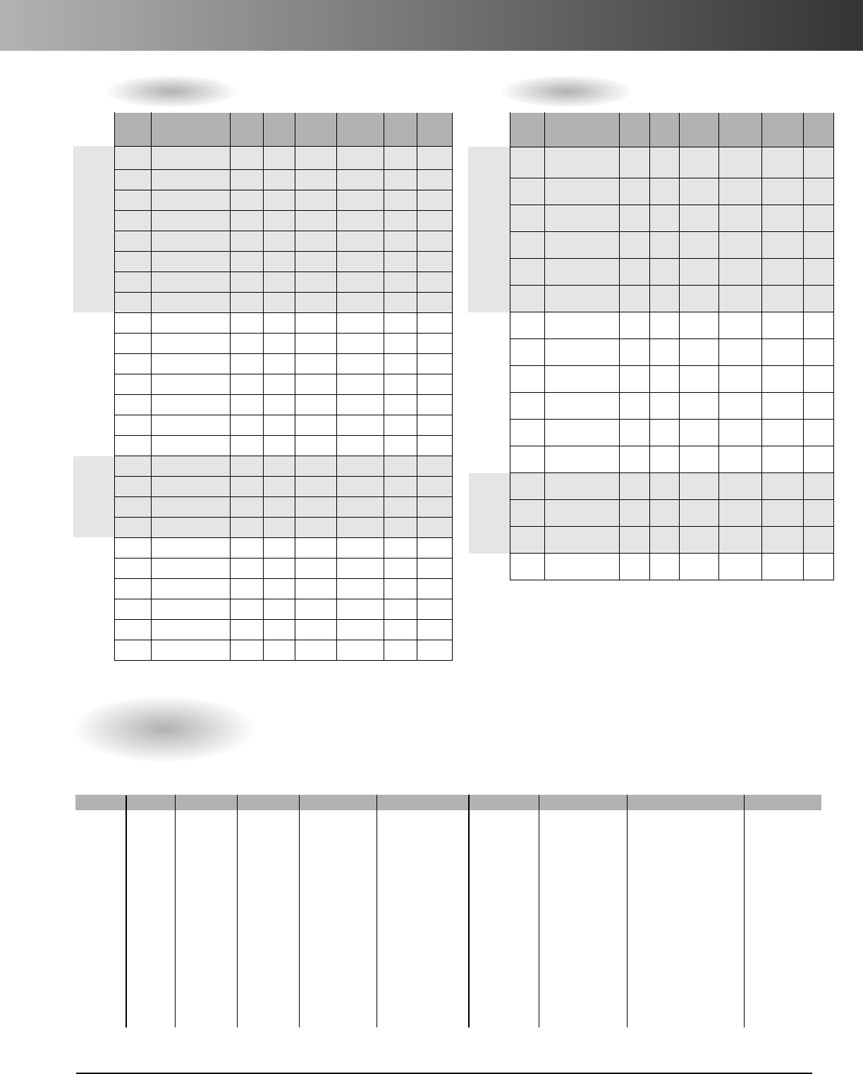
www.carlon.com 285
Corrugated HDPE Conduit
Standard Length – Reels
Reel
Wt. per
Nom. Nom. Pull Reel Length
100 ft.
Color Part No. I.D. O.D. Tape Size (ft.)
(lbs.)
Orange A5D2S1JNNB1000 1.049 1.340 1130 lb. 48-30-24 1000 12.5
Orange A5D2S1JNNB1800 1.049 1.340 1130 lb. 48-30-24 1800 12.5
Orange A5D2S1JNNB2000 1.049 1.340 1130 lb. 48-41-24 2000 12.5
Orange A5D2S1JNNB2700 1.049 1.340 1130 lb. 48-41-24 2700 12.5
Orange A5D2S1JNNB5000 1.049 1.340 1130 lb. 66-41-24 5000 12.5
Orange A5D2S1JNNB6500 1.049 1.340 1130 lb. 72-41-24 6500 12.5
Orange A5D2S1JNNB7000 1.049 1.340 1130 lb. 72-45-24 7000 12.5
Orange A5D2S1JNNB8000 1.049 1.340 1130 lb. 82-41-24 8000 12.5
Orange A6D2S1JNNB1000 1.250 1.565 1130 lb. 48-30-24 1000 14.4
Orange A6D2S1JNNB1600 1.250 1.565 1130 lb. 48-41-24 1600 14.4
Orange A6D2S1JNNB2500 1.250 1.565 1130 lb. 66-41-24 2500 14.4
Orange A6D2S1JNNB4000 1.250 1.565 1130 lb. 66-41-24 4000 14.4
Orange A6D2S1JNNB5000 1.250 1.565 1130 lb. 72-41-24 5000 14.4
Orange A6D2S1JNNB6000 1.250 1.565 1130 lb. 82-41-24 6000 14.4
Orange A6D2S1JNNB7000 1.250 1.565 1130 lb. 84-45-24 7000 14.4
Orange A9D2S1JNNB1000 1.500 1.825 1130 lb. 66-41-24 1000 17.8
Orange A9D2S1JNNB2200 1.500 1.825 1130 lb. 66-41-24 2200 17.8
Orange A9D2S1JNNB2900 1.500 1.825 1130 lb. 72-41-24 2900 17.8
Orange A9D2S1JNNB4000 1.500 1.825 1130 lb. 82-41-24 4000 17.8
Orange A13D2S1JNNB500 2.000 2.425 1130 lb. 48-30-24 500 25.0
Orange A13D2S1JNNB750 2.000 2.425 1130 lb. 48-41-24 750 25.0
Orange A13D2S1JNNB1000 2.000 2.425 1130 lb. 66-41-24 1000 25.0
Orange A13D2S1JNNB1500 2.000 2.425 1130 lb. 66-41-24 1500 25.0
Orange A13D2S1JNNB1800 2.000 2.425 1130 lb. 72-41-24 1800 25.0
Orange A13D2S1JNNB2000 2.000 2.425 1130 lb. 82-41-24 2000 25.0
1"
2"
1
1
/
4
"
1
1
/
2
"
Standard Length – Coils
Reel
Wt. per
Nom. Nom. Pull Box Length
100 ft.
Color Part No. I.D. O.D. Tape Size (ft.)
(lbs.)
Orange A5D2E1JNNA250 1.049 1.340 Empty COIL 250/Split 12.5
Orange A5D2E1JNNA250B 1.049 1.340 Empty 34-14-34 250/Split 12.5
Orange A5D2S1JNNB250 1.049 1.340 1130 lb. COIL 250 12.5
Orange A5D2S1JNNB250B 1.049 1.340 1130 lb. 34-14-34 250 12.5
Orange A5D2S1JNNB500 1.049 1.340 1130 lb. COIL 500 12.5
Orange A5D2S1JNNB500B 1.049 1.340 1130 lb. 39-15-39 500 12.5
Orange A6D2E1JNNA250 1.250 1.565 Empty COIL 250/Split 14.4
Orange A6D2E1JNNA250B 1.250 1.565 Empty 39-15-39 250/Split 14.4
Orange A6D2S1JNNB250 1.250 1.565 1130 lb. COIL 250 14.4
Orange A6D2S1JNNB250B 1.250 1.565 1130 lb. 39-15-39 250 14.4
Orange A6D2S1JNNB500 1.250 1.565 1130 lb. COIL 500 14.4
Orange A6D2S1JNNB500B 1.250 1.565 1130 lb. 44-18-44 500 14.4
Orange A9D2S1JNNB250 1.500 1.825 1130 lb.COIL 250 17.8
Orange A9D2S1JNNB250B 1.500 1.825 1130 lb. 44-18-44 250 17.8
Orange A9D2S1JNNB500 1.500 1.825 1130 lb. COIL 500 17.8
Orange A13D2S1JNNB250 2.000 2.425 1130 lb. COIL 250 25.0
1"
2"
1
1
/
4
"
1
1
/
2
"
*Custom Orders are not returnable
*Custom lengths are available in minimum order quantities of 1000 ft. or min. set up charge
How to Build a PartNumber:
Product Size Type Wall Options Splits Color Stripes Tape Length
A = HDPE 5=1" D = Corrugated 2=None - Corr N=None - Custom 1=1Way Single A = Black NN = None A = Empty 1500
6 = 1-1/4" E = Slit 2 = 2 Way Segmented B = Blue 1A = Black Stripe B = 1130 lb. Polyester Tape (Equals 1500 Feet)
9 = 1-1/2" S = Standard Length 3 = 3 Way Segmented C = Brown 1B = Blue Stripe C = 1250 lb. Polyester Tape
13 = 2" 4=4Way Segmented D = Buff 1C = Brown Stripe
D=1500
Polyester
lbs.
5=2Way Parallel E = Grey 1D = Buff Stripe E = 1800 lb. Polyester Tape
6=3Way Parallel F = Green 1E = Grey Stripe
G = 200 lbs.
Polyester Tape
7=4Way Parallel G = Lilac 1F = Green Stripe
J = 2500 lbs.
Polyester Tape
12 = 2 Way Compart H = Lt. Green 1G = Lilac Stripe
T = 1250 lbs. Poly Metric Tape
13 = 3 Way Compart J = Orange 1H = Lt. Green Stripe
14 = 4 Way Compart K=Red 1J = Orange Stripe
L = Terra Cotta 1K = Red Stripe
M = White 1L = Terra Cotta Stripe
N = Yellow 1M = White Stripe
1N = Yellow Stripe
Custom Orders
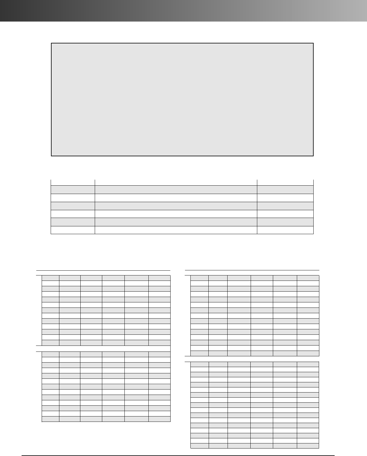
www.carlon.com
286
HDPE Conduit Specifications
3.0 Product
Description
Polyethylene duct and innerduct
is an extruded coilable tubing
for use as a single or multiple
raceway.
The conduit may be direct
buried, encased in concrete and
used as innerducts.
Innerducts are used primarily
toprovide multiple raceways
within an existing conduit
system.
4.0 Ovality
Conduit 3" or larger needs to
be re-rounded
Specifications
2.0 Material
Carlon duct is manufactured from
asuitable thermoplastic polymer
conforming to the minimum standard
of PE334470E/C as defined in ASTM
D3350. (see table 1)
Carlon
®
High Density
Polyethylene
duct is manufactured in the
following configurations:
Smoothwall –Smooth Interior and
Smooth Exterior wall.
Rib/Smooth –Ribbed Interior and
Smooth Exterior wall.
1.0 General
1.1 Carlon HDPE duct is manufactured to the
following various industry standards and
specifications for dimensional requirements.
ASTM F 2160 Solid Wall High Density
Polyethylene (HDPE) Conduit Based on
Controlled Outside Diameter (OD).
ASTM D 2239 Polyethylene (PE) Plastic Pipe
(SIDR) Based on Controlled Inside Diameter.
ASTM D 3035 Polyethylene (PE) Plastic Pipe
(SDR) Based on Controlled Outside Diameter.
NEMA TC-7 Smooth Wall Coilable Polyethylene
Electrical Plastic Conduit.
UL 651B Continuous Length HDPE
Table 1 – Resin Properties
The resin properties shall meet or exceed the values listed below for HDPE.
ASTM Test Description Values HDPE
D-1505 Density g/CM3.941 - .955
D-1238 Melt Index, g/10 min Condition E .05 - .50
D-790 Flexural Modulus, MPa (PSI) 80,000 min.
D-638 Tensile strength at yield (psi) 3000 min.
D-1693 Environmental Stress Crack Resistance Condition B,F10 96 hrs. min.
D-746 Brittleness Temperature -75˚C
Specifications
Pull
Nom. Nom. Nom. Min. Wt/ Tensile
Size ID OD Wall 100 Ft. Safe lbs.
SDR 7 - ASTM D3035
1" 0.939 1.315 0.188 28.552 743
1-1/4" 1.186 1.660 0.237 45.448 1183
1-1/2' 1.358 1.900 0.271 59.491 1549
2" 1.697 2.375 0.339 93.012 2421
3" 2.500 3.500 0.500 202.140 5262
4" 3.214 4.500 0.643 334.212 8700
5" 3.972 5.562 0.795 510.709 13295
6" 4.733 6.625 0.946 723.976 18847
8" 6.161 8.625 1.232 1227.418 31953
10 7.678 10.750 1.536 1907.218 49649
12 9.108 12.750 1.821 2681.954 69818
14 10.000 14.000 2.000 3234.240 84195
16 11.428 16.000 2.286 4224.753 109980
SDR 9 - ASTM D3035 / F2160
1" 1.023 1.315 0.146 23.000 599
1-1/4" 1.292 1.660 0.184 36.599 953
1-1/2" 1.478 1.900 0.211 48.026 1250
2" 1.847 2.375 0.264 75.102 1955
3" 2.722 3.500 0.389 163.084 4245
4" 3.500 4.500 0.500 269.520 7016
5" 4.326 5.562 0.618 411.745 10719
6" 5.153 6.625 0.736 584.091 15205
8" 6.709 8.625 0.958 989.810 25767
10" 8.362 10.750 1.194 1537.593 40027
12" 9.916 12.750 1.417 2164.092 56336
14" 10.888 14.000 1.556 2609.340 67927
16" 12.444 16.000 1.778 3407.638 88709
Pull
Nom. Nom. Nom. Min. Wt/ Tensile
Size ID OD Wall 100 Ft. Safe lbs.
SDR 11 - ASTM D3035 / F2160
1/2" 0.688 0.840 0.076 7.825 204
3/4" 0.860 1.050 0.095 12.226 318
1" 1.075 1.315 0.120 19.325 503
1-1/4" 1.358 1.660 0.151 30.706 799
1-1/2" 1.554 1.900 0.173 40.262 1048
2" 1.943 2.375 0.216 62.845 1636
3" 2.864 3.500 0.318 136.360 3550
4" 3.682 4.500 0.409 225.483 5870
5" 4.550 5.562 0.506 344.761 8975
6" 5.421 6.625 0.602 488.619 12720
8" 7.057 8.625 0.784 828.416 21566
10" 8.796 10.750 0.977 1286.718 33496
12" 10.432 12.750 1.159 1810.362 47128
14" 11.454 14.000 1.273 2183.310 56837
16" 13.090 16.000 1.455 2851.923 74242
SDR 13.5 - ASTM D3035 / F2160 / NEMA TC-7 EPEC-B
1/2" 0.716 0.84 0.062 6.500 169
3/4" 0.894 1.050 0.078 10.217 266
1" 1.121 1.315 0.097 15.921 414
1-1/4" 1.414 1.660 0.123 25.477 663
1-1/2" 1.618 1.900 0.141 33.423 870
2" 2.023 2.375 0.176 52.155 1358
2-1/2" 2.449 2.875 0.213 76.410 1989
3" 2.982 3.500 0.259 113.120 2945
4" 3.834 4.500 0.333 186.994 4868
4-3/4" 4.084 4.750 0.333 198.213 5160
5" 4.738 5.562 0.412 285.934 7444
6" 5.643 6.625 0.491 405.869 10566
8" 7.347 8.625 0.639 687.688 17902
10" 9.158 10.750 0.796 1067.755 27796
12" 10.862 12.750 0.944 1501.882 39098
14" 11.926 14.000 1.037 1811.529 47158
16" 13.630 16.000 1.185 2365.816 61588
Requests for certifications must be requested at time of quote
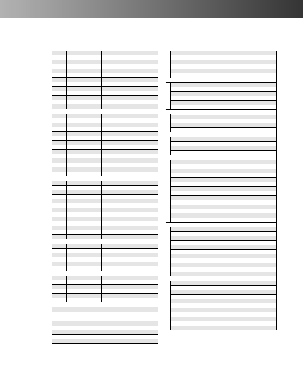
www.carlon.com 287
HDPE Conduit Specifications
Specifications
Pull
Nom. Nom. Nom. OD Min. Wall Wt/ Tensile
Size ID OD Wall 100 Ft. Safe lbs.
Pull
Nom. Nom. Nom. OD Min. Wall Wt/ Tensile
Size ID OD Wall 100 Ft. Safe lbs.
SIDR 11.5 TRUE
1" 1.020 1.194 0.087 12.979 338
1-1/4" 1.270 1.488 0.109 20.256 527
1-1/2" 1.520 1.780 0.130 28.906 752
2" 1.995 2.343 0.178 50.859 1352
4" 4.050 4.700 0.325 191.612 4988
6" 6.050 7.000 0.475 417.672 10873
SIDR 15 - ASTM D2239
1" 1.049 1.189 0.070 10.556 275
1-1/4" 1.380 1.564 0.092 18.250 475
1-1/2" 1.610 1.824 0.107 24.758 645
2" 2.067 2.343 0.138 41.006 1067
4" 4.026 4.562 0.268 155.081 4037
6" 6.065 6.873 0.404 352.192 9168
TRUE 9 - ASTM F2160
1" 1.024 1.259 0.111 18.075 447
1-1/4" 1.274 1.569 0.139 28.255 697
1-1/2" 1.529 1.883 0.167 40.692 1005
2" 2.039 2.510 0.222 72.183 1782
TRUE 11 - ASTM F2160
1" 1.024 1.217 0.091 14.571 359
1-1/4" 1.274 1.516 0.114 22.747 561
1-1/2" 1.529 1.817 0.136 32.465 802
2" 2.039 2.425 0.182 58.051 1432
SCHEDULE 40 - ASTM D2447 / F2160 / NEMA TC-7 EPEC-40
1/2" 0.622 0.84 0.109 10.738 280
3/4" 0.824 1.05 0.113 14.269 371
1" 1.049 1.315 0.133 21.185 551
1-1/4" 1.380 1.660 0.140 28.677 747
1-1/2" 1.610 1.900 0.145 34.293 893
2" 2.067 2.375 0.154 46.093 1200
2-1/2" 2.469 2.875 0.203 73.096 1903
3" 3.068 3.500 0.216 95.591 2488
4" 4.026 4.500 0.237 136.152 3544
5" 5.046 5.562 0.258 184.410 4801
6" 6.065 6.625 0.280 239.415 6233
8" 7.981 8.625 0.322 360.290 9379
10" 10.020 10.750 0.365 510.811 13298
12" 11.938 12.750 0.406 675.372 17582
SCHEDULE 80 - ASTM D2447 / F2160 / NEMA TC-7 EPEC-80
1/2" 0.546 0.84 0.147 13.728 357
3/4" 0.742 1.05 0.154 18.595 484
1" 0.957 1.315 0.179 27.403 713
1-1/4" 1.278 1.660 0.191 37.811 984
1-1/2" 1.500 1.900 0.200 45.818 1193
2" 1.939 2.375 0.218 63.368 1650
2-1/2" 2.323 2.875 0.276 96.667 2516
3" 2.900 3.500 0.300 129.370 3368
4" 3.826 4.500 0.337 189.059 4922
5" 4.812 5.562 0.375 262.125 6824
6" 5.761 6.625 0.432 360.534 9386
NEMA TC-7 EPEC A
1/2" 0.546 0.84 0.06 6.307 164
3/4" 0.93 1.05 0.06 8.005 208
1" 1.165 1.315 0.075 12.533 326
1-1/4" 1.460 1.660 0.100 21.023 547
1-1/2" 1.670 1.900 0.115 27.663 720
2 2.085 2.375 0.145 43.575 1134
2-1/2" 2.469 2.875 0.203 73.096 1903
3" 3.068 3.500 0.216 95.591 2488
4" 4.026 4.500 0.237 136.152 3544
5" 5.046 5.562 0.258 184.410 4801
6" 6.065 6.625 0.280 239.415 6233
SDR 15.5 - ASTM D3035
1" 1.147 1.315 0.084 13.935 363
1-1/4" 1.446 1.660 0.107 22.393 583
1-1/2" 1.654 1.900 0.123 29.455 767
2" 2.069 2.375 0.153 45.814 1193
3" 3.048 3.500 0.226 99.712 2596
4" 3.920 4.500 0.290 164.528 4283
5" 4.844 5.562 0.359 251.715 6553
6" 5.771 6.625 0.427 356.649 9284
8" 7.513 8.625 0.556 604.582 15739
10" 9.362 10.750 0.694 940.472 24483
12" 11.104 12.750 0.823 1322.794 34435
14" 12.194 14.000 0.903 1593.751 41489
16" 13.936 16.000 1.032 2081.634 54190
SDR 17 - ASTM D3035
1" 1.161 1.315 0.077 12.846 334
1-1/4" 1.464 1.660 0.098 20.629 537
1-1/2" 1.676 1.900 0.112 26.986 703
2" 2.095 2.375 0.140 42.166 1098
2-1/2" 2.537 2.875 0.169 61.628 1604
3" 3.088 3.500 0.206 91.443 2380
4" 3.970 4.500 0.265 151.238 3937
5" 4.908 5.562 0.327 230.688 6005
6" 5.845 6.625 0.390 327.689 8531
8" 7.611 8.625 0.507 554.649 14439
10" 9.486 10.750 0.632 861.733 22433
12" 11.250 12.750 0.750 1212.840 31573
14" 12.352 14.000 0.824 1463.093 38088
16" 14.118 16.000 0.941 1909.619 49712
SDR 21 - ASTM D3035
1" 1.189 1.315 0.063 10.629 277
1-1/4" 1.502 1.660 0.079 16.831 438
1-1/2' 1.720 1.900 0.090 21.952 571
2" 2.149 2.375 0.113 34.445 897
3" 3.166 3.500 0.167 75.009 1953
4" 4.072 4.500 0.214 123.602 3218
5" 5.032 5.562 0.265 189.163 4924
6" 5.995 6.625 0.315 267.856 6973
8" 7.803 8.625 0.411 454.944 11843
10 9.726 10.750 0.512 706.393 18389
12 11.536 12.750 0.607 993.289 25858
14 12.666 14.000 0.667 1198.436 31198
16 14.476 16.000 0.762 1564.746 40734
SIDR 7 - ASTM D2239
1" 1.049 1.349 0.150 24.237 631
1-1/4' 1.380 1.774 0.197 41.866 1090
1-1/2" 1.610 2.070 0.230 57.030 1485
2" 2.067 2.658 0.295 94.002 2447
4" 4.026 5.176 0.575 356.617 9283
6" 6.065 7.798 0.866 809.388 21069
SIDR 9 - ASTM D2239
1" 1.049 1.283 0.117 18.384 479
1-1/4" 1.380 1.686 0.153 31.608 823
1-1/2" 1.610 1.968 0.179 43.154 1123
2" 2.067 2.527 0.230 71.195 1853
4" 4.026 4.921 0.447 269.664 7021
6" 6.065 7.143 0.674 612.092 15932
SIDR 9 TRUE
1" 1.020 1.242 0.111 16.918 440
1-1/4" 1.270 1.546 0.138 26.184 682
SIDR 11.5 - ASTM D2239
1" 1.049 1.231 0.091 13.980 364
1-1/4" 1.380 1.620 0.120 24.257 631
1-1/2" 1.610 1.890 0.140 33.016 859
2" 2.067 2.427 0.180 54.505 1419
4" 4.026 4.726 0.350 206.398 5373
6" 6.065 7.119 0.527 468.154 12187
Internal Rib – Add .04 to Nom. ID (1/2" through 6") Not available in all wall types - consult factory.
Pull Tensile Safe = Based on Plastic Pipe Institute tensile calculations and maximum tensile stress recommendations of
1/3 yield tensile for pulls of 30 to 60 minutes or less in directional drilling applications and pulling as innerduct into conduit.
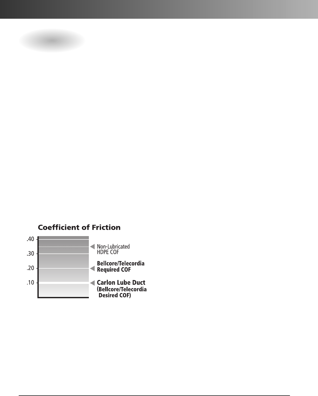
www.carlon.com
288
LubeDuct HDPE Conduit
LubeDuct pre-lubricated HDPE conduit utilizes a
Carlon/Pyramid pre-lubrication coating process
to provide a permanent low friction surface. The
low coefficient-of-friction reduces cable damage,
lowers pulling tensions, and allows multiple long
distance cable pulls or jetting of cable.
Benefits:
•
Low coefficient of friction
•
Lower pulling tensions
•
Less cable damage
•
Longer cable pulls over multiple bends
•
Long life,will not evaporate
Coefficient rating based on Bellcore/Telecordia
GR-356-CORE for optical cable innerducts.
LubeDuct COF: 0.10
Bellcore Test Procedure:
•
420 Degree Bend
•
36" Radius
•
Medium Jacket Cable with 15 lb.
Applied Weight
•
65 Ft/Min for a minimum travel
distance of 10 Ft.
•
Evaporation rate 0.5% at 500 Degrees F
Cut-Through Rating:
Cut-Through resistance based on
Bellcore/Telecordia GR-356-CORE for
optical cable innerducts
Carlon/Pyramid
Cut-Through Rating:
No Cut-Through at 3000 ft.
•
No signs of cut through or
degradation of core for 30 minute duration
•
1800 lb. Pull Tape
•
450 lbs. Tensile @ 100 Ft/Minute
Coefficient of Friction
Carlon
®
/Pyramid Industries
™
LubeDuct Pre-Lubricated HDPE Conduit
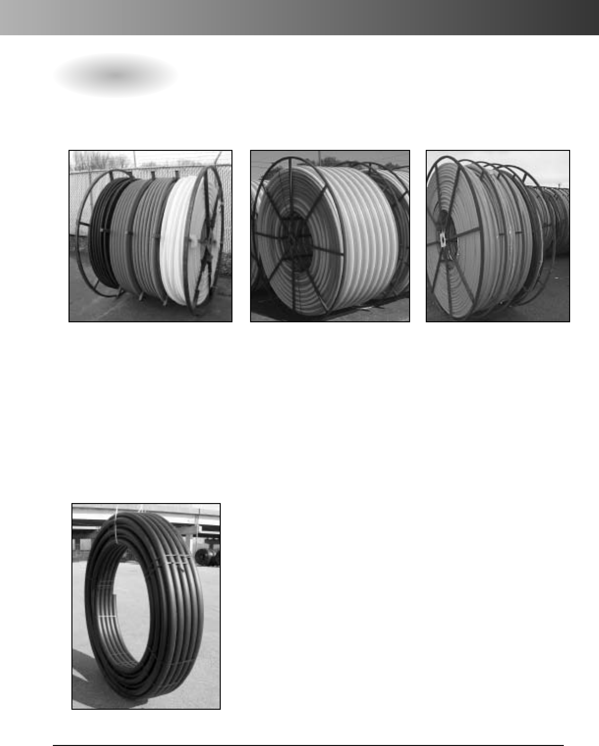
www.carlon.com 289
HDPE Conduit Packaging Options & Truckload Quantities
Compartmentalized
(3/4" through 2")
1 1/2" – 2" diameter recommended
Paralleled
(3/4" through 2")
1" – 1 1/4" diameter recommended
Segmented
(3/4" – 2")
Packaging Options
Physically segmenting different
colors into one, two, three or four
separate segments allowing
independent pulling of ducts.
Physically compartmentalizing
different colors into one, two,
three or four separate segments
allowing independent pulling of
ducts. Full rings help align duct
during pull.
Extruding each color onto a single
reel and then simultaneously
pulling onto one reel. Ideal for
using all ducts at one time.
Standard length and custom
coils available 1" - 6".
Call for quantity and
dimensions available.
Reels
*Carlon does not recommend putting Sch. 40 HDPE on reels
Coils
NOTE: 4" through 6" Schedule
40 HDPE is available in
straight lengths only.
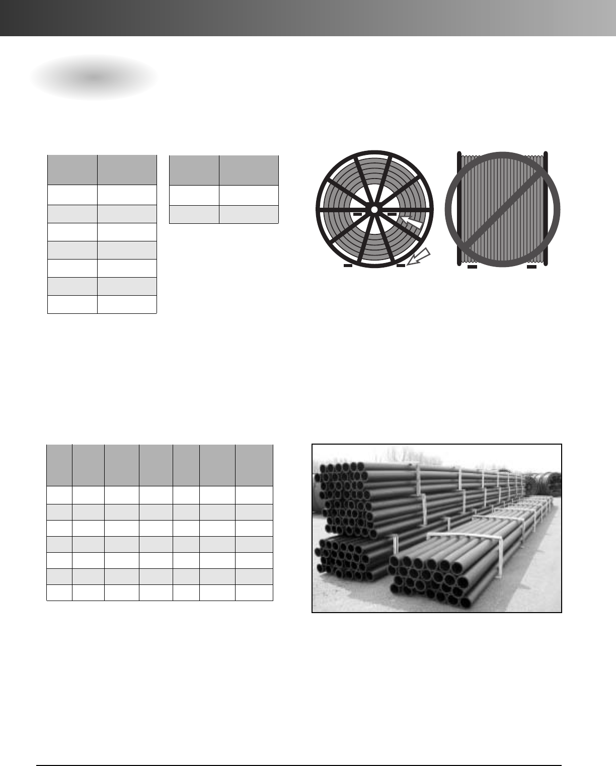
www.carlon.com
290
HDPE Conduit Reel Chart
Flatbed (48 ft.) Step Deck Flatbed
NOTE: Two additional
reels, 96" or smaller, can
fit on the upper deck.
Number of
Reel Reels per
Size Truckload
48" 24
66" 18
72" 16
82" 14
84" 14
96" 12
102" 12
Number of
Reel Reels per
Size Truckload
114" 8
120" 8
Truckload Quantities
# of Ft. per Ft. per Total Feet Total Feet
Lengths Bundle Bundle Bundles per Truck per Truck
per 40 ft. 50 ft. per 40 ft. 50 ft.
Size Bundle Lengths Lengths Truck Lengths Lengths
4" 57 2280 2850 8 18240 22800
6" 26 1040 1300 8 8320 10400
8" 14 560 700 8 4480 5600
10" 4160 200 18 2880 3600
12" 4 160 200 14 2240 2800
14" 3 120 150 14 1680 2100
16" 3 120 150 12 1440 1800
Reels
Bundles 40 ft / 50 ft Lengths
Reels must be lifted from the side with lift truck forks
inserted through the spokes of the reel, or at the bottom
with entry from the side of the reel. Reels should NEVER
be lifted from the front of the reel or contact innerduct.
Loading Reels
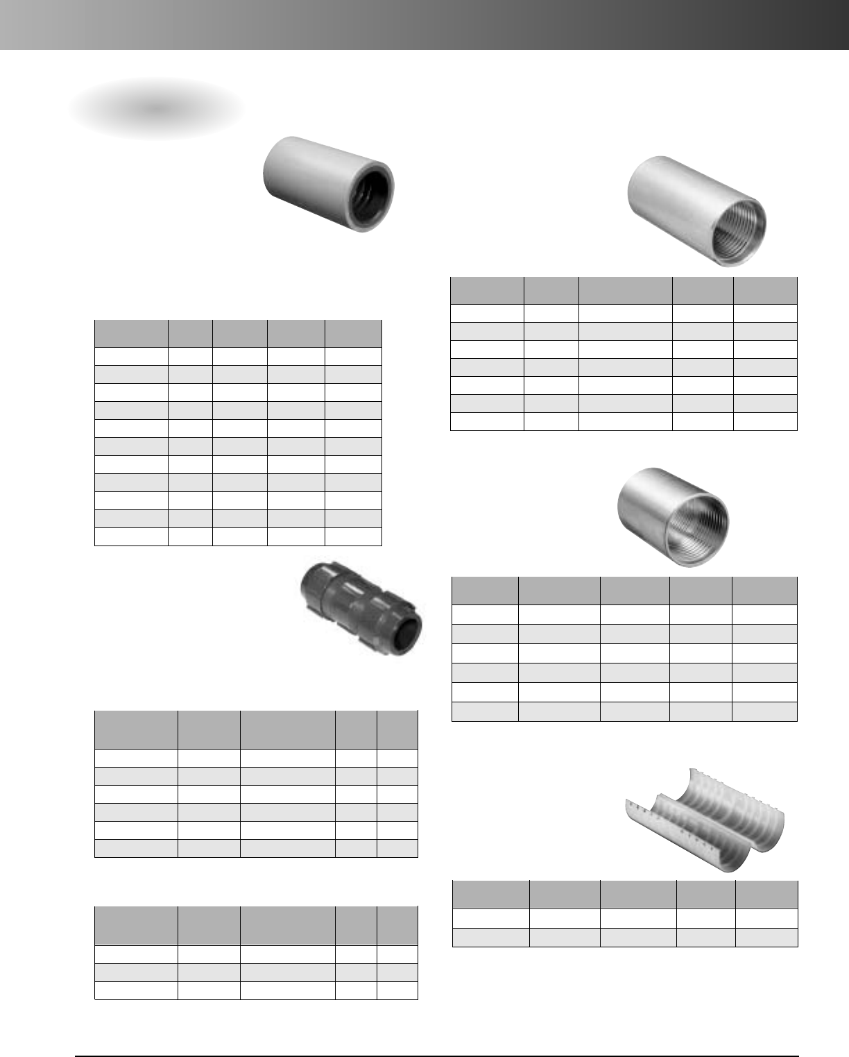
www.carlon.com 291
HDPE Conduit Accessories
Couplings
Universal Aluminum
Couplings
Self-threading, which draws
each end of the conduit into
the center of the coupler.
*Double “E-Loc”
®
Designed to join both smoothwall
and ribbed OD wall innerduct and are
used when air and water-tight integrity is
imperative.Internal pressures above 200 psi are
maintained when the conduit is unrestrained.
Barbed Couplings
Press-On/Screw-On
*Standard “E-Loc”
®
Designed for use with
smoothwall OD controlled
innerduct (ASTM 3035), Sch. 40 and
Sch. 80 innerduct, and is pressure tight to
internal pressures above 200 psi when restrained
or buried. Ideal for joining PE to PVC or threaded
steel conduit.
Nonmetallic
Clamshell Couplings
For use with Corrugated HDPE
Part Nom. O.D. Std. Ctn. Std. Ctn.
No. Size (of Duct) Qty. Wt.
E144F 1" 1.34" 30 1.7
E144GT 11/4" 1.565" 25 2
Part Nom. O.D. Std. Ctn. Std. Ctn.
No. Size (of Duct) Qty. Wt.
BS1.315 1" SDR 1.315" 100 16
BS1.194 1" True 11 1.194" 100 16
BS1.488 11/4" True 11 1.488" 100 16
BS1.660 11/4" SDR 1.660" 100 16
BS1.900 11/2" SDR 1.900" 100 24
BS2.375 2" SDR 2.375" 100 34
Aluminum
Part Nom. O.D. Std. Ctn. Std. Ctn.
No. Size (Duct Range) Qty. Wt.
P75
3
/
4
" .91 – 1.08 10 12
P100 1" 1.21 – 1.41 100 25
P125 1
1
/
4
" 1.44 – 1.68 100 28
P150CPLR 1
1
/
2
" 1.80 – 2.02 100 35
P200 2" 2.31 – 2.48 50 19
P300 3" 3.495 – 3.505 12 10
P400 4" 4.41 – 4.65 12 12
Part Nom. O.D. Std. Ctn. Std. Ctn.
No. Size (of Duct) Qty. Wt.
EL.084 1/2" .084" 1 .40
EL1.050 3/4" 1.050" 1 1.00
EL1.315 1" 1.315" 1 1.00
EL1.660 11/4" 1.660" 1 0.68
EL1.900 11/2" 1.900" 1 1.12
EL2.375 2" 2.375" 1 1.63
EL2.875 21/2" 2.875" 1 1.80
EL3.500 3" 3.500" 1 1.92
EL4.500 4" 4.500" 1 2.68
EL5.563 5" 5.563" 1 3.31
EL600 6" 6.625" 1 3.58
*“E-Loc” is a registered trademark of ETCO Specialty Products, Inc.
Transition Couplings
Std. Std.
Part Nom. O.D. Ctn. Ctn.
No. Size (of Duct) Qty. Wt.
DEL150-154 11/4" 1.500" - 1.540" 50 58
DEL150-166 11/4"1.500" - 1.660" 50 58
DEL154-166 11/4"1.540" - 1.660" 50 58
Std. Std.
Part Nom. O.D. Ctn. Ctn.
No. Size (of Duct) Qty. Wt.
DEL131 1" 1.315" 50 63
DEL150 11/4" True 1.500" 50 58
DEL154 11/4" 1.540" 50 58
DEL166 11/4" 1.660" 50 53
DEL190 11/2"1.900" 24 43
DEL237 2" 2.375" 25 57
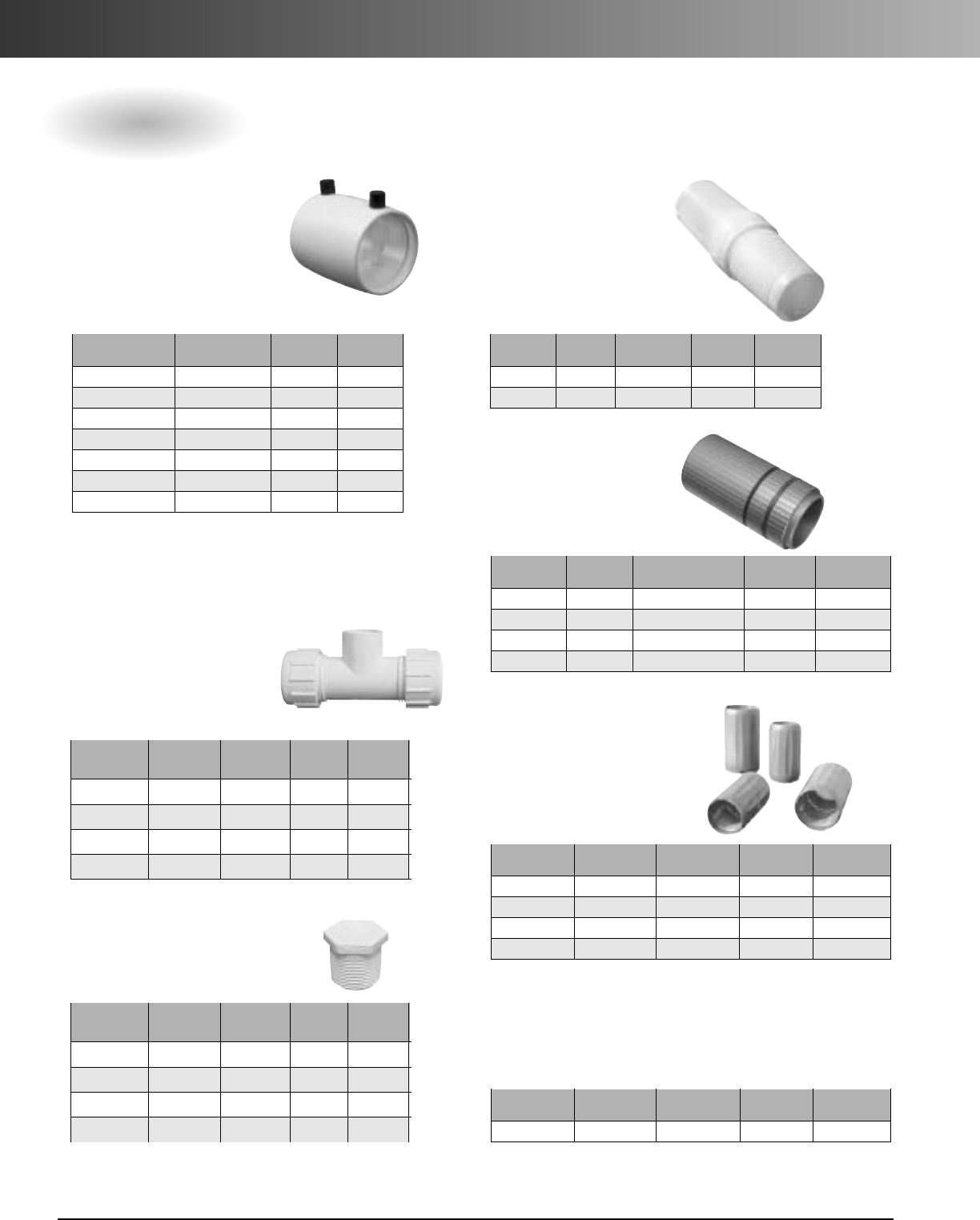
www.carlon.com
292
HDPE Conduit Accessories
Couplings
Terminating Connector
Electrofusion Coupling
Provides an airtight duct
system and is used to join
HDPE to PVC or threaded steel
conduit. Ideal for directional
bore applications.
Nonmetallic
Internal Couplings
Nonmetallic, self-threading
and are recommended for use
with corrugated duct.
Part Nom. I.D. Std. Ctn. Std. Ctn.
No. Size Range Qty. Wt.
PIC100 1" 1.05 100 24
PIC125 1 1/4" 1.25 100 26
Part Nom. O.D. Std. Ctn. Std. Ctn.
No. (of Duct) Qty. Wt.
575-4075 1.488" 40 12.96
575-4049 1.526" 40 12.44
575-0640 1.660" 40 12
575-0641 1.900" 140 55.3
575-0642 2.375" 30 17.46
575-0643 3.500" 36 45.47
575-0644 4.500" 10 18.77
Part Nom. O.D. Std. Ctn. Std. Ctn.
No. Size Range Qty. Wt.
TC100 1"
.91 – 1.08
12 50
TC125 1
1
/
4
" 1.495 – 1.70 12 52
TC150 1
1
/
2
" 1.80 – 2.00 12 56
TC200 2" 2.31 – 2.52 12 58
Tuff-Link Couplers
Part Nom. Std. Ctn. Std. Ctn.
No. Size O.D. Qty. Wt.
TFL100 1"
1.299"
1.2
TFL125 1
1
/
4
" 1.660" 1 .2
TFL150 1
1
/
2
" 1.900" 1 .2
TFL200 2" 2.375" 1 .6
Expansion Sleeve
Part Nom. O.D. Std. Ctn. Std. Ctn.
No. Size of Duct Qty. Wt.
EXP125
1
1
/
4
" 9T 1.524 1 1
Toneable Pressure
Coupling
Nom. O.D. Nom. Std. Ctn. Std. Ctn.
Part No. of Duct O.D. Qty. Wt. (lbs.)
TDC100 1" 1.315 60 34
TDC125 1 1/4" 1.66 36 28
TDC150 1 1/2"1.90 30 31
TDC200 2" 2.375 12 18
Designed to join Carlon®
Toneable Duct System
150 PSI at 73°F
Nom. O.D. Nom. Std. Ctn. Std. Ctn.
Part No. of Duct O.D. Qty. Wt. (lbs.)
TPLG100 1" 1.315 50 4
TPLG125 1 1/4" 1.66 25 3
TPLG150 1 1/2" 1.90 25 3.5
TPLG200 2" 2.375 10 2.7
Threaded Plugs
For use with Toneable Coupling
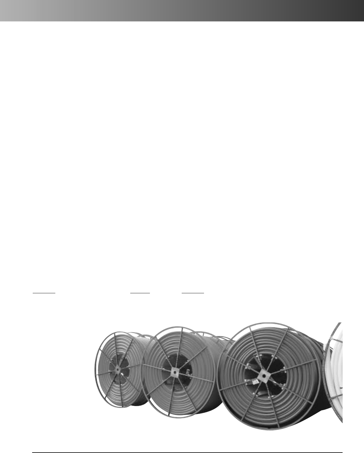
www.carlon.com 293
HDPE Conduit Reel Return Policy
The Carlon Reel Return Policy offers our customers the opportunity to recycle empty steel reels used to ship Carlon High
Density Polyethylene. A credit will be issued for each reel returned to Lamson & Sessions HDPE plants in good condition. Reels
may also be picked up in truckload quantities when consolidated into one location. Details outlining the program are listed below:
Reel Shipment: Reels may be returned broken down into flanges and staves or fully assembled. Steel tubular spoked reels
supplied by Carlon or of similar type meeting the Reel Design and Quality Requirements section below will be accepted. All broken
down reel flanges and staves should be banded for forklift off loading and safe transport.
Freight: Reels may either be shipped back to plants by customer or arranged for pick-up by Lamson & Sessions. Reels returned for
credit with customer choosing a carrier and paying all freight charges for return of Reels (Class 55 freight is recommended) when
returning reels. Reels must be shipped "Prepaid". Reels shipped collect will be refused. A 24-hour notice to receiving plant is
needed before the truck arrives. It is Lamson & Sessions policy to honor appointments and unload in an efficient manner. Lamson
& Sessions will not pay any detention incurred by carriers. Reel pick-up can be arranged by contacting Sipping Manager at any of
the following Carlon HDPE locations:
The Carlon Reel Return Policy
Lamson & Sessions
1422 Irwin Drive
Erie, PA 16505
Ph: 814-455-7587
Lamson & Sessions
1776 E. Beamer
Woodland, CA 95685
Ph: 530-669-0160
Lamson & Sessions
237 Forest View Dr.
Seymour, MO 65746
Ph: 417-926-1846
Lamson & Sessions
9000 Joiner Rd.
Tennille, GA 31089
Ph: 478-553-0024
Pick-up Reels: Reels will be picked by carriers chosen by Lamson & Sessions as arranged between customer and Lamson &
Sessions Shipping Manager. Reels are requested to be broken down with all components on sizes 102" and smaller, but will be
pick-up assembled or unassembled. Quantities of Truckload or more will be picked within 30 days of request, while smaller
quantities may take up to 90 days or more to gather depending on transportation in the area.
Reel Quality and Deign Requirements: Reel designs include steel tubular spoked reels using a minimum 14 gauge
(.075" Nom) steel and means of disassembly including clevis pins or bolts. Reels must be undamaged, in full working condi-
tion, and include all flanges and staves for full credit. This includes but is not limited to warping, flattening, or any structural
damage to the reel or its components.Reel acceptability will be determined by receiving plant using quality inspection criteria.
Credit: A credit for each reel meeting the above requirements will be issued to the customer’s account. If the reel does not
meet the quality requirements, a credit will not be issued and a $20 disposal fee for each non-usable reel will be deducted
from total credit.
Reel Sizes: The following reel sizes and staves are the only acceptable sizes as they are most common standard size reels for
Lamson & Sessions and most HDPE manufacturers.
Flanges Staves Spindle
48" 82" 102" 45" 2 3/4" Minimum
66" 84" 114" 41"
72" 96" 120" 33"
www.carlon.com
294
Carlon
®
HDPE Quote Request
Date: Needed By: Destination:
Customer: Account Number: Application:
Rep Agency: Market: Power Telecommunication Electrical CATV
Minimum Custom Run
Quantities:
1/2" - 1" 5000 Ft.
11/4" - 2" 2500 Ft.
21/2" - 16" 1000 Ft.
Fax completed Quote Request to your Local Carlon Representative
Visit www.carlon.com to locate a Carlon Representative
1. PRODUCT TYPE
AHDPE
E Aerial HDPE
S Aerial Figure 8 - 6.6M
T Aerial Figure 8 - 10M
U UL Listed HDPE
Certification Required
Specification
Custom Printline
NN NONE
3A 3 Black Stripes
3B 3 Blue Stripes
3C 3 Brown Stripes
3D 3 Buff Stripes
3E 3 Grey Stripes
3F 3 Green Stripes
3G 3 Lilac Stripes
3H 3 Lt. Green
3J 3 Orange Stripes
3K 3 Red Stripes
3L 3 Terra Cotta Stripes
3M 3 White Stripes
3N 3 Yellow Stripes
9. PULL LINE
A Empty
B 1130 lbs. Polyester Tape
C 1250 lbs. Polyester Tape
D 1500 lbs. Polyester Tape
E 1800 lbs. Polyester Tape
G 200 lbs. Polyester Tape
J 2500 lbs. Polyester Tape
K
400 lbs. Detectable Poly Tape 22 Ga
T 1250 lbs. Poly Metric Tape
V
1250 lbs. Detectable Poly Tape 22 Ga
10. Quantity
Total Length Feet
Max Reel Size
Carlon Quote #
Pricing Specialist
5. OPTIONS
N Standard/No Options
B Supplied Cable
D Lube Duct
E Slit - Corr
F Toneable/18G
(Min. Wall .14)
G Toneable/22G
(Min. Wall .12)
A Black
B Blue
C Brown
D Buff
E Grey
F Green
G Lilac
H Lt. Green
J Orange
K Red
L Terra Cotta
M White
N Yellow
6. REEL SPLITS
1 1- Way Single
2 2- Part Segmented
3 3- Part Segmented
4 4- Part Segmented
5 2- Way Parallel
6 3- Way Parallel
7 4- Way Parallel
12 2- Way Compart
13 3- Way Compart
14 4- Way Compart
2 Corrugated
4 SCH 40
5 SCH 80
6 SDR 11
9 SDR 13.5
13 SDR 15.5
14 SDR 17
16 SDR 21
22 SDR 7
24 SDR 9
26 SIDR 11.5
27 SIDR 11.5 True
29 SIDR 15
34 SIDR 7
36 SIDR 9
37 SIDR 9 True
42 TC-7-A
45 True 11
46 True 9
3. CONFIGURATION
B Smooth Out/Ribbed In
C Smooth Out/Smooth In
DCorrugated
2. SIZE
2 1/2"
3 3/4"
51"
6 1-1/4"
9 1-1/2"
13 2"
14 2-1/2"
15 3"
16 4"
17 4.75"
18 5"
22 6"
23 7"
24 8"
25 10"
26 12"
27 14"
28 16"
Target Price
Project Stage Bid/Buy
Competitors
• Freight quoted F.O.B., origin (freight additional) from plant specified.
• Custom product non-cancelable 24 hours after order acknowledgement or production has started.
4. WALL TYPE
(Sizes 8" - 16" available in Black or Black with Stripes only.)
7. COLOR
8. STRIPE
(Single Stripe only on Toneable)
4" - 6" Sch. 40 HDPE available in
straight lengths only.
www.carlon.com 295
Carlon
®
Cable and
Installation Accessories
Duct Plugs
Split Plugs
Pulling Harness
Pulling Eyes
Swivels
Line Missiles
Warning Tape
Rope & Tape
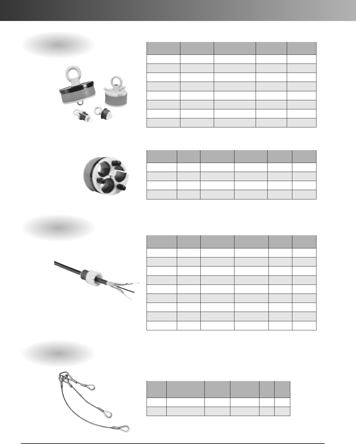
www.carlon.com
296
Cable and Installation Accessories
Duct Plugs
Split Plugs for Sealing Innerduct and Cable
Duct I.D. Cable O.D. Std. Ctn. Std. Ctn.
Part No. Size Range Range Qty. Wt.
MAFPG2 1" 1.00" - 1.10" 0.35" - 0.57" 50 8
MAFPG21 1" 1.00" - 1.10" 0.43" - 0.57" 50 8
MAFPG22 1" 1.00" - 1.10" 0.57" - 0.70" 50 8
MAFPG3 11/4"1.22" - 1.36" 0.35" - 0.57" 50 10
MAFPG4 11/4" 1.22" - 1.36" 0.57" - 0.70" 50 10
MAFPG41 11/4"1.22" - 1.34" 0.70" - 0.90" 50 10
MAFPG5 11/2" 1.50" - 1.65" 0.35" - 0.57" 50 15
MAFPG6 11/2" 1.50" - 1.65" 0.50" - 0.70" 50 15
MAFPG9 2" 1.98" - 2.15" 0.35" - 0.57" 50 22
Multiple Innerduct Pulling Harness
Working Working Std.
Load Load Ctn. Wt./Ea.
Part No. Description Per Leg (lbs.) Combined (lbs.) Qty. (lbs.)
MAPH3
3-Way 1/4" Cable
1400 2900 114
MAPH4
4-Way 1/4" Cable
1400 4200 1 15
Duct I.D. Innerduct O.D. Std. Ctn. Std. Ctn.
Part No. Type Range Range Qty. Wt.
MATPG2 3-Hole 3.92" - 4.21" 1.31" - 1.42" 24 27
MATPG3 3-Hole 3.92" - 4.21" 1.53" - 1.67" 24 24
MAQPG2 4-Hole 3.92" - 4.21" 1.19" - 1.36" 24 23
MAQPG4 4-Hole 4.16" - 4.34" 1.19" - 1.36" 24 34
Multi-Access
Duct I.D. Std. Ctn. Std. Ctn.
Part No. Size Range Qty. Wt.
MAEPG2 1" .96" - 1.16" 50 4.5
MAEPG4 11/4"1.14" - 1.48" 50 5.5
MAEPG3 11/2" 1.49" - 1.83" 50 7.5
MAEPG5 2" 1.83" - 2.36" 50 12.5
MAEPG55 3" 2.99" - 3.46" 50 19.5
MAEPG6 31/2"3.42" - 4.00" 25 13
MAEPG7 4" 3.94" - 4.33" 50 32.5
MAEPG8 5" 5.00" - 5.35" 25 24.5
Blank
For use with Pulling Innerducts into a 4" Conduit
www.carlon.com 297
Cable and Installation Accessories
Innerduct Pulling Eyes
Swivels - Ball Bearing
Work/Break Wt./Ea.
Part No. Description Load (lbs.) Dimensions (lbs.)
MASV4 Non-Breakaway 1800 7/8"x 41/2" .53
MASV5 Non-Breakaway 600 5/8"x 4" 1.00
Work/Break
Std. W
t./Ea.
Pin
Part No. Description Load (lbs.) Dimensions
Ctn. Qty.
(lbs.) Part No. Description
MASV6 Breakaway 600 7/8"x 41/2" 1 .55 MASVP6 7/8" Replacement Pin for MASV6
MASV7 Breakaway 600 5/8"x 31/2" 1 .19 MASVP7 5/8" Replacement Pin for MASV7
MASV8 Breakaway 450 5/8"x 31/2" 1 .19 MASVP8 5/8" Replacement Pin for MASV8
Swivels - Breakaway and Replacement Pins
Part No. Size Range Std. Ctn. Qty. Wt./Ea. (lbs.)
MAPE3 1 - 11/8" .93 - 1.06 1 1.0
MAPE4 7/8" .71 - .87 1 1.5
MAPE5 1 - 11/8" 1.06 - 1.43 1 1.0
MAPE6 11/4" 1.06 - 1.43 1 2.0
MAPE7 17/16." 1.343 - 1.50 1 4.5
MAPE8 11/2" 1.50 - 1.625 1 5.0
MAPE9 2" 1.97 - 2.09 1 6.0
Line Missiles
Std. Ctn. Std. Ctn.
Part No. Description Qty. Wt.
MAPRO3 3-Way for
11/4" Duct
25 25
MAPRO4 4-Way for
1" Duct
25 18
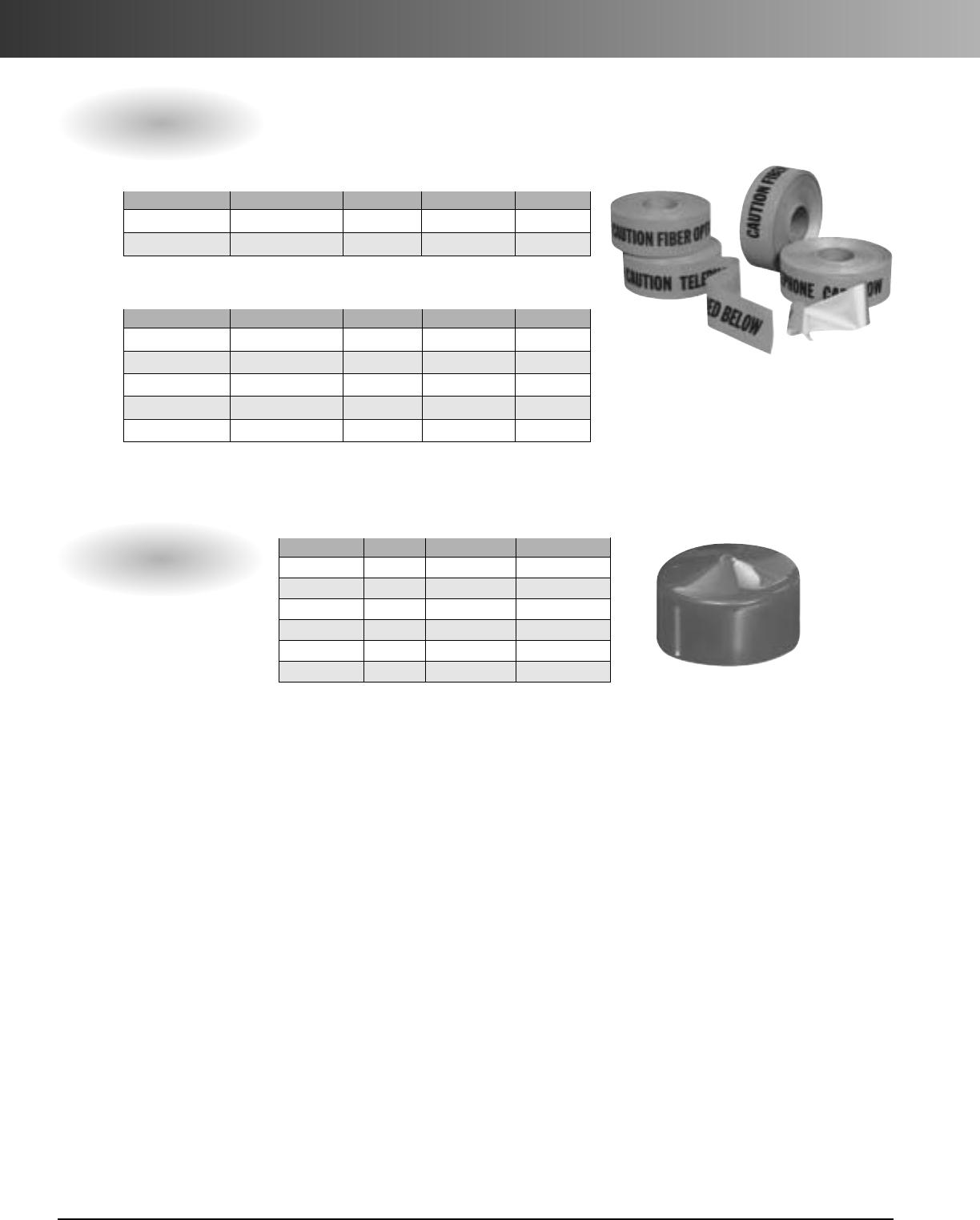
www.carlon.com
298
Cable and Installation Accessories
End Caps
Part No. Size Nom. O.D. Std. Ctn. Qty.
EC1.315 1" 1.315" 1
EC1.488 11/4" 1.488" 1
EC1.660 11/4" 1.660" 1
EC1.900 11/2" 1.900" 1
EC2.375 2" 2.375" 1
EC4.500 4" 4.500" 1
Underground Warning Tape – Orange
Part No. Type Width Ft. per Spool Wt. ea. lbs.
MAT3T21 Standard 3" 1000' 7
MAT3T61 Detectable 3" 1000' 8
CAUTION TELEPHONE CABLE BURIED BELOW
Part No. Type Width Ft. per Spool Wt. ea. lbs.
MAT3O21 Standard 3" 1000' 7
MAT6O21 Standard 6" 1000' 13
MAT3O51 Extra Stretch 3" 1000' 7
MAT3O61 Detectable 3" 1000' 8
MAT6O61 Detectable 6" 1000' 16
CAUTION FIBER OPTIC CABLE BURIED BELOW
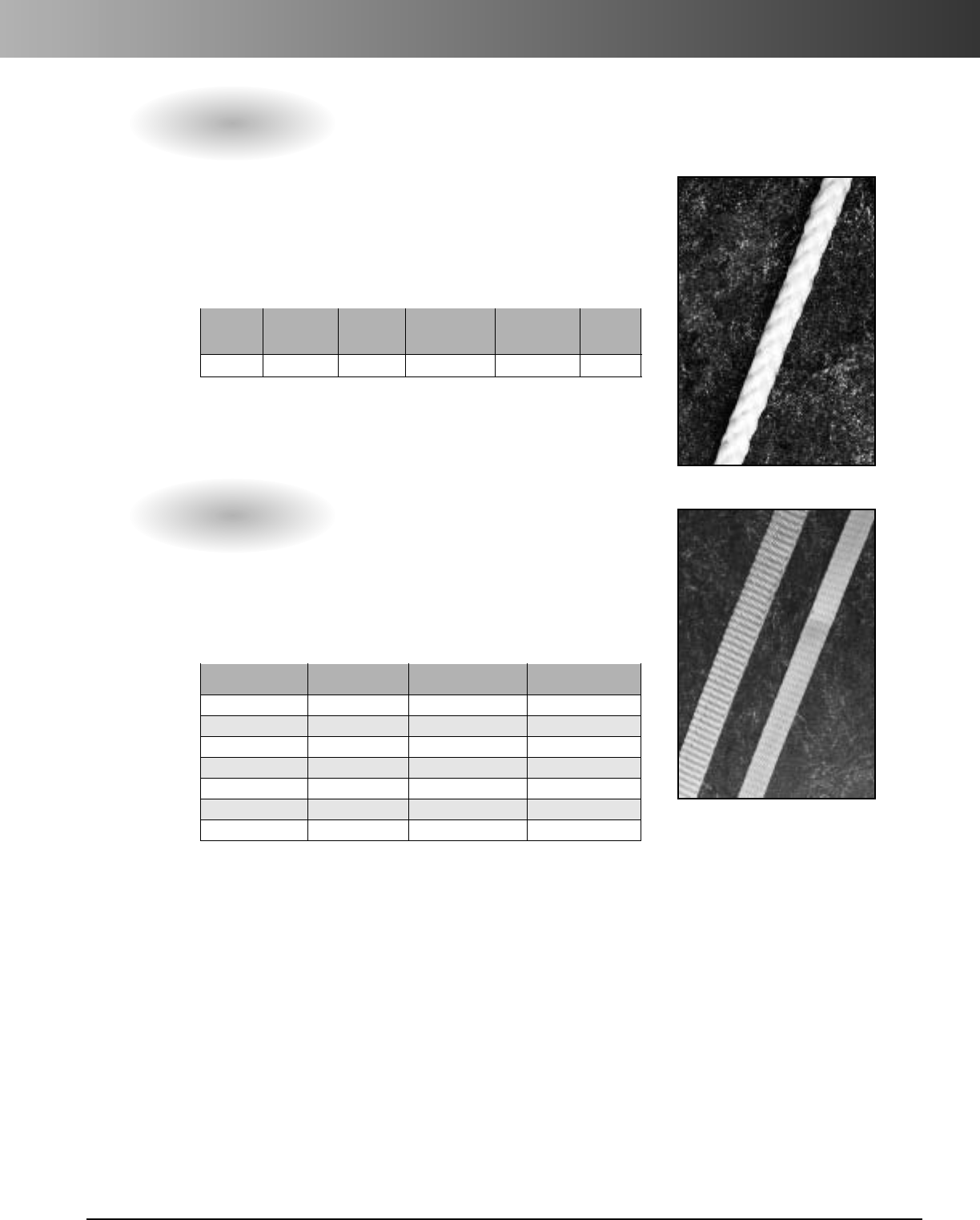
www.carlon.com 299
Cable and Installation Accessories
Rope (Conduit Pulling Lines for Conductors or Fiber Optics)
Tape
Prelubricated, woven polyester tape made from low
friction, high abrasion resistant yarns providing a low
coefficient of friction. Tape is printed with sequential
footage markings for accurate measurements.
Part Tensile Reel
No. Size Strength (lbs.) Lengths
TL14203 1/2" 1130 3,000 ft.
TL14205 1/2"1130 5,000 ft.
TL14505 1/2" 1250 5,000 ft.
TL14510 1/2"1250 10,000 ft.
TL38203 5/8" 1800 3,000 ft.
TL38265 5/8" 1800 6,500 ft.
TL38210 5/8" 1800 10,000 ft.
This rope is constructed of polyethylene over polyester,
designed specifically for fiber-optic pulling. The
polyethylene jacket gives the “slippery” feel that gives
less drag in pulling through conduit.
White Diamond Braid Rope
Recommended Approximate Std.
Reel Working Avg. Ctn.
Part No. Lengths Diameter Load (lbs.) Tensile (lbs.) Wt. (lbs.)
SB14105 5,000 ft. 1/4" 260 1700 1000
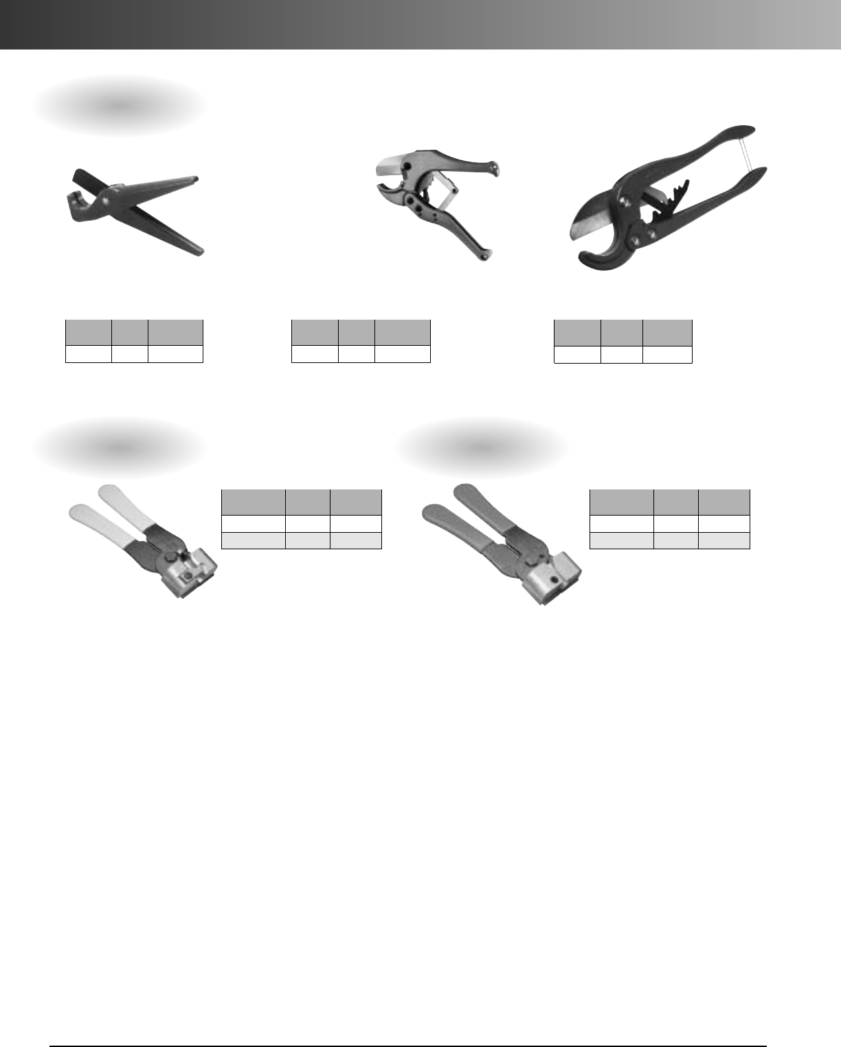
www.carlon.com
300
Cable and Installation Accessories
Std.
Part No. Size Ctn. Qty.
CC120B 8" 10
Std.
Part No. Size Ctn. Qty.
3056MW 6.6M 1
30510MW 10M 1
Std.
Part No. Size Ctn. Qty.
CC125 9" 1
Std..
Part No. Size Ctn. Qty.
CC122 171/2"1
Hand held cutter
makes fast square,
smooth field cuts on
Innerduct sizes 1/2"
through 11/4".
For clean cuts of Innerduct
sizes 1/2" through 2".
For fast, smooth
field cuts of 1/2"
through 1" Innerduct.
Kwikcut Cutter Medium
Cutter
Large
Cutter
Conduit Cutters
Figure-8 Web Slitter
Std.
Part No. Size Ctn. Qty.
3056MJ 6.6M 1
30510MJ 10M 1
Figure-8 Jacket Slitter

www.carlon.com 301
Product Category Index
Product Page
Boreable Multi-Gard®Trenchless Raceway. . . . . . . . . . . . . . . . . . . . . . . . . . . . . . . . . . . . . . . . . 233
Bore-Gard®Trenchless Raceway. . . . . . . . . . . . . . . . . . . . . . . . . . . . . . . . . . . . . . . . . . . . . . . . . 232
Carflex®Liquidtight Fittings . . . . . . . . . . . . . . . . . . . . . . . . . . . . . . . . . . . . . . . . . . . . . . . . . . . . . . 6
Carflex®Liquidtight Flexible Nonmetallic Tubing . . . . . . . . . . . . . . . . . . . . . . . . . . . . . . . . . . . . . . 4
Carflex®Omni Connectors . . . . . . . . . . . . . . . . . . . . . . . . . . . . . . . . . . . . . . . . . . . . . . . . . . . . . . . 9
Carflex®Pre-Wired Liquidtight Whips . . . . . . . . . . . . . . . . . . . . . . . . . . . . . . . . . . . . . . . . . . . . . 11
Carflex®X-Flex™Flexible Nonmetallic Tubing . . . . . . . . . . . . . . . . . . . . . . . . . . . . . . . . . . . . . . . . 5
Cement . . . . . . . . . . . . . . . . . . . . . . . . . . . . . . . . . . . . . . . . . . . . . . . . . . . . . . . . . . . . . . . . . . . . 220
Chimes . . . . . . . . . . . . . . . . . . . . . . . . . . . . . . . . . . . . . . . . . . . . . . . . . . . . . . . . . . . . . . . . . . . . . 15
Circuit Safe®JIC Enclosures. . . . . . . . . . . . . . . . . . . . . . . . . . . . . . . . . . . . . . . . . . . . . . . . . . . . . 122
Circuit Safe®NEMA Enclosures. . . . . . . . . . . . . . . . . . . . . . . . . . . . . . . . . . . . . . . . . . . . . . . . . . 112
Cord Grips. . . . . . . . . . . . . . . . . . . . . . . . . . . . . . . . . . . . . . . . . . . . . . . . . . . . . . . . . . . . . . . . . . . 12
Curved Lid J-Box . . . . . . . . . . . . . . . . . . . . . . . . . . . . . . . . . . . . . . . . . . . . . . . . . . . . . . . . . . . . . . 48
ENT Boxes and Fittings . . . . . . . . . . . . . . . . . . . . . . . . . . . . . . . . . . . . . . . . . . . . . . . . . . . . . . . . . 21
Flex-Plus®Blue™ENT. . . . . . . . . . . . . . . . . . . . . . . . . . . . . . . . . . . . . . . . . . . . . . . . . . . . . . . . . . . 20
Floor Box Systems. . . . . . . . . . . . . . . . . . . . . . . . . . . . . . . . . . . . . . . . . . . . . . . . . . . . . . . . . . . . . 33
FS/FD Boxes . . . . . . . . . . . . . . . . . . . . . . . . . . . . . . . . . . . . . . . . . . . . . . . . . . . . . . . . . . . . . . . . 181
General Purpose Raceway. . . . . . . . . . . . . . . . . . . . . . . . . . . . . . . . . . . . . . . . . . . . . . . . . . . . . . . 93
Hal-Free Riser-Gard®. . . . . . . . . . . . . . . . . . . . . . . . . . . . . . . . . . . . . . . . . . . . . . . . . . . . . . . . . . . 92
High Density Polyethylene (HDPE). . . . . . . . . . . . . . . . . . . . . . . . . . . . . . . . . . . . . . . . . . . . . . . . 269
Himeline®Enclosures . . . . . . . . . . . . . . . . . . . . . . . . . . . . . . . . . . . . . . . . . . . . . . . . . . . . . . . . . 137
Intra-Gard®Multi-Cell Raceway . . . . . . . . . . . . . . . . . . . . . . . . . . . . . . . . . . . . . . . . . . . . . . . . . 261
In-Use Weatherproof Covers . . . . . . . . . . . . . . . . . . . . . . . . . . . . . . . . . . . . . . . . . . . . . . . . . . . . . 52
Junction Boxes . . . . . . . . . . . . . . . . . . . . . . . . . . . . . . . . . . . . . . . . . . . . . . . . . . . . . . . . . . . . . . 180
LubeDuct Pre-Lubricated HDPE Conduit . . . . . . . . . . . . . . . . . . . . . . . . . . . . . . . . . . . . . . . . . . . 288
Multi-Gard®Multi-Cell Raceway . . . . . . . . . . . . . . . . . . . . . . . . . . . . . . . . . . . . . . . . . . . . . . . . . 237
P&C®Duct - Types EB and DB . . . . . . . . . . . . . . . . . . . . . . . . . . . . . . . . . . . . . . . . . . . . . . . . . . . 192
P&C®Duct Fittings and Sweeps . . . . . . . . . . . . . . . . . . . . . . . . . . . . . . . . . . . . . . . . . . . . . . . . . 196
P&C Flex®Corrugated Flexible Conduit . . . . . . . . . . . . . . . . . . . . . . . . . . . . . . . . . . . . . . . . . . . 209
Plenum-Gard®Flexible Raceway. . . . . . . . . . . . . . . . . . . . . . . . . . . . . . . . . . . . . . . . . . . . . . . . . . 88
PV-Mold®Pole Riser System . . . . . . . . . . . . . . . . . . . . . . . . . . . . . . . . . . . . . . . . . . . . . . . . . . . . 211
Resi-Gard®Flexible Raceway. . . . . . . . . . . . . . . . . . . . . . . . . . . . . . . . . . . . . . . . . . . . . . . . . . . . 106
Riser-Gard®Flexible Raceway . . . . . . . . . . . . . . . . . . . . . . . . . . . . . . . . . . . . . . . . . . . . . . . . . . . . 90
Schedule 40 & 80 Conduit . . . . . . . . . . . . . . . . . . . . . . . . . . . . . . . . . . . . . . . . . . . . . . . . . . . . . 168
Schedule 40 & 80 Fittings . . . . . . . . . . . . . . . . . . . . . . . . . . . . . . . . . . . . . . . . . . . . . . . . . . . . . . 174
Schedule 40 & 80 Special/Standard Elbows . . . . . . . . . . . . . . . . . . . . . . . . . . . . . . . . . . . . . . . . 170
Slack and Splice Enclosures. . . . . . . . . . . . . . . . . . . . . . . . . . . . . . . . . . . . . . . . . . . . . . . . . . . . . 156
Slip Meter Risers . . . . . . . . . . . . . . . . . . . . . . . . . . . . . . . . . . . . . . . . . . . . . . . . . . . . . . . . . . . . . 215
Spacers - Snap-Loc®. . . . . . . . . . . . . . . . . . . . . . . . . . . . . . . . . . . . . . . . . . . . . . . . . . . . . . . . . . 225
Spacers - Snap-N-Stac™. . . . . . . . . . . . . . . . . . . . . . . . . . . . . . . . . . . . . . . . . . . . . . . . . . . . . . . . 227
Split Duct. . . . . . . . . . . . . . . . . . . . . . . . . . . . . . . . . . . . . . . . . . . . . . . . . . . . . . . . . . . . . . . . . . . 217
Structured Cable Management Systems . . . . . . . . . . . . . . . . . . . . . . . . . . . . . . . . . . . . . . . . . . . 103
Telephone Duct - Types B, C, and D. . . . . . . . . . . . . . . . . . . . . . . . . . . . . . . . . . . . . . . . . . . . . . . 202
Telephone Duct Fittings and Sweeps. . . . . . . . . . . . . . . . . . . . . . . . . . . . . . . . . . . . . . . . . . . . . . 203
Utility Conduit, Fittings and Elbows . . . . . . . . . . . . . . . . . . . . . . . . . . . . . . . . . . . . . . . . . . . . . . 190
Weatherproof Covers and Lighting Systems . . . . . . . . . . . . . . . . . . . . . . . . . . . . . . . . . . . . . . . . . 51
Wire Handling Products . . . . . . . . . . . . . . . . . . . . . . . . . . . . . . . . . . . . . . . . . . . . . . . . . . . . . . . . 57
Wire-Safe®Wireway and Wiring Trough . . . . . . . . . . . . . . . . . . . . . . . . . . . . . . . . . . . . . . . . . . . . 61
Zip Box®Blue™Switch/Outlet Boxes . . . . . . . . . . . . . . . . . . . . . . . . . . . . . . . . . . . . . . . . . . . . . . . 69

www.carlon.com
302
Part Number Index
Part No.
Page
11811D-2500 209
11811T-250 209
11812-250 209
11812AG-001 209
11813-1200 209
11813-250 209
11813-500 209
11813-750 209
11813D-1200 209
11815-250 209
11815-800 209
11815D-800 209
12005-200 20
12005AK-001 20
12005R-200 20
12005-UPC 20
12005Y-200 20
12007-100 20
12007AA-001 20
12007R-100 20
12007-UPC 20
12007Y-100 20
12008-010 20
12008-100 20
12008-750 20
12008R-100 20
12008R-750 20
12008Y-100 20
12008Y-750 20
12009-750 20
12010-750 20
12011-500 20
12011R-500 20
12011Y-500 20
1205AKR-001 20
1205AKY-001 20
1207AAR-001 20
1207AAY-001 20
15004-001 4
15004-100 4
15005-001 4
15005-050 4
15005-100 4
15005BK-001 4
15005BK-100 4
15007-001 4
15007-100 4
15008-100 4
15008-500 4
15009-100 4
15009-200 4
Part No.
Page
17011 64
17013 64
17015 64
17017 64
18011 64
18013 64
18015 64
18017 64
18111 64
18113 64
18115 64
18117 64
18211 64
18213 64
18215 64
18217 64
18311 64
18313 64
18315 64
18317 64
18411 64
18413 64
18415 64
18417 64
18511 64
18513 64
18515 64
18517 64
18611 64
18613 64
18615 64
18617 64
59111 212
59113 212
59115 212
59116 212
59117 212
11808-5200 209
11808D-2700 209
11808D-5200 209
11809-4500 209
11809D-4500 209
11810-250 209
11810-4500 209
11810D-4500 209
11810T-2300 209
11810T-250 209
11811-1100 209
11811-250 209
11811-2500 209
11811-700 209
Part No.
Page
49014-020 168
49014SD-010 218
49015-010 168
49015-020 168
49015SD-010 218
49016-010 168
49016-020 168
49016SD-010 218
49017-010 168
49017-020 168
49017SD-010 218
49405-010 169
49405-020 169
49407-010 169
49407-020 169
49408-010 169
49408-020 169
49409-010 169
49409-020 169
49410-010 169
49410-020 169
49411-010 169
49411-020 169
49411SD-010 218
49412-010 169
49412-020 169
49413-010 169
49413-020 169
49415-010 169
49415-020 169
49415SD-010 218
49416-010 169
49417-010 169
49417-020 169
575-0640 292
575-0641 292
575-0642 292
575-0643 292
575-0644 292
575-4049 292
575-4075 292
59010N 211
59011N 211
59013N 211
59015N 211
59016N 211
59017N 211
59208N 211
59211N 211
59213N 211
59215N 211
Part No.
Page
15010-050 4
15010-100 4
15010-150 4
15011-050 4
15011-100 4
15104-100 5
15105-100 5
15107-100 5
15108-100 5
15109-100 5
15110-100 5
15111-050 5
30510MJ 300
30510MW 300
3056MJ 300
3056MW 300
48711-020 193
48713-020 193
48715-010 193
48715-020 193
48716-010 193
48716-020 193
48717-010 193
48717-020 193
48808-020 194
48810-020 194
48811-020 194
48813-020 194
48814-020 194
48815-020 194
48816-020 194
48817-020 194
49005-010 168
49007-010 168
49007-020 168
49008-010 168
49008-020 168
49009-010 168
49009-020 168
49010-010 168
49010-020 168
49011-010 168
49011-020 168
49011SD-010 218
49012-010 168
49012-020 168
49012SD-010 218
49013-010 168
49013-020 168
49013SD-010 218
49014-010 168

www.carlon.com 303
Part Number Index
Part No.
Page
59216N 211
59411N 211
59413N 211
59610-010 190
59610-020 190
59611-010 190
59611-020 190
59612-010 190
59612-020 190
59613-010 190
59613-020 190
59615-010 190
59615-020 190
59616-010 190
59616-020 190
59617-010 190
59617-020 190
59618-010 190
59618-020 190
59810L-020 219
59813L-020 219
68315-020 202
68315W-020 202
68415-020 202
68415W-020 202
68515-020 202
68515PL-020 219
68515SD-010 218
68515W-020 202
68515WL-020 219
68615-020 202
68711-020 193
68713-020 193
68715-020 193
68716-010 193
68716-020 193
68717-020 193
68811-020 194
68813-020 194
68815-020 194
68816-020 194
68817-010 194
68817-020 194
68913D-020 195
68915-020 195
68915D-020 195
68916-020 195
68916D-020 195
68917-020 195
A122 25
A13C4N1JNNC2500 271
Part No.
Page
A13C6N1ANNA4000 271
A13C6N1ENNA4000 271
A13C6N1JNNA4000 271
A13C9N1A3KA4000 271
A13C9N1ANNA4000 271
A13C9N1JNNA4000 271
A13D2S1JNNB1000 285
A13D2S1JNNB1500 285
A13D2S1JNNB1800 285
A13D2S1JNNB2000 285
A13D2S1JNNB250 285
A13D2S1JNNB500 285
A13D2S1JNNB750 285
A15C9N1ANNA1000 271
A15C9N1JNNA1000 271
A16C26N1JNNC700 271
A16C6N1ANNA766 271
A16C6N1JNNA766 271
A16C9N1ANNA766 271
A16C9N1JNNA766 271
A17C9N1ENNA700 271
A17C9N1JNNA700 271
A18C9N1ANNA480 271
A18C9N1ENNA480 271
A200D 21
A200E 21
A200F 21
A210D 21
A210E 21
A210F 21
A220D 21
A220E 21
A220F 21
A22C6N1ANNA450 271
A22C9N1ANNA450 271
A22C9N1ENNA450 271
A230D 21
A230E 21
A230F 21
A238 25
A238DIV 25
A240D 26
A240E 26
A240F 26
A243D 26
A243E 26
A243F 26
A245D 24
A245E 24
A245F 24
A253D 26
Part No.
Page
A5D2S1JNNB6500 285
A5D2S1JNNB7000 285
A5D2S1JNNB8000 285
A615D 29
A615DE 29
A615DH 29
A615DJ 29
A615DL 29
A615E 29
A6C6N1JNNA5000 271
A6C6N1JNNB5000 271
A6C9N1JNNA8000 271
A6C9N1JNNB250 271
A6C9N1JNNB500 271
A6C9N1JNNB5000 271
A6C9N1JNNB8000 271
A6C9N1JNNC2500 271
A6C9N1JNNC5000 271
A6D2E1JNNA250 285
A6D2E1JNNA250B 285
A6D2S1JNNB1000 285
A6D2S1JNNB1600 285
A6D2S1JNNB250 285
A6D2S1JNNB2500 285
A6D2S1JNNB250B 285
A6D2S1JNNB4000 285
A6D2S1JNNB500 285
A6D2S1JNNB5000 285
A6D2S1JNNB500B 285
A6D2S1JNNB6000 285
A6D2S1JNNB7000 285
A861 27
A862D 27
A862E 27
A863-4SQ 22
A863BC 22
A863CF 22
A863CFG 22
A863D 22
A863DG 22
A863MB 23
A863S 22
A863SG 22
A864D 27
A864E 27
A864F 27
A9C6N1JNNA5000 271
A9C9N1JNNA5000 271
A9C9N1JNNB5000 271
A9D2S1JNNB1000 285
A9D2S1JNNB2200 285
Part No.
Page
A253E 26
A253F 26
A263D 24
A263E 24
A263F 24
A273DE 24
A273EF 24
A293DEF 23
A340F 94
A343F 94
A353F 94
A400 28
A410 28
A411 28
A412 28
A413 28
A414 28
A420 28
A421 28
A422 28
A470D 28
A471 28
A472 28
A52151D 27
A52151E 27
A52171D 27
A52171E 27
A5217DE 27
A521DE 27
A5329DE 27
A540DS 27
A58381D 27
A58381E 27
A5C6N1JNNA7000 271
A5C6N1JNNB7000 271
A5C9N1JNNA7000 271
A5C9N1JNNB1800 271
A5C9N1JNNB250 271
A5C9N1JNNB500 271
A5C9N1JNNB7000 271
A5D2E1JNNA250 285
A5D2E1JNNA250B 285
A5D2S1JNNB1000 285
A5D2S1JNNB1800 285
A5D2S1JNNB2000 285
A5D2S1JNNB250 285
A5D2S1JNNB250B 285
A5D2S1JNNB2700 285
A5D2S1JNNB500 285
A5D2S1JNNB5000 285
A5D2S1JNNB500B 285

www.carlon.com
304
Part Number Index
Part No.
Page
CK225 16
CP100N 128
CP100NB 129
CP200N 128
CP200NB 12
CP300N 128
CP300NB 129
CP900 130
CPC4WH 83
CS1085 124
CS12106 124
CS14126 124
CS16147 124
CS665 124
CS863 124
CV1085 124
CV12106 124
CV14126 124
CV16147 124
CV665 124
CV863 124
DE4X1-1000 90
DE4X1-350 91
DEL131 291
DEL150 291
DEL150-154 291
DEL150-166 291
DEL154 291
DEL154-166 291
DEL166 291
DEL190 291
DEL237 291
DF4X1-250S 91
DF4X1C-1000 90
DF4X1C-1500 90
DF4X1C-250 91
DF4X1C-2700 90
DF4X1C-500 91
DF4X1C-500R 90
DF4X1C-5200 90
DF4X1C-6500 90
DF4X1C-7000 90
DF4X1C-9400 90
DG4X1-200 91
DG4X1-200S 91
DG4X1C-1500 90
DG4X1C-1600 90
DG4X1C-200 91
DG4X1C-3200 90
DG4X1C-4500 90
DG4X1C-500 91
Part No.
Page
C3024C4 125
CA861G 27
CC1085 123
CC120B 222
CC12106 123
CC122 222
CC125 222
CC14126 123
CC16147 123
CC665 123
CC863 123
CE4X1-1000 88
CE4X1-1000S 88
CE4X1-350 89
CF4X1-250 89
CF4X1-250S 89
CF4X1C-100 89
CF4X1C-1000 88
CF4X1C-1500 88
CF4X1C-250 89
CF4X1C-500 88
CF4X1C-5200 88
CF4X1C-6500 88
CF4X1C-8000 88
CG4X1-900S 88
CG4X1C-1600 88
CG4X1C-200 89
CG4X1C-3200 88
CG4X1C-500 88
CG4X1C-6500 88
CG4X1C-900 88
CH100R 133
CH208 133
CH4X1C-1200 88
CH4X1C-150 89
CH4X1C-350 88
CH4X1C-4000 88
CJ1085 123
CJ12106 123
CJ14126 123
CJ16147 123
CJ4X1C-100 89
CJ4X1C-2000 88
CJ4X1C-225 88
CJ4X1C-2800 88
CJ4X1C-700 88
CJ665 123
CJ863 123
CJB159 133
CJTL 133
CK221RP 16
Part No.
Page
BG380SP-010 236
BG380SP-020 236
BG3PE 236
BG440SP-010 236
BG440SP-020 236
BG480SP-010 236
BG480SP-020 236
BG4PE 236
BG4X1B-5600 93
BG540SP-010 236
BG540SP-020 236
BG5PE 236
BG640SP-010 236
BG640SP-020 236
BG6PE 236
BH118R 80
BH122A 79
BH122S 79
BH234R 80
BH235A 79
BH235S 79
BH353A 80
BH353S 80
BH464A 80
BH464S 80
BH4X1B-4500 93
BH525A 82
BH525H 82
BH525HP 82
BH525L 82
BH525LP 82
BH525P 82
BH525S 82
BH525SP 82
BH614R 81
BH614RP 81
BJ4X1B-2000 93
BS1.194 291
BS1.315 291
BS1.488 291
BS1.660 291
BS1.900 291
BS2.375 291
C2016A4 125
C2016B4 125
C2016C4 125
C2420A4 125
C2420B4 125
C2420C4 125
C3024A4 125
C3024B4 125
Part No.
Page
A9D2S1JNNB250 285
A9D2S1JNNB250B 285
A9D2S1JNNB2900 285
A9D2S1JNNB4000 285
A9D2S1JNNB500 285
B108B-UPC 73
B108R-UPC 75
B112HB 72
B114RR-UPC 75
B114R-UPC 75
B118A 73
B118B-UPC 73
B120A-UPC 73
B120R 75
B121ADJ 71
B121BFBB 42
B121BFBR 42
B121BFBRW 42
B122A-UPC 73
B1EXTB 76
B225R-UPC 75
B232A-UPC 74
B232B-UPC 74
B234ADJ 71
B234ADJC 71
B234BFBB 43
B344AB 74
B355R 75
B418A-UPC 74
B432AR-UPC 74
B432A-UPC 74
B455AH 74
B455A-UPC 74
B468R 75
B518A-UPC 77
B518P-UPC 77
B520A-UPC 77
B520P-UPC 77
B618RP-UPC 75
B618R-UPC 75
B620DC 78
B620HG-UPC 78
B620H-UPC 78
B620K 78
B620KG-UPC 78
B620L-UPC 77
B708-SHK 77
B720-SHK 77
BF4X1B-8000 93
BG340SP-010 236
BG340SP-020 236
www.carlon.com 305
Part Number Index
Part No.
Page
E939NL 212
E939NR 212
E939NRT 212
E940D 174
E940E 174
E940F 174
E940G 174
E940H 174
E940J 174
E940K 174
E940K-CAR 174
E940L 174
E940L-CAR 174
E940M 174
E940N 174
E940N-CAR 174
E940P 174
E940R 174
E941H 174
E941J 174
E941K 174
E941L 174
E941N 174
E941PF 174
E941RF 174
E942D 175
E942E 175
E942F 175
E942G 175
E942H 175
E942J 175
E942K 175
E942K-CAR 175
E942L 175
E942L-CAR 175
E942M 175
E942N 175
E942N-CAR 175
E942NX9 175
E942P 175
E942R 175
E942RX 175
E943D 175
E943DW 178
E943E 175
E943EW 178
E943F 175
E943FW 178
E943G 175
E943GW 178
E943H 175
Part No.
Page
E900NW 204
E900PS 204
E901N 205
E901NS 205
E902N 205
E903N 204
E904M 205
E904M12 205
E904M8 205
E904MM 205
E904MS 205
E904MX 205
E904N 205
E904N12 205
E904N24 205
E904N8 205
E904NS 205
E905N 205
E905NL 205
E906N 205
E907N 204
E907NY 204
E908N 204
E908NM 205
E9098NS 204
E9098PS 204
E913N 205
E913NF 205
E914N 204
E916N 205
E916NS 205
E916NSW 205
E916NW 205
E917N 204
E923NM 205
E92CSH 178
E92CSJ 178
E92CSL 178
E92CSN 178
E92CSP 178
E92CSR 178
E935J 177
E935L 177
E935N 177
E935P 177
E935R 177
E938JR 212
E938NRR 212
E938NT 212
E939JN 212
E939N 212
Part No.
Page
E244NF5 200
E244PF 200
E244PF5 200
E244RF 200
E244RF5 200
E245J 200
E245N 200
E245P 200
E245R 200
E252LJ 201
E252NJS 201
E252NL 201
E252PN 201
E252RNS 201
E252RP 201
E297J 201
E297JN 201
E297L 201
E297LR 201
E297N 201
E297NT 201
E297P 201
E297PS 201
E297PT 201
E297RF 201
E297RR 201
E297RT 201
E299JM 201
E299JP 201
E299JR 201
E299LF 201
E299LR 201
E299NX7 201
E365D-CAR 56
E365DW-CAR 56
E381D-CAR 56
E381DW-CAR 56
E382DE 56
E382DEW 56
E442K 175
E442R 175
E442T 175
E460R-CAR 28
E88C24 50
E88DIV 50
E88L24 50
E900N 204
E900NS 204
E900NS8 204
E900NSW 204
E900NU 204
Part No.
Page
DG4X1C-500R 90
DG4X1C-5600 90
DG4X1C-6500 90
DG4X1C-900 90
DH4X1C-1200 90
DH4X1C-150 91
DH4X1C-4000 90
DH4X1C-4500 90
DJ4X1C-100 91
DJ4X1C-2000 90
DJ4X1C-2800 90
DJ4X1C-700 90
E1212C24 50
E1212DIV 50
E1212L24 50
E144F 291
E144GT 291
E147E 95
E147F 95
E200J 200
E200JS6 218
E200KS7 218
E200L 200
E200LS7 218
E200LSS 218
E200M 200
E200MS8 218
E200N 200
E200NS8 218
E200NSS 218
E200P 200
E200PS8 218
E200PS9 218
E200R 200
E200RS1 218
E240L 200
E240N 200
E240P 200
E240RF 200
E241L 200
E241N 200
E241PF 200
E242J 200
E2440N5 200
E2440NF 200
E2440P5 200
E2440PF 200
E2440RF 200
E244J 200
E244L 200
E244NF 200

www.carlon.com
306
Part Number Index
Part No.
Page
E943HW 178
E943J 175
E943JW 178
E943K 175
E943K-CAR 175
E943L 175
E943L-CAR 175
E943M 175
E943N 175
E943N-CAR 175
E943P 175
E943R 175
E945D 174
E945DX 174
E945E 174
E945EX 174
E945F 174
E945FX 174
E945G 174
E945GX 174
E945H 174
E945HX 174
E945J 174
E945JX 174
E945K 174
E945KX 174
E945KXL 174
E945L 174
E945LX 174
E945M 174
E945MX 174
E945N 174
E945NX 174
E945P 174
E945PX 174
E945R 174
E945RX 174
E948H 175
E948J 175
E948JR 175
E948JS 175
E948K 175
E948L 175
E948L12 175
E948L6 175
E948LS 175
E948N 175
E948N12 175
E948N7 175
E948NS 175
E948P 175
Part No.
Page
E978EC-CAR 184
E978FC-CAR 184
E978GC-CAR 184
E978HC-CAR 184
E978JC-CAR 184
E979DFN-CAR 181
E979EFN-CAR 181
E979FFN 181
E97ABR2 40
E97BR 41
E97BR2 41
E97BR2D 41
E97BRG 41
E97CCR 40
E97DSB 40
E97DSC 40
E97DSI 40
E97DSS 40
E97DST 40
E97SSRB 40
E97SSRC 40
E97SSRS 40
E9801 182
E9801DN 182
E9801EN 182
E9801FN 182
E9802 183
E9802CN-CAR 183
E9802D 183
E9802E 183
E9802F 183
E980CM-CAR 183
E980CN-CAR 183
E980DFN 181
E980EFN 181
E980FFN 181
E980FFN-CAR 181
E9811DN 182
E9811EN 182
E9811FN 182
E9812D 183
E9812E 183
E9812F 183
E981DFN 181
E981EFN 181
E981FFN 181
E981FFN-CAR 181
E982DFN 181
E982EFN 181
E982FFN-CTN 181
E983D-CAR 179
Part No.
Page
E955H 174
E955J 174
E958D 177
E958E 177
E958F 177
E958G 177
E958H 177
E958J 177
E958K 177
E958L 177
E958N 177
E958P 177
E958R 177
E960GFL 56
E960GLB 56
E960PGL 56
E962E 56
E966JJ 212
E970CD 178
E970CE 178
E971C 176
E971D 176
E971FB 39
E971FBDI 45
E971FBDIB 45
E972Y 39
E973K 39
E9761B 36
E9761BR 37
E9761C 36
E9761S 36
E9762B 36
E9762BR 37
E9762C 36
E9762S 36
E9763B 36
E9763BR 37
E9763C 36
E9763S 36
E976AK2 35
E976RFB 35
E977DC 185
E977EC 185
E977FC 185
E977GC 185
E977HC 185
E977JC 185
E977KC-CAR 185
E977LC-CAR 185
E977NC-CAR 185
E978DC-CAR 184
Part No.
Page
E948PS 175
E948R 175
E948R10 175
E948R12 175
E948RS 175
E949J5 177
E949J6 177
E949JN 177
E949JX 177
E949LR 177
E949N5 177
E949NR 177
E949R5 177
E949RX 177
E950ED 176
E950FD-CAR 176
E950FE 176
E950GE-CAR 176
E950GF 176
E950HF-CAR 176
E950HG-CAR 176
E950JG-CAR 176
E950JH-CAR 176
E950KJ-CAR 176
E950LJ-CAR 176
E950LK 176
E950NL 176
E952KJ 176
E952LJ 176
E952LK 176
E952NL 176
E952NM 176
E952PN 176
E952RP 176
E954HX 175
E954J 175
E954JX 175
E954JXS 216
E954JXX 216
E954K 175
E954KX 175
E954KXX 216
E954L 175
E954LX 175
E954LXS 216
E954LXX 216
E954NXX 216
E955D 174
E955E 174
E955F 174
E955G 174
www.carlon.com 307
Part Number Index
Part No.
Page
EGLFL 65
EGLFN 65
EGLFR 65
EGLIJ 65
EGLIL 65
EGLIN 65
EGLIR 65
EGPR 65
EGSBJ 65
EGSBL 65
EGSBN 65
EGSBR 65
EGSEJ 65
EGSEL 65
EGSEN 65
EGSER 65
EGTEJ 65
EGTEL 65
EGTEN 65
EGTER 65
EGTFJ 65
EGTFL 65
EGTFN 65
EGTFR 65
EL.084 291
EL1.050 291
EL1.315 291
EL1.660 291
EL1.900 291
EL2.375 291
EL2.875 291
EL3.500 291
EL4.500 291
EL5.563 291
EL600 291
EMP1194 139
EMP1210 139
EMP1411 139
EMP743 139
EMP974 139
EXP125 292
G280J 223
GSUP 236
GSUP3 236
GSUP5 236
GSUP6 236
HB1BL 72
HB1DP 72
HB1GF 72
HB1SW 72
HC1612B 145
Part No.
Page
E998E-CAR 177
E998F 177
E998F-CAR 177
E998G-CAR 177
E998H-CAR 177
E998J-CAR 177
E998K-UPC 177
E998L 177
E998N 177
E9G2DDN-CAR 53
E9G2DSN-CAR 53
E9G2GTN-CAR 53
E9G2SSN 53
E9U2CRN 54
E9U2GRN 54
E9U2WRN 54
E9UDVCRN 54
E9UDVGRN 54
E9UDVWRN 54
E9UHCRN 54
E9UHGRN 54
E9UHWRN 54
E9UVCRN 54
E9UVGRN 54
E9UVWRN 54
EC1.315 298
EC1.488 298
EC1.660 298
EC1.900 298
EC2.375 298
EC4.500 298
EGCEJ 65
EGCEL 65
EGCEN 65
EGCER 65
EGCIJ 65
EGCIL 65
EGCIN 65
EGFCJ 65
EGFCL 65
EGFCN 65
EGFCR 65
EGFJ 65
EGFL 65
EGFN 65
EGFR 65
EGLEJ 65
EGLEL 65
EGLEN 65
EGLER 65
EGLFJ 65
Part No.
Page
E989UUN 180
E98DHGN-CAR 53
E98G20N 52
E98G30N-CAR 52
E98G5FN-CAR 52
E98GCBN 53
E98GDRN-CAR 52
E98GFCN-CAR 52
E98GHGN-CAR 53
E98SRCN-CAR 52
E98SSCN-CAR 53
E98TSCN-CAR 53
E990D 178
E990DR-CAR 178
E990E 178
E990ER-CAR 178
E994DR-CTN 177
E994ER-CTN 177
E994F 177
E995G 177
E995G-CTN 177
E995J 177
E996D 176
E996E 176
E996F 176
E996G 176
E996H 176
E996J 176
E996K-CAR 176
E996L 176
E996L-CAR 176
E996N 176
E997F 177
E997F-CAR 177
E997G 177
E997G-CAR 177
E997H 177
E997H-CAR 177
E997J 177
E997J-CAR 177
E997K 177
E997K-CAR 177
E997L 177
E997L-CAR 177
E997M 177
E997N 177
E997P 177
E997R 177
E997T 177
E998D 177
E998E 177
Part No.
Page
E983E-CAR 179
E983F 179
E983G 179
E983H-CAR 179
E983J 179
E9842D 176
E9842E 176
E984D-CAR 179
E984E-CAR 179
E984F-CAR 179
E984G-CAR 179
E984H-CAR 179
E984J 179
E984J-CAR 179
E985D-CAR 179
E985E-CAR 179
E985F-CAR 179
E985G-CAR 179
E985H-CAR 179
E985J 179
E986D-CAR 179
E986E-CAR 179
E986F-CAR 179
E986G-CAR 179
E986H-CAR 179
E986J 179
E986K 179
E986L 179
E986M 179
E986N 179
E987D-CAR 179
E987E-CAR 179
E987F-CAR 179
E987G-CAR 179
E987H-CAR 179
E987J 179
E987N-CAR 180
E987R-CAR 180
E988D-CAR 179
E988E 179
E988F-CAR 179
E988G-CAR 179
E988H-CAR 179
E988J 179
E989N-CAR 180
E989NNJ-CAR 180
E989NNR-CAR 180
E989PPJ-CAR 180
E989RRR-UPC 180
E989R-UPC 180
E989SSX-UPC 180

www.carlon.com
308
Part Number Index
Part No.
Page
HS21D9C 141
HS21DBP 142
HS7A7 141
HS7A7C 141
HS7ABP 142
HSCH 142
HSMFSS 142
HSMFZ 142
HSTS4 142
HSTS6 142
HVM27 135
I41240-020 263
I41240MC-020 263
I4124540 264
I4129040 264
I412C-020 263
I412CMC-020 263
I41540-020 262
I41540MC-020 262
I415C-020 262
I415CMC-020 262
I42240-020 262
I42240MC-020 262
I422C-020 262
I422CMC-020 262
I4HISG 264
I4ISG 264
I4ISG15 264
I4ISH 264
I4SFG-020 262
I4SFG4-020 262
I4SFG5-020 262
I4SFG6-020 262
I4SFGA-020 262
I4SFGB-020 262
I4SFGG-020 262
I4SXG-020 262
I62240-020 263
I622C-020 263
I6SFG-020 263
I6SXG-020 263
IF3FG4 264
IF3FG6 264
IF3HG4 264
IF3HG6 264
IF5FG4 264
IF5FG6 264
IF5HG4 264
IF5HG6 264
IF7FG4 264
IF7FG6 264
Part No.
Page
HPCO400 147
HPCO500 147
HPFA4 148
HPFA5 148
HPFA6 148
HPLM200 148
HPLM250 148
HPLM300 148
HPPF300 147
HPPF400 147
HPPF500 147
HPPF600 147
HPPLH 149
HPRFK 147
HPRLA 149
HPRSH 149
HPSFS1 148
HPTPLM 149
HPVEA9 135
HPVM25 135
HPVM35 135
HPWMF 147
HS11A7 141
HS11A7C 141
HS11A9 141
HS11A9C 141
HS11ABP 142
HS11B7 141
HS11B7C 141
HS11B9 141
HS11B9C 141
HS11BBP 142
HS11C7 141
HS11C7C 141
HS11C9 141
HS11C9C 141
HS11CBP 142
HS15C7 141
HS15C7C 141
HS15C9 141
HS15C9C 141
HS15CBP 142
HS15D9 141
HS15D9C 141
HS15DBP 142
HS21C7 141
HS21C7C 141
HS21C9 141
HS21C9C 141
HS21CBP 142
HS21D9 141
Part No.
Page
HLA2030 151
HLA3020 151
HLA3030 151
HLA30402 151
HLA4020 151
HLA4030 151
HLA40402 151
HLA40502 151
HLA5020 151
HLA5030 151
HLA50402 151
HLABPA4 153
HLAHAN 153
HLAMFSS 153
HLAPAD 153
HLATD 153
HLATEL 153
HLP3318 155
HLP3318G 155
HLP3323 155
HLP3323G 155
HLP3331 155
HLP3331G 155
HLP33442 155
HLP33442L 155
HLP3344G 155
HLPED3318 155
HLPED3323 155
HLPED3331 155
HLPED33442 155
HLS2020 151
HLS2030 151
HLS3020 151
HLS3030 151
HLS30402 151
HLS4020 151
HLS4030 151
HLS40402 151
HLS40502 151
HLS5020 151
HLS5030 151
HLS50402 151
HP1612B 145
HP2016B 145
HP2416C 145
HP3020D 145
HP3325D 145
HPBNGB 147
HPBNGC 147
HPBU149
HPCO300 147
Part No.
Page
HC2016B 145
HC2416C 145
HC3020D 145
HC3325D 145
HE1194 139
HE12105 139
HE1210C 139
HE14114 139
HE1411C 139
HE432 139
HE432C 139
HE443 139
HE443C 139
HE533 139
HE533C 139
HE743 139
HE743C 139
HE974 139
HE974C 139
HEWMB 139
HF4X4C-5000 92
HG4X4C-4000 92
HH11A7 141
HH11A7C 141
HH11A9 141
HH11A9C 141
HH11B7 141
HH11B7C 141
HH11B9 141
HH11B9C 141
HH11C7 141
HH11C7C 141
HH11C9 141
HH11C9C 141
HH15C7 141
HH15C7C 141
HH15C9 141
HH15C9C 141
HH15D9 141
HH15D9C 141
HH21C7 141
HH21C7C 141
HH21C9 141
HH21C9C 141
HH21D9 141
HH21D9C 141
HH4X4C-2000 92
HH7A7 141
HH7A7C 141
HJ4X4C-2000 92
HLA2020 151
www.carlon.com 309
Part Number Index
Part No.
Page
MAFPG4 296
MAFPG41 296
MAFPG5 296
MAFPG6 296
MAFPG9 296
MAPE1012 279
MAPE3 297
MAPE4 297
MAPE5 297
MAPE6 297
MAPE7 297
MAPE8 297
MAPE9 297
MAPH3 296
MAPH4 296
MAPH6 279
MAPRO3 297
MAPRO4 297
MAQPG2 296
MAQPG4 296
MASV4 297
MASV5 297
MASV6 297
MASV7 297
MASV8 297
MASVP6 297
MASVP7 297
MASVP8 297
MAT3021 298
MAT3051 298
MAT3061 298
MAT3T21 298
MAT3T61 298
MAT6021 298
MAT6061 298
MATPG2 296
MATPG3 296
MB3HN3S 248
MB5HN3S 248
MB5HN4S 248
MB7HN3S 248
MB7HN4S 248
MB9HN3S 248
MB9HN4S 248
MBCC3 249
MBCC4 249
MBEC3 250
MBEC4 250
MBSS3S-020 248
MBSS4S-020 248
MD3FN3S 239
Part No.
Page
LP50402BP 152
LT100 9
LT100G 9
LT20C 7
LT20C-CAR 7
LT20D-NEW 7
LT20E-NEW 7
LT20F 7
LT20G 7
LT20H 7
LT20J 7
LT38 9
LT38G 9
LT43C 6
LT43C-CAR 6
LT43D-NEW 6
LT43E-NEW 6
LT43F 6
LT43G 6
LT43H 6
LT43J 6
LT50 9
LT50G 9
LT75 9
LT75G 9
LT9100 9
LT9100G 9
LT938 9
LT938G 9
LT950 9
LT950G 9
LT975 9
LT975G 9
LT9LD 178
LT9LE 178
LT9LF 178
MA30EK 248
MAEPG2 296
MAEPG3 296
MAEPG4 296
MAEPG5 296
MAEPG55 296
MAEPG6 296
MAEPG7 296
MAEPG8 296
MAES3 241
MAES4 241
MAFPG2 296
MAFPG21 296
MAFPG22 296
MAFPG3 296
Part No.
Page
JP86 134
JP86P 134
JP88 134
JP88P 134
LA1412BP 155
LA1816BP 155
LA1916BP 155
LA2020BP 152
LA2725BP 155
LA3020BP 152
LA3030BP 152
LA30402BP 152
LA4020BP 152
LA4030BP 152
LA40402BP 152
LA40502BP 152
LA5020BP 152
LA5030BP 152
LA50402BP 152
LH07 12
LH09 12
LH100 13
LH100G 13
LH11 12
LH13 12
LH16 12
LH21 12
LH38 13
LH38G 13
LH50 13
LH50G 13
LH75 13
LH75G 13
LN20DA 8
LN20EA 8
LN20FA 8
LN20FA-CAR 8
LN43DA8
LN43EA 8
LN43FA 8
LN43FA-CAR 8
LP2020BP 152
LP3020BP 152
LP3030BP 152
LP30402BP 152
LP4020BP 152
LP4030BP 152
LP40402BP 152
LP40502BP 152
LP5020BP 152
LP5030BP 152
Part No.
Page
IF7HG4 264
IF7HG6 264
IF9FG4 264
IF9FG6 264
IF9HG4 264
IF9HG6 264
IRS4 265
IX3FG4 264
IX3FG6 264
IX3HG4 264
IX3HG6 264
IX5FG4 264
IX5FG6 264
IX5HG4 264
IX5HG6 264
IX7FG4 264
IX7FG6 264
IX7HG4 264
IX7HG6 264
IX9FG4 264
IX9FG6 264
IX9HG4 264
IX9HG6 264
J1085P 130
J1085W 126
J12106P 130
J12106W 126
J14126P 130
J14126W 126
J16147P 130
J16147W 126
J665P 130
J665W 126
J863P 130
J863W 126
JP1010 134
JP1010P 134
JP108 134
JP108P 134
JP1210 134
JP1210P 134
JP1212 134
JP1212P 134
JP1412 134
JP1412P 134
JP1614 134
JP1614P 134
JP64 134
JP64P 134
JP66 134
JP66P 134
www.carlon.com
310
Part Number Index
Part No.
Page
MHEC3 250
MHEC4 250
MHSS3S-020 248
MHSS4S-020 248
MP3FN3S 252
MP3FN4S 252
MP5FN3S 252
MP5FN4S 252
MP7FN3S 252
MP7FN4S 252
MP7HN3S 252
MP7HN4S 252
MP9FN3S 252
MP9FN4S 252
MP9HN3S 252
MP9HN4S 252
MPCC10 279
MPCC12 279
MPCC16 279
MPEC10 279
MPEC12 279
MPEC16 279
MPPC10 279
MPPC12 279
MPPC8 279
MPSS3S-010 252
MPSS4S-010 252
MR3HN4S 252
MR5HN4S 252
MR7FN4S 252
MR7HN3S 252
MR7HN4S 252
MR9FN3S 252
MR9FN4S 252
MR9HN3S 252
MR9HN4S 252
MREC3 253
MREC4 253
MRFB3 252
MRFB4 252
MROS3 253
MROS4 253
MRSS3S-010 252
MRSS3SFB-010 254
MRSS4S-010 252
MRSS4SFB-010 254
MS3HN3S 248
MS3HN4S 248
MS5HN4S 248
MS7HN3S 248
MS7HN4S 248
Part No.
Page
MFAB3 240
MFAB4 240
MFAD3 240
MFAD4 240
MFAE3 240
MFAE4 240
MFAH3 240
MFAH4 240
MFAR3 240
MFAR4 240
MFAS3 240
MFAS4 240
MFCC3 240
MFCC4 240
MFEC3 241
MFEC4 241
MFFB3 239
MFFB3J 239
MFFB4 239
MFFB4J 239
MFFC3 239
MFFC3J 239
MFFC4 239
MFFC4J 239
MFR13S 241
MFR14S 241
MFR33S 241
MFR44S 241
MFSS3B-020 236
MFSS3S-020 239
MFSS4B-020 236
MFSS4S-020 239
MFSSR 241
MFT13 240
MFT14 240
MFT23 240
MFT24 240
MFT63 240
MFT64 240
MFT93 240
MFT94 240
MH3HN3S 248
MH3HN4S 248
MH5HN3S 248
MH5HN4S 248
MH7HN3S 248
MH7HN4S 248
MH9HN3S 248
MH9HN4S 248
MHCC3 249
MHCC4 249
Part No.
Page
MDFC4 239
MDFC4J 239
MDSS3S-020 239
MDSS4S-020 239
MDSSR 241
MDT13 240
MDT14 240
MDT23 240
MDT24 240
MDT63 240
MDT64 240
MDT93 240
ME7FN3S 256
ME7FN4S 256
ME9FN3S 256
ME9FN4S 256
MESS3S-010 256
MESS3SFB-010 256
MESS4S-010 256
MESS4SFB-010 256
MET63 256
MET64 256
MF3FN3S 239
MF3FN4S 239
MF3HN4S 239
MF3JN3S 239
MF3MN3S 239
MF5FN3S 239
MF5FN4S 239
MF5HN3S 239
MF5HN4S 239
MF5JN3S 239
MF5JN4S 239
MF5MN3S 239
MF5MN4S 239
MF7FN3S 239
MF7FN4S 239
MF7HN3S 239
MF7HN4S 239
MF7JN3S 239
MF7JN4S 239
MF7MN3S 239
MF7MN4S 239
MF9FN3S 239
MF9FN4S 239
MF9HN3S 239
MF9HN4S 239
MF9JN3S 239
MF9JN4S 239
MF9MN3S 239
MF9MN4S 239
Part No.
Page
MD3FN4S 239
MD3HN3S 239
MD3HN4S 239
MD3JN3S 239
MD3JN4S 239
MD3MN3S 239
MD3MN4S 239
MD5FN3S 239
MD5FN4S 239
MD5HN3S 239
MD5HN4S 239
MD5JN3S 239
MD5JN4S 239
MD5MN3S 239
MD5MN4S 239
MD7FN3S 239
MD7FN4S 239
MD7HN3S 239
MD7HN4S 239
MD7JN3S 239
MD7JN4S 239
MD7MN3S 239
MD7MN4S 239
MD9FN3S 239
MD9FN4S 239
MD9HN3S 239
MD9HN4S 239
MD9JN3S 239
MD9JN4S 239
MD9MN3S 239
MD9MN4S 239
MDAB3 240
MDAB4 240
MDAE3 240
MDAE4 240
MDAH3 240
MDAH4 240
MDAR3 240
MDAR4 240
MDAS3 240
MDAS4 240
MDCC3 240
MDCC4 240
MDEC3 241
MDEC4 241
MDFB3 239
MDFB3J 239
MDFB4 239
MDFB4J 239
MDFC3 239
MDFC3J 239
www.carlon.com 311
Part Number Index
Part No.
Page
NI644 116
NI64L 116
NI64W 136
NI664 116
NI66L 116
NI66W 136
NI864 116
NI86L 116
NI86W 136
NI884 116
NI88L 116
NI88W 136
NJ10106 118
NJ1010L 118
NJ1084 118
NJ1086 118
NJ108L 118
NJ12106 118
NJ1210L 118
NJ12126 118
NJ1212L 118
NJ14126 118
NJ1412L 118
NJ16146 118
NJ1614L 118
NJ644 118
NJ64L 118
NJ664 118
NJ66L 118
NJ864 118
NJ86L 118
NJ884 118
NJ88L 118
NL1010B 118
NL1084B 118
NL1086B 118
NL1210B 118
NL1212B 118
NL1412B 118
NL1614B 118
NL644B 118
NL664B 118
NL864B 118
NL884B 118
NMK10V 131
NMK12V 131
NMK14V 131
NMK4V 131
NMK6V 131
NMK8V 131
NP1010B 114
Part No.
Page
NC88L 118
NH10106 116
NH1010C 116
NH1010L 116
NH1084 116
NH1086 116
NH108C 116
NH108L 116
NH12106 116
NH1210C 116
NH1210L 116
NH12126 116
NH1212C 116
NH1212L 116
NH14126 116
NH1412C 116
NH1412L 116
NH16146 116
NH1614C 116
NH1614L 116
NH644 116
NH64C 116
NH64L 116
NH664 116
NH66C 116
NH66L 116
NH864 116
NH86C 116
NH86L 116
NH884 116
NH88C 116
NH88L 116
NI10106 116
NI1010L 116
NI1010W 136
NI1084 116
NI1086 116
NI108L 116
NI108W 136
NI12106 116
NI1210L 116
NI1210W 136
NI12126 116
NI1212L 116
NI1212W 136
NI14126 116
NI1412L 116
NI1412W 136
NI16146 116
NI1614L 116
NI1614W 136
Part No.
Page
MXAR4 240
MXCC3 240
MXCC4 240
MXEC3 241
MXEC4 241
MXFB3 239
MXFB3J 239
MXFB4 239
MXFB4J 239
MXFC3 239
MXFC3J 239
MXFC4 239
MXFC4J 239
MXR13S 241
MXR14S 241
MXR24S 241
MXR33S 241
MXSS3S-020 239
MXSS4S-020 239
MXT13 240
MXT14 240
MXT23 240
MXT24 240
MXT63 240
MXT64 240
MXT93 240
MXT94 240
NBPADJ2 131
NBPSWG 131
NBPSWG2 131
NBPTSK 131
NC10106 118
NC1010L 118
NC1084 118
NC1086 118
NC108L 118
NC12106 118
NC1210L 118
NC12126 118
NC1212L 118
NC14126 118
NC1412L 118
NC16146 118
NC1614L 118
NC644 118
NC64L 118
NC664 118
NC66L 118
NC864 118
NC86L 118
NC884 118
Part No.
Page
MS9HN3S 248
MS9HN4S 248
MSCC3 249
MSCC4 249
MSEC3 250
MSEC4 250
MSSS3S-020 248
MSSS4S-020 248
MX3FN3S 239
MX3FN4S 239
MX3HN3S 239
MX3HN4S 239
MX3JN3S 239
MX3JN4S 239
MX3MN3S 239
MX3MN4S 239
MX5FN3S 239
MX5FN4S 239
MX5HN3S 239
MX5HN4S 239
MX5JN3S 239
MX5JN4S 239
MX5MN3S 239
MX5MN4S 239
MX7FN3S 239
MX7FN4S 239
MX7HN3S 239
MX7HN4S 239
MX7JN3S 239
MX7JN4S 239
MX7MN3S 239
MX7MN4S 239
MX9FN3S 239
MX9FN4S 239
MX9HN3S 239
MX9HN4S 239
MX9JN3S 239
MX9JN4S 239
MX9MN3S 239
MX9MN4S 239
MXAB3 240
MXAB4 240
MXAD3 240
MXAD4 240
MXAE3 240
MXAE4 240
MXAF3 240
MXAF4 240
MXAH3 240
MXAH4 240
MXAR3 240

www.carlon.com
312
Part Number Index
Part No.
Page
PF3HR 197
PF3IJ 197
PF3IR 197
PF3SJ 197
PF3SN 197
PF3SP 197
PF3SR 197
PF3VJ 197
PF3VL 197
PF3VN 197
PF3VP 197
PF5DL 197
PF5DN 197
PF5DP 197
PF5FF 197
PF5FL 197
PF5FN 197
PF5FP 197
PF5FR 197
PF5HL 197
PF5HN 197
PF5HR 197
PF5IJ 197
PF5IL 197
PF5IP 197
PF5IR 197
PF5SL 197
PF5SN 197
PF5SP 197
PF5SR 197
PF5UP 197
PF5VN 197
PF5VP 197
PF5VR 197
PF6CH 197
PF6CJ 197
PF6CL 197
PF6DL 197
PF6DN 197
PF6DP 197
PF6FJ 197
PF6FL 197
PF6FN 197
PF6FR 197
PF6HJ 197
PF6HN 197
PF6HP 197
PF6HR 197
PF6IN 197
PF6IP 197
PF6SJ 197
Part No.
Page
NV1614L 114
NV644 114
NV64L 114
NV664 114
NV66L 114
NV864 114
NV86L 114
NV884 114
NV88L 114
P100 291
P125 291
P150CPLR 291
P200 291
P258H 176
P258JT 176
P258K 176
P258LT 176
P258NT 176
P258NTB 204
P258PT 176
P258RT 176
P300 291
P400 291
P75 291
P7701W-CAR 55
P7801W-CAR 55
P7901W-CAR 55
P8001W-CAR 55
P8005W-CAR 55
P8010W-CAR 55
P8060W-CAR 55
PE3SNS 195
PE3SP 195
PE3SPS 195
PE3SRS 195
PE7SP 195
PE9HN 195
PE9HP 195
PF3CJ 197
PF3CL 197
PF3DF 197
PF3DH 197
PF3DP 197
PF3FJ 197
PF3FL 197
PF3FN 197
PF3FP 197
PF3FR 197
PF3HL 197
PF3HN 197
PF3HP 197
Part No.
Page
NP1084B 114
NP1086B 114
NP1210B 114
NP1212B 114
NP1412B 114
NP1614B 114
NP2016 134
NP2016P 134
NP2420 134
NP2420P 134
NP3024 134
NP3024P 134
NP644B 114
NP664B 114
NP864B 114
NP884B 114
NPL1L 132
NPL1S 132
NS10106 114
NS1010L 114
NS1084 114
NS1086 114
NS108L 114
NS12106 114
NS1210L 114
NS12126 114
NS1212L 114
NS14126 114
NS1412L 114
NS16146 114
NS1614L 114
NS644 114
NS64L 114
NS664 114
NS66L 114
NS864 114
NS86L 114
NS884 114
NS88L 114
NV10106 114
NV1010L 114
NV1084 114
NV1086 114
NV108L 114
NV12106 114
NV1210L 114
NV12126 114
NV1212L 114
NV14126 114
NV1412L 114
NV16146 114
Part No.
Page
PF6SN 197
PF6SP 197
PF6VJ 197
PF6VN 197
PF6VR 197
PF7CF 196
PF7CH 196
PF7CJ 196
PF7CL 196
PF7DF 196
PF7DH 196
PF7DJ 196
PF7DL 196
PF7DN 196
PF7FF 196
PF7FH 196
PF7FJ 196
PF7FL 196
PF7FN 196
PF7FP 196
PF7FR 196
PF7HJ 196
PF7HL 196
PF7HN 196
PF7HP 196
PF7HR 196
PF7IL 196
PF7IP 196
PF7NN 196
PF7SH 196
PF7SJ 196
PF7SL 196
PF7SN 196
PF7SP 196
PF7SR 196
PF7VN 196
PF7VP 196
PF7VR 196
PF9CH 196
PF9CJ 196
PF9CL 196
PF9CN 196
PF9DF 196
PF9DH 196
PF9DJ 196
PF9DL 196
PF9DN 196
PF9DP 196
PF9FF 196
PF9FJ 196
PF9FL 196

www.carlon.com 313
Part Number Index
Part No.
Page
PMR2416 146
PMR3020 146
PMR3325 146
RC3200 17
RC3250 16
RC3252 16
RC3253 16
RC3260 17
RC3301 18
RC3311 18
RC3395 18
S258RH 226
S28612 226
S287F 226
S287J 226
S288JHN 226
S288JJN 226
S288JLN 226
S288LHN 226
S288LJN 226
S288LLN 226
S288NFN 226
S288NHN 226
S288NJN 226
S288NLN 226
S288PHN 226
S288PJN 226
S288PLN 226
S288RHN 226
S288RJN 226
S288RLN 226
S288SHN 226
S288SJN 226
S289JHN 226
S289JJN 226
S289JLN 226
S289LHN 226
S289LJN 226
S289LLN 226
S289NFN 226
S289NHN 226
S289NJN 226
S289NLN 226
S289PHN 226
S289PJN 226
S289PLN 226
S289RHN 226
S289RJN 226
S289RLN 226
S289SHN 226
S289SJN 226
Part No.
Page
PH9CN 198
PH9DJ 198
PH9DJL 219
PH9DL 198
PH9DLL 219
PH9DN 198
PH9DP 198
PH9FJ 198
PH9FJL 219
PH9FL 198
PH9FN 198
PH9FNL 219
PH9FP 198
PH9FR 198
PH9HJ 198
PH9HL 198
PH9HN 198
PH9HP 198
PH9HR 198
PH9IJ 198
PH9IL 198
PH9IN 198
PH9IR 198
PH9OJ 198
PH9SJ 198
PH9SL 198
PH9SN 198
PH9SP 198
PH9SR 198
PH9VN 198
PH9VP 198
PH9VR 198
PIC100 292
PIC125 292
PID1612 145
PID2016 145
PID2416 145
PID3020 145
PID3325 145
PMB1612 146
PMB2016 146
PMB2416 146
PMB3020 146
PMB3325 146
PMM1612 146
PMM2016 146
PMM2416 146
PMM3020 146
PMM3325 146
PMR1612 146
PMR2016 146
Part No.
Page
PH5HR 199
PH5IJ 199
PH5IL 199
PH5IR 199
PH5SN 199
PH5SP 199
PH5SR 199
PH5VJ 199
PH5VN 199
PH6CJ 199
PH6CL 199
PH6CN 199
PH6DJ 199
PH6DN 199
PH6DP 199
PH6FJ 199
PH6FL 199
PH6FN 199
PH6FP 199
PH6FR 199
PH6HN 199
PH6HR 199
PH6IN 199
PH6SL 199
PH7CJ 198
PH7CL 198
PH7CN 198
PH7DJ 198
PH7DL 198
PH7DN 198
PH7DP 198
PH7FJ 198
PH7FL 198
PH7FN 198
PH7FP 198
PH7FR 198
PH7HJ 198
PH7HL 198
PH7HN 198
PH7HP 198
PH7HR 198
PH7IJ 198
PH7IL 198
PH7IP 198
PH7IR 198
PH7SJ 198
PH7SN 198
PH7SP 198
PH7SR 198
PH9CJ 198
PH9CL 198
Part No.
Page
PF9FN 196
PF9FP 196
PF9FR 196
PF9HL 196
PF9HN 196
PF9HP 196
PF9HR 196
PF9IL 196
PF9IN 196
PF9IP 196
PF9IR 196
PF9SH 196
PF9SJ 196
PF9SL 196
PF9SR 196
PF9VL 196
PF9VN 196
PF9VP 196
PH3CJ 199
PH3CN 199
PH3DJ 199
PH3DN 199
PH3DP 199
PH3FJ 199
PH3FL 199
PH3FN 199
PH3FP 199
PH3FR 199
PH3HN 199
PH3IN 199
PH3IP 199
PH3IR 199
PH3SJ 199
PH3SL 199
PH3SN 199
PH3SP 199
PH3SR 199
PH3VR 199
PH5CJ 199
PH5CL 199
PH5CN 199
PH5DJ 199
PH5DL 199
PH5DP 199
PH5FJ 199
PH5FL 199
PH5FN 199
PH5FP 199
PH5HL 199
PH5HN 199
PH5HP 199
www.carlon.com
314
Part Number Index
Part No.
Page
TW6TN 203
TW6TNL 219
TW7DN 203
TW7DNL 219
TW7FN 203
TW7FNL 219
TW7HN 203
TW7IN 203
TW7JN 203
TW7MN 203
TW7NN 203
TW7ON 203
TW7RN 203
TW7SN 203
TW7TN 203
TW9DN 203
TW9DNL 219
TW9FN 203
TW9FNL 219
TW9HN 203
TW9HNL 219
TW9IN 203
TW9JN 203
TW9MN 203
TW9NN 203
TW9SN 203
TW9TN 203
U13C6N1ENNA4000 281
U15C9N1ENNA1000 281
U16C9N1ENNA1000 281
U16C9N1ENNA766 281
U18C9N1ENNA480 281
U22C9N1ENNA450 281
U5C4N1ENNB1800 281
U5C4N1ENNB250 281
U5C4N1ENNB500 281
U5C4N1ENNB7000 281
U6C4N1ENNB1400 281
U6C4N1ENNB250 281
U6C4N1ENNB500 281
U6C4N1ENNB5000 281
U9C4N1ENNA5000 281
UA3AD 170
UA3AE 170
UA3AF 170
UA3AG 170
UA3AH 170
UA3AJ 170
UA3AK 170
UA3AL 170
UA3AM 170
Part No.
Page
TP6FN 203
TP6HN 203
TP6JN 203
TP6NN 203
TP6RN 203
TP6SN 203
TP6TN 203
TP7DN 203
TP7FN 203
TP7HN 203
TP7IN 203
TP7JN 203
TP7MN 203
TP7NN 203
TP7ON 203
TP7RN 203
TP7SN 203
TP7TN 203
TP7UN 203
TP9CN 203
TP9DN 203
TP9FN 203
TP9HN 203
TP9IN 203
TP9JN 203
TP9MN 203
TP9NN 203
TP9SN 203
TP9TN 203
TP9UN 203
TPLG100 292
TPLG125 292
TPLG150 292
TPLG200 292
TW3DN 203
TW3FN 203
TW3HN 203
TW5DN 203
TW5DNL 219
TW5FN 203
TW5HN 203
TW5JN 203
TW5MN 203
TW5SN 203
TW6FN 203
TW6HN 203
TW6JN 203
TW6MN 203
TW6NN 203
TW6RN 203
TW6SN 203
Part No.
Page
SP4W20-2 228
SP4W30-2 228
SP6W20-2 228
SP6W30-2 228
SPL111 157
SPL122 157
SPL211 157
SPL222 157
SSLL 132
SSLS 132
TA9ENT 203
TA9FN 203
TA9FNT 203
TA9FNTL 203
TC100 292
TC125 292
TC150 292
TC200 292
TDC100 292
TDC125 292
TDC150 292
TDC200 292
TFL100 292
TFL125 292
TFL150 292
TFL200 292
TL14203 299
TL14205 299
TL14505 224
TL14510 224
TL38203 224
TL38210 224
TL38210 299
TL38265 224
TP3DN 203
TP3FN 203
TP3HN 203
TP3IN 203
TP3JN 203
TP3SN 203
TP5DN 203
TP5FN 203
TP5HN 203
TP5IN 203
TP5JN 203
TP5MN 203
TP5RN 203
TP5SN 203
TP5TN 203
TP5UN 203
TP5VN 203
Part No.
Page
SB14105 224
SC100A 108
SC100ADJC 107
SC100FBBC 110
SC100FBVC 110
SC100FBWC 110
SC100RR 108
SC100SC 107
SC12CC 109
SC14CC 109
SC200A 108
SC200ADJC 107
SC200DV 107
SC200RR 108
SC34CC 109
SCA240E 106
SCA240F 106
SCA243E 106
SCA243F 106
SCA253E 106
SCA253F 106
SCA410 108
SCDIV 108
SCE4X1-100 106
SCE4X1-1000 106
SCE940G 106
SCE940H 106
SCE940J 106
SCE943G 106
SCE943H 106
SCE943J 106
SCE977EC 109
SCE977FC 109
SCE977GC 109
SCE977HC 109
SCE977JC 109
SCF4X1C-100 106
SCF4X1C-1500 106
SCG4X1C-100 106
SCH4X1C-50 106
SCJ4X1C-50 106
SCJ4X1C-500 106
SLK11 157
SLK12 157
SLK21 157
SLK22 157
SLK31 157
SLK32 157
SP2W20-2 228
SP2W30-2 228
SP4W15-2 228

www.carlon.com 315
Part Number Index
Part No.
Page
UA6DN 172
UA6FJ 172
UA6FJB 172
UA6FL 172
UA6FLB 172
UA6FM 172
UA6FN 172
UA6FNB 172
UA6FP 172
UA6FPB 172
UA6FR 172
UA6FRB 172
UA6HJ 172
UA6HJB 172
UA6HL 172
UA6HLB 172
UA6HM 172
UA6HN 172
UA6HNB 172
UA6HP 172
UA6HPB 172
UA6HR 172
UA6HRB 172
UA7AD 170
UA7ADB 170
UA7AE 170
UA7AEB 170
UA7AER-CAR 170
UA7AF 170
UA7AFB 170
UA7AF-CAR 170
UA7AG 170
UA7AGB 170
UA7AH 170
UA7AHB 170
UA7AJ 170
UA7AJB 170
UA7AJB-CAR 170
UA7AJ-CAR 170
UA7AK 170
UA7AKB 170
UA7AKB-CAR 170
UA7AK-CAR 170
UA7ALB 170
UA7ALB-CAR 170
UA7AL-CAR 170
UA7AM 170
UA7AMB 170
UA7AN 170
UA7ANB 170
UA7AP 170
Part No.
Page
UA5HT 172
UA5IN 172
UA5INSD 218
UA5IP 172
UA5IR 172
UA5JN 172
UA5RR 172
UA5SN 172
UA5SNB 172
UA5SP 172
UA5SR 172
UA5UNB 172
UA5UPB 172
UA5VJ 172
UA5VL 172
UA5VNB 172
UA5VPB 172
UA5VR 172
UA6AD 170
UA6ADB 170
UA6AE 170
UA6AEB 170
UA6AF 170
UA6AFB 170
UA6AG 170
UA6AGB 170
UA6AH 170
UA6AHB 170
UA6AJ 170
UA6AJB 170
UA6AK 170
UA6AKB 170
UA6AL 170
UA6ALB 170
UA6AM 170
UA6AMB 170
UA6AN 170
UA6ANB 170
UA6AP 170
UA6APB 170
UA6AR 170
UA6ARB 170
UA6CJ 172
UA6CK 172
UA6CL 172
UA6DJ 172
UA6DJB 172
UA6DK 172
UA6DL 172
UA6DLB 172
UA6DM 172
Part No.
Page
UA5ARB 170
UA5CJ 172
UA5CJB 172
UA5CK 172
UA5CLB 172
UA5DJ 172
UA5DJB 172
UA5DK 172
UA5DL 172
UA5DLB 172
UA5DM 172
UA5DN 172
UA5DNB 172
UA5DPB 172
UA5EJ 172
UA5EJB 172
UA5EK 172
UA5EL 172
UA5ELB 172
UA5EM 172
UA5EN 172
UA5ENB 172
UA5EP 172
UA5EPB 172
UA5FF 172
UA5FG 172
UA5FH 172
UA5FHB 172
UA5FJ 172
UA5FJB 172
UA5FK 172
UA5FL 172
UA5FLB 172
UA5FM 172
UA5FN 172
UA5FNB 172
UA5FP 172
UA5FPB 172
UA5FR 172
UA5FRB 172
UA5FT 172
UA5HJ 172
UA5HK 172
UA5HL 172
UA5HM 172
UA5HN 172
UA5HNB 172
UA5HP 172
UA5HPB 172
UA5HR 172
UA5HRB 172
Part No.
Page
UA3AN 170
UA3ANB 170
UA3AP 170
UA3AR 170
UA3DJ 172
UA3DJB 172
UA3DL 172
UA3DLB 172
UA3DM 172
UA3DN 172
UA3DNB 172
UA3FJ 172
UA3FJB 172
UA3FL 172
UA3FLB 172
UA3FN 172
UA3FNB 172
UA3FP 172
UA3FPB 172
UA3FR 172
UA3FRB 172
UA3FT 172
UA3HJ 172
UA3HK 172
UA3HL 172
UA3HM 172
UA3HN 172
UA3HNB 172
UA3HP 172
UA3HR 172
UA3IJSD 218
UA3ILSD 218
UA3INSD 218
UA3SNB 172
UA3UPB 172
UA5AD 170
UA5AE 170
UA5AF 170
UA5AG 170
UA5AH 170
UA5AJ 170
UA5AJB 170
UA5AK 170
UA5AL 170
UA5ALB 170
UA5AM 170
UA5AN 170
UA5ANB 170
UA5AP 170
UA5APB 170
UA5AR 170

www.carlon.com
316
Part Number Index
Part No.
Page
UA9FM 171
UA9FMB 171
UA9FN 171
UA9FNB 171
UA9FP 171
UA9FPB 171
UA9FR 171
UA9FRB 171
UA9HF 171
UA9HG 171
UA9HH 171
UA9HJ 171
UA9HJB 171
UA9HK 171
UA9HKB 171
UA9HL 171
UA9HLB 171
UA9HM 171
UA9HMB 171
UA9HN 171
UA9HNB 171
UA9HP 171
UA9HPB 171
UA9HR 171
UA9HRB 171
UA9HT 171
UA9IL 171
UA9IN 171
UA9INB 171
UA9IP 171
UA9IPB 171
UA9IR 171
UA9IRB 171
UA9JJ 171
UA9JN 171
UA9TRB 171
UAFAD 173
UAFAE 173
UAFAF 173
UB3AL 173
UB3AR 173
UB3FP 173
UB5AL 173
UB5AN 173
UB5AP 173
UB5APB 173
UB5DHB 173
UB5DJB 173
UB5DKB 173
UB5DL 173
UB5DLB 173
UB5DN 173
UB5DNB 173
UB5FJB 173
UB5FLB 173
UB5FNB 173
Part No.
Page
UA9CG 171
UA9CGB 171
UA9CH 171
UA9CHB 171
UA9CJ 171
UA9CJB 171
UA9CK 171
UA9CKB 171
UA9CL 171
UA9CLB 171
UA9CNB 171
UA9DF 171
UA9DFB 171
UA9DG 171
UA9DGB 171
UA9DH 171
UA9DHB 171
UA9DJ 171
UA9DJB-UPC 171
UA9DK 171
UA9DKB-UPC 171
UA9DL 171
UA9DLB-UPC 171
UA9DM 171
UA9DMB 171
UA9DN 171
UA9DNB 171
UA9EF 171
UA9EFB 171
UA9EG 171
UA9EGB 171
UA9EH 171
UA9EHB 171
UA9EJ 171
UA9EJB 171
UA9EK 171
UA9EKB 171
UA9EL 171
UA9ELB 171
UA9EM 171
UA9EMB 171
UA9EN 171
UA9ENB 171
UA9EP 171
UA9EPB 171
UA9FF 171
UA9FG 171
UA9FGB 171
UA9FH 171
UA9FHB 171
UA9FJB 171
UA9FJ-UPC 171
UA9FKB 171
UA9FK-UPC 171
UA9FL 171
UA9FLB 171
Part No.
Page
UA7FRB 171
UA7FT 171
UA7HF 171
UA7HG 171
UA7HH 171
UA7HJ 171
UA7HJB 171
UA7HJSD 218
UA7HK 171
UA7HLB 171
UA7HLSD 218
UA7HN 171
UA7HNB 171
UA7HP 171
UA7HPB 171
UA7HR 171
UA7HRB 171
UA7HT 171
UA7IJSD 218
UA7ILSD 218
UA7INSD 218
UA7IPB 171
UA7NNB 171
UA7NPB 171
UA7SJ 171
UA7SN 171
UA7SNB 171
UA7SPB 171
UA9AD 170
UA9ADB 170
UA9ADR-CAR 170
UA9AE 170
UA9AEB 170
UA9AFB-CTN 170
UA9AFR-CTN 170
UA9AG 170
UA9AGB 170
UA9AH 170
UA9AHB 170
UA9AJ 170
UA9AJB 170
UA9AJ-CAR 170
UA9AKB-CAR 170
UA9AK-CAR 170
UA9AL 170
UA9ALB-CAR 170
UA9AM 170
UA9AMB 170
UA9AN 170
UA9ANB 170
UA9AP 170
UA9APB 170
UA9AR 170
UA9ARB 170
UA9CF 171
UA9CFB 171
Part No.
Page
UA7APB 170
UA7AR 170
UA7ARB 170
UA7BJB 171
UA7CF 171
UA7CG 171
UA7CH 171
UA7CJ 171
UA7CJB 171
UA7CK 171
UA7CL 171
UA7CLB 171
UA7DF 171
UA7DG 171
UA7DH 171
UA7DJ 171
UA7DJB 171
UA7DJSD 218
UA7DK 171
UA7DKB 171
UA7DL 171
UA7DLB 171
UA7DM 171
UA7DN 171
UA7DNB 171
UA7EF 171
UA7EG 171
UA7EH 171
UA7EJ 171
UA7EJB 171
UA7EK 171
UA7EL 171
UA7ELB 171
UA7EM 171
UA7EN 171
UA7ENB 171
UA7EP 171
UA7EPB 171
UA7FF 171
UA7FG 171
UA7FH 171
UA7FHB 171
UA7FJ 171
UA7FJB 171
UA7FJSD 218
UA7FK 171
UA7FKB 171
UA7FL 171
UA7FLB 171
UA7FLSD 218
UA7FM 171
UA7FN 171
UA7FNB 171
UA7FP 171
UA7FPB 171
UA7FR 171

www.carlon.com 317
Part Number Index
Part No.
Page
UC9DPBLB 191
UC9FHB 190
UC9FJB 190
UC9FJBLB 191
UC9FKB 190
UC9FLB 190
UC9FLBLB 191
UC9FNB 190
UC9FNBLB 191
UC9FPBLB 191
UC9FRB 190
UC9FRBLB 191
UC9HJB 190
UC9HJBLB 191
UC9HLBLB 191
UC9HNB 190
UC9HNBLB 191
UC9HPBLB 191
UC9HRB 190
UC9HRBLB 191
VC9902 220
VC9903 220
VC9922 220
VC9923 220
VC9924-24 220
VC9925 220
VC9932 220
VC9941P 220
VC9961P 220
VC9962 220
VC9963 220
VC9963SC 109
VC9964 220
VC9981P 220
VC9982 220
VC9983 220
VC9984 220
VC9992 30
VC9LV2 220
VC9LV3 220
VC9LV5 220
WCD3104 11
WCD3106 11
WCD3124 11
WCD3126 11
WCD4 11
WCD6 11
WCE3084 11
WCE3086 11
WCE4 11
WCE6 11
WK7001 58
WK7101 58
WK7103 58
WK7201 59
WK7202 59
WK7203 59
Part No.
Page
UB9FNB 173
UB9FP 173
UB9FR 173
UB9HF 173
UB9HG 173
UB9HH 173
UB9HJ 173
UB9HK 173
UB9HL 173
UB9HN 173
UB9HNB 173
UB9HP 173
UB9HR 173
UB9IP 173
UB9IR 173
UB9NN 173
UC5CKB 190
UC5FKB 190
UC5FNB 190
UC5FRB 190
UC5FRBLB 191
UC5HNB 190
UC7CJBLB 191
UC7CKB 190
UC7DJBLB 191
UC7DLBLB 191
UC7DNBLB 191
UC7DPBLB 191
UC7FHB 190
UC7FJB 190
UC7FJBLB 191
UC7FKB 190
UC7FLB 190
UC7FLBLB 191
UC7FNB 190
UC7FNBLB 191
UC7FPBLB 191
UC7FRBLB 191
UC7HJBLB 191
UC7HLBLB 191
UC7HNB 190
UC7HNBLB 191
UC7HPBLB 191
UC7HRB 190
UC7HRBLB 191
UC7ITB 190
UC9BHB 190
UC9CJBLB 191
UC9DHB 190
UC9DJB 190
UC9DJBLB 191
UC9DKB 190
UC9DLB 190
UC9DLBLB 191
UC9DNB 190
UC9DNBLB 191
Part No.
Page
UB7HG 173
UB7HH 173
UB7HJ 173
UB7HK 173
UB7HL 173
UB7HN 173
UB7HP 173
UB7HR 173
UB7IR 173
UB9AD 173
UB9AD-CAR 173
UB9AE 173
UB9AE-CAR 173
UB9AF 173
UB9AF-CAR 173
UB9AG173
UB9AG-CAR 173
UB9AH 173
UB9AH-CAR 173
UB9AJ 173
UB9AJ-CAR 173
UB9AK 173
UB9AK-CAR 173
UB9AL-CAR 173
UB9AN 173
UB9AP 173
UB9APB 173
UB9AR 173
UB9CF 173
UB9CG 173
UB9CH 173
UB9CJ 173
UB9CK 173
UB9CL 173
UB9DF 173
UB9DG 173
UB9DHB 173
UB9DH-UPC 173
UB9DJB 173
UB9DJ-UPC 173
UB9DKB 173
UB9DK-UPC 173
UB9DL 173
UB9DLB 173
UB9DN 173
UB9DNB 173
UB9FF 173
UB9FG 173
UB9FH 173
UB9FJ 173
UB9FJB 173
UB9FK 173
UB9FKB 173
UB9FL 173
UB9FLB 173
UB9FN 173
Part No.
Page
UB5FP 173
UB6AD 173
UB6AE 173
UB6AF 173
UB6AG 173
UB6AH 173
UB6AJ 173
UB6AK 173
UB6AL 173
UB6AN 173
UB6AP 173
UB6AR 173
UB6FN 173
UB6FR 173
UB7AD 173
UB7AE-UPC 173
UB7AF-UPC 173
UB7AG-CAR 173
UB7AH 173
UB7AH-CAR 173
UB7AJ-UPC 173
UB7AK 173
UB7AL 173
UB7AN 173
UB7AP 173
UB7APB 173
UB7AR 173
UB7CF 173
UB7CH 173
UB7CJ 173
UB7CL 173
UB7DF 173
UB7DG 173
UB7DH 173
UB7DHB 173
UB7DJ 173
UB7DJB 173
UB7DK 173
UB7DKB 173
UB7DL 173
UB7DLB 173
UB7DN 173
UB7DNB 173
UB7FF 173
UB7FG 173
UB7FH 173
UB7FJ 173
UB7FJB 173
UB7FK 173
UB7FL 173
UB7FLB 173
UB7FN 173
UB7FNB 173
UB7FP 173
UB7FR 173
UB7HF 173

www.carlon.com
318
Notes

www.carlon.com 319
Notes
LIMITED WARRANTY/DEFECTIVE PRODUCTS/SHORT COUNTS
Carlon warrants to its distributors that its products conform to all product specifications contained
in the contract of sale and, using Carlon product specifications as a standard, are free from defects
in material and manufacture as of the date they are shipped by Carlon. This warranty covers Carlon
distributors only.
IF A DISTRIBUTOR BELIEVES THAT IT HAS DISCOVERED A DEFECT IN MATERIAL OR MANUFACTURE IN
ANY PRODUCT COVERED BY THIS WARRANTY OR IF THE DISTRIBUTOR DISCOVERS A SHORT COUNT
IN ANY SHIPMENT, THE DISTRIBUTOR MUST NOTIFY CARLON, IN WRITING, WITHIN SIXTY (60) DAYS
OF RECEIPT OF THE GOODS TO WHICH THE CLAIM RELATES, OR IN ANY EVENT WITHIN SEVENTY (70)
DAYS OF THE DATE THAT THE GOODS WERE SHIPPED BY Carlon. Carlon will provide replacement
goods to meet any short count for which it receives timely notice, but may require verification of any
such claim. Defective goods should be shipped to Carlon, freight prepaid, and be in accordance with
Carlon defective goods policy which requires prior approval by an authorized Carlon Manager. Carlon
liability for breach of this warranty shall be limited to replacement of any goods that Carlon finds to
be defective with an equivalent amount of goods, or at Carlon sole option, refund of the purchase
price. Claims that are not made within the warranty period (i.e., within seventy (70) days of shipment)
shall be deemed waived.
CARLON SHALL NOT BE LIABLE FOR ANY INCIDENTAL OR CONSEQUENTIAL DAMAGES CAUSED
BY BREACH OF THIS WARRANTY. THIS EXCLUSION APPLIES WHETHER SUCH DAMAGES ARE SOUGHT
BASED ON BREACH OF WARRANTY BREACH OF CONTRACT, NEGLIGENCE, STRICT LIABILITY IN TORT
OR ANY OTHER LEGAL THEORY. THIS WARRANTY DOES NOT APPLY TO CLAIMS FOR PERSONAL
INJURYBY A THIRD PARTY. THIS WARRANTY DOES NOT COVER DAMAGE IN SHIPMENT. CLAIMS FOR
DAMAGE IN SHIPMENT SHOULD BE MADE TO THE CARRIER IN ACCORDANCE WITH THE TERMS OF
THE SHIPPING AGREEMENTS.
THIS WARRANTY IS IN LIEU OF ALL OTHER WARRANTIES, WHETHER EXPRESS, IMPLIED, OR ORAL,
INCLUDING THE IMPLIED WARRANTY OF MERCHANTABILITY, ANY IMPLIED WARRANTY OF FITNESS
FOR A PARTICULAR PURPOSE, AND ANY IMPLIED WARRANTIES OTHERWISE ARISING FROM A
COURSE OF DEALING OR TRADE.
Inside Sales:
Region Phone Fax
NORTHEAST (610) 759-6760 (610) 759-9138
SOUTHEAST (800) 3CARLON (216) 766-6444
CENTRAL (800) 3CARLON (216) 766-6444
WEST (530) 666-1681 (530) 669-0173
CARLON 50M SP 2/05
©Lamson & Sessions 2005
In USA, contact:
25701 Science Park Drive
•
Cleveland, Ohio 44122
1-800-3-CARLON (1-800-322-7566)
•
In Ohio, (216) 464-3400
Fax: (216) 766-6444
TDD/Hearing Impaired Access (216) 831-5918
www.carlon.com
In Canada, contact:
c/o Multimodal Logistics
415 TradersBoulevardEast
Mississauga, Ontario
•
Canada L4Z 1P2
(905) 755-1262
•
(888) 269-9902
Fax: (905) 755-1265
•
(888) 229-8622
