Cooper B Line Spring Steel Fasteners Catalog 93022
60257-Catalog 60257-Catalog 60257-Catalog Batch10 unilog cesco-content
61854-Catalog 61854-Catalog 61854-Catalog Batch10 unilog cesco-content
88901-Catalog 88901-Catalog 88901-Catalog Batch10 unilog cesco-content
185304-Catalog 185304-Catalog 185304-Catalog 781011 Batch5 unilog cesco-content
290887-Attachment 290887-Attachment 290887-Attachment 781011 Batch5 unilog cesco-content
2014-10-17
: Pdf 93022-Catalog 93022-Catalog 781011 Batch10 unilog
Open the PDF directly: View PDF ![]() .
.
Page Count: 256 [warning: Documents this large are best viewed by clicking the View PDF Link!]
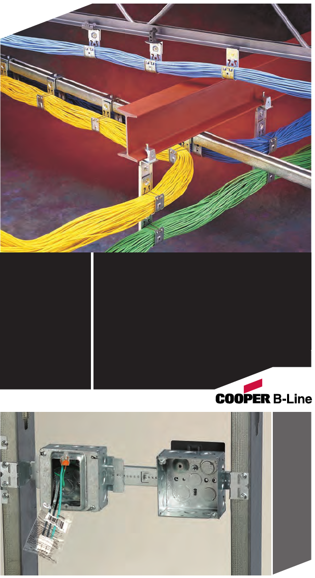
Spring Steel
Fasteners
Wall Studs, Conduit & Cable, Acoustical Tee,
Beams, Hangers, Lathers Channel,
Communication & Low Voltage, Accessories,
Anchors
BLF-12

Cooper B-Line has long been a leading manufacturer of support
systems and electrical enclosures for the mechanical, electrical and
telecommunications industries. Our products are used in industrial,
commercial utility and OEM installations. Cooper B-Line is proud of
the demanding standard of research, design, engineering, and
manufacturing that go into each and every product. But exceptional
quality and value is nothing new to Cooper B-Line. Our customers
have access to the most complete product systems offered including
metal framing, cable tray, Cent-R-Rail™, pipe hangers, electrical
enclosures and Telecom products.
Many of Cooper B-Line’s products are listed by Underwriters
Laboratories, Inc. and approved by Canadian Standards Association.
All Cooper B-Line products are manufactured to meet or exceed
industry standards for their design and manufacture.
Cooper B-Line products are produced in six modern plants
consisting of over 900,000 square feet. These facilities are located
in Highland, Illinois; Troy, Illinois; Reno, Nevada; Sherman, Texas;
Corona, California; and Pinckneyville, Illinois. Regional sales and
distribution centers are located throughout the United States
stocking standard Cooper B-Line products for quick service and
delivery.
This catalog is designed to be helpful to contractors in the
application and selection of spring steel fasteners and support
products for construction and maintenance.
If a unique application requires a special design not included in
this catalog, Cooper B-Line’s engineering personnel are ready to
furnish design consultation and realistic cost estimates. In addition,
sales representatives with extensive product knowledge are located
throughout the United States and abroad for your convenience.
Introduction

Table Of Contents
Ruff-IN™Pre-Fab . . . . . . . . . . . . . . . . . . . . . . . . . . . . 2-7
Pictorial Index . . . . . . . . . . . . . . . . . . . . . . . . . . . . . . 8-14
Numbering Guide . . . . . . . . . . . . . . . . . . . . . . . . . . . . . 15
Technical Data . . . . . . . . . . . . . . . . . . . . . . . . . . . . 16-17
Wall Studs . . . . . . . . . . . . . . . . . . . . . . . . . . . . . . . . . . 18-41
Conduit & Cable . . . . . . . . . . . . . . . . . . . . . . . . . . 42-69
Acoustical Tee . . . . . . . . . . . . . . . . . . . . . . . . . . . . 70-89
Beams . . . . . . . . . . . . . . . . . . . . . . . . . . . . . . . . . . . . . 90-113
Hangers . . . . . . . . . . . . . . . . . . . . . . . . . . . . . . . . . 114-139
Lathers Channel . . . . . . . . . . . . . . . . . . . . . . 140-143
Communication & Low Voltage . . . . 144-171
Accessories . . . . . . . . . . . . . . . . . . . . . . . . . . . . 172-181
Anchors . . . . . . . . . . . . . . . . . . . . . . . . . . . . . . . . . 182-215
NEC Requirements . . . . . . . . . . . . . . . . . . . 216-231
TIA/EIA Requirements . . . . . . . . . . . . . . . 232-233
Reference Data . . . . . . . . . . . . . . . . . . . . . . . 234-241
Alphanumeric Index . . . . . . . . . . . . . . . . . . 242-250
Website: www.cooperbline.com
1
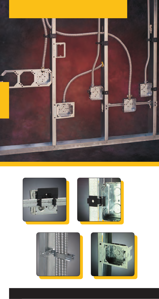
Ruff-IN™Pre-Fab
Ruff-IN™Pre-Fab
2
See Ruff-IN Pre-Fab Systems brochure for complete
product information and part numbers.
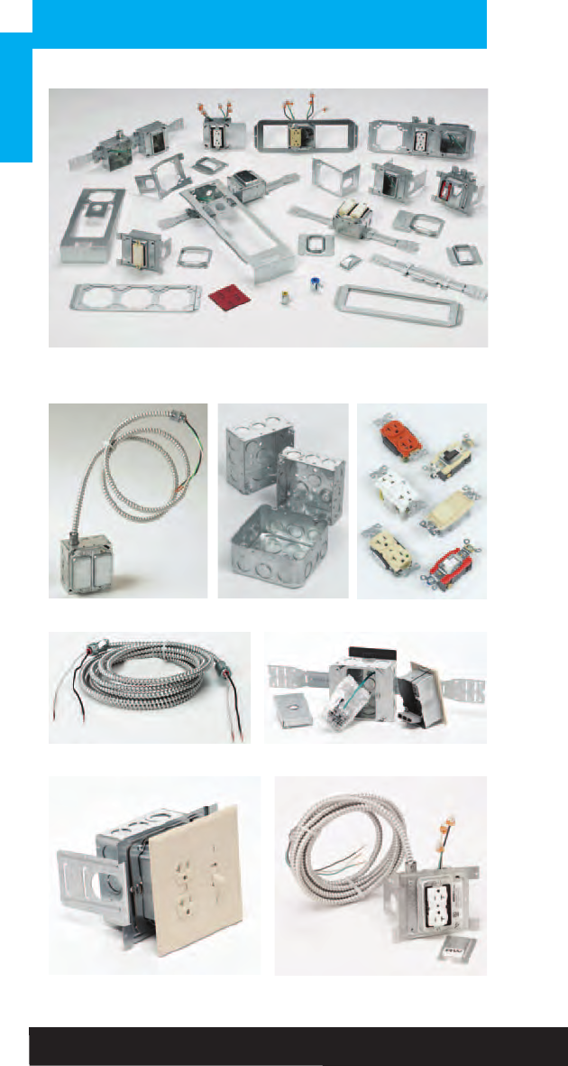
Cooper B-Line’s Ruff-IN product offering continues to
expand with product and assembly options.
Due to the fast-paced growth of this category, the
detailed product information now resides in its own
brochure.
Pages 3 -7 provides a brief overview of the Ruff-IN
product line offerings.
3
Ruff-IN™Pre-Fab
Ruff-IN™Pre-Fab
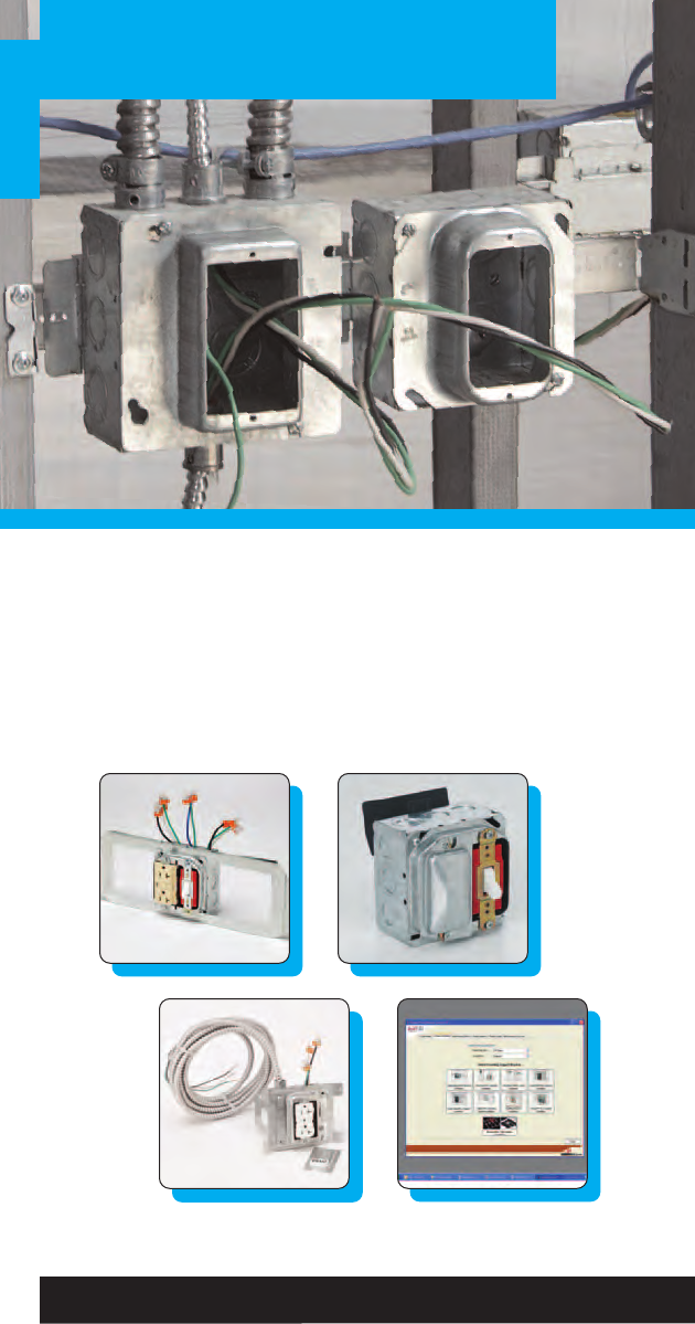
Cooper B-Line Has The Total Pre-Fab Offering…
No matter what your preference for pre-fab may be, we have it!
Choose the pre-fab offering below that best fits your needs:
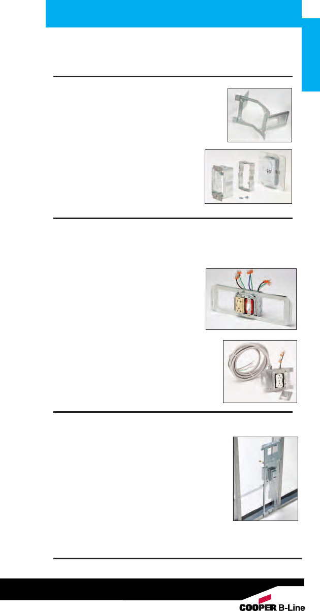
Basic Ruff-IN
Offering Contents: Bracket, Box, Mud Ring,
Ground Wire
•Ideal solution for a contractor sampling
pre-fab for the first time that wants to
keep the control of his or her project.
•Published lead times of 3-5 days ARO,
and NEXT DAY SHIPPING ON (16)
QUICK-SHIP ASSEMBLIES.
(See page 5)
Ruff-IN with Wiring Devices and/or MC Cable Whips
Offering Contents: Basic Ruff-IN with Wiring Device, Protective Cover Plates,
and MC Cable whip with connector(s)
• Assemblies are pre-wired for quick plug
and-play installation using Wago™ or
wire nut connectors.
• Cooper Wiring Device's ArrowLink
connector offers additional labor
savings with its pluf in feature.
(See page 4 for more details)
• Pre-wired Ruff-IN assemblies with
devices and a pre-cut MC cable whip
attached.
• Whip lengths available in 5-foot increments.
•Includes option to order MC cable whips only.
Total Ruff-IN™
Perfect for a contractor that desires take-off services
and engineering expertise of Cooper B-Line
• Perfect for a contractor interested in trying
pre- fab for the first time that needs the
engineering and assembly expertise of Cooper
B-Line.
• Industry leading, published lead times for
Total Ruff-IN quotation responses and order
assembly.
See Ruff-IN Pre-Fab Systems brochure for complete product information and part numbers.
4
Ruff-IN™Pre-Fab
Ruff-IN™Pre-Fab
See Ruff-IN Pre-Fab Systems brochure for complete
product information and part numbers.
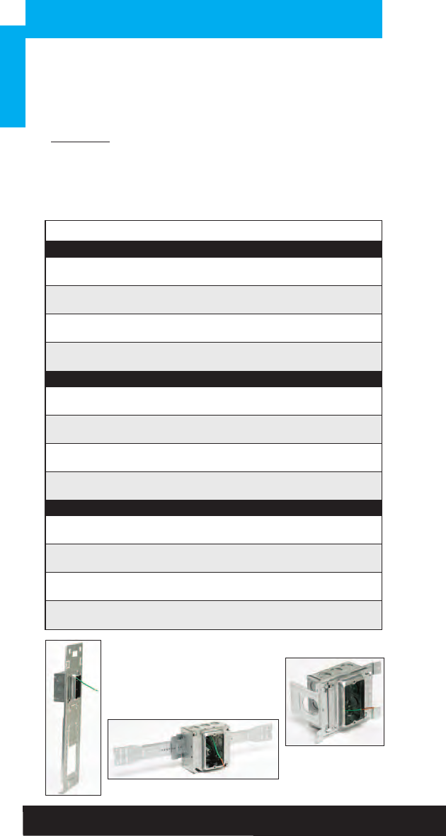
Distributor Quick Ship Program
Next Day Shipping Available on
12 Ruff-In Assemblies & 16 Rapid Ring™Assemblies
• No need to request a lead time, order today and we’ll ship
out of stock tomorrow!
• Ask your Cooper B-Line Sales Representative for more
information on stock-able Ruff-IN assemblies.
CBL Part # UPC # Max. Order Qty.
BBF Series Floor-mount
BBF18-1104DA 78205154072 50
18” BBF floor-mount, 1-gang
5
/
8
” plaster ring, TP403 box, stranded ground wire
BBF18-1104D 78205154065 50
18” BBF floor-mount, 1-gang
5
/
8
” plaster ring, TP403 box, solid ground wire
BBF18-1124DA 78205155199 25
18” BBF floor-mount, 1-gang
3
/
4
” plaster ring, TP403 box, stranded ground wire
BBF18-1124D 78205154176 125
18” BBF floor-mount, 1-gang
3
/
4
” plaster ring, TP403 box, solid ground wire
Double-Sided Box Support
BB76-1104DA 78205155200 100
6” Double-sided box support 1-gang 5/8” plaster ring, TP403 box, stranded ground wire
BB76-1104D 78205138768 25
6” Double-sided box support 1-gang 5/8” plaster ring, TP403 box, solid ground wire
BB76-1124DA 78205154049 50
6” Double-sided box support 1-gang 3/4” plaster ring, TP403 box, stranded ground wire
BB76-1124D 78205138771 25
6” Double-sided box support 1-gang 3/4” plaster ring, TP403 box, solid ground wire
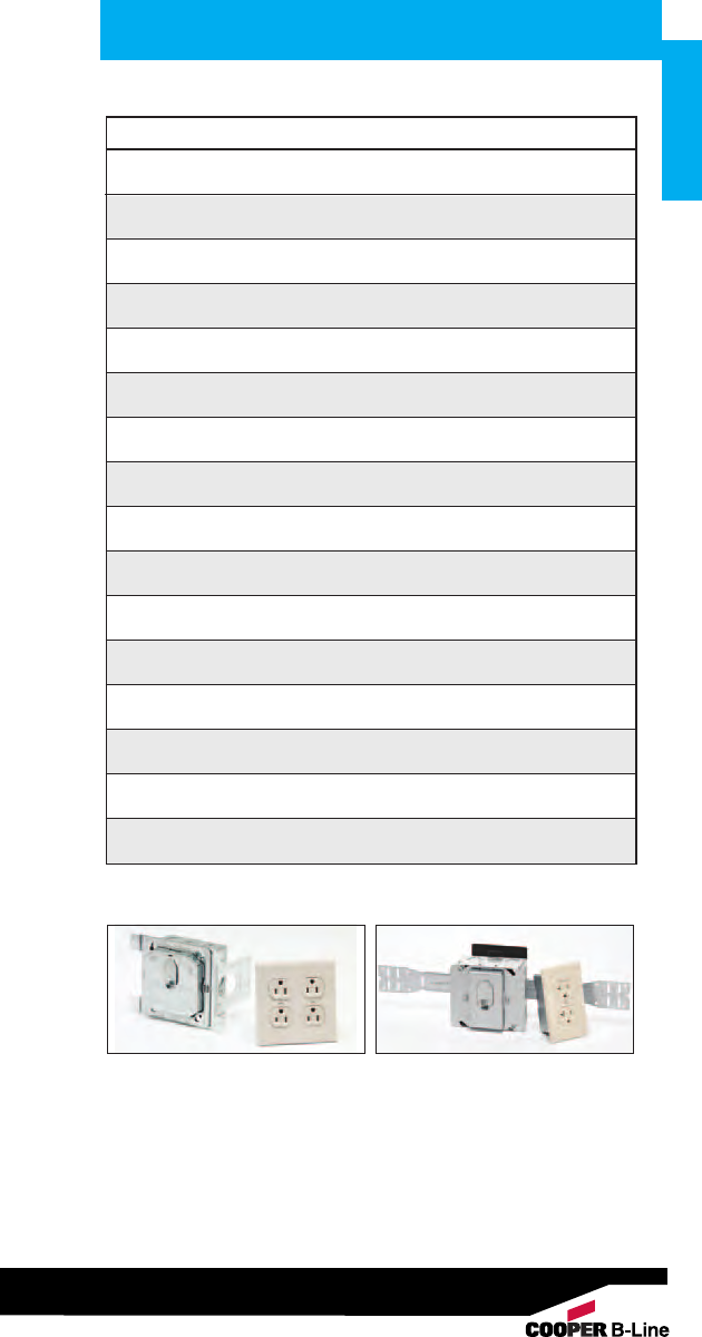
Telescoping Slider Bracket
BB216TS-1104DA 78205139289 25
16” Telescoping Slider Brkt, 1-gang 5/8” plaster ring, TP403 box, stranded ground wire
BB216TS-1104D 78205138619 25
16” Telescoping Slider Brkt, 1-gang 5/8” plaster ring, TP403 box, solid ground wire
BB216TS-1124DA 78205139292 25
16” Telescoping Slider Brkt, 1-gang 3/4” plaster ring, TP403 box, stranded ground wire
BB216TS-1124D 78205138621 250
16” Telescoping Slider Brkt, 1-gang 3/4” plaster ring, TP403 box, solid ground wire
Ruff-IN Quick Ship Pre-Fab Assemblies
BBF18-1104DA
BB76-1104D
BB216TS-1104D
5
Ruff-IN™Pre-Fab
Ruff-IN™Pre-Fab
See Ruff-IN Pre-Fab Systems brochure for complete product information and part numbers.
CBL Part # UPC # Max. Order Qty.
BBF18-1RR4DA 78205176289 50
18” BBF floor-mount, 1-gang Rapid Ring, TP403 box, stranded ground wire
BBF18-1RR4D 78205176290 50
18” BBF floor-mount, 1-gang Rapid Ring, TP403 box, solid ground wire
BBF18-2RR4DA 78205176084 50
18” BBF floor-mount, 2-gang Rapid Ring, TP403 box, stranded ground wire
BBF18-2RR4D 78205176293 50
18” BBF floor-mount, 2-gang Rapid Ring, TP403 box, solid ground wire
BB76-1RR4DA 78205176085 50
6” Double-sided box support 1-gang Rapid Ring, TP403 box, stranded ground wire
BB76-1RR4D 78205176301 50
6” Double-sided box support 1-gang Rapid Ring, TP403 box, solid ground wire
BB76-2RR4DA 78205176302 50
6” Double-sided box support 2-gang Rapid Ring, TP403 box, stranded ground wire
BB76-2RR4D 78205176303 50
6” Double-sided box support 2-gang Rapid Ring, TP403 box, solid ground wire
BB216TS-1RR4DA 78205176294 50
16” Telescoping Slider Brkt, 1-gang Rapid Ring, TP403 box, stranded ground wire
BB216TS-1RR4D 78205176295 50
16” Telescoping Slider Brkt, 1-gang Rapid Ring, TP403 box, solid ground wire
BB216TS-2RR4DA 78205176296 50
16” Telescoping Slider Brkt, 2-gang Rapid Ring, TP403 box, stranded ground wire
BB216TS-2RR4D 78205176297 50
16” Telescoping Slider Brkt, 2-gang Rapid Ring, TP403 box, solid ground wire
BB216TCL-1RR4DA 78205176088 50
16” Telescoping Brkt with Croc-Lock, 1-gang Rapid Ring, TP403 box, stranded ground wire
BB216TCL-1RR4D 78205176298 50
16” Telescoping Brkt with Croc-Lock, 1-gang Rapid Ring, TP403 box, solid ground wire
BB216TCL-2RR4DA 78205176299 50
16” Telescoping Brkt with Croc-Lock, 2-gang Rapid Ring, TP403 box, stranded ground wire
BB216TCL-2RR4D 78205176300 50
16” Telescoping Brkt with Croc-Lock, 2-gang Rapid Ring, TP403 box, solid ground wire
Rapid Ring™Quick Ship Pre-Fab Assemblies
Double Sided Box
Support with
Rapid Ring
Telescoping Slider
Bracket with
Rapid Ring
6
Ruff-IN™Pre-Fab
Ruff-IN™Pre-Fab
See Ruff-IN Pre-Fab Systems brochure for complete product information and part numbers.
7
Ruff-IN™Pre-Fab
Ruff-IN™Pre-Fab
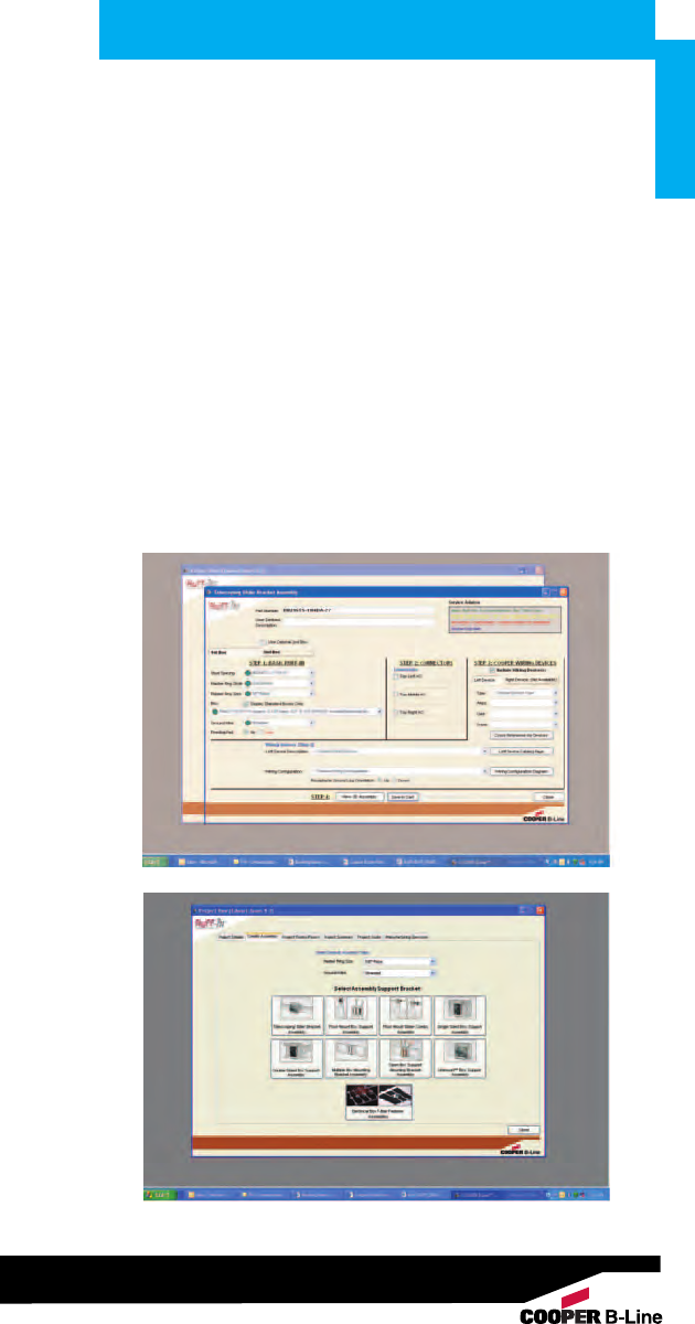
Cooper B-Line’s Ruff-IN Configurator program has been developed to
simplify the planning process for pre-fab construction. The program will
walk you through a component selection process, build customized pre-fab
assemblies, and create a project BOM to accelerate the quotation process.
Configurator Features
• Build an assembly to your own specification by choosing from
brackets, boxes, plaster rings, wiring devices, and other accessories.
• Check the assembly for accuracy by reviewing a 3D, rotatable image
that is created in real time.
• Configure multiple assemblies and save them as a project.
• Divide the project into rooms and specify the types and quantities of
assemblies that go in each location.
• Print a customized project submittal package with the push of a button.
• Submit the entire project with your specific job and assembly
information to Cooper B-Line for a quote with one click.
All of these features translate into fewer mistakes and less time spent
during the take-off process. Let the Cooper B-Line Ruff-IN Configurator go
to work for you. Build your next project using Cooper B-Line’s Ruff-IN
pre-fabricated wiring assemblies today!
See Ruff-IN Pre-Fab Systems brochure for complete product information and part numbers.
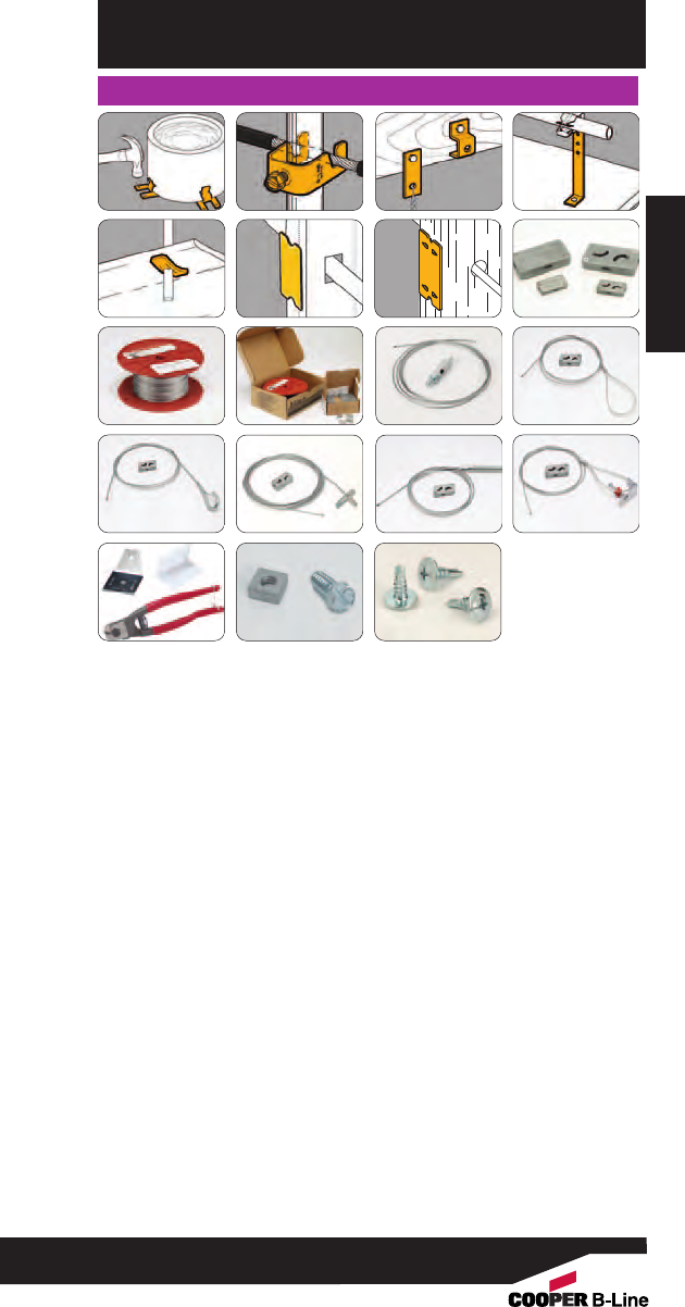
Wall Studs
Conduit & Cable
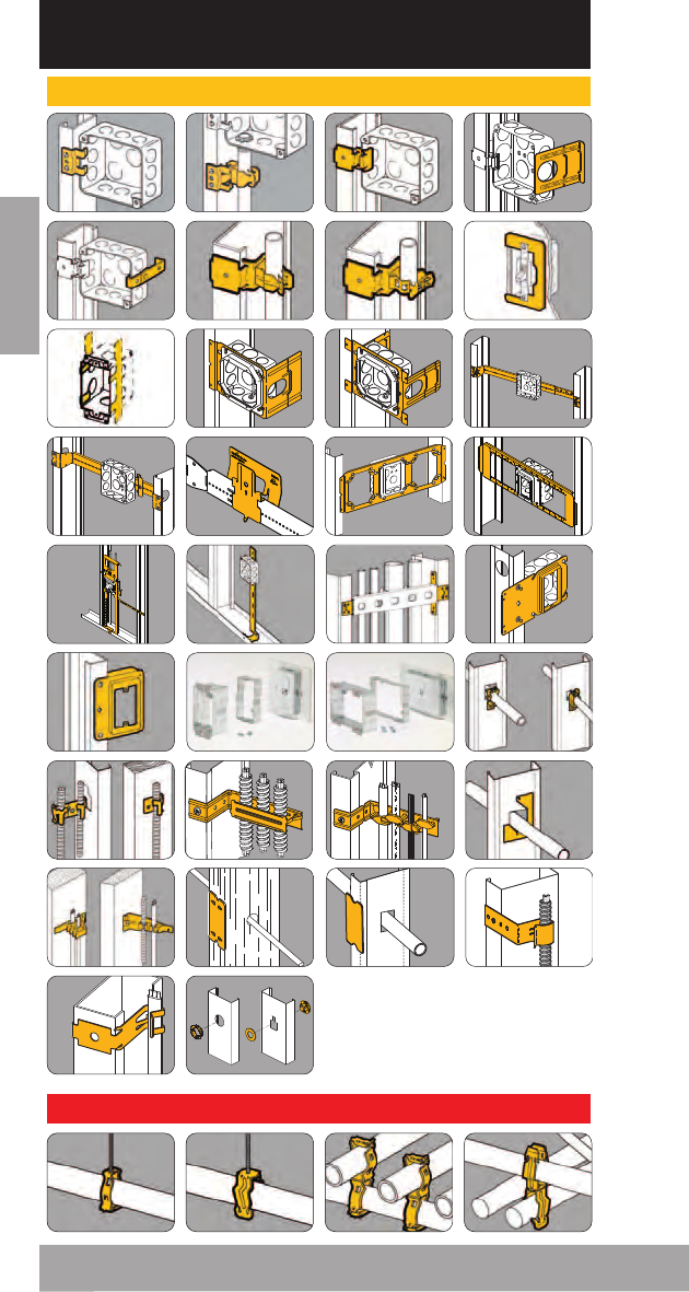
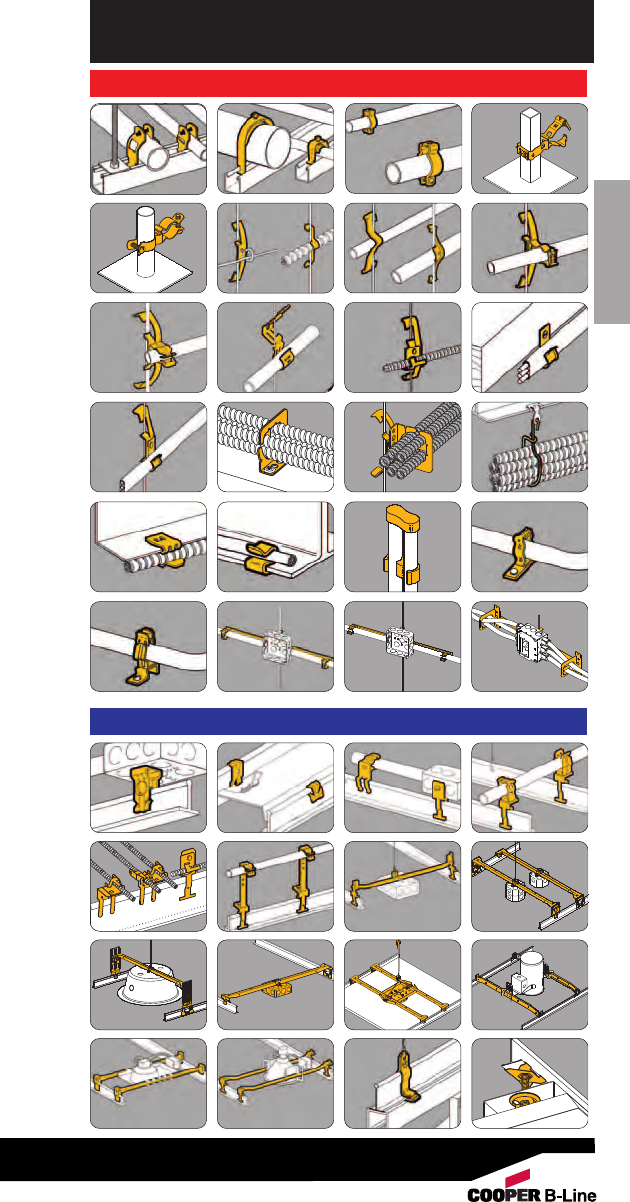
Pictorial Index
30 31 32
32
31
33 33 34
35 36 37 38
38 39 39 40
40 41
45
43 44 45
Pictorial Index
19
21
19
22
20
22
20
23
23
26
24
27
25
28
26
29
8
Conduit & Cable
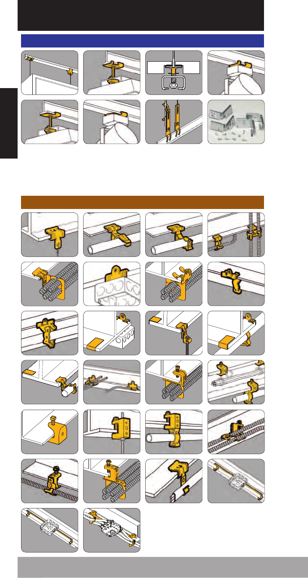
Pictorial Index
55 56 56 57
57
60
58
61
59
62
60
63
63 64 66 68
71 71 72 73
74 77
75 76
Pictorial Index
51 52 53 54
Acoustical Tee
78 78 79 80
81 81 82 83
9
47 48 50
46
Acoustical Tee
Pictorial Index
91
95
92
96
93
97
94
98
Pictorial Index
83 84 84 85
86 86 87 88
Beams
99 100 100 101
101
105
112
102 103 104
106 106 108
113
108 109 110 111
10
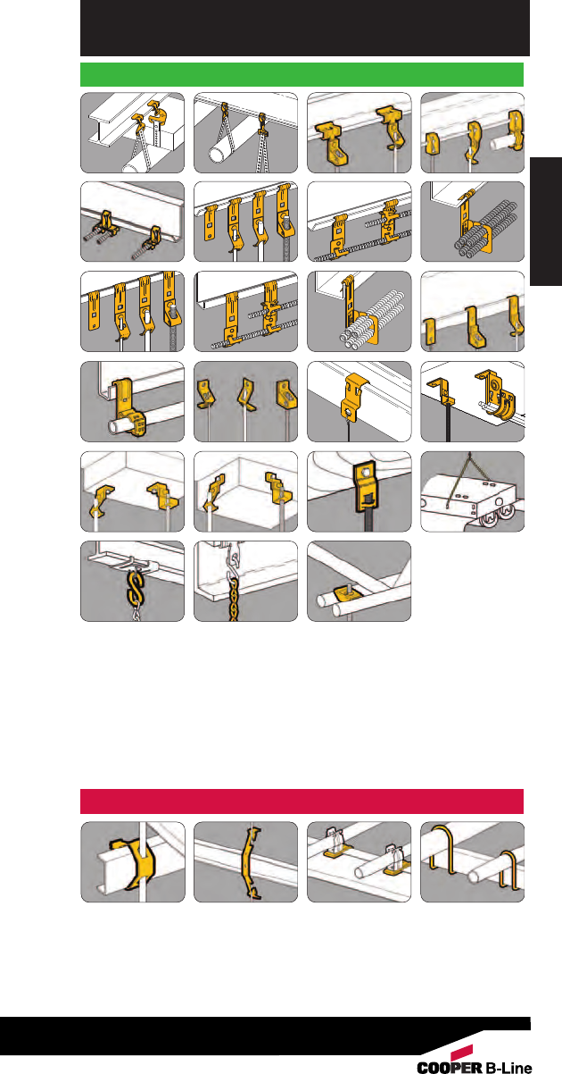
Hangers
Pictorial Index
Pictorial Index
115 115 116 118
130 131 132 134
136 137 138 138
119 120 122 123
124 126 127 128
139 139 139
11
141 142 142 143
Lathers Channel
Pictorial Index
Pictorial Index
151 151 152
150
153 153 154 155
156 156 157 157
158 159 159 160
161 162 162 163
164 166 166 167
168 169 170 170
171 171
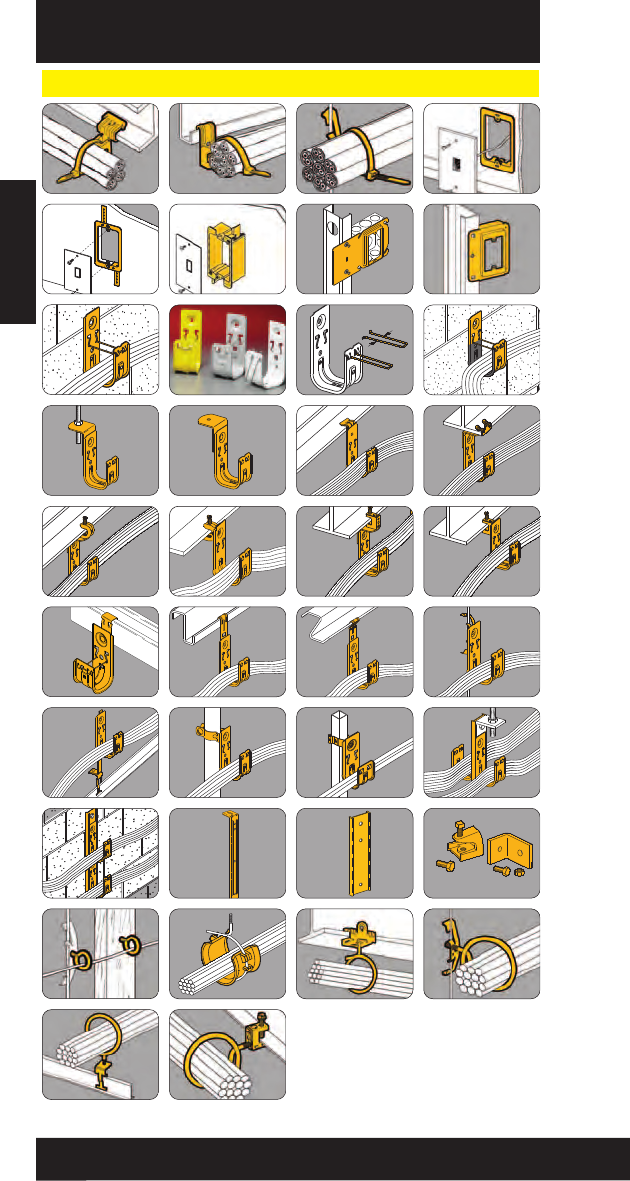
Communication & Low Voltage
12
145 145 145 146
147 147 148 149
Pictorial Index
Pictorial Index
13
173 174 174 174
Accessories
175 175 175 176
176 177 178
179 179 179
179
179
180 181 181

Pictorial Index
Pictorial Index
14
184 186 186 188
Anchors
189 190 191 192
194 200
205
196
202 204203
198
206 207 208 209
210
214
213211 212

Part Numbering Guide
BG - 8-12 - 4T
Numbering Guid
15
Family Size Suffix
A Series - Anchors Based on 16th AS - Anchor Strap
*B Series - Pipe Strap of an inch BL - Equipment Blue
BA - Acoustical Tee Component 1 - 1/16” BN - Brass Nut
BB - Box Attachment 2 - 1/8” BR - Brown
BC - Beam Clamp 4 - 1/4” BW - Bright White
*BCH - Cable Hook 5 - 5/16”CW - Computer White
*BCS/BES - Conduit Spacer 6 - 3/8”D - Deep Box
BD - Deck Attachment 8 - 1/2”FB - Flat Black
*BE - Edge Attachment 9 - 9/16” GR - Green
BF - Flange Attachment 12 - 3/4” H- Hanger
*BG - Guide-Rite™Fastener 16 - 1” LH - Less Hardware
BH - Hanger Attachment 20 - 11/4” LN - Less Nut
BK - KwikWire 24 - 11/2” LS - Less Stud
BL - Conduit Hangers (mini’s) 32 - 2” OR - Orange
BM - Miscellaneous 64 - 4” R - Right Angle
BN - Push Nuts RR - Regal Red
*BP - Push Type Fasteners S - Stud
*BPC - Break Apart Straps T - Threaded
*BR - Bridle Rings TG - Telco Gray
BRC - Cable Fastener W - White
*BRS - Bridle Ring Saddle WBN - White /Brass Nut
BT - Installation Tools WN - Wing Nut
*BU - Universal Beam Attachment YL - Safety Yellow
BW - Bat Wing Fastener 4T - 1/4” Thread Imp.
BX - FMC Support
*The data in the size column only applies to these product families.
BG - 8-12 - 4T
Guide-Rite™
Fastener
1/2” & 3/4”
Conduit
1/4” Thread
Impression
This part numbering guide can be used to quickly translate
our part numbers into meaningful data.

Materials
Technical Data - Materials
Steel Specification
High Carbon Cold Rolled ASTM A684, AISI 1055
Electrolytic Zinc Coated ASTM A591
Pre-Galvanized ASTM A653
Load Data
The design load ratings for Cooper B-Line fasteners are specified in this
catalog as static load capacity or ultimate static load capacity. By definition,
the listed static load capacity has a safety factor of three (3.0), the listed
ultimate static load capacity has no safety factor. In either case, these stated
loads are not to be exceeded, and loads should be applied only as depicted in
the catalog and/or instruction sheets. The load capacity of a fastener having
more than one component is equal to the load capacity of the lowest rated
component.
Fasteners having no load ratings are designed for proper placement of
boxes, conduit, etc., and not for supporting loads.
Cooper B-Line fasteners are designed for use with support members (e.g.:
angle iron, bar joists, beams, columns, flanges, purlins, wire, rod) that comply
with the applicable AISI standards and threaded rod that complies with the
applicable AISI standards.
Quality Assurance
Cooper B-Line has an established Q.C. program in which raw material and
finished products are sampled, inspected and tested by certified inspectors to
assure that all applicable standards are met. Cooper B-Line’s fasteners are
manufactured in controlled lots and each part is identified by a lot number
stamped into the part. This number allows Cooper B-Line to track each step
of the manufacturing process including raw material, die set-up, heat treating,
and finishing. Samples are tested to verify correct hardness, corrosion
resistance and load carrying capacity.
Heat Treatment
Cooper B-Line spring steel fasteners are heat treated to make the steel
hard and give the parts their spring quality and strength. The hardness for a
given fastener depends on the required load carrying capacity and the
application.
Steel
Cooper B-Line’s spring steel fasteners are manufactured from spheroidized
annealed high carbon cold rolled steel (ASTM A684, AISI 1055). Mild steel
fasteners are manufactured from electrolytic zinc coated steel (ASTM A591)
or pre-galvanized steel (ASTM A563).
Electrolytic zinc coated and pre-galvanized steel is produced by coating
coils of sheet steel with zinc at the mills. These coils are then slit to size and
fabricated into Cooper B-Line products.
16

Technical Data - Finishes
Pre-Galvanized Zinc
Pre-galvanized steel is produced by coating coils of sheet steel with zinc by
continuously rolling the material through molten zinc at the mills. This is also
known as mill galvanized or hot-dip mill galvanized. These coils are then slit to
size and fabricated into Cooper B-Line products.
The G90 specification calls for a coating of .90 ounces of zinc per square
foot on each side of the sheet.
During fabrication, cut edges and welded areas are not normally zinc coated;
however, the zinc near the uncoated metal becomes a sacrificial anode to
protect the bare areas after a short period of time.
Pre-galvanized steel is recommended for indoor use in dry areas.
Electro-galvanized Zinc
Electro-galvanized zinc (also known as zinc plated or electroplated) is the
process by which a coating of zinc is deposited on the steel by electrolysis
from a bath of zinc salts.
The coating is pure zinc and is mechanically bonded to the steel. A
maximum of .5 mils of zinc can be applied by this method.
When exposed to air and moisture, zinc forms a tough, adherent, protective
film consisting of a mixture of zinc oxides, hydroxides, and carbonates. This
film is in itself a barrier coating which slows subsequent corrosive attack of the
zinc.
This coating is usually recommended for indoor use in relatively dry areas.
Paint
Some standard fasteners have a gloss white acrylic enamel applied over the
zinc phosphate finish for an enhanced appearance that compliments white
ceiling grids.
Zinc Phosphate
Cooper B-Line's spring steel fasteners receive a coating* of sealant
impregnated zinc phosphate. This type of coating was commercially developed
by industry to inhibit oxidation of ferrous metals for up to 72 hours in a specified
salt fog atmosphere. As applied to its fasteners, Cooper B-Line rates this
coating for 30 hours when salt fog tested per ASTM B-117.
Although rust resistant, Cooper B-Line fasteners should be used only indoors
and in non-corrosive environments.
Unless otherwise noted, the standard finish for Cooper B-Line’s spring steel
fasteners is Zinc Phosphate.
*At least 1000 milligrams of zinc phosphate per square foot.
CAUTION: Do not use Cooper B-Line Fasteners outdoors or in corrosive
environments. Proper application of each fastener is shown in this catalog
and on the installation sheet inside each carton. Failure due to improper
installation may cause harm to personnel and/or property. Allowable loads
shown apply to the fastener only and do not account for the structure, which
supports the fastener. Flanges, wires and rods used with these fasteners must
meet A.I.S.I. standards. To improve personal safety on the jobsite, always
observe all federal and local safety regulations: wear gloves, safety glasses
and a hard hat.
Finish Specification
Zinc-Phosphate MIL-P-16232 Type Z
Electro-galvanized Zinc ASTM B633
Pre-Galvanized Zinc ASTM A653, G90
Gloss White Paint Acrylic Enamel
Technical Data - Finishes
17
Wall Studs
Wall Studs
18
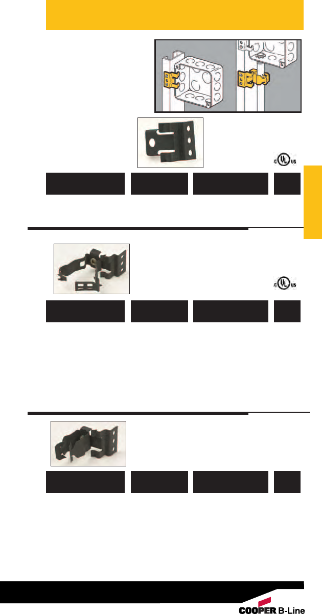
Wall Studs
Box To Stud
Fastener
• Attaches with screws
to metal studs.
• BB1 supports electrical
box.
• BG series features
Guide-Rite design.
• BP series features
push-type design.
781011 18145 BB1 Electrical Box 100
Support Clip
UPC/Part
Number Description
Catalog
Number
Box
Qty.
Guide-Rite™Conduit To
Stud Fastener
781011 18420 BG-6-B1 *3/8"100
781011 18475 BG-8-12-B1 1/2", 3/4" 100
781011 18555 BG-16-B1 1" 100
UPC/Part
Number
Conduit Size
EMT & Rigid
Catalog
Number
Box
Qty.
Push Type Conduit
To Stud Fastener
UPC/Part
Number Conduit Size
Catalog
Number
Box
Qty.
781011 19245 BP-8-B1 1/2" EMT 100
781011 19345 BP-12-B1 3/4" EMT, 100
1/2" IMC, Rigid
781011 19440 BP-16-B1 1" EMT, 100
3/4" IMC, Rigid
Wall Studs
Patent #4958792
*BG-6 will accept the following range ∅.420 - ∅.675:
14/2 thru 10/4 MC/AC cable and 5/16 or 3/8flexible conduit
Read safety/installation instruction sheets in packages before use. These products are designed for positioning only. No load rating.
19
Wall Studs
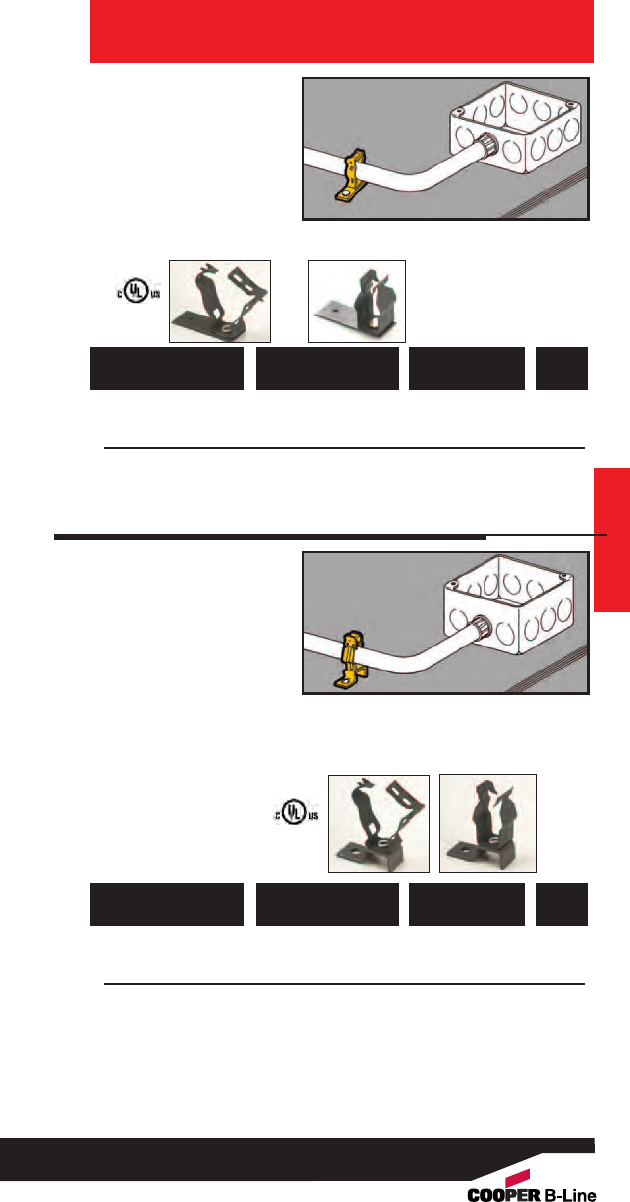
Box To Stud
Fastener
• Attaches electrical
boxes (requiring
plaster rings) to most
metal studs.
• Box mounts flush to
back of drywall.
• Simply installed with
a hammer.
781011 18270 BB9 Electrical Box 100
Support
UPC/Part
Number Description
Catalog
Number
Box
Qty.
Wall Studs
20
Read safety/installation instruction sheets in packages before use. These products are designed for positioning only. No load rating.
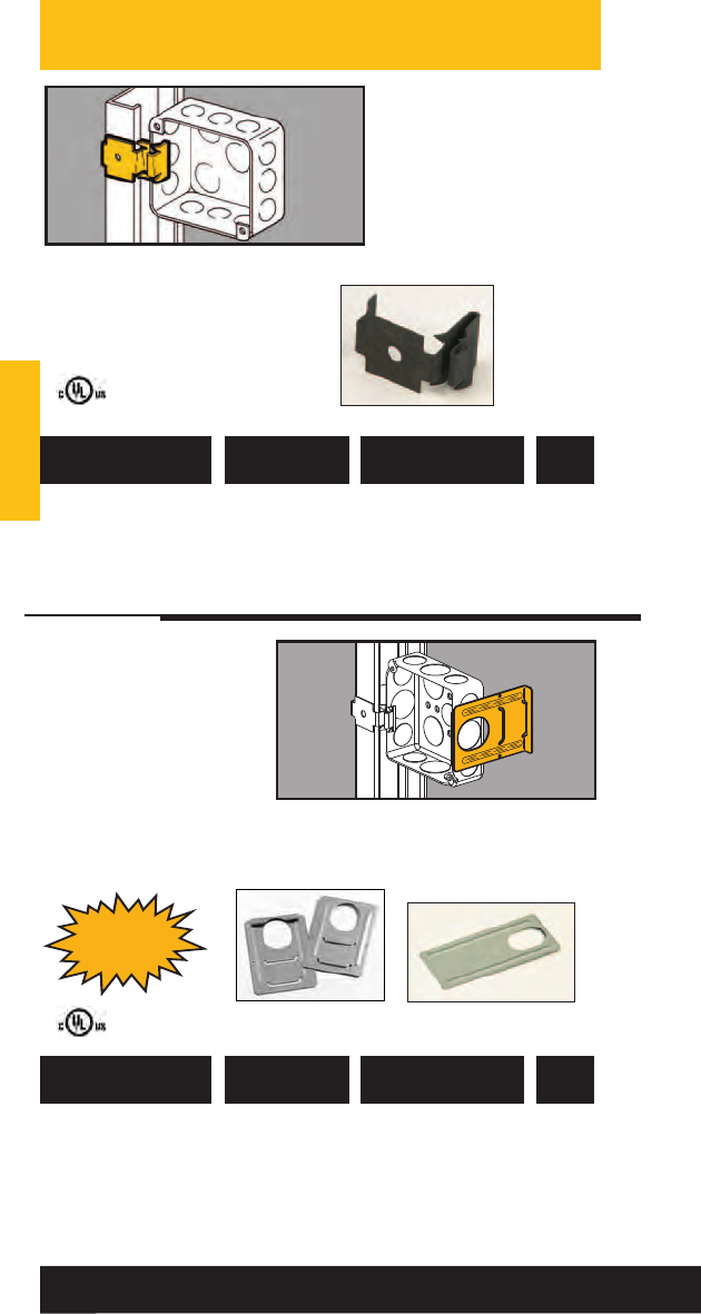
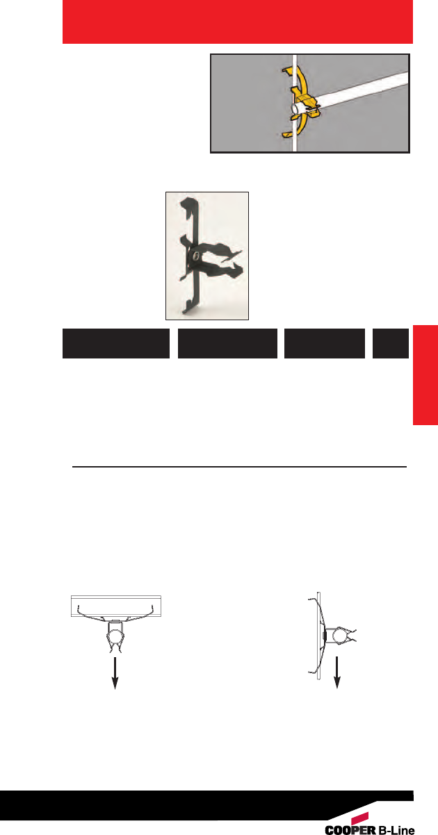
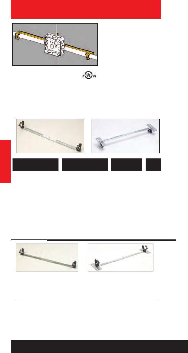
Adjustable Box
Stabilizers
•Provides far-side
support for electrical
boxes in 21/2” thru
6” studs.
• Cut outs facilitate
bending to provide
precise installation
with greater stability.
• Easily snaps onto box
side and is secured in
place by plaster ring.
781011 92876 BB12 21/2” thru 4” 100
781011 92879 BB12-6 6” 100
UPC/Part
Number Metal Stud Size
Catalog
Number
Box
Qty.
BB12-6
BB12
Replaces
BF1 Series
Wall Studs
Box Stabilizer
781011 18320 BF1-40 21/2”100
781011 18325 BF1-56 31/2”100
781011 18330 BF1-64 4” 100
781011 18335 BF1-96 6” 100
UPC/Part
Number Metal Stud Size
Catalog
Number
Box
Qty.
Wall Studs
•Provides far-side
support for
electrical boxes.
•See BB12 Series for
a better solution.
BF1-64
BF1-96
BF1-56
BF1-40
Read safety/installation instruction sheets in packages before use. These products are designed for positioning only. No load rating.
21
Wall Studs
Guide-Rite™Conduit
To Stud Fastener
Push Type Conduit
To Stud Fastener
• Attaches conduit to
most metal studs.
• BG Series features
Guide-Rite design.
• BP Series feature
push-type design.
781011 18425 BG-6-B5 *3/8” or BX 100
781011 18480 BG-8-12-B5 1/2”, 3/4” 100
781011 18560 BG-16-B5 1” 100
781011 18645 BG-20-B5 11/4”50
Patent #4958792
UPC/Part
Number
Conduit Size
EMT & Rigid
Catalog
Number
Box
Qty.
781011 19250 BP-8-B5 1/2” EMT 100
781011 19350 BP-12-B5 3/4” EMT, 100
1/2” IMC, Rigid
781011 19445 BP-16-B5 1” EMT 100
3/4” IMC, Rigid
UPC/Part
Number Conduit Size
Catalog
Number
Box
Qty.
Wall Studs
* BG-6 will accept the following range ∅.420 - ∅.675:
14/2 thru 10/4 MC/AC cable and 5/16 or 3/8flexible conduit
Read safety/installation instruction sheets in packages before use. These products are designed for positioning only. No load rating.
22
Wall Studs
Read safety/installation instruction sheets in packages before use. These products are designed for positioning only. No load rating.
23
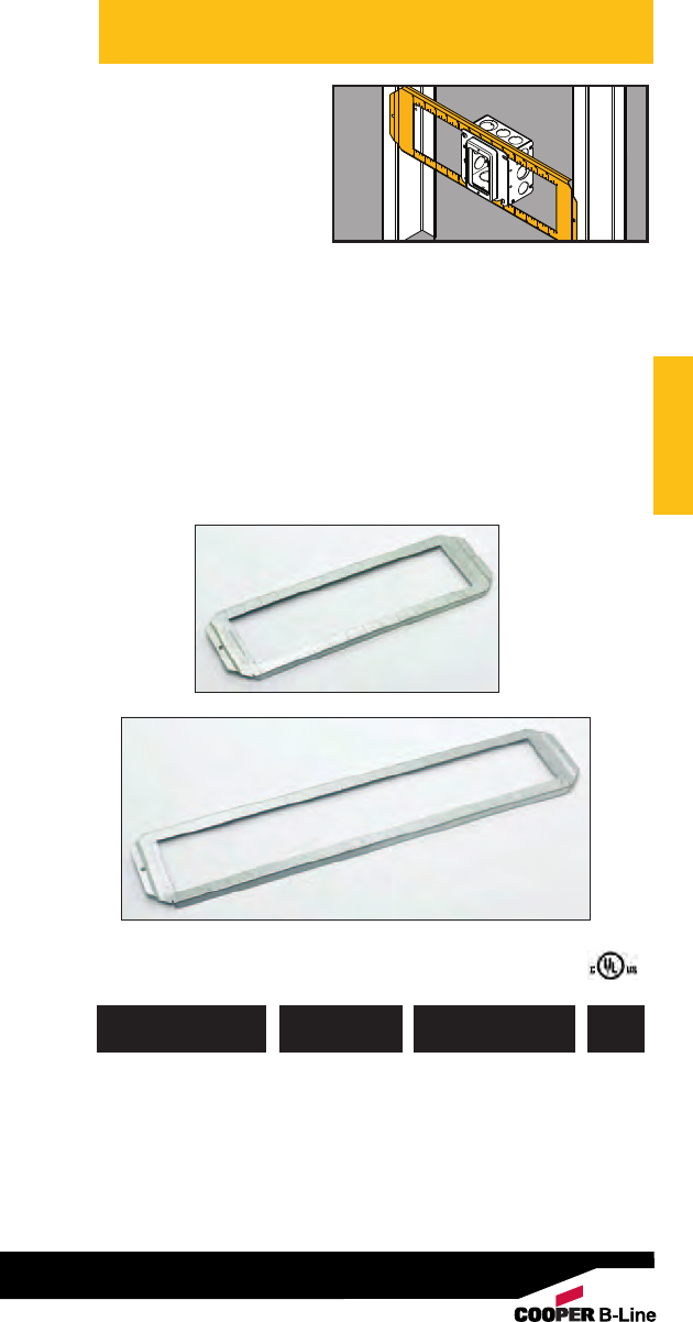
Retainer Leveler
• BB32 adds rigidity to
devices in oversize
wall openings.
• Holds wiring device
firmly in drywall.
• Can be used with
switches, receptacles,
GFCIs and decorator
devices.
• Ideal for positioning
devices in pre-fab
installations.
• Finish: Pre-Galvanized
781011 18215 BB32 Adds Rigidity to 100
Oversize Wall
Openings
UPC/Part
Number Description
Catalog
Number
Box
Qty.
Box Support
• Attaches electrical
boxes to finished
drywall.
•Box is completely
supported by drywall.
• Prevents box from
pulling out of wall.
• Finish: Pre-Galvanized
781011 01138 BB33 Box Support 11/2”100 pr.
781011 04936 BB33L Long Leg 21/4” 100
Box Support
UPC/Part
Number Description
Catalog
Number
Box
Qty.
Length
A
A
A
BB33 BB33L
Wall Studs
Wall Studs
Wall Studs
Read safety/installation instruction sheets in packages before use. These products are designed for positioning only. No load rating.
24
Box Support
Brackets
• Improved far-side
support stands up during
drywall installation and
out performs competitor
brackets.
• Supports 4” or 411/16”,
square boxes.
• Brackets may be piggy-
backed in series.
• Finish: Pre-Galvanized.
• See Ruff-IN™brochure
for pre-fab box
assemblies.
781011 18190 BB4-23 31/2”, 21/2” 100
781011 18200 BB4-4 4”, 31/2”, 21/2” 100
781011 18202 BB4-6 6”, 51/2”, 31/2”, 21/2” 100
UPC/Part
Number Metal Stud Size
Catalog
Number
Box
Qty.
BB4-23
BB4-4 BB4-6
Wall Studs
Wall Studs
Read safety/installation instruction sheets in packages before use. These products are designed for positioning only. No load rating.
25
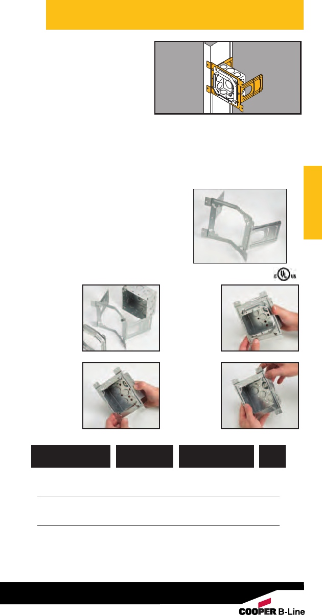
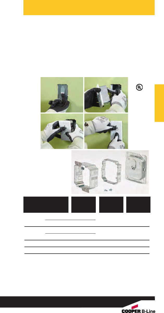
Double-Sided
Box Support
Bracket w/
Marty-Mouse™
Ears
• Double-side box support,
designed for Pre-Fab. Unit
can be installed on either
side of stud without
repositioning box or devices.
• Patented Marty-Mouse™
ears feature an innovative
keyhole pattern to secure outlet
box to bracket with or without the
plaster ring.
• Wider box opening accommodates
one or two gang adjustable plaster
rings (B1AJ & B2AJ).
• Enhanced far-side support stands
up during drywall installation and
out performs competitor brackets.
• See Ruff-IN™brochure for pre-fab
box assemblies.
• Finish: Pre-Galvanized
782051 38645 BB73 31/2”, 21/2”50
782051 38717 BB74 4”, 31/2”, 21/2”50
782051 38759 BB76 6”, 51/2”, 31/2”, 21/2”25
Patent # 5595362
UPC/Part
Number Stud Size
Catalog
Number
Box
Qty.
4. With the tabs
closed, the box
remains
secured to the
bracket when
the plaster ring
is removed
1. Bracket is
shipped with
ear tabs in
the open
position
2. Insert box
screws into
open slots
3. When plaster
ring is installed,
the ear tabs are
bent down into
the closed
position
Wall Studs
Read safety/installation instruction sheets in packages before use. These products are designed for positioning only. No load rating.
26
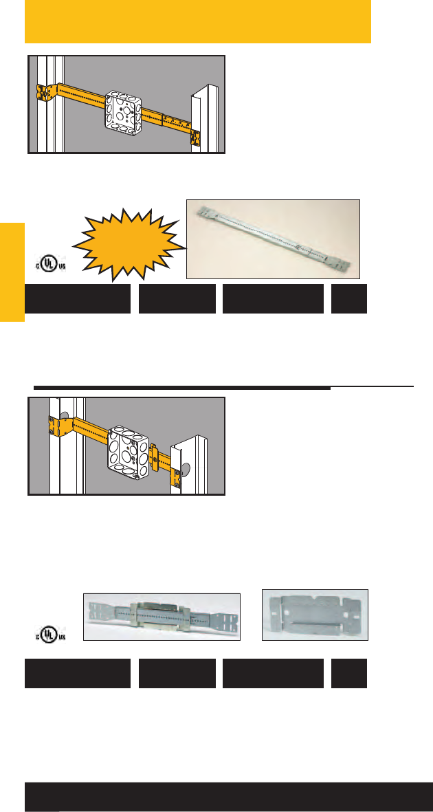
Telescoping
Box Mounting
Bracket
• Completely adjustable
- fits a range of stud
spacings and 11/2” or
21/8” deep boxes.
• Pre-punched screw
holes provide for easy
box installation.
• Bar is marked with
scale for stud spacing.
• Finish: Pre-galvanized
781011 04256 BB2-16T 11” to 18” 50
781011 01664 BB2-24T 15” to 26” 50
UPC/Part
Number
Metal Stud
Spacing
Catalog
Number
Box
Qty.
Telescoping Slider
Bracket
•Designed for pre-fab.
• Box can be attached
to slider bracket
before or after slider
is installed on
telescoping bracket.
• Box location can be
field adjusted by
moving slider along
telescoping bracket.
• See Ruff-IN™brochure
for pre-fab box
assemblies.
• Finish: Pre-galvanized
782051 38614 BB216TS 11” to 18” 20
782051 38628 BB224TS 15” to 26” 20
782051 38613 BB2TS Slider Bracket Only 50
Patent # 7,472,875
UPC/Part
Number Stud Spacing
Catalog
Number
Box
Qty.
Licensed under Patent #5386959 • Patent #5209444
BB216TS BB2TS
Replaces
BB2-16 &
24 Series
BB2-24T
Wall Studs
Wall Studs
Read safety/installation instruction sheets in packages before use. These products are designed for positioning only. No load rating.
27
UPC/Part
Number Description
Catalog
Number
Box
Qty.
781011 01675 BWHS-9 #8 x 9/16” 1000
Sheet Metal Screw
781011 04925 BWHS-9D #8 x 9/16” 1000
Self-Drilling
Sheet Metal Screw
Note: BWHS-9 & BWHS-9D can be used with all fasteners requiring
attachment with sheet metal screws, except on BB2-16, BB2-16D,
BB2-24 & BB2-24D which only BWHS-9 can be used.
Mounting
Screws
BWHS-9 BWHS-9D
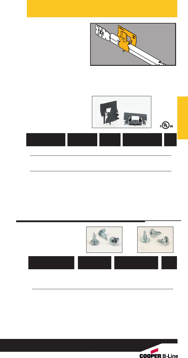
• Designed for pre-fab..
• Outlet boxes mount to the
CROC-LOK with single
screw.
• CROC-LOK box assemblies
can be attached before or
after the telescoping bar is
mounted in the stud wall.
• The tool-less design enables
CROC-LOK assemblies to be field
installed in less than 4 seconds.
Simply squeeze, secure and
walk away.
• See Ruff-IN™brochure
for pre-fab box assemblies.
782051 51291 BB2CL N/A Croc-Lok only 50
782051 51292 BB216TCL 11”-16” BB216T with 20
Croc-Lok
782051 51293 BB224TCL 15”-24” BB224T with 20
Croc-Lok
U.S. Patent # 8,403,277
UPC/Part
Number Description
Catalog
Number
Stud
Spacing
Box
Qty.
CROC-LOK™
Box Mounting
Bracket
Note:
Secures to Cooper B-Line BB2-16T and BB2-24T telescoping brackets only.
For a standard 21/8” deep box, the stud depth must be 31/2” or greater.
For a shallow 11/2” deep box, the stud depth must be 21/2” or greater.
Wall Studs
Wall Studs
Read safety/installation instruction sheets in packages before use. These products are designed for positioning only. No load rating.
28
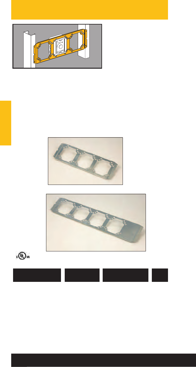
Box Mounting
Bracket
• Supports boxes or
plaster rings between
studs 16” or 24” on
center.
• Accepts US &
Canadian boxes.
• Accommodates 4” or
411/16” boxes.
• Allows side-by-side
mounting of 11/2” or
21/8” deep boxes.
• See Ruff-IN™brochure
for pre-fab box
assemblies.
• Finish: Pre-galvanized
781011 02898 BB8-16 16” Stud Spacing 25
781011 02900 BB8-24 24” Stud Spacing 25
UPC/Part
Number Description
Catalog
Number
Box
Qty.
BB8-24
BB8-16
Wall Studs
Wall Studs
Read safety/installation instruction sheets in packages before use. These products are designed for positioning only. No load rating.
29
Open Box
Mounting
Bracket
• Open box Support secures
boxes and plaster rings
between studs 16” and 24”
on center.
• Accommodates 4”, 411/16”
and multi-gang boxes.
• Open design allows infinite
adjustability - box can be
placed in any horizontal
position along the bracket.
• Stamped markings at 1/4”,
1/2” and 1” increments
allow the installer to easily
locate the desired box
position.
• See Ruff-IN™brochure for pre-fab box
assemblies.
• Finish: Pre-galvanized
782051 45325 BB7-16 16” Stud Spacing 25
782051 45328 BB7-24 24” Stud Spacing 25
UPC/Part
Number Description
Catalog
Number
Box
Qty.
BB7-24
BB7-16
Wall Studs
Wall Studs
Read safety/installation instruction sheets in packages before use. These products are designed for positioning only. No load rating.
30
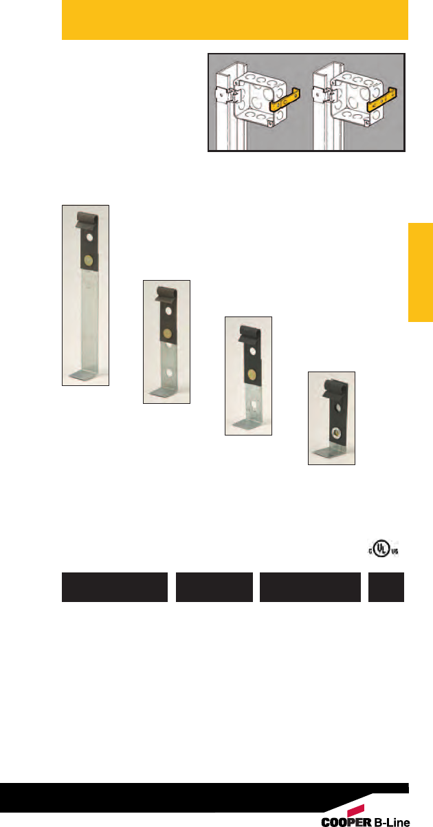
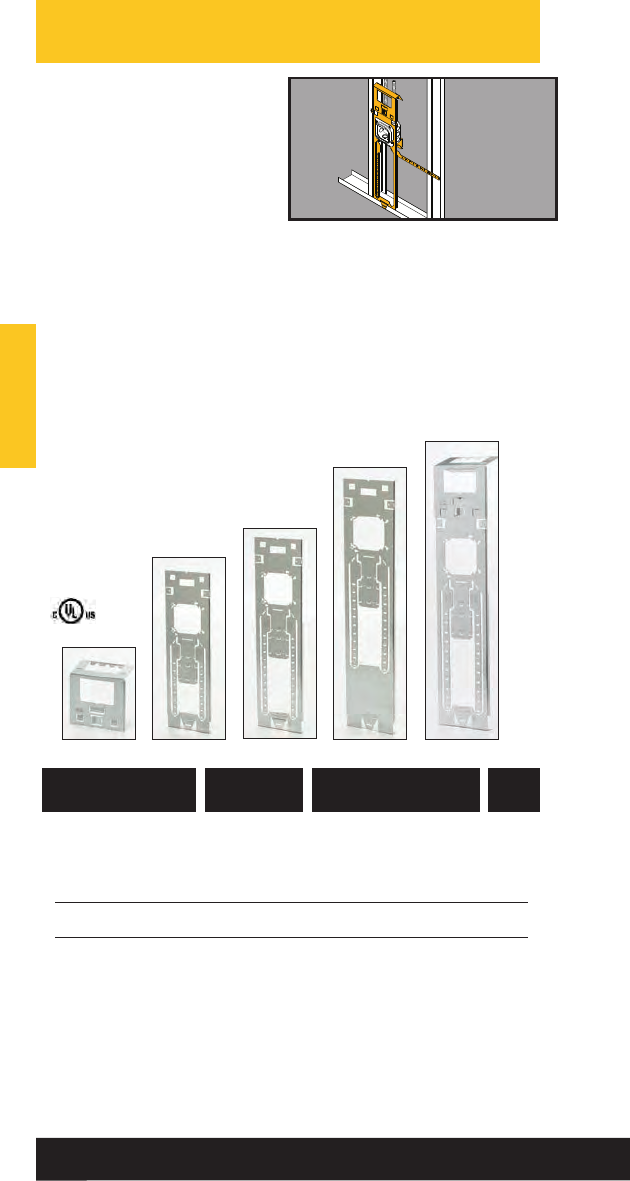
Floor-Mount Box
Support
• New BBF floorstand
provides the most rigid
support in the industry.
• Far-side support
accomodates 6”, 51/2”,
35/8”, and 21/2” stud
depths.
• Fold-out tab built-in to
attach floor stand to stud
if desired.
• Integral “wings” provide rigid support
when floorstand is mounted between
studs.
• Optional cable containment clip securely
attaches to floorstand without hardware.
• Patented Marty Mouse™ears enable
boxes to be secured in place with or
without the plaster rings.
• Finish: Pre-galvanized.
• See Ruff-IN™brochure for
pre-fab box assemblies.
782051 52944 BBF15 15” Floorstand 25
782051 52945 BBF18 18” Floorstand 25
782051 52946 BBF24 24” Floorstand 25
782051 52947 BBFC Cable Clip 25
782051 52948 BBF15C 15” Floorstand with 25
Cable Clip
782051 52949 BBF18C 18” Floorstand with 25
Cable Clip
782051 52950 BBF24C 24” Floorstand with 25
Cable Clip
Patent # 5595362
Patent # 7956285 B2
UPC/Part
Number
Box
Center Height
Catalog
Number
Box
Qty.
BBF15 BBF18 BBF24
BBFC BBFxxC
Wall Studs
Wall Studs
Read safety/installation instruction sheets in packages before use. These products are designed for positioning only. No load rating.
31
Floor
Mounted
Box
Support
•See BBF Series for a
better solution.
• Provides support for
electrical box from
floor track or concrete
forms.
• 18” length with break-
away feature for 12” or
16” box mounting.
• Finish: Pre-galvanized
UPC/Part
Number Description
Catalog
Number
Box
Qty.
781011 03623 BB-18 Floor Mounted 50
Box Support
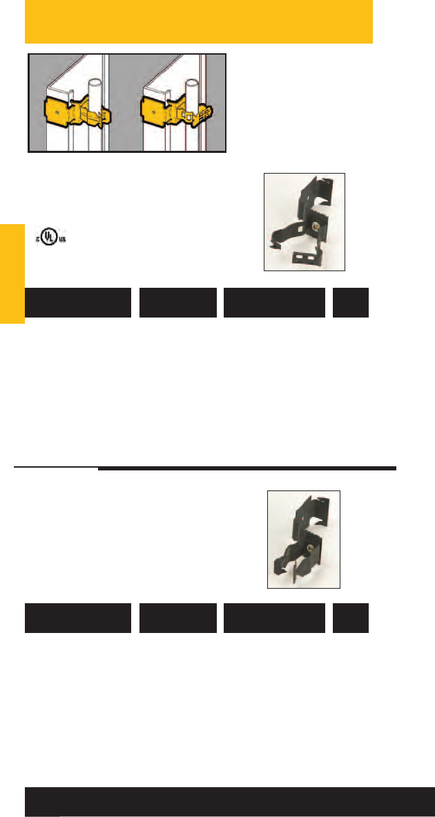
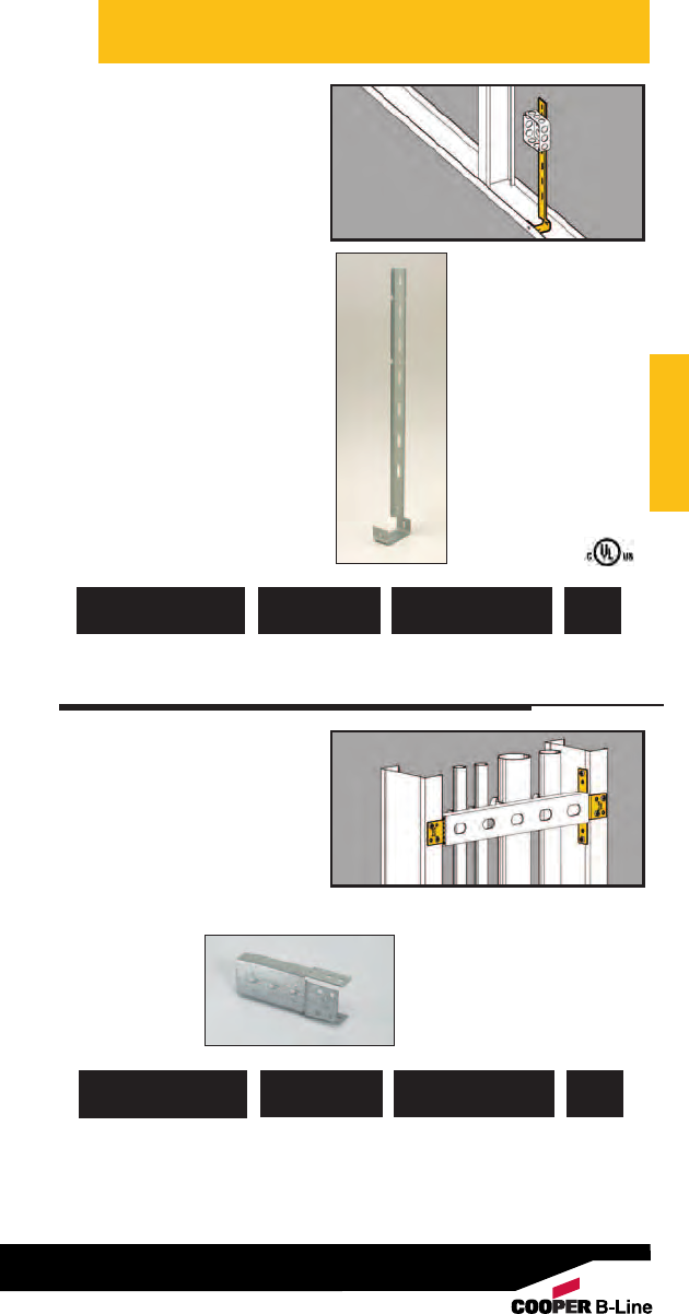
Strut Mounting
Brackets
•Attaches 13/16" strut,
11/2" lathers channel,
1/2" EMT or 3/4" EMT
to metal studs.
•Provides support for
vertical runs of
conduit.
• Finish: Pre-galvanized
781011 01658 BMB1 Strut Mounting 25 pr.
Bracket
UPC/Part
Number Description
Catalog
Number
Box
Qty.
Wall Studs
Wall Studs
Read safety/installation instruction sheets in packages before use. These products are designed for positioning only. No load rating.
32
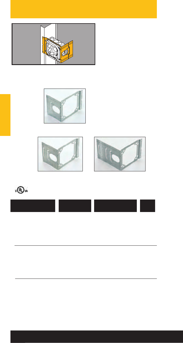
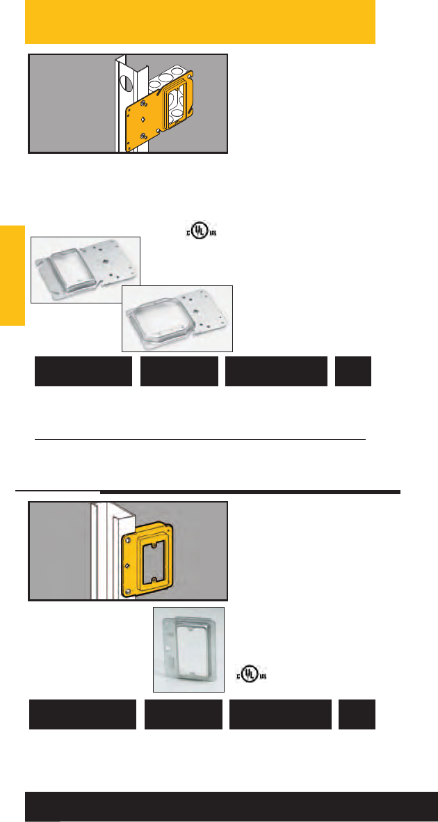
Uni-Mount™
Box Support/Cover
Plate Mounting
Bracket
• Uni-Mount provides
a secure support for
4” square boxes and
features a built-in
plaster ring.
• Rigid bracket design
eliminates the need
for far-side support.
• Enlarged viewing hole
makes it easier to find
mark lines on the stud.
• Gangable design
accepts BB423 bracket
to mount boxes on both
sides of the stud.
• See Ruff-IN™brochure
for pre-fab box
assemblies.
• Finish: Pre-galvanized
782051 22768 BB40-08 1/2” Raise 50
782051 22771 BB40-10 5/8” Raise 50
782051 22772 BB40-12 3/4” Raise 50
782051 22773 BB45-08 1/2” Raise 50
782051 22774 BB45-10 5/8” Raise 50
782051 22775 BB45-12 3/4” Raise 50
UPC/Part
Number Description
Catalog
Number
Box
Qty.
Single Gang
BB40 Series
Double Gang
BB45 Series
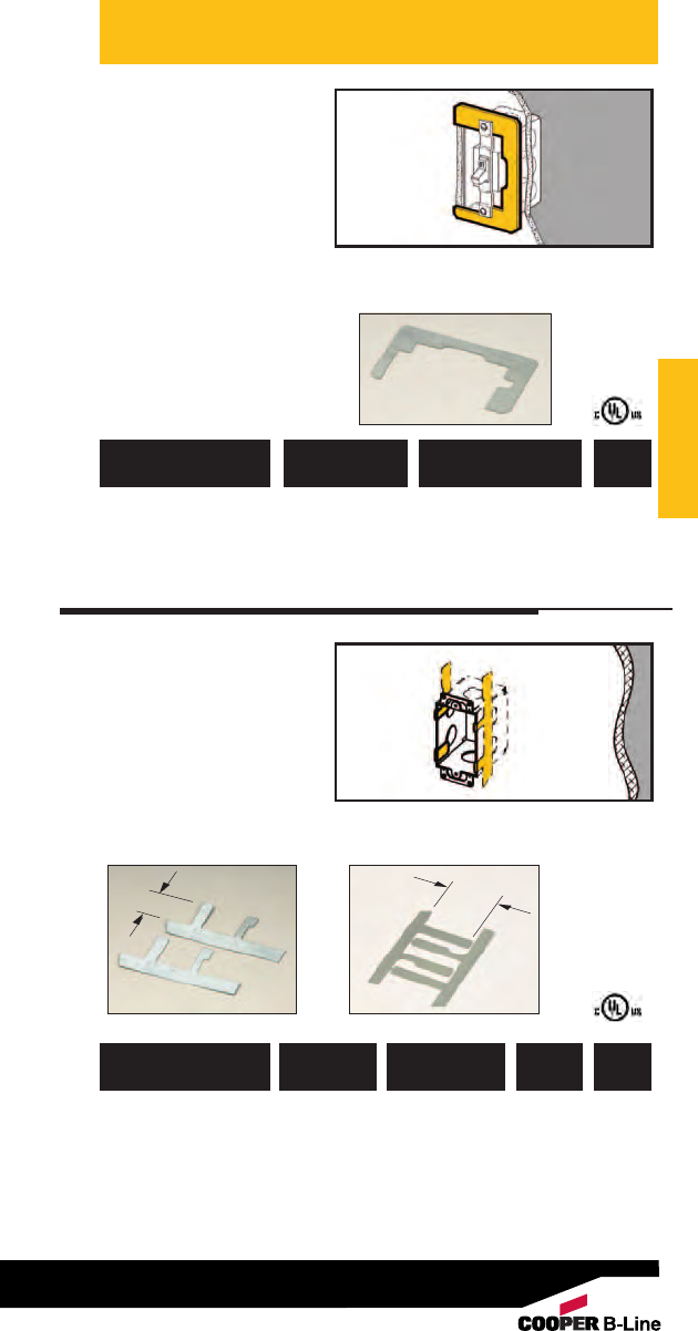
Cover Plate
Mounting
Bracket
•Provides attachment
base for low voltage
outlets.
•Replaces electrical box
in Class 2 low voltage
installations.
• Can be piggy-backed.
• For 1/2” and 5/8”
drywall applications.
• Finish: Pre-galvanized
781011 19873 BB15 Single Gang 50
Stud Bracket
UPC/Part
Number Description
Catalog
Number
Box
Qty.
Wall Studs
Wall Studs
Read safety/installation instruction sheets in packages before use. These products are designed for positioning only. No load rating.
33
Rapid Ring™
Self Adjusting Pre-Fab Ring
The Rapid Ring self-adjusting pre-fab plaster ring can help you win tight
bids and beat the profit squeeze with its innovative 4-step installation. This
revolutionary new pre-fab system installs in as little as 15 seconds per unit,
compressing your project schedule, cutting operational costs and reducing
onsite waste.
Because the Rapid Ring is a self-adjusting pre-fab ring, you’ll never need to
adjust a mud ring again. With a simple push of the Rapid Ring you’re flush
every time.
12
34
Stop Plate
Sleeve
Sleeve
Extender Protective
Plate
Box Plate
Go to www.blineRapidRing.com for more information.
14” sq. B1RRP4C B1RRR B1RRE
411/16” sq. B1RRP5C
24” sq. B2RRP4C B2RRR B2RRE
411/16” sq. B2RRP5C
3 3-gang 6B3RRPC B3RRR B3RRE
4 4-gang 7B4RRPC B4RRR B4RRE
For Use With
Wiring Electrical
Device Qty. Box 5
Sleeve 2,3
Cat No.
Box Plate 1
Cat No.
Sleeve
Extender 4
Cat No.
1. Protective plate included with box plate. 5. Minimum electrical box depth is 21/8”
2. Wall thickness range: 1/2” min. to 11/4” max. 6. Keyhole knockouts allow use on 2-gang electrical box.
3. Stop plates included with sleeve. 7. Keyhole knockouts allow use on 3-gang electrical box.
4. Sleeve extender is an optional accessory to extend max. wall thickness range to 2”
(order separately, mounting hardware included)
1. Remove protective plate.
2. Connect the wiring device.
3. Position the device assembly.
4. Push in the device assembly–
and you’re done!
Patent Pending
Wall Studs
Conduit/Cable
Supports
• Supports horizontal
runs of conduit,
flexible conduit, MC
or AC cable through
metal studs.
• Attaches easily with a
single sheet metal
screw.
• Prevents conduit/cable
rattling.
781011 01228 BG-6-H7 *3/8”, MC, AC, or FMC 100
781011 01238 BG-8-12-H7 1/2” or 3/4”100
Patent #4958792
UPC/Part
Number
Conduit/Cable
Size
Catalog
Number
Box
Qty.
Wall Studs
781011 01227 BP-8-H7 1/2” EMT 100
781011 01226 BP-12-H7 3/4” EMT 100
1/2” IMC, Rigid
781011 01200 BX4-H7 MC, AC, or FMC 100
781011 01205 BX4M-H7 MC, AC, or FMC 100
BG-x-H7
BP-x-H7
BX4-H7
BX4M-H7
*BG-6 will accept the following range ∅.420 - ∅.675:
14/2 thru 10/4 MC/AC cable and 5/16 or 3/8flexible conduit
Read safety/installation instruction sheets in packages before use. These products are designed for positioning only. No load rating.
34
Wall Studs
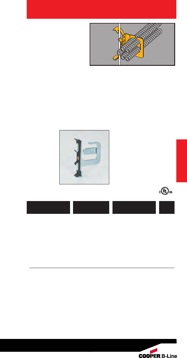
Flexible Conduit/
Cable Fasteners
• Attaches MC, AC, sizes
14/2 through 10/3 or
3/8" FMC to studs or
flanges up to 3/16"
thick.
• Snaps into place on
metal stud openings
or may be screwed to
metal or wood studs.
• BX4M may be snapped
in half to make two
BX4's.
• Allows cables to be
positioned a minimum
of 11/4" from face of
stud as required by
NEC Article 300.4(D).
781011 01079 BX4 Single Runs 100
UPC/Part
Number Description
Catalog
Number
Box
Qty.
Wall Studs
781011 01080 BX4M Double Runs 100
781011 01224 BX4MD Up to 4 Runs 100
BX4
BX4M BX4MD
Read safety/installation instruction sheets in packages before use. These products are designed for positioning only. No load rating.
35
Wall Studs
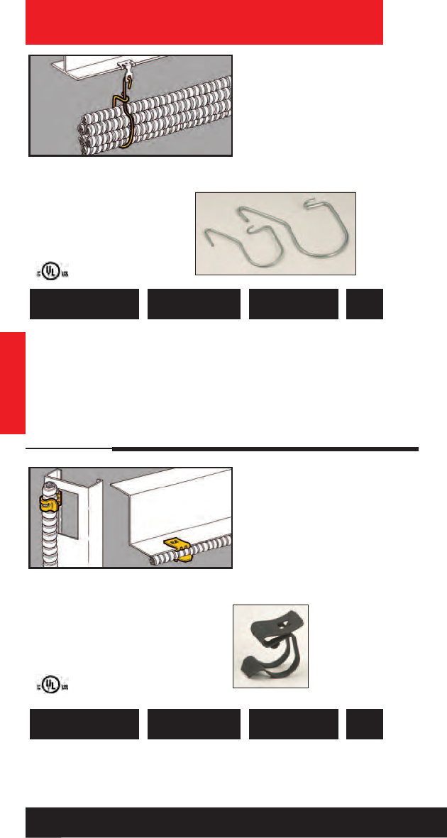
Cable Support
• Metal cable support
can be used in
plenum-rated areas.
• Longer locking tabs.
• Shipped pre-assembled.
• Hinge can be opened
for greater cable
capacity.
• Allows cables to be
positioned a minimum
of 11/4" from face of
stud as required by
NEC Article 300.4(D).
781011 04980 BRC4M Up to 3/4” FMC 100
Note: Canadian applications are limited to wood studs only.
UPC/Part
Number Description
Catalog
Number
Box
Qty.
Cable Type
Cable Non-Metallic Metal Clad Armored Cable
Size (NM) (MC) (AC)
Qty. Dia. Qty. Dia. Qty. Dia.
14-2 w/ Grnd 8.360 5.439 5.464
14-3 w/ Grnd 8.307 5 .464 5 .483
14-4 w/ Grnd 8 .336 4 .494 4 .517
12-2 w/ Grnd 7.410 5.475 4.498
12-3 w/ Grnd 8.347 4 .505 4 .521
12-4 w/ Grnd 7 .381 4 .539 4 .557
10-2 w/ Grnd 6.494 4.542 4.560
10-3 w/ Grnd 7.422 4 .580 4 .588
10-4 w/ Grnd NA NA 3.623 3.632
8-2 w/ Grnd 4.612 NA NA NA NA
8-3 w/ Grnd 4 .565 NA NA NA NA
6-2 w/ Grnd 4.650 NA NA NA NA
5/16 FMC 5 (,470 to .510 Dia.)
3/8FMC 4 (.560 to .610 Dia.)
1/2FMC 1 (.860 to .920 Dia.)
3/4FMC 1 (1.045 to 1.105 Dia.)
Wall Studs
The quantity of cables shown in the chart is the maximum.
Fewer cables can be supported. Diameters are based on data from
a leading cable manufacturer (may vary slightly).
Diameters of some NM cables refer to the widest dimension of a flat
cable. NA = Not applicable
Read safety/installation instruction sheets in packages before use. These products are designed for positioning only. No load rating.
36
Wall Studs
Staple-Lok™
Multi-Purpose
Cable Support
• Individual plastic
staples grip cable and
reduce slipping.
• Secures up through
#10 type NM cable.
• Supports AC, MC or
FMC cable up to 1/2”
O.D.
• Break-apart feature
allows installation on
studs and furring
strips.
• Allows cables to be
positioned a minimum
of 11/4” from face of
stud as required by
NEC Article 300.4(D).
UPC/Part
Number Cable Size
Catalog
Number
Box
Qty.
Wall Studs
781011 03587 BRC4 Up to .500” O.D. 100
Patent #5587555
37
Read safety/installation instruction sheets in packages before use. These products are designed for positioning only. No load rating.
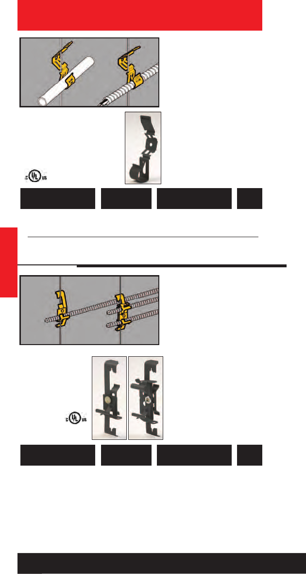
Wall Studs
Conduit/Cable
Supports
• Allows conduit, MC,
AC, or FMC to be
pulled through metal
studs.
• Provides support for
horizontal runs of
conduit or cable
through metal stud.
• Prevents conduit/cable
rattling.
• Finish: Pre-galvanized
781011 01657 BX82 Up to 1” 100
UPC/Part
Number
Conduit/Cable
Size
Catalog
Number
Box
Qty.
Wall Studs
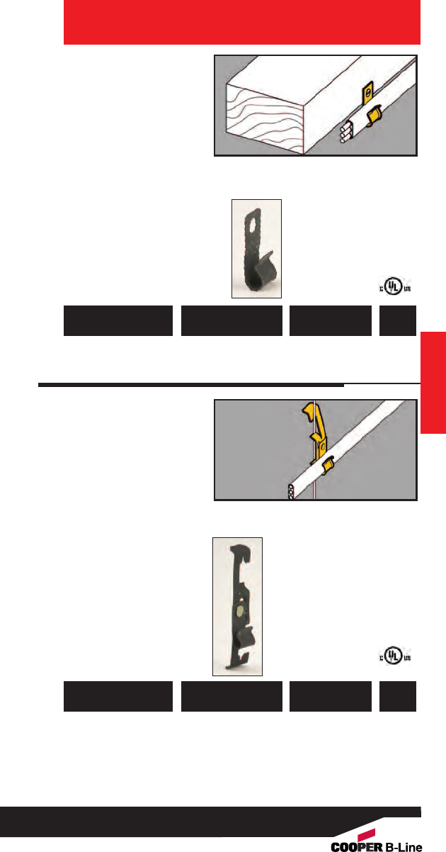
Cable Fasteners
• Attaches Type NM
cables to wood studs.
•Can be used to
support computer,
CATV, telephone,
security and
instrumentation cables.
• Provided with nail
inserted.
• Allows cables to be
positioned a minimum
of 11/4” from face of
stud as required by
NEC Article 300.4(D).
781011 02941 BRC1 Wood Stud 50
Cable Fastener
781011 02942 BRC2 Furring Strip 50
Cable Fastener
UPC/Part
Number Description
Catalog
Number
Box
Qty.
BRC1 BRC2
38
Read safety/installation instruction sheets in packages before use. These products are designed for positioning only. No load rating.
Wall Studs
Nail Plates
For Wood Studs
• Protects cable, plastic
pipe and copper
tubing from screw or
nail penetration.
• Easily installed with a
hammer.
• Complies with NEC
Article 300-4.
781011 04927 BM3 Nail Plate 100
UPC/Part
Number Description
Catalog
Number
Box
Qty.
Wall Studs
Nail Plates
For Metal Studs
• Protects cable, plastic
pipe and copper
tubing from screw or
nail penetration.
•Comes with industrial
grade double stick
tape on back for easy
installation on stud.
•Complies with NEC
Article 300-4.
782051 26251 BM3M Nail Plate 100
UPC/Part
Number Description
Catalog
Number
Box
Qty.
Just Peel Tape
and
Stick To Stud
39
Read safety/installation instruction sheets in packages before use. These products are designed for positioning only. No load rating.
top
bottom
Wall Studs
Conduit Support
•Larger capacity:
Redesigned BB38D
attaches 1/2” to 1” EMT
or flexible conduit to
metal or wood studs.
• BB38 attaches MC/AC
cable, 1/2” & 3/4” EMT to
metal or wood studs.
• Eliminates the need for
offset bending of conduit.
• Aligns conduit with
standard box knockouts.
781011 04265 BB38 11/2” 100
781011 95244 BB38D 21/8” 100
UPC/Part
Number Box Depth
Catalog
Number
Box
Qty.
Wall Studs
BB38 BB38D
Flexible Conduit/
Cable Fasteners
• Secures Romex®sizes
14/2 w/ground thru
12/3 w/ground,
MC/AC sizes 14/2
thru 12/3 to metal or
wood studs.
• Allows cables to be
positioned a minimum
of 11/4” from face of
stud as required by
NEC Article 300.4(D).
781011 19755 BX5 Secures Flexible 100
Conduit or Cable
to Metal or Wood Studs
UPC/Part
Number Description
Catalog
Number
Box
Qty.
40
Read safety/installation instruction sheets in packages before use. These products are designed for positioning only. No load rating.
Improved
Design
Romex®is a registered trademark used by Southwire®Company, Carrollton, Georgia.
Wall Studs
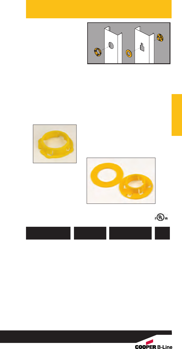
Wall Studs
Metal Stud
Grommet
• BM1 snaps into
standard 111/32"
diameter holes in
metal studs from
25 Ga. to 16 Ga.
• Redesigned BM2 is
shipped as one piece
and easily separated for
installation.
• Universal BM2 provides
360° protection. Fits all
factory punched metal
stud holes.
• Protects wire insulation
in accordance with
NEC Article 300.4(B) (1).
781011 19100 BM1 Plastic Grommet 100
781011 19102 BM1M Plastic Grommet 1000
(Bulk Quantity)
781011 04926 BM2 Universal 100
Grommet
UPC/Part
Number Description
Catalog
Number
Box
Qty.
41
Read safety/installation instruction sheets in packages before use. These products are designed for positioning only. No load rating.
BM2
BM1

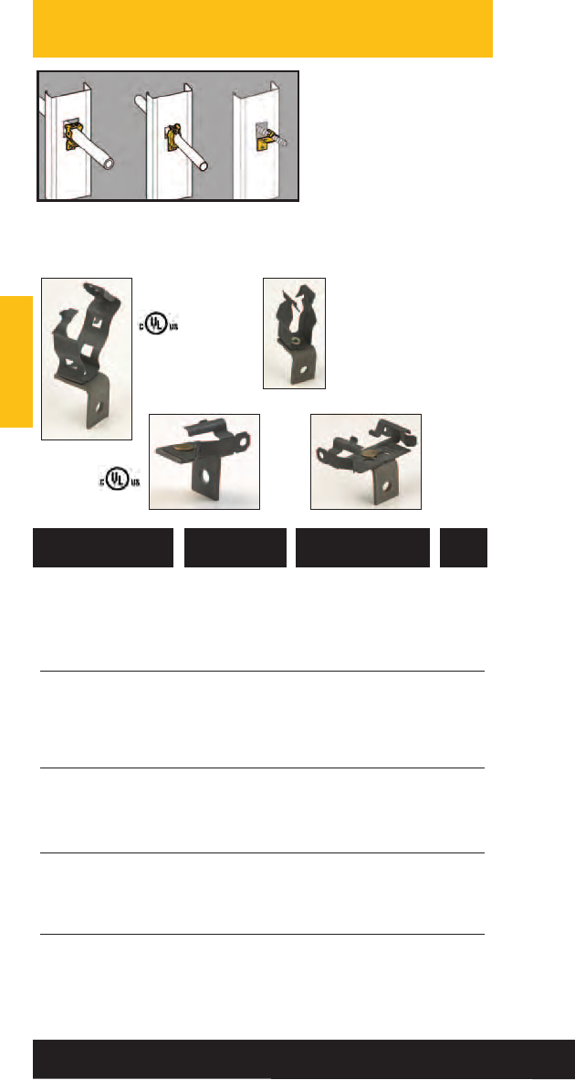
Conduit & Cable
Conduit & Cable
42
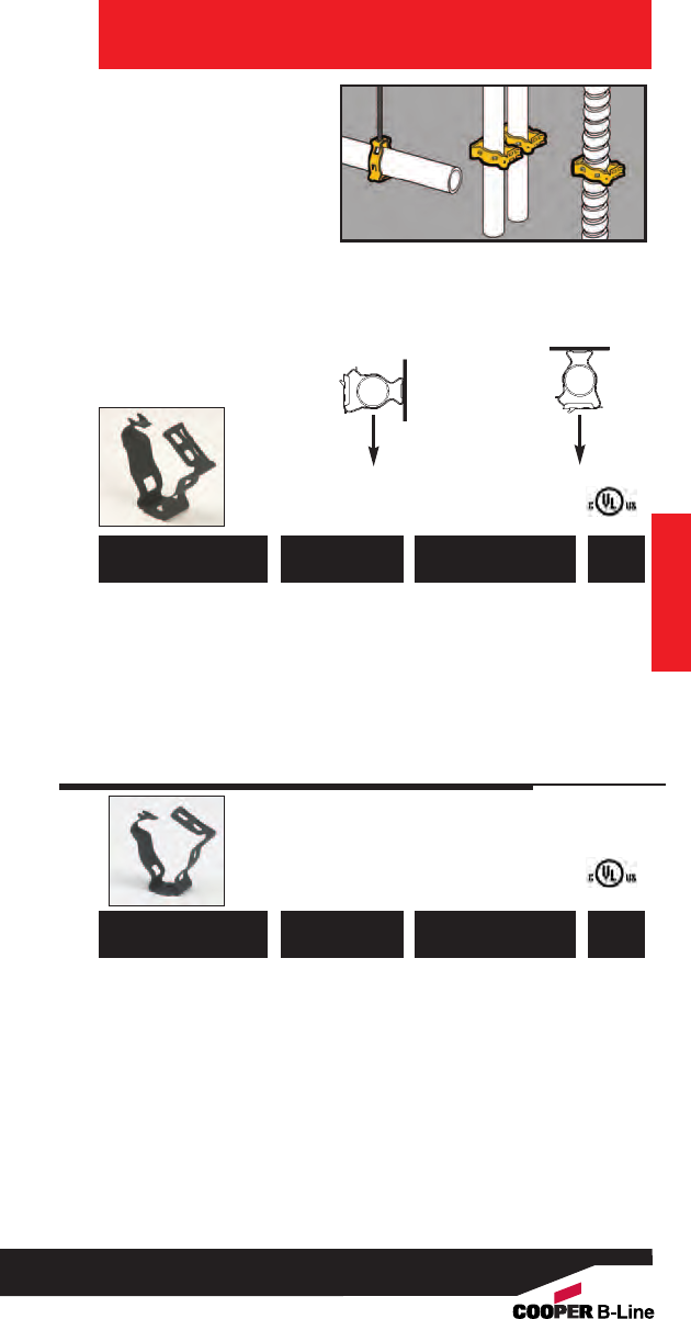
• Supports 3/8" to 2" conduit.
• Unique Guide-Rite
Fastener provides for fast
and easy installation with
pliers.
•New redesigned BG-6
accomodates a wide
variety of MC/AC cables.
•Now available in DURA-
COPPER™finish - add
DCU to part number.
•Static Load Capacity:
100 Lbs. - Vertical
25 Lbs. - Horizontal
Conduit & Cable
Guide-Rite™
Conduit Fasteners
Conduit & Cable
781011 18350 BG-6*3/8” 100
781011 18355 BG-8-12 1/2”, 3/4”100
781011 18360 BG-16 1” 100
781011 18365 BG-20 11/4” 100
781011 18370 BG-24 11/2” 100
781011 18375 BG-32 2” 100
Patent #4958792
781011 18380 BG-6-4T*3/8” 100
781011 18385 BG-8-12-4T 1/2”, 3/4”100
781011 18390 BG-16-4T 1” 100
781011 18395 BG-20-4T 11/4”100
781011 18400 BG-24-4T 11/2” 100
781011 18405 BG-32-4T 2” 100
Patent #4958792
*BG-6 and BG-6-4T will accept the following range ∅.420 - ∅.675:
14/2 thru 10/4 MC/AC cable and 5/16 or 3/8flexible conduit
UPC/Part
Number
Conduit Size
EMT/Rigid
Catalog
Number
Box
Qty.
UPC/Part
Number
Conduit Size
EMT/Rigid
Catalog
Number
Box
Qty.
Static
Load
Capacity
25
Lbs.
100
Lbs.
Clearance Hole
For 1/4" Bolt
1/4"-20
Thread Impression
43
Read safety/installation instruction sheets in packages before use.
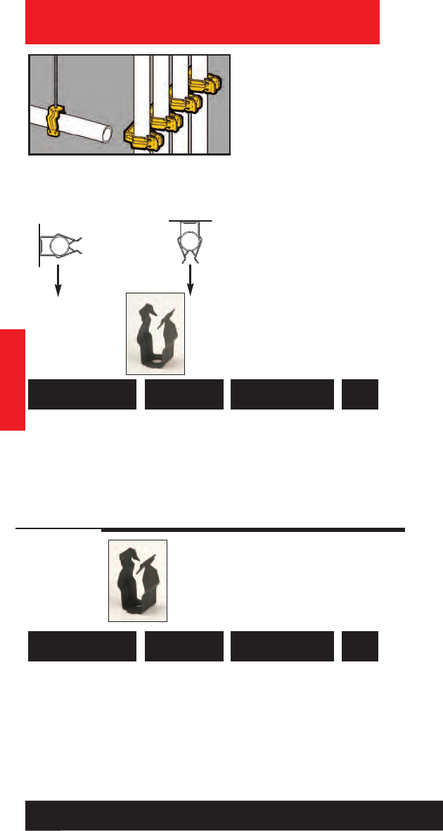
Conduit & Cable
Push-Type
Conduit Fasteners
• Conduit easily snaps into
push type fastener for
secure support.
• Available with
clearance hole for 1/4"
bolt or 1/4"-20 thread
impression.
•Ultimate Static Load
Capacity:
25 Lbs. Vertical
15 Lbs. Horizontal
Conduit & Cable
15
Lbs.
25
Lbs.
Ultimate
Static Load
Capacity
Clearance Hole
For 1/4" Bolt
781011 19200 BP-8 1/2” EMT 100
781011 19205 BP-12 3/4” EMT 100
1/2” IMC, Rigid
781011 19210 BP-16 1” EMT 100
3/4” IMC, Rigid
1/4"-20
Thread Impression
781011 19215 BP-8-4T 1/2” EMT 100
781011 19220 BP-12-4T 3/4” EMT 100
1/2” IMC, Rigid
781011 19225 BP-16-4T 1” EMT 100
3/4” IMC, Rigid
UPC/Part
Number Conduit Size
Catalog
Number
Box
Qty.
UPC/Part
Number Conduit Size
Catalog
Number
Box
Qty.
44
Read safety/installation instruction sheets in packages before use.
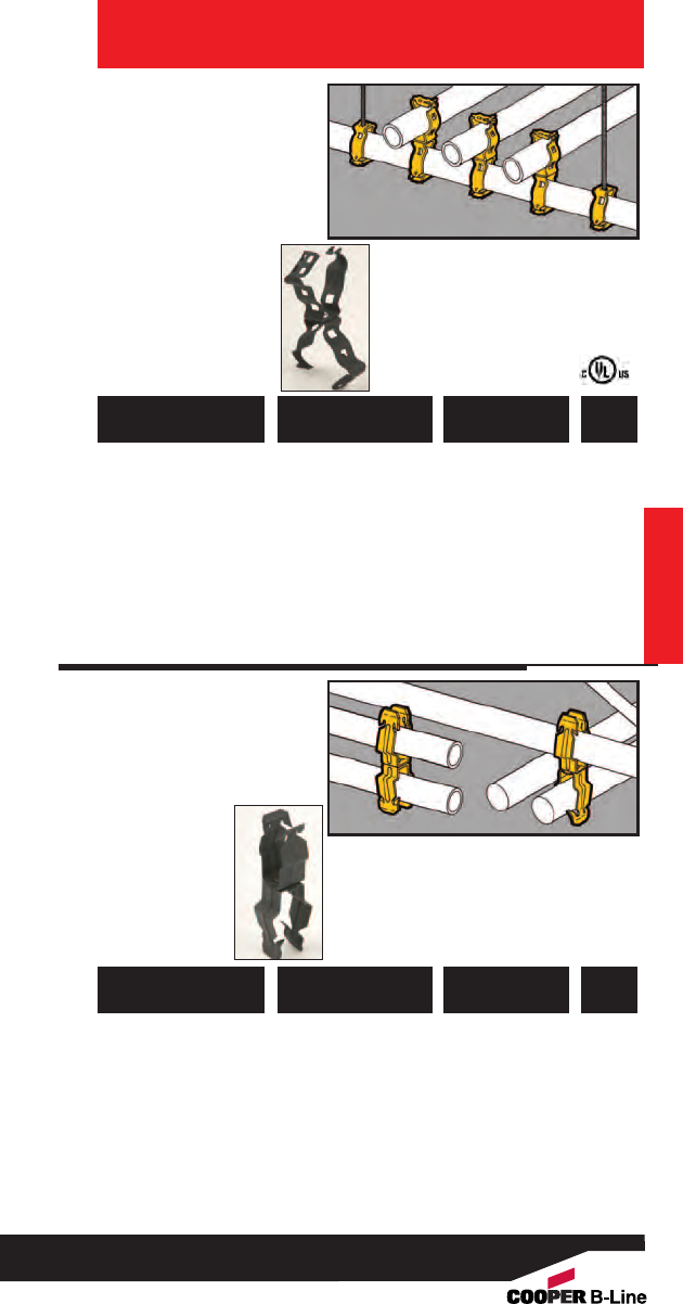
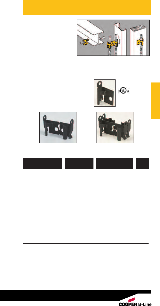
• For use with 3/8" to 2"
conduit.
•Guide-Rite Fastener
provides for fast and
easy installation with
pliers.
•Note: Total load of
trapeze must not
exceed 100 Lbs.
Conduit & Cable
Guide-Rite™
Conduit Trapeze
Fasteners
Conduit & Cable
781011 18615 BG-16-G-6*3/8” 100
781011 18620 BG-16-G-8-12 1/2” or 3/4” 100
781011 18595 BG-16-G-16 1” 100
781011 18600 BG-16-G-20 11/4”50
781011 18605 BG-16-G-24 11/2”50
781011 18610 BG-16-G-32 2” 50
Patent #4958792
*BG-6 will accept the following range ∅.420 - ∅.675:
14/2 thru 10/4 MC/AC cable and 5/16 or 3/8flexible conduit
UPC/Part
Number
Conduit To
1” Trapeze
Catalog
Number
Box
Qty.
•An ideal spacer
between conduits.
• No installation tools
required.
•Ultimate Static Load
Capacity:
25 Lbs.
Push-Type
Conduit To
Conduit Fasteners
781011 19303 BP-8-P-8 1/2” to 1/2”100
781011 19295 BP-8-P-12 1/2” to 3/4” 100
781011 19300 BP-8-P-16 1/2” to 1” 100
781011 19395 BP-12-P-12 3/4” to 3/4” 100
781011 19400 BP-12-P-16 3/4” to 1” 100
781011 19495 BP-16-P-16 1” to 1” 100
Note: For rigid conduit with BP series, use next size larger
fastener (1/2" Rigid use BP-12).
UPC/Part
Number
Conduit To
1” Trapeze
Catalog
Number
Box
Qty.
45
Read safety/installation instruction sheets in packages before use.
781011 01676 BPC-8 1/2” 100
781011 01677 BPC-12 3/4” 100
781011 01680 BPC-16 1” 100
781011 01679 BPC-20 11/4”50
781011 01678 BPC-24 11/2”50
781011 01681 BPC-32 2” 50
781011 03977 BPC-40 21/2”50
781011 03978 BPC-48 3” 50
781011 03979 BPC-56 31/2”25
781011 03981 BPC-64 4” 25
Patent #4044428
UPC/Part
Number
Rigid or EMT
Conduit Size
Catalog
Number
Box
Qty.
Conduit & Cable
Break-Apart
Conduit Clamps
• Patented Multi-Grip
design fits Rigid, IMC
or EMT conduit.
• Convenient break-apart
clamp features retained
bolt and 5/16” thread
impression to eliminate
handling of nuts and
bolts.
• Finish: Zinc-Plated.
• Static Load Capacity:
200 lbs.
Conduit & Cable
200
Lbs.
BPC-8 thru BPC-32
BPC-40 thru BPC-64
Static Load
Capacity
46
Read safety/installation instruction sheets in packages before use.
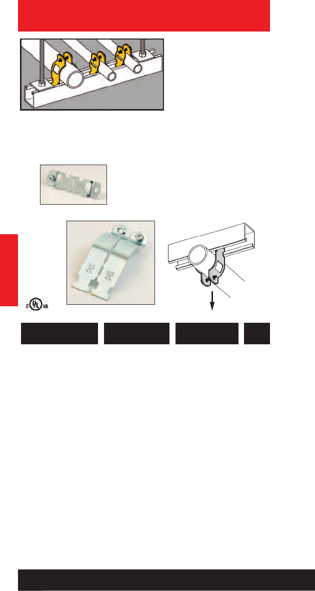
• Attaches conduit,
flexible conduit or
cables to standard
strut channels.
• B1506S designed to
secure and support
MC/AC cables.
• Unique one-piece
design eliminates
handling of hardware
and allows easy installation
and removal in side-by-side
conduit runs.
• Anti-rock feature prevents clamp
from disengaging during installation.
• Finish: Zinc-Plated
Conduit & Cable
Conduit Strut
Clamps
781011 63150 B1508
1/2”-- -- -- 200 Lbs. 100
781011 63154 B1512
3/4”1/2” -- -- 200 Lbs. 100
781011 63157 B1516
1” 3/4”-- -- 300 Lbs. 100
781011 63160 B1520
11/4” 1” -- -- 300 Lbs. 100
Note: Clamps without saddle are not recommended for flexible conduit or cable.
UPC/Part
Number
Static
Load Cap.
Catalog
Number
Conduit Size
EMT Rigid
OD Range
Min Max
Box
Qty.
Conduit & Cable
782051 44495 B1506S
*
3/8”
*
-- .400 .630 200 Lbs. 100
781011 63164 B1508S
1/2”-- .250 .680 200 Lbs. 100
781011 63168 B1512S
3/4”1/2”.500 .840 200 Lbs. 100
781011 63171 B1516S
1” 3/4” .750 1.050 300 Lbs. 100
781011 63177 B1520S
11/4”1” 1.125 1.315 300 Lbs. 100
781011 63182 B1524S
11/2”1
1/4” 1.375 1.660 400 Lbs. 50
781011 63188 B1532S
2” 11/2” 1.875 2.200 400 Lbs. 50
781011 63193 B1534S
-- 2” 2.125 2.375 400 Lbs. 25
781011 63199 B1540S
21/2” 21/2”2.625 2.875 400 Lbs. 25
781011 63205 B1548S
3” 3” 3.250 3.500 400 Lbs. 25
781011 63211 B1556S
31/2” 31/2”3.750 4.000 400 Lbs. 10
781011 63215 B1564S
4” 4” 4.250 4.500 400 Lbs. 10
Patent #5022614
B1508
thru
B1520
B1506S
thru
B1524S
B1532S
thru
B1564S
*B1506S will accept the following
AC Cable 14/2, 14/3, 14/4, 12/2, 12/3, 12/4, 10/2, 10/3, 10/4
MC Cable 14/2, 14/3, 14/4, 12/2, 12/3, 12/4, 10/2, 10/3, 10/4
47
Read safety/installation instruction sheets in packages before use.
Conduit & Cable
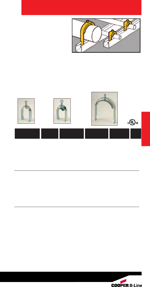
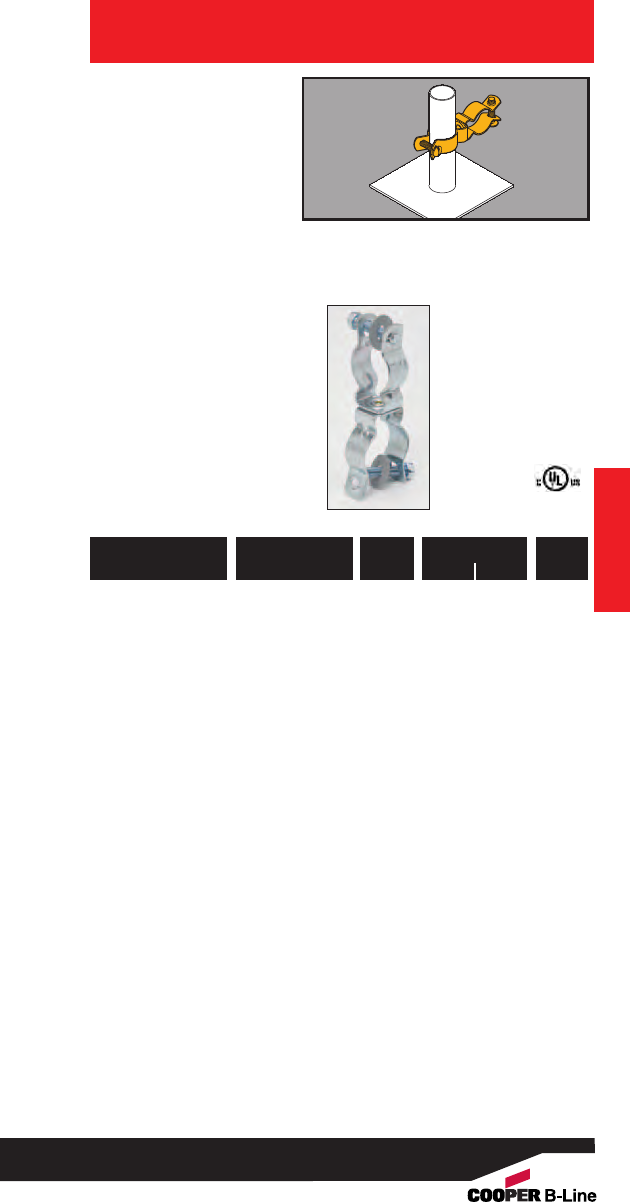
Conduit
Hangers
• For use with 1/2" thru
4" Conduit.
• Static Load Capacity:
400 lbs.
• Now available in DURA-
COPPER™finish - add
DCU to part number.
• Finish: Zinc-Plated
Conduit & Cable
With Retained Bolt
And
Thread Impression
With Bolt And Nut
781011 19800 BL1400*01/2”1/2” 100
781011 19801 BL1410*13/4”3/4” 100
781011 19802 BL1420*2 1” 1” 100
781011 19803 BL1425*2.5 11/4” -- 100
781011 19804 BL1430*3 11/2” 11/4”100
781011 19805 BL1440†4-- 11/2”50
781011 19806 BL1450†5 2” 2” 50
781011 19807 BL1460†6 21/2” 21/2”25
781011 19808 BL1470†7 3” 3” 25
781011 19809 BL1480†8 31/2” 31/2”10
781011 19810 BL1490†9 4” 4” 10
*9/32” mounting hole. †11/32” mounting hole.
UPC/Part
Number
Trade
Size
Catalog
Number
Conduit Size
EMT Rigid
Box
Qty.
UPC/Part
Number
Trade
Size
Catalog
Number
Conduit Size
EMT Rigid
Box
Qty.
48
Read safety/installation instruction sheets in packages before use.
Conduit & Cable
49
Read safety/installation instruction sheets in packages before use. These products are designed for positioning only. No load rating.
Stainless Steel
Conduit Hangers
• For use with 1/2" thru
4" Conduit.
• Static Load Capacity:
400 lbs.
• Material: Type 304
Stainless Steel
With Retained Bolt
And
Thread Impression
With Bolt And Nut
781011 57490 BL1400-SS4*01/2”1/2”25
781011 57497 BL1410-SS4*13/4”3/4”25
781011 57506 BL1420-SS4*2 1” 1” 25
781011 87485 BL1425-SS4*2.5 11/4” -- 25
781011 57517 BL1430-SS4*3 11/2” 11/4”25
781011 57525 BL1440-SS4†4-- 11/2”25
781011 57535 BL1450-SS4†5 2” 2” 10
781011 57546 BL1460-SS4†6 21/2” 21/2”10
781011 87481 BL1470-SS4†7 3” 3” 10
781011 87486 BL1480-SS4†8 31/2” 31/2”10
781011 87482 BL1490-SS4†9 4” 4” 10
*9/32” mounting hole. †11/32” mounting hole.
UPC/Part
Number
Trade
Size
Catalog
Number
Conduit Size
EMT Rigid
Box
Qty.
UPC/Part
Number
Trade
Size
Catalog
Number
Conduit Size
EMT Rigid
Box
Qty.
Conduit & Cable

782051 25589 BG-8-12-G6*3/8”100
781011 88538 BG-8-12-G812 1/2” or 3/4” 100
781011 18620 BG-16-G812 1” 100
782051 25594 BG-8-12-G20 11/4”50
782051 25595 BG-8-12-G24 11/2”50
782051 25597 BG-8-12-G32 2” 50
Patent #4958792
*BG-6 will accept the following range ∅.420 - ∅.675:
14/2 thru 10/4 MC/AC cable and 5/16 or 3/8flexible conduit
UPC/Part
Number
Conduit Size
EMT/Rigid
Catalog
Number
Box
Qty.
Conduit & Cable
Guide-Rite™
Conduit To
Pedestal Support
• Supports conduit from
square computer floor
pedestals.
• Unique Guide-Rite
Fastener provides for
fast and easy installation
with pliers.
•Static Load Capacity:
25 lbs.
Conduit & Cable
50
Read safety/installation instruction sheets in packages before use.
• Supports conduit from
1” O.D. computer
floor pedestals.
• Also available in Type
304 Stainless Steel.
Contact factory for
details.
• Static Load Capacity:
25 lbs.
• Finish: Zinc-Plated
Conduit & Cable
Conduit To
Pedestal Support
Conduit & Cable
782051 25599 BL1410-L1400 01/2”1/2”50
782051 25601 BL1410-L1410 13/4”3/4”50
782051 25602 BL1410-L1420 2 1” 1” 50
782051 25603 BL1410-L1425 2.5 -- 11/4”50
782051 25607 BL1410-L1430 3 11/4” 11/2”50
782051 25612 BL1410-L1440 4 11/2”-- 25
782051 25614 BL1410-L1450 5 2” 2” 25
782051 25617 BL1410-L1460 6 21/2” 21/2”10
782051 25618 BL1410-L1470 73” 3” 10
782051 25619 BL1410-L1480 83
1/2”3
1/2”5
UPC/Part
Number
Conduit Size
Rigid EMT
Catalog
Number
Trade
Size
Box
Qty.
51
Read safety/installation instruction sheets in packages before use.
Conduit & Cable
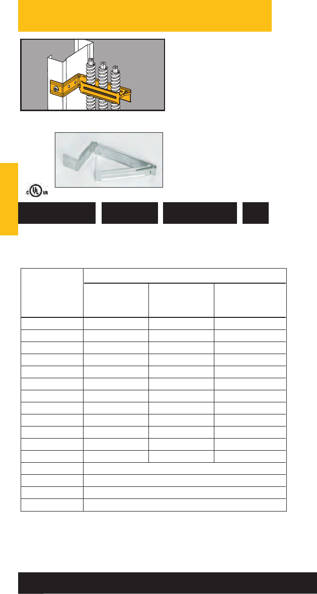
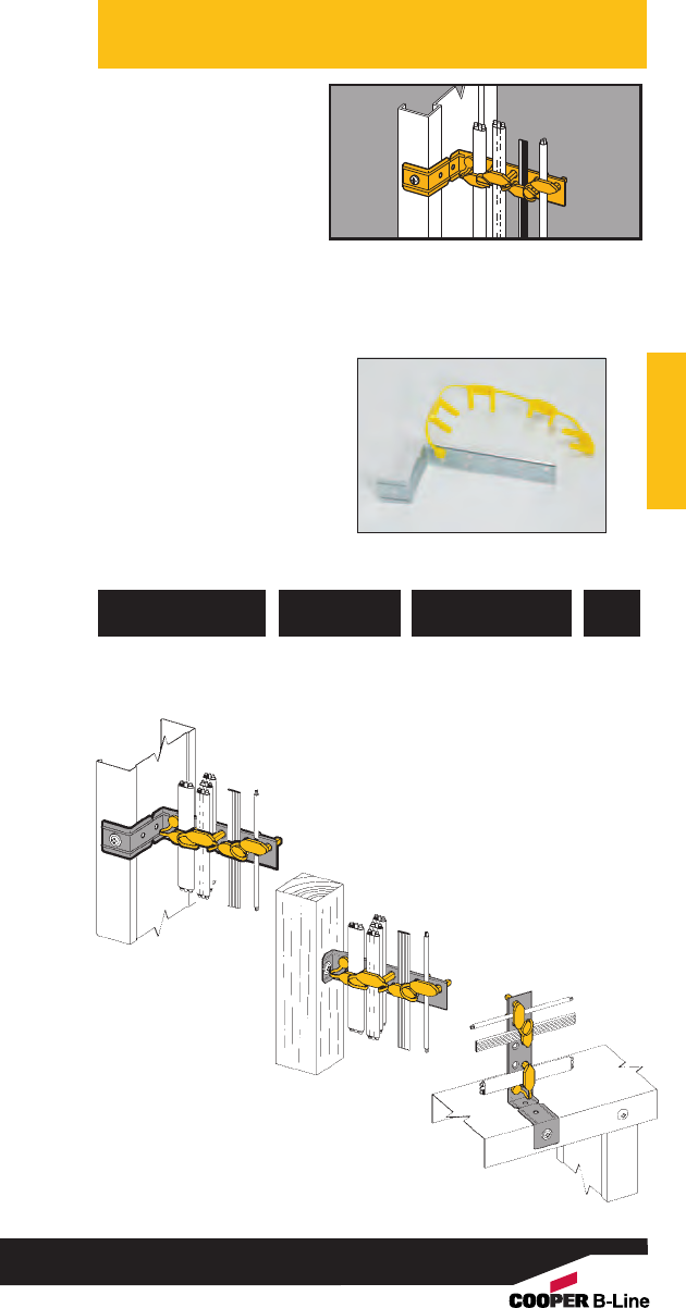
Rod & Wire
Fasteners
• BW2 and BW6 support
#10-24 or 1/4”-20
threaded bridle rings and
provide attachment for
electrical boxes.
• BW2S & BW6S are
provided with one each
1/4”-20 x 3/8” screw and
hex nut.
• BW4 supports cables
from #12 thru #8 wire.
Conduit & Cable
25 Lbs.
50 Lbs.
Static Load
Capacity
781011 19705 BW4 Multi-size 100
Wire Fastener
UPC/Part
Number Description
Catalog
Number
Box
Qty.
MC/AC #12 #10 #8 & #9
Cable Size Wire Wire Wire
14/2 Cable BW4 BW4 BW4
14/3 Cable BW4 BW4 BW4
12/2 Cable BW4 BW4 BW4
12/3 Cable BW4 BW-8 BW-8
BW4 is designed for positioning only. No load rating.
Note: An independent means of support is required by NEC Article 300.11.
Refer to pages 220-221 for additional support methods.
781011 19700 BW2 #12 wire thru 1/8” - 3/8” 100
1/4” plain or threaded rod
782051 40156 BW2S #12 wire thru 1/8” - 3/8” 100
1/4” plain or threaded rod
781011 95516 BW6 3/8” plain or 3/8” - 7/16” 100
threaded rod
782051 40157 BW6S 3/8” plain or 3/8” - 7/16” 100
threaded rod
UPC/Part
Number
Drop Rod/
Wire Size
Flange
Thickness
Catalog
Number
Box
Qty.
52
Read safety/installation instruction sheets in packages before use.
• See BX8 and BX18 for
a better solution.
•Attaches conduit to
wire rods or flanges.
• Can be used for
flexible metallic
tubing or armored
cable.
Conduit & Cable
Rod & Wire Fasteners
Conduit & Cable
781011 19710 BW-8 100
781011 19715 BW-12 100
781011 19720 BW-16 100
781011 19725 BW-20 100
UPC/Part
Number
Catalog
Number
Box
Qty.
Conduit #10 #8 3/16"1/8"5/16"7/16"
Size & #12 & #9 & 1/4" to 1/4" to 3/8" to 1/2"
WireWire Rod Flange Flange Flange
1/2" EMT BW-8 BW-8 BW-8 BW-8 BW-12 BW-12
1/2" Rigid BW-8 BW-12 BW-12 BW-12 BW-12 BW-16
3/4" EMT BW-12 BW-12 BW-12 BW-12 BW-16 BW-16
3/4" Rigid BW-12 BW-12 BW-16 BW-16 BW-20* BW-20*
1" EMT --- BW-16 BW-16 BW-16 BW-20* BW-20*
1" Rigid --- --- --- BW-20* BW-20* BW-20*
11/4" EMT --- BW-20 BW-20 BW-20 --- ---
*Note: For horizontal applications only.
Static Load Capacity
25 Lbs. 50 Lbs.
100 Lbs.
Vertical
Flange Vertical
Wire or
Rod
Horizontal
Flange
Note: An independent means of support is required by NEC Article 300.11.
Refer to pages 220-221 for additional support methods.
BW-8 BW-16
53
Read safety/installation instruction sheets in packages before use.
781011 18540 BG-8-12-W2 1/2”, 3/4”100
781011 18640 BG-16-W2 1” 100
781011 95519 BG-8-12-W6 1/2”, 3/4” 100
781011 95520 BG-16-W6 1” 100
Patent #4958792
UPC/Part
Number
Conduit Size
EMT/Rigid
Catalog
Number
Box
Qty.
Conduit & Cable
Guide-Rite™
Conduit To Rod
Fasteners
• Assemblies support
1/2", 3/4" and 1”
conduit.
• W2 series attaches to
1/8” thru 3/8” flanges
or #12 wire thru 1/4”
plain or threaded rod.
• W6 series attaches to
3/8” thru 7/16” flanges
or 3/8” plain or
threaded rod.
Conduit & Cable
50 Lbs. 25 Lbs.
Static Load
Capacity
Note: An independent means of support is required by NEC Article 300.11.
Refer to pages 220-221 for additional support methods.
54
Read safety/installation instruction sheets in packages before use.
• Assemblies support
1/2", 3/4" and 1”
conduit.
• W2 series attaches to
1/8” thru 3/8” flanges
or #12 wire thru 1/4”
plain or threaded rod.
• W6 series attaches to
3/8” thru 7/16” flanges
or 3/8” plain or
threaded rod.
Conduit & Cable
Conduit & Cable
781011 19325 BP-8-W2 1/2” EMT 100
781011 19420 BP-12-W2 3/4” EMT 100
1/2” IMC, Rigid
781011 19505 BP-16-W2 1” EMT or 100
3/4” IMC, Rigid
781011 95521 BP-8-W6 1/2” EMT 100
781011 95522 BP-12-W6 3/4” EMT 100
1/2” IMC, Rigid
781011 95523 BP-16-W6 1” EMT or 100
3/4” IMC, Rigid
UPC/Part
Number Conduit Size
Catalog
Number
Box
Qty.
25 Lbs. 15 Lbs.
Ultimate Static
Load Capacity
Note: An independent means of support is required by NEC Article 300.11.
Refer to pages 220-221 for additional support methods.
Push-Type
Conduit To Rod
Fasteners
55
Read safety/installation instruction sheets in packages before use.
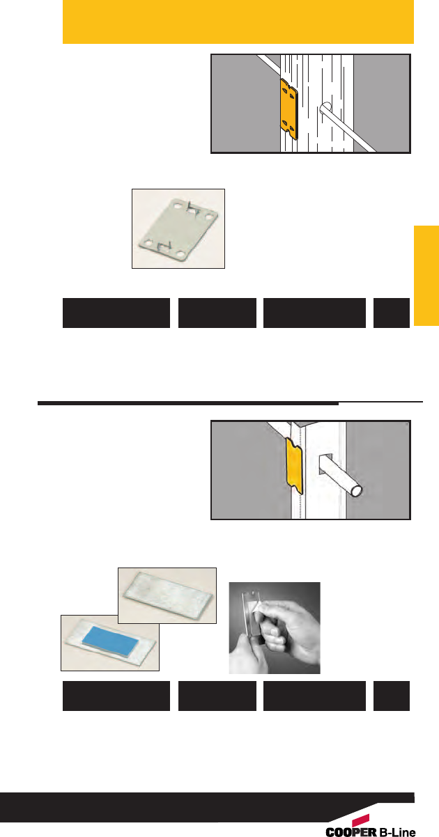
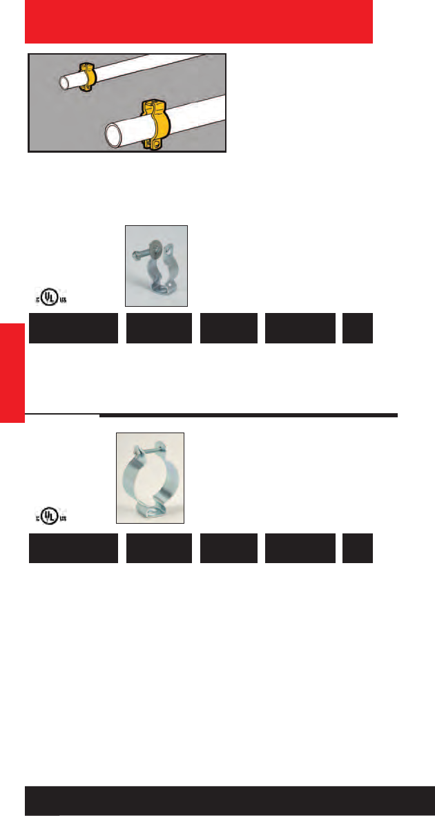
781011 01402 BX-8 .375” to .706” O.D. 100
781011 02943 BX-18 .706” to 1.380” O.D. 100
781011 01685 BX-8B Bulk Packed in 4000
Fiber Barrels
UPC/Part
Number
Cable/Conduit
Size
Catalog
Number
Box
Qty.
Conduit & Cable
• Can be used in place of
batwings.
• Will not bend or
deform hanger wire.
• Attaches to #12 - #8
wire and 1/4" plain rod.
• Accommodates MC, AC,
3/8" FMC or 1/2" EMT.
• Cable can be installed
before or after
attachment to wire.
• Static Load Capacity:
BX-8 - 20 Lbs.
BX-18 - 30 Lbs.
Conduit & Cable
781011 01219 BX4-W2 Single Runs 100
781011 01189 BX4M-W2 Double Runs 100
781011 95517 BX4-W6 Single Runs 100
781011 95518 BX4M-W6 Double Runs 100
UPC/Part
Number Description
Catalog
Number
Box
Qty.
• Assemblies support MC,
AC, sizes 14/2 through
10/3 or 3/8FMC.
•W2 series attaches to
1/8” thru 3/8” flanges
or #12 wire thru 1/4”
plain or threaded rod.
• W6 series attaches to
3/8” thru 7/16” flanges
or 3/8” plain or
threaded rod.
BX4-W2
Cable
To Rod
Fasteners
BX4M-W2
Note: An independent means of support is required by NEC Article 300.11.
Refer to pages 220-221 for additional support methods.
Flex-Rite™
Cable/Conduit
To Wire
Fasteners
56
Read safety/installation instruction sheets in packages before use.
• Attaches Type NM
cable to most
structures.
• Supports cable sizes
14/2 and 12/2 with
ground wire.
• May be used with
other B-Line fasteners
for attachment to
acoustical tees, beams,
drop wires, etc.
Conduit & Cable
Cable Fasteners
Conduit & Cable
781011 03553 BRC3 Type NM 100
Cable Fastener
UPC/Part
Number Description
Catalog
Number
Box
Qty.
•Supports cable sizes
14/2 and 12/2 with
ground wire.
•W2 series supports
cable from #12 wire
thru 1/4” plain or
threaded rod.
•W6 series supports
cable from 3/8” plain
or threaded rod. Cable Fasteners
781011 03547 BRC3-W2 Type NM Cable 100
To Wire Fastener
781011 95524 BRC3-W6 Type NM Cable 100
To Wire Fastener
UPC/Part
Number Description
Catalog
Number
Box
Qty.
57
Read safety/installation instruction sheets in packages before use. These products are designed for positioning only. No load rating.
782051 43593 BRC51 .430” to .560” 50
Up to 4 Runs
782051 43594 BRC52 .430” to .560” 50
Up to 9 Runs
782051 43595 BRC53 .560” to .690” 50
Up to 7 Runs
UPC/Part
Number
Cable Diameter &
Number Of Runs
Catalog
Number
Box
Qty.
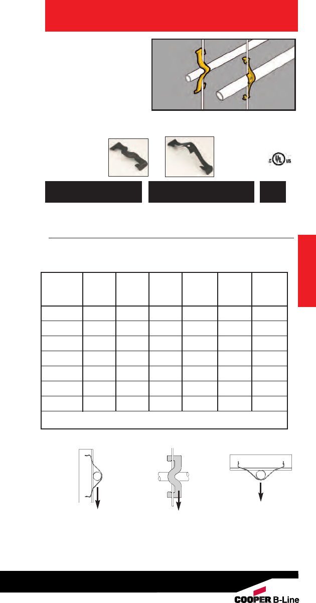
Conduit & Cable
Multi-Run Cable
Carrier for MC/AC
Cable
• Secures and supports
multiple runs of MC/AC
cable as required by
the NEC.
• Effectively organizes
cables and eliminates
derating issues.
• Retention tab is open
for easy loading and
unloading and contains
cables when bent in
place.
• Compatible with new
BCH-HBA for multi-tier
assemblies.
• Load Capacity: 50 lbs.
• Finish: Zinc Plated
Conduit & Cable
BRC51
BRC53
BRC52
58
Read safety/installation instruction sheets in packages before use.
• Secures and supports
multiple runs of
MC/AC cable as
required by the NEC.
• W2 Series attaches to
1/8” thru 3/8” flanges
or #12 thru 1/4” plain
or threaded rod.
• W6 Series attaches to
3/8” thru 7/16” flanges
or 3/8” plain or
threaded rod.
• Load Capacity: 50 lbs.
• Finish: Zinc Plated
Conduit & Cable
Multi-Run Cable
Carrier for
MC/AC Cable
Conduit & Cable
782051 44075 BRC51-W2 .430” to .560” 25
Up to 4 Runs
782051 44076 BRC52-W2 .430” to .560” 25
Up to 9 Runs
782051 44077 BRC53-W2 .560” to .690” 25
Up to 7 Runs
782051 44078 BRC51-W6 .430” to .560” 25
Up to 4 Runs
782051 44079 BRC52-W6 .430” to .560” 25
Up to 9 Runs
782051 44080 BRC53-W6 .560” to .690” 25
Up to 7 Runs
UPC/Part
Number
Cable Diameter &
Number Of Runs
Catalog
Number
Box
Qty.
59
Read safety/installation instruction sheets in packages before use. These products are designed for positioning only. No load rating.
Note: An independent means of support is required by NEC Article 300.11.
Refer to pages 220-221 for additional support methods.
782051 04934 BX2 Usable Area = 100
2 sq. in.
781011 19765 BX6 Usable Area = 100
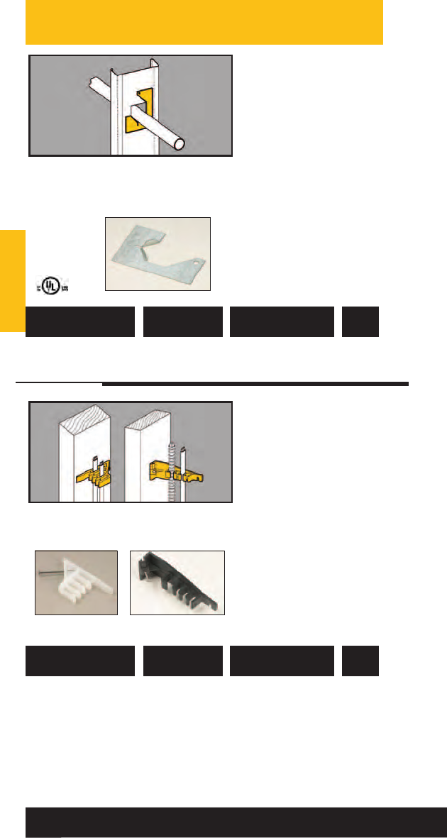
4 sq. in.
781011 19766 BX24 Usable Area = 100
13 sq. in.
UPC/Part
Number Description
Catalog
Number
Box
Qty.
Conduit & Cable
Flexible Cable
Support
• Designed to support
multiple runs of
MC, AC, FMC or
communication cable.
• Static Load Capacity:
BX2 - 50 lbs.
BX6 & BX24 - 75 Lbs.
• Finish: Zinc Plated
Conduit & Cable
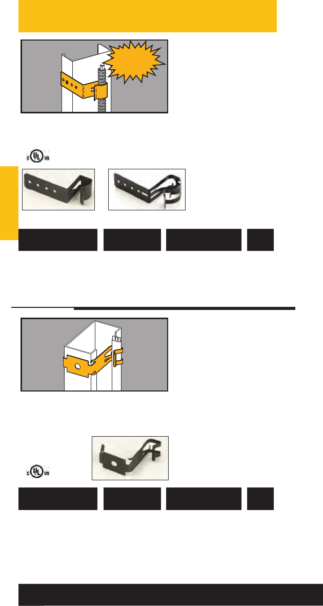
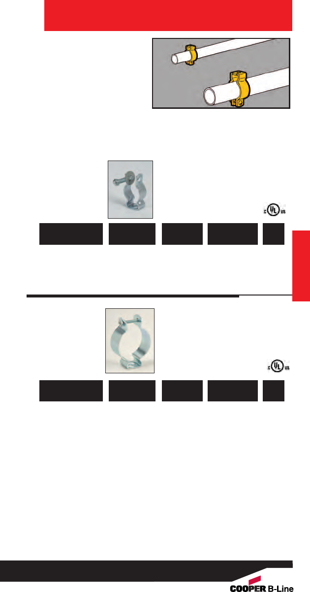
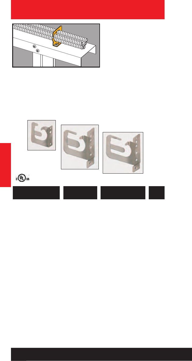
781011 19770 BX9 Flexible Conduit 100
Fastener
UPC/Part
Number Description
Catalog
Number
Box
Qty.
Flexible Conduit/
Cable Fasteners
•Fastens flexible conduit
and other small cables
to beam flanges, bar
joists or metal studs.
•Cable O.D. range of
0.42” to 0.70”.
• Maximum flange
thickness 5/32”.
60
Read safety/installation instruction sheets in packages before use.
BX2
BX6
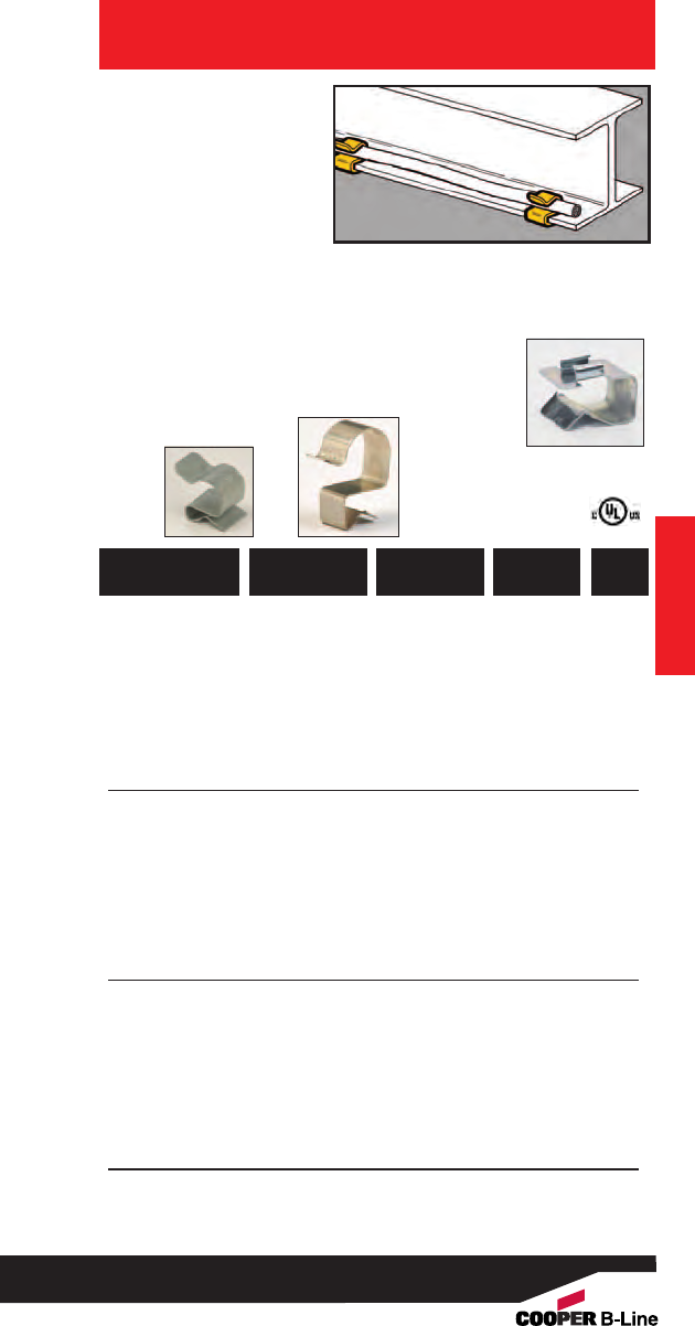
• Secures cable along
flanges 1/16" to 3/4"
thick.
• The BFA flange
adapters attach BXS
series to thicker
flanges.
• BX_-67 accepts 14/2,
12/2 & 10/2 romex
with ground.
• BX_-1011 accepts 14/2,
12/2 & 10/2 romex
with ground.
•BX_-1214 accepts 10/3,
romex with ground.
• Finish: Zinc Plated
Conduit & Cable
Flexible Conduit/
Cable Fasteners
Conduit & Cable
781011 19973 BXS-67 1/16” - 5/32”.218 to .281 100
781011 19974 BXS-89 1/16” - 5/32” .290 to .375 100
781011 19975 BXS-1011 1/16” - 5/32” .375 to .437 100
781011 19976 BXS-1214 1/16” - 5/32” .444 to .560 100
781011 19977 BXS-1519 1/16” - 5/32”.500 to .718 100
781011 19978 BXS-2024 1/16” - 5/32” .748 to .945 100
781011 19979 BXS-2530 1/16” - 5/32” .968 to 1.250 100
781011 19980 BXM-67 5/32” - 9/32” .218 to .281 100
781011 19981 BXM-89 5/32” - 9/32” .290 to .375 100
781011 19982 BXM-1011 5/32” - 9/32”.375 to .437 100
781011 19983 BXM-1214 5/32” - 9/32” .444 to .560 100
781011 19984 BXM-1519 5/32” - 9/32”.500 to .718 100
781011 19985 BXM-2024 5/32” - 9/32”.748 to .945 100
781011 19986 BXM-2530 5/32” - 9/32” .968 to 1.250 100
781011 19987 BXL-67 5/16” - 1/2”.218 to .281 100
781011 19988 BXL-89 5/16” - 1/2” .290 to .375 100
781011 19989 BXL-1011 5/16” - 1/2” .375 to .437 100
781011 19990 BXL-1214 5/16” - 1/2”.444 to .560 100
781011 19991 BXL-1519 5/16” - 1/2” .500 to .718 100
781011 19992 BXL-2024 5/16” - 1/2” .748 to .945 100
781011 19993 BXL-2530 5/16” - 1/2” .968 to 1.250 100
781011 19955 BFA-1215 1/2” - 5/8”-- 100
781011 19956 BFA-1520 5/8” - 3/4” -- 100
UPC/Part
Number
Flange
Thickness
Catalog
Number
Box
Qty.
BXS
Series
BXL
Series
BFA Series
(For Use with
BXS Series
Only)
Cable
Diameter
61
Read safety/installation instruction sheets in packages before use. These products are designed for positioning only. No load rating.
782051 22356 BCS-8 1/2” Rigid Conduit 50
782051 40057 BES-8 1/2” EMT Conduit 50
782051 22357 BCS-12 3/4” Rigid Conduit 50
782051 40058 BES-12 3/4” EMT Conduit 50
782051 22358 BCS-16 1” Rigid Conduit 50
782051 40059 BES-16 1” EMT Conduit 50
782051 22359 BCS-8C 1/2” Rigid Conduit 50
782051 40060 BES-8C 1/2” EMT Conduit 50
782051 22361 BCS-12C 3/4” Rigid Conduit 50
782051 40061 BES-12C 3/4” EMT Conduit 50
782051 22362 BCS-16C 1” Rigid Conduit 50
782051 40062 BES-16C 1” EMT Conduit 50
Patent #5896892
UPC/Part
Number Conduit Size
Catalog
Number
Box
Qty.
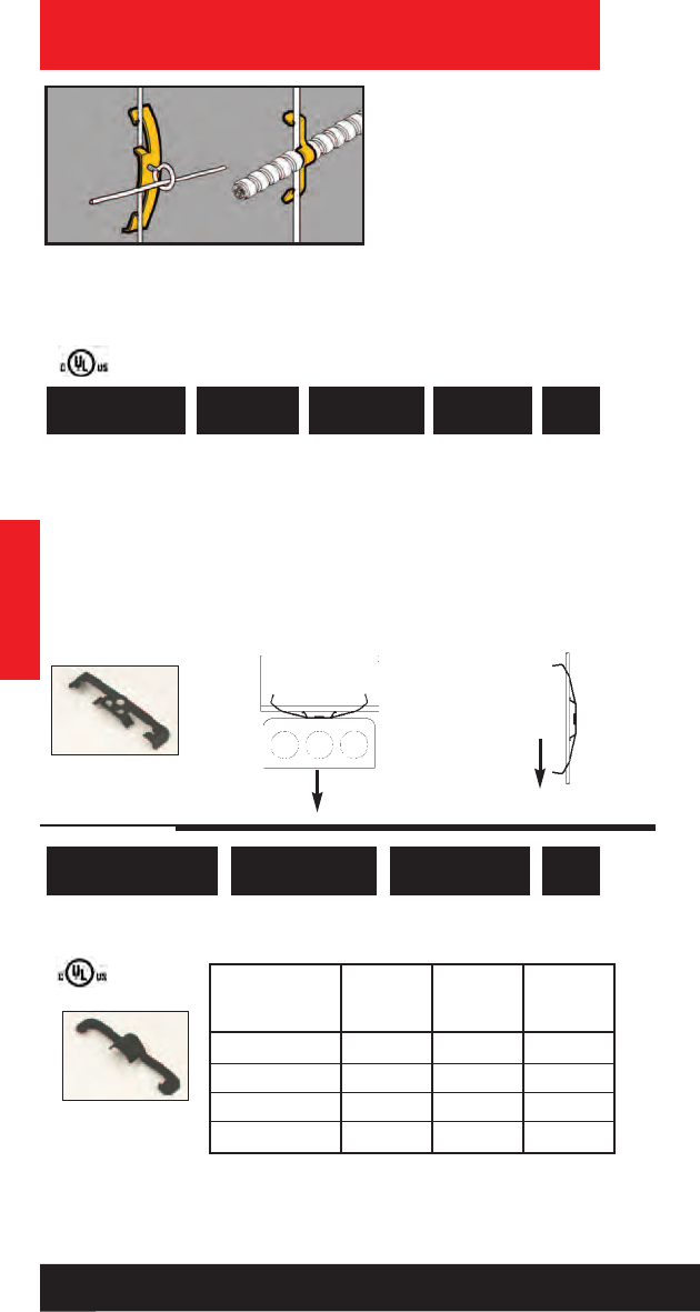
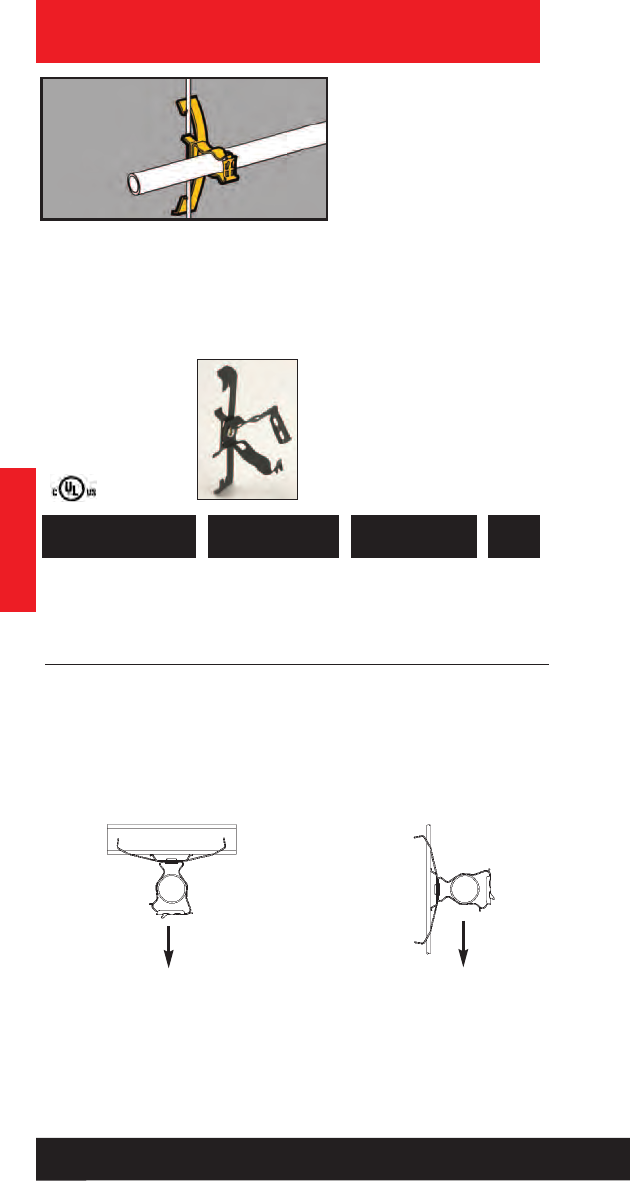
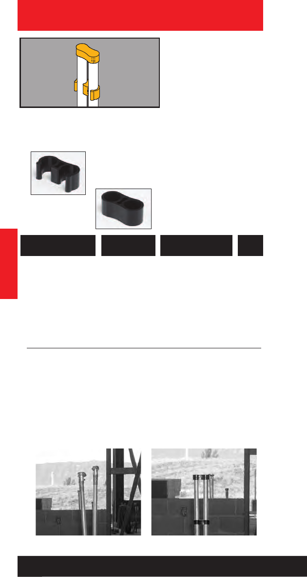
Conduit & Cable
Conduit Quick
Caps & Spacers
• Quick caps and spacers
eliminate the time
consuming method of
duct taping conduit
stubs.
• Quick spacers are
designed to separate
and secure conduit
during concrete pours.
• Quick caps maintain
spacing and keep
conduit free from dirt
and debris.
• Quick caps and spacers
properly space conduit
for any 4” square box.
• New EMT sizes now
available.
Conduit & Cable
Old Method New Method with Quick
Cap & Spacer
BCS-C & BES-C
Conduit Caps
BCS & BES
Conduit
Spacers
62
Read safety/installation instruction sheets in packages before use. These products are designed for positioning only. No load rating.
Conduit & Cable
Conduit & Cable
63
Read safety/installation instruction sheets in packages before use.
• Eliminates the need
for offset bends when
used with 11/2" deep
boxes.
• Attaches conduit to
concrete, steel or
wood with nails.
• May be attached after
conduit positioning. Conduit Spacer
Brackets
781011 18495 BG-8-12-D3 1/2” or 3/4” 100
Patent #4958792
781011 19265 BP-8-D3 1/2” EMT 100
781011 19365 BP-12-D3 3/4” EMT or 100
1/2” IMC, Rigid
UPC/Part
Number Conduit Size
Catalog
Number
Box
Qty.
BG BP
• Eliminates the need
for offset bends when
used with 21/8" deep
boxes.
• Provides secure
support between
conduit and deck.
• D4 Series is easily
installed with screw
gun or powder
actuated tools.
• Allows for complete
conduit layout prior
to anchoring.
Conduit Spacer
Brackets
781011 18500 BG-8-12-D4 1/2” or 3/4” 100
Patent #4958792
781011 19270 BP-8-D4 1/2” EMT 100
781011 19370 BP-12-D4 3/4” EMT or 100
1/2” IMC, Rigid
781011 19460 BP-16-D4 1” EMT or 100
3/4” IMC, Rigid
UPC/Part
Number Conduit Size
Catalog
Number
Box
Qty.
BG BP
781011 03575 BG6-S18 *3/8”25
781011 03573 BG812-S18 1/2” or 3/4”25
781011 03574 BG16-S18 1” 25
With Multiple Conduit Plate
782051 52812 BG6-S18-MC3 *3/8”25
782051 52900 BG812-S18-MC3 1/2” or 3/4”25
782051 52901 BG16-S18-MC3 1” 25
Patent #4958792
UPC/Part
Number
Conduit Size
EMT & Rigid
Catalog
Number
Box
Qty.
Conduit & Cable
Guide-Rite™
Conduit & Box
Support Fasteners
• New BMC3 plate is
available to support
multiple conduit runs.
• Riveted assembly
provides support for
electrical boxes and
conduit runs on either
side of the box.
• Reduces drop wires by
66% when using W2/W6
assemblies.
• Assemblies using BMC3
plate include center
conduit clip. Additional
conduit clips may be
purchased separately.
Conduit & Cable
64
Read safety/installation instruction sheets in packages before use.
BG__-S18-W2 BG__-S18-MC3
With Stud
782051 52902 BG6-S18S *3/8”25
781011 04979 BG812-S18S 1/2” & 3/4”25
782051 52903 BG16-S18S 1” 25
With Stud & Multiple Conduit Plate
782051 52904 BG6-S18S-MC3 *3/8”25
782051 52905 BG812-S18S-MC3 1/2” & 3/4”25
782051 52906 BG16-S18S-MC3 1” 25
BG-__-S18-S
With 1/4”-20 x 5/8”
Stud
BG-__-S18-S-MC3
With 1/4”-20 x 5/8”
Stud
• See pages Ruff-IN™brochure for
pre-fab box assemblies.
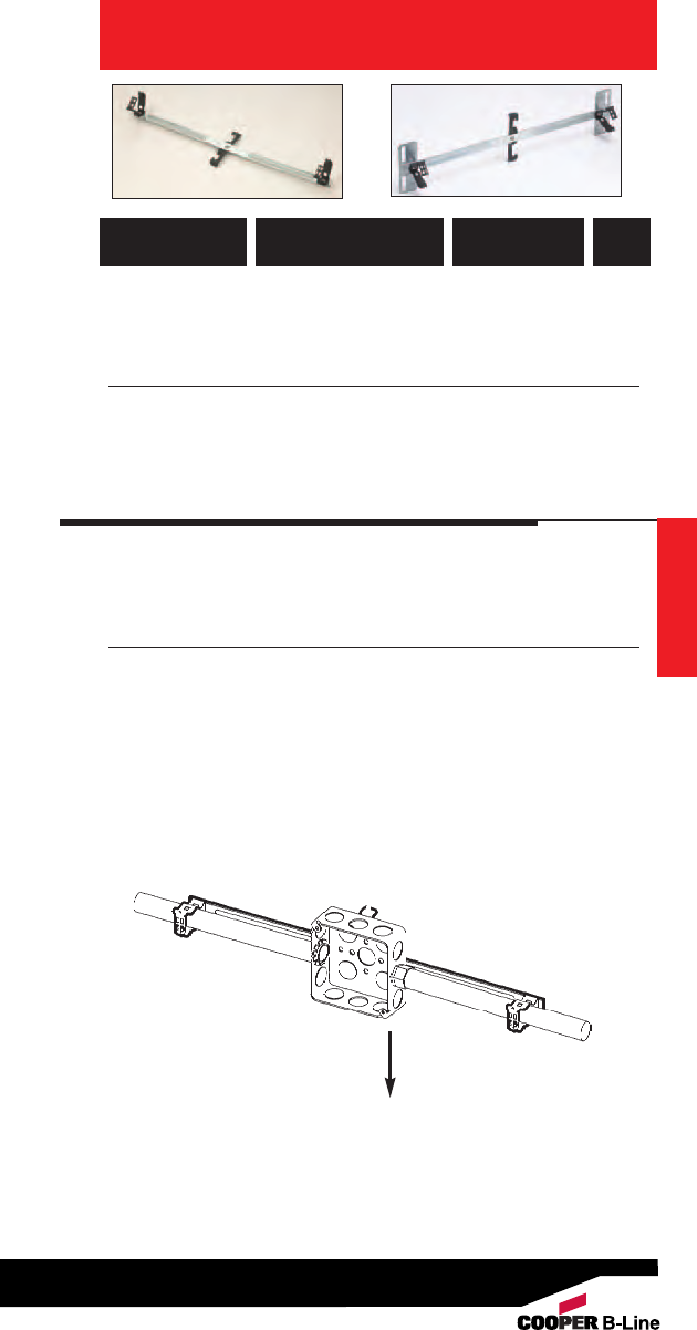
Conduit & Cable
UPC/Part
Number
Conduit Size
EMT & Rigid
Catalog
Number
Box
Qty.
*BG-6 will accept the following range ∅.420 - ∅.675:
14/2 thru 10/4 MC/AC cable and 5/16 or 3/8flexible conduit
** Note: An independent means of support is required by NEC Article
300.11. Refer to pages 220-221 for additional support methods.
65
Read safety/installation instruction sheets in packages before use.
W2 Series for #12 thru 1/4” Rod **
781011 03578 BG6-S18-W2 *3/8”25
781011 03576 BG812-S18-W2 1/2” & 3/4”25
781011 03577 BG16-S18-W2 1” 25
W2 Series for #12 thru 1/4” Rod & Multiple Conduit Plate **
782051 52855 BG6-S18-W2-MC3 *3/8”25
782051 52739 BG812-S18-W2-MC3 1/2” & 3/4”25
782051 52862 BG16-S18-W2-MC3 1” 25
BG__-S18-W_ BG__-S18-W_-MC3
W6 Series for 3/8” Plain or Threaded Rod **
781011 99581 BG6-S18-W6 *3/8”25
781011 99582 BG812-S18-W6 1/2” & 3/4”25
781011 99580 BG16-S18-W6 1” 25
W6 Series for 3/8” Plain or Threaded Rod & Multiple Conduit Plate **
782051 52856 BG6-S18-W6-MC3 *3/8”25
782051 52860 BG812-S18-W6-MC3 1/2” & 3/4”25
782051 52864 BG16-S18-W6-MC3 1” 25
25 Lbs.
Static Load
Capacity
Conduit & Cable
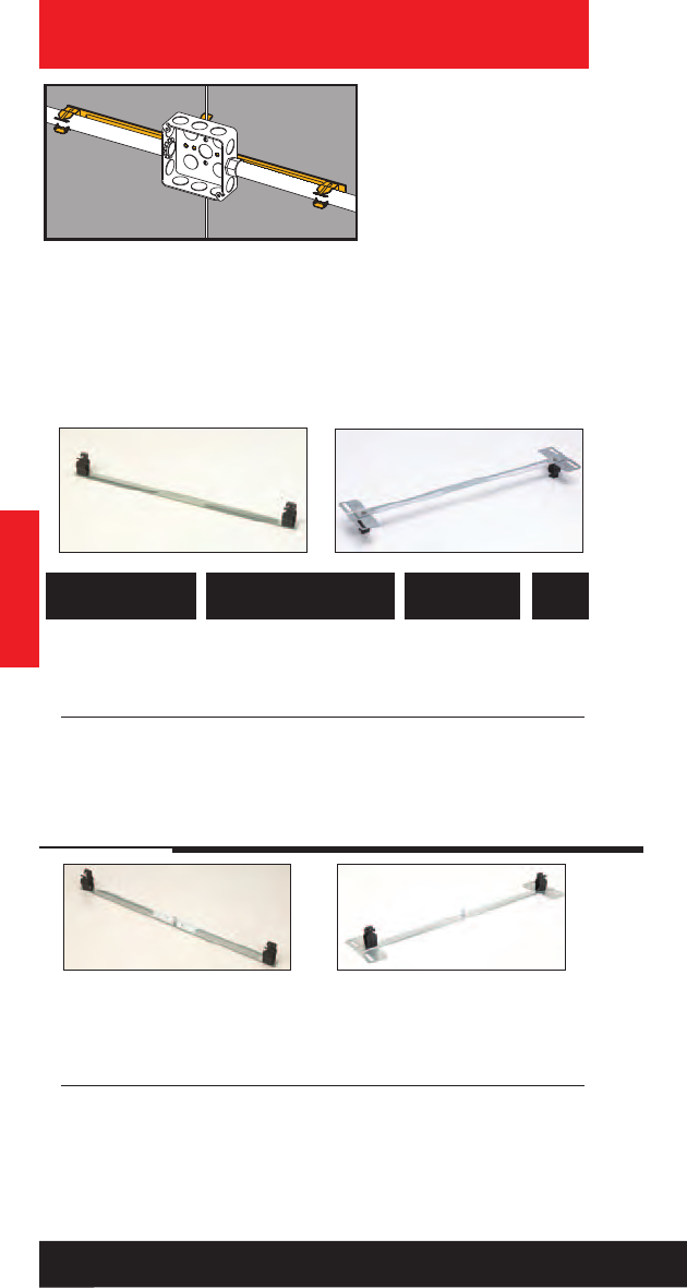
Conduit & Cable
Conduit & Cable
66
Read safety/installation instruction sheets in packages before use.
• New BMC3 plate is
available to support
multiple conduit runs.
• Riveted assembly
provides support for
electrical boxes and
conduit runs on either
side of the box.
• Reduces drop wires by
66% when using W2/W6
assemblies.
•Assemblies using BMC3
plate include center
conduit clip. Additional
conduit clips may be
purchased separately.
Push-Type
Conduit & Box
Support Fasteners
782051 23604 BP8-S18 1/2” EMT 25
782051 23605 BP12-S18 3/4” EMT, 1/2” Rigid 25
782051 23606 BP16-S18 1” EMT, 3/4” Rigid 25
With Multiple Conduit Plate
782051 52907 BP8-S18-MC3 1/2” EMT 25
782051 52908 BP12-S18-MC3 3/4” EMT, 1/2” Rigid 25
782051 52909 BP16-S18-MC3 1” EMT, 3/4” Rigid 25
UPC/Part
Number Conduit Size
Catalog
Number
Box
Qty.
BP__-S18 BP__-S18-MC3
With Stud
782051 23631 BP8-S18S
1/2” EMT
25
782051 23633 BP12-S18S
3/4” EMT, 1/2” Rigid
25
782051 23634 BP16-S18S
1” EMT, 3/4” Rigid
25
With Stud & Multiple Conduit Plate
782051 52913 BP8-S18S-MC3
1/2” EMT
25
782051 52914 BP12-S18S-MC3
3/4” EMT, 1/2” Rigid
25
782051 52915 BP16-S18S-MC3
1” EMT, 3/4” Rigid
25
BP-__-S18-S
With 1/4”-20 x 5/8”
Stud
BP-__-S18-S-MC3
With 1/4”-20 x 5/8”
Stud
• See pages Ruff-IN™brochure for
pre-fab box assemblies.
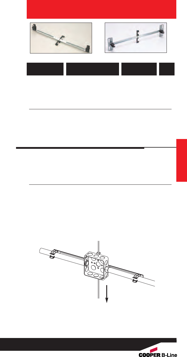
Conduit & Cable
67
Read safety/installation instruction sheets in packages before use.
UPC/Part
Number Conduit Size
Catalog
Number
Box
Qty.
** Note: An independent means of support is required by NEC Article
300.11. Refer to pages 220-221 for additional support methods.
W2 Series for #12 thru 1/4” Rod **
782051 23615 BP8-S18-W2
1/2” EMT
25
782051 23619 BP12-S18-W2
3/4” EMT, 1/2” Rigid
25
782051 23627 BP16-S18-W2
1” EMT, 3/4” Rigid
25
W2 Series for #12 thru 1/4” Rod & Multiple Conduit Plate **
782051 52847 BP8-S18-W2-MC3
1/2” EMT
25
782051 52848 BP12-S18-W2-MC3
3/4” EMT, 1/2” Rigid
25
782051 52849 BP16-S18-W2-MC3
1” EMT, 3/4” Rigid
25
BG__-S18-W_ BG__-S18-W_-MC3
W6 Series for 3/8” Plain or Threaded Rod **
782051 23628 BP8-S18-W6
1/2” EMT
25
782051 23629 BP12-S18-W6
3/4” EMT, 1/2” Rigid
25
782051 23630 BP16-S18-W6
1” EMT, 3/4” Rigid
25
W6 Series for 3/8” Plain or Threaded Rod & Multiple Conduit Plate **
782051 52850 BP8-S18-W6-MC3
1/2” EMT
25
782051 52851 BP12-S18-W6-MC3
3/4” EMT, 1/2” Rigid
25
782051 52854 BP16-S18-W6-MC3
1” EMT, 3/4” Rigid
25
25 Lbs.
Static Load
Capacity
Conduit & Cable
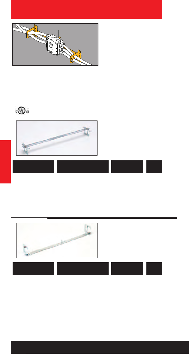
Conduit & Cable
Conduit & Cable
68
Read safety/installation instruction sheets in packages before use.
• Riveted assembly
provides support for
electrical boxes and
cable runs on either
side of the box.
• Reduces drop wires by
66% when using W2/W6
assemblies.
• Cable retension tab is
open for easy loading
and contains the cables
when bent in place.
•See Ruff-IN™brochure
for pre-fab box
assemblies.
Multi-Run Cable
Carrier & Box
Support Fasteners
782051 52916 BRC51-S18 Up to 4 runs 25
.430” - .560”
782051 52918 BRC53-S18 Up to 7 runs 25
.560” - .690”
UPC/Part
Number Conduit Size
Catalog
Number
Box
Qty.
UPC/Part
Number Conduit Size
Catalog
Number
Box
Qty.
BRC5_-S18
With Stud
782051 52919 BRC51-S18S Up to 4 runs 25
.430” - .560”
782051 52921 BRC53-S18S Up to 7 runs 25
.560” - .690”
BRC5_-S18-S
With 1/4”-20 x 5/8”
Stud
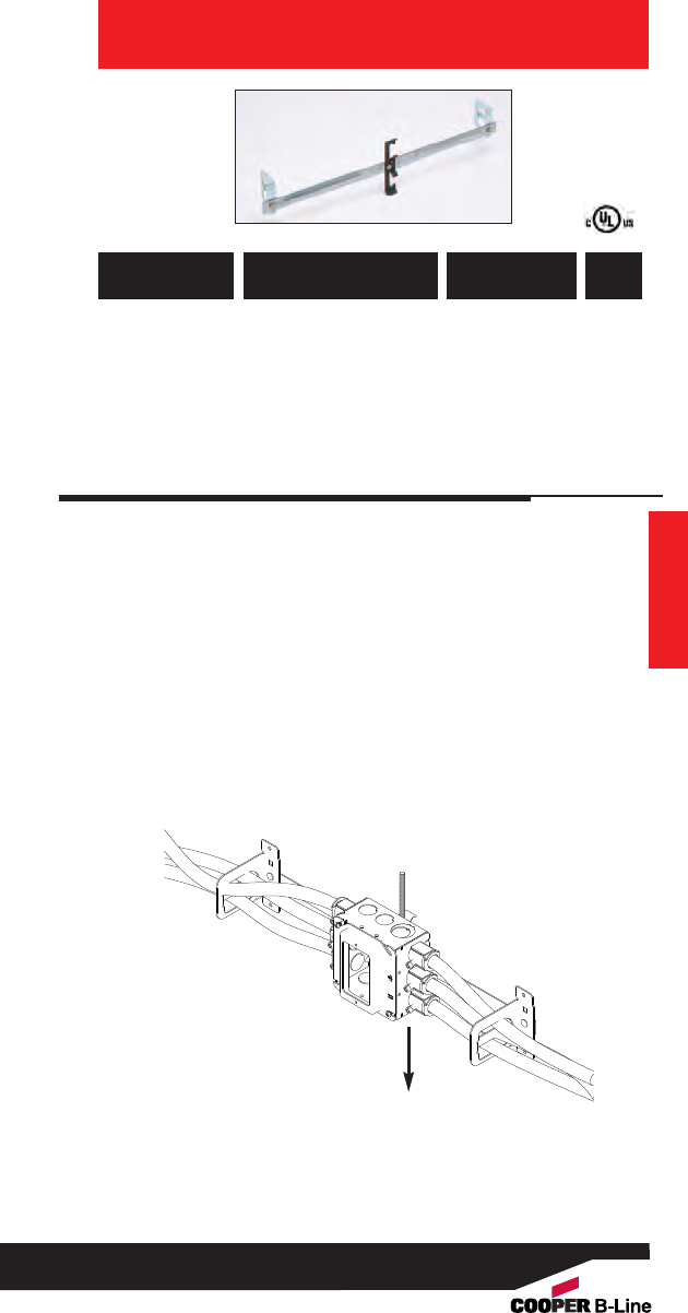
Conduit & Cable
Conduit & Cable
69
Read safety/installation instruction sheets in packages before use.
UPC/Part
Number Conduit Size
Catalog
Number
Box
Qty.
** Note: An independent means of support is required by NEC Article
300.11. Refer to pages 220-221 for additional support methods.
W2 Series for #12 thru 1/4” Rod **
782051 52865 BRC51-S18-W2 Up to 4 runs 25
.430” - .560”
782051 52869 BRC53-S18-W2 Up to 7 runs 25
.560” - .690”
BRC5_-S18-W_
W6 Series for 3/8” Plain or Threaded Rod **
782051 52866 BRC51-S18-W6 Up to 4 runs 25
.430” - .560”
782051 52870 BRC53-S18-W6 Up to 7 runs 25
.560” - .690”
25 Lbs.
Static Load
Capacity

Acoustical Tee
Acoustical Tee
70
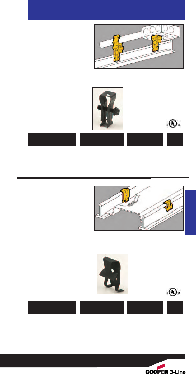
• Attaches to top of
acoustical T-Bar with
1/4"-20 screw.
• Has 1/4"-20 thread
impression for
attachment to box or
conduit fastener.
•Warning: Do not use
for hanging acoustical
tee.
Acoustical Tee
T-Bar Support
Fasteners
Acoustical Tee
781011 18090 BA14 T-Bar Support 100
Clip
UPC/Part
Number Description
Catalog
Number
Box
Qty.
• Gives positive support
for troffers and lay-in
fixtures.
•Complies with NEC
Article 410.16(C) for
fixtures supported by
suspended ceilings.
• Fits rectangular or
round head T-Bars.
• Commonly known as
“Hurricane Clip”.
Troffer Fasteners
781011 18095 BA15 For Straight Lip 100
or Upturned Lip
Fixtures
UPC/Part
Number Description
Catalog
Number
Box
Qty.
71
Read safety/installation instruction sheets in packages before use. These products are designed for positioning only. No load rating.
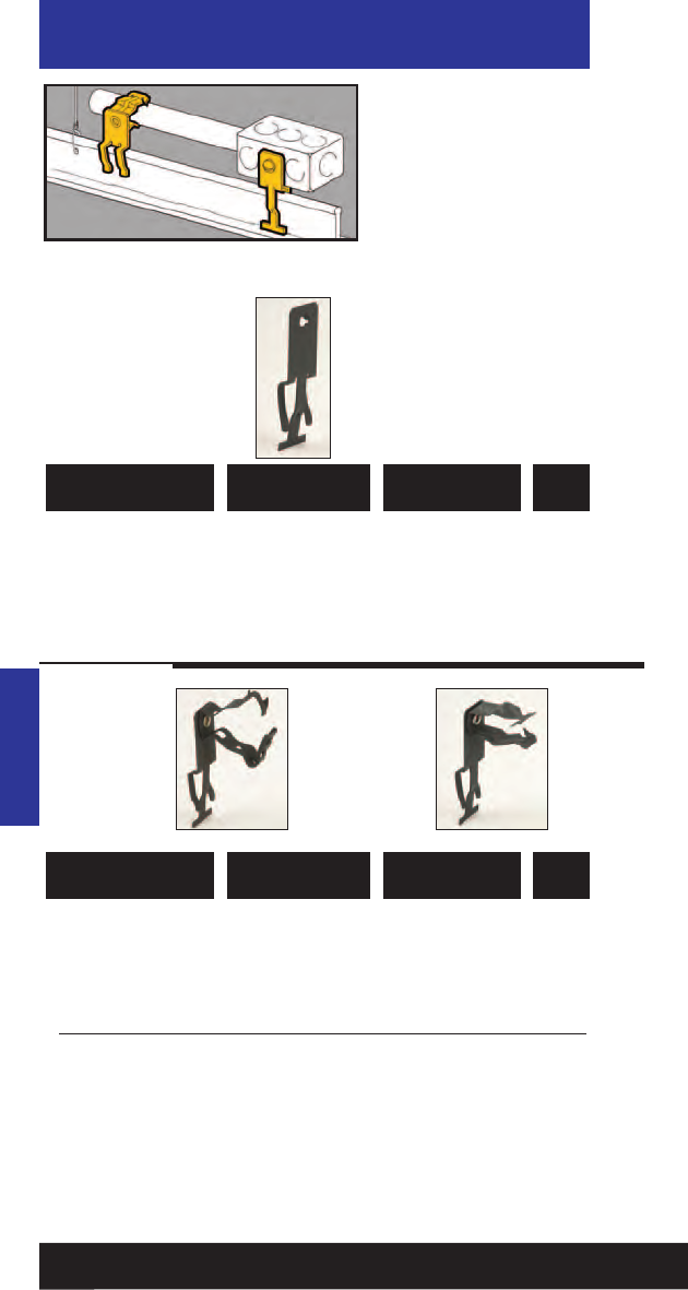
781011 18120 BA5-4T With 1/4”-20 100
Thread Impression
UPC/Part
Number Description
Catalog
Number
Box
Qty.
Acoustical Tee
Side Mount T-Bar
Fasteners
• A positive method for
supporting vertical
boxes, conduit or cable
above T-Bar.
• Allows conduit to clear
drop wires.
•Warning: Do not use
for hanging acoustical
tee.
Acoustical Tee
BA5-4T
781011 18410 BG-6-A5*3/8” 100
781011 18465 BG-8-12-A5 1/2”, 3/4”100
781011 18545 BG-16-A5 1” 100
Patent #4958792
781011 19235 BP-8-A5 1/2” EMT 100
781011 19335 BP-12-A5 3/4” EMT 100
1/2” IMC, Rigid
781011 19430 BP-16-A5 1” EMT 100
3/4” IMC, Rigid
*BG-6 will accept the following range ∅.420 - ∅.675:
14/2 thru 10/4 MC/AC cable and 5/16 or 3/8flexible conduit
UPC/Part
Number Conduit Size
Catalog
Number
Box
Qty.
BG
Series BP
Series
72
Read safety/installation instruction sheets in packages before use. These products are designed for positioning only. No load rating.
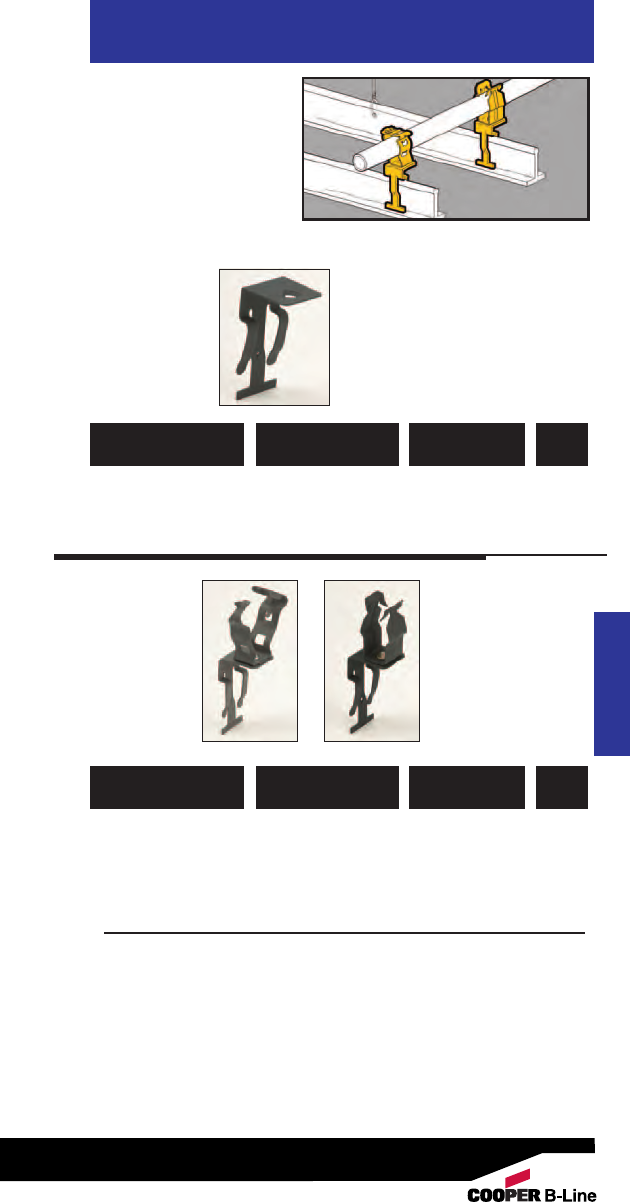
• A positive method for
supporting horizontal
boxes or conduit
above T-Bar.
• Allows conduit to
clear drop wires.
•Warning: Do not use
for hanging acoustical
tee.
Acoustical Tee
Top Mount T-Bar
Fasteners
Acoustical Tee
781011 18125 BA6-4T With 1/4”-20 100
Thread Impression
UPC/Part
Number Description
Catalog
Number
Box
Qty.
781011 88540 BG-6-A6*3/8” 100
781011 18470 BG-8-12-A6 1/2”, 3/4”100
781011 18550 BG-16-A6 1” 100
Patent #4958792
781011 19240 BP-8-A6 1/2” EMT 100
781011 19340 BP-12-A6 3/4” EMT 100
1/2” IMC, Rigid
781011 19435 BP-16-A6 1” EMT 100
3/4” IMC, Rigid
*BG-6 will accept the following range ∅.420 - ∅.675:
14/2 thru 10/4 MC/AC cable and 5/16 or 3/8flexible conduit
UPC/Part
Number Conduit Size
Catalog
Number
Box
Qty.
BG
Series BP
Series
73
Read safety/installation instruction sheets in packages before use. These products are designed for positioning only. No load rating.
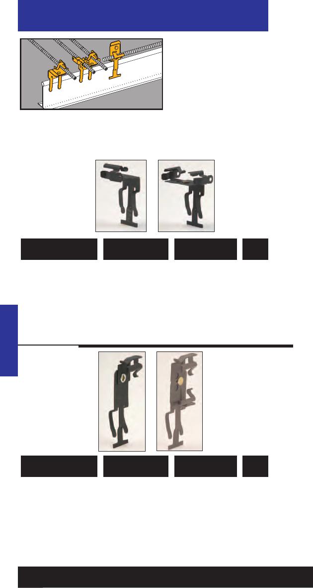
781011 01220 BX4-A6 Single Runs 100
781011 01216 BX4M-A6 Double Runs 100
Note: Fasteners will rotate 360°.
UPC/Part
Number Description
Catalog
Number
Box
Qty.
781011 01187 BX4-A5 Single Runs 100
781011 01212 BX4M-A5 Double Runs 100
Note: Fasteners will rotate 360°.
UPC/Part
Number Description
Catalog
Number
Box
Qty.
Acoustical Tee
Top Mount T-Bar
Fasteners
• A positive method for
supporting cable or
flexible conduit above
T-Bar.
• Assemblies support
MC, AC, sizes 14/2
through 10/3 or
3/8" FMC.
Acoustical Tee
BX4-A6 BX4M-A6
BX4-A5 BX4M-A5
74
Read safety/installation instruction sheets in packages before use. These products are designed for positioning only. No load rating.
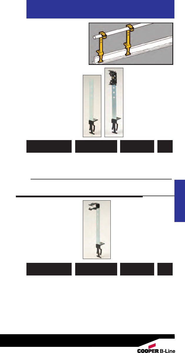
• Supports conduit and
electrical boxes above
T-Bar.
• Height adjusts from
41/4" to 71/4".
• Conduit fasteners can
be attached at 3/4"
increments.
• BX4M-A28 supports
cable or FMC above
T-Bar.
Acoustical Tee
Support
Fasteners
Acoustical Tee
781011 18115 BA28 1/2” Holes Allow 50
for Adjustment
Between 41/4” and 71/4”
ar 3/4” increments
781011 01211 BX4M-A28 Double Runs 25
MC, AC, or FMC
UPC/Part
Number Description
Catalog
Number
Box
Qty.
781011 19230 BP-8-A28 1/2” EMT 100
781011 19330 BP-12-A28 3/4” EMT 100
1/2” IMC, Rigid
781011 19425 BP-16-A28 1” EMT 100
3/4” IMC, Rigid
Note: Adjustable BP Conduit Fastener is attached with screw in 71/4"
top hole position.
UPC/Part
Number
Conduit
Size
Catalog
Number
Box
Qty.
BA28
BP-12-A28
BX4M-A28
75
Read safety/installation instruction sheets in packages before use. These products are designed for positioning only. No load rating.
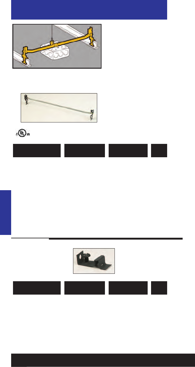
781011 18080 BA12 Box Hanger 50
24” Span
781011 18082 BA12-12 Box Hanger 50
12” Span
781011 18085 BA12-20 Box Hanger 50
20” Span
781011 18087 BA12-30 Box Hanger 50
30” Span
UPC/Part
Number Description
Catalog
Number
Box
Qty.
Acoustical Tee
Electrical Box
T-Bar Fasteners
• See BA50 for a stronger,
more cost-effective
solution.
• Supports octagonal
or square boxes.
• Allows for flush
mounting or 3/4" offset
for plaster ring.
• One BB27 box mounting
clip with screw included
with each hanger.
• Load Capacity: 20 lbs.
• For additional support,
attach dropwire to BB27
box mounting clip.
•Warning: Do not use
for hanging acoustical
tee.
Acoustical Tee
781011 18170 BB27 Box Mounting 50
Clip (with Screw)
781011 01673 SRHMS1/4x3/81/4”-20 x 3/8”50
Slotted Round
Head Machine
Screw
UPC/Part
Number Description
Catalog
Number
Box
Qty.
76
Read safety/installation instruction sheets in packages before use.
BA12-20
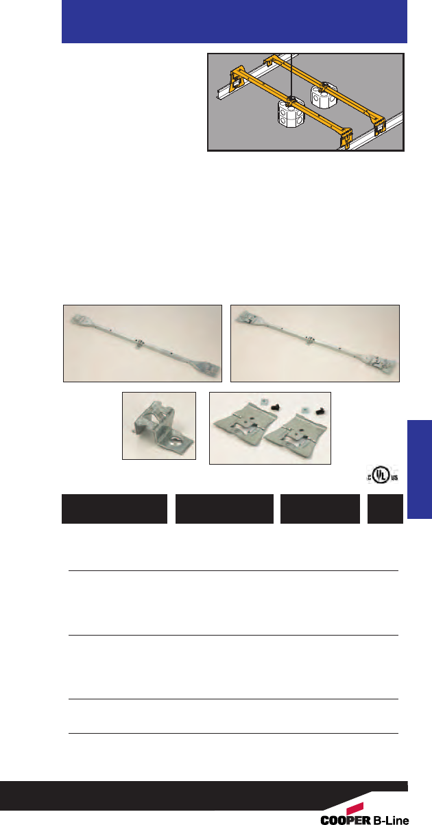
• Supports octagonal or
square boxes on 24”
span.
• Bendable ends mount
11/2” or 21/8” deep
boxes without tools.
• Self-centering feature
positions box on
center.
• Ultimate Static Load Capacity:
50 Lbs. (without dedicated dropwire)
•Static Load Capacity:
70 Lbs. (with dedicated dropwire)
35 Lbs. Canada
• Finish: Pre-galvanized
• See Ruff-IN™brochure for pre-fab box
assemblies.
Acoustical Tee
Heavy Duty
Electrical
Box Hanger
Acoustical Tee
781011 96490 BA50 Box Hanger 25
782051 35905 BA50CAN*Box Hanger 25
781011 96491 BA50D Box Hanger for 25
box with 11/2” extension
782051 35906 BA50DCAN*Box Hanger for 25
box with 11/2” extension
782051 36570 BA50C4T Box Mounting 25
Clip with Hardware
782051 36571 BA50C3T*Box Mounting 25
Clip with Hardware
781011 96489 BA50E Extender Brackets 10
with Hardware pair
* Canada Only
UPC/Part
Number Description
Catalog
Number
Box
Qty.
BA50C3T & BA50C4T BA50E
77
Read safety/installation instruction sheets in packages before use.
BA50 &
BA50CAN
BA50D &
BA50DCAN
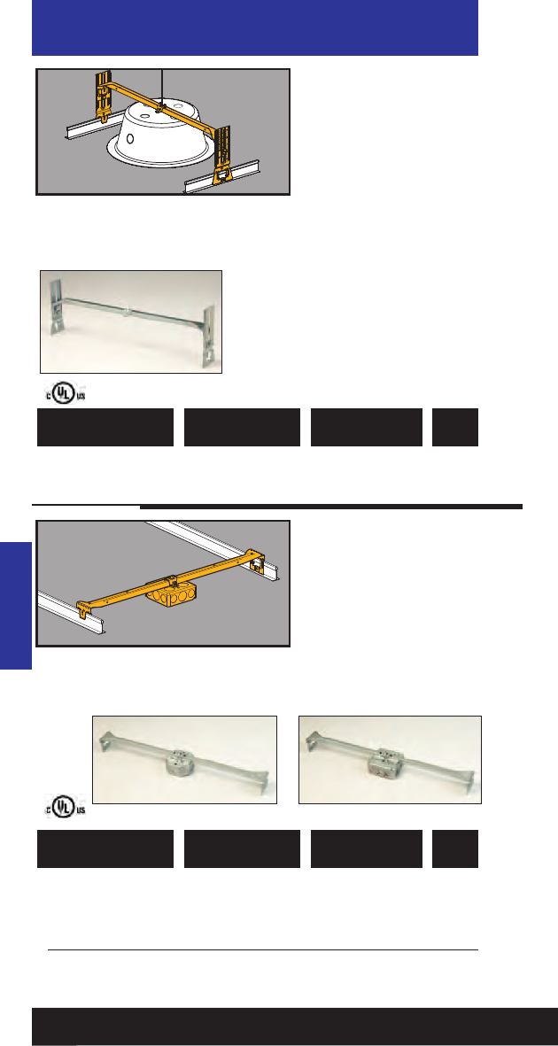
782051 18460 BA50A Adjustable Box 10
Hanger for T-Bar
UPC/Part
Number Description
Catalog
Number
Box
Qty.
Acoustical Tee
Adjustable Box
Support
• Adjustable box support
for suspended ceilings.
• Accomodates heights
from 11/2” to 83/4”.
• Integral ruler enables
height adjustments
without measuring.
• Ideal for installation of speaker
cases, emergency light fixtures,
etc. in suspended ceilings.
• Static Load Capacity:
25 Lbs. without dedicated
dropwire
70 Lbs. with dedicated dropwire
35 Lbs. (Canada) with dedicated
dropwire
• See Ruff-IN™brochure for
pre-fab box assemblies.
Acoustical Tee
782051 24855 BA50-OB-24 11/2” Deep Box 10
to T-Bar Fastener
782051 24856 BA50-OB-34 21/8” Deep Box 10
to T-Bar Fastener
782051 24857 BA50-SB-24 11/2” Deep Box 10
to T-Bar Fastener
UPC/Part
Number Description
Catalog
Number
Box
Qty.
Electrical Box
T-Bar Fasteners
• Pre-assembled T-Bar
fasteners speed
installation.
• Boxes have 1/2” and 3/4”
knockouts.
•Loading not to exceed
50 lbs. in U.S.A. without
independent support.
35 Lbs. in Canada
• 24” span
78
Read safety/installation instruction sheets in packages before use.
BA50-OB BA50-SB
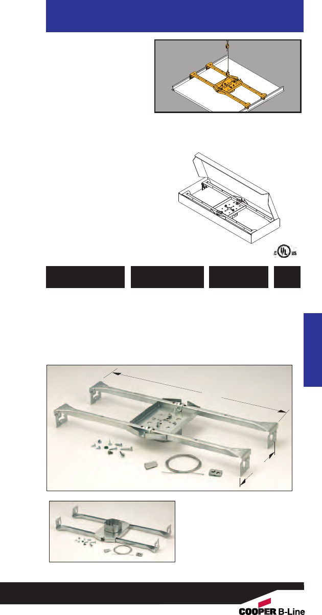
• Pre-assembled fan/
fixture hanger installs
on T-Bar in less than
30 seconds.
• Positions and secures
fans and fixtures in
suspended ceilings.
• Includes Kwik-Wire™
cable and clamps which
attach to mounting clips
for easy installation.
• Recommended for use in
seismic areas.
•UL Listed for fan support
up to 70 lbs. or fixture
support up to 90 lbs.
35 Lbs. Canada
• Finish: Pre-galvanized
Acoustical Tee
RediMount™
Fan Hanger
Acoustical Tee
781011 96492 BA50F Fan/Fixture 1
Hanger Includes
4” x 11/2” deep
Octagon Box
UPC/Part
Number Description
Catalog
Number
Box
Qty.
9.25”
24”
79
Read safety/installation instruction sheets in packages before use.
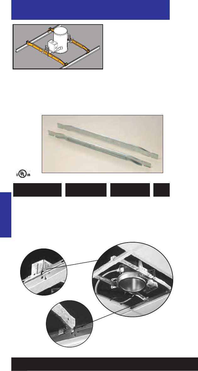
782051 99873 BA40 Fixture Bar 20 pair
UPC/Part
Number Description
Catalog
Number
Box
Qty.
Acoustical Tee
QuikFix™
Fastening System
•New QuikFix™ Fastening
System mounts spec
grade downlights 50%
faster than “wire bound”
installation methods.
•QuikFix™System is
pre-sized for 24" spacing.
•No tools required.
•Recommended for use in
seismic areas.
•UL listed for fixture
support up to 50 lbs.
Acoustical Tee
Patent # 6286265
•Innovative design features offset
bar hangers with integral locking
tabs that secure downlights to
T-Bar and prevent lifting or sliding.
80
Read safety/installation instruction sheets in packages before use.
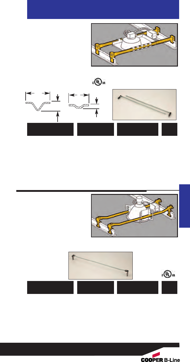
Acoustical Tee
Light Fixture
T-Bar Fasteners
Acoustical Tee
781011 18100 BA17 CAPRI1R-9X, R-10C 10
(Wide Bar) CAPR1R-10X sets
CAPR1PR-751CX
HALO®2 H7, HALO®2 H17
JUNO®3 AP, APT
JUNO®3 IC, ICT, J, SC, TC
THOMAS®4 RI-IC
781011 18105 BA18 CAPRI1HSG 10
(Narrow Bar) LIGHTOLIER®5 711 sets
UPC/Part
Number
“High Hat”
Fixtures
Catalog
Number
Box
Qty.
UPC/Part
Number
“High Hat”
Fixtures
Catalog
Number
Box
Qty.
BA17
1/4"
5/8"
BA18
1/8"
1/2"
• Adjustable span from
20" to 30".
• Fits horizontal and
vertical flanges.
• Fixture position is
adjustable.
• No center clips or
tools required.
• One set completes one
fixture installation
(four bars per set).
781011 18110 BA20 Fits LIGHTOLIER®5 10
CALCULITE®5 Series sets
Fixtures
1. CAPRI is a mark used by Thomas Industries, Inc., Louisville, KY.
2. HALO®is the registered trademark of Cooper Industries, Elk Grove, IL.
3. JUNO®is the registered trademark of JUNO Lighting, Inc., Morton Grove, IL.
4. THOMAS®
is the registered trademark of Thomas Industries, Inc., Louisville, KY.
5. LIGHTOLIER
®
and CALCULITE
®
are the registered trademarks of Lightolier, Inc.,
Secaucus, NJ.
•Fixture position is
adjustable within the
span of the hanger.
• Fixed span of 24
inches for T-Bar
applications.
• Requires only a
screwdriver to install.
• One set completes
one fixture
installation
(four bars
per set).
Light Fixture
T-Bar
Fasteners
81
Read safety/installation instruction sheets in packages before use.
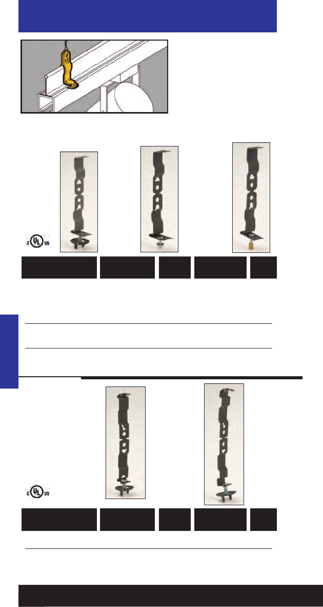
781011 18065 BA1 15/16”1/4”-20 x 5/8” 100
781011 18070 BA1-24 15/16”1/4”-20 x 11/2” 100
781011 18075 BA1-32 15/16”1/4”-20 x 2” 100
781011 02891 BA1-T 15/16”#8-32 x 5/8”100
with Pal Nut
781011 02897 BA1-T-BN 15/16” #8-32 x 5/8” 100
with with Brass Nut
UPC/Part
Number
T-Bar
Size
Stud
Size
Catalog
Number
Box
Qty.
UPC/Part
Number
T-Bar
Size
Stud
Size
Catalog
Number
Box
Qty.
Acoustical Tee
Suspension
Fasteners
• Allows for independent
suspension of fixtures.
• Fits most acoustical
T-Bars.
• BA-4-WN wing nut
included with all 1/4”-20
suspension hangers.
• Static Load Capacity:
65 Lbs.
Acoustical Tee
BA1-T
BA1 BA1-T-BN
782051 25585 BA1-9 9/16”1/4”-20 x 5/8” 100
782051 25587 BA1-95 9/16”1/4”-20 x 5/8” 100
& 15/16”
BA1-9 BA1-95
82
Read safety/installation instruction sheets in packages before use.
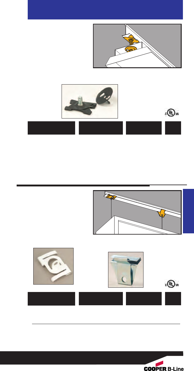
• Supports electrical
fixtures from standard
15/16” T-Bars.
• BA-4-WN wing nut
included.
•1/4”-20 stud available
in varying lengths.
• Static Load Capacity:
50 Lbs.
Acoustical Tee
T-Bar Scissor
Fasteners
Acoustical Tee
781011 04258 BAX-4-16 5/8” 100
781011 04262 BAX-4-16-24 11/2” 100
781011 04263 BAX-4-16-32 2” 100
781011 04264 BAX-4-16-48 3” 100
UPC/Part
Number Stud Length
Catalog
Number
Box
Qty.
•BA-4-16-H supports
signs from 15/16" T-Bar.
• BA-4-16-H1 supports
signs from 9/16" or
15/16" T-Bar.
• Static Load Capacity:
40 Lbs.
Sign Hangers
781011 18040 BA-4-16-H Sign Hanger 100
with White Finish
781011 04449 BA-4-16-H1 Sign Hanger 100
with Zinc Plated Finish
UPC/Part
Number Stud Length
Catalog
Number
Box
Qty.
BA-4-16-H BA-4-16-H1
83
Read safety/installation instruction sheets in packages before use.
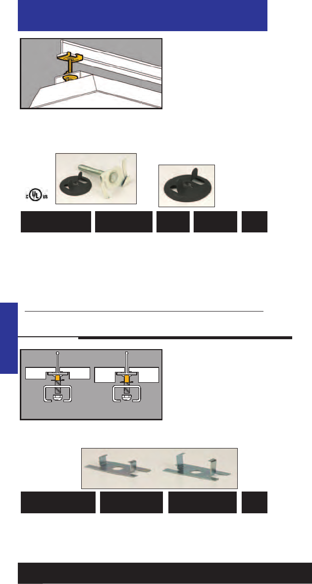
781011 18020 BA-4-16 Black 5/8” 100
781011 18055 BA-4-16-W White 5/8”100
781011 18025 BA-4-16-24 White 11/2” 100
781011 18030 BA-4-16-32 White 2” 100
781011 18035 BA-4-16-48 White 3” 100
781011 18060 BA-4-WN Black 100
UPC/Part
Number
Stud
Length
Catalog
Number Finish Box
Qty.
Acoustical Tee
15/16” Twist
Fasteners
• Supports electrical
fixtures from 15/16"
T-Bar.
•1/4"-20 stud available in
varying lengths.
• Includes BA-4-WN wing
nut with impression.
• Static Load Capacity:
BA4-16 Series = 50 lbs.
BA4-WN Series = 100
lbs.
Acoustical Tee
BA-4-WN
781011 95575 BA-21 1/4” Spacer 100
781011 99567 BA-21D 3/8” Spacer 100
UPC/Part
Number Description
Catalog
Number
Box
Qty.
T-Bar Spacers
• T-Bar spacer provides
flush mounting surface
for tegular tile
installations.
• Spacer must be used in
combination with
B-Line’s BA-4-16 or
BA-2-16 series fasteners.
•Finish: Zinc Plated
BA-21 BA-21D
84
Read safety/installation instruction sheets in packages before use.
BA-21 BA-21D
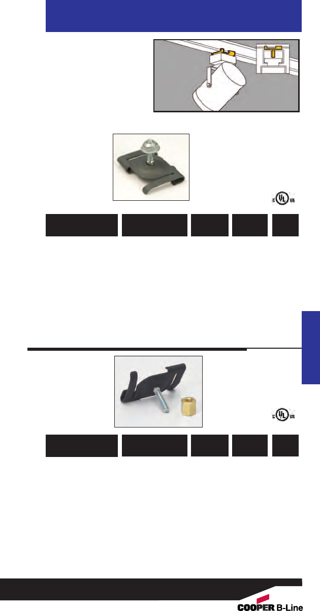
• Supports electrical
fixtures from 15/16"
T-Bar.
• #8-32 stud available
in varying lengths.
• Static Load Capacity:
25 Lbs.
Acoustical Tee
15/16” Twist
Fasteners
Acoustical Tee
781011 18000 BA-2-16
Black 5/8” 100
with Pal Nut
781011 04259 BA-2-16-7
Black 7/16” 100
with Pal Nut
781011 18010 BA-2-16-W
White 5/8” 100
with Pal Nut
781011 04261 BA-2-16-7-W
White 7/16”100
with Pal Nut
781011 18000 BA-2-16-BN
Black 5/8”100
with Brass Nut
781011 04260 BA-2-16-7-BN
Black 7/16” 100
with Brass Nut
781011 18015 BA-2-16-WBN
White 5/8” 100
with Brass Nut
781011 99566 BA-2-16-7-WBN
White 7/16” 100
with Brass Nut
UPC/Part
Number
Stud
Length
Catalog
Number Finish Box
Qty.
UPC/Part
Number
Stud
Length
Catalog
Number Finish Box
Qty.
85
Read safety/installation instruction sheets in packages before use.
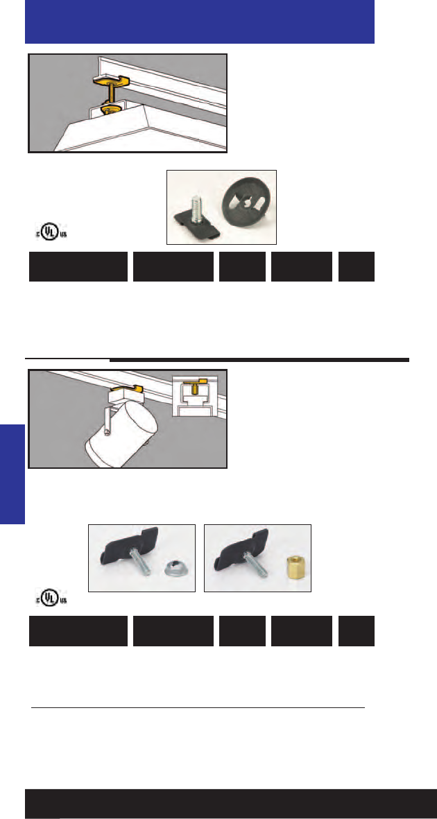
Acoustical Tee
9/16” Twist
Fasteners
• Supports electrical
fixtures from 9/16"
T-Bar.
• Stud size:
1/4"-20 x 5/8".
• Static Load Capacity:
40 Lbs.
Acoustical Tee
781011 03458 BA-4-9 Black 5/8” 100
781011 03461 BA-4-9-W White 5/8” 100
UPC/Part
Number
Stud
Length
Catalog
Number Finish Box
Qty.
9/16” Twist
Fasteners
781011 03467 BA-2-9
Black 5/8”100
781011 03466 BA-2-9-7
Black 7/16” 100
781011 03459 BA-2-9-W
White 5/8” 100
781011 03465 BA-2-9-BN
Black 5/8” 100
781011 03464 BA-2-9-7-BN
Black 7/16” 100
781011 03460 BA-2-9-WBN
White 5/8” 100
UPC/Part
Number
Stud
Length
Catalog
Number Finish Box
Qty.
BA-2-9-BN
Series
with Brass
Nut
BA-2-9
Series
with Pal
Nut
• Supports electrical
fixtures and track
lighting from 9/16"
T-Bar.
• Stud size:
#8-32 x length.
• Static Load Capacity:
25 Lbs.
86
Read safety/installation instruction sheets in packages before use.
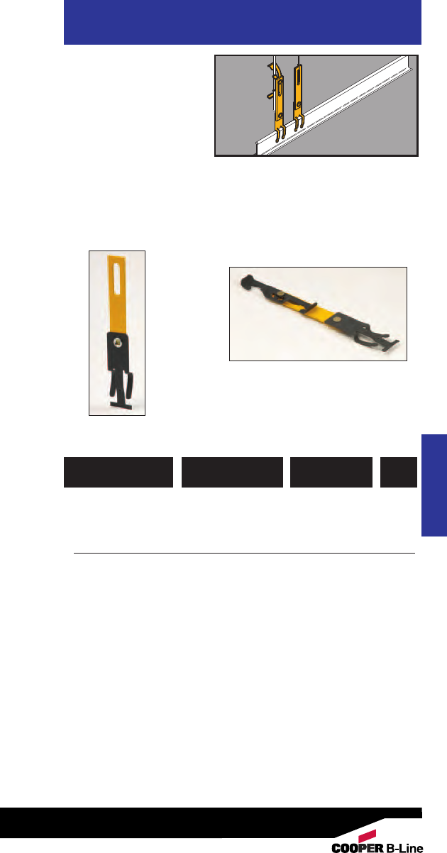
• Secures independent
support wires to
ceiling grid as required
by NEC Article 300.11.
• Slotted design permits
adjustment when
securing rods.
• Bright yellow color,
Per NEC 300.11 (A),
is easily identified by
inspectors.
Acoustical Tee
Drop Wire/Rod
Securing Clip
Acoustical Tee
781011 99569 BA311 #12 thru #8 100
Wire
781011 99570 BA311-W2 #12 thru 100
1/4” Plain or
Threaded Rod
781011 99571 BA311-W6 3/8” Plain or 100
Threaded Rod
UPC/Part
Number Description
Catalog
Number
Box
Qty.
BA-311
BA-311-W2 Shown
87
Read safety/installation instruction sheets in packages before use.

Acoustical Tee
Acoustical Tee
88
Read safety/installation instruction sheets in packages before use.
• BA-SFC Series provides seismic restraint for light fixtures
within a suspended ceiling.
• B-Line’s BA-SFC reduces labor by attaching light fixtures to
the T-bar frame and eliminating extra drop wires or chains.
• Provides positive attachment of fixtures to ceiling grid
members, in compliance with ICBO Acceptance Criteria
184 (AC 184).
•Satisfies NEC 410.16(C) which requires positive attachment
for secure fastening of luminaries.
•Load rating: 200 lbs.
782051 45911 BA-SFC Seismic Fixture Clamp 25 sets
attaches one (4 clamps
standard 2’ x 4’ light per set)
fixture to T-bar ceiling
782051 45912 BA-SFC-E * For attachment of two 25 sets
standard 2’ x 4’ light (4 clamps
fixtures end-to-end per set)
onto T-bar ceiling
782051 45913 BA-SFC-S * For attachment of two 25 sets
standard 2’ x 4’ light (4 clamps
fixtures side-by-side per set)
onto T-bar ceiling
782051 45914 BA-SFC-CF * For attachment of 50 sets
standard 2’ x 2’ light (2 clamps
fixtures onto T-bar per set)
782051 45915 BA-SFC-CFS Seismic Fixture Clamp 100 sets
for reinforcement (2 clamps
of main runner per set)
connection points
*BASFC is required to complete installation.
UPC/Part
Number Description
Catalog
Number
Box
Qty.
Seismic Fixture
Clamps
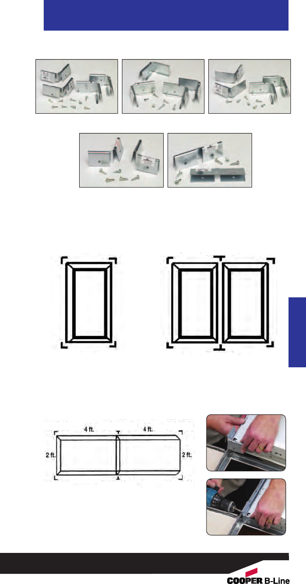
Acoustical Tee
Acoustical Tee
89
Read safety/installation instruction sheets in packages before use.
BA-SFC BA-SFC-E BA-SFC-S
BA-SFC-CF BA-SFC-CFS
Seismic Fixture Clamps cont.
Single Fixture
Installation Two Fixtures (Side by Side)
Two Fixtures (End to End)
Parts Required:
1 pc. BA-SFC Installation Kit
1 pc. BA-SFC-E Installation Kit
Parts Required:
1 pc. BA-SFC Installation Kit
1 pc. BA-SFC-S Installation Kit
Parts Required:
1 pc. BA-SFC Installation Kit
BA-SFC BA-SFC
BA-SFC BA-SFC
BA-SFC BA-SFC-S
BA-SFC BA-SFC-S
BA-SFC
BA-SFC BA-SFC
BA-SFC
BA-SFC-E
BA-SFC-E BA-SFC
BA-SFC
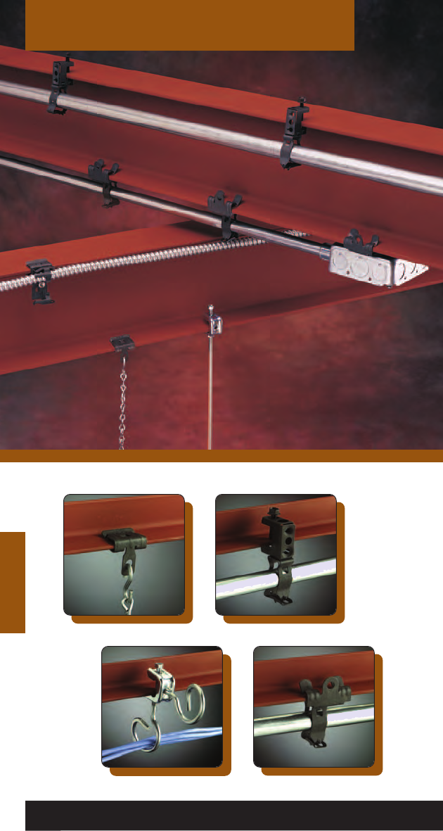
Beams
Beams
90
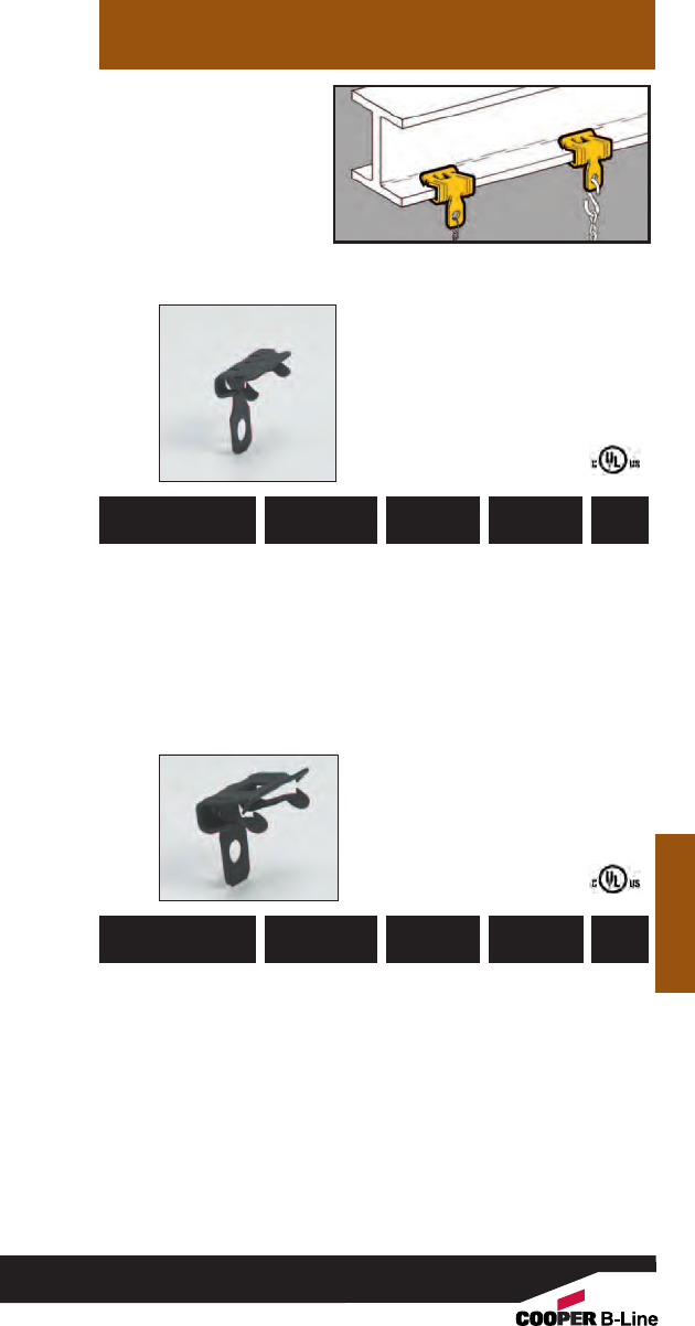
• Permits fast and easy
installation on bulb
tees and beams.
• Clearance hole for 1/4"
bolt in tab.
• Simply installed with a
hammer.
Beams
Flange Beam
Fasteners
Beams
781011 18290 BE-1-2
3/32” - 9/64” 160 lbs. 100
781011 18295 BE-2-4
1/8” - 1/4”200 lbs. 100
781011 18300 BE-5-8
5/16” - 1/2”200 lbs. 100
781011 18305 BE-9-12
9/16” - 3/4”200 lbs. 100
UPC/Part
Number
Static
Load Cap.
Catalog
Number
Flange
Thickness
Box
Qty.
UPC/Part
Number
Static
Load Cap.
Catalog
Number
Flange
Thickness
Box
Qty.
91
Read safety/installation instruction sheets in packages before use.
BE-2-4
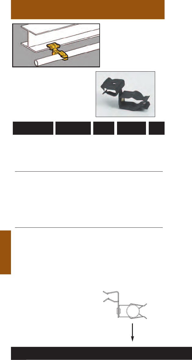
Beams
Push-Type
Conduit To Beam
Fasteners
• Quickly attaches
conduit to beams.
• Fasteners will rotate
360°.
• Simply installed with a
hammer.
Beams
781011 19275 BP-8-E-2-4 1/2” EMT 1/8” - 1/4” 100
781011 19280 BP-8-E-5-8 1/2” EMT 5/16” - 1/2” 100
781011 19285 BP-8-E-9-12 1/2” EMT 9/16” - 3/4” 100
781011 19375 BP-12-E-2-4 3/4” EMT 1/8” - 1/4” 100
1/2” IMC, Rigid
781011 19380 BP-12-E-5-8 3/4” EMT 5/16” - 1/2” 100
1/2” IMC, Rigid
781011 19385 BP-12-E-9-123/4” EMT 9/16” - 3/4” 100
1/2” IMC, Rigid
781011 19465 BP-16-E-2-4 1” EMT 1/8” - 1/4” 100
3/4” IMC, Rigid
781011 19470 BP-16-E-5-8 1” EMT 5/16” - 1/2” 100
3/4” IMC, Rigid
781011 19475 BP-16-E-9-12 1” EMT 9/16” - 3/4” 100
3/4” IMC, Rigid
UPC/Part
Number
Flange
Thickness
Catalog
Number
Conduit
Size
Box
Qty.
15 Lbs.
Ultimate
Static Load
Capacity
92
Read safety/installation instruction sheets in packages before use.
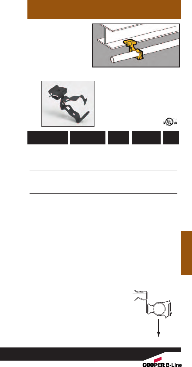
• Unique Guide-Rite
Fastener provides for
fast and easy
installation.
•Fasteners will rotate
360°.
• Simply installed with a
hammer and pliers.
Beams
Guide-Rite™
Conduit To Beam
Fasteners
Beams
Static Load
Capacity
25 Lbs.
*BG-6 will accept the following
range ∅.420 - ∅.675:
14/2 thru 10/4 MC/AC cable
and 5/16 or 3/8flexible conduit
781011 18430 BG-6-E-2-4
*
3/8”1/8” - 1/4”100
781011 18435 BG-6-E-5-8
*
3/8”5/16” - 1/2” 100
781011 18440 BG-6-E-9-12
*
3/8”9/16” - 3/4” 100
781011 18505 BG-8-12-E-2-4 1/2”, 3/4”1/8” - 1/4” 100
781011 18510 BG-8-12-E-5-8 1/2”, 3/4”5/16” - 1/2” 100
781011 18515 BG-8-12-E-9-12 1/2”, 3/4”9/16” - 3/4” 100
781011 18575 BG-16-E-2-4 1” 1/8” - 1/4” 100
781011 18580 BG-16-E-5-8 1” 5/16” - 1/2” 100
781011 18585 BG-16-E-9-12 1” 9/16” - 3/4”100
781011 18660 BG-20-E-2-4 11/4”1/8” - 1/4” 100
781011 18665 BG-20-E-5-8 11/4”5/16” - 1/2” 100
781011 18670 BG-20-E-9-12 11/4”9/16” - 3/4” 100
781011 18705 BG-24-E-2-4 11/2”1/8” - 1/4”50
781011 18710 BG-24-E-5-8 11/2”5/16” - 1/2”50
781011 18715 BG-24-E-9-12 11/2”9/16” - 3/4”50
781011 18745 BG-32-E-2-4 2” 1/8” - 1/4”50
781011 18750 BG-32-E-5-8 2” 5/16” - 1/2”50
781011 18755 BG-32-E-9-12 2” 9/16” - 3/4”50
Patent #4958792
UPC/Part
Number
Flange
Thickness
Catalog
Number
Conduit
Size
Box
Qty.
93
Read safety/installation instruction sheets in packages before use.
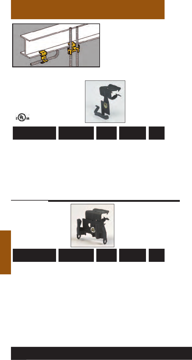
Beams
Cable To Beam
Fasteners
• Attaches MC, AC, sizes
14/2 through 10/3 or
3/8" FMC to beam
flanges 1/8" to 3/4"
thick.
• Fasteners will rotate
360°.
• Simply installed with a
hammer.
Beams
781011 01192 BX4-E-2-4 Single 1/8” - 1/4” 100
781011 01193 BX4-E-5-8 Single 5/16” - 1/2” 100
781011 01194 BX4-E-9-12 Single 9/16” - 3/4” 100
781011 01213 BX4M-E-2-4 Double 1/8” - 1/4” 100
781011 01214 BX4M-E-5-8 Double 5/16” - 1/2”100
781011 01215 BX4M-E-9-12 Double 9/16” - 3/4”100
UPC/Part
Number
Flange
Thickness
Catalog
Number
Type of
Runs
Box
Qty.
UPC/Part
Number
Flange
Thickness
Catalog
Number
Type of
Runs
Box
Qty.
94
Read safety/installation instruction sheets in packages before use. These products are designed for positioning only. No load rating.
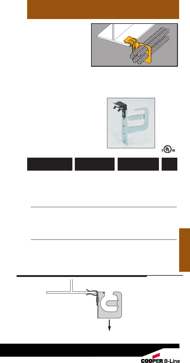
• Secures and supports
MC/AC cables as
required by the NEC.
• Effectively organizes
cables and eliminates
derating issues.
• BRC5-1 secures up to
four (4) runs of .430 to
.560 diameter cable.
• BRC5-2 secures up to
nine (9) runs of .430 to
.560 diameter cable.
• BRC5-3 secures up to
seven (7) runs of .560
to .690 diameter cable.
• Load Capacity: 50 lbs.
Beams
MC/AC Cable
Carrier to Beam
Fastener
Beams
782051 44093 BRC51-E12 3/32” - 9/64” 25
782051 44096 BRC51-E24 1/8” - 1/4” 25
782051 44099 BRC51-E58 5/16” - 1/2” 25
782051 44102 BRC51-E912 9/16” - 3/4” 25
782051 44094 BRC52-E12 3/32” - 9/64”25
782051 44097 BRC52-E24 1/8” - 1/4”25
782051 44100 BRC52-E58 5/16” - 1/2”25
782051 44103 BRC52-E912 9/16” - 3/4”25
782051 44095 BRC53-E12 3/32” - 9/64” 25
782051 44098 BRC53-E24 1/8” - 1/4” 25
782051 44101 BRC53-E58 5/16” - 1/2” 25
782051 44104 BRC53-E912 9/16” - 3/4” 25
UPC/Part
Number
Flange
Thickness
Catalog
Number
Box
Qty.
50 Lbs.
Static
Load
Capacity
95
Read safety/installation instruction sheets in packages before use.
BRC5-2-E24
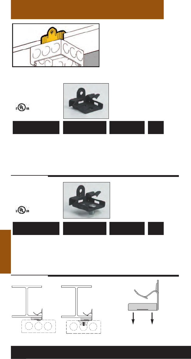
Beams
Universal Beam
Fasteners
• Suspend boxes or
fixtures from beam
flanges 1/8" to 3/4"
thick.
• Provided with 1/4"-20
thread impression for
quick and secure
attachment.
• Simply installed with a
hammer.
Beams
781011 19600 BU-2-4 1/8” - 1/4” 100
781011 19605 BU-5-8 5/16” - 1/2” 100
781011 19610 BU-9-12 9/16” - 3/4” 100
781011 19615 BU-2-4-S 1/8” - 1/4” 100
781011 19620 BU-5-8-S 5/16” - 1/2”100
781011 19625 BU-9-12-S 9/16” - 3/4” 100
UPC/Part
Number
Flange
Thickness
Catalog
Number
Box
Qty.
UPC/Part
Number
Flange
Thickness
Catalog
Number
Box
Qty.
1/4”-20 x 3/8”
Staked Stud
75 Lbs. 100 Lbs.
Static
Load
Capacity
96
Read safety/installation instruction sheets in packages before use. These products are designed for positioning only. No load rating.
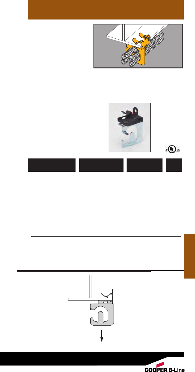
• Secures and supports
MC/AC cables as
required by the NEC.
• Effectively organizes
cables and eliminates
derating issues.
• BRC5-1 secures up to
four (4) runs of .430 to
.560 diameter cable.
• BRC5-2 secures up to
nine (9) runs of .430 to
.560 diameter cable.
• BRC5-3 secures up to
seven (7) runs of .560
to .690 diameter cable.
• Load Capacity: 50 lbs.
Beams
MC/AC Cable
Carrier to Beam
Fastener
Beams
782051 44066 BRC51-U24 1/8” - 1/4” 25
782051 44069 BRC51-U58 5/16” - 1/2” 25
782051 44072 BRC51-U912 9/16” - 3/4” 25
782051 44067 BRC52-U24 1/8” - 1/4”25
782051 44070 BRC52-U58 5/16” - 1/2”25
782051 44073 BRC52-U912 9/16” - 3/4”25
782051 44068 BRC53-U24 1/8” - 1/4” 25
782051 44071 BRC53-U58 5/16” - 1/2” 25
782051 44074 BRC53-U912 9/16” - 3/4” 25
UPC/Part
Number
Flange
Thickness
Catalog
Number
Box
Qty.
75 Lbs.
Static
Load
Capacity
97
Read safety/installation instruction sheets in packages before use.
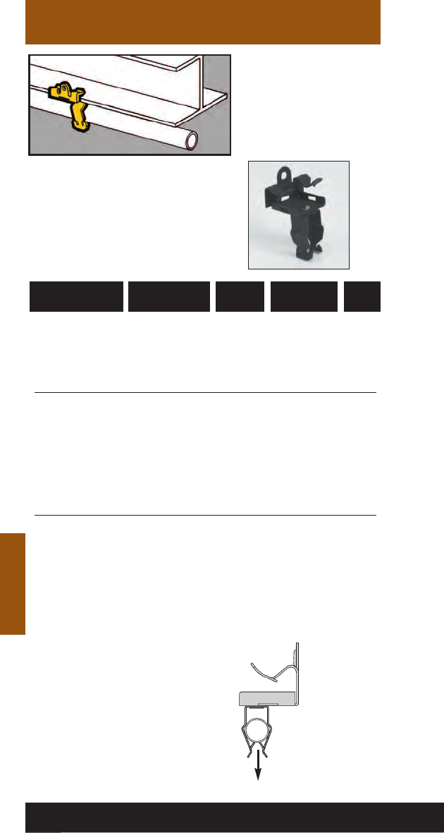
Beams
Beams
Push-Type
Conduit To Beam
Fasteners
• Quickly attaches
conduit to beams.
• Fasteners will rotate
360°.
• Simply installed with a
hammer.
781011 19310 BP-8-U-2-4 1/2” EMT 1/8” - 1/4” 100
781011 19315 BP-8-U-5-8 1/2” EMT 5/16” - 1/2” 100
781011 19320 BP-8-U-9-12 1/2” EMT 9/16” - 3/4” 100
781011 19405 BP-12-U-2-4 3/4” EMT 1/8” - 1/4” 100
1/2” IMC, Rigid
781011 19410 BP-12-U-5-8 3/4” EMT 5/16” - 1/2” 100
1/2” IMC, Rigid
781011 19415 BP-12-U-9-123/4” EMT 9/16” - 3/4” 100
1/2” IMC, Rigid
781011 19490 BP-16-U-2-4 1” EMT 1/8” - 1/4” 100
3/4” IMC, Rigid
781011 19495 BP-16-U-5-8 1” EMT 5/16” - 1/2” 100
3/4” IMC, Rigid
781011 19500 BP-16-U-9-12 1” EMT 9/16” - 3/4” 100
3/4” IMC, Rigid
UPC/Part
Number
Flange
Thickness
Catalog
Number
Conduit
Size
Box
Qty.
Ultimate
Static Load
Capacity
25 Lbs.
98
Read safety/installation instruction sheets in packages before use. These products are designed for positioning only. No load rating.
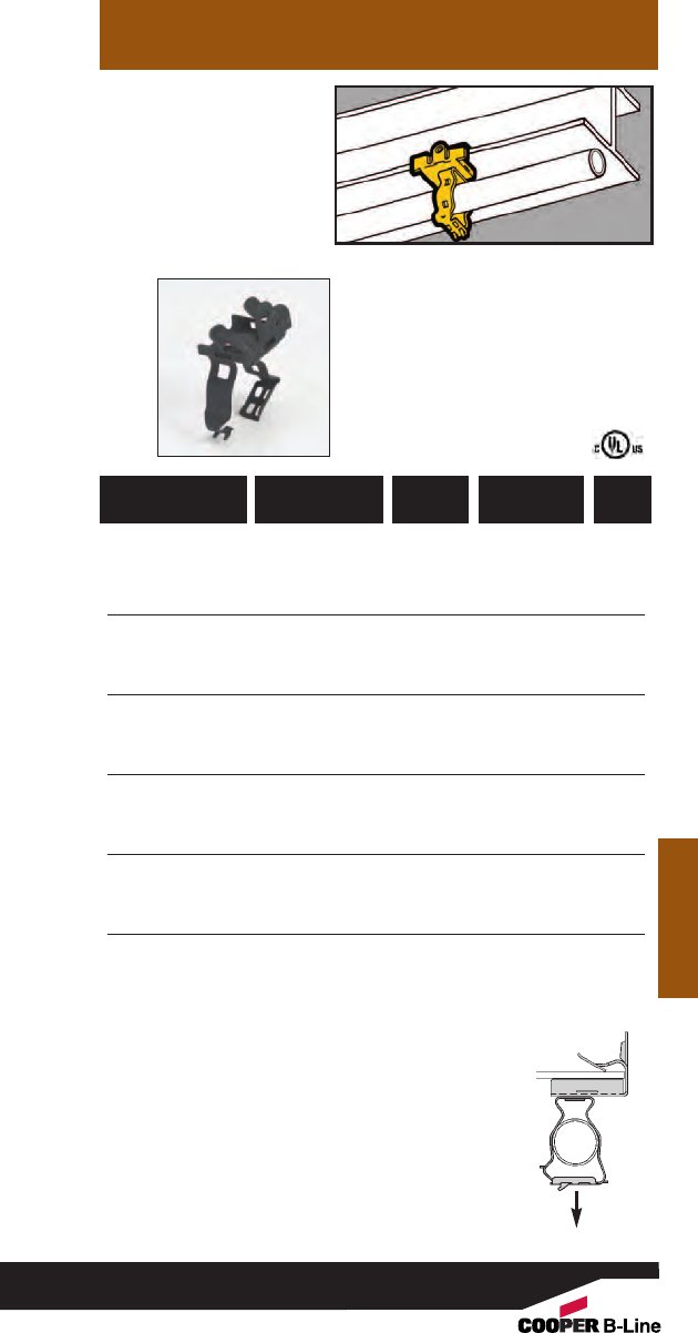
Beams
Beams
• Unique Guide-Rite
Fastener provides for
fast and easy
installation.
•Fasteners will rotate
360°.
• Simply installed with a
hammer and pliers.
Guide-Rite™
Conduit To Beam
Fasteners
Static Load
Capacity
75 Lbs.
*BG-6 will accept the following
range ∅.420 - ∅.675:
14/2 thru 10/4 MC/AC cable
and 5/16 or 3/8flexible conduit
781011 18450 BG-6-U-2-4
*
3/8”1/8” - 1/4” 100
781011 18455 BG-6-U-5-8
*
3/8”5/16” - 1/2”100
781011 18460 BG-6-U-9-12
*
3/8”9/16” - 3/4” 100
781011 18525 BG-8-12-U-2-4 1/2”, 3/4”1/8” - 1/4” 100
781011 18530 BG-8-12-U-5-8 1/2”, 3/4”5/16” - 1/2”100
781011 18535 BG-8-12-U-9-12 1/2”, 3/4”9/16” - 3/4” 100
781011 18625 BG-16-U-2-4 1” 1/8” - 1/4” 100
781011 18630 BG-16-U-5-8 1” 5/16” - 1/2”100
781011 18635 BG-16-U-9-12 1” 9/16” - 3/4” 100
781011 18680 BG-20-U-2-4 11/4”1/8” - 1/4” 100
781011 18685 BG-20-U-5-8 11/4”5/16” - 1/2”100
781011 18690 BG-20-U-9-12 11/4”9/16” - 3/4” 100
781011 18720 BG-24-U-2-4 11/2”1/8” - 1/4”50
781011 18725 BG-24-U-5-8 11/2”5/16” - 1/2”50
781011 18730 BG-24-U-9-12 11/2”9/16” - 3/4”50
781011 18760 BG-32-U-2-4 2” 1/8” - 1/4”50
781011 18765 BG-32-U-5-8 2” 5/16” - 1/2”50
781011 18770 BG-32-U-9-12 2” 9/16” - 3/4”50
Patent #4958792
UPC/Part
Number
Flange
Thickness
Catalog
Number
Conduit
Size
Box
Qty.
99
Read safety/installation instruction sheets in packages before use.
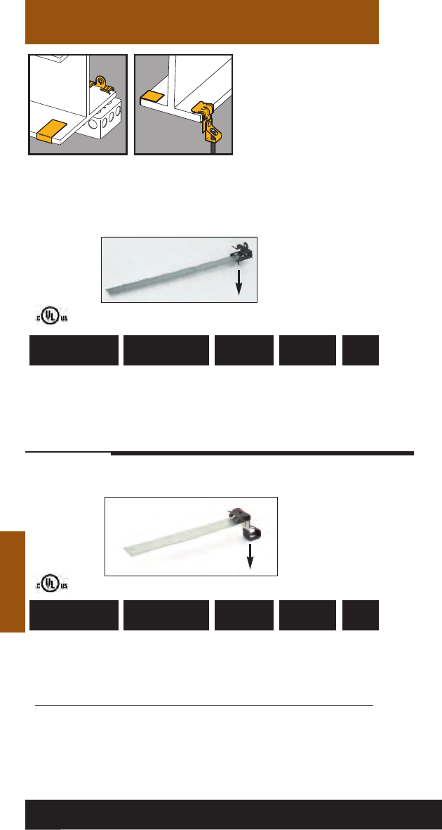
Beams
Beams
• Anchor strap provides
secure attachment to
beam flanges.
• Suspends threaded rod
from beam flanges.
• 8” anchor straps are
provided for 1/8" to
1/4" thick flanges.
• 13” anchor straps are
provided for 5/16" to
3/4" thick flanges.
781011 04942 BU-2-4-S-AS 1/4”-20 x 3/8”1/8” - 1/4”50
781011 04943 BU-5-8-S-AS 1/4”-20 x 3/8”5/16” - 1/2”50
781011 04944 BU-9-12-S-AS 1/4”-20 x 3/8”9/16” - 3/4”50
UPC/Part
Number
Flange
Thicknes
s
Catalog
Number
Stud
Size
Box
Qty.
Flange
Thickness
Box
Qty.
Beam Fasteners
With Anchor
Straps
Static Load
Capacity
781011 04948 BH4-E-2-4-AS 1/4”-20 1/8” - 1/4”50
781011 04949 BH4-E-5-8-AS 1/4”-20 5/16” - 1/2”50
781011 04950 BH4-E-9-12-AS 1/4”-20 9/16” - 3/4”50
781011 04951 BH6-E-2-4-AS 3/8”-16 1/8” - 1/4”50
781011 04952 BH6-E-5-8-AS 3/8”-16 5/16” - 1/2”50
781011 04953 BH6-E-9-12-AS 3/8”-16 9/16” - 3/4”50
UPC/Part
Number
Catalog
Number
Threaded
Rod Size
Static Load
Capacity
100
Read safety/installation instruction sheets in packages before use.
160 Lbs.
75 Lbs.
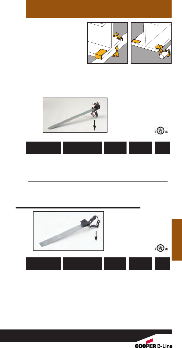
Beams
• Anchor strap provides
secure attachment to
beam flanges.
• Unique Guide-Rite™
Fastener provides for
fast and easy
installation.
• 8” anchor straps are
provided for 1/8" to 1/4"
thick flanges.
• 13” anchor straps are
provided for 5/16" to 3/4"
thick flanges.
Conduit To Beam
Fasteners With
Anchor Straps
781011 04966 BG-8-12-U-2-4-AS 1/2”, 3/4”1/8” - 1/4”50
781011 04967 BG-8-12-U-5-8-AS 1/2”, 3/4”5/16” - 1/2”50
781011 04968 BG-8-12-U-9-12-AS 1/2”, 3/4”9/16” - 3/4”50
781011 04969 BG-16-U-2-4-AS 1” 1/8” - 1/4”50
781011 04970 BG-16-U-5-8-AS 1” 5/16” - 1/2”50
781011 04971 BG-16-U-9-12-AS 1” 9/16” - 3/4”50
UPC/Part
Number
Flange
Thickness
Catalog
Number
Conduit
Size
Box
Qty.
Flange
Thickness
Box
Qty.
Static Load
Capacity
781011 04972 BG-8-12-E-2-4-AS 1/2”, 3/4”
1/8” - 1/4”50
781011 04973 BG-8-12-E-5-8-AS 1/2”, 3/4”
5/16” - 1/2”50
781011 04974 BG-8-12-E-9-12-AS 1/2”, 3/4”
9/16” - 3/4”50
781011 04975 BG-16-E-2-4-AS 1”
1/8” - 1/4”50
781011 04976 BG-16-E-5-8-AS 1”
5/16” - 1/2”50
781011 04977 BG-16-E-9-12-AS 1”
9/16” - 3/4”50
UPC/Part
Number
Catalog
Number
Conduit
Size
25 Lbs.
Static Load
Capacity
Beams
101
Read safety/installation instruction sheets in packages before use.
75 Lbs.
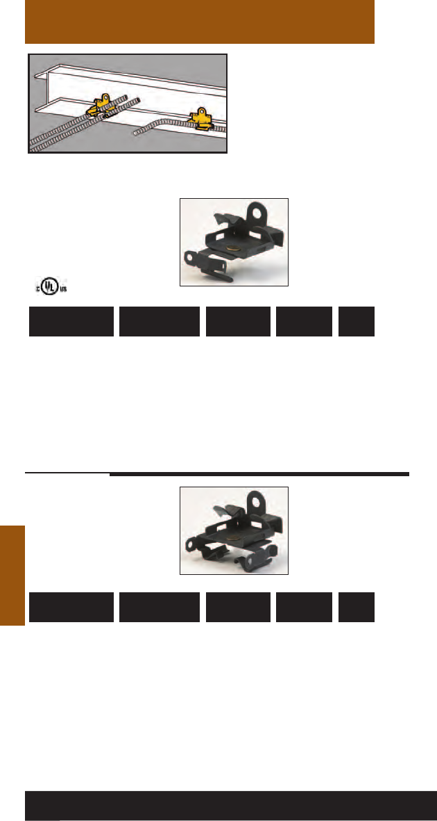
Beams
Beams
• Attaches MC, AC, sizes
14/2 through 10/3 or
3/8" FMC to flanges
1/8" to 3/4" thick.
• Fasteners will rotate
360°.
781011 01197 BX4-U-2-4 Single Runs 1/8” - 1/4”100
781011 01198 BX4-U-5-8 Single Runs 5/16” - 1/2” 100
781011 01199 BX4-U-9-12 Single Runs 9/16” - 3/4” 100
781011 01206 BX4M-U-2-4 Double Runs 1/8” - 1/4”100
781011 01207 BX4M-U-5-8 Double Runs 5/16” - 1/2” 100
781011 01208 BX4M-U-9-12 Double Runs 9/16” - 3/4”100
UPC/Part
Number
Flange
Thickness
Catalog
Number
Description
Box
Qty.
UPC/Part
Number
Flange
Thickness
Catalog
Number
Description
Box
Qty.
Cable To Beam
Fasteners
102
Read safety/installation instruction sheets in packages before use.
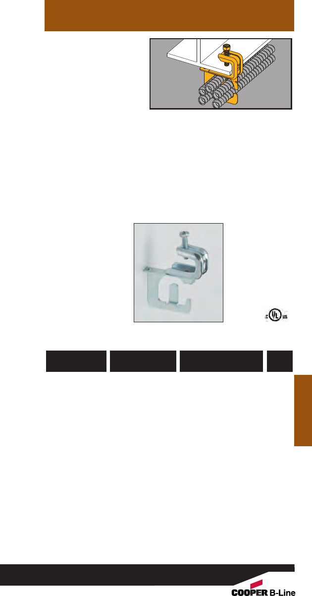
• Secures and supports
MC/AC cables as
required by the NEC.
• Effectively organizes
cables and eliminates
derating issues.
• Fits beam flanges
from 1/8” thru 5/8” thick.
• Load Capacity: 50 lbs.
Beams
MC/AC Cable
Carrier to
Beam Fastener
Beams
782051 44087 BRC51-C442
.430” to .560”
25
Up to 4 Runs
782051 44088 BRC52-C442
.430” to .560”
25
Up to 9 Runs
782051 44089 BRC53-C442
.560” to .690”
25
Up to 7 Runs
UPC/Part
Number
Catalog
Number
Cable Diameter &
Number Of Runs
Box
Qty.
103
Read safety/installation instruction sheets in packages before use.
BRC5-1-C442
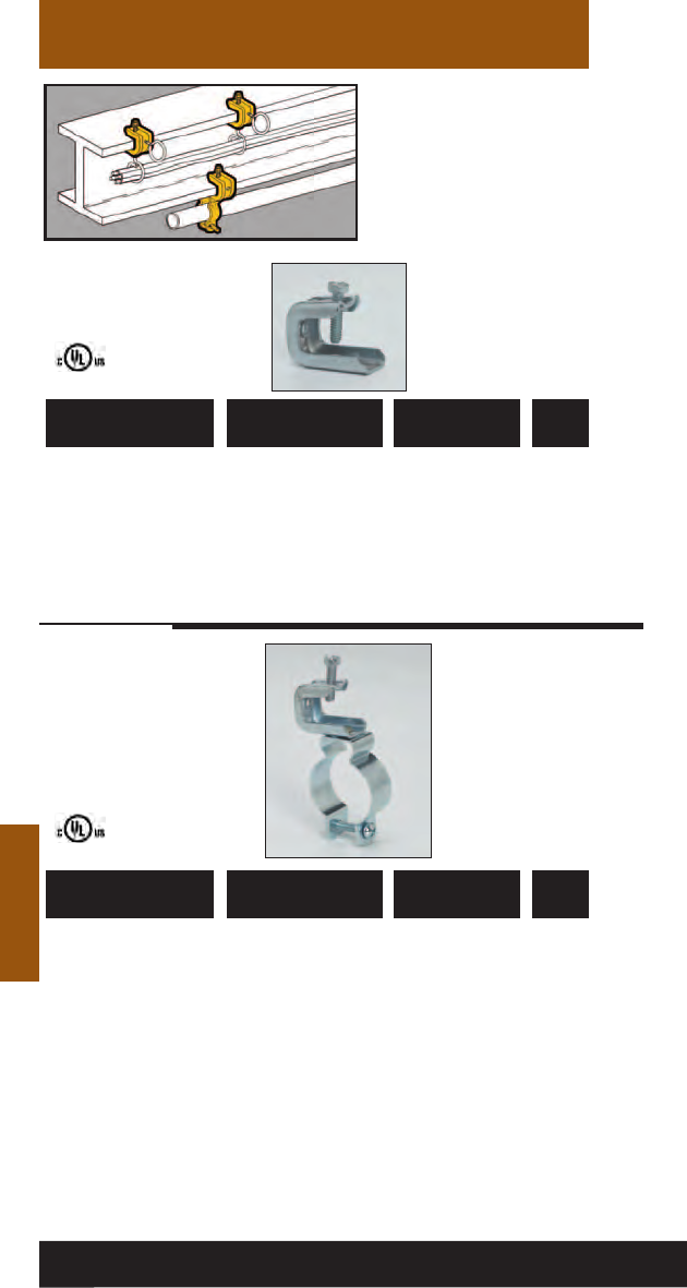
Beams
• BC442 fits beam
flanges 1/8" to 5/8".
BC442-6 fits beam
flanges up to 3/4".
• Finish: Zinc Plated
• Static Load Capacity:
BC442 = 100 Lbs.
BC442-6 = 200 Lbs.
Beam
Fasteners
Beams
781011 18278 BC442 Accepts 1/4”-20 50
Threaded Rod or
1/4”-20 Threaded
Bridle Rings
781011 04283 BC442-6 Accepts 3/8”-16 25
Threaded Rod
UPC/Part
Number Description
Catalog
Number
Box
Qty.
781011 19850 BL1400-C442 1/2” 1/2”50
781011 19851 BL1410-C442 3/4”3/4”50
781011 19852 BL1420-C442 1” 1” 50
781011 19853 BL1425-C442 -- 11/4”50
781011 19854 BL1430-C442 11/4”1
1/2”50
781011 19855 BL1440-C442 11/2” -- 25
781011 19856 BL1450-C442 2” 2” 25
UPC/Part
Number
Conduit Size
Rigid EMT
Catalog
Number
Box
Qty.
104
Read safety/installation instruction sheets in packages before use. These products are designed for positioning only. No load rating.
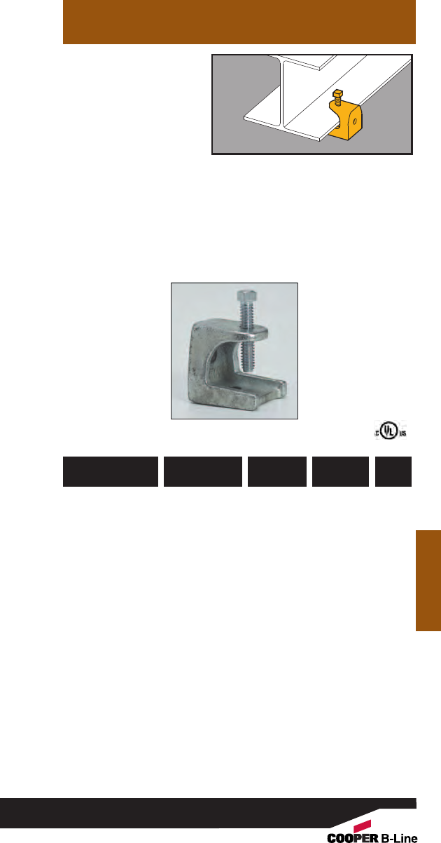
• Can be used with
1/4"-20 and 3/8"-16
threaded rod or bridle
rings.
• Fits beam flanges
through 1/2” thick.
• Safety Factor of 5.
• Finish: Zinc-Plated
Beams
Beam
Fasteners
Beams
781011 55333 B444-1/41/4”-20 150 lbs. 50
781011 55338 B444-5/16 5/16”-18 150 lbs. 50
781011 55343 B444-3/83/8”-16 350 lbs. 25
UPC/Part
Number
Static
Load Cap.
Catalog
Number
Rod
Size
Box
Qty.
105
Read safety/installation instruction sheets in packages before use.
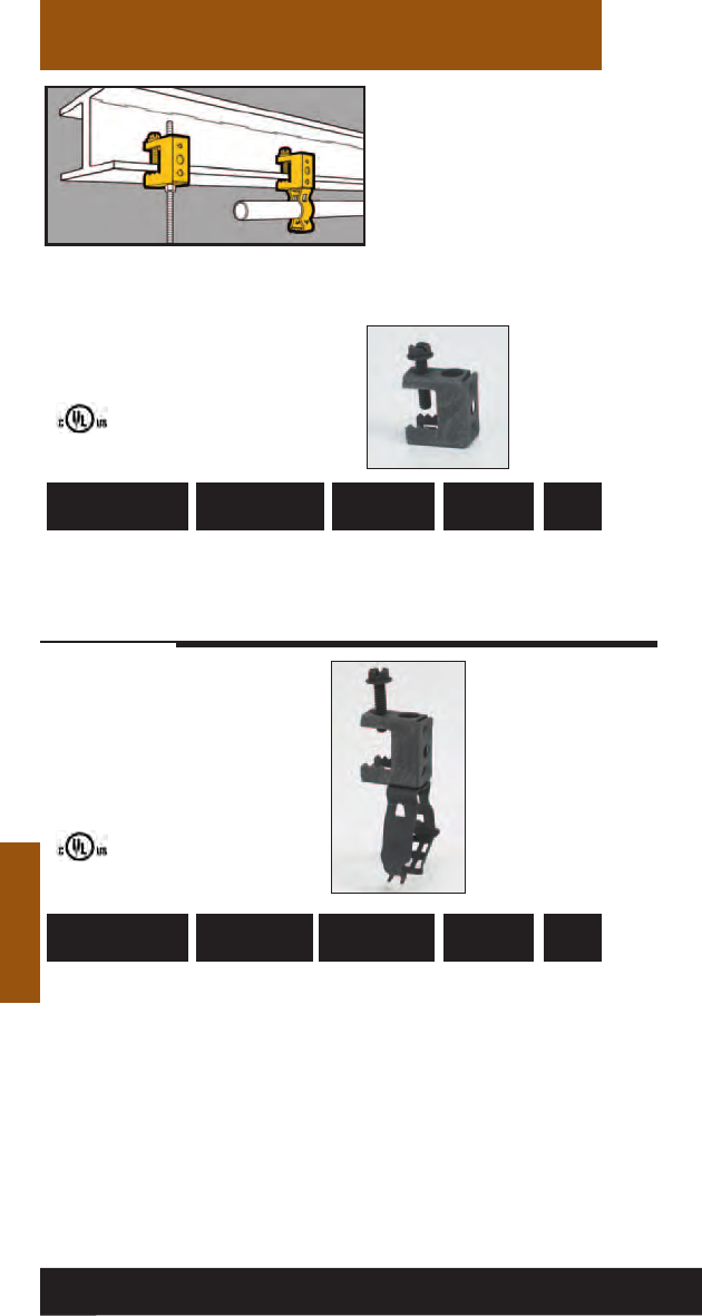
Beams
Beams
781011 18275 BC1
Thru 1/2” 100 Lbs. 100
UPC/Part
Number
Static
Load Cap.
Catalog
Number
Flange
Thickness
Box
Qty.
781011 18490 BG-8-12-C2 1/2”, 3/4” 100 Lbs. 100
781011 18570 BG-16-C2 1” 100 Lbs. 100
781011 18655 BG-20-C2 11/4”100 Lbs. 100
781011 18700 BG-24-C2 11/2” 100 Lbs. 100
781011 18740 BG-32-C2 2” 100 Lbs. 100
UPC/Part
Number
Static
Load Cap.
Catalog
Number
Conduit Size
EMT & Rigid
Box
Qty.
Guide-Rite™
Fastener
• Fits beam flanges thru
1/2" thick.
• Accepts "S" hooks, 1/4"
and 3/8" threaded rod,
1/4"-20 or #10-24
threaded bridle rings.
• Supports conduit and
electrical boxes.
Conduit To Beam
Fasteners
106
Read safety/installation instruction sheets in packages before use.
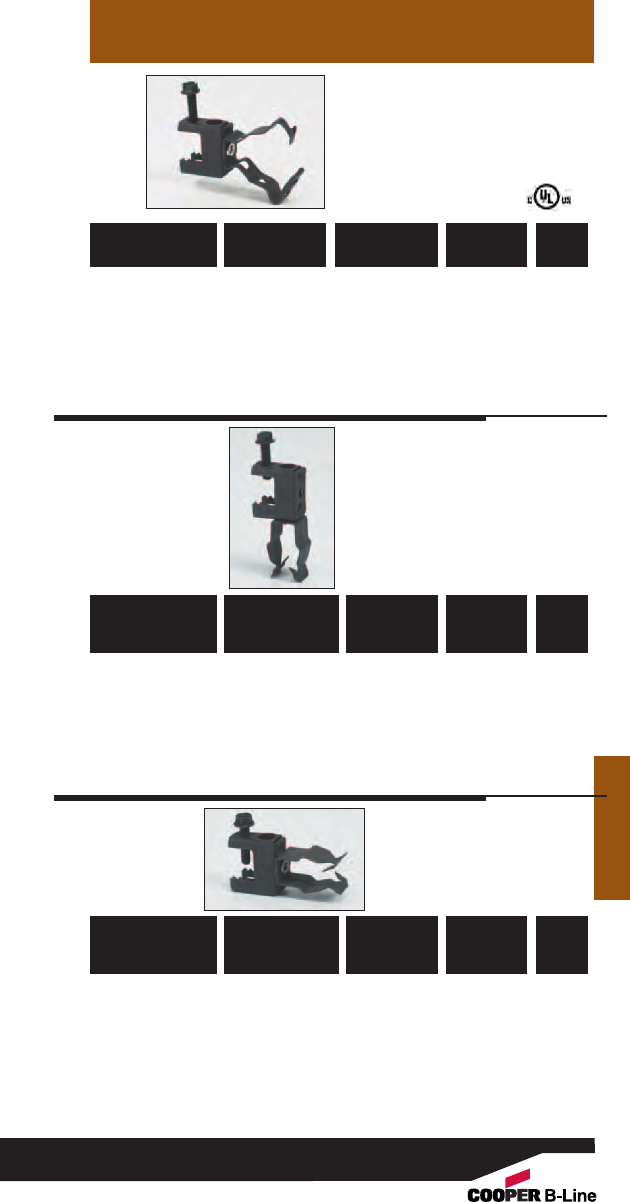
Beams
Beams
Conduit To Beam
Fasteners
Guide-Rite™
Fastener
Push-Type
Push-Type
781011 18485 BG-8-12-C1 1/2”, 3/4” 25 Lbs. 100
781011 18565 BG-16-C1 1” 25 Lbs. 100
781011 18650 BG-20-C1 11/4” 25 Lbs. 100
781011 18695 BG-24-C1 11/2” 25 Lbs. 50
781011 18735 BG-32-C1 2” 25 Lbs. 50
UPC/Part
Number
Static
Load Cap.
Catalog
Number
Conduit Size
EMT & Rigid
Box
Qty.
781011 19260 BP-8-C2
1/2” EMT 25 Lbs. 100
781011 19360 BP-12-C2
3/4” EMT 25 Lbs. 100
1/2” IMC, Rigid
781011 19455 BP-16-C2
1” EMT 25 Lbs. 100
3/4” IMC, Rigid
781011 19255 BP-8-C1
1/2” EMT 25 Lbs. 100
781011 19355 BP-12-C1
3/4” EMT 25 Lbs. 100
1/2” IMC, Rigid
781011 19450 BP-16-C1
1” EMT 25 Lbs. 100
3/4” IMC, Rigid
UPC/Part
Number
Ultimate
Static
Load Cap.
Catalog
Number
Conduit
Size
Box
Qty.
UPC/Part
Number
Ultimate
Static
Load Cap.
Catalog
Number
Conduit
Size
Box
Qty.
107
Read safety/installation instruction sheets in packages before use.
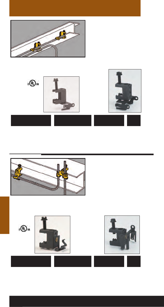
Beams
• Attaches MC, AC, sizes
14/2 through 10/3
or 3/8" FMC to beam
flanges thru 1/2" thick.
• Fasteners will rotate
360°.
• Requires only a
screwdriver to install.
Beams
Cable To Beam
Fasteners
• Attaches MC, AC, sizes
14/2 through 10/3
or 3/8" FMC to beam
flanges thru 1/2" thick.
• Fasteners will rotate
360°.
•Requires only a
screwdriver to install.
Cable To Beam
Fasteners
781011 01190 BX4-C2 Single Runs 100
781011 01210 BX4M-C2 Double Runs 100
UPC/Part
Number
Flange
Thickness
Catalog
Number
Box
Qty.
BX4-C2 BX4M-C2
781011 01191 BX4-C1 Single Runs 100
781011 01209 BX4M-C1 Double Runs 100
UPC/Part
Number
Flange
Thickness
Catalog
Number
Box
Qty.
BX4-C1 BX4M-C1
108
Read safety/installation instruction sheets in packages before use. These products are designed for positioning only. No load rating.
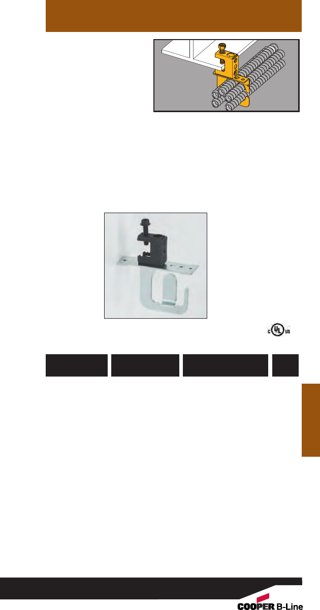
• Secures and supports
MC/AC cables as
required by the NEC.
• Effectively organizes
cables and eliminates
derating issues.
• Fits beam flanges
thru 1/2” thick.
• Load Capacity: 50 lbs.
Beams
MC/AC Cable
Carrier to
Beam Fastener
Beams
782051 44090 BRC51-C2
.430” to .560”
25
Up to 4 Runs
782051 44091 BRC52-C2
.430” to .560”
25
Up to 9 Runs
782051 44092 BRC53-C2
.560” to .690”
25
Up to 7 Runs
UPC/Part
Number
Catalog
Number
Box
Qty.
Cable Diameter &
Number Of Runs
109
Read safety/installation instruction sheets in packages before use.
BRC5-x-C2

Beams
Beams
• Attaches Type NM cable
to beam flanges 1/8” to
1/2” thick.
• Supports cable sizes
14/2 and 12/2 with
ground wire.
• Simply installed with a
hammer.
Cable To Beam
Fasteners
781011 03550 BRC3-E-2-4 1/8” to 1/4” 100
781011 03551 BRC3-E-5-8 5/16” to 1/2”100
781011 03552 BRC3-E-9-12 9/16” to 3/4” 100
UPC/Part
Number
Flange
Thickness
Catalog
Number
Box
Qty.
110
Read safety/installation instruction sheets in packages before use. These products are designed for positioning only. No load rating.
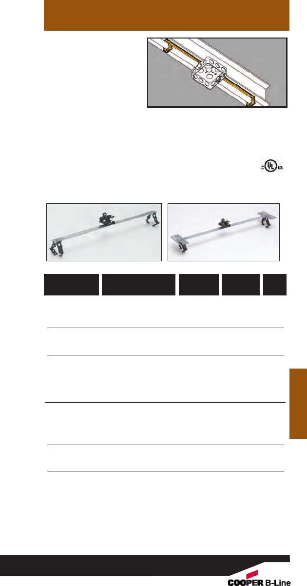
• New BMC3 plate is
available to support
multiple conduit runs.
• Riveted assembly
secures electrical boxes
and conduit runs to
beam flangles 1/8” to
1/2” thick.
• Provides support for
conduit on either side
of electrical box.
• Assemblies using BMC3
plate include center
conduit clamp. Additional
conduit clamps may be
purchased separately.
Beams
Guide-Rite™
Conduit & Box
Support Fasteners
781011 03583 BG6-S18-U24
*
3/8”1/8” to 1/4”25
781011 03584 BG6-S18-U58
*
3/8”5/16” to 1/2”25
781011 03579 BG812-S18-U24 1/2”, 3/4”1/8” to 1/4”25
781011 03580 BG812-S18-U58 1/2”, 3/4”5/16” to 1/2”25
781011 03581 BG16-S18-U24 1” 1/8” to 1/4”25
781011 03582 BG16-S18-U58 1” 5/16” to 1/2”25
Patent #4958792
With Multiple Conduit Plate
782051 52813 BG6-S18-U24-MC3
*
3/8”1/8” to 1/4”25
782051 52814 BG6-S18-U58-MC3
*
3/8”5/16” to 1/2”25
782051 52815 BG812-S18-U24-MC3 1/2”, 3/4”1/8” to 1/4”25
782051 52816 BG812-S18-U58-MC3 1/2”, 3/4”5/16” to 1/2”25
782051 52817 BG16-S18-U24-MC3 1” 1/8” to 1/4”25
782051 52823 BG16-S18-U58-MC3 1” 5/16” to 1/2”25
*BG-6 will accept the following range ∅.420 - ∅.675:
14/2 thru 10/4 MC/AC cable and 5/16 or 3/8flexible conduit
UPC/Part
Number
Flange
Thickness
Catalog
Number
Conduit
Size
Box
Qty.
Beams
111
Read safety/installation instruction sheets in packages before use.
BG__-S18-U__ BG__-S18-U__-MC3
• See Ruff-IN™brochure for
pre-fab box assemblies.

Beams
Beams
112
Read safety/installation instruction sheets in packages before use. These products are designed for positioning only. No load rating.
782051 23635 BP8-S18-U24 3/8”1/8” to 1/4”25
782051 23638 BP8-S18-U58 3/8”5/16” to 1/2”25
782051 23636 BP12-S18-U24 1/2”, 3/4”1/8” to 1/4”25
782051 23639 BP12-S18-U58 1/2”, 3/4”5/16” to 1/2”25
782051 23637 BP16-S18-U24 1” 1/8” to 1/4”25
782051 23640 BP16-S18-U58 1” 5/16” to 1/2”25
With Multiple Conduit Plate
782051 52824 BP8-S18-U24-MC3 3/8”1/8” to 1/4”25
782051 52826 BP8-S18-U58-MC3 3/8”5/16” to 1/2”25
782051 52827 BP12-S18-U24-MC3 1/2”, 3/4”1/8” to 1/4”25
782051 52828 BP12-S18-U58-MC3 1/2”, 3/4”5/16” to 1/2”25
782051 52825 BP16-S18-U24-MC3 1” 1/8” to 1/4”25
782051 52964 BP16-S18-U58-MC3 1” 5/16” to 1/2”25
UPC/Part
Number
Flange
Thickness
Catalog
Number
Conduit Size
EMT IMC/Rigid
Box
Qty.
• New BMC3 plate is
available to support
multiple conduit runs.
• Riveted assembly
secures electrical boxes
and conduit runs to
beam flangles 1/8” to
1/2” thick.
• Provides support for
conduit on either side
of electrical box.
• Assemblies using BMC3
plate include center
conduit clamp. Additional
conduit clamps may be
purchased separately.
Push-Type
Conduit & Box
Support Fasteners
BP__-S18-U__ BP__-S18-U__-MC3
• See Ruff-IN™brochure for
pre-fab box assemblies.
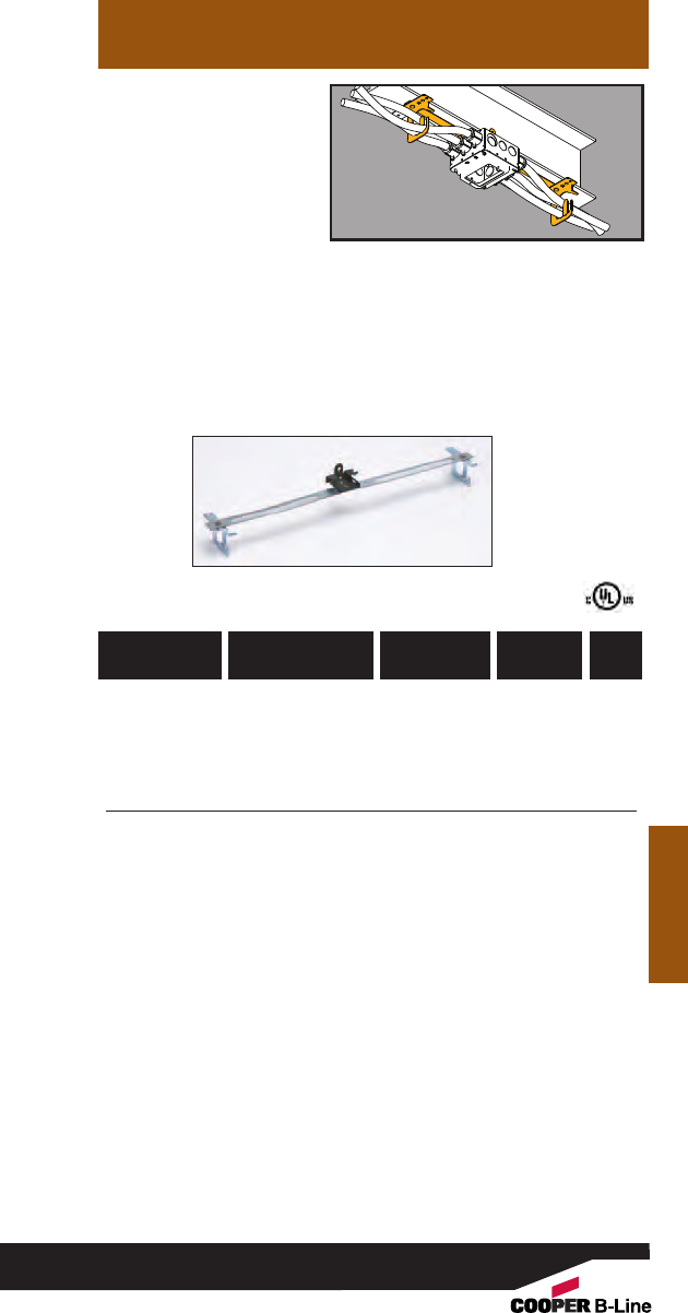
Beams
Beams
113
Read safety/installation instruction sheets in packages before use.
• Riveted assembly
provides support for
electrical box and cable
run on either side of
box.
• Cable retension tab is
open for easy loading
and contains cable
when bent in place.
• See Ruff-IN™brochure
for pre-fab box
assemblies.
Multi-Run Cable
Carrier & Box
Support Fastener
782051 52829 BRC51-S18-U24 .43” - .56” 1/8” to 1/4”25
up to 4 runs
782051 52830 BRC51-S18-U58 .56” - .69” 5/16” to 1/2”25
up to 7 runs
782051 52834 BRC53-S18-U24 .43” - .56” 1/8” to 1/4”25
up to 4 runs
782051 52835 BRC53-S18-U58 .56” - .69” 5/16” to 1/2”25
up to 7 runs
UPC/Part
Number
Flange
Thickness
Catalog
Number
Cable Size
# of Runs
Box
Qty.
BRC5_-S18-U__
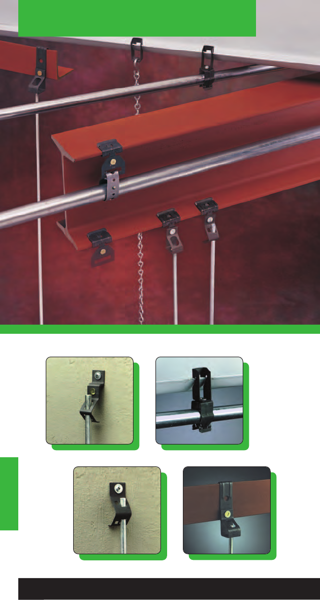
Hangers
Hangers
114
Read safety/installation instruction sheets in packages before use.
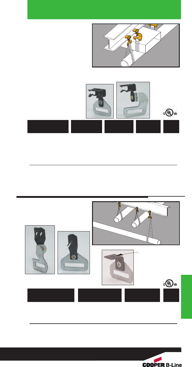
• Suspends straps thru
11/2" wide from beam
flanges 1/8" to 3/4"
thick.
• Suspends straps
parallel or at right
angles to beams.
• Simply installed with a
hammer.
• Static Load Capacity:
200 Lbs.
Hangers
Strap Hangers
Hangers
781011 04930 BHE-1-2 Parallel 1/16” to 1/8” 100
781011 18870 BH-2-4 Parallel 1/8” to 1/4” 100
781011 18880 BH-5-8 Parallel 5/16” to 1/2” 100
781011 18890 BH-9-12 Parallel 9/16” to 3/4”100
781011 04115 BH-1-2-R Right Angle 1/16” to 1/8”100
781011 18875 BH-2-4-R Right Angle 1/8” to 1/4” 100
781011 18885 BH-5-8-R Right Angle 5/16” to 1/2” 100
781011 18895 BH-9-12-R Right Angle 9/16” to 3/4”100
UPC/Part
Number
Flange
Thickness
Catalog
Number Description Box
Qty.
Parallel
Right Angle
781011 03385 BH-F12
Right Angle
100
781011 03384 BH-F12-R
Parallel
100
781011 19922 BH-H7
Parallel
100
UPC/Part
Number Description
Catalog
Number
Box
Qty.
“Z” Purlin
Hangers
BH-H7
.281ӯ
BH-F12 BH-F12-R
115
Read safety/installation instruction sheets in packages before use.

Hangers
• Suspend wire or plain
and threaded rod from
beam flanges 1/8" to
3/4" thick.
• Simply installed with a
hammer.
• Static Load Capacity:
160 Lbs.
Hangers
781011 18900 BH1-E-2-4 1/8” - 1/4”#8 Wire or 100
1/4” Plain Rod
781011 18905 BH1-E-5-8 5/16” - 1/2”#8 Wire or 100
1/4” Plain Rod
781011 18910 BH1-E-9-12 9/16” - 3/4” #8 Wire or 100
1/4” Plain Rod
UPC/Part
Number Description
Catalog
Number
Flange
Thickness
Box
Qty.
781011 18940 BH2-E-2-4 1/8” - 1/4”3/8” 100
781011 18945 BH2-E-5-8 5/16” - 1/2”3/8” 100
781011 18950 BH2-E-9-12 9/16” - 3/4”3/8” 100
UPC/Part
Number
Plain Rod
Size
Catalog
Number
Flange
Thickness
Box
Qty.
Rod To Beam
Hangers
116
Read safety/installation instruction sheets in packages before use.
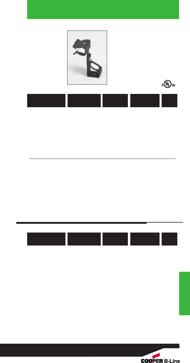
Hangers
Rod To Beam
Hangers
Hangers
With Thread
Impression
781011 18980 BH4-E-2-4 1/8” - 1/4”1/4” 100
781011 18985 BH4-E-5-8 5/16” - 1/2”1/4” 100
781011 18990 BH4-E-9-12 9/16” - 3/4”1/4” 100
781011 19060 BH6-E-2-4 1/8” - 1/4”3/8” 100
781011 19065 BH6-E-5-8 5/16” - 1/2”3/8” 100
781011 19070 BH6-E-9-12 9/16” - 3/4”3/8”100
Note: BH4 and BH6 have thread impressions.
UPC/Part
Number
Threaded
Rod Size
Catalog
Number
Flange
Thickness
Box
Qty.
781011 19020 BH5-E-2-4* 1/8” - 1/4”1/4” or 3/8”100
781011 19025 BH5-E-5-8* 5/16” - 1/2”1/4” or 3/8” 100
781011 19030 BH5-E-9-12* 9/16” - 3/4”1/4” or 3/8”100
*Nuts Required.
UPC/Part
Number
Threaded
Rod Size
Catalog
Number
Flange
Thickness
Box
Qty.
117
Read safety/installation instruction sheets in packages before use.
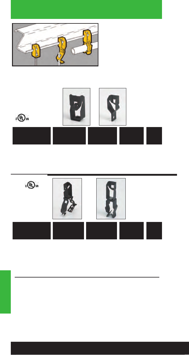
Hangers
• Compensates for angle
of purlin lip.
• Allows for parallel
conduit runs or vertical
support drops.
• Riveted fasteners will
rotate 360°.
• Maximum Purlin
thickness of 3/32".
Hangers
781011 18345 BF13
With 1/4” Hole 100 100
781011 18340 BF12
For “S” Hooks 100 100
UPC/Part
Number
Static
Load Cap.
Lbs.
Catalog
Number Description Box
Qty.
“Z” Purlin
Hangers
781011 18445 BG-6-F13
*
3/8” 100 100
781011 18520 BG-8-12-F13 1/2”, 3/4” 100 100
781011 18590 BG-16-F13 1” 100 100
781011 18675 BG-20-F13 11/4” 100 50
781011 19290 BP-8-F13 1/2” EMT 25 100
781011 19390 BP-12-F13 3/4” EMT 25 100
1/2” IMC, Rigid
781011 19480 BP-16-F13 1” EMT 25 50
3/4” IMC, Rigid
*BG-6 will accept the following range ∅.420 - ∅.675:
14/2 thru 10/4 MC/AC cable and 5/16 or 3/8flexible conduit
UPC/Part
Number
Static
Load Cap.
Lbs.
Catalog
Number
Conduit
Size
EMT & Rigid
Box
Qty.
Push-Type
BP Series
Guide-Rite™
Fastener
BG Series
BF13 BF12
118
Read safety/installation instruction sheets in packages before use.
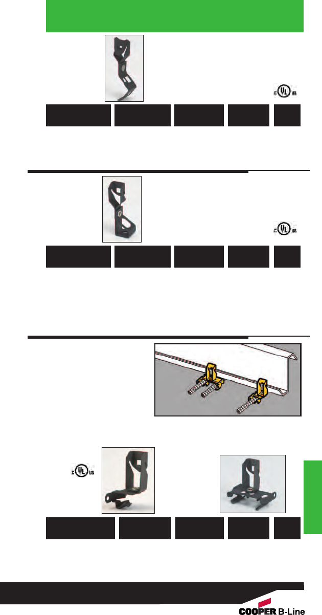
Hangers
Universal Beam
Fasteners
Hangers
781011 18920 BH1-F12
#8 Wire or 100 Lbs. 100
1/4” Plain Rod
781011 18960 BH2-F12
3/8” Plain Rod 100 Lbs. 100
UPC/Part
Number
Static
Load Cap.
Catalog
Number Description Box
Qty.
781011 19000 BH4-F12
1/4” 100 Lbs. 100
781011 19080 BH6-F12
3/8” 100 Lbs. 100
781011 19040 BH5-F12*
1/4” & 3/8” 100 Lbs. 100
*Nuts Required.
Note: BH4 and BH6 have thread impressions.
UPC/Part
Number
Static
Load Cap.
Catalog
Number
Threaded
Rod Size
Box
Qty.
•Compensates for
angle of purlin lip.
•Attaches MC, AC, sizes
14/2 through 10/3
or 3/8" FMC to “Z”
Purlins up to 3/32"
thick.
•Fastener will rotate
360°.
•Simply installed with
a hammer.
Cable To “Z” Purlin
Flange Hangers
781011 01188 BX4-F13
Single Runs Thru 3/32” 100
781011 01204 BX4M-F13
Double Runs Thru 3/32” 100
UPC/Part
Number
Flange
Thickness
Catalog
Number Description Box
Qty.
BX4-F13 BX4M-F13
119
Read safety/installation instruction sheets in packages before use.
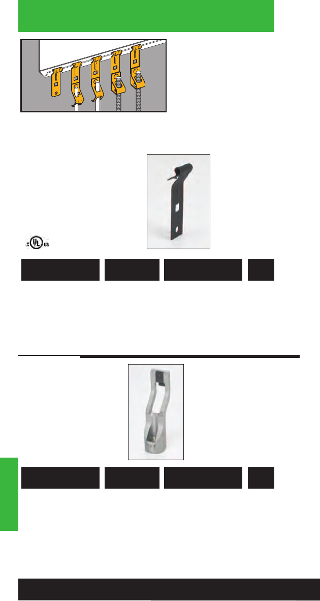
Hangers
• Suspend wire, or plain
and threaded rod from
“Z” Purlins.
• Fits “Z” Purlins 1/16" to
1/4" thick.
• Simply installed with a
hammer.
• Static Load Capacity:
160 Lbs.
Hangers
“Z” Purlin
Flange Hangers
781011 04271 BF4 For “S” Hooks, 100
Bolting Straps and
Wrap Wire
UPC/Part
Number Description
Catalog
Number
Box
Qty.
781011 04164 BT3 Installation Tool 1
for BF4 Hangers
(Insert 1/2” Rigid
conduit for installation)
UPC/Part
Number Description
Catalog
Number
Box
Qty.
120
Read safety/installation instruction sheets in packages before use.
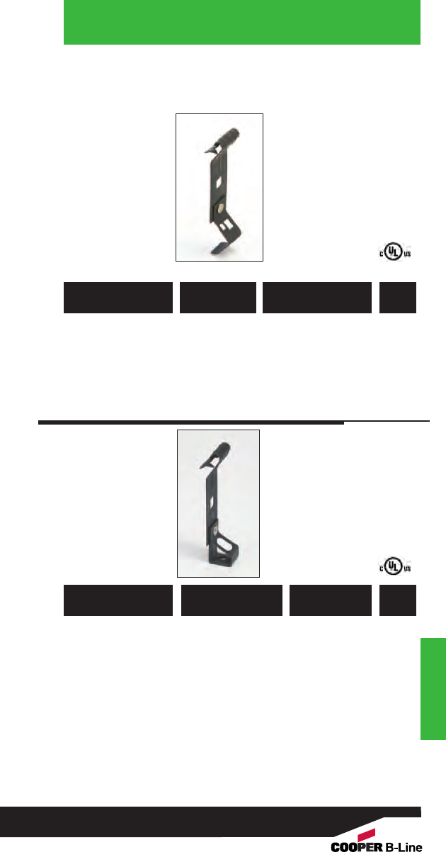
Hangers
“Z” Purlin
Flange Hangers
Hangers
781011 04286 BH4-F4 1/4” 100
781011 04280 BH6-F4 3/8” 100
781011 04278 BH5-F4* 1/4” - 3/8” 100
* Nuts required.
Note: BH4 & BH6 have thread impressions.
UPC/Part
Number
Threaded
Rod Size
Catalog
Number
Box
Qty.
781011 04274 BH1-F4 #8 Wire or 100
1/4” Plain Rod
781011 04276 BH2-F4 3/8” Plain Rod 100
UPC/Part
Number Description
Catalog
Number
Box
Qty.
121
Read safety/installation instruction sheets in packages before use.
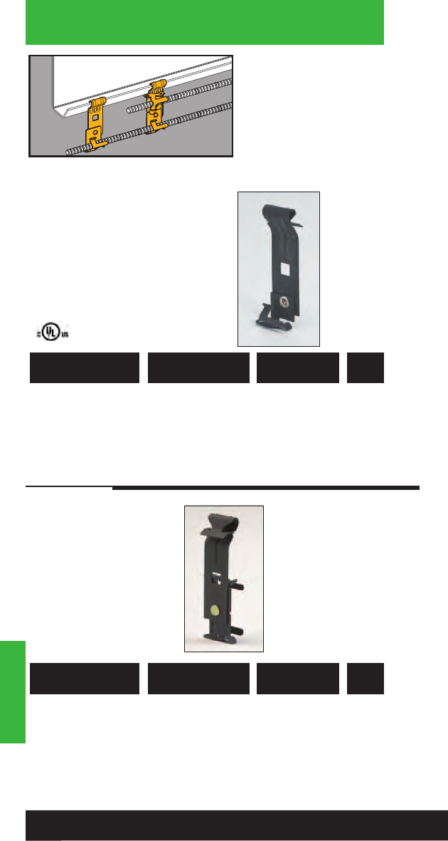
Hangers
• Attaches MC, AC,
sizes 14/2 thru 10/3 or
3/8" FMC to “Z” Purlins.
• Fits “Z” Purlin flanges
1/16" to 1/4" thick.
• Fastener will rotate
360°.
Hangers
Cable To “Z” Purlin
Flange Hangers
781011 04931 BX4-F4 Single Runs 100
These products are designed for positioning only. No load rating.
UPC/Part
Number Description
Catalog
Number
Box
Qty.
781011 04932 BX4M-F4 Double Runs 100
This product is designed for positioning only. No load rating.
UPC/Part
Number Description
Catalog
Number
Box
Qty.
122
Read safety/installation instruction sheets in packages before use.
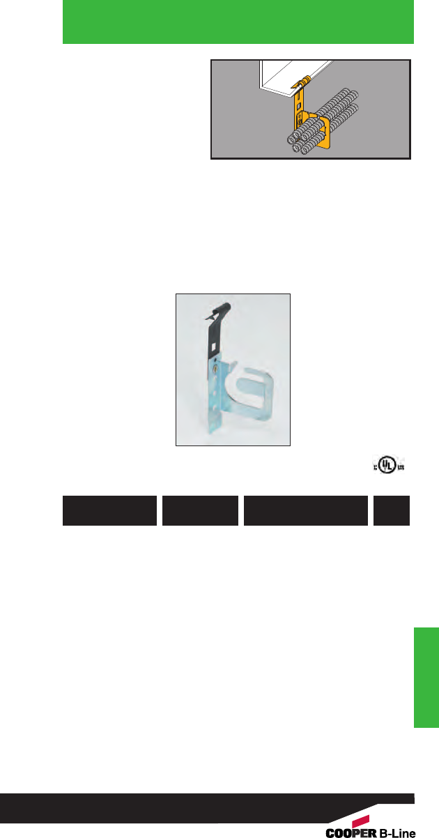
Hangers
Hangers
• Secures and supports
multiple runs of
MC/AC cable to ‘Z’
purlins.
• Effectively organizes
cables and eliminates
derating issues.
• Retention tab is open
for easy loading and
unloading and
contains cables when
bent in place.
• Load Capacity: 50 lbs.
MC/AC Cable
Carrier to
‘Z’ Purlin Flange
Hanger
782051 44084 BRC51-F4
.430” to .560”
25
Up to 4 Runs
782051 44085 BRC52-F4
.430” to .560”
25
Up to 9 Runs
782051 44086 BRC53-F4
.560” to .690”
25
Up to 7 Runs
UPC/Part
Number
Catalog
Number
Cable Diameter &
Number Of Runs
Box
Qty.
123
Read safety/installation instruction sheets in packages before use.
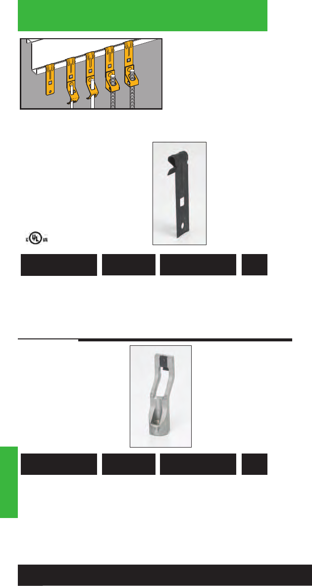
Hangers
• Suspend wire, or
plain and threaded rod
from vertical flanges.
• Fits vertical flanges
1/16" to 1/4" thick.
• Static Load Capacity:
160 Lbs.
Hangers
Vertical Flange
Hangers
781011 04270 BF3 For “S” Hooks, 100
Bolting Straps and
Wrap Wire
UPC/Part
Number Description
Catalog
Number
Box
Qty.
781011 04164 BT3 Installation Tool 1
for BF3 Hangers
(Insert 1/2” Rigid
conduit for installation)
UPC/Part
Number Description
Catalog
Number
Box
Qty.
124
Read safety/installation instruction sheets in packages before use.
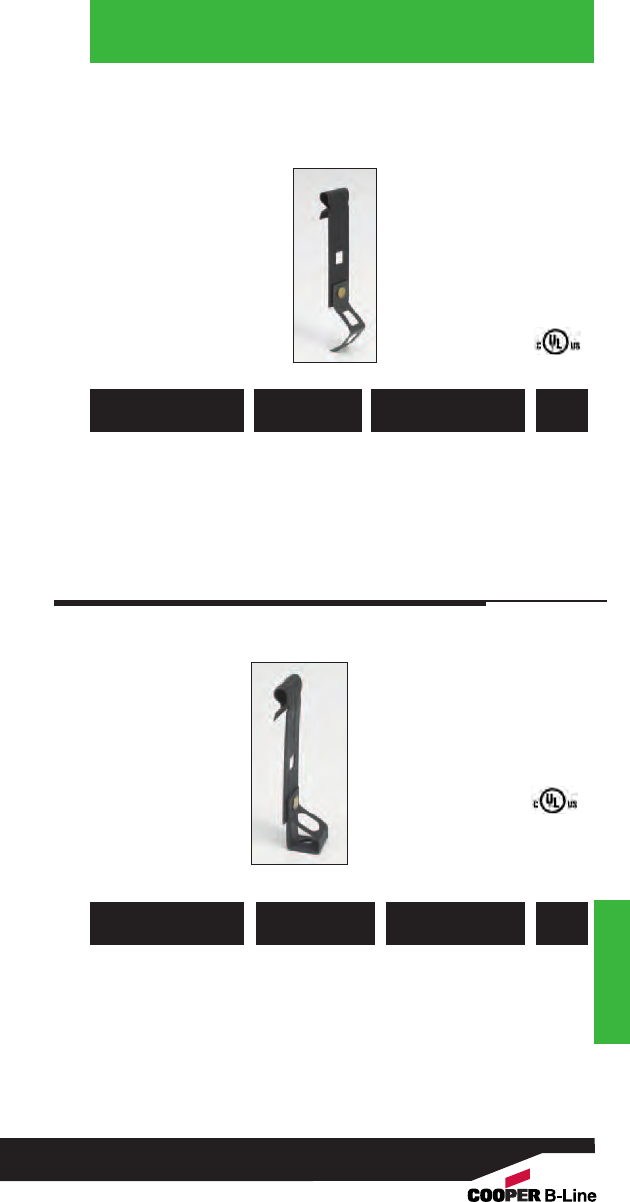
Hangers
Hangers
41/4”
Overall Height
Vertical Flange
Hangers
781011 04285 BH4-F3 1/4” 100
781011 04279 BH6-F3 3/8”100
781011 04933 BH5-F3* 1/4”, 3/8” 100
* Nuts required.
UPC/Part
Number
Threaded Rod
Size
Catalog
Number
Box
Qty.
781011 04273 BH1-F3 #8 Wire or 100
1/4” Plain Rod
781011 04275 BH2-F3 3/8” Plain Rod 100
UPC/Part
Number Description
Catalog
Number
Box
Qty.
125
Read safety/installation instruction sheets in packages before use.
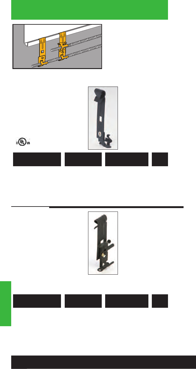
Hangers
• Attaches MC, AC, sizes
14/2 through 10/3
or 3/8" flexible conduit
FMC to vertical flanges
1/16" to 1/4" thick.
• Fastener will rotate
360°.
• Simply installed with a
hammer.
Hangers
Cable To Vertical
Flange Hangers
781011 04281 BX4-F3 Single Runs 100
This product is designed for positioning only. No load rating.
UPC/Part
Number Description
Catalog
Number
Box
Qty.
781011 04282 BX4M-F3 Double Runs 100
This product is designed for positioning only. No load rating.
UPC/Part
Number Description
Catalog
Number
Box
Qty.
126
Read safety/installation instruction sheets in packages before use.
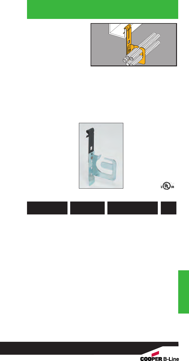
Hangers
Hangers
• Secures and supports
multiple runs of
MC/AC cable to
vertical flanges.
• Effectively organizes
cables and eliminates
derating issues.
• Retention tab is open
for easy loading and
unloading and
contains cables when
bent in place.
• Load Capacity: 50 lbs.
MC/AC Cable
Carrier To
Vertical Flange
Hanger
782051 44081 BRC51-F3
.430” to .560”
25
Up to 4 Runs
782051 44082 BRC52-F3
.430” to .560”
25
Up to 9 Runs
782051 44083 BRC53-F3
.560” to .690”
25
Up to 7 Runs
UPC/Part
Number
Catalog
Number
Cable Diameter &
Number Of Runs
Box
Qty.
127
Read safety/installation instruction sheets in packages before use.
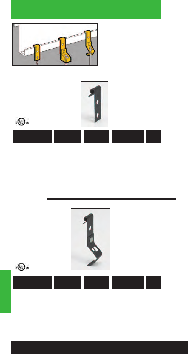
Hangers
• Suspend wire, or
plain or threaded rod
from vertical flanges.
• Fits vertical flanges
1/16" to 1/4" thick.
• Static Load Capacity:
160 Lbs.
Hangers
781011 18310 BF1 1/16” - 5/32”For “S” Hooks, 100
Bolting Straps
and Wrap Wire
781011 18315 BF2 5/32” - 1/4” For “S” Hooks, 100
Bolting Straps
and Wrap Wire
UPC/Part
Number Description
Catalog
Number
Flange
Thickness
Box
Qty.
Vertical Flange
Hangers
781011 18915 BH1-F1 1/16” - 5/32” #8 Wire or 100
1/4” Plain Rod
781011 18925 BH1-F2 5/32” - 1/4” #8 Wire or 100
1/4” Plain Rod
UPC/Part
Number Description
Catalog
Number
Flange
Thickness
Box
Qty.
128
Read safety/installation instruction sheets in packages before use.
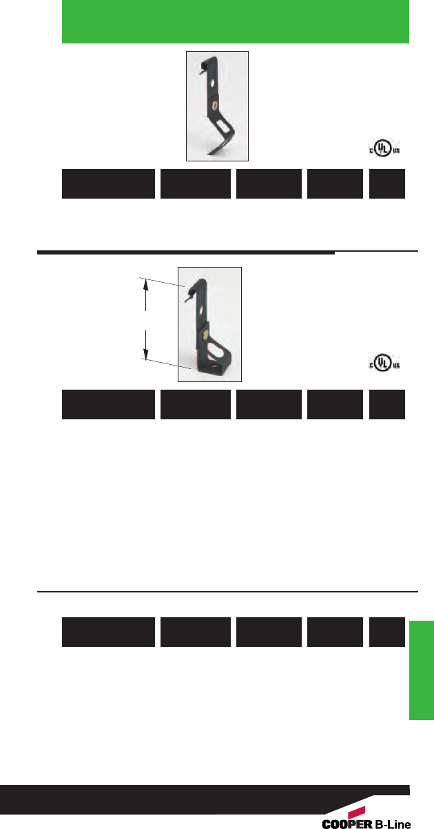
Hangers
Vertical Flange
Hangers
Hangers
781011 18955 BH2-F1 1/16” to 5/32”3/8” 100
781011 18965 BH2-F2 5/32” to 1/4”3/8”100
UPC/Part
Number
Plain
Rod Size
Catalog
Number
Flange
Thickness
Box
Qty.
781011 18995 BH4-F1 1/16” to 5/32”1/4”100
781011 19075 BH6-F1 1/16” to 5/32”3/8”100
781011 19005 BH4-F2 5/32” to 1/4”1/4” 100
781011 19085 BH6-F2 5/32” to 1/4”3/8” 100
UPC/Part
Number
Threaded
Rod Size
Catalog
Number
Flange
Thickness
Box
Qty.
781011 19035 BH5-F1* 1/16” to 5/32”1/4”, 3/8” 100
781011 19045 BH5-F2* 5/32” to 1/4”1/4”, 3/8”100
* Nuts required.
UPC/Part
Number
Plain
Rod Size
Catalog
Number
Flange
Thickness
Box
Qty.
23/4”
129
Read safety/installation instruction sheets in packages before use.
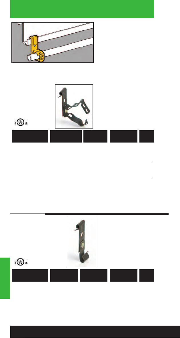
Hangers
• Supports 3/8" to 1"
conduit from vertical
flanges 1/16" to 1/4"
thick.
• Patented Guide-Rite™
feature ensures
fastener will close and
lock every time.
• Simply installed with a
hammer and pliers.
• Static Load Capacity:
25 Lbs.
Hangers
781011 19957 BG-6-F1
*
3/8”1/16” - 5/32” 100
781011 19960 BG-6-F2
*
3/8”5/32” - 1/4”100
781011 19958 BG-8-12-F1 1/2” & 3/4”1/16” - 5/32” 100
781011 19961 BG-8-12-F2 1/2” & 3/4”5/32” - 1/4” 100
781011 19959 BG-16-F1 1” 1/16” - 5/32” 100
781011 19962 BG-16-F2 1” 5/32” - 1/4” 100
Patent #4958792
*BG-6 will accept the following range ∅.420 - ∅.675:
14/2 thru 10/4 MC/AC cable and 5/16 or 3/8flexible conduit
UPC/Part
Number
Flange
Thickness
Catalog
Number
Conduit
Size
Box
Qty.
781011 03556 BRC3-F1 14/2 & 12/2 1/16” - 5/32” 100
With Ground
781011 03557 BRC3-F2 14/2 & 12/2 5/32” - 1/4” 100
With Ground
UPC/Part
Number
Flange
Thickness
Catalog
Number Wire Size Box
Qty.
Conduit To
Vertical Flange
Hangers
Guide-Rite™
Fastener
Note: These products are designed for positioning only. No load rating.
130
Read safety/installation instruction sheets in packages before use.
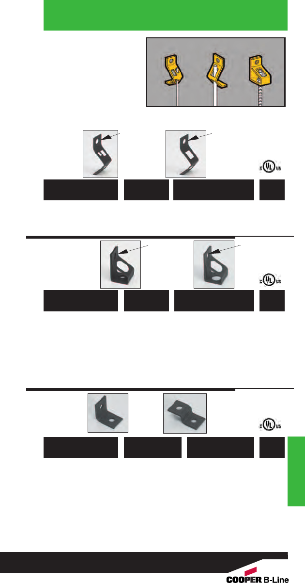
• BH1, BH2: Supports
wire or plain rod.
• BH7, BH8: For wire or
chain drop from
concrete or wood.
• BH4, BH5, BH6
supports 1/4" or 3/8"
threaded rod.
• Static Load Capacity: 160 Lbs.
Hangers
Components
781011 18800 BH1 #8 Wire or 1/4” Plain Rod 100
781011 18805 BH2 For 3/8” Plain Rod 100
781011 18815 BH4 For 1/4” 100
Threaded Rod
781011 18825 BH6 For 3/8”100
Threaded Rod
781011 18820 BH5* For 1/4” & 3/8” 100
Threaded Rod
* Nuts required.
Note: BH4 & BH6 have thread impressions.
UPC/Part
Number Description
Catalog
Number
Box
Qty.
UPC/Part
Number Description
Catalog
Number
Box
Qty.
UPC/Part
Number Description
Catalog
Number
Box
Qty.
BH2
.281ӯ
BH1
.281ӯ
781011 18830 BH7 Angle Bracket 100
With .281ӯ Holes
781011 18835 BH7-6 Angle Bracket 100
With .281ӯ & .406ӯ Holes
781011 18840 BH8 Offset Bracket 100
With .281ӯ Holes
781011 18845 BH8-6 Offset Bracket 100
With .281ӯ & .406ӯ Holes
BH7 BH8
BH4
BH6
.281ӯ
BH5
Hangers
131
Read safety/installation instruction sheets in packages before use.
.281ӯ
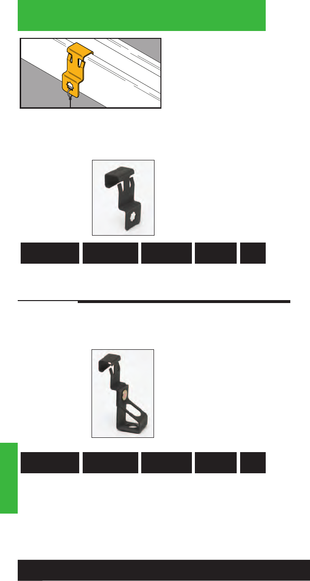
Hangers
Hangers
132
Read safety/installation instruction sheets in packages before use.
• The BSC4 Series
provides a simple,
snap-on attachment to
strut, eliminating the
need for tools and/or
drilling during installation.
• Great for retrofit and
add-on applications.
• BSC4 provides a 1/4”
mounting hole along the
side of a standard strut
member.
• Riveted assemblies allow
for easy attachment of
conduit, cable and rod.
782051 46573 BSC4 Strut Clip 60 lbs. 100
UPC/Part
Number
Load
Capacity
Catalog
Number Description Box
Qty.
782051 46581 BH4-SC4 1/4”-20 60 lbs. 100
782051 46582 BH6-SC4 3/8”-20 60 lbs. 100
UPC/Part
Number
Load
Capacity
Catalog
Number Rod Size Box
Qty.
Strut Fasteners
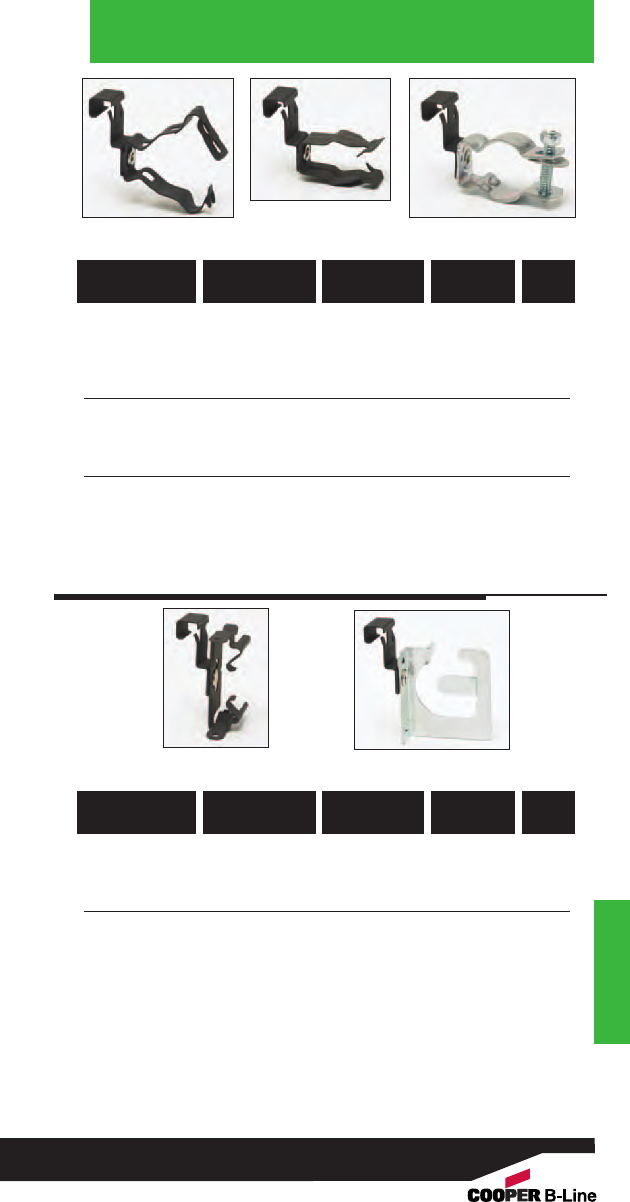
Hangers
Hangers
133
Read safety/installation instruction sheets in packages before use.
782051 46577 BG6-SC4 MC/AC & 3/8” 25 lbs. 100
782051 46578 BG812-SC4 1/2” & 3/4” 25 lbs. 100
782051 46579 BP8-SC4 1/2” 15 lbs. 100
782051 46580 BP12-SC4 3/4” 15 lbs. 100
782051 46588 BL1400-SC4 1/2”60 lbs. 100
782051 46589 BL1410-SC4 3/4” 60 lbs. 100
782051 46590 BL1420-SC4 1” 60 lbs. 100
UPC/Part
Number
Load
Capacity
Catalog
Number
Conduit
Size
Box
Qty.
BG_-SC4
BP_-SC4
BL14__-SC4
782051 46584 BX4M-SC4 14/2 - 10/3 -- 100
up to 2 runs
782051 46585 BRC51-SC4 .43” - .56” 50 lbs. 100
up to 4 runs
782051 46586 BRC52-SC4 .43” - .56” 50 lbs. 100
up to 9 runs
782051 46587 BRC53-SC4 .56” - .69” 50 lbs. 100
up to 7 runs
UPC/Part
Number
Load
Capacity
Catalog
Number
Cable Size
Runs
Box
Qty.
BX4M_-SC4 BRC5_-SC4
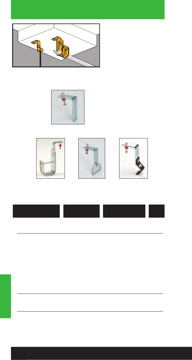
Hangers
• Special support bracket
allows clearance for
powder actuated tools.
• Exclusive 11/4” drive pin
now pre-installed.
• Pins rated for concrete
up to 4000 psi.
• Static Load Capacity:
30 Lbs. unless specified.
Limited by fastener
assembly. Pin rating
must be considered
before installation.
Hangers
Drive Pin
Fasteners
782051 25583 BPNA Angle Bracket 100
782051 28090 BCH12-PNA 3/4” 100
Cable Hook
782051 25584 BCH21-PNA 15/16”50
Cable Hook
782051 25586 BCH32-PNA 2” 50
Cable Hook
782051 25588 BCH64-PNAB 4” 25
Cable Hook
782051 25611 BH-PNA Strap Hanger 100
Cable Hook
782051 25593 BH1-PNA #8 Wire or 100
1/4” Plain Rod
782051 25596 BH2-PNA 3/8” Plain Rod 100
UPC/Part
Number Description
Catalog
Number
Box
Qty.
BCH21-PNA
BCH32-PNA
BH-PNA BH1-PNA
BH2-PNA
134
Read safety/installation instruction sheets in packages before use.
BPNA
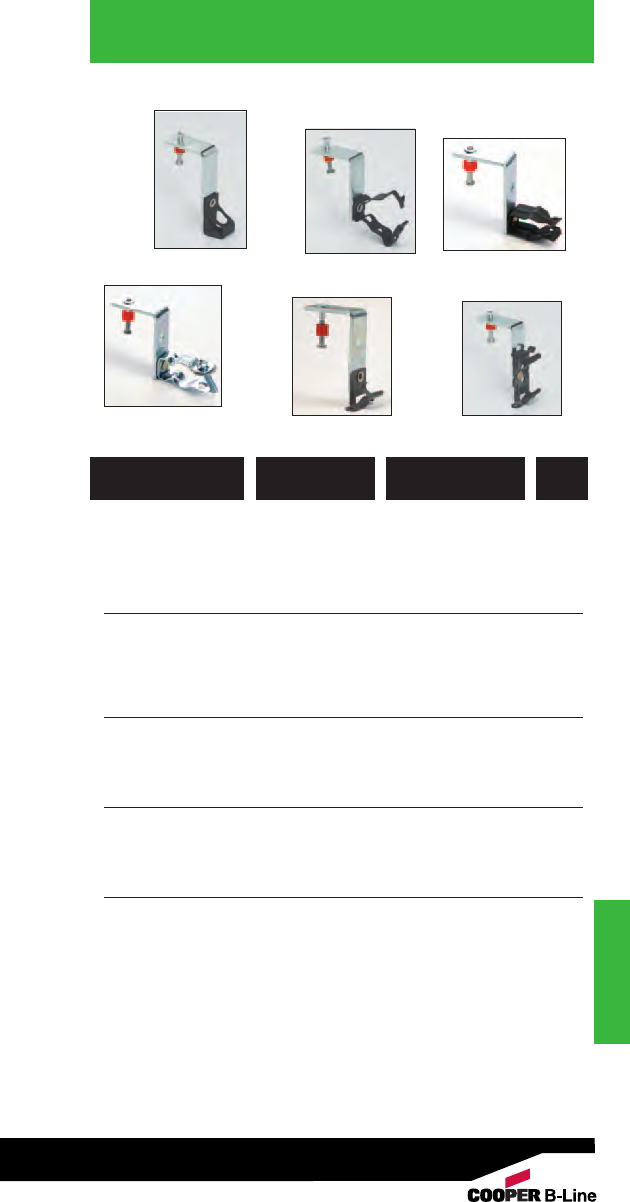
Hangers
Drive Pin
Fasteners
Hangers
BH_-PNA
BX4-PNA BX4M-PNA
BG_-PNA BP_-PNA
BL14__-PNA
782051 25604 BH4-PNA*1/4” Threaded Rod 100
782051 25606 BH6-PNA*3/8” Threaded Rod 100
782051 25605 BH5-PNA** 1/4” or 3/8” 100
Threaded Rod
782051 25613 BG6-PNA*** 3/8” Conduit 100
782051 25615 BG8-12-PNA 1/2” & 3/4”100
Conduit
782051 25616 BG16-PNA 1” Conduit 100
782051 25623 BP8-PNA 1/2” EMT 100
782051 25624 BP12-PNA 3/4” EMT 100
782051 25630 BP16-PNA 1” EMT 100
782051 25620 BL1400-PNA 1/2” Conduit 100
782051 25621 BL1410-PNA 3/4” Conduit 100
782051 25622 BL1420-PNA 1” Conduit 100
782051 25590 BX4-PNA Single Run 100
MC, AC or FMC
782051 25591 BX4M-PNA Double Run 100
MC, AC or FMC
*With threaded impressions. ** Nuts required.
*** BG-6 will accept the following range ∅.420 - ∅.675:
14/2 thru 10/4 MC/AC cable and 5/16 or 3/8flexible conduit
UPC/Part
Number Description
Catalog
Number
Box
Qty.
135
Read safety/installation instruction sheets in packages before use.
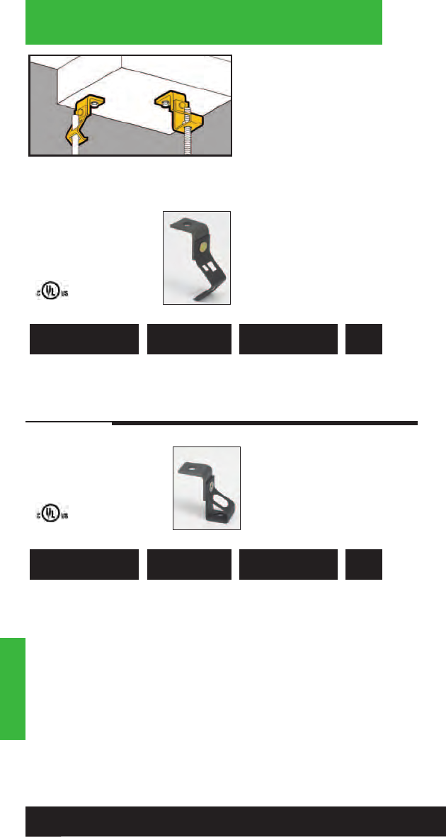
Hangers
• Suspend plain or
threaded rod and drop
wire from ceilings,
walls, concrete beams,
joists and laminated
wood beams.
• Clearance hole for 1/4"
bolt provided.
• Static Load Capacity:
160 Lbs.
Hangers
Angle Bracket
Fasteners
781011 18930 BH1-H7 #8 Wire or 100
1/4” Plain Rod
781011 18970 BH2-H7 3/8” Plain Rod 100
UPC/Part
Number Description
Catalog
Number
Box
Qty.
781011 19010 BH4-H7 1/4”-20 100
781011 19090 BH6-H7 3/8”-16 100
781011 19050 BH5-H7* 1/4”-20 or 3/8”-16 100
* Nuts required.
Note: BH4 & BH6 have thread impressions.
UPC/Part
Number
Threaded
Rod Size
Catalog
Number
Box
Qty.
136
Read safety/installation instruction sheets in packages before use.
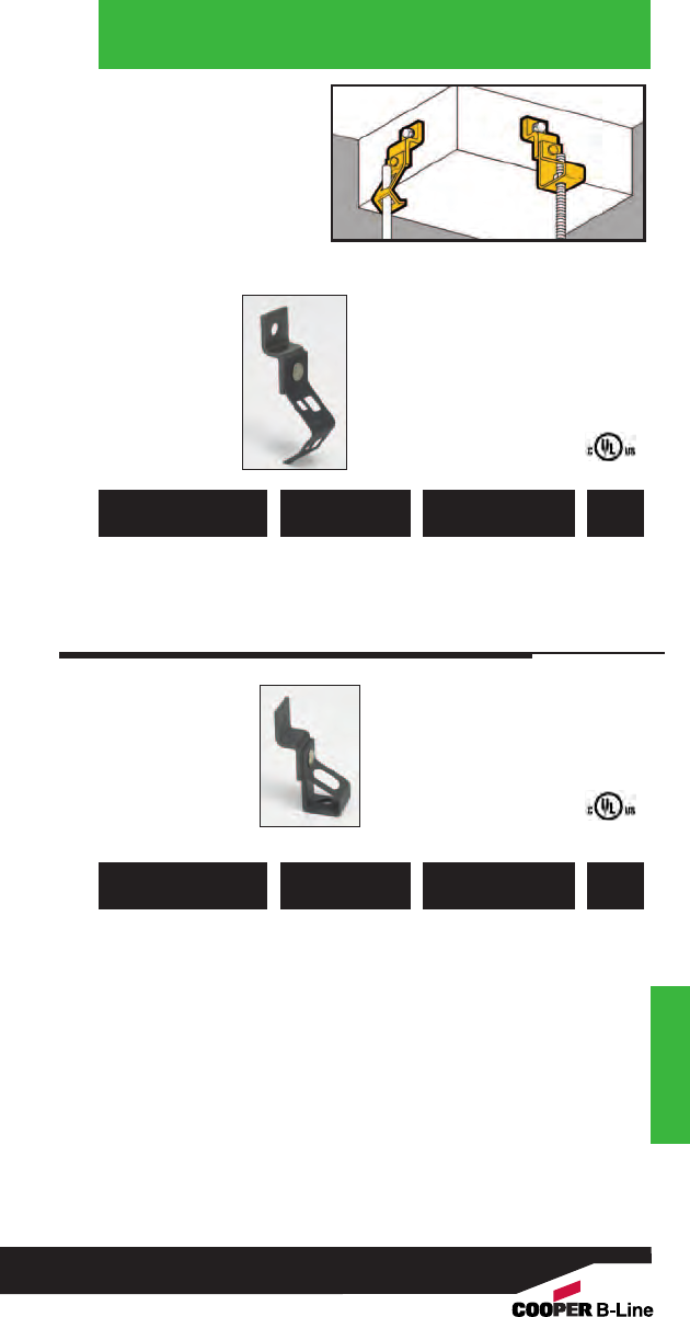
• Suspend plain or
threaded rod and drop
wire from ceilings,
walls, beams, and
joists.
• Clearance hole for 1/4"
bolt provided.
• Static Load Capacity:
160 Lbs.
Hangers
Offset Bracket
Fasteners
Hangers
781011 18935 BH1-H8 #8 Wire or 100
1/4” Plain Rod
781011 18975 BH2-H8 3/8” Plain Rod 100
UPC/Part
Number Description
Catalog
Number
Box
Qty.
781011 19015 BH4-H8 1/4”-20 100
781011 19095 BH6-H8 3/8”-16 100
781011 19055 BH5-H8* 1/4”-20 or 3/8”-16 100
* Nuts required.
Note: BH4 & BH6 have thread impressions.
UPC/Part
Number
Threaded
Rod Size
Catalog
Number
Box
Qty.
137
Read safety/installation instruction sheets in packages before use.
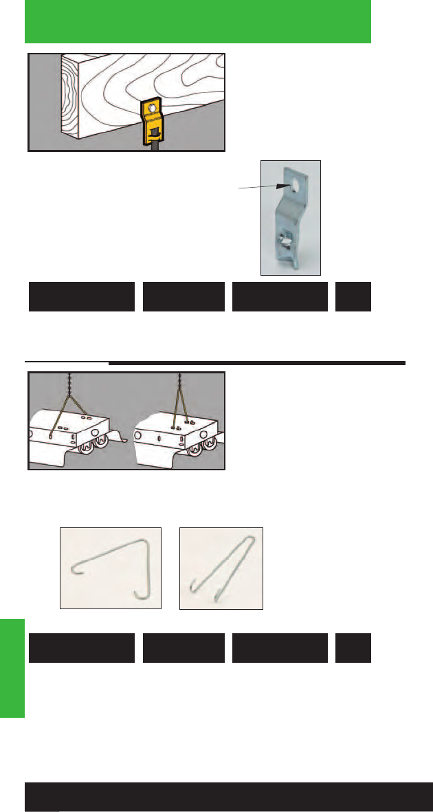
Hangers
• Suspend 3/8" threaded
rod from ceilings, walls,
beams, and joists.
• Finish: Zinc Plated
• Static Load Capacity:
610 Lbs.
Hangers
Threaded Rod
Hangers .406ӯ
781011 01661 B3223-3/8Offset Eye 100
Socket
UPC/Part
Number Description
Catalog
Number
Box
Qty.
Light Fixture
Hangers
781011 01236 BH15 Side Mount 100
Fluorescent Light
Fixture Hanger
781011 01237 BH16 Top Mount 100
Fluorescent Light
Fixture Hanger
UPC/Part
Number Description
Catalog
Number
Box
Qty.
BH15 BH16
• For hanging industrial
class fluorescent
lighting fixtures.
• Use with Jack Chain
and “S” Hooks.
• Static Load Capacity:
29 Lbs.
•Finish: Zinc Plated
138
Read safety/installation instruction sheets in packages before use.

• For support of light
fixtures and signs.
• Static Load Capacity:
29 Lbs.
• Finish: Zinc Plated
Hangers
Jack Chain &
“S” Hooks
BH9
BH9-10 BH10
781011 18850 BH9 #12 Single 100 ft.
Jack Chain
781011 02901 BH9-10 #10 Single 100 ft.
Jack Chain
781011 18855 BH10 #11 “S” Hook 50
UPC/Part
Number Description
Catalog
Number
Box
Qty.
•Allows centering on
all open web joists
with round bottom
chords.
• Static Load Capacity:
BH11 = 200 Lbs.
BH12 = 100 Lbs.
Wedge Hangers
781011 18860 BH11 With 3/8” 100
Clearance Hole
781011 18865 BH12 With 1/4”-20 100
Thread Impression
UPC/Part
Number Description
Catalog
Number
Box
Qty.
BH12
BH11
139
Read safety/installation instruction sheets in packages before use.
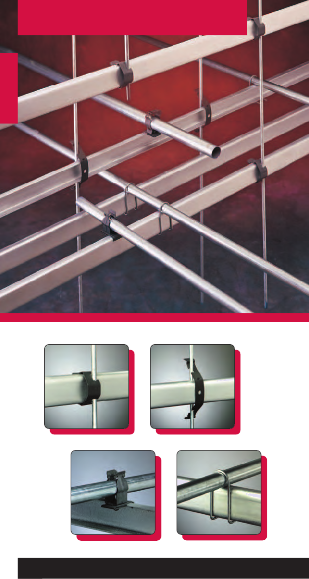
Lathers Channel
Lathers Channel
140
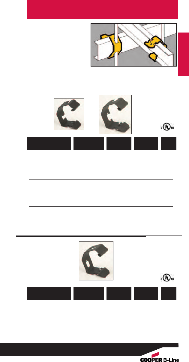
• For fastening standard
lathers channels to
wires and plain rods.
• Fits 1/2" through 5/8"
channel flange widths.
• Accepted for use by
the City of New York
Department of
Buildings. MEA
383-91-M.
• Static Load Capacity:
160 Lbs.
Lathers Channel
Rod & Wire
Fasteners
Lathers Channel
781011 19882 BL-24-2 11/2” #8 Wire 100
UPC/Part
Number
Rod/Wire
Size
Catalog
Number
Channel
Size
Box
Qty.
UPC/Part
Number
Rod/Wire
Size
Catalog
Number
Channel
Size
Box
Qty.
781011 19885 BL-32-4 2” 1/4” Rod 100
781011 19884 BL-24-4C 11/2”1/4” Rod 100
Center Mount
Side Mounts
781011 19883 BL-24-4 11/2”1/4” Rod 100
141
Read safety/installation instruction sheets in packages before use.
BL-24-4
BL-24-2
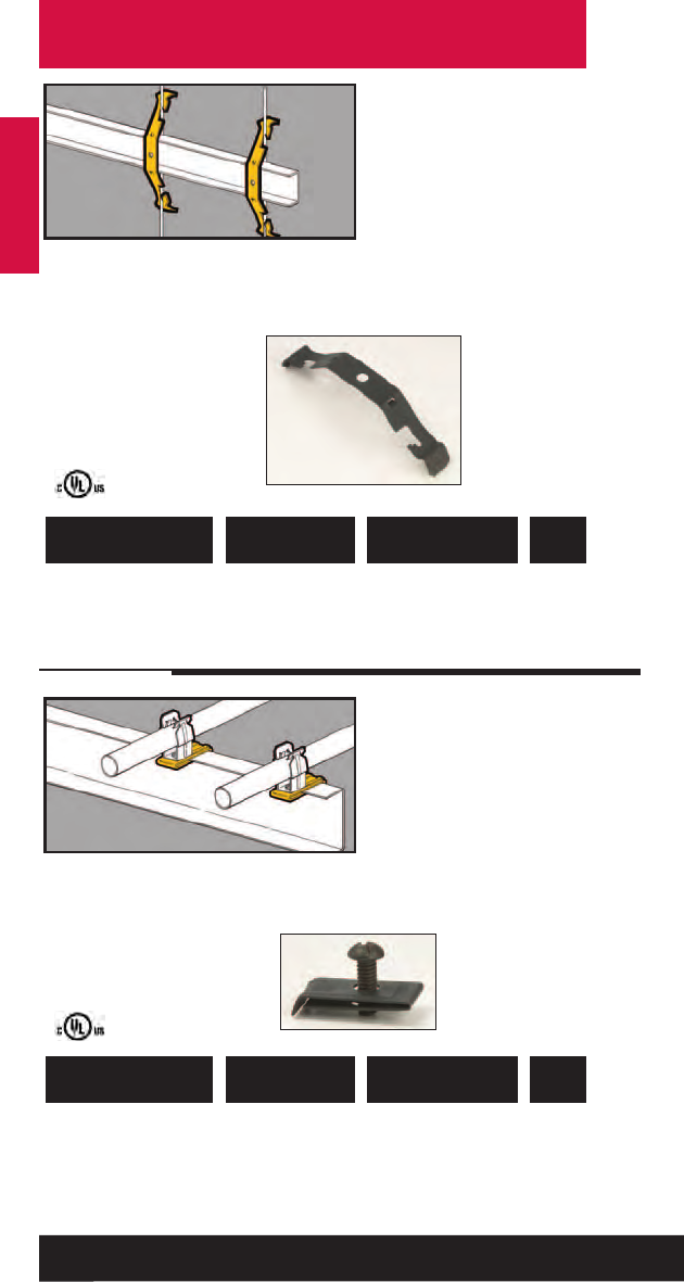
Lathers Channel
• For fastening standard
11/2" lathers channel to
wires and plain rods.
• Wire size: #8 and #9.
• Rod size: 3/16" and 1/4".
• Fits 9/16" thru 5/8"
channel flange widths.
• Static Load Capacity:
100 Lbs.
Lathers Channel
Rod & Wire
Fasteners
781011 19880 BL1 Channel to Rod 100
& Wire
UPC/Part
Number Description
Catalog
Number
Box
Qty.
• Serves as a mounting
base for conduit
fasteners or electrical
boxes.
•Attaches to either
flange of lathers
channel with 1/4"-20
screw (furnished).
• Fits channel flange
widths up to 5/8".
Flange
Fasteners
781011 19881 BL2 Flange Fastener 100
with Screw
Note: This product is designed for positioning only. No load rating.
UPC/Part
Number Description
Catalog
Number
Box
Qty.
142
Read safety/installation instruction sheets in packages before use.
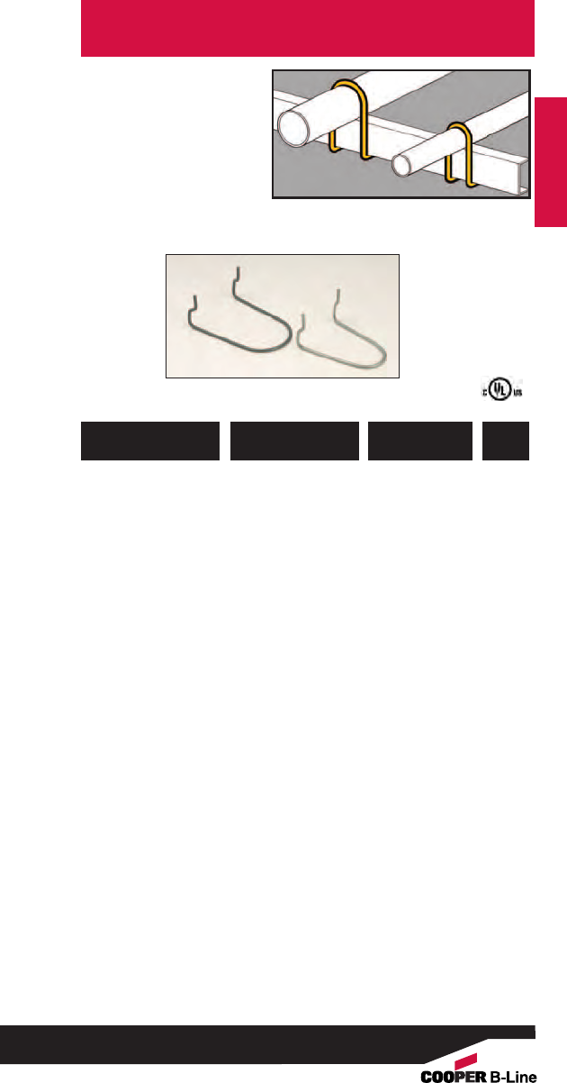
• Fastens EMT to 11/2"
lathers channel.
• Static Load Capacity:
50 Lbs.
• Finish: Zinc Plated
Lathers Channel
Conduit Fasteners
Lathers Channel
781011 19902 BL3-8 1/2” 100
781011 19903 BL3-12 3/4” 100
781011 19904 BL3-16 1” 100
781011 19905 BL3-20 11/4” 100
UPC/Part
Number
EMT Conduit
Size
Catalog
Number
Box
Qty.
143
Read safety/installation instruction sheets in packages before use.
BL3-12
BL3-20
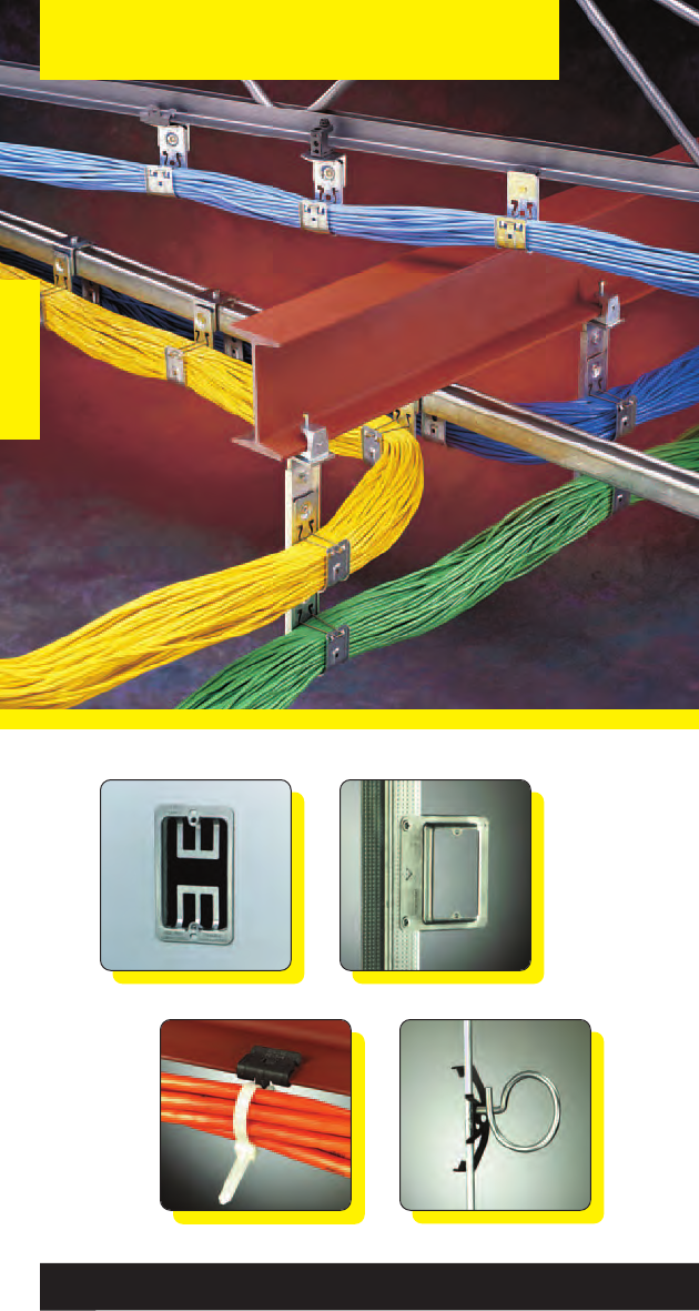
Communication & Low Voltage
Communication & Low Voltage
144
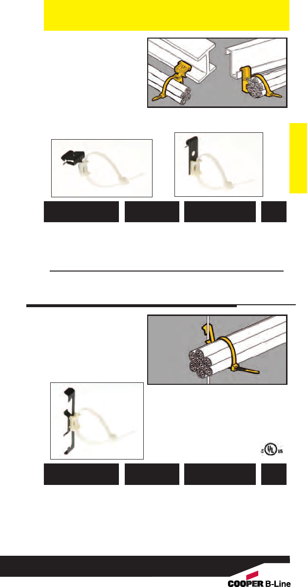
Communication & Low Voltage
Communication & Low Voltage
• Supports cable ties up
to 9/32" wide from
flanges 1/16" to 3/4"
thick.
• 8" cable tie included.
• Simply installed with
a hammer.
Cable Fasteners
781011 19970 BE-2-4-CT2
1/8” to 1/4” 100
781011 19971 BE-5-8-CT2
5/16” to 1/2” 100
781011 19972 BE-9-12-CT2
9/16” to 3/4” 100
781011 19968 BF1-CT2
1/16” to 5/32” 100
781011 19969 BF2-CT2
5/32” to 1/4” 100
UPC/Part
Number Description
Catalog
Number
Box
Qty.
• Supports cable ties up
to 9/32" wide from
drop wires.
• 8" cable tie included.
Cable
Fasteners
781011 02866 BW2-CT2
#12 wire thru 100
1/4” plain or
threaded rod
781011 95603 BW6-CT2
3/8” plain or 100
threaded rod
UPC/Part
Number Description
Catalog
Number
Box
Qty.
145
Read safety/installation instruction sheets in packages before use. These products are designed for positioning only. No load rating.
BE Series
BF Series
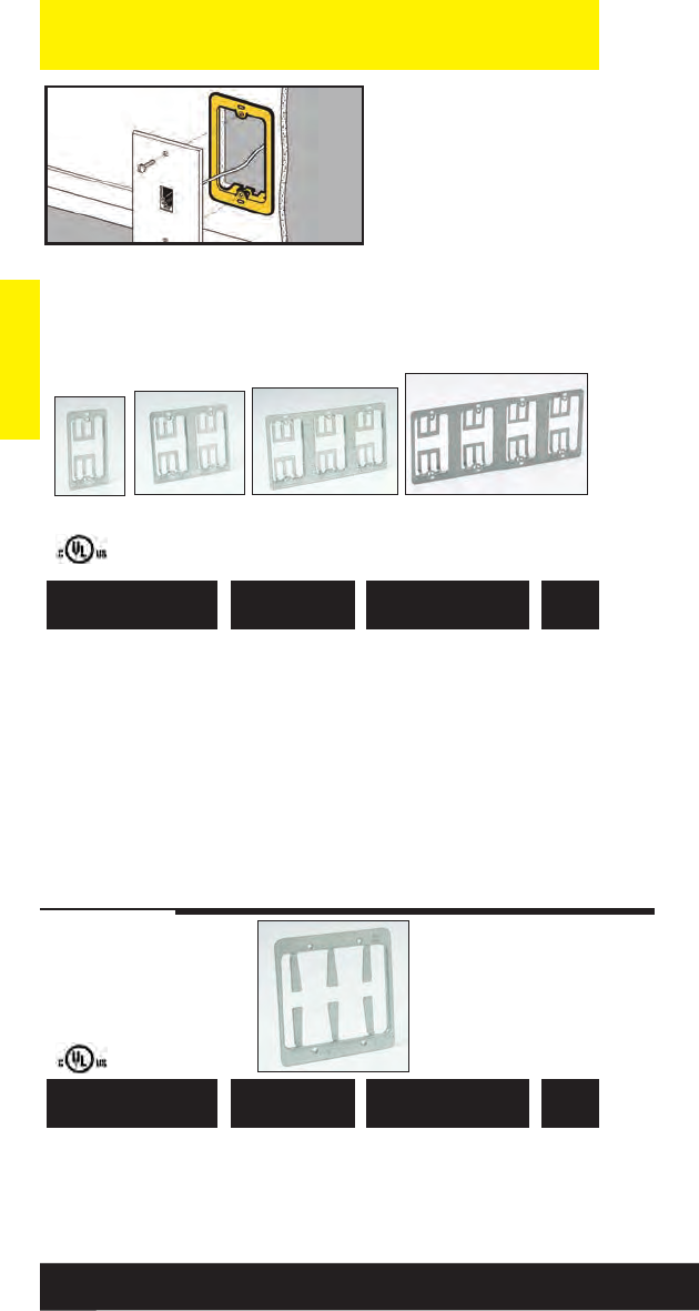
Communication & Low Voltage
• Replaces electrical box
in Class 2 low voltage
installations.
• Provides attachment
base for low voltage
outlets.
• Accepts Decora®* style
cover plates.
• Maximum 11/4” drywall
thickness.
• Finish: Pre-galvanized
* Decora® is a registered trademark of Leviton Corporation.
Communication & Low Voltage
Cover Plate
Mounting
Brackets
781011 18150 BB10 Single Gang 50
Bracket
781011 18152 BB10-2 Mounts 2 10
Single Plates
781011 19878 BB10-3 Mounts 3 10
Single Plates
781011 19879 BB10-4 Mounts 4 10
Single Plates
Patent # Re.33305
781011 18130 BB20 Double Gang 10
Bracket
Patent # Re.33305
UPC/Part
Number Description
Catalog
Number
Box
Qty.
UPC/Part
Number Description
Catalog
Number
Box
Qty.
146
Read safety/installation instruction sheets in packages before use. These products are designed for positioning only. No load rating.
BB10 BB10-2 BB10-3 BB10-4
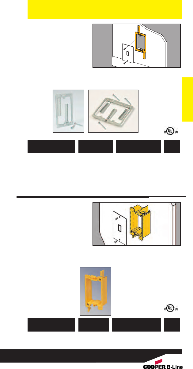
• Replaces electrical box
in Class 2 low voltage
installations.
• Provides attachment
base for low voltage
outlets.
• Maximum 11/4”
drywall thickness.
• Finish: Pre-galvanized
Communication & Low Voltage
Cover Plate
Mounting
Bracket
Communication & Low Voltage
781011 90895 BB10L Single Gang 50
Bracket
781011 90896 BB20L Double Gang 50
Bracket
UPC/Part
Number Description
Catalog
Number
Box
Qty.
• Provides attachment
base for low voltage
outlets.
•Replaces electrical box
in Class 2 low voltage
installations.
• Design eliminates
sharp edges from
bracket.
•Maximum wall
thickness: 3/4”
Plastic Cover
Plate Mounting
Bracket
782051 39235 BB10P Single Gang Bracket 50
UPC/Part
Number Description
Catalog
Number
Box
Qty.
BB10L BB20L
147
Read safety/installation instruction sheets in packages before use. These products are designed for positioning only. No load rating.
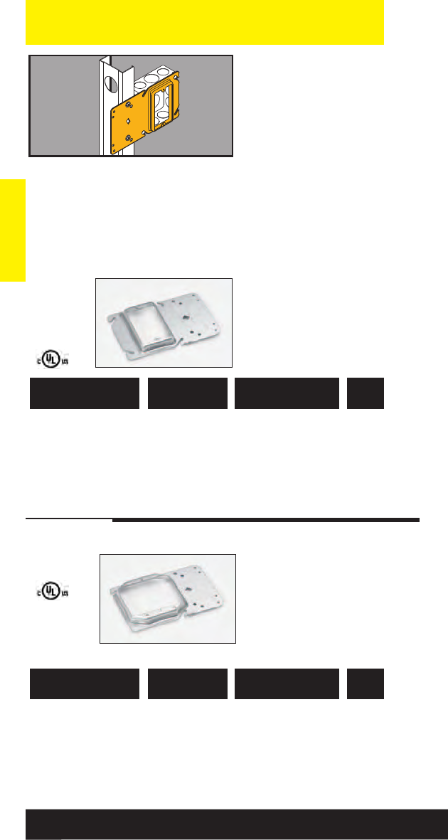
Communication & Low Voltage
• Uni-Mount™offers a
secure box support for
4” square boxes and
features a built-in
plaster ring.
• Rigid bracket design
eliminates the need for
far-side support.
• Replaces electrical
boxes in Class 2 low
voltage installations.
• Guide tabs ensure
consistent alignment on
studs.
• Finish: Pre-galvanized
Communication & Low Voltage
Uni-Mount™ Box
Support/Cover
Plate Mounting
Brackets
782051 22768 BB40-08 1/2” Raise 50
782051 22771 BB40-10 5/8” Raise 50
782051 22772 BB40-12 3/4” Raise 50
UPC/Part
Number Description
Catalog
Number
Box
Qty.
UPC/Part
Number Description
Catalog
Number
Box
Qty.
Single
Gang
782051 22773 BB45-08 1/2” Raise 50
782051 22774 BB45-10 5/8” Raise 50
782051 22775 BB45-12 3/4” Raise 50
Double
Gang
148
Read safety/installation instruction sheets in packages before use. These products are designed for positioning only. No load rating.
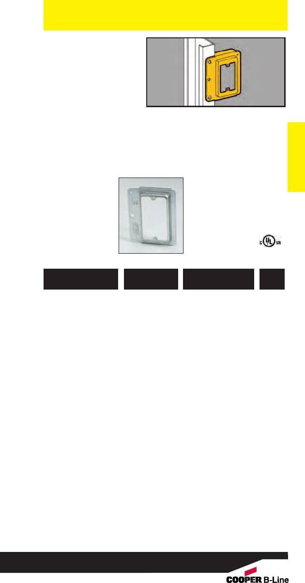
Communication & Low Voltage
Communication & Low Voltage
• Locates communication
outlets before drywall
is installed.
• Replaces electrical box
in Class 2 low voltage
installations.
• For 1/2” and 5/8”
drywall applications.
• Finish: Pre-galvanized Cover Plate
Mounting
Bracket
781011 19873 BB15 Single Gang Stud 25
Bracket
UPC/Part
Number Description
Catalog
Number
Box
Qty.
149
Read safety/installation instruction sheets in packages before use. These products are designed for positioning only. No load rating.

• Supports Cat. 5/5e/6/6A
fiber optic, innerduct
and low voltage cabling
requirements.
• Qwik-Latch™ cable
retainers included with
hooks.
• Static Load Capacity:
30 Lbs.
• Finish: Pre-Galvanized
Communication & Low Voltage
Communication & Low Voltage
Cable Hooks
782051 28060 BCH12 3/4” 16 4-Pair UTP 50
Cat 5e or 2-Strand
Fiber Optic Cable
or 10 CAT6
781011 04713 BCH21 15/16” 50 4-Pair UTP 50
Cat 5e or 2-Strand
Fiber Optic Cable
or 32 CAT6
781011 04717 BCH32 2” 80 4-Pair UTP 50
Cat 5e or 2-Strand
Fiber Optic Cable
or 50 CAT6
781011 04721 BCH64 4” 300 4-Pair UTP 25
Cat 5e or 2-Strand
Fiber Optic Cable
or 185 CAT6
UPC/Part
Number
Capacity
Up To
Hook
Size
Catalog
Number
Box
Qty.
(See pages 234-235 for technical data.)
Patent #5961081
Open Closed
BCH21
BCH32
BCH64
BCH12
150
Read safety/installation instruction sheets in packages before use.
For special finish colors see page 151
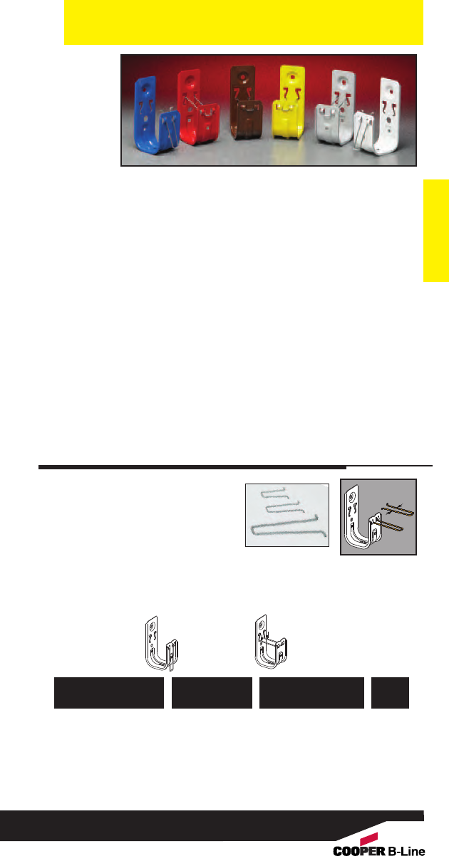
• Powder coated cable hooks are
available in a range of colors to help
meet your cable identification
requirements.
• Standard riveted assemblies are available
with painted cable hooks.
• Part numbers can be made by adding the paint
color suffix after the cable hook part number.
• Minimum order quantity 500 pieces.
• Standard lead time is 5-10 working days.
Communication & Low Voltage
Communication & Low Voltage
151
Read safety/installation instruction sheets in packages before use.
Painted
Cable Hooks
Bright White - BW Green - GR
Brown - BR Orange - OR
Computer White - CW Regal Red - RR
Equipment Blue - BL Safety Yellow - YL
Flat Black - FB Telcom Gray - TG
Part # Example:
Painted Cable Hook Part Number - BCH32BW
Painted Cable Hook Assembly - BCH32BW-U24
• Exclusive Qwik-Latch™
retainers are included on
all cable hook purchases.
• Provides secure
containment of cables
and offers quick open/close
feature to add or remove
cables.
•Finish: Pre-galvanized
Retainer
in open
position
Push
retainer
down to
lock
781011 04847 BCHR21
15/16”50
781011 04848 BCHR32
2” 50
781011 04849 BCHR64
4” 50
UPC/Part
Number
Cable Retainer
For Hook Size
Catalog
Number
Box
Qty.
Replacement
Cable Retainers
Patent #5961081
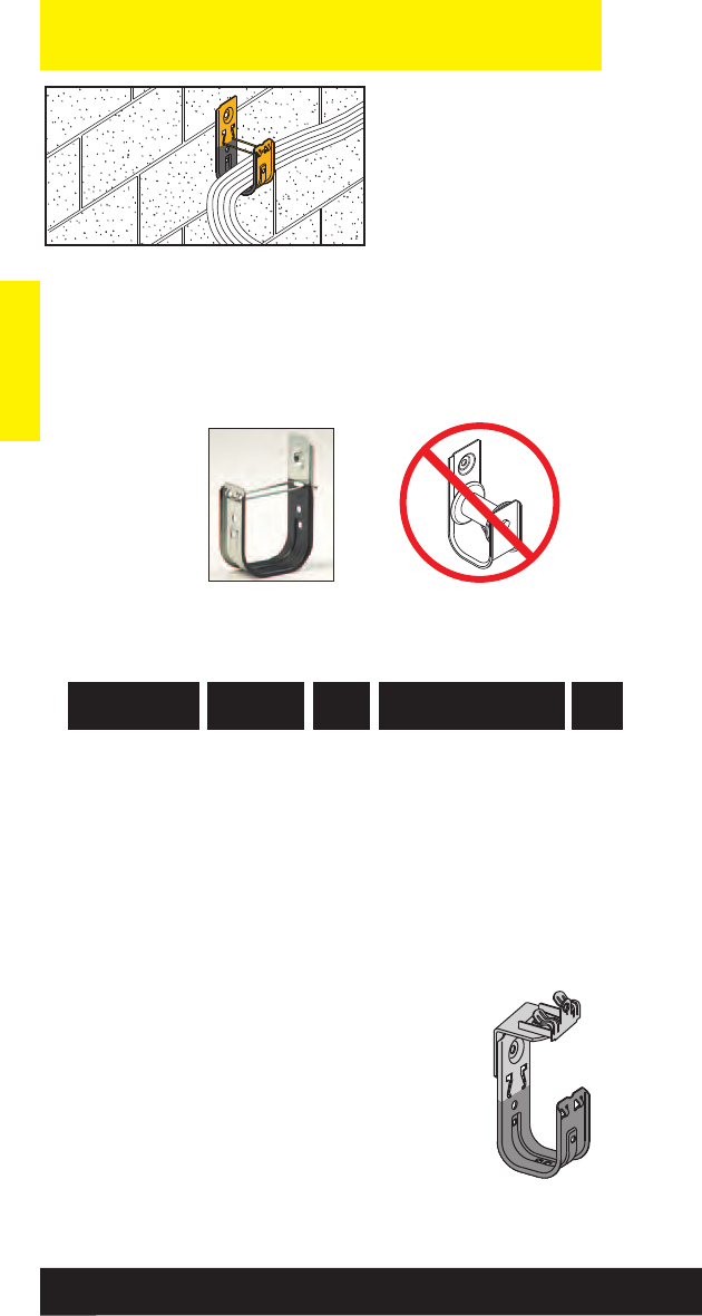
Communication & Low Voltage
Communication & Low Voltage
152
Read safety/installation instruction sheets in packages before use.
• Xylan®coating
provides smooth
frictionless surface for
cable pulling.
• Great for use in corners,
drop-outs or direction
change.
• X-Hook has lower
coefficient of
friction than Teflon®.
•Qwik-Latch cable retainer
included with each hook.
• Static Load Capacity:
30 Lbs.
X-Hook
Low Friction
Cable Hooks
782051 29940 BCH21X 15/16” 50 4-Pair UTP 50
Cat 5e or 2-Strand
Fiber Optic Cable
or 32 CAT6
782051 29941 BCH32X 2” 80 4-Pair UTP 50
Cat 5e or 2-Strand
Fiber Optic Cable
or 50 CAT6
782051 29942 BCH64X 4” 300 4-Pair UTP 25
Cat 5e or 2-Strand
Fiber Optic Cable
or 185 CAT6
UPC/Part
Number Capacity
Hook
Size
Catalog
Number
Box
Qty.
Note: For cable hook assemblies with X-Hooks add an X
to the part number.
Example: BCH32X-U-2-4
(See pages 234-235 for technical data.)
Cable rollers are too expensive and
require installation and removal.
New Xylan®coating reduces cable
friction. Ideal for pulling cable.
BCH64X
Xylan®is a registered trademark used by Whitford Corporation
Teflon®is a registered trademark used by DuPont®
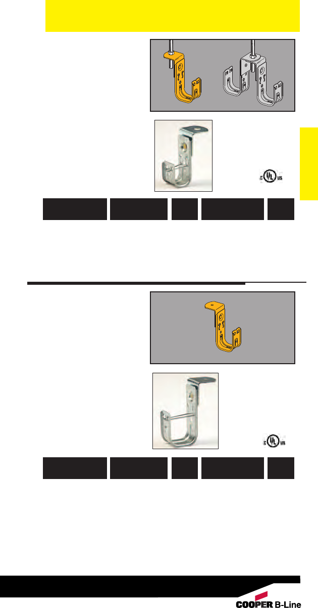
Communication & Low Voltage
Communication & Low Voltage
153
Read safety/installation instruction sheets in packages before use.
• .505” diameter hole
designed to support
cable from 3/8” or
1/2” threaded rod.
• Allows back-to-back
and multi-tier
installations.
• Qwik-Latch™cable
retainer included with
each hook.
• Static Load Capacity:
30 Lbs.
• Finish: Pre-galvanized
Cable
To ATR
Fasteners
• Designed for direct
attachment to
structures.
•Supports cable from
1/4” threaded rod.
• .265” diameter hole
accepts anchors,
screws or common
nails.
• Qwik-Latch cable
retainer included with
each hook.
•Static Load Capacity:
30 Lbs.
•Finish: Pre-galvanized
Angle
Bracket
Cable
Fasteners
(See pages 234-235 for technical data.)
782051 28089 BCH12-RB 3/4”.265” Diameter 50
781011 04735 BCH21-RB 15/16” .265” Diameter 50
781011 04738 BCH32-RB 2” .265” Diameter 50
781011 04742 BCH64-RB 4” .265” Diameter 25
UPC/Part
Number Hole Size
Hook
Size
Catalog
Number
Box
Qty.
781011 04725 BCH21-AB 15/16” .505” Diameter 50
781011 04729 BCH32-AB 2” .505” Diameter 50
781011 04732 BCH64-AB 4” .505” Diameter 25
UPC/Part
Number Hole Size
Hook
Size
Catalog
Number
Box
Qty.
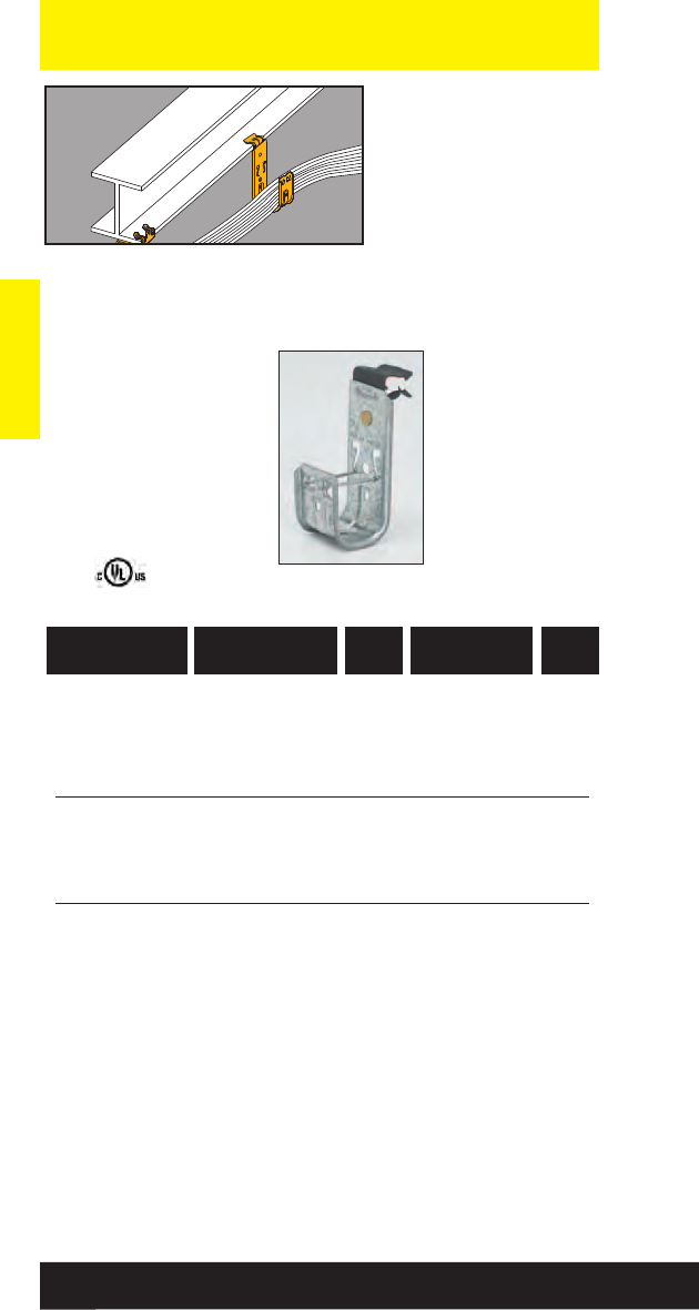
Communication & Low Voltage
Communication & Low Voltage
154
Read safety/installation instruction sheets in packages before use.
• Permits fast and easy
installation on beam
flanges.
• Qwik-Latch™cable
retainer included with
each hook.
• Static Load Capacity:
30 Lbs.
• Finish: Pre-galvanized
Cable To Beam
Fasteners
(See pages 234-235 for technical data.)
782051 28067 BCH12-E-2-4 3/4”1/8” to 1/4”50
782051 28072 BCH12-E-5-8 3/4”5/16” to 1/2”50
782051 28073 BCH12-E-9-12 3/4”9/16” to 3/4”50
781011 04803 BCH21-E-2-4 15/16”1/8” to 1/4”50
781011 04805 BCH21-E-5-8 15/16”5/16” to 1/2”50
781011 04807 BCH21-E-9-12 15/16”9/16” to 3/4”50
781011 04825 BCH32-E-2-4 2” 1/8” to 1/4”25
781011 04827 BCH32-E-5-8 2” 5/16” to 1/2”25
781011 04829 BCH32-E-9-12 2” 9/16” to 3/4”25
UPC/Part
Number
Flange
Thickness
Hook
Size
Catalog
Number
Box
Qty.
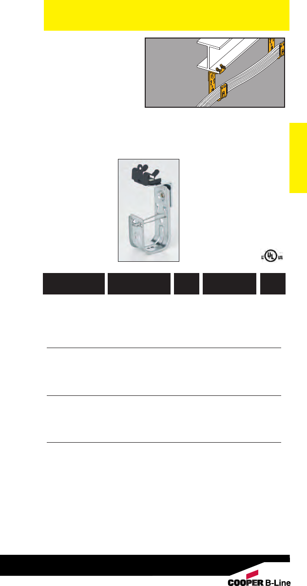
Communication & Low Voltage
Communication & Low Voltage
155
Read safety/installation instruction sheets in packages before use.
• Permits fast and easy
installation on beam
flanges.
• Qwik-Latch™cable
retainer included with
each hook.
• Static Load Capacity:
30 Lbs.
• Finish: Pre-galvanized Cable To Beam
Fasteners
Allows
360°
Rotation
782051 28062 BCH12-U-2-4 3/4”1/8” to 1/4”50
782051 28064 BCH12-U-5-8 3/4”5/16” to 1/2”50
782051 28066 BCH12-U-9-12 3/4”9/16” to 3/4”50
781011 04809 BCH21-U-2-4 15/16”1/8” to 1/4”50
781011 04811 BCH21-U-5-8 15/16”5/16” to 1/2”50
781011 04813 BCH21-U-9-12 15/16”9/16” to 3/4”50
781011 04831 BCH32-U-2-4 2” 1/8” to 1/4”50
781011 04833 BCH32-U-5-8 2” 5/16” to 1/2”50
781011 04835 BCH32-U-9-12 2” 9/16” to 3/4”50
781011 04864 BCH64-U-2-4 4” 1/8” to 1/4”25
781011 04865 BCH64-U-5-8 4” 5/16” to 1/2”25
781011 04866 BCH64-U-9-12 4” 9/16” to 3/4”25
UPC/Part
Number
Flange
Thickness
Hook
Size
Catalog
Number
Box
Qty.
(See pages 234-235 for technical data.)
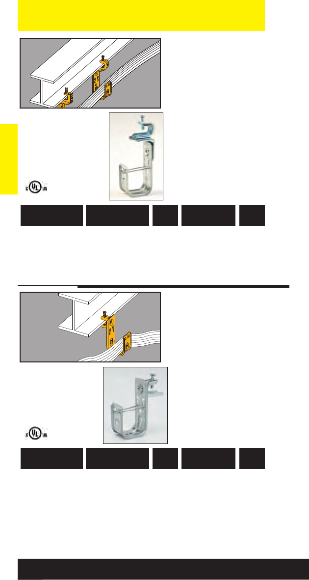
Communication & Low Voltage
Communication & Low Voltage
156
Read safety/installation instruction sheets in packages before use.
• 360° rotation allows
cable to run in any
direction.
• Qwik-Latch™cable
retainer included with
each hook.
• Static Load Capacity:
30 Lbs.
• Finish: Pre-galvanized
Cable
To Beam
Fasteners
782051 28077 BCH12-C442 3/4”1/8” to 5/8”50
781011 04823 BCH21-C442 15/16”1/8” to 5/8”50
781011 04845 BCH32-C442 2” 1/8” to 5/8”50
781011 04868 BCH64-C442 4” 1/8” to 5/8”25
UPC/Part
Number
Flange
Thickness
Hook
Size
Catalog
Number
Box
Qty.
(See pages 234-235 for technical data.)
• 360° rotation allows
cable to run in any
direction.
• Qwik-Latch cable
retainer included with
each hook.
•Static Load Capacity:
30 Lbs.
• Finish: Pre-galvanized
Cable
To Beam
Fasteners
782051 41850 BCH12-C442A 3/4”1/8” to 5/8”50
782051 41851 BCH21-C442A 15/16”1/8” to 5/8”50
782051 41852 BCH32-C442A 2” 1/8” to 5/8”50
782051 41853 BCH64-C442A 4” 1/8” to 5/8”25
UPC/Part
Number
Flange
Thickness
Hook
Size
Catalog
Number
Box
Qty.
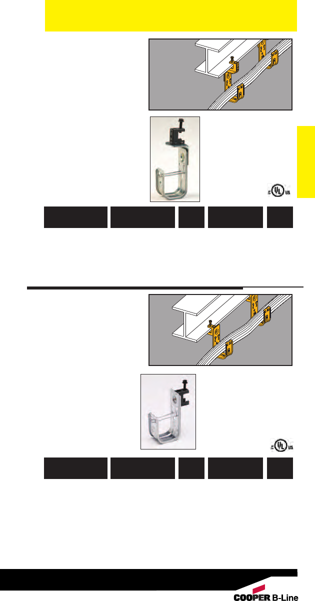
Communication & Low Voltage
Communication & Low Voltage
157
Read safety/installation instruction sheets in packages before use.
• 360° rotation allows
cable to run in any
direction.
• Qwik-Latch™cable
retainer included with
each hook.
• Static Load Capacity:
30 Lbs.
• Finish: Pre-galvanized Cable To
Beam
Fasteners
(See pages 234-235 for technical data.)
782051 28074 BCH12-C2 3/4” thru 1/2”50
781011 04821 BCH21-C2 15/16” thru 1/2”50
781011 04843 BCH32-C2 2” thru 1/2”50
781011 04867 BCH64-C2 4” thru 1/2”25
UPC/Part
Number
Flange
Thickness
Hook
Size
Catalog
Number
Box
Qty.
•Qwik-Latch cable
retainer included with
each hook.
• Static Load Capacity:
30 Lbs.
• Finish: Pre-galvanized
Cable To
Beam
Fasteners
782051 41303 BCH12-C1 3/4” thru 1/2”50
781011 95578 BCH21-C1 15/16” thru 1/2”50
781011 95560 BCH32-C1 2” thru 1/2”50
782051 41304 BCH64-C1 4” thru 1/2”25
UPC/Part
Number
Flange
Thickness
Hook
Size
Catalog
Number
Box
Qty.
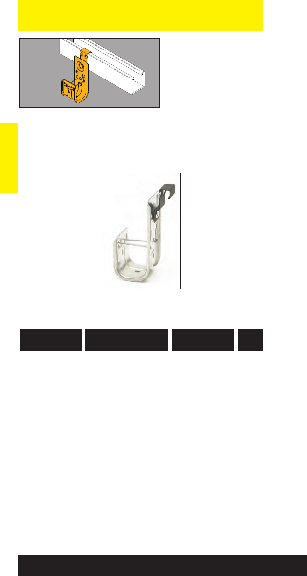
Communication & Low Voltage
Communication & Low Voltage
158
Read safety/installation instruction sheets in packages before use.
• BSC4 provides a
simple snap-on
attachment to strut,
eliminating the need for
tools or drilling.
• Great for retrofit
applications.
• Load Capacity:
30 Lbs.
• Finish: Pre-galvanized
Cable Hook
To Strut
Attachment
782051 46573 BCH12-SC4 3/4” 50
782051 46574 BCH21-SC4 15/16” 50
782051 46575 BCH32-SC4 2” 50
782051 46576 BCH64-SC4 4” 25
UPC/Part
Number
Cable Hook
Size
Catalog
Number
Box
Qty.
(See pages 234-235 for technical data.)
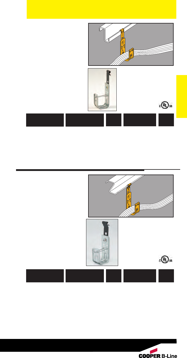
Communication & Low Voltage
Communication & Low Voltage
159
Read safety/installation instruction sheets in packages before use.
• Supports cable from
vertical flanges.
• Qwik-Latch™cable
retainer included with
each hook.
• Static Load Capacity:
30 Lbs.
• Finish: Pre-galvanized
Cable To
Flange
Fasteners
782051 28078 BCH12-F3 3/4”1/16” to 1/4”50
781011 04815 BCH21-F3 15/16”1/16” to 1/4”50
781011 04837 BCH32-F3 2” 1/16” to 1/4”50
781011 04869 BCH64-F3 4” 1/16” to 1/4”25
UPC/Part
Number
Flange
Thickness
Hook
Size
Catalog
Number
Box
Qty.
• Supports cable from
angled flanges.
•Qwik-Latch cable
retainer included with
each hook.
• Static Load Capacity:
30 Lbs.
• Finish: Pre-galvanized
Cable To
Flange
Fasteners
782051 28079 BCH12-F4 3/4”1/16” to 1/4”50
781011 04817 BCH21-F4 15/16”1/16” to 1/4”50
781011 04839 BCH32-F4 2” 1/16” to 1/4”50
781011 04870 BCH64-F4 4” 1/16” to 1/4”25
UPC/Part
Number
Flange
Thickness
Hook
Size
Catalog
Number
Box
Qty.
(See pages 234-235 for technical data.)
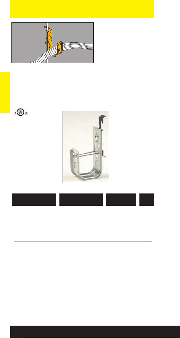
Communication & Low Voltage
Communication & Low Voltage
160
Read safety/installation instruction sheets in packages before use.
• Supports cable from
#12 wire thru 3/8”
threaded rod.
• Qwik-Latch™cable
retainer included with
each hook.
• W2 series attaches to
#12 wire thru 1/4”
plain or threaded rod.
• W6 series attaches to
3/8” plain or threaded
rod.
• Static Load Capacity:
25 Lbs.
• Finish: Pre-galvanized
Cable
To Wire
and Rod
Fasteners
782051 28081 BCH12-W2 3/4”50
781011 04819 BCH21-W2 15/16”50
781011 04841 BCH32-W2 2” 50
782051 28082 BCH12-W6 3/4”50
781011 95567 BCH21-W6 15/16”50
781011 95569 BCH32-W6 2” 50
UPC/Part
Number Description
Catalog
Number
Box
Qty.
(See pages 234-235 for technical data.)
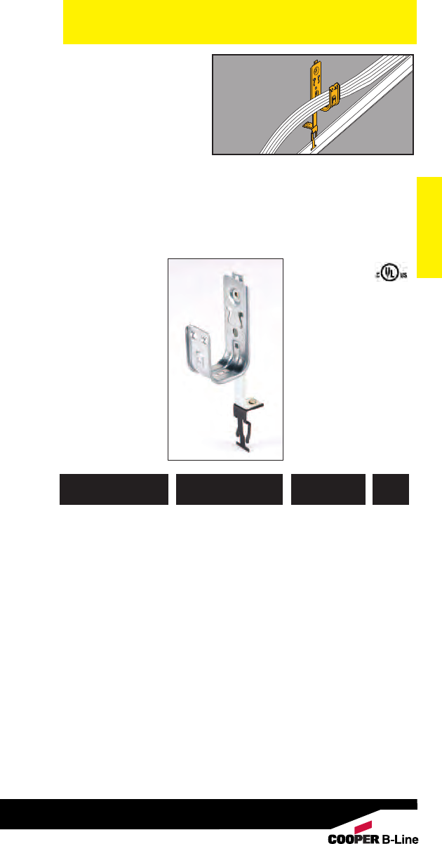
Communication & Low Voltage
Communication & Low Voltage
161
Read safety/installation instruction sheets in packages before use.
• Supports cable above
ceiling grid and allows
360° rotation.
• Provides compliance
with the EIA/TIA
requirements.
• Permits dropwire
attachment if required.
• Qwik-Latch™cable
retainer included with
each hook.
• Static Load Capacity:
30 Lbs.
• Finish: Pre-galvanized
Cable
To T-Bar
Fasteners
782051 28083 BCH12-A28 3/4”50
781011 04857 BCH21-A28 15/16”50
781011 04858 BCH32-A28 2” 50
UPC/Part
Number Description
Catalog
Number
Box
Qty.
(See pages 234-235 for technical data.)
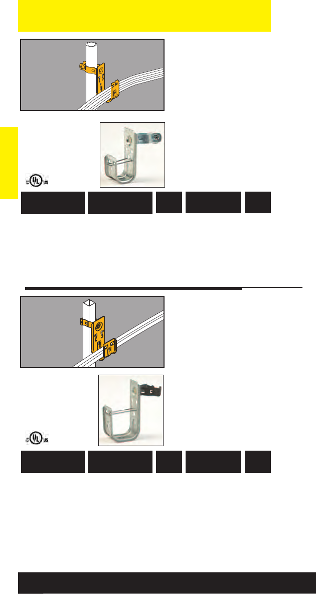
Communication & Low Voltage
Communication & Low Voltage
162
Read safety/installation instruction sheets in packages before use.
• Supports cable from
computer floor post.
• Organizes cable off the
floor for a neat
installation.
• Qwik-Latch™cable
retainer included with
each hook.
• Static Load Capacity:
30 Lbs.
• Finish: Pre-galvanized
Cable
To Floor
Support
Fasteners
782051 28085 BCH12-L1410 3/4” 1” O.D. 50
781011 04851 BCH21-L1410 15/16” 1” O.D. 50
781011 04855 BCH32-L1410 2” 1” O.D. 50
781011 04871 BCH64-L1410 4” 1” O.D. 25
UPC/Part
Number
Floor Post
Size
Hook
Size
Catalog
Number
Box
Qty.
• Supports cable from
square computer floor
post.
•Organizes cable off the
floor for a neat
installation.
• Qwik-Latch™cable
retainer included with
each hook.
• Static Load Capacity:
30 Lbs.
•Finish: Pre-galvanized
Cable
To Floor
Support
Fasteners
782051 28086 BCH12-G-8-12 3/4”1” Square 50
781011 72487 BCH21-G-8-12 15/16” 1” Square 50
781011 72489 BCH32-G-8-12 2” 1” Square 50
781011 72491 BCH64-G-8-12 4” 1” Square 25
UPC/Part
Number
Floor Post
Size
Hook
Size
Catalog
Number
Box
Qty.
(See pages 234-235 for technical data.)
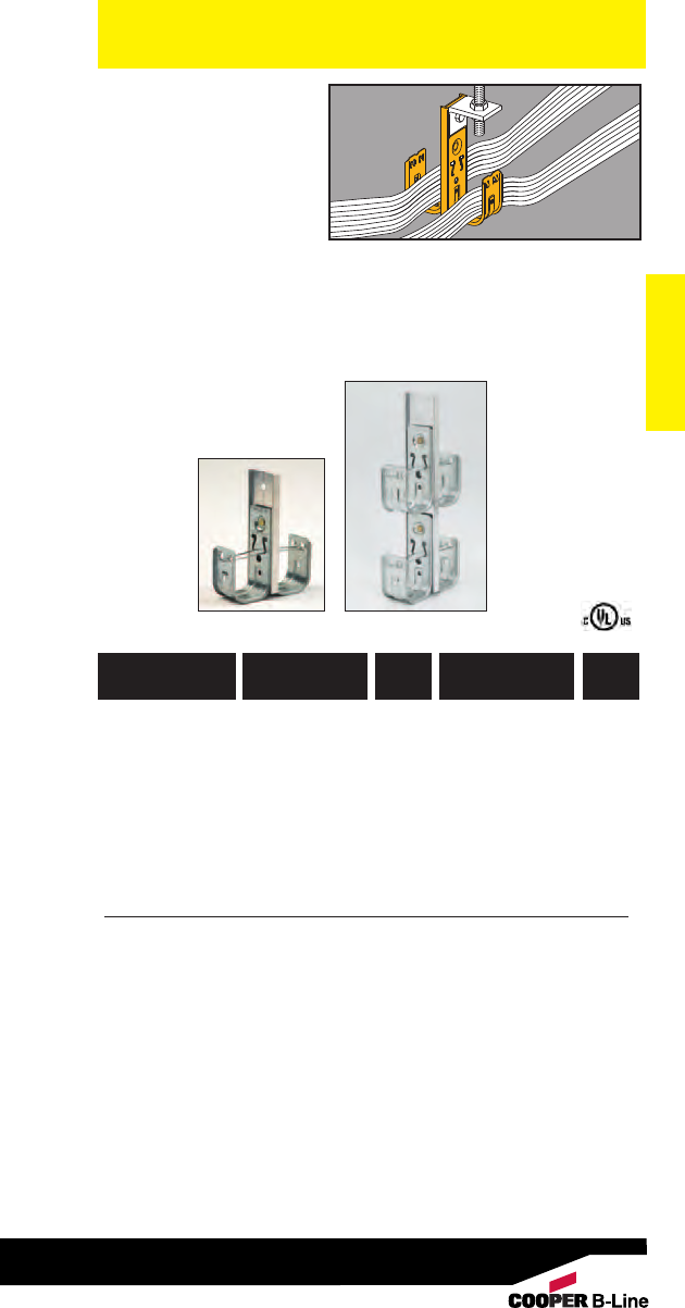
• Factory assembled
multi-tier fasteners
speed up installation.
• Unique design
prevents hook and
assembly rotation
when pulling cable.
• All support bars
furnished in 6063-T6 aluminum.
• Shown with optional BCHK2 kit.
•Qwik-Latch™cable retainer included
with each hook.
• Static Load Capacity: (per hook)
30 Lbs.
• Finish: Pre-galvanized
Communication & Low Voltage
Double-Sided
Multi-Tier
Cable
Fasteners
Communication & Low Voltage
(See pages 234-235 for technical data.)
781011 04758 BCH21-1D 15/16” 1 Tier, 2-Sided, 20
51/2” High
781011 04762 BCH32-1D 2” 1 Tier, 2-Sided, 25
63/16” High
781011 04874 BCH64-1D 4” 1 Tier, 2-Sided, 10
9” High
781011 04766 BCH21-2D 15/16”2 Tier, 2-Sided, 10
91/4” High
781011 04770 BCH32-2D 2” 2 Tier, 2-Sided, 10
11” High
781011 04875 BCH64-2D 4” 2 Tier, 2-Sided, 10
181/4” High
UPC/Part
Number Description
Hook
Size
Catalog
Number
Box
Qty.
1D 2D
Patent #5961081
163
Read safety/installation instruction sheets in packages before use.
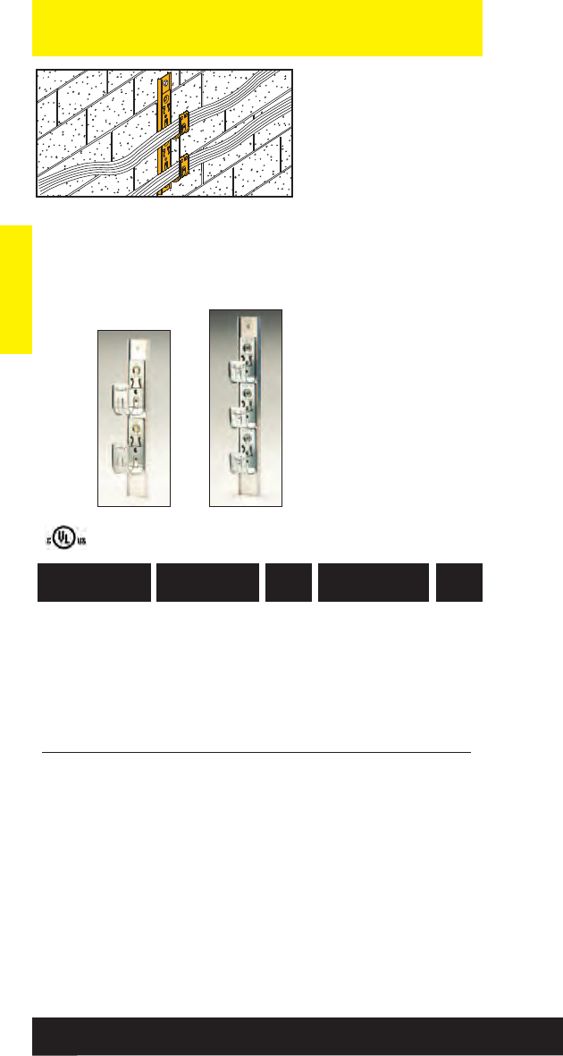
Communication & Low Voltage
• Factory assembled
multi-tier fasteners
speed up installation.
• Available in two-six
tier assemblies.
• Unique design prevents
hook and assembly
rotation when pulling
cable.
• Qwik-Latch™cable
retainer included with
each hook.
• All support bars
furnished in 6063-T6
aluminum.
• Static Load Capacity:
30 Lbs. (per hook)
Communication & Low Voltage
Single-Sided
Multi-Tier
Cable Fasteners
781011 04773 BCH21-2S 15/16”2 Tier, 1-Sided, 10
11” Overall Height
781011 04776 BCH32-2S 2” 2 Tier, 1-Sided, 10
123/4” Overall Height
781011 95300 BCH64-2S 4” 2 Tier, 1-Sided, 10
195/16” Overall Height
781011 04779 BCH21-3S 15/16” 3 Tier, 1-Sided, 10
143/4” Overall Height
781011 04782 BCH32-3S 2” 3 Tier, 1-Sided, 10
171/2” Overall Height
781011 95303 BCH64-3S 4” 3 Tier, 1-Sided, 10
281/16” Overall Height
UPC/Part
Number Description
Hook
Size
Catalog
Number
Box
Qty.
2S 3S
(See pages 234-235 for technical data.)
Patent #5961081
164
Read safety/installation instruction sheets in packages before use.
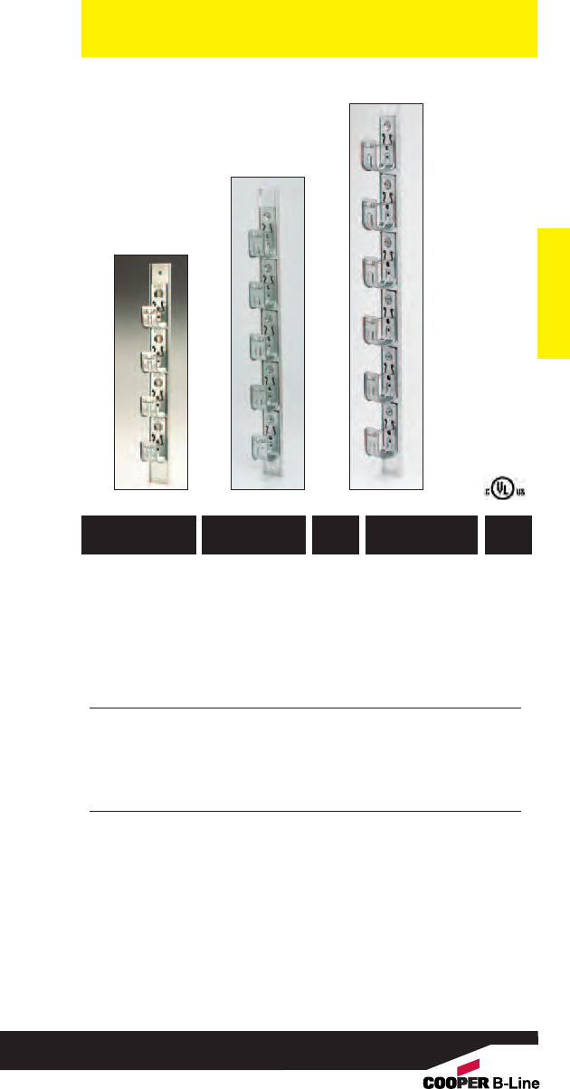
Communication & Low Voltage
Communication & Low Voltage
781011 04785 BCH21-4S 15/16”4 Tier, 1-Sided, 10
181/2” Overall Height
781011 04788 BCH32-4S 2” 4 Tier, 1-Sided, 10
213/4” Overall Height
781011 97872 BCH64-4S 4” 4 Tier, 1-Sided, 10
3613/16” Overall Height
781011 04791 BCH21-5S 15/16”5 Tier, 1-Sided, 10
213/4” Overall Height
781011 04794 BCH32-5S 2” 5 Tier, 1-Sided, 10
27” Overall Height
781011 04797 BCH21-6S 15/16” 6 Tier, 1-Sided, 10
26” Overall Height
781011 04800 BCH32-6S 2” 6 Tier, 1-Sided, 10
313/4” Overall Height
UPC/Part
Number Description
Hook
Size
Catalog
Number
Box
Qty.
(See pages 234-235 for technical data.)
4S
5S
6S
Patent #5961081
165
Read safety/installation instruction sheets in packages before use.
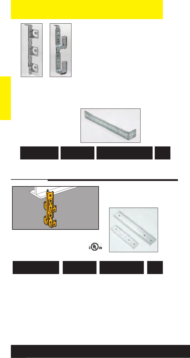
Communication & Low Voltage
Communication & Low Voltage
• Support bars furnished
in 6063-T6 aluminum.
Multi-Tier Cable
Hook Kits
(See pages 234-235 for technical data.)
781011 99572 BCH-HB21 Support Bar for 20
BCH21 and BCH32
81/4” long with .281
Ø
holes
781011 99574 BCH-HB64 Support Bar for 20
BCH64
135/16” long with .281
Ø
holes
UPC/Part
Number Description
Catalog
Number
Box
Qty.
166
Read safety/installation instruction sheets in packages before use.
BCH-HB
Support Bars
Shown with
BRC5
Brackets
Shown with
Cable
Hooks
• The BCH-HBA combines a
tiered support bar and angle
bracket into one piece.
• More flexibility! The BCH-HBA
can be supported from 3/16”,
1/4”, 5/16” or 3/8” rod.
• Mounts up to three BCH21 or
BCH32 cable hooks or
two BCH64 cable hooks per
side.
• Mounts up to three BRC5
MC/AC cable support brackets
per side.
• Load Capacity: 180 lbs.
Multi-Tier
Support Bar
782051 43819 BCH-HBA Multi-Tier Support Bar 40
UPC/Part
Number Description
Catalog
Number
Box
Qty.
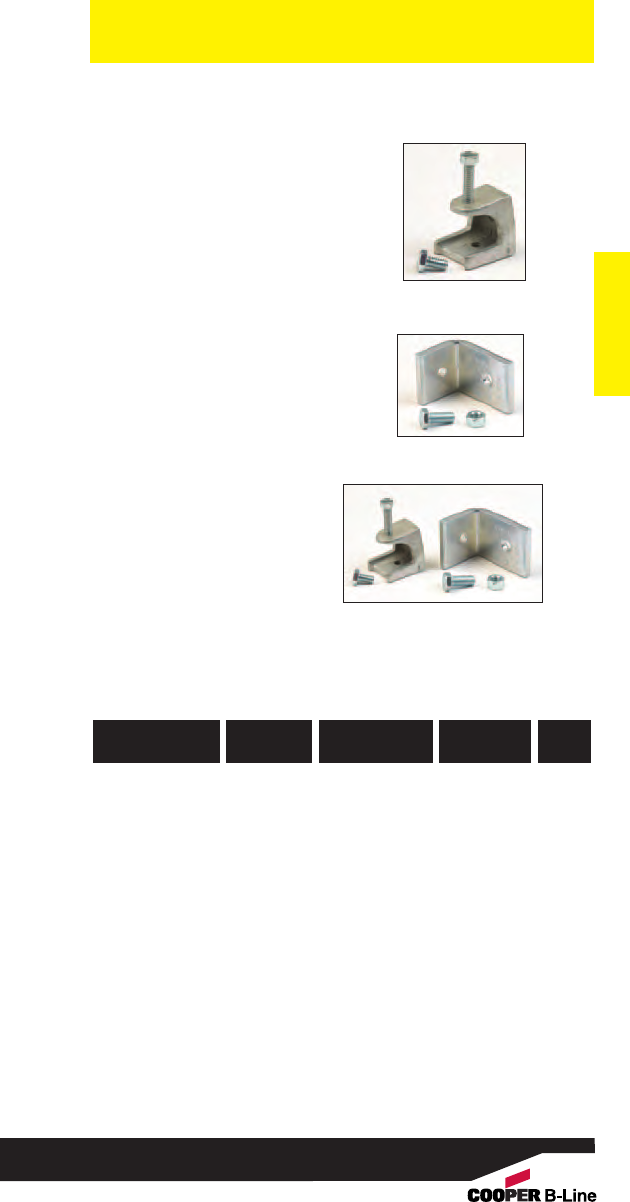
Communication & Low Voltage
Communication & Low Voltage
• BCHK1 includes:
Beam clamp (B444-1/4)
and 1/4”-20 x 1/2”
hex head cap screw
• BCHK2 includes:
Angle bracket (.320ӯ
and .390ӯ holes) and
1/4”-20 x 1/2” hex head
cap screw
• BCHK3 includes:
1 each BCHK1 Kit and
BCHK2 Kit
Multi-Tier
Attachment Kits
BCHK1
BCHK2
BCHK3
781011 04872 BCHK1 Beam Clamp Thru 1/2” 10
781011 04860 BCHK2 Angle Bracket -- 10
781011 04873 BCHK3 Beam Clamp Thru 1/2” 10
with Angle
Bracket
(swivels 360°)
UPC/Part
Number
Flange
Thickness
Kit
Description
Catalog
Number
Box
Qty.
167
Read safety/installation instruction sheets in packages before use.
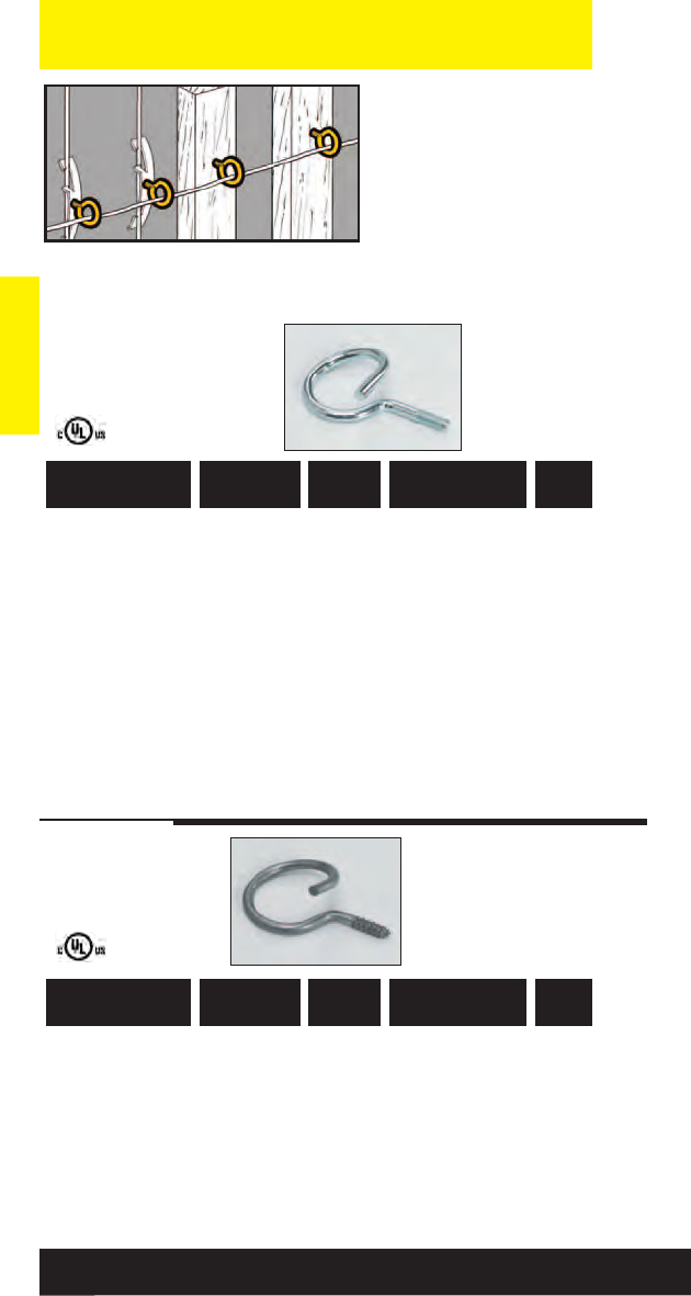
Communication & Low Voltage
• Supports low voltage
communication cables
from beams or rods
when used with other
fasteners.
•Ultimate Static
Load Capacity: 50 Lbs.
•Finish: Zinc Plated
Communication & Low Voltage
Threaded
Bridle Rings
Lag Screw
for Wood
Beams
781011 19550 BR-8-T 1/2” #10-24 x 9/16” 100
781011 19555 BR-12-T 3/4” #10-24 x 9/16” 100
781011 19560 BR-20-T 11/4” #10-24 x 9/16” 100
781011 19570 BR-32-T 2” #10-24 x 9/16” 100
781011 19565 BR-20-4T 11/4”1/4”-20 x 9/16” 100
781011 19575 BR-32-4T 2” 1/4”-20 x 9/16” 100
781011 19889 BR-64-4T 4” 1/4”-20 x 9/16” 50
781011 19875 BR-16-3W 1” 9/16” x 9/16” 100
781011 19886 BR-24-4W 11/2”1/4” x 27/32” 100
781011 19876 BR-32-4W 2” 1/4” x 7/8” 100
UPC/Part
Number
Thread Size x
Thread Length
Ring
Size
Catalog
Number
Box
Qty.
UPC/Part
Number
Thread Size x
Thread Length
Ring
Size
Catalog
Number
Box
Qty.
168
Read safety/installation instruction sheets in packages before use.
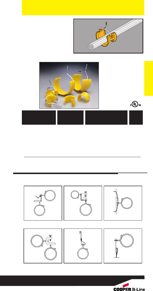
• The convenience of a
bridle ring with the
cable-bearing surface
of a hook.
• 2” saddle is available
separately. Can be
easily attached before
or after cable
installation.
Communication & Low Voltage
Bridle Ring
Saddles
Communication & Low Voltage
7820511 22761 BRS-32A 1/4”-20 x 7/8”50
2” Ring Assembly.
7820511 22762 BRS-64A 1/4”-20 x 1” 25
4” Ring Assembly.
7820511 22759 BRS-32 2” Saddle Only 50
UPC/Part
Number
Thread Size x
Thread Length/
Description
Catalog
Number
Box
Qty.
BRS-32A
BRS-64A
BRS-32
Also available for use with the following B-Line Fasteners.
BU-9-12 BC1 BW2
BC442 BH4-F3 BA5-4T
169
Read safety/installation instruction sheets in packages before use.
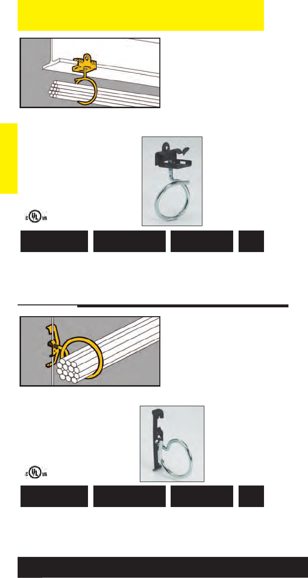
Communication & Low Voltage
• Supports low voltage
communication cables
from beam flanges 1/8”
to 3/4” thick.
• Pre-assembled with 2”
bridle ring.
• Reduces installation
time.
• Static Load Capacity :
15 lbs.
Communication & Low Voltage
Bridle Ring/Beam
Fastener Assy.
781011 02921 BR-32-4T-U-2-4
1/8” to 1/4”50
781011 02923 BR-32-4T-U-5-8
5/16” to 1/2”50
781011 02924 BR-32-4T-U-9-12
9/16” to 3/4”50
UPC/Part
Number Description
Catalog
Number
Box
Qty.
• Supports low voltage
communication cables
from drop wire.
• Pre-assembled with 2”
bridle ring.
•Reduces installation
time.
• Static Load Capacity :
15 lbs.
Bridle Ring/Rod
& Wire
Fastener Assy.
781011 02929 BR-32-4T-W2
#12 Wire Thru 50
1/4” Plain or
Threaded Rod
UPC/Part
Number Description
Catalog
Number
Box
Qty.
170
Read safety/installation instruction sheets in packages before use.
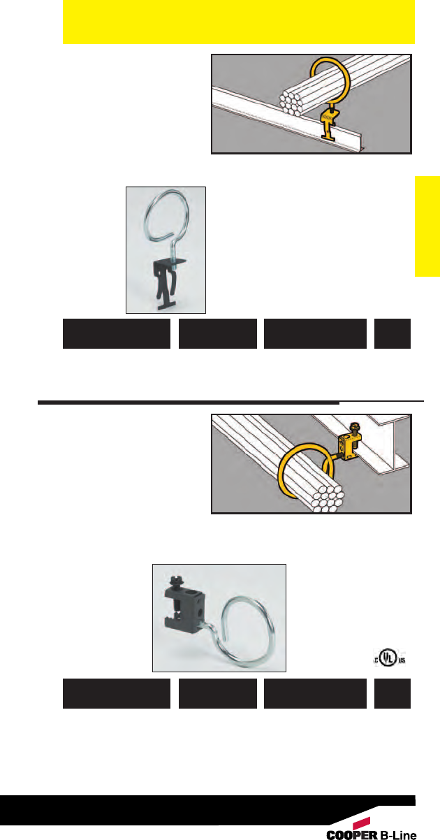
• Supports low voltage
communication cables
above the T-Bar.
• Pre-assembled with 2”
bridle ring.
• Reduces installation
time.
• For positioning only -
No Load Rating
Communication & Low Voltage
Bridle Ring/T-Bar
Fastener Assembly
Communication & Low Voltage
781011 02934 BR-32-4T-A6 2” Ring Size 50
UPC/Part
Number Description
Catalog
Number
Box
Qty.
•Supports low voltage
communication cables
from beam flanges
thru 1/2” thick.
•Pre-assembled with 2”
bridle ring.
•Reduces installation
time.
• Static Load Capacity:
15 lbs. Bridle Ring/Beam
Fastener Assembly
781011 02937 BR-32-4T-C1 2” Ring Size 50
UPC/Part
Number Description
Catalog
Number
Box
Qty.
171
Read safety/installation instruction sheets in packages before use.

Accessories
Accessories
172
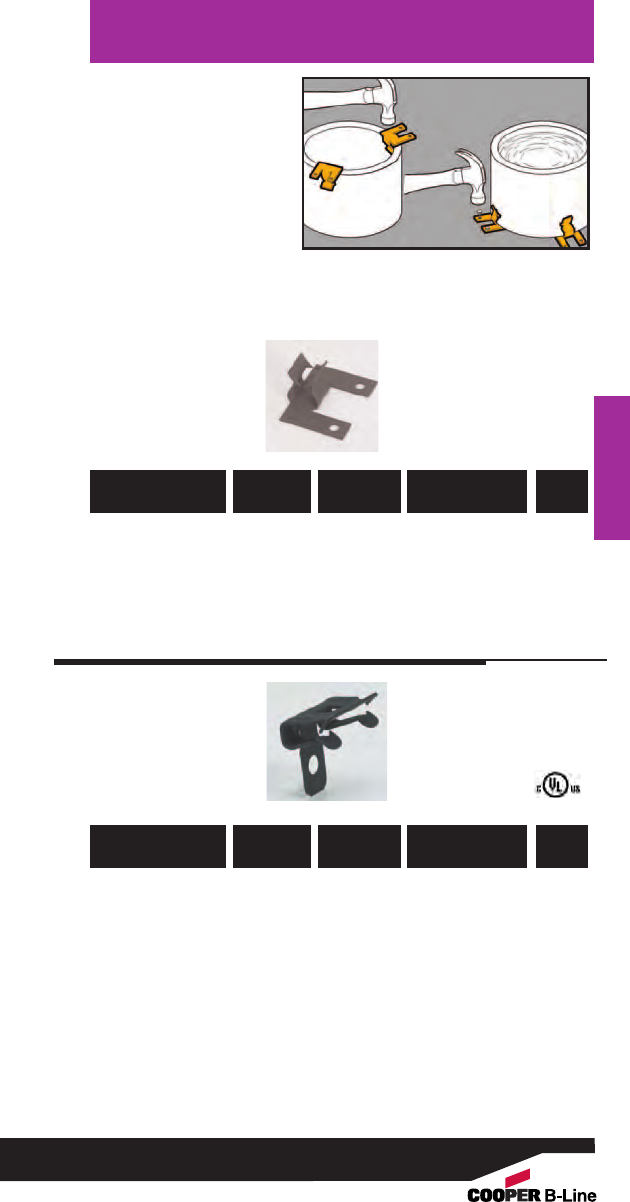
Accessories
•Allows for rigid
attachment of pipe
sleeves to wall and
floor forms for
concrete pouring.
• Accommodates
Schedule 40, Schedule
80, or 5/16" and
smaller wall thickness.
Pipe Sleeve
Fasteners
781011 18285 BD40 All Dia. 5/16” & Under 100
781011 18285 BD40 2” to 6” Schedule 40 100
Pipe
781011 18300 BE-5-8 6” Schedule 80 100
Pipe
781011 18300 BE-5-8 8” to 10” Schedule 40 100
Pipe
781011 18305 BE-9-12 9” to 14” Schedule 80 100
Pipe
UPC/Part
Number
Wall
Thickness
Sleeve
Diameter
Catalog
Number
Box
Qty.
UPC/Part
Number
Wall
Thickness
Sleeve
Diameter
Catalog
Number
Box
Qty.
Accessories
173
Read safety/installation instruction sheets in packages before use.
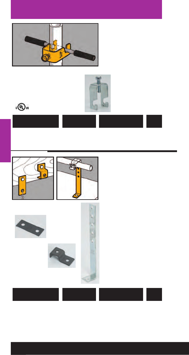
Accessories
• Attaches signal
reference grid wire to
computer floor posts.
• Fits #8 thru #4 stranded
wire. (.146” O.D. thru
.232” O.D.).
• Fits 3/4" to 1" round or
square posts.
Reference Wire
Fasteners
Accessories
781011 01659 BM5 Single Reference 100
Grid Wire Fastener
UPC/Part
Number Description
Catalog
Number
Box
Qty.
781011 01686 BD2 Flat Bracket 100
781011 18280 BD4 Offset Bracket 100
781011 01449 BA28B Angle Bracket 50
UPC/Part
Number Description
Catalog
Number
Box
Qty.
BD2
BD4
BA28B
• Brackets are easily
attached with screws or
drive pins to wood,
concrete or steel
structures.
• Brackets are adaptable
for use with a wide
variety of fasteners,
wires, “S” hooks and
hangers.
174
Read safety/installation instruction sheets in packages before use.
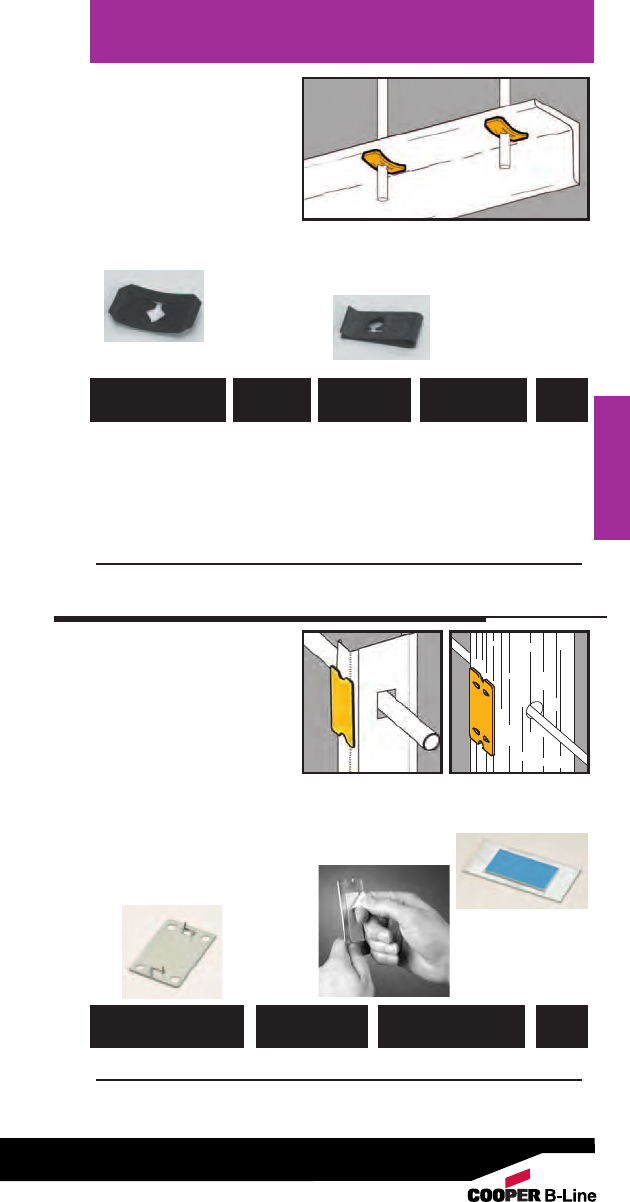
• Push Nuts designed
for use with plain rod.
• "U" Nuts provide
1/4"-20 thread
impression for
unthreaded hole.
• No installation tools
required.
Accessories
Accessory Nuts
Accessories
781011 19115 BN-2 #8 Wire 100 lbs. thru 100
3/8” hole
781011 19120 BN-4 1/4” Plain 100 lbs. thru 100
Rod 3/8” hole
781011 19125 BN-6 3/8” Plain 200 lbs. thru 100
Rod 1/2” hole
781011 19110 BN1 1/4” Threaded 50 lbs. on 100
Rod 9/32” hole
UPC/Part
Number
Static Load
Capacity
Rod/Wire
Size
Catalog
Number
Box
Qty.
BN-2, BN-4,
BN-6
Push Nuts BN1
"U" Nuts With
Thread Impression
Nail Plates
• Protects cable, plastic
pipe and copper
tubing from screw or
nail penetration.
•BM3M comes with
industrial grade
double stick tape on
back for easy
installation on metal stud.
• BM3 used on wood studs.
• Complies with NEC
Article 300-4.
782051 26251 BM3M Nail Plate 100
781011 04927 BM3 Nail Plate 100
UPC/Part
Number Description
Catalog
Number
Box
Qty.
Just Peel Tape
and
Stick To Stud
BM3
BM3M
BM3M
BM3
175
Read safety/installation instruction sheets in packages before use.
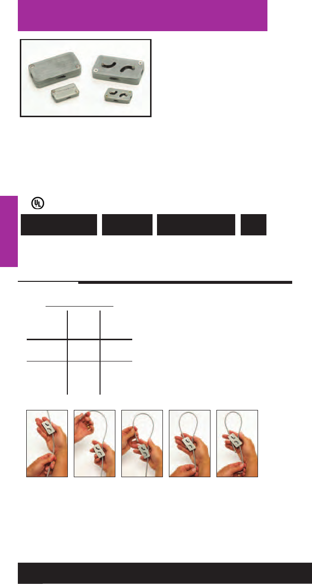
Accessories
• KwikWire™system
replaces jack chain or
ATR to support lighting,
ductwork, cable tray, etc.
• Can be quickly installed
around beams - No
drilling required.
• Ideal for sloped ceilings
- can hang objects at
up to 60° angles.
• Simple height
adjustments are made
by releasing locking
tab, no tools required.
• Spools of wire can be cut
to length in field,
reducing waste and up
front planning.
Accessories
KwikWire™Clamps
782051 40719 BKC100 1/16” & 3/32” 100
782051 40723 BKC200 1/8” & 3/16”50
UPC/Part
Number
For Use With Wire
Rope Diameters
Catalog
Number
Box
Qty.
176
Read safety/installation instruction sheets in packages before use.
KwikWire™ Clamp
Working Loads*
Clamp Wire Lbs.
Part No. Rope Safety
Dia. Factor 5
1/16” 0-75
BKC100 3/32” 25-150
3/32”25-150
BKC200 1/8”25-250
3/16” 50-640
* Working loads shown are for
hanging vertically.
For suspending at 15°, 30°, 45°
or 60° angles from vertical use
the following percentage of
the working loads from the
chart:
15°= 96%, 30°= 86%,
45°= 70%, 60°= 50%
ç2 43 5
1. Pass the wire through the KwikWire™ Clamp
2. Loop wire through/around support
3. Pass wire back through KwikWire™Clamp
4. Push wire through clamp leaving 2” to 3” tail, then apply tension on wire
5. To adjust, remove tension and pull wire slightly to disengage teeth, slide
adjustment pin in direction shown by arrow to release wire.
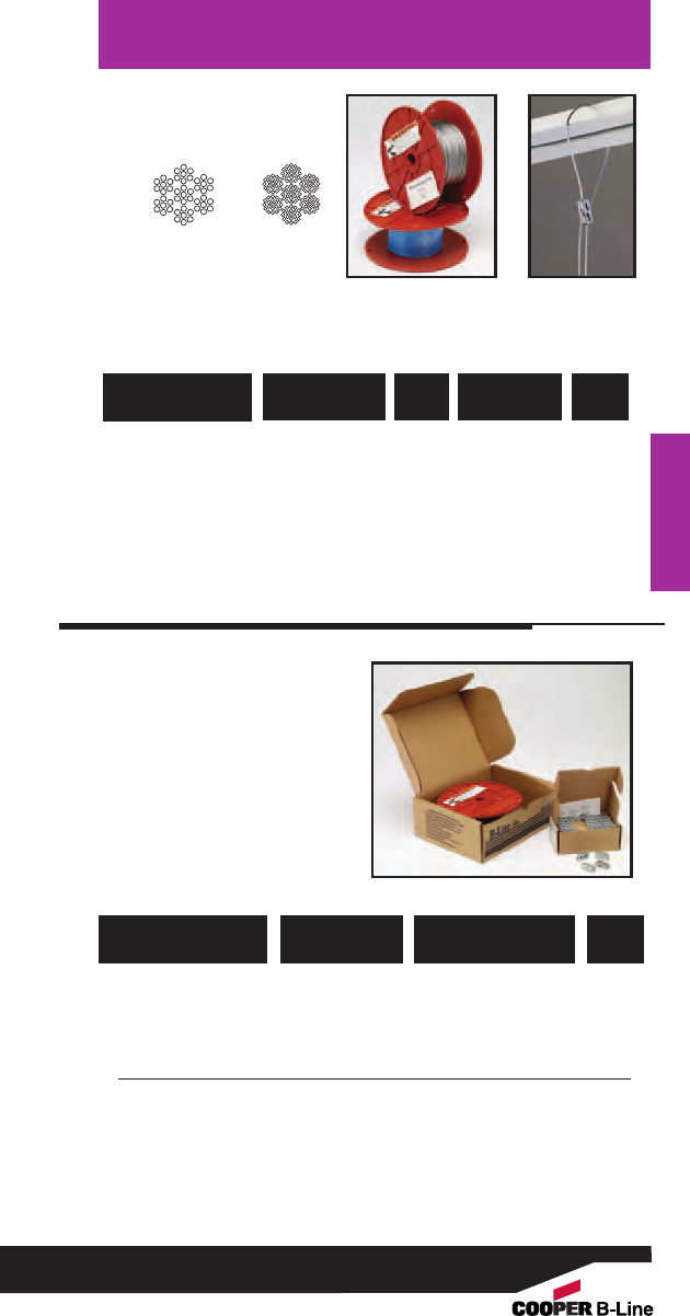
Accessories
Accessories
• B-Line KwikPak™ includes
a supply of kwik-clamps
and a spool of wire rope.
• KwikPak are shipped in
a specially designed
dispenser box to ease
field cutting of wire.
782051 40749 BKP10063 BKC100 (100 pcs.) 1
1/16ӯ Wire Rope (500 ft.)
782051 40751 BKP10094 BKC100 (100 pcs.) 1
3/32ӯ Wire Rope (500 ft.)
782051 40761 BKP20125 BKC200 (50 pcs.) 1
1/8ӯ Wire Rope (500 ft.)
782051 40763 BKP20188 BKC200 (50 pcs.) 1
3/16ӯ Wire Rope (250 ft.)
UPC/Part
Number Kit Includes
Catalog
Number
Box
Qty.
177
Read safety/installation instruction sheets in packages before use.
KwikPak™
782051 40725 BKW063 (1) 1/16” 96 500 ft
782051 40727 BKW094 (1) 3/32” 184 500 ft
782051 40733 BKW125 (1) 1/8” 340 500 ft
782051 40734 BKW188 (2) 3/16” 840 250 ft
(1) Wire rope construction Type 7 x 7 (2) Wire rope construction Type 7 x 19
Uncoated Galvanized Wire
UPC/Part
Number
Rope
Dia.
Working
Load - Lbs.
Catalog
Number
Spool
Qty.
7 x 7 7 x 19
KwikWire™Wire Rope
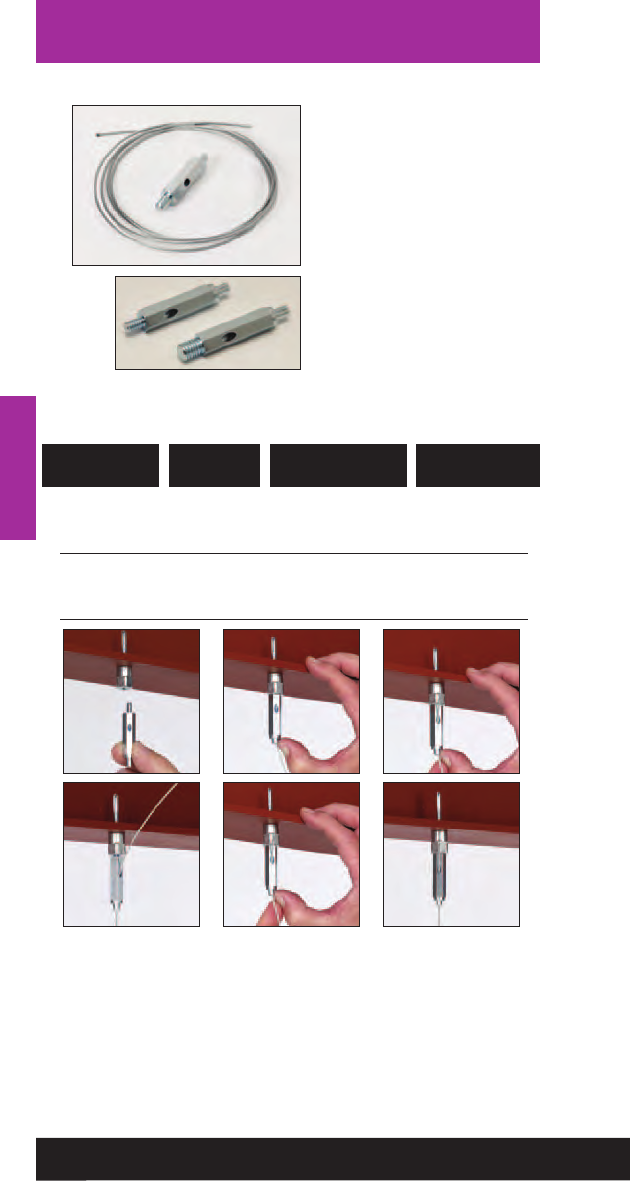
Accessories
Accessories
178
Read safety/installation instruction sheets in packages before use.
KwikWire™Hanger
1/16” (1.5 mm) 45 (20kg)
BKF100-4 1/4”-20 3/32” (2.5 mm) 90 (40kg)
1/16” (1.5 mm) 45 (20kg)
BKF100-6 3/8”-16 3/32” (2.5 mm) 90 (40kg)
UPC/Part
Number
Wire Rope Dia.
in. (mm)
Thread
Size
Loading* SF5
lbs. (kg)
• KwikWire™hanger
combines the versatility of
a bolt with an adjustable
wire rope solution.
• Can be quickly installed
in existing anchors or
metal brackets with a nut.
•Ideal for supporting light
fixtures, wire basket cable
tray, HVAC ducts, and
sign/banner supports.
• See page 176 for wire rope
spools.
123
456
1. Screw KwikWire Hanger into installed hanger support
2. Push wire up through the bottom of KwikWire Hanger
3. Continue pushing through until 1/4” minimum is extending out the
side of the KwikWire Hanger
4. To adjust up - pull or push more wire through KwikWire Hanger
5. To adjust down - push up on bottom of KwikWire Hanger and allow
wire to feed down
6. When hanging the wire is complete, cut off any excess cable wire if desired
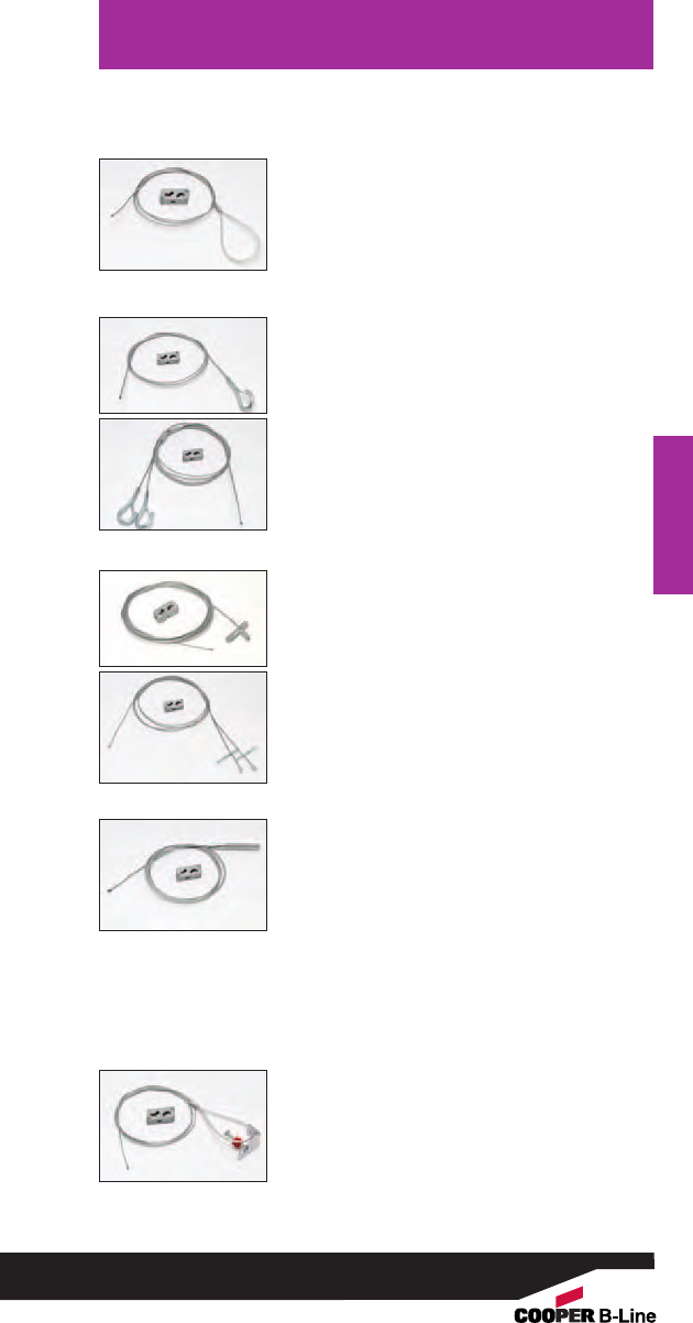
Accessories
Accessories
179
Read safety/installation instruction sheets in packages before use.
KwikWire™Accessories
•Available as a wire rope with loop termination only or
as a ready-to-use kit with a BKC100 clamp.
• Available in lengths of 40”, 80”, 120”, 180”, 240”,
and 360”.
Loop Termination
•Ideal for use with ARS, ARC, ADI, ACPW, or ACPD
anchors.
• Available as a wire rope with bolt termination only
or as a ready-to-use kit with a BKC100 clamp.
• Available in lengths of 40”, 80”, 120”, 180”, 240”,
and 360”.
• Available in single, double (Y), and triple (3) styles
•All double (Y) and triple (3) styles are non-stock,
consult Cooper B-Li ne for lead times
Bolt Loop Termination
• Available as a wire rope with angle bracket termination
only or as a ready-to-use kit with a BKC100 clamp.
• Available in lengths of 40”, 80”, 120”, 180”, 240”,
and 360”.
Angle Bracket Termination
Single & “Y” Style Hook Termination
• Hook designed to accept up to 3/8” diameter wire.
• Available as a wire rope with hook termination only
or as a ready-to-use kit with a BKC100 clamp.
• Available in lengths of 40”, 80”, 120”, 180”, 240”,
and 360”.
• Available in single, double (Y), and triple (3) leg
styles
Single & “Y” Style Toggle Termination
• Available as a wire rope with toggle termination only
or as a ready-to-use kit with a BKC100 clamp.
• Available in lengths of 40”, 80”, 120”, 180”, 240”,
and 360”.
• Available in single, double (Y), and triple (3) leg styles
• All triple (3) leg styles are non-stock, consult Cooper
B-Line for lead times
BKL Series
BKH Series
BKYH Series
BKT Series
BKTY Series
BKB Series
BKA Series
For additional options, refer to KwikWire Brochure (KWHS)
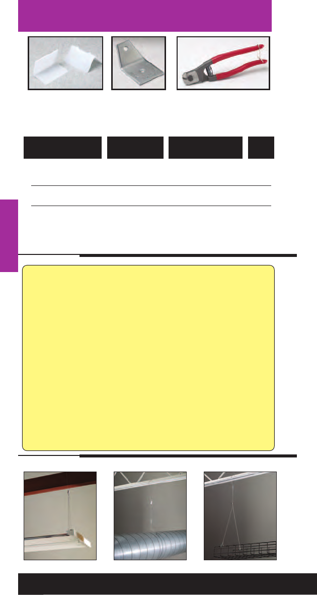
Accessories
Accessories
Application Photos
KwikWire™ System Recommendations:
•Do not exceed the safe working load of the products shown in
their charts
• KwikWire™ Clamp load ratings are guaranteed only when used
in combination with B-Line/Cooper supplied wire rope
•Do not use for overhead lifting or hoisting
• Do not use if cable or components are visibly distorted or worn,
remove damaged cable end prior to inserting in KwikWire™ Clamp
• Do not paint cable near working area of KwikWire Clamp connector
•Do not apply lubricant
• Keep product clean and free of dirt
• Do not use on coated wire rope
• Do not use in chlorinated or caustic atmospheres
• For use in dry locations
• Cooper’s BKCC tool is recommended for cutting wire rope to
prevent fraying
•For use on vertical applications only
782051 40766 BKCP Air Duct Corner 100
Protector
781011 56059 B601-62 Air Duct Support 50
782051 40297 BKCC Wire Rope Cutter 1
Danger: Never use cutters on energized circuits, wire, or cable.
Note: Additional accessories include BE Series (pg. 79),
BF Series (pgs. 106 & 110), and BPNA Series (pg. 118)
UPC/Part
Number Description
Catalog
Number Qty.
BKCP B601-62 BKCC
KwikWire™Accessories
180
Read safety/installation instruction sheets in packages before use.
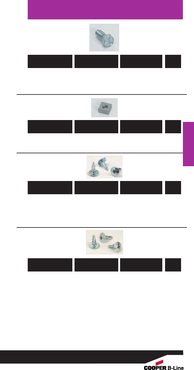
Accessories
Accessories
181
Read safety/installation instruction sheets in packages before use.
781011 01687 SHHMS 1/4x 1/21/4”-20 x 1/2” 100
Slotted Hex Head
Machine Screw
781011 42103 MSQN1/41/4”-20 Machine 100
Square Nut
UPC/Part
Number Description
Catalog
Number
Box
Qty.
UPC/Part
Number Description
Catalog
Number
Box
Qty.
UPC/Part
Number Description
Catalog
Number
Box
Qty.
781011 10675 BWHS-9 Sheet Metal 1000
Screw #8 x 9/16”
Note: BWHS-9 can be used with all fasteners requiring
attachments with sheet metal screws.
781011 04925 BWHS-9D #8 x 1/2” 1000
Self-Drilling
Sheet Metal Screw
Note: BWHS-9 can be used with all fasteners requiring
attachments with sheet metal screws except BB2-16, BB2-16D,
BB2-24 & BB2-24D.
UPC/Part
Number Description
Catalog
Number
Box
Qty.

Anchors
Anchors
182

Anchors
Glossary
Prefix - Description Screw Dia. Length Suffix
ACB - Concrete Anchor Bolt 4 - #4 75 - 3/4” AN - Acorn Nut
ACPD - Bang-IT 6 - #6 81 - 13/16” CH - Combo Head
ACPW - Wood-Knocker 8 - #8 87 - 7/8” F - Flat
ACS - Concrete Screw 10 - #10 100 - 1” FL - Flanged
ADA - Drive Anchor 12 - 1/8” 118 - 13/18” H - Hex
ADE - Double Expansion Anchor 18 - 3/16” 125 - 11/4” HN - Hex Nut
ADH - Hollow-Base Drop-IN 25 - 1/4” 150 - 11/2”HS - Hole Saw
ADI - Drop-In 31 - 5/16” 175 - 13/4” K - Kit
ADM - Mini Drop-In 37 - 3/8” 187 - 17/8” M - Mushroom
ADN - Drive Nail 50 - 1/2” 200 - 2” OH - Oval Head
AMS - Machine Screw 62 - 5/8” 225 - 21/4” PH - Pan Head
APC - Conical Anchor 75 - 3/4” 250 - 21/2” RH - Rod Hanger
APD - Plastic Driller 87 - 7/8” 275 - 23/4” RS - Slotted Round
APDM - Plastic Driller - Mini 300 - 3” Head
APH - Plastic Hollow Wall Anchor 325 - 31/4” SS4 - 304 Stainless
APS - Plastic Screw Anchor 350 - 31/2”Steel
ARC - Rapid Rod™Concrete 375 - 33/4”T - Tool
ARS - Rapid Rod™Steel 400 - 4” WH - Wire Hanger
ARW - Rapid Rod™Wood 425 - 41/4”
ASA - Sleeve Anchor 450 - 41/2”
ASE - Single Expansion Anchor 500 - 5”
ATB - Toggle Bolt 525 - 51/4”
ATM - Self-Tapping Machine 550 - 51/2”
Screw Anchor 600 - 6”
AWA - Wedge Anchor 700 - 7”
AWSD - Seismic Wedge Anchor
AWS - Wall Screw
AZD - Zinc Driller
AZDM - Zinc Driller-Mini
183
Read safety/installation instruction sheets in packages before use.
Anchors

Anchors
Anchors
184
Read safety/installation instruction sheets in packages before use.
• One-piece, all steel threaded fastener system for
suspending steel threaded rod.
• Suitable for overhead installations such as suspending
cable tray, pipe hangers, strut and conduit.
• Side Mount (SW) available for side mounting applications.
• Lower in-place cost, when compared to beam clamps,
lag bolts and drop-ins.
• Steel rapid rods can be installed with a screw gun or
hammer drill.
• UL & FM approved.
• Made of Zinc Plated carbon steel.
Rapid Rod™Hangers
Steel Rapid Rod - Data
Point Style #3 #5
Self-Drilling Range (in.) 20 ga. - 3/16 3/16 - 1/2
Screw Size (UNC) * 1/4”-20 1/4”-20
Thread Length (in.) * 13/16 31/32
Steel Rapid Rod - Load Data
Rod/ Minimum Steel Gauge Thickness
Anchor
Size 20 (.036”) 18 (.048”) 16 (.060”) 14 (.075”) 12 (.105”) 3/16”1/4”
1/4100 155 245 290 390 800 1260
1/4 w/nut 390 390 440 440 510 960 510
3/8100 155 245 290 390 490 490
3/8 w/nut 365 365 365 365 365 365 365
1/2120 175 230 390 510 820 1260
Rapid Rod Hangers
Steel
Loads shown for ASTM A36 steel beams and ASTM A572 steel purlins
include a safety factor of 4.
For UL & FM listings, steel rapid rod must be installed with a retaining nut.
UL & FM load rating for 3/8” rapid rod is 365 lbs. and can support up to a
maximum 4” pipe.
UL & FM load rating for 1/2” rapid rod is 900 lbs. and can support up to a
maximum 6” pipe.
*Dimensions for self-drilling (embedded) portion of anchor.
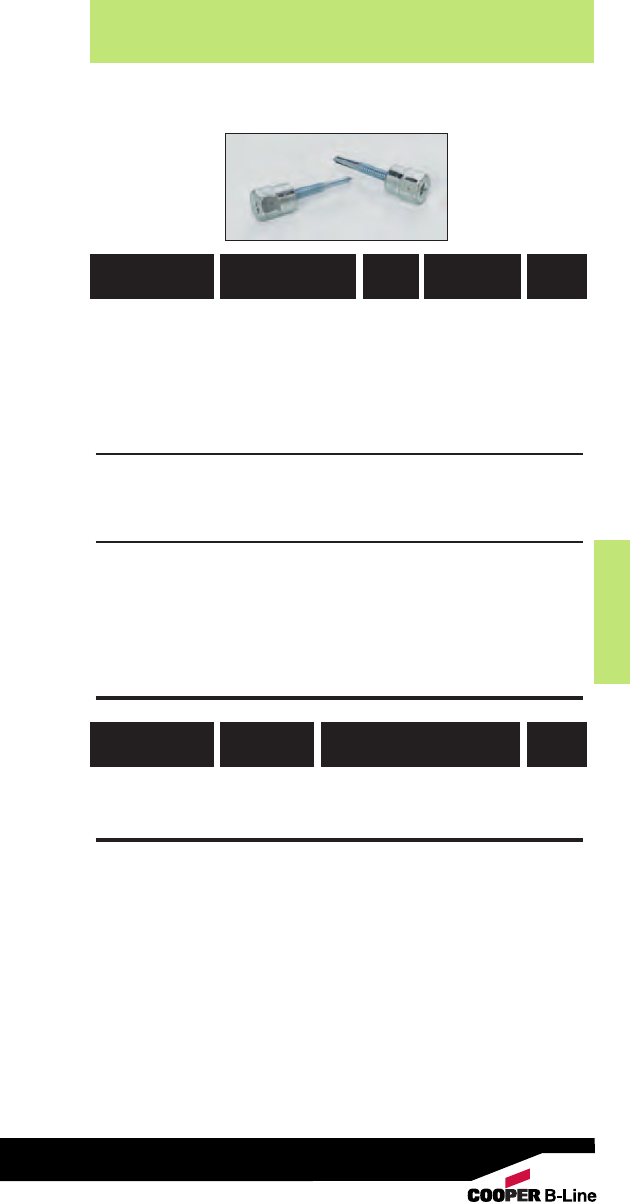
Anchors
Anchors
185
Read safety/installation instruction sheets in packages before use.
Rapid Rod™Hangers
Steel Rod Hanger - Point Style #3 For Purlins
782051 53317 ARS-25-100 1/4"1/4" X 1" 100
782051 53318 ARS-37-200 3/8"1/4" X 2" 100
782051 53320 ARS-37-100HN ** 3/8"1/4" X 1" w/nuts 100
782051 53321 ARS-37-150 3/8"1/4" X 11/2" 100
782051 53322 ARS-37-150HN ** 3/8"1/4" X 11/2" w/nuts 100
Steel Rod Hanger - Side Mount - Point Style #3 For Purlins
782051 53323 ARS-25-100SW 1/4"1/4" X 1" 100
782051 53324 ARS-37-100SW 3/8"1/4" X 1" w/nuts 100
Steel Rod Hanger - Point Style #5 For Beams
782051 53325 ARS-25-150HD 1/4"#12-24 X 11/2"100
782051 53326 ARS-37-150HDHN **3/8" #12-24 X 11/2" w/nuts 100
782051 53327 ARS-50-150HDHN **1/2"#12-24 X 11/2" w/nuts 100
** For UL & FM listings, steel rapid rod should be installed with a retaining nut.
Tool
782051 53287 7187 Universal Steel & Wood Socket 1
UPC/Part
Number
Box
Qty.
Rod
Size
Shank Size
& Length
Catalog
Number
UPC/Part
Number
Box
Qty.
Tool Description
Catalog
Number

Anchors
Anchors
186
Read safety/installation instruction sheets in packages before use.
• One-piece, all steel threaded fastener system for
suspending steel threaded rod.
• Suitable for overhead installations such as suspending
cable tray, pipe hangers, strut and conduit.
• Side Mount (SW) available for side mounting applications.
• Lower in-place cost, when compared to beam clamps,
lag bolts and drop-ins.
•Wood rapid rods can be installed with a screw gun or
hammer drill.
• Concrete rapid rods can be installed with an adjustable
torque, battery powered screw gun or hammer drill.
• UL & FM approved.
• Made of Zinc Plated carbon steel.
Rapid Rod™Hangers
Wood Rapid Rod - Data 1/4” Thread 3/8” Thread
Forming Forming
Pre-Drill Diameter (in.) 1/81/8
Point Style Type 17 Type 17
Wood Rapid Rod - Embedment & Load Data
Rod/Anchor
Size Embedment Depth Fir Pine Spruce
1/41” 170 160 160
3/82” 375 375 375
1/221/2” 665 775 775
Rapid Rod Hangers - Wood
Concrete Rapid Rod - Data 1/4”3/8”1/2”
ANSI Drill Bit (in.) 1/41/43/8
Thread Length (in.) 11/813/821/2
Min. Embedment Depth (in.) 11/411/223/4
Load Capacity Tension (lbs.) * 485 650 1510
Load Capacity Shear (lbs.) * 610 660 1580
Rapid Rod Hangers - Concrete
Minimum load ratings are based on a safety factor of 4.
UL approved load capacity for 3/8” rod sizes and 1/4” screw size is 260 lbs.,
maximum 3” pipe. UL approved load capacity for 3/8” rod sizes and 3/8” screw size
is 375 lbs., maximum 4” pipe. FM approval only applies to 3/8” x 21/2”screw size.
Approved for 365 lbs., up to 4” pipe.
* Based on concrete compression strength of 4000 psi using applied safety
factor of 4.0. For additional loading information contact factory.
FM approved load capacity for 3/8” anchor is 365 lbs., maximum 4” pipe
size. FM approved load capacity for 1/2” anchor is 950 lbs., maximum
8” pipe size.
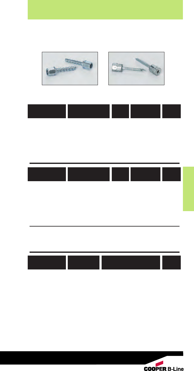
Anchors
Anchors
187
Read safety/installation instruction sheets in packages before use.
Rapid Rod™Hangers
Concrete Rod Hanger - ANSI Wedge-Bolt OT Thread Shank Style
782051 53328 ARC-25-125 1/4"1/4" X 11/4" 100
782051 53329 ARC-37-150 3/8"1/4" X 11/2" 100
782051 53330 ARC-50-275 1/2"3/8" X 23/4"50
For side mount concrete applications use ARW-25-100SW or ARW-37-200SW
with 1/4” drill bit.
Wood Rod Hanger - Point Style Type 17
782051 53331 ARW-25-200 1/4"1/4" X 2" 100
782051 53332 ARW-37-100 3/8"1/4" X 1" 100
782051 53333 ARW-37-200 3/8"1/4" X 2" 100
782051 53334 ARW-37-250 3/8"3/8" X 21/2" 100
782051 53335 ARW-50-250 1/2"3/8" X 21/2"100
Wood Rod Hanger - Side Mount - Point Style Type 17
782051 53336 ARW-25-100SW 1/4"1/4" X 1" 100
782051 53337 ARW-37-200SW 3/8"1/4" X 2" 100
Tools
782051 53287 7187 Universal Steel & Wood Socket 1
782051 53288 7195 1/4" Concrete Socket 1
782051 53289 7197 3/8" Concrete Socket 1
782051 53290 7198 1/2" Concrete Socket 1
782051 53360 5874 Concrete Tapper Sleeve Assy. 1
782051 53361 5866 1/4" X 6" Hex Shank SDS Drill Bit 1
UPC/Part
Number
Box
Qty.
Rod
Size
Shank Size
& Length
Catalog
Number
UPC/Part
Number
Box
Qty.
Rod
Size
Shank Size
& Length
Catalog
Number
UPC/Part
Number
Box
Qty.
Rod
Size
Catalog
Number
ARC Series ARW Series

Anchors
Anchors
188
Read safety/installation instruction sheets in packages before use.
•Designed for use in solid concrete.
• Can be used for overhead applications such as
suspending cable tray, strut, pipe supports and lighting.
• Flanged (lipped) version installs flush for easy
inspection and standardizes rod heights.
• Smooth wall drop-in can be installed
flush mounted or below the base
material surface.
• UL & FM approved.
• Available in Zinc Plated finish
or Stainless Steel.
Drop-in Anchors
Drop-in Anchor - Smooth Wall - Steel
781011 03218 ADI-25 1/4"1" 7/16"100
781011 03219 ADI-37 3/8"1
9/16"5/8"50
781011 03220 ADI-50 1/2"2"
13/16"50
781011 03221 ADI-62 5/8"2
1/2"1
13/16"25
781011 03222 ADI-75 3/4"3
3/16"1
3/8"10
Drop-in Anchor - Smooth Wall - Stainless Steel
781011 03223 ADI-25SS4 1/4"1"7/16" 100
781011 03224 ADI-37SS4 3/8"1
9/16"5/8"50
781011 03226 ADI-50SS4 1/2"2" 13/16"50
781011 03227 ADI-62SS4 5/8" 21/2" 113/16"25
781011 03228 ADI-75SS4 3/4"3
3/16"1
3/8"10
Drop-in Anchor - Flanged - Steel
782051 53297 ADI-25FL 1/4"1"7/16" 100
782051 53298 ADI-37FL 3/8"1
9/16"5/8"50
782051 53299 ADI-50FL 1/2"2" 13/16"50
Setting Tools
781011 03229 6305 1/4"39/64" 1
781011 03231 6307 3/8"61/64"1
781011 03232 6309 1/2" 13/16" 1
781011 03233 6311 5/8"1
5/16"1
781011 03234 6313 3/4"1
61/64"1
UPC/Part
Number
Box
Qty.
Rod
Size
Anchor
Length
Thread
Depth
Catalog
Number
UPC/Part
Number
Box
Qty.
Rod
Size
Pin
Length
Catalog
Number
Drop-In Anchors - Data 1/4”3/8”1/2”5/8”3/4”
ANSI Drill Bit Size (in.) 3/81/25/87/81
Max. Tightening Torque (ft-lbs) 5 10 20 40 80
Thread Size (UNC) 1/4”-20 3/8”-16 1/2”-13 5/8”-11 3/4”-10
Min. Embedment Depth (in.) 11
9/16 22
1/233/16
Load Capacity Tension (lbs) * 495 1045 1440 1860 3600
Load Capacity Shear (lbs) * 530 1145 1600 3095 3920
* Based on concrete compression strength of 4000 psi using applied safety
factor of 4.0. For additional loading information contact factory.
Smooth Wall
FlangedSetting Tool
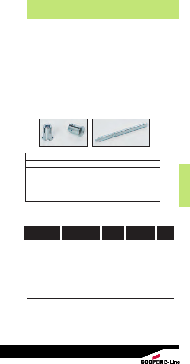
Anchors
Anchors
189
Read safety/installation instruction sheets in packages before use.
•Carbon steel machine bolt anchor for use in shallow
embedment applications.
• Can be used in solid concrete and precast hollow core
plank, in addition to post-tensioned concrete slabs and
concrete pours over metal deck.
• Can be used for overhead applications such as suspending
cable tray, strut, pipe supports and lighting.
• Flanged (lipped) version installs flush for easy inspection
and standardizes rod heights.
• Setting tool scores flange when set to verify proper
expansion
• Available in zinc plated finish.
Mini Drop-in Anchors
Mini Drop-in Anchor - Steel
782051 53300 ADM-25 1/4"3/8"100
782051 53302 ADM-37 3/8"13/32"50
782051 53304 ADM-50 1/2"5/8"50
Setting Tools
782051 53301 6336 1/4"--1
782051 53303 6323 3/8"-- 1
782051 53305 6338 1/2"-- 1
UPC/Part
Number
Box
Qty.
Rod
Size
Thread
Depth
Catalog
Number
Mini Drop-In Anchors - Data 1/4”3/8”1/2”
ANSI Drill Bit Size (in.) 3/81/25/8
Max. Tightening Torque (ft-lbs) 3 5 10
Thread Size (UNC) 1/4”-20 3/8”-16 1/2”-13
Min. Embedment Depth (in.) 5/83/41
Load Capacity Tension (lbs) *350 530 840
Load Capacity Shear (lbs) * 415 1055 1220
* Based on concrete compression strength of 4000 psi using applied safety
factor of 4.0. For additional loading information contact factory.
Setting ToolAnchor
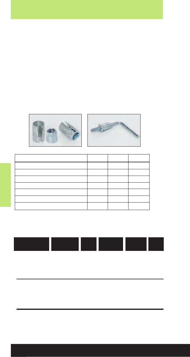
Anchors
Anchors
190
Read safety/installation instruction sheets in packages before use.
• For use in hollow base materials such as hollow concrete
block, brick with weep holes, and precast hollow core plank.
• Can also be used in solid base materials.
• Smooth wall drop-in can be installed flush mounted or below
the base material surface.
• Available in Zinc Plated finish.
Hollow Base Drop-in Anchors
Hollow Base Drop-In
782051 53291 ADH-25 1/4"7/8"5/8" 100
782051 53293 ADH-37 3/8"1
5/16"15/16"50
782051 53295 ADH-50 1/2" 13/4" 11/4"50
Setting Tools
782051 53292 9323 1/4"-- -- 1
782051 53294 9343 3/8" -- -- 1
782051 53296 9353 1/2"-- -- 1
UPC/Part
Number
Box
Qty.
Rod
Size
Sleeve
Length
Overall
Length
Catalog
Number
Hollow Base Drop-In - Data 1/4”3/8”1/2”
ANSI Drill Bit Size (in.) 3/85/83/4
Max. Tightening Torque (ft-lbs) 5 10 20
Thread Size (UNC) 1/4”-20 3/8”-16 1/2”-13
Thread Length In Cone (in.) 3/85/83/4
Min. Embedment Depth (in.) 3/41 11/2
Load Capacity Tension (lbs) * 285 520 1005
Load Capacity Shear (lbs) * 300 640 1005
* Based on concrete compression strength of 4000 psi using applied safety
factor of 4.0. For additional loading information contact factory.
Setting ToolAnchor
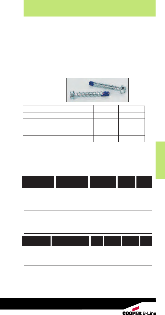
Anchors
Anchors
191
Read safety/installation instruction sheets in packages before use.
•For use in racking, shelving, material handling, structural
anchorage, masonry and food & beverage facilities.
• One piece heavy-duty anchor with a finished hex-head.
• Fits standard fixture hole dimensions in fabricated steel.
• Fast installation and immediate loading reduces downtime.
• For proper performance, screw anchors must be installed
with the corresponding bits. The bits have a matched
tolerance range designed to provide optimum performance.
Concrete Screw Bolts
Screw Type Anchor - Steel
782051 53247 ACB-25-175 1/4" x 13/4"1
5/8" 100
782051 53248 ACB-25-225 1/4" x 21/4"2" 100
782051 53249 ACB-25-300 1/4" x 3" 23/4"100
782051 53250 ACB-37-175 3/8" x 13/4" 11/2"50
782051 53251 ACB-37-250 3/8" x 21/2" 21/4"50
782051 53252 ACB-37-300 3/8" x 3" 23/4"50
782051 53253 ACB-37-400 3/8" x 4" 33/4"50
Drill Bits - Straight Shank Type
782051 53254 1372 1/4"4" 6” 1
782051 53256 1380 3/8" 4" 6” 1
Drill Bits - SDS Type
782051 53255 1314 1/4" 4" 6” 1
782051 53257 1316 3/8"4" 6” 1
Note: Matched tolerance bits must be used for installation.
UPC/Part
Number
Box
Qty.
Anchor
Length
Thread
Length
Catalog
Number
UPC/Part
Number
Box
Qty.
Drill
Size
Usable
Length
Overall
Length
Catalog
Number
Concrete Screw Bolts - Data 1/4”3/8”
ACB Drill Bit Size (in.) 1/43/8
Concrete Screw Tolerance Range (in.) 0.255 - 0.259 0.385 - 0.389
Min. Embedment Depth (in.) 11
1/2
Load Capacity Tension (lbs) *
335 630
Load Capacity
Shear (lbs) * 520 1170
* Based on concrete compression strength of 4000 psi in uncracked concrete
using applied safety factor of 4.0. For additional loading information contact
factory.
For ultimate strength design data in cracked and uncracked concrete, see
ICC-ES ESR-2526.
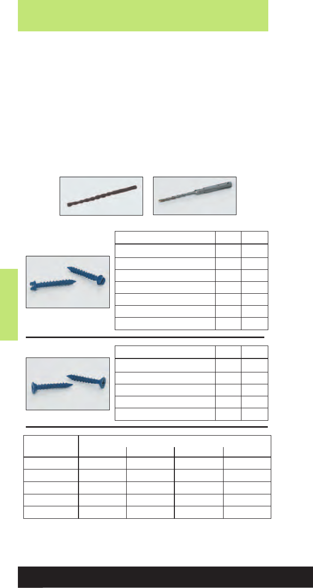
Anchors
Anchors
192
Read safety/installation instruction sheets in packages before use.
• Light to medium duty anchor for use in concrete, masonry
block and brick base materials.
• Concrete screws are engineered with matched tolerance bits
and installation tools to optimize performance.
• High low thread design for greater stability and grip.
• No hole spotting required.
• One drill bit is packaged in each box of concrete screws.
• Blue fluorocarbon coating for corrosion resistance.
Concrete Screws
Hex Head - Data 3/16”1/4”
ANSI Drill Bit Size (in.) 5/32 3/16
Fixture Clearance Hole (in.) 1/45/16
Head Height (in.) 7/64 9/64
Head Width (in.) 1/45/16
Washer O.D. (in.) 11/32 13/32
Washer Thickness (in.) 1/32 1/32
Hex Driver (in.) 1/45/16
* Based on concrete compression strength of 4000 psi using applied safety
factor of 4.0. For additional loading information contact factory.
Flat Head - Data 3/16”1/4”
ANSI Drill Bit Size (in.) 5/32 3/16
Fixture Clearance Hole (in.) 1/45/16
Phillips Head O.D. (in.) 3/81/2
Phillips Head Height (in.) 9/64 3/16
Phillips Bit Size 2 3
Embedment Nominal Anchor Dia. / Loading*
Depth 3/16” Tension 3/16” Shear 1/4” Tension 1/4” Shear
1” 90 175 265 205
11/4”175 230 335 355
13/8” 215 230 370 385
11/2” 255 230 405 355
13/4”375 235 435 370
Flat Head
Straight Shank Drill Bit SDS Hex Drill Bit
Hex Head

Anchors
Anchors
193
Read safety/installation instruction sheets in packages before use.
Concrete Screws
Hex Head Concrete Screws
781011 03342 ACS-18-125H 3/16" X 11/4" 100
781011 03343 ACS-18-175H 3/16" X 13/4" 100
781011 03344 ACS-18-225H 3/16" X 21/4" 100
781011 03346 ACS-18-275H 3/16" X 23/4" 100
781011 03347 ACS-18-325H 3/16" X 31/4" 100
781011 03348 ACS-18-375H 3/16" X 33/4" 100
781011 03349 ACS-18-400H 3/16" X 4" 100
781011 03351 ACS-25-125H 1/4" X 11/4" 100
781011 03352 ACS-25-175H 1/4" X 13/4" 100
781011 03353 ACS-25-225H 1/4" X 21/4" 100
781011 03354 ACS-25-275H 1/4" X 23/4" 100
781011 03356 ACS-25-325H 1/4" X 31/4" 100
781011 03357 ACS-25-375H 1/4" X 33/4" 100
781011 03358 ACS-25-400H 1/4" X 4" 100
Flat Head Concrete Screws
782051 53259 ACS-18-125F 3/16" X 11/4" 100
782051 53260 ACS-18-175F 3/16" X 13/4" 100
782051 53261 ACS-18-225F 3/16" X 21/4" 100
782051 53262 ACS-18-275F 3/16" X 23/4" 100
782051 53263 ACS-25-125F 1/4" X 11/4" 100
782051 53264 ACS-25-175F 1/4" X 13/4" 100
782051 53265 ACS-25-225F 1/4" X 21/4" 100
782051 53266 ACS-25-275F 1/4" X 23/4" 100
Straight Shank Drill Bits
782051 53267 2782 5/32" X 41/2"3" 1
782051 53269 2786 3/16" X 41/2"3" 1
SDS Hex Drill Bits
782051 53268 2793 5/32" X 5" 3" 1
782051 53270 2796 3/16" X 5" 3" 1
Setting Tool
781011 03453 2791 Concrete Screw Tool Kit 1
UPC/Part
Number
Box
Qty.
Size
Catalog
Number
UPC/Part
Number
Box
Qty.
Bit Size Usable
Length
Catalog
Number
UPC/Part
Number
Box
Qty.
Description
Catalog
Number
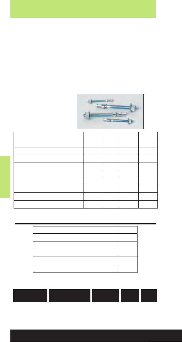
Anchors
Anchors
194
Read safety/installation instruction sheets in packages before use.
• Heavy and medium duty all purpose anchor.
• For use in solid concrete and grout filled block.
• Anchors can be installed through the fixture, no need
for hole spotting.
• Interlocking clip wedges prevent anchor spinning during
installation.
• Wire hanger hole size 9/32” diameter, head height 3/4”.
• UL & FM approved.
• Available in Zinc Plated Carbon Steel or Type 304
Stainless Steel.
Wedge Expansion Anchors
Wedge Expansion Anchor -
Data 1/4”3/8”1/2”5/8”
ANSI Drill Bit Size (in.) 1/43/81/25/8
Fixture Clearance Hole (in.) 5/16 7/16 9/16 11/16
Thread Size (UNC) 1/4”-20 3/8”-16 1/2”-13 5/8”-11
Washer O.D. (in.) 5/813/16 11/16 13/4
Wrench Size 7/16 9/16 3/415/16
Max. Tightening Torque (ft-lbs) 8 28 60 90
Min. Embedment Depth (in.) 11/815/821/423/4
Load Capacity Tension (lbs) *360 760 1390 2075
Load Capacity Shear (lbs) * 405 940 1700 2975
* Based on concrete compression strength of 4000 psi using applied safety
factor of 4.0. For additional loading contact factory.
* Based on concrete compression strength of 4000 psi using applied
safety factor of 4.0. For additional loading information contact factory.
Wire Hanger Wedge Anchor -
Data 1/4”
ANSI Drill Bit Size (in.) 1/4
Min. Embedment Depth (in.) 11/8
Head Height (in.) 3/4
Load Capacity Tension (lbs) * 360
Load Capacity Shear (lbs) * 405
UPC/Part
Number
Box
Qty.
Size Hole
Size
Catalog
Number
Wire Hanger
781011 03106 AWA-25-200WH 1/4" X 2" 9/32"100

Anchors
Anchors
195
Read safety/installation instruction sheets in packages before use.
Wedge Expansion Anchors
Wedge Anchor
781011 03068 AWA-25-175 1/4" X 13/4"3/4" 100
781011 03069 AWA-25-225 1/4" X 21/4"1
1/4" 100
781011 03070 AWA-25-325 1/4" X 31/4" 21/4"100
781011 03071 AWA-37-225 3/8" X 21/4"1
1/4"50
781011 03072 AWA-37-275 3/8" X 23/4"1
5/8"50
781011 03073 AWA-37-300 3/8" X 3" 17/8"50
782051 53364 AWA-37-350 3/8" X 31/2"2
3/8"50
781011 03074 AWA-37-375 3/8" X 33/4"2
5/8"50
781011 03075 AWA-37-500 3/8" X 5" 37/8"50
782051 53366 AWA-50-275 1/2" X 23/4"1
3/8"50
781011 03077 AWA-50-375 1/2" X 33/4"2
3/8"50
782051 45636 AWA-50-450 1/2" X 41/2"3
1/8"50
781011 03079 AWA-50-550 1/2" X 51/2"4
1/8"50
781011 03080 AWA-50-700 1/2" X 7" 55/8"25
781011 03081 AWA-62-350 5/8" X 31/2" 2" 25
781011 03082 AWA-62-450 5/8" X 41/2" 3" 25
781011 03083 AWA-62-500 5/8" X 5" 31/2"25
781011 03084 AWA-62-600 5/8" X 6" 41/2"25
781011 03085 AWA-62-700 5/8" X 7" 51/2"25
Wedge Anchor - Stainless Steel
781011 03146 AWA-25-175SS4 1/4" X 13/4"3/4"100
781011 03147 AWA-25-225SS4 1/4" X 21/4" 11/4"100
781011 03148 AWA-25-325SS4 1/4" X 31/4"2
1/4" 100
781011 03149 AWA-37-225SS4 3/8" X 21/4"1
1/4"50
781011 03150 AWA-37-275SS4 3/8" X 23/4"1
5/8"50
781011 03151 AWA-37-300SS4 3/8" X 3" 17/8"50
782051 53365 AWA-37-350SS4 3/8" X 31/2"2
3/8"50
781011 03152 AWA-37-375SS4 3/8" X 33/4" 25/8"50
781011 03153 AWA-37-500SS4 3/8" X 5" 31/8"50
781011 03154 AWA-50-275SS4 1/2" X 23/4"1
3/8"50
781011 03155 AWA-50-375SS4 1/2" X 33/4" 23/8"50
782051 53367 AWA-50-450SS4 1/2" X 41/2"3
1/8"50
781011 03157 AWA-50-550SS4 1/2" X 51/2"4
1/8"50
782051 53368 AWA-50-700SS4 1/2" X 7" 55/8"25
782051 53369 AWA-62-350SS4 5/8" X 31/2" 2" 25
782051 53370 AWA-62-450SS4 5/8" X 41/2"3" 25
782051 53779 AWA-62-500SS4 5/8" X 5" 31/2"25
782051 53371 AWA-62-600SS4 5/8" X 6" 41/2"25
782051 43044 AWA-62-700SS4 5/8" X 7" 51/2"25
UPC/Part
Number
Box
Qty.
Size Thread
Length
Catalog
Number

Anchors
Anchors
196
Read safety/installation instruction sheets in packages before use.
Seismic Wedge Anchors
• Fully threaded, torque-controlled, wedge anchor which is
designed for consistent performance in cracked and
uncracked concrete.
• For use in concrete, structural sand lightweight concrete,
and concrete over metal deck.
• Nominal drill bit size is the same as the anchor diameter.
• ICC-ES listed, ESR-2502, Category 1
• Zinc plated carbon steel body with stainless steel expansion
clip from premium performance.
• Qualified for seismic and wind loading.
Seismic Wedge Anchor - Data
3/8”1/2”5/8”3/4”
ANSI Drill Bit Size (in.) 3/81/25/83/4
Fixture Clearance Hole (in.) 7/16 9/16 11/16 13/16
Minimum Hole Depth (in.) 25/823/441/45
Minimum Concrete Thickness (in.) 44
1/253/47
Max. Tightening Torque (ft-lbs) 20 40 60 110
Min. Embedment Depth (in.) 23/821/237/841/2
For loading information, see ICC-ES ESR-2502.

Anchors
Anchors
197
Read safety/installation instruction sheets in packages before use.
Seismic Wedge Anchors
Seismic Wedge Anchor
782051 53398 AWSD-37-300 3/8" X 3" 13/4"50
782051 53399 AWSD-37-350 3/8" X 31/2"2
1/4"50
782051 53400 AWSD-37-375 3/8" X 33/4"2
1/2"50
782051 53401 AWSD-37-500 3/8" X 5" 33/4"50
782051 53402 AWSD-50-375 1/2" X 33/4" 21/8"50
782051 53403 AWSD-50-450 1/2" X 41/2"2
7/8"50
782051 53404 AWSD-50-550 1/2" X 51/2"3
7/8"50
782051 53405 AWSD-50-700 1/2" X 7" 53/8"50
782051 53406 AWSD-62-475 5/8" X 43/4" 27/8"25
782051 53407 AWSD-62-500 5/8" X 5" 31/8"25
782051 53408 AWSD-62-600 5/8" X 6" 41/8"25
782051 53409 AWSD-62-700 5/8" X 7" 51/8"25
782051 53410 AWSD-75-550 3/4" X 51/2" 31/4"20
782051 53411 AWSD-75-625 3/4" X 61/4" 4" 20
782051 53425 AWSD-75-700 3/4" X 7" 43/4"20
UPC/Part
Number
Box
Qty.
Size Thread
Length
Catalog
Number
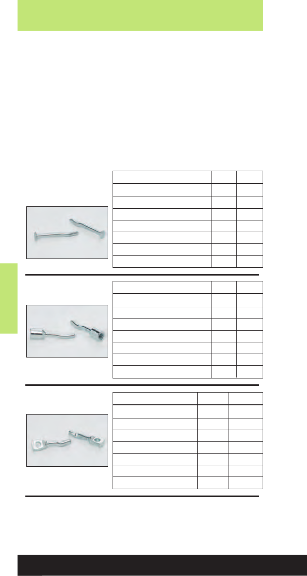
Anchors
Anchors
198
Read safety/installation instruction sheets in packages before use.
• One-piece, tamper-proof vibration resistant anchor
for use in concrete.
• Anchor is formed with an ‘s’ shaped configuration at the
working end of the anchor to create an expansion
mechanism.
• Anchor is pre-expanded so no secondary tightening
operation is required.
• FM approved.
• Made of Zinc Plated carbon steel.
Drive Anchor
Mushroom Head -
Data 3/16”1/4”
ANSI Drill Bit Size (in.) 3/16 1/4
Fixture Clearance Hole (in.) 1/45/16
Head Height (in.) 7/64 7/64
Head Size O.D. (in.) 7/16 1/2
Min. Embedment Depth (in.) 7/87/8
Load Capacity Tension (lbs.) * 215 235
Load Capacity Shear (lbs.) * 330 470
* Based on concrete compression strength of 4000 psi using applied safety
factor of 4.0. For additional loading information contact factory.
Rod Hanger - Data 1/4”3/8”
ANSI Drill Bit Size (in.) 3/16 1/4
UNC Thread Size 1/4”-20 3/8”-16
Head Height (in.) 1/25/8
Head Size O.D. (in.) 13/32 35/64
Min. Embedment Depth (in.) 11/413/4
Load Capacity Tension (lbs.) *315 500
Load Capacity Shear (lbs.) *245 525
Wire Hanger -
Data 3/16”1/4”
ANSI Drill Bit Size (in.) 3/16 1/4
Tie-Wire Hole (in.) 3/16 9/32
Head Height (in.) 37/64 41/64
Head Width (in.)
9/64 x 7/16 3/16 x 9/16
Min. Embedment Depth (in.) 11/811/8
Load Capacity Tension (lbs.)*
265 290
Load Capacity Shear (lbs.)*
240 330

Anchors
Anchors
199
Read safety/installation instruction sheets in packages before use.
Drive Anchors
Mushroom Head
782051 53271 ADA-18-100 3/16" X 1" 100
782051 53272 ADA-18-125 3/16" X 11/4" 100
782051 53273 ADA-18-150 3/16" X 11/2" 100
782051 53274 ADA-18-200 3/16" X 2" 100
782051 53275 ADA-18-250 3/16" X 21/2" 100
782051 53276 ADA-18-300 3/16" X 3" 100
782051 53278 ADA-25-100 1/4" X 1" 100
782051 53279 ADA-25-125 1/4" X 11/4" 100
782051 53280 ADA-25-150 1/4" X 11/2" 100
782051 53281 ADA-25-200 1/4" X 2" 100
782051 53282 ADA-25-250 1/4" X 21/2" 100
782051 53283 ADA-25-300 1/4" X 3" 100
Rod Hanger
782051 53284 ADA-25RH 1/4"100
782051 53286 ADA-37RH 3/8" 100
Wire Hanger
782051 53277 ADA-18WH 3/16" 100
782051 53285 ADA-25WH 1/4" 100
UPC/Part
Number
Box
Qty.
Size
Catalog
Number
UPC/Part
Number
Box
Qty.
Head Size
Catalog
Number
UPC/Part
Number
Box
Qty.
Head Size
Catalog
Number
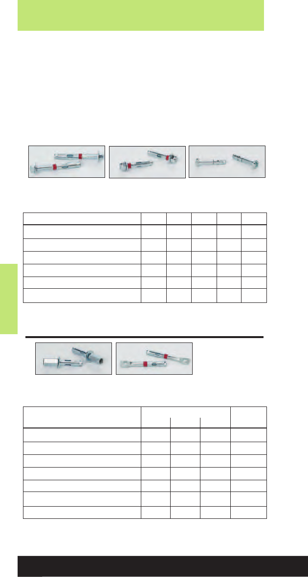
Anchors
Anchors
200
Read safety/installation instruction sheets in packages before use.
• For use in concrete and masonry substrates.
• Suitable for solid and hollow core materials.
• Fits standard fixture holes - no need to undersize anchors
for proper fit.
• Sleeve has 360° contact area and reduces concrete stress.
• UL & FM approved.
• Available in Zinc Plated Steel or Type 304 Stainless Steel.
Sleeve Type Expansion Anchors
Hex Nut (HN)
Style
Acorn Nut (AN)
Style
Rod Hanger
(RH) Style
Wire Hanger
(WH) Style
Slotted Round
Head (RS) Style
Sleeve Type Expansion - Data 1/4”3/8”1/2”5/8”3/4”
ANSI Drill Bit Size (in.) 1/43/81/25/83/4
Fixture Clearance Hole (in.) 5/16 7/16 9/16 11/16 15/16
Plow Bolt Size (UNC)
#10-24 5/16”-18 3/8”-16 1/2”-13 5/8”-11
Min. Embedment Depth (in.) 5/815/821/421/421/4
Load Capacity Tension (lbs) * 155 670 1255 1465 2105
Load Capacity Shear (lbs) * 300 610 1055 1800 2900
* Based on concrete compression strength of 4000 psi using applied safety
factor of 4.0. For additional loading contact factory.
* Based on concrete compression strength of 4000 psi using applied safety
factor of 4.0. For additional loading go to www.cooperbline.com.
Sleeve Type Expansion - Data
Hanger Rod Wire Hanger
1/4”3/8”1/2”5/16”
ANSI Drill Bit Size (in.) 1/43/81/25/16
Fixture Clearance Hole (in.) NA NA NA 1/4
Plow Bolt Size (UNC) #10-24 5/16
”
-18 3/8
”
-16 1/4
”
-20
Coupling Height (in.) 7/81 11/4NA
Min. Embedment Depth (in.) 5/815/821/411/2
Load Capacity Tension (lbs) * 155 670 1255 520
Load Capacity Shear (lbs) *300 610 1055 380

Anchors
Anchors
201
Read safety/installation instruction sheets in packages before use.
Sleeve Type Expansion Anchors
Hex Nut Style
781011 02995 ASA-37-187HN 3/8" X17/8"1
5/8"50
781011 02996 ASA-37-300HN 3/8" X 3" 15/8"50
782051 53346 ASA-37-400HN 3/8" X 4" 15/8"50
781011 02997 ASA-50-225HN 1/2" X 21/4"2
1/8"25
781011 02998 ASA-50-300HN 1/2" X 3" 21/4"25
781011 02999 ASA-50-400HN 1/2" X 4" 21/4"25
782051 53351 ASA-50-525HN 1/2" X 51/4"2
1/4"25
781011 03002 ASA-50-600HN 1/2" X 6" 21/4"10
781011 03003 ASA-62-225HN 5/8" X 21/4"2
1/8"25
781011 03004 ASA-62-300HN 5/8" X 3" 23/4"25
781011 03005 ASA-62-425HN 5/8" X 41/4"2
3/4"10
781011 03006 ASA-62-600HN 5/8" X 6" 23/4"10
781011 03007 ASA-75-250HN 3/4" X 21/2"2
1/8"10
781011 03008 ASA-75-425HN 3/4" X 41/4"3
3/8"10
781011 03009 ASA-75-625HN 3/4" X 61/4"3
3/8"10
Hex Nut Style - Stainless Steel
782051 53343 ASA-37-187HNSS4 3/8" X 17/8"1
5/8"50
782051 53345 ASA-37-300HNSS4 3/8" X 3" 15/8"50
782051 53347 ASA-50-225HNSS4 1/2" X 21/4"2
1/8"25
782051 53349 ASA-50-300HNSS4 1/2" X 3" 21/4"25
782051 53350 ASA-50-400HNSS4 1/2" X 4" 21/4"25
782051 53352 ASA-62-425HNSS4 5/8" X 41/4" 23/4"10
782051 53353 ASA-75-400HNSS4 3/4" X 4" 33/8"10
Acorn Nut Style
782051 53341 ASA-25-62AN 1/4" X 5/8"1/2"100
781011 02991 ASA-25-137AN 1/4" X 13/8" 11/8"100
781011 02992 ASA-25-225AN 1/4" X 21/4"1
1/8" 100
Slotted Round Head Style
782051 53338 ASA-25-112RS 1/4" X 11/8" 1" 100
782051 53340 ASA-25-200RS 1/4" X 2" 11/8"100
Rod Hanger
782051 53339 ASA-25-150RH 1/4" X 11/2"5/16"50
782051 53344 ASA-37-187RH 3/8" X 17/8"3/8"50
782051 53348 ASA-50-225RH 1/2" X 21/4"1/2"25
Wire Hanger
782051 53342 ASA-31-150WH 5/16" X 11/2"5/16" 100
UPC/Part
Number
Box
Qty.
Size Thread
Length
Catalog
Number
UPC/Part
Number
Box
Qty.
Size Drill
Dia.
Catalog
Number
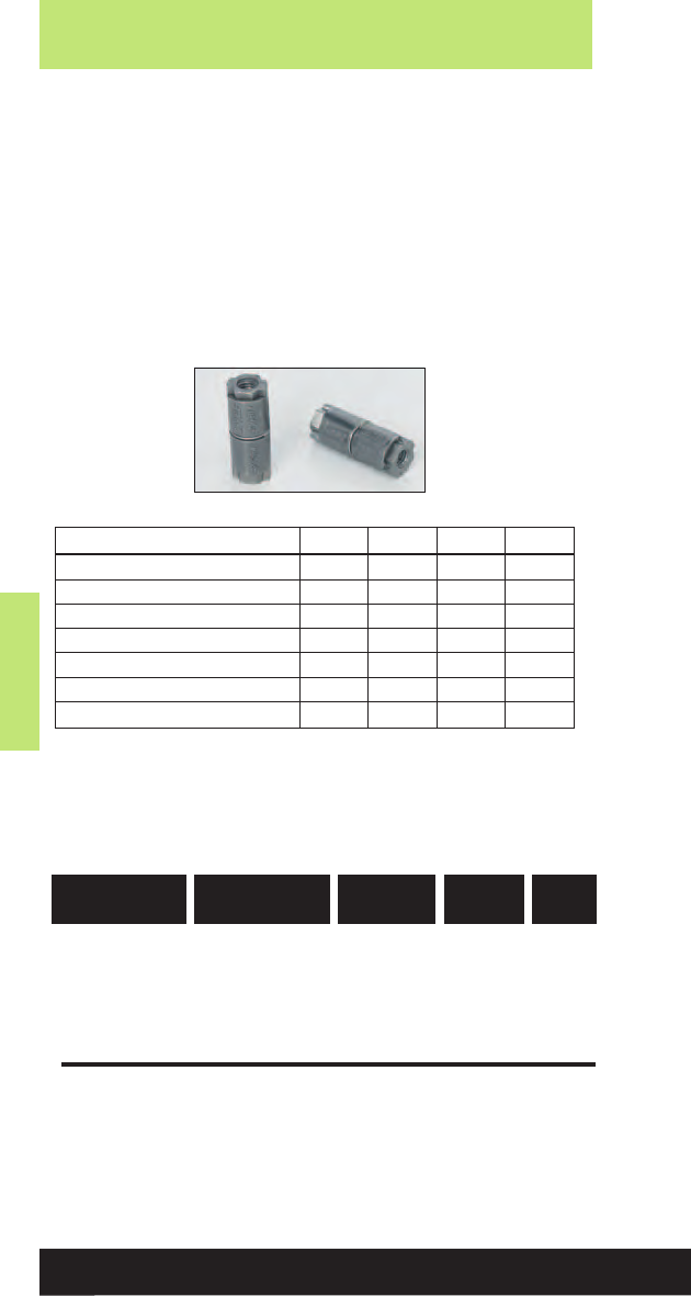
Anchors
Anchors
202
Read safety/installation instruction sheets in packages before use.
•For use in concrete, block, brick or stone.
• Double expansion anchor is particularly suited for base
materials of questionable strength (job site tests are
recommended).
• Internally threaded anchor for easy removability and
service work.
• Made of Zamac Alloy material.
Double Expansion Anchors
Double Expansion Anchor
781011 03251 ADE-25 1/4"1
3/8"50
781011 03253 ADE-37 3/8"2" 50
781011 03254 ADE-50 1/2"2
1/2"25
781011 03256 ADE-62 5/8" 23/4"25
UPC/Part
Number
Box
Qty.
Rod
Diameter
Anchor
Length
Catalog
Number
* Based on concrete compression strength of 4000 psi using applied safety
factor of 4.0. For additional loading information contact factory.
Double Expansion - Data 1/4”3/8”1/2”5/8”
ANSI Drill Bit Size (in.) 1/23/47/81
Max. Tightening Torque (ft-lbs) 5 10 20 30
Thread Size (UNC) 1/4”-20 3/8”-16 1/2”-13 5/8”-11
Thread Length In Cone (in.) 1/25/83/47/8
Min. Embedment Depth (in.) 11/413/421/421/2
Load Capacity Tension (lbs) *415 875 1625 1750
Load Capacity Shear (lbs) * 405 1000 1540 2855
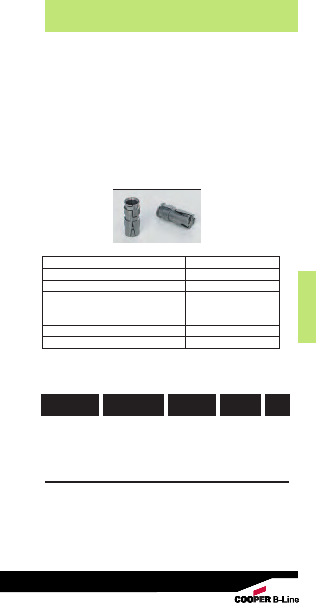
Anchors
Anchors
203
Read safety/installation instruction sheets in packages before use.
• For use in concrete, block, brick or stone.
• Recommended for floor and wall attachments.
• Not recommended for overhead applications.
• Internally threaded anchor for easy removability and
service work.
• Made of Zamac Alloy material.
Single Expansion Anchors
Single Expansion
781011 03245 ASE-25 1/4"1
5/16"50
781011 03247 ASE-37 3/8" 11/2"50
781011 03248 ASE-50 1/2"2
1/16"25
781011 03249 ASE-62 5/8" 25/8"25
UPC/Part
Number
Box
Qty.
Rod
Size
Anchor
Length
Catalog
Number
* Based on concrete compression strength of 4000 psi using applied safety
factor of 4.0. For additional loading information contact factory.
Single Expansion - Data 1/4”3/8”1/2”5/8”
ANSI Drill Bit Size (in.) 1/23/47/81
Max. Tightening Torque (ft-lbs) 5 10 20 30
Thread Size (UNC) 1/4”-20 3/8”-16 1/2”-13 5/8”-11
Thread Length In Cone (in.) 5/16 5/16 7/16 5/8
Min. Embedment Depth (in.) 13/815/821/223/4
Load Capacity Tension (lbs) *500 725 1225 2050
Load Capacity Shear (lbs) *405 950 1540 2855
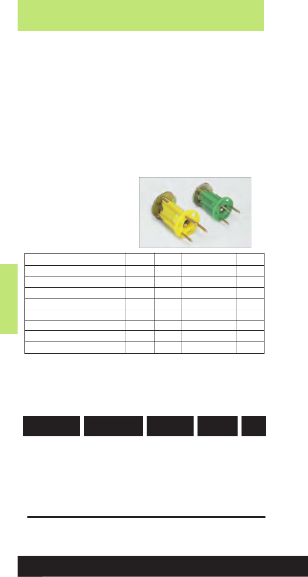
Anchors
Anchors
204
Read safety/installation instruction sheets in packages before use.
•Wood-Knocker concrete inserts are installed onto wooden
forms used to support newly poured concrete floor slabs,
roof slabs or walls.
• When the forms are stripped, the color-coded flange is
visibly embedded in the concrete surface.
• The unique, six sided impact plate offers resistance to
rotation within the concrete as threaded rod is being
installed.
• Suitable for overhead installations such as suspending cable
tray, pipe hangers, strut and conduit.
• Color coded by size for all trades.
• UL and FM approved.
• Lowest in-place cost.
Wood Knocker Anchors
* Based on normal weight concrete with minimum compression strength of
3000 psi. Allowable load capacities are calculated using applied safety
factor of 4.0. For additional loading information contact factory.
Minimum embedment depth is 2”.
Wood Knocker - Data 1/4”3/8”1/2”5/8”3/4”
Insert Thread Length (in.) 3/85/811/16 15/16 11/8
Plastic Flange Diameter (in.) 13/813/813/815/815/8
Thread Size (UNC) 1/4”-20 3/8”-16 1/2”-13 5/8”-113/4”-10
Overall Length (in.) 17/817/817/817/817/8
Min. Insert Spacing (in.) 9 9 9 12 12
Min. End Distance (in.) 66699
Load Capacity Tension (lbs) * 930 1200 1200 1160 1160
Load Capacity Shear (lbs) * 370 1330 1840 2800 2800
Wood Knocker
782051 31147 ACPW-25 1/4"Brown 100
782051 31149 ACPW-37 3/8"Green 100
782051 31151 ACPW-50 1/2" Yellow 100
782051 31152 ACPW-62 5/8" Red 50
782051 31153 ACPW-75 3/4" Purple 50
UPC/Part
Number
Box
Qty.
Rod
Diameter Color
Catalog
Number
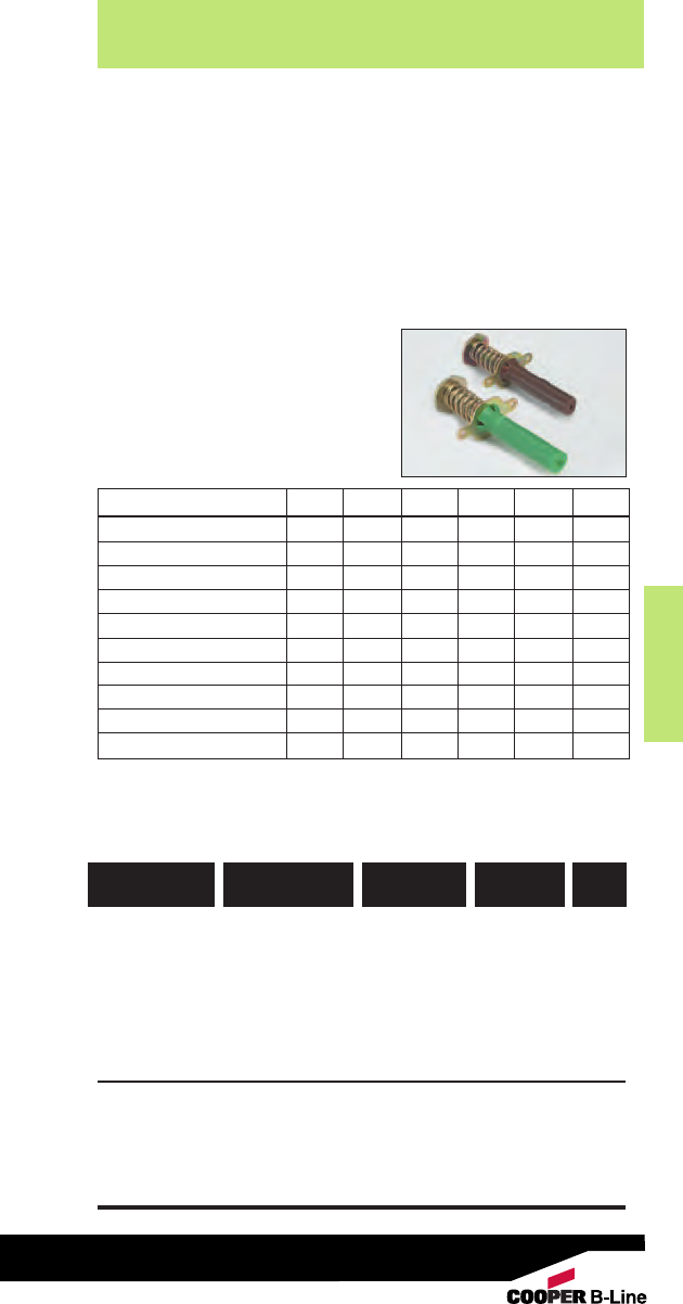
Anchors
Anchors
205
Read safety/installation instruction sheets in packages before use.
Bang-It - Data 1/4”3/8”1/2”5/8”3/4”7/8”
Metal Hole Saw Diameter (in.) 13/16 13/16 13/16 13/16 13/16 13/16
Drilling Speed (rpm) 700-900 700-900 700-900 500-700 500-700 500-700
Insert Thread Length (in.) 3/85/811/16 15/16 11/815/16
Length of Sleeve (in.) 33/833/833/833/833/833/8
Thread Size (UNC) 1/4”-20 3/8”-16 1/2”-13 5/8”-11 3/4”-10 7/8”-9
Embedment Depth (in.) 2222 22
Upper Deck Tension Load (lbs) *
835 1435 1775 2200 2200 2200
Lower Deck Tension Load (lbs) *
835 1115 1115 1115 1115 1115
Upper Deck Shear Load (lbs) *
620 620 620 740 740 740
Lower Deck Shear Load (lbs) *
625 840 840 840 840 840
• Bang-It concrete inserts are designed for installation in and
through metal composite deck used to support newly poured
concrete floors or roof slabs.
• After installation, the protective sleeve of the insert protrudes
below the surface of the deck, allowing overhead attachment
of threaded rod.
• The unique, six sided impact plate offers resistance to
rotation within the concrete as threaded rod is bing installed.
• Suitable for overhead installations such as suspending cable
tray, pipe hangers, strut and
conduit.
• Color coded by size for all trades.
• UL and FM approved.
• Lowest in-place cost.
Bang-It Anchors
Bang-It
782051 31154 ACPD-25 1/4" Brown 100
782051 31156 ACPD-37 3/8"Green 100
782051 31157 ACPD-50 1/2" Yellow 100
782051 31158 ACPD-62 5/8" Red 50
782051 31166 ACPD-75 3/4"Purple 50
782051 53258 ACPD-87 7/8" Black 50
Tools
782051 31169 ACPD-81HS 13/16”
Carbide Hole Saw
1
for
1/4”, 3/8”, 1/2”
782051 311671 ACPD-118HS 113/16”
Carbide Hole Saw
1
for
5/8”, 3/4”, 7/8”
UPC/Part
Number
Box
Qty.
Rod
Diameter Color
Catalog
Number
* Based on normal weight concrete with minimum compression strength of
3000 psi. Allowable load capacities are calculated using applied safety
factor of 4.0. For additional loading information contact factory.
Minimum insert spacing of 12”, minimum end spacing 12”.
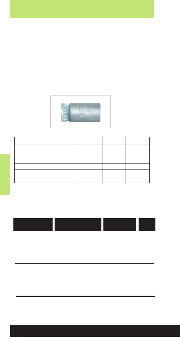
Anchors
Anchors
206
Read safety/installation instruction sheets in packages before use.
Machine Screw Anchor
781011 03239 AMS-25 1/4"100
781011 03242 AMS-37 3/8"50
781011 03243 AMS-50 1/2"50
Setting Tool
782051 09765 9221 1/4"1
782051 09767 9231 3/8"1
782051 09768 9241 1/2" 1
UPC/Part
Number
Box
Qty.
Rod
Diameter
Catalog
Number
•For use in concrete, block, brick or stone.
• Not recommended for use in overhead applications.
• Readily accepts machine bolts.
• Internally threaded anchor for easy removability and
service work.
• Anchor installation requires shallow embedment.
• Made of Zamac Alloy material.
Machine Screw Anchors
* Based on concrete compression strength of 4000 psi using applied safety
factor of 4.0. For additional loading information contact factory.
Machine Screw Anchor - Data 1/4”3/8”1/2”
ANSI Drill Bit Size (in.) 1/23/47/8
Max. Tightening Torque (ft-lbs) 5 10 15
Thread Size (UNC) 1/4”-20 3/8”-16 1/2”-13
Min. Embedment Depth (in.) 7/811/411/2
Load Capacity Tension (lbs) *585 775 1095
Load Capacity Shear (lbs) *355 825 1135
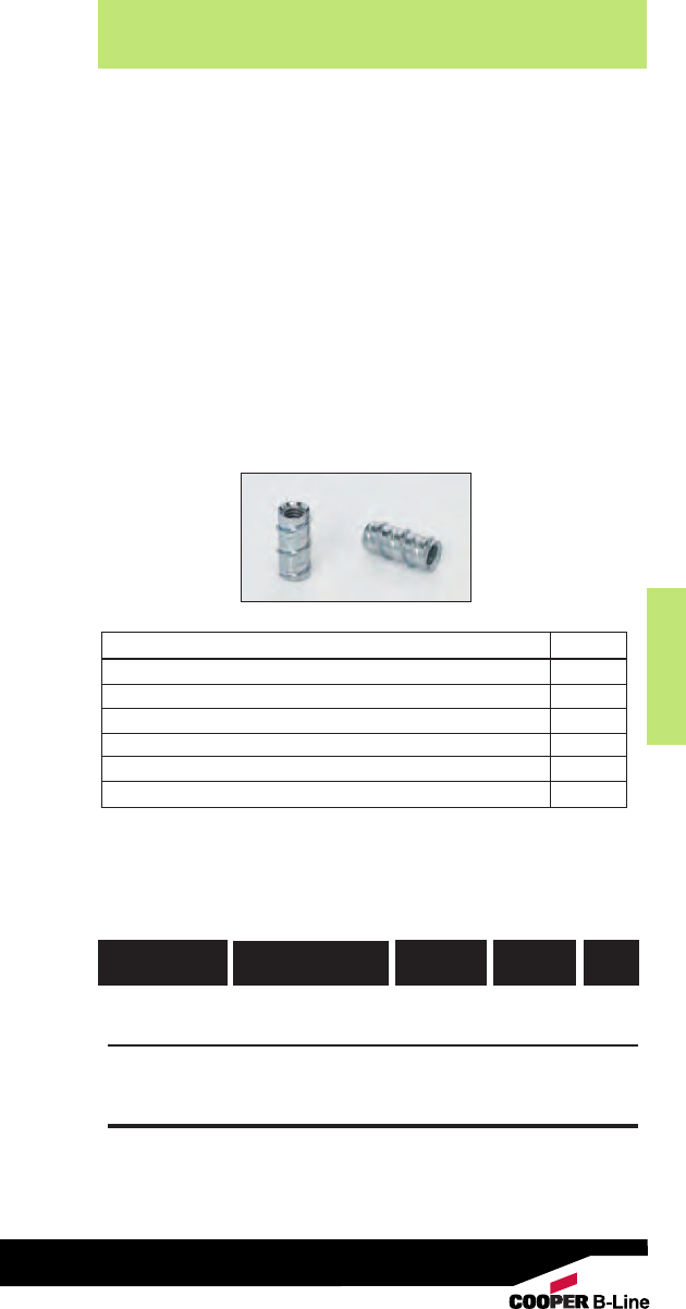
Anchors
Anchors
207
Read safety/installation instruction sheets in packages before use.
• For use in normal-weight concrete, structural sand
lightweight concrete and concrete over metal deck.
• Anchor design allows for shallow embedment and
mechanically interlocks with base material.
• Internally threaded anchor for easy adjustment and
removability of threaded rod or bolt.
•Fast anchor installation with a powered impact wrench.
• Suitable for overhead applications such as suspending
cable tray, strut, pipe hangers and conduit.
• FM Approved.
•ICC-ES listed, ESR-2272
• Made of Zinc Plated carbon steel.
• Setting tool included.
Self-Tapping Machine
Screw Anchors
* Based on concrete compression strength of 4000 psi in uncracked concrete
using applied safety factor of 4.0. For additional loading information contact
factory.
For ultimate strength design data in cracked and uncracked concrete, see
ICC-ES ESR-2526.
Self-Tapping Machine Screw Anchor
782051 53362 ATM-37 3/811/16"50
Tool
782051 53363 6407 SD 3/8-- 1
UPC/Part
Number
Box
Qty.
Size Thread
Depth
Catalog
Number
Self-Tapping Machine Screw - Data 3/8”
ANSI Drill Bit Size (in.) 1/2
Min. Concrete Thickness (in.) 4
Max. Tightening Torque (ft-lbs) 8
Min. Embedment Depth (in.) 15/8
Load Capacity Tension (lbs) *
540
Load Capacity Shear (lbs) *
825
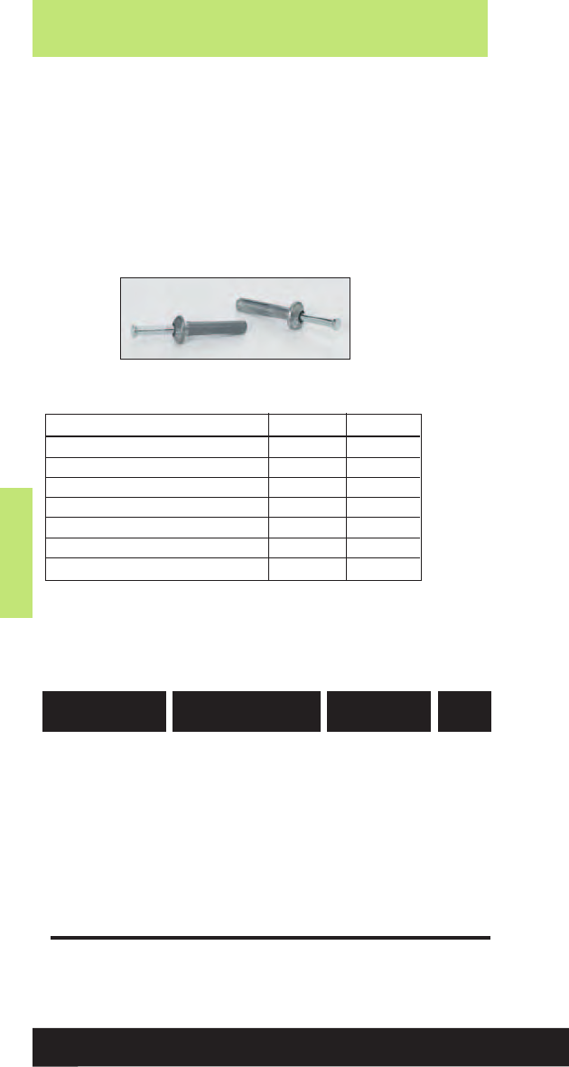
Anchors
Anchors
208
Read safety/installation instruction sheets in packages before use.
Drive Nail Anchor
781011 02964 ADN-18-87 3/16" x 7/8"100
781011 02965 ADN-25-75 1/4" x 3/4" 100
781011 02966 ADN-25-100 1/4" x 1" 100
781011 02967 ADN-25-125 1/4" x 11/4" 100
781011 02968 ADN-25-150 1/4" x 11/2"100
781011 02969 ADN-25-200 1/4" x 2" 100
782051 53306 ADN-25-300 1/4" x 3" 100
UPC/Part
Number
Box
Qty.
Size
Catalog
Number
•For use in concrete, block or brick.
• Anchor is recommended for light duty, tamper-proof
applications.
• Not recommended for overhead applications.
• Made of Zamac Alloy material.
Drive Nail Anchors
* Based on concrete compression strength of 4000 psi using applied safety
factor of 4.0. For additional loading information contact factory.
Drive Nail - Data 3/16”1/4”
ANSI Drill Bit Size (in.) 3/16 1/4
Fixture Clearance Hole (in.) 1/45/16
Head Height (in.) 7/64 9/64
Head Size, O.D. (in.) 13/32 35/64
Min. Embedment Depth (in.) 3/45/8
Load Capacity Tension (lbs) *125 150
Load Capacity Shear (lbs) *175 205
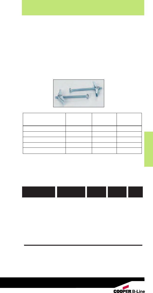
Anchors
Anchors
209
Read safety/installation instruction sheets in packages before use.
Toggle Bolt
782051 53354 ATB-18-300 1/2"3/16" x 3" 50
782051 53355 ATB-18-400 1/2"3/16" x 4" 50
782051 53356 ATB-25-300 5/8"1/4" x 3" 50
782051 53357 ATB-25-400 5/8"1/4" x 4" 50
782051 53358 ATB-37-300 7/8"3/8" x 3" 25
782051 53359 ATB-37-400 7/8"3/8" x 4" 25
UPC/Part
Number
Box
Qty.
Size
Catalog
Number
Drill
Diameter
• The toggle bolt is a spring wing type hollow wall anchor
designed for use in block, wallboard and other hollow
base materials.
• Anchor is a two-part assembly consisting of a machine
screw and a spring wing toggle.
• Adjustable to accommodate various wall thicknesses up
to 21/2".
• Combo round head bolt is provided.
• Made of zinc plated carbon steel.
Toggle Bolts
Allowable load capacities are calculated using applied safety factor of 4.0.
For additional loading information contact factory.
* Based on hollow wall concrete masonry with minimum compression
strength of 1500 psi.
Toggle Bolt - Data 3/16”1/4”3/8”
Tension Shear Tension Shear Tension Shear
(lbs.) (lbs.) (lbs.) (lbs.) (lbs.) (lbs.)
3/8” Wallboard 35 35 55 55 60 65
1/2” Wallboard 45 50 60 60 65 75
5/8” Wallboard 60 60 65 65 75 80
3/4” Wallboard 75 70 80 75 85 90
Hollow Concrete Masonry * 70 70 70 120 195 140
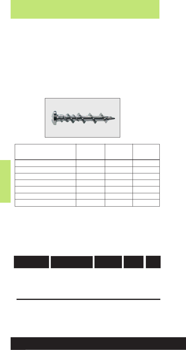
Anchors
Anchors
210
Read safety/installation instruction sheets in packages before use.
•One-piece, all steel anchor with high-profile threads for easy
fastening into wallboard and other masonry base materials.
• Deep cutting, corkscrew-like threads provide for smooth
entry and a strong hold.
• No pre-drilling is required when fastening into wallboard
or wood.
• Fastening into concrete, hollow or grout filled block, brick
and plaster requires a pre-drilled 3/16" ANSI hole.
• Installed with a No. 8 drill bit or No. 2 Phillips driver.
• Made of case hardened carbon steel with chrome finish.
Wall Screws
* Based on concrete compression strength of 4000 psi. Allowable load
capacities are calculated using an applied safety factor of 4.0. For
additional loading contact factory.
Wall Screw - Data Minimum Load Cap. Load Cap.
Embedment Tension Shear
Depth (lbs.) * (lbs.) *
Concrete * 3/4”90 260
1/2” Wallboard NA 20 60
5/8” Wallboard NA 35 90
3/4” Plywood NA 65 150
Grout-Filled Concrete Masonry 1” 55 165
Hollow Concrete Masonry 1” 60 165
Brick Masonry 3/4” 70 120
Wall Screw
782051 53372 AWS-CH 3/16" x 11/4” Combo 100
782051 53373 AWS-OH 3/16" x 11/4”Oval 100
782051 53374 AWS-PH 3/16" x 11/4” Pan 100
UPC/Part
Number
Box
Qty.
Size Head
Type
Catalog
Number
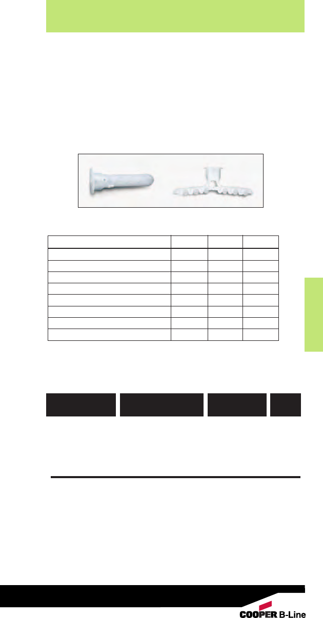
Anchors
Anchors
211
Read safety/installation instruction sheets in packages before use.
Plastic Screw Anchors
782051 53315 APS-4 #4 - #10 100
782051 53316 APS-6 #6 - #12 100
782051 53319 APS-8 #8 - #14 100
UPC/Part
Number
Box
Qty.
Screw Size
Catalog
Number
•One-piece anchor designed for light duty applications in
wallboard, concrete and masonry.
• Works in hollow or solid base materials.
• Suitable for screws with various thread sizes and styles -
screws may be installed with a screw gun.
Plastic Screw Anchors
* Allowable load capacities are calculated using an applied safety factor of 4.0.
For additional loading information contact factory.
Plastic Screw Anchor - Data APS-4 APS-6 APS-8
Drill Diameter (in.) 3/16 1/45/16
Screw Size Range #4-#10 #6-#12 #8-#14
Min, Thread Length (in.) 13/16 13/8113/16
Min. Hole Diameter (in.) 13/819/16 2
Min. Wall Thickness (in.) 1/43/81/2
Min. Embedded Thread Length (in.) 17/82 29/16
Load Capacity Tension (lbs) *18 20 22
Load Capacity Shear (lbs) * 32 40 45
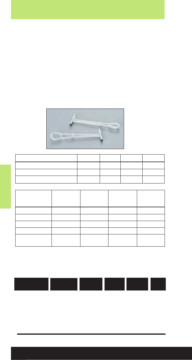
Anchors
Anchors
212
Read safety/installation instruction sheets in packages before use.
• Heavy duty hollow wall anchor designed for use in plaster,
wallboard, concrete block, or hollow tile.
• Pre-assembled anchor consisting of a carbon steel wing
and a locking cap/ratchet leg assembly molded from
engineered plastic.
• When compared to traditional toggles, this anchor can be
installed in a smaller hole and does not require a fixture or
screw to set it.
• Adjustable to accommodate various wall thickness up to
21/2".
Plastic Hollow Wall Anchors
Plastic Hollow Wall Anchor
782051 53311 APH-18 3/16” x 4” 1/2”3/8" - 21/2”50
782051 53312 APH-25 1/4” x 4” 1/2”3/8" - 21/2”50
782051 53313 APH-37 3/8” x 4” 3/4”3/8" - 21/2”25
782051 53314 APH-50 1/2” x 4” 3/4”3/8" - 21/2”25
UPC/Part
Number
Box
Qty.
Anchor
Size
Drill
Dia.
Wall
Thick.
Catalog
Number
Plastic Hollow Wall - Data 3/16”1/4”3/8”1/2”
Thread Size (UNC) 3/16”-24 1/4”-20 3/8”-16 1/2”-13
Max. Tightening Torque (ft-lbs) 5555
Minimum Clearance (in.) 17/8”1
7/8”1
7/8”1
7/8”
Allowable load capacities are calculated using an applied safety factor of 4.0.
For additional loading information contact factory.
* Based on hollow wall concrete masonry with minimum compression
strength of 1500 psi.
Plastic Hollow 3/16”1/4”3/8”1/2”
Wall - Data
Tension Shear Tension Shear Tension Shear Tension Shear
(lbs.) (lbs.) (lbs.) (lbs.) (lbs.) (lbs.) (lbs.) (lbs.)
3/8” Wallboard 30 60 35 70 35 70 35 75
1/2” Wallboard 35 70 35 75 40 75 40 90
5/8” Wallboard 50 95 55 105 55 105 55 110
3/4” Wallboard 50 110 55 120 60 120 60 120
Hollow Concrete 215 150 270 285 285 465 345 595
Masonry *
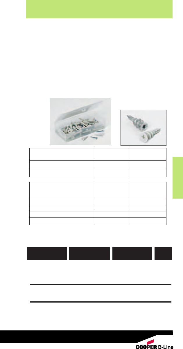
Anchors
Anchors
213
Read safety/installation instruction sheets in packages before use.
Self-Drilling Wallboard Anchor
781011 03314 APD-8K #8 x 1" 50
781011 03318 AZD-8K #8 x 1" 50
782051 53310 APDM-6K #6 x 1" 50
782051 53375 AZDM-6K #6 x 1" 50
UPC/Part
Number
Box
Qty.
Screw Size
Catalog
Number
• One-piece self drilling anchor designed for use in hollow
wallboard for light to medium duty loads.
• Ideal for mounting electrical fixtures, phone systems, and
miscellaneous hardware.
• APD/AZD designed for use in 3/8" to 1" wallboard.
• APDM/AZDM designed for use in 3/8" to 5/8" wallboard.
• Kit includes 50 anchors, 50 screws and #2 Phillips Drive Bit.
• Available in engineered Nylon and Zamac Alloy.
Self-Drilling Wallboard Anchors
Self-Drilling Wallboard APD/AZD APDM/AZDM
Anchor - Data
Tension Shear Tension Shear
(lbs.) (lbs.) (lbs.) (lbs.)
3/8” Wallboard 15 15 10 15
1/2” Wallboard 15 20 15 15
5/8” Wallboard 20 25 20 20
3/4” Wallboard 20 25 20 20
Self-Drilling Wallboard APD/AZD APDM/AZDM
Anchor - Data
Anchor Length (in.) 111/16 15/16
Min. Screw Engagement (in.) 3/43/4
Allowable load capacities are calculated using an applied safety factor
of 4.0. For additional loading information contact factory.
APD
APDM-6K
AZD
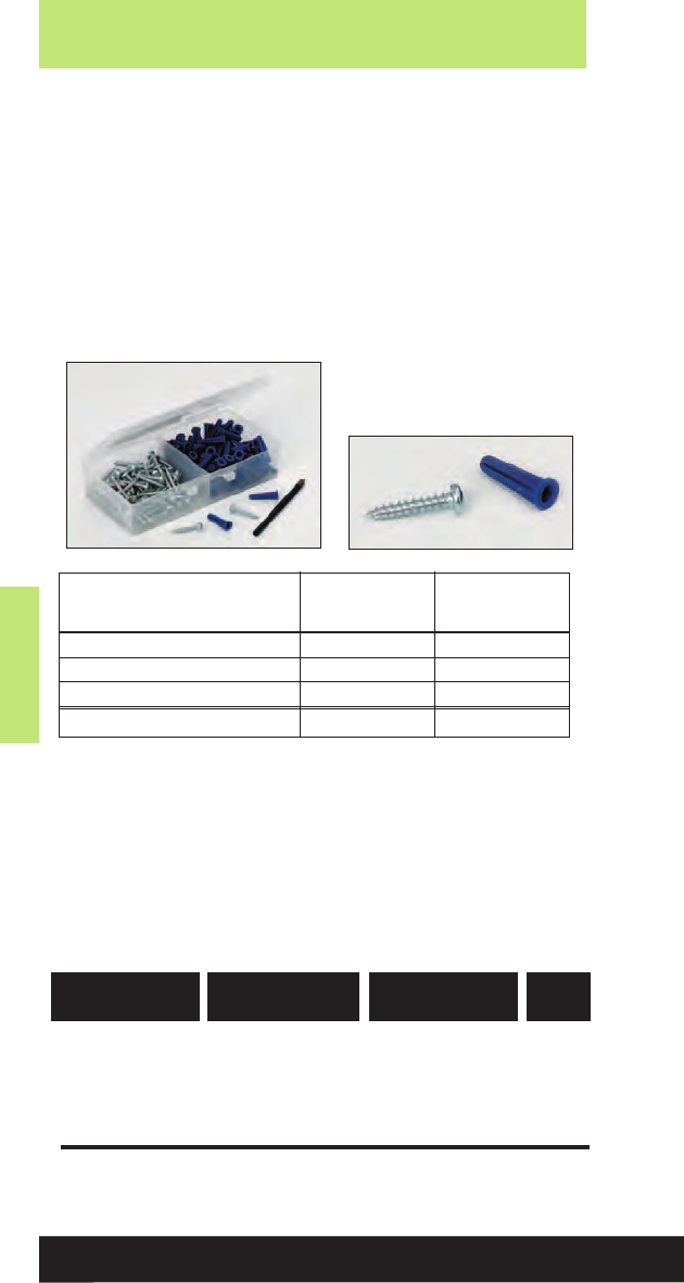
Anchors
Anchors
214
Read safety/installation instruction sheets in packages before use.
• Designed for use with lightweight fixtures.
• Recommended for use in concrete, block and brick.
• Recommended for light duty static applications where
holding power is not critical.
• Not recommended for overhead use.
• Kit includes 100 anchors, 100 screws and one drill bit.
• Made of engineered plastic.
Plastic Conical Anchors
Plastic Conical Anchor
782051 53307 APC-8K #8 x 1" 100
782051 53308 APC-10K #10 x 1" 100
782051 53309 APC-12K #12 x 1" 100
UPC/Part
Number
Box
Qty.
Screw Size
Catalog
Number
Plastic Conical Anchor - Data #8 #10 - #12
Tension Shear Tension Shear
(lbs.) (lbs.) (lbs.) (lbs.)
Nominal Weight Concrete * 110 70 140 90
Hollow Concrete Masonry ** 60 45 70 55
Clay Brick Masonry *** 30 50 55 65
Minimum Embedment Depth 7/8”7/8” 1” 1”
* Based on concrete compression strength of 4000 psi.
** Based on hollow concrete masonry with minimum compression strength
of 1500 psi.
*** Based on clay brick masonry with minimum compression strength of
1500 psi.
Loads contain an applied safety factor of 4.0. For additional loading
information contact factory.

Anchors
Anchors
215
Read safety/installation instruction sheets in packages before use.

NEC Requirements
Reprinted with permission from NFPA70-2005, the National Electrical Code
®
, Copyright
®
2005, National Fire Protection Association,
Quincy, MA 02269. This reprinted material is not the complete and official position of the National Fire Protection Association, on the
referenced subject which is represented only by the standard in its entirety.
NEC Requirements
Code Compliance for
Spring Steel Fasteners
Based on the 2005 NEC®
B-Line has recognized the need for a reference source,
detailing the National Electrical Code requirements for Spring
Steel Fasteners. The following pages are reprinted portions of
the 2005 NEC. These sections address nearly every aspect
of fastener installations and offer design solutions for the
electrical industry. If a topic has not been covered sufficiently
to answer a specific question or if additional information is
desired, contact B-Line’s engineering department.
The following information has been carefully checked for
accuracy and is believed to be correct and current. No
warranty, either expressed or implied, is made as to either its
applicability to, or its compatibility with, specific requirements,
of this information, nor for damages consequent to its use. All
design characteristics, specifications, tolerances and similar
information are subject to change without notice.
To obtain a copy of the NEC®contact:
National Fire Protection Association
1 Batterymarch Park
P.O. Box 9101
Quincy, Massachusetts 02269-9101
1-800-344-3555
National Electrical Code®and NEC®
are registered trademarks of the
National Fire Protection Association, Inc.
Quincy, MA 02269.
216

NEC Requirements
NEC Requirements
90.4 Enforcement. This Code is intended to be suitable for
mandatory application by governmental bodies that
exercise legal jurisdiction over electrical installations,
including signaling and communications systems, and for
use by insurance inspectors. The authority having
jurisdiction for enforcement of the Code has the
responsibility for making interpretations of the rules, for
deciding upon the approval of equipment and materials,
and for granting the special permission contemplated in a
number of the rules.
By special permission, the authority having
jurisdiction may waive specific requirements in this
Code or permit alternate methods where it is assured
that equivalent objectives can be achieved by
establishing and maintaining effective safety. *
This Code may require new products, constructions, or
materials that may not yet be available at the time the
Code is adopted. In such event, the authority having
jurisdiction may permit the use of the products,
constructions, or materials that comply with the most
recent previous edition of this Code adopted by the
jurisdiction.
Article 100 - Definitions
Listed. Equipment, materials, or services included in a
list published by an organization that is acceptable to the
authority having jurisdiction and concerned with
evaluation of products or services, that maintains periodic
inspection of production of listed equipment or materials
or periodic evaluation of services, and whose listing
states that the equipment, material, or services either
meets appropriate designated standards or has been
tested and found suitable for a specific purpose.
FPN: The means for identifying listed equipment may vary for
each organization concerned with product evaluation, some of
which do not recognize equipment as listed unless it is labeled.
Use of the system employed by the listing organization allows the
authority having jurisdiction to identify a listed product.
*Note: Local codes may override certain requirements of the
National Electrical Code®. Consult your local inspector for
further details.
Reprinted with permission from NFPA 70-2005, the National Electrical Code
®
, Copyright
®
2005, National Fire Protection
Association, Quincy, MA 02269. This reprinted material is not the complete and official position of the National Fire Protection
Association, on the referenced subject which is represented only by the standard in its entirety.
217

NEC Requirements
Reprinted with permission from NFPA 70-2005, the National Electrical Code
®
, Copyright
®
2005, National Fire Protection Association,
Quincy, MA 02269. This reprinted material is not the complete and official position of the National Fire Protection Association, on the
referenced subject which is represented only by the standard in its entirety.
NEC Requirements
300.4 Protection Against Physical Damage.
Where subject to physical damage, conductors shall
be adequately protected.
(A) Cables and Raceways through Wood Members.
(1) Bored Holes. . . . , holes shall be bored so that
the edge of the hole is not less than 32mm (11/4in.)
from the nearest edge of the wood member. Where
this distance cannot be maintained, the cable or
raceway shall be protected from penetration by
screws or nails by a steel plate or bushing, at least
1.6 mm (1/16 in.) thick, and of appropriate length and
width installed to cover the area of the wiring.
(See Figure 1)
Exception No. 1: Steel plates shall not be required
to protect RMC, IMC, RNC, or EMT.
Exception No. 2: A listed and marked steel plate less
than 1.6 mm (1/16 in.) thick that provides equal or
better protection against nail or screw penetration
shall be permitted.
(2) Notches in Wood. . . . , cables or raceways
shall be permitted to be laid in notches in wood
studs, joists, rafters, or other wood members where
the cable or raceway at those points is protected
against nails or screws by a steel plate at least
1.6 mm (1/16 in.) thick, and of appropriate length and
width, installed to cover the area of the wiring. The
steel plate shall be installed before the building
finish is applied. (See Figure 1)
Exception: See Exceptions 1 & 2 from (1) Bored Holes
(B) Nonmetallic-Sheathed Cables and Electrical
Nonmetallic Tubing through Metal Framing
Members.
(1) Nonmetallic-Sheathed Cable. . . . where
nonmetallic-sheathed cables pass through either
factory or field punched, cut or drilled slots or holes
in metal members, the cable shall be protected by
listed bushings or listed grommets covering all metal
edges that are securely fastened in the opening prior
to installation of the cable. (See Figure 2)
(2) Nonmetallic-Sheathed Cable and Electrical
Nonmetallic Tubing. Where nails or screws are
likely to penetrate nonmetallic-sheathed cable or
electrical nonmetallic tubing, a steel sleeve, steel
plate, or steel clip not less than 1.6 mm (1/16 in.) in
thickness shall be used to protect the cable or
tubing. (See Figure 1)
Exception: See Exception 2 from (A)(1) Bored Holes
218
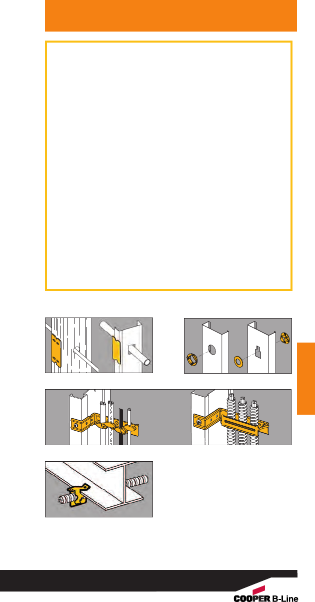
NEC Requirements
NEC Requirements
Reprinted with permission from NFPA 70-2005, the National Electrical Code
®
, Copyright
®
2005, National Fire Protection
Association, Quincy, MA 02269. This reprinted material is not the complete and official position of the National Fire Protection
Association, on the referenced subject which is represented only by the standard in its entirety.
(D) Cables and Raceways Parallel to Framing Members
and Furring Strips. . . . , the cable or race way shall
be installed and supported so that the nearest outside
surface of the cable or raceway is not less than 32 mm
(11/4in.) from the nearest edge of the framing member
or furring strips where nails or screws are likely to
penetrate. Where this distance cannot be maintained,
the cable or raceway shall be protected from penetration
by nails or screws by a steel plate, sleeve, or equivalent
at least 1.6 mm (1/16 in.) thick
(See Figures 1, 3, 4)
Exception 1: See Exception 1 from (A)(1) Bored Holes
Exception No. 2: For concealed work in finished
buildings, or finished panels for prefabricated buildings
where such supporting is impracticable, it shall be
permissible to fish the cables between access points.
Exception 3: See Exception 2 from (A)(1) Bored Holes
(E) Cables and Raceways Installed in Shallow Grooves.
. . . , shall be protected by 1.6 mm (1/16 in.) thick steel
plate, sleeve, or equivalent or by not less than 32 mm
(11/4in.) free space for the full length of the groove in
which the cable or raceway is installed.
(See Figure 1)
Exception: See Exceptions 1 & 2 from (A)(1) Bored Holes
Figure 1 - BM3 & BM3M
Figure 3 - BRC4 & BRC4M
Figure 2 - BM1/BM2
Figure 4 - BX4
219

NEC Requirements
Reprinted with permission from NFPA 70-2005, the National Electrical Code
®
, Copyright
®
2005, National Fire Protection Association,
Quincy, MA 02269. This reprinted material is not the complete and official position of the National Fire Protection Association, on the
referenced subject which is represented only by the standard in its entirety.
NEC Requirements
300.11 Securing and Supporting.
(A) Secured in Place. Raceways, cable assemblies,
boxes, cabinets, and fittings shall be securely fastened
in place. Support wires that do not provide secure
support shall not be permitted as the sole support.
Support wires and associated fittings that provide
secure support and that are installed in addition to the
ceiling grid support wires shall be permitted as the sole
support. Where independent support wires are used,
they shall be secured at both ends. Cables and race
ways shall not be supported by ceiling grids.
(1) Fire Rated Assemblies. Wiring located
within the cavity of a fire-rated floor-ceiling or
roof-ceiling assembly shall not be secured to, or
supported by, the ceiling assembly, including the
ceiling support wires. An independent means of
secure support shall be provided and shall be
permitted to be attached to the assembly. Where
independent support wires are used, they shall
be distinguishable by color, tagging, or other
effective means from those that are part of the
fire-rated design.
Exception: The ceiling support system shall be
permitted to support wiring and equipment that
have been tested as part of the fire-rated assembly.
(2) Non-Fire-Rated Assemblies. Wiring located
within the cavity of a non-fire-rated floor-ceiling
or roof-ceiling assembly shall not be secured to,
or supported by, the ceiling assembly, including
the ceiling support wires.
An independent means of secure support shall
be provided.
Exception: The ceiling support system shall be
permitted to support branch-circuit wiring and
associated equipment where installed in accordance
with the ceiling system manufacturer’s instructions.
220
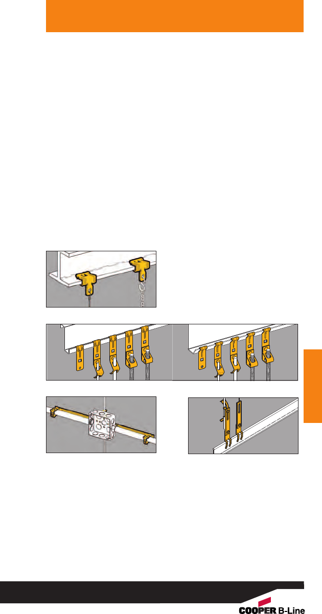
NEC Requirements
NEC Requirements
Reprinted with permission from NFPA 70-2005, the National Electrical Code
®
, Copyright
®
2005, National Fire Protection
Association, Quincy, MA 02269. This reprinted material is not the complete and official position of the National Fire Protection
Association, on the referenced subject which is represented only by the standard in its entirety.
Note: Apreviously acceptable practice, namely supporting
cable and raceways by the ceiling grid, is no longer
allowed. The intent of Article 300.11 is simple: an
independent means of secure support must be
provided for cable assemblies, raceways, boxes, etc.
(See Figures 5 - 8)
Typical Drop Wire / Rod Applications
Additional drop wires, which are installed specifically
for cable support, must be secured at both ends. When
independent wires are used in fire-rated assemblies,
they must be distinguishable from those wires that are
part of the fire-rated assembly. B-Line’s BA-311 series
can be used to secure support wire to the ceiling grid.
Its bright yellow color allows it to be easily
recognized by inspectors. (See Figure 8)
Figure 5 - BE Series
Upper Attachments
Figure 6 - BF3 Series & BF4 Series
Figure 7 - BG-8-12-S18-W2 Figure 8 - BA311
221

NEC Requirements
Reprinted with permission from NFPA 70-2005, the National Electrical Code
®
, Copyright
®
2005, National Fire Protection Association,
Quincy, MA 02269. This reprinted material is not the complete and official position of the National Fire Protection Association, on the
referenced subject which is represented only by the standard in its entirety.
NEC Requirements
310.15 Ampacities For Conductors Rated 0-2000 Volts.
(B) Tables . . . . .
(2) Adjustment Factors.
(a) More Than Three Current-Carrying
Conductors in a Raceway or Cable. Where
the number of current-carrying conductors in
a raceway or cable exceeds three, or where
single conductors or multiconductor cables
are stacked or bundled longer than 600 mm
(24 in.) without maintaining spacing and are
not installed in raceways, the allowable
ampacity of each conductor shall be reduced
as shown in Table 310.15(B)(2)(a). Each
current-carrying conductor of a paralleled set
of conductors shall be counted as a current-
carrying conductor.
FPN No. 1: See Annex B, Table B.310.11, for
adjustment factors for more than three current-
carrying conductors in a raceway or cable with
load diversity.
FPN No. 2: See 366.23(A), for correction factors for
conductors in sheet metal auxiliary gutters and
376.22 for correction factors for conductors in
metal raceways.
Exception No. 1: Where conductors of different
systems, as provided in 300.3, are installed in a
common raceway or cable, the derating factors
shown in Table 310.15(B)(2)(a) shall apply only to
the number of power and lighting conductors
(Articles 210, 215, 220, and 230).
Exception No. 2: For conductors installed in cable
trays, the provisions of 392.11 shall apply.
Exception No. 3: Derating factors shall not apply
to conductors in nipples having a length not
exceeding 600 mm (24 in.).
Exception No. 4: Derating factors shall not apply to
underground conductors entering or leaving an
outdoor trench if those conductors have physical
protection in the form of rigid metal conduit,
intermediate metal conduit, or rigid nonmetallic
conduit having a length not exceeding 3.05 m
(10 ft) and if the number of conductors does not
exceed four.
222
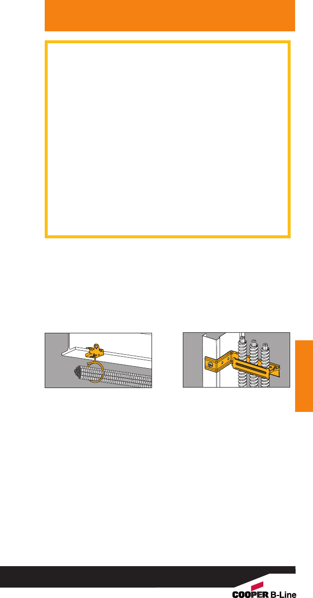
Exception No. 5: Adjustment factors shall not apply
to Type AC cable or to Type MC cable without an
overall outer jacket under the following conditions:
(1) Each cable has not more than three
current-carrying conductors.
(2) The conductors are 12 AWG copper.
(3) Not more than 20 current-carrying
conductors are bundled, stacked, or
supported on “bridle rings”.
(See Figure 9)
A 60 percent adjustment factor shall be applied
where current-carrying conductors in these cables
that are stacked or bundled longer than 600 mm
(24 in.) without maintaining spacing exceeds 20.
(b) More Than One Conduit, Tube, or
Raceway Spacing between conduits,
tubing, or raceways shall be maintained.
NEC Requirements
NEC Requirements
Reprinted with permission from NFPA 70-2005, the National Electrical Code
®
, Copyright
®
2005, National Fire Protection
Association, Quincy, MA 02269. This reprinted material is not the complete and official position of the National Fire Protection
Association, on the referenced subject which is represented only by the standard in its entirety.
Figure 9 - Bridle Rings Figure 10 - BRC4M
223

314.23 Supports. Enclosures within the scope of this
article shall be supported in accordance with one or
more of the provisions in 314.23 (A) through (H).
(C) Mounting in Finished Surfaces. An enclosure
mounted in a finished surface shall be rigidly
secured thereto by clamps, anchors, or fittings
identified for the application. (See Figures 11 & 12)
(D) Suspended Ceilings. An enclosure mounted to
structural or supporting elements of a suspended
ceiling shall be not more than 1650 cm3(100 in.3) in
size and shall be securely fastened in place in
accordance with either (D)(1) or (D)(2).
(1) Framing Members. An enclosure shall be
fastened to the framing members by mechanical
means such as bolts, screws, or rivets, or by the
use of clips or other securing means identified for
use with the type of ceiling framing member(s)
and enclosure(s) employed. . . . . (See Figure 13)
(2) Support Wires. The installation shall comply
with the provisions of 300.11(A). The enclosure
shall be secured, using methods identified for the
purpose to ceiling support wire(s), including any
additional support wire(s) installed for that purpose.
Support wire(s) used for enclosure support shall be
fastened at each end so as to be taut within the
ceiling cavity. (See Figure 14)
(E) Raceway Supported Enclosures, Without
Devices, Luminaries (Fixtures), orLampholders.
. . . It shall be supported by two or more conduits
threaded wrenchtight into the enclosure or hubs.
Each conduit shall be secured within 900 mm (3 ft)
of the enclosure, or within 450 mm (18 in.) of the
enclosure if all conduit entries are on the same
side. (See Figure 15)
(F) Raceway Supported Enclosures, With Devices,
Luminaries (Fixtures), or Lampholders. . . . It
shall be supported by two or more conduits threaded
wrenchtight into the enclosure or hubs.
Each conduit shall be secured within 450 mm (18 in.)
of the enclosure. (See Figure 15)
314.27 Outlet Boxes
(B) Maximum Luminaire (Fixture) Weight. Outlet boxes
or fitting installed as required by 314.23 shall be per
mitted to support luminaries (lighting fixtures) weighing
23 kg (50 lbs.) or less. Aluminaire (lighting fixture) that
weighs more than 23 kg (50 lbs.) shall be supported
independently of the outlet box unless the outlet box is
listed for the weight to be supported.
(See Figure 13)
NEC Requirements
Reprinted with permission from NFPA 70-2005, the National Electrical Code
®
, Copyright
®
2005, National Fire Protection Association,
Quincy, MA 02269. This reprinted material is not the complete and official position of the National Fire Protection Association, on the
referenced subject which is represented only by the standard in its entirety.
NEC Requirements
224
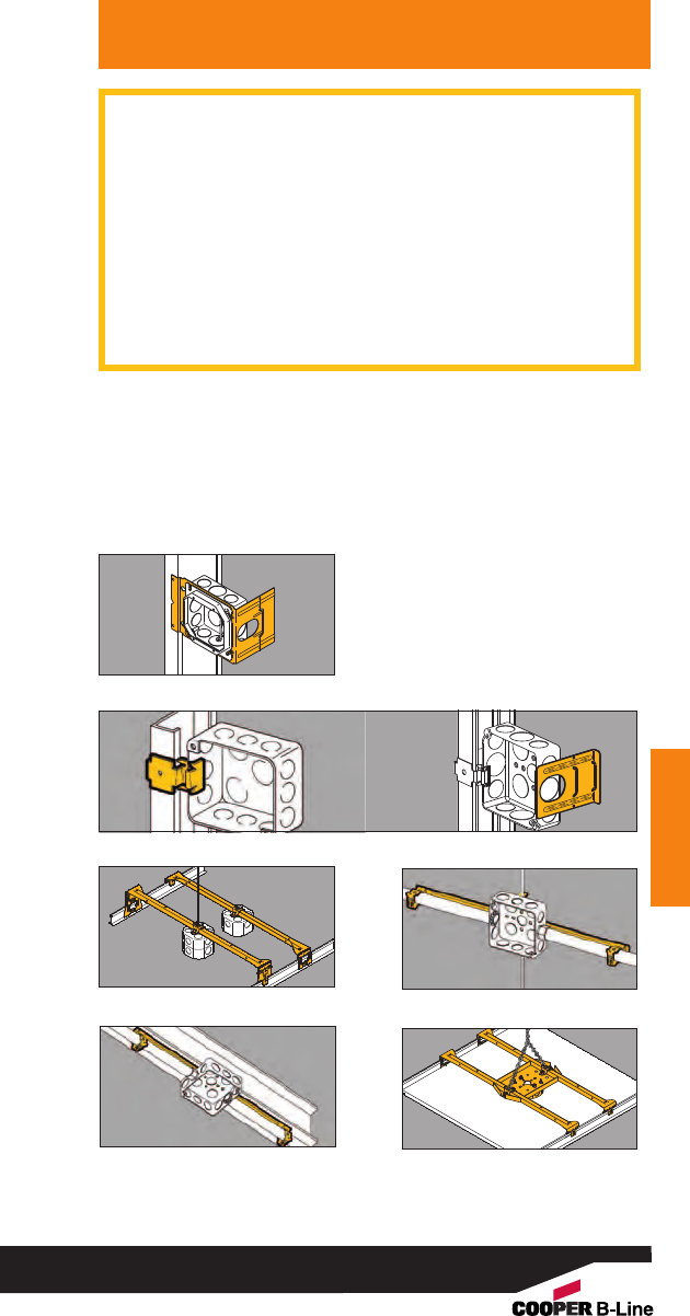
NEC Requirements
NEC Requirements
Reprinted with permission from NFPA 70-2005, the National Electrical Code
®
, Copyright
®
2005, National Fire Protection
Association, Quincy, MA 02269. This reprinted material is not the complete and official position of the National Fire Protection
Association, on the referenced subject which is represented only by the standard in its entirety.
(D) Boxes at Ceiling-Suspended (Paddle) Fan Outlets.
Outlet boxes or outlet box systems used as the sole
support of a ceiling-suspended (paddle) fan shall be
listed, shall be marked by their manufacturer as suitable
for this purpose, and shall not support ceiling-suspended
(paddle) fans that weigh more than 32 kg (70 lb). For
outlet boxes or outlet box systems designed to support
of a ceiling-suspended (paddle) fans that weigh more
than 16 kg (35 lb), the required marking shall include the
maximum weight to be supported.
(See Figure 16)
Figure 11 - BB4-23
Figure 12 - BB9 & BB12
Figure 13 - BA50 Figure 14 - BG-8-12-S18-W2
Figure 15 - BG-8-12-S18-U-2-4 Figure 16 - BA50F
225

NEC Requirements
Reprinted with permission from NFPA 70-2005, the National Electrical Code
®
, Copyright
®
2005, National Fire Protection Association,
Quincy, MA 02269. This reprinted material is not the complete and official position of the National Fire Protection Association, on the
referenced subject which is represented only by the standard in its entirety.
NEC Requirements
Article 320
Armored Cable : Type AC
320.17 Through or Parallel to Framing Members.
Type AC cable shall be protected in accordance with
300.4 (A), (C), and (D) where installed through or
parallel to framing members. (See Figures 17 & 18)
320.30 Securing and Supporting.
(A) General. Type AC shall be supported and secured by
staples, cable ties, straps, hangers, or similar fittings,
designed and installed so as not to damage the cable.
(B) Securing. Unless otherwise provided, Type AC cable
shall be secured within 300 mm (12 in.) of every out
let box, junction box, cabinet, or fitting and at intervals
not exceeding 1.4 m (41/2ft) where installed on or
across framing members. (See Figures 19 -22)
(C) Supporting. Unless otherwise provided, Type AC
cable shall be supported at intervals not exceeding
1.4 m (41/2ft). Horizontal runs of Type AC cable
installed in wooden or metal framing members or
similar supporting means shall be considered
supported where such support does not exceed 1.4 m
(41/2ft) intervals.
Article 330
Metal-Clad Cable : Type MC
330.17 Through or Parallel to Framing Members.
Type MC cable shall be protected in accordance with
300.4 (A), (C), and (D) where installed through or
parallel to framing members. (See Figures 17 & 18)
330.30 Securing and Supporting.
(A) General. Type MC shall be supported and secured
by staples, cable ties, straps, hangers, or
similar fittings or other approved means designed
and installed so as not to damage the cable.
(B) Securing. Unless otherwise provided, cables
shall be secured at intervals not exceeding 1.8 m
(6 ft). Cables containing four or fewer conductors sized
no larger than 10 AWG shall be secured within
300 mm (12 in.) of every box, cabinet, fitting or other
cable termination. (See Figure 19 - 22)
(C) Supporting. Unless otherwise provided, cables shall
be supported at intervals not exceeding 1.8 m (6ft).
Horizontal runs of Type MC cable installed in wooden
or metal framing members or similar supporting means
shall be considered supported and secured where
such support does not exceed 1.8 m (6 ft) intervals.
Article 334
Nonmetallic Sheathed Cables
334.17 Through or Parallel to Framing Members.
Type NM, NMC, or NMS cable shall be protected in
accordance with 300.4 where installed through or
226
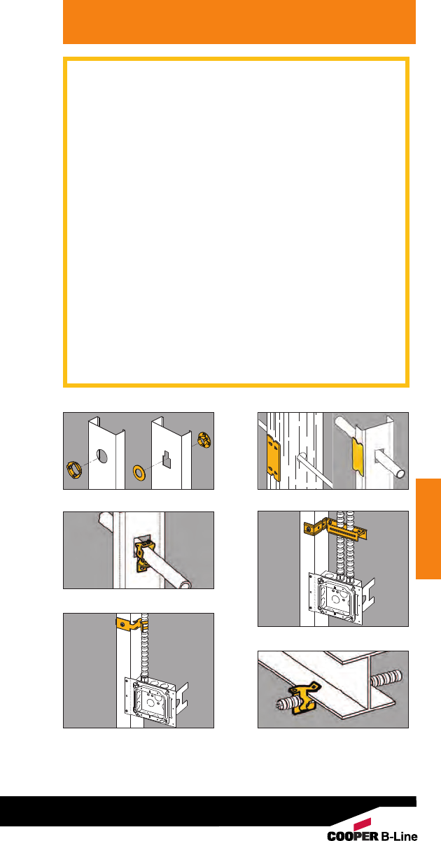
NEC Requirements
NEC Requirements
Reprinted with permission from NFPA 70-2005, the National Electrical Code
®
, Copyright
®
2005, National Fire Protection
Association, Quincy, MA 02269. This reprinted material is not the complete and official position of the National Fire Protection
Association, on the referenced subject which is represented only by the standard in its entirety.
parallel to framing members. Grommets used as
required in 300.4(B)(1) shall remain in place and be
listed for the purpose of cable protection.
(See Figures 17 & 18)
334.30 Securing and Supporting. Nonmetallic-sheathed
cable shall be supported and secured by staples, cable
ties, straps, hangers, or similar fittings designed and
installed so as not to damage the cable, at intervals not
exceeding 1.4 m (41/2ft) and within 300 mm (12 in.) of
every outlet box, junction box, cabinet, or fitting. Flat
cables shall not be stapled on edge. Sections of cable
protected from physical damage by raceway shall not be
required to be secured within the raceway.
(See Figures 19 - 22)
(A) Horizontal Runs Through Holes and Notches. In
other than vertical runs, cables installed in
accordance with 300.4 shall be considered to be
supported and secured where such support does not
exceed 1.4 m ( 41/2ft) intervals and the nonmetallic-
sheathed cable is securely fastened in place by an
approved means within 300 mm (12 in.) of each box,
cabinet, conduit body, or other nonmetallic-sheathed
cable termination.
FPN: See 314.17(C) for support where nonmetallic
boxes are used.
Figure 17 - BM1/BM2
Figure 19 - BG-8-12-H7
Figure 22 - BX4
Figure 20 - BRC4 & BRC4M
Figure 21 - BX5
Figure 18 - BM3 & BM3M
227

NEC Requirements
Reprinted with permission from NFPA 70-2005, the National Electrical Code
®
, Copyright
®
2005, National Fire Protection Association,
Quincy, MA 02269. This reprinted material is not the complete and official position of the National Fire Protection Association, on the
referenced subject which is represented only by the standard in its entirety.
NEC Requirements
Article 344
Rigid Metal Conduit : Type RMC
344.30 Securing and Supporting.
(A) Securely Fastened. RMC shall be securely fastened
within 900 mm (3 ft) of each outlet box, junction box,
device box, cabinet, conduit body, or other conduit
termination. Fastening shall be permitted to be
increased to a distance of 1.5 m (5 ft) where structural
members do not readily permit fastening within 900 mm
(3 ft). Where approved, conduit shall not be required to
be securely fastened within 900 mm (3 ft) of the service
head for above-the-roof termination of a mast.
(See Figures 23 - 25)
(B) Supports. RMC shall be supported in accordance
with one of the following:
(1) Conduit shall be supported at intervals not
exceeding 3 m (10 ft).
(2) The distance between supports for straight
runs of conduit shall be permitted in
accordance with Table 344.30(B)(2), . . . .
(3) Exposed vertical risers from industrial machinery
or fixed equipment shall be permitted to be
supported at intervals not exceeding
6 m (20 ft) . . . .
(4) Horizontal runs of RMC supported by openings
through framing members at intervals not
exceeding 3 m (10 ft) and securely fastened
within 900 mm (3 ft) of termination points
shall be permitted. (See Figure 26)
Article 348
Flexible Metal Conduit: Type FMC
348.30 Securing and Supporting.
(A) Securely Fastened. FMC shall be securely fastened in
place by an approved means within 300 mm (12 in.) of
each box, cabinet, conduit body, or other conduit
termination and shall be supported and secured at
intervals not to exceed 1.4 m (41/2ft).
(See Figures 23 - 25)
(B) Supports. Horizontal runs of FMC supported by
openings through framing members at intervals not
greater than 1.4 m ( 41/2ft) and securely fastened
within 300 mm (12 in) of termination points shall be
permitted. (See Figure 26)
* See NFPA 70-2005 for exceptions.
Article 358
Electrical Metallic Tubing - Type EMT
358.30 Securing and Supporting.
(A) Securely Fastened. EMT shall be securely fastened in
place at least every 3 m (10 ft). In addition, each EMT
run between termination points shall be securely
within 900 mm (3 ft) of each outlet box, junction box,
228
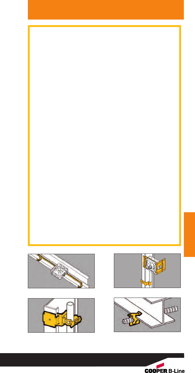
NEC Requirements
NEC Requirements
Reprinted with permission from NFPA 70-2005, the National Electrical Code
®
, Copyright
®
2005, National Fire Protection
Association, Quincy, MA 02269. This reprinted material is not the complete and official position of the National Fire Protection
Association, on the referenced subject which is represented only by the standard in its entirety.
device box, cabinet, conduit body, or other tubing
termination. (See Figures 23 - 25)
Exception No. 1: Fastening of unbroken lengths
shall be permitted to be increased to a distance of
1.5 m (5 ft) where structural members do not
readily permit fastening within 900 mm (3 ft).
Exception No. 2: For concealed work in finished
buildings or prefinished wall panels where such
securing is impracticable, unbroken lengths (with
out coupling) of EMT shall be permitted to be fished.
(B) Supports. Horizontal runs of EMT supported by
openings through framing members at intervals not
greater than 3 m (10 ft) and securely fastened within
900 mm (3 ft) of termination points shall be permitted.
(See Figure 26)
Article 362
Electrical Nonmetallic Tubing - Type ENT
362.30 Securing and Supporting.
(A) Securely Fastened. ENT shall be securely
fastened at intervals not exceeding 900 mm (3 ft).
In addition, ENT shall be securely fastened in place
within 900 mm (3 ft) of each outlet box, device box,
junction box, cabinet, or fitting where it terminates.
(See Figures 23 - 25)
Exception No. 1: Lengths not exceeding a distance of
1.8 m (6 ft) from a luminaire (fixture) terminal
connection for tap connection to lighting luminaries
(fixtures) shall be permitted without being secured.
Exception No. 2: Lengths not exceeding 1.8 m (6 ft)
from the last point where the raceway is securely
fastened for connection within an accessible ceiling to
luminaire(s) [lighting fixture(s)] or other equipment.
(B) Supports. Horizontal runs of ENT supported by
openings in framing members at intervals not
exceeding 900 mm (3 ft) of termination points shall be
permitted. (See Figure 26)
Figure 23 - BG-8-12-S18-U-2-4 Figure 24 - BB38
Figure 25 - BG-8-12-B1 Figure 26 - BX4
229

NEC Requirements
Reprinted with permission from NFPA 70-2005, the National Electrical Code
®
, Copyright
®
2005, National Fire Protection Association,
Quincy, MA 02269. This reprinted material is not the complete and official position of the National Fire Protection Association, on the
referenced subject which is represented only by the standard in its entirety.
NEC Requirements
Article 410
Luminaries (Lighting Fixtures),
Lampholders, and Lamps
410.16 Means of Support.
(A) Outlet Boxes. Outlet boxes or fittings installed as
required by 314.23 and complying with the provisions
of 314.27(A) and 314.27(B) shall be permitted to
support luminaries (fixtures).
(C) Suspended Ceilings. Framing members of
suspended ceiling systems used to support luminaries
(fixtures) shall be securely fastened to each other and
shall be securely attached to the building structure at
appropriate intervals. Luminaries (fixtures) shall be
securely fastened to the ceiling framing member by
mechanical means such as bolts, screws, or rivets.
Listed clips identified for use with the type of ceiling
framing member(s) and luminaire(s) [fixture(s)] shall
also be permitted. (See Figures 27 - 31)
410.104 Fastening. Lighting track shall be securely
mounted so that each fastening is suitable for supporting
the maximum weight of luminaries (fixtures) that can be
installed. Unless identified for supports at greater intervals,
a single section 1.2 m (4 ft.) or shorter in length shall have
two supports, and, where installed in a continuous row,
each individual section of not more than 1.2 m (4 ft.) in
length shall have one additional support. (See Figure 30)
422.18 Support of Ceiling-Suspended (Paddle) Fans
Ceiling-suspended (paddle) fans shall be supported
independently of an outlet box or by listed outlet
box or outlet box systems identified for the use and
installed in accordance with 314.27(D). (See Figure 32)
Article 800
Communication Circuits
800.24 Mechanical Execution of Work.
Communications circuits and equipment shall be
installed in a neat and workmanlike manner. Cables
installed exposed on the surface of ceilings and
sidewalls shall be supported by the building structure in
such a manner that the cable will not be damaged by
normal building use. Such cables shall be secured by
straps, staples, hangers, or similar fittings designed and
installed so as not to damage the cable. The installation
shall also conform with 300.4(D) and 300.11.
FPN: Accepted industry practices are described in
ANSI/NECA/BICSI 568-2001, Standard for Installing
Commercial Building Telecommunications Cabling,
and other ANSI-approved installation standards.
230
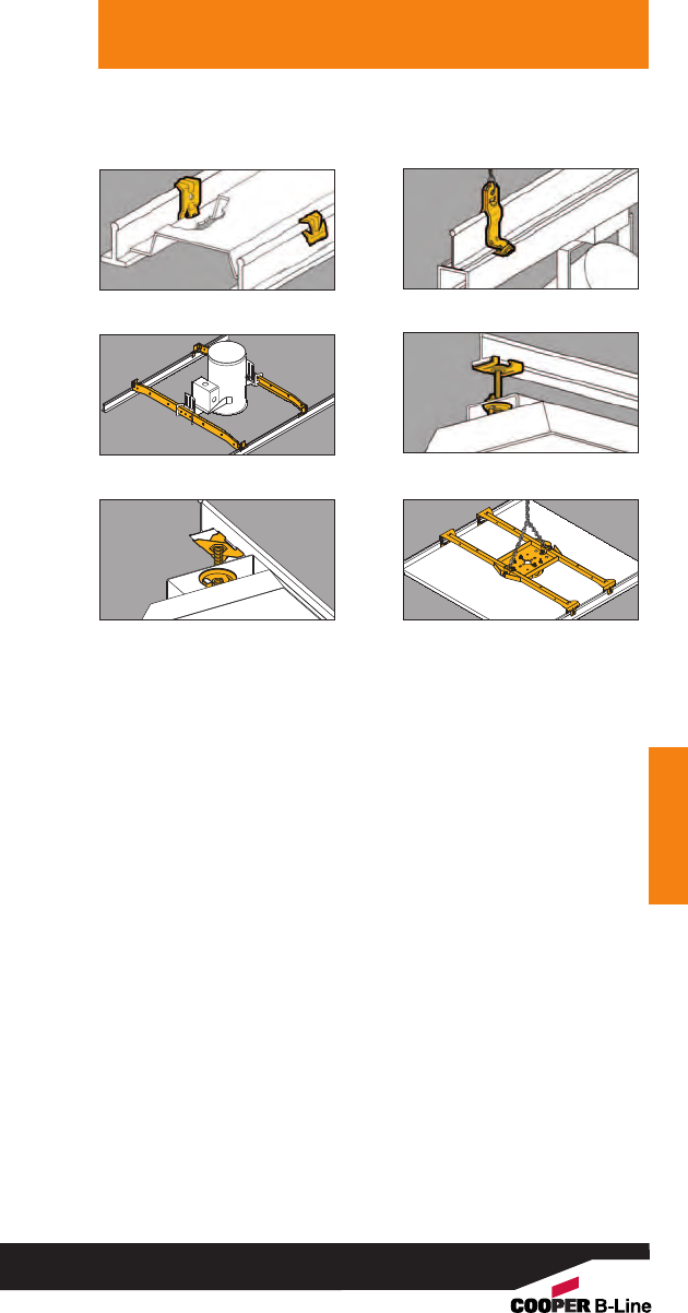
NEC Requirements
NEC Requirements
Reprinted with permission from NFPA 70-2005, the National Electrical Code
®
, Copyright
®
2005, National Fire Protection
Association, Quincy, MA 02269. This reprinted material is not the complete and official position of the National Fire Protection
Association, on the referenced subject which is represented only by the standard in its entirety.
Figure 27 - BA15 Figure 28 - BA1
Figure 29 - BA40 Figure 30 - BA 4-16 Series
Figure 31 - BAX Series Figure 32 - BA50F
231

TIA/EIA Requirements
Reprinted with permission from NFPA 70-2005, the National Electrical Code
®
, Copyright
®
2005, National Fire Protection Association,
Quincy, MA 02269. This reprinted material is not the complete and official position of the National Fire Protection Association, on the
referenced subject which is represented only by the standard in its entirety.
TIA/EIA Requirements
ANSI/TIA/EIA-569-A
4. Horizontal pathways and related spaces
4.6 Ceiling pathway
4.6.2 Design guidelines
4.6.2.1 Planning. The design shall provide a
suitable means for supporting cable from the
telecommunications closet to the work areas to be
served. Cable shall not be laid directly on the
ceiling tile or rails.
4.6.2.2 Clearance. A minimum of 75 mm (3 in.)
clear vertical space shall be available above the
ceiling tiles for the horizontal cabling and pathway.
(See Figure 33)
4.6.5 Cable support
4.6.5.1 Where zone conduit or cable tray is not
available in a suspended ceiling space and
where telecommunications cables are allowed to
be placed in the ceiling, adequate open-top
cable supports, located on 1220-1525 mm (48-
60 inch) centers, shall be provided. Where larger
quantities of cables (50-75 cables) bunched
together in the ceiling at a congested area, such
as close to the telecommunications closet, special
supports shall be designed and installed to carry
the additional weight. (See Figures 33 & 34)
4.6.5.2 A suspended ceiling support rod or wire may
be used to mount appropriate cable fasteners
loaded with multiple cables up to the total weight
for which the fastener is approved. The T-bar rail
of a suspended ceiling may be used to mount
appropriate cable fasteners loaded with cable up
to a total weight of 0.7 kg/m (0.45 lb/ft). The
fastener design shall not interfere with the
inserting or removing of the ceiling tile.
(See Figures 33 & 34)
NOTES
1) Aweight of 1.0 kg (2.2 lbs.) or 0.7 kg/m with
spacing of support wire/rod at 1.5 m (5 ft.) is
equivalent to a bundle of sixteen 4-pair 24 AWG
UTP cables, including fasteners.
2) If any side pull is exerted on the support wire,
like a turn in direction of the cables, the level
of the ceiling tee rail could be affected.
232
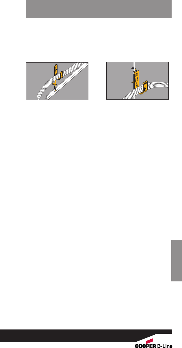
TIA/EIA Requirements
TIA/EIA Requirements
Reprinted with permission from NFPA 70-2005, the National Electrical Code
®
, Copyright
®
2005, National Fire Protection
Association, Quincy, MA 02269. This reprinted material is not the complete and official position of the National Fire Protection
Association, on the referenced subject which is represented only by the standard in its entirety.
Figure 33 - BCHxx-A28 Figure 34 - BCHxx-W2
233
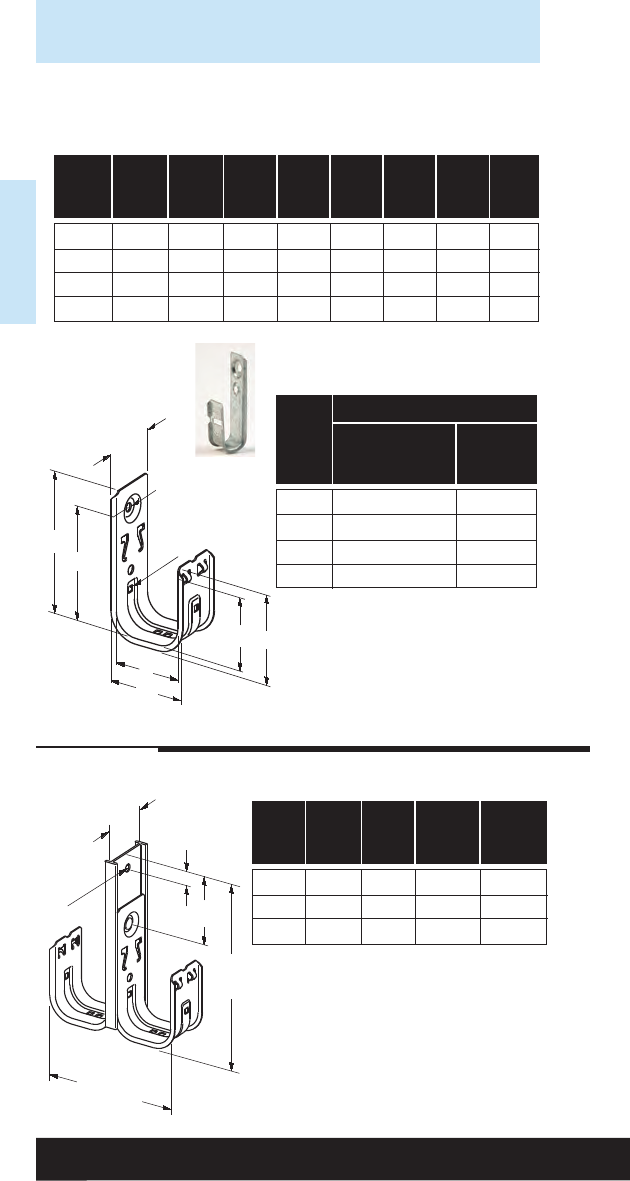
Reference Data
Reference Data
‘A’
‘B’
‘C’
‘E’
‘D’
‘F’
‘G’
‘H’
.26 Ø
Cable Static Load Capacity (S.F. 3)
Hook Galvanized & Spring
Size Stainless Steel Steel
In.
Lbs. Lbs.
3/4
30 --
15/16
30 100
2 30 100
4 30 100
Stated loads are per hook and
should not be exceeded. The load
capacity of a fastener having more
than one component is equal to the
load capacity of the lowest rated
component.
Load Capacity
Hook ‘A’ ‘B’ ‘C’ ‘D’ ‘E’ ‘F’ ‘G’ ‘H’
Size
In. In. In. In. In. In. In. In. In.
3/4.88 3.18 2.68 1.00 .75 1.69 .94 --
15/16 1.62 3.62 2.81 1.69 1.31 2.00 1.37 .20
2 1.62 4.31 3.50 2.38 2.00 2.69 2.06 .20
4 2.00 6.81 5.56 4.55 4.00 4.84 4.06 .31
Single-Sided Single-Tier Cable Fasteners
Overall
Height
‘A’
‘B’
.32 Ø
.75
Overall
Width
Hook ‘A’ ‘B’ Overall Overall
Size Height Width
In. In. In. In. In.
15/16 1.90 2.50 5.50 3.47
2 1.90 2.50 6.19 4.85
4 2.38 2.94 9.00 9.19
Double-Sided Single-Tier Cable Fasteners
Cable Hook Technical Data
234
BCH12
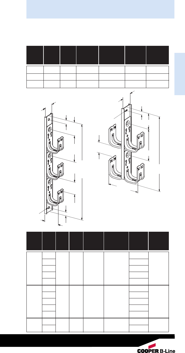
Reference Data
Cable Hook Technical Data
Reference Data
Hook ‘A’ ‘B’ Spacing Clearance Overall Overall
Size Height Width
In. In. In. In. In. In. In.
15/16 1.90 2.50 3.75 1.94 9.25 3.47
2 1.90 2.50 4.75 2.25 10.94 4.85
4 2.38 2.94 9.38 4.50 18.20 9.19
Double-Sided Double-Tier Cable Fasteners
Hook No. ‘A’‘B’ Spacing Clearance Overall Overall
Size Tiers Height Width
In. In. In. In. In. In. In.
2 11.00
314.75
15/16 4 1.90 2.50 3.75 1.94 18.50 1.96
522.25
626.00
212.75
3 17.50
2 4 1.90 2.50 4.75 2.25 22.25 2.66
5 27.00
631.75
2 19.33
432.38 2.94 8.75 3.19 28.08 4.82
Single-Sided Multi-Tier
Cable Fasteners
(2 thru 6 Tier)
‘A’
Clearance
Overall Width
.75
.75
.32 Ø
‘B’
Spacing
Typ.
Overall
Height
‘A’
‘B’
Overall
Height
Clearance
Overall
Width
.75
.32 Ø
Spacing
235
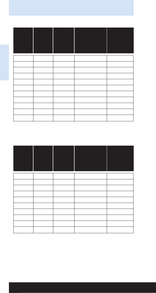
Minimum Weight
Nominal Nominal Weight of Conduit
Conduit Outside Inside Per 100 Ft. and
Size Diameter Diameter With Couplings Conductors
Attached Per 100 Ft.*
In. In. In. Lbs. Lbs.
3/80.675 0.493 51.5 65.1
1/20.840 0.632 79.0 101.1
3/41.050 0.836 105.0 145.8
1 1.315 1.063 153.0 219.3
11/41.660 1.394 201.0 318.3
11/21.900 1.624 249.0 408.8
2 2.375 2.083 332.0 593.8
21/22.875 2.489 527.0 901.0
3 3.500 3.090 682.0 1259.0
31/24.000 3.570 831.0 1604.0
4 4.500 4.050 972.0 1967.0
Rigid Steel Conduit (Heavy Wall Conduit)
Minimum Weight
Nominal Nominal Weight of Conduit
Conduit Outside Inside Per 100 Ft. and
Size Diameter Diameter With Couplings Conductors
Attached Per 100 Ft.*
In. In. In. Lbs. Lbs.
1/20.815 0.745 60.0 82.1
3/41.029 0.954 82.0 122.8
1 1.290 1.205 116.0 182.3
11/41.638 1.553 150.0 267.3
11/21.883 1.793 182.0 341.8
2 2.360 2.266 242.0 503.8
21/22.857 2.727 401.0 775.0
3 3.476 3.346 493.0 1069.0
31/23.971 3.841 573.0 1346.0
4 4.466 4.336 638.0 1632.0
Intermediate Metal Conduit (IMC)
Reference Data
Reference Data
Dimensions taken from ANSI C80.3 - 1977.
* Conduit plus weight of heaviest conductor combination as
specified by the National Electrical Code.
236
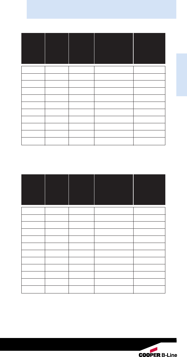
Reference Data
Reference Data
Minimum Weight
Nominal Nominal Weight of Conduit
Conduit Outside Inside Per 100 Ft. and
Size Diameter Diameter With Couplings Conductors
Attached Per 100 Ft.*
In. In. In. Lbs. Lbs.
3/80.577 0.493 23.0 36.6
1/20.706 0.622 28.5 50.6
3/40.922 0.824 43.5 84.3
1 1.163 1.049 64.0 130.3
11/41.510 1.380 95.0 212.3
11/21.740 1.610 110.0 269.8
2 2.197 2.067 140.0 401.8
21/22.875 2.731 205.0 579.0
3 3.500 3.356 250.0 826.3
31/24.000 3.834 325.0 1098.0
4 4.500 4.334 370.0 1364.0
Electrical Metallic Tubing (EMT) - Thinwall Conduit
Minimum Weight
Nominal Nominal Weight of Conduit
Conduit Outside Inside Per 100 Ft. and
Size Diameter Diameter With Couplings Conductors
Attached Per 100 Ft.*
In. In. In. Lbs. Lbs.
1/20.840 0.632 27.4 49.5
3/41.050 0.836 36.4 77.2
1 1.315 1.063 53.0 119.3
11/41.660 1.394 69.6 186.9
11/21.900 1.624 82.2 242.0
2 2.375 2.083 115.7 377.5
21/22.875 2.489 182.5 556.5
3 3.500 3.090 238.9 815.2
31/24.00 3.570 287.7 1061.0
4 4.500 4.050 340.0 1334.0
55.563 5.073 465.4 2028.0
6 6.625 6.093 612.5 2870.0
Rigid Aluminum Conduit
Dimensions taken from ANSI C80.3 - 1977.
* Conduit plus weight of heaviest conductor combination as
specified by the National Electrical Code.
237
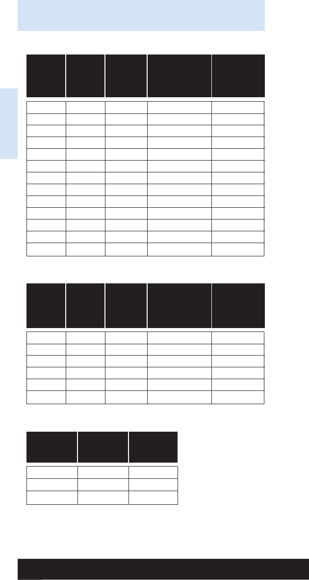
Nominal
Pipe Outside Wall Weight Weight
Size Diameter Thickness of Pipe of Water
In. In. In. Lbs. Per Ft. Lbs. Per Ft.
1/80.405 0.068 0.04 0.02
1/40.540 0.088 0.07 0.04
3/80.675 0.091 0.10 0.08
1/20.840 0.109 0.15 0.10
3/41.050 0.113 0.20 0.20
1 1.315 0.133 0.30 0.40
11/41.660 0.140 0.40 0.60
11/21.900 0.145 0.50 0.90
2 2.375 0.155 0.60 1.40
21/22.875 0.203 1.00 2.10
3 3.500 0.216 1.30 3.20
31/24.000 0.226 1.60 4.30
4 4.500 0.237 1.90 5.50
Schedule 40 PVC Plastic Pipe
Weight
Nominal Minimum of Conduit
Nominal Outside Inside Weight and
Size Diameter Diameter of Conduit Conductors
In. In. In. Lbs. Per 100 Ft. Lbs. Per 100 Ft.
1/20.840 0.560 11.0 33.1
3/41.050 0.760 14.0 54.8
11.315 1.000 20.0 86.3
11/41.660 1.402 19.0 136.3
11/21.990 1.554 27.0 186.8
2 2.375 2.030 32.0 261.8
Electrical Non-Metallic Tubing (ENT)
Design
Thread Root Load
Size Area (SF=5)
1/4”-20 0.027 in.2240 lbs.
5/16”-18 0.045 in.2400 lbs.
3/8”-16 0.068 in.2610 lbs.
All Threaded Rod (ATR)
Reference Data
Reference Data
Dimensions taken from ANSI B1.1 1982 Unified Inch Screw
Threads. All threads are UNCR series.
Tabulated loads
are based on an allow-
able tensile stress of
12000 psi reduced by
25% resulting in 9000
psi. From ANSI/MSS
SP-58, Table 3.
238
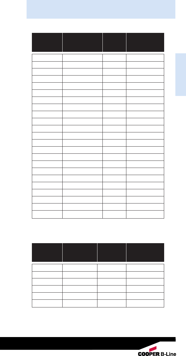
Reference Data
Reference Data
Trade Grounding Armor Approximate
Size Conductor AWG O.D. Wt. Per 100 Ft.
In. Lbs.
14-2 Solid 14 0.470 17.5
14-3 Solid 14 0.480 20.5
14-4 Solid 14 0.510 23.0
12-2 Solid 12 0.495 21.5
12-3 Solid 12 0.530 25.5
12-4 Solid 12 0.565 29.5
10-2 Solid 10 0.560 28.5
10-3 Solid 10 0.600 34.0
10-4 Solid 10 0.645 39.5
8-2 Stranded 10 0.710 45.0
8-3 Stranded 10 0.770 54.5
8-4 Stranded 10 0.835 64.5
6-2 Stranded 8 0.795 59.0
6-3 Stranded 8 0.865 72.0
6-4 Stranded 80.945 86.0
4-2 Stranded 8 0.945 78.5
4-3 Stranded 8 1.035 98.5
4-4 Stranded 81.135 119.5
3-3 Stranded 6 1.025 107.0
3-4 Stranded 6 1.120 126.0
2-2 Stranded 6 1.075 104.5
2-3 Stranded 6 1.180 134.0
2-4 Stranded 6 1.295 164.0
MC -- Metal Clad Cable Specifications
Pair AWG
Count Size O.D. Weight
In. Lbs. Per 100 Ft.
2 24 0.16 1.3
3 24 0.18 1.7
4 24 0.20 2.1
6 24 0.27 3.5
824 0.30 4.2
25 24 0.50 13.0
Category 5 Cable
239
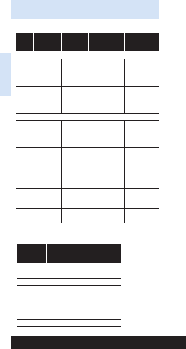
Trade Approximate Approximate
Size O.D. Weight
In. Lbs. Per 100 Ft.
14 AWG 0.11 1.7
12 AWG 0.13 2.5
10 AWG 0.16 4.0
8 AWG 0.22 6.5
6 AWG 0.25 9.7
4 AWG 0.32 15.5
3 AWG 0.35 19.1
2 AWG 0.38 23.6
1 AWG 0.45 30.4
1/0 AWG 0.49 37.5
Type THHN -- Insulated Single
Conductor Building Wire
Size Number Ground Approximate Approximate
AWG of Strands Wire Size O.D. Weight
In. Lbs. Per 100 Ft.
Without Ground Wire
14-2 Solid -- .17 x .37 5.3
12-2 Solid -- .19 x .40 7.0
10-2 Solid -- .22 x .45 10.1
14-3 Solid -- 0.295 8.2
12-3 Solid -- 0.332 10.9
10-3 Solid -- 0.396 15.7
8-3 7 -- 0.538 27.8
6-3 7 -- 0.611 42.2
With Ground Wire
14-2 Solid 14 .17 x .37 6.4
12-2 Solid 12 .19 x .41 9.0
10-2 Solid 10 .22 x .49 13.3
8-2 7 10 .28 x .61 21.5
6-2 7 10 .32 x .73 31.3
14-3 Solid 14 .322 9.3
12-3 Solid 12 .363 12.9
10-3 Solid 10 .436 18.7
14-4 Solid 14 .450 11.6
12-4 Solid 12 .490 16.1
10-4 Solid 10 .550 23.3
8-3 7 10 .552 30.5
6-3 710 .61145.0
4-3 7 8 .821 66.4
2-3 7 8 .946 93.0
Type NM -- Non-Metallic Sheathed Cable
Reference Data
Reference Data
240

Reference Data
Reference Data
Trade Armor Approximate
Size O.D. Weight
In. Lbs. Per 100 Ft.
14-2 Solid 0.433 18.0
14-3 Solid 0.453 20.0
14-4 Solid 0.486 25.0
12-2 Solid 0.467 21.0
12-3 Solid 0.489 24.5
12-4 Solid 0.520 29.0
10-2 Solid 0.476 25.0
10-3 Solid 0.500 29.5
10-4 Solid 0.541 38.0
8-2 Solid 0.570 34.5
8-3 Solid 0.601 41.5
8-4 Solid 0.654 48.0
8-2 Stranded 0.604 34.5
8-3 Stranded 0.637 42.0
8-4 Stranded 0.695 51.5
6-2 Stranded 0.700 44.5
6-3 Stranded 0.739 56.0
6-4 Stranded 0.807 68.5
4-2 Stranded 0.836 62.0
4-3 Stranded 0.885 80.0
4-4 Stranded 0.971 99.5
3-3 Stranded 0.990 94.0
3-4 Stranded 1.085 118.0
2-2 Stranded 0.956 81.5
2-3 Stranded 1.014 109.5
2-4 Stranded 1.115 138.0
AC -- Armored Cable Specifications
241

Index
Index
Catalog No. Page Catalog No. Page
A
ACB Series . . . . . . . . . . . . . . . 191
ACPD Series . . . . . . . . . . . . . 205
ACPW Series . . . . . . . . . . . . . 204
ACS Series . . . . . . . . . . 192-193
ADA Series . . . . . . . . . . 198-199
ADI Series . . . . . . . . . . . . . . . . 188
ADE Series . . . . . . . . . . . . . . . 202
ADH Series . . . . . . . . . . . . . . . 190
ADM Series . . . . . . . . . . . . . . . 189
ADN Series . . . . . . . . . . . . . . . 206
AMS Series . . . . . . . . . . . . . . . 206
APC Series . . . . . . . . . . . . . . . 214
APD Series . . . . . . . . . . . . . . . 213
APH Series . . . . . . . . . . . . . . . 212
APS Series . . . . . . . . . . . . . . . . 211
ARC Series . . . . . . . . . . 186-187
ARS Series . . . . . . . . . . 184-185
ARW Series . . . . . . . . . . 186-187
ASA Series . . . . . . . . . . . 200-201
ASE Series . . . . . . . . . . . . . . . 203
ATB Series . . . . . . . . . . . . . . . . 209
ATM Series . . . . . . . . . . . . . . . 207
AWA Series . . . . . . . . . . .194-195
AWS Series . . . . . . . . . . . . . . . 210
AWSD Series . . . . . . . . 196-197
AZD Series . . . . . . . . . . . . . . . 213
B
B444-1/4 . . . . . . . . . . . . . . . . . . . 105
B444-5/16 . . . . . . . . . . . . . . . . . . 105
B444-3/8 . . . . . . . . . . . . . . . . . . . 105
B601-62 . . . . . . . . . . . . . . . . . . . 180
B1506S . . . . . . . . . . . . . . . . . . . . . 47
B1508 . . . . . . . . . . . . . . . . . . . . . . 47
B1508S . . . . . . . . . . . . . . . . . . . . . 47
B1512 . . . . . . . . . . . . . . . . . . . . . . 47
B1512S . . . . . . . . . . . . . . . . . . . . . 47
B1516 . . . . . . . . . . . . . . . . . . . . . . 47
B1516S . . . . . . . . . . . . . . . . . . . . . 47
B1520 . . . . . . . . . . . . . . . . . . . . . . 47
B1520S . . . . . . . . . . . . . . . . . . . . . 47
B1524S . . . . . . . . . . . . . . . . . . . . . 47
B1532S . . . . . . . . . . . . . . . . . . . . . 47
B1534S . . . . . . . . . . . . . . . . . . . . . 47
B1540S . . . . . . . . . . . . . . . . . . . . . 47
B1548S . . . . . . . . . . . . . . . . . . . . . 47
B1556S . . . . . . . . . . . . . . . . . . . . . 47
B1564S . . . . . . . . . . . . . . . . . . . . . 47
B3223-3/8 . . . . . . . . . . . . . . . . . 138
BA
BA1 . . . . . . . . . . . . . . . . . . . . . . . . . 82
BA1-9 . . . . . . . . . . . . . . . . . . . . . . 82
BA1-24 . . . . . . . . . . . . . . . . . . . . . 82
BA1-32 . . . . . . . . . . . . . . . . . . . . . 82
BA1-95 . . . . . . . . . . . . . . . . . . . . . 82
BA1-T . . . . . . . . . . . . . . . . . . . . . . 82
BA1-T-BN . . . . . . . . . . . . . . . . . . 82
BA-2-9 . . . . . . . . . . . . . . . . . . . . . 86
BA-2-9-BN . . . . . . . . . . . . . . . . . 86
BA-2-9-W . . . . . . . . . . . . . . . . . . 86
BA-2-9-WBN . . . . . . . . . . . . . . . 86
BA-2-9-7 . . . . . . . . . . . . . . . . . . . 86
BA-2-9-7-BN . . . . . . . . . . . . . . . 86
BA-2-16 . . . . . . . . . . . . . . . . . . . . 85
BA-2-16-BN . . . . . . . . . . . . . . . . 85
BA-2-16-W . . . . . . . . . . . . . . . . . 85
BA-2-16-WBN . . . . . . . . . . . . . 85
BA-2-16-7 . . . . . . . . . . . . . . . . . . 85
BA-2-16-7-BN . . . . . . . . . . . . . 85
BA-2-16-7-W . . . . . . . . . . . . . . . 85
BA-2-16-7-WBN . . . . . . . . . . . 85
BA-4-9 . . . . . . . . . . . . . . . . . . . . . 86
BA-4-9-W . . . . . . . . . . . . . . . . . . 86
BA-4-16 . . . . . . . . . . . . . . . . . . . . 84
BA-4-16-24 . . . . . . . . . . . . . . . . 84
BA-4-16-32 . . . . . . . . . . . . . . . . 84
BA-4-16-48 . . . . . . . . . . . . . . . . 84
BA-4-16-H . . . . . . . . . . . . . . . . . 83
BA-4-16-H1 . . . . . . . . . . . . . . . . 83
BA-4-16-W . . . . . . . . . . . . . . . . . 84
BA-4-WN . . . . . . . . . . . . . . . . . . . 84
BA-5-4T . . . . . . . . . . . . . . . . . . . . 72
BA-6-4T . . . . . . . . . . . . . . . . . . . . 73
BA12 . . . . . . . . . . . . . . . . . . . . . . . 76
BA12-12 . . . . . . . . . . . . . . . . . . . . 76
BA12-20 . . . . . . . . . . . . . . . . . . . . 76
BA12-30 . . . . . . . . . . . . . . . . . . . . 76
BA14 . . . . . . . . . . . . . . . . . . . . . . . 71
BA15 . . . . . . . . . . . . . . . . . . . . . . . 71
BA17 . . . . . . . . . . . . . . . . . . . . . . . 81
BA18 . . . . . . . . . . . . . . . . . . . . . . . 81
BA20 . . . . . . . . . . . . . . . . . . . . . . . 81
BA-21 . . . . . . . . . . . . . . . . . . . . . . 84
BA-21D . . . . . . . . . . . . . . . . . . . . . 84
BA28 . . . . . . . . . . . . . . . . . . . . . . . 75
BA28B . . . . . . . . . . . . . . . . . . . . 174
BA40 . . . . . . . . . . . . . . . . . . . . . . . 80
BA50 . . . . . . . . . . . . . . . . . . . . . . . 77
BA50A . . . . . . . . . . . . . . . . . . . . . . 78
BA50CAN . . . . . . . . . . . . . . . . . . 77
BA50C3T . . . . . . . . . . . . . . . . . . . 77
BA50C4T . . . . . . . . . . . . . . . . . . . 77
BA50D . . . . . . . . . . . . . . . . . . . . . . 77
BA50DCAN . . . . . . . . . . . . . . . . 77
BA50E . . . . . . . . . . . . . . . . . . . . . . 77
BA50F . . . . . . . . . . . . . . . . . . . . . . 79
BA50-OB-24 . . . . . . . . . . . . . . . 78
BA50-OB-34 . . . . . . . . . . . . . . . 78
BA50-SB-24 . . . . . . . . . . . . . . . . 78
242

Index
Index
Catalog No. Page Catalog No. Page
BA cont.
BA311 . . . . . . . . . . . . . . . . . . . . . . 87
BA311-W2 . . . . . . . . . . . . . . . . . . 87
BA311-W6 . . . . . . . . . . . . . . . . . . 87
BA-SFC . . . . . . . . . . . . . . . . . . . . 88
BA-SFC-CF . . . . . . . . . . . . . . . . 88
BA-SFC-CFS . . . . . . . . . . . . . . . 88
BA-SFC-E . . . . . . . . . . . . . . . . . . 88
BA-SFC-S . . . . . . . . . . . . . . . . . . 88
BAX-4-16 . . . . . . . . . . . . . . . . . . . 83
BAX-4-16-24 . . . . . . . . . . . . . . . 83
BAX-4-16-32 . . . . . . . . . . . . . . . 83
BAX-4-16-48 . . . . . . . . . . . . . . . 83
BB
BB1 . . . . . . . . . . . . . . . . . . . . . . . . . 19
BB2-16T . . . . . . . . . . . . . . . . . . . . 26
BB2-24T . . . . . . . . . . . . . . . . . . . . 26
BB2CL . . . . . . . . . . . . . . . . . . . . . . 27
BB2TS . . . . . . . . . . . . . . . . . . . . . . 26
BB4-4 . . . . . . . . . . . . . . . . . . . . . . 24
BB4-6 . . . . . . . . . . . . . . . . . . . . . . 24
BB4-23 . . . . . . . . . . . . . . . . . . . . . 24
BB7-16 . . . . . . . . . . . . . . . . . . . . . 29
BB7-24 . . . . . . . . . . . . . . . . . . . . . 29
BB8-16 . . . . . . . . . . . . . . . . . . . . . 28
BB8-24 . . . . . . . . . . . . . . . . . . . . . 28
BB9 . . . . . . . . . . . . . . . . . . . . . . . . . 20
BB10 . . . . . . . . . . . . . . . . . . . . . . 146
BB10-2 . . . . . . . . . . . . . . . . . . . . 146
BB10-3 . . . . . . . . . . . . . . . . . . . . 146
BB10-4 . . . . . . . . . . . . . . . . . . . . 146
BB10L . . . . . . . . . . . . . . . . . . . . . 147
BB10P . . . . . . . . . . . . . . . . . . . . 147
BB12 . . . . . . . . . . . . . . . . . . . . . . . 20
BB12-6 . . . . . . . . . . . . . . . . . . . . . 20
BB15 . . . . . . . . . . . . . . . . . . 32, 149
BB-18 . . . . . . . . . . . . . . . . . . . . . . 31
BB20 . . . . . . . . . . . . . . . . . . . . . . 146
BB20L . . . . . . . . . . . . . . . . . . . . . 147
BB27 . . . . . . . . . . . . . . . . . . . . . . . 76
BB32 . . . . . . . . . . . . . . . . . . . . . . . 23
BB33 . . . . . . . . . . . . . . . . . . . . . . . 23
BB33L . . . . . . . . . . . . . . . . . . . . . . 23
BB38 . . . . . . . . . . . . . . . . . . . . . . . 40
BB38D . . . . . . . . . . . . . . . . . . . . . . 40
BB40-08 . . . . . . . . . . . . . . 32, 148
BB40-10 . . . . . . . . . . . . . . 32, 148
BB40-12 . . . . . . . . . . . . . . 32, 148
BB45-08 . . . . . . . . . . . . . . 32, 148
BB45-10 . . . . . . . . . . . . . . 32, 148
BB45-12 . . . . . . . . . . . . . . 32, 148
BB73 . . . . . . . . . . . . . . . . . . . . . . . 25
BB74 . . . . . . . . . . . . . . . . . . . . . . . 25
BB76 . . . . . . . . . . . . . . . . . . . . . . . 25
BB216TCL . . . . . . . . . . . . . . . . . 27
BB216TS . . . . . . . . . . . . . . . . . . . 26
BB224TCL . . . . . . . . . . . . . . . . . 27
BB224TS . . . . . . . . . . . . . . . . . . . 26
BBF15 . . . . . . . . . . . . . . . . . . . . . . 30
BBF15FC . . . . . . . . . . . . . . . . . . . 30
BBF18 . . . . . . . . . . . . . . . . . . . . . . 30
BBF18FC . . . . . . . . . . . . . . . . . . . 30
BBF24 . . . . . . . . . . . . . . . . . . . . . . 30
BBF24FC . . . . . . . . . . . . . . . . . . . 30
BBFC . . . . . . . . . . . . . . . . . . . . . . . 30
BC
BC1 . . . . . . . . . . . . . . . . . . . . . . . 106
BC442 . . . . . . . . . . . . . . . . . . . . . 104
BC442-6 . . . . . . . . . . . . . . . . . . 104
BCH12 . . . . . . . . . . . . . . . . . . . . 150
BCH12-A28 . . . . . . . . . . . . . . . 161
BCH12-C1 . . . . . . . . . . . . . . . . 157
BCH12-C2 . . . . . . . . . . . . . . . . 157
BCH12-C442 . . . . . . . . . . . . . 156
BCH12-C442A . . . . . . . . . . . . 156
BCH12-E-2-4 . . . . . . . . . . . . . 154
BCH12-E-5-8 . . . . . . . . . . . . . 154
BCH12-E-9-12 . . . . . . . . . . . . 154
BCH12-F3 . . . . . . . . . . . . . . . . 159
BCH12-F4 . . . . . . . . . . . . . . . . 159
BCH12-G-8-12 . . . . . . . . . . . 162
BCH12-L1410 . . . . . . . . . . . . 162
BCH12-PNA . . . . . . . . . . . . . . 134
BCH12-RB . . . . . . . . . . . . . . . . 153
BCH12-SC4 . . . . . . . . . . . . . . . 158
BCH12-U-2-4 . . . . . . . . . . . . . 155
BCH12-U-5-8 . . . . . . . . . . . . . 155
BCH12-U-9-12 . . . . . . . . . . . 155
BCH12-W2 . . . . . . . . . . . . . . . . 160
BCH12-W6 . . . . . . . . . . . . . . . . 160
BCH21 . . . . . . . . . . . . . . . . . . . . 150
BCH21-1D . . . . . . . . . . . . . . . . 163
BCH21-2D . . . . . . . . . . . . . . . . 163
BCH21-2S . . . . . . . . . . . . . . . . 164
BCH21-3S . . . . . . . . . . . . . . . . 164
BCH21-4S . . . . . . . . . . . . . . . . 165
BCH21-5S . . . . . . . . . . . . . . . . 165
BCH21-6S . . . . . . . . . . . . . . . . 165
BCH21-A28 . . . . . . . . . . . . . . . 161
BCH21-AB . . . . . . . . . . . . . . . . 153
BCH21-C1 . . . . . . . . . . . . . . . . 157
BCH21-C2 . . . . . . . . . . . . . . . . 157
BCH21-C442 . . . . . . . . . . . . . 156
BCH21-C442A . . . . . . . . . . . . 156
BCH21-E-2-4 . . . . . . . . . . . . . 154
BCH21-E-5-8 . . . . . . . . . . . . . 154
BCH21-E-9-12 . . . . . . . . . . . . 154
BCH21-F3 . . . . . . . . . . . . . . . . 159
BCH21-F4 . . . . . . . . . . . . . . . . 159
BCH21-G-8-12 . . . . . . . . . . . 162
BCH21-L1410 . . . . . . . . . . . . 162
BCH21-PNA . . . . . . . . . . . . . . 134
BCH21-RB . . . . . . . . . . . . . . . . 153
BCH21-SC4 . . . . . . . . . . . . . . . 158
BCH21-U-2-4 . . . . . . . . . . . . . 155
BCH21-U-5-8 . . . . . . . . . . . . . 155
243

Index
Index
Catalog No. Page Catalog No. Page
BC cont.
BCH21-U-9-12 . . . . . . . . . . . 155
BCH21-W2 . . . . . . . . . . . . . . . . 160
BCH21-W6 . . . . . . . . . . . . . . . . 160
BCH21X . . . . . . . . . . . . . . . . . . . 152
BCH32 . . . . . . . . . . . . . . . . . . . . 150
BCH32-1D . . . . . . . . . . . . . . . . 163
BCH32-2D . . . . . . . . . . . . . . . . 163
BCH32-2S . . . . . . . . . . . . . . . . 164
BCH32-3S . . . . . . . . . . . . . . . . 164
BCH32-4S . . . . . . . . . . . . . . . . 165
BCH32-5S . . . . . . . . . . . . . . . . 165
BCH32-6S . . . . . . . . . . . . . . . . 165
BCH32-A28 . . . . . . . . . . . . . . . 161
BCH32-AB . . . . . . . . . . . . . . . . 153
BCH32-C1 . . . . . . . . . . . . . . . . 157
BCH32-C2 . . . . . . . . . . . . . . . . 157
BCH32-C442 . . . . . . . . . . . . . 156
BCH32-C442A . . . . . . . . . . . . 156
BCH32-E-2-4 . . . . . . . . . . . . . 154
BCH32-E-5-8 . . . . . . . . . . . . . 154
BCH32-E-9-12 . . . . . . . . . . . . 154
BCH32-F3 . . . . . . . . . . . . . . . . 159
BCH32-F4 . . . . . . . . . . . . . . . . 159
BCH32-G-8-12 . . . . . . . . . . . 162
BCH32-L1410 . . . . . . . . . . . . 162
BCH32-PNA . . . . . . . . . . . . . . 134
BCH32-RB . . . . . . . . . . . . . . . . 153
BCH32-SC4 . . . . . . . . . . . . . . . 158
BCH32-U-2-4 . . . . . . . . . . . . . 155
BCH32-U-5-8 . . . . . . . . . . . . . 155
BCH32-U-9-12 . . . . . . . . . . . 155
BCH32-W2 . . . . . . . . . . . . . . . . 160
BCH32-W6 . . . . . . . . . . . . . . . . 160
BCH32X . . . . . . . . . . . . . . . . . . . 152
BCH64 . . . . . . . . . . . . . . . . . . . . 150
BCH64-1D . . . . . . . . . . . . . . . . 163
BCH64-2D . . . . . . . . . . . . . . . . 163
BCH64-2S . . . . . . . . . . . . . . . . 164
BCH64-3S . . . . . . . . . . . . . . . . 164
BCH64-4S . . . . . . . . . . . . . . . . 165
BCH64-AB . . . . . . . . . . . . . . . . 153
BCH64-C1 . . . . . . . . . . . . . . . . 157
BCH64-C2 . . . . . . . . . . . . . . . . 157
BCH64-C442 . . . . . . . . . . . . . 156
BCH64-C442A . . . . . . . . . . . . 156
BCH64-F3 . . . . . . . . . . . . . . . . 159
BCH64-F4 . . . . . . . . . . . . . . . . 159
BCH64-G-8-12 . . . . . . . . . . . 162
BCH64-L1410 . . . . . . . . . . . . 162
BCH64-PNAB . . . . . . . . . . . . 134
BCH64-RB . . . . . . . . . . . . . . . . 153
BCH64-SC4 . . . . . . . . . . . . . . . 158
BCH64-U-2-4 . . . . . . . . . . . . . 155
BCH64-U-5-8 . . . . . . . . . . . . . 155
BCH64-U-9-12 . . . . . . . . . . . 155
BCH64X . . . . . . . . . . . . . . . . . . . 152
BCH-HBA . . . . . . . . . . . . . . . . . 166
BCH-HB21 . . . . . . . . . . . . . . . . 166
BCH-HB64 . . . . . . . . . . . . . . . . 166
BCHK1 . . . . . . . . . . . . . . . . . . . . 167
BCHK2 . . . . . . . . . . . . . . . . . . . . 167
BCHK3 . . . . . . . . . . . . . . . . . . . . 167
BCHR21 . . . . . . . . . . . . . . . . . . 151
BCHR32 . . . . . . . . . . . . . . . . . . 151
BCHR64 . . . . . . . . . . . . . . . . . . 151
BCS-8 . . . . . . . . . . . . . . . . . . . . . . 62
BCS-8C . . . . . . . . . . . . . . . . . . . . 62
BCS-12 . . . . . . . . . . . . . . . . . . . . . 62
BCS-12C . . . . . . . . . . . . . . . . . . . 62
BCS-16 . . . . . . . . . . . . . . . . . . . . . 62
BCS-16C . . . . . . . . . . . . . . . . . . . 62
BD
BD2 . . . . . . . . . . . . . . . . . . . . . . . 174
BD4 . . . . . . . . . . . . . . . . . . . . . . . 174
BD40 . . . . . . . . . . . . . . . . . . . . . . 173
BE
BE-1-2 . . . . . . . . . . . . . . . . . . . . . . 91
BE-2-4 . . . . . . . . . . . . . . . . . . . . . . 91
BE-2-4-CT2 . . . . . . . . . . . . . . . 145
BE-5-8 . . . . . . . . . . . . . . . . . 91, 173
BE-5-8-CT2 . . . . . . . . . . . . . . . 145
BE-9-12 . . . . . . . . . . . . . . . . 91, 173
BE-9-12-CT2 . . . . . . . . . . . . . 145
BES-8 . . . . . . . . . . . . . . . . . . . . . . . 62
BES-8C . . . . . . . . . . . . . . . . . . . . . 62
BES-12 . . . . . . . . . . . . . . . . . . . . . . 62
BES-12C . . . . . . . . . . . . . . . . . . . 62
BES-16 . . . . . . . . . . . . . . . . . . . . . . 62
BES-16C . . . . . . . . . . . . . . . . . . . 62
BF
BF1 . . . . . . . . . . . . . . . . . . . . . . . . 128
BF1-40 . . . . . . . . . . . . . . . . . . . . . . 21
BF1-56 . . . . . . . . . . . . . . . . . . . . . 21
BF1-64 . . . . . . . . . . . . . . . . . . . . . . 21
BF1-96 . . . . . . . . . . . . . . . . . . . . . 21
BF1-CT2 . . . . . . . . . . . . . . . . . . . 145
BF2 . . . . . . . . . . . . . . . . . . . . . . . . 128
BF2-CT2 . . . . . . . . . . . . . . . . . . . 145
BF3 . . . . . . . . . . . . . . . . . . . . . . . . 124
BF4 . . . . . . . . . . . . . . . . . . . . . . . . 120
BF12 . . . . . . . . . . . . . . . . . . . . . . 118
BF13 . . . . . . . . . . . . . . . . . . . . . . 118
BFA-1215 . . . . . . . . . . . . . . . . . . 61
BFA-1520 . . . . . . . . . . . . . . . . . . 61
244

Index
Index
Catalog No. Page Catalog No. Page
BG
BG-6 . . . . . . . . . . . . . . . . . . . . . . . . 43
BG-6-4T . . . . . . . . . . . . . . . . . . . . 43
BG-6-A5 . . . . . . . . . . . . . . . . . . . . 72
BG-6-A6 . . . . . . . . . . . . . . . . . . . . 73
BG-6-B1 . . . . . . . . . . . . . . . . . . . . 19
BG-6-B5 . . . . . . . . . . . . . . . . . . . . 22
BG-6-E-2-4 . . . . . . . . . . . . . . . . 93
BG-6-E-5-8 . . . . . . . . . . . . . . . . 93
BG-6-E-9-12 . . . . . . . . . . . . . . . 93
BG-6-F1 . . . . . . . . . . . . . . . . . . . 130
BG-6-F2 . . . . . . . . . . . . . . . . . . . 130
BG-6-F13 . . . . . . . . . . . . . . . . . 118
BG-6-H7 . . . . . . . . . . . . . . . . . . . . 34
BG-6-PNA . . . . . . . . . . . . . . . . 135
BG6-S18 . . . . . . . . . . . . . . . . . . . 64
BG6-S18-MC3 . . . . . . . . . . . . . 64
BG6-S18-S . . . . . . . . . . . . . . . . . 64
BG6-S18-S-MC3 . . . . . . . . . . . 64
BG6-S18-U24 . . . . . . . . . . . . . 111
BG6-S18-U24-MC3 . . . . . . . 111
BG6-S18-U58 . . . . . . . . . . . . . 111
BG6-S18-U58-MC3 . . . . . . . 111
BG6-S18-W2 . . . . . . . . . . . . . . . 65
BG6-S18-W2-MC3 . . . . . . . . . 65
BG6-S18-W6 . . . . . . . . . . . . . . . 65
BG6-S18-W6-MC3 . . . . . . . . . 65
BG6-SC4 . . . . . . . . . . . . . . . . . . 133
BG-6-U-2-4 . . . . . . . . . . . . . . . . 99
BG-6-U-5-8 . . . . . . . . . . . . . . . . 99
BG-6-U-9-12 . . . . . . . . . . . . . . . 99
BG-8-12 . . . . . . . . . . . . . . . . . . . . 43
BG-8-12-4T . . . . . . . . . . . . . . . . 43
BG-8-12-A5 . . . . . . . . . . . . . . . . 72
BG-8-12-A6 . . . . . . . . . . . . . . . . 73
BG-8-12-B1 . . . . . . . . . . . . . . . . 19
BG-8-12-B5 . . . . . . . . . . . . . . . . 22
BG-8-12-C1 . . . . . . . . . . . . . . . 107
BG-8-12-C2 . . . . . . . . . . . . . . . 106
BG-8-12-D3 . . . . . . . . . . . . . . . . 63
BG-8-12-D4 . . . . . . . . . . . . . . . . 63
BG-8-12-E-2-4 . . . . . . . . . . . . . 93
BG-8-12-E-2-4-AS . . . . . . . 101
BG-8-12-E-5-8 . . . . . . . . . . . . . 93
BG-8-12-E-5-8-AS . . . . . . . 101
BG-8-12-E-9-12 . . . . . . . . . . . 93
BG-8-12-E-9-12-AS . . . . . . 101
BG-8-12-F1 . . . . . . . . . . . . . . . 130
BG-8-12-F2 . . . . . . . . . . . . . . . 130
BG-8-12-F13 . . . . . . . . . . . . . . 118
BG-8-12-G6 . . . . . . . . . . . . . . . . 50
BG-8-12-G20 . . . . . . . . . . . . . . 50
BG-8-12-G24 . . . . . . . . . . . . . . 50
BG-8-12-G32 . . . . . . . . . . . . . . 50
BG-8-12-G812 . . . . . . . . . . . . . 50
BG-8-12-H7 . . . . . . . . . . . . . . . . 34
BG-8-12-PNA . . . . . . . . . . . . . 135
BG812-S18 . . . . . . . . . . . . . . . . . 64
BG812-S18-MC3 . . . . . . . . . . 64
BG812-S18S . . . . . . . . . . . . . . . 64
BG812-S18-S-MC3 . . . . . . . . 64
BG812-S18-U24 . . . . . . . . . . 111
BG812-S18-U24-MC3 . . . . 111
BG812-S18-U58 . . . . . . . . . . 111
BG812-S18-U58-MC3 . . . . 111
BG812-S18-W2 . . . . . . . . . . . . 65
BG812-S18-W2-MC3 . . . . . . 65
BG812-S18-W6 . . . . . . . . . . . . 65
BG812-S18-W6-MC3 . . . . . . 65
BG812-SC4 . . . . . . . . . . . . . . . 133
BG-8-12-U-2-4 . . . . . . . . . . . . . 99
BG-8-12-U-2-4-AS . . . . . . . 101
BG-8-12-U-5-8 . . . . . . . . . . . . . 99
BG-8-12-U-5-8-AS . . . . . . . 101
BG-8-12-U-9-12 . . . . . . . . . . . 99
BG-8-12-U-9-12-AS . . . . . . 101
BG-8-12-W2 . . . . . . . . . . . . . . . 54
BG-8-12-W6 . . . . . . . . . . . . . . . 54
BG-16 . . . . . . . . . . . . . . . . . . . . . . 43
BG-16-4T . . . . . . . . . . . . . . . . . . 43
BG-16-A5 . . . . . . . . . . . . . . . . . . 72
BG-16-A6 . . . . . . . . . . . . . . . . . . 73
BG-16-B1 . . . . . . . . . . . . . . . . . . 19
BG-16-B5 . . . . . . . . . . . . . . . . . . 22
BG-16-C1 . . . . . . . . . . . . . . . . . 107
BG-16-C2 . . . . . . . . . . . . . . . . . 106
BG-16-E-2-4 . . . . . . . . . . . . . . . 92
BG-16-E-2-4-AS . . . . . . . . . . 101
BG-16-E-5-8 . . . . . . . . . . . . . . . 93
BG-16-E-5-8-AS . . . . . . . . . . 101
BG-16-E-9-12 . . . . . . . . . . . . . . 93
BG-16-E-9-12-AS . . . . . . . . 101
BG-16-F1 . . . . . . . . . . . . . . . . . 130
BG-16-F2 . . . . . . . . . . . . . . . . . 130
BG-16-F13 . . . . . . . . . . . . . . . . 118
BG-16-G-6 . . . . . . . . . . . . . . . . . 45
BG-16-G-8-12 . . . . . . . . . 45, 50
BG-16-G-16 . . . . . . . . . . . . . . . . 45
BG-16-G-20 . . . . . . . . . . . . . . . . 45
BG-16-G-24 . . . . . . . . . . . . . . . . 45
BG-16-G-32 . . . . . . . . . . . . . . . . 45
BG-16-PNA . . . . . . . . . . . . . . . 135
BG-16-S18 . . . . . . . . . . . . . . . . . 64
BG16-S18-MC3 . . . . . . . . . . . . 64
BG16-S18-S . . . . . . . . . . . . . . . . 64
BG16-S18-S-MC3 . . . . . . . . . 64
BG16-S18-U24 . . . . . . . . . . . . 111
BG16-S18-U24-MC3 . . . . . 111
BG16-S18-U58 . . . . . . . . . . . . 111
BG16-S18-U58-MC3 . . . . . 111
BG16-S18-W2 . . . . . . . . . . . . . 65
BG16-S18-W2-MC3 . . . . . . . 65
BG16-S18-W6 . . . . . . . . . . . . . 65
BG16-S18-W6-MC3 . . . . . . . 65
BG-16-U-2-4 . . . . . . . . . . . . . . . 99
BG-16-U-2-4-AS . . . . . . . . . 101
BG-16-U-5-8 . . . . . . . . . . . . . . . 99
BG-16-U-5-8-AS . . . . . . . . . 101
BG-16-U-9-12 . . . . . . . . . . . . . . 99
BG-16-U-9-12-AS . . . . . . . . 101
245

Index
Index
Catalog No. Page Catalog No. Page
BG cont.
BG-16-W2 . . . . . . . . . . . . . . . . . . 54
BG-16-W6 . . . . . . . . . . . . . . . . . . 54
BG-20 . . . . . . . . . . . . . . . . . . . . . . 43
BG-20-4T . . . . . . . . . . . . . . . . . . 43
BG-20-B5 . . . . . . . . . . . . . . . . . . 22
BG-20-C1 . . . . . . . . . . . . . . . . . 107
BG-20-C2 . . . . . . . . . . . . . . . . . 106
BG-20-E-2-4 . . . . . . . . . . . . . . . 93
BG-20-E-5-8 . . . . . . . . . . . . . . . 93
BG-20-E-9-12 . . . . . . . . . . . . . . 93
BG-20-F13 . . . . . . . . . . . . . . . . 118
BG-20-U-2-4 . . . . . . . . . . . . . . . 99
BG-20-U-5-8 . . . . . . . . . . . . . . . 99
BG-20-U-9-12 . . . . . . . . . . . . . . 99
BG-24 . . . . . . . . . . . . . . . . . . . . . . 43
BG-24-4T . . . . . . . . . . . . . . . . . . 43
BG-24-C1 . . . . . . . . . . . . . . . . . 107
BG-24-C2 . . . . . . . . . . . . . . . . . 106
BG-24-E-2-4 . . . . . . . . . . . . . . . 93
BG-24-E-5-8 . . . . . . . . . . . . . . . 93
BG-24-E-9-12 . . . . . . . . . . . . . . 93
BG-24-U-2-4 . . . . . . . . . . . . . . . 99
BG-24-U-5-8 . . . . . . . . . . . . . . . 99
BG-24-U-9-12 . . . . . . . . . . . . . . 99
BG-32 . . . . . . . . . . . . . . . . . . . . . . 43
BG-32-4T . . . . . . . . . . . . . . . . . . 43
BG-32-C1 . . . . . . . . . . . . . . . . . 107
BG-32-C2 . . . . . . . . . . . . . . . . . 106
BG-32-E-2-4 . . . . . . . . . . . . . . . 93
BG-32-E-5-8 . . . . . . . . . . . . . . . 93
BG-32-E-9-12 . . . . . . . . . . . . . . 93
BG-32-U-2-4 . . . . . . . . . . . . . . . 99
BG-32-U-5-8 . . . . . . . . . . . . . . . 99
BG-32-U-9-12 . . . . . . . . . . . . . . 99
BH
BH1 . . . . . . . . . . . . . . . . . . . . . . . 131
BH1-E-2-4 . . . . . . . . . . . . . . . . 116
BH1-E-5-8 . . . . . . . . . . . . . . . . 116
BH1-E-9-12 . . . . . . . . . . . . . . . 116
BH1-F1 . . . . . . . . . . . . . . . . . . . . 128
BH1-F2 . . . . . . . . . . . . . . . . . . . . 128
BH1-F3 . . . . . . . . . . . . . . . . . . . . 125
BH1-F4 . . . . . . . . . . . . . . . . . . . . 121
BH1-F12 . . . . . . . . . . . . . . . . . . 119
BH1-H7 . . . . . . . . . . . . . . . . . . . 136
BH1-H8 . . . . . . . . . . . . . . . . . . . 137
BH1-PNA . . . . . . . . . . . . . . . . . 134
BH-1-2-R . . . . . . . . . . . . . . . . . 115
BH2 . . . . . . . . . . . . . . . . . . . . . . . 131
BH2-E-2-4 . . . . . . . . . . . . . . . . 116
BH2-E-5-8 . . . . . . . . . . . . . . . . 116
BH2-E-9-12 . . . . . . . . . . . . . . . 116
BH2-F1 . . . . . . . . . . . . . . . . . . . . 129
BH2-F2 . . . . . . . . . . . . . . . . . . . . 129
BH2-F3 . . . . . . . . . . . . . . . . . . . . 125
BH2-F4 . . . . . . . . . . . . . . . . . . . . 121
BH2-F12 . . . . . . . . . . . . . . . . . . 119
BH2-H7 . . . . . . . . . . . . . . . . . . . 136
BH2-H8 . . . . . . . . . . . . . . . . . . . 137
BH2-PNA . . . . . . . . . . . . . . . . . 134
BH-2-4 . . . . . . . . . . . . . . . . . . . . 115
BH-2-4-R . . . . . . . . . . . . . . . . . 115
BH4 . . . . . . . . . . . . . . . . . . . . . . . 131
BH4-E-2-4 . . . . . . . . . . . . . . . . 117
BH4-E-2-4-AS . . . . . . . . . . . . 100
BH4-E-5-8 . . . . . . . . . . . . . . . . 117
BH4-E-5-8-AS . . . . . . . . . . . . 100
BH4-E-9-12 . . . . . . . . . . . . . . . 117
BH4-E-9-12-AS . . . . . . . . . . . 100
BH4-F1 . . . . . . . . . . . . . . . . . . . . 129
BH4-F2 . . . . . . . . . . . . . . . . . . . . 129
BH4-F3 . . . . . . . . . . . . . . . . . . . . 125
BH4-F4 . . . . . . . . . . . . . . . . . . . . 121
BH4-F12 . . . . . . . . . . . . . . . . . . 119
BH4-H7 . . . . . . . . . . . . . . . . . . . 136
BH4-H8 . . . . . . . . . . . . . . . . . . . 137
BH4-PNA . . . . . . . . . . . . . . . . . 135
BH4-SC4 . . . . . . . . . . . . . . . . . . 132
BH5 . . . . . . . . . . . . . . . . . . . . . . . 131
BH5-E-2-4 . . . . . . . . . . . . . . . . 117
BH5-E-5-8 . . . . . . . . . . . . . . . . 117
BH5-E-9-12 . . . . . . . . . . . . . . . 117
BH5-F1 . . . . . . . . . . . . . . . . . . . . 129
BH5-F2 . . . . . . . . . . . . . . . . . . . . 129
BH5-F3 . . . . . . . . . . . . . . . . . . . . 125
BH5-F4 . . . . . . . . . . . . . . . . . . . . 121
BH5-F12 . . . . . . . . . . . . . . . . . . 119
BH5-H7 . . . . . . . . . . . . . . . . . . . 136
BH5-H8 . . . . . . . . . . . . . . . . . . . 137
BH5-PNA . . . . . . . . . . . . . . . . . 135
BH-5-8 . . . . . . . . . . . . . . . . . . . . 115
BH-5-8-R . . . . . . . . . . . . . . . . . 115
BH6 . . . . . . . . . . . . . . . . . . . . . . . 131
BH6-E-2-4 . . . . . . . . . . . . . . . . 117
BH6-E-2-4-AS . . . . . . . . . . . . 100
BH6-E-5-8 . . . . . . . . . . . . . . . . 117
BH6-E-5-8-AS . . . . . . . . . . . . 100
BH6-E-9-12 . . . . . . . . . . . . . . . 117
BH6-E-9-12-AS . . . . . . . . . . . 100
BH6-F1 . . . . . . . . . . . . . . . . . . . . 129
BH6-F2 . . . . . . . . . . . . . . . . . . . . 129
BH6-F3 . . . . . . . . . . . . . . . . . . . . 125
BH6-F4 . . . . . . . . . . . . . . . . . . . . 121
BH6-F12 . . . . . . . . . . . . . . . . . . 119
BH6-H7 . . . . . . . . . . . . . . . . . . . 136
BH6-H8 . . . . . . . . . . . . . . . . . . . 137
BH6-PNA . . . . . . . . . . . . . . . . . 135
BH6-SC4 . . . . . . . . . . . . . . . . . . 132
BH7 . . . . . . . . . . . . . . . . . . . . . . . 131
BH7-6 . . . . . . . . . . . . . . . . . . . . . 131
BH8 . . . . . . . . . . . . . . . . . . . . . . . 131
BH8-6 . . . . . . . . . . . . . . . . . . . . . 131
BH9 . . . . . . . . . . . . . . . . . . . . . . . 139
BH9-10 . . . . . . . . . . . . . . . . . . . . 139
BH-9-12 . . . . . . . . . . . . . . . . . . . 115
BH-9-12-R . . . . . . . . . . . . . . . . 115
BH10 . . . . . . . . . . . . . . . . . . . . . . 139
246

Index
Index
Catalog No. Page Catalog No. Page
BH cont.
BH11 . . . . . . . . . . . . . . . . . . . . . . 139
BH12 . . . . . . . . . . . . . . . . . . . . . . 139
BH15 . . . . . . . . . . . . . . . . . . . . . . 138
BH16 . . . . . . . . . . . . . . . . . . . . . . 138
BHE-1-2 . . . . . . . . . . . . . . . . . . . 115
BH-F12 . . . . . . . . . . . . . . . . . . . . 115
BH-F12-R . . . . . . . . . . . . . . . . . 115
BH-H7 . . . . . . . . . . . . . . . . . . . . . 115
BH-PNA . . . . . . . . . . . . . . . . . . . 134
BK
BKA Series . . . . . . . . . . . . . . . 179
BKB Series . . . . . . . . . . . . . . . 179
BKC100 . . . . . . . . . . . . . . . . . . . 176
BKC200 . . . . . . . . . . . . . . . . . . . 176
BKCC . . . . . . . . . . . . . . . . . . . . . 180
BKCP . . . . . . . . . . . . . . . . . . . . . 180
BKF100-4 . . . . . . . . . . . . . . . . . 178
BKF100-6 . . . . . . . . . . . . . . . . . 178
BKH Series . . . . . . . . . . . . . . . 179
BKL Series . . . . . . . . . . . . . . . 179
BKP10063 . . . . . . . . . . . . . . . . 177
BKP10094 . . . . . . . . . . . . . . . . 177
BKP20125 . . . . . . . . . . . . . . . . 177
BKP20188 . . . . . . . . . . . . . . . . 177
BKT Series . . . . . . . . . . . . . . . 179
BKW063 . . . . . . . . . . . . . . . . . . 177
BKW094 . . . . . . . . . . . . . . . . . . 177
BKW125 . . . . . . . . . . . . . . . . . . 177
BKW188 . . . . . . . . . . . . . . . . . . 177
BL
BL1 . . . . . . . . . . . . . . . . . . . . . . . . 142
BL2 . . . . . . . . . . . . . . . . . . . . . . . . 142
BL3-8 . . . . . . . . . . . . . . . . . . . . . 143
BL3-12 . . . . . . . . . . . . . . . . . . . . 143
BL3-16 . . . . . . . . . . . . . . . . . . . . 143
BL3-20 . . . . . . . . . . . . . . . . . . . . 143
BL-24-2 . . . . . . . . . . . . . . . . . . . 141
BL-24-4 . . . . . . . . . . . . . . . . . . . 141
BL-24-4C . . . . . . . . . . . . . . . . . 141
BL-32-4 . . . . . . . . . . . . . . . . . . . 141
BL1400 . . . . . . . . . . . . . . . . . 48, 49
BL1400-C442 . . . . . . . . . . . . . 104
BL1400-PNA . . . . . . . . . . . . . . 135
BL1400-SC4 . . . . . . . . . . . . . . 133
BL1410 . . . . . . . . . . . . . . . . . 48, 49
BL1410-C442 . . . . . . . . . . . . . 104
BL1410-L1400 . . . . . . . . . . . . . 51
BL1410-L1410 . . . . . . . . . . . . . 51
BL1410-L1420 . . . . . . . . . . . . . 51
BL1410-L1425 . . . . . . . . . . . . . 51
BL1410-L1430 . . . . . . . . . . . . . 51
BL1410-L1440 . . . . . . . . . . . . . 51
BL1410-L1450 . . . . . . . . . . . . . 51
BL1410-L1460 . . . . . . . . . . . . . 51
BL1410-L1470 . . . . . . . . . . . . . 51
BL1410-L1480 . . . . . . . . . . . . . 51
BL1410-PNA . . . . . . . . . . . . . . 135
BL1410-SC4 . . . . . . . . . . . . . . 133
BL1420 . . . . . . . . . . . . . . . . . 48, 49
BL1420-C442 . . . . . . . . . . . . . 104
BL1420-PNA . . . . . . . . . . . . . . 135
BL1420-SC4 . . . . . . . . . . . . . . 133
BL1425 . . . . . . . . . . . . . . . . . 48, 49
BL1425-C442 . . . . . . . . . . . . . 104
BL1430 . . . . . . . . . . . . . . . . . 48, 49
BL1430-C442 . . . . . . . . . . . . . 104
BL1440 . . . . . . . . . . . . . . . . . 48, 49
BL1440-C442 . . . . . . . . . . . . . 104
BL1450 . . . . . . . . . . . . . . . . . 48, 49
BL1450-C442 . . . . . . . . . . . . . 104
BL1460 . . . . . . . . . . . . . . . . . 48, 49
BL1470 . . . . . . . . . . . . . . . . . 48, 49
BL1480 . . . . . . . . . . . . . . . . . 48, 49
BL1490 . . . . . . . . . . . . . . . . . 48, 49
BM
BM1 . . . . . . . . . . . . . . . . . . . . . . . . 41
BM1M . . . . . . . . . . . . . . . . . . . . . . 41
BM2 . . . . . . . . . . . . . . . . . . . . . . . . 41
BM3 . . . . . . . . . . . . . . . . . . . 39, 175
BM3M . . . . . . . . . . . . . . . . . 39, 175
BM5 . . . . . . . . . . . . . . . . . . . . . . . 174
BMB1 . . . . . . . . . . . . . . . . . . . . . . . 31
BMR4 Series . . . . . . . . . . . . . 187
BMR5 Series . . . . . . . . . . . . . 187
BN
BN1 . . . . . . . . . . . . . . . . . . . . . . . 175
BN-2 . . . . . . . . . . . . . . . . . . . . . . 175
BN-4 . . . . . . . . . . . . . . . . . . . . . . 175
BN-6 . . . . . . . . . . . . . . . . . . . . . . 175
BP
BP-8 . . . . . . . . . . . . . . . . . . . . . . . . 44
BP-8-4T . . . . . . . . . . . . . . . . . . . . 44
BP-8-A28 . . . . . . . . . . . . . . . . . . . 75
BP-8-A5 . . . . . . . . . . . . . . . . . . . . 72
BP-8-A6 . . . . . . . . . . . . . . . . . . . . 73
BP-8-B1 . . . . . . . . . . . . . . . . . . . . 19
BP-8-B5 . . . . . . . . . . . . . . . . . . . . 22
BP-8-C1 . . . . . . . . . . . . . . . . . . 107
BP-8-C2 . . . . . . . . . . . . . . . . . . 106
BP-8-D3 . . . . . . . . . . . . . . . . . . . . 63
BP-8-D4 . . . . . . . . . . . . . . . . . . . . 63
BP-8-E-2-4 . . . . . . . . . . . . . . . . . 92
BP-8-E-5-8 . . . . . . . . . . . . . . . . . 92
BP-8-E-9-12 . . . . . . . . . . . . . . . 92
BP-8-F13 . . . . . . . . . . . . . . . . . . 118
BP-8-H7 . . . . . . . . . . . . . . . . . . . . 34
BP-8-P-8 . . . . . . . . . . . . . . . . . . . 45
BP-8-P-12 . . . . . . . . . . . . . . . . . . 45
BP-8-P-16 . . . . . . . . . . . . . . . . . . 45
BP-8-PNA . . . . . . . . . . . . . . . . 135
247

Index
Index
Catalog No. Page Catalog No. Page
BP cont.
BP8-S18 . . . . . . . . . . . . . . . . . . . . 66
BP8-S18-MC3 . . . . . . . . . . . . . 66
BP8-S18S . . . . . . . . . . . . . . . . . . 66
BP8-S18-S-MC3 . . . . . . . . . . . 66
BP8-S18-U24 . . . . . . . . . . . . . 112
BP8-S18-U24-MC3 . . . . . . . 112
BP8-S18-U58 . . . . . . . . . . . . . 112
BP8-S18-U58-MC3 . . . . . . . 112
BP8-S18-W2 . . . . . . . . . . . . . . . 67
BP8-S18-W2-MC3 . . . . . . . . . 67
BP8-S18-W6 . . . . . . . . . . . . . . . 67
BP8-S18-W6-MC3 . . . . . . . . . 67
BP8-SC4 . . . . . . . . . . . . . . . . . . 133
BP-8-U-2-4 . . . . . . . . . . . . . . . . 98
BP-8-U-5-8 . . . . . . . . . . . . . . . . 98
BP-8-U-9-12 . . . . . . . . . . . . . . . 98
BP-8-W2 . . . . . . . . . . . . . . . . . . . 55
BP-8-W6 . . . . . . . . . . . . . . . . . . . 55
BP-12 . . . . . . . . . . . . . . . . . . . . . . 44
BP-12-4T . . . . . . . . . . . . . . . . . . . 44
BP-12-A28 . . . . . . . . . . . . . . . . . 75
BP-12-A5 . . . . . . . . . . . . . . . . . . . 72
BP-12-A6 . . . . . . . . . . . . . . . . . . . 73
BP-12-B1 . . . . . . . . . . . . . . . . . . 19
BP-12-B5 . . . . . . . . . . . . . . . . . . 22
BP-12-C1 . . . . . . . . . . . . . . . . . 107
BP-12-C2 . . . . . . . . . . . . . . . . . 107
BP-12-D3 . . . . . . . . . . . . . . . . . . 63
BP-12-D4 . . . . . . . . . . . . . . . . . . 63
BP-12-E-2-4 . . . . . . . . . . . . . . . 92
BP-12-E-5-8 . . . . . . . . . . . . . . . 92
BP-12-E-9-12 . . . . . . . . . . . . . . 92
BP-12-F13 . . . . . . . . . . . . . . . . 118
BP-12-H7 . . . . . . . . . . . . . . . . . . 34
BP-12-P-12 . . . . . . . . . . . . . . . . 45
BP-12-P-16 . . . . . . . . . . . . . . . . 45
BP-12-PNA . . . . . . . . . . . . . . . 135
BP-12-S18 . . . . . . . . . . . . . . . . . 66
BP12-S18-MC3 . . . . . . . . . . . . 66
BP12-S18S . . . . . . . . . . . . . . . . . 66
BP12-S18-S-MC3 . . . . . . . . . 66
BP12-S18-U24 . . . . . . . . . . . . 112
BP12-S18-U24-MC3 . . . . . 112
BP12-S18-U58 . . . . . . . . . . . . 112
BP12-S18-U58-MC3 . . . . . 112
BP12-S18-W2 . . . . . . . . . . . . . . 67
BP12-S18-W2-MC3 . . . . . . . 67
BP12-S18-W6 . . . . . . . . . . . . . . 67
BP12-S18-W6-MC3 . . . . . . . 67
BP12-SC4 . . . . . . . . . . . . . . . . 133
BP-12-U-2-4 . . . . . . . . . . . . . . . 98
BP-12-U-5-8 . . . . . . . . . . . . . . . 98
BP-12-U-9-12 . . . . . . . . . . . . . . 98
BP-12-W2 . . . . . . . . . . . . . . . . . . 55
BP-12-W6 . . . . . . . . . . . . . . . . . . 55
BP-16 . . . . . . . . . . . . . . . . . . . . . . 44
BP-16-4T . . . . . . . . . . . . . . . . . . . 44
BP-16-A28 . . . . . . . . . . . . . . . . . 75
BP-16-A5 . . . . . . . . . . . . . . . . . . . 72
BP-16-A6 . . . . . . . . . . . . . . . . . . . 73
BP-16-B1 . . . . . . . . . . . . . . . . . . 19
BP-16-B5 . . . . . . . . . . . . . . . . . . 22
BP-16-C1 . . . . . . . . . . . . . . . . . 107
BP-16-C2 . . . . . . . . . . . . . . . . . 107
BP-16-D4 . . . . . . . . . . . . . . . . . . 63
BP-16-E-2-4 . . . . . . . . . . . . . . . 92
BP-16-E-5-8 . . . . . . . . . . . . . . . 92
BP-16-E-9-12 . . . . . . . . . . . . . . 92
BP-16-F13 . . . . . . . . . . . . . . . . 118
BP-16-P-16 . . . . . . . . . . . . . . . . 45
BP-16-PNA . . . . . . . . . . . . . . . 135
BP-16-S18 . . . . . . . . . . . . . . . . . 66
BP16-S18-MC3 . . . . . . . . . . . . 66
BP16-S18S . . . . . . . . . . . . . . . . . 66
BP16-S18-S-MC3 . . . . . . . . . 66
BP16-S18-U24 . . . . . . . . . . . . 112
BP16-S18-U24-MC3 . . . . . 112
BP16-S18-U58 . . . . . . . . . . . . 112
BP16-S18-U58-MC3 . . . . . 112
BP16-S18-W2 . . . . . . . . . . . . . . 67
BP16-S18-W2-MC3 . . . . . . . 67
BP16-S18-W6 . . . . . . . . . . . . . . 67
BP16-S18-W6-MC3 . . . . . . . 67
BP-16-U-2-4 . . . . . . . . . . . . . . . 98
BP-16-U-5-8 . . . . . . . . . . . . . . . 98
BP-16-U-9-12 . . . . . . . . . . . . . . 98
BP-16-W2 . . . . . . . . . . . . . . . . . . 55
BP-16-W6 . . . . . . . . . . . . . . . . . . 55
BPC-8 . . . . . . . . . . . . . . . . . . . . . . 46
BPC-12 . . . . . . . . . . . . . . . . . . . . . 46
BPC-16 . . . . . . . . . . . . . . . . . . . . . 46
BPC-20 . . . . . . . . . . . . . . . . . . . . . 46
BPC-24 . . . . . . . . . . . . . . . . . . . . . 46
BPC-32 . . . . . . . . . . . . . . . . . . . . . 46
BPC-40 . . . . . . . . . . . . . . . . . . . . . 46
BPC-48 . . . . . . . . . . . . . . . . . . . . . 46
BPC-56 . . . . . . . . . . . . . . . . . . . . . 46
BPC-64 . . . . . . . . . . . . . . . . . . . . . 46
BPNA . . . . . . . . . . . . . . . . . . . . . 134
BR
BR-8-T . . . . . . . . . . . . . . . . . . . . 168
BR-12-T . . . . . . . . . . . . . . . . . . . 168
BR-16-3W . . . . . . . . . . . . . . . . 168
BR-20-4T . . . . . . . . . . . . . . . . . 168
BR-20-T . . . . . . . . . . . . . . . . . . . 168
BR-24-4W . . . . . . . . . . . . . . . . 168
BR-32-4T . . . . . . . . . . . . . . . . . 168
BR-32-4T-A6 . . . . . . . . . . . . . . 171
BR-32-4T-C1 . . . . . . . . . . . . . 171
BR-32-4T-U-2-4 . . . . . . . . . . 170
BR-32-4T-U-5-8 . . . . . . . . . . 170
BR-32-4T-U-9-12 . . . . . . . . . 170
BR-32-4T-W2 . . . . . . . . . . . . . 170
BR-32-4W . . . . . . . . . . . . . . . . 168
BR-32-T . . . . . . . . . . . . . . . . . . . 168
BR-64-4T . . . . . . . . . . . . . . . . . 168
BRC1 . . . . . . . . . . . . . . . . . . . . . . . 38
248

Index
Index
Catalog No. Page Catalog No. Page
BR cont.
BRC2 . . . . . . . . . . . . . . . . . . . . . . . 38
BRC3 . . . . . . . . . . . . . . . . . . . . . . . 57
BRC3-E-2-4 . . . . . . . . . . . . . . . 110
BRC3-E-5-8 . . . . . . . . . . . . . . . 110
BRC3-E-9-12 . . . . . . . . . . . . . 110
BRC3-F1 . . . . . . . . . . . . . . . . . . 130
BRC3-F2 . . . . . . . . . . . . . . . . . . 130
BRC3-W2 . . . . . . . . . . . . . . . . . . 57
BRC3-W6 . . . . . . . . . . . . . . . . . . 57
BRC4 . . . . . . . . . . . . . . . . . . . . . . . 37
BRC4M . . . . . . . . . . . . . . . . . . . . . 36
BRC5-1 . . . . . . . . . . . . . . . . . . . . . 58
BRC5-1-C2 . . . . . . . . . . . . . . . 109
BRC5-1-C442 . . . . . . . . . . . . 103
BRC5-1-E12 . . . . . . . . . . . . . . . 95
BRC5-1-E24 . . . . . . . . . . . . . . . 95
BRC5-1-E58 . . . . . . . . . . . . . . . 95
BRC5-1-E912 . . . . . . . . . . . . . . 95
BRC5-1-F3 . . . . . . . . . . . . . . . . 127
BRC5-1-F4 . . . . . . . . . . . . . . . . 123
BRC51-S18 . . . . . . . . . . . . . . . . 68
BRC51-S18-S . . . . . . . . . . . . . . 68
BRC51-S18-U24 . . . . . . . . . . 113
BRC51-S18-U58 . . . . . . . . . . 113
BRC51-S18-W2 . . . . . . . . . . . . 69
BRC51-S18-W6 . . . . . . . . . . . . 69
BRC51-SC4 . . . . . . . . . . . . . . . 133
BRC5-1-U24 . . . . . . . . . . . . . . . 97
BRC5-1-U58 . . . . . . . . . . . . . . . 97
BRC5-1-U912 . . . . . . . . . . . . . . 97
BRC5-1-W2 . . . . . . . . . . . . . . . . 59
BRC5-1-W6 . . . . . . . . . . . . . . . . 59
BRC5-2 . . . . . . . . . . . . . . . . . . . . . 58
BRC5-2-C2 . . . . . . . . . . . . . . . 109
BRC5-2-C442 . . . . . . . . . . . . 103
BRC5-2-E12 . . . . . . . . . . . . . . . 95
BRC5-2-E24 . . . . . . . . . . . . . . . 95
BRC5-2-E58 . . . . . . . . . . . . . . . 95
BRC5-2-E912 . . . . . . . . . . . . . . 95
BRC5-2-F3 . . . . . . . . . . . . . . . . 127
BRC5-2-F4 . . . . . . . . . . . . . . . . 123
BRC52-SC4 . . . . . . . . . . . . . . . 133
BRC5-2-U24 . . . . . . . . . . . . . . . 97
BRC5-2-U58 . . . . . . . . . . . . . . . 97
BRC5-2-U912 . . . . . . . . . . . . . . 97
BRC5-2-W2 . . . . . . . . . . . . . . . . 59
BRC5-2-W6 . . . . . . . . . . . . . . . . 59
BRC5-3 . . . . . . . . . . . . . . . . . . . . . 58
BRC5-3-C2 . . . . . . . . . . . . . . . 109
BRC5-3-C442 . . . . . . . . . . . . 103
BRC5-3-E12 . . . . . . . . . . . . . . . 95
BRC5-3-E24 . . . . . . . . . . . . . . . 95
BRC5-3-E58 . . . . . . . . . . . . . . . 95
BRC5-3-E912 . . . . . . . . . . . . . . 95
BRC5-3-F3 . . . . . . . . . . . . . . . . 127
BRC5-3-F4 . . . . . . . . . . . . . . . . 123
BRC53-S18 . . . . . . . . . . . . . . . . 68
BRC53-S18-S . . . . . . . . . . . . . . 68
BRC53-S18-U24 . . . . . . . . . . 113
BRC53-S18-U58 . . . . . . . . . . 113
BRC53-S18-W2 . . . . . . . . . . . . 69
BRC53-S18-W6 . . . . . . . . . . . . 69
BRC53-SC4 . . . . . . . . . . . . . . . 133
BRC5-3-U24 . . . . . . . . . . . . . . . 97
BRC5-3-U58 . . . . . . . . . . . . . . . 97
BRC5-3-U912 . . . . . . . . . . . . . . 97
BRC5-3-W2 . . . . . . . . . . . . . . . . 59
BRC5-3-W6 . . . . . . . . . . . . . . . . 59
BRS-32 . . . . . . . . . . . . . . . . . . . 169
BRS-32A . . . . . . . . . . . . . . . . . . 169
BRS-64A . . . . . . . . . . . . . . . . . . 169
BS
BSC4 . . . . . . . . . . . . . . . . . . . . . . 132
BT
BT3 . . . . . . . . . . . . . . . . . . 120, 124
BU
BU-2-4 . . . . . . . . . . . . . . . . . . . . . 96
BU-2-4-S . . . . . . . . . . . . . . . . . . . 96
BU-2-4-S-AS . . . . . . . . . . . . . 100
BU-5-8 . . . . . . . . . . . . . . . . . . . . . 96
BU-5-8-S . . . . . . . . . . . . . . . . . . . 96
BU-5-8-S-AS . . . . . . . . . . . . . 100
BU-9-12 . . . . . . . . . . . . . . . . . . . . 96
BU-9-12-S . . . . . . . . . . . . . . . . . 96
BU-9-12-S-AS . . . . . . . . . . . . 100
BW
BW2 . . . . . . . . . . . . . . . . . . . . . . . . 52
BW2-CT2 . . . . . . . . . . . . . . . . . 145
BW2S . . . . . . . . . . . . . . . . . . . . . . . 52
BW4 . . . . . . . . . . . . . . . . . . . . . . . . 52
BW6 . . . . . . . . . . . . . . . . . . . . . . . . 52
BW6-CT2 . . . . . . . . . . . . . . . . . 145
BW6S . . . . . . . . . . . . . . . . . . . . . . . 52
BW-8 . . . . . . . . . . . . . . . . . . . . . . . 53
BW-12 . . . . . . . . . . . . . . . . . . . . . . 53
BW-16 . . . . . . . . . . . . . . . . . . . . . . 53
BW-20 . . . . . . . . . . . . . . . . . . . . . . 53
BWHS-9 . . . . . . . . . . . . . . 27, 181
BWHS-9D . . . . . . . . . . . . . 27, 181
BX
BX2 . . . . . . . . . . . . . . . . . . . . . . . . . 60
BX4 . . . . . . . . . . . . . . . . . . . . . . . . . 36
BX4-A5 . . . . . . . . . . . . . . . . . . . . . 74
BX4-A6 . . . . . . . . . . . . . . . . . . . . . 74
BX4-C1 . . . . . . . . . . . . . . . . . . . 108
BX4-C2 . . . . . . . . . . . . . . . . . . . 108
BX4-E-2-4 . . . . . . . . . . . . . . . . . . 94
BX4-E-5-8 . . . . . . . . . . . . . . . . . . 94
BX4-E-9-12 . . . . . . . . . . . . . . . . 94
BX4-F3 . . . . . . . . . . . . . . . . . . . . 126
BX4-F4 . . . . . . . . . . . . . . . . . . . . 122
249

Index
Index
Catalog No. Page Catalog No. Page
BX cont.
BX4-F13 . . . . . . . . . . . . . . . . . . . 119
BX4-H7 . . . . . . . . . . . . . . . . . . . . . 34
BX4-PNA . . . . . . . . . . . . . . . . . 135
BX4-U-2-4 . . . . . . . . . . . . . . . . 102
BX4-U-5-8 . . . . . . . . . . . . . . . . 102
BX4-U-9-12 . . . . . . . . . . . . . . . 102
BX4-W2 . . . . . . . . . . . . . . . . . . . . 56
BX4-W6 . . . . . . . . . . . . . . . . . . . . 56
BX4M . . . . . . . . . . . . . . . . . . . . . . . 35
BX4M-A5 . . . . . . . . . . . . . . . . . . . 74
BX4M-A6 . . . . . . . . . . . . . . . . . . . 74
BX4M-A28 . . . . . . . . . . . . . . . . . 75
BX4M-C1 . . . . . . . . . . . . . . . . . 108
BX4M-C2 . . . . . . . . . . . . . . . . . 108
BX4MD . . . . . . . . . . . . . . . . . . . . . 35
BX4M-E-2-4 . . . . . . . . . . . . . . . 94
BX4M-E-5-8 . . . . . . . . . . . . . . . 94
BX4M-E-9-12 . . . . . . . . . . . . . . 94
BX4M-F3 . . . . . . . . . . . . . . . . . . 126
BX4M-F4 . . . . . . . . . . . . . . . . . . 122
BX4M-F13 . . . . . . . . . . . . . . . . 119
BX4M-H7 . . . . . . . . . . . . . . . . . . . 34
BX4M-PNA . . . . . . . . . . . . . . . 135
BX4M-SC4 . . . . . . . . . . . . . . . . 133
BX4M-U-2-4 . . . . . . . . . . . . . . 102
BX4M-U-5-8 . . . . . . . . . . . . . . 102
BX4M-U-9-12 . . . . . . . . . . . . . 102
BX4M-W2 . . . . . . . . . . . . . . . . . . 56
BX4M-W6 . . . . . . . . . . . . . . . . . . 56
BX5 . . . . . . . . . . . . . . . . . . . . . . . . . 40
BX6 . . . . . . . . . . . . . . . . . . . . . . . . . 60
BX-8 . . . . . . . . . . . . . . . . . . . . . . . . 56
BX-8B . . . . . . . . . . . . . . . . . . . . . . 56
BX9 . . . . . . . . . . . . . . . . . . . . . . . . . 60
BX-18 . . . . . . . . . . . . . . . . . . . . . . 56
BX24 . . . . . . . . . . . . . . . . . . . . . . . 60
BX82 . . . . . . . . . . . . . . . . . . . . . . . 38
BXL-67 . . . . . . . . . . . . . . . . . . . . . 61
BXL-89 . . . . . . . . . . . . . . . . . . . . . 61
BXL-1011 . . . . . . . . . . . . . . . . . . 61
BXL-1214 . . . . . . . . . . . . . . . . . . 61
BXL-1519 . . . . . . . . . . . . . . . . . . 61
BXL-2024 . . . . . . . . . . . . . . . . . . 61
BXL-2530 . . . . . . . . . . . . . . . . . . 61
BXM-67 . . . . . . . . . . . . . . . . . . . . 61
BXM-89 . . . . . . . . . . . . . . . . . . . . 61
BXM-1011 . . . . . . . . . . . . . . . . . . 61
BXM-1214 . . . . . . . . . . . . . . . . . . 61
BXM-1519 . . . . . . . . . . . . . . . . . . 61
BXM-2024 . . . . . . . . . . . . . . . . . . 61
BXM-2530 . . . . . . . . . . . . . . . . . . 61
BXS-67 . . . . . . . . . . . . . . . . . . . . . 61
BXS-89 . . . . . . . . . . . . . . . . . . . . . 61
BXS-1011 . . . . . . . . . . . . . . . . . . 61
BXS-1214 . . . . . . . . . . . . . . . . . . 61
BXS-1519 . . . . . . . . . . . . . . . . . . 61
BXS-2024 . . . . . . . . . . . . . . . . . . 61
BXS-2530 . . . . . . . . . . . . . . . . . . 61
M
MSQN 1/4 . . . . . . . . . . . . . . . . . 181
R
Rapid Ring™Series . . . . . . . 33
S
SHHMS 1/4x 1/2 . . . . . . . . . . 181
SRHMS 1/4x 3/8 . . . . . . . . . . . 76
250

Notes
251

Notes
252

NOTICE
Cooper B-Line reserves the right to change the
specifications, materials, equipment, prices or the
availability of products at any time without prior
notice. While every effort has been made to assure
the accuracy of information contained in this
catalog at the time of publication, Cooper B-Line is
not responsible for inaccuracies resulting from
undetected errors or omissions.
SYSTEMS THAT MAKE SENSE
“B-VOCALSM
“B-VOCALSM
Questions, Comments, Suggestions?
with Cooper B-Line
”
Voice Of the Customer...Actively Listening
bvocal@cooperindustries.com
877-351-9450
“B-VOCALSM

Service Facility - Canada:
Cooper B-Line - Canada
Div. of Cooper Ind. Canada, Inc.
5925 McLaughlin Road
Mississauga, ON L5R 1B8
Canada
Phone: (800) 569-3660
Fax: (888) 753-3355
Emai l : bl i necanada@cooper i ndust r i es. com
Cooper B-Line
509 West Monroe Street
Highland, IL 62249
Phone: 800-851-7415
Fax: 618-654-1917
www. cooper bl i ne. com
© 2012 Cooper B-Line, Inc. BLF-12 Printed in U.S.A. 50312
Cooper US, Inc.
600 Travis, Ste. 5600
Houston, TX 77002-1001
Phone: 713-209-8400
www.cooperindustries.com
