Baldor SIMG Instruction Manual Installation Directions
2014-11-11
: Pdf 93984-Installationsheet 93984-InstallationSheet 781568 Batch12 unilog
Open the PDF directly: View PDF ![]() .
.
Page Count: 24

Accessory for BC204 Regenerative Drive
Installation and Operating Manual
MOTORS AND DRIVES
SIGNAL ISOLATOR
4/2000 MN1387

TABLE OF CONTENTS
Section Page
i. Safety Warning . . . . . . . . . . . . . . . . . . . . . . . . . . . . . . . . . . . . . . . . . . . . . . . . . . . . . . . . . . 1
I. Introduction . . . . . . . . . . . . . . . . . . . . . . . . . . . . . . . . . . . . . . . . . . . . . . . . . . . . . . . . . . . . 2
II. Installation Instructions . . . . . . . . . . . . . . . . . . . . . . . . . . . . . . . . . . . . . . . . . . . . . . . . . . . . 6
III. Connections to the BC215 . . . . . . . . . . . . . . . . . . . . . . . . . . . . . . . . . . . . . . . . . . . . . . . . 12
IV. Calibration Procedure . . . . . . . . . . . . . . . . . . . . . . . . . . . . . . . . . . . . . . . . . . . . . . . . . . . .16
V. Installing the BC215 Finger-Safe Cover . . . . . . . . . . . . . . . . . . . . . . . . . . . . . . . . . . . . . . 17
VI. Limited Warranty . . . . . . . . . . . . . . . . . . . . . . . . . . . . . . . . . . . . . . . . . . . . . . . . . . . . . . . 18
Tables
1. General Performance Specifications . . . . . . . . . . . . . . . . . . . . . . . . . . . . . . . . . . . . . . . . . . 6
2. Terminal Block Wiring Information . . . . . . . . . . . . . . . . . . . . . . . . . . . . . . . . . . . . . . . . . . . 12
3. Resistor for Signal Following from Armature Voltage . . . . . . . . . . . . . . . . . . . . . . . . . . . . .14
Figures
1. Control Layout . . . . . . . . . . . . . . . . . . . . . . . . . . . . . . . . . . . . . . . . . . . . . . . . . . . . . . . . . . 3
2A. Mechanical Specifications . . . . . . . . . . . . . . . . . . . . . . . . . . . . . . . . . . . . . . . . . . . . . . . . . .4
2B. Mechanical Specifications (Continued) . . . . . . . . . . . . . . . . . . . . . . . . . . . . . . . . . . . . . . . . 5
3. BC204/BC215 Assembly Diagram . . . . . . . . . . . . . . . . . . . . . . . . . . . . . . . . . . . . . . . . . . . 7
4. Removing the BC204 Finger-Safe Cover . . . . . . . . . . . . . . . . . . . . . . . . . . . . . . . . . . . . . . 8
5. Removing Terminal Block TB1 . . . . . . . . . . . . . . . . . . . . . . . . . . . . . . . . . . . . . . . . . . . . . . 9
6. Removing the BC204 Finger-Safe Cover Panel . . . . . . . . . . . . . . . . . . . . . . . . . . . . . . . . . 9
7. Removing the BC204 Finger-Safe Cover Field Tab . . . . . . . . . . . . . . . . . . . . . . . . . . . . . . . 9
8. Connection Diagram . . . . . . . . . . . . . . . . . . . . . . . . . . . . . . . . . . . . . . . . . . . . . . . . . . . . . 10
9. Installing Field Connector . . . . . . . . . . . . . . . . . . . . . . . . . . . . . . . . . . . . . . . . . . . . . . . . . 11
10. Voltage Following Connection . . . . . . . . . . . . . . . . . . . . . . . . . . . . . . . . . . . . . . . . . . . . . . 12
11. Main Speed Potentiometer Connections . . . . . . . . . . . . . . . . . . . . . . . . . . . . . . . . . . . . . . 13
12. Signal Following from Armature Voltage . . . . . . . . . . . . . . . . . . . . . . . . . . . . . . . . . . . . . . .14
13. Enable Switch Connection . . . . . . . . . . . . . . . . . . . . . . . . . . . . . . . . . . . . . . . . . . . . . . . . 16
14. Removing The BC215 Finger Safe Cover Field Tab . . . . . . . . . . . . . . . . . . . . . . . . . . . . . 17
ii

1
i. SAFETY WARNING! Please read carefully:
Be sure to follow all instructions carefully. Fire and/or electrocution can result due to
improper use of this product.
This product should be installed and serviced by a qualified technician, electrician, or
electrical maintenance person familiar with its operation and the hazard involved. Proper
installation, which includes wiring, mounting in proper enclosure, fusing or other over cur-
rent protection and grounding, can reduce the chance of electric shocks, fires, or explo-
sion in this product or products used with this product, such as electric motors, switches,
coils, solenoids, and relays. Eye protection must be worn and insulated adjustment tools
must be used when working with control under power. This product is constructed of
materials (plastics, metals, carbon, silicon, etc.) Which may be a potential hazard.
Proper shielding, grounding, and filtering of this product can reduce the emission of radio
frequency interference (RFI) which may adversely affect sensitive electronic equipment.
If information is required on this product, contact our factory. It is the responsibility of the
equipment manufacturer and individual installer to supply this safety warning to the ulti-
mate user of this product. (SW effective 11/92)
This control contains electronic start/stop and enable circuits that can be used to start
and stop the control. However, these circuits are never to be used as safety disconnects
since they are not fail-safe. Use only the AC line for this purpose.
!
This product complies with all CE directives pertinent at the time of manufacture.
Contact factory for detailed installation instructions and Declaration of Conformity.

I. INTRODUCTION
Thank you for purchasing the BC215 Bipolar Signal Isolator. Baldor is com-
mitted to providing total customer satisfaction by producing quality products
that are easy to install and operate. The BC215 is manufactured with sur-
face mount components incorporating advanced circuitry and technology.
The BC215 provides input isolation and is used to isolate, amplify, and con-
dition DC voltage signals from any external source (power supplies, motors,
tachometer generators, transducers, and potentiometers). The isolated out-
put voltage of the BC215 provides input signals to the BC204 Regenerative
Drive. In also provides isolation for motor direction switching and an isolat-
ed power supply for transducer or potentiometer operation. The PWR LED
provides indication that power is applied.
All input connections (+15, -15, SIG, COM, and EN) are made via a barrier
terminal block and are isolated from AC line and motor wiring.
The BC215 is factory calibrated to accept a signal input voltage of -10V to
+10V DC. OFFSET and MAX trimpots are provided in order to recalibrate the
BC215 for specific applications.
2
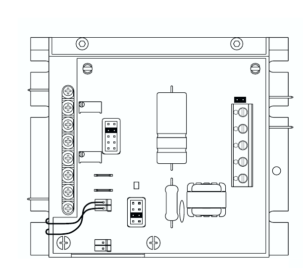
FIGURE 1 – CONTROL LAYOUT
(Illustrates Factory Setting of Jumpers and Approximate Trimpot Settings)
3
TACH
CON3
T1(-)
T2(+)
PWR TB1
L1
COM ENSIG
-15V+15V
L2
J1
ENABLE
A90
T7
A180
T50
F-
CON2
F+
1.7A
F-
OFFSET
2.5
5.0
7.5
10A
MAX
F+
F+
F-
M2
RACCMAXFCLIR RCL FACC
M1
DB RESP
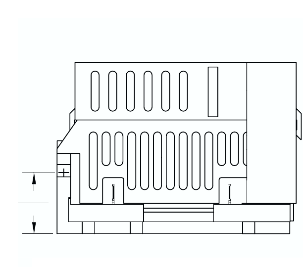
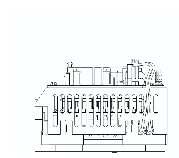
FIGURE 2A – MECHANICAL SPECIFICATIONS (INCHES / mm)
(Shown Mounted onto BC204)
4
0.95
[24.21]
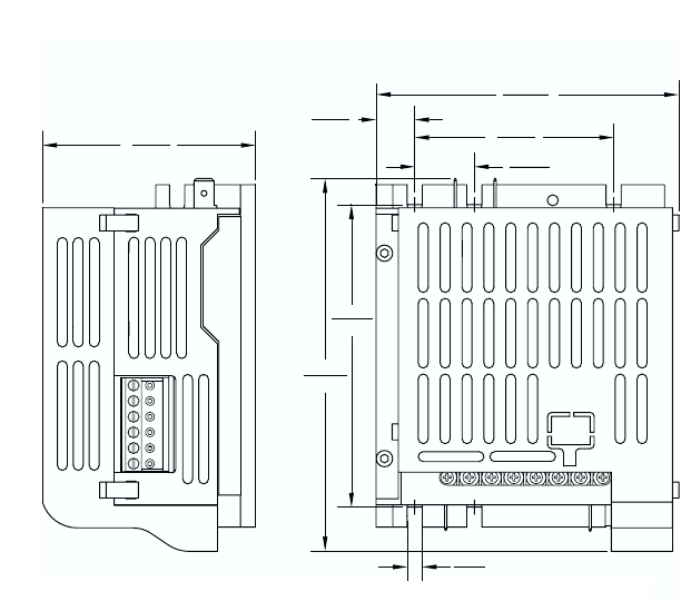
FIGURE 2B – MECHANICAL SPECIFICATIONS (INCHES / mm)
(Shown Mounted onto BC204)
5
L1 L2
M2
RACCMAXFCLIR RCL FACC
M1
DB RESP
2.67
[67.92]
0.48
[12.32]
3.80
[96.52]
4.68
[118.99]
0.19
[
4.83
]
TYP
3.80
[96.65]
2.50
[63.50]
0.75
[19.05]

TABLE 1 – GENERAL PERFORMANCE SPECIFICATIONS
II. INSTALLATION INSTRUCTIONS: Mounting the BC215 onto the BC204
See figure 3 on page 7. Note: This figure is also supplied as a separate drawing.
Warning! Make sure all power is disconnected from the BC204 before
proceeding.
A. Removing the BC204 Finger-Safe Cover
If a finger-safe cover is not installed on the BC204, proceed to section IIC (Modifying
the BC204 Finger-Safe cover). If a finger-safe cover is installed on the BC204,
remove the two (2) socket head 5-40 X 5/16” screws located at the rear of the BC204
using the supplied 3/32” hex key. Also, remove the two (2) 6-32 X 1-3/4” screws
located on either side of terminal block TB1. See figure 4 on page 8.
6
—
±5 to ±25
MAX Trimpot Range (with 10V DC Input) (% Speed)
Parameter Specification Factory Setting
Voltage Following Input Range (V DC) -10 to +10
Potentiometer Operation (kΩ) 5 —
OFFSET Trimpot Range (with 0V DC Input) (% Speed) ± 50 0
+15V DC and -15V DC Power Supply Max. Current Rating (mA DC)
0 – 110 100
25 —
Forward, Reverse, and Enable Input Switch Types Dry Contact or
Open Collector
Input/Output Linearity (%) 0.1 —
Thermal Drift (mV/ ºC) 0.4 —
Ambient Operating Temperature Range (ºC) 0 – 50
—
!
B. Removing Terminal Block
TB1 from the BC204
Remove terminal block TB1 from
the BC204 by rocking it back and
forth or using a screwdriver to gen-
tly pry it off. See figure 5 on page
9. The removed terminal block
TB1 will not be used and may be
discarded.
C. Modifying the BC204 Finger-
Safe Cover
Once the BC204 finger-safe cover
is removed, it has to be modified to
accommodate the BC215. Cut out
the finger-safe cover panel
at seven (7) places as
shown in figure 6 on page
9. (Note: Some finger-
safe covers may already
have the panel removed.)
To access the field termi-
nals (F+ and F- on the
BC204) cut out the field
tab of the BC204 finger-
safe cover at three (3)
places as shown in figure
7 on page 9.
7
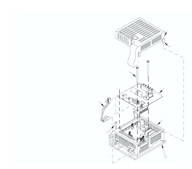
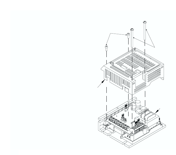
FIGURE 3 – BC204/BC215 ASSEMBLY DIAGRAM
Snap on cover
(4 places)
BC215
Finger-Safe Cover
6-32 x 1-3/4" Screws
(2 places)
5-40 x 5/16"
Screws
(2 places)
Cable
Assembly
Note:
Yellow to F+
Brown to F-
BC215
BC204
Finger-Safe Cover
BC204
D. Installing the BC204 Finger-
Safe Cover
Once the BC204 finger-safe
cover has been modified, it
can be installed onto the
BC204. Initially, use only the
two (2) 5-40 X 5/16” socket
head screws, using the sup-
plied 3/32” hex key. Do not
over tighten these screws or
damage may result to the
BC204 finger-safe cover.
Note: All jumpers on the
BC204 must be set to their
appropriate positions
before installing the
BC204 finger-safe cover.
E. Installing the BC215 onto
the BC204
The terminal block located
on the bottom of the BC215
plugs onto the six (6) header
pins where TB1 was
removed from the BC204.
The two holes on the back of
the BC215 snap onto the fin-
ger-safe cover.
8
BC204
Finger-Safe
Cover
BC204
5-40 x 5/16"
Screws
6-32 x 1-3/4"
Screws
FIGURE 4 – REMOVING THE BC204
FINGER-SAFE COVER
Use the two (2) 6-32 X 1-3/4”
screws previously removed to
secure the BC215 to the BC204.
Do not over tighten these screws or
damage may result to the BC215
and BC204. See figure 3 on page 7.
9
BC204
Terminal Block
TB1
FIGURE 5 –
REMOVING
TERMINAL
BLOCK TB1
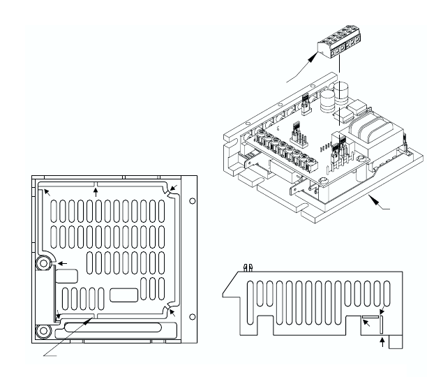
BC204 Finger-Safe Cover
Remove Panel (cut 7 places) to Install BC215.
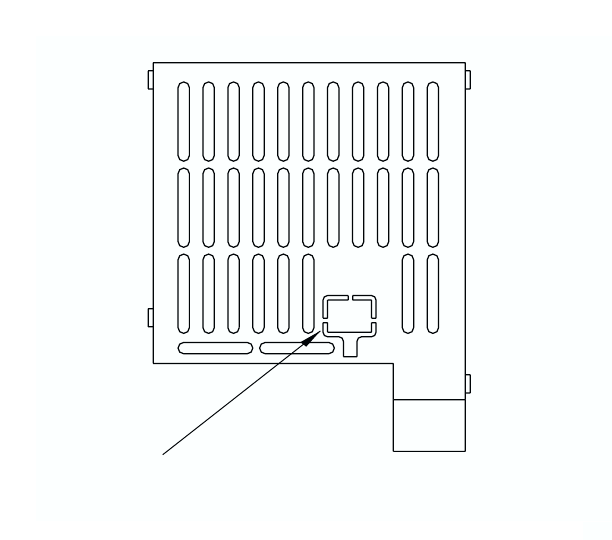
FIGURE 6 – REMOVING THE BC204
FINGER-SAFE COVER PANEL
BC204 Finger-Safe Cover
Remove Tab (cut 3 places) to Access Field Terminals.
FIGURE 7 – REMOVING THE BC204
FINGER-SAFE FIELD TAB
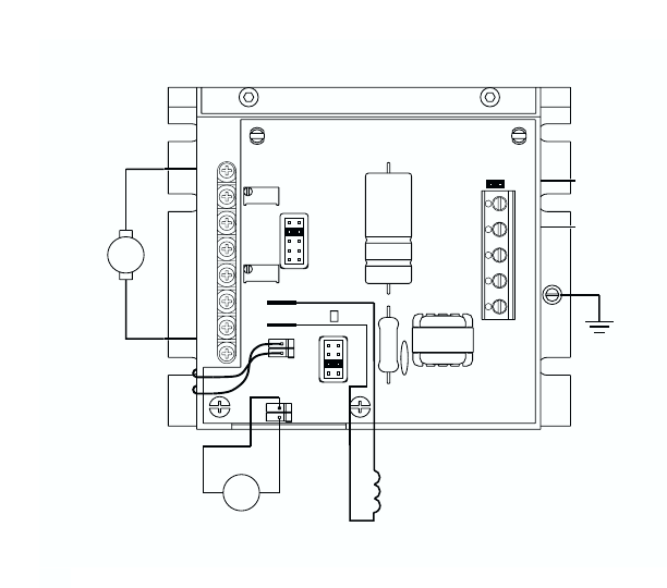
FIGURE 8 – CONNECTION DIAGRAM
10
-
+
+
-
DC TACHOMETER
GENERATOR
-+
G
TACH
CON3
T1(-)
T2(+)
A90
T7
A180
T50
PWR TB1
J1
ENABLE
+15V -15V SIG COM EN
CON2
OFFSET
MAX
F+ F-
F+
F-
AC
LINE
L2
L1
GROUND
DB RESP
M1
ARMATURE
7.5
5.0
1.7A
2.5
RCL FCL MAX FACC
M2 F- F+
RACC
A
FIELD
(SHUNT MOTORS ONLY)
10A
IR
F. Wiring the BC215 to the BC204
See figure 8 on page 10.
The BC215 is powered from the BC204 with a connector that is installed from the
BC215 CON2 to the BC204 F+ and F- terminals. The yellow wire connects to the
BC204 F+ terminal and the brown wire connects to the BC204 F- terminal. When
the field connector is properly installed the wires should cross over each other. See
figure 9. If the connector is wired incorrectly, the BC215 PWR LED will not illuminate
and the control will not operate. Note: It is recommended that these wires be twist-
ed at least three (3) times to help reduce noise.
11
FIGURE 9 – INSTALLING
FIELD CONNECTOR
III. Connections to the BC215
Safety Warning! Do not use FWD-STOP-REV contacts as a safety discon-
nect since they are not fail-safe. Use only the AC line for this purpose.
Note: BC215 Enable jumper J1 must be installed, or a connection must be made
between EN and COM terminals of BC215 TB1 in order for the BC204 to operate.
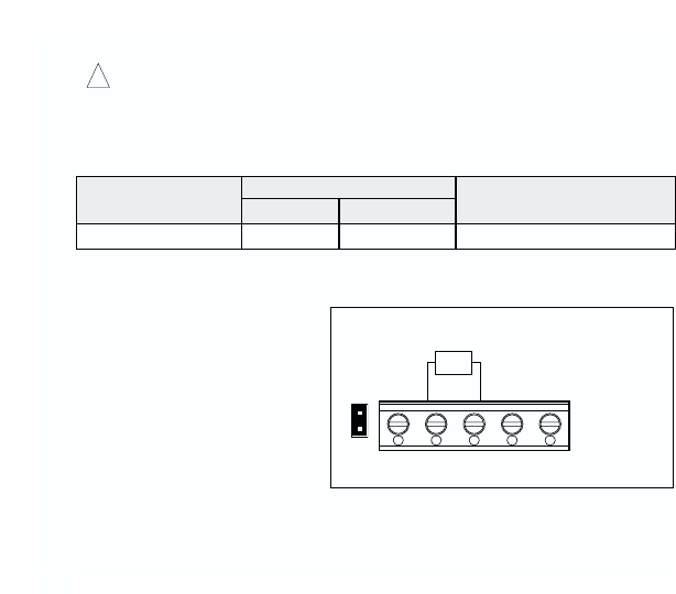
A. Voltage Following – Uses a
voltage source to vary motor
speed. See figure 10. Connect
the voltage source to TB1 ter-
minals SIG and COM. When a
0V DC signal is applied, the
control will operate at the mini-
mum set speed (set by the
OFFSET trimpot on the
BC215). When a 10V DC sig-
nal is applied, the motor will
operate at the maximum set
speed (set by the MAX trimpot on the BC215).
Applying a positive (+) signal to SIG terminal, with respect to COM terminal, will oper-
ate the motor in the forward direction.
12
!
3.5
Connection Designation
Supply Wire Gauge (AWG – Cu) Maximum Tightening Torque
(in-lbs)
MaximumMinimum
Logic Connections 24 14
TABLE 2 – TERMINAL BLOCK (TB1) WIRING INFORMATION
(BC204 Jumper J4 in 10V Position)
(BC215 Enable Jumper J1 Installed)
± 10VDC
EN COM SIG -15 +15
J1
TB1
VDC
FIGURE 10 – VOLTAGE FOLLOWING
CONNECTION
Applying a negative (-) signal to SIG terminal, with respect to COM terminal, will
operate the motor in the reverse direction.
13
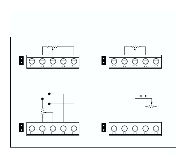
Unidirectional With Reversing Contact Bidirectional Potentiometer
J1
TB1
5K
REV
REV FWD
FWD
STOP
EN COM SIG -15 +15 EN COM SIG -15 +15
EN COM SIG -15 +15 EN COM SIG -15 +15
J1
TB1
J1
TB1
Forward Reverse
5K
5K
J1
TB1
5K
A. B.
D. C.
FIGURE 11 – MAIN SPEED POTENTIOMETER CONNECTIONS
(BC204 Jumper J4 in 15V Position, BC215 Enable Jumper J1 Installed)
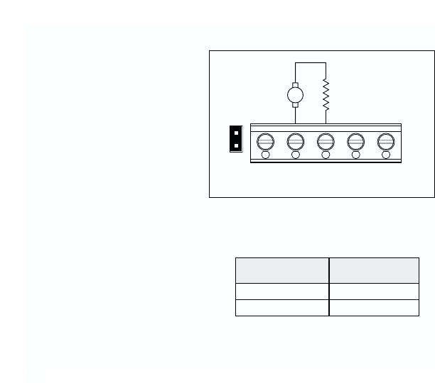
B. Signal Following from
Armature Voltage – Uses
motor armature voltage as a
signal input. If the signal input
voltage applied to the BC215
is derived from a motor arma-
ture voltage output, it is neces-
sary to install a 1/4W resistor
in series with the signal lead
into the BC215. For a 90V DC
motor, install a 150K resistor.
for a 180V DC motor, install a
330K resistor.
C. Unidirectional Potentiometer
Operation (Forward) – Uses a
potentiometer to vary motor speed.
See figure 11A on page 13.
Connect the 5K potentiometer to
TB1 terminals marked “SIG” (wiper
of potentiometer), “+15V” (high side
of potentiometer), and “COM” (low
side of potentiometer). Use the
potentiometer to vary motor speed.
If the motor is not running in the
desired direction, either reconnect
the high side of the potentiometer to TB1 terminal marked “-15V” or reverse the
motor leads.
14
330K
Armature Voltage
Range (VDC) 1/4W Resistor (Ω)
0 – ± 90 150K
0 – ± 180
EN COM SIG -15 +15
J1
TB1
1/4W Resistor
(See Table 3)
Armature
+
-A
FIGURE 12 – SIGNAL FOLLOWING FROM
ARMATURE VOLTAGE
TABLE 3 – RESISTOR FOR
SIGNAL FOLLOWING FROM
ARMATURE VOLTAGE

D. Unidirectional Potentiometer Operation (Reverse) – Uses a potentiometer to vary
motor speed. See figure 11B on page 13. Connect the 5K potentiometer to TB1 ter-
minals marked “SIG” (wiper of potentiometer), “-15V” (high side of potentiometer),
and “COM” (low side of potentiometer). Use the potentiometer to vary motor speed
and the switching device to select motor direction. If the motor is not running in the
desired direction, either reconnect the high side of the potentiometer to TB1 terminal
marked “+15V” or reverse the motor leads.
E. Bidirectional Potentiometer Operation – Uses a potentiometer to vary motor
speed and direction. See figure 11C on page 13. Connect the 5K potentiometer to
TB1 terminals marked “SIG” (wiper of potentiometer), “+15V” (high side of poten-
tiometer), and “-15V” (low side of potentiometer). Use the potentiometer to vary
motor speed and direction.
When the potentiometer is in the center position, the control output can be set to
zero, using the OFFSET trimpot. Rotating the trimpot clockwise will cause the motor
to rotate in the forward direction. Rotating the potentiometer counterclockwise will
cause the motor to rotate in the reverse direction.
F. Unidirectional Potentiometer with Reversing Contacts – Uses a potentiometer to
vary motor speed. See figure 11D on page 13. Connect the 5K potentiometer to TB1
terminals marked “SIG” (wiper of potentiometer), “+15V” (high side of potentiometer),
and “COM” (low side of potentiometer). Use the potentiometer to vary motor speed
and the switching device to select motor direction. When the potentiometer is set to
0% (fully counterclockwise), the motor will operate at the minimum set speed (set by
the OFFSET trimpot on the BC215). When the potentiometer is set to 100% (fully
clockwise) the motor will operate at full speed (set by the MAX trimpot on the
BC215).
15
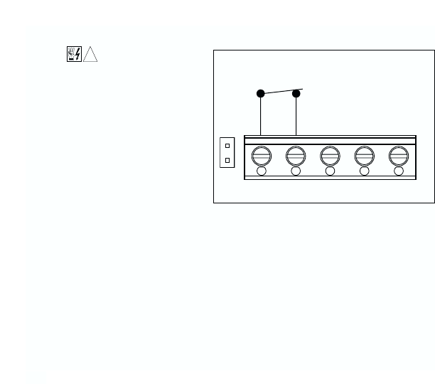
G. Enable Switch Connection
Safety Warning! Do
not use Enable or
Start/Stop contacts as a safety
disconnect since they are not
fail-safe. Use only the AC line
for this purpose. See figure 13.
If a Start/Stop function is
required, remove BC215
Enable jumper J1 and wire a
switch to EN and COM termi-
nals of BC215 TB1. When the
switch is opened, the control
will stop. When the switch is
closed, the control will operate.
H. Tachometer Generator Connection
See figure 8 on page 10. To wire a 7V or 50V per 1000RPM tachometer generator
to the BC215, connect the positive (+) side of the tachometer generator to terminal
“T2” and the negative (-) side of the tachometer generator to terminal “T1“ of the
BC215. Note: If the positive (+) and negative (-) tachometer generator connections
are not connected as described above, the motor will run at full speed only.
I. Motor Field Connection
If a shunt wound motor is used, the motor field wires connect to F+ and F- terminals
on the BC215. To access these terminals, cut out the field tab of the BC215 finger-
safe cover at three (3) places as shown in figure 14 on page 17.
16
EN COM SIG -15 +15
Enable
Open to Stop
J1
TB1
FIGURE 13 – ENABLE SWITCH CONNECTION
(BC215 Enable Jumper J1 Removed)
!
17
BC215 Finger-Safe Cover
Cut Out Tab (3 Places) to Access Field Terminals.
(For Shunt Wound Motors Only.)
FIGURE 14 – REMOVING THE BC215 FINGER-SAFE COVER FIELD TAB

IV. CALIBRATION PROCEDURE
(See Safety Warning, on page 1)
The BC215 is factory calibrated, but readjustments to the OFFSET and MAX trimpots
can be made to customize for a particular signal input requirement. It may be neces-
sary to repeat the calibration steps to achieve accurate settings.
A. Unidirectional Voltage Following Calibration
See figure 10 on page 12.
1. Apply 0V DC input signal (or connect SIG and COM terminals).
2. Monitor the BC204 output and adjust the OFFSET trimpot on the BC215 for the
desired minimum setting.
3. Apply the maximum voltage input signal.
4. Monitor the BC204 output voltage and adjust the MAX trimpot on the BC215 for
the desired maximum setting.
B. Unidirectional Potentiometer Operation Calibration:
See figure 11A, B or C on page 13.
1. Set potentiometer to 0% rotation (fully counterclockwise).
2. Monitor the BC204 output and adjust the OFFSET trimpot on the BC215 for the
desired minimum setting.
3. Set potentiometer to 100% rotation (fully clockwise).
4. Monitor the BC204 output voltage and adjust the MAX trimpot on the BC215 for
the desired maximum setting.
18

V. INSTALLING the BC215 FINGER-SAFE COVER
After all adjustments and wiring have been completed on the BC204 and the BC215,
install the BC215 finger-safe cover onto the BC204 finger-safe cover by snapping the
four (4) clips of the BC215 finger-safe cover into the four (4) slots of the BC204 finger-
safe cover.
Note: Ensure that the yellow and brown field wires (from CON2 of the BC215 to F+ and
F- terminals of the BC204) are within the shroud of the BC215 finger-safe cover. See
figure 3 on page 7.
19

– NOTES –
20

– NOTES –
21

(A40208) – Rev. A – 5/2000
VI. LIMITED WARRANTY
For a period of 2 years from date of original purchase, BALDOR will repair or replace without
charge controls which our examination proves to be defective in material or workmanship. This
warranty is valid if the unit has not been tampered with by unauthorized persons, misused,
abused, or improperly installed and has been used in accordance with the instructions and/or
ratings supplied. This warranty is in lieu of any other warranty or guarantee expressed or
implied. BALDOR shall not be held responsible for any expense (including installation and
removal), inconvenience, or consequential damage, including injury to any person, caused by
items of our manufacture or sale. (Some states do not allow the exclusion or limitation of inci-
dental or consequential damages, so the above exclusion may not apply.) In any event,
BALDOR’s total liability, under all circumstances, shall not exceed the full purchase price of the
control. Claims for purchase price refunds, repairs, or replacements must be referred to BAL-
DOR with all pertinent data as to the defect, the date purchased, the task performed by the con-
trol, and the problem encountered. No liability is assumed for expendable items such as fuses.
Goods may be returned only with written notification including a BALDOR Return Authorization
Number and any return shipments must be prepaid.
Baldor Electric Company
5711 R. S. Boreham, Jr. Street
Fort Smith, AR 72902-2400 U.S.A
(501) 646-4711 Fax (501) 648-5792
International Fax (501) 648-5895
MOTORS AND DRIVES
