2CDC446001D0201.p65 95842 Catalog
2014-07-05
: Pdf 95842-Catalog 95842-Catalog 662019 Batch5 unilog
Open the PDF directly: View PDF ![]() .
.
Page Count: 36
Technical data Busbar systems and
installation accessories

2
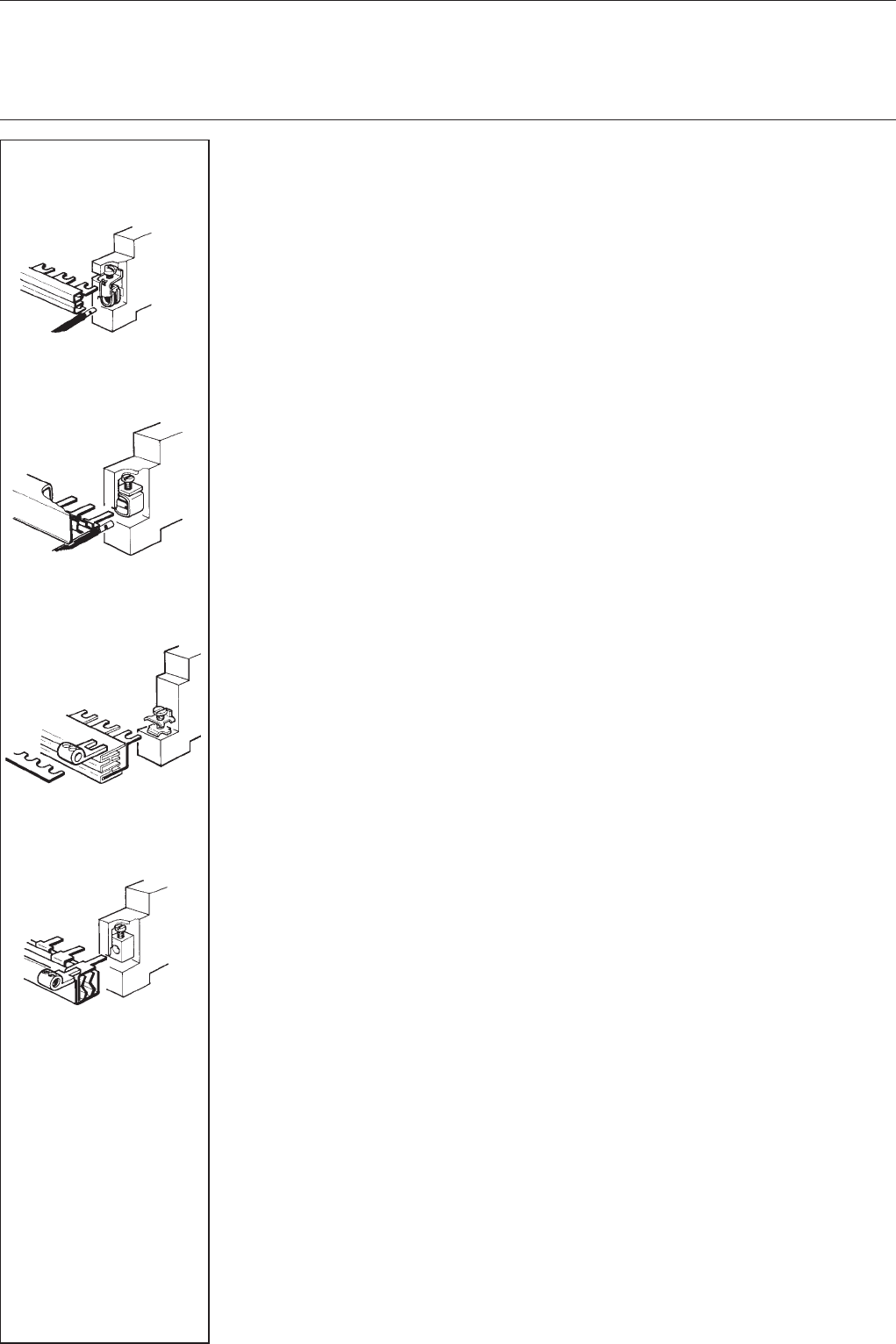
When connecting aluminum conductors, ensure that
the contact surfaces of the conductors are cleaned,
brushed and treated with grease.
Re-tighten contacts terminals 6-8 weeks after
installation.
Standard Terms for Sale and Delivery
For domestic business, the Standard Terms for Delivery of Products and Services of the Electrical
Industry (ABB Form 2292) shall apply in connection with the Standard Sales Terms (ABB Form 327)
in their then applicable version. For foreign business, the Standard Terms for Delivery of Products
and Services of the Electrical Industry (ABB Form 2293 German-English, or ABB Form 2294
German-French) shall apply in connection with the Standard Sales Terms (ABB-Form 2381 English)
in their then applicable version.
Warranty
We assume warranty in accordance with the standard sales and delivery terms.
Complaints shall be made in writing within eight days following receipt of the goods.
Technical information is not binding and subject to change without notice.

3
System pro M
Installation accessories
for consumer units and built-in devices
Contents page
Wiring accessories
Short description, technical data ............................................................................. 4
Loads, connection capacity ..................................................................................... 5
Shock-protected busbars
for the System pro M compact series ................................................................... 6
Wiring examples for System pro M compact ........................................................ 7
Identification system for System pro M compact ................................................. 8
Universal comb busbars
for MCBs with combined box terminals .................................................................. 9
Shock-protected busbar blocks for MCBs with combined box terminals ............. 9
Shock-protection caps, end caps ......................................................................... 10
Shock-protected busbars blocks for MCBs with box terminals ........................... 11
Shock-protected busbars blocks
for MCBs with shock protection and combined box terminals ............................ 12
Shock-protected busbar blocks
for MCBs with shock protection and box terminals .............................................. 13
Busbar blocks for MCBs with screw terminals ..................................................... 14
Busbar blocks for MCBs with box terminals ......................................................... 15
Shock-protected busbars blocks
with shock protection and combined box terminals ............................................. 16
Busbars
Busbar blocks, comb busbars and oblong-hole busbars
for fuse-elements ................................................................................................... 17
Busbar blocks
for switch-disconnectors ....................................................................................... 17
Busbar blocks
for fuse-elements DO ............................................................................................. 17
Universal comb busbars
for fuse-elements DO ............................................................................................. 17
Oblong-hole busbars for fuse-elements D ............................................................ 17
Terminal clamps ..................................................................................................... 17
Terminals, interconnecting wires
Terminals, flexible connection wires ...................................................................... 18
Wiring kit, neutral or protective-conductor terminals & accessories .................... 19
Installation accessories
Device mounting rails and fixing accessories ....................................................... 20
Blanking plates, filling pieces (example see page 25) ........................................... 21
Lockout devices and accessories.......................................................................... 22
Housings and terminal covers
Terminal covers with grou ndplate......................................................................... 22
Flange frame, insulated housings, N + PE common terminals ............................. 23
Labelling material
Individual identification labels & label mats ........................................................... 24
Dimensions
Busbars................................................................................................................... 26
Wiring kit, terminals ................................................................................................ 31
Feeder terminals, protective-conductor terminals ................................................ 32
Common terminals, terminal covers ...................................................................... 33
Insulated housings ................................................................................................. 34
N + PE common terminals ..................................................................................... 35
4
System pro M
box terminal
combined box terminal
box terminal
screw terminal
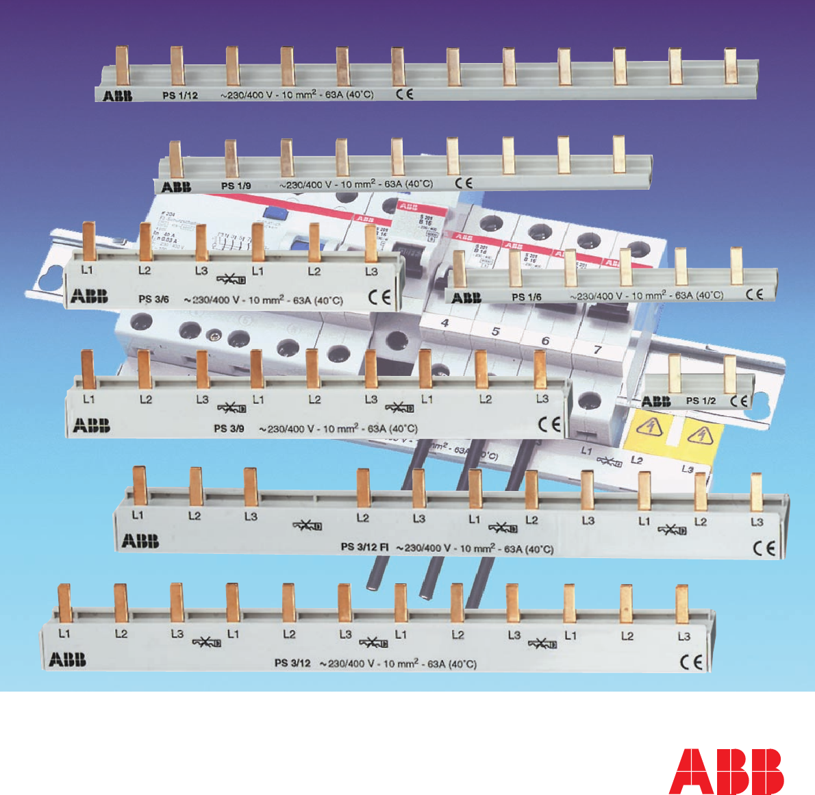
Busbar systems
Brief description
The busbar systems are included a complete program that offers safe and efficient installations
of consumer unit built-in devices, e.g. MCBs, residual-current-operated circuit-breakers with or
without overcurrent release (RCCBs, RCBOs) and the modular rail components (MDRC).
When choosing the right busbars, consider the following:
쎲type of terminal (e.g. combined box, box, or screw terminals)
쎲No. of poles of the devices (e.g. 1-, 2-, 3-, 4-pole, 1-pole + neutral NA)
쎲type of device: MCB, RCCB, RCBO, or modular installation devices (MDRC))
쎲device mix (e.g. MCB and MDRC on one rail)
쎲use of additional devices (e.g. MCB plus auxiliary switch)
쎲busbar connection capacity (loads)
쎲No. of modules (busbars supplied at various lengths)
Technical data
specifications: DIN EN 60 439 Part (VDE 0660 Part 500): 2000-08
busbar material: SF-Cu F 24
insulation material: Cycoloy 3600 plastics, temp. resistant 욷 90 °C/194 °F
flame-retardant, self-extinguishing,
dioxin and halogene-free
busbar connection capacities: 6 mm2 to 36 mm2
rated operational current: 400 VAC
rated current In: 63 A (10 mm2)
80 A (16 mm2)
rated impulse
withstand voltage Uimp:4 kV
impulse test voltage (1.2/50): 6.2 kV
short-circuit withstand capacity: 25 kA
climatic resistance: constant climate: 23/83; 40/92; 55/20 according to
DIN 50015
damp heat, 28 cycles (IEC 68 Part 2-30)
insulation coordination: according to VDE 0110 Part 1, April 1997 (IEC 664)
– overvoltage category: III
– pollution degree: 2
SK 0074 Z91
SK 0075 Z91
SK 0092 Z91
SK 0096 Z91
5
System pro MBusbar systems
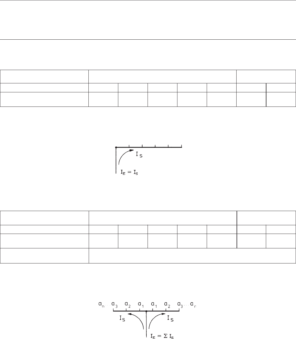
Loads depending on supply point and required connection capacity
1. End feeding
comb and oblong-hole busbars (type KS) busbar blocks
(type PS/PSB )
cross section/mm210 12 20 24 36 10 16
max. supply current
IS/phase A 63 65 90 100 130* 63 80
* If fed via the terminals, always ensure that the following values are not exceeded, irrespective of the current carrying capacity (IS) of the busbar:
For S 200 and S 200M series: max. 110 A.
For S 280 series: max. 140 A.
SK 0062 Z91
2.Non-end feeding (center or elsewhere on the rail)
comb and oblong-hole busbars (KS-type) busbar blocks
(type PS/PSB)
cross section/mm210 12 20 24 36 10 16
max. current in branch
IE/phase A 100 110 150* 170* 220* 100 120*
max. supply current depends on cross section
IE/phase A
* If fed via the terminals, always ensure that the following values are not exceeded, irrespective of the current carrying capacity (IS) of the busbar:
For S 200 and S 200M series: max. 110 A.
For S 280 series: max. 140 A.
SK 0063 Z91
6
System pro MBusbars
and accessories
PS 1/2 – PS 1/12 SK 0027 B99
PS 3/6 – PS 3/12 SK 0028 B99
PS 3/57 FI SK 0058 Z02
PS 3/12 FI (GHV…)
PS 4/58 N SK 0065 Z02
PS 4/58/16 N
PV 3 SK 0120 Z01
PV 4 SK 0121 Z01
SZ-BSK SK 0100 B99
Selection table busbars (can only be used for compact series)
conn. module phases order details bbn price price w'ght pack.
capacity 40 16779 1 piece group 1 pc. units
mm2type code order code EAN kg pc.
Busbars not to be cut to length (closed design) no end caps required
10 2 1 PS 1/2 2CDL 210 001 R1002 46300 3 0.008 180
10 3 1 PS 1/3 2CDL 210 001 R1003 51465 1 0.025 60
10 6 1 PS 1/6 2CDL 210 001 R1006 46310 2 0.025 60
10 9 1 PS 1/9 2CDL 210 001 R1009 46320 1 0.039 30
10 12 1 PS 1/12 2CDL 210 001 R1012 46330 0 0.052 30
10 6 3 PS 3/6 2CDL 231 001 R1006 46340 9 0.042 60
10 9 3 PS 3/9 2CDL 231 001 R1009 46350 8 0.069 30
10 12 3 PS 3/12 2CDL 231 001 R1012 46360 7 0.096 30
(no NA)
10 12 3 PS 3/12 FI 2CDL 231 002 R1012 46370 6 0.094 30
1, 2, 3 and 4-pole busbars to be cut to length
10 60 1 PS 1/60 2CDL 210 001 R1060 51466 8 0.260 30
16 60 1 PS 1/60/16 2CDL 210 001 R1660 51665 5 0.410 30
10 12 2 PS 2/12 2CDL 220 001 R1012 55652 1 0.070 50
10 58 2 PS 2/58 2CDL 220 001 R1058 55655 2 0.320 10
16 58 2 PS 2/58/16 2CDL 220 001 R1658 55656 9 0.545 10
10 48 2 PS 2/48 H 2CDL 220 001 R1048 55653 8 0.470 10
16 48 2 PS 2/48/16 H* 2CDL 220 001 R1648 55654 5 0.680 10
10 12 3 PS 3/12 2CDL 230 001 R1012 57611 6 0.110 50
16 12 3 PS 3/12/16 2CDL 230 001 R1612 56280 5 0.150 50
10 60 3 PS 3/60 2CDL 230 001 R1060 51469 9 0.505 10
16 60 3 PS 3/60/16 2CDL 230 001 R1660 51470 5 0.760 10
10 39 3 PS 3/39 H* 2CDL 230 001 R1039 55659 0 0.505 10
16 39 3 PS 3/39/16 H* 2CDL 230 001 R1639 55660 6 0.760 10
10 48 3 PS 3/48 H* 2CDL 230 001 R1048 55661 3 0.505 10
16 48 3 PS 3/48/16 H* 2CDL 230 001 R1648 55664 4 0.760 10
10 9 3 PS 3/9 FI 2CDL 230 002 R1009 51751 5 0.065 50
10 10 3 PS 3/10 FI 2CDL 230 002 R1010 51752 2 0.073 50
10 12 3 PS 3/12 FI 2CDL 230 002 R1012 57107 4 0.110 50
10 12 3 PS 3/12 FI H 2CDL 230 003 R1012 57108 1 0.110 50
10 57 3 PS 3/57 FI 2CDL 230 002 R1057 55665 1 0.550 10
10 12 4 PS 4/12 2CDL 240 001 R1012 55666 8 0.120 50
16 12 4 PS 4/12/16 2CDL 240 001 R1612 55667 5 0.241 50
10 60 4 PS 4/60 2CDL 240 001 R1060 55668 2 0.803 10
16 60 4 PS 4/60/16 2CDL 240 001 R1660 55674 3 1.205 10
10 58 4 PS 4/58 N 2CDL 240 001 R1058 55670 5 0.803 10
16 58 4 PS 4/58/16 N 2CDL 240 001 R1658 55673 6 1.205 10
16 52 4 PS 4/52/16 H* 2CDL 240 001 R1652 55669 9 1.305 10
* rail with cutout for auxiliary switch
Note: PS 1/60 and PS 1/60/16 no end cap required
PS 2/.. and PS 3/.. use PS END
PS 4/.. use PS END 1
see also wiring examples on page 7*
End caps
PS-END 2CDL 200 001 R0001 51472 9 0.001 50
PS-END 1 2CDL 200 001 R0002 57011 4 0.001
Main circuit breaker busbar
3-phase busbar (10 mm2) for connecting main circuit breaker E 463/3-KB and pro M compact
devices incl. end caps. No. of poles: 12 (1 x E 463/3-KB + 9 x S 201)
12 3 PS 3/12 E463 2CDL 230 004 R1012 51741 6 0.081 30
Rail connectors
for wiring of component rails in the consumer unit, rail-to-rail clearance 125 mm.
In the case of the 4-pole connector, the color of the N conductor is blue.
10 3-pole RV 3 GH V036 0504 R0023 51238 1 0.080 25
10 4-pole RV 4 GH V036 0504 R0024 51224 4 0.114 25
Auxiliary contact bridge
wire jumper for integrated auxiliary contact S 200 H for series connections.
1/2 mod. HKB GH V036 0504 R0100 52313 4 0.001 1000
Shock-protection caps for PS...
5 parts SZ-BSK 2CDL 200 001 R0011 42000 6 0.003 10
* for connecting larger connection capacities see terminals insulated SZ-Ast page 18
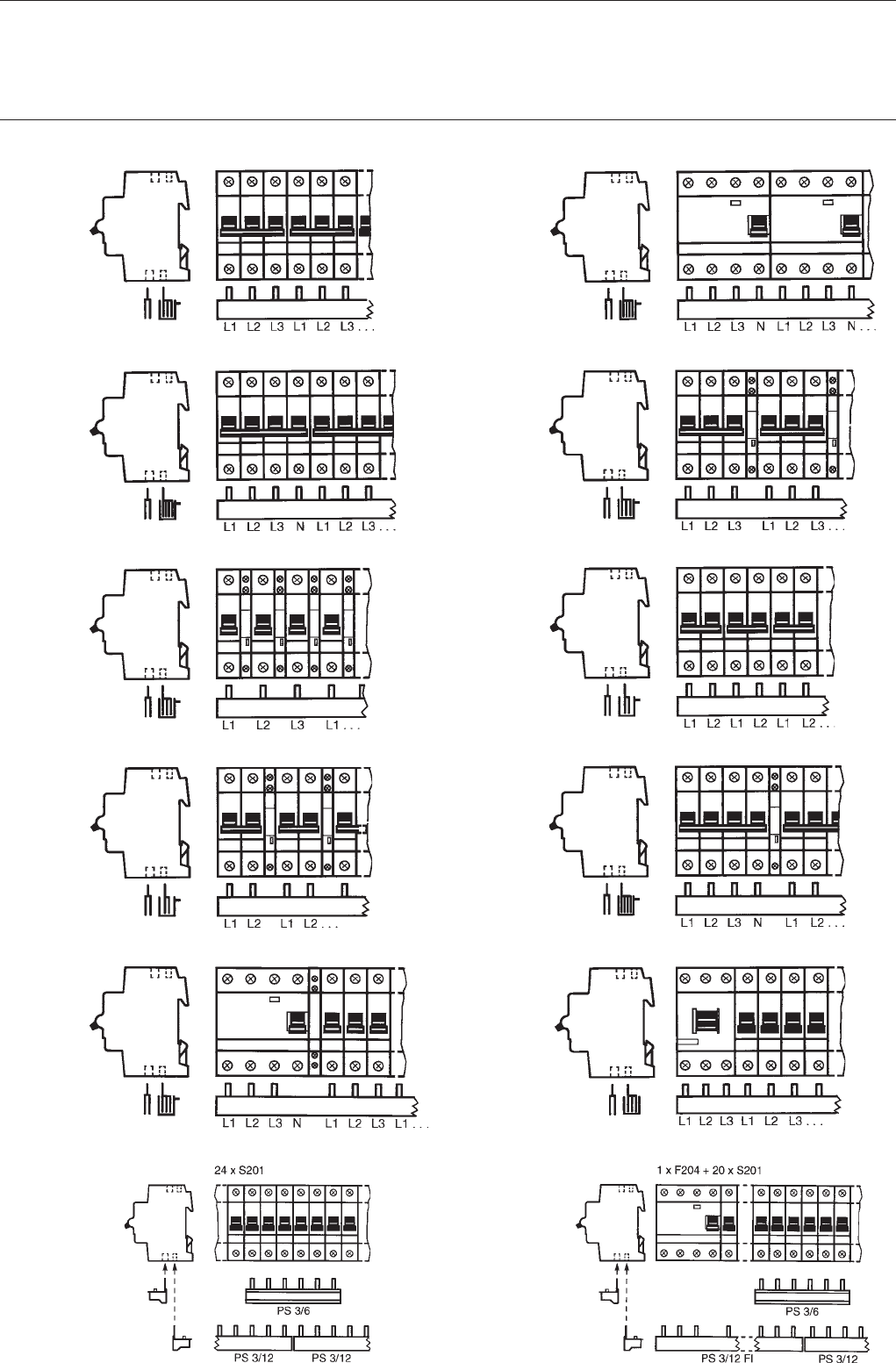
7
System pro MBusbar systems
SK 0060 Z02
PS 3/12
PS 3/12/16
PS 3/60
PS 3/60/16
Wiring kit
PS 4/12
PS 4/12/16
PS 4/60
PS 4/60/16
PS 3/39 H
PS 3/39/16 H
PS 2/48 H
PS 2/48/16 H
PS 3/12 FI H
example for
overlapping
devices
SK 0063 Z02SK 0061 Z02SK 0057 Z02SK 0193 Z02SK 0250 Z02
SK 0064 Z02
PS 4/12
PS 4/12/16
PS 4/60
PS 4/60/16
PS 3/48 H
PS 3/48/16 H
PS 2/12
PS 2/12/16
PS 2/58
PS 2/58/16
PS 4/52/16 H
PS 3/12 E 463
example for
overlapping
devices
SK 0062 Z02SK 0059 Z02SK 0056 Z02SK 0023 Z01SK 0251 Z02
8
System pro M
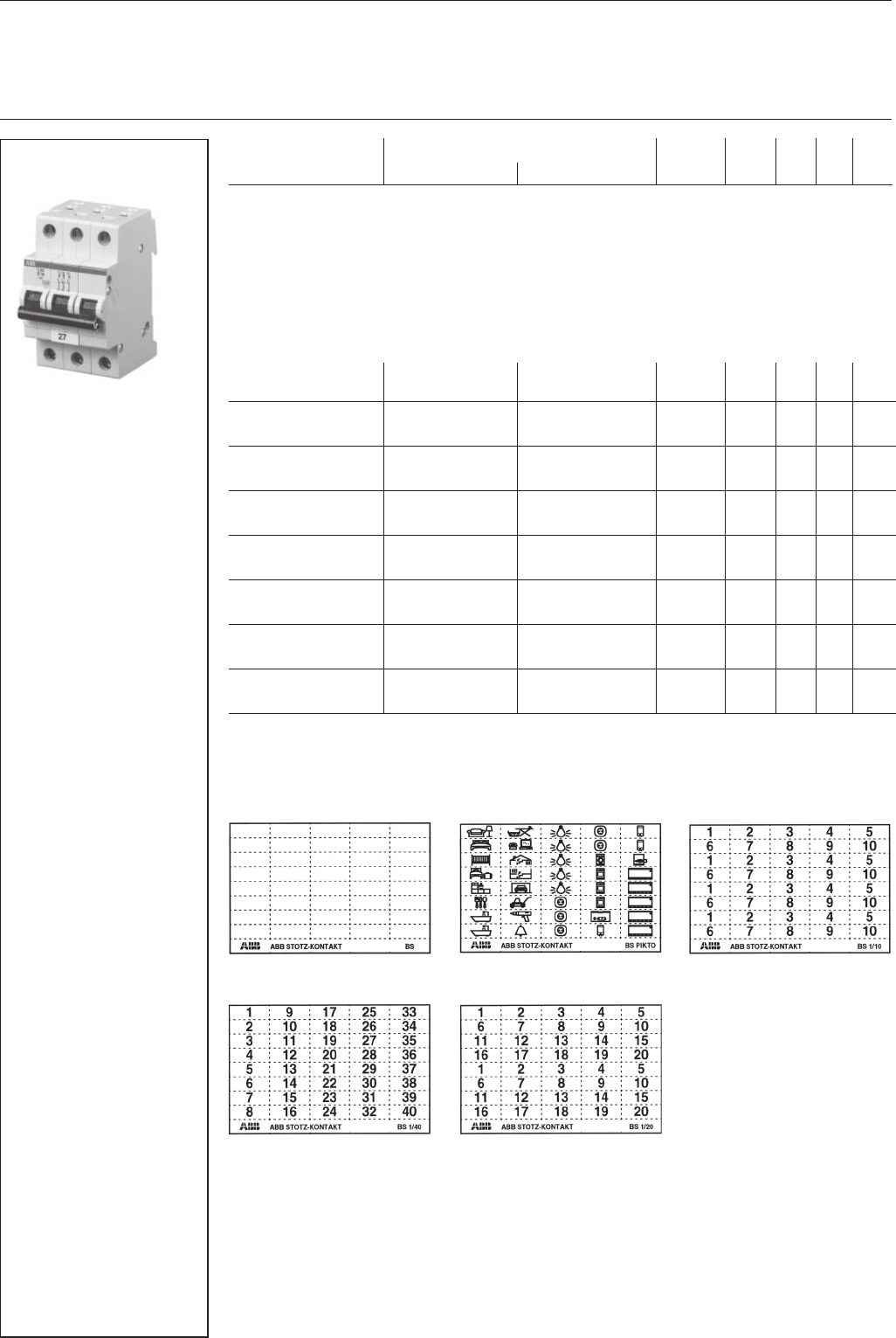
Labelling system
Self-adhesive identification labels are available for all devices of the System pro M compact series.
An integrated positioning aid ensures the exact arrangement of labels.
identification labels BS GH S200 1946 R0001 47810 6 0.004 30
blank
identification labels BS Pikto GH S200 1946 R0002 47820 5 0.004 30
with pictograms
identification labels BS 1/10 GH S200 1946 R0003 47830 4 0.004 30
marked 4 x 1 – 10
identification labels BS 1/20 GH S200 1946 R0004 47840 3 0.004 30
marked 2 x 1 – 20
identification labels BS 1/40 GH S200 1946 R0005 47850 2 0.004 30
marked 1 – 40
identification labels BS 41/80 GH S200 1946 R0006 58591 0 0.004 30
marked 41 – 80
identification labels BS 81/120 GH S200 1946 R0007 58592 7 0.004 30
marked 81 – 120
identification labels BS 121/160 GH S200 1946 R0008 58593 4 0.004 30
marked 121 – 160
Customised labels on request.
Selection table
package comes with 40 labels, marked or blank. Blank labels can be labeled by hand with an indelible, waterproof pen
or with computerised labelling systems (plotter).
identification label
from BS 1/40
SK 0047 B99
description order details bbn price price w'ght pack.
40 16779 1 piece group 1 pc. units
type code order code EAN kg pc.
Accessories
Identification labels
↑
Sk 0101 Z99 Sk 0102 Z99
Sk 0105 Z99 Sk 0104 Z99
Sk 0103 Z99
Samples
9
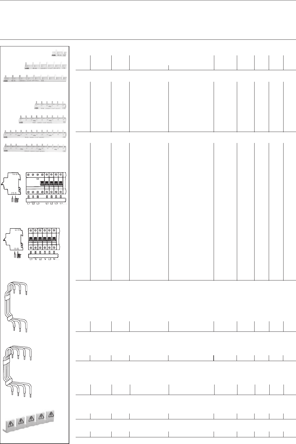
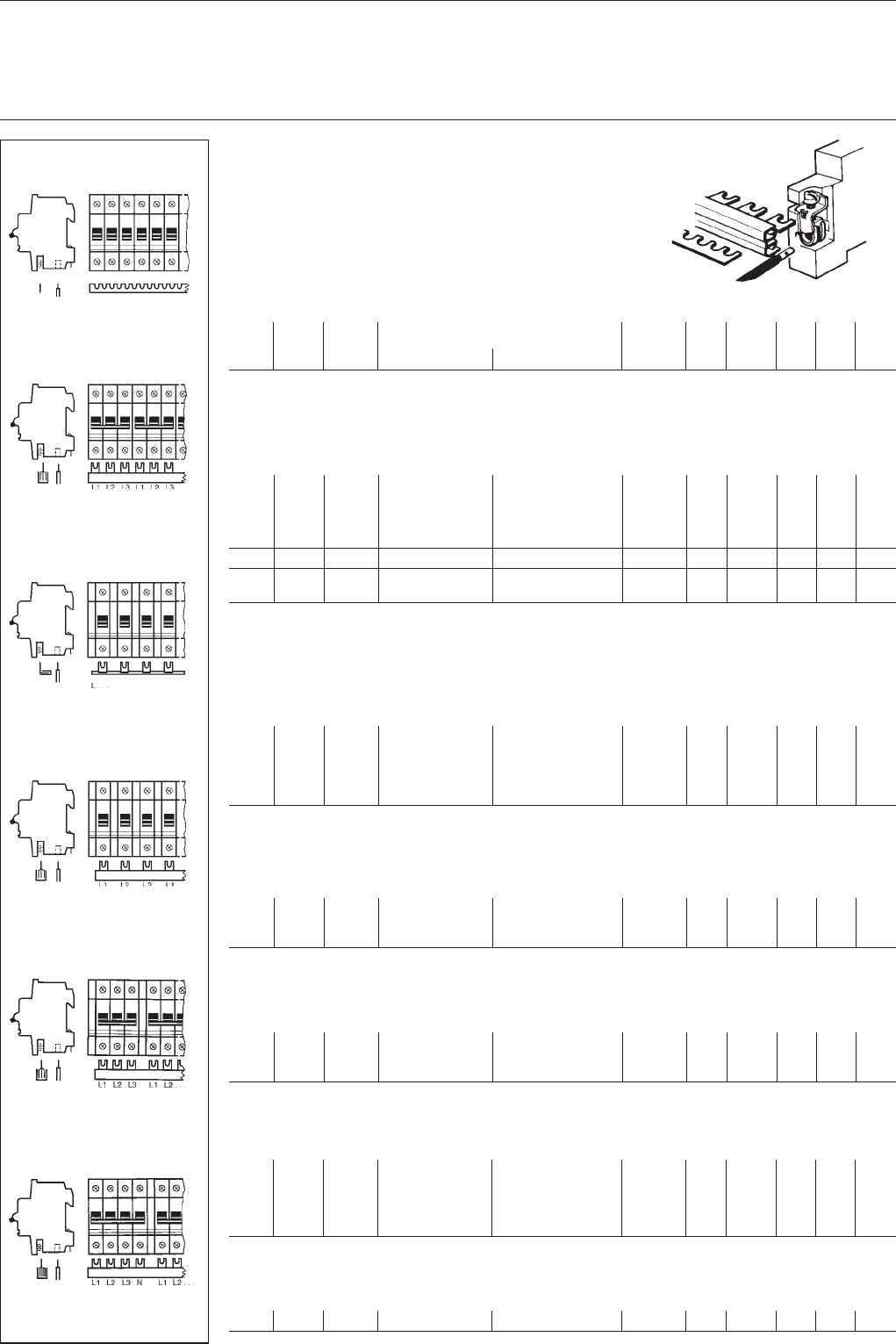
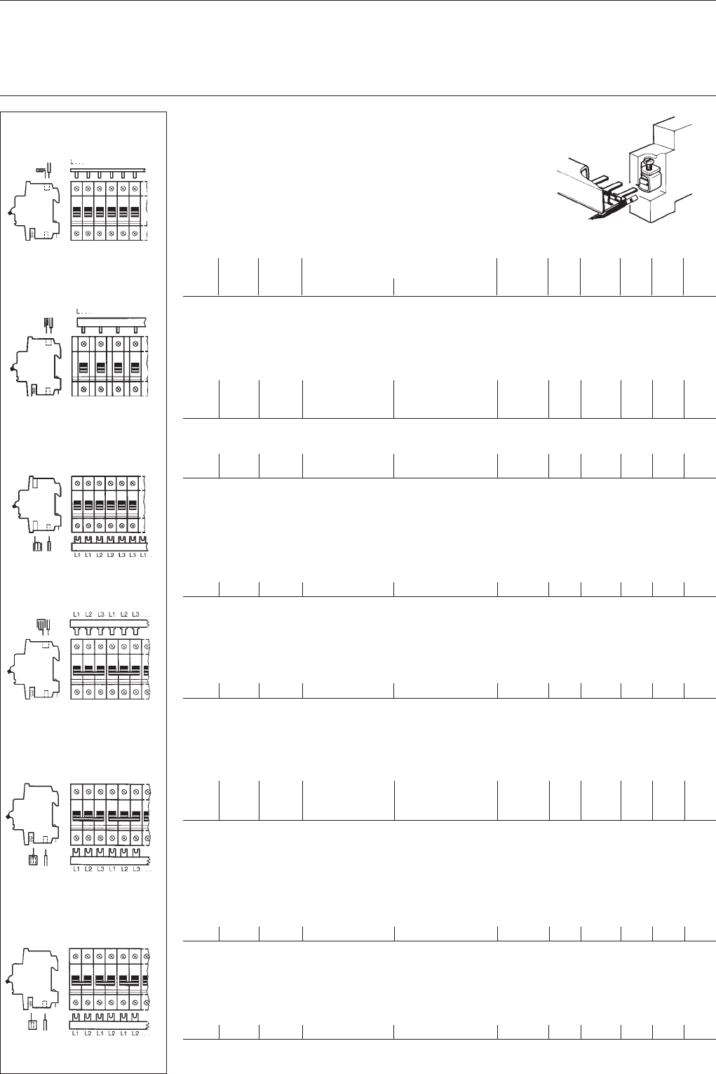
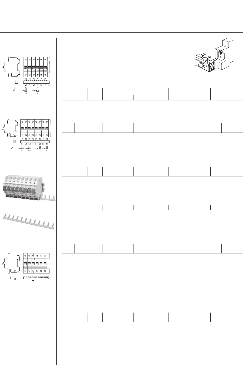
System pro MBusbar systems
Shock-protected busbar blocks
and comb busbars
for MCBs
with combined box terminals
(no terminals required)
(end caps see page 10)
SK 0061 Z91
conn. length No. of order details bbn Cu price price w'ght pack.
capac. poles 40 12233 No. 1 pc. group 1 pc. units
mm² mm type code order code EAN kg pc.
Universal comb busbars
for MCBs: 1 pole
supply: 1 phase
12 207 12 x 1 SZ-KS 1/12* GJ I232 2322 R0001 59790 1 0.023 0.015 100
12 988 56 x 1 SZ-KS 1/56* GJ I232 2322 R0002 59800 7 0.110 0.073 50
24 207 12 x 1 SZ-KS 2/12* GJ I232 2322 R0003 59810 6 0.046 0.031 100
24 988 56 x 1 SZ-KS 2/56* GJ I232 2322 R0004 59820 5 0.220 0.138 50
36 988 56 x 1 SZ-VB 45.32* GJ I232 2148 R0001 59720 8 0.330 0.233 50
16 202 12 x 1 SZ-KS 18/12 N GH V036 0875 R0041 74530 2 0.071 0.073 50
16 1007 56 x 1 SZ-KS 18/56 N GH V036 0875 R0042 74520 3 0.320 0.300 50
* without insulation, for adequate cover see page 14, SZ-BSA
Busbar blocks
for MCBs: 1- or 3-pole
supply: 3 phases
10 213 4 x 3 SZ-PSB 3 N GH L520 1915 R0005 29400 3 0.085 0.082 30
10 1058 20 x 3 SZ-PSB 4 N GH L520 1915 R0006 29410 2 0.505 0.468 10
16 213 4 x 3 SZ-PSB 11 N GH L520 1916 R0005 29420 1 0.160 0.136 30
16 1058 20 x 3 SZ-PSB 12 N GH L520 1916 R0006 29430 0 0.720 0.700 10
Use shock-protection caps SZ-BSK 5, see page 10
1 pole with auxiliary switch
1 phase
10 1020 39 x 1 SZ-KS 3/39 N GH V036 0874 R0060 55130 9 0.205 0.206 10
16 1020 39 x 1 SZ-KS 4/39 N GH V036 0874 R0062 55150 7 0.320 0.283 10
1 pole with auxiliary switch
3 phases
10 1018 13 x 3 SZ-PSB 46 N GH V036 0874 R0024 54870 5 0.505 0.451 10
16 1018 13 x 3 SZ-PSB 48 N GH V036 0874 R0026 54890 3 0.760 0.620 10
3 pole with auxiliary switch
3 phases
10 176 3 x 3 SZ-PSB 49 N GH V036 0874 R0027 54900 9 0.105 0.076 30
10 980 16 x 3 SZ-PSB 50 N GH V036 0874 R0028 54910 8 0.505 0.442 10
16 176 3 x 3 SZ-PSB 51 N GH V036 0874 R0029 54920 7 0.152 0.104 30
16 980 16 x 3 SZ-PSB 52 N GH V036 0874 R0030 54930 6 0.760 0.632 10
4 pole with auxiliary switch
3 phases + N
16 1020 13 x 4 SZ-PSB 130 N GH V036 0503 R0040 40330 61.32 0.810 10
bbn-No. 40 16779
end caps:
PSB-END 6
SZ-PSB 130 N
4 pole + aux.switch & 3phases + N
SK 0169 Z98
SZ-PSB 49 N, SZ-PSB 50 N
SZ-PSB 51 N, SZ-PSB 52 N
3 pole + aux. switch and 3 phases
SK 0097 Z96
SZ-PSB 46 N
SZ-PSB 48 N
1 pole + aux. switch with 3 phases
SK 0096 Z96
SZ-KS 3/39 N
SZ-KS 4/39 N
1 pole + aux. switch with 1 phase
SK 0095 Z96
SZ-PSB 3 N, SZ-PSB 4 N
SZ-PSB 11 N, SZ-PSB 12 N
1- or 3-pole with 3 phases
SK 0139 Z96
SZ-KS 1/12, SZ-KS 1/56
SZ-KS 2/12, SZ-KS 2/56
1 pole with 1 phase
SK 0183 Z97
end caps:
PSB-END 3
end caps:
PSB-END 3
end caps:
PSB-END 4
10
System pro MBusbar systems
SZ-PSB 53 N, SZ-PSB 54 N
SZ-PSB 55 N, SZ-PSB 56 N
1 pole + NA or
2 pole with 2 phases or
1 phase + N
SK 0098 Z96
SZ-PSB 92 N
2 pole + aux. switch with 2 phases
1 pole + NA + auxiliary switch.
with 2 phases or
1 phase + N + auxiliary switch
SK 0099 Z96
SZ-PSP 58 N
SZ-PSB 60 N
1 pole + NA with 4 phases or
3 phases + N
SK 0100 Z96
SZ-PSB 61 N, SZ-PSB 62 N
SZ-PSB 63 N, SZ-PSB 64 N
3 pole + NA or
4 pole with 4 phases or
3 phases + N
SK 0101 Z96
SZ-BSK 5 SK 0053 Z95
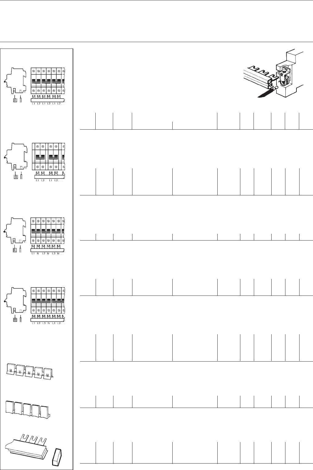
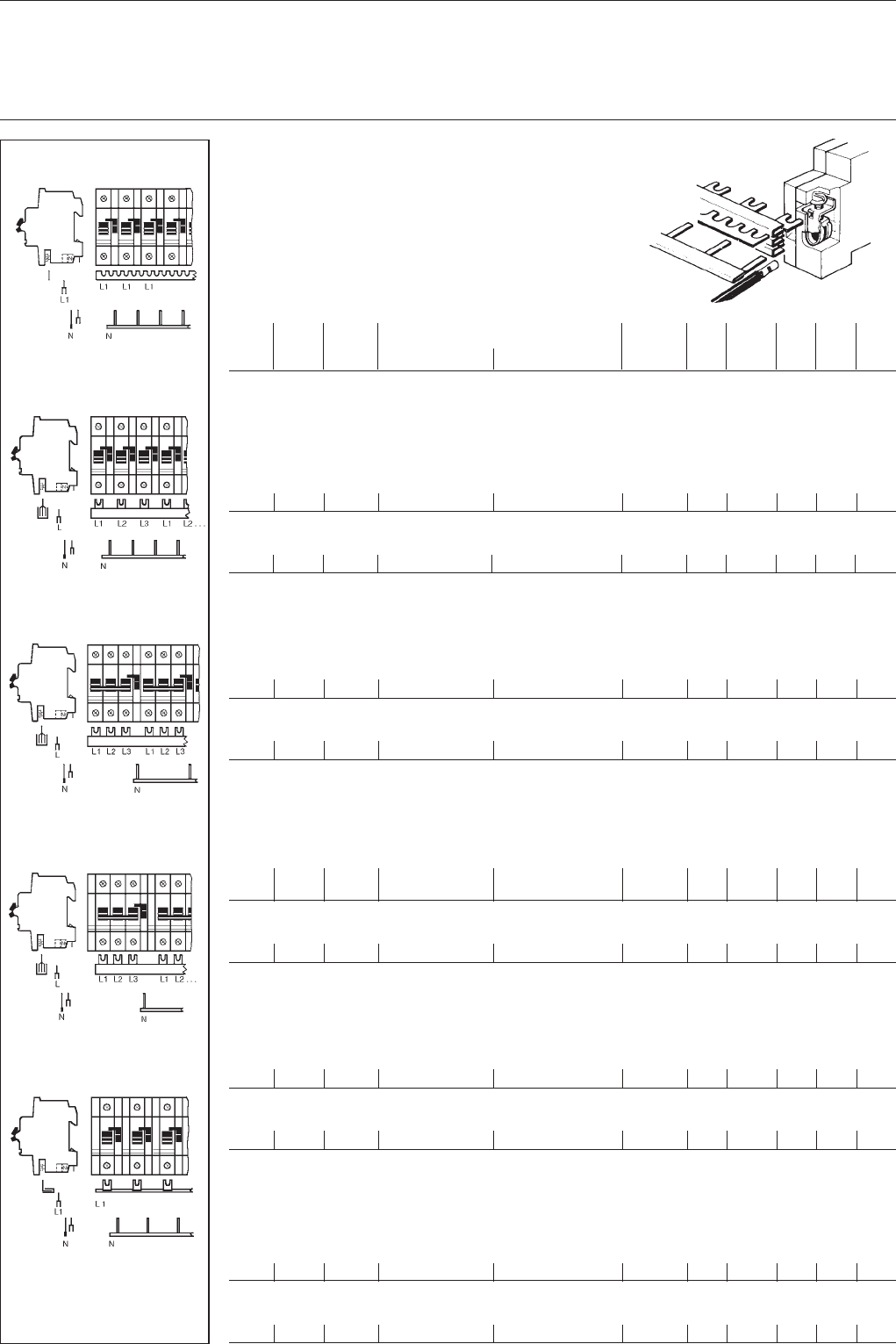
Shock-protected busbars blocks
for MCBs
with combined box terminals
(no terminals required)
(end caps see below)
SK 0074 Z91
conn. length No. order details bbn Cu- price price w'ght pack.
capac. of 40 12233 of 1 pc. group 1 pc. units
mm² mm poles type code order code EAN kg pc.
for MCBs: 1 pole + NA or 2 pole
supply: 1 phase + N or 2 phases
10 212 6 x 2 SZ-PSB 53 N GH V036 0874 R0031 54940 5 0.070 0.078 30
10 1035 29 x 2 SZ-PSB 54 N GH V036 0874 R0032 54950 4 0.320 0.403 10
16 212 6 x 2 SZ-PSB 55 N GH V036 0874 R0033 54960 3 0.115 0.106 30
16 1035 29 x 2 SZ-PSB 56 N GH V036 0874 R0034 54970 2 0.545 0.534 10
2 pole with auxiliary switch
1 phase + N or 2 phases
16 1044 24 x 2 SZ-PSB 92 N GH V036 0875 R0010 55380 8 0.680 0.650 10
1 pole + NA
3 phases + N
10 1056 29 x 2 SZ-PSB 58 N GH V036 0874 R0036 54990 0 0.803 0.626 10
16 1056 29 x 2 SZ-PSB 60 N GH V036 0874 R0038 55010 4 1.205 0.861 10
3 pole + NA or 4 pole
3 phases + N
10 212 3 x 4 SZ-PSB 61 N GH V036 0874 R0039 55020 3 0.120 0.112 30
10 1056 15 x 4 SZ-PSB 62 N GH V036 0874 R0040 55030 2 0.803 0.650 10
16 212 3 x 4 SZ-PSB 63 N GH V036 0874 R0041 55040 1 0.241 0.156 30
16 1056 15 x 4 SZ-PSB 64 N GH V036 0874 R0042 55050 0 1.205 0.884 10
Shock-protection caps for busbar blocks with fork-type connection
5 parts SZ-BSK 5 * GH V036 0505 R0001 15430 70.003 10
5 parts SZ-BSK GH V036 0505 R0002 42000 61.32 0.003 10
* for busbars blocks SZ-PSB 3 N; 4 N; 11 N and 12 N
End caps for shock-protected busbar blocks
PSB-END 6 GH L520 1921 R0007 51453 8– 0.006 50
PSB-END 3 GH V036 1325 R0001 55630 4 – 0.001 50
PSB-END 4 GH V036 1325 R0002 55640 3 – 0.001 50
PSB-END 7* GH V036 1325 R0003 52312 7– 0.001 2
bbn-No. 40 16779 * for SZ-PSB 140N
end caps:
PSB-END 3
end caps:
PSB-END 3
end caps:
PSB-END 4
end caps:
PSB-END 4
SZ-BSK SK 0186 Z98
PSB-END
SK 0104 Z97
11
System pro MBusbar systems
SZ-KS 16/12 N (NB)
SZ-KS 16/56 N (NB)
1 pole with 1 phase
SK 0102 Z96
Shock-protected busbar blocks
for MCBs with box terminals
(no terminals required)
(end caps see page 10)
SZ-PSB 3 UL
1- or 3 pole with 3 phases
conn. length No. order details bbn Cu- price price w'ght pack.
capac. of 40 12233 of 1 pc. group 1 pc. units
mm² mm poles type code order code EAN kg pc.
for MCBs: 1 pole
supply: 1 phase
16 57 4 x 1 SZ-KS 16/4 N GH V036 0875 R0034 52187 5 0.028 0.014 90
16 202 12 x 1 SZ-KS 16/12 N GH V036 0875 R0035 55550 5 0.075 0.042 30
16 1007 56 x 1 SZ-KS 16/56 N GH V036 0875 R0036 55560 4 0.280 0.250 10
16 230 12 x 1 SZ-KS 16/12 NB* GH V036 0503 R0025 15880 0 0.075 0.042 30
16 1044 56 x 1 SZ-KS 16/56 NB* GH V036 0503 R0026 27910 9 0.280 0.250 10
* insulation blue
for MCBs: 1 pole
3 phases
16 1064 20 x 3 SZ-PSB 137 N GH V036 0503 R0060 55629 3 0.720 0.700 10
1 pole with auxiliary switch
1 phase
16 1012 39 x 1 SZ-KS 13/39 N GH V036 0875 R0030 55540 6 0.251 0.157 10
1- or 3 pole
3 phases
10 1064 20 x 3 SZ-PSB 22 N GH V036 0503 R0047 51110 00.505 0.525 10
16 212 4 x 3 SZ-PSB 23 N GH V036 0875 R0011 15910 40.152 0.17 30
16 1000 20 x 3 SZ-PSB 24 N GH V036 0875 R0012 55400 3 0.76 0.74 10
UL-approved busbar blocks* (tested up to 600 V)
for MCBs: 1 pole + NA or 2 pole
supply: 1 phase + N or 2 phases
10 214 6 x 2 SZ-PSB 53 UL GH V036 0503 R0019 28980 10.24 0.099 30
1- or 3 pole
3 phases
10 214 4 x 3 SZ-PSB 3 UL GH V036 0503 R0017 28970 20.15 0.114 30
bbn-No. 40 16779
* not be cut to length
SK 0050 Z98
SK 0075 Z91
end caps:
PSB-END 3
SZ-PSB 53 UL
1 pole + NA or
2 pole with 2 phases
SK 0049 Z98
SZ-PSB 22 N, SZ-PSB 23 N,
SZ-PSB 24 N
1- or 3-pole with 3 phases
SK 0093 Z97
SZ-KS 13/39 N
1 pole + aux. switch with 1 phase
SK 0258 Z98
SZ-PSB 137 N
SK 0195 Z02
12
System pro MBusbar systems
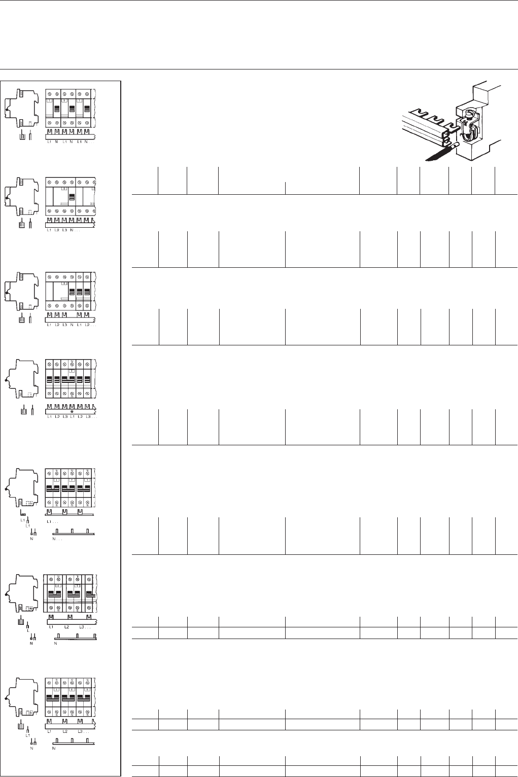
Shock-protected busbar blocks
for MCBs
with shock protection
and combined box terminals
(no terminals required)
(end caps see page 10)
SK 0097 Z98
SZ-KS 8/56 and
SZ-KS 48 NT
SZ-PSB 48 N and
SZ-KS 48 NT
SZ-PSB 51 N and
SZ-KS 52 NT
SZ-PSB 76 N and
SZ-KS 76 NT
SZ-KS 6/30 and
SZ-KS 6/30 NT
end caps:
PSB-END 3
end caps:
PSB-END 3
end caps:
PSB-END 3
conn. length No. order details bbn Cu price price w'ght pack.
capac. of 40 12233 No. 1 pc. group 1 pc. units
mm² mm poles type code order code EAN kg pc.
for MCBs: 1 pole with NT
supply: 1 phase + N
connection of main poles
24 1000 37 x 1 SZ-KS 8/56 GH V036 0875 R0008 55370 9 0.220 0.145 50
connection of neutral
16 1008 38 x 1 SZ-KS 48 NT GH V036 0874 R0046 55070 8 0.520 50
1 pole with NT
3 phases + N
connection of main poles
16 1044 39 x 1 SZ-PSB 48 N GH V036 0874 R0026 54890 3 0.760 10
connection of neutral
16 1008 38 x 1 SZ-KS 48 NT GH V036 0874 R0046 55070 8 0.520 50
3 pole with NT
3 phases + N
connection of main poles
16 188 3 x 3 SZ-PSB 51 N GH V036 0874 R0029 54920 7 0.152 30
16 980 16 x 3 SZ-PSB 52 N GH V036 0874 R0030 54930 6 0.760 10
connection of neutral
16 939 16 x 1 SZ-KS 52 NT GH V036 0874 R0050 55090 6 0.458 50
3 pole with NT u. auxiliary switch
3 phases + N
connection of main poles
16 1044 15 x 3 SZ-PSB 76 N GH V036 0874 R0054 55110 1 1.150 10
connection of neutral
16 994 15 x 1 SZ-KS 76 NT GH V036 0874 R0066 55180 4 0.523 50
1 pole with NT u. auxiliary switch
1 phase + N
connection of main poles
16 1038 30 x 1 SZ-KS 6/30 GH V036 0874 R0088 55310 5 0.320 10
connection of neutral
16 1030 30 x 1 SZ-KS 6/30 NT GH V036 0874 R0068 55200 9 0.522 50
SK 0012 Z97
SK 0008 Z97
SK 0011 Z97
SK 0010 Z97
SK 0009 Z97
13
System pro MBusbar systems
Shock-protected busbar blocks
for MCBs
with shock protection
and box terminals
(no terminals required)
(end caps see page 10)
SK 0075 Z91
SZ-PSB 25 N, SZ-PSB 26 N
1 pole + NA or
2 pole with 2 phases or 1 phase + N
SZ-PSB 82, SZ-PSB 84
1 pole + NA with 3 phases
SZ-PSB 32
3 pole + NA or
4 pole with 4 phases or
3 phases + N
SK 0091 Z97SK 0094 Z97SK 0092 Z97
conn. length No. order details bbn Cu price price w'ght pack.
capac. of 40 12233 No. 1 pc. group 1 pc. units
mm² mm poles type code order code EAN kg pc.
1 pole + NA or 2 pole
1 phase + N
10 213 6 x 2 SZ-PSB 25 N GH V036 0874 R0005 54760 9 0.070 0.12 30
10 1035 29 x 2 SZ-PSB 26 N GH V036 0874 R0006 54770 8 0.320 0.6 10
1 pole + NA
3 phases + N
10 1048 29 x 2 SZ-PSB 82 GH V036 0874 R0071 55220 7 0.803 0.628 10
16 1048 29 x 2 SZ-PSB 84 GH V036 0874 R0073 55240 5 1.205 0.865 10
3 pole + NA or 4 pole
3 phases + N
16 1065 15 x 4 SZ-PSB 32 GH V036 0874 R0012 54810 1 1.205 0.972 10
3 pole with auxiliary switch
3 phases
16 980 16 x 3 SZ-PSB 128 N GH V036 0503 R0031 25980 40.600 0.6 10
bbn-No. 40 16779
SZ-PSB 128 N
3 pole + auxiliary switch with 3
phases
SK 0207 Z99
end caps:
PSB-END 3
end caps:
PSB-END 4
end caps:
PSB-END 4
end caps:
PSB-END 3
14
System pro MBusbar systems
Busbar blocks
for MCBs
with screw terminals
(terminals see page 18)
(end caps see page 10)
SK 0098 Z98
SZ-PSB 20
1 pole + aux. switch with 3 phases
SZ-PSB 92 N
2 pole + aux. switch with 2 phases
SZ-PSB 18
3 pole + aux. switch with 3 phases
SZ-VB 45.32
1 pole with 1 phase
SZ-KS 1/12, SZ-KS 1/56.
SZ-KS 2/12, SZ-KS 2/56
1 pole with 1 phase
SK 0095 Z97SK 0099 Z96SK 0097 Z97SK 0113 Z96SK 0114 Z96
terminals:
3 x SZ-AS 4 I
end cap: PSB-END 3
terminals:
2 x SZ-AS 4 I
end cap: PSB-END 3
conn. length No. order details bbn Cu price price w'ght pack.
capac. of 40 12233 No. 1 pc. group 1 pc. units
mm² mm poles type code order code EAN kg pc.
for MCBs: 1 pole with auxiliary switch
supply: 3 phases
16 1044 13 x 3 SZ-PSB 20 GH V036 0874 R0020 54850 7 0.780 0.65 10
2 pole with auxiliary switch
2 phases
16 1065 24 x 2 SZ-PSB 92 GH V036 0874 R0086 55290 0 0.680 10
16 1044 24 x 2 SZ-PSB 92 N GH V036 0875 R0010 55380 8 0.680 0.65 10
L-type
T-type
3 pole with auxiliary switch
3 phases
16 990 16 x 3 SZ-PSB 18 GH V036 0874 R0018 54840 8 0.780 0.73 10
Comb busbar
for MCBs: 1 pole
supply: 1 phase
36 988 56 x 1 SZ-VB 45.32* GJ I2322 148 R0001 59720 8 0.330 0.28 50
* without insulation, for adequate cover see below, SZ-BSA
Universal comb busbars
for MCBs: 1 pole
supply: 1 phase
12 207 12 x 1 SZ-KS 1/12* GJ I2322 322 R0001 59790 1 0.023 0.015 100
12 988 56 x 1 SZ-KS 1/56* GJ I2322 322 R0002 59800 7 0.110 0.073 50
24 207 12 x 1 SZ-KS 2/12* GJ I2322 322 R0003 59810 6 0.046 0.031 100
24 988 56 x 1 SZ-KS 2/56* GJ I2322 322 R0004 59820 5 0.220 0.145 50
* without insulation, for adequate cover see below, SZ-BSA
Insulation cover
for universal comb busbar
212 mm long SZ-BSA GH V036 0505 R0003 51471 2 – 0.007 50
terminals:
3 x SZ-AS 4 I
end cap: PSB-END 3
terminals:
1 x SZ-AS 2 I
terminals:
1 x SZ-AS 2 I
15
System pro MBusbar systems
Busbar blocks
for MCBs with box terminals
(terminals see page 18)
(end caps see page 10)
SK 0096 Z91
SZ-PSB 25 N, SZ-PSB 26 N
1 pole + NA or
2 pole with 2 phases or
1 phases + N
SZ-PSB 32
3 pole + NA or
4 pole with 4 phases or
3 phases + N
SK 0254 B91
SZ-KS 1/12.
SZ-KS 2/12
SK 0088 Z97SK 0090 Z97
SZ-KS 7/12
SK 0098 B91
SK 0118 Z96
N terminal outside of
busbar terminal lug
conn. length No. order details bbn Cu price price w'ght pack.
capac. of 40 12233 No. 1 pc. group 1 pc. units
mm² mm poles type code order code EAN kg pc.
for MCBs S 610
36 37 x 1 SZ-KS 14/36 N GH V036 0875 R0006 52311 00.920 0.455 30
36 12 x 3 SZ-PSB 140 N* GH V036 0503 R0001 52310 33.715 1.163 10
** end cap PSB-END 7, see page 10
for MCBs: 1 pole + NA or 2 pole
supply: 1 phase + N
10 213 6 x 2 SZ-PSB 25 N GH V036 0874 R0005 54760 9 0.070 0.12 30
10 1035 29 x 2 SZ-PSB 26 N GH V036 0874 R0006 54770 8 0.320 0.6 10
3 pole + NA or 4 pole
3 phases N
16 1065 15 x 4 SZ-PSB 32 GH V036 0874 R0012 54810 1 1.205 0.972 10
Comb busbars for built-in devices – switches, pushbuttons, indicator lights,
single-phase, for cross wiring;
with shock protection
6 206 12 x 1 SZ-KS 7/12 N GH V036 0875 R0020 54351 40.038 0.025 100
6 990 56 x 1 SZ-KS 7/56 N GH V036 0875 R0021 54352 10.187 0.110 50
bbn-No. 40 16779
Busbar for residual-current-operated devices (RCD)
Universal-comb busbars for cross wiring STOTZ-RCD F 271/P 271*
to STOTZ MCB S 2
Supply single-phase
Devices are still perfectly safe from touch by the back of the hand or the finger according to DIN EN 50274 (DIN VDE 0660
Part 514) if comb busbars are installed.
12 210 12 x 1 SZ-KS 1/12 GJ I232 2322 R0001 59790 1 0.023 0.015 100
12 210 12 x 1 SZ-KS 2/12 GJ I232 2322 R0003 59810 6 0.110 0.031 100
* Note: N terminal of F 271 (P 271) is outside the busbar terminal lug.
terminals:
3 x SZ-Ast 25 (I)
/
end caps: terminals:
PSB-END 3 2 x SZ-Ast 25 (I)
/
end caps: terminals:
PSB-END 3 4 x SZ-Ast 25
16
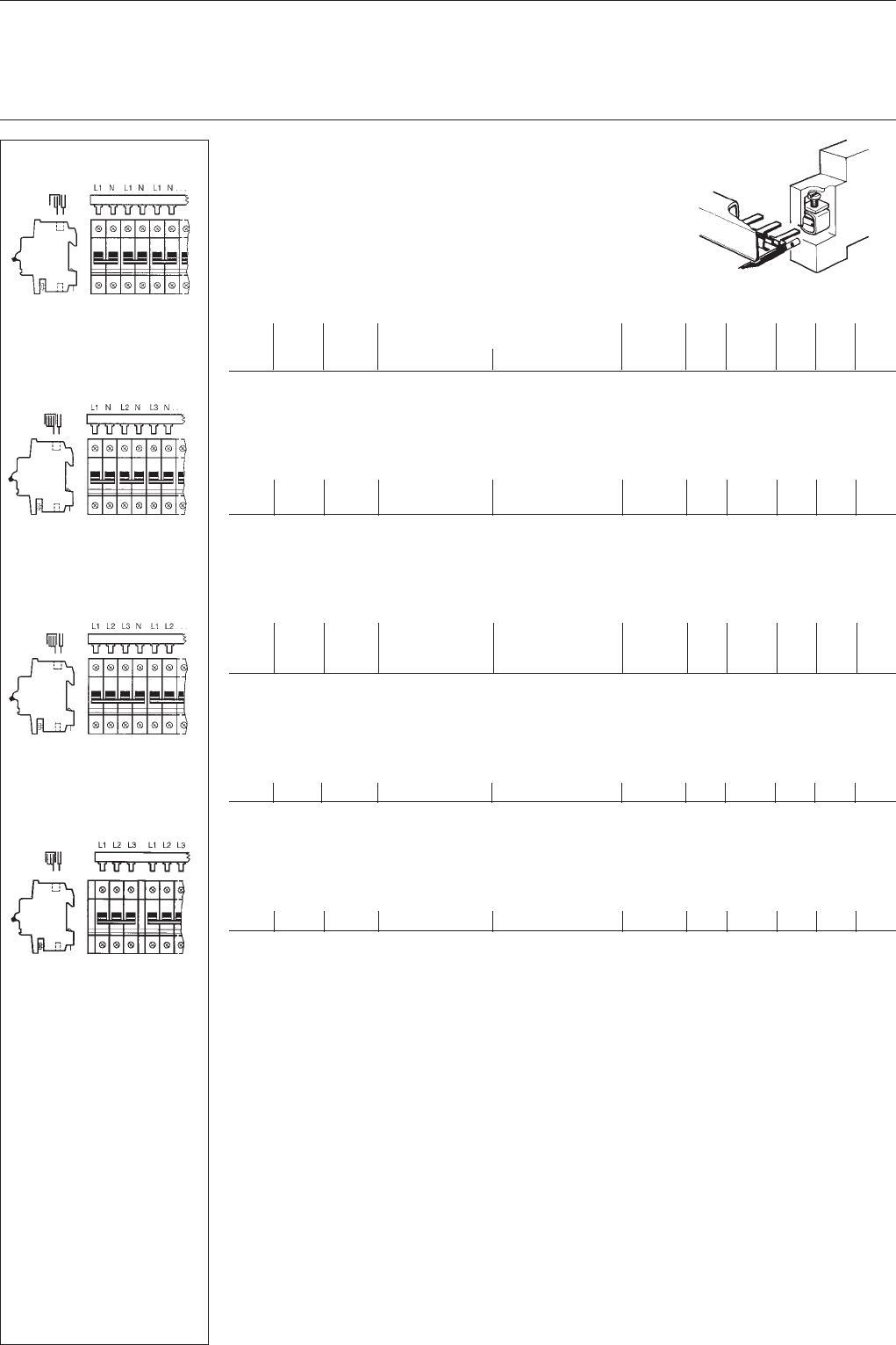
System pro MBusbar systems
Shock-protected busbar blocks
with shock protection
and combined box terminals
(no terminals required)
(end caps see page 10)
SK 0074 Z91
conn. length No. order details bbn Cu price price w'ght pack.
capac. of 40 12233 No. 1 pc. group 1 pc. units
mm² mm poles type code order code EAN kg pc.
for RCD: type F 372, F 672, 2 pole
supply: 1 phase + N
10 212 6 x 2 SZ-PSB 53 N GH V036 0874 R0031 54940 5 0.070 0.078 30
10 1035 29 x 2 SZ-PSB 54 N GH V036 0874 R0032 54950 4 0.320 0.403 10
16 212 6 x 2 SZ-PSB 55 N GH V036 0874 R0033 54960 3 0.115 0.106 30
16 1035 29 x 2 SZ-PSB 56 N GH V036 0874 R0034 54970 2 0.545 0.534 10
for RCD: type F 374,F 674 (80 and 100 A), 4 pole
supply: 3 phase + N
10 212 3 x 4 SZ-PSB 61 N GH V036 0874 R0039 55020 3 0.120 0.112 30
10 1056 15 x 4 SZ-PSB 62 N GH V036 0874 R0040 55030 2 0.803 0.650 10
16 212 3 x 4 SZ-PSB 63 N GH V036 0874 R0041 55040 1 0.241 0.156 30
16 1056 15 x 4 SZ-PSB 64 N GH V036 0874 R0042 55050 0 1.205 0.884 10
for combination of
RCD: type F 374, F 674 (80 and 100 A), 4 pole +
MCBs S 260/70/80
supply: 3 phases + N
10 212 3x3+2x1 SZ-PSB 97 N GH V036 0875 R0025 55490 4 0.100 0.099 30
10 212 3x3+2x1 SZ-PSB 97 N H GH V036 0875 R0027 57110 4 0.100 0.099 30
10 1020 19 x 3 SZ-PSB 98 N GH V036 0875 R0026 55500 0 0.550 0.480 10
10 1020 13 x 3 SZ-PSB 98 N H GH V036 0875 R0028 57111 1 0.550 0.480 10
N cutout for RCD
for combination of
people protector: type P 271, F 271 and
MCB S 260/70/80
supply: 3 phases + N
10 213 4 x 3 SZ-PSB 3 N GH L520 1915 R0005 29400 30.085 0.082 30
10 1058 20 x 3 SZ-PSB 4 N GH L520 1915 R0006 29410 20.505 0.468 10
16 213 4 x 3 SZ-PSB 11 N GH L520 1916 R0005 29420 10.160 0.126 30
16 1058 20 x 3 SZ-PSB 12 N GH L520 1916 R0006 29430 00.720 0.700 10
bbn-No. 40 16779
for combination of
people protector: type P 271 and multiSTOTZ type F 271 with aux. switch
supply: 3 phases + N
10 1032 8 x 3 SZ-PSB 133 N GH V036 0503 R0043 49946 00.800 0.394 10
10 1028 24 x 1 SZ-KS 12/24 NB* GH V036 0875 R0043 49947 70.250 0.140 10
bbn-No. 40 16779 * insulation blue
for combination of
people protector type P 271 and multiSTOTZ type F 271
supply: 1 phase + N
10 1038 30 x 1 SZ-KS 9/30 N GH V036 0875 R0018 55460 7 0.200 0.159 10
16 1029 30 x 1 SZ-KS 11/30 N GH V036 0875 R0022 55480 5 0.280 0.182 10
Supply: 3 phases + N
10 1036 30 x 1 SZ-PSB 96 NGH V036 0875 R0016 55440 9 0.500 0.388 10
16 1029 30 x 1 SZ-KS 11/30 N GH V036 0875 R0022 55480 5 0.280 0.182 10
end caps:
PSB-END 3
end caps:
PSB-END 4
end caps:
PSB-END 3
end caps:
PSB-END 3
end caps:
PSB-END 6
end caps:
PSB-END 3
SK 0119 Z96
SZ-PSB 53 N, SZ-PSB 54 N.
SZ-PSB 55 N, SZ-PSB 56 N
2 pole with 2 phases or 1 phase + N
SZ-PSB 61 N, SZ-PSB 62 N.
SZ-PSB 63 N, SZ-PSB 64 N
4 pole with 4 phases or
3 phases + N
SK 0120 Z96
SZ-PSB 97 N, SZ-PSB 98 N
4 pole with 4 phases or
3 phases + N
SK 0121 Z96
SZ-PSB 3 N, SZ-PSB 4 N.
SZ-PSB 11 N, SZ-PSB 12 N
1 pole with NA + LS with 3 phases
*N terminal of F 271/P 271
outside of busbar
terminal lug
SK 0122 Z96
SZ-KS 9/30 N
SZ-KS 11/30 N
1 pole + N for 1 phase
SK 0123 Z96
SZ-PSB 96 N
SZ-KS 11/30 N
1 pole + N for 1 phase + N
SK 0124 Z96
SZ-PSB 133 N
SZ-KS 12/24 N
1 pole + N for 1 phase
SK 0226 Z99
17
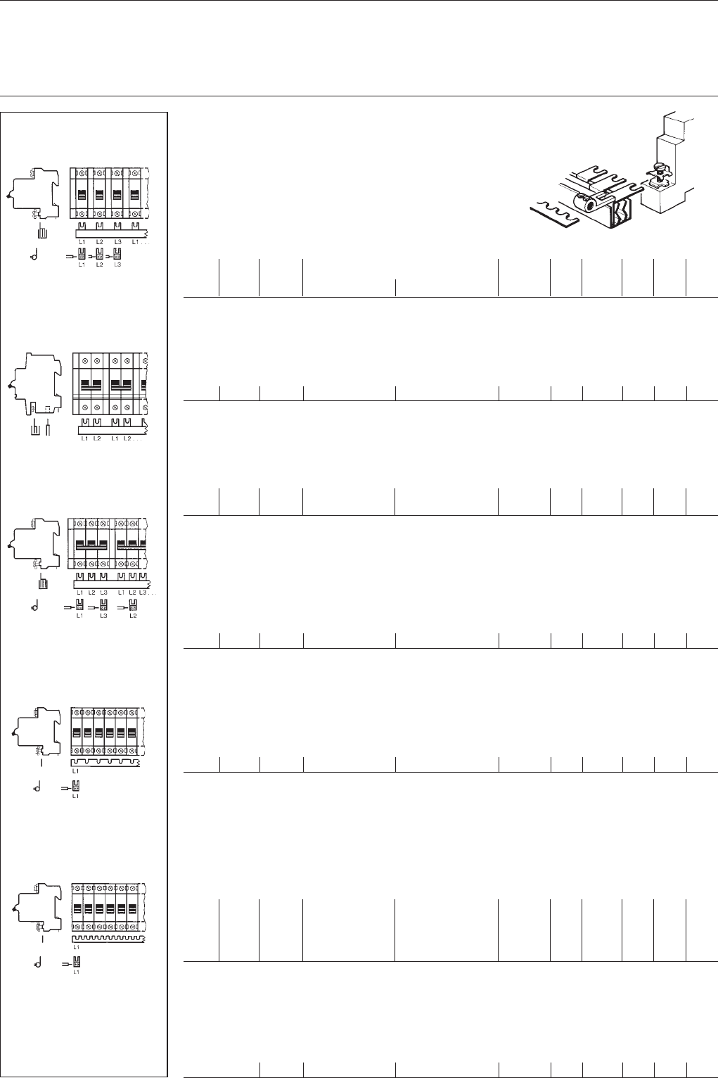
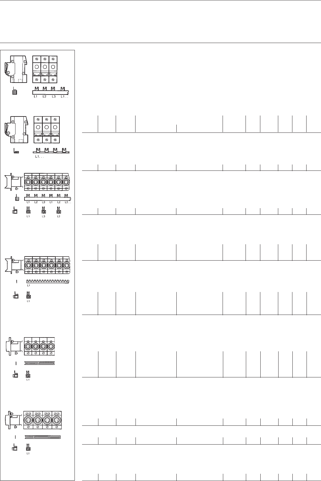
System pro MBusbar systems
Busbar blocks, comb and oblong-hole busbars
for fuse-elements
(terminals see page 18)
conn. length No. order details bbn Cu price price w'ght pack.
capac. of 40 12233 No. 1 pc. group 1 pc. units
mm² mm poles type code order code EAN kg pc.
Busbar blocks
for switch-disconnector ILTS or LINOCUR: 1- or 3 pole
supply: 3 phases
16 1045 13 x 3 SZ-PSB 8 ILTS GH V036 0503 R0049 51672 30.780 15 0.650 30
bbn-No. 40 16779
Busbar blocks
for switch-disconnector ILTS or LINOCUR: 2 pole
supply: 2 phases
16 1016 19 x 2 SZ-PSB 106 ILTS GH V036 0503 R0006 57971 1 0.525 0.470 10
Comb busbar
for switch-disconnector ILTS or LINOCUR:
supply: 1 phase
16 4 x 1 SZ-KS 4/4 ILTS GH V036 0874 R0067 55091 8 0.025 0.035 50
16 10 x 1 SZ-KS 4/10 ILTS GH V036 0874 R0065 54935 6 0.063 0.086 50
16 37 x 1 SZ-KS 4/37 ILTS GH V036 0874 R0064 54934 9 0.230 0.320 10
Busbar blocks
for fuse elements DO: 1- or 3 pole
supply: 3 phases
10 231 3 x 3 SZ-PSB 1 N GH V036 0503 R0021 10430 20.120 0.105 30
10 1045 13 x 3 SZ-PSB 2 N GH V036 0503 R0022 10440 10.505 0.470 10
16 231 3 x 3 SZ-PSB 7 N GH V036 0503 R0023 10450 00.180 0.140 30
16 1045 13 x 3 SZ-PSB 8 N GH V036 0503 R0024 10460 90.760 0.635 10
bbn-No. 40 16779
Universal-comb busbars
for fuse elements DO: 1 pole
supply: 1 phase
12 207 8 x 1 SZ-KS 1/12* GJ I232 2322 R0001 59790 1 0.023 0.015 100
12 988 37 x 1 SZ-KS 1/56* GJ I232 2322 R0002 59800 7 0.110 0.073 50
24 207 8 x 1 SZ-KS 2/12* GJ I232 2322 R0003 59810 6 0.046 0.031 100
24 988 37 x 1 SZ-KS 2/56* GJ I232 2322 R0004 59820 5 0.220 0.138 50
* without insulation, for adequate cover see page 14, SZ-BSA
Oblong-hole busbars
for fuse-elements D: 1 pole
supply: 1 phase
for fuse base D. 25 A
10 1023 25 x 1 SZ-VB 45.26-2* GJ I232 2065 R0002 59700 0 0.150 0.095 50
for fuse base D. 63 A
20 976 19 x 1 SZ-VB 45.25-2* GJ I232 2064 R0002 59680 5 0.300 0.171 50
* without insulation. For adaquate cover, see page 14, SZ-BSA
Terminal clamps
prevent cut ends to open in the case of oblong-hole busbars.
SZ-BG 1 GH L430 1911 R0001 05620 0 0.002 100
end caps:
PSB-END 3
terminals:
3 x SZ-AS 2 I
terminals:
1 x SZ-AS 2 I
end caps:
PSB-END 3
terminals:
3 x SZ-AS 7 I
SZ-PSB 1 N, SZ-PSB 2 N,
SZ-PSB 7 N, SZ-PSB 8 N
fuse DO
1- or 3-pole with 3 phases
2CDC 062 190
F0003
SZ-PSB 8 ILTS
SK 0071 Z01
SZ-KS 4 l … ILTS
SK 0196 Z02
SZ-VB 45.25-2
fuse D, 63 A
1 pole with 1 phase
2CDC 062 187 F0003
SZ-VB 45.26-2
fuse D, 25 A
1 pole with 1 phase
2CDC 062 188 F0003
SZ-KS 1/12, SZ-KS 1/56,
SZ-KS 2/12, SZ-KS 2/56
fuse DO
1 pole with 1 phase
2CDC 062 189
F0003
end caps:
PSB-END 3
18
System pro M
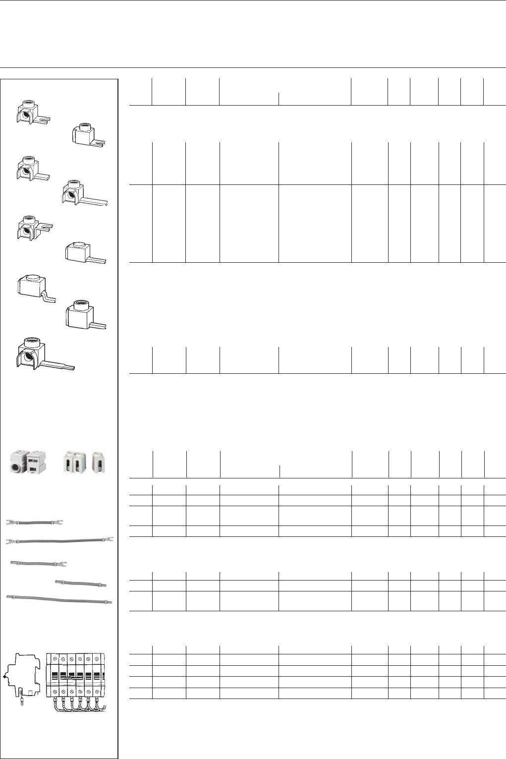
Terminals for busbars
Flexible connection wires
conn.
type of terminal
order details bbn Cu price price w'ght pack.
capac. connect. lug 40 12233 No. 1 pc. group 1 pc. units
mm² L/mm type code order code EAN kg pc.
Terminals, insulated
6-35 fork 10 SZ-AS 2 I GH V036 0501 R0011 39330 00.023 30
6-25 fork 15 SZ-AS 4 I GH V036 0501 R0005 12410 20.011 50
6-25 fork 15 SZ-AS 5 I GH V036 0501 R0014 57012 10.012 50
6-50 fork 15 SZ-AS 8 I GH V036 0501 R0008 25950 70.014 50
6-50 fork 15 SZ-AS 10 I GH V036 0501 R0017 58295 70.014 50
6-25 pin 15 SZ-Ast 25 I GH V036 0501 R0007 12430 00.011 50
6-25 pin 30* SZ-Ast 6 I GH V036 0501 R0004 12400 30.014 50
6-50 pin 15 SZ-Ast 50 I GH V036 0501 R0009 25960 60.014 50
6-50 pin 15 SZ-Ast 55 I GH V036 0501 R0015 57131 90.014 50
6-50 pin 32 SZ-Ast 12 I GH V036 0501 R0010 25970 50.024 50
6-50 pin 42 SZ-Ast 24 I GH V036 0501 R0016 57191 30.025 50
6-25 pin 30 SZ-Ast 9 I GH V036 0501 R0003 15900 50.014 50
25-95 pin 18* SZ-Ast 95 GH V036 0501 R0013 52262 50.067 3
25-95 pin 12* SZ-Ast 95 gk GH V036 0501 R0012 52261 80.067 3
bbn-No. 40 16779 * not available for pro M compact
Feeder terminals
safe from touch of the back of the hand/finger according to DIN EN 50274 (DIN VDE 0660 Part 514).
Single-pole terminals can be mounted side by side to multipole terminals.
6-35 SZ-ESK GH V036 0501 R0021 50661 80.030 10
6-35 SZ-ESK 2 GH V036 0501 R0001 96920 30.024 10
6-25 SZ-ESK 1 GH V036 0501 R0020 51841 30.031 10
bbn-No. 40 16779
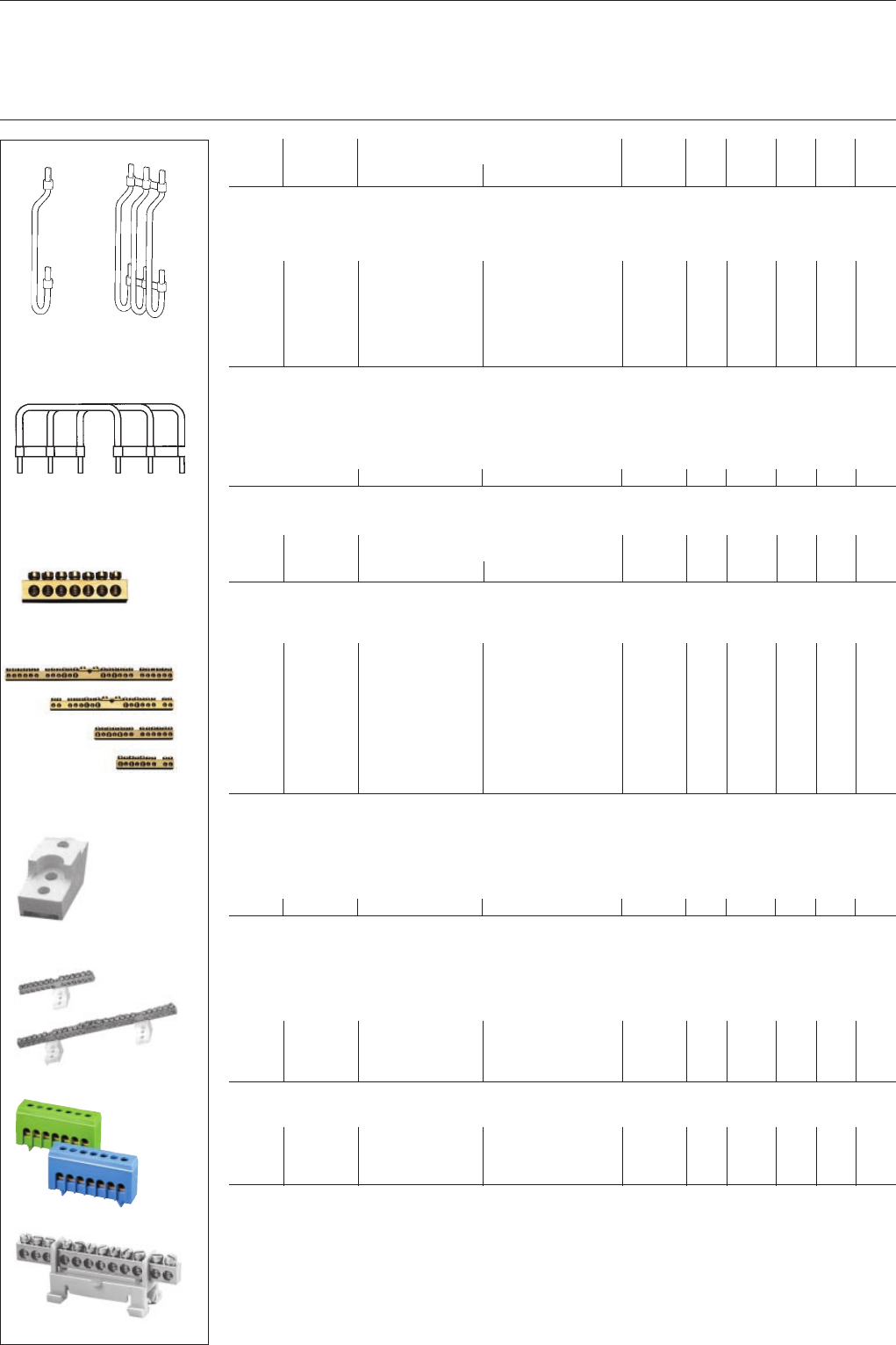
Flexible connecting wires
with fork-type cable lug (black)
conn. length order details bbn Cu price price w'ght pack.
capac. 40 12233 No. 1 pc. group 1 pc. units
mm² type code order code EAN kg pc.
6 125 SZ-DB 121 GH V036 1425 R0001 55650 2 0.006 0.025
1000/50
10 135 SZ-DB 122 N GH V036 1425 R0031 55670 0 0.010 0.02
500/25
6 260 SZ-DB 231 N GH V036 1425 R0032 55680 9 0.014 0.02
500/25
10 SZ-DB 232 N GH V036 1425 R0033 55690 8 0.022 0.04
250/25
10 330 SZ-DB 311 GH V036 1425 R0034 55700 4 0.029 0.05
100/25
with fork-type cable lug and connector sleeve (black)
6 125 SZ-DB 123 GH V036 1425 R0006 55660 1 0.007 0.01
1000/50
10 135 SZ-DB 124 N GH V036 1425 R0035 55710 3 0.012 0.02
500/25
6 260 SZ-DB 235 GH V036 1425 R0036 55720 2 0.014 0.02
500/25
10 SZ-DB 236 GH V036 1425 R0037 55730 1 0.024 0.04
250/25
with connector sleeves (black)
6 125 SZ-DB 125 N GH V036 1425 R0038 55740 0 0.007 0.01
1000/50
6 260 SZ-DB 233 N GH V036 1425 R0039 55750 9 0.015 0.02
500/25
10 135 SZ-DB 126 N GH V036 1425 R0040 55760 8 0.013 0.02
500/25
10 260 SZ-DB 234 N GH V036 1425 R0041 55770 7 0.025 0.04
250/25
10 330 SZ-DB 312 GH V036 1425 R0042 55780 6 0.032 0.05
100/25
SZ-AS 4 I
SZ-AS 8 I
SK 0066 Z94
SZ-Ast 25 I
SZ-Ast 50 I
SK 0068 Z94
SZ-Ast 6 I
SZ-Ast 9 I
SK 0069 Z94
SZ-AS 5 I
SZ-AS 10 l
SK 0247 Z02
SZ-DB 121
SZ-DB 232 N
SZ-DB 125 N
SZ-DB 233 N SK 0078 B91
SZ-DB 123
example 1
wiring of devices consisting of
modules with different lengths with
SZ-DB 121 or 122
SK 0086 Z97
SK 0096 Z98
SZ-AS 2 I
SZ-ESK
SK 0068 B00
SZ-Ast 95
SK 0119 Z01
SZ-ESK 1
SZ-ESK 2
SK 0133 B99
SK 0118 Z01
SK 0188 Z02
SK 0187 Z02
SZ-Ast 95 gk
SZ-Ast 24 I
SZ-Ast 12 l
SZ-Ast 55 I
19
System pro M
Wiring kit
Neutral (N) and protective conductor (PE)
common terminals
conn. No. of poles order details bbn Cu price price w'ght pack.
capac. 40 16779 1 pc. group 1 pc. units
type code order code EAN kg pc.
Wiring kit
for wiring of component rails in the consumer unit, rail-to-rail clr. 125 mm.
10 mm² 1 pole SZ-VS 1 GH V036 0504 R0001 28790 6 0.022 0.03 30
10 mm² 1 pole SZ-VS 1B* GH V036 0504 R0011 49670 4 0.022 0.03 30
10 mm² 2 pole SZ-VS 2 GH V036 0504 R0002 28800 2 0.044 0.06 30
10 mm² 3 pole SZ-VS 3 GH V036 0504 R0003 28810 1 0.066 0.10 30
10 mm² 4 pole SZ-VS 4 GH V036 0504 R0004 28820 0 0.088 0.13 30
* insulation blue
connection set
for 3-pole MCBs of the S 2 series and motor circuit-breakers MS 225/325.
Use filling piece SZ-FST 2 if no accessories are fitted.
connection set SZ-SM 3 GH V036 0504 R0005 41580 4 0.02 15 0.047 50
input output order details bbn price price w'ght pack.
40 12233 1 pc. group 1 pc. units
mm² mm² type code order code EAN kg pc.
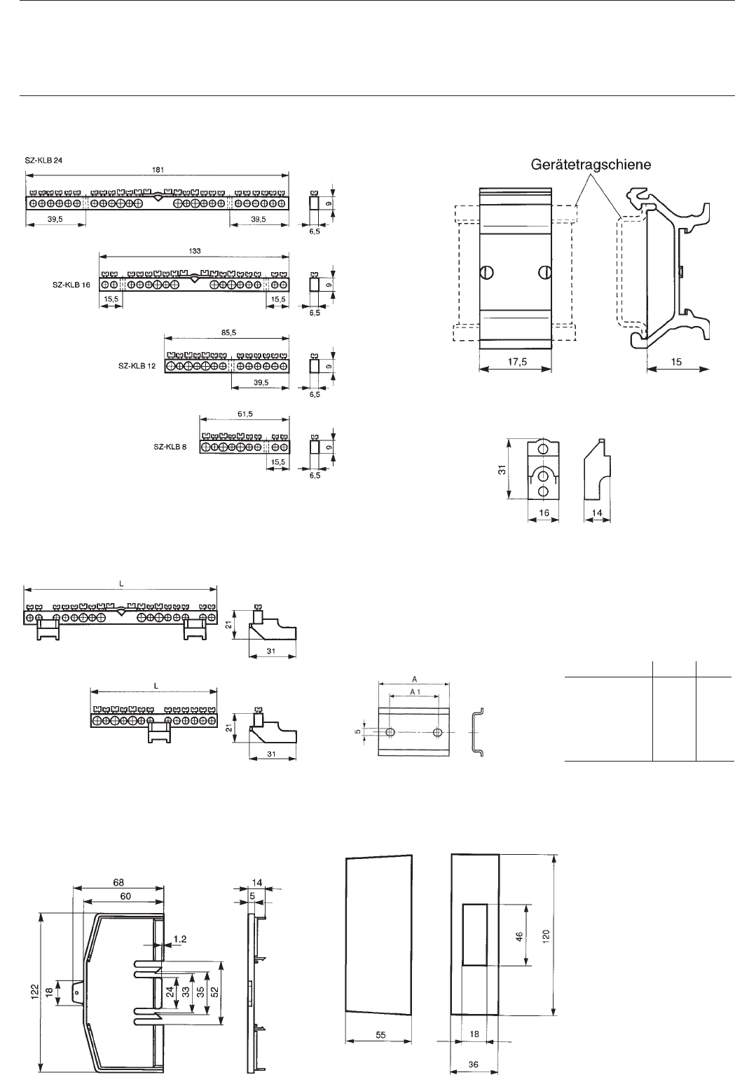
Neutral or protective-conductor terminals without insulation holder
1 x 16 6 x to 16 SZ-6/3 GH V036 0876 R0003 50592 50.022 10
1 x 16 2 x to 16 SZ-KLB 8 GJ I232 0131 R0001 59660 7 0.025 30
6 x to 10
1 x 16 2 x to 16 SZ-KLB 12 GJ I232 0071 R0013 59530 3 0.035 30
10 x to 10
1 x 35 4 x to 16 SZ-KLB 16 GJ I232 0072 R0017 59540 2 0.077 30
12 x to 10
1 x 35 4 x to 16 SZ-KLB 24 GJ I232 0073 R0016 59550 1 0.100 30
20 x to 10
Holders for SZ-KLB terminals
screw-fixing
SZ-KLB 8 and 12 each 1 piece required
SZ-KLB 16 and 24 each 2 pieces required
SZ-Ktr GJ I202 4027 R0001 59450 4 0.003 100
Neutral and protective-conductor terminals with insulation holder for
quick fastening onto DIN rails EN 50 022
neutral with insulation holder blue; type C finger safe, conductor opening closed on one side
1 x 16 6 x 16 SZ-N 6/3 GH V036 0876 R0001 55570 3 0.027 20
1 x 16 11 x 16 SZ-N 11/3 GH V036 0876 R0002 55580 2 0.043 20
1 x 16 6 x 16 SZ-N 6/3 C GH V036 0876 R0011 57095 40.028 20
1 x 16 6 x 16 SZ-N 11/3 C GH V036 0876 R0012 57096 10.046 20
protective conductor with insulation holder green/yellow; type C finger safe, conductor opening closed on one side
1 x 16 6 x 16 SZ-PE 6/3 GH V036 0876 R0004 55600 7 0.027 20
1 x 16 11 x 16 SZ-PE 11/3 GH V036 0876 R0005 55610 6 0.043 20
1 x 16 6 x 16 SZ-PE 6/3 C GH V036 0876 R0014 57097 80.028 20
1 x 16 11 x 16 SZ-PE 11/3 C GH V036 0876 R0015 57098 50.046 20
bbn-No. 40 16779
SZ-VS 1 SZ-VS 3
SZ-N6/3
SK 0151 Z96
SK 0152 Z96
SK 0101 B00
SZ-KLB 8, 12, 16, 24
SZ-Ktr
SK 0082 B91
SZ-Ktr with KLB
SK 0059 B91
SK 0087 B02
SZ-N11/3
SK 0084 B91
SZ-SM 3
SK 0255 Z98
SK 0102 B00
SZ-6/3
20
System pro M
Device mounting rails
and fixing accessories
length order details bbn price price w'ght pack.
40 12233 1 pc. gruppe 1 pc. units
mm type code order code EAN kg pc.
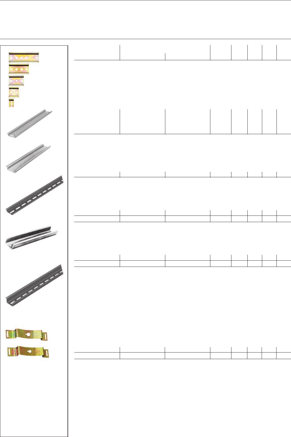
DIN rails
DIN rails (DIN EN 60 715 – 35 x 7.5)
for individual installation with 2 screws on an even surface (1 module = 17.5 mm)
for 1 module DSW 1 GH S210 1926 R0001 13580 6 0.060 10
for 2 modules DSW 2 GH S210 1926 R0002 13590 5 0.012 10
for 3 modules DSW 3 GH S210 1926 R0003 13600 1 0.018 10
for 4 modules DSW 4 GH S210 1926 R0004 13610 0 0.024 10
for 6 modules DSW 6 GH S210 1926 R0006 13620 9 0.036 10
DIN rail DIN EN 60 715, 35 x 7.5, material thickness 1 mm,
surface protected, galvanised.
241 SKV-GTS 1 GH L110 1915 R0001 04090 2 0.09 40
DIN rails DIN EN 60 715, 35 x 7.5, material thickness 1 mm, surface galvanised.
1000 SZ-SI 45.460 GJ I232 2218 R0001 59730 7 0.35 10
2000 SZ-TS 7.5 L2 GJ I232 2218 R0007 59760 4 0.70 20
DIN rails DIN EN 60 715, 35 x 15, material thickness 1.5 mm, surface galvanised
2000 SZ-SI 45.472 GJ I232 2218 R0010 59780 2 1.30 10
2000 SZ-TS 15 L2 GJ I232 2218 R0009 59770 3 0.78 10
DSW 6
DSW 4
DSW 3
DSW 2
DSW 1
SK 0100 B00
SZ-SI 45.460
SK 0088 B91
SZ-TS 7.5 L2
SK 0089 B91
SZ-SI 45.472
SK 0090 B91
SZ-TS 15 L2
SK 0091 B91 SK 0087 B91
SKV-GTS 1
SZ-FB 45.53-1
SZ-FB 45.53-3
SK 0092 B00
Catch spring for mounitng devices onto DIN rails (DIN EN 60 715, 35 x 7.5)
for screw type M4 SZ-FB 45.53-3 GJ I184 2013 P0003 64560 2 0.03 50
for screw type M5 SZ-FB 45.53-1 GJ I184 2013 P0004 64580 0 0.03 50
21
System pro M
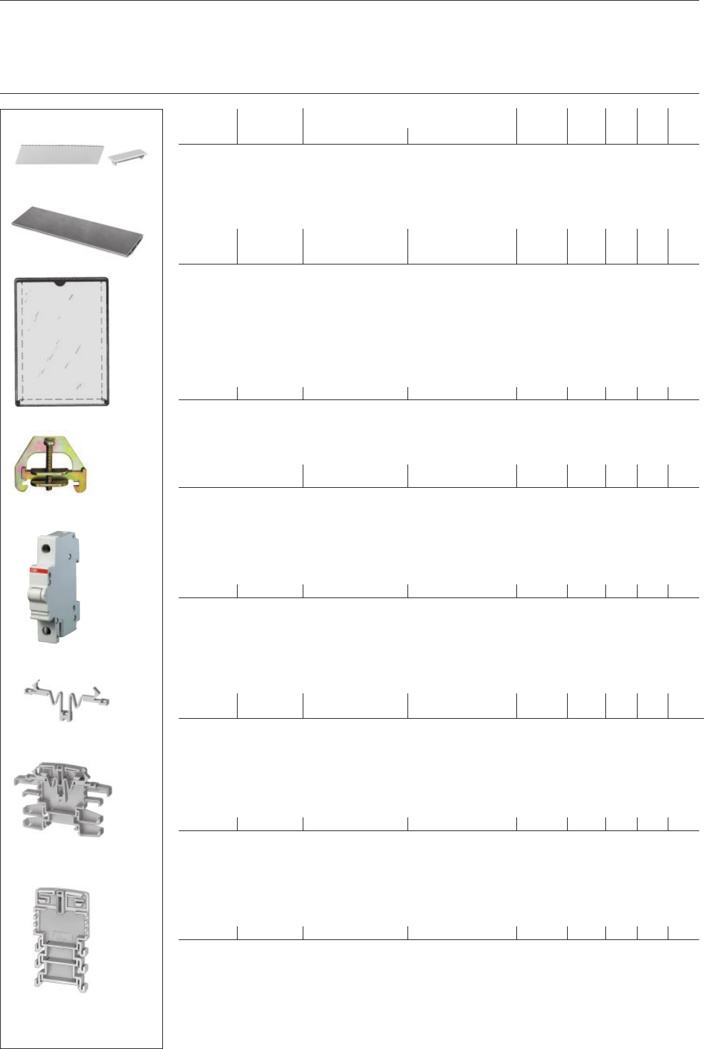
Blanking and sealing plates
Filling pieces
height of order details bbn price price w'ght pack.
cutout/color width 40 12233 1 pc. group 1 pc. units
mm mm type code order code EAN kg pc.
Blanking plates
for device covers with materials of a thickness of 1 to 3 mm, width: 1 module = 17.5 mm; color: grey RAL 7035,
white RAL 9001
46/grey 213 SZ-BP 1 GH L530 1904 R0001 06050 4 0.028 100
46/white 17.5 SZ-BP GH S270 1913 R0001 12857 40.005
46/grey 17.5 SZ-BP 2 GH S270 1913 R0002 12861 10.005
bbn-No. 80 00126
Spring piece
holder for device covers, various heights available (in connection with filling piece FST 2)
SZ-FDT 2 GH L530 1908 R0005 06080 1 0.002 25
Sealing plate
seal-proof locking of stamped-out device covers.
Detachable only from the inside of the device cover.
Can be used for device covers with 1.5 to 3 mm material thickness.
46/grey 1500 SZ-VP 1500 GJ I995 9038 R0001 60290 2 0.366 10
Circuit diagram holder DIN A4*
self-adhesive SZ-TA 1 GJ I480 0002 R0001 60270 4 0.2 20
with transparent cover
* to be discontinued
End bracket
prevents lateral shifting of built-in devices mounted on DIN rails according to DIN EN 60 715, 35 x 7.5 mm.
END GJ I100 1814 R0001 59090 2 0.02 50
Filling piece
for e.g. heat dissipation of closely mounted devices that generate much heat.
Width 8.75 mm, as spacer, two different heights, breakbale, for DIN rails according to DIN EN 60 715, 35 x 7.5 mm.
8.75 SZ-FST 2 GH L530 1908 R0002 06070 2 0.01 25
17.5 SZ-FST 3 GH L530 1908 R0003 51887 10.054 10
bbn-No. 40 16779
Filling piece
two different heights, breakable, for DIN rails according to DIN EN 60 715, 35 x 7.5 mm
for MCBs S 220 (3 different heights)
8.75 SZ-FST GH I148 0003 R0001 59410 8 0.01 25
SZ-BP 1
SK 0045 B91
SZ-BP
SZ-BP 2
SZ-VP 1500
SK 0100 B91
SZ-TA 1
SK 0101 B91
SZ-FDT 2
SK 0103 B91
SZ-FST
SK 0184 B91
SZ-FST 2 + SZ-FDT 2
SK 0105 B91
END
SK 0090 B00
SZ-FST 3
SK 0012 B01
22
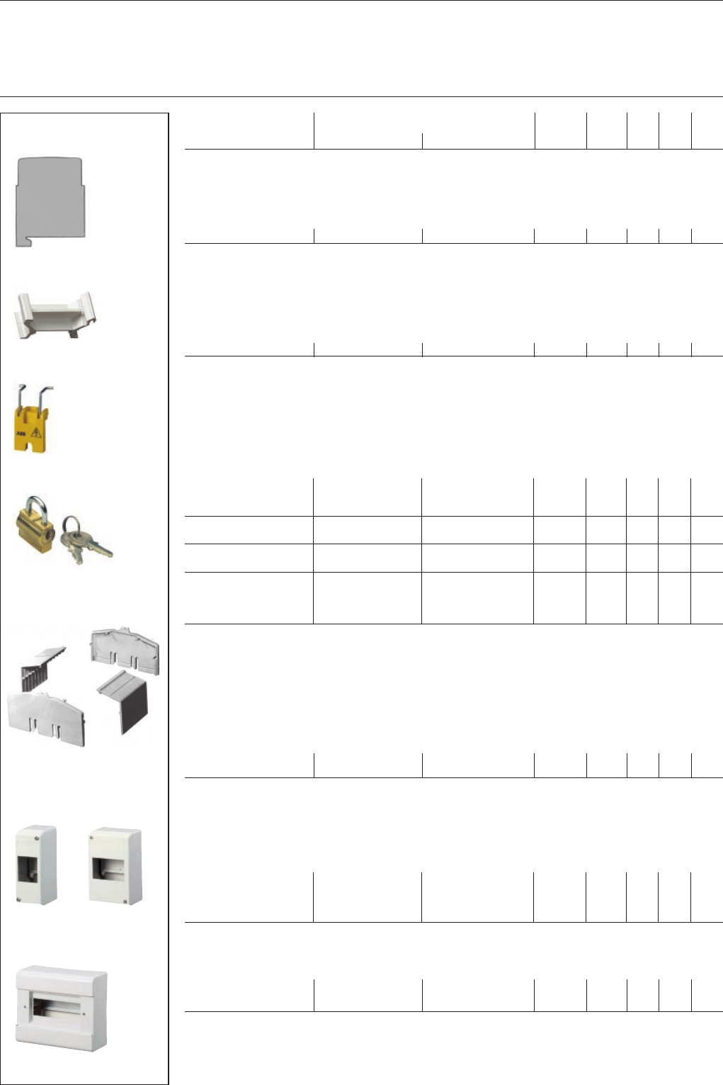
System pro M
Locking device
Terminal covers
description order details bbn price price w'ght pack.
40 12233 1 pc. group 1 pc. units
type code order code EAN kg pc.
Filler plate *
material thickness 1 mm, color grey RAL 7035, compensates for mounting tolerances of MCBs
SZ-FW GH L530 1901 R0001 06030 6 0.001 25
* to be discontinued
Elevation piece
compensates for different size of built-in devices with a mounting height of 68 mm and power MCBs of series S 210 (83 mm)
SZ-ES 68/83 GH V021 1425 R0001 53390 9 0.003 100
Locking device for MCBs and switches
prevents unauthorised or dangerous operation of the operating lever. An adaptor makes it possible to block the operating
lever whether switched ON or OFF. The lever is blocked with a padlock having a cross bar section of 3 or, as the case may
be, 6 mm max.. For multipole devices, one lock may be fitted per pole.
The lock adaptor can be used for all MCBs of the S 220, S 280 series as well as for switches E 220 and 270.
Locking devices 3 mm SA 1 GJ F110 1903 R0001 58760 5 0.004 10
for padlock bar 6 mm SA 1E GJ F110 1903 R0004 58790 2 0.004 10
for S 290 SA 1/S 290 GJ F110 1903 R0007 58261 20.004 10
padlock
with 2 keys SA 2 GJ F110 1903 R0002 58770 4 0.02 10
padlock, identical
locking with 2 keys SA 2 i GJ F110 9999 R0001 96940 1 0.02 10
lock adaptor incl.
padlock
with 3 keys
in transparent box SA 3 GJ F110 1903 R0003 58780 3 0.05 10
bbn-No. 40 16779
Terminal cover KA 27
provides overall touch protection of live parts. Suitable for installations acc. to DIN EN 50274 (DIN VDE 0660 Part 514)
and BGV A2.
End parts can be snapped onto mounting rails EN 60 715, 35 mm. Covers are 486 mm = 27 modules
(18 mm each) long. Knockouts for each half module for individualised use.
cover, 1 piece KA 27 H GH S210 1933 R0001 13630 8 0.104 10
end part, 1 piece KA 27 S GH S210 1934 R0001 13640 7 0.027 10
Terminal covers with base plate, protection IP 40
material: high-impact and flame-retardant (UL 94 V-0), color: white (RAL 9001), glow-wire test 960 °C according to IEC 695-2-1
The base plate has an integrated top-hat rail for snap-on fixing of MCBs, RCDs, modular built-in devices, etc.
for 2 modules PCD 2 N GH S270 1921 R0002 12402 60.09 1
for 4 modules PCD 4 N GH S270 1921 R0004 12404 00.15 1
for 6 modules PCD 6 N GH S270 1921 R0006 12406 40.2 1
for 8 modules PCD 8 N GH S270 1921 R0008 12408 80.7 1
Common terminals for terminal covers PCD*
for PCD 4 N and 6 N KL-PCD 4/6 GH S270 1912 R0004 12502 30.017
for PCD 8 N KL-PCD 8 GH S270 1912 R0008 12592 70.079
bbn-No. 80 00126 * to be discontinued
SZ-FW
SK 0106 B91
SZ-ES 68/83
SK 0091 B00
SA 1
SK 0108 B91
SA 2
SK 0109 B91
KA 27 H + KA 27 S SK 0112 B91
PCD 2 N PCD 4 N
SK 0076 B96
SK 0077 B96
PCD 8 N
SK 0079 B96
쐰
23
System pro M
Terminal covers
Flange frames
Insulated housings
E 430-AP
SK 0093 B00
S 500-ME 2
SK 0127 B92
QES 4/3 N
SMO ...
SK 0089 Z98
description order details bbn price price w'ght pack.
40 12233 1 pc. group 1 pc. units
type code order code EAN kg pc.
Terminal cover with top hat rail, surface mounted
for built-in devices
that are one module
thick E 430-AP GH V021 0895 R0100 53030 4 10
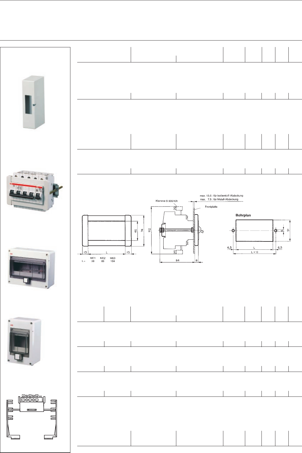
Flange-mounting installation
consists of flange frame, fixing bolts and DIN rail
for MCBs of S 280 and S 220 series
for 2 modules S 500-ME 1 GH S500 1008 R0001 48450 8
for 5 modules S 500-ME 2 GH S500 1008 R0002 48460 7
for 10 modules S 500-ME 3 GH S500 1008 R0003 48470 6
terminal for rear connection of main contacts, front-mounted
up to 25 mm² S 500-K 1 GH S500 1210 R0001 48530 7
flange-mounted measurements in mm
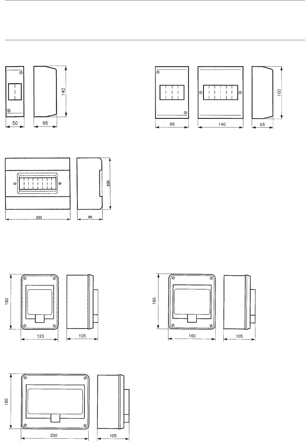
Insulated housings IP 55
come with DIN rail according to DIN EN 60 715 and cable entry grommet without N + PE common terminals (see SMO)
Material: high-impact and flame-retardant (UL 94 V-0), color grey (RAL 7035), glow-wire test 960 °C according to IEC 695-2-1
type with
knock- enclosed order details bbn price price w'ght pack.
outs cable 80 00126 1 pc. group 1 pc. units
Ø in mm grommets type code order code EAN kg pc.
housings for 4 modules
2 x Ø 27 2 QES 4/3 N GH L111 2304 R0013 12644 0 0.370 18
housings for 6 modules
2 x Ø 27 2 QES 6/3 N GH L111 2306 R0013 12646 4 0.440 12
housings for 10 modules
6 x Ø 32 3 QES 10/3 N GH L111 2310 R0013 12650 1 0.690 10
N + PE common terminals for QES (IP 55)*
Neutral and protective-conductor terminals with insulation holder for screw-fixing
for QES 4/3 N SMO 4 GH L430 1910 R0004 12880 2 0.093 10
for QES 6/3 N SMO 6 GH L430 1910 R0006 12882 6 0.125 10
for QES 10/3 N SMO 10 GH L430 1910 R0010 12884 0 0.105 10
* to be discontinued
SK0134 Z92
SK 0018 B98
QES 10/3 N
SK 0019 B98

24
System pro M
Labelling material
for pro M devices
description order details bbn price price w'ght pack.
40 12233 1 pc. group 1 pc. units
type code order code EAN kg pc.
Individual identification labels
include transparent label carriers for slide-in paper labels (blank or marked). Can be used for switches, pushbuttons,
indicator lights, latching relays, installations relays and MCBs, RCDs and ABB i-bus EIB components.
label carrier ST GH S210 1945 R0002 13820 3 100
snap-on
label ST-E GH S210 1946 R0002 13830 2 1
(1 set = 300 piece) set
write-on labels
numbered 1-100 ST-EN GH S210 1946 R0003 64530 5 1
(1 set = 5 x 1-100) set
Identification label mats
40 labels each, blank or marked. Blank label mats can be labled by hand with an indelible, waterproof pen or with
computerised labelling systems (plotter).
identification labels
blank SZ-KZS GH S210 1946 R0004 00850 10.007 30
marked 1–40 SZ-KZS/1 GH S210 1946 R0005 00860 00.007 30
marked 41–80 SZ-KZS/2 GH S210 1946 R0006 00870 90.007 30
marked 81–120 SZ-KZS/3 GH S210 1946 R0007 00880 80.007 30
marked 121–160 SZ-KZS/4 GH S210 1946 R0008 00890 70.007 30
with pictograms SZ-KZS/5 GH S210 1946 R0009 00900 30.007 30
marked 2 x 1-20 SZ-KZS/6 GH S210 1946 R0010 05080 70.007 30
marked 4 x 1-10 SZ-KZS/9 GH S210 1946 R0013 39050 70.007 30
marked 4 x 11-20 SZ-KZS/10 GH S210 1946 R0014 39060 60.007 30
marked L1 SZ-KZS/11 GH S210 1946 R0015 52484 10.007 30
marked L2 SZ-KZS/12 GH S210 1946 R0016 52485 80.007 30
marked L3 SZ-KZS/13 GH S210 1946 R0017 52486 50.007 30
Customised labels on request: minimum orders for 50 mats or small-scale surcharge.
bbn-No. 40 16779
ST + ST-E
SK 0187 B91
ST
SZ-KZS
SK 0018 Z94 SK 0120 B91
SK 0202 B93
SK 0166 Z93
SK 0164 Z93
SK 0165 Z93
SK 0004 Z94
SK 0162 Z93
SK 0163 Z93
25
System pro M
Applications
Busbar supply with feeder terminal SZ-ESK 2 (see page 18)
SK 0078 B93
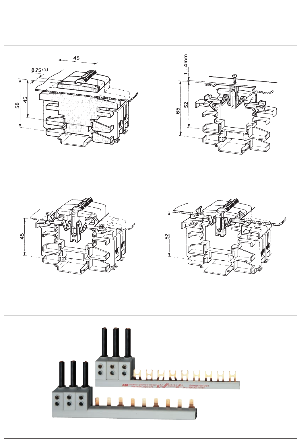
Filling piece FST 2
has knockouts to detach filling piece FST 2 in
two different heights to adapt to the specific
height of other devices.
SK 0317 Z93
Spring piece FDT 2
which is plugged onto filling piece FST 2
serves as a holder for device covers.
SK 0318 Z93
SK 0319 Z93
SK 0320 Z93
Spring piece FDT 2
If snapped on the other way round, spring piece FDT 2 can be used to arrest device covers
and, by snapping into place, prevents device deformations.
The height depends on where the piece is inserted, 45 mm (left illustration) or
52 mm (right illustration).
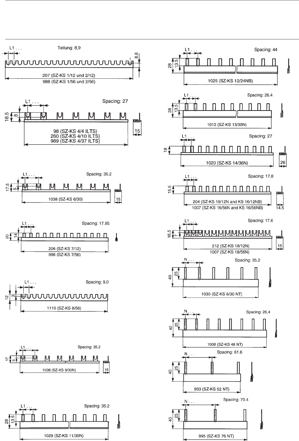
26
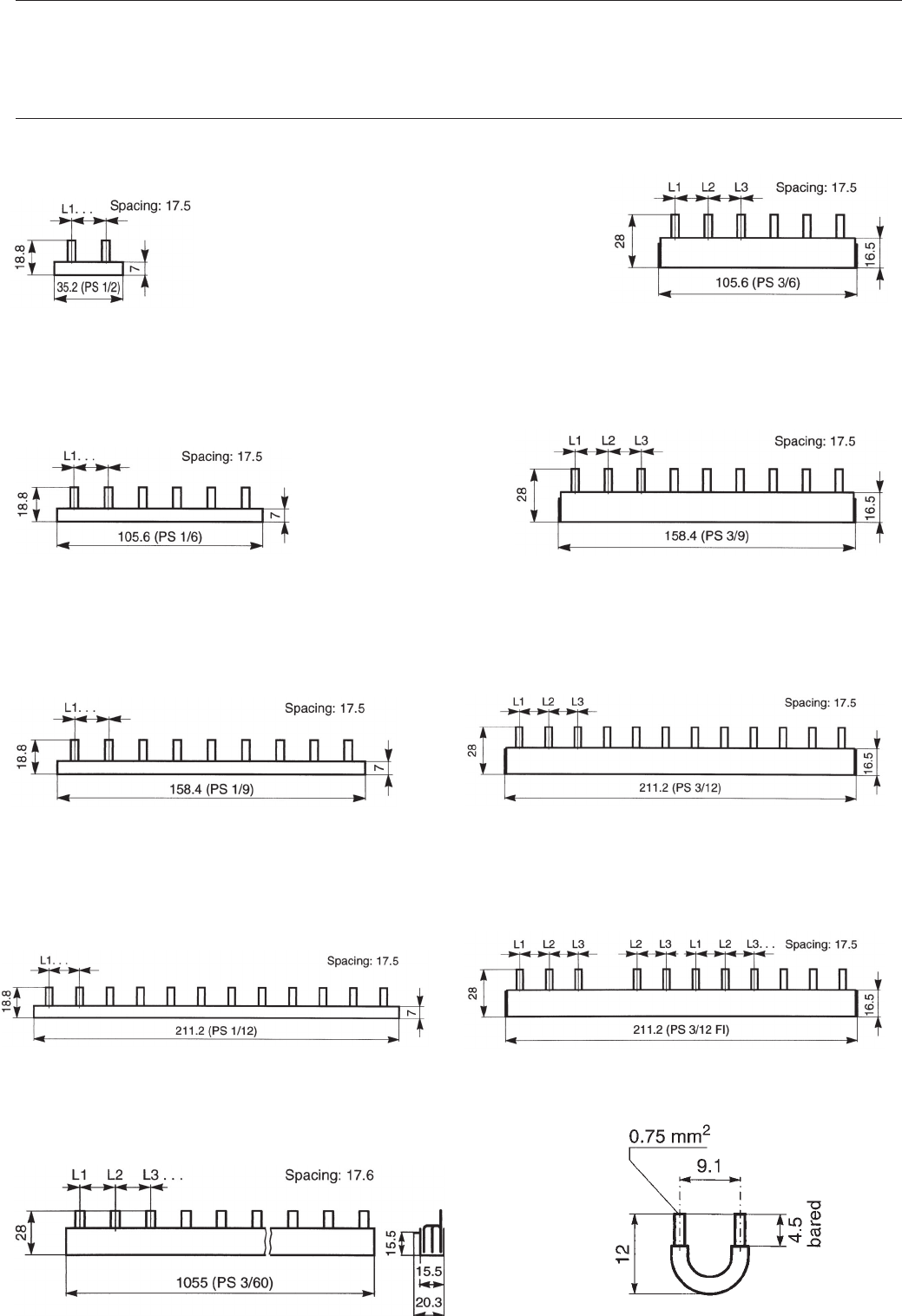
System pro M
2CDC 062 139 F0203
2CDC 062 145 F0203
Dimensions measurements in mm
2CDC 062 149 F0203
auxiliary contact bridge HKB
(PS 3/60/16)
2CDC 062 144 F0203
2CDC 062 142 F0203
2CDC 062 256 F0203 2CDC 062 146 F0203
2CDC 062 140 F0203
2CDC 062 141 F0203
2CDC 062 147 F0203
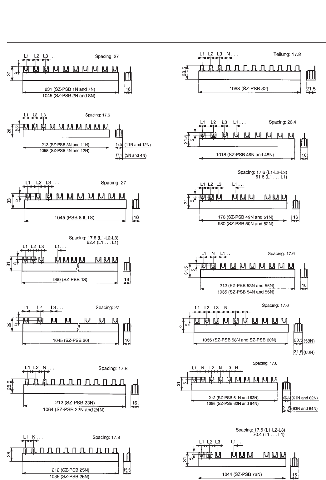
27
System pro M
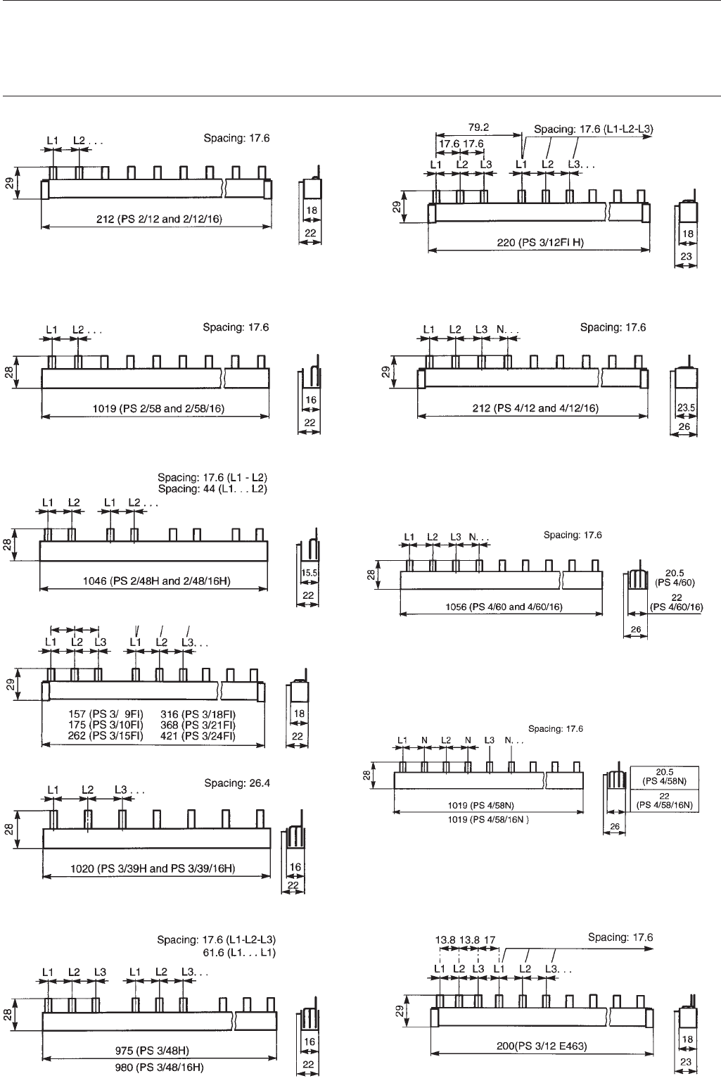
Dimensions measurements in mm
2CDC 062 143 F0203 2CDC 062 257 F0203
2CDC 062 261 F0203 2CDC 062 251 F0203
2CDC 062 260 F0203
2CDC 062 267 F0203 2CDC 062 269 F0203
2CDC 062 252 F0203 2CDC 062 253 F0203
2CDC 062 265 F0203
2CDC 062 071 F0103
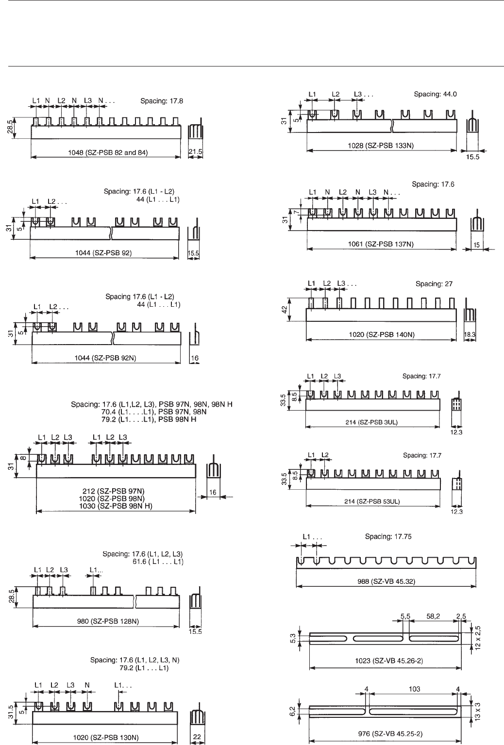
28
System pro M
Dimensions measurements in mm
SK 0034 Z01
2CDC 062 270 F0203
SK 0288 Z98 SK 0286 Z98
SK 0290 Z98 SK 0289 Z98
2CDC 062 274 F0203
SK 0292 Z98
SK 0298 Z98
2CDC 062 272 F0203 SK 0287 Z98 SK 0295 Z98 SK 0293 Z98SK 0294 Z98 2CDC 062 271 F0203
SK 0297 Z98
29
System pro M
Dimensions measurements in mm
SK 0209 Z99 2CDC 062 279 F0203
2CDC 062 288 F0203
SK 0306 Z98 SK 0299 Z98
SK 0302 Z98
SK 0319 Z98
SK 0307 Z98
SK 0320 Z98
SK 0310 Z98 2CDC 062 289 F0203
SK 0019 Z98SK 0315 Z98SK 0211 Z99
30
System pro M
Dimensions measurements in mm
2CDC 062 293 F0203
SK 0326 Z98SK 0327 Z98
2CDC 062 303 F0003
SK 0321 Z98
SK 0322 Z98SK 0030 Z98
2CDC 062 041 F0203
2CDC 062 286 F0203
2CDC 062 302 F0003 SK 0028 Z99 SK 0316 Z98 SK 0300 Z98 2CDC 062 287 F0203
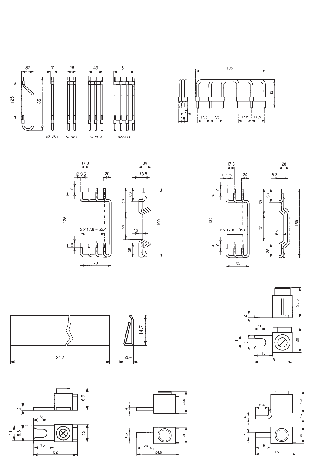
31
System pro M
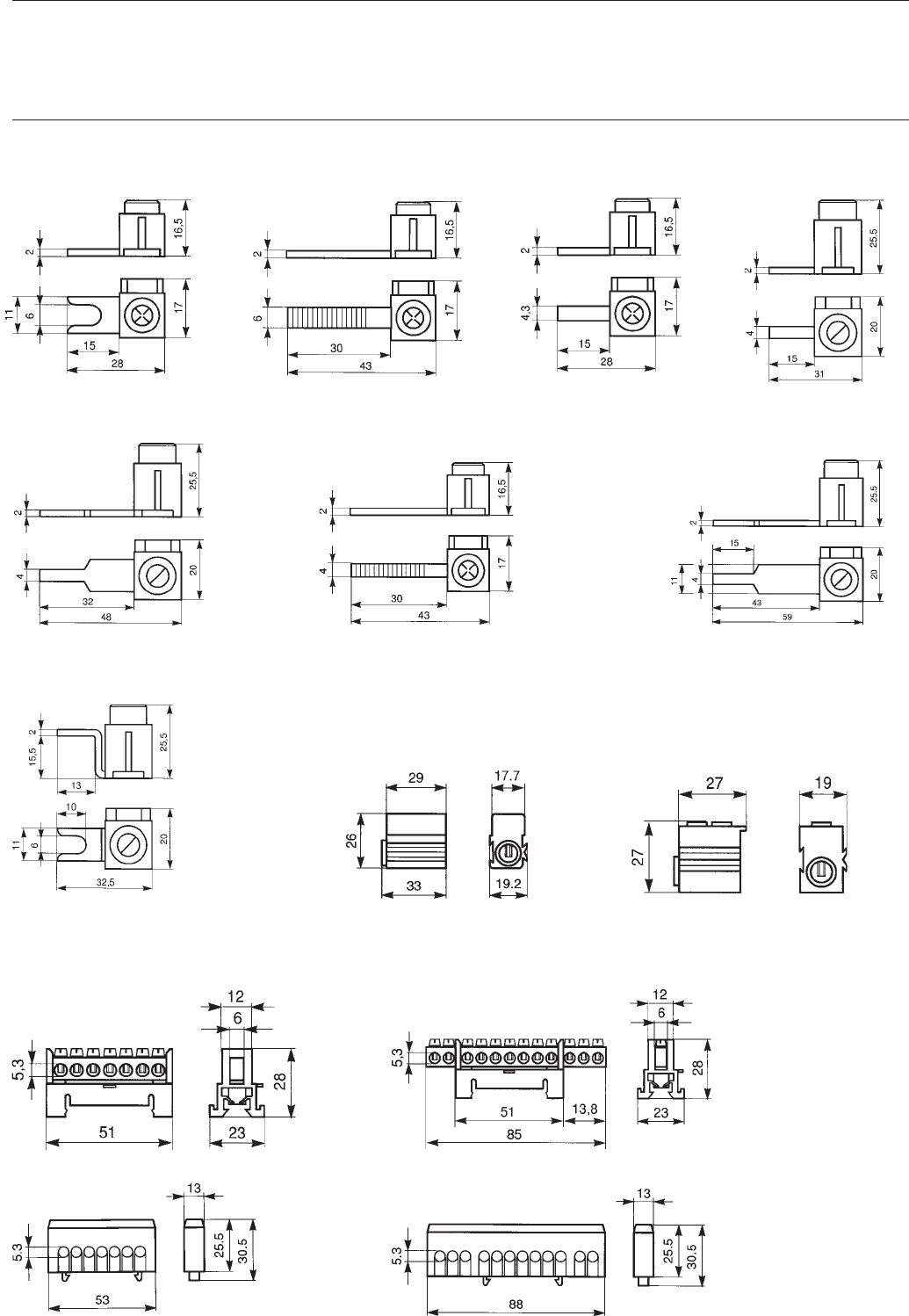
Dimensions measurements in mm
Terminals
SK 0068 Z98
SZ-VS
Wiring kit
SZ-AS 5 I/10 I
Connection set SZ-SM
SK 0198 Z98
SZ-Ast 95
SK 0002 Z02
SZ-Ast 95 gK
SK 0003 Z02
2CDC 062 044 F0103
SK 0007 Z02
SZ-BSA SZ-AS 8 I
SK 0070 Z98
RV 4
SK 0010 Z02
RV 3
SK 0009 Z02
32
System pro M
Dimensions measurements in mm
Terminals
SZ-AS 4 I
SK 0069 Z98
SZ-ASt 6 I
SK 0071 Z98
SZ-ASt 12 I
SK 0074 Z98
SZ-ASt 50 I
SK 0073 Z98
SZ-ASt 9 I
SK 0076 Z98
SZ-AS 24 I
2CDC 062 045 F0003
SZ-ASt 25 I
SK 0075 Z98
SZ-AS 2 I
SK 0095 Z98
Protective-conductor
terminals
SZ-ESK 1/SZ-ESK 2
SK 0067 Z98
SZ-ESK
SK 0001 Z02
Feeder terminals
SZ-PE 6/3
SK 0065 Z98
SK 0066 Z98
SZ-PE 11/3
SK-N 11/3c; SZ-PE 11/3c
SK 0181 Z02
SK 0182 Z02
SZ-N 6/3c; SZ-PE 6/3c
33
System pro M
Dimensions measurements in mm
Common terminals with terminal holder
SK 0085 Z98
Terminal holder Ktr
Common terminals with terminal holder
SK 0090 Z98
Terminal cover KA 27 Terminal cover E 430-AP
SK 0057 Z98
SK 0084 Z98
SK 0021 Z99
Elevation piece SZ-ES
SK 0184 Z99
Device mounting rails
SK 0150 Z93
name A A1
DSW 1 17.5 15
DSW 2 35 20
DSW 3 52.5 37.5
DSW 4 70 55
DSW 6 105 90
DSW 1 has vertical drill holes.
Dimensions measurements in mm
Terminal covers
SK 0136 Z96
PCD 2 N PCD 4 N/PCD 6 N
SK 0137 Z96
PCD 8 N
SK 0138 Z96
Insulated housings
QES 4/3 N
SK 0078 Z98
QES 6/3 N
SK 0079 Z98
QES 10/3 N
SK 0080 Z98
34
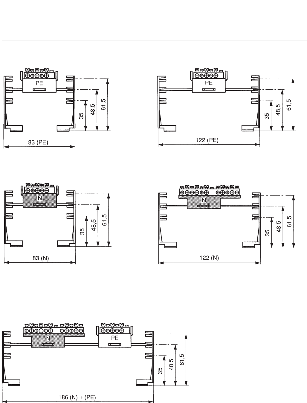
Dimensions measurements in mm
N + PE common terminals for QES
SMO 4
SK 0086 Z98
SMO 6
SK 0087 Z98
SMO 10
SK 0088 Z98
35

Stand: März 1998
Pub. No. 2CDC 446 001 D0201
replaces G STO 3067 98 S0002
ABB STOTZ-KONTAKT GmbH
Postfach 10 16 80, 69006 Heidelberg/Germany
Eppelheimer Straße 82, 69123 Heidelberg/Germany
Telephone: +49 (0)6221 701-0
Telefax: +49 (0)6221 701-723
www.abb.de/stotz-kontakt
