0611CT1001 97253 Catalog
62149-Attachment 62149-Attachment 62149-Attachment 785901 Batch5 unilog cesco-content
27439-Attachment 27439-Attachment 27439-Attachment 785901 Batch4 unilog cesco-content
2014-06-03
: Pdf 97253-Catalog 97253-Catalog 785901 Batch4 unilog
Open the PDF directly: View PDF ![]() .
.
Page Count: 244 [warning: Documents this large are best viewed by clicking the View PDF Link!]
PowerPact™ H-, J-, and L-Frame
Circuit Breakers
Catalog
0611CT1001
2012
Class 0611
CONTENTS
Description . . . . . . . . . . . . . . . . . . . . . . . . . . . . . . . . . . . . . . . . . . . . . Page
Catalog Numbering . . . . . . . . . . . . . . . . . . . . . . . . . . . . . . . . . . . . . . . . . . .7
General Information . . . . . . . . . . . . . . . . . . . . . . . . . . . . . . . . . . . . . . . . . .10
Circuit Breakers . . . . . . . . . . . . . . . . . . . . . . . . . . . . . . . . . . . . . . . . . . . . .20
Automatic Switches . . . . . . . . . . . . . . . . . . . . . . . . . . . . . . . . . . . . . . . . . .38
Motor Circuit Protection . . . . . . . . . . . . . . . . . . . . . . . . . . . . . . . . . . . . . . .42
Trip Units . . . . . . . . . . . . . . . . . . . . . . . . . . . . . . . . . . . . . . . . . . . . . . . . . .54
Accessories for Micrologic™ Trip Units . . . . . . . . . . . . . . . . . . . . . . . . . . .73
Accessories and Auxiliaries . . . . . . . . . . . . . . . . . . . . . . . . . . . . . . . . . . . .90
Circuit Breaker Mounting and Connections . . . . . . . . . . . . . . . . . . . . . . . 113
Installation Recommendations . . . . . . . . . . . . . . . . . . . . . . . . . . . . . . . .126
Wiring Diagrams. . . . . . . . . . . . . . . . . . . . . . . . . . . . . . . . . . . . . . . . . . . .136
Dimensions . . . . . . . . . . . . . . . . . . . . . . . . . . . . . . . . . . . . . . . . . . . . . . .145
Trip Curves . . . . . . . . . . . . . . . . . . . . . . . . . . . . . . . . . . . . . . . . . . . . . . . .168
Catalog Numbers . . . . . . . . . . . . . . . . . . . . . . . . . . . . . . . . . . . . . . . . . . .228
Glossary . . . . . . . . . . . . . . . . . . . . . . . . . . . . . . . . . . . . . . . . . . . . . . . . . .233
™

© 2011–2012 Schneider Electric
All Rights Reserved
PowerPact™ H-, J-, and L-Frame Circuit Breakers
2
05/2012
™

PowerPact™ H-, J-, and L-Frame Circuit Breakers
3
05/2012
© 2011–2012 Schneider Electric
All Rights Reserved
™
SECTION 1: CATALOG NUMBERING ..............................................................................7
PowerPact with Micrologic™ Circuit Breakers.............................................................................. 7
Catalog Numbering....................................................................................................................... 8
SECTION 2: GENERAL INFORMATION .........................................................................10
Applications ................................................................................................................................ 10
Flexible Configurations ............................................................................................................... 12
General Characteristics ............................................................................................................. 13
PowerPact H-, J-, and L-frame Circuit Breaker Trip Units ......................................................... 18
SECTION 3: CIRCUIT BREAKERS .................................................................................20
Dual-Break Rotating Contacts ....................................................................................................20
High Ampere Interrupting Ratings (AIR) ..................................................................................... 20
Internal Operating Mechanism....................................................................................................20
Handle Position Indication .......................................................................................................... 21
Circuit Breaker Ratings............................................................................................................... 21
Special Applications.................................................................................................................... 23
H- and J-Frame Catalog Numbers.............................................................................................. 24
L-Frame Circuit Breaker Catalog Numbers................................................................................. 33
SECTION 4: AUTOMATIC SWITCHES ...........................................................................38
Automatic Switch Functions ....................................................................................................... 38
Specifications.............................................................................................................................. 39
Catalog Numbers........................................................................................................................ 40
SECTION 5: MOTOR CIRCUIT PROTECTION ...............................................................42
General Information .................................................................................................................... 42
Motor Branch Circuit Protection Function .................................................................................. 42
Trip Class of a Overload Relay Device....................................................................................... 43
Asynchronous-Motor Starting Parameters ................................................................................. 43
Motor-Feeder Solutions ............................................................................................................. 43
Electronic Motor Circuit Protectors (AC Only)............................................................................. 45
Micrologic™ 1.3 M Electronic Trip Units for Instantaneous
Protection Only (L-Frame Circuit Breakers Only) ..................................................................... 48
Micrologic 2.2 M and 2.3 M Electronic Trip Units ....................................................................... 49
Indications................................................................................................................................... 50

© 2011–2012 Schneider Electric
All Rights Reserved
PowerPact™ H-, J-, and L-Frame Circuit Breakers
4
05/2012
™
SECTION 6: TRIP UNITS ................................................................................................ 54
Available Trip Units ..................................................................................................................... 54
Protection of Distribution Systems ..............................................................................................57
SECTION 7: ACCESSORIES FOR MICROLOGIC™ TRIP UNITS ................................ 73
Display Options........................................................................................................................... 73
Circuit Breaker Communication Network Options....................................................................... 76
SECTION 8: ACCESSORIES AND AUXILIARIES ......................................................... 90
Communication Network ............................................................................................................ 90
Accessory Connections............................................................................................................... 93
Auxiliary and Alarm Indication Contacts...................................................................................... 93
SDx and SDTAM Modules for Micrologic™ ............................................................................... 95
Shunt Trip (MX) and Undervoltage Trip (MN) ............................................................................. 97
Motor Operator............................................................................................................................ 98
Add-On Ground-Fault Module (GFM) (H- and J-Frame Only) ..................................................100
Earth Leakage Module (ELM) (H- and J-Frame Only) .............................................................. 101
Rotary Operating Handles......................................................................................................... 102
Class 9422 Flange-Mounted Variable-Depth Operating Mechanism........................................105
Locking Systems....................................................................................................................... 105
Manual Mechanical Interlocking Systems ................................................................................ 106
Sealing Accessory..................................................................................................................... 109
Front-Panel Escutcheons.......................................................................................................... 109
Toggle Collars (For Drawout Mounting) ....................................................................................110
Toggle Boot............................................................................................................................... 110
Handle Extension ...................................................................................................................... 110
Circuit Breaker Enclosures and Enclosure Accessories ........................................................... 111
SECTION 9: CIRCUIT BREAKER MOUNTING AND CONNECTIONS ........................ 113
Mounting Configurations ........................................................................................................... 113
Unit-Mount Circuit Breakers...................................................................................................... 114
I-Line™ Circuit breakers ........................................................................................................... 115
Connection ................................................................................................................................ 119

PowerPact™ H-, J-, and L-Frame Circuit Breakers
5
05/2012
© 2011–2012 Schneider Electric
All Rights Reserved
™
SECTION 10: INSTALLATION RECOMMENDATIONS .................................................126
Operating conditions ................................................................................................................ 126
Installation in Equipment .......................................................................................................... 129
Safety Clearances and Minimum Distances ............................................................................. 129
Safety Clearance ...................................................................................................................... 130
Control Wiring .......................................................................................................................... 131
24 Vdc Power Supply Module .................................................................................................. 133
Wiring ....................................................................................................................................... 134
Modbus ..................................................................................................................................... 135
SECTION 11: WIRING DIAGRAMS ................................................................................136
SECTION 12: DIMENSIONS ...........................................................................................145
SECTION 13: TRIP CURVES ...........................................................................................168
CATALOG NUMBERS ..............................................................................228
GLOSSARY ...............................................................................................233

© 2011–2012 Schneider Electric
All Rights Reserved
PowerPact™ H-, J-, and L-Frame Circuit Breakers
6
05/2012
™
PowerPact™ H-, J-, and L-Frame Circuit Breakers
Catalog Numbering
7
05/2012
© 2011–2012 Schneider Electric
All Rights Reserved
™
Section 1—Catalog Numbering
PowerPact with Micrologic™ Circuit Breakers
The PowerPact H-, J-, and L-frame circuit breakers are designed to protect electrical systems from
damage caused by overloads and short circuits. H- and J-frame circuit breakers are available with
either thermal-magnetic or Micrologic™ electronic trip units. L-frame circuit breakers are available with
Micrologic electronic trip unit.
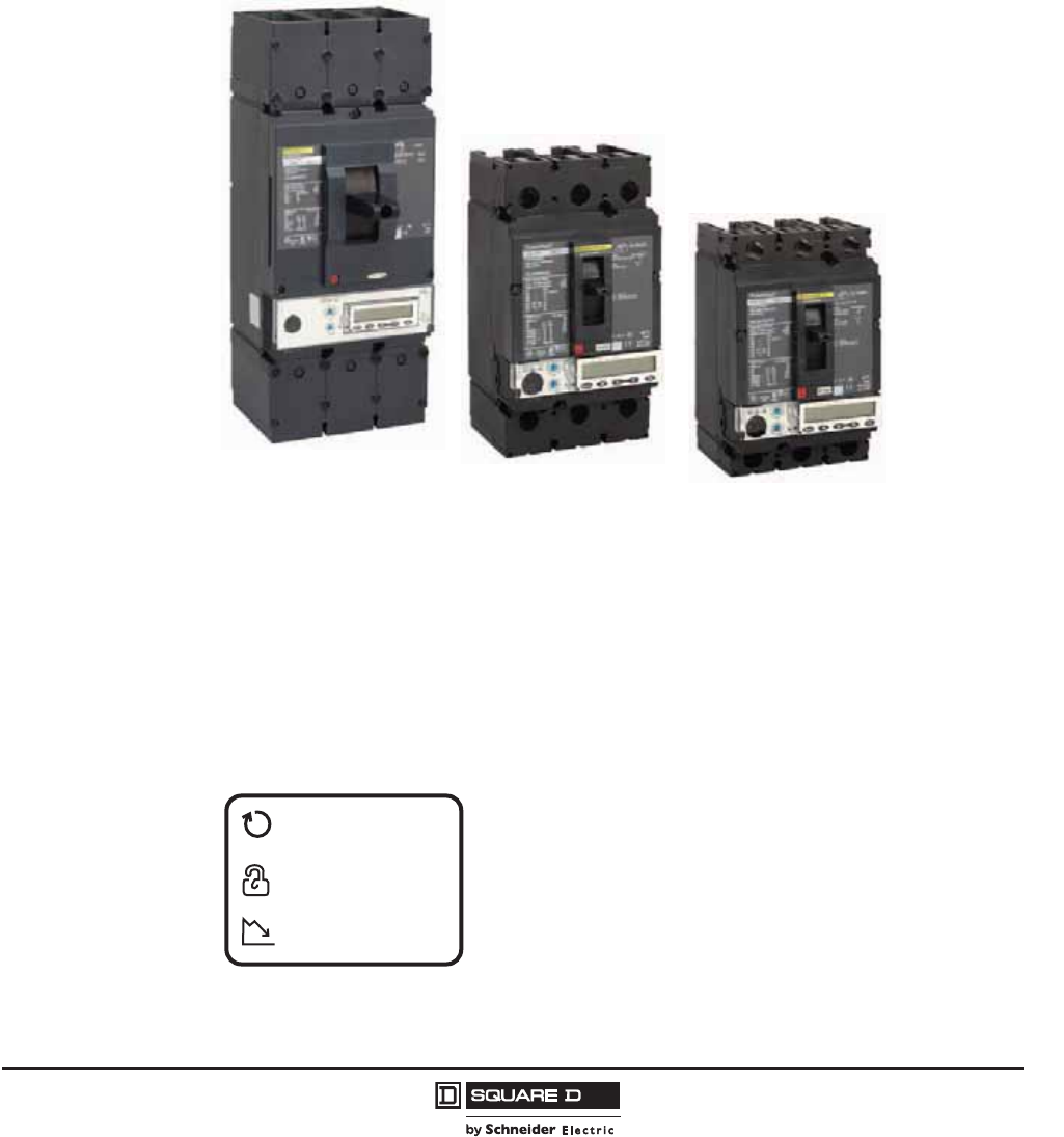
Direct Access to Energy Management
The new generation PowerPact with Micrologic circuit breakers set the standard with direct access to
energy management. Integrated metering enhances their protective functions. For the first time,
Schneider Electric™ users can monitor energy from 15 A to 3000 A, offering new performance in a
remarkably compact device.
•Smart – A meter in every breaker
•Safe – Combines safety and performance in one compact device
•Simple – Easy to select, install, and use
Increased energy
availability
Safety and
Protection
Energy measurement
and control
© 2011–2012 Schneider Electric
All Rights Reserved
PowerPact™ H-, J-, and L-Frame Circuit Breakers
Catalog Numbering
8
05/2012
™
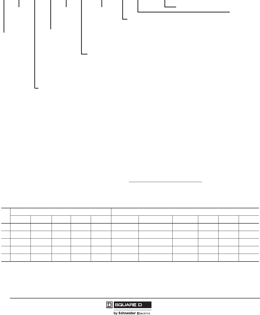
Catalog Numbering
Table 1: Interrupting Rating
UL/CSA/NOM IEC 647-2 Icu/Ics
240 Vac 480 Vac 600 Vac 250 Vdc1
1250 Vdc ratings only available with PowerPact H or J circuit breakers with thermal-magnetic trip units (not including MCP).
500 Vdc2
2UL 500 Vdc ratings only available with PowerPact J circuit breakers with thermal-magnetic trip units (not including MCP).
220/240 Vac 380/440/415 Vac 500/525 Vac 690 Vac 250 Vdc1500 Vdc3
3IEC 500 Vdc rating only available on PowerPact J-frame circuit beakers.
D25 kA 18 kA 14 kA 20 kA — 25/25 kA 18/18 kA 14/14 kA — 20 kA 20 kA
G65 kA 35 kA 18 kA 20 kA 20 kA 65/65 kA 35/35 kA 18/18 kA — 20 kA 20 kA
J100 kA 65 kA 25 kA 20 kA — 100/100 kA 65/65 kA 25/25 kA — 20 kA 20 kA
L125 kA 100 kA 50 kA 20 kA — 125/125 kA 100/100 kA 50/50 kA — 20 kA 20 kA
R200 kA 200 kA 100 kA — — 150 kA 125 kA 75 kA 20 kA — —
Trip Unit
Micrologic™ Electronic Trip Units
U31 LI Standard Protection
U33 LSI Standard Protection
U43 LSI plus Ammeter
U44 LSIG plus Ammeter
U53 LSI plus Energy Management
U54 LSIG plus Energy Management
M37 Magnetic Only (L-Frame Only)
M38 Motor Protector Circuit Breaker
S40 400 A Molded Case Switch (L-Frame Automatic Switch)
S60 600 A Molded Case Switch (L-Frame Automatic Switch)
F40 400 A L-Frame Only (No Trip Unit)
F60 600 A L-Frame Only (No Trip Unit)
Thermal-Magnetic Trip Units
— Standard Fixed Trip Unit (Suitable for reverse connection)
F06 60 A H-Frame Only (No trip unit)
F15 150 A H-Frame Only (No trip unit)
F25 250 A J-Frame Only (No trip unit)
T Complete Circuit Breaker (Frame + removable trip unit)
S15 150 A Molded Case Switch (H-Frame automatic switch)
S17 175 A Molded Case Switch (J-Frame automatic switch)
S25 250 A Molded Case Switch (J-Frame automatic switch)
C 100% Rated Continuous Current Rating1
M71 30 A H-Frame Motor Circuit Protector (MCP)
M72 50 A H-Frame Motor Circuit Protector (MCP)
M73 100 A H-Frame Motor Circuit Protector (MCP)
M74 150 A H-Frame Motor Circuit Protector (MCP)
M75 250 A J-Frame Motor Circuit Protector (MCP)
D81 500 Vdc 150–175 A J-Frame Molded Case Circuit Breaker
D82 500 Vdc 200–250 A J-Frame Molded Case Circuit Breaker
R 100% Rated Continuous Current Rating Complete Circuit Breaker
(Frame + removable trip unit)
1100% ratings valid for:
3P H/J frame unit mount only
3P/4P L-frame 250 A and 400 A unit mount
3P L-frame 250 A and 400 A I-Line
I-Line™ Phasing
— ABC (3P)
6 CBA (3P)
1AB(2P)
2AC(2P)
3BA(2P)
4BC(2P)
5CA(2P)
6CB(2P)
Frame
H H-Frame
J J-Frame
L L-Frame
Poles
22P
33P
4 4P
Amperage
060 60 A
100 100 A
150 150 A
250 250 A
400 400 A
600 600 A
000 Switch or
Frame only
Voltage
6 600 Vac
Terminations
L Lugs Line/Load Side
M Lugs Line Side
P Lugs Load Side
FBus Bar
AI-Line
S Rear Connected
N Plug-in
DDrawout
K Reverse I-Line
Performance Level (kA) (See Table 1)
Accessory Suffix Code (See Table 2)
– J L L 3 6 250 T – – – – –
Brand
_ Square D™
N Schneider
Electric
PowerPact™ H-, J-, and L-Frame Circuit Breakers
Catalog Numbering
9
05/2012
© 2011–2012 Schneider Electric
All Rights Reserved
™
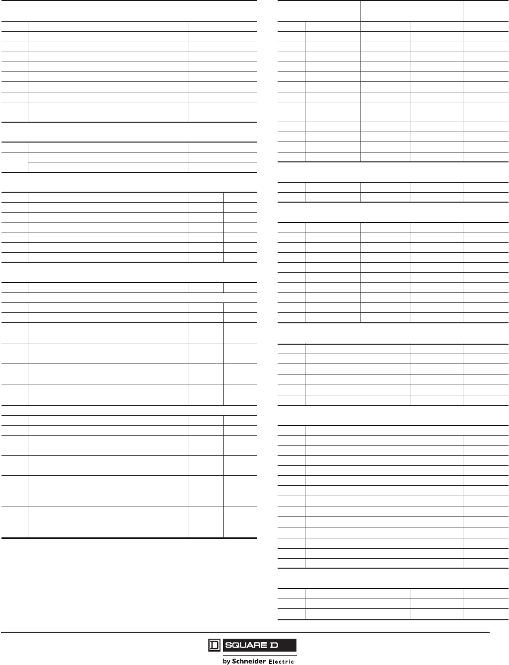
Table 2: Factory Installed Accessory Suffix Codes (Building Sequence as Listed) and Field-Installable Kit Number
(1) Communication Networks1(5) Shunt Trip (6) Undervoltage Release
UVR Voltage
Suffix Description Kit No. Suffix Kit No. Suffix Kit No.
EA NSX Cord 1.3 m, V 480 V S434201 SK S29384 UK S29404 24 Vac
EB NSX Cord 3 m, V 480 V S434202 SL S29385 UL S29405 48 Vac
ED NSX Cord 1.3 m, V > 480 V S434204 SA S29386 UA S29406 120 Vac
EE NSX Cord 3 m, V > 480 V S434303 SD S29387 UD S29407 208/277 Vac
EG4BSCM + NSX Cord 1.3 m, V 480 V S434201BS SH S29388 UH S29408 380/480 Vac
EH4BSCM + NSX Cord 3 m, V 480 V S434202BS SJ S29389 UJ S29409 525/600 Vac
EK4BSCM + NSX Cord 1.3 m, V > 480 V S434204BS SN S29382 UN S29402 12 Vdc
EL4BSCM + NSX Cord 3 m, V > 480 V S434303BS SO S29390 UO S29410 24 Vdc
EN 24 Vdc Power Supply Terminal Block S434210 SU S29391 UU S29411 30 Vdc
(2) Indication Contacts SP S29392 UP S29412 48 Vdc
SV S29383 UV S29403 60 Vdc
Suffix Description Kit No. SR S29393 UR S29413 125 Vdc
VSDX S429532 SS S29394 US S29414 250 Vdc
SDTAM (motor only trip units) S429424 (6) Communicating Motor Operator5
(3) Auxiliary Switch Suffix Voltage H-Frame J-Frame L-Frame
Suffix Contacts Kit No. Kit Qty. NC 220/240 Vac S429441 S431549 S432652
AA 1A/1B Standard S29450 1 (7) Motor Operator
AB 2A/2B Standard S29450 2
AC 3A/3B Standard (L-frame only) S29450 3 Suffix Voltage H-Frame J-Frame L-Frame
AE 1A/1B Low-Level S29452 1 ML 48/60 Vac S29440 S31548 S432639
AF 2A/2B Low-Level S29452 2 MA 120 Vac S29433 S31540 S432640
AG 3A/3B Low Level (L-frame only) S29452 3 MD 277 Vac S29434 S31541 S432641
(4) Alarm/Overcurrent Trip Switch MF 380/415 Vac — — S432642
MH 440/480 Vac S29435 S31542 S432647
Suffix Switch Kit No. Kit Qty. MO 24/30 Vdc S29436 S31543 S432643
PowerPact L-Frame and PowerPact H/J-Frame with Micrologic™ 5/6 trip units MV 48/60 Vdc S29437 S31544 S432644
BC Alarm Switch S29450 1 MR 110/130 Vdc S29438 S31545 S432645
BH Alarm Switch Low-Level S29452 1 MS 250 Vdc S29439 S31546 S432646
BD Overcurrent Trip Switch, Standard
SDE Actuator
S29450
S29451
1
1(8) Rotary Handle
BJ Overcurrent Trip Switch, Low-Level
SDE Actuator
S29452
S29451
1
1
Suffix Handle Type (color) H/J-Frame L-Frame
RD10 Direct Mount (black) S29337 S32597
BE Alarm Switch and
Overcurrent Trip Switch, Standard S29450 2 RD20 Direct Mount (red) S29339 S32599
RE10 Extended Door Mount (black) S29338 S32598
BK Alarm Switch and
Overcurrent Trip Switch, Low-Level S29452 2 RT10 Telescoping (black) S29343 S32603
RE20 Extended Door Mount (red) S29340 S32600
PowerPact H/J-Frame with Thermal-Magnetic or Micrologic 1/2/3 trip units (9) Wire Harnesses2
BC Alarm Switch S29450 1
BH Alarm Switch Low-Level S29452 1 Suffix Harness2Kit No.
BD Overcurrent Trip Switch, Standard
SDE Actuator
S29450
S29451
1
1
YH3 ZSI Wire Harness, H/J Frame S434300
YH3 ZSI Wire Harness, L-Frame S434301
BJ Overcurrent Trip Switch, Low-Level
SDE Actuator
S29452
S29451
1
1
YH2 ENCT Wire Harness S434302
YH1 OF Wire Harness S434500
BE
Alarm Switch and
Overcurrent Trip Switch, Standard
SDE Actuator
S29450 2 YH1 SD/SDE Wire Harness S434501
YH1 SDx/SDTAM Wire Harness S434502
S29451 1 YH1 MN Wire Harness S434503
BK
Alarm Switch and
Overcurrent Trip Switch, Low-Level S29452 2 YH1 MX Wire Harness S434504
YH1 Motor Operator Wire Harness S434506
SDE Actuator S29451 1 YH1 Communicating Motor Operator Wire Harness S434507
1 Except for 24 Vdc Power Supply Terminal Block, installation requires IFM (STRV00210) for
Modbus communication and/or FDM (STRV00121) for external display
2 YH1 = all installed accessories but ZSI and ENCT
YH2 = ENCT and all installed accessories
YH3 = ZSI and all installed accessories
YH4 = ZSI, ENCT and all installed accessories
3 I-Line™ wire harness included for communication network accessories.
Optional wire harness for unit mount requires YH1 suffix.
4 If using with a motor operator, requires Communicating Motor Operator (suffix NC).
5 Requires Micrologic trip unit U43, U44, U53, or U54 and communication accessories EG, EH, EK,
or EL.
YH13NSX Wire Harness S434508
YH4 ENCT and ZSI Wire Harnesses —
YH1324 Vdc Power Supply Wire Harness S434505
(10) Handle Padlocks
Suffix Padlock Type H/J-Frame L-Frame
YP Handle Padlock, ON or OFF S29371 S32631
YQ Handle Padlock, OFF Only S37422 NJPAF
© 2011–2012 Schneider Electric
All Rights Reserved
PowerPact™ H-, J-, and L-Frame Circuit Breakers
General Information
10
05/2012
™
Section 2—General Information
The PowerPact H-, J-, and L-frame circuit breakers are designed to protect electrical systems from
damage caused by overloads and short circuits. H- and J-frame circuit breakers are available with
either thermal-magnetic or Micrologic™ electronic trip units. L-frame circuit breakers are available with
Micrologic electronic trip unit.
H- and J-frame circuit breakers with thermal-magnetic trip units contain individual thermal (overload)
and instantaneous (short circuit) sensing elements in each pole. The amperage ratings of the thermal
trip elements are calibrated at 104°F (40°C) free air ambient temperature. Per the National Electric
Code® (NEC®) and the Canadian Electrical Code, standard circuit breakers may only be applied
continuously at up to 80% of their rating. Circuit breakers rated for 100% operation are available but
require specially-designed enclosures, copper lugs, and 194°F (90°C) rated wire.
Devices with the Micrologic electronic trip unit provide adjustable protection settings for greater system
flexibility. In addition to electronic protection, Micrologic trip units allow users to monitor both energy
and power. Through direct access to in-depth information and networking using open protocols,
PowerPact circuit breakers with Micrologic trip units let operators optimize the management of their
electrical installations. Far more than a circuit breaker, these circuit breakers are a measurement and
communication tool ready to meet energy-efficiency needs through optimized power requirements,
increased energy availability, and improved installation management.
Applications
PowerPact H-, J-, and L-frame circuit breakers offer high performance and a wide range of
interchangeable trip units to protect most applications.
Electronic trip units provide highly accurate protection with wide setting ranges and can integrate
measurement, metering and communication functions. They can be combined with the front display
module (FDM121) to provide functions similar to a power meter.
Table 3: Applications
Power Meter
PowerPact H-, J-, and L-frame circuit breakers equipped with Micrologic 5 / 6 trip units offer
type A (ammeter) or E (energy) metering functions as well as communication capability. Using
Micrologic trip unit sensors and intelligence, PowerPact H-, J-, and L-frame circuit breakers
provide access to measurements of all the main electrical parameters on the built-in screen, on a
dedicated front display module (FDM121) or through the communication network.
Operating assistance
Integration of measurement functions provides operators with operating assistance functions
including alarms tripped by user-selected measurement values, time-stamped event tables and
histories, and maintenance indicators.
Front display module
The main measurements can be read on the built-in screen of Micrologic 5 / 6 trip units. They
can also be displayed on the equipment FDM121 along with pop-up windows signalling the main
alarms.
Communication Network
PowerPact H-, J-, and L-frame circuit breakers equipped with Micrologic 5 / 6 trip units provide
communication capabilities. Simple RJ45 cables connect to a Modbus™ communication
interface module.
PowerPact™ H-, J-, and L-Frame Circuit Breakers
General Information
11
05/2012
© 2011–2012 Schneider Electric
All Rights Reserved
™
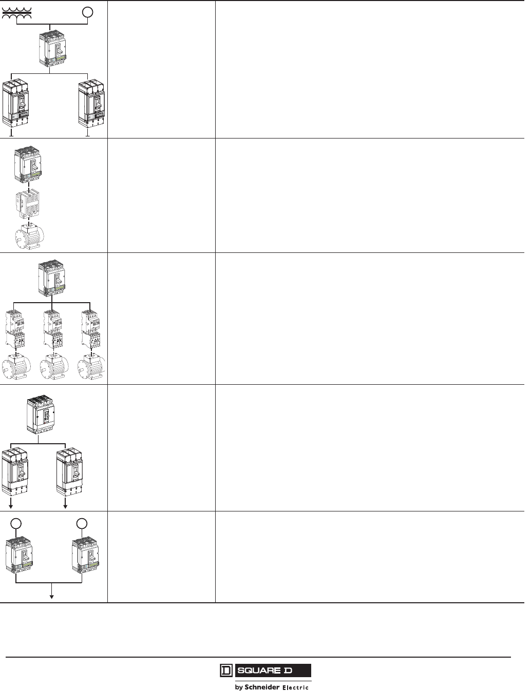
Protection of distribution
systems
The PowerPact H-, J-, and L-frame circuit breakers provide protection against short circuits and
overloads for:
• distribution systems supplied by transformers
• distribution systems supplied by engine generator sets
They are easily installed at all levels in distribution systems, from the main LV switchboard to the
subdistribution boards and enclosures. All PowerPact circuit breakers can protect against
insulation faults by adding an external Vigirex relay.
Protection of motors
The PowerPact H-, J-, and L-frame circuit breakers include a number of versions to protect
motor applications:
• basic short-circuit protection with electronic instantaneous only MCP or the electronic
Micrologic™ 1.3 M trip units, combined with a special overload relay to provide thermal
protection
• protection against overloads, short circuit and phase unbalance or loss with Micrologic 2 M
trip units
The exceptional limiting capacity of the PowerPact circuit breakers automatically provides
coordination with the motor starter.
Protection of special
applications
The PowerPact H-, J-, and L-frame circuit breakers offer a number of version for special
protection applications:
• industrial control panels with:
— compliance with international standards IEC 60947-2 and UL 508/CSA 22.2 N°14
—compliance with UL489
— installation in universal and functional enclosures
• 400 Hz systems
Control using automatic
switches
An automatic switch version of PowerPact H-, J-, and L-frame circuit breakers is available for
circuit control. All add-on functions for the circuit breakers may be combined with the basic
automatic switch function, including motor operators.
For information on other automatic switches, contact Schneider Electric™.
Manual transfer systems
To ensure a continuous supply of power, some electrical installations are connected to two
power systems:
• the normal source, usually the utility (U)
• a replacement source to supply the installation when the normal source is not available,
generally from a generator (G)
A mechanical and/or electrical interlocking system between two circuit breakers or automatic
switches avoids all risk of parallel connection of the sources during switching.
A system can be manual transfer mechanical device interlocking.
Table 3: Applications
G
06114447
rciMcigolo
E
2
.5
r
I
%
A
0
3
>
0
3
>0
1
1
>
.9
2
9
.
3
9
.
4
9
.5
9
.
1
8
9
.
7
9
.
6
9
.
Ir)
o
I
x
(
5
.
1
2
5
.
2
34
0
1
8
6
5
d
s
I)
r
I
x
(
06114448
rciMcigolo
E
2
.5
r
I
%
A
0
3
>
0
3
>01
1
>
.9
2
9
.
3
9.
4
9
.59
.
1
8
9.
7
9
.
6
9
.
Ir)
o
I
x
(
5
.
1
2
5
.
2
34
0
1
8
6
5
d
s
I)
r
I
x
(
06114449
rciMcigolo
E
2
.5
r
I
%
A
0
3
>
0
3
>0
1
1
>
.9
2
9
.
3
9
.
4
9
.59
.
1
8
9
.
7
9
.
6
9
.
Ir)
o
I
x
(
5
.
1
2
5
.
2
34
0
1
8
6
5
d
s
I)
r
I
x(
06114450
06114451
rciMcigolo
E
2
.5
r
I
%
A
0
3
>
0
3
>0
1
1
>
.9
2
9
.
3
9
.
4
9
.5
9
.
1
8
9
.
7
9
.
6
9
.
Ir)
o
I
x(
5
.
1
2
5
.
2
34
0
1
8
6
5
ds
I)
r
I
x(
rciMcigolo
E
2
.5
r
I
%
A
0
3
>
0
3
>01
1
>
.9
2
9
.
3
9
.
4
9
.5
9
.
1
8
9
.
7
9
.
6
9
.
Ir)
o
I
x
(
5
.
1
2
5
.
2
34
0
1
8
6
5
d
s
I)
r
I
x
(
UG
© 2011–2012 Schneider Electric
All Rights Reserved
PowerPact™ H-, J-, and L-Frame Circuit Breakers
General Information
12
05/2012
™
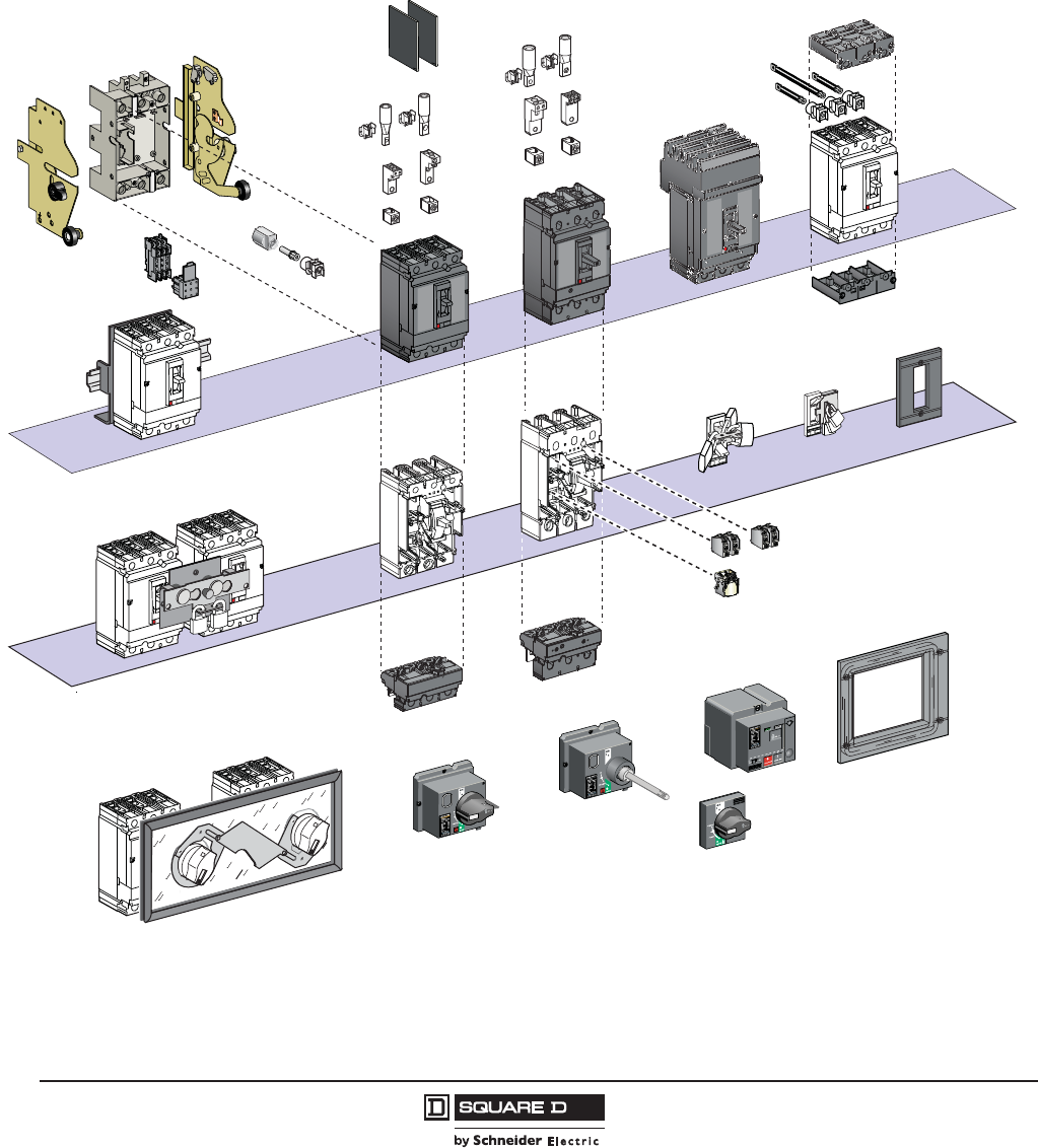
Flexible Configurations
The PowerPact H-, J- and L-frame circuit breakers may be configured with lugs, bus bar connections,
rear connections, I-Line™, drawout cradle, or plug-in base.
Field Installable Accessories and Trip Units
Figure 1: Field Installable Accessories and Trip Units
06113259
PowerPact™ H-, J-, and L-Frame Circuit Breakers
General Information
13
05/2012
© 2011–2012 Schneider Electric
All Rights Reserved
™
General Characteristics
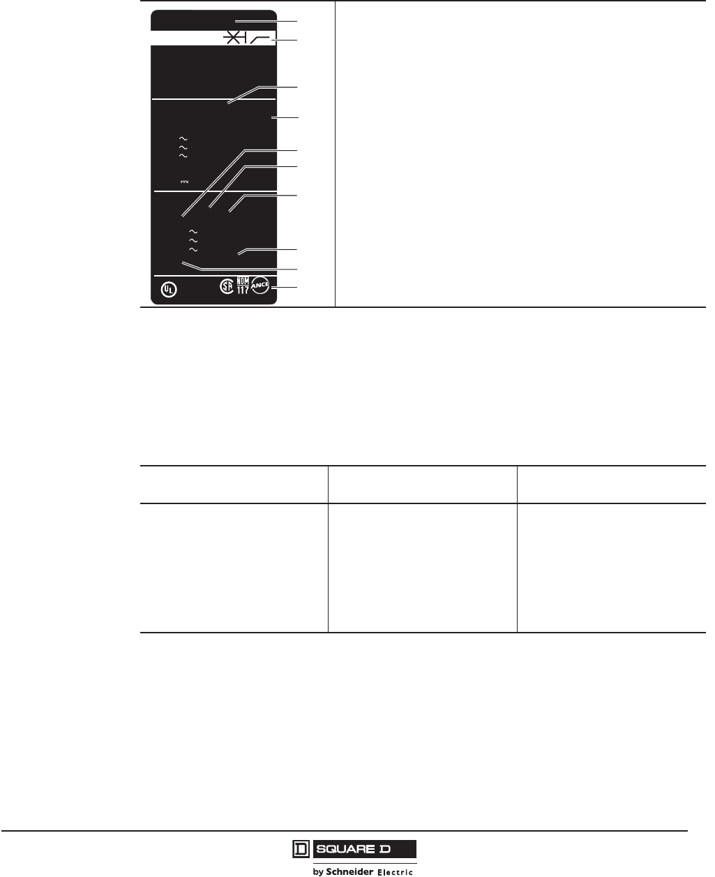
Faceplate Label
Codes and Standards
H-, J-, and L-frame circuit breakers, automatic switches and electronic motor circuit protectors are
manufactured and tested in accordance with the following standards.
NOTE: Apply circuit breakers according to guidelines detailed in the National Electric Code (NEC) and
other local wiring codes.
Characteristics indicated on the faceplate label:
A. Circuit breaker type
B. Circuit breaker disconnector symbol
C. Performance levels
D. Standards
E. Ue: Operating voltage per IEC
F. Icu: Ultimate breaking capacity per IEC
G. Ics: Service breaking capacity per IEC
H. Uimp: Rated impulse withstand voltage per IEC
I. Ui: Insulation voltage per IEC
J. Certification marks
NOTE: When the circuit breaker is equipped with an extended
rotary handle, the door must be opened to view the faceplate.
Table 4: Codes and Standards (Domestic)
PowerPact H-, J-, and L-Frame
Circuit Breakers
H-, J-, and L-Frame
Switches
PowerPact H-, J-, and L-Frame
Motor Circuit Protectors
UL 4891
IEC 60947-2
CSA C22.2 No. 52
Federal Specification W-C-375B/GEN
NEMA AB1
NMX J-266
CCC
CE Marking
1PowerPact H- and J-frame circuit breakers are in UL File E10027. PowerPact L-frame circuit breakers are in UL File E63335.
2PowerPact H- and J-frame circuit breakers are in CSA File LR40970. PowerPact L-frame circuit breakers are in CSA File 69561.
UL 4893
IEC 60947-3
CSA C22.2 No. 54
Federal Specification W-C-375B/GEN
NEMA AB1
NMX J-266
CE Marking
3PowerPact H- and J-frame switches are in UL File E87159.
4PowerPact H- and J-frame switches are in CSA File LR32390.
UL 508
IEC 60947-2
CSA C22.2 No. 14
NEMA AB1
CCC
CE Marking
06113983
PowerPact
TM
HDA36100
Circuit Breaker
Interuptor Automático
Disjoncteur
HD 150
Interrupting Rating
Valor de Interrupción
Valeur d’interruption
UL
CSA
NEMA
NOM
(V)
240
480
600
240 1Ø - 3Ø
480 1Ø - 3Ø
250
(kA)
25 50/50 Hz
18
14
42
18
20
AIR/Anom.I
50/60 Hz
Ue
(V)
220/240
380/440
400/525
Ui 750V
Icu
(kA)
25
18
14
Uimp 8kV
Ics
(kA)
25
18
14
IEC 60947-2
AS
BS
CIE
UNE
UTE
VDE
MR
153555
LISTED C.B.
Issue No. 186
E10027
F
E
C
D
B
A
J
G
H
I
© 2011–2012 Schneider Electric
All Rights Reserved
PowerPact™ H-, J-, and L-Frame Circuit Breakers
General Information
14
05/2012
™
Vibration
PowerPact H-, J-, and L-frame devices resist mechanical vibration.
Tests are carried out in compliance with standard UL489 SA and SB for the levels required by
merchant-marine inspection organizations (Veritas, Lloyd's, etc.):
PowerPact H-, J-, and L-frame circuit breaker meet IEC 60068-2-6 for vibration:
— 2.0 to 25.0 Hz and amplitude +/- 1.6 mm
— 25.0 to 100 Hz acceleration +/- 4.0 g
Excessive vibration may cause tripping, breaks in connections or damage to mechanical parts.
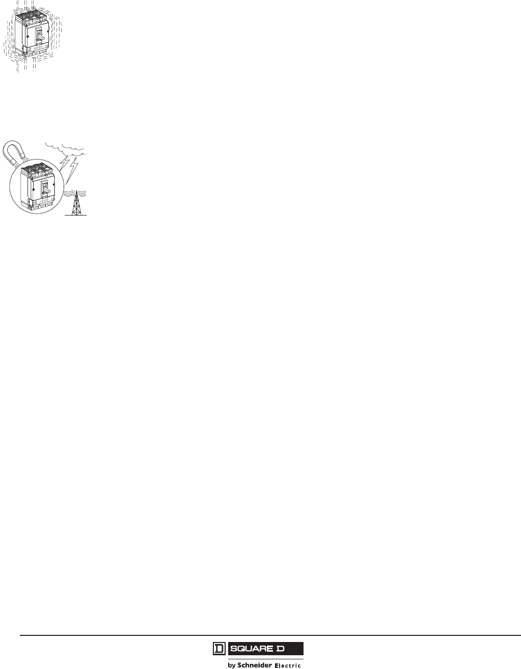
Electromagnetic disturbances
PowerPact H-, J-, and L-frame devices are protected against:
•overvoltages caused by circuit switching
•overvoltages caused by an atmospheric disturbances or by a distribution-system outage (such as
from failure due to lightning)
•devices emitting radio waves (radios, walkie-talkies, radar, etc.)
•electrostatic discharges produced directly by users
PowerPact H-, J-, and L-frame devices have successfully passed the electromagnetic-compatibility
tests (EMC) defined by the following international standards:
•IEC/EN 60947-2: Low-voltage switchgear and controlgear, part 2: Circuit breakers:
— Annex F: Immunity tests for circuit breakers with electronic protection
— Annex B: Immunity tests for residual current protection
•IEC/EN 61000-4-2: Electrostatic-discharge immunity tests
•IEC/EN 61000-4-3: Radiated, radio-frequency, electromagnetic-field immunity tests
•IEC/EN 61000-4-4: Electrical fast transient/burst immunity tests
•IEC/EN 61000-4-5: Surge immunity tests
•IEC/EN 61000-4-6: Immunity tests for conducted disturbances induced by radio frequency fields
•CISPR 11: Limits and methods of measurement of electromagnetic disturbance characteristics of
industrial, scientific and medical (ISM) radio-frequency equipment.
These tests ensure that:
•no nuisance tripping occurs
•tripping times are respected
Tropicalization
The materials used in PowerPact circuit breakers will not support the growth of fungus and mold.
PowerPact circuit breakers have passed the test defined below for extreme atmospheric conditions.
Dry cold and dry heat:
— IEC 68-2-1–dry cold at -55 °C
— IEC 68-2-2–dry heat at +85° C
Damp heat (tropicalization)
— IEC 68-2-30–damp heat (temperature + 55° C and relative humidity of 95%)
— IEC 68-2-52 level 2–salt mist
06114107
06114108

PowerPact™ H-, J-, and L-Frame Circuit Breakers
General Information
15
05/2012
© 2011–2012 Schneider Electric
All Rights Reserved
™
Special Ratings
The H-frame and J-frame circuit breakers also comply with the following special ratings:
•HACR rating
•SWD switch duty rating (applies only to 15 and 20 A / 277 Vac or less, 2P and 3P)
•HID high intensity discharge lighting rating (15–50 A)
The L-frame circuit breakers complies with the following special rating:
•HACR rating
Marine Ratings
UL Marine Listed/CSA Certified Circuit Breakers (UL489 Supplement SA)
The PowerPact H- and J-frame circuit breakers with thermal-magnetic trip units meet the UL 489
Supplement SA requirements for use on vessels of any length under or over 65 ft. (19.8 m). The
PowerPact H-, J-, and L-frame circuit breakers with Micrologic™ electronic trip units meet the UL 489
Supplement SA for use on vessels over 65 ft. (19.8 m) in length. Marine circuit breakers must not use
aluminum or aluminum alloys for terminal connections and must be calibrated at an ambient
temperature of 104° F (40° C). Standard circuit breakers should not be specified or used in the place of
marine rated circuit breakers.
Circuit breakers can be ordered with the Marine SA listing by adding the suffixes “LC” (copper lugs)
and “YA” (marine) to the catalog number.
UL Naval Listed/CSA Certified Circuit Breakers (UL 489 Supplement SB)
The PowerPact H-, J-, and L-frame circuit breakers with Micrologic trip units meet the UL 489
Supplement SB requirements for use on naval vessels. These circuit breakers are subject to various
vibration tests as described in UL 489 Supplement SB. Naval circuit breakers must not use aluminum or
aluminum alloys for terminal connections and must be calibrated at an ambient temperature of 122° F
(50° C). Standard circuit breakers should not be specified or used in the place of navel rated circuit
breakers.
Circuit breakers can be ordered with the Naval SB listing by adding the suffixes “LC” (copper lugs) and
“YA1” (naval) to the catalog number.
American Bureau of Shipping (ABS)
The PowerPact H-, J-, and L-Frame circuit breakers are certified to ABS-NVR (American Bureau of
Shipping - Naval Vessel Rules), for use on Naval vessels.
© 2011–2012 Schneider Electric
All Rights Reserved
PowerPact™ H-, J-, and L-Frame Circuit Breakers
General Information
16
05/2012
™
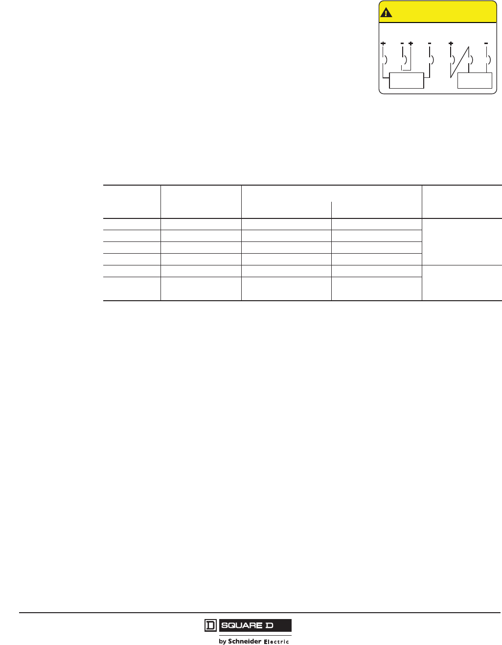
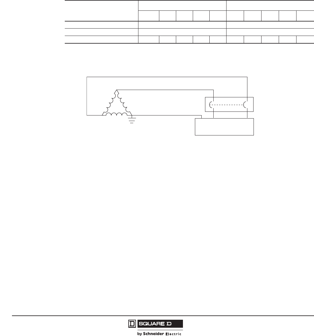
UL 489 SC Listed 500 Vdc Circuit Breakers
The UL Listed/CSA Certified thermal-magnetic J-Frame molded
case circuit breakers are specifically designed for use on
ungrounded dc systems having a maximum short-circuit voltage of
500 Vdc or a maximum floating (unloaded) voltage of 600 Vdc. The
circuit breakers are suitable for use only with UPS (uninterruptable
power supplies) and ungrounded systems. This two-level voltage
rating allows these circuit breakers to be applied to battery sources
having a short-circuit availability of 20,000 amperes at 500 Vdc.
These circuit breakers are UL Listed/CSA Certified for the
interrupting ratings shown only if applied with three poles
connected in series (series connection is external to circuit
breaker). See diagram below.
NOTE: Due to external series connection, I-Line™ circuit breakers are not available for this
application.
Table 5: DC Molded Case Circuit Breakers
Ampere
Rating
Circuit Breaker
Cat. No.
Adjustable Magnetic Trip Range—DC Amperes Performance Level
@ 500 Vdc
Low High
100 A JGL37100D81 400 600
20 k AIR
125 A JGL37125D81 400 600
150 A JGL37150D81 400 600
175 A JGL37175D81 400 600
200 A JGL37200D82 500 850
20 k AIR225 A JGL37225D82 500 850
250 A JGL37250D82 500 850
CAUTION/PRECAUCION/
ATTENTION
Connect only as shown/Conectar solo asi/
Francher seulement comme suit:
300 V 300 V
Load/Carga/
Charge
600 V MAX.
MAX. MAX.
Load/Carga/
Charge
or
o
ou
Source = 600 Vdc max. (floating)
500 Vdc max. (loaded)
PowerPact™ H-, J-, and L-Frame Circuit Breakers
General Information
17
05/2012
© 2011–2012 Schneider Electric
All Rights Reserved
™
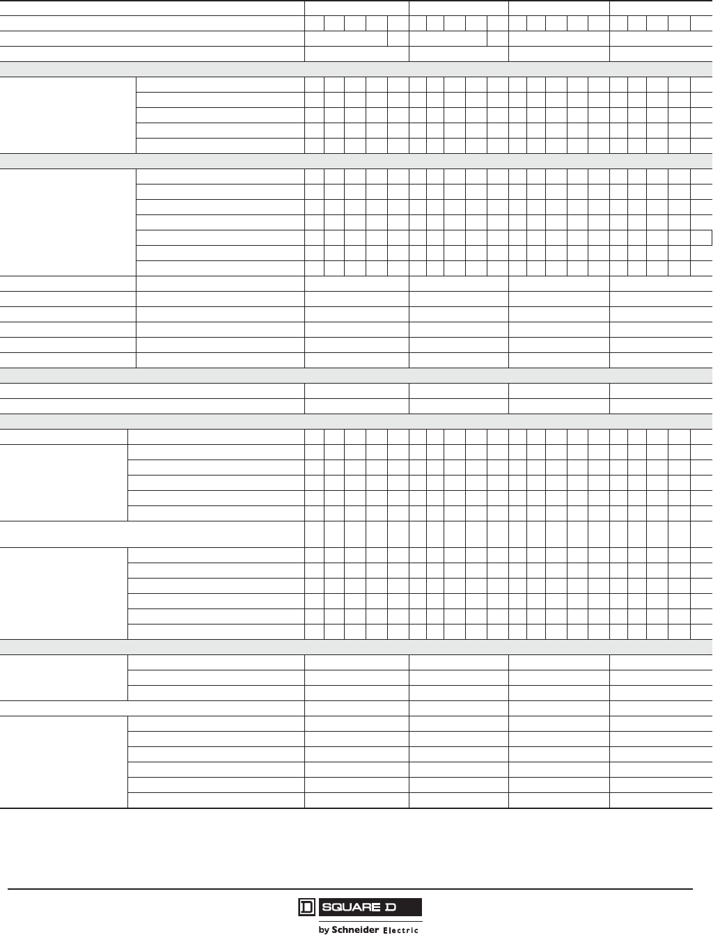
Table 6: Circuit Breakers
Circuit Breaker 150 A H-Frame 250 A J-Frame 400 A L-Frame 600 A L-Frame
Circuit Breaker Type HD HG HJ HL HR JD JG JJ JL JR LD LG LJ LL LR LD LG LJ LL LR
Number of poles12, 3 3 2, 3 3 3, 4 3, 4
Amperage Range (A) 15-150 70-250 70-400 200-600
UL 489 Circuit Breaker Ratings
UL/CSA/NOM
(kA rms)
240 Vac 25 65 100 125 200 25 65 100 125 200 25 65 100 125 200 25 65 100 125 200
480 Vac 18 35 65 100 200 18 35 65 100 200 18 35 65 100 200 18 35 65 100 200
600 Vac 14 18 25 50 100 14 18 25 50 100 14 18 25 50 100 14 18 25 50 100
250 Vdc220 20 20 20 --- 20 20 20 20 --- --- --- --- --- --- --- --- --- --- ---
500 Vdc2, 3 --- --- --- --- --- --- 20 --- --- --- --- --- --- --- --- --- --- --- --- ---
IEC 947-2 Circuit Breaker Ratings
Ultimate breaking capacity
(Icu)
(kA rms)
220/240 Vac 25 65 100 125 150 25 65 100 125 150 25 65 100 125 150 25 65 100 125 150
380/415 Vac 18 35 65 100 125 18 35 65 100 125 18 35 65 100 125 18 35 65 100 125
440/480 Vac 18 35 65 100 125 18 35 65 100 125 18 35 65 100 125 18 35 65 100 125
500/525 Vac 1418255075141825507514182550751418255075
4
690 Vac --- --- --- --- 20 --- --- --- --- 20 --- --- --- --- 20 --- --- --- --- 20
250 Vdc2--- --- --- --- --- 20 20 20 20 --- --- --- --- --- --- --- --- --- --- ---
500 Vdc2, 3 --- --- --- --- --- 20 20 20 20 --- --- --- --- --- --- --- --- --- --- ---
Service breaking capacity (Ics) % Icu 100% 100% 100% 100%
Insulation Voltage Vi750 Vac 750 Vac 750 Vac 750 Vac
Impulse Withstand Voltage Vimp 8 kVac 8 kVac 8 kVac 8 kVac
Operational Voltage Ve690 Vac 690 Vac 690 Vac 690 Vac
Sensor Rating In150 A 250 A 400 A 600 A
Utilization Category --- A A A A
Operations (Open-Close Cycles)
Without Current 4000 5000 5000 5000
With Current 4000 1000 1000 1000
Protection and Measurements
Short-circuit protection Magnetic only
Overload/short-circuit
protection
Thermal-magnetic ------------------------------
Electronic
with neutral protection (Off-0.5-1-OSN)5
with ground fault protection
with zone selective interlocking (ZSI)6
Display / I, V, f, P, E, THD measurements / interrupted-current
measurement
Options
Front display module (FDM121)
Operating assistance
Counters
Histories and alarms
Metering Com
Device status/control com
Dimensions / Weight / Connections
Dimensions 3P
(Unit Mount)
in. (mm)
Height 6.4 (163) 7.5 (191) 13.38 (340) 13.38 (340)
Width 4.1 (104) 4.1 (104) 5.51 (140) 5.51 (140)
Depth 3.4 (86) 3.4 (86) 4.33 (110) 4.33 (110)
Weight 3P - lb. (Kg) 4.8 (2.2) 5.3 (2.4) 13.2 (6.0) 13.7 (6.2)
Connections / Terminations
Unit Mount
I-Line™
Rear Connection
Plug-In
Drawout
Optional Lugs
1H and J-frame breakers with Micrologic™ trip units available only with 3P. The HJ, HL and the J-Frame 2P breakers are 3P modules.
2DC not available with PowerPact H, J or L-frame circuit breakers with Micrologic trip units.
3500 Vdc specific catalog numbers, ungrounded UPS systems only.
4Ics for 600 A L-frame circuit breaker at 525 V is 19 kA.

© 2011–2012 Schneider Electric
All Rights Reserved
PowerPact™ H-, J-, and L-Frame Circuit Breakers
General Information
18
05/2012
™
PowerPact H-, J-, and L-frame Circuit Breaker Trip Units
Thermal-Magnetic or Electronic Trip Unit?
Thermal-magnetic trip units (available on H- and J-frame circuit breakers only) protect against
overcurrents and short-circuits using tried and true techniques. For applications requiring installation
optimization and energy efficiency, electronic trip units offering more advanced protection functions
combined with measurements.
Trip units using digital electronics are faster as well as more accurate. Wide setting ranges make
installation upgrades easier. Designed with processing capabilities, Micrologic trip units can provide
measurement information and device operating assistance. With this information, users can avoid or
deal more effectively with disturbances and can play a more active role in system operation. They can
manage the installation, anticipate events and plan any necessary servicing.
5OSN: Over Sized Neutral protection for neutrals carrying high currents (e.g. 3rd harmonics).
6ZSI using restraint wires.
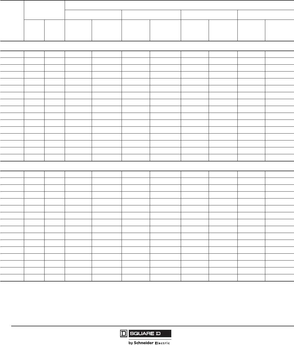
Table 7: Micrologic™ Trip Unit Features
Features
Micrologic Trip Unit (X = Standard Feature, O = Available Option
Standard Ammeter Energy
3.2/3.3 3.2S/3.3S 5.2A/5.3A 6.2A/6.3A 5.2E/5.3E 6.2E/6.3E
LI X
LSI1
1The LSI with 3.2S/3.3S trip units have fixed short time and long time delays.
XX X
LSIG/Ground Fault Trip2
2Requires neutral current transformer on three-phase four-wire loads.
XX
Ground-Fault Alarm Trip X X
Current Settings Directly in Amperes X X X X X X
True RMS Sensing X X X X X X
UL Listed XXXXXX
Thermal Imaging XXXXXX
LED for Long-Time Pickup X X X X X X
LED for Long-Time Alarm X X X X X X
LED Green “Ready” Indicator X X X X X X
Up to 12 Alarms Used Together X X X X
Digital Ammeter X X X X
Zone-Selective Interlocking3
3ZSI for H/J-frame devices is only IN. ZSI for L-frame devices is IN and OUT.
XXXX
Communications O O O O O O
LCD Display X X X X
Front Display Module FDM121 O O O O
Advanced User Interface X X X X
Neutral Protection X X X X
Contact Wear Indication4
4Indication available using the communication system only.
XXXX
Incremental Fine Tuning of Settings X X X X
Load Profile4, 5
5% of hours in 4 current ranges: 0–49%, 50–79%, 80–89%, and >90% In.
XXXX
Power Measurement XX
Power Quality Measurements XX
PowerPact™ H-, J-, and L-Frame Circuit Breakers
General Information
19
05/2012
© 2011–2012 Schneider Electric
All Rights Reserved
™
Accurate Measurements for Complete Protection
PowerPact H-, J-, and L-frame circuit breakers devices offer excellent measurement accuracy from
15 amperes on up to the short-circuit currents. This is made possible by a new generation of current
transformers combining “iron-core” sensors for self-powered electronics and “air core” sensors
(Rogowski coils) for measurements. The protection functions are managed by an ASIC (Application
Specific Integrated Circuit) component that is independent of the measurement functions. This
independence ensures immunity to conducted and radiated disturbances and a high level of reliability.
Numerous Security Functions
Torque-limiting screws
The screws secure the trip unit to the circuit breaker. When the correct tightening torque is
reached, the screw heads break off. Optimum tightening avoids any risk of temperature rise. A
torque wrench is no longer required.
Easy and sure changing of trip
units
All trip units are interchangeable, without wiring. A mechanical mismatch-protection system
makes it impossible to mount a trip unit on a circuit breaker with a lower rating.
“Ready” LED for a continuous
self-test
The LED on the front of the electronic trip units indicates the result of the self-test running
continuously on the measurement system and the tripping release. As long as the green LED is
flashing, the links between the CTs, the processing electronics and the tripping mechanism are
operational. The circuit breaker is ready to protect. A minimum current of 15 to 50 A, depending
on the device, is required for this indication function.
A patented dual adjustment
system for protection functions.
Available on Micrologic™ 5 / 6 trip units, the system consists of:
• an adjustment using rotary switches sets the maximum value
• an adjustment using the keypad or made remotely, fine-tunes the setting. This setting may
not exceed the first one. It can be read directly on the Micrologic trip unit screen, to within
one ampere and a fraction of a second.
© 2011–2012 Schneider Electric
All Rights Reserved
PowerPact™ H-, J-, and L-Frame Circuit Breakers
Circuit Breakers
20
05/2012
™
Section 3—Circuit Breakers
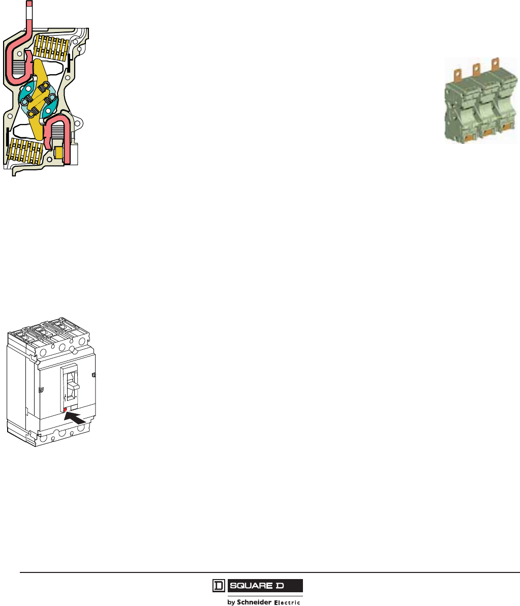
Dual-Break Rotating Contacts
All PowerPact H-, J-, and L-frame circuit breakers are equipped with dual-break rotating contacts that
reduce the amount of peak current during a short circuit fault. This reduces the let-through currents
and enhances equipment protection.
Reduced Let-Through Currents
The moving contact has the shape of an elongated “S” and rotates around a
floating axis. The shape of the fixed and moving contacts are such that the
repelling forces appear as soon as the circuit reaches approximately 15 times In.
Due to the rotating movement, repulsion is rapid and the device greatly limits
short-circuit currents, whatever the interrupting level of the unit (D, G, J or L). The
fault current is extinguished before it can fully develop. Lower let-through currents
provide less peak energy, reducing the required bus bar bracing, lowering
enclosure pressure, and delivering improved series or combination ratings. See
page 21 for UL Current Limiting labels.
High Ampere Interrupting Ratings (AIR)
Circuit breakers are available with interrupting ratings up to:
•200 kA at 240 Vac delta
•200 kA at 480 Vac delta
•100 kA at 600 Vac delta.
See Table 1 for additional performance levels.
Internal Operating Mechanism
PowerPact H-, J-, and L-frame circuit breakers have an over-center toggle mechanism providing quick-
make, quick-break operation. The operating mechanism is also trip-free, which allows tripping even
when the circuit breaker handle is held in the “ON” position.
Internal cross-bars provide common opening and closing of all poles with a single operating handle.
All PowerPact circuit breakers have an integral push-to-trip button in the cover to manually trip the
circuit breaker. This should be used as part of a regular preventive maintenance program.
06113234
06113262
06113266
Push-to-Trip
PowerPact™ H-, J-, and L-Frame Circuit Breakers
Circuit Breakers
21
05/2012
© 2011–2012 Schneider Electric
All Rights Reserved
™
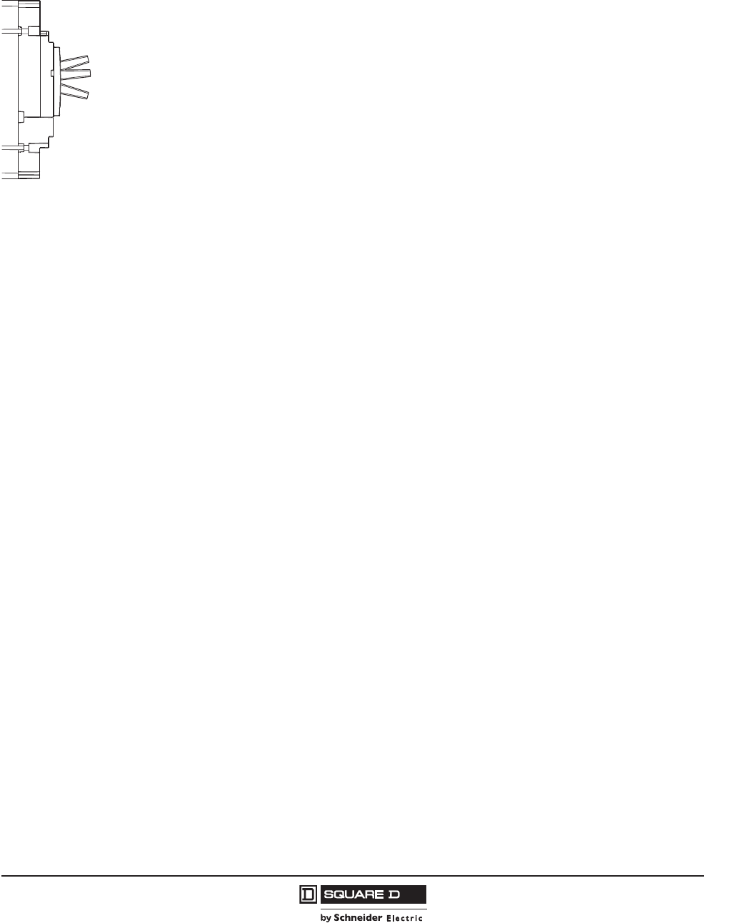
Handle Position Indication
The circuit breaker handle can assume any of three positions, ON, tripped or OFF as shown. The
center tripped position provides positive visual indication that the circuit breaker has tripped.
The circuit breaker can be reset by first pushing the handle to the extreme “OFF” position. Power can
then be restored to the load by pushing the handle to the “ON” position.
Circuit Breaker Ratings
The interrupting rating is the highest current at rated voltage the circuit breaker is designed to safely
interrupt under standard test conditions. Circuit breakers must be selected with interrupting ratings equal
to or greater than the available short-circuit current at the point where the circuit breaker is applied to the
system (unless it is a branch device in a series rated combination). Interrupting ratings are shown on
Table 6: Circuit Breakers on page 17 and on the faceplate label on the front of the circuit breaker.
Reverse Feeding of Circuit Breakers
The standard unit-mount H-, J-, and L-frame circuit breakers have sealed trip units and may be reverse
fed. See Tables 12–13 and 24–29 for catalog numbers.
Circuit breakers with field-interchangeable trip units (designated by the suffix T and labeled “LINE” and
“LOAD”) cannot be reverse fed. Neither can circuit breaker frames without terminations or trip units.
Current Limiting
The current limiting attributes of PowerPact H-, J-, and L-frame circuit breakers provide greater
protection for downstream devices by limiting the let-through current in the event of a fault. The
current-limiting capabilities of HJ/HL/HR, JJ/JL/JR, and LJ/LL/LR frame circuit breakers are
documented with Underwriters Laboratories and Canadian Standards Association. These current-
limiting circuit breakers ship with a label that identifies them as UL/CSA Current Limiting CIrcuit
Breakers. (The HD/HG, JD/JG, and LD/LG circuit breakers do not carry the UL Current Limiting label)
The trip curves with let-through data are available in the trip curve section in this catalog.
Please note that as let-through curves for UL Listed/CSA Certified Current-Limiting Circuit Breakers,
these curves are maximum let-through values.
100% Rated
Some models of the H-, J-, and L-frame circuit breakers are UL Listed/CSA Certified to be applied at
up to 100% of their current rating. Because of the additional heat generated, the use of specially-
designed enclosures, copper lugs on H- and J-frame circuit breakers, and 194°F (90°C) rated wire is
required when applying circuit breakers at 100% of continuous current rating. (L-frame circuit breakers
can use aluminum or copper lugs.) Markings on the circuit breaker indicate the minimum enclosure
size and ventilation required. The 194°F (90°C) wire must be sized according to the ampacities of the
167°F (75°C) wire column in the NEC. Circuit breakers with 100% rating can also be used in
applications requiring only standard (80%) continuous loading.
ON
Tripped
OFF
© 2011–2012 Schneider Electric
All Rights Reserved
PowerPact™ H-, J-, and L-Frame Circuit Breakers
Circuit Breakers
22
05/2012
™
100% ratings valid for:
•3P H/J-frame unit mount construction only
•3P/4P L-frame 250 A and 400 A unit mount construction
•3P L-frame 250 A and 400 A I-Line™ construction
Corner Grounded Delta Ratings (1Ø-3Ø)
Circuit breakers suitable for corner-grounded circuits are marked 1Ø-3Ø. For additional information,
refer to data bulletin 2700DB0202R2/09.
Table 8: Corner Grounded Delta Ratings (1Ø-3Ø)
2P H-Frame 2P J-Frame
HD HG HJ1
1Built using 3P module
HL1HR1JD1JG1JJ1JL1JR1
Ampere Rating (A) 15–150 150–250
Voltage Rating (Vac) 240 240
UL Interrupting Rating (kA) 42 42 65 100 200 42 42 65 100 200
Figure 2: Three-Phase 240 Vac Corner-Grounded Delta System
2P
Circuit Breaker
Load
06113257
PowerPact™ H-, J-, and L-Frame Circuit Breakers
Circuit Breakers
23
05/2012
© 2011–2012 Schneider Electric
All Rights Reserved
™
Special Applications
Protection of Industrial Control Panels
PowerPact H-, J-, and L-frame circuit breakers are also used in industrial control panels. They serve as
an incoming devices or can be combined with contactors to protect motor feeders:
•compliance with worldwide standards including IEC 60947-2 and UL 508 / CSA C22.2 N°14
•overload and short-circuit protection
•installation in universal and functional type
PowerPact H-, J-, and L-frame circuit breakers equipped for motor protection functions as described in
the following pages can be used in industrial control panels. The accessories for the PowerPact H-, J-,
and L-frame circuit breakers are suitable for the special needs of these applications.
400 Hz Applications
Micrologic™ 3.2/3, 5.2/3 A or E and 6.2/3 with A or E measurement functions are suitable for 400 Hz.
The use of electronics offers the advantage of greater operating stability when the frequency varies.
However the units are still subject to temperature rise caused by the frequency.
The practical consequences are:
•limit settings: see the Ir derating table below
•the long-time, short-time and instantaneous pick-ups are not modified (see pages 58 or 60)
•the accuracy of the displayed measurements is 2% (class II).
Auxiliary Switch (OF) in 400 Hz Networks
Shunt Trip (MX) or Undervoltage Trip (MN) Voltage Release at 400 Hz and 440 V
For circuit breakers on 400 Hz systems, only 125 Vdc undervoltage trip (MN) or shunt trip (MX) releases
may be used. The release must be supplied by the 400 Hz system through a rectifier bridge (to be selected
from the table below) and an additional resistor with characteristics depending on the system voltage.
Table 9: Thermal Derating Maximum Ir Setting
Circuit Breaker Maximum Setting Coefficient Max Ir Setting at 400 Hz
H-Frame, 100 A 1 100
J-Frame, 250 A 0.9 225
L-Frame, 400 A 0.8 320
L-Frame, 600 A 0.65 390
Table 10: Electrical Characteristics of Auxiliary Switches
Contact Standard Low Level
Utilization cat. (IEC 60947-5-1) AC12 AC15 AC12 AC15
Operational current
24 V 6 A6 A5 A3 A
40 V 6 A6 A5 A3 A
110 V 6 A5 A5 A2.5 A
200/240 V 6 A 4 A 5 A 2 A
380/415 V 6 A 2 A 5 A 1.5 A
Table 11: Rectifier Bridges for MN or MX Releases
Voltage Rectifier Additional Resistor
220/240 V
Thomson 110 BHz or
General Instrument W06 or
Semikron SKB at 1.2/1.3
4.2 k-5 W
380/240 V Semikron SKB at 1.2/1.3 10.7 k-10 W
© 2011–2012 Schneider Electric
All Rights Reserved
PowerPact™ H-, J-, and L-Frame Circuit Breakers
Circuit Breakers
24
05/2012
™
H- and J-Frame Catalog Numbers
Unit-Mount Circuit Breaker Catalog Numbers
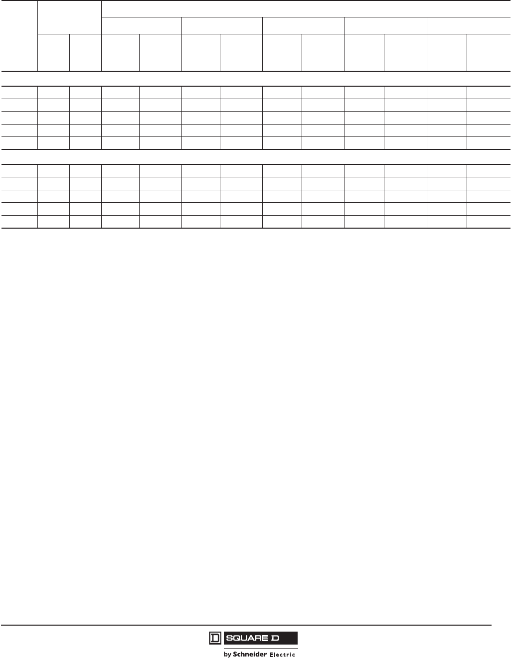
Table 12: PowerPact H-Frame 150 A Unit-Mount1 Thermal-Magnetic Circuit Breakers (600 Vac, 250 Vdc) with Factory
Sealed Trip Unit (Suitable for Reverse Connection)
Current
Rating @
40 C
Fixed AC
Magnetic Trip
Interrupting Rating
DG J
2L2
Hold Trip
Standard
(80%)
Rated
100% Rated3
Standard
(80%)
Rated
100% Rated3
Standard
(80%)
Rated
100%
Rated3
Standard
(80%)
Rated
100%
Rated3
H-Frame, 150 A, 2P, 600 Vac 50/60Hz, 250 Vdc4
15 A 350 A 750 A HDL26015 HDL26015C HGL26015 HGL26015C HJL26015 HJL26015C HLL26015 HLL26015C
20 A 350 A 750 A HDL26020 HDL26020C HGL26020 HGL26020C HJL26020 HJL26020C HLL26020 HLL26020C
25 A 350 A 750 A HDL26025 HDL26025C HGL26025 HGL26025C HJL26025 HJL26025C HLL26025 HLL26025C
30 A 350 A 750 A HDL26030 HDL26030C HGL26030 HGL26030C HJL26030 HJL26030C HLL26030 HLL26030C
35 A 400 A 850 A HDL26035 HDL26035C HGL26035 HGL26035C HJL26035 HJL26035C HLL26035 HLL26035C
40 A 400 A 850 A HDL26040 HDL26040C HGL26040 HGL26040C HJL26040 HJL26040C HLL26040 HLL26040C
45 A 400 A 850 A HDL26045 HDL26045C HGL26045 HGL26045C HJL26045 HJL26045C HLL26045 HLL26045C
50 A 400 A 850 A HDL26050 HDL26050C HGL26050 HGL26050C HJL26050 HJL26050C HLL26050 HLL26050C
60 A 800 A 1450 A HDL26060 HDL26060C HGL26060 HGL26060C HJL26060 HJL26060C HLL26060 HLL26060C
70 A 800 A 1450 A HDL26070 HDL26070C HGL26070 HGL26070C HJL26070 HJL26070C HLL26070 HLL26070C
80 A 800 A 1450 A HDL26080 HDL26080C HGL26080 HGL26080C HJL26080 HJL26080C HLL26080 HLL26080C
90 A 800 A 1450 A HDL26090 HDL26090C HGL26090 HGL26090C HJL26090 HJL26090C HLL26090 HLL26090C
100 A 900 A 1700 A HDL26100 HDL26100C HGL26100 HGL26100C HJL26100 HJL26100C HLL26100 HLL26100C
110 A 900 A 1700 A HDL26110 HDL26110C HGL26110 HGL26110C HJL26110 HJL26110C HLL26110 HLL26110C
125 A 900 A 1700 A HDL26125 HDL26125C HGL26125 HGL26125C HJL26125 HJL26125C HLL26125 HLL26125C
150 A 900 A 1700 A HDL26150 HDL26150C HGL26150 HGL26150C HJL26150 HJL26150C HLL26150 HLL26150C
H-Frame, 150 A, 3P, 600 Vac 50/60Hz, 250 Vdc
15 A 350 A 750 A HDL36015 HDL36015C HGL36015 HGL36015C HJL36015 HJL36015C HLL36015 HLL36015C
20 A 350 A 750 A HDL36020 HDL36020C HGL36020 HGL36020C HJL36020 HJL36020C HLL36020 HLL36020C
25 A 350 A 750 A HDL36025 HDL36025C HGL36025 HGL36025C HJL36025 HJL36025C HLL36025 HLL36025C
30 A 350 A 750 A HDL36030 HDL36030C HGL36030 HGL36030C HJL36030 HJL36030C HLL36030 HLL36030C
35 A 400 A 850 A HDL36035 HDL36035C HGL36035 HGL36035C HJL36035 HJL36035C HLL36035 HLL36035C
40 A 400 A 850 A HDL36040 HDL36040C HGL36040 HGL36040C HJL36040 HJL36040C HLL36040 HLL36040C
45 A 400 A 850 A HDL36045 HDL36045C HGL36045 HGL36045C HJL36045 HJL36045C HLL36045 HLL36045C
50 A 400 A 850 A HDL36050 HDL36050C HGL36050 HGL36050C HJL36050 HJL36050C HLL36050 HLL36050C
60 A 800 A 1450 A HDL36060 HDL36060C HGL36060 HGL36060C HJL36060 HJL36060C HLL36060 HLL36060C
70 A 800 A 1450 A HDL36070 HDL36070C HGL36070 HGL36070C HJL36070 HJL36070C HLL36070 HLL36070C
80 A 800 A 1450 A HDL36080 HDL36080C HGL36080 HGL36080C HJL36080 HJL36080C HLL36080 HLL36080C
90 A 800 A 1450 A HDL36090 HDL36090C HGL36090 HGL36090C HJL36090 HJL36090C HLL36090 HLL36090C
100 A 900 A 1700 A HDL36100 HDL36100C HGL36100 HGL36100C HJL36100 HJL36100C HLL36100 HLL36100C
110 A 900 A 1700 A HDL36110 HDL36110C HGL36110 HGL36110C HJL36110 HJL36110C HLL36110 HLL36110C
125 A 900 A 1700 A HDL36125 HDL36125C HGL36125 HGL36125C HJL36125 HJL36125C HLL36125 HLL36125C
150 A 900 A 1700 A HDL36150 HDL36150C HGL36150 HGL36150C HJL36150 HJL36150C HLL36150 HLL36150C
1Standard Lug Kit: AL150HD Terminal Wire Range: 14–3/0 AWG Al or Cu
2UL Listed/CSA Certified as current limiting circuit breakers.
3100% rated circuit breakers have copper lugs and can be used with copper wire only.
4HD and HG circuit breakers are true 2-pole construction.
PowerPact™ H-, J-, and L-Frame Circuit Breakers
Circuit Breakers
25
05/2012
© 2011–2012 Schneider Electric
All Rights Reserved
™
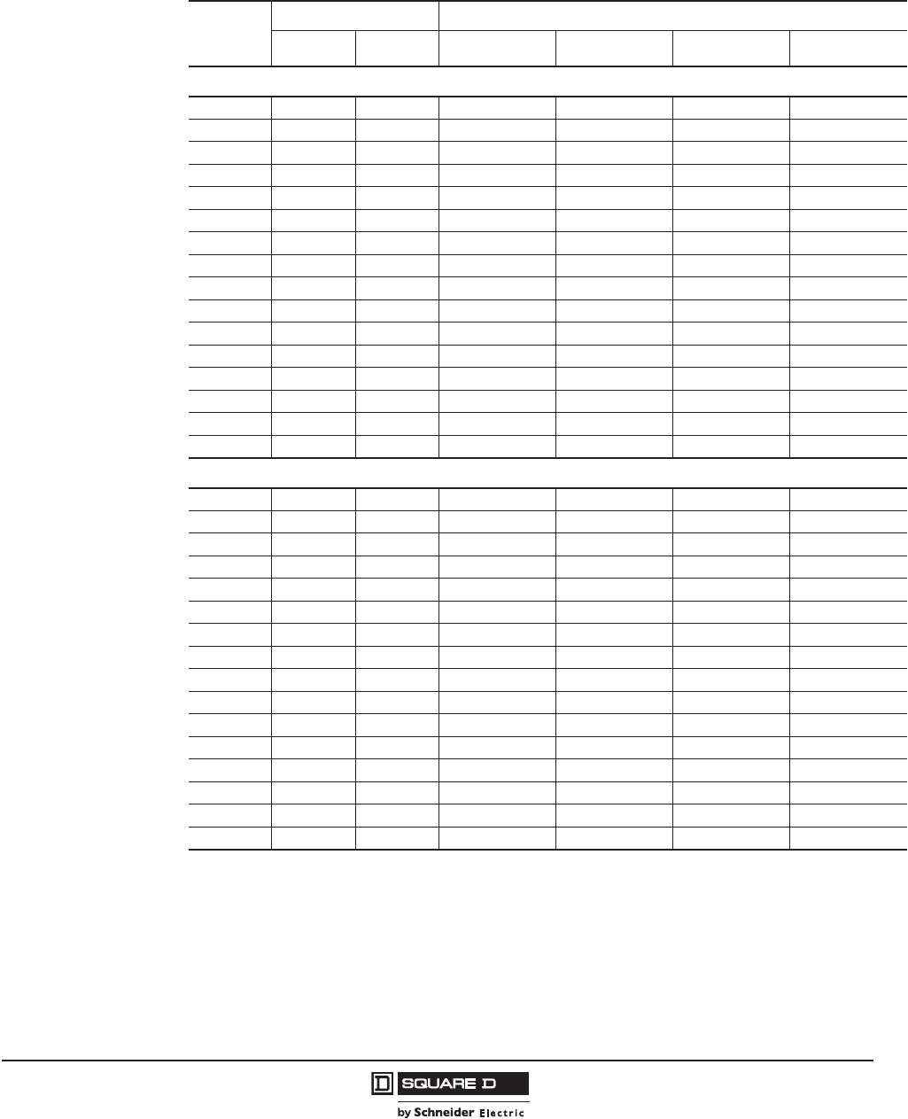
Table 13: PowerPact J-Frame 250 A Unit-Mount Thermal-Magnetic Circuit Breakers with Factory Sealed Trip Unit
(Suitable for Reverse Connection)
Current
Rating
@ 40 C
Adjustable AC
Magnetic Trip
Interrupting Rating
DGJ
1L1R1
Hold Trip
Standard
(80%)
Rated
100%
Rated2
Standard
(80%)
Rated
100%
Rated2
Standard
(80%)
Rated
100%
Rated2
Standard
(80%)
Rated
100%
Rated2
Standard
(80%)
Rated
100%
Rated2
J-Frame, 250 A, 2P, 600 Vac 50/60Hz, 250 Vdc
150 A3750 A 1500 A JDL26150 JDL26150C JGL26150 JGL26150C JJL26150 JJL26150C JLL26150 JLL26150C ——
175 A3875 A 1750 A JDL26175 JDL26175C JGL26175 JGL26175C JJL26175 JJL26175C JLL26175 JLL26175C ——
200 A41000 A 2000 A JDL26200 JDL26200C JGL26200 JGL26200C JJL26200 JJL26200C JLL26200 JLL26200C ——
225 A41125 A 2250 A JDL26225 JDL26225C JGL26225 JGL26225C JJL26225 JJL26225C JLL26225 JLL26225C ——
250 A41250 A 2500 A JDL26250 JDL26250C JGL26250 JGL26250C JJL26250 JJL26250C JLL26250 JLL26250C ——
J-Frame, 250 A, 3P, 600 Vac 50/60Hz, 250 Vdc
150 A3750 A 1500 A JDL36150 JDL36150C JGL36150 JGL36150C JJL36150 JJL36150C JLL36150 JLL36150C JRL36150 JRL36150C
175 A3875 A 1750 A JDL36175 JDL36175C JGL36175 JGL36175C JJL36175 JJL36175C JLL36175 JLL36175C JRL36175 JRL36175C
200 A41000 A 2000 A JDL36200 JDL36200C JGL36200 JGL36200C JJL36200 JJL36200C JLL36200 JLL36200C JRL36200 JRL36200C
225 A41125 A 2250 A JDL36225 JDL36225C JGL36225 JGL36225C JJL36225 JJL36225C JLL36225 JLL36225C JRL36225 JRL36225C
250 A41250 A 2500 A JDL36250 JDL36250C JGL36250 JGL36250C JJL36250 JJL36250C JLL36250 JLL36250C JRL36250 JRL36250C
1UL Listed/CSA Certified as current limiting circuit breakers.
2100% rated circuit breakers have copper lugs and can be used with copper wire only.
3Standard Lug Kit: AL175JD Terminal Wire Range: 4–4/0 AWG Al or Cu
4Standard Lug Kit: AL250JD Terminal Wire Range: 3/0 AWG–350 kcmil Al or Cu

© 2011–2012 Schneider Electric
All Rights Reserved
PowerPact™ H-, J-, and L-Frame Circuit Breakers
Circuit Breakers
26
05/2012
™
Table 14: H-Frame 150 A and J-Frame 250 A Electronic Trip UL Rated Circuit Breakers
(600 Vac, 50/60 Hz) With Factory Sealed Trip Unit Suitable for Reverse Connection
Electronic Trip Unit Sensor
Rating
Interrupting Rating
Type Function Trip Unit D G J1L2R2
Standard (80%) Rated Circuit Breakers, 3P
Standard LI 3.22
60 A3
100 A3
150 A3
HDL36060U31X
HDL36100U31X
HDL36150U31X
HGL36060U31X
HGL36100U31X
HGL36150U31X
HJL36060U31X
HJL36100U31X
HJL36150U31X
HLL36060U31X
HLL36100U31X
HLL36150U31X
HRL36060U31X
HRL36100U31X
HRL36150U31X
250 A4JDL36250U31X JGL36250U31X JJL36250U31X JLL36250U31X JRL36250U31X
Standard LSI 3.2S2
60 A3
100 A3
150 A3
HDL36060U33X
HDL36100U33X
HDL36150U33X
HGL36060U33X
HGL36100U33X
HGL36150U33X
HJL36060U33X
HJL36100U33X
HJL36150U33X
HLL36060U33X
HLL36100U33X
HLL36150U33X
HRL36060U33X
HRL36100U33X
HRL36150U33X
250 A4JDL36250U33X JGL36250U33X JJL36250U33X JLL36250U33X JRLL36250U33X
Ammeter LSI 5.2A
60 A3
100 A3
150 A3
HDL36060U43X
HDL36100U43X
HDL36150U43X
HGL36060U43X
HGL36100U43X
HGL36150U43X
HJL36060U43X
HJL36100U43X
HJL36150U43X
HLL36060U43X
HLL36100U43X
HLL36150U43X
HRL36060U43X
HRL36100U43X
HRL36150U43X
250 A4JDL36250U43X JGL36250U43X JJL36250U43X JLL36250U43X JRL36250U43X
Energy LSI 5.2E
60 A3
100 A3
150 A3
HDL36060U53X
HDL36100U53X
HDL36150U53X
HGL36060U53X
HGL36100U53X
HGL36150U53X
HJL36060U53X
HJL36100U53X
HJL36150U53X
HLL36060U53X
HLL36100U53X
HLL36150U53X
HRL36060U53X
HRL36100U53X
HRL36150U53X
250 A4JDL36250U53X JGL36250U53X JJL36250U53X JLL36250U53X JRL36250U53X
Ammeter LSIG 6.2A
60 A3
100 A3
150 A3
HDL36060U44X
HDL36100U44X
HDL36150U44X
HGL36060U44X
HGL36100U44X
HGL36150U44X
HJL36060U44X
HJL36100U44X
HJL36150U44X
HLL36060U44X
HLL36100U44X
HLL36150U44X
HRL36060U44X
HRL36100U44X
HRL36150U44X
250 A4JDL36250U44X JGL36250U44X JJL36250U44X JLL36250U44X JRL36250U44X
Energy LSIG 6.2E
60 A3
100 A3
150 A3
HDL36060U54X
HDL36100U54X
HDL36150U54X
HGL36060U54X
HGL36100U54X
HGL36150U54X
HJL36060U54X
HJL36100U54X
HJL36150U54X
HLL36060U54X
HLL36100U54X
HLL36150U54X
HRL36060U54X
HRL36100U54X
HRL36150U54X
250 A4JDL36250U54X JGL36250U54X JJL36250U54X JLL36250U54X JRL36250U54X
100% Rated Circuit Breakers, 3P5
Standard LI 3.22
60 A3
100 A3
150 A3
HDL36060CU31X
HDL36100CU31X
HDL36150CU31X
HGL36060CU31X
HGL36100CU31X
HGL36150CU31X
HJL36060CU31X
HJL36100CU31X
HJL36150CU31X
HLL36060CU31X
HLL36100CU31X
HLL36150CU31X
HRL36060CU31X
HRL36100CU31X
HRL36150CU31X
250 A4JDL36250CU31X JGL36250CU31X JJL36250CU31X JLL36250CU31X JRL36250CU31X
Standard LSI 3.2S2
60 A3
100 A3
150 A3
HDL36060CU33X
HDL36100CU33X
HDL36150CU33X
HGL36060CU33X
HGL36100CU33X
HGL36150CU33X
HJL36060CU33X
HJL36100CU33X
HJL36150CU33X
HLL36060CU33X
HLL36100CU33X
HLL36150CU33X
HRL36060CU33X
HRL36100CU33X
HRL36150CU33X
250 A4JDL36250CU33X JGL36250CU33X JJL36250CU33X JLL36250CU33X JRL36250CU33X
Ammeter LSI 5.2A
60 A3
100 A3
150 A3
HDL36060CU43X
HDL36100CU43X
HDL36150CU43X
HGL36060CU43X
HGL36100CU43X
HGL36150CU43X
HJL36060CU43X
HJL36100CU43X
HJL36150CU43X
HLL36060CU43X
HLL36100CU43X
HLL36150CU43X
HRL36060CU43X
HRL36100CU43X
HRL36150CU43X
250 A4JDL36250CU43X JGL36250CU43X JJL36250CU43X JLL36250CU43X JRL36250CU43X
Energy LSI 5.2E
60 A3
100 A3
150 A3
HDL36060CU53X
HDL36100CU53X
HDL36150CU53X
HGL36060CU53X
HGL36100CU53X
HGL36150CU53X
HJL36060CU53X
HJL36100CU53X
HJL36150CU53X
HLL36060CU53X
HLL36100CU53X
HLL36150CU53X
HRL36060CU53X
HRL36100CU53X
HRL36150CU53X
250 A4JDL36250CU53X JGL36250CU53X JJL36250CU53X JLL36250CU53X JRL36250CU53X
1UL Listed/CSA Certified as current limiting circuit breakers.
23P circuit breakers with this trip unit can be used for 2P applications.
3Standard Lug Kit: AL150HD Terminal Wire Range: 14–3/0 AWG Al or Cu
4Standard Lug Kit: AL250JD Terminal Wire Range: 3/0 AWG–350 kcmil Al or Cu
For smaller wire range (4–4/0 AWG Al or Cu), replace the lug’s wire binding screws with the larger binding screws provided.
5100% rated circuit breakers have copper lugs and can be used with copper wire only.
PowerPact™ H-, J-, and L-Frame Circuit Breakers
Circuit Breakers
27
05/2012
© 2011–2012 Schneider Electric
All Rights Reserved
™
I-Line™ Circuit Breaker Catalog Numbers
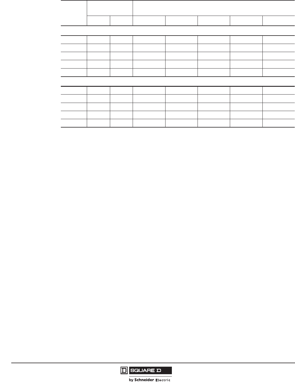
Table 15: PowerPact H-Frame 150 A I-Line Thermal-Magnetic Circuit Breakers1 with Factory
Sealed Trip Unit (Suitable for Reverse Connection)2
1Standard Lug Kit: AL150HD Terminal Wire Range: 14–3/0 AWG Al or Cu
2No 100% I-Line available.
Current
Rating @
40 C
Fixed AC Magnetic Trip Interrupting Rating3 Standard (80%) Rated
3 () Indicates phasing. See “Catalog Numbering” on page 8.
Hold Trip D G J4
4UL Listed/CSA Certified as current limiting circuit breakers.
L4
H-Frame, 150 A, 2P, 600 Vac 50/60Hz, 250 Vdc
15 A 350 A 750 A HDA26015( ) HGA26015( ) HJA26015( ) HLA26015( )
20 A 350 A 750 A HDA26020( ) HGA26020( ) HJA26020( ) HLA26020( )
25 A 350 A 750 A HDA26025( ) HGA26025( ) HJA26025( ) HLA26025( )
30 A 350 A 750 A HDA26030( ) HGA26030( ) HJA26030( ) HLA26030( )
35 A 400 A 850 A HDA26035( ) HGA26035( ) HJA26035( ) HLA26035( )
40 A 400 A 850 A HDA26040( ) HGA26040( ) HJA26040( ) HLA26040( )
45 A 400 A 850 A HDA26045( ) HGA26045( ) HJA26045( ) HLA26045( )
50 A 400 A 850 A HDA26050( ) HGA26050( ) HJA26050( ) HLA26050( )
60 A 800 A 1450 A HDA26060( ) HGA26060( ) HJA26060( ) HLA26060( )
70 A 800 A 1450 A HDA26070( ) HGA26070( ) HJA26070( ) HLA26070( )
80 A 800 A 1450 A HDA26080( ) HGA26080( ) HJA26080( ) HLA26080( )
90 A 800 A 1450 A HDA26090( ) HGA26090( ) HJA26090( ) HLA26090( )
100 A 900 A 1700 A HDA26100( ) HGA26100( ) HJA26100( ) HLA26100( )
110 A 900 A 1700 A HDA26110( ) HGA26110( ) HJA26110( ) HLA26110( )
125 A 900 A 1700 A HDA26125( ) HGA26125( ) HJA26125( ) HLA26125( )
150 A 900 A 1700 A HDA26150( ) HGA26150( ) HJA26150( ) HLA26150( )
H-Frame, 150 A, 3P, 600 Vac 50/60Hz, 250 Vdc
15 A 350 A 750 A HDA36015 HGA36015 HJA36015 HLA36015
20 A 350 A 750 A HDA36020 HGA36020 HJA36020 HLA36020
25 A 350 A 750 A HDA36025 HGA36025 HJA36025 HLA36025
30 A 350 A 750 A HDA36030 HGA36030 HJA36030 HLA36030
35 A 400 A 850 A HDA36035 HGA36035 HJA36035 HLA36035
40 A 400 A 850 A HDA36040 HGA36040 HJA36040 HLA36040
45 A 400 A 850 A HDA36045 HGA36045 HJA36045 HLA36045
50 A 400 A 850 A HDA36050 HGA36050 HJA36050 HLA36050
60 A 800 A 1450 A HDA36060 HGA36060 HJA36060 HLA36060
70 A 800 A 1450 A HDA36070 HGA36070 HJA36070 HLA36070
80 A 800 A 1450 A HDA36080 HGA36080 HJA36080 HLA36080
90 A 800 A 1450 A HDA36090 HGA36090 HJA36090 HLA36090
100 A 900 A 1700 A HDA36100 HGA36100 HJA36100 HLA36100
110 A 900 A 1700 A HDA36110 HGA36110 HJA36110 HLA36110
125 A 900 A 1700 A HDA36125 HGA36125 HJA36125 HLA36125
150 A 900 A 1700 A HDA36150 HGA36150 HJA36150 HLA36150
© 2011–2012 Schneider Electric
All Rights Reserved
PowerPact™ H-, J-, and L-Frame Circuit Breakers
Circuit Breakers
28
05/2012
™
Table 16: PowerPact J-Frame 250A I-Line™ Thermal-Magnetic Circuit Breakers with Factory
Sealed Trip Unit (Suitable for Reverse Connection)1
1No 100% I-Line available.
Current
Rating @
40 C
Adjustable AC
Magnetic Trip Interrupting Rating2 Standard (80%) Rated
2() Indicates phasing. See “Catalog Numbering” on page 8.
Hold Trip D G J3
3UL Listed/CSA Certified as current limiting
L3R3
J-Frame, 250 A, 2P, 600 Vac 50/60Hz, 250 Vdc
150 A4
4Standard Lug Kit: AL175JD Terminal Wire Range: 4–4/0 AWG Al or Cu
750 A 1500 A JDA26150( ) JGA26150( ) JJA26150( ) ——
175 A4875 A 1750 A JDA26175( ) JGA26175( ) JJA26175( ) ——
200 A5
5Standard Lug Kit: AL250JD Terminal Wire Range: 3/0 AWG–350 kcmil Al or Cu
1000 A 2000 A JDA26200( ) JGA26200( ) JJA26200( ) ——
225 A51125 A 2250 A JDA26225( ) JGA26225( ) JJA26225( ) ——
250 A51250 A 2500 A JDA26250( ) JGA26250( ) JJA26250( ) ——
J-Frame, 250 A, 3P, 600 Vac 50/60Hz, 250 Vdc
150 A4750 A 1500 A JDA36150 JGA36150 JJA36150 JLA36150 JRA36150
175 A4875 A 1750 A JDA36175 JGA36175 JJA36175 JLA36175 JRA36175
200 A51000 A 2000 A JDA36200 JGA36200 JJA36200 JLA36200 JRA36200
225 A51125 A 2250 A JDA36225 JGA36225 JJA36225 JLA36225 JRA36225
250 A51250 A 2500 A JDA36250 JGA36250 JJA36250 JLA36250 JRA36250

PowerPact™ H-, J-, and L-Frame Circuit Breakers
Circuit Breakers
29
05/2012
© 2011–2012 Schneider Electric
All Rights Reserved
™
Table 17: H-Frame 150 A and J-Frame 250 A I-Line™ Standard (80%) Rated Electronic Trip UL Rated Circuit Breakers
(3P, 600 Vac, 50/60 Hz) With Factory Sealed Trip Unit Suitable for Reverse Connection 1
1No 100% I-Line available.
Electronic Trip Unit Sensor
Rating
Interrupting Rating
Type Function Trip Unit D G J2
2UL Listed/CSA Certified as current limiting circuit breakers.
L2R2
Standard LI 3.23
33P circuit breakers with this trip unit can be used for 2P applications.
60 A4
100 A4
150 A4
4Standard Lug Kit: AL150HD Terminal Wire Range: 14–3/0 AWG Al or Cu
HDA36060U31X
HDA36100U31X
HDA36150U31X
HGA36060U31X
HGA36100U31X
HGA36150U31X
HJA36060U31X
HJA36100U31X
HJA36150U31X
HLA36060U31X
HLA36100U31X
HLA36150U31
HRA36060U31X
HRA36100U31X
HRA36150U31
250 A3, 5
5Standard Lug Kit: AL250JD Terminal Wire Range: 3/0 AWG–350 kcmil Al or Cu
For smaller wire range (4–4/0 AWG Al or Cu), replace the lug’s wire binding screws with the larger binding screws provided.
JDA36250U31X JGA36250U31X JJA36250U31X JLA36250U31X JRA36250U31X
Standard LSI 3.2S3
60 A4
100 A4
150 A4
HDA36060U33X
HDA36100U33X
HDA36150U33X
HGA36060U33X
HGA36100U33X
HGA36150U33X
HJA36060U33X
HJA36100U33X
HJA36150U33X
HLA36060U33X
HLA36100U33X
HLA36150U33X
HRA36060U33X
HRA36100U33X
HRA36150U33X
250 A3, 5JDA36250U33X JGA36250U33X JJA36250U33X JLA36250U33X JRA36250U33X
Ammeter LSI 5.2A
60 A4
100 A4
150 A4
HDA36060U43X
HDA36100U43X
HDA36150U43X
HGA36060U43X(
HGA36100U43X
HGA36150U43X
HJA36060U43X
HJA36100U43X
HJA36150U43X
HLA36060U43X
HLA36100U43X
HLA36150U43X
HRA36060U43X
HRA36100U43X
HRA36150U43X
250 A3, 5JDA36250U43X JGA36250U43X JJA36250U43X JLA36250U43X JRA36250U43X
Energy LSI 5.2E
60 A4
100 A4
150 A4
HDA36060U53X
HDA36100U53X
HDA36150U53X
HGA36060U53X
HGA36100U53X
HGA36150U53X
HJA36060U53X
HJA36100U53X
HJA36150U53X
HLA36060U53X
HLA36100U53X
HLA36150U53X
HRA36060U53X
HRA36100U53X
HRA36150U53X
250 A3, 5JDA36250U53X JGA36250U53X JJA36250U53X JLA36250U53X JRA36250U53X
Ammeter LSIG 6.2A
60 A4
100 A4
150 A4
HDA36060U44X
HDA36100U44X
HDA36150U44X
HGA36060U44X
HGA36100U44X
HGA36150U44X
HJA36060U44X
HJA36100U44X
HJA36150U44X
HLA36060U44X
HLA36100U44X
HLA36150U44X
HRA36060U44X
HRA36100U44X
HRA36150U44X
250 A3, 5JDA36250U44X JGA36250U44X JJA36250U44X JLA36250U44X JRA36250U44X
Energy LSIG 6.2E
60 A4
100 A4
150 A4
HDA36060U54X
HDA36100U54X
HDA36150U54X
HGA36060U54X
HGA36100U54X
HGA36150U54X
HJA36060U54X
HJA36100U54X
HJA36150U54X(
HLA36060U54X
HLA36100U54X
HLA36150U54X
HRA36060U54X
HRA36100U54X
HRA36150U54X
250 A3, 5JDA36250U54X JGA36250U54X JJA36250U54X JLA36250U54X JRA36250U54X
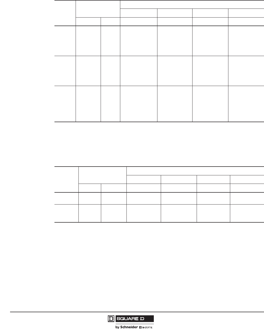
© 2011–2012 Schneider Electric
All Rights Reserved
PowerPact™ H-, J-, and L-Frame Circuit Breakers
Circuit Breakers
30
05/2012
™
Circuit Breakers with Field-Interchangeable Trip Units Catalog Numbers
Table 18: H-Frame 150 A Circuit Breaker Frame1 with Field-Interchangeable
Thermal-Magnetic Trip Units2 (3P, 600 Vac, 250 Vdc)
1Standard Lug Kit: AL150HD Terminal Wire Range: 14–3/0 AWG Al or Cu
2Circuit breakers will be labeled with Line and Load markings and are not suitable for reverse connections.
Only available on standard (80%) rated 3P unit-mount circuit breakers. Not available in R interrupting rating. Not available with
I-Line™ or Plug-In constructions.
Ampere
Rating
Fixed AC
Magnetic Trip
Interrupting Rating
DGJ
3
3UL Listed/CSA Certified as current limiting circuit breakers.
L3
Hold Trip Cat. No. Cat. No. Cat. No. Cat. No.
15 A 350 A 750 A HDL36015T HGL36015T HJL36015T HLL36015T
20 A 350 A 750 A HDL36020T HGL36020T HJL36020T HLL36020T
25 A 350 A 750 A HDL36025T HGL36025T HJL36025T HLL36025T
30 A 350 A 750 A HDL36030T HGL36030T HJL36030T HLL36030T
35 A 400 A 850 A HDL36035T HGL36035T HJL36035T HLL36035T
40 A 400 A 850 A HDL36040T HGL36040T HJL36040T HLL36040T
45 A 400 A 850 A HDL36045T HGL36045T HJL36045T HLL36045T
50 A 400 A 850 A HDL36050T HGL36050T HJL36050T HLL36050T
60 A 800 A 1450 A HDL36060T HGL36060T HJL36060T HLL36060T
70 A 800 A 1450 A HDL36070T HGL36070T HJL36070T HLL36070T
80 A 800 A 1450 A HDL36080T HGL36080T HJL36080T HLL36080T
90 A 800 A 1450 A HDL36090T HGL36090T HJL36090T HLL36090T
100 A 900 A 1700 A HDL36100T HGL36100T HJL36100T HLL36100T
110 A 900 A 1700 A HDL36110T HGL36110T HJL36110T HLL36110T
125 A 900 A 1700 A HDL36125T HGL36125T HJL36125T HLL36125T
150 A 900 A 1700 A HDL36150T HGL36150T HJL36150T HLL36150T
Table 19: J-Frame 250 A Circuit Breaker Frame with Field-Interchangeable
Thermal-Magnetic Trip Units1 (3P, 600 Vac, 250 Vdc)
1Circuit breakers will be labeled with Line and Load markings and are not suitable for reverse connections.
Only available on standard (80%) rated 3P unit-mount circuit breakers. Not available in R interrupting rating. Not available with
I-Line™ or Plug-In constructions.
Ampere
Rating
Adjustable AC
Magnetic Trip
Interrupting Rating
DG J
2
2UL Listed/CSA Certified as current limiting circuit breakers.
L3
Low High Cat. No. Cat. No. Cat. No. Cat. No.
150 A3
3Standard Lug Kit: AL175JD Terminal Wire Range: 4–4/0 AWG Al or Cu
750 A 1500 A JDL36150T JGL36150T JJL36150T JLL36150T
175 A3875 A 1750 A JDL36175T JGL36175T JJL36175T JLL36175T
200 A4
4Standard Lug Kit: AL250JD Terminal Wire Range: 3/0 AWG–350 kcmil Al or Cu
1000 A 2000 A JDL36200T JGL36200T JJL36200T JLL36200T
225 A41125 A 2250 A JDL36225T JGL36225T JJL36225T JLL36225T
250 A41250 A 2500 A JDL36250T JGL36250T JJL36250T JLL36250T
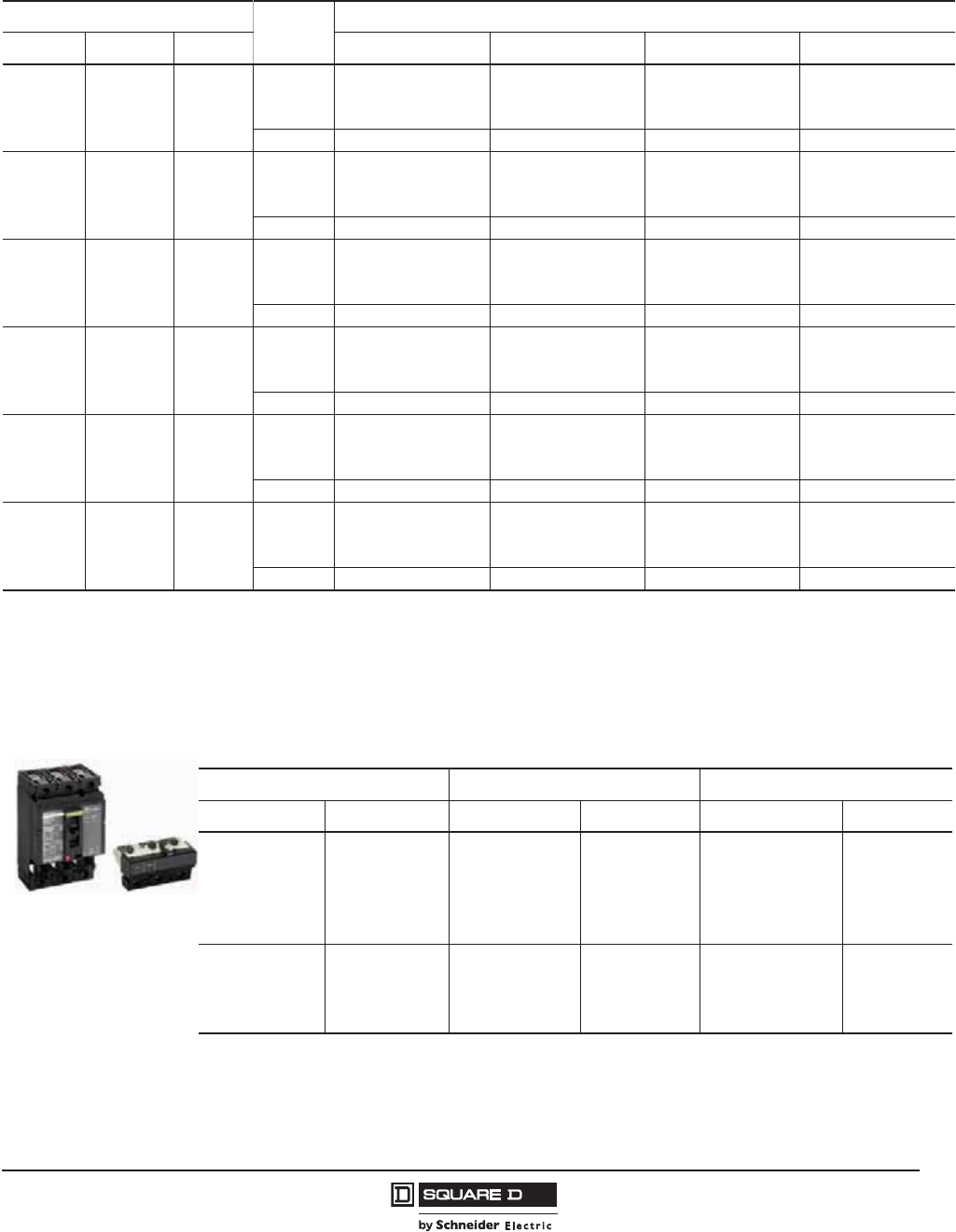
PowerPact™ H-, J-, and L-Frame Circuit Breakers
Circuit Breakers
31
05/2012
© 2011–2012 Schneider Electric
All Rights Reserved
™
Table 20: H-Frame 150 A and J-Frame 250 A 3P Circuit Breakers with Lugs and Field-Interchangeable Electronic Trip
Units1, 2 (Standard (80%) Rated, 600 Vac, 50/60 Hz)
Electronic Trip Unit Sensor
Size
Interrupting Rating
Type Function Trip Unit D G J3L3
Standard LI 3.2
60 A4
100 A4
150 A4
HDL36060TU31X
HDL36100TU31X
HDL36150TU31X
HGL36060TU31X
HGL36100TU31X
HGL36150TU31X
HJL36060TU31X
HJL36100TU31X
HJL36150TU31X
HLL36060TU31X
HLL36100TU31X
HLL36150TU31X
250 A5JDL36250TU31X JGL36250TU31X JJL36250TU31X JLL36250TU31X
Standard LSI 3.2S
60 A4
100 A4
150 A4
HDL36060TU33X
HDL36100TU33X
HDL36150TU33X
HGL36060TU33X
HGL36100TU33X
HGL36150TU33X
HJL36060TU33X
HJL36100TU33X
HJL36150TU33X
HLL36060TU33X
HLL36100TU33X
HLL36150TU33X
250 A5JDL36250TU33X JGL36250TU33X JJL36250TU33X JLL36250TU33X
Ammeter LSI 5.2A
60 A4
100 A4
150 A4
HDL36060TU43X
HDL36100TU43X
HDL36150TU43X
HGL36060TU43X
HGL36100TU43X
HGL36150TU43X
HJL36060TU43X
HJL36100TU43X
HJL36150TU43X
HLL36060TU43X
HLL36100TU43X
HLL36150TU43X
250 A5JDL36250TU43X JGL36250TU43X JJL36250TU43X JLL36250TU43X
Energy LSI 5.2E
60 A4
100 A4
150 A4
HDL36060TU53X
HDL36100TU53X
HDL36150TU53X
HGL36060TU53X
HGL36100TU53X
HGL36150TU53X
HJL36060TU53X
HJL36100TU53X
HJL36150TU53X
HLL36060TU53X
HLL36100TU53X
HLL36150TU53X
250 A5JDL36250TU53X JGL36250TU53X JJL36250TU53X JLL36250TU53X
Ammeter LSIG 6.2A
60 A4
100 A4
150 A4
HDL36060TU44X
HDL36100TU44X
HDL36150TU44X
HGL36060TU44X
HGL36100TU44X
HGL36150TU44X
HJL36060TU44X
HJL36100TU44X
HJL36150TU44X
HLL36060TU44X
HLL36100TU44X
HLL36150TU44X
250 A5JDL36250TU44X JGL36250TU44X JJL36250TU44X JLL36250TU44X
Energy LSIG 6.2E
60 A4
100 A4
150 A4
HDL36060TU54X
HDL36100TU54X
HDL36150TU54X
HGL36060TU54X
HGL36100TU54X
HGL36150TU54X
HJL36060TU54X
HJL36100TU54X
HJL36150TU54X
HLL36060TU54X
HLL36100TU54X
HLL36150TU54X
250 A5JDL36250TU54X JGL36250TU54X JJL36250TU54X JLL36250TU54X
1Circuit breakers will be labeled with Line and Load markings and are not suitable for reverse connections.
2Only available on 3P unit-mount circuit breakers. Not available in R interrupting rating. Not available with I-Line™ or Plug-in constructions.
3UL Listed/CSA Certified as current limiting circuit breakers.
4Standard Lug Kit: AL150HD Terminal Wire Range: 14–3/0 AWG Al or C
5Standard Lug Kit: AL250JD Terminal Wire Range: 3/0 AWG–350 kcmil Al or Cu
For smaller wire range (4–4/0 AWG Al or Cu), replace the lug’s wire binding screws with the larger binding screws provided.
Table 21: H-Frame and J-Frame 3P Field-Installable Thermal-Magnetic Trip Units
15–60 A H-Frame 70–150 A H-Frame 150–250 A J-Frame
Amperage Cat. No. Amperage Cat. No. Amperage Cat. No.
15 A HT3015 70 A HT3070 150 A JT3150
20 A HT3020 80 A HT3080 175 A JT3175
25 A HT3025 90 A HT3090 200 A JT3200
30 A HT3030 100 A HT3100 225 A JT3225
35 A HT3035 110 A HT3110 250 A JT3250
40 A HT3040 125 A HT3125 — —
45 A HT3045 150 A HT3150 — —
50 A HT3050 — — — —
60 A HT3060 — — — —
H-Frame Trip Unit
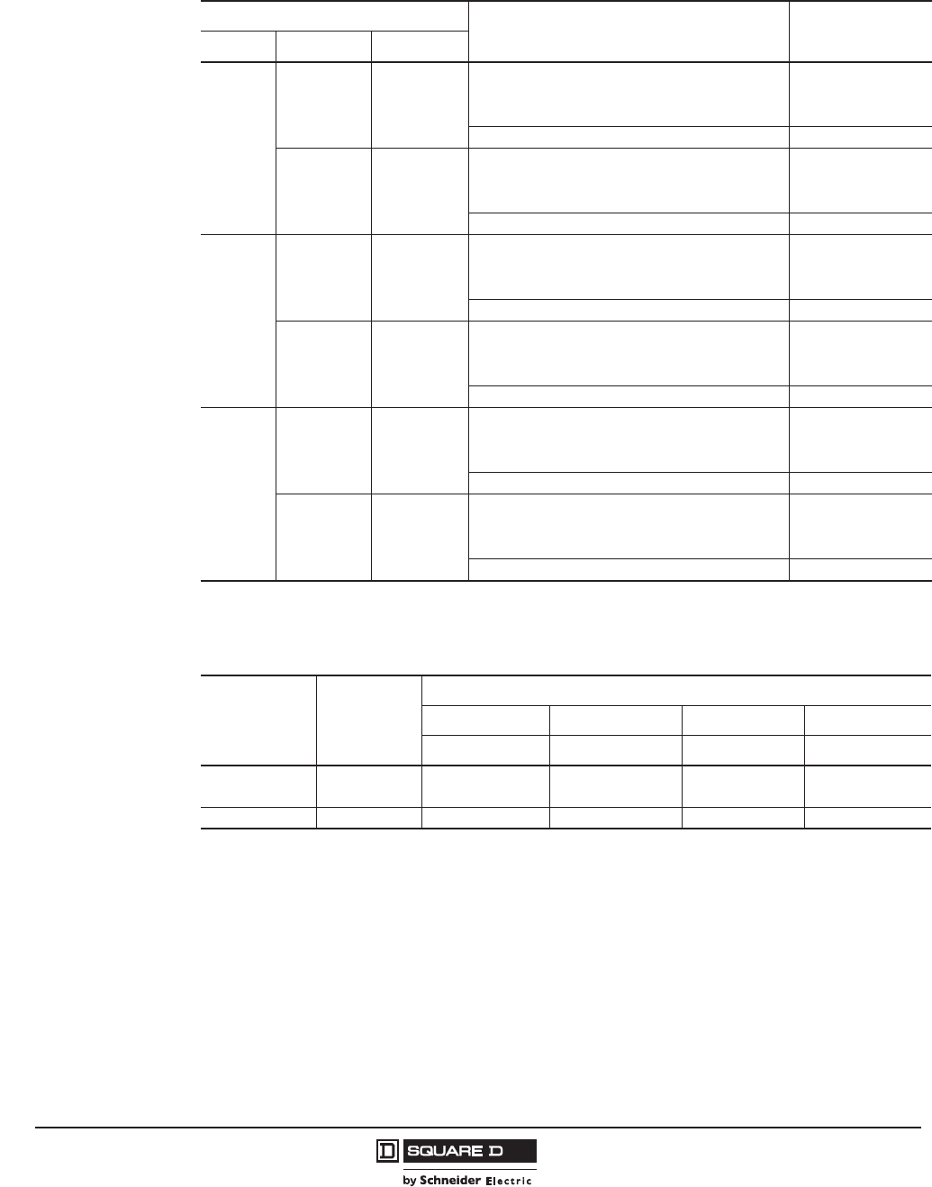
© 2011–2012 Schneider Electric
All Rights Reserved
PowerPact™ H-, J-, and L-Frame Circuit Breakers
Circuit Breakers
32
05/2012
™
Table 22: H-Frame and J-Frame 3P Field-Installable Micrologic™ Electronic Trip Units1
1Electronic trip units cannot be used for DC applications.
Electronic Trip Unit
Ampere Settings Trip Unit
Cat. No.
Type Function Trip Unit
Standard
LI 3.2
15-20-25-30-35-40-45-50-60 HE3060U31X
35-40-45-50-60-70-80-90-100 HE3100U31X
50-60-70-80-90-100-110-125-150 HE3150U31X
70-80-100-125-150-175-200-225-250 JE3250U31X
LSI 3.2S
15-20-25-30-35-40-45-50-60 HE3060U33X
35-40-45-50-60-70-80-90-100 HE3100U33X
50-60-70-80-90-100-110-125-150 HE3150U33X
70-80-100-125-150-175-200-225-250 JE3250U33X
Ammeter
LSI 5.2A
15–60 HE3060U43X
35–100 HE3100U43X
50–150 HE3150U43X
70–250 JE3250U43X
LSIG 6.2A
15–60 HE3060U44X
35–100 HE3100U44X
50–150 HE3150U44X
70–250 JE3250U44X
Energy
LSI 5.2E
15–60 HE3060U53X
35–100 HE3100U53X
50–150 HE3150U53X
70–250 JE3250U53X
LSIG 6.2E
15–60 HE3060U54X
35–100 HE3100U54X
50–150 HE3150U54X
70–250 JE3250U54X
Table 23: H-Frame 150A and J-Frame 250 A 3P Basic Circuit Breaker Frame Without
Terminations or Trip Unit (600 Vac, 250 Vdc1)
1Not suitable for reverse connection.
Circuit
Breaker
Frame
Ampere
Rating
Interrupting Rating
DG J
2
2UL Listed/CSA Certified as current limiting circuit breakers.
L2
Cat. No. Cat. No. Cat. No. Cat. No.
H-Frame3
3Field-installable trip units must match frame ampere rating.
15–60 A HDF36000F06 HGF36000F06 HJF36000F06 HLF36000F06
70–150 A HDF36000F15 HGF36000F15 HJF36000F15 HLF36000F15
J-Frame 150–250 A JDF36000F25 JGF36000F25 JJF36000F25 JLF36000F25

PowerPact™ H-, J-, and L-Frame Circuit Breakers
Circuit Breakers
33
05/2012
© 2011–2012 Schneider Electric
All Rights Reserved
™
L-Frame Circuit Breaker Catalog Numbers
Unit-Mount Circuit Breaker Catalog Numbers
Table 24: L-Frame 600 A Electronic Trip UL Rated 3P Circuit Breakers
(600 Vac, 50/60 Hz) With Factory Sealed Trip Unit Suitable for Reverse Connection
Electronic Trip Unit Sensor
Rating
Interrupting Rating (2nd Letter of Catalog Number)
Type Function Trip Unit D G J1 L
1 R
1
Standard (80%) Rated, 600 Vac, 50/60 Hz
Standard LI 3.32
250 A3LDL36250U31X LGL36250U31X LJL36250U31X LLL36250U31X LRL36250U31X
400 A4
600 A4
LDL36400U31X
LDL36600U31X
LGL36400U31X
LGL36600U31X
LJL36400U31X
LJL36600U31X
LLL36400U31X
LLL36600U31X
LRL36400U31X
LRL36600U31X
Standard LSI 3.3S2
250 A3LDL36250U33X LGL36250U33X LJL36250U33X LLL36250U33X LRL36250U33X
400 A4
600 A4
LDL36400U33X
LDL36600U33X
LGL36400U33X
LGL36600U33X
LJL36400U33X
LJL36600U33X
LLL36400U33X
LLL36600U33X
LRL36400U33X
LRL36600U33X
Ammeter LSI 5.3A 400 A4
600 A4
LDL36400U43X
LDL36600U43X
LGL36400U43X
LGL36600U43X
LJL36400U43X
LJL36600U43X
LLL36400U43X
LLL36600U43X
LRL36400U43X
LRL36600U43X
Energy LSI 5.3E 400 A4
600 A4
LDL36400U53X
LDL36600U53X
LGL36400U53X
LGL36600U53X
LJL36400U53X
LJL36600U53X
LLL36400U53X
LLL36600U53X
LRL36400U53X
LRL36600U53X
Ammeter LSIG 6.3A 400 A4
600 A4
LDL36400U44X
LDL36600U44X
LGL36400U44X
LGL36600U44X
LJL36400U44X
LJL36600U44X
LLL36400U44X
LLL36600U44X
LRL36400U44X
LRL36600U44X
Energy LSIG 6.3E 400 A4
600 A4
LDL36400U54X
LDL36600U54X
LGL36400U54X
LGL36600U54X
LJL36400U54X
LJL36600U54X
LLL36400U54X
LLL36600U54X
LRL36400U54X
LRL36600U54X
100% Rated, 600 Vac, 50/60 Hz
Standard LI 3.32250 A3LDL36250CU31X LGL36250CU31X LJL36250CU31X LLL36250CU31X LRL36250CU31X
400 A4LDL36400CU31X LGL36400CU31X LJL36400CU31X LLL36400CU31X LRL36400CU31X
Standard LSI 3.3S2250 A3LDL36250CU33X LGL36250CU33X LJL36250CU33X LLL36250CU33X LRL36250CU33X
400 A4LDL36400CU33X LGL36400CU33X LJL3640C0U33X LLL36400CU33X LRL36400CU33X
Ammeter LSI 5.3A 400 A4LDL36400CU43X LGL36400CU43X LJL36400CU43X LLL36400CU43X LRL36400CU43X
Energy LSI 5.3E 400 A4LDL36400CU53X LGL36400CU53X LJL36400CU53X LLL36400CU53X LRL36400CU53X
Ammeter LSIG 6.3A 400 A4LDL36400CU44X LGL36400CU44X LJL36400CU44X LLL36400CU44X LRL36400CU44X
Energy LSIG 6.3E 400 A4LDL36400CU54X LGL36400CU54X LJL36400CU54X LLL36400CU54X LRL36400CU54X
1UL Listed/CSA Certified as current limiting circuit breakers.
23P circuit breakers with this trip unit can be used for 2P applications.
3Standard Lug Kit: AL400L61K3 Terminal Wire Range: (1) 2 AWG–600 kcmil Cu or (1) 2 AWG–500 kcmil Al
4Standard Lug Kit: AL600LS52K3 Terminal Wire Range: (2) 2/0 AWG–500 kcmil Al/Cu
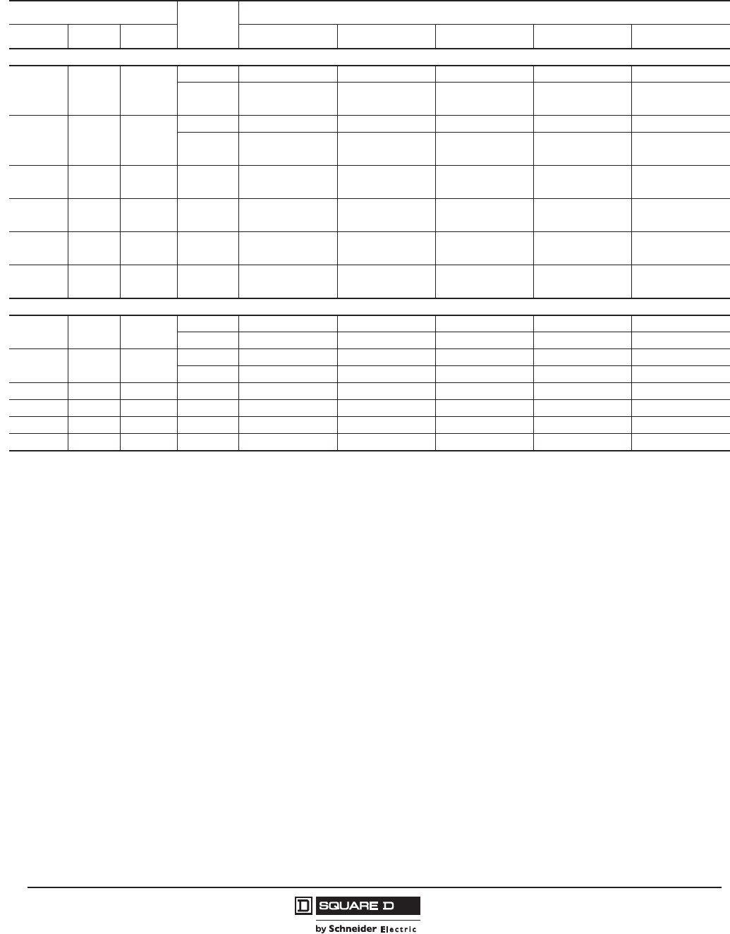
© 2011–2012 Schneider Electric
All Rights Reserved
PowerPact™ H-, J-, and L-Frame Circuit Breakers
Circuit Breakers
34
05/2012
™
Table 25: L-Frame 600 A Electronic Trip UL Rated 4P Circuit Breakers
(600 Vac, 50/60 Hz) With Factory Sealed Trip Unit Suitable for Reverse Connection
Electronic Trip Unit Sensor
Rating
Interrupting Rating (2nd Letter of Catalog Number)
Type Function Trip Unit D G J1L1 R
1
Standard (80%) Rated, 600 Vac, 50/60 Hz
Standard LI 3.3
250 A2LDL46250U31X LGL46250U31X LJL46250U31X LLL46250U31X LRL46250U31X
400 A3
600 A3
LDL46400U31X
LDL46600U31X
LGL46400U31X
LGL46600U31X
LJL46400U31X
LJL46600U31X
LLL46400U31X
LLL46600U31X
LRL46400U31X
LRL46600U31X
Standard LSI 3.3S
250 A2LDL46250U33X LGL46250U33X LJL46250U33X LLL46250U33X LRL46250U33X
400 A3
600 A3
LDL46400U33X
LDL46600U33X
LGL46400U33X
LGL46600U33X
LJL46400U33X
LJL46600U33X
LLL46400U33X
LLL46600U33X
LRL46400U33X
LRL46600U33X
Ammeter LSI 5.3A 400 A3
600 A3
LDL46400U43X
LDL46600U43X
LGL46400U43X
LGL46600U43X
LJL46400U43X
LJL46600U43X
LLL46400U43X
LLL46600U43X
LRL46400U43X
LRL46600U43X
Energy LSI 5.3E 400 A3
600 A3
LDL46400U53X
LDL46600U53X
LGL46400U53X
LGL46600U53X
LJL46400U53X
LJL46600U53X
LLL46400U53X
LLL46600U53X
LRL46400U53X
LRL46600U53X
Ammeter LSIG 6.3A 400 A3
600 A3
LDL46400U44X
LDL46600U44X
LGL46400U44X
LGL46600U44X
LJL46400U44X
LJL46600U44X
LLL46400U44X
LLL46600U44X
LRL46400U44X
LRL46600U44X
Energy LSIG 6.3E 400 A3
600 A3
LDL46400U54X
LDL46600U54X
LGL46400U54X
LGL46600U54X
LJL46400U54X
LJL46600U54X
LLL46400U54X
LLL46600U54X
LRL46400U54X
LRL46600U54X
100% Rated, 600 Vac, 50/60 Hz
Standard LI 3.3 250 A2LDL46250CU31X LGL46250CU31X LJL46250CU31X LLL46250CU31X LRL46250CU31X
400 A3LDL46400CU31X LGL46400CU31X LJL46400CU31X LLL46400CU31X LRL46400CU31X
Standard LSI 3.3S 250 A2LDL46250CU33X LGL46250CU33X LJL46250CU33X LLL46250CU33X LRL46250CU33X
400 A3LDL46400CU33X LGL46400CU33X LJL46400CU33X LLL46400CU33X LRL46400CU33X
Ammeter LSI 5.3A 400 A3LDL46400CU43X LGL46400CU43X LJL46400CU43X LLL46400CU43X LRL46400CU43X
Energy LSI 5.3E 400 A3LDL46400CU53X LGL46400CU53X LJL46400CU53X LLL46400CU53X LRL46400CU53X
Ammeter LSIG 6.3A 400 A3LDL46400CU44X LGL46400CU44X LJL46400CU44X LLL46400CU44X LRL46400CU44X
Energy LSIG 6.3E 400 A3LDL46400CU54X LGL46400CU54X LJL46400CU54X LLL46400CU54X LRL46400CU54X
1UL Listed/CSA Certified as current limiting circuit breakers.
2Standard Lug Kit: AL400L61K4 Terminal Wire Range: (1) 2 AWG–600 kcmil Cu or (1) 2 AWG–500 kcmil Al
3Standard Lug Kit: AL600LS52K4 Terminal Wire Range: (2) 2/0 AWG–500 kcmil Al/Cu
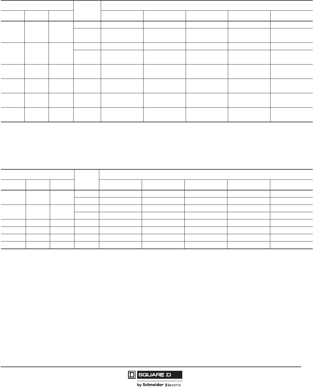
PowerPact™ H-, J-, and L-Frame Circuit Breakers
Circuit Breakers
35
05/2012
© 2011–2012 Schneider Electric
All Rights Reserved
™
I-Line™ Circuit Breaker Catalog Numbers
Table 26: L-Frame 600 A I-Line Standard (80%) Rated Electronic Trip UL Rated Circuit Breakers
(600 Vac, 50/60 Hz) With Factory Sealed Trip Unit Suitable for Reverse Connection
Electronic Trip Unit Sensor
Rating
Interrupting Rating
Type Function Trip Unit D G J 1L3 R
3
Standard LI 3.32
250 A3LDA36250U31X LGA36250U31X LJA36250U31X LLA36250U31X LRA36250U31X
400 A4
600 A4
LDA36400U31X
LDA36600U31X
LGA36400U31X
LGA36600U31X
LJA36400U31X
LJA36600U31X
LLA36400U31X
LLA36600U31X
LRA36400U31X
LRA36600U31X
Standard LSI 3.3S2
250 A3LDA36250U33X LGA36250U33X LJA36250U33X LLA36250U33X LRA36250U33X
400 A4
600 A4
LDA36400U33X
LDA36600U33X
LGA36400U33X
LGA36600U33X
LJA36400U33X
LJA36600U33X
LLA36400U33X
LLA36600U33X
LRA36400U33X
LRA36600U33X
Ammeter LSI 5.3A 400 A44
600 A4
LDA36400U43X
LDA36600U43X
LGA36400U43X
LGA36600U43X
LJA36400U43X
LJA36600U43X
LLA36400U43X
LLA36600U43X
LRA36400U43X
LRA36600U43X
Energy LSI 5.3E 400 A4
600 A4
LDA36400U53X
LDA36600U53X
LGA36400U53X
LGA36600U53X
LJA36400U53X
LJA36600U53X
LLA36400U53X
LLA36600U53X
LRA36400U53X
LRA36600U53X
Ammeter LSIG 6.3A 400 A4
600 A4
LDA36400U44X
LDA36600U44X
LGA36400U44X
LGA36600U44X
LJA36400U44X
LJA36600U44X
LLA36400U44X
LLA36600U44X
LRA36400U44X
LRA36600U44X
Energy LSIG 6.3E 400 A4
600 A4
LDA36400U54X
LDA36600U54X
LGA36400U54X
LGA36600U54X
LJA36400U54X
LJA36600U54X
LLA36400U54X
LLA36600U54X
LRA36400U54X
LRA36600U54X
1UL Listed/CSA Certified as current limiting circuit breakers.
23P circuit breakers with this trip unit can be used for 2P applications.
3Standard Lug Kit: AL400L61K3 Terminal Wire Range: (1) 2 AWG–600 kcmil Cu or (1) 2 AWG–500 kcmil Al
4Standard Lug Kit: AL600LS52K3 Terminal Wire Range: (2) 2/0 AWG–500 kcmil Al/Cu
Table 27: L-Frame 250 A and 400 A I-Line 100% Rated Electronic Trip UL Rated Circuit Breakers
(600 Vac, 50/60 Hz) With Factory Sealed Trip Unit Suitable for Reverse Connection
Electronic Trip Unit Sensor
Rating
Interrupting Rating
Type Function Trip Unit D G J 1L3 R
3
Standard LI 3.32250 A3LDA36250CU31X LGA36250CU31X LJA36250CU31X LLA36250CU31X LRA36250CU31X
400 A4LDA36400CU31X LGA36400CU31X LJA36400CU31X LLA36400CU31X LRA36400CU31X
Standard LSI 3.3S2250 A3LDA36250CU33X LGA36250CU33X LJA36250CU33X LLA36250CU33X LRA36250CU33X
400 A4LDA36400CU33X LGA36400CU33X LJA36400CU33X LLA36400CU33X LRA36400CU33X
Ammeter LSI 5.3A 400 A4LDA36400CU43X LGA36400CU43X LJA36400CU43X LLA36400CU43X LRA36400CU43X
Energy LSI 5.3E 400 A4LDA36400CU53X LGA36400CU53X LJA36400CU53X LLA36400CU53X LRA36400CU53X
Ammeter LSIG 6.3A 400 A4LDA36400CU44X LGA36400CU44X LJA36400CU44X LLA36400CU44X LRA36400CU44X
Energy LSIG 6.3E 400 A4LDA36400CU54X LGA36400CU54X LJA36400CU54X LLA36400CU54X LRA36400CU54X
1UL Listed/CSA Certified as current limiting circuit breakers.
23P circuit breakers with this trip unit can be used for 2P applications.
3Standard Lug Kit: AL400L61K3 Terminal Wire Range: (1) 2 AWG–600 kcmil Cu or (1) 2 AWG–500 kcmil Al
4Standard Lug Kit: AL600LS52K3 Terminal Wire Range: (2) 2/0 AWG–500 kcmil Al/Cu
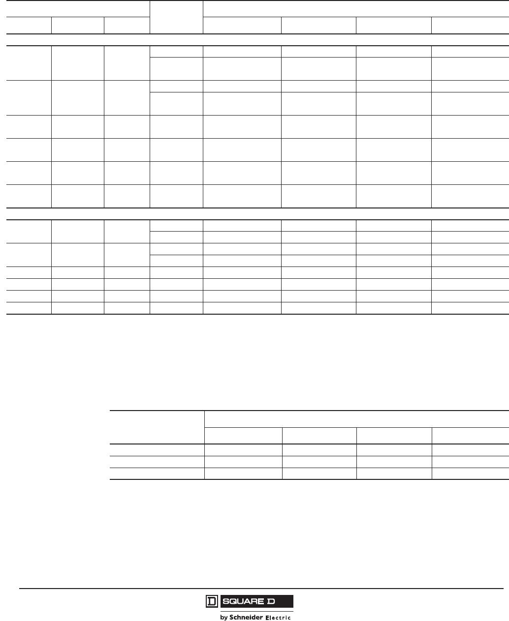
© 2011–2012 Schneider Electric
All Rights Reserved
PowerPact™ H-, J-, and L-Frame Circuit Breakers
Circuit Breakers
36
05/2012
™
Circuit Breakers with Field-Interchangeable Trip Units Catalog Numbers
Table 28: L-Frame 3 Pole, 600 A Circuit Breakers with Lugs and Field-Interchangeable Electronic Trip Units
(600 Vac, 50/60 Hz)1, 2
1Circuit breakers will be labeled with Line and Load markings and are not suitable for reverse connections.
2Only available on 3P unit-mount circuit breakers. Not available in R interrupting rating. Not available with I-Line™ or Plug-in constructions.
Electronic Trip Unit Sensor
Rating
Interrupting Rating
Type Function Trip Unit D G J 3
3UL Listed/CSA Certified as current limiting circuit breakers.
L3
Standard (80% Rated), 600 Vac, 50/60 Hz
Standard LI 3.3
250 A4
4Standard Lug Kit: AL400L61K3 Terminal Wire Range: (1) 2 AWG–600 kcmil Cu or (1) 2 AWG–500 kcmil Al
LDL36250TU31X LGL36250TU31X LJL36250TU31X LLL36250TU31X
400 A5
600 A5
5Standard Lug Kit: AL600LS52K3 Terminal Wire Range: (2) 2/0 AWG–500 kcmil Al/Cu
LDL36400TU31X
LDL36600TU31X
LGL36400TU31X
LGL36600TU31X
LJL36400TU31X
LJL36600TU31X
LLL36400TU31X
LLL36600TU31X
Standard LSI 3.3S
250 A4LDL36250TU33X LGL36250TU33X LJL36250TU33X LLL36250TU33X
400 A5
600 A5
LDL36400TU33X
LDL36600TU33X
LGL36400TU33X
LGL36600TU33X
LJL36400TU33X
LJL36600TU33X
LLL36400TU33X
LLL36600TU33X
Ammeter LSI 5.3A 400 A5
600 A5
LDL36400TU43X
LDL36600TU43X
LGL36400TU43X
LGL36600TU43X
LJL36400TU43X
LJL36600TU43X
LLL36400TU43X
LLL36600TU43X
Energy LSI 5.3E 400 A5
600 A5
LDL36400TU53X
LDL36600TU53X
LGL36400TU53X
LGL36600TU53X
LJL36400TU53X
LJL36600TU53X
LLL36400TU53X
LLL36600TU53X
Ammeter LSIG 6.3A 400 A5
600 A5
LDL36400TU44X
LDL36600TU44X
LGL36400TU44X
LGL36600TU44X
LJL36400TU44X
LJL36600TU44X
LLL36400TU44X
LLL36600TU44X
Energy LSIG 6.3E 400 A5
600 A5
LDL36400TU54X
LDL36600TU54X
LGL36400TU54X
LGL36600TU54X
LJL36400TU54X
LJL36600TU54X
LLL36400TU54X
LLL36600TU54X
100% Rated, 600 Vac, 50/60 Hz
Standard LI 3.3 250 A4LDL36250RU31X LGL36250RU31X LJL36250RU31X LLL36250RU31X
400 A5LDL36400RU31X LGL36400RU31X LJL36400RU31X LLL36400RU31X
Standard LSI 3.3S 250 A4LDL36250RU33X LGL36250RU33X LJL36250RU33X LLL36250RU33X
400 A5LDL36400RU33X LGL36400RU33X LJL36400RU33X LLL36400RU33X
Ammeter LSI 5.3A 400 A5LDL36400RU43X LGL36400RU43X LJL36400RU43X LLL36400RU43X
Energy LSI 5.3E 400 A5LDL36400RU53X LGL36400RU53X LJL36400RU53X LLL36400RU53X
Ammeter LSIG 6.3A 400 A5LDL36400RU44X LGL36400RU44X LJL36400RU44X LLL36400RU44X
Energy LSIG 6.3E 400 A5LDL36400RU54X LGL36400RU54X LJL36400RU54X LLL36400RU54X
Table 29: L-Frame 600 A, 3 Pole, Basic Circuit Breaker Frame Without Terminations or Trip
Units (600 Vac, 50/60 Hz)1
1Not suitable for reverse connection.
Ampere
Rating
Interrupting Rating
D G J
2
2UL Listed/CSA Certified as current limiting
L2
250 A (70–250 A) LDF36000F25 LGF36000F25 LJF36000F25 LLF36000F25
400 A (125–400 A) LDF36000F40 LGF36000F40 LJF36000F40 LLF36000F40
600 A (200–600 A) LDF36000F60 LGF36000F60 LJF36000F60 LLF36000F60

PowerPact™ H-, J-, and L-Frame Circuit Breakers
Circuit Breakers
37
05/2012
© 2011–2012 Schneider Electric
All Rights Reserved
™
Table 30: L-Frame 3P Field-Installable Micrologic™ Electronic Trip Units
Electronic Trip Unit
Ampere Setting Trip Unit
Cat. No.
Type Function Trip Unit
Standard
LI 3.3
70-80-100-125-150-175-200-225-250 LE3250U31X
125-150-175-200-225-250-300-350-400 LE3400U31X
200-225-250-300-350-400-450-500-600 LE3600U31X
LSI 3.3S
70-80-100-125-150-175-200-225-250 LE3250U33X
125-150-175-200-225-250-300-350-400 LE3400U33X
200-225-250-300-350-400-450-500-600 LE3600U33X
Ammeter
LSI 5.3A 125–400 LE3400U43X
200–600 LE3600U43X
LSIG 6.3A 125–400 LE3400U44X
200–600 LE3600U44X
Energy
LSI 5.3E 125–400 LE3400U53X
200–600 LE3600U53X
LSIG 6.3E 125–400 LE3400U54X
200–600 LE3600U54X

© 2011–2012 Schneider Electric
All Rights Reserved
PowerPact™ H-, J-, and L-Frame Circuit Breakers
Automatic Switches
38
05/2012
™
Section 4—Automatic Switches
Automatic Switch Functions
An automatic switch can be used to open and close a circuit under normal operating conditions. They
are similar in construction to circuit breakers, except that the switches open instantaneously at a factory-set,
non-adjustable trip point calibrated to protect only the molded case switch itself.
Molded case switches are intended for use as disconnect devices only. UL489 requires molded case
switches to be protected by a circuit breaker or fuse of equivalent rating. Molded case switches are
labeled with their appropriate withstand ratings. The withstand rating of a switch is defined as the
maximum current at rated voltage that the molded case switch will withstand without damage when
protected by a circuit breaker with an equal continuous current rating.
PowerPact H-, J-, and L-frame automatic switches are available in unit mount, I-Line™, plug-in and
drawout versions. They use the same accessories and offer the same connection possibilities as the
circuit-breaker versions. They may be interlocked with another switch or circuit breaker to form a
source-changeover system.
Switches are Listed under UL file E103740 and Certified under CSA file LR88980.
Motor Operator
PowerPact H-, J-, and L-frame switches equipped with a motor operator module allow remote closing
and opening.
Ground Fault Protection (H- and J-Frame Circuit Breakers Only)
An ELM or GFM module may be added to an automatic switch to monitor all leakage currents in the
outgoing circuits of the equipment on which the automatic switch is installed. When the ELM or GFM
module detects an earth-leakage current, the automatic switch interrupts the load current.
Automatic Switch Protection
The automatic switch can make and break its rated current. For an overload or a short-circuit, it must
be protected by an upstream device, in compliance with installation standards. Due to their high-set
instantaneous release PowerPact H-, J- and L-frame automatic switches are self-protected.
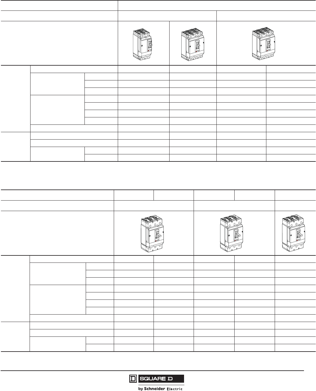
PowerPact™ H-, J-, and L-Frame Circuit Breakers
Automatic Switches
39
05/2012
© 2011–2012 Schneider Electric
All Rights Reserved
™
Specifications
Table 31: H-Frame Automatic Molded Case Switch Specifications
Frame H-Frame
Withstand Rating “G” “L”
UL 489
Poles 2P 3P 2P13P
Catalog Number
150 A HGL26000S15 HGL3600S15 HLL26000S15 HLL36000S15
175 A — — — —
250 A — — — —
Withstand Ratings
240 Vac 65 kA 65 kA 125 kA 125 kA
480 Vac 35 kA 35 kA 100 kA 100 kA
600 Vac 18 kA 18 kA 50 kA 50 kA
250 Vdc 20 kA 20 kA 20 kA 20 kA
AC Trip Point 2250 A 2250 A 2250 A 2250 A
IEC 60947-3
Rated Insulation Voltage 750 Vac 750 Vac 750 Vac 750 Vac
Rated Impulse Withstand Voltage 8 kV 8 kV 8 kV 8 kV
Rated Operational Voltage ac 525 Vac 525 Vac 525 Vac 525 Vac
dc — — — —
12P devices use a 3P switch frame with the center pole inoperative.
Table 32: J-Frame Automatic Molded Case Switch Specifications
Frame J-Frame
Withstand Rating “G” “L” “R”
UL 489
Poles 2P1
12P devices use a 3P switch frame with the center pole inoperative.
3P 2P13P 3P
Catalog Number
150 A — — — — —
175 A JGL26000S17 JGL36000S17 JLL26000S17 JLL36000S17 JRL36000S17
250 A JGL26000S25 JGL36000S25 JLL26000S25 JLL36000S25 JRL36000S25
Withstand Ratings
240 Vac 65 kA 65 kA 125 kA 125 kA 200 kA
480 Vac 35 kA 35 kA 100 kA 100 kA 200 kA
600 Vac 18 kA 18 kA 50 kA 50 kA 100 kA
250 Vdc 20 kA 20 kA 20 kA 20 kA 20 kA
AC Trip Point 3125 A 3125 A 3125 A 3125 A 3125 A
IEC 60947-3
Rated Insulation Voltage 750 Vac 750 Vac 750 Vac 750 Vac 750 Vac
Rated Impulse Withstand Voltage 8 kV 8 kV 8 kV 8 kV 8 kV
Rated Operational Voltage ac 525 Vac 525 Vac 525 Vac 525 Vac 525 Vac
dc 500 Vdc 500 Vdc 500 Vdc 500 Vdc 500 Vdc

© 2011–2012 Schneider Electric
All Rights Reserved
PowerPact™ H-, J-, and L-Frame Circuit Breakers
Automatic Switches
40
05/2012
™
Catalog Numbers
Table 33: PowerPact H-Frame and J-Frame 250 A Unit-Mount Automatic Molded Case
Switches, 600 Vac with Factory Sealed Trip Unit (Suitable for Reverse Connection)
Ampere
Rating
2-pole 3-pole Withstand Rating 1
1The withstand rating is the fault current, at rated voltage, that the molded case switch will withstand without damage when
protected by a circuit breaker or fuse with an equal continuous current rating.
Trip
Point
Standard Lug Kit
Terminal Wire Range
Cat. No. Cat. No. 240 Vac 480 Vac 600 Vac
G Withstand
150 A HGL26000S152
22-pole device with 3 in. (76 mm) mounting height, all other 2-pole circuit breakers use 3-pole switch 4.5 in. (114 mm) mounting
height.
HGL36000S15 65 35 18 2250 A AL150HD
#14–#3/0 AWG Al or Cu
175 A JGL26000S17 JGL36000S17 65 35 18 3125 A AL250JD
#3/0–350 kcmil Al or Cu
250 A JGL26000S25 JGL36000S25
L Withstand
150 A HLL26000S15 HLL36000S15 125 100 50 2250 A AL150HD
#14–#3/0 AWG Al or Cu
175 A JLL26000S17 JLL36000S17 125 100 50 3125 A AL250JD
#3/0–350 kcmil Al or Cu
250 A JLL26000S25 JLL36000S25
R Withstand
175 A — JRL36000S17 200 200 100 3125 A AL250JD
#3/0–350 kcmil Al or Cu
250 A — JRL36000S25
Table 34: PowerPact H-Frame and J-Frame I-Line™ Automatic Molded Case Switches, 600
Vac with Factory Sealed Trip Unit (Suitable for Reverse Connection)
Ampere
Rating
2-pole 3-pole Withstand Rating 1
1The withstand rating is the fault current, at rated voltage, that the molded case switch will withstand without damage when
protected by a circuit breaker or fuse with an equal continuous current rating.
Trip
Point
Standard Lug Kit
Terminal Wire Range
Cat. No. Cat. No. 240 Vac 480 Vac 600 Vac
G Withstand
150 A HGA26000S15( )2
22-pole device with 3 in. (76 mm) mounting height, all other 2-pole circuit breakers use 3-pole 4.5 in. (114 mm) mounting height.
HGA36000S15 65 35 18 1300 A AL150HD
#14–#3/0 AWG Al or Cu
175 A JGA26000S17( ) JGA36000S17 65 35 18 2500 A AL250JD
#3/0–350 kcmil Al or Cu
250 A JGA26000S25( ) JGA36000S25
L Withstand
150 A HLA26000S15( ) HLA36000S15 125 100 50 1300 A AL150HD
#14–#3/0 AWG Al or Cu
175 A JLA26000S17( ) JLA36000S17 125 100 50 1300 A AL250JD
#3/0–350 kcmil Al or Cu
250 A JLA26000S25( ) JLA36000S25 2500 A
R Withstand
175 A JRA26000S17( ) JRA36000S17 200 200 100 3125A AL250JD
#3/0–350 kcmil Al or Cu
250 A JRA26000S25( ) JRA36000S25
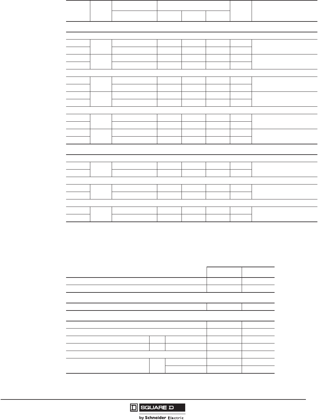
PowerPact™ H-, J-, and L-Frame Circuit Breakers
Automatic Switches
41
05/2012
© 2011–2012 Schneider Electric
All Rights Reserved
™
Table 35: PowerPact L-Frame 600 A Unit-Mount Automatic Molded Case Switches, 600 Vac
Ampere
Rating Poles1
14P circuit breaker available as bus connected, with lug configurations, and in plug-in, draw-out and rear-connected configurations.
Cat. No. Withstand Rating 2
2The withstand rating is the fault current, at rated voltage, that the molded case switch will withstand without damage when
protected by a circuit breaker or fuse with an equal continuous current rating.
Trip
Point
Standard Lug Terminal
Wire Range
240 Vac 480 Vac 600 Vac
Unit-Mount Automatic Molded Case Switches,
G Withstand
400 A 3P LGL36000S40X 65 kA 35 kA 18 kA 4800 A AL600LS52K3
(2) 2 AWG–500 kcmil Al/Cu
600 A LGL36000S60X 65 kA 35 kA 18 kA 6600 A
400 A 4P LGL46000S40X 65 kA 35 kA 18 kA 4800 A AL600LS52K4
(2) 2 AWG–500 kcmil Al/Cu
600 A LGL46000S60X 65 kA 35 kA 18 kA 6600 A
L Withstand
400 A 3P LLL36000S40X 125 kA 100 kA 50 kA 4800 A AL600LS52K3
(2) 2 AWG–500 kcmil Al/Cu
600 A LLL36000S60X 125 kA 100 kA 50 kA 6600 A
400 A 4P LLL46000S40X 125 kA 100 kA 50 kA 4800 A AL600LS52K4
(2) 2 AWG–500 kcmil Al/Cu
600 A LLL46000S60X 125 kA 100 kA 50 kA 6600 A
R Withstand
400 A 3P LRL36000S40X 200 kA 200 kA 100 kA 4800 A AL600LS52K3
(2) 2 AWG–500 kcmil Al/Cu
600 A LRL36000S60X 200 kA 200 kA 100 kA 6600 A
400 A 4P LRL46000S40X 200 kA 200 kA 100 kA 4800 A AL600LS52K4
(2) 2 AWG–500 kcmil Al/Cu
600 A LRL46000S60X 200 kA 200 kA 100 kA 6600 A
I-Line™ Circuit Breakers Automatic Molded Case Switches
G Withstand
400 A 3P LGA36000S40X 65 kA 35 kA 18 kA 4800 A AL600LF52K3
(2) 3/0 AWG–500 kcmil Al/Cu
600 A LGA36000S60X 65 kA 35 kA 18 kA 6600 A
L Withstand
400 A 3P LLA36000S40X 125 kA 100 kA 50 kA 4800 A AL600LF52K3
(2) 3/0 AWG–500 kcmil Al/Cu
600 A LLA36000S60X 125 kA 100 kA 50 kA 6600 A
R Withstand
400 A 3P LRA36000S40X 200 kA 200 kA 100 kA 4800 A AL600LF52K3
(2) 3/0 AWG–500 kcmil Al/Cu
600 A LRA36000S60X 200 kA 200 kA 100 kA 6600 A
Table 36: L-Frame Ratings and Withstand Ratings
400 A 600 A
Number of Poles 3, 4 3, 4
Ampere Rating (A) 400 600
UL 489 Ratings
Rated Voltage (V) 600 600
IEC 60947-3 ratings
Rated Insulation Voltage (V) 750 750
Rated Impulse Withstand Voltage (kV) 8 8
Rated Operational Voltage Ue AC 50/60 Hz 525 525
Rated Operational Current Ie AC 525 V 400 600
Making Capacity (kA peak) 7.1 8.5
Short-Time Withstand Current (kA rms) Icw Icw (kA ms) 5 6
Duration (s) 1 1

© 2011–2012 Schneider Electric
All Rights Reserved
PowerPact™ H-, J-, and L-Frame Circuit Breakers
Motor Circuit Protection
42
05/2012
™
Section 5—Motor Circuit Protection
General Information
The parameters to be considered for motor-feeder protection depend on:
•the application (type of machine driven, operating safety, frequency of operation, etc.)
•the level of continuity of service required by the load or the application
•the applicable standards for the protection of equipment.
The required electrical functions are:
•isolation
•switching, generally at high endurance levels
•protection against overloads and short-circuits, adapted to the motor
•additional special protection.
A motor branch circuit must comply with the requirements of standard UL508 concerning contactors
and their protection:
•coordination of feeder components
•overload relay trip classes.
Motor Branch Circuit Protection Function
A motor branch circuit comprises a set of devices for motor protection and control, as well as for
protection of the branch circuit itself.
Switching
The purpose is to control the motor (ON / OFF), either manually, automatically or remotely, taking into
account overloads upon start-up and the long service life required. This function is provided by a
contactor. When the coil of the contactor's electromagnet is energized, the contactor closes and
establishes, through the poles, the circuit between the upstream supply and the motor, through the
circuit breaker.
Basic Protection
•Short-circuit protection
Detection and breaking, as quickly as possible, of high short-circuit currents to avoid damage to the
installation. This function is provided by a circuit breaker.
•Overload protection
Detection of overload currents and motor shutdown before temperature rise in the motor and
conductors damages insulation. This function is provided by a circuit breaker or a separate motor
overload relay.
•Phase unbalance or phase loss protection
Phase unbalance or phase loss can cause temperature rise and braking torques that can lead to
premature ageing of the motor. These effects are even greater during starting, therefore protection
must be virtually immediate.
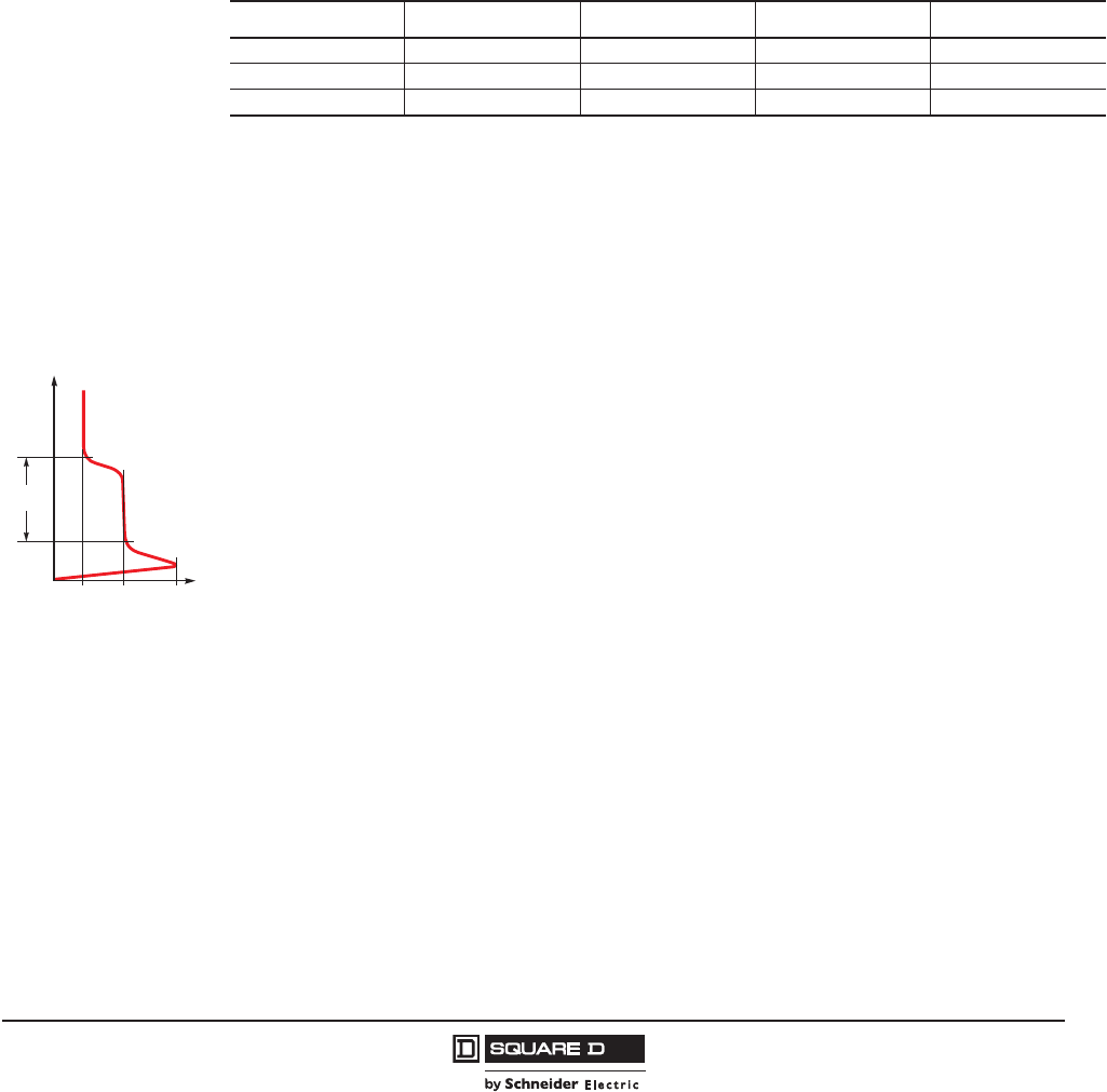
PowerPact™ H-, J-, and L-Frame Circuit Breakers
Motor Circuit Protection
43
05/2012
© 2011–2012 Schneider Electric
All Rights Reserved
™
Additional Electronic Protection
•Locked rotor
•Under-load
•Long starts and stalled rotor
•Insulation faults
Trip Class of a Overload Relay Device
The motor branch circuit includes thermal protection that may be built into the circuit breaker. The
protection must have a trip class suited to motor starting. Depending on the application, the motor
starting time varies from a few seconds (no-load start) to a few dozen seconds (high-inertia load).
Example: In class 20, the motor must have finished starting within 20 seconds (6 to 20 s) for a starting
current of 6 x FLA.
Asynchronous-Motor Starting Parameters
The main parameters of direct on-line starting of three-phase asynchronous motors (90% of all
applications) are listed below.
•FLA: Full load amperes
This is the current drawn by the motor at full rated load.
•Id: locked rotor current
This is the current drawn by the motor during starting, on average 6.0 x In for a duration of 5 to 30
seconds depending on the application. These values determine the trip class and any additional
“long-start” protection devices that may be needed.
•Id: peak starting current
This is the subtransient current during the first two half-waves when the system is energized, on the
average 14 In for 10 to 15 ms (e.g. 1840 A peak).
The protection settings must effectively protect the motor, notably through a suitable overload relay trip
class, but let the peak starting current through.
Motor-Feeder Solutions
PowerPact H-, J-, and L-frame circuit breakers motor circuit breakers are designed for motor-feeder
solutions using:
•three devices, including an electronic MCP or 1.3 M instantaneous-only trip unit
•two devices including a 2 M electronic trip unit.
Table 37: Trip Class of Overload Relays as a Function of Their FLA Setting
Class 1.05 FLA1
1Time for a cold start (motor off and cold).
1.2 FLA1 1.5 FLA2
2Time for warm start (motor running under normal conditions).
6.0 FLA1
5 t > 2 h t < 2h t < 2 mn 2 s < t 5 s
10 t > 2 h t < 2h t < 4 mn 4 s < t 10 s
20 t > 2 h t < 2h t < 8 mn 6 s < t 20 s
06114579
td
t”d
I*d
Id
FLA
Starting
time
Typical motor-starting curve
t
I
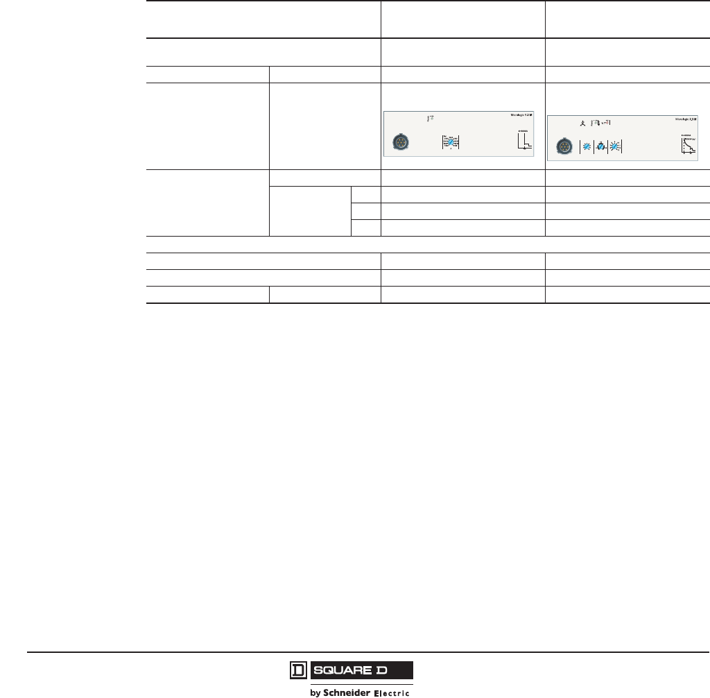
© 2011–2012 Schneider Electric
All Rights Reserved
PowerPact™ H-, J-, and L-Frame Circuit Breakers
Motor Circuit Protection
44
05/2012
™
PowerPact H-, J-, and L-Frame with Micrologic™ Trip Units Motor-Protection Range
PowerPact H-, J-, and L-frame circuit breakers with Micrologic trip units can be used to create motor-
feeder solutions comprising two or three devices. The protection devices are designed for continuous
duty at 104°F (40°C).
Three-device solutions
•1 PowerPact circuit breaker with Micrologic 1.3 M trip unit
•1 contactor
•overload relay
Two-device solutions
•1 PowerPact circuit breaker with a Micrologic 2 M electronic trip unit.
•1 contactor
Table 38: Motor Protection Specifications
Type of Motor Protection 3 Devices (Circuit Breaker +
Contactor + Overload Relay)
2 Devices (Circuit Breaker +
Contactor)
PowerPact H-, J-, or L-frame circuit breaker PowerPact L-frame 400/600 A PowerPact H-, J-, and L-Frame 100–
600 A
Type 2 coordination with Contactor + overload relay Contactor
Trip Unit Type
Micrologic 1.3 M
Electronic Trip Unit Micrologic 2 M
Electronic Trip Unit
Overload Relay
Separate X
Built-in, Class
5X
10 X
20 X
Protection functions of PowerPact H-, J-, and L-frame circuit breaker
Short-circuits X X
Overloads X
Special motor functions Phase unbalance X
Isd (x FLA)
190
310
290
270
250
230
210
50
FLA (A) Class.
348
330
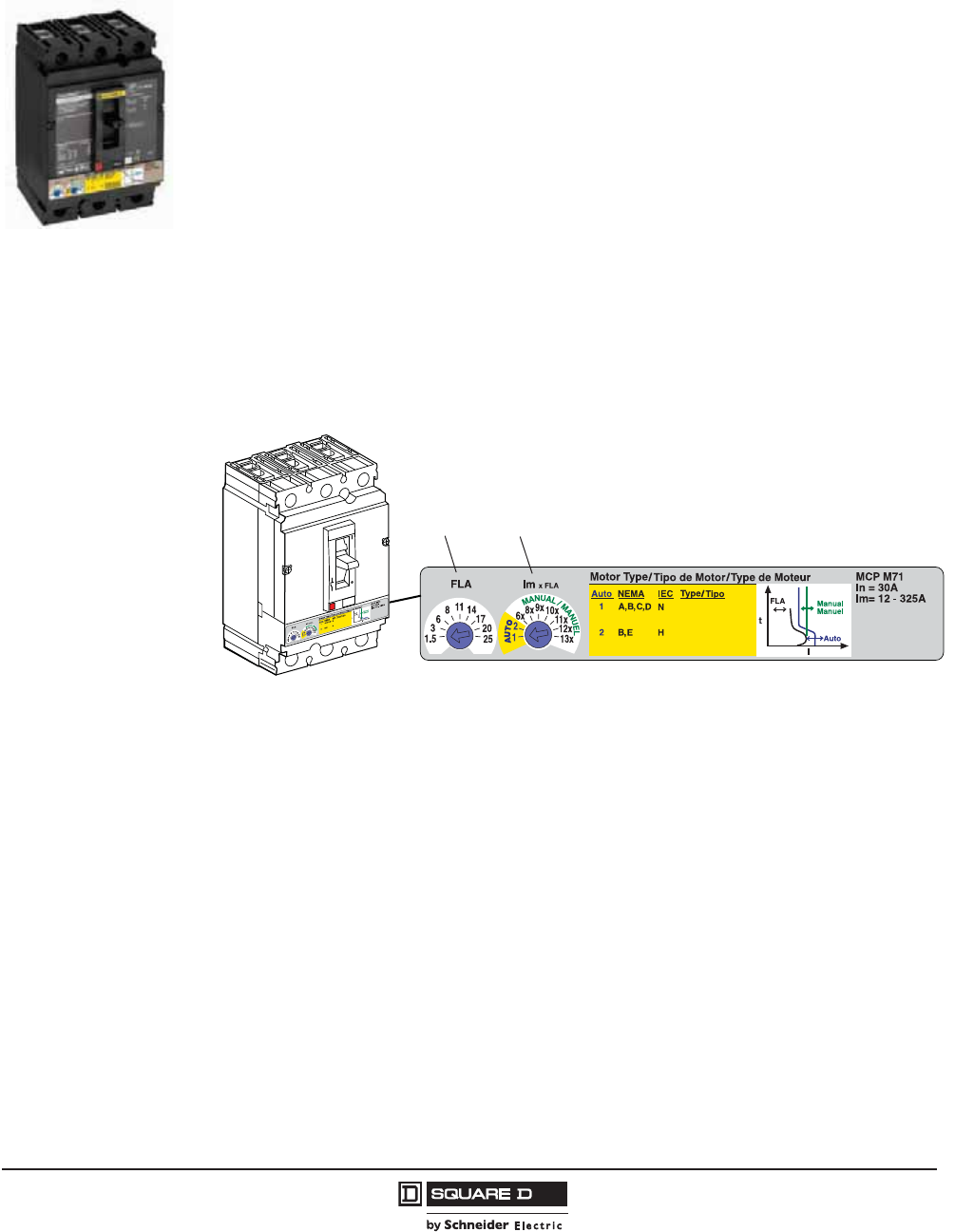
PowerPact™ H-, J-, and L-Frame Circuit Breakers
Motor Circuit Protection
45
05/2012
© 2011–2012 Schneider Electric
All Rights Reserved
™
Electronic Motor Circuit Protectors (AC Only)
PowerPact H- and J-frame Electronic Motor Circuit Protectors (MCP) are instantaneous-trip circuit
breakers. They are designed to offer short circuit protection and are National Electrical Code® (NEC®)
compliant when installed as part of a combination controller having motor overload protection. MCP
circuit breakers accept the same accessories and terminals as the equivalent thermal-magnetic circuit
breakers. (See Section 3 for Accessories.)
The unique design of the PowerPact MCPs includes two rotary switches to allow quick setting
adjustments based on the characteristics of the motor.
The first rotary switch allows for Full Load Amperes (FLA) adjustment across the range of the frame size.
The second rotary switch selects the type of motor protection based on Automatic 1 for Standard
Efficiency or Automatic 2 for High Energy Efficient. When using the automatic settings the MCP
microprocessor automatically adjusts the trip settings for both current and time to align with the start-up
characteristic for the motor type, whether it is a standard or energy-efficient motor. This includes a
dampening means to accommodate a transient motor in-rush current without nuisance tripping of the
circuit breaker. Rotary switch 2 also allows for traditional motor protection from 8 to 13 times the
selected FLA.
The MCP rotary switches are detented and allow the device to be set to specific trip values within a
typical accuracy range of +/-5%.
Full Load Amp Settings
1. Determine the motor’s full-load current by referring to the nameplate on the motor.
2. Set the trip range by turning the FLA rotary switch to the setting closest to the motor’s full load
current.
Automatic Protection Settings
The MCP microprocessor automatically adjusts the trip settings for both current and time to align with
the start-up characteristics for the motor type selected. This includes a dampening means to
accommodate a transient motor in-rush current without nuisance tripping of the circuit breaker.
06113533
AB
Standard
Energy Efficient
Energie Efficace
Energia Eficiente
Standard
Energy Efficient
Energie Efficace
Energia Eficiente
(A) Full Load Amp Setting (FLA).
(B) Instantaneous Trip Point Settings (Im).

© 2011–2012 Schneider Electric
All Rights Reserved
PowerPact™ H-, J-, and L-Frame Circuit Breakers
Motor Circuit Protection
46
05/2012
™
Manual Protection Settings
The manual settings may be adjusted to multiples of current based on the rotary switch setting for
motor Full Load Amps (FLA).
For example, if FLA rotary switch is set to 20 and Im rotary switch is set to 9x, then the instantaneous
trip point will be 180 A.
See Tables 44 thru 46 for more information.
•High Short Circuit Current Ratings (SCCR)
The PowerPact MCP helps achieve the high UL508A Short Circuit Current Rating (SCCR) needed
to meet NEC Article 409 requirements for industrial control panels. They deliver up to 100 kA at
480 Vac SCCR when used in combination with approved Square D™ NEMA or Schneider
Electric™ IEC motor starters.
Figure 3: Automatic Protection Settings
I
t
06114001
Standard
Energy Efficient
Energie Efficace
Motor Type / Tipo de Motor / Type de Moteur
Energia Eficiente
BA
Auto Setting
Dampening for
Motor In-Rush
Instantaneous
Trip Point = (FLA) x (Im)
06114902
AB
Standard
Energy Efficient
Energie Efficace
Energia Eficiente
A. (A) Full Load Amp Setting (FLA).
A. (B) Instantaneous Trip Point
Settings (Im).
Table 39: H- and J-Frame Electronic Motor Circuit Protectors (MCP)
Frame Current
Full Load
Amperes
Range
Adjustable
Instantaneous
Trip Range
Suffix
J Interrupting
(See SCCR Table Below)
L Interrupting
(See SCCR Table Below) R Interrupting
Cat. No. Cat. No. Cat. No.
H-Frame
30 A 1.5–25 A 9–325 A M71 HJL36030M71 HLL36030M71 HRL36030M71
50 A 14–42 A 84–546 A M72 HJL36050M72 HLL36050M72 HRL36050M72
100 A 30–80 A 180–1040 A M73 HJL36100M73 HLL36100M73 HRL36100M73
150 A 58–130 A 348–1690 A M74 HJL36150M74 HLL36150M74 HRL36150M74
J-Frame 250 A 114–217 A 684–2500 A M75 JJL36250M75 JLL36250M75 JRL36250M75
Table 40: Short Circuit Current Ratings (SCCR)
Contactor/Starter
J Interrupting L Interrupting R Interrupting
200–240 Vac 480 Vac 600 Vac 200–240 Vac 480 Vac 600 Vac 200–240 Vac 480 Vac 600 Vac
Tesys D-line and F-line 100 kA 65 kA 25 kA 100 kA 100 kA 50 kA 200 kA 200 kA 100 kA
NEMA Type S 100 kA 65 kA 25 kA 100 kA 100 kA 50 kA 200 kA 200 kA 100 kA
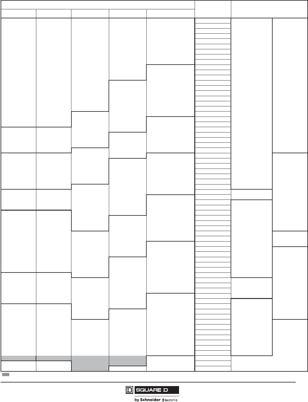
PowerPact™ H-, J-, and L-Frame Circuit Breakers
Motor Circuit Protection
47
05/2012
© 2011–2012 Schneider Electric
All Rights Reserved
™
”
Table 41: MCP Selection by HP Ratings of Induction-Type Squirrel-Cage and Wound-Rotor Motors
Horsepower Rating of Induction-Type Squirrel-Cage and Wound-Rotor Motors 3Ø 60 Hz NEC Full Load
Amperes
PowerPact H-Frame and
J-Frame Electronic MCP
Starter Size 200 Vac 230 Vac 480 Vac 575 Vac
00
1/2 0.9 A
HJL36030M71
and
HLL36030M71
1/2–10 hp
1/2 1.1 A
3/4 1.3 A
3/4 1 1.7 A
1 2.1 A
1/2 2.2 A
1-1/2 2.4 A
1/2 2.5 A
2 2.7 A
1-1/2 3 A
3/4 3.2 A
2 3.4 A
3/4 3.7 A
3 3.9 A
1 4.2 A
14.8 A
3 4.8 A
1-1/2 6 A
5 6.1 A
2 6.8 A
1-1/2 6.9 A
0
5 7.6 A
27.8 A
7-1/2 9 A
3 9.6 A
3 7-1/2 10 11 A
1
10 14 A
HJL36050M72
and
HLL36050M72
10–25 hp
5 15.2 A
15 17 A
517.5 A
15 21 A
7-1/2 20 22 A
7-1/2 25.3 A
2
20 25 27 A
10 28 A
30 32 A
HJL36100M73
and
HLL36100M73
15–50 hp
10 32.2 A
3
25 34 A
30 40 A
40 41 A
15 42 A
15 48.3 A
40 50 52 A
20 54 A
20 60 62 A
HJL36150M74
and
HLL36150M74
30–100 hp
50 65 A
25 68 A
60 75 77 A
25 78.2 A
4
30 80 A
30 92 A
75 96 A
100 99 A
40 104 A
40 120 A
JJL36250M75
and
JLL36250M75
50–150 hp
100 124 A
5
125 125 A
50 130 A
150 144 A
50 150 A
60 154 A
125 156 A
60 177.1 A
150 180 A
75 200 192 A
75 221 A
200 240 A
100 248 A
Shaded area is not covered by J-frame electronic motor circuit protector.
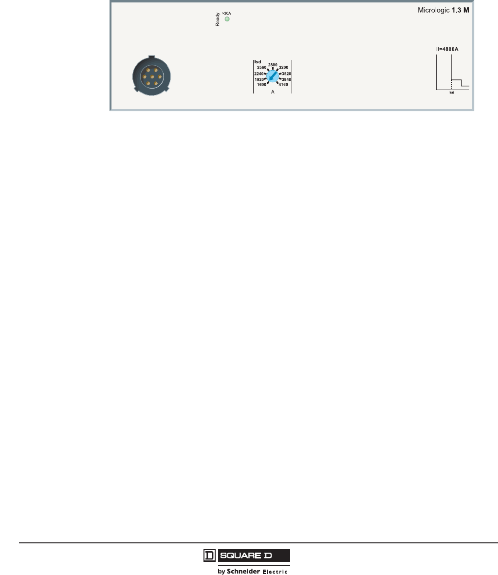
© 2011–2012 Schneider Electric
All Rights Reserved
PowerPact™ H-, J-, and L-Frame Circuit Breakers
Motor Circuit Protection
48
05/2012
™
Micrologic™ 1.3 M Electronic Trip Units for Instantaneous
Protection Only (L-Frame Circuit Breakers Only)
Micrologic 1.3 M trip units are used in 3-device motor-feeder solutions on PowerPact L-frame circuit
breakers with performance levels G/J/L. They provide short-circuit protection for motors up to 250 kW
at 400 V.
Micrologic 1.3 M trip units provide instantaneous protection only, using electronic technology. They are
dedicated to 600 A 3-pole (3P 3D) circuit breakers or 4pole circuit breakers with detection on 3 poles
(4P, 3D). They are especially used in 3-pole versions for motor protection, see Section 5—Motor
Circuit Protection.
Circuit breakers equipped with Micrologic 1.3 M trip units, without thermal protection, are used in
certain applications to replace automatic switches. Micrologic 1.3 M trip units are available on
PowerPact L-frame circuit breakers only.
NOTE: All Micrologic trip units have a transparent, sealable cover that protects access to the
adjustment rotary switches.
They also provide the benefits of electronic technology:
•accurate settings
•tests
•“Ready” LED.
Circuit breakers with a Micrologic 1.3 M trip unit are combined with a overload relay and a contactor.
Protection settings are made using a rotary switch.
Protection Version
3-pole (3P): 3-pole frame circuit breakers equipped with detection on all 3 poles.
Indications
The green “Ready” LED blinks slowly when the electronic trip unit is ready to provide protection. It
indicates the trip unit is operating correctly.
NOTE: All the trip units have a transparent sealable cover that protects access to the adjustment
rotary switches.
06114580
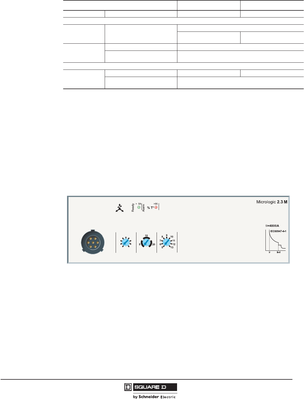
PowerPact™ H-, J-, and L-Frame Circuit Breakers
Motor Circuit Protection
49
05/2012
© 2011–2012 Schneider Electric
All Rights Reserved
™
Micrologic 2.2 M and 2.3 M Electronic Trip Units
Micrologic 2.2 M and 2.3 M trip units provide built-in thermal and instantaneous protection. They are
used in 2-device motor-feeder solutions on PowerPact H-, J-, and L-frame circuit breakers with
performance levels J/L. They provide protection for motors up to 315 kW at 400 V against:
•short-circuits
•overloads with selection of a trip class (5, 10 or 20)
•phase unbalance.
Circuit breakers with a Micrologic 2.2 M/ 2.3 M trip unit include protection similar to an inverse-time
overload relay. They are combined with a contactor.
Protection settings are made using a rotary switch.
Overloads (or Thermal Protection)
Long-time protection and trip class (FLA)
•Inverse-time thermal protection
•against overloads with adjustable pick-up FLA.
•Settings are made in amperes. The tripping curve for the long-time protection, which indicates the
time delay tr before tripping, is defined by the selected trip class.
Table 42: Micrologic™ 1.3 M Electronic Trip Unit
Rating: In at 104°F (40°C)1
1Motor standards require operation at 104°F (40°C). Circuit-breaker ratings are derated to take this requirement into account
400 A 600 A
Circuit Breaker PowerPact L-frame X X
Short-time protection
Pick-up (A)
accuracy ±15%
Isd
There is a very short delay to let
through motor starting currents
Adjustable directly in amps
9 settings: 2000-2400-2800-
3200-3600-4000-4800 A
9 settings: 3000-3600-4200-
4800-5400-6000-6600-7200 A
Time delay (ms)
tsd Non-adjustable
Non-tripping time
Maximum break time
20
60
Instantaneous protection
Pick-up (A)
accuracy ±15%
Ii non-adjustable 4800 7200
Non-tripping time
Maximum break time
0
30 ms
06114582
Isd (x FLA)
190
310
290
270
250
230
210
50
FLA (A) Class.
348
330

© 2011–2012 Schneider Electric
All Rights Reserved
PowerPact™ H-, J-, and L-Frame Circuit Breakers
Motor Circuit Protection
50
05/2012
™
Trip Class
•The class is selected as a function of the normal motor starting time.
— Class 5: starting time less than 5 s
— Class 10: starting time less than 10 s
— Class 20: starting time less than 20 s
•For a given class, it is necessary to check that all motor-feeder components are sized to carry the
6 x FLA starting current without excessive temperature rise during the time corresponding to the
class.
Short-Circuits
Short-time protection (Isd)
•Provides protection with an adjustable pick-up Isd.
•There is a very short delay to let through motor starting currents.
Non-adjustable instantaneous protection (li)
•Instantaneous protection with non-adjustable pick-up li.
Phase Unbalance or Phase Loss (lunbal)
•This function opens the circuit breaker if a phase unbalance occurs:
— that is greater than the 30% fixed pick-up Iunbal
— following the non-adjustable time delay tunbal equal to:
• 0.7 s during starting
• 4 s during normal operation
•Phase loss is an extreme case of phase unbalance and leads to tripping under the same conditions
Indications
Front indications
•The green “Ready” LED blinks slowly when the electronic trip unit is ready to provide protection. It
indicates the trip unit is operating correctly.
•Red alarm LED for motor operation goes ON when the thermal image of the rotor and stator is
greater than 95% of the permissible temperature rise.
Remote indications using SDTAM module
•PowerPact H-, J-, and L-frame devices with a Micrologic™ 2 M trip unit can be equipped with an
SDTAM module dedicated to motor applications for:
— a contact to indicate circuit-breaker overload
— a contact to open the contactor. In the event of a phase unbalance or overload, this output is
activated 400 ms before circuit-breaker tripping to open the contactor and avoid circuit breaker
tripping
•This module takes the place of the shunt trip (MN)/undervoltage trip (MX) coils and an auxiliary
switch (OF) contact
SDTAM remote indication relay module with its terminal block.
Note: All the trip units have a transparent sealable cover that protects access to the adjustment rotary
switches.
PowerPact™ H-, J-, and L-Frame Circuit Breakers
Motor Circuit Protection
51
05/2012
© 2011–2012 Schneider Electric
All Rights Reserved
™
Table 43: Micrologic™ 2.2 M and 2.3 M Electronic Trip Unit
Rating: In at 104°F (40°C)130 A 50 A 100 A 150 A 250 A 400 A 600 A
Circuit Breaker
PowerPact H-frame X X X X — — —
PowerPact J-frame — — — — X — —
PowerPact L-frame — — — — — X X
Overloads (or Thermal Protection): Long-Time Protection and Trip Class
Pick-Up (A)
Tripping between
1.05 and 1.20 FLA
FLA Value depending on trip unit rating (In) and setting on rotary switch
In = 30 AFLA =141618202122232425
In = 50 AFLA =141721242729323642
In = 100 A FLA = 30 35 41 45 51 56 63 71 80
In = 150 A FLA = 58 71 78 86 91 97 110 119 130
In = 250 A FLA = 114 137 145 155 163 172 181 210 217
In = 400 A FLA = 190 210 230 250 270 290 310 330 348
In = 600 A FLA = 312 338 364 390 416 442 468 484 520
Time Delay
Trip Class 5 10 20
Time Delay (s)
Depending on
selected trip class
tr
1.5 x FLA 120 240 480 For warm start
6 x FLA 6.5 13.5 26 For cold start
7.2 x FLA 5 10 20 For cold start
S Short Circuits: Short-time protection with fixed time delay
Pick-up (A)
accuracy ±15% Isd = FLA x 5 6 7 8 9 10111213
Time delay (ms)
tsd Non-adjustable
Non-tripping time 20
Maximum break time 60
I Short Circuit: Non-adjustable instantaneous protection
Pick-up (A)
accuracy ±15% Ii non-adjustable 450 750 1500 2250 3750 4800 7200
Time delay (ms) Non-tripping time 0
Maximum break time 30 ms
Phase unbalance or phase loss
Pick-up (A)
accuracy ±20% Iunbal in % average current230%
Time delay (ms) Non-adjustable 0.7 s during starting
4 s during normal operation
1Motor standards require operation at 104°F (40°C). Circuit-breaker ratings are derated to take this requirement into account.
2The unbalance measurement takes into account the most unbalanced phase with respect to the average current.
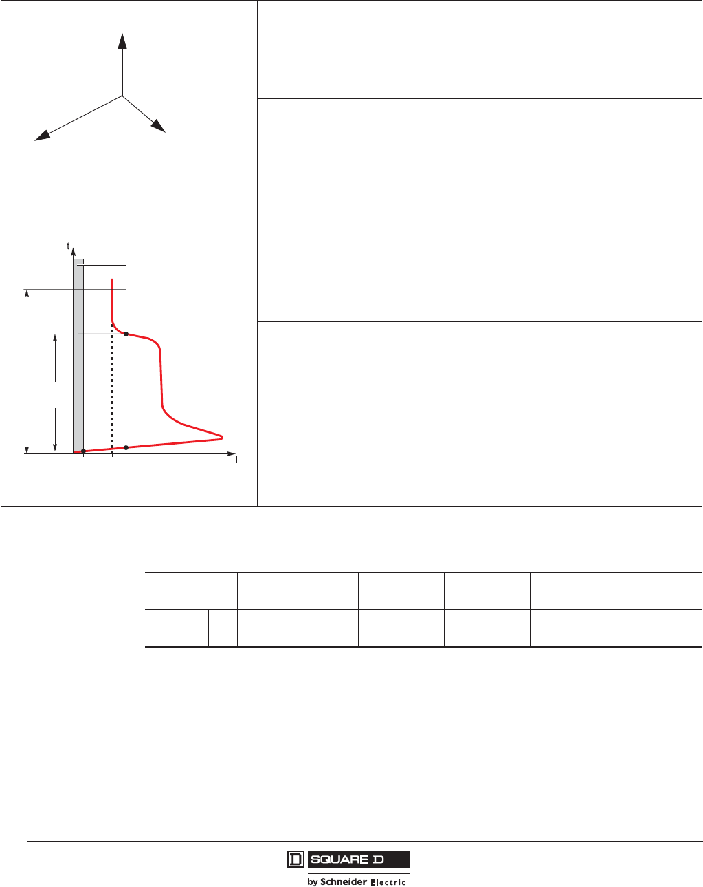
© 2011–2012 Schneider Electric
All Rights Reserved
PowerPact™ H-, J-, and L-Frame Circuit Breakers
Motor Circuit Protection
52
05/2012
™
Additional Technical Characteristics
Table 44: Additional Technical Characteristics
Phase unbalance
An unbalance in three-phase systems occurs when the three
voltages are not equal in amplitude and/or not displaced 120°
with respect to each other. It is generally due to single-phase
loads that are incorrectly distributed throughout the system and
unbalance the voltages between the phases.
These unbalances create negative current components that
cause braking torques and temperature rise in asynchronous
machines, thus leading to premature ageing.
Phase loss
Phase loss is a special case of phase unbalance.
• During normal operation, it produces the effects mentioned
above and tripping must occur after four seconds.
• During starting, the absence of a phase may cause motor
reversing, i.e. it is the load that determines the direction of
rotation. This requires virtually immediate tripping (0.7
seconds).
Starting time in compliance with the class (Micrologic™ 2 M)
For normal motor starting, Micrologic 2 M checks the conditions
below with respect to the thermal-protection (long-time) pick-up
FLA:
• current > 10% x FLA (motor-off limit)
• overrun of 1.5 x FLA threshold, then return below this
threshold before the end of a 10 s time delay.
If either of these conditions is not met, the thermal protection
trips the device after a maximum time equal to that of the
selected class. Pick-up FLA must have been set to the current
indicated on the motor rating plate.
Starting time in compliance
with the class
(Micrologic 2 M)
For normal motor starting, Micrologic 2 M checks the conditions
below with respect to the thermal-protection (long-time) pick-up
FLA:
• current > 10% x FLA (motor-off limit)
• overrun of 1.5 x FLA threshold, then return below this
threshold before the end of a 10 s time delay
If either of these conditions is not met, the thermal protection
trips the device after a maximum time equal to that of the
selected class.
Pick-up FLA must have been set to the current indicated on the
motor rating plate.
06114586
1 to 200 s
Return
Overrun
FLA1.5 FLA (Micrologic 2-M)
or Ilong (Micrologic 6 E-M)
10 % FLA
Motor-Off zone
Starting
Time
Long
Start Time
Limit
Motor Starting and Long Starts
Unbalance of Phase Currents and Voltages
IB (VB)
IC (VC)
IA (VA)
Table 45: L-Frame Electronic Trip Unit Magnetic Only 3 Pole, 600 Vac, 50/60 Hz—Three
Device Solutions1
1Three-device solutions are the traditional solutions: motor circuit protector plus motor starter plus overload relay.
Sensor Rating Trip
Unit
Adjustable2
Trip Range (A)
2UL magnetic trip tolerances are -20%/+30% from the nominal values shown.
G-Interrupting
Cat. No.
J-Interrupting
Cat. No.
L-Interrupting
Cat. No.
R-Interrupting
Cat. No.
PowerPact
L-Frame
400
1.3 M
500–1200% LGL36400M37X LJL36400M37X LLL36400M37X LRL36400M37X
600 500–1200% LGL36600M37X LJL36600M37X LLL36600M37X LRL36600M37X

PowerPact™ H-, J-, and L-Frame Circuit Breakers
Motor Circuit Protection
53
05/2012
© 2011–2012 Schneider Electric
All Rights Reserved
™
Table 46: H-Frame (150 A), J-Frame (250 A) and L-Frame (600 A) Electronic Motor Protector Circuit Breakers
(UL Ratings)—Two Device Solutions1
Electronic
Trip Unit
Type
Frame Sensor
Rating
Trip
Unit
Full Load
Amperes
Range (FLA)
Isd (x FLA) G Interrupting
Cat. No.
J Interrupting
Cat. No.
L Interrupting
Cat. No.
R Interrupting
Cat. No.
Standard2
H-Frame
30
2.2 M
14–25 5-13 x FLA HGL36030M38X HJL36030M38X HLL36030M38X HRL36030M38X
50 14–42 5-13 x FLA HGL36050M38X HJL36050M38X HLL36050M38X HRL36050M38X
100 30–80 5-13 x FLA HGL36100M38X HJL36100M38X HLL36100M38X HRL36100M38X
150 58–130 5-13 x FLA HGL36150M38X HJL36150M38X HLL36150M38X HRL36150M38X
J-Frame 250 114–217 5-13 x FLA JGL36250M38X JJL36250M38X JLL36250M38X JRL36250M38X
L-Frame 400 2.3 M 190–348 5-13 x FLA LGL36400M38X LJL36400M38X LLL36400M38X LRL36400M38X
600 312–520 5-13 x FLA LGL36600M38X LJL36600M38X LLL36600M38X LRL36600M38X
1Two-device solutions (these electronic motor protector circuit breakers include short circuit and overload protection)
—1 electronic motor circuit protector with a Micrologic™ 2.2 M electronic trip unit, plus
—1 contactor
2The standard trip unit offers Class 5, 10 and 20 and phase unbalance or phase loss protection.

© 2011–2012 Schneider Electric
All Rights Reserved
PowerPact™ H-, J-, and L-Frame Circuit Breakers
Trip Units
54
05/2012
™
Section 6—Trip Units
Available Trip Units
•PowerPact H-, J-, and L-Frame circuit breakers offer a range of thermal-magnetic and Micrologic™
electronic trip units in interchangeable cases. Thermal-magnetic trip units are designed to open
automatically under overload or short circuit. H-frame and J-frame thermal-magnetic circuit
breakers contain individual thermal (overload) and instantaneous (short circuit) sensing elements
in each pole.
•Micrologic electronic trip units provide intelligent operation, with wide setting ranges make
installation upgrades easier. Designed with processing capabilities, Micrologic trip units can
provide measurement information and device operating assistance to supply all of the information
required to manage the electrical installation and optimize energy use.
Micrologic trip units offer excellent measurement accuracy, using a new generation of current
transformers combining “iron-core” sensors for self-powered electronics and “air-core” sensors
(Rogowski coils) for measurements. The protection functions are managed by an ASIC component
that is independent of the measurement functions. This independence ensures immunity to
conducted and radiated disturbances and a high level of reliability.
An LED on the front of the electronic trip units indicates the result of the self-test running continuously on
the measurement system and the tripping release. When the green LED is flashing, the links between
the CTs, the processing electronics and the Mitop release are operational. The circuit breaker is ready
to protect. A minimum current of 15 to 50 A, depending on the device, is required for this function.
The dual adjustment for protection functions on Micrologic 5 / 6 consists of:
— an adjustment using rotary switches sets the maximum value
— an adjustment, made using the keypad or remotely, fine-tunes the setting. This setting may not
exceed the first one. It can be read directly on the Micrologic screen, to within one ampere and
a fraction of a second.
NOTE: All the trip units have a transparent sealable cover that protects access to the adjustment
rotary switches.
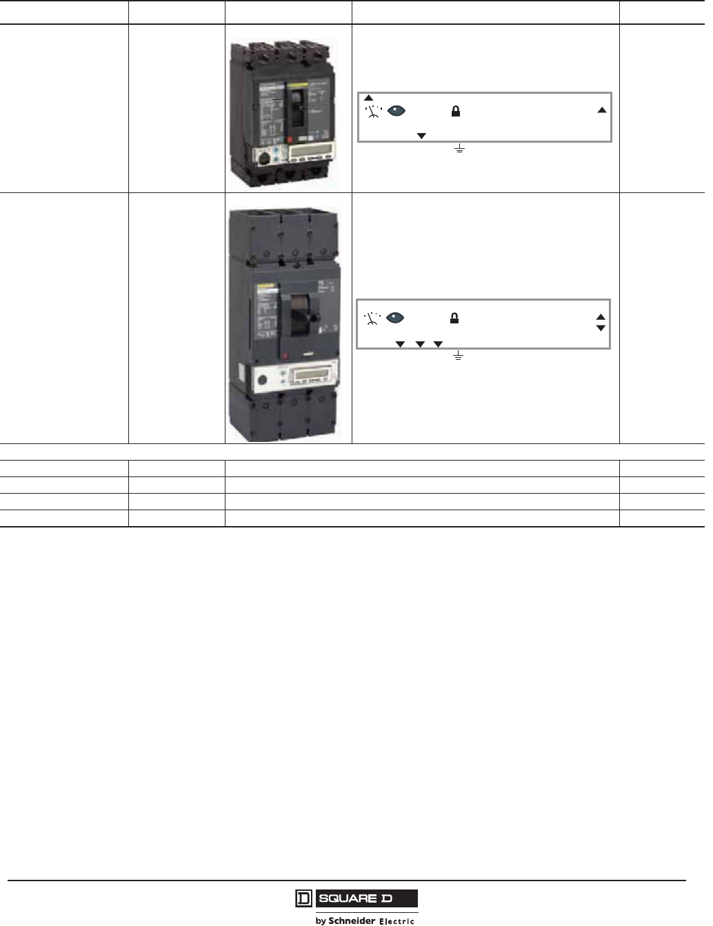
PowerPact™ H-, J-, and L-Frame Circuit Breakers
Trip Units
55
05/2012
© 2011–2012 Schneider Electric
All Rights Reserved
™
For Micrologic trip unit features, see table 7 on page 18.
Table 47: Understanding the Names of Micrologic™ Electronic Trip Units
Protection Frame Measurements Applications
1: I
3: LI or LSI
5: LSI
6: LSIG
H- and J-frame
A: Ammeter
DIstribution
or
M: Motors
L: Long time
S: Short time
I: Instantaneous
G: Ground fault
L-frame
E: Energy
Examples
Micrologic 1.3 M Trip Unit Instantaneous only 400 or 600 A Motor
Micrologic 3.3 Trip Unit LI 250, 400, or 600 A Distribution
Micrologic 3.2S Trip Unit LSI 60, 100, 150, or 250 A Distribution
Micrologic 5.2A Trip Unit LSI—Ammeter 60, 100, 150, or 250 A Distribution
Ir tr Isd tsd Ii Ig tg
200 A
N 1/A 2/B 3/C
N 1/A 2/B 3/C
Ir tr Isd tsd Ii (x In
255 kWh
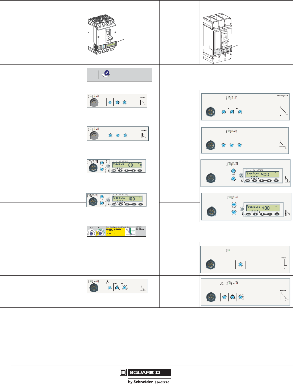
© 2011–2012 Schneider Electric
All Rights Reserved
PowerPact™ H-, J-, and L-Frame Circuit Breakers
Trip Units
56
05/2012
™
Table 48: Trip Unit Availability
Trip Unit Type Trip Unit
H-, J-Frame
Trip Unit
L-Frame
Distribution Protection
Thermal-Magnetic T-M N/A
Distribution Protection
LI Micrologic™ 3.2 Micrologic 3.3
Distribution Protection
LSI
Fixed ST and LT delays
Micrologic 3.2S Micrologic 3.3S
Distribution Protection
LSI + Ammeter Micrologic 5.2 A Micrologic 5.3 A
Distribution Protection
LSI + Energy Monitoring Micrologic 5.2 E Micrologic 5.3 E
Distribution Protection
LSIG + Ammeter Micrologic 6.2 A Micrologic 6.3 A
Distribution Protection
LSIG + Energy Monitoring Micrologic 6.2 E Micrologic 6.3 E
Motor Circuit Protection
Magnetic Only MN/A
Motor Protection
Micrologic 1 M N/A Micrologic 1.3M
Motor Protection
Micrologic 2 M Micrologic 2.2 M Micrologic 2.3 M
rciMcigolo
E
2
.5
r
I
%
A
0
3
>
0
3
>01
1
>
.9
2
9
.
3
9
.
4
9
.5
9
.
1
8
9
.
7
9
.
6
9
.
Ir)
o
Ix
(
5
.
1
2
5
.
2
34
0
1
8
6
5
d
s
I)
r
I
x
(
Trip
Unit
Trip
Unit
250A
1250 2500
lnlm (= li)
Ii
tr
Ir
3.2
Ir (A) tr @ 6 Ir Ii (x In)
15 60
50
45
40
35
30
25
20
.5 16
16
16
8
4
2
1
1.5 15
12
10
8
6
4
3
2
450 16
16
8
4
216
.5
150
175
200
350
125
300
250
225
12
8
45
3
110
1.5
2
6
Ir (A) Ii (x In)Tr @ 6 Ir Ii
Ii
3.2S
Ir (A) Isd (x In) Ii (x In)
15 60
50
45
40
35
30
25
20
1.5 12
10
6
5
4
3
2
1.5 15
12
10
8
6
4
3
2
8
tsd
tr
Ir Isd
450
6
5
4
3
1.5
150
175
200
350
125
300
250
225
12
8
45
3
210
1.5
2
6
Ir (A) Ii (x In)
3.3S
Micrologic
Ii
tsd
tr
Ir Isd
Isd (x In)
12
10
8
Ii (x In)
35
15
2
3
48
6
10
12
15
20
25
30 40
45
50
60
1.5
5.3 A
Micrologic
Isd
tr
Ir
tsd
Ii
Ii (x In)
225
125
2
3
46
5
8
10
12
150
175
200 250
300
350
400
1.5
Ii (x In)
35
15
2
3
48
6
10
12
15
20
25
30 40
45
50
60
1.5
Ig tg
6.2E
6.3 A
Micrologic
Isd
tr
Ir
tsd
Ii
Ii (x In)
225
125
2
3
46
5
8
10
12
150
175
200 250
300
350
400
1.5
Ir tr Isd tsd Ii(xIn) Ig tg
Standard
Energy Efficient
Energie Efficace
Energia Eficiente
4400
4000
3200 3600
2800
2400
2000 4800
Isd (A)
1.3 M
Micrologic
Isd (x FLA)
114
181
172
163
155
145
137
FLA (A) Class.
217
210
Ii=3750
Micrologic
2.2 M
Isd
FLA
Isd (x FLA)
190
310
290
270
250
230
210
50
FLA (A) Class.
348
330
2.3M
Micrologic
Isd
FLA
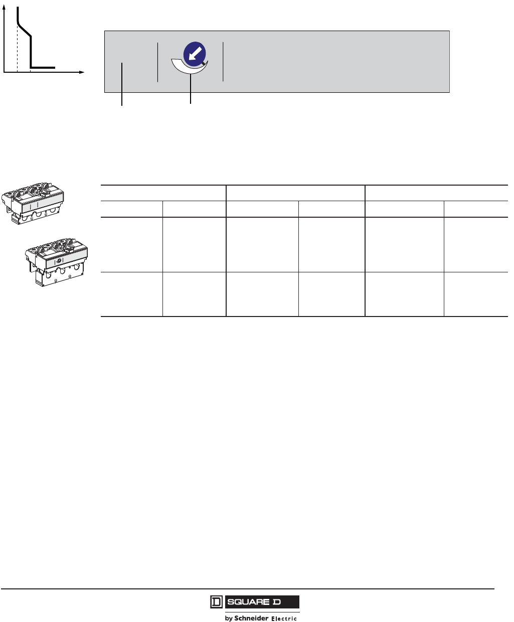
PowerPact™ H-, J-, and L-Frame Circuit Breakers
Trip Units
57
05/2012
© 2011–2012 Schneider Electric
All Rights Reserved
™
Protection of Distribution Systems
Thermal-Magnetic Trip Units
TM thermal-magnetic trip units can be used on PowerPact H and J-frame circuit breakers with interrupting
levels D/G/J/L. Thermal-magnetic trip units are available in factory sealed or field-interchangeable
constructions.
t
0lnlil
H-Frame Trip Curve
(ln) Fixed threshold thermal
protection against
overload
(li) Fixed threshold
instantaneous protection
against short circuits
06113269
Table 49: H-Frame and J-Frame 3P Field-Installable Thermal-Magnetic Trip Unit
15–60 A H-Frame 70–150 A H-Frame 150–250 A J-Frame
Amperage Cat. No. Amperage Cat. No. Amperage Cat. No.
15 A HT3015 70 A HT3070 150 A JT3150
20 A HT3020 80 A HT3080 175 A JT3175
25 A HT3025 90 A HT3090 200 A JT3200
30 A HT3030 100 A HT3100 225 A JT3225
35 A HT3035 110 A HT3110 250 A JT3250
40 A HT3040 125 A HT3125 — —
45 A HT3045 150 A HT3150 — —
50 A HT3050 — — — —
60 A HT3060 — — — —
250A
1250 2500
lnlm (= li)
60A 1125A
(ln)(l
i)
06113271
250A
1250 2500
(ln)(lm)
06113272
J-Frame Trip Unit
H-Frame Trip Unit
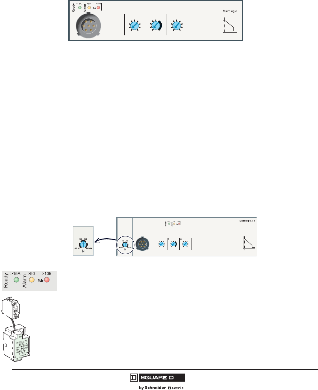
© 2011–2012 Schneider Electric
All Rights Reserved
PowerPact™ H-, J-, and L-Frame Circuit Breakers
Trip Units
58
05/2012
™
Micrologic™ 3 Trip Units
Micrologic 3 trip units can be used on PowerPact H-, J-, and L-Frame circuit breakers with performance
levels D/G/J/L.
They provide:
•standard protection of distribution cables
•indication of:
— overloads (using LEDs)
— overload tripping (using the SDx relay module).
Circuit breakers equipped with Micrologic 3 trip units can be used to protect distribution systems
supplied by transformers.
Protection
Settings are made using the adjustment rotary switches.
Overloads: Long time protection (Ir)
Inverse time protection against overloads with an adjustable current pick-up Ir set using a rotary switch
and an adjustable time delay tr.
Neutral protection
•On 3-pole L-frame circuit breakers, neutral protection is not possible.
•On four-pole L-frame circuit breakers, neutral protection may be set using a three-position switch:
— switch position 4P 3D: neutral unprotected
— switch position 4P 3D + N/2: neutral protection at half the value of the phase pick-up, (0.5 x Ir)
— switch position 4P 4D: neutral fully protected at Ir
Indicators
Front indicators
•The green “Ready” LED blinks slowly when the electronic trip unit is ready to provide protection. It
indicates the trip unit is operating correctly.
•Orange overload pre-alarm LED: steady on when I > 90% Ir
•Red overload LED: steady on when I > 105% Ir
Remote indicators
An overload trip signal can be remotely checked by installing an SDx relay module inside the circuit
breaker. This module receives the signal from the Micrologic electronic trip unit through an optical link
and makes it available on the terminal block. The signal is cleared when the circuit breaker is reclosed.
See page 94.
Ii
tr
Ir
3.2
Ir (A) tr @ 6 Ir Ii (x In)
15 60
50
45
40
35
30
25
20
.5 16
16
16
8
4
2
1
1.5 15
12
10
8
6
4
3
2
450 16
16
8
4
216
.5
150
175
200
350
125
300
250
225
12
8
45
3
110
1.5
2
6
Ir (A) Ii (x In)Tr @ 6 Ir
Ii
06114622
06114621
x
SDX Module
Front Indicators
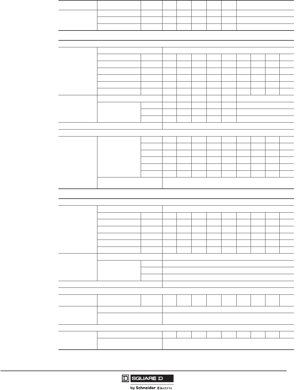
PowerPact™ H-, J-, and L-Frame Circuit Breakers
Trip Units
59
05/2012
© 2011–2012 Schneider Electric
All Rights Reserved
™
Table 50: Micrologic™ 3 Trip Unit
Ratings In at 104°F (40°C)1
1 If the trip units are used in high-temperature environments, the Micrologic trip unit setting must take into account the thermal
limitations of the circuit breaker. See the temperature derating information on page 126.
60 A 100 A 150 A 250 A 400 A 600 A
Circuit Breaker
H-frame X X X
J-frame X
L-frame X X X
Micrologic 3.2 / 3.3 trip units
L Long-time protection
Pick-Up (A)
Tripping between
1.05 and 1.20 Ir
IrValue depending on sensor rating (In) and setting on rotary switch
In =60 A Ir = 1520 25 30 35 40455060
In = 100 A Ir = 3540 45 50 60 708090100
In = 150 A Ir = 5060708090100110125150
In = 250 A Ir = 70 80 100 125 150 175 200 225 250
In = 400 A Ir = 125 150 175 200 225 250 300 350 400
In = 600 A Ir = 200 225 250 300 350 400 450 500 600
Time Delay (s)
Accuracy 0 to -20%
tr0.5124816
1.5 x Ir15 25 50 100 200 400
6 x Ir0.5124816
7.2 x Ir0.35 0.7 1.4 2.8 5.5 11
Thermal memory 20 minutes before and after tripping
I Instantaneous
Pick-up (A)
accuracy ± 15%
Ii x
60 A 1.5 2 3 4 6 8 10 12 15
100 A 1.5 2 3 4 6 8 10 12 15
150 A 1.5 2 3 4 6 8 10 12 15
250 A1.52345681012
400 A1.52345681012
600 A1.52345681011
Non-tripping time
Maximum break time
10 ms
50 ms for I > 1.5 Ii
Micrologic 3.2S / 3.3S trip units
L Long-time protection
Pick-Up (A)
Tripping between
1.05 and 1.20 Ir
IrValue depending on sensor rating (In) and setting on rotary switch
In =60 A Ir = 1520 25 30 35 40455060
In = 100 A Ir = 3540 45 50 60 708090100
In = 150 A Ir = 5060708090100110125150
In = 250 A Ir = 70 80 100 125 150 175 200 225 250
In = 400 A Ir = 125 150 175 200 225 250 300 350 400
In = 600 A Ir = 200 225 250 300 350 400 450 500 600
Time Delay (s)
Accuracy 0 to -20%
trnon-adjustable
1.5 x Ir400
6 x Ir16
7.2 x Ir11
Thermal memory 20 minutes before and after tripping
S Short-time protection
Pick-up (A)
accuracy ± 10% Isd - Ir x... 1.5234567810
Time delay (ms)
tsd non-adjustable
Non-tripping time
Maximum break time
20
80
I Instantaneous
Pick-up (A)
accuracy ± 15%
Ii x In1.5 2 3 4 6 8 10 12 15
Non-tripping time
Maximum break time
10 ms
50 ms for I > 1.5 Ii
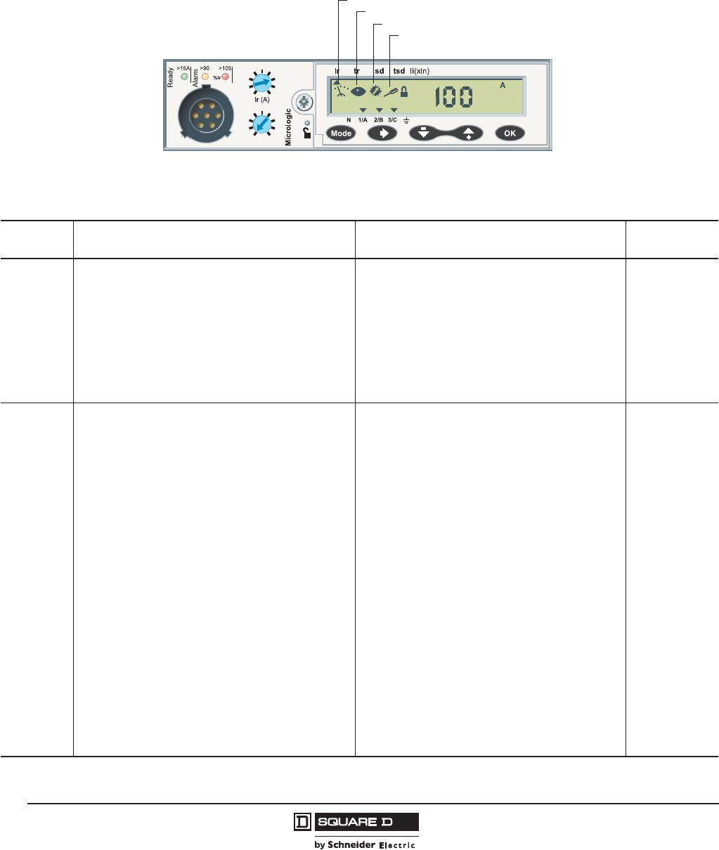
© 2011–2012 Schneider Electric
All Rights Reserved
PowerPact™ H-, J-, and L-Frame Circuit Breakers
Trip Units
60
05/2012
™
Micrologic™ 5 / 6 A or E Trip Units
Micrologic 5 / 6 A (Ammeter) or E (Energy) trip units can be used on PowerPact H-, J-, and L-frame
circuit breakers with performance levels D, G, J, or L. They all have a front display module. They offer
basic LSI protection (Micrologic 5 trip unit) or LSI and ground-fault protection G (Micrologic 6 trip unit).
They also offer measurement, alarm and energy values.
The capabilities of Micrologic 5 / 6 A and E trip units come into full play with the front display module.
When the two are connected using a simple cable with RJ45 connectors, the combination offers full
Power Meter capabilities and all the measurements required to monitor the electrical installation.
Ii (x In)
35
15
2
3
48
6
10
12
15
20
25
30 40
45
50
60
1.5
Ig tg
6.2E
Measurement
Display
Maintenance
Settings
Measurements Operating and Maintenance Assistance Communication
Network
Ammeter
(Micrologic A
Trip Unit)
Current measurements
• Phase and neutral currents IA, IB, IC, IN
• Average current of the 3 phases Iavg
• Highest current of the three phases Imax
• Ground-fault current Ig (Micrologic 6.2 / 6.3 A) trip units
• Maximum and minimum current measured
Indicators, alarms and histories
• Fault types
• Alarms for high/low alarm thresholds linked to I
measurements
• Trip, alarm and operating histories
• Time-stamped tables for settings and maximum current
Maintenance indicators
• Operation, trip and alarm counters
• Operating hours counter
• Contact wear
• Load profile and thermal image
Modbus™ with
add-on module
Energy
(Micrologic E
Trip Unit)
Current measurements
• Phase and neutral currents IA, IB, IC, IN
• Average current of the 3 phases Iavg
• Highest current of the three phases Imax
• Ground-fault current Ig (Micrologic 6.2 / 6.3 A trip units)
• Maximum and minimum current measured
• Current unbalance between phases
Voltage measurements
• Phase-to-phase (V) and phase-to-neutral (U) voltages
• Average voltages Vavg, Uavg
• Ph-Ph (V) and Ph-N (U) voltage unbalance
Frequency measurements
• Frequency (f)
Power-quality indicators
• Total harmonic distortion (THD) for current and voltage
Power measurements
• Active, reactive and apparent power, total and per phase
• Power factor and cos
Maximum and minimum
• For all I, V, f, P, E measurements
Demand current and power measurements
• Demand values, total and per phase
• Maximum demand
Energy metering
• Active, reactive and apparent energy, total and per phase
Indicators, alarms and histories
• Fault types
• Alarms for high/low thresholds linked to I, V, f, P, E
measurements
• Trip, alarm and operating histories
• Time-stamped tables for settings and I, V, f, P, E
maximum values
Maintenance indicators
• Operation, trip and alarm counters
• Operating hours counter
• Contact wear
• Load profile and thermal image
Modbus with
add-on module

PowerPact™ H-, J-, and L-Frame Circuit Breakers
Trip Units
61
05/2012
© 2011–2012 Schneider Electric
All Rights Reserved
™
Power Requirements
The amount of current needed to power the trip unit is printed in the upper left hand corner of the trip
unit by the Ready LED.
Protection
Settings can be adjusted in two ways, using the rotary switches and/or the keypad.
•The keypad can be used to make fine adjustments in 1 A steps below the maximum value defined
by the setting on the rotary switch.
•Access to setting modifications using the keypad is protected by a locking function displayed on the
screen and controlled by a microswitch.
•The lock is activated automatically if the keypad is not used for 5 minutes.
•Access to the microswitch is protected by a transparent, sealable cover.
•With the cover closed, it is still possible to display the various settings and measurements using the
keypad.
Overloads: Long-Time Protection (Ir)
Inverse time protection against overloads with an adjustable current pick-up Ir is set using a rotary
switch or the keypad for fine adjustments. The time delay tr is set using the keypad.
Short-Circuits: Short-Time Protection (Isd)
Short-circuit protection with an adjustable pick-up Isd and adjustable time delay tsd, with the possibility
of including a portion of an inverse time curve (I2t On).
Short-Circuits: Instantaneous Protection (Ii)
Instantaneous protection with adjustable pick-up Ii.
Additional Ground Fault Protection (Ig) on Micrologic™ 6 Trip Units
Residual type ground-fault protection with an adjustable pick-up Ig and adjustable time delay tg.
Possibility of including a portion of an inverse time curve (I2t On).
Neutral Protection
•On 4-pole circuit breakers, this protection can be set using the keypad:
— Off: neutral unprotected
— 0.5: neutral protection at half the value of the phase pick-up (0.5 x Ir)
— 1.0: neutral fully protected at Ir
— OSN: Oversized neutral protection at 1.6 times the value of the phase pick-up.
Used when there is a high level of 3rd order harmonics (or orders that are multiples of 3) that
accumulate in the neutral and create a high current. In this case, the device must be limited to
Ir= 0.63 x In for the maximum neutral protection setting of 1.6 x Ir.
•With 3-pole circuit breakers, the neutral can be protected by installing an external neutral sensor
with the output (T1, T2) connected to the trip unit.
Table 51: Trip Unit Power Requirements
Frame Power-Up Requirement
H-Frame, 60 A
60 A > 15 A
100 A > 15 A
150 A > 30 A
J-Frame, 250A 250A > 30 A
L-Frame, 600 A 400 A > 50 A
600 A > 50 A
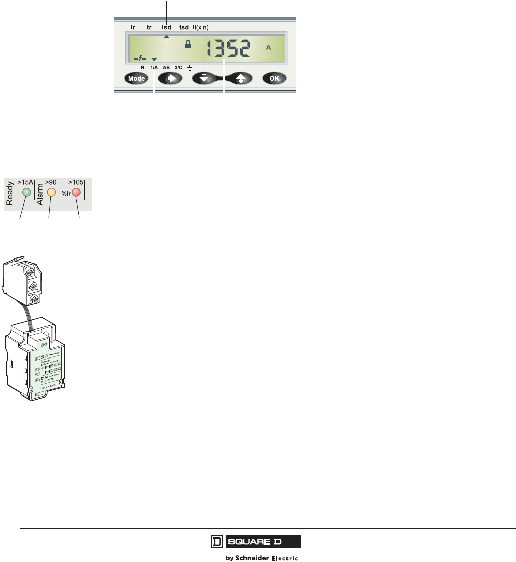
© 2011–2012 Schneider Electric
All Rights Reserved
PowerPact™ H-, J-, and L-Frame Circuit Breakers
Trip Units
62
05/2012
™
Zone Selective Interlocking (ZSI)
A ZSI terminal block may be used to interconnect a number of Micrologic™ trip units to provide zone
selective interlocking for short-time (Isd) and ground-fault (Ig) protection, without a time delay. For
PowerPact H- and J-frame circuit breakers, the ZSI function is available only in relation to the
upstream circuit breaker (ZSI out). For PowerPact L-frame circuit breakers, the ZSI function is
available in relation to the upstream circuit breaker (ZSI out) and downstream circuit breakers (ZSI in).
Display of Type of Fault.
On a fault trip, the type of fault (Ir, Isd, Ii, Ig), the
phase concerned and the interrupted current are
displayed. An external power supply is required.
Indicators
Front Indicators
•The green “Ready” LED blinks slowly when the electronic trip unit is ready to provide protection. It
indicates the trip unit is operating correctly.
•Orange overload pre-alarm LED stays on when I > 90% Ir
•Red overload LED stays on when I > 105% Ir
Remote Indicators
An SDx relay module installed inside the circuit breaker can be used to remote the following
information:
•overload trip
•overload prealarm (Micrologic 5 trip units) or ground fault trip (Micrologic 6 trip units).
This module receives the signal from the Micrologic electronic trip unit through an optical link and
makes it available on the terminal block. The signal is cleared when the circuit breaker is closed. Note:
all the trip units have a transparent sealable cover
These outputs can be reprogrammed to be assigned to other types of tripping or that protects access
to the adjustment rotary switch. The module is described in detail in the section dealing with
accessories.
06114623
Isd Fault
Fault Phase Interrupted Current
Display of Interrupted Current.
Green
LED
Yellow
LED
Red
LED
SDx Module
06114621
x

PowerPact™ H-, J-, and L-Frame Circuit Breakers
Trip Units
63
05/2012
© 2011–2012 Schneider Electric
All Rights Reserved
™
Table 52: Micrologic™ 5/6 Trip Unit
Ratings In at 104°F (40°C)160 A 100 A 150 A 250 A 400 A 600 A
Circuit Breaker
H-frame XXX
J-frame X
L-frame XX
L Long-time protection
Pick-up (A)
tripping between
1.05 and 1.20 Ir
Irrotary switch Value depending on the trip unit rating (In) and setting on rotary switch
In = 60 A Ir = 15 20 25 30 35 40 45 50 60
In = 100 A Ir = 35 40 45 50 60 70 80 90 100
In = 150 A Ir = 50 60 70 80 90 100 110 125 150
In = 250 A Ir = 70 80 100 125 150 175 200 225 250
In = 400 A Ir = 125 150 175 225 225 250 300 350 400
In = 600 A Ir = 200 225 250 350 300 400 450 500 600
keypad setting Fine adjustment in 1 A steps below maximum value set on rotary switch
Time Delay (s)
Accuracy 0 to -20%
tr = keypad setting 0.5 1 2 4 8 16
1.5 x Ir 15 25 50 100 200 400
6 x Ir 0.5124816
7.2 x Ir 0.35 0.7 1.4 2.8 5.5 11
Thermal memory 20 minutes before and after tripping
S Short-time protection
Pick-up (A)
accuracy ± 10% Isd keypad setting 1.52 2.53 3.54 4.55 5.56 6.57 7.58 8.59 9.510
Fine adjustment in 0.5 x Ir steps using the keypad
Time delay
tsd = Keypad
setting
I2t Off 0 0.1 s 0.2 s 0.3 s 0.4 s
It On — 0.1 s 0.2 s 0.3 s 0.4 s
Non-tripping time
Maximum break time
20 ms
80 ms
80 ms
140 ms
140 ms
200 ms
230 ms
320 ms
350 ms
500 ms
I Instantaneous
Pick-up (A)
accuracy ± 15%
Ii = In x Rotary
Switch
60 A1.52.3468101215
100 A1.52.3468101215
150 A1.52.3468101215
250 A1.52.345681012
400 A1.52.345681012
600 A1.52.345681011
Non-tripping time
Maximum break time
10 ms
50 ms for I > Ii
G Ground-fault protection - for Micrologic 6 A or E Trip Units
Pick-up (A)
accuracy ± 10%
IgKeypad Setting
In= 60 A Ig = 0.3 0.35 0.4 0.45 0.5 0.55 0.6 0.65 0.7 0.75 0.8 0.85 0.9 0.95 1
In= 100–600 A Ig = 0.2 2.5 0.3 0.35 0.4 0.45 0.5 0.55 0.6 0.65 0.7 0.75 0.8 0.85 0.9 0.95 1
Time delay (s)
tg = Keypad
setting
I2t Off 0 0.1 0.2 0.3 0.4
It On — 0.1 0.2 0.3 0.4
Non-tripping time
Maximum break time
20
80
80
140
140
200
230
320
350
500
Test Ig function Built in
1 If the trip units are used in high-temperature environments, the Micrologic trip unit setting must take into account the thermal limitations of the circuit breaker. See the
temperature derating information on page 126.
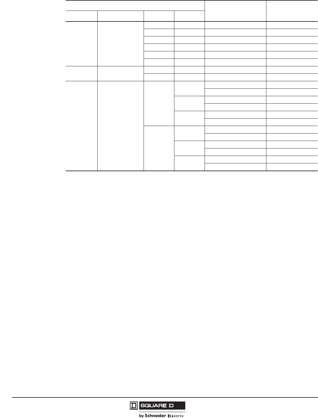
© 2011–2012 Schneider Electric
All Rights Reserved
PowerPact™ H-, J-, and L-Frame Circuit Breakers
Trip Units
64
05/2012
™
Table 53: Micrologic™ 3 Field-Installable Trip Units
Circuit Breaker
Trip Unit Type Catalog No.
Frame Standard Poles Rating
H-frame UL/CSA/NOM
3P 60 A Micrologic 3.2 HE3060U31X
3P 60 A Micrologic 3.2S HE3060U33X
3P 100 A Micrologic 3.2 HE3100U31X
3P 100 A Micrologic 3.2S HE3100U33X
3P 150 A Micrologic 3.2 HE3150U31X
3P 150 A Micrologic 3.2S HE3150U33X
J-Frame UL/CSA/NOM 3P 250 A Micrologic 3.2 JE3250U31X
3P 250 A Micrologic 3.2S JE3250U33X
L-Frame UL/CSA/NOM
3P
250 A Micrologic 3.3 LE3250U31X
Micrologic 3.3S LE3250U33X
400 A Micrologic 3.3 LE3400U31X
Micrologic 3.3S LE3400U33X
600 A Micrologic 3.3 LE3600U31X
Micrologic 3.3S LE3600U33X
4P
250 A Micrologic 3.3 LE4250U31X
Micrologic 3.3S LE4250U33X
400 A Micrologic 3.3 LE4400U31X
Micrologic 3.3S LE4400U33X
600 A Micrologic 3.3 LE4600U31X
Micrologic 3.3S LE4600U33X
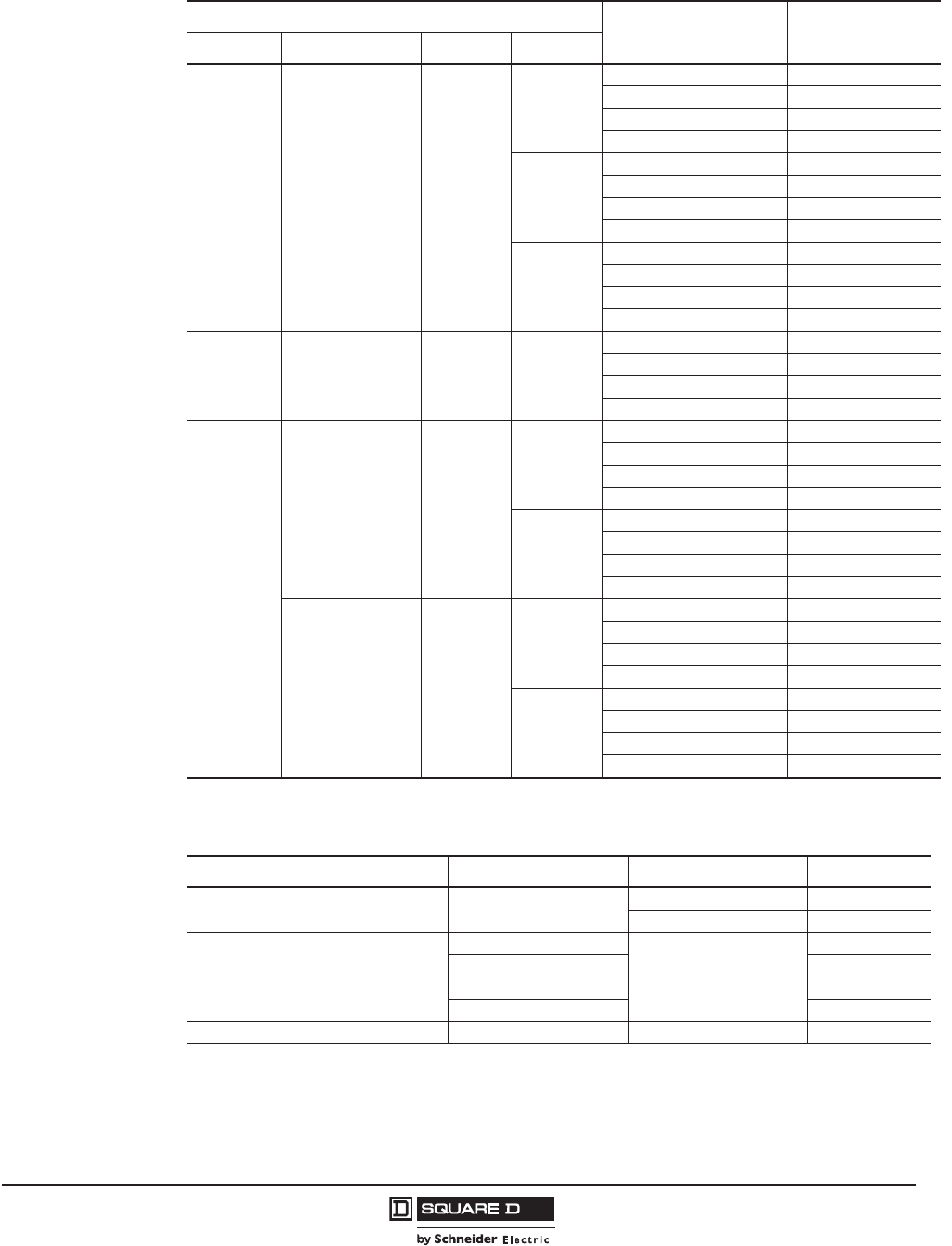
PowerPact™ H-, J-, and L-Frame Circuit Breakers
Trip Units
65
05/2012
© 2011–2012 Schneider Electric
All Rights Reserved
™
Table 54: Micrologic™ 5 and 6 Field-Installable Trip Units
Circuit Breaker
Trip Unit Type Catalog No.
Frame Standard Poles Rating
H-frame UL/CSA/NOM 3P
60 A
Micrologic 5.2 A HE3060U43X
Micrologic 6.2 A HE3060U44X
Micrologic 5.2 E HE3060U53X
Micrologic 6.2 E HE3060U54X
100 A
Micrologic 5.2 A HE3060U43X
Micrologic 6.2 A HE3100U44X
Micrologic 5.2 E HE3100U53X
Micrologic 6.2 E HE3100U54X
150 A
Micrologic 5.2 A HE3150U43X
Micrologic 6.2 A HE3150U44X
Micrologic 5.2 E HE3150U53X
Micrologic 6.2 E HE3150U54X
J-Frame UL/CSA/NOM 3P 250 A
Micrologic 5.2 A JE3250U43X
Micrologic 6.2 A JE3250U44X
Micrologic 5.2 E JE3250U53X
Micrologic 6.2 E JE3250U54X
L-Frame
UL/CSA/NOM 3P
400 A
Micrologic 5.3 A LE3400U43X
Micrologic 6.3 A LE3400U44X
Micrologic 5.3 E LE3400U53X
Micrologic 6.3 E LE3400U54X
600 A
Micrologic 5.3 A LE3600U43X
Micrologic 6.3 A LE3600U44X
Micrologic 5.3 E LE3600U53X
Micrologic 6.3 E LE3600U54X
UL/CSA/NOM 4P
400 A
Micrologic 5.3 A LE4400U43X
Micrologic 6.3 A LE4400U44X
Micrologic 5.3 E LE4400U53X
Micrologic 6.3 E LE4400U54X
600 A
Micrologic 5.3 A LE4600U43X
Micrologic 6.3 A LE4600U44X
Micrologic 5.3 E LE4600U53X
Micrologic 6.3 E LE4600U54X
Table 55: Micrologic Spare Parts
Description Frame Trip Unit Catalog No.
LCD Display H/J/L Micrologic 5 S429483
Micrologic 6 S429484
Trip Unit Cover-Transparent
H/J Micrologic 3 S429481
LS432461
H/J Micrologic 5/6 S429478
LS432459
Trip Unit Wire Seal H Micrologic 3/5/6 MICROTUSEAL
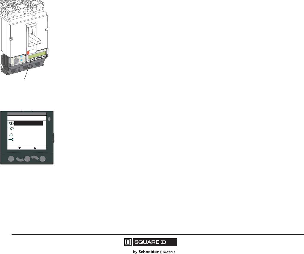
© 2011–2012 Schneider Electric
All Rights Reserved
PowerPact™ H-, J-, and L-Frame Circuit Breakers
Trip Units
66
05/2012
™
Power Meter Functions
In addition to protection functions, Micrologic™ 5 / 6 trip units offer all the functions of Power Meter
products as well as operating-assistance for the circuit breaker.
•display of settings
•measurement functions:
— Ammeter (A)
— Energy (E)
•alarms
•time-stamped histories and event tables
•maintenance indicator
•communication network.
Micrologic A and E trip unit measurement functions are made possible by the trip unit intelligence and
the accuracy of the sensors. They are handled by a microprocessor that operates independent of
protection functions.
Display
Micrologic Trip Unit LCD
The user can display all the protection settings and the main measurements on the LCD screen of the
trip unit.
•Micrologic A trip unit: instantaneous rms current measurements
•Micrologic E trip unit: voltage, frequency and power measurements and energy metering, in
addition to the measurements offered by Micrologic A
To make the display available under all conditions and increase operating comfort, an external power
supply is recommended for Micrologic A trip unit. It is indispensable to:
•display faults and interrupted current measurements
•use all the functions of Micrologic E trip unit (such as metering of low power and energy values)
•ensure operation of the communication network.
The external power supply can be shared by several devices. For description, see page 79.
Front Display Module (FDM121)
An FDM121 can be connected to a Micrologic trip unit using a prefabricated cable to display all
measurements on a screen. The result is a veritable 96 x 96 mm Power Meter.
In addition to the information displayed on the Micrologic trip unit LCD, the FDM121 screen shows
demand, power quality and maximum/minimum values along with alarms, histories and maintenance
indicators.
The FDM121 requires a 24 Vdc power supply. The Micrologic trip unit is supplied by the same power
supply through the cable connecting it to the FDM.
PC Screen
When the Micrologic trip unit, with or without a front display module, is connected to a communication
network, all information can be accessed using a PC with the appropriate software installed.
r
c
i
Mcigolo
E
2
.5
r
I
%
A
0
3
>
0
3
>0
1
1
>
.9
2
9
.
3
9
.
4
9
.5
9
.
1
89
.
7
9
.
6
9
.
Ir )
o
I
x
(
5.
1
2
5
.
2
34
0
1
8
6
5
d
s
I)
r
I
x
(
Trip Unit LCD
Main menu
Metering
Alarms
Quick view
ESC OK
Services
FDM121 Display
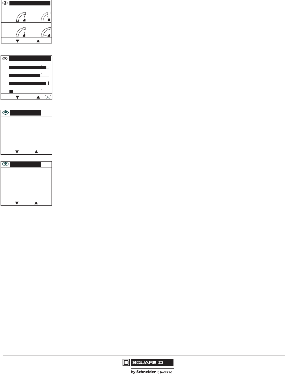
PowerPact™ H-, J-, and L-Frame Circuit Breakers
Trip Units
67
05/2012
© 2011–2012 Schneider Electric
All Rights Reserved
™
Measurements
Instantaneous RMS Measurements
The Micrologic™ A and E trip units continuously display the RMS value of the highest current of the
three phases and neutral (Imax). The navigation buttons can be used to scroll through the main
measurements.
In the event of a fault trip, the current interrupted is memorized.
The Micrologic A trip unit measures phase, neutral, ground fault currents. The Micrologic E trip unit
offers voltage, frequency and power measurements in addition to the measurements provided by
Micrologic A trip unit.
Maximum / Minimum Values
Every instantaneous measurement provided by Micrologic A or E trip unit can be associated with a
maximum/minimum. The maximum for the highest current of the three phases and neutral, the
demand current and power can be reset using the trip unit keypad, the front display module or the
communication network.
Energy Metering
The Micrologic E trip units also measures the energy consumed since the last reset of the meter. The
active energy meter can be reset using the keypad and the front display module or the communication
network.
Demand and Maximum Demand Values
Micrologic E trip units also calculates demand current and power values. These calculations can be
made using a block or sliding interval that can be set from 5 to 60 minutes in steps of 1 minute. The
window can be synchronized with a signal sent through the communication network. Whatever the
calculation method, the calculated values can be recovered on a PC using the Modbus communication
network.
Ordinary spreadsheet software can be used to provide trend curves and forecasts based on this data.
They will provide a basis for load shedding and reconnection operations used to adjust consumption to
the subscribed power.
Power Quality
Micrologic E trip units calculate power quality indicators taking into account the presence of up to the
15th order, including the total harmonic distortion (THD) of unit. current and voltage.
NOTE: The front display module will display voltage and current phases as A/B/C instead of 1/2/3.
ESC
I
IA 431 A IB 385 A
IC 426 A IN 2 A
888
06114156
ESC
I
IA
IB
IC
IN
100 120
431 A
100 120
100 120
100 120
385 A
426 A
2 A
06114155
PQS 5/7
Ptot 127 kW
Qtot 13 kVAr
Stot 129 kVA
ESC
Energy 6/7
Ep 11318 kWh
Eq 257 kVArh
Es 13815 kVAh
ESC
Current
Voltage
Consumption
Power
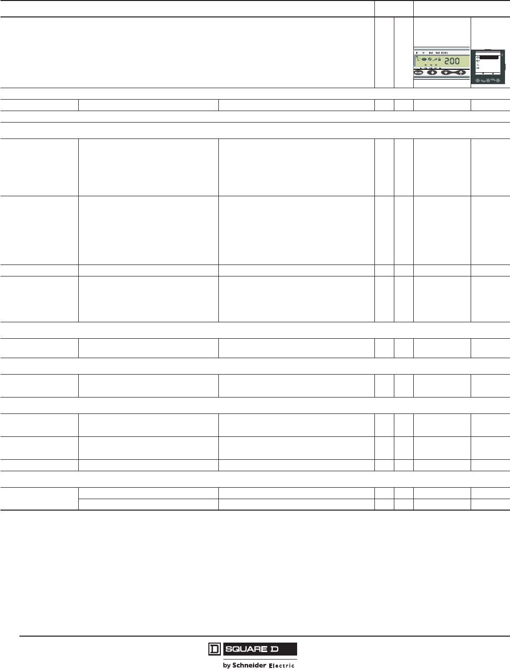
© 2011–2012 Schneider Electric
All Rights Reserved
PowerPact™ H-, J-, and L-Frame Circuit Breakers
Trip Units
68
05/2012
™
Table 56: Micrologic™ 5/6 Trip Units Integrated Power Meter Functions
Type Display
AE
Trip Unit
LCD
Front
Display
Module
Display of Protection Settings
Pick-ups (A) and delays All settings can be displayed Ir, tr, Isd, tsd, Ii, Ig, tg XXX
Measurements
Instantaneous rms measurements
Currents (A)
Phase and neutral
Average of phases
Highest current of the 3 phases and neutral
Ground fault (Micrologic 6 trip unit)
Current unbalance between phases
IA, IB, IC, IN
Iavg = (IA + IB + IC) / 3
Imax of IA, IB, IC, IN
% Ig (pick-up setting)
% Iavg
X
X
X
X
—
X
X
X
X
X
X
—
X
X
—
X
X
X
X
X
Voltage (V)
Phase-to-phase
Phase-to-neutral
Average of phase-to-phase voltages
Average of phase-to-neutral voltages
Ph-Ph and Ph-N voltage unbalance
Phase sequence
VAB, VBC, VCA
UAN, UBN, UCN
Vavg = (VAB + VAC + VBC) / 3
Uavg = (UAN + UBN + UCN) / 3
% Vavg and% Uavg
1-2-3, 1-3-2
—
—
—
—
—
—
X
X
X
X
X
X
X
X
—
—
—
X
X
X
X
X
X
X
Frequency (Hz) Power System f — X X X
Power
Active (kW)
Reactive (kVAR)
Apparent (kVA)
Power factor and cos (fundamental)
P, total/per phase
Q, total/per phase
S, total/per phase
PF and cos , total and per phase
—
—
—
—
X
X
X
X
X
X
X
—
X
X
X
X
Maximum, minimum (MAX/MIN)
Associated with instantaneous rms
measurements
Reset with Micrologic trip unit or front display
module XX— X
Energy metering
Energy Active (kWh), reactive (kVAR), apparent
(kVA)
Total since last reset
Absolute or signed mode1—X X X
Demand and maximum demand values
Demand current (A) Phases and neutral Present value on the selected window
Maximum demand since last reset
—
—
X
X
—
—
X
X
Demand power Active (kWh), reactive (kVAR), apparent
(kVA)
Present value on the selected window
Maximum demand since last reset
—
—
X
X
—
—
X
X
Calculation window Adjustable from 5 to 60 minutes in 1 minute steps — X — 2
Power quality
Total harmonic
distortion THD (%)
Of voltage with respect to rms value THDU, THDV of the Ph-Ph and Ph-N voltage — X — X
Of current with respect to rms value THDI of the phase current — X — X
1Absolute mode: E absolute = E out + E in; Signed mode: E signed = E out - E in.
2Available through the communication network only.
Main menu
Metering
Alarms
Quick view
ESC OK
Services

PowerPact™ H-, J-, and L-Frame Circuit Breakers
Trip Units
69
05/2012
© 2011–2012 Schneider Electric
All Rights Reserved
™
Additional technical characteristics
Measurement accuracy of the entire measurement system, including the sensors:
•Current: +/- 1%
•Voltage: +/- 0.5%
•Power and energy: +/- 2%
•Frequency: +/- 0.1%.
Operating-Assistance Functions Characteristics
Micrologic™ Trip Unit Alarms with Time-Stamping
Alarm Types
The user can assign an alarm to all Micrologic A or E trip unit measurements or events:
•up to 12 alarms can be used together:
— two alarms are predefined and activated automatically:
Micrologic 5 trip unit: overload (Ir)
Micrologic 6 trip unit: overload (Ir) and ground fault (Ig)
— thresholds, priorities and time delays can be set for ten other alarms.
•the same measurement can be used for different alarms to precisely monitor certain values, e.g.
the frequency or the voltage
•alarms can also be assigned to various states: phase lead/lag, four quadrants,
•phase sequence selection of display priorities, with screen displaying a window showing high
priority alarm
•alarm time-stamping.
Alarm Settings
Alarms cannot be set using the keypad or the front display module. They are set through the
communication network with the PC. Set-up includes the threshold, priority, activation delay before
display and deactivation delay. It is also possible to reprogram the standard assignment for the two
SDx relay outputs to user-selected alarms.
Alarm Reading
Remote alarm indicators
•reading on the front display module or on a PC through the communication network
•system remote indicators using SDx relay with two output contacts for alarms.
•Micrologic trip unit built-in LCD display.
Histories and Event Tables
Micrologic A and E trip unit have histories and event tables that are always active.
Three types of time-stamped histories
•Tripping due to overruns of Ir, Isd, Ii, Ig: last 17 trips
•Alarms: last 10 alarms
•Operating events: last 10 events
Each history record is stored with:
•indicators in clear text in a number of user-selectable languages
•time-stamping: date and time of event
•status: pick-up / drop-out

© 2011–2012 Schneider Electric
All Rights Reserved
PowerPact™ H-, J-, and L-Frame Circuit Breakers
Trip Units
70
05/2012
™
Two types of time-stamped event tables
•Protection settings
•Minimums / maximums
Display of alarms and tables
The time-stamped history and event tables may be displayed on a PC through the communication network.
Embedded memory
Micrologic™ A and E trip units have a non-volatile memory that saves all data on alarms, histories,
event tables, counters and maintenance indicators even if power is lost.
Maintenance Indicators
Micrologic A and E trip units have indicators for, among others, the number of operating cycles, contact
wear and operating times (operating hours counter) of the PowerPact H-, J-, and L-frame circuit breakers.
It is possible to assign an alarm to the operating cycle counter to plan maintenance. The various
indicators can be used together with the trip histories to analyze the level of stresses the device has
been subjected to. The information provided by the indicators cannot be displayed on the Micrologic
trip unit LCD. It is displayed on the PC through the communication network.
Management of Installed Devices
Each circuit breaker equipped with a Micrologic 5 or 6 trip unit can be identified using the
communication network:
•serial number
•firmware version
•hardware version
•device name assigned by the user.
This information together with that previously described provides a clear view of the state of the
installed devices.
NOTE: Please refer to page 73 for more details on display formats.
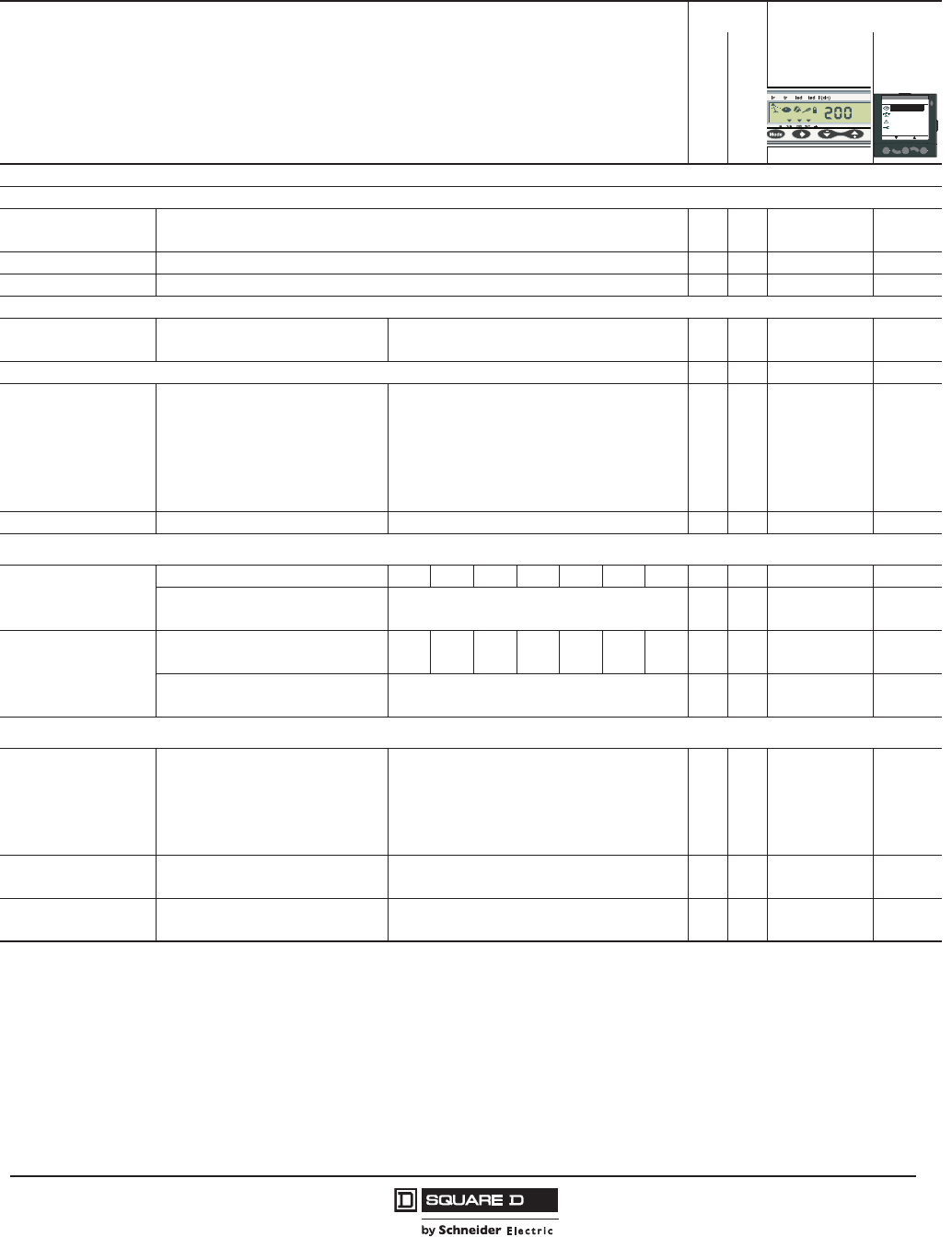
PowerPact™ H-, J-, and L-Frame Circuit Breakers
Trip Units
71
05/2012
© 2011–2012 Schneider Electric
All Rights Reserved
™
Table 57: Micrologic™ 5/6 Trip Units Operating Assistance Functions
Type Display
AE
Trip Unit
LCD
Front
Display
Module
Operating Assistance
Personalized Alarms
Settings Up to 10 alarms assigned to all A and E measurements
Phase lead/lag, four quadrants, phase sequence, display priority selection
X
—
X
X
—
—
1
1
Display Alarms and tripping XX— 1
Remote Indicators Activation of two dedicated contacts on SDx module X X — 1
Time-Stamped Histories
Trips (last 17) Cause of tripping
(time-stamping with ms)
Ir, Isd, Ii (Micrologic 5, 6 Trip Unit)
Ig (Micrologic 6 Trip Unit)
X
X
X
X
—
—
1
1
Alarms (last 10) XX— 1
Operating events (last 10) Event types
Modification of protection setting by rotary switch
Opening of keypad lock
Test using keypad
Test using external tool
Time setting (date and time)
Reset for maximum, minimum and energy meter
—
—
—
—
—
X
X
X
X
X
X
X
—
—
—
—
—
X
1
1
1
1
1
X
Time Stamping Presentation Date and time, text, status X X — 1
Time-Stamped Event Tables
Protection settings
Setting modified (value displayed) IrtrIsd tsd Ii IgtgXX— 1
Time-stamping
Previous value
Date and time of modification
Value before modification
X
X
X
X
—
—
1
1
Min/Max
Values monitored IA
IA
IB
IB
IC
IC
IN
IN
Ii X X — 1
Time-stamping
Previous value
Date and time of min/max record
Min/max value XX— 1
Maintenance Indicators
Counter
Mechanical cycles2
Electrical cycles2
Trips
Alarms
Hours
Assignable to an alarm
Assignable to an alarm
One per type of trip
One for each type of alarm
Total operating time (hours)
XX— 1
Indicator Contact wear % X
X
X
X—1
Load profile Hours at different load levels % of hours in four current ranges: 0–49% In,
50–79% In, 80–89% In and 90% In
X
X
X
X—1
1Available through the communication network only.
2The BSCM (page 78) is required for these functions.
Main menu
Metering
Alarms
Quick view
ESC OK
Services
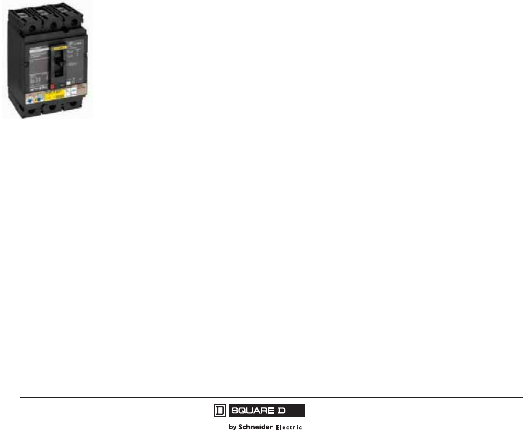
© 2011–2012 Schneider Electric
All Rights Reserved
PowerPact™ H-, J-, and L-Frame Circuit Breakers
Trip Units
72
05/2012
™
Additional technical characteristics:
•Contact wear
Each time PowerPact H-, J-, and L-frame circuit breakers open, the Micrologic™ 5 / 6 trip unit
measures the interrupted current and increments the contact-wear indicator as a function of the
interrupted current, according to test results stored in memory. Breaking under normal load
conditions results in a very slight increment. The indicator value may be read on the front display
module. It provides an estimation of contact wear calculated on the basis of the cumulative forces
affecting the circuit breaker. When the indicator reaches 80%, it is advised to replace the circuit
breaker to ensure the availability of the protected equipment.
•Circuit breaker load profile
Micrologic 5 / 6 trip units calculate the load profile of the circuit breaker protecting a load circuit. The
profile indicates the percentage of the total operating time at four current levels (% of In):
— 0 to 49% In
— 50 to 79% In
— 80 to 89% In
— 90% I
n.
— This information can be used to optimize use of the protected devices or to plan ahead for
expansion.
Motor Circuit Protectors (AC Only)
See Section 5 for information about PowerPact H-, J- and L-frame electronic motor circuit protectors
(MCP) with trip units:
•Micrologic 1.3 M
•Micrologic 2 M
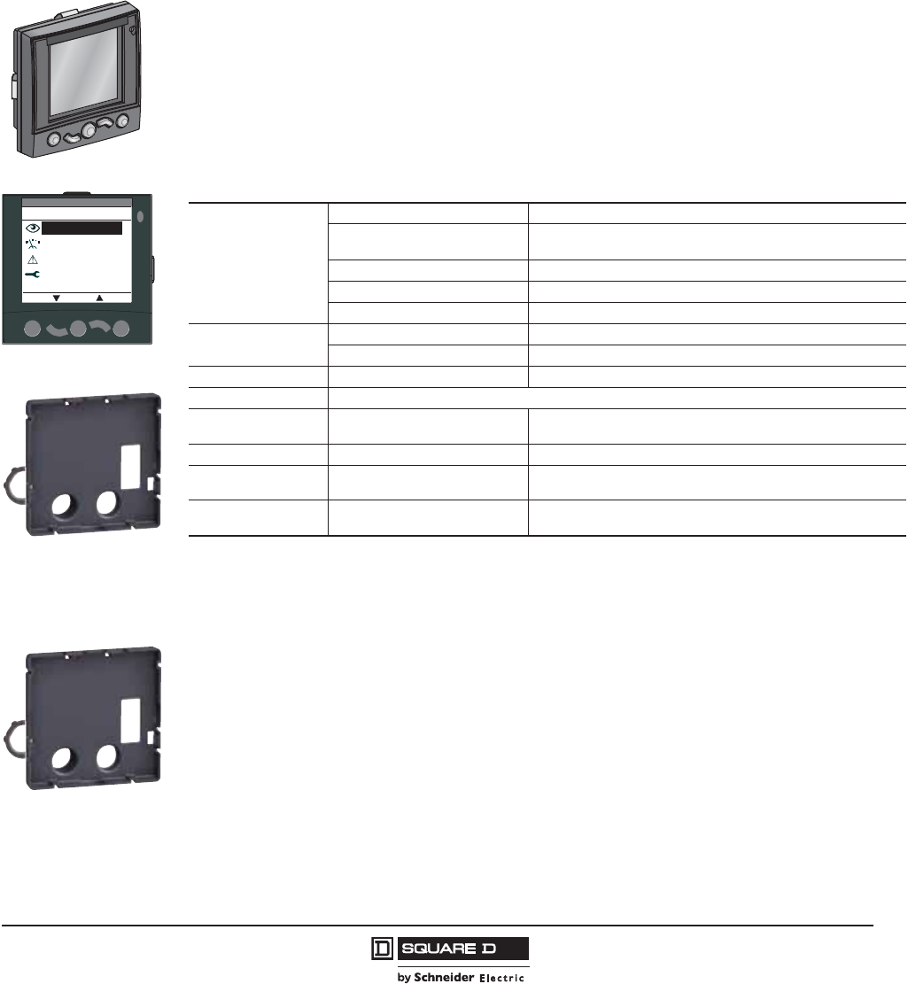
PowerPact™ H-, J-, and L-Frame Circuit Breakers
Accessories for Micrologic™ Trip Units
73
05/2012
© 2011–2012 Schneider Electric
All Rights Reserved
™
Section 7—Accessories for Micrologic™ Trip Units
Display Options
Front Display Module Functions (FDM121)
(Micrologic 5 / 6 A or E Trip Units Only)
The front display module (FDM121) can be integrated in the PowerPact H-, J-, and L-frame circuit
breaker system. It uses the sensors and processing capacity of the Micrologic trip unit to display
measurements, demand, power quality and maximum/minimum values along with alarms, histories,
and maintenance indicators.
It is easy to use and requires no special software or settings and is immediately operational when
connected to the PowerPact H-, J-, and L-frame circuit breakers by a simple cable.
The FDM121 is a large display, but requires very little depth. The anti-glare graphic display screen is
backlit for easy reading even under poor ambient lighting and at sharp angles.
Mounting
The FDM121 is easily installed in equipment.
•Standard door cut-out 3.62 x 3.62 in. (92 x 92 mm).
•Attached using clips.
To avoid a cut-out in the door, an accessory is available for surface mounting by drilling only two
0.87 in. (22 mm) diameter holes.
The FDM121 degree of protection is NEMA12 / IP54 in front. NEMA12 / IP54 is maintained after
mounting by using the supplied gasket during installation.
06114205
Main menu
Metering
Alarms
Quick view
ESC OK
Services
06114215
FDM121 Display
Surface Mount Accessory
Table 58: Characteristics
Screen
Size 96 x 96 x 30 mm
Installation Requires 10 mm behind the door (or 20 mm when the 24 Vdc power
supply connector is used).
Backlighting White
Viewing Angle Vertical ±60°, horizontal ±30°
Resolution High: excellent reading of graphic symbols.
Alarm LED Flashing orange Alarm pick-up
Steady orange after operator reset Alarm condition persists.
Operating temperature 14°F to 131°F (-10 °C to +55 °C).
Certifications UL, CSA, CE
24 Vdc power supply Tolerances 24 V -20% +10%
(19.2 V to 26.4 V)
When the FDM121 is connected to the communication network, the
24 Vdc is supplied by the communication network wiring.
Power Requirements 40 mA, 24 Vdc
Mounting Standard door cut-out 92 x 92 mm.
Attached using clips.
To avoid a cut-out in the door, a surface-mount accessory is
available for surface mounting by drilling two 22 mm diameter holes.
Degree of protection NEMA12 / IP54 in front. NEMA12 / IP54 is maintained after mounting by using the supplied
gasket during installation.
06114215
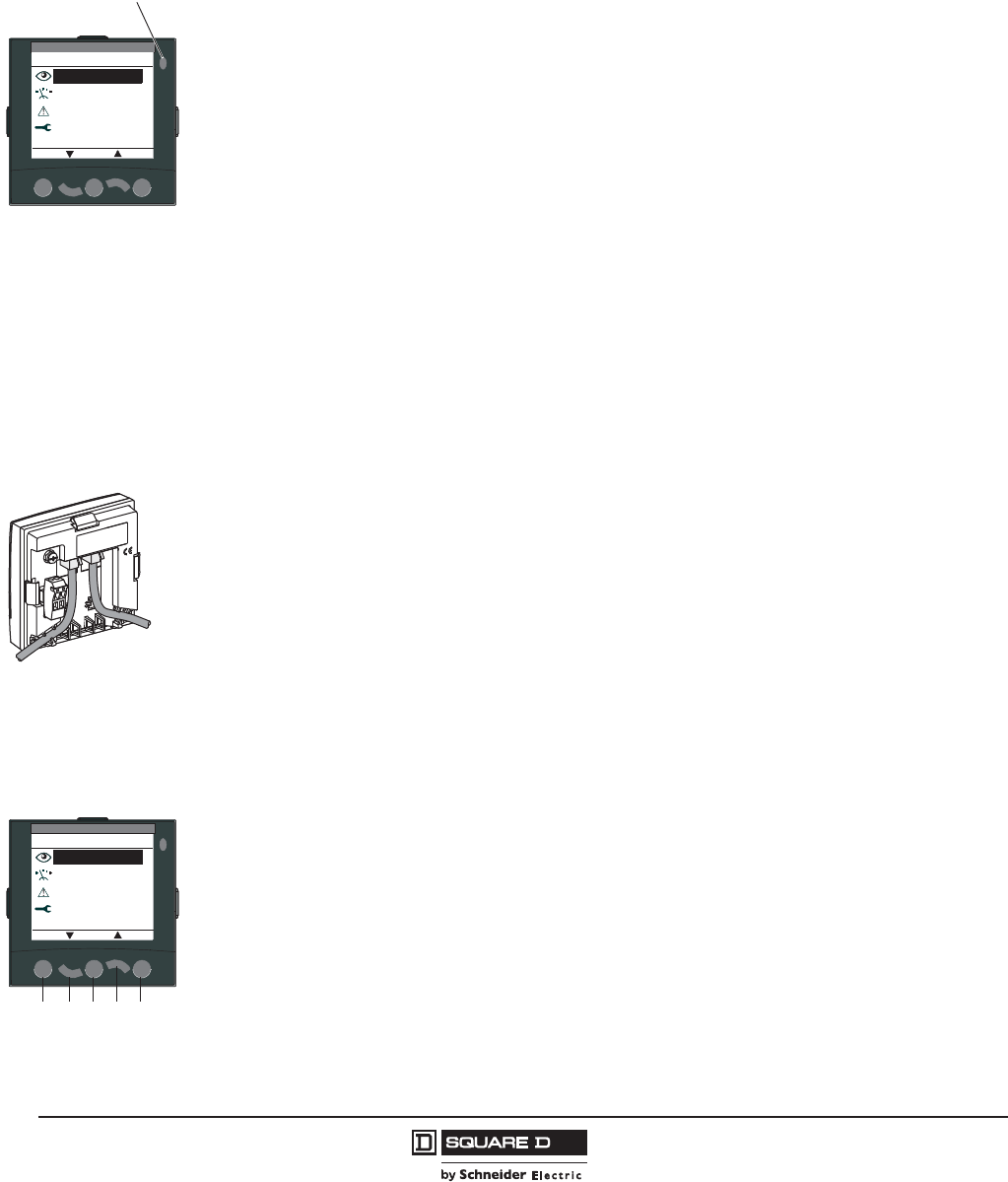
© 2011–2012 Schneider Electric
All Rights Reserved
PowerPact™ H-, J-, and L-Frame Circuit Breakers
Accessories for Micrologic™ Trip Units
74
05/2012
™
Display of Micrologic Trip Unit Measurements and Alarms
The FDM121 is intended to display Micrologic 5 / 6 trip unit measurements, alarms and operating
information. It cannot be used to modify the protection settings. Measurements may be easily
accessed through a menu.
All user-defined alarms are automatically displayed. The display mode depends on the priority level
selected during alarm set-up:
•high priority: a pop-up window displays the time-stamped description of the alarm and the orange
LED flashes
•medium priority: the orange Alarm LED goes steady on l
•low priority: no display on the screen.
All faults resulting in a trip automatically produce a high-priority alarm, without any special settings
required. In all cases, the alarm history is updated.
If power to the FDM121 fails, all information is stored in the Micrologic trip unit non-volatile memory.
The data can be consulted using the communication network when power is restored.
Status Indications and Remote Control
When the circuit breaker is equipped with the BSCM module (page 78), the FDM121 display can also
be used to view circuit breaker status conditions:
•Auxiliary switch (OF): ON/OFF
•Alarm switch (SD): trip indication
•Overcurrent trip switch (SDE): fault-trip indication (overload, short-circuit, ground fault)
Electrical Connection
The FDM121 is equipped with:
•a 24 Vdc terminal block:
— plug-in type with 2 wire inputs per point for easy daisy-chaining
— power supply range of 24 V -20% (19.2 V) to 24 V +10% (26.4 V)
•two RJ45 jacks.
The Micrologic trip unit connects to the internal communication network terminal block on the
PowerPact H-, J-, and L-frame circuit breakers using the pre-wired NSX cord. Connection to one of the
RJ45 connectors on the FDM121 automatically establishes communication between the Micrologic trip
unit and the FDM121 and supplies power to the Micrologic trip unit measurement functions.
When the second connector is not used, it must be fitted with a line terminator TRV00880.
Navigation
Five buttons are used for intuitive and fast navigation.
The “Context” button may be used to select the type of display (digital [text], bargraph, analog).
The user can select the display language (Chinese, English, French, German, Italian, Portuguese,
Spanish, etc.) Other languages can be downloaded.
Screens
Main menu
When powered up, the FDM121 screen automatically displays the ON/OFF status of the device.
When not in use, the screen is not backlit. Backlighting can be activated by pressing one of the
buttons. It goes off after 3 minutes.
Main menu
Metering
Alarms
Quick view
ESC OK
Services
06114141
Orange
LED
Main menu
Metering
Alarms
Quick view
ESC OK
Services
06114141
ABCDE
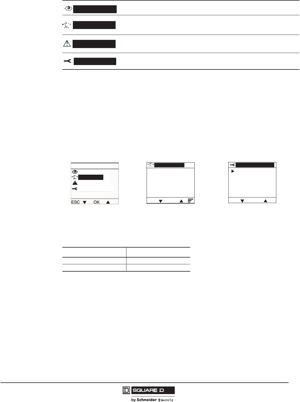
PowerPact™ H-, J-, and L-Frame Circuit Breakers
Accessories for Micrologic™ Trip Units
75
05/2012
© 2011–2012 Schneider Electric
All Rights Reserved
™
Fast access to essential information:
•“Quick view” provides access to five screens that display a summary of essential operating
information (I, V, f, P, E, THD, circuit breaker On / Off).
Access to detailed information
•“Metering” can be used to display the measurement data (I, U-V, f, P, Q, S, E, THD, PF) with the
corresponding min/max values.
•Alarms displays active alarms and the alarm history
•Services provides access to the operation counters, energy and maximum reset function,
maintenance indicators, identification of modules connected to the internal bus and FDM121
internal settings (language, contrast, etc.)
Catalog Numbers
Provides access to five screens that display a summary of essential operating information (I, U, f,
P, E, THD, circuit breaker On / Off).
Used to display the measurement data (I, U-V, f, P, Q, S, E, THD, PF) with the corresponding
min/max values.
Displays active alarms and the alarm history
Provides access to the operation counters, energy and maximum reset function, maintenance
indicators, identification of modules connected to the internal bus and FDM121 internal settings
(language, contrast, etc.)
Table 59: Front Display Module Catalog Numbers
Description Catalog No.
FDM121 STRV00121
FDM121 Mounting Accessory TRV00128
Quick view
Metering
Alarms
Services
ESC
V L-L
VAB 406 V
VBC 415 V
VCA 409 V
1/10
06114153
Quick view
Alarms
Services
Main menu
Service
Metering
06114149
ESC OK
Services
Reset
Set-up
Maintenance
Product ID
Language
06114164
Quick View Metering Sub-Menu Services

© 2011–2012 Schneider Electric
All Rights Reserved
PowerPact™ H-, J-, and L-Frame Circuit Breakers
Accessories for Micrologic™ Trip Units
76
05/2012
™
Circuit Breaker Communication Network Options
All PowerPact H-, J-, and L-frame circuit breakers devices can be equipped with the communication
function using a pre-wired connection system and a Modbus™ communication interface module. The
interface module can be connected directly or through the front display module (FDM121).
The PowerPact H-, J-, and L-frame circuit breakers can be integrated in a Modbus communication network.
Four functional levels can be used separately or combined to adapt to all supervision requirements.
Level Function
Communication of status indications
Compatible with PowerPact H-, J- and L-frame circuit breakers and
automatic switches. Use the BSCM module to access the following
information:
• ON/OFF position
• trip indication
• fault-trip indication
Communication of commands
Available on all circuit breakers and automatic switches with
communicating motor operators, the remote control can be used to:
• open
•closed
• reset
Communication of measurements with
Micrologic 5 / 6 A or E trip unit
This level provides access to:
• instantaneous and demand values
• maximums/minimums
• energy metering
• demand current and power
• power quality
Communication of operating assistance with
Micrologic 5 / 6 A or E trip unit
This level also provides access to:
• protection and alarm settings
• time-stamped histories and event tables
• maintenance indicators
PowerPact H-, J-, or L-frame circuit
breaker is connected to the Modbus
communication interface module (IFM) or
front display module (FDM121) through the
internal terminal block for the NSX cord.
The front display module is connected to
the Modbus communication interface
module by a communication cable with
RJ45 connectors on both ends.
1. Modbus network
2. Modbus communication interface
module
3. NSX cord
4. Internal terminal block for
communication using the NSX cord
5. BSCM module
6. Prefabricated wiring
7. Micrologic trip unit
8. FDM121 display
9. RJ45 cable
10. Line terminator
(for unused connectors, if applicable)
06114559
Modbus
24 Vdc
10
10
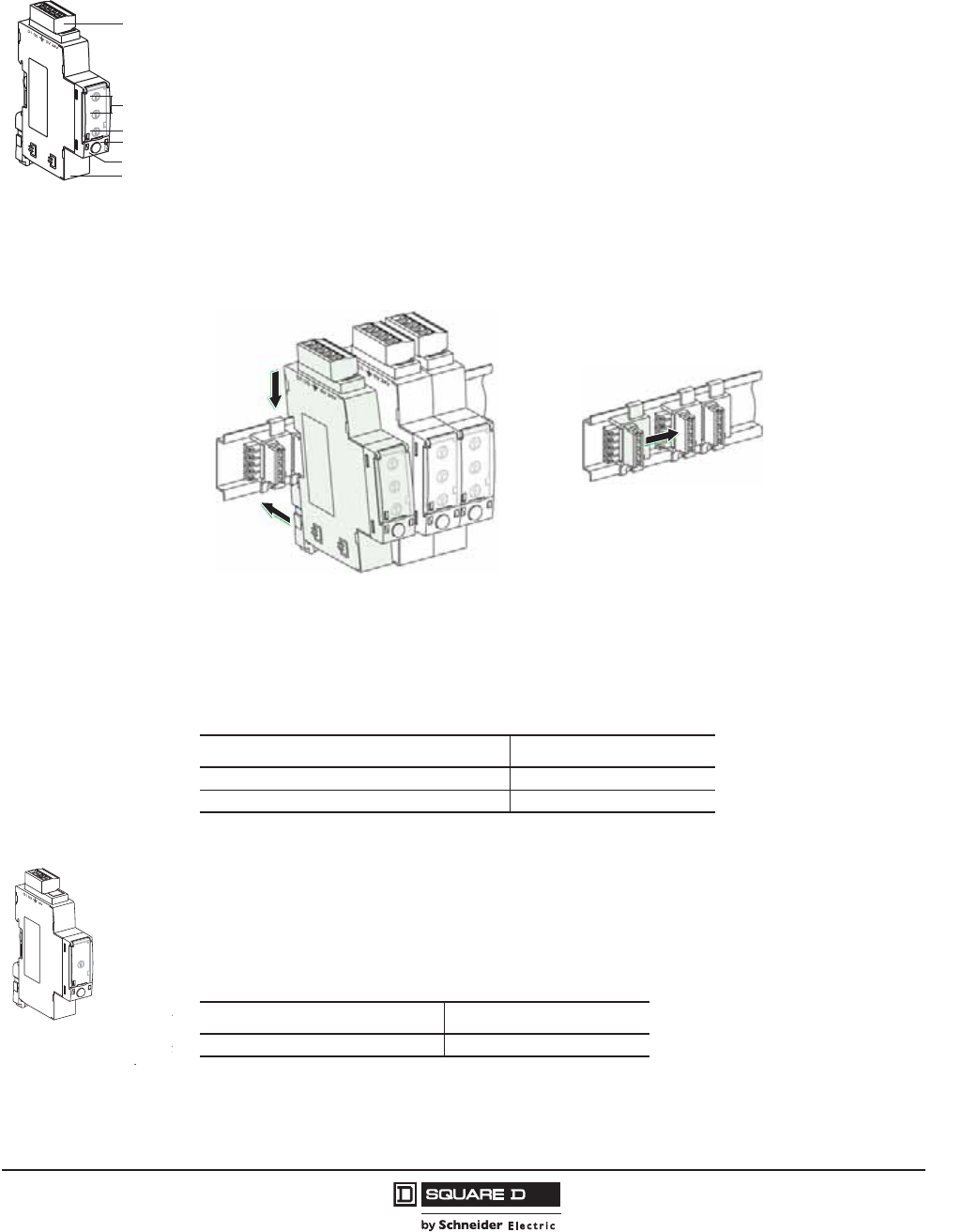
PowerPact™ H-, J-, and L-Frame Circuit Breakers
Accessories for Micrologic™ Trip Units
77
05/2012
© 2011–2012 Schneider Electric
All Rights Reserved
™
Modbus Communication Interface Module (IFM)
Functions
This module, required for connection to the network, contains the Modbus address (1 to 99) declared
by the user using the two rotary switches in front. It automatically adapts (baud rate, parity) to the
Modbus network in which it is installed.
It is equipped with a lock-out switch to enable or disable operations involving writing to Micrologic trip
unit, (such as reset, counter reset, setting modifications, device opening and closing commands).
There is a built-in test function to check the connections of the Modbus communication interface
module with the Micrologic trip unit and front display module.
Mounting
The module is mounted on a DIN rail. A number of modules may be clipped one next to the other. For
this, a stacking accessory (shown below) is available for fast clip-connection of both the Modbus link
and the 24 Vdc supply.
The Modbus communication interface module supplies 24 Vdc to the corresponding Micrologic trip
unit, front display module, and BSCM module. Module power requirements is 60 mA / 24 Vdc.
Catalog Numbers
Isolated Modus Repeater Module
Since Modbus interface modules (part number STRV00210) are not isolated, an isolated Modbus
Repeater Module needs to be inserted between the Modbus network inside the equipment and the
Modbus network outside the equipment.
06114269
1. Five-point Modbus and
24 Vdc connector
2. Two Modbus address
rotary switches (1 to 99)
3. Modbus traffic LED
4. Lock-out to disable
writing to the trip unit
5. Test LED
6. Test button
7. Two connectors for
RJ45 cable
1
2
3
4
5
6
Table 60: IFM Catalog Numbers
Description Catalog No.
Modbus Communication Interface Module (IFM) STRV00210
Stacking Connectors for IFM (10) TRV00217
06114272
06114273
Stacking Connector
06114395
Table 61: Catalog Number
Description Catalog No.
Isolated Modbus Repeater Module STRV00211
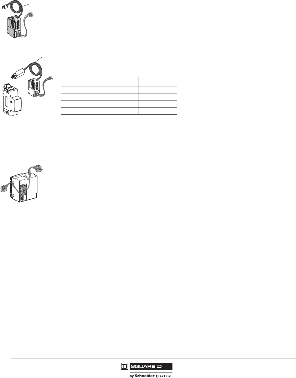
© 2011–2012 Schneider Electric
All Rights Reserved
PowerPact™ H-, J-, and L-Frame Circuit Breakers
Accessories for Micrologic™ Trip Units
78
05/2012
™
NSX Cord
Micrologic trip units are connected to the Modbus communication interface module (IFM) or front
display module through the internal terminal block for the NSX cord equipped with an RJ45 connector.
The NSX cord is available in two cable lengths:
•4.27 ft (1.3 m)
•9.84 ft (3 m)
Lengths up to 32.8 ft (10 m) are possible using extensions.
•For voltage V 480 V, available in 3 prefabricated lengths: 0.35 m, 1.3 m and 3 m.
•For voltages V > 480 V, a special 1.3 m cable with an insulation accessory is required.
•A set of cables with RJ45 connectors is available to adapt to different distances between devices.
Breaker Status and Control Module (BSCM)
Functions
The optional BSCM Breaker Status & Control Module is used to acquire device status indications and
control the communicating remote-control function. It includes a memory used to manage the
maintenance indicators.
Status indications
Indication of device status:
Auxiliary switch (OF), alarm switch (SD), and overcurrent trip switch (SDE).
Maintenance indicators
The BSCM manages the following indicators:
•mechanical operation counter
•electrical operation counter
•history of status indications.
It is possible to assign an alarm to the operation counters.
Controls
The BSCM can be used to carry out communicating remote control operations using the
communicating motor operator (open, close and reset) in different modes (manual, auto).
Mounting
The BSCM can be installed on all PowerPact H-, J-, and L-frame circuit breakers and automatic
switches with Micrologic trip units. It simply clips into the auxiliary contact slots. It occupies the slots of
one auxiliary switch (OF) and one overcurrent trip switch (SDE). The BSCM is supplied with 24 Vdc
power automatically through the NSX cord when the communication network is installed.
06114192
Cable
Length
Cable
Length
NSX Cord,
V > 480 V
NSX Cord,
V 480 V
Isolation Module
for NSX Cord
with V > 480 V
Table 62: NSX Cord Catalog Numbers
Description Catalog No.
NSX Cord 4.27 ft (1.3 m), V 480 V S434201
NSX Cord 9.84 ft (3 m), V 480 V S434202
NSX Cord 4.27 ft (1.3 m), V > 480 V S434204
NSX Cord 9.84 ft (3 m), V > 480 V S434303
06113592
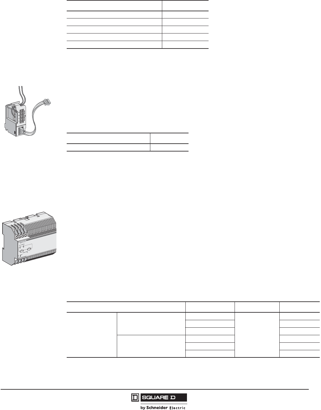
PowerPact™ H-, J-, and L-Frame Circuit Breakers
Accessories for Micrologic™ Trip Units
79
05/2012
© 2011–2012 Schneider Electric
All Rights Reserved
™
Catalog Numbers
24 Vdc Power-Supply Terminal Block
The Micrologic 5/6 trip unit display is operational when current is flowing through the circuit breaker. To
power the Micrologic 5/6 trip unit when the trip unit is not connected to an FDM121 or to the
communication network, a 24 Vdc power-supply terminal block can be installed only on Micrologic 5/6
trip units. When used, it excludes connection of an NSX cord.
External 24 Vdc Power-Supply Module
An external 24 Vdc power supply is required for installation in a communication network, whatever the
type of trip unit.
On installations without a communication network, the power supply is available as an option for
Micrologic 5/6 trip units in order to:
•modify settings when the circuit breaker is open
•display measurements when the current flowing through the circuit breaker is low (15 to 50 A
depending on the rating)
•maintain the display of the cause of tripping and interrupted current.
A single external 24 Vdc supply may be used for the entire network, depending on the number of
devices in the communication network. The required characteristics are:
•output voltage: 24 Vdc ± 5%
•ripple: ± 1%
To determine the required output current of the 24 Vdc power supply, it is necessary to sum up the
currents consumed by the different loads supplied:
Table 63: BSCM Catalog Numbers
Description Catalog No.
Replacement BSCM S434205
BSCM with NSX Cord 1.3 m, V 480 V S434201BS
BSCM with NSX Cord 3 m, V 480 V S434202BS
BSCM with NSX Cord 1.3 m, V > 480 V S434204BS
BSCM with NSX Cord 3 m, V > 480 V S434303BS
06114571
24 Vdc Terminal Block
Table 64: 24 Vdc Catalog Number
Description Catalog No.
24 Vdc Terminal Block Unit Mount S434210
External 24 Vdc
Power-Supply Module
Table 65: Available External Power-Supply Modules (1 A)
Available External Power-Supply Modules Input Voltage Output Power Cat. No.
Power supply
Vdc (±5%)
24–30
5 VA/5W
685823
48–60 685824
100–125 685825
Vac (+10%, -15%)
110–130 685826
200–240 685827
380–415 685829
© 2011–2012 Schneider Electric
All Rights Reserved
PowerPact™ H-, J-, and L-Frame Circuit Breakers
Accessories for Micrologic™ Trip Units
80
05/2012
™
L
For installation recommendations, see page page 133
Battery Module
The battery module is a back-up supply for the external power-supply module. The input/output
voltages are 24 Vdc and it can supply power for approximately three hours (100 mA).
Pocket Tester
The pocket tester connects to the Micrologic trip unit test connector. It powers up the Micrologic trip
unit and the Ready LED. It supplies the screen, allows settings to be made using the keypad, and
provides thermal imaging inhibit functions.
The pocket tester runs off of two Alkaline AA batteries.
Table 66: Power Requirements
Module Typical Consumption
24 Vdc @ 68°F (20°C)
Maximum Consumption
19.2 Vdc @ 140°F (60°C)
Micrologic 5/6 trip units 30 mA 55 mA
BSCM 9 mA 15 mA
FDM121 21 mA 30 mA
IFM 21 mA 30 mA
Isolated Modbus Repeater Module 15 mA 19 mA
06114568
Battery Module
Table 67: Battery Module
Description Catalog No.
Battery Module 685831
06114567
Pocket Tester
Table 68: Pocket Tester
Description Catalog No.
Pocket Tester S434206
PowerPact™ H-, J-, and L-Frame Circuit Breakers
Accessories for Micrologic™ Trip Units
81
05/2012
© 2011–2012 Schneider Electric
All Rights Reserved
™
UST Test Adapter (UTA) Tester for Test and Maintenance
The UTA Tester includes:
•configuration and maintenance module
•power supply (110–220 Vac / 50-60 Hz 24 Vdc - 1 A)
•special Micrologic cable for connection to the trip-unit test connector
•standard USB cable
•standard RJ45 cable
•user manual
Included in the UTA Tester, the UTA Tester module tests Micrologic trip unit operation and provides
access to all parameters and settings. It connects to the Micrologic trip unit test connector and can
operate in two modes.
•Stand-alone mode to:
— supply the Micrologic trip unit with power and check operation using the Ready LED
— Provides ground-fault inhibit and thermal memory inhibit
•PC mode, connected to a PC with a USB or Bluetooth link. This mode provides access to
protection settings, alarm settings and readings of all indicators. Using the associated RSU
software utility, it is possible to store, in a dedicated file for each device, all the data that can
transferred to another device.
This mode also offers operating-test functions:
— check on trip time delay (trip curve)
— check on non-tripping time (coordination)
— check on ZSI (Zone Selective Interlocking) function
— alarm simulation
— display of setting curves
— display of currents
— printing of test reports
— optional Bluetooth link (to PC).
06114570
UTA Tester Module
Table 69: UTA Tester Catalog Numbers
Description Catalog No.
UTA Tester (complete) STRV00910
Spare 110-240 V power supply TRV00915
Spare Micrologic cable TRV00917
Spare UTA Tester Module STRV00911
Bluetooth/Modbus Option for UTA Tester SVW3A8114

© 2011–2012 Schneider Electric
All Rights Reserved
PowerPact™ H-, J-, and L-Frame Circuit Breakers
Accessories for Micrologic™ Trip Units
82
05/2012
™
Universal Logic Plug System
The Universal Logic Plug (ULP) system allows the PowerPact H-, J- and L-frame circuit breakers to
become metering and supervision tools to assist for energy efficiency. For easy connection of the
different modules, the prefabricated cables are identified by a ULP symbol. The connection points on
compatible modules are marked in the same manner.
For more information about the ULP System, see page 132 or bulletin 48940-329-01, ULP (Universal
Logic Plug) Connection System—User Guide.
06113879
Test connector
Display
110/240 V
30
USB or Bluetooth Link
ULP Symbol
Table 70: ULP Accessories Catalog Numbers
Description Qty Catalog No.
RJ45 connectors, female/female 10 TRV00870
ULP Line termination 10 TRV00880
RJ45/RJ45 male cord L= 0.3 m 10 TRV00803
RJ45/RJ45 male cord L= 0.6 m 10 TRV00806
RJ45/RJ45 male cord L = 1 m 5 TRV00810
RJ45/RJ45 male cord L = 2 m 5 TRV00820
RJ45/RJ45 male cord L = 3 m 5 TRV00830
RJ45/RJ45 male cord L = 5 m 1 TRV00850
Modbus Line Terminations 2 VW3A8306DRC
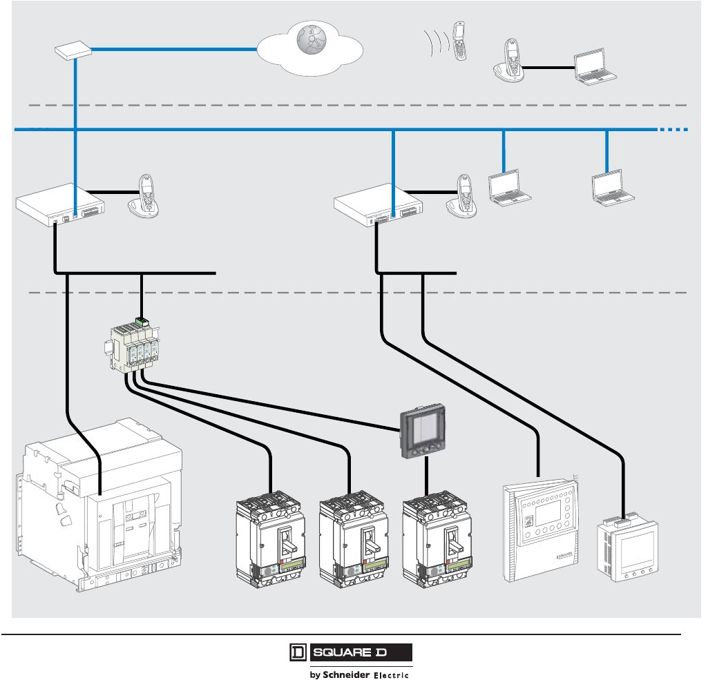
PowerPact™ H-, J-, and L-Frame Circuit Breakers
Accessories for Micrologic™ Trip Units
83
05/2012
© 2011–2012 Schneider Electric
All Rights Reserved
™
Circuit Breaker Communication Networks and Software
Modbus™ Communication Network
Modbus is the most widely used communication protocol in industrial networks. It operates in master-
slave mode. The devices (slaves) communicate one after the other with a gateway (master).
Masterpact™ and PowerPact™ circuit breakers with Micrologic™ trip units, PowerLogic™ and
Sepam™ products all operate with this protocol. A Modbus network is generally implemented on an LV
or MV system. Micrologic trip units use the Modbus communication protocol, compatible with ION-
Enterprise PowerLogic supervision systems.
Depending on the data monitored and the desired refresh rate, a Modbus network connected to a
gateway can serve 4 to 16 devices. For larger installations, a number of Modbus networks can be
connected to an Ethernet® network (TCP/IP/Modbus protocol) through their gateways.
The downloadable RSUsoftware application facilitates implementation of communication network
functions.
06114560
Firewall
Internet
Automatic
notification
Nomad
mode
Site Intranet
MPS100
Modbus Modbus
EGX400
Ethernet (TCP/IP/Modbus)
Consultation
RSU
RCU
Consultation
RSU
RCU
FDM121
Masterpact PowerPact
Modbus
PowerLogic
Power Meter
Sepam
rciMcigolo
E
2
.5
r
I
%
A
0
3
>
0
3
>0
1
1
>
.9
2
9
.
3
9
.
4
9
.5
9
.
1
8
9
.
7
9
.
69
.
Ir )o
I
x
(
5
.
1
2
5
.
2
34
0
1
8
6
5
d
sI )
r
I
x
(
rciMcigolo
E
2
.5
r
I
%
A
0
3
>
0
3
>0
1
1
>
.9
2
9
.
3
9
.
4
9
.5
9
.
1
8
9
.
7
9
.
6
9
.
Ir )o
I
x
(
5
.
1
2
5
.
2
34
0
1
8
6
5
d
sI )
r
I
x
(
rciMcigolo
E
2
.5
r
I
%
A
0
3
>
0
3
>0
1
1
>
.9
2
9
.
3
9
.
4
9
.5
9
.
1
8
9
.
7
9
.
69
.
Ir )o
I
x
(
5
.
1
2
5
.
2
34
0
1
8
6
5
d
sI )
r
I
x
(
IFM Module
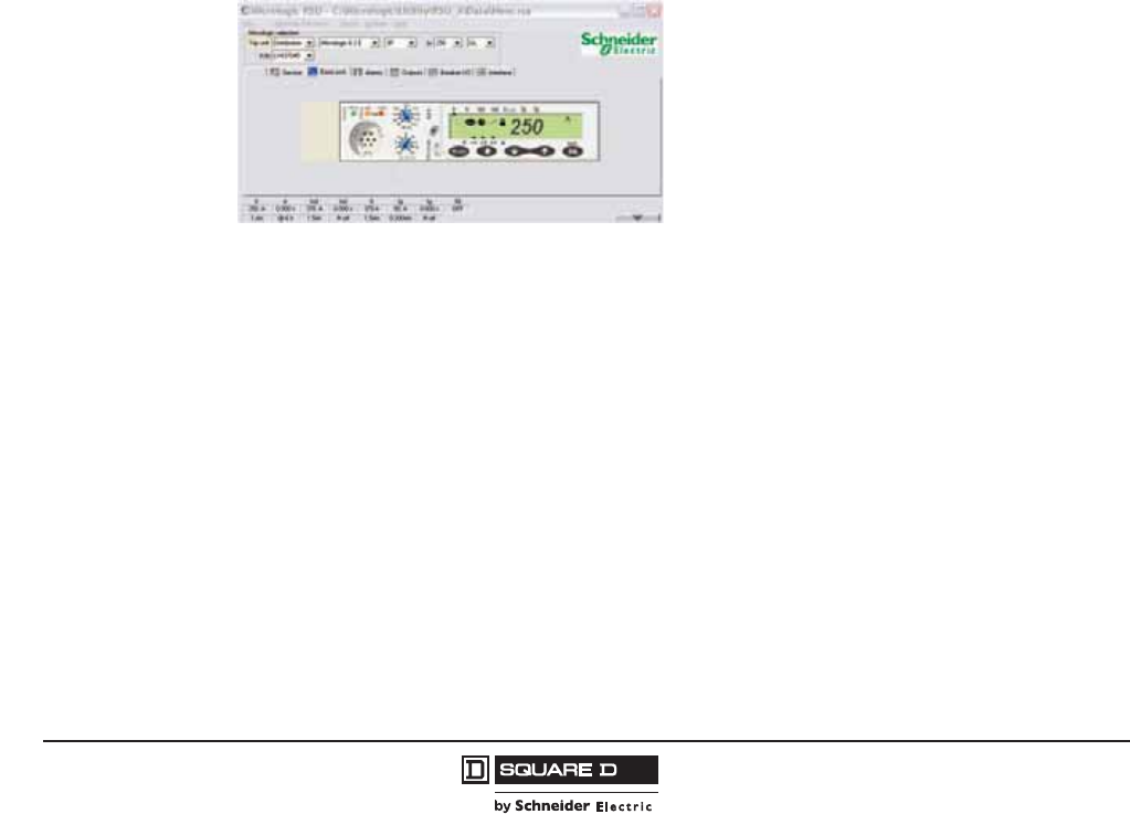
© 2011–2012 Schneider Electric
All Rights Reserved
PowerPact™ H-, J-, and L-Frame Circuit Breakers
Accessories for Micrologic™ Trip Units
84
05/2012
™
Supervision Software
Schneider Electric™ electrical installation supervision, management and expert system software
integrates PowerPact H-, J-, and L-frame electronic circuit breakers identification modules.
Types of Software
Micrologic trip unit communication network functions are designed to interface with software dedicated
to electrical installations:
•installation supervision
•electrical installation supervision
•power system management: electrical engineering expert systems
•process control
•SCADA (Supervisory Control & Data Acquisition), EMS (Enterprise Management System) or BMS
(Building Management System) type software.
Remote Setting Utility (RSU)
The downloadable Micrologic Trip Unit Utility, RSU, facilitates the implementation of communication
network functions.
•The RSU is available to assist in starting up a communicating installation. The software can be
downloaded from the Schneider Electric internet site.
•The “Live update” function enables immediate updating to obtain the most recent upgrades. These
easy-to-use utilities include starting assistance and online help. They are compatible with Microsoft
Windows 2000, XP, Vista and Windows 7.
RSU mini-supervision screen for current measurements.
PowerPact™ H-, J-, and L-Frame Circuit Breakers
Accessories for Micrologic™ Trip Units
85
05/2012
© 2011–2012 Schneider Electric
All Rights Reserved
™
The RSU can be used to set the protection functions and alarms for each Masterpact™ and PowerPact
device.
After connection to the network and entry of the circuit-breaker Modbus address, the software
automatically detects the type of trip unit installed.
There are two possible operating modes. For each selected circuit breaker, the user can do the following.
To download the RSU software (LV4ST100):
•go to www.schneider-electric.com and do a search for LV4ST100.
•Click on LV4ST100, then click Software/Firmware under Downloads menu, then download.
Gateway
The gateway has two functions:
•access to the company intranet (Ethernet) by converting Modbus frames to the TCP/IP/Modbus
protocol
•optional web page server for the information from the devices.
Examples include EGX300 and EGX100.
Operating Mode Operation Description
Off-Line with the Software
Disconnected from the
Communication Network
Determine the protection settings
The settings are carried out on a screen that shows the front of the trip unit. The
Micrologic trip unit setting rotary switches, keypad and screen are simulated for easy
use of all Micrologic trip unit setting functions.
Save and duplicate the protection
settings
Each configuration created can be saved for subsequent device programming. It can
also be duplicated and used as the basis for programming another circuit breaker.
On-Line with the Software
Connected to the Network
Display the current settings
The software displays the trip unit and
provides access to all settings.
The software displays the trip unit and provides access to all settings.
View the corresponding protection
curves
A graphic curve module in the software displays the protection curve corresponding to
the settings.
Display the current settings
Modify settings in a secure manner
There are different levels of security:
— password: by default, it is the same for all devices, but can be differentiated for each
device
— locking of the Modbus communication interface module which must be unlocked
before the corresponding device can be set remotely
— maximum settings limited by the positions of the two rotary switches on the trip unit.
These rotary switches, set by the user, determine the maximum settings that can be
made using the communication network.
Settings are modified by:
— either direct, on-line setting of the protection settings on the screen
— or by loading the settings prepared in off-line mode. This is possible only if the
positions of the rotary switches allow the new settings.
All manual settings made subsequently on the device have priority.
Program alarms
Up to 12 alarms can be linked to measurements or events.
two alarms are predefined and activated automatically:
— Micrologic 5 trip unit: overload (Ir)
— Micrologic 6 trip unit: overload (Ir) and ground fault (Ig)
thresholds, priorities and time delays can be set for 10 other alarms. They may be
selected from a list of 91 alarms
Set the outputs of the SDx relays This is required when the user wants to change the standard configuration and assign
different signals to the 2 outputs of the SDx relay.
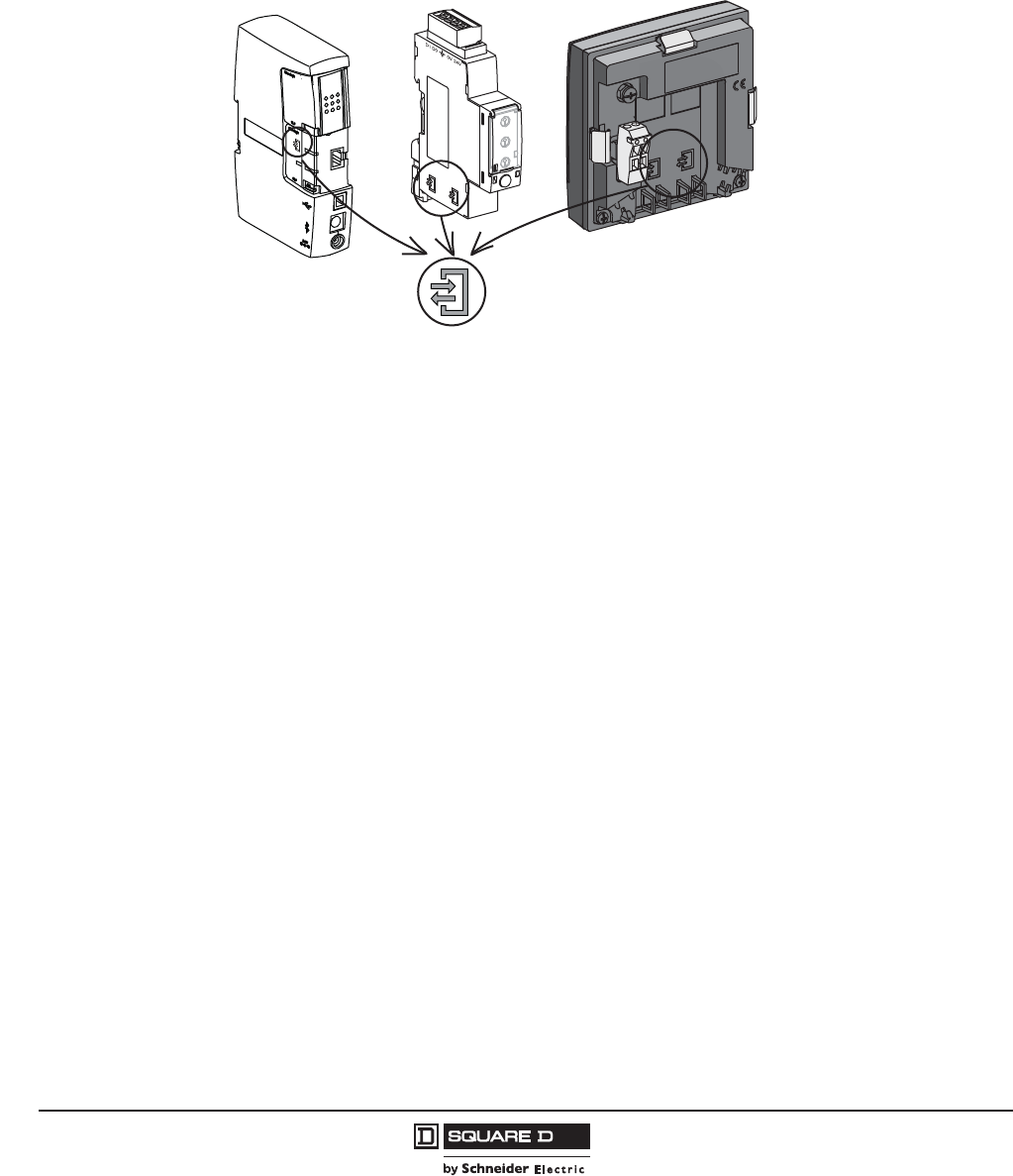
© 2011–2012 Schneider Electric
All Rights Reserved
PowerPact™ H-, J-, and L-Frame Circuit Breakers
Accessories for Micrologic™ Trip Units
86
05/2012
™
Integration of PowerPact H-, J-, and L-frame Circuit Breakers
Micrologic trip unit communication network functions are designed to interface with software dedicated
to electrical installations. PowerPact H-, J-, and L-frame circuit breakers are integrated using Modbus
communication interface modules connected through FDM121 front display modules or NSX cords.
For easy connection of the different modules, the prefabricated cables are identified by ULP (Universal
Logic Plug) symbols. The connection points on compatible modules are marked in the same manner.
Schneider Electric™ Solutions
Electrical Equipment Supervision using Gateways such as the EGX300 Web Servers
•A simple solution for customers who want to consult the main electrical parameters of installed
devices without dedicated software.
•Up to 16 devices are connected using Modbus communication interface modules to an MPS100 or
EGX300 Ethernet gateway integrating the functions of a web page server. The embedded Web
pages can be easily configured with just a few mouse clicks. The information they provide is
updated in real time.
•The Web pages can be consulted using a standard Web browser on a PC connected through
Ethernet to the company Intranet or remotely using a modem. Automatic notification of alarms and
threshold overruns is possible using e-mail or SMS (Short Message Service).
SMS Electrical Engineering Expert System Software
PowerLogic™ SMS is a family of web-enabled software products for high-end power-monitoring
applications. It is designed for large power systems.
SMS products offer detailed analysis of electrical events, long-duration data logging and extensive,
economical report-building capabilities (such as power usage monitoring and tariff management).
A wide variety of screens can be displayed in real time, including more than 50 tables, analogue
meters, bargraphs, alarms logs with links to display waveforms and predefined reports on energy
quality and service costs.
06114186
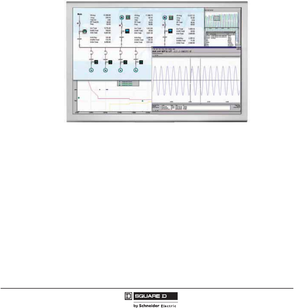
PowerPact™ H-, J-, and L-Frame Circuit Breakers
Accessories for Micrologic™ Trip Units
87
05/2012
© 2011–2012 Schneider Electric
All Rights Reserved
™
Electrical Installation Supervision using ION-Enterprise Software
•PowerLogic™ ION-Enterprise software is ideally suited to the supervision needs of small system
applications, monitoring up to 32 devices.
•Installed on a PC under Windows, it represents a cost-effective and easy-to-implement power-
monitoring solution that offers:
— automatic detection of compatible devices
— real-time monitoring of data including power requirements
— a report generator with a number of pre-defined reports that can be exported to
— Excel
— cost allocation
— time-stamped data-logging possibilities
— Modbus serial and Modbus TCP/IP compatible communication.
Other Software
PowerPact H-, J-, and L-frame devices can forward their measurement and operating information to
special software integrating the electrical installation and other technical facilities:
•SCADA process control software: Vijeo CITECT
•BMS Building Management System software: Vista.
For more information, contact your local field office.
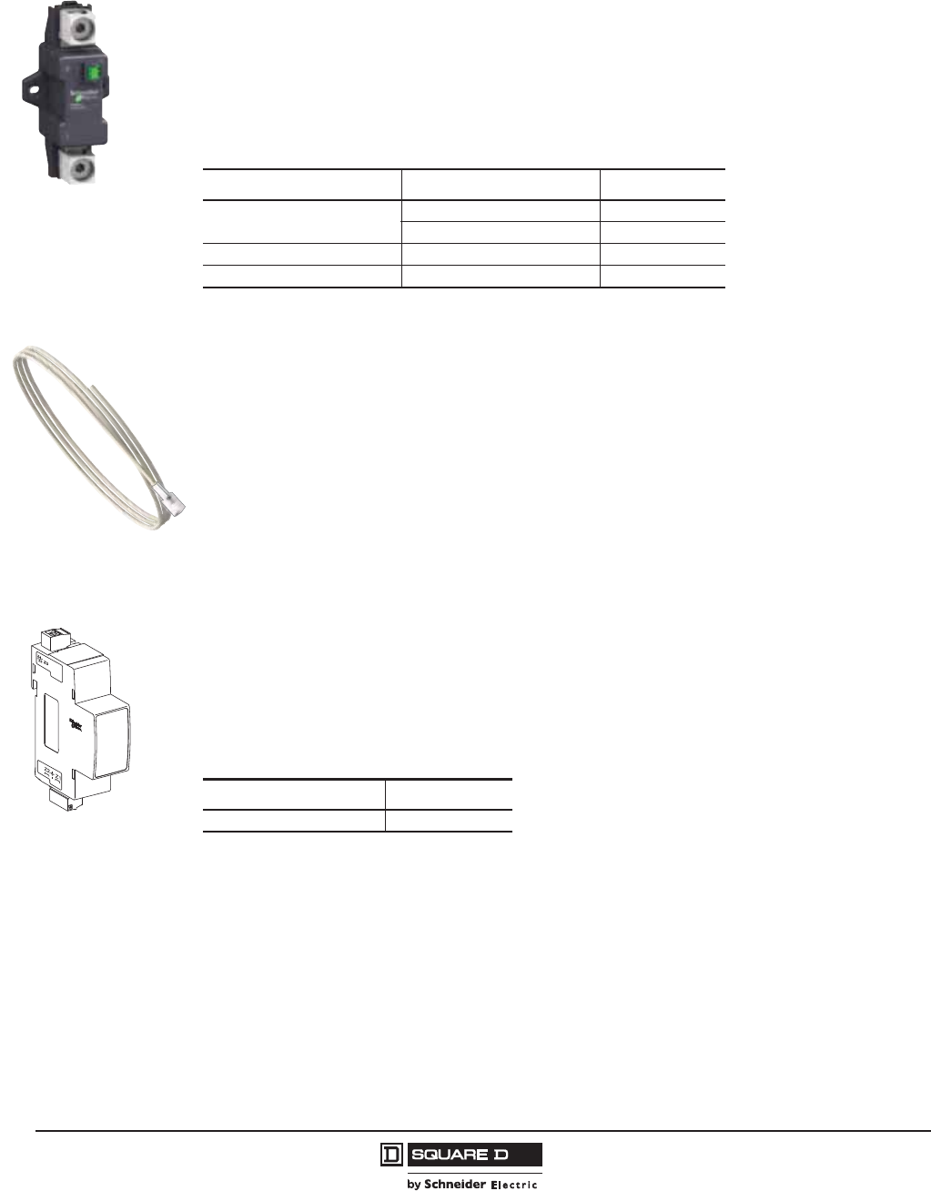
© 2011–2012 Schneider Electric
All Rights Reserved
PowerPact™ H-, J-, and L-Frame Circuit Breakers
Accessories for Micrologic™ Trip Units
88
05/2012
™
External Neutral Current Transformer (ENCT)
The external neutral current transformer is a sensor required for a three-pole circuit breaker in a
system with a distributed neutral to measure the neutral current in order to:
•protect the neutral conductor
•protect against ground faults.
This current transformer can be connected to Micrologic 5 / 6 trip units. The transformer rating must be
compatible with that of the circuit breaker.
For installation recommendations, see page 132.
External Neutral Voltage Tap (ENVT)
The external neutral voltage tap is required for Micrologic E power metering with a three-pole circuit
breaker in a system with a distributed neutral. It is used to connect the neutral to the Micrologic trip unit
to measure phase-to-neutral (Ph-N) voltages.
The ENVT is included with the Micrologic 5/6 electronic trip unit.
Zone Selective Interlock (ZSI) Module
A ZSI terminal block may be used to interconnect a number of Micrologic trip units to provide zone
selective interlocking for short-time (Isd) and ground-fault (Ig) protection, without a time delay. For
PowerPact H- and J-frame circuit breakers, the ZSI function is available only in relation to the
upstream circuit breaker (ZSI out). For PowerPact L-frame circuit breakers, the ZSI function is
available in relation to the upstream circuit breaker (ZSI out) and downstream circuit breakers (ZSI in)
06114564
External neutral current
transformer
Table 71: Current Transformers
Circuit Breaker Rating Catalog No.
H-Frame 60–100 A S429521
150 A S430562
J-Frame 250 A S430563
L-Frame 400–600 A S432575
06114565
External Neutral
Voltage Tap
06113870
Table 72: ZSI Catalog Number
Description Catalog No.
ZSI Module S434212
PowerPact™ H-, J-, and L-Frame Circuit Breakers
Accessories for Micrologic™ Trip Units
89
05/2012
© 2011–2012 Schneider Electric
All Rights Reserved
™
I-Line™ Wiring Harness
Accessories installed in I-Line circuit breakers require the use of optional wiring harnesses (not
provided). The wiring harness allows the accessory wiring to exit the circuit breaker through wiring
channels in the side of the circuit breakers. Wire harnesses may also be used for unit-mount
applications.
Table 73: Wiring Harness Catalog Numbers
Description Catalog No.
Auxiliary Switch (OF) I-Line Wire Harness S434500
Alarm Switch (SD)/Overcurrent Trip Switch (SDE) I-Line Wire Harness S434501
SDx/SDTAM I-Line Wire Harness S434502
Undervoltage Trip (MN) I-Line Wire Harness S434503
Shunt Trip (MX) I-Line Wire Harness S434504
24 Vdc Power Supply Terminal Block I-Line Wire Harness S434505
Motor Operator (MT) I-Line Wire Harness S434506
Communicating Motor Operator (MTc) I-Line Wire Harness S434507
NSX Cord I-Line Wire Harness S434508
ZSI (H/J-Frame, Out Only) I-Line Wire Harness S434300
ZSI (L-Frame, In and Out) I-Line Wire Harness S434301
ENCT I-Line Wire Harness S434302
06164779
H, J-Frame L-Frame

© 2011–2012 Schneider Electric
All Rights Reserved
PowerPact™ H-, J-, and L-Frame Circuit Breakers
Accessories and Auxiliaries
90
05/2012
™
Section 8—Accessories and Auxiliaries
All PowerPact H-, J-, and L-frame circuit breakers and automatic switches have slots for the electrical
auxiliaries
Circuit breakers equipped with Micrologic™ trip units may be equipped with a fault-trip indication to
identify the type of fault by installing
•one indication module with two outputs (see page 94)
— either an SDx module with Micrologic 3.x / 5.x A or E / 6.x A or E
— or an SDTAM module with Micrologic 2.x M.
This module occupies the slots of one auxiliary switch (OF) contact and an undervoltage trip
(MN)/shunt trip (MX).
All these auxiliaries may be installed with a motor operator.
Communication Network
Communication networks require specific auxiliaries.
Communication of status indications
•1 BSCM module
•1 NSX cord (internal terminal block) for both communication and 24 Vdc supply to the BSCM.
Communication of status conditions is compatible with a standard motor operator.
Communication of status indications and controls requires, in addition to the previous auxiliaries:
•1 communicating motor operator connected to the BSCM.
Communication of measurements is available on Micrologic 5 / 6. The system consists of:
•1 NSX cord (internal terminal block) for both communication and 24 Vdc supply to the Micrologic.
Communication of measurements is compatible with a standard or communicating motor operator.
Communication of status indications, controls and measurements is available on Micrologic 5 / 6. The
system consists of:
•1 BSCM module
•1 NSX cord (internal terminal block) for both communication and 24 Vdc supply to the BSCM and
the Micrologic
•1 communicating motor operator connected to the BSCM.
Installation of SDx or SDTAM is compatible with communication network.
H- and J-Frame L-Frame
•4 indication contacts
— 2 ON/OFF (auxiliary switches [OF1 and
OF2])
— 1 trip indication (alarm switch [SD])
— 1 fault-trip indication (overcurrent trip
switch [SDE])
•one remote-tripping release
— either 1 undervoltage trip (MN)
— or 1 shunt trip (MX)
•5 indication contacts
— 3 ON/OFF auxiliary switches (OF1, OF2,
and OF3)
— 1 trip indication (alarm switch [SD])
— 1 fault-trip indication (overcurrent trip
switch [SDE])
•one remote-tripping release
— either 1 undervoltage trip (MN)
— or 1 shunt trip (MX)
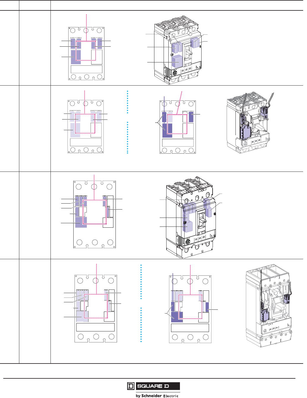
PowerPact™ H-, J-, and L-Frame Circuit Breakers
Accessories and Auxiliaries
91
05/2012
© 2011–2012 Schneider Electric
All Rights Reserved
™
Table 74: Standard Auxiliary Possibilities Based on Trip Unit
Type Trip Unit Auxiliary Possibilities
H-Frame
J-Frame Micrologic™ 3
H-Frame
J-Frame
Micrologic 5
Micrologic 6
L-Frame Micrologic 1.3 M
Micrologic 3
L-Frame Micrologic 5
Micrologic 6
06114463
OF1
SD
OF2
SDE
Motor Operator
MN /
MX
SD
OF1
OF2
SDE
MN /
MX
3.2
Micrologic
5
.
1
2
5
.
2
34
0
1
8
6
5
.9
2
9
.
3
9
.
4
9
.5
9
.
1
8
9
.
7
9
.
6
9.
0
0
1
0
1
1
5
2
1
0
4
10
6
1
0
5
2
5
2
2
0
0
2
5
7
1
Ird
s
I
d
s
I)
r
I
x
(
Ir )
o
I
x
(
o
I)
A
(
r
I
%
A
0
3
>
0
3
>0
1
1
>
SDx /
SDTAM
Motor Operator
24 Vdc
Supply
Terminal
Block
06114464
OF1
SD
OF2
SDE
Motor Operator
MN /
MX
The SDx or SDTAM uses the OF1 and MN/MX slots.
External connection is made via a terminal block in the OF1 slot.
The 24 Vdc supply provides for the Micrologic 5 / 6 display when the device is OFF or under low-load conditions.
or
06114467
OF1 SD
SDE
OF2
OF3
Reserved
MN /
MX
OF1,
OF2,
OF3
SD
SDE
Reserved
MN /
MX
3.2
Micrologic
5.
1
2
5
.2
34
0
1
8
6
5
.9
2
9
.
3
9
.
4
9
.5
9
.
1
8
9
.
7
9
.
6
9
.
0
0
1
0
1
1
52
1
0
4
106
1
0
5
2
5
2
2
0
0
2
5
7
1
Ir d
s
I
d
s
I)
r
I
x
(
Ir)
o
I
x(
o
I)
A
(
r
I
%
A
0
3
>
0
3
>0
1
1
>
06114468
SD
OF1
OF2
OF3
Reserved
MN /
MX
SDE
Motor Operator
SDx /
SDTAM
24 Vdc
Supply
Terminal
Block
Motor Operator
Rotary Handle
External connection is made using a terminal block in the reserved slot.
The 24 V DC supply provides for the Micrologic 5 / 6 display when the
device is OFF or under low-load conditions.
or
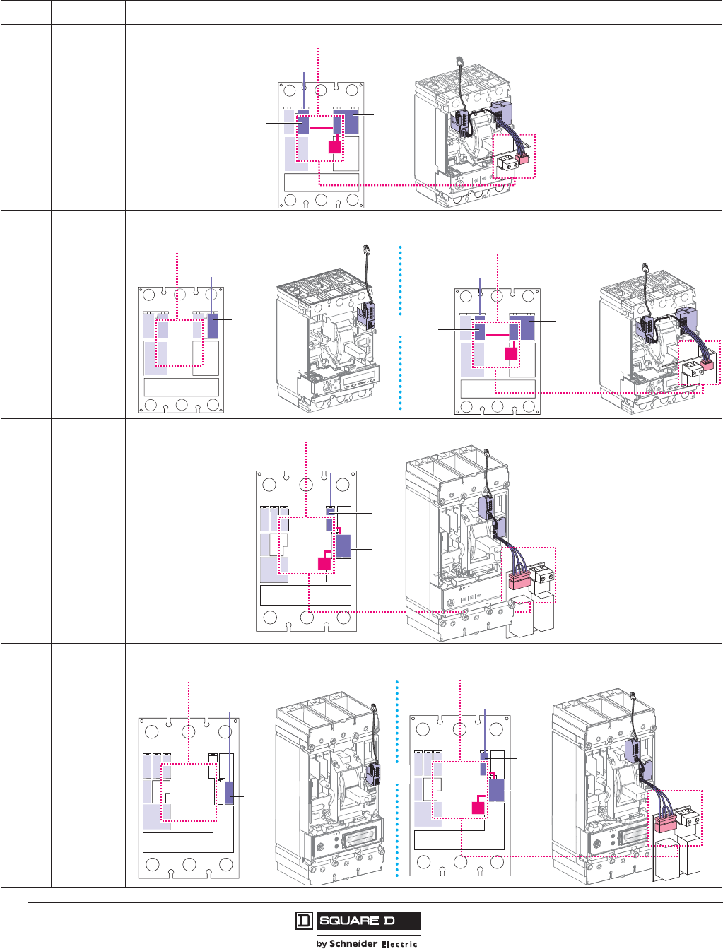
© 2011–2012 Schneider Electric
All Rights Reserved
PowerPact™ H-, J-, and L-Frame Circuit Breakers
Accessories and Auxiliaries
92
05/2012
™
Table 75: Communication Network Auxiliary Possibilities Based on Trip Unit
Type Trip Unit Auxiliary Possibilities
H-Frame
J-Frame Micrologic™ 3
H-Frame
J-Frame
Micrologic 5
Micrologic 6
L-Frame Micrologic 1.3 M
Micrologic 3
L-Frame Micrologic 5
Micrologic 6
NSX
Cord
BSCM
Communicating
Motor Operator
Communication of status indications and controls
Communication of measurements with or
without FDM121 display
Communication of status indications, controls and
measurements with or without FDM121 display
06114466
NSX
Cord
Motor Operator Communicating
Motor Operator
NSX
Cord
BSCM
or
NSX
Cord
BSCM
Communicating
Motor Operator
Communication of status indications and controls
Communication of status indications Communication of status indications, controls and
measurements with or without FDM121 display
06114470
NSX
Cord
Motor Operator
NSX
Cord
BSCM
Communicating
Motor Operator
or
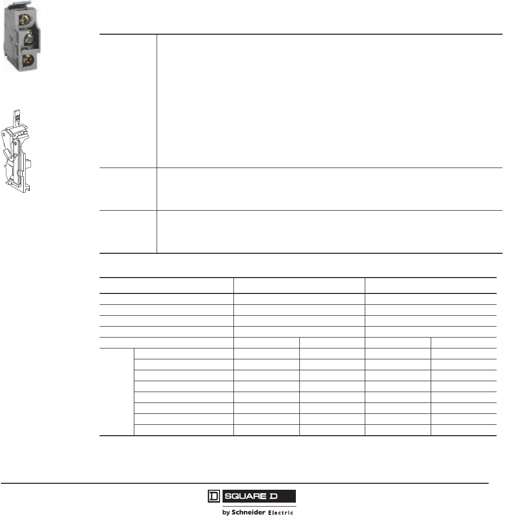
PowerPact™ H-, J-, and L-Frame Circuit Breakers
Accessories and Auxiliaries
93
05/2012
© 2011–2012 Schneider Electric
All Rights Reserved
™
Accessory Connections
Electrical accessories are fitted with numbered terminal blocks for wires with the following maximum size:
•16 AWG (1.5 mm2) for auxiliary switches (OF1 or OF2), and shunt trip (MX) or undervoltage trip (MN)
•14 AWG (2.5 mm2) for the motor operator
Auxiliary switch wiring exits fixed mounted devices through a knock-out in the front cover.
NOTE: See page 115 for plug-in and page 117 for drawout options.
Auxiliary and Alarm Indication Contacts
Auxiliary indication contacts provide remote information of the circuit breaker status and can thus be
used for indications, electrical locking, relays, etc.
Auxiliary Switch (OF)/
Alarm Switch (SD)
Overcurrent Trip
Switch Actuator (SDE)
Table 76: Auxiliary and Alarm Indication Contacts
Applications
Open/Closed—Auxiliary Switches (OF)
• Indicates the position of the circuit breaker contacts
Trip Indication—Alarm Switch (SD)
• Indicates that the circuit breaker has tripped due to an overload, short circuit or ground fault, the operation of
a shunt trip or undervoltage trip or the “push-to-trip” button
• Resets when the circuit breaker is reset
Overcurrent Trip Switch (SDE)
• Indicates that the circuit breaker has tripped due to an overload, short circuit or ground fault
• Resets when the circuit breaker is reset
The above switches are also available in low-level versions (with gold flash plating) capable of switching very
low loads (e.g., for controlling PLCs or electronic circuits)
Rotary Handle Indicator: CAO (early-break) and CAF (early-make)
• Fitted in the rotary handle module (see page 102)
Installation &
Connection
• The auxiliary switch (OF), alarm switch (SD), and overcurrent trip switch (SDE) indication contacts snap into
cavities behind the front accessory cover of the circuit breaker.
• One model serves for all indication functions depending on where it is fitted in the circuit breaker.
• The overcurrent trip switch (SDE) in a circuit breaker equipped with a thermal-magnetic or Micrologic™ 1/2/3
trip unit requires the SDE actuator.
Standards
• The internal accessories comply with requirements of Underwriters Laboratories® Inc. (UL®).
• UL 489 and Canadian Standard Association C22.2 No. 5-02 Standards.
• All internal accessories are Listed for field installation per UL file E103955 and Certified under CSA file LR 69561.
• Auxiliary indicator contacts comply with UL 489, CSA C22.2 No. 5-02 and IEC 60947-5 Standards. “Low-
level” indicator contacts are not UL Recognized.
Table 77: Electrical Characteristics
Characteristic Standard Low-Level1
1 If the maximum voltage and current is exceeded, the low-level function of the switch will be lost but the switch will continue to
function as a standard switch.
Supplied as Standard (Form C) 4 4
Maximum Number of Contacts 4 4
Rated Thermal Current 6 A 5 A
Maximum Load 100 mA at 24 V 1 mA at 4 V
Operational Current AC DC AC DC
24 V 6 A6 A5 A5 A
48 V 6 A 2.5 A 5 A 2.5 A
110 V 6 A 0.6 A 5 A 0.6
220/240 V 6 A — 5 A —
250 V — 0.6 A 5 A 0.3 A
380/440 V 6 A — 5 A —
480 V 6 A — 5 A —
660/690 V 6 A — — —

© 2011–2012 Schneider Electric
All Rights Reserved
PowerPact™ H-, J-, and L-Frame Circuit Breakers
Accessories and Auxiliaries
94
05/2012
™
Table 78: Auxiliary Switch Catalog Numbers
Contacts Factory-Installed Suffix Field-Installable Kit No. Kit Qty.
1A/1B Standard AA S29450 1
2A/2B Standard AB S29450 2
1A/1B Low-Level (Gold) AE S29482 1
2A/2B Low-Level (Gold) AF S29482 2
Table 79: Alarm/Overcurrent Trip Switch Catalog Numbers
Suffix Switch Kit No. Kit Qty.
PowerPact L-Frame
PowerPact H/J-Frame with Micrologic™ 5/6 trip units
BC Alarm Switch S29450 1
BH Alarm Switch Low-Level S29452 1
BD Overcurrent Trip Switch Standard S29450 1
BJ Overcurrent Trip Switch Low-Level S29452 1
BE Alarm Switch and Overcurrent Trip Switch, Standard S29450 2
BK Alarm Switch and Overcurrent Trip Switch, Low-Level S29452 2
PowerPact H/J-Frame with Thermal-Magnetic or
Micrologic 1/2/3 trip units
BC Alarm Switch S29450 1
BH Alarm Switch, Low-Level S29452 1
BD Overcurrent Trip Switch, Standard
SDE Actuator
S29450
S29451
1
1
BJ Overcurrent Trip Switch, Low-Level
SDE Actuator
S29452
S29451
1
1
BE Alarm Switch and Overcurrent Trip Switch, Standard
SDE Actuators
S29450
S29451
2
2
BK Alarm Switch and Overcurrent Trip Switch, Low-Level
SDE Actuators
S29452
S29451
2
2
PowerPact™ H-, J-, and L-Frame Circuit Breakers
Accessories and Auxiliaries
95
05/2012
© 2011–2012 Schneider Electric
All Rights Reserved
™
SDx and SDTAM Modules for Micrologic™
SDx and SDTAM are relay modules with two outputs. They send different signals depending on the
type of fault. They may not be used together.
SDx Module
The SDx module remotely monitors the trip or alarm conditions of PowerPact H-, J-, and L-frame circuit
breakers equipped with electronic protection.
An SDx relay module installed inside the circuit breaker can be used to remote the overload trip signal.
This module receives the signal from the Micrologic electronic trip unit through an optical link and
makes it available on the terminal block. The signal is cleared when the circuit breaker is closed. These
outputs can be reprogrammed to be assigned to other types of tripping or alarm (see page 94).
The SDx module may be used in 400 Hz systems for voltages from 24 to 440V.
The SD2 output, available on all Micrologic trip units, corresponds to the overload-trip indication.
The SD4 output, available on Micrologic 5 / 6, is assigned to:
•overload pre-alarm (Micrologic 5)
•ground-fault trip indication (Micrologic 6)
These two outputs automatically reset when the device is closed (turned ON).
For Micrologic 5 / 6, the SD2 and SD4 outputs can be reprogrammed to be assigned to other types of
tripping or alarm.
It is possible to assign a function output characteristics:
•latching with a time delay. Return to the initial state occurs at the end of the time delay
•permanent latching. Return to the initial state takes place through the communication function.
Static outputs: 24–415 V AC / Vdc; 80 mA max.
SDTAM Module
The SDTAM module, linked to the contactor controller, opens the contactor when an overload or other
motor fault occurs, thus avoiding opening of the circuit breaker. The SDTAM module is specifically for
the motor-protection Micrologic trip units 2 M (2.2 M and 2.3 M).
Micrologic 2 M
The SD4 output opens the contactor 400 ms before normal circuit-breaker opening in the following
cases:
•overload (long-time protection for the trip class)
•phase unbalance or phase loss
The SD2 output serves to memorize contactor opening by SDTAM.
Output characteristics
Output reset can be:
•manual by a pushbutton included in the wiring diagram
•automatic after an adjustable time delay (1 to 15 minutes) to take into account the motor-cooling
time
Static outputs: 24–415 Vac / Vdc; 80 mA max. a (+) 24–415 V
06113591
SDx module with
terminal block.
06114033
SDTAM module
with terminal block.

© 2011–2012 Schneider Electric
All Rights Reserved
PowerPact™ H-, J-, and L-Frame Circuit Breakers
Accessories and Auxiliaries
96
05/2012
™
06114461
+-
L
H
Q
B4
A1
Vac (220/240 V)
Vac
0I
auto
manu
NSX cord
BSCM
Schematic of the communicating motor operator .
06114462
OF3
31
32
34
21
OF2
Open
22
24
OF1
11
Closed Closed
12
14
81
SDE
Fault
82
84
91
SD
Fault
92
94
121
CAF2
131
CAF1
RD
WH
134
124
101
CAO1
Open
YE
VT
102
104
RD
WH
GY
Table 80: SDx and SDTAM Catalog Numbers
Contacts Factory-Installed Suffix Field-Installable Kit No.
SDx V S429532
SDTAM (motor trip units only) V S429424
PowerPact™ H-, J-, and L-Frame Circuit Breakers
Accessories and Auxiliaries
97
05/2012
© 2011–2012 Schneider Electric
All Rights Reserved
™
Shunt Trip (MX) and Undervoltage Trip (MN)
A voltage release can be used to trip the circuit breaker using a control signal.
Table 81: Shunt Trip and Undervoltage Trip
Applications
Shunt Trip (MX)
• Trips the circuit breaker when the control voltage rises above 70% of its rated voltage
• Impulse type t20 ms or maintained control signals
• AC shunt trips are suitable for ground-fault protection when combined with a Class I ground-fault
sensing element
• Continuous duty rated coil
Undervoltage Trip (MN)
• Trips the circuit breaker when the control voltage drops below a tripping threshold
• Drops out between 35% and 70% of the rated voltage
• Continuous duty rated coil
• Circuit breaker closing is possible only if the voltage exceeds 85% of the rated voltage. If an undervoltage
condition exists, operation of the closing mechanism of the circuit breaker will not permit the main contacts
to touch, even momentarily. This is commonly called “Kiss Free”.
Installation and
Connection
• Accessories are common to H-, J-, and L-frame circuit breakers and snap into cavities under the front
accessory cover of the circuit breaker
• Each terminal may be connected by one 18–14 AWG (1.0–2.5 mm2) stranded copper wire
Operation
• The circuit breaker must be reset locally after being tripped by shunt trip (MX) or undervoltage trip (MN)
• Tripping by the shunt trip or undervoltage trip has priority over manual (or motor operator) closing; in the
presence of a standing trip order such an action does not result in any closing, even temporarily, of the
main contacts
• Endurance: 50% of the rated mechanical endurance of the circuit breaker
Table 82: Electrical Characteristics
AC DC
Rated Voltage (V) 24, 48, 120, 208/277, 380/480, 525, 600 12, 24, 30, 48, 60, 125, 250
Power Requirements Pickup (shunt trip) < 10 VA < 5 W
Seal-in (undervoltage trip) < 5 VA < 5 W
Clearing Time (ms) < 50 < 50
Table 83: Shunt Trip and Undervoltage Trip Suffix Codes and Kit Numbers
Voltage
Shunt Trip (MX) Undervoltage Release (MN)
Factory-Installed
Suffix
Field-Installable
Kit No.
Factory-Installed
Suffix
Field-Installable
Kit No.
24 Vac SK S29384 UK S29404
48 Vac SL S29385 UL S29405
120 Vac SA S29386 UA S29406
208/277 Vac SD S29387 UD S29407
380/480 Vac SH S29388 UH S29408
525/600 Vac SJ S29389 UJ S29409
12 Vdc SN S29382 UN S29402
24 Vdc SO S29390 UO S29410
30 Vdc SU S29391 UU S29411
48 Vdc SP S29392 UP S29412
60 Vdc SV S29383 UV S29403
125 Vdc SR S29393 UR S29413
250 Vdc SS S29394 US S29414
Table 84: Adjustable and Fixed Time Delay Units for Undervoltage Trip
Rated Voltage
Field-Installable Kit No.
Adjustable Fixed
48 Vac/dc S33680 S29426
100/130 Vac/dc S33681 —
220/250 Vac/dc S33682 S29427
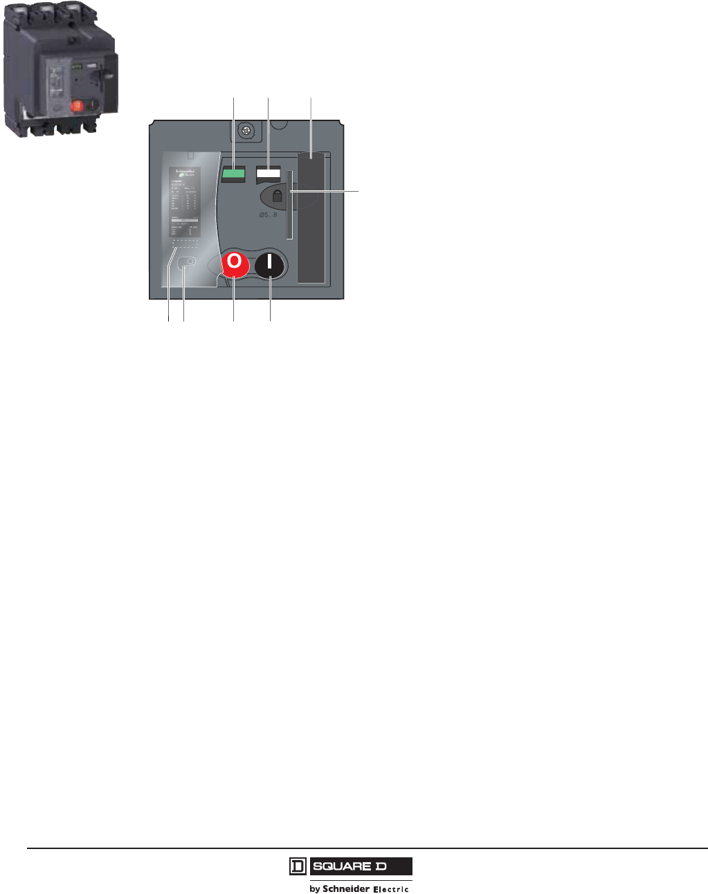
© 2011–2012 Schneider Electric
All Rights Reserved
PowerPact™ H-, J-, and L-Frame Circuit Breakers
Accessories and Auxiliaries
98
05/2012
™
Motor Operator
The motor operator remotely operates the circuit breaker featuring easy and sure operation:
•All circuit breaker indications and information remain visible and accessible, including trip unit
settings and circuit breaker connection
•Suitability for isolation is maintained and padlocking remains possible
•Double insulation front face
Applications:
•Local motor-driven operation, centralized operation, automatic distribution control
•Normal/standby manual transfer or switching to a replacement source to optimize energy costs
•Load shedding and reconnection to optimize energy costs
•Less than five cycle closing time for source synchronization
Installation and Connection
•All installations are available for H- and J-frame circuit breakers.
All installations are available for L-frame circuit breakers except I-Line
•Connections of the motor operator module are to a built-in terminal block behind its front cover
•Stranded copper wire 14 AWG (2.5 mm2)
Automatic Operation
The motor operator is connected in series with the overcurrent trip switch (SDE).
•ON and OFF by two impulse type or continuous control signals
•Depending on the wiring, resetting can be done locally, remotely or automatically
•Mandatory manual reset following tripping due to an electrical fault (with overcurrent trip switch)
Manual Operation
•Transfer to manual mode with possibility of remote mode indication
•ON and OFF by two push buttons
•Recharging of stored-energy system by pumping the lever
•Padlocking in off position
discharged
0OFF
OFF ON
31 2
5
678
4
1. Contact position indicator
(suitability for isolation)
2. Spring status indicator (charged,
discharged)
3. Manual spring-charging handle
4. Keylock device (optional)
Locking device (off position)
using one to three padlocks,
diameter 0.2–0.32 in. (5–8 mm),
not supplied
5. ON push button
6. OFF push button
7. Manual/auto mode selection
switch; the position of the switch
can be indicated remotely
8. Operation counter

PowerPact™ H-, J-, and L-Frame Circuit Breakers
Accessories and Auxiliaries
99
05/2012
© 2011–2012 Schneider Electric
All Rights Reserved
™
Manual Mode
Switch
Table 85: Motor Operator Characteristics
Response Time (ms) Opening < 600
Closing < 80
Operating Frequency cycles/minute max. 4
Power Requirements1
1For H- and J-frame, the inrush current is 2x operating current for 10 ms.
AC (VA) Opening 500
Closing 500
DC (W) Opening 500
500Closing
Table 86: Motor Operator and Accessory Suffix Codes and Catalog Numbers
Device1
1For NSX cord (communication suffixes EA, EB, ED, and EE) any motor operator may be selected.
For BSCM + NSX cord (communication suffixes EB, EH, EK, and EL) only the communicating motor operator may be selected.
Control Voltage Factory-Installed
Suffix
Field-Installable Kit No.
H-Frame J-Frame L-Frame
Communicating Motor Operator 220/240 Vac 50/60 Hz NC S429441 S431549 S432652
Motor Operator
48/60 Vac 50/60 Hz ML S29440 S31548 S432639
110/130 Vac 50/60 Hz MA S29433 S31540 S432640
208/277 Vac 60 Hz MD S29434 S31541 S432641
380/415 Vac 50/60 Hz MF — — S432642
440/480 Vac 60 Hz MH S29435 S31542 S432647
24/30 Vdc MO S29436 S31543 S432643
48/60 Vdc MV S29437 S31544 S432644
110/130 Vdc MR S29438 S31545 S432645
250 Vdc MS S29439 S31546 S432646
Lock Mounting Hardware — — — — S32649
Ronis Lock — — S41940 S41940 S41940
Profalux Lock — — S42888 S42888 S42888
Mounting Hardware with Ronis
Lock ——S429449 S429449 —
Operations Counter — — — — S32648
Adapter for I-Line™ Circuit
Breaker S37420 S37420 —
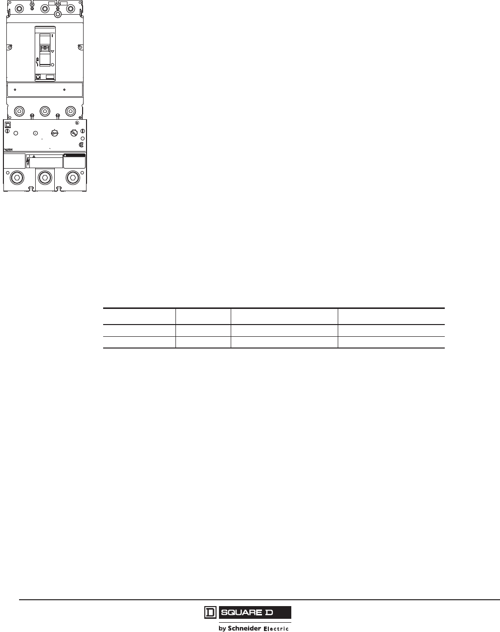
© 2011–2012 Schneider Electric
All Rights Reserved
PowerPact™ H-, J-, and L-Frame Circuit Breakers
Accessories and Auxiliaries
100
05/2012
™
Add-On Ground-Fault Module (GFM) (H- and J-Frame Only)
The Micrologic™ Ground-Fault Module (GFM) is a UL Listed/CSA Certified circuit breaker accessory
which protects equipment from damage caused by ground faults. It is an add-on module which, when
connected to a PowerPact H- or J-frame thermal-magnetic circuit breaker only, provides ground-fault
sensing and ground-fault relay functions.
HD/JD ground-fault modules feature:
•Adjustable ground-fault pickup levels
•Adjustable ground-fault time delays
•Integral ground-fault push-to-test feature
•Ground-fault indicator (mechanical for local, contacts for remote)
•All GFMs are supplied for I-Line™ mounting as standard, easily convertible to unit mount by
removing the I-Line bracket.
•Fault-powered (through the sensing current transformer) for electronics, shunt trip, and integral test
feature. Meets NEC 230.95(C).
•A 12 Vdc shunt trip module (Catalog No. S29382) is required in the circuit breaker. This may be
field installed or factory installed when the circuit breaker is ordered with an -SN suffix.
•UL 1053 – Ground-fault Sensing and Relaying Equipment
The GFM system requires the following:
•H-frame (15–150 A) or J-frame (150–250 A) molded case circuit breaker
•Shunt trip for circuit breaker (may be factory-installed or field-installed)
•Bus bar connection (terminal nut inserts) for OFF end of circuit breaker
•Optional neutral current transformer, catalog number GFM25CT (must be ordered for 4-wire
applications).
09603039
Ground-Fault Module
Module de défaut de mise à la terre
Modulo de falla a tierra
Ground-Fault Indicator
Fault Indicator
Push to reset
Indicateur de défaut de
mise à la terre
Pousser pour réinitialiser
Indicador de falla a tierra
Oprima para restablecer
Push-to-test
Requires 120 V Pick-upDelay Band
1=min.
1
23
4
20A
40A
60A
80A
100A
Class I Ground-fault Protection
Protection de défaut de mise à la terre classe I
Protección de falla a tierra clase I
100A 600 Vac/V max.
Replace cover after adjusting/Replacer le couvercle avant aprés le réglage/Vuelva a colocar la cubierta después de ajustar
52H
4
LISTED
Circuit
Breaker
Accessory
GFM150HD
TM
4068715 H238
DANGER PELIGRO
HAZARD OF ELECTRICAL SHOCK OR BURN.
DANGER DE D’CHARGE ELECTRIQUE OU DE
BRULURE.
PELIGRO DE DESCARGA ELECTRICA O
QUEMADURAS.
Ter m i n al strip wiring ter minals must
not be dielectric tested.
No se deben realizar pruebas
dieléctricasa a las terminalses de
la tabilla de conexiones.
Les bornes de câblage de la
barrette de connexion ne doivent
pas étre véroflées diélectriquement.
Replace lug cover after
wiring.
Replacez le couvre-
cosse après le câblage
.
Vuelva a colocar después
de realizar el cableado
PELIGRODANGER
®
!
J-Frame Circuit Breaker
with GFM Installed
Table 87: Ground-Fault Module
Catalog No. Rating Sensitivity Time Delay (Approximate)
GFM150HD 150 A 20, 40, 60, 80, 100 A 0.2, 0.3, 0.4, 0.6 sec
GFM250JD 250 A 40, 80, 120, 160, 200 A 0.2, 0.3, 0.4, 0.6 sec
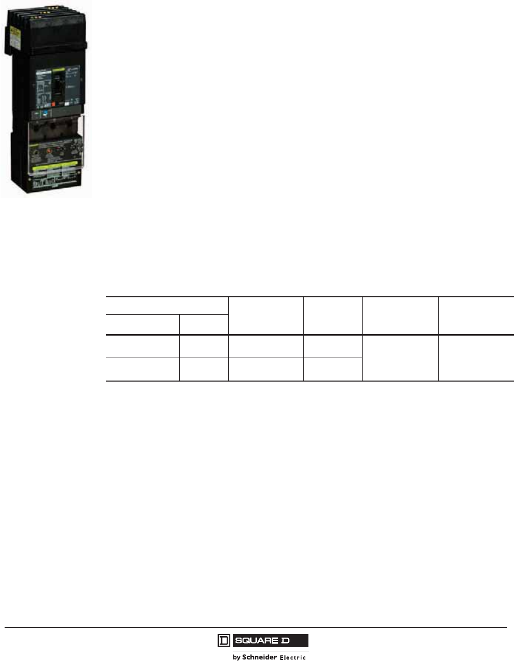
PowerPact™ H-, J-, and L-Frame Circuit Breakers
Accessories and Auxiliaries
101
05/2012
© 2011–2012 Schneider Electric
All Rights Reserved
™
Earth Leakage Module (ELM) (H- and J-Frame Only)
The Earth Leakage Module (ELM) is an add-on module which, when connected to a PowerPact H- or
J-frame MCCB, provides low-level ground-fault sensing and ground-fault relay functions.
Because these ELMs are highly sensitive (30 mA to 3 A), they provide much greater protection than
GFMs (20 Amps to 200 Amps sensitivity). The ELMs provide greater protection of control circuits and
other sensitive equipment. The associated circuit breaker must have a 48 Vdc shunt trip), which may
be field-installed (kit S29392) or factory-installed (suffix –SP) in the H- or J-Frame circuit breaker.
The add-on Earth Leakage Module (ELM) features:
•Adjustable ground-fault pickup levels as low as 30 mA
•Adjustable ground-fault time delays from instantaneous to 500 msec
(time delay can be applied to any setting)
•Integral ground fault push-to-test feature
•Ground-fault indicator; pop-up button for local status and contacts for remote indication (to be used
only with the tripping option)
•All ELMs are supplied for I-Line™ mounting and are easily convertible to unit-mount by removing
the I-Line mounting feet
•Three poles; 240 to 600 Vac maximum: 3-phase, 3-wire (no neutral) and 1-phase, 2-wire
applications
•Line-power obtained through internal bus to provide power for electronics, shunt trip, and integral
test feature
•A shunt trip is required in the circuit breaker; it may be field-installed or factory-installed in the
PowerPact H and J circuit breakers.
•UL 1053 – Ground-fault Sensing and Relaying Equipment
Factory-Installed ELMs
The catalog number for circuit breakers with factory-installed ELM should include the special suffixes
SP and VL or VM:
H D M 3 6 150 SP VL
where
•H = H-fame (or J = J-frame)
•D = D interruption level (or G, J or L)
•M = Lugs on ON end and terminal nuts on OFF end (required)
•SP = Factory-installed 48 Vdc shunt trip (S29392, required)
•VL= Earth Leakage Module (ELM) <150 A (H-frame) or
VM = Earth Leakage Module (ELM) <250 A (J-frame)
J-Frame Circuit Breaker
with ELM Installed
Table 88: ELM Selection Chart 1
1At 250 A, the ELM250JD can be used with standard (80%) rated circuit breakers only.
Companion Circuit Breaker Enclosure Space
Required I-Line
Equipment
Catalog No. Pick-Up
Adjustments
Ground-Fault
Time Delay
Adjustments
Prefix Size
HD, HG, HJ, HL 15–150 A LA ELM150HD 30 mA
100 mA
300 mA
1A
3A
Instantaneous
60 ms
100 ms
500 msec
JD, JG, JJ, JL 150–250 A LA ELM250JD
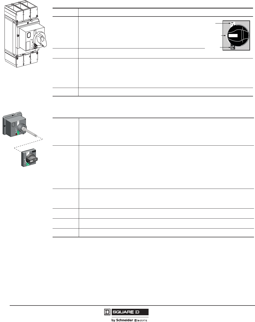
© 2011–2012 Schneider Electric
All Rights Reserved
PowerPact™ H-, J-, and L-Frame Circuit Breakers
Accessories and Auxiliaries
102
05/2012
™
Rotary Operating Handles
Directly Mounted Rotary Operating Handles
Door-Mounted (Extended) Rotary Operating Handle
Directly Mounted Rotary
Operating Handle
push
to
trip
06163068
Installation The directly mounted rotary operating handle replaces the circuit breaker front accessory cover (secured by screws).
Operation
The direct rotary handle maintains:
• Suitability for isolation
• Indication of three positions: I (ON), Tripped and O (OFF)
• Access to the “push-to-trip” button
• Visibility of, and access to, trip unit settings
• The circuit breaker may be locked in the OFF position by using one to three
padlocks (not supplied)
Models • Standard with black handle
• VDE type with red handle and yellow bezel for machine tool control
Variations
Accessories transform the standard direct rotary handle for the following situations:
• Motor control centers (MCCs):
– Opening of door prevented when circuit breaker is on
– Closing of circuit breaker inhibited when door is open
• Machine tool control; complies with CNOMO E03.81.501N; degree of protection IP54
• Early make or early break contacts may be installed into direct mount rotary handle
Standards The directly-mounted rotary operating handle is UL Listed under file E103955 and CSA Certified under file LR 69561
I/ON
(Closed)
Tripped
O/OFF
(Open)
Door Mounted Rotary
Operating Handle
Installation
The door-mounted (extended) rotary operating handle is made up of:
• A unit that replaces the front accessory cover of the circuit breaker (secured by screws)
• An assembly (handle and front plate) on the door that is always secured in the same position, whether the
circuit breaker is installed vertically or horizontally
• An adjustable extension shaft
• The handle mechanism can be used in NEMA 3R and 12 enclosure applications
Operation
The door mounted operating handle makes it possible to operate circuit breakers installed in enclosure from the
front. The door mounted operating handle maintains:
• Suitability for isolation
• Indication of the three positions OFF (O), ON (I) and tripped
• Visibility of and access to trip unit settings when the door is open
• Degree of protection: IP40 as per IEC 529
Defeatable interlock prevents opening of door when circuit breaker is on
The circuit breaker may be locked in the off position by using one to three padlocks, padlock shackle diameter
0.19–0.31 in. (5–8 mm); padlocks are not supplied; locking prevents opening of the enclosure door
Shaft
Length
The shaft length is the distance between the back of the circuit breaker and the door:
• Minimum shaft length is 7.4 (185 mm)
• Maximum shaft length is 24 in. (600 mm)
• Extended shaft length must be adjusted
Models • Standard with black handle
• VDE type with red handle and yellow bezel for machine tool control
Variations For drawout configurations, the extended rotary handle is also available with a telescopic shaft containing two
stable positions
Standards The door-mounted rotary operating handle is UL Listed under file E103955 and CSA Certified under file LR 69561
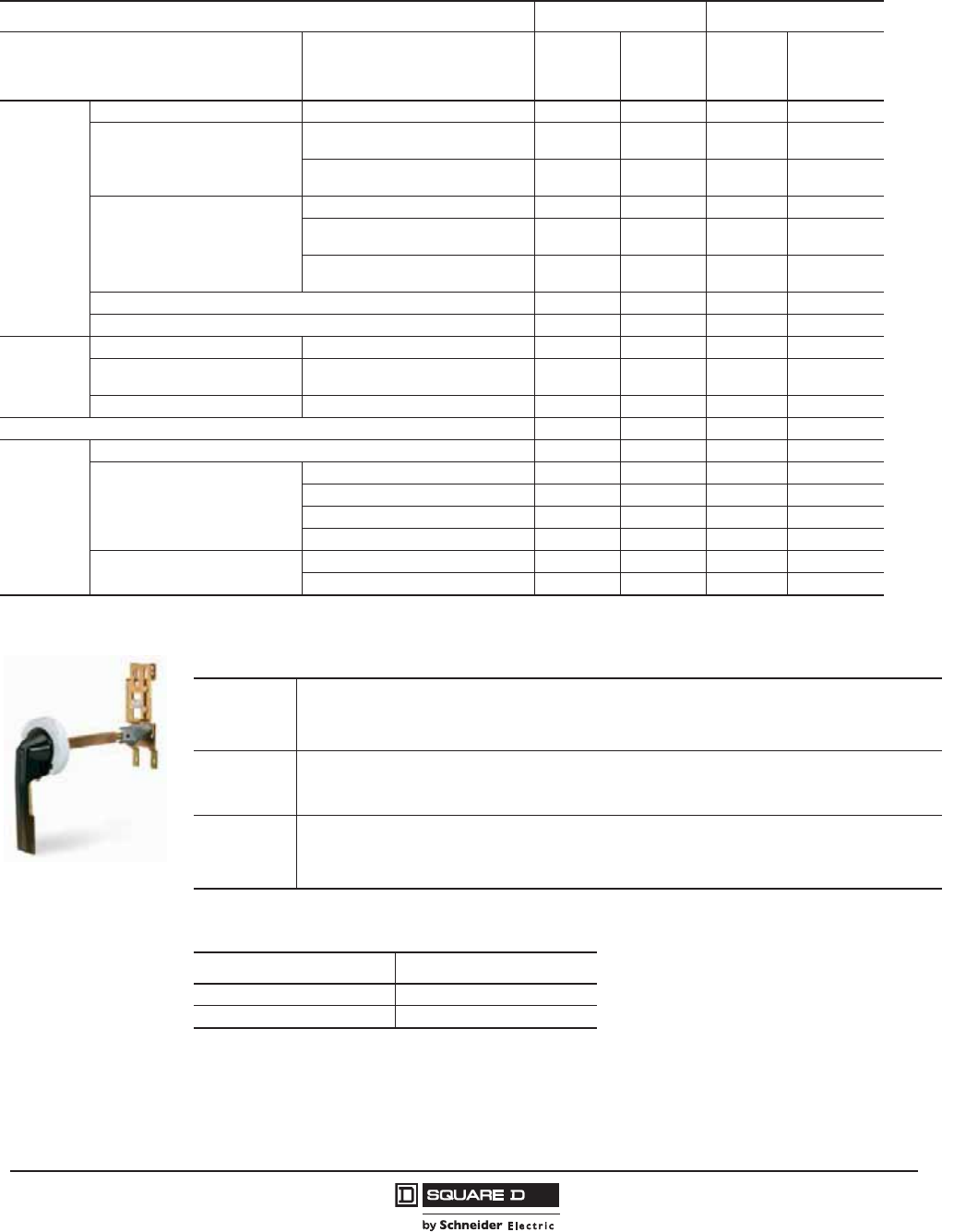
PowerPact™ H-, J-, and L-Frame Circuit Breakers
Accessories and Auxiliaries
103
05/2012
© 2011–2012 Schneider Electric
All Rights Reserved
™
Class 9421 NEMA Door Mounted Rotary Operating Handles
Table 89: Rotary Operated Handles
H- and J-Frame L-Frame
Device Description
Factory
Installed
Suffix
Field
Installable
Kit No.
Factory
Installed
Suffix
Field
Installable
Kit No.
Direct
Mounted
Standard Handle Black Handle only RD10 S29337 RD10 S32597
Standard Black Handle with
One early-break switch RD12 S29337 +
S29345 RD12 S32597 +
S32605
Two early-make switches RD13 S29337 +
S29346 RD13 S32597 +
S29346
Red handle on yellow bezel
Handle Only RD20 S29339 RD20 S32599
One early-break switch RD22 S29339 +
S29345 RD22 S32599 +
S32605
Two early-make switches RD23 S29339 +
S29346 RD23 S32599 +
S29346
MCC Conversion Accessory — S429341 — S32606
CNOMO Conversion Accessory — S29342 — S32602
Door Mounted
Standard black handle Handle Only RE10 S29338 RE10 S32598
Standard Black Handle with: Two early make switches RE13 S29338 +
S29345 RE13 S32598 +
S32605
Red handle on yellow bezel Handle Only RE20 S29340 RE20 S32600
Telescoping RT10 S29343 RT10 S32603
Accessories
Key lock adapter — S429344 — S32604
Key locks
Ronis 1351.500 — S41940 — S41940
Profalux KS5 B24 D4Z — S42888 — S42888
2 Ronis keylocks with 1 key — S41950 — S41950
2 Profalux keylocks with 1 key — S42878 — S42878
Indication Auxiliary Switch One early-break switch — S29345 — S32605
Two early-make switches — S29346 — S29346
Installation
The extended rotary operating handle is made up of:
• A mounting plate that provides a rotary actuator for a standard toggle circuit breaker
• Handle assemblies available for NEMA 3, 3R, 4, and 4X
• Available in standard or short (3 in.) handle assemblies
Operation
The door mounted operating handle makes it possible to operate circuit breakers installed in enclosure from the front.
Provides ON (I) and OFF (O) indication
The circuit breaker may be locked in the off position
Shaft Length
The shaft length is the distance between the back of the circuit breaker and the door:
• Minimum mounting depth is 5.5 in. (138 mm)
• Maximum mounting depth is 10.75 in. (273 mm) with standard shaft
• Maximum mounting depth is 21.3 in. (543 mm) with long shaft
H- and J-Frame Class 9421 Door-Mounted Operating Mechanism
Description Catalog No.
Standard Shaft Kit 9421LJ1
Long Shaft Kit 9421LJ4
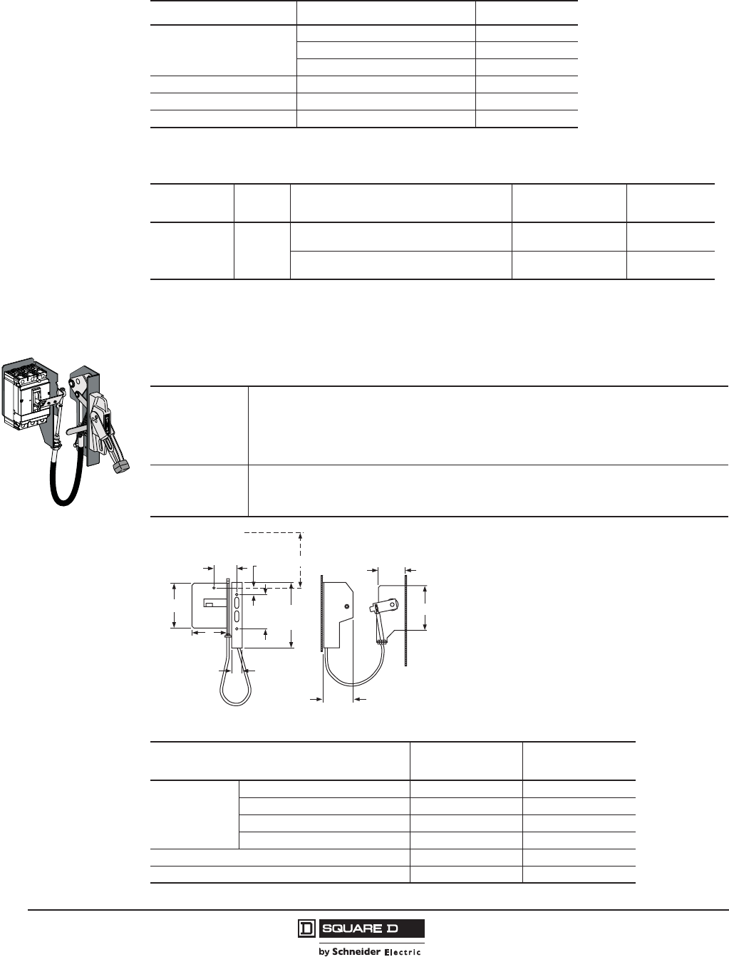
© 2011–2012 Schneider Electric
All Rights Reserved
PowerPact™ H-, J-, and L-Frame Circuit Breakers
Accessories and Auxiliaries
104
05/2012
™
Class 9422 Cable Operating Handle
Flange-mounted handle cable operating mechanism is for use with Class 9422 Type A handle
operators especially designed for tall, deep enclosures where placement flexibility is required.
Table 90: H- and J-Frame Component Parts
Description Catalog No.
Standard Handle Assembly
Type 1, 3R, 12 9421LH6
NEMA Type 3 and 4, Painted 9421LH46
NEMA Type 3 and 4, Chrome Plated 9421LC46
Operating Mechanism Includes Lockout 9421LJ7
Standard Shaft Support Bracket Not Required 9421LS8
Long Shaft Support Bracket Included 9421LS13
Table 91: L-Frame NEMA Door-Mounted Rotary Operated Handles
Handle Type Poles Operating Mechanism Included in Kit Mounting Depth
Min–Max Kit Number
Painted 6 in. 3
9421LS8 and 9421LC46 7-1/4 to 12-1/16 in.
(184 to 306 mm) 9421LD1
9421LS13 and 9421LH46 7-1/4 to 22-5/8 in.
(184 to 575 mm) 9421LD4
F
Applications
• The cable operator maintains:
Suitability for isolation
Indication of three positions: O (OFF), I (ON) and tripped
Access to push-to-test
• The circuit breaker may be locked in the off position by one to three padlocks
• Door can be locked closed due to interlocking features of the handle operator
Installation
• Handle is mounted on flange of enclosure using specified mounting dimensions while circuit breaker and
operating mechanism are mounted to inside of enclosure using two screws
• Cable lengths available in 3-, 5- or 10-foot lengths to accommodate a variety of mounting locations
Handles are available in painted NEMA 1, 3, 3R, 4 (sheet steel) and 12 ratings or chrome (NEMA 4, 4x)
Table 92: Class 9422 Cable Operating Mechanisms and A1 Handles
Description H- and J-Frame
Kit Number
L-Frame
Kit Number
Cable Mechanism
Length
36 in. (914 mm) 9422CSF30 9422CSJ30
60 in (1524 mm) 9422CSF50 9422CSJ50
84 in. (2134 m) 9422CSF70 —
120 in. (3048 mm) 9422CSF10 9422CSJ10
A1 painted flange handle — 9422A1
Operating Mechanism Only — 9422RSI
1.44
(37)
9.12
(232)
4.25
(108)
4.69
(119)
1.00
(25)
CA
B
X
E
D
06113534
Refer to NEC Article 430-10 for minimum dimension X from
circuit breaker top mounting hole to wall or barrier to ensure
adequate wire bending space.
Note: Bend radius in cable must never be less than 6 in. (152
mm). Electrical clearances must be maintained between cable
and live electrical parts.
in.
[mm]
Dimensions:
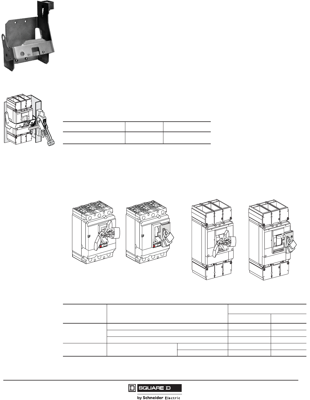
PowerPact™ H-, J-, and L-Frame Circuit Breakers
Accessories and Auxiliaries
105
05/2012
© 2011–2012 Schneider Electric
All Rights Reserved
™
Class 9422 Flange-Mounted Variable-Depth Operating
Mechanism
Designed for installation in custom built control enclosures where main or branch circuit protective
devices are required.
•All circuit breaker operating mechanisms are suitable for either right- or left-hand flange mounting,
convertible on the job.
•H- and J-frame variable mounting depth range: 5.88–17.75 in. (149–451 mm).
•H- and J-frame operating mechanism 9422RQ1 does not include handle mechanism.
Designed for installation in custom-built control enclosures where main or branch circuit protective
devices are required. All circuit breaker operating mechanisms are suitable for either right- or left-hand
flange mounting, convertible in the field.
Locking Systems
Padlocking systems can receive up to three padlocks with diameters of 0.19–0.31 in. (5–8 mm);
padlocks not supplied.
06113535
Threaded-rod flange-mounted
variable depth operating
mechanism
push
to
trip
06163063
Table 93: L-Frame Flange-Mounted Operating Mechanism
Description Depth Kit Number
Variable Depth Mechanism 9.00–17.75 in.
(229–451 mm) 9422RSI
Table 94: Device Locking, Interlocking Options
Device Description
Field-Installed Cat. No.
H- and J-Frame L-Frame
Handle
Padlocking
Device1
1Rotary handles and motor operators have integral padlocking capability.
Removable (lock OFF only) S29370 S29370
Fixed (lock OFF or ON) S29371 S32631
Fixed (lock OFF only)2
2Not available in HD or HG 2P modules.
S37422 NJPAF
Key Locking Provision and 2 locks keyed alike Ronis — S41950
Profalux — S42878
Removable Attachment
06113316
Fixed Padlock Attachment
push
to
trip
Removable Attachment
06163065
push
to
trip
Fixed Padlock Attachment
H- and J-Frame L-Frame
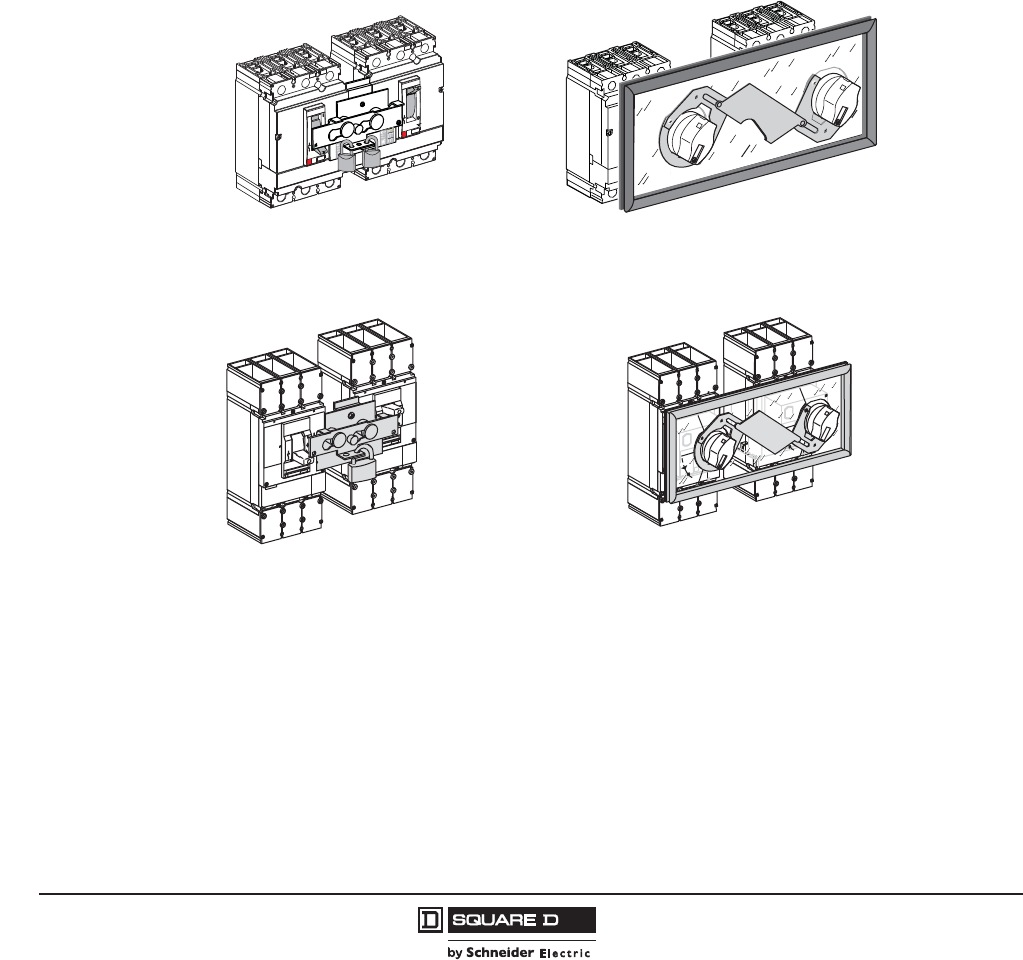
© 2011–2012 Schneider Electric
All Rights Reserved
PowerPact™ H-, J-, and L-Frame Circuit Breakers
Accessories and Auxiliaries
106
05/2012
™
Manual Mechanical Interlocking Systems
Some installations use two power supply sources to counter any temporary loss in the main supply. A
mechanical interlocking system is required to safely switch between the two sources. The replacement
source can be a generator set or another network.
Managing multiple power sources can be controlled manually by mechanical interlocks.
The mechanical interlocking system is made up of:
•two H-, J-, or L-frame devices (circuit breakers or switches) controlled manually
•mechanical interlocking, which prevents handle movement from the Off position while the other
device is in the On position.
Since it is controlled manually by a maintenance technician, switchover time from the normal source to
the replacement source can vary.
Figure 4: Interlocking Systems
H- and J-Frame
L-Frame
Interlocking with Toggle Control (S29354)
06113319
Interlocking with Rotary Handles (S29369)
06113320
push
push
to
trip
06163066
push
to
trip
push
to
trip
push
to
trip
ON
I
O
OFF
push
to
trip
ON
I
O
OFF
ON
I
O
tripped tripped
ON
I
OFF
O
reset
reset
OFF
06163067
Interlocking with Toggle Control (S32614)
Interlocking with Rotary Handles (S32621)

PowerPact™ H-, J-, and L-Frame Circuit Breakers
Accessories and Auxiliaries
107
05/2012
© 2011–2012 Schneider Electric
All Rights Reserved
™
Interlocking of Circuit Breakers With Toggle Control
Two devices can be interlocked using this system. Two identical interlocking systems can be used to
interlock three devices installed side by side.
Authorized positions:
•one device closed (ON), the others open (OFF)
•all devices open (OFF)
The system is locked using one or two padlocks (shackle diameter 0.19–0.31 in. [5 to 8 mm]). This
system can be expanded to more than three devices.
There are two interlocking-system models:
•one for PowerPact H- and J-frame circuit breakers
•one for PowerPact L-frame circuit breakers
All toggle-controlled unit-mount or plug-in PowerPact H-, J-, and L-frame circuit breakers and
automatic switches of the same frame size can be interlocked. The devices must be either all unit-
mount or all plug-in versions. Interlocking is not available for I-Line™ constructions.
The toggle interlock system can receive one or two padlocks with diameters of 0.19–0.31 in. (5–8 mm).
Both interlocked circuit breakers must be unit-mount or both plug-in. Two sliding interlocking bars can
be used to interlock three circuit breakers installed side-by-side, in which case one circuit breaker is in
the ON (I) position and the two others in the OFF (O) position. (Kit S29354. Not available for 2P HD
and HG devices.)
Interlocking of Two Devices with Rotary Handles
Interlocking involves padlocking the rotary handles on two devices which may be either circuit breakers
or automatic switches.
Authorized positions:
•one device closed (ON), the other open (OFF)
•both devices open (OFF).
The system is locked using up to three padlocks (shackle diameter 0.19–0.31 in. [5 to 8 mm]).
There are two interlocking-system models:
•one for PowerPact H- and J-frame circuit breakers
•one for PowerPact L-frame circuit breakers
All rotary-handle unit-mount or plug-in PowerPact H-, J-, and L-frame circuit breakers and automatic
switches of the same frame size can be interlocked. The devices must be either all unit-mount or all
plug-in versions. Interlocking is not available for I-Line constructions
The rotary handles are padlocked with the devices in the OFF (I) position. The interlock mechanism
inhibits the two devices from being closed (ON/I) at the same time, but allows for both devices to be
open (OFF/O) simultaneously. (Kit S29369. Not available for 2P HD and HG devices.)
Table 95: Interlocking Accessories
Accessory Means
Kit Number
H-, J-Frame L-Frame
Interlocking
(UL listed)
Mechanical for circuit breakers with rotary handles1
1Not available in HD or HG 2P modules.
S29369 S32621
Mechanical for circuit breakers with toggles1S29354 S32614
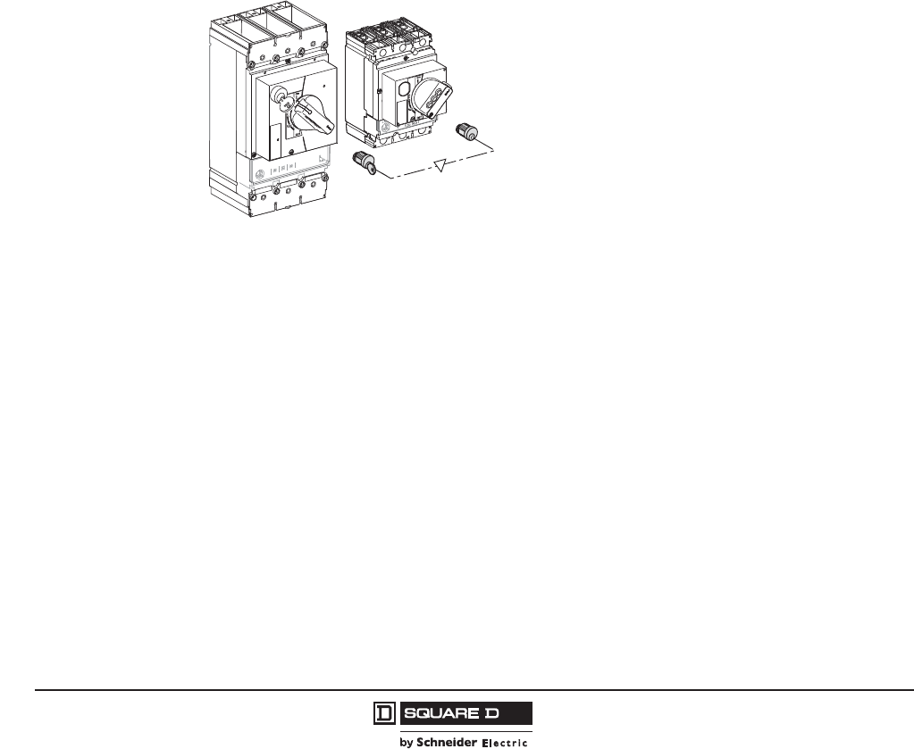
© 2011–2012 Schneider Electric
All Rights Reserved
PowerPact™ H-, J-, and L-Frame Circuit Breakers
Accessories and Auxiliaries
108
05/2012
™
Interlocking Devices using Keylocks (Captive Keys)
Interlocking using keylocks makes it possible to interlock two or more devices that are physically
distant or that have very different characteristics, for example medium-voltage and low-voltage devices
or a PowerPact H-, J-, and L-frame circuit breaker and automatic switch.
Each device is equipped with an identical keylock and the key is captive on the closed (ON) device. A
single key is available for all devices. It is necessary to first open (OFF position) the device with the key
before the key can be withdrawn and used to close another device.
All rotary-handle PowerPact H-, J-, and L-frame circuit breakers and automatic switches can be
interlocked between each other or with any other device equipped with the same type of keylock.
For circuit breakers equipped with rotary handles or a motor operator. Interlocking with keys may be
easily implemented by equipping each of the circuit breakers, either unit-mount or drawout, with a
directly mounted rotary operating handle and a standard keylock, with only one key for the two
keylocks. This solution enables interlocking between two circuit breakers that are geographically
distant or that have significantly different characteristics.
Use:
•A keylock adapter (one required for each circuit breaker)
•Two identical keylocks with a single key
See Table 89 for more information.
Interlocking with Keys
ON
I
06153116
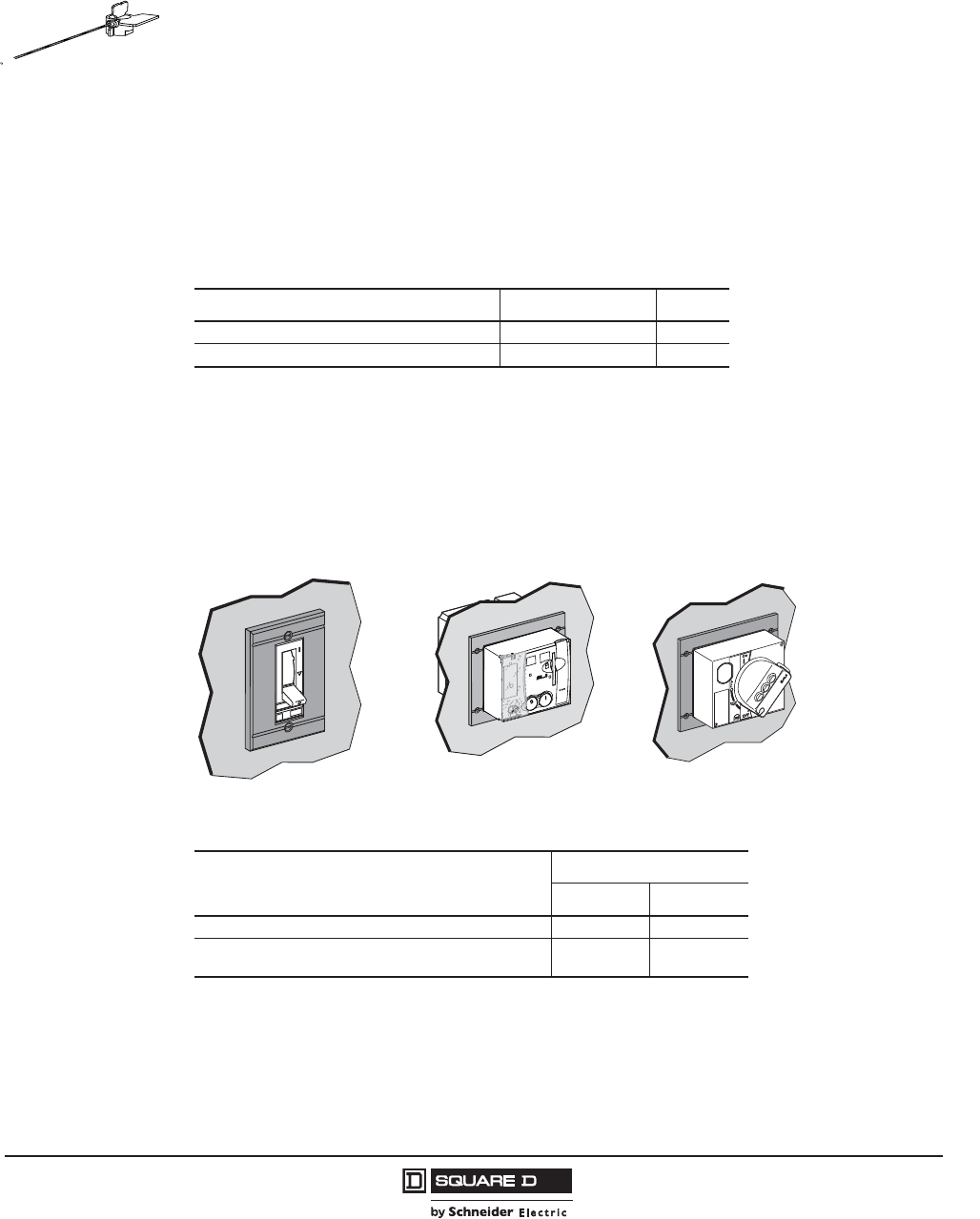
PowerPact™ H-, J-, and L-Frame Circuit Breakers
Accessories and Auxiliaries
109
05/2012
© 2011–2012 Schneider Electric
All Rights Reserved
™
Sealing Accessory
The sealing accessory kits includes the elements required to fit seals to prevent:
•Front accessory cover removal
•Rotary handle removal
•Opening of the motor operator
•Access to accessories
•Access to trip unit settings
•Access to ground-fault protection settings
•Trip unit removal
•Terminal cover removal
•Access to power connections
Front-Panel Escutcheons
•For unit-mount or plug-in installation
•Front-panel escutcheons for toggle handles secures to the panel from the front
•Front-panel escutcheons for motor-operated or rotary-operating handle secures to the panel by
four screws from the front
Table 96: Sealing Accessory Kits
Description Kit No. Qty.
Trip Unit Sealing Accessory Kit MICROTUSEAL 6
Front Cover Screws Sealing Accessory Kit S29375 6
Table 97: Front-Panel Escutcheons
Description
Kit Number
H-, J-Frame L-Frame
Front Panel Escutcheon for Toggle Circuit Breakers S29315 32556
Front Panel Escutcheon for Rotary Handle, Motor Operator
or Extended Escutcheon S29317 S32558
push
to
trip
06153117
2
1
O
push OFF
5...8
I
push ON
O
OFF discharged
2
1
O
push OFF
5...8
I
push ON
O
OFF discharged
06153118
manu auto
O
OFF
ON
I
push
to
trip
06153119

© 2011–2012 Schneider Electric
All Rights Reserved
PowerPact™ H-, J-, and L-Frame Circuit Breakers
Accessories and Auxiliaries
110
05/2012
™
Toggle Collars (For Drawout Mounting)
Toggle collars make it possible to maintain degrees of protection regardless of the circuit breaker
position (connected, disconnected):
•Front panel escutcheons are required (identical to those for rotary handle and ammeter module)
•Toggle collars are secured by two screws on the circuit breaker
•Front panel escutcheons are secured on the enclosure
•Toggle extension is supplied with the toggle collar
Front panel escutcheons for motor operator and rotary operating handles are the same as for the unit-
mount circuit breakers.
Toggle Boot
•NEMA 1, 2, 3, 3R protection
•Fits on front of circuit breaker
Handle Extension
Designed to extend the circuit breaker handle for easier manual circuit breaker operation.
push
to
trip
06153121
Table 98: Toggle Collars
Description H-, J-Frame Kit Number L-Frame Kit Number
Toggle Collar S29284 S32534
06153120
Table 99: Toggle Boot
Description
Kit Number
H-, J-Frame1
1Not available for HD and HG 2P modules
L-Frame
Toggle Boot S29319 S32560
06163078
NS 400-630
06163064
T-Handle
Extension
Toggle
Extension
Table 100: Handle Extensions
Description Qty.
Kit Number
H-, J-Frame L-Frame
T-Handle Extension (Temporary) 1 — 32595
Toggle Extension (Fixed) 5 S29313 S432553
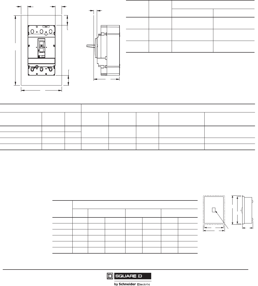
PowerPact™ H-, J-, and L-Frame Circuit Breakers
Accessories and Auxiliaries
111
05/2012
© 2011–2012 Schneider Electric
All Rights Reserved
™
Circuit Breaker Enclosures and Enclosure Accessories
•Square D™ brand circuit breaker enclosures are UL Listed/CSA Certified and are suitable for use
as service entrance equipment, except as footnoted.
•The short circuit rating of an enclosed circuit breaker is equal to the rating of the circuit breaker
installed, except as footnoted.
•Circuit breakers are ordered and shipped separately for field installation.
Table 101: Enclosure Dimensions
Circuit
Breaker Amperage
Enclosure Dimensions (h x w x d)
Standard (80%) 100% Rated
H-Frame 15–150 A 18.13 x 8.63 x 4.13 in.
(461 x 219 x 105 mm)
62 x 14 x 22.5 in.
(1575 x 356 x 572 mm)
J-Frame 150–250 A 28.5 x 12.38 x 5.38 in.
(724 x 314 x 137 mm)
62 x 14 x 22.5 in.
(1575 x 356 x 572 mm)
L-Frame 250–600 A 40.5 x 13.75 x 4.33 in.
(1030 x 350 x 110 mm)
40.5 x 13.75 x 4.33 in.
(1030 x 350 x 110 mm)
48996-053-01
1.00 MIN
[25,4]
1.00 MIN
[25,4]
4.00 MIN
[101,6]
00 MIN
4.00 MIN
[101,6]
h
h
d
Table 102: Circuit Breaker Enclosure Catalog Numbers
Circuit Breaker Enclosure Cat. No.
Cat. No. Prefix Rating Poles NEMA 1
Flush
NEMA 1
Surface
NEMA
3R1
NEMA 4, 4X, 5, 3, 3R
Stainless Steel
NEMA 12/3R, 5
(Without Knockouts)2
HDL,HGL,HJL,HLL 15–150 A 2, 3 J250F J250S J250R J250DS J250AWK
JDL,JGL,JJL,JLL 150–250 A 2, 3
HDL 15–100 A 3 — HD100S3, 4, 5 —— —
JDL 150–250 A 3 — JD250S3, 5, 6 —— —
1Enclosures with NRB or RB suffix have provisions for 3/4 in. through 2-1/2 in. bolt-on hubs in top endwall. Enclosures with R suffix have blank endwalls and require
field cut opening.
2Suitable for rainproof NEMA 3R application by removing drain screw from bottom endwall.
3Copper wire only
4Maximum short circuit current rating is 25 kA, 240 Vac
5Order service ground kit PKOGTA2 if required.
6Maximum short circuit current rating is 18 kA, 480 Vac.
Table 103: Dimensions
Cat. No.
Approximate Dimension
Series H W D
HD100S A01 17.00 in. 431.8 mm 7.90 in. 200.7 mm 4.75 in. 120.7 mm
J250F A01 32.40 in. 823 mm 15.40 in. 391 mm 6.00 in. 152 mm
J250S A01 31.36 in. 797 mm 14.36 in. 365 mm 6.00 in. 152 mm
J250R A01 31.05 in. 789 mm 14.47 in. 368 mm 6.28 in. 160 mm
J250DS A01 32.26 in. 819 mm 9.72 in. 247 mm 7.94 in. 202 mm
J250AWK A01 32.26 in. 819 mm 9.72 in. 247 mm 7.94 in. 202 mm
W
NEMA Type 1
W
D
H
H
WB enclosure
uses 2 circuit breakers
© 2011–2012 Schneider Electric
All Rights Reserved
PowerPact™ H-, J-, and L-Frame Circuit Breakers
Accessories and Auxiliaries
112
05/2012
™
Table 104: Insulated Grounded Neutral Assembly
Circuit Breaker Neutral Assembly For Use With Terminal Lug Data—Total
Available (Line plus Load)
AWG/kcmil
Cat. No. Prefix Ampere
Rating
NEMA 1 & 3R NEMA 4, 4X, 5, 12 & 12K
Cat. No. Cat. No.
HDL,HGL,HJL,HLL 15–100 A SN100FA SN100FA (4) 14–1/0 Cu or (4) 12–1/0 Al
HDL,HGL,HJL,HLL 125–150 A SN400LA SN400LA (2) 1–600 or
(4) 1–250 Al/Cu, plus (2) 4–300 Al/Cu
JDL,JGL,JJL,JLL 150–250 A SN400LA SN400LA (2) 1–600 or
(4) 1–250 Al/Cu, plus (2) 4–300 Al/Cu
Table 105: Service Ground Kits
Circuit Breaker
Cat. No. Prefix
Ground Bar
Cat. No.
Number of
Terminals
Conductors
Per Terminal Wire Range
HDL,HGL,HJL,HLL,
JDL,JGL,JJL,JLL PKOGTJ250 2 1 6 AWG–300 kcmil
Al/Cu
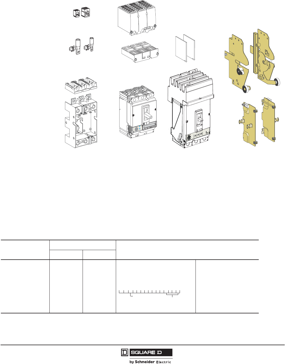
PowerPact™ H-, J-, and L-Frame Circuit Breakers
Circuit Breaker Mounting and Connections
113
05/2012
© 2011–2012 Schneider Electric
All Rights Reserved
™
Section 9—Circuit Breaker Mounting and Connections
Mounting Configurations
The PowerPact H-, J-, and L-frame circuit breakers are available in a variety of configurations.
Refer to circuit breaker installation bulletin before installing circuit breaker, accessories, or wiring.
r
c
i
Mcigolo
E
2
.5
r
I
%
A
0
3
>
0
3
>01
1
>
.9
2
9
.
3
9
.
4
9
.5
9
.
1
8
9
.
7
9
.
6
9
.
Ir )
o
I
x
(
5
.
1
2
5
.
2
34
0
1
8
6
5
d
s
I)
r
I
x
(
C1 C2
MX/SHT
200/240V
5.
1
2
5
.2
34
0
1
8
6
5
.9
2
9.
3
9
.
4
9
.5
9
.
1
8
9
.
7
9
.
6
9
.
0
0
1
0
1
1
5
2
1
0
4
10
6
1
0
5
2
5
2
2
0
0
2
5
7
1
2.
2
c
i
g
o
l
o
r
c
i
M
Ir d
s
I
d
s
I)
r
I
x
(
Ir)
o
I
x
(
o
I)
A
(
r
I
%
A
0
3
>
0
3
>0
1
1
>
Table 106: Mounting Options
Termination Letter
Poles
Options Code Suffix
H-, J-Frame L-Frame
A = I-Line™
F = Bus Bar
L = Lugs on Both Ends
M = Lugs ON End
P = Lugs OFF End
N = Plug-In
D = Drawout
S = Rear Connection
3 Pole Only
3 Pole Only
3 Pole Only
3 Pole Only
3 Pole Only
3 Pole Only
3 Pole Only
3 Pole Only
3 Pole Only
3 or 4 Pole
3 or 4 Pole
3 or 4 Pole
3or 4 Pole
3 or 4 Pole
3 or 4 Pole
3 or 4 Pole
For factory-installed terminations, place
termination letter in the third block of the
circuit breaker catalog number.
(N, and D Terminations Only)
H = Plug-In or Drawout
J = No Stationary part
0 = No Switches
0 = No Shutters
L G D 3 6 4 0 0 E 2 0 H J 0 0
Termination No. Options Code
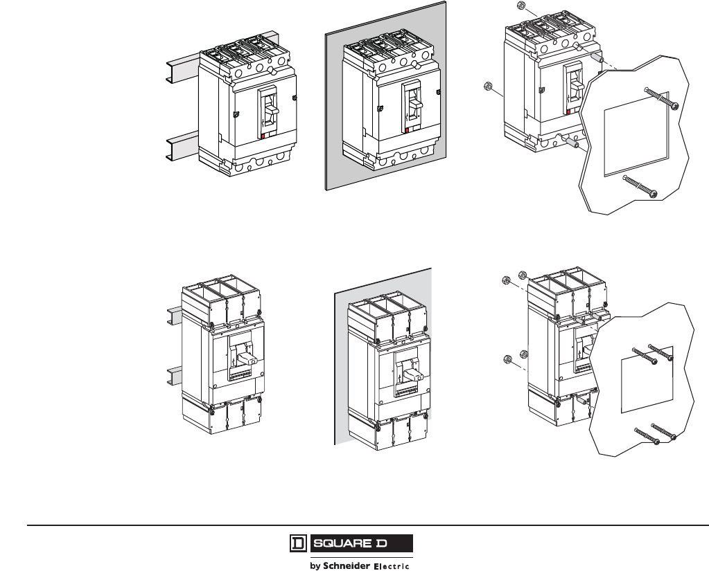
© 2011–2012 Schneider Electric
All Rights Reserved
PowerPact™ H-, J-, and L-Frame Circuit Breakers
Circuit Breaker Mounting and Connections
114
05/2012
™
Unit-Mount Circuit Breakers
The standard lugs can be removed for the installation of compression-type lugs or bus connections. All
lugs are UL Listed/CSA Certified for their proper application and marked for use with aluminum and
copper (Al/Cu) or copper only (Cu) conductors. Lugs suitable for copper and aluminum conductors are
made of tin-plated aluminum.
Mounting
H-, J-, and L-frame circuit breakers may be mounted vertically, horizontally or flat on their back without
any derating of characteristics.
Unit-mount H- and J-frame circuit breakers are supplied with two mounting screws, unit-mount L-frame
circuit breakers are supplied with four mounting screws. These mounting screws are inserted through
mounting holes molded into the circuit breaker case and threaded into the mounting enclosure, rails or
through the panel door for flush mounting.
A DIN rail mounting bracket (catalog no. S29305) is available for the H- and J-frame circuit breakers.
NOTE: DIN rail mounting is not compatible with motor operated applications.
Figure 5: Unit-Mounting Options
L-Frame Circuit Breakers (4 Mounting Screws)
06163057
push
to
trip
06163058
push
to
trip
Mounting on Rails Mounting on Backplate Flush Mounting
06113273
06113274
06113275
push
to
trip
06163056
push
to
trip
H-, J-Frame Circuit Breakers (2 Mounting Screws)
Mounting on Rails Mounting on Backplate Flush Mounting
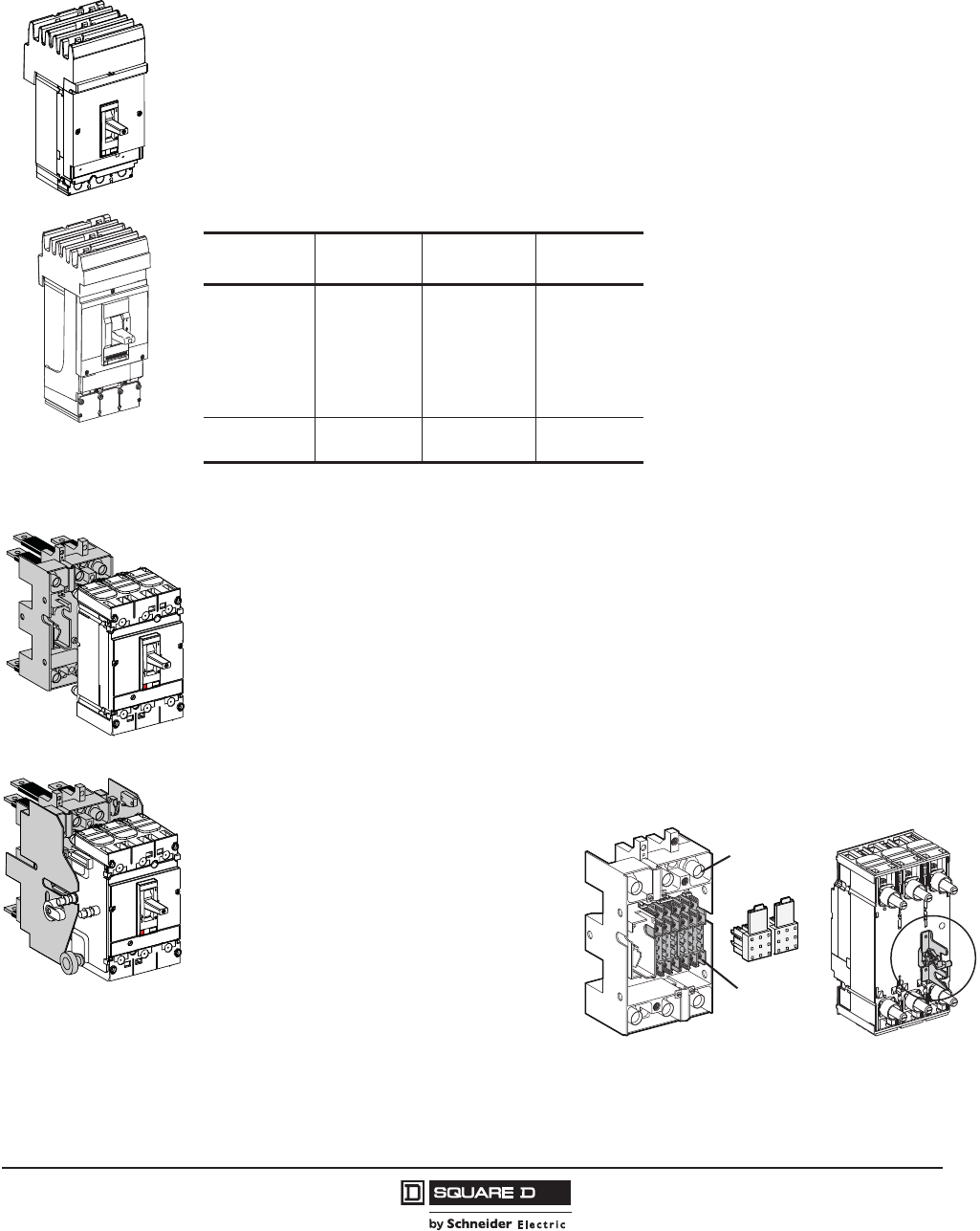
PowerPact™ H-, J-, and L-Frame Circuit Breakers
Circuit Breaker Mounting and Connections
115
05/2012
© 2011–2012 Schneider Electric
All Rights Reserved
™
I-Line™ Circuit breakers
PowerPact H-, J-, and L-frame circuit breakers are available in I-Line construction for easy installation
and removal in I-Line applications.
I-Line circuit breakers use “blow-on” type line side connectors. In case of a short circuit, increased
magnetic flux causes the plug-on connectors of the circuit breaker to tighten their grasp on the bus
bars. The I-Line connectors and circuit breaker mounting bracket are integral parts of I-Line circuit
breakers and cannot be removed or replaced. I-Line circuit breakers come with mechanical load side
lugs, or optional terminal nut to connect to bus bars or to compression (crimp) lugs.
.
Plug-In Circuit Breaker Mounting
The plug-in base is mounted through a panel. The plug-in configuration makes it possible to:
•Extract and/or rapidly replace the circuit breaker without having to touch connections
•Allow for addition of future circuits at a later date
When the circuit breaker is in the connected position, the primary voltage is fed through the circuit
breaker by means of multiple finger disconnects. Control voltage of internal accessories is provided
through secondary disconnects.
Parts of a Plug-In Configuration
•Plug-in Base: The plug-in base provides mounting through a front panel or mounting on rails.
•Disconnects: Provides both primary and
secondary disconnect to the circuit
breaker.
•Safety Trip Interlock: The safety trip
causes automatic tripping if the circuit
breaker is ON before engaging or
withdrawing it; the safety trip does not
prevent the circuit breaker operation, even
when the circuit breaker is disconnected.
•Plug-in Base: The plug-in base provides
mounting through a front panel or mounting
on rails.
•Mandatory short terminal shields
06163048
push
to
Table 107: Phase Options—Example HDA36150
Phase Option
Number
Phase
Connection 2P Example 3P Example
1
2
3
4
5
6
AB
AC
BA
BC
CA
CB
HDA261501
HDA261502
HDA261503
HDA261504
HDA261505
HDA261506
—
—
—
—
—
—
Standard
6
ABC
CBA
—
—
HDA36150
HDA361506
Plug-In Mounting
Drawout Mounting
06113284 06113281
123
4
5
6
7
8
9
123
4
5
6
7
8
9
Secondary
Disconnects
Primary
Disconnects
Safety Trip Interlock
Mounted on Back of
Circuit Breaker
06113311

© 2011–2012 Schneider Electric
All Rights Reserved
PowerPact™ H-, J-, and L-Frame Circuit Breakers
Circuit Breaker Mounting and Connections
116
05/2012
™
Accessory circuits exit the circuit breaker using one to three secondary disconnecting blocks (nine
wires each). Circuit breaker connection wires for the options installed with trip unit STR53UP exit
through the automatic secondary disconnecting blocks. These are made up of:
•A moving part connected to the circuit breaker through a support (one support per circuit breaker)
•A fixed part mounted on the plug-in base, equipped with connectors for wire up to 14 AWG (2.5 mm2)
For test purposes, circuit breakers may be equipped with one to three manual auxiliary connectors,
which allow the auxiliaries to remain connected when in the “disconnected” position.
The L-frame plug-in mounting is Listed under UL file E113555 and Certified under CSA file LR 69561.
Disconnecting Blocks
Manual Auxiliary Connector
Figure 6: Plug-In Base (Mounting Options)
Mounting Through
a Panel Mounting on Rails
06113285
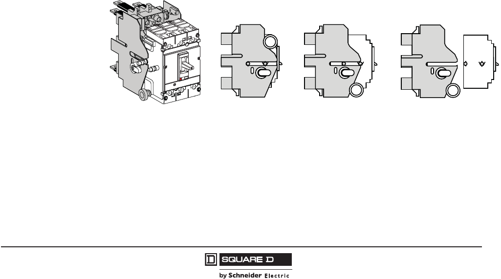
PowerPact™ H-, J-, and L-Frame Circuit Breakers
Circuit Breaker Mounting and Connections
117
05/2012
© 2011–2012 Schneider Electric
All Rights Reserved
™
Drawout Mounting
The cradle is made up of two side plates installed on the plug-in base and two other plates mounted on
the circuit breaker.
The drawout mounting provides all of the functions of the plug-in base, plus:
•Disconnected position—the power circuit is disconnected, the circuit breaker is simply withdrawn
and may still be operated (on, off, push-to-trip)
•Circuit breaker may be locked using 1 to 3 padlocks, diameter 0.19 to 0.31 inch (5–8 mm), to
prevent connection
•Auxiliaries can be tested using manual auxiliary connector
Drawout mounting is on a backplate:
•Through a front panel or on rails
•Horizontally or vertically
Accessories for drawout circuit breakers:
•Auxiliary indicator contacts indicator contacts for installation on the fixed part of the cradle,
indicating the “connected” and “disconnected” position
•Toggle collar for circuit breakers with toggle through front panel, intended to maintain the degree of
protections whatever the position of the circuit breakers (supplied with a toggle extension)
•Keylock which can be used to
— Prevent insertion for connection
— Lock the circuit breaker in the connected or disconnected position
•Telescopic shaft for extended rotary handles
•Control voltage, which is provided through automatic secondary disconnect in the connected
position only. Electrical accessories can be tested in the disconnected position with an external
wiring harness.
The drawout-mounted cradle is listed under UL file E113555 and certified under CSA file LR69561.
Figure 7: Drawout Mounting Positions
Connected Disconnected Removed
06113288

© 2011–2012 Schneider Electric
All Rights Reserved
PowerPact™ H-, J-, and L-Frame Circuit Breakers
Circuit Breaker Mounting and Connections
118
05/2012
™
Table 108: Plug-In and Drawout Mountings for H- and J-Frame Circuit Breakers
(3P or 2P in a 3P module)
Description
Factory
Installed
Suffix
Field-
Installed
Cat. No.
Complete Factory-Assembled
Circuit Breakers
Plug-in base shipped with circuit breaker N —
Drawout cradle shipped with circuit breaker D —
Special Order Options for
Plug-In and Drawout Circuit
Breakers
Plug-In Base Circuit breaker Only HJ00
Plug-in base kit S29278
Drawout
Cradle
Circuit breaker only HJ00
Plug-in base kit S29278
Cradle side plates (fixed part of chassis) S29282
Circuit breaker side plates (moving part of chassis) S29283
Accessories for Plug-In and
Drawout
H-Frame Shutter Kit (set of two) S37442
J-Frame Shutter Kit (set of two) S37443
Secondary
Disconnect
Blocks
Fixed part 9-wire connector (mounted on base) S29273
Moving part 9-wire connector (mounted on circuit breaker) S29274
Support for 2-moving connectors S29275
Extended escutcheon with extended toggle collar S29284
Two position indicating switches (connected/disconnected) S29287
Short Terminal Covers 29321
Table 109: Plug-In and Drawout Mountings for L-Frame Circuit Breakers
Description Poles
Plug-in Mounting Drawout Mounting
Factory
Installed
Suffix
Field-
Installed Factory
Installed
Suffix
Field-
Installed
Qty Kit. No. Qty Kit. No.
Kit (stationary and moving parts) 3N — D —
4N — D —
Stationary Part Plug-in base 3S32514 S32514
4S32515 S32515
Fixed part of chassis S32532
Moving Part
Circuit breaker only HJ00 HJ00
Moving part of chassis S32533
Short terminal covers 32x
1
1Order two of kit.
S32562 2x1S32562
42x
1S32563 2x1S32563
push
to
trip
Handle Escutcheon
Table 110: Plug-In and Drawout Accessories
Plug-In and Drawout Accessories
Field-Installed
Kit No.
H-, J-Frame L-Frame
Secondary Disconnecting Blocks1
1Included when electrical accessories are factory installed.
Fixed Part 9-Wire Connector S29273 S29273
Moving Part 9-Wire Connector S29274 S32523
Support for Moving Connectors 2x2
2Order two of kit.
S29275 3x3
3Order three of kit.
S32525
Manual Auxiliary Connector 9-Wire Connector for Disconnected Operation — S29272
Shutter Two Shutters for Plug-In Base 29271 32521
Classic
Accessories
Extended Escutcheon for Toggle Collar S29284 S32534
Locking Device (Key Lock is Not Included) S29286 S29286
Two Position Indicator Contacts (Connected/Disconnected) S29287 S29287
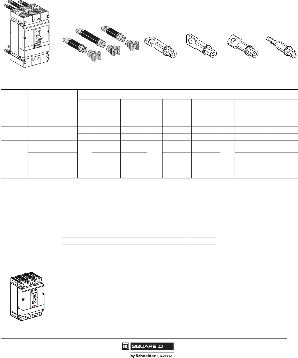
PowerPact™ H-, J-, and L-Frame Circuit Breakers
Circuit Breaker Mounting and Connections
119
05/2012
© 2011–2012 Schneider Electric
All Rights Reserved
™
Connection
Rear Connection
For connection of bus bars or cables with compression lugs. Rear connections are easily installed on
the circuit breaker terminals. The same connection may be installed flat, edgewise or at a 45° angle.
All combinations are possible. The circuit breaker is mounted on a backplate.
Mechanical Lugs
Unit-mount H-, J-, and L-frame circuit breakers can be ordered with mechanical line and load side lugs.
The standard lugs can be removed for the installation of compression-type lugs or bus connections. All
lugs are UL Listed/CSA Certified for their proper application and marked for use with aluminum and
copper (Al/Cu) or copper only (Cu) conductors. Lugs suitable for copper and aluminum conductors are
made of tin-plated aluminum. Lugs suitable for use with copper conductors only are made of copper.
Mechanical Lugs for the H- and J-frame circuit breakers lay on top of the circuit breaker terminals and
can be installed without the use of any tools. The lugs are held in place with snap features built into the
insulating retainer and are secured with the clamp force applied to the wire binding screw.
Mechanical lugs are sold either factory installed or as field installable kits.
push
to
trip
One Long and Two Short Four Positions Possible for Each Connector
Horizontal Vertical 45° Angle
06113278
Table 111: Rear Connections
Device Description
H-Frame J-Frame L-Frame
Poles
Factory-
Installed
Termination
No.
Field-
Installable
Cat. No.
Poles
Factory-
Installed
Termination
No.
Field-
Installed
Cat. No.
Poles
Factory-
Installed
Termination
No.
Field-Installed
Cat. No.
Mixed Rear Connection Kit12 S — 2 S — 3 S S32477
3 S S37432 3 S S37437 4 S S32478
Consisting of:
Short rear connections
(set of 2) 2 or 3
—2x
2S37433
2 or 3
—2x
2S37438
3
—2x
2,3 S432475
Long rear connections
(set of 2) — S37434 — S374394—2x
3S432476
Short terminal cover (3P) 3 — S37436 3 — S37440 3 — 2x5S32562
Short terminal cover (4P) 4 — — — — — 4 — 2x5S32563
1Kit contains four short rear connections, two long rear connections (four long rear connections for 4P), hardware and two terminal covers.
2Order two kits (two in kit x two kits for total of four)
3Parts only, no hardware is included. See Table 112, below.
4For use with 3P circuit breakers only.
5Order two kits (kit contains only one terminal cover, two terminal covers are required per circuit breaker).
Table 112: L-Frame Rear Connection Hardware
Description Cat. No.
Set of 4 M10 x 25 terminal screws and washers for one side. S36967
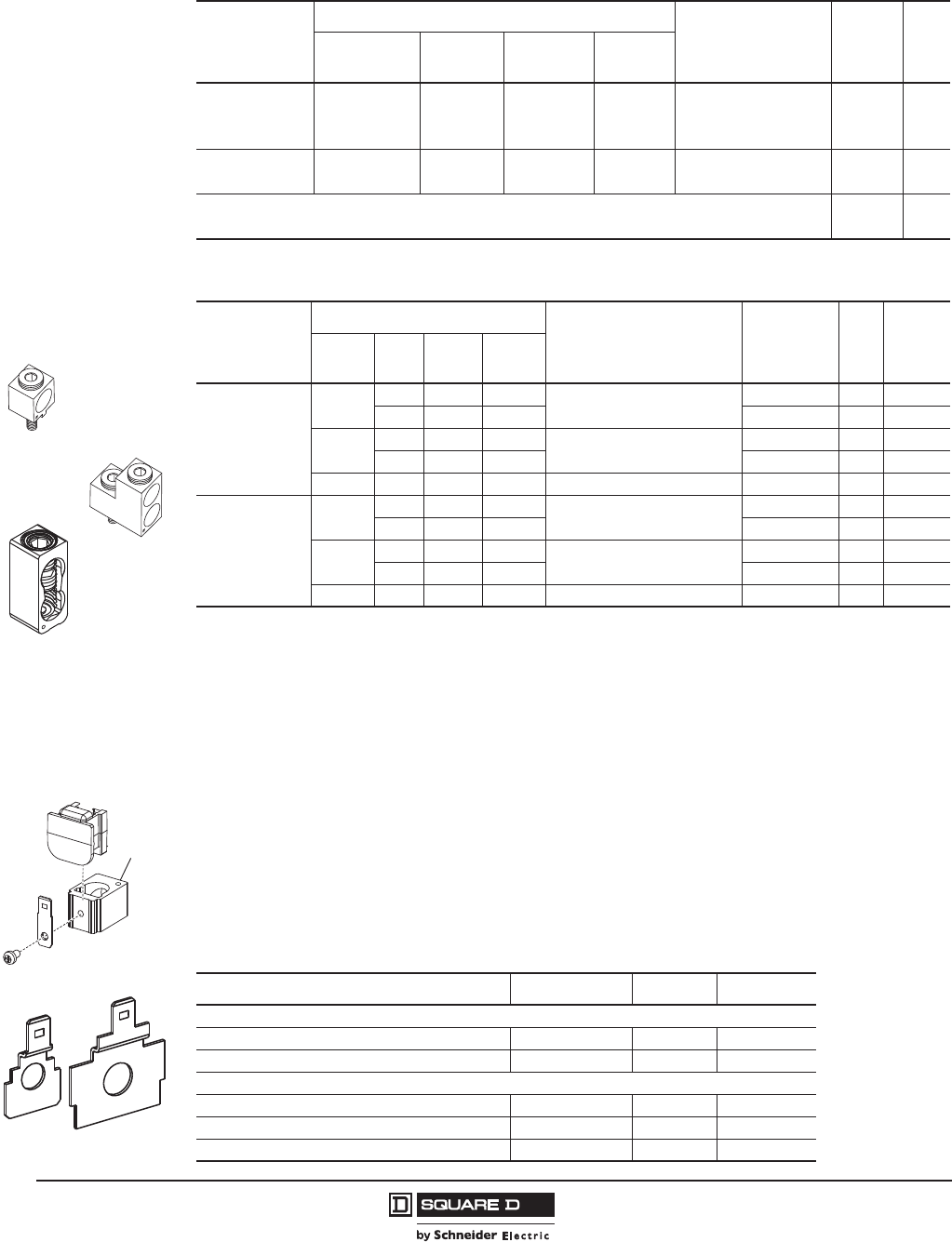
© 2011–2012 Schneider Electric
All Rights Reserved
PowerPact™ H-, J-, and L-Frame Circuit Breakers
Circuit Breaker Mounting and Connections
120
05/2012
™
Voltage Takeoff (Control Wire Terminals) for Mechanical Lugs and
Terminal Nuts
Powerpact H- and J-Frame mechanical lugs may be equipped with a separate control wire termination.
The kit is available factory installed or as a field installable kit. The adaptor is secured underneath the
lug and has a tab extension suitable for attachment of a 0.250 inch slip-on connector.
All L-frame mechanical lugs are pre-tapped for control wires. For control wire installation, use an 8-32
x 1/4 in. screw (not provided) into tapped control wire hole in lower left hand corner of the lug.
Fully insulated type connectors must be used to prevent live parts from extending into the wiring gutter
area.
Table 113: Mechanical Lug Kits for H-Frame and J-Frame Circuit Breakers
Circuit Breaker Application Number of Wires
Per Lug and Wire
Range
Kit Cat.
No.
Qty
Per
Kit
Standard Ampere
Rating Optional Ampere
Rating
Al Lugs for Use
with Al or Cu Wire
HD, HG, HJ, HL 15–150 A (1) 14–3/0 AWG Al or Cu AL150HD 3
JD, JG, JJ, JL 150–175 A (1) 4-4/0 AWG Al or Cu AL175JD 3
JD, JG, JJ, JL 200–250 A JD,JG,JJ,JL 150–175 A (1) 3/0–350 kcmil Al or Cu AL250JD 3
Cu Lugs for Use
with Cu Wire Only
HD,HG,HJ,HL 15–150 A (1) 14–2/0 AWG Cu CU150HD 3
JD,JG,JJ,JL 150–250 A (1) 1/0–300 kcmil Cu CU250JD 3
Control Wire Terminal for H-frame lug kit S37423 2
Control Wire Terminal for J-frame lug kit S37424 2
Table 114: Mechanical Lug Kits for L-Frame Circuit Breakers1
1For lug pack information, see Figure 31 on page 157.
Circuit Breaker Application
Number of Wires
Per Lug and Wire Range2
2For control wire installation, use an 8-32 x 1/4 in. screw (not provided) into tapped control wire hole in lower left hand corner of lug.
Kit Cat. No.
Qty
Per
Kit
Type of
Termina
l Shield3
3For terminal shield dimensions, see Figure 31 on page 157.
Ampere
Rating Poles Unit
Mount I-Line™
Al Lugs for Use
with Al or Cu Wire
250 3X X
(1) 2 AWG–500 kcmil Al
(1) 2 AWG–600 kcmil Cu
AL400L61K3 3Short
4X — AL400L61K4 4Short
400/600 3X —
(2) 2/0 AWG–500 kcmil Al or Cu AL600LS52K3 3 Medium
4X — AL600LS52K4 4 Medium
400/600 3 X X (2) 3/0 AWG–500 kcmil Al or Cu AL600LF52K3 3Short
Cu Lugs for Use
with Cu Wire Only
250/400 3X X
(1) 2 AWG–500 kcmil Al
(1) 2 AWG–600 kcmil Cu
CU400L61K3 3Short
4X — CU400L61K4 4Short
400/600 3X —
(1) 2/0 AWG–500 kcmil Al or Cu CU600LS52K3 3 Medium
4X — CU600LS52K4 4 Medium
400/600 3 X X (1) 3/0 AWG–500 kcmil Al or Cu CU600LF52K3 3Short
06163037
600 A Lug
AL600LS52K3
06163038
600 A Lug
AL600LF52K3
400 A Lug
AL400L6IK3
06114127
06113294
Mechanical Lug Control
Wire Terminal
Busbar Control Wire
Terminal
Control
Wire
Hole
Table 115: Control Wire Terminals
Description Frame Cat. No. Qty Per Kit
Mechanical Lugs
Control Wire Terminal for H-Frame Lugs HD/HG/HJ/HL S37423 2
Control Wire Terminal for J-Frame Lugs JD/JG/JJ/JL S37424 2
Busbar Connection
Control Wire Terminal for H-Frame Terminal Nut HD/HG/HJ/HL S37429 2
Control Wire Terminal for J-Frame Terminal Nut JD/JG/JJ/JL S37430 2
Control Tap takeoff L-Frame 29348 2
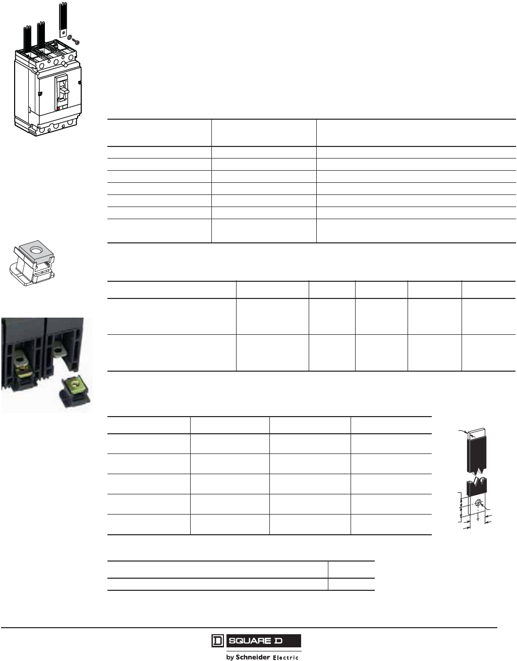
PowerPact™ H-, J-, and L-Frame Circuit Breakers
Circuit Breaker Mounting and Connections
121
05/2012
© 2011–2012 Schneider Electric
All Rights Reserved
™
Bus-Bar Connections
The H-, J- and L-frame circuit breakers may be equipped with captive nuts and screws for direct
connection to bars or to compression (crimp) lugs
For H- and J-frame, these are readily field-installable, simply by removing the mechanical lug and
replacing with the appropriate terminal nut inset described in Table 116. They are also available
factory-installed, using the Product Selector or by using the catalog suffixes below.
For L-frame, the mechanical lug can be removed, leaving the threaded nut insert intact. This
configuration may be ordered with the suffixes described below. Connection hardware (terminal
screws) must be ordered as in table 116.
06113279
Terminal Nut Insert
Table 116: Factory-Installed Terminal Nut Inserts for Bus or Crimp Lug Connection
Cat. No. Termination
(Position 4)
Special Terminations
Options Description
F Terminal nut insert on both ends; no lugs either end
M Terminal nut insert on OFF end; lugs on ON end only
P Terminal nut insert on ON end; lugs on OFF end only
A -TA I-Line™ on ON end; English terminal nuts on OFF end1
1For H- and J-frame only. L-frame terminal nuts are metric only.
A -TB I-Line on ON end; Metric terminal nuts on OFF end1
F, M, or P -TW For -F-, Metric terminal nuts on both ends1
F, M, or P -TX For -M, lugs on ON end; Metric terminal nuts on OFF end
For -P, Metric terminal nuts on ON end; lugs on OFF end
Table 117: Terminal Nuts for Bus Bar Connection of H-Frame and J-Frame Circuit Breakers
Description1
1Screws not included.
Frame Tap Cat. No. Qty Per Kit Torque
H-Frame Terminal Nut Insert–English HD/HG/HJ/HL 1/4-20 S37425 2
80–90 lb-in
(9–10.2 N•m)
H-Frame Terminal Nut Insert–English HD/HG/HJ/HL 1/4-20 S37444 3
H-Frame Terminal Nut Insert–Metric HD/HG/HJ/HL M6 S37426 2
J-Frame Terminal Nut Insert–English JD/JG/JJ/JL 1/4-20 S37427 2
80–90 lb-in
(9–10.2 N•m)
J-Frame Terminal Nut Insert–English JD/JG/JJ/JL 1/4-20 S37445 3
J-Frame Terminal Nut Insert–Metric JD/JG/JJ/JL M8 S37428 2
Table 118: Bar Dimensions
Dimension H-Frame J-Frame L-Frame
A0.250 in.
(6.4 mm)
0.3125 in.
(7.9 mm)
0.4 in.
(10 mm)
B0.125–0.375 in.
(3.2–9.5 mm)
0.125–0.375 in.
(3.2–.5 mm)
0.11–0.39 in.
(3–10 mm)
C0.50 in.
(12.7 mm)
0.50–0.75 in.
(12.7–1.1 mm)
1.35 in.
(32 mm)
D0.3 in.
(7.6 mm)
0.625 in.
(15.9 mm)
<0.51 in.
13 mm)
E0.3 in.
(7.6 mm)
0.375 in.
(9.5 mm)
0.64 in.
(16 mm)
Table 119: L-Frame Bus Bar Connections Hardware
Description Cat. No.
Set of 4 M10 x 25 terminal screws and washers for one side. S36967
==
D
EC
A Ø
B
06113283
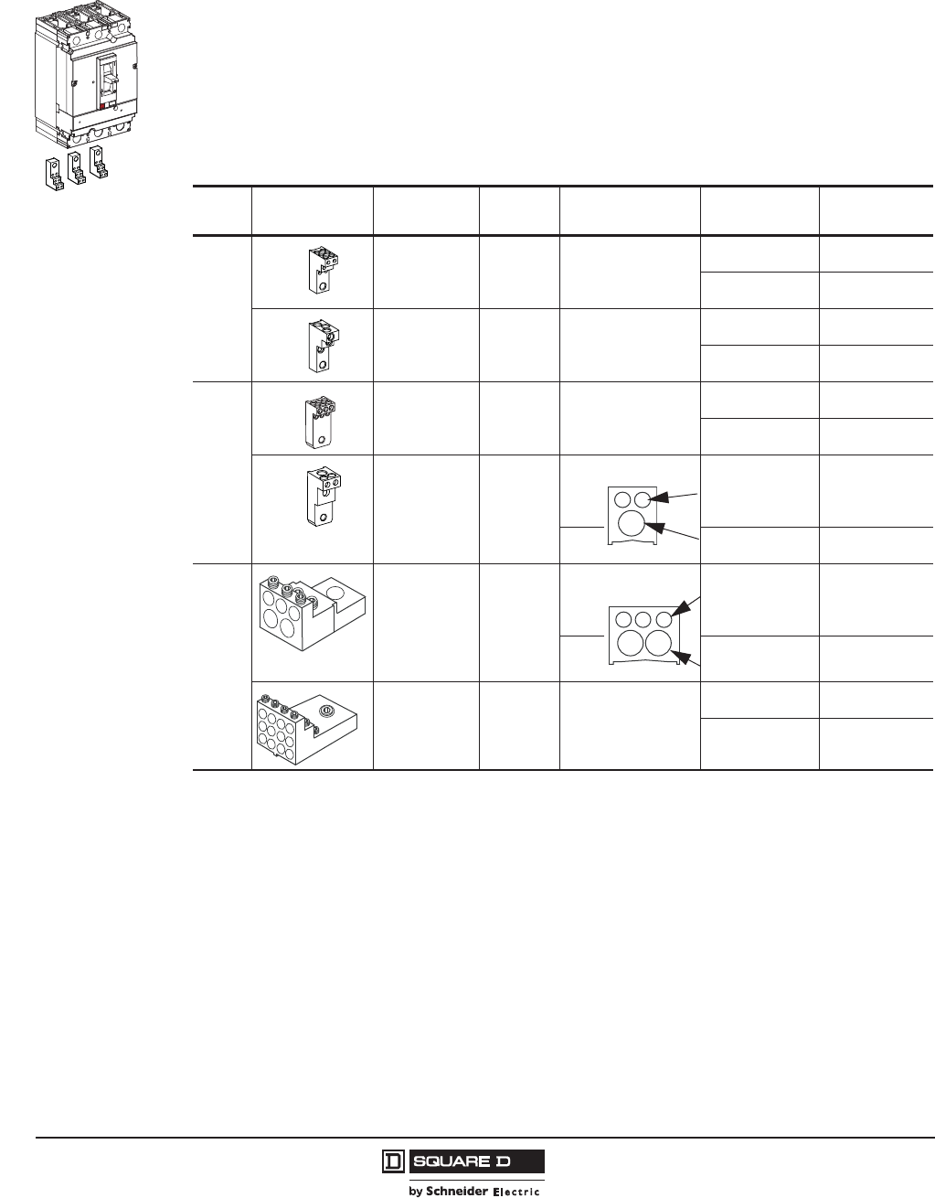
© 2011–2012 Schneider Electric
All Rights Reserved
PowerPact™ H-, J-, and L-Frame Circuit Breakers
Circuit Breaker Mounting and Connections
122
05/2012
™
Power Distribution Connectors
The power distribution connectors (PDC) can be used for multiple load wire connections on one circuit
breaker. Use in place of standard distribution blocks to save space and time. Field installable kit
includes tin-plated aluminum lug, connectors, and required mounting hardware.
•For use on load end of circuit breaker only
•For use in UL 508 Industrial Control applications
•For use in UL 1995/CSA C22.2 No. 236 heating and cooling equipment
•For copper wire only
See Table 123 for the phase barriers for power distribution connectors.
06113295
Table 120: Power Distribution Connectors
Frame Kit Number Qty per
Kit Wires per Terminal Wire Range Wire Binding
Screw Torque
H-Frame
PDC6HD6 16
8–6 AWG
(10–16 mm2)
25 lb-in
(2.8 N•m)
14–10 AWG
(2.5–6 mm2)
20 lb-in
(2.3 N•m)
PDC3HD2 13
2 AWG
(35 mm2)
40 lb-in
(4.5 N•m)
14–3 AWG
(2.5–35 mm2)
35 lb-in
(4.0 N•m)
J-Frame
PDC6JD4 16
8–4 AWG
(10–25 mm2)
35 lb-in
(4.0 N•m)
14–10 AWG
(2.5–6 mm2)
20 lb-in
(2.3 N•m)
PDC3JD20 1
3 total
2
14–6 AWG Cu
(2.5–16 mm2) or
4–1 AWG Cu
(25–50 mm2)
35 lb-in
(4.0 N•m)
40 lb-in
(4.5 N•m)
and 1 3–2/0 AWG Cu
(35–70 mm2)
50 lb-in
(5.6 N•m)
L-Frame
PDC5DG20L3 1
1Kit includes terminal shield.
3
5 total
3
4–1 AWG
(25–50 mm2) or
14–6 AWG
(2.5–16 mm2)
40 lb-in
(4.5 N•m)
35 lb-in
(4.0 N•m)
and 2 3–2/0 AWG
(35–70 mm2)
50 lb-in
(5.6 N•m)
PDC12DG4L3 1312
8–4 AWG
(10–25 mm2)
35 lb-in
(4.0 N•m)
14–10 AWG
(2.5–6 mm2)
20 lb-in
(2.3 N•m)
06113296
06113297
06113298
06113299
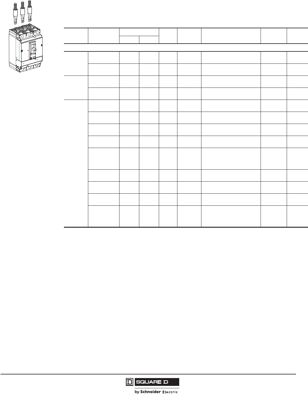
PowerPact™ H-, J-, and L-Frame Circuit Breakers
Circuit Breaker Mounting and Connections
123
05/2012
© 2011–2012 Schneider Electric
All Rights Reserved
™
Compression Lugs
Both copper and aluminum compression lug kits are available for the H-, J-, and L-frame circuit
breakers. Each kit contains required insulators and all mounting hardware. Compression lugs require
the long lug cover pack, see Figure 31 on page 157.
06113300
Table 121: Compression Lug Kits for Al/Cu Connectors
Circuit
Breaker Lug Kit Rating @ 75 C Poles Wires
per Lug Wire Range Lugs per
Terminal
Lugs
per Kit
Al Cu
Al/Cu Connectors
H-Frame
YA060HD d60 A d60 A 3 1 6–2 AWG Cu or Al
(16–35 mm2)13
YA150HD d150 A d150 A 3 1 1/0–4/0 AWG Cu or Al
(50–95 mm2)13
J-Frame
YA150JD d200 A d200 A 3 1 1–3/0 AWG Cu or Al
(50–95 mm2)23
YA250J35 d250 A d250 A 3 1 3/0 AWG–350 kcmil Cu or Al
(95–185 mm2)23
L-Frame
YA400L31K3 230 A 285 A 3 1 4-300 kcmil Al/Cu
(25–150 mm2)13
YA600L32K3 460 A 570 A 3 2 4-300 kcmil A/Cu
(25–150 mm2)26
YA400L51K3 310 A 380 A 3 1 2/0-500 kcmil A/Cu
(70–240 mm2)13
YA600L52K3 620 A 760 A 3 2 2/0-500 kcmil Al/Cu
(70–240 mm2)26
YA400L71K3 385 A 475 A 3 1
500-750 kcmil A
(240–400 mm2)l
500 kcmil Cu
(240 mm2)
13
YA600L32K4 460 A 570 A 4 2 4-300 kcmil A/Cu
(25–150 mm2)18
YA400L51K4 310 A 380 A 4 1 2/0-500 kcmil Al/Cu
(70–240 mm2)24
YA600L52K4 620 A 760 A 4 2 2/0-500 kcmil Al/Cu
(70–240 mm2)18
YA400L71K4 385 A 475 A 4 1
500-750 kcmil Al
(240–400 mm2)
500 kcmil Cu
(240 mm2)
24

© 2011–2012 Schneider Electric
All Rights Reserved
PowerPact™ H-, J-, and L-Frame Circuit Breakers
Circuit Breaker Mounting and Connections
124
05/2012
™
Table 122: Compression Lug Kits for Cu Connectors
Circuit
Breaker Lug Kit Rating @ 75 C Poles Wires
per Lug Wire Range Lugs per
Terminal
Lugs
per Kit
Al Cu
H-Frame
CYA060HD —d60 A 3 1 6–1/0 AWG Cu
(16–50 mm2)13
CYA150HD —d150 A 3 1 4–2/0 AWG Cu
(25–70 mm2)13
J-Frame
CYA150JD —d150 A 3 1 4–2/0 AWG Cu
(25–70 mm2)23
CYA250J3 —d250 A 3 1 2/0 AWG–300 kcmil Cu
(70–185 mm2)23
L-Frame
CYA400L31K3 — 285 A 3 1 2/0-300 kcmil Cu
(70–150 mm2)13
CYA600L32K3 — 570 A 3 2 2/0-300 kcmil Cu
(70–150 mm2)26
CYA400L51K3 — 380A 3 1 250-500 kcmil Cu
(150–240 mm2)13
CYA600L52K3 — 760A 3 2 250-500 kcmil Cu
(150–240 mm2)26
CYA400L71K3 — 475 A 3 1
500-750 kcmil Al
(240–400 mm2)
500 kcmil Cu
(240 mm2)
13
CYA400L31K4 — 285A 4 1 2/0-300 kcmil Cu
(70–150 mm2)14
CYA600L32K4 — 570 A 4 2 2/0-300 kcmil Cu
(70–150 mm2)28
CYA400L51K4 — 380 A 4 1 250-500 kcmil Cu
(150–240 mm2)14
CYA600L52K4 — 760 A 4 2 250-500 kcmil Cu
(150–240 mm2)28
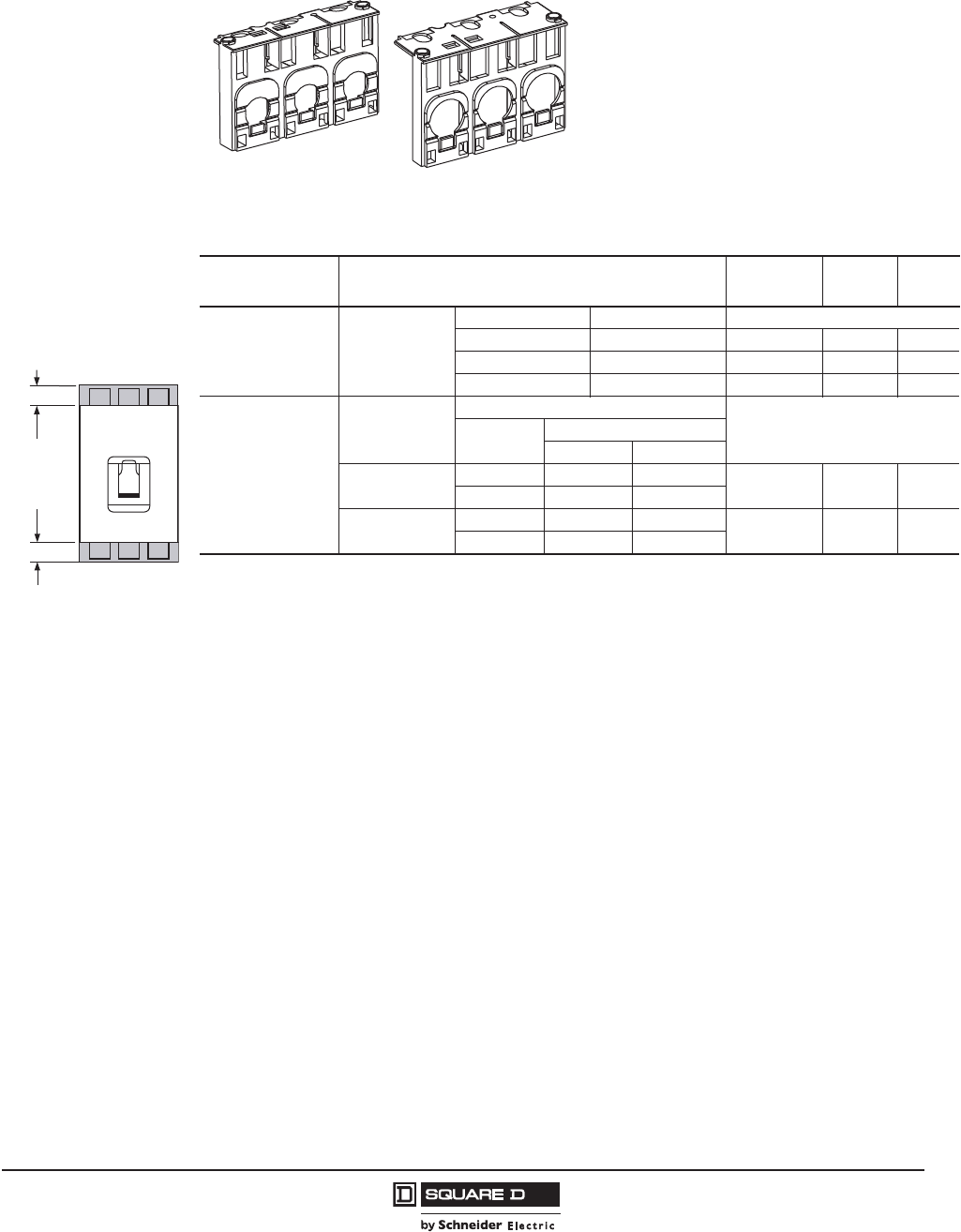
PowerPact™ H-, J-, and L-Frame Circuit Breakers
Circuit Breaker Mounting and Connections
125
05/2012
© 2011–2012 Schneider Electric
All Rights Reserved
™
Terminal Shields
NOTE: L-frame terminal shields are shipped with the mechanical lug kits, see Table 114.
C
Table 123: Terminal Shields and Phase Barriers
Used With Description Dimension
B (in.) Cat. No. Qty Per
Kit
H- and J-Frame
Mechanical Lugs Short Lug Shield
Frame Max. Wire Size
H-Frame 60 A 3 AWG 0.50 S37446 1
H-Frame 150 A 3/0 AWG 0.50 S37447 1
J-Frame 350 kcmil 0.24 S37448 1
H- and J-Frame Power
Distribution
Connectors and
Compression Lugs
Compatible with:
PDC Compression Lugs
Aluminum Copper
H-Frame Long
Lug Shield
PDC6HD6 YA060HD CYA060HD 2.24 S37449 1
PDC3HD2 YA150HD CYA150HD
J-Frame Long Lug
Shield
PDC6JD4 YA150JD CYA150JD 1.68 S37450 1
PDC3JD2 CYA250J3
06113494
H-Frame Short Lug Shield
06113493
J-Frame Short Lug Shield
Extremity
of
Molded Case
w/Mechanical
Lugs
“B” See Table
Phase barrier or
terminal shield
extension past end
of circuit breaker
“B” See Table
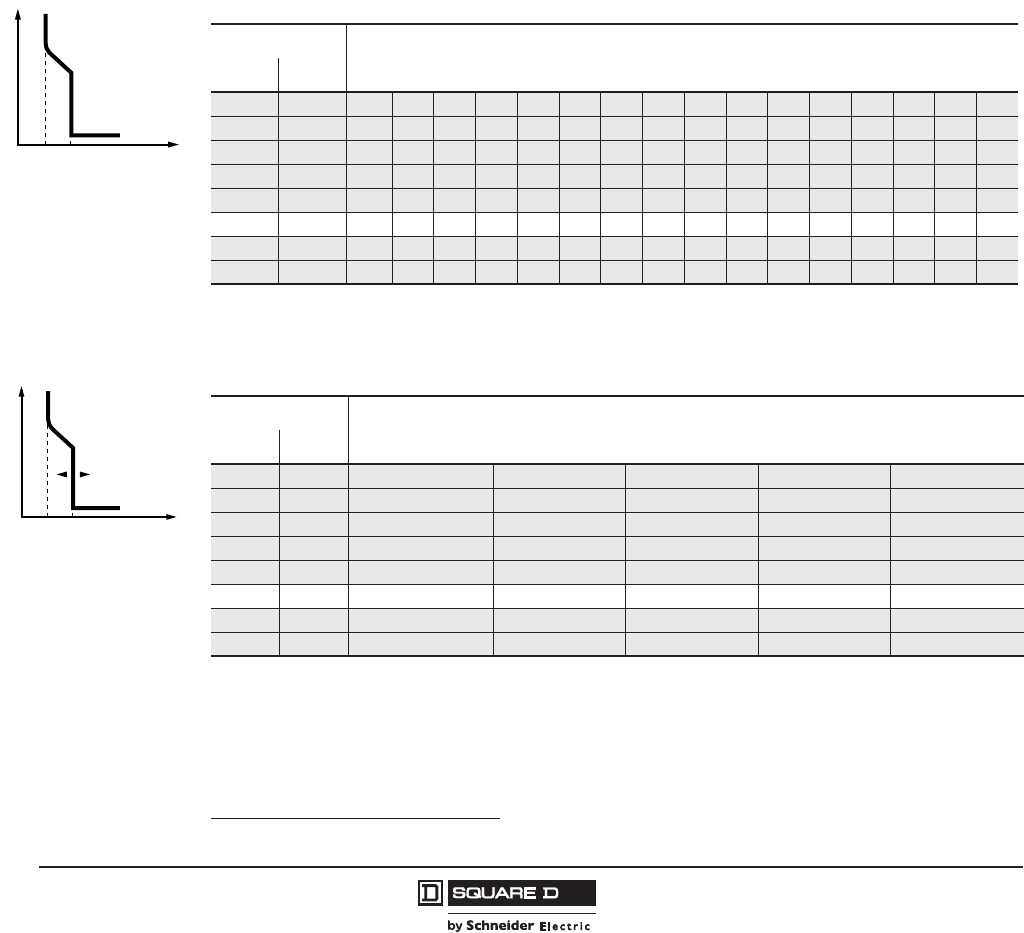
© 2011–2012 Schneider Electric
All Rights Reserved
PowerPact™ H-, J-, and L-Frame Circuit Breakers
Installation Recommendations
126
05/2012
™
Section 10—Installation Recommendations
Operating conditions
Temperature Derating
•PowerPact H-, J-, and L-frame circuit breakers may be used between -13°F and 158°F (-25 °C and
+70 °C). For temperatures higher than 104° F (40° C°) inside the enclosure, devices must be
derated.
•Circuit breakers should be put into service under normal ambient, operating-temperature
conditions.
•The permissible storage-temperature range for PowerPact H-, J-, and L-frame circuit breakers in
the original packing is -58°F1 and 185°F (-50 °C1 and +85 °C).
1 -40°F (-40 °C) for Micrologic™ trip units with an LCD screen.
t
0lnlil
H-Frame Trip Curve
(ln) Fixed threshold thermal
protection against
overload
(li) Fixed threshold
instantaneous protection
against short circuits
06113269
Table 124: Temperature Derating for H-Frame Trip Unit Thermal Protection—Long-Time
Temperature1
1Shaded areas indicate temperature rerated values, non-shaded areas inside an enclosure are standard circuit breaker ampere ratings
at 104° F (40° C°).
Rating (A) In
°C °F
-10 14 23 30 38 46 53 60 68 76 88 103 112 123 137 160 180 221
032 21 28 36 43 49 56 63 71 83 97 107 117 131 151 171 207
10 50 20 26 33 40 46 52 59 66 77 90 101 111 126 141 161 194
20 68 18 24 31 37 42 48 54 62 72 84 96 105 120 132 152 180
30 86 17 22 28 34 39 44 50 56 66 77 88 98 110 121 139 165
40 104 15 20 25 30 35 40 45 50 60 70 80 90 100 110 125 150
50 122 12 17 21 25 30 34 38 43 53 62 72 80 86 95 109 131
60 140 914 17 20 24 28 31 35 46 53 63 70 72 80 93 111
t
0lnlml
J-Frame Trip Unit
(ln) Fixed threshold thermal
protection against
overload
(lm) Adjustable instantaneous
protection against short
circuits
06113270
Table 125: Temperature Derating for J-Frame Trip Unit Thermal Protection—Long-Time
Temperature1
1Shaded areas indicate temperature rerated values, non-shaded areas are standard circuit breaker ampere ratings at 104° F (40° C°).
Rating (A) In
°C °F
-10 14 221 264 289 330 377
032 207 247 273 310 354
10 50 194 230 256 290 330
20 68 180 213 240 270 307
30 86 165 194 220 248 279
40 104 150 175 200 225 250
50 122 131 150 176 193 214
60 140 111 124 151 160 177

PowerPact™ H-, J-, and L-Frame Circuit Breakers
Installation Recommendations
127
05/2012
© 2011–2012 Schneider Electric
All Rights Reserved
™
PowerPact H-, J- and L-Frame Circuit Breakers Equipped with Electronic Trip Units
Electronic trip units are not affected by variations in temperature. If the trip units are used in high-
temperature environments, the Micrologic™ trip unit setting must nevertheless take into account the
temperature limits of the circuit breaker.
Changes in temperature do not affect measurements by electronic trip units.
•The built-in CT sensors with Rogowski coils measure the current.
•The control electronics compare the value of the current to the settings defined for 104°F (40°C).
Because temperature has no effect on the CT measurements, the tripping thresholds do not need to
be modified.
However, the temperature rise caused by the flow of current combined with the ambient temperature
increases the temperature of the device. To avoid reaching the thermal withstand value, it is necessary
to limit the current flowing through the device, that is the maximum Ir setting as a function of the
temperature.
The table below indicates the maximum long-time (LT) protection setting Ir (A) depending on the
ambient temperature.
Example. A unit-mount PowerPact L-frame circuit breaker equipped with a Micrologic can have a
maximum Ir setting of:
•400 A up to 122°F (50 °C)
•380 A up to 140°F (60 °C)
Table 126: Derating Circuit Breakers with Micrologic Trip Units
Temperature
Type of Device Rating 104°F
(40°C)
113°F
(45°C)
122°F
(50°C)
131°F
(55°C)
140°F
(60°C)
149°F
(65°C)
158°F
(70°C)
H-Frame
Unit-mount, plug-in or drawout
60 A No derating
100 A No derating
150 A No derating
J-Frame
Unit-mount 250 250 250 250 245 237 230 225
Plug-in or drawout 250 250 245 237 230 225 220 215
L-Frame
Unit-mount 400 400 400 400 390 380 370 360
Plug-in or drawout 400 400 390 380 370 360 350 340
Unit-mount 600 600 600 600 585 570 550 535
Plug-in or drawout 600 570 550 535 520 505 490 475

© 2011–2012 Schneider Electric
All Rights Reserved
PowerPact™ H-, J-, and L-Frame Circuit Breakers
Installation Recommendations
128
05/2012
™
Altitude derating
Altitude does not significantly affect the characteristics of PowerPact H-, J-, and L-frame circuit
breakers circuit breakers up to 6560 ft (2000 m). Above this altitude, it is necessary to take into
account the decrease in the dielectric strength and cooling capacity of air.
The following table gives the corrections to be applied for altitudes above 6560 ft (2000 m). The
breaking capacities remain unchanged.
400 Hz Derating
Application of H- and J-frame circuit breakers at frequencies above 60 Hz requires that special
consideration be given to the effects of high frequency on the circuit breaker characteristics. Thermal
and instantaneous operations must be treated separately.
At frequencies below 60 Hz, the thermal derating of PowerPact H and J-frame circuit breakers is
negligible. However, at frequencies above 60 Hz, thermal derating is required.
One of the most common high frequency applications is at 400 Hz.
For more information, refer to Data Bulletin 0100DB0101, Determining Current Carrying Capacity in
Special Applications.
2000 M
Table 127: Altitude Derating
Altitude 6560 ft
(2000 m)
9840 ft
(3000 m)
13120 ft
(4000 m)
16400 ft
(5000 m)
Dielectric withstand voltage 3000 V 2500 V 2100 V 1800 V
Insulation voltage Vi 800 V 700 V 600 V 500 V
Maximum operational voltage Ve690 V 590 V 520 V 460 V
Average current capacity (A) at 104°F (40°C) In x 1 0. 0.96 0.93 0.9
Table 128: 400 Hz Derating
Circuit Breaker 400 Hz Derating Multiplier
H-Frame 0.95
J-Frame 0.90
L-Frame, 400 A 0.80
L-Frame, 600 A 0.65
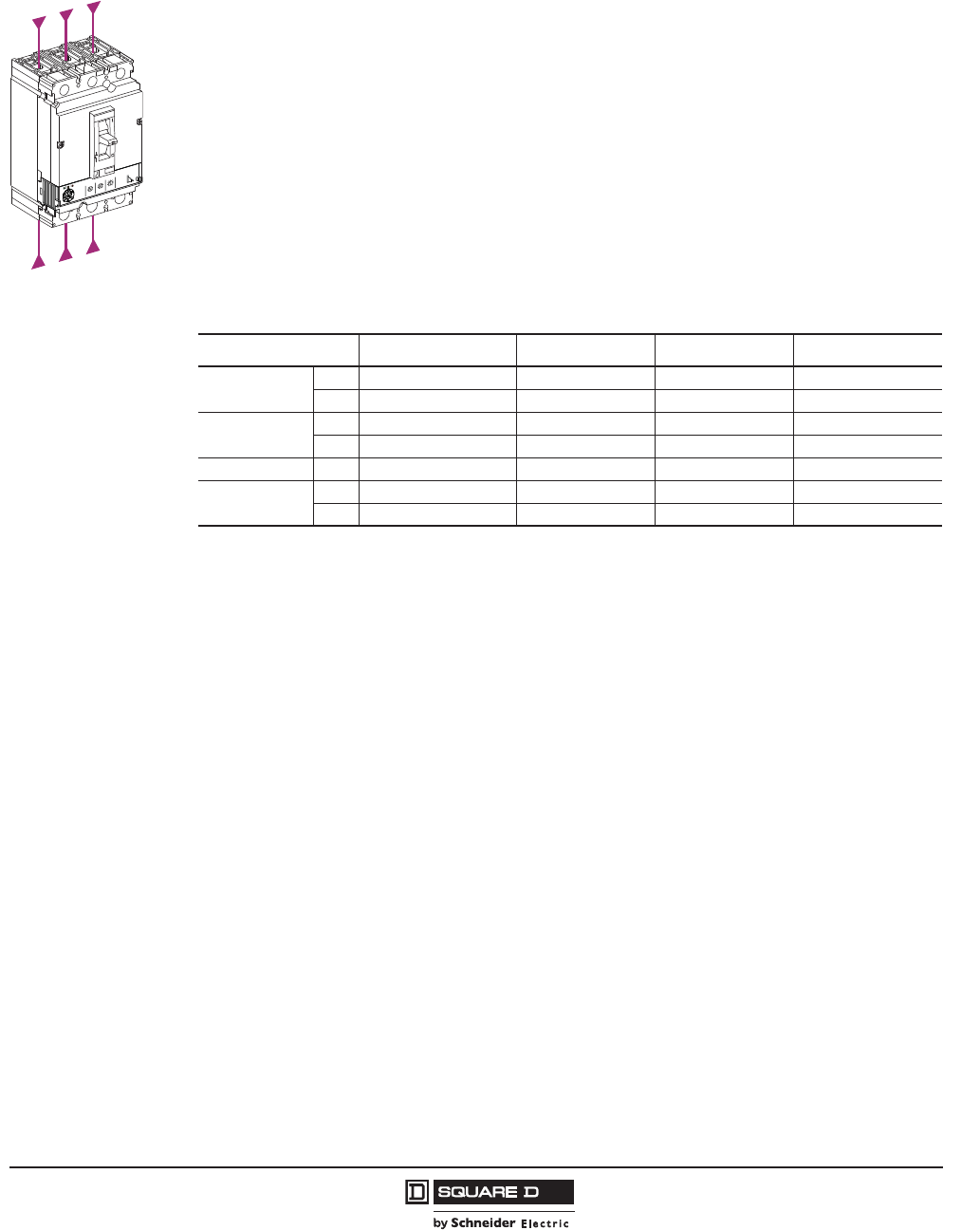
PowerPact™ H-, J-, and L-Frame Circuit Breakers
Installation Recommendations
129
05/2012
© 2011–2012 Schneider Electric
All Rights Reserved
™
Installation in Equipment
Power from the Top or Bottom
PowerPact H-, J-, and L-frame circuit breakers with factory-sealed trip units can be supplied from
either the top or the bottom without any reduction in performance. This capability facilitates connection
when installed in end-use equipment.
All connection and insulation accessories can be used on circuit breakers supplied either from the top
or bottom.
Weight
The table below presents the weights of the circuit breakers and the main accessories, which must be
summed to obtain the total weight. The values are valid for all performance categories.
Safety Clearances and Minimum Distances
General Rules
When installing a circuit breaker, minimum distances (safety clearances) must be maintained between
the device and panels, bars and other protection devices installed nearby. These distances, which
depend on the voltage, are defined by tests carried out in accordance with UL standards.
If installation is not checked by type tests, it is also necessary to:
•use insulated bars for circuit-breaker connections
•segregate the busbars using phase barriers
For PowerPact H-, J-, and L-frame devices, terminal shields and interphase barriers are recommended and
may be mandatory depending on the operating voltage of the device and type of installation (unit-mount,
drawout, etc.).
Power Connections
The table below indicates the connection requirements for PowerPact H-, J-, and L-frame devices to
ensure insulation of live parts for the various types of connection.
•unit-mount devices with front connection or rear connection
•plug-in or drawout devices.
Connection accessories such as crimp lugs, terminal extensions (straight, right-angle, double-L and
45°) and spreaders are supplied with interphase barriers. Long terminal shields provide a degree of
protection of IP40 (ingress).
3.2
Micrologic
5
.
1
2
5
.
2
34
0
1
8
6
5
.9
2
9
.
3
9
.
4
9
.5
9
.
1
8
9
.
7
9
.
6
9
.
00
1
0
1
1
5
2
1
0
4
10
6
1
0
5
2
52
2
0
02
5
7
1
Ird
s
I
ds
I)
r
I
x
(
Ir)
o
I
x
(
o
I)
A
(
r
I
%
A0
3
>
0
3
>01
1
>
06114588
Table 129: Weights
Type of Device Circuit Breakers Base Cradle Motor Operator
H-frame, 100 A 2P 3.95 lb (1.79 kg) 1.75 lb (0.8 kg) 4.85 lb (2.2 kg) 2.65 lb (1.2 kg)
3P 4.52 lb (2.05 kg) 1.75 lb (0.8 kg) 4.85 lb (2.2 kg) 2.65 lb (1.2 kg)
H-frame, 150 A 2P 4.08 lb (1.85 kg) 1.75 lb (0.8 kg) 4.85 lb (2.2 kg) 2.65 lb (1.2 kg)
3P 4.85 lb (2.2 kg) 1.75 lb (0.8 kg) 4.85 lb (2.2 kg) 2.65 lb (1.2 kg)
J-frame, 250 A 3P 5.29 lb (2.4 kg) 1.75 lb (0.8 kg) 4.85 lb (2.2 kg) 2.65 lb (1.2 kg)
L-frame, 600 A 3P 13.65 lb (6.19 kg) 5.29 lb (2.4 kg) 4.85 lb (2.2 kg) 6.17 lb (2.8 kg)
4P 17.92 lb (8.13 kg) 6.17 lb (2.8 kg) 4.85 lb (2.2 kg) 6.17 lb (2.8 kg)
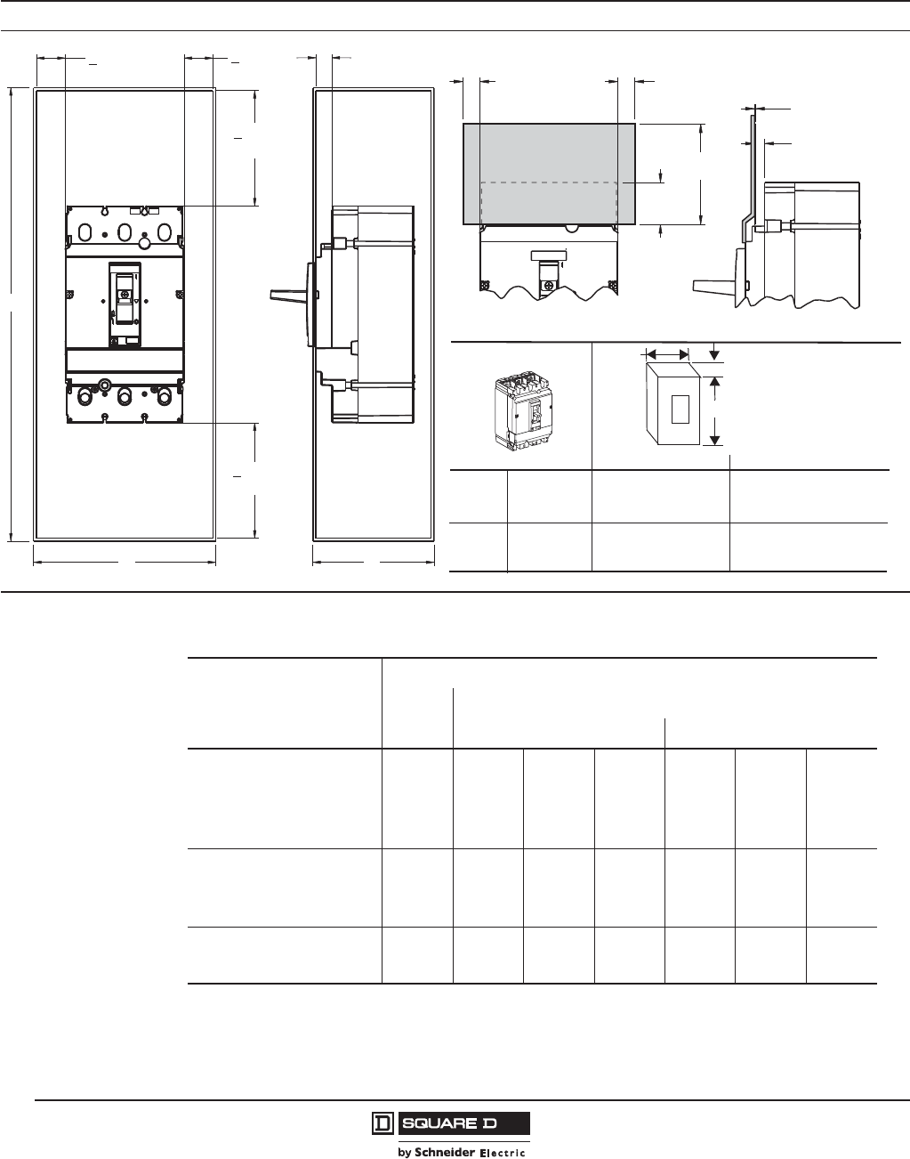
© 2011–2012 Schneider Electric
All Rights Reserved
PowerPact™ H-, J-, and L-Frame Circuit Breakers
Installation Recommendations
130
05/2012
™
Safety Clearance
H- and J-Frame Safety Clearances
1.00
(25,4)
>
1.00
(25,4)
>
4.00
(101,6)
>
4.00
(101,6)
>
H
WD
A
06113539
.50
(12,7)
.50
(12,7)
< .56
(14,2)
.03
(,8)
3.00
(76,2)
1.25
(31,8)
06113538
Enclosure Dimensions
D
HD/HG/
HJ/HL
JD/JG/
JJ/JL
15–150 A
150–250 A
Standard (80%) Rated
18.13 x 8.63 x 4.13 in.
(461 x 219 x 105 mm)
28.5 x 12.38 x 5.38 in.
(724 x 314 x 137 mm)
62 x 22.5 x14 in.
(572 x 1575 x 356 mm)
62 x 22.5 x14 in.
(572 x 1575 x 356 mm)
100% Rated
Fiber Insulating Plate
06113931
H x W x D
W
H
If dimension A < 0.56 in., attach fiber insulating plate, not provided, to enclosure cover.
Table 130: Minimum Safety Clearances
Operating Voltage
Clearance
Between
Devices
Between Device and Sheet Metal
Painted Sheet Metal Bare Sheet Metal
V 440 V
for devices equipped with:
• No accessories 0 0 30 30 5 40 40
• Interphase barriers 0 0 0 0 0 0 0
• Long terminal shields 0 0 0 0 0 0 0
440 < V 600
for devices equipped with:
• Interphase barriers1
1Only for J-frame devices
0 0 0 0 20 10 10
• Long terminal shields 0 0 0 0 10 10 10
V > 600 V
for devices equipped with:
• Long terminal shields 0 10 50 50 20 100 100
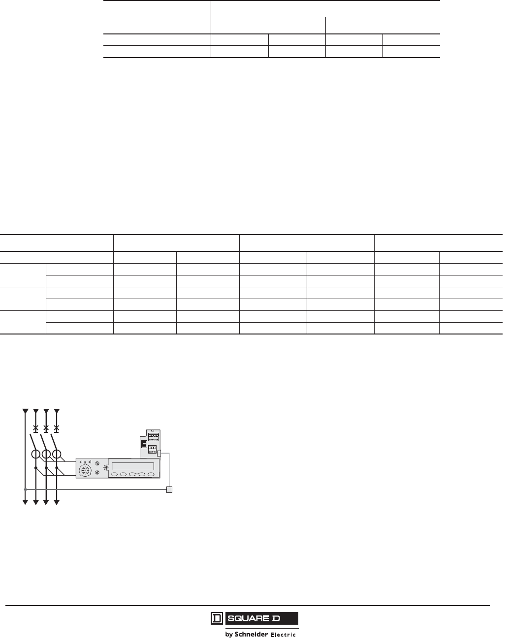
PowerPact™ H-, J-, and L-Frame Circuit Breakers
Installation Recommendations
131
05/2012
© 2011–2012 Schneider Electric
All Rights Reserved
™
Clearances with Respect to Live Bare Busbars
Control Wiring
Remote Tripping by Undervoltage Trip (MN) or Shunt Trip (MX)
Power requirements are approximately:
•30 VA for pick-up of the undervoltage trip (MN) and shunt trip (MX)
•300–500 VA for the motor operator.
\
External Neutral Voltage Tap (ENVT)
Table 131: Minimum Safety Clearances to Bare Busbars
Operating Voltage
Clearances to Live Bare Busbars1
1These clearances can be reduced for special installations as long as the configuration is checked by tests.
Spacing 60 mm Spacing > 60 mm
V 440 V 350 350 80 80
440 V < V 600 V 350 350 120 120
Table 132: Recommended Maximum Cable Lengths1
Power Supply Voltage (Vdc) 12 Vdc 24 Vdc 48 Vdc
Cable cross-section 16 AWG (1.5 mm²) 14 AWG (2.5mm²) 16 AWG (1.5 mm²) 14 AWG (2.5mm²) 16 AWG (1.5 mm²) 14 AWG (2.5mm²)
Undervoltage
Trip (MN)
V source 100% 49 ft (15 m) — 525 ft (160 m) — 2100 ft (640 m) —
V source 85% 23 ft (7 m) — 131 ft (40 m) — 525 ft (160 m) —
Shunt Trip
(MX)
V source 100% 197 ft (60 m) — 787 ft (240 m) — 3150 ft (960 m) —
V source 85% 98 ft (30 m) — 394 ft (120 m) — 1575 ft (480 m) —
Motor
Operator
V source 100% — 33 ft (10 m) 16 m) 213 ft (65 m) 361 ft (110 m)
V source 85% — — 6.6 ft (2 m) 4 m) 56 ft (17 m) 82 ft (25 m)
1the indicated length is that of each of the two wires.
This connection is required for accurate power measurements on 3-pole
circuit breakers equipped with Micrologic™ 5 / 6 E trip units in installations
with a distributed neutral. It can be used to measure phase-neutral
voltages and calculate power using the 3 wattmeter method.
PowerPact H-, J-, and L-frame 3-pole circuit breakers come with a wire
installed on the device for the connection to the ENVT. This wire is
equipped with a connector for connection to an external wire with:
•cross-sectional area of 18–14 AWG (1 mm² to 2.5 mm²)
•maximum length of 32.8 ft (10 m).
06114599
N A B C
I
V
ENVT
Wire
Ready for
Connection
External Wire
3P+N
External neutral voltage tap (ENVT)
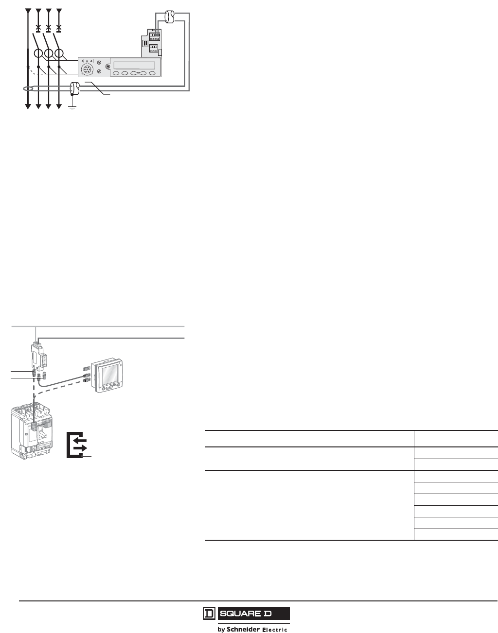
© 2011–2012 Schneider Electric
All Rights Reserved
PowerPact™ H-, J-, and L-Frame Circuit Breakers
Installation Recommendations
132
05/2012
™
External Neutral Current Transformer (ENCT)
ULP Connection System Between Micrologic, FDM121 Module and
Modbus™ Interface
This connection is required to protect the neutral on 3-pole circuit breakers
equipped with Micrologic™ 5 / 6 A or E trip units in installations with a
distributed neutral. For Micrologic 6 A or E, it is required for ground-fault
protection.
The ENCT is connected in the same way for unit-mount, plug-in or drawout
devices:
•unit-mount devices are connected using terminals T1 and T2 of the
internal terminal block.
•plug-in and drawout devices are not connected using the auxiliary
terminals.
The wires must be connected/disconnected inside the devices using
terminals T1 and T2.
The ENCT must be connected to the Micrologic trip unit by a shielded
twisted pair. The shielding should be connected to the enclosure earth only
at the CT end, no more than 12 in. (30 cm) from the CT.
•the power connections of the CT to the neutral (H2 and H1) must be
made in the same way for power supply from the top or the bottom (see
figure). Make sure they are not reversed for devices with power supply
from the bottom.
•cross-sectional area of 22–16 AWG (0.4 mm² to 1.5 mm²)
•maximum length of 32.8 ft (10 m).
06114600
N A B C 3P+N: supply from the top
I
V
ENCT
T1
T2
H2
H1
T1
T2
The ULP (Universal Logic Plug) wiring system used by H-, J- and L-frame
circuit breakers for connection through the Modbus network requires
neither tools nor settings. The prefabricated cables are used for both data
transfer and distribution of 24 Vdc power. Connectors on each component
are identified by ULP symbols, ensuring total compatibility between each
component.
A line terminator must be fitted to all components with an unused RJ45
connector.
Table 133: Available Cables
Cable Available Lengths
NSX cord for connection of the internal terminal block to the Modbus
interface or the FDM121 display using an RJ45 connector.
4.27 ft (1.3 m)
9.84 ft (3 m)
ULP cables with RJ45 connectors at each end for the other
connections between ULP wiring components
For greater distances, two cables can be interconnected using the
RJ45 female/ female connector. Maximum length of 32.8 ft (10 m)
between 2 modules and 98.4 ft (30 m) in all.
0.98 ft (0.3 m)
1.97 ft (0.6 m)
3.28 ft (1 m)
2.56 ft (2 m)
9.84 ft (3 m)
16.4 ft (5 m)
06114602
Modbus
24 Vdc
ULP wiring
1
3
2
ULP connection system.
1RJ45
2Line terminator
3ULP symbol
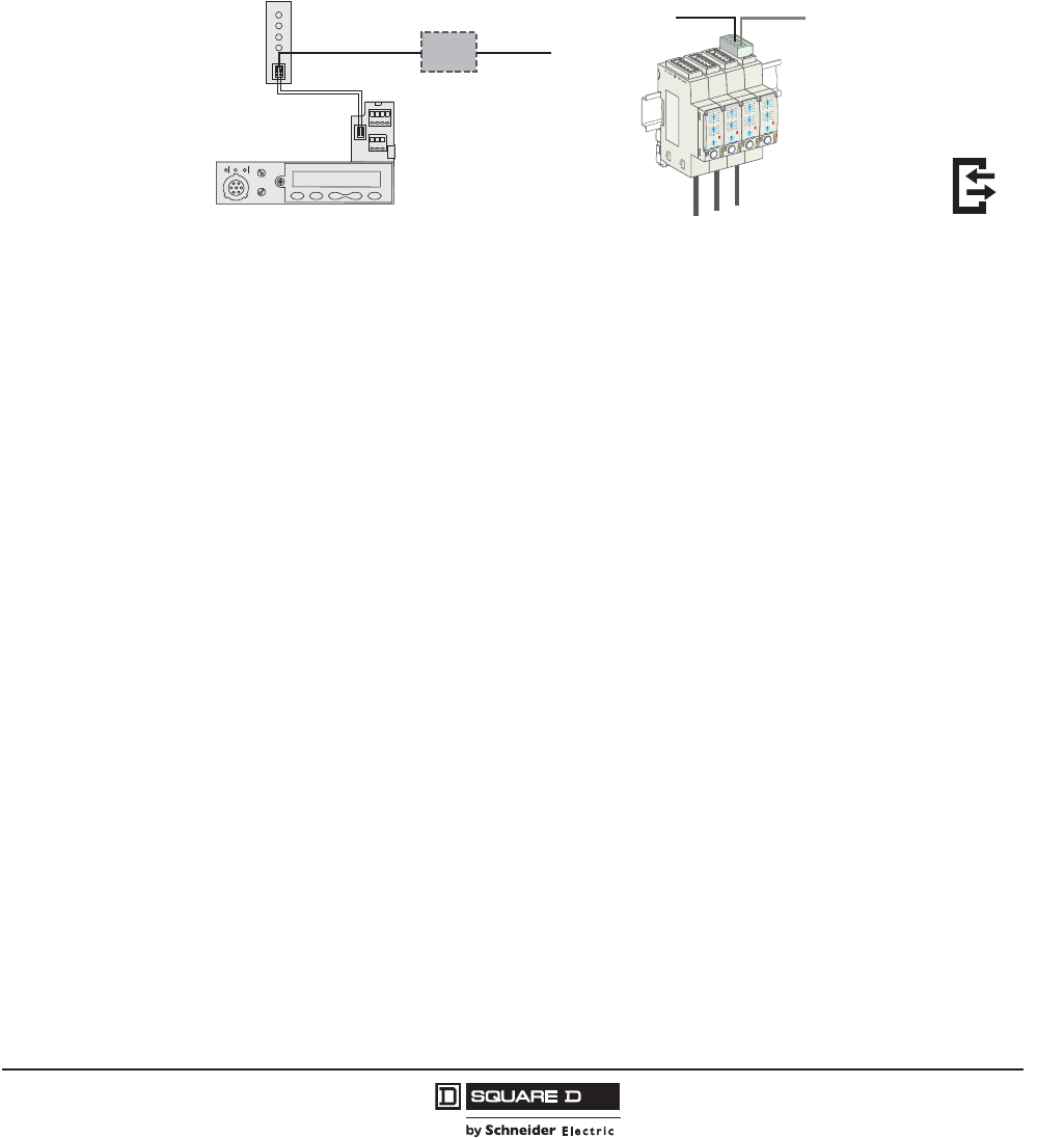
PowerPact™ H-, J-, and L-Frame Circuit Breakers
Installation Recommendations
133
05/2012
© 2011–2012 Schneider Electric
All Rights Reserved
™
24 Vdc Power Supply Module
An external 24 Vdc power supply is required for installations with communication networks, regardless
of the type of trip unit.
On installations without communication networks, the power supply is available as an option for
Micrologic™ 5/6 to:
•modify settings when the circuit breaker is open (OFF position)
•display measurements when the current flowing through the circuit breaker is low
•maintain the display of the cause of tripping
To determine power requirements of devices, see page 80.
06114603
24 Vdc 24 Vdc
Battery
Power supply, without the Communication function,
using the terminal block with a backup battery.
06114604
Downstream ULP wiring
for 24 Vdc supply
24 Vdc Modbus
Power supply, with the communication function,
using the Modbus interface.
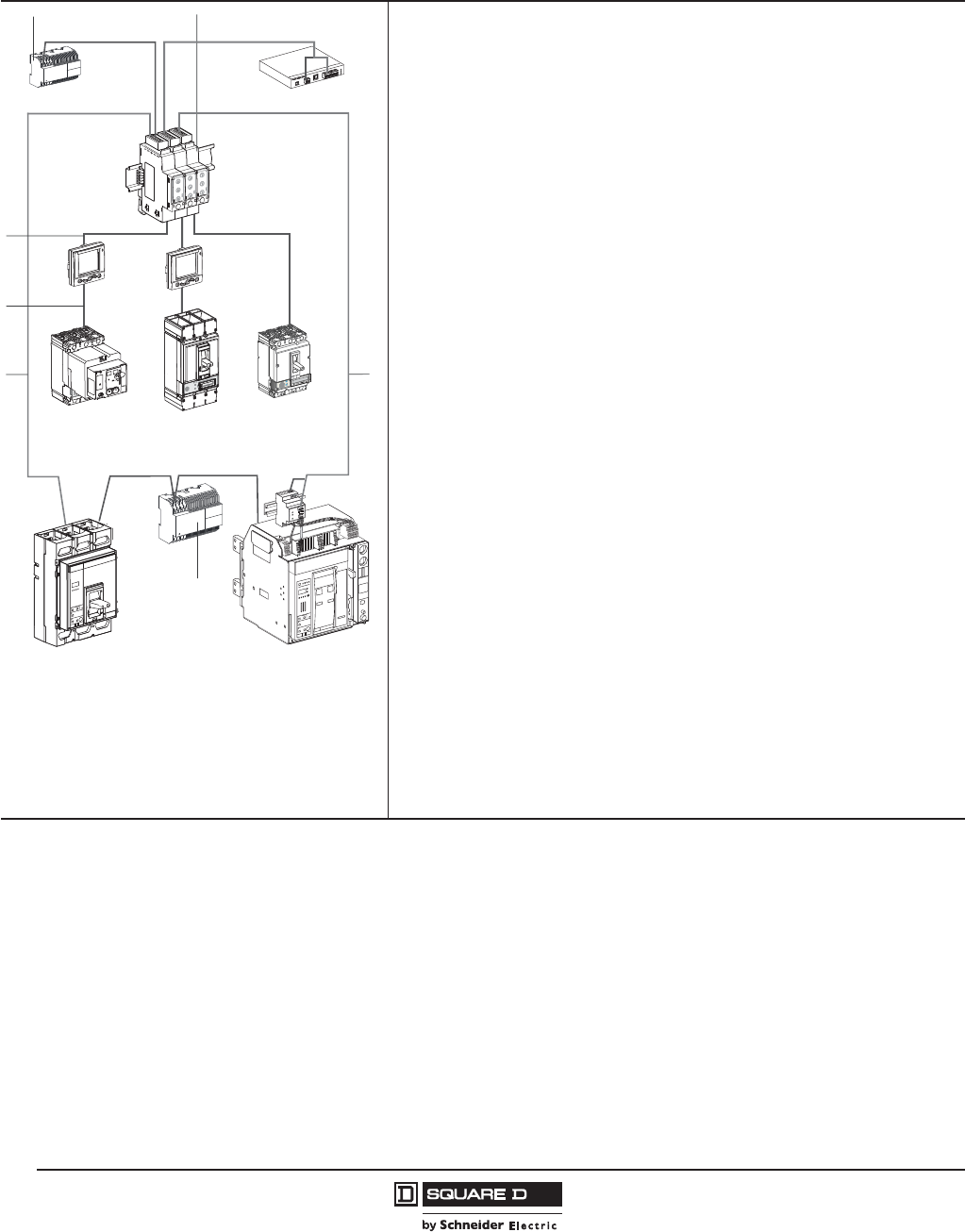
© 2011–2012 Schneider Electric
All Rights Reserved
PowerPact™ H-, J-, and L-Frame Circuit Breakers
Installation Recommendations
134
05/2012
™
Wiring
Micrologic™ 5 or 6 Without the Communication Function
The external 24 Vdc supply is connected through the circuit breaker terminal
block.
Use of a 24 Vdc battery provides backup power for approximate 3 hours
(100 mA) in the event of an interruption in the external supply.
Micrologic 5 or 6 With the Communication Function
The external 24 Vdc supply is connected through the Modbus interface
using a five-pin connector, including two for the power supply. Stacking
accessories (see page 77) can be used to supply a number of interfaces by
fast clip-on connection.
The 24 Vdc power is distributed downstream by the ULP (Universal Logic
Plug) communication cables with RJ45 connectors. This system ensures
both data transfer and power distribution to the connected modules.
Recommendations for 24 Vdc Wiring
Do not connect the positive terminal to ground
•Do not connect the negative terminal to ground.
•The maximum length for each conductor (+/-) is 33 ft (10 m).
•For connection distances greater than ten metres, the plus and minus
conductors of the 24 Vdc supply must be twisted to improve EMC.
•The 24 Vdc conductors must cross the power cables perpendicularly. If
this is difficult or impossible, the plus and minus conductors must be
twisted.
06114605
EGX / MPS100
FDM121
+ BSCM
J-Frame
FDM121
L-Frame
+ BSCM
+ communicating
motor operator
+
M
U
Masterpact NT
P-Frame
Modbus + 24 Vdc
21
6
Modbus + 24 Vdc Modbus + 24 Vdc
24 Vdc
24 Vdc
3
4
55
1Modbus interface module with connection accessory.
224 Vdc power supply of Micrologic for Powerpact H-, J-, and
L-Frame communication modules.
3ULP cord.
4NSX cord.
5Modbus cable + 24 Vdc part no. 50965 (Schneider Electric)
recommended or part no. 7895A (Belden).
624 Vdc power supply of Micrologic for PowerPact M-Frame/
Masterpact circuit breakers.
rciMcigolo
E
2
.5
r
I
%
A
0
3
>
0
3
>0
1
1
>
.9
2
9
.
3
9
.
4
9
.5
9.
1
8
9
.
7
9
.
6
9
.
Ir )
o
I
x
(
5
.
1
2
5
.
2
34
0
1
8
6
5
d
s
I)
r
I
x
(
J-Frame

PowerPact™ H-, J-, and L-Frame Circuit Breakers
Installation Recommendations
135
05/2012
© 2011–2012 Schneider Electric
All Rights Reserved
™
Modbus
Each PowerPact H-, J-, and L-frame circuit breaker equipped with Micrologic™ 5/6 and an FDM121
display is connected to the Modbus network using the Modbus com module. Connection of all the
circuit breakers and other Modbus devices in the equipment to a Modbus bus is made much easier by
using a Modbus RJ45 junction block installed in the equipment.
Recommendations for Modbus Wiring:
•The shielding may be grounded on one end only
•The conductors must be twisted to improve immunity (EMC)
•The Modbus conductors must cross the power cables perpendicularly
Example.
A unit-mount PowerPact L-frame circuit breaker with a Micrologic trip unit can have a maximum Ir setting of:
•400 A up to 122°F (50 °C)
•380 A up to 140°F (60 °C)
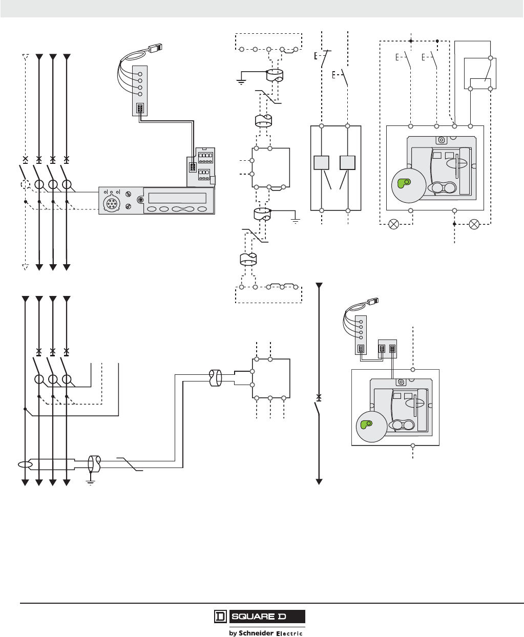
© 2011–2012 Schneider Electric
All Rights Reserved
PowerPact™ H-, J-, and L-Frame Circuit Breakers
Wiring Diagrams
136
05/2012
™
Section 11—Wiring Diagrams
Unit-Mount Circuit Breakers
Power Micrologic™ Trip Unit1Remote Operation
Motor Operator
Communicating Motor Operator
Continued on next page
Z2
Z1
Upstream CB
Z1
Z2
Z3
Z4
Z5
Z3
Z4
Z5
Downstream CB
Z1
Z2
Z3
Z4
Z5
T1
T2
NLALBLC
Q
I
V
+-
L
H
NSX cord
3P or 4P
3P + N
NLALBLC
ENVT
Q
T1
T2
H2
H1
IV
ENCT
Z2
Z1
Z3
Z4
Z5
T1
T2
06114459
BPO BPF
D2
C2
A4
A2
B4
MN MX
D1
C1
A1
B2
SDE
SDE
2848
81
L1
Vac (-) manu
Vac (+) Vac (+)
Vac
(-)
or 0I
auto
manu
06114460
06114461
+-
L
H
Q
B4
A1
Vac (220/240 V)
Vac
0I
auto
manu
NSX cord
BSCM
Schematic of the communicating motor operator .
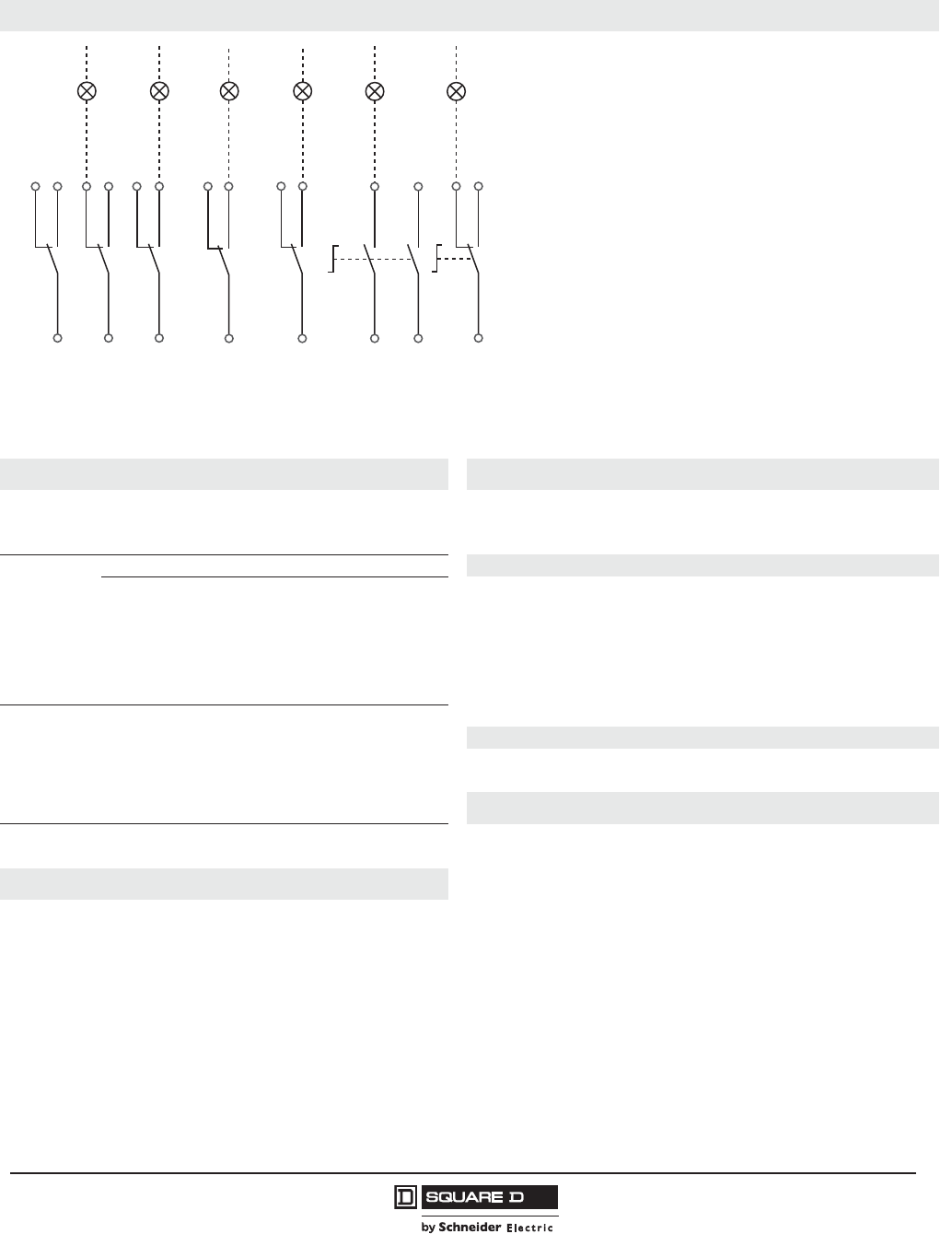
PowerPact™ H-, J-, and L-Frame Circuit Breakers
Wiring Diagrams
137
05/2012
© 2011–2012 Schneider Electric
All Rights Reserved
™
Indication Contacts
The diagram is shown with circuits de-energized, relays in normal position, and all devices open, connected, and charged.
Terminal connections shown as O must be connected by the customer.
Micrologic™ Trip Unit A or E Remote Operation
A/E
Communication
H (WH), L(BL): data
-(BK), +(RD): 24 Vdc power supply
MN
or
MX
Undervoltage Release
Shunt Release
A/E
ZSI (Zone Selective Interlocking) Motor Operator
Z1: ZSI OUT SOURCE
Z2: ZSI OUT
Z3: ZSI IN SOURCE
Z4: ZSI IN ST (short time)
Z5: ZSI IN GF (ground fault)
(Z3, Z4, and Z5 for L-frame circuit breaker only)
A4
A2
B4, A1
L1
B2
BPO
BPF
Opening Order
Closing Order
Power Supply to Motor Operator
Manual Position (manu)
Overcurrent Trip Switch Interlocking (mandatory for correct operation)
Opening Pushbutton
Closing Pushbutton
A/E
ENCT: External Neutral Current Transformer:
-Shielded cable with 1 twisted pair (T1, T2)
-Shielding earthed at CT end only
Connection L = 12 in. (30 cm) max.
-Maximum length of 33 ft (10 m)
-Cable size of 22 AWG
-Recommended cable: Belden 9451SB or equivalent
Communicating Motor Operator
B4, A1
BSCM
Motor Operator Power Supply
Breaker Status and Control Module
Indication Contacts
EENVT: External Neutral Voltage Tap for Connection
to the Neutral using a 3P Circuit Breaker
OF2/OF1
OF3
SDE
SD
CAF2/CAF1
CAO1
Device ON/OFF Auxiliary Switches
Device ON/OFF Auxiliary Switches (L-Frame)
Overcurrent Trip Switch
(short-circuit, overload, ground fault, earth leakage)
Alarm Switch
Early-Make Contact (rotary handle only)
Early-Break Contact (rotary handle only)
Color Code for Auxiliary Wiring
RD: Red
WH: White
YE: Yellow
BK: Black
GN: Green
VI: Violet
GY: Gray
OR: Orange
BL: Blue
Unit-Mount Circuit Breakers (continued)
06114462
OF3
31
32
34
21
OF2
Open
22
24
OF1
11
Closed Closed
12
14
81
SDE
Fault
82
84
91
SD
Fault
92
94
121
CAF2
131
CAF1
RD
WH
134
124
101
CAO1
Open
YE
VT
102
104
RD
WH
GY

© 2011–2012 Schneider Electric
All Rights Reserved
PowerPact™ H-, J-, and L-Frame Circuit Breakers
Wiring Diagrams
138
05/2012
™
Plug-In and Drawout Circuit Breakers
Power Micrologic™ Trip Unit1Remote Operation
Motor Operator
Communicating Motor Operator
Continued on next page
06114463
Z2
Z1
Z2
Z1
Z3
Z4
Z5
Z3
Z4
Z5
BK
GN
VT
YE
RD
T1
T2
NLALBLC
ENVT
Q
T1
T2
H2
H1
IV
ENCT
3P + N
Z2
Z1
22/32
24/34
Upstream CB
Z1
Z2
Z3
Z4
Z5
Z3
Z4
Z5
41
42
44
BK
GN
VT
YE
RD
Downstream
Z1
Z2
Z3
Z4
Z5
T1
T2
NLALBLC
Q
I
V
+
-
L
H
B4
A1
84
A2
NSX cord
3P or 4P
RD
BK
BL
WH
06114464
BPO BPF
D2
C2
D2
C2
A4
A2
RD
BL
WH
OR
OR
BL
B4
A4
A2
B4
MN MX
D1
C1
D1/C1
A1
BK
GN
WH
A1
B2
SDE
SDE
84
84
82
81
L1
L1
Vac (-) manu
Vac (+)
Vac (+)
Vac (-)
or 0I
auto
manu
06114465
+-
L
H
B4 B4
GN
A1
OR
A4
Vac
0I
auto
manu
Vac (220/240 V)
NSX cord
BSCM
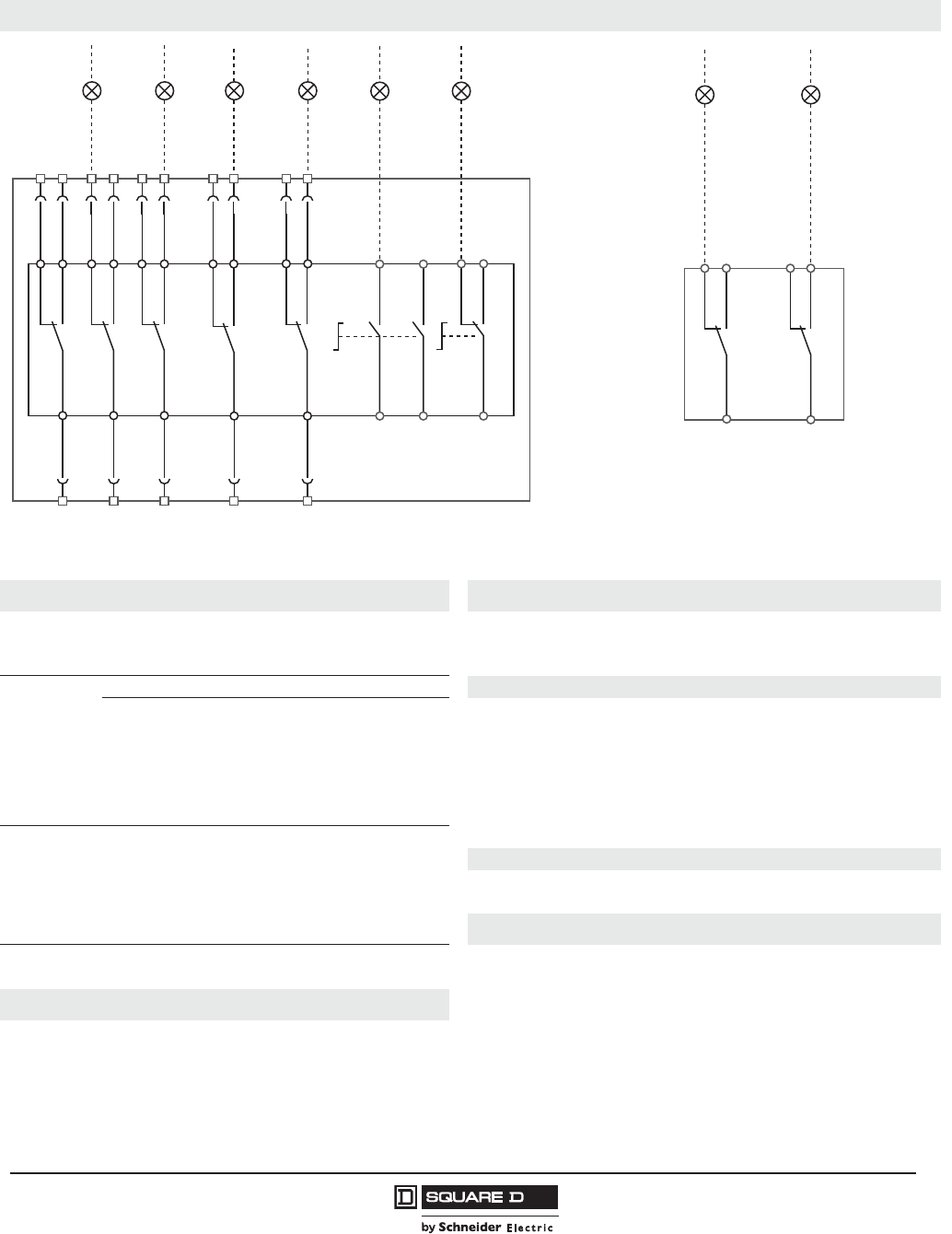
PowerPact™ H-, J-, and L-Frame Circuit Breakers
Wiring Diagrams
139
05/2012
© 2011–2012 Schneider Electric
All Rights Reserved
™
Indication Contacts Carriage Switches
The diagram is shown with circuits de-energized, relays in normal position, and all devices open, connected, and charged.
Terminal connections shown as and O must be connected by the customer.
Micrologic™ Trip Unit A or E Remote Operation
A/E
Communication
H (WH), L(BL): data
-(BK), +(RD): 24 Vdc power supply
MN
or
MX
Undervoltage Release
Shunt Release
A/E
ZSI (Zone Selective Interlocking) Motor Operator
Z1: ZSI OUT SOURCE
Z2: ZSI OUT
Z3: ZSI IN SOURCE
Z4: ZSI IN ST (short time)
Z5: ZSI IN GF (ground fault)
(Z3, Z4, and Z5 for L-frame circuit breaker only)
A4
A2
B4, A1
L1
B2
BPO
BP
Opening Order
Closing Order
Power Supply to Motor Operator
Manual Position (manu)
Overcurrent Trip Switch Interlocking (mandatory for correct operation)
Opening Pushbutton
Closing Pushbutton
A/E
ENCT: External Neutral Current Transformer:
-Shielded cable with 1 twisted pair (T1, T2)
-Shielding earthed at CT end only
Connection L = 12 in. (30 cm) max.
-Maximum length of 33 ft (10 m)
-Cable size of 22 AWG
-Recommended cable: Belden 9451SB or equivalent
Communicating Motor Operator
B4, A1
BSCM
Motor Operator Power Supply
Breaker Status and Control Module
Indication Contacts
EENVT: External Neutral Voltage Tap for Connection
to the Neutral using a 3P Circuit Breaker
OF2/OF1
OF3
SDE
SD
CAF2/CAF1
CAO1
Device ON/OFF Auxiliary Switches
Device ON/OFF Auxiliary Switches (L-Frame)
Overcurrent Trip Switch
(short-circuit, overload, ground fault, earth leakage)
Alarm Switch
Early-Make Contact (rotary handle only)
Early-Break Contact (rotary handle only)
Color Code for Auxiliary Wiring
RD: Red
WH: White
YE: Yellow
BK: Black
GN: Green
VI: Violet
GY: Gray
OR: Orange
BL: Blue
Plug-In and Drawout Circuit Breakers (continued)
06114466
OF3
31
32
34
21
OF2
Open
22
24
OF1
11
Closed
12
14
81
SDE
Fault
82
84
91
SD
Fault
92
94
121
CAF2
131
CAF1
Closed
RD
WH
134
124
101
CAO1
Open
YE
VT
102
104
RD
WH
GY
YE
VT
GN
RD
GN
RD
YE
VT
YE
VT
GY
GY
GY
BK
BK
31
21
11
81
91
32
34
22
24
12
14
82
84
92
94
06114466
VT
VT
GY
GY
314
312
352
354
CE CD
Connected Disconnected
YE
YE
311
351
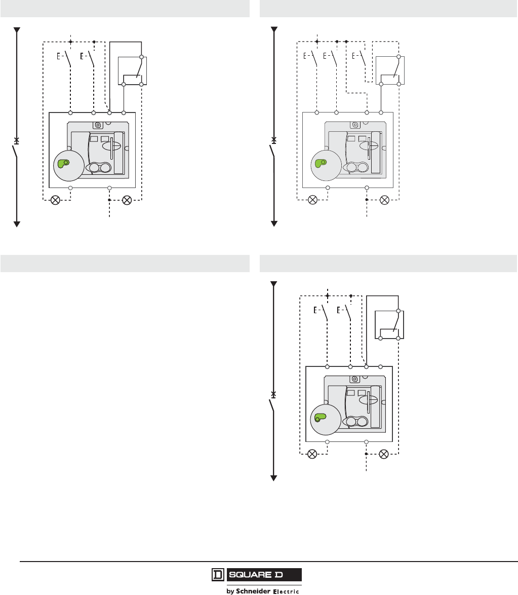
© 2011–2012 Schneider Electric
All Rights Reserved
PowerPact™ H-, J-, and L-Frame Circuit Breakers
Wiring Diagrams
140
05/2012
™
Motor Operator
NOTE: The diagram is shown with circuits de-energized, relays in normal position, and all devices open,
connected, and charged.
After tripping initiated by the “Push to trip” button, the undervoltage release (MN), or the shunt release
(MX), device can be reset automatically, remotely, or manually.
Following tripping due to an electrical fault, reset must be carried out manually.
Motor Operator with Automatic Reset Motor Operator with Remote Reset
Symbols Motor Operator with Manual Reset
Q:
A4:
A2:
B4, A1:
L1:
B2:
BPO:
BPF:
SDE:
Circuit Breaker
Opening Order
Closing Order
Motor Operator Power Supply
Manual Position (manu)
Overcurrent Trip Switch Interlocking (mandatory for correct operation)
Opening Pushbutton
Closing Pushbutton
Fault-Trip Indication Contact
(short-circuit, overload, ground fault, earth leakage)
06114475
Q
BPO BPF
A4
A2
B4
A1
B2
SDE
SDE
2848
81
L1
manu
Vac
(+)
Vac
(-)
0I
auto
manu
06114468
BPO BPF Reset
A4
A2
B4
A1
B2
2848
81
L1
manu
Vac
(+)
Vac
(-)
0I
auto
manu
Q
SDE
SDE
06114760
Q
BPO BPF
A4
A2
B4
A1
B2
SDE
SDE
2848
81
L1
manu
Vac
(+)
Vac
(-)
0I
auto
manu
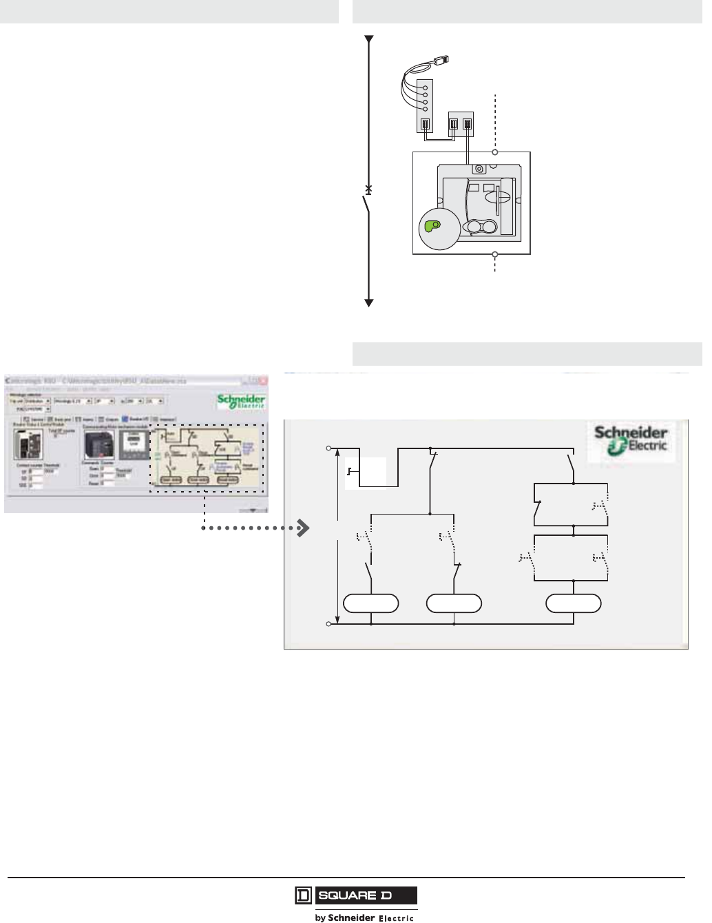
PowerPact™ H-, J-, and L-Frame Circuit Breakers
Wiring Diagrams
141
05/2012
© 2011–2012 Schneider Electric
All Rights Reserved
™
Symbols Communicating Motor Operator
Q:
B4, A1:
BSCM:
Circuit Breaker
Motor Operator Power Supply
Breaker Status and Control Module
RSU Screen for Communicating Motor Operator
Single-line diagram of communicating motor operator
Opening, closing and reset orders are transmitted through the communication
network. The “Enable automatic reset” and “Enable reset even if SDE”
parameters must be set using the RSU software using the screen by clicking the
blue text.
“Auto/Manu” is a switch on the front of the motor operator.
Terminal connections shown as O must be connected by the customer.
Motor Operator (continued)
06114461
+-
L
H
Q
B4
A1
Vac (220/240 V)
Vac
0I
auto
manu
NSX cord
BSCM
Schematic of the communicating motor operator .
06114670
Open motor
Open
command
220
VAC
OF OF
SD
Close
command
Reset
command
Enable
automatic
reset
Enable
reset
even if
SDE
SDE
SD
B4
A1
Close motor Reset motor
Auto
Manu
RSU utility setup screen for the
communicating motor operator
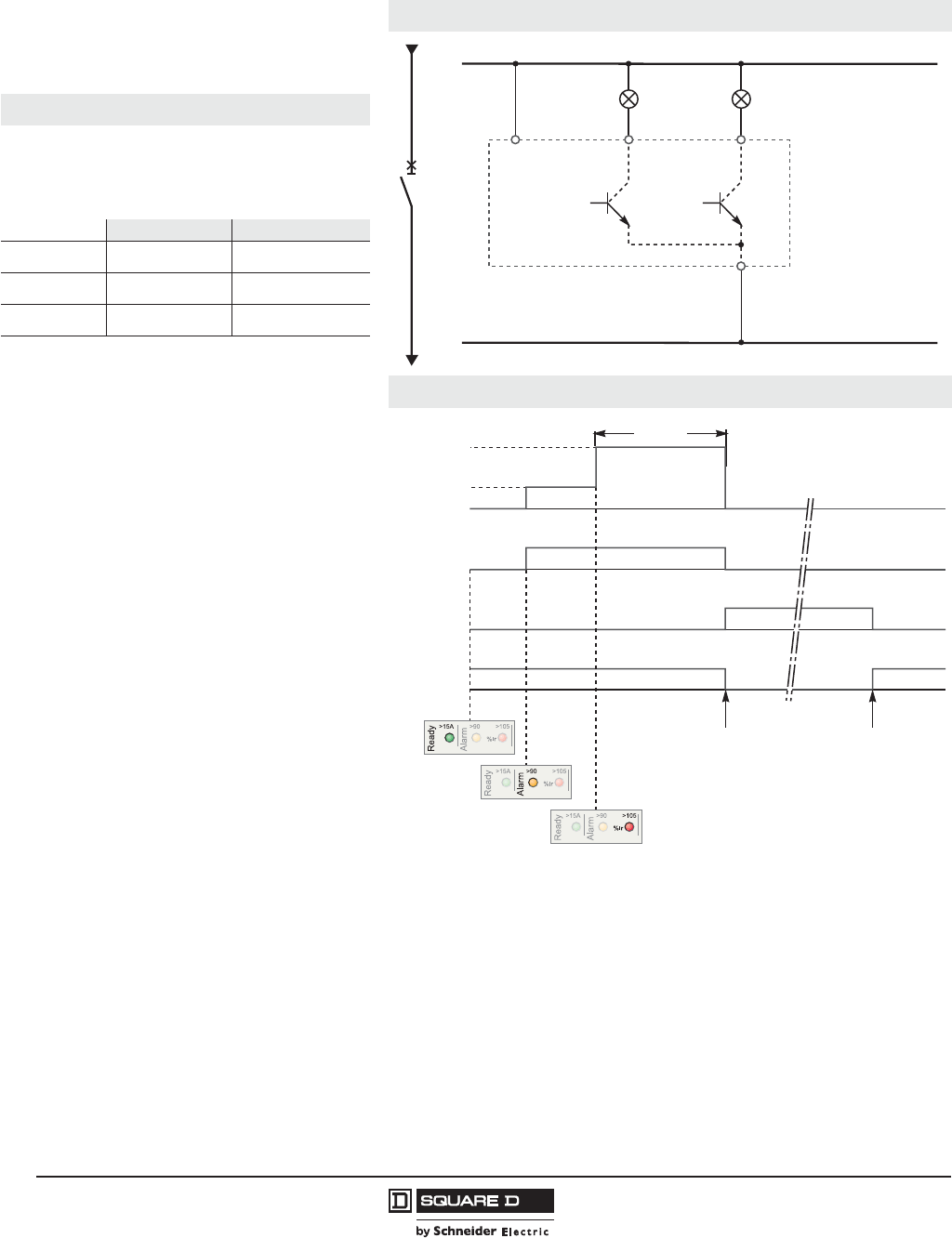
© 2011–2012 Schneider Electric
All Rights Reserved
PowerPact™ H-, J-, and L-Frame Circuit Breakers
Wiring Diagrams
142
05/2012
™
SDx Module with Micrologic™ Trip Unit
NOTE: The diagram is shown with circuits de-
energized, relays in normal position, and all
devices open, connected, and charged.
Connection
Symbols
SD1, SD3:
SD2:
SD4:
SDx Module Power Supply
Output 1 (80 mA max.)
Output 2 (80 mA max.)
SD2 SD4
Micrologic 3 SDT —
Micrologic 5 SDT or Output 1 PAL Ir or Output 2
Micrologic 6 SDT or Output 1 SDG or Output 2
Terminal connections shown as O must be connected by the
customer.
Operation
I:
PAL Ir:
SDG:
SDT:
Q:
Charge Current
Thermal Overload Pre-Alarm
Ground-Fault Signal
Thermal-Fault Signal
Circuit Breaker
06114470
Vac (+) 24–415 V
Vac (-)
SD1
SD4
SD2
SD3
STD
or output 1
PAL Ir
or SDG
or output 2
SDx
Q
06114463
Circuit breaker
trip order
Circuit breaker
reset
PAL Ir
SDG
SDT
Q
> 90 % Ir
I
> 105 % Ir
tr at 6 Ir

PowerPact™ H-, J-, and L-Frame Circuit Breakers
Wiring Diagrams
143
05/2012
© 2011–2012 Schneider Electric
All Rights Reserved
™
SDTAM Module with Micrologic™ M Trip Unit
NOTE: The diagram is shown with circuits de-
energized, relays in normal position, and all
devices open, connected, and charged.
Connection
Symbols
SD1, SD3:
SD2:
SD4:
SDTAM Module Power Supply
Thermal Fault Signal (80 mA max.)
Contactor Control Output (80 mA max.)
SD2 SD4
Micrologic 2 M SDT KA1
Terminal connections shown as O must be connected by the
customer.
Operation
I:
SDT:
KA1:
KM1:
Q:
Charge Current
Thermal Fault Signal
Auxiliary Relay (RBN or RTBT Relay)
Motor Contactor
Circuit Breaker
06114472
Vac (+) 24 to 415 V
Vac (-)
SD1
SD4
SD2
SD3
SDT
Manual
reset KA1
KA1
KM1
KM1
Closing
order
Opening
order
SDTAM
Auto reset (minutes)
Q
KM1
OFF
114
15
212
410
68
06114473
Class (tr) at 7.2 Ir
400 ms
400 ms before
circuit-breaker
tripping order
Contactor
closing order
Manual or
automatic reset
SDT
KA1
KM1
Q
I
< 95 % T°
> 95 % T°
%T°
%T°
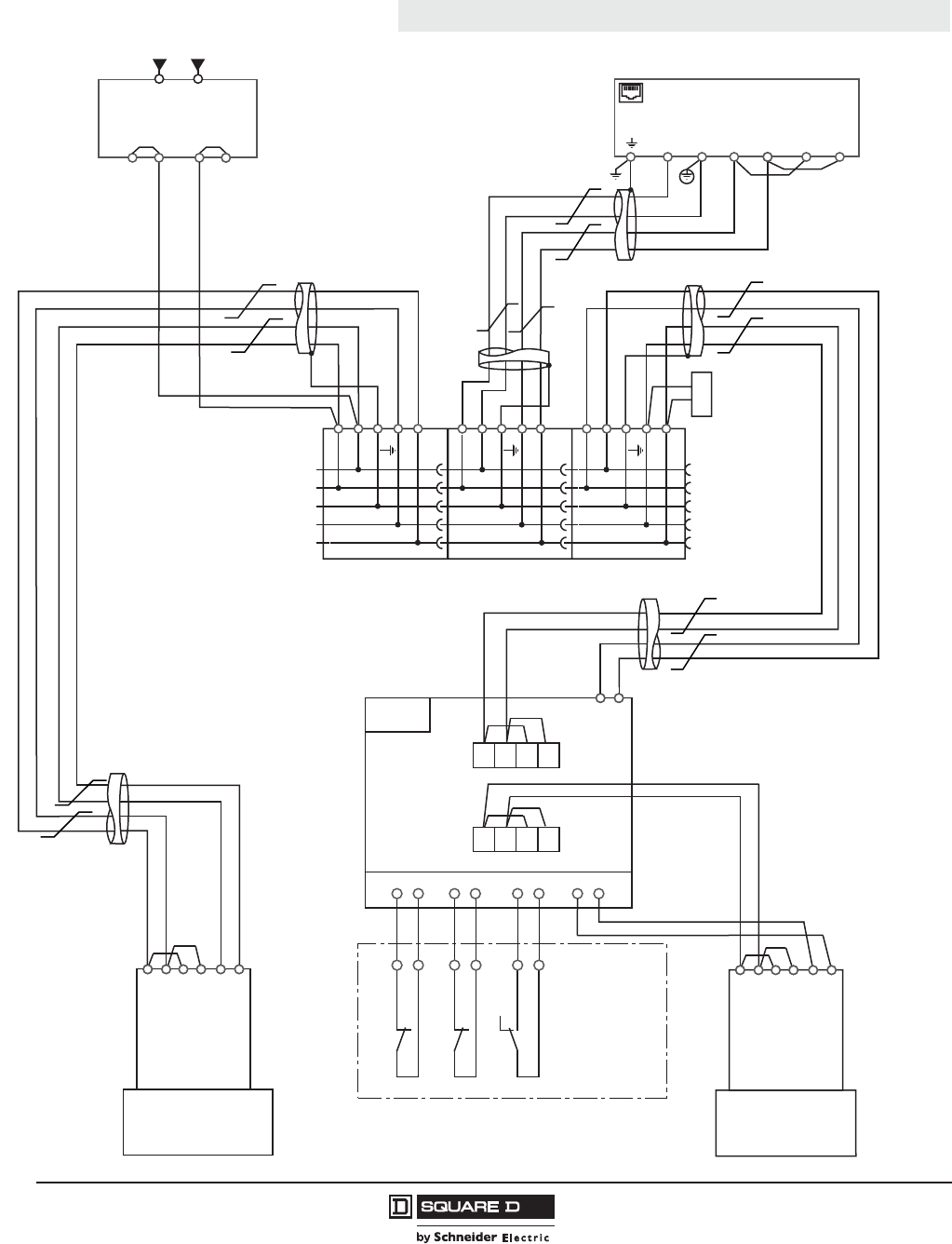
© 2011–2012 Schneider Electric
All Rights Reserved
PowerPact™ H-, J-, and L-Frame Circuit Breakers
Wiring Diagrams
144
05/2012
™
Modbus™ Module
Detailed connection of the circuit breakers on
communication network Modbus
Connection
06114474
24 V
0 V
D0
D1
24 V
0 V
D0
D1
24 V
0 V
D0
D1
G3
G1 G2
G4
24 V Power Supply
CCM
A B A' B'
A B A' B'
Cradle
Masterpact NT/NW
914
911 812
811 314
311
CT
CT CD CE + -
+-
CD CE
BCM
(Masterpact NT/NW)
Network
Breaker
BCM
(PowerPact P/R-Frame)
E3
E4
E5
E6
E2
E1
A/Tx-
B/Tx+
A'/Rx-
B'/Rx+
0 V
24 V
brown
white
yellow
blue
black
red
E3
E4
E5
E6
E2
E1
A/Tx-
B/Tx+
A'/Rx-
B'/Rx+
0 V
24 V
brown
white
yellow
blue
black
red
Modbus Line
Termination
Modbus Communication Interface Module (PowerPact H-, J-, L-Frame)
24 V 0 V Rx- Rx+ Tx- Tx+
EGX / 100 / 300
White
Blue
White
Blue
White
Blue
White
Blue
White
Blue
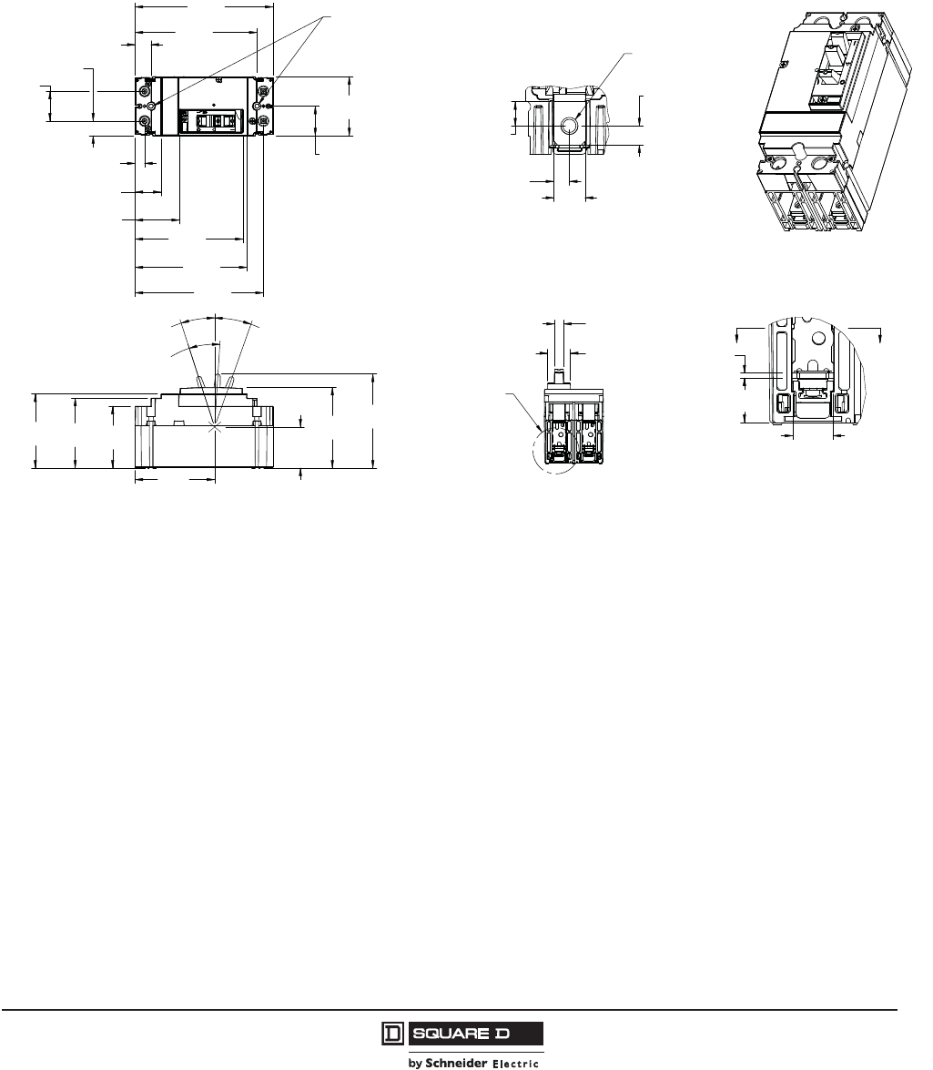
PowerPact™ H-, J-, and L-Frame Circuit Breakers
Dimensions
145
05/2012
© 2011–2012 Schneider Electric
All Rights Reserved
™
Section 12—Dimensions
PowerPact H-Frame Circuit Breakers
Figure 8: 15–150 A Bus Bar PowerPact H-Frame 2P HD/HG Thermal-Magnetic Only Circuit Breaker
BB
Ø.20
[5,1]
MOUNTING HOLE
SEE DETAIL A
ISOMETRIC VIEW
SCALE 1:2
DETAIL A
SCALE 1:1
SECTION B-B
SCALE 1:1
Ø.20
[5,1]
1.37
34,8[]
5.20
132,0[]
5.66
143,8[]
6.40
162,6[]
.44
11,3[]
.74
18,8[]
1.20
30,5[]
2.06
52,4[] 5.01
127,3[]
5.96
151,3[]
1.38
35,0[]
.68
17,3[]
2.74
69,7[]
2.87
72,9[]
3.24
82,4[]
3.44
87,3[]
3.69
93,8[]
1.91
48,5[]
3.74
95,1[]
4.36
110,8[]
OFF
17.9°
ON
19.5°
TRIPPED
21.5°
.62
15,9[]
.69
17,5[]
.08
2,0[]
.30
7,5[]
.49
12,3[]
.24
6,2[]
1.06
27,0[]
.43
10,8[]
.37
9,5[]
48996-018-01
Dimensions: in.
[mm]

© 2011–2012 Schneider Electric
All Rights Reserved
PowerPact™ H-, J-, and L-Frame Circuit Breakers
Dimensions
146
05/2012
™
Figure 9: 15–150 A Unit Mount PowerPact H-Frame 2P HD/HG Thermal-Magnetic Only Circuit Breaker
Figure 10: 15–150 A Bus Bar PowerPact H-Frame 3P Circuit Breaker
1.37
34,8[]
5.20
132,0[]
5.66
143,8[]
6.40
162,6[]
.69
17,5[]
1.38
35,0[] 2.74
69,7[]
.44
11,3[]
.74
18,8[]
1.20
30,5[]
2.06
52,4[] 5.01
127,3[]
5.96
151,3[]
2.87
72,9[]
3.24
82,4[]
3.44
87,3[]
1.91
48,5[]
OFF
17.9°
TRIPPED
21.5°
ON
19.5°
3.74
95,1[]
4.36
110,8[]
3.69
93,8[]
1.06
27,0[]
.43
10,8[]
.62
15,9[]
.69
17,5[]
.08
2,0[]
Ø.20
[5,1]
MOUNTING HOLE
SEE DETAIL A
ISOMETRIC VIEW
SCALE 1:2
DETAIL A
SCALE 1:1
48996-016-01
Dimensions: in.
[mm]
B
B
Ø.20
[5,1]
(MOUNTING HOLE)
SEE DETAIL A
SCALE 1:2
DETAIL A
SCALE 1:1
SECTION B-B
SCALE 1:1
1.38
35,0[]
1.37
34,8[]
5.20
132,1[]
5.66
143,8[]
6.40
162,6[]
2.04
51,9[]
A
.74
18,8[]
.44
11,3[]
4.99
126,7[]
5.96
151,3[]
1.38
35,0[]
1.38
35,0[]
2.06
52,4[] 4.12
104,7[]
2.87
72,9[]
3.24
82,4[]
3.74
95,1[]
4.36
110,8[]
TRIPPED
21.5°
OFF
17.9°
ON
19.5°
1.91
48,5[]
3.69
93,8[]
.08
2,0[]
.62
15,9[]
.29
7,4[]
.47
12,0[]
.24
6,0[]
.29
7,4[]
.73
18,6[]
Ø
(1/4-20 TERMINAL NUT)
.26
6,7[]
.40
10,3[]
1.06
27,0[]
Thermal-Magnetic
and MCP
Micrologic
Electronic Trip
Dim. “A”
Trip Unit
1.20
[30,5]
1.13
[28,8]
Dim. “B”
3.44
[87,4]
3.49
[88,6]
B
Dimensions: in.
[mm]
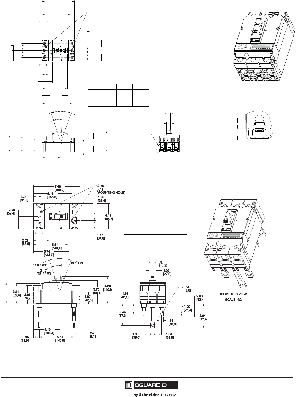
PowerPact™ H-, J-, and L-Frame Circuit Breakers
Dimensions
147
05/2012
© 2011–2012 Schneider Electric
All Rights Reserved
™
Figure 11: 15–150 A Lug-Lug PowerPact H-Frame 3P Circuit Breaker
Figure 12: 15–150 A Rear Connected PowerPact H-Frame 3P Circuit Breaker
Ø.20
[5,1]
(MOUNTING HOLE)
SEE DETAIL A
ISOMETRIC VIEW
SCALE 1:2
DETAIL A
SCALE 1:1
5.20
132,1[]
5.66
143,8[]
6.40
162,6[]
1.38
35,0[]
1.37
34,8[]
.74
18,8[]
.44
11,3[]
2.04
51,9[] 4.99
126,7[]
5.96
151,3[]
2.06
52,4[] 4.12
104,7[]
2.87
72,9[]
3.24
82,4[] 1.91
48,5[]
TRIPPED
21.5°
OFF
17.9°
ON
19.5°
3.69
93,8[]
3.74
95,1[]
4.36
110,8[]
1.06
27,0[]
.43
10,8[]
.62
15,9[]
.08
2,0[]
.73
18,6[]
1.38
35,0[]
1.38
35,0[]
48996-012-01
A
Thermal-Magnetic
and MCP
Micrologic
Electronic Trip
Dim. “A”
Trip Unit
1.20
[30,5]
1.13
[28,8]
Dim. “B”
3.44
[87,4]
3.49
[88,6]
B
Dimensions: in.
[mm]
AThermal-Magnetic
and MCP
Micrologic
Electronic Trip
Dim. “A”
Trip Unit
1.70
[43,2]
1.63
[41,5]
Dim. “B”
3.44
[87,4]
3.49
[88,6]
B
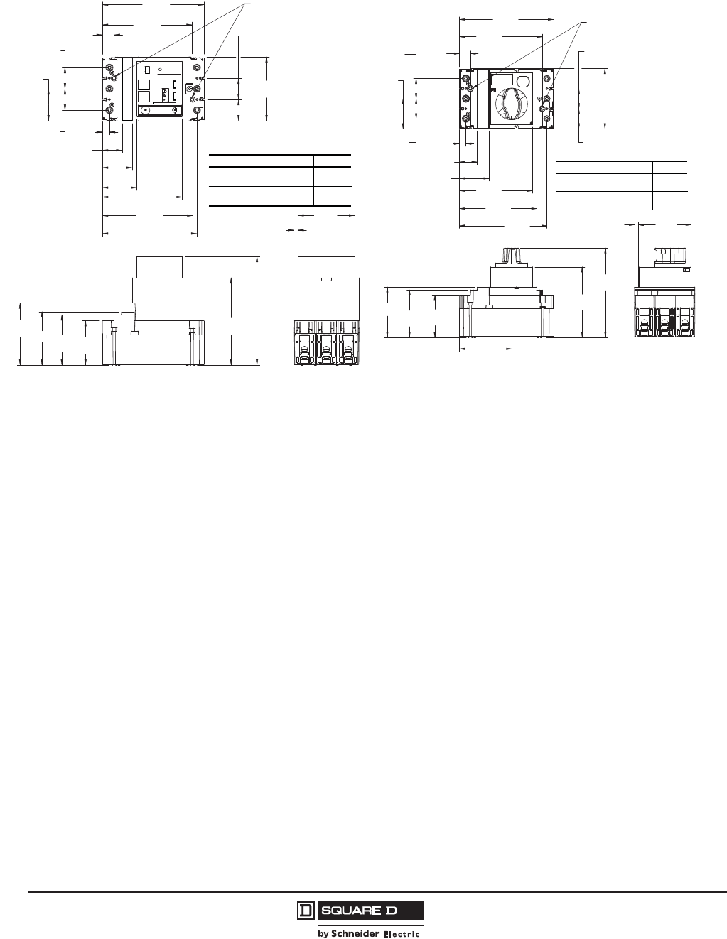
© 2011–2012 Schneider Electric
All Rights Reserved
PowerPact™ H-, J-, and L-Frame Circuit Breakers
Dimensions
148
05/2012
™
Figure 13: Motor Operator Detail
(PowerPact H-Frame Circuit Breaker)
Figure 14: Rotary Handle Detail
(PowerPact H-Frame Circuit Breaker)
Ø .20
5,1[]
(MOUNTING HOLE)
6.40
162,6[]
5.66
143,8[]
.74
18,8[]
4.12
104,7[]
1.38
35,0[]
1.37
34,8[]
5.04
128,0[]
2.16
55,0[]
1.89
48,1[]
A
2.06
52,4[]
1.38
35,0[]
1.38
35,0[]
7.01
178,1[]
5.63
143,1[]
2.87
72,9[]
3.24
82,4[]
4.00
101,7[]
3.58
91,0[]
.27
6,8[]
.44
11,3[]
5.96
151,3[]
5.71
145,0[]
Thermal-Magnetic
and MCP
Micrologic
Electronic Trip
Dim. “A”
Trip Unit
1.24
[31,5]
1.17
[29,7]
Dim. “B”
3.44
[87,4]
3.49
[88,6]
B
3.58
91,0[]
.27
[6,7]
4.82
122,4[]
6.12
155,4[]
2.87
72,9[]
3.24
82,4[]
3.54
[90,2]
6.40
[162,6]
.74
18,8[]
5.66
143,8[]
.44
[11,3]
A
2.02
[51,2] 5.00
[126,9]
5.27
[133,9]
5.96
[151,3]
1.37
34,8[]
1.38
[35,0]
4.12
[104,7]
1.38
[35,0]
1.38
[35,0]
2.06
[52,4]
Ø.20
[5,1]
(MOUNTING HOLE)
Thermal-Magnetic
and MCP
Micrologic
Electronic Trip
Dim. “A”
Trip Unit
1.20
[30,5]
1.13
[28,8]
Dim. “B”
3.44
[87,4]
3.49
[88,6]
B
Dimensions: in.
[mm]
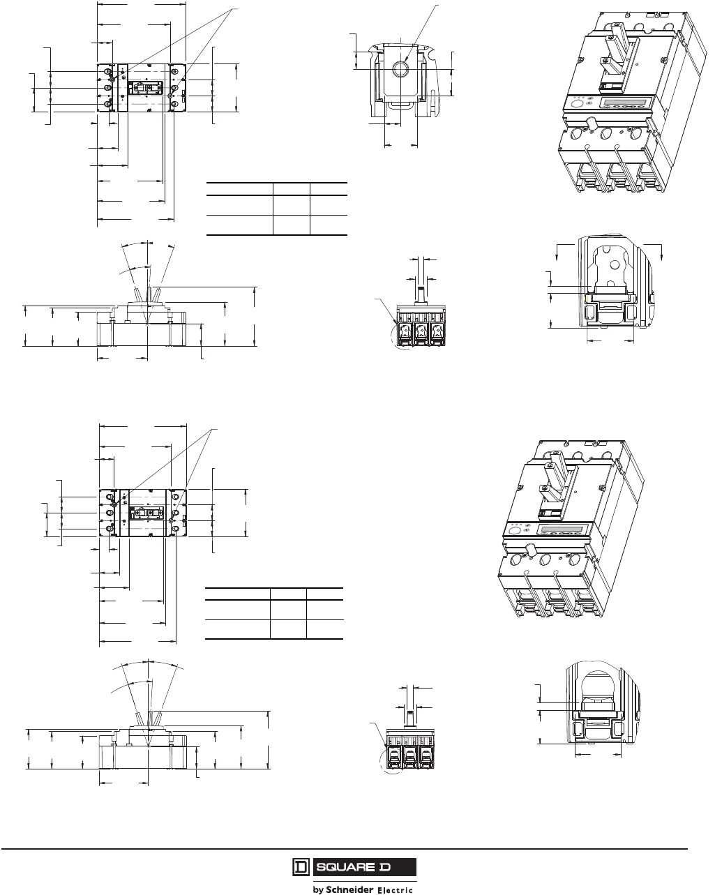
PowerPact™ H-, J-, and L-Frame Circuit Breakers
Dimensions
149
05/2012
© 2011–2012 Schneider Electric
All Rights Reserved
™
PowerPact J-Frame Circuit Breakers
Figure 15: 150–250 A Bus Bar PowerPact J-Frame 3P Circuit Breaker
BB
Ø .20
[5,1]
(MOUNTING HOLE)
SEE DETAIL A
ISOMETRIC VIEW
SCALE 1:2
DETAIL A
SCALE 1:1
SECTION B-B
SCALE 1:1
1.37
34,8[]
1.38
35,0[]
1.00
25,5[]
1.30
33,0[]
2.60
66,1[] 5.57
141,5[]
6.52
165,5[]
5.74
145,8[]
6.22
158,0[]
7.52
191,0[]
1.38
35,0[]
1.38
35,0[]
2.06
52,4[] 4.12
104,7[]
3.24
82,4[]
ON
19.5°
TRIPPED
21.5°
1.91
48,5[]
3.74
95,1[]
5.00
127,0[]
.48
12,2[]
OFF
17.9°
4.25
108,0[]
.35
8,9[]
.70
17,7[]
.57
14,4[]
.16
4,0[]
.37
9,4[]
.73
18,6[]
Ø
(5/16-18 TERMINAL NUT)
.35
8,9[]
1.05
26,6[]
.99
25,2[]
2.87
72,9[]
48996-022-01
A
Thermal-Magnetic
and MCP
Micrologic
Electronic Trip
Dim. “A”
Trip Unit
1.76
[44,7]
1.69
[44,0]
Dim. “B”
3.44
[87,4]
3.49
[88,6]
B
Dimensions: in.
[mm]
Figure 16: 150–250 A Lug-Lug PowerPact J-Frame 3P Circuit Breaker
Ø .20
[5,1]
(MOUNTING HOLE)
SEE DETAIL A
ISOMETRIC VIEW
SCALE 1:2
DETAIL A
SCALE 1:1
1.30
33,0[]
2.60
66,1[] 5.57
141,5[]
1.37
34,8[]
1.38
35,0[]
5.74
145,8[]
6.22
158,0[]
7.52
191,0[]
1.38
35,0[]
1.38
35,0[]
2.06
52,4[] 4.12
104,7[]
2.87
72,9[]
3.24
82,4[]
4.25
108,0[]
1.91
48,5[]
3.24
82,4[]
3.74
95,1[]
5.00
127,0[]
TRIPPED
21.5°
OFF
17.9°
ON
19.5°
1.06
27,0[]
.53
13,4[]
.99
25,2[]
.16
4,0[]
.73
18,6[]
.86
21,9[]
6.66
169,2[]
48996-014-01
A
Thermal-Magnetic
and MCP
Micrologic
Electronic Trip
Dim. “A”
Trip Unit
1.76
[44,7]
1.69
[43,0]
Dim. “B”
3.44
[87,4]
3.49
[88,6]
B
Dimensions: in.
[mm]

© 2011–2012 Schneider Electric
All Rights Reserved
PowerPact™ H-, J-, and L-Frame Circuit Breakers
Dimensions
150
05/2012
™
Figure 17: 150–250 A Rear Connected PowerPact J-Frame 3P Circuit Breaker
Figure 18: Motor Operator Detail
(PowerPact J-Frame Circuit Breaker)
Figure 19: Rotary Handle Detail
(PowerPact J-Frame Circuit Breaker)
Ø .20
5,1[]
(MOUNTING HOLE)
ISOMETRIC VIEW
SCALE 1:2
8.00
203,2[]
6.46
164,1[]
6.02
152,9[]
4.12
104,7[]
1.38
35,0[]
1.37
34,8[]
5.81
147,6[]
2.84
72,2[]
1.54
39,1[]
2.06
52,4[]
5.00
126,9[]
.24
6,0[]
5.51
[140,0]
1.24
31,6[]
3.24
82,4[]
4.49
114,2[]
.48
12,2[]
1.04
26,5[]
2.06
52,3[]
3.84
97,5[]
.71
18,0[]
1.00
25,3[]
1.66
42,1[]
3.44
87,3[]
1.38
35,0[]
1.38
35,0[]
Ø .34
8,6[]
2.95
74,9[]
3.74
[95,1]
48996-023-01
A
Thermal-Magnetic
and MCP
Micrologic
Electronic Trip
Dim. “A”
Trip Unit
2.04
[51,8]
1.97
[50,1]
Dim. “B”
3.44
[87,4]
3.49
[88,6]
B
Dimensions: in.
[mm]
Ø .20
5,1[]
(MOUNTING HOLE)
7.52
191,0[]
5.50
139,8[]
2.63
66,8[]
4.12
104,7[]
1.38
35,0[]
1.37
34,8[]
1.30
33,0[]
A
2.36
59,9[]
6.22
158,0[]
2.06
52,4[]
1.38
35,0[]
1.38
35,0[]
2.87
72,9[]
3.24
82,4[]
4.01
101,7[]
5.63
143,1[]
7.01
178,1[]
3.58
91,0[]
.27
6,8[]
.86
22,0[]
6.65
169,0[]
6.17
156,7[]
Thermal-Magnetic
and MCP
Micrologic
Electronic Trip
Dim. “A”
Trip Unit
1.80
[45,7]
1.73
[44,0]
Dim. “B”
3.44
[87,4]
3.49
[88,6]
B
Ø .20
5,1[]
(MOUNTING HOLE)
7.52
191,0[]
6.22
158,0[]
1.30
33,0[]
4.12
104,7[]
1.38
35,0[]
1.37
34,8[]
5.83
148,0[]
5.55
141,0[]
2.06
52,4[]
1.38
35,0[]
1.38
35,0[]
6.12
155,4[]
4.82
122,4[]
2.87
72,9[]
3.24
82,4[]
4.11
104,5[]
3.58
91,0[]
.27
6,7[]
6.66
169,0[]
.86
21,8[]
A
2.68
68,1[]
Thermal-Magnetic
and MCP
Micrologic
Electronic Trip
Dim. “A”
Trip Unit
1.76
[44,7]
1.69
[43,0]
Dim. “B”
3.44
[87,4]
3.49
[88,6]
B
Dimensions: in.
[mm]
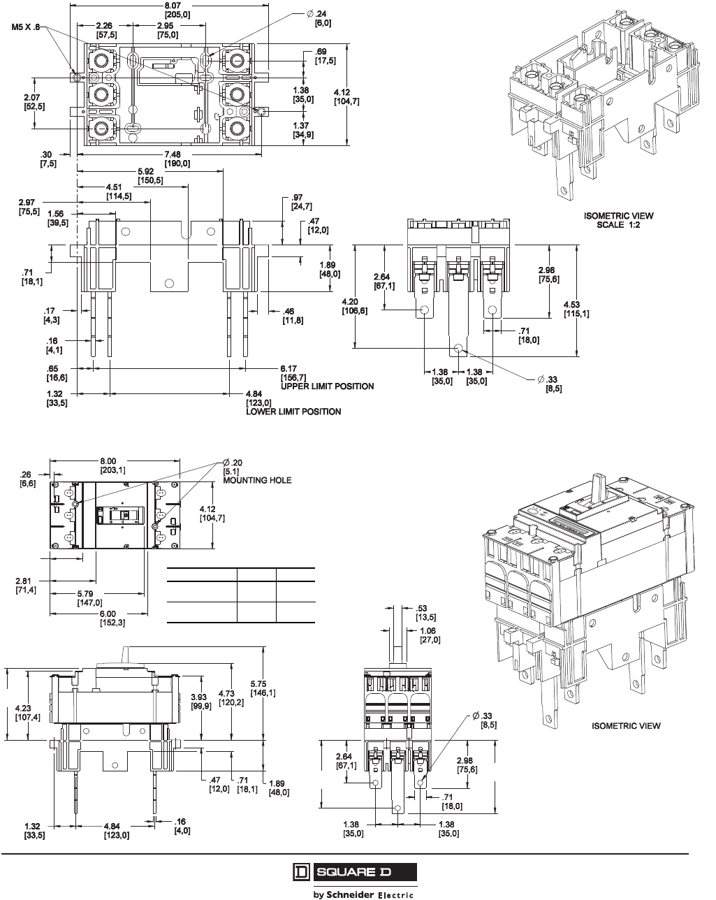
PowerPact™ H-, J-, and L-Frame Circuit Breakers
Dimensions
151
05/2012
© 2011–2012 Schneider Electric
All Rights Reserved
™
PowerPact H- and J-Frame Plug-In Circuit Breakers
Figure 20: 15–250 A PowerPact H- and J-Frame 3P Circuit Breaker Plug-In Base
48996-045-01
Dimensions: in.
[mm]
Figure 21: 15–250 A PowerPact H- and J-Frame Plug-In 3P Circuit Breaker
2.00
(50,8)
1.93
(49,1)
Thermal-Magnetic
and MCP
Micrologic
Electronic Trip
Dim. “A”
Trip Unit Dim. “B”
4.43
[112,4]
4.48
[113,6]
B
48996-024-01
A
4.86
[123,4]
4.53
[115,1]
Dimensions: in.
[mm]
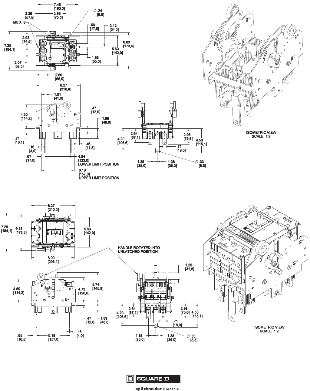
© 2011–2012 Schneider Electric
All Rights Reserved
PowerPact™ H-, J-, and L-Frame Circuit Breakers
Dimensions
152
05/2012
™
PowerPact H- and J-Frame Drawout Circuit Breakers
Figure 22: 15–250 A PowerPact H- and J-Frame 3P Circuit Breaker Cradle
48996-046-01
Dimensions: in.
[mm]
Figure 23: 15–250 A PowerPact H- and J-Frame Drawout 3P Circuit Breaker
48996-025-01
Dimensions: in.
[mm]
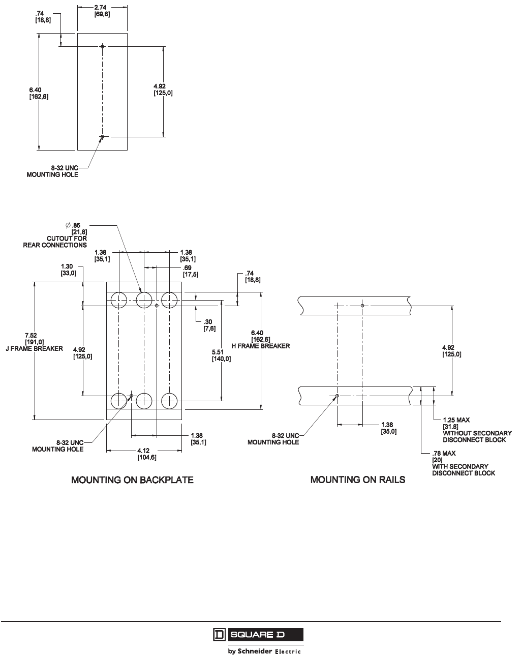
PowerPact™ H-, J-, and L-Frame Circuit Breakers
Dimensions
153
05/2012
© 2011–2012 Schneider Electric
All Rights Reserved
™
PowerPact H- and J-Frame Circuit Breaker Mounting
Figure 24: PowerPact H-Frame 2P HD/HG Thermal-Magnetic Only Circuit Breaker
Dimensions: in.
[mm]
Figure 25: PowerPact H- and J-Frame 3P Circuit Breaker
Dimensions: in.
[mm]

© 2011–2012 Schneider Electric
All Rights Reserved
PowerPact™ H-, J-, and L-Frame Circuit Breakers
Dimensions
154
05/2012
™
PowerPact H- and J-Frame Circuit Breaker Door Cutouts
Figure 26: PowerPact H- and J-Frame Circuit Breaker Toggle Handle Door Cutout
Thermal-Magnetic
and MCP
Electronic with
Micrologic
Dim. “A”
Trip Unit
4.10
(104,1)
4.17
(106,0)
A
Dim. “B”
0.41
(10,4)
0.3
(8,)
B
Dimensions: in.
[mm]
Figure 27: PowerPact H- and J-Frame Circuit Breaker Toggle Handle With Escutcheon Door Cutout
Dimensions: in.
[mm]
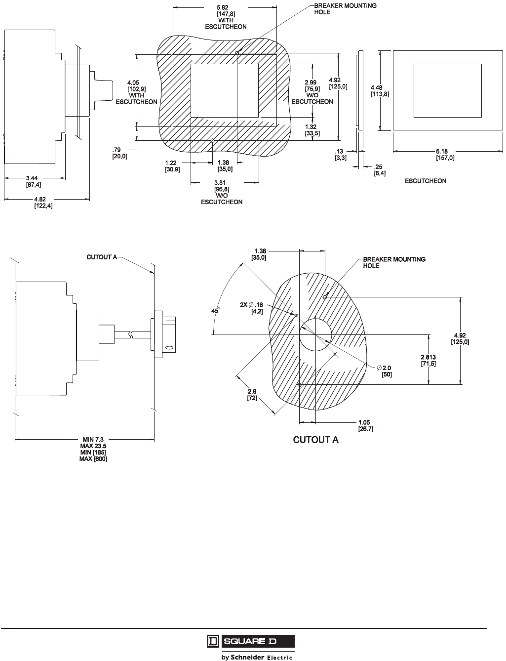
PowerPact™ H-, J-, and L-Frame Circuit Breakers
Dimensions
155
05/2012
© 2011–2012 Schneider Electric
All Rights Reserved
™
Figure 28: PowerPact H- and J-Frame Circuit Breaker Fixed Rotary Handle Cutout
Dimensions: in.
[mm]
Figure 29: PowerPact H- and J-Frame Circuit Breaker Door Mounted Rotary Handle Cutout
Dimensions: in.
[mm]
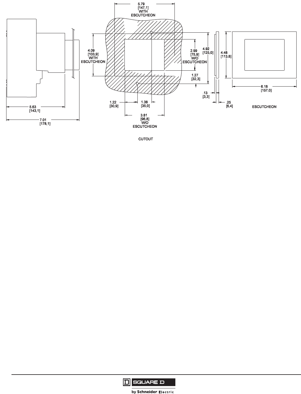
© 2011–2012 Schneider Electric
All Rights Reserved
PowerPact™ H-, J-, and L-Frame Circuit Breakers
Dimensions
156
05/2012
™
Figure 30: PowerPact H- and J-Frame Circuit Breaker Motor Operator Cutout
Dimensions: in.
[mm]
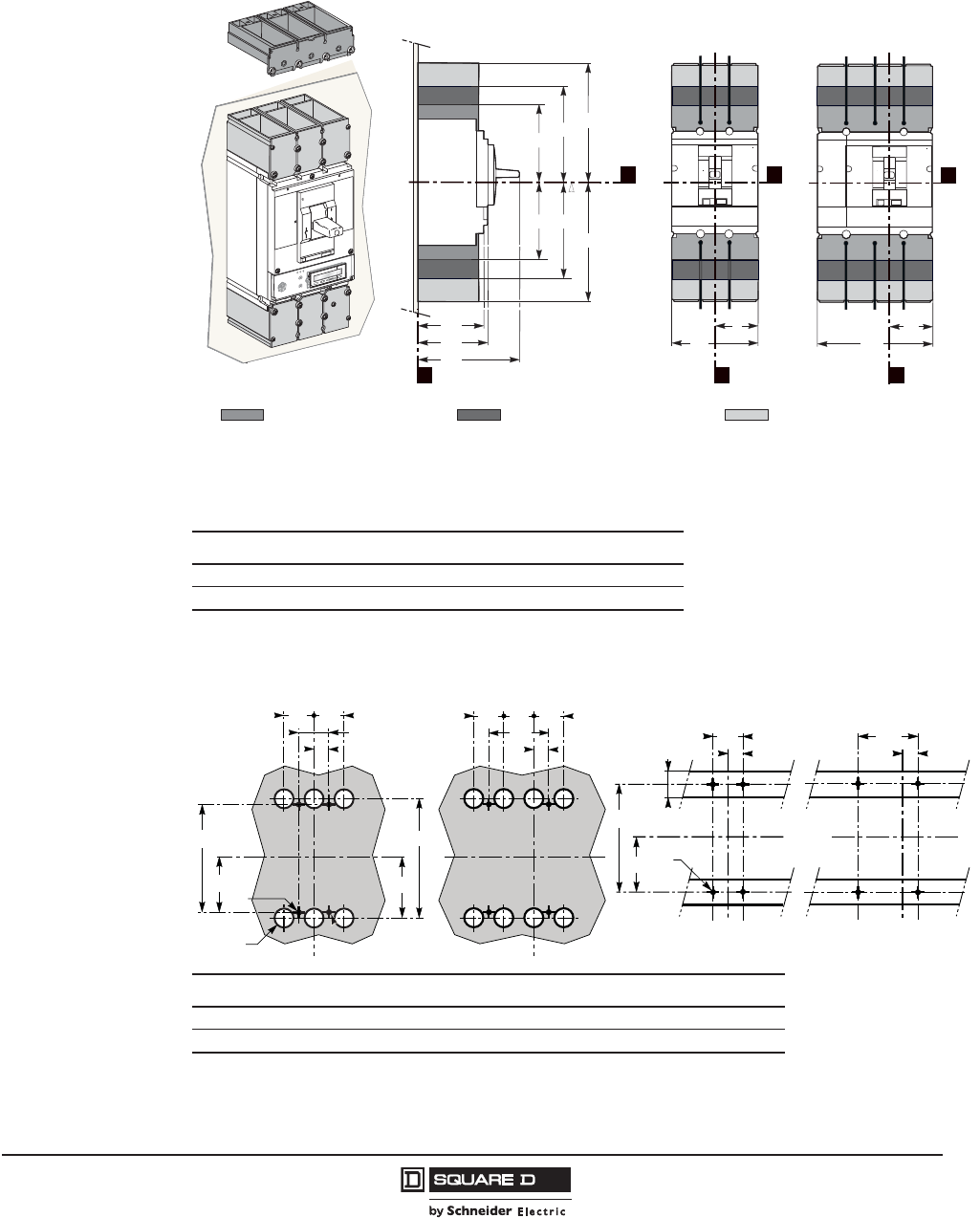
PowerPact™ H-, J-, and L-Frame Circuit Breakers
Dimensions
157
05/2012
© 2011–2012 Schneider Electric
All Rights Reserved
™
PowerPact L-Frame Circuit Breakers
Figure 31: PowerPact L-Frame Fixed Mounted Electronic Trip Circuit Breaker
A A2 A3 B B1 B2 C1 C2 C3
inch 6.69 5.65 7.87 2.76 5.51 7.28 3.76 4.33 6.61
mm 170 143.5 200 70 140 185 105 110 168
A2 = Short lug pack
AL400L61K3
AL400L61K4
CU400L61K3
CU400L61K4
AL600LF52K3
CU600LF5283
A = Medium lug pack
AL600LS52K3
AL600LS52K4
CU600LS52K3
CU600LS52K4
06163219
Z
X
A2
A
C1
A2
A3
A3
A
C2
C3
B1
B
X
YY
X
B
B2
push
to
trip
A3 = Long lug pack
Compression Lug Kits
Figure 32: PowerPact L-Frame Circuit Breaker Mounting
G G1G4G5K
1
1For 2 pole circuit breaker, the middle holes are not required.
K1 K2 T T42
2For rear connected circuit breakers only.
U3
3V is d78 in. (20 mm) on C-frame circuit breakers with secondary disconnecting blocks.
inch 3.93 7.87 4.46 8.93 0.88 1.77 3.54 0.23 1.25 1.38
mm 100 200 113.5 227 22.5 45 90 6 32 35
K
K1 K1 K1
X
Y
K2
K
G
G1
K1 K1
K1
G4
G5
X
Y
Ø T
Ø T4
3P 4P
06153129
Y
X
K2
K
Y
X
K1
GT
V K
3P 4P
06153130
G1
Mounting on Backplate Mounting on Rails

© 2011–2012 Schneider Electric
All Rights Reserved
PowerPact™ H-, J-, and L-Frame Circuit Breakers
Dimensions
158
05/2012
™
Figure 33: Front Panel Cutouts for PowerPact L-Frame Fixed or Plug-In Circuit Breakers
C C1 C2 C3 P5 P6 R R1 R2 R4 R5 '
inch 1.63 4.56 3.64 7.24 4.21 4.40 1.24 2.48 2.81 5.62 7.40 3.93 + (5 x h)
mm 41.5 116 92.5 184 107 112 31.5 63 71.5 143 188 100 + (5 x h)
X
P5
P6
A
B/C
Z
06153131
X
Y
C
C1
R
R1
Cutout A
06153132
X
Y
C2
C3
R2
R4(3P)
R5(4P)
Cutout B
06153133
X
Y
C2
C3
Cutout C
06153134
Δ
h
06153138
Figure 34: PowerPact L-Frame Circuit Breaker Front Panel Cutouts for Toggle Boot and
Escutcheon
C6 C7 C20 C21 P6 R6 R7 R12 R13 '
inch 2.2 6 1.83 5.00 4.40 3.5 7 2.48 4.96 3.93 + (5 x h)
mm 56.5 155 46.5 126 112 90 180 63 126 100 + (5 x h)
C20
C21
X
R13
R12
Y
06153135
X
P6
Z
06153136
X
Y
C6
C7
R6
R7
06153137
Δ
h
06153138
With Toggle Boot With Escutcheon Door Hinge Point
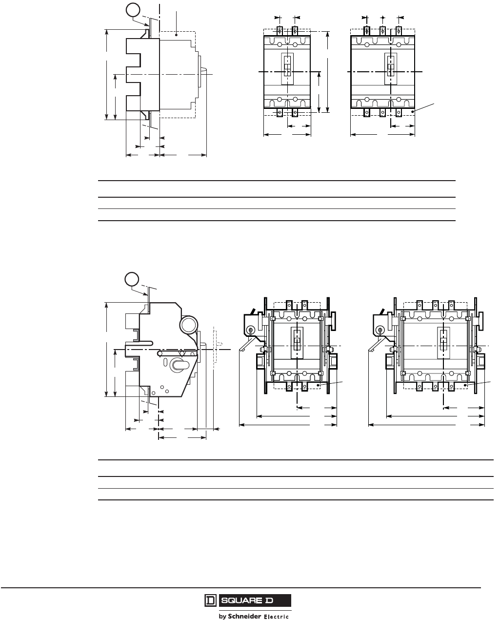
PowerPact™ H-, J-, and L-Frame Circuit Breakers
Dimensions
159
05/2012
© 2011–2012 Schneider Electric
All Rights Reserved
™
PowerPact L-Frame Plug-In and Drawout Mounting
Figure 35: PowerPact L-Frame Plug-In Circuit Breaker (On Base)
G10G11H16H17K1L L1L2P4P7P8P9
inch 5.90 11.8 6.20 12.40 1.77 2.75 5.51 7.28 6.61 1.06 1.77 3.93
mm 150 300 157.5 315 45 70 140 185 168 27 45 100
Figure 36: PowerPact L-Frame Drawout Circuit Breaker (on Cradle)
H18H19L6L7L8L10P2P4P7P8P9P12L9
inch 5.51 11.02 4.33 8.66 98.46 11.61 4.33 6.61 1.06 1.77 3.93 1.25 10.43
mm 140 280 110 220 250 295 110 168 27 45 100 32 265
M
X
H16
P4
P9
P7
H17
(
*
)
Z
P8
06153139
(*)
L
L2
K1 K1
X
Y
G10
G11
L1
L
X
K1
Y
3P 4P
06153140
A = Terminal shields
M = Through front panel
M
Z
H19
P7
P9
P4
P2 P12
X
H18
P8
06153141
(
Y
X
L10
L6
L9
(
*
)
Y
X
L8
L6
L7
3P 4P
M = Through front panel

© 2011–2012 Schneider Electric
All Rights Reserved
PowerPact™ H-, J-, and L-Frame Circuit Breakers
Dimensions
160
05/2012
™
Figure 37: PowerPact L-Frame Circuit Breaker Mounting Through a Backplate
G10G11G12G13K K1K2K5K6K7K11K12K13
inch 5.90 11.8 5.39 10.7 0.88 1.77 3.54 2.81 2.81 7.4 7.40 3.60 8.98
mm 150 300 137 274 22.5 45 90 71.5 143 188 91.5 183 228
3P 4P
K
G10
G11
K1
G12
G13
K5
K6
X
Y
T
K
K2
K5
K7
X
Y
06153143
3P 4P
K
G10
G11
K1
G12
G13
K11
K12
X
Y
T
K
K2
K11
K13
X
Y
06153144
Plug-In Base Cradle
Figure 38: PowerPact L-Frame Circuit Breaker Mounting on Rails (Plug-In Base or Cradle)
G20 G21 K20 K21 K22 T
inch 2.95 5.90 8.97 1.96 5.71 0.24
mm 75 150 50 100 145 6
Figure 39: PowerPact L-Frame Circuit Breaker Front-Panel Cutouts
C11 C17 P44 R8 R9
inch 6.10 2.22 5.78 3.54 7.08
mm 155 56.5 147 90 180
Y
X
K20
K22
Y
X
K20
K21
G20
G21
T
U
3P 4P
06153145
P44
X
Z
06153146
Y
C17
C11
R8
R9
X
06153147
Plug-in Mounting
Drawout with Extended
Front-Panel Escutcheons
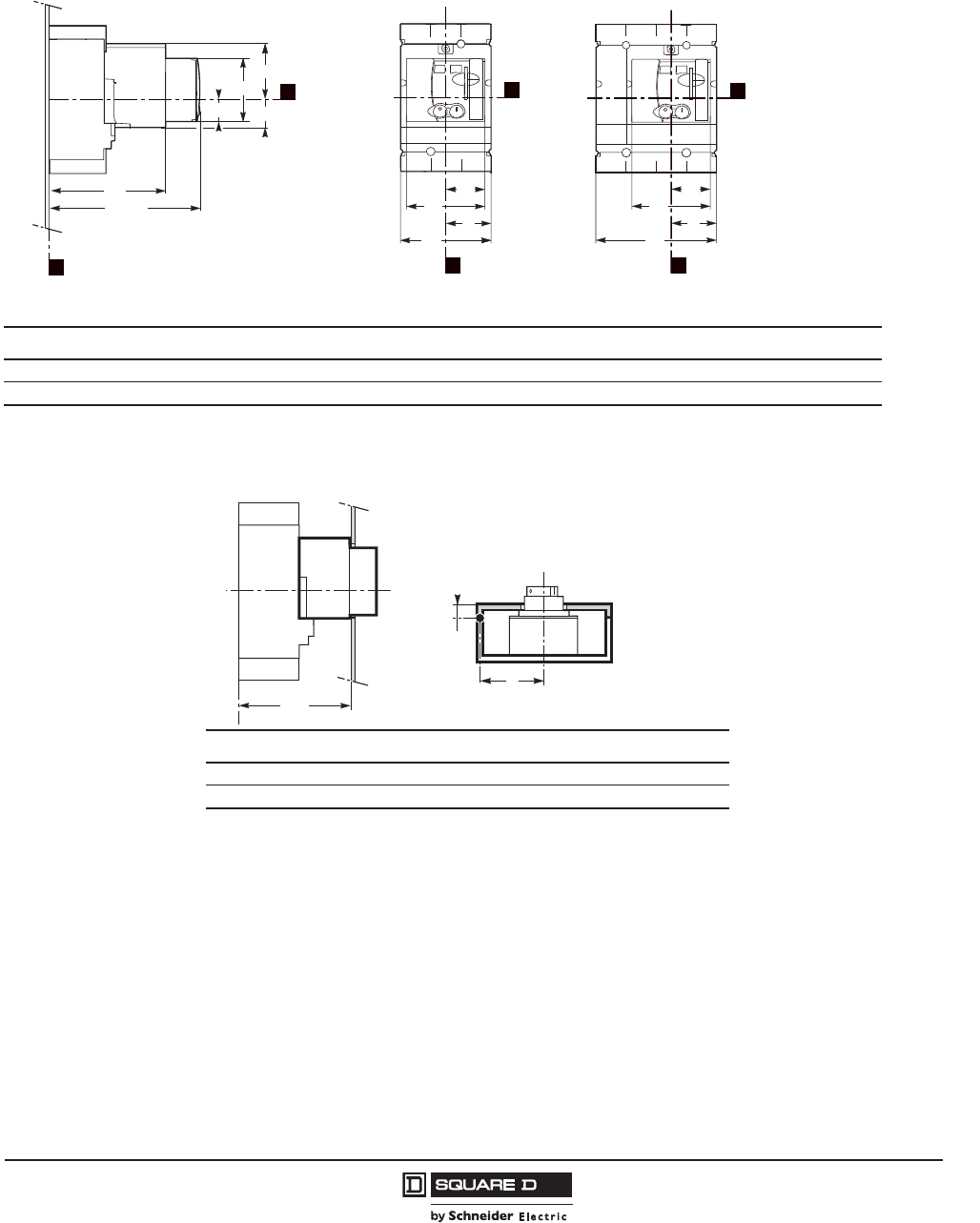
PowerPact™ H-, J-, and L-Frame Circuit Breakers
Dimensions
161
05/2012
© 2011–2012 Schneider Electric
All Rights Reserved
™
PowerPact L-Frame Circuit Breaker Handles and Handle Operators
Figure 40: PowerPact L-Frame Circuit Breaker Motor Operators
A14A15A16A17B B1B2B8B9C4C5C6D1
inch 1.57 4.84 2.05 3.94 2.76 5.51 7.28 2.42 4.84 8.46 10.08 10.16 3.94
mm 40 123 52 100 70 140 185 61.5 123 215 256 258 100
B1
B
B8
B9
X
Y
06163220
C4
Z
XX
C5/C6
A17
A15
A14 A16
B2
B
B8
B9
X
Y
C5: without keylock
C6: with keylock
Figure 41: PowerPact L-Frame Circuit Breaker Motor Operator Front-Panel Cutouts
C22 C23 P45 R14 R15 '
inch 1.63 4.96 8.54 2.53 5.08 3.93 + (5 x h)
mm 41.5 126 217 64.5 129 100 + (5 x h)
Z
P45
X
06153150
Δ
h
06153138
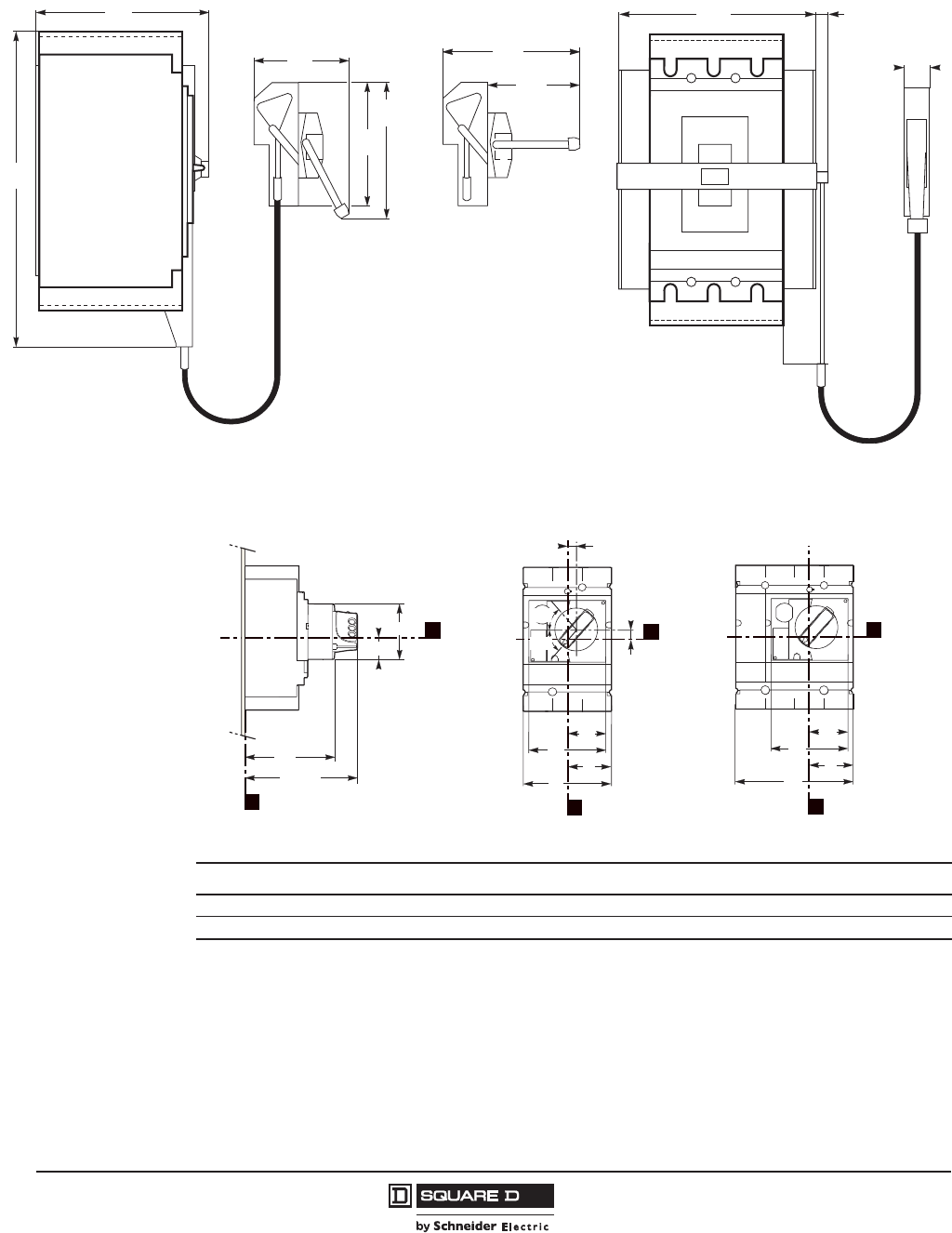
© 2011–2012 Schneider Electric
All Rights Reserved
PowerPact™ H-, J-, and L-Frame Circuit Breakers
Dimensions
162
05/2012
™
Figure 42: PowerPact L-Frame Circuit Breaker Cable-Operating Handles
11.32
287
11.32
287
7.01
178
4.31
184
13.5
343
4.31
109
9.38
238
10.38
264
06153154
7.996
203
0.31
8
1.06
27
06153155
Dimensions: in.
[mm]
Figure 43: PowerPact L-Frame Circuit Breaker Rotary-Operating Handles
A14A15A18B B1B2B8B9B10C7C8C9D1
inch 1.57 4.84 0.97 2.76 5.51 7.28 2.42 4.84 0.20 5.71 7.05 7.40 3.94
mm 40 123 24.6 70 140 185 61.5 123 5 145 179 188 100
A18
B10
X
B
B1
B8
B9
Y
60°
60°
O
I
06163221
C7
Z
XX
C8/C9
A14
A15 X
B2
B
B8
B9
Y
C8: without keylock
C9: with keylock

PowerPact™ H-, J-, and L-Frame Circuit Breakers
Dimensions
163
05/2012
© 2011–2012 Schneider Electric
All Rights Reserved
™
Figure 44: PowerPact L-Frame Motor-Control Center Circuit Breaker Direct Rotary-Operating
Handle
A18 A19 A20 B10 B11 B12 P1 S1 S2 S3 S4 S5
inch 0.97 3.27 6.30 0.20 3.35 6.30 5.87 5.71 2.95 5.71 2.01 0.04–0.12
mm 24.6 83 160 5 85 160 149 145 75 145 51 1–3
A18
A19
A20
X
B10
B12
B11
Y
P1
S5 max.
Z
XX
06163222
X
Y
S4
S3
S2
S1
Front-Panel Cutout Operating Handle
Figure 45: PowerPact L-Frame Circuit Breaker Extended Rotary Handle Mounting
R1 min R1 max R2 min R2 max A18 B10 D1
inch 7.68 23.62 10.71 23.62 0.97 0.20 3.94
mm 195 600 272 600 24.6 5 100
06163223
M
N
R2
1.06 [27]
D1
M
N
Z
XX
1.06 [27]
1.77 [45]
D1 R1 1.85
[47]
M
N
Z
XX
2 Ø
Ø
X
Y
A18
B10
1.42
[36]
2.83
[72]
45°
X
Y
A18
1.48
[37.5]
B10
60°
60°
2.95
[75]
2.95
[75]
0.39
[10]
1.48
[37.5]
0.17
[4.2]
1.97
[50]
1.77 [45] 1.85
[47]
Fixed or Plug-In Mounted Drawout Mounting
Dimensions: in.
[mm]

© 2011–2012 Schneider Electric
All Rights Reserved
PowerPact™ H-, J-, and L-Frame Circuit Breakers
Dimensions
164
05/2012
™
L-Frame Circuit Breaker Front Accessories
Figure 46: PowerPact L-Frame Circuit Breaker Extended Escutcheons
A4 A5 B2 B3 C S6
inch 4.82 5.43 4.82 5.43 2.36 1.38
mm 122.5 134 122.5 134 60 35
For toggle
06163224
B2
A4
Y
S6
X
IP43 toggle cover
B3
A5
Y
C
X
Figure 47: PowerPact L-Frame Circuit Breaker Front-Panel Escutcheons
A1 A2 D1 D2 M2 M3 M6 M7
inch 4.01 7.44 0.13 0.25 6.10 5.59 6.45 5.94
mm 102 189 3.5 6.5 115 142 164 151
06153173
M2
A1
06153174
D2D1
M3
06153175
06153176
M6
A2
06153177
D2D1
M7
06153178
For Toggle For Extended Escutcheon, Motor Operator Module or Rotary Handle
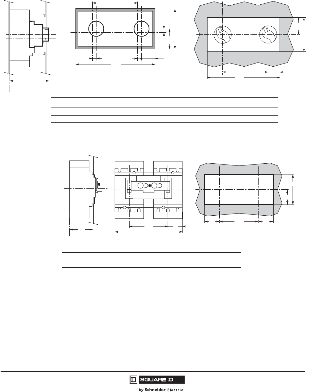
PowerPact™ H-, J-, and L-Frame Circuit Breakers
Dimensions
165
05/2012
© 2011–2012 Schneider Electric
All Rights Reserved
™
PowerPact L-Frame Circuit Breaker Interlocking Systems
Figure 48: PowerPact L-Frame Circuit Breaker Interlocking Systems with Rotary-Operating Handles
ABCDFGHJ KL MN
inch 16.38 4.53 3.94 7.87 8.27 6.18 0.20 0.97 15.20 3.94 6.89 2.93
mm 416 115 100 200 210 157 5 24.6 386 100 175 74.5
Z
G
06153179
X
J
Y
F
B
H
A
C
D
H
06153180
F
K
L
N
M
06153181
Figure 49: PowerPact L-Frame Circuit Breaker Interlocking Systems with Toggle Handles
C2 C3 L L16 L17 R2 R19 P5
inch 3.64 7.24 2.75 7.28 12.79 2.81 7.28 4.21
mm 92.5 184 70 185 325 71.5 185 107
P5
Z
06153182
X
Y
L16
L17
L
06153183
X
Y
C2
C3
R19 R2R2 Y
06153184
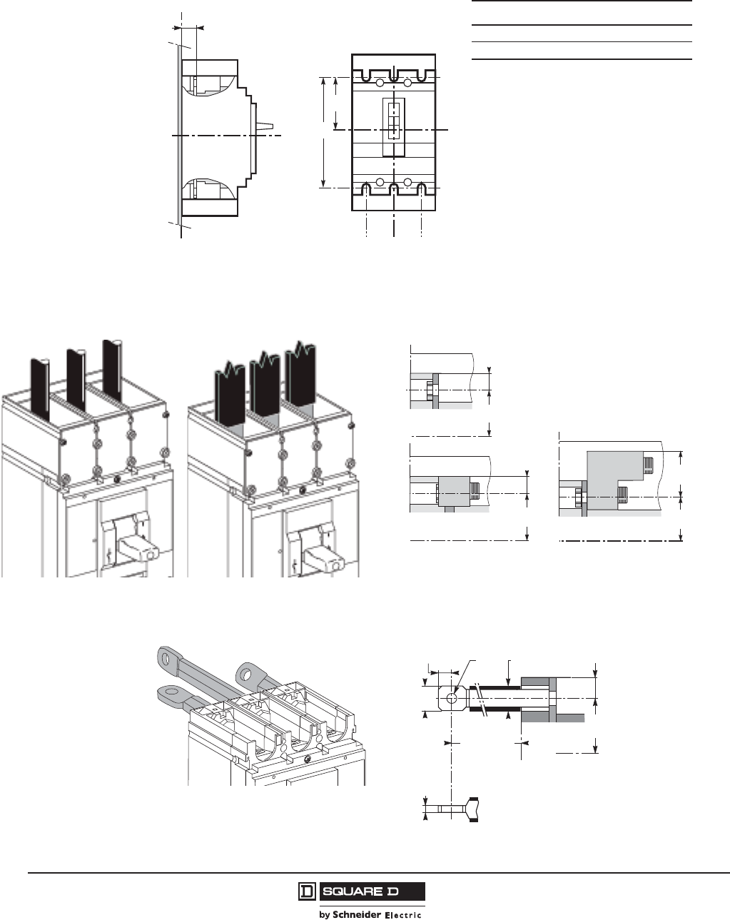
© 2011–2012 Schneider Electric
All Rights Reserved
PowerPact™ H-, J-, and L-Frame Circuit Breakers
Dimensions
166
05/2012
™
PowerPact L-Frame Circuit Breaker Connectors
Figure 50: PowerPact L-Frame Circuit Breaker Fixed-Mounted Connections
G4 G5 K1 P13
inch 4.46 8.93 1.77 1.02
mm 113.5 227 45 526
X
Z
P13
06153185
X
Y
K1K1
G4
G5
06153186
Figure 51: PowerPact L-Frame Circuit Breaker Front Connections
4.46
[113.5]
Z
X
0.55
[14]
06153189
Z
X
4.46
[113.5]
1.83
[46.5]
06153192
Z
X
0.55
[14]
4.46
113.5]
06153191
Front Connections Bus Bar Connection
M10 Screws
Dimensions: in.
[mm]
Figure 52: PowerPact L-Frame Circuit Breaker Rear Connections
(*) Short RC : 1.96 [50]
(**) Long RC : 4.52 [115]
1.99 [50] (*)
4.52 [115](**)
1.18
[30]
0.59
[15] 0.33
[13]
0.31
[8]
4.46
[113.5]
X
Z
0.55
[14]
0.91
[23.2]
06153195
Dimensions: in.
[mm]

PowerPact™ H-, J-, and L-Frame Circuit Breakers
Dimensions
167
05/2012
© 2011–2012 Schneider Electric
All Rights Reserved
™
Figure 53: PowerPact L-Frame Circuit Breaker Plug-In or Drawout Mounting Connections
K1
inch 1.77
mm 45
Figure 54: PowerPact L-Frame Circuit Breaker Rear Connections Fitted at Lower Limit
EG33P22 P23
inch 0.23 4.09 4.50–7.14 3.93–6.57
mm 6 104 114.5–181.5 100–167
Figure 55: PowerPact L-Frame Circuit Breaker Rear Connections Fitted at Upper Limit
E G35 P22 P23
inch 0.23 5.07 4.50–7.14 3.93–6.57
mm 6 129 114.5–181.5 100–167
X
Z
06153196
X
K1
Y
K1
X
K1
Y
K1
K1
3P 4P
06153197
06153198
G33
E
P23
P22
X
Z
06153199
06153200
P23
P22
G35
E
X
Z
06153201
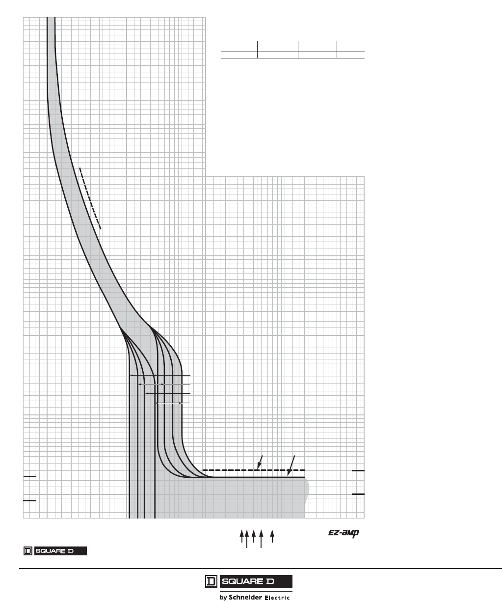
© 2011–2012 Schneider Electric
All Rights Reserved
PowerPact™ H-, J-, and L-Frame Circuit Breakers
Trip Curves
168
05/2012
™
Section 13—Trip Curves
PowerPact H- and J-Frame Thermal-Magnetic Trip Circuit Breakers
Figure 56: H-Frame 15–35 A (HD, HG, HJ, and HL) Thermal-Magnetic Trip
1.5
700
150
200
300
400
600
800
900
2000
3000
4000
5000
7000
8000
9000
10000
.5
.6
.7
.8
.9
1
2
3
4
5
6
7
8
9
10
15
20
30
40
50
60
70
80
90
100
6000
1500
1000
500
.005
.006
.007
.008
.009
.01
.015
.02
.03
.04
.05
.06
.07
.08
.09
.1
.15
.2
.3
.4
.5
.6
.7
.8
.9
1
1.5
2
3
4
5
6
7
8
9
10
20
30
40
50
60
70
80
90
100
15
200
300
400
500
600
700
800
900
1000
1500
2000
3000
4000
6000
7000
8000
9000
5000
10000
1
.5
.6
.7
.8
.9
1.5
2
3
4
5
6
7
8
9
10
15
20
30
40
50
60
70
80
90
100
MULTIPLES OF RATED CURRENT
TIME IN SECONDS
.005
.006
.007
.008
.009
.01
.015
.02
.03
.04
.05
.06
.07
.08
.09
.1
.15
.2
.3
.4
.5
.6
.7
.8
.9
1
1.5
2
3
4
5
6
7
8
9
10
15
20
30
40
50
60
70
80
90
100
150
200
300
400
500
600
700
800
900
1000
1500
2000
3000
4000
5000
6000
7000
8000
9000
10000
TIME IN SECONDS
1
/
2
CYCLE
(60 Hz)
1
/
2
CYCLE
(50 Hz)
150
200
300
400
500
600
700
800
900
1000
1500
2000
3000
4000
5000
6000
7000
8000
9000
10000
150
MULTIPLES OF RATED CURRENT
1 CYCLE
(60 Hz)
1 CYCLE
(50 Hz)
MAXIMUM SINGLE-POLE TRIP TIMES
AT 25°C BASED ON NEMA AB-4 2003
25 A
30 A, 35 A
20 A
15 A
MAXIMUM CLEARING TIME
(AT 50 Hz) (AT 60 Hz)
2535
2030
15
HD, HG, HJ, HL MOLDED CASE CIRCUIT BREAKERS
CHARACTERISTIC TRIP CURVE NO. 50-1
CIRCUIT BREAKER INFORMATION
Circuit Breaker Continuous Maximum Number
Prefix Ampere Rating AC Voltage of Poles
HD, HG, HJ, HL 15–35 600 2, 3
This curve is to be used for application and coordination purposes only. The
EZ-AMP overlay feature at the bottom of the page should be used during
coordination studies.
All time/current characteristic curve data is based on 40°C ambient cold start.
Terminations are made with conductors of appropriate length and ratings.
Curve No. 0050TC0401
June 2004
Drawing No. 48095-050-01
TM
© 2004 Schneider Electric All Rights Reserved
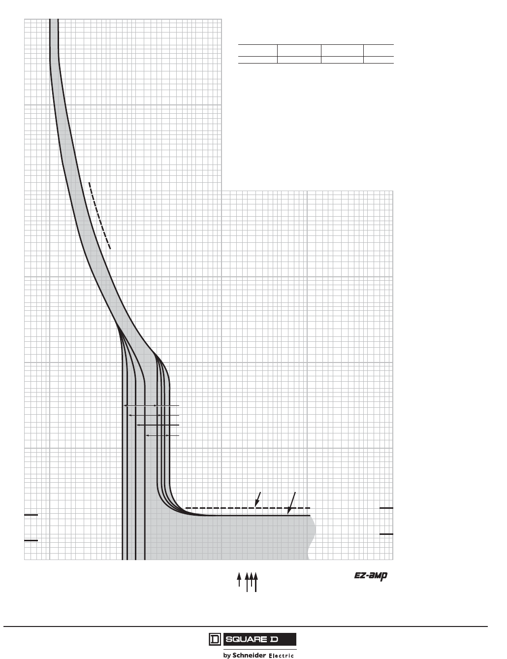
PowerPact™ H-, J-, and L-Frame Circuit Breakers
Trip Curves
169
05/2012
© 2011–2012 Schneider Electric
All Rights Reserved
™
Figure 57: H-Frame 40–60 A (HD, HG, HJ, and HL) Thermal-Magnetic Trip
1.5
700
150
200
300
400
600
800
900
2000
3000
4000
5000
7000
8000
9000
10000
.5
.6
.7
.8
.9
1
2
3
4
5
6
7
8
9
10
15
20
30
40
50
60
70
80
90
100
6000
1500
1000
500
.005
.006
.007
.008
.009
.01
.015
.02
.03
.04
.05
.06
.07
.08
.09
.1
.15
.2
.3
.4
.5
.6
.7
.8
.9
1
1.5
2
3
4
5
6
7
8
9
10
20
30
40
50
60
70
80
90
100
15
200
300
400
500
600
700
800
900
1000
1500
2000
3000
4000
6000
7000
8000
9000
5000
10000
1
.5
.6
.7
.8
.9
1.5
2
3
4
5
6
7
8
9
10
15
20
30
40
50
60
70
80
90
100
MULTIPLES OF RATED CURRENT
TIME IN SECONDS
.005
.006
.007
.008
.009
.01
.015
.02
.03
.04
.05
.06
.07
.08
.09
.1
.15
.2
.3
.4
.5
.6
.7
.8
.9
1
1.5
2
3
4
5
6
7
8
9
10
15
20
30
40
50
60
70
80
90
100
150
200
300
400
500
600
700
800
900
1000
1500
2000
3000
4000
5000
6000
7000
8000
9000
10000
TIME IN SECONDS
1/2 CYCLE
(60 Hz)
1/2 CYCLE
(50 Hz)
150
200
300
400
500
600
700
800
900
1000
1500
2000
3000
4000
5000
6000
7000
8000
9000
10000
150
MULTIPLES OF RATED CURRENT
1 CYCLE
(60 Hz)
1 CYCLE
(50 Hz)
MAXIMUM SINGLE-POLE TRIP TIMES
AT 25°C BASED ON NEMA AB-4 2003
45 A
50 A
40 A
60 A
MAXIMUM CLEARING TIME
(AT 50 Hz) (AT 60 Hz)
40
60 45
50
HD, HG, HJ, HL MOLDED CASE CIRCUIT BREAKERS
CHARACTERISTIC TRIP CURVE NO. 50-2
CIRCUIT BREAKER INFORMATION
Circuit Breaker Continuous Maximum Number
Prefix Ampere Rating AC Voltage of Poles
HD, HG, HJ, HL 40–60 600 2, 3
This curve is to be used for application and coordination purposes only. The
EZ-AMP overlay feature at the bottom of the page should be used during
coordination studies.
All time/current characteristic curve data is based on 40°C ambient cold start.
Terminations are made with conductors of appropriate length and ratings.
Curve No. 0050TC0402
June 2004
Drawing No. 48095-050-02
TM
© 2004 Schneider Electric All Rights Reserved
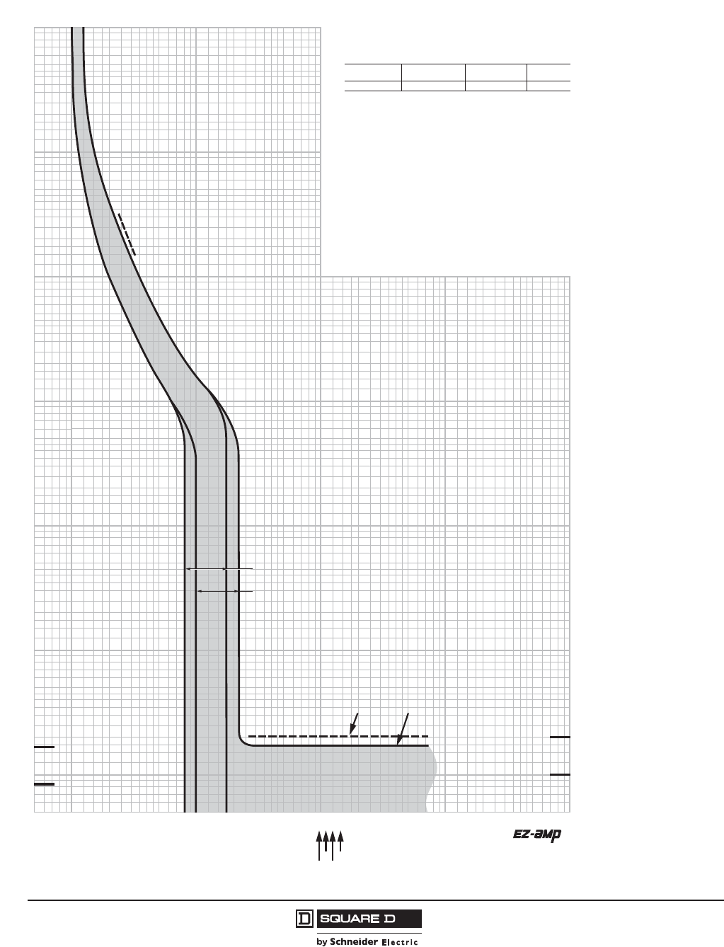
© 2011–2012 Schneider Electric
All Rights Reserved
PowerPact™ H-, J-, and L-Frame Circuit Breakers
Trip Curves
170
05/2012
™
Figure 58: H-Frame 70–100 A (HD, HG, HJ, and HL) Thermal-Magnetic Trip
1.5
700
150
200
300
400
600
800
900
2000
3000
4000
5000
7000
8000
9000
10000
.5
.6
.7
.8
.9
1
2
3
4
5
6
7
8
9
10
15
20
30
40
50
60
70
80
90
100
6000
1500
1000
500
.005
.006
.007
.008
.009
.01
.015
.02
.03
.04
.05
.06
.07
.08
.09
.1
.15
.2
.3
.4
.5
.6
.7
.8
.9
1
1.5
2
3
4
5
6
7
8
9
10
20
30
40
50
60
70
80
90
100
15
200
300
400
500
600
700
800
900
1000
1500
2000
3000
4000
6000
7000
8000
9000
5000
10000
1
.5
.6
.7
.8
.9
1.5
2
3
4
5
6
7
8
9
10
15
20
30
40
50
60
70
80
90
100
MULTIPLES OF RATED CURRENT
TIME IN SECONDS
.005
.006
.007
.008
.009
.01
.015
.02
.03
.04
.05
.06
.07
.08
.09
.1
.15
.2
.3
.4
.5
.6
.7
.8
.9
1
1.5
2
3
4
5
6
7
8
9
10
15
20
30
40
50
60
70
80
90
100
150
200
300
400
500
600
700
800
900
1000
1500
2000
3000
4000
5000
6000
7000
8000
9000
10000
TIME IN SECONDS
1/2 CYCLE
(60 Hz)
1/2 CYCLE
(50 Hz)
150
200
300
400
500
600
700
800
900
1000
1500
2000
3000
4000
5000
6000
7000
8000
9000
10000
150
MULTIPLES OF RATED CURRENT
1 CYCLE
(60 Hz)
1 CYCLE
(50 Hz)
MAXIMUM CLEARING TIME
(AT 50 Hz) (AT 60 Hz)
70
80100
90
MAXIMUM SINGLE-POLE TRIP TIMES
AT 25°C BASED ON NEMA AB-4 2003
90 A, 100 A
70 A, 80 A
HD, HG, HJ, HL MOLDED CASE CIRCUIT BREAKERS
CHARACTERISTIC TRIP CURVE NO. 50-3
CIRCUIT BREAKER INFORMATION
Circuit Breaker Continuous Maximum Number
Prefix Ampere Rating AC Voltage of Poles
HD, HG, HJ, HL 70–100 600 2, 3
This curve is to be used for application and coordination purposes only. The
EZ-AMP overlay feature at the bottom of the page should be used during
coordination studies.
All time/current characteristic curve data is based on 40°C ambient cold start.
Terminations are made with conductors of appropriate length and ratings.
Curve No. 0050TC0403
June 2004
Drawing No. 48095-050-03
TM
© 2004 Schneider Electric All Rights Reserved
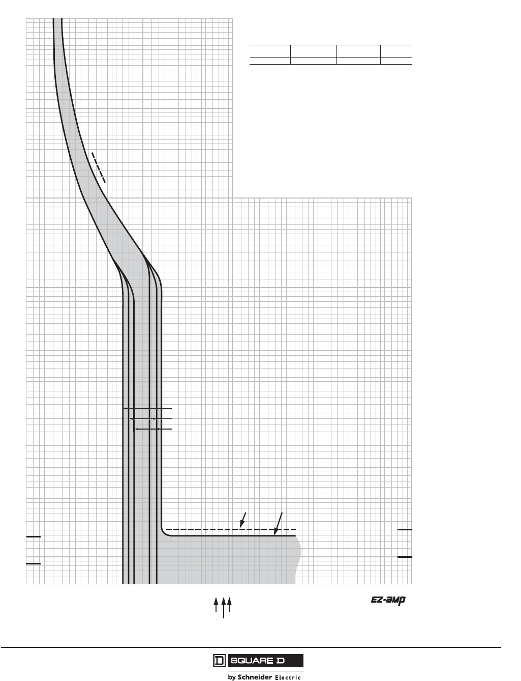
PowerPact™ H-, J-, and L-Frame Circuit Breakers
Trip Curves
171
05/2012
© 2011–2012 Schneider Electric
All Rights Reserved
™
Figure 59: H-Frame 110–150 A (HD, HG, HJ, and HL) Thermal-Magnetic Trip
1.5
700
150
200
300
400
600
800
900
2000
3000
4000
5000
7000
8000
9000
10000
.5
.6
.7
.8
.9
1
2
3
4
5
6
7
8
9
10
15
20
30
40
50
60
70
80
90
100
6000
1500
1000
500
.005
.006
.007
.008
.009
.01
.015
.02
.03
.04
.05
.06
.07
.08
.09
.1
.15
.2
.3
.4
.5
.6
.7
.8
.9
1
1.5
2
3
4
5
6
7
8
9
10
20
30
40
50
60
70
80
90
100
15
200
300
400
500
600
700
800
900
1000
1500
2000
3000
4000
6000
7000
8000
9000
5000
10000
1
.5
.6
.7
.8
.9
1.5
2
3
4
5
6
7
8
9
10
15
20
30
40
50
60
70
80
90
100
MULTIPLES OF RATED CURRENT
TIME IN SECONDS
.005
.006
.007
.008
.009
.01
.015
.02
.03
.04
.05
.06
.07
.08
.09
.1
.15
.2
.3
.4
.5
.6
.7
.8
.9
1
1.5
2
3
4
5
6
7
8
9
10
15
20
30
40
50
60
70
80
90
100
150
200
300
400
500
600
700
800
900
1000
1500
2000
3000
4000
5000
6000
7000
8000
9000
10000
TIME IN SECONDS
1/2 CYCLE
(60 Hz)
1/2 CYCLE
(50 Hz)
150
200
300
400
500
600
700
800
900
1000
1500
2000
3000
4000
5000
6000
7000
8000
9000
10000
150
MULTIPLES OF RATED CURRENT
1 CYCLE
(60 Hz)
1 CYCLE
(50 Hz)
MAXIMUM CLEARING TIME
(AT 50 Hz) (AT 60 Hz)
110
125
150
MAXIMUM SINGLE-POLE TRIP TIMES
AT 25°C BASED ON NEMA AB-4 2003
150 A
125 A
110 A
HD, HG, HJ, HL MOLDED CASE CIRCUIT BREAKERS
CHARACTERISTIC TRIP CURVE NO. 50-4
CIRCUIT BREAKER INFORMATION
Circuit Breaker Continuous Maximum Number
Prefix Ampere Rating AC Voltage of Poles
HD, HG, HJ, HL 110–150 600 2, 3
This curve is to be used for application and coordination purposes only. The
EZ-AMP overlay feature at the bottom of the page should be used during
coordination studies.
All time/current characteristic curve data is based on 40°C ambient cold start.
Terminations are made with conductors of appropriate length and ratings.
Curve No. 0050TC0404
June 2004
Drawing No. 48095-050-04
TM
© 2004 Schneider Electric All Rights Reserved
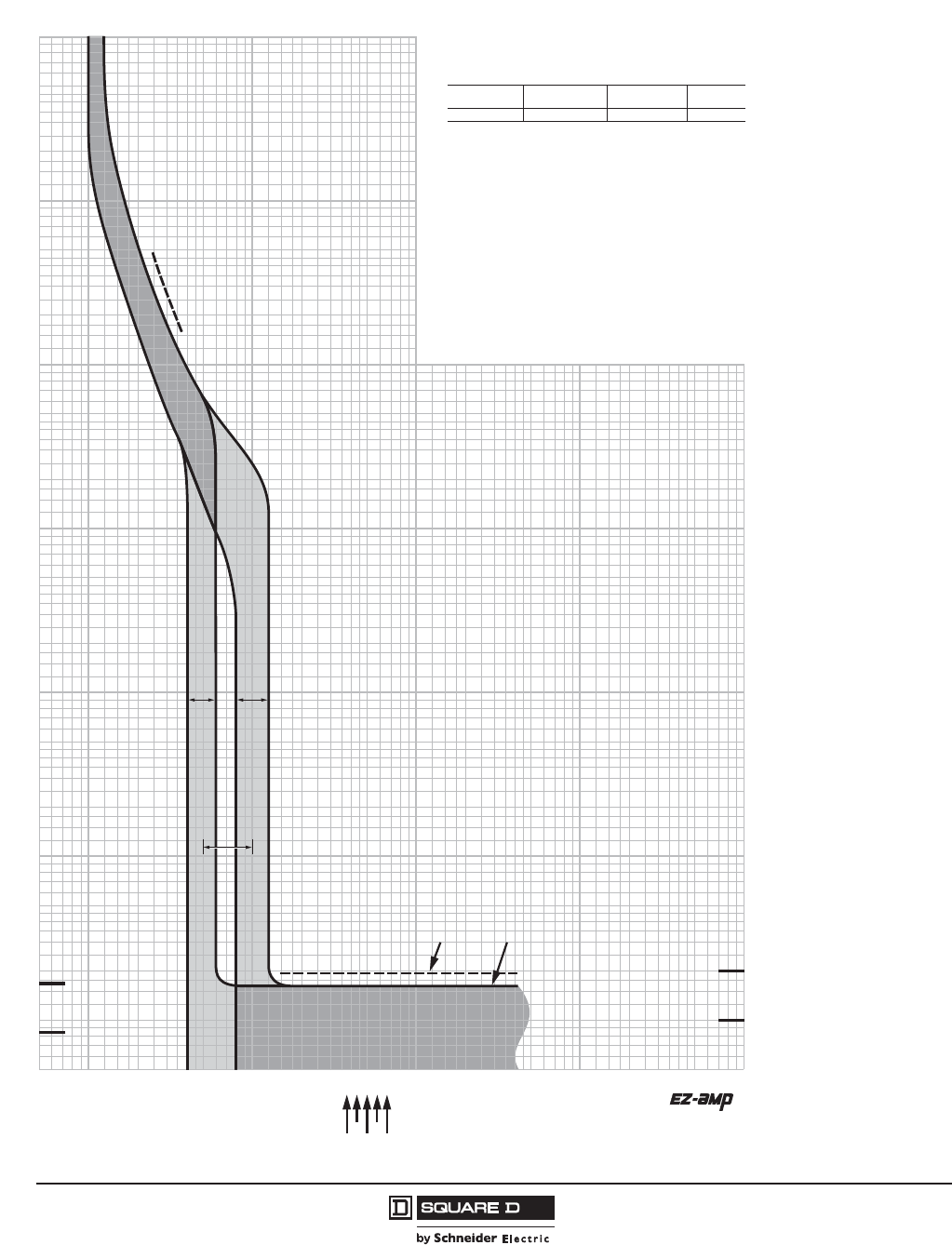
© 2011–2012 Schneider Electric
All Rights Reserved
PowerPact™ H-, J-, and L-Frame Circuit Breakers
Trip Curves
172
05/2012
™
Figure 60: J-Frame 150–250 A (JD, JG, JJ, and JL) Thermal-Magnetic Trip
1.5
700
150
200
300
400
600
800
900
2000
3000
4000
5000
7000
8000
9000
10000
.5
.6
.7
.8
.9
1
2
3
4
5
6
7
8
9
10
15
20
30
40
50
60
70
80
90
100
6000
1500
1000
500
.005
.006
.007
.008
.009
.01
.015
.02
.03
.04
.05
.06
.07
.08
.09
.1
.15
.2
.3
.4
.5
.6
.7
.8
.9
1
1.5
2
3
4
5
6
7
8
9
10
20
30
40
50
60
70
80
90
100
15
200
300
400
500
600
700
800
900
1000
1500
2000
3000
4000
6000
7000
8000
9000
5000
10000
1
.5
.6
.7
.8
.9
1.5
2
3
4
5
6
7
8
9
10
15
20
30
40
50
60
70
80
90
100
MULTIPLES OF RATED CURRENT
TIME IN SECONDS
.005
.006
.007
.008
.009
.01
.015
.02
.03
.04
.05
.06
.07
.08
.09
.1
.15
.2
.3
.4
.5
.6
.7
.8
.9
1
1.5
2
3
4
5
6
7
8
9
10
15
20
30
40
50
60
70
80
90
100
150
200
300
400
500
600
700
800
900
1000
1500
2000
3000
4000
5000
6000
7000
8000
9000
10000
TIME IN SECONDS
1/2 CYCLE
(60 Hz)
1/2 CYCLE
(50 Hz)
150
200
300
400
500
600
700
800
900
1000
1500
2000
3000
4000
5000
6000
7000
8000
9000
10000
150
MULTIPLES OF RATED CURRENT
1 CYCLE
(60 Hz)
1 CYCLE
(50 Hz)
LIMITS HIGH
SETTING
LIMITS LOW
SETTING
MAGNETIC TRIP
ADJUSTMENT RANGE
MAXIMUM CLEARING TIME
(AT 50 Hz) (AT 60 Hz)
225
200
150
250
175
MAXIMUM SINGLE-POLE TRIP TIMES
AT 25°C BASED ON NEMA AB-4 2003
JD, JG, JJ, JL MOLDED CASE CIRCUIT BREAKERS
CHARACTERISTIC TRIP CURVE NO. 50-5
CIRCUIT BREAKER INFORMATION
Circuit Breaker Continuous Maximum Number
Prefix Ampere Rating AC Voltage of Poles
JD, JG, JJ, JL 150–250 600 2, 3
This curve is to be used for application and coordination purposes only. The
EZ-AMP overlay feature at the bottom of the page should be used during
coordination studies.
All time/current characteristic curve data is based on 40°C ambient cold start.
Terminations are made with conductors of appropriate length and ratings.
Curve No. 0050TC0405
June 2004
Drawing No. 48095-050-05
TM
© 2004 Schneider Electric All Rights Reserved

PowerPact™ H-, J-, and L-Frame Circuit Breakers
Trip Curves
173
05/2012
© 2011–2012 Schneider Electric
All Rights Reserved
™
Figure 61: J-Frame 100 A (JG) 500 Vdc Thermal-Magnetic 500 Trip
500 Vdc JG MOLDED CASE CIRCUIT BREAKERS
CHARACTERISTIC TRIP CURVE NO. 50-14
CIRCUIT BREAKER INFORMATION
Circuit Breaker Continuous Maximum Number
Prefix Ampere Rating DC Voltage of Poles
JG 100 600 3 in series
This curve is to be used for application and coordination purposes only. The
EZ-AMP overlay feature at the bottom of the page should be used during
coordination studies.
All time/current characteristic curve data is based on 40°C ambient cold start.
Terminations are made with conductors of appropriate length and ratings.
Curve No. 0050TC0914
September 2009
Drawing No. 48095-050-14
TM
© 2009 Schneider Electric All Rights Reserved

© 2011–2012 Schneider Electric
All Rights Reserved
PowerPact™ H-, J-, and L-Frame Circuit Breakers
Trip Curves
174
05/2012
™
Figure 62: J-Frame 125 A (JG) 500 Vdc Thermal-Magnetic Trip
500 Vdc JG MOLDED CASE CIRCUIT BREAKERS
CHARACTERISTIC TRIP CURVE NO. 50-15
CIRCUIT BREAKER INFORMATION
Circuit Breaker Continuous Maximum Number
Prefix Ampere Rating DC Voltage of Poles
JG 125 600 2, 3
This curve is to be used for application and coordination purposes only. The
EZ-AMP overlay feature at the bottom of the page should be used during
coordination studies.
All time/current characteristic curve data is based on 40°C ambient cold start.
Terminations are made with conductors of appropriate length and ratings.
Curve No. 0050TC0915
September 2009
Drawing No. 48095-050-15
TM
© 2009 Schneider Electric All Rights Reserved
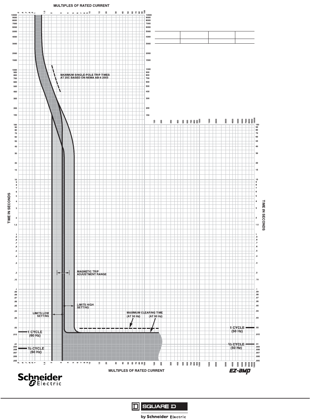
PowerPact™ H-, J-, and L-Frame Circuit Breakers
Trip Curves
175
05/2012
© 2011–2012 Schneider Electric
All Rights Reserved
™
Figure 63: J-Frame 150 A (JG) 500 Vdc Thermal-Magnetic Trip
500 Vdc JG MOLDED CASE CIRCUIT BREAKERS
CHARACTERISTIC TRIP CURVE NO. 50-16
CIRCUIT BREAKER INFORMATION
Circuit Breaker Continuous Maximum Number
Prefix Ampere Rating DC Voltage of Poles
JG 150 600 2, 3
This curve is to be used for application and coordination purposes only. The
EZ-AMP overlay feature at the bottom of the page should be used during
coordination studies.
All time/current characteristic curve data is based on 40°C ambient cold start.
Terminations are made with conductors of appropriate length and ratings.
Curve No. 0050TC0916
September 2009
Drawing No. 48095-050-16
TM
© 2009 Schneider Electric All Rights Reserved

© 2011–2012 Schneider Electric
All Rights Reserved
PowerPact™ H-, J-, and L-Frame Circuit Breakers
Trip Curves
176
05/2012
™
Figure 64: J-Frame 175 A (JG) 500 Vdc Thermal-Magnetic Trip
500 Vdc JG MOLDED CASE CIRCUIT BREAKERS
CHARACTERISTIC TRIP CURVE NO. 50-17
CIRCUIT BREAKER INFORMATION
Circuit Breaker Continuous Maximum Number
Prefix Ampere Rating DC Voltage of Poles
JG 175 600 2, 3
This curve is to be used for application and coordination purposes only. The
EZ-AMP overlay feature at the bottom of the page should be used during
coordination studies.
All time/current characteristic curve data is based on 40°C ambient cold start.
Terminations are made with conductors of appropriate length and ratings.
Curve No. 0050TC0917
September 2009
Drawing No. 48095-050-17
TM
© 2009 Schneider Electric All Rights Reserved
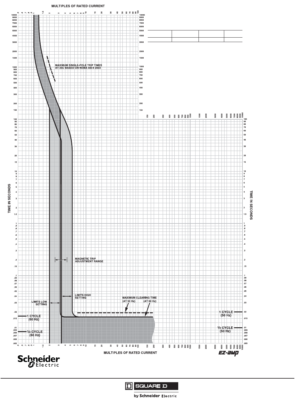
PowerPact™ H-, J-, and L-Frame Circuit Breakers
Trip Curves
177
05/2012
© 2011–2012 Schneider Electric
All Rights Reserved
™
Figure 65: J-Frame 200 A (JG) 500 Vdc Thermal-Magnetic Trip
500 Vdc JG MOLDED CASE CIRCUIT BREAKERS
CHARACTERISTIC TRIP CURVE NO. 50-18
CIRCUIT BREAKER INFORMATION
Circuit Breaker Continuous Maximum Number
Prefix Ampere Rating DC Voltage of Poles
JG 200 600 2, 3
This curve is to be used for application and coordination purposes only. The
EZ-AMP overlay feature at the bottom of the page should be used during
coordination studies.
All time/current characteristic curve data is based on 40°C ambient cold start.
Terminations are made with conductors of appropriate length and ratings.
Curve No. 0050TC0918
September 2009
Drawing No. 48095-050-18
TM
© 2009 Schneider Electric All Rights Reserved
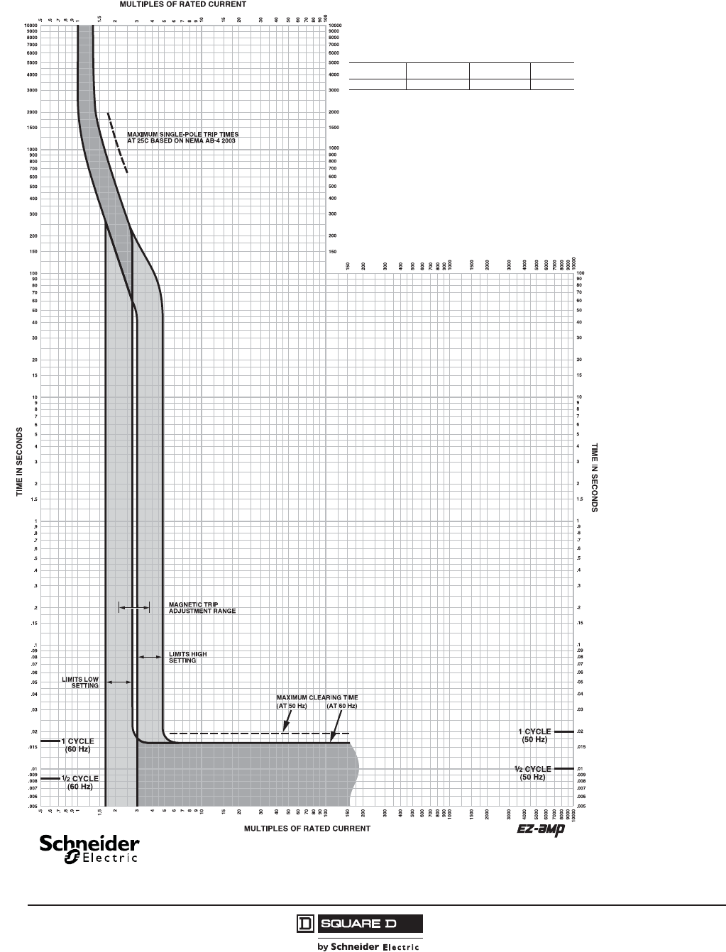
© 2011–2012 Schneider Electric
All Rights Reserved
PowerPact™ H-, J-, and L-Frame Circuit Breakers
Trip Curves
178
05/2012
™
Figure 66: J-Frame 225 A (JG) 500 Vdc Thermal-Magnetic Trip
500 Vdc JG MOLDED CASE CIRCUIT BREAKERS
CHARACTERISTIC TRIP CURVE NO. 50-19
CIRCUIT BREAKER INFORMATION
Circuit Breaker Continuous Maximum Number
Prefix Ampere Rating DC Voltage of Poles
JG 225 600 2, 3
This curve is to be used for application and coordination purposes only. The
EZ-AMP overlay feature at the bottom of the page should be used during
coordination studies.
All time/current characteristic curve data is based on 40°C ambient cold start.
Terminations are made with conductors of appropriate length and ratings.
Curve No. 0050TC0919
September 2009
Drawing No. 48095-050-19
TM
© 2009 Schneider Electric All Rights Reserved
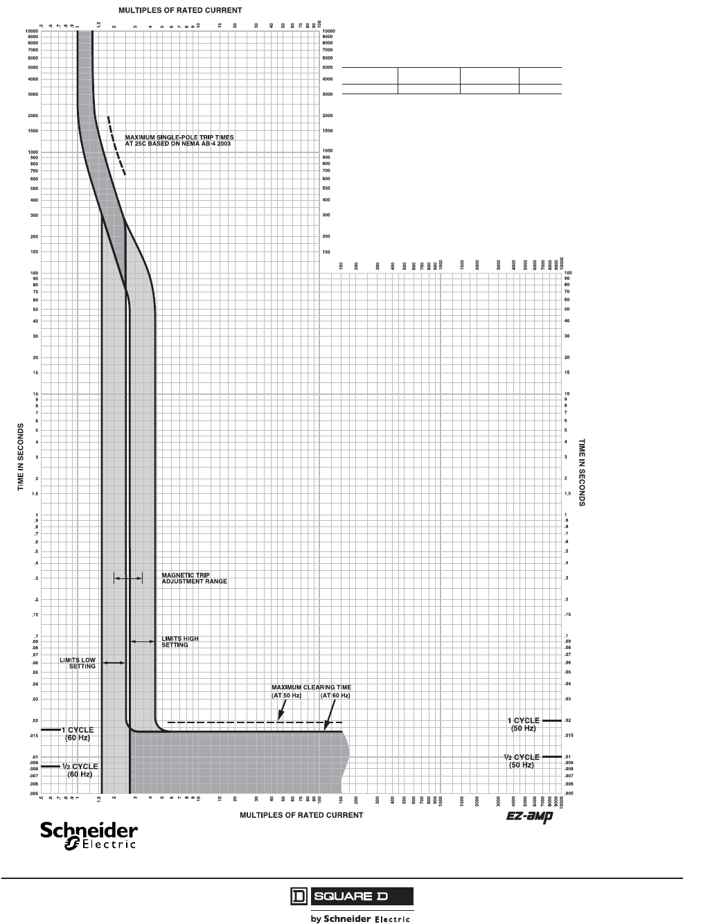
PowerPact™ H-, J-, and L-Frame Circuit Breakers
Trip Curves
179
05/2012
© 2011–2012 Schneider Electric
All Rights Reserved
™
Figure 67: J-Frame 250 A (JG) 500 Vdc Thermal-Magnetic Trip
500 Vdc JG MOLDED CASE CIRCUIT BREAKERS
CHARACTERISTIC TRIP CURVE NO. 50-20
CIRCUIT BREAKER INFORMATION
Circuit Breaker Continuous Maximum Number
Prefix Ampere Rating DC Voltage of Poles
JG 250 600 2, 3
This curve is to be used for application and coordination purposes only. The
EZ-AMP overlay feature at the bottom of the page should be used during
coordination studies.
All time/current characteristic curve data is based on 40°C ambient cold start.
Terminations are made with conductors of appropriate length and ratings.
Curve No. 0050TC0920
September 2009
Drawing No. 48095-050-20
TM
© 2009 Schneider Electric All Rights Reserved
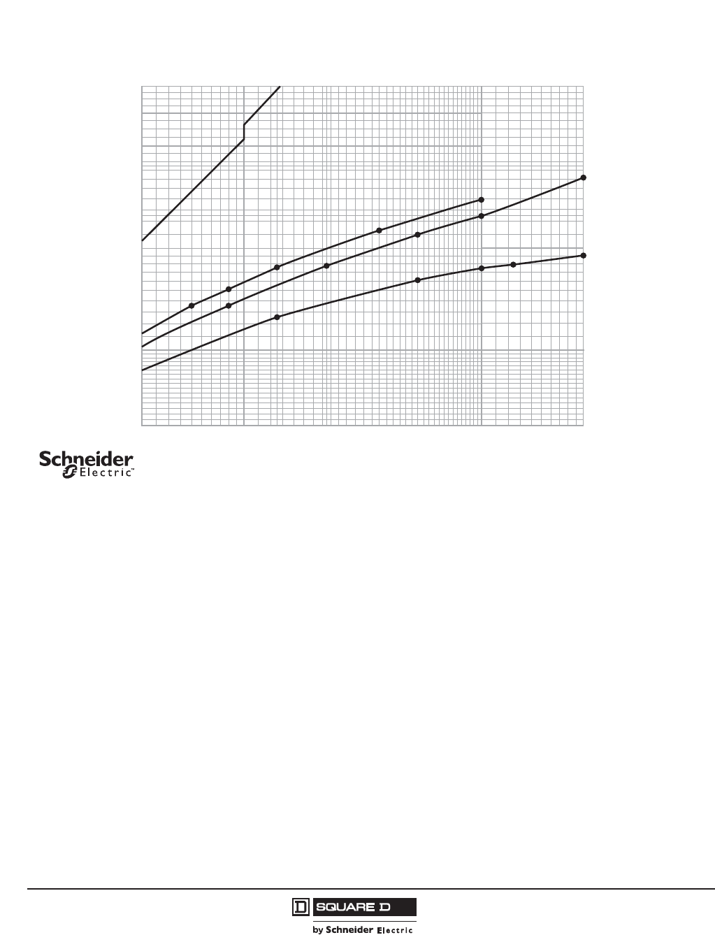
© 2011–2012 Schneider Electric
All Rights Reserved
PowerPact™ H-, J-, and L-Frame Circuit Breakers
Trip Curves
180
05/2012
™
Figure 68: H-Frame 150 A Typical Peak Let-Through Curves
20 30 40 50 60 70 80 9010
6
7
8
9
10
200100
20
30
40
50
60
Available Short Circuit Current (RMS Symmetrical Amperes x 103)
Typical* Peak Let-Through Current (Amperes x 103)
*Based on typical values obtained throughout the circuit breaker development and UL test programs.
Ip
D
D
D
G
G
G
J
J
JL
R
480 V
240 V
L
R
600 V
L
R
Maximum
Available
Peak Current
at 25% Power Factor
Maximum
Available
Peak Current
at 15% Power Factor
(/(&7521,&02/'('&$6(&,5&8,7%5($.(56
32:(53$&7+² )5$0(&855(17/,0,7,1*&,5&8,7%5($.(56
$)5$0($7$1'9
³$
3($./(77+528*+&855(17OS
'UDZLQJ1R
$SULO
5HY
6FKQHLGHU(OHFWULFDOOULJKWVUHVHUYHG
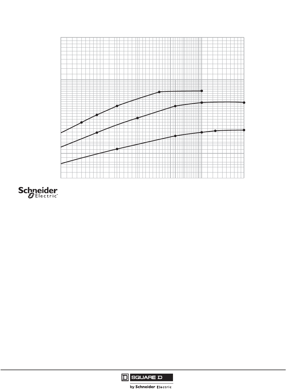
PowerPact™ H-, J-, and L-Frame Circuit Breakers
Trip Curves
181
05/2012
© 2011–2012 Schneider Electric
All Rights Reserved
™
Figure 69: H-Frame 150 A Typical I2t Let-Through Curves
20 30 40 50 60 70 80 9010
.2
.3
.4
.5
.6
.7
.8
.9
200100
2
1
Available Short Circuit Current (RMS Symmetrical Amperes x 103)
Typical* Let-Through I2t (Amperes2 Seconds x 106)
*Based on typical values obtained throughout the circuit breaker development and UL test programs.
I2t
240 V
J
D
D
D
G
G
G
J
J
LR
480 V
LR
600 V
LR
(/(&7521,&02/'('&$6(&,5&8,7%5($.(56
32:(53$&7+² )5$0(&855(17/,0,7,1*&,5&8,7%5($.(56
$)5$0($7$1'9
³$
/(77+528*+&855(17OW
'UDZLQJ1R
$SULO
5HY
6FKQHLGHU(OHFWULFDOOULJKWVUHVHUYHG
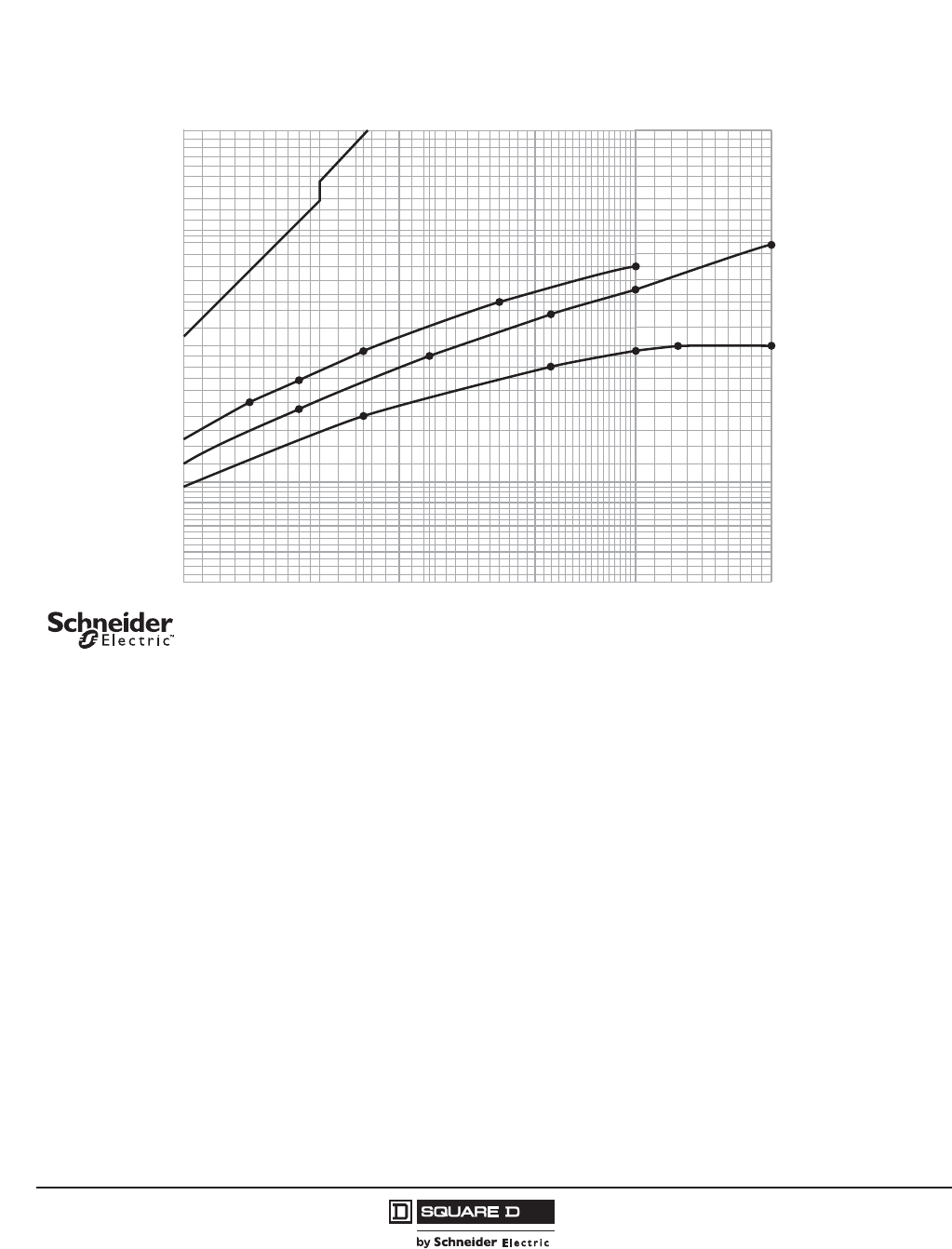
© 2011–2012 Schneider Electric
All Rights Reserved
PowerPact™ H-, J-, and L-Frame Circuit Breakers
Trip Curves
182
05/2012
™
Figure 70: J-Frame 250 A Typical Peak Let-Through Curves
20 30 40 50 60 70 80 9010
6
7
8
9
10
200100
20
30
40
50
60
Available Short Circuit Current (RMS Symmetrical Amperes x 103)
Typical* Peak Let-Through Current (Amperes x 103)
*Based on typical values obtained throughout the circuit breaker development and UL test programs.
Ip
Maximum
Available
Peak Current
at 25% Power Factor
Maximum
Available
Peak Current
at 15% Power Factor
D
240 V
D
D
G
G
G
J
J
JLR
480 V
L
R
600 V
L
R
(/(&7521,&02/'('&$6(&,5&8,7%5($.(56
32:(53$&7-² )5$0(&855(17/,0,7,1*&,5&8,7%5($.(56
$)5$0($7$1'9
³$
3($./(77+528*+&855(17OS
'UDZLQJ1R
$SULO
5HY
6FKQHLGHU(OHFWULFDOOULJKWVUHVHUYHG
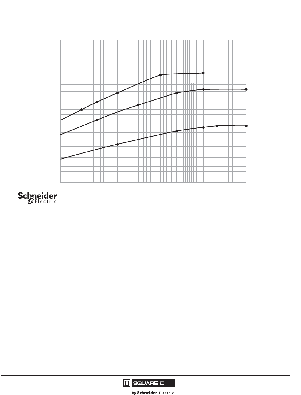
PowerPact™ H-, J-, and L-Frame Circuit Breakers
Trip Curves
183
05/2012
© 2011–2012 Schneider Electric
All Rights Reserved
™
Figure 71: J-Frame 250 A Typical I2t Let-Through Curves
20 30 40 50 60 70 80 9010
.2
.3
.4
.5
.6
.7
.8
.9
200100
2
1
Available Short Circuit Current (RMS Symmetrical Amperes x 103)
Typical* Let-Through I2t (Amperes2 Seconds x 106)
*Based on typical values obtained throughout the circuit breaker development and UL test programs.
I2t
D
240 V
J
D
D
G
G
G
J
J
LR
480 V
LR
600 V
LR
(/(&7521,&02/'('&$6(&,5&8,7%5($.(56
32:(53$&7-² )5$0(&855(17/,0,7,1*&,5&8,7%5($.(56
$)5$0($7$1'9
³$
/(77+528*+&855(17OW
'UDZLQJ1R
$SULO
5HY
6FKQHLGHU(OHFWULFDOOULJKWVUHVHUYHG
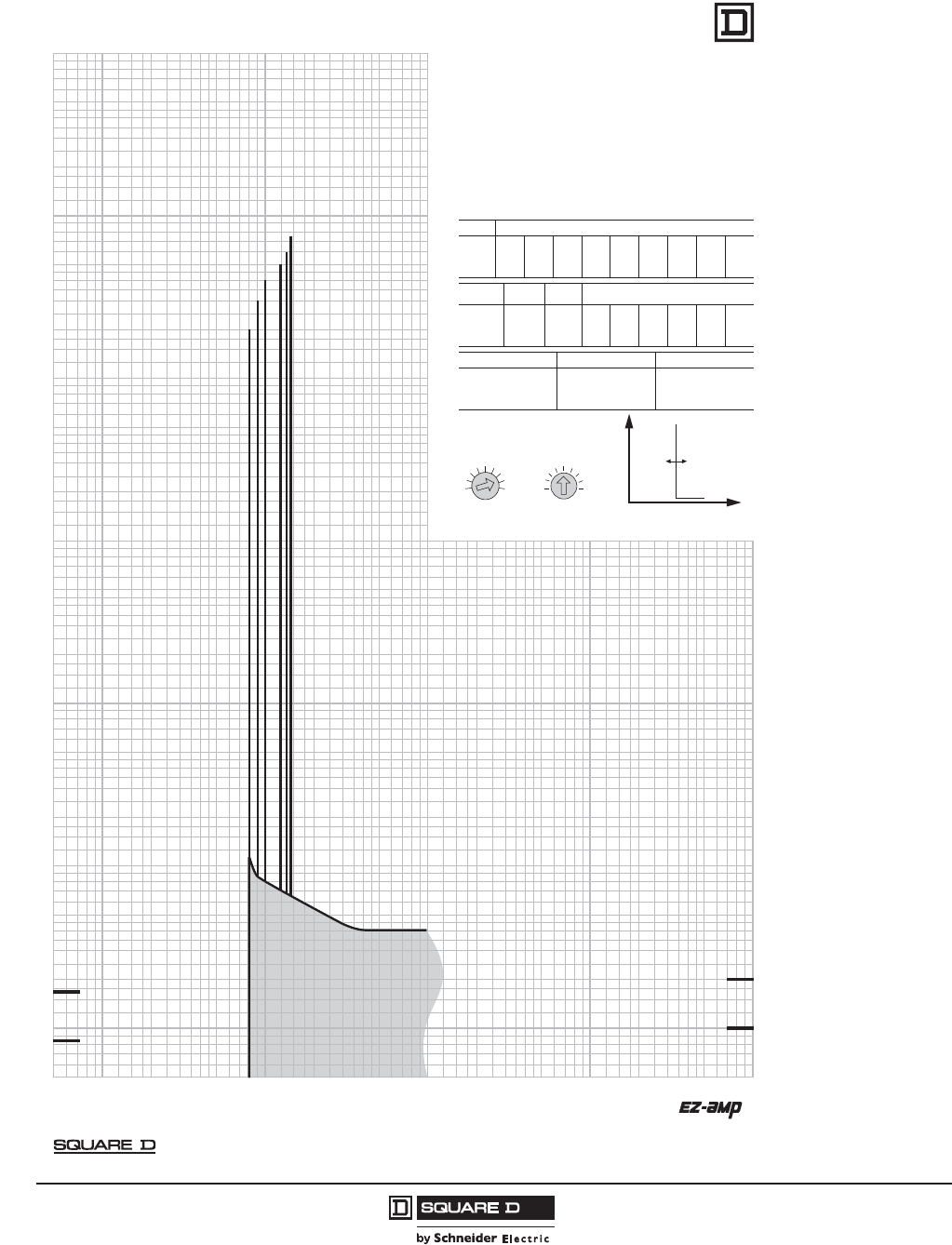
© 2011–2012 Schneider Electric
All Rights Reserved
PowerPact™ H-, J-, and L-Frame Circuit Breakers
Trip Curves
184
05/2012
™
Figure 72: H- and J-Frame Motor Circuit Protector
!"
!"
!"
!"
#
#
#
#
#
#
$&'$+,//:&;<
,
,
<
,
/
/
:
&
;
<
:
&
/
$
=
+
,
$
=
>
?
,
@#
## # #
#
#
#
/
@
&</$&/$&,>'<B:E>:&/
POWERPACT H/J FRAME MOTOR CIRCUIT PROTECTOR
WITH MANUAL SETTINGS
CHARACTERISTIC TRIP CURVE NO. 045-1
The time-current curve information represents the typical response and is to
be used for application and coordination purposes only.
Curves apply from -30C to +60C ambient temperature.
Notes:
• The MCP is an instantaneous only breaker that detects the peaks of the
current. In order to trip within the specified time-current levels, consecutive
peaks of the current must exceed the selected setting’s threshold.
• Total clearing times shown include the response times of the trip unit, the
circuit breaker opening, and the extinction of the current.
• The time-current curve represents single-phase to three-phase fault currents.
MOTOR CIRCUIT PROTECTOR INFORMATION
Suffix # FLA Adjustments
M71 1.5 3 6 8 11 14 17 20 25
M72 14 17 21 24 27 29 32 36 42
M73 30 35 41 46 51 56 63 71 80
M74 58 71 79 86 91 97 110 119 130
M75 114 137 145 155 163 172 181 210 217
Suffix Lowest Highest IM
# Setting Setting Adjustment
M71 12 325 8x 9x 10x 11x 12x 13x
M72 112 546 8x 9x 10x 11x 12x 13x
M73 240 1040 8x 9x 10x 11x 12x 13x
M74 464 1690 8x 9x 10x 11x 12x 13x
M75 912 2500 8x 9x 10x 11x 12x 13x
Suffix # Nominal Fault Current Level Maximum Clearing Time
M71 670
M72 1150
M73 2150 1/2-1 Cycle
M74 3450
M75 3600
© 2006 Schneider Electric all rights reserved
Curve No. 0045TC0601
August 2006
Drawing No. 48095-045-01
TM

PowerPact™ H-, J-, and L-Frame Circuit Breakers
Trip Curves
185
05/2012
© 2011–2012 Schneider Electric
All Rights Reserved
™
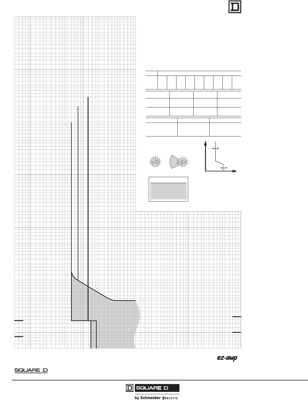
© 2011–2012 Schneider Electric
All Rights Reserved
PowerPact™ H-, J-, and L-Frame Circuit Breakers
Trip Curves
186
05/2012
™
Figure 73: H- and J-Frame Motor Circuit Protector
POWERPACT H/J FRAME MOTOR CIRCUIT PROTECTOR
WITH AUTO SETTINGS
CHARACTERISTIC TRIP CURVE NO. 045-2
The time-current curve information represents the typical response and is to
be used for application and coordination purposes only.
Curves apply from -30C to +60C ambient temperature.
Notes:
t The MCP is an instantaneous only breaker that detects the peaks of the
current. In order to trip within the specied time-current levels, consecutive
peaks of the current must exceed the selected setting’s threshold.
t Total clearing times shown include the response times of the trip unit, the
circuit breaker opening, and the extinction of the current.
tThe time-current curve represents single-phase to three-phase fault currents.
MOTOR CIRCUIT PROTECTOR INFORMATION
stnemtsujdA ALF# xiffuS
M71 1.5 3 6 8 11 14 17 20 25
M72 14 17 21 24 27 29 32 36 42
M73 30 35 41 46 51 56 63 71 80
M74 58 71 79 86 91 97 110 119 130
M75 114 137 145 155 163 172 181 210 217
Sux # Auto Instantaneous Trip Dampening For Motor
Setting Point % FLA In-Rush % FLA
M71, M72 Auto 1 800 1300
M73, M74 Auto 2 1100 1700
6x 600 1300
Auto 1 800 1300
M75 Auto 2 1100 1100 – 1700
6x 600 1100 – 1300
Sux # Nominal Fault Current Level Maximum Clearing Time
07617M
051127M
elcyC 1-2/1051237M
054347M
006357M
© 2006 Schneider Electric all rights reserved
Curve No. 0045TC0602
August 2006
Drawing No. 48095-045-02
TM

PowerPact™ H-, J-, and L-Frame Circuit Breakers
Trip Curves
187
05/2012
© 2011–2012 Schneider Electric
All Rights Reserved
™
Figure 74: H-Frame UL Listed Current-Limiting Circuit Breaker
20000
30000
40000
50000
60000
70000
80000
90000
100000
5000
6000
7000
8000
9000
150000
200000
10000
6000
7000
8000
9000
10000
20000
30000
40000
50000
60000
Availability (RMS Symmetrical Amperes)
Maximum* Peak Let-Through Current (Amperes)
*Based on maximum values obtained throughout the circuit breaker development and UL test programs.
Ip
Maximum
Available
Peak Current
at 15% Power Factor 600 V 3Ø
480 V 3Ø
240 V 3Ø
7+(50$/0$*1(7,&02/'('&$6(&,5&8,7%5($.(56
+²)5$0(&855(17/,0,7,1*&,5&8,7%5($.(56
+$)5$0($7$1'9
+-+/$1'+5³$
3($./(77+528*+&855(17OS
'UDZLQJ1R
$SULO
5HY
6FKQHLGHU(OHFWULFDOOULJKWVUHVHUYHG
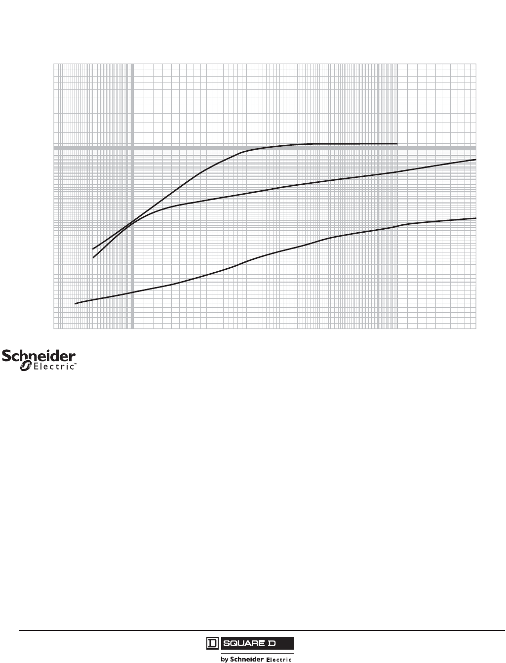
© 2011–2012 Schneider Electric
All Rights Reserved
PowerPact™ H-, J-, and L-Frame Circuit Breakers
Trip Curves
188
05/2012
™
Figure 75: H-Frame UL Listed Current-Limiting Circuit Breaker
20000
30000
40000
50000
60000
70000
80000
90000
5000
6000
7000
8000
9000
100000
150000
200000
10000
.2
.3
.4
.5
.6
.7
.8
.9
1.0
2.0
Availability (RMS Symmetrical Amperes)
I
2
t
*Based on maximum values obtained throughout the circuit breaker development and UL test programs.
Maximum* Let-Through I
2
t (Amperes
2
Seconds x 10
6
)
600 V 3Ø
480 V 3Ø
240 V 3Ø
7+(50$/0$*1(7,&02/'('&$6(&,5&8,7%5($.(56
+²)5$0(&855(17/,0,7,1*&,5&8,7%5($.(56
+$)5$0($7$1'9
+-+/$1'+5³$
/(77+528*+&855(17O
W
'UDZLQJ1R
$SULO
5HY
6FKQHLGHU(OHFWULFDOOULJKWVUHVHUYHG
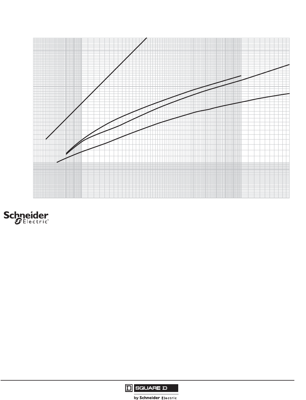
PowerPact™ H-, J-, and L-Frame Circuit Breakers
Trip Curves
189
05/2012
© 2011–2012 Schneider Electric
All Rights Reserved
™
Figure 76: J-Frame UL Listed Current -Limiting Circuit Breaker
20000
30000
40000
50000
60000
70000
80000
90000
100000
5000
6000
7000
8000
9000
150000
200000
10000
6000
7000
8000
9000
10000
20000
30000
40000
50000
60000
Availability (RMS Symmetrical Amperes)
Maximum* Peak Let-Through Current (Amperes)
*Based on maximum values obtained throughout the circuit breaker development and UL test programs.
Ip
Maximum
Available
Peak Current
at 15% Power Factor
600 V 3Ø
480 V 3Ø
240 V 3Ø
7+(50$/0$*1(7,&02/'('&$6(&,5&8,7%5($.(56
-²)5$0(&855(17/,0,7,1*&,5&8,7%5($.(56
-$)5$0($7$1'9
---/$1'-5³$
3($./(77+528*+&855(17OS
'UDZLQJ1R
$SULO
5HY
6FKQHLGHU(OHFWULFDOOULJKWVUHVHUYHG
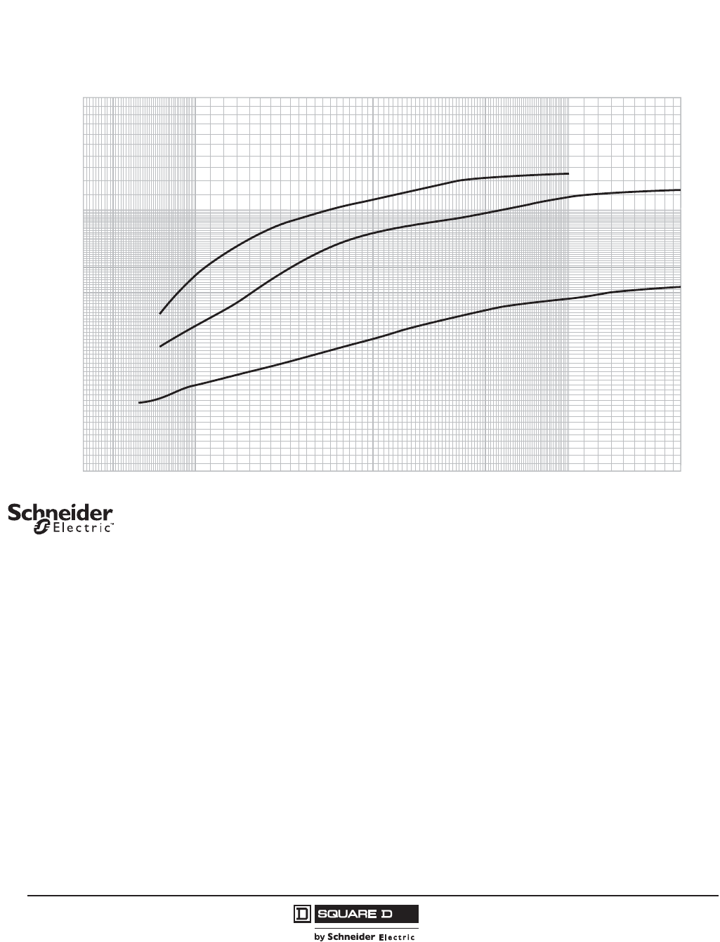
© 2011–2012 Schneider Electric
All Rights Reserved
PowerPact™ H-, J-, and L-Frame Circuit Breakers
Trip Curves
190
05/2012
™
Figure 77: J-Frame UL Listed Current-Limiting Circuit Breaker
20000
30000
40000
50000
60000
70000
80000
90000
5000
6000
7000
8000
9000
100000
150000
200000
10000
.2
.3
.4
.5
.6
.7
.8
.9
1.0
2.0
Availability (RMS Symmetrical Amperes)
I2t
*Based on maximum values obtained throughout the circuit breaker development and UL test programs.
Maximum* Let-Through I2t (Amperes2 Seconds x 106)
600 V 3Ø
480 V 3Ø
240 V 3Ø
7+(50$/0$*1(7,&02/'('&$6(&,5&8,7%5($.(56
-²)5$0(&855(17/,0,7,1*&,5&8,7%5($.(56
-$)5$0($7$1'9
---/$1'-5³$
/(77+528*+&855(17O
W
'UDZLQJ1R
$SULO
5HY
6FKQHLGHU(OHFWULFDOOULJKWVUHVHUYHG
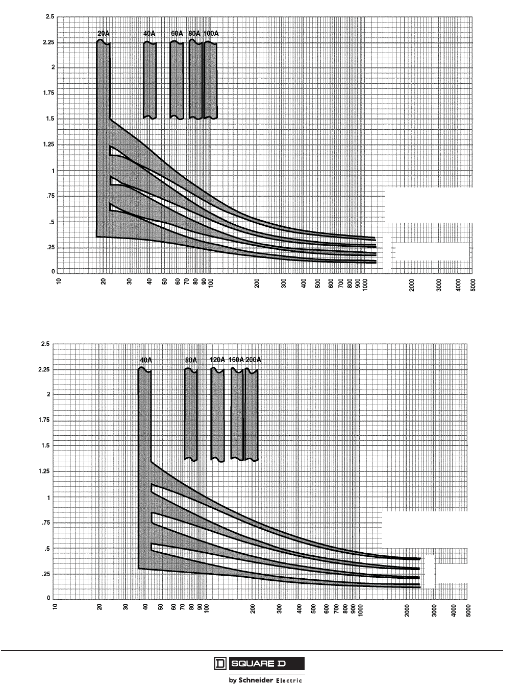
PowerPact™ H-, J-, and L-Frame Circuit Breakers
Trip Curves
191
05/2012
© 2011–2012 Schneider Electric
All Rights Reserved
™
Figure 78: Ground Fault Module GFM150HD Trip Curve
Pickup Levels ±10% Curve 980-1
Time in Seconds
Current in Amperes
Circuit Breaker Will
Instantaneous Trip
Above 1200 A
4
3
2
1
Delay Band
09603011
Figure 79: Ground Fault Module GFM250JD Trip Curve
Pickup Levels ±10% Curve 980-2
Time in Seconds
Current in Amperes
Circuit Breaker Will
Instantaneous Trip Above
2500 A
4
3
2
1
Delay Band
09603012
© 2011–2012 Schneider Electric
All Rights Reserved
PowerPact™ H-, J-, and L-Frame Circuit Breakers
Trip Curves
192
05/2012
™
Figure 80: Earth Leakage Module Trip Curve
.015
.005
.006
.007
.008
.009
.01
.02
.03
.04
.05
.06
.07
.08
.09
.1
.15
.2
.3
.4
.015
.005
.006
.007
.008
.009
.01
.02
.03
.04
.05
.06
.07
.08
.09
.1
.15
.2
.3
.4
.005
.006
.007
.008
.009
.01
.015
.02
.03
.04
.05
.06
.07
.08
.09
.1
.15
.2
.3
.4
.5
.6
.7
.8
.9
1
1.5
2
3
4
5
6
7
8
9
10
20
30
40
50
60
70
80
90
100
15
1500
2000
3000
4000
6000
7000
8000
9000
5000
10000
TRIP THRESHOLD CURRENT (AMPERES)
TIME IN SECONDS
.005
.006
.007
.008
.009
.01
.015
.02
.03
.04
.05
.06
.07
.08
.09
.1
.15
.2
.3
.4
.5
.6
.7
.8
.9
1
1.5
2
3
4
5
6
7
8
9
10
15
20
30
40
50
60
70
80
90
100
150
200
300
400
500
600
700
800
900
1000
150
200
300
400
500
600
700
800
900
1000
1500
2000
3000
4000
5000
6000
7000
8000
9000
10000
TIME IN SECONDS
1
/
2
CYCLE
(60 Hz)
1
/
2
CYCLE
(50 Hz)
1.5
2
3
4
5
6
7
8
9
10
.5
.6
.7
.8
.9
1
15
20
30
40
50
60
70
80
90
100
1.5
2
3
4
5
6
7
8
9
10
.5
.6
.7
.8
.9
1
15
20
30
40
50
60
70
80
90
100
TRIP THRESHOLD CURRENT (AMPERES)
1 CYCLE
(60 Hz)
1 CYCLE
(50 Hz)
3.0 A
1.0 A
300 MA
0.50 SECONDS
0.10 SECONDS
0.06 SECONDS
INSTANTANEOUS
100 MA
30 MA
EARTH LEAKAGE MODULES (ELM) FOR
POWERPACT TM H AND J-FRAME
MOLDED CASE CIRCUIT BREAKERS
CHARACTERISTIC TRIP CURVE NO. 961-1
Catalog Number Circuit Breaker CB Amps CB Voltage Number Of Poles
ELM150HD PowerPact H-Frame 15–150 600 3
ELM250JD PowerPact J-Frame 150–250 600 3
Total clearing times shown include the response times of the ELM,
the circuit breaker shunt trip, the circuit breaker opening, and the
extinction of the current. Curves apply from -30°C to +60°C ambient
temperature. Refer also to the circuit breaker trip curves for
PowerPact H- and J-Frame Circuit Breakers.
Note: Trip curves dene the performance under normal conditions.
Add 0.030 seconds for closing breaker/module on an existing fault.
PowerPact™ H-, J-, and L-Frame Circuit Breakers
Trip Curves
193
05/2012
© 2011–2012 Schneider Electric
All Rights Reserved
™
PowerPact H- and J-Frame Thermal-Magnetic Trip MCP Instantaneous Trip Points
Table 134: M71 Instantaneous Trip Points
Automatic Setting (A) Manual Adjustment (A)
Im Setting 1 2 6x 8x 9x 10x 11x 12x 13x
Motor Type NEMA A, B, C, D B, E (FLA) x (Im)
IEC N H
FLA
1.5 12 16.5 9 12 13.5 15 16.5 18 19.5
3 24 33 18 242730333639
6 48 66 36 485460667278
8 64 88 48 6472808896104
11 88 121 66 88 99 110 121 132 143
14 112 154 84 112 126 140 154 168 182
17 136 187 102 136 153 170 187 204 221
20 160 220 120 160 180 200 220 240 260
25 200 275 150 200 225 250 275 300 325
Dampening for motor in-rush (% FLA) 1300% 1700% 1300% —
Table 135: M72 Instantaneous Trip Points
Automatic Setting (A)1
1± 5% of nominal amperage shown above
Manual Adjustment (A)1
Im Setting 1 2 6x 8x 9x 10x 11x 12x 13x
Motor Type NEMA A, B, C, D B, E (FLA) x (Im)
IEC N H
FLA
14 112 154 84 112 126 140 154 168 182
17 136 187 102 136 153 170 187 204 221
21 168 231 126 168 189 210 231 252 273
24 192 264 144 192 216 240 264 288 312
27 216 297 162 216 243 270 297 324 351
29 232 319 174 232 261 290 319 348 377
32 256 352 192 256 288 320 352 384 416
36 288 396 216 288 324 360 396 432 468
42 336 462 252 336 378 420 462 504 546
Dampening for motor in-rush (% FLA) 1300% 1700% 1300% —
© 2011–2012 Schneider Electric
All Rights Reserved
PowerPact™ H-, J-, and L-Frame Circuit Breakers
Trip Curves
194
05/2012
™
Table 136: M73 Instantaneous Trip Points
Automatic Setting (A)1
1± 5% of nominal amperage shown above
Manual Adjustment (A)1
Im Setting 1 2 6x 8x 9x 10x 11x 12x 13x
Motor Type NEMA A, B, C, D B, E (FLA) x (Im)
IEC N H
FLA
30 240 330 180 240 270 300 330 360 390
35 280 385 210 280 315 350 385 420 455
41 328 451 246 328 369 410 451 492 533
46 368 506 276 368 414 460 506 552 598
51 408 561 306 408 459 510 561 612 663
56 448 616 336 448 504 560 616 672 728
63 504 693 378 504 567 630 693 756 819
71 568 781 426 568 639 710 781 852 923
80 640 880 480 640 720 800 880 960 1040
Dampening for motor in-rush (% FLA) 1300% 1700% 1300% —
Table 137: M74 Instantaneous Trip Points
Automatic Setting (A)1
1± 5% of nominal amperage shown above
Manual Adjustment (A)1
Im Setting 1 2 6x 8x 9x 10x 11x 12x 13x
Motor Type NEMA A, B, C, D B, E (FLA) x (Im)
IEC N H
FLA
58 464 638 348 464 522 580 638 696 754
71 568 781 426 568 639 710 781 852 923
79 632 869 474 632 711 790 869 948 1027
86 688 946 516 688 774 860 946 1032 1118
91 728 1001 546 728 819 910 1001 1092 1183
97 776 1067 582 776 873 970 1067 1164 1261
110 880 1210 660 880 990 1100 1210 1320 1430
119 952 1309 714 952 1071 1190 1309 1428 1547
130 1040 1430 780 1040 1170 1300 1430 1560 1690
Dampening for motor in-rush (% FLA) 1300% 1700% 1300% —
Table 138: M75 Instantaneous Trip Points
Automatic Setting (A)1
1± 5% of nominal amperage shown above
Manual Adjustment (A)1
Im Setting 1 2 6x 8x 9x 10x 11x 12x 13x
Motor Type NEMA A, B, C, D B, E (FLA) x (Im)
IEC N H
FLA
114 912 1254 684 912 1026 1140 1254 1368 1482
137 1096 1507 822 1096 1233 1370 1507 1644 1781
145 1160 1595 870 1160 1305 1450 1595 1740 1885
155 1240 1705 930 1240 1395 1550 1705 1860 2015
163 1304 1793 978 1304 1467 1630 1793 1956 2119
172 1376 1892 1032 1376 1548 1720 1892 2064 2236
181 1448 1991 1086 1448 1629 1810 1991 2172 2353
210 1680 2310 1260 1680 1890 2100 2310 2500 2
22500 A maximum instantaneous trip point
2500 2
217 1736 2387 1302 1736 1953 2170 2387 2500 22500 2
Dampening for motor in-rush (% FLA) 1100–1300% 1100–1700% 1100–
1300% —

PowerPact™ H-, J-, and L-Frame Circuit Breakers
Trip Curves
195
05/2012
© 2011–2012 Schneider Electric
All Rights Reserved
™
PowerPact H-Frame Electronic Trip Circuit Breakers—
60 A/100 A/150 A Frame
Figure 81: Micrologic™ 3.2 Electronic Trip Unit Long Time Trip Curve
16
MICROLOGIC™ ELECTRONIC TRIP UNITS
Micrologic™ 3.2 Long Time Trip Curve
60A, 100A, 150A H-Frame
The time-current curve information is to be used
for application and coordination purposes only.
Notes:
1. There is a thermal-imaging effect that can act
to shorten the long-time delay. The thermal
imaging effect comes into play if a current
above the long-time delay pickup value exists
for a time and then is cleared by the tripping of
a downstream device or the circuit breaker
itself. A subsequent overload will cause the
circuit breaker to trip in a shorter time than
normal. The amount of time delay reduction is
inverse to the amount of time that has elapsed
since the previous overload. Approximately 20
minutes is required between overloads to
completely reset thermal-imaging.
2. Total clearing times shown include the
response times of the trip unit, the circuit
breaker opening, and the extinction of the
current.
Curves apply from -35ºC to +70ºC (-31ºF to
+158ºF) ambient temperature.
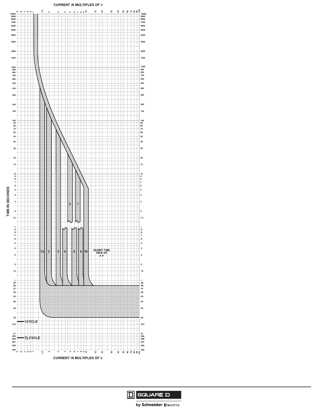
© 2011–2012 Schneider Electric
All Rights Reserved
PowerPact™ H-, J-, and L-Frame Circuit Breakers
Trip Curves
196
05/2012
™
Figure 82: Micrologic™ 3.2S Electronic Trip Unit Long Time / Short Time Trip Curve
MICROLOGIC™ ELECTRONIC TRIP UNITS
Micrologic™ 3.2S Long Time/
Short Time Trip Curve
60A, 100A, 150A H-Frame
The time-current curve information is to be used
for application and coordination purposes only.
Notes:
1. There is a thermal-imaging effect that can act
to shorten the long-time delay. The thermal
imaging effect comes into play if a current
above the long-time delay pickup value exists
for a time and then is cleared by the tripping of
a downstream device or the circuit breaker
itself. A subsequent overload will cause the
circuit breaker to trip in a shorter time than
normal. The amount of time delay reduction is
inverse to the amount of time that has elapsed
since the previous overload. Approximately 20
minutes is required between overloads to
completely reset thermal-imaging.
2. Total clearing times shown include the
response times of the trip unit, the circuit
breaker opening, and the extinction of the
current.
Curves apply from -35ºC to +70ºC (-31ºF to
+158ºF) ambient temperature.
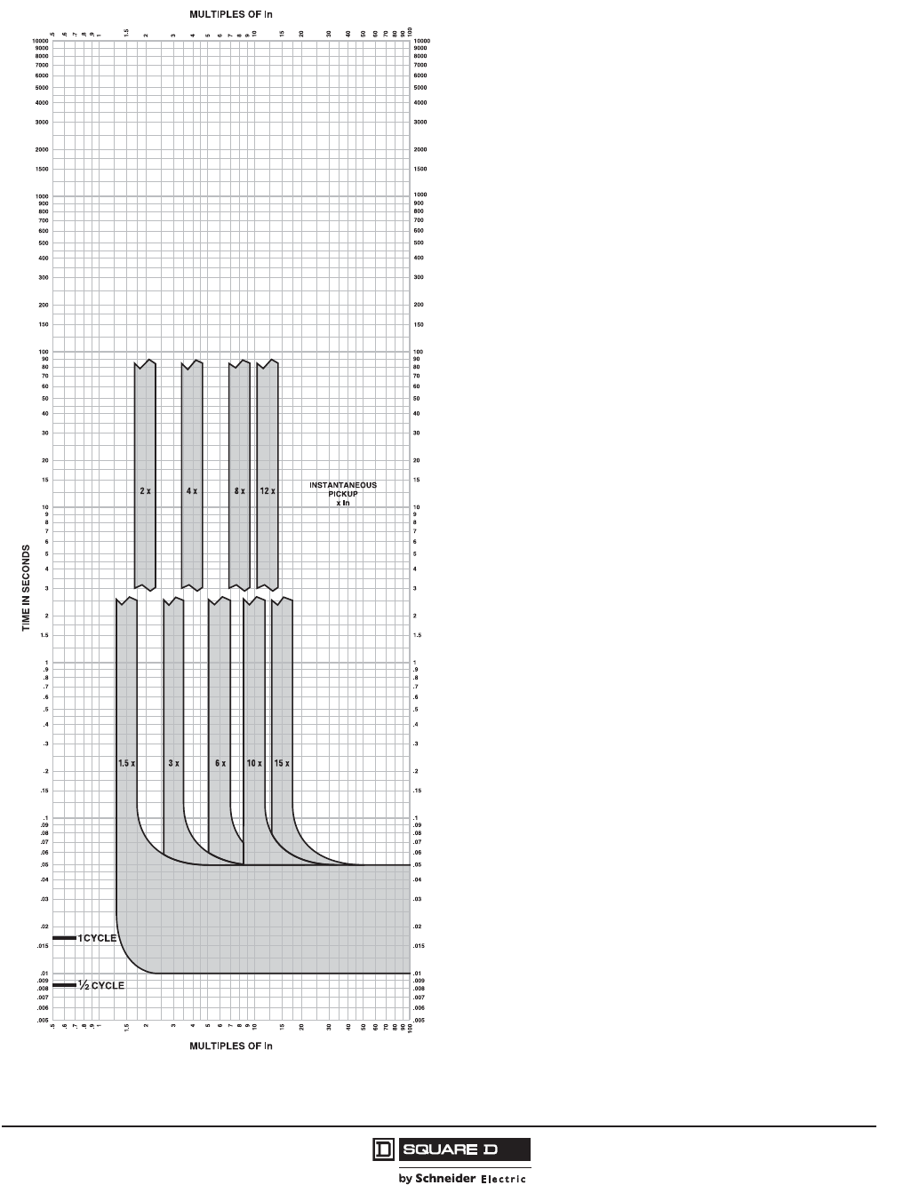
PowerPact™ H-, J-, and L-Frame Circuit Breakers
Trip Curves
197
05/2012
© 2011–2012 Schneider Electric
All Rights Reserved
™
Figure 83: Micrologic™ 3.2/3.2S/5.2A/5.2E/6.2A/6.2E Electronic Trip Unit Instantaneous Trip Curve
MICROLOGIC™ ELECTRONIC TRIP UNITS
Micrologic™ 3.2/3.2S/5.2A or E/6.2A or E
Instantaneous Trip Curve
60A, 100A, 150A H-Frame
The time-current curve information is to be used
for application and coordination purposes only.
Notes:
1. There is a thermal-imaging effect that can act
to shorten the long-time delay. The thermal
imaging effect comes into play if a current
above the long-time delay pickup value exists
for a time and then is cleared by the tripping of
a downstream device or the circuit breaker
itself. A subsequent overload will cause the
circuit breaker to trip in a shorter time than
normal. The amount of time delay reduction is
inverse to the amount of time that has elapsed
since the previous overload. Approximately 20
minutes is required between overloads to
completely reset thermal-imaging.
2. Total clearing times shown include the
response times of the trip unit, the circuit
breaker opening, and the extinction of the
current.
3. In = Maximum dial setting of Ir.
60A H-Frame: In = 60A = Max Ir setting
100A H-Frame: In = 100A = Max Ir setting
150A H-Frame: In = 150A = Max Ir setting
Curves apply from -35ºC to +70ºC (-31ºF to
+158ºF) ambient temperature.

© 2011–2012 Schneider Electric
All Rights Reserved
PowerPact™ H-, J-, and L-Frame Circuit Breakers
Trip Curves
198
05/2012
™
Figure 84: Micrologic™ 5.2A/5.2E/6.2A/6.2E Electronic Trip Unit Long Time Trip Curve
16
MICROLOGIC™ ELECTRONIC TRIP UNITS
Micrologic™ 5.2A or E/6.2A or E
Long Time Trip Curve
60A, 100A, 150A H-Frame
The time-current curve information is to be used
for application and coordination purposes only.
Notes:
1. There is a thermal-imaging effect that can act
to shorten the long-time delay. The thermal
imaging effect comes into play if a current
above the long-time delay pickup value exists
for a time and then is cleared by the tripping of
a downstream device or the circuit breaker
itself. A subsequent overload will cause the
circuit breaker to trip in a shorter time than
normal. The amount of time delay reduction is
inverse to the amount of time that has elapsed
since the previous overload. Approximately 20
minutes is required between overloads to
completely reset thermal-imaging.
2. Total clearing times shown include the
response times of the trip unit, the circuit
breaker opening, and the extinction of the
current.
Curves apply from -35ºC to +70ºC (-31ºF to
+158ºF) ambient temperature.

PowerPact™ H-, J-, and L-Frame Circuit Breakers
Trip Curves
199
05/2012
© 2011–2012 Schneider Electric
All Rights Reserved
™
Figure 85: Micrologic™ 5.2A/5.2E/6.2A/6.2E Electronic Trip Unit Short Time Trip Curve
MICROLOGIC™ ELECTRONIC TRIP UNITS
Micrologic™ 5.2A or E/6.2A or E
Short Time Trip Curve
60A, 100A, 150A H-Frame
The time-current curve information is to be used
for application and coordination purposes only.
Notes:
1. There is a thermal-imaging effect that can act
to shorten the long-time delay. The thermal
imaging effect comes into play if a current
above the long-time delay pickup value exists
for a time and then is cleared by the tripping of
a downstream device or the circuit breaker
itself. A subsequent overload will cause the
circuit breaker to trip in a shorter time than
normal. The amount of time delay reduction is
inverse to the amount of time that has elapsed
since the previous overload. Approximately 20
minutes is required between overloads to
completely reset thermal-imaging.
2. Total clearing times shown include the
response times of the trip unit, the circuit
breaker opening, and the extinction of the
current.
Curves apply from -35ºC to +70ºC (-31ºF to
+158ºF) ambient temperature.

© 2011–2012 Schneider Electric
All Rights Reserved
PowerPact™ H-, J-, and L-Frame Circuit Breakers
Trip Curves
200
05/2012
™
Figure 86: Micrologic™ 6.2A/6.2E Electronic Trip Unit Ground Fault Trip Curve
MICROLOGIC™ ELECTRONIC TRIP UNITS
Micrologic™ 6.2A or E
Ground Fault Trip Curve
100A, 150A H-Frame
The time-current curve information is to be used
for application and coordination purposes only.
1. Total clearing times shown include the
response times of the trip unit, the circuit
breaker opening, and the extinction of the
current.
Curves apply from -35ºC to +70ºC (-31ºF to
+158ºF) ambient temperature.

PowerPact™ H-, J-, and L-Frame Circuit Breakers
Trip Curves
201
05/2012
© 2011–2012 Schneider Electric
All Rights Reserved
™
Figure 87: Micrologic™ 6.2A/6.2E Electronic Trip Unit Ground Fault Trip Curve
0.4 OFF
0.3 OFF
MICROLOGIC™ ELECTRONIC TRIP UNITS
Micrologic™ 6.2A or E
Ground Fault Trip Curve
60A H-Frame
The time-current curve information is to be used
for application and coordination purposes only.
1. Total clearing times shown include the
response times of the trip unit, the circuit
breaker opening, and the extinction of the
current.
Curves apply from -35ºC to +70ºC (-31ºF to
+158ºF) ambient temperature.
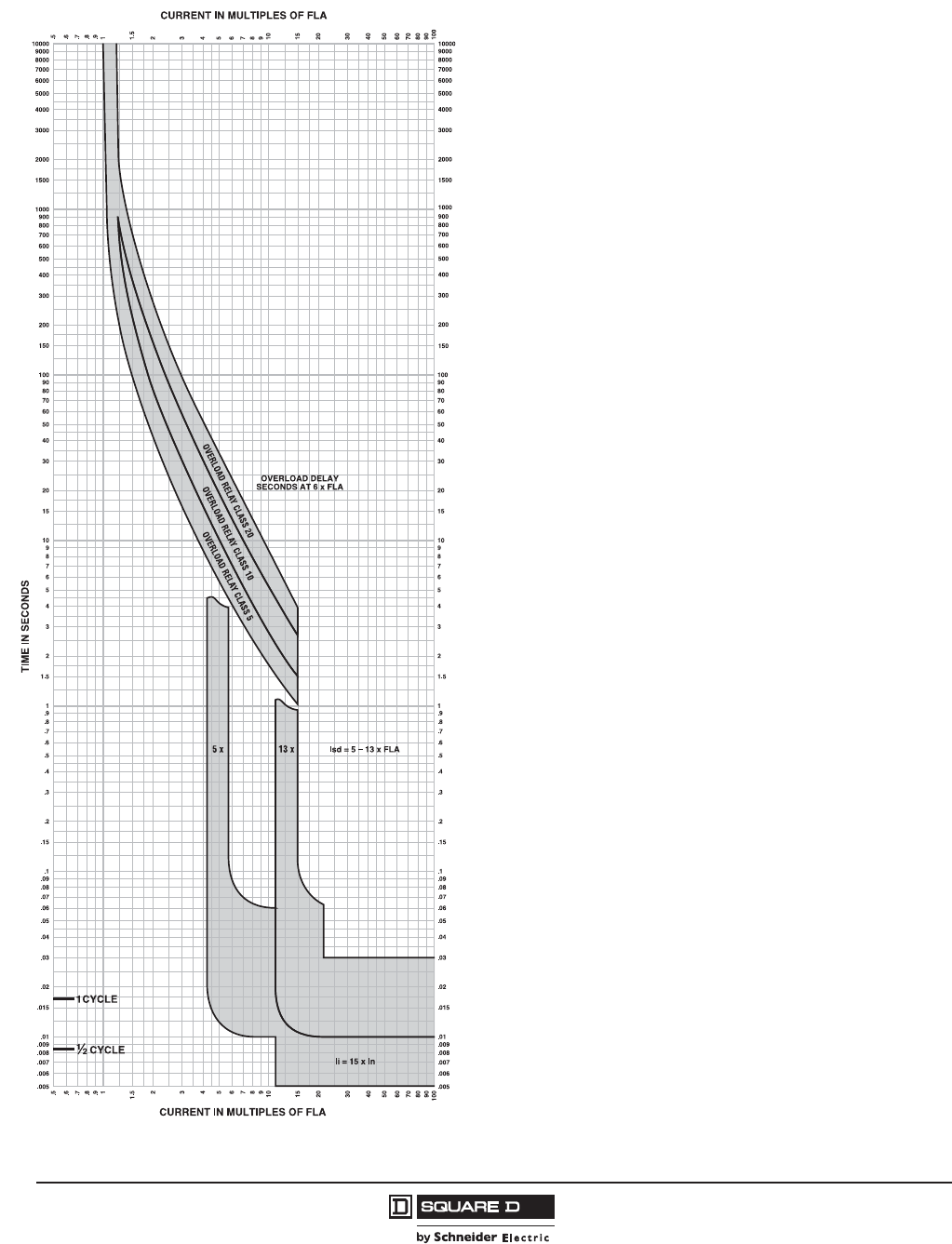
© 2011–2012 Schneider Electric
All Rights Reserved
PowerPact™ H-, J-, and L-Frame Circuit Breakers
Trip Curves
202
05/2012
™
Figure 88: Micrologic™ 2.2 M Electronic Trip Unit Overload Trip Curve
MICROLOGIC™ ELECTRONIC TRIP UNITS
Micrologic™ 2.2M Overload Trip Curve
30A, 50A, 100A, 150A H-Frame, 250A J-Frame
The time-current curve information is to be used
for application and coordination purposes only.
Notes:
1. If overload still exists past overload relay delay,
MCP will open 0.4 seconds later.
2. Total clearing times shown include the
response times of the trip unit, the circuit
breaker opening, and the extinction of the
current.
3. Isd minimum and maximum only shown.
4. li = 15 x In
In = 30A, 50A, 100A, 150A, 250A
MCP will trip <30ms at 15 x In
Curves apply from -35ºC to +70ºC (-31ºF to
+158ºF) ambient temperature.
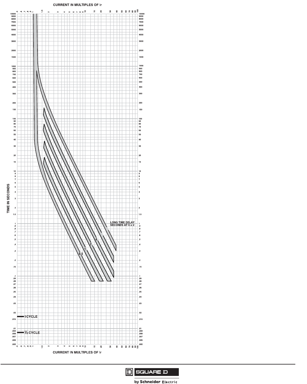
PowerPact™ H-, J-, and L-Frame Circuit Breakers
Trip Curves
203
05/2012
© 2011–2012 Schneider Electric
All Rights Reserved
™
J-Frame Electronic Trip Circuit Breakers—250 A Frame
Figure 89: Micrologic™ 3.2 Electronic Trip Unit Long-Time Trip Curve
16
8
MICROLOGIC™ ELECTRONIC TRIP UNITS
Micrologic™ 3.2 Long Time Trip Curve
250A J-Frame
The time-current curve information is to be used
for application and coordination purposes only.
Notes:
1. There is a thermal-imaging effect that can act
to shorten the long-time delay. The thermal
imaging effect comes into play if a current
above the long-time delay pickup value exists
for a time and then is cleared by the tripping of
a downstream device or the circuit breaker
itself. A subsequent overload will cause the
circuit breaker to trip in a shorter time than
normal. The amount of time delay reduction is
inverse to the amount of time that has elapsed
since the previous overload. Approximately 20
minutes is required between overloads to
completely reset thermal-imaging.
2. Total clearing times shown include the
response times of the trip unit, the circuit
breaker opening, and the extinction of the
current.
Curves apply from -35ºC to +70ºC (-31ºF to
+158ºF) ambient temperature.

© 2011–2012 Schneider Electric
All Rights Reserved
PowerPact™ H-, J-, and L-Frame Circuit Breakers
Trip Curves
204
05/2012
™
Figure 90: Micrologic™ 3.2S Electronic Trip Unit Long Time / Short Time Trip Curve
MICROLOGIC™ ELECTRONIC TRIP UNITS
Micrologic™ 3.2S Long Time/
Short Time Trip Curve
250A J-Frame
The time-current curve information is to be used
for application and coordination purposes only.
Notes:
1. There is a thermal-imaging effect that can act
to shorten the long-time delay. The thermal
imaging effect comes into play if a current
above the long-time delay pickup value exists
for a time and then is cleared by the tripping of
a downstream device or the circuit breaker
itself. A subsequent overload will cause the
circuit breaker to trip in a shorter time than
normal. The amount of time delay reduction is
inverse to the amount of time that has elapsed
since the previous overload. Approximately 20
minutes is required between overloads to
completely reset thermal-imaging.
2. Total clearing times shown include the
response times of the trip unit, the circuit
breaker opening, and the extinction of the
current.
Curves apply from -35ºC to +70ºC (-31ºF to
+158ºF) ambient temperature.
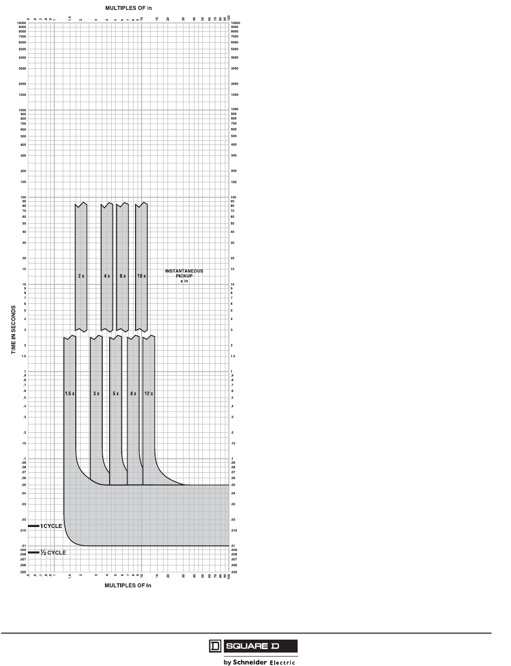
PowerPact™ H-, J-, and L-Frame Circuit Breakers
Trip Curves
205
05/2012
© 2011–2012 Schneider Electric
All Rights Reserved
™
Figure 91: Micrologic™ 3.2/3.2S/5.2A/5.2E/6.2A/6.2E Electronic Trip Curve Instantaneous Trip Curve
MICROLOGIC™ ELECTRONIC TRIP UNITS
Micrologic™ 3.2/3.2S/5.2A or E/6.2A or E
Instantaneous Trip Curve
250A J-Frame
The time-current curve information is to be used
for application and coordination purposes only.
Notes:
1. There is a thermal-imaging effect that can act
to shorten the long-time delay. The thermal
imaging effect comes into play if a current
above the long-time delay pickup value exists
for a time and then is cleared by the tripping of
a downstream device or the circuit breaker
itself. A subsequent overload will cause the
circuit breaker to trip in a shorter time than
normal. The amount of time delay reduction is
inverse to the amount of time that has elapsed
since the previous overload. Approximately 20
minutes is required between overloads to
completely reset thermal-imaging.
2. Total clearing times shown include the
response times of the trip unit, the circuit
breaker opening, and the extinction of the
current.
3. In = Maximum dial setting of Ir.
250A J-Frame: In = 250A = Max Ir setting
Curves apply from -35ºC to +70ºC (-31ºF to
+158ºF) ambient temperature.
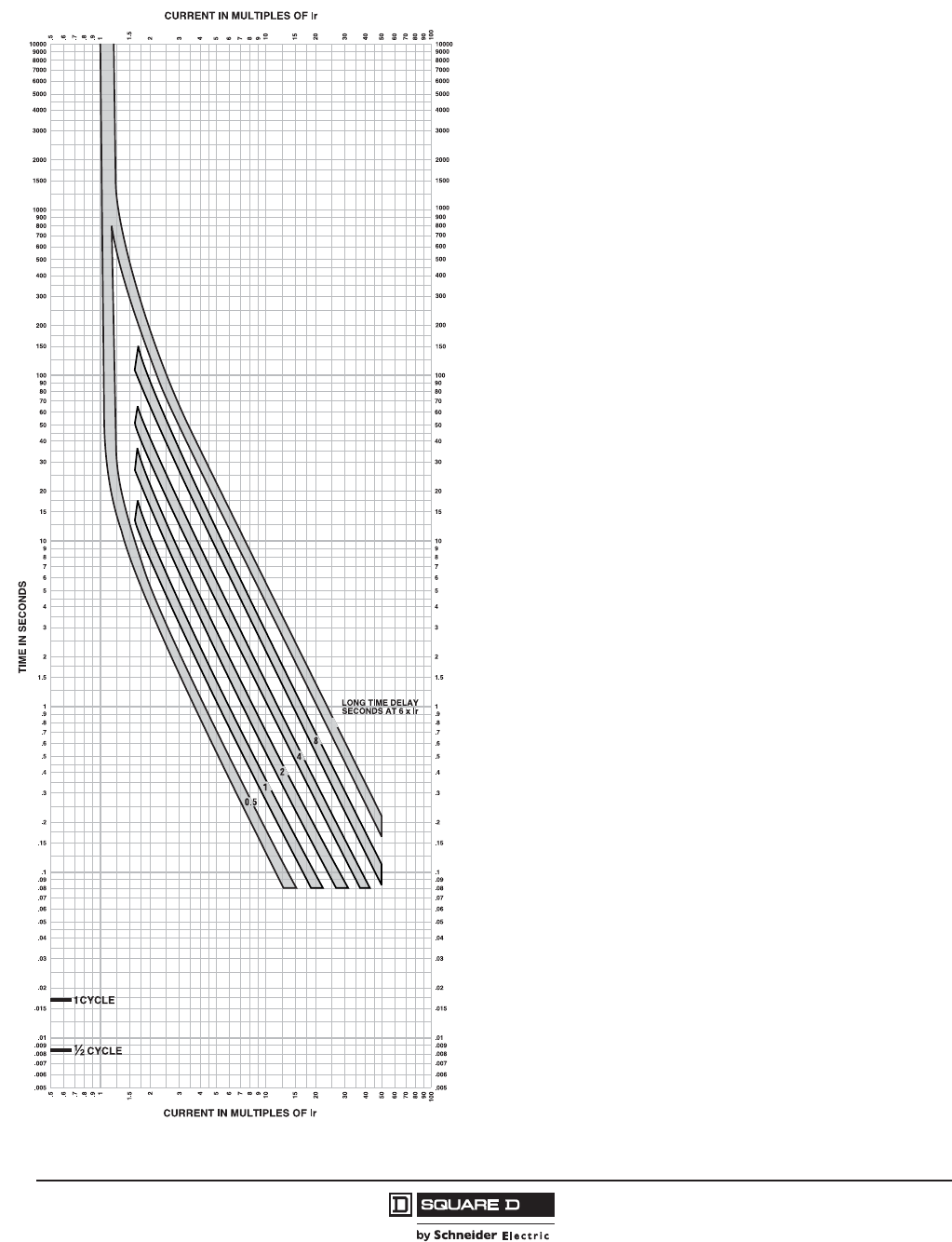
© 2011–2012 Schneider Electric
All Rights Reserved
PowerPact™ H-, J-, and L-Frame Circuit Breakers
Trip Curves
206
05/2012
™
Figure 92: Micrologic™ 5.2A/5.2E/6.2A/6.2E Electronic Trip Unit Long Time Trip Curve
16
MICROLOGIC™ ELECTRONIC TRIP UNITS
Micrologic™ 5.2A or E/6.2A or E
Long Time Trip Curve
250A J-Frame
The time-current curve information is to be used
for application and coordination purposes only.
Notes:
1. There is a thermal-imaging effect that can act
to shorten the long-time delay. The thermal
imaging effect comes into play if a current
above the long-time delay pickup value exists
for a time and then is cleared by the tripping of
a downstream device or the circuit breaker
itself. A subsequent overload will cause the
circuit breaker to trip in a shorter time than
normal. The amount of time delay reduction is
inverse to the amount of time that has elapsed
since the previous overload. Approximately 20
minutes is required between overloads to
completely reset thermal-imaging.
2. Total clearing times shown include the
response times of the trip unit, the circuit
breaker opening, and the extinction of the
current.
Curves apply from -35ºC to +70ºC (-31ºF to
+158ºF) ambient temperature.

PowerPact™ H-, J-, and L-Frame Circuit Breakers
Trip Curves
207
05/2012
© 2011–2012 Schneider Electric
All Rights Reserved
™
Figure 93: Micrologic™ 5.2A/5.2E/6.2A/6.2E Electronic Trip Unit Short Time Trip Curve
MICROLOGIC™ ELECTRONIC TRIP UNITS
Micrologic™ 5.2A or E/6.2A or E
Short Time Trip Curve
250A J-Frame
The time-current curve information is to be used
for application and coordination purposes only.
Notes:
1. There is a thermal-imaging effect that can act
to shorten the long-time delay. The thermal
imaging effect comes into play if a current
above the long-time delay pickup value exists
for a time and then is cleared by the tripping of
a downstream device or the circuit breaker
itself. A subsequent overload will cause the
circuit breaker to trip in a shorter time than
normal. The amount of time delay reduction is
inverse to the amount of time that has elapsed
since the previous overload. Approximately 20
minutes is required between overloads to
completely reset thermal-imaging.
2. Total clearing times shown include the
response times of the trip unit, the circuit
breaker opening, and the extinction of the
current.
Curves apply from -35ºC to +70ºC (-31ºF to
+158ºF) ambient temperature.
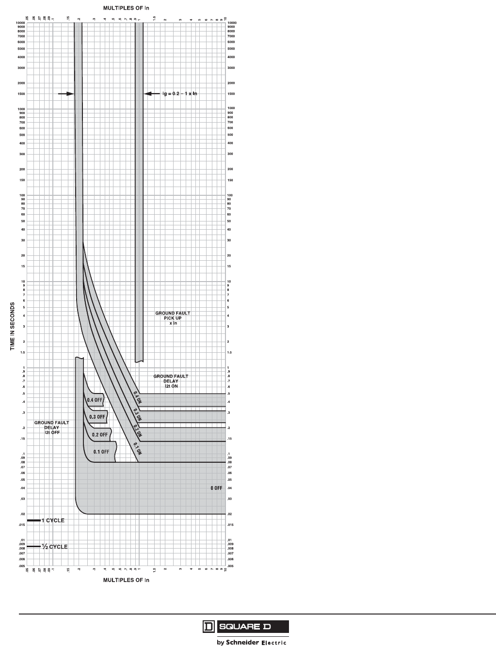
© 2011–2012 Schneider Electric
All Rights Reserved
PowerPact™ H-, J-, and L-Frame Circuit Breakers
Trip Curves
208
05/2012
™
Figure 94: Micrologic™ 6.2A/6.2E Electronic Trip Unit Ground Fault Trip Curve
MICROLOGIC™ ELECTRONIC TRIP UNITS
Micrologic™ 6.2A or E
Ground Fault Trip Curve
250A J-Frame
The time-current curve information is to be used
for application and coordination purposes only.
1. Total clearing times shown include the
response times of the trip unit, the circuit
breaker opening, and the extinction of the
current.
Curves apply from -35ºC to +70ºC (-31ºF to
+158ºF) ambient temperature.
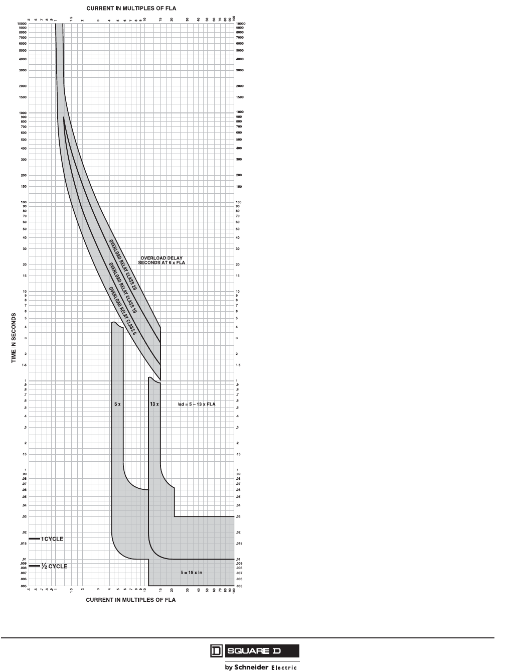
PowerPact™ H-, J-, and L-Frame Circuit Breakers
Trip Curves
209
05/2012
© 2011–2012 Schneider Electric
All Rights Reserved
™
Figure 95: Micrologic™ 2.2 M Electronic Trip Unit Overload Trip Curve
MICROLOGIC™ ELECTRONIC TRIP UNITS
Micrologic™ 2.2M Overload Trip Curve
30A, 50A, 100A, 150A H-Frame, 250A J-Frame
The time-current curve information is to be used
for application and coordination purposes only.
Notes:
1. If overload still exists past overload relay delay,
MCP will open 0.4 seconds later.
2. Total clearing times shown include the
response times of the trip unit, the circuit
breaker opening, and the extinction of the
current.
3. Isd minimum and maximum only shown.
4. li = 15 x In
In = 30A, 50A, 100A, 150A, 250A
MCP will trip <30ms at 15 x In
Curves apply from -35ºC to +70ºC (-31ºF to
+158ºF) ambient temperature.
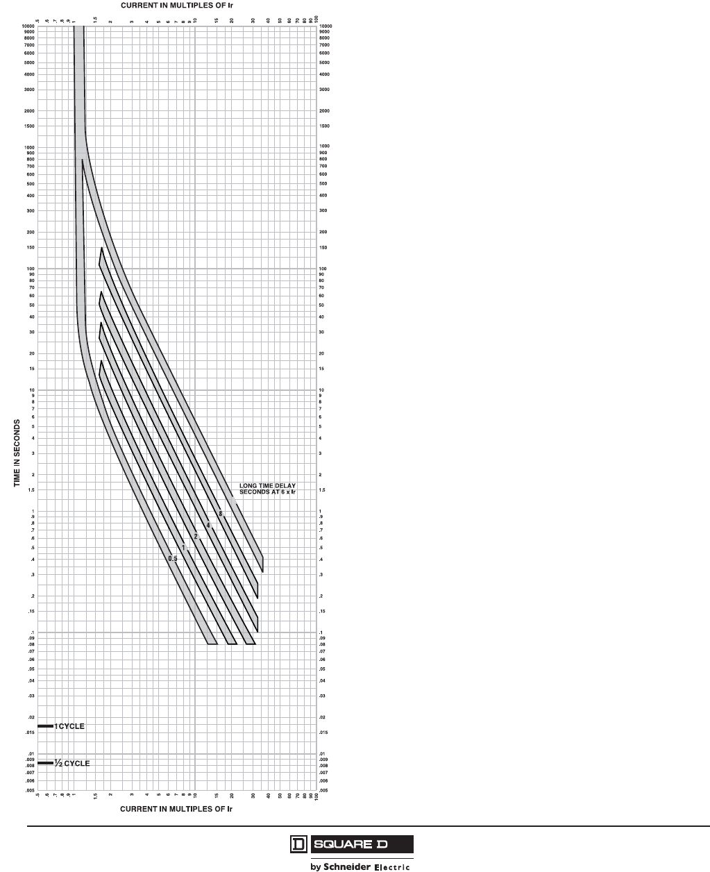
© 2011–2012 Schneider Electric
All Rights Reserved
PowerPact™ H-, J-, and L-Frame Circuit Breakers
Trip Curves
210
05/2012
™
PowerPact L-Frame Electronic Trip Circuit Breakers—
250 A/400 A/600 A Frame
Figure 96: Micrologic™ 3.3 Electronic Trip Unit Long Time Trip Curve
16
MICROLOGIC™ ELECTRONIC TRIP UNITS
Micrologic™ 3.3 Long Time Trip Curve
250A, 400A L-Frame
The time-current curve information is to be used
for application and coordination purposes only.
Notes:
1. There is a thermal-imaging effect that can act
to shorten the long-time delay. The thermal
imaging effect comes into play if a current
above the long-time delay pickup value exists
for a time and then is cleared by the tripping of
a downstream device or the circuit breaker
itself. A subsequent overload will cause the
circuit breaker to trip in a shorter time than
normal. The amount of time delay reduction is
inverse to the amount of time that has elapsed
since the previous overload. Approximately 20
minutes is required between overloads to
completely reset thermal-imaging.
2. Total clearing times shown include the
response times of the trip unit, the circuit
breaker opening, and the extinction of the
current.
Curves apply from -35ºC to +70ºC (-31ºF to
+158ºF) ambient temperature.

PowerPact™ H-, J-, and L-Frame Circuit Breakers
Trip Curves
211
05/2012
© 2011–2012 Schneider Electric
All Rights Reserved
™
Figure 97: Micrologic™ 3.3S Electronic Trip Unit Long Time/Short Time Trip Curve
MICROLOGIC™ ELECTRONIC TRIP UNITS
Micrologic™ 3.3S Long Time/
Short Time Trip Curve
250A, 400A L-Frame
The time-current curve information is to be used
for application and coordination purposes only.
Notes:
1. There is a thermal-imaging effect that can act
to shorten the long-time delay. The thermal
imaging effect comes into play if a current
above the long-time delay pickup value exists
for a time and then is cleared by the tripping of
a downstream device or the circuit breaker
itself. A subsequent overload will cause the
circuit breaker to trip in a shorter time than
normal. The amount of time delay reduction is
inverse to the amount of time that has elapsed
since the previous overload. Approximately 20
minutes is required between overloads to
completely reset thermal-imaging.
2. Total clearing times shown include the
response times of the trip unit, the circuit
breaker opening, and the extinction of the
current.
Curves apply from -35ºC to +70ºC (-31ºF to
+158ºF) ambient temperature.
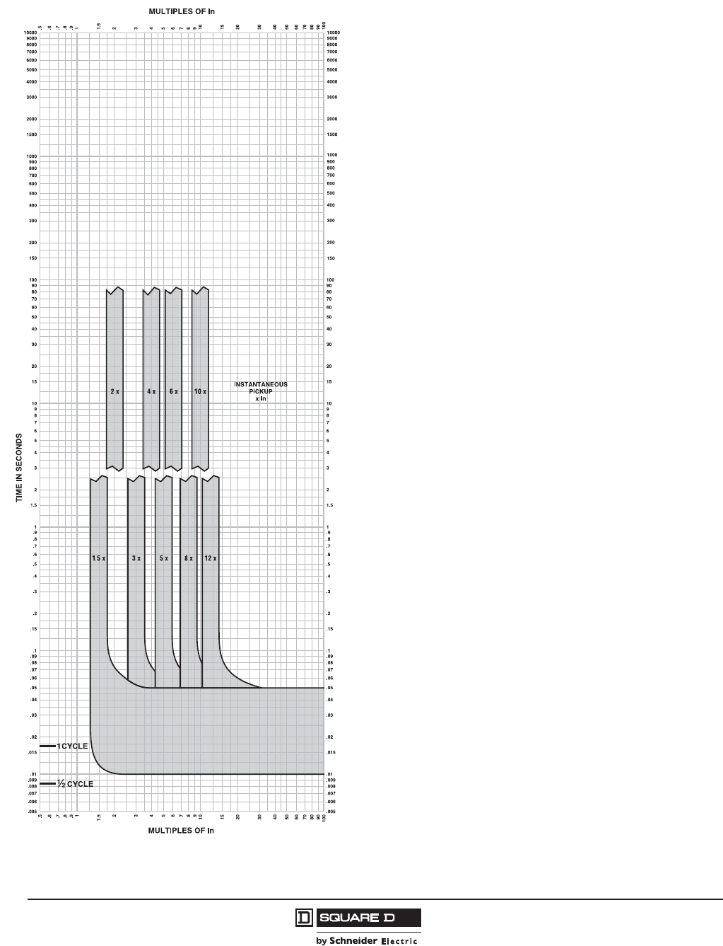
© 2011–2012 Schneider Electric
All Rights Reserved
PowerPact™ H-, J-, and L-Frame Circuit Breakers
Trip Curves
212
05/2012
™
Figure 98: Micrologic™ 3.3/3.3S Electronic Trip Unit Instantaneous Trip Curve
MICROLOGIC™ ELECTRONIC TRIP UNITS
Micrologic™ 3.3/3.3S
Instantaneous Trip Curve
250A L-Frame
The time-current curve information is to be used
for application and coordination purposes only.
Notes:
1. There is a thermal-imaging effect that can act
to shorten the long-time delay. The thermal
imaging effect comes into play if a current
above the long-time delay pickup value exists
for a time and then is cleared by the tripping of
a downstream device or the circuit breaker
itself. A subsequent overload will cause the
circuit breaker to trip in a shorter time than
normal. The amount of time delay reduction is
inverse to the amount of time that has elapsed
since the previous overload. Approximately 20
minutes is required between overloads to
completely reset thermal-imaging.
2. Total clearing times shown include the
response times of the trip unit, the circuit
breaker opening, and the extinction of the
current.
3. In = Maximum dial setting of Ir.
250A L-Frame: In = 250A = Max Ir setting
Curves apply from -35ºC to +70ºC (-31ºF to
+158ºF) ambient temperature.

PowerPact™ H-, J-, and L-Frame Circuit Breakers
Trip Curves
213
05/2012
© 2011–2012 Schneider Electric
All Rights Reserved
™
Figure 99: Micrologic™ 3.3/3.3S/5.3A/5.3E/6.3A/6.3E Electronic Trip Unit Instantaneous Trip Curve
MICROLOGIC™ ELECTRONIC TRIP UNITS
Micrologic™ 3.3/3.3S/5.3A or E/6.3A or E
Instantaneous Trip Curve
400A L-Frame
The time-current curve information is to be used
for application and coordination purposes only.
Notes:
1. There is a thermal-imaging effect that can act
to shorten the long-time delay. The thermal
imaging effect comes into play if a current
above the long-time delay pickup value exists
for a time and then is cleared by the tripping of
a downstream device or the circuit breaker
itself. A subsequent overload will cause the
circuit breaker to trip in a shorter time than
normal. The amount of time delay reduction is
inverse to the amount of time that has elapsed
since the previous overload. Approximately 20
minutes is required between overloads to
completely reset thermal-imaging.
2. Total clearing times shown include the
response times of the trip unit, the circuit
breaker opening, and the extinction of the
current.
3. In = Maximum dial setting of Ir.
400A L-Frame: In = 400A = Max Ir setting
Curves apply from -35ºC to +70ºC (-31ºF to
+158ºF) ambient temperature.
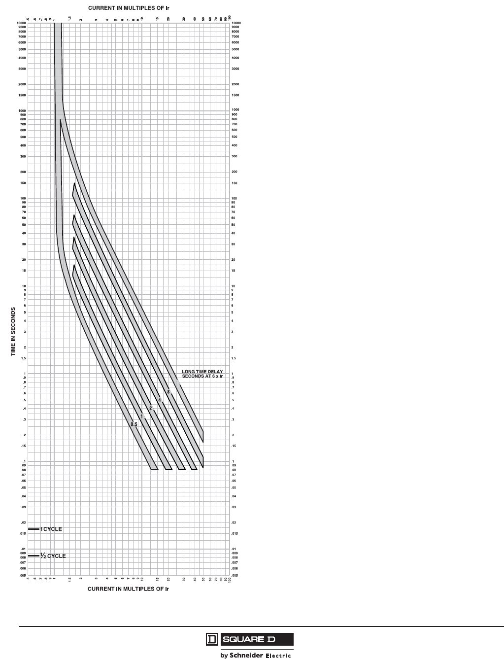
© 2011–2012 Schneider Electric
All Rights Reserved
PowerPact™ H-, J-, and L-Frame Circuit Breakers
Trip Curves
214
05/2012
™
Figure 100: Micrologic™ 5.3A/5.3E/6.3A/6.3E Electronic Trip Unit Long Time Trip Curve
16
MICROLOGIC™ ELECTRONIC TRIP UNITS
Micrologic™ 5.3A or E/6.3A or E
Long Time Trip Curve
400A L-Frame
The time-current curve information is to be used
for application and coordination purposes only.
Notes:
1. There is a thermal-imaging effect that can act
to shorten the long-time delay. The thermal
imaging effect comes into play if a current
above the long-time delay pickup value exists
for a time and then is cleared by the tripping of
a downstream device or the circuit breaker
itself. A subsequent overload will cause the
circuit breaker to trip in a shorter time than
normal. The amount of time delay reduction is
inverse to the amount of time that has elapsed
since the previous overload. Approximately 20
minutes is required between overloads to
completely reset thermal-imaging.
2. Total clearing times shown include the
response times of the trip unit, the circuit
breaker opening, and the extinction of the
current.
Curves apply from -35ºC to +70ºC (-31ºF to
+158ºF) ambient temperature.
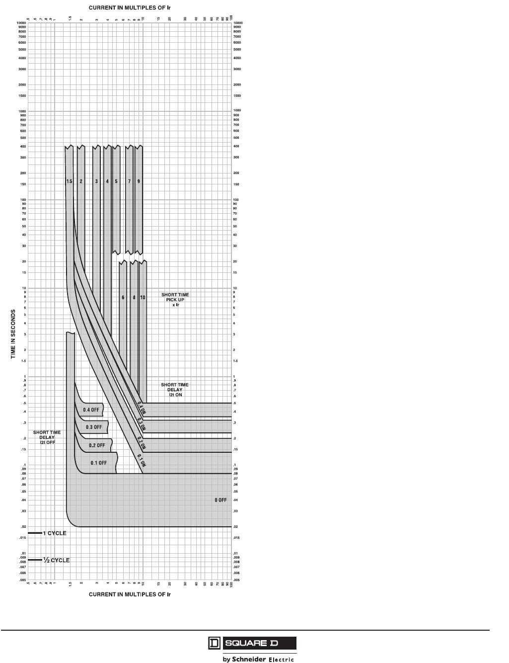
PowerPact™ H-, J-, and L-Frame Circuit Breakers
Trip Curves
215
05/2012
© 2011–2012 Schneider Electric
All Rights Reserved
™
Figure 101: Micrologic™ 5.3A/5.3E/6.3A/6.3E Electronic Trip Unit Short Time Trip Curve
MICROLOGIC™ ELECTRONIC TRIP UNITS
Micrologic™ 5.3A or E/6.3A or E
Short Time Trip Curve
400A L-Frame
The time-current curve information is to be used
for application and coordination purposes only.
Notes:
1. There is a thermal-imaging effect that can act
to shorten the long-time delay. The thermal
imaging effect comes into play if a current
above the long-time delay pickup value exists
for a time and then is cleared by the tripping of
a downstream device or the circuit breaker
itself. A subsequent overload will cause the
circuit breaker to trip in a shorter time than
normal. The amount of time delay reduction is
inverse to the amount of time that has elapsed
since the previous overload. Approximately 20
minutes is required between overloads to
completely reset thermal-imaging.
2. Total clearing times shown include the
response times of the trip unit, the circuit
breaker opening, and the extinction of the
current.
Curves apply from -35ºC to +70ºC (-31ºF to
+158ºF) ambient temperature.
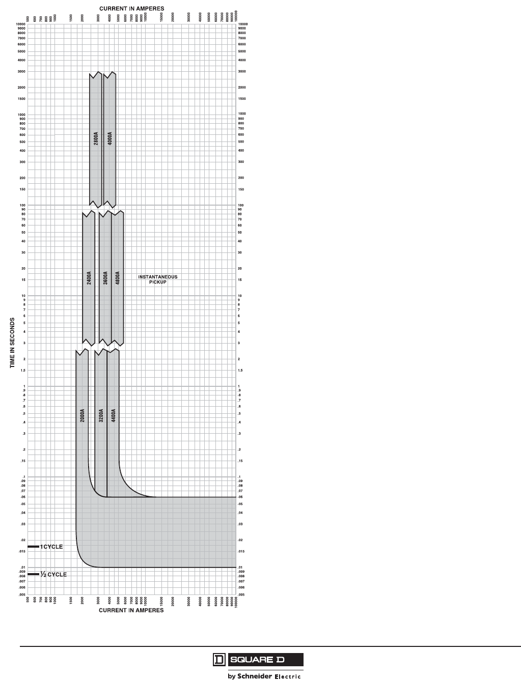
© 2011–2012 Schneider Electric
All Rights Reserved
PowerPact™ H-, J-, and L-Frame Circuit Breakers
Trip Curves
216
05/2012
™
Figure 102: Micrologic™ 1.3 M Electronic Trip Unit Instantaneous Trip Curve
MICROLOGIC™ ELECTRONIC TRIP UNITS
Micrologic™ 1.3M Instantaneous Trip Curve
400A L-Frame
The time-current curve information is to be used
for application and coordination purposes only.
Notes:
1. Total clearing times shown include the
response times of the trip unit, the circuit
breaker opening, and the extinction of the
current.
Curves apply from -35ºC to +70ºC (-31ºF to
+158ºF) ambient temperature.

PowerPact™ H-, J-, and L-Frame Circuit Breakers
Trip Curves
217
05/2012
© 2011–2012 Schneider Electric
All Rights Reserved
™
Figure 103: Micrologic™ 2.3 M Electronic Trip Unit Overload Trip Curve
MICROLOGIC™ ELECTRONIC TRIP UNITS
Micrologic™ 2.3M Overload Trip Curve
400A, 600A L-Frame
The time-current curve information is to be used
for application and coordination purposes only.
Notes:
1. If overload still exists past overload relay delay,
MCP will open 0.4 seconds later.
2. Total clearing times shown include the
response times of the trip unit, the circuit
breaker opening, and the extinction of the
current.
3. Isd minimum and maximum only shown.
4. li = 12 x In
In = 400A, 600A
MCP will trip <30ms at 12 x In
Curves apply from -35ºC to +70ºC (-31ºF to
+158ºF) ambient temperature.

© 2011–2012 Schneider Electric
All Rights Reserved
PowerPact™ H-, J-, and L-Frame Circuit Breakers
Trip Curves
218
05/2012
™
Figure 104: Micrologic™ 3.3 Electronic Trip Unit Long Time Trip Curve
16
MICROLOGIC™ ELECTRONIC TRIP UNITS
Micrologic™ 3.3 Long Time Trip Curve
600A L-Frame
The time-current curve information is to be used
for application and coordination purposes only.
Notes:
1. There is a thermal-imaging effect that can act
to shorten the long-time delay. The thermal
imaging effect comes into play if a current
above the long-time delay pickup value exists
for a time and then is cleared by the tripping of
a downstream device or the circuit breaker
itself. A subsequent overload will cause the
circuit breaker to trip in a shorter time than
normal. The amount of time delay reduction is
inverse to the amount of time that has elapsed
since the previous overload. Approximately 20
minutes is required between overloads to
completely reset thermal-imaging.
2. Total clearing times shown include the
response times of the trip unit, the circuit
breaker opening, and the extinction of the
current.
Curves apply from -35ºC to +70ºC (-31ºF to
+158ºF) ambient temperature.

PowerPact™ H-, J-, and L-Frame Circuit Breakers
Trip Curves
219
05/2012
© 2011–2012 Schneider Electric
All Rights Reserved
™
Figure 105: Micrologic™ 3.3S Electronic Trip Unit Long Time/Short Time Trip Curve
MICROLOGIC™ ELECTRONIC TRIP UNITS
Micrologic™ 3.3S Long Time/
Short Time Trip Curve
600A L-Frame
The time-current curve information is to be used
for application and coordination purposes only.
Notes:
1. There is a thermal-imaging effect that can act
to shorten the long-time delay. The thermal
imaging effect comes into play if a current
above the long-time delay pickup value exists
for a time and then is cleared by the tripping of
a downstream device or the circuit breaker
itself. A subsequent overload will cause the
circuit breaker to trip in a shorter time than
normal. The amount of time delay reduction is
inverse to the amount of time that has elapsed
since the previous overload. Approximately 20
minutes is required between overloads to
completely reset thermal-imaging.
2. Total clearing times shown include the
response times of the trip unit, the circuit
breaker opening, and the extinction of the
current.
Curves apply from -35ºC to +70ºC (-31ºF to
+158ºF) ambient temperature.

© 2011–2012 Schneider Electric
All Rights Reserved
PowerPact™ H-, J-, and L-Frame Circuit Breakers
Trip Curves
220
05/2012
™
Figure 106: Micrologic™ 3.3/3.3S/5.3A/5.3E/6.3A/6.3E Electronic Trip Unit Instantaneous Trip Curve
MICROLOGIC™ ELECTRONIC TRIP UNITS
Micrologic™ 3.3/3.3S/5.3A or E/6.3A or E
Instantaneous Trip Curve
600A L-Frame
The time-current curve information is to be used
for application and coordination purposes only.
Notes:
1. There is a thermal-imaging effect that can act
to shorten the long-time delay. The thermal
imaging effect comes into play if a current
above the long-time delay pickup value exists
for a time and then is cleared by the tripping of
a downstream device or the circuit breaker
itself. A subsequent overload will cause the
circuit breaker to trip in a shorter time than
normal. The amount of time delay reduction is
inverse to the amount of time that has elapsed
since the previous overload. Approximately 20
minutes is required between overloads to
completely reset thermal-imaging.
2. Total clearing times shown include the
response times of the trip unit, the circuit
breaker opening, and the extinction of the
current.
3. In = Maximum dial setting of Ir.
600A L-Frame: In = 600A = Max Ir setting
Curves apply from -35ºC to +70ºC (-31ºF to
+158ºF) ambient temperature.
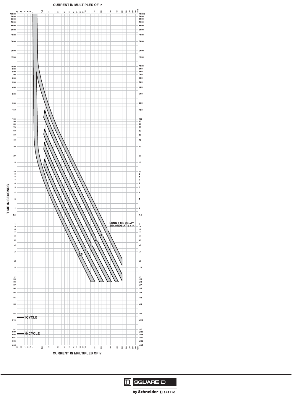
PowerPact™ H-, J-, and L-Frame Circuit Breakers
Trip Curves
221
05/2012
© 2011–2012 Schneider Electric
All Rights Reserved
™
Figure 107: Micrologic™ 5.3A/5.3E/6.3A/6.3E Electronic Trip Unit Long Time Trip Curve
16
MICROLOGIC™ ELECTRONIC TRIP UNITS
Micrologic™ 5.3A or E/6.3A or E
Long Time Trip Curve
600A L-Frame
The time-current curve information is to be used
for application and coordination purposes only.
Notes:
1. There is a thermal-imaging effect that can act
to shorten the long-time delay. The thermal
imaging effect comes into play if a current
above the long-time delay pickup value exists
for a time and then is cleared by the tripping of
a downstream device or the circuit breaker
itself. A subsequent overload will cause the
circuit breaker to trip in a shorter time than
normal. The amount of time delay reduction is
inverse to the amount of time that has elapsed
since the previous overload. Approximately 20
minutes is required between overloads to
completely reset thermal-imaging.
2. Total clearing times shown include the
response times of the trip unit, the circuit
breaker opening, and the extinction of the
current.
Curves apply from -35ºC to +70ºC (-31ºF to
+158ºF) ambient temperature.
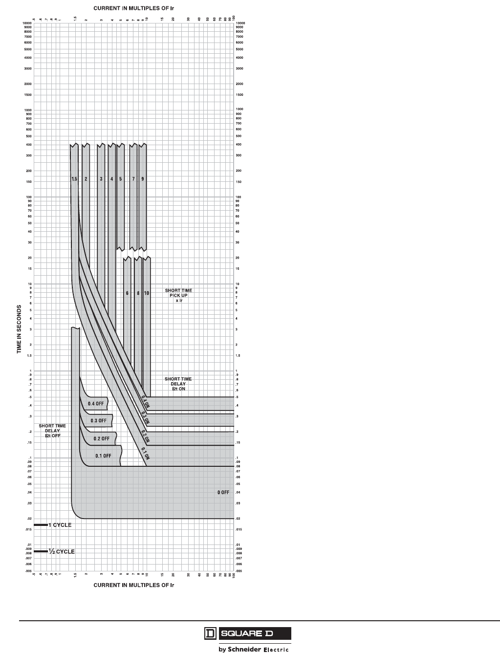
© 2011–2012 Schneider Electric
All Rights Reserved
PowerPact™ H-, J-, and L-Frame Circuit Breakers
Trip Curves
222
05/2012
™
Figure 108: Micrologic™ 5.3A/5.3E/6.3A/6.3E Electronic Trip Unit Short Time Trip Curve
MICROLOGIC™ ELECTRONIC TRIP UNITS
Micrologic™ 5.3A or E/6.3A or E
Short Time Trip Curve
600A L-Frame
The time-current curve information is to be used
for application and coordination purposes only.
Notes:
1. There is a thermal-imaging effect that can act
to shorten the long-time delay. The thermal
imaging effect comes into play if a current
above the long-time delay pickup value exists
for a time and then is cleared by the tripping of
a downstream device or the circuit breaker
itself. A subsequent overload will cause the
circuit breaker to trip in a shorter time than
normal. The amount of time delay reduction is
inverse to the amount of time that has elapsed
since the previous overload. Approximately 20
minutes is required between overloads to
completely reset thermal-imaging.
2. Total clearing times shown include the
response times of the trip unit, the circuit
breaker opening, and the extinction of the
current.
Curves apply from -35ºC to +70ºC (-31ºF to
+158ºF) ambient temperature.

PowerPact™ H-, J-, and L-Frame Circuit Breakers
Trip Curves
223
05/2012
© 2011–2012 Schneider Electric
All Rights Reserved
™
Figure 109: Micrologic™ 1.3 M Electronic Trip Unit Instantaneous Trip Curve
MICROLOGIC™ ELECTRONIC TRIP UNITS
Micrologic™ 1.3M Instantaneous Trip Curve
600A L-Frame
The time-current curve information is to be used
for application and coordination purposes only.
Notes:
1. Total clearing times shown include the
response times of the trip unit, the circuit
breaker opening, and the extinction of the
current.
Curves apply from -35ºC to +70ºC (-31ºF to
+158ºF) ambient temperature.
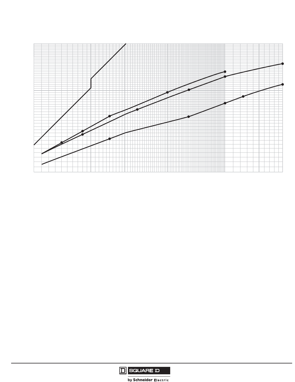
© 2011–2012 Schneider Electric
All Rights Reserved
PowerPact™ H-, J-, and L-Frame Circuit Breakers
Trip Curves
224
05/2012
™
)
Figure 110: L-Frame 600 A Typical Peak Let-Through Curves
20000
30000
40000
50000
60000
70000
80000
90000
100000
150000
200000
10000
15000
20000
30000
40000
50000
60000
70000
Available Short Circuit Current (RMS Symmetrical Amperes)
Ip
Typical* Peak Let-Through Current (Amperes)
*Based on typical values obtained throughout the circuit breaker development and UL test programs.
Maximum
Available
Peak Current
at 15% Power Factor
Maximum
Available
Peak Current
at 25% Power Factor
600 V 3Ø 480 V 3Ø
240 V 3Ø
D
D
G
J
L
R
D
G
J
R
R
L
G
J
L
(/(&7521,&02/'('&$6(&,5&8,7%5($.(56
32:(53$&7/² )5$0(&855(17/,0,7,1*&,5&8,7%5($.(56
$)5$0($7$1'9
/'/*/-//$1'/5³$
3($./(77+528*+&855(17OS
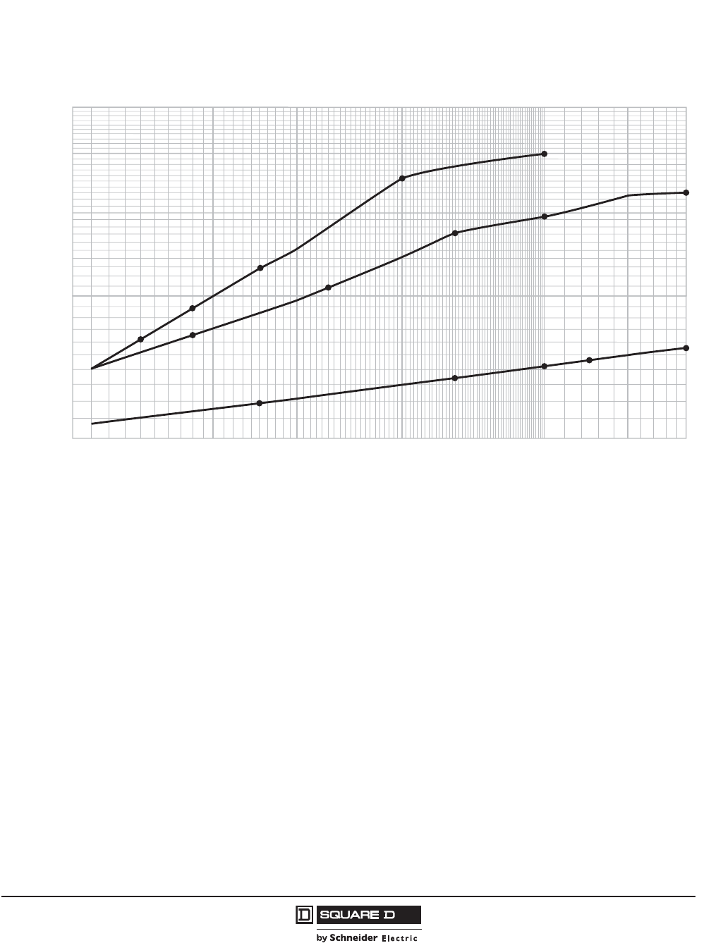
PowerPact™ H-, J-, and L-Frame Circuit Breakers
Trip Curves
225
05/2012
© 2011–2012 Schneider Electric
All Rights Reserved
™
Figure 111: L-Frame 600 A Typical I2t Let-Through Curves
20000
30000
40000
50000
60000
70000
80000
90000
100000
150000
200000
10000
2
1
3
4
5
Available Short Circuit Current (RMS Symmetrical Amperes)
I
2
t
*Based on typical values obtained throughout the circuit breaker development and UL test programs.
Typical* Let-Through I
2
t (Amperes
2
Seconds x 10
6
)
600 V 3Ø
D
D
G
J
L
R
R
G
JL
D
G
J
L
480 V 3Ø
R
240 V 3Ø
(/(&7521,&02/'('&$6(&,5&8,7%5($.(56
32:(53$&7/² )5$0(&855(17/,0,7,1*&,5&8,7%5($.(56
$)5$0($7$1'9
/'/*/-//$1'/5³$
/(77+528*+O
W
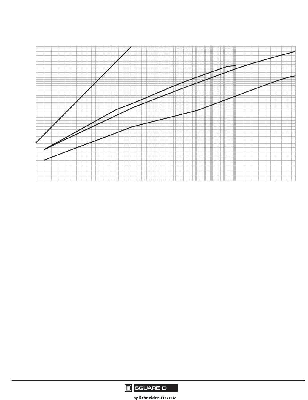
© 2011–2012 Schneider Electric
All Rights Reserved
PowerPact™ H-, J-, and L-Frame Circuit Breakers
Trip Curves
226
05/2012
™
Figure 112: L-Frame UL Listed Current-Limiting Circuit Breaker
20000
30000
40000
50000
60000
70000
80000
90000
100000
150000
200000
10000
15000
20000
30000
40000
50000
60000
70000
Availability (RMS Symmetrical Amperes)
Ip
Maximum* Peak Let-Through Current (Amperes)
*Based on maximum values obtained throughout the circuit breaker development and UL test programs.
Maximum
Available
Peak Current
at 15% Power Factor
600 V 3Ø
480 V 3Ø
240 V 3Ø
(/(&7521,&02/'('&$6(&,5&8,7%5($.(56
32:(53$&7/² )5$0(&855(17/,0,7,1*&,5&8,7%5($.(56
$)5$0($7$1'9
/-//$1'/5³$
3($./(77+528*+&855(17OS
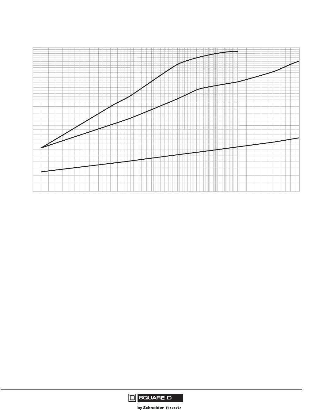
PowerPact™ H-, J-, and L-Frame Circuit Breakers
Trip Curves
227
05/2012
© 2011–2012 Schneider Electric
All Rights Reserved
™
Figure 113: L-Frame UL Listed Current-Limiting Circuit Breaker
20000
30000
40000
50000
60000
70000
80000
90000
100000
150000
200000
10000
2
1
3
4
5
Availability (RMS Symmetrical Amperes)
I
2
t
*Based on maximum values obtained throughout the circuit breaker development and UL test programs.
Maximum* Let-Through I
2
t (Amperes
2
Seconds x 10
6
)
240 V 3Ø
600 V 3Ø
480 V 3Ø
(/(&7521,&02/'('&$6(&,5&8,7%5($.(56
32:(53$&7/² )5$0(&855(17/,0,7,1*&,5&8,7%5($.(56
$)5$0($7$1'9
/-//$1'/5³$
/(77+528*+O
W

™© 2011–2012 Schneider Electric
All Rights Reserved
PowerPact™ H-, J-, and L-Frame Circuit Breakers
Catalog Numbers
228
05/2012
29271 .......................... 118
29321 .......................... 118
29348 .......................... 120
32521 .......................... 118
32556 .......................... 109
32595 .......................... 110
685823 ..........................79
685824 ..........................79
685825 ..........................79
685826 ..........................79
685827 ..........................79
685829 ..........................79
685831 ..........................80
9421LC46 ...................104
9421LD1 .....................104
9421LD4 .....................104
9421LH46 ...................104
9421LH6 .....................104
9421LJ1 ......................103
9421LJ4 ......................103
9421LJ7 ......................104
9421LS13 ................... 104
9421LS8 ..................... 104
9422A1 ....................... 104
9422CSF10 ................. 104
9422CSF30 ................. 104
9422CSF50 ................. 104
9422CSF70 ................. 104
9422CSJ10 ................. 104
9422CSJ30 ................. 104
9422CSJ50 ................. 104
9422RSI ...................... 104
9422RSI ...................... 105
AL150HD .................... 120
AL175JD ..................... 120
AL250JD ..................... 120
AL400L61K3 ...............120
AL400L61K4 ...............120
AL600LF52K3 ............. 120
AL600LS52K3 ............. 120
AL600LS52K4 ............. 120
CU150HD ................... 120
CU250JD .................... 120
CU400L61K3 .............. 120
CU400L61K4 .............. 120
CU600LF52K3 ............ 120
CU600LS52K3 ............ 120
CU600LS52K4 ............ 120
CYA060HD ................. 124
CYA150HD ................. 124
CYA150JD .................. 124
CYA250J3 ................... 124
CYA400L31K3 ............ 124
CYA400L31K4 ............ 124
CYA400L51K3 ............ 124
CYA400L51K4 ............ 124
CYA400L71K3 ............ 124
CYA600L32K3 ............ 124
CYA600L32K4 ............ 124
CYA600L52K3 ............ 124
CYA600L52K4 ............ 124
ELM150HD ................. 101
ELM250JD .................. 101
GFM150HD ................. 100
GFM250JD .................100
HDA26015( ) ................. 27
HDA26020( ) ................. 27
HDA26025( ) ................. 27
HDA26030( ) ................. 27
HDA26035( ) ................. 27
HDA26040( ) ................. 27
HDA26045( ) ................. 27
HDA26050( ) ................. 27
HDA26060( ) ................. 27
HDA26070( ) ................. 27
HDA26080( ) ................. 27
HDA26090( ) ................. 27
HDA26100( ) ................. 27
HDA26110( ) ................ 27
HDA26125( ) ................ 27
HDA26150( ) ................ 27
HDA261501 ................ 115
HDA261502 ................ 115
HDA261503 ................ 115
HDA261504 ................ 115
HDA261505 ................ 115
HDA261506 ................ 115
HDA36015 .................... 27
HDA36020 .................... 27
HDA36025 .................... 27
HDA36030 .................... 27
HDA36035 .................... 27
HDA36040 .................... 27
HDA36045 .................... 27
HDA36050 .................... 27
HDA36060 .................... 27
HDA36060U31X ........... 29
HDA36060U33X ........... 29
HDA36060U43X ........... 29
HDA36060U44X ........... 29
HDA36060U53X ........... 29
HDA36060U54X ........... 29
HDA36070 .................... 27
HDA36080 .................... 27
HDA36090 .................... 27
HDA36100 .................... 27
HDA36100U31X ........... 29
HDA36100U33X ........... 29
HDA36100U43X ........... 29
HDA36100U44X ........... 29
HDA36100U53X ........... 29
HDA36100U54X ........... 29
HDA36110 .................... 27
HDA36125 .................... 27
HDA36150 .................. 115
HDA36150 .................... 27
HDA361506 ................ 115
HDA36150U31X ........... 29
HDA36150U33X ........... 29
HDA36150U43X ........... 29
HDA36150U44X ........... 29
HDA36150U53X ........... 29
HDA36150U54X ........... 29
HDF36000F06 .............. 32
HDF36000F15 .............. 32
HDL26015 .................... 24
HDL26015C .................. 24
HDL26020 .................... 24
HDL26020C .................. 24
HDL26025 .................... 24
HDL26025C .................. 24
HDL26030 .................... 24
HDL26030C .................. 24
HDL26035 .................... 24
HDL26035C .................. 24
HDL26040 .................... 24
HDL26040C .................. 24
HDL26045 .................... 24
HDL26045C .................. 24
HDL26050 .................... 24
HDL26050C .................. 24
HDL26060 .................... 24
HDL26060C .................. 24
HDL26070 .................... 24
HDL26070C .................. 24
HDL26080 .................... 24
HDL26080C .................. 24
HDL26090 .................... 24
HDL26090C .................. 24
HDL26100 .................... 24
HDL26100C .................. 24
HDL26110 .................... 24
HDL26110C .................. 24
HDL26125 .................... 24
HDL26125C .................. 24
HDL26150 .................... 24
HDL26150C ..................24
HDL36015 .....................24
HDL36015C ..................24
HDL36015T ...................30
HDL36020 .....................24
HDL36020C ..................24
HDL36020T ...................30
HDL36025 .....................24
HDL36025C ..................24
HDL36025T ...................30
HDL36030 .....................24
HDL36030C ..................24
HDL36030T ...................30
HDL36035 .....................24
HDL36035C ..................24
HDL36035T ...................30
HDL36040 .....................24
HDL36040C ..................24
HDL36040T ...................30
HDL36045 .....................24
HDL36045C ..................24
HDL36045T ...................30
HDL36050 .....................24
HDL36050C ..................24
HDL36050T ...................30
HDL36060 .....................24
HDL36060C ..................24
HDL36060CU31X .........26
HDL36060CU33X .........26
HDL36060CU43X .........26
HDL36060CU53X .........26
HDL36060T ...................30
HDL36060TU31X ..........31
HDL36060TU33X ..........31
HDL36060TU43X ..........31
HDL36060TU44X ..........31
HDL36060TU53X ..........31
HDL36060TU54X ..........31
HDL36060U31X ............26
HDL36060U33X ............26
HDL36060U43X ............26
HDL36060U44X ............26
HDL36060U53X ............26
HDL36060U54X ............26
HDL36070 .....................24
HDL36070C ..................24
HDL36070T ...................30
HDL36080 .....................24
HDL36080C ..................24
HDL36080T ...................30
HDL36090 .....................24
HDL36090C ..................24
HDL36090T ...................30
HDL36100 .....................24
HDL36100C ..................24
HDL36100CU31X .........26
HDL36100CU33X .........26
HDL36100CU43X .........26
HDL36100CU53X .........26
HDL36100T ...................30
HDL36100TU31X ..........31
HDL36100TU33X ..........31
HDL36100TU43X ..........31
HDL36100TU44X ..........31
HDL36100TU53X ..........31
HDL36100TU54X ..........31
HDL36100U31X ............26
HDL36100U33X ............26
HDL36100U43X ............26
HDL36100U44X ............26
HDL36100U53X ............26
HDL36100U54X ............26
HDL36110 .....................24
HDL36110C ..................24
HDL36110T ...................30
HDL36125 .....................24
HDL36125C ..................24
HDL36125T ...................30
HDL36150 .................... 24
HDL36150C .................. 24
HDL36150CU31X ......... 26
HDL36150CU33X ......... 26
HDL36150CU43X ......... 26
HDL36150CU53X ......... 26
HDL36150T .................. 30
HDL36150TU31X ......... 31
HDL36150TU33X ......... 31
HDL36150TU43X ......... 31
HDL36150TU44X ......... 31
HDL36150TU53X ......... 31
HDL36150TU54X ......... 31
HDL36150U31X ........... 26
HDL36150U33X ........... 26
HDL36150U43X ........... 26
HDL36150U44X ........... 26
HDL36150U53X ........... 26
HDL36150U54X ........... 26
HE3060U31X ................ 32
HE3060U31X ................ 64
HE3060U33X ................ 32
HE3060U33X ................ 64
HE3060U43X ................ 32
HE3060U43X ................ 65
HE3060U43X ................ 65
HE3060U44X ................ 32
HE3060U44X ................ 65
HE3060U53X ................ 32
HE3060U53X ................ 65
HE3060U54X ................ 32
HE3060U54X ................ 65
HE3100U31X ................ 32
HE3100U31X ................ 64
HE3100U33X ................ 32
HE3100U33X ................ 64
HE3100U43X ................ 32
HE3100U44X ................ 32
HE3100U44X ................ 65
HE3100U53X ................ 32
HE3100U53X ................ 65
HE3100U54X ................ 32
HE3100U54X ................ 65
HE3150U31X ................ 32
HE3150U31X ................ 64
HE3150U33X ................ 32
HE3150U33X ................ 64
HE3150U43X ................ 32
HE3150U43X ................ 65
HE3150U44X ................ 32
HE3150U44X ................ 65
HE3150U53X ................ 32
HE3150U53X ................ 65
HE3150U54X ................ 32
HE3150U54X ................ 65
HGA26015( ) ................ 27
HGA26020( ) ................ 27
HGA26025( ) ................ 27
HGA26030( ) ................ 27
HGA26035( ) ................ 27
HGA26040( ) ................ 27
HGA26045( ) ................ 27
HGA26050( ) ................ 27
HGA26060( ) ................ 27
HGA26070( ) ................ 27
HGA26080( ) ................ 27
HGA26090( ) ................ 27
HGA26100( ) ................ 27
HGA26110( ) ................ 27
HGA26125( ) ................ 27
HGA26150( ) ................ 27
HGA36015 .................... 27
HGA36020 .................... 27
HGA36025 .................... 27
HGA36030 .................... 27
HGA36035 .................... 27
HGA36040 .................... 27
HGA36045 .................... 27
HGA36050 ....................27
HGA36060 ....................27
HGA36060U31X ...........29
HGA36060U33X ...........29
HGA36060U43X( ..........29
HGA36060U44X ...........29
HGA36060U53X ...........29
HGA36060U54X ...........29
HGA36070 ....................27
HGA36080 ....................27
HGA36090 ....................27
HGA36100 ....................27
HGA36100U31X ...........29
HGA36100U33X ...........29
HGA36100U43X ...........29
HGA36100U44X ...........29
HGA36100U53X ...........29
HGA36100U54X ...........29
HGA36110 ....................27
HGA36125 ....................27
HGA36150 ....................27
HGA36150U31X ...........29
HGA36150U33X ...........29
HGA36150U43X ...........29
HGA36150U44X ...........29
HGA36150U53X ...........29
HGA36150U54X ...........29
HGF36000F06 ..............32
HGF36000F15 ..............32
HGL26015 .....................24
HGL26015C ..................24
HGL26020 .....................24
HGL26020C ..................24
HGL26025 .....................24
HGL26025C ..................24
HGL26030 .....................24
HGL26030C ..................24
HGL26035 .....................24
HGL26035C ..................24
HGL26040 .....................24
HGL26040C ..................24
HGL26045 .....................24
HGL26045C ..................24
HGL26050 .....................24
HGL26050C ..................24
HGL26060 .....................24
HGL26060C ..................24
HGL26070 .....................24
HGL26070C ..................24
HGL26080 .....................24
HGL26080C ..................24
HGL26090 .....................24
HGL26090C ..................24
HGL26100 .....................24
HGL26100C ..................24
HGL26110 .....................24
HGL26110C ..................24
HGL26125 .....................24
HGL26125C ..................24
HGL26150 .....................24
HGL26150C ..................24
HGL36015 .....................24
HGL36015C ..................24
HGL36015T ...................30
HGL36020 .....................24
HGL36020C ..................24
HGL36020T ...................30
HGL36025 .....................24
HGL36025C ..................24
HGL36025T ...................30
HGL36030 .....................24
HGL36030C ..................24
HGL36030T ...................30
HGL36035 .....................24
HGL36035C ..................24
HGL36035T ...................30
HGL36040 .....................24
HGL36040C ..................24
Catalog Numbers

™
PowerPact™ H-, J-, and L-Frame Circuit Breakers
Catalog Numbers
229
05/2012
© 2011–2012 Schneider Electric
All Rights Reserved
HGL36040T ..................30
HGL36045 ....................24
HGL36045C ..................24
HGL36045T ..................30
HGL36050 ....................24
HGL36050C ..................24
HGL36050T ..................30
HGL36060 ....................24
HGL36060C ..................24
HGL36060CU31X ......... 26
HGL36060CU33X ......... 26
HGL36060CU43X ......... 26
HGL36060CU53X ......... 26
HGL36060T ..................30
HGL36060TU31X .........31
HGL36060TU33X .........31
HGL36060TU43X .........31
HGL36060TU44X .........31
HGL36060TU53X .........31
HGL36060TU54X .........31
HGL36060U31X ........... 26
HGL36060U33X ........... 26
HGL36060U43X ........... 26
HGL36060U44X ........... 26
HGL36060U53X ........... 26
HGL36060U54X ........... 26
HGL36070 ....................24
HGL36070C ..................24
HGL36070T ..................30
HGL36080 ....................24
HGL36080C ..................24
HGL36080T ..................30
HGL36090 ....................24
HGL36090C ..................24
HGL36090T ..................30
HGL36100 ....................24
HGL36100C ..................24
HGL36100CU31X ......... 26
HGL36100CU33X ......... 26
HGL36100CU43X ......... 26
HGL36100CU53X ......... 26
HGL36100T ..................30
HGL36100TU31X .........31
HGL36100TU33X .........31
HGL36100TU43X .........31
HGL36100TU44X .........31
HGL36100TU53X .........31
HGL36100TU54X .........31
HGL36100U31X ........... 26
HGL36100U33X ........... 26
HGL36100U43X ........... 26
HGL36100U44X ........... 26
HGL36100U53X ........... 26
HGL36100U54X ........... 26
HGL36110 ....................24
HGL36110C ..................24
HGL36110T ..................30
HGL36125 ....................24
HGL36125C ..................24
HGL36125T ..................30
HGL36150 ....................24
HGL36150C ..................24
HGL36150CU31X ......... 26
HGL36150CU33X ......... 26
HGL36150CU43X ......... 26
HGL36150CU53X ......... 26
HGL36150T ..................30
HGL36150TU31X .........31
HGL36150TU33X .........31
HGL36150TU43X .........31
HGL36150TU44X .........31
HGL36150TU53X .........31
HGL36150TU54X .........31
HGL36150U31X ........... 26
HGL36150U33X ........... 26
HGL36150U43X ........... 26
HGL36150U44X ........... 26
HGL36150U53X ........... 26
HGL36150U54X ........... 26
HJA26015( ) .................. 27
HJA26020( ) ................. 27
HJA26025( ) ................. 27
HJA26030( ) ................. 27
HJA26035( ) ................. 27
HJA26040( ) ................. 27
HJA26045( ) ................. 27
HJA26050( ) ................. 27
HJA26060( ) ................. 27
HJA26070( ) ................. 27
HJA26080( ) ................. 27
HJA26090( ) ................. 27
HJA26100( ) ................. 27
HJA26110( ) ................. 27
HJA26125( ) ................. 27
HJA26150( ) ................. 27
HJA36015 ..................... 27
HJA36020 ..................... 27
HJA36025 ..................... 27
HJA36030 ..................... 27
HJA36035 ..................... 27
HJA36040 ..................... 27
HJA36045 ..................... 27
HJA36050 ..................... 27
HJA36060 ..................... 27
HJA36060U31X ............ 29
HJA36060U33X ............ 29
HJA36060U43X ............ 29
HJA36060U44X ............ 29
HJA36060U53X ............ 29
HJA36060U54X ............ 29
HJA36070 ..................... 27
HJA36080 ..................... 27
HJA36090 ..................... 27
HJA36100 ..................... 27
HJA36100U31X ............ 29
HJA36100U33X ............ 29
HJA36100U43X ............ 29
HJA36100U44X ............ 29
HJA36100U53X ............ 29
HJA36100U54X ............ 29
HJA36110 ..................... 27
HJA36125 ..................... 27
HJA36150 ..................... 27
HJA36150U31X ............ 29
HJA36150U33X ............ 29
HJA36150U43X ............ 29
HJA36150U44X ............ 29
HJA36150U53X ............ 29
HJA36150U54X( .......... 29
HJF36000F06 ............... 32
HJF36000F15 ............... 32
HJL26015 ..................... 24
HJL26015C .................. 24
HJL26020 ..................... 24
HJL26020C .................. 24
HJL26025 ..................... 24
HJL26025C .................. 24
HJL26030 ..................... 24
HJL26030C .................. 24
HJL26035 ..................... 24
HJL26035C .................. 24
HJL26040 ..................... 24
HJL26040C .................. 24
HJL26045 ..................... 24
HJL26045C .................. 24
HJL26050 ..................... 24
HJL26050C .................. 24
HJL26060 ..................... 24
HJL26060C .................. 24
HJL26070 ..................... 24
HJL26070C .................. 24
HJL26080 ..................... 24
HJL26080C .................. 24
HJL26090 ..................... 24
HJL26090C .................. 24
HJL26100 ..................... 24
HJL26100C .................. 24
HJL26110 ..................... 24
HJL26110C .................. 24
HJL26125 ..................... 24
HJL26125C ...................24
HJL26150 ......................24
HJL26150C ...................24
HJL36015 ......................24
HJL36015C ...................24
HJL36015T ...................30
HJL36020 ......................24
HJL36020C ...................24
HJL36020T ...................30
HJL36025 ......................24
HJL36025C ...................24
HJL36025T ...................30
HJL36030 ......................24
HJL36030C ...................24
HJL36030M71 ...............46
HJL36030T ...................30
HJL36035 ......................24
HJL36035C ...................24
HJL36035T ...................30
HJL36040 ......................24
HJL36040C ...................24
HJL36040T ...................30
HJL36045 ......................24
HJL36045C ...................24
HJL36045T ...................30
HJL36050 ......................24
HJL36050C ...................24
HJL36050M72 ...............46
HJL36050T ...................30
HJL36060 ......................24
HJL36060C ...................24
HJL36060CU31X ..........26
HJL36060CU33X ..........26
HJL36060CU43X ..........26
HJL36060CU53X ..........26
HJL36060T ...................30
HJL36060TU31X ..........31
HJL36060TU33X ..........31
HJL36060TU43X ..........31
HJL36060TU44X ..........31
HJL36060TU53X ..........31
HJL36060TU54X ..........31
HJL36060U31X .............26
HJL36060U33X .............26
HJL36060U43X .............26
HJL36060U44X .............26
HJL36060U53X .............26
HJL36060U54X .............26
HJL36070 ......................24
HJL36070C ...................24
HJL36070T ...................30
HJL36080 ......................24
HJL36080C ...................24
HJL36080T ...................30
HJL36090 ......................24
HJL36090C ...................24
HJL36090T ...................30
HJL36100 ......................24
HJL36100C ...................24
HJL36100CU31X ..........26
HJL36100CU33X ..........26
HJL36100CU43X ..........26
HJL36100CU53X ..........26
HJL36100M73 ...............46
HJL36100T ...................30
HJL36100TU31X ..........31
HJL36100TU33X ..........31
HJL36100TU43X ..........31
HJL36100TU44X ..........31
HJL36100TU53X ..........31
HJL36100TU54X ..........31
HJL36100U31X .............26
HJL36100U33X .............26
HJL36100U43X .............26
HJL36100U44X .............26
HJL36100U53X .............26
HJL36100U54X .............26
HJL36110 ......................24
HJL36110C ...................24
HJL36110T ...................30
HJL36125 ..................... 24
HJL36125C ................... 24
HJL36125T ................... 30
HJL36150 ..................... 24
HJL36150C ................... 24
HJL36150CU31X .......... 26
HJL36150CU33X .......... 26
HJL36150CU43X .......... 26
HJL36150CU53X .......... 26
HJL36150M74 .............. 46
HJL36150T ................... 30
HJL36150TU31X .......... 31
HJL36150TU33X .......... 31
HJL36150TU43X .......... 31
HJL36150TU44X .......... 31
HJL36150TU53X .......... 31
HJL36150TU54X .......... 31
HJL36150U31X ............ 26
HJL36150U33X ............ 26
HJL36150U43X ............ 26
HJL36150U44X ............ 26
HJL36150U53X ............ 26
HJL36150U54X ............ 26
HLA26015( ) ................. 27
HLA26020( ) ................. 27
HLA26025( ) ................. 27
HLA26030( ) ................. 27
HLA26035( ) ................. 27
HLA26040( ) ................. 27
HLA26045( ) ................. 27
HLA26050( ) ................. 27
HLA26060( ) ................. 27
HLA26070( ) ................. 27
HLA26080( ) ................. 27
HLA26090( ) ................. 27
HLA26100( ) ................. 27
HLA26110( ) ................. 27
HLA26125( ) ................. 27
HLA26150( ) ................. 27
HLA36015 ..................... 27
HLA36020 ..................... 27
HLA36025 ..................... 27
HLA36030 ..................... 27
HLA36035 ..................... 27
HLA36040 ..................... 27
HLA36045 ..................... 27
HLA36050 ..................... 27
HLA36060 ..................... 27
HLA36060U31X ............ 29
HLA36060U33X ............ 29
HLA36060U43X ............ 29
HLA36060U44X ............ 29
HLA36060U53X ............ 29
HLA36060U54X ............ 29
HLA36070 ..................... 27
HLA36080 ..................... 27
HLA36090 ..................... 27
HLA36100 ..................... 27
HLA36100U31X ............ 29
HLA36100U33X ............ 29
HLA36100U43X ............ 29
HLA36100U44X ............ 29
HLA36100U53X ............ 29
HLA36100U54X ............ 29
HLA36110 ..................... 27
HLA36125 ..................... 27
HLA36150 ..................... 27
HLA36150U31 .............. 29
HLA36150U33X ............ 29
HLA36150U43X ............ 29
HLA36150U44X ............ 29
HLA36150U53X ............ 29
HLA36150U54X ............ 29
HLF36000F06 ............... 32
HLF36000F15 ............... 32
HLL26015 ..................... 24
HLL26015C .................. 24
HLL26020 ..................... 24
HLL26020C .................. 24
HLL26025 ..................... 24
HLL26025C ...................24
HLL26030 ......................24
HLL26030C ...................24
HLL26035 ......................24
HLL26035C ...................24
HLL26040 ......................24
HLL26040C ...................24
HLL26045 ......................24
HLL26045C ...................24
HLL26050 ......................24
HLL26050C ...................24
HLL26060 ......................24
HLL26060C ...................24
HLL26070 ......................24
HLL26070C ...................24
HLL26080 ......................24
HLL26080C ...................24
HLL26090 ......................24
HLL26090C ...................24
HLL26100 ......................24
HLL26100C ...................24
HLL26110 ......................24
HLL26110C ...................24
HLL26125 ......................24
HLL26125C ...................24
HLL26150 ......................24
HLL26150C ...................24
HLL36015 ......................24
HLL36015C ...................24
HLL36015T ...................30
HLL36020 ......................24
HLL36020C ...................24
HLL36020T ...................30
HLL36025 ......................24
HLL36025C ...................24
HLL36025T ...................30
HLL36030 ......................24
HLL36030C ...................24
HLL36030M71 ...............46
HLL36030T ...................30
HLL36035 ......................24
HLL36035C ...................24
HLL36035T ...................30
HLL36040 ......................24
HLL36040C ...................24
HLL36040T ...................30
HLL36045 ......................24
HLL36045C ...................24
HLL36045T ...................30
HLL36050 ......................24
HLL36050C ...................24
HLL36050M72 ...............46
HLL36050T ...................30
HLL36060 ......................24
HLL36060C ...................24
HLL36060CU31X ..........26
HLL36060CU33X ..........26
HLL36060CU43X ..........26
HLL36060CU53X ..........26
HLL36060T ...................30
HLL36060TU31X ..........31
HLL36060TU33X ..........31
HLL36060TU43X ..........31
HLL36060TU44X ..........31
HLL36060TU53X ..........31
HLL36060TU54X ..........31
HLL36060U31X .............26
HLL36060U33X .............26
HLL36060U43X .............26
HLL36060U44X .............26
HLL36060U53X .............26
HLL36060U54X .............26
HLL36070 ......................24
HLL36070C ...................24
HLL36070T ...................30
HLL36080 ......................24
HLL36080C ...................24
HLL36080T ...................30
HLL36090 ......................24
HLL36090C ...................24

™© 2011–2012 Schneider Electric
All Rights Reserved
PowerPact™ H-, J-, and L-Frame Circuit Breakers
Catalog Numbers
230
05/2012
HLL36090T ...................30
HLL36100 .....................24
HLL36100C ...................24
HLL36100CU31X ..........26
HLL36100CU33X ..........26
HLL36100CU43X ..........26
HLL36100CU53X ..........26
HLL36100M73 ..............46
HLL36100T ...................30
HLL36100TU31X ..........31
HLL36100TU33X ..........31
HLL36100TU43X ..........31
HLL36100TU44X ..........31
HLL36100TU53X ..........31
HLL36100TU54X ..........31
HLL36100U31X ............26
HLL36100U33X ............26
HLL36100U43X ............26
HLL36100U44X ............26
HLL36100U53X ............26
HLL36100U54X ............26
HLL36110 .....................24
HLL36110C ...................24
HLL36110T ...................30
HLL36125 .....................24
HLL36125C ...................24
HLL36125T ...................30
HLL36150 .....................24
HLL36150C ...................24
HLL36150CU31X ..........26
HLL36150CU33X ..........26
HLL36150CU43X ..........26
HLL36150CU53X ..........26
HLL36150M74 ..............46
HLL36150T ...................30
HLL36150TU31X ..........31
HLL36150TU33X ..........31
HLL36150TU43X ..........31
HLL36150TU44X ..........31
HLL36150TU53X ..........31
HLL36150TU54X ..........31
HLL36150U31X ............26
HLL36150U33X ............26
HLL36150U43X ............26
HLL36150U44X ............26
HLL36150U53X ............26
HLL36150U54X ............26
HRA36060U31X ........... 29
HRA36060U33X ........... 29
HRA36060U43X ........... 29
HRA36060U44X ........... 29
HRA36060U53X ........... 29
HRA36060U54X ........... 29
HRA36100U31X ........... 29
HRA36100U33X ........... 29
HRA36100U43X ........... 29
HRA36100U44X ........... 29
HRA36100U53X ........... 29
HRA36100U54X ........... 29
HRA36150U31 .............. 29
HRA36150U33X ........... 29
HRA36150U43X ........... 29
HRA36150U44X ........... 29
HRA36150U53X ........... 29
HRA36150U54X ........... 29
HRL36030M71 ..............46
HRL36050M72 ..............46
HRL36060CU31X .........26
HRL36060CU33X .........26
HRL36060CU43X .........26
HRL36060CU53X .........26
HRL36060U31X ............26
HRL36060U33X ............26
HRL36060U43X ............26
HRL36060U44X ............26
HRL36060U53X ............26
HRL36060U54X ............26
HRL36100CU31X .........26
HRL36100CU33X .........26
HRL36100CU43X .........26
HRL36100CU53X ......... 26
HRL36100M73 ............. 46
HRL36100U31X ........... 26
HRL36100U33X ........... 26
HRL36100U43X ........... 26
HRL36100U44X ........... 26
HRL36100U53X ........... 26
HRL36100U54X ........... 26
HRL36150CU31X ......... 26
HRL36150CU33X ......... 26
HRL36150CU43X ......... 26
HRL36150CU53X ......... 26
HRL36150M74 ............. 46
HRL36150U31X ........... 26
HRL36150U33X ........... 26
HRL36150U43X ........... 26
HRL36150U44X ........... 26
HRL36150U53X ........... 26
HRL36150U54X ........... 26
HT3015 ......................... 31
HT3015 ......................... 57
HT3020 ......................... 31
HT3020 ......................... 57
HT3025 ......................... 31
HT3025 ......................... 57
HT3030 ......................... 31
HT3030 ......................... 57
HT3035 ......................... 31
HT3035 ......................... 57
HT3040 ......................... 31
HT3040 ......................... 57
HT3045 ......................... 31
HT3045 ......................... 57
HT3050 ......................... 31
HT3050 ......................... 57
HT3060 ......................... 31
HT3060 ......................... 57
HT3070 ......................... 31
HT3070 ......................... 57
HT3080 ......................... 31
HT3080 ......................... 57
HT3090 ......................... 31
HT3090 ......................... 57
HT3100 ......................... 31
HT3100 ......................... 57
HT3110 ......................... 31
HT3110 ......................... 57
HT3125 ......................... 31
HT3125 ......................... 57
HT3150 ......................... 31
HT3150 ......................... 57
JDA26150( ) ................. 28
JDA26175( ) ................. 28
JDA26200( ) ................. 28
JDA26225( ) ................. 28
JDA26250( ) ................. 28
JDA36150 ..................... 28
JDA36175 ..................... 28
JDA36200 ..................... 28
JDA36225 ..................... 28
JDA36250 ..................... 28
JDA36250U31X ............ 29
JDA36250U33X ............ 29
JDA36250U43X ............ 29
JDA36250U44X ............ 29
JDA36250U53X ............ 29
JDA36250U54X ............ 29
JDF36000F25 ............... 32
JDL26150 ..................... 25
JDL26150C .................. 25
JDL26175 ..................... 25
JDL26175C .................. 25
JDL26200 ..................... 25
JDL26200C .................. 25
JDL26225 ..................... 25
JDL26225C .................. 25
JDL26250 ..................... 25
JDL26250C .................. 25
JDL36150 ..................... 25
JDL36150C .................. 25
JDL36150T ...................30
JDL36175 ......................25
JDL36175C ...................25
JDL36175T ...................30
JDL36200 ......................25
JDL36200C ...................25
JDL36200T ...................30
JDL36225 ......................25
JDL36225C ...................25
JDL36225T ...................30
JDL36250 ......................25
JDL36250C ...................25
JDL36250CU31X ..........26
JDL36250CU33X ..........26
JDL36250CU43X ..........26
JDL36250CU53X ..........26
JDL36250T ...................30
JDL36250TU31X ..........31
JDL36250TU33X ..........31
JDL36250TU43X ..........31
JDL36250TU44X ..........31
JDL36250TU53X ..........31
JDL36250TU54X ..........31
JDL36250U31X .............26
JDL36250U33X .............26
JDL36250U43X .............26
JDL36250U44X .............26
JDL36250U53X .............26
JDL36250U54X .............26
JE3250U31X .................32
JE3250U31X .................64
JE3250U33X .................32
JE3250U33X .................64
JE3250U43X .................32
JE3250U43X .................65
JE3250U44X .................32
JE3250U44X .................65
JE3250U53X .................32
JE3250U53X .................65
JE3250U54X .................32
JE3250U54X .................65
JGA26150( ) ..................28
JGA26175( ) ..................28
JGA26200( ) ..................28
JGA26225( ) ..................28
JGA26250( ) ..................28
JGA36150 .....................28
JGA36175 .....................28
JGA36200 .....................28
JGA36225 .....................28
JGA36250 .....................28
JGA36250U31X ............29
JGA36250U33X ............29
JGA36250U43X ............29
JGA36250U44X ............29
JGA36250U53X ............29
JGA36250U54X ............29
JGF36000F25 ...............32
JGL26150 .....................25
JGL26150C ...................25
JGL26175 .....................25
JGL26175C ...................25
JGL26200 .....................25
JGL26200C ...................25
JGL26225 .....................25
JGL26225C ...................25
JGL26250 .....................25
JGL26250C ...................25
JGL36150 .....................25
JGL36150C ...................25
JGL36150T ...................30
JGL36175 .....................25
JGL36175C ...................25
JGL36175T ...................30
JGL36200 .....................25
JGL36200C ...................25
JGL36200T ...................30
JGL36225 .....................25
JGL36225C ...................25
JGL36225T ...................30
JGL36250 ..................... 25
JGL36250C ................... 25
JGL36250CU31X .......... 26
JGL36250CU33X .......... 26
JGL36250CU43X .......... 26
JGL36250CU53X .......... 26
JGL36250T ................... 30
JGL36250TU31X .......... 31
JGL36250TU33X .......... 31
JGL36250TU43X .......... 31
JGL36250TU44X .......... 31
JGL36250TU53X .......... 31
JGL36250TU54X .......... 31
JGL36250U31X ............ 26
JGL36250U33X ............ 26
JGL36250U43X ............ 26
JGL36250U44X ............ 26
JGL36250U53X ............ 26
JGL36250U54X ............ 26
JGL37100D81 ............... 16
JGL37125D81 ............... 16
JGL37150D81 ............... 16
JGL37175D81 ............... 16
JGL37200D82 ............... 16
JGL37225D82 ............... 16
JGL37250D82 ............... 16
JJA26150( ) .................. 28
JJA26175( ) .................. 28
JJA26200( ) .................. 28
JJA26225( ) .................. 28
JJA26250( ) .................. 28
JJA36150 ...................... 28
JJA36175 ...................... 28
JJA36200 ...................... 28
JJA36225 ...................... 28
JJA36250 ...................... 28
JJA36250U31X ............. 29
JJA36250U33X ............. 29
JJA36250U43X ............. 29
JJA36250U44X ............. 29
JJA36250U53X ............. 29
JJA36250U54X ............. 29
JJF36000F25 ................ 32
JJL26150 ...................... 25
JJL26150C .................... 25
JJL26175 ...................... 25
JJL26175C .................... 25
JJL26200 ...................... 25
JJL26200C .................... 25
JJL26225 ...................... 25
JJL26225C .................... 25
JJL26250 ...................... 25
JJL26250C .................... 25
JJL36150 ...................... 25
JJL36150C .................... 25
JJL36150T .................... 30
JJL36175 ...................... 25
JJL36175C .................... 25
JJL36175T .................... 30
JJL36200 ...................... 25
JJL36200C .................... 25
JJL36200T .................... 30
JJL36225 ...................... 25
JJL36225C .................... 25
JJL36225T .................... 30
JJL36250 ...................... 25
JJL36250C .................... 25
JJL36250CU31X ........... 26
JJL36250CU33X ........... 26
JJL36250CU43X ........... 26
JJL36250CU53X ........... 26
JJL36250M75 ............... 46
JJL36250T .................... 30
JJL36250TU31X ........... 31
JJL36250TU33X ........... 31
JJL36250TU43X ........... 31
JJL36250TU44X ........... 31
JJL36250TU53X ........... 31
JJL36250TU54X ........... 31
JJL36250U31X ............. 26
JJL36250U33X ............. 26
JJL36250U43X ............. 26
JJL36250U44X ............. 26
JJL36250U53X ............. 26
JJL36250U54X ............. 26
JLA36150 ..................... 28
JLA36175 ..................... 28
JLA36200 ..................... 28
JLA36225 ..................... 28
JLA36250 ..................... 28
JLA36250U31X ............ 29
JLA36250U33X ............ 29
JLA36250U43X ............ 29
JLA36250U44X ............ 29
JLA36250U53X ............ 29
JLA36250U54X ............ 29
JLF36000F25 ............... 32
JLL26150 ...................... 25
JLL26150C ................... 25
JLL26175 ...................... 25
JLL26175C ................... 25
JLL26200 ...................... 25
JLL26200C ................... 25
JLL26225 ...................... 25
JLL26225C ................... 25
JLL26250 ...................... 25
JLL26250C ................... 25
JLL36150 ...................... 25
JLL36150C ................... 25
JLL36150T ................... 30
JLL36175 ...................... 25
JLL36175C ................... 25
JLL36175T ................... 30
JLL36200 ...................... 25
JLL36200C ................... 25
JLL36200T ................... 30
JLL36225 ...................... 25
JLL36225C ................... 25
JLL36225T ................... 30
JLL36250 ...................... 25
JLL36250C ................... 25
JLL36250CU31X .......... 26
JLL36250CU33X .......... 26
JLL36250CU43X .......... 26
JLL36250CU53X .......... 26
JLL36250M75 ............... 46
JLL36250T ................... 30
JLL36250TU31X .......... 31
JLL36250TU33X .......... 31
JLL36250TU43X .......... 31
JLL36250TU44X .......... 31
JLL36250TU53X .......... 31
JLL36250TU54X .......... 31
JLL36250U31X ............. 26
JLL36250U33X ............. 26
JLL36250U43X ............. 26
JLL36250U44X ............. 26
JLL36250U53X ............. 26
JLL36250U54X ............. 26
JRA36150 ..................... 28
JRA36175 ..................... 28
JRA36200 ..................... 28
JRA36225 ..................... 28
JRA36250 ..................... 28
JRA36250U31X ............ 29
JRA36250U33X ............ 29
JRA36250U43X ............ 29
JRA36250U44X ............ 29
JRA36250U53X ............ 29
JRA36250U54X ............ 29
JRL36150 ..................... 25
JRL36150C .................. 25
JRL36175 ..................... 25
JRL36175C .................. 25
JRL36200 ..................... 25
JRL36200C .................. 25
JRL36225 ..................... 25
JRL36225C .................. 25
JRL36250 ..................... 25
JRL36250C .................. 25

™
PowerPact™ H-, J-, and L-Frame Circuit Breakers
Catalog Numbers
231
05/2012
© 2011–2012 Schneider Electric
All Rights Reserved
JRL36250CU31X ..........26
JRL36250CU33X ..........26
JRL36250CU43X ..........26
JRL36250CU53X ..........26
JRL36250M75 ..............46
JRL36250U31X ............ 26
JRL36250U43X ............ 26
JRL36250U44X ............ 26
JRL36250U53X ............ 26
JRL36250U54X ............ 26
JRLL36250U33X ..........26
JT3150 .......................... 31
JT3150 .......................... 57
JT3175 .......................... 31
JT3175 .......................... 57
JT3200 .......................... 31
JT3200 .......................... 57
JT3225 .......................... 31
JT3225 .......................... 57
JT3250 .......................... 31
JT3250 .......................... 57
LDA36250CU31X .........35
LDA36250CU33X .........35
LDA36250U31X ............ 35
LDA36250U33X ............ 35
LDA36400CU31X .........35
LDA36400CU33X .........35
LDA36400CU43X .........35
LDA36400CU44X .........35
LDA36400CU53X .........35
LDA36400CU54X .........35
LDA36400U31X
LDA36600U31X ............ 35
LDA36400U33X ............ 35
LDA36400U43X ............ 35
LDA36400U44X ............ 35
LDA36400U53X ............ 35
LDA36400U54X ............ 35
LDA36600U33X ............ 35
LDA36600U43X ............ 35
LDA36600U44X ............ 35
LDA36600U53X ............ 35
LDA36600U54X ............ 35
LDF36000F25 ............... 36
LDF36000F40 ............... 36
LDF36000F60 ............... 36
LDL36250CU31X .......... 33
LDL36250CU33X .......... 33
LDL36250RU31X .......... 36
LDL36250RU33X .......... 36
LDL36250TU31X .......... 36
LDL36250TU33X .......... 36
LDL36250U31X ............ 33
LDL36250U33X ............ 33
LDL36400CU31X .......... 33
LDL36400CU33X .......... 33
LDL36400CU43X .......... 33
LDL36400CU44X .......... 33
LDL36400CU53X .......... 33
LDL36400CU54X .......... 33
LDL36400RU31X .......... 36
LDL36400RU33X .......... 36
LDL36400RU43X .......... 36
LDL36400RU44X .......... 36
LDL36400RU53X .......... 36
LDL36400RU54X .......... 36
LDL36400TU31X .......... 36
LDL36400TU33X .......... 36
LDL36400TU43X .......... 36
LDL36400TU44X .......... 36
LDL36400TU53X .......... 36
LDL36400TU54X .......... 36
LDL36400U31X ............ 33
LDL36400U33X ............ 33
LDL36400U43X ............ 33
LDL36400U44X ............ 33
LDL36400U53X ............ 33
LDL36400U54X ............ 33
LDL36600TU31X .......... 36
LDL36600TU33X .......... 36
LDL36600TU43X .......... 36
LDL36600TU44X .......... 36
LDL36600TU53X .......... 36
LDL36600TU54X .......... 36
LDL36600U31X ............ 33
LDL36600U33X ............ 33
LDL36600U43X ............ 33
LDL36600U44X ............ 33
LDL36600U53X ............ 33
LDL36600U54X ............ 33
LDL46250CU31X ......... 34
LDL46250CU33X ......... 34
LDL46250U31X ............ 34
LDL46250U33X ............ 34
LDL46400CU31X ......... 34
LDL46400CU33X ......... 34
LDL46400CU43X ......... 34
LDL46400CU44X ......... 34
LDL46400CU53X ......... 34
LDL46400CU54X ......... 34
LDL46400U31X ............ 34
LDL46400U33X ............ 34
LDL46400U43X ............ 34
LDL46400U44X ............ 34
LDL46400U53X ............ 34
LDL46400U54X ............ 34
LDL46600U31X ............ 34
LDL46600U33X ............ 34
LDL46600U43X ............ 34
LDL46600U44X ............ 34
LDL46600U53X ............ 34
LDL46600U54X ............ 34
LE3250U31X ................ 37
LE3250U31X ................ 64
LE3250U33X ................ 37
LE3250U33X ................ 64
LE3400U31X ................ 37
LE3400U31X ................ 64
LE3400U33X ................ 37
LE3400U33X ................ 64
LE3400U43X ................ 37
LE3400U43X ................ 65
LE3400U44X ................ 37
LE3400U44X ................ 65
LE3400U53X ................ 37
LE3400U53X ................ 65
LE3400U54X ................ 37
LE3400U54X ................ 65
LE3600U31X ................ 37
LE3600U31X ................ 64
LE3600U33X ................ 37
LE3600U33X ................ 64
LE3600U43X ................ 37
LE3600U43X ................ 65
LE3600U44X ................ 37
LE3600U44X ................ 65
LE3600U53X ................ 37
LE3600U53X ................ 65
LE3600U54X ................ 37
LE3600U54X ................ 65
LE4250U31X ................ 64
LE4250U33X ................ 64
LE4400U31X ................ 64
LE4400U33X ................ 64
LE4400U43X ................ 65
LE4400U44X ................ 65
LE4400U53X ................ 65
LE4400U54X ................ 65
LE4600U31X ................ 64
LE4600U33X ................ 64
LE4600U43X ................ 65
LE4600U44X ................ 65
LE4600U53X ................ 65
LE4600U54X ................ 65
LGA36000S40X ........... 41
LGA36000S60X ........... 41
LGA36250CU31X ......... 35
LGA36250CU33X ......... 35
LGA36250U31X ........... 35
LGA36250U33X ........... 35
LGA36400CU31X .........35
LGA36400CU33X .........35
LGA36400CU43X .........35
LGA36400CU44X .........35
LGA36400CU53X .........35
LGA36400CU54X .........35
LGA36400U31X ............35
LGA36400U33X ............35
LGA36400U43X ............35
LGA36400U44X ............35
LGA36400U53X ............35
LGA36400U54X ............35
LGA36600U31X ............35
LGA36600U33X ............35
LGA36600U43X ............35
LGA36600U44X ............35
LGA36600U53X ............35
LGA36600U54X ............35
LGF36000F25 ...............36
LGF36000F40 ...............36
LGF36000F60 ...............36
LGL36000S40X ............41
LGL36000S60X ............41
LGL36250CU31X ..........33
LGL36250CU33X ..........33
LGL36250RU31X ..........36
LGL36250RU33X ..........36
LGL36250TU31X ..........36
LGL36250TU33X ..........36
LGL36250U31X ............33
LGL36250U33X ............33
LGL36400CU31X ..........33
LGL36400CU33X ..........33
LGL36400CU43X ..........33
LGL36400CU44X ..........33
LGL36400CU53X ..........33
LGL36400CU54X ..........33
LGL36400RU31X ..........36
LGL36400RU33X ..........36
LGL36400RU43X ..........36
LGL36400RU44X ..........36
LGL36400RU53X ..........36
LGL36400RU54X ..........36
LGL36400TU31X ..........36
LGL36400TU33X ..........36
LGL36400TU43X ..........36
LGL36400TU44X ..........36
LGL36400TU53X ..........36
LGL36400TU54X ..........36
LGL36400U31X ............33
LGL36400U33X ............33
LGL36400U43X ............33
LGL36400U44X ............33
LGL36400U53X ............33
LGL36400U54X ............33
LGL36600TU31X ..........36
LGL36600TU33X ..........36
LGL36600TU43X ..........36
LGL36600TU44X ..........36
LGL36600TU53X ..........36
LGL36600TU54X ..........36
LGL36600U31X ............33
LGL36600U33X ............33
LGL36600U43X ............33
LGL36600U44X ............33
LGL36600U53X ............33
LGL36600U54X ............33
LGL46000S40X ............41
LGL46000S60X ............41
LGL46250CU31X ..........34
LGL46250CU33X ..........34
LGL46250U31X ............34
LGL46250U33X ............34
LGL46400CU31X ..........34
LGL46400CU33X ..........34
LGL46400CU43X ..........34
LGL46400CU44X ..........34
LGL46400CU53X ..........34
LGL46400CU54X ..........34
LGL46400U31X ............34
LGL46400U33X ............ 34
LGL46400U43X ............ 34
LGL46400U44X ............ 34
LGL46400U53X ............ 34
LGL46400U54X ............ 34
LGL46600U31X ............ 34
LGL46600U33X ............ 34
LGL46600U43X ............ 34
LGL46600U44X ............ 34
LGL46600U53X ............ 34
LGL46600U54X ............ 34
LJA36250CU31X .......... 35
LJA36250CU33X .......... 35
LJA36250U31X ............ 35
LJA36250U33X ............ 35
LJA36400CU31X .......... 35
LJA36400CU33X .......... 35
LJA36400CU43X .......... 35
LJA36400CU44X .......... 35
LJA36400CU53X .......... 35
LJA36400CU54X .......... 35
LJA36400U31X ............ 35
LJA36400U33X ............ 35
LJA36400U43X ............ 35
LJA36400U44X ............ 35
LJA36400U53X ............ 35
LJA36400U54X ............ 35
LJA36600U31X ............ 35
LJA36600U33X ............ 35
LJA36600U43X ............ 35
LJA36600U44X ............ 35
LJA36600U53X ............ 35
LJA36600U54X ............ 35
LJF36000F25 ............... 36
LJF36000F40 ............... 36
LJF36000F60 ............... 36
LJL36250CU31X .......... 33
LJL36250CU33X .......... 33
LJL36250RU31X .......... 36
LJL36250RU33X .......... 36
LJL36250TU31X ........... 36
LJL36250TU33X ........... 36
LJL36250U31X ............. 33
LJL36250U33X ............. 33
LJL36400CU31X .......... 33
LJL36400CU43X .......... 33
LJL36400CU44X .......... 33
LJL36400CU53X .......... 33
LJL36400CU54X .......... 33
LJL36400RU31X .......... 36
LJL36400RU33X .......... 36
LJL36400RU43X .......... 36
LJL36400RU44X .......... 36
LJL36400RU53X .......... 36
LJL36400RU54X .......... 36
LJL36400TU31X ........... 36
LJL36400TU33X ........... 36
LJL36400TU43X ........... 36
LJL36400TU44X ........... 36
LJL36400TU53X ........... 36
LJL36400TU54X ........... 36
LJL36400U31X ............. 33
LJL36400U33X ............. 33
LJL36400U43X ............. 33
LJL36400U44X ............. 33
LJL36400U53X ............. 33
LJL36400U54X ............. 33
LJL3640C0U33X .......... 33
LJL36600TU31X ........... 36
LJL36600TU33X ........... 36
LJL36600TU43X ........... 36
LJL36600TU44X ........... 36
LJL36600TU53X ........... 36
LJL36600TU54X ........... 36
LJL36600U31X ............. 33
LJL36600U33X ............. 33
LJL36600U43X ............. 33
LJL36600U44X ............. 33
LJL36600U53X ............. 33
LJL36600U54X ............. 33
LJL46250CU31X ...........34
LJL46250CU33X ...........34
LJL46250U31X .............34
LJL46250U33X .............34
LJL46400CU31X ...........34
LJL46400CU33X ...........34
LJL46400CU43X ...........34
LJL46400CU44X ...........34
LJL46400CU53X ...........34
LJL46400CU54X ...........34
LJL46400U31X .............34
LJL46400U33X .............34
LJL46400U43X .............34
LJL46400U44X .............34
LJL46400U53X .............34
LJL46400U54X .............34
LJL46600U31X .............34
LJL46600U33X .............34
LJL46600U43X .............34
LJL46600U44X .............34
LJL46600U53X .............34
LJL46600U54X .............34
LLA36000S40X .............41
LLA36000S60X .............41
LLA36250CU31X ..........35
LLA36250CU33X ..........35
LLA36250U31X .............35
LLA36250U33X .............35
LLA36400CU31X ..........35
LLA36400CU33X ..........35
LLA36400CU43X ..........35
LLA36400CU44X ..........35
LLA36400CU53X ..........35
LLA36400CU54X ..........35
LLA36400U31X .............35
LLA36400U33X .............35
LLA36400U43X .............35
LLA36400U44X .............35
LLA36400U53X .............35
LLA36400U54X .............35
LLA36600U31X .............35
LLA36600U33X .............35
LLA36600U43X .............35
LLA36600U44X .............35
LLA36600U53X .............35
LLA36600U54X .............35
LLF36000F25 ................36
LLF36000F40 ................36
LLF36000F60 ................36
LLL36000S40X .............41
LLL36000S60X .............41
LLL36250CU31X ...........33
LLL36250CU33X ...........33
LLL36250RU31X ...........36
LLL36250RU33X ...........36
LLL36250TU31X ...........36
LLL36250TU33X ...........36
LLL36250U31X .............33
LLL36250U33X .............33
LLL36400CU31X ...........33
LLL36400CU33X ...........33
LLL36400CU43X ...........33
LLL36400CU44X ...........33
LLL36400CU53X ...........33
LLL36400CU54X ...........33
LLL36400RU31X ...........36
LLL36400RU33X ...........36
LLL36400RU43X ...........36
LLL36400RU44X ...........36
LLL36400RU53X ...........36
LLL36400RU54X ...........36
LLL36400TU31X ...........36
LLL36400TU33X ...........36
LLL36400TU43X ...........36
LLL36400TU44X ...........36
LLL36400TU53X ...........36
LLL36400TU54X ...........36
LLL36400U31X .............33
LLL36400U33X .............33
LLL36400U43X .............33

™© 2011–2012 Schneider Electric
All Rights Reserved
PowerPact™ H-, J-, and L-Frame Circuit Breakers
Catalog Numbers
232
05/2012
LLL36400U44X .............33
LLL36400U53X .............33
LLL36400U54X .............33
LLL36600TU31X ...........36
LLL36600TU33X ...........36
LLL36600TU43X ...........36
LLL36600TU44X ...........36
LLL36600TU53X ...........36
LLL36600TU54X ...........36
LLL36600U31X .............33
LLL36600U33X .............33
LLL36600U43X .............33
LLL36600U44X .............33
LLL36600U53X .............33
LLL36600U54X .............33
LLL46000S40X .............41
LLL46000S60X .............41
LLL46250CU31X ..........34
LLL46250CU33X ..........34
LLL46250U31X .............34
LLL46250U33X .............34
LLL46400CU31X ..........34
LLL46400CU33X ..........34
LLL46400CU43X ..........34
LLL46400CU44X ..........34
LLL46400CU53X ..........34
LLL46400CU54X ..........34
LLL46400U31X .............34
LLL46400U33X .............34
LLL46400U43X .............34
LLL46400U44X .............34
LLL46400U53X .............34
LLL46400U54X .............34
LLL46600U31X .............34
LLL46600U33X .............34
LLL46600U43X .............34
LLL46600U44X .............34
LLL46600U53X .............34
LLL46600U54X .............34
LRA36000S40X ............41
LRA36000S60X ............41
LRA36250CU31X ......... 35
LRA36250CU33X ......... 35
LRA36250U31X ............35
LRA36250U33X ............35
LRA36400CU31X ......... 35
LRA36400CU33X ......... 35
LRA36400CU43X ......... 35
LRA36400CU44X ......... 35
LRA36400CU53X ......... 35
LRA36400CU54X ......... 35
LRA36400U31X ............35
LRA36400U33X ............35
LRA36400U43X ............35
LRA36400U44X ............35
LRA36400U53X ............35
LRA36400U54X ............35
LRA36600U31X ............35
LRA36600U33X ............35
LRA36600U43X ............35
LRA36600U44X ............35
LRA36600U53X ............35
LRA36600U54X ............35
LRL36000S40X ............41
LRL36000S60X ............41
LRL36250CU31X ..........33
LRL36250CU33X ..........33
LRL36250U31X ............33
LRL36250U33X ............33
LRL36400CU31X ..........33
LRL36400CU33X ..........33
LRL36400CU43X ..........33
LRL36400CU44X ..........33
LRL36400CU53X ..........33
LRL36400CU54X ..........33
LRL36400U31X ............33
LRL36400U33X ............33
LRL36400U43X ............33
LRL36400U44X ............33
LRL36400U53X ............33
LRL36400U54X ............ 33
LRL36600U31X ............ 33
LRL36600U33X ............ 33
LRL36600U43X ............ 33
LRL36600U44X ............ 33
LRL36600U53X ............ 33
LRL36600U54X ............ 33
LRL46000S40X ............ 41
LRL46000S60X ............ 41
LRL46250CU31X ......... 34
LRL46250CU33X ......... 34
LRL46250U31X ............ 34
LRL46250U33X ............ 34
LRL46400CU31X ......... 34
LRL46400CU33X ......... 34
LRL46400CU43X ......... 34
LRL46400CU44X ......... 34
LRL46400CU53X ......... 34
LRL46400CU54X ......... 34
LRL46400U31X ............ 34
LRL46400U33X ............ 34
LRL46400U43X ............ 34
LRL46400U44X ............ 34
LRL46400U53X ............ 34
LRL46400U54X ............ 34
LRL46600U31X ............ 34
LRL46600U33X ............ 34
LRL46600U43X ............ 34
LRL46600U44X ............ 34
LRL46600U53X ............ 34
LRL46600U54X ............ 34
MICROTUSEAL ......... 109
MICROTUSEAL ........... 65
PDC12DG4L3 ............ 122
PDC3HD2 ................... 122
PDC3JD20 ................. 122
PDC5DG20L3 ............ 122
PDC6HD6 ................... 122
PDC6JD4 ................... 122
S29272 ....................... 118
S29273 ....................... 118
S29273 ....................... 118
S29273 ....................... 118
S29274 ....................... 118
S29274 ....................... 118
S29275 ....................... 118
S29275 ....................... 118
S29278 ....................... 118
S29278 ....................... 118
S29282 ....................... 118
S29283 ....................... 118
S29284 ....................... 110
S29284 ....................... 118
S29284 ....................... 118
S29286 ....................... 118
S29286 ....................... 118
S29287 ....................... 118
S29287 ....................... 118
S29287 ....................... 118
S29313 ....................... 110
S29315 ....................... 109
S29317 ....................... 109
S29319 ....................... 110
S29375 ....................... 109
S29382 ......................... 97
S29383 ......................... 97
S29384 ......................... 97
S29385 ......................... 97
S29386 ......................... 97
S29387 ......................... 97
S29388 ......................... 97
S29389 ......................... 97
S29390 ......................... 97
S29391 ......................... 97
S29392 ......................... 97
S29393 ......................... 97
S29394 ......................... 97
S29402 ......................... 97
S29403 ......................... 97
S29404 ......................... 97
S29405 ..........................97
S29406 ..........................97
S29407 ..........................97
S29408 ..........................97
S29409 ..........................97
S29410 ..........................97
S29411 ..........................97
S29412 ..........................97
S29413 ..........................97
S29414 ..........................97
S29433 ..........................99
S29434 ..........................99
S29435 ..........................99
S29436 ..........................99
S29437 ..........................99
S29438 ..........................99
S29439 ..........................99
S29440 ..........................99
S29450 ..........................94
S29450 ..........................94
S29482 ..........................94
S29482 ..........................94
S31540 ..........................99
S31541 ..........................99
S31542 ..........................99
S31543 ..........................99
S31544 ..........................99
S31545 ..........................99
S31546 ..........................99
S31548 ..........................99
S32514 ........................118
S32514 ........................118
S32515 ........................118
S32515 ........................118
S32523 ........................118
S32525 ........................118
S32532 ........................118
S32533 ........................118
S32534 ........................110
S32534 ........................118
S32558 ........................109
S32560 ........................110
S32562 ........................118
S32562 ........................118
S32563 ........................118
S32563 ........................118
S32648 ..........................99
S32649 ..........................99
S36967 ........................119
S36967 ........................121
S37420 ..........................99
S37420 ..........................99
S37423 ........................120
S37423 ........................120
S37424 ........................120
S37424 ........................120
S37425 ........................121
S37426 ........................121
S37427 ........................121
S37428 ........................121
S37429 ........................120
S37430 ........................120
S37442 ........................118
S37443 ........................118
S37444 ........................121
S37445 ........................121
S41940 ..........................99
S41940 ..........................99
S41940 ..........................99
S42888 ..........................99
S42888 ..........................99
S42888 ..........................99
S429424 ........................96
S429441 ........................99
S429449 ........................99
S429449 ........................99
S429478 ........................65
S429481 ........................65
S429483 ........................65
S429484 ........................65
S429521 ....................... 88
S429532 ....................... 96
S430562 ....................... 88
S430563 ....................... 88
S431549 ....................... 99
S432459 ....................... 65
S432461 ....................... 65
S432553 ..................... 110
S432575 ....................... 88
S432639 ....................... 99
S432640 ....................... 99
S432641 ....................... 99
S432642 ....................... 99
S432643 ....................... 99
S432644 ....................... 99
S432645 ....................... 99
S432646 ....................... 99
S432647 ....................... 99
S432652 ....................... 99
S434201 ....................... 78
S434201BS ................... 79
S434202 ....................... 78
S434202BS ................... 79
S434204 ....................... 78
S434204BS ................... 79
S434205 ....................... 79
S434206 ....................... 80
S434210 ....................... 79
S434212 ....................... 88
S434300 ....................... 89
S434301 ....................... 89
S434302 ....................... 89
S434303 ....................... 78
S434303BS ................... 79
S434500 ....................... 89
S434501 ....................... 89
S434502 ....................... 89
S434503 ....................... 89
S434504 ....................... 89
S434505 ....................... 89
S434506 ....................... 89
S434507 ....................... 89
S434508 ....................... 89
SN100FA .................... 112
SN100FA .................... 112
SN400LA .................... 112
SN400LA .................... 112
SN400LA .................... 112
SN400LA .................... 112
STRV00121 ..................75
STRV00210 ..................77
STRV00211 ..................77
STRV00910 ..................81
STRV00911 ..................81
SVW3A8114 ................. 81
TRV00128 ..................... 75
TRV00217 ..................... 77
TRV00803 ..................... 82
TRV00806 ..................... 82
TRV00810 ..................... 82
TRV00820 ..................... 82
TRV00830 ..................... 82
TRV00850 ..................... 82
TRV00870 ..................... 82
TRV00880 ..................... 82
TRV00915 ..................... 81
TRV00917 ..................... 81
VW3A8306DRC ............ 82
YA060HD .................... 123
YA150HD .................... 123
YA150JD ..................... 123
YA250J35 ................... 123
YA400L31K3 ............... 123
YA400L51K3 ............... 123
YA400L51K4 ............... 123
YA400L71K3 ............... 123
YA400L71K4 ............... 123
YA600L32K3 ............... 123
YA600L32K4 ............... 123
YA600L52K3 ............... 123
YA600L52K4 .............. 123

PowerPact™ H-, J-, and L-Frame Circuit Breakers
Glossary
233
05/2012
© 2011–2012 Schneider Electric
All Rights Reserved
™
Glossary
accessory = An electrical or mechanical device that performs a secondary or minor function apart
from overcurrent protection.
accessory cover = A removable cover on the front of a circuit breaker behind which are mounted the
trip unit and all electrical accessories.
adjustable rating plug = A component which plugs into the trip unit, establishing the ampere rating of
the circuit breaker
AIC = Amperes interrupting capacity.
AIR = See amperes interrupting rating.
alarm switch (bell alarm) = See overcurrent trip switch.
ambient temperature rating = Temperature at which the continuous current rating (handle rating) of a
circuit breaker is based; the temperature of the air immediately surrounding the circuit breaker which
can affect the thermal (overload) tripping characteristics of thermal-magnetic circuit breakers.
Electronic trip circuit breakers, however, are insensitive to normal (-10° to 50°C) ambient conditions.
ammeter (local current meter) = A module that mounts directly to the circuit breaker trip unit and
reports RMS phase and ground-fault current values as seen by the trip unit. Current values are
displayed one phase at a time.
ampacity = The current, in amperes, that a conductor or circuit breaker can carry continuously under
the conditions of use without exceeding its temperature rating.
ampere = The equivalent of one coulomb per second or the steady current produced by one volt
applied across a resistance of one ohm.
amperes interrupting rating = The highest current at rated voltage that an overcurrent protective
device is intended to interrupt under specified test conditions (NEC).
ANCE (National Association of Standardization and Certification for the Electrical Sector) = The
standards and certification agency accredited by the Mexican government.
ANSI® = American National Standards Institute.
automatic molded case switch = A switch with construction similar to a molded case circuit breaker
except that the switch opens only instantaneously at a non-adjustable trip point calibrated to protect
only the molded case switch itself.
auxiliary switch = A switch mechanically operated by the main device for signaling, interlocking, or
other purposes.
bell alarm = A mechanically-operated switch used to indicate the main contact position of a circuit
breaker, which indicates when a circuit breaker has tripped. Also see overcurrent trip switch.
BPFE = See electrical closing push button.
branch circuit = The circuit between the final overcurrent device protecting the circuit and the outlet(s).
BCM = See circuit breaker communications module.
Canadian Standards Association® (CSA®) = Canadian product safety testing and certification
organization.
carriage= See cradle.
CCM = See cradle communication module.
CD = See cell switch.
CDM = See mechanical operation counter.
CE = See cell switch.

© 2011–2012 Schneider Electric
All Rights Reserved
PowerPact™ H-, J-, and L-Frame Circuit Breakers
Glossary
234
05/2012
™
cell switch = A switch which indicates the position of a drawout circuit breaker in relation to the cradle.
—CD = Disconnected position cell switch.
—CE = Connected position cell switch.
—CT = Test position cell switch.
CH = A spring-charged contact inside of the spring charging motor on insulated-case and low-voltage
power circuit breakers.
charging handle= See spring charging handle.
circuit breaker = A device designed to open and close a circuit by non-automatic means and to open
the circuit automatically on an overcurrent without damage to itself when properly applied within its rating.
circuit breaker communications module (BCM) = A module which, when installed in a circuit
breaker, receives and transmits information on the communication network.
circuit breaker frame = (1) The circuit breaker housing which contains the current carrying components,
the current sensing components, and the tripping and operating mechanism. (2) That portion of an
interchangeable trip molded case circuit breaker remaining when the interchangeable trip unit is removed.
close button = A button for manually closing the main contacts after the closing springs are charged.
close button cover = A cover which fits over the close button and blocks access to it. Access to the
close button may be permitted through the use of a tool or rod inserted through a small hole in the front
of the close button cover.
closing coil (shunt close) = A coil which closes the circuit breaker electrically using an external
voltage source when a specified voltage is applied across the coil.
coil clearing switch = A mechanically-operated switch in series with the coil of a shunt trip device
which breaks the coil current when the circuit breaker opens.
communication network = A network allowing the flow of information between electrical components,
comprised of programmable controller interface units, protocol software and modems.
conductor = A substance or body that allows a current of electricity to pass continuously along it.
continuous current rating (handle rating) (ampere rating) = The designated RMS alternating or
direct current in amperes which a device or assembly will carry continuously in free air without tripping
or exceeding temperature limits.
continuous load = A load where the maximum current on the circuit is expected to continue.
cradle communications module (CCM) = An external module which allows addressing of the cradle
and retention of the address when the drawout circuit breaker is in the disconnected position and
which is used to transmit information about the position of the circuit breaker in the cradle to the
communication network.
cradle compartment = A compartment containing all connectors, shields, adapters, barriers,
spreaders, shutters, keys and interlocking devices for a drawout circuit breaker.
CSA® = See Canadian Standards Association.
CT = Current transformer. See also cell switch.
current path (of a circuit breaker) = The current-carrying conductors within a circuit breaker
between, and including, line and load terminations.
current transformer (current sensor) (CT) = An instrument to measure current, encircling a
conductor carrying the current to be measured or controlled.
demand metering = The metering of power or current demand seen by a circuit breaker. It is
calculated over a fixed or sliding time window that can be programmed from five to 60 minutes.
Depending on the contract signed with the power supplier, specific programming makes it possible to
avoid or minimize the cost of overrunning the subscribed power. Maximum demand values are
systematically stored and time stamped.
disconnecting contacts = See main disconnecting contacts and secondary disconnecting contacts.

PowerPact™ H-, J-, and L-Frame Circuit Breakers
Glossary
235
05/2012
© 2011–2012 Schneider Electric
All Rights Reserved
™
drawout circuit breaker = An assembly of a circuit breaker and a supporting structure (cradle) so
constructed that the circuit breaker is supported and can be moved to either the main circuit connected
or disconnected position without removing connections or mounting supports.
drawout mechanism = A mechanism which engages the drawout cradle assembly and draws the
circuit breaker into or out of the equipment. The drawout mechanism includes the drawout mechanism
shaft, drawout levering device arms and a drawout position indicator.
drawout position indicator = An indicating means which shows the position of the circuit breaker in
the drawout structure.
drawout access cover (drawout shaft cover) = A shutter which allows or restricts access to the
drawout shaft.
electrical closing push button (BPFE) = A push button used to electrically close a circuit breaker
using a shunt close with communication option. This takes into account all safety functions that are
part of the control and monitoring system of the installation.
electrical operator (motor operator) = An electrical device used to open and close a circuit breaker
or switch and reset a circuit breaker. See also spring charging motor.
electronic trip circuit breaker = A circuit breaker which uses current sensors and electronic circuitry
to sense, measure and respond to current levels.
fixed-mounted circuit breaker = A circuit breaker so mounted that it cannot be removed without
removing primary and sometimes secondary connections and/or mounting supports.
frame size = The largest ampere rating available in a group of circuit breakers of similar physical
configuration.
frequency = The number of cycles per second for an alternating current system.
frequency rating = The range of frequencies within which a product can be applied.
ground fault = An unintentional current path, through ground, back to the source.
ground-fault delay = The length of time the circuit breaker trip unit will delay before initiating a trip
signal to the circuit breaker after a ground fault has been detected.
ground-fault module = An electronic accessory used in combination with thermal-magnetic circuit
breakers to provide branch circuit ground-fault protection and ground-fault indication.
ground-fault pickup = The level of ground-fault current at which the trip system begins timing.
handle rating = Continuous current rating.
IDMTL = Long-time delay curve which can be varied in slope to enhance selectivity.
IEC® = International Electrotechnical Commission.
IEEE® = Institute of Electrical and Electronics Engineers.
Ig = See ground-fault pickup.
Ii = See instantaneous pickup.
In = See sensor rating.
individually-mounted circuit breaker = A circuit breaker so mounted that it cannot be removed
without removing primary and sometimes secondary connections and/or mounting supports.
instantaneous pickup = The current level at which the circuit breaker will trip with no intentional time
delay.
instantaneous trip = A qualifying term indicating that no delay is purposely introduced in the tripping
action of the circuit breaker during short-circuit conditions.
insulated case circuit breaker (ICCB) = UL Standard 489 Listed non-fused molded case circuit breakers
which utilize a two-step stored energy closing mechanism, electronic trip system and drawout construction.

© 2011–2012 Schneider Electric
All Rights Reserved
PowerPact™ H-, J-, and L-Frame Circuit Breakers
Glossary
236
05/2012
™
integral ground-fault protection for equipment = Equipment ground-fault protection on grounded
neutral systems provided by components internal to the circuit breaker.
interchangeable trip unit = A trip unit which can be interchanged by a user among circuit breaker
frames of the same design.
interrupting rating = The highest current at rated voltage available at the incoming terminals of the
circuit breaker. When the circuit breaker can be used at more than one voltage, the interrupting rating
will be shown on the circuit breaker for each voltage level. The interrupting rating of a circuit breaker
must be equal to or greater than the available short-circuit current at the point at which the circuit
breaker is applied to the system.
inverse time = A qualifying term indicating there is purposely introduced a delay in the tripping action
of the circuit breaker, which delay decreases as the magnitude of the current increases.
Ir = See long-time pickup.
Isd = See short-time pickup.
I2t = See let-through current.
I2 t IN (I2 t ON) = An inverse time delay characteristic.
I2 t OUT (I2 t OFF) = A constant time delay characteristic.
latch check switch = A mechanically-operated switch which senses if the trip latch is reset.
let-through current = The peak current (measured in amperes) which passes through an overcurrent
protective device during an interruption.
let-through I2t = An expression related to energy (measured in ampere-squared seconds) which
passes through an overcurrent protective device during an interruption.
LI = A combination of adjustable trip functions including long-time ampere rating, long-time delay, and
instantaneous pickup.
lifting adapter = A device used with a crane, chain block or an optional lifting mechanism supplied
with switchgear for removing and installing a drawout circuit breaker or fuse truck.
LIG = A combination of adjustable trip functions including long-time ampere rating, long-time delay,
instantaneous pickup, ground-fault pickup and ground-fault delay.
limit switch = A switch mechanically operated by a device.
local current meter = An ammeter installed as part of the trip unit.
long-time ampere rating = An adjustment which, in combination with the installed rating plug,
establishes the continuous current rating of a full-function electronic trip circuit breaker.
long-time delay = The length of time the circuit breaker will carry a sustained overcurrent (greater
than the long-time pickup) before initiating a trip signal.
long-time pickup = The current level at which the circuit breaker long-time delay function begins timing.
low voltage power circuit breaker (LVPCB) = A circuit breaker tested to the ANSI C37 Standards
with a two-step stored-energy mechanism, an electronic trip system, and drawout construction.
LS = A combination of adjustable trip functions including long-time ampere rating, long-time delay,
short-time pickup, short-time delay and a defeatable instantaneous pickup.
LSG = A combination of adjustable trip functions including long-time ampere rating, long-time delay,
short-time pickup, short-time delay, defeatable instantaneous pickup, ground-fault pickup and ground-
fault delay.
LSI = A combination of adjustable trip functions including long-time ampere rating, long-time delay,
short-time pickup, short-time delay and defeatable instantaneous pickup.
LSIG = A combination of adjustable trip functions including long-time ampere rating, long-time delay,
short-time pickup, short-time delay, defeatable instantaneous pickup, ground-fault pickup and ground-
fault delay.

PowerPact™ H-, J-, and L-Frame Circuit Breakers
Glossary
237
05/2012
© 2011–2012 Schneider Electric
All Rights Reserved
™
main disconnecting contacts = Spring-loaded and self-aligning contact on the rear of a drawout
circuit breaker that provide positive electrical contact when the circuit breaker is in the connected
position.
Masterpact™ = The family of universal power circuit breakers including insulated case circuit breakers
and low-voltage power circuit breakers.
MCH = See spring-charging motor.
MDGF = Modified differential ground-fault system.
manual charging handle = A manually-operated handle which charges the circuit breaker closing springs.
mechanical operation counter (CDM) = A mechanical device which indicates the total number of
circuit breaker operating cycles.
Micrologic™ = The family of electronic trip systems available on molded case circuit breakers,
insulated case circuit breakers and low-voltage power circuit breakers.
miniature circuit breaker (MCB) = A small circuit breaker which is assembled as an integral unit in a
supportive and enclosed housing of insulating material, rated 150 A or less and used in 120 V, 120/240 V,
240 V and 480Y/277 V ac systems and dc systems up to 125 Vdc.
MN = See undervoltage release.
Modbus™ communication network = A communication network comprised of programmable
controller interface units, protocol software and modems.
molded case circuit breaker (MCCB) = A circuit breaker which is assembled as an integral unit in a
supportive and enclosed housing of insulating material, generally 20 to 3000 A in size and used in
systems up to 600 Vac and 500 Vdc.
motor circuit protector = A recognized component of construction similar to a circuit breaker except
with no thermal elements so that it provides short-circuit protection only.
MX = See shunt trip.
National Association of Standardization and Certification for the Electrical Sector = See ANCE.
neutral current transformer = A current transformer which encircles the neutral conductor; required
on circuit breakers with ground-fault protection, when applied on a grounded system.
NMX® (Norma Mexicana X) = Listing mark indicating certification to non-mandatory Mexican safety
standards.
NOM = Listing mark indicating certification to mandatory Mexican safety standards
OF = See auxiliary switch.
open/closed indicator = An indicating means which displays the position (open or closed) of the main
contacts.
operating mechanism = An internal mechanical system which opens and closes the circuit breaker
contacts.
OTS = Overcurrent trip switch (alarm switch, bell alarm). A mechanical switch that operates when the
circuit breaker is tripped by the trip system.
overcurrent = Any current in excess of the rated continuous current of equipment or the ampacity of a
conductor.
overcurrent mechanism = An internal mechanical system which trips the circuit breaker during an
overcurrent.
overcurrent trip element = A device which detects an overcurrent and transmits the energy
necessary to open the circuit automatically (UL only).
overcurrent trip switch (SDE) = A mechanically-operated switch which indicates when a circuit
breaker has tripped due to overcurrent conditions.

© 2011–2012 Schneider Electric
All Rights Reserved
PowerPact™ H-, J-, and L-Frame Circuit Breakers
Glossary
238
05/2012
™
overload delay = The length of time the circuit breaker will carry a sustained low-level overcurrent
before initiating a trip signal.
peak current sensing = A method of determining the current by means of detecting the current peaks.
peak let-through current = The maximum peak current flowing in a circuit during an overcurrent condition.
PF = A switch used to indicate a circuit breaker is ready to close.
phase barrier = A barrier which provides phase-to-phase or phase-to-ground isolation.
PowerLogic™ = The family of electronic circuit monitoring systems available on molded case circuit
breakers, insulated case circuit breakers and low-voltage power circuit breakers.
Power-Zone™ = The family of low-voltage and medium-voltage switchgear.
programmable contact module (M6C and M2C) = A programmable module which indicates the type
of fault and the instantaneous and delayed threshold overruns. It may be programmed with
instantaneous return to the initial state, without return to the initial state, or with return to the initial state
following a delay.
primary disconnect contacts = An electrical plug-on connector in the main current path between the
drawout components and the cradle mounted in the equipment.
push-to-close button = A button for manually closing the main contacts after the closing springs are
charged.
push-to-open button = A button for manually opening the circuit breaker.
push-to-trip button = A button for manually tripping the circuit breaker.
racking device shutter = See drawout shaft cover.
racking interlock = An interlock to prevent racking of a drawout circuit breaker when the enclosure
door is open by not allowing the racking crank to be inserted into the circuit breaker.
rating plug = A component which plugs into the full-function electronic trip unit, establishing the
maximum continuous current rating of the circuit breaker.
remote reset after fault (RES) = A component which resets the overcurrent trip switch (SDE) and the
mechanical operator after tripping.
RES = See remote reset after fault.
residual ground-fault sensing = A means of providing equipment ground-fault protection utilizing
sensors on each individual phase.
restraint interface module (RIM) = A component which allows zone-selective interlocking
communication between Square D™ full-function electronic trip systems, add-on ground-fault modules
and zero-sequence ground-fault relays.
RIM = Restraint interface module.
RMS = Root-mean-square.
RMS current sensing = A method of determining the true RMS current of sinusoidal and non-sinusoidal
waveforms by sampling the current waveform a number of times per cycle, then calculating the true RMS
value.
safety shutter = A device that closes to block access to the main disconnects when the circuit breaker
is in the disconnected, test or withdrawn position.
SDE = See overcurrent trip switch.
secondary disconnect contacts = An electrical plug-on connector in the secondary (control) circuit
between a drawout circuit breaker and its cradle in the equipment.
sensor = The current sensing element within the circuit breaker which provides the sensing function
for that circuit breaker.
sensor plug = A component used with a Micrologic™ trip system to set the sensor size of a circuit breaker.

PowerPact™ H-, J-, and L-Frame Circuit Breakers
Glossary
239
05/2012
© 2011–2012 Schneider Electric
All Rights Reserved
™
sensor size = Maximum ampere rating possible for a specific circuit breaker, based on the size of the
current sensor inside the circuit breaker. Sensor size is less than or equal to frame size.
SGR = Source ground return system.
short-circuit delay (STD) = The length of time the circuit breaker will carry a short circuit (current
greater than the short-circuit pickup) before initiating a trip signal.
short-circuit pickup = The current level at which the circuit breaker short-circuit delay function begins
timing.
short-time delay = The length of time the circuit breaker will carry a short circuit (current greater than
the short-time pickup) before initiating a trip signal.
short-time pickup = The current level at which the circuit breaker short-time delay function begins timing.
shunt close (closing coil) (XF) = An accessory which closes the circuit breaker from a remote
location using an external voltage source.
shunt trip (MX) = An accessory which trips the circuit breaker from a remote location using an external
voltage source.
spring-charging handle = A handle located on the front of the circuit breaker used to manually
charge the stored energy mechanism.
spring charging motor = A motor which electrically charges the stored energy closing spring(s).
STD = Short-time delay.
stored energy mechanism (SEM) = A spring mechanism that is compressed or “charged” and then
released or “discharged” to close the circuit breaker.
terminal block = The connections for control wiring.
tg = See ground-fault delay.
thermal imaging = A trip unit function that accurately maps the heating and cooling effects of load
behavior on rated conductors to provide thermal protection without nuisance tripping.
thermal-magnetic circuit breaker = A general purpose term for circuit breakers that use bimetals and
electromagnetic assemblies to provide both thermal and magnetic overcurrent protection.
thermal memory = Provides continuous temperature rise status of the wiring for a period of time both
before and after the device trips. This allows the circuit breaker to respond to a series of overload
conditions which would otherwise go undetected.
tr = See long-time delay.
tsd = See short-time delay.
two-step stored energy mechanism = See stored energy mechanism.
transformer = A static device with primary winding, connected in series with the conductor (bus)
carrying the current to be measured or controlled within the switchgear.
trip button = See push-to-trip button.
trip curve = A graphical representation of the response of a circuit breaker to current over a period of time.
trip indicator = A module that mounts directly to the circuit breaker trip unit that displays whether the
circuit breaker tripped due to an overload, a short-circuit or a ground-fault condition.
trip indicator reset = A button on the trip indicator module used to reset the trip indicator.
trip system = A system which consists of a Micrologic™ trip unit and current transformers.
trip unit = A programmable device which measures and times current flowing through the circuit
breaker and initiates a trip signal when appropriate.
UL® = See Underwriters Laboratories Inc.

© 2011–2012 Schneider Electric
All Rights Reserved
PowerPact™ H-, J-, and L-Frame Circuit Breakers
Glossary
240
05/2012
™
undervoltage trip (MN, UVR) = An accessory which trips the circuit breaker automatically when the
monitored circuit voltage falls below a predetermined percentage of its specified value.
Underwriters Laboratories Inc.® (UL®) = An independent, not-for-profit standards development,
product safety testing and certification organization.
unit-mount circuit breaker = A circuit breaker mounted such that it cannot be removed without
removing primary and sometimes secondary connections or mounting supports.
withstand rating = The level of RMS symmetrical current that a circuit breaker can carry with the
contacts in a closed position for a stated period of time–usually stated in cycles.
zero-blind time = Metering method used by the Micrologic™ H trip unit where a dedicated metering
data chain is separate from the protection data chain so that a greater number of data samples can be
used for metering. This increases the number of samples taken per time period, which in turn gives the
H trip unit a higher degree of metering accuracy.
zero-sequence ground-fault sensing = A means of providing equipment ground-fault protection
utilizing an external sensor (surrounding all phase and neutral conductors).
zone-selective interlocking (ZSI) = A communication capability between electronic trip systems and
ground-fault relays which permits a short circuit or ground fault to be isolated and cleared by the
nearest upstream device with no intentional time delay.
ZSI = Zone-selective interlocking.

0611CT1001 R05/12 © 2011–2012 Schneider Electric All Rights Reserved
Replaces 0611CT1001 R09/11
Schneider Electric USA, Inc.
3700 Sixth St. SW
Cedar Rapids, IA 52404 USA
1-888-778-2733
www.schneider-electric.us
Schneider Electric Canada, Inc.
5985 McLaughlin Road
Mississauga On, L5R 1B8
Tel:1-800-565-6699
www.schneider-electric.ca
05/2012
Square D™ and Schneider Electric™ are trademarks or registered trademarks of Schneider
Electric. Other trademarks used herein are the property of their respective owners.
