Installation Directions
2016-10-06
: Pdf 99915-Installationsheet 99915-InstallationSheet B5 unilog
Open the PDF directly: View PDF ![]() .
.
Page Count: 1

EIO0000000691.01
www.schneider-electric.com
Modicon TM5
EIO0000000691 04/2012
Modicon TM5
CANopen Interface
Hardware Guide
04/2012

2EIO0000000691 04/2012
The information provided in this documentation contains general descriptions and/or
technical characteristics of the performance of the products contained herein. This
documentation is not intended as a substitute for and is not to be used for
determining suitability or reliability of these products for specific user applications. It
is the duty of any such user or integrator to perform the appropriate and complete
risk analysis, evaluation and testing of the products with respect to the relevant
specific application or use thereof. Neither Schneider Electric nor any of its affiliates
or subsidiaries shall be responsible or liable for misuse of the information contained
herein. If you have any suggestions for improvements or amendments or have found
errors in this publication, please notify us.
No part of this document may be reproduced in any form or by any means, electronic
or mechanical, including photocopying, without express written permission of
Schneider Electric.
All pertinent state, regional, and local safety regulations must be observed when
installing and using this product. For reasons of safety and to help ensure
compliance with documented system data, only the manufacturer should perform
repairs to components.
When devices are used for applications with technical safety requirements, the
relevant instructions must be followed.
Failure to use Schneider Electric software or approved software with our hardware
products may result in injury, harm, or improper operating results.
Failure to observe this information can result in injury or equipment damage.
© 2012 Schneider Electric. All rights reserved.

EIO0000000691 04/2012 3
Table of Contents
Safety Information . . . . . . . . . . . . . . . . . . . . . . . . . . . . . . 5
About the Book . . . . . . . . . . . . . . . . . . . . . . . . . . . . . . . . . 7
Chapter 1 TM5 System General Rules for Implementing . . . . . . . . 11
Installation Requirements . . . . . . . . . . . . . . . . . . . . . . . . . . . . . . . . . . . . . 12
Wiring Rules and Recommendations . . . . . . . . . . . . . . . . . . . . . . . . . . . . 15
Environmental Characteristics. . . . . . . . . . . . . . . . . . . . . . . . . . . . . . . . . . 19
Chapter 2 TM5 Field Bus Interface General Overview . . . . . . . . . . 23
General Description. . . . . . . . . . . . . . . . . . . . . . . . . . . . . . . . . . . . . . . . . . 24
Physical Description . . . . . . . . . . . . . . . . . . . . . . . . . . . . . . . . . . . . . . . . . 26
Chapter 3 TM5 Field Bus Interface Installation . . . . . . . . . . . . . . . . 29
First Startup. . . . . . . . . . . . . . . . . . . . . . . . . . . . . . . . . . . . . . . . . . . . . . . . 29
Chapter 4 TM5 CANopen Interface Module . . . . . . . . . . . . . . . . . . . 31
TM5NCO1 Presentation . . . . . . . . . . . . . . . . . . . . . . . . . . . . . . . . . . . . . . 32
Setting the CANopen Bit-rate . . . . . . . . . . . . . . . . . . . . . . . . . . . . . . . . . . 35
Setting the CANopen Address . . . . . . . . . . . . . . . . . . . . . . . . . . . . . . . . . 38
TM5NCO1 Characteristics . . . . . . . . . . . . . . . . . . . . . . . . . . . . . . . . . . . . 40
TM5NCO1 Wiring Diagram . . . . . . . . . . . . . . . . . . . . . . . . . . . . . . . . . . . . 42
Chapter 5 TM5 Interface Power Distribution Module (IPDM) . . . . . 45
TM5SPS3 Presentation. . . . . . . . . . . . . . . . . . . . . . . . . . . . . . . . . . . . . . . 46
TM5SPS3 Characteristics . . . . . . . . . . . . . . . . . . . . . . . . . . . . . . . . . . . . . 48
TM5SPS3 Wiring Diagram . . . . . . . . . . . . . . . . . . . . . . . . . . . . . . . . . . . . 50
Glossary . . . . . . . . . . . . . . . . . . . . . . . . . . . . . . . . . . . . . . . . . . . 53
Index . . . . . . . . . . . . . . . . . . . . . . . . . . . . . . . . . . . . . . . . . . . 63

4EIO0000000691 04/2012
EIO0000000691 04/2012 5
§
Safety Information
Important Information
NOTICE
Read these instructions carefully, and look at the equipment to become familiar with
the device before trying to install, operate, or maintain it. The following special
messages may appear throughout this documentation or on the equipment to warn
of potential hazards or to call attention to information that clarifies or simplifies a
procedure.

6EIO0000000691 04/2012
PLEASE NOTE
Electrical equipment should be installed, operated, serviced, and maintained only by
qualified personnel. No responsibility is assumed by Schneider Electric for any
consequences arising out of the use of this material.
A qualified person is one who has skills and knowledge related to the construction
and operation of electrical equipment and its installation, and has received safety
training to recognize and avoid the hazards involved.

EIO0000000691 04/2012 7
About the Book
At a Glance
Document Scope
This manual describes the hardware implementation of the Modicon TM5 field bus
interface. It provides parts descriptions, specifications, wiring diagrams, installation
and setup for Modicon TM5 field bus interface.
Validity Note
This document has been updated with the release of the Performance Distributed
I/O Configuration Software V1.0.
The technical characteristics of the device(s) described in this manual also appear
online. To access this information online:
Step Action
1 Go to the Schneider Electric home page www.schneider-electric.com.
2 In the Search box type the model number of a product or the name of a product
range.
zDo not include blank spaces in the model number/product range.
zTo get information on a grouping similar modules, use asterisks (*).
3 If you entered a model number, go to the Product datasheets search results
and click on the model number that interests you.
If you entered the name of a product range, go to the Product Ranges search
results and click on the product range that interests you.
4 If more than one model number appears in the Products search results, click on
the model number that interests you.

8EIO0000000691 04/2012
The characteristics presented in this manual should be the same as those that
appear online. In line with our policy of constant improvement we may revise content
over time to improve clarity and accuracy. In the event that you see a difference
between the manual and online information, use the online information as your
reference.
Related Documents
You can download these technical publications and other technical information from
our website at www.schneider-electric.com.
5 Depending on the size of your screen, you may need to scroll down to see the
data sheet.
6 To save or print a data sheet as a .pdf file, click Download XXX product
datasheet.
Step Action
Title of Documentation Reference Number
Modicon TM5 / TM7 CANopen Interface - Programming Guide EIO0000000700 (Eng);
EIO0000000701 (Fre);
EIO0000000702 (Ger);
EIO0000000703 (Spa);
EIO0000000704 (Ita);
EIO0000000705 (Chs)
Modicon TM5 Expansion Modules DTM Configuration -
Programming Guide
EIO0000000679 (Eng);
EIO0000000680 (Fre);
EIO0000000681 (Ger);
EIO0000000682 (Spa);
EIO0000000683 (Ita);
EIO0000000684 (Chs)
Modicon TM5 / TM7 Flexible System - System Planning and
Installation Guide
EIO0000000426 (Eng);
EIO0000000427 (Fre);
EIO0000000428 (Ger);
EIO0000000429 (Spa);
EIO0000000430 (Ita);
EIO0000000431 (Chs)
CANopen Hardware Setup Manual 35010857 (Eng);
35010859 (Fre);
35010858 (Ger);
35010860 (Spa);
35010861 (Ita);
33004206 (Chs)
TM5 CANopen Blocks Instruction Sheet S1A3362300

EIO0000000691 04/2012 9
Product Related Information
DANGER
HAZARD OF ELECTRIC SHOCK, EXPLOSION OR ARC FLASH
zDisconnect all power from all equipment including connected devices prior to
removing any covers or doors, or installing or removing any accessories,
hardware, cables, or wires except under the specific conditions specified in the
appropriate hardware guide for this equipment.
zAlways use a properly rated voltage sensing device to confirm the power is off
where and when indicated.
zReplace and secure all covers, accessories, hardware, cables, and wires and
confirm that a proper ground connection exists before applying power to the
unit.
zUse only the specified voltage when operating this equipment and any
associated products.
Failure to follow these instructions will result in death or serious injury.
DANGER
EXPLOSIVE POTENTIAL
zOnly use this equipment in non-hazardous locations, or in locations that comply
with Class I, Division 2, Groups A, B, C and D.
zDo not substitute components which would impair compliance to Class I
Division 2.
zDo not connect or disconnect equipment unless power has been removed or the
location is known to be non-hazardous.
Failure to follow these instructions will result in death or serious injury.

10 EIO0000000691 04/2012
1 For additional information, refer to NEMA ICS 1.1 (latest edition), "Safety
Guidelines for the Application, Installation, and Maintenance of Solid State Control"
and to NEMA ICS 7.1 (latest edition), "Safety Standards for Construction and Guide
for Selection, Installation and Operation of Adjustable-Speed Drive Systems" or their
equivalent governing your particular location.
User Comments
We welcome your comments about this document. You can reach us by e-mail at
techcomm@schneider-electric.com.
WARNING
LOSS OF CONTROL
zThe designer of any control scheme must consider the potential failure modes
of control paths and, for certain critical control functions, provide a means to
achieve a safe state during and after a path failure. Examples of critical control
functions are emergency stop and overtravel stop, power outage and restart.
zSeparate or redundant control paths must be provided for critical control
functions.
zSystem control paths may include communication links. Consideration must be
given to the implications of unanticipated transmission delays or failures of the
link.
zObserve all accident prevention regulations and local safety guidelines.1
zEach implementation of this equipment must be individually and thoroughly
tested for proper operation before being placed into service.
Failure to follow these instructions can result in death, serious injury, or
equipment damage.
WARNING
UNINTENDED EQUIPMENT OPERATION
zOnly use software approved by Schneider Electric for use with this equipment.
zUpdate your application program every time you change the physical hardware
configuration.
Failure to follow these instructions can result in death, serious injury, or
equipment damage.


Rules for Implementing
12 EIO0000000691 04/2012
Installation Requirements
Before Starting
Read and understand this chapter before beginning the installation of your TM5
System.
Programming Considerations
DANGER
HAZARD OF ELECTRIC SHOCK, EXPLOSION OR ARC FLASH
zDisconnect all power from all equipment including connected devices prior to
removing any covers or doors, or installing or removing any accessories,
hardware, cables, or wires except under the specific conditions specified in the
appropriate hardware guide for this equipment.
zAlways use a properly rated voltage sensing device to confirm the power is off
where and when indicated.
zReplace and secure all covers, accessories, hardware, cables, and wires and
confirm that a proper ground connection exists before applying power to the
unit.
zUse only the specified voltage when operating this equipment and any
associated products.
Failure to follow these instructions will result in death or serious injury.
NOTICE
ELECTROSTATIC DISCHARGE
zStore all components in their protective packaging until immediately before
assembly.
zNever touch exposed conductive parts such as contacts or terminals.
Failure to follow these instructions can result in equipment damage.
WARNING
UNINTENDED EQUIPMENT OPERATION
zOnly use software approved by Schneider Electric for use with this equipment.
zUpdate your application program every time you change the physical hardware
configuration.
Failure to follow these instructions can result in death, serious injury, or
equipment damage.
Rules for Implementing
EIO0000000691 04/2012 13
Operating Environment
DANGER
EXPLOSIVE POTENTIAL
zOnly use this equipment in non-hazardous locations, or in locations that comply
with Class I, Division 2, Groups A, B, C and D.
zDo not substitute components which would impair compliance to Class I
Division 2.
zDo not connect or disconnect equipment unless power has been removed or the
location is known to be non-hazardous.
Failure to follow these instructions will result in death or serious injury.
WARNING
UNINTENDED EQUIPMENT OPERATION
Install and operate this equipment according to the environmental conditions
described in the operating limits.
Failure to follow these instructions can result in death, serious injury, or
equipment damage.

Rules for Implementing
14 EIO0000000691 04/2012
Installation Considerations
NOTE: Schneider Electric recommends the use of UL-recognized and CSA
approved JDYX2 or JDYX8 fuse types.
WARNING
UNINTENDED EQUIPMENT OPERATION
zUse appropriate safety interlocks where personnel and/or equipment hazards
exist.
zInstall and operate this equipment in an enclosure appropriately rated for its
intended environment.
zUse the sensor and actuator power supplies only for supplying power to the
sensors or actuators connected to the module.
zPower line and output circuits must be wired and fused in compliance with local
and national regulatory requirements for the rated current and voltage of the
particular equipment.
zDo not use this equipment in safety-critical machine functions.
zDo not disassemble, repair, or modify this equipment.
zDo not connect any wiring to reserved, unused connections, or to connections
designated as Not Connected (N.C.).
Failure to follow these instructions can result in death, serious injury, or
equipment damage.

Rules for Implementing
EIO0000000691 04/2012 15
Wiring Rules and Recommendations
Introduction
There are several rules that must be followed when wiring the TM5 System.
Wiring Rules
The following rules must be applied when wiring the TM5 System:
zI/O and communication wiring must be kept separate from the power wiring.
Route these 2 types of wiring in separate cable ducting.
zVerify that the operating conditions and environment are within the specification
values.
zUse proper wire sizes to meet voltage and current requirements.
zUse copper conductors only.
zUse twisted-pair, shielded cables for analog, expert or fast I/O and TM5 bus
signals.
zUse twisted-pair, shielded cables for encoder, networks and field bus (CAN,
serial, Ethernet).
DANGER
HAZARD OF ELECTRIC SHOCK, EXPLOSION OR ARC FLASH
zDisconnect all power from all equipment including connected devices prior to
removing any covers or doors, or installing or removing any accessories,
hardware, cables, or wires except under the specific conditions specified in the
appropriate hardware guide for this equipment.
zAlways use a properly rated voltage sensing device to confirm the power is off
where and when indicated.
zReplace and secure all covers, accessories, hardware, cables, and wires and
confirm that a proper ground connection exists before applying power to the
unit.
zUse only the specified voltage when operating this equipment and any
associated products.
Failure to follow these instructions will result in death or serious injury.
Rules for Implementing
16 EIO0000000691 04/2012
NOTE: 1Multipoint grounding is permissible if connections are made to an
equipotential ground plane dimensioned to help avoid cable shield damage in the
event of power system short circuit currents.
Refer to the section Grounding the TM5 System (see Modicon TM5 / TM7 Flexible
System, System Planning and Installation Guide) to ground the shielded cables.
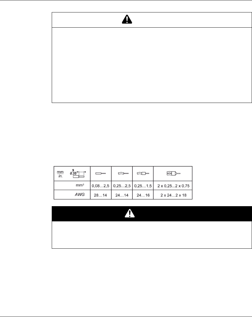
The table below provides the wire sizes to use with the removable spring terminal
blocks:
The spring clamp connectors of the terminal block are designed for only one wire or
one cable end. Two wires to the same connector must be installed with a double wire
cable end to help prevent loosening.
WARNING
IMPROPER GROUNDING CAN CAUSE UNINTENDED EQUIPMENT OPERA-
TION
zUse cables with insulated shielded jackets for analog I/O, fast I/O and
communication signals.
zGround shielded cables for analog I/O, fast I/O and communication signals at a
single point 1
zAlways comply with local wiring requirements regarding grounding of cable
shields.
Failure to follow these instructions can result in death, serious injury, or
equipment damage.
DANGER
FIRE HAZARD
Use only the recommended wire sizes for I/O channels and power supplies.
Failure to follow these instructions will result in death or serious injury.

Rules for Implementing
EIO0000000691 04/2012 17
Terminal Block
Plugging a terminal block into the incorrect electronic module can cause an electric
shock or unintended operation of the application and/or damage the electronic
module.
NOTE: To help prevent a terminal block from being inserted incorrectly, clearly and
uniquely code and label each terminal block and electronic module according to the
instructions in Coding the TM5 System (see Modicon TM5 / TM7 Flexible System,
System Planning and Installation Guide).
Stress Relief Using Cable Tie
There are two methods to reduce the stress on cables:
zThe terminal blocks (see Modicon TM5 / TM7 Flexible System, System Planning
and Installation Guide) have slots to attach cable ties. A cable tie can be fed
through this slot to secure cables and wires to reduce stress between them and
the terminal block connections.
zAfter grounding the TM5 System via the TM2XMTGB grounding plate
(see Modicon TM5 / TM7 Flexible System, System Planning and Installation
Guide), wires can be bundled and fixed to the grounding plate tabs using wire ties
to reduce stress on the cables.
DANGER
LOOSE WIRING CAUSES ELECTRIC SHOCK
Do not insert more than one wire per connector of the terminal block without a
double wire cable end.
Failure to follow these instructions will result in death or serious injury.
DANGER
UNINTENDED EQUIPMENT OPERATION OR ELECTRIC SHOCK
Be sure to connect the terminal blocks to their designated location.
Failure to follow these instructions will result in death or serious injury.
Rules for Implementing
18 EIO0000000691 04/2012
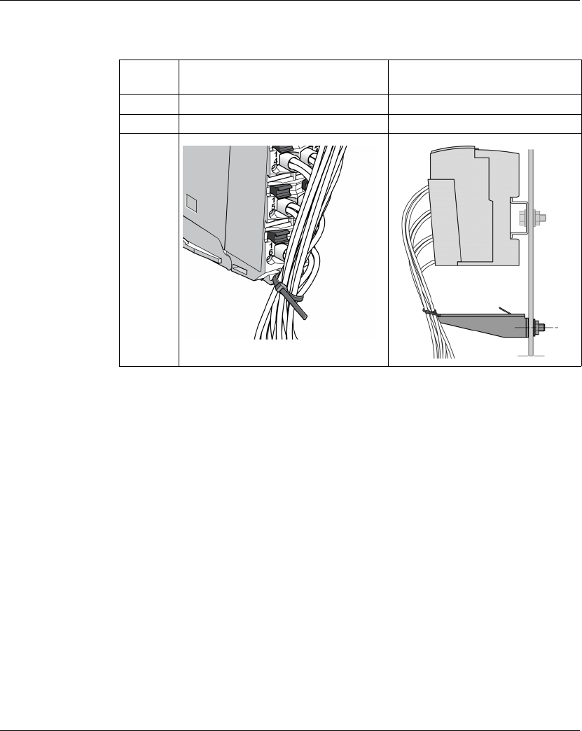
The table below provides the size of the cable tie and shows the two methods to
reduce the stress on the cables:
Cable Tie
Size
Terminal block TM2XMTGB Grounding plate
Thickness 1.2 mm (0.05 in.) maximum 1.2 mm (0.05 in.)
Width 4 mm (0.16 in.) maximum 2.5...3 mm (0.1...0.12 in.)
Mounting
figure

Rules for Implementing
EIO0000000691 04/2012 19
Environmental Characteristics
Introduction
The following information describes the system-wide environmental requirements
and characteristics for the TM5 System.
The general environmental characteristics are common to all components of the
TM5 System.
Enclosure Requirements
TM5 components are designed as Zone B, Class A industrial equipment according
to IEC/CISPR Publication 11. If they are used in environments other than those
described in the standard, or in environments that do not meet the specifications in
this manual, your ability to meet electromagnetic compatibility requirements in the
presence of conducted and/or radiated interference may be reduced.
All TM5 components meet European Community (CE) requirements for open
equipment as defined by EN61131-2. You must install them in an enclosure
designed for the specific environmental conditions and to minimize the possibility of
unintended contact with hazardous voltages. Your enclosure should be constructed
of metal to improve the electromagnetic immunity of your TM5 System. Your
enclosure should have a keyed locking mechanism to minimize unauthorized
access.

Rules for Implementing
20 EIO0000000691 04/2012
Environmental Characteristics
This equipment meets UL, CSA, GOST-R and c-Tick certifications and CE
requirements as indicated in the table below. This equipment is intended for use in
a Pollution Degree 2 industrial environment.
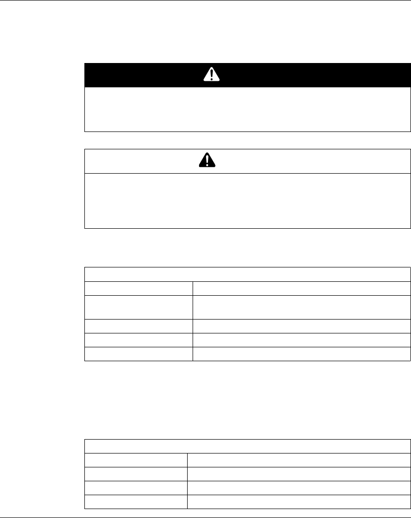
The table below provides the general environmental characteristics:
Characteristic Specification
This product is compliant with Europe RoHS recommendations and China RoHS regulations.
Standard IEC61131-2 ed. 3 2007
Agencies UL 508
CSA 22.2 No. 142-M1987
CSA 22.2 No. 213-M1987
Ambient operating
temperature
Horizontal installation -10...60 °C (14...140 °F)1, 2
Vertical installation -10...50 °C (14...122 °F)2
Storage temperature -40...70 °C (-40...158 °F)
Relative humidity 5...95% (non-condensing)
Degree of pollution IEC60664 2
Degree of
protection
IEC61131-2 IP20
Corrosion immunity No
Operating altitude 0...2000 m (0...6.560 ft.)
Storage altitude 0...3000 m (0...9.842 ft.)
Vibration
resistance
Mounted on a DIN rail 3.5 mm (0.138 in.) fixed amplitude from
5...8.4 Hz
9.8 m/s2 (1 gn) fixed acceleration from
8.4...150 Hz
Mechanical shock resistance 147 m/s2 (15 gn) for a duration of 11 ms
Connection type Removable spring terminal block
Connector insertion/removal cycles 50
Note:
1 Some devices have temperature operating restrictions that require de-rating between
55 °C and 60 °C (131 °F and 140 °F), and may be subject to other possible restrictions.
See the specific characteristics for your electronic module.
2 For compliance to Class I, Div 2 environment ratings, do not operate this device in
locations with ambient temperatures less than 0 °C (32°F).

Rules for Implementing
EIO0000000691 04/2012 21
Electromagnetic Susceptibility
The table below provides the TM5 System electromagnetic susceptibility
specifications:
Characteristic Specification Range
Electrostatic
discharge
IEC/EN 61000-4-2 8 kV (air discharge)
4 kV (contact discharge)
Electromagnetic
fields
IEC/EN 61000-4-3 10 V/m (80 MHz...2 GHz)
1 V/m (2...2.7 GHz)
Fast transients burst IEC/EN 61000-4-4 Power lines: 2 kV
I/O: 1 kV
Shielded cable: 1 kV
Repetition rate: 5 and 100 KHz
Surge immunity
24 Vdc circuit
IEC/EN 61000-4-5 1 kV in common mode
0.5 kV in differential mode
Surge immunity
230 Vac circuit
2 kV in common mode
1 kV in differential mode
Induced
electromagnetic field
IEC/EN 61000-4-6 10 Veff (0.15...80 MHz)
Conducted emission EN 55011 (IEC/CISPR11) 150...500 kHz, quasi peak 79 dBµV
500 kHz...30 MHz, quasi peak
73 dBµV
Radiated emission EN 55011 (IEC/CISPR11) 30...230 MHz, 10 m@40 dBµV/m
230 MHz...1 GHz, 10 m@47 dBµV/m

Rules for Implementing
22 EIO0000000691 04/2012

Overview
24 EIO0000000691 04/2012
General Description
Introduction
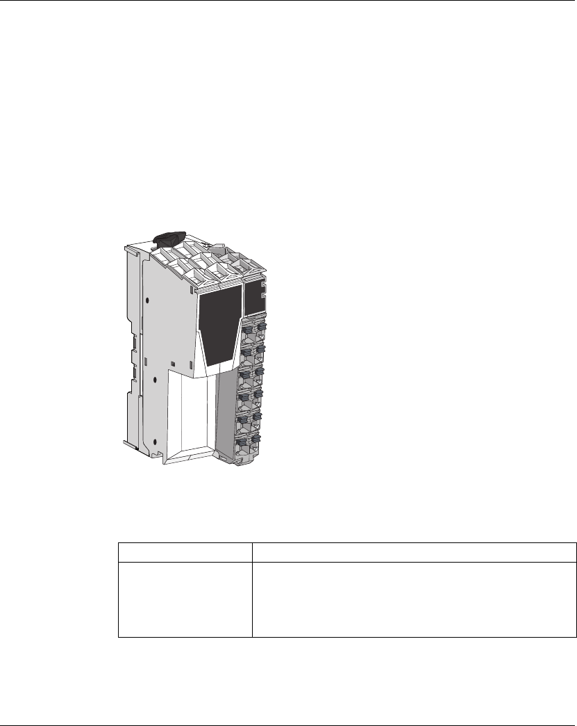
The TM5 field bus interface with built-in power distribution is the first element of the
TM5 distributed I/O island (see Modicon TM5 / TM7 Flexible System, System
Planning and Installation Guide). When assembled together, the TM5 field bus
interface is composed of four elements:
zField bus Interface bus base
zField bus interface module
zInterface Power Distribution Module (IPDM)
zTerminal block
The following figure shows a TM5 field bus interface when assembled:
TM5 Field Bus Interface Features
The table below provides the bus base reference:
2
1
2
3
2
4
2
5
2
6
2
2
1
1
1
2
1
3
1
4
1
5
1
6
TM5ACTB12PS
12
11
1098765
4x10
not
used
PWR
3
2
1
0
RUN
ERR
TxD
TM5NC01
98765
4x1
not
used
3
2
1
0
Reference Description
TM5ACBN1
(see Modicon TM5 / TM7
Flexible System, System
Planning and Installation
Guide)
Bus base for field bus interface module and Interface Power
Distribution Module (IPDM)

Overview
EIO0000000691 04/2012 25
The table below provides the field bus interface module references:
The table below provides the Interface Power Distribution Module (IPDM) reference:
The table below provides the terminal block reference:
Reference Description
TM5NCO1 (see page 31) CANopen interface module
TM5NS31 SERCOS III interface module
Reference Description
TM5SPS3 (see page 45) Field bus interface 24 Vdc power supply
Reference Description
TM5ACTB12PS
(see Modicon TM5 / TM7
Flexible System, System
Planning and Installation
Guide)
24 Vdc, 12-pin terminal block for PDM, IPDM and Receiver
electronic module
Overview
26 EIO0000000691 04/2012
Physical Description
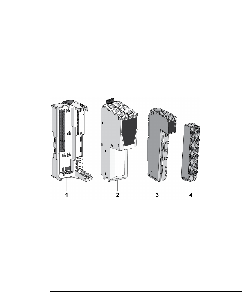
Introduction
Each field bus interface consists of four elements. These elements are the:
zField bus interface bus base
zField bus interface module
zInterface Power Distribution Module (IPDM)
zTerminal block
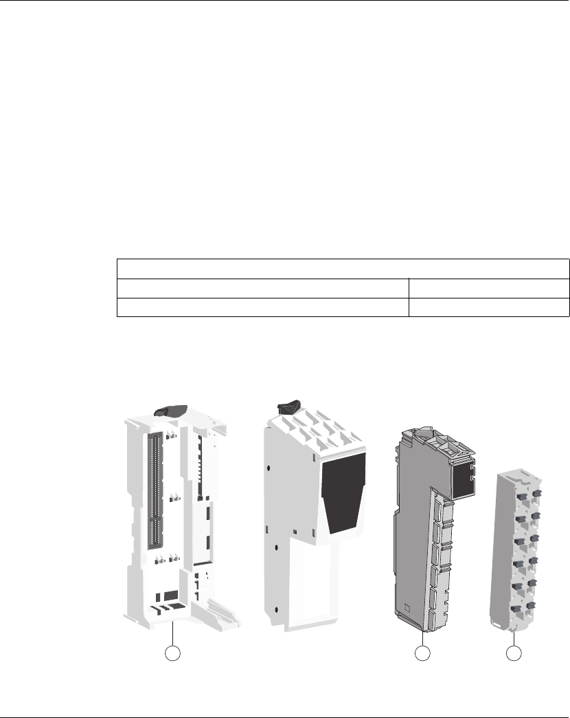
Elements
The following figure shows the different parts that compose the TM5 field bus
interface:
(1) Field bus interface bus base
(2) Field bus interface module
(3) Interface Power Distribution Module (IPDM)
(4) Terminal block
When assembled the four elements form an integral unit that resists vibration and
electrostatic discharge.
NOTICE
ELECTROSTATIC DISCHARGE
zNever touch the pin connectors of the block.
zAlways keep the cables or sealing plugs in place during normal operation.
Failure to follow these instructions can result in equipment damage.
Overview
EIO0000000691 04/2012 27
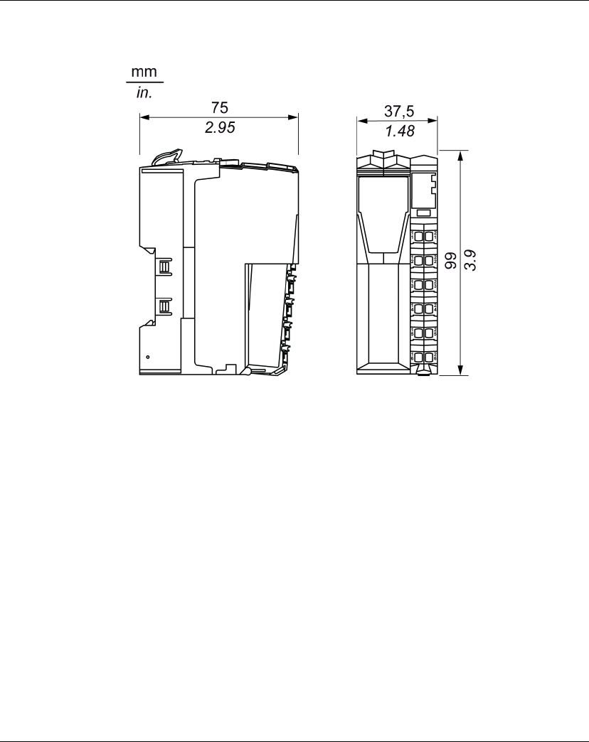
Dimensions
The following figure shows the dimensions of the TM5 field bus interface:
Accessories
Refer to the Installation of Accessories (see Modicon TM5 / TM7 Flexible System,
System Planning and Installation Guide).
Labeling
Refer to the Labeling the TM5 System (see Modicon TM5 / TM7 Flexible System,
System Planning and Installation Guide).

Overview
28 EIO0000000691 04/2012

EIO0000000691 04/2012 29
3
Modicon TM5
TM5 Field Bus Interface Ins tallation
EIO0000000691 04/2012
TM5 Field Bus Interface
Installation
First Startup
Overview
This procedure helps you through the installation and startup of your TM5 field bus
interface.
Startup Procedure
Step Action Comment
1 Unpack your field bus interface module
and check the contents of the package.
Package content:
zInstruction Sheet
zfield bus interface module
2 Unpack:
zThe bus base of your field bus
interface
zthe Interface Power Distribution
Module (IPDM)
zThe terminal block
For more information, refer to the
Physical Description (see page 26).
3 Assemble all separate parts together. For more information, refer to the Field
Bus Interface Installation (see Modicon
TM5 / TM7 Flexible System, System
Planning and Installation Guide).
4 Choose an appropriate cabinet and DIN
rail and install your field bus interface on
the DIN rail.
For more information, refer to the DIN
Rail Installation and Enclosing the TM5
System (see Modicon TM5 / TM7
Flexible System, System Planning and
Installation Guide).
5 Install the expansion modules. For more information, refer to the Slices
Installation or Compact I/O Installation
(see Modicon TM5 / TM7 Flexible
System, System Planning and
Installation Guide).

TM5 Field Bus Interface Installation
30 EIO0000000691 04/2012
6 Connect the communication field bus
interface
For more information, refer to TM5NCO1
Wiring Diagram (see page 42).
7 Connect your devices to the inputs and
outputs.
For more information refer to TM5
Hardware Guides.
8 Connect the external 24 Vdc power
source(s) to the Interface Power
Distribution Module (IPDM) and any
optional Power Distribution Modules
(PDM).
For more information, refer to IPDM
Wiring Diagram (see page 50).
9 Verify all connections. —
Step Action Comment

EIO0000000691 04/2012 31
4
Modicon TM5
TM5NCO1
EIO0000000691 04/2012
TM5 CANopen Interface Module
What’s in this Chapter?
This chapter contains the following topics:
Topic Page
TM5NCO1 Presentation 32
Setting the CANopen Bit-rate 35
Setting the CANopen Address 38
TM5NCO1 Characteristics 40
TM5NCO1 Wiring Diagram 42
TM5NCO1
32 EIO0000000691 04/2012
TM5NCO1 Presentation
Main Characteristics
The table below describes the main characteristics of the TM5NCO1 CANopen
interface module:
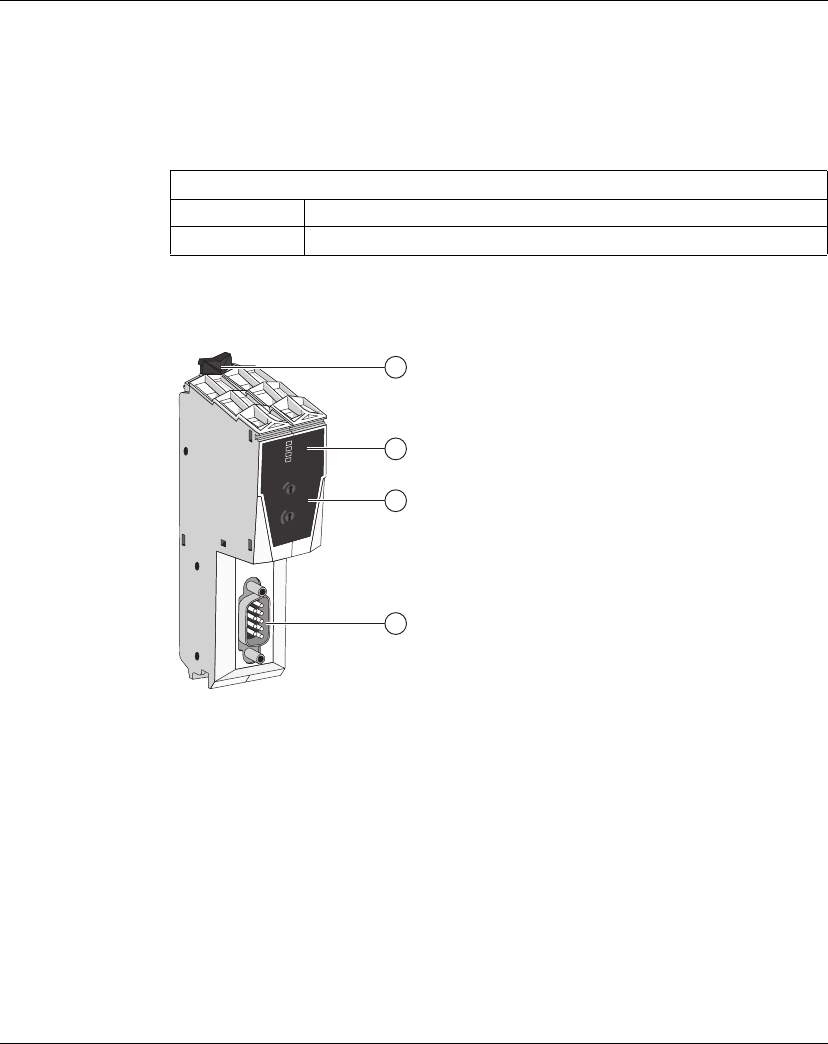
Presentation
The figure below shows the TM5NCO1:
(1) Locking clip
(2) Status LEDs
(3) CANopen address and bit-rate setting rotary switches
(4) CANopen bus connector (SUB-D 9)
Main Characteristics
Interface type CANopen
Connector type SUB-D 9, male
12
11
1098765
4x10
not
used
3
2
1
0
TM5NC01
98765
4x1
not
used
3
2
1
0
PWR
RUN
ERR
TxD
1
2
3
4
TM5NCO1
EIO0000000691 04/2012 33
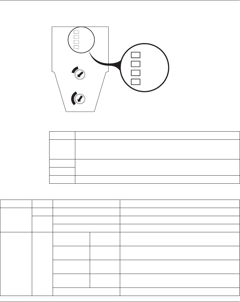
Status LEDs
The following figure shows the LEDs of the TM5NCO1 CANopen interface module:
The table below describes each LED available with the TM5NCO1 CANopen
interface module:
The table below describes the TM5NCO1 CANopen interface module status LEDs:
LED Description
PWR Indicates the status of the distributed island:
zpower supply
zdetected internal errors
RUN Dedicated to CANopen bus according to the CAN CiA standard and Schneider
Electric implementation
ERR
TxD Indicates the communication on the TM5 Expansion bus
PWR
x10
0123
4
5
6
7
8
9
0123
4
5
6
7
8
9
10
11
12
x1
not
used
not
used
RUN
ERR
TxD
PWR
RUN
ERR
TxD
TM5NC01
LED Color Status Description
PWR Green On Power supply connected, internal tests OK
Red On Detected error on the TM5 bus
Off Power supply not connected
RUN
(CAN_RUN)
Green Flashing On: 50 ms
Off: 50 ms
Bit-rate detection in progress (alternatively flashing with
the ERR LED)
Flashing On: 200 ms
Off: 200 ms
Preoperational state
1 x Flashing On: 200 ms
Off: 1 s
STOP state
3 x Flashing On: 200 ms
Off: 1 s
Firmware update
On Operational state

TM5NCO1
34 EIO0000000691 04/2012
ERR
(CAN_ERR)
Red Off No detected error or operational state
Flashing On: 50 ms
Off: 50 ms
Bit-rate detection in progress (alternatively flashing with
the RUN LED)
Flashing On: 200 ms
Off: 200 ms
Invalid configuration
1 x Flashing On: 200 ms
Off: 1 s
At least one of the error counters of the CANopen
interface module has reached the threshold “CANopen in
Error Passive Mode”.
2 x Flashing On: 200 ms
Off: 1 s
Guard or heartbeat event occurred
3 x Flashing On: 200 ms
Off: 1 s
The synchronisation message was not received in the
configured time.
4 x Flashing On: 200 ms
Off: 1 s
An expected PDO (Process Data Object) was not
received before the event timer has expired.
On The CANopen interface module is in bus off state (no
communication).
TxD Yellow Off The TM5 CANopen interface module is not transmitting
data via the TM5 expansion bus.
On The TM5 CANopen interface module is transmitting data
via the TM5 expansion bus.
LED Color Status Description
TM5NCO1
EIO0000000691 04/2012 35
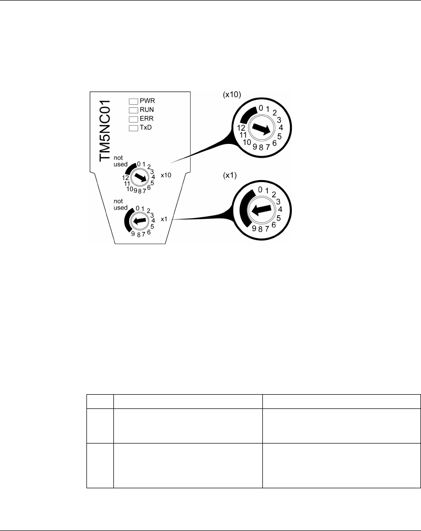
Setting the CANopen Bit-rate
Presentation
By default, the bit-rate is automatically detected by the CANopen interface module.
However, you can force a bit-rate to be configured using the two rotary switches.
(x10) CANopen bit-rate setting
(x1) Authorize to set the CANopen bit-rate
The Bit-rate
The CANopen interface module detects a new bit-rate selection by the rotary
switches only during power up. The bit-rate is written to non-volatile memory.
Set x1 rotary switch to any of the six unnumbered positions to set a particular bit-
rate with the x10 rotary switch.
Setting the Bit-rate
Instructions for setting the bit-rate are in the table.
Step Action Comment
1 Remove power to the CANopen
interface module.
The CANopen interface module detects
the changes you are about to make only at
the next power up cycle.
2 With a small screwdriver, set the x1
rotary switch to any position after 9.
Setting the rotary switch to any of these
unnumbered positions prepares the
CANopen interface module to accept a
new bit-rate.

TM5NCO1
36 EIO0000000691 04/2012
Bit-rate Selection Table
The following table shows the rotary switch positions and the bit-rate:
NOTE: Setting the x10 rotary switch between 10 and 12 and unnumbered part will
generate an error detected at the next power on.
3 With a small screwdriver, set the x10
rotary switch to the position that
corresponds to your selected bit-rate.
Use the rotary switch position you selected
in the last step. Use the bit-rate selection
table below to determine the position of the
rotary switch.
4 Reapply power your CANopen interface
module.
The CANopen interface module reads the
rotary switch settings only during power
up.
5 Wait until the RUN and ERR LEDs flash
3 times (ON: 50 ms / OFF: 50 ms).
The CANopen interface module has
written the new bit-rate setting to memory.
6 Again, remove power to the CANopen
interface module and proceed to the
CANopen Address Settings Rotary
Switches procedure (see page 40).
The bit-rate has been established for the
CANopen interface module.
Step Action Comment
Position x10 rotary switch Bit-rate
0 10 kbits/s
1 20 kbits/s
2 50 kbits/s
3 125 kbits/s
4 250 kbits/s
5 500 kbits/s
6 800 kbits/s
71Mbits/s
8 Automatic bit-rate detection
9 Automatic bit-rate detection (default value)
10...12 Not used

TM5NCO1
EIO0000000691 04/2012 37
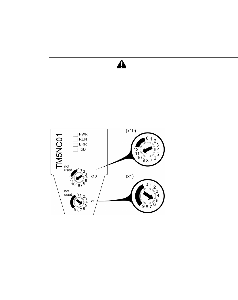
CANopen Bit-rate Setting Example
The following figure shows an example when the CANopen bit-rate is configured to
500 kbits/s:
(x10) Set the CANopen bit-rate
(x1) Authorize to set the CANopen bit-rate
TM5NCO1
38 EIO0000000691 04/2012
Setting the CANopen Address
Presentation
The CANopen interface module address (from 1 to 126, decimal) is configured using
the two CANopen address settings rotary switches. The factory setting of the rotary
switches is 0.
To reset the CANopen interface module, remove power and provide a correct
address before reapplying power to the module.
The following figure shows the TM5NCO1 CANopen rotary switches:
(x10) High order rotary switch: represents the ‘tens’ of the CANopen address
(x1) Low order rotary switch: represents the ‘ones’ of the CANopen address
CAUTION
UNINTENDED EQUIPMENT OPERATION
Do not use an address outside of the specified range (from 1 to 126).
Failure to follow these instructions can result in injury or equipment damage.

TM5NCO1
EIO0000000691 04/2012 39
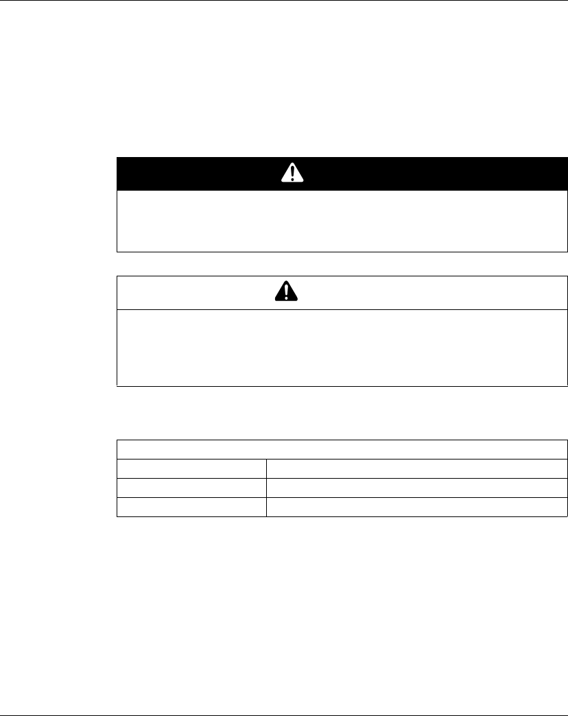
CANopen Address Setting Example
The following figure shows an example when the CANopen address is configured to
115 (decimal):
(x10) High order rotary switch: the ‘tens’ of the CANopen address is set to 11
(x1) Low order rotary switch: the ‘ones’ of the CANopen address is set to 5
TM5NCO1
40 EIO0000000691 04/2012
TM5NCO1 Characteristics
Capabilities
The protocol and function supported by the CAN port is CANopen. For more
information, please refer to the CANOpen Hardware Setup Manual (see page 8).
Characteristics
The table below provides the general characteristics of the TM5NCO1 field bus
interface module:
See also Environmental Characteristics (see page 19).
DANGER
FIRE HAZARD
Use only the recommended wire sizes for I/O channels and power supplies.
Failure to follow these instructions will result in death or serious injury.
WARNING
UNINTENDED EQUIPMENT OPERATION
Do not exceed any of the rated values specified in the following tables.
Failure to follow these instructions can result in death, serious injury, or
equipment damage.
General Characteristics
TM5 power bus consumption 300 mA
Power dissipation 1.5 W
Weight 50 g (1.8 oz)

TM5NCO1
EIO0000000691 04/2012 41
The table below describes the CAN characteristics of the TM5NCO1 field bus
interface module:
1 Part 1 and Part 2 of ISO 11898:2002 are equivalent to ISO 11898:1993.
2 Auto bit-rate detection
Characteristics Description
Standard CAN-CIA (ISO 11898-2:2002 Part 2)1
Connector type Sub-D 9, male
Protocol supported CANopen
CAN power distribution No
Maximal cable length Refer to Transmission Speed and Cable Length chapter in the
CANopen Hardware Setup Manual (see page 8)
Isolation between CAN bus
and ground
500 Vac RMS, 700 Vdc
Line termination Refer to Basic Topology chapter in the CANopen Hardware
Setup Manual (see page 8)
Bit-rate (Kbit/s)21000 800 500 250 125 50 20 10
ID code for firmware update 45164 dec
TM5NCO1
42 EIO0000000691 04/2012
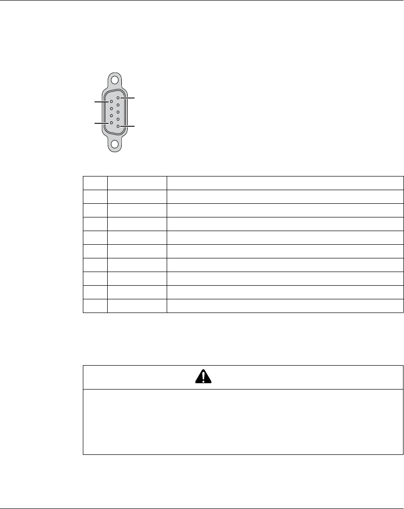
TM5NCO1 Wiring Diagram
Wiring Diagram
The following figure shows the pins of the CANopen bus connector:
The table below describes the pins of the CANopen bus connector:
Although the cable shield is connected to pin 6 (ground), it is still necessary to
properly and externally ground the cable shield (see page 43) to your functional
ground (FE).
Pin Designation Description
1 – Reserved (N.C.)
2 CAN_L CAN_L bus Line (Low)
3 CAN_GND CAN ground
4 – Reserved (N.C.)
5 (CAN_SHLD) Optional CAN shield
6 GND Ground, connection to pin 3
7 CAN_H CAN_H bus Line (High)
8 – Reserved (N.C.)
9 (CAN_V+) Reserved (N.C.)
WARNING
UNINTENDED EQUIPMENT OPERATION
Do not connect wires to unused terminals or terminals marked “Not Connected
(N.C.)”.
Failure to follow these instructions can result in death, serious injury, or
equipment damage.
1
5
6
9
TM5NCO1
EIO0000000691 04/2012 43
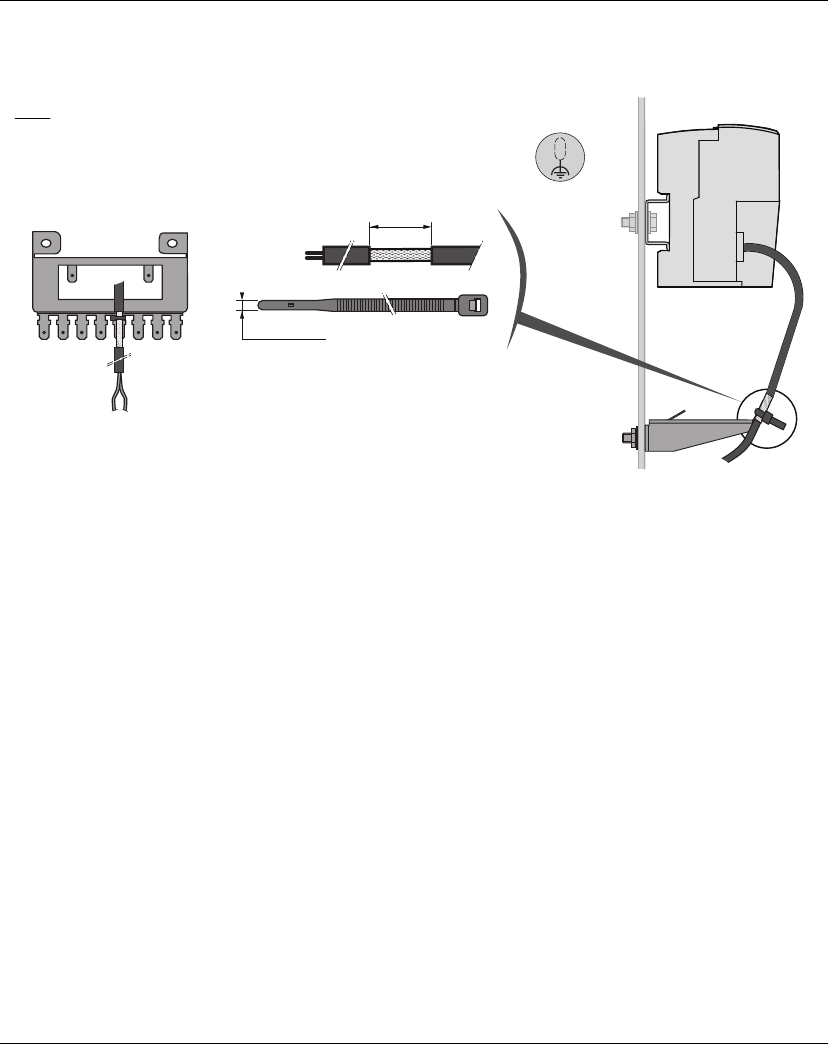
Field Bus Cable Shielding
The following figure shows how to connect the field bus cable shielding:
(1) Functional ground
15
0.59
FE (1)
2,5…3
0.1…0.12
TM2XMTGB
in.
mm

TM5NCO1
44 EIO0000000691 04/2012

TM5SPS3
46 EIO0000000691 04/2012
TM5SPS3 Presentation
Main Characteristics
The TM5SPS3 CANopen Interface Power Distribution Module (IPDM) consists of
two dedicated electrical circuits:
za 24 Vdc Main power that serves the electronics of the field bus Interface Module
and generates independent power for the TM5 power bus that serves the
expansion modules.
za 24 Vdc I/O power segment that serves:
- the expansion modules,
- the sensors and actuators connected to the expansion modules,
- the external devices connected to the Common Distribution Modules (CDM)
The table below provides the main characteristics of the TM5SPS3 interface power
distribution module:
Ordering Information
The following figure and table provide the references to create a TM5 field bus
interface with the TM5SPS3 IPDM:
Main Characteristics
Maximum current provided on 24 Vdc I/O power segment 6300 mA
TM5 power bus generated 750 mA
1 2 3
12
11
1098765
4x10
not
used
3
2
1
0
TM5NC01
98765
4x1
not
used
3
2
1
0
PWR
RUN
ERR
TxD
2
1
2
3
2
4
2
5
2
6
2
2
1
1
1
2
1
3
1
4
1
5
1
6
TM5SPS3
EIO0000000691 04/2012 47
NOTE: For more information, refer to TM5 Bus Bases and Terminal Blocks
(see Modicon TM5 / TM7 Flexible System, System Planning and Installation Guide).
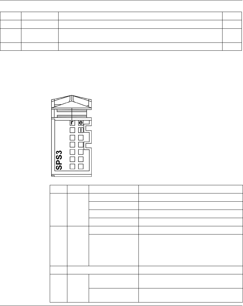
Status LEDs
The following figure and table provide the TM5SPS3 IPDM status LEDs:
Number Reference Description Color
1 TM5ACBN1 Bus base 24 Vdc I/O power segment left isolated White
2 TM5SPS3 Field bus interface 24 Vdc power supply (Interface Power Distribution Module
(IPDM))
Grey
3 TM5ACTB12PS 24 Vdc, 12-pin terminal block for PDM, IPDM and receiver electronic module Grey
LED Color Status Description
r Green Off Power supply not connected
Single flash Reset status
Flashing TM5 expansion bus in preoperational status
On RUN status
e Red Off OK or module not connected
Double flash Indicates one of the following conditions:
z24 Vdc I/O power segment, via the external
power supply or supplies, is too low.
zTM5 power bus, via the external power supply
or supplies, is too low.
e+r Steady red/single green flash Invalid firmware
l Red Off The TM5 interface power distribution module
supply is within the acceptable range
On The TM5 interface power distribution module
supply is insufficient
TM5SPS3
48 EIO0000000691 04/2012
TM5SPS3 Characteristics
General Characteristics
The table below provides the general characteristics of the TM5SPS3 interface
power distribution module:
See also Environmental Characteristics (see page 19).
TM5 Power Bus Characteristics
The table below provides the TM5 power bus characteristics of the TM5SPS3
interface power distribution module:
DANGER
FIRE HAZARD
Use only the recommended wire sizes for I/O channels and power supplies.
Failure to follow these instructions will result in death or serious injury.
WARNING
UNINTENDED EQUIPMENT OPERATION
Do not exceed any of the rated values specified in the following tables.
Failure to follow these instructions can result in death, serious injury, or
equipment damage.
General Characteristics
Rated power supply voltage 24 Vdc
24 Vdc I/O power segment
current draw
25 mA
Power dissipation 1.82 W max.
Weight 30 g (1.1 oz)
ID code 8076 dec
TM5 Power Bus Characteristics
Power supply range 20.4...28.8 Vdc
Rated input current 0.7 A at 24 Vdc
Reverse polarity protection Yes
Fuse Integrated, cannot be exchanged

TM5SPS3
EIO0000000691 04/2012 49
Temperature De-rating
The TM5SPS3 interface power distribution module is subject to temperature
restrictions depending on the current consumption on the TM5 power bus:
zup to 500 mA: -10...60°C (14...140°F)
zover 500 mA: -10...55°C (14...131°F)
24 Vdc I/O Power Segment Characteristics
The table below provides the 24 Vdc I/O power segment characteristics of the
TM5SPS3 interface power distribution module:
1 The isolation of the electronic module is 500 Vac RMS between the electronics
power by the TM5 bus and those powered by 24 Vdc I/O power segment connected
to the module. In practice, the TM5 electronic module is installed in the bus base,
and there is a bridge between the TM5 power bus and the 24 Vdc I/O power
segment. The two power circuits reference the same functional ground (FE) through
specific components designed to reduce effects of electromagnetic interference.
These components are rated at 30 Vdc or 60 Vdc. This effectively reduces isolation
of the entire system from the 500 Vac RMS.
Current generated zOn TM5 power bus: 750 mA
zTo supply the field bus interface module: 300 mA
Parallel operation Yes 1
Electrical isolation See note 2
1 In parallel operation, only 75% of the rated power can be assumed. Please ensure that all
parallel operating power supplies are switched on and off simultaneously.
2 The two power circuits reference the same functional ground (FE) through specific
components designed to reduce effects of electromagnetic interference. These components
are rated at 30 or 60 V.
TM5 Power Bus Characteristics
24 Vdc I/O Power Segment Characteristics
Power supply range 20.4...28.8 Vdc
Rated power supply voltage 24 Vdc
Maximum current provided 10 A
Reverse polarity protection No
Short circuit protection External fuse type T slow-blow 10 A max. 250 V
Isolation between power segment and
TM5 buses
See note 1
TM5SPS3
50 EIO0000000691 04/2012
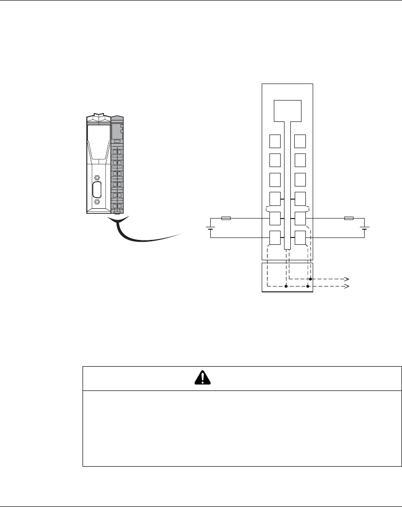
TM5SPS3 Wiring Diagram
Wiring Diagram
The following figure shows the wiring diagram for the TM5SPS3 interface power
distribution module:
(A) Interface Power Distribution Module (IPDM)
(1) Internal electronics
(2) 24 Vdc I/O power segment integrated in the bus bases
(3) PS1/PS2: External isolated power supply 24 Vdc
(4) External fuse, Type T slow blow, 10 A max., 250 V
(5) External fuse, Type T slow blow, 1 A, 250 V
WARNING
POTENTIAL OF OVERHEATING AND FIRE
zDo not connect the modules directly to line voltage.
zUse only isolating PELV or SELV power supplies to supply power to the
modules.
Failure to follow these instructions can result in death, serious injury, or
equipment damage.
PCI 0
Must be
covered
1
12
1
1
22
2
1
32
3
1
42
4
1
52
5
1
62
6
(A)
24 V
0 V
(5)
PS1 (3)
+
_
0 V
(4)
PS2 (3)
+
_
24 V - PS224 V - PS1
24 V
(2)
c+24 V
0 V
c+24 Vc+24 V
(1)
1
1
2
1
1
2
2
2
2
3
2
4
2
6
2
5
1
3
1
4
1
5
1
6

TM5SPS3
EIO0000000691 04/2012 51
WARNING
UNINTENDED EQUIPMENT OPERATION
Do not connect wires to unused terminals or terminals marked “Not Connected
(N.C.)”.
Failure to follow these instructions can result in death, serious injury, or
equipment damage.

TM5SPS3
52 EIO0000000691 04/2012

EIO0000000691 04/2012 53
Modicon TM 5
Glossary
EIO00000 00691 04/2012
Glossary
A
analog input
An analog input module contains circuits that convert an analog DC input signal to
a digital value that can be manipulated by the processor. By implication, the analog
input is usually direct. That means a data table value directly reflects the analog
signal value.
analog output
An analog output module contains circuits that transmit an analog DC signal
proportional to a digital value input to the module from the processor. By implication,
these analog outputs are usually direct. That means a data table value directly
controls the analog signal value.
AWG
The american wire gauge standard specifies wire gauges in North America.
Acoded
These connectors have one raised key on the male connector and one mating slot
on the female connector. This is the standard coding used for sensors and
distribution box applications:

Glossary
54 EIO0000000691 04/2012
B
bus base
A bus base is a mounting device that is designed to seat an electronic module on a
DIN rail and connect it to the TM5 bus for M258 and LMC058 controllers. Each base
bus extends the TM5 data and to the power buses and the 24 Vdc I/O power
segment. The electronic modules are added to the TM5 system through their
insertion on the base bus. The base bus also supplies the articulation point for the
terminal blocks.
Bcoded
These connectors have one raised key on the female connector and one mating slot
on the male connector. These connectors (also called reverse keyed) are used for
field bus applications:
C
CAN
The controller area network protocol (ISO 11898) for serial bus networks is designed
for the interconnection of smart devices (from multiple manufacturers) in smart
systems for real-time industrial applications. CAN multimaster systems help ensure
high data integrity through the implementation of broadcast messaging and
advanced diagnostic mechanisms. Originally developed for use in automobiles,
CAN is now used in a variety of industrial automation control environments.
CANopen
CANopen is an open industry-standard communication protocol and device profile
specification.
compact I/O module
A compact I/O module is an indissociable group of five analog and/or digital I/O
electronic modules in a single reference.

Glossary
EIO0000000691 04/2012 55
configuration
The configuration includes the arrangement and interconnection of hardware
components within a system and the hardware and software selections that
determine the operating characteristics of the system.
controller
A controller (or “programmable logic controller,” or “programmable controller”) is
used to automate industrial processes.
CPDM
controller power distribution module
crosstalk
The crosstalk is an undesired signal caused by a capacitive, inductive or conductive
coupling between two channels.
CSA
The canadian standards association defines and maintains standards for industrial
electronic equipment in hazardous environments.
CTS
Clear to send is a data transmission signal and acknowledges the RDS signal from
the transmitting station.
D
De-rating
De-rating describes a reduction in an operating specification. For devices in general
it is usually a specified reduction in nominal power to facilitate operation at increased
ambient conditions like higher temperatures or higher altitudes.
DHCP
The dynamic host configuration protocol is an advanced extension of BOOTP.
DHCP is a more advanced, but both DHCP and BOOTP are common. (DHCP can
handle BOOTP client requests.)

Glossary
56 EIO0000000691 04/2012
digital I/O
A digital input or output has an individual circuit connection at the electronic module
that corresponds directly to a data table bit that holds the value of the signal at that
I/O circuit. It gives the control logic digital access to I/O values.
DIN
Deutsches Institut für Normung is a German institution that sets engineering and
dimensional standards.
E
electronic module
In a programmable controller system, most electronic modules directly interface to
the sensors, actuators, and external devices of the machine/process. This electronic
module is the component that mounts in a bus base and provides electrical
connections between the controller and the field devices. Electronic modules are
offered in a variety of signal levels and capacities. (Some electronic modules are not
I/O interfaces, including power distribution modules and transmitter/receiver
modules.)
EN
EN identifies one of many European standards maintained by CEN (European
Committee for Standardization), CENELEC (European Committee for
Electrotechnical Standardization), or ETSI (European Telecommunications
Standards Institute).
encoder
An encoder is a device for length or angular measurement (linear or rotary
encoders).
Ethernet
Ethernet is a physical and data link layer technology for LANs, also known as
IEE 802.3.
expansion bus
The expansion bus is an electronic communication bus between expansion modules
and a CPU.

Glossary
EIO0000000691 04/2012 57
expert I/O
Expert I/Os are dedicated modules or channels for advanced features. These
features are generally embedded in the module in order to not use the resources of
the PLC Controller and to allow a fast response time, depending of the feature.
Regarding the function, it could be considered as a “stand alone” module, because
the function is independent of the Controller processing cycle, it just exchanges
some information with the Controller CPU.
F
FAST I/O
FAST I/Os are specific I/Os with some electrical features (response time, for
example) but the treatment of these channels is done by the Controller CPU.
FE
Functional ground is the point of a system or device that must be grounded to help
prevent equipment damage.
FG
frequency generator
firmware
The firmware represents the operating system on a controller.
H
hot swapping
Hot swapping is the replacement of a component with a like component while the
system remains operational. The replacement component begins to function
automatically after it is installed.
HSC
high-speed counter.

Glossary
58 EIO0000000691 04/2012
I
I/O
input/output
IEC
The international electrotechnical commission is a non-profit and non-governmental
international standards organization that prepares and publishes international
standards for all electrical, electronic, and related technologies.
input filter
An input filter is a special function that rejects input noises. It is useful for helping to
minimize input noises and chatter in limit switches. All inputs provide a level of input
filtering using the hardware. Additional filtering with software is also configurable
through the programing or the configuration software.
IP 20
Ingress protection rating according to IEC 60529. IP20 modules are protected
against ingress and contact of objects larger than 12.5 mm. The module is not
protected against harmful ingress of water.
IP 67
Ingress protection rating according to IEC 60529. IP67 modules are completely
protected against ingress of dust and contact. Ingress of water in harmful quantity is
not possible when the enclosure is immersed in water up to 1 m (3.28 ft.).
L
LED
A light emitting diode is an indicator that lights up when electricity passes through it.
M
Modbus
The Modbus communication protocol allows communications between many
devices connected to the same network.

Glossary
EIO0000000691 04/2012 59
N
NC
A normally closed contact is a contact pair that is closed when the actuator is de-
energized (no power is applied) and open when the actuator is energized (power is
applied).
network
A network includes interconnected devices that share a common data path and
protocol for communications.
P
PCI
A peripheral component interconnect is an industry-standard bus for attaching
peripherals.
PDM
A power distribution module distributes either AC or DC field power to a cluster of
I/O modules.
PE
Protective ground is a return line across the bus for fault currents generated at a
sensor or actuator device in the control system.
Pt100/Pt1000
Platinum resistance thermometer are characterized by their nominal resistance R0
at a temperature of 0° C.
zPt100 (R0 = 100 Ohm)
zPt1000 (R0 = 1 kOhm)
PWM
Pulse width modulation is used for regulation processes (e.g. actuators for
temperature control) where a pulse signal is modulated in its length. For these kind
of signals, transistor outputs are used.

Glossary
60 EIO0000000691 04/2012
R
RS-232
RS-232 (also known as EIA RS-232C or V.24) is a standard type of serial
communication bus, based on three wires.
RS-485
RS-485 (also known as EIA RS-485) is a standard type of serial communication bus,
based on two wires.
RTS
Request to send is a data transmission signal and will be acknowledged by the CTS
signal from the destination node.
RxD
receiving data (data transmission signal)
S
SEL-V
A system that follows IEC 61140 guidelines for safety extra low voltage is protected
in such a way that voltage between any 2 accessible parts (or between 1 accessible
part and the PE terminal for Class 1 equipment) does not exceed a specified value
under normal conditions or under single-fault conditions.
SERCOS
The SErial Realtime COmmunications System is a digital control bus that
interconnects:
zmotion controls,
zdrives,
zI/Os,
zsensors and actuators, for numerically controlled machines and systems.
It is a standardized and open controller-to-intelligent digital device interface,
designed for high-speed serial communication of standardized closed-loop real-time
data.
SERCOS III
Industrial Ethernet based on the SERCOS implementation.

Glossary
EIO0000000691 04/2012 61
sink input
A sink input is a wiring arrangement in which the device provides current to the input
electronic module. A sink input is referenced to 0 Vdc.
SL
serial line
source output
A source output is a wiring arrangement in which the output electronic module
provides current to the device. A source output is referenced to +24 Vdc.
T
terminal block
The terminal block is the component that mounts in an electronic module and
provides electrical connections between the controller and the field devices.
TxD
TxD represents a transmit signal.
U
UL
Underwriters laboratories, US organization for product testing and safety
certification.

Glossary
62 EIO0000000691 04/2012

EIO0000000691 04/2012 63
C
B
A
Modicon TM5
Index
EIO0000000691 04/2012
Index
B
bit-rate
selecting, 36
setting, 35, 35
C
characteristics
TM5NCO1, 40
TM5SPS3, 48
E
environmental characteristics, 19
F
field bus
bit-rate, setting, 35
installation, 29
I
installation
field bus, 29
installation requirements, 12
N
node
bit-rate, setting, 35
P
presentation
TM5NCO1, 32
TM5SPS3, 46
R
rotary switches, 35
bit-rate setting, 35
T
TM5NCO1
characteristics, 40
presentation, 32
wiring diagram, 42
TM5SPS3
characteristics, 48
presentation, 46
wiring diagram, 50
W
wiring diagram
TM5NCO1, 42
TM5SPS3, 50
wiring rules, 15

Index
64 EIO0000000691 04/2012
