ARM7 TDMI Manual Pt3
User Manual: Pdf
Open the PDF directly: View PDF ![]() .
.
Page Count: 46
ARM7TDMI Data Sheet
ARM DDI 0029E
5-1
11
1
Open Access
THUMB Instruction Set
This chapter describes the THUMB instruction set.
Format Summary 5-2
Opcode Summary 5-3
5.1 Format 1: move shifted register 5-5
5.2 Format 2: add/subtract 5-7
5.3 Format 3: move/compare/add/subtract immediate 5-9
5.4 Format 4: ALU operations 5-11
5.5 Format 5: Hi register operations/branch exchange 5-13
5.6 Format 6: PC-relative load 5-16
5.7 Format 7: load/store with register offset 5-18
5.8 Format 8: load/store sign-extended byte/halfword 5-20
5.9 Format 9: load/store with immediate offset 5-22
5.10 Format 10: load/store halfword 5-24
5.11 Format 11: SP-relative load/store 5-26
5.12 Format 12: load address 5-28
5.13 Format 13: add offset to Stack Pointer 5-30
5.14 Format 14: push/pop registers 5-32
5.15 Format 15: multiple load/store 5-34
5.16 Format 16: conditional branch 5-36
5.17 Format 17: software interrupt 5-38
5.18 Format 18: unconditional branch 5-39
5.19 Format 19: long branch with link 5-40
5.20 Instruction Set Examples 5-42
5

THUMB Instruction Set
ARM7TDMI Data Sheet
ARM DDI 0029E
5-2
Open Access
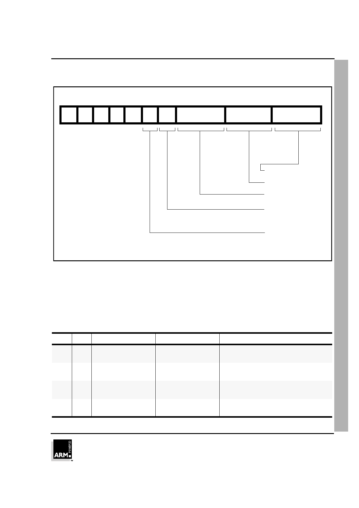
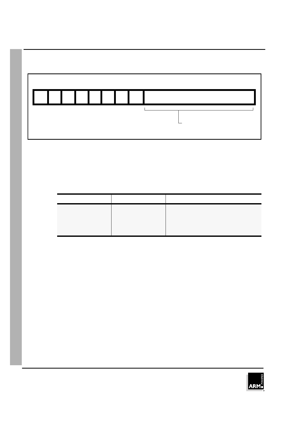
Format Summary
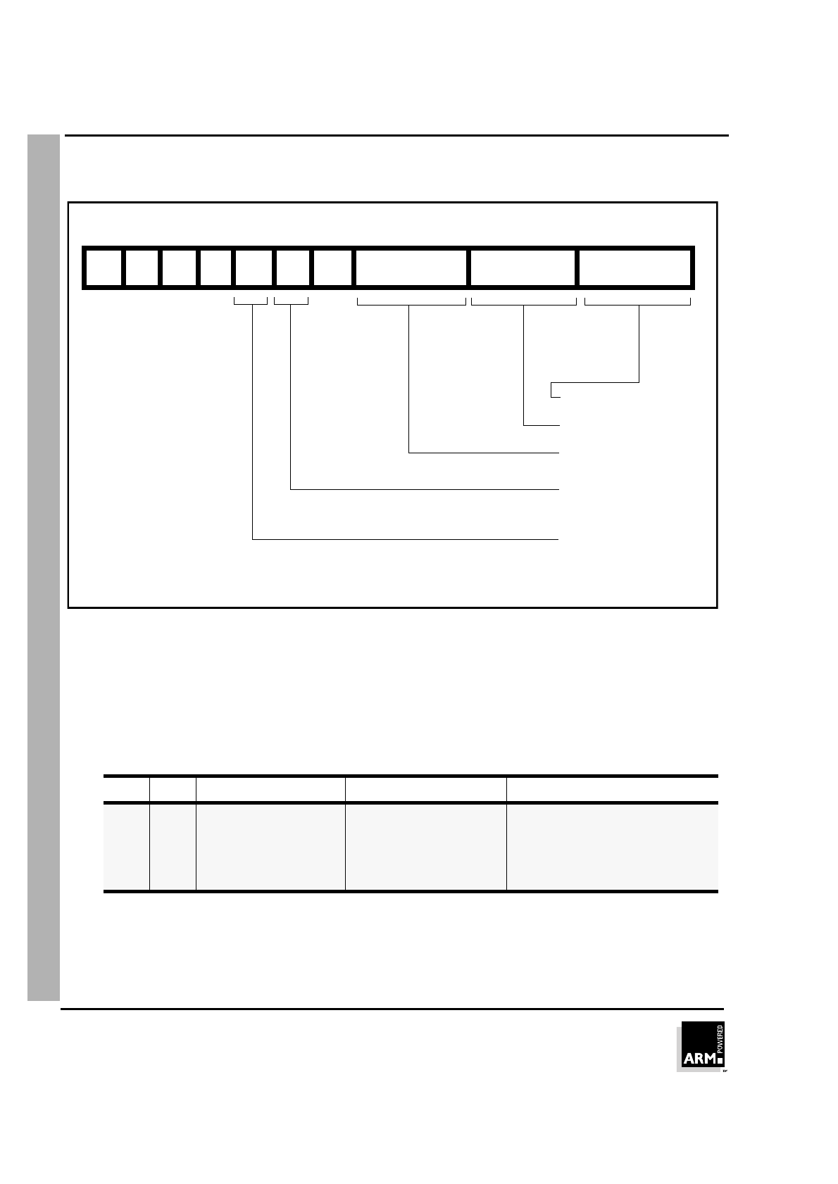
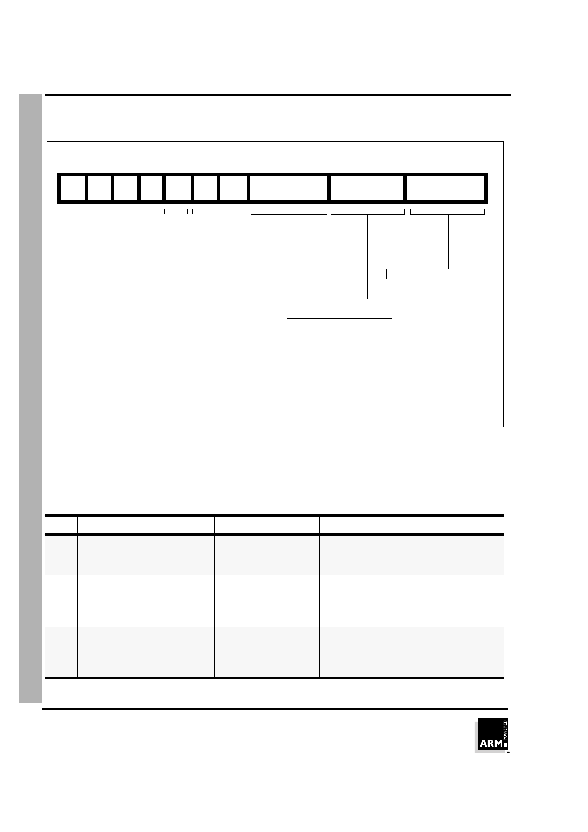
The THUMB instruction set formats are shown in the following figure.
Figure 5-1: THUMB instruction set formats
15 14 13 12 11 10 9 8 7 6 5 4 3 2 1 0
1
0 0 0 Op Offset5 Rs Rd
Move shifted register
2
0 0 0 1 1 I Op Rn/offset3 Rs Rd
Add/subtract
3
0 0 1 Op Rd Offset8
Move/compare/add
/subtract immediate
4
0 1 0 0 0 0 Op Rs Rd
ALU operations
5
0 1 0 0 0 1 Op H1 H2 Rs/Hs Rd/Hd
Hi register operations
/branch exchange
6
0 1 0 0 1 Rd Word8
PC-relative load
7
0 1 0 1 L B 0 Ro Rb Rd
Load/store with register
offset
8
0 1 0 1 H S 1 Ro Rb Rd
Load/store sign-extended
byte/halfword
9
0 1 1 B L Offset5 Rb Rd
Load/store with immediate
offset
10
1 0 0 0 L Offset5 Rb Rd
Load/store halfword
11
1 0 0 1 L Rd Word8
SP-relative load/store
12
1 0 1 0 SP Rd Word8
Load address
13
1 0 1 1 0 0 0 0 S SWord7
Add offset to stack pointer
14
1 0 1 1 L 1 0 R Rlist
Push/pop registers
15
1 1 0 0 L Rb Rlist
Multiple load/store
16
1 1 0 1 Cond Soffset8
Conditional branch
17
1 1 0 1 1 1 1 1 Value8
Software Interrupt
18
1 1 1 0 0 Offset11
Unconditional branch
19
1 1 1 1 H Offset
Long branch with link
15 14 13 12 11 10 9 8 7 6 5 4 3 2 1 0
THUMB Instruction Set
ARM7TDMI Data Sheet
ARM DDI 0029E
5-3
Open Access
Opcode Summary
The following table summarizes the THUMB instruction set. For further
information about a particular instruction please refer to the sections listed in the
right-most column.
Mnemonic Instruction Lo register
operand Hi register
operand Condition
codes set See Section:
ADC Add with Carry ✔ ✔ 5.4
ADD Add ✔ ✔ ✔➀ 5.1.3, 5.5, 5.12, 5.13
AND AND ✔ ✔ 5.4
ASR Arithmetic Shift Right ✔ ✔ 5.1, 5.4
B Unconditional branch ✔5.16
B
xx
Conditional branch ✔5.17
BIC Bit Clear ✔ ✔ 5.4
BL Branch and Link 5.19
BX Branch and Exchange ✔ ✔ 5.5
CMN Compare Negative ✔ ✔ 5.4
CMP Compare ✔ ✔ ✔ 5.3, 5.4, 5.5
EOR EOR ✔ ✔ 5.4
LDMIA Load multiple ✔5.15
LDR Load word ✔5.7, 5.6, 5.9, 5.11
LDRB Load byte ✔5.7, 5.9
LDRH Load halfword ✔5.8, 5.10
LSL Logical Shift Left ✔ ✔ 5.1, 5.4
LDSB Load sign-extended
byte
✔5.8
LDSH Load sign-extended
halfword
✔5.8
LSR Logical Shift Right ✔ ✔ 5.1, 5.4
MOV Move register ✔ ✔ ✔➁ 5.3, 5.5
MUL Multiply ✔ ✔ 5.4
MVN Move Negative register ✔ ✔ 5.4
Table 5-1: THUMB instruction set opcodes
THUMB Instruction Set
ARM7TDMI Data Sheet
ARM DDI 0029E
5-4
Open Access
➀The condition codes are unaffected by the format 5, 12 and 13
versions of this instruction.
➁The condition codes are unaffected by the format 5 version of this
instruction.
NEG Negate ✔ ✔ 5.4
ORR OR ✔ ✔ 5.4
POP Pop registers ✔5.14
PUSH Push registers ✔5.14
ROR Rotate Right ✔ ✔ 5.4
SBC Subtract with Carry ✔ ✔ 5.4
STMIA Store Multiple ✔5.15
STR Store word ✔5.7, 5.9, 5.11
STRB Store byte ✔5.7
STRH Store halfword ✔5.8, 5.10
SWI Software Interrupt 5.17
SUB Subtract ✔ ✔ 5.1.3, 5.3
TST Test bits ✔ ✔ 5.4
Mnemonic Instruction Lo register
operand Hi register
operand Condition
codes set See Section:
Table 5-1: THUMB instruction set opcodes (Continued)
THUMB Instruction Set
ARM7TDMI Data Sheet
ARM DDI 0029E
5-5
Open Access
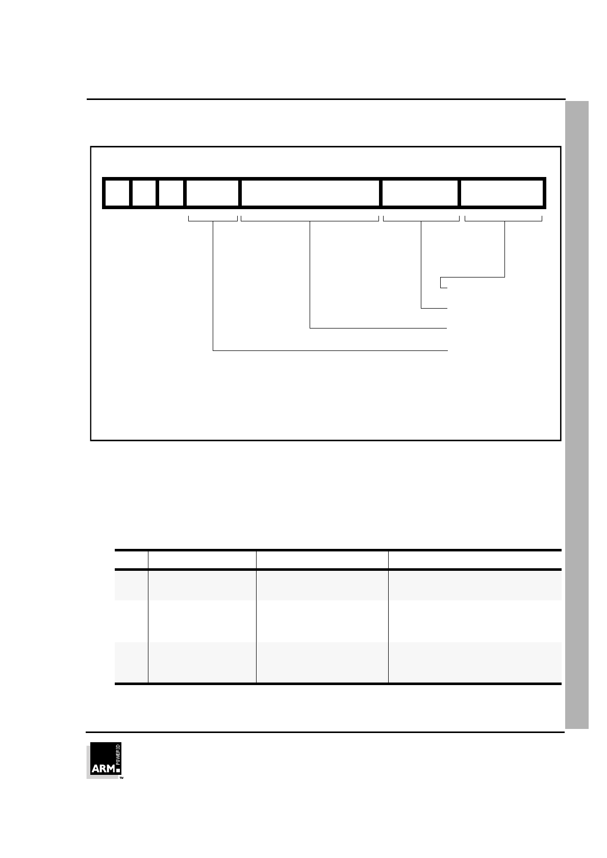
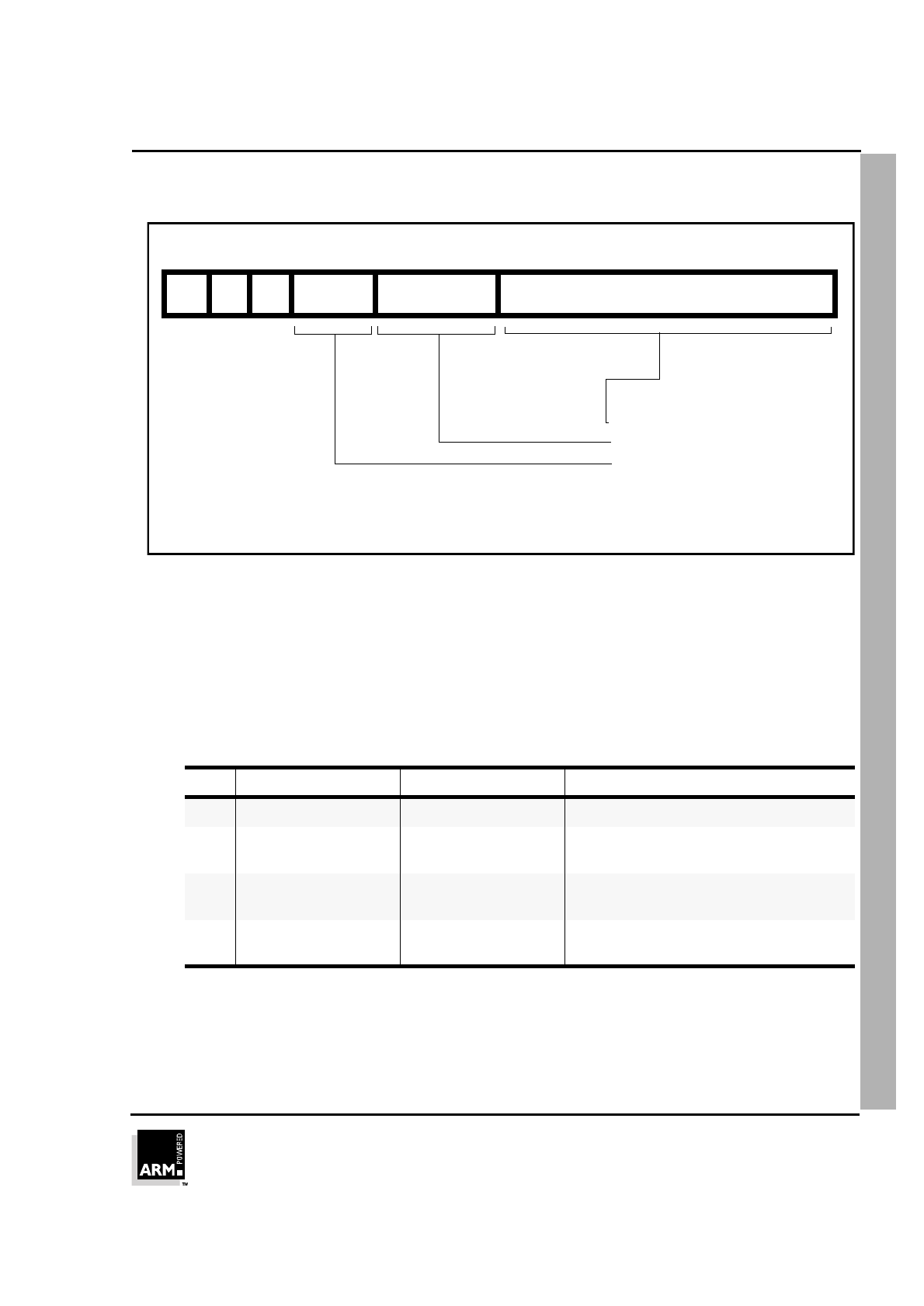
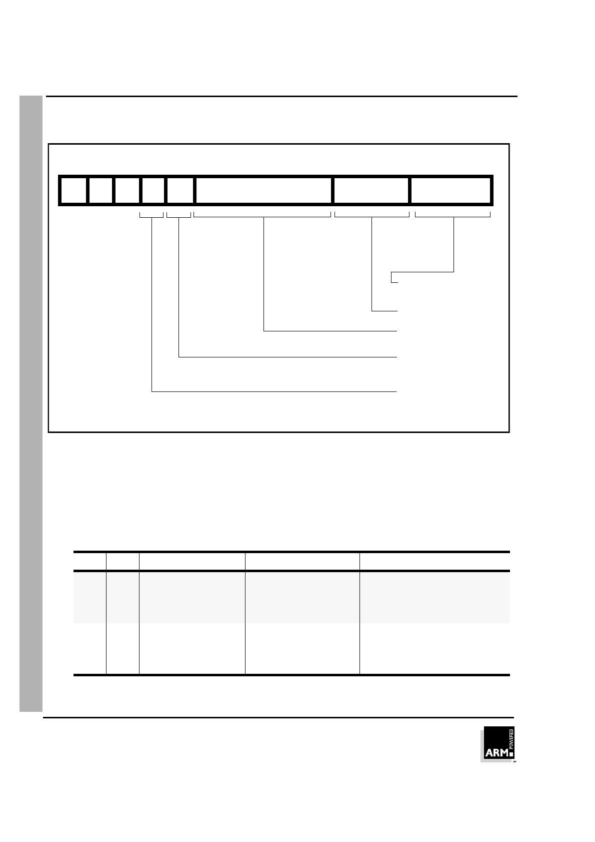
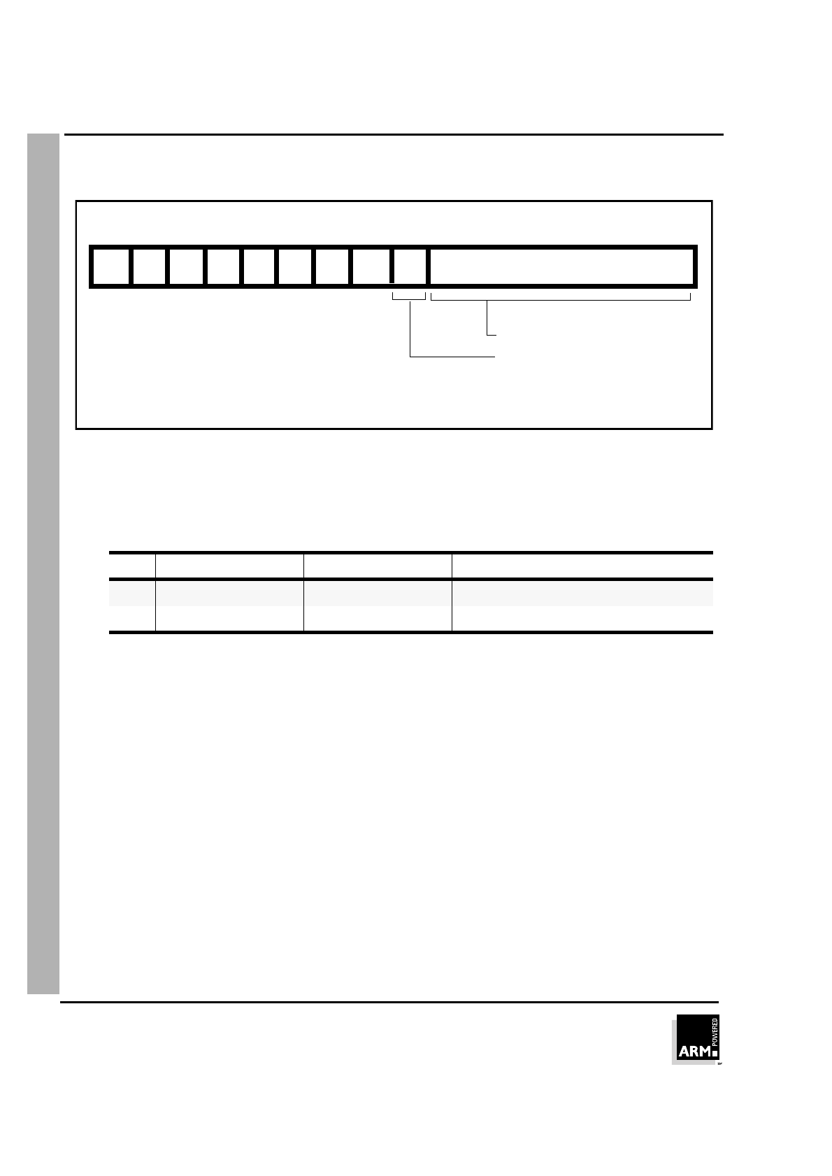
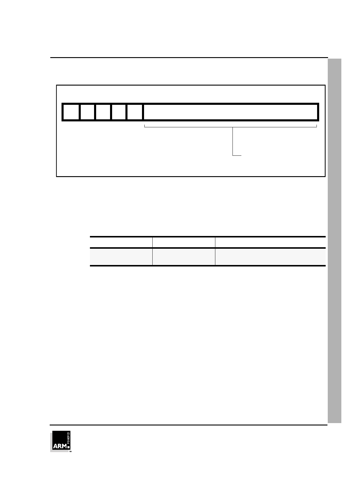
5.1 Format 1: move shifted register
Figure 5-2: Format 1
5.1.1 Operation
These instructions move a shifted value between Lo registers. The THUMB assembler
syntax is shown in ➲
Table 5-2: Summary of format 1 instructions
.
Note All instructions in this group set the CPSR condition codes.
OP THUMB assembler ARM equivalent Action
00 LSL Rd, Rs, #Offset5 MOVS Rd, Rs, LSL #Offset5 Shift Rs left by a 5-bit immediate value
and store the result in Rd.
01 LSR Rd, Rs, #Offset5 MOVS Rd, Rs, LSR #Offset5 Perform logical shift right on Rs by a 5-
bit immediate value and store the result
in Rd.
10 ASR Rd, Rs, #Offset5 MOVS Rd, Rs, ASR #Offset5 Perform arithmetic shift right on Rs by a
5-bit immediate value and store the
result in Rd.
Table 5-2: Summary of format 1 instructions
0123456789101112131415
Offset5 Rs000
Destination register
Source register
Immediate value
Opcode
Op Rd
0 - LSL
1 - LSR
2 - ASR

THUMB Instruction Set
ARM7TDMI Data Sheet
ARM DDI 0029E
5-6
Open Access
5.1.2 Instruction cycle times
All instructions in this format have an equivalent ARM instruction as shown in ➲
Table
5-2: Summary of format 1 instructions
on page 5-5. The instruction cycle times for the
THUMB instruction are identical to that of the equivalent ARM instruction. For more
information on instruction cycle times, please refer to ➲
Chapter 10, Instruction Cycle
Operations
.
5.1.3 Examples
LSR R2, R5, #27 ; Logical shift right the contents
; of R5 by 27 and store the result in R2.
; Set condition codes on the result.
THUMB Instruction Set
ARM7TDMI Data Sheet
ARM DDI 0029E
5-7
Open Access
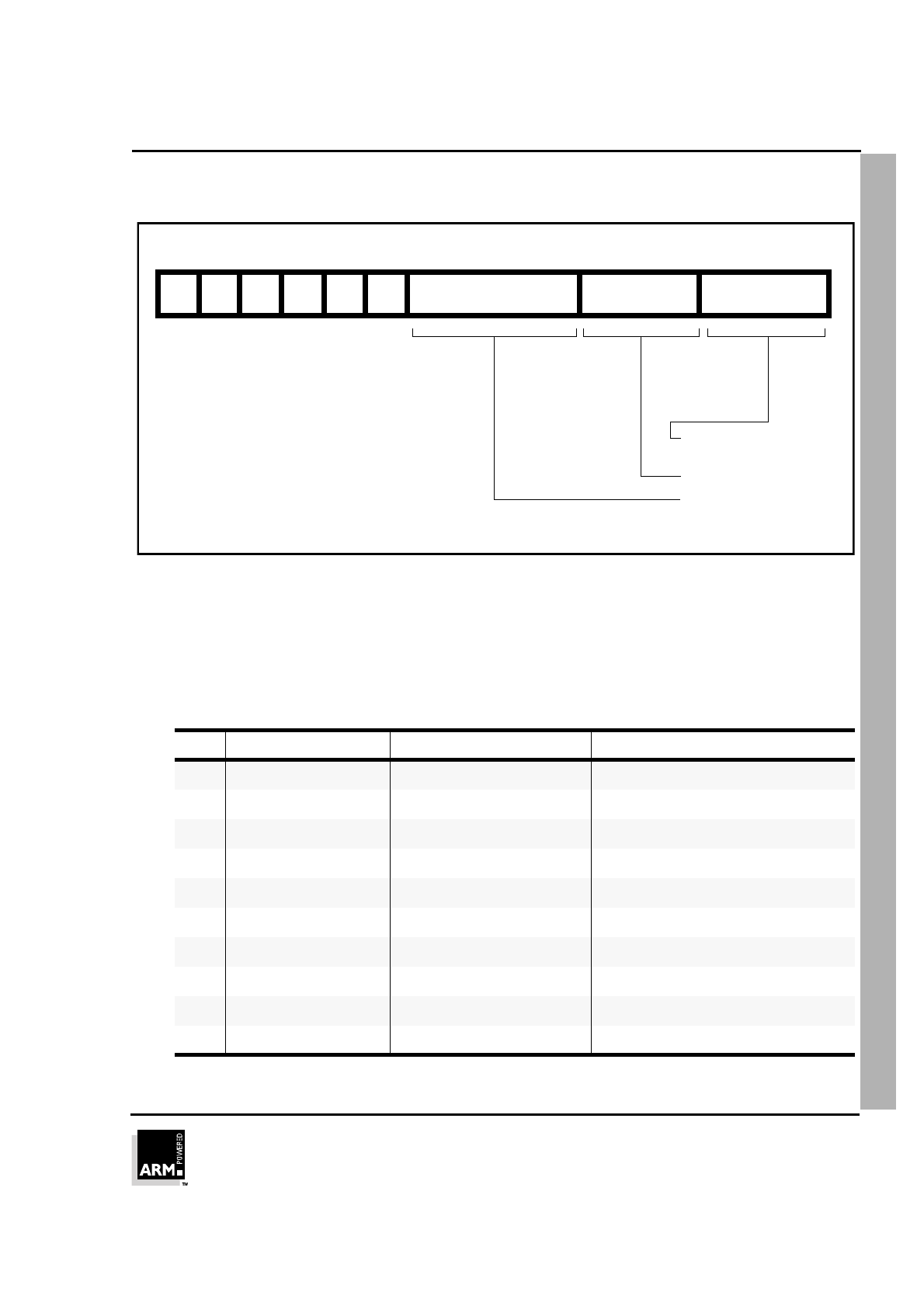
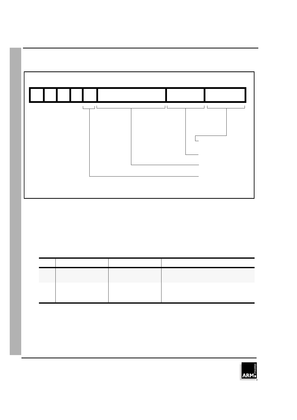
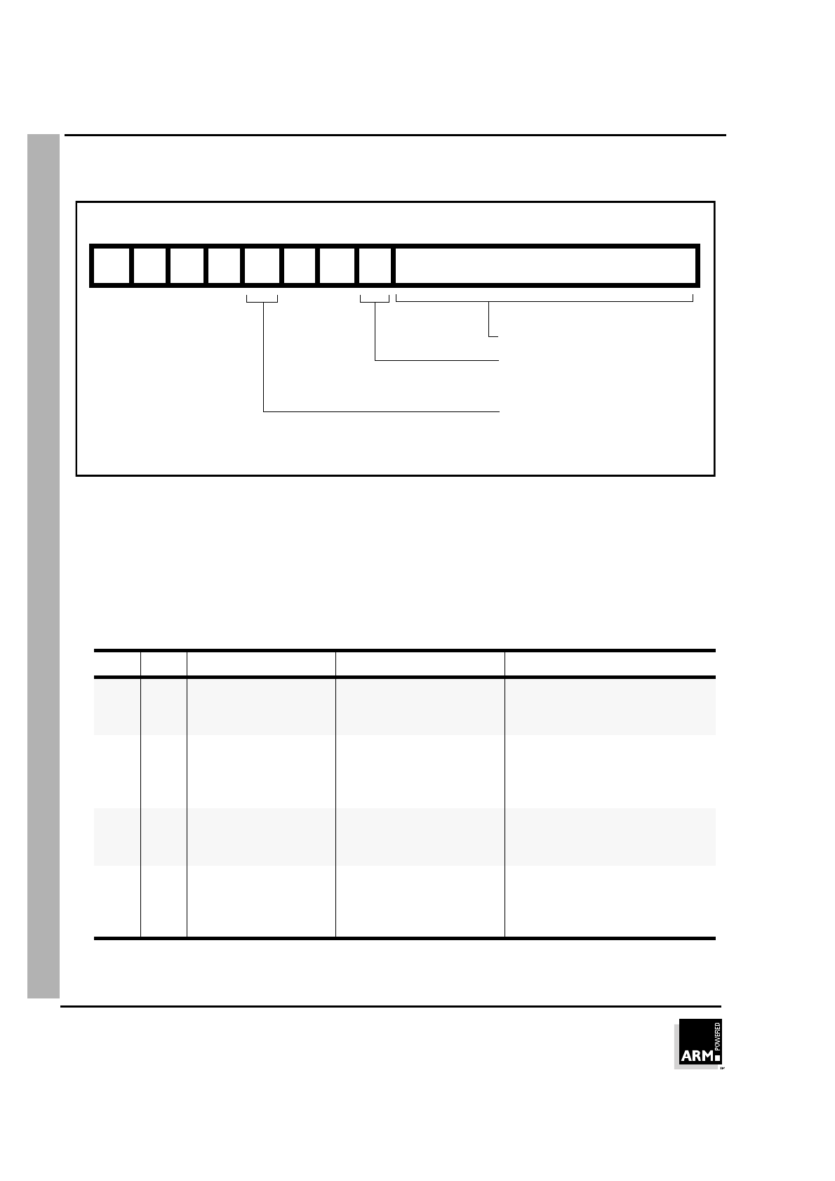
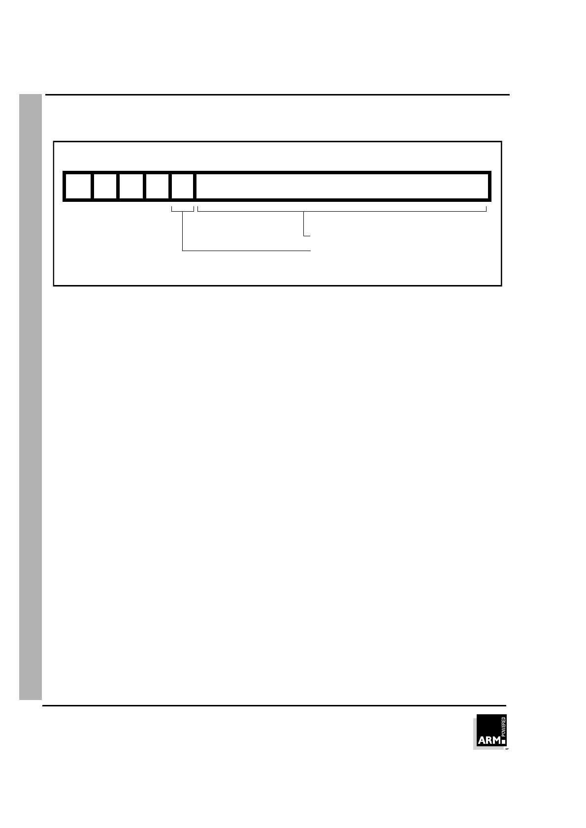
5.2 Format 2: add/subtract
Figure 5-3: Format 2
5.2.1 Operation
These instructions allow the contents of a Lo register or a 3-bit immediate value to be
added to or subtracted from a Lo register. The THUMB assembler syntax is shown in
➲
Table 5-3: Summary of format 2 instructions
.
Note All instructions in this group set the CPSR condition codes.
Op I THUMB assembler ARM equivalent Action
0 0 ADD Rd, Rs, Rn ADDS Rd, Rs, Rn Add contents of Rn to contents of Rs. Place
result in Rd.
0 1 ADD Rd, Rs, #Offset3 ADDS Rd, Rs, #Offset3 Add 3-bit immediate value to contents of
Rs. Place result in Rd.
1 0 SUB Rd, Rs, Rn SUBS Rd, Rs, Rn Subtract contents of Rn from contents of
Rs. Place result in Rd.
1 1 SUB Rd, Rs, #Offset3 SUBS Rd, Rs, #Offset3 Subtract 3-bit immediate value from
contents of Rs. Place result in Rd.
Table 5-3: Summary of format 2 instructions
0123456789101112131415
Rn/Offset3 Rs1000
Destination register
Opcode
Source register
0 - ADD
Register/
1 - SUB
Immediate value
Immediate flag
0 - Register operand
1 - Immediate operand
1 I Op Rd

THUMB Instruction Set
ARM7TDMI Data Sheet
ARM DDI 0029E
5-8
Open Access
5.2.2 Instruction cycle times
All instructions in this format have an equivalent ARM instruction as shown in ➲
Table
5-3: Summary of format 2 instructions
on page 5-7. The instruction cycle times for the
THUMB instruction are identical to that of the equivalent ARM instruction. For more
information on instruction cycle times, please refer to ➲
Chapter 10, Instruction Cycle
Operations
.
5.2.3 Examples
ADD R0, R3, R4 ; R0 := R3 + R4 and set condition codes on
; the result.
SUB R6, R2, #6 ; R6 := R2 - 6 and set condition codes.
THUMB Instruction Set
ARM7TDMI Data Sheet
ARM DDI 0029E
5-9
Open Access
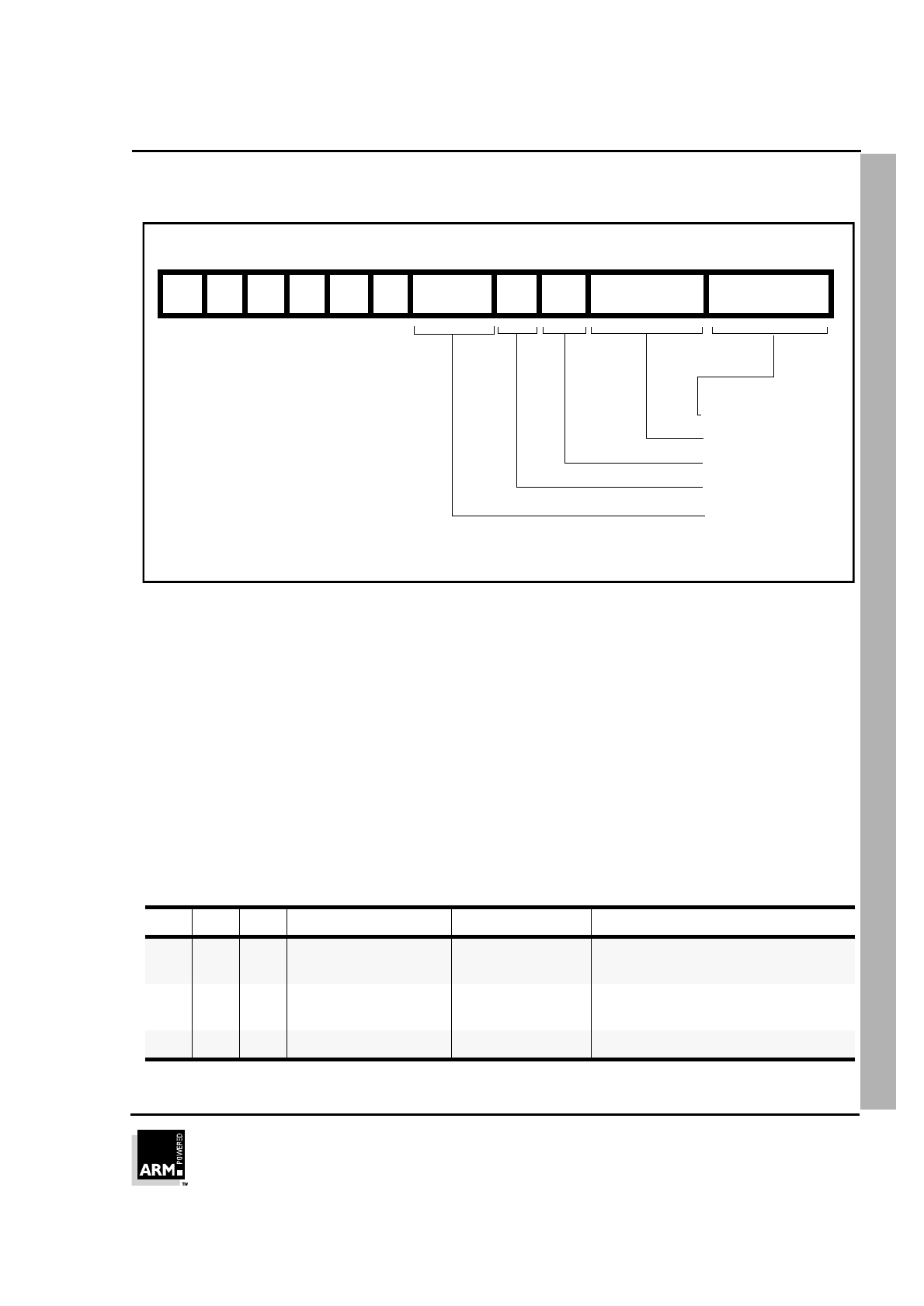
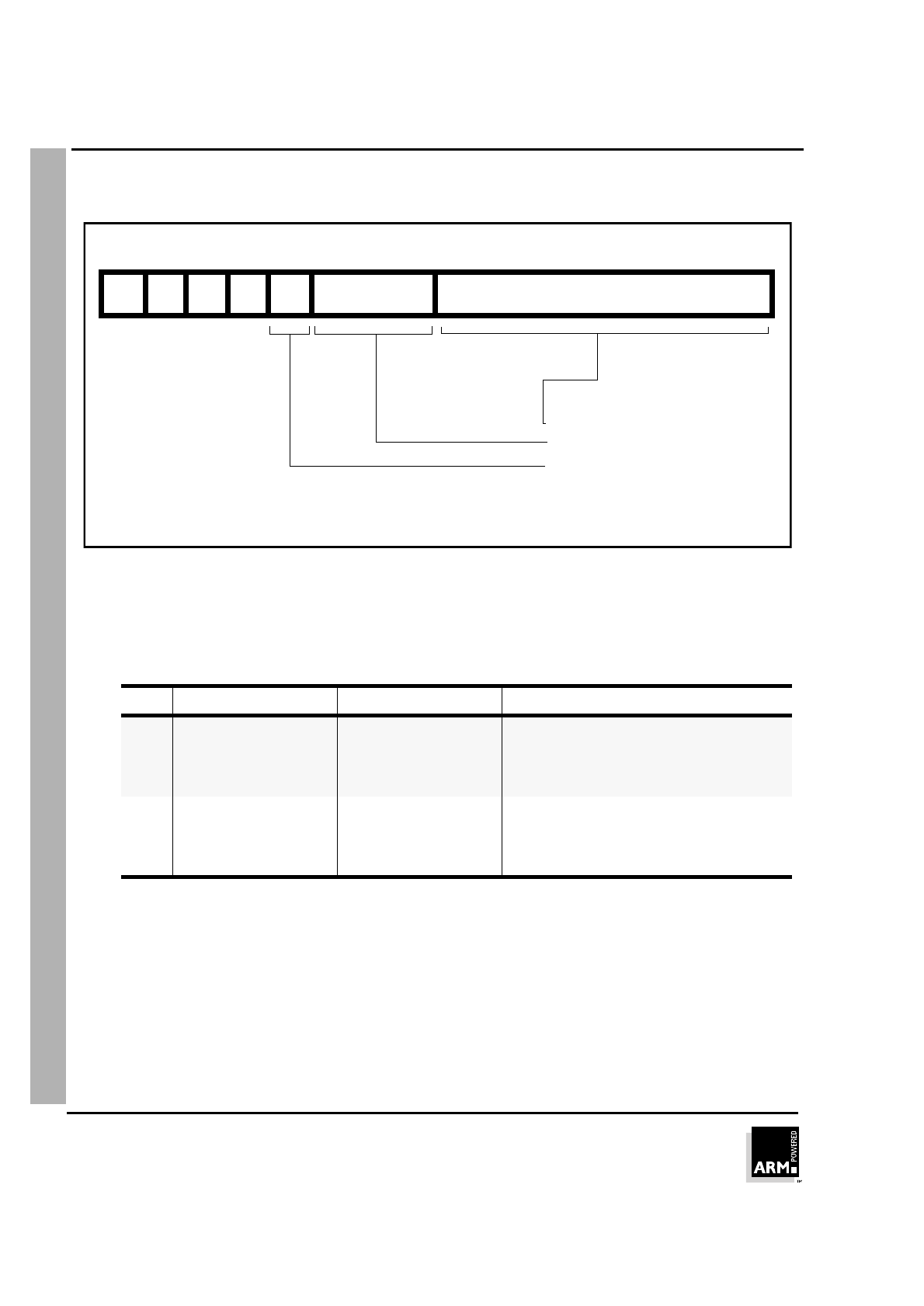
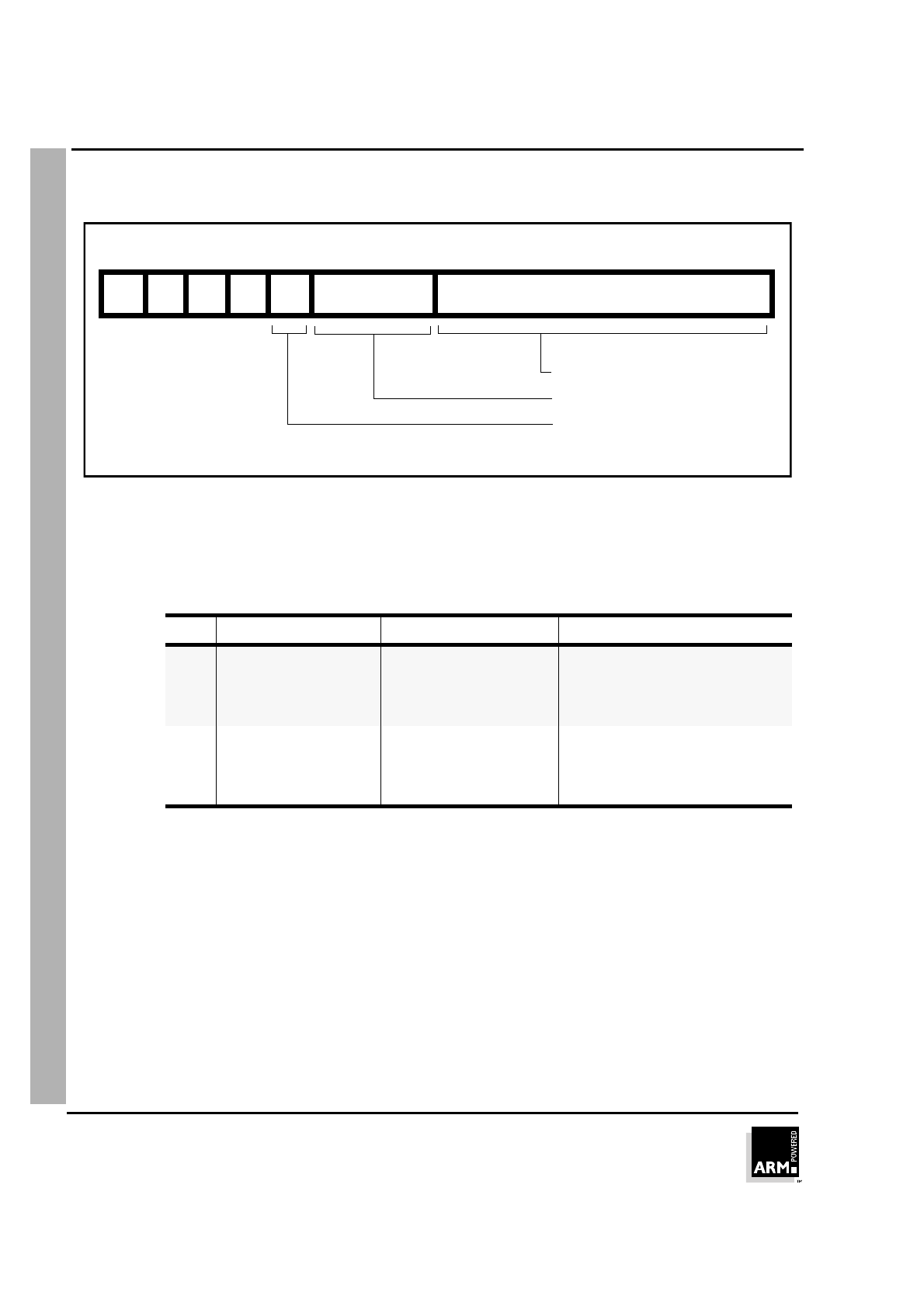
5.3 Format 3: move/compare/add/subtract immediate
Figure 5-4: Format 3
5.3.1 Operations
The instructions in this group perform operations between a Lo register and an 8-bit
immediate value.
The THUMB assembler syntax is shown in ➲
Table 5-4: Summary of format 3
instructions
.
Note All instructions in this group set the CPSR condition codes.
Op THUMB assembler ARM equivalent Action
00 MOV Rd, #Offset8 MOVS Rd, #Offset8 Move 8-bit immediate value into Rd.
01 CMP Rd, #Offset8 CMP Rd, #Offset8 Compare contents of Rd with 8-bit
immediate value.
10 ADD Rd, #Offset8 ADDS Rd, Rd, #Offset8 Add 8-bit immediate value to contents of Rd
and place the result in Rd.
11 SUB Rd, #Offset8 SUBS Rd, Rd, #Offset8 Subtract 8-bit immediate value from
contents of Rd and place the result in Rd.
Table 5-4: Summary of format 3 instructions
0123456789101112131415
RdOp100 Offset8
Source/destination register
Immediate value
Opcode
0 - MOV
1 - CMP
2 - ADD
3 SUB

THUMB Instruction Set
ARM7TDMI Data Sheet
ARM DDI 0029E
5-10
Open Access
5.3.2 Instruction cycle times
All instructions in this format have an equivalent ARM instruction as shown in ➲
Table
5-4: Summary of format 3 instructions
on page 5-9. The instruction cycle times for the
THUMB instruction are identical to that of the equivalent ARM instruction. For more
information on instruction cycle times, please refer to ➲
Chapter 10, Instruction Cycle
Operations
.
5.3.3 Examples
MOV R0, #128 ; R0 := 128 and set condition codes
CMP R2, #62 ; Set condition codes on R2 - 62
ADD R1, #255 ; R1 := R1 + 255 and set condition
; codes
SUB R6, #145 ; R6 := R6 - 145 and set condition
; codes
THUMB Instruction Set
ARM7TDMI Data Sheet
ARM DDI 0029E
5-11
Open Access
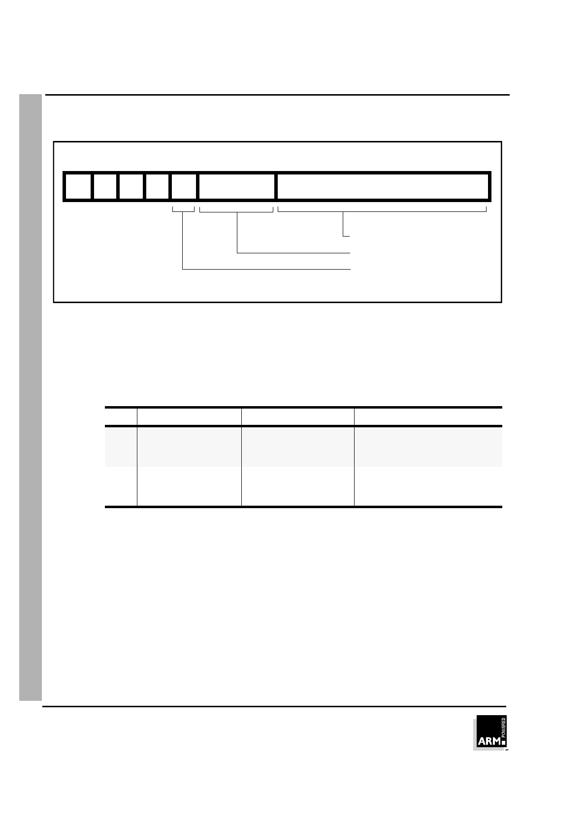
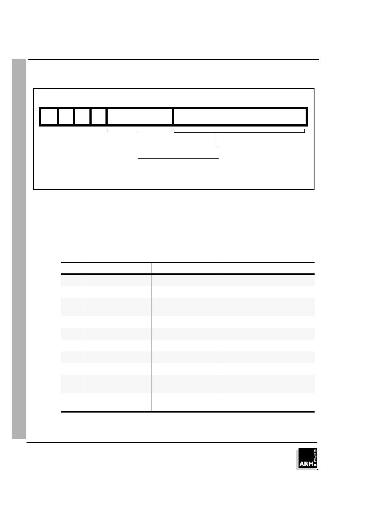
5.4 Format 4: ALU operations
Figure 5-5: Format 4
5.4.1 Operation
The following instructions perform ALU operations on a Lo register pair.
Note All instructions in this group set the CPSR condition codes.
OP THUMB assembler ARM equivalent Action
0000 AND Rd, Rs ANDS Rd, Rd, Rs Rd:= Rd AND Rs
0001 EOR Rd, Rs EORS Rd, Rd, Rs Rd:= Rd EOR Rs
0010 LSL Rd, Rs MOVS Rd, Rd, LSL Rs Rd := Rd << Rs
0011 LSR Rd, Rs MOVS Rd, Rd, LSR Rs Rd := Rd >> Rs
0100 ASR Rd, Rs MOVS Rd, Rd, ASR Rs Rd := Rd ASR Rs
0101 ADC Rd, Rs ADCS Rd, Rd, Rs Rd := Rd + Rs + C-bit
0110 SBC Rd, Rs SBCS Rd, Rd, Rs Rd := Rd - Rs - NOT C-bit
0111 ROR Rd, Rs MOVS Rd, Rd, ROR Rs Rd := Rd ROR Rs
1000 TST Rd, Rs TST Rd, Rs Set condition codes on Rd AND Rs
1001 NEG Rd, Rs RSBS Rd, Rs, #0 Rd = -Rs
Table 5-5: Summary of Format 4 instructions
0123456789101112131415
Op Rs010
Source/destination
Source register 2
Opcode
Rd
register
000

THUMB Instruction Set
ARM7TDMI Data Sheet
ARM DDI 0029E
5-12
Open Access
5.4.2 Instruction cycle times
All instructions in this format have an equivalent ARM instruction as shown in ➲
Table
5-5: Summary of Format 4 instructions
on page 5-11. The instruction cycle times for
the THUMB instruction are identical to that of the equivalent ARM instruction. For more
information on instruction cycle times, please refer to ➲
Chapter 10, Instruction Cycle
Operations
.
5.4.3 Examples
EOR R3, R4 ; R3 := R3 EOR R4 and set condition codes
ROR R1, R0 ; Rotate Right R1 by the value in R0, store
; the result in R1 and set condition codes
NEG R5, R3 ; Subtract the contents of R3 from zero,
; store the result in R5. Set condition codes
; ie R5 = -R3
CMP R2, R6 ; Set the condition codes on the result of
; R2 - R6
MUL R0, R7 ; R0 := R7 * R0 and set condition codes
1010 CMP Rd, Rs CMP Rd, Rs Set condition codes on Rd - Rs
1011 CMN Rd, Rs CMN Rd, Rs Set condition codes on Rd + Rs
1100 ORR Rd, Rs ORRS Rd, Rd, Rs Rd := Rd OR Rs
1101 MUL Rd, Rs MULS Rd, Rs, Rd Rd := Rs * Rd
1110 BIC Rd, Rs BICS Rd, Rd, Rs Rd := Rd AND NOT Rs
1111 MVN Rd, Rs MVNS Rd, Rs Rd := NOT Rs
OP THUMB assembler ARM equivalent Action
Table 5-5: Summary of Format 4 instructions (Continued)
THUMB Instruction Set
ARM7TDMI Data Sheet
ARM DDI 0029E
5-13
Open Access
5.5 Format 5: Hi register operations/branch exchange
Figure 5-6: Format 5
5.5.1 Operation
There are four sets of instructions in this group. The first three allow ADD, CMP and
MOV operations to be performed between Lo and Hi registers, or a pair of Hi registers.
The fourth, BX, allows a Branch to be performed which may also be used to switch
processor state.
The THUMB assembler syntax is shown in ➲
Table 5-6: Summary of format 5
instructions
Note In this group only CMP (Op = 01) sets the CPSR condition codes.
The action of H1= 0, H2 = 0 for Op = 00 (ADD), Op =01 (CMP) and Op = 10 (MOV) is
undefined, and should not be used.
Op H1 H2 THUMB assembler ARM equivalent Action
00 0 1 ADD Rd, Hs ADD Rd, Rd, Hs Add a register in the range 8-15 to a
register in the range 0-7.
00 1 0 ADD Hd, Rs ADD Hd, Hd, Rs Add a register in the range 0-7 to a
register in the range 8-15.
00 1 1 ADD Hd, Hs ADD Hd, Hd, Hs Add two registers in the range 8-15
Table 5-6: Summary of format 5 instructions
0123456789101112131415
Op010 Rs/Hs
Destination register
Source register
0 0 H1
Opcode
1 H2
Hi operand flag 2
Hi operand flag 1
Rd/Hd
THUMB Instruction Set
ARM7TDMI Data Sheet
ARM DDI 0029E
5-14
Open Access
5.5.2 Instruction cycle times
All instructions in this format have an equivalent ARM instruction as shown in ➲
Table
5-6: Summary of format 5 instructions
on page 5-13. The instruction cycle times for the
THUMB instruction are identical to that of the equivalent ARM instruction. For more
information on instruction cycle times, please refer to ➲
Chapter 10, Instruction Cycle
Operations
.
5.5.3 The BX instruction
BX performs a Branch to a routine whose start address is specified in a Lo or Hi
register.
Bit 0 of the address determines the processor state on entry to the routine:
Bit 0 = 0 causes the processor to enter ARM state.
Bit 0 = 1 causes the processor to enter THUMB state.
Note The action of H1 = 1 for this instruction is undefined, and should not be used.
01 0 1 CMP Rd, Hs CMP Rd, Hs Compare a register in the range 0-7
with a register in the range 8-15. Set
the condition code flags on the result.
01 1 0 CMP Hd, Rs CMP Hd, Rs Compare a register in the range 8-15
with a register in the range 0-7. Set the
condition code flags on the result.
01 1 1 CMP Hd, Hs CMP Hd, Hs Compare two registers in the range 8-
15. Set the condition code flags on the
result.
10 0 1 MOV Rd, Hs MOV Rd, Hs Move a value from a register in the
range 8-15 to a register in the range 0-
7.
10 1 0 MOV Hd, Rs MOV Hd, Rs Move a value from a register in the
range 0-7 to a register in the range 8-
15.
10 1 1 MOV Hd, Hs MOV Hd, Hs Move a value between two registers in
the range 8-15.
11 0 0 BX Rs BX Rs Perform branch (plus optional state
change) to address in a register in the
range 0-7.
11 0 1 BX Hs BX Hs Perform branch (plus optional state
change) to address in a register in the
range 8-15.
Op H1 H2 THUMB assembler ARM equivalent Action
Table 5-6: Summary of format 5 instructions (Continued)

THUMB Instruction Set
ARM7TDMI Data Sheet
ARM DDI 0029E
5-15
Open Access
5.5.4 Examples
Hi register operations
ADD PC, R5 ; PC := PC + R5 but don't set the
; condition codes.
CMP R4, R12 ; Set the condition codes on the
; result of R4 - R12.
MOV R15, R14 ; Move R14 (LR) into R15 (PC)
; but don't set the condition codes,
; eg. return from subroutine.
Branch and exchange
; Switch from THUMB to ARM state.
ADR R1,outofTHUMB
; Load address of outofTHUMB
; into R1.
MOV R11,R1
BX R11 ; Transfer the contents of R11 into
; the PC.
; Bit 0 of R11 determines whether
; ARM or THUMB state is entered, ie.
; ARM state here.
...
ALIGN
CODE32
outofTHUMB
; Now processing ARM instructions...
5.5.5 Using R15 as an operand
If R15 is used as an operand, the value will be the address of the instruction + 4 with
bit 0 cleared. Executing a BX PC in THUMB state from a non-word aligned address
will result in unpredictable execution.

THUMB Instruction Set
ARM7TDMI Data Sheet
ARM DDI 0029E
5-16
Open Access
5.6 Format 6: PC-relative load
Figure 5-7: Format 6
5.6.1 Operation
This instruction loads a word from an address specified as a 10-bit immediate offset
from the PC.
The THUMB assembler syntax is shown below.
Note The value specified by #Imm is a full 10-bit address, but must always be word-aligned
(ie with bits 1:0 set to 0), since the assembler places #Imm >> 2 in field Word8.
Note The value of the PC will be 4 bytes greater than the address of this instruction, but bit
1 of the PC is forced to 0 to ensure it is word aligned.
THUMB assembler ARM equivalent Action
LDR Rd, [PC, #Imm] LDR Rd, [R15, #Imm] Add unsigned offset (255 words,
1020 bytes) in Imm to the current
value of the PC. Load the word
from the resulting address into Rd.
Table 5-7: Summary of PC-relative load instruction
0123456789101112131415
Rd010 Word8
Destination register
Immediate value
0 1

THUMB Instruction Set
ARM7TDMI Data Sheet
ARM DDI 0029E
5-17
Open Access
5.6.2 Instruction cycle times
All instructions in this format have an equivalent ARM instruction as shown in ➲
Table
5-7: Summary of PC-relative load instruction
on page 5-16. The instruction cycle times
for the THUMB instruction are identical to that of the equivalent ARM instruction. For
more information on instruction cycle times, please refer to ➲
Chapter 10, Instruction
Cycle Operations
.
5.6.3 Examples
LDR R3,[PC,#844] ; Load into R3 the word found at the
; address formed by adding 844 to PC.
; bit[1] of PC is forced to zero.
; Note that the THUMB opcode will contain
; 211 as the Word8 value.
THUMB Instruction Set
ARM7TDMI Data Sheet
ARM DDI 0029E
5-18
Open Access
5.7 Format 7: load/store with register offset
Figure 5-8: Format 7
5.7.1 Operation
These instructions transfer byte or word values between registers and memory.
Memory addresses are pre-indexed using an offset register in the range 0-7.
The THUMB assembler syntax is shown in ➲
Table 5-8: Summary of format 7
instructions
.
L B THUMB assembler ARM equivalent Action
0 0 STR Rd, [Rb, Ro] STR Rd, [Rb, Ro] Pre-indexed word store:
Calculate the target address by
adding together the value in Rb
and the value in Ro. Store the
contents of Rd at the address.
Table 5-8: Summary of format 7 instructions
0123456789101112131415
Ro RbL010
Source/destination
Base register
Offset register
1 B 0 Rd
Byte/Word flag
Load/Store flag
0 - Transfer word quantity
1 - Transfer byte quantity
0 - Store to memory
1 - Load from memory
register
THUMB Instruction Set
ARM7TDMI Data Sheet
ARM DDI 0029E
5-19
Open Access
5.7.2 Instruction cycle times
All instructions in this format have an equivalent ARM instruction as shown in ➲
Table
5-8: Summary of format 7 instructions
on page 5-18. The instruction cycle times for the
THUMB instruction are identical to that of the equivalent ARM instruction. For more
information on instruction cycle times, please refer to ➲
Chapter 10, Instruction Cycle
Operations
.
5.7.3 Examples
STR R3, [R2,R6] ; Store word in R3 at the address
; formed by adding R6 to R2.
LDRB R2, [R0,R7] ; Load into R2 the byte found at
; the address formed by adding
; R7 to R0.
0 1 STRB Rd, [Rb, Ro] STRB Rd, [Rb, Ro] Pre-indexed byte store:
Calculate the target address by
adding together the value in Rb
and the value in Ro. Store the byte
value in Rd at the resulting
address.
1 0 LDR Rd, [Rb, Ro] LDR Rd, [Rb, Ro] Pre-indexed word load:
Calculate the source address by
adding together the value in Rb
and the value in Ro. Load the
contents of the address into Rd.
1 1 LDRB Rd, [Rb, Ro] LDRB Rd, [Rb, Ro] Pre-indexed byte load:
Calculate the source address by
adding together the value in Rb
and the value in Ro. Load the byte
value at the resulting address.
L B THUMB assembler ARM equivalent Action
Table 5-8: Summary of format 7 instructions (Continued)
THUMB Instruction Set
ARM7TDMI Data Sheet
ARM DDI 0029E
5-20
Open Access
5.8 Format 8: load/store sign-extended byte/halfword
Figure 5-9: Format 8
5.8.1 Operation
These instructions load optionally sign-extended bytes or halfwords, and store
halfwords. The THUMB assembler syntax is shown below.
S H THUMB assembler ARM equivalent Action
0 0 STRH Rd, [Rb, Ro] STRH Rd, [Rb, Ro] Store halfword:
Add Ro to base address in Rb. Store bits 0-
15 of Rd at the resulting address.
0 1 LDRH Rd, [Rb, Ro] LDRH Rd, [Rb, Ro] Load halfword:
Add Ro to base address in Rb. Load bits 0-
15 of Rd from the resulting address, and set
bits 16-31 of Rd to 0.
1 0 LDSB Rd, [Rb, Ro] LDRSB Rd, [Rb, Ro] Load sign-extended byte:
Add Ro to base address in Rb. Load bits 0-
7 of Rd from the resulting address, and set
bits 8-31 of Rd to bit 7.
Table 5-9: Summary of format 8 instructions
0123456789101112131415
Ro RbH010
Destination register
Base register
Offset register
H flag
1 S 1 Rd
Sign-extended flag
0 - Operand not sign-extended
1 - Operand sign-extended

THUMB Instruction Set
ARM7TDMI Data Sheet
ARM DDI 0029E
5-21
Open Access
5.8.2 Instruction cycle times
All instructions in this format have an equivalent ARM instruction as shown in ➲
Table
5-9: Summary of format 8 instructions
on page 5-20. The instruction cycle times for the
THUMB instruction are identical to that of the equivalent ARM instruction. For more
information on instruction cycle times, please refer to ➲
Chapter 10, Instruction Cycle
Operations
.
5.8.3 Examples
STRH R4, [R3, R0] ; Store the lower 16 bits of R4 at the
; address formed by adding R0 to R3.
LDSB R2, [R7, R1] ; Load into R2 the sign extended byte
; found at the address formed by adding
; R1 to R7.
LDSH R3, [R4, R2] ; Load into R3 the sign extended halfword
; found at the address formed by adding
; R2 to R4.
1 1 LDSH Rd, [Rb, Ro] LDRSH Rd, [Rb, Ro] Load sign-extended halfword:
Add Ro to base address in Rb. Load bits 0-
15 of Rd from the resulting address, and set
bits 16-31 of Rd to bit 15.
S H THUMB assembler ARM equivalent Action
Table 5-9: Summary of format 8 instructions (Continued)
THUMB Instruction Set
ARM7TDMI Data Sheet
ARM DDI 0029E
5-22
Open Access
5.9 Format 9: load/store with immediate offset
Figure 5-10: Format 9
5.9.1 Operation
These instructions transfer byte or word values between registers and memory using
an immediate 5 or 7-bit offset.
The THUMB assembler syntax is shown in ➲
Table 5-10: Summary of format 9
instructions
.
L B THUMB assembler ARM equivalent Action
0 0 STR Rd, [Rb, #Imm] STR Rd, [Rb, #Imm] Calculate the target address by
adding together the value in Rb
and Imm. Store the contents of Rd
at the address.
1 0 LDR Rd, [Rb, #Imm] LDR Rd, [Rb, #Imm] Calculate the source address by
adding together the value in Rb
and Imm. Load Rd from the
address.
Table 5-10: Summary of format 9 instructions
0123456789101112131415
Offset5 RbL110
Source/destination
Base register
Offset value
B Rd
Byte/Word flag
Load/Store flag
0 - Transfer word quantity
1 - Transfer byte quantity
0 - Store to memory
1 - Load from memory
register

THUMB Instruction Set
ARM7TDMI Data Sheet
ARM DDI 0029E
5-23
Open Access
Note For word accesses (B = 0), the value specified by #Imm is a full 7-bit address, but must
be word-aligned (ie with bits 1:0 set to 0), since the assembler places #Imm >> 2 in
the Offset5 field.
5.9.2 Instruction cycle times
All instructions in this format have an equivalent ARM instruction as shown in ➲
Table
5-10: Summary of format 9 instructions
on page 5-22. The instruction cycle times for
the THUMB instruction are identical to that of the equivalent ARM instruction. For more
information on instruction cycle times, please refer to ➲
Chapter 10, Instruction Cycle
Operations
.
5.9.3 Examples
LDR R2, [R5,#116] ; Load into R2 the word found at the
; address formed by adding 116 to R5.
; Note that the THUMB opcode will
; contain 29 as the Offset5 value.
STRB R1, [R0,#13] ; Store the lower 8 bits of R1 at the
; address formed by adding 13 to R0.
; Note that the THUMB opcode will
; contain 13 as the Offset5 value.
0 1 STRB Rd, [Rb, #Imm] STRB Rd, [Rb, #Imm] Calculate the target address by
adding together the value in Rb
and Imm. Store the byte value in
Rd at the address.
1 1 LDRB Rd, [Rb, #Imm] LDRB Rd, [Rb, #Imm] Calculate source address by
adding together the value in Rb
and Imm. Load the byte value at
the address into Rd.
L B THUMB assembler ARM equivalent Action
Table 5-10: Summary of format 9 instructions (Continued)
THUMB Instruction Set
ARM7TDMI Data Sheet
ARM DDI 0029E
5-24
Open Access
5.10 Format 10: load/store halfword
Figure 5-11: Format 10
5.10.1 Operation
These instructions transfer halfword values between a Lo register and memory.
Addresses are pre-indexed, using a 6-bit immediate value.
The THUMB assembler syntax is shown in ➲
Table 5-11: Halfword data transfer
instructions
.
Note #Imm is a full 6-bit address but must be halfword-aligned (ie with bit 0 set to 0) since
the assembler places #Imm >> 1 in the Offset5 field.
L THUMB assembler ARM equivalent Action
0 STRH Rd, [Rb, #Imm] STRH Rd, [Rb, #Imm] Add #Imm to base address in Rb and store
bits 0-15 of Rd at the resulting address.
1 LDRH Rd, [Rb, #Imm] LDRH Rd, [Rb, #Imm] Add #Imm to base address in Rb. Load bits
0-15 from the resulting address into Rd and
set bits 16-31 to zero.
Table 5-11: Halfword data transfer instructions
0123456789101112131415
Offset5 RbL001
Source/destination
Base register
Immediate value
0 Rd
register
Load/Store bit
0 - Store to memory
1 - Load from memory

THUMB Instruction Set
ARM7TDMI Data Sheet
ARM DDI 0029E
5-25
Open Access
5.10.2 Instruction cycle times
All instructions in this format have an equivalent ARM instruction as shown in ➲
Table
5-11: Halfword data transfer instructions
on page 5-24. The instruction cycle times for
the THUMB instruction are identical to that of the equivalent ARM instruction. For more
information on instruction cycle times, please refer to ➲
Chapter 10, Instruction Cycle
Operations
.
5.10.3 Examples
STRH R6, [R1, #56] ; Store the lower 16 bits of R4 at
; the address formed by adding 56
; R1.
; Note that the THUMB opcode will
; contain 28 as the Offset5 value.
LDRH R4, [R7, #4] ; Load into R4 the halfword found at
; the address formed by adding 4 to R7.
; Note that the THUMB opcode will contain
; 2 as the Offset5 value.
THUMB Instruction Set
ARM7TDMI Data Sheet
ARM DDI 0029E
5-26
Open Access
5.11 Format 11: SP-relative load/store
Figure 5-12: Format 11
5.11.1 Operation
The instructions in this group perform an SP-relative load or store.The THUMB
assembler syntax is shown in the following table.
Note The offset supplied in #Imm is a full 10-bit address, but must always be word-aligned
(ie bits 1:0 set to 0), since the assembler places #Imm >> 2 in the Word8 field.
L THUMB assembler ARM equivalent Action
0 STR Rd, [SP, #Imm] STR Rd, [R13 #Imm] Add unsigned offset (255 words, 1020
bytes) in Imm to the current value of the SP
(R7). Store the contents of Rd at the
resulting address.
1 LDR Rd, [SP, #Imm] LDR Rd, [R13 #Imm] Add unsigned offset (255 words, 1020
bytes) in Imm to the current value of the SP
(R7). Load the word from the resulting
address into Rd.
Table 5-12: SP-relative load/store instructions
0123456789101112131415
Rd001 Word8
Destination register
Immediate value
1 L
Load/Store bit
0 - Store to memory
1 - Load from memory

THUMB Instruction Set
ARM7TDMI Data Sheet
ARM DDI 0029E
5-27
Open Access
5.11.2 Instruction cycle times
All instructions in this format have an equivalent ARM instruction as shown in ➲
Table
5-12: SP-relative load/store instructions
on page 5-26. The instruction cycle times for
the THUMB instruction are identical to that of the equivalent ARM instruction. For more
information on instruction cycle times, please refer to ➲
Chapter 10, Instruction Cycle
Operations
.
5.11.3 Examples
STR R4, [SP,#492] ; Store the contents of R4 at the address
; formed by adding 492 to SP (R13).
; Note that the THUMB opcode will contain
; 123 as the Word8 value.
THUMB Instruction Set
ARM7TDMI Data Sheet
ARM DDI 0029E
5-28
Open Access
5.12 Format 12: load address
Figure 5-13: Format 12
5.12.1 Operation
These instructions calculate an address by adding an 10-bit constant to either the PC
or the SP, and load the resulting address into a register.
The THUMB assembler syntax is shown in the following table.
Note The value specified by #Imm is a full 10-bit value, but this must be word-aligned (ie
with bits 1:0 set to 0) since the assembler places #Imm >> 2 in field Word8.
Where the PC is used as the source register (SP = 0), bit 1 of the PC is always read
as 0. The value of the PC will be 4 bytes greater than the address of the instruction
before bit 1 is forced to 0.
The CPSR condition codes are unaffected by these instructions.
SP THUMB assembler ARM equivalent Action
0 ADD Rd, PC, #Imm ADD Rd, R15, #Imm Add #Imm to the current value of
the program counter (PC) and load
the result into Rd.
1 ADD Rd, SP, #Imm ADD Rd, R13, #Imm Add #Imm to the current value of
the stack pointer (SP) and load the
result into Rd.
Table 5-13: Load address
0123456789101112131415
Rd101 0 SP Word8
8-bit unsigned constant
Destination register
Source
0 - PC
1 - SP

THUMB Instruction Set
ARM7TDMI Data Sheet
ARM DDI 0029E
5-29
Open Access
5.12.2 Instruction cycle times
All instructions in this format have an equivalent ARM instruction as shown in ➲
Table
5-13: Load address
on page 5-28. The instruction cycle times for the THUMB
instruction are identical to that of the equivalent ARM instruction. For more information
on instruction cycle times, please refer to ➲
Chapter 10, Instruction Cycle Operations
.
5.12.3 Examples
ADD R2, PC, #572 ; R2 := PC + 572, but don't set the
; condition codes. bit[1] of PC is
; forced to zero.
; Note that the THUMB opcode will
; contain 143 as the Word8 value.
ADD R6, SP, #212 ; R6 := SP (R13) + 212, but don't
; set the condition codes.
; Note that the THUMB opcode will
; contain 53 as the Word8 value.
THUMB Instruction Set
ARM7TDMI Data Sheet
ARM DDI 0029E
5-30
Open Access
5.13 Format 13: add offset to Stack Pointer
Figure 5-14: Format 13
5.13.1 Operation
This instruction adds a 9-bit signed constant to the stack pointer. The following table
shows the THUMB assembler syntax.
Note The offset specified by #Imm can be up to -/+ 508, but must be word-aligned (ie with
bits 1:0 set to 0) since the assembler converts #Imm to an 8-bit sign + magnitude
number before placing it in field SWord7.
Note The condition codes are not set by this instruction.
5.13.2 Instruction cycle times
All instructions in this format have an equivalent ARM instruction as shown in ➲
Table
5-14: The ADD SP instruction
on page 5-30. The instruction cycle times for the
THUMB instruction are identical to that of the equivalent ARM instruction. For more
information on instruction cycle times, please refer to ➲
Chapter 10, Instruction Cycle
Operations
S THUMB assembler ARM equivalent Action
0 ADD SP, #Imm ADD R13, R13, #Imm Add #Imm to the stack pointer (SP).
1 ADD SP, #-Imm SUB R13, R13, #Imm Add #-Imm to the stack pointer (SP).
Table 5-14: The ADD SP instruction
0123456789101112131415
101 1
7-bit immediate value
SWord7000 0 S
Sign flag
0 -Offset is positive
1 -Offset is negative

THUMB Instruction Set
ARM7TDMI Data Sheet
ARM DDI 0029E
5-31
Open Access
5.13.3 Examples
ADD SP, #268 ; SP (R13) := SP + 268, but don't set
; the condition codes.
; Note that the THUMB opcode will
; contain 67 as the Word7 value and S=0.
ADD SP, #-104 ; SP (R13) := SP - 104, but don't set
; the condition codes.
; Note that the THUMB opcode will contain
; 26 as the Word7 value and S=1.
THUMB Instruction Set
ARM7TDMI Data Sheet
ARM DDI 0029E
5-32
Open Access
5.14 Format 14: push/pop registers
Figure 5-15: Format 14
5.14.1 Operation
The instructions in this group allow registers 0-7 and optionally LR to be pushed onto
the stack, and registers 0-7 and optionally PC to be popped off the stack.
The THUMB assembler syntax is shown in ➲
Table 5-15: PUSH and POP instructions
.
Note The stack is always assumed to be Full Descending.
L R THUMB assembler ARM equivalent Action
0 0 PUSH { Rlist } STMDB R13!, { Rlist } Push the registers specified by
Rlist onto the stack. Update the
stack pointer.
0 1 PUSH { Rlist, LR } STMDB R13!, { Rlist, R14 } Push the Link Register and the
registers specified by Rlist (if any)
onto the stack. Update the stack
pointer.
1 0 POP { Rlist } LDMIA R13!, { Rlist } Pop values off the stack into the
registers specified by Rlist. Update
the stack pointer.
1 1 POP { Rlist, PC } LDMIA R13!, { Rlist, R15 } Pop values off the stack and load
into the registers specified by Rlist.
Pop the PC off the stack. Update
the stack pointer.
Table 5-15: PUSH and POP instructions
0123456789101112131415
10 0 Rlist
Register list
PC/LR bit
Load/Store bit
0 - Store to memory
1 - Load from memory
1 1 L 1
0 - Do not store LR/load PC
1 - Store LR/Load PC
R

THUMB Instruction Set
ARM7TDMI Data Sheet
ARM DDI 0029E
5-33
Open Access
5.14.2 Instruction cycle times
All instructions in this format have an equivalent ARM instruction as shown in ➲
Table
5-15: PUSH and POP instructions
on page 5-32. The instruction cycle times for the
THUMB instruction are identical to that of the equivalent ARM instruction. For more
information on instruction cycle times, please refer to ➲
Chapter 10, Instruction Cycle
Operations
.
5.14.3 Examples
PUSH {R0-R4,LR} ; Store R0,R1,R2,R3,R4 and R14 (LR) at
; the stack pointed to by R13 (SP) and
; update R13.
; Useful at start of a sub-routine to
; save workspace and return address.
POP {R2,R6,PC} ; Load R2,R6 and R15 (PC) from the stack
; pointed to by R13 (SP) and update R13.
; Useful to restore workspace and return
; from sub-routine.
THUMB Instruction Set
ARM7TDMI Data Sheet
ARM DDI 0029E
5-34
Open Access
5.15 Format 15: multiple load/store
Figure 5-16: Format 15
5.15.1 Operation
These instructions allow multiple loading and storing of Lo registers. The THUMB
assembler syntax is shown in the following table.
5.15.2 Instruction cycle times
All instructions in this format have an equivalent ARM instruction as shown in ➲
Table
5-16: The multiple load/store instructions
on page 5-34. The instruction cycle times for
the THUMB instruction are identical to that of the equivalent ARM instruction. For more
information on instruction cycle times, please refer to ➲
Chapter 10, Instruction Cycle
Operations
L THUMB assembler ARM equivalent Action
0 STMIA Rb!, { Rlist } STMIA Rb!, { Rlist } Store the registers specified by
Rlist, starting at the base address
in Rb. Write back the new base
address.
1 LDMIA Rb!, { Rlist } LDMIA Rb!, { Rlist } Load the registers specified by
Rlist, starting at the base address
in Rb. Write back the new base
address.
Table 5-16: The multiple load/store instructions
0123456789101112131415
Rb011 0 L Rlist
Register list
Base register
Load/Store bit
0 - Store to memory
1 - Load from memory

THUMB Instruction Set
ARM7TDMI Data Sheet
ARM DDI 0029E
5-35
Open Access
5.15.3 Examples
STMIA R0!, {R3-R7} ; Store the contents of registers R3-R7
; starting at the address specified in
; R0, incrementing the addresses for each
; word.
; Write back the updated value of R0.
THUMB Instruction Set
ARM7TDMI Data Sheet
ARM DDI 0029E
5-36
Open Access
5.16 Format 16: conditional branch
Figure 5-17: Format 16
5.16.1 Operation
The instructions in this group all perform a conditional Branch depending on the state
of the CPSR condition codes. The branch offset must take account of the prefetch
operation, which causes the PC to be 1 word (4 bytes) ahead of the current instruction.
The THUMB assembler syntax is shown in the following table.
Cond THUMB assembler ARM equivalent Action
0000 BEQ label BEQ label Branch if Z set (equal)
0001 BNE label BNE label Branch if Z clear (not equal)
0010 BCS label BCS label Branch if C set (unsigned higher or
same)
0011 BCC label BCC label Branch if C clear (unsigned lower)
0100 BMI label BMI label Branch if N set (negative)
0101 BPL label BPL label Branch if N clear (positive or zero)
0110 BVS label BVS label Branch if V set (overflow)
0111 BVC label BVC label Branch if V clear (no overflow)
1000 BHI label BHI label Branch if C set and Z clear
(unsigned higher)
1001 BLS label BLS label Branch if C clear or Z set
(unsigned lower or same)
Table 5-17: The conditional branch instructions
0123456789101112131415
011 1
8-bit signed immediate
Condition
Cond SOffset8
THUMB Instruction Set
ARM7TDMI Data Sheet
ARM DDI 0029E
5-37
Open Access
Note While label specifies a full 9-bit two’s complement address, this must always be
halfword-aligned (ie with bit 0 set to 0) since the assembler actually places label >> 1
in field SOffset8.
Note Cond = 1110 is undefined, and should not be used.
Cond = 1111 creates the SWI instruction: see ➲
5.17 Format 17: software interrupt
on
page 5-38.
5.16.2 Instruction cycle times
All instructions in this format have an equivalent ARM instruction as shown in ➲
Table
5-17: The conditional branch instructions
on page 5-36. The instruction cycle times for
the THUMB instruction are identical to that of the equivalent ARM instruction. For more
information on instruction cycle times, please refer to ➲
Chapter 10, Instruction Cycle
Operations
5.16.3 Examples
CMP R0, #45 ; Branch to ’over’ if R0 > 45.
BGT over ; Note that the THUMB opcode will contain
... ; the number of halfwords to offset.
...
...
over ... ; Must be halfword aligned.
...
1010 BGE label BGE label Branch if N set and V set, or N
clear and V clear (greater or
equal)
1011 BLT label BLT label Branch if N set and V clear, or N
clear and V set (less than)
1100 BGT label BGT label Branch if Z clear, and either N set
and V set or N clear and V clear
(greater than)
1101 BLE label BLE label Branch if Z set, or N set and V
clear, or N clear and V set (less
than or equal)
Cond THUMB assembler ARM equivalent Action
Table 5-17: The conditional branch instructions (Continued)
THUMB Instruction Set
ARM7TDMI Data Sheet
ARM DDI 0029E
5-38
Open Access
5.17 Format 17: software interrupt
Figure 5-18: Format 17
5.17.1 Operation
The SWI instruction performs a software interrupt. On taking the SWI, the processor
switches into ARM state and enters Supervisor (SVC) mode.
The THUMB assembler syntax for this instruction is shown below.
Note Value8 is used solely by the SWI handler: it is ignored by the processor.
5.17.2 Instruction cycle times
All instructions in this format have an equivalent ARM instruction as shown in ➲
Table
5-18: The SWI instruction
on page 5-38. The instruction cycle times for the THUMB
instruction are identical to that of the equivalent ARM instruction. For more information
on instruction cycle times, please refer to ➲
Chapter 10, Instruction Cycle Operations
5.17.3 Examples
SWI 18 ; Take the software interrupt exception.
; Enter Supervisor mode with 18 as the
; requested SWI number.
THUMB assembler ARM equivalent Action
SWI Value8 SWI Value8 Perform Software Interrupt:
Move the address of the next instruction
into LR, move CPSR to SPSR, load the SWI
vector address (0x8) into the PC. Switch to
ARM state and enter SVC mode.
Table 5-18: The SWI instruction
0123456789101112131415
011 1 Value8111 1
Comment field
THUMB Instruction Set
ARM7TDMI Data Sheet
ARM DDI 0029E
5-39
Open Access
5.18 Format 18: unconditional branch
Figure 5-19: Format 18
5.18.1 Operation
This instruction performs a PC-relative Branch. The THUMB assembler syntax is
shown below. The branch offset must take account of the prefetch operation, which
causes the PC to be 1 word (4 bytes) ahead of the current instruction.
Note The address specified by label is a full 12-bit two’s complement address, but must
always be halfword aligned (ie bit 0 set to 0), since the assembler places label >> 1 in
the Offset11 field.
5.18.2 Examples
here B here ; Branch onto itself.
; Assembles to 0xE7FE.
; (Note effect of PC offset).
B jimmy ; Branch to 'jimmy'.
... ; Note that the THUMB opcode will
; contain the number of halfwords
; to offset.
jimmy ... ; Must be halfword aligned.
THUMB assembler ARM equivalent Action
B label BAL label (halfword
offset) Branch PC relative +/- Offset11 << 1, where
label is PC +/- 2048 bytes.
Table 5-19: Summary of Branch instruction
0123456789101112131415
111 Offset11
Immediate value
0 0
THUMB Instruction Set
ARM7TDMI Data Sheet
ARM DDI 0029E
5-40
Open Access
5.19 Format 19: long branch with link
Figure 5-20: Format 19
5.19.1 Operation
This format specifies a long branch with link.
The assembler splits the 23-bit two’s complement half-word offset specifed by the
label into two 11-bit halves, ignoring bit 0 (which must be 0), and creates two THUMB
instructions.
Instruction 1 (H = 0)
In the first instruction the Offset field contains the upper 11 bits of the target address.
This is shifted left by 12 bits and added to the current PC address. The resulting
address is placed in LR.
Instruction 2 (H =1)
In the second instruction the Offset field contains an 11-bit representation lower half of
the target address. This is shifted left by 1 bit and added to LR. LR, which now contains
the full 23-bit address, is placed in PC, the address of the instruction following the BL
is placed in LR and bit 0 of LR is set.
The branch offset must take account of the prefetch operation, which causes the PC
to be 1 word (4 bytes) ahead of the current instruction
0123456789101112131415
111 1 OffsetH
Long branch and link offset high/low
Low/high offset bit
0 - offset high
1 - offset low
THUMB Instruction Set
ARM7TDMI Data Sheet
ARM DDI 0029E
5-41
Open Access
5.19.2 Instruction cycle times
This instruction format does not have an equivalent ARM instruction. For details of the
instruction cycle times, please refer to ➲
Chapter 10, Instruction Cycle Operations
.
5.19.3 Examples
BL faraway ; Unconditionally Branch to 'faraway'
next ... ; and place following instruction
; address, ie ’next’, in R14,the Link
; Register and set bit 0 of LR high.
; Note that the THUMB opcodes will
; contain the number of halfwords to
; offset.
faraway ... ; Must be Half-word aligned.
H THUMB assembler ARM equivalent Action
0 BL label none LR := PC + OffsetHigh << 12
1 temp := next instruction address
PC := LR + OffsetLow << 1
LR := temp | 1
Table 5-20: The BL instruction

THUMB Instruction Set
ARM7TDMI Data Sheet
ARM DDI 0029E
5-42
Open Access
5.20 Instruction Set Examples
The following examples show ways in which the THUMB instructions may be used to
generate small and efficient code. Each example also shows the ARM equivalent so
these may be compared.
5.20.1 Multiplication by a constant using shifts and adds
The following shows code to multiply by various constants using 1, 2 or 3 Thumb
instructions alongside the ARM equivalents. For other constants it is generally better
to use the built-in MUL instruction rather than using a sequence of 4 or more
instructions.
Thumb ARM
1 Multiplication by 2^n (1,2,4,8,...)
LSL Ra, Rb, LSL #n MOV Ra, Rb, LSL #n
2 Multiplication by 2^n+1 (3,5,9,17,...)
LSL Rt, Rb, #n ADD Ra, Rb, Rb, LSL #n
ADD Ra, Rt, Rb
3 Multiplication by 2^n-1 (3,7,15,...)
LSL Rt, Rb, #n RSB Ra, Rb, Rb, LSL #n
SUB Ra, Rt, Rb
4 Multiplication by -2^n (-2, -4, -8, ...)
LSL Ra, Rb, #n MOV Ra, Rb, LSL #n
MVN Ra, Ra RSB Ra, Ra, #0
5 Multiplication by -2^n-1 (-3, -7, -15, ...)
LSL Rt, Rb, #n SUB Ra, Rb, Rb, LSL #n
SUB Ra, Rb, Rt
6 Multiplication by any C = {2^n+1, 2^n-1, -2^n or -2^n-1} * 2^n
Effectively this is any of the multiplications in 2 to 5 followed by a final shift.
This allows the following additional constants to be multiplied.
6, 10, 12, 14, 18, 20, 24, 28, 30, 34, 36, 40, 48, 56, 60, 62 .....
(2..5) (2..5)
LSL Ra, Ra, #n MOV Ra, Ra, LSL #n

THUMB Instruction Set
ARM7TDMI Data Sheet
ARM DDI 0029E
5-43
Open Access
5.20.2 General purpose signed divide
This example shows a general purpose signed divide and remainder routine in both
Thumb and ARM code.
Thumb code
signed_divide
; Signed divide of R1 by R0: returns quotient in R0,
; remainder in R1
; Get abs value of R0 into R3
ASR R2, R0, #31 ; Get 0 or -1 in R2 depending on sign of R0
EOR R0, R2 ; EOR with -1 (0xFFFFFFFF) if negative
SUB R3, R0, R2 ; and ADD 1 (SUB -1) to get abs value
; SUB always sets flag so go & report division by 0 if necessary
; BEQ divide_by_zero
; Get abs value of R1 by xoring with 0xFFFFFFFF and adding 1
; if negative
ASR R0, R1, #31 ; Get 0 or -1 in R3 depending on sign of R1
EOR R1, R0 ; EOR with -1 (0xFFFFFFFF) if negative
SUB R1, R0 ; and ADD 1 (SUB -1) to get abs value
; Save signs (0 or -1 in R0 & R2) for later use in determining
; sign of quotient & remainder.
PUSH {R0, R2}
; Justification, shift 1 bit at a time until divisor (R0 value)
; is just <= than dividend (R1 value). To do this shift dividend
; right by 1 and stop as soon as shifted value becomes >.
LSR R0, R1, #1
MOV R2, R3
B %FT0
just_l LSL R2, #1
0 CMP R2, R0
BLS just_l
MOV R0, #0 ; Set accumulator to 0
B %FT0 ; Branch into division loop
div_l LSR R2, #1
0 CMP R1, R2 ; Test subtract
BCC %FT0
SUB R1, R2 ; If successful do a real
; subtract

THUMB Instruction Set
ARM7TDMI Data Sheet
ARM DDI 0029E
5-44
Open Access
0 ADC R0, R0 ; Shift result and add 1 if
; subtract succeeded
CMP R2, R3 ; Terminate when R2 == R3 (ie we have just
BNE div_l ; tested subtracting the 'ones' value).
; Now fixup the signs of the quotient (R0) and remainder (R1)
POP {R2, R3} ; Get dividend/divisor signs back
EOR R3, R2 ; Result sign
EOR R0, R3 ; Negate if result sign = -1
SUB R0, R3
EOR R1, R2 ; Negate remainder if dividend sign = -1
SUB R1, R2
MOV pc, lr
ARM code
signed_divide
; effectively zero a4 as top bit will be shifted out later
ANDS a4, a1, #&80000000
RSBMI a1, a1, #0
EORS ip, a4, a2, ASR #32
; ip bit 31 = sign of result
; ip bit 30 = sign of a2
RSBCS a2, a2, #0
; central part is identical code to udiv
; (without MOV a4, #0 which comes for free as part of signed
; entry sequence)
MOVS a3, a1
BEQ divide_by_zero
just_l
; justification stage shifts 1 bit at a time
CMP a3, a2, LSR #1
MOVLS a3, a3, LSL #1
; NB: LSL #1 is always OK if LS succeeds
BLO s_loop
div_l
CMP a2, a3
ADC a4, a4, a4
SUBCS a2, a2, a3
TEQ a3, a1
MOVNE a3, a3, LSR #1

THUMB Instruction Set
ARM7TDMI Data Sheet
ARM DDI 0029E
5-45
Open Access
BNE s_loop2
MOV a1, a4
MOVS ip, ip, ASL #1
RSBCS a1, a1, #0
RSBMI a2, a2, #0
MOV pc, lr
5.20.3 Division by a constant
Division by a constant can often be performed by a short fixed sequence of shifts, adds
and subtracts. For an explanation of the algorithm see
The ARM Cookbook
(ARM
DUYI-0005B), section entitiled
Division by a constant
.
Here is an example of a divide by 10 routine based on the algorithm in the ARM
Cookbook in both Thumb and ARM code.
Thumb code
udiv10
; takes argument in a1
; returns quotient in a1, remainder in a2
MOV a2, a1
LSR a3, a1, #2
SUB a1, a3
LSR a3, a1, #4
ADD a1, a3
LSR a3, a1, #8
ADD a1, a3
LSR a3, a1, #16
ADD a1, a3
LSR a1, #3
ASL a3, a1, #2
ADD a3, a1
ASL a3, #1
SUB a2, a3
CMP a2, #10
BLT %FT0
ADD a1, #1
SUB a2, #10
0
MOV pc, lr

THUMB Instruction Set
ARM7TDMI Data Sheet
ARM DDI 0029E
5-46
Open Access
ARM code
udiv10
; takes argument in a1
; returns quotient in a1, remainder in a2
SUB a2, a1, #10
SUB a1, a1, a1, lsr #2
ADD a1, a1, a1, lsr #4
ADD a1, a1, a1, lsr #8
ADD a1, a1, a1, lsr #16
MOV a1, a1, lsr #3
ADD a3, a1, a1, asl #2
SUBS a2, a2, a3, asl #1
ADDPL a1, a1, #1
ADDMI a2, a2, #10
MOV pc, lr
