Hands On: Actor Framework On Instructions
User Manual: Pdf
Open the PDF directly: View PDF ![]() .
.
Page Count: 41
National Instruments
Hands-On:
Actor Framework
The Object is the Message
2
3
Introduction
The Actor Framework (AF) helps you build applications in LabVIEW where multiple parallel tasks must
communicate with each other. Using the framework, you will avoid many of the common deadlock and
race conditions of parallel systems, and enjoy more code reuse. Starting from a list of requirements and a
module diagram, you will build a small working example consisting of several actors and messages.
The framework first appeared in 2010 in the online NI.com forums. As of LabVIEW 2012, it ships as part
of LabVIEW.
You will get the most benefit from this session if you have some knowledge of object-oriented
programming in LabVIEW. The instructions for this exercise assume that you are familiar with the
mechanics of creating LabVIEW classes, setting their inheritance, creating static dispatch, dynamic
dispatch, override, and accessor VIs, and setting access scope. If you are not, you may wish to read
Help LabVIEW Help… Contents Fundamentals LabVIEW Object-Oriented Programming before
continuing.
Prior to this hands-on session, you may wish to visit http://ni.com/actorframework to read more about
how the AF can help you as a developer. If you are familiar with the framework, you can skip to page 6.
What is an Actor?
Let’s start with a brief introduction to the Actor Framework with a single actor object. In this simple
example, we will launch multiple actors of the same class, and interact with those actors with a few
messages. This will give you a feel for how actors operate within an application.
1. Open the project <Desktop>\Seminars\Actor Framework\Simple Actor Example\Simple Actor
Example.lvproj.
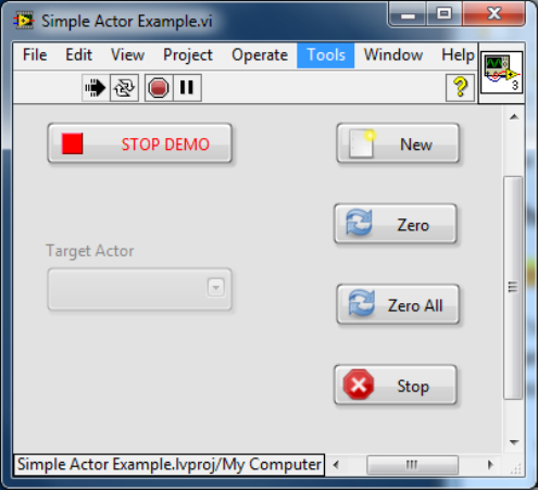
2. Open and run Simple Actor Example.vi. This is the top level VI that will launch our actors.
3. Click on New. This will launch a single actor.
4. Observe the gauge as it sweeps through its range.
4
5. On Simple Actor Example.vi,click on Zero. Observe that the gauge on the actor’s front panel
goes to zero, and then resumes sweeping. This is an example of the top level application
sending a message to an actor.
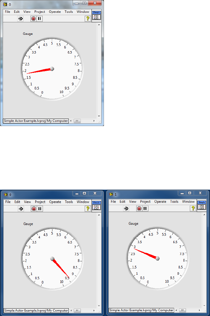
6. On Simple Actor Example.vi, click on New. This will launch a second instance of the actor.
Note that the new instance has a different title bar, and a different gauge value from the first
actor, but it shows the same sweep behavior.
7. On Simple Actor Example.vi, click the Target Actor menu ring, and select 1.
8. Click Zero. Note that the gauge on actor 1 reset to zero, but the gauge on actor 0 did not. This
demonstrates that we can send messages to a single actor, without affecting other actors, even
when the other actors are of the same actor class.
9. Click Zero All. Note that the gauges on both actors reset to zero. We can send the same
message to more than one actor, and both will respond.
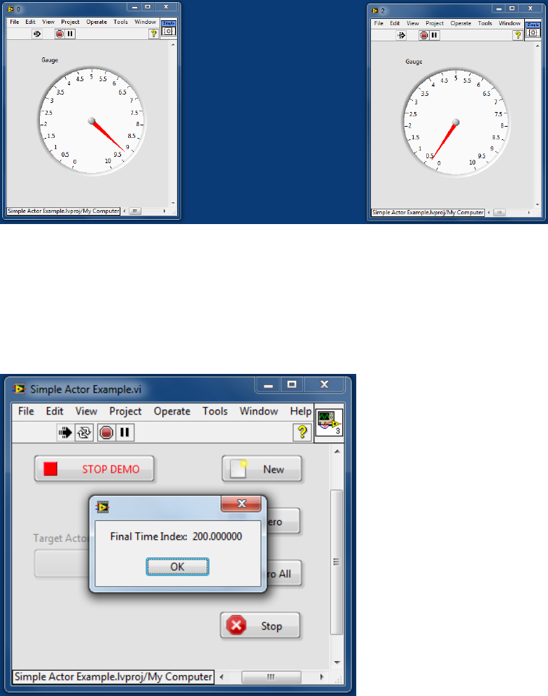
10. Click New to launch a third instance of the actor.
5
11. Click Stop. Note that only the panel for actor 1 disappears because that is the one currently set
in our Target selector. We can stop actors independently.
12. Note that a dialog box appears that displays a Final Time Index. When an actor stops, it sends a
message to its owner - a last acknowledgement that contains the final state of the actor (in this
case, the time index used to generate the value displayed in the actor’s gauge). Note that the
gauges of the remaining actors keep running while this dialog box is displayed. Every actor is
independent, making it easy to write applications where user interfaces remain responsive even
when other tasks are executing. Click OK to dismiss the dialog box.
13. Click STOP DEMO. Note that Simple Actor Example.vi stops, and the panels for both
remaining actors close. Note also that no Final Time Index dialogs appear – this example
chooses to ignore messages from its actors during shutdown.
Take a moment to consider how you would write this application without the Actor Framework.
How do you currently write applications with multiple, parallel processes?
6
How do you manage message traffic in your parallel systems?
How do you launch multiple copies of the same process?
How do you keep your UI responsive to the user while other operations are executing?
These are common challenges for large systems developed in LabVIEW. Actor Framework gives us a
set of standard tools for addressing these challenges that minimizes software errors and creates
opportunities for code reuse.
The Challenge
In this guided example, we will build an application to control an evaporative cooler. The finished
application will be a simplified version of the Feedback Evaporative Cooler sample project that ships with
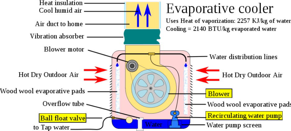
LabVIEW 2012. An evaporative cooler is a simple device that uses water evaporation to cool air. Such
coolers are used as low-cost solutions for home cooling in hot, dry climates like the American Southwest,
and similar devices appear throughout industry. A schematic of such a cooler is shown in Figure 1.
Figure 1: An Evaporative Cooler
By Nevit Dilman (Own work) [CC-BY-SA-3.0 (http://creativecommons.org/licenses/by-sa/3.0)], via Wikimedia Commons
An evaporative cooler contains three distinct subsystems:
1. a water reservoir, where water level is maintained by a valve,
2. a pump, which distributes water over the sponge-like evaporative pads, and
3. a fan or blower, to force the cool moist air into the home.
Water distributed over the pads drips back into the water reservoir, so the pump does not actually empty
the reservoir. However, evaporation will deplete the reservoir over time, even if the cooler is not running.
Although the system could be controlled manually by an operator, with separate switches to turn on the
pump and fan, we want to write a controller that will maintain a more-or-less constant temperature without
human interaction.
Our controller must do the following:
7
1) Control the water level in the reservoir, independent of any other system operation
a) Open a valve to add water to the reservoir when the water level drops below a defined low level
b) Close the water valve when the water level reaches a defined high level
2) Control the temperature
a) Turn on the cooler when the inside temperature reaches a high limit
i) Turn on the pump to wet the pads for some interval and then
ii) Turn on the fan (pre-wetted pads provide more effective cooling)
b) Turn the cooler off when the temperature reaches a low limit of (high limit minus five degrees)
3) Continuously display inside temperature, pump status, and fan status to the operator
4) Allow the operator to change the high limit used to turn on the cooler through a user interface.
To make things more interesting, we will assume that the controller is for an industrial cooler, with the
following additional requirements:
5) The fan will be a dual fan system, with fault detection. If a fault is detected while the primary fan is
running, the cooler will stop the primary fan and start a secondary fan.
6) If a fault in the secondary fan is detected while it is running, the cooler will stop the secondary fan,
and restart the primary fan, provided the primary fan is no longer in a fault state.
7) The cooler will operate with or without a user interface, to facilitate using the cooler system as part of
a larger application.
The Solution Design
To solve this problem, we are going to create a series of software modules, each of which will have its
own independent task on which to work. We call these modules “actors”, and each type of actor will be
defined by a LabVIEW class. The actors will have a limited ability to communicate with each other. The
communication is deliberately limited in order to create a system where it is possible to state with certainty
where certain messages originate. That leads to an application that is easier to debug and to modify
without worrying about breaking a little-known connection between modules.
The Actor Framework defines the ancestor Actor.lvclass from which all actor classes inherit. It defines the
communication mechanism that the actors use. It gives us a structure we can use to understand the
program architecture, which is often bewildering in unstructured-but-highly-parallel applications.
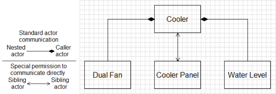
Here is a module diagram for a cooler system based on the Actor Framework. It shows the relationships
between the modules we will write.
8
Figure 2: Cooler Controller Implemented in Actor Framework
This is the communications graph. See Figure 3 for the inheritance tree of the classes.
The main object in this system is an instance of Cooler.lvclass. Cooler controls a Dual Fan system
(Dual Fan.lvclass) and a Water Level controller (Water Level.lvclass), and communicates with a user
interface (Cooler Panel). Cooler is responsible for the control logic for starting/stopping the cooler
hardware, and creating/destroying its software components. Since our pump is a simple on/off device with
no feedback, Cooler will manage it directly.
Dual Fan.lvclass manages a pair of fans, including detecting and managing fan faults.
Water Level.lvclass monitors a water level sensor and controls the valve to add water to the cooler’s
reservoir.
Cooler Panel.lvclass is the user interface. It shows the current status of the fan system and water
pump, and the outside temperature. It has a user control for desired temperature.
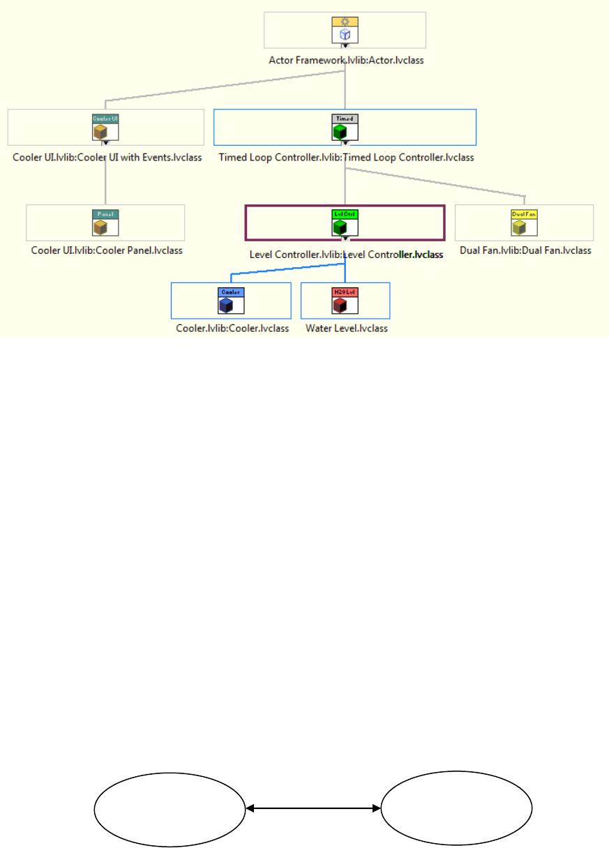
We will build the system on a set of common ancestor classes. Each adds control logic that is shared by
other classes in the system. Timed Loop Controller.lvclass implements the timed polling scheme that
Dual Fan, Water Level, and Cooler will use to read inputs from system hardware. Level
Controller.lvclass implements logic for a simple limit/deadband control scheme used by Water Level and
Cooler. Cooler UI with Events.lvclass implements an interface for communicating with user interface
actors.
9
Figure 3: Class Hierarchy of the Cooler Controller
Actors communicate by exchanging messages over queues. Each message is defined by a LabVIEW
class. Actor Framework includes Message.lvclass; all message classes inherit from this common
ancestor. A message class consists of the data to be transmitted (if any) and some code that invokes a
method of the receiving actor. In the course of the exercise, we will build several message classes to
manage the interactions between the modules of our cooler system.
The Exercise
You will find the project file for this exercise at <Desktop>\Seminars\Actor Framework\Exercise\AF
Hands-On Exercise.lvproj.
In this exercise, we will build each of these actors and the message classes that tie them together. Since
our focus is on Actor Framework and not object-oriented LabVIEW, the project, library structure, and actor
classes (but not most of their methods) have already been created. The exercise also provides VIs that
contain the control logic the various actors will need. You will implement the inheritance structure,
messaging, user interface, and actor startup/shutdown functionality.
For this exercise, we chose to simulate hardware I/O with global variables, as they are both hardware and
platform independent. The global variable VI is Simulation.lvlib:Simulation Data_Global.vi. Another
VI, Simulation.lvlib:Simulation VI.vi, contains the code for running the I/O simulation. You will run this
VI concurrently with your finished example to simulate the response of the system.
Figure 4: Simulation Control
Cooler
Application
Simulation.vi
Global variables

10
Part 1 – Create the Cooler Controller
1. Create the Timed Loop Controller
(10 minutes)
Cooler, Dual Fan, and Water Level each read a process value (PV) and write a control value (CV). We
have decided to make each of these actors poll for their data. Furthermore, we want each instance of
these actors to be able to poll at different rates.
We will define a polling mechanism for all three actors, and encapsulate that behavior in Timed Loop
Controller.lvclass. At this stage, we are only concerned with the mechanism for triggering an update;
the details of how an input value is read and transformed into an output value will be left to the child
classes. Timed Loop Controller is an abstract class, one that exists primarily to define a common
interface for child classes (called concrete classes).
a. Complete the basic class structure
The basic class has been created for you, and can be found in Timed Loop Controller.lvlib:Timed
Loop Controller.lvclass. It has one attribute, Poll Rate. We have provided a write accessor for this
attribute.
1. Modify Timed Loop Controller.lvclass to inherit from Actor.lvclass.
Next, we must create the method VI that will perform the actual update. Since Timed Loop Controller
cannot know the read/write mechanism that will be used, this method is an abstract method – one that will
be overwritten by a child class.
2. Create a new VI from Dynamic Dispatch Template
3. Save the VI as Update.vi. You do not need to modify either the front panel or block diagram.
4. Give the VI the following icon.
5. Save and close the VI when you are done.
b. Create messages for this actor
Now that the basic class structure is complete, we will create the message classes we will need to access
the actor’s methods. In general, you will provide a message class for every public method of your actor.
LabVIEW provides a tool to automate creating message classes for your actors. Most of the message
classes generated by this tool can be used without further modification.
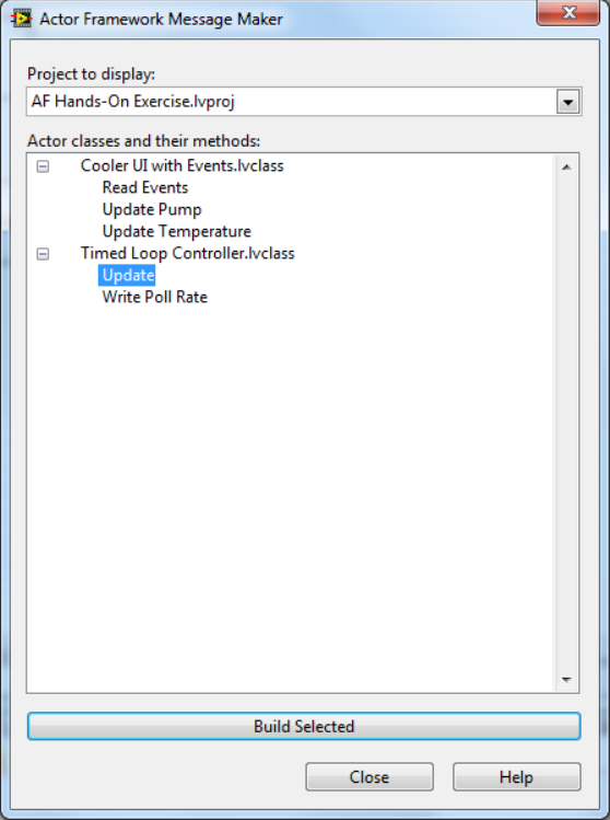
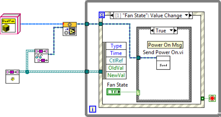
1. From the LabVIEW menu bar, select Tools Actor Framework Message Maker…
2. On the Message Maker dialog, select the project to display. (AF Hands-On Exercise should
be the only one available.)
3. Under Timed Loop Controller.lvclass, highlight the method “Update.” Click on Build
Selected.
11
4. When Message Maker has finished creating VIs, click Close.
The Message Maker will create a new class, Update Msg.lvclass, and open three new VIs in that class:
Update Msg.ctl defines the data the message will carry (in this case, none)
Send Update.vi sends this message to an actor using the actor’s queue
Do.vi is executed by the receiving actor; this Do.vi invokes the Update method of that actor
The VIs are automatically saved by the Message Maker.
5. Close these VIs when you are done inspecting them.
6. Move Update Msg.lvclass to the “Messages For This Actor” folder of Timed Loop
Controller.lvlib.
We recommend grouping an actor and most of the messages it can receive into a common .lvlib file.
Exceptions to this general advice are discussed in the AF documentation. Packaging the actor and
messages together helps programmers keep track of which messages go to which actors. Doing so also
allows us to limit the access scope of a message, and thus limit the list of possible senders of that
message. In this case, we want to guarantee the update timing of a Timed Loop Controller, which we
cannot do if any actor can send the Update message to the controller. Protecting against this possibility
is simple.
12
7. Change the access scope of Update Msg.lvclass to Private.
You will note that we will not provide a message class for Write Poll Rate.vi. As you will see when you
create the actor core, Timed Loop Controller only uses the poll rate when it starts the timing loop, so
changing the rate after startup will not affect execution. Because the poll rate is only set prior to
launching the Timed Loop Controller actor, it does not make sense to provide a message class for this
method.
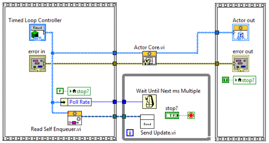
c. Create Actor Core
Our last step is to add polling functionality. We will do this by appending a timing loop to the Actor Core
which will generate Update messages at a fixed interval.
1. Right click on Timed Loop Controller.lvclass and select New VI for Override...
2. Select Actor Core.vi. LabVIEW will create Timed Loop Controller.lvclass:Actor Core.vi.
3. Modify the new VI as shown.
You can find Read Self Enqueuer.vi on the Functions Data Communications Actor Framework
palette.
Note that the ‘stop?’ control must not use a latching mechanical action. If you create ‘stop?’ by right-
clicking on the stop terminal of the while loop, you must remember to manually change the mechanical
action to one of the switch options. Alternately, you can simply drop push button, rocker, or switch
Boolean (but not an OK, Cancel, or Stop button) on the front panel.
4. On the front panel, hide the ‘stop?’ control.
5. Save and close this VI.
6. Right click on Timed Loop Controller.lvlib, and select Save All (this Library).
13
2. Create Level Controller
(10 min)
For Cooler and Water Level, we will need to implement logic to control a binary control state (on or off for
a valve or cooling system) in response to a numeric value (water level or inside temperature). The logic is
the same for both classes:
The controller state will go high if the process value rises above the high limit
The controller state will go low if the process value drops below the low limit
When the controller is initialized, if the process value is between the high and low limits, the
controller state will be set to low
Note that Cooler actors and Water Level actors perform different actions when the controller changes
state, but the fundamental logic is the same. It makes sense to create an abstract parent class that
encapsulates this behavior so that we programmers only have to write the logic of the state changes
once.
We want this actor to use the update mechanism we defined for Timed Loop Controllers, so we will make
our new Level Controller actor inherit from Timed Loop Controller.
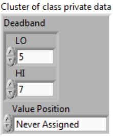
a. Complete the basic class structure
Level Controller.lvclass has been created for you. Level Controller’s attributes include a cluster called
Deadband, which contains a high and a low value. If the variable being controlled falls between these
two values, the controller does not change state. The class private data has already been written for you:
1. Change Level Controller to inherit from Timed Loop Controller.
In order to keep Level Controller an abstract class, we will need to create abstract methods to acquire the
process value and drive the control value. Later, concrete child classes (Cooler and Water Level) will
override these methods.
2. Right click on Level Controller.lvclass, and select New VI from Dynamic Dispatch
Template.
3. Save the new VI as Get New Level.vi.
4. Add the Level numeric indicator to its front panel and connector pane as shown below.
5. Modify the icon as shown. You do not need to modify its block diagram.
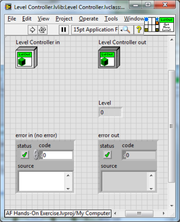
14
6. Save and close the VI.
7. Change its access scope to Protected.
8. Create another VI from Dynamic Dispatch Template.
9. Name the new VI Set Output State.vi.
10. Add the Output State Boolean control to its front panel and connector pane as shown below.
11. Modify the icon as shown. You do not need to modify its block diagram.
15
12. Save and close this VI.
13. Change its access scope to Protected.
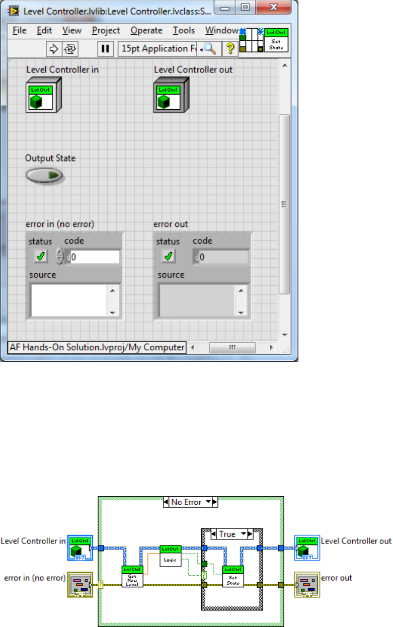
Now that we can interact with our process and control values, we need to provide the control logic. We
do this by overriding the Update method. Remember that the Update method of Timed Loop defines the
action to take every time the time interval elapses.
14. Create a new VI for Override, and select Update.vi.
15. Replace the block diagram with the following.
16
State Logic.vi is a private method of Level Controller, and has been provided for you. It implements the
control logic we defined for this actor.
Since Level Controller is a type of Timed Loop Controller, it will, at a fixed interval, acquire a new process
value from Get New Level.vi and apply control logic to it in State Logic.vi. If State Logic.vi indicates that
the controller’s state must change, Level Controller will use the results to update the control value with
Set Output State.vi.
b. Create messages for this actor
Write Deadband.vi is the only method of this actor that we wish to allow other actors to invoke. A
message class for this method has been provided for you.
1. Right click on Level Controller.lvlib\Messages For This Actor, and select Add File…
2. Select the file <Desktop>\Seminars\Actor Framework\Exercise\Level Controller\Level
Controller Messages\Write Deadband Msg\Write Deadband Msg.lvclass.
3. Save All (this Library) when you are done.
Since Level Controller does not require an additional processing loop, and has no nested actors, we do
not need to override Actor Core.vi.
3. Create Water Level
(5 min)
Water Level is a concrete implementation of a Level Controller. We will use it to guarantee that the water
in our evaporative cooler’s reservoir never falls below a minimum safe level. We need to define how we
acquire our process value and how we set our control value, as neither behavior is specified by the parent
class.
a. Complete the basic class structure
Water Level.lvclass has been created for you.
1. Change WaterLevel.lvclass to inherit from Level Controller.
2. Create a new VI for Override, and select Get New Level.vi.
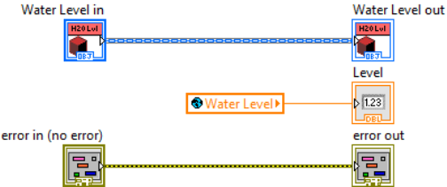
3. Modify the block diagram of Get New Level.vi to look like this. Recall that the global variable
VI is located in Simulation.lvlib, and is called Simulation Data_Global.vi.
4. Create a new VI for Override, and select Set Output State.vi.
5. Modify its block diagram to look like this.
17
Note how Water Level uses the results of Level Controller’s state logic. A logical value of “high”,
associated with a process value above the high limit, is converted into a control value of “low,” which
closes the water valve.
b. Override Stop Core.vi to guarantee safe shutdown
We should make sure the water valve is closed when Water Level shuts down.
1. Create a new VI for Override, and select Stop Core.vi.
2. Add the Water Valve State global from Simulation.lvlib:Simulation Data_Global.vi to the
block diagram, as shown.
3. Wire a Boolean False value to the global variable.
4. Save and close this VI.
c. Test the actor
We have provided you with a VI to test Water Level.
1. Open Water Level Test.vi in the Test VIs folder of the Exercise project.
2. Open Simulation Data_Global.vi in Simulation.lvlib.
3. Start Water Level Test.vi. Note that Water Valve State becomes True.
4. We have set the water level high limit to 7 and the low limit to 5. On Simulation
Data_Global.vi, adjust the value of Water Level, and observe the change in valve state.
5. Set the water level to 4 and stop Water Level Test.vi. Observe that the valve state changes
to False.
6. Close both of these VIs when you are done.
Tip: Make a hardware abstraction layer (HAL)
18
Water Level illustrates one approach to building a hardware abstraction layer. In the preceding exercise,
we used global variables to simulate I/O, but you could very easily write another concrete implementation
of Level Controller that uses DAQ, CompactRIO, or any other hardware. These thin, hardware-specific
inheritance layers can be swapped out at run-time. The Feedback Evaporative Cooler sample project
shows this technique in more detail. For more information on building Hardware Abstraction Layers in
LabVIEW, please visit: http://zone.ni.com/devzone/cda/epd/p/id/6307
4. Create Dual Fan
(20 min)
Dual Fan is a concrete implementation of a Timed Loop Controller. It manages the I/O and logic
operations to control a pair of fans (primary and backup) and respond to hardware faults. When Dual Fan
is off, both fans are idle. When Dual Fan is on, the following rules apply:
If no fan faults are detected, turning on Dual Fan starts Fan A.
If a fan fault is detected for a running fan, Dual Fan will stop the faulted fan and attempt to start
the other fan.
If both fan faults are detected, Dual Fan will stop both fans.
If the fan is on and both fans are faulty, as soon as one is fixed, that one will start running.
a. Complete the basic class structure
Dual Fan.lvlib:Dual Fan.lvclass has been created for you, along with some of its methods.
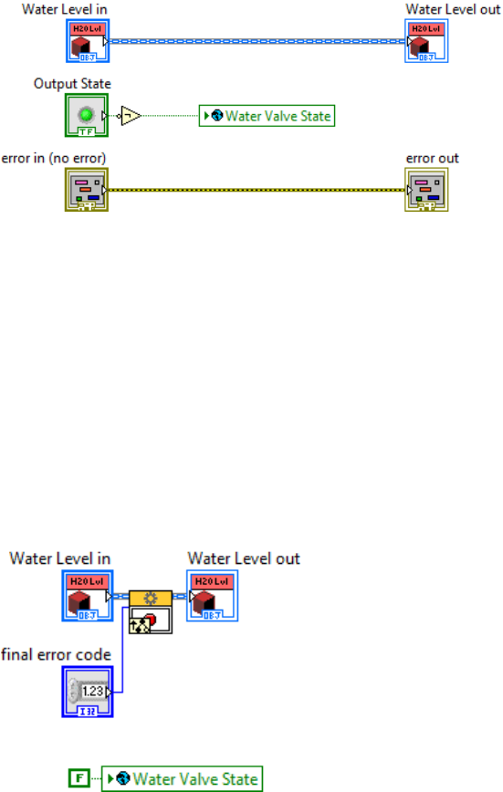
1. Open Dual Fan.ctl and examine the class’s attributes.
2. Open Power On .vi and inspect its block diagram. This method contains the logic to start
the dual fan system.
19
3. Close this VI when you are done.
4. Open Power Off.vi and inspect its block diagram. This method contains the logic to stop the
dual fan system.
5. Close this VI when you are done.
We want to use the update mechanism we defined for Timed Loop Controllers to drive our new Dual
Fan class. We will change Dual Fan to inherit from Timed Loop Controller, and provide a concrete
implementation of Update.vi that implements the desired control logic.
6. Change Dual Fan to inherit from Timed Loop Controller.
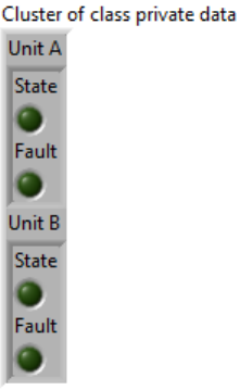
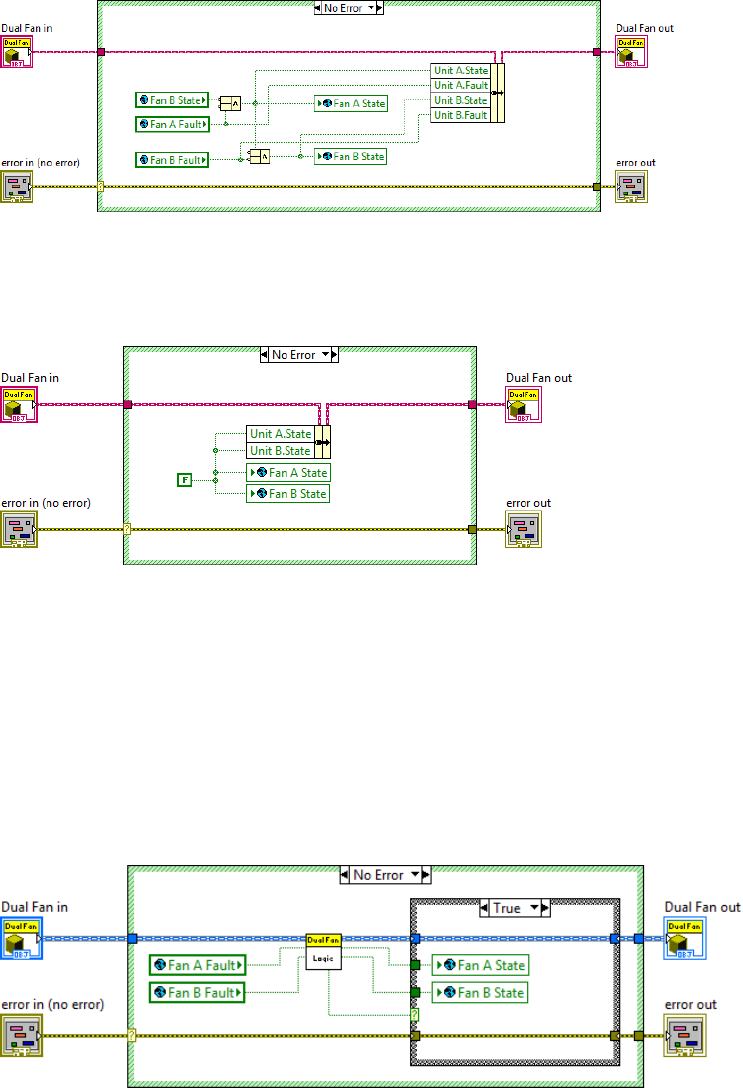
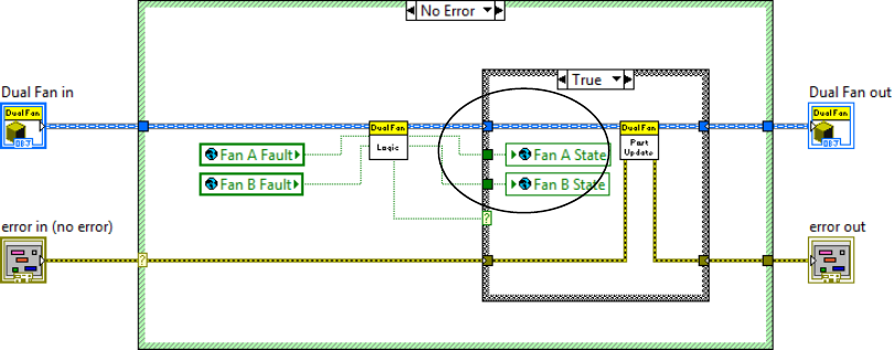
7. Create a Create a new VI for Override, and select Update.vi.
8. Modify the VI’s block diagram as shown. Recall that the global variables can be found on
Simulation.lvlib:Simulation Data_Global.vi.
State Logic.vi is a private method that implements the control logic we have defined for this actor. It has
been provided for you.
b. Create a stop core to guarantee safe shutdown
We should make sure to stop the fan hardware when Dual Fan shuts down.
20
1. Create a new VI for Override, and select Stop Core.vi.
2. Modify the block diagram as shown.
3. Save and close this VI.
c. Create messages for this actor
1. Use the Actor Framework Message Maker (Tools Actor Framework Message Maker…) to
create message classes for Power On and Power Off. You can create more than one
message class at a time. Ctrl-click on a method to add it to your selections, or shift-click on
two methods to select all methods in a range. You may only select methods for a single actor
at a time. If you select an actor, you can create messages for all of its public methods.
2. Once you have made your selections, click on Build Selected.
21
3. Close the Message Maker when it is done.
4. Move Power On Msg.lvclass and Power Off Msg.lvclass into Dual Fan.lvlib\Messages For
This Actor.
5. Save All (this Library) when you are done.
Dual Fan does not require an override of Actor Core.vi.
d. Test the actor
We have provided you with a VI to test Dual Fan. You will need to complete this VI.
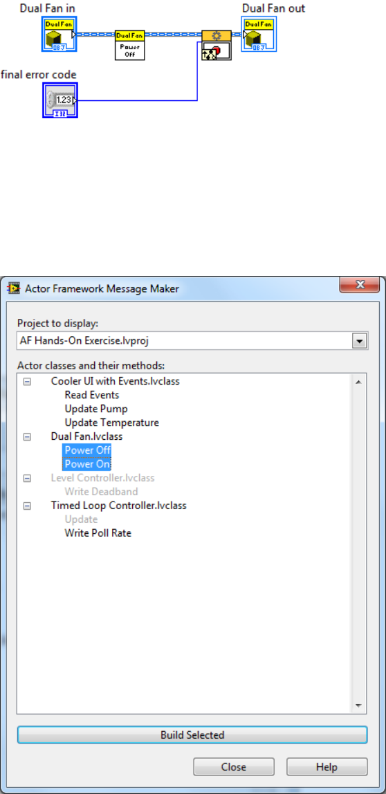
1. Open Dual Fan Test.vi in the Test VIs folder of the Exercise project, and go to its block
diagram.
2. Go to the Fan State case of the event structure. Add Send Power On.vi to the True case of
the case structure.
3. Wire the Caller-To-Actor Enqueuer to its enqueuer input.
4. Add Send Power Off.vi to the False case of the case structure.
5. Wire the Caller-To-Actor Enqueuer to its enqueuer input.
22
6. Save your changes to this VI.
7. Open Simulation.lvlib:Simulation Data_Global.vi.
8. Start Dual Fan Test.vi, and click Fan State to turn on the Dual Fan. Note that Fan A State
becomes True.
9. Toggle Fan A Fault and Fan B Fault, and observe the change in fan states.
10. Stop Dual Fan Test.vi, and close both of these VIs when you are done.
5. Create Cooler
(20 min)
We are now ready to create Cooler.lvclass. Like Water Level, Cooler is a concrete child class of the
Level Controller. Cooler is responsible for managing the lifetimes of Dual Fan and Water Level. Cooler
must initialize and launch these two actors, and must tell them to stop when Cooler is stopped.
Dual Fan and Water Level are examples of nested actors. An actor that launches nested actors is the
caller of those actors.
a. Complete the basic class structure
Cooler.lvlib:Cooler.lvclass has been created for you.
1. Change Cooler to inherit from Level Controller.
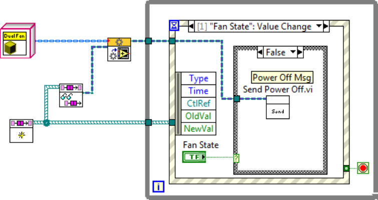
2. Open Cooler.ctl, and add three instances of Message Enqueuer.lvclass to Cooler’s private
data. Message Enqueuer.lvclass can be found in Actor Framework.lvlib.
23
3. Name the new objects Dual Fan, Water Level, and UI. (We will use UI later, when we write
the user interface).
4. Save and close Cooler.ctl.
Since Cooler is a concrete implementation of Level Controller, it must override the Get New Level.vi and
Set Output State.vi methods.
An override VI has been provided for Get New Level.vi. This VI obtains a new indoor temperature value
from the simulator, and is substantially similar to the override we made for Water Level.
An override VI has also been provided for Set Output State.vi. We need to modify it to implement the
delay between when the cooler’s pump turns on, and when the fans start. We will implement this feature
using the Time-Delayed Message. The Time-Delayed Message is not actually a message class, but is
rather a set of VIs that allow you to specify a message to be sent to an actor after some specified delay
period. We will use these VIs to complete Set Output State.vi.
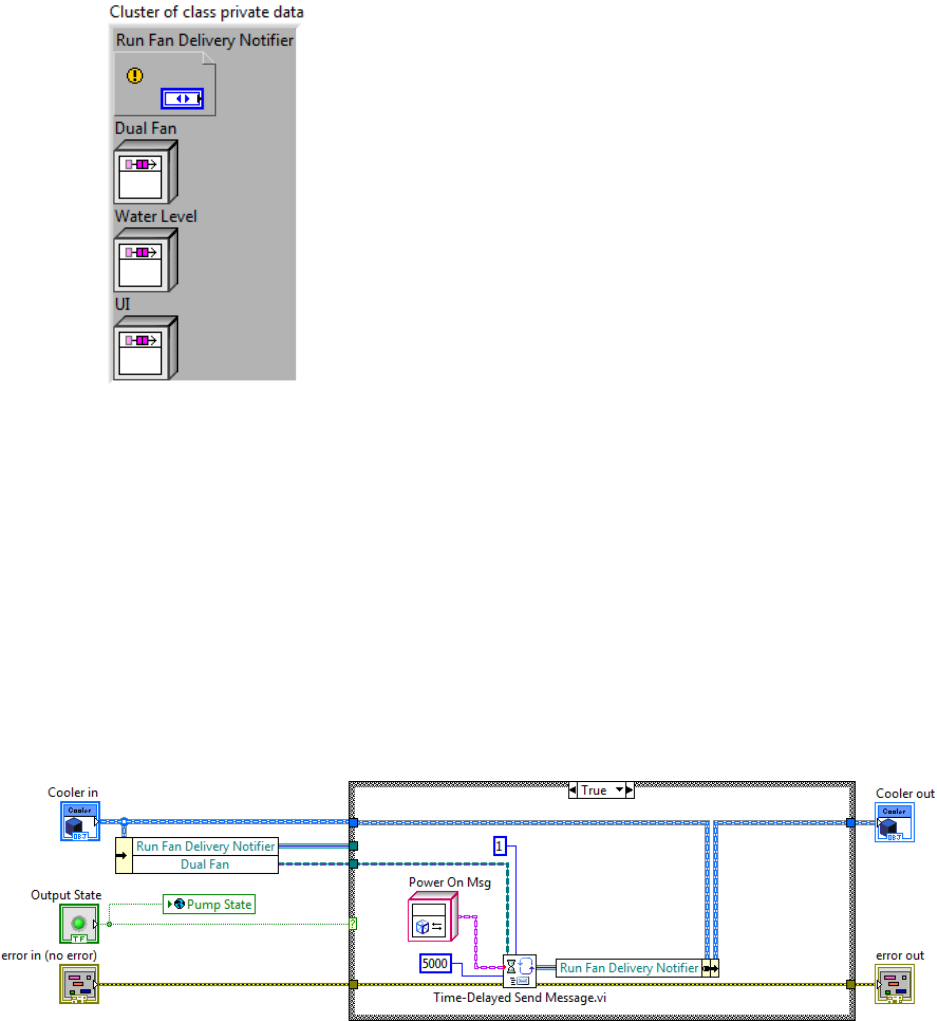
5. Open Set Output State.vi, and modify the block diagram as shown.
When the output state transitions to True, we want to send the Power On message to Dual Fan.
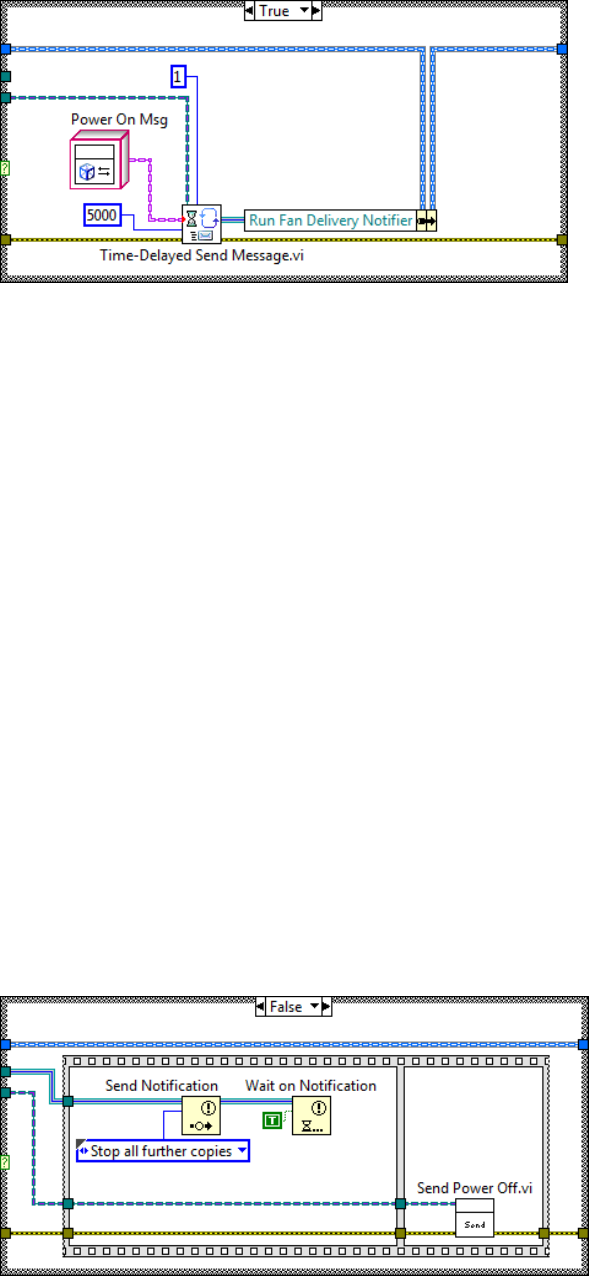
24
6. Add an instance of Dual Fan.lvlib:Power On Msg.lvclass to the True case.
7. Add Time-Delayed Send Message.vi to the True case, and wire it as shown. Time-Delayed
Send Message.vi can be found on the Functions Data Communication Actor Framework
Advanced palette.
We want to configure Time-Delayed Send Message.vi to send one copy of the message after a 5
second delay.
8. Wire a value of 5000 to the Milliseconds to Wait input of Time-Delayed Send Message.vi.
9. Wire a value of 1 to the # Copies input.
The Time-Delayed Message uses a notifier to manage the time delay. We can use the notifier to manage
the delivery of any remaining, unsent messages.
When the output state transitions to False, we want to send the Power Off message.
10. Add Dual Fan.lvlib:Power Off Msg.lvclass:Send Power Off.vi to the False case, and wire
it as shown.
We also need to abort the time-delayed message, should the output state transition to False during our
delay period. Sending the “Stop all further copies” notification will cancel any pending message and
destroy the notifier. We should wait for the notifier to be destroyed before sending the Power Off
message. By waiting, we guarantee that we cannot send a Power On message after we send Power Off.
11. Add a Send Notification function to the False case, and wire it as shown.
12. Add a Wait on Notification, and wire it as shown. Wire a Boolean “True” to the ignore
previous (F) input.
25
13. Save and close the VI.
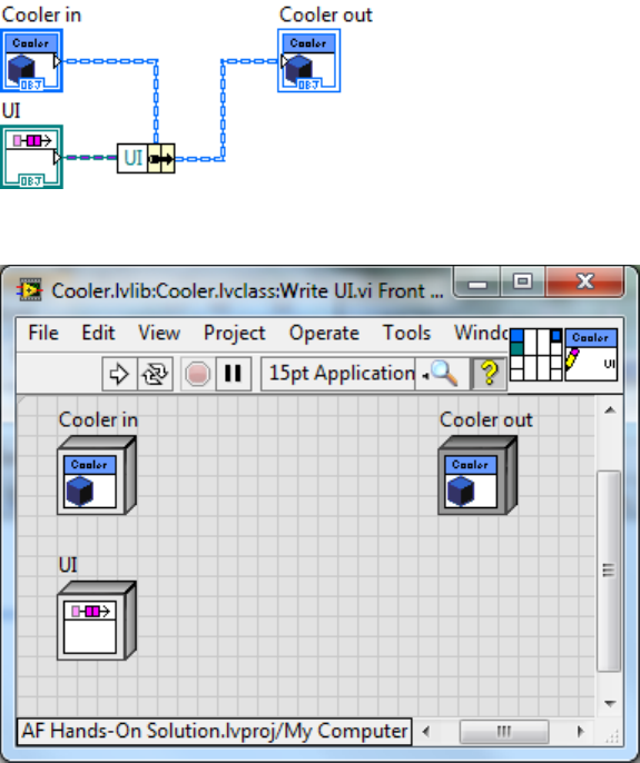
14. Create a new VI for Data Member Access. Select a static accessor for the UI attribute, select
write access, and uncheck “Include error handling terminals.” The VI will look like this when
you are done.
15. Save and close this VI.
b. Create messages for this actor
1. Use the Actor Framework Message Maker to create a message class for Write UI.
2. Move the new message class to Cooler.lvlib\Messages For This Actor.
3. Save All (this Library) when you are done.
We will need this accessor method and message when we implement the user interface.
c. Create Actor Core
Cooler must manage the lifetimes of its parts, Dual Fan and Water Level. This means that we must add
code to create and launch these actors. Launching nested actors is a function of Actor Core.vi.
1. Create a new VI for Override, and select Actor Core.vi.
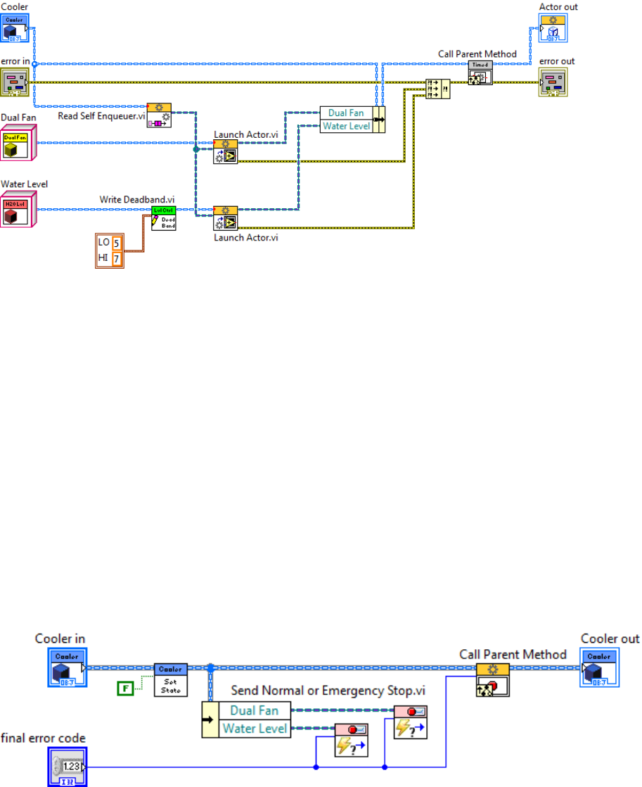
26
2. Modify the block diagram to look like this.
Recall that Write Deadband.vi is a Level Controller method. Launch Actor.vi is a method of
Actor.lvclass, which can be found in Actor Framework.lvlib or in the Actor Framework palette.
Note that Dual Fan and Water Level must be launched before Call Parent Method. This ensures that
Dual Fan and Water Level are both ready to receive messages from Cooler before Cooler can send any
messages.
Note also that we are setting default deadband values for our two Level Controllers before launch. An
actor is a normal LabVIEW object; you can invoke any of its methods or properties as needed prior to
calling Launch Actor.vi.
d. Create behavior to correctly stop nested actors
An actor is responsible for destroying anything it creates. This includes objects such as its queue or any
of its nested actors. For nested actors, this is done in an override of Stop Core.vi.
1. Create a new VI for Override, and select Stop Core.vi.
2. Modify its block diagram as shown.
3. Close the VI and Save All (This Library)
Send Normal Or Emergency Stop.vi is a method of Stop Msg.lvclass, which can be found in Actor
Framework.lvlib or in the Actor Framework palette.
27
e. Test the actor
The example includes a VI to test Cooler. You must first add it to the project.
1. Add the file <Desktop>\Actor Framework\Exercise\Support\Cooler Test.vi to the Test VIs
folder of the Exercise project.
2. Open Cooler Test.vi.
3. Inspect the VI’s block diagram.
4. Open Simulation.lvlib:Simulation Data_Global.vi.
5. Start Cooler Test.vi.
6. Adjust the indoor temperature and observe the change in pump and fan states. Recall that
there is a five second delay after the pump turns on before the fan starts.
7. Toggle the fan fault Booleans and watch the change in fan states.
8. Adjust the water level, and watch the change in the state of the water valve.
9. Stop Cooler Test.vi, and close both of these VIs when you are done.
This concludes Part 1. At this point, we have implemented all of the functionality of an evaporative cooler
controller except for the user interface. Our solution is both modular and parallelized. Actor Framework
made this task easier in many key ways.
We wrote a single update mechanism (Timed Loop Controller) that we were able to reuse for
three separate processes (Water Level, Dual Fan, and Cooler).
We wrote a single deadband controller (Level Controller) that we were able to reuse for two
processes (Water Level and Cooler).
We did not have to write code to manage message traffic or launch parallel processes.
We used the Actor Framework Message Maker to easily generate messages for our actors.
If time permits, you may proceed to Part 2, where you will build the user interface for the cooler controller.
28
Part 2 – Create the User Interface
Now that we have completed our software model of the system, we can turn our attention to the user
interface. Recall our requirements:
Display inside temperature, pump status, and fan status to the operator
Allow the operator to set the temperature (the high limit) at which to turn on the cooler
Allow the cooler to operate with or without a user interface
The most robust solution that meets all of our requirements is to create a separate UI actor and
messaging infrastructure. This decouples the lifetimes of Cooler and Cooler Panel, so we can launch and
stop them independently, write new panels without risk to the cooler’s execution logic, and reuse our user
interface with a different software model (i.e. a different type of cooler or any device that sends the same
messages).
To facilitate these benefits, it is sometimes helpful to start with an abstract user interface layer, from which
our actual UIs will inherit. This abstract layer will typically include all of the messages supported by the UI
class family, and may include some common support code. Cooler will be able to send status messages
to any child of this abstract class.
1. Create Cooler UI with Events
(20 min)
In this example, the abstract class is Cooler UI.lvlib:Cooler UI with Events.lvclass. Cooler UI with
Events receives messages from Cooler, and translates those messages into user events that can be
received by an event structure. Children of this class will register for those events, and update their front
panels when they receive messages. Cooler UI with Events has been created for you. The class already
inherits from Actor.lvclass. It includes a read accessor method that returns a cluster of user events.
a. Complete the basic class structure
We will start by creating the set of user events. We wish to guarantee that the event refnums are
available as soon as we create an instance of this or any child class, so the best place to create the
events is in an override of Actor.lvclass:Pre Launch Init.vi. Launch Actor.vi invokes this protected
method just prior to launching Actor Core.vi. Note that you cannot launch a nested actor inside Pre
Launch Init.vi; however, any other initialization operations should occur here.
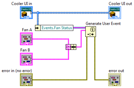
1. Create a new VI for Override, and select Pre Launch Init.vi.
2. Modify the VI’s block diagram as shown.
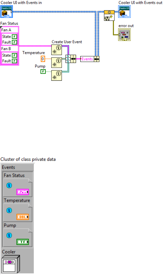
29
The Fan Status cluster has been built for you. It has been saved as Status.ctl, and is a member of
Cooler UI with Events. A cluster of user events matching the cluster you will create is already part of the
class attributes.
Cooler UI with Events will need to send messages to Cooler, so it will need to hold a copy of Cooler’s
enqueuer as an attribute.
3. Open Cooler UI with Events.ctl
4. Add a Message Enqueuer object to the cluster of class private data.
5. Rename the Message Enqueuer “Cooler.”
6. Save and close Cooler UI with Events.ctl.
7. Create a VI for Data Member Access for Cooler, and select write access.
8. The VI should look like this when you are done.
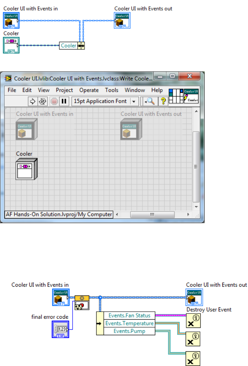
30
9. Save this VI with its default name, Write Cooler.vi.
Having created a set of references, Cooler UI with Events must destroy them. The proper place to do this
is in Stop Core.vi.
Create a new VI for Override, and select Stop Core.vi. Add the following to its block diagram.
10. Save and close this VI.
Next, we will create a method to change the Cooler’s target temperature.
31
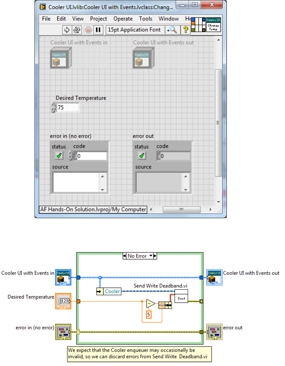
11. Create a new VI from Static Dispatch Template.
12. Modify the VI’s front panel, connector pane, and icon as shown.
13. Add the following code to its block diagram. Note that Send Write Deadband.vi is part of
Write Deadband Msg.lvclass, which you created for Level Controller.
32
Do not wire the error cluster through Send Write Deadband.vi. We want to allow for the possibility that
the Cooler might not be present at run time. This would be the case, for example, if we choose to test our
UI independently of the software model. This may cause issues if you have automatic error handling
enabled, or use VI Analyzer to inspect your code, so consider explicitly wiring the error output of Send
Write Deadband.vi to the case structure and documenting why you are not propagating the error any
further, as shown.
For the purpose of this example, we have decided to always set the low limit to five degrees below the
high limit
14. Save this VI as Change Desired Temperature.vi
Next, we will create a VI to update the fan display.
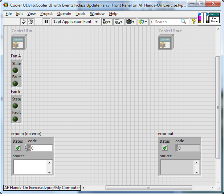
15. Create a new VI from Dynamic Dispatch Template.
16. Modify the VI’s front panel, connector pane, and icon as shown. For the Fan A and Fan B
inputs, use Unit Data.ctl, in the Support VIs folder.
17. Add the following code to the VI’s block diagram.
33
18. Save this VI as Update Fan.vi.
Methods to update the pump and temperature displays have already been provided. They are similar to
Update Fan.vi.
b. Create messages for this actor
Use the Actor Framework Message Maker to create message classes for
1. Change Desired Temperature
2. Update Fan
3. Update Pump
4. Update Temperature
5. Write Cooler
Recall that you can create more than one message at a time.
6. Move these messages to Cooler UI.lvlib\Messages For This Actor. Save All (this Library)
when done.
2. Modify Cooler Class to Send Messages to Cooler UI
(5 min)
Now that we have defined a message set for our user interfaces, we can revisit Cooler, and modify it to
send status updates. In the previous section, we created several messages for Cooler UI with Events.
We will modify three methods of Cooler.lvclass to send one of those messages to Cooler UI with
Events.lvclass.
1. Open Cooler.lvclass:Get New Level.vi.
2. Modify the VI’s block diagram as shown. Recall that Send Update Temperature.vi is a
member of Cooler UI with Events.lvlib:Update Temperature Msg.lvclass.
34
3. Do not propagate the error cluster through Send Update Temperature.vi, but consider
wiring the error output to the border of the case structure, and including a comment.
4. Save and close this VI.
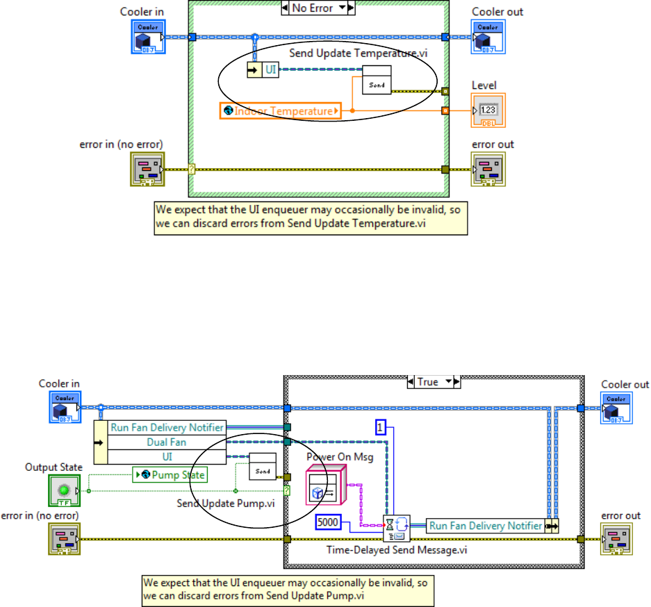
5. Open Set Output State.vi.
6. Modify the VI’s block diagram as shown. Consider propagating the error output from Send
Update Pump.vi and including a comment.
7. Save and close this VI.
8. Open Update Fan Status.vi.
9. Modify the VI’s block diagram as shown. Consider propagating the error output from Send
Update Fan.vi and including a comment
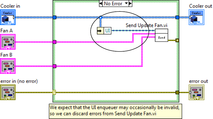
35
10. Save and close this VI.
3. Modify Dual Fan to send a message to Cooler
(5 min)
In the previous section, we created a Cooler method that sends the status of the Dual Fan system to our
user interface. Cooler, however, does not currently have access to that status information. We need to
modify Dual Fan to update Cooler whenever the status of its fans changes.
a. Create the message for the cooler
1. Use the Actor Framework Message Maker to create a message for Cooler.lvclass:Update
Fan Status.vi
2. Move this class to Cooler.lvlib\Messages For This Actor.
3. Save All (this Library) when you are done.
b. Modify Dual Fan
We want Dual Fan to notify Cooler whenever its fan status changes. This can happen when the Power
On, Power Off, or Update methods are invoked. It makes sense to create a method VI to encapsulate the
messaging behavior. We have provided the method, Post Update.vi, for you.
1. Open Dual Fan.lvclass:Post Update.vi.
2. Modify the VI’s block diagram as shown.
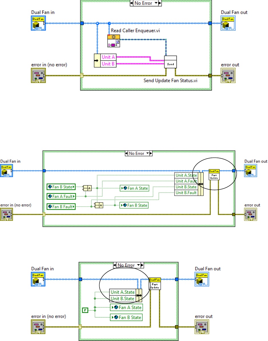
36
Read Caller Enqueuer.vi is a member of Actor.lvclass, which can be found in Actor Framework.lvlib.
3. Save your changes.
You will now add this method to Power On.vi, Power Off.vi, and Update.vi.
Open Power On.vi. Modify its block diagram as shown.
4. Save and close the VI.
5. Open Power Off.vi.
6. Modify the VI’s block diagram as shown.
7. Save and close the VI.
8. Open Update.vi.
9. Modify the VI’s block diagram as shown.
37
10. Save and close the VI.
4. Create the Cooler Panel
(15 min)
Cooler Panel is a concrete child class of Cooler UI with Events. It builds on the functionality of its parent
to provide the actual user interface.
Cooler Panel.lvclass has been created for you.
1. Change Cooler Panel to inherit from Cooler UI with Events.lvclass.
2. Create a new VI for Override, and select Actor Core.vi.
3. Open the new VI’s block diagram.
We have provided the user interface elements for you in an example VI.
4. Open Cooler Panel UI Components.vi, located in the Support VIs folder.
5. Open this VI’s block diagram.
6. Copy the entire contents of the block diagram of Cooler Panel UI Components.vi to the
block diagram of Actor Core.vi. (This will also copy the front panel elements for you).
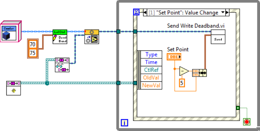
7. Modify Actor Core.vi to look like this (a detailed sequence of steps is included below):
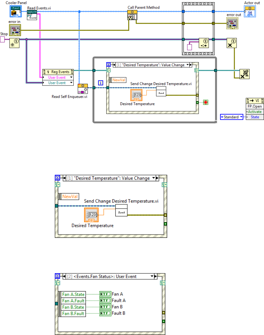
38
Read Self Enqueuer.vi is a method of Actor.lvclass. Recall that Read Events.vi is a method of Cooler
UI with Events.lvclass.
7a. Wire the Events output of Read Events.vi to a new input of Register For Events .
7b. Modify the Desired Temperature value change event as shown.
Recall that Change Desired Temperature is a message for Cooler.
7c. Link the following event to the Fan Status event.
7d. Link the following event to the Temp event.
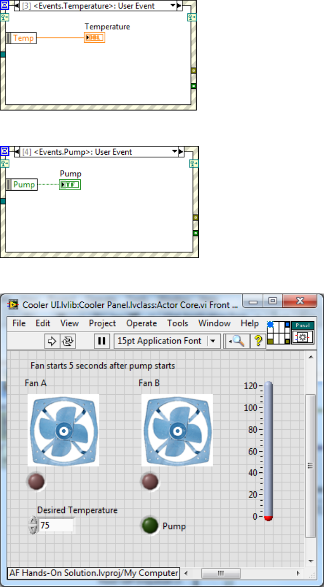
39
7e. Link the following event to the Pump event.
7f. Arrange the front panel of Actor Core.vi to look like this.
7g. Save Actor Core.vi.
40
5. Create Application Launcher
(5 min)
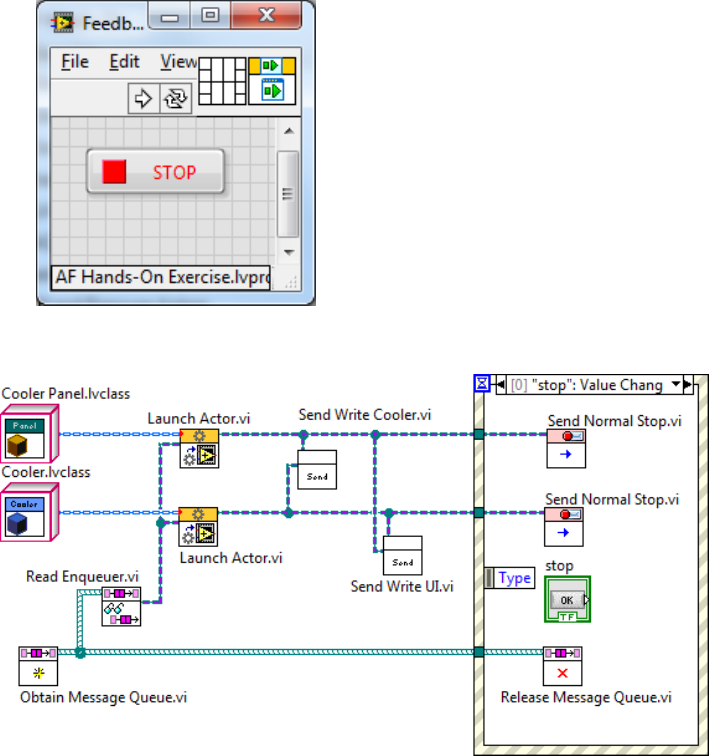
Finally, we will create a small top-level VI to launch our actor system.
1. Create the following VI. Save it as Exercise\Feedback Evaporative Cooler Demo.vi
You will find most of the VIs you will need in Actor Framework.lvlib.
Obtain Message Queue.vi, Read Enqueuer.vi, and Release Message Queue.vi are methods of
Message Queue.lvclass.
Send Normal Stop.vi is a method of Stop Msg.lvclass. You can send a Stop Msg to any actor; that actor
will shut down and return a Last Ack message to its caller.
Launch Actor.vi is the only public method of Actor.lvclass.
Note that this top-level application handles the exchange of queues between Cooler and Cooler Panel.
This step is required to allow the two actors to exchange messages.
41
2. Save this VI.
3. Open and run Simulation.lvlib:Simulation.vi, and then
4. Run Feedback Evaporative Cooler Demo.vi.
You should see the pump turn on, followed by the primary fan. The indoor temperature will fall to 70
degrees, at which point the fan will stop and the temperature will start to rise again. If you wish, you can
open Simulation.lvlib:Simulation Data_Global.vi, and observe the operation of Water Level.
This concludes Part 2. We have implemented a user interface for our cooler controller that displays the
state of the system and allows operators to set desired temperature. We can run the cooler with or
without the user interface. We can also create new user interfaces by inheriting from Cooler UI with
Events, and use whatever interface suits our current needs.
Thank you for participating in the Actor Framework Hands-On session. Please join the online community
for the framework at
http://ni.com/actorframework
