ALPS Large Fragment Surgical Technique
2016-03-31
: Pdf Alps Large Fragment Surgical Technique ALPS_Large_Fragment_Surgical_Technique 3 2016 pdf
Open the PDF directly: View PDF ![]() .
.
Page Count: 24
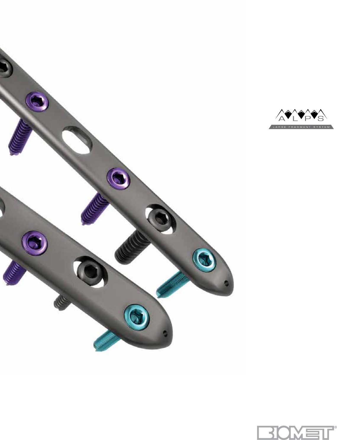
Large Fragment
Plating System
Surgical Technique
2

3
Contents
Design Rationale .......................................................................................................................................................... 4
Introduction .................................................................................................................................................................. 5
Interfragmentary Fixation ............................................................................................................................................. 6
Insertion of a 4.5 mm Cortical Screw .................................................................................................................... 7
Insertion of a 6.5 mm Cancellous Lag Screw ........................................................................................................ 8
Plate Selection ............................................................................................................................................................. 9
Plate Insertion ............................................................................................................................................................ 10
Use of the Tension Device ......................................................................................................................................... 10
Neutral Insertion of a 4.5 mm Non-Locking Cortical Screw in a Compression Slot ................................................. 11
Dynamic Compression/Eccentric Insertion of a 4.5 mm Non-Locking Cortical Screw in a Compression Slot ........ 12
Insertion of a 4.5 mm Locking Cortical Screw or 5.5 mm Cancellous Screw in a Threaded Hole ........................... 13
Insertion of a 4.5 mm Non-Locking Cortical Screw in a Threaded Hole ................................................................... 14
Insertion of a 6.5 mm Non-Locking Cancellous Screw into any Plate Hole ............................................................. 15
Optional Instruments and Implants ............................................................................................................................ 16
Case Layout ............................................................................................................................................................... 17
Implant Trays .............................................................................................................................................................. 18
Instrument Trays ......................................................................................................................................................... 21
Indications and Contraindications ............................................................................................................................. 24
A.L.P.S.
™
Large Fragment Plating System
4
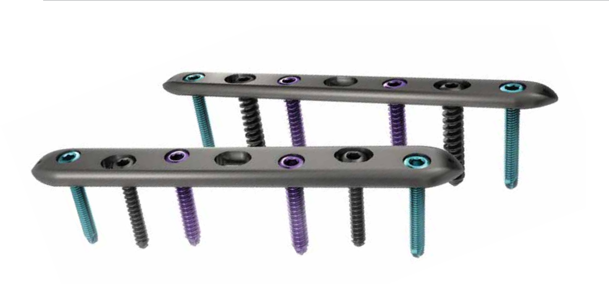
Locked screw fixation
The round threaded screw holes accept screws that will
lock into position when tightened to establish a fixed angle
construct for strong fixation in osteopenic bone or when
optimal screw purchase is required.
The Biomet Large Fragment System is a titanium plate and screw system that fuses locking screw technology with conventional plating techniques. The set was designed
to maximize treatment options when managing fractures requiring large fragment fixation, as well as, to serve as the core system for additional anatomic implants.
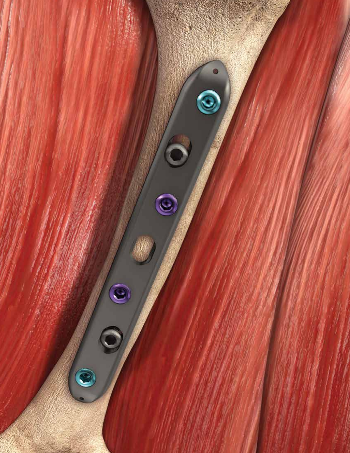
Hybrid Compression Plating
Technology (HCP®) for
compression and locked fixation
Compression screw fixation
The oval screw hole can accept non-locking screws to allow
for up to 90 degrees of axial and 32 degrees of transverse
screw angulation while offering 3 mm of axial compression.
The screws can be positioned and used in compression,
neutral and buttress modes.
A.L.P.S.
™
Large Fragment Plating System

5
Introduction
The Biomet Large Fragment System is a titanium plate and
screw system that fuses locking screw technology with
conventional plating techniques. The set was designed
to maximize treatment options when managing fractures
requiring large fragment fixation.
Indications for Use:
Fixation of fractures of various long bones such as the:
• femur
• tibia
• humerus
The Hybrid Compression Plates are further indicated for
use in fixation of osteopenic bone and fixation stabilization
of nonunions, malunions, and osteotomies.
System Contents:
• 4.5 mm Hybrid Compression Plates (HCP®),
Broad and Narrow
• T - Plates
• L - Plates
• 4.5 mm Cortical Screws, Locking
• 4.5 mm Cortical Screws, Non-locking
• 5.5 mm Cancellous Screws, Locking
• 6.5 mm Cancellous Lag Screws, 22 mm Thread,
Non-locking
• 6.5 mm Cancellous Lag Screws, 40 mm Thread,
Non-locking
• 6.5 mm Cancellous Screws, Full Thread, Non-locking
• 4.5 mm Flat Washers
• 6.5 mm Cupped Washers
• 6.5 mm Flat Washers
4.5 mm Hybrid Compression Plate (HCP®)
Features:
4.5 mm Hybrid Compression Plate (HCP®)
• Uniform hole spacing
• Compression, neutral and buttress screw positions
• Threaded holes for locking screw option
• 90 degrees of axial screw angulation
• 32 degrees of transverse screw angulation
• 3 mm of compression
• Bullet-shaped plate ends for submuscular insertion
• 4 – 14 holes, Narrow Plate
• 6 – 14 holes, Broad Plate
4.5 mm Locking Cortical Screw
• Larger core diameter and thread pitch compared to a
standard 4.5 mm cortical screw
• Self tapping tip minimizes the need for pre-tapping
and eases screw insertion
• Hex drive
• Tapered screw head helps ensure alignment of the
screw head into the plate hole
• Tapered threaded head minimizes screw back-out and
construct pullout
• Available in lengths of 8 – 60 mm in 2 mm increments
and 65 mm
5.5 mm Locking Cancellous Screw
• Hex drive
• Tapered screw head helps ensure alignment of the
screw head into the plate hole
• Tapered threaded head minimizes screw back-out and
construct pullout
• Available in lengths of 26 – 50 mm, 55 – 100 mm
in 5 mm increments
A.L.P.S.
™
Large Fragment Plating System
6
To apply compression across the fracture site, the screw
threads must engage only the far fragment. If the screw
threads engage the near cortex, the fracture will be
distracted, and compression will not be possible. The
4.5 mm cortical screws are generally selected for use in
diaphyseal bone. The 6.5 mm cancellous bone screws are
generally used in metaphyseal bone (Figure 2).
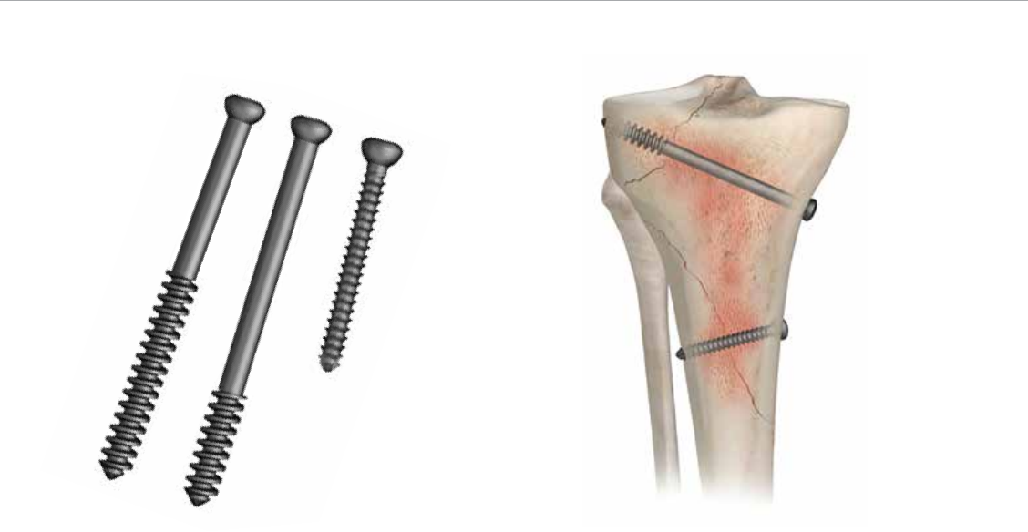
Interfragmentary Fixation
Interfragmentary fixation uses lag screws (Figure 1) to apply
compression across the fracture surface.
Intra-articular and epiphyseal fractures are frequent
applications for interfragmentary fixation.
Figure 1 Figure 2
7
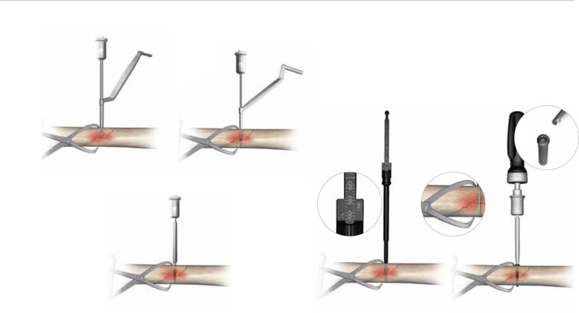
Determine the required screw length by taking a direct
reading from the NL line on the Large Fragment Depth
Gauge (Cat. No. 8162-99-007) (Figure 6).
Note: In hard or dense bone, tap the pilot hole in the far
cortex with the 4.5 mm Cortical Tap (Cat. No. 8242-45-
070) prior to attempting to insert the screw. The 3.2/4.5
mm double drill guide can be used as a tissue protector.
Insert the appropriate length 4.5 mm Cortical Screw (Cat.
No. 8157-45-0XX) screw by hand with the Ratchet Handle
(Cat. No. 2141-24-000) or power drill by using the 4.5 mm
Driver Shank (Cat. No. 8242-19-000) (Figure 7). Always
perform final seating of the screw by hand.
4.5 mm Cortical Screws (Cat. No. 8157-45-0XX)
Reduce the fracture and maintain the reduction with bone
forceps. Drill a gliding hole in the near cortex with the 4.5
mm Drill Bit (Cat. No. 8242-73-000) using the 3.2/4.5
Double Drill Guide (Cat. No. 8241-97-000) (Figure 3)
Note: For oblique fractures, guide the drill bit so it bisects
the angle between a line perpendicular to the plane of the
fracture and a line perpendicular to the axis of the bone.
Insert the 3.2 mm drill guide into the glide hole. Drill a pilot
hole into the far cortex with the 3.2 mm Drill Bit (Cat. No.
9399-99-315) (Figure 4).
Note: If necessary, prepare the near cortex with the
Countersink (Cat. No. 8242-20-100) to allow the screw
head to sit flush on the cortical surface (Figure 5).
Figure 6
Take depth reading from
NL line
Cortical tap
Figure 7
Insert the 4.5 mm cortical screw
using the 3.5 mm hex driver
Figure 5
Use countersink as necessary
Figure 3
Drill near cortex with the
4.5 mm drill bit
Figure 4
Drill far cortex with the
3.2 mm drill bit
A.L.P.S.
™
Large Fragment Plating System
8
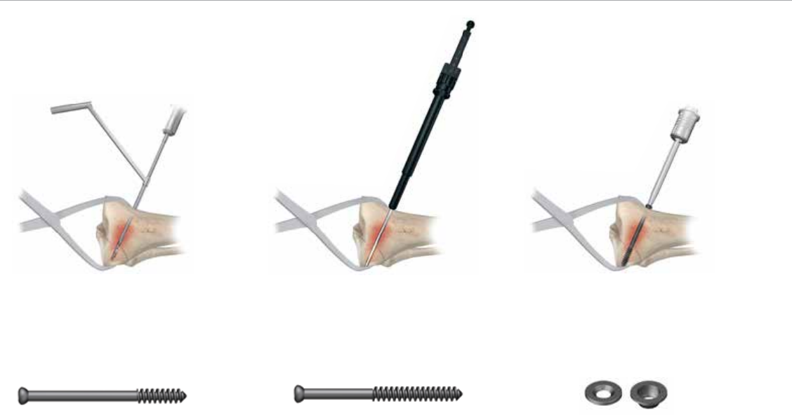
Note: In hard or dense bone, tap the near cortex with the
6.5 mm Cancellous Tap (Cat. No. 8242-75-000) prior to
attempting to insert the screw. The 3.8/6.5 mm drill guide
can be used as a soft tissue protector.
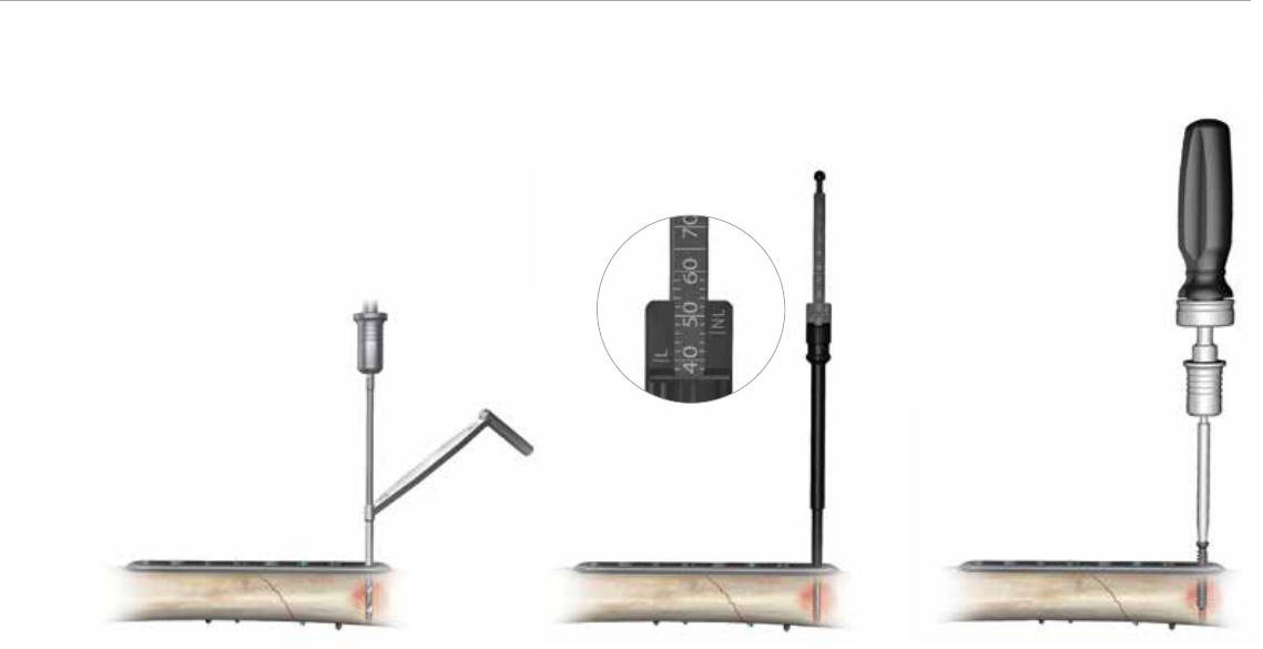
Insert the appropriate length 6.5 mm cancellous lag
screw (Cat. No. 8157-62-0XX/8157-64-0XX) by hand or
with power using the 4.5/6.5 Screwdriver Shank. Always
perform final seating of the screw by hand (Figure 10).
Note: In soft cancellous bone, the use of the flat or
cupped washer may prevent the screw head from sinking
into the near cortex and allow better compression across
the fracture site (Figure 11).
6.5 mm Cancellous Lag Screws
The cancellous lag screw is available with 22 or 40 mm
thread length portions. The threaded portion will reside
in the far fragment only, thus determining the appropriate
thread length.
Reduce the fracture and maintain the reduction with
bone forceps. Drill both cortices with the 3.8 mm Drill Bit
(Cat. No. 8162-99-013) perpendicular to the plane of the
fracture using the 3.8/6.5 mm Drill Guide (Cat. No.8242-
21-000). Advance the drill across the fracture site to
the required depth, confirming the position with image
intensification (Figure 8).
Determine the required screw length by taking a direct
reading from the NL line on the Large Fragment Depth
Gauge (Figure 9).
Figure 1122 mm Thread Length
(Cat. No. 8157-62-0XX)
40 mm Thread Length
(Cat. No. 8157-64-0XX)
Figure 9
Take depth reading from NL line
Figure 10
Insert the 6.5 mm cancellousscrew using
the 3.5 mm hex driver
Figure 8
Drill perpendicular to the fracture plane
with the 3.8 mm drill bit
9
Reduction and Temporary Placement: Position the center
of the plate over the fracture site and hold in place with
reduction forceps or the provisional fixation pins.
Use of the Provisional Fixation Pin (Cat. No. 8162-99-
001/6) Avoid placing the provisional fixation pin in a
screw hole that will be needed immediately for implant
fixation. The self-drilling pin has a quick connect for power
insertion. Advance the pin slowly until the shoulder of
the pin contacts the plate and pulls it down to the bone
(Figure 12).
Note: Advancing the pin beyond that point may result in
stripping of the threads.
Figure 12
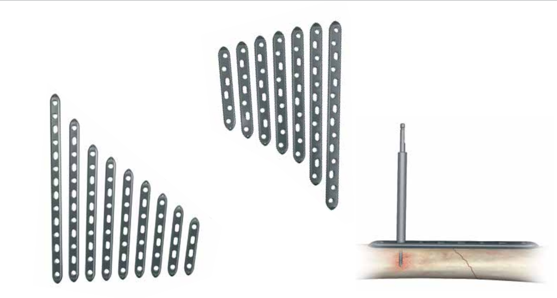
Plate Selection
A plate should be selected that has a minimum of three
screw holes in each main fracture fragment. Longer plates
are generally recommended, as this will increase the working
length of the plate. Screw holes are an option for screw
placement, not a requirement. Screws should, however be
placed in the holes nearest the fracture and at the ends
of the plate. Typically, non-locked screws are used for
interfragmentary compression and to bring the plate down
to the near cortex, with locked screws placed in selected,
as well as terminal screw holes. When straight plates are
used on straight bones the plate must be slightly pre-bent
to assure compression of the far cortex and avoid
fracture gapping.
Note: Bending should occur between the plate holes and
not through any threaded holes.
Hybrid Compression Plate Narrow
(Cat. No. 8162-45-0XX)
Hybrid Compression
Plate Broad
(Cat. No. 8162-45-2XX)
A.L.P.S.
™
Large Fragment Plating System
10
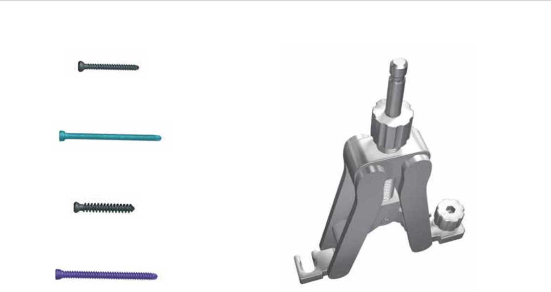
Articulating Tensioning Device
The Articulating Tensioning Device (Cat. No. 8162-99-
005) is to be used in conjunction with the 4.5 mm Hybrid
Broad or Narrow Compression plates (HCP®) in order to
achieve additional compression of a fracture. This device
can be used in fractures of the humerus, femur and tibia
when fracture gaps exist that exceed 2 mm and when
active compression plating techniques are not possible or
ineffective (Figure 13).
First, the proper technique requires that one fully extends
the arms of the tensioner. Next, the hybrid compression
plate is fixed to the main portion of the bone. This can
be accomplished with a couple non-locking compression
screws. The articulating tensioner is then attached to the
plate by means of the tensioner set screw. This set screw
threads directly into the last locked hole of the plate.
6.5 mm non-locking cancellous screw
4.5 mm non-locking cortical screw
4.5 mm locking cortical screw
5.5 mm locking cancellous screw Figure 13
The Articulating Tensioning Device.
Plate Insertion
Determine the type of screw to be used: 4.5 mm
locking cortical, 4.5 mm non-locking cortical, 5.5 mm
locking cancellous or 6.5 mm non-locking cancellous.
Any combination of screws can be used. If a combination
of locking and non-locking screws is used, a non-locking
screw should be inserted first to pull the plate to the bone.
11
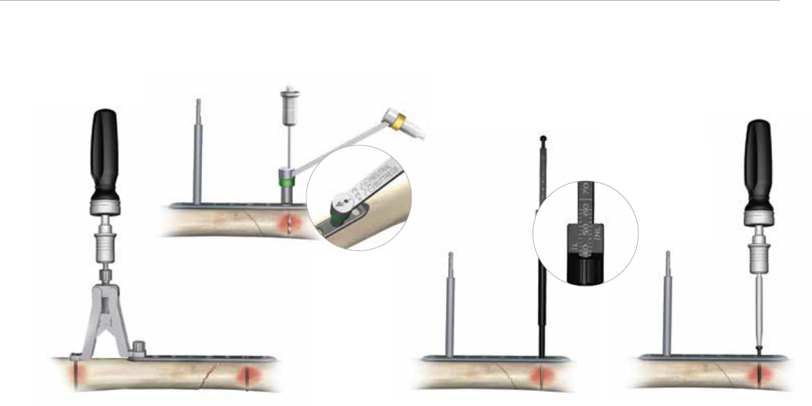
Neutral Insertion of a 4.5 mm Non-Locking
Cortical Screw in a Compression Slot
Insert the neutral (green) end of the 3.2 mm ACP Drill
Guide (Cat. No. 8242-26-000) into the compression slot
with the arrow pointed toward the fracture line (Figure 15).
Drill through both cortices with the 3.2 mm drill bit.
CAUTION: The arrow on the neutral (green) end of the
3.2 mm ACP drill guide must point toward the fracture site
to ensure neutral screw placement.
Measure the drilled hole with the large fragment depth
gauge by taking a direct reading from the NL line
(Figure 16).
Insert the appropriate length 4.5 mm non-locking cortical
screw with the 3.5 mm hex driver coupled to the ratchet
handle (Figure 17).
A non-locked 4.5 mm Cortical Screw (Cat. No. 8157-
45-0XX) is used to connect the opposite end of the
tensioner to the other main segment of bone. Next, one
must connect the Ratchet Screwdriver Handle (Cat. No.
2141-24-000) to the top of the tensioner. To compress the
fracture, screw the ratchet clockwise, which will draw the
arms of the tensioner towards the center, thus reducing
the fracture (Figure 14).
Note: Special care should be given when using the
articulating tensioner in oblique fractures of the diaphysis.
The tensioner should compress the fracture so that the
loose fracture segment is forced into the anxilla that is
formed from the main bone segment and plate.
Figure 17
Insert the 4.5 mm non-locking
cortical screw using the 3.5 mm
hex driver
Figure 16
Take the depth reading
from the NL line
Figure 15
Drill with the 3.2 mm drill bit in the
neutral position
Figure 14
The Articulating Tensioning Device is to be used
in conjunction with the 4.5 mm Hybrid Broad or
Narrow Compression plates in order to achieve
additional compression of a fracture.
A.L.P.S.
™
Large Fragment Plating System
12
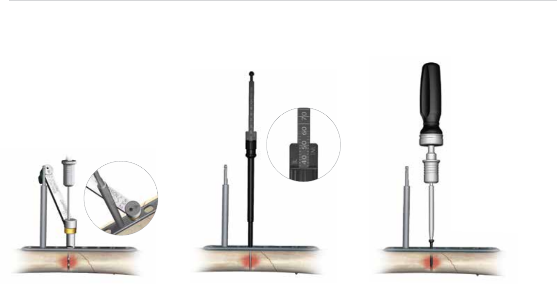
Insert the appropriate length 4.5 mm non-locking cortical
screw with the 3.5 mm hex driver coupled to the ratchet
handle (Figure 20).
Figure 19
Take the depth reading
from the NL line
Figure 20
Insert the 4.5 mm non-locking
cortical screw using the 3.5 mm hex driver
Dynamic Compression/Eccentric Insertion
of a 4.5 mm Non-Locking Cortical Screw
in a Compression Slot
Insert the compression (gold) end of the 3.2 mm ACP drill
guide into the compression slot with the arrow pointed
toward the fracture line. Drill through both cortices with the
3.2 mm drill bit (Figure 18).
CAUTION: The arrow on the compression end of the
3.2 mm ACP Drill Guide must point toward the fracture
site to obtain compression. If the arrow is misdirected
away from the fracture, distraction of the fracture will
occur. Measure the drilled hole with the large fragment
depth gauge by taking a direct reading from the NL line
(Figure 19).
Figure 18
Drill with the 3.2 mm drill bit
in the eccentric position.
13
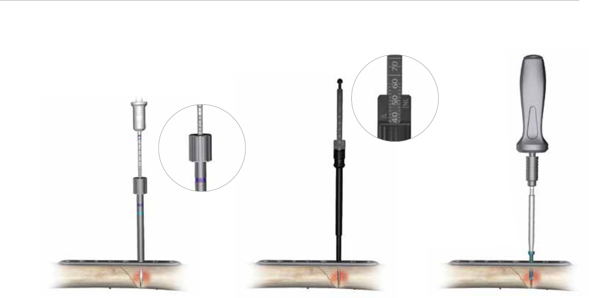
Insert the selected locking screw with the 3.5 mm Hex
Driver coupled to the 4.5 Nm Torque-Limiting Screwdriver
Handle (Cat. No. 8162-99-016) (Figure 23).
Tip: Using a power screwdriver is not recommended for
insertion of any locking screws. If using power, it should be
at a slow speed. Perform all final screw tightening by hand
with the torque-limiting screwdriver.
Figure 21
Drill with the 3.8 mm calibrated drill bit reading
the depth from the top of the drill guide
Figure 22
Take the depth reading
from the L line
Figure 23
Insert the locking screw using
the 3.5 mm hex driver on the
torque-limiting handle
Insertion of a 4.5 mm Locking Cortical
Screw or 5.5 mm Locking Cancellous Screw
in a Threaded Hole
(4.5 mm Cortical Cat. No. 8161-45-2XX or 5.5 mm
Cancellous Cat. No. 8161-55-XXX)
Screw the 3.8 mm Locking Drill Guide (Cat. No. 8162-99-
012) into a threaded plate hole until fully seated. Drill with
the 3.8 mm Calibrated Drill Bit (Cat. No. 8162-99-009) to
the desired depth and read the depth measurement from
the calibrated drill bit at the top of the drill guide (Figure
21). Remove the 3.8 mm locking drill guide.
Note: If a second method of measurement is desired,
measure the drilled hole by taking a direct reading from
the L line on the large fragment depth gauge (Figure 22).
A.L.P.S.
™
Large Fragment Plating System
14
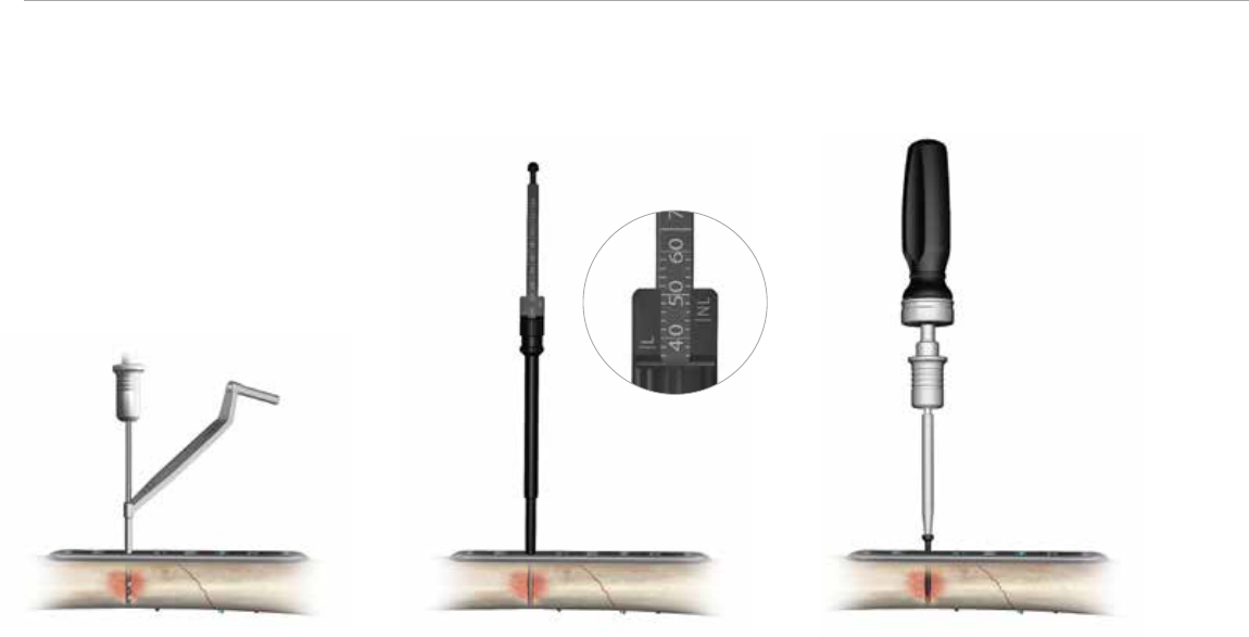
Insert the appropriate length 4.5 mm non-locking cortical
screw with the 3.5 mm hex driver coupled to the ratchet
handle (Figure 26).
Figure 25
Take the depth reading
from the NL line
Figure 26
Insert the 4.5 mm non-locking
cortical screw using the 3.5 mm hex driver
Figure 24
Drill with the 3.2 mm drill bit through
the 3.2/4.5 mm drill guide
Insertion of a 4.5 mm Non-Locking Cortical
Screw in a Threaded Hole
Insert the 3.2 mm end of the 3.2/4.5 mm drill guide into
the threaded hole and drill through both cortices with the
3.2 mm drill bit (Figure 24).
Measure the drilled hole by taking a direct reading from
the NL line on the large fragment depth gauge (Figure 25).
15
Insert the appropriate length 6.5 mm cancellous screw
with the 3.5 mm hex driver coupled to the ratchet handle
(Figure 29).
Tip: A tap for each screw type is available for use in
dense bone.
Figure 29
Insert the 6.5 mm cancellous screw
using the 3.5 mm hex driver
Insertion of a 6.5 mm Non-Locking
Cancellous Screw (Cat. No. 8157-61-XXX)
into any Plate Hole
Insert the 3.8 mm end of the 3.8 mm/6.5 mm drill guide
into the plate hole and drill through both cortices with the
3.8 mm drill bit (Figure 27).
Measure the drilled hole by taking a direct reading from
the NL line on the large fragment depth gauge (Figure 28).
Figure 27
Drill with the 3.8 mm drill bit through
the 3.8/6.5 mm drill guide
Figure 28
Take the depth reading
from the NL line
A.L.P.S.
™
Large Fragment Plating System
16
Optional Instruments
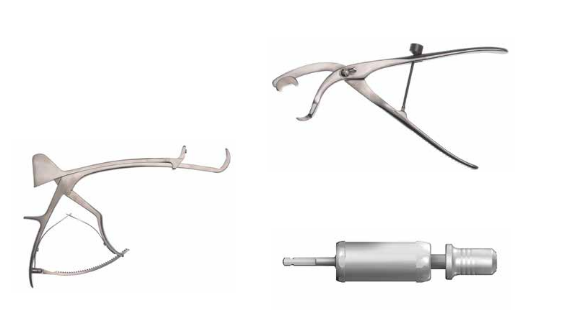
1. 2141-19-000 Femoral Bone Clamp
2. 8162-99-011 Large Fragment Bone Clamp
3. 2142-04-035 Torque Limiting Power Adaptor
Figure 1
Figure 2
Figure 3
17
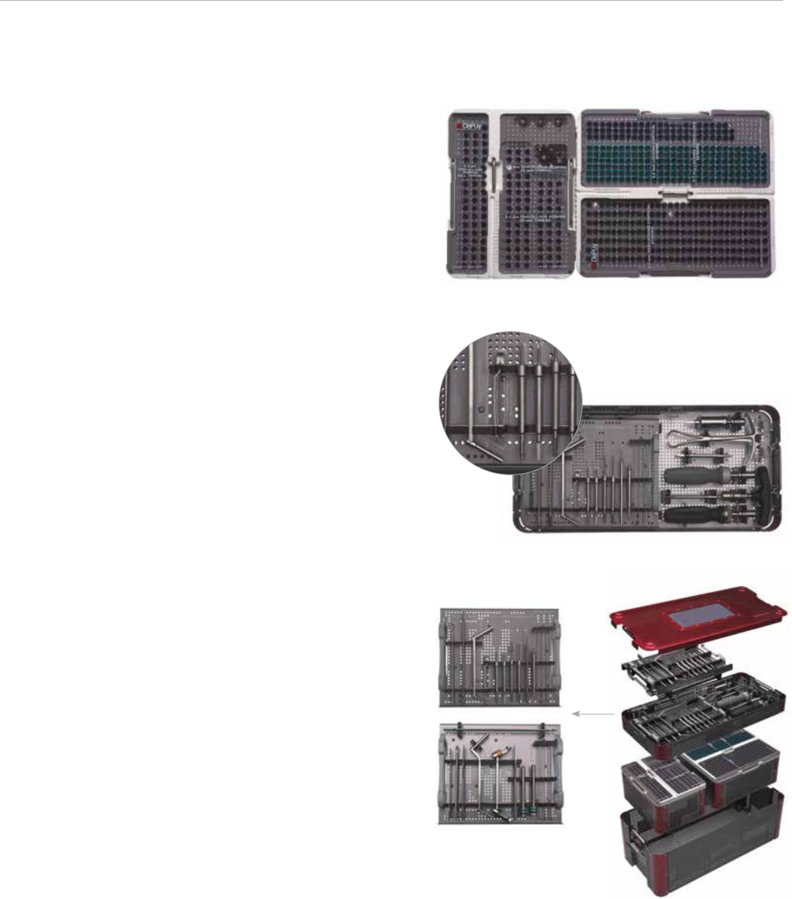
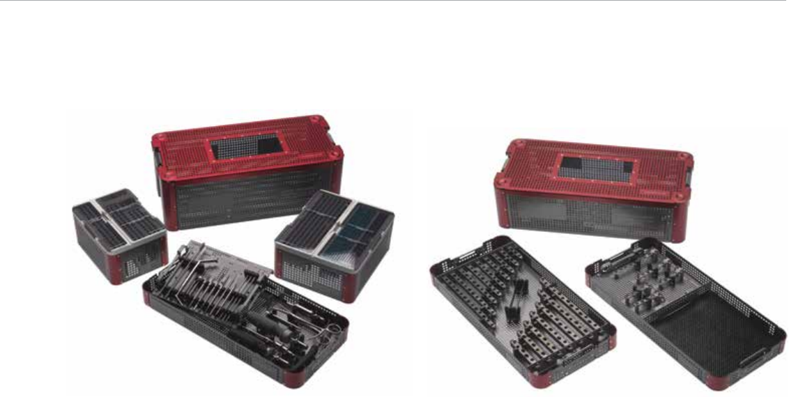
Case Layout
The large fragment case was designed to reflect the varied
functional requirements of our customers. The system
consists of two screw modules, one plate module and two
instrument trays (Figure 30).
The entire system can be housed in one large base or it
can be split into a separate instrument and implant base.
The trays contain three-dimensional graphics for rapid
implant and instrument identification enhancing both
surgical and processing efficiencies (Figure 31).
The screw instruments are contained on an innovative “flip”
tray that can be placed on the Mayo stand permitting rapid
transition between the various screw types. Everything
needed for implant insertion is at your fingertips (Figure 32).
Figure 30
Figure 31
Figure 32
The screw instruments
double sided flip tray
Surgeon Design Team
and Surgical Technique of:
George Haidukewych, M.D.
Orthopaedic Trauma Service,
Florida Orthopaedic Institute,
Tampa General Hospital,
Tampa, Florida
David M. Huebner, M.D.
Director of Orthopaedic Trauma,
Good Samaritan Hospital,
Kearney, Nebraska
Roy Sanders, M.D.
Chief, Department of Orthopaedics,
Tampa General Hospital
Director, Orthopaedic Trauma Services,
Florida Orthopaedic Institute,
Tampa, Florida
Michael Wich, M.D.
Deputy Head,
Department of Trauma and
Orthopaedic Surgery,
Unfallkrankenhaus Berlin,
Berlin, Germany
A.L.P.S.
™
Large Fragment Plating System
18
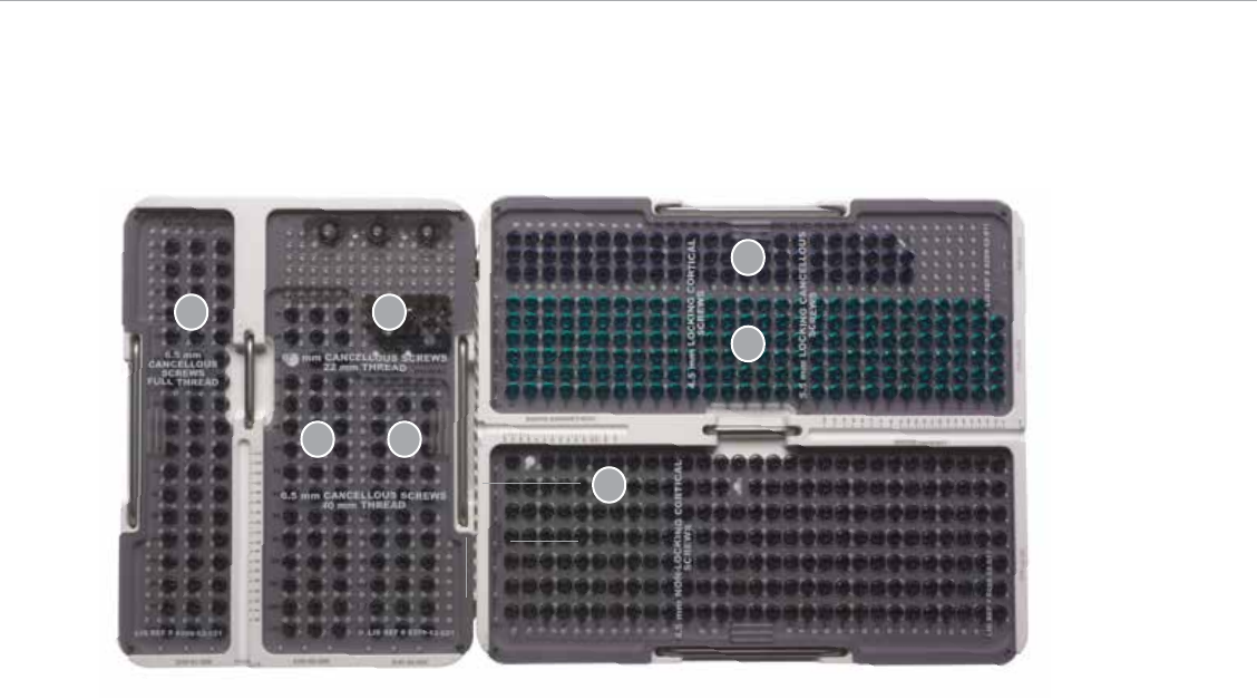
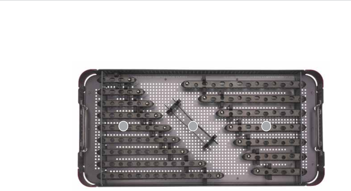
6. 8161-45-2XX 4.5 mm Locking
Cortical Screws
8 – 60 mm in 2 mm increments
65 mm
7. 8161-55-XXX 5.5 mm Locking
Cancellous Screws
26 – 50 mm in 2 mm
increments
65 – 100 mm in 5 mm
increments
Implant Trays
Large Fragment Screw Modules
1. 8157-61-XXX 6.5 mm Cancellous Screws FT
25 – 110 mm in 5 mm
increments
2. 8157-62-XXX 6.5 mm Cancellous Screws
22 mm Thread
40 – 110 mm in 5 mm
increments
3. 14260/14261/14097 Flat/Cupped/Spider Washers
4. 8157-64-XXX 6.5 mm Cancellous Screws
40 mm Thread
60 – 110 mm in 5 mm
increments
5. 8157-45-XXX 4.5 mm Non-locking
Cortical Screws
14 – 60 mm in 2 mm
increments
65 – 70 mm
1 3
2 4
5
6
7
19
3. 4.5 mm Broad Hybrid Compression Plates
8162-45-206 6 Hole Plate
8162-45-207 7 Hole Plate
8162-45-208 8 Hole Plate
8162-45-209 9 Hole Plate
8162-45-210 10 Hole Plate
8162-45-212 12 Hole Plate
8162-45-214 14 Hole Plate
1. 4.5 mm Narrow Hybrid Compression Plates
8162-45-004 4 Hole Plate
8162-45-005 5 Hole Plate
8162-45-006 6 Hole Plate
8162-45-007 7 Hole Plate
8162-45-008 8 Hole Plate
8162-45-009 9 Hole Plate
8162-45-010 10 Hole Plate
8162-45-012 12 Hole Plate
8162-45-014 14 Hole Plate
2. Bending Template
8162-99-002 7 Hole
12 3
A.L.P.S.
™
Large Fragment Plating System
20
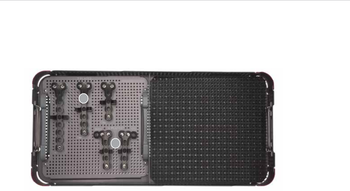
1. 143614 4.5 mm T Plate 4 Hole
143616 4.5 mm T Plate 6 Hole
143618 4.5 mm T Plate 8 Hole
2. 143454 4 Hole Recon T Plate Right
143444 4 Hole Recon T Plate Left
These non-locking plates are indicated for use on the tibia,
femur and humerus.
1
2
Plate Module/Reduction Instrument Tray
21
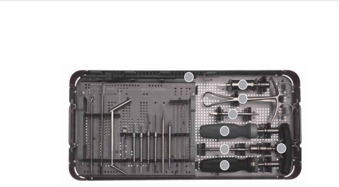
Instrument Trays
Screw Instrument Tray
1. 2142-04-035 Torque Limiting Adaptor
2. 13577 Large Forceps with Points
3. 8242-19-000 4.5/6.5 Screwdriver Shank
4. 8162-99-016 4.5 Nm Torque Limiting Handle
5. 2141-26-035 3.5 Hex Extractor
6. 2141-24-000 Ratchet Handle
7. 2810-01-004 Hudson Handle
8. 8162-99-007 Hook Depth Gauge
1
6
2
5
3
4
7
8
A.L.P.S.
™
Large Fragment Plating System
22
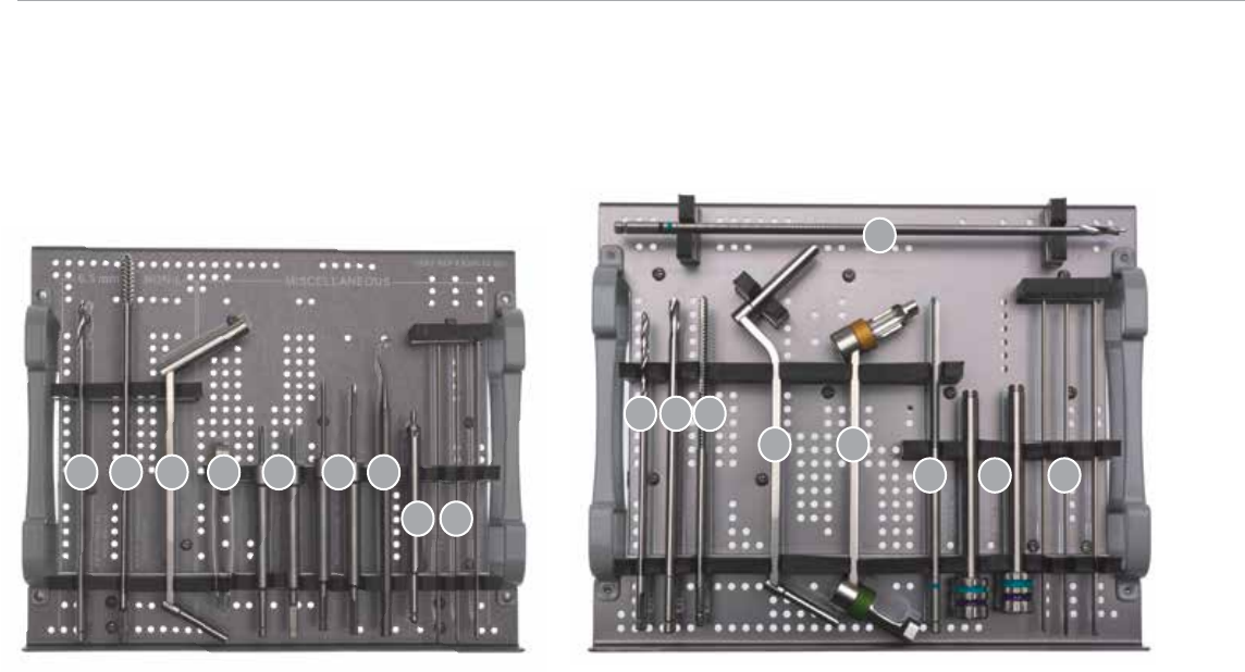
1. 8162-99-013 3.8 mm Drill Bit
2. 8242-75-000 6.5 mm Cancellous Tap
3. 8242-21-000 3.8/6.5 mm Drill Guide
4. 13571 Screw Forceps
5. 8162-99-001 Provisional Fixation Pin 20 mm
6. 8162-99-006 Provisional Fixation Pin 40 mm
7. 13572 Sharp Hook
8. 8242-20-100 4.5/6.5 mm Countersink
9. 141796 &144256 K Wires
1. 9399-99-315 3.2 mm Drill Bit
2. 8242-73-000 4.5 mm Solid Drill Bit
3. 8242-45-070 4.5 mm Cortical Tap
4. 8241-97-000 3.2/4.5 mm Double Drill Guide
5. 8242-26-000 3.2 mm ACP Drill Guide
6. 8162-99-010 4.5 mm Locking Cortical Tap
7. 8162-99-012 3.8 Locking Drill Guide
8. 141796 & 144256 K Wires
9. 8162-99-009 3.8 mm Calibrated Drill Bit
Flip Tray - Side 1
1 62 53 4 7
98
Flip Tray - Side 2
876
5
1 2 3
4
9
23
The entire system can be housed in one large base
(Figure 40) or it can be split into a separate instrument
and implant base (Figure 41).
The large fragment case was designed to reflect the varied
functional requirements of our customers. The system
consists of two screw modules, one plate module and two
instrument trays.
Figure 40 Figure 41

Biomet as the manufacturer of medical devices, does not practice medicine. Each
surgeon is responsible for the appropriate selection of implant(s) and techniques for
each individual patient.
All trademarks herein are the property of Biomet, Inc. or its subsidiaries unless
otherwise indicated.
This material is intended for the sole use and benefit of the Biomet sales force and
physicians. It is not to be redistributed, duplicated or disclosed without the express
written consent of Biomet.
For product information, including indications, contraindications, warnings, precautions
and potential adverse effects, see the package insert.
©2013 Biomet Orthopedics • Form No. BMET0096.1 • REV0313
IMPORTANT
This Essential Product Information does not include all of the information necessary
for selection and use of a device. Please see full labeling for all necessary information.
INDICATIONS
The Large Fragment Locking Plating System is intended for fixation of various long
bones, such as the humerus, femur and tibia. It is also for use in fixation of osteopenic
bone and fixation and stabilization of non-unions, malunions, and osteotomies.
The use of bone plates and screws provides the orthopaedic surgeon a means of
bone fixation and helps generally in the management of fractures and reconstructive
surgeries.These implants are intended as a guide to normal healing, and are NOT
intended to replace normal body structure or bear the weight of the body in the
presence of incomplete bone healing. Delayed unions or nonunions in the presence
of load bearing or weight bearing might eventually cause the implant to break due
to metal fatigue. All metal surgical implants are subjected to repeated stress in use,
which can result in metal fatigue.
CONTRAINDICATIONS
• Active infection
• Conditions which tend to retard healing such as blood supply limitations,
previous infections, insufficient quantity or quality of bone to permit stabilization
of the fracture complex
• Conditions that restrict the patient’s ability or willingness to follow postoperative
instructions during the healing process
• Foreign body sensitivity
• Cases where the implant(s) would cross open epiphyseal plates in skeletally
immature patients.
• Cases with malignant primary or metastatic tumors which preclude adequate
bone support or screw fixations, unless supplemental fixation or stabilization
methods are utilized.
WARNINGS AND PRECAUTIONS
Bone screws and plates are intended for partial weight bearing and non-weight
bearing applications. These components cannot be expected to withstand the
unsupported stresses of full weight bearing.
ADVERSE EVENTS
The following are the most frequent adverse events after fixation with orthopaedic
plates and screws: loosening, bending, cracking or fracture of the components or
loss of fixation in bone attributable to nonunion, osteoporosis, markedly unstable
comminuted fractures; loss of anatomic position with nonunion or malunion with
rotation or angulation; infection and allergies and adverse reactions to the device
material.
Responsible Manufacturer
Biomet, Inc.
P.O. Box 587
56 E. Bell Drive
Warsaw, Indiana 46581-0587
USA
www.biomet.com
