Anterior Approach Surgical Technique
2013-06-11
: Pdf Anterior Approach Surgical Technique Anterior_Approach_Surgical_Technique 6 2013 pdf
Open the PDF directly: View PDF ![]() .
.
Page Count: 40
THE ANTERIOR
APPROACH
as described by Joel Matta, M.D.
SURGICAL TECHNIQUE

Table Of COnTenTs
Anterior Approach Surgical Technique DePuy Synthes Joint Reconstruction
Introduction 2
hana® Table 4
Pre-Operative Set-Up 6
Incision and Initial Exposure 8
Exposure 10
Capsular Exposure 12
Dislocation 14
Dislocation and Femoral Head Resection 15
Femoral Head Resection 16
Acetabular Reaming 17
Femoral Preparation 19
Femoral Broaching and Trialing 23
Femoral Trialing 24
Final Implantation 25
Hints and Tips 26
Preventing Infection in Obese Patients 30
Ordering Information 32

Minimally invasive or tissue-sparing orthopaedic procedures
have gained attention as patients demand shortened re-
covery time and accelerated rehabilitation. Development
of efficient, repeatable, tissue-sparing total hip replace-
ment procedures is important.
The Anterior Approach Surgical Technique for Total Hip
Replacement is described by Joel Matta, M.D., who has
brought the Anterior Approach technique as it is known
today into the United States. This approach is an advanced
application of the Smith-Petersen approach using the
PROfx®, hana® or hana SSXT® tables from Mizuho OSI®.
These tables help to streamline the technique, creating a
reproducible procedure that minimizes soft-tissue releases
and eliminates the need for secondary incisions to accom-
modate instrumentation or the femoral component. The
technique does not cut any muscles, but separates them
to allow access into the hip joint. The result is that mus-
cles are spared during surgery. With these advantages,
the Anterior Approach provides the potential for a quicker
recovery compared to traditional hip replacement surgery.
Anterior Approach Education Program
DePuy Synthes Joint Reconstruction has collaborated with
Joel Matta, M.D., to build a comprehensive training and ed-
ucation program around the Anterior Approach. This pro-
gram features Anterior Approach Courses offering hands-on
cadaveric training, didactic lectures and interactive discus-
sion. Surgical technique papers, surgical technique videos,
specially designed Anterior Approach instrumentation, mar-
keting materials and a field specialist further augment DePuy
Synthes Joint Reconstruction’s comprehensive Anterior Ap-
proach program.
Anterior Approach Resources
Additional resources for surgeons, patients and OR Staff
can be found at www.DePuy.com/AnteriorApproach in-
cluding an interactive 3D animation for surgeon and OR
staff education.
ANTERIOR APPROACH PHILOSOPHY
INTRODUCTION
* The hana® table is not a DePuy Synthes Joint Reconstruction product, nor is it the only table that can be used for this approach. This surgical technique still applies when
using other tables.
2 DePuy Synthes Joint Reconstruction Anterior Approach Surgical Technique

Joel Matta, M.D.
ABOUT JOEL MATTA, M.D.
Joel Matta, M.D., brought the Anterior Approach to the
United States from Europe and has advanced the tech-
nique through training and education. The CORAIL® Total
Hip System and the Anterior Approach surgical instru-
ments were designed in conjunction with Dr. Matta and a
team of other surgeons. Having performed over 3,000
plus, Anterior Approach hip replacements, Dr. Matta has
also been instrumental in the training of many orthopae-
dic surgeons in the technique, and serves as chairman of
DePuy Synthes Joint Reconstruction’s Anterior Approach
Courses.
Dr. Matta is founder and chairman of the Anterior Total
Hip Arthroplasty Collaborative (ATHAC, www.athac.org),
the founder and director of the Hip & Pelvis Institute at
Saint John’s Health Center in Santa Monica, CA, and the
author of over 100 publications and videos and hip re-
placement and pelvic surgery.
Dr. Matta is a consultant for DePuy Synthes Joint
Reconstruction, and receives royalties as the designer
of the PROfx®, hana® or hana SSXT® tables which are
manufactured by Mizuho OSI.
Anterior Approach Surgical Technique DePuy Synthes Joint Reconstruction 3
Extensive Imaging Capability
Un-restricted C-Arm access.
Radiolucent 35 inch (89 cm) cantelevered top section.
Radiolucent leg spars for uninterrupted imaging.
Allows Precise Control of Patient Position, Manipulation and Traction
Proven performance for Anterior Approach to total hip procedures.
Allows bilateral hip replacement for qualified patients.
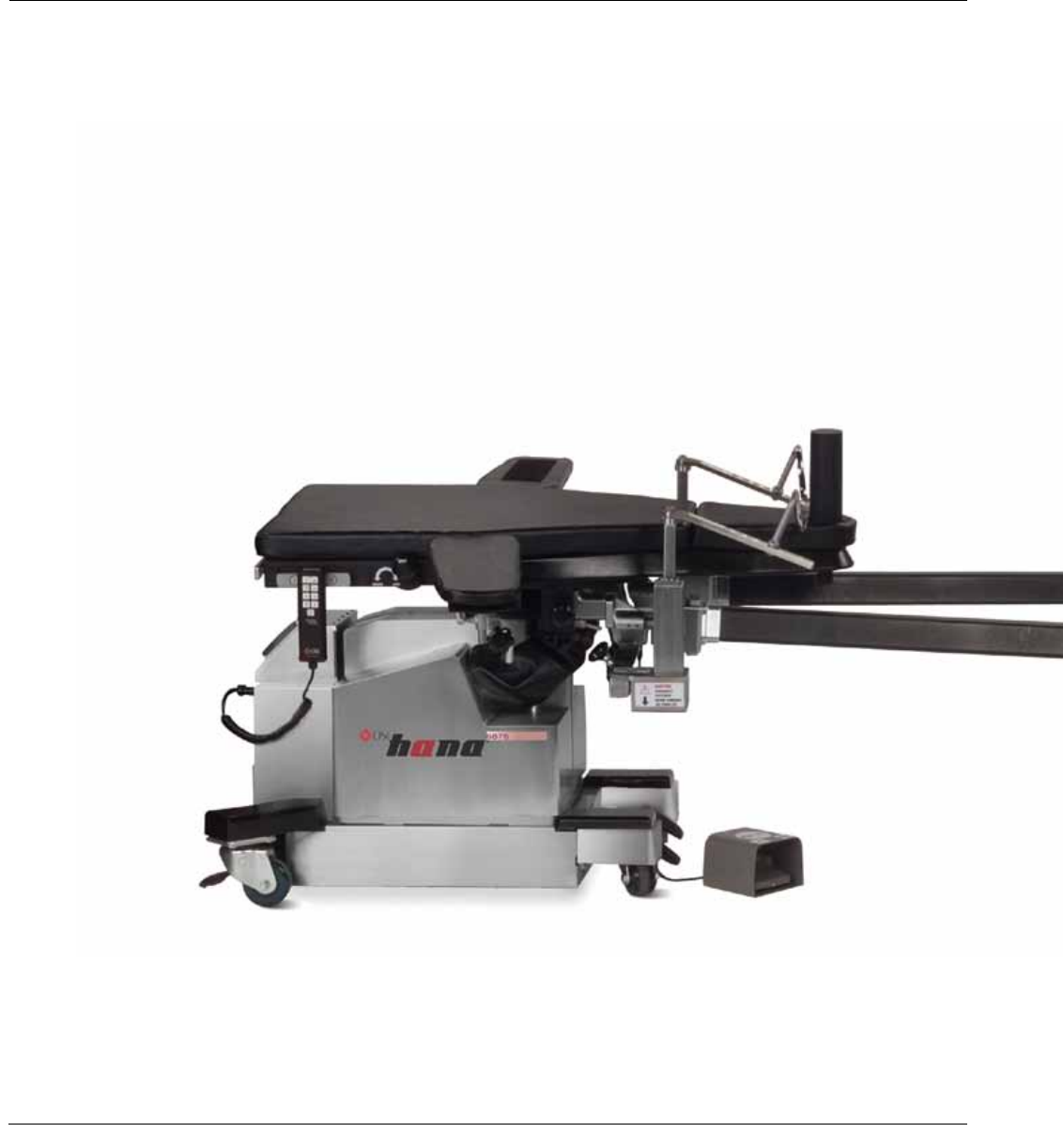
hana® TABLE
Introduction
The hana® table allows the surgeon to perform Total Hip Arthroplasty through a single anterior approach incision, with-
out detachment of muscle from the pelvis, or femur. The table allows hyperextension, abduction, adduction and exter-
nal rotation of the hip for femoral component placements, a positioning option not possible with conventional tables.
Minimizing the disturbance to the lateral and posterior soft tissues provides immediate stability of the hip after surgery.
4 DePuy Synthes Joint Reconstruction Anterior Approach Surgical Technique
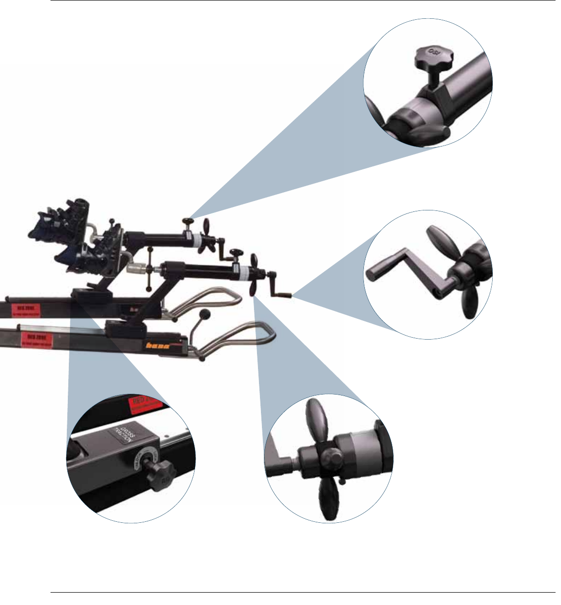
Internal/External Rotation
Gross Traction
OR Team Engineered
Facilitates OR Team performance.
Proprietary features make pre-operative and intra-opera-
tive protocol easier than a standard OR table
Suited to the Newest Technologies
Supports tissue-sparing techniques for MIS procedures.
Provides new level of surgical assistance
for surgeon and OR team. Rotation Lock
Fine Traction
Anterior Approach Surgical Technique DePuy Synthes Joint Reconstruction 5

Extra large drape Clear drape
Figure 2
Extra large drape
Figure 1
Figure 3
Split drape Split drapeTowels
Before transferring the patient to the hana® table, it is
recommended that the patient’s feet be secured into the
boots. Apply web roll around the foot, then self-adherent
wrap (Coban™) around the upper ankle. With the boot
liner out of the shell, position the foot inside the liner. Se-
cure the tongue and the Velcro® strap then place the foot
into the boot. Ensure that the heel drops down into the
shell. Affix the buckle straps and securely tighten the foot.
Test the stability of the boot on the foot by holding the
ankle while pulling on the boot handle.
Position the patient on the hana table in preparation for
surgery. Typically, the patient’s arms are placed roughly
perpendicular outward and not over the chest. Arms placed
on the chest can interfere with femoral preparation later
in the procedure.
1. Use a clear U drape (non sterile) around operative area
and towards the foot (Figure 1). A towel wrapped over
each boot reduces the chance of perforation through
the curtain.
2. Place two extra large drapes over the lower extremities
starting distal to operative area. Place two large drapes
across the top of the patient (Figure 2).
3. Staple three towels around operative area, one on each
side of the incision area and one medial to the incision
area (Figure 3).
PATIENT SET-UP AND DRAPING
PRE-OPERATIVE SET-UP
6 DePuy Synthes Joint Reconstruction Anterior Approach Surgical Technique
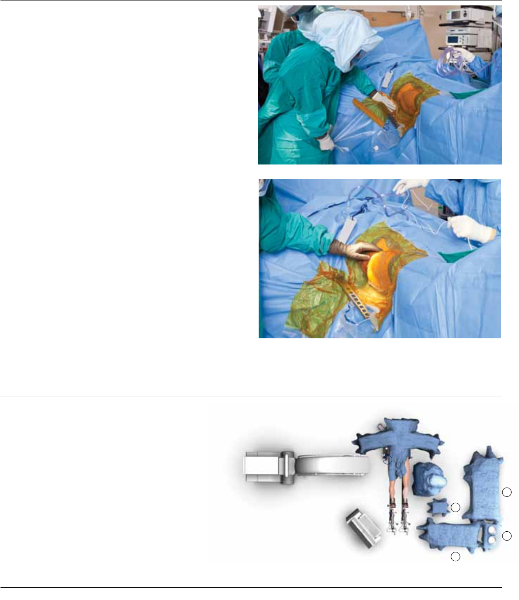
Figure 4
Figure 5
ROOM SET-UP
4. Apply an impervious U drape with adhesive around the
operative area and extending over the legs. Apply an-
other in the opposite direction over the head.
5. Place a split drape with adhesive proximal and distal to
the operative area.
6. Cover exposed skin with iodine incise drape (Figure 4).
7. Cut a small hole in the drape for the femoral hook lift,
place the hook bracket on the lift and seal with iodine
incise drape (Figure 5).
The OR is set up such that the instruments are on the op-
erative side of the patient. Generally, the use of 2 back ta-
bles (A), 1 Mayo stand (B) and 1 basin stand (C) is suffi-
cient, creating an L-shaped area.
The C-Arm (D) is positioned on the non-operative side,
perpendicular to the patient. A typical OR team will con-
sist of the surgeon, physician’s assistant, anesthesiologist,
scrub nurse, circulating nurse/table operator and X-ray
technician (Figure 6).
A
A
C
B
DSurgeon
Figure 6
Anterior Approach Surgical Technique DePuy Synthes Joint Reconstruction 7
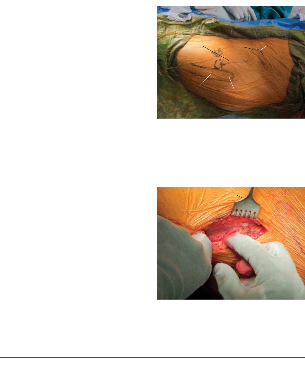
Mark the locations of the iliac crest, greater trochanter and
the anterior superior iliac spine (ASIS) (Figure 7). Start the in-
cision approximately 3 cm lateral and 1 cm distal to the ASIS,
and continue in a posterior and distal direction toward the
anterior border of the femur. The incision will be 8-9 cm and
parallels the fibers of the tensor fascia lata muscle.
INCISION AND INITIAL EXPOSURE
Figure 8
Incision Iliac Crest ASIS
Figure 7
Greater TrochanterProximal Femur
Volkman’s Retractor
The tensor fibers are visible through the translucent fascia
(Figure 8).
8 DePuy Synthes Joint Reconstruction Anterior Approach Surgical Technique
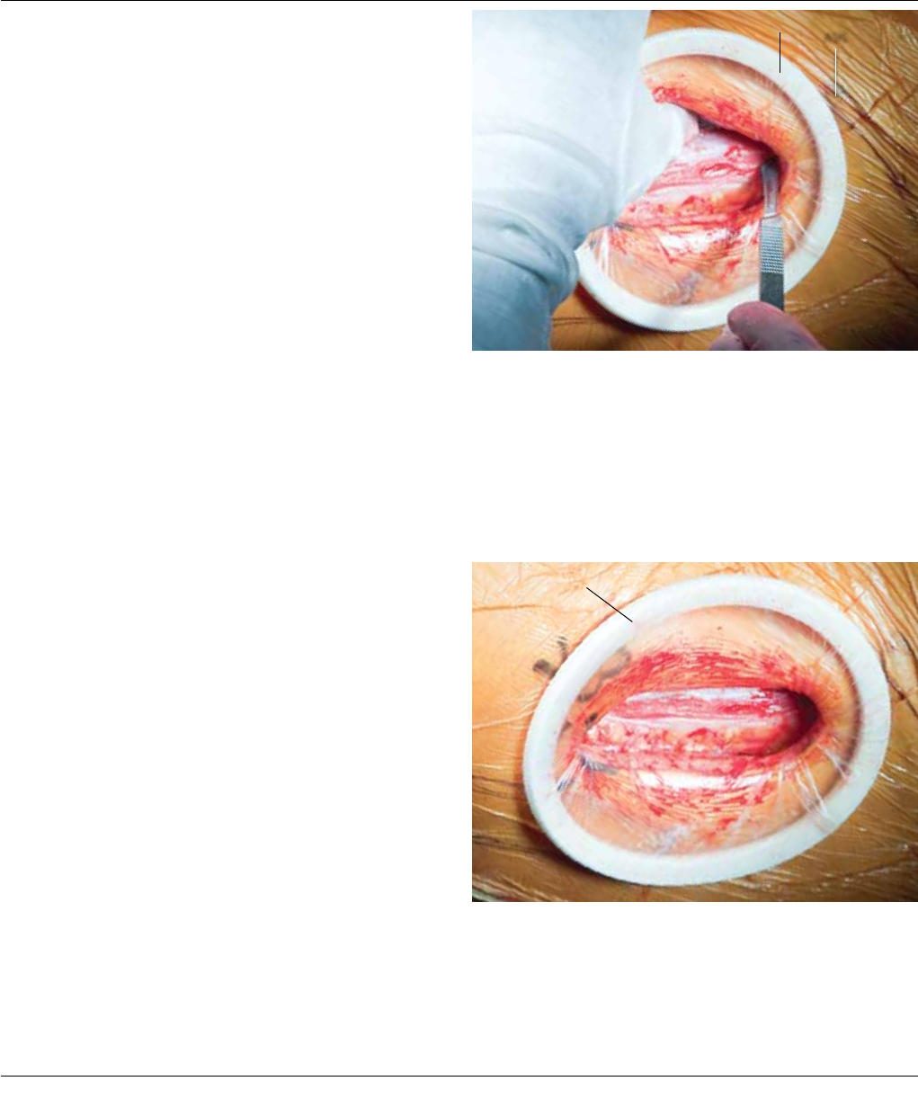
A soft tissue protector (Protractor®) may be inserted into
the wound. Incise the fascia over the tensor and parallel
to its fibers. Extend the fascial split beneath the skin prox-
imal (toward the ASIS) and distal (Figure 9).
Figure 10
Protractor®
Protractor®
ASIS
Figure 9
Coagulate the vessel that perforates the fascia.
The fascial incision is typically between the anterior two-
thirds and posterior one-third of the tensor muscle (Figure
10). Avoid splitting the iliotibial band, which lies along the
posterior border of the tensor. Splitting this will lead to
the muscle interval posterior to the tensor commonly
known as the Watson-Jones approach.
Anterior Approach Surgical Technique DePuy Synthes Joint Reconstruction 9
Lift the anterior tensor flap with an Allis Clamp and using
your finger, bluntly dissect inside the tensor sheath, ante-
rior and medial to the tensor muscle.
The location and obliquity of the incision along with the
deep dissection within the tensor sheath, protects the lat-
eral femoral cutaneous nerve.
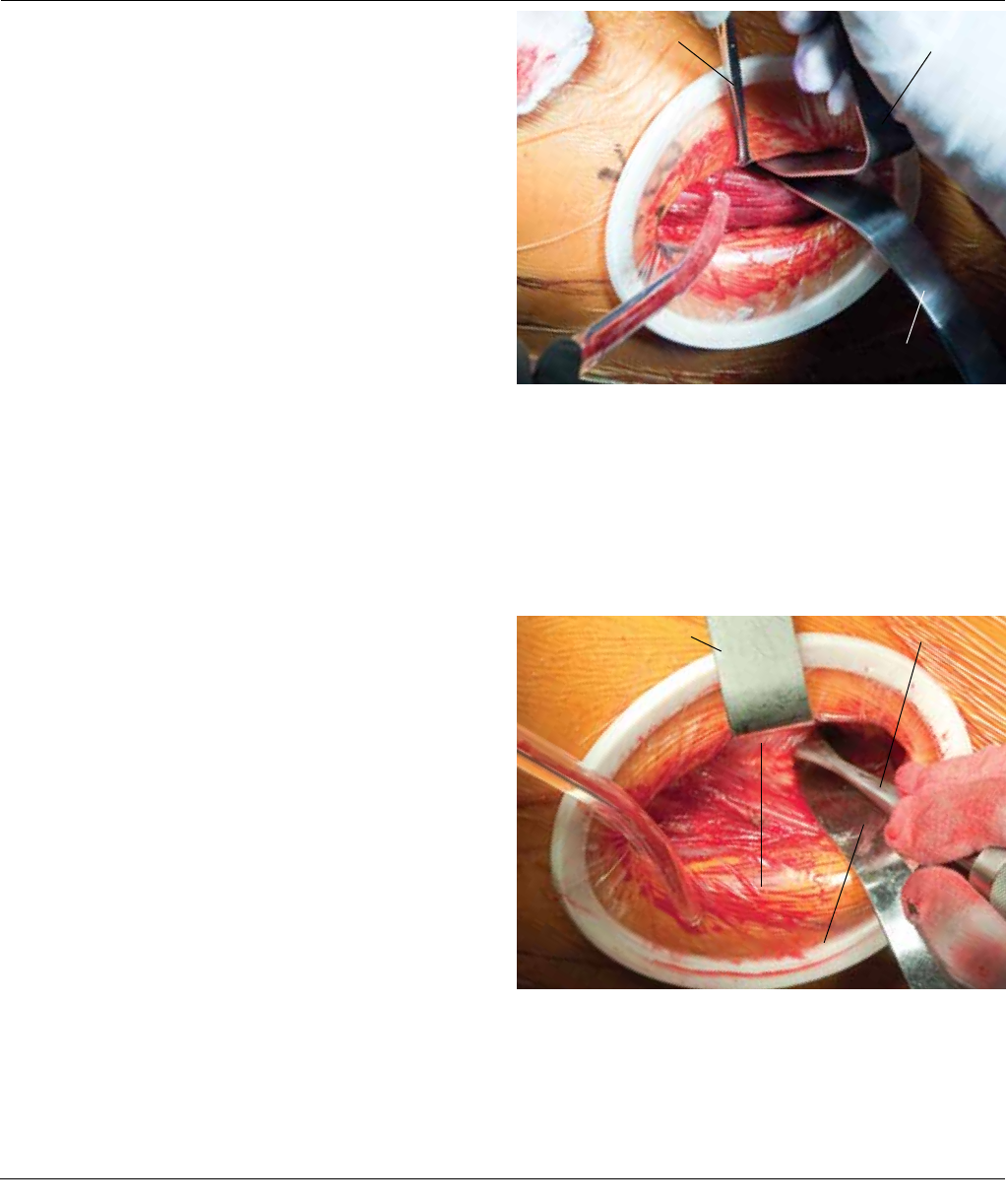
Place a Hibbs Retractor (Cat. No. 2598-07-180) medially
to aid visualization. Palpate the ASIS and move your finger
distal and lateral to palpate the anterior hip capsule. Place
a blunt-tipped Cobra Retractor (Cat. No. 37-4106) lateral
to the hip capsule and locate the origin of the rectus fem-
orus. Retract the tensor and gluteus minimus laterally. Use
the Hibbs Retractor and retract the sartorius and rectus
femorus muscles medially (Figure 11).
EXPOSURE
Allis Clamp Hibbs Retractor
Cobra Retractor
Figure 11
Hibbs Retractor
Cobra Retractor
Rectus
Key/Cobb Elevator
Figure 12
To elevate the iliopsoas and rectus femorus muscles from
the anterior capsule, pass a Key/Cobb elevator posterior
to the origin of the rectus femorus and anterior to the hip
capsule, directing it medial and distal (Figure 12).
10 DePuy Synthes Joint Reconstruction Anterior Approach Surgical Technique
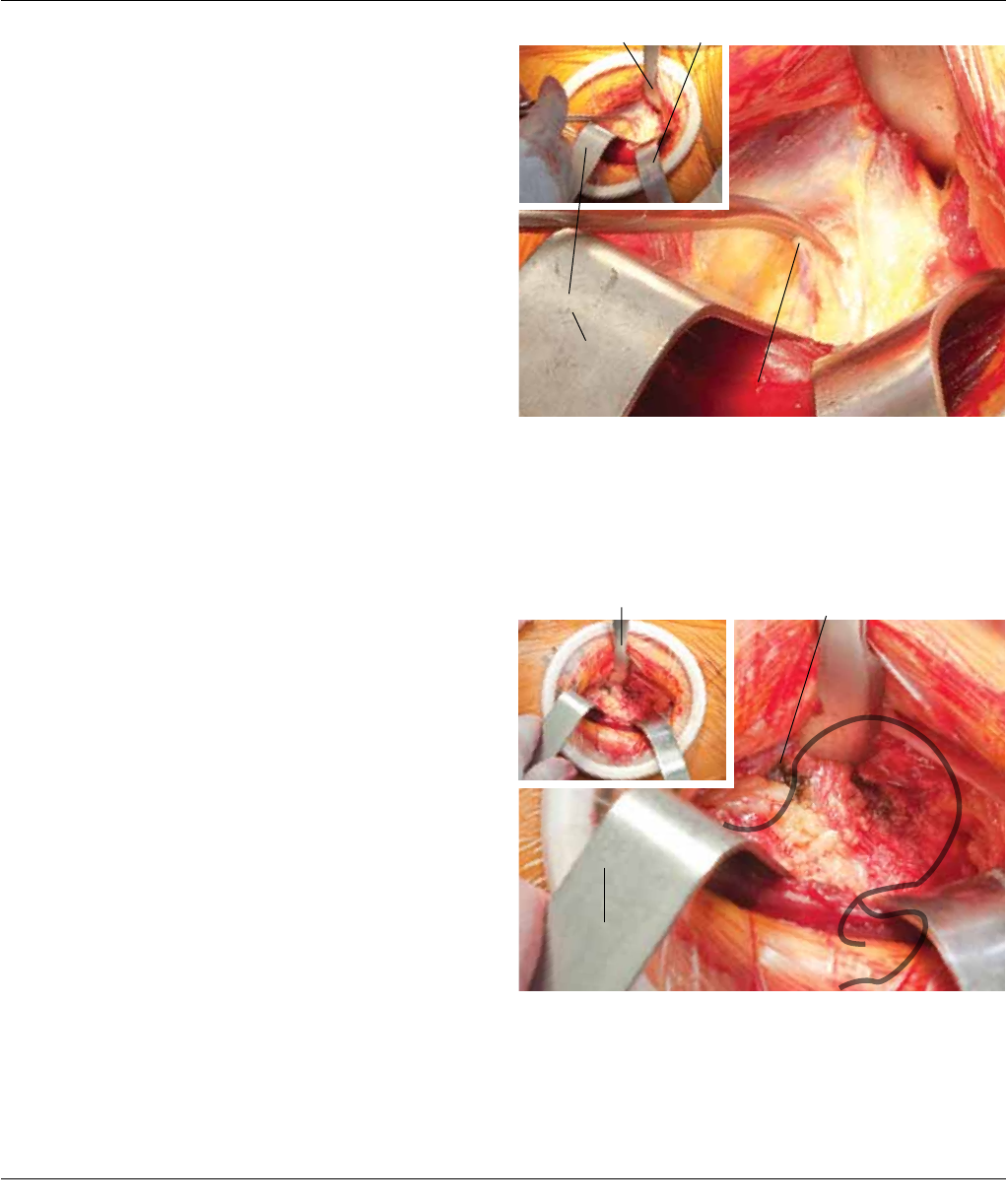
Place the tip of the MI Narrow Curved Hohmann Retrac-
tor (Cat. No. 2598-07-190) on the antero-medial hip cap-
sule to retract the rectus femorus and sartorius medially.
As the Hohmann and Cobra retract medially and laterally,
use your finger to tease the fascia lata off the distal ten-
sor to enhance exposure and avoid rupture of the tensor
fibers (Figure 13).
Figure 13
Clamped Circumflex Vessels
Hibbs Retractor
Hibbs Retractor
Figure 14
MI Narrow Curved
Hohmann Retractor
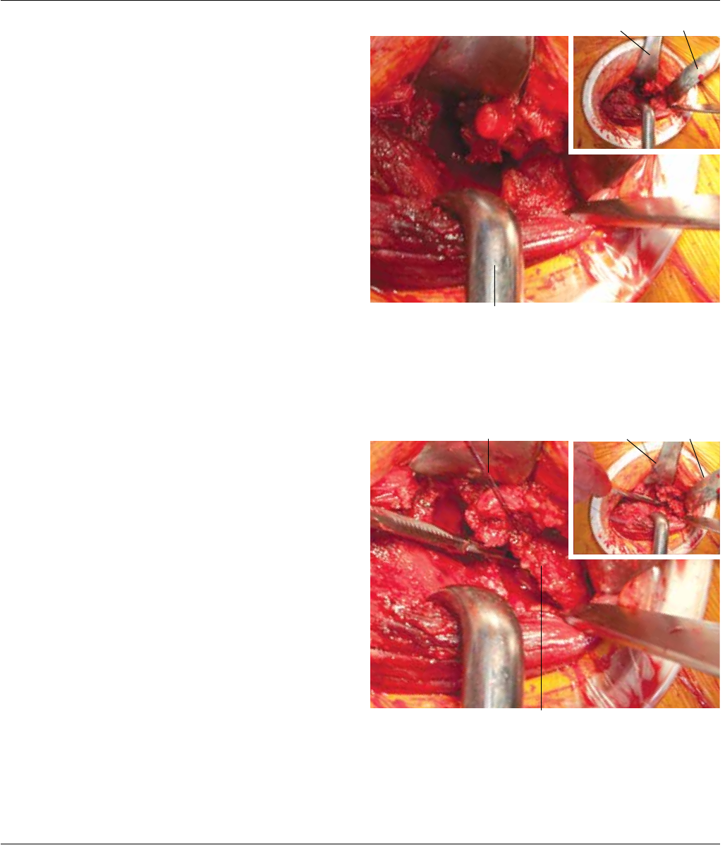
Retract the tensor laterally with a Hibbs Retractor to facili-
tate visualization of the anterior capsule. Dissect distally
to enhance exposure. The lateral femoral circumflex ves-
sels are also now visualized distal to the hip capsule. Cut
and tie, or cauterize both sides of the vessel, taking care
to cauterize all of the branches (Figure 14).
Cobra Retractor
MI Narrow Curved
Hohmann Retractor Cauterized
Circumflex Vessels
Anterior Approach Surgical Technique DePuy Synthes Joint Reconstruction 11
For more mobility of tensor muscle, release the fascia
layer distal to the cauterized vessels. Retract the tensor to
visualize the fibers of the vastus lateralis muscle.
Cut the capsule parallel to the neck at the junction of the
anterior and lateral/superior capsule; continue down to the
base of the neck, until reaching the inter-trochanteric line.
Ensure that the lateral shoulder (saddle) of the neck is visi-
ble where the lateral portion of the neck joins the tip of
the greater trochanter (Figure 15).
CAPSULAR EXPOSURE
Hibbs
Retractor
Cobra Retractor
MI Narrow Curved
Hohmann Retractor
Figure 15
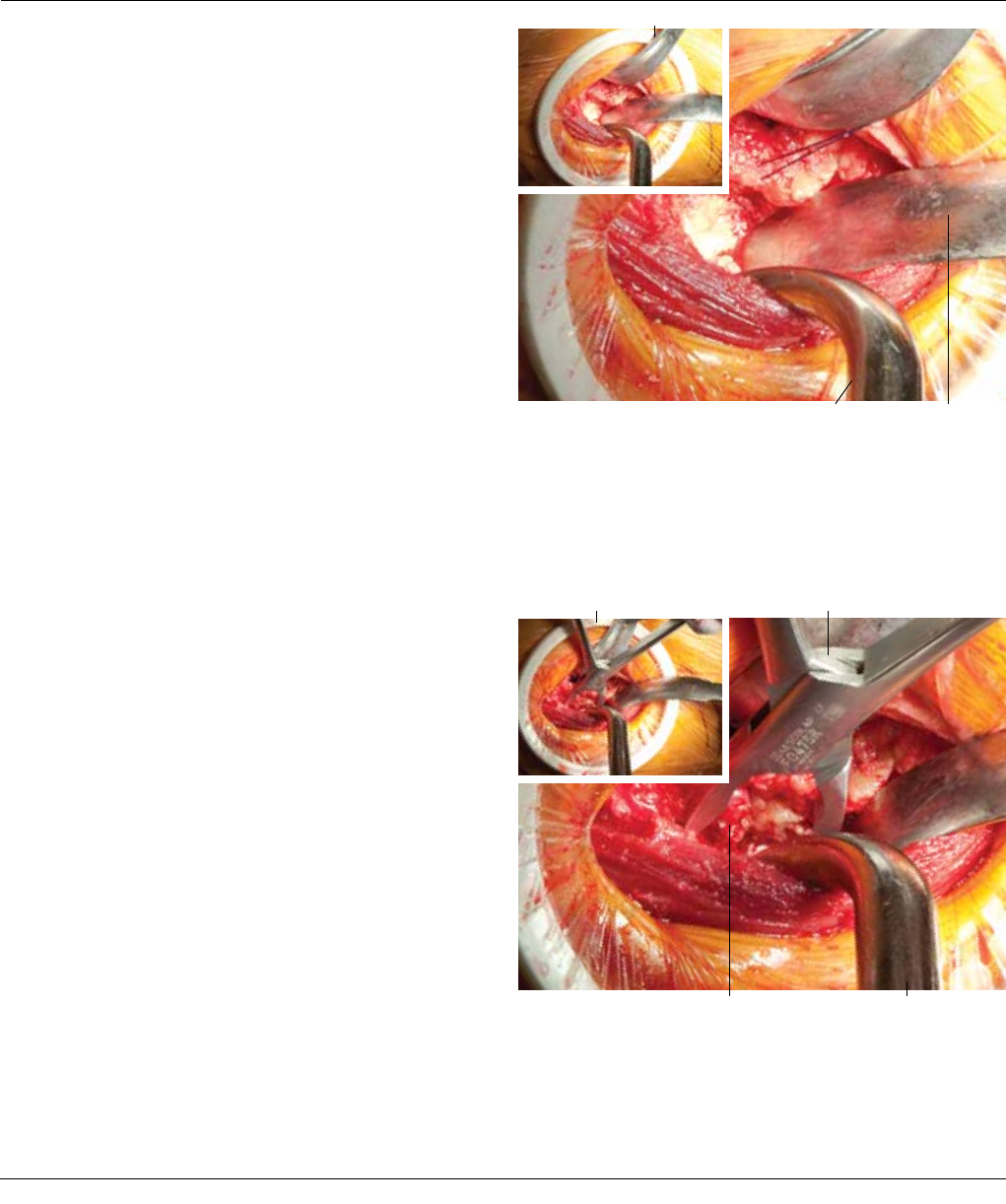
Figure 16
Anterior Capsule Tag
Hibbs
Retractor
Lateral Capsule Tag
Cobra Retractor
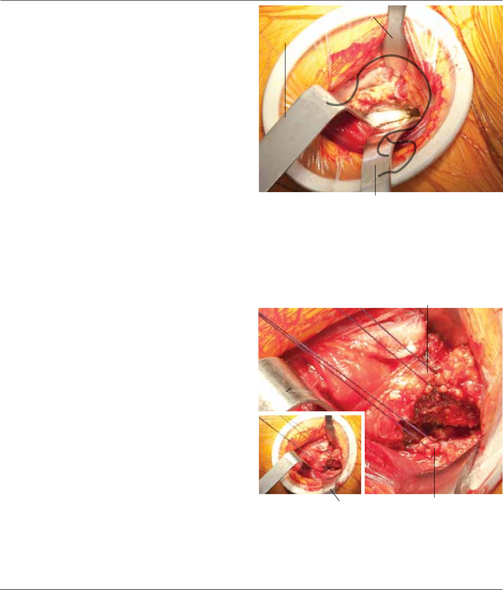
To retract the capsule, position a suture tag into the lateral
edge of the anterior capsule (Figure 16). From the distal ex-
tent of the capsular incision, cut at a right angle medially
along the intertrochanteric line (junction of the anterior
capsule and the origin of the vastus lateralis muscle).
Cut the anterior capsule off the base of the neck. This en-
sures visualization and mobility of the femur during femo-
ral preparation. Place a sharp-tipped Cobra Retractor (Cat
2598-07-200) under the anterior capsule and around the
anterior neck. Detach the capsule from the intertrochan-
teric line area.
12 DePuy Synthes Joint Reconstruction Anterior Approach Surgical Technique
Watch for and cauterize bleeders along the intertrochan-
teric line. Place a tag suture on the cut edge of the lateral
capsule, near the greater trochanter. Place the lateral
cobra inside the lateral capsule along the lateral neck.
Slide the tip of a small Hohmann Retractor (Cat. No.
2598-07-190), under the anterior capsule and over the
anterior rim.
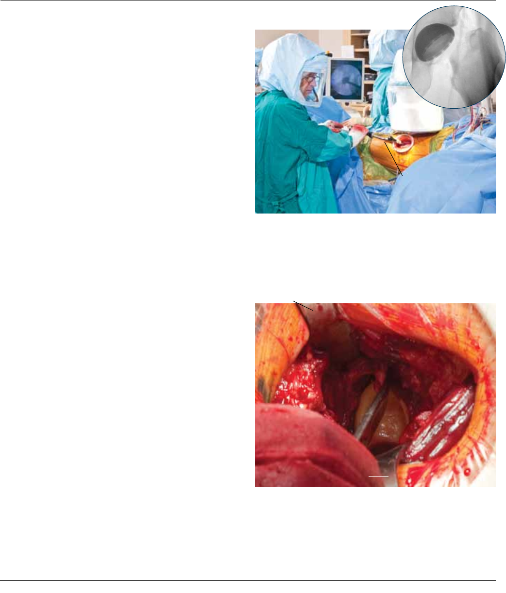
Locate and remove the labrum to visualize the bony rim
of the acetabulum. The labrum is often ossified (acetabu-
lar osteophyte), if so, excise with an osteotome, failing to
do so may make inserting the Bone Skid difficult. Request
gross traction be applied and lock. Using approximately
3-4 turns of fine traction, the femoral head will pull away
from the acetabulum (Figure 17).
Femoral Head Labrum removed
from Acetabulum
Figure 17
Cobra
Retractor
3 or 4 turns of fine traction
Lock
gross
traction
Figure 18 Cobra Retractor
Cobra
Retractor
Murphy Bone Skid
Push the Murphy Bone Skid (Cat. No. 2004-00-000)
between the superior head and acetabular roof and
“lever” to loosen the soft tissues. Remove the Skid.
Request the operator to remove 2 turns of fine traction.
Place the Murphy Bone Skid between the femoral head
and anterior rim (Figure 18). Mobilize the head and exter-
nally rotate the hip approximately 20 degrees.
Anterior Approach Surgical Technique DePuy Synthes Joint Reconstruction 13
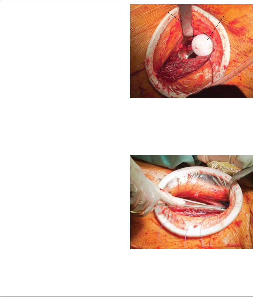
Under power, insert the Modular Head Ball Remover (Cat.
No. 2125-00-600), or Corkscrew, into the femoral head in
an anterior to posterior direction and attach the Excel T-
Handle (Cat. No. 2001-42-000) (Figure 19).
DISLOCATION
Murphy Bone Skid
Corkscrew
Figure 19
Cobra
Retractor
Murphy Bone Skid
Unlock
Cobra Retractor
Figure 20
Corkscrew
Unlock the rotation on the table. Using leverage from
the Murphy Bone Skid and by pulling and rotating with
the corkscrew dislocate the head anterior and lateral
(Figure 20).
14 DePuy Synthes Joint Reconstruction Anterior Approach Surgical Technique
DISLOCATION AND FEMORAL HEAD RESECTION
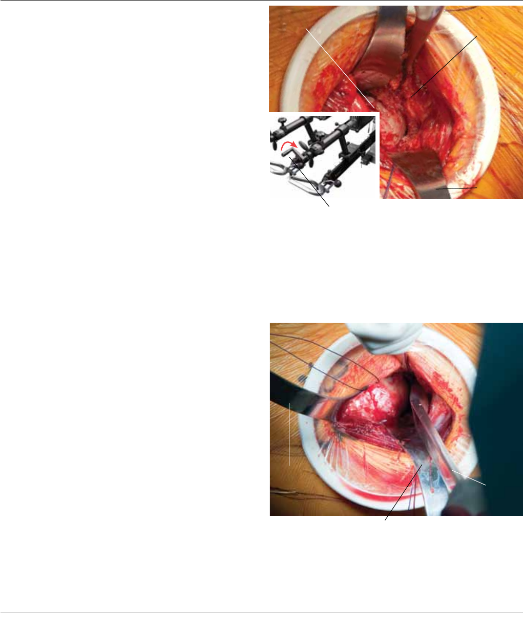
Remove the Murphy Bone Skid and place Cobra Retrac-
tors medial and lateral to the neck. Using a small Hohm-
ann Retractor to slide under the muscle, with the tip
around the lesser trochanter, retract the vastus origin. Re-
lease the capsule off the medial and posterior-medial
neck (Figure 21). This dislocation and capsular release will
later enhance femoral mobility and access.
Identify and coagulate bleeders near the base of the neck.
Unlock the table rotation and internally rotate the leg to
reduce the hip. The neck cut should be based on the pre-
operative templating. Most often, the lateral portion of
the neck cut comes near the lateral shoulder of the neck,
by the junction of the greater trochanter. This can be used
as an indicator for the neck cut.
Figure 21 Corkscrew
Capsular Release
Posterior/Medial Neck
Saw
Osteotome
Figure 22
Cobra Retractor
Hibbs Retractor
Completing Neck Cut
Unlock rotation and
internally rotate
Small Hohmann
Retractor Cobra Retractor
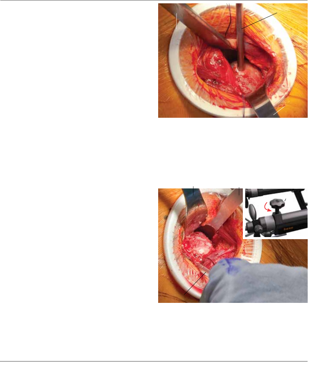
Using a Hibbs Retractor to protect the tensor from the
Oscillating Saw Blade, aim in a medial direction so the ex-
cursion of the saw does not come into contact with the
posterior greater trochanter. Make the cut using the saw.
Use an Osteotome with the blade parallel to the long axis
of the body to finish the cut (between the greater tro-
chanter and the base of the neck) (Figure 22).
Note: An in-situ neck cut may also be performed,
if preferred. A neck cut following dislocation is
described here since dislocation can aid with femo-
ral mobility.
Anterior Approach Surgical Technique DePuy Synthes Joint Reconstruction 15

Prevent sharp edges from catching on muscles by rotating
the head to bring the uncut side out first (Figure 23).
Externally rotate the hip about 45 degrees. Pull up on the
tag suture attached to the anterior capsule and place an MI
Narrow Curved Hohmann Retractor under the capsule and
over the inferior part of the anterior rim. Place a Cobra Re-
tractor over the mid-portion of the posterior rim with the
tip outside of the labrum, but inside of the capsule.
FEMORAL HEAD RESECTION
Corkscrew
Hibbs
Retractor
Figure 24
Figure 23
MI Narrow
Curved Hohmann
Inferior Capsule
Posterior Labrum
Slight external rotation
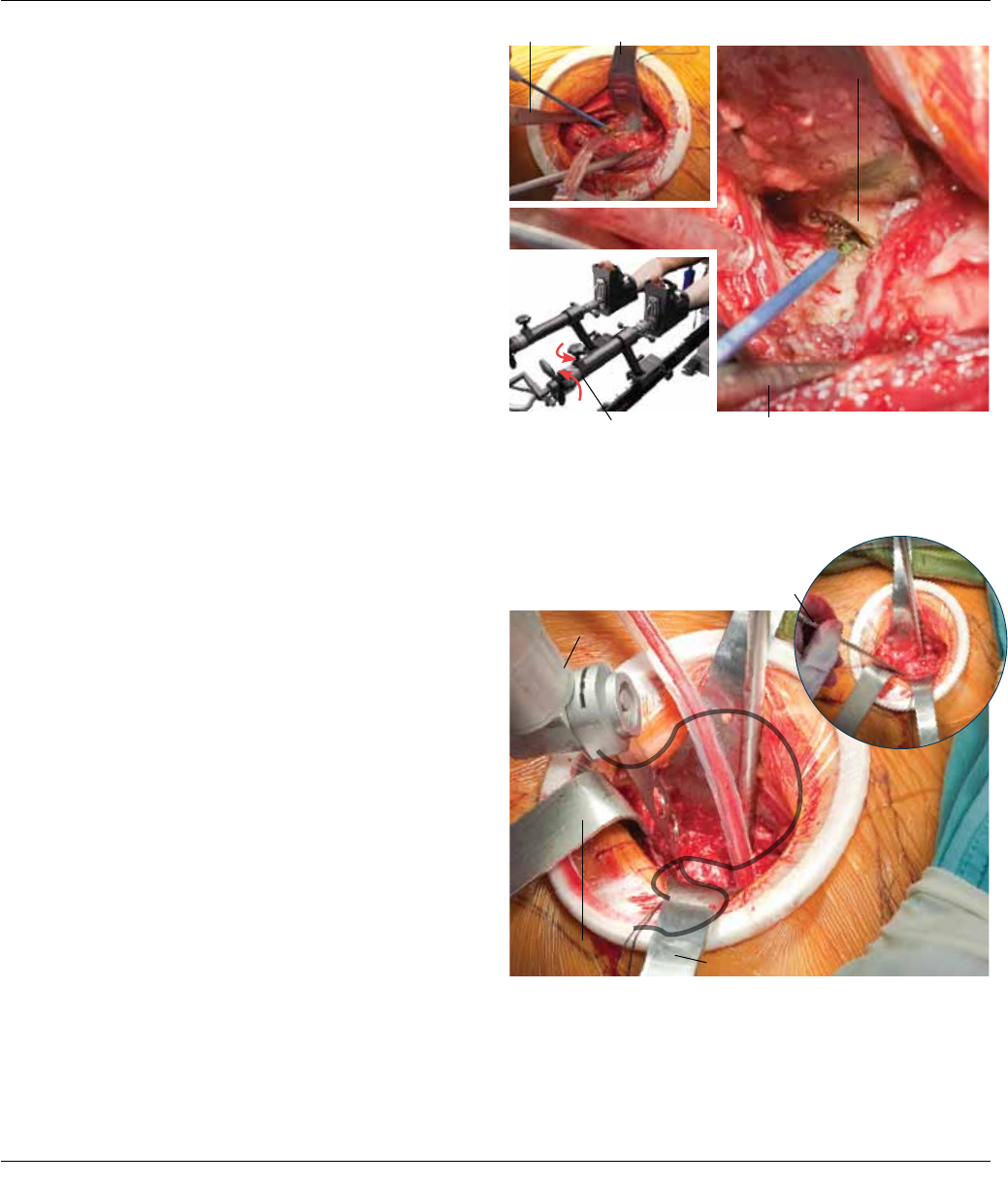
Cut the inferior capsule transversely to allow a little re-
lease, excising inferior capsule if needed. With a knife,
excise residual posterior, and if present, anterior labrum
(Figure 24).
16 DePuy Synthes Joint Reconstruction Anterior Approach Surgical Technique
ACETABULAR REAMING
Begin reaming the acetabulum by aiming the reamer an-
terior to posterior, and proximal. Medialize with the
reamer aimed medial and slightly posterior and superior
(Figure 25). Sequentially ream in 1-2 mm increments.
Check progress by visualizing the acetabulum and by
checking with the C-Arm. Look for and control bleeding
near the obturator foramen.
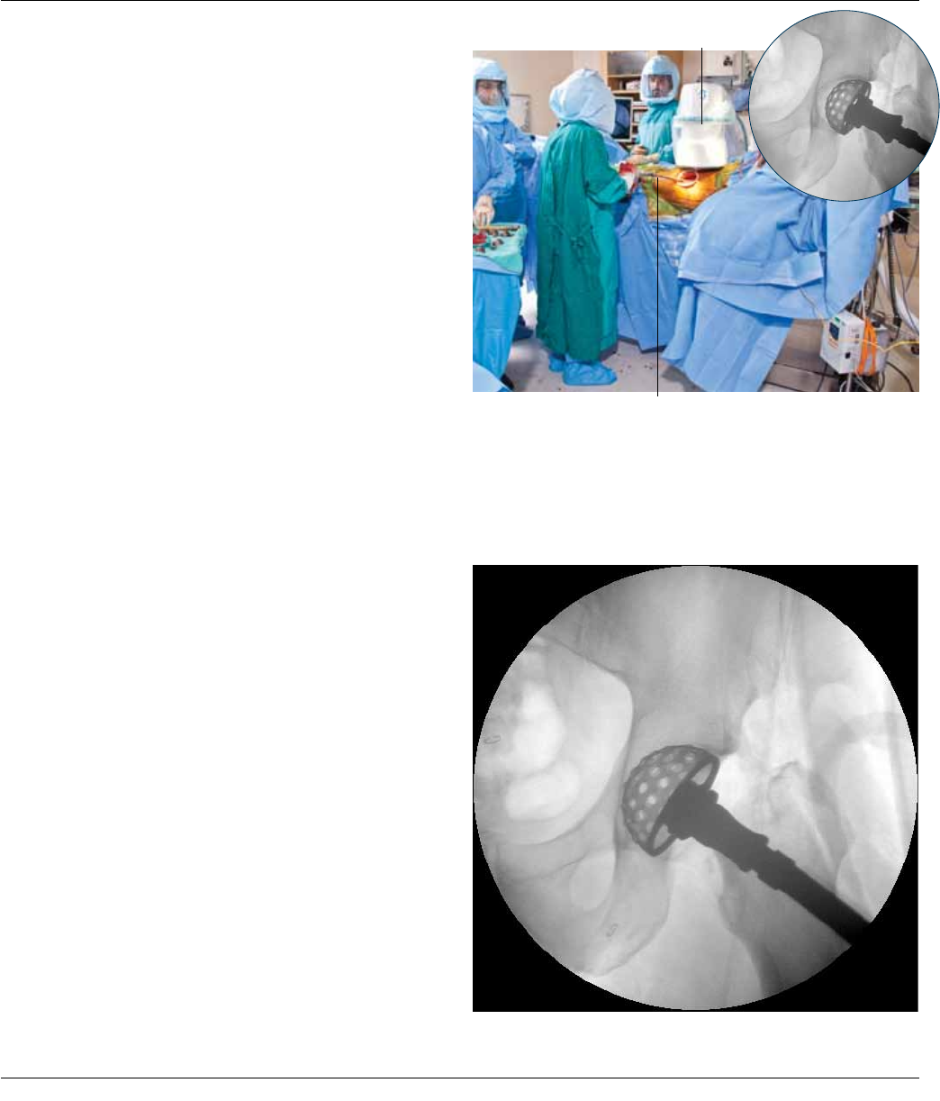
Before reaming to the final templated size, it is recom-
mended that the reamer position be checked with fluo-
roscopy. Generally, the cup should be placed at the pa-
tient’s anatomic center of rotation. Rotate the C-Arm
image (A/P view) on the screen until the pelvis image ap-
pears level (when the transverse anatomic line is horizon-
tal). With the image centered over the midline, the coccyx
should be pointing right at the symphysis, and the obtu-
rator foramina should look identical. You may need to or-
bit and rainbow the C-Arm to accomplish this.
C-Arm
Figure 25
Figure 26
Reamer
After leveling the image and pelvis, center the image over
the operative acetabulum. The image of the reamer
shows where the cup will be centered (Figure 26). The
cup should have a good circumferential fit.
Tip: A cup that is too large may lack purchase and
an overhanging anterior edge may impinge on the il-
iopsoas tendon.
Anterior Approach Surgical Technique DePuy Synthes Joint Reconstruction 17
When you have reamed to the appropriate size, you can
insert the PINNACLE® Trial or Cup (trial liner optional). Af-
ter confirming alignment and position, remove the trial
and insert the final prosthesis. For surgeons unaccus-
tomed to the supine position, it is common to place the
cup with too much inclination and anteversion. The cor-
rect insertion orientation is typically more parallel to the
floor and long axis of the body than expected. Check for
proper placement of the final component with the C-
Arm. Aim for a targeted 40-45 degrees of inclination and
15-20 degrees of anteversion (Figure 27).
The angle and proportions of the image of the ellipse of
the rim of the cup indicates inclination and anteversion.
Note: See front pocket for transparency of an ellipse
for comparison.
ACETABULAR REAMING
Figure 27
Figure 28
Cobra Retractor
Cup Inserter
Cobra Retractor
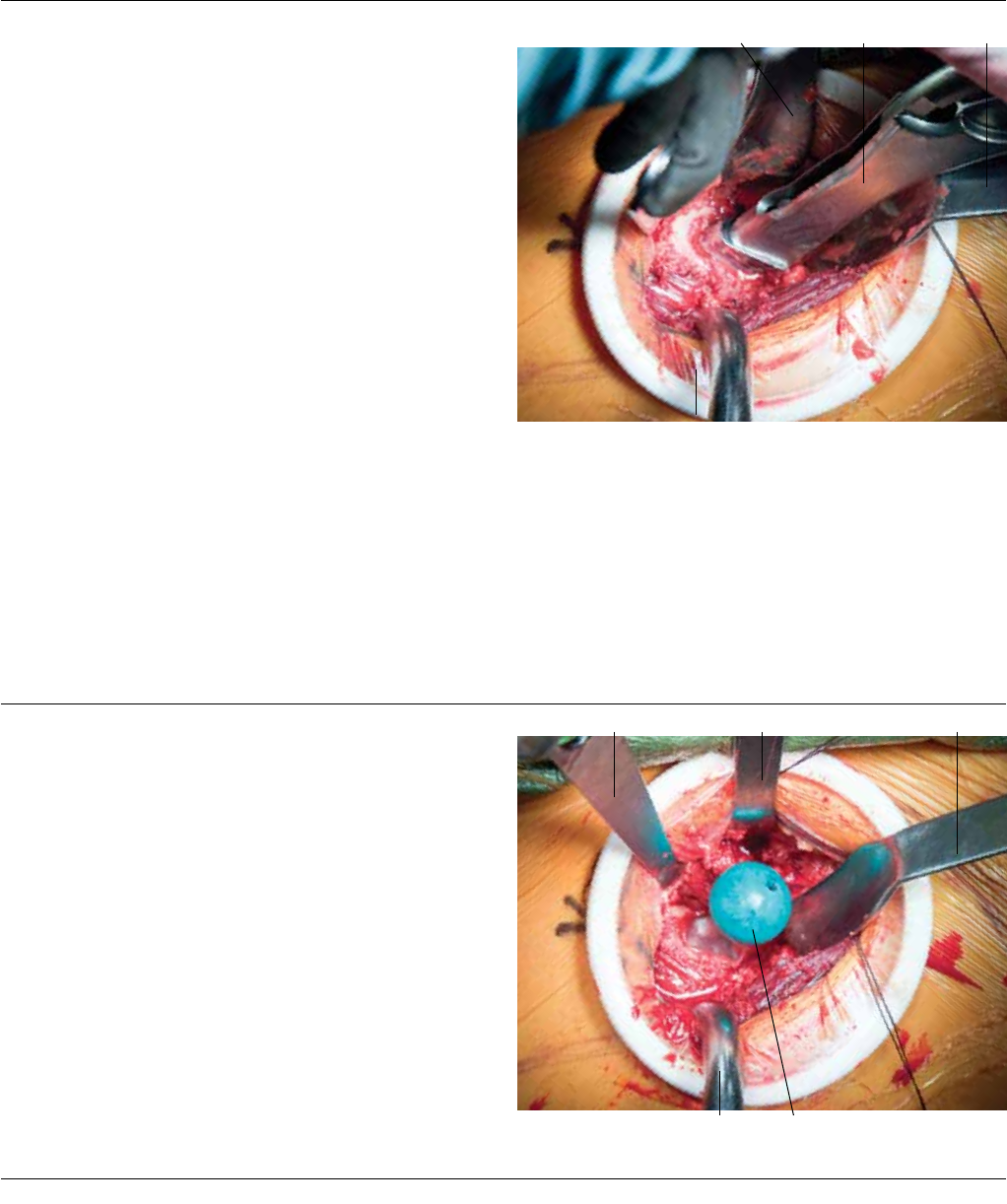
Place the final component into position and impact the
Cup. Before inserting the Cup Liner, check the Acetabular
Retractors. A Cobra Retractor should be placed over the
mid-portion of the posterior rim. Detach the Cup and in-
sert the Liner into the Cup, seating it into the Cup
(Figure 28). Impact the Liner and perform a final check of
the Cup and Liner placement under X-ray.
18 DePuy Synthes Joint Reconstruction Anterior Approach Surgical Technique
Bone Hook Rotate from
45˚ to 0˚
FEMORAL PREPARATION
FEMORAL PREPARATION
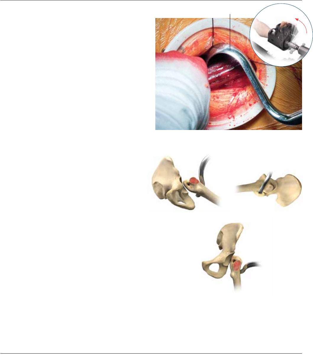
Internally rotate the femur to the neutral position. Palpate
the vastus tubercle, and place the tip of the bone hook
(either the right or left, corresponding to the operative
hip) just distal to the vastus tubercle and around the pos-
terior femur (Figures 29 -30).
Do not force external rotation of the femur. Very force-
ful external rotation can cause a lower extremity frac-
ture. If the patient is elderly and osteoporotic, it is often
safest for the surgeon to grasp the foot boot with its
overlying drape. The surgeon then applies extremity
torque that he or she is comfortable with and the un-
scrubbed table operator locks the position. In many
cases, initial femoral external rotation is short of 90 de-
grees, but subsequent soft tissue releases will allow 90
degrees of femoral external rotation.
View 3
Figure 30
Figure 29
View 1 View 2
Anterior Approach Surgical Technique DePuy Synthes Joint Reconstruction 19
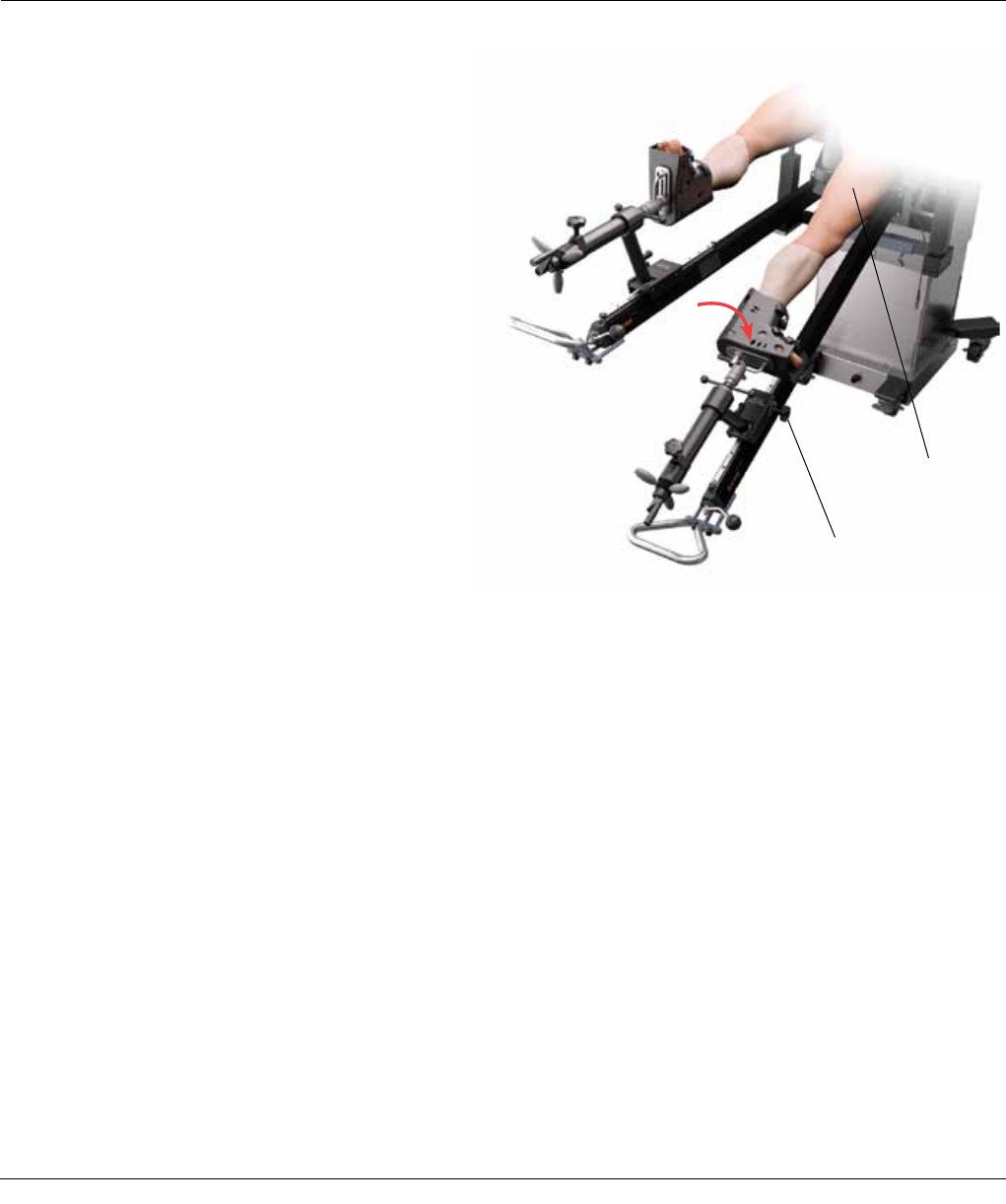
Figure 31
Gross Traction Unlocked
Extend the leg to the
floor and adduct
Foot EXTERNALLY rotated 110-120 degrees
(Rotation of femur 90 degrees)
Lift up on the femur with the bone hook and pull laterally
away from the acetabulum. From the table, unlock the
gross traction – using no traction at this stage. Externally
rotate the foot approximately 110-120 degrees, this will
result with the femur rotating approximately 90 degrees.
Lock the rotation wheel, unlock gross traction and extend
and adduct the leg (Figure 31).
Femoral Preparation
20 DePuy Synthes Joint Reconstruction Anterior Approach Surgical Technique
Place a Cobra or Muller Retractor (Cat. No. 2176-10-000)
along the posterior cortex of the femur. Next, place a
Trochanteric Retractor (Cat No. 2598-07-240) over the tip
of the greater trochanter, and outside the hip capsule
(Figure 32).
Place the bone hook into the bracket on the table and
manually lift the Hook. Lift the femur and raise the jack to
bring the bracket up to hold the Hook.
Note: Use the table bracket as a shelf, not as a lift for
the bone hook and femur.
Figure 32 Bone Hook
Figure 33 Lateral Capsule
Anterior Capsule Suture
Trochanteric
Retractor
Trochanteric
Retractor
Cobra Retractor
Cobra Retractor
Detach the lateral capsule anterior to posterior from the
inside of the greater trochanter, into the piriformis fossa.
Pull up on the suture attached to the anterior capsule to
facilitate this (Figure 33).
Anterior Approach Surgical Technique DePuy Synthes Joint Reconstruction 21
Cauterize the region of the retinacular vessels along the
posterior superior neck. The piriformis and obturator in-
ternus tendons insert on the anterior portion of the
greater trochanter. Typically, the piriformis tendon lies su-
perior to the anterior greater trochanter. The obturator in-
ternus tendon typically lies medial to the tip of the greater
trochanter. Further release of the capsule from the medial
trochanter tip and partial or total release of the internus
tendon provides full exposure of the medial trochanter tip
and enhanced femoral mobility
At this point you will see some fibers of the capsule and
may see some of the obturator internus tendon. If you
need to see more of the inside of the greater trochanter,
incise along the inner surface of the greater trochanter to
enhance visualization (Figure 34).
A manual lateral and anterior pull on the Bone Hook (after
soft tissue release) can give further femoral exposure. This
position is maintained by raising the hook bracket. At this
point, further femoral rotation, if necessary, may be possi-
ble. The strong insertion of the obturator externus tendon
is seen in the piriformis fossa and should be preserved. The
obturator externus pulls the femur in a medial direction
and thereby has an important anti-dislocation function.
Use a Long-Handled Rongeur (Cat. No. 2598-07-690),
to remove the lateral neck remnant and if necessary, to
get more lateral into the inside of the greater trochanter
(Figure 35).
Femoral Preparation
Figure 34
Figure 35 Bone HookLateral Neck Remnant
Bone Hook Hohmann Retractor
Rongeur
Cobra Retractor
Cobra Retractor
22 DePuy Synthes Joint Reconstruction Anterior Approach Surgical Technique
BROACHING
TRIALING
FEMORAL BROACHING AND TRIALING
Start the CORAIL® Total Hip System broach insertion near
the calcar, by pushing the smallest size compaction
broach by hand (Figure 36).
Orient the broach such that the plane of the broach is
parallel to the posterior cortex. Sequentially broach to the
proper size with the broach attached to the selected
broach handle. This will progressively enlarge the metaph-
yseal cavity by compacting and shaping the cancellous
bone until the level of the neck resection is reached.
Check the depth of broach insertion in relation to the tip
of the greater trochanter and match this to the templated
pre-operative plan.
Broaching should continue until complete stability
is achieved with the last size broach used without reach-
ing cortical contact in the femoral canal, ensuring cancel-
lous bone preservation. The size of each CORAIL broach is
the same as the corresponding implant without the 155
thick HA (hydroxyapatite) coating.
Place the appropriate trial neck and head onto the broach
(Figure 37). Lower the bracket and take out the retractors
and femoral hook. Use the table to bring the leg back to
neutral position. Pull back on the gross traction and inter-
nally rotate the leg to reduce the hip.
Broach Handle
Figure 36 Bone Hook
Bone Hook Trial Head
Trochanteric
RetractorCobra or Muller Retractor
Figure 37
Trochanteric RetractorHohmann Retractor Cobra or Muller Retractor
Tip: If you impact a broach and it does not fully seat
in the canal, it is recommended that you go back to
the previous size broach and re-establish the broach
envelope of cancellous bone to accept the smaller
size implant. The CORAIL implant’s design allows
you to go back to the smaller size if needed.
Anterior Approach Surgical Technique DePuy Synthes Joint Reconstruction 23
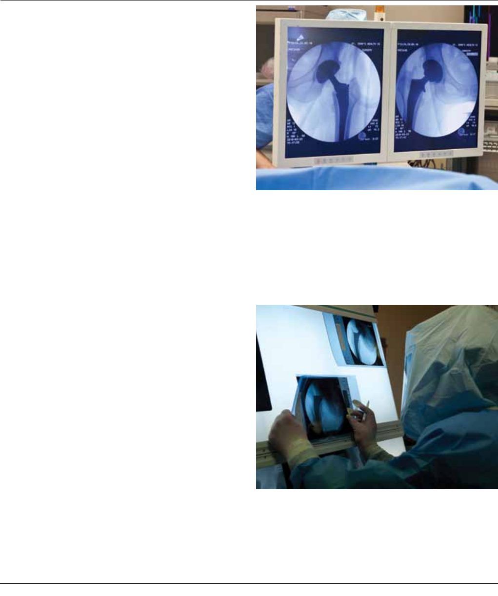
Check the leg length and offset with the X-ray. Position
the hips identically to get accurate comparison views. The
table is very helpful for making and holding small adjust-
ments of abduction and rotation to maximize the accu-
racy of comparison X-rays. Take an X-ray of the non-oper-
ative hip to be used as a control. Then take a picture of
the operative hip for comparison (Figure 38).
FEMORAL TRIALING
Figure 38
Figure 39
With the two prints, check femoral offset and leg length
by overlaying the X-rays (Figure 39).
Tip: Take a distal X-ray to check stem direction and
correct sizing in the canal.
24 DePuy Synthes Joint Reconstruction Anterior Approach Surgical Technique
FINAL IMPLANTATION
Return the femur to the preparation position (dislocate,
externally rotate, extend and adduct). Re-establish the
femoral exposure with the retractors and elevate the fe-
mur with the bone hook. If the trial reduction was satis-
factory, with good broach size and position, and accurate
length and offset, then plane the calcar. Place the MI Cal-
car Planer (assemble Shaft 2570-04-500, and Mill Disc-
2001-47-000 Small, 2001-48-000 Medium, or 2001-49-
000 Large) onto the broach trunion and mill the calcar to
the broach face, allowing the implant collar (if used) to
seat flush against the calcar. Make certain the calcar
planer is rotating before engaging the calcar to prevent
the planer from binding on the calcar.
If during trial reduction, it was determined that adjustments
were needed, make the necessary adjustments to correct
broach size, inserter depth, neck length or offset. Significant
adjustments should be checked with another trial.
Place the final CORAIL implant by hand into the prepared
canal until 1-2 cm of HA coating is visible.
Impact the stem with light blows until it is seated using
the Anterior Inserter (Cat. Nos. 2598-07-460, Modular In-
serter Handle, and 2598-07-440, CORAIL/TRI-LOCK Bone
Preservation Stem Anterior Inserter Shaft). Place the final
head onto the stem and impact. Using the hana table,
complete the final reduction (Figure 40).
Take a final X-ray and perform wound closure by tying the
two sutures together and irrigating out. Close the fascia,
subcutaneous tissue and skin (Figure 41).
Final Head
Figure 40
Figure 41
Cobra or Muller Retractor
Anterior Approach Surgical Technique DePuy Synthes Joint Reconstruction 25

CORAIL Tips
• The use of the collared CORAIL stem can help control
for subsidence, especially in Type C bone.
• The CORAIL is a cancellous impaction broach and stem,
and it does not fit and fill. You should not have to use
aggressive mallet blows to seat the broach or the stem,
wrist motion is usually sufficient. Be particularly careful
in Type A bone where the cancellous bone is usually
dense, and do not try to force too large of a size in this
type of bone.
Approach Tips
• For your first Anterior Approach cases, select your pa-
tients carefully. The most difficult patients are the
heavy, muscular males that have short femoral necks,
or morbidly obese patients. As you become more com-
fortable with the technique, you will find that you can
expand your patient selection. Many surgeons use the
Anterior Approach on all patients, once they are
through the initial learning curve.
• Orthopaedic surgeons are accustomed to palpating
bone, cutting to the bone and following it. The Ante-
rior Approach may produce some initial unfamiliarity
because it is more of a pure soft tissue approach and
relies on recognition of soft tissue landmarks.
• Be meticulous with exposure of the lateral neck/top of
the trochanter. It improves access to the femur and
makes it easier to avoid varus implant placement.
• Early in the learning curve, the main difficulty is mobili-
zation of the femur. Some surgeons recommend excis-
ing the anterior capsule, which may help with a large
patient. Some surgeons will do this routinely and it
may help early in the learning curve.
• Some surgeons start the case with the hip in slight flex-
ion, which can help to relax the rectus.
Incision Tips
• For the surgeon unfamiliar with the approach, the inci-
sion will appear more lateral than expected. The inci-
sion should go over the belly of the tensor fascia lata
muscle and lateral to the interval between the tensor
and sartorius. This preserves the lateral cutaneous
nerve of the thigh and allows access inside the tensor
sheath. If you are too medial to the tensor sheath,
there is the potential for damage due to muscle ener-
vation. If you are too lateral, the operation can still be
performed through a different interval. The tensor may
be split, which is an approach used by Keggi. The Wat-
son-Jones interval is further lateral and posterior to the
tensor.
• If the incision is too distal, the first Cobra may not be
placed correctly. You should be able to feel the anterior
innominate bone through the incision, and this gener-
ally requires that the proximal incision cross the groin
crease. To find the superior lateral neck for the first re-
tractor placement, feel with your finger as you dissect
the medial border of the tensor off its sheath proxi-
mally until you can feel the anterior border of the
bone. Follow it deep until you feel the superior neck,
and place the cobra here.
• Make sure the lateral circumflex vessels are cauterized
during the approach.
Dislocation Tips
• Excise the anterior hip capsule in a trapezoidal shape,
with the wide part of the trapezoid along the femoral
inner trochanteric line and the narrow part at the ace-
tabular rim.
• With the hip skid, start superiorly between the roof and
the head. Generally, four turns of traction are needed.
The next step is to re-insert the skid between the ante-
rior wall and the head, and take off two turns of trac-
tion to relax the anterior structures. Use a curved osteo-
tome or a long, curved scissor to sever the ligamentum if
you experience difficulty placing the hip skid.
• Posterior capsule release followed by an internus and
piriformis release will expose most hips.
• Externus releases are rarely needed, and are difficult
because of the intimate contact with the fossa and
posterior bone.
HINTS AND TIPS
26 DePuy Synthes Joint Reconstruction Anterior Approach Surgical Technique

Neck Cut Tips
• Cutting the neck from anterior to posterior introduces
the possibility of the saw inadvertently cutting the pos-
terior greater trochanter. Guard against this by aiming
the saw somewhat medial and cutting the calcar area
first. Next, cut only the anterior neck more lateral and
finally cut the lateral shoulder of the neck with an os-
teotome in a posterior and medial direction. A small
bridge of the bone in the posterior neck near the
greater trochanter may be left uncut but it will fracture
and the spike left can easily be trimmed later.
• It is difficult with the Anterior Approach to re-cut the
neck. With other techniques, you may have learned
that if the neck cut is long, you can always come back.
With the Anterior Approach, a long neck cut will chal-
lenge you the rest of the case, making it difficult to get
reamers and the cup into the acetabulum. Take your
time, cut the neck at the right length the first time
through, which means you must know where the infe-
rior trochanter is before the osteotomy.
• While cutting the neck, take care not to cut the greater
trochanter, which is a posterior structure. If the hip is
slightly externally rotated, it can endanger the trochan-
ter when the saw comes through the posterior cortex.
Some surgeons finish the superior lateral cut with the
osteotome to protect against cutting the trochanter.
• To help avoid fracture of the greater trochanter, some
surgeons release the capsule when extended, and ro-
tate the femur to mobilize better for rotation and ele-
vation before releasing external rotators.
• Once the hip is dislocated anteriorly, you can use a
small Hohmann to retract the vastus lateralis from the
calcar and then release the inferior medial capsule from
the neck. With the corkscrew still in place and the hip
dislocated anteriorly, perform a sub-capital femoral
neck resection with a long, narrow saw blade.
• Because the corkscrew is still attached to the head and
the head is anterior, you simply remove the head and
internally rotate the hip to about 30 degrees of exter-
nal rotation. Next, complete the neck cut and remove
the remaining neck segment at the desired level of
neck resection.
Head Removal Tips
• Some surgeons remove the head with a segmental cut
in the femoral neck without dislocating the hip.
• When removing the head, use a Hibbs retractor and a
Cobra to protect the tensor from the sharp, cut edge
of the neck.
Acetabular Preparation Tips
• When reaming, keep traction on, with the leg exter-
nally rotated about 60 degrees to help keep the femo-
ral neck out of the way.
• If you are having difficulty getting the acetabular ream-
ers into the acetabulum, make sure the femoral neck
cut is not too long.
• Be careful reaming the acetabulum, as the tendency is
to ream too anteriorly. You can reduce anterior retrac-
tor tension when inserting reamer, and during ream-
ing, to allow centralization of reamer and avoid prefer-
ential anterior reaming.
• If needed, you can place the reamer into the acetabu-
lum, and then attach the power.
Anterior Approach Surgical Technique DePuy Synthes Joint Reconstruction 27

Cup Insertion Tips
• Cup insertion is straightforward, and it is recom-
mended that you use fluoroscopy, starting with a true
A/P pelvis view to verify your landmarks.
• Most of the errors in positioning the acetabular com-
ponent are placing it too abducted and too anteverted.
After proper placement, the correctly positioned ace-
tabulum will often appear in the wound to be more
horizontal and less anteverted than expected. This ef-
fect is accentuated if the patient’s lumbar lordosis in-
creases when supine under anesthesia on the ortho-
paedic table, as is often the case. An increase in
lordosis is easily identified with an image view of the
obturator foramina showing a decreasing superior-infe-
rior dimension.
Femoral Preparation Tips
• Some surgeons recommend incising the piriformis to
expose the femur and get to the true piriformis fossa
for the starting point into the femur.
• Access to the femur requires patience and a stepwise
approach. Many surgeons release the capsule from the
medial femoral neck after dislocating the head. If you
choose to not dislocate and cut the neck in situ, this
capsular release can be performed after head removal
and with the femur externally rotated. Release the
band of capsule just inferior to the acetabulum. The fe-
mur is placed in the preparation position with the table
with successive external rotation (approximately 120
degrees), hyperextension, adduction, and proximal ele-
vation with the hook. First, the lateral capsule is re-
leased from the lateral neck remnant and medial
greater trochanter, which is typically enough to allow
the femur to displace lateral and anterior. The bone
hook is progressively raised as the femur mobility al-
lows. Do not force the bone hook up, because it will
risk a fracture of the greater trochanter.
• If further femoral displacement is needed you can pro-
gressively release the tendons of the obturator inter-
nus, piriformis, and obturator externus. An obturator
externus tendon release is rarely necessary and is least
desirable because it has the most medial anti-disloca-
tion pull on the femur. At times the femur will not ini-
tially rotate externally to 90 degrees but will after re-
lease of the lateral capsule.
• The femoral elevation hook should not be thought of
as a strong traction device. The hook is a support that
keeps the femur from falling posterior from a position
that you can manually create by pulling on the hook.
Feel the tension on the hook and make sure that you
can still manually lift the femur a little higher than the
hook supports it.
• Ensure that all traction is off the operative leg before
placing it in extension and external rotation.
• Do not force the proximal femur up if it resists. Instead,
release the posterior superior capsule, and try to pull
the femur away from the acetabulum. The posterior
part of the greater trochanter tends to get caught on
the posterior rim of the acetabulum. If you try to force
it up, you will risk fracture of
the trochanter.
• You can enter the femoral canal with a Kuntcher Awl
or the Canal Finder (Cat. No 9400-80-001). It has just
the right bend and gets the entry in the right align-
ment under fluoro. It has helped some surgeons when
they first started on the learning curve and may help
avoid violation of the canal.
Hints and Tips
28 DePuy Synthes Joint Reconstruction Anterior Approach Surgical Technique

Femoral Broaching Tips
• Broaching is straightforward, but be cautious of a pa-
tient with a flexion contracture, as the femur may be sit-
ting straight out instead of down, and you can broach
out the back of the femur if you are not careful.
• Femoral anteversion is judged by palpation of the pa-
tella and visualization of the neck cut. The plane of the
broach should be roughly parallel to the plane of the
posterior neck cortex. Most femurs have very little ana-
tomic anteversion.
• The broach handle should be up against the patient’s
side to avoid having the broach perforate the posterior
part of the proximal femur.
C-Arm Tips
• The purpose of the image intensifier is to enhance the
accuracy of the cup placement and femoral length and
offset compared to standard techniques. Use your
standard cues for orientation of the acetabular compo-
nent and use the image as your check. Place the femo-
ral trial according to the pre-operative template and in-
tra-operative bony landmarks (greater and lesser
trochanter) and then make a check with the C-Arm.
• Capture a true A/P pelvis view and note how many de-
grees of orbit are present. Once the acetabular compo-
nent is impacted, view the hip using continuous fluoro
while orbiting the fluoro laterally. When the posterior
rim of the acetabular component is superimposed on
the anterior rim of the shell lock the orbit. Note how
many degrees of orbit are present. This number minus
the initial number from the A/P will be the anteversion
angle of the cup. It is very important to start the proce-
dure with a balanced pelvis where the coccyx lines up
with the symphysis pubis.
• Check your stem version with the femur as the refer-
ence. Using the final broach as your guide, reduce the
hip and balance the pelvis under fluoro to assure the
center of the coccyx is in line with the symphysis. Orbit
the fluoro beam to obtain an A/P of the hip and proxi-
mal femur. Using continuous fluoro, unlock the table
rotation, manipulate the operative leg at the knee or
foot while viewing the image screen. When rotating
from external to internal you will observe the femoral
stems anterior surface is at its maximum medial to lat-
eral diameter (when using a tapered stem) and relative
foot position. If the foot is externally rotated, then your
stem is retroverted. If the foot is internally rotated 10
to 15 degrees, then your stem is well-rotated. If, how-
ever, you have the foot extremely internally rotated,
then your femoral stem is excessively anteverted.
Stability Checking Tips
• Check hip stability with 60 degrees of external rotation
and 50-60 degrees of extension.
• Take the boot out of the spar, grasp the foot with the
sterile drapes that are covering it and put the leg in a
ROM test, and/ or your preferred checks.
Retractor Tips
• Use a Sorrel Retractor (2598-07-210) placed over a lap
sponge over the tensor muscle and attach it to a weight
(2598-07-230). It obviates the need for an assistant to
retract the tensor posteriorly with a Hibbs retractor.
• The long-handled Cobras are good for obese patients
and allow the hands of the assistant to be out of the
way while broaching.
• Take care when using the anterior acetabulum retractor
– do not use a long pointed tip, and stay on the bone
to avoid injury to the femoral nerve.
Anterior Approach Surgical Technique DePuy Synthes Joint Reconstruction 29

There has been concern expressed regarding the possibility
of wound infection for obese patients undergoing Anterior
Total Hip Arthroplasty (ATHA). I will give my thoughts
which may be useful because my personal series docu-
ments only one deep infection in over 1350 primaries. This
patient was not particularly obese but had psoriatic arthritis
with skin lesions adjacent to the operative site.
Obesity by itself is of course an infection risk because of
the thick, poorly vascularized sub-cutaneous layer. Poste-
rior and lateral approaches with their fat layer - thicker
than anterior - certainly pose their own risks. The major
concern and observed problem from anterior, however,
has been an overhanging pannus with
a deep skin crease.
Surgery should not be performed, particularly ATHA, if
the skin fold has observed inflammation, skin breakdown,
or evidence of fungal infection. “Goopy stuff” in the fold
and redness are obvious warning flags. I have had pa-
tients that needed a dermatologic consult pre-op. This led
to topical medications and dressing material in the fold.
I think prepping and draping methodically and carefully is
very important. In extreme cases the abdomen can be
taped toward the opposite side. Assuming the skin is
clean and in good condition, I shave local and adjacent
pubic hair. The main goal is to have adhesive vinyl drapes
that stick and remain stuck during the prep and through-
out the procedure.
I don’t think that vinyl drape application is as simple as it
seems to many in the OR and I harp on the details of this
to nurses and assistants. Another principle is that making
your drape border far from the wound edges enhances
sterility because there is less likelihood that unsticking of
the drapes will make a window to surrounding unsterile
areas. I make an outline of tincture of benzoin where the
sticky edge drapes. Allow the benzoin to dry prior to vinyl
border drape application. Proximal this outline is above or
at the iliac crest and distal at mid thigh, and posterior,
posterior to the greater trochanter by 7 to 10 cm. The
medial border should be as medial as possible without be-
ing deep in the skin crease between the pubic promi-
nence and the thigh.
I find if the medial drape is too medial it is very difficult to
keep it firmly attached during the prep. When the border
vinyl drapes are placed on the benzoin border they should
not be placed under tension. If anything, place the skin
under slight tension so that the vinyl edge will sit down
and in the concavities and folds and stay there. The big-
gest problem I see is that the person applying pulls the vi-
nyl drape and it does not go into and firmly attach to the
depths of the concavities and folds. No tension during ap-
plication! The prepping must also not create detachment
of the vinyl drape border.
Once the vinyl drape border is established I don’t let the
subsequent drapes make the exposed surgical area
smaller. After placing some sheets above and below, I sta-
ple towels to the skin along the vinyl border and then ap-
ply split sheets above and below. The splits are not placed
on the skin but on the bordering towels and leave a small
margin of the towel border visible.
The most important step follows, which is getting the Be-
tadine® impregnated skin vi drape properly applied. The
prepped area must be dry. Again don’t stretch the drape,
stretch the skin. An assistant needs to pull the pannus
proximally to flatten out the fold as much as possible. The
vi drape is then patted first into the concavities and then
outward over the convexities. At the completion the vi
drape if applied properly should look wrinkled not tense
and smooth. If pulled under tension, it will pull away from
the concavities during the case and open the widow to
unsterile areas. You may need a bigger vi drape than you
think because of stretching out the skin and following the
concavities of the obese. If there are air bubbles under the
vi drape, puncture them. Don’t “walk them to the side”
with your fingers. When you do this you unstick and res-
tick areas of the vinyl making it lose some of its adhesive-
ness which makes it more likely to detach during the sur-
gery and open a window to groin or other bacteria.
PREVENTING INFECTION IN OBESE PATIENTS
Joel Matta, M.D.
30 DePuy Synthes Joint Reconstruction Anterior Approach Surgical Technique

Probably my details, like the towel border and U drapes,
are individual to my routine and not essential. However, a
firmly attached border with benzoin and maintaining inti-
mate vi drape attachment during the surgery is essential.
An additional benefit of this technique is that the vi drape
usually turns the fold into a more gentle concavity and
helps hold the pannus up.
Begin the incision lateral enough and you will usually avoid
the worst of the pannus fold. Usually my incision is not lon-
ger than 10 cm, but make it as long as necessary. I prefer
the Protractor because it helps protect the skin and sub
cut. Like any other surgery, being gentle with soft tissues
and hemostasis is important in preventing infection. I have
started using the Tissue Link AquaMantis which I think
helps down in corners and hard to reach bleeders. I think it
helps with capsule bleeding. Get adequate femoral mobili-
zation so that the tensor doesn’t get ripped. Femoral mobi-
lization combined with adequate incision length will also
limit broach and handle trauma to the tissues.
Deep and sub cut drains are optional according to prefer-
ence and bleeding at the end. After closing the fascia, I like
to put only one running layer of 2-0 in the sub cut. I don’t
like to try to approximate the dermis at this point because
the wound tends to split sub cut sutures that are very su-
perficial. For the sub cut I think that usually less is better
because a lot of suture just crushes the fat leading to drain-
age. I then prefer a running sub cut that is resorbable. Se-
cure the suture ends well with benzoin and Steri-Strips™
pinching the free ends of the suture. Dermabond® is the
last layer, then a dressing after the Dermabond dries.
After surgery, it is probably best to keep a dressing in the
skin fold to help prevent maceration. Do not allow the
nurses to place tape on the Steri-Strips or the tape will
pull them off.
I think that some obese patients will inevitably get some
proximal wound maceration and the skin may open some
in this area but the problem seems to remain superficial
and it gradually heals. If the wound opens a little in this
area, I do not try to close it.
No tubs or swimming pool (just showers) for the first 2
weeks and possibly longer if there is a wound problem.
Anterior Approach Surgical Technique DePuy Synthes Joint Reconstruction 31

TSS Core Case 1
1. 2598-07-460 Universal Stem Insert Handle
2. Trial Heads – Two Sets Per Case
3. 2598-07-570 Retaining Stem Inserter (2 pcs)
4. 2598-07-530 Modular Box Osteotome
ORDERING INFORMATION
7
5
6
1
1
2
2
3
2
4
3
4
Base
Insert
1. Any two handles:
2570-00-000 SUMMIT
®
Universal Broach Handle
9522-10-500F CORAIL AMT Straight Broach Handle
9522-11-500 CORAIL AMT Curved Broach Handle
2598-07-540 Long Posterior Broach Handle
2001-97-000 Optional Version Control Rod
(for Posterior Broach Handle)
2598-07-550 Extra Curved Broach Handle
2598-07-350 Anterior Broach Handle - Left
2598-07-360 Anterior Broach Handle - Right
2. 2598-07-470 CORAIL/TRI-LOCK
Posterior Stem Insert Shaft
3. 2598-07-480 SUMMIT Posterior Stem Insert Shaft
4. 2598-07-435 Bullet Tip Stem Insert Shaft
5. 2598-07-430 Standard Straight Stem Insert Shaft
6. 2598-07-450 SUMMIT Anterior Stem Insert Shaft
7. 2598-07-440 CORAIL/TRI-LOCK Anterior Stem Insert Shaft
2598-07-390 Tissue Sparing Femoral Core Case 1
Complete
2598-07-410 Lid
2598-07-411 Insert
2598-07-400 Base
32 DePuy Synthes Joint Reconstruction Anterior Approach Surgical Technique
Other broach handle options:
2570-00-000 SUMMIT Universal Broach Handle
9522-10-500F CORAIL AMT Straight Broach Handle
9522-11-500 CORAIL AMT Curved Broach Handle
Technique-specific femoral component inserters:
2598-07-460 Universal Stem Inserter Handle
2598-07-440 CORAIL/TRI-LOCK Bone Preservation
Stem Anterior Inserter Shaft
2598-07-450 SUMMIT Anterior Inserter Shaft
2598-07-430 Standard Straight Inserter Shaft
2598-07-470 CORAIL/TRI-LOCK Bone Preservation
Stem Posterior Inserter Shaft
2598-07-480 SUMMIT Posterior Inserter Shaft
2598-07-435 Bullet Tip Inserter Shaft
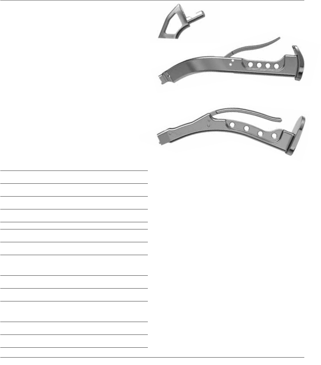
Modular Box Osteotome 2598-07-530
Dual Offset Anterior Approach Broach Handle
Left 2598-07-350, Right 2598-07-360
Extra-Curved Broach Handle 2598-07-550
Suitable for multiple surgical approaches.
Anterior Approach Surgical Technique DePuy Synthes Joint Reconstruction 33
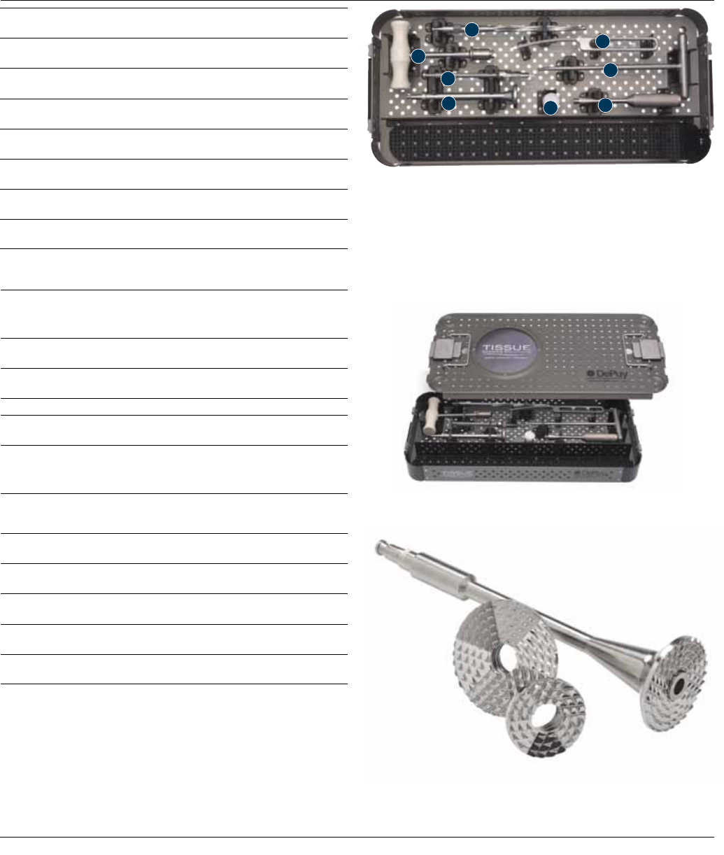
TSS Core Case 2
1. 2354-10-000 Muller Awl Reamer w/Hudson End
2. 2001-42-000 Excel T-Handle
3. 2001-80-501 IM Initiator Sized
4. 9400-80-007 MI Calcar Reamer Small (Shielded)
5. 85-3927 Femoral Rasp
6. 9400-80-001 Canal Finder
7. 2001-65-000 Femoral/Humeral Head Impactor
Ordering Information
1
2
3
4
5
6
7
7
2598-07-420 Tissue Sparing Femoral Core Case 2
Complete
2598-07-422 Lid
2598-07-421 Base
Optional Replacement Part:
2001-66-000 Replacement Tip
for Femoral Head Impactor
Calcar Planer
2570-04-500 MI Calcar Reamer Shaft
2001-47-000 Calcar Mill Discs – Small
2001-48-000 Calcar Mill Discs – Medium
2001-49-000 Calcar Mill Discs – Large
34 DePuy Synthes Joint Reconstruction Anterior Approach Surgical Technique
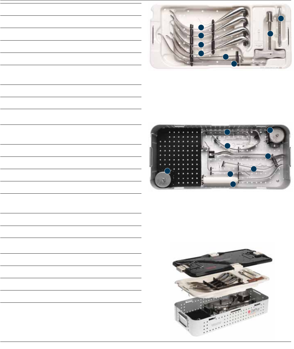
Anterior Approach Instrumentation
1. 37-4106 Blunted Serrated Cobra (2)
2. 2598-07-200 MI 2-Incision Sharp Cobra (Serrated Point)
3. 2598-07-260 Blunted Cobra
4. 2598-07-240 Single Prong Soft Tissue Retractor
5. 2181-10-000 Hohmann Retractor Narrow/Curved
(120 degree)
6. 2001-42-000 Excel T-Handle
7. 2125-00-600 Modular Head Ball Remover
1. 2598-07-180 Right Angle Posterior Capsular Retractor
(Hibbs)
2. 2598-07-230 Sorrel Retractor Weight 2lbs
3. 32598-07-210 Sorrel Incision Retractor Blade Wide
4. 2004-00-000 Murphy Bone Skid
5. 2598-07-190 MI Narrow Curved Hohmann
6. 2598-07-110 MI Gluteus Medius Retractor
(Right Angle Hohmann)
7. 2176-10-000 Muller Type Retractor
8. 2598-07-220 Sorrel Retractor Weight 2.5 lbs
2598-07-310 Anterior Approach Case Complete
2598-07-320 Lid
2598-07-340 Insert
2598-07-330 Base
Insert
Base
1
1
3
2
4
5
6
7
8
1
2
3
4
5
6
7
Anterior Approach Surgical Technique DePuy Synthes Joint Reconstruction 35

MI Retractor Kit
1. 2598-07-650 MI XL Femoral Neck Elevator
2. 2598-07-625 Inferior Posterior Capsular Retractor Right
3. 2598-07-626 Inferior Posterior Capsular Retractor Left
4. 2598-07-180 Right Angle Posterior Capsular Retractor
5. 2598-07-120 Blunt Right Angle
Posterior Capsular Retractor
6. 2598-07-150 Sciatic Nerve Retractor
7. 2598-07-140 Superior Capsular Retractor
8. 2598-07-170 Anterior Hohmann
1. 2598-07-130 MI Cobra Retractor with Armrest
2. 2598-07-190 MI Narrow Curved Hohmann
3. 2598-07-160 MI Narrow Cobra
4. 2598-07-110 MI Gluteus Medius Retractor
(Right Angle Hohmann)
2598-07-500 MI Retractor Case Complete
2598-07-520 Lid
2598-07-515 Insert
2598-07-510 Base
Ordering Information
Insert
Base
2
1
1
4
3
2
3
5
6
4
8
7
36 DePuy Synthes Joint Reconstruction Anterior Approach Surgical Technique
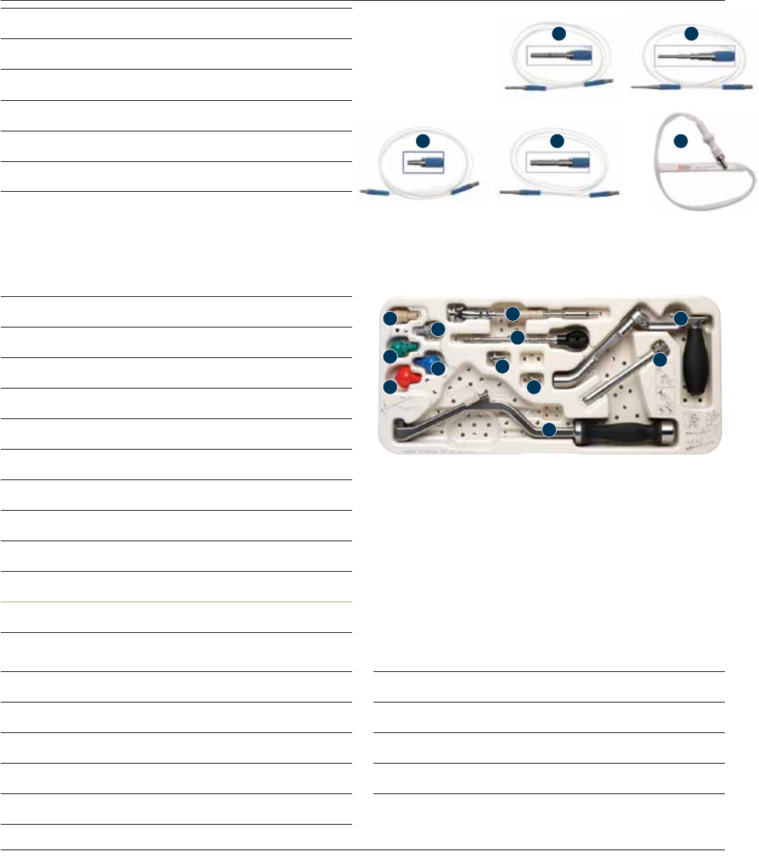
Lighted Retractors
1. 2598-07-940 Cable with Olympus Adaptor
2. 2598-07-930 Cable with Storz Adaptor
3. 2598-07-910 Cable with ACMI Adaptor
4. 2598-07-920 Cable with Wolf Adaptor
5. 2598-07-900 Lightstrips (Package of 5)
MAcS Acetabular Set
1. 9200-10-024 Impactor Tip 22.225 mm
2. 9200-10-025 Impactor Tip 26 mm
3. 9200-10-026 Impactor Tip 28 mm
4. 9200-10-027 Impactor Tip 32 mm
5. 9200-10-028 Impactor Tip 36 mm
6. 2598-08-160 Angled Drive Shaft Dual Coupling
7. 9200-10-029 Angled Acetabular Inserter
8. 9200-10-023 Bantam Adaptor
9. 2598-08-150 Angled Reamer Driver Housing Assembly
9200-10-017 MAcS Case Complete
Inserter Replacement Parts (not shown):
9200-10-088 Spring
9200-10-089 Button
9200-10-091 Lock Catch
9200-10-093 Standard Adapter
Optional Impactor Tips (not shown):
2217-50-060 Impactor Tip 40 mm
2217-50-061 Impactor Tip 44 mm
2217-50-062 Impactor Tip 48 mm
16
7
7
7
9
9
3
5
2
48
1
3
2
4 5
Anterior Approach Surgical Technique DePuy Synthes Joint Reconstruction 37

Important
This Essential Product Information sheet does not include all of
the information necessary for selection and use of a device. Please
see full labeling for all necessary information.
Intended Use/Indications
Total Hip Arthroplasty (THA) is intended to provide increased pa-
tient mobility and reduce pain by replacing the damaged hip
joint articulation in patients where there is evidence of sufficient
sound bone to seat and support the components.
THA is indicated for a severely painful and/or disabled joint
from osteoarthritis, traumatic arthritis, rheumatoid arthritis or
congenital hip dysplasia; avascular necrosis of the femoral head;
acute traumatic fracture of the femoral head or neck; failed pre-
vious hip surgery; and certain cases of ankylosis.
Porous-coated Pinnacle Acetabular Cups are indicated for ce-
mentless applications. Self-Centering Hip Prostheses and Hemi-
Hip Prostheses are intended to be used for hemi-hip arthroplasty
where there is evidence of a satisfactory natural acetabulum and
sufficient femoral bone to seat and support the femoral stem.
The Cathcart is not intended for use in total hip arthroplasty.
Hemi-hip arthroplasty is indicated
in the following conditions:
Acute fracture of the femoral head or neck that cannot be re-
duced and treated with internal fixation; fracture dislocation of
the hip that cannot be appropriately reduced and treated with
internal fixation; avascular necrosis of the femoral head; non-
union of femoral neck fractures; certain high subcapital and
femoral neck fractures in the elderly; degenerative arthritis in-
volving only the femoral head in which the acetabulum does not
require replacement; and pathology involving only the femoral
head/neck and/or proximal femur that can be adequately
treated by hemi-hip arthroplasty.
Contraindications
THA and hemi-hip arthroplasty are contraindicated in cases of:
active local or systemic infection; loss of musculature, neuro-
muscular compromise or vascular deficiency in the affected limb,
rendering the procedure unjustifiable; poor bone quality; Char-
cot’s or Paget’s disease; for hemi-hip arthroplasty – pathological
conditions of the acetabulum that preclude the use of the natu-
ral acetabulum as an appropriate articular surface. Ceramic
heads without inner titanium sleeves are contraindicated in revi-
sion surgery when the femoral stem is well fixed and is not be-
ing replaced.
Warnings and Precautions
Ceramic coated femoral stem prostheses are indicated for
uncemented press fit fixation. CAUTION: DO NOT USE
BONE CEMENT FOR FIXATION OF A CERAMIC
COATED PROSTHESIS.
Components labeled for “Cemented Use Only” are to be im-
planted only with bone cement. The following conditions tend
to adversely affect hip replacement implants: excessive patient
weight, high levels of patient activity, likelihood of falls, poor
bone stock, metabolic disorders, history of infections, severe de-
formities leading to impaired fixation or improper positioning,
tumors of the supporting bone structures, allergic reactions to
materials, tissue reactions, and disabilities of other joints.
Adverse Events
The following are the most frequent adverse events after hip ar-
throplasty: change in position of the components, loosening of
components, wear or fracture of components, dislocation, infec-
tion, peripheral neuropathies, tissue reaction.
Total Hip Prostheses, Self-Centering™ Hip Prostheses and Hemi-Hip Prostheses
DePuy Orthopaedics, Inc.
700 Orthopaedic Drive
Warsaw, IN 46582
T. +1 (800) 366-8143
www.depuysynthes.com
© DePuy Synthes Joint Reconstruction, a division of DOI 2013
0612-15-511 (Rev. 2) 5/13 3M
Limited Warranty and Disclaimer: DePuy Synthes Joint Reconstruction products are sold with a limited warranty to the original purchaser against defects
in workmanship and materials. Any other express or implied warranties, including warranties of merchantability or fitness, are hereby disclaimed.
WARNING: In the USA, this product has labeling limitations. See package insert for complete information.
CAUTION: USA Law restricts these devices to sale by or on the order of a physician.
Not all products are currently available in all markets.
