MergedFile Assembly Manual
User Manual: Pdf
Open the PDF directly: View PDF ![]() .
.
Page Count: 29

Assembly Manual
Dylan Brenneis
July 2017
i
Contents
Table of Figures ............................................................................................................................................ ii
1 Introduction ........................................................................................................................................... 2
2 Naming and Definitions ........................................................................................................................ 1
2.1 Digits ................................................................................................................................................... 1
2.2 Joints ................................................................................................................................................... 1
2.3 Finger Parts ......................................................................................................................................... 1
3 Required Materials ................................................................................................................................ 2
3.1 3D Printed Parts .................................................................................................................................. 2
3.2 Ordered Parts ...................................................................................................................................... 3
3.3 Tools ................................................................................................................................................... 5
4 Assembly Flowchart ............................................................................................................................. 5
5 Material Preparation .............................................................................................................................. 6
5.1 3D Printed Parts (17h 0m) .................................................................................................................. 6
5.2 Potentiometers (1h 45m) ..................................................................................................................... 7
5.3 FSRs (1h 0m) ...................................................................................................................................... 8
5.3.1 Fingertips ............................................................................................................................. 9
5.4 Screws (0h 45m) ................................................................................................................................. 9
6 Thumb Assembly (1h 0m) .................................................................................................................. 10
6.1 Part Assembly ................................................................................................................................... 10
6.2 Mounting to Palm ............................................................................................................................. 11
7 Finger Assembly (0h 15m each finger) ............................................................................................... 11
8 Servo Installation and Finger Tensioning (0h 7m each finger) ........................................................... 12
9 Breadboard Hub (3h 0m) .................................................................................................................... 14
10 Aluminum Servo Cover (0h 45m) .................................................................................................. 17
11 Ventral Palm Cover; USB Webcam (0h 20m) ................................................................................ 17
12 Palm Grips (1h 15m) ....................................................................................................................... 18
13 Wiring (1h 0m) ............................................................................................................................... 19
13.1 Testing............................................................................................................................................. 19
13.2 Full Implementation ........................................................................................................................ 20
14 Appendix A: Grip Pattern Template .................................................................................................. I
15 Appendix B: Servo Cover Template ................................................................................................ II
ii
Table of Figures
Figure 1: Digit numbering ............................................................................................................................ 1
Figure 2: Joint names .................................................................................................................................... 1
Figure 3: Example part naming convention .................................................................................................. 1
Figure 4: Dorsal Palm post processing ......................................................................................................... 7
Figure 5: Sanding locations for finger joints ................................................................................................ 7
Figure 6: Filing of DP - D Lock .................................................................................................................... 7
Figure 7: Potentiometer polarity ................................................................................................................... 8
Figure 8: Finished potentiometers................................................................................................................. 8
Figure 9: Fingertip assembly diagram .......................................................................................................... 9
Figure 10: Finished fingertip without grip pads ............................................................................................ 9
Figure 11: Thumb assembly diagram .......................................................................................................... 10
Figure 12: Assembled thumb prior to MC - P Geared Rotator installation, showing servo position ......... 10
Figure 13: Thumb mounted to dorsal palm ................................................................................................. 11
Figure 14: Index finger (D2) assembly diagram ......................................................................................... 11
Figure 15: Full Forward Position of servo .................................................................................................. 12
Figure 16: Zip-tie installed in servo spool .................................................................................................. 12
Figure 17: Servo spool installation on servo ............................................................................................... 13
Figure 18: Required cut for zip-tie .............................................................................................................. 13
Figure 19: Servo installation and finger tensioning complete, showing servo positions for right and left
hand ............................................................................................................................................................. 13
Figure 20: Breadboard clips salvaged from mini breadboard, cut and soldered as necessary .................... 14
Figure 21: Prototyping wire soldered to individual breadboard clip .......................................................... 14
Figure 22: Soldered connections ................................................................................................................. 14
Figure 23: Molex connector configurations ................................................................................................ 15
Figure 24: Breadboard orientation on hub .................................................................................................. 15
Figure 25: Finished soldered connections for breadboard hub, top and front view .................................... 15
Figure 26: Finished breadboard hub ........................................................................................................... 16
Figure 27: Pinout for breadboard hub. Breadboard holes to the left of the green line correspond to sensor
signal connections; holes to the right correspond to servo motor command signals. Use this diagram as a
reference when connecting the wiring to ensure proper connection. .......................................................... 16
Figure 28: Installation of aluminum servo covers (left hand) ..................................................................... 17
Figure 29: USB Webcam installed in ventral palm (right hand) ................................................................ 17
Figure 30: Grip diagram .............................................................................................................................. 18
Figure 31: Test Setup Wiring ...................................................................................................................... 19
Figure 32: Full wiring diagram for individual finger potentiometer control .............................................. 20
Figure 33: Full wiring diagram ................................................................................................................... 21
1 Introduction
The HANDi Hand was designed as an open-source robotic platform specifically designed for machine
learning research. The inexpensive and easily modifiable design allows versatility for research studies,
and the suite of sensors provides valuable information for machine learning and prosthetics research.
The open-source release provides all solid-modelling files, .stl files, Arduino code, and assembly
instruction required to construct a fully functional HANDi Hand, and should also give the maker enough
flexibility to make alterations to the design as necessary to suit their own needs. Both left and right hand
1
versions are available. To contact the original designers, or to receive support for your build, please visit
BLINCdev.ca.
This assembly manual outlines all the information required to print and source parts, and assemble the
HANDi Hand as currently designed. The hand takes an estimated 30 hours to build.
2 Naming and Definitions
This section outlines the naming conventions for the various parts of the hand.
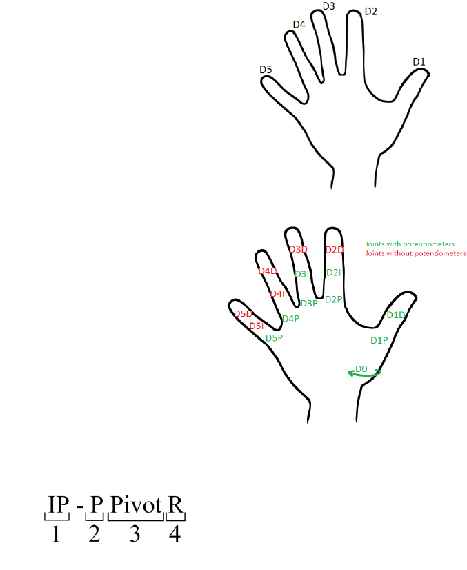
2.1 Digits
The digits are referred to by standard numbering, beginning with the
thumb as D1 (See Figure 1).
2.2 Joints
The joints are named in accordance with Figure 2. The names are
constructed first with a digit indicator (i.e. D2) followed by a joint
indicator D, I or P, indicating distal, intermediate, or proximal
respectively. Potentiometers are named for the joints that they
measure. The digit D0 refers to thumb rotation.
2.3 Finger Parts
Each phalanx of the finger is made up of multiple parts. The parts are named with convention in Figure 3:
1: Phalanx indicator. PP = Proximal Phalanx, IP = Intermediate Phalanx, DP = Distal Phalanx, MC =
Metacarpal
2: Part position indicator. P = Proximal, D = Distal
3: Position modifier. There are sometimes multiple parts in the same location that must be differentiated
by their function (pivot, main, lock, tip, etc).
4: Handedness indicator. R = Right Hand, L = Left Hand
Figure 2: Joint names
Figure 1: Digit numbering
Figure 3: Example part naming convention

2
3 Required Materials
3.1 3D Printed Parts
The 3D printed parts are designed to be printed in PLA without support material and without rafts, except
where indicated. Parts are designed for the print tolerance of a MakerBot Replicator 2. Some filing may
be necessary to ensure a smooth running fit between parts.
All files required for 3D printing can be accessed via BLINCdev.ca. The suggested print specifications
for each part are found in Table 1. The table lists all of the part sets that must be printed for a complete
hand. In the event that a particular component is needed, the individual STL files can be found on
blincdev.ca in addition to the grouped parts in Table 1.
Table 1: 3D printed parts
Part Name
Print Specifications
Estimated Print
Time
Est. Material Weight
Dorsal Palm
0.2 mm layer, 10% infill
Print with raft
6h 0m
64 g
Ventral Palm
0.2 mm layer, 10% infill
1h 55m
22 g
Thumb Screw Cap
0.2 mm layer, 10% infill
0h 15m
2 g
D2 Full Finger
0.2 mm layer, 10% infill
1h 10m
9 g
D3 Full Finger
0.2 mm layer, 10% infill
1h 10m
9 g
D4 Full Finger
0.2 mm layer, 10% infill
1h 10m
9 g
D5 Full Finger
0.2 mm layer, 10% infill
1h 10m
9 g
Full Thumb
0.2 mm layer, 10% infill
2h 30m
25 g
Breadboard
0.1 mm layer, 10% infill
0h 25m
3 g
Connector Hub
0.2 mm layer, 10% infill
0h 15m
3 g
Pot Activator Set of 15
0.1 mm layer, 10% infill
0h 10m
1 g
Pot Placeholder Set of 6
0.2 mm layer, 10% infill
0h 10m
2 g
Servo Spool Full Set
0.1 mm layer, 10% infill
0h 25m
4 g
Servo Spur Gear
0.1 mm layer, 10% infill
0h 5m
1 g
TOTAL:
16h 50m
163 g

3
3.2 Ordered Parts
The table below contains all the items (excluding tools) required for building a complete HANDi Hand.
Table 2: Parts for ordering
Item
Description
Vendor
Part No.
Link
QTY
Cost/
Item
Ext. Cost
Curr.
Notes
SENSORS/ELECTRONICS
Sensor
Rotary
Position
SMD
Rotary
Position
Sensor,
muRata
Electronics
Digi-Key
490-14859-1-ND
(Digi-Key)
SV03A103AEA01R
00 (MFG)
https://www.digikey.ca/pro
duct-detail/en/murata-
electronics-north-
america/SV03A103AEA0
1R00/490-14859-1-
ND/6623608
9
$1.71
$15.39
CAD
400 Short
Tail with
solder tabs
FSR 400
(force
sensitive
resistor) with
short tail and
solder tabs
Digi-Key
1027-1014-ND
(Digi-Key)
34-00004
(MFG)
https://www.digikey.ca/pro
duct-detail/en/interlink-
electronics/34-
00004/1027-1014-
ND/2798665
5
$15.46
$77.30
CAD
Arduino
Mega
Board MCU
MEGA2560
Digi-Key
1050-1018-ND
https://www.digikey.ca/pro
duct-
detail/en/A000067/1050-
1018-ND/2639006
1
$50.38
$50.38
CAD
Wall
Adapter
AC/DC Wall
Mount
Adapter 5V
18W
Digi-Key
Q976-ND (Digi-
Key)
QAWA-18-5-US01
(MFG)
https://www.digikey.ca/pro
duct-
detail/en/qualtek/QAWA-
18-5-US01/Q976-
ND/6412294
2
$21.14
$42.28
CAD
100 kOhm
Resistor
RES 100K
Ohm 1/4
Watt, 5%
Axial
Digi-Key
10KEBK-ND (Digi-
Key)
CFR16J100K
(MFG)
https://www.digikey.ca/pro
duct-detail/en/1623927-
1/A105979CT-
ND/3477574
5
$0.15
$0.75
CAD
DC Barrel
Jack
Adapter -
Female
Barrel Jack
adapter
Sparkfun
PRT-10288
https://www.sparkfun.com/
products/10288
1
$2.95
$2.95
USD
Break
Away
Headers -
Straight
Conn Header
.100” SNGL
STR 40 POS
Digi-Key
S1011EC-40-ND
(Digi-Key)
PRPC040SAAN-RC
(MFG)
https://www.digikey.ca/pro
ducts/en?keywords=S1011
EC-40-ND
2
$1.04
$2.08
CAN
Breadboard
Miniature
Breadboard
Sparkfun
PRT-12043
https://www.sparkfun.com/
products/12043
1
$3.95
$3.95
USD
Only the metal
connectors are
required for
assembly; any
breadboard will
do. See Section
9
Molex
Receptacle
Housing
4POS 2MM
Sherlock
Digi-Key
WM5983-ND (Digi-
Key)
0355070400 (MFG)
https://www.digikey.ca/pro
ducts/en?keywords=WM5
983-ND
2
$0.24
$0.48
CAN
Molex
Receptacle
Housing
6POS 2MM
Sherlock
Digi-Key
WM5985-ND (Digi-
Key)
0355070600 (MFG)
https://www.digikey.ca/pro
ducts/en?keywords=WM5
985-ND
2
$0.28
$0.56
CAN

4
Molex
Header
4POS 2MM
Vert Tin
Sherlock
Digi-Key
WM18922-ND
(Digi-Key)
3562-0450 (MFG)
https://www.digikey.ca/pro
ducts/en?keywords=WM1
8922-ND
2
$0.47
$0.94
CAN
Molex
Header
6POS 2MM
Vert Tin
Sherlock
Digi-Key
WM18924-ND
(Digi-Key)
0353620650 (MFG)
https://www.digikey.ca/pro
ducts/en?keywords=WM1
8924-ND%20
2
$0.61
$1.22
CAN
Terminal
contact
CONN
TERM
FEMALE 24-
30 AWG TIN
Digi-Key
WM6050-ND (Digi-
Key)
0502128100 (MFG)
https://www.digikey.ca/pro
ducts/en?vendor=0&keyw
ords=50212-8100
20
$0.375
$7.50
CAD
Molex
Receptacle
Housing
Mini SPOX
2POS 2.5MM
SHROUD
Digi-Key
WM18873-ND
(Digi-Key)
0050375023 (MFG)
https://www.digikey.ca/pro
ducts/en?vendor=0&keyw
ords=50375023
2
$0.30
$0.60
CAD
Molex
Header
Mini SPOX
2POS 2.5MM
Vert Tin
Digi-Key
WM18886-ND
(Digi-Key)
0022035025 (MFG)
https://www.digikey.ca/pro
ducts/en?vendor=0&keyw
ords=22035025
2
$0.68
$1.36
CAD
Terminal
contact
CONN
TERM
FEMALE 22-
28 AWG
CRIMP
Digi-Key
WM17406-ND
(Digi-Key)
0008701040
https://www.digikey.ca/pro
ducts/en?x=0&y=0&lang=
en&site=ca&KeyWords=0
8701040
4
$0.33
$1.32
CAD
Heat Shrink
Tubing
Assorted Heat
Shrink
Tubing
Sparkfun
PRT-09353
https://www.sparkfun.com/
products/9353
1
$7.95
$7.95
USD
Red, black, and
yellow 1.5mm
diameter
required for
assembly,
approximately
2-3 pieces of
each
Mini
Webcam
300K PIXEL
USB 2.0 Mini
webcam
Digikey
402990004-ND
(Digi-Key)
402990004 (MFG)
https://www.digikey.ca/pro
ducts/en?keywords=40299
0004-ND
1
$12.11
$12.11
CAD
Hitec HS
35HD
Servo
Ultra-Nano
Analog servo,
180 degree
rotation
Sparkfun
ROB-11882
https://www.sparkfun.com/
products/11882
6
$24.95
$149.70
USD
MATERIALS
Medium-
Strength
Textured
Neoprene
Rubber
Adhesive
Back, 1/32"
thick,
12"x12", 40A
Durometer
Hardness
McMaster-
Carr
8445K61
https://www.mcmaster.co
m/#8445k61/=18l0h88
1
$11.08
$11.08
USD
Approximately
2000 mm^2
needed for
assembly
Easy-to-
Weld
Corrosion-
Resistant
5052
Aluminum
Sheet, 0.080"
Thick, 6" x 6"
McMaster-
Carr
88895K105
https://www.mcmaster.co
m/#88895k105/=18l0irl
1
$5.78
$5.78
USD
HARDWARE/MISCELLANEOUS

5
Continuous
-Flex Wire
26-gauge
continuous
flex wire, 50',
Black
McMaster-
Carr
7071K19
https://www.mcmaster.co
m/#7071k19/=18l0k9k
50
$1.20
$60.00
USD
Approximately
50' needed for
in-hand wiring,
50' for hand-arm
wiring
Metric
Cheese
Head
Slotted
Machine
Screw
18-8 Stainless
Steel, M2
Size, 25 mm
Length, .4mm
Pitch, Pack of
50
McMaster-
Carr
91800A023
https://www.mcmaster.co
m/#91800a023/=18l0ku6
1
$7.45
$7.45
USD
16 needed for
assembly, 14 of
which are cut to
size as in
Section 5.4
Loctite
Instant-
Bonding
Adhesive
#404, 0.3 oz
Bottle
McMaster-
Carr
7569A22
https://www.mcmaster.co
m/#7569a22/=18l0vy5
1
$27.37
$27.37
USD
Any super-glue
will work.
Type 18-8
Stainless
Steel Flat
Washer
M2.5 Screw
Size, 2.2mm
ID, 5.0mm
OD, Pack of
100
McMaster-
Carr
93475A195
https://www.mcmaster.co
m/?error_redirect=true%20
-
%2093475a196/=x3cpi7#9
3475a195/=18l0xfy
1
$1.06
$1.06
USD
16 needed for
assembly
Cable Tie
CBL TIE
Locking NAT
18LB 5.9”
Digi-Key
Q731-ND (Digi-
Key)
17-M150N-C
https://www.digikey.ca/pro
ducts/en?keywords=Q731-
ND
100
$0.084
$8.40
CAD
9 needed for
assembly
TOTAL:
$760.33
CAD
Delivery costs
not included.
Currency
conversion of 1
CAD = 0.80
USD
3.3 Tools
The following tools are required to create a HANDi Hand:
3D printer (MakerBot Replicator 2
suggested)
Dremel tool with sanding wheel
120 grit sandpaper
Small files
Narrow flat screwdriver
#0 Philips screwdriver
Tin snips
Large flat metal file
Wire strippers
Soldering iron and solder
Heat gun
Hobby knife
Fine tweezers
Needlenose pliers
Wire cutter
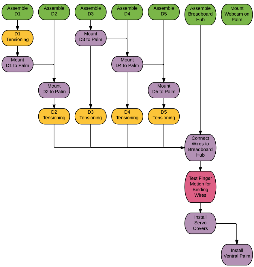
4 Assembly Flowchart
A particular order of operations must be followed when assembling the hand, and is outlined in the
following flowchart. A process described in any bubble cannot be completed until all items attached to
incoming arrows have been completed.
6
5 Material Preparation
5.1 3D Printed Parts (17h 0m)
Print parts as specified in section 3.1 The parts are designed to involve as little post-processing as
possible; however a few things should be done.
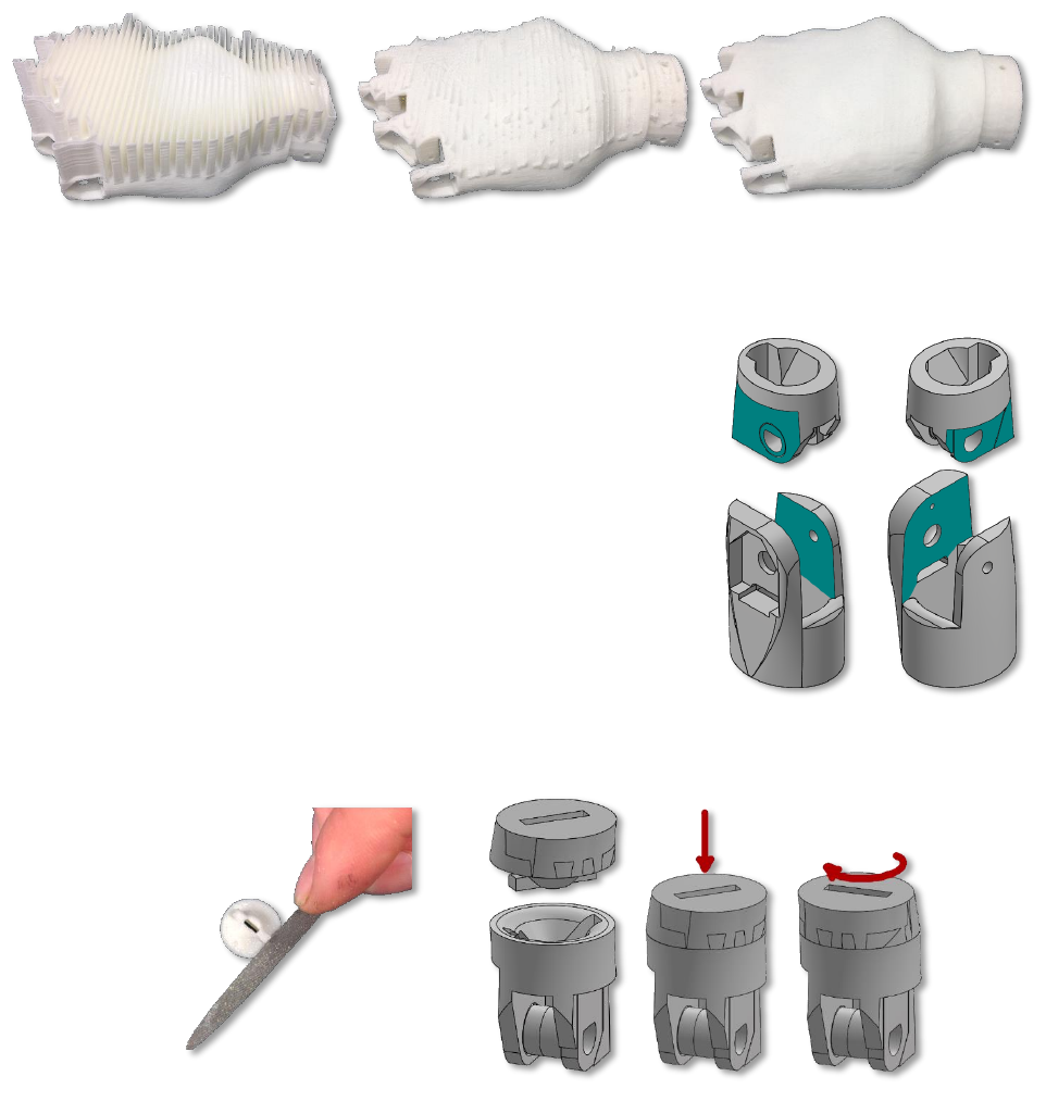
1. Dorsal Palm: Remove print supports using needlenose pliers, then sand smooth using dremel tool
with sanding wheel. See Figure 4. The inside faces of the connections with the fingers should also
be sanded using 120 grit sandpaper, to ensure a smooth running fit.
7
2. Finger Joints: The outside faces of all XP – P Main and XP –
P Pivot parts, as well as the inside faces of all XP – D parts
should be sanded lightly with 120 grit sandpaper to ensure a
smooth running fit between the parts. Figure 5 shows the
locations that need to be sanded for the intermediate joint of
the fingers. Proximal and distal joints will also need to be
sanded. It is best to install the pivot parts in the main parts
prior to sanding. Any surfaces that will be glued should also
be sanded; refer to Figure 11 and Figure 14.
3. Fingertip Locks: the locking wings on all DP – D Lock parts
should be filed slightly using a small semi-rounded file. The
goal is to have them twist into a locked position with the DP
– P Main parts. They should therefore be filed such that the
twisting motion is possible, but sufficient friction still exists
to keep the fingertips in the locked position.
4. Breadboard and Connector Hub: the holes in these parts will likely be partially occluded by the
3D printed plastic. It is recommended that these holes be drilled out after printing using a .95 mm
drill bit.
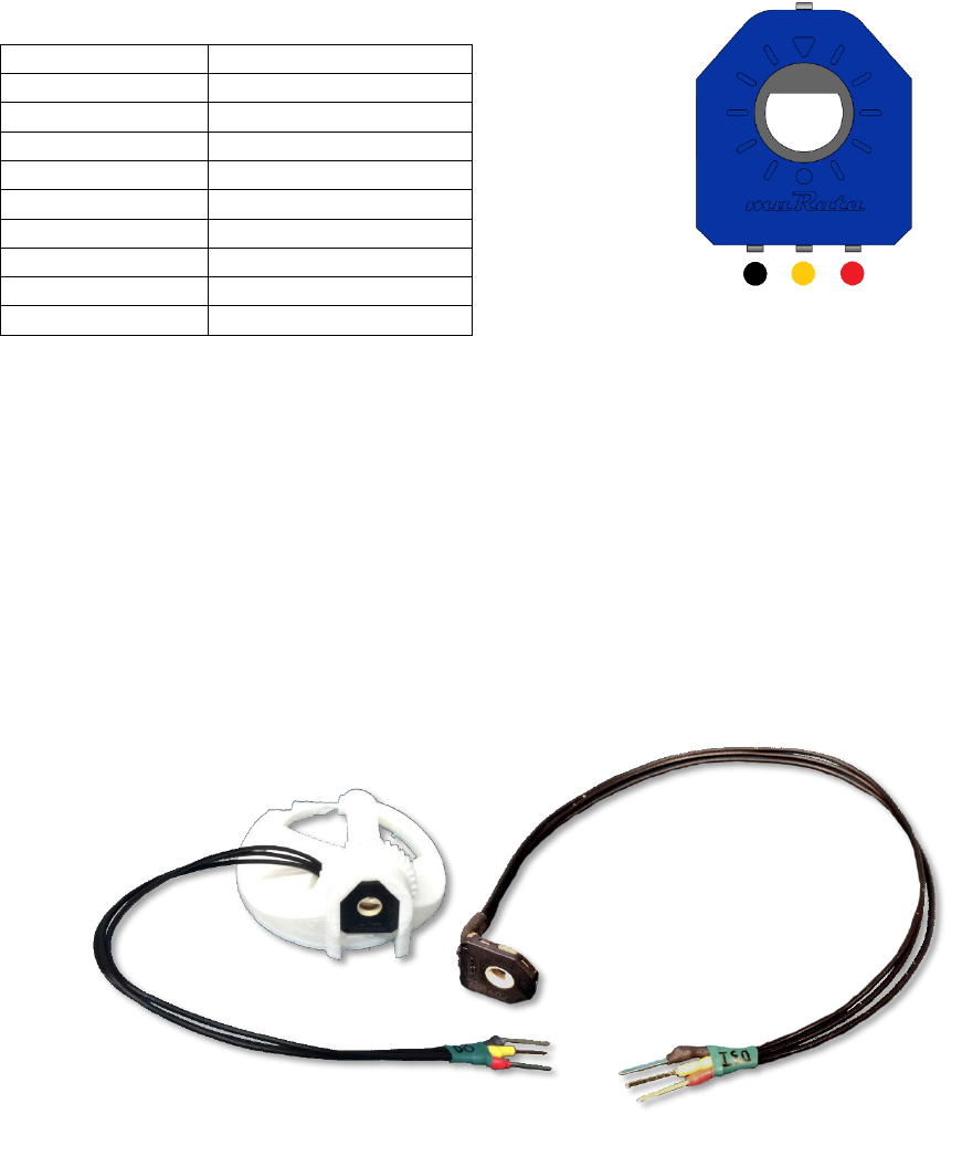
5.2 Potentiometers (1h 45m)
In the current version, there are 9 potentiometers (limited due to the number of analog input pins on the
Arduino Mega). The suggested lengths of the connecting wires are found in Table 3:
Figure 5: Sanding locations for finger joints
Figure 6: Filing of DP - D Lock
(a) As printed
(b) Supports removed with pliers
(c) Smoothed with dremel tool
Figure 4: Dorsal Palm post processing
8
Table 3: Suggested wire lengths for potentiometers
Potentiometer ID
Suggested Wire Length
D0
150 mm
D1P
150 mm
D1D
190 mm
D2P
150 mm
D2I
190 mm
D3P
150 mm
D3I
190 mm
D4P
150 mm
D5P
150 mm
1. Cut off the top lone pin on the potentiometer as short as possible.
2. Solder the wires to the potentiometer and a straight pin header to the other end of each wire. See
note below about D0.
3. Use black heat-shrink on the connections near the potentiometer, and coloured heat shrink on the
far connections corresponding to the polarity noted in Figure 7.
4. Heat shrink the 3 wires together near the loose end using a light coloured heat shrink tubing.
Label the wires here with the potentiometer ID.
Note: the straight pin headers for the D0 potentiometer must be soldered to the wires after the
potentiometer is installed in MC – Geared Rotator, and the wires routed through the narrow channel.
Black heat-shrink tubing near the potentiometer will not fit in this channel, so it is omitted. Figure 8
shows finished D0 and D3I potentiometers.
5.3 FSRs (1h 0m)
Each fingertip requires an FSR. The recommended wire length for finger FSRs is 250 mm; for the thumb
FSR 200 mm is recommended.
1. Solder each wire to the solder tabs of the FSR.
2. Install FSR in fingertip (see 5.3.1 ).
3. Use black heat-shrink tubing on the connections near the FSR.
4. Solder the wires to straight pin headers.
5. Use yellow and red heat shrink tubing on the connections with the straight pin headers.
Figure 7: Potentiometer polarity
Figure 8: Finished potentiometers
9
6. Heat shrink the two wires together using a light coloured heat shrink, and label the wires here
with the ID of the finger they represent.
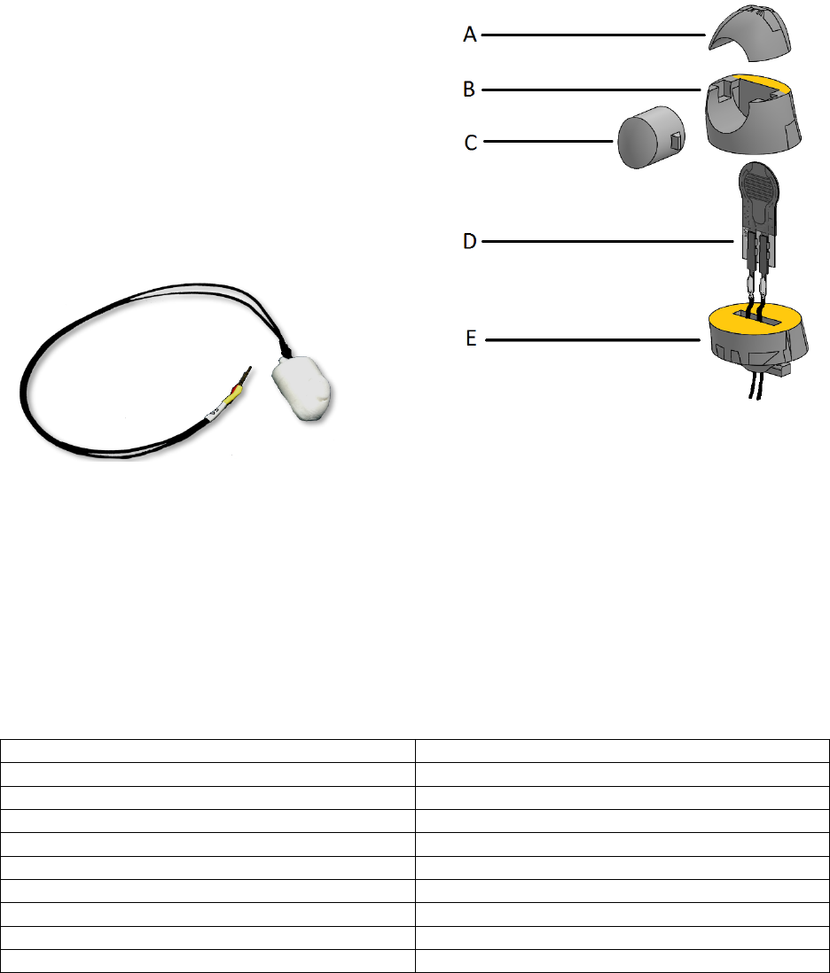
5.3.1 Fingertips
The fingertips should be assembled as per Figure 9.
Use superglue on the surfaces marked in yellow. It is
imperative that no glue should contact the FSR
Actuator; it should move freely inside the fingertip.
The finished fingertip is shown in Figure 10.
A. DP – D Tip
B. DP – D Main
C. DP – D FSR Actuator
D. FSR400 Short Tail resistor
E. DP – D Lock
It is recommended that fingertip grip pads be cut from the neoprene rubber sheet (See section 12 ). Be
careful when gluing the rubber to the fingertip that the movement of the FSR actuator does not become
restricted in any way.
5.4 Screws (0h 45m)
The screws used as hinges in each of the finger joints are required to be cut to length from the 25 mm M2
screws. The lengths of the various screws can be referenced from Table 4. The screws should be cut to
length in a manner such that the threads are preserved.
Table 4: Screw Lengths
Screw Position
Length of Screw Thread
D2D, D3D, D4D, D5D
15 mm
D2I, D3I, D4I, D5I
15.5 mm
D2P, D4P, D5P
17.5 mm
D3P
20.5 mm
D1D
18.5 mm
D1P
22 mm
D0 (both bottom and top screws)
25 mm
Ventral Palm Screws (4)
12 mm
Geared Rotator Screws (2)
5 mm
Figure 9: Fingertip assembly diagram
Figure 10: Finished fingertip without grip pads
10
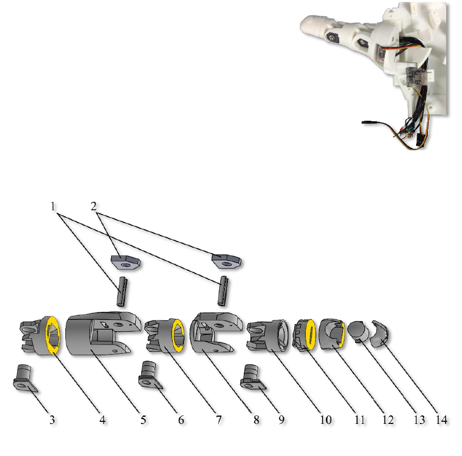
6 Thumb Assembly (1h 0m)
6.1 Part Assembly
Assemble the thumb parts as shown in Figure 11. File or sand parts as necessary to achieve good fits.
Use superglue on the surfaces marked in yellow.
1. Pot Activator
2. Potentiometer
3. MC – P Geared Rotator
4. Servo Spool Thumb
5. Hitec HS-35 HD Servo
6. MC –P Main
7. MC – D
8. IP – P PivotTH
9. IP – P MainTh
10. IP – DTH
11. DP – P PivotTH
12. DP – P MainTH
13. DP – D LockTH
14. DP – D MainTH
15. DP – D FSR ActuatorTH
16. DP – D TipTH
The appropriate M2 screws for each joint should be
installed using an M2 washer. The screws extend through the potentiometer and pot activator, screwing
into the far side of the finger joint. Tightening these screws too much will cause the joints to bind.
Tighten the screws until contact with the potentiometer, then back out ½ turn.
Figure 11: Thumb assembly diagram
Figure 12: Assembled thumb prior to MC - P
Geared Rotator installation, showing servo
position
11
The thumb zip-tie should be installed and tensioned before the MC – P Geared Rotator is attached using
two 5mm M2 screws. See Section 8 Figure 12 shows an assembled thumb prior to MC – P Geared
Rotator installation, showing the correct servo positioning for full extension.
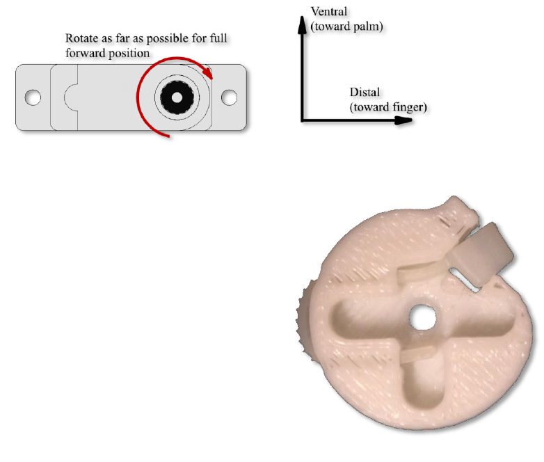
6.2 Mounting to Palm
Rotate the D0 servo with the small gear to the mounting
position. Looking down from the top of the hand, this will be
fully clockwise for a right hand assembly, and fully counter
clockwise for a left hand assembly.
Position the thumb so that it is rotated outward as much as
possible, and secure to the palm using two 25 mm M2 screws;
one from the top and one from the bottom. Be sure to include
a pot activator on the bottom side.
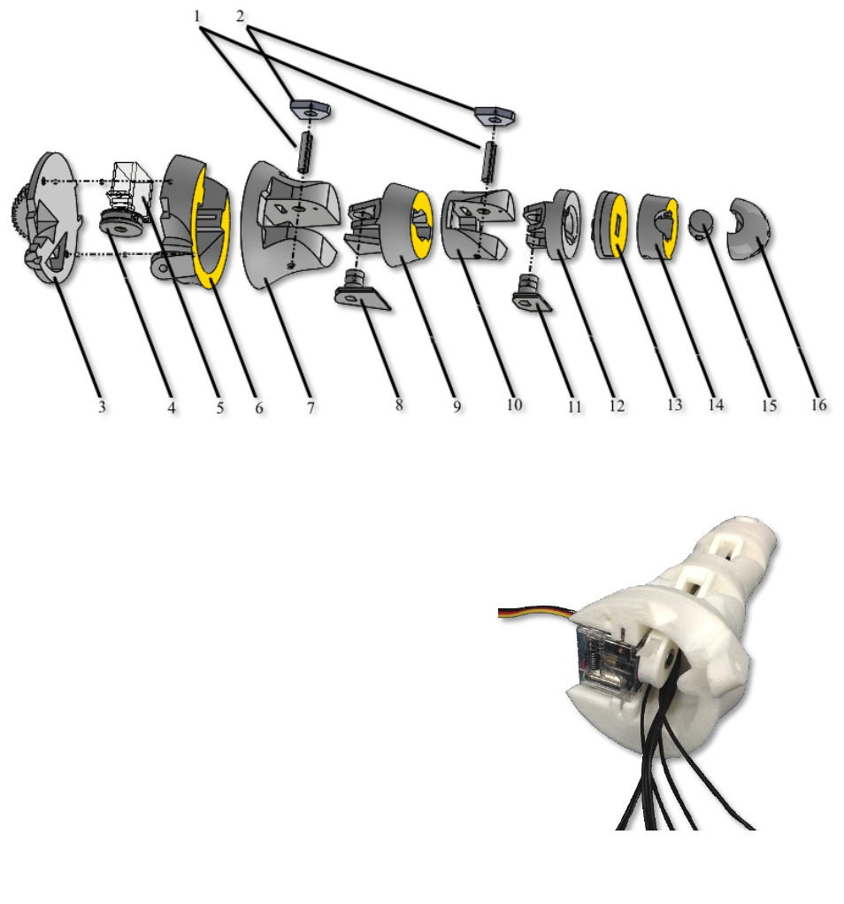
7 Finger Assembly (0h 15m each finger)
Assemble the finger parts as shown in Figure 14. File or sand the parts as necessary to achieve good fits.
Use superglue on the faces marked in yellow.
1. Pot Activator
2. Potentiometer*
3. PP – P PivotD2**
4. PP – P MainD2**
5. PP – D
6. IP – P Pivot
7. IP – P Main
8. IP – P D
9. DP – P Pivot
10. DP – P Main
11. DP – D Lock
12. DP – D Main
13. DP – D FSR Actuator
14. DP – D Tip
* The number of potentiometers used, and their location depends on the finger. Wherever a
potentiometer is omitted, a Pot Placeholder should be used in its place. For use with an Arduino
Figure 13: Thumb mounted to dorsal palm
Figure 14: Index finger (D2) assembly diagram
12
Mega, the suggested potentiometer positions are given in Figure 2, Section 2.2 .A Pot Activator
should be used regardless of whether a potentiometer or a Pot Placeholder is used.
** This assembly diagram shows the index finger (D2). For other fingers, substitute the appropriate parts
here (i.e. D3 for middle finger, etc.).
8 Servo Installation and Finger Tensioning (0h 7m each finger)
Tensioning of fingers and thumb are identical processes, with the exception that the thumb servo spool
will not include a zip-tie receiver. Here the tendon zip-tie passes directly through the spool.
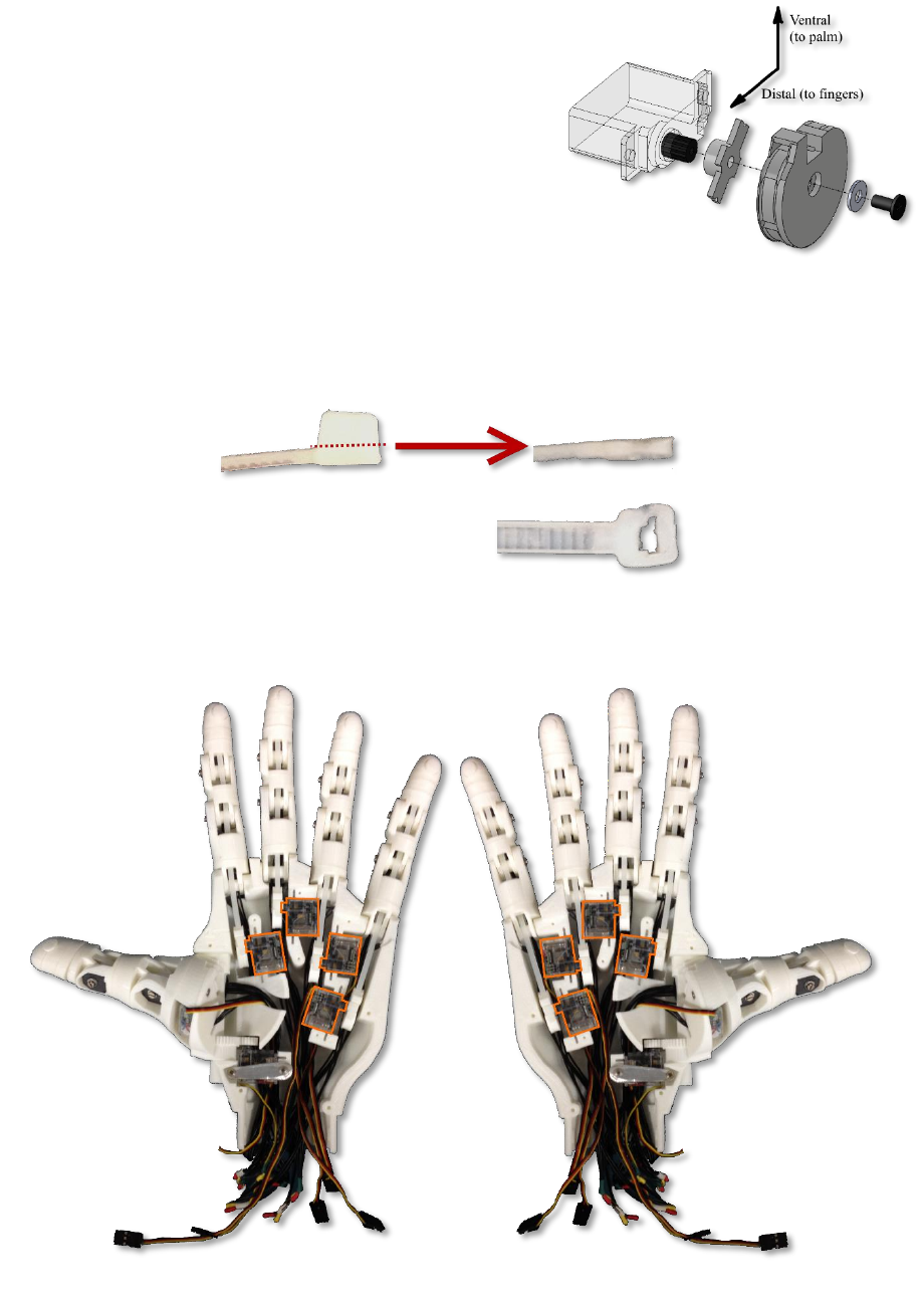
1. Rotate servo to the full forward position using the Arduino sketch Pot_to_Servo_Control.ino.
Wiring for this sketch is explained in section 13.1 . See Figure 15 for the definition of full
forward position. Servo orientation matters for this operation, and changes depending on the
finger in question. Refer to Figure 19 for correct servo positioning.
2. Install a zip-tie in the servo spool as per Figure 16.
3. Install the servo spool on the servo, using the plus-shaped servo
horn with ends clipped, ensuring that the zip-tie receiving
end is at the top of the servo (most ventral when mounted
in the palm). See Figure 17.
4. Cut a zip-tie’s receiving end so that the thickness is
constant along the entire zip-tie. Sidecutters work best
for this operation; fine adjustments can be made with
a hobby knife when necessary. The cut is illustrated in
Figure 18. This end of the zip-tie will serve as the
stopper at the tip of the finger.
Figure 15: Full Forward Position of servo
Figure 16: Zip-tie installed in servo spool
13
5. Thread the zip-tie through the finger from the distal to
the proximal end, staying ventral to each of the joint
pivots.
6. Pass the tendon zip-tie through the zip-tie receiver on
the servo spool (or through the spool itself in the case
of the thumb spool). There should be no slack in the
zip-tie when the finger is fully extended, the servo is
fully rotated forward, and the servo is installed in the
dorsal palm. Trim the free end of the tendon zip-tie.
Figure 19 shows the completed tensioning and servo
installation.
Figure 17: Servo spool installation on servo
Figure 18: Required cut for zip-tie
Figure 19: Servo installation and finger tensioning complete, showing servo positions for right and left hand
14
9 Breadboard Hub (3h 0m)
Creation of the breadboard hub is by far the most technically difficult and labor intensive operation in
assembling the HANDi Hand, and is not required to have a fully functional hand. The breadboard hub
reduces the number of wires leaving the hand from 60 to 22, which is important when interfacing with a
movable arm since a large bulk of wires will tend to bind and restrict motion of the arm. Work is
currently being done on the design of an in-palm PCB which will increase the sensing capabilities of the
hand while simultaneously reducing the amount of wiring required. Please check BLINCdev.ca for
information about upcoming releases.
1. Print out the breadboard and connector hub with
the specifications given in Table 1, page 2.
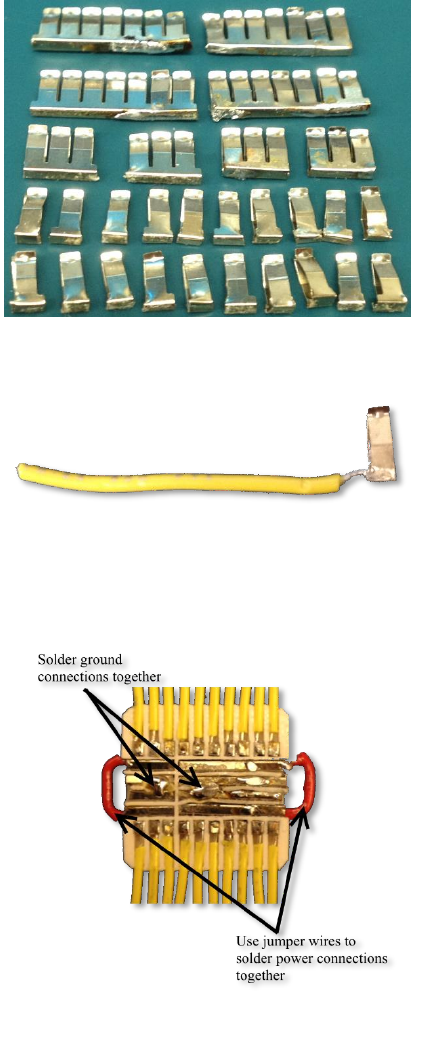
2. Remove the clips from the miniature breadboard,
and cut/solder them together to obtain 4 clips
with 7 receptacles, 4 with 3 receptacles, and 20
with 1 receptacle. When soldering the clips
together for the 7 receptacle clips, be careful to
ensure that the receptacles line up with the holes
of the printed breadboard. Refer to Figure 20.
3. Solder a 1” piece of prototyping wire (22 AWG)
to each single receptacle clip at the base (Figure
21).
4. Press-fit each of the receptacles into the bottom
of the printed breadboard, making sure no part of
any receptacle extends past the base of the
board.
5. Solder jumper wires between the power
receptacles and ground receptacles as in Figure
22.
6. Test the board for proper conductivity at each
receptacle. Adjust receptacle positioning if
necessary.
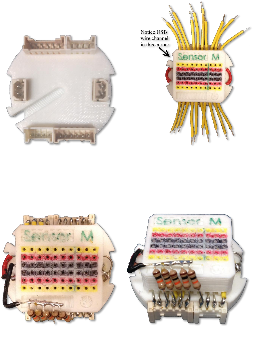
7. Superglue the molex connectors to the connector
hub, referring to Figure 23.
8. Superglue the printed breadboard to the other side
of the connector hub, being careful to note the
orientation shown in Figure 24.
Figure 22: Soldered connections
Figure 20: Breadboard clips salvaged from mini
breadboard, cut and soldered as necessary
Figure 21: Prototyping wire soldered to individual
breadboard clip
15
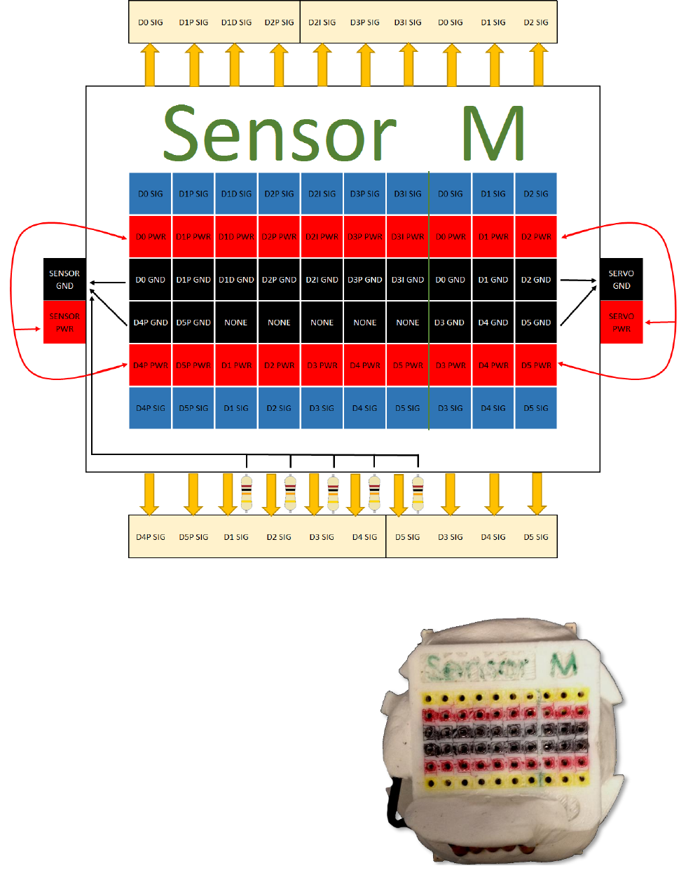
9. Solder the power and ground connections to the header pins. Refer to Figure 27 to ensure power
and ground are soldered to the correct header pins.
10. Solder the yellow jumper wires to the appropriate receptacle pins, and the 100 kΩ resistors to
appropriate receptacle pins as shown in Figure 25:
Figure 23: Molex connector configurations
Figure 24: Breadboard orientation on hub
Figure 25: Finished soldered connections for breadboard hub, top and front view
16
11. Cover and protect all connections using Sugru or
similar methods. See finished breadboard hub in
Figure 26.
Figure 27: Pinout for breadboard hub. Breadboard holes to the left of the green line correspond to sensor signal connections;
holes to the right correspond to servo motor command signals. Use this diagram as a reference when connecting the wiring to
ensure proper connection.
Figure 26: Finished breadboard hub
17
10 Aluminum Servo Cover (0h 45m)
The servo covers are made of aluminum. They act as a heat
sink and reduce the tendency to overheat the servos, and as
well have less tendency to warp than the 3D printed plastic.
They can be cut from the aluminum sheet given in the Bill
of Materials, to the size and shape given in Appendix B:
Servo Cover Template. Cut around the outside shape using
tin snips, and file down to the exact shape and size using a
flat metal file. Drill the holes using a 1/16” drill bit. Attach
the servo covers using the coarse thread stainless steel
phillips screws provided with the HS-35HD servo motors.
Refer to Figure 28 for orientation of the servo covers for
installation.
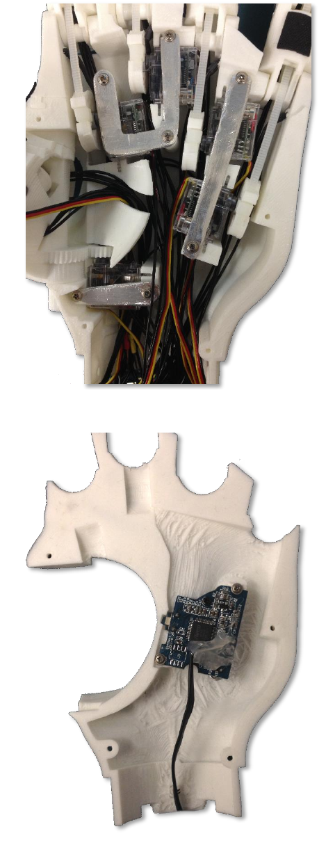
11 Ventral Palm Cover; USB
Webcam (0h 20m)
The webcam used currently is a mini webcam from Seeed
Technology. Remove the PCB and lens from the camera
housing, and mount it to the ventral palm using the extra
small black screws that came with the HS-35HD servo
motors. Figure 29 shows the USB webcam mounted to the
ventral palm.
The USB cable from the camera will be routed out of
the wrist cavity via the USB wire channel noted earlier
in section 9 .
Mount the ventral palm to the front of the dorsal palm,
being careful to ensure all wires are routed properly and
there are no pinch points. The ventral palm is secured
using four 12mm M2 screws.
Figure 29: USB Webcam installed in ventral palm (right hand)
Figure 28: Installation of aluminum servo covers (left
hand)
18
12 Palm Grips (1h 15m)
To increase the friction on the palm, palm grips made of neoprene extra strength rubber are superglued to
the palm plate and the finger phalanxes. A template for the grips is found in Appendix A: Grip Pattern
Template. The locations for the grips can be found in Figure 30.
The radial palm grip should be glued to both the ventral palm and the dorsal palm, covering the seam.
Once glued in place, cut along the seam with a hobby knife to make the ventral palm removable again.
Figure 30: Grip diagram
20
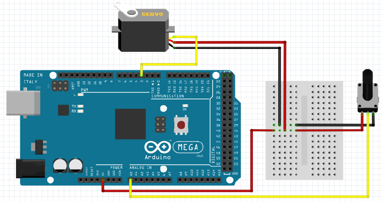
13.2 Full Implementation
The wiring diagram in Figure 32 outlines the wiring setup including 6 control potentiometers (one for
each degree of freedom), 5 position sensing potentiometers, 5 FSRs, 6 servos, and servo power switch.
This wiring setup is intended for use with the Arduino sketch Potentiometer_Control.ino.
Figure 32: Full wiring diagram for individual finger potentiometer control
21
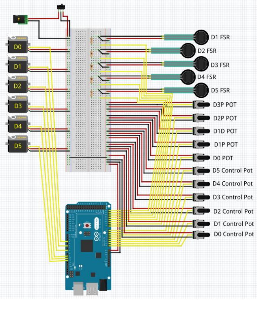
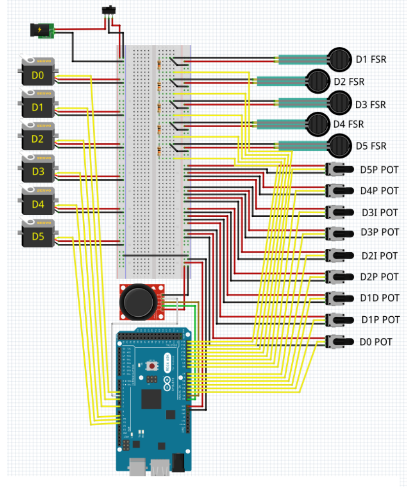
The wiring diagram in Figure 33 outlines the complete wiring setup for 9 potentiometers, 5 FSRs, 6
servos, thumb joystick control, and servo power switch. This wiring setup is intended for use with the
Arduino sketches Individual_Vel_rev1.ino and Grasp_Vel_rev2.ino.
The custom in-wrist breadboard removes a lot of the complications for wiring; if the sensors and servos
are connected to the breadboard hub as per Figure 27 on page 16, the circuit above will be created when
the following connections are made to the Arduino Mega (see Table 5):
Figure 33: Full wiring diagram

22
Table 5: Pin connections to Arduino Mega
Sensor
Pin on Arduino Mega
D0 Pot
A2
D1P Pot
A3
D1D Pot
A4
D2P Pot
A5
D2I Pot
A6
D3P Pot
A7
D3I Pot
A8
D4P Pot
A9
D5P Pot
A10
D1 FSR
A11
D2 FSR
A12
D3 FSR
A13
D4 FSR
A14
D5 FSR
A15
D0 Servo
Digital 3
D1 Servo
Digital 5
D2 Servo
Digital 6
D3 Servo
Digital 9
D4 Servo
Digital 10
D5 Servo
Digital 11
I
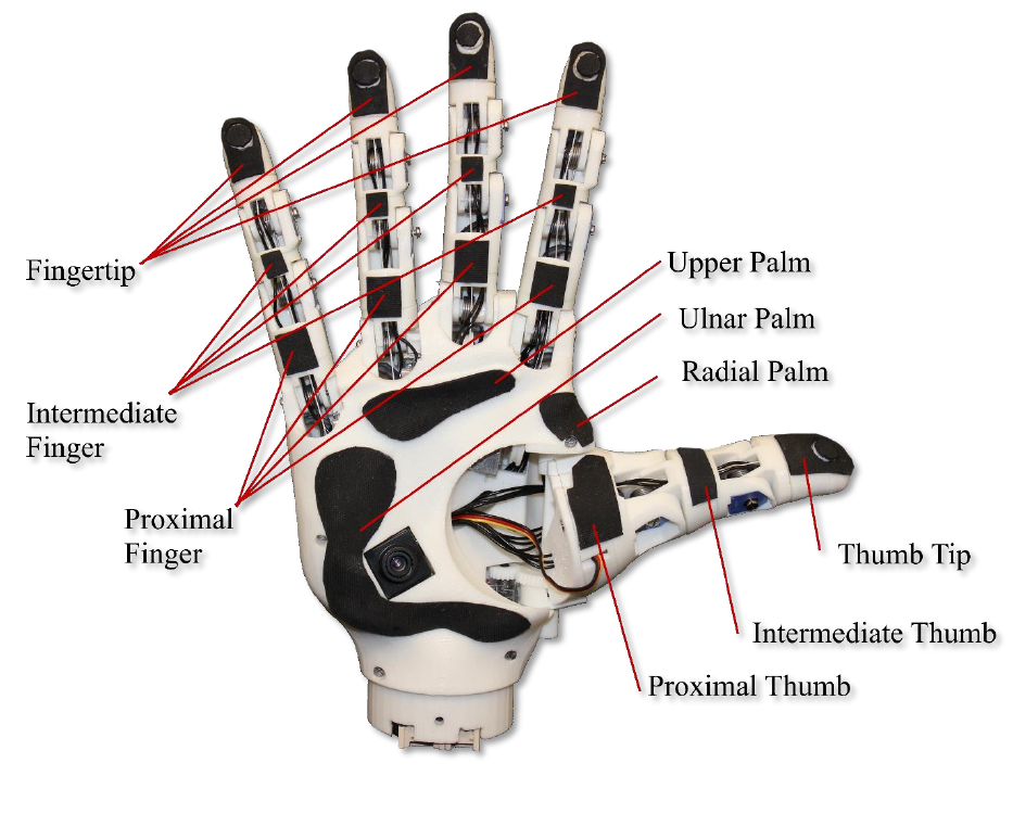
14 Appendix A: Grip Pattern Template
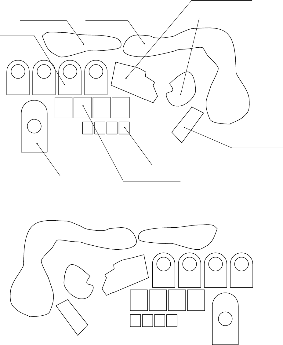
RIGHT HAND
Radial palm
Ulnar palm
Upper palm
Proximal thumb
Proximal finger
Intermediate
thumb
Intermediate finger
Thumb tip
Fingertip
LEFT HAND
Drawing is to scale; print out and
use as template to cut extra strength neoprene rubber
II
15 Appendix B: Servo Cover Template
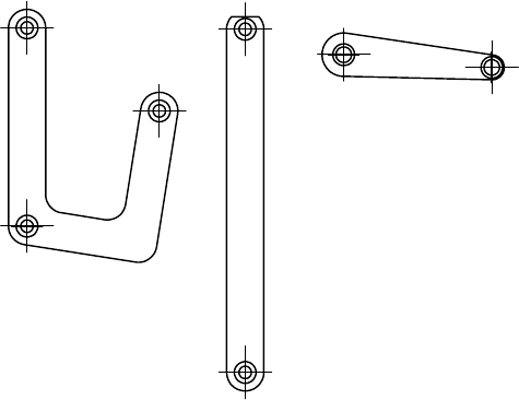
Items are in 1:1 scale; print and cut out as template.
