AVP A1HDCI
Denon-Denon-Stereo-Amplifier-Av-Surround-Pre-Amplifier-Users-Manual-221505 denon-denon-stereo-amplifier-av-surround-pre-amplifier-users-manual-221505
AVP-A1HDCI to the manual 63824ed9-1563-4317-965b-723685d5388b
2015-06-29
: Pdf Avp-A1Hdci AVP-A1HDCI DENOM MANUAIS AV audio_video
Open the PDF directly: View PDF ![]() .
.
Page Count: 128 [warning: Documents this large are best viewed by clicking the View PDF Link!]

AV SURROUND PRE-AMPLIFIER
AVP-A1HDCI
Owner’s Manual
GraphicalUserInterface
Use this manual in combination with the
operating guide displayed on the GUI screen.
GUI Menu Operation (vpage 24)
GUI Menu Map (vpage 25)
Language (vpage 44)
Remote Control Unit Operations (vpage 77)
I
n SAFETY PRECAUTIONS
CAUTION
RISK OF ELECTRIC SHOCK
DO NOT OPEN
CAUTION:
TO REDUCE THE RISK OF ELECTRIC SHOCK, DO NOT REMOVE
COVER (OR BACK). NO USER-SERVICEABLE PARTS INSIDE.
REFER SERVICING TO QUALIFIED SERVICE PERSONNEL.
The lightning flash with arrowhead symbol, within an equilateral
triangle, is intended to alert the user to the presence of
uninsulated “dangerous voltage” within the product’s enclosure
that may be of sufficient magnitude to constitute a risk of electric
shock to persons.
The exclamation point within an equilateral triangle is intended
to alert the user to the presence of important operating
and maintenance (servicing) instructions in the literature
accompanying the appliance.
WARNING:
TO REDUCE THE RISK OF FIRE OR ELECTRIC SHOCK, DO NOT
EXPOSE THIS APPLIANCE TO RAIN OR MOISTURE.
SAFETY INSTRUCTIONS
1. Read Instructions – All the safety and operating instructions should be read
before the product is operated.
2. Retain Instructions – The safety and operating instructions should be
retained for future reference.
3. Heed Warnings – All warnings on the product and in the operating
instructions should be adhered to.
4. Follow Instructions – All operating and use instructions should be
followed.
5. Cleaning – Unplug this product from the wall outlet before cleaning. Do not
use liquid cleaners or aerosol cleaners.
6. Attachments – Do not use attachments not recommended by the product
manufacturer as they may cause hazards.
7. Water and Moisture – Do not use this product near water – for example,
near a bath tub, wash bowl, kitchen sink, or laundry tub; in a wet basement;
or near a swimming pool; and the like.
8. Accessories – Do not place this product on an unstable cart, stand, tripod,
bracket, or table. The product may fall, causing serious injury to a child
or adult, and serious damage to the product. Use only with a cart, stand,
tripod, bracket, or table recommended by the manufacturer, or sold with
the product. Any mounting of the product should
follow the manufacturer’s instructions, and should
use a mounting accessory recommended by the
manufacturer.
9. A product and cart combination should be moved
with care. Quick stops, excessive force, and
uneven surfaces may cause the product and cart
combination to overturn.
10. Ventilation – Slots and openings in the cabinet are provided for ventilation
and to ensure reliable operation of the product and to protect it from
overheating, and these openings must not be blocked or covered. The
openings should never be blocked by placing the product on a bed, sofa,
rug, or other similar surface. This product should not be placed in a built-in
installation such as a bookcase or rack unless proper ventilation is provided
or the manufacturer’s instructions have been adhered to.
11. Power Sources – This product should be operated only from the type of
power source indicated on the marking label. If you are not sure of the type
of power supply to your home, consult your product dealer or local power
company. For products intended to operate from battery power, or other
sources, refer to the operating instructions.
12. Grounding or Polarization – This product may be equipped with a polarized
alternating-current line plug (a plug having one blade wider than the other).
This plug will fit into the power outlet only one way. This is a safety feature.
If you are unable to insert the plug fully into the outlet, try reversing the
plug. If the plug should still fail to fit, contact your electrician to replace your
obsolete outlet. Do not defeat the safety purpose of the polarized plug.
13. Power-Cord Protection – Power-supply cords should be routed so that they
are not likely to be walked on or pinched by items placed upon or against
them, paying particular attention to cords at plugs, convenience receptacles,
and the point where they exit from the product.
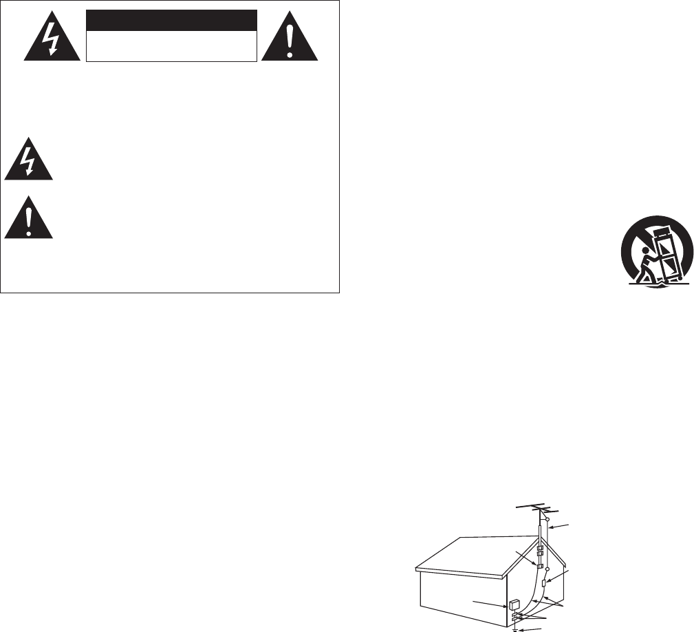
15. Outdoor Antenna Grounding – If an outside antenna or cable system is
connected to the product, be sure the antenna or cable system is grounded
so as to provide some protection against voltage surges and built-up static
charges. Article 810 of the National Electrical Code, ANSI/NFPA 70, provides
information with regard to proper grounding of the mast and supporting
structure, grounding of the lead-in wire to an antenna discharge unit, size
of grounding conductors, location of antenna-discharge unit, connection to
grounding electrodes, and requirements for the grounding electrode. See
Figure A.
16. Lightning – For added protection for this product during a lightning storm,
or when it is left unattended and unused for long periods of time, unplug it
from the wall outlet and disconnect the antenna or cable system. This will
prevent damage to the product due to lightning and power-line surges.
17. Power Lines – An outside antenna system should not be located in the
vicinity of overhead power lines or other electric light or power circuits, or
where it can fall into such power lines or circuits. When installing an outside
antenna system, extreme care should be taken to keep from touching such
power lines or circuits as contact with them might be fatal.
18. Overloading – Do not overload wall outlets, extension cords, or integral
convenience receptacles as this can result in a risk of fire or electric shock.
19. Object and Liquid Entry – Never push objects of any kind into this product
through openings as they may touch dangerous voltage points or short-out
parts that could result in a fire or electric shock. Never spill liquid of any kind
on the product.
20. Servicing – Do not attempt to service this product yourself as opening or
removing covers may expose you to dangerous voltage or other hazards.
Refer all servicing to qualified service personnel.
21. Damage Requiring Service – Unplug this product from the wall outlet
and refer servicing to qualified service personnel under the following
conditions:
a) When the power-supply cord or plug is damaged,
b) If liquid has been spilled, or objects have fallen into the product,
c) If the product has been exposed to rain or water,
d) If the product does not operate normally by following the operating
instructions. Adjust only those controls that are covered by the operating
instructions as an improper adjustment of other controls may result in
damage and will often require extensive work by a qualified technician to
restore the product to its normal operation,
e) If the product has been dropped or damaged in any way, and
f) When the product exhibits a distinct change in performance – this
indicates a need for service.
22. Replacement Parts – When replacement parts are required, be sure the
service technician has used replacement parts specified by the manufacturer
or have the same characteristics as the original part. Unauthorized
substitutions may result in fire, electric shock, or other hazards.
23. Safety Check – Upon completion of any service or repairs to this product,
ask the service technician to perform safety checks to determine that the
product is in proper operating condition.
24. Wall or Ceiling Mounting – The product should be mounted to a wall or
ceiling only as recommended by the manufacturer.
25. Heat – The product should be situated away from heat sources such as
radiators, heat registers, stoves, or other products (including amplifiers) that
produce heat.
FIGURE A
EXAMPLE OF ANTENNA GROUNDING
AS PER NATIONAL
ELECTRICAL CODE "/5&//"
-&"%*/
8*3&
(306/%
$-".1
&-&$53*$
4&37*$&
&26*1.&/5
"/5&//"
%*4$)"3(&6/*5
/&$4&$5*0/
(306/%*/($0/%6$5034
/&$4&$5*0/
(306/%$-".14
108&34&37*$&(306/%*/(
&-&$530%&4:45&.
/&$"351"35)
/&$/"5*0/"-&-&$53*$"-$0%&
II
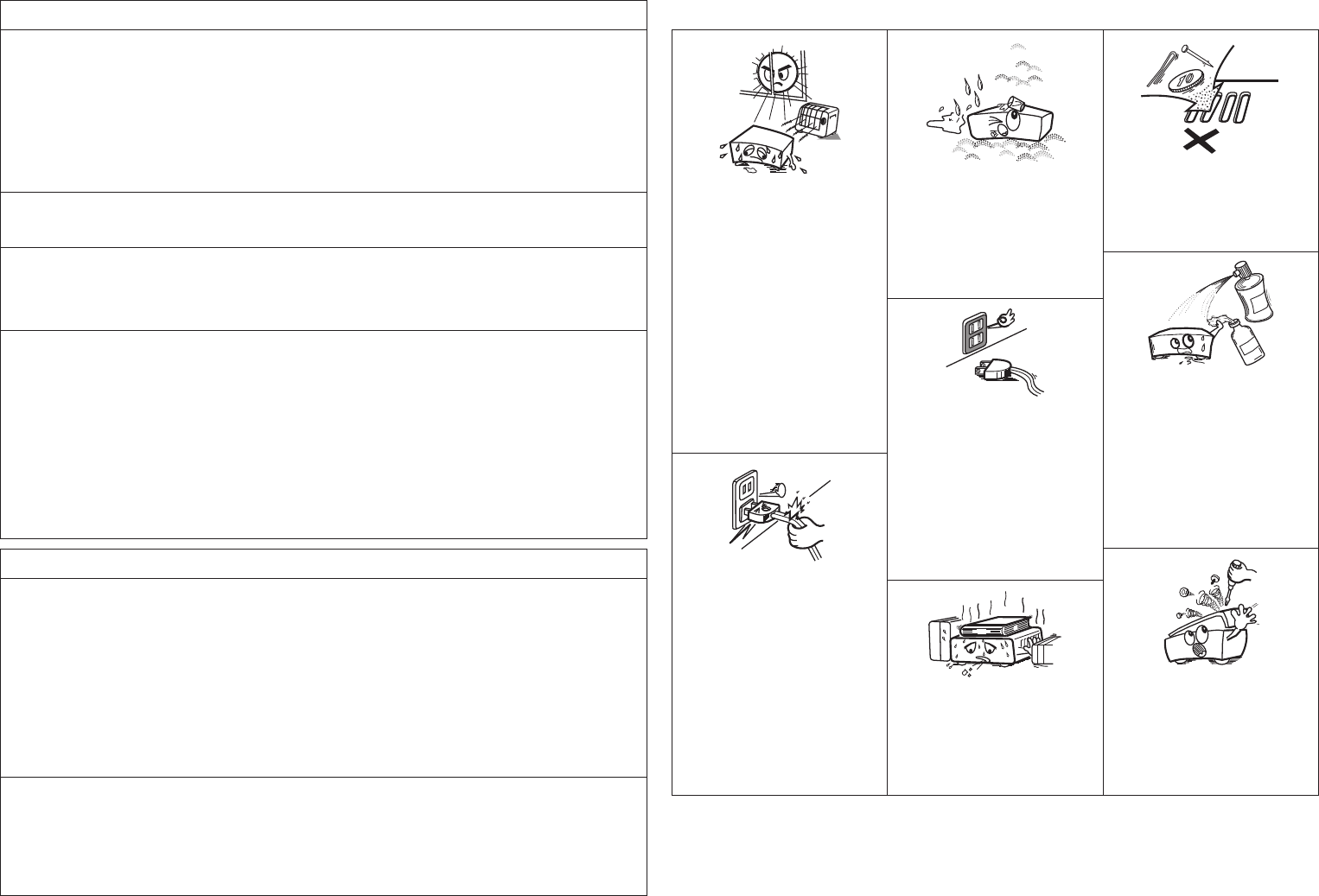
• Avoid high temperatures.
Allow for sufficient heat dispersion when
installed in a rack.
• Eviter des températures élevées.
Tenir compte d’une dispersion de chaleur
suffisante lors de l’installation sur une
étagère.
• Handle the power cord carefully.
Hold the plug when unplugging the cord.
• Manipuler le cordon d’alimentation avec
précaution.
Tenir la prise lors du débranchement du
cordon.
• Keep the unit free from moisture, water,
and dust.
• Protéger l’appareil contre l’humidité, l’eau
et la poussière.
• Unplug the power cord when not using the
unit for long periods of time.
• Débrancher le cordon d’alimentation
lorsque l’appareil n’est pas utilisé pendant
de longues périodes.
* (For apparatuses with ventilation holes)
• Do not obstruct the ventilation holes.
• Ne pas obstruer les trous d’aération.
• Do not let foreign objects into the unit.
• Ne pas laisser des objets étrangers dans
l’appareil.
• Do not let insecticides, benzene, and
thinner come in contact with the unit.
• Ne pas mettre en contact des insecticides,
du benzène et un diluant avec l’appareil.
• Never disassemble or modify the unit in
any way.
• Ne jamais démonter ou modifier l’appareil
d’une manière ou d’une autre.
n NOTE ON USE / OBSERVATIONS RELATIVES A L’UTILISATION
FCC Information (For US customers)
1. COMPLIANCE INFORMATION
Product Name: AV Surround Pre-Amplifier
Model Number: AVP-A1HDCI
This product contains FCC ID: BV2- MPGBR052.
This product complies with Part 15 of the FCC Rules. Operation is subject to the following two conditions: (1) this
product may not cause harmful interference, and (2) this product must accept any interference received, including
interference that may cause undesired operation.
Denon Electronics (USA), LLC
100 Corporate Drive, Mahwah, NJ 07430-2041
Tel. 201-762-6500 (Main)
2. IMPORTANT NOTICE: DO NOT MODIFY THIS PRODUCT
This product, when installed as indicated in the instructions contained in this manual, meets FCC requirements.
Modification not expressly approved by DENON may void your authority, granted by the FCC, to use the product.
3. CAUTION
• To comply with FCC RF exposure compliance requirement, separation distance of at least 20 cm must be
maintained between the antenna of this product and all persons.
• This product and its antenna must not be co-located or operating in conjunction with any other antenna or
transmitter.
4. NOTE
This product has been tested and found to comply with the limits for a Class B digital device, pursuant to Part 15
of the FCC Rules. These limits are designed to provide reasonable protection against harmful interference in a
residential installation.
This product generates, uses and can radiate radio frequency energy and, if not installed and used in accordance
with the instructions, may cause harmful interference to radio communications. However, there is no guarantee
that interference will not occur in a particular installation. If this product does cause harmful interference to radio or
television reception, which can be determined by turning the product OFF and ON, the user is encouraged to try to
correct the interference by one or more of the following measures:
• Reorient or relocate the receiving antenna.
• Increase the separation between the equipment and receiver.
• Connect the product into an outlet on a circuit different from that to which the receiver is connected.
• Consult the local retailer authorized to distribute this type of product or an experienced radio/TV technician for
help.
IC Information (For Canadian customers)
1. PRODUCT
This product contains IC 6963A-MPGBR052.
This product complies with RSS-210 of Industry Canada. Operation is subject to the following two conditions:
(1) this product may not cause harmful interference, and (2) this product must accept any interference received,
including interference that may cause undesired operation.
This Class B digital apparatus complies with Canadian ICES-003.
APPAREIL
Cet appareil contiens IC 6963A- MPGBR052.
Cet appareil est conforme à la norme CNR-210 du Canada. L’utilisation de ce dispositif est autorisée seulement
aux deux conditions suivantes : (1) il ne doit pas produire de brouillage, et (2) l’utilisateur du dispositif doit être
prêt à accepter tout brouillage radioélectrique reçu, même si ce brouillage est susceptible de compromettre le
fonctionnement du dispositif.
Cet appareil numérique de la classe B est conforme à la norme NMB-003 du Canada.
2. CAUTION
To reduce potential radio interference to other users, the antenna type and its gain should be so chosen that the
equivalent isotropically radiated power (e.i.r.p.) is not more than that permitted for successful communication.
ATTENTION
Afin de réduire le risque d’interférence aux autres utilisateurs, il faut choisir le type d’antenne et son gain de façon à
ce que la puissance isotrope rayonnée équivalente (p.i.r.e.) ne soit pas supérieure au niveau requis pour l’obtention
d’une communication satisfaisante.

Accessories ·····················································································3
Cautions on Handling ·····································································3
Cautions on Installation ·································································3
About the Remote Control Unit ····················································3
Inserting the Batteries ·······························································3, 4
Operating Range of the Remote Control Unit ································4
Part Names and Functions ····························································4
Front Panel ·················································································4, 5
Display ···························································································5
Rear Panel ······················································································6
Remote Control Unit ······································································7
Preparations ··················································································26
Auto Setup ····················································································26
a Auto Setup ········································································26, 27
Error Messages·······································································28
s Option ·····················································································28
d Parameter Check ····································································28
Contents Example of the Display of the GUI Mark at a Title ····················24
Example of Display of Default Values ········································24
Examples of GUI Screen Displays ···············································24
Example: Browse Menu (Top Menu) ···········································24
Example: Menus with Illustrations (Auto Setup) ··························24
Cursor Position Display ································································24
Operations ·····················································································24
GUI Menu Map ··············································································25
Input Source Selection ·································································45
Settings Related to Playing Input Sources ··························45, 46
a Play ·························································································46
s Auto Preset ·············································································46
d Preset Skip ··············································································46
f Preset Name ···········································································46
g Video ·················································································46, 47
h Input Mode ·············································································47
j Rename···················································································47
k Source Level ···········································································47
l Input Att. ·················································································48
A0 Playback Mode (iPod)······························································48
A1 Assign ···············································································48, 49
A2 Playback Mode········································································49
A3 Still Picture ··············································································49
A4 Antenna Aiming ······································································49
Speaker Setup ··············································································29
a Speaker Configuration·····························································29
s Subwoofer Setup ····································································29
d Distance ··················································································30
f Channel Level ·········································································30
g Crossover Frequency ························································30, 31
h THX Audio Setup·····································································31
j Surround Speaker ···································································31
HDMI Setup ···················································································32
a Color Space ·············································································32
s RGB Range ·············································································32
d Auto Lip Sync ··········································································32
f Audio ·······················································································32
g Monitor Out ············································································32
h HDMI Control ··········································································32
Audio Setup ··················································································33
a EXT. IN Setup··········································································33
s 2ch Direct/Stereo ····································································33
d Downmix Option ·····································································34
f Auto Surround Mode ······························································34
g Manual EQ ··············································································34
Network Setup ·············································································35
a Network Setup ································································35 ~ 38
s Other ·······················································································38
d Network Information ·······························································38
Zone Setup ····················································································39
a ZONE2 ····················································································39
s ZONE3 ····················································································39
d OSD ························································································39
Option Setup ·················································································40
a Pre-out Assign·········································································40
s XLR Out Polarity······································································41
d POA Setting ············································································41
f Volume Control ·······································································41
g Source Delete ·········································································41
h GUI ····················································································41, 42
j Quick Select Name ·································································42
k Trigger Out 1 ···········································································42
l Trigger Out 2 ···········································································42
A0 Trigger Out 3 ···········································································42
A1 Trigger Out 4 ···········································································42
A2 Transducer Setup ····································································42
A3 Digital Out ···············································································43
A4 Remote ID···············································································43
A5 2Way Remote ·········································································43
A6 Dimmer ···················································································43
A7 Setup Lock ··············································································43
A8 Maintenance Mode ·································································43
A9 Firmware Update ····································································43
S0 Add New Feature ····································································44
Language ·······················································································44
Preparations ····················································································8
Cables Used for Connections ························································8
Video Conversion Function ····························································9
Speaker Layout ···········································································10
Connecting to the Power Amp ····················································10
POA-A1HDCI Connection and Operation ·····························10 ~ 12
Connecting Equipment with HDMI connectors ···················12, 13
Connecting the Monitor ·······························································13
Connecting the Playback Components ······································13
DVD Player ···················································································13
Record Player ···············································································14
CD Player ·····················································································14
iPod® ···························································································· 14
TV/CABLE Tuner ··········································································15
Satellite Receiver ·········································································15
Connecting the Recording Components ····································16
Digital Video Recorder ·································································16
Video Cassette Recorder ·····························································17
CD Recorder / MD Recorder / Tape Deck ···································· 17
Connections to Other Devices ·····················································18
Components Equipped with a DENON LINK connector ··············18
Video Camera / Game Console ····················································18
Component with Multi-channel Output connectors ·····················18
USB Port ······················································································19
XM Connector ·············································································· 19
Antenna terminals ·······································································20
Network Audio ·············································································21
Multi Zone ····················································································22
External Controller ·······································································23
Connecting the Power Cord ························································23
Once Connections are Completed ··············································23
Getting Started
Auto Setup
GUI Menu Operations
Manual Setup
Source Select
Connections

Troubleshooting ······························································ 103 ~ 107
Specifications ··············································································108
Other Information ······························································ 88 ~ 102
List of preset codes ··········································· End of this manual
Main Remote Control Unit ··························································77
Operating DENON Audio Components ········································77
Presetting ·····················································································77
Operating Preset Components ············································77 ~ 79
Setting the Remote ID ·································································80
Learning Function ········································································80
System Call Function ···································································81
Punch Through Function ······························································81
Setting the Time the Backlight Stays Lit ······································ 82
Adjusting the Backlight’s Brightness ···········································82
Resetting the Main Remote Control Unit ····································82
Sub Remote Control Unit Operations ··································83, 84
Switching Zones ··········································································85
Setting the Zone for Which the Sub Remote Control Unit
is Used (ZONE SELECT LOCK Mode) ··········································85
Setting the Remote ID ·································································85
Resetting the Settings ·································································85
Preparations ··················································································58
Turning the Power On ··································································58
Operations During Playback ························································· 58
Playing Video and Audio Equipment ··········································58
Basic Operation ············································································58
Listening to FM/AM Broadcasts ·················································59
Basic Operation ············································································59
Presetting Radio Stations (Preset Memory) ·································59
Listening to Preset Stations ··················································· 59, 60
RDS (Radio Data System) ····························································60
RDS Search ··················································································60
PTY Search ···················································································60
TP Search ·····················································································61
RT (Radio Text) ·············································································61
Listening to XM Satellite Radio Programs ·································61
Basic Operation ············································································62
Checking the XM Signal Strength and Radio ID ···························62
Searching Categories ···································································62
Accessing XM Radio Channels Directly ·······································62
Listening to HD Radio™ Stations ···············································63
Basic Operation ············································································63
Selecting Audio Programs ····························································64
Check the HD Radio Reception Information ································64
iPod® Playback ·············································································64
Basic Operation ············································································64
Listening to Music ·······································································65
Viewing Still Pictures or Videos on the iPod ································65
Playing Network Audio,
USB Memory Devices or Rhapsody ············································66
Basic Operation ············································································67
Listening to Internet Radio ···························································68
Playing Files Stored on a Computer ············································· 69
Playing Files Stored on USB Memory Devices ······················69, 70
Listening to Rhapsody ·································································70
Operating the AVP-A1HDCI
Using a Browser (Web control) ·············································· 71, 72
Multi-Zone Connections ······························································86
Multi-Zone Operations ·································································87
Turning the Power On and Off ·····················································87
Selecting the Input Source ···························································87
Adjusting the Volume ···································································87
Turning off the Sound Temporarily ··············································87
Audio ·····························································································52
a Surround Parameters ······················································52 ~ 54
s Tone ·················································································· 54, 55
d Room EQ ················································································55
f Dynamic EQ ············································································55
g RESTORER ·············································································55
h Night Mode ·············································································55
j Audio Delay ·············································································56
Picture Adjust ···············································································56
a Contrast ··················································································56
s Brightness ···············································································56
d Chroma Level ··········································································56
f Hue ·························································································56
g DNR ························································································56
h Enhancer ·················································································56
j Sharpness ···············································································56
Status ····························································································56
a MAIN ZONE ············································································56
s ZONE2/3/4 ··············································································56
Audio Input Signal ········································································57
HDMI Information ·········································································57
a Signal Information ···································································57
s Monitor1 ·················································································57
d Monitor2 ·················································································57
Auto Surround Mode ···································································57
Quick Select ··················································································57
Preset Station ···············································································57
Parameter
Information
Playback Remote Control Unit Operations
Multi-Zone Connections and Operations
HOME THX CINEMA ·····································································50
Surround Playback of 2-channel Sources ····································· 50
Playing Multi-channel Sources (Dolby Digital, DTS, etc.) ·············50
Standard Playback ········································································50
Surround Playback of 2-channel Sources ····································· 50
Playing Multi-channel Sources (Dolby Digital, DTS, etc.) ·············51
Dolby Headphone ········································································51
DSP Simulation Playback ····························································51
Stereo Playback ············································································ 51
Direct Playback ·············································································52
Playback in the PURE DIRECT Mode ···········································52
Surround Mode
Other Operations ·······································································72
Playing Super Audio CD ·······························································72
Recording on an External Device (REC OUT mode) ····················73
Convenient Functions ··································································74
HDMI Control Function ································································74
Channel Level ··············································································75
Fader Function ·············································································75
Quick Select Function ··································································75
Personal Memory Plus Function ··················································75
Last Function Memory ·································································76
Backup Memory ···········································································76
Resetting the Microprocessor ·····················································76
Other Operations and Functions
Connections Setup Playback Remote Control Multi-Zone Information Troubleshooting Specifications
In addition to the AVP-A1HDCI, the included main remote control unit
(RC-1067) can also be used to operate the equipment listed below.
q DENON system components
w Non-DENON system components
• By setting the preset memory (vpage 77 ~ 79)
• By using the learn function (vpage 80)
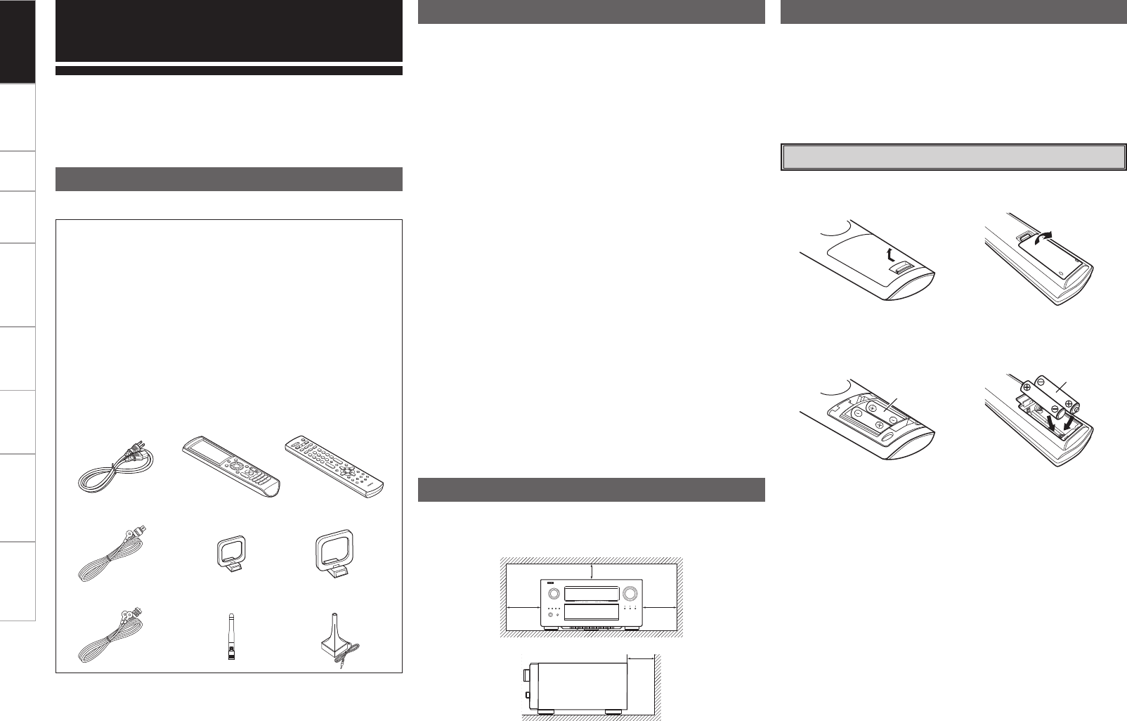
q Lift the clasp and remove the rear lid.
e Put the rear cover back on.
(RC-1067) (RC-1070)
(RC-1067) (RC-1070)
LR6/AA
R03/AAA
w Load the two batteries properly as indicated by the marks in the
battery compartment.
About the Remote Control Unit
Inserting the Batteries
• Before turning the power switch on
Check once again that all connections are correct and that there are
no problems with the connection cables.
• Power is supplied to some of the circuitry even when the unit is
set to the standby mode. When traveling or leaving home for long
periods of time, be sure to unplug the power cord from the power
outlet.
• About condensation
If there is a major difference in temperature between the inside of
the unit and the surroundings, condensation (dew) may form on
the operating parts inside the unit, causing the unit not to operate
properly.
If this happens, let the unit sit for an hour or two with the power
turned off and wait until there is little difference in temperature
before using the unit.
• Cautions on using mobile phones
Using a mobile phone near this unit may result in noise. If so, move
the mobile phone away from this unit when it is in use.
• Moving the unit
Turn off the power and unplug the power cord from the power
outlet.
Next, disconnect the connection cables to other system units before
moving the unit.
• Note that the illustrations in these instructions may differ from the
actual unit for explanation purposes.
• Light Emitting Diodes (LED) are used in the AVP-A1HDCI circuit.
When powered on, a green light shows inside part of the AVP-
A1HDCI, however this is not a fault.
Note:
For proper heat dispersal, do not install this unit in a confined
space, such as a bookcase or similar enclosure.
b Note
b
Wall
b
b
Cautions on Handling
Cautions on Installation
Check that the following parts are supplied with the product.
q Owner’s manual ...................................................................... 1
w Warranty (for North America model only) ................................ 1
e Service station list ................................................................... 1
r Power cord (Cord length: Approx. 5 ft /1.5 m) ........................ 1
t Main remote control (RC-1067) ............................................... 1
y LR6/AA batteries (for RC-1067) ............................................... 2
u Sub remote control (RC-1070) ................................................. 1
i R03/AAA batteries (for RC-1070) ............................................. 2
o FM indoor antenna .................................................................. 1
Q0 AM loop antenna (small, for AM broadcasts) .......................... 1
Q1 AM loop antenna (large, for HD Radio broadcasts) ................. 1
Q2 Dipole antenna (for HD Radio broadcasts) .............................. 1
Q3 Rod antenna for wireless LAN connection .............................. 1
Q4 Setup microphone (Cord length: Approx. 7.6 m) ..................... 1
r t u
Q1
o
Q4Q3
Q0
Q2
Thank you for purchasing this DENON product. To ensure proper
operation, please read this owner’s manual carefully before using the
product.
After reading them, be sure to keep them for future reference.
Getting Started
Accessories
Getting Started
Connections Setup Playback Remote Control Multi-Zone Information Troubleshooting Specifications
For buttons not explained here, see the page indicated in parentheses ( ).
q w e r t
yioQ0 u
Q1 Q2 Q3 Q4
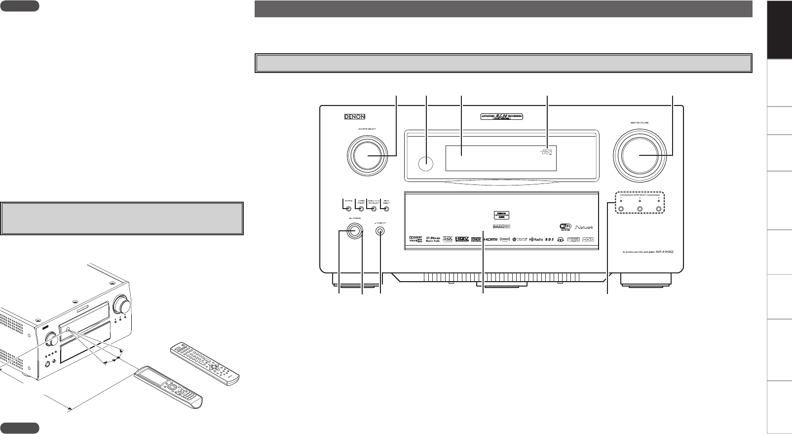
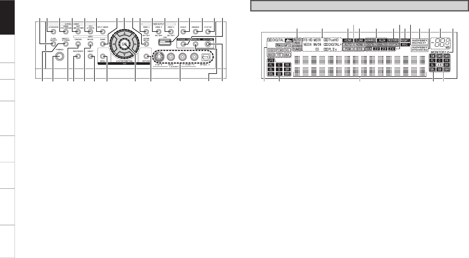
Part Names and Functions
Front Panel
q Power operation button (ON/STANDBY) ·····························(58)
w Power indicator ·······································································(58)
e Power switch (hON jOFF) ··················································(58)
r Door ····························································································(5)
t QUICK SELECT buttons / indicators ······································(75)
y MASTER VOLUME control knob ············································(58)
u Master volume indicator
i Display ························································································(5)
o Remote control sensor ·····························································(4)
Q0 SOURCE SELECT knob ···························································(45)
Q1 SOURCE button ·······································································(45)
Q2 TUNING PRESET button ·························································(59)
Q3 ZONE2/3/4 / REC SELECT button ····································(73, 87)
Q4 VIDEO SELECT button ····························································(46)
30°
30°
Approx. 7 m
or
(RC-1067)
(RC-1070)
NOTE
• Replace the batteries with new ones if the set does not operate
even when the remote control unit is operated close to the unit.
• The supplied batteries are only for verifying operation.
• When inserting the batteries, be sure to do so in the proper direction,
following the “q” and “w” marks in the battery compartment.
• To prevent damage or leakage of battery fluid:
• Do not use a new battery together with an old one.
• Do not use two different types of batteries.
• Do not attempt to charge dry batteries.
• Do not short-circuit, disassemble, heat or dispose of batteries in
flames.
• If the battery fluid should leak, carefully wipe the fluid off the inside
of the battery compartment and insert new batteries.
• Remove the batteries from the remote control unit if it will not be in
use for long periods.
• When replacing the batteries, have the new batteries ready and
insert them as quickly as possible.
Operating Range of the Remote Control
Unit
Point the remote control unit at the remote sensor when operating it.
NOTE
The set may function improperly or the remote control unit may not
operate if the remote control sensor is exposed to direct sunlight,
strong artificial light from an inverter type fluorescent lamp or infrared
light.
Getting Started
Connections Setup Playback Remote Control Multi-Zone Information Troubleshooting Specifications
t
uQ4Q8Q9 o iQ1Q0Q6 Q2
Q3Q5Q7 y
wq e r
q Input signal indicators
w Input signal channel indicators
These light when digital signals are input.
e Information display
The input source name, surround mode, setting
values and other information are displayed
here.
r Output signal channel indicators
t Surround speaker indicators
These light according to the settings of the
surround A and B speakers.
y Monitor output indicators
These light according to the HDMI monitor
output setting. When set to “Auto (Dual)”, the
indicators light according to the connection
status.
u Master volume indicator
i AUDYSSEY DYNAMIC EQ indicator
This lights when the Dynamic EQ is selected.
o AUDYSSEY MULTEQ XT indicator
This lights when the room equalizer is selected.
Q0 Recording output source indicator
This lights when the REC OUT mode is
selected.
Q1 NIGHT indicator
This lights when the night mode is selected.
Q2 Multi zone indicators
These light when the power for the respective
zone is turned on.
Q3 RESTORER indicator
This lights when the RESTORER mode is
selected.
Q4 ADVANCED AL24 indicator
This lights when Advanced AL24 Processing is
activated (vpage 92).
Q5 D.LINK indicator
This lights when playing using DENON LINK
connections.
Q6 Input mode indicators
Q7 HDMI indicator
This lights when playing using HDMI
connections.
Q8 Decoder indicators
These light when the respective decoders are
operating.
Q9 Tuner reception mode indicators
These light according to the reception conditions
when the input source is set to “TUNER” or
“HD Radio”.
• AUTO
This lights when in the auto tuning mode.
• RDS
These light when receiving RDS broadcasts.
• STEREO
In the FM mode, this lights when receiving
analog stereo broadcasts.
• TUNED
This lights when the broadcast is properly tuned
in.
Display
q DIRECT/STEREO button ···························· (51)
w Headphones jack (PHONES) ················ (58, 73)
e CINEMA button ·········································· (50)
r RESTORER button ······································ (55)
t MUSIC button ············································· (50)
y NIGHT button ············································· (55)
u MENU button ·············································· (24)
i CH SEL / ENTER button ······················· (24, 75)
o RETURN button ·········································· (24)
Q0 V.AUX INPUT connectors ·························· (18)
Q1 ROOM EQ button ······································· (55)
Q2 SETUP MIC jack ·········································· (26)
Q3 DYNAMIC EQ button ·································· (55)
Q4 STATUS button ·········································· (57)
Q5 DIMMER button ·········································· (43)
q w er t y u i o Q0 Q1 Q2
Q3Q4Q5Q6Q7Q8Q9W0W1W2W3W4W5W6W7W8W9
GWith the door openH
Q6 SCALE button ············································· (47)
Q7 USB port ······················································ (19)
Q8 ZONE4 ON/OFF button ······························ (87)
Q9 ZONE3 ON/OFF button ······························ (87)
W0 ZONE2 ON/OFF button ······························ (87)
W1 AUDIO DELAY button ································ (56)
W2 Cursor buttons (uio p) ·························· (24)
W3 GAME button ·············································· (50)
W4 INPUT MODE button ·································· (47)
W5 7CH STEREO button ··································· (51)
W6 DSP SIMULATION button ·························· (51)
W7 HOME THX CINEMA button ······················ (50)
W8 STANDARD button ····································· (51)
W9 PURE DIRECT button ································· (52)
Getting Started
Connections Setup Playback Remote Control Multi-Zone Information Troubleshooting Specifications
q
W1 i W0
W2W3 W4
Q9 Q8 Q7 Q6 Q5 Q4 Q3 Q2 Q1Q0 o i
w e r t y u
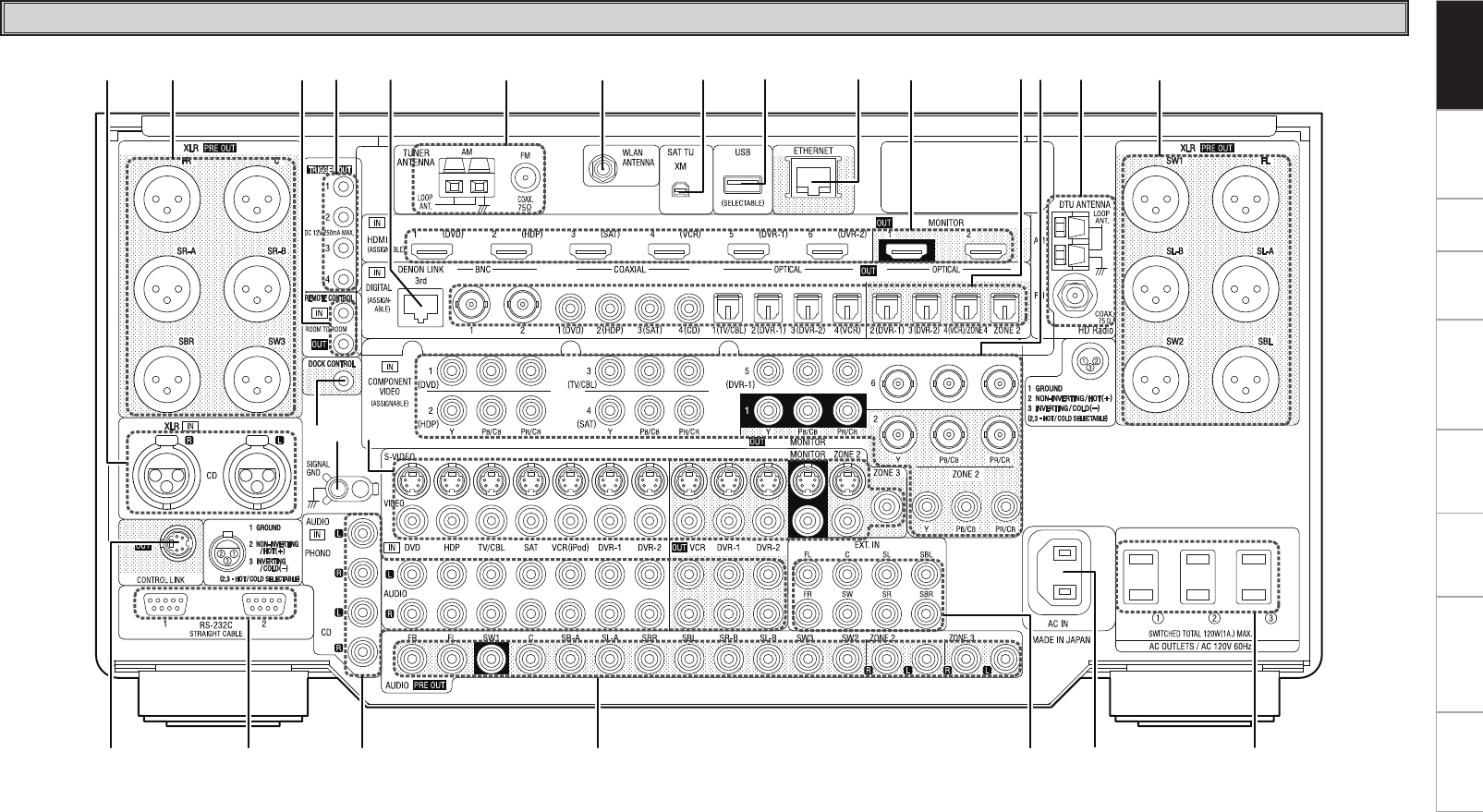
q CONTROL LINK connector ························· (11)
w RS-232C connector ····································· (23)
e Analog audio connectors (AUDIO) ··········· (14)
r RCA PRE OUT connectors ··················· (11, 22)
t EXT. IN connectors ····································· (18)
y AC inlet (AC IN) ··········································· (23)
u AC OUTLETS ··············································· (23)
i XLR PRE OUT connectors ·························· (11)
o HD Radio antenna terminals
(DTU ANTENNA) ········································ (20)
Q0 COMPONENT VIDEO connectors ········ (13, 22)
Q1 Digital audio connectors
(OPTICAL / COAXIAL / BNC) ··············· (13, 22)
Q2 HDMI connectors ········································ (12)
Q3 ETHERNET connector ································ (21)
Q4 USB port ······················································ (19)
Q5 XM connector (SAT TU) ····························· (19)
Q6 WLAN ANTENNA terminal ························ (21)
Q7 FM/AM antenna terminals
(TUNER ANTENNA) ···································· (20)
Q8 DENON LINK connector ····························· (18)
Rear Panel
Q9 TRIGGER OUT jacks ··································· (23)
W0 REMOTE CONTROL jacks ·························· (22)
W1 XLR audio connectors (CD) ······················· (14)
W2 DOCK CONTROL jack ································· (14)
W3 SIGNAL GND terminal ······························· (14)
W4 VIDEO / S-VIDEO connectors ···················· (13)
Getting Started
Connections Setup Playback Remote Control Multi-Zone Information Troubleshooting Specifications
q
i
w
e
r
t
y
u
o
Q1
Q3
Q4
Q2
Q0
Q5
Q6
Q7
Q9
W0
W2
W5
W7
W6
W4
W3
W1
Q8
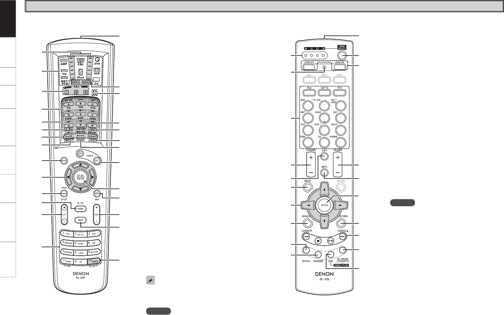
q Signal transmission indicator ··················· (77)
w Mode select buttons ·································· (77)
e Quick select / System call buttons ····· (75, 81)
r Surround mode buttons ····················(50 ~ 52)
t System buttons ···································· (78, 79)
y Audio delay button (A. DL) ························ (56)
u Tuner system buttons ·························· (59, 79)
i Input mode button (INPUT) ······················· (47)
o MENU button ·············································· (24)
Q0 Cursor buttons (uio p) ························· (24)
Q1 Parameter / Search button
(PARA / SRCH) ·························· (52, 60, 62, 65)
Q2 Monitor select (M. SEL) /
HOME button ········································ (32, 77)
Q3 Channel buttons (CH) ····················· (59, 65, 78)
Q4 Input source select /
Number buttons ··································· (45, 58)
Q5 Remote control signal transmitter ············· (4)
Q6 Device select indicators (DEV1 / DEV2) ··· (77)
Q7 ZONE3 / ZONE4 select indicators
(Z3 / Z4) ······················································· (87)
Q8 RESTORER button (RSTR) ························· (55)
Q9 Night button (NGT) ···································· (55)
W0 Test tone button (TEST) ···························· (30)
W1 Surround speaker select button (SPKR) ···· (31)
W2 POWER buttons ·········································· (58)
W3 Channel select (CH SEL) /
ENTER button ······································· (24, 75)
W4 Return button (RTN) ·································· (24)
W5 Master volume control buttons (VOL) ····· (58)
W6 Muting button (MUTE) ························ (58, 87)
W7 Main remote control unit setup button
(RC SETUP) ················································· (77)
q
r
t
y
i
o
Q0
u
e
w
Q4
Q7
Q8
Q9
W0
Q6
Q5
Q2
Q3
Q1
q ZONE indicators ········································· (85)
w Advanced setup button ····························· (85)
e Input source select buttons ······················· (45)
r CHANNEL buttons ································ (65, 84)
t SHIFT button ··············································· (59)
y MENU button ·············································· (24)
u Cursor buttons (uio p) ························· (24)
i SEARCH button ······························ (60, 62, 65)
o REPEAT button ··········································· (65)
Q0 RANDOM button ········································ (65)
Q1 Remote control signal transmitter ············· (4)
Q2 ZONE SELECT button ································ (85)
Q3 Zone power on/off buttons
(ZONE ON / ZONE OFF) ····························· (87)
Q4 Master volume control buttons
(VOLUME) ·················································· (58)
Q5 Muting button (MUTE) ························ (58, 87)
Q6 ENTER button ············································· (24)
Q7 RETURN button ·········································· (24)
Q8 System buttons ······························ (59, 83, 84)
Q9 ALL MUSIC/FAVORITES
(DIRECT PLAY) button ······························ (83)
W0 USB (DIRECT PLAY) button ······················· (83)
n Main remote control unit (RC-1067) n Sub remote control unit (RC-1070)
The time for which the backlight stays on can
be changed (vpage 82 “Setting the Time the
Backlight Stays Lit”).
Remote Control Unit
NOTE
The ZONE2 mode QUICK SELECT (1 ~ 3), A. DL,
RSTR, NGT, INPUT, SPKR, TEST and surround
mode buttons cannot be used.
NOTE
The AUX-1, AUX-2, AUX-3 and OPTION buttons
cannot be used.
Getting Started
Getting Started Setup Playback Remote Control Multi-Zone Information Troubleshooting Specifications
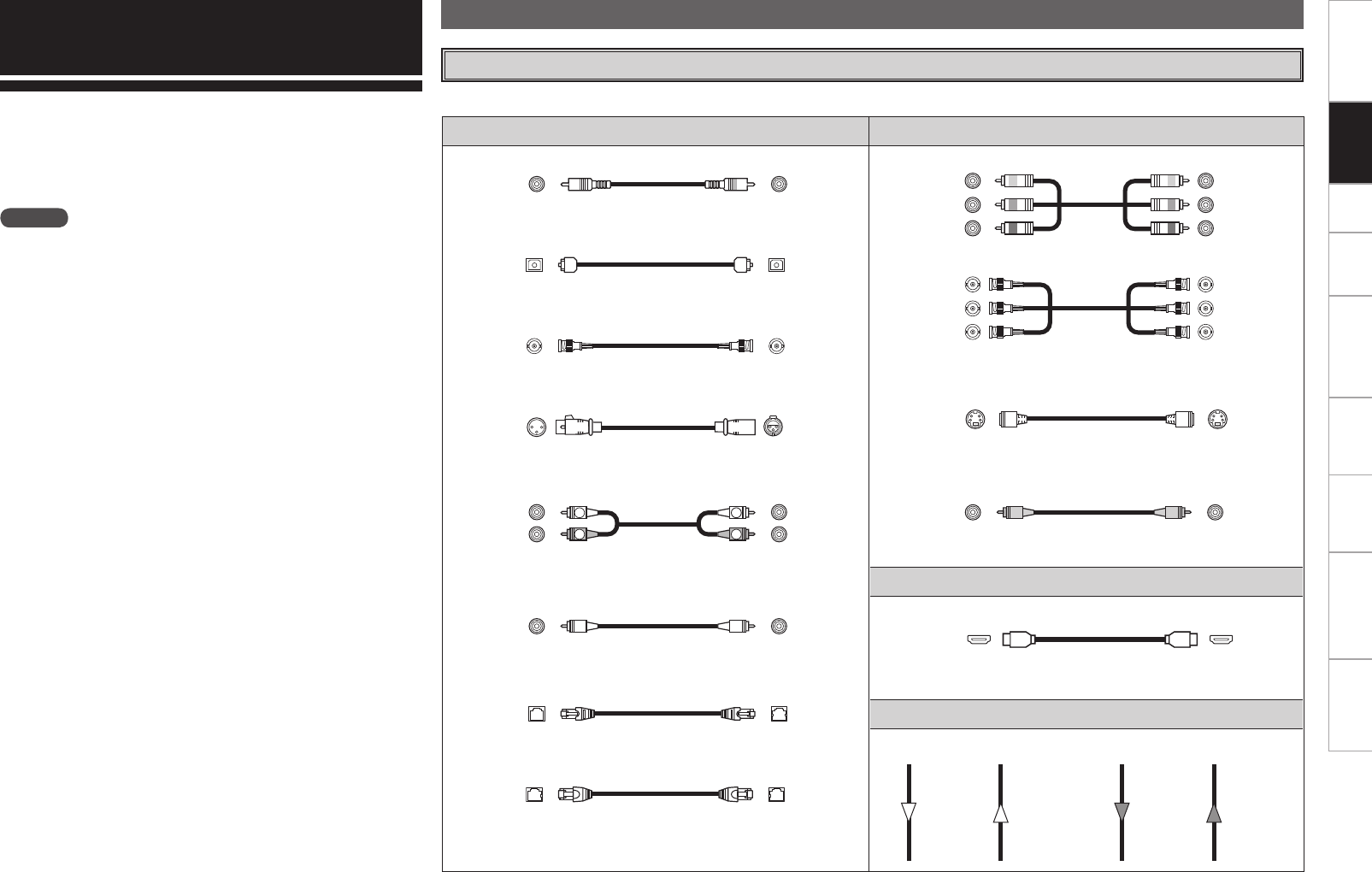
Audio cables Video cables
Coaxial digital connections
(Orange)
Coaxial digital (75 Ω/ohms pin-plug) cable
Optical digital connections
Optical cable
BNC digital connections
BNC (75 Ω/ohms) cable
Analog connections (XLR)
Balanced cable
Analog connections (stereo, RCA)
(White)
(Red)
R
L
R
L
Stereo pin-plug cable
Analog connections (monaural, for subwoofer)
(Black)
Pin-plug cable
DENON LINK connections
DENON LINK cable
Network connections (wired LAN)
Ethernet cable
Component video connections
(Green)
(Blue)
(Red)
(Y)
(PB/CB)
(PR/CR)
Component video cable
(Green)
(Blue)
(Red)
(Y)
(PB/CB)
(PR/CR)
BNC (75 Ω/ohms) cable
S-Video connections
S-Video cable
Video connections
(Yellow)
75 Ω/ohms pin-plug video cable
Audio and video cables
HDMI connections
19-pin HDMI cable
Signal direction
Audio signal: Video signal:
Output
Input
Input
Output
Output
Input
Input
Output
Connections
NOTE
• Do not plug in the power cord until all connections have been
completed.
• When making connections, also refer to the operating instructions of
the other components.
• Be sure to connect the left and right channels properly (left with left,
right with right).
• Do not bundle power cords together with connection cables. Doing
so can result in humming or noise.
Connections for all compatible audio and video signal formats are
described in these operating instructions. Please select the types
of connections suited for the equipment you are connecting.
With some types of connections, certain settings must be made
on the AVP-A1HDCI. For details, refer to the instructions for the
respective connection items below.
Cables Used for Connections
Select the cables according to the equipment being connected.
Preparations
Connections
Getting Started Setup Playback Remote Control Multi-Zone Information Troubleshooting Specifications
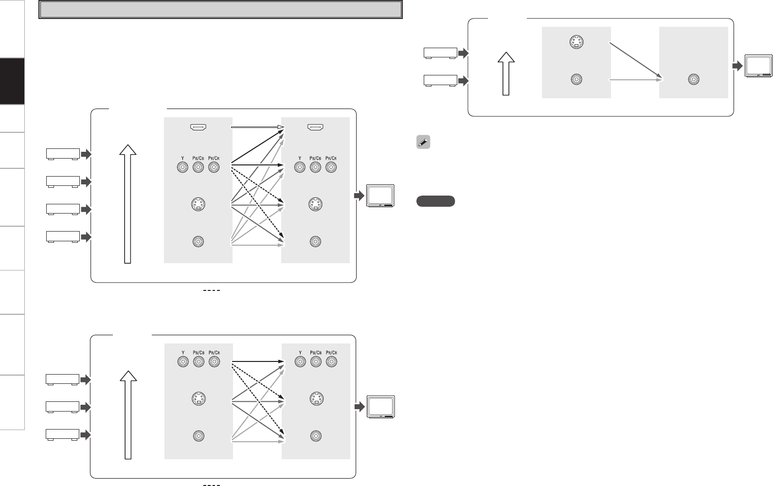
GFlow of video signals for ZONE2H
• This function automatically converts various formats of video signals input to the AVP-A1HDCI into the
format used to output the video signals from the AVP-A1HDCI to a monitor.
• The AVP-A1HDCI’s video input/output circuitry is compatible with the following four types of video
signals:
Digital video signals: HDMI
Analog video signals: Component video, S-Video and Video
Video Conversion Function
GFlow of video signals inside the AVP-A1HDCIH
MAIN ZONE
High picture
quality playback HDMI connector
Component video
connectors
S-Video connector
Video connector
Monitor
HDMI connector
Component video
connectors
S-Video connector
Video connector
Video inputs Video outputs
: When 480i/576i signals are input
Component video
connectors
S-Video connector
Video connector
Component video
connectors
Video connector
Video inputs Video outputs
ZONE2
NOTE
• For optimum video performance, THX recommends that you set the conversion mode to “OFF” to use
video signals pass through system without up conversion.
Example: View video input from a component video on the component video monitor.
• HDMI signals cannot be converted into analog signals.
• 1080p component input video signals cannot be output to anything other than component video
connectors.
• 480p/576p, 1080i and 720p component video input signals cannot be converted into S-Video or Video
format.
• When a non-standard video signal from a game machine or some other source is input, the video
conversion function might not operate.
• When not using this function, connect a monitor output with the same type of connector as the video
input connector.
• The resolution of the HDMI input-compatible monitor connected to the AVP-A1HDCI can be checked at
GUI menu “Information” – “HDMI Information” – “Monitor1” or “Monitor2” (vpage 57).
High picture
quality playback
ZONE2
monitor
GFlow of video signals for ZONE3H
S-Video connector
Video connector Video connector
Video inputs Video outputs
ZONE3
High picture
quality playback ZONE3
monitor
S-Video connector
: When 480i/576i signals are input
Connections
0
Getting Started Setup Playback Remote Control Multi-Zone Information Troubleshooting Specifications
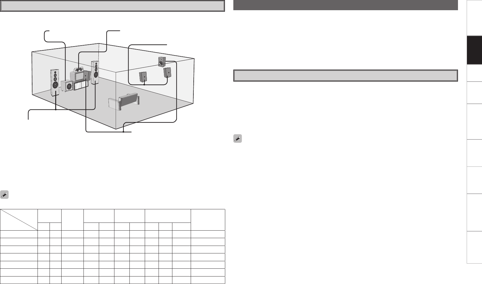
The illustration below shows a basic example of installation of the amplifier combined with 8 speakers and
a monitor.
Speaker Layout
Subwoofer Center speaker
Surround speakers
Front speakers
Place the front speakers to the
sides of the monitor or screen and
as flush with the screen surface as
possible.
Surround back speakers
The table below shows a typical speaker configuration for the AVP-A1HDCI.
FRONT CENTER
SURROUND
A
SURROUND
BSURROUND BACK SUBWOOFER
(b)
L R L R L R L R 1 only
9.1-channels S S S S S S S S S –S
7.1-channels S S S S S – – S S –S
6.1-channels S S S S S – – – – S S
5.1-channels S S S S S – – – – – S
3.1-channels S S S – – – – – – – S
2.1-channels S S – – – – – – – – S
2-channels S S – – – – – – – – –
Two surround back speakers are required to use the THX Ultra2 Cinema,THX Music mode and THX Games
mode.
Set the surround back speakers so that the distance to the listening position is the same for both the left
and right speakers. It is also recommended that the deviations of the distance from the listening position
to L and R channel speakers (front left (FL) and front right (FR), surround left (SL) and surround right (SR),
surround back left (SBL) and surround back right (SBR)) is less than 2 ft (60 cm).
b The AVP-A1HDCI can be connected to a maximum of 3 subwoofers.
• For instructions for connecting speakers, please refer to the POA-A1HDCI owner’s manual.
• When using just one surround back speaker, connect it to the left channel (SBL).
• Connect the AVP-A1HDCI pre-out terminal to the power amp (sold separately).
• AVP-A1HDCI has a RCA pre-out terminal and XLR pre-out terminal. Connect accordingly with the power
amp you want to use.
• The polarity of the XLR pre-out terminal can be switched using GUI menu “Manual Setup” – “Option
Setup” – “XLR Out Polarity” (vpage 41).
• Connect the speakers to the power amp.
• Refer to the owner’s manual of each piece of equipment when making connections.
POA-A1HDCI Connection and Operation
• When connecting the AVP-A1HDCI to the power amp POA-A1HDCI with a control link cable (included
with the POA-A1HDCI), you can perform the following control operations.
• POA-A1HDCI channel input selection and power amp settings
• Link POA-A1HDCI to AVP-A1HDCI On/Standby control
• Link POA-A1HDCI meter operation to AVP-A1HDCI display on/off control (vpage 43)
• Updating POA-A1HDCI firmware (vpage 43)
• Up to 2 POA-A1HDCI units can be connected. Refer to the POA-A1HDCI owner's manual for making
connections and POA-A1HDCI settings.
Connecting to the Power Amp
Connections
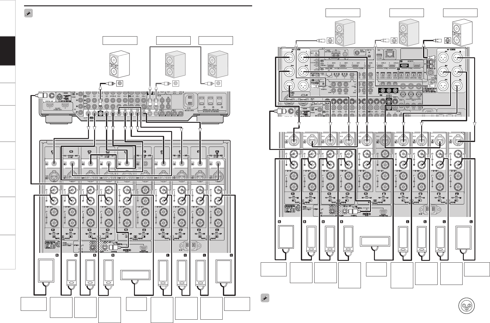
Getting Started Setup Playback Remote Control Multi-Zone Information Troubleshooting Specifications
SPEAKERS
XLR
RCA
SPEAKERS
XLR
RCA
SPEAKERS
XLR
RCA
SPEAKERS
XLR
RCA
SPEAKERS
XLR
RCA
SPEAKERS
XLR
RCA
SPEAKERS
XLR
RCA
SPEAKERS
XLR
RCA
SPEAKERS
XLR
RCA
SPEAKERS
XLR
RCA
*/
(R) (L) (L) (L)
(R)
*/ */
(L)
(R) (R)
w q
w qw q
w q
w q
w qw qw q
w q
Front
speaker (R)
Center
speaker
Subwoofer 1
Subwoofer
with built-in
amplifier
Surround
speaker-
B (R)
Surround
speaker-
A (R)
b L : Left
R : Right
Front
speaker (L)
Surround
back
speaker
(R)
Surround
speaker-
A (L)
Surround
speaker-
B (L)
Surround
back
speaker
(L)
Subwoofer 2 Subwoofer 3
AVP-A1HDCI
SPEAKERS
XLR
RCA
SPEAKERS
XLR
RCA
SPEAKERS
XLR
RCA
SPEAKERS
XLR
RCA
SPEAKERS
XLR
RCA
SPEAKERS
XLR
RCA
SPEAKERS
XLR
RCA
SPEAKERS
XLR
RCA
SPEAKERS
XLR
RCA
SPEAKERS
XLR
RCA
*/
(R) (L) (L) (L)
(R)
*/ */
(L)
(R) (R)
w q
w qw q
w q
w q
w qw qw q
w q
Subwoofer 3
Subwoofer with
built-in amplifier
b L : Left
R : Right
Subwoofer 2 Subwoofer 1
The default AVP-A1HDCI balance model XLR pre-out terminal pin alignment is as shown.
q : GROUND w : HOT e : COLD
Connections
n Connecting the RCA pre-out terminal (Example : 9.3-channels)
n Connecting the XLR pre-out terminal (Example : 9.3-channels)
When using Subwoofer 2 or 3, set GUI menu “Manual Setup” – “Speaker Setup” – “Subwoofer
Setup” (vpage 29).
POA-A1HDCI
AVP-A1HDCI
Front
speaker (R)
Center
speaker
Surround
speaker-
B (R)
Surround
speaker-
A (R)
Front
speaker (L)
Surround
back
speaker
(R)
Surround
speaker-
A (L)
Surround
speaker-
B (L)
Surround
back
speaker
(L)
POA-A1HDCI
Connections
Getting Started Setup Playback Remote Control Multi-Zone Information Troubleshooting Specifications
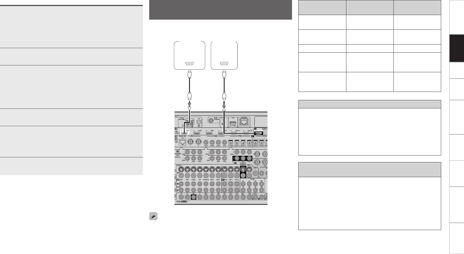
With HDMI connections, the video and audio signals can be transferred
with a single cable.
065
)%.*
*/
)%.*
Compatible audio
format Details Discs
(examples)
2-channel linear PCM 2ch 32-192 kHz
16/20/24 bits
CD, DVD-Video,
DVD-Audio
Multi-channel linear
PCM
8ch 32-192 kHz
16/20/24 bits DVD-Audio
Dolby Digital, DTS Bitstream DVD-Video
DSD
2/5.1ch
2.8224 MHz
1 bit
SACD
Dolby Digital Plus,
Dolby TrueHD,
DTS-HD
Bitstream HD DVD,
Blu-ray Disc
Monitor
DVD
player
b The AVP-A1HDCI is supported to the feature of HDMI listed below.
• 30 and 36 bit Deep Color
• xvYCC
• Auto Lipsync Correction
Copyright protection system (HDCP)
In order to play the digital video and audio signals of a DVD- Video or
DVD-Audio disc using HDMI/DVI connections, both the connected
DVD player and monitor must be equipped for a copyright protection
system called “HDCP” (High-bandwidth Digital Content Protection).
HDCP is a copy protection technology consisting of data encoding
and mutual identification of the devices.
The AVP-A1HDCI is HDCP-compatible. For details on the DVD player
or monitor you are using, refer to its operating instructions.
When connecting with an HDMI/DVI converter cable
(adapter)
• HDMI video signals are theoretically compatible with the DVI
format.
When connecting to a monitor, etc., equipped with a DVI-D
connector, connection is possible using an HDMI/DVI converter
cable, but depending on the combination of components in some
cases the video signals will not be output.
• When connecting using an HDMI/DVI converter adapter, the video
signals may not be output properly due to poor connections with
the connected cable, etc.
• By default, HDMI sound is output from the speaker of the power
amp connected to AVP-A1HDCI.
• To output the sound from the TV, make the settings at GUI menu
“Manual Setup” – “HDMI Setup” – “Audio” – “TV” (vpage 32).
Connecting Equipment with HDMI
connectors
Operations
1Connect AVP-A1HDCI and POA-A1HDCI with the
control link cable.
b The control link cable is included with the POA-A1HDCI.
b AVP-A1HDCI can be connected and control to up to 2 POA-
A1HDCI units.
Refer to the POA-A1HDCI user’s manual for how to connect.
2Set the POA-A1HDCI’s control selector switch to
“AVP”.
3Set the POA-A1HDCI’s mode select switch according
to the number of POA-A1HDCI units you are
connecting.
When connecting 1 unit : “1”
When connecting 2 units : 1st unit “1”, 2nd unit “2”
b Refer to the POA-A1HDCI owner’s manual for details.
4Switch the AVP-A1HDCI and POA-A1HDCI power
on.
5Depending on the number of POA-A1HDCI units to
be connected, set GUI menu “Option Setup” – “POA
Setting” – “POA LINK” to either “ON (Single)” or
“ON (Dual)” (vpage 41).
6Use GUI menu “Option Setup” – “POA Setting”
– “LINK Check” to check the connection.
Connections
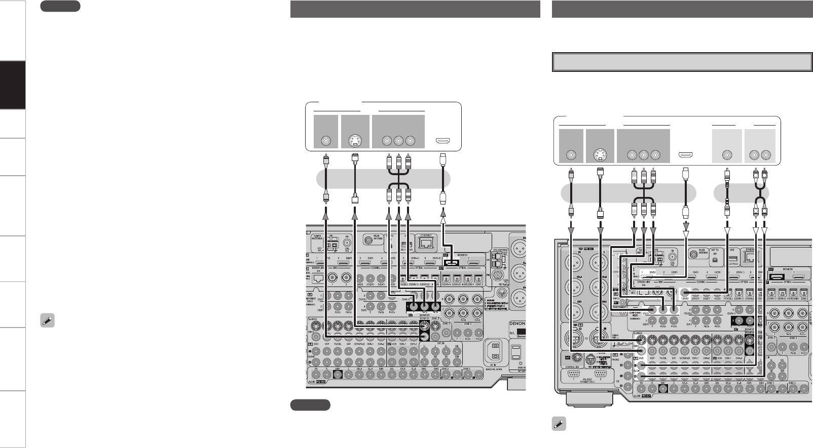
Getting Started Setup Playback Remote Control Multi-Zone Information Troubleshooting Specifications
• Connect the cables to be used (vpage 9 “Video Conversion
Function”).
• With HDMI connections, the video and audio signals can be
transferred with a single cable.
• To output the audio signals to the monitor with HDMI connections,
set GUI menu “Manual Setup” – “HDMI Setup” – “Audio” to “TV”
(vpage 32).
Connecting the Monitor
47*%&0
*/
7*%&0
$0.10/&/57*%&0
: 1#13
7*%&0
*/
)%.*
*/ */
Monitor
Connecting the Playback Components
NOTE
• The component video connectors may be indicated differently on
your monitor. For details, see the monitor’s operating instructions.
• The audio signals output from the HDMI connectors are only the
HDMI input signals.
47*%&0
065
"6%*07*%&0
$0.10/&/57*%&0
: 1#13
7*%&0
065 065
"6%*0
$0"9*"-
065
3-
065065
)%.*
R
L
R
L
Carefully check the left (L) and right (R) channels and the inputs and
outputs, and be sure to interconnect correctly.
DVD Player
• Connect the cables to be used.
• With HDMI connections, the video and audio signals can be transferred
with a single cable.
DVD player
• Connect an HDP (High-Definition Player) in the same way.
• When using an optical cable or a BNC cable for the digital audio
connection, make the settings at GUI menu “Source Select” – “DVD”
– “Assign” – “Digital” (vpage 48).
• When using a BNC cable for the component video connection, make
the settings at GUI menu “Source Select” – “DVD” – “Assign” –
“Component” (vpage 48).
• When the AVP-A1HDCI and DVD player are connected using an
HDMI cable, also connect the AVP-A1HDCI and monitor using an
HDMI cable.
• If the connected monitor or DVD player only has a DVI-D
connector, use an HDMI/DVI converter cable. When using a DVI
cable, no audio signals are transmitted.
• Use a Deep Color compatible cable for connection to Deep Color
compatible devices.
NOTE
• Use a CPPM-compatible DVD player to play DVD-Audio discs that
are copyright-protected by CPPM.
• The audio signals output from the HDMI connector (sampling
frequency, bit rate, etc.) may be restricted by the connected
device.
• Video signals are not output properly when using devices that are
not HDCP-compatible.
• Video signals are not output if the input video signals do not match
the monitor’s resolution. In this case, switch the DVD player’s
resolution to a resolution with which the monitor is compatible.
• If the GUI menu “Manual Setup” – “HDMI Setup” – “Audio”
setting (vpage 32) is set to “Amp”, the sound may be
interrupted when the monitor’s power is turned off.
• Use a cable on which the HDMI logo is indicated (a certified HDMI
product) for connection to the HDMI connector. Normal playback
may not be possible when using a cable other than one on which
the HDMI logo is indicated (a non-HDMI-certified product).
• If the monitor or DVD player does not support Deep Color, Deep
Color signal transfer is not possible.
• If the monitor or DVD player does not support xvYCC, xvYCC
signal transfer is not possible.
• If the monitor does not support “Auto Lipsync Correction”
function, this function will not work.
• The AVP-A1HDCI is compatible with the HDMI’s CEC (Consumer
Electronics Control) function. Please note the following.
• It may not work depending on the device it is connected to and
its setup.
• It does not operate with televisions or players that are not
compatible with HDMI’s CEC.
Connections
Getting Started Setup Playback Remote Control Multi-Zone Information Troubleshooting Specifications
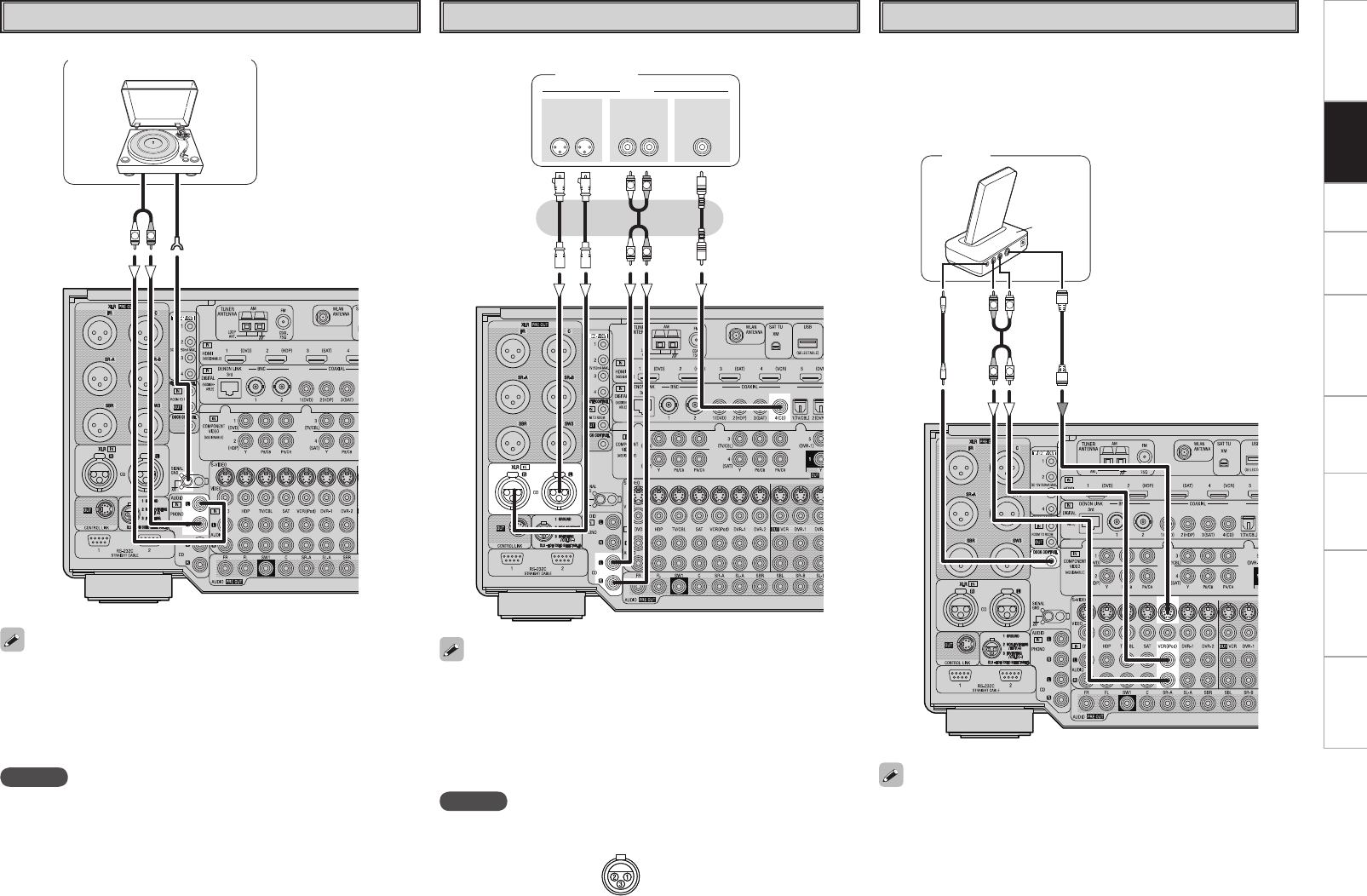
Record Player
• When connecting a record player with an MC cartridge, use a
commercially available MC head amplifier or a step-up transformer.
• Induction humming (a booming sound) may be produced from the
speakers if the volume is raised with no record player connected.
• With some record players, noise may be generated when the ground
wire is connected. If so, disconnect the ground wire.
(/%
"6%*0
065
R
L
Turntable (MM cartridge)
NOTE
The AVP-A1HDCI’s SIGNAL GND terminal is meant to reduce noise
when a record player is connected. This is not a safety ground
terminal.
R
L
R
L
"6%*0
"6%*0 $0"9*"-
065
3-3-
065
9-3
065
CD Player
Connect the cables to be used.
CD player
iPod®
Example :
RL
RL
"4%3
iPod
• When using an optical cable or a BNC cable for the digital audio
connection, make the settings at GUI menu “Source Select” – “CD”
– “Assign” – “Digital” (vpage 48).
• The default analog audio input setting is “RCA”. When using a
balanced cable for the analog audio connection, make the settings at
GUI menu “Source Select” – “CD” – “Assign” – “Analog” (vpage
49).
• With the default settings, the iPod can be used connected to the
VCR (iPod) connector.
• To assign the iPod to a connector other than VCR (iPod), make the
settings at GUI menu “Source Select” – “(input source to which
iPod dock assigned)” – “Assign” – “iPod dock” (vpage 49).
Use a DENON Control Dock for iPod (ASD-1R, sold separately) to
connect the iPod to the AVP-A1HDCI. For instructions on the Control
Dock for iPod settings, refer to the Control Dock for iPod’s operating
instructions.
NOTE
The default AVP-A1HDCI balance model XLR input connectors pin
alignment is as shown.
q : GROUND
w : HOT
e : COLD
Connections
Getting Started Setup Playback Remote Control Multi-Zone Information Troubleshooting Specifications
47*%&0
065
"6%*07*%&0
$0.10/&/57*%&0
: 1#13
7*%&0
065 065
"6%*0
3-
065065
R
L
R
L
015*$"-
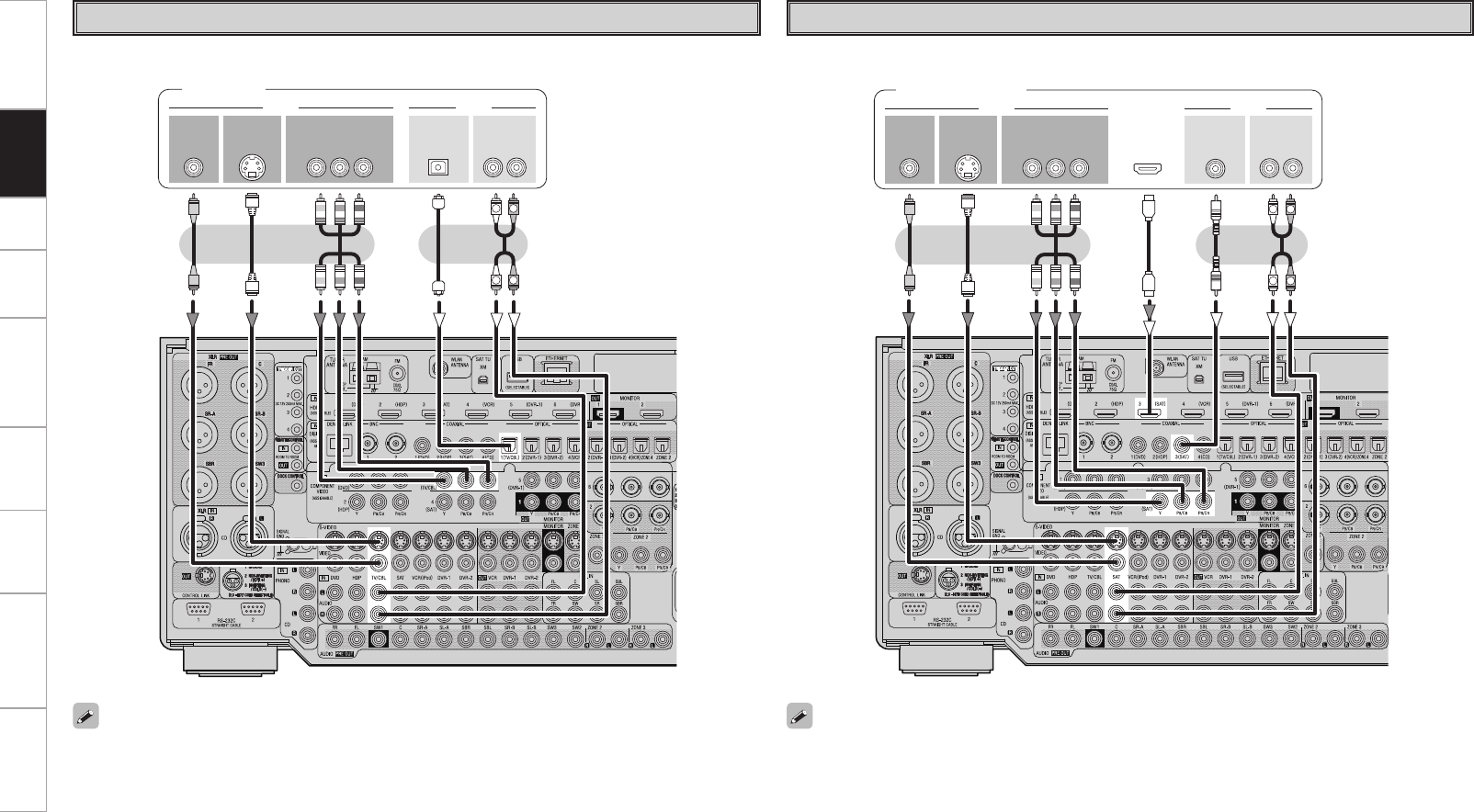
TV/CABLE Tuner
Connect the cables to be used.
TV tuner
• When using a coaxial digital cable or a BNC cable for the digital audio connection, make the settings at
GUI menu “Source Select” – “TV/CBL” – “Assign” – “Digital” (vpage 48).
• When using a BNC cable for the component video connection, make the settings at GUI menu “Source
Select” – “TV/CBL” – “Assign” – “Component” (vpage 48).
Satellite Receiver
Connect the cables to be used.
47*%&0
065
"6%*07*%&0
$0.10/&/57*%&0
: 1#13
7*%&0
065 065
"6%*0
3-
065
R
L
R
L
065
)%.* $0"9*"-
065
DBS / BS tuner
• When using an optical cable or a BNC cable for the digital audio connection, make the settings at GUI
menu “Source Select” – “SAT” – “Assign” – “Digital” (vpage 48).
• When using a BNC cable for the component video connection, make the settings at GUI menu “Source
Select” – “SAT” – “Assign” – “Component” (vpage 48).
Connections
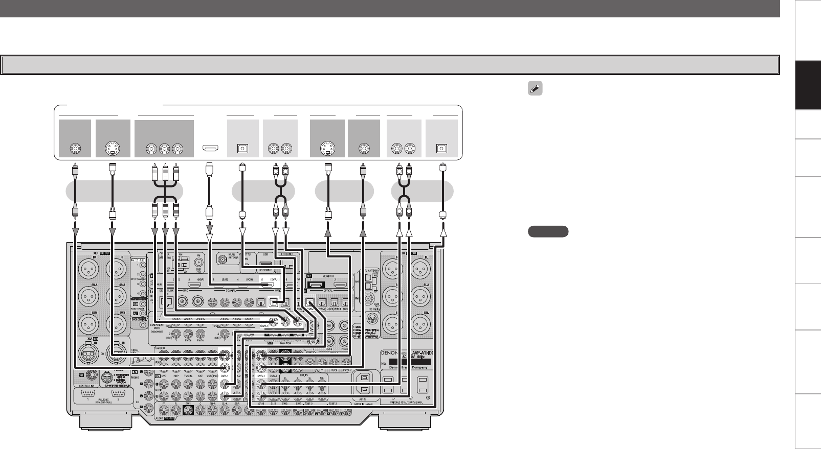
Getting Started Setup Playback Remote Control Multi-Zone Information Troubleshooting Specifications
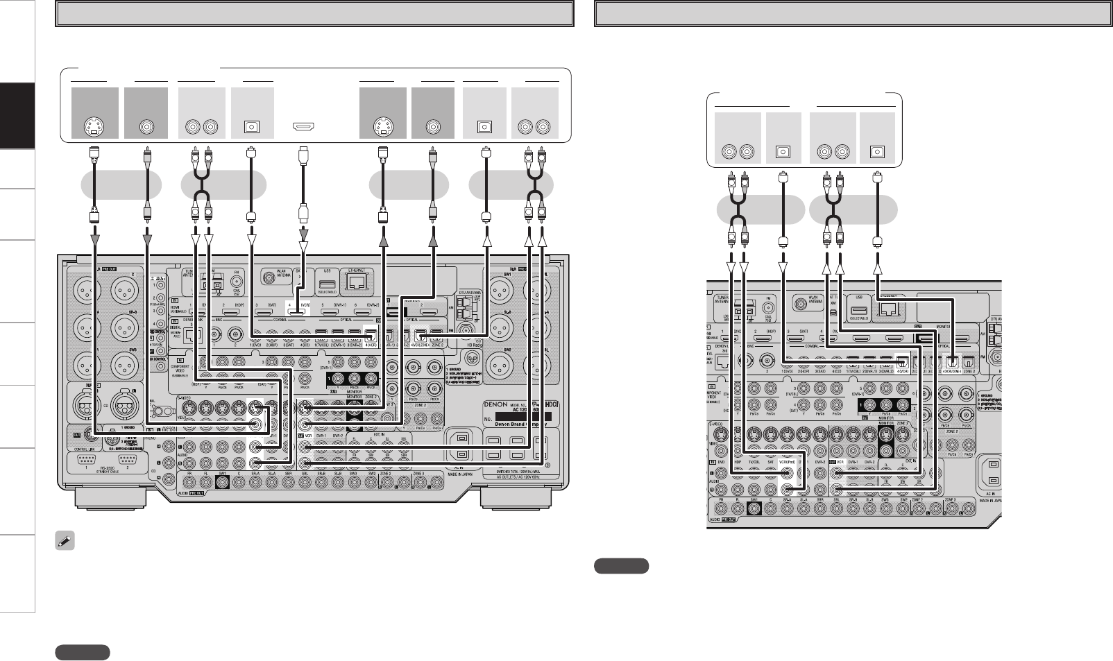
Carefully check the left (L) and right (R) channels and the inputs and outputs, and be sure to interconnect correctly.
Connecting the Recording Components
Digital Video Recorder
Connect the cables to be used.
R
L
R
L
R
L
R
L
47*%&0 47*%&0
*/
3-3-
*/
*/
"6%*0 "6%*07*%&0 7*%&0
*/065
015*$"- 015*$"-
065
"6%*0 "6%*0
065
7*%&0 7*%&0
065 065
)%.*
$0.10/&/57*%&0
: 1#13
065
Digital video recorder
NOTE
• Do not connect the output of the component connected to the AVP-
A1HDCI’s OPTICAL2 output connector to any input connector other
than OPTICAL2.
• Do not connect the output of the component connected to the AVP-
A1HDCI’s OPTICAL3 output connector to any input connector other
than OPTICAL3.
• Make analog connections if you wish to record analog audio
signals.
• When recording to a digital video recorder, it is necessary that the
type of cable used with the playback source equipment be the same
type that is connected to the AVP-A1HDCI DVR-1 OUT connector.
Example: TV IN → S-Video cable : DVR-1 OUT → S-Video cable
TV IN → Video cable : DVR-1 OUT → Video cable
• Connect a DVR-2 in the same way.
• When using a component video cable or a BNC cable for the
component video connection make the settings at GUI menu
“Source Select” – “DVR-1” or “DVR-2” – “Assign” – “Component”
(vpage 48).
Connections
Getting Started Setup Playback Remote Control Multi-Zone Information Troubleshooting Specifications
R
L
R
L
R
L
R
L
47*%&0 47*%&0
*/
3-3-
*/
*/
065
"6%*0 "6%*07*%&0 7*%&0
*/065
015*$"- 015*$"-
065
"6%*0 "6%*07*%&0 7*%&0
065 065
)%.*
Video Cassette Recorder
Connect the cables to be used.
Video cassette recorder
• When recording to a VCR, it is necessary that the type of cable used with the playback source equipment
be the same type that is connected to the AVP-A1HDCI VCR OUT connector.
Example: TV IN → S-Video cable : VCR OUT → S-Video cable
TV IN → Video cable : VCR OUT → Video cable
• When using a component video cable or a BNC cable for the video connection, make the settings at GUI
menu “Source Select” – “VCR” – “Assign” – “Component” (vpage 48).
NOTE
Do not connect the output of the component connected to the AVP-A1HDCI’s OPTICAL4 output connector
to any input connector other than OPTICAL4.
3-3-
*/ */065
015*$"- 015*$"-
065
"6%*0"6%*0
"6%*0
R
L
R
L
R
L
R
L
CD Recorder / MD Recorder / Tape Deck
Make analog connections if you wish to record analog audio signals, or digital connections if you wish to
record digital audio signals, depending on the types of connectors on the components being used.
CD recorder / MD recorder /
Tape deck
NOTE
Do not connect the output of the component connected to the AVP-A1HDCI’s OPTICAL4 output connector
to any input connector other than OPTICAL4.
Connections
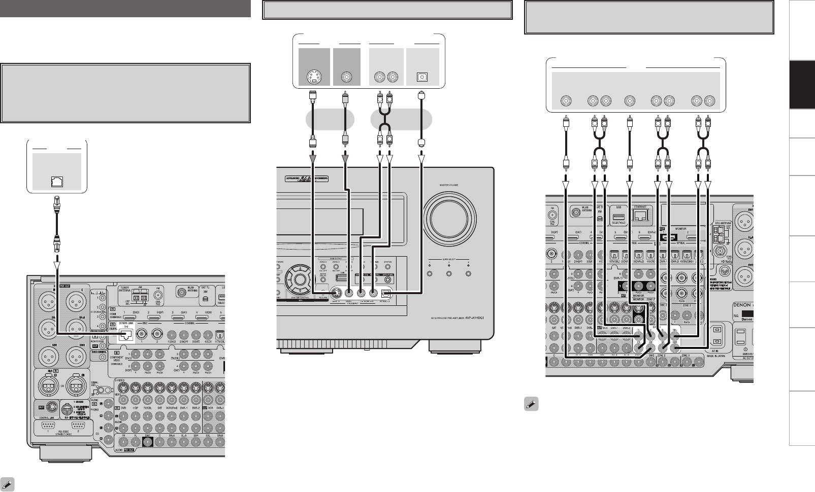
Getting Started Setup Playback Remote Control Multi-Zone Information Troubleshooting Specifications
Carefully check the left (L) and right (R) channels and the inputs and
outputs, and be sure to interconnect correctly.
Connections to Other Devices
%&/0/-*/,
"6%*0
Components Equipped with a DENON
LINK connector
Multi-channel playback is possible with DVD-Audio discs, Super
Audio CD, etc.
DVD player
To use with DENON LINK connections, make the settings at GUI menu
“Source Select” – “(input source)” – “Assign” – “Digital” – “DENON
LINK” (vpage 48).
47*%&0
065
"6%*07*%&0
7*%&0
065 065
015*$"-"6%*0
3-
065
R
L
R
L
Video Camera / Game Console
Video camera / Game console
46#
800'&3
$&/5&3 463306/%
#"$,
3-
463306/%
3-
'30/5
3-
"6%*0
R
L
R
L
R
L
R
L
R
L
R
L
Component with Multi-channel Output
connectors
DVD player / Super Audio CD player /
External decoder
• To play the analog input signals input to the EXT. IN connectors,
press the INPUT MODE button on the main unit or INPUT button
on the main remote control unit and select “EXT. IN” or make the
settings at GUI menu “Source Select” – “(input source)” – “Input
Mode” – “Input Mode” – “EXT. IN” (vpage 47).
• The video signal can be connected in the same way as a DVD player
(vpage 13).
• To play copyright-protected discs, connect the AVP-A1HDCI’s EXT.
IN connector with the DVD player’s analog multi-channel output
connector.
Connections
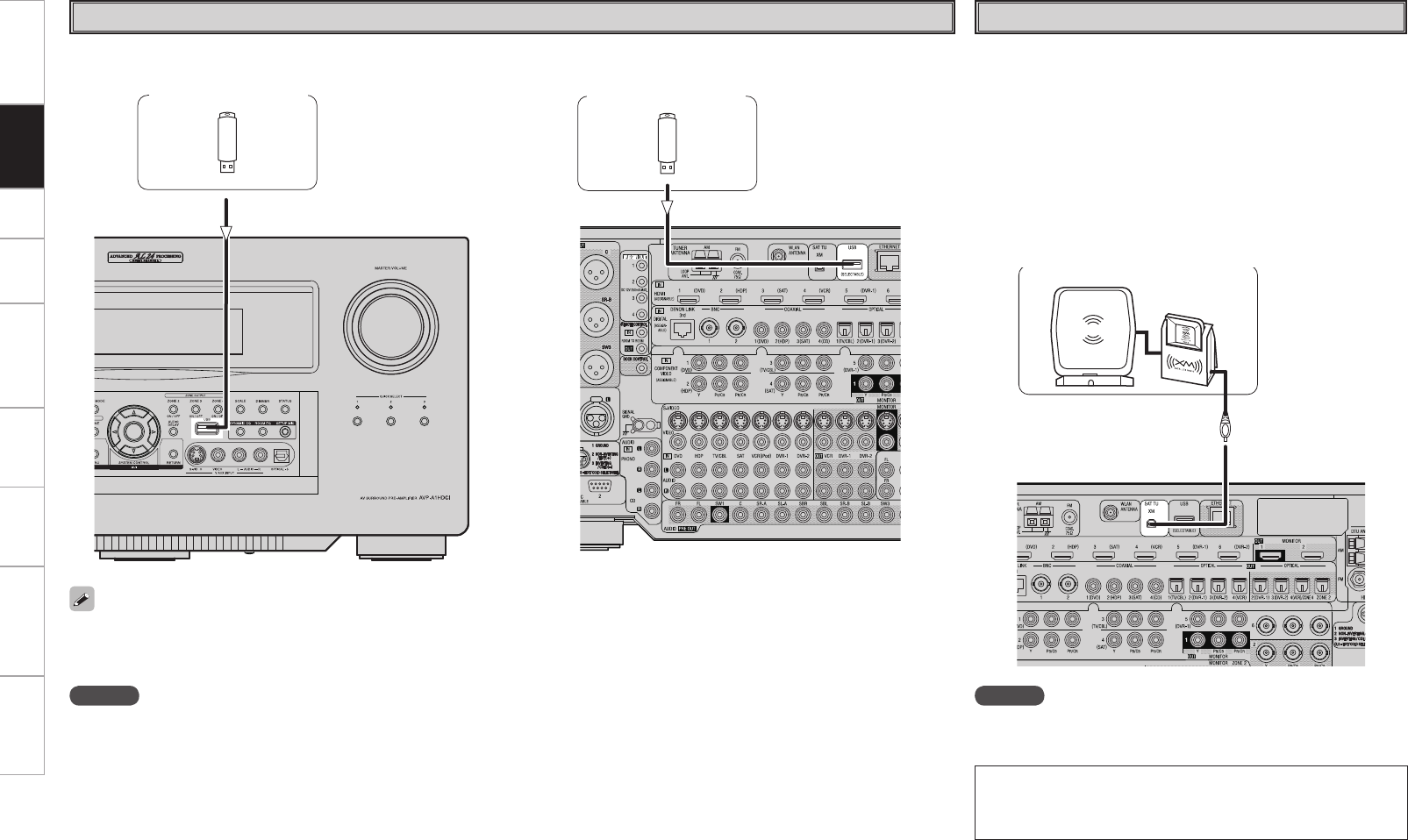
Getting Started Setup Playback Remote Control Multi-Zone Information Troubleshooting Specifications
USB Port
• In the initial status, USB memory devices can be used by connecting them to the USB port on the front panel.
• To change the port to be used, see “USB Select” on page 49.
• For instructions on playing the files on a USB memory device, see page 69, 70.
NOTE
• Set to the USB port you want to use.
• The AVP-A1HDCI is equipped with two USB ports, one each on the front and rear panels. It is not possible to use the set with USB memory
devices connected to both the ports at the same time. Select the USB port you want to use at the GUI menu “Source Select” – “NET/USB”
– “Playback Mode” – “USB Select”.
• Do not use the extension cable for connecting the USB memory deveice to the AVP-A1HDCI’s USB port.
Use of the extension cable may cause harmful interference.
n Front panel n Rear panel
USB memory device USB memory device
XM
NOTE
Keep the power cord unplugged until the XM Mini-Tuner and Home
Dock connection have been completed.
XM Connector
• The AVP-A1HDCI is an XM Ready® receiver. You can receive XM®
Satellite Radio by connecting to the XM Mini-Tuner and Home Dock
(includes home antenna, each sold separately) and subscribing to the
XM service.
• Plug the XM Mini-Tuner and Home Dock into the XM connector on
the rear panel.
• Position the Home Dock antenna near a south-facing window to
receive the best signal.
For details, see “Listening to XM Satellite Radio Programs” (vpage
61).
When making connections, also refer to the operating instructions of
the XM Mini-Tuner and Home Dock.
XM Mini-Tuner and Home Dock
• The XM name and related logo are registered trademarks of XM
Satellite Radio Inc. All rights reserved.
• XM Ready is a registered trademark of XM Satellite Radio Inc. All
rights reserved.
Connections
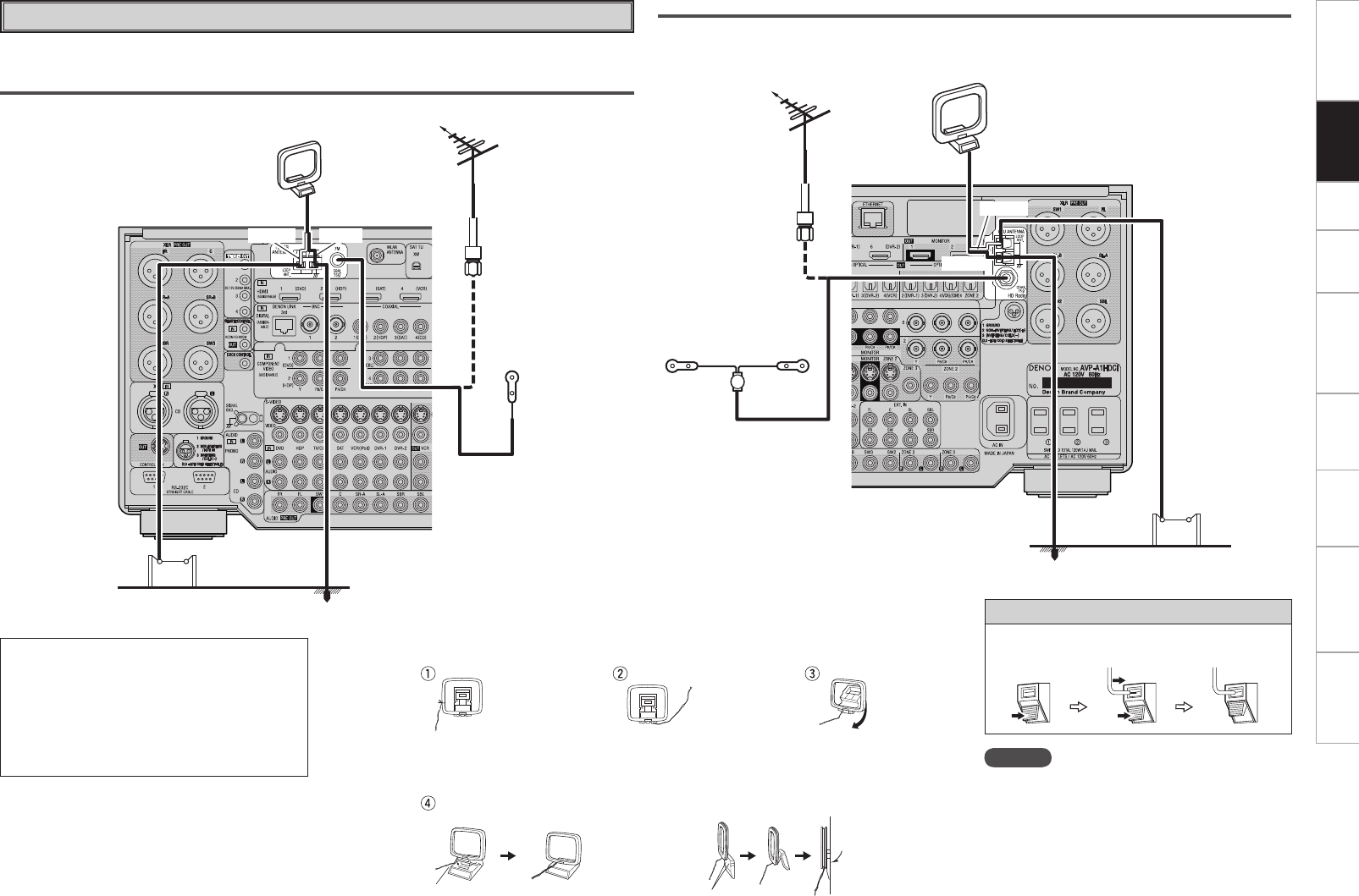
0
Getting Started Setup Playback Remote Control Multi-Zone Information Troubleshooting Specifications
Antenna terminals
An F-type FM antenna cable plug can be connected directly.
AM/FM
Direction of broadcasting station
AM loop antenna
(small, supplied)
FM antenna
75 Ω/ohms
Coaxial cable
FM indoor
antenna
(supplied)
Ground
AM outdoor antenna
Note to CATV system installer:
This reminder is provided to call the CATV system
installer’s attention to Article 820-40 of the NEC
which provides guidelines for proper grounding
and, in particular, specifies that the cable ground
shall be connected to the grounding system of
the building, as close to the point of cable entry
as practical.
AM loop antenna assembly
Remove the vinyl tie and take
out the connection line.
Connect to the AM
antenna terminals.
Bend in the reverse direction.
a. With the antenna on top of
any stable surface.
Mount
b. With the antenna attached
to a wall.
Installation hole Mount on wall, etc.
HD Radio™ broadcast
HD Radio broadcast is a service that is only available within the United States.
Direction of broadcasting station
FM antenna
75 Ω/ohms
Coaxial cable
FM indoor antenna
(dipole, for HD Radio
broadcasting, supplied)
Ground
AM outdoor antenna
AM loop antenna
(large, for HD Radio broadcasting, supplied)
• To prevent interference, install at least 3.3 feet/
1 m away from the antenna connected to the
AVP-A1HDCI’s other AM tuner terminal.
Connection of AM antennas
1. Push the
lever.
2. Insert the
conductor.
3. Return the
lever.
NOTE
• Do not connect two FM antennas
simultaneously.
• Even if an external AM antenna is used, do not
disconnect the AM loop antenna.
• Make sure the AM loop antenna lead terminals do
not touch metal parts of the panel.
(White)
(Black)
(Black)
(White)
Connections
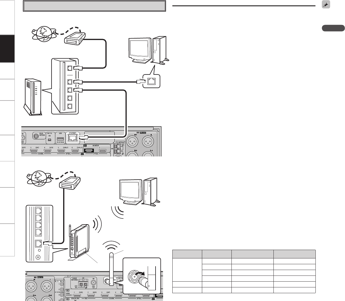
Getting Started Setup Playback Remote Control Multi-Zone Information Troubleshooting Specifications
Network Audio
[Wired LAN]
[Wireless LAN]
To WAN side
Internet
Router
Computer
To LAN port
To LAN port
To WAN side
Internet Modem
Router with access point
Computer
LAN port/Ethernet
connector
Rod antenna
(supplied)
Modem
Required system
n Broadband Internet connection
A broadband line connection to the Internet is required in order to
use the AVP-A1HDCI’s Internet radio function and firmware update.
n Modem
This is a device that is connected to the broadband line to communicate
with the Internet. Some are integrated with the router.
n Router
• When using the AVP-A1HDCI, we recommend you use a router
equipped with the following functions:
· Built-in DHCP (Dynamic Host Configuration Protocol) server
This function automatically assigns IP addresses on the LAN.
· Built-in 100BASE-TX switch
When connecting multiple devices, we recommend a switching
hub with a speed of 100 Mbps or greater.
• When using with a wireless LAN, prepare a broadband router with
built-in access point.
n Ethernet cable (CAT-5 or greater recommended)
Use for wired LAN.
• The AVP-A1HDCI does not come with an Ethernet cable.
• Some flat type Ethernet cables are easily affected by noise.
We recommend using a normal type cable.
• If the sound is broken in an environment in which there is much
power supply noise from electric products or in a noisy network
environment, use a shielded type Ethernet cable.
n Computer
A computer with the following specifications is required to use a
media server:
• OS
Windows® XP Service Pack2, Windows Vista
• Software (Prepare one of the following.)
· .NET Framework 1.1 and Windows Media Connect (Windows XP)
· Windows Media Player ver.11
· DLNA-compatible server software
• Internet browser
Microsoft Internet Explorer 5.01 or later
• LAN port
• 300 MB or more free disk space
b Free disk space is required to store music and video files. The
following sizes are approximate.
Format Bit rate Per minute Per hour
MP3 / WMA
MPEG-4 AAC
128 kbps Approx. 1 MB Approx. 60 MB
192 kbps Approx. 1.5 MB Approx. 90 MB
256 kbps Approx. 2 MB Approx. 120 MB
392 kbps Approx. 3 MB Approx. 180 MB
WAV (LPCM) 1400 kbps Approx. 10 MB Approx. 600 MB
FLAC 1080 kbps Approx. 7.7 MB Approx. 464 MB
NOTE
• A contract with an ISP is required to connect to the Internet.
No additional contract is needed if you already have a broadband
connection to the Internet.
• The types of routers that can be used depend on the ISP. Contact an
ISP or a computer shop for details.
• Depending on the server, video files may be displayed, but they
cannot be played on the AVP-A1HDCI.
For connections to the Internet, contact an ISP (Internet Service
Provider) or a computer shop.
n Others
• If you have an Internet provider contract for a line on which
network settings are made manually, make the settings at GUI
menu “Manual Setup” – “Network Setup” (vpage 35 ~ 38).
• With the AVP-A1HDCI, it is possible to use the DHCP and Auto IP
functions to make the network settings automatically.
• When using a broadband router (DHCP function), the AVP-A1HDCI
sets the IP address, etc., automatically.
When using the AVP-A1HDCI connected to a network with no
DHCP function, make the settings for the IP address, etc., at GUI
menu “Manual Setup” – “Network Setup” (vpage 35 ~ 38).
• The AVP-A1HDCI is not compatible with PPPoE. A PPPoE-
compatible router is required if you have a contract for a line of the
type with which the PPPoE is set.
• Depending on the ISP with which you have your contract, it may
be necessary to make proxy server settings to use the Internet
radio function. If you made proxy server settings on the computer
to connect to the Internet, make the proxy server settings on the
AVP-A1HDCI in the same way.
Turn clockwise.
Connections
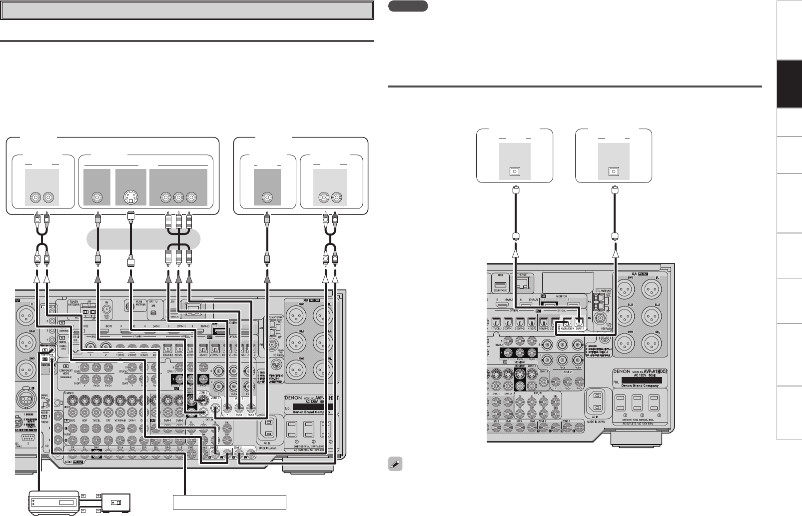
Getting Started Setup Playback Remote Control Multi-Zone Information Troubleshooting Specifications
Multi Zone
ZONE2 or ZONE3 Pre-out Connections
• If another power amplifier or pre-main (integrated) amplifier is connected, the ZONE2 or ZONE3 pre-out
(variable or fixed level) connectors can be used to play a different program source in ZONE2 or ZONE3
the same time (vpage 86, 87).
• To the monitor output of ZONE2, various formats of video signals input by the video conversion function
are automatically converted and output (vpage 9).
• To the monitor output of ZONE3, video signals input from the S video terminal or video terminal is output
(vpage 9).
• The ZONE2 (ZONE3) video out is only for ZONE2 (ZONE3).
R
L
R
L
"6%*0
3-
*/ */
7*%&0
"6%*0
R
L
R
L
"6%*0
3-
*/
"6%*0
7*%&0 7*%&0
*/
7*%&0 $0.10/&/57*%&0
: 1#13
*/
47*%&0
*/
"69
065
ZONE2
Power
amplier
Input Output
Infrared
retransmitter
Infrared
sensor Extension jack for future use.
NOTE
• For the audio output, use high quality pin-plug cords so that no induction humming or noise is produced.
• For instructions on installing and operating separately sold devices, refer to the respective devices’
operating instructions.
• To conduct multi-zone playback, see “Multi-Zone Connections and Operations” (vpage 86, 87).
Monitor
"6%*0
*/
015*$"-
"6%*0
*/
015*$"-
Monitor Power
amplier
ZONE3
ZONE2 or ZONE4 Optical Connections
The AVP-A1HDCI is equipped with Optical output connectors for ZONE2 and ZONE4. If a bit-stream amp
is rigged-up, these zones can also be used to enjoy home theater.
AV amplier
(ZONE2)
AV amplier
(ZONE4)
• Connect the monitor for ZONE2 the same as the “ZONE2 or ZONE3 Pre-out Connectors” (vSee left
column).
• If the signal inputted to ZONE2 is analog, change to PCM(2-channel) signal, and output it from ZONE2
optical output connectors.
Connections
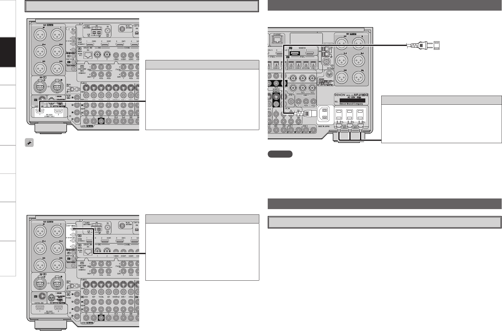
Getting Started Setup Playback Remote Control Multi-Zone Information Troubleshooting Specifications
NOTE
• Insert the AC plugs securely. Incomplete connections could cause noise.
• Only use the AC outlets to plug in audio devices. Do not use them as power supplies for hairdryers or
anything other than audio equipment. In addition, do not connect audio devices such as high electricity
consumption power amplifiers (e.g. POA-A1HDCI).
Wait until all connections have been completed before connecting the power cord.
To household
power outlet
(AC 120 V, 60 Hz)
Power cord
(included)
Connection to the AC outlets
• These outlets supply power to external audio
devices.
• The power supplied from this outlets turns on and
off together with the set’s power switch.
• Audio equipment with a total power consumption
of 120 W (1 A) can be connected.
Connecting the Power Cord
Trigger output jacks
The power of an external device equipped with
a trigger input jack can be turned on and off in
association with operations on the AVP-A1HDCI.
For details, see GUI menu “Manual Setup” –
“Option Setup” – “Trigger Out 1”, “Trigger Out 2”,
“Trigger Out 3” or “Trigger Out 4” (vpage 42).
• Output level: 250 mA/12 V
Check the trigger input conditions of the
connected device.
External Controller
• When using in combination with an RF Remote Controller (RC-7000CI, sold separately) and RF Remote
Receiver (RC-7001RCI, sold separately) two-way communication with an RF Remote Controller is possible.
The AVP-A1HDCI’s status information as well as iPod and Internet audio music files can be browsed
watching the RF Remote Controller’s display. For details, refer to the operating instructions of the
respective devices.
• When used in combination with an RF Remote Controller and RF Remote Receiver, make the settings at
GUI menu “Manual Setup” – “Option Setup” – “2Way Remote” – “Used” (vpage 42).
• When using the 2-way remote control unit, connect to the Port 1 RS-232C connector.
• If GUI menu “Manual Setup” – “Option Setup” – “2Way Remote”is set to “Used”, you cannot use port
1 of the RS-232C connector for the external controller.
RS-232C connector
This connector is used for an external controller.
b If you use an external controller to operate
the unit via the RS-232C terminal, you must
confirm the following beforehand.
q Turn on the AVP-A1HDCI’s power.
w Turn off the AVP-A1HDCI’s power from the
external controller.
e AVP-A1HDCI enters the standby status.
Turning the Power On (vpage 58)
Once Connections are Completed
Connections
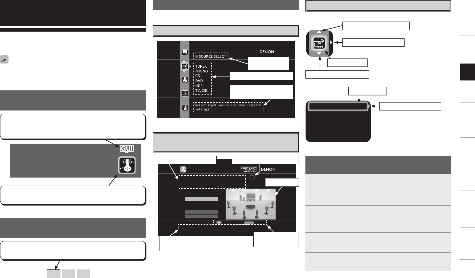
Getting Started Connections Playback Remote Control Multi-Zone Information Troubleshooting Specifications
Auto Setup
Optimize settings for speakers in use.
Some typical examples are described below.
AUTO SETUP
1 2 3 4 5
Start
RETURN
Pre-out Assign
XLR Out Polarity
Config. 9.1
SW 1SP
STEP1 Speaker Detection
Please place the microphone at ear
height at main listening position.
Start Auto Setup
Enter Cancel
Selected item
name
List of subsequent items
Guidance text for item
at cursor position
Operation step indicators
Illustration
Operation
button guidance
Guidance text for item at cursor
position
Operation guidance text
n Icon
n List
Assign
Input Mode
Video
Rename
Switch the selected item
Selected item
Switch the selected item
Switch to the next item
Selected item
Example of the Display of the GUI
Mark at a Title
Example: Browse Menu (Top Menu)
Examples of GUI Screen Displays
Example: Menus with Illustrations
(Auto Setup)
Cursor Position Display
Operations
The same operation is possible on the main unit or remote control unit.
GUI Menu Operations
With the AVP-A1HDCI, settings and operations for most functions can
be performed by operating while looking at the GUI menus displayed
on the monitor screen.
b Switch the selected item using
ui.
1Press the MENU button.
The GUI menu is displayed.
b To operate from the main remote control unit, be sure to set the
remote control unit to the AMP mode.
2Press the u i p button to select the menu to be set
or operated.
b To return to the previous item, press the o or RETURN button.
3Press the ENTER button to enter the setting.
4Press the MENU button to nish.
Example of Display of Default
Values
[Selectable items] 9.1 7.1 5.1
In lists of selectable items or adjustable ranges, the item
surrounded by a border is the default value.
Items for which this mark is indicated at the title can be operated
from the GUI.
We recommend performing such operations from the GUI.
This is the GUI icon for this setting item or for the menu series to
which this item belongs.
Switch to the next item
The GUI cannot be superimposed when xvYCC signals and component
1080p signal, computer’s resolution (e.g.VGA) are input.
Setup
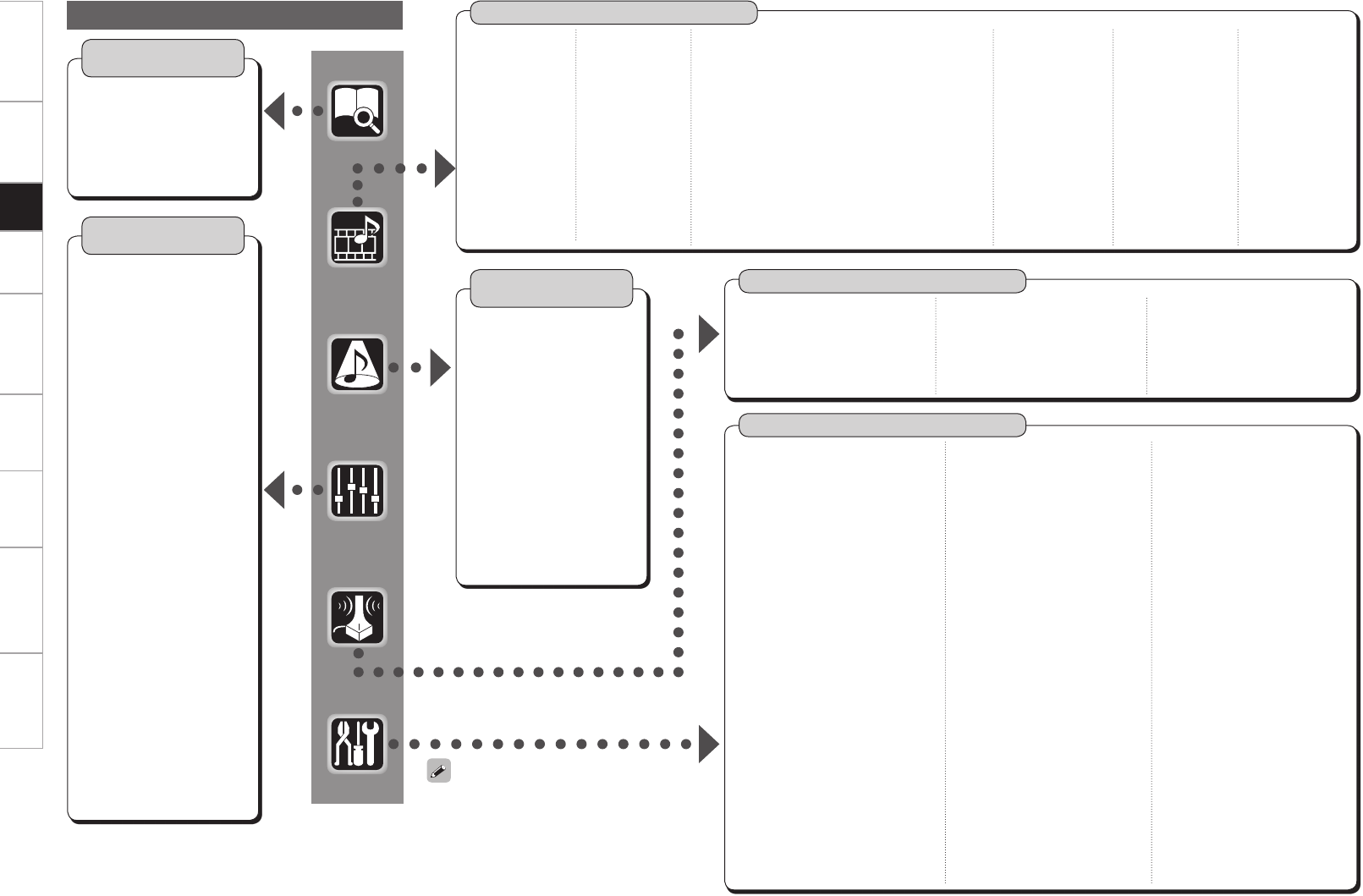
Getting Started Connections Playback Remote Control Multi-Zone Information Troubleshooting Specifications
GUI Menu Map
Parameter
(vpage 52 ~ 56)
Information
(vpage 56, 57)
n Status
• MAIN ZONE
• ZONE2/3/4
n Audio Input Signal
n HDMI Information
n Auto Surround Mode
n Quick Select
n Preset Station
n Audio
• Surround Parameters
· Mode
· Decoder
· Cinema EQ
· DRC
· D.COMP
· LFE
· Center Image
· Panorama
· Dimension
· Center Width
· Delay Time
· Effect
· Effect Level
· Room Size
· AFDM
· SB CH Out
· Input Channel
· Subwoofer Att.
· Subwoofer
· Default
• Tone
· Tone Defeat
· Bass
· Treble
· Front
· Center
· Surround
· Surround Back
· Subwoofer
• Room EQ
• Dynamic EQ
• RESTORER
• Night Mode
• Audio Delay
n Picture Adjust
• Contrast
• Brightness
• Chroma Level
• Hue
• DNR
• Enhancer
• Sharpness
Manual Setup (vpage 29 ~ 44)
n Speaker Setup (vpage 29 ~ 31)
• Speaker Configuration
• Subwoofer Setup
• Distance
• Channel Level
• Crossover Frequency
• THX Audio Setup
• Surround Speaker
n HDMI Setup (vpage 32)
• Color Space
• RGB Range
• Auto Lip Sync
• Audio
• Monitor Out
• HDMI Control
n Audio Setup (vpage 33, 34)
• EXT. IN Setup
· Mode
· Surround Back Input
· Surround Speaker
· Subwoofer Level
· Input Att.
• 2ch Direct/Stereo
• Downmix Option
• Auto Surround Mode
• Manual EQ
Auto Setup (vpage 26 ~ 28)
n Auto Setup
• STEP1: Speaker Detection
• STEP2: Measurement
• STEP3: Calculation
• STEP4: Check
• STEP5: Store
n Option
• Room EQ
• Direct Mode
• Mic Select
n Parameter Check
• Speaker Configuration Check
• Distance Check
• Channel Level Check
• Crossover Check
• EQ Check
• Restore
n Network Setup
(vpage 35 ~ 38)
• Network Setup
• Other
· Power Saving
· Character
· PC Language
· Rhapsody Account
• Network Information
n Zone Setup (vpage 39)
• ZONE2, ZONE3
· Bass
· Treble
· HPF
· Lch Level
· Rch Level
· Channel
· Volume Level
· Volume Limit
· Power On Level
· Mute Level
· Video Convert (ZONE2 only)
• OSD
n Option Setup (vpage 40 ~ 44)
• Pre-out Assign
• XLR Out Polarity
• POA Setting
• Volume Control
· Volume Limit
· Power On Level
· Mute Level
• Source Delete
• GUI
· Screensaver
· Wall Paper
· Format
· Text
· Master Volume
· NET/USB / iPod / Tuner
• Quick Select Name
• Trigger Out 1
• Trigger Out 2
• Trigger Out 3
• Trigger Out 4
• Transducer Setup
• Digital Out
• Remote ID
• 2Way Remote
• Dimmer
• Setup Lock
• Maintenance Mode
• Firmware Update
• Add New Feature
n Language (vpage 44)
Surround Mode
(vpage 50 ~ 52)
n STEREO
n DIRECT
n STANDARD
n DOLBY HEADPHONE
(When using headphones)
n DOLBY PL
II
x, DOLBY PL
II
or
DOLBY PL
n DTS NEO:6
n neural
n HOME THX CINEMA
n 7CH STEREO
n WIDE SCREEN
n SUPER STADIUM
n ROCK ARENA
n JAZZ CLUB
n CLASSIC CONCERT
n MONO
n VIDEO GAME
n MATRIX
When “Screensaver” is set to “ON”, the
screensaver is activated if no operation is
performed for about 3 minutes.
n TUNER (FM/AM)
• Play
• Auto Preset
• Preset Skip
• Preset Name
• Video
· Video Select
· i/p Scaler
· Resolution
• Input Mode
• Rename
• Source Level
n PHONO
• Video
· Video Select
· i/p Scaler
· Resolution
• Input Mode
• Rename
• Source Level
• Input Att.
n CD, DVD, HDP, TV/CBL, SAT, VCR, DVR-1,
DVR-2, V.AUX
• Play (iPod) • Video
• Playback Mode (iPod) · Video Select
• Assign · Video Convert
· HDMI (Excluding CD)
· Digital · i/p Scaler
· Component · Resolution
· Analog · Progressive Mode
(CD only) (Excluding CD)
· iPod dock · Aspect
(Excluding CD)
• Input Mode
• Rename
• Source Level
• Input Att.
n NET/USB
• Play
• Playback Mode
• Still Picture
• Video
· Video Select
· i/p Scaler
· Resolution
• Input Mode
• Rename
• Source Level
n XM
• Play
• Preset Skip
• Antenna Aiming
• Video
· Video Select
· i/p Scaler
· Resolution
• Input Mode
• Rename
• Source Level
n HD Radio
• Play
• Auto Preset
• Preset Skip
• Preset Name
• Video
· Video Select
· i/p Scaler
· Resolution
• Input Mode
• Rename
• Source Level
Source Select (vpage 45 ~ 49)
Setup
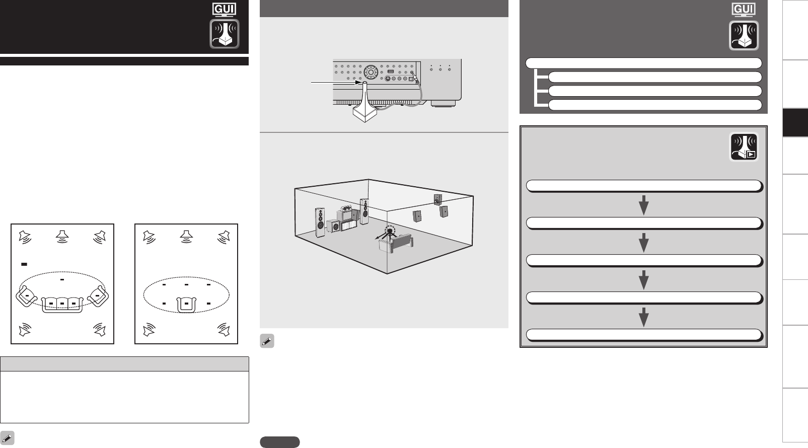
Getting Started Connections Playback Remote Control Multi-Zone Information Troubleshooting Specifications
*M
*M
Example qExample w
( :Measuring positions)
• Audyssey MultEQ® XT automatically measures the acoustical
problems in the listening environment to create the best audio
experience for your home theater.
• It optimizes a large listening area where one or more listeners are
seated.
Measurements are performed by placing the calibrated microphone
(DM-A505Z) successively at multiple positions throughout the
listening area as shown in Example q. For best results, it is
strongly recommended to measure 6 or more positions so that the
measurements have the proper spatial weighting.
Even if the listening environment is small as shown in Example w,
measuring at multiple points throughout the listening environment
results in more effective correction.
Auto Setup
To make manual adjustments to the settings, see pages 29 ~ 31.
About the main listening position (*M)
The main listening position refers to the most central position where
one would normally sit within the listening environment.
MultEQ XT uses the measurements from this position to calculate
speaker distance, level, polarity, and the optimum crossover value
for the subwoofer.
Preparations
When using a subwoofer, make the following settings before starting
the auto setup procedure:
• Defeat the volume and crossover controls if possible
• If this is not possible then set
• Volume: “12 o’clock” position
• Crossover frequency: “Maximum/Highest Frequency”
• Low pass filter: “Off”
• Standby mode: “Off”
NOTE
• Do not disconnect the setup microphone until the auto setup
procedure is completed.
• When using headphones, unplug the headphones before starting
the auto setup procedure.
1Connect the included calibrated setup microphone to
the SETUP MIC jack on the main unit.
The “Auto Setup” screen appears automatically.
2Place the microphone at ear height on a tripod or stand
with the microphone pointing directly up towards the
ceiling.
b It is not recommended to hold it in your hand. Be sure that the
path from microphone to the speakers is not blocked by objects.
Avoid placing the microphone close to a seat back or wall as sound
reflections may give inaccurate results.
Sound
receptor
Setup
microphone
Auto Setup
Optimize settings for speakers in use.
F Menu tree F
Auto Setup
a Auto Setup
s Option
d Parameter Check
a Auto Setup
The settings are performed automatically.
GAuto setup flowH
STEP1: Speaker Detection
STEP2: Measurement (2 to 8 positions)
STEP3: Calculation
STEP4: Check
STEP5: Store
Setup

Getting Started Connections Playback Remote Control Multi-Zone Information Troubleshooting Specifications
Configuration
The speaker system to be measured can be selected ahead of time
here.
[Selectable items] 9.1 z1
7.1 z1
5.1 z1
9.2 z2
7.2 z2
5.2 z2
9.3 z3
7.3 z3
5.3 z3
z1: This can be set when “Subwoofer” is set to “1SP”.
z2: This can be set when “Subwoofer” is set to “2SP L/R” or “2SP
MIX”.
z3: This can be set when “Subwoofer” is set to “3SP L/R/LFE” or
“3SP MIX”.
Start
Start Auto Setup.
The Audyssey MultEQ XT Auto Setup process automatically calculates
the size, level, distance, bass management crossover frequency, and
optimal settings for each speaker and subwoofer. Audyssey MultEQ
XT corrects acoustical distortions within the listening area.
Before starting, connect and position all your speakers.
Once started, MultEQ XT will play a series of test tones through each
speaker.
If an error message appears during the measurements, check “Error
Messages” (vpage 28), take the advised action, then start the
measurements again.
Setting the correct speaker configuration can reduce the time required
to measure during the auto setup procedure as the system will not
have to look for speakers that are not connected.
STEP1 : Speaker Detection
The speaker connection and polarity are detected at the first
measurement position. The following attributes are also determined
at this time: “Speaker Size”, “Speaker Distance”, “Channel Level”,
“Crossover Frequency”.
Once the measurements are completed, the results are displayed.
NOTE
• Loud test tone may be played during Audyssey MultEQ XT
Automatic Speaker Setup. This is part of normal operation. If there is
background noise in room, these test tones will increase in volume.
• Do not stand between the speakers and setup microphone or allow
obstacles in the path while the measurements are being made. This
will cause inaccurate readings.
• Quiet the listening environment before beginning measurements and
refrain from talking. Turn off air conditioning units or other devices
that emit noise if at all possible as measurements may be affected
by these sounds.
• Operating the MASTER VOLUME knob on the main unit or the VOL
+/– buttons on the remote control unit during the measurements will
cancel the measurements.
• Do not change the speaker connections or subwoofer volume after
“STEP1”.
STEP2: Measurement
STEP3: Calculation
After completing a measurement position, move the microphone to
the next position.
Measure at least 6 positions (main listening position and at least 5 other
surrounding positions). For best results it is recommend measuring 6
or more positions (with a maximum of 8 positions).
NOTE
Do not turn the power off while the settings are being stored.
When “Calculate” is selected at “STEP2”, the measurements taken
are analyzed automatically to determine how the speaker system
interacts with the room.
The time required for this analysis depends on the number of speakers
connected. The higher the number of speakers, the longer the time
required for analysis.
STEP4: Check
Once the auto setup procedure is complete, a measuring result check
screen appears.
Select any item whose results you want to check to review the
results.
Values that are different from the actual distance may be set for
speakers with built-in filters (subwoofers, etc.). This is because filters
add electrical delay to the signal that should be compensated.
STEP5: Store
The auto setup measurement results are stored in the AVP-A1HDCI.
Subwoofer
The configuration of the measuring subwoofer can be selected
beforehand.
[Selectable items] 1SP 2SP L/R 2SP MIX
3SP L/R/LFE 3SP MIX
Pre-out Assign
Change the pre-out assignment.
[Selectable items] Normal Free Assign
XLR Out Polarity
Set to switch the XLR pre-out terminal polarity.
[Selectable items] XLR XLR (INV)
Set each channel.
Setup

Getting Started Connections Playback Remote Control Multi-Zone Information Troubleshooting Specifications
Error Messages
If the auto setup procedure could not be completed due to speaker installation, the measuring environment, etc., an error message is
displayed. If this happens, check the relevant items, be sure to take the necessary measures, then perform the auto setup procedure over
again.
Error messages (examples) Cause Measures
No microphone or speaker • Included setup microphone is not connected.
• Not all speakers could be detected.
• The front L speaker was not properly detected.
• Connect the included setup microphone to the SETUP
MIC jack on the main unit.
• Check the speaker connections.
Ambient noise is too high
or Level is too low
• Too much noise in the room for accurate
measurements to be made.
• Speaker or subwoofer sound is too low for
accurate measurements to be made.
• Either turn off any device generating noise or move it
away.
• Try again when the surroundings are quieter.
• Check the speaker installation and the direction in which
the speakers are facing.
• Adjust the subwoofer’s volume.
None • Displayed speaker could not be detected.
· The front R speaker was not properly detected.
· Only one channel of the surround (A) and
surround (B) speakers was detected.
· Sound was output from the R channel when only
one surround back speaker was connected.
· The surround back or the surround (B) speaker
was detected, but the surround (A) speaker
was not detected.
· When the subwoofer configuration is set at
“2SP L/R”, “2SP MIX”, “3SP L/R/LFE” or “3SP
MIX”, the subwoofer could not be detected.
• Check the connections of the displayed speaker.
Phase • Displayed speaker connected with the polarities
reversed.
• If the XLR pre-out terminal is used, the polarity is
reversed.
• Check the polarities of the displayed speaker.
• Check the polarity setting for the XLR output of the
displayed pre-set channel.
• For some speakers, this error message may be displayed
even if the speaker is properly connected. If you are sure
that the wiring is correct, select “Skip”.
Room EQ
Select room EQ setting method.
[Selectable items] All Assign
s Option
Select settings for room EQ, mic, etc.
Direct Mode
Select room EQ use for DIRECT or PURE DIRECT mode.
[Selectable items] ON OFF
Mic Select
Select the microphone type if not using supplied mic.
The microphone connected to V.AUX Lch is used.
[Selectable items] Mic
V.AUX L
NOTE Be sure to turn the power off before checking the speaker connections.
Select “Retry” to make the measurements again.
Only a professionally certified installer should ever connect a
professionally-calibrated microphone to the V.AUX L input on the front
panel.
• Sometimes due to the electrical complexities of subwoofers and the interaction with the room, THX recommends setting the level and the
distance of the subwoofer manually.
• Sometimes due to interaction with the room, you may notice irregular results when setting the level and/or distance of the main speakers. If
this happens, THX recommends setting them manually.
• Please note that any THX main speakers should be set to Small (80 Hz). If you set up your speakers using Auto Setup, please make sure
manually that any THX speakers are set to Small with 80 Hz crossover.
d Parameter Check
Check auto setup measurement results.
This is displayed after the auto setup procedure is
completed.
[Selectable items]
Spkr Config Check Distance Check Ch. Level Check
Crossover Check EQ Check Restore
The auto setup results can be reset to what was originally calculated
by MultEQ XT when “Restore” is selected.
Setup
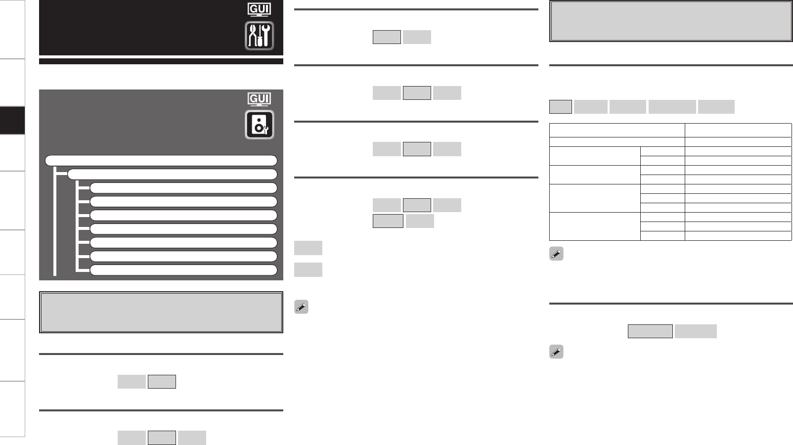
Getting Started Connections Playback Remote Control Multi-Zone Information Troubleshooting Specifications
Make detailed settings for various parameters
Speaker Setup
Use this procedure to set the speakers manually
or if you wish to change the settings made with
the auto setup procedure.
F Menu tree F
Manual Setup
Speaker Setup
a Speaker Configuration
s Subwoofer Setup
d Distance
f Channel Level
g Crossover Frequency
h THX Audio Setup
j Surround Speaker
Manual Setup
Front
Select front speaker size.
[Selectable items] Large Small
a Speaker Configuration
Select speaker configuration and size.
(bass reproduction capability)
Center
Select center speaker use and size.
[Selectable items] Large Small None
Subwoofer
Select subwoofer use.
[Selectable items] Yes No
Surround A
Select surround speakers A use and size.
[Selectable items] Large Small None
Surround B
Select surround speakers B use and size.
[Selectable items] Large Small None
Surround Back
Select surround back speaker use and size.
[Selectable items] Large Small None
2spkrs 1spkr
• Select “Large” or “Small” not according to the physical size of the
speaker but according to the low frequency reproduction capabilities
based on the frequency set at “Crossover Frequency” (vpage 30,
31).
• When “Front” is set to “Small”, “Subwoofer” is automatically set to
“Yes”.
• If “Subwoofer” is set to “No”, “Front” is automatically set to
“Large”.
• If “Surround A” is set to “None”, “Surround B” and “Surround
Back” are automatically set to “None”.
• When using just one surround back speaker, connect it to the left
channel (SBL).
• To take full advantage of the performance of the Home THX certified
speaker systems, set the front, center and surround speaker size
parameters to “Small” and the subwoofer to “Yes”.
Large : Select this for a large speaker with strong bass
reproduction.
Small : Select this for a smaller speaker with weaker bass
reproduction.
s Subwoofer Setup
Select subwoofer output configuration and bass signal for
playback.
Configuration
Select number of subwoofers and configuration.
[Selectable items]
1SP 2SP L/R 2SP MIX 3SP L/R/LFE 3SP MIX
• THX recommends LFE–THX– mode so that bass interference is less
likely to occur in the room.
• This can be set when the GUI menu “Speaker Configuration” –
“Subwoofer” is set to “Yes”.
• Play music or a movie source and select the mode offering the
strongest bass.
• Select “LFE+Main” if you want the bass signals to always be
produced from the subwoofer.
Mode
Select bass signal for playing with the subwoofer.
[Selectable items] LFE–THX– LFE+Main
When “2SP MIX” or “3SP MIX” is selected, “Subwoofer 1”,
“Subwoofer 2” and “Subwoofer 3” are each displayed.
Subwoofer Configuration Subwoofer Connector
1SP SW1
2SP L/R L SW1
R SW2
2SP MIX 1 SW1
2 SW2
3SP L/R/LFE
L SW1
R SW2
LFE SW3
3SP MIX
1 SW1
2 SW2
3 SW3
Setup
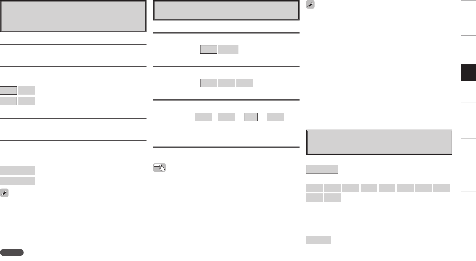
0
Getting Started Connections Playback Remote Control Multi-Zone Information Troubleshooting Specifications
Distance measurement
Select the speaker you want to set, then set the distance.
Set the value closest to the measured distance.
[Variable range]
0.0ft ~ 60.0ft : Display when “Feet” is set.
0.00m ~ 18.00m : Display when “Meters” is set.
Mode
Select test tone playback method.
[Selectable items] Auto Manual
f Channel Level
Adjust channel levels to obtain equal volume from all speakers.
Surround
Select surround speaker from which test tone is output.
[Selectable items] A B A+B
Start
Output test tone.
[Variable range] OFF z
–12dB ~ 0dB ~ +12dB
z: “OFF” can be set by pressing o when the subwoofer’s volume is
set to –12 dB.
Operating from the main remote control unit
Adjusting with the main remote control unit using the test tones
is only possible in the “Auto” mode and only effective in the
STANDARD (Dolby/DTS Surround) and HOME THX CINEMA modes.
The adjusted levels for the different modes are automatically stored
in the memory.
GAdjusting using test tonesH
q Press the TEST button.
Test tones are output from the various speakers.
w Use the o p button to adjust so that the volume is equal for all
speakers.
e When the adjustments are completed, press the TEST button
again.
• The level of each channel should be adjusted to 75 dB (Cweighted,
slow meter mode) on a sound level meter at the listening position. If
a sound level meter is not available adjust the channels by ear so the
sound levels are the same. Because adjusting the subwoofer level
test tone by ear is difficult, use a well known music selection and
adjust for natural balance.
• When the GUI menu “Speaker Configuration” – “Surround Back”
setting (vpage 29) is set to “1spkr”, the surround back speaker
display is set to “Surround Back”.
• Speakers set to “None” in the “Speaker Configuration” settings are
not displayed.
• “Surround” can be set when GUI menu “Speaker Configuration”
–“Surround B” is set to “Large” or “Small” (vpage 29).
• When using surround speakers, be sure to adjust the volume of the
different speakers.
• When “Channel Level” is adjusted, the adjusted values are set for all
the surround modes. To adjust the channel level separately for the
different surround modes, use the operation see page 75.
Default
Resets the settings to the default values.
NOTE
Set the distance between the listening position and the various
speakers to no more than 20 ft (6.00 meters).
Two surround back speakers are required to use the THX Ultra2
Cinema, THX Music mode and THX Games mode.
Set the surround back speakers so that the distance to the listening
position is the same for both the left and right speakers.
It is also recommended that the deviations of the distance from the
listening position to L and R channel speakers (front left (FL) and front
right (FR), surround left (SL) and surround right (SR), surround back left
(SBL) and surround back right (SBR) is less than 2 ft (60 cm).
d Distance
Set distance from listening position to speakers.
Before making the settings, measure the distance from the
listening position to the different speakers.
Feet / Meters
Select unit for distance.
Step
Select step. (smallest distance)
[Selectable items]
1ft 0.1ft : Can be selected when “Feet” is set.
0.1m 0.01m : Can be selected when “Meters” is set.
Default
Resets the settings to the default values.
g Crossover Frequency
Select crossover frequency from which subwoofer handles low
range signal.
[Selectable items]
FIXED–THX– :
Setup when using a THX-certified speaker.
40Hz 60Hz 80Hz 90Hz 100Hz 110Hz 120Hz 150Hz
200Hz 250Hz :
Only the portion of the bass sound of the various speakers output
from the subwoofer that has a frequency below the frequency set
here is output.
Set this according to the low frequency reproduction capabilities of
the speakers you are using.
Advanced :
Specify crossover frequency for each speaker.
Setup
Getting Started Connections Playback Remote Control Multi-Zone Information Troubleshooting Specifications
j Surround Speaker
Select surround speakers to use for each surround mode.
Operating from the main remote control unit
Press the SPKR button.
Surround A Surround B
Surround A+B
h THX Audio Setup
Set the speaker to play the optimal THX surround mode.
THX Ultra2 Subwoofer
Set when using a subwoofer compatible with THX Ultra2 standards or
a subwoofer that can be properly played at low range.
[Selectable items] Yes No
Make these settings when “Yes” is selected for the subwoofer in the
“Speaker Configuration” settings. This option is not available when
“No” is selected (vpage 29).
BGC (Boundary Gain Compensation)
If bass sound feels big compensate by lowering volume.
[Selectable items] ON OFF
• If the bass sound seems too strong:
Set “BGC” to “ON”. This activates a filter that gently reduces very
deep bass below 55 Hz to provide the flattest overall deep bass
response. Select “ON” or “OFF” according to how strong you prefer
the deep bass response to be.
• This can be set when the “THX Ultra2 Subwoofer” setting is set to
“Yes”.
SB Speaker Position
Set the distance between the left and right surround back speakers.
[Selectable items] Under 1ft 1ft – 4ft Over 4ft
• When two surround back speakers have been set in “Speaker
Configuration” (vpage 29), set the distance of the speakers. This
option is not available when “1spkr” is selected.
• This setting is necessary to achieve the optimum effect in the THX
Surround EX, THX Ultra2 Cinema, THX Music mode and THX Games
mode.
THX/DOLBY/DTS Cinema
[Selectable items] A B A+B
THX/DOLBY/DTS Music
[Selectable items] A B A+B
THX/DOLBY Game
[Selectable items] A B A+B
WIDE SCREEN
[Selectable items] A B A+B
7CH STEREO
[Selectable items] A B A+B
DSP SIMULATION
[Selectable items] A B A+B
MULTI CH MODE
[Selectable items] A B A+B
• This can be set when GUI menu “Speaker Configuration” – “Surround
A” and “Surround B” are used (vpage 29).
• Make the surround speaker settings when the input mode is set to
“EXT. IN” at GUI menu “Manual Setup” – “Audio Setup” – “EXT. IN
Setup” (vpage 33).
• Please set all THX Certified speakers, set the “Speaker Configuration”
for all speakers to “Small”. We recommend using with the crossover
frequency set to “FIXED–THX–”, but depending on the speaker,
setting it to a different frequency may improve frequency response
near the crossover frequency.
• The “Crossover Frequency” can be set when there are speakers
that have been set to “Small” at GUI menu “Speaker Configuration”
or when “Subwoofer” is set to “Yes” (vpage 29).
• At the “Advanced” settings, if the “Subwoofer Setup” (vpage
29) setting is set to “LFE–THX–”, GUI menu speakers for which
“Speaker Configuration” is set to “Small” can be set. If set to
“LFE+Main”, the setting can be made regardless of the speaker
size.
• For speakers set to “Small”, sound below the crossover frequency
is cut from the sound output. The cut bass sound is output from the
subwoofer or front speakers.
About Speaker Type Setting when Using Both
Surround speakers A and B
If “Small” is set for either surround speakers A or B, the output is the
same as when “Small” is set for both A and B.
Setup
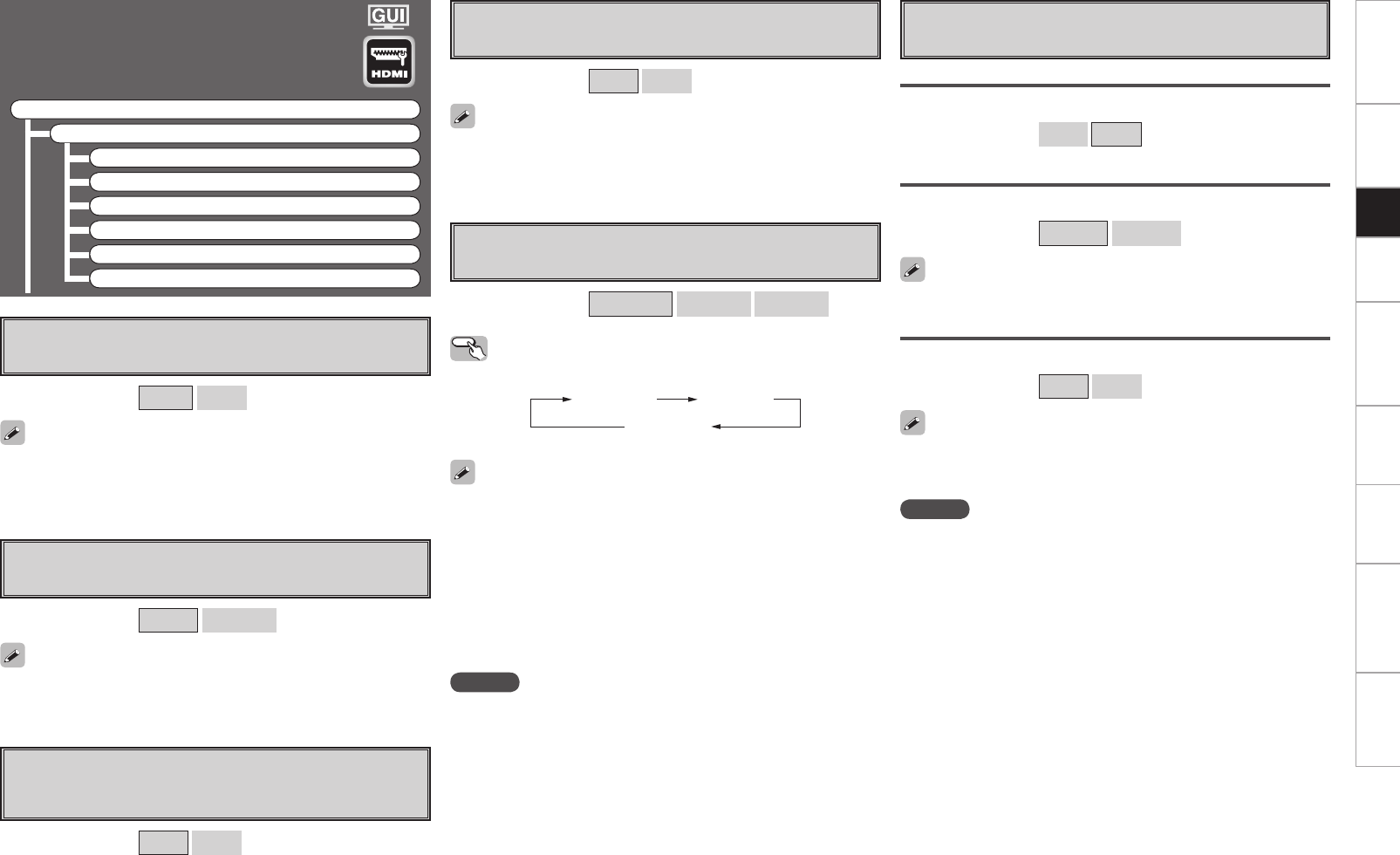
Getting Started Connections Playback Remote Control Multi-Zone Information Troubleshooting Specifications
HDMI Setup
Make settings for HDMI video/audio output.
F Menu tree F
Manual Setup
HDMI Setup
a Color Space
s RGB Range
d Auto Lip Sync
f Audio
g Monitor Out
h HDMI Control
a Color Space
Make settings for output color space.
[Selectable items] YCbCr RGB
When connected to a monitor with a DVI-D connector (HDCP
compatible) using an HDMI/DVI converter cable, the signals are output
in RGB format, regardless of this setting.
s RGB Range
Make settings for RGB output range.
[Selectable items] Normal Enhanced
d Auto Lip Sync
Automatic compensation for timing shift in audio and video
output.
[Selectable items] ON OFF
f Audio
Select HDMI audio output device.
[Selectable items] Amp TV
g Monitor Out
Make settings for HDMI monitor output.
[Selectable items] Auto (Dual) Monitor 1 Monitor 2
Operating from the main remote control unit
Press the M.SEL button.
• When “Monitor Out” is set to “Auto (Dual)”, connections with
the MONITOR 1 or MONITOR 2 connectors are recognized
automatically.
• If both the MONITOR 1 and 2 connectors are connected and
“Resolution” is set to “Auto” (vpage 47), the signals are output
with a resolution compatible with both monitors.
• If “Resolution” is set to something other than “Auto”, check the
resolutions with which your monitor is compatible at GUI menu
“Information” – “HDMI Information” – “Monitor 1” and “Monitor
2” and set accordingly (vpage 57).
When “YCbCr” is selected under “Color Space”, “RGB Range” will
have no effect.
h HDMI Control
Make settings for HDMI control function.
Control
Set HDMI control function to ON/OFF.
[Selectable items] ON OFF
Control Monitor
Select the interlocking monitor through the HDMI controls.
[Selectable items] Monitor1 Monitor2
Power Off Control
Interlock with the power off function through the HDMI controls.
[Selectable items] ON OFF
This can be set when “Control“ is set to “ON“.
• This can be set when “Control“ is set to “ON“.
• Please consult the operating instructions for each connected device
to check the settings.
GUI menu “HDMI Control”- “Control” is “ON”, the “Amp” and “TV”
will switch with the operation of any television not related to this
setting.
NOTE
• When the “Control” setting has been changed, always turn off the
power to the connecting devices afterwards and then turn back on.
•The HDMI control function does not work when the power to the
equipment is off.
• For details, see “HDMI Control Function” (vpage 74).
Auto (Dual) Monitor 1
Monitor 2
NOTE
Depending on the monitor you have connected, the display may not
be correct when you set to “Auto (Dual)”. In such a case, set to either
“Monitor 1” or “Monitor 2”.
Setup
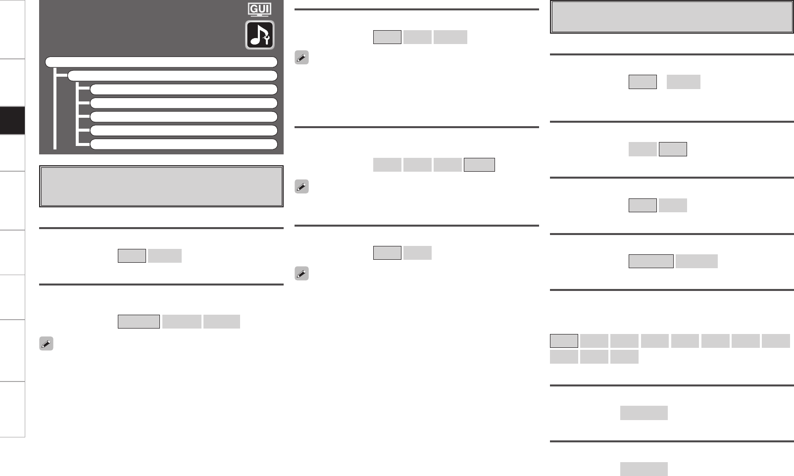
Getting Started Connections Playback Remote Control Multi-Zone Information Troubleshooting Specifications
a EXT. IN Setup
Setup playback method for analog signals inputted from external
input connectors (EXT. IN).
Audio Setup
Make settings for audio playback.
F Menu tree F
Manual Setup
Audio Setup
a EXT.IN Setup
s 2ch Direct/Stereo
d Downmix Option
f Auto Surround Mode
g Manual EQ
s 2ch Direct/Stereo
Make speaker settings for 2-channel mode playback.
Setting
To change the settings, select “Custom”.
[Selectable items] Basic z
Custom
z: Use the same settings as in “Speaker Setup”.
Front
Select front speaker size.
[Selectable items] Large Small
Subwoofer
Select subwoofer use.
[Selectable items] Yes No
Subwoofer Mode
Select low range signal to be reproduced by subwoofer.
[Selectable items] LFE–THX– LFE+Main
Crossover
Select crossover frequency from which subwoofer handles low range
signal.
[Selectable items]
THX 40Hz 60Hz 80Hz 90Hz 100Hz 110Hz 120Hz
150Hz 200Hz 250Hz
Distance FL
Set distance from listening position to front left speaker.
[Variable range] 0.0ft ~ 60.0ft
Distance FR
Set distance from listening position to front right speaker.
[Variable range] 0.0ft ~ 60.0ft
Surround Speaker
Select the surround speakers to use.
[Selectable items] A B A+B
• This can be set when “Mode” is set to “Analog”.
• This can be set when GUI menu “Speaker Setup” – “Speaker
Configuration” – “Surround A” and “Surround B” are used (vpage
29).
Mode
Select playback mode.
[Selectable items] DSP Analog
Surround Back Input
Select surround back channel input in combination with the connected
player.
[Selectable items] Not Used SBL/SBR SB(SBL)
This can be set when “Mode” is set to “DSP”.
Subwoofer Level
Set the subwoofer level for playback.
Select according to the player in use.
[Selectable items] 0dB +5dB +10dB +15dB
We recommend setting to “+15 dB”.
Input Att.
Setup when input level is too large and playback volume is distorted.
[Selectable items] OFF –6dB
This can be set when “Mode” is set to “DSP”.
Setup
Getting Started Connections Playback Remote Control Multi-Zone Information Troubleshooting Specifications
d Downmix Option
Set dynamic range for downmix playback of Dolby Digital sources.
[Selectable items] ON OFF
• Set this to “ON” if the sound from the front speakers seems
distorted.
• When not using the center speaker or surround speakers, the
playback sound is down-mixed and output from the front speakers.
f Auto Surround Mode
Make setting for memorizing surround mode setting for each
input signal type.
[Selectable items] ON OFF
• The auto surround mode function lets you store in the memory the
surround mode last used for playing the four types of input signals
listed below.
q Analog and PCM 2-channel signals
w Dolby Digital and DTS 2-channel signals
e Dolby Digital and DTS multi-channel signals
r Multi-channel signals other than Dolby Digital and DTS (PCM,
DSD, etc.)
• When playing in the PURE DIRECT mode, the surround mode does
not change even if the input signal is changed.
g Manual EQ
Adjust tonal quality for each speaker using graphic equalizer.
Adjust CH
Select speaker adjustment method.
[Selectable items] Each L/R All
Select the speaker and frequency band and adjust the level.
[Selectable items]
63Hz 125Hz 250Hz 500Hz 1kHz 2kHz 4kHz 8kHz
16kHz
[Variable range]
–20dB ~ 0dB ~ +6dB
Curve Copy
Copy the Room EQ’s “Audyssey Flat” correction curve.
[Selectable items] Yes No
“Curve Copy” is displayed after the auto setup procedure has been
performed.
Default
Resets the settings to the default values.
Setup
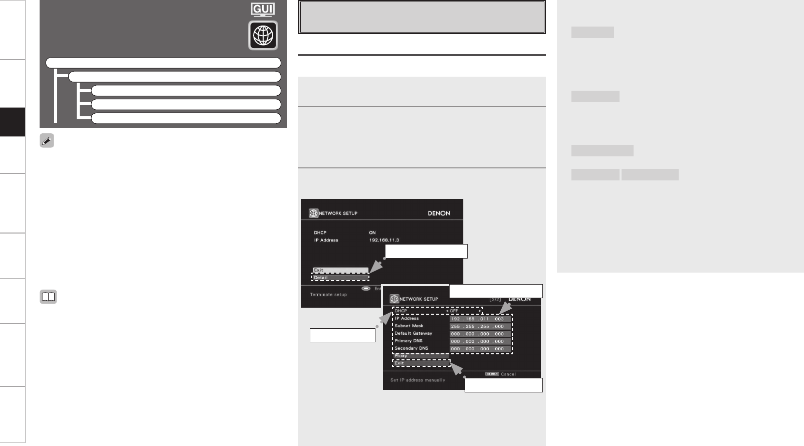
Getting Started Connections Playback Remote Control Multi-Zone Information Troubleshooting Specifications
Network Setup
Make network settings.
F Menu tree F
Manual Setup
Network Setup
a Network Setup
s Other
d Network Information
1Connect the LAN cable (vpage 21).
2Turn on the AVP-A1HDCI (vpage 58).
AVP-A1HDCI performs automatic network setup due to the
DHCP function.
When connecting to a network that has no DHCP function,
perform the setting in step 3.
3Set the IP address at the GUI menu “Manual Setup”
“Network Setup” – “Network Setup”.
q Select “Detail” and press the ENTER button.
w Use the o p button to set “DHCP” to “OFF”, then press the i
button.
The DHCP function is disabled.
a Network Setup
Make settings for wired or wireless LAN.
Wired LAN settings
Use this procedure to configure the Wired LAN settings.
• DHCP (Dynamic Host Configuration Protocol) :
These are systems by which the IP address and other network
settings are automatically set for the AVP-A1HDCI, computer,
broadband router and network devices.
• DNS (Domain Name System) :
This is a system for converting the domain names used when
browsing Internet sites (for example, “www.denon.jp”) into the
IP addresses actually used for communications (for example,
“202.221.192.106”).
q Select “Detail”.
e Input the address.
r Select “Exit”.
w Set “OFF”.
• If you are using a broadband router (DHCP function), there is no need
to make the settings at “Setting the IP Address” and “Setting the
Proxy”, since the DHCP function is set to “ON” in the AVP-A1HDCI’s
default settings.
• If the AVP-A1HDCI is being used connected to a network without
the DHCP function, the network settings must be made. In this
case, some knowledge of networks is required. For details, consult
a network administrator.
• If you cannot connect to the Internet, recheck the connections and
settings (vpage 21).
• If you do not understand about Internet connection, contact your ISP
(Internet Service Provider) or the store from which you purchased
your computer.
e Use the ui p button to input the address and press the ENTER
button.
IP Address :
Set the IP address within the ranges shown below. The Network
Audio function cannot be used if other IP addresses are set.
CLASS A: 10.0.0.0 ~ 10.255.255.255
CLASS B: 172.16.0.0 ~ 172.31.255.255
CLASS C: 192.168.0.0 ~ 192.168.255.255
Subnet Mask :
When connecting an xDSL modem or terminal adapter directly
to the AVP-A1HDCI, input the subnet mask indicated in the
documentation supplied by your provider. Normally input
255.255.255.0.
Default Gateway :
When connected to a gateway (router), input its IP address.
Primary DNS Secondary DNS :
If there is only one DNS address indicated in the documentation
supplied by your provider, input it at “Primary DNS”. If there are
two or more DNS addresses, input the first one at “Secondary
DNS”.
r Use the i button to select “Exit” and press the ENTER button.
Setup is complete.
b When connecting to the network via a Proxy server, select “Proxy”
and press the ENTER button (vpage 38 “Proxy settings”).
Setup
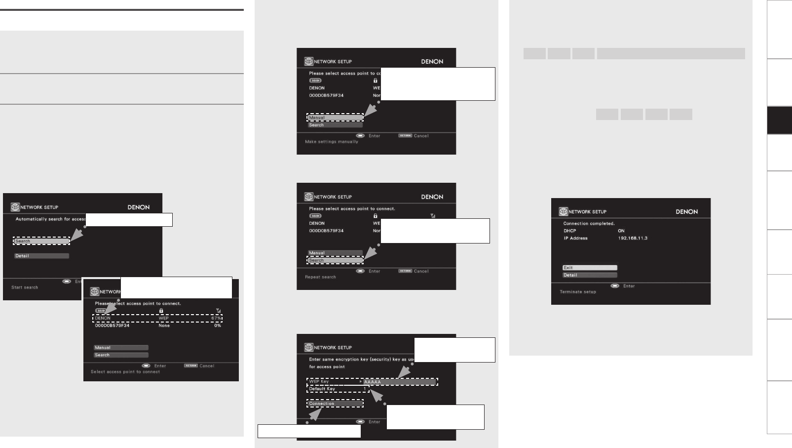
Getting Started Connections Setup Playback Remote Control Multi-Zone Information Troubleshooting SpecificationsSetup
b If the access points are not detected automatically, use the i
button to select the “Manual” and press the ENTER button.
Setting becomes manual. For details, see “Manual settings”
(vpage 37).
b If the access points are repeat search, use the i button to select
the “Search” and press the ENTER button.
e If there is an encryption setting for the access point you selected
in step w, enter same encryption key as used for the access
point. (If there is no encryption setting, proceed to step t.)
1Fitting a rod antenna (vpage 21).
b If a LAN cable is connected, remove it.
2Turn on the AVP-A1HDCI (vpage 58).
3Set the access point at the GUI menu “Manual Setup”
– “Network Setup” – “Network Setup”.
When searching access points to connect automatically, refer to
“Automatic settings”.
When searching access points to connect manually, refer to
“Manual settings”.
n Automatic settings
q Select “Search” and press the ENTER button.
The access point you have set is displayed.
w Use the ui button to select the access point, and then press
the ENTER button.
Select when searching
access points again.
Wireless LAN settings
Use this procedure to configure the Wireless LAN settings.
w Select the access point.
Example) DENON
Select when access
points cannot be searched
automatically.
q Select “Search”.
r Set only during
“WEP” in step w.
t Select “Connection”.
e Enter
encryption key.
Use the uio p button to input the “Key” (encryption key) and
press the ENTER button.
Enter the same encryption key as used for the access point.
[Characters that can be input]
A ~ Z a ~ z 0 ~ 9 ! “ # % & ’ ( ) * + , - . / : ; < = > ? @ [ \ ] (space)
When no security settings have been used in the Internet
connection settings, this step is not necessary.
r When encryption is by “WEP”, select the “Default Key” using
the i button, and then press the o p button.
[Selectable items] 1 2 3 4
Select the same default key as used for the access point. This
should normally be set to “1”.
t Use the i button to select “Connection” and press the ENTER
button.
Network connection starts.
When connection is established with the access point,
“Connection completed.” is displayed.
AVP-A1HDCI performs automatic network setup due to the DHCP
function.
When connecting to a network that has no DHCP function,
perform the setting in step 4.
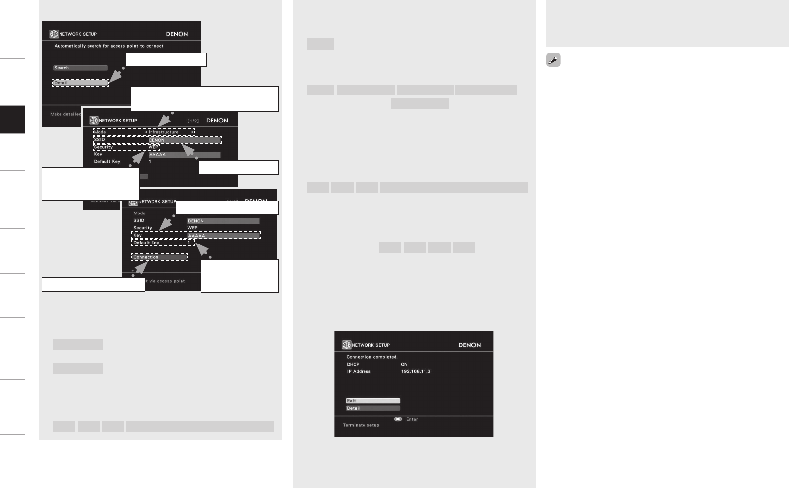
Getting Started Connections Playback Remote Control Multi-Zone Information Troubleshooting Specifications
r Use the ui button to select the Security and press the i
button.
[Selectable items]
None :
Select if not encrypted.
Can also be used even without encryption, through we
recommend encryption for improved security.
WEP WPA-PSK(TKIP) WPA-PSK(AES) WPA2-PSK(TKIP)
WPA2-PSK(AES) :
Select the encryption method according to the encryption setting
of the access point you are using.
t Use the uio p button to input the “Key” (encryption key) and
press the ENTER button.
Enter the same encryption key as used for the access point.
[Characters that can be input]
A ~ Z a ~ z 0 ~ 9 ! “ # % & ’ ( ) * + , - . / : ; < = > ? @ [ \ ] (space)
When no security settings have been used in the Internet
connection settings, this step is not necessary.
y When encryption is by “WEP”, select the “Default Key” using
the i button, and then press the o p button.
[Selectable items] 1 2 3 4
Select the same default key as used for the access point. This
should normally be set to “1”.
u Use the i button to select “Connection” and press the ENTER
button.
Network connection starts.
When connection is established with the access point,
“Connection completed.” is displayed.
AVP-A1HDCI performs automatic network setup due to the DHCP
function.
When connecting to a network that has no DHCP function,
perform the setting in step 4.
n Manual settings
q Select “Detail” and press the ENTER button.
w Use the o p button to select the Mode and press the i button.
[Selectable items]
Infrastructure :
Select when communication is via an access
point.
Ad-hoc :
Select during direct communication, when an
access point is not used.
e Use the uio p button to input the name of the wireless
network (SSID) and press the ENTER button.
[Characters that can be input]
A ~ Z a ~ z 0 ~ 9 ! “ # % & ’ ( ) * + , - . / : ; < = > ? @ [ \ ] (space)
q Select “Detail”.
e Input the SSID.
w Select the communication mode.
Example) Infrastructure
r Select the
encryption method.
Example) WEP
y Set only
during “WEP”
in step r.
u Select “Connection”.
t Enter encryption key.
If you are using a router with no DHCP function to automatically assign
the IP address, set the IP address manually.
4Set the IP address.
b For details, see page 35 “Wired LAN settings” in step 3.
Setup
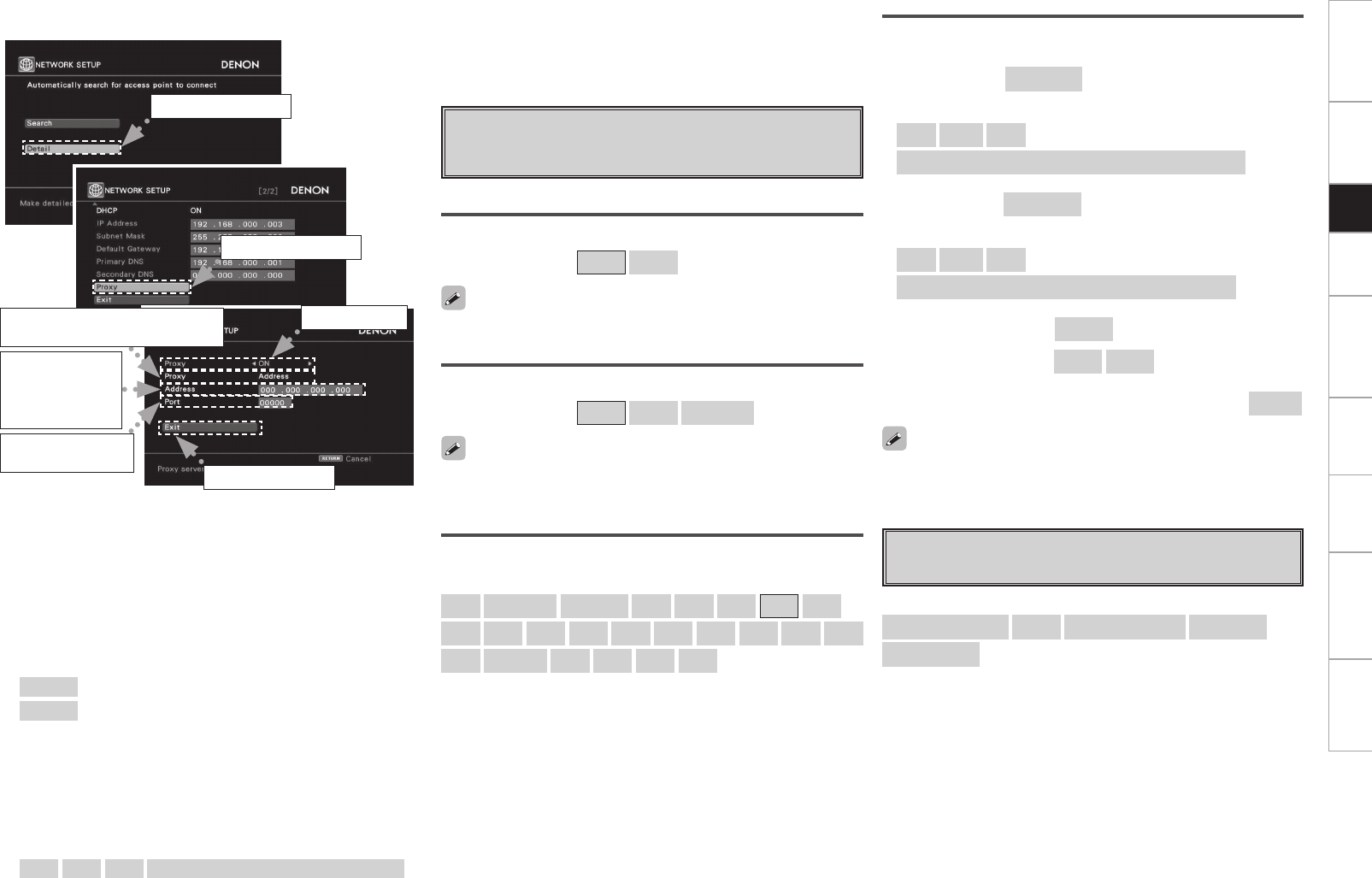
Getting Started Connections Playback Remote Control Multi-Zone Information Troubleshooting Specifications
n Proxy settings
Make this setting when connecting to the Internet via a proxy server.
q On the GUI menu, select “Manual Setup” – “Network Setup”
– “Network Setup” – “Detail” and press the ENTER button.
w Use the ui button to set “Proxy” and press the ENTER button.
e Use the o p button to set “Proxy” to “ON” and press the i
button.
The proxy server is enabled.
r Use the o p button to select the proxy server input method, and
then press the i button.
[Selectable items]
Address : Select when inputting by address.
Name : Select when inputting by domain name.
t Use the ui p button to input the proxy server address or domain
name and press the ENTER button.
When “Address” is selected in step r :
Input the address
When“Name” is selected in step r :
Input the domain name
[Characters that can be input]
A ~ Z a ~ z 0 ~ 9 ! “ # % & ’ ( ) * + , - . / : ; < = > ? @ [ \ ] (space)
q Select “Detail”.
e Set “ON”.
w Select “Proxy”.
r Selecting the input method.
Example) Address
y Input the port
number.
u Select “Exit”.
t Input the
address
or domain
name.
y Use the uio p button to input the proxy server port number and
press the ENTER button.
u Use the i button to select “Exit” and press the ENTER button.
Setup is complete.
s Other
Make setting for amp power save mode and computer language
environment.
Power Saving
Make setting for power saving when not connected to network.
[Selectable items] ON OFF
PC Language
Select computer environment language.
[Selectable items]
ara chi (smpl) chi (trad) cze dan dut eng fin
fre ger gre heb hun ita jpn kor nor pol
por por (BR) rus spa swe tur
Character
Set the character code type of the MP3 ID3-Tag played by USB.
[Selectable items] Auto Latin Japanese
If the characters are not properly displayed when set to “Auto”, set to
“Latin” or “Japanese”.
To use the web control function, set this setting to “OFF”.
d Network Information
Display network information.
[Items to be checked]
Wired or Wireless SSID DHCP= ON or OFF IP Address
MAC Address
Rhapsody Account
Set or change Username and Password.
“Listening to Rhapsody“ (vpage 70)
n Enter username : Username
[Input characters]
a ~ z A ~ Z 0 ~ 9
! “ # $ % & ( ) * + , - . / : ; < = > ? @ [ \ ] ^ _ ` { | } ˜ (space)
n Enter password : Password
[Input characters]
a ~ z A ~ Z 0 ~ 9
! “ # $ % & ( ) * + , - . / : ; < = > ? @ [ \ ] ^ ` { | } ˜ (space)
n Clear Rhapsody account : Clear
[Selectable items] Yes No
n
Merge “My Library“ in the trial account with the full account :
Merge
The Account Number received is displayed during the 30-day free
trial.
Setup
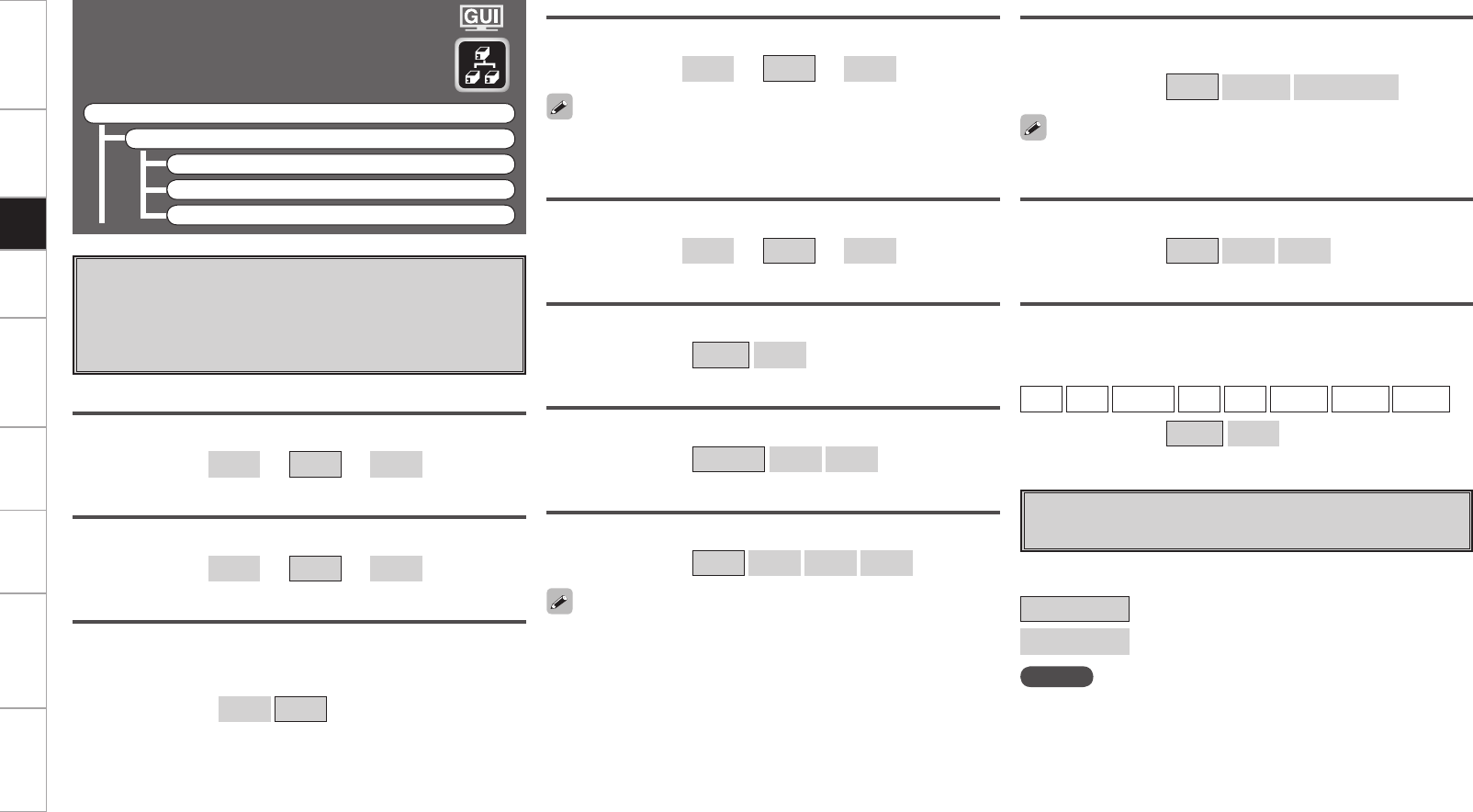
Getting Started Connections Playback Remote Control Multi-Zone Information Troubleshooting Specifications
Zone Setup
Make settings for audio playback in a multi-zone
system.
F Menu tree F
Manual Setup
Zone Setup
a ZONE2
s ZONE3
d OSD
a ZONE2
Make settings for audio playback in a ZONE2 system.
s ZONE3
Make settings for audio playback in a ZONE3 system.
Bass
Adjust low frequency range (bass).
[Variable range] –10dB ~ 0dB ~ +10dB
Treble
Adjust high frequency range (treble).
[Variable range] –10dB ~ 0dB ~ +10dB
HPF
When using speakers that cannot satisfactorily play low frequencies,
distortion of the bass sound can be reduced by setting “HPF” to
“ON”.
[Selectable items] ON OFF
d OSD
Set ZONE2 monitor as onscreen display Zone.
[Selectable items]
ZONE2 : Display only ZONE2 operations.
ZONE2/ZONE3 : Display ZONE2 and ZONE3 operations.
NOTE
On-screen display appears only on the ZONE2 monitor.It does not
appear on the ZONE3 monitor.
Power On Level
Define the volume setting that is active when the power is turned
on.
[Selectable items] Last – – –dB –70dB ~ 18dB
Mute Level
Set the amount of attenuation when muting is on.
[Selectable items] Full –40dB –20dB
This can be set when “Volume Level“ is set to “Variable“.
Video Convert (ZONE2 only)
Automatically convert video input signal to ZONE2 monitor output
format.
[Input source]
DVD HDP TV/CBL SAT VCR DVR-1 DVR-2 V.AUX
[Selectable items] ON OFF
Volume Limit
Make a setting for maximum volume.
[Selectable items] OFF –20dB –10dB 0dB
This can be set when “Volume Level“ is set to “Variable“.
Lch Level
Adjust the left channel output level.
[Variable range] –12dB ~ 0dB ~ +12dB
The “Lch Level“ and “Rch Level“ can be set when “Channel“ is set
to “Stereo“.
Rch Level
Adjust the right channel output level.
[Variable range] –12dB ~ 0dB ~ +12dB
Channel
Switch between stereo and mono output.
[Selectable items] Stereo Mono
Volume Level
Adjust the main volume level.
[Selectable items] Variable –40dB 0dB
Setup
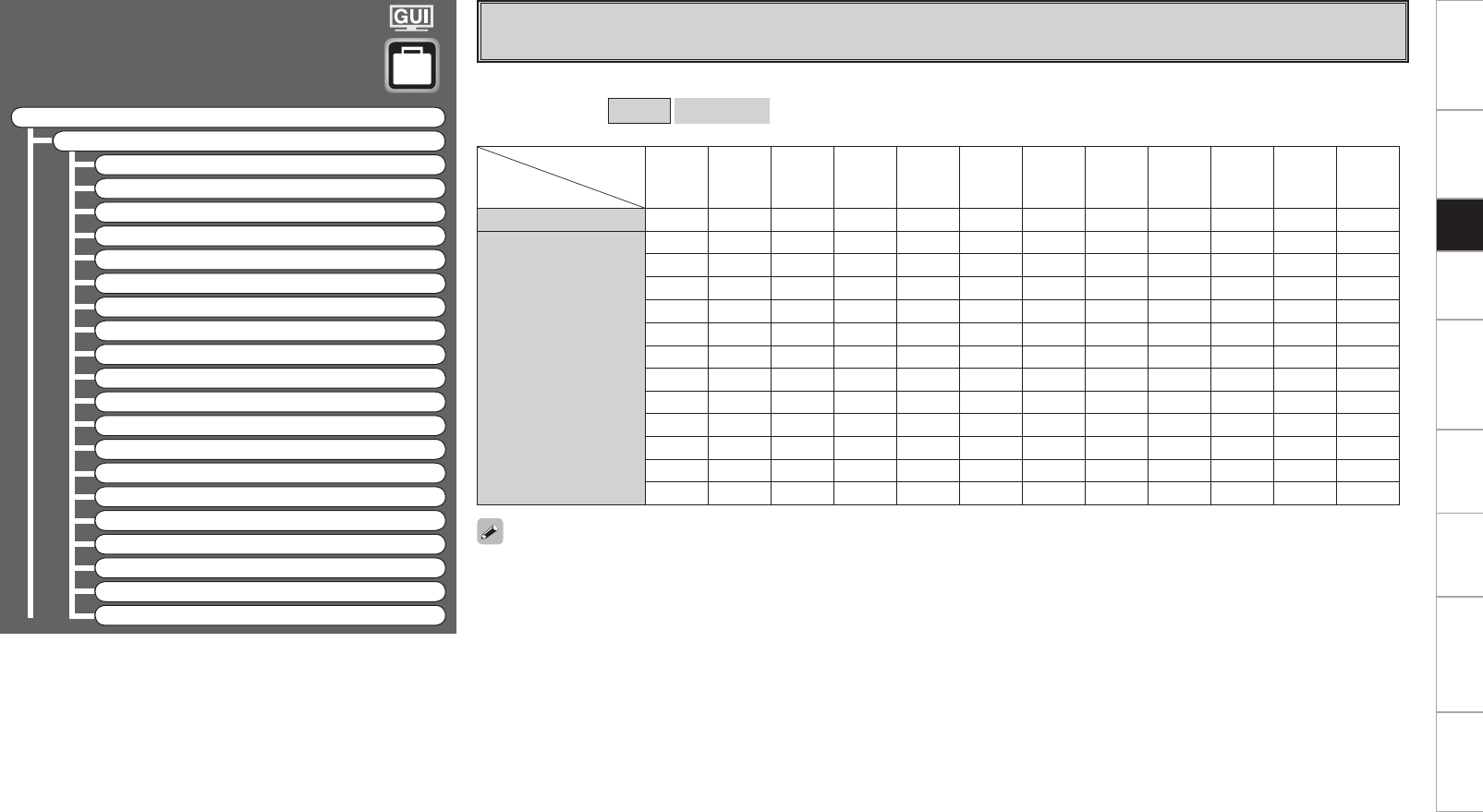
0
Getting Started Connections Playback Remote Control Multi-Zone Information Troubleshooting Specifications
Option Setup
Make various other settings.
F Menu tree F
Manual Setup
Option Setup
a Pre-out Assign
s XLR Out Polarity
d POA Setting
f Volume Control
g Source Delete
h GUI
j Quick Select Name
k Trigger Out 1
l Trigger Out 2
A0 Trigger Out 3
A1 Trigger Out 4
A2 Transducer Setup
A3 Digital Out
A4 Remote ID
A5 2Way Remote
A6 Dimmer
A7 Setup Lock
A8 Maintenance Mode
A9 Firmware Update
S0 Add New Feature
Setting “Free Assign” allows you to freely assign each pre-out to any channel, depending on the environment used.
[Selectable items] Normal Free Assign
a Pre-out Assign
Change the pre-out assignment.
• Channels that are set up in the GUI menu “Speaker Setup”-“Speaker Configuration” to “None” can be set up, but will not generate output.
• Pre-out terminals in ZONE2 and ZONE3 can not be allocated.
• One channel can be assigned to up to 4 pre-out terminals.
Preout terminal
Pre-out Assign
FL FR C SL (A) SR (A) SL (B) SR (B) SBL SBR SW1 SW2 SW3
Normal FL FR C SL (A) SR (A) SL (B) SR (B) SBL SBR SW1 SW2 SW3
Free Assign
FL FL FL FL FL FL FL FL FL FL FL FL
FR FR FR FR FR FR FR FR FR FR FR FR
C C C C C C C C C C C C
SL (A) SL (A) SL (A) SL (A) SL (A) SL (A) SL (A) SL (A) SL (A) SL (A) SL (A) SL (A)
SR (A) SR (A) SR (A) SR (A) SR (A) SR (A) SR (A) SR (A) SR (A) SR (A) SR (A) SR (A)
SL (B) SL (B) SL (B) SL (B) SL (B) SL (B) SL (B) SL (B) SL (B) SL (B) SL (B) SL (B)
SR (B) SR (B) SR (B) SR (B) SR (B) SR (B) SR (B) SR (B) SR (B) SR (B) SR (B) SR (B)
SBL SBL SBL SBL SBL SBL SBL SBL SBL SBL SBL SBL
SBR SBR SBR SBR SBR SBR SBR SBR SBR SBR SBR SBR
SW1 SW1 SW1 SW1 SW1 SW1 SW1 SW1 SW1 SW1 SW1 SW1
SW2 SW2 SW2 SW2 SW2 SW2 SW2 SW2 SW2 SW2 SW2 SW2
SW3 SW3 SW3 SW3 SW3 SW3 SW3 SW3 SW3 SW3 SW3 SW3
Setup

Getting Started Connections Playback Remote Control Multi-Zone Information Troubleshooting Specifications
s XLR Out Polarity
Set to switch the XLR pre-out terminal polarity.
d POA Setting
Set when connecting the receiver to a POA-A1HDCI.
POA LINK
Set when connecting the receiver to a POA-A1HDCI through a
CONTROL LINK.
[Selectable items] OFF ON (Single) ON (Dual)
[Selectable channels]
Front L Front R Center Surround A L Surround A R
Surround B L Surround B R Surround Back L
Surround Back R Subwoofer 1 Subwoofer 2 Subwoofer 3
[Selectable items] XLR qGROUND
wHOT
eCOLD
XLR (INV) qGROUND
wCOLD
eHOT
g
Source Delete
Remove input sources that are not used from the display.
[Selectable items] ON Delete
NOTE
• Input sources being used in the various zones cannot be deleted.
• Input sources set to “Delete” cannot be selected from GUI menu
“Source Select” or using the SOURCE SELECT knob on the main unit
or SOURCE SELECT button on the remote control unit.
h GUI
Make GUI related settings.
Screensaver
Make screensaver settings.
Use the screensaver to prevent burn-in on the monitor screen.
When set to “ON”, the screensaver is activated if there is no activity
for about 3 minutes.
[Selectable items] ON OFF
Wall Paper
Change the GUI background.
[Selectable items] Picture Black Gray Blue
Format
Select the video output signal format to match the monitor.
[Selectable items] NTSC PAL
NOTE
When a format other than the video format of the connected monitor
is set, the picture will not be displayed properly. Use the procedure
described below to change the video format.
f Volume Control
Set the MAIN ZONE volume setting.
Volume Limit
Make a setting for maximum volume.
[Selectable items] OFF –20dB –10dB 0dB
Power On Level
This sets the volume set when the MAIN ZONE’s power is turned
on.
[Selectable items] Last – – –dB –80dB ~ 18dB
Mute Level
This sets the amount of attenuation of the volume when the mute
mode is set in the MAIN ZONE.
[Selectable items] Full –40dB –20dB
POA 1/POA 2
Set POA-A1HDCI for which the MODE select switch is set to “1” or
“2”.
LINK Check
Check CONTROL LINK.
n Input Selector
Select the setup channel.
[Selectable items] L1 R1 L2 R2 L3 R3
L4 R4 L5 R5
Select the connector input to be used for each channel.
[Selectable items] RCA XLR OFF
n Power Amp
Select the setup channel.
[Selectable items] L1/L2 L3/L4 L5/R5 R1/R2 R3/R4
Set the power amp usage for each channel.
[Selectable items] NORMAL BI-AMP BRIDGE (BTL)
See the POA-A1HDCI operating instructions.
Setup
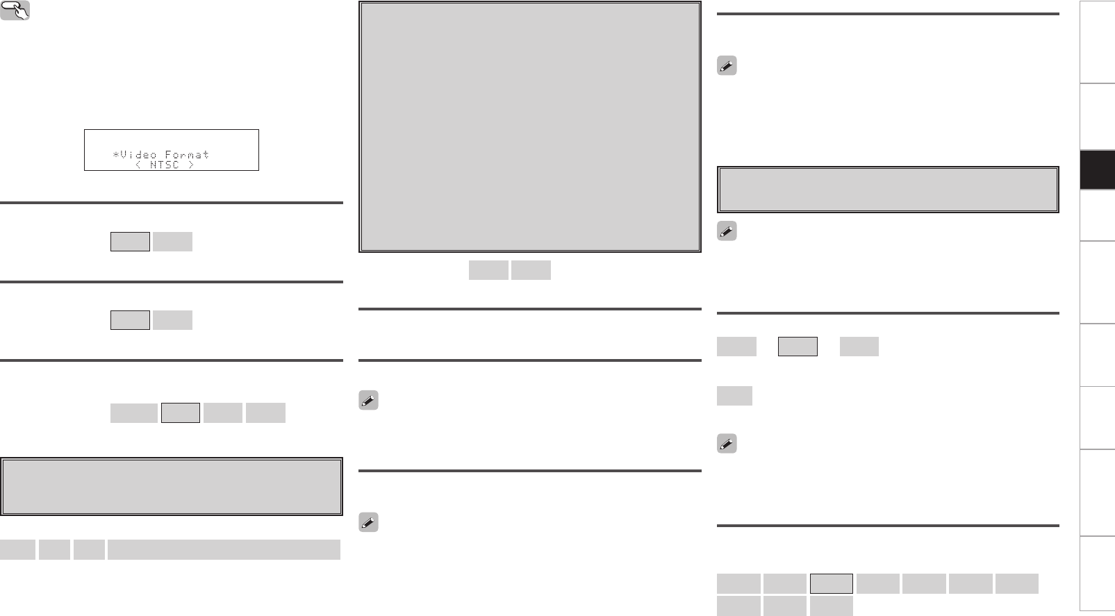
Getting Started Connections Playback Remote Control Multi-Zone Information Troubleshooting Specifications
Master Volume
Master volume display during adjustment.
[Selectable items] ON OFF
NET/USB / iPod / Tuner
This sets the time the on-screen display is displayed when an operation
is performed.
[Selectable items] Always 30s 10s OFF
j Quick Select Name
Change “Quick Select” display name.
Up to 16 characters can be input.
[Input characters]
A ~ Z a ~ z 0 ~ 9 ! “ # % & ’ ( ) * + , - . / : ; < = > ? @ [ \ ] (space)
Text
Text information display.
[Selectable items] ON OFF
Operating from the main unit
b The GUI menu is not displayed when performing this setting.
q Press and hold the AUDIO DELAY and RETURN buttons for at least 3
seconds.
“Video Format” appears on the display.
w Use the o p button to make the setting.
e Press the ENTER, MENU or RETURN button to complete the
setting.
k Trigger Out 1
Select the conditions to turn on the trigger out 1 with respect to
the zone, input source, surround mode, HDMI monitor, etc.
For details about the trigger out function, see page 23.
l Trigger Out 2
This sets the conditions to turn on the trigger out 2, in the same
way as “Trigger Out 1” above.
A0 Trigger Out 3
This sets the conditions to turn on the trigger out 3, in the same
way as “Trigger Out 1” above.
A1 Trigger Out 4
This sets the conditions to turn on the trigger out 4, in the same
way as “Trigger Out 1” above.
[Selectable items] ON – – –
Setting with Respect to the Zone
When the power of the zone turned on/off, the trigger out turns on.
Setting with Respect to the Input Source
When the input source set to on is selected, the trigger out turns on.
Associated with respect to the input source for zones set to “ON” at
“Setting with Respect to the Zone”.
Setting with Respect to the Surround Mode
When the surround mode set to on is selected, the trigger out turns
on.
A2 Transducer Setup
Set when using transducer.
The Transducer Setup can be accessed through GUI menu “Speaker
Setup” – “Subwoofer Setup” is “1SP”, “2SP L/R” or “2SP MIX”. The
transducer signal is outputted from “SW3”.
Setting with Respect to the Monitor
When the HDMI monitor set to on is selected, the trigger out turns
on.
Level
[Variable range]
–12dB ~ 0dB ~ +12dB :
Set the transducer level.
OFF :
Turn the transducer output off.
LPF
Set the upper limit of the low frequency output to the transducer.
[Selectable items]
40Hz 60Hz 80Hz 90Hz 100Hz 110Hz 120Hz
150Hz 200Hz 250Hz
When you adjust “Level”, the adjusted value is set for all surround
modes. To adjust the level for individual surround modes, use “Channel
Level” (vpage 75).
This is effective when the “MAIN ZONE” has been set to “ON” for
the “Setting with Respect to the Zone” and the input source which is
set to “ON” has been selected for the “Setting with Respect to the
Input Source”.
This is effective when the “MAIN ZONE” has been set to “ON” for
the “Setting with Respect to the Zone” and the input source which is
set to “ON” has been selected for the “Setting with Respect to the
Input Source”.
Setup
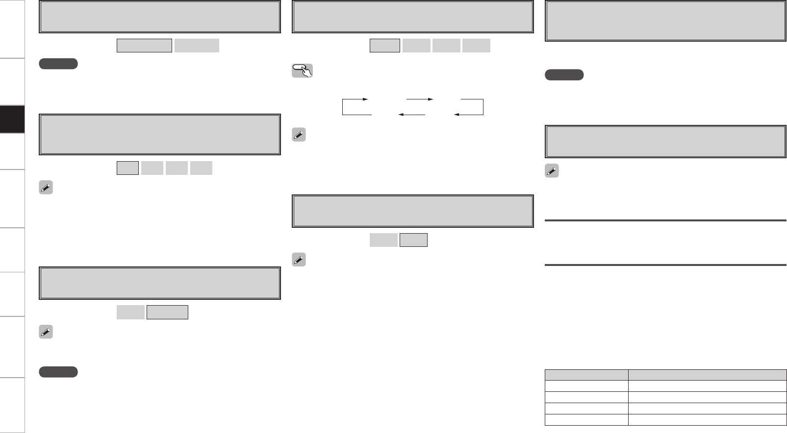
Getting Started Connections Playback Remote Control Multi-Zone Information Troubleshooting Specifications
A4 Remote ID
Set remote control ID.
Match the ID setting of the remote control unit and the receiver.
• When changing the remote ID, also change the AMP, iPod, TU and
NET/DTU modes of the main remote control unit at the same time
(vpage 80).
• When changing the remote ID, also change the sub remote control
unit at the same time (vpage 85).
A3 Digital Out
Set usage of OPT4 OUT.
NOTE
The ZONE4 operations cannot be performed when set to “Rec
Select”.
[Selectable items] ZONE4 Select Rec Select
[Selectable items] 1 2 3 4
A5 2Way Remote
Set when using the 2-way remote control unit.
When using a 2-way remote control unit (RC-7000CI and RC-7001RCI,
sold separately), set this to “Used”.
[Selectable items] Used Not Used
NOTE
• When using the 2-way remote control unit, connect to the Port 1
RS-232C connector.
• If GUI menu “Manual Setup” – “Option Setup” – “2Way Remote”is
set to “Used”, you cannot use port 1 of the RS-232C terminal for the
external controller.
A6 Dimmer
Adjust display brightness of the receiver.
Operating from the main unit
Press the DIMMER button.
[Selectable items] Bright Dim Dark OFF
Bright Dim
DarkOFF
A7 Setup Lock
Protect settings from inadvertent change.
• When “Setup Lock” is set to “ON”, the settings listed below can
no longer be changed. Also, “SETUP LOCKED!” is displayed if you
attempt to operate related buttons.
⋅ GUI menu operations
⋅ RESTORER
⋅ Night Mode
⋅ Parameter
⋅ Room EQ
⋅ Channel Level
⋅ Audio Delay
• To cancel the setting, press the MENU button to re-display the
“Setup Lock” screen, then change the setting to “OFF”.
[Selectable items] ON OFF
A8 Maintenance Mode
This sets the function for maintenance by a DENON serviceperson
or installer. (For professional use only.)
NOTE
Only use this function if so instructed by a DENON serviceperson or
installer.
This function allows a DENON serviceperson or installer to check the
AVP-A1HDCI’s status and make settings via the Internet.
A9 Firmware Update
Update the firmware of the receiver.
Check for Update
You can check for firmware updates. You can also check approximately
how long it will take to complete an update.
Start
Execute the update process.
When updating starts, the power indicator becomes red and the GUI
screen is shut down.
The amount of update time which has elapsed is displayed during the
update process.
When updating is complete the power indicator becomes green and
normal status is resumed.
b
If the display reads as shown below, check the settings and network
environment, then update again.
Display Description
Updating failed Updating failed.
Login failed Failure to log into server.
Server is busy Server is busy. Wait a while then try again.
Connection fail Failure connecting to server.
If POA-A1HDCI is connected using the control link, POA-A1HDCI
meter operation is turned OFF when the AVP-A1HDCI display is
turned “OFF”.
If POA-A1HDCI is connected using the control link, POA-A1HDCI is
updated simultaneously with update of AVP-A1HDCI.
Setup
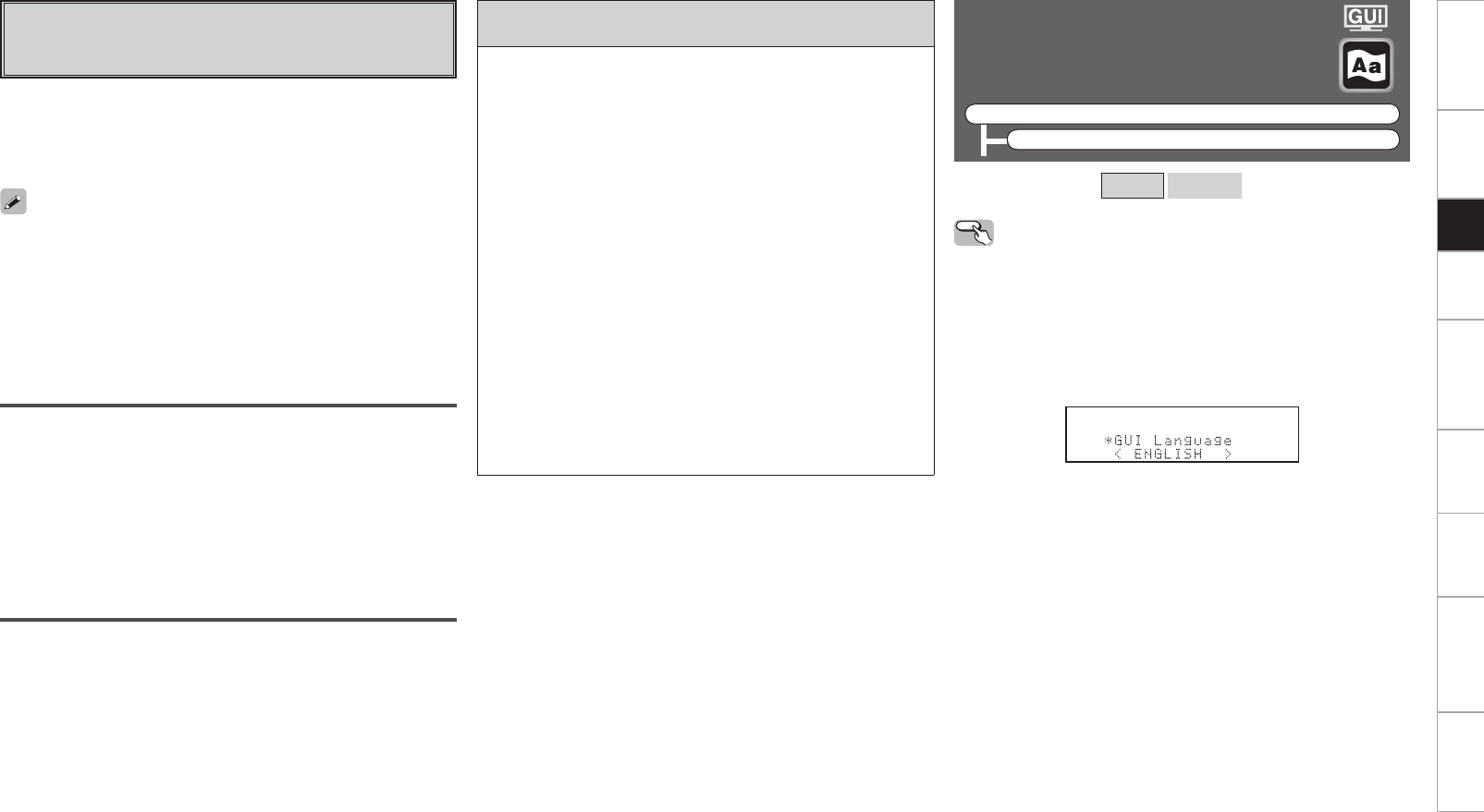
Getting Started Connections Playback Remote Control Multi-Zone Information Troubleshooting Specifications
Notes concerning use of “Firmware Update” and
“Add New Feature”
• In order to use these functions, you must have the correct system
requirements and settings for a broadband Internet connection. For
details, see pages 35 ~ 38.
• Do not turn off the power until updating or upgrating is completed.
• Normally there is no need to use this function, aside from the cases
described below.
⋅ Firmware Update : In the case of applying the latest firmware
updates (free)
⋅ Add New Feature : In the case of future upgrades to add new
functions to the receiver (payment required)
⋅ Information regarding the “Firmware Update” function and “Add
New Feature” will be announced on the DENON web site each
time related plans are defined.
• Even with a broadband connection to the Internet, approximately
1 hour is required for the updating/upgrading procedure to be
completed.
Once updating/upgrading starts, normal operations on the
AVP-A1HDCI cannot be performed until updating/upgrading is
completed.
Furthermore, updating/upgrading the firmware may reset the
backup data for the parameters, etc., set for the AVP-A1HDCI.
• When updating/upgrading the firmware, we recommend using
wired connections (Ethernet cable).
Upgrade
Execute the upgrade process.
When upgrading starts, the power indicator becomes red and the GUI
screen is shut down.
The amount of upgrade time which has elapsed is displayed during
the upgrade process.
When upgrading is complete the power indicator becomes green and
normal status is resumed.
b
If the upgrade is not successful, an error message identical to those
in “Firmware Update” will appear on the display.
S0 Add New Feature
Display the new functions which can be purchased for downloading
to the AVP-A1HDCI and upgrade.
When you purchase a new function and register your user information,
“Registerd” is displayed on this menu and you can proceed with the
upgrade.
Upon completion of the upgrade, you can start using the new
function.
When “Not Registered” is displayed on the Add New Feature screen,
you cannot upgrade.
To use the upgrade function, you should purchase an upgrade package
from the DENON website.
To purchase the package, you will need the ID number shown on this
screen.
To display the ID number on the screen, hold the p and STATUS
buttons on the main unit down for 3 seconds or more.
Upgrade Status
A list of the additional functions provided by the Upgrade will be
displayed.
Language
Select the language displayed on the GUI screen.
F Menu tree F
Manual Setup
Language
[Selectable items] English Français
Operating from the main unit
b The GUI menu is not displayed when performing this setting.
q Press and hold the AUDIO DELAY and RETURN buttons for at least
3 seconds.
“Video Format” appears on the display.
w Use the ui button to set “GUI Language”.
e Use the o p button to make the setting.
r Press the ENTER, MENU or RETURN button to complete the
setting.
Setup
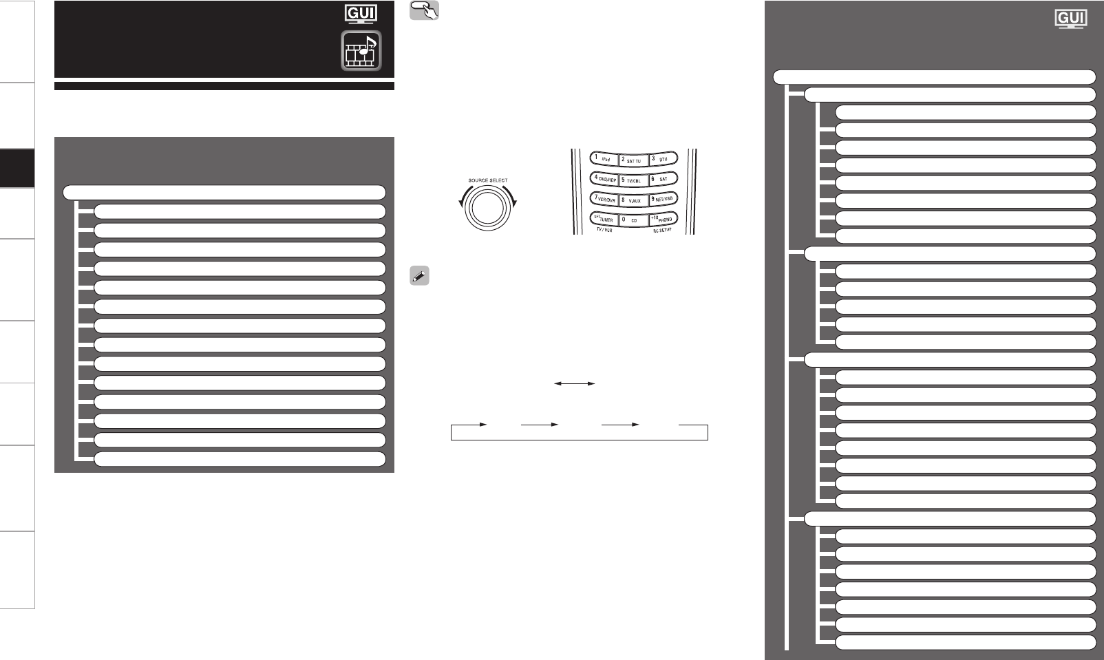
Getting Started Connections Playback Remote Control Multi-Zone Information Troubleshooting Specifications
Input Source Selection
F Menu tree F
Source Select
TUNER
PHONO
CD
DVD
HDP
TV/CBL
SAT
VCR
DVR-1
DVR-2
V.AUX
NET/USB
XM
HD Radio
Use this procedure to select the input source and make the settings
related to playing input sources.
Source Select
Operating from the main unit or main remote
control unit
GOperation on the main unitH
Turn the SOURCE SELECT knob.
b If “Rec Select” or “Video Select” is selected, press the SOURCE
button before turning the SOURCE SELECT knob.
GOperation on the main remote control unitH
Press the SOURCE SELECT button.
The desired input source can be selected directly.
(Main unit) (Main remote control unit)
• To operate the AVP-A1HDCI using the main remote control unit, set
the remote control unit to the AMP mode (vpage 77 “Remote
Control Unit Operations”).
• Pressing the DVD/HDP button and the VCR/DVR button on the main
remote control will switch between the following.
DVD/HDP :
DVD HDP
VCR/DVR :
VCR DVR-1 DVR-2
Settings Related to Playing
Input Sources
F Menu tree F
Source Select
TUNER
a Play
s Auto Preset
d Preset Skip
f Preset Name
g Video
h Input Mode
j Rename
k Source Level
PHONO
g Video
h Input Mode
j Rename
k Source Level
l Input Att.
CD, DVD, HDP, TV/CBL, SAT, VCR, DVR-1, DVR-2, V.AUX
a Playz
A0 Playback Mode (iPod)z
A1 Assign
g Video
h Input Mode
j Rename
k Source Level
l Input Att.
NET/USB
a Play
A2 Playback Mode
A3 Still Picture
g Video
h Input Mode
j Rename
k Source Level
Setup
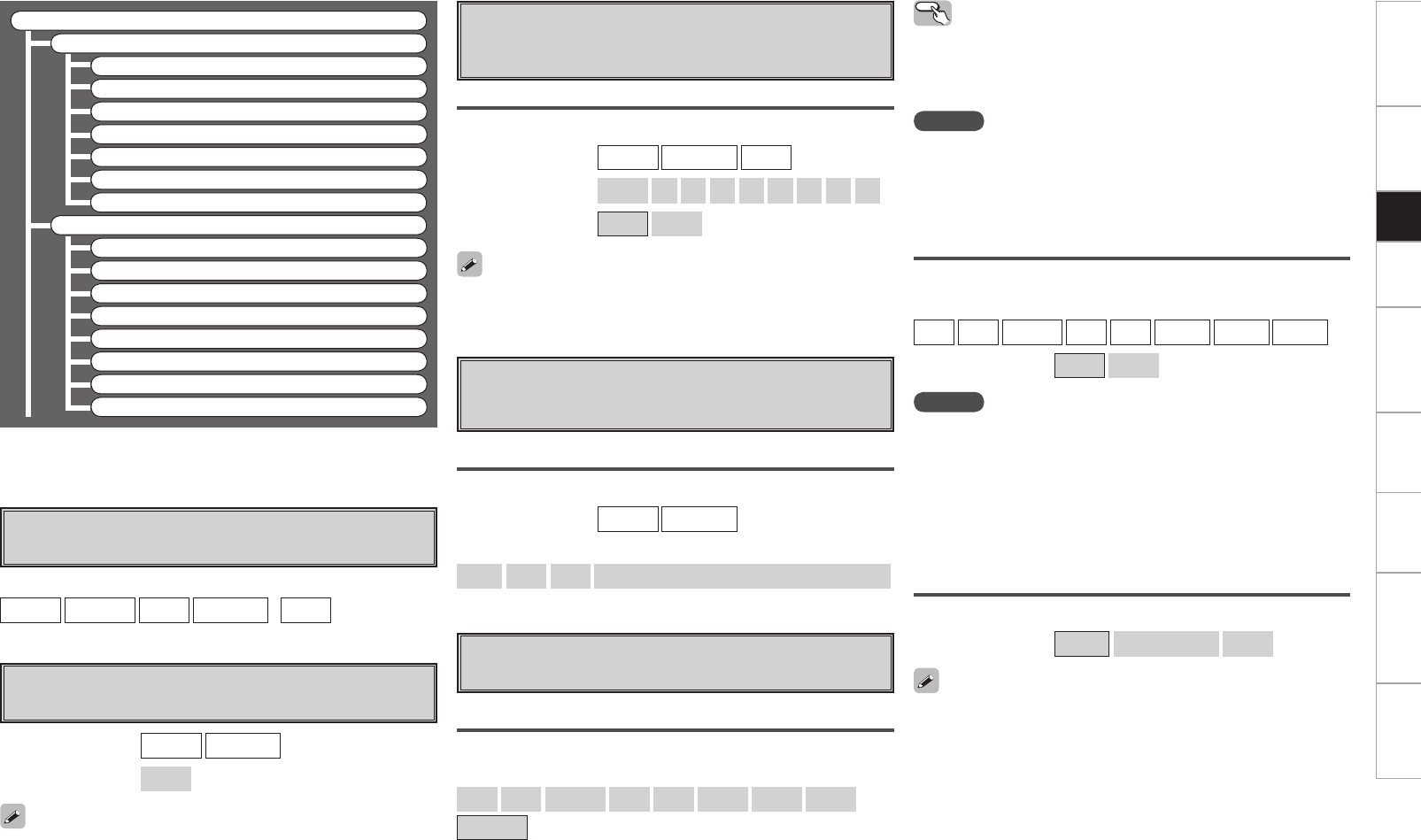
Getting Started Connections Playback Remote Control Multi-Zone Information Troubleshooting Specifications
Source Select
XM
a Play
d Preset Skip
A4 Antenna Aiming
g Video
h Input Mode
j Rename
k Source Level
HD Radio
a Play
s Auto Preset
d Preset Skip
f Preset Name
g Video
h Input Mode
j Rename
k Source Level
z : “Play” and “Playback Mode (iPod)” are displayed for input sources
for which “iPod dock” is assigned.
a Play
The playback screen is displayed.
s Auto Preset
Use the auto preset function to program radio stations.
If an FM station cannot be preset automatically, select the desired
station by tuning it in manually, then preset it manually.
[Input source]
TUNER NET/USB XM HD Radio (iPod )
[Input source] TUNER HD Radio
[Selectable items] Start
d
Preset Skip
Set the preset memories that you do not want to display
when tuning.
When set to “All” to “Skip”, it is possible to skip entire preset memory
blocks (A to G).
A ~ G
Select the preset channel(s) you do not want to display.
[Input source] TUNER HD Radio XM
[Selectable items] All 1 2 3 4 5 6 7 8
[Selectable items] ON Skip
f Preset Name
Assign name to a preset memory.
Names containing up to 8 characters can be input.
A1 ~ G8
Select the preset memory number.
[Input source] TUNER HD Radio
[Characters that can be input]
A ~ Z a ~ z 0 ~ 9 ! “ # % & ’ ( ) * + , - . / : ; < = > ? @ [ \ ] (space)
g Video
Setting the video source.
Video Select
Switch video input source while listening to audio signal.
[Selectable items]
DVD HDP TV/CBL SAT VCR DVR-1 DVR-2 V.AUX
SOURCE
Operating from the main unit
Press the VIDEO SELECT button, then turn the SOURCE SELECT knob
until the desired picture appears.
b To cancel, press the main unit’s VIDEO SELECT button, then turn
the main unit’s SOURCE SELECT knob and select “SOURCE”.
NOTE
• It is not possible to select HDMI input signals.
• When playing HDMI video input signals, the analog video signal of
another input source cannot be selected for the HDMI video output.
• Input sources for which “Delete” is selected at “Source Delete”
cannot be selected.
Video Convert
Automatically convert video input signal to monitor output format.
[Input source]
DVD HDP TV/CBL SAT VCR DVR-1 DVR-2 V.AUX
[Selectable items] ON OFF
NOTE
• For optimum video performance, THX recommends that you set
the conversion mode to “OFF” to use video signals pass through
system without up conversion.
Example: View video input from a component video on the
component video monitor.
• When a non-standard video signal from a game machine or some
other source is input, the video conversion function might not
operate. If this happens, please set the conversion mode to “OFF”.
i/p Scaler
Make settings for i/p scaler function.
[Selectable items] A to H A to H & H to H OFF
• This can not be set when “Video Convert“ is set to “OFF”.
• The “A to H & H to H” can be set to the input source assigned to the
HDMI input connector.
• “A to H & H to H” setting:
• Deep color (10 bit/12 bit) signals are converted into 8-bit signals.
• The i/p scaler function does not work if xvYCC or computer’s
resolution signals are input.
Setup
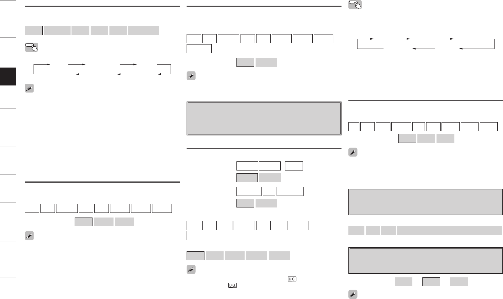
Getting Started Connections Playback Remote Control Multi-Zone Information Troubleshooting Specifications
This can be set when “i/p Scaler” is set to anything other than “OFF”.
Aspect
This sets the aspect ratio when outputting 480i/576i or 480p/576p
input signals from the HDMI output connector.
[Input source]
DVD HDP TV/CBL SAT VCR DVR-1 DVR-2 V.AUX
NET/USB
[Selectable items] Full Normal
This can be set when “i/p Scaler” is set to anything other than “OFF”.
Progressive Mode
Select optimum progressive mode for video material.
[Input source]
DVD HDP TV/CBL SAT VCR DVR-1 DVR-2 V.AUX
[Selectable items] Auto Video1 Video2
• This can be set when “i/p Scaler” is set to anything other than
“OFF”.
• When the “i/p Scaler” is set to “A to H & H to H”, the resolutions can
be setup to the analog video input signal and HDMI input signal.
• To enjoy 1080p/24 Hz video images, use a monitor which supports
1080p/24 Hz video signals.
• With film source (24 Hz), you can enjoy a film-like image. It is
recommended that you use 1080p/60 Hz for video source and mixed
source.
• It is not possible to convert a 50 Hz signal to 1080p/24 Hz. It is output
at a resolution of 1080p/50 Hz.
• It is not possible to convert a 1080p/60 Hz signal to 1080p/24 Hz.
Operating from the main unit
Press the SCALE button.
Auto 480p / 576p 1080i
1080p1080p:24 Hz 720p
Resolution
Set resolution for video signal output to HDMI.
[Selectable items]
Auto 480p/576p 1080i 720p 1080p 1080p:24 Hz
h Input Mode
Make input mode and decode mode settings for this source.
The selectable input modes depend on the input source and
“Assign” setting (vpage 48, 49).
Input Mode
Set the input mode for this source.
[Input source] TUNER PHONO (iPod )
[Selectable items] Analog EXT. IN
[Input source] NET/USB XM HD Radio
[Selectable items] Auto EXT. IN
[Input source]
CD DVD HDP TV/CBL SAT VCR DVR-1 DVR-2
V.AUX
[Selectable items]
Auto HDMI Digital Analog EXT. IN
When a digital signal is properly input, the “ ” indicator lights on
the display. If the “ ” indicator does not light, check the digital input
connector assignment and the connections.
Operating from the main unit or main remote
control unit
Press the INPUT MODE button on the main unit or the INPUT button
on the main remote control unit.
z1: This can be selected for input sources for which the GUI menu
“Assign” setting is set to “HDMI” (vpage 48). Excluding CD
and TUNER.
z2: This can be selected for input sources for which the GUI menu
“Assign” setting is set to “Digital” (vpage 48).
Auto
EXT. IN
HDMI z1Digital z2
Analog
Decode Mode
Set the decode mode for this source.
[Input source]
CD DVD HDP TV/CBL SAT VCR DVR-1 DVR-2 V.AUX
[Selectable items] Auto PCM DTS
• This can be selected for input sources for which the GUI menu
“Assign” setting is set to “HDMI” or “Digital”.
• Only set “PCM” and “DTS” when playing the respective signals.
j Rename
Change the display name for this source.
Names containing up to 8 characters can be input.
[Characters that can be input]
A ~ Z a ~ z 0 ~ 9 ! “ # % & ’ ( ) * + , - . / : ; < = > ? @ [ \ ] (space)
For input sources for which “HDMI” or “Digital” are set at the GUI
menu “Assign” setting, the analog input level and digital input level
can be set separately.
k Source Level
Corrects the playback level of the selected input source’s audio
input.
[Variable range] –12dB ~ 0dB ~ +12dB
Setup
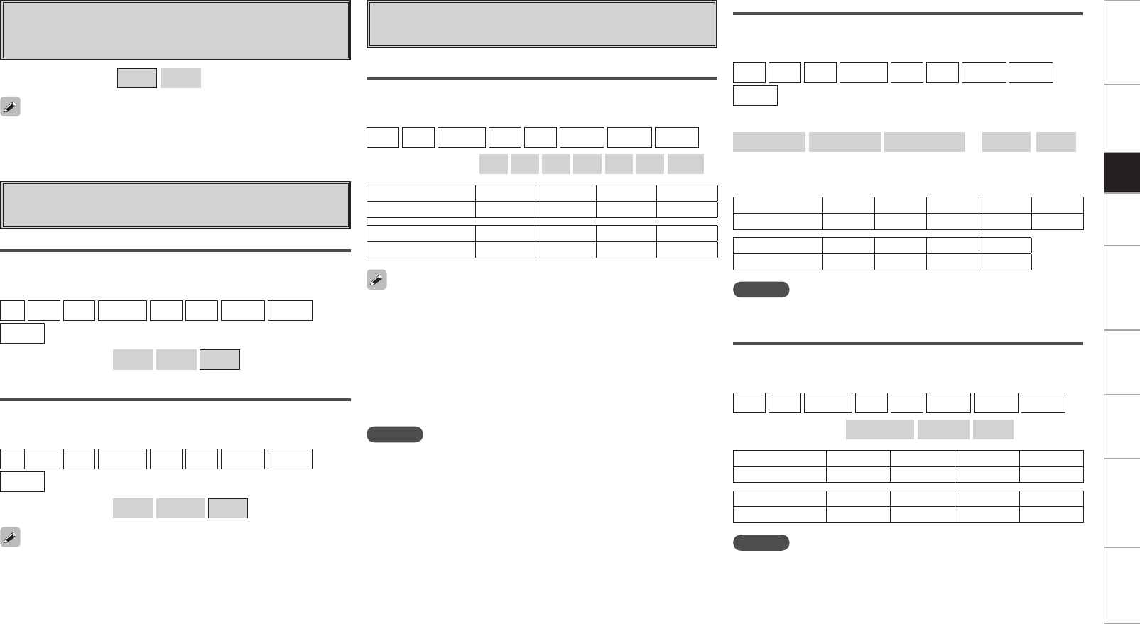
Getting Started Connections Playback Remote Control Multi-Zone Information Troubleshooting Specifications
l Input Att.
Set when replay sound is distorted because the input level is too
large.
[Selectable items] OFF –6dB
A0 Playback Mode (iPod)
Make settings for iPod playback.
Repeat
Make settings for repeat mode.
[Input source]
CD DVD HDP TV/CBL SAT VCR DVR-1 DVR-2
V.AUX
[Selectable items] All One OFF
Shuffle
Make settings for shuffle mode.
[Input source]
CD DVD HDP TV/CBL SAT VCR DVR-1 DVR-2
V.AUX
[Selectable items] Songs Albums OFF
This can be selected for input sources for which “Assign” is assigned
at the “iPod dock” setting.
• With an HDMI connection, video and audio signals are transmitted
simultaneously. To play the video signal assigned at “HDMI”
combined with the audio signal assigned at “Digital”, select “Digital”
at the GUI menu “Source Select“ – “Input Mode” (vpage 47).
• When the AVP-A1HDCI and monitor are connected with an HDMI
cable, if the monitor is not compatible with HDMI audio signal
playback, only the video signals are output to the monitor.
• The audio signals input from the analog, digital and EXT. IN connectors
are not output to the monitor.
NOTE
This cannot be set for input sources for which “iPod dock” is assigned.
A1 Assign
Assign input sources to input connectors.
HDMI
Select HDMI connector to assign to this source.
[Input source]
DVD HDP TV/CBL SAT VCR DVR-1 DVR-2 V.AUX
[Selectable items] 1 2 3 4 5 6 None
Input source DVD HDP TV/CBL SAT
Default setting HDMI1 HDMI2 None HDMI3
Input source VCR DVR-1 DVR-2 V.AUX
Default setting HDMI4 HDMI5 HDMI6 None
Digital
Select digital input connector to assign to this source.
[Input source]
CD DVD HDP TV/CBL SAT VCR DVR-1 DVR-2
V.AUX
[Selectable items]
Coaxial1 ~ 4 Optical1 ~ 5 DENON LINK z BNC1/2 None
z: When a DENON DVD player and the DENON LINK have been
connected, be sure to make a setting to “DENON LINK”.
NOTE
This cannot be set for input sources for which “iPod dock” is assigned.
Input source CD DVD HDP TV/CBL SAT
Default setting
Coaxial 4 Coaxial 1 Coaxial 2
Optical 1
Coaxial 3
Input source VCR DVR-1 DVR-2 V.AUX
Default setting Optical 4 Optical 2 Optical 3 Optical 5
“Input Att.” is effective during DSP processing of analog audio
signals.
Component
Select component video input to assign to this source.
[Input source]
DVD HDP TV/CBL SAT VCR DVR-1 DVR-2 V.AUX
[Selectable items] 1 ~ 5 – RCA 6 – BNC None
NOTE
This cannot be set for input sources for which “iPod dock” is assigned.
Input source DVD HDP TV/CBL SAT
Default setting
1-RCA 2-RCA 3-RCA 4-RCA
Input source VCR DVR-1 DVR-2 V.AUX
Default setting None
5-RCA
None None
Setup
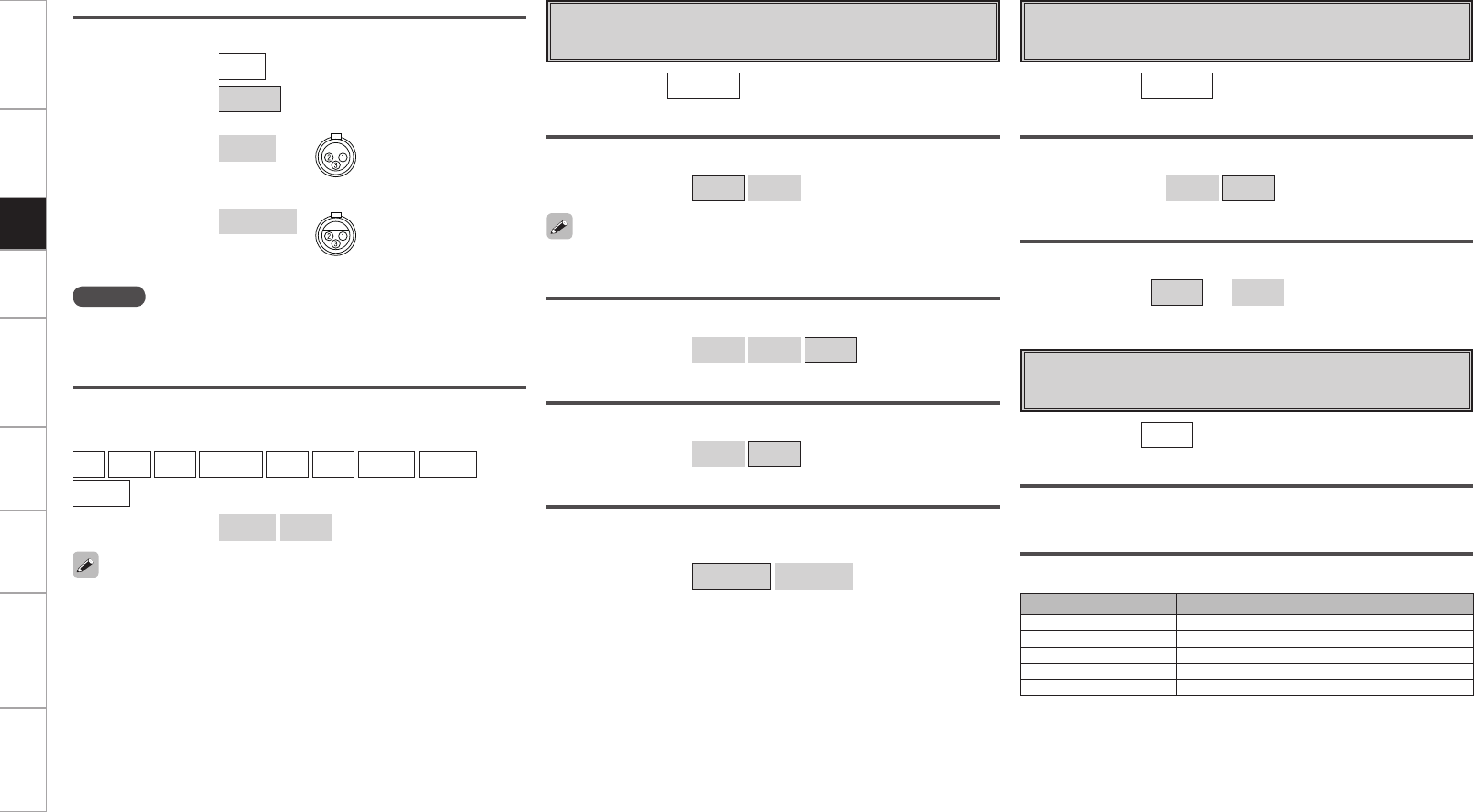
Getting Started Connections Playback Remote Control Multi-Zone Information Troubleshooting Specifications
A2 Playback Mode
Make settings for “NET/USB” playback.
[Input source] NET/USB
USB Select
Select USB port to use.
[Selectable items] Front Rear
Repeat
Make settings for repeat mode.
[Selectable items] All One OFF
Random
Make random mode settings.
[Selectable items] ON OFF
Direct Play
Set the folder to be played using the DIRECT PLAY button on the sub
remote control unit.
[Selectable items] Favorites All Music
Match the port to be used and the setting.
A3 Still Picture
Make settings for still picture (JPEG) playback.
Slide Show
Make slideshow settings.
[Selectable items] ON OFF
Interval
Set the playback time per image.
[Variable range] 5s ~ 60s
[Input source] NET/USB
iPod dock
Assign Control Dock for iPod to this source.
[Input source]
CD DVD HDP TV/CBL SAT VCR DVR-1 DVR-2
V.AUX
[Selectable items] Assign None
• With the default settings, the Control Dock for iPod can be used
connected to the VCR (iPod) connector.
• Even if “iPod dock” is set to “Assign”, if the set is not connected to
a Control dock for iPod, the input source can be used as the normal
input source.
Analog
Select the analog connector using the CD input.
[Input source] CD
[Selectable items] RCA
XLR qGROUND
wHOT
eCOLD
XLR (INV) qGROUND
wCOLD
eHOT
NOTE
When you assign “iPod dock,” you cannot select “XLR”, or
“XLR(INV)”.
Satellite
Indicate satellite signal strength.
Terrestrial
Indicate terrestrial signal strength.
A4 Antenna Aiming
Adjust the XM radio reception sensitivity.
Display Condition
¡¡¡¡ Signal strength is strong
¡¡¡ Signal strength is good
¡¡ Signal strength is marginal
¡Signal strength is weak
No signal
[Input source] XM
Setup
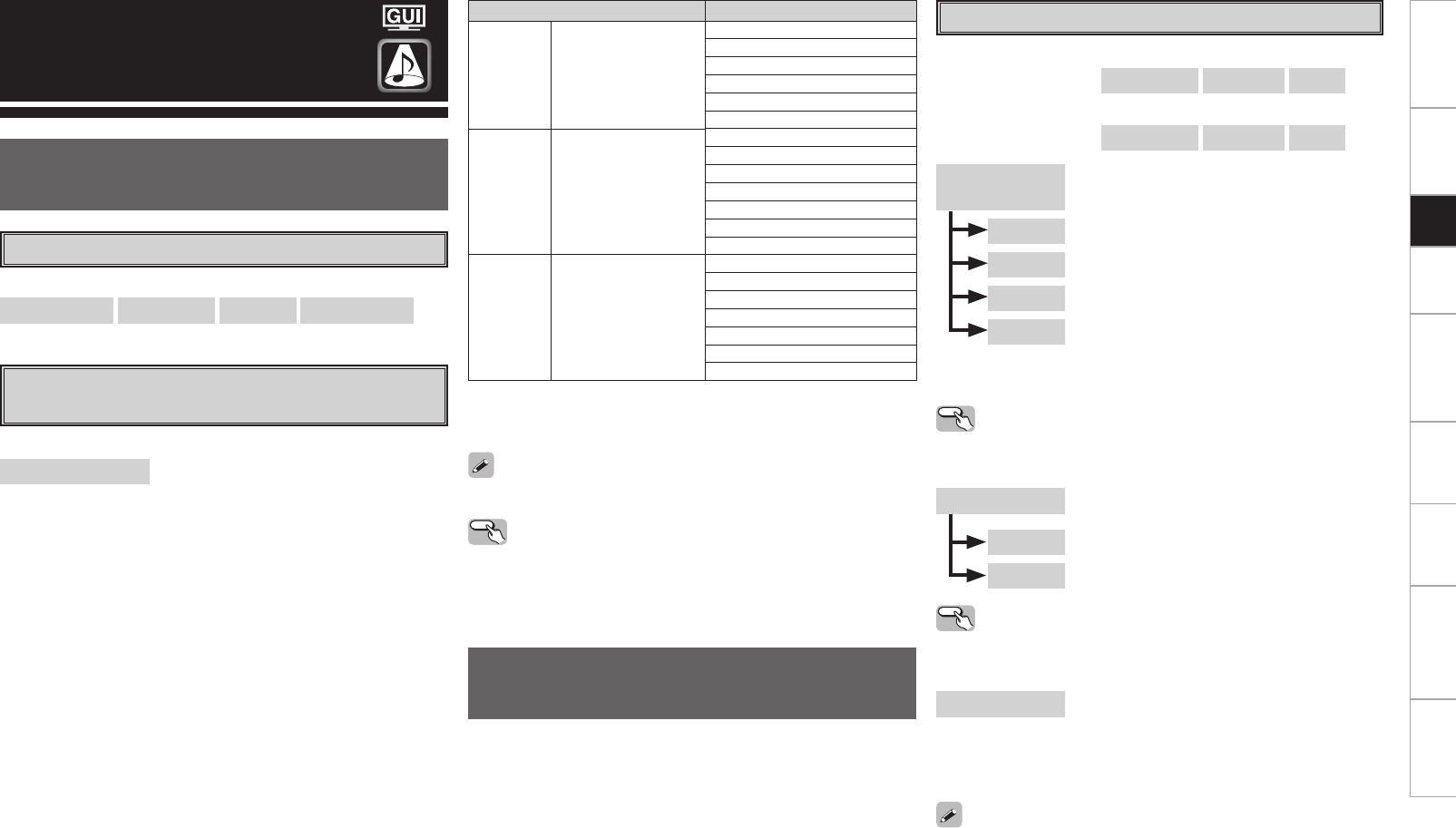
0
Getting Started Connections Playback Remote Control Multi-Zone Information Troubleshooting Specifications
Surround Mode
HOME THX CINEMA
THX surround sound mode to recreate the authentic sound of
movie soundtracks.
Surround Playback of 2-channel Sources
[Selectable items]
PLgx CINEMA PLg CINEMA Pro Logic NEO:6 CINEMA
[Selectable items]
HOME THX CINEMA :
This mode is for decoding the input signals according to their format
and playing THX surround sound.
The display when the HOME THX CINEMA mode is selected depends
on the input signal and surround back output playback mode.
Playing Multi-channel Sources
(Dolby Digital, DTS, etc.)
Input signal Display
Dolby
Digital
Source
DOLBY DIGITAL
(other than 2ch) /
DOLBY DIGITAL EX
DOLBY DIGITAL Plus
DOLBY TrueHD
THX SURROUND EX
THX Ultra2 Cinema
THX Music Mode
THX Games Mode
THX Cinema
PLgx C + THX
DTS
Surround
Source
DTS (5.1ch) /
DTS-ES Discrete 6.1 /
DTS-ES Matrix 6.1 /
DTS 96/24 /
DTS-HD High
Resolution Audio
DTS-HD Master Audio
ES MTRX6.1 + THX (z1)
ES DSCRT6.1 + THX (z2)
THX Ultra2 Cinema
THX Music Mode
THX Games Mode
THX Cinema
PLgx C + THX
DVD-
Audio,
SACD
PCM (multi ch) /
DSD (multi ch)
THX SURROUND EX
THX Ultra2 Cinema
THX Music Mode
THX Games Mode
PLgx C + THX
M CH 5.1 + THX
M CH 7.1 + THX
z1: This is displayed when the input signal is “DTS-ES Matrix 6.1”
and the AVP-A1HDCI’s “AFDM” setting is set to “ON”.
z2: This is displayed when the input signal is “DTS-ES Discrete 6.1”.
Operating from the main unit or main remote
control unit
Press the HOME THX CINEMA button on the main unit or the THX
button on the main remote control unit.
For details, see page 95.
Standard Playback
This is the standard mode for enjoying surround sound according
to the program source.
To select these surround modes pressing the STANDARD button on
the main unit or press the STD button on the main remote control unit.
The mode switches each time the button is pressed.
Surround Playback of 2-channel Sources
DOLBY PLgx
or DOLBY PLg
:
The signals are decoded in DOLBY PLgx or
DOLBY PLg for playback.
Cinema : This mode is suited for movie sources.
Music : This mode is suited for music sources.
Game : This mode is suited for games.
Pro Logic : This is the Pro Logic playback mode. This can
be selected when playing with a DOLBY PLg
decoder. When this mode is selected, “DOLBY
PL” is displayed.
DTS NEO:6 : The signals are decoded in DTS NEO:6 for
playback.
Cinema : This mode is suited for movie sources.
Music : This mode is suited for music sources.
Operating from the main unit
The “Cinema” or “Music” modes can be directly selected with the
CINEMA button or MUSIC button on the main unit.
neural : It is possible to play analog input signals and
PCM (2-channel, 48kHz or less) in the surround
mode.
This is the optimum mode for playing sources
recorded in XM HD Surround (vpage 92).
n When using a surround back speaker
[Selectable items] DOLBY PLgx DTS NEO:6 neural
n When not using a surround back speaker
[Selectable items] DOLBY PLg DTS NEO:6 neural
Operating from the main unit
The “Cinema”, “Music”, or “Game” modes can be directly selected
with the CINEMA, MUSIC or GAME button on the main unit.
Select the “Cinema”, “Music”, “Game” and “Pro Logic” modes
at GUI menu “Parameter” – “Audio” – “Surround Parameters” –
“Mode” (vpage 52).
Setup
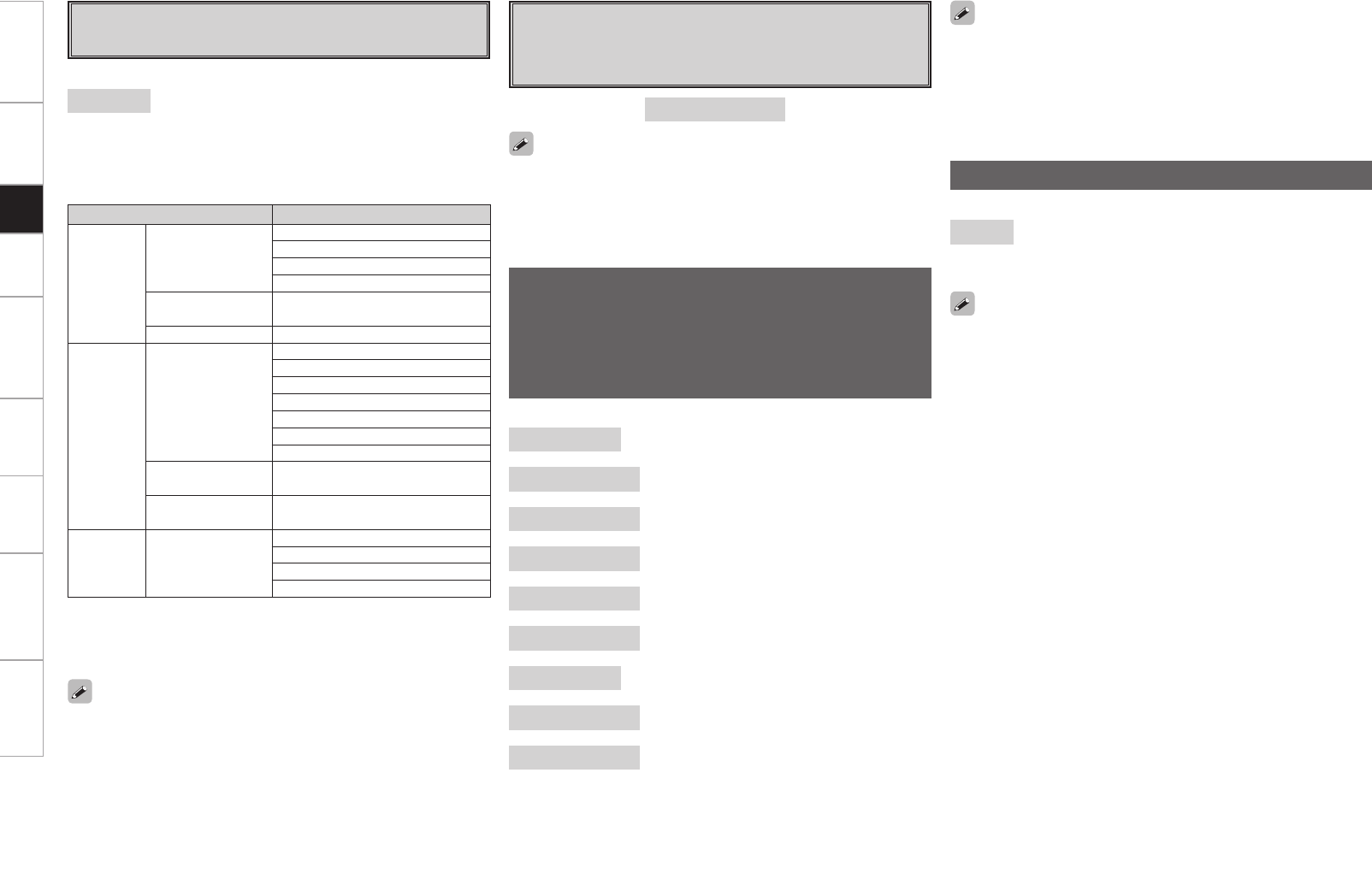
Getting Started Connections Playback Remote Control Multi-Zone Information Troubleshooting Specifications
Input signal Display
Dolby
Digital
Source
DOLBY DIGITAL
(other than 2ch) /
DOLBY DIGITAL
EX
DOLBY DIGITAL
DOLBY DIGITAL EX
DOLBY DIGITAL+PLgx CINEMA
DOLBY DIGITAL+PLgx MUSIC
DOLBY DIGITAL
Plus DOLBY DIGITAL +
DOLBY TrueHD DOLBY TrueHD
DTS
Surround
Source
DTS (5.1ch) /
DTS-ES Discrete
6.1 /
DTS-ES Matrix
6.1 /
DTS 96/24
DTS SURROUND
DTS+PLgx CINEMA
DTS+PLgx MUSIC
DTS+NEO:6
DTS ES MTRX6.1 (z1)
DTS ES DSCRT6.1 (z2)
DTS 96/24 (z3)
DTS-HD High
Resolution Audio DTS-HD HI RES
DTS-HD Master
Audio DTS-HD MSTR
DVD-
Audio,
SACD
PCM (multi ch) /
DSD (multi ch)
MULTI CH IN
MULTI IN+PLgx CINEMA
MULTI IN+PLgx MUSIC
MULTI CH IN 7.1
z1: This is displayed when the input signal is “DTS-ES Matrix 6.1”
and the AVP-A1HDCI’s “AFDM” setting is set to “ON”.
z2: This is displayed when the input signal is “DTS-ES Discrete 6.1”.
z3: This is displayed when the input signal is “DTS 96/24”.
For details, see page 95, 96.
[Selectable items]
STANDARD :
This mode is for decoding the input signals according to their format
and playing surround sound.
The display when the STANDARD mode is selected depends on the
input signal and surround back output playback mode.
Playing Multi-channel Sources
(Dolby Digital, DTS, etc.)
[Selectable items]
7CH STEREO z1 : This mode is for enjoying stereo sound from
all speakers.
WIDE SCREEN : This mode is for enjoying the atmosphere of
viewing a movie on a large screen.
SUPER STADIUM : This mode is suited for viewing sports
programs.
ROCK ARENA : This mode is for enjoying the atmosphere of a
live concert in an arena.
JAZZ CLUB : This mode is for enjoying the atmosphere of a
live concert in a jazz club.
CLASSIC CONCERT : This mode is for appreciating classical concert
programs.
MONO z2: This mode is for playing monaural movie
sources with surround sound.
VIDEO GAME : This mode is suited for achieving surround
sound with video games.
MATRIX : This mode lets you add a sense of expansion
to stereo music sources.
z1: Can also be set by pressing the 7CH STEREO button on the main
unit. However, the GUI menu is not displayed.
z2: When playing sources recorded in monaural in the MONO mode,
the sound will be off balance with a single channel (left or right),
so input to both channels.
DSP Simulation Playback
The desired mode according to the program source and viewing
situation can be selected from among 9 DENON original surround
modes.
The surround parameters can be adjusted (vpage 93, 94) to
achieve an even more realistic, powerful sound field.
Dolby Headphone
The Dolby Headphone mode is set when headphones are
connected to the PHONES jack while in the STANDARD (DOLBY/
DTS SURROUND) mode.
[Selectable items] DOLBY HEADPHONE
When RECOUT mode is set to “SOURCE”, with this amplifier
signals encoded in the Dolby Headphone mode can be output from
the recording output terminals and recorded on another recorder
(vpage 73).
[Selectable items]
STEREO :
This is the mode for playing in stereo. The tone can be adjusted.
Sound is output from the front left and right speakers and subwoofer.
Stereo Playback
• Press the DSP SIMULATION button on the main unit or SIMU button
on the main remote control unit to switch the surround mode. The
mode switches each time the button is pressed.
• Depending on the program source being played, it may not be
possible to achieve a satisfactory surround effect. In this case, try
other modes to achieve a sound field suited to your tastes.
When the main unit’s DIRECT/STEREO button or the main remote
control unit’s D/ST button is pressed, DIRECT mode can be switched
to STEREO mode.
Setup
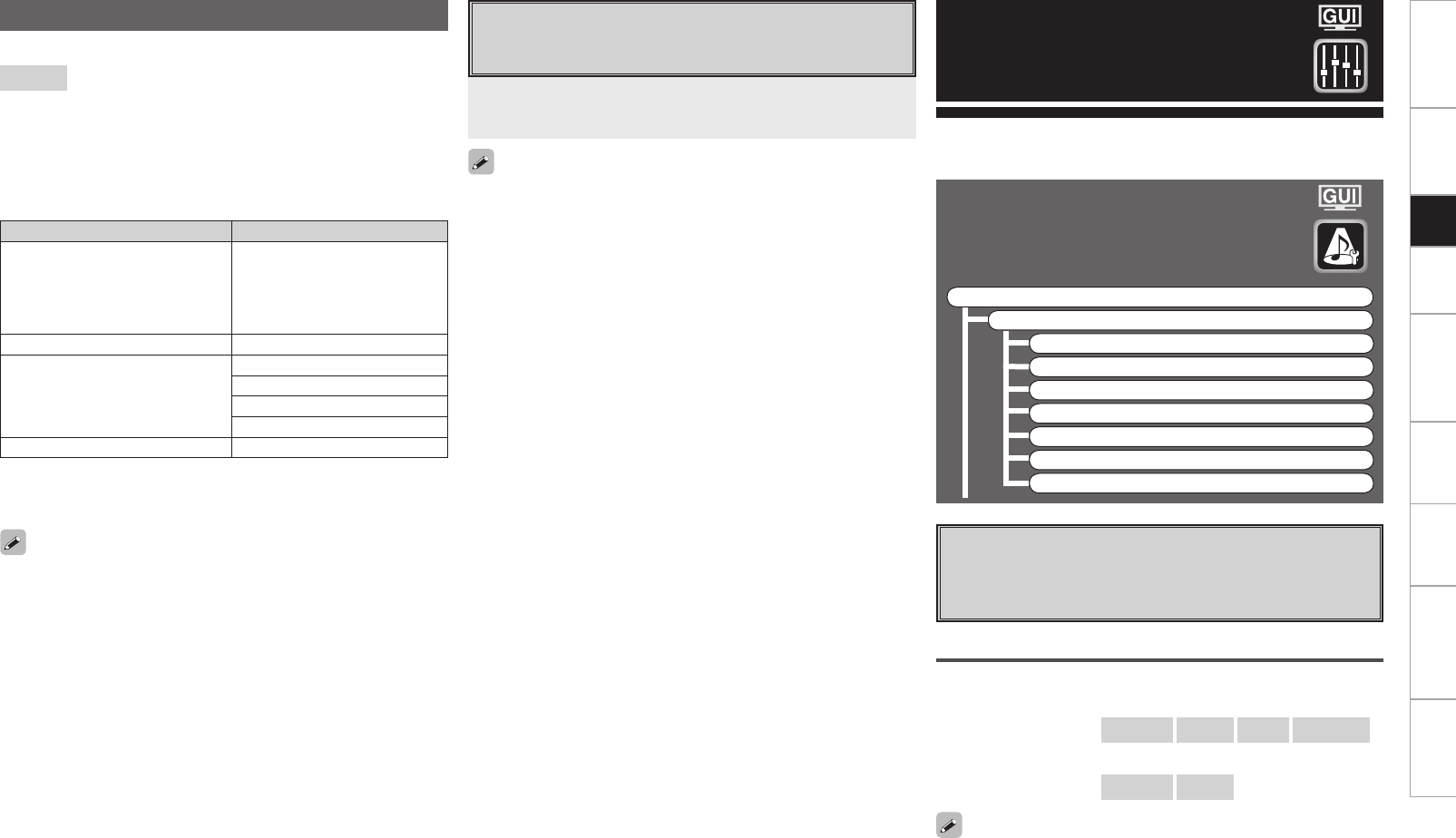
Getting Started Connections Playback Remote Control Multi-Zone Information Troubleshooting Specifications
For details, see page 96.
• To cancel, press the PURE DIRECT button on the main unit or the
PURE button on the main remote control unit.
• When in the PURE DIRECT mode, the GUI screen is not displayed
and the display on the main unit is turned off.
• If the HDMI input connector is selected, video outputs are output in
the PURE DIRECT mode.
• The channel level and surround parameters in the PURE DIRECT
mode are the same as in the DIRECT mode.
Press the PURE DIRECT button on the main unit or the
PURE button on the main remote control unit.
Parameter
Audio
Adjust various audio parameters.
F Menu tree F
Parameter
Audio
a Surround Parameters
s Tone
d Room EQ
f Dynamic EQ
g RESTORER
h Night Mode
j Audio Delay
Parameters can be called out directly by pressing the PARA button on
the main remote control unit.
a Surround Parameters
Adjust surround sound parameters.
The adjustable parameters differ for the different surround modes
(vpage 93, 94).
Mode
Select the mode according to the playback source.
n In the PLgx or PLg mode
[Selectable items] Cinema Music Game Pro Logic
n In the DTS NEO:6 mode
[Selectable items] Cinema Music
The “Music” mode is also effective for movie sources including a lot
of stereo music.
Playback in the PURE DIRECT Mode
This is the mode that recreates the original sound most faithfully,
providing extremely high quality sound.
Input signal Display
Analog signal /
PCM (2ch) /
Dolby Digital source /
DTS source /
Other 2-channel digital signals
DIRECT
DSD (2ch) DSD DIRECT (z)
PCM (multi ch)
MULTI CH DIRECT
M DIRECT + PLgx CINEMA
M DIRECT + PLgx MUSIC
M DIRECT 7.1
DSD (multi ch) DSD MULTI DIRECT (z)
[Selectable items]
DIRECT :
In this mode the signals bypass the tone control circuitry for high
quality sound.
The display when the DIRECT mode is selected depends on the input
signal.
For multi-channel sources, the display depends on the surround back
output’s play mode.
z: When DSD signals are converted to PCM signals as set by the
audio parameters and speaker settings, “DIRECT” or “MULTI CH
DIRECT” is displayed.
Direct Playback
Setup
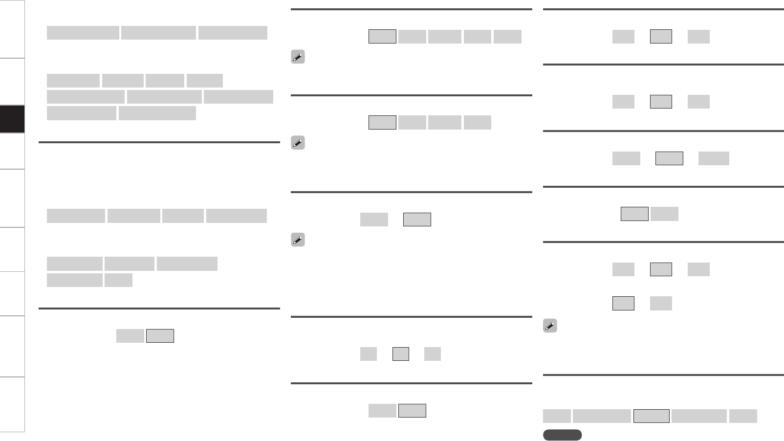
Getting Started Connections Playback Remote Control Multi-Zone Information Troubleshooting Specifications
DRC
Compress dynamic range (difference between loud and soft sounds).
[Selectable items] Auto Low Middle High OFF
This can be set in the Dolby TrueHD mode.
D.COMP
Compress dynamic range (difference between loud and soft sounds).
[Selectable items] OFF Low Middle High
When playing DTS sources, this is only displayed for compatible
software.
LFE
Adjust the low-frequency effects level (LFE).
[Variable range] –10dB ~ 0dB
Center Image
Assign center channel signal to front left and right channels for wider
sound.
[Variable range] 0.0 ~ 0.3 ~ 1.0
Panorama
Assign front L/R signal also to surround channels, for wider sound.
[Selectable items] ON OFF
For proper playback of the different program sources, we recommend
setting to the values below.
• Dolby Digital sources: “0 dB”
• DTS movie sources: “0 dB”
• DTS music sources: “–10 dB”
Delay Time
Adjust delay time to control sound stage size.
[Variable range] 0 ms ~ 30 ms ~ 300 ms
Effect
Switch effect signal for multi-surround speakers on and off.
[Selectable items] ON OFF
Effect Level
Adjust effect signal level.
[Variable range] 1 ~ 10 ~ 15
b Only when the surround mode is “MONO”.
[Variable range] 0 ~ 15
Room Size
Determine size of acoustic environment.
[Selectable items]
Small Medium small Medium Medium large Large
Set to a lower level if the positioning and sense of phase of the
surround signals seems unnatural.
NOTE
“Room Size” does not indicate the size of the room in which sources
are played.
Dimension
Shift sound image center to front or rear, to adjust playback balance.
[Variable range] 0 ~ 3 ~ 6
Center Width
Assign center channel signal to front left and right channels for wider
sound.
[Variable range] 0 ~ 3 ~ 7
Cinema EQ
Soften the treble range of movie soundtracks for better understanding.
[Selectable items] ON OFF
n In the THX mode (for 2-channel sources)
[Selectable items]
Surround Back ON Surround Back OFF THX Games Mode
n In the THX mode (for Multi-channel sources)
[Selectable items]
THX Surr. EX ES DSCRT ES MTRX 7.1+THX
PLIIx Cinema + THX THX Ultra2 Cinema THX Music Mode
THX Games Mode Surround Back OFF
Decoder
Select this when playing analog, PCM or other 2 channel sources.
The signals are converted into multichannel signals using the decoders
shown below and played in the Dolby Headphone mode.
n In the THX mode (for 2-channel sources)
[Selectable items]
PLIIx CINEMA PLII CINEMA Pro Logic NEO:6 CINEMA
n In the DOLBY HEADPHONE mode
[Selectable items]
PLII CINEMA PLII MUSIC NEO:6 CINEMA
NEO:6 MUSIC OFF
Setup
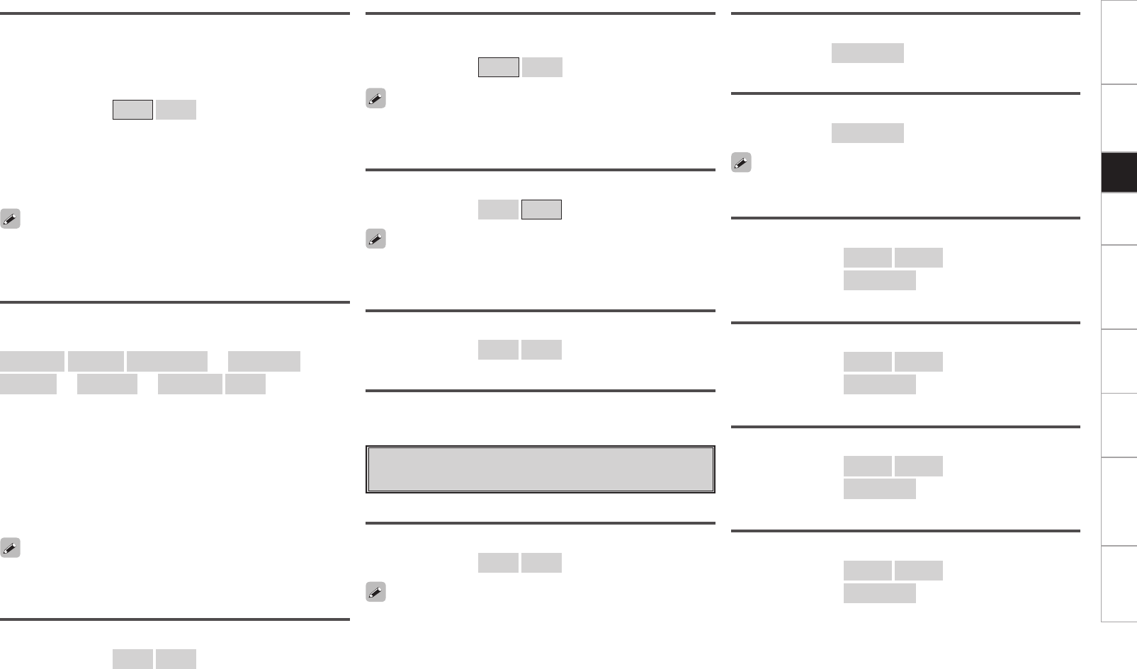
Getting Started Connections Playback Remote Control Multi-Zone Information Troubleshooting Specifications
Subwoofer Att.
Attenuate subwoofer level when using EXT. IN input.
[Selectable items] ON OFF
Set this to “ON” if the subwoofer channel level seems too high when
playing Super Audio CD.
Subwoofer
Turn subwoofer output on and off.
[Selectable items] ON OFF
Default
Resets the settings to the default values.
Tone Defeat
Turn tone adjustments off.
[Selectable items] ON OFF
The tone cannot be adjusted when in the DIRECT, PURE DIRECT and
HOME THX CINEMA mode.
Bass
Adjust bass for all channels together.
[Variable range] –6dB ~ +6dB
Treble
Adjust treble for all channels together.
[Variable range] –6dB ~ +6dB
“Bass” and “Treble” can be set when “Tone Defeat” is set to “OFF”.
s Tone
Adjust the tonal quality of the sound.
Front
Adjust each front channel tone.
[Selectable items] Bass Treble
[Variable range] –6dB ~ +6dB
Center
Adjust each center channel tone.
[Selectable items] Bass Treble
[Variable range] –6dB ~ +6dB
Surround
Adjust each surround channel tone.
[Selectable items] Bass Treble
[Variable range] –6dB ~ +6dB
Surround Back
Adjust each surround back channel tone.
[Selectable items] Bass Treble
[Variable range] –6dB ~ +6dB
AFDM
Auto-select surround mode by source.
This function only works for software containing a special identification
signal.
If the software being played is recorded in Dolby Digital EX or DTS-ES,
it is played in 6.1-channels. If not, it is played in 5.1-channels.
[Selectable items] ON OFF
Example : Playing Dolby Digital software (with EX flag)
• When “AFDM” is set to “ON”, the surround mode is automatically
set to the DOLBY D + PLgx C mode.
• To play in the DOLBY DIGITAL EX mode, set “AFDM” to “OFF” and
“SB CH Out” to “MTRX ON”.
Some Dolby Digital EX sources do not include EX flags. If the playback
mode does not switch automatically even when “AFDM” is set to
“ON”, set “SB CH Out” to “MTRX ON” or “PLgx CINEMA”.
SB CH Out (for Multi-channel sources)
Select playback mode for surround back channels.
[Selectable items]
NON MTRX MTRX ON PL
II
x CINEMA z1
PL
II
x MUSIC z2
ES MTRX z3
ES DSCRT z4 DSCRT ON OFF
z1: This can be selected when “Surround Back” is set to “2spkrs”
at the GUI menu “Manual Setup” – “Speaker Setup” – “Speaker
Configuration” setting (vpage 29).
z2: This can be selected when “Surround Back” is set to “2spkrs”
or “1spkr” at the GUI menu “Manual Setup” – “Speaker Setup”
– “Speaker Configuration” setting.
z3: This can be selected when playing DTS sources.
z4: This can be selected when playing DTS sources including a
discrete 6.1-channel signal identification signal.
SB CH Out (for 2-channel sources)
Determine whether to use surround back speakers.
[Selectable items] ON OFF
Input Channel
Select channel using external input connectors (EXT. IN) for source
being played.
[Selectable items] 8CH 2CH
Can be selected when GUI menu “Manual Setup” – “Audio Setup”–
“EXT. IN Setup”– “Mode” is set to “DSP” (vpage 33).
When using the surround back speaker, you can change the “SB
CH Out” setting by pressing the STANDARD button.
Setup
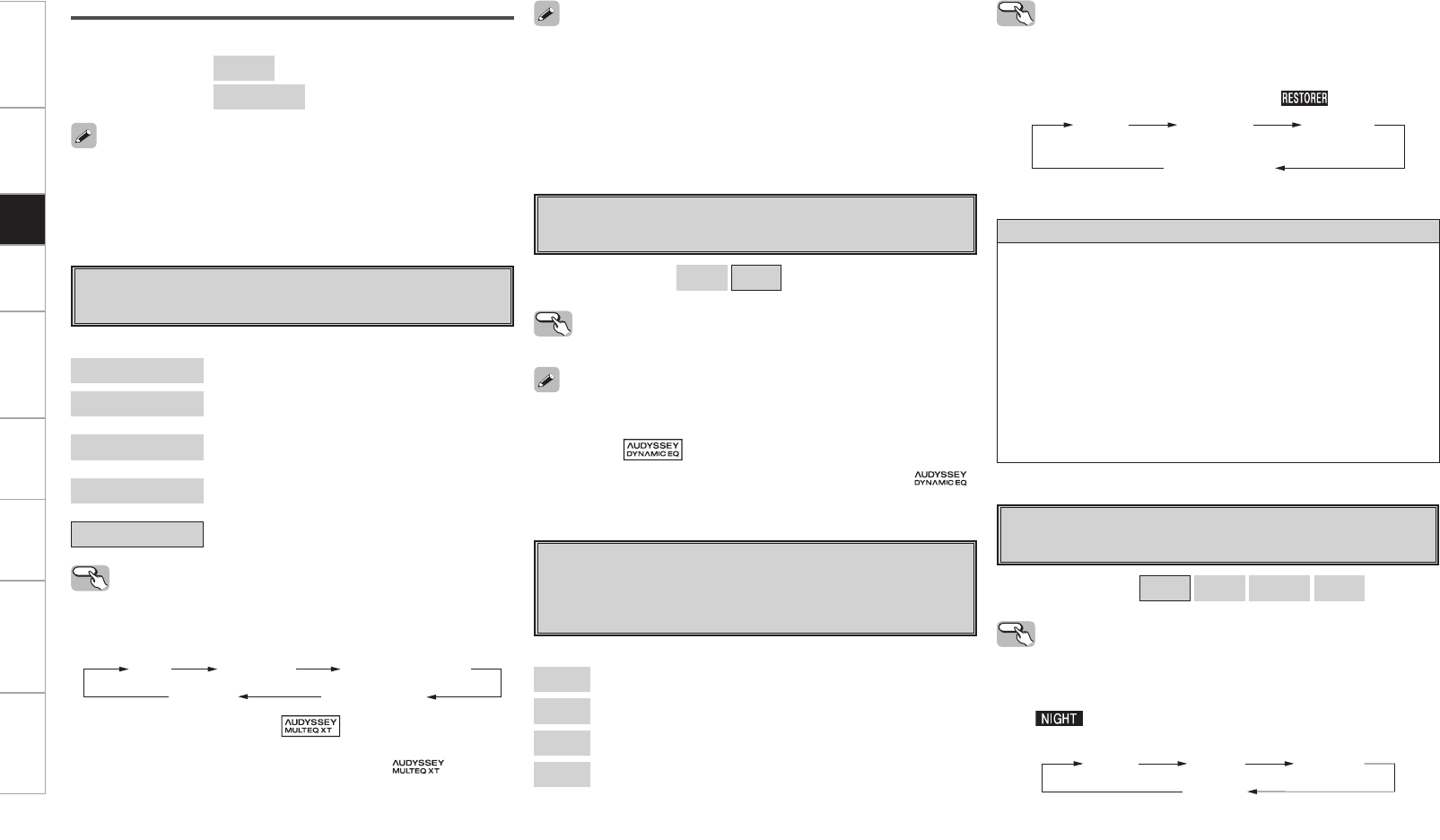
Getting Started Connections Playback Remote Control Multi-Zone Information Troubleshooting Specifications
About the RESTORER function
• Such compressed audio formats as MP3, WMA (Windows Media
Audio) and MPEG-4 AAC reduce the amount of data by eliminating
signal components that are hard for the human ear to hear. The
RESTORER function generates the signals eliminated upon
compression, restoring the sound to conditions near those of the
original sound before compression. It also corrects the sense of
volume of the bass to obtain richer sound with compressed audio
signals.
• This is displayed on the GUI menu and can be set when the input
source is set to “XM”, “HD Radio” or “NET/USB”, or when analog
signals (including AM/FM signals) or PCM signals (fs = 44.1/48
kHz) are input.
[Selectable items]
OFF
Mode1 (RESTORER 64)
Mode2 (RESTORER 96)
Mode3 (RESTORER HQ)
The default setting for “NET/USB” and “iPod” is “Mode3”. All others
are set to “OFF”.
g RESTORER
This function restores compressed audio signals to how they
were before compression and corrects the sense of volume of
the bass and treble to obtain richer playback sound.
Operating from the main unit or main remote
control unit
During playback, press the RESTORER button on the main unit or the
RSTR button on the main remote control unit.
When set to something other than “OFF”, “ ” is displayed.
Mode 1
(RESTORER 64)
Mode 2
(RESTORER 96)
Mode 3
(RESTORER HQ)
OFF
d Room EQ
Select room equalizer for current environment.
[Selectable items]
Audyssey : Optimize frequency response of all speakers.
Audyssey Byp. L/R : Optimize frequency response of speakers
except front L and R speakers.
Audyssey Flat : Optimize frequency response of all speakers to
flat response.
Manual : Apply frequency response set with “Manual
EQ” (vpage 34).
OFF : Turn equalizer off.
Operating from the main unit or main remote
control unit
Press the ROOM EQ button on the main unit or the EQ button on the
main remote control.
Audyssey Audyssey Byp. L/R
Audyssey Flat
Manual
OFF
When “Audyssey” is selected, “ ” lights.
When “Audyssey Byp. L/R” or “Audyssey Flat” is selected, or when
the auto setup measuring results have changed, “ ” lights.
• “Audyssey”, “Audyssey Byp. L/R” and “Audyssey Flat” can be
selected after the auto setup procedure has been performed.
• If the settings of the speakers for which “None” has been determined
at “Auto Setup” are changed, “Audyssey”, “Audyssey Byp. L/R”
and “Audyssey Flat” cannot be selected and measurements have to
be taken again to include the newly-added speakers.
• When using headphones, “Room EQ” is always set to “OFF”.
Audyssey
OFF
Manual
Audyssey Byp. L/R
Audyssey Flat
[Selectable items] ON
OFF
• “Dynamic EQ” is displayed when selecting “Audyssey”, “Audyssey
Flat” or “Audyssey Byp.L/R” in the “Room EQ” setup. When set to
“ON”, the “ ” indicator is lit.
• When the audio setup measuring results have changed, “ “
lights.
f Dynamic EQ
Make Dynamic EQ settings.
Operating from the main unit
Press the DYNAMIC EQ button.
h Night Mode
Optimized setting for late-night listening.
[Selectable items] OFF Low Middle High
Operating from the main unit or main remote
control unit
Press the NIGHT button on the main unit or the NGT button on the
main remote control unit.
The “ ” indicator lights when “Low”, “Middle” or “High” is
selected.
OFF Low Middle
High
Subwoofer
Adjust each subwoofer channel tone.
[Selectable items] Bass
[Variable range] –6dB ~ +6dB
• This can be set individually for the separate surround mode other
than PURE DIRECT, DIRECT and Home THX Cinema mode.
• When “Dynamic EQ” is set to “ON”, you cannot use the “Tone”
setting (vpage 94).
Setup
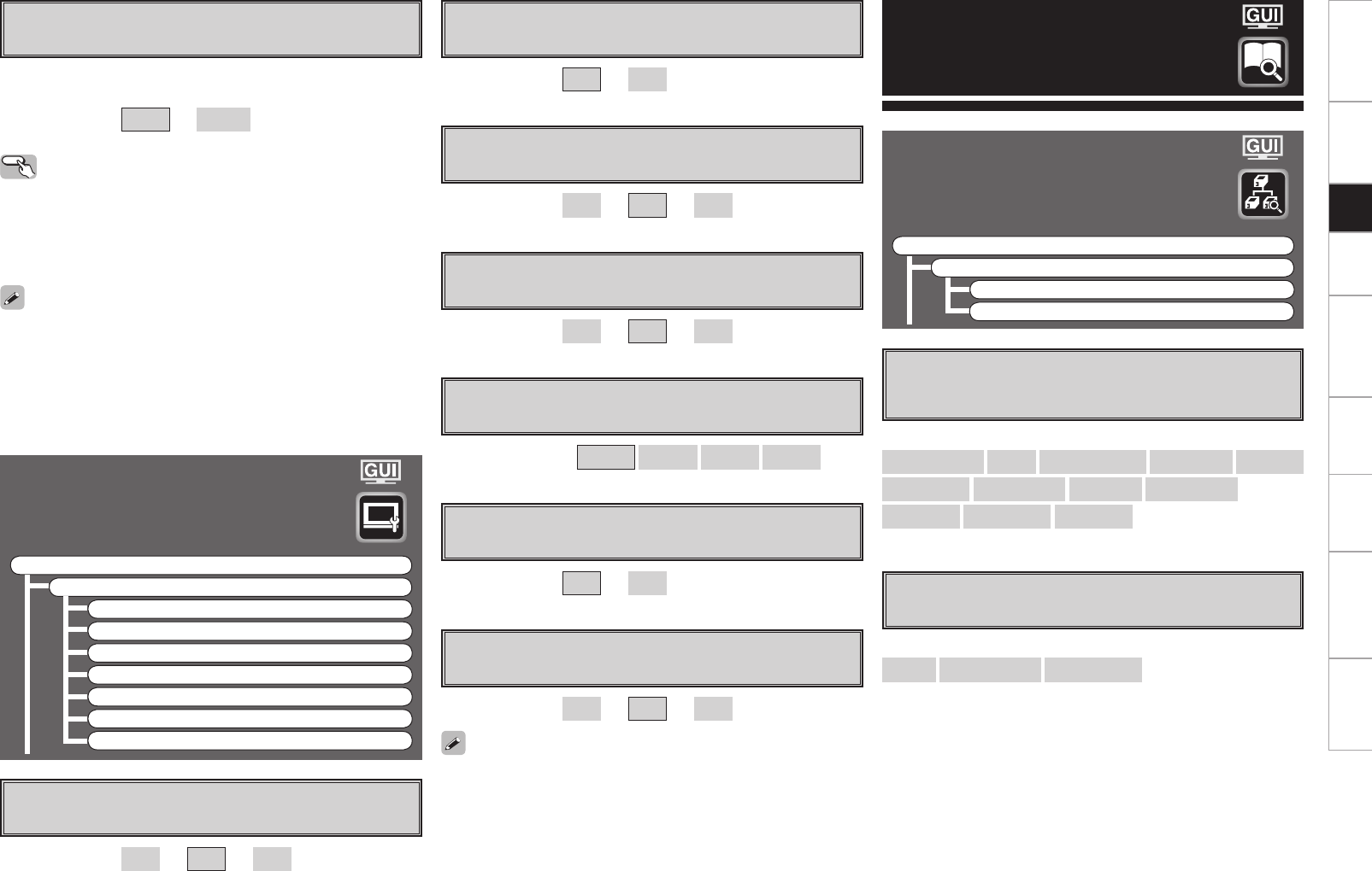
Getting Started Connections Playback Remote Control Multi-Zone Information Troubleshooting Specifications
Information
a MAIN ZONE
Shows information about settings for MAIN ZONE.
The items displayed differ according to the input source.
s ZONE2/3/4
Shows information about settings for multi-zone.
[Items to be checked]
Select Source Name Surround Mode Input Mode Room EQ
Dynamic EQ Video Select i/p Scaler Source Level
Rec Select Night Mode RESTORER etc.
[Items to be checked]
Power Select Source Volume Level
• When the input signal is 1080p the “Picture Adjust” setting will be
ineffective.
• Adjusting the “Contrast”, “Brightness”, “Chroma Level” and “Hue”
settings does not affect the HDMI input signal.
• “Hue” can be adjusted for composite video and S-Video signals.
• The adjustment values are stored for the individual input sources.
• “DNR”, “Enhancer”, and “Sharpness” are each effective with HDMI
output. However, they are ineffective with 480i/576i output.
f Hue
Adjust color hue.
[Variable range] –6 ~ 0 ~ +6
g DNR
Reduces the overall level of noise on the picture.
[Selectable items] OFF Low Middle High
h Enhancer
Emphasize picture contours.
[Variable range] 0 ~ +12
j Sharpness
Adjust color definition.
[Variable range] –6 ~ 0 ~ +6
Picture Adjust
Adjust the picture quality.
F Menu tree F
Parameter
Picture Adjust
a Contrast
s Brightness
d Chroma Level
f Hue
g DNR
h Enhancer
j Sharpness
[Variable range] –6 ~ 0 ~ +6
a Contrast
Adjust picture contrast.
s Brightness
Adjust picture brightness.
d Chroma Level
Adjust picture chroma level (saturation).
[Variable range] 0 ~ +12
[Variable range] –6 ~ 0 ~ +6
j Audio Delay
Compensate for mismatched timing between video and audio.
Delay audio.
This sets the delay time for audio signals.
[Variable range] 0 ms ~ 200 ms
• This cannot be adjusted when playing in the EXT. IN (when in analog
mode), DIRECT or STEREO mode (with “Crossover Frequency” set
to “FIXED–THX–”, “Front” set to “Large”, “Tone Defeat” to “ON”
and “Room EQ” to “OFF”).
• The adjustment range is 0 to 100 ms when the Auto Lipsync
Correction function is activated.
Operating from the main unit or the main
remote control unit
b The GUI menu is not displayed when carrying out this setting.
q Press the AUDIO DELAY button on the main unit or A. DL button on
the main remote control unit.
w Use the o p button to set.
Status
Shows information about current settings.
F Menu tree F
Information
Status
a MAIN ZONE
s ZONE2/3/4
Setup
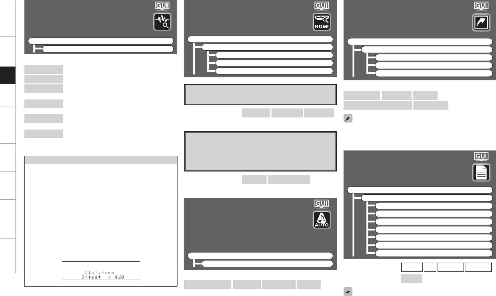
Getting Started Connections Playback Remote Control Multi-Zone Information Troubleshooting Specifications
Auto Surround Mode
Shows information about auto surround mode
settings.
The surround mode for which the last memory
function was used for the different input signal
types is displayed.
F Menu tree F
Information
Auto Surround Mode
Quick Select
Shows information about “Quick Select” settings.
F Menu tree F
Information
Quick Select
Quick Select 1
Quick Select 2
Quick Select 3
HDMI Information
Shows information about HDMI input/output
signals and monitor.
F Menu tree F
Information
HDMI Information
a Signal Information
s Monitor1
d Monitor2
Audio Input Signal
Shows information about audio input signals.
F Menu tree F
Information
Audio Input Signal
Preset Station
Shows information about preset stations.
F Menu tree F
Information
Preset Station
A
B
C
D
E
F
G
[Items to be checked]
Select Source Input Mode Room EQ
Auto Surround Mode setting Volume Level
[Input source] TUNER XM HD Radio NET/USB
[Items to be checked] A1 ~ G8
For instructions on storing settings at Quick Select 1 to 3, see page
75.
When the STATUS button on the main unit is pressed, the set’s status
can be checked on the display.
[Items to be checked]
Analog/PCM 2ch Digital 2ch Digital 5.1ch Multi ch
a Signal Information
The HDMI input/output signal information is displayed.
s Monitor1
The HDMI monitor 1 information is displayed.
d Monitor2
The HDMI monitor 2 information is displayed.
[Items to be checked] Resolution Color Space Pixel Depth
[Items to be checked] Interface Supported resol.
[Items to be checked]
Surround Mode : The currently set surround mode is displayed.
Signal : The input signal type is displayed.
fs : The input signal’s sampling frequency is
displayed.
Format : The number of channels in the input signal (front,
surround, LFE) is displayed.
Offset : The dialogue normalization correction value is
displayed.
Flag : “MATRIX” is displayed if the input signal has
undergone matrix processing, “DISCRETE” if the
input signal has undergone discrete processing.
Dialogue normalization function
Dialogue Normalization (Dial Norm) is a feature of Dolby Digital,
which is used to keep the programs at the same average listening
level so the user does not have to change the volume control
between Dolby Digital programs. When playing back software
which has been encoded in Dolby Digital, sometimes you may see
a brief message in the front panel display which will read “Dial.
Norm X dB” (X being a numeric value). The display is showing how
the program level relates with THX calibration level. If you want to
play the program at calibrated theatrical levels, you may wish to
adjust the volume. For example, if you see the following message:
“Dial. Norm + 4 dB” in the front panel display, to keep the overall
output level at THX calibrated loudness, just turn down the volume
control by 4 dB. However, unlike a movie theater where the playback
loudness is preset, you can choose your preferred volume setting
for best enjoyment.
Setup
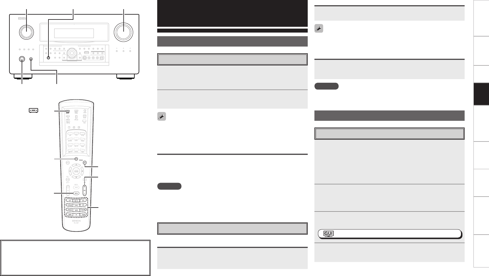
Getting Started Connections Setup Remote Control Multi-Zone Information Troubleshooting Specifications
<ON/STANDBY> <POWER>
<PHONES>
SOURCE SELECT MASTER VOLUME
SOURCE
SELECT
[POWER ON]
[MUTE]
[POWER OFF]
MASTER
VOLUME
[ AMP]
Playback
Playing Video and Audio Equipment
1Prepare the equipment.
q Load the DVD, CD or other software in the player.
(vSee the operating instructions of the respective devices.)
w To play a video device, switch the monitor input.
(vSee the monitor’s operating instructions.)
2To operate using the main remote control unit, set the
remote control unit to the AMP mode.
(vpage 77 “Remote Control Unit Operations”)
3Use SOURCE SELECT to select the input source.
: “Source Select” (vpage 45)
4Start playback.
(vSee the operating instructions of the respective devices.)
About the button names in these explanations
< > : Buttons on the main unit
[ ] : Buttons on the remote control unit
Button name only:
Buttons on the main unit and remote control unit
Preparations
1Press <POWER>.
The power indicator lights red and the power is set to the
standby mode.
2Press <ON/STANDBY> or [POWER ON].
The power indicator flashes green and the power turns on.
To operate the AVP-A1HDCI using the main remote control unit, set
the remote control unit to the AMP mode (vpage 77 “Remote
Control Unit Operations”).
Turning the Power Off
q Press <ON/STANDBY> or [POWER OFF].
The power is set to the standby mode.
w Press <POWER>.
The power indicator turns off, and so does the power.
NOTE
Power continues to be supplied to some of the circuitry even when the
power is in the standby mode. When leaving home for long periods of
time or when traveling, either press <POWER> to turn off the power,
or unplug the power cord from the power outlet.
Turning the Power On
Either turn <MASTER VOLUME> or press [MASTER
VOLUME].
Press [MUTE].
To cancel, press [MUTE] again. Muting can also be canceled by adjusting
the master volume.
Plug the headphones into <PHONES>.
The sound from the pre-out connectors is automatically cut.
NOTE
Be careful not to set the volume too high when using headphones.
Operations During Playback
Adjusting the Master Volume
Turning Off the Sound Temporarily (Muting)
Listening with Headphones
Basic Operation
Playback
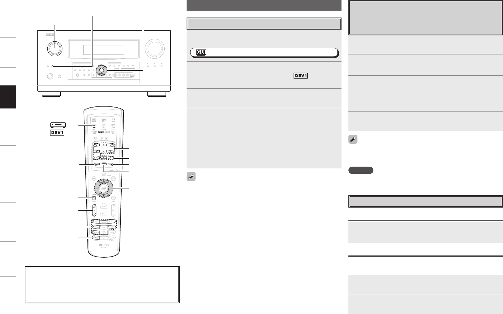
Getting Started Connections Setup Remote Control Multi-Zone Information Troubleshooting Specifications
Presetting Radio Stations
(Preset Memory)
Your favorite broadcast stations can be preset so that you can
tune them in easily. Up to 56 stations can be preset.
1Tune in the broadcast station you want to preset.
2Press [MEMO].
3Press [A ~ G] to select the block in which the station is
to be preset, then press [CHANNEL] or [1 ~ 8] to select
the preset number.
b The memory block can also be selected by pressing [SHIFT].
4Press [MEMO] again to complete the setting.
• To preset other stations, repeat steps 1 to 4.
• Stations can be preset automatically at GUI menu “Source Select”
– “TUNER” – “Auto Preset” (vpage 46).
NOTE
Preset stations are erased by overwriting them.
1Either turn <SOURCE SELECT> or press [TUNER]
(AMP mode) to select “TUNER”.
: ”Source Select” (vpage 45)
2To operate using the main remote control unit, set the
remote control unit to the TUNER ( ) mode.
(vpage 77 “Remote Control Unit Operations”)
3Press [BAND] to select “FM” or “AM”.
4Tune in the desired broadcast station.
q To tune in automatically (Auto Tuning)
Press [MODE] to light the “AUTO” indicator on the display, then
use [d f] to select the station you want to hear.
w To tune in manually (Manual Tuning)
Press [MODE] to turn off the display’s “AUTO” indicator, then use
[d f] to select the station you want to hear.
Listening to FM/AM Broadcasts
• It is also possible to switch to “FM” or “AM” in step 1 by pressing
[TUNER].
• If the desired station cannot be tuned in with auto tuning, tune it in
manually.
• When tuning in stations manually, press and hold [d f] to change
frequencies continuously.
• The time for which the GUI menus are displayed can be set at
GUI menu “Manual Setup” – “Option Setup” – “GUI” – “Tuner”
(vpage 42).
Basic Operation
<SOURCE SELECT>
<TUNING PRESET>
ui
[SEARCH]
[CHANNEL]
[TUNER],
(AMP mode)
[SHIFT]
ui
[ TU]
[d f]
[A ~ G]
[1 ~ 8]
[MEMO]
[MODE]
[BAND]
About the button names in these explanations
< > : Buttons on the main unit
[ ] : Buttons on the remote control unit
Button name only:
Buttons on the main unit and remote control unit
( mode)
Press <TUNING PRESET>, then turn <SOURCE SELECT>
to select the preset radio station.
Listening to Preset Stations
Operation on the Main Unit
Operation on the Main Remote Control Unit
n Recalling preset stations from the remote control
unit
1Press [A ~ G] to select the memory block.
2Press [CHANNEL] or [1 ~ 8] to select the desired preset
channel.
Playback
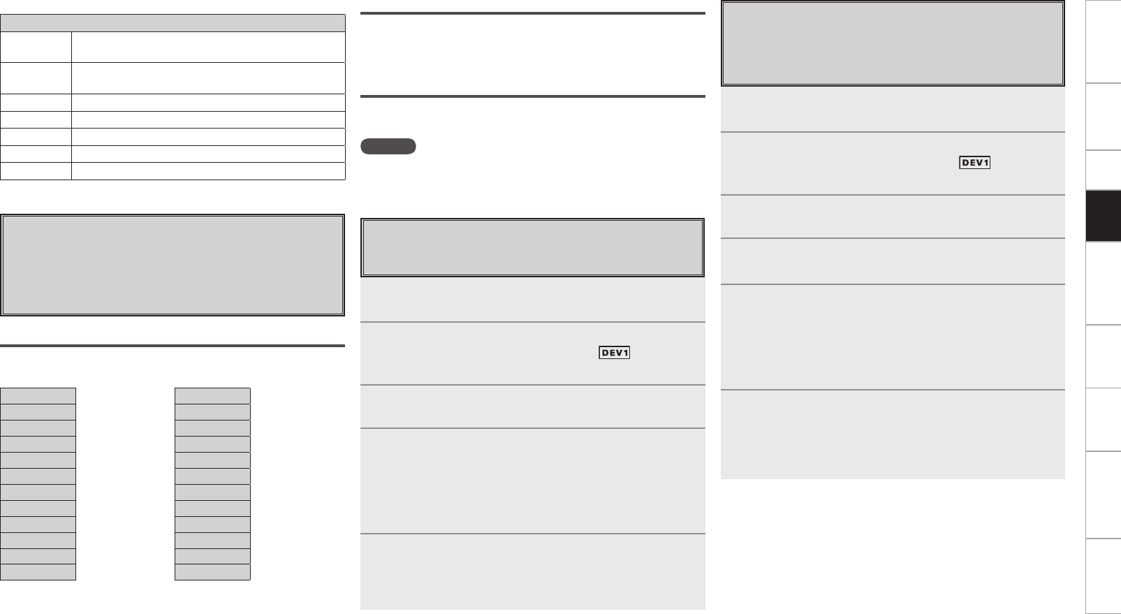
0
Getting Started Connections Setup Remote Control Multi-Zone Information Troubleshooting Specifications
Program Type (PTY)
PTY identifies the type of RDS program.
The program types and their displays are as follows:
NEWS News
INFOM Information
SPORTS Sports
TALK Talk
ROCK Rock
CLS ROCK Classic rock
ADLT HIT Adult hits
SOFT RCK Soft rock
TOP 40 Top 40
COUNTRY Country
OLDIES Oldies
SOFT Soft
NOSTALGA Nostalgia
JAZZ Jazz
CLASSICL Classical
R & B R & B
SOFT R&B Soft R&B
LANGUAGE Language
REL MUSC Religious music
REL TALK Religious talk
PERSNLTY Personality
PUBLIC Public
COLLEGE College
WEATHER Weather
Traffic Program (TP)
TP identifies programs that carry traffic announcements.
This allows you to easily find out the latest traffic conditions in your
area before leaving home.
RDS (Radio Data System)
RDS (works only on the FM band) is a broadcasting service which
allows a station to send additional information along with the
regular radio program signal.
The following three types of RDS information can be received
with this unit:
Radio Text (RT)
RT allows RDS stations to send text messages that appear on the
display.
NOTE
The operations described below using [SEARCH] will not function in
areas in which there are no RDS broadcasts.
1Either turn <SOURCE SELECT> or press [TUNER]
(AMP mode) to select “TUNER”.
2To operate using the main remote control unit, set the
remote control unit to the TUNER ( ) mode.
(vpage 77 “Remote Control Unit Operations”)
3Press [SEARCH] to select “RDS”.
4Press [CHANNEL].
The search for RDS stations begins automatically.
b If no RDS stations are found with the above operation, all the
reception bands are searched.
b When a broadcast station is found, that station’s name appears on
the display.
5To continue searching, repeat steps 2 to 3.
b If no RDS station is found when all the frequencies have been
searched, “NO RDS” is displayed.
RDS Search
Use this function to automatically tune to FM stations that provide
the RDS service.
n Default settings
Auto tuner presets
A1 ~ A8 87.5 / 89.1 / 98.1 / 107.9 / 90.1 / 90.1 / 90.1 /
90.1 MHz
B1 ~ B8 520 / 600 / 1000 / 1400 / 1500 / 1710 kHz,
90.1 / 90.1 MHz
C1 ~ C8 90.1 MHz
D1 ~ D8 90.1 MHz
E1 ~ E8 90.1 MHz
F1 ~ F8 90.1 MHz
G1 ~ G8 90.1 MHz
1Either turn <SOURCE SELECT> or press [TUNER]
(AMP mode) to select “TUNER”.
2To operate using the main remote control unit, set the
remote control unit to the TUNER ( ) mode.
(vpage 77 “Remote Control Unit Operations”)
3Press [SEARCH] to select “PTY”.
4Watching the display, press ui to call out the
desired program type.
5Press [CHANNEL].
PTY search begins automatically.
b If there is no station broadcasting the designated program type
with the above operation, all the reception bands are searched.
b The station name is displayed on the display after searching
stops.
6To continue searching, repeat steps 2 to 4.
b If no station broadcasting the designated program type is found
when all the frequencies have been searched, “NO PROGRAMME”
is displayed.
PTY Search
Use this function to find RDS stations broadcasting a designated
program type (PTY).
For a description of each program type, refer to “Program Type
(PTY)”.
Playback
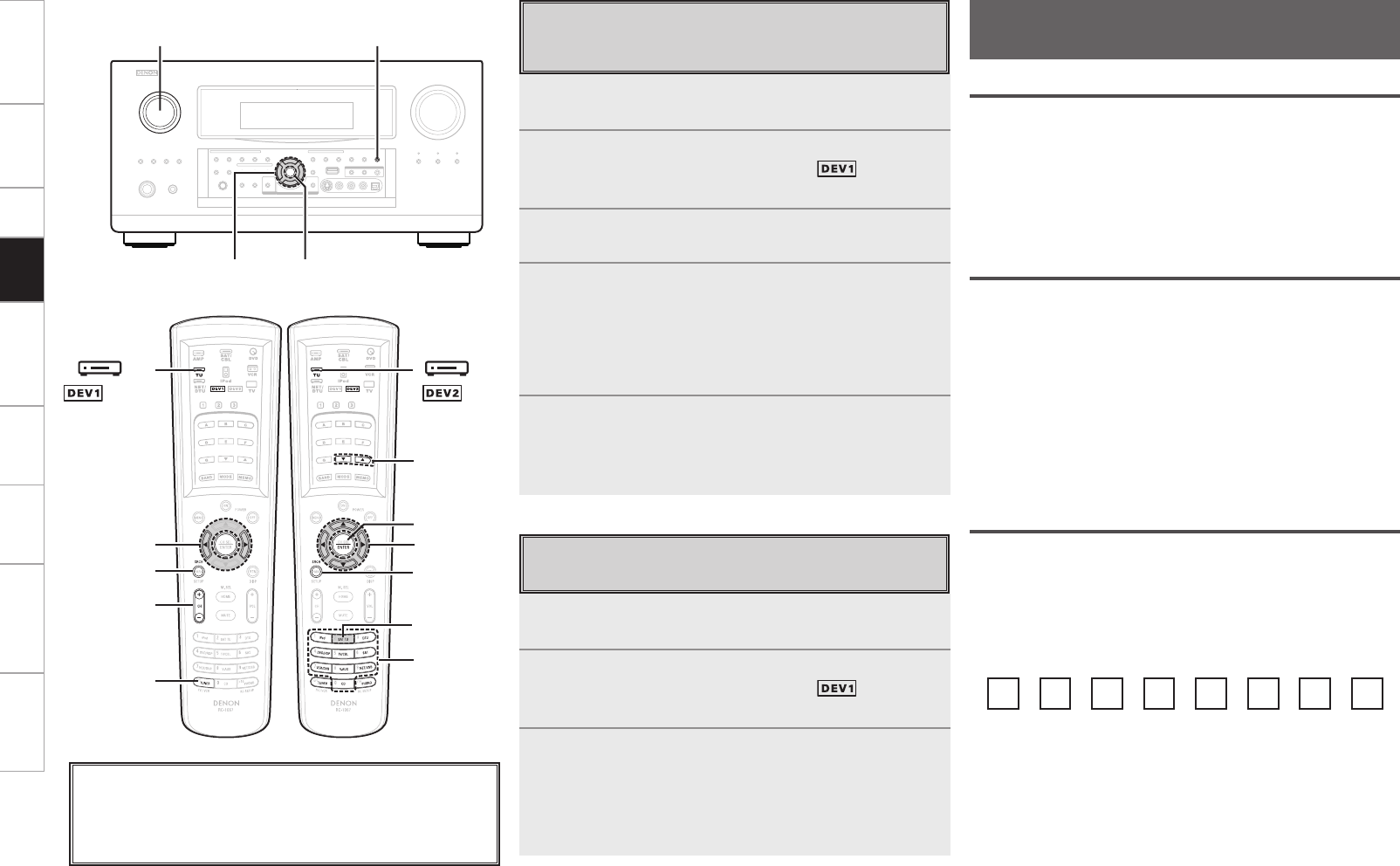
Getting Started Connections Setup Remote Control Multi-Zone Information Troubleshooting Specifications
[SEARCH]
[NUMBER]
[d f]
uiop
ENTER
[SAT TU]
(AMP mode)
[ TU]
[SEARCH]
[CHANNEL]
[TUNER]
op
[ TU]
1Either turn <SOURCE SELECT> or press [TUNER]
(AMP mode) to select “TUNER”.
2To operate using the main remote control unit, set the
remote control unit to the TUNER ( ) mode.
(vpage 77 “Remote Control Unit Operations”)
3Press [SEARCH] to select “TP”.
4Press [CHANNEL].
TP search begins automatically.
b If no TP station is found with the above operation, all the reception
bands are searched.
b The station name is displayed on the display after searching
stops.
5To continue searching, repeat steps 2 to 3.
b If no other TP station is found when all the frequencies have been
searched, “NO PROGRAMME” is displayed.
TP Search
Use this function to find RDS stations broadcasting traffic
programs (TP stations).
<SOURCE SELECT> <STATUS>
ENTER
uio p
About the button names in these explanations
< > : Buttons on the main unit
[ ] : Buttons on the remote control unit
Button name only:
Buttons on the main unit and remote control unit
( mode)
(AMP mode) 1Either turn <SOURCE SELECT> or press [TUNER]
(AMP mode) to select “TUNER”.
2To operate using the main remote control unit, set the
remote control unit to the TUNER ( ) mode.
(vpage 77 “Remote Control Unit Operations”)
3Press [SEARCH] to select “RT”.
b While receiving an RDS broadcast station, the text data broadcast
from the station is displayed.
b To turn the display off, press o p.
b If no text data is being broadcast, “NO TEXT DATA” is displayed.
RT (Radio Text)
“RT” appears on the display when radio text data is received.
Listening to XM Satellite Radio
Programs
( mode)
About XM Radio
XM is North America’s number one satellite radio company, offering
an extraordinary variety of commercial-free music, plus the best in
premier sports, news, talk radio, comedy, children’s and entertainment
programming, broadcast in superior digital audio quality coast to coast.
For more information, or to subscribe, U.S. customers visit xmradio.
com or call XM Listener Care at 1-800- XMRADIO (1-800-967-2346);
Canadian customers visit xmradio.ca or call XM Listener Care at 1-877-
GETXMSR (1-877-438-9677).
XM Ready® Legal
XM monthly service subscription sold separately. XM Mini-Tuner and
Home Dock required (each sold separately) to receive XM service.
It is prohibited to copy, decompile, disassemble, reverse engineer,
hack, manipulate or otherwise make available any technology or
software incorporated in receivers compatible with the XM satellite
Radio System. Installation costs and other fees and taxes, including a
one-time activation fee may apply. All fees and programming subject
to change. Channels with frequent explicit language are indicated with
an XL. Channel blocking is available for XM radio receivers by calling
1-800-XMRADIO (U.S. residents) and 1-877-GETXMSR (Canadian
residents). XM Service only available in the 48 contiguous United
States and Canada. ©2008 XM Satellite Radio Inc. All rights reserved.
XM Ready® Subscription
Once you have installed the XM Mini-Tuner Home Dock, inserted the
XM Mini-Tuner, connected the XM Mini-Tuner Home Dock to your
XM Ready® audio system, and installed the antenna, you are ready
to subscribe and begin receiving XM programming. There are three
places to find your eight character XM Radio ID: On the XM Mini-
Tuner, on the XM Mini-Tuner package, and on XM Channel 0. Record
the Radio ID below for reference.
Note:
The XM Radio ID does not use the letters “I”, “O”, “S” or
“F”.
Activate your XM Satellite Radio service in the U.S. online at
http://activate.xmradio.com or call 1-800-XMRADIO (1-800-967-
2346). Activate your XM Satellite Radio service in Canada online at
https://activate.xmradio.ca or call 1-877-GET-XMSR (1-877-438- 9677).
You will need a major credit card. XM will send a signal from the
satellites to activate the full channel lineup. Activation normally takes
10-15 minutes, but during peak busy periods you may need to keep
your XM Ready audio system on for up to an hour. When you can
access the full lineup on your XM Ready audio system you are done.
Playback
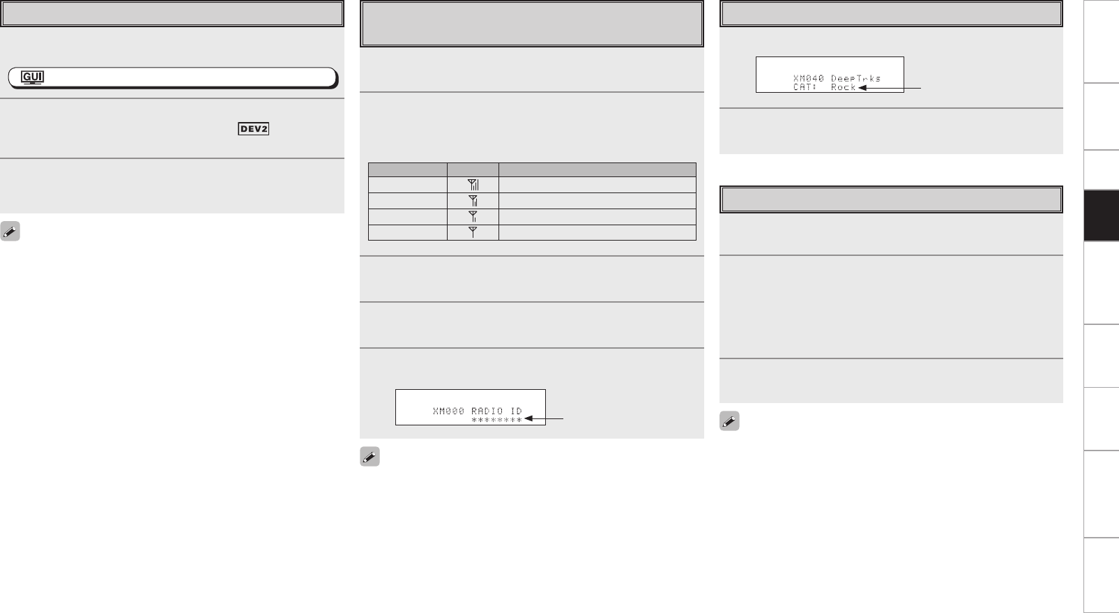
Getting Started Connections Setup Remote Control Multi-Zone Information Troubleshooting Specifications
1Either turn <SOURCE SELECT> or press [SAT TU]
(AMP mode) to select “XM”.
: ”Source Select” (vpage 45)
2To operate using the main remote control unit, set the
remote control unit to the TUNER ( ) mode.
(vpage 77 “Remote Control Unit Operations”)
3Use [d f] to select the channel.
When the channel is tuned in, the name of the song and artist
are displayed.
• The channel switches continuously when [d f] is pressed and held.
• XM Radio channels can be preset using the same procedure as for
FM/AM stations (vpage 59, 60 “Presetting Radio Stations (Preset
Memory)” and “Listening to Preset Stations”).
• The artist name, song title, category and reception level can be
checked by pressing <STATUS>.
• The time for which the GUI menus are displayed can be set at
GUI menu “Manual Setup” – “Option Setup” – “GUI” – “Tuner”
(vpage 42).
Basic Operation Checking the XM Signal Strength and
Radio ID
1Either turn <SOURCE SELECT> or press [SAT TU]
(AMP mode) to select “XM”.
2Press <STATUS> until “SIGNAL” appears on the
display.
The display will switch as shown below, depending on the
reception conditions.
Display GUI Status
GOOD Signal strength is good
MARGINAL Signal strength is marginal
WEAK Signal strength is weak
NO No signal
3Adjust the position of the antenna until “SIGNAL:
GOOD” is shown on the display.
4Press <STATUS> until the channel (example:
“XM001”) is displayed.
5Press [d f] and select channel 0 (XM000).
The radio ID is shown on the display.
The strength of both the XM satellite and terrestrial signals can be
checked at GUI menu “Source Select” – “XM” – “Antenna Aiming”
(vpage 49).
Radio ID
Accessing XM Radio Channels Directly
1Press [SEARCH].
2Press [NUMBER] then input the channel.
Example: Accessing channel “XM123”:
[1] → [2] → [3]
b If no button is pressed within several seconds, the channel
automatically switches to the one whose number has been input.
3Press ENTER to set that channel.
Reception switches to the selected channel.
• “LOADING” is displayed while channels or data are being received.
• “XM - - -” is displayed if the selected channel cannot be used.
Searching Categories
1Press o p.
2Use o p to select the category, then use ui to select
the desired channel.
Channel category
Playback
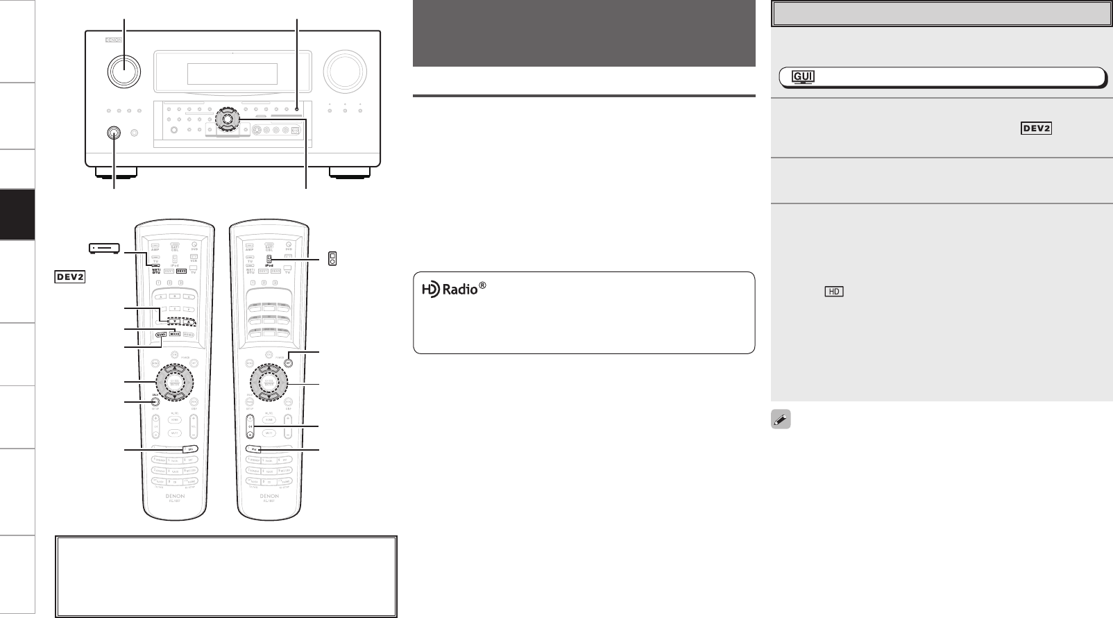
Getting Started Connections Setup Remote Control Multi-Zone Information Troubleshooting Specifications
<SOURCE SELECT>
<ON / STANDBY>
<STATUS>
ui
About the button names in these explanations
< > : Buttons on the main unit
[ ] : Buttons on the remote control unit
Button name only:
Buttons on the main unit and remote control unit
[BAND]
[SEARCH]
[MODE]
[d f]
ui
[DTU]
[
NET/DTU]
ui
[POWER OFF]
[ iPod]
[iPod]
[CHANNEL
–
]
( mode)
(AMP mode) (AMP mode)
HD Radio™ Technology Manufactured Under License From iBiquity
Digital Corp. U.S. and Foreign Patents. HD Radio™ and the HD and
HD Radio logos are proprietary trademarks of iBiquity Digital Corp.
Using the HD Radio Receiver
HD Radio technology provides higher quality sound than conventional
broadcasts and allows reception of data services.
• FM sounds as sensational as CDs
• AM sounds as rich as analog FM stereo
• A variety of “data services”, including text-based information, song
title, artist name, album name, genre, etc. can be received.
Furthermore, in addition to conventional broadcasts, with HD
Radio broadcasting it is possible to choose from up to 8 multicast
programs.
For detailed information on HD Radio technology, please go to “www.
ibiquity.com”.
Listening to HD Radio™ Stations
HD Radio stations offer higher sound quality than conventional
FM/AM broadcasts. It is also possible to receive data services and
select broadcasts from among up to eight multicast programs. 1Either turn <SOURCE SELECT> or press [DTU] (AMP
mode) to select “HD Radio”.
: “Source Select” (vpage 45)
2To operate using the main remote control unit, set the
remote control unit to the NET/DTU ( ) mode.
(vpage 77 “Remote Control Unit Operations”)
3Press [BAND] to select “FM” or “AM”.
4Tune in the desired broadcast station.
q To tune in automatically (Auto Tuning)
Press [MODE] to select “HD Auto” or “Auto”, then use [d f] to
select the station you want to hear.
• The “ ” indicator lights on the display when an HD Radio
station is tuned in.
• When “HD Auto” (tuning mode) is selected, only HD Radio
stations are tuned in.
• If “Auto” (tuning mode) is selected, both HD Radio and analog
stations are tuned in.
w To tune in manually (Manual Tuning)
Press [MODE] to select “Manual”, then use [d f].
Basic Operation
• It is also possible to switch to “FM” or “AM” at step 1 by pressing
[DTU].
• If the desired station cannot be tuned in with auto tuning, tune it in
manually.
• When tuning in stations manually, press and hold [d f] to change
frequencies continuously.
• HD Radio stations can be preset using the same procedure as for
FM/AM stations (vpage 59, 60 “Presetting Radio Stations (Preset
Memory)” and “Listening to Preset Stations”). In addition, with HD
Radio technology, multicasts can also be preset.
• The time for which the GUI menu is displayed can be set at GUI
menu “Manual Setup” – “Option Setup” – “GUI” – “Tuner”
(vpage 42).
Playback
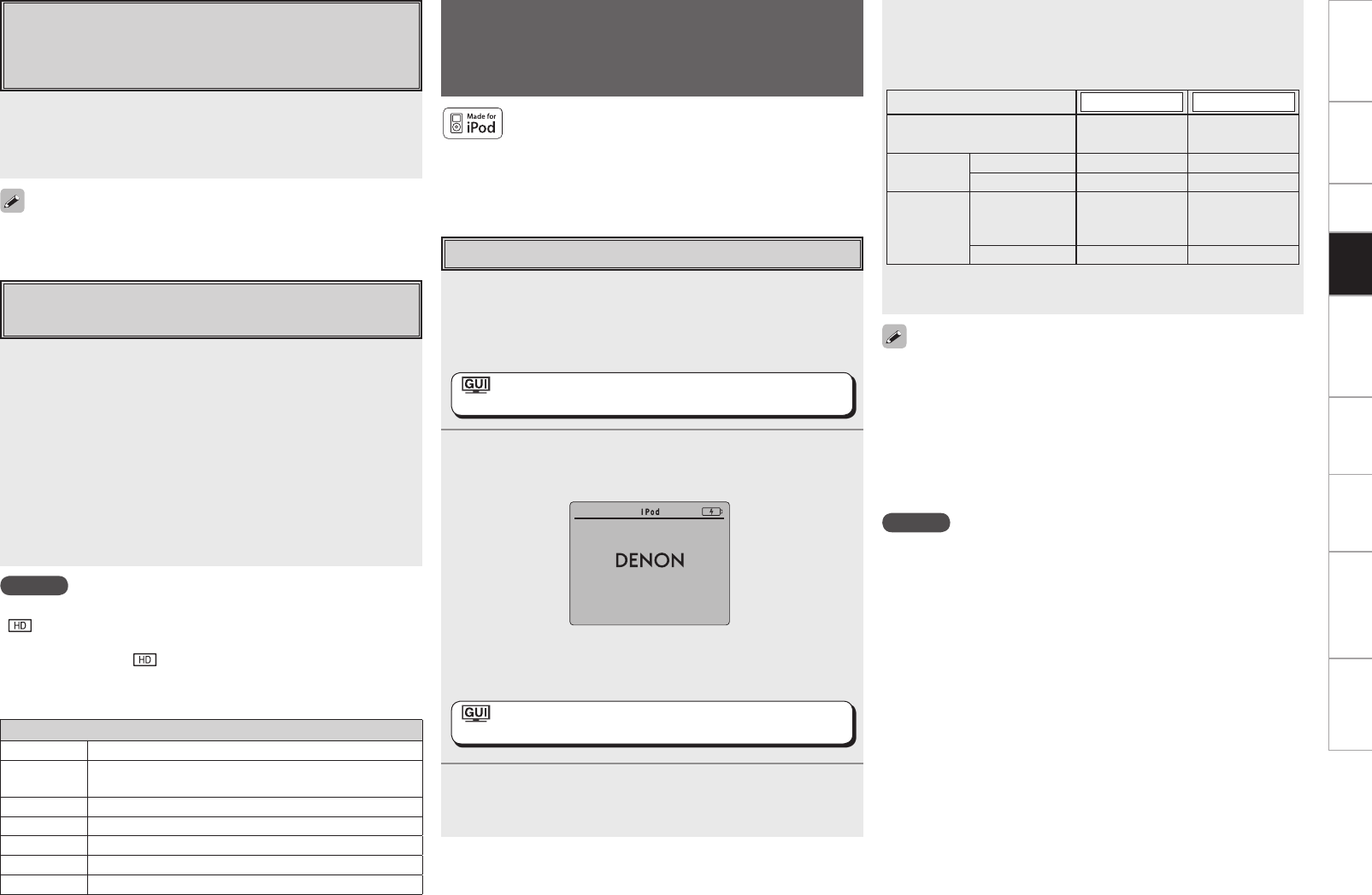
Getting Started Connections Setup Remote Control Multi-Zone Information Troubleshooting Specifications
Check the HD Radio Reception
Information
Press <STATUS> while an HD Radio broadcast is being
received.
The current reception information is shown on the display.
q Normal
↓
w Frequency / Signal strength
↓
e Long station name / Program and Program type
↓
r Title name / Artist name
↓
t Album name / Genre name
Selecting Audio Programs
An HD Radio broadcast includes up to 8 audio programs (HD1 to
HD8 and Analog). The different audio programs also have data
programs.
Press [SEARCH] or ui to select the audio program.
If the station you are listening to has multiple audio programs, “HD1”
is indicated on the display. If it only has one audio program, “HD”
is indicated.
If an audio program from HD2 to HD8 has been interrupted, HD1 is
automatically selected after about 20 seconds.
NOTE
If the station signal weakens while receiving a digital broadcast (while
“ ” and text is displayed), the mode automatically switches to the
analog reception mode (the reception frequency is displayed).
Because of this, the “ ” indicator and text may flicker if the station
signal level is weak and unstable.
n Default settings
Tuner presets
A1 ~ A8 87.5 / 87.9 / 89.1 / 93.3 / 97.9 / 98.1 / 98.9 /100.1 MHz
B1 ~ B8 101.9 / 102.7 / 107.9 / 90.1 / 90.1 / 90.1 / 90.1 / 90.1
MHz
C1 ~ C8 530 / 600 / 930 / 1000 / 1120 / 1210 / 1400 / 1710 kHz
D1 ~ D8 90.1 MHz
E1 ~ E8 90.1 MHz
F1 ~ F8 90.1 MHz
G1 ~ G8 90.1 MHz
NOTE
• Depending on the type of iPod and the software version, some
functions may not operate.
• DENON will accept no responsibility whatsoever for any loss of iPod
data.
• With the default settings, the iPod can be used connected to the
VCR (iPod) connector.
• Use the RESTORER mode to expand the low and high frequency
components of compressed audio files and achieve a richer sound.
The default setting is “Mode3”.
• Press <ON/STANDBY> or [POWER OFF] and set the AVP-A1HDCI’s
power to the standby mode before disconnecting the iPod. Also
switch the input source to one to which the GUI menu “iPod dock”
is not assigned before disconnecting the iPod.
iPod® Playback
The music on an iPod can be played by using the Control Dock for
iPod (ASD-1R, sold separately).
The operation can also be performed using the buttons on the main
unit or remote control unit while watching the GUI menus.
iPod is a trademark of Apple Inc., registered in the U.S.
and other countries.
b The iPod may only be used to copy or play contents that are not
copyrighted or contents for which copying or playback is legally
permitted for your private use as an individual. Be sure to comply
with applicable copyright legislation.
1Make the necessary preparations.
q Set the iPod in the DENON Control Dock for iPod.
(vSee the Control Dock for iPod’s operating instructions.)
w Assign the Control Dock for iPod’s input.
: ”Source Select” – “(input source)” – “Assign”–
”iPod dock” (vpage 49)
2Either turn <SOURCE SELECT> or press [iPod] (AMP
mode) to select the input source assigned in step 1-w
above.
(iPod screen)
b If the screens above are not displayed, the iPod may not be
properly connected. Try connecting again.
: ”Source Select” – “(input source)” – “Play”
(vpage 46)
3To operate using the main remote control unit, set the
remote control unit to the iPod mode.
(vpage 77 “Remote Control Unit Operations”)
OK to disconnect
Basic Operation
4Press [SEARCH] and hold it down for a 2 seconds or
more to select the display mode.
To switch between modes, press and hold down the button.
When remote mode is active, “Remote” is displayed.
[Display mode] Browse mode Remote mode
Display location Main unit display
iPod display
Playable
files
Audio file S S
Video file A S
z
Active
buttons
Remote
control unit
(AVP-A1HDCI)
S S
iPod A S
z : Video may not be output, depending on the combination of ASD-
1R and iPod.
Playback
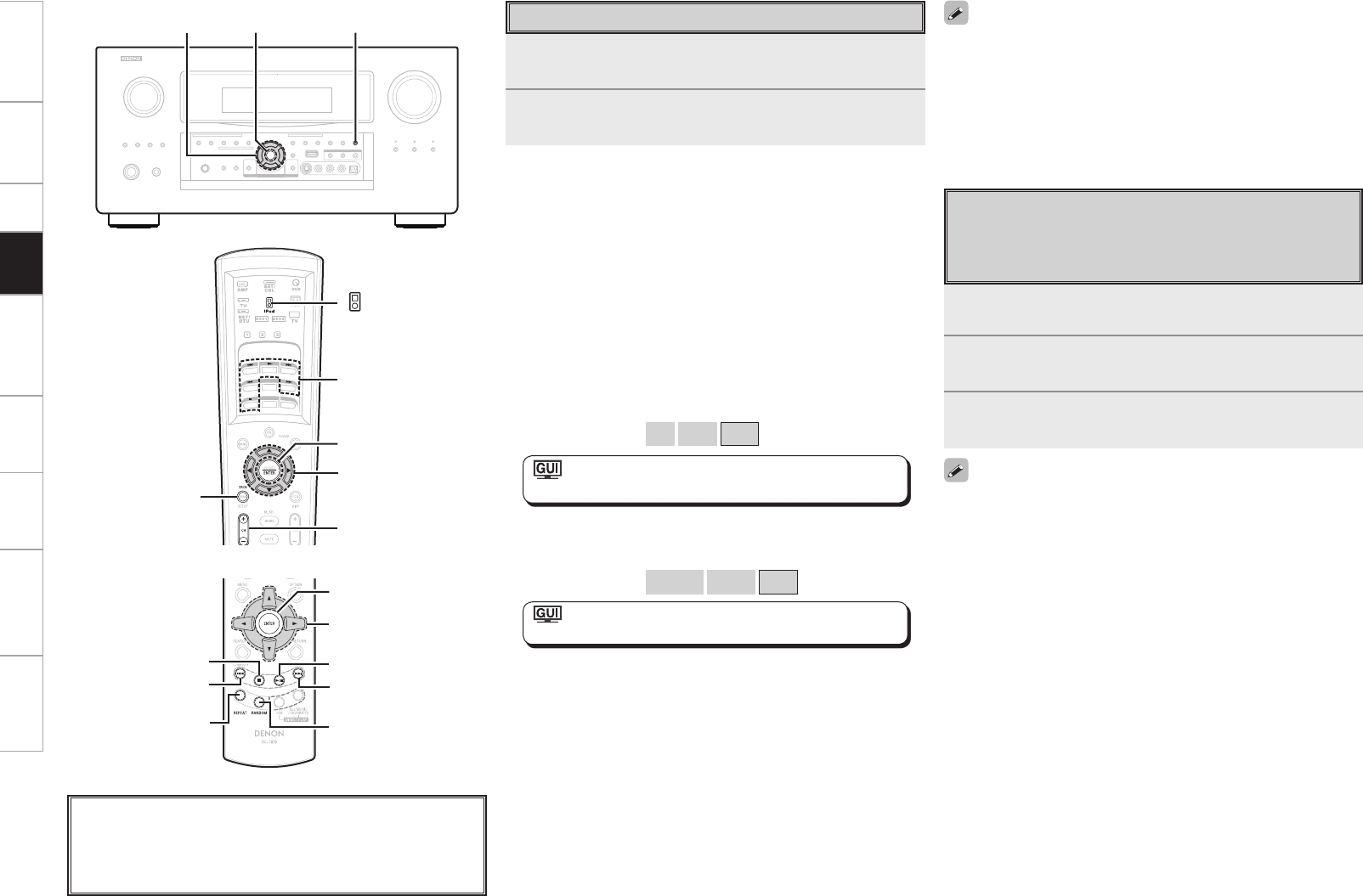
Getting Started Connections Setup Remote Control Multi-Zone Information Troubleshooting Specifications
<STATUS>
ENTER
uio p
uiop
[SEARCH]
[CHANNEL +/−]
ENTER
[8],[9],
[6],[7],
[1],[2]
[ iPod]
About the button names in these explanations
< > : Buttons on the main unit
[ ] : Buttons on the remote control unit
Button name only:
Buttons on the main unit and remote control unit
Viewing Still Pictures or Videos on the
iPod
Photo and video data on the iPod can be viewed on the monitor.
(Only for iPod equipped with slideshow or video functions.)
1Press and hold [SEARCH] to set the Remote mode.
“Remote iPod” is displayed on the AVP-A1HDCI’s display.
2Watching the iPod’s screen, use ui to select
“Photos” or “Videos”.
3Press ENTER until the image you want to view is
displayed.
• “TV Out” at the iPod’s “Slideshow Settings” or “Video Settings”
must be set to “On” in order to display the iPod’s photo data or videos
on the monitor. For details, see the iPod’s operating instructions.
• When unable to operate by the remote control unit, use the iPod
unit.
Shuffling playback
Press [CHANNEL +] or [RANDOM] on the sub remote control unit.
[Selectable items] Albums
Songs
OFF
: ”Source Select” – “(input source)” –
”Playback Mode (iPod)” – “Shuffle” (vpage 48)
Searching up or down pages
Press [SEARCH], then press o (down) or p (up).
To cancel, press ui or [SEARCH].
To switch between the Browse and Remote modes
Either press and hold [SEARCH].
• The title name, artist name and album name can be checked by
pressing <STATUS> during playback.
• On the AVP-A1HDCI, folder and file names can be displayed as
titles. Any characters that cannot be displayed are replaced with “ .
(period)”.
• The time for which the GUI are displayed can be set at GUI menu
“Manual Setup” – “Option Setup” – “GUI” – “iPod” (vpage 42).
(Main remote control unit)
To pause
During playback, press ENTER or [1].
Press again to resume playback.
Fast-forwarding or fast-reversing
During playback, either press and hold u (to fast-reverse) or i (to
fast-forward), or press [6] or [7].
To cue to the beginning of a track
During playback, either press u (to cue to the previous track) or i (to
cue to the next track), or press [8] or [9].
To stop
During playback, either press and hold ENTER or press [2].
Playing repeatedly
Press [CHANNEL –] or [REPEAT] on the sub remote control unit.
[Selectable items] All
One
OFF
: ”Source Select” – “(input source)” –
”Playback Mode (iPod)” – “Repeat” (vpage 48)
Listening to Music
1Use ui to select the menu, then press ENTER or p
to select the music le to be played.
2Press ENTER or p.
Playback starts.
[REPEAT]
[8]
[2]
[9]
[1/3]
[RANDOM]
uiop
ENTER
(Sub remote control unit)
Playback
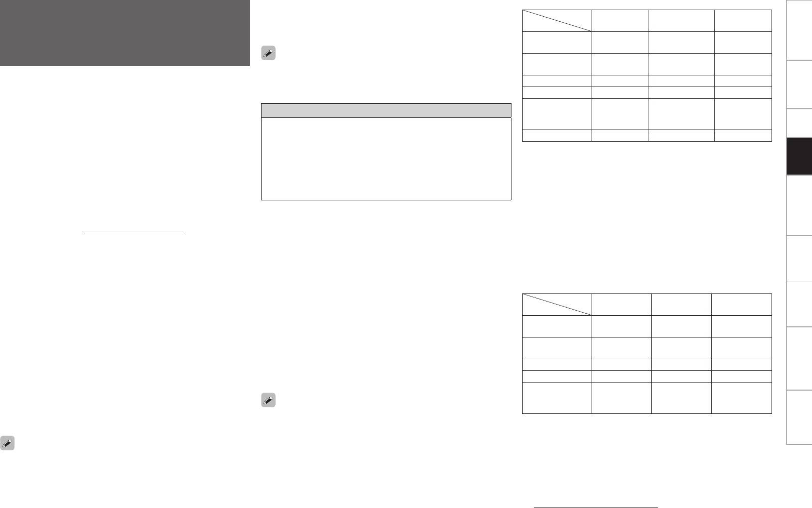
Getting Started Connections Setup Remote Control Multi-Zone Information Troubleshooting Specifications
n USB memory devices
A USB memory device can be connected to the AVP-A1HDCI’s
USB port to play music and still picture (JPEG) files stored on the
USB memory device.
· Only USB memory devices conforming to mass storage class and
MTP (Media Transfer Protocol) standards can be played on the
AVP-A1HDCI.
· The AVP-A1HDCI is compatible with USB memory devices in
“FAT16” or “FAT32” format.
GAlbum art functionH
When an MP3 music file includes album art data, the album art can
be displayed while playing the file.
GSlide show functionH
Still picture (JPEG) files stored on USB memory devices can be
played as slide shows.
The time for which each picture is displayed can be set.
Installing Windows Media Player ver. 11
q If Windows XP Service Pack 2 has not yet been installed, either
download it free of charge from Microsoft or install it via a
Windows update installer.
w Download the latest version of Windows Media Player ver.
11, either directly from Microsoft or using a Windows update
installer.
b When using Windows Vista, there is no need to download a new
version of Windows Media Player.
GSlide show functionH
Still picture (JPEG) files stored in folders on a media server can be
played as slide shows.
The time for which each picture is displayed can be set.
When still picture (JPEG) files are played on the AVP-A1HDCI, they are
played in the direction in which they are stored in the folder, so store
in them in the direction in which you want them to play.
When still picture (JPEG) files are played on the AVP-A1HDCI, they are
played in the direction in which they are stored in the folder, so store
in them in the direction in which you want them to play.
[Compatible formats]
Internet
radio
Media server
bUSBb
WMA (Windows
Media Audio) S S Sz
MP3 (MPEG-1
Audio Layer-3) S S S
WAV –S S
MPEG-4 AAC – Sz Sz
FLAC (Free
Lossless Audio
Codec)
–S S
JPEG –S S
A server or server software compatible with distribution in the
corresponding formats is required to play music files via a network.
z: Only files that are not protected by copyright can be played on the
AVP-A1HDCI.
Contents downloaded from pay sites on the Internet are copyright
protected. Also, files encoded in WMA format when ripped from a
CD, etc., on a computer may be copyright protected, depending on
the computer’s settings.
b Media server and USB
• The AVP-A1HDCI is compatible with MP3 ID3-Tag (Ver. 2)
standards.
• The AVP-A1HDCI is compatible with WMA META tags.
[Playable formats]
Sampling
frequency Bit rate Extension
WMA (Windows
Media Audio) 32/44.1/48 kHz 48~192 kbps .wma
MP3 (MPEG-1
Audio Layer-3) 32/44.1/48 kHz 32~320 kbps .mp3
WAV 32/44.1/48 kHz – .wav
MPEG-4 AAC 32/44.1/48 kHz 16~320 kbps .aac/.m4a/.mp4
FLAC (Free
Lossless Audio
Codec)
32/44.1/48 kHz – .flac
WAV format Quantization bit rate: 16 bits.
n Rhapsody
Rhapsody is a paid music broadcast service of RealNetworks.
When you first listen to Rhapsody, take advantage of the “30-day
free trial”. When the free trial period has expired, it is necessary to
subscribe to a Rhapsody account at the Rhapsody homepage and
register this machine. See the Rhapsody homepage for details.
www.rhapsody.com/denon/signup
Playing Network Audio, USB
Memory Devices or Rhapsody
This procedure can be used to play Internet radio stations or music
or still picture (JPEG) fi les stored on a computer or USB memory
device or Rhapsody.
n About the Internet radio function
• Internet radio refers to radio broadcasts distributed over the
Internet. Internet radio stations from around the world can be
tuned in.
The AVP-A1HDCI is equipped with the following Internet radio
functions:
· Stations can be selected by genre and region.
· Up to 56 Internet radio stations can be preset.
· Internet radio stations in MP3 and WMA (Windows Media Audio)
format can be listened to.
· Your favorite radio stations can be registered by accessing an
exclusive DENON Internet radio URL from a Web browser on a
computer.
b The function is managed for individual users, so you must
provide your MAC or e-mail address.
Exclusive URL: http://www.radiodenon.com
b The radio station database service may be suspended without
notice.
• The AVP-A1HDCI’s Internet radio station list is created using a radio
station database service (vTuner). This database service provides a
list edited and created for the AVP-A1HDCI.
n Media server
This function lets you play music files and playlists (m3u, wpl) stored
on a computer (media server) connected to the AVP-A1HDCI via a
network.
With the AVP-A1HDCI’s network audio playback function,
connection to the server is possible using one of the technologies
below.
· Windows Media Player Network Sharing Service
· Windows Media DRM10
GAlbum art functionH
When a WMA (Windows Media Audio), MP3 or MPEG-4 AAC file
includes album art data, the album art can be displayed while the
music files are playing.
For music files in WMA (Windows Media Audio) format, the album art
is only played when using Windows Media Player ver. 11.
Playback
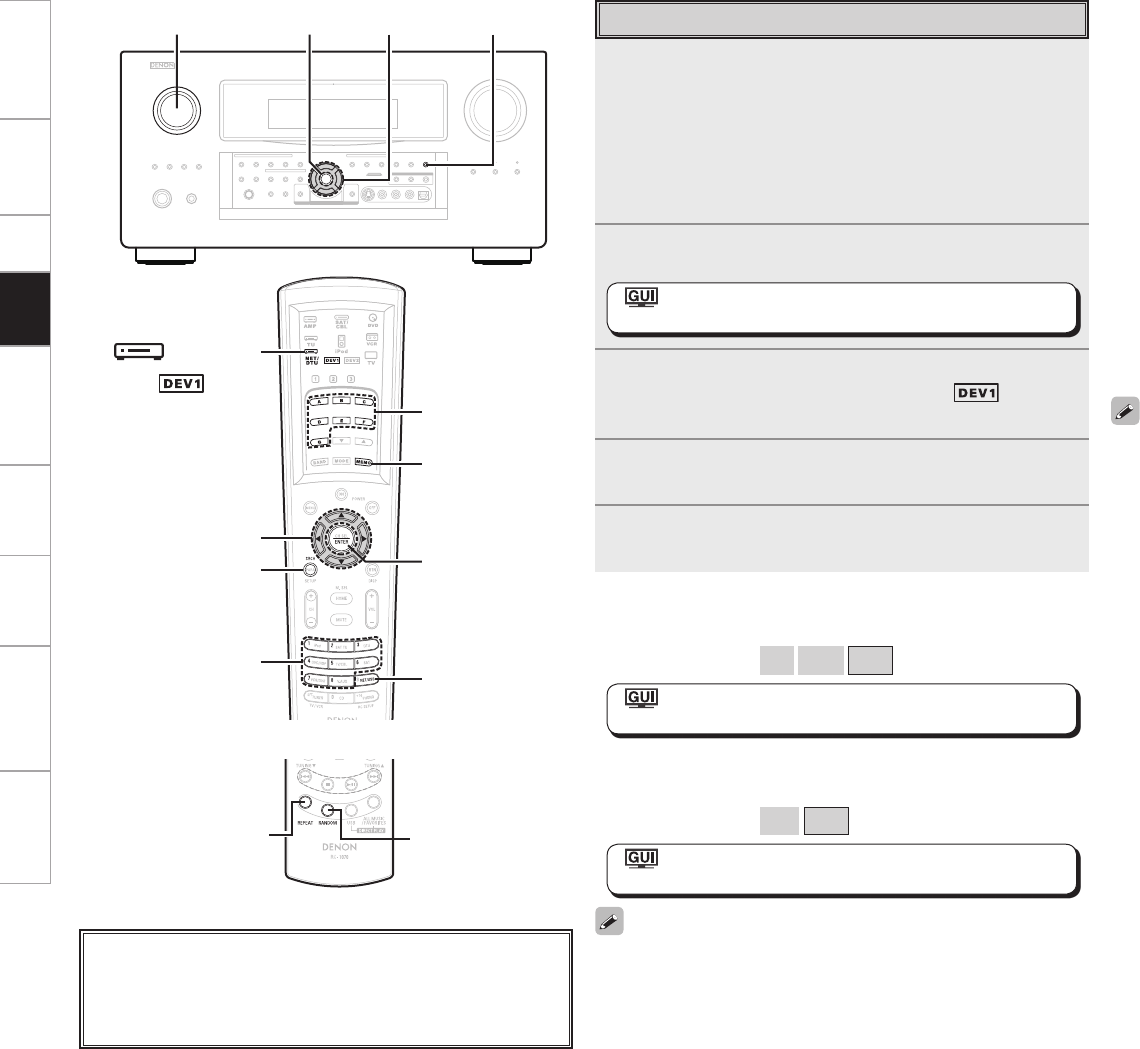
Getting Started Connections Setup Remote Control Multi-Zone Information Troubleshooting Specifications
To pause
During playback, press ENTER.
Press again to resume playback.
To stop
During the play or pause mode, press and hold ENTER.
Searching up or down pages
Press [SEARCH], then press o (down) or p (up).
To cancel, press ui or [SEARCH].
Searching by first letter (Character search)
This operation is convenient for choosing items from the menu screens
for Internet radio stations or files stored on the computer.
q When the menu screen is displayed, press [SEARCH] twice.
w Use o p to select the first letter you want to search for.
If there are multiple items starting with the selected letter, they are
displayed in alphabetical order.
If it is not possible to search the list, “unsorted list.” is displayed.
To cancel, press or ui or [SEARCH].
• Use the RESTORER mode to expand the low and high frequency
components of compressed audio files and achieve a richer sound.
The default setting is “Mode3”.
• The time for which the GUI are displayed can be set at GUI menu
“Manual Setup” – “Option Setup” – “GUI” – “NET/USB” (vpage
42).
• Use <STATUS> to switch between displaying the title name, artist
name or album name.
• The track display order differs with the server specification. When,
due to the server specification, track display is not in alphabetical
order, character search may not operate correctly.
1Make the necessary preparations.
q Check the network environment, then turn on the AVP-A1HDCI’s
power. (vpage 21 “Network Audio”)
w If settings are required, make the network settings.
(vpage 35 ~ 38 “Network Setup”)
e Prepare the computer. (vComputer’s operating instructions)
Install “Windows Media Player ver. 11”.
2Either turn <SOURCE SELECT> or press [NET/USB]
(AMP mode) to select “NET/USB”.
: “Source Select” –“NET/USB” –“Play”
(vpage 46)
3To operate using the main remote control unit, set the
remote control unit to the NET/DTU ( ) mode.
(vpage 77 “Remote Control Unit Operations”)
4Use ui to select the menu, then press ENTER or p
to select the le you want to play.
5Press ENTER or p.
Playback starts.
Basic Operation
<SOURCE SELECT> <STATUS>
ENTER uio p
uiop
[1 ~ 8]
ENTER
[MEMO]
[SEARCH]
[NET/USB]
[A ~ G]
[ NET/DTU]
About the button names in these explanations
< > : Buttons on the main unit
[ ] : Buttons on the remote control unit
Button name only:
Buttons on the main unit and remote control unit
( mode)
(AMP mode)
Playing repeatedly
Press [REPEAT] on the sub remote control unit.
[Selectable items] All
One
OFF
: “Source Select” – “NET/USB” – “Playback Mode” –
“Repeat” (vpage 49)
Playing in random order
Press [RANDOM] on the sub remote control unit.
[Selectable items] ON
OFF
: “Source Select” – “NET/USB” – “Playback Mode” –
“Random” (vpage 49)
The repeat mode and random mode can only be used when playing
tracks recorded in USB/Media Server/Rhapsody.
[REPEAT] [RANDOM]
(Main remote control unit)
(Sub remote control unit)
Playback
Getting Started Connections Setup Remote Control Multi-Zone Information Troubleshooting Specifications
1Press [MEMO] while the Internet radio station you
want to register is playing.
2Use ui to select “Favorites”, then press ENTER.
3Press o to select “Yes”.
The Internet radio station is registered.
If you do not want to register it, press p.
1Use ui to select “Favorites”, then press ENTER or
p.
2Use ui to select the Internet radio station, then
press ENTER or p.
The AVP-A1HDCI automatically connects to the Internet and
playback begins.
1Use ui to select “Favorites”, then press ENTER or
p.
2Use ui to select the Internet radio station you want
to clear, then press [MEMO].
3Press o to select “Delete”.
The selected Internet radio station is cleared.
To cancel the operation without clearing the station, press p.
NOTE
If registered at a number that has already been preset, the previously
registered setting is cleared.
Press [A ~ G], then press [1 ~ 8].
The AVP-A1HDCI automatically connects to the Internet and playback
begins.
1While the Internet radio station you want to preset is
playing, press [MEMO].
2Use ui to select “Preset”, then press ENTER.
3Press [A ~ G], then press [1 ~ 8] to select the desired
preset number.
The Internet radio station is now preset.
• There are many Internet radio stations on the Internet, and the
quality of the programs they broadcast as well as the bit rate of the
tracks varies widely.
Generally, the higher the bit rate, the higher the sound quality, but
depending on the communication lines and server traffic, the music
or audio signals being streamed may be interrupted.
Inversely, lower bit rates mean a lower sound quality but less
tendency for the sound to be interrupted.
• “Server Full” or “Connection Down” is displayed if the station is
busy or not broadcasting.
• On the AVP-A1HDCI, folder and file names can be displayed as
titles. Any characters that cannot be displayed are replaced with “ .
(period)”.
1Use ui to select “Internet Radio”, then press ENTER
or p.
2Use ui to select the item you want to play, then
press ENTER or p.
The station list is displayed.
3Use ui to select the station, then press ENTER or
p.
Playback starts once buffering reaches “100%”.
Listening to Internet Radio
1Use ui to select “Recently Played”, then press
ENTER or p.
2Use ui to select the item you want to play, then
press ENTER or p.
NOTE
Up to 20 stations stored in “Recently Played”.
n Recently Played Internet Radio Stations
Recently played internet radio stations can be selected from
“Recently Played” in top menu.
Presetting Internet Radio Stations
Preset Internet radio stations can be selected directly.
n Listening to Preset Internet Radio Stations
Registering Internet Radio Stations as Your Favorites
Favorites are listed at the top of the menu screen, so when a station
is registered as a favorite it can be tuned in easily.
n Listening to Internet Radio Stations Registered in
Your Favorites
n Clearing Internet Radio Stations from Your Favorites
Playback
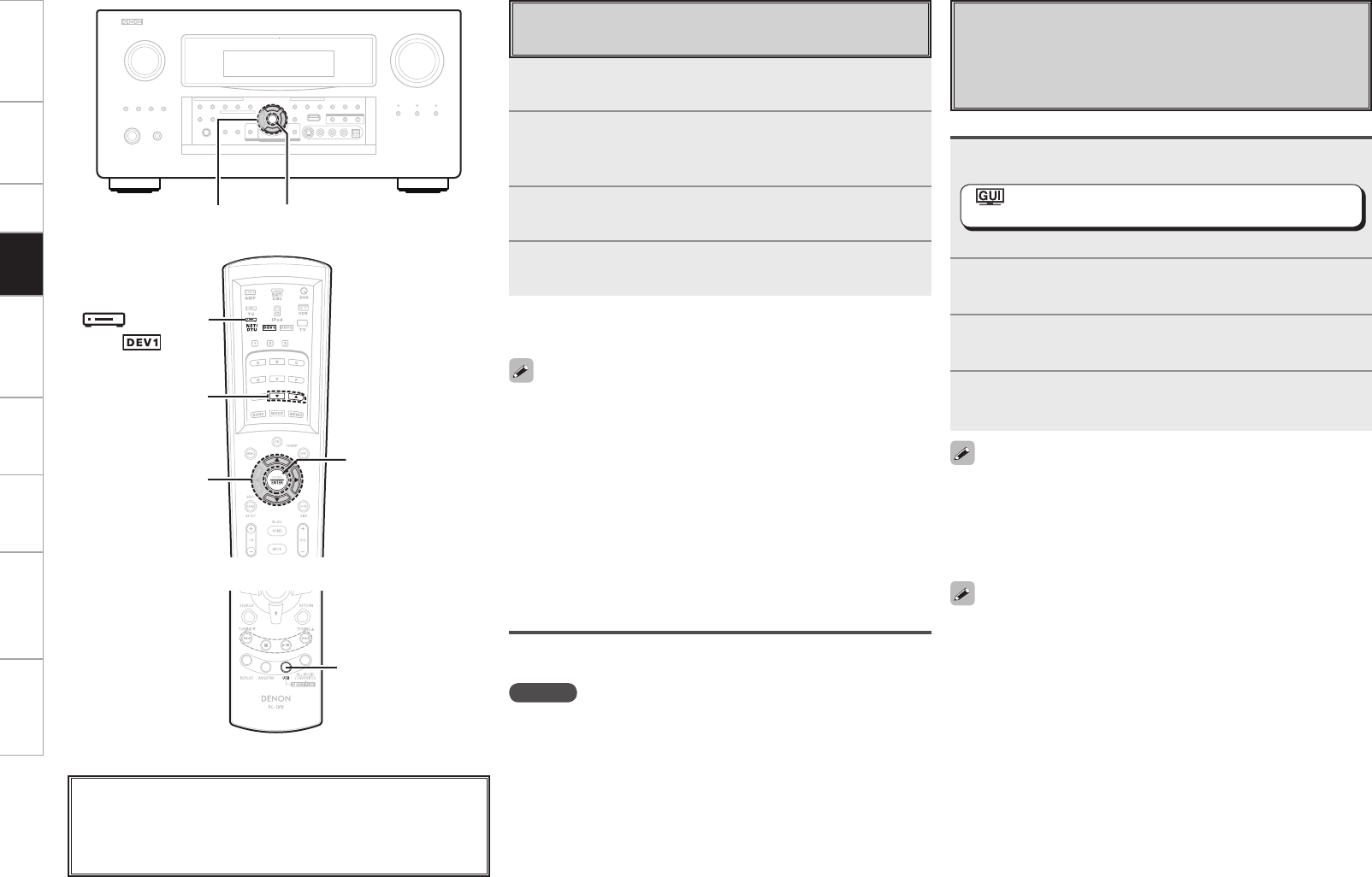
Getting Started Connections Setup Remote Control Multi-Zone Information Troubleshooting Specifications
Playing Files Stored on USB Memory
Devices
Only USB memory devices conforming to mass storage class and
MTP (Media Transfer Protocol) standards can be played on the
AVP-A1HDCI.
Basic Operation
1Make the necessary preparations.
• Set the USB port to be used.
: “Source Select” – “NET/USB” – “Playback Mode” –
“USB Select” (vpage 49)
• Connect the USB memory device to the set USB port.
2Use ui to select “USB”, then press ENTER or p.
3Use ui to select the search item or folder, then press
ENTER or p.
4Use ui to select the le, then press ENTER or p.
Playback starts once buffering reaches “100%”.
• By default, the front panel’s USB port will be used.
• Depending on the size of the still picture (JPEG) file, some time may
be required for the file to be displayed.
Playing files that have been Preset or Registered in
Your Favorites
Files can be preset, registered in your favorites and played using the
same operations as for Internet radio stations.
NOTE
• Presettings are erased by overwriting them.
• When the operation described below is performed, the media
server’s database is updated and it may no longer be possible to
play preset or favorite music files.
• When you quit the media server and then restart it.
• When music files are deleted or added on the media server.
• When using an ESCIENT server, place “ESCIENT” before the server
name.
Playing Files Stored on a Computer
Use this procedure to play music files, image files or playlists.
1Use ui to select “Media Server”, then press ENTER
or p.
2Use ui to select the host name of the computer on
which the music le you want to play is located, then
press ENTER or p.
3Use ui to select the search item or folder, then press
ENTER or p.
4Use ui to select the le, then press ENTER or p.
Playback starts once buffering reaches “100%”.
• When playing still picture (JPEG) files, files can also be selected
using the operation described below.
During playback, either press [d] (previous file) or [f] (next file).
• Connections to the required system and specific settings must be
made in order to play music files (vpage 21).
• Before starting, you must launch the computer’s server software
and set the files as server contents. For details, see the operating
instructions of your server software.
• Depending on the size of the still picture (JPEG) file, some time may
be required for the file to be displayed.
Selecting tracks
During playback, either press u (previous track) or i (next track).
ENTER
ui p
ui p ENTER
[df]
[ NET/DTU]
About the button names in these explanations
< > : Buttons on the main unit
[ ] : Buttons on the remote control unit
Button name only:
Buttons on the main unit and remote control unit
[USB]
(Main remote control unit)
(Sub remote control unit)
( mode)
Selecting tracks
During playback, either press u (previous track) or i (next track).
• When playing still picture (JPEG) files, tracks can also be selected
using the operation described below.
During playback, either press [d] (previous file) or [f] (next file).
• If the USB memory device is divided into multiple partitions, only the
top partition can be selected.
• The AVP-A1HDCI is compatible with MP3 files conforming to
“MPEG-1 Audio Layer-3” standards.
• When [USB] is pressed, playback starts from the first track on the
USB memory device.
Playback
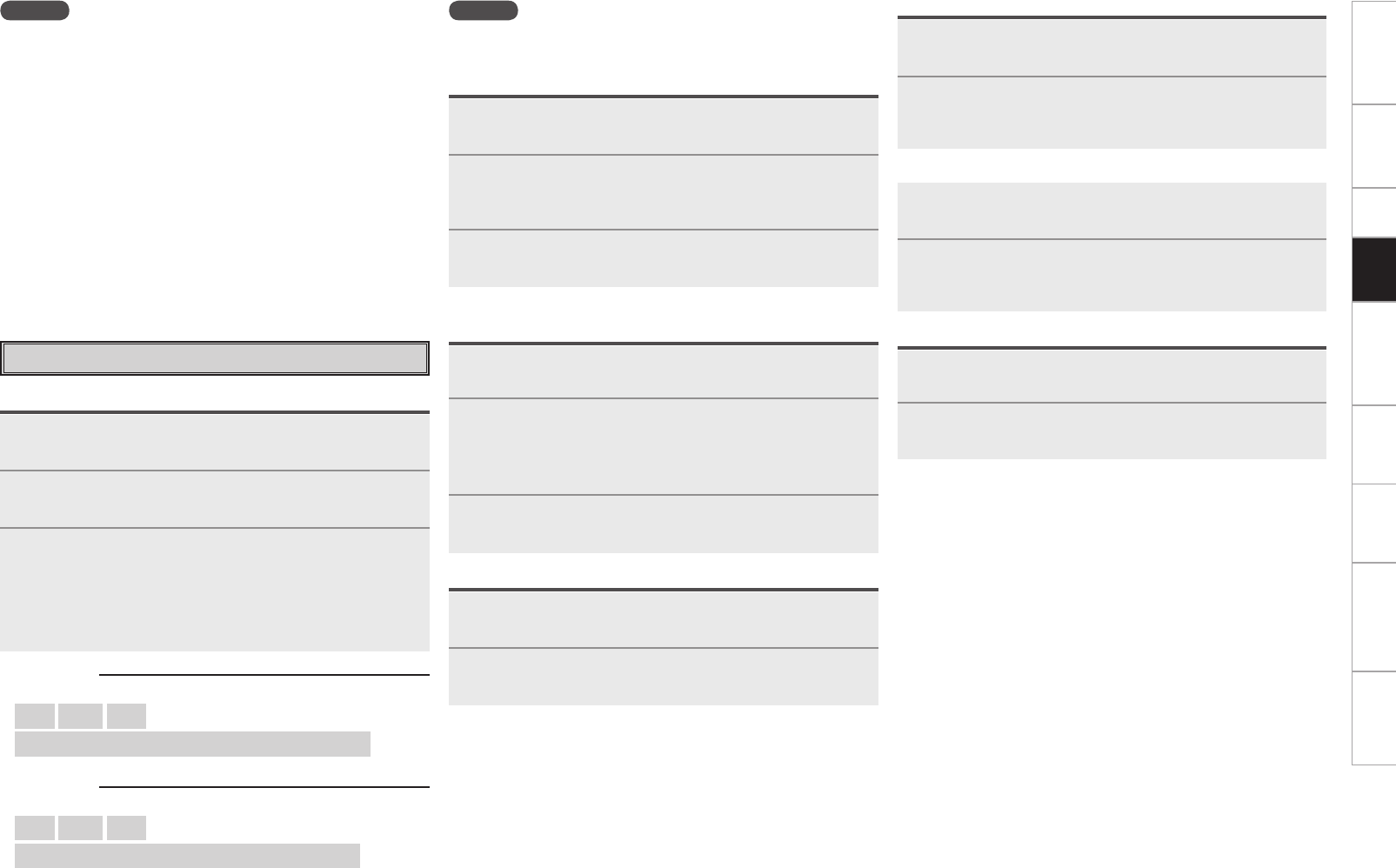
0
Getting Started Connections Setup Remote Control Multi-Zone Information Troubleshooting Specifications
NOTE
• The AVP-A1HDCI is equipped with two USB ports, one each on the
front and rear panels. It is not possible to use the set with USB
memory devices connected to both the ports at the same time.
Select the USB port you want to use at the “Source Select” – “NET/
USB” – “Playback Mode” – “USB Select” menu.
• DENON will accept no responsibility whatsoever for any loss or
damage to data on USB memory devices when using the USB
memory device connected to the AVP-A1HDCI.
• USB memory devices will not work via a USB hub.
• DENON does not guarantee that all USB memory devices will operate
or receive power. When using a USB connection type portable hard
disk of the type for which power can be supplied by connecting an
AC adapter, we recommend using the AC adapter.
• It is not possible to connect and use a computer via the AVP-
A1HDCI’s USB port using a USB cable.
• The AVP-A1HDCI is not compatible with the iPod shuffle.
n Username :
[Input characters]
a ~ z A ~ Z 0 ~ 9
! “ # $ % & ( ) * + , - . / : ; < = > ? @ [ \ ] ^ _ ` { | } ˜ (space)
n Password :
[Input characters]
a ~ z A ~ Z 0 ~ 9
! “ # $ % & ( ) * + , - . / : ; < = > ? @ [ \ ] ^ ` { | } ˜ (space)
1Use ui to select “Rhapsody”, then press ENTER or
p.
2Use ui to select “I have a Rhapsody account” or
“Start 30-day free trial”, then press ENTER or p.
3q When selecting “I have a Rhapsody account”
Enter Username and Password.
Select “OK”, then press ENTER.
w When selecting “Start 30-day free trial”
Select “Accept” then press ENTER.
b To cancel, select “Reject”, then press ENTER.
NOTE
• The password should be no longer than 99 characters.
• The password may not contain underscores ( _ ).
Listening to Rhapsody
Preparations
1Use ui to select “Rhapsody Music Guide”, then
press ENTER or p.
2Use ui to select the information for track selection,
then press ENTER or p.
After selecting, the information is displayed.
3Use ui to select the track, then press ENTER or p.
1Use ui to select “Search”, then press ENTER or p.
2Use ui to select the search item, then press ENTER
or p.
The search display appears.
b You can search by artist name, album name or track name.
3Enter the characters, then press ENTER.
Search From Rhapsody Latest Information
Enter a Character Search For the Track You Want to
Listen to
1Use ui to select “Rhapsody Channels”, then press
ENTER or p.
2Use ui to select radio station, then press ENTER or
p.
1Press p while the track you wish to register is
playing.
2Use ui to select “Add to My Library”, then press
ENTER.
The track is entered in the Library.
1Use ui to select “My Library”, then press ENTER
or p.
2Use ui to select the information or track, then press
ENTER.
After selecting, the information is displayed.
1Press p during playback.
2Use ui to select the search item, then press ENTER
or p.
Search From the Rhapsody Internet Radio Station
Registering Tracks in My Library
n Listening to Tracks Registered In My Library
Displaying the Track Menu During Play
Playback

Getting Started Connections Setup Remote Control Multi-Zone Information Troubleshooting Specifications
Operating the AVP-A1HDCI Using a
Browser (Web control)
This function lets you operate the AVP-A1HDCI using Internet
Explorer.
1Switch “OFF” the “Power Saving” setting under
“Manual Setup” – “Network Setup” – “Other” on the
GUI menu (vpage 38).
2Check the AVP-A1HDCI’s IP address with “Manual
Setup” – “Network Setup” – “Network Information”
on the GUI menu (vpage 38).
3Enter the AVP-A1HDCI IP address in Internet
Explorer’s address box.
For example, if the IP address of AVP-A1HDCI is “192.168.11.3”,
enter “http://192.168.11.3”.
Checking the IP address.
Entering the IP address.
4When the top menu is displayed, click on the menu
you want to operate.
5Operate.
[Example 1] Main zone control screen
*1 : Normally, there is a change to the latest information each time
you operate. When operated from the main unit, click because
the screen is not updated.
*2 : Displayed when setting “Top Menu Link Setup” to “ON” in
[Example 3].
*3 : To avoid mistakenly performing menu operations of a zone you
are not operating, we recommend that you register the setting
contents for each zone under Favorites in your browser.
Click when
you operate
each zone.
(vExample 1)
Click when you
operate the setup
menu. (vExample 2)
Click to change
zone name.
(vExample 3)
Click when you
operate a small screen
such as a PDA screen,
etc. (vExample 4)
Click when you update to
the latest information. (*1)
Click to perform each
operation.
Changes to each operation
screen.
(vExample 5)
Click to add a setting to the “Favorites” in your browser. (*3)
Click to return to the top
menu. (*2)
[Example 2] Setup menu screen
[Example 3] Zone name change screen
Click “v” and select from
the displayed items.
Click to
determine a
setting.
After entering
characters, click “Set”
to set, or click “Def” to
return to initial setting.
Enter figures or click
“<” or “>” to make
the setting, and then
click “Set”.
Click the menu from which you want to make
settings.
The display on the right becomes each setting
screen.
Click “SAVE” when you want to save settings, and click
“LOAD” when you want to call settings.
Becomes each operation screen.
Enter zone
name.
Click to set
zone name.
Click when
changing the
background
color of each
operation
screen.
Click to
return to the
top menu.
Click “ON” when
performing Top Menu
Link Setup.
When set up, return to
the top menu from each
operation screen.
(Default setting : “OFF”)
Playback
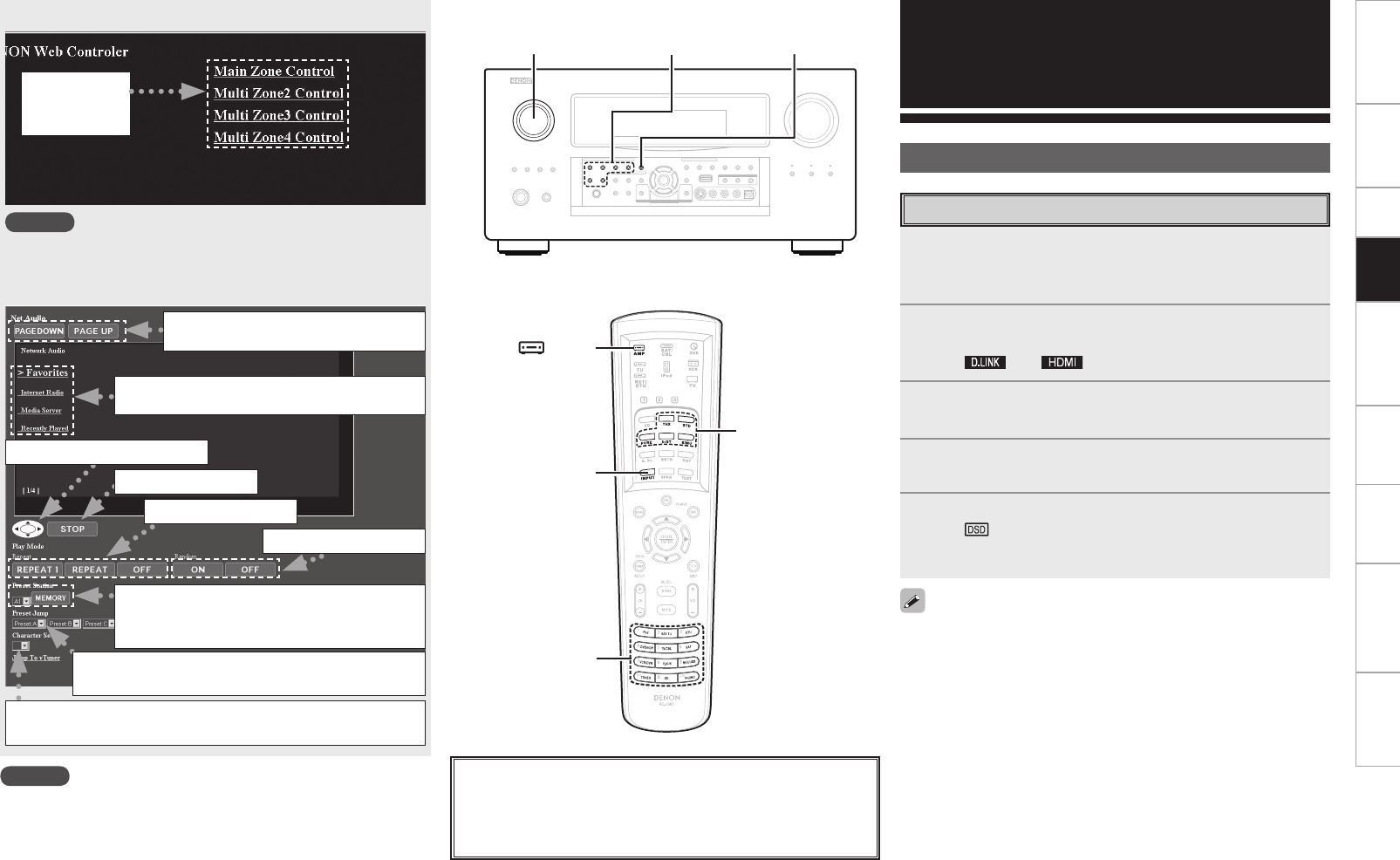
Getting Started Connections Setup Remote Control Multi-Zone Information Troubleshooting Specifications
[Example 4] PDA menu screen
NOTE
You cannot change setup menu operations and zone name on the
PDA menu screen.
[Example 5] Net Audio operating screen
Select to
operate each
zone.
Click the menu from which you want to
make settings.
Click to move up/down the menu
pages.
Click to repeat play.
When registering presets, click “v” to
select the channel you want to register,
and then click “MEMORY”.
Click to stop play.
Click to random play.
Click when selecting menu.
Click “v” to select the preset channel you want
to play.
When searching using an acronym, click “v” and select
from the displayed characters.
NOTE
• To perform web control, you must connect a web control device
such as a PC to the same network as the AVP-A1HDCI.
• With web control, some network settings, etc., cannot be set.
• When updating firmware, settings made by the web controller may
be reset.
SOURCE SELECT INPUT MODE
INPUT MODE
[ AMP]
SOURCE
SELECT
About the button names in these explanations
< > : Buttons on the main unit
[ ] : Buttons on the remote control unit
Button name only:
Buttons on the main unit and remote control unit
Surround mode Other Operations and
Functions
Other Operations
Playing Super Audio CD
1Assign “DENON LINK” with the “Digital” setting or
assign “HDMI” with the “HDMI” setting (vpage
48).
2Either turn <SOURCE SELECT> or press [SOURCE
SELECT] to select the input source assigned in step 1.
The “ ” or “ ” indicator lights on the display.
3Select “AUTO” for the INPUT MODE (vpage 47).
4Select the surround mode (vpage 50 ~ 52).
We recommend playing in the DIRECT mode.
5Start playing the Super Audio CD.
The “ ” indicator lights on the display.
For operating instructions, refer to the respective equipment’s
operating instructions.
• When playing DSD signals in the DIRECT or PURE DIRECT mode,
the DSD signals are converted as such into analog signals. When
playing in other surround modes, the DSD signals are first converted
into PCM format, then into analog signals.
• “DSD DIRECT” is shown on the display when playing DSD 2-channel
signals in the DIRECT mode. “DSD MULTI DIRECT” is shown on
the display when playing DSD multi--channel signals in the DIRECT
mode.
• The DSD signal may not be output depending on the equipment
that is connected.For further details, refer to the user manual for the
equipment being used.
Surround mode
Playback
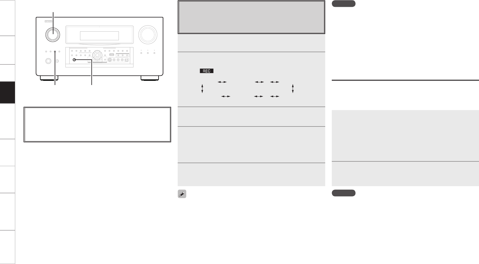
Getting Started Connections Setup Remote Control Multi-Zone Information Troubleshooting Specifications
<ZONE2/3/4 /
REC SELECT> <PHONES>
<SOURCE SELECT>
About the button names in these explanations
< > : Buttons on the main unit
[ ] : Buttons on the remote control unit
Button name only:
Buttons on the main unit and remote control unit
Recording on an External Device
(REC OUT mode)
You can listen to one program source while recording a different
program source.
1Press <ZONE2/3/4 / REC SELECT>.
“ZONE3 SOURCE” is shown on the display.
2Turn <SOURCE SELECT> until “RECOUT SOURCE”
is displayed.
The “ ” indicator lights.
ZONE3 SOURCE ZONE3 TUNER ZONE3 HD Radio····
RECOUT HD Radio RECOUT XM RECOUT SOURCE····
3Turn <SOURCE SELECT> to choose the input source
to be recorded.
4Play the program source.
For operating instructions, refer to the respective equipment’s
operating instructions.
To record FM or AM broadcasts, select the broadcast (vpage
59).
5Start recording.
For operating instructions, refer to the respective equipment’s
operating instructions.
• To cancel, press <ZONE2/3/4 / REC SELECT>, then turn <SOURCE
SELECT> until “ZONE3 SOURCE” is displayed.
• Make a test recording before starting the actual recording.
• Signals are only output to the analog REC OUT connectors when
the digital signals input to the digital input connectors (OPTICAL/
COAXIAL) are PCM (2-channel) signals.
• Digital audio signals input to the DENON LINK or HDMI connectors
are not output to the REC OUT connectors, so connect using the
OPTICAL or COAXIAL connectors.
• Sources selected with the REC OUT mode are output from ZONE3
as well.
• In the REC OUT mode, the remote control unit’s ZONE3 mode
buttons cannot be operated.
• When the “Digital Out” setting is set to “ZONE4 Select”, the
OPTICAL4 output connector becomes the ZONE4 output. When
using for recording, set to “Rec Select”.
• Copyright protected network audio (Internet radio, media server,
USB and Rhapsody) signals cannot be output from the digital output
connectors (OPTICAL).
NOTE
• Recordings you make are for your personal enjoyment and should
not be used for other purposes without permission of the copyright
holder.
• When “DENON LINK” is assigned at the GUI menu “Assign” setting,
the PCM signals, network audio signals (Internet radio, media server,
USB and Rhapsody), XM signals and HD Radio signals input from the
digital input connectors cannot be output from the analog REC OUT
connectors.
• Input sources for which “Delete” is selected at “Source Delete”
cannot be selected.
Dolby Headphone recording
When REC OUT mode is set to “SOURCE”, with the AVP-A1HDCI it
is possible to output signals encoded in the Dolby Headphone mode
from the recording output terminal and record them on a separate
recorder.
1The Dolby Headphone play mode is set when
headphones are connected to <PHONES> during
playback in the STANDARD (DOLBY/DTS
Surround) mode.
When this is done, signals encoded in the Dolby Headphone
mode are automatically output from the recording output
terminals (analog and digital) and can be recorded.
2Select the parameters and set the desired mode.
Start recording.
Refer to the “Dolby Headphone” (vpage 51).
NOTE
Do not disconnect the headphones during recording.
Playback
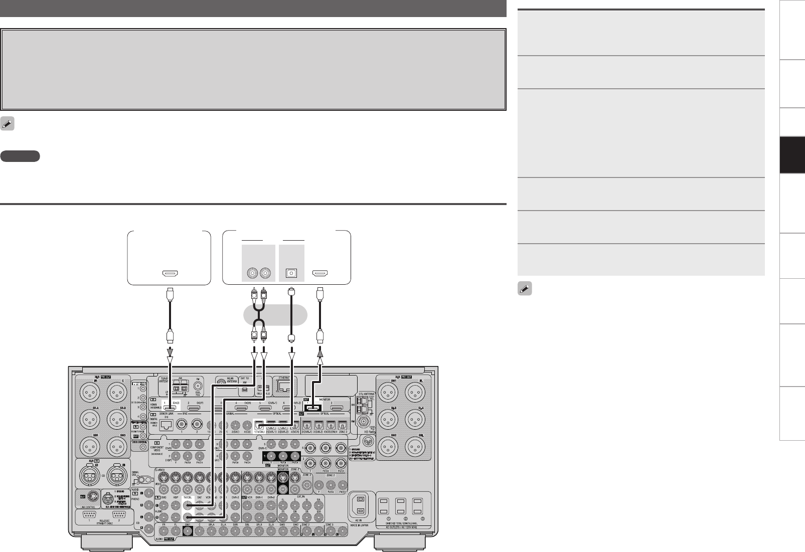
Getting Started Connections Setup Remote Control Multi-Zone Information Troubleshooting Specifications
Convenient Functions
HDMI Control Function
When connecting the AVP-A1HDCI to a television or player compatible with the HDMI control function, the following operations are
possible.
• Turn power ON/OFF (Synchronize with television)
• Switch to sound output equipment (TV and AVP-A1HDCI)
• Adjust volume
• Switch input source
3-
065
015*$"-
065
"6%*0
"6%*0
R
L
R
L
065
)%.*
*/
)%.*
When using these functions set as follows: GUI menu “Manual Setup” – “HDMI Setup” – “HDMI Control” (vpage 32).
Connections
Player compatible
with HDMI
control function
Television compatible with
HDMI control function
NOTE
When using the HDMI control function, do not assign HDMI input to “TV/CBL” by setting “Source Select” – “(input source)” – “Assign” in the
GUI menu.
1Connect the HDMI to the AVP-A1HDCI with
equipment compatible with the HDMI control
function.
2Put the power on for all the equipment connected to
the HDMI.
3Check the settings for all the equipment connected to
the HDMI and make HDMI available to them.
b Please consult the operating instructions for the connected
equipment to check the settings.
b Operations 1 ~ 3 do not have to be repeated once started.
b Carryout Operations 2 and 3 should any of the equipment be
plugged out.
4Switch the television input to the HDMI connected to
the AVP-A1HDCI.
5Switch the AVP-A1HDCI input to the HDMI input
source and check if the picture from the player is ok.
6Put the television power on standby and check if the
AVP-A1HDCI goes into standby.
If the AVP-A1HDCI does not work please check the following.
• Is the GUI menu “Manual Setup” – “HDMI Setup” – “HDMI Control”
– “Control” (vpage 32) set to “ON”?
• Is the GUI menu “Manual Setup” – “HDMI Setup” – “HDMI Control”
– “Control Monitor” (vpage 32) set for the monitor output
connected to television?
• Is the GUI menu “Manual Setup” – “HDMI Setup” – “HDMI Control”
– “Power Off Control” (vpage 32) set to “ON”?
• Is the control function used for the television HDMI properly set?
(Check the television operating instructions for details.)
• Should any of the operations below be performed, the interlocking
function may be reset, in which case, repeat Operation's 2 and 3.
• GUI menu “Source Select” – (input source) – “Assign” – “HDMI”
(vpage 48) setting has changed
• There is a change to the connection between the equipment and
the HDMI, or an increase in equipment.
• Change of HDMI monitor output in AVP-A1HDCI setup.
Operations
Playback
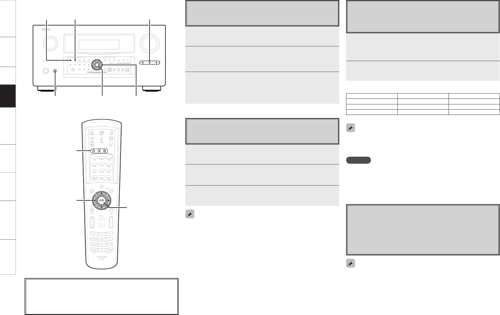
Getting Started Connections Setup Remote Control Multi-Zone Information Troubleshooting Specifications
CH SELECT
<POWER>
<STANDARD> <HOME THX CINEMA>QUICK SELECT
uio p
uio p
CH SELECT
QUICK SELECT
About the button names in these explanations
< > : Buttons on the main unit
[ ] : Buttons on the remote control unit
Button name only:
Buttons on the main unit and remote control unit
1Set the input source, input mode, surround mode,
room EQ settings and volume to the conditions you
want to store.
2Press and hold the desired QUICK SELECT.
Keep pressing the button until the quick select indicator lights.
• To call out the settings, press QUICK SELECT at which the desired
settings were stored.
• The Quick Select name can be changed (vpage 42).
NOTE
Input sources stored with the quick select function cannot be selected
if they have been deleted at GUI menu “Manual Setup” – “Option
Setup” – “Source Delete” (vpage 41). In this case, store them
again.
Input Source Volume
Quick Select 1 DVD –40 dB
Quick Select 2 TV/CBL –40 dB
Quick Select 3 VCR –40 dB
[Quick Select Defaults]
1Press CH SELECT.
2Press ui or CH SELECT to select “Fader”.
3Use o p to adjust the volume of the speakers.
(o: front, p: rear)
• The fader function does not affect the subwoofer.
• The fader can be adjusted until the volume of the speaker adjusted
to the lowest value is –12 dB.
1Press CH SELECT.
2Use ui or CH SELECT to select the speaker.
The speaker that can be set switches each time one of the
buttons is pressed.
3Use o p to adjust the volume.
b ”OFF” can be set by pressing o when the subwoofer’s volume
is set to –12dB.
The surround parameters, tone control, room EQ settings and the
volumes of the different speakers are stored for the individual surround
modes.
Quick Select Function
With this function, the currently playing input source, input mode,
surround mode, room EQ settings and volume can be stored in
the memory.
Fader Function
This function lets you adjust (fade) the sound from all the front or
rear speakers at once.
Channel Level
You can adjust the channel level either according to the playback
sources or to suit your taste, as described below.
Personal Memory Plus Function
This function sets the settings (input mode, surround mode,
HDMI output mode, Picture Adjust, Audio Delay etc.) last selected
for the individual input sources.
When you switch to an input source, the settings are automatically
set to the ones that were set the last time that input source was
used.
Playback

Getting Started Connections Setup Remote Control Multi-Zone Information Troubleshooting Specifications
1Turn off the power using <POWER>.
2Press <POWER> while simultaneously pressing
<STANDARD> and <HOME THX CINEMA>.
3Once the display starts ashing at intervals of about 1
second, release the two buttons.
If in step 3 the display does not flash at intervals of about 1 second,
start over from step 1.
Resetting the Microprocessor
Perform this procedure if the display is abnormal or if operations
cannot be performed.
All settings are reset when the microcomputer is reset.
Last Function Memory
This stores the settings as they were directly before the standby
mode was set.
When the power is turned back on, the settings are restored to as
they were directly before the standby mode was set.
Backup Memory
The various settings are backed up for about 1 week, even if the
power is turned off or the power cord is disconnected.
Playback
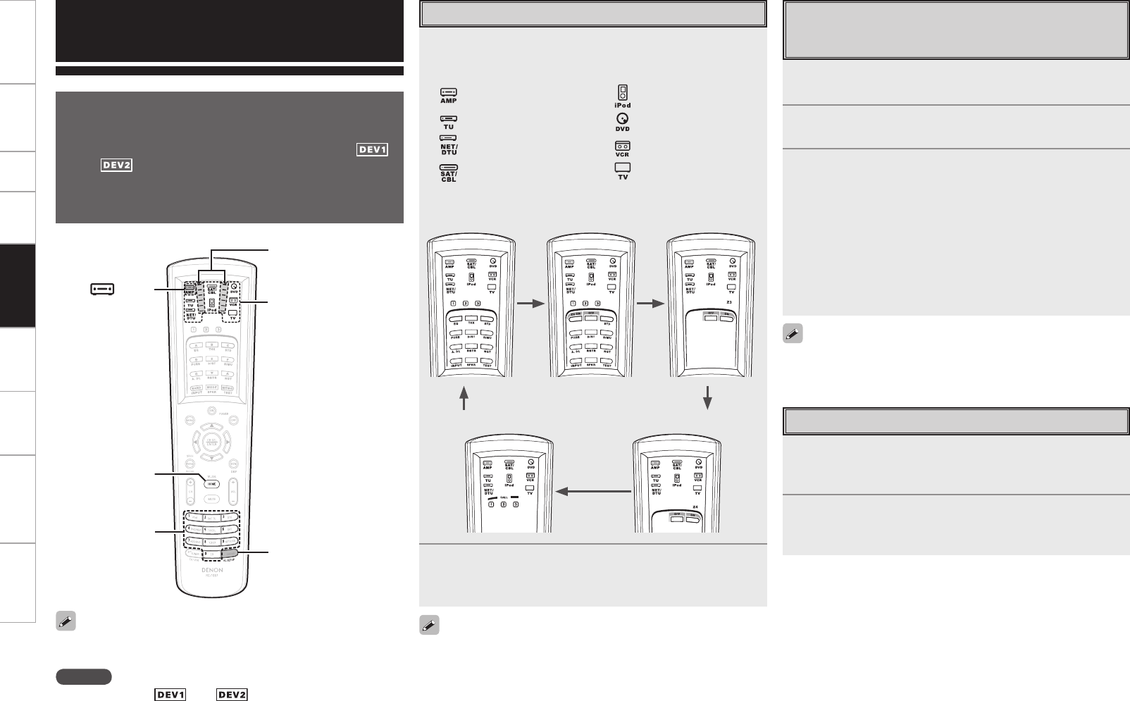
Getting Started Connections Setup Playback Multi-Zone Information Troubleshooting Specifications
Remote Control Unit Operations
Main Remote Control Unit
• On the main remote control unit, the display switches according
to the device being operated and the mode.
• In modes other than iPod, the mode switches between“ ”
and “ ” each time the [MODE SELECTOR] is pressed.
• In the AMP, TUNER, NET/DTU and iPod modes, when the remote
ID is set, the AVP-A1HDCI can be used independently even in an
environment containing multiple DENON amplifiers.
Depending on the model and year of manufacture of your equipment,
some buttons may not operate.
NOTE
The device mode (“ ” or “ ”) cannot be changed while the
setting is being made.
1Press [MODE SELECTOR] for the component to be
operated.
The indicator for the component to be operated flashes.
: AMP / ZONE2 / ZONE3 / ZONE4 /
SYSTEM CALL
: TUNER (FM/AM) / XM
: NETWORK/USB /
DIGITAL TUNER (HD Radio)
: Satellite Receiver / Cable TV
: iPod
: DVD player (recorder) /
CD player (recorder)
: VCR / TAPE
: TV
b The mode switches each time [AMP] is pressed.
GAMP modeH GZONE2 modeH GZONE3 modeH
GSYSTEM CALL modeH GZONE4 modeH
2Operate the component.
b For details, refer to the component’s operating instructions.
1Press [MODE SELECTOR] for the device you want to
preset.
2Press and hold in [RC SETUP] for at least 3 seconds.
The signal transmission indicator flashes twice.
3Press [NUMBER] and input the 5-digit number of the
brand of the component to be preset. The numbers
are shown in the Preset Code Table (vEnd of this
manual).
When the code is registered, the signal transmission indicator
flashes twice.
When the preset code is transmitted, the mode indicator for the
component to which that code belongs flashes.
b The input mode is canceled if no button is operated for 10
seconds.
Some brands have more than one preset code. If the component does
not operate, try inputting a different code.
1Press [MODE SELECTOR] for the component to be
operated.
The mode indicator of the device to be operated flashes.
2Operate the component.
b For details, refer to the component’s operating instructions.
[NUMBER]
[MODE SELECTOR]
[RC SETUP]
[HOME]
[ AMP]
Signal transmission
indicator
[HOME] is used to return to the AMP mode (AMP, ZONE2, ZONE3,
ZONE4 or SYSTEM CALL) when in any mode other than AMP.
Operating DENON Audio Components Presetting
The included main remote control unit can be preset to operate
devices of various brands.
Operating Preset Components
Remote Control
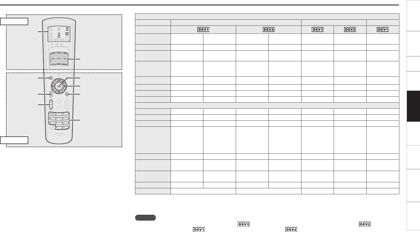
Getting Started Connections Setup Playback Multi-Zone Information Troubleshooting Specifications
[MENU]
[MODE
SELECTOR]
[CH + /
SHUFFLE],
[CH – /
REPEAT]
[SETUP/
SEARCH]
[ENTER]
[RETURN]
[0 ~ 9, +10]
[uiop]
[1],
[8 9],
[6 7], [3],
[2],
[SOURCE ON],
[SOURCE OFF]
EL Display
MODE SELECTOR DVD VCR iPod
Device Mode
Device operated DVD
(Default setting) DVD Recorder CD
(Default setting) CD Recorder VCR TAPE iPod
1Playback Playback Playback Playback Playback Playback Playback/Pause
8 9 Auto search
(cue)
Auto search
(cue)
Auto search
(cue)
Auto search
(cue)
Auto search
(cue)
Auto search
(cue)
Auto search
(cue)
6 7
Manual search
(fast-reverse/
fast-forward)
Manual search
(fast-reverse/
fast-forward)
Manual search
(fast-reverse/
fast-forward)
Manual search
(fast-reverse/
fast-forward)
Manual search
(fast-reverse/
fast-forward)
Manual search
(fast-reverse/
fast-forward)
Manual search
(fast-reverse/
fast-forward)
3Pause Pause Pause Pause Pause Pause –
2Stop Stop Stop Stop Stop Stop Stop
SOURCE ON Power on Power on – – Power on – –
SOURCE OFF Power off Power off – – Power off – –
Buttons
MENU Menu/guide Menu/guide – – Menu/guide – Menu
u i o p Cursor Cursor – – Cursor – Cursor
ENTER Enter setting Enter setting – – Enter setting – Enter
SETUP/SEARCH Set up Set up – – Set up –
Page forward
screen / Browse/
Remote mode
switching (Press
and hold)
RETURN Return Return – – Cancel – Return
CH + / SHUFFLE – – – – Switch channels – 1-track/album
shuffle play
CH - / REPEAT – – – – Switch channels – 1-track/all-track
repeat play
0 ~ 9, +10 Select track Select track Select track Select track – – –
Special Remarks q, w q q q –
Functions of Buttons by Component
GSpecial RemarksH
q Only one component can be preset for each mode. If a new code is preset, the previous code is automatically cleared.
w The names of the functions for the DVD remote control buttons differ from brand to brand. Check beforehand.
NOTE
• Preset a DVD player or DVD recorder for the “DVD” ( ) mode. Preset a CD player or CD recorder for the “DVD” ( ) mode.
• Preset a VCR for the “VCR” ( ) mode. Preset a tape deck for the “VCR” ( ) mode.
EL Display
Buttons
Remote Control
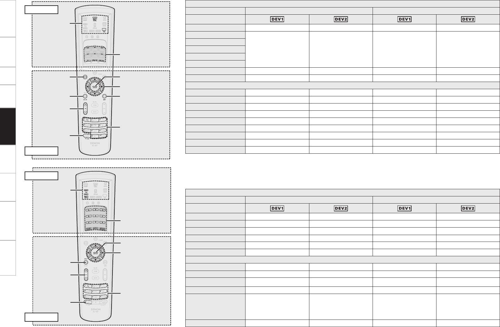
Getting Started Connections Setup Playback Multi-Zone Information Troubleshooting Specifications
[MENU]
[CH +/–]
[TV/VCR]
[ENTER]
[DISPLAY]
[0 ~ 9, +10]
[uiop]
[SETUP]
[1],
[8 9],
[6 7], [3],
[2],
[SOURCE ON],
[SOURCE OFF]
[MODE
SELECTOR]
EL Display
MODE SELECTOR TV Satellite Receiver / Cable TV
Device Mode
Device operated TV (HITACHI) TV (SONY) SAT SAT
1
Punch through Punch through Punch through Punch through
8 9
6 7
3
2
SOURCE ON Power on Power on Power on Power on
SOURCE OFF Power off Power off Power off Power off
Buttons
MENU Menu/guide Menu/guide Menu/guide Menu/guide
u i o p Cursor Cursor Cursor Cursor
ENTER Enter setting Enter setting Enter setting Enter setting
SETUP Set up Set up Set up Set up
DISPLAY Display Display Display Display
CH + / – Switch channels Switch channels Switch channels Switch channels
0 ~ 9, +10 Channel selection Channel selection Channel selection Channel selection
TV/VCR Switch inputs Switch inputs – –
Special Remarks q, e q, e q, e q, e
GSpecial RemarksH
q Only one component can be preset for each mode. If a new code is preset, the previous code is automatically cleared.
e The CD, VCR or DVD buttons (one only set) can be assigned to the TV, satellite receiver and cable TV mode (vpage 81 “Punch Through
Function”).
EL Display
Buttons
[CH +/–]
[SEARCH]
[SHIFT]
[A ~ G], [d f],
[BAND],
[MODE],
[MEMO]
[ENTER]
[0 ~ 9]
[uiop]
[MODE
SELECTOR]
EL Display
MODE SELECTOR TU NET / DTU
Device Mode
Device operated Analog tuner XM NET / USB HD Radio
A ~ G Preset memory block selection Preset memory block selection Preset memory block selection Preset memory block selection
d f Tuning + / –Channel selection – Tuning + / –
BAND AM/FM switching – – AM/FM switching
MODE Switch search modes – – Switch search modes
MEMO Preset memory registration Preset memory registration Preset memory registration Preset memory registration
Buttons
u i o p – Category search Cursor Multicast switching (ui)
ENTER – – Enter, Playback/Pause –
SEARCH RDS search Direct search Search Multicast switching
CH + / – Preset channel selection Preset channel selection Preset channel selection Preset channel selection
0 ~ 9 Preset channel selection
(1 ~ 8)
Preset channel selection
(1 ~ 8) /
Direct channel search
(0 ~ 9)
Preset channel selection
(1 ~ 8)
Preset channel selection
(1 ~ 8)
SHIFT Switch memory block Switch memory block – Switch memory block
EL Display
Buttons
Remote Control
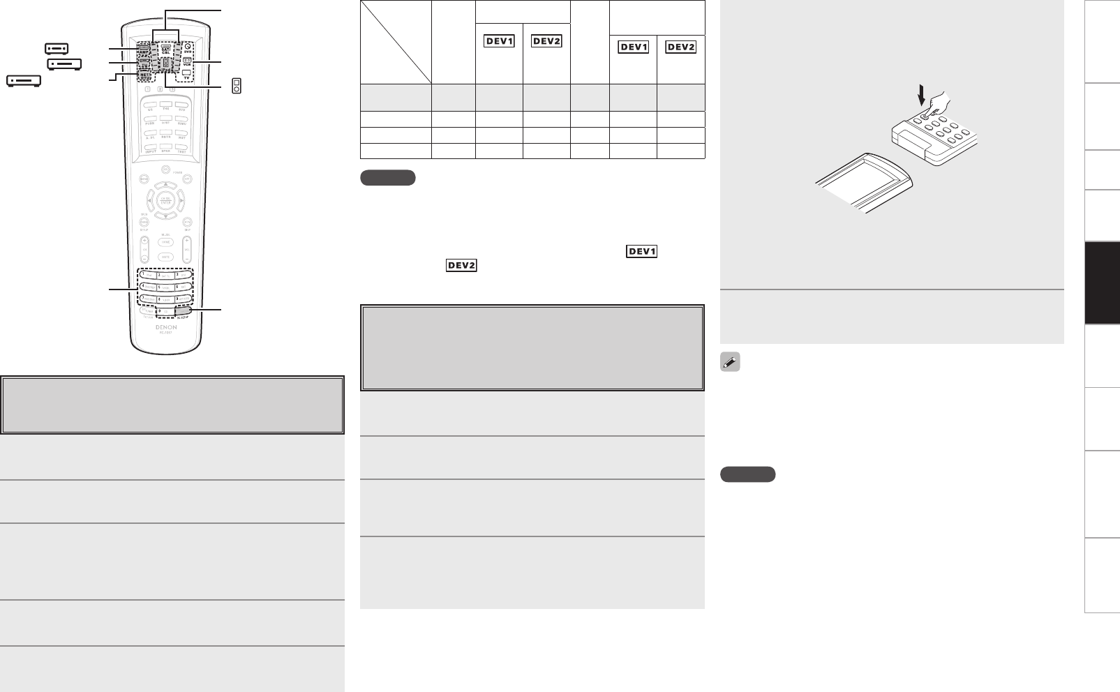
0
Getting Started Connections Setup Playback Multi-Zone Information Troubleshooting Specifications
Setting the Remote ID
When using multiple DENON AV receivers in the same room,
make this setting so that only the desired AV receiver operates.
1Press [AMP] to set the main remote control unit to the
AMP mode.
2Press and hold in [RC SETUP] for at least 3 seconds.
The signal transmission indicator flashes twice.
3Refer to the table at the right, and use [NUMBER] to
input the 5-digit number corresponding to the remote
ID to be changed.
The signal transmission indicator flashes twice.
4Press [TU], [iPod] or [NET/DTU] to select the mode to
be set.
5Repeat steps 2 to 4 to set the remote IDs for all modes.
NOTE
• When changing a setting, be sure to set the same remote ID as the
AVP-A1HDCI’s (vpage 43).
• When changing the AMP mode’s remote ID, also change the
“TUNER”, “iPod” and “NET/DTU” remote ID at the same time.
• Set the remote ID of an analog tuner for “TUNER” ( ), the XM
remote ID for “ ”.
5Point the main remote control units directly at each
other and press and hold the button on the other
device’s remote control unit that you want to learn.
Once learning is completed normally, the display lights and the
signal transmission indicator flashes twice.
b If you want to learn other buttons, repeat steps 4 and 5.
b The mode can be switched by pressing [MODE SELECTOR].
b The signal transmission indicator lights once for a long time if
learning was not possible
6Press and hold in [RC SETUP] for at least 3 seconds.
The signal transmission indicator flashes twice and the setting
is completed.
[NUMBER]
[MODE SELECTOR]
[RC SETUP]
[ NET/DTU]
[ TU]
[ AMP]
[ iPod]
Other device’s
remote control unit
AVP-A1HDCI’s main remote
control unit (RC-1067)
Learning Function
If your AV devices are of a brand other than DENON or if they
cannot be operated with the preset memory function, their remote
control signals can be transfered to stored in the AVP-A1HDCI’s
main remote control unit.
1Press [MODE SELECTOR] for the device you want to
set.
2Press and hold in [RC SETUP] for at least 3 seconds.
The signal transmission indicator flashes twice.
3Press [9], [7] and [5], in that order.
The signal transmission indicator flashes twice and the learning
mode is set.
4Press the button to be set.
The main remote control unit’s display turns off.
b If a button that cannot be learned is pressed, the signal transmission
indicator lights but the signal is not learned.
• With some remote control units, the signals cannot be learned or the
device will not operate properly even when the signals have been
learned. In this case, use the device’s own remote control unit.
• Learned buttons have priority over the preset memory. If you no
longer need the learned setting, reset the learning function (vpage
82).
NOTE
• [HOME] cannot be learned.
• Do not learn any remote control signals at [RC SETUP].
• The AMP, ZONE2, ZONE3, ZONE4 and SYSTEM CALL modes
cannot be learned.
Signal transmission
indicator
MODE
SELECTOR
Remote ID
AMP
(MAIN)
TUNER
iPod
NET/DTU
(Analog
TUNER)
(XM) (Net
Audio)
(HD
Radio)
1
(Default) 81001 52863 52864 72815 62865 62840
2 82001 52795 52812 72816 62837 62841
3 83001 52800 52813 72817 62838 62842
4 84001 52805 52814 72818 62839 62843
Remote Control
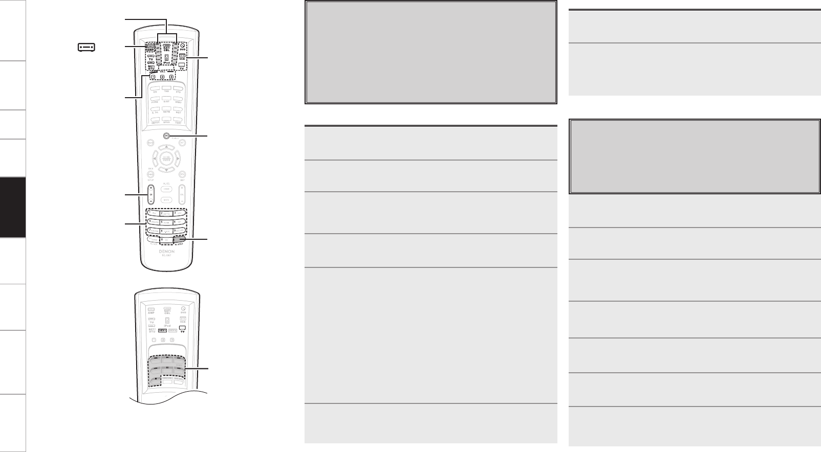
Getting Started Connections Setup Playback Multi-Zone Information Troubleshooting Specifications
System Call Function
This function lets you register a series of operations at a single
button.
For example, the amplifier can be turned on, the input source
selected, the monitor’s power turned on, the source device’s
power turned on and the play mode set all by pressing a single
button.
Up to 32 signals each can be registered at [SYSTEM CALL] (1, 2
or 3).
1Press [MODE SELECTOR] for the device you want to
register.
2Press and hold in [RC SETUP] for at least 3 seconds.
The signal transmission indicator flashes twice.
3Press [9], [7] and [8], in that order.
The signal transmission indicator flashes twice and the system
call registration mode is set.
4Press [SYSTEM CALL] (1, 2 or 3) at which you want to
register the signals.
5Press the buttons you want to register in the same
sequence as the operations you want to perform.
The signal transmission indicator lights when a button is
pressed.
Example : Press [POWER ON].
↓
Press [MODE SELECTOR] – [DVD].
↓
Press [1].
b The mode can be switched by pressing [MODE SELECTOR].
b Perform the registration procedure for all the buttons you want to
register.
6Press and hold in [RC SETUP] for at least 3 seconds.
The signal transmission indicator flashes twice and the setting
is completed.
Calling out
1Press [AMP], to select “SYSTEM CALL”.
2Press [SYSTEM CALL] (1, 2 or 3) at which the signals
were registered.
The registered signals are transmitted in the registered
sequence.
Registering Punch Through Function
CD, DVD or VCR mode buttons can be stored at unused TV or
SAT/CBL mode buttons.
For example, when DVD mode buttons are assigned to the TV
mode, the DVD mode operations can be performed while in the
TV mode.
1Press [MODE SELECTOR] for the device you want to
punch through (CD, DVD or VCR).
2Press and hold in [RC SETUP] for at least 3 seconds.
The signal transmission indicator flashes twice.
3Press [9], [8] and [4], in that order.
The signal transmission indicator flashes twice and the punch
through setting mode is set.
4Press [MODE SELECTOR] for the device you want to
punch through (CD, DVD or VCR).
5Press the button you want to punch through (1, 2,
6, 7, 8, 9 or 3).
6Press [MODE SELECTOR] for the equipment (TV or
SAT/CBL) you want to set to punch-through.
7Press and hold in [RC SETUP] for at least 3 seconds.
The signal transmission indicator flashes twice and the setting
is completed.
Signal
transmission
indicator
[NUMBER]
[MODE
SELECTOR]
[RC SETUP]
[CHANNEL+/–]
[SYSTEM CALL]
[ AMP]
[POWER ON]
[8], [9],
[1],
[6], [7],
[3], [2]
Remote Control

Getting Started Connections Setup Playback Multi-Zone Information Troubleshooting Specifications
1Press [MODE SELECTOR] for the device you want to
reset.
2Press and hold in [RC SETUP] for at least 3 seconds.
The signal transmission indicator flashes twice.
3Press [9], [7] and [6], in that order.
The signal transmission indicator flashes twice.
4Press the button you want to reset twice.
The signal transmission indicator flashes twice.
Resetting the Main Remote Control Unit
Learning Function
GResetting button by buttonH
1Press [MODE SELECTOR] for the device you want to
reset.
2Press and hold in [RC SETUP] for at least 3 seconds.
The signal transmission indicator flashes twice.
3Press [9], [7] and [6], in that order.
The signal transmission indicator flashes twice.
4Press [MODE SELECTOR] for the device you want to
reset twice.
The signal transmission indicator flashes twice.
GResetting by device modeH
1Press and hold in [RC SETUP] for at least 3 seconds.
The signal transmission indicator flashes twice.
2Press [9], [7] and [8], in that order.
The signal transmission indicator flashes twice.
3Press [SYSTEM CALL] (1, 2 or 3) you want to reset.
4Press and hold in [RC SETUP] for at least 3 seconds.
The signal transmission indicator flashes twice.
1Press [MODE SELECTOR] for the device you want to
reset (TV or SAT/CBL).
2Press and hold in [RC SETUP] for at least 3 seconds.
The signal transmission indicator flashes twice.
3Press [9], [8] and [4], in that order.
The signal transmission indicator flashes twice.
4Press and hold in [RC SETUP] for at least 3 seconds.
The signal transmission indicator flashes twice.
1Press and hold in [RC SETUP] for at least 3 seconds.
The signal transmission indicator flashes twice.
2Press [9], [8] and [1], in that order.
The signal transmission indicator flashes 4 times.
All the settings are restored to their defaults.
System call function
Punch-through function
All settings
Setting the Time the Backlight Stays Lit
1Press and hold in [RC SETUP] for at least 3 seconds.
The signal transmission indicator flashes twice.
2Press [9], [7] and [3], in that order.
The signal transmission indicator flashes twice and the backlight
on time setting mode is set.
3Set the light on time.
The signal transmission indicator flashes twice.
[Settable times] : [1] : 5 sec.
[2] : 10 sec. (Default)
[3] : 15 sec.
[4] : 20 sec.
[5] : 25 sec.
Adjusting the Backlight’s Brightness
The display’s brightness can be adjusted in 5 steps.
(Default: Step 3)
1Press and hold in [RC SETUP] for at least 3 seconds.
The signal transmission indicator flashes twice.
2Press [CHANNEL +] or [CHANNEL –].
The display gets one step brighter when [+] is pressed.
The display gets one step darker when [–] is pressed.
3Press [RC SETUP] to complete the setting.
Remote Control
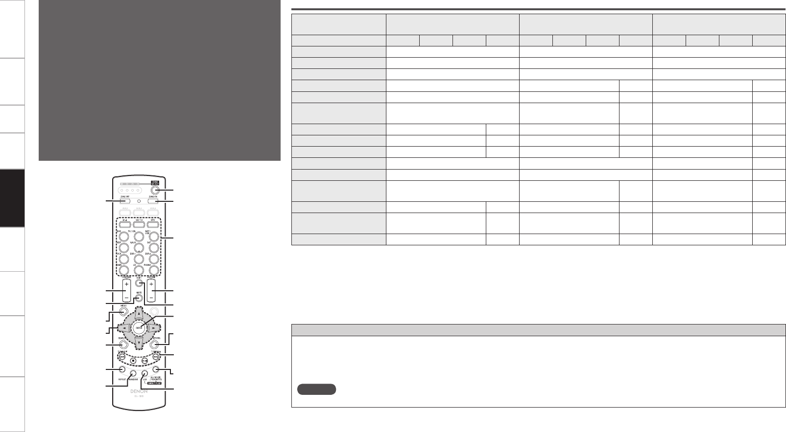
Getting Started Connections Setup Playback Multi-Zone Information Troubleshooting Specifications
Sub Remote Control Unit Operations
• The sub remote control unit is equipped with frequently used
buttons, so it can be used for simple remote control unit
operations.
• The sub remote control unit can also be used for multi-zone, so
you can use it to control the AVP-A1HDCI from other rooms.
• The operations listed below can be performed with the sub
remote control unit.
• Switching the input source
• Adjusting the volume
• Tuner (AM/FM), XM, HD Radio and iPod operations
• NET/USB direct play
• GUI menu and ZONE2 on-screen display operations
• Zone power on/off
• It is not possible to operate devices other than the amplifier.
[USB]
[ALL MUSIC], [FAVORITES]
[8 9], [2], [1/3],
[TUNING d f]
[ZONE SELECT]
[ZONE ON]
[ZONE OFF]
[MENU]
[SEARCH]
[MUTE]
[CHANNEL +/–]
[RANDOM]
[REPEAT]
[SOURCE SELECT]
[VOLUME +/–]
[SHIFT]
[ENTER]
[RETURN]
[uiop]
Device operated DVD, HDP, TV / CBL, DVR-1, DVR-2, VCR,
V.AUX, SAT, CD, PHONO
TUNER
(AM/FM)
DTU
(HD Radio)
Zone selection M Z2 Z3 Z4 M Z2 Z3 Z4 M Z2 Z3 Z4
ZONE SELECT Zone operation mode selection Zone operation mode selection Zone operation mode selection
ZONE OFF Power turned off (b1) Power turned off (b1) Power turned off (b1)
ZONE ON Power turned on (b1) Power turned on (b1) Power turned on (b1)
SOURCE SELECT Input source selection (b2) Input source selection – Input source selection –
CHANNEL + / – – Preset channel selection – Preset channel selection –
SHIFT –Preset channel memory
block selection –Preset channel memory
block selection –
VOLUME + / – Adjustment of volume (b1) –Adjustment of volume (b1) –Adjustment of volume (b1) –
MUTE Muting (b1) –Muting (b1) –Muting (b1) –
MENU Selected zone menu – Selected zone menu – Selected zone menu –
u i o p – – Multicast switching (u i)–
SEARCH – RDS search Multicast switching –
8 9,
TUNING d f – Tuning – Tuning –
USB b3–b3–b3–
ALL MUSIC *
(Media server only) b4–b4–b4–
FAVORITES * b5–b5–b5–
b1: Affects the currently selected zone.
b2: In ZONE4, it is not possible to select “XM”, “HD Radio”, or sources with no digital input signals (“TUNER”, “PHONO”, “iPod”, etc.).
Network audio signals (Internet radio, media server, USB) can be played as long as they are not copyright-protected.
b3: The input source switches to “NET/USB” and the files on the USB memory device are played.
b4: The input source switches to “NET/USB” and the files in “All Music” on the media server are played.
b5: The input source switches to “NET/USB” and the files in “Favorites” are played.
*: Whether “All Music” or “Favorites” is selected depends on the “Direct Play” setting (vpage 49).
Functions of Buttons by Component
DIRECT PLAY button
• Playback is possible in the mode selected at GUI menu “Source Select” – “NET/USB” – “Playback Mode” – “Direct Play”.
FAVORITES: Playback starts from the first track registered in the favorites.
ALL MUSIC: Playback starts from the first track registered in the “All Music” folder.
• When [USB] is pressed, playback starts from the first track on the USB memory device.
NOTE
When the media server is stopped or restarted, it may no longer be possible to play tracks stored in the favorites.
Remote Control
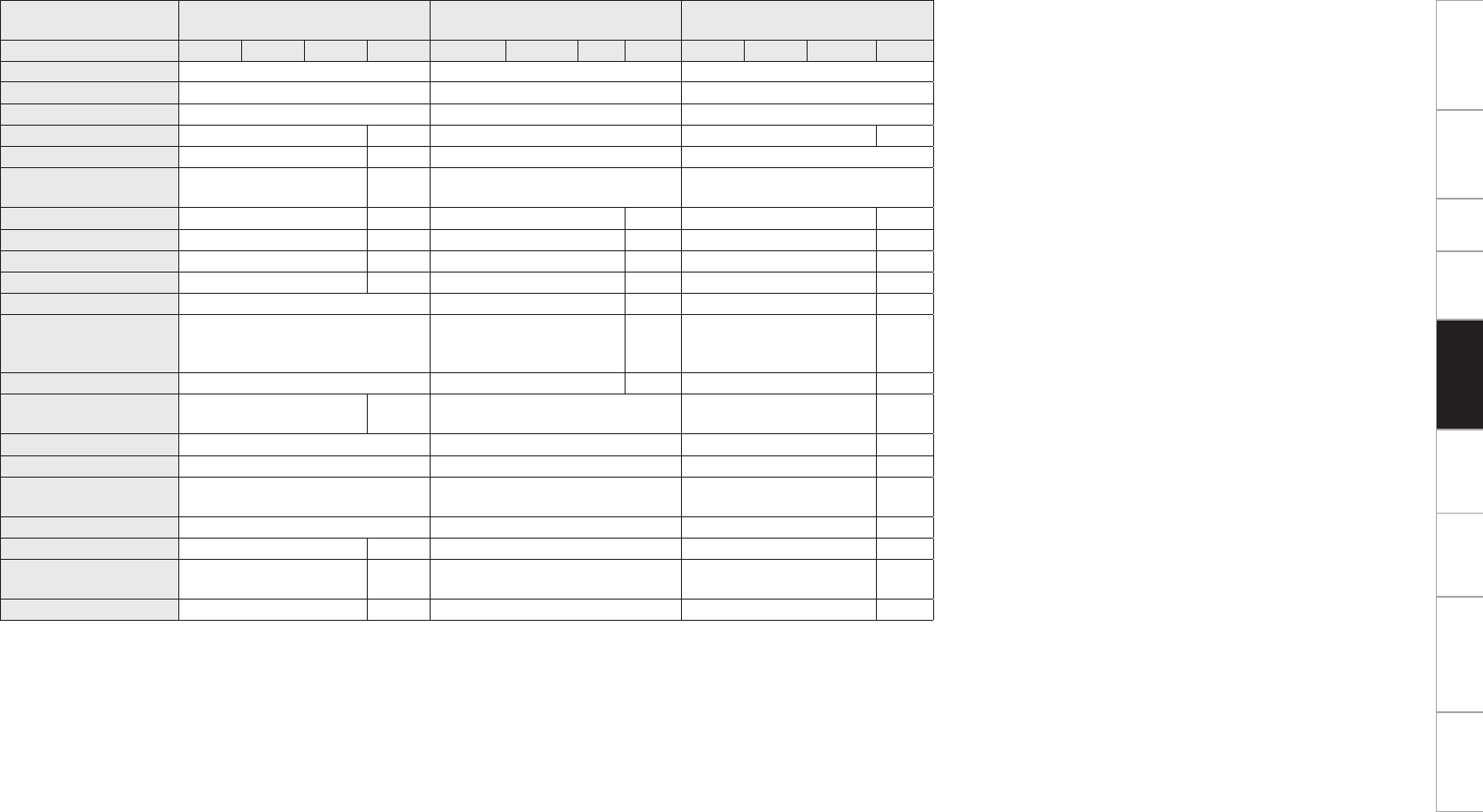
Getting Started Connections Setup Playback Multi-Zone Information Troubleshooting Specifications
Device operated SAT TU
(XM) NET / USB iPod
Zone selection M Z2 Z3 Z4 M Z2 Z3 Z4 M Z2 Z3 Z4
ZONE SELECT Zone operation mode selection Zone operation mode selection Zone operation mode selection
ZONE OFF Power turned off (b1) Power turned off (b1) Power turned off (b1)
ZONE ON Power turned on (b1) Power turned on (b1) Power turned on (b1)
SOURCE SELECT Input source selection – Input source selection (b2)
Input source selection
–
CHANNEL + / – Preset channel selection – Preset channel selection –
SHIFT Preset channel memory
block selection – – –
VOLUME + / – Adjustment of volume (b1) –Adjustment of volume (b1) –Adjustment of volume (b1) –
MUTE Muting (b1) –Muting (b1) –Muting (b1) –
MENU Selected zone menu – Selected zone menu – Selected zone menu –
u i o p Category search – File operations – File operations –
ENTER – File operations – File operations –
SEARCH Direct access of channel Page forward screen /
Character search –
Page forward screen /
Browse/Remote mode
switching (press and hold)
–
RETURN – File operations – File operations –
8 9,
TUNING d f Channel selection – Track search Track search –
2– Stop Stop –
1/3– Play/pause Play/pause –
REPEAT –1-track/all-track repeat play
(USB / Media server) 1-track/all-track repeat play –
RANDOM – Random play (USB / Media server) Song/album shuffle play –
USB b3–b3b3–
ALL MUSIC *
(Media server only) b4–b4b4–
FAVORITES * b5–b5b5–
b1: Affects the currently selected zone.
b2: In ZONE4, it is not possible to select “XM”, “HD Radio”, or sources with no digital input signals (“TUNER”, “PHONO”, “iPod”, etc.).
Network audio signals (Internet radio, media server, USB) can be played as long as they are not copyright-protected.
b3: The input source switches to “NET/USB” and the files on the USB memory device are played.
b4: The input source switches to “NET/USB” and the files in “All Music” on the media server are played.
b5: The input source switches to “NET/USB” and the files in “Favorites” are played.
*: Whether “All Music” or “Favorites” is selected depends on the “Direct Play” setting (vpage 49).
Remote Control
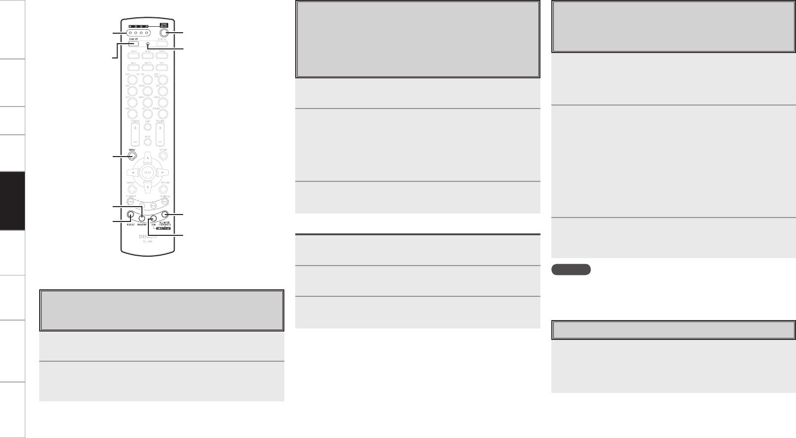
Getting Started Connections Setup Playback Multi-Zone Information Troubleshooting Specifications
[USB]
[ALL MUSIC/
FAVORITES]
[ZONE SELECT]
[ZONE OFF]
[MENU]
[RANDOM]
[REPEAT]
[ADVANCED SETUP]
1Press [ZONE SELECT].
The currently selected multi-zone indicator lights.
2While the multi-zone indicator is light, press [ZONE
SELECT] to select the zone to be operated.
The currently selected multi-zone indicator lights.
1Use the tip of a pen to press [ADVANCED SETUP].
All the multi-zone indicators light.
2Select the multi-zone to be set.
The selected multi-zone indicator lights.
q To set to “MAIN ZONE” : Press [REPEAT].
w To set to “ZONE2” : Press [RANDOM].
e To set to “ZONE3” : Press [USB].
r To set to “ZONE4” : Press [ALL MUSIC/FAVORITES].
3Use the tip of a pen to press [ADVANCED SETUP].
The multi-zone indicator turns off.
To Cancel
1Use the tip of a pen to press [ADVANCED SETUP].
The currently selected multi-zone indicator lights.
2Press [ZONE SELECT].
All the multi-zone indicators light.
3Use the tip of a pen to press [ADVANCED SETUP].
The multi-zone indicator turns off.
1While pressing [MENU], press [ADVANCED SETUP]
with the tip of a pen.
The multi-zone indicator corresponding to the currently selected
remote ID flashes.
2Select the remote ID to be set.
q To set to 1 : Press [REPEAT].
The “M” indicator flashes.
w To set to 2 : Press [RANDOM].
The “Z2” indicator flashes.
e To set to 3 : Press [USB].
The “Z3” indicator flashes.
r To set to 4 : Press [ALL MUSIC/FAVORITES].
The “Z4” indicator flashes.
3While pressing [MENU], press [ADVANCED SETUP]
with the tip of a pen.
The multi-zone indicator turns off.
While pressing [ZONE OFF], press [ADVANCED SETUP]
with the tip of a pen.
All the multi-zone indicators flash 4 times, then all the settings are
restored to their defaults.
NOTE
When changing a setting, be sure to set the same remote ID as the
AVP-A1HDCI’s (vpage 43).
Multi-zone indicator
Switching Zones
Use this procedure to select the zone to be operated by the sub
remote control unit.
Setting the Zone for Which the Sub
Remote Control Unit is Used (ZONE
SELECT LOCK Mode)
We recommend always using the sub remote control unit for the
same room. When this is done, the unit can be set so that the
zone does not switch when buttons are operated.
Setting the Remote ID
When using multiple DENON AV receivers in the same room,
make this setting so that no AV receiver other than the desired
one operates.
Resetting the Settings
Remote Control
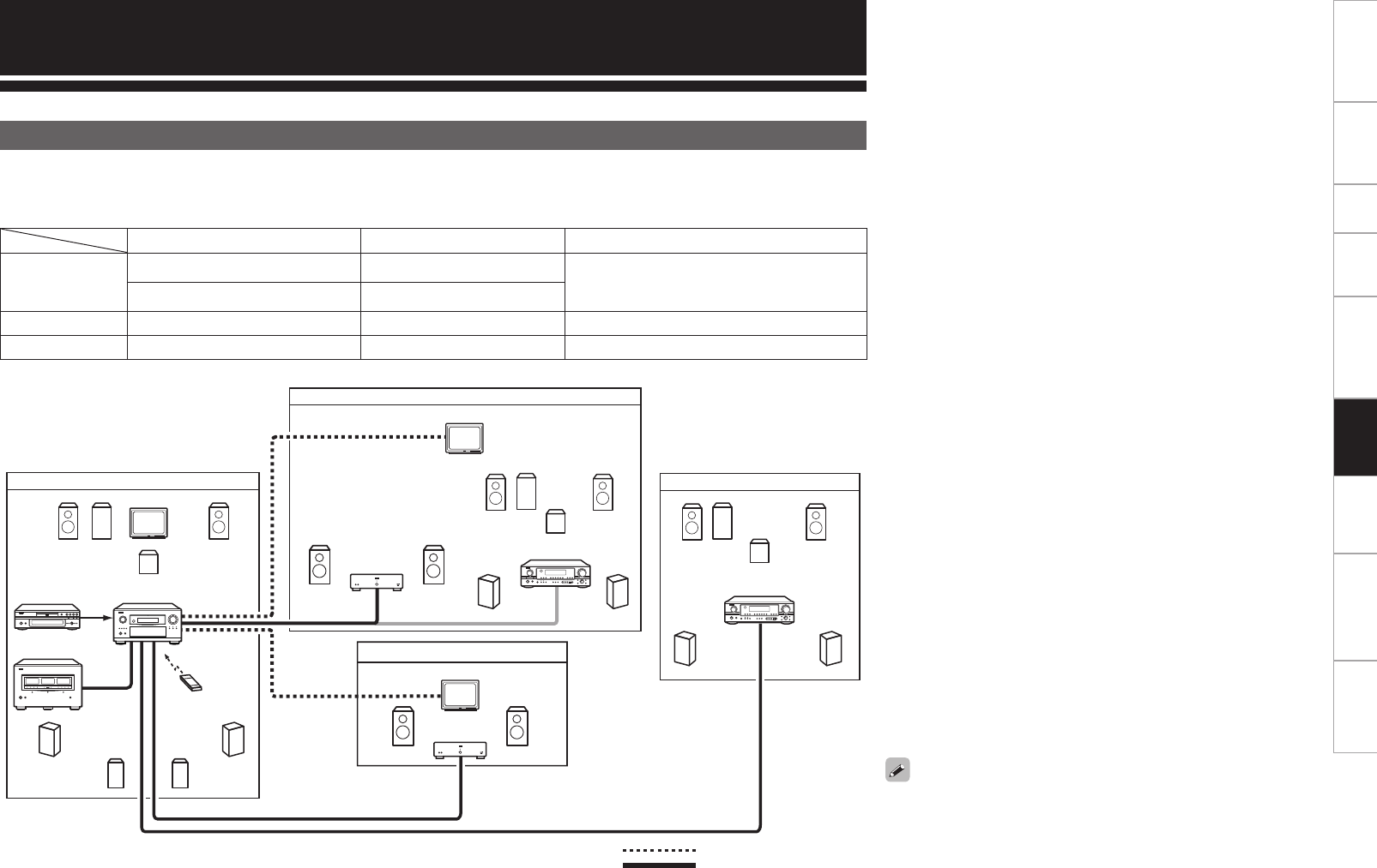
Getting Started Connections Setup Playback Remote Control Information Troubleshooting Specifications
Multi-Zone Connections and Operations
Connectors for audio output Audio signals Connectors for video output
ZONE2
ZONE2 PRE OUT Stereo ZONE2 VIDEO OUT,
ZONE2 S-VIDEO OUT,
ZONE2 COMPONENT VIDEO OUT
ZONE2 OPTICAL OUT Bit-stream
ZONE3 ZONE3 PRE OUT Stereo ZONE3 VIDEO OUT
ZONE4 ZONE4 OPTICAL4 OUT Bit-stream –
Multi-Zone Connections
• For ZONE2, it is necessary to set in sequence with the signal connected to either the power amplifier or bit stream amps.
The amp should be the power amplifier in the case of ZONE3, and the bit-stream for ZONE4.
• If the signal inputted to ZONE2 is analog, change to PCM(2-channel) signal, and output it from ZONE2 optical output connectors.
$
'- 48 48
48
'3
4- 43
4#
3
4#
-
$
'- '3
4- 43
$
'- '3
4- 43
ZONE3 audio output
MAIN ZONE (7.1-channel system)
Monitor
ZONE2
ZONE3
DVD player
Input
Remote
control unit
ZONE2 audio
output
ZONE2 video
output
AVP-A1HDCI
Monitor
Power amplifier
: Video cable
: Audio cable
• When only using one speaker for ZONE2 or ZONE3, set to “Mono”.
In this case, the ZONE2 (ZONE3) monaural output is output from
the ZONE2 (ZONE3) pre-out L and R connectors, so connect as
desired.
• Separate power amplifiers are needed for ZONE2 and ZONE3.
AV amplifier
ZONE4
ZONE4
digital output
Monitor
ZONE3 video
output
AV amplifier
Power amplifier or
ZONE2 digital output
Power amplifier
Multi-Zone
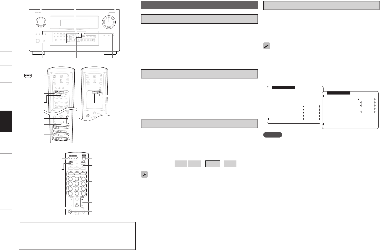
Getting Started Connections Setup Playback Remote Control Information Troubleshooting Specifications
Multi-Zone Operations
Turning the Power On and Off
GOperation on the main unitH
Press <ZONE2 ON/OFF>, <ZONE3 ON/OFF> or <ZONE4 ON/OFF> for
the zone to be operated.
When the power turns on, the multi-zone indicator lights on the display.
GOperation on the remote control unitH
In the zone mode you want to operate, press [ON] or [OFF].
Selecting the Input Source
GOperation on the main unitH
q Press <ZONE2/3/4 / REC SELECT> and select the zone to be adjusted.
w Turn <SOURCE SELECT>.
GOperation on the remote control unitH
In the zone mode you want to operate, press [SOURCE SELECT].
Adjusting the Volume
GOperation on the main unitH
q Press <ZONE2/3/4 / REC SELECT> and select the zone to be adjusted.
w Turn <VOLUME> to adjust.
GOperation on the remote control unitH
In the zone mode whose volume you want to adjust, press [VOLUME].
[Variable range] – – – –70dB ~ –40dB ~ 18dB
• The volume can be adjusted when GUI menu “Manual Setup”
– “Zone Setup” – “(select the zone)” – “Volume Level” is set to
“Variable”. The volume can be increased up to the value set at
GUI menu “Manual Setup” – “Zone Setup” – “(select the zone)”
– “Volume Limit” (vpage 39).
• The volume for ZONE2 and ZONE3 can be adjusted with the remote
control unit.
SOURCE SELECT
<ZONE2 ON/OFF>
<ZONE2/3/4/ REC SELECT>
<ZONE3 ON/OFF> <ZONE4 ON/OFF>
VOLUME
[ON]
[OFF]
[MUTE]
VOLUME
[ AMP]
SOURCE
SELECT
(ZONE2 mode)
About the button names in these explanations
< > : Buttons on the main unit
[ ] : Buttons on the remote control unit
Button name only:
Buttons on the main unit and remote control unit
ZONE2 MENU
INPUT :DVD
SIGNAL:ANALOG
VOL. :-40dB
>Bass 0dB
HPF OFF
Treble 0dB
Lch Lev. 0dB
Rch Lev. 0dB
ZONE2 MENU
>Channel STEREO
Vol.Lev. VAR
P.On Lev. LAST
Vol.Limit OFF
Mute Lev. FULL
Turning off the Sound Temporarily
In the zone mode for which you want to mute the sound, press
[MUTE].
The sound is reduced to the level set at GUI menu “Manual Setup”
– “Zone Setup” – “(select the zone)” – “Mute Level” (vpage 39).
To cancel, either adjust the volume or press [MUTE] again.
The setting is canceled when the zone’s power is turned off.
• The source selected for ZONE3 is also output from the recording
output connectors.
• When the [MENU] is selected, it is possible to carryout “Zone
Setup” looking at the on-screen display in ZONE2. Also, when the
“OSD” is set as “ZONE2/ZONE3”, the on-screen display comes on
the ZONE2 monitor when ZONE3 has been operated so it is possible
to operate it looking at this.
NOTE
• The digital signal from the digital input connectors (OPTICAL/
COAXIAL) are output to the analog audio connectors in ZONE2 and
ZONE3 in the case of PCM (2-channel) signals only.
• Digital audio signals input from the DENON LINK or HDMI connectors
cannot be played in multi-zone.
• “XM” or “HD Radio” cannot be selected with digital output
(OPTICAL) in ZONE2. Copyright-protected Network audio signals
(Internet radio, media server, USB, Rhapsody) cannot be output.
• In ZONE4, it is not possible to select “XM”, “HD Radio”, or sources
with no digital input signals (“TUNER”, “PHONO”, “iPod”, etc.).
Network audio signals (Internet radio, media server, USB, Rhapsody)
can be played as long as they are not copyright-protected.
• When certain digital signals are being input, noise may be output
from the ZONE2 and ZONE3 audio output connectors.
(ZONE3 or
ZONE4 mode)
[OFF]
[ON]
[MENU]
[ZONE SELECT]
[OFF]
[MUTE]
Multi-zone
indicator
[ON]
VOLUME
[MENU]
SOURCE SELECT
(Main remote control unit)
(Sub remote control unit)
Multi-Zone
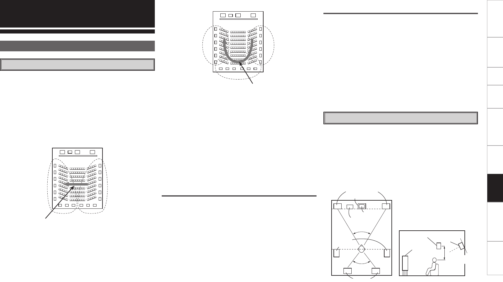
Getting Started Connections Setup Playback Remote Control Multi-Zone Troubleshooting Specifications
Surround back speakers
The THX Surround EX format adds new “Surround Back” (SB)
channels to the conventional 5.1 channel system. This makes it easy
to achieve sound positioned directly behind the listener, something
that was previously difficult with sources designed for conventional
multi surround speakers. In addition, the acoustic image extending
between the sides and the rear is narrowed, thus greatly improving
the expression of the surround signals for sounds moving from the
sides to the back and from the front to the point directly behind the
listening position.
'- $
48
'3
43DI4-DI
Change of positioning and acoustic image
with 5.1-channel systems
Movement of acoustic image from SR to SL
'- $
48
'3
4-DI 43DI
4#DI
Change of positioning and acoustic image
with 6.1-channel systems
Movement of acoustic image from
SR to SB to SL
In addition to sources recorded in 6.1-channels, the surround effect of
conventional 2- to 5.1-channel sources can also be enhanced.
Other Information
About Speaker Installation
Number of surround back speakers
With THX Surround EX, the surround back channel consists of one
channel of playback signals, but we recommend using two speakers.
The modes that use the new ASA technology from THX (vpage
91) are most effective when using two monopole type surround back
speakers placed close together.
Using two speakers results in a smoother blend with the sound of the
surround channels and better sound positioning of the surround back
channel when listening from a position other than the center.
Placement of the surround left and right channels
when using surround back speakers
Using surround back speakers greatly improves the positioning of the
sound at the rear. Because of this, the surround left and right channels
play an important role in achieving a smooth transition of the acoustic
image from the front to the back. As shown on the diagram above, in a
movie theater the surround signals are also produced from diagonally
in front of the listeners, creating an acoustic image as if the sound
were floating in space.
To achieve these effects, we recommend placing the speakers for the
surround left and right channels slightly more towards the front than
with conventional surround systems. Doing so sometimes increases
the surround effect when playing conventional 5.1 channel sources in
the THX Surround EX mode. Check the surround effects of the various
modes before selecting the surround mode.
Examples of speaker layouts
Below we introduce examples of speaker layouts. Refer to these to
arrange your speakers according to their type and how you want to
use them.
G1H For THX surround EX systems
(Using surround back speakers)
q When mainly playing movies
Recommended when your surround speakers are single or 2-way
speakers.
Surround back speakers
Subwoofer
Surround
speakers
Monitor
Center speaker
Front speakers
60°
60°
Surround
speaker
Surround back
speaker
Front speaker
Point slightly
downwards
GAs seen from aboveH GAs seen from the sideH
2 to 3 feet /
60 to 90 cm
Speaker(s) for one or two channels are required in order to achieve
a THX Surround EX system with the AVP-A1HDCI. Adding these,
however, allows you to achieve stronger surround effects not only
with sources recorded in THX Surround EX, but also with conventional
2- to 5.1 channel sources. The WIDE SCREEN mode is a mode for
achieving surround sound with up to 7.1 channels using surround back
speakers, for sources recorded in conventional Dolby Surround as well
as Dolby Digital 5.1 channel and DTS Surround 5.1 channel sources.
Furthermore, all the DENON original surround modes (vpage 51
“DSP Simulation Playback”) are compatible with 7.1 channel playback,
so you can enjoy 7.1 channel sound with any signal source.
Information
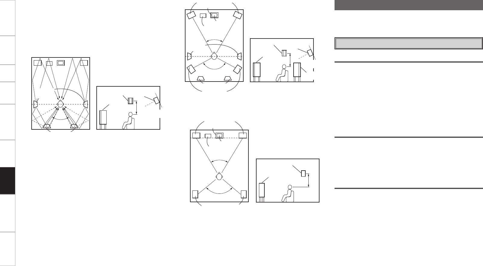
Getting Started Connections Setup Playback Remote Control Multi-Zone Troubleshooting Specifications
G2H When not using surround back speakers
Subwoofer
Surround speakers
Monitor
Center speaker
Front speakers
60°
120°
Front speaker
Surround speaker
GAs seen from aboveH GAs seen from the sideH
Dolby Digital
Dolby Digital is a multichannel digital signal format developed by Dolby
Laboratories.
A total of 5.1-channels are played: 3 front channels (“FL” , “FR” and
“C”), 2 surround channels (“SL” and “SR”) and the “LFE” channel for
low frequencies.
Because of this, there is no crosstalk between channels and a realistic
sound field with a “three-dimensional” feeling (sense of distance,
movement and positioning) is achieved.
A real, overpowering sense of presence is achieved when playing
movie sources in AV rooms as well.
Surround
Dolby Surround
The AVP-A1HDCI is equipped with a digital signal processing circuit
that lets you play program sources in the surround mode to achieve
the same sense of presence as in a movie theater.
w Setting for primarily watching movies using diffusion type
speakers for the surround speakers
For the greatest sense of surround sound envelopment, diffuse
radiation speakers such as bipolar (THX) types, or dipolar types,
provide a wider dispersion than is possible to obtain from a direct
radiating speaker (monopolar). Place these speakers at either side
of the prime listening position, mounted above ear level.
Surround
speakers
60°
Surround back speakers
Surround
speaker
Surround back
speaker
Front speaker
Point slightly
downwards
GAs seen from aboveH GAs seen from the sideH
Path of the surround sound from the
speakers to the listening position
Center speaker
Front speakers
Subwoofer
Monitor
45° ~ 60°
120°
Surround back
speaker
Surround
speaker A
Surround speaker B
Surround
speaker A
Surround back
speaker
Front speaker
Point slightly
downwards
Surround
speaker B
GAs seen from aboveH GAs seen from the sideH
e When playing movies and music
To activate the appropriate speakers for movies and music, we
suggest that during setup, choose Dolby Digital/DTS with THX and
Surround Speakers A (the bipolar or dipolar speakers mounted at
the sides of the listening position).
Choose Dolby Digital/DTS without THX and Surround Speakers B
(the direct radiating speakers mounted at the rear corners of the
listening room). Then, by simply activating the THX function (used
during movie playback, the Surround A speakers are automatically
activated. For multi-channel music listening (Dolby Digital or DTS
music programs), turn off the THX enhancements by touching the
THX button on the remote control, and the Surround B speakers
will be automatically activated.
Example: Movie sources (Dolby, DTS Surround, etc.)
“THX” or “THX Cinema” mode … Speakers A
Music sources (DVD video, DTS CD, etc.)
“Dolby/DTS Surround” … Speakers B
The speakers can be switched at the touch of a button by turning
HOME THX CINEMA on when playing movies and off when playing
multi-channel music.
Dolby TrueHD
Dolby TrueHD is a high definition audio technology developed by Dolby
Laboratories, using lossless coding technology to faithfully reproduce
the sound of the studio master.
This format is compatible with a maximum sampling frequency of 96
kHz and up to 7.1-channels, so it is used for applications particularly
prioritizing sound quality.
Dolby Digital Plus
Dolby Digital Plus is an improved Dolby Digital signal format that is
compatible with up to 7.1-channels of discrete digital sound and also
improves sound quality thanks to extra data bit rate performance. It
is upwardly compatible with conventional Dolby Digital, so it offers
greater flexibility in response to the source signal and the conditions
of the playback equipment.
2 to 3 feet /
60 to 90 cm
2 to 3 feet /
60 to 90 cm
2 to 3 feet /
60 to 90 cm
Information
0
Getting Started Connections Setup Playback Remote Control Multi-Zone Troubleshooting Specifications
Dolby Pro Logic gx
Dolby Pro Logic gx is a further improved version of the Dolby Pro
Logic g matrix decoding technology.
Audio signals recorded in 2-channels are decoded to achieve a natural
sound with up to 7.1-channels.
There are 3 modes: “Music” suited for playing music, “Cinema”
suited for playing movies, and “Game” which is optimized for playing
games.
b Sources recorded in Dolby Surround
Sources recorded in Dolby Surround are indicated with the following
logo marks.
Dolby Surround support mark :
Manufactured under license from Dolby Laboratories.
“Dolby”, “Pro Logic” and the double-D symbol are trademarks
of Dolby Laboratories.
DTS Surround
DTS Digital Surround
DTS Digital Surround is the standard digital surround format of DTS,
Inc., compatible with a sampling frequency of 44.1 or 48 kHz and up
to 5.1-channels of digital discrete surround sound.
DTS-HD High Resolution Audio
DTS-HD High Resolution Audio is an improved version of the
conventional DTS, DTS-ES and DTS 96/24 signals formats, compatible
with sampling frequencies of 96 or 48 kHz and up to 7.1-channels
of discrete digital sound. High data bit rate performance provides
high quality sound. This format is fully compatible with conventional
products, including conventional DTS digital surround 5.1-channel
data.
DTS-HD Master Audio
DTS-HD Master Audio is DTS, Inc’s lossless audio format compatible
with up to 96 kHz/7.1-channels. The lossless audio coding technology
faithfully reproduces the sound of the studio master. It is fully
compatible with conventional products, including conventional DTS
digital surround 5.1-channel data.
DTS-ES™ Discrete 6.1
DTS-ES™ Discrete 6.1 is a 6.1-channel discrete digital audio format
adding a surround back (SB) channel to the DTS digital surround sound.
Decoding of conventional 5.1-channel audio signals is also possible
according to the decoder.
DTS-ES™ Matrix 6.1
DTS-ES™ Matrix 6.1 is a 6.1-channel discrete digital audio format
inserting a surround back (SB) channel to the DTS digital surround
sound through matrix encoding. Decoding of conventional 5.1-channel
audio signals is also possible according to the decoder.
DTS NEO:6™ Surround
DTS NEO:6™ is a matrix decoding technology for achieving 6.1-
channel surround playback with 2-channel sources. It includes “DTS
NEO:6 CINEMA” suited for playing movies and “DTS NEO:6 MUSIC”
suited for playing music.
Manufactured under license under U.S. Patent #’s: 5,451,942;
5,956,674; 5,974,380; 5,978,762; 6,226,616; 6,487,535 & other
U.S. and worldwide patents issued & pending. DTS is a registered
trademark and the DTS logos, Symbol, DTS-HD and DTS-HD
Master Audio are trademarks of DTS, Inc.© 1996-2007 DTS, Inc.
All Rights Reserved.
DTS 96/24
DTS 96/24 is a digital audio format enabling high sound quality
playback in 5.1-channels with a sampling frequency of 96 kHz and 24
bit quantization on DVD-Video.
Dolby Pro Logic g
Dolby Pro Logic g is a matrix decoding technology developed by Dolby
Laboratories.
Regular music such as that on CDs is encoded into 5-channels to
achieve an excellent surround effect.
The surround channel signals are converted into stereo and full band
signals (with a frequency response of 20 Hz to 20 kHz or greater) to
create a “three-dimensional” sound image offering a rich sense of
presence for all stereo sources.
Home THX Cinema Surround
THX is an exclusive set of standards and technologies established by
the world-renowned film production company, Lucasfilm Ltd. THX
grew from George Lucas’ personal desire to make your experience of
the film soundtrack, in both movie theaters and in your home theater,
as faithful as possible to what the director intended.
Movie soundtracks are mixed in special movie theaters called dubbing
stages and are designed to be played back in movie theaters with
similar equipment and conditions. The soundtrack created for movie
theaters is then transferred directly onto Laserdisc, VHS tape,
DVD, etc., and is not changed for playback in a small home theater
environment.
THX engineers developed patented technologies to accurately translate
the sound from the movie theater environment into the home, correcting
the tonal and spatial errors that occur. On the AVP-A1HDCI, when the
Home THX Cinema mode is on, THX post-processing is automatically
added after the Dolby Pro Logic, Dolby Digital or DTS decoder:
Re-EQ™ (Re-Equalization)
The tonal balance of a film soundtrack will be excessively bright and
harsh when played back over audio equipment in the home because
film soundtracks are designed to be played back in large movie
theaters using very different professional equipment. Re-Equalization
restores the correct tonal balance for listening to a movie soundtrack
in a normal home environment.
Dolby Headphone
This is a three-dimensional sound technology developed jointly by
Dolby Laboratories and Lake Technology Ltd. of Australia for achieving
surround sound using regular headphones.
Previously, when using headphones all the sounds resonated inside
the head and it was uncomfortable to listen with headphones for long
periods of time. Dolby Headphone simulates speaker playback in a
room and places the sound at the front or the sides, outside the head,
to achieve a powerful sound like the sound of movie or home theaters.
This technology is mainly for multichannel audio/video equipment with
Dolby Digital or Dolby Pro Logic Surround decoding functions and
works with a high performance digital signal processing (DSP) chip.
Dolby Headphone is effective not only for multichannel sources but
also for stereo programs.
On the AVP-A1HDCI, it is possible to output signals encoded in the
Dolby Headphone mode from the recording output terminal and record
them on a separate recorder.
Information
Dolby Digital EX
Dolby Digital EX is a 6.1-channel surround format proposed by Dolby
Laboratories that allows users to enjoy in their homes the “DOLBY
DIGITAL SURROUND EX” audio format jointly developed by Dolby
Laboratories and Lucas Films.
The 6.1 channels of sound, including surround back channels, provide
improved sound positioning and expression of space.

Getting Started Connections Setup Playback Remote Control Multi-Zone Troubleshooting Specifications
Adaptive Decorrelation™
In a movie theater, a large number of surround speakers help create an
enveloping surround sound experience, while in a home theater there
are usually only two speakers. This can make the surround speakers
sound like headphones that lack spaciousness and envelopment. The
surround sounds will also collapse into the closest speaker as you
move away from the middle seating position. Adaptive Decorrelation
slightly changes one surround channel’s time and phase relationship
with respect to the other surround channel. This expands the listening
position and creates—with only two speakers—the same spacious
surround experience as in a movie theater.
THX Ultra2™
Before any home theater component can be THX Ultra2 certified,
it must incorporate all the features above and also pass a rigorous
series of quality and performance tests. Only then can a product
feature the THX Ultra2 logo, which is your guarantee that the Home
Theater products you purchase will give you superb performance for
many years to come. THX Ultra2 requirements cover every aspect
of the product including power amplifier performance, pre-amplifier
performance and operation, as well as hundreds of other parameters
in both the digital and analog domain.
In addition to improvements to the power amplifier with respect
to previous THX Ultra standards, three surround modes have been
added: the THX Ultra2 Cinema mode, THX Music Mode and THX
Games Mode.
THX Ultra2 Cinema
THX Ultra2 Cinema mode plays 5.1 movies using all 8 speakers giving
you the best possible movie watching experience. In this mode, new
THX processing blends the side surround speakers and back surround
speakers providing the optimal mix of ambient and directional surround
sounds.
DTS-ES (Matrix and 6.1 Discrete) and Dolby Digital Surround EX
encoded soundtracks will be automatically detected in Ultra2 Cinema
mode if the appropriate flag has been encoded.
Some Dolby Digital Surround EX soundtracks are missing the digital
flag that allows automatic switching. If you know that the movie that
you are watching is encoded in Surround EX, you can manually select
the THX Surround EX playback mode, otherwise THX Ultra2 Cinema
mode will apply processing to provide optimum replay.
THX Music Mode
For the replay of 5.1 multi-channel music the THX Music Mode should
be selected. In this mode new THX processing is applied to the
surround channels of all 5.1 encoded music sources such as DTS and
Dolby Digital to provide a wide stable rear soundstage.
THX Games Mode
For the replay of stereo and multi-channel game audio the THX Games
Mode should be selected. In this mode THX ASA processing is applied
to the surround channels of all 5.1 and 2.0 encoded game sources
such as analog, PCM, DTS and Dolby Digital. This accurately places all
game audio surround information, providing a full 360 degree playback
environment. THX Games Mode is unique as it gives you a smooth
transition of audio in all points of the surround field.
ASA (Advanced Speaker Array)
ASA is a proprietary THX technology which processes the sound fed to
2 side and 2 back surround speakers to provide the optimal surround
sound experience. When you set up your home theater system using
all eight speaker outputs (Left, Center, Right, Surround Right, Surround
Back Right, Surround Back Left, Surround Left and Subwoofer) placing
the two Surround Back speakers close together facing the front of the
room as shown in the diagram will provide the largest sweet spot. If
for practical reasons you have to place the Surround Back speakers
apart, you will need to go THX Audio Set-up screen and choose the
setting that most closely corresponds to the speaker spacing, which
will re-optimize the surround sound-field.
ASA is used in three new modes; THX Ultra2 Cinema, THX Music
Mode and THX Games Mode.
Boundary Gain Compensation
If your chosen listening room layout (for practical or aesthetic reasons)
results in the most of the listeners being close to the rear wall, the
resulting bass level can be sufficiently reinforced by the boundary that
the overall sound quality becomes “boomy”. THX Ultra2 receivers
and controllers contain the BGC (Boundary Gain Compensation)
feature to provide an improved bass balance. BGC can be selected
by choosing “THX Ultra2 Subwoofer–Yes” from the “Boundary Gain
Compensation” section of the THX Audio setup menu.
THX and Re-EQ, THX Timbre Matching, THX Adaptive Decorrelation,
and THX Advanced Speaker Array are trademarks of THX Ltd. THX
may be registered in some jurisdictions. All rights reserved.
In 1999, a new surround system was launched simultaneously with the
release of the movie “Star Wars Episode I”. “Dolby Digital Surround
EX” is a new movie sound track that greatly enhances the sense
of spatial expression and the positioning of the surround channel
sound. The result is 360 degrees of movement and moving sound
effects that seem to pass right over the listener’s head. This system
was developed jointly by THX and Dolby Laboratories, fusing THX’s
idea of improving spatial expression and achieving a uniform 360
degree sound positioning with Dolby Laboratories’ matrix encoding
technology. Emphasis was placed on compatibility with the existing
system Dolby Digital 5.1 channel, and the new “surround back (SB)
channel” was added to achieve improvements over the conventional
5.1 channel system in terms of the positioning of the sound at the
rear, the acoustic image of sound moving from the two sides to the
back as well as sound moving from the front to the center rear with
the multi surround speaker systems used in movie theaters, thereby
enabling various types of surround sound. The surround back channel
signal is a matrix-encoded signal inserted into both the Dolby Digital
SL (surround left) and SR (surround right) channels. Upon playback, the
signals are decoded by a high precision digital matrix decoder within
the Dolby Digital decoder into the SL, SR and SB channels and output
as 6.1 channels of signals. With the AVP-A1HDCI, the signals further
undergo Home THX Cinema processing to achieve a THX Surround
EX system. Even without the proper environment for playing the SB
channel, Dolby Digital Surround EX signals are 100% compatible with
existing 5.1 channel playback systems, so they can be played as such.
In this case, the SB channel signal is produced as a monaural signal
from both the SL and SR channels, so none of the signal components
are missing. The effects specific to THX Surround EX (the sense of
spatial expression and the positioning of the sound), however, are the
same as with conventional 5.1 channel surround systems.
Timbre Matching™
The human ear changes our perception of a sound depending on the
direction from which the sound is coming. In a movie theater, there
is an array of surround speakers so that the surround information is
all around you. In a home theater, only two speakers located to the
side of your head are used. The Timbre Matching feature filters the
information going to the surround speakers so that they more closely
match the tonal characteristics of the sound coming from the front
speakers. This ensures seamless panning between the front and
surround speakers.
THX™ Surround EX™
Information
Getting Started Connections Setup Playback Remote Control Multi-Zone Troubleshooting Specifications
Audyssey
HDCD® is an encoding/decoding technology that greatly reduces
the distortion that occurs upon digital recording while maintaining
compatibility with the conventional CD format, thus expanding the
dynamic range and achieving a high resolution.
Conventional CDs and HDCD compatible CDs are identified
automatically to select the optimum digital processing.
HDCD®
(High Definition Compatible Digital®)
Manufactured under license from Audyssey Laboratories.
U.S. and foreign patents pending. Audyssey MultEQ® XT is a
registered trademark of Audyssey Laboratories. Dynamic EQ™ is
a trademark of Audyssey Laboratories.
®, HDCD®, High Definition Compatible Digital® and
Microsoft® are either registered trademarks or trademarks of
Microsoft Corporation, Inc. in the United States and/or other
countries. HDCD system manufactured under license from
Microsoft Corporation, Inc. This product is covered by one or more
of the following: In the USA: 5,479,168, 5,638,074, 5,640,161,
5,808,574, 5,838,274, 5,854,600, 5,864,311, 5,872,531, and in
Australia: 669114. Other patents pending.
DENON LINK
Advanced AL24 Processing Multi
channel
DENON LINK is a unique digital, balanced transfer type interface
developed by DENON. It offers high speed, high quality transfer of
digital audio data with low signal loss. It can be used together with
DENON DVD players equipped with a special DENON LINK connector
using a single cable to enable playback with high sound quality.
It allows digital transfer of the 192 kHz/24 bit 2-channel digital signals
of DVD-Audio discs, PCM multi-channel signals, etc. Full-spec digital
transfer of the audio contents of Super Audio CD is possible by
connecting a player equipped for DENON LINK 3rd Edition.
Equipped with “Advanced AL24 Processing” time axis region
information volume expansion
In addition to the existing “AL24 Processing Plus” bit expansion
technology, DENON has also developed “Advanced AL24 Processing”
that dramatically improves information volume in the time axis region
using high-speed signal detection and processing technology. In
addition to expanding original 16-bit digital data to 24 bits, “Advanced
AL24 Processing” uses data interpolation along the time axis or up-
converted sampling to achieve natural interpolation without losing the
original data. A digital filter is used to further expand adaptability and
perform optimum filtering calculations for ringing-free pulse response,
pulsive music data and attack sounds.
This results in the reproduction of such spatial information as the
delicate nuances in the music, the positions of the performers, and
the breadth, height, and depth of the concert hall. “Advanced AL24
Processing” is conducted for all channels and modes other than DSD
DIRECT.
Audyssey MultEQ® XT
Audyssey MultEQ® XT is the first technology to properly measure
sound information throughout a listening area, then combine this
information to accurately represent the acoustical problems in
the room. Based on these measurements, MultEQ XT calculates
an equalization solution that corrects for both time and frequency
response problems in every seat. Audyssey MultEQ XT not only
corrects frequency response problem in a large listening area but also
performs a fully automated surround system setup.
For a detailed description, see page 26.
Audyssey Dynamic EQ™
Audyssey Dynamic EQ solves the problem of deteriorating sound
quality as volume is decreased by taking into account human perception
and room acoustics. Dynamic EQ selects the best possible frequency
response and surround levels moment-by-moment as volume is
changed. The result is bass response, tonal balance and surround
impression that remain constant despite changes in volume. This
is the first technology to combine information from incoming source
levels with actual output sound levels in the room, a pre-requisite
for delivering a loudness correction solution. Audyssey Dynamic EQ
works in tandem with Audyssey MultEQ to provide well-balanced
sound for every listener at any volume level.
THX and Ultra2 are trademarks of THX Ltd. THX may be registered
in some jurisdictions. All rights reserved. Surround EX is a
trademark of Dolby Laboratories. Used with permission.
For more information, visit www.audyssey.com.
Neural Surround™, a breakthrough in audio technology, will bring the
excitement of surround music to more of America’s listening audience.
It provides the rich envelopment and discrete image detail of surround
sound in a format 100 % compatible with stereo. With superior
spectral resolution and channel separation, Neural Surround™ draws
the brain’s attention to sonic details in musical instruments, vocals,
and ambience that are typically masked by other playback systems.
This allows the listener to fully experience the richness and subtleties
in recorded performance as never before. As the chosen format for XM
Satellite Radio’s new XM HD surround programming, Neural Surround
will help deliver more surround music to more listeners than any other
broadcast format. XM Satellite Radio will be the first radio company to
broadcast surround sound on the radio 24 hours a day and will offer
three channels fully dedicated to Neural Surround™ music. This alone
will amount to more than 25,000 hours of Neural Surround™ music
each year.
Neural Surround
This product is manufactured under license from Neural Audio
Corporation.
D&M Holdings Inc. hereby grants the user a non-exclusive,
nontransferable, limited license right exercisable to use the NA
SURROUND Technology and other US and World Wide Patents
Pending technology.
“Neural” and “Neural Audio” and “Neural Surround” are
trademarks of Neural Audio Corporation. All Rights Reserved.
Information
Getting Started Connections Setup Playback Remote Control Multi-Zone Troubleshooting Specifications
HDMI
(High-Definition Multimedia Interface)
HDMI is a digital interface standard for next generation TVs based
on DVI (Digital Visual Interface) standards and optimized for use in
consumer equipment.
Non-compressed digital video and multi-channel audio signals are
transmitted with a single connection.
HDMI is also compatible with HDCP (High-bandwidth Digital Contents
Protection), a technology for protecting copyrights that encrypts digital
video signals in the same was as with DVI.
“HDMI”, “HDMI logo” and “High-Definition Multimedia
Interface” are trademarks or registered trademarks of HDMI
Licensing LLC.
Deep Color
Eliminates on-screen color banding, for smooth tonal transitions and
subtle gradations between colors.
Enables increased contrast ratio.
Can represent many times more shades of gray between black and
white.
At 30-bit pixel depth, a four times improvement would be the minimum,
and the typical improvement would be eight times or more.
xvYCC
Next-generation “xvYCC” color space supports 1.8 times as many
colors as existing HDTV signals.
Lets HDTVs display colors more accurately.
Enables displays with natural, vivid colors.
Lip Sync
Because consumer electronics devices are using increasingly
complex digital signal processing to enhance the clarity and detail of
the content, synchronization of video and audio in user devices has
become a greater challenge and could potentially require complex end-
user adjustments. HDMI 1.3 incorporates an automatic video/audio
synching capability that allows devices to perform this synchronization
automatically with total accuracy.
Surround Mode
Signals and adjustability in the different modes
Channel output Parameter (default values are shown in parentheses)
Front L/R Center Surround
L/R
Surround
Back L/R Subwoofer D. COMP
z1
DRC
z2
LFE
z3
AFDM
z1SB CH Out Cinema
EQ.
PURE DIRECT, DIRECT S A A A D S (OFF) S (Auto) S (0 dB) A A A
DSD DIRECT S A A A A A A A A A A
DSD MULTI DIRECT S D D D D A A S (0 dB) A S A
MULTI CH DIRECT S D D D D A A S (0 dB) S (ON) S A
STEREO S A A A D S (OFF) S (Auto) S (0 dB) AAA
EXT. IN S D D D D A A A A S (NOTE6) A
MULTI CH IN S D D D D A A S (0 dB) S (ON) S A
WIDE SCREEN S D D D D S (OFF) S (Auto) S (0 dB) A S S (OFF)
HOME THX CINEMA
(2ch) S D D D D A A A A S A
HOME THX CINEMA
(5.1ch) S D D D D A A S (0 dB) S (ON) S A
DOLBY PRO LOGIC gxS D D D D S (OFF) S (Auto) A A S S (NOTE1)
DOLBY PRO LOGIC g S D D A D S (OFF) S (Auto) A A S S (NOTE2)
DTS NEO:6 S D D D D S (OFF) S (Auto) A A S S (NOTE1)
DOLBY DIGITAL S D D D D S (OFF) A S (0 dB) S (ON) S S (OFF)
DOLBY DIGITAL Plus S D D D D S (OFF) A S (0 dB) S (ON) S S (OFF)
DOLBY TrueHD S D D D D A S (Auto) S (0 dB) S (ON) S S (OFF)
DTS SURROUND S D D D D S (OFF) A S (0 dB) S (ON) S S (OFF)
DTS 96/24 S D D D D S (OFF) A S (0 dB) S (ON) S S (OFF)
DTS-HD S D D D D S (OFF) A S (0 dB) S (ON) S S (OFF)
neural S D D D D A A A A S A
7CH STEREO S D D D D S (OFF) S (Auto) S (0 dB) A S A
SUPER STADIUM S D D D D S (OFF) S (Auto) S (0 dB) A S A
ROCK ARENA S D D D D S (OFF) S (Auto) S (0 dB) ASA
JAZZ CLUB S D D D D S (OFF) S (Auto) S (0 dB) A S A
CLASSIC CONCERT S D D D D S (OFF) S (Auto) S (0 dB) A S A
MONO S D D D D S (OFF) S (Auto) S (0 dB) A S A
VIDEO GAME S D D D D S (OFF) S (Auto) S (0 dB) A S A
MATRIX S D D D D S (OFF) S (Auto) S (0 dB) A S A
DOLBY HEADPHONE S A A A A A A A A A A
S : Signal / Adjustable
A : No signal / Not adjustable
D : Turned on or off by speaker configuration setting
NOTE1 : This parameter is availabe when the GUI menu “Parameter” – “Audio” – “Surround Parameters” – “Mode” is set to “Cinema”
(vpage 52).
NOTE2 : This parameter is availabe when the GUI menu “Parameter” – “Audio” – “Surround Parameters” – “Mode” is set to “Cinema”
or “Pro Logic” (vpage 52).
NOTE6 : This parameter can be used when GUI menu “Manual Setup”– “Audio Setup”– “ EXT. IN Setup”– “Mode” is set to “DSP”
(vpage 33)
NOTE:
z1 : When playing Dolby Digital and DTS signals.
z2 : When playing Dolby True HD signal.
z3 : When playing Dolby Digital, DTS, DVD-Audio and Super Audio CD.
Surround Modes and Parameters
Information

Getting Started Connections Setup Playback Remote Control Multi-Zone Troubleshooting Specifications
Surround Mode
Signals and adjustability in the different modes
Parameter (default values are shown in parentheses)
Mode Decoder Room Size Effect Level Delay Time Subwoofer
PRO LOGIC g/gx MUSIC mode
only
NEO:6
MUSIC
mode only
EXT. IN only
Tone z1 Night Mode Room EQ Dynamic
EQ z2RESTORER
Panorama Dimension Center
Width
Center
Image
Subwoofer
Att.
Input
Channel
(NOTE6)
PURE DIRECT, DIRECT A A A A A S A A A A S S A S (OFF) S (NOTE5) S (NOTE5) S
DSD DIRECT A A A A A S A A A A A A A A A A A
DSD MULTI DIRECT A A A A A A A A A A A A A A A A A
MULTI CH DIRECT A A A A A A A A A A S S A S (OFF) S (NOTE5) S (NOTE5) A
STEREO A A A A A A A A A A S S S (0 dB) S (OFF) S (OFF) S (OFF) S
EXT. IN A A A A A A A A A A S S A A A A A
MULTI CH IN A A A A A A A A A A S S S (0 dB) S (OFF) S (OFF) S (OFF) A
WIDE SCREEN A A A S (ON, 10) A A A A A A S S S (0 dB) S (OFF) S (OFF) S (OFF) S
HOME THX CINEMA
(2ch) S (PLIIx C) S A A A A A A A A S S A S (OFF) S (OFF) S (OFF) S
HOME THX CINEMA
(5.1ch) A A A A A A A A A A S S A S (OFF) S (OFF) S (OFF) A
DOLBY PRO LOGIC gxS (Cinema) A A A A A S (OFF) S (3) S (3) A A A S (0 dB) S (OFF) S (OFF) S (OFF) S
DOLBY PRO LOGIC g S (Cinema) A A A A A S (OFF) S (3) S (3) A A A S (0 dB) S (OFF) S (OFF) S (OFF) S
DTS NEO:6 S (Cinema) A A A A A A A A S (0.3) A A S (0 dB) S (OFF) S (OFF) S (OFF) S
DOLBY DIGITAL A A A A A A A A A A A A S (0 dB) S (OFF) S (OFF) S (OFF) A
DOLBY DIGITAL Plus A A A A A A A A A A A A S (0 dB) A S (OFF) S (OFF) A
DOLBY TrueHD A A A A A A A A A A A A S (0 dB) A S (OFF) S (OFF) A
DTS SURROUND A A A A A A A A A A S S S (0 dB) S (OFF) S (OFF) S (OFF) A
DTS 96/24 A A A A A A A A A A A A S (0 dB) S (OFF) S (OFF) S (OFF) A
DTS-HD A A A A A A A A A A A A S (0 dB) A S (OFF) S (OFF) A
neural A A A A A A A A A A A A S (0 dB) S (OFF) S (OFF) S (OFF) S
7CH STEREO A A A A A A A A A A S S S (0 dB) S (OFF) S (OFF) S (OFF) S
SUPER STADIUM A A S (Medium) S (10) A A A A A A S S S (NOTE3) S (OFF) S (OFF) S (OFF) S
ROCK ARENA A A S (Medium) S (10) A A A A A A S S S (NOTE4) S (OFF) S (OFF) S (OFF) S
JAZZ CLUB A A S (Medium) S (10) A A A A A A S S S (0 dB) S (OFF) S (OFF) S (OFF) S
CLASSIC CONCERT A A S (Medium) S (10) A A A A A A S S S (0 dB) S (OFF) S (OFF) S (OFF) S
MONO A A S (Medium) S (0) A A A A A A S S S (0 dB) S (OFF) S (OFF) S (OFF) S
VIDEO GAME A A S (Medium) S (10) A A A A A A S S S (0 dB) S (OFF) S (OFF) S (OFF) S
MATRIX A A A A S (30 ms) A A A A A S S S (0 dB) S (OFF) S (OFF) S (OFF) S
DOLBY HEADPHONE A S A A A A A A A A A A S (0 dB) S (OFF) S (OFF) S (OFF) S
S : Signal / Adjustable
A : No signal / Not adjustable
NOTE3 : BASS +6 dB, TREBLE 0 dB
NOTE4 : BASS +6 dB, TREBLE +4 dB
NOTE5 : Can be used according to the “Direct Mode” setting.
NOTE6 : “DSP” mode only
z1 : When “Dynamic EQ” is set to “ON”, you cannot use the “Tone” setting.
z2 : Can be set when GUI menu “Parameter” – “Audio” – “Room EQ” is set to “Audyssey”, “Audyssey Flat”, “Audyssey Byp.L/R”.
Information
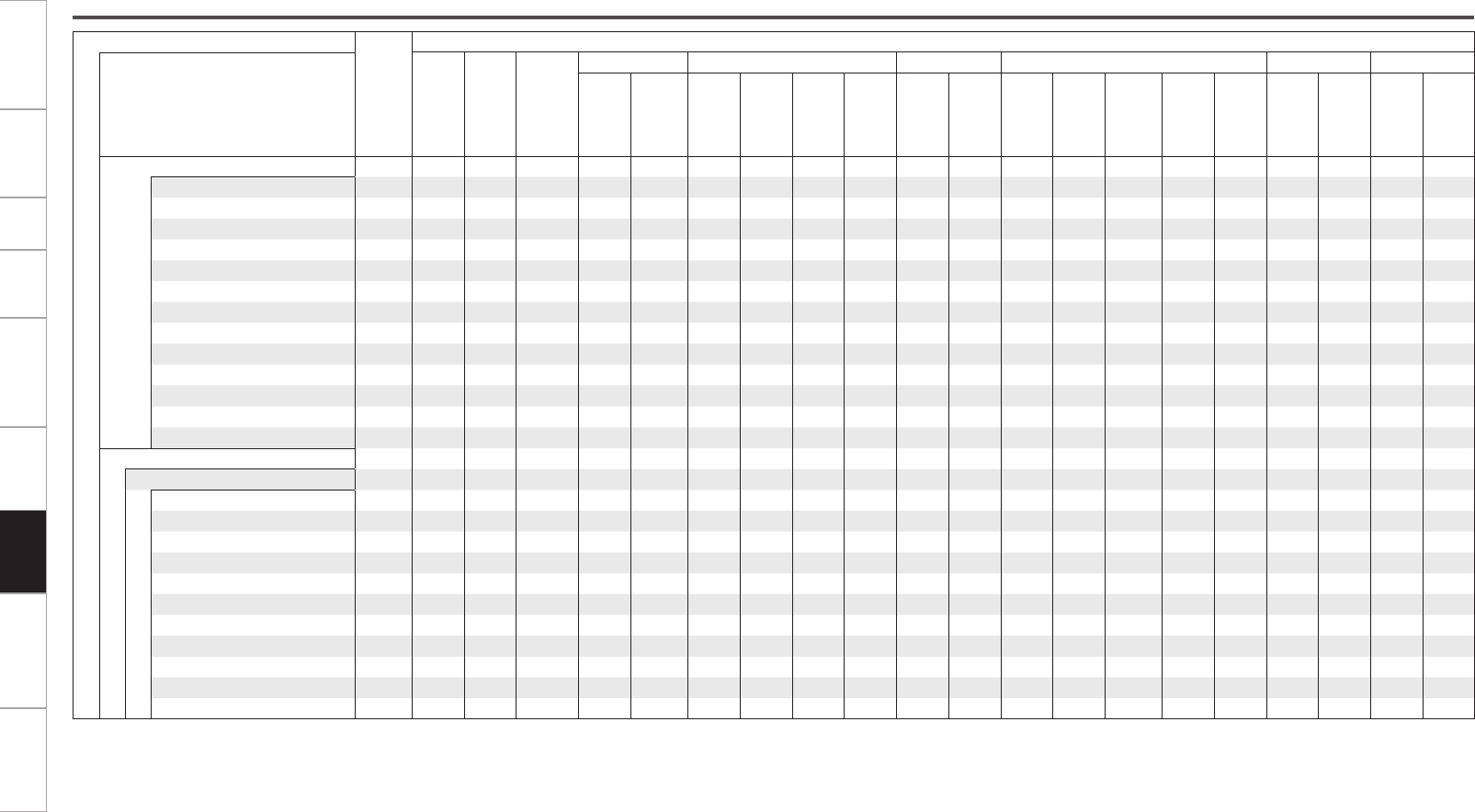
Getting Started Connections Setup Playback Remote Control Multi-Zone Troubleshooting Specifications
Button
Note
Input signals
ANALOG
LINEAR
PCM /
WAV
WMA
(Windows
Media Audio)
/ MP3 /
MPEG-4
AAC / FLAC
DTS-HD DTS DOLBY DOLBY DIGITAL DVD-AUDIO Super Audio CD
Surround mode DTS-HD
Master
Audio
DTS-HD
High
Resolution
Audio
DTS ES
DSCRT
(With
Flag)
DTS ES
MTRX
(With
Flag)
DTS
(5.1ch)
DTS
96/24
DOLBY
TrueHD
DOLBY
DIGITAL
Plus
DOLBY
DIGITAL
EX (With
Flag)
DOLBY
DIGITAL
EX (With
no Flag)
DOLBY
DIGITAL
(5.1/5/4ch)
DOLBY
DIGITAL
(4/3ch)
DOLBY
DIGITAL
(2ch)
DVD-
Audio
(multi ch)
DVD-
Audio
(2ch)
DSD
(multi ch)
DSD
(2ch)
HOME THX CINEMA
ES DSCRT6.1 + THX z1A A A S S D A A A A A A A A A A A A A A
ES MTRX6.1 + THX z1A A A S S A D S S A A A A A A A A A A A
THX SURROUND EX z1A A A A A A A A A S S D S S S A S A S A
THX Ultra2 Cinema z2A A A S S S S S S S S S S S S A S A S A
THX Music Mode z2A A A S S S S S S S S S S S S A S A S A
THX Games Mode z2S S S S S S S S S S S S S S S S S S S S
THX Cinema A A A S S S S S S S S S S S S A S A S A
PLgx C + THX z3S S S S S S S S S S S S S S S S S S S S
PLg C + THX S S S A A A A A A A A A A A A S A S A S
DOLBY PL + THX S S S A A A A A A A A A A A A S A S A S
NEO:6 + THX S S S A A A A A A A A A A A A S A S A S
MULTI CH 7.1 + THX A A A A A A A A A A A A A A A A S (7.1) AAA
MULTI CH 5.1 + THX A A A A A A A A A A A A A A A A S A S A
STANDARD
DTS SURROUND
DTS-HD MSTR AA A F A A A A A A A A A A A A AAA A
DTS-HD HI RES A A A A F A A A A A A A A A A A A A A A
DTS ES DSCRT6.1 z1A A A A A F D A A A A A A A A A A A A A A
DTS ES MTRX6.1 z1A A A A A A F D A A A A A A A A A A A A A
DTS SURROUND A A A A A S S F A A A A A A A A A A A A
DTS 96/24 A A A A A A A A F A A A A A A A A A A A
DTS (–HD) + PLgx CINEMA z2A A A S S S S S S A A A A A A A A A A A
DTS (–HD) + PLgx MUSIC z1A A A S S S S S S A A A A A A A A A A A
DTS (–HD) + NEO:6 z1A A A S S A S S S A A A A A A A A A A A
DTS NEO:6 CINEMA S S S A A A A A A A A A A A A S A S A S
DTS NEO:6 MUSIC S S S A A A A A A A A A A A A S A S A S
F : Mode selectable in initial status
D : Mode fixed when “AFDM” is “ON”
S : Selectable mode
A : Non-selectable mode
NOTE:
z1: This mode is not available when the surround back speaker setup is set to “None” (vpage 29).
z2: This mode is not available when the surround back speaker setup is set to “1spkr” or “None” (vpage 29).
z3: For input signals other than 2 channel signals, this mode cannot be selected when surround back speaker is set
to “1spkr” or “None”.
Differences in Surround Mode Names Depending on the Input Signals
Information
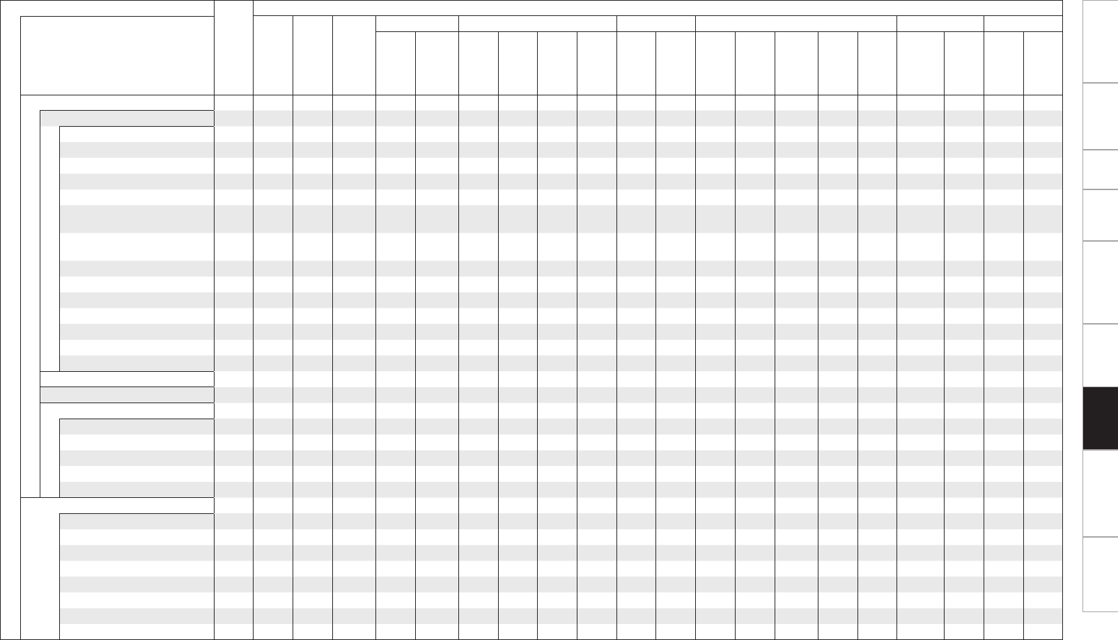
Getting Started Connections Setup Playback Remote Control Multi-Zone Troubleshooting Specifications
Button
Note
Input signals
ANALOG
LINEAR
PCM /
WAV
WMA
(Windows
Media
Audio) / MP3
/ MPEG-4
AAC / FLAC
DTS-HD DTS DOLBY DOLBY DIGITAL DVD-AUDIO Super Audio CD
Surround mode DTS-HD
Master
Audio
DTS-HD
High
Resolution
Audio
DTS ES
DSCRT
(With
Flag)
DTS ES
MTRX
(With
Flag)
DTS
(5.1ch)
DTS
96/24
DOLBY
TrueHD
DOLBY
DIGITAL
Plus
DOLBY
DIGITAL
EX (With
Flag)
DOLBY
DIGITAL
EX (With
no Flag)
DOLBY
DIGITAL
(5.1/5/4ch)
DOLBY
DIGITAL
(4/3ch)
DOLBY
DIGITAL
(2ch)
DVD-Audio
(multi ch)
DVD-
Audio
(2ch)
DSD
(multi ch)
DSD
(2ch)
STANDARD
DOLBY SURROUND
DOLBY TrueHD A A A A A A A A A F A A A A A A A A A A
DOLBY DIGITAL+ AAAA A A A A A A F A A A A A A A A A
DOLBY DIGITAL EX z1A A A A A A A A A A A S S S S A A A A A
DOLBY (D+) (HD) +EX z1AAAA A A A A A S S A A A A A A A A A
DOLBY DIGITAL AAAA A A A A A A A S F F F A A A A A
DOLBY (D) (D+) (HD) +PLgx
CINEMA
z2A A A A A A A A A S S F D S S S A A A A A
DOLBY (D) (D+) (HD) +PLgx
MUSIC
z1AA A A A A A A A S S S S S S A A A A A
DOLBY PRO LOGIC gx CINEMA z1S S S A A A A A A A A A A A A S A S A S
DOLBY PRO LOGIC gx MUSIC z1SS S A A A A A A A A A A A A S A S A S
DOLBY PRO LOGIC gx GAME z1S S S A A A A A A A A A A A A S A S A S
DOLBY PRO LOGIC g CINEMA SS S A A A A A A A A A A A A S A S A S
DOLBY PRO LOGIC g MUSIC S S S A A A A A A A A A A A A S A S A S
DOLBY PRO LOGIC g GAME S S S A A A A A A A A A A A A S A S A S
DOLBY PRO LOGIC S S S A A A A A A A A A A A A S A S A S
DOLBY HEADPHONE z4S S S S S S S S S S S S S S S S S S S S
neural S S S A A A A A A A A A A A A A A A A A
MULTI CH IN
MULTI CH IN A A A A A A A A A A A A A A A A F A F A
MULTI IN + PLgx CINEMA z2A A A A A A A A A A A A A A A A S A S A
MULTI IN + PLgx MUSIC z1A A A A A A A A A A A A A A A A S A S A
MULTI IN + Dolby EX z1A A A A A A A A A A A A A A A A S A S A
MULTI CH IN 7.1 A A A A A A A A A A A A A A A A F D
(7.1)
A A A
DIRECT
DIRECT S S S S S S S S S S S S S S S S A S A S
DSD DIRECT A A A A A A A A A A A A A A A A A A A S
DSD MULTI DIRECT A A A A A A A A A A A A A A A A A A S A
MULTI CH DIRECT A A A A A A A A A A A A A A A A S A S A
M DIRECT + PLgx CINEMA z2A A A A A A A A A A A A A A A A S A S A
M DIRECT + PLgx MUSIC z1A A A A A A A A A A A A A A A A S A S A
M DIRECT + Dolby EX z1A A A A A A A A A A A A A A A A S A S A
M DIRECT 7.1 A A A A A A A A A A A A A A A A S
(7.1)
A A A
NOTE:
z1: This mode is not available when the surround back speaker setup is set to “None” (vpage 29).
z2: This mode is not available when the surround back speaker setup is set to “1spkr” or “None” (vpage 29).
z4: You can select this when the headphone plug is inserted into the headphone jack.
F : Mode selectable in initial status
D : Mode fixed when “AFDM” is “ON”
S : Selectable mode
A : Non-selectable mode
Information
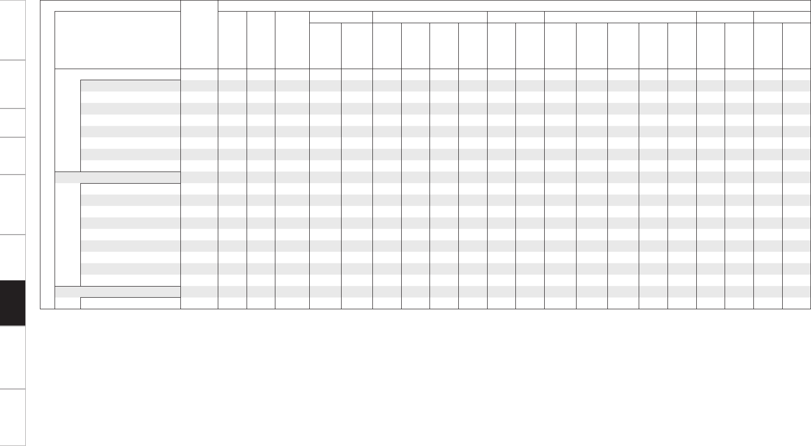
Getting Started Connections Setup Playback Remote Control Multi-Zone Troubleshooting Specifications
Button
Note
Input signals
ANALOG
LINEAR
PCM /
WAV
WMA
(Windows
Media Audio)
/ MP3 /
MPEG-4
AAC / FLAC
DTS-HD DTS DOLBY DOLBY DIGITAL DVD-AUDIO Super Audio CD
Surround mode DTS-HD
Master
Audio
DTS-HD
High
Resolution
Audio
DTS ES
DSCRT
(With
Flag)
DTS ES
MTRX
(With
Flag)
DTS
(5.1ch)
DTS
96/24
DOLBY
TrueHD
DOLBY
DIGITAL
Plus
DOLBY
DIGITAL
EX (With
Flag)
DOLBY
DIGITAL
EX (With
no Flag)
DOLBY
DIGITAL
(5.1/5/4ch)
DOLBY
DIGITAL
(4/3ch)
DOLBY
DIGITAL
(2ch)
DVD-
Audio
(multi ch)
DVD-
Audio
(2ch)
DSD
(multi ch) DSD (2ch)
PURE DIRECT
PURE DIRECT S S S S S S S S S S S S S S S S A S A S
DSD PURE DIRECT A A A A A A A A A A A A A A A A A A A S
DSD MULTI PURE A A A A A A A A A A A A A A A A A A S A
MULTI CH PURE DIRECT A A A A A A A A A A A A A A A A S A S A
M PURE D + PLgx CINEMA z2A A A A A A A A A A A A A A A A S A S A
M PURE D + PLgx MUSIC z1A A A A A A A A A A A A A A A A S A S A
M PURE D + Dolby EX z1A A A A A A A A A A A A A A A A S A S A
M CH PURE DIRECT 7.1 A A A A A A A A A A A A A A A A S
(7.1)
AAA
DSP SIMULATION
7CH STEREO z5S S S S S S S S S S S S S S S S S S S S
WIDE SCREEN S S S S S S S S S S S S S S S S S S S S
SUPER STADIUM S S S S S S S S S S S S S S S S S S S S
ROCK ARENA S S S S S S S S S S S S S S S S S S S S
JAZZ CLUB S S S S S S S S S S S S S S S S S S S S
CLASSIC CONCERT S S S S S S S S S S S S S S S S S S S S
MONO S S S S S S S S S S S S S S S S S S S S
VIDEO GAME S S S S S S S S S S S S S S S S S S S S
MATRIX S S S S S S S S S S S S S S S S S S S S
STEREO
STEREO F F F S S S S S S S S S S S S F S F S F
F : Mode selectable in initial status
S : Selectable mode
A : Non-selectable mode
NOTE :
z1: This mode is not available when the surround back speaker setup is set to “None” (vpage 29).
z2: This mode is not available when the surround back speaker setup is set to “1spkr” or “None” (vpage 29).
z5: If the surround back speaker setup is set to “None” and when using headphones, then “5CH STEREO” is displayed.
“9CH STEREO” is displayed when surround (A+B) and the surround back speaker are used.
Information
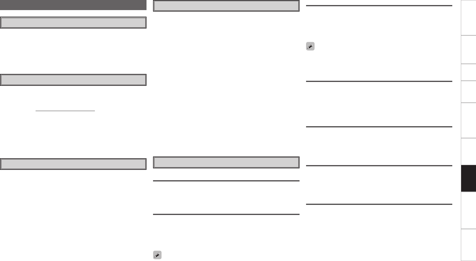
Getting Started Connections Setup Playback Remote Control Multi-Zone Troubleshooting Specifications
Windows Media Player ver.11
vTuner
This is a free online contents server for Internet radio. Note that usage
fees are included in upgrade costs.
For inquiries about this service, visit the vTuner site below.
vTuner website: http://www.radiodenon.com
This product is protected by certain intellectual property rights of
Nothing Else Matters Software and BridgeCo. Use or distribution of
such technology outside of this product is prohibited without a license
from Nothing Else Matters Software and BridgeCo or an authorized
subsidiary.
Windows Media DRM
A copyright-protected technology developed by Microsoft.
• Windows Vista and the Windows logo are trademarks of the
Microsoft group of companies.
• The PlaysForSure logo, Windows Media and the Windows logo are
trademarks or registered trademarks of Microsoft Corporation in the
United States and/or other countries.
• Content providers are using the digital rights management technology
for Windows Media contained in this device (WM-DRM) to protect
the integrity of their content (Secure Content) so that their intellectual
property, including copyright, in such content is not misappropriated.
This device uses WM-DRM software to play Secure Content (WM-
DRM Software). If the security of the WM-DRM Software in this
device has been compromised, owners of Secure Content (Secure
Content Owners) may request that Microsoft revoke the WM-DRM
Software’s right to acquire new licenses to copy, display and/or play
Secure Content. Revocation does not alter the WM-DRM Software’s
ability to play unprotected content. A list of revoked WM-DRM
Software is sent to your device whenever you download a license
for Secure Content from the Internet or from a PC. Microsoft may,
in conjunction with such license, also download revocation list onto
your device on behalf of Secure Content Owners.
About Networks
This is a media player distributed free of charge by Microsoft
Corporation.
It can be used to play playlists created with Windows Media Player
ver. 11 as well as files in such formats as WMA, DRM WMA, MP3
and WAV.
About Wireless LAN
Wi-Fi®
Wi-Fi Certification assures tested and proven interoperability by the
Wi-Fi Alliance, a group certifying interoperability among wireless LAN
devices.
IEEE 802.11b
This is one wireless LAN standard set by the 802 working group
that establishes LAN technology standards at the IEEE (Institute of
Electrical and Electronics Engineers) of the United States. It uses the
2.4 GHz band usable freely without a radio frequency license (ISM
band), enabling communications at a maximum speed of 11 Mbps.
IEEE 802.11g
This is another wireless LAN standard set by the 802 working group
that establishes LAN technology standards at the IEEE (Institute of
Electrical and Electronics Engineers) of the United States, and is
compatible with IEEE 802.11b. It also uses the 2.4 GHz band, but
enables communications at a maximum speed of 54 Mbps.
Infrastructure Communications
“Infrastructure Communications” refers to networks using wireless
LAN access points.
This function can be used to connect to the Internet or a wired LAN
via a wireless LAN access point. Wireless LAN access points include
wireless broadband routers.
Ad-hoc Communications
Signal transfer through wireless interconnection of computers is referred
to as “ad hoc communications”. With such ad hoc communications
there is no connection to the Internet. Ad hoc communications are
suited for establishing simple temporary networks.
The value indicated above is the maximum theoretical value for the
wireless LAN standard, and does not indicate the actual data transfer
rate.
The value indicated above is the maximum theoretical value for the
wireless LAN standard, and does not indicate the actual data transfer
rate.
Network Names (SSID: Security Set Identifier)
When forming wireless LAN networks, groups are formed to prevent
interference, data theft, etc. This grouping is done by “SSID” or
“Security Set Identifiers”. For further security, a WEP key is set and
signal transfer is not possible unless the SSID and WEP key match.
WEP Key (Network Key)
This is key information used for encrypting data when conducting
data transfer. On the AVP-A1HDCI, the same WEP key is used for
data encryption and decryption, so the same WEP key must be set on
both devices in order for communications to be established between
them.
DLNA
• DLNA and DLNA CERTIFIED are trademarks and/or service marks of
Digital Living Network Alliance.
• Some contents may not be compatible with other DLNA CERTIFIED™
products.
Information

Getting Started Connections Setup Playback Remote Control Multi-Zone Troubleshooting Specifications
WPA (Wi-Fi Protected Access)
This is a security standard established by the Wi-Fi Alliance. In addition
to the conventional SSID (network name) and WEP key (network key),
it also uses a user identification function and encrypting protocol for
stronger security.
WPA2 (Wi-Fi Protected Access 2)
This is a new version of the WPA established by the Wi-Fi Alliance,
compatible with more secure AES encryption.
WPA-PSK/WPA2-PSK (Pre-shared Key)
This is a simple authentication system for mutual authentication when
a preset character string matches on the wireless LAN access point
and client.
Passphrase
This refers to the code key used for WPA-PSK/WPA2-PSK authentication,
a WPA authentication method.
TKIP (Temporal Key Integrity Protocol)
This is a network key used for WPA. The encryption algorithm is RC4,
the same as for WEP, but the security level is increased by changing
the network key used for encryption for each packet.
AES (Advanced Encryption Standard)
This is a next generation standard encryption method replacing the
current DES and 3DES, and because of its high security it is expected
to be applied widely to wireless LANs in the future. It uses the
“Rijndael” algorithm developed by two Belgian cryptographers to
divide the data into blocks of fixed lengths and encrypt each block. It
supports data lengths of 128, 192 and 256 bits and key lengths of 128,
192 and 256 bits as well, offering extremely high encryption security.
Information
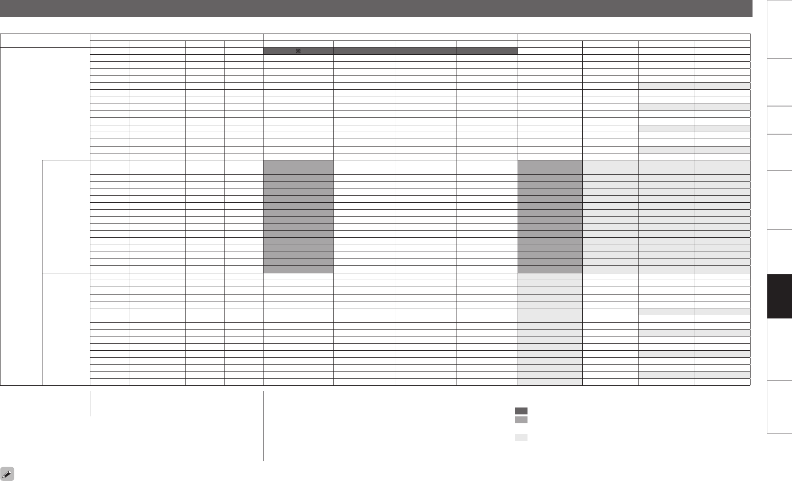
00
Getting Started Connections Setup Playback Remote Control Multi-Zone Troubleshooting Specifications
Video Convert Input signal Monitor output Monitor output (when GUI menu displayed)
HDMI COMPONENT S-VIDEO VIDEO HDMI COMPONENT S-VIDEO VIDEO HDMI COMPONENT S-VIDEO VIDEO
ON
A A A A bb z4z4z4z4
A A A S b VIDEOz1VIDEOz1 VIDEOz1 z5 VIDEOz1 z5b VIDEOz3VIDEOz3 VIDEOz3 VIDEOz3
A A S A b S-VIDEOz1S-VIDEOz1 S-VIDEOz1 S-VIDEOz1b S-VIDEOz3S-VIDEOz3 S-VIDEOz3 S-VIDEOz3
A A S S b S-VIDEOz1S-VIDEOz1 S-VIDEOz1 S-VIDEOz1b S-VIDEOz3S-VIDEOz3 S-VIDEOz3 S-VIDEOz3
A S (1080p) A A A COMPONENT A A b z4z4z4z4
A S (480p ~ 720p) A A b COMPONENTz1COMPONENTz1A A b COMPONENTz3COMPONENTz3A A
A S (480i/576i) A A b COMPONENTz1COMPONENTz1 COMPONENTz1 COMPONENTz1b COMPONENTz3COMPONENTz3 COMPONENTz3 COMPONENTz3
A S (1080p) A S b VIDEOz1COMPONENT VIDEO z1 z5 VIDEO z1 z5b VIDEOz3VIDEOz3 VIDEOz3 VIDEOz3
A S (480p ~ 720p) A S b COMPONENTz1COMPONENTz1AVIDEO b COMPONENTz3COMPONENTz3AVIDEO
A S (480i/576i) A S b COMPONENTz1COMPONENTz1 COMPONENTz1 COMPONENTz1b COMPONENTz3COMPONENTz3 COMPONENTz3 COMPONENTz3
A S (1080p) S A b S-VIDEOz1COMPONENT S-VIDEOz1 S-VIDEOz1b S-VIDEOz3S-VIDEOz3 S-VIDEOz3 S-VIDEOz3
A S (480p ~ 720p) S A b COMPONENTz1COMPONENTz1 S-VIDEO S-VIDEO b COMPONENTz3COMPONENTz3 S-VIDEO S-VIDEO
A S (480i/576i) S A b COMPONENTz1COMPONENTz1 COMPONENTz1 COMPONENTz1b COMPONENTz3COMPONENTz3 COMPONENTz3 COMPONENTz3
A S (1080p) S S b S-VIDEOz1COMPONENT S-VIDEOz1 S-VIDEOz1b S-VIDEO*3 S-VIDEOz3 S-VIDEOz3 S-VIDEOz3
A S (480p ~ 720p) S S b COMPONENTz1COMPONENTz1 S-VIDEO S-VIDEO b COMPONENTz3COMPONENTz3 S-VIDEO S-VIDEO
A S (480i/576i) S S b COMPONENTz1COMPONENTz1 COMPONENTz1 COMPONENTz1b COMPONENTz3COMPONENTz3 COMPONENTz3 COMPONENTz3
With HDMI
monitor
S A A A HDMIz2AAAHDMIz3AAA
S A A S HDMIz2 VIDEOz1 VIDEO z1 z5 VIDEO z1 z5 HDMIz3 VIDEO VIDEO VIDEO
S A S A HDMIz2 S-VIDEOz1 S-VIDEOz1 S-VIDEOz1 HDMIz3 S-VIDEO S-VIDEO S-VIDEO
S A S S HDMIz2 S-VIDEOz1 S-VIDEOz1 S-VIDEOz1 HDMIz3 S-VIDEO S-VIDEO S-VIDEO
S S (1080p) A A HDMIz2 COMPONENT A A HDMIz3 COMPONENT A A
S S (480p ~ 720p) A A HDMIz2 COMPONENTz1A A HDMIz3 COMPONENT A A
S S (480i/576i) A A HDMIz2 COMPONENTz1 COMPONENTz1 COMPONENTz1 HDMIz3 COMPONENT COMPONENT COMPONENT
S S (1080p) A S HDMIz2 COMPONENT VIDEO z1 z5 VIDEO z1 z5 HDMIz3 COMPONENT VIDEO VIDEO
S S (480p ~ 720p) A S HDMIz2 COMPONENTz1AVIDEO HDMIz3 COMPONENT AVIDEO
S S (480i/576i) A S HDMIz2 COMPONENTz1 COMPONENTz1 COMPONENTz1 HDMIz3 COMPONENT COMPONENT COMPONENT
S S (1080p) S A HDMIz2 COMPONENT S-VIDEOz1 S-VIDEOz1 HDMIz3 COMPONENT S-VIDEO S-VIDEO
S S (480p ~ 720p) S A HDMIz2 COMPONENTz1 S-VIDEO S-VIDEO HDMIz3 COMPONENT S-VIDEO S-VIDEO
S S (480i/576i) S A HDMIz2 COMPONENTz1 COMPONENTz1 COMPONENTz1 HDMIz3 COMPONENT COMPONENT COMPONENT
S S (1080p) S S HDMIz2 COMPONENT S-VIDEOz1 S-VIDEOz1 HDMIz3 COMPONENT S-VIDEO S-VIDEO
S S (480p ~ 720p) S S HDMIz2 COMPONENTz1 S-VIDEO S-VIDEO HDMIz3 COMPONENT S-VIDEO S-VIDEO
S S (480i/576i) S S HDMIz2 COMPONENTz1 COMPONENTz1 COMPONENTz1 HDMIz3 COMPONENT COMPONENT COMPONENT
Without HDMI
monitor
or
with HDMI
monitor off
S A A A A A A A A z4z4z4
S A A S A VIDEOz1 VIDEOz1 z5 VIDEOz1 z5AVIDEOz3 VIDEOz3 VIDEOz3
S A S A A S-VIDEOz1 S-VIDEOz1 S-VIDEOz1AS-VIDEOz3 S-VIDEOz3 S-VIDEOz3
S A S S A S-VIDEOz1 S-VIDEOz1 S-VIDEOz1AS-VIDEOz3 S-VIDEOz3 S-VIDEOz3
S S (1080p) A A A COMPONENT A A A z4z4z4
S S (480p ~ 720p) A A A COMPONENTz1A A A COMPONENTz3A A
S S (480i/576i) A A A COMPONENTz1 COMPONENTz1 COMPONENTz1ACOMPONENTz3 COMPONENTz3 COMPONENTz3
S S (1080p) A S A COMPONENT VIDEOz1 z5 VIDEO z1 z5AVIDEOz3 VIDEOz3 VIDEOz3
S S (480p ~ 720p) A S A COMPONENTz1AVIDEO ACOMPONENTz3AVIDEO
S S (480i/576i) A S A COMPONENTz1 COMPONENTz1 COMPONENTz1ACOMPONENTz3 COMPONENTz3 COMPONENTz3
S S (1080p) S A A COMPONENT S-VIDEOz1 S-VIDEOz1AS-VIDEOz3 S-VIDEOz3 S-VIDEOz3
S S (480p ~ 720p) S A A COMPONENTz1 S-VIDEO S-VIDEO ACOMPONENTz3 S-VIDEO S-VIDEO
S S (480i/576i) S A A COMPONENTz1 COMPONENTz1 COMPONENTz1ACOMPONENTz3 COMPONENTz3 COMPONENTz3
S S (1080p) S S A COMPONENT S-VIDEOz1 S-VIDEOz1AS-VIDEOz3 S-VIDEOz3 S-VIDEOz3
S S (480p ~ 720p) S S A COMPONENTz1 S-VIDEO S-VIDEO ACOMPONENTz3 S-VIDEO S-VIDEO
S S (480i/576i) S S A COMPONENTz1 COMPONENTz1 COMPONENTz1ACOMPONENTz3 COMPONENTz3 COMPONENTz3
Relationship Between Video Signals and Monitor Output
n MAIN ZONE
S : Signal present
A : No signal
480p ~ 720p : 480p / 576p / 1080i / 720p
A : No output
z1 : The “Picture Adjust” setting can be made (“Contrast”, “Brightness”,
“Chroma Level”, “Hue”).
z2 : The “Picture Adjust” setting can be made (“DNR”, “Enhancer”,
“Sharpness”).
z3 : Superimposed over video signal
z4 : Only displayed when the MENU button is pressed
z5 : If the input signal is in SECAM format, it is converted to PAL for output
b : Output according to “Resolution” setting (i/p Scaler : When “A to H” is
set) (vpage 46).
: Wallpaper or set background color displayed
: Output according to “Resolution” setting (i/p Scaler : When “H to H”
is set) (vpage 46).
: GUI menu not displayed
• The MAIN ZONE video conversion function is compatible with the following formats: NTSC, PAL, SECAM, NTSC4,43, PAL -N, PAL -M and PAL -60.
• When SECAM signals of video input are up-converted, the signals are output in PAL format from the S-Video connector.
• If the input signal is a component 1080p signal, up-converting to HDMI is not possible.
• The GUI menu display cannot be superimposed when xvYCC signals and component 1080p signal, computer’s resolution (e.g. VGA) are input.
Information
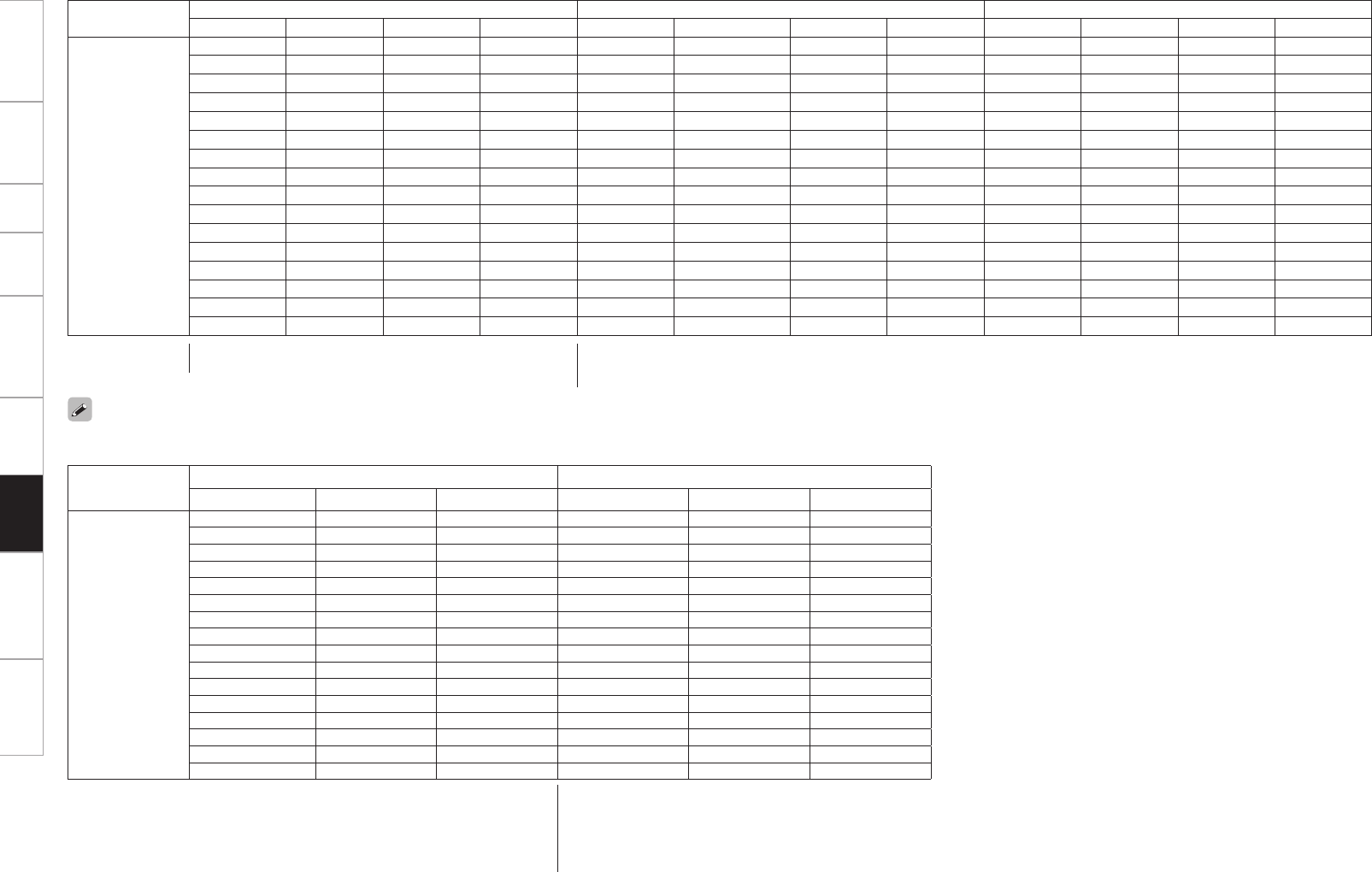
0
Getting Started Connections Setup Playback Remote Control Multi-Zone Troubleshooting Specifications
Video Convert Input signal Monitor output (Normally) Monitor output (when GUI menu displayed)
HDMI COMPONENT S-VIDEO VIDEO HDMI COMPONENT S-VIDEO VIDEO HDMI COMPONENT S-VIDEO VIDEO
OFF
A A A A A A A A S S S S
A A A S A A A S (VIDEO) SSSS
A A S A A A S (S-VIDEO) ASSSS
A A S S A A S (S-VIDEO) S (VIDEO) SSSS
A S A A A S (COMPONENT) A A S S S S
A S A S A S (COMPONENT) A S (VIDEO) SSSS
A S S A A S (COMPONENT) S (S-VIDEO) A SSSS
A S S S A S (COMPONENT) S (S-VIDEO) S (VIDEO) SSSS
S A A A S (HDMI) A A A S (HDMI)zAAA
S A A S S (HDMI) A A S (VIDEO) S (HDMI)zAAA
S A S A S (HDMI) A S (S-VIDEO) A S (HDMI)zAAA
S A S S S (HDMI) A S (S-VIDEO) S (VIDEO) S (HDMI)zAAA
S S A A S (HDMI) S (COMPONENT) A A S (HDMI)zAAA
S S A S S (HDMI) S (COMPONENT) A S (VIDEO) S (HDMI)zAAA
S S S A S (HDMI) S (COMPONENT) S (S-VIDEO) A S (HDMI)zAAA
S S S S S (HDMI) S (COMPONENT) S (S-VIDEO) S (VIDEO) S (HDMI)zAAA
S : Signal present
A : No signal
S : Output present
A : No output
z : Superimposed over video signal
To display the GUI menu on an HDMI monitor, output with a resolution of 480p/576p.
n ZONE2
Video Convert Input signal Monitor output
COMPONENT S-VIDEO VIDEO COMPONENT S-VIDEO VIDEO
ON
A A A A A A
A A S S (VIDEO) S (VIDEO) S (VIDEO)
A S A S (S-VIDEO) S (S-VIDEO) S (S-VIDEO)
A S S S (S-VIDEO) S (S-VIDEO) S (S-VIDEO)
S (1080p) A A S (COMPONENT) A A
S (480p ~ 720p) A A S (COMPONENT) A A
S (480i / 576i) A A S (COMPONENT) S (COMPONENT) S (COMPONENT)
S (1080p) A S S (COMPONENT)z1S (VIDEO) S (VIDEO)
S (480p ~ 720p) A S S (COMPONENT)z1S (VIDEO) S (VIDEO)
S (480i / 576i) A S S (COMPONENT)z1S (COMPONENT) S (VIDEO)
S (1080p) S A S (COMPONENT)z2S (S-VIDEO) S (S-VIDEO)
S (480p ~ 720p) S A S (COMPONENT)z2S (S-VIDEO) S (S-VIDEO)
S (480i / 576i) S A S (COMPONENT)z2S (S-VIDEO) S (S-VIDEO)
S (1080p) S S S (COMPONENT)z2S (S-VIDEO) S (S-VIDEO)
S (480p ~ 720p) S S S (COMPONENT)z2S (S-VIDEO) S (S-VIDEO)
S (480i / 576i) S S S (COMPONENT)z2S (S-VIDEO) S (S-VIDEO)
S : Output present
A : No output
z1 : With On-screen display, the VIDEO signal is superimposed output.
z2 : With On-screen display, the S-VIDEO signal is superimposed output.
COMPONENT :
When you operate the MENU button, on-screen display is displayed.
Information
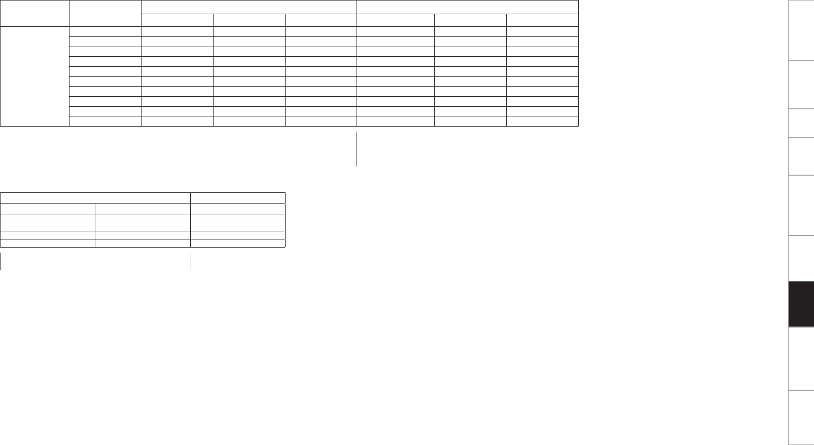
0
Getting Started Connections Setup Playback Remote Control Multi-Zone Troubleshooting Specifications
Input signal Monitor output
S-VIDEO VIDEO VIDEO
AAA
A S S (VIDEO)
S A S (S-VIDEO)
S S S (S-VIDEO)
Video Convert S-VIDEO
Monitor Out
Input signal Monitor output
COMPONENT S-VIDEO VIDEO COMPONENT S-VIDEO VIDEO
OFF
–A A A A A A
–A A S A A S (VIDEO)
–A S A A S (S-VIDEO) A
Used A S S A S (S-VIDEO) S (VIDEO)*2
Not used A S S A –S (VIDEO)
–S A A S (COMPONENT) A A
–S A S S (COMPONENT)z1A S (VIDEO)
–S S A S (COMPONENT)z2S (S-VIDEO) A
Used SS S S (COMPONENT)z2S (S-VIDEO) S (VIDEO)*2
Not used S S S S (COMPONENT)z1–S (VIDEO)
S : Output present
A : No output
z1 : With On-screen display, the VIDEO signal is superimposed output.
z2 : With On-screen display, the S-VIDEO signal is superimposed output.
n ZONE3
S : Signal present
A : No signal
S : Output present
A : No output
Information
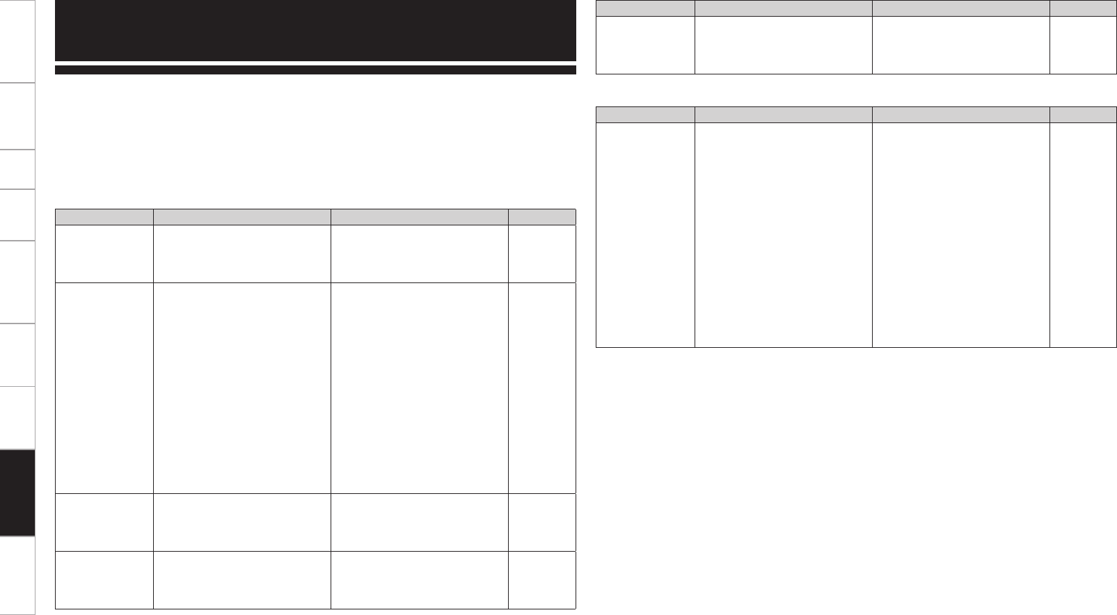
0
Getting Started Connections Setup Playback Remote Control Multi-Zone Information Specifications
If a problem should arise, first check the following:
1. Are the connections correct?
2. Is the set being operated as described in the owner’s manual?
3. Are the other components operating properly?
If this unit does not operate properly, check the items listed in the table below. Should the problem persist,
there may be a malfunction.
In this case, disconnect the power immediately and contact your store of purchase.
Symptom Cause Countermeasure Page
Power does not
turn on, or turns
off directly after it
was turned on.
• Connection of the power cord is
faulty.
• Check that the power plug is
securely inserted into the AVP-
A1HDCI’s AC inlet and the wall
power outlet.
23
No sound is
produced from
speakers.
• The connection with the input
devices or power amp is faulty.
• Device you want to play and set
input source do not match.
• Master volume is turned too
low.
• Mute mode is set.
• Headphones are connected.
• No digital signals are being
input.
• The connectors to which the
digital inputs are assigned and
the settable input modes do not
match.
• Check the connections.
• Select an appropriate input
source.
• Adjust the master volume to an
appropriate level.
• Cancel the mute mode.
• Disconnect the headphones.
• Select an input source for which
the digital input setting has been
made.
• Set the input mode.
11
45
58
58
58
45, 48
47
Display is off. • The “Dimmer” setting is set to
“OFF”.
• The PURE DIRECT mode is set.
• Set to something other than
“OFF”.
• Set a surround mode other than
the PURE DIRECT mode.
43
52
“DOLBY DIGITAL”
indicator does not
appear on display.
• DVD player’s digital audio output
setting is not proper.
• Check the DVD player’s audio
output setting. For details, read
the DVD player’s operating
instructions.
–
Symptom Cause Countermeasure Page
Power turns off
suddenly and
power indicator
flashes red.
• Set is damaged. • Turn off the power and contact a
DENON service center.
–
GGeneralH
Symptom Cause Countermeasure Page
Set does not work
properly when
remote control
unit operated.
• Batteries are worn.
• You are operating outside of the
specified range.
• Obstacle between main unit and
remote control unit.
• The batteries are not inserted in
the proper direction, as indicated
by the polarity marks in the
battery compartment.
• The set’s remote control sensor
is exposed to strong light (direct
sunlight, inverter type fluorescent
bulb light, etc.).
• The remote ID of the main unit
and remote control unit do not
match.
• Replace with new batteries.
• Operate within the specified
range.
• Remove the obstacle.
• Insert the batteries in the
proper direction, following the
polarity marks in the battery
compartment.
• Move the set to a place in which
the remote control sensor will
not be exposed to strong light.
• Set the same remote IDs for the
main unit and remote control
unit.
3, 4
4
–
3, 4
4
43, 80, 85
GRemote Control UnitH
Troubleshooting
Troubleshooting

0
Getting Started Connections Setup Playback Remote Control Multi-Zone Information Specifications
Symptom Cause Countermeasure Page
No sound is
produced from
center speaker.
• You are playing a monaural
source (TV, AM radio broadcast,
etc.) in the “STANDARD” (Dolby/
DTS Surround) or “HOME THX
CINEMA” mode.
• The mode is set to something
other than “STANDARD” (Dolby/
DTS Surround) or “HOME THX
CINEMA” .
50
No sound
is produced
from surround
speakers.
• The surround mode is set to
“STEREO”, “DIRECT” or “PURE
DIRECT”.
• Set to a surround playback
mode.
50 ~ 52
No sound is
produced from
surround back
speaker.
• Surround back speaker setting is
set to “None”.
• Surround mode not set to a mode
for 6.1- or 7.1-channel playback.
• Set to something other than
“None”.
• Select a surround playback
mode.
29
50 ~ 52
No sound is
produced from
subwoofer.
• Subwoofer’s power not turned
on.
• The “Subwoofer” setting at
“Speaker configuration” is set to
“No”.
• The subwoofer is not properly
connected.
• The subwoofer’s volume is
turned off.
• Turn on the subwoofer’s power.
• Set to “Yes”.
• Check the connections.
• Adjust the subwoofer’s volume
to an appropriate level.
–
29
11
–
No test tones are
produced when
main remote
control unit’s TEST
button is pressed.
• Surround mode not set
to “STANDARD” (Dolby/DTS
Surround) or “HOME THX
CINEMA” mode.
• Set to the “STANDARD” (Dolby/
DTS Surround) or “HOME THX
CINEMA” mode.
50
DTS sound is not
output.
• DVD player’s audio output setting
is not set to bitstream.
• DVD player is not compatible
with DTS sound playback.
• The AVP-A1HDCI’s “Decode
Mode” setting is set to “PCM”.
• Set the DVD player. For details,
refer to the DVD player’s
operating instructions.
• Use a DTS-compatible player.
• Set to the “Auto” or “DTS”
mode.
–
–
47
HDMI audio
signals are not
output from
speakers.
• The “Manual Setup” – “HDMI
Setup” – “Audio” setting is set to
“TV”.
• Set to “Amp”. 32
Symptom Cause Countermeasure Page
No sound is
output from
the monitor
connected
with HDMI
connections.
• The “Manual Setup” – “HDMI
Setup” – “Audio” setting is set to
“Amp”.
• Set to “TV”. 32
GAudioH
Symptom Cause Countermeasure Page
The on-screen
display does not
appear.
• The format of the GUI and TV
(NTSC or PAL) do not match.
• Match the format of the GUI and
TV.
41
No picture
appears.
• The connections between the
AVP-A1HDCI and monitor are
faulty.
• The monitor’s input setting is
wrong.
• PURE DIRECT mode is set.
• The player is connected using the
component input connectors, the
monitor is connected using the
video (yellow) or S-Video output
connectors.
• Check the connections.
• Set properly.
• Cancel the PURE DIRECT mode.
• High definition (1080i/720p) and
progressive (480p/576p) video
signals are not down-converted.
Set the player to interlace
(480i/576i) signals.
12, 13
–
52
–
No picture
appears
with HDMI
connections.
• The connections to the HDMI
connectors are faulty.
• HDMI input setting is improper.
• The monitor is not compatible
with copyright protection
(HDCP).
• The HDMI format of the player
and monitor do not match.
• Depending on the monitor you
have connected, the display may
not be correct when you set to
“Auto (Dual)”.
• Check the connections.
• Check the HDMI input setting.
• Connect a monitor that is
compatible with copyright
protection (HDCP).
• Match the HDMI format of the
player and monitor.
• Set to either “Monitor 1” or
“Monitor 2”.
12
48
12
12
32
Picture cannot be
recorded.
• Input source does not match
recorder’s video connection
connector (video or S-Video).
• The video conversion function
does not work for the REC
OUT connectors. Match the
input source and recorder
connections.
16, 17
DVDs cannot be
copied on a VCR. –
• This is not a malfunction. Most
movie software includes copy
prevention signals and cannot be
copied.
–
GVideoH
Troubleshooting

0
Getting Started Connections Setup Playback Remote Control Multi-Zone Information Specifications
Symptom Cause Countermeasure Page
When a USB
memory device
is connected,
“USB” is not
displayed on the
GUI menu.
• The set cannot recognize a USB
memory device.
• A USB memory device not
conforming to mass storage class
or MTP standards is connected.
• The set port and the connected
port do not match.
• A USB memory device that
the set cannot recognize is
connected.
• USB memory device is connected
via USB hub.
• Check the connection.
• Connect a USB memory device
conforming to mass storage
class or MTP standards.
• Connect to the port set at “USB
Select”.
• This is not a malfunction. DENON
does not guarantee that all USB
memory devices will operate or
receive power.
• Connect the USB memory device
directly to the USB port.
19
–
49
–
–
Files on a USB
memory device
cannot be played.
• USB memory device is in format
other than FAT16 or FAT32.
• USB memory device is divided
into multiple partitions.
• Files are stored in a non-
compatible format.
• You are attempting to play a file
that is copyright protected.
• Set the format to FAT16 or
FAT32. For details, refer to the
USB memory device’s operating
instructions.
• When divided into multiple
partitions, only files stored in the
top partition can be played.
• Record the files in a compatible
format.
• Files that are copyright protected
cannot be played on this set.
–
–
66
66
The file names
are not displayed
properly (“...”, etc.).
• Characters that cannot be
displayed are used.
• This is not a malfunction. On
this set, characters that cannot
be displayed are replaced with a
“ . (period)”.
–
GNET/USB / RhapsodyH
Symptom Cause Countermeasure Page
iPod cannot be
played.
• The input source assigned to
“iPod dock” is not selected.
• Cable is not properly connected.
• Control Dock for iPod’s AC
adapter is not connected to
power outlet.
• Switch to the input source
assigned at “iPod dock”.
• Reconnect.
• Plug the Control Dock for iPod’s
AC adapter into a power outlet.
49
14
–
GiPodHSymptom Cause Countermeasure Page
Internet radio
cannot be played.
• Ethernet cable is not properly
connected or network is
disconnected.
• Program is being broadcast in
non-compatible format.
• The computer’s or router’s
firewall is activated.
• Radio station is not currently
broadcasting.
• IP address is wrong.
• Check the connection status.
• Only Internet radio programs in
MP3 and WMA can be played on
this set.
• Check the computer’s or router’s
firewall settings.
• Choose a radio station that is
currently broadcasting.
• Check the set’s IP address.
21
66
–
68
38
Files stored on a
computer cannot
be played.
• Files are stored in a non-
compatible format.
• You are attempting to play a file
that is copyright protected.
• Set and computer are connected
by USB cable.
• Record in a compatible format.
• Files that are copyright protected
cannot be played on this set.
• The set’s USB port cannot
be used for connection to a
computer.
66
66
–
Server is not
found, or it is
not possible to
connect to the
server.
• The computer’s or router’s
firewall is activated.
• Computer’s power is not turned
on.
• Server is not running.
• Set’s IP address is wrong.
• Check the computer’s or router’s
firewall settings.
• Turn on the power.
• Launch the server.
• Check the set’s IP address.
–
–
–
38
Cannot connect to
preset or favorite
radio stations.
• Radio station is not currently
broadcasting.
• Radio station is not currently in
service.
• Wait a while before trying again.
• It is not possible to connect to
radio stations that are no longer
in service.
–
–
For some
radio stations,
“Server Full”
or “Connection
Down” is
displayed and
station cannot be
connected to.
• Station is congested or not
currently broadcasting.
• Wait a while before trying again. –
Sound is broken
during playback.
• Network’s signal transfer speed
is slow or communications lines
or radio station is congested.
• This is not a malfunction. When
playing broadcast data with a
high bit rate, the sound may
be broken, depending on the
communications conditions.
–
Sound quality is
poor or played
sound is noisy.
• File being played has a low bit
rate.
• This is not a malfunction. –
Troubleshooting

0
Getting Started Connections Setup Playback Remote Control Multi-Zone Information Specifications
Symptom Cause Countermeasure Page
Cannot login
to Rhapsody.
(“Username
or Password
is incorrect” is
displayed)
• Login information is incorrect.
• Trial period has expired.
• Check if the Username for
Rhapsody has been properly
entered.
•
Re-enter the Password. (Password
is not displayed.)
• Get a full account.
www.rhapsody.com/denon/signup
38
38
66, 70
Cannnot play. • When the trial period has finished,
there is a limit to the playing time
and number of tracks that can be
played.
• Get a full account.
www.rhapsody.com/denon/signup
66, 70
Stops in the
middle of playing.
• When the trial period has finished,
there is a limit to the playing time
and number of tracks that can be
played.
• Get a full account. 66, 70
Cannot compile
Playlist.
• The AVP-A1HDCI does not
respond to playlist compilation.
• When the playlist is compiled in
“PC Application”, it is registered
to “My Library”. In this way, the
playlist can be played in AVP-
A1HDCI.
b Need full account.
–
Cannot delete
Rhapsody
Channel
registered in “My
Channels”.
• Cannot be done with AVP-
A1HDCI.
• Delete from “PC Application”. –
Cannot delete
Tracks, Playlists,
Channels
registered in “My
Library”.
• Cannot be done with AVP-
A1HDCI.
• Delete from “PC Application”.
b Need full account.
–
GXM Satellite RadioH
Symptom Cause Countermeasure Page
“CHECK XM
TUNER” is
displayed.
• The XM Mini-Tuner is not
installed or not fully seated in the
XM Mini-Tuner Dock or the XM
Mini-Tuner dock is not connected
to the AVP-A1HDCI.
• Confirm the XM Mini-Tuner is
fully seated in the dock and check
the XM Mini-Tuner dock cable is
connected to the AVP-A1HDCI.
19
”CHECK
ANTENNA” is
displayed.
• AVP-A1HDCI’s XM connector and
the XM Mini-Tuner and Home
Dock is not properly connected.
• Check that the connections are
correct.
19
Symptom Cause Countermeasure Page
Cannot connect
to network.
• The settings of the SSID
and network key (WEP) are
incorrect.
• The reception is poor and the
signals cannot be received.
• There are multiple networks and
the usable channels overlap.
• Match the network settings with
the AVP-A1HDCI’s settings.
• Shorten the distance from the
wireless LAN’s access point,
remove any obstacles and
otherwise improve visibility, then
try reconnecting. Also install
away from microwave ovens
and the access points of other
networks.
• Set the access point’s channel
settings away from the channels
used for other networks.
Alternatively, connect using a
network cable.
35 ~ 38
–
–
Played sound is
interrupted or
sound cannot be
played.
• There are multiple networks and
the usable channels overlap.
• Set the access point’s channel
settings away from the channels
used for other networks.
Alternatively, connect using a
network cable.
–
GWireless LANH
Troubleshooting
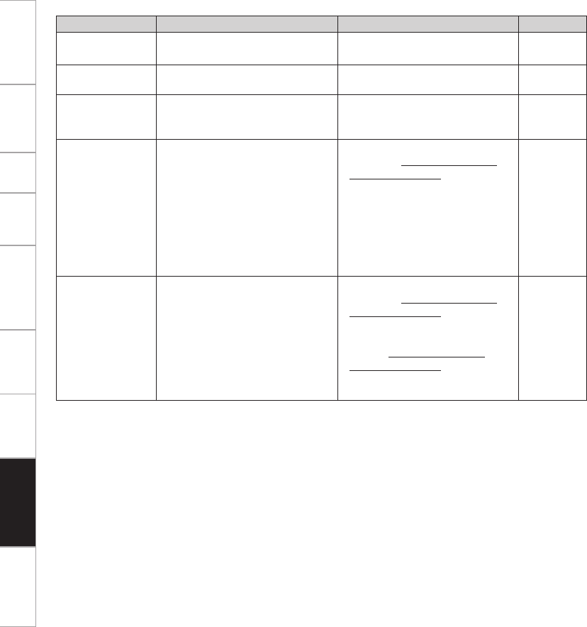
0
Getting Started Connections Setup Playback Remote Control Multi-Zone Information Specifications
GXM Satellite RadioH
Symptom Cause Countermeasure Page
”NO SIGNAL” is
displayed.
• The signal cannot be received. • Reposition your XM Mini-Tuner
and Home Dock antenna.
–
”OFF AIR” is
displayed.
• The selected channel is not
currently broadcasting.
• Select another channel. –
Receiving only
XM channels 0
and 1.
• The XM Mini-Tuner is not
activated.
• Contact XM Radio. –
“
XM - - -
” is
displayed.
• You selected an XM channel that
is blocked or cannot be receive
with your XM subscription
package.
• Consult the latest channel
guide at www.xmradio.com or
www.xmaradio.ca for the current
list of channels. For cases of
a new radio or a radio that has
not received XM’s signal for an
extended period, allow the radio
to receive the XM satellite signal
for at least 5 minutes and then
try to select the channel again.
–
“
UPDATING
” is
displayed.
• The selected channel is not
available. The channel may have
been reassigned to a different
channel number. This message
may occur initially with a new
radio or a radio that has not
received XM’s signal for an
extended period.
• Consult the latest channel
guide at www.xmradio.com or
www.xmaradio.ca for the current
list of channels. For information
on receiving this channel,
visit www.xmradio.com or
www.xmaradio.ca contact XM
Satellite Radio at 1-800-967-2346
or 1-877-438-9677.
–
Troubleshooting

0
Getting Started Connections Setup Playback Remote Control Multi-Zone Information Troubleshooting
n HD Radio section [FM] [AM]
(note: µV at 75 Ω/ohms, 0 dBf = 1 x 10-15 W)
Receiving Range: 87.5 MHz ~ 107.9 MHz 530 kHz ~ 1710 kHz
Usable Sensitivity: 1.0 µV (11.2 dBf) 20 µV
50 dB Quieting Sensitivity: MONO 1.6 µV (15.3 dBf)
STEREO 23 µV (38.5 dBf)
S/N (IHF-A): MONO 77 dB
STEREO 72 dB
HD 85 dB 85 dB
Total harmonic Distortion (at 1 kHz): MONO 0.2 %
STEREO 0.3 %
HD 0.01 % 0.01 %
n Wireless LAN
Network type (wireless LAN standards) :
Conforming to IEEE 802.11b
Conforming to IEEE 802.11g
(Conforming to Wi-Fi®)z
Transfer rate: DS-SS: 11 / 5.5 / 2 / 1 Mbps (Automatic switching)
OFDM: 54 / 48 / 36 / 24 / 18 / 12 / 9 / 6 Mbps (Automatic switching)
Security: SSID (Network name)
WEP key (network key) (64/128 bits)
WPA-PSK (TKIP/AES)
WPA2-PSK (TKIP/AES)
Used frequency range: 2,412 MHz ~ 2,472 MHz
No. of channels: Conforming to IEEE 802.11b : 11ch (DS-SS) (Of which 1 channel used)
Conforming to IEEE 802.11g : 11ch (OFDM) (Of which 1 channel used)
n General
Power supply: AC 120 V, 60 Hz
Power consumption: 2 A
0.3 W (Standby)
Maximum external dimensions: 434 (W) x 214 (H) x 488 (D) mm (17-3/32” x 8-27/64” x 19-7/32”)
Weight: 27 kg (Approx 59 lbs 8 oz)
n Main remote control unit (RC-1067)
Batteries: LR6/AA Type (two batteries)
Maximum external dimensions: 63 (W) x 238 (H) x 31 (D) mm
Weight: 190 g (Approx 6.7 oz) (including batteries)
n Sub remote control unit (RC-1070)
Batteries: R03/AAA Type (two batteries)
Maximum external dimensions: 49 (W) x 220 (H) x 24.5 (D) mm
Weight: 114 g (Approx 4 oz) (including batteries)
z: Wi-Fi® conformity indicates tested and proven interoperability by the “Wi-Fi Alliance”, a group certifying interoperability
among wireless LAN devices.
b For purposes of improvement, specifications and design are subject to change without notice.
n Audio section
• Analog
Input sensitivity / Input impedance: RCA Pre output (unbalanced) : 200 mV / 47 kΩ/kohms
XLR Pre output (balanced) : 400 mV / 100 kΩ/kohms
Frequency response: 10 Hz ~ 100 kHz +1, –3 dB (DIRECT mode)
S/N: 102 dB (IHF–A weighted, DIRECT mode)
Distortion: 0.005 % (20 Hz ~ 20 kHz) (DIRECT mode)
Rated output: RCA Pre output (unbalanced) : 1.2 V
XLR Pre output (balanced) : 2.4 V
• Digital
D/A output: Rated output — 2 V (at 0 dB playback)
Total harmonic distortion — 0.005 % (1 kHz, at 0 dB)
Dynamic range — 110 dB
Digital input: Format — Digital audio interface
• Phono equalizer (PHONO input — REC OUT)
Input sensitivity: 2.5 mV
RIAA deviation: ±1 dB (20 Hz to 20 kHz)
S/N: 74 dB (A weighting, with 5 mV input)
Rated output: 150 mV
Distortion factor: 0.03 % (1 kHz, 3 V)
n Video section
• Standard video connectors
Input / output level and impedance: 1 Vp-p, 75 Ω/ohms
Frequency response: 5 Hz ~ 10 MHz — +0, –3 dB (when video convert set to “OFF”)
• S-Video connectors
Input / output level and impedance: Y (brightness) signal — 1 Vp-p, 75 Ω/ohms
C (color) signal — 0.286 Vp-p, 75 Ω/ohms
Frequency response: 5 Hz ~ 10 MHz — +0, –3 dB (when video convert set to “OFF”)
• Color component video connector
Input / output level and impedance: Y (brightness) signal — 1 Vp-p, 75 Ω/ohms
PB / CB signal — 0.7 Vp-p, 75 Ω/ohms
PR / CR signal — 0.7 Vp-p, 75 Ω/ohms
Frequency response: 5 Hz ~ 100 MHz — +0, –3 dB (when video convert set to “OFF”)
n Tuner section [FM] [AM]
(note: µV at 75 Ω/ohms, 0 dBf = 1 x 10-15 W)
Receiving Range: 87.5 MHz ~ 107.9 MHz 520 kHz ~ 1710 kHz
Usable Sensitivity: 1.0 µV (11.2 dBf) 19 µV
50 dB Quieting Sensitivity: MONO 1.6 µV (15.3 dBf)
STEREO 23 µV (38.5 dBf)
S/N (IHF-A): MONO 77 dB
STEREO 72 dB
Total harmonic Distortion (at 1 kHz): MONO 0.2 %
STEREO 0.3 %
Specifications
Specifications

PRESET CODE
List of preset codes
Denon Amp
DDenon 81001, 82001, 83001, 84001
Denon Tuner
DDenon (Analog) 52863, 52795, 52800, 52805
Denon (XM Radio) 52864, 52812, 52813, 52814
Denon Digital Tuner
DDenon (NET) 62865, 62837, 62838, 62839
Denon (HD Radio) 62840, 62841, 62842, 62843
Denon iPod
DDenon 72815, 72816, 72817, 72818
Cable
AA-Mark 00008, 00144
ABC 00237, 00003, 00008
Accuphase 00003
Acorn 00237
Action 00237
Active 00237
ADB 01230
Aichi Denshi 01512
Americast 00899
Amstrad 01222
Archer 00237
Auna 01230
Austar 00276
BBCC 00276
Bell South 00899
Bestlink 00303
Birmingham Cable
Communications 00276
British Telecom 00003
CCable & Wireless 01068
Century 00008
Coship 01462
DDaehan 00778
Daeryung 01877, 00877, 00477, 00008
Digeo 01187
Director 00476
DX Antenna 01500
EEmerson 00303
Encon 00008
FFosgate 00276
Foxtel 01222
France Telecom 00817
Freebox 01482
Fujitsu 01497
GGalaxi 00008
GE 00237, 00144
Gehua 00476
General Instrument 00476, 00810, 00276, 00003
Gibralter 00003
GNI 01466
GoldStar 00144
HHitachi 00003, 00008
Hongtian Jiangsu 01462
Hwalin 00303
IInsight 00476, 00810
JJerrold 00476, 00810, 00276, 00003
Jiuzhou 01445
KKNC 00008
LLG 00144
MMacab 00817
Madritel 01230
Maspro 01510
Matav 01082
Memorex 00000
Mitsubishi 00003
Motorola 01376, 00476, 00810, 00276,
01187
MS 00303
NNEC 01496
Noos 00817
Nova Vision 00008
Novaplex 00008
NTL 00276, 00003, 01060, 01068
OOak 00303
Ono 01068
Optus 00276, 01060
PPace 01877, 00877, 00237, 00008,
01060, 01068, 01577
Panasonic 00000, 00008, 00144, 01488
Paragon 00000, 00008, 00525
Penney 00000
Philips 01305, 00317, 00817
Pioneer 01877, 00877, 00144, 00533,
01500
Pulsar 00000
PVP Stereo Visual
Matrix 00003
QQuasar 00000
RRadioShack 00303
Regal 00276
Runco 00000
SSagem 00817
Salora 00000
Samsung 00003, 00000, 00144, 00778,
00840, 01060, 01666
Scientific Atlanta 01877, 00877, 00477, 00237,
00003, 00000, 00008, 01510
Skyworth 01464
Sony 01006, 01460
Sprucer 00144
Starcom 00003
StarHub 00276
Sumitomo 01500, 01504
Supercable 00276
TTaihan 00778
TCL 01445
Telewest 01068
Time Warner cable 01877
TongKook 00840
Torx 00003
Toshiba 00000, 01509
Trans PX 00276, 00303
TS 00003, 00303
UUnited Cable 00276, 00003
US Electronics 00276, 00003, 00008
VVideoway 00000
Visiopass 00817
ZZenith 00000, 00525, 00899
Cable/PVR Combination b1
AAmericast 00899
DDigeo 01187
FFreebox 01482
GGeneral Instrument 00810
JJerrold 00810
MMotorola 01376, 00810, 01187
PPace 01877, 00237
Pioneer 01877, 00877
SScientific Atlanta 01877, 00877
Sony 01006
Supercable 00276
TTime Warner cable 01877
ZZenith 00899
CD Player
AAcoustic Research 40420
Advantage 40032
Aiwa 40157
Arcam 40157
Audio Research 40157
Audiolab 40157
Audiomeca 40157
Audioton 40157
AVI 40157
B
Balanced Audio
Technology
40157
Burmester 40420
Bush 40388
CCairn 40157
California Audio Labs
40029, 40303
Cambridge 40157
Cambridge Audio 40157
Cambridge
Soundworks 40157
Carver 40157, 40179
CDC 40420
CEC 40420
Copland 40393
Curtis Mathes 40032
Cyrus 40157
DDenon 40873, 40003, 40766,
[42867]z, 42868
DKK 40000
DMX Electronics 40157
Dual 40003
Dynaco 40157
Dynamic Bass 40179
FFisher 40000, 40179
GGarrard 40393, 40420
Genexxa 40000, 40032, 40037, 40179
Goldmund 40157
Grundig 40157
HHafler 40173
Harman/Kardon 40100, 40157, 40173
Hitachi 40032
IInkel 40157
Integra 40101
JJerrold 40003
JVC 40032, 40072
KKenwood 40681, 40000, 40029, 40157,
40028, 40037, 40036, 40190
KLH 41318
Krell 40157
LLinn 40157
Loewe 40157
Luxman 40393
LXI 40179
MMagnavox 40157
Marantz 40029, 40157
Matsui 40157
MCS 40029
Memorex 40000, 40032, 40179, 40420,
40468
Meridian 40157
Micromega 40157
Miro 40000
Mission 40157
Modulaire 40000, 40032, 40087, 40179,
40420, 40468
MTC 40420
Musical Fidelity 40393
Myryad 40157
NNAD 40000, 40721
Naim 40157
NSM 40157
OOnkyo 40868, 40101
Optimus 40000, 40032, 40037, 40087,
40179, 40393, 40420, 40468
Orion 40393
PPanasonic 40029, 40303, 40388, 40752
Parasound 40420
Penney 40029
Philips 40157
Pioneer 40032, 40101, 40468
Polk Audio 40157
Proceed 40420
Proton 40157
QQED 40157
Quad 40157
Quasar 40029
RRadiola 40157
RadioShack 40000, 40032, 40179, 40420,
40468
RCA 40032, 40053, 40179, 40420,
40468
Realistic 40000, 40032, 40087, 40179,
40420, 40468
Restek 40157
Revox 40157
Roksan 40420
Rotel 40157, 40420
Royal 40420
SSAE 40157
Saisho 40000
Sansui 40000, 40157
Sanyo 40000, 40087, 40179
SAST 40157
Sears 40179
Sharp 40037
Siemens 40157
Silsonic 40036
Simaudio 40157
Sonic Frontiers 40157
Sony 40490, 40000, 40100, 41364,
40185
Sugden 40157
Sylvania 40157
TTAG McLaren 40157
Tandy 40032
Tascam 40393, 40420

PRESET CODE
Teac 40490, 40393, 40420
Technics 40029, 40303
Techwood 40303
Thomson 40053
Thorens 40157
Thule Audio 40157
Tokai 40420
UUniversum 40157, 40053
VVictor 40072
W
Wadia 40393
Wards 40000, 40032, 40157, 40053,
40087, 40179
YYamaha 40490, 40868, 40032, 40036
Yorx 40000
CD Recorder
DDenon 40766, 42868
JJVC 40072
RRCA 40053, 40420
SSony 40000, 40100, 41364
TTeac 40420
Thomson 40053
Tape Deck
AAiwa 20029, 20197, 20200, 21315
Akai 20283, 20439
Arcam 20076
Audiolab 20029
CCarver 20029
DDenon 20076, 20371, 21311,
[22471]z
FFisher 20074
GGarrard 20308, 20309, 20375, 20439
Genexxa 20439
GoldStar 20375
Grundig 20029, 20375
HHarman/Kardon 20182, 20029, 21314
IInkel 20070, 20071, 20337
JJVC 20244, 20273, 20274, 20303,
20304, 20310, 21309
KKenwood 20070, 20071, 20092, 20233,
20234, 21364
LLG 20375
Luxman 20308, 20309
MMagnavox 20029
Marantz 20029, 20009
Memorex 20099
Mitsubishi 20283, 20439
Myryad 20029
OOnkyo 20135, 20136, 20282
Optimus 20027, 20220, 20337, 20439
Orion 20308, 20309
PPalladium 20375
Panasonic 20229
Philips 20029, 20229
Phonotrend 20337
Pioneer 20027, 20220, 20099, 20109,
21306, 21312
Polk Audio 20029
RRadiola 20029
RCA 20027, 20220
Revox 20029
SSansui 20029, 20009
Sanyo 20074
Sharp 20231, 20371
Sherwood 20337
Sonic 20375
Sony 20243, 20170, 20291, 20234,
21313
TTaeKwang 20439
Tandberg 20109
Teac 20280, 20283, 20289, 20308,
20309
Technics 20229
Technovox 20229
Thorens 20029
UUniversum 20375, 20439
VVictor 20244, 20273, 20274
W
Wards 20027, 20029
Wharfedale 20439
YYamaha 20097, 20094
HDTV Tuner b1
AABS 01272
Accurian 01653
Alienware 01272
CCyberPower 01272
DD-Link 01554
Dgtec 01363
EEpson 01563
GGateway 01272
HHewlett Packard 01272, 01267
Howard Computers 01272
HP 01272, 01267
Hush 01272
IiBUYPOWER 01272
LLG 01415
Linksys 01272, 01365
MMedia Center PC 01272
Microsoft 01272, 01805
Mind 01272
Motorola 01363
NNiveus Media 01272
Northgate 01272
PPackard Bell 01272
Panasonic 01120
Pioneer 01010
RRicavision 01272
SSamsung 01190, 01490
Sensory Science 01126
Sharp 01010
SMC 01456
Sony 01272, 01324, 01364
Stack 9 01272
Sylvania 01563
Systemax 01272
TTagar Systems 01272
Toshiba 01272
Touch 01272
VViewsonic 01272, 01329
Vizio 01126
Voodoo 01272
XXbox 01805
ZZT Group 01272
Satellite Receiver
A@sat 01300
@Sky 01334
A-Mark 00345
ABsat 00123, 00713
ADB 00642, 01259, 01367, 01418,
01473, 01491
AGS 00710
Aiwa 01514
Akai 00200
Alba 00455, 00713, 01284, 01659,
01811
Allsat 00200, 01043
Alltech 00713
Allvision 01232, 01334, 01412
AlphaStar 00772
Amitronica 00713
Amstrad
00345, 00713, 00795, 00847,
00863, 00882, 01113, 01175,
01693, 01801
Anglo 00713
Ankaro 00713
AntSat 01083
Apollo 00455
Arcon 01043, 01075
Armstrong 00200
Arnion 01300
Asat 00200
ASCI 01334
ASLF 00713
AssCom 00853
Astacom 00710
Aston 00142
Astra 00713
Astratec 01743
Astro 00173, 00658, 01099, 01100,
01113
Atlantic Telephone 01333
Atsat 01300
AtSky 01334
Audioline 01672
Aurora 00642, 00879, 01333, 01433
Austar 00497, 00642, 00863, 00879,
01176, 01259
Axiel 00710
Axil 01457, 01659
Axis 01111
BB@ytronic 01412
Beko 00455
Bell ExpressVu 00775
Big Sat 01457
Black Diamond 01284
Blaupunkt 00173
Blue Sky 00713
Boca 00713, 01232, 01366
Boston 00710, 01251
Brainwave 00658, 01672
British Sky
Broadcasting 00847, 01175, 01662, 01847
Broco 00713
BskyB 00847, 01175, 01662
BT 00710, 01296
Bubu Sat 00713
Bush 01284, 01645, 01672, 01743,
01811
CCanal 00853
Canal Digital 00853, 01622
Canal Satellite 00853, 01339, 01853
Canal+ 00853
Centrex 01457
CGV 01413, 01567
Chaparral 00216
Cherokee 00123, 00710
Chess 00713, 01085, 01334, 01626
Chili 01718
CityCom 00299, 00394, 00818, 01075,
01176, 01232
Classic 01672
Clatronic 01413
CNS 01367
Comag 01232, 01366, 01412, 01413
Condor 01700
Conia 01695
Contec 00394
Continental Edison 01695
Coship 01457
Crossdigital 01109
Crown 01284
Cryptovision 00455, 00795
Cyfra+ 01076
Cyrus 00200
DD-box 00723, 00873, 01114
Daewoo 00713, 01111, 01296, 01743
Delfa 00863
Deltasat 01075
Dgtec 01542, 01631, 01242
Digenius 00299
Digiality 01685
Digifusion 01645, 01743
DigiLogic 01284
DigiQuest 00863, 01300, 01457, 01473
DigiSat 01232
Digisky 01457
DigitAll World 01227
Digiturk 01076
Digiwave 01631
Dijam 01296
DiPro 01367, 01543
DirecTV
01377, 00392, 00566, 00639,
01639, 01142, 00247, 00749,
01749, 00724, 00819, 01856,
01076, 01108, 00099, 01109,
01414, 01442, 01609, 01392,
01640
Discovery 00710
Dish Network System
01505, 01005, 00775, 01775
Dishpro 01505, 01005, 00775, 01775
Distratel 01283, 01704
DMT 01075
DNT 00200
Dream Multimedia 01237
DSE 01375
DSTV 00642, 00879, 01433
Durabrand 01284
DX Antenna 01530
EEchostar
01505, 01005, 00775, 00455,
00610, 00713, 00853, 00871,
01086, 01200, 01323, 01409,
01418, 01473, 01775
Einhell 00713
Elap 00713, 01567
Elsat 00713
Elta 00200, 01659
Emme Esse 00871
Energy Sistem 01631
Engel 00713, 01251
EP Sat 00455
Esat 00879
Eurieult 00882

Eurocrypt 00455
EuroLine 01251
Europa 00863
Europhon 00299
Eurosky 00262, 00299
Eurostar 00818
Eutelsat 00713
Expressvu 00775, 01775
FFenner 00713
Ferguson 00455, 01291, 01743
Finlandia 00455
Finlux 00455
Flair Mate 00713
FMD 01251, 01413, 01457
Force 01101
Fortec Star 01083
Foxtel 00455, 00497, 00795, 00879,
01162, 01176, 01356
Fracapro Planet 00871
Fracarro 00125, 00871
France Telecom 00871
Freesat 00882
FTE 00863
FTEmaximal 00713, 00863
Fuba 00173, 00262, 00299, 00394,
01214, 01251, 01801
Fugionkyo 00125
Funai 01377
GGalaxis 00853, 00863, 01101, 01111,
01557
Gardiner 00818
Garnet 01075
GbSAT 01214
GE 00392, 00566
Gecco 01412
General Instrument 00869
General Satellite 01176
GF Good Friends 01043
GF Star 01043
Globo 01251, 01334, 01412, 01429,
01626
GOD Digital 00200
GOI 00775, 01775
Gold Box 00853
Gold Vision 01631
Golden Interstar 01283
GoldStar 00394
Goodmans 00455, 01284, 01291
Gradiente 00887
Granada 00455
Grundig 00173, 00345, 00847, 00853,
00879, 01291
HHandan 01622
Hanseatic 01099, 01100
Hauppauge 01672
HB 01214, 01801
HDT 01159
Hills 01232
Hirschmann
00125, 00173, 00299, 00710,
00882, 01085, 01111, 01232,
01412
Hisense 01535
Hitachi 00749, 00819, 00455, 01250,
01284, 01518, 01523, 01525
Homecast 01214, 01680, 01700
Hornet 01300
Houston 00775
HTS 00775, 01775
Hughes Network
Systems 01142, 00749, 01749, 01442
Humax
00863, 01176, 01225, 01406,
01427, 01675, 01743, 01790,
01915
Huth 01075
Hyundai 01075, 01159
IiCan 01367
ID Digital 01176
ILLUSION sat 01557, 01631
iLo 01535
Imperial 01334, 01429, 01672
Indovision 00887
Ingelen 00882
Innova 00099
Interstar 01214
InVideo 00871
ISkyB 00887
Italtel 00871
ITT Nokia 00455, 00723, 00873
JJadeworld 00642
Jaeger 01334
Jerrold 00869
Jiuzhou 01450
JOK 00710
JVC 00775, 01507, 01531, 01775
KK-SAT 00713
Kamm 00713
Kaon 01300
KaTelco 01111
Kathrein
00123, 00173, 00200, 00249,
00394, 00442, 00480, 00504,
00658, 00713, 00818, 01221,
01416, 01561, 01567
Kennex 00125
Kenwood 00853
Klap 00710
Kocmoc TB 01333
Koscom 01043
Kosmos 00442, 01333
Kreiling 00249, 00658
Kreiselmeyer 00173
Kross 01695
LL&S Electronic 01043, 01334
Labgear 01296
LaSAT 00173, 00299
Lava 01631
Legend 01718
Legrand 01718
Lemon 01334
Lenco 00713
Lenoxx 01611
LG 01075, 01414
Lifesat 00299, 00713, 01043
Lodos 01284
Logik 01284
Logix 01075
Lorenzen 00299
Luxor 00345, 00873
MM Electronic 00818
M vision 01557
Magnavox 00724, 00722
Manata 00710, 00713
Manhattan 00455, 00710, 01083
Marantz 00200
Maspro 00173, 00713, 01530
Master’s 00394
Matsui 00173, 00710, 01284, 01743
Maximum 01075, 01334, 01685
McIntosh 00869
MDS 01225
Mediabox 00853
Mediacom 01206
MediaSa 00853
Medion 00299, 00713, 01043, 01075,
01232, 01334, 01412, 01626
Medison 00713
Mega 00200
Memorex 00724
Metronic 00713, 00818, 01283, 01334,
01375, 01704
Metz 00173
MiCO 01811
Micro 00713
Micro Elektronic 00713
Micro Technology 00713
Micromaxx 00299
Microstar 01075
Microtec 00713
Mitsubishi 00749, 00455
Morgan’s 00200, 00713, 01232, 01412
Motorola 00869, 00856, 01473
MTEC 01214
Muller 01695
Multibroadcast 00642, 00879
Multichoice 00642, 00879, 01333, 01433,
01559, 01560
Mx Onda 01659
Myryad 00200
Mysat 00713
MySky 01693, 01848, 01850
NNEC 01519
NEOTION 01334
Netgem 01322
Netsat 00099, 00887
Neuf TV 01322
Neuhaus 00713
Neuling 01232
Neusat 00713
Nevir 01659
Next Level 00869
Nikko 00200, 00713, 00723
Noda Electronic 01704
Nokia 00455, 00723, 00751, 00853,
00873, 01023, 01223, 01723
Nordmende 00455, 01611
OOctalTV 01505
Okano 00442
Omega 00887
Opentel 01232, 01412
Optex 00394, 00713, 01043, 01283,
01611
Optimus 00724
Optus 00879
Orbis 01232, 01334, 01412
Orbitech 01099, 01100
Origo 00497
OSAT 00345
PP/Sat 01232
Pace
00200, 00329, 00455, 00497,
00795, 00847, 00853, 00887,
01175, 01323, 01356, 01423,
01693, 01717, 01848, 01850
Pacific 01284, 01375
Packard Bell 01111
Packsat 00710
Palcom 00299, 01409
Panarex 01159
Panasat 00615, 00879, 01333, 01433
Panasonic
00247, 00701, 00455, 00847,
01304, 01404, 01508, 01526,
01527
Panda 00173, 00455
Pansat 01159
Patriot 00710
Paysat 00724
peeKTon 01457
Philips
01142, 00749, 01749, 00775,
00724, 00819, 01076, 00722,
00099, 00710, 00455, 00818,
00200, 00847, 00853, 00173,
01114, 00133, 01442, 01543,
01672
Phonotrend 00863, 01200
Pilotime 01339
Pino 01334
Pioneer 01142, 00329, 00853, 01308,
01442
Planet 00871
Plasmatic 00442
PMB 00713, 01611
Polytron 00394
Portland 01296
Preisner 00262, 01101, 01113, 01366
Premier 00723, 00853, 00873, 01429
Prima 00795
Primacom 01111
Primestar 00869
Profile 00710
Promax 00455
Proscan 00392, 00566
Proton 01535
QQNS 01367, 01402, 01404
Quadral 00710
Quelle 00299
RRadiola 00200
RadioShack 00566, 00775, 00869
Radix 00394, 00882, 01113, 01317
RCA
00392, 00566, 01142, 00775,
00855, 00143, 01291, 01392,
01442
Rebox 01214
Regal 01251
RFT 00200
Roadstar 00713, 00853
Rollmaster 01413
Rover 00713
Rownsonic 01567
SSAB 01251
Saba 00710, 00820
Sabre 00455
Sagem 00820, 01114, 01253, 01307,
01690
Samsung
01377, 01142, 01276, 01108,
01109, 00853, 00863, 01206,
01442, 01458, 01570, 01609,
01700, 01916
Sat Control 01300
Sat Team 00713
SAT+ 01409
Satec 00713
Satelco 01232
Satplus 01100
PRESET CODE

Satstation 01083
Schaub Lorenz 01214
Schneider 00710, 01206, 01251
Schwaiger
00394, 00504, 00863, 01075,
01083, 01111, 01317, 01334,
01412, 01457
SCS 00299
Sedea Electronique 00125, 01206, 01283, 01626
SEG 01075, 01087, 01251, 01626
Seleco 00871
Septimo 01375
Serd 01412
Serino 00610
Servimat 01611
ServiSat 00713, 01251
Sharp 01517
Siemens 00173, 01334, 01429
Silva 00299
Skantin 00713
SKR 00713
SKY
00856, 00099, 00847, 00887,
01014, 01175, 01662, 01693,
01847, 01848, 01850
SKY Italia 00853, 01693, 01847, 01848
Sky Television 01014
Sky XL 01251, 01412
Sky+ 01175
Skymaster 00713, 01075, 01085, 01200,
01334, 01409, 01567, 01611
Skymax 00200
Skyplus 01232, 01334, 01412
SkySat 00713
Skyvision 01334
SL 00299, 01672
SM Electronic 00713, 01200, 01409
Smart 00713, 00882, 01101, 01113,
01232, 01404, 01413
Sony 00639, 01639, 00455, 00847,
00853, 01524, 01558, 01640
Star 00887
Star Choice 00869
Star Trak 00772, 00869
Starland 00713
Starlite 00200
Stream 01847, 01848
Strong
00125, 00713, 00820, 00853,
00879, 01159, 01284, 01300,
01409, 01626
Sunkai 00123
Sunny 01300
Sunsat 00713
Sunstar 00642
Supernova 00887
SVA 01455
Systec 01334
TTantec 00455
Tarbs 01225
Tatung 00455
TBoston 01659
Teac 01225, 01227, 01251, 01322
Tecatel 01200
TechniSat 00262, 00455, 00863, 01099,
01100, 01195, 01197, 01322
Technomate 01283, 01610
Technosonic 01672
Technotrend 01429
Techwood 01284, 01626
Tele System
Electronic 01251, 01409, 01611, 01801
Teleciel 01043
TeleClub 01367
Telefunken 00710
Teleka 00262, 00442
Telestar 01099, 01100, 01251, 01334,
01610, 01626
Telesystem 01801
Televes 00455, 01214, 01300, 01334
Televisa 00887
Telewire 01232
Tevion 00713, 01409, 01622, 01672
Thomson
00392, 00566, 00455, 00710,
00713, 00820, 00847, 00853,
01046, 01175, 01291, 01534,
01543, 01662
Thorn 00455
Tiny 01672
Tioko 00394
Tivo 01142, 01442
Tokai 00200
Tonna 00455, 00713, 01611
Topfield 01206, 01208, 01545, 01783
Toshiba
00749, 01749, 00790, 00819,
00455, 01285, 01501, 01516,
01530
TPS 00820, 01253, 01307
Triax
00200, 00713, 00853, 01113,
01227, 01251, 01291, 01296,
01626
Trio 01075
TT-micro 01429
Turnsat 00713
Twinner 00713, 01611
UUEC 00879, 01162, 01333, 01356
UltimateTV 01392, 01640
Uniden 00724, 00722
Unisat 00200
United 01251
Universum 00173, 00299, 01087, 01099,
01251
US Digital 01535
USDTV 01535
VVariosat 00173
Ventana 00200
Vestel 01251
VH Sat 00299
Viasat 01682
ViewSat 01232
Visionic 00125, 01283
VisionNet 01557
Visiosat 00142, 00710, 00713, 01413,
01457, 01718
Viva 00856
Vivid 01162
Voom 00869
VTech 00818
W
Wavelength 01232, 01413
Wewa 00455
Wharfedale 01284
Winbox 01801
Wintel 00299
Wisi 00173, 00299, 00455
Worldsat 00123, 00710, 01214, 01251,
01543
XXcom 00123
XMS 01075
Xsat 00123, 00713, 00847, 01214,
01323
Xtreme 01300
YYakumo 01413
Yamada 01718
Yes 00887
ZZehnder
00394, 00504, 00818, 01075,
01232, 01251, 01334, 01412,
01413
Zenith 00856, 01856
Zeta Technology 00200
Zodiac 01801
Satellite Receiver/
PVR Combination b1, b3
b1
A@sat 01300
Allvision 01412
Amstrad 01175
Atsat 01300
BB@ytronic 01412
British Sky
Broadcasting 01175
BskyB 01175, 01662
Bush 01645
CCanal Satellite 01339
Comag 01412
DDigifusion 01645
DigiQuest 01300
Digiturk 01076
DirecTV
01377, 00392, 00639, 01142,
01076, 00099, 01392, 01442,
01640
Dish Network System
01505, 00775
Dishpro 01505, 00775
DMT 01075
Dream Multimedia 01237
EEchostar 01505, 00775, 00610
Expressvu 00775
FFoxtel 01356
GGbSAT 01214
Gecco 01412
Globo 01412
HHDT 01159
Hirschmann 01412
Homecast 01680
Hughes Network
Systems 01142, 01442
Humax 01176, 01427, 01675
Huth 01075
Hyundai 01075, 01159
KKaon 01300
Kathrein 00249, 00658, 01221, 01561
LLG 01075
MMaximum 01334
Mediacom 01206
Medion 01412
Microstar 01075
Morgan’s 01412
Motorola 00869
MTEC 01214
Multichoice 01333, 01559, 01560
MySky 01693, 01848, 01850
NNEOTION 01334
Nokia 01023
OOpentel 01412
Orbis 01412
PPace 01175, 01356, 01423, 01850
Panasonic 01304
Philips 01142, 00099, 01442
Pilotime 01339
Proscan 00392
RRadix 01317
RCA 01392
Rebox 01214
SSagem 01253, 01307
Samsung 01206, 01442, 01570, 01609
Sat Control 01300
Schneider 01206
Schwaiger 01075, 01412
Sedea Electronique 01206
Serd 01412
SKY 01175, 01693, 01848, 01850
SKY Italia 01848
Sky XL 01412
Skymaster 01075
Skyplus 01412
Sony 00639, 01640
Star Choice 00869
Strong 01300
Sunny 01300
TTechniSat 01195, 01197
Thomson 01175, 01534, 01662
Topfield 01206, 01545, 01783
TPS 01253, 01307
XXtreme 01300
ZZehnder 01075, 01412
b3
HHughes Network
Systems 20739
PPhilips 20739
SSamsung 20739
Television
1888 10264
AA-Mark 10047, 10054, 10009
A.R. Systems 10037, 10352, 10374, 10455,
10556
Accent 10009, 10037
Accuscan 10047
Accuscreen 10001
Acoustic Research 11269
Action 10030, 10650
Acura 10009
Addison 10092, 10108, 10653
ADL 11217
Admiral
10047, 10054, 10017, 10051,
10093, 10463, 10180, 10163,
10264, 10418
Advent 10761, 10783, 10815, 10817,
10842, 10876, 11933
Adventuri 10000
Adyson 10217
AEG 11163, 11556
Agashi 10217, 10264
Agna 10150
Aiko
10092, 10009, 10035, 10037,
10217, 10264, 10361, 10371,
10433
Aim 10706, 10037, 10455, 10805
Aiwa 10264, 10701, 11904, 11911
Akai
10000, 10060, 10812, 10702,
10178, 10030, 10145, 10602,
10606, 10631, 10648, 10672,
10714, 10715, 11207, 11537,
11675, 11676, 11903, 10556,
10548, 10480, 10433, 10371,
10361, 10264, 10218, 10217,
10208, 10163, 10037, 10035,
10009
PRESET CODE

Akashi 10009, 10860
Akiba 10037, 10218, 10455
Akira 10418
Akito 10037
Akura
10171, 10009, 10037, 10163,
10218, 10264, 10668, 10714,
11037, 11498, 11556, 11982
Alaron 10170
Alba
10009, 10036, 10037, 10073,
10163, 10218, 10352, 10370,
10371, 10418, 10443, 10487,
10668, 10714, 11037
Albatron 10700, 10843
Alfide 10672
All-Tel 10865, 11269
Alleron 10030, 10170
Allorgan 10217
Allstar 10037
Ambassador 10150
America Action 10180
American High 10000, 10060
Amplivision 10217, 10370
Amstrad
10000, 10171, 10009, 10011,
10037, 10163, 10218, 10264,
10362, 10371, 10433, 10648,
11037, 11982
Amtron 10000, 10180
Anam 10250, 10180, 10009, 10037,
10700, 10861
Anam National 10250, 10037, 10650
Andersson 11149, 11163
Anglo 10009, 10264
Anhua 10051
Anitech 10009, 10037, 10264
Ansonic 10009, 10037, 10163, 10370,
10374, 10668
AOC
10451, 10093, 10180, 10060,
10178, 10030, 10092, 10009,
10108
Aolinpike 10264
Apex Digital 10156, 10748, 10879, 10765,
10767, 11217, 11943
AR 10352, 10556
Arc En Ciel 10109
Arcam 10217
Ardem 10037, 10714
Aristocrat 10163
Aristona 10037, 10556
ART 11037
Arthur Martin 10163
ASA 10070
Asberg 10037
Asora 10009
Astra 10037
Asuka 10217, 10218, 10264
ATD 10698
Atlantic 10001, 10037
Atori 10009
Auchan 10163
Audinac 10180
Audiosonic
10009, 10037, 10109, 10217,
10218, 10264, 10370, 10374,
10486, 10714, 10715, 10820
Audioton 10217, 10264, 10370, 10486
Audiovox
10451, 10180, 10092, 10623,
10802, 10875, 11937, 11951,
11952
Audioworld 10698
Aumark 10060
Autovox 10217
Aventura 10171
AVP 10000
Awa
10451, 10009, 10011, 10036,
10108, 10217, 10264, 10374,
10606
Axion 11937, 11958
Axxent 10009
BBaier 10876
Baihe 10009, 10264
Baile 10001, 10009, 10374, 10661
Baird 10037, 10073, 10109, 10208,
10217, 10343, 11196
Bang & Olufsen 10565
Baohuashi 10264
Baosheng 10009, 10817
Barco 10163, 10556
Basic Line
10009, 10037, 10163, 10217,
10218, 10374, 10455, 10556,
10668, 11037, 11163
Bastide 10217
Bauer 10805
Baur 10037, 10195, 10361, 10455,
10512
Baysonic 10180
Bazin 10217
Beaumark 10017, 10178, 10030
Beijing
10812, 10001, 10009, 10208,
10226, 10264, 10374, 10661,
10817, 10821
Beko
10037, 10195, 10370, 10418,
10486, 10606, 10714, 10715,
10808, 11037
Belcor 10030
Bell & Howell 10054, 10017, 10154, 10093
Belson 10698, 11191
Belstar 11037
BenQ 11032, 11756
Beon 10037, 10163, 10218, 10418
Berthen 10668
Best 10370
Bestar 10037, 10370, 10374
Bestar-Daewoo 10374
Binatone 10217
Black Diamond 10614, 10820, 10821, 11037,
11163, 11909
Blackway 10218
Blaupunkt 10036, 10170, 10195, 10200,
10327, 10455
Blue Sky
10037, 10218, 10455, 10487,
10499, 10556, 10668, 10714,
10715, 11037, 11191, 11363
Boots 10009, 10217
BPL 10037, 10208
Bradford 10180
Brandt 10109, 10287, 10335, 10560,
10625, 10714
Brinkmann 10037, 10418, 10486, 10668
Brionvega 10037, 10362
Britannia 10217
Brockwood 10178, 10030
Broksonic 10236, 10463, 10180, 11911,
11938
Brother 10264
BSR 10163
BTC 10218
Bush
11900, 11556, 11037, 10778,
10714, 10698, 10668, 10661,
10614, 10556, 10487, 10374,
10371, 10361, 10335, 10264,
10218, 10217, 10208, 10163,
10037, 10036, 10009
CCaihong 10009, 10817
Cailing 10748
Candle 10030
Canton 10218
Capehart 10017, 10178, 10030, 10092,
10036
Capetronic 10030
Capsonic 10264
Carad 10610, 10668, 11037
Carena 10037, 10455
Carnivale 10030
Carrefour 10036, 10037, 10070
Carver 10054, 10170
Cascade 10009, 10037
Casio 10037
Cathay 10037, 10218
CCE 10037, 10217
Celebrity 10000
Celera 10765
Celestial 10767, 10819, 10820, 10821
Centrex 10780
Centrum 11037
Centurion 10037
CGE 10074, 10163, 10370, 10418
Changcheng 10051, 10001, 10009, 10264,
10374, 10661, 10817
Changfei 10009, 10374, 10817
Changfeng 10264, 10817
Changhai 10009, 10817
Changhong
10156, 10765, 10009, 10264,
10508, 10767, 10783, 10817,
10819, 10820, 10821, 11008,
11156
Chengdu 10009, 10817
Ching Tai 10092, 10009
Chun Yun 10000, 10180, 10092, 10009,
10700, 10843
Chunfeng 10009, 10264
Chung Hsin 10180, 10053, 10036, 10108
Chunsun 10009, 10817
Cimline 10009, 10218
Cinema 10672
Cineral 10451, 10092
Cinex 10648, 11556
Citek 10047
Citizen
10054, 10000, 10451, 10463,
10180, 10060, 10030, 10171,
10092, 10001, 10035
City 10009
Clarion 10180
Clarivox 10037, 10070, 10418
Classic 10030, 10092, 10499
Clatronic 10009, 10037, 10217, 10218,
10264, 10370, 10371, 10714
Clayton 11037
CMS Hightec 10217
Colortyme 10047, 10054, 10017, 10060,
10178, 10030
Commercial Solutions
11447, 10047
Concorde 10009
Condor 10009, 10037, 10264, 10370,
10418
Conia 10820, 10821, 11498
Conic 10178
Conrac 10808
Conrowa 10156, 10145, 10009, 10264,
10698, 11156, 11170
Contec 10180, 10009, 10036, 10037
Continental Edison 10109, 10287, 10487
Cosmel 10009, 10037
Craig 10180, 10171
Crosley 10054, 10000, 10180, 10030,
10171, 10074, 10163, 10370
Crown
10093, 10180, 10053, 10009,
10037, 10208, 10370, 10418,
10486, 10487, 10606, 10672,
10712, 10714, 10715, 11037
Crown Mustang 10672
CS Electronics 10218
CTX 11756
Curtis Mathes
10047, 10054, 10154, 10000,
10051, 10451, 10093, 10180,
10060, 10702, 10178, 10030,
10145, 10166, 10037, 10035,
11147, 11347
CXC 10180
Cybertron 10218
Cytronix 11298
DD-Vision 10037, 10556, 11982
Daewoo
10154, 10451, 10180, 10178,
10030, 10092, 11661, 10634,
10661, 10672, 10700, 10860,
10865, 10876, 10880, 11755,
11756, 11909, 10623, 10556,
10499, 10374, 10264, 10218,
10217, 10170, 10109, 10108,
10037, 10036, 10009
Dainichi 10218
Dansai 10009, 10035, 10036, 10037,
10208, 10217
Dantax 10370, 10486, 10714, 10715
Datsura 10208
Dawa 10009, 10037
Daytek 10672, 11207
Dayton 10092, 10009, 11207
Daytron 10180, 10178, 10030, 10092,
10009, 10036, 10037, 10374
Dayu 10374, 10661
De Graaf 10163, 10208, 10548
Decca 10037, 10217
Degraff 10163, 10208
Deitron 10374
Dell 11080, 11178
Denko 10264
Denon 10145, 10511
Denver 10037, 10587
Desmet 10009, 10037
Diamant 10037
Diamond 10706, 10009, 10371, 10672,
10698, 10820, 10860
Digatron 10037
Digiline 10037, 10668
Digital Life 10872
Digitex 10820
Digitor 10037
Digix Media 10880
Dixi 10009, 10037, 10217
DL 10587, 10780, 10872
Domeos 10668
Domland 10394
Dongda 10009
Donghai 10009
Dream Vision 11164, 11704
DSE 10698, 10820, 11556
DTS 10009
Dual 10037, 10217, 10343, 10352,
10394, 11037, 11137
Dual Tec 10217
Dumont 10017, 10180, 10178, 10070,
10217
Durabrand 10463, 10180, 10178, 10171,
11034, 11463
Dux 10037
Dwin 10093
Dynatech 10217
Dynatron 10037
PRESET CODE

EEasy Living 11248
Eaton 10060
Ecco 10773
ECE 10037
Edison-Minerva 10487
Elbe 10037, 10217, 10218, 10362,
10610
Elcit 10163
Electroband 10000
Electrograph 11755
Electrohome 10154, 10000, 10463, 10150,
10178, 10030, 10073
Elekta 10009, 10264
Elfunk 11037, 11208
ELG 10037
Elin 10009, 10037, 10361, 10548
Elite 10037, 10218
Elta 10009, 10264
Emerald 10178
Emerson
10047, 10017, 10154, 10451,
10236, 10463, 10180, 10150,
10178, 10171, 11944, 11911,
11909, 10714, 10668, 10623,
10486, 10036, 10371, 10370,
10361, 10037, 10195, 10170,
10070, 10073
Envision 10030, 10813
Enzer 10860
Erae 11371
Erres 10037
ESA 10812, 10171, 11944
ESC 10037, 10217
Ether 10030, 10009
Etron 10001, 10009, 10163, 10820
Eurofeel 10217, 10264
Euroman 10037, 10217, 10264, 10370
Europa 10037
Europhon 10037, 10109, 10217
Evesham Technology 11248
Evolution 11756
Expert 10163
Exquisit 10037
FFeilang 10009
Feilu 10009, 10817
Feiyan 10264
Feiyue 10009, 10817
Fenner 10009, 10374
Fer0 10335
Ferguson
10053, 10037, 10073, 10109,
10195, 10287, 10335, 10343,
10443, 10548, 10560, 10625,
11037
Fidelity 10171, 10037, 10163, 10217,
10264, 10361, 10371, 10512
Filsai 10217
Finlandia 10163, 10208, 10346, 10361,
10548
Finlux
10037, 10070, 10163, 10217,
10346, 10480, 10556, 10631,
10714, 10715, 10808, 11556
Firstar 10236, 10009
Firstline
10009, 10037, 10208, 10217,
10361, 10374, 10556, 10668,
10714, 10808, 11037, 11191,
11363, 11371
Fisher
10047, 10054, 10154, 10000,
10036, 10208, 10217, 10361,
10370
Flint 10037, 10218, 10264, 10455,
10610
Force 11149
Formenti 10037, 10163
Fortress 10093
Fraba 10037, 10370
Friac 10009, 10037, 10370, 10499,
10610
Frontech 10009, 10163, 10217, 10264
Fujimaro 10865, 11498
Fujitsu 10009, 10217, 10352, 10683,
10809, 10853
Fujitsu General 10009, 10217, 10683
Fujitsu Siemens 10808, 10809, 11163, 11298
Funai 10000, 10180, 10171, 10264,
10668, 11271, 11904
Furi 10145, 10264, 10817
Furichi 10860
Futronic 10264, 10860
Futuretech 10180
GGalaxi 10037
Galaxis 10037, 10370
Ganxin 10817
Gateway 11755, 11756
GBC 10009, 10163, 10218, 10374
GE
11447, 10047, 11454, 10000,
10051, 10451, 10093, 10180,
10060, 10178, 10030, 10092,
11922, 11917, 11347, 11147,
10625, 10560, 10335, 10035
GEC 10037, 10163, 10217, 10361
Geloso 10009, 10163, 10374
Gemini 10047
General 10109, 10287
General Technic 10009
Genesis 10009, 10037
Genexxa 10009, 10037, 10163, 10218
Gericom 10808, 10865, 10880, 11217,
11298
Gevalt 11371
Giant 10009, 10217
Gibralter 10017, 10000, 10030
Go Video 10060, 10886
Go Vision 11937
Goldfunk 10668
GoldStar
10047, 10054, 10154, 10178,
10030, 10715, 10714, 10606,
10455, 10361, 10217, 10163,
10109, 10073, 10037, 10036,
10009, 10001
Gooding 10487
Goodmans
10000, 11909, 11900, 11163,
11037, 10880, 10808, 10714,
10668, 10661, 10634, 10625,
10587, 10560, 10556, 10499,
10487, 10480, 10374, 10371,
10343, 10335, 10264, 10218,
10217, 10037, 10036, 10035,
10011, 10009
Gorenje 10370
GPM 10218
Gradiente 10053, 10037, 10170
Graetz 10163, 10361, 10371, 10487,
10714, 11163
Gran Prix 10648
Granada
10036, 10037, 10108, 10163,
10208, 10217, 10226, 10343,
10548, 10560
Grandin
10009, 10037, 10163, 10218,
10374, 10455, 10610, 10668,
10714, 10715, 10865, 10880,
11037, 11191
Gronic 10217
Grundig
10706, 10009, 10036, 10037,
10070, 10163, 10195, 10443,
10487, 10556, 10587, 10672,
10683, 11371
Grundy 10180, 10195
Grunkel 11163
Grunpy 10180
HH & B 10808
Haaz 10706
Haier 11034, 10037, 10508, 10587,
10698, 11017
Haihong 10009
Haiyan 10264, 10817
Halifax 10217, 10264
Hallmark 10236, 10180, 10178
Hampton 10217
Hanimex 10218
Hankook 10180, 10178, 10030
Hanseatic
10009, 10037, 10217, 10361,
10370, 10394, 10499, 10556,
10634, 10661, 10714, 10808
Hantarex 10009, 10037, 10865
Hantor 10037
Harley Davidson 10000, 10180, 10060, 10178,
10030, 11904
Harman/Kardon 10054
Harsper 10865
Harvard 10180
Harwa 10773, 11196, 11269
Harwood 10009, 10037, 10487
Hauppauge 10037
Havermy 10093
HCM 10009, 10037, 10217, 10218,
10264, 10418
Heathkit 10017
Helios 10865
Hello Kitty 10451
Hema 10009, 10217
Hewlett Packard 11494, 11502
Hifivox 10109
Highline 10037, 10264
Hikona 10218
Hikone 10218
Hinari
10009, 10036, 10037, 10163,
10208, 10218, 10264, 10352,
10443
Hisawa 10218, 10455, 10610, 10714
Hisense
10156, 10748, 10145, 10009,
10208, 10508, 10556, 10780,
10821, 10860, 11022, 11156,
11170, 11208, 11363
Hitachi
10047, 10054, 10017, 10000,
11256, 10156, 10051, 10150,
10178, 10030, 11145, 10145,
10092, 10744, 10877, 10634,
11037, 11137, 11149, 11156,
11170, 11225, 11576, 11904,
11960, 10578, 10548, 10508,
10499, 10481, 10480, 10343,
10217, 10163, 10109, 10108,
10037, 10036, 10035, 10009
Hitachi Fujian 10150, 10108, 10860
Hitec 10698
Hitsu 10009, 10218, 10455, 10610
Hoeher 10714, 10865, 11163, 11556
Home Electronics 10606
Hongmei 10093, 10009, 10264, 10817
Hongyan 10264, 10817
Hornyphon 10037
Hoshai 10218, 10455
HP 11494, 11502
Hua Tun 10009
Huafa 10145, 10009
Huanghaimei 10009
Huanghe 10009, 10817
Huanglong 10009
Huangshan 10009, 10264, 10817
Huanyu 10217, 10264, 10374, 10817
Huaqiang 10264
Huari 10145, 10264
Hugoson 11217
Huodateji 10051
Hygashi 10217
Hyper 10009, 10217
Hypersonic 10361
Hypson
10037, 10217, 10264, 10455,
10486, 10556, 10668, 10714,
10715, 11037
Hyundai 10849, 10860, 10865, 10876,
11556
IIberia 10037
ICE 10037, 10217, 10218, 10264,
10371
ICeS 10218
Iiyama 10877, 11217
Ima 10236, 10180, 10178
Imperial 10037, 10074, 10370, 10418
Imperial Crown 10001, 10009, 10264, 10374,
10661
Indiana 10037
Infinity 10054
InFocus 11164
Ingelen 10163, 10487, 10610, 10714
Ingersol 10009
Inno Hit 10009, 10217, 10218, 11163
Innova 10037
Innowert 10865, 11298
Inotech 10773, 10820
Insignia 10171, 11517
Inteq 10017, 10145
Interbuy 10009, 10037, 10264
Interfunk 10037, 10109, 10163, 10200,
10327, 10361, 10512
Internal 10037, 11909
Intervision
10009, 10037, 10217, 10218,
10264, 10394, 10455, 10486,
10487
Irradio 10009, 10037, 10218, 10371
Isukai 10037, 10218, 10455
ITC 10217
ITS 10037, 10218, 10264, 10371
ITT 10163, 10208, 10346, 10361,
10480, 10548, 10610
ITT Nokia
10070, 10163, 10195, 10208,
10346, 10361, 10480, 10548,
10606, 10610
ITV 10037, 10264, 10374
IX 10877
JJBL 10054
JCB 10000
JDV 11982
Jean 10156, 10051, 10236, 10092,
10009, 10036
JEC 10035
Jensen 10761, 10815, 10817, 11933
Jiahua 10051
JiaLiCai 10009, 10264
JIL 10030
Jinfeng 10051, 10208, 10226, 10817
Jinque 10009, 10264, 10817
Jinta 10009, 10264
Jinxing
10054, 10156, 10145, 10009,
10037, 10264, 10556, 10698,
10817, 10821, 11011
JMB 10443, 10499, 10556, 10634
JNC 10876
Jocel 10712
Johnson 10455
Jubilee 10556
Juhua 10264, 10817
Jutan 10030
PRESET CODE

JVC
10054, 10093, 10463, 10053,
10030, 10070, 10036, 10218,
10371, 10418, 10508, 10606,
10650, 10653, 10683, 10731,
11253, 11923
KKaige 10009, 10264, 10817
Kaisui 10009, 10037, 10217, 10218,
10455
Kambrook 10217
Kamp 10017, 10180, 10217
Kangli 10001, 10009, 10264, 10374,
10661, 10817
Kangyi 10009, 10264
Kapsch 10163, 10361
Karcher 10264, 10370, 10606, 10610,
10714, 10778, 11556
Kathrein 10556
Kawa 10371
Kawasho 10030
KB Aristocrat 10163
KDS 11498
KEC 10180, 10060
Kendo 10037, 10362, 10370, 10610,
10648, 11037
Kennedy 10163
Kennex 10668, 11037
Kenwood 10180, 10030
Khind 10706
KIC 10217
Kiota 10001, 10371, 10455
Kioto 10706, 10556
Kiton 10037, 10668
KLH 10156, 10180, 10765, 10767,
11962
KLL 10037
Kloss 10030
Kneissel 10037, 10362, 10370, 10374,
10499, 10556, 10610
Kolin 10180, 10150, 10053, 10036,
10108, 11331
Kolster 10037, 10218
Kongque 10009, 10264, 10817
Konichi 10009
Konig 10037
Konka
10180, 10037, 10218, 10371,
10418, 10587, 10641, 10714,
10817, 11084
Kontakt 10487
Korpel 10037
Korting 10370
Kosmos 10037
Koyoda 10009
Kreisen 10876
KTV 10463, 10180, 10030, 10217
Kuaile 10009, 10264
Kulun 10009
Kunlun 10051, 10208, 10226, 10264,
10374, 10661, 10817
Kyoshu 10418
Kyoto 10163, 10217
LL&S Electronic 10714, 10808, 10865
Lark 10154
LaSAT 10486
Lavis 11037
Leader 10009
Lecson 10037
Legend 10009
Lenco 10037, 10374, 10587
Lenoir 10009
Lexsor 11196
Leyco 10037, 10264
LG
10054, 11265, 10060, 10178,
10030, 11758, 11637, 11191,
11178, 10856, 10715, 10714,
10700, 10698, 10556, 10370,
10361, 10217, 10163, 10109,
10108, 10037, 10009, 10001
Liesenk & Tter 10037
Liesenkotter 10037, 10327
Lifetec
10009, 10037, 10218, 10374,
10668, 10683, 10714, 11037,
11137
Lihua 10817
Lloyd’s 10236, 10180, 10030, 10001,
10009, 11904
Local India TV 10009, 10208, 10602
Local Malaysia TV 10698
Lodos 11037
Loewe 10037, 10370, 10512, 10633,
10790
Logik
10236, 10180, 10060, 10001,
10009, 10011, 10371, 10698,
10773, 10880, 11037, 11217
Logix 10668
Longjiang 10264, 10817
Luker 11982
Luma 10009, 10163, 10362, 10374,
11037
Lumatron 10037, 10073, 10163, 10217,
10264, 10361, 10556
Lux May 10009, 10037
Luxor
10163, 10208, 10217, 10346,
10361, 10480, 10548, 10631,
11037, 11163
LXI
10047, 10054, 10017, 10154,
10000, 10156, 10051, 10093,
10060, 10053, 10178, 10030,
10171, 10166, 10037, 10036,
10035, 10001, 10208
MM Electronic
10009, 10037, 10109, 10163,
10195, 10217, 10287, 10343,
10346, 10374, 10480, 10512,
10634, 10661, 10714
Madison 10037
MAG 11498
Magnadyne 10054, 10163
Magnafon 10073
Magnasonic 10054, 10000, 10156, 10093,
10030, 10092, 10109
Magnavox
10047, 11454, 10054, 10154,
10000, 10250, 10051, 10180,
10060, 10030, 10171, 10092,
10706, 11944, 11904, 11755,
11254, 10802, 10780, 10011,
10035, 10037, 10036
Magnum 10037, 10648, 10714, 10715
Majestic 10017
Mandor 10264
Manesth 10035, 10037, 10217, 10264
Manhattan 10037, 10668, 10778, 10876,
11037, 11267
Marantz 11454, 10054, 10030, 10037,
10556, 10704, 10855
Mark 10009, 10037, 10217, 10374,
10714, 10715
Master’s 10499
Mastro 10053, 10706, 10698, 10780
Masuda 10009, 10037, 10217, 10218,
10264, 10371
Matsui
11037, 10744, 10714, 10556,
10487, 10455, 10443, 10433,
10371, 10352, 10335, 10217,
10208, 10195, 10163, 10037,
10036, 10035, 10011, 10009
Matsushita 10250, 10051, 10650
Maxdorf 10773
Maxent 11755, 11756
Maxim 11556, 11982
MCE 10009
Meck 10698
Mediator 10037, 10556
Medion
10037, 10512, 10556, 10668,
10698, 10714, 10808, 10880,
11037, 11137, 11248, 11900
Megapower 10700
Megas 10610
Megatron 10047, 10178, 10145, 10009
MEI 11037
Meile 10264, 10817
Memorex
10154, 10250, 10463, 10180,
10150, 10060, 10178, 10030,
10009, 10035, 10037, 10195,
10877, 11037, 11911
Memphis 10009
Mercury 10060, 10001, 10009, 10037
Mermaid 10037
Metronic 10625
Metz
10037, 10195, 10367, 10388,
10447, 10587, 10668, 10746,
11163
MGA 10150, 10178, 10030, 10218,
10374
MGN Technology 10178
Micro Genius 10150
Micromaxx 10037, 10668, 10714, 10808,
11037
Microstar 10808
MicroTEK 10820, 10860
Midland 10047, 10017, 10051
Mikomi 11037, 11149
Minato 10037, 10556
Minerva 10070, 10108, 10195, 10487
Minoka 10037
Mirror 11900
Mitsubishi
10154, 10250, 10093, 10236,
10180, 11250, 10150, 10178,
10030, 11917, 11037, 10836,
10817, 10556, 10512, 10195,
10108, 10037, 10036, 10011
Mivar 10217
Monaco 10009
Monivision 10700, 10843
Morgan’s 10037
Motorola 10054, 10051, 10093, 10150
MTC 10180, 10060, 10030, 10092,
10011, 10370, 10512
MTlogic 10714
Mudan 10051, 10009, 10208, 10226,
10264, 10817
Multitec 10037, 10486, 10668, 11037,
11556
Multitech 10180, 10009, 10037, 10217,
10264, 10370, 10486
Murphy 10163
Musikland 10218
Mx Onda 11498
Myryad 10556
NNAD 10156, 10178, 10166, 10037,
10361, 10866, 11156
Naiko 10037, 10606, 11982
Nakimura 10037, 10374
Nanbao 10009, 10264
Nansheng 10264, 10817
Narita 11982
NAT 10226
National 10051, 10208, 10226, 10508
NEC
10047, 10154, 10156, 10051,
10053, 10178, 10030, 11704,
11270, 11170, 10817, 10704,
10661, 10653, 10508, 10499,
10455, 10374, 10264, 10217,
10170, 10036, 10011, 10009
Neckermann 10037, 10200, 10327, 10370,
10418, 10556
NEI 10037, 10163, 10371
Neovia 10865, 10876, 11371
Netsat 10037
NetTV 11755
Neufunk 10009, 10037, 10218, 10556,
10610, 10714
New Tech 10009, 10037, 10217, 10343,
10556
New World 10218
Newave 10093, 10178, 10092, 10009
Nikkai 10009, 10035, 10036, 10037,
10163, 10217, 10218, 10264
Nikkei 10714
Nikko 10178, 10030, 10092
Nikkodo 10178, 10030, 10092
Nishi 10030
Nobliko 10070
Nogamatic 10109
Nokia
10163, 10208, 10346, 10361,
10374, 10480, 10548, 10606,
10610, 10631
Norcent 10748, 10824
Nordic 10217
Nordmende 10037, 10109, 10195, 10287,
10343, 10560, 10714
Normerel 10037
Novatronic 10037, 10374
NTC 10092
Nu-Tec 10455, 10698, 10820
Nyon 10000
OOceanic 10163, 10208, 10361, 10548
Odeon 10264
Okano 10009, 10037, 10264, 10370
Olevia 11144, 11240, 11331, 11610
Omega 10264
Omni 10748, 10698, 10780, 10872
Onida 10053, 11253
Onimax 10714
Onwa 10180, 10218, 10371, 10433,
10602
Opera 10037
Optimus
10154, 10250, 10093, 10180,
10150, 10178, 10030, 10166,
10650
Optoma 10887
Optonica 10093
Orbit 10037
Orcom 11504
Orion
10017, 10236, 10463, 10180,
10178, 11463, 10011, 10037,
10264, 10443, 10556, 10714,
10880, 11196, 11911
Orline 10037, 10218
Ormond 10668, 11037
Osaki 10037, 10217, 10218, 10264,
10374, 10556
Osio 10037
Oso 10218
Osume 10036, 10037, 10218
Otic 11498
Otto Versand
10093, 10036, 10037, 10109,
10195, 10217, 10226, 10343,
10361, 10512, 10556
PPace 10092
Pacific 10037, 10443, 10556, 10714,
11037, 11137
Palladium
10037, 10163, 10200, 10217,
10327, 10370, 10418, 10556,
10714, 11137
Palsonic
10001, 10037, 10217, 10218,
10264, 10418, 10698, 10773,
10778, 11196, 11269, 11904
Panama 10009, 10037, 10217, 10264
Panashiba 10001
PRESET CODE

Panasonic
10054, 10000, 10156, 10250,
10051, 10236, 10030, 11947,
11946, 11941, 11480, 11310,
11291, 11271, 10853, 10650,
10548, 10508, 10367, 10361,
10226, 10208, 10163, 10108,
10037, 10035
Panavision 10037
Panda
10051, 10706, 10009, 10208,
10226, 10264, 10508, 10698,
10780, 10817, 10821
Pathe Cinema 10163
Pathe Marconi 10109
Pausa 10009
Paxonic 10060, 10030
PCE 10156, 10060
Penney
10047, 10000, 10156, 10250,
10051, 10060, 10178, 10030,
10035, 10036, 10037, 10070,
10108, 11347
Perdio 10037, 10163
Perfekt 10037
Petters 11523
Philco
10054, 10451, 10463, 10180,
10178, 10030, 10145, 11661,
10037, 10074, 10163, 10370,
10418
Philharmonic 10217
Philips
11454, 10054, 10017, 10000,
10051, 10178, 10030, 10171,
10092, 11961, 11756, 11254,
10690, 10556, 10512, 10374,
10361, 10343, 10200, 10108,
10037, 10009
Phocus 10714
Phoenix 10037, 10163, 10370, 10486
Phonola 10037, 10556
Pilot 10051, 10060, 10178, 10030,
10706, 10011
Pioneer
10166, 10011, 10037, 10109,
10163, 10170, 10287, 10361,
10370, 10486, 10512, 10679,
10760, 10866, 11260
Pionier 10370, 10486, 11556
Plantron 10009, 10037, 10264
Playsonic 10037, 10217, 10714, 10715
Polaroid 10765, 10865, 11276, 11316,
11341, 11498, 11523
Poppy 10009
Portland 10451, 10092, 10374
Powerpoint 10037, 10487, 10698
Prandoni-Prince 10361
Precision 10236, 10180, 10217
Premier 10009, 10264
President 10860
Prima 10761, 10009, 10264, 10783,
10815, 10817, 11269, 11933
Princeton 10700
Prinston 11037
Prinz 10361
Prism 10250, 10051
Profex 10009, 10163, 10361
Profi 10009
Profilo 11556
Profitronic 10037
Proline 10037, 10073, 10625, 10634,
11037
Proscan 11447, 10047, 11347, 11922
Prosco 10156
Prosonic 10037, 10217, 10370, 10371,
10374, 10668, 10714
Protec 10009, 10037, 10217, 10264
Protech 10009, 10037, 10217, 10264,
10418, 10486, 10668, 11037
Proton 10178, 10030, 10001, 10009
Proview 11498
ProVision 10037, 10556, 10714, 11037
Pulsar 10017, 10092
Pulser 10178, 10092
Pvision 10876, 11191
Pye 10037, 10374, 10556
Pymi 10009
QQingdao 10051, 10208, 10226, 10264,
10817
Quadral 10051, 10218
Quartz 10150, 10178
Quasar 10250, 10051, 10009, 10035,
10650, 10865
Quelle
10011, 10037, 10070, 10074,
10109, 10195, 10200, 10327,
10361, 10512, 10668, 11037
Questa 10036
Questar 10036
RR-Line 10037
Rabbit 10047
Radialva 10163, 10218
Radiola 10037, 10217, 10556
Radiomarelli 10037
RadioShack 10047, 10154, 10180, 10150,
10178, 10030, 10037, 11904
Radiotone 10009, 10037, 10264, 10370,
10418, 10648, 10668, 11037
Rank 10070
Rank Arena 10036, 10602
RBM 10070
RCA
11447, 10047, 11454, 10054,
10000, 10051, 10093, 10178,
10030, 10092, 11958, 11953,
11948, 11922, 11917, 11547,
11347, 11247, 11147, 11047,
10679, 10625, 10560, 10090
Realistic 10047, 10154, 10180, 10150,
10178, 10030
Recor 10037, 10418
Rectiligne 10037
Rediffusion 10036, 10163, 10346, 10361,
10548
Redstar 10037
Reflex 10037, 10668, 11037
Relisys 10865, 10876, 10877, 11207,
11298
Remotec 10250, 10093, 10145, 10171,
10037
Reoc 10714
Revox 10037
Rex 10163, 10264
RFT 10037, 10264
Rinex 10773
Roadstar
10009, 10037, 10218, 10264,
10418, 10668, 10714, 11037,
11900
Rolson 11371
Rover 10036, 10877
Rowa 10748, 10009, 10037, 10264,
10587, 10698, 10712, 10817
Royal Lux 10335, 10370
Runco 10017, 10060, 10030
Ruyi 10817
SSaba
10250, 10109, 10163, 10287,
10335, 10343, 10361, 10498,
10548, 10560, 10625, 10714
Sagem 10455, 10610, 10618
Saige 10009, 10817
Saisho 10009, 10011, 10163, 10217,
10264
Saivod 10037, 10668, 10712, 11037,
11163, 11556, 11982
Sakai 10163
Sakyno 10455
Salora 10163, 10208, 10361, 10480,
10548, 10631
Salsa 10335
Sampo
10047, 10154, 10093, 10178,
10030, 10171, 10092, 10009,
10036, 10650, 10700, 11755,
11756
Samsung
10047, 10054, 10017, 10154,
10156, 10093, 10060, 10812,
10702, 10178, 10030, 10092,
10814, 10766, 10718, 10618,
10587, 10817, 10821, 11060,
11249, 11312, 11903, 11959,
10556, 10371, 10370, 10362,
10264, 10226, 10217, 10208,
10163, 10090, 10037, 10036,
10035, 10009
Sandra 10217
Sanjian 10264
Sanky 10060, 10030
Sansui
10463, 10060, 10030, 10706,
10037, 10371, 10455, 10602,
10714, 10861, 11371, 11537,
11904, 11911
Santon 10009
Sanyo
10047, 10054, 10154, 10000,
10156, 10463, 10180, 10145,
10171, 11755, 11208, 10704,
10508, 10370, 10264, 10217,
10208, 10170, 10163, 10108,
10088, 10037, 10036, 10011,
10009
Sanyong 10037
Sanyuan 10093, 10009, 10817
Saville 10060
SBR 10037, 10556
Sceptre 11217
Schaub Lorenz 10361, 10374, 10486, 10548,
10606, 10714, 11191
Schneider
11982, 11904, 11137, 11037,
10714, 10668, 10648, 10556,
10394, 10371, 10361, 10352,
10343, 10218, 10217, 10163,
10070, 10037
Scotch 10178
Scotland 10163
Scott 10236, 10180, 10178, 10030
Sears
10047, 10054, 10017, 10154,
10000, 10156, 10051, 10093,
10060, 10053, 10178, 10030,
10171, 10166, 10035, 10036,
10037, 10001, 10208, 11904
Seaway 10634
Seelver 11037
SEG
10009, 10036, 10037, 10217,
10218, 10264, 10362, 10487,
10668, 11037, 11163
SEI 10037, 10163
Sei-Sinudyne 10037
Seleco 10163, 10264, 10346, 10362,
10371
Semivox 10180
Semp 10156
Sencora 10009
Sentra 10035
Serino 10093, 10455, 10610
Shancha 10264, 10817
Shanghai 10009, 10208, 10226, 10264,
10817
Shaofeng 10145, 10817
Sharp
10054, 10093, 10180, 10053,
10030, 10009, 10036, 10200,
10650, 10653, 10668, 11193,
11393, 11917
Shen Ying 10092, 10009
Shencai 10145, 10009, 10264
Sheng Chia 10093, 10236, 10009
Shenyang 10009, 10264, 10817
Sherwood 10009
Shintoshi 10037
Shivaki 10178, 10037, 10374, 10443,
10556
Show 10009, 10418
Siarem 10163
Siemens 10145, 10037, 10195, 10200,
10327
Siera 10037, 10556
Siesta 10370
Signature 10047, 10093, 10030
Silva 10037, 10361, 10648
Silva Schneider 10037, 11556
Silvano 10587
Silver 10036, 10361, 10455, 10715
SilverCrest 11037
Simpson 10178, 10030, 10011
Singer 10060, 10092, 10009, 10037,
10335, 10371, 10433, 11537
Sinotec 10773
Sinudyne 10037, 10163, 10361
Skantic 10163
SKY 10037, 10880, 11504
Sky Brazil 10880
Sky-North 10037
Skygiant 10180
Skyworth 10748, 10009, 10037, 10264,
10698, 10805, 10817, 11115
Sliding 10865, 10880
SLX 10668
Smaragd 10487
Soemtron 10865, 11298
Solar Drape 10000
Solavox 10037, 10163, 10361, 10548
Sole 10813
Sonawa 10218
Songba 10009
Soniko 10037
Sonitron 10208, 10217, 10370
Sonneclair 10037
Sonoko 10009, 10037, 10217, 10264
Sonolor 10163, 10208, 10361, 10548
Sontec 10009, 10037, 10370
Sony
10017, 10154, 11100, 10000,
10150, 10053, 10011, 10036,
10037, 10074, 10353, 10650,
11505, 11651, 11751, 11904
Sound & Vision 10218, 10374
Soundesign 10180, 10178
Soundwave 10037, 10418, 10715
Sova 11952
Sowa 10156, 10051, 10060, 10178,
10092, 10036, 10226
Soyea 10773
Spectra 10009
Spectravision 10156, 10178
Spectroniq 11498
Squareview 10171
SR2000 10154, 10171
Ssangyong 10009
SSS 10180
Staksonic 10009
Standard 10009, 10037, 10217, 10218,
10374, 11037
Standard Components
10009, 10218
Starlite 10236, 10180, 10009, 10037,
10163, 10264
Stenway 10218
Stern 10163, 10264
Stevison 11982
Strato 10009, 10037, 10264
PRESET CODE

Strong 11149, 11163
Studio Experience 10843
Stylandia 10217
Sunkai 10218, 10455, 10487, 10610,
10865
Sunstar 10009, 10037, 10264, 10371
Sunwatt 10455
Sunwood 10037
Superla 10217
Superscan 10093, 10864, 11944
Supersonic 10009, 10208, 10455, 10805
SuperTech 10009, 10037, 10218, 10556
Supra 10178, 10009, 10374
Supreme 10000
Susumu 10218, 10287, 10335
Sutron 10009
SV2000 10054
SVA 10748, 10587, 10865, 10870,
10871, 10872
Svasa 10455
Swisstec 10880, 11504
Sydney 10217
Sylvania
10047, 10054, 10154, 10000,
10051, 10178, 10030, 10171,
10092, 10036, 10037, 10876,
11271, 11904, 11944
Symphonic 10000, 10180, 10178, 10171,
11904, 11944
Synco 10000, 10451, 10093, 10060,
10178, 10092, 10036
Syntax 11144, 11240, 11331
Sysline 10037
TT+A 10447
Tacico 10178, 10092, 10009
Tai Yi 10009
Taishan 10009, 10374, 10817
Tandberg 10109, 10361, 10367
Tandy 10093, 10163, 10217, 10218
Targa 11371
Tashiko 10092, 10036, 10163, 10170,
10217, 10650
Tatung
10054, 10154, 10000, 10156,
10051, 10060, 10037, 10036,
10011, 10009, 10217, 11156,
11191, 11248, 11254, 11371,
11556, 11756
TCL 10706, 10698, 11027, 11537
TCM 10714, 10808
Teac
10154, 10178, 10171, 10706,
11755, 11149, 11037, 10714,
10712, 10698, 10668, 10512,
10455, 10418, 10264, 10217,
10170, 10037, 10009
Tec 10009, 10037, 10163, 10217,
10335
Tech Line 10037, 10668, 11163
Techica 10218
Technica 11982
Technics 10054, 10250, 10051, 10226,
10556, 10650
TechniSat 10556, 11267
Technisson 10714
Technosonic 10499, 10556
Technovox 10030, 10217
Techview 10847
Techwood 10250, 10051, 10060, 11163
Tecnimagen 10556
Teco
10051, 10093, 10178, 10092,
10009, 10036, 10218, 10264,
10653, 11040
Tedelex 10009, 10208, 10217, 10418,
10606, 10698, 11537
Teiron 10009
Tek 10820
Teknika 10054, 10463, 10180, 10150,
10060, 10178, 10092
Tele System
Electronic
10876
Teleavia 10287, 10343
Telecolor 10017
Telecor 10037, 10163, 10217, 10218,
10394
Telefunken
10702, 11504, 10821, 10820,
10819, 10714, 10712, 10698,
10625, 10587, 10560, 10498,
10486, 10346, 10343, 10335,
10287, 10109, 10074, 10073,
10037
Telefusion 10037
Telegazi 10037, 10163, 10218, 10264
Telemeister 10037
Telesonic 10037
Telestar 10009, 10037, 10556
Teletech 10009, 10037, 10668, 11037
Teleton 10036, 10217
Televideon 10163
Teleview 10037
Tempest 10009, 10264, 10455
Tennessee 10037
Tensai 10009, 10037, 10217, 10218,
10371, 10374, 10715, 11037
Tenson 10009
Tera 10030, 10092
Tevion
10037, 10556, 10648, 10668,
10714, 10808, 11037, 11137,
11248, 11298, 11498, 11556
Texet 10009, 10217, 10218, 10374
Texla 10780
ThemeScene 10887
Thomas 10047, 10178, 10001, 11904
Thomson
11447, 10047, 10037, 10109,
10287, 10335, 10343, 10560,
10625
Thorn
10035, 10036, 10037, 10073,
10074, 10109, 10163, 10264,
10335, 10343, 10361, 10499,
10512
Thorn-Ferguson 10073, 10335, 10343, 10499
Tiane 10093, 10817
Tiny 11269
TMK 10236, 10180, 10178
TML 11756
TNCi 10017
Tobishi 10218
Tobo 10748, 10009, 10264
Tocom 10156
Tokai 10009, 10037, 10163, 10217,
10374, 10668, 11037
Tokaido 11037
Tokyo 10035
Tomashi 10218
Tongguang 10264
Tongtel 10587, 10780
Topline 10668, 11037
Toshiba
10154, 11256, 10156, 10150,
11265, 10060, 11145, 10145,
10166, 11037, 11156, 11163,
11164, 11356, 11508, 11556,
11656, 11704, 11945, 11971,
10845, 10821, 10718, 10650,
10618, 10508, 10264, 10217,
10195, 10109, 10070, 10036,
10035, 10011, 10009
Totevision 10051
Towada 10217
Toyoda 10009, 10264, 10371
Toyomenka 10178
Trakton 10217, 10264
Trans Continens 10037, 10217, 10668, 11037
TRANS-continents 10556, 10865
Transonic
10009, 10037, 10264, 10418,
10455, 10512, 10587, 10698,
10712, 10780
Triad 10218, 10556
Trident 10217
Trio 11498
Tristar 10218, 10264
Triumph 10037, 10346, 10556
Truetone 10250, 10051
Tuntex 10030, 10092, 10009
TVS 10463
TVTEXT 95 10556
UUher 10037, 10370, 10374, 10418,
10480, 10486
Ultra 10092
Ultravox 10037, 10163, 10374
Unic Line 10037, 10455
United 10037, 10587, 10714, 10715,
11037, 11982
Universal 10047, 10037
Universum
11163, 11037, 10668, 10631,
10618, 10512, 10480, 10418,
10370, 10362, 10361, 10346,
10327, 10264, 10217, 10200,
10195, 10170, 10109, 10074,
10070, 10037, 10036, 10011,
10009
Univox 10037, 10163
VV 10864, 10885, 11755, 11756
V2max 10865
V7 Videoseven 10880, 11217, 11755
Vector Research 10030
Vestel 10037, 10217, 10668, 11037,
11163
Vexa 10009, 10037
Victor 10250, 10053, 10036, 10650,
10653
Videocon 10508
Videologic 10218
Videologique 10217, 10218
Videomac 10009
VideoSystem 10037
Videotechnic 10217, 10374
Videoton 10163
Vidikron 10054
Vidtech 10178, 10036
Viewpia 10876
Viewsonic 10857, 10864, 10885, 11330,
11578, 11627, 11755
Viking 10060
Viore 11207
Vision 10037, 10217, 10264
Vizio 10864, 10885, 11755, 11756,
11758
Vortec 10037
Voxson 10178, 10037, 10163, 10418
W
Waltham 10037, 10109, 10217, 10418,
10443, 10668, 11037
Wards
10047, 10054, 10017, 10154,
10000, 10156, 10051, 10093,
10236, 10180, 10060, 10178,
10030, 10166, 11347, 11156,
11147, 10866, 10195, 10001,
10037, 10035
Warumaia 10374, 10661
Watson 10009, 10037, 10163, 10218,
10394, 10668, 10714, 11037
Watt Radio 10163
Waycon 10156
Wega 10036, 10037
Wegavox 10009
Weipai 10009
Welltech 10714
Weltblick 10217
Welton 10178
Weltstar 11037
Westinghouse 10000, 10451, 10885, 10889,
11282, 11577
Wharfedale 10037, 10556, 10860, 11556
White
Westinghouse
10451, 10236, 10463, 10037,
10623, 10889, 11909
Windsor 10668, 11037
Windy Sam 10556
Wintel 10714
World 10451, 10236, 10463, 10180
World-of-Vision 10865, 10877, 10880, 11217,
11298
Worldview 10455
XX-View 11191
Xenius 10634, 10661
Xiahua 10009, 10264, 10698, 10773,
10817
Xianghai 10009
Xiangyang 10264
Xiangyu 10009
Xihu 10264, 10817
Xingfu 10009
Xinghai 10264
XLogic 10698, 10860
Xoceco 11064
Xoro 11196, 11217
XR-1000 10154, 10180, 10171
Xrypton 10037
YYamaha 10030, 10650, 11576
Yamishi 10037, 10217, 10218, 10455
Yapshe 10250
Yingge 10009
Yokan 10037
Yoko 10009, 10037, 10217, 10218,
10264, 10370
Yonggu 10009
Yorx 10030, 10218
Youlanasi 10817
Yousida 10009
Yuhang 10009
ZZanussi 10163, 10217, 10264
Zenith
10047, 10017, 10000, 10093,
10463, 11265, 10812, 10178,
10030, 11145, 10145, 10171,
10092, 10037, 11904, 11909,
11911
ZhuHai 10009, 10374
TV/DVD Combination b2, b4
b2
AAdvent 11933
Akai 11675
Akura 11982
Alba 11037
Amstrad 11982
Apex Digital 11943
Audiovox 11937, 11951, 11952
Axion 11937, 11958
BBlack Diamond 11037
Bush 10698, 11037, 11900
CCentrum 11037
Crown 11037
DD-Vision 11982
Denver 10587
PRESET CODE

EElfunk 11037
FFerguson 11037
Finlux 11556
GGoodmans 10587, 11037, 11900
HHitachi 11960
JJDV 11982
Jensen 11933
KKLH 11962
LLenco 10587
Logik 11037
Luker 11982
Luxor 11037
MMatsui 11037
Maxim 11982
Medion 11900
Mirror 11900
NNaiko 11982
Narita 11982
PPanasonic 11941
Philips 11454, 10556, 11961
Powerpoint 10698
Prima 11933
RRCA 11948, 11958
Roadstar 11900
SSaivod 11982
Samsung 11903
Schneider 11982
SEG 11037
Sova 11952
Stevison 11982
Sylvania 10171
TTeac 10698
Technica 11982
Telefunken 10698
Thomson 10625
Transonic 10587
UUnited 10587, 11037, 11982
VVestel 11037
b4
AAkai 30695
Akura 31367
Alba 30695, 30884
Amstrad 31367
Apex Digital 30830
BBlack Diamond 30713, 30884
Broksonic 30695
Bush 30713, 30884
CCentrum 30713
Citizen 30695
Crown 30713
DD-Vision 31367
DMTech 31271
EElfunk 30713, 30884
Emerson 30675, 31268
ESA 31268
FFerguson 30695, 30713, 30884
Funai 31268
GGoodmans 30713
Grandin 30713
Grundig 30539, 30695
HHitachi 31247
IInsignia 31268
JJDV 31367
JNC 31271
KKonka 31192
LLogik 30713, 30884
Luker 31367
Luxor 30713
MMagnavox 31268
Matsui 30713, 30884
Maxim 31367
NNaiko 31367
Narita 31367
Neovia 31271
OOrion 30695
PPacific 30695
Panasonic 31490
Philips 30539, 30854, 31260
RRCA 31022
SSaivod 31367
Samsung 30899
Sansui 30695
Schneider 31367
SEG 30713, 30884
Sliding 31115
Stevison 31367
Sylvania 30630, 30675, 31268
TTechnica 31367
Thomson 30551
Toshiba 30695
UUnited 30713, 30884, 31367
Universum 30713
VVestel 30884
TV/VCR Combination b2, b3, b4
b2
AAiwa 11904, 11911
America Action 10180
Amstrad 10171
Audiovox 10180
BBeko 10486
Black Diamond 11909
Broksonic 10463, 11911
Bush 11556
CCurtis Mathes 10051
DDaewoo 11909
EEmerson 10236, 10463, 11909, 11911
FFerguson 10073, 10625
Fidelity 10171
Funai 11904
GGE 10047, 10051, 10093, 11917,
11922
GoldStar 10037
Goodmans 10374, 11909
Grundig 10037, 10195, 10556
HHarley Davidson 11904
Hinari 10036
Hitachi 11904
IInternal 11909
JJVC 11923
LLG 10178
Lloyd’s 11904
MMagnavox 10054, 11904
Memorex 10250
Mitsubishi 10093, 10556, 11917
OOrion 10463, 11911
PPalsonic 11904
Panasonic 10250, 10051
Penney 10051
Philips 10037, 10556
QQuasar 10250, 10051
RRadiola 10556
RadioShack 11904
RCA 10047, 10051, 10093, 11917,
11922
SSaba 10625
Samsung 11959
Sansui 10463, 11904, 11911
Schneider 10037, 10556, 11904
Sears 11904
Sharp 10093, 11917
Siemens 10037
Sony 10000, 11505, 11904
Sylvania 10054
Symphonic 11904
TTeac 10178, 10171
Technics 10556
Thomas 11904
Thomson 10625
Toshiba 11971
W
White
Westinghouse 11909
ZZenith 11904, 11909, 11911
b3
AAiwa 20000, 20352, 20479, 20742,
21137
Akai 20352
Alba 20352
America Action 20278
Amstrad 20000
Audiovox 20278
BBeko 20104
Bestar 20278
Blue Sky 20278, 20352, 20742
BPL 20046
Broksonic 20002, 20479, 21479
Bush 20352, 20742
CCitizen 20278, 21278
Curtis Mathes 20035, 21035
DDaewoo 20278, 20637, 21278
Dantax 20352
EEmerson 20002, 20278, 20479, 20637,
21278, 21479
FFerguson 20000, 20278
Fidelity 20000
Firstline 20278
Funai 20000
GGE 20060, 20035, 20048, 20240,
20807, 21035, 21060
GoldStar 20037, 20480, 21237
Goodmans 20278, 20352, 20637
Grandin 20278, 20742
Grundig 20081, 20347, 20352, 20742
HHanimex 20352
Harley Davidson 20000
Hinari 20352
Hitachi 20000
Hypson 20037
IInternal 20278, 20637
JJBL 20278
JMB 20352
KKambrook 20037
Kneissel 20278, 20352
LLG 20037, 20480, 21237
Lloyd’s 20000
Loewe 20037
MMagnasonic 20278, 21278
Magnavox 20081, 20000, 21781
Magnin 20240
Matsui 20352, 20742
Medion 20352
Memorex 20162, 20037, 21162, 21237,
21262
MGA 20240
Mitsubishi 20048, 20081, 20043, 20807
OOptimus 20162, 21162, 21262
Orion 20002, 20352, 20479, 20742,
21479
PPace 20352
Pacific 20742
Palsonic 20000
Panasonic 20035, 20162, 21035, 21162,
21262
Penney 20035, 20037, 20240, 21035,
21237
Philips 20081
Portland 20637
QQuasar 20035, 20162, 21035, 21162
RRadiola 20081
RadioShack 20000
RCA 20060, 20035, 20048, 20240,
20807, 21035, 21060
SSaba 20320
Samsung 20240, 20432, 21014
Sansui 20000, 20479, 21479
Sanyo 20240
Saville 20352
Schneider 20081, 20000
Sears 20037, 20000, 21237
SEG 20637
Sharp 20037, 20048, 20807
Shivaki 20037
Siemens 20081
Sinudyne 20352
Sony 20032, 20000, 21232
Supra 20348
Sylvania 20081, 21781
Symphonic 20000
TTatung 20352
Teac 20037, 20000, 20637, 20642
Technics 20081
Technosonic 20352
Telefunken 20278
Thomas 20000
Thomson 20278
Toshiba 20352, 20432, 20845, 21145
UUnited 20742
W
White
Westinghouse 20278, 20637
ZZenith 20000, 20479, 20637, 21479
b4
TThomson 30551
TV/VCR/DVD Combination
b2, b3, b4
b2
AAkai 11903
BBroksonic 11938
EEmerson 11944
ESA 11944
MMagnavox 11944
PPanasonic 11946, 11947
RRCA 11953
PRESET CODE 0

SSharp 11917
Sylvania 11944
Symphonic 11944
TToshiba 11945
b3
SSharp 20807
b4
AAkai 30899
EEmerson 30821
ESA 30821
MMagnavox 30821
PPanasonic 31362, 31462
RRCA 31132
SSharp 30630
Superscan 30821
Sylvania 30821
Symphonic 30821
TToshiba 31045
VCR
AA-Mark 20037, 20240, 20000, 20278,
20046
ABS 21972
Admiral 20060, 20048, 20039, 20047,
20104, 20121, 20209, 20479
Adventura 20037, 20240, 20000
Aiko 20278
Aim 20278, 20348, 20642
Aiwa
20037, 20032, 20000, 20209,
20041, 20348, 20352, 20479,
20742, 21137
Akai 20037, 20240, 20041, 20106,
20315, 20348, 20352, 20642
Akura 20041
Alba 20081, 20000, 20209, 20278,
20315, 20348, 20352
Alienware 21972
Allegro 20039, 21137
Allorgan 20240
Allstar 20081
America Action 20278
American High 20035, 20081
Amoisonic 20479
Amstrad 20000, 20278
Anam 20162, 20037, 20240, 20278,
20226, 20480
Anam National 20162, 20226, 21162, 21562
Ansonic 20000
Aristona 20081
ASA 20037, 20081
Asha 20240
Astra 20035, 20240
Asuka 20037, 20081, 20000, 20038
Audiolab 20081
Audiosonic 20278
Audiovox 20037, 20278, 20038
Avis 20000
AVP 20000, 20352
Awa 20037, 20043, 20278, 20642
BBaird 20000, 20104, 20041, 20278,
20046, 20106
Basic Line 20104, 20278, 20046
Beaumark 20240
Beko 20104
Bell & Howell 20035, 20048, 20039, 20000,
20104, 20046, 20479
Bestar 20278
Black Diamond 20642
Black Panther 20278
Blaupunkt 20162, 20081, 20226
Blue Sky
20037, 20209, 20278, 20348,
20352, 20480, 20642, 20742,
21137
BPL 20046
Brandt 20041, 20320
Brandt Electronique 20041
Brinkmann 20209, 20348
Broksonic 20184, 20121, 20209, 20002,
20348, 20479, 21479
Bush
20081, 20000, 20209, 20278,
20315, 20348, 20352, 20642,
20742
CCalix 20037
Candle 20037, 20038
Canon 20035
Capehart 20002
Carena 20081, 20209
Carrefour 20045
Carrera 20240
Carver 20035, 20081
Casio 20000
Cathay 20278
CCE 20278
CGE 20000, 20041
Changhong 20048, 20081
Cimline 20209
Cineral 20278
CineVision 21137
Citizen 20035, 20037, 20240, 20000,
20209, 20278, 20479, 21278
Classic 20037
Clatronic 20000, 21593
Colortyme 20060, 20035, 20045, 20278
Colt 20000
Combitech 20352
Condor 20278
Craig 20037, 20047, 20240
Criterion 20000
Crosley 20035, 20081, 20000
Crown 20037, 20278, 20480
Curtis Mathes
20060, 20035, 20162, 20240,
20000, 20041, 20278, 20432,
21035
Cybernex 20240
CyberPower 21972
Cyrus 20081
DDaewoo
20037, 20045, 20104, 20209,
20278, 20046, 20352, 20637,
20642, 21137, 21278
Dansai 20278
Dantax 20352
Daytron 20037, 20278
De Graaf 20048, 20081, 20042, 20104,
20046
Decca 20081, 20000, 20067, 20209,
20041, 20352
Degraff 20048, 20081, 20042, 20104
Deitron 20278
Dell 21972
Denon 20081, 20042
Derwent 20041
Diamant 20037
Diamond 20348
Digitor 20642
DirecTV 20739
Domland 20209
DSE 20642
Dual 20081, 20000, 20041, 20278,
20348
Dumont 20081, 20000, 20104
Durabrand 20039, 20038, 20642
Dynatech 20240, 20000
EElbe 20278, 20038
Electrohome 20060, 20037, 20240, 20000,
20043, 20209
Electrophonic 20037
Elin 20240
Elta 20278
Emerald 20184, 20121
Emerex 20032
Emerson
20035, 20037, 20184, 20039,
20240, 20045, 20000, 20121,
20043, 20209, 20002, 20278,
20348, 20479, 20637, 21278,
21479, 21593
ESA 21137
ESC 20240, 20278
EuroLine 21593
FFerguson 20000, 20041, 20278, 20320,
20348
Fidelity 20240, 20000, 20352, 20432
Finlandia
20037, 20048, 20081, 20000,
20042, 20104, 20043, 20046,
20106, 20226
Finlux 20081, 20000, 20042, 20104
Firstline
20037, 20045, 20042, 20043,
20209, 20278, 20348, 20480,
21137
Fisher 20039, 20047, 20000, 20104,
20046
Flint 20209, 20348
Fuji 20035, 20033
Fujitsu 20037, 20045, 20000
Fujitsu General 20037
Funai 20037, 20000, 20278, 21593
GGalaxi 20000
Galaxis 20278
Garrard 20000
Gateway 21972
GE
20060, 20035, 20048, 20240,
20000, 20226, 20320, 20807,
21035, 21060
GEC 20081
Gemini 20060
General 20045
General Technic 20348
Genexxa 20037, 20000, 20104, 20278
Go Video 20240, 20432, 20614, 21137
GoldStar
20035, 20037, 20039, 20000,
20209, 20278, 20038, 20225,
20226, 20480, 21137, 21237
Goodmans
20037, 20081, 20240, 20000,
20209, 20278, 20348, 20352,
20637, 20642, 20742
GPX 20037
Gradiente 20000
Graetz 20240, 20104, 20041
Granada
20035, 20037, 20048, 20081,
20240, 20000, 20042, 20104,
20046, 20226
Grandin 20037, 20000, 20209, 20278,
20742
Grundig 20081, 20226, 20320, 20347,
20348, 20352, 20742
HHaaz 20348
Hanimex 20352
Hanseatic 20037, 20081, 20209, 20038
Haojie 20240
Harley Davidson 20000
Harman/Kardon 20081, 20038
Headquarter 20046
Hewlett Packard 21972
HI-Q 20035, 20047, 20000
Hinari 20240, 20209, 20041, 20278,
20352
Hisawa 20209, 2035
Hischito 20045
Hitachi
20035, 20037, 20081, 20240,
20045, 20000, 20042, 20041,
20046, 20089
Hoeher 20278, 20642
Hornyphon 20081
Howard Computers 21972
HP 21972
Hughes Network
Systems 20042, 20739
Humax 20739
Hush 21972
Hypson 20037, 20000, 20209, 20278,
20352, 20480
Hytek 20047, 20000
IiBUYPOWER 21972
Imperial 20000
Ingersol 20240, 20209
Interbuy 20037
Interfunk 20081, 20104
Internal 20278, 20637
International 20037, 20278, 20642
Intervision 20037, 20000, 20209, 20278,
20348
Irradio 20037, 20081, 21137
ITT 20240, 20104, 20041, 20046,
20106
ITT Nokia 20240, 20104, 20041, 20106
ITV 20037, 20278
JJaneil 20240
JBL 20278
Jensen 20067, 20041
JMB 20209, 20348, 20352, 20742
Joyce 20000
JVC 20184, 20081, 20045, 20067,
20041, 21162
KKambrook 20037
Karcher 20081, 20278, 20642
KEC 20037, 20278
Kendo 20037, 20209, 20278, 20106,
20315, 20348, 20642
Kenwood 20067, 20041, 20038, 20046
KIC 20000
Kimari 20047
Kneissel 20037, 20209, 20278, 20348,
20352
Kodak 20035, 20037
Kolin 20043, 20041
Kolster 20209
KTV 20000
Kuba 20047
Kuba Electronic 20047
LLenco 20278
LG
20037, 20240, 20045, 20000,
20042, 20209, 20278, 20038,
20225, 20480, 21137, 21237
Lifetec 20209, 20348
Linksys 21972
Lloyd’s 20240, 20000, 20038
Loewe 21062, 20162, 20037, 20081,
21262, 21562
Logik 20240, 20000, 20209, 20106
Lumatron 20278, 21137
Lunatron 21137
PRESET CODE

Luxor 20048, 20047, 20104, 20043,
20046, 20106, 20315
LXI 20037, 20000, 20042, 20067
MM Electronic 20037, 20240, 20000, 20038
Magnadyne 20081
Magnasonic 20037, 20240, 20000, 20278,
21278
Magnavox
20035, 20037, 20048, 20039,
20081, 20240, 20000, 20226,
20618, 20642, 21593, 21781
Magnin 20240
Magnum 20642
Manesth 20081, 20045, 20209
Marantz 20035, 20081, 20209, 20038
Mark 20000, 20278
Marta 20037
Mastec 20642
Master’s 20278
Matsui 20037, 20240, 20209, 20278,
20348, 20352, 20742
Matsushita 20035, 20162, 20081, 20226,
21162
Media Center PC 21972
Mediator 20081
Medion 20209, 20348, 20352, 20642
MEI 20035
Memorex
20035, 20162, 20037, 20048,
20039, 20047, 20240, 20000,
20104, 20209, 20278, 20046,
20348, 20479, 21162, 21237,
21262
Metronic 20081
Metz
21062, 20162, 20037, 20081,
20226, 20347, 20836, 21162,
21262, 21562
MGA 20060, 20240, 20043
MGN Technology 20240
Micormay 20348
Micromaxx 20209
Microsoft 21972
Midland 20240
Migros 20000
Mind 21972
Minolta 20042
Mitsubishi
20060, 20048, 20047, 20081,
20000, 20042, 20067, 20043,
20041, 20480, 20642, 20807
Motorola 20035, 20048
MTC 20240, 20000
MTX 20000
Multitec 20037
Multitech 20039, 20000
Murphy 20000
Myryad 20081
NNAD 20240, 20104
Naiko 20348, 20642
NAP 20039
National 20226
Nebula Electronics 20033
NEC
20035, 20037, 20048, 20104,
20067, 20041, 20278, 20038,
21137
Neckermann 20081, 20041
Nesco 20000
Neufunk 20209
Newave 20037
Nikkai 20278
Nikko 20037, 20278
Nikkodo 20037, 20278
Nishi 20240
Niveus Media 21972
Noblex 20240
Nokia
20048, 20081, 20240, 20042,
20104, 20041, 20278, 20046,
20106, 20315
Nordmende 20067, 20041, 20320
Northgate 21972
Nu-Tec 20209
OOceanic 20048, 20081, 20000, 20104,
20041, 20046, 20106
Okano 20209, 20278, 20315, 20348
Olympus 20035, 20162, 20104, 20226
Onimax 20642
Onkyo 20222
Optimus
21062, 20035, 20162, 20037,
20048, 20047, 20240, 20000,
20104, 20432, 21162, 21262
Orion
20184, 20240, 20000, 20104,
20121, 20209, 20002, 20278,
20348, 20352, 20479, 20742,
21479
Orson 20000
Osaki 20037, 20000
Otake 20209
Otto Versand 20081
PPace 20352
Pacific 20000, 20348, 20642, 20742
Packard Bell 21972
Palladium 20037, 20209, 20041, 20348
Palsonic 20000, 20642
Panama 20035
Panasonic
21062, 20035, 20162, 20000,
20225, 20226, 20614, 20616,
20836, 21035, 21162, 21262,
21562
Pathe Cinema 20043
Pathe Marconi 20041
Penney
20035, 20162, 20037, 20047,
20081, 20240, 20000, 20042,
20067, 20038, 21035, 21237
Pentax 20042
Perdio 20000, 20209
Philco 20035, 20081, 20000, 20209,
20038, 20226, 20479
Philips
20035, 20162, 20048, 20081,
20045, 20000, 20209, 20226,
20616, 20618, 20739, 21081,
21181
Phoenix 20278
Phonola 20081
Pilot 20037
Pioneer 20162, 20081, 20042, 20067
Polk Audio 20081
Portland 20278, 20637
Presidian 21593
Prinz 20000
Profitronic 20081, 20240
Proline 20000, 20278, 20320, 20642
Proscan 20060, 21060
Prosco 20278
Prosonic 20209, 20278
Protec 20000
Protech 20081
ProVision 20278
Pulsar 20039, 20240, 20278
Pulser 20240
Pye 20081, 20000
QQisheng 20060
Quarter 20046
Quartz 20035, 20047, 20046
Quasar 20035, 20162, 20002, 20278,
20226, 21035, 21162
Quelle 20081
RRadialva 20037, 20048, 20081
Radiola 20081
Radionette 20037, 21137
RadioShack
20035, 20162, 20037, 20048,
20047, 20240, 20000, 20104,
20046, 21162
Radix 20037
Randex 20037
Rank 20041
Rank Arena 20041
RCA
20060, 20035, 20048, 20240,
20045, 20000, 20042, 20106,
20226, 20320, 20807, 20880,
21035, 21060
Realistic
20035, 20162, 20037, 20048,
20047, 20240, 20000, 20104,
20121, 20278, 20046, 21162
Reoc 20348
ReplayTV 20614, 20616
Rex 20041
Ricavision 21972
Rio 21137
Roadstar 20037, 20081, 20240, 20278,
20038, 20742
Runco 20039
SSaba 20041, 20278, 20320
Saisho 20209, 20348
Salora 20104, 20043, 20046, 20106
Sampo 20037, 20048
Samsung 20060, 20240, 20045, 20000,
20038, 20432, 20739, 21014
Samtron 20240
Sanky 20048, 20039
Sansei 20048
Sansui
20240, 20000, 20067, 20209,
20041, 20002, 20106, 20348,
20479, 21479
Sanyo
20048, 20047, 20240, 20000,
20104, 20067, 20209, 20046,
20348, 20479, 21137
Saville 20240, 20278, 20352
SBR 20081
ScanSonic 20240
Schaub Lorenz 20000, 20104, 20041, 20106,
20315, 20348
Schneider
20037, 20081, 20240, 20000,
20042, 20278, 20348, 20352,
20642, 21137
Scott 20184, 20045, 20121, 20043
Sears
20060, 20035, 20162, 20037,
20048, 20039, 20047, 20033,
20045, 20000, 20042, 20104,
20067, 20043, 20209, 20041,
21237, 20046
Seaway 20278
SEG 20081, 20240, 20278, 20637,
20642
SEI 20081
Sei-Sinudyne 20081
Seleco 20037, 20041
Semp 20045
Sentra 20278
Sharp 20037, 20048, 20047, 20032,
20000, 20209, 20807
Shinco 20000
Shintom 20039, 20240, 20000, 20104
Shivaki 20037
Shogun 20240
Siemens 20037, 20081, 20104, 20046,
20320, 20347
Siera 20081
Signature 20060, 20035, 20037, 20048,
20000, 20046, 20479
Silva 20037
Silver 20278
SilverCrest 20642
Singer 20037, 20240, 20045, 20348
Sinudyne 20081, 20209, 20352
Smaragd 20348
Sonic Blue 20614, 20616, 21137
Sonographe 20046
Sonolor 20048, 20046
Sontec 20037, 20278
Sonwa 20642
Sony
20035, 20048, 20047, 20032,
20033, 20000, 20067, 20046,
20106, 20226, 20636, 21232,
21972
Soundmaster 20000
Soundwave 20037, 20209, 20348
Stack 9 21972
Standard 20278
Stern 20278
STS 20042
Sunkai 20209, 20278, 20348
Sunstar 20000
Suntronic 20000
Supra 20037, 20278, 20348
Susumu 20037
SV2000 20000
SVA 20000
Sylvania 20035, 20081, 20000, 20043,
21593, 21781
Symphonic 20240, 20000, 20002, 21593
Systemax 21972
TT+A 20162
Tagar Systems 21972
Taisho 20209
Tandberg 20278
Tandy 20000, 20104
Tashiko 20037, 20048, 20081, 20240,
20000
Tatung
20048, 20081, 20045, 20000,
20067, 20043, 20209, 20041,
20348, 20352
Tchibo 20348
TCM 20348
Teac 20037, 20000, 20067, 20041,
20278, 20637, 20642, 21593
Technics 20035, 20162, 20037, 20081,
20000, 20226, 21162
TechniSat 20348
Technosonic 20352
Teco 20035, 20037, 20048, 20041,
20038
Tedelex 20037, 20209, 20348, 20642
Teknika 20035, 20037, 20000
Teleavia 20041
Telecorder 20240
Telefunken 20209, 20041, 20278, 20320,
20642
Telerent 20226
Telestar 20037
Teletech 20000, 20278
Tensai 20037, 20000, 20278
Tevion 20209, 20348, 20479, 20642
Texet 20278
Thomas 20000, 20002
Thomson 20060, 20067, 20041, 20278,
20320
Thorn 20037, 20104, 20041, 20320
Tisonic 20278
Tivo 20618, 20636, 20739, 21996
TMK 20240, 20000
PRESET CODE

TNIX 20037
Tocom 20240
Tokai 20037, 20104, 20041
Topline 20348
Toshiba
20081, 20240, 20045, 20000,
20042, 20067, 20043, 20209,
20041, 20352, 20432, 20742,
20845, 21008, 21145, 21972,
21996
Tosonic 20278
Totevision 20037, 20240
Touch 21972
Toyoda 20278
Tradex 20081
Triad 20278
Trix 20037
UUher 20240
Ultra 20045, 20278
Ultravox 20278
Unitech 20240
United 20348, 20742, 21593
Universum
20037, 20081, 20240, 20000,
20104, 20209, 20106, 20348,
21137
VVector 20045
Vector Research 20184, 20038
Victor 20067, 20041
Video Concepts 20045
Video Technic 20000
Videomagic 20037
Videosonic 20240, 20000
Viewsonic 21972
Villain 20000
Voodoo 21972
W
Wards
20060, 20035, 20037, 20048,
20039, 20047, 20081, 20033,
20240, 20045, 20000, 20042,
20043, 20041, 20038, 20046,
20479
Watson 20081, 20352, 20642
Weltblick 20037
Wharfedale 20642
White
Westinghouse
20000, 20209, 20278, 20479,
20637
World 20209, 20002, 20348, 20479
XXR-1000 20035, 20240, 20000
YYamaha 20041, 20038
Yamishi 20278
Yoko 20037, 20240
ZZenith
20037, 20039, 20033, 20000,
20209, 20041, 20278, 20479,
20637, 21137, 21479
ZT Group 21972
ZX 20209, 20348, 20352
PVR b3
AABS 21972
Alienware 21972
CCyberPower 21972
DDell 21972
DirecTV 20739
GGateway 21972
Go Video 20614
HHewlett Packard 21972
Howard Computers 21972
HP 21972
Hughes Network
Systems 20739
Humax 20739
Hush 21972
IiBUYPOWER 21972
LLinksys 21972
MMedia Center PC 21972
Microsoft 21972
Mind 21972
NNiveus Media 21972
Northgate 21972
PPanasonic 20614, 20616
Philips 20618, 20739
RRCA 20880
ReplayTV 20614, 20616
SSamsung 20739
Sonic Blue 20614, 20616
Sony 20636, 21972
Stack 9 21972
Systemax 21972
TTagar Systems 21972
Tivo 20618, 20636, 20739
Toshiba 21008, 21972, 21996
Touch 21972
VViewsonic 21972
Voodoo 21972
ZZT Group 21972
DVD Player
13D LAB 30503, 30539
4Kus 31158
AA-Trend 30714
Acoustic Solutions 30713, 30730, 31228
AEG 30770, 30788, 30790, 31923
AFK 31051, 31152, 31923
Aim 30672, 30699, 30833
Airis 30672, 31005, 31224, 31250,
31321, 31345
Aiwa 30533, 30641
Akai
30690, 30695, 30705, 30770,
30788, 30790, 30884, 30898,
30899, 31115, 31205, 31233,
31695
Akashi 30838
AKI 31005
Akira 30699, 31321
Akura 30898, 31051, 31140, 31233,
31367
Alba
30672, 30539, 30717, 30695,
30699, 30713, 30730, 30783,
30884, 31140, 31530, 31695
Alco 30790
Alize 31151
All-Tel 31451
Allegro 30869
Altacom 31224
Amitech 30784, 30770, 30850
Amoi 30852
Amphion Media
Works 30872
Amstrad 30713, 30770, 31151, 31367
AMW 30872
Anam 31913
Ansonic 30759, 30774, 30831
Apex Digital
30533, 30672, 30717, 30755,
30794, 30796, 30797, 30830,
31004, 31020, 31056, 31061
Aristona 30539, 30646
Arrgo 31023
ASCOMTEC 31923
Asono 31224
Aspire Digital 31168
Atacom 31224
Audiosonic 30690, 31923
Audiovox 30717, 30790
Audioworld 30790
Autovox 30713
Auvio 30843
Awa 30730, 30872
Axion 30730
BBase 31451
Basic Line 30713
Baze 30898
BBK 30862, 31224
Beep 31163
Bellagio 31004
Belson 31086, 31923
Binatone 31923
Black Diamond 30713, 30833, 30884
Blaupunkt 30717
Blu:sens 31233, 31321
Blue Nova
International 31321
Blue Parade 30571
Blue Sky 30672, 30651, 30695, 30699,
30713, 30790, 30843, 31423
Boghe 31004
Boman 30783, 30898, 31005
Bose 32023
Brainwave 30770, 31115
Brandt 30503, 30651, 30551
Broksonic 30695
Bush
30672, 30717, 30690, 30699,
30713, 30723, 30730, 30831,
30833, 30884, 31051, 31140,
31483, 31695, 31832
Byd:sign 30872
CC-Tech 30798, 31152
California Audio Labs
30490
Cambridge Audio 30751, 31109
Cambridge
Soundworks 30690
Campomatic Digital 31051
Cat 30699, 30789, 31421, 31923
CCE 30730
Celestial 31020
cello 31730
Centrex 30672, 31004
Centrum 30713, 30789, 31005, 31227,
31923
CGV 30751, 31115
Changhong 30627, 31061
Cinea 30831, 30841
Cinetec 30713, 30872
cineULTRA 30699
CineVision 30833, 30869, 31483
Citizen 30695
Clairtone 30571
Classic 30730, 31730
Clatronic 30672, 30675, 30788, 31233
Clayton 30713
Coby 30730, 30852, 31086, 31321,
31923
Codex 31233
Commax 31321
Conia 30672, 30852, 31321
Contel 30788
Continental Edison 30831, 30872
Craig 30831
Creative 30503, 30539
Crown 30690, 30713, 30770, 31115
Crypto 31228
Curtis Mathes 31087
Cybercom 30831
CyberHome 30714, 30816, 30874, 31023,
31024, 31117, 31129, 31502
Cytron 30651, 30705, 30774, 31347
DD-Vision 31115, 31367
Daenyx 30872
Daewoo
30490, 30784, 30705, 30714,
30770, 30833, 30869, 30872,
31172, 31483, 31906
Dalton 31036
Dansai 30770, 30783, 31115, 31695
Dantax 30539, 30713, 30723, 30790
Daytek 30872, 31005
Dayton 30872
DCE 30831
Decca 30770, 31115
Denon 30490, 30634, 31634,
[32134]z
Denver 30672, 30699, 30788, 30898,
31056, 31104, 31321, 31923
Denzel 30665
Desay 30843, 31212
Dgtec 30672
Diamond 30651, 30751, 30768, 30790
Digihome 30713
DigiLogic 30713
digiRED 30717
Digitech 31832
Digitor 30651, 30690, 30833, 31005,
31423
Digitrex 30672, 31004, 31056
DiK 30831
Dinamic 30788
Disney 30675, 30831, 31270
DiViDo 30705
DK Digital 30831
DMTech 30783, 31271
Dragon 30831
DreamX 31151
DSE 30833, 31152, 31730
Dual
30651, 30665, 30675, 30713,
30730, 30783, 30790, 30831,
31023
Durabrand 30713, 30831, 31023, 31502
DVD2000 30521
DVX 30768
EE:max 31233, 31321
EagleTec 30714
eBench 31152
ECC 30730
Eclipse 30723, 30751
Elfunk 30713, 30850, 30884
Elin 30770
Elite 31152
Ellion 30850, 31421
Elta
30672, 30690, 30770, 30788,
30850, 31051, 31115, 31151,
31233
Eltax 31233, 31321
Emerson 30591, 30675, 30705, 30821,
31268
Enterprise 30591
PRESET CODE

Entivo 30503, 30539
Enzer 30784, 30770, 31228
ESA 30821, 31268
EuroLine 30675, 30788, 31115, 31233
FFenner 30651
Ferguson 30651, 30695, 30713, 30884,
30898, 31695, 31730
Finlux 30672, 30591, 30741, 30751,
30770, 30783
Firstline 30651, 30713, 30843, 30869,
31530
Fisher 30670
Funai 30675, 30695, 31268
Fusion 30862
GGateway 31158
GE 30522, 30815, 30717
General Electric 30717
Germatic 31051
Global Link 31224
Global Solutions 30768
Global Sphere 31152
Go Video
30573, 30744, 30717, 30715,
30741, 30783, 30833, 30869,
31044, 31075, 31099, 31158,
31483, 31730
GoldStar 30591, 30741, 30869
Goodmans
30651, 30690, 30713, 30723,
30730, 30783, 30790, 30833,
31004, 31140, 31423, 31530,
31730, 31923
GP Audio 31140
GPX 30699, 30741
Gradiente 30490, 30651
Graetz 30665
Gran Prix 30831, 30898
Grandin 30713, 31233
Greenhill 30717
Grundig
30539, 30651, 30551, 30670,
30686, 30695, 30705, 30713,
30775, 30790, 31004, 31036,
31695, 31730, 31832, 31920
Grunkel 30770, 30790, 30831
HH & B 30713, 30841, 30850, 31233,
31421
Haaz 30751, 31152
Haier 30843
Hanseatic 30741, 30783, 30790
Harman/Kardon 30582, 30702
HCM 30788
HDT 30705
HE 30730, 31163, 31923
Henss 30713
HiMAX 30843
Hitachi 30573, 30664, 30665, 30713,
31247, 31920
Hiteker 30672, 31923
Hoeher 30651, 30713, 30831, 31004,
31224
Home Electronics 30730, 30770
Home Tech Industries
31224
Hoyo 30665
Humax 30646
Hyundai 30783, 30850, 31061, 31228
IiLo 31348
Ingelen 30788
Ingersol 31023
Initial 30839, 30717
Inno Hit 30713
Insignia 31268
Integra 30571, 30627, 31634
Irradio 30869, 31115, 31224, 31233
IRT 30783
ISP 30695
JJamo 31036
Jaton 30665
JBL 30702
JDB 30730
JDV 31367
Jeken 30699
Jepssen 31250
JMB 30695
JNC 30672, 31271
JSI 31423
JVC 30503, 30539, 30558, 30623,
30867, 31164, 31597, 31860
jWin 31051
KKansas Technologies 31233, 31530
Karcher 30783
Kawasaki 30790
Kendo 30672, 30699, 30713, 30831
Kennex 30713, 30770, 30898
Kenwood 30490, 30534
Kiiro 30770
Kiss 30665, 30841, 31523
KLH 30815, 30717, 30790, 31020
Kloss 30533
Koda 31230
Konka 31192
Koss 30651, 31061, 31423
Kreisen 31421
KXD 31321, 31923
LLasonic 30627, 30798, 30789
Lawson 30768
Lecson 31533
Leiker 30872
Lenco 30651, 30699, 30713, 30770,
30774
Lenoir 31228
Lenoxx 30690, 30838
Lexia 30699, 30768
LG 30591, 30741, 30790, 30869,
31906
Lifetec 30651, 30831, 31347
Limit 30768, 31104
LiteOn 31058, 31158
Lodos 30713
Loewe 30539, 30511, 30741, 30885
Logik 30713, 30884
Logix 30705, 30783
Luker 31367
Lumatron 30695, 30705, 30713, 30741,
30833, 31115, 31321, 31832
Lunatron 30741
Luxman 30573
Luxor 30713, 31004, 31695, 31730
MMagnasonic 30651, 30675
Magnat 31923
Magnavox
30503, 30539, 30646, 30675,
30713, 30821, 30885, 31140,
31268
Magnex 30723
Majestic 31345
Manhattan 30705, 30713
Marantz 30503, 30539, 30675
Mark 30713
Marquant 30770
Matsui 30672, 30651, 30695, 30713,
30884, 31004, 31695, 31730
Maxdorf 30788
Maxent 31347
Maxim 30713, 30872, 31367
Maya 31345
MBO 30690, 30730, 31730
McIntosh 31533
MDS 30713
Mecotek 30770
Medion
30651, 30630, 30774, 30783,
30831, 31006, 31270, 31345,
31347, 31423
MEI 30790
Memorex 30690, 30695, 30831, 31270
Metronic 30690
Metz 30525, 30571, 30713
MiCO 30723, 30751, 31223
Micromaxx 31695
Micromedia 30503, 30539
Micromega 30539, 31005
Microsoft 30522, 31708
Microstar 30831
Minato 30752
Minax 30713
Minerva 30705
Minoka 30770, 31115
Mintek 30839, 30717
Mirror 30752
Mitsubishi 31521, 30521, 30713, 31403
Mizuda 30770, 31451
Monyka 30665
MPX 30843
Mustek 30730, 31730
Mx Onda 30651, 30751, 31223
Mystral 30831
NNAD 30741
Naiko 30770, 31004, 31367
Narita 31367
NEC 30741, 30869, 31404
Neovia 31271
Nesa 30717
Neufunk 30665
Nevir 30770, 30831, 31197
NexxTech 31402
Nikkai 31923
Nintaus 31051, 31202
Niro 32024
Norcent 30872, 31923
Nordmende 30774, 30831
Noriko 30752
Nova 31923
Nowa 30843
Nu-Tec 31228
OOkano 30752
Olidata 30672
Omni 30690, 30833, 30838, 30862,
31104, 31832
Onix 30838
Onkyo 30503, 30627
Oopla 31158
Oppo 31224
Optim 30843
Optimus 30525, 30571
Orbit 30872
Orion 30695, 31233, 31695
Oritron 30651
Ormond 30713
PP&B 31451
Pacific 30695, 30713, 30759, 30768,
30790, 30831
Packard Bell 30831
Palladium 30695, 30713, 31906, 31920
Palsonic 30672, 30852, 31056, 31321
Panasonic
30503, 30490, 30571, 30703,
31362, 31462, 31490, 31579,
31762, 31834, 31905, 31908
Panda 30717, 30789, 31203
peeKTon 30898, 31224
Philco 30690, 30862
Philips
30503, 30539, 30646, 30675,
30854, 30885, 31158, 31260,
31267, 31340, 31354
Philo 31345
Phonotrend 30699
PianoDisc 31024
Pioneer 30490, 30525, 30571, 30631,
31965
Plu2 30850
Pointer 30784
Polaroid 31020, 31061, 31086
Polk Audio 30539
Portland 30770
Powerpoint 30872, 31005
Presidian 30675
Prima 31228
Prinz 30831
Prism 30705, 30831
Pro2 31345
ProCaster 31004
Proceed 30672
Proline 30672, 30651, 30686, 30833,
31004, 31483
Proscan 30522
Proson 30713
Prosonic 30699, 30752
ProVision 30699, 30730, 31163, 31321,
31923
Pye 30539, 30646
QQONIX 31051
Qwestar 30651
RRadionette 30741, 30869, 31906, 32024
RadioShack 30571
Raite 30665
RCA
30522, 30571, 30717, 30790,
30822, 31022, 31132, 31769,
31913, 31965
Realistic 30571
REC 30490
Redstar 30759, 30763, 30770, 30788,
30898, 31345, 31923
Relisys 31347
Reoc 30752, 30768
Revoy 30699, 30841
Rex 30838
Richmond 31233
Rio 30869
Roadstar
30672, 30690, 30699, 30713,
30730, 30833, 30898, 31051,
31227
Rocksonic 30789
Ronin 30872
Rotel 30558, 30623
Rowa 30717, 30759, 30872, 31004
Rownsonic 30789
SSaba 30651, 3055
Sabaki 30798
Saivod 30759, 30831, 31367
PRESET CODE

Salora 30741
Sampo 30752, 31321, 31347
Samsung
30490, 30573, 30744, 30199,
30820, 30899, 31044, 31075,
31635, 31932
Sansui
30784, 30695, 30751, 30763,
30768, 31051, 31228, 31230,
31695, 31832
Sanyo 30670, 30675, 30695, 30713,
30873, 31228
Scan 30705, 30850
ScanMagic 30730, 31730
ScanSonic 31695
Schaub Lorenz 30770, 30788, 31115, 31151
Schneider
30539, 30646, 30651, 30705,
30713, 30774, 30783, 30788,
30790, 30831, 30869, 31367
Schwaiger 30752
Scientific Labs 30768
Scott 30672, 30651, 31005, 31036,
31233, 31423
Seeltech 31224, 31451
SEG 30798, 30665, 30713, 30763,
30872, 30884, 31483, 31530
Sensory Science 31158
Shanghai 30672
Sharp 30630, 30675, 30713, 30752,
31256, 32015, 32024
Sharper Image 31117
Sherwood 30717, 30741, 30770
Shinco 30717
Shinsonic 30533, 30839
Siemssen 31382
Sigmatek 31005, 31224
Siltex 31224
Silva 30788, 30898
Silva Schneider 30831, 30898
SilverCrest 31152
Simaudio 30885
Singer 30690, 30751, 30768
Sistemas 30672
Skantic 30539, 30713
Skymaster 30730, 30768
Skyworth 30898
Sliding 31115
Slim Art 30784
SM Electronic 30690, 30730, 30768, 31152
Smart 30705, 30713
Sonai 30755
Sonashi 30831
Sonic Blue 30573, 30715, 30783, 30869,
31099
Sony
30533, 31533, 30864, 30573,
30630, 30772, 31033, 31070,
31431, 31433, 31536, 31633,
31769, 31981, 32043
Sound Color 31233
Soundmaster 30768
Soundmax 30768
Soundwave 30783
Spectra 30872
Standard 30651, 30768, 30788, 30831,
30898
Star Clusters 31152, 31227
Starlogic 31005
Starmedia 31005, 31224
Stevison 31367
Strong 30713
Sunkai 30770, 30850
Sunstech 30831
Sunwood 30788, 30898
Superscan 30821
Supervision 30768, 31152
SVA 30672, 30717, 30752, 31105
Sylvania 30630, 30675, 30821, 31268
Symphonic 30675, 30821, 31268
Synn 30768
TTandberg 30713, 31695
Tangent 31321
Targa 31227
Tatung 30770, 31695
Tchibo 30741
TCL 31180
TCM 30741, 30790
Teac
30571, 30717, 30675, 30741,
30759, 30768, 30790, 30833,
31006, 31197, 31227
Tec 30898
Technica 31367, 31695
Technics 30490, 30703, 31905
Technika 30770, 30831, 31115, 31695
Technisson 31115
Technosonic 30730, 31051, 31115
Techwood 30713, 31530
Tedelex 30690, 30768, 31004, 31228
Telefunken 30789, 30790, 30833, 31483,
31832, 31923
Teletech 30713, 30768
Tensai 30651, 30690, 30770
Tevion
30651, 30798, 30768, 30833,
30898, 31036, 31227, 31347,
31382, 31483, 31730, 31923
Theta Digital 30571
Thomson 30522, 30511, 30551
Tivo 31503
Tokai 30784, 30665, 30788, 30790,
30898
Tom-Tec 30789
Top Suxess 31224
Toshiba
30503, 30573, 30539, 30695,
31045, 31154, 31503, 31510,
31769
TRANS-continents 30831, 30872, 31321, 31327
Transonic 30730
Tredex 30843
TruVision 31451
Tsinghua Tongfang 31205
TSM 31224
UUmax 30690, 31151
Unimax 30770
United
30675, 30695, 30699, 30713,
30730, 30788, 30884, 31115,
31152, 31228, 31367, 31832
Universum 30591, 30713, 30741, 30790,
30869, 31227, 31530, 31913
Uptek 30763
upXus 31345
Urban Concepts 30503, 30539
US Logic 30839
VVenturer 30790
Vestel 30713, 30884, 31530
Victor 31597
Vieta 30705
Viewmaster 30862, 31224
Voxson 30690, 30730, 30774, 30831
Vtrek 31228
W
Waitec 31151, 31224, 31233
Walkvision 30717
Waltham 31530
Welkin 30831
Wellington 30713
Weltstar 30713
Wesder 30699
Wharfedale 30686, 30751, 30752, 30790,
31832
Wilson 30831, 31233
Windsor 30713
Windy Sam 30573
WIZE 31115
Woxter 31005, 31151, 31224
XXbox 30522, 31708
Xenius 30790
XLogic 30768, 31152, 31228
XMS 30770, 30788
Xoro 31183, 31250
YYakumo 31004, 31056
Yamada 30872, 31004, 31056, 31151,
31158
Yamaha 30490, 30539, 30646, 30545,
31354
Yamakawa 30665, 30872, 31104
Yukai 30730, 31730
ZZenith 30503, 30591, 30741, 30869,
31906
Zeus 30784
DVD Recorder
14Kus 31158
AAiris 31321
Akira 31321
Alba 31530
Apex Digital 31056
Aristona 30646
Aspire Digital 31168
BBelson 31086
CCat 31421
cello 31730
Centrum 31227
Classic 31730
Coby 31086
Commax 31321
Conia 31321
CyberHome 31129, 31502
Cytron 31347
DDenon 30490
Denver 31056
Digitrex 31056
DSE 31730
Durabrand 31502
EE:max 31321
Ellion 31421
Eltax 31321
Emerson 30675
FFerguson 31730
Firstline 31530
Funai 30675
GGateway 31158
Go Video 30741, 31158, 31730
Goodmans 31530, 31730
GPX 30741
Grundig 31730
HH & B 31421
Humax 30646
IiLo 31348
JJVC 31164, 31597
KKansas Technologies 31530
Kreisen 31421
KXD 31321
LLG 30741
Lifetec 31347
LiteOn 31158
Loewe 30741
Lumatron 31321
Luxor 31730
MMagnavox 30646, 30675
Matsui 31730
Maxent 31347
MBO 31730
Medion 31347
MiCO 30751
Mitsubishi 31403
Mustek 31730
NNEC 31404
OOopla 31158
PPalsonic 31056, 31321
Panasonic 30490, 31579
Philips 30646, 31158
Pioneer 30631
Polaroid 31086
ProVision 31321
Pye 30646
RRCA 30522
Relisys 31347
Roadstar 31227
SSampo 31347
Samsung 30490, 31635
ScanMagic 31730
Schneider 30646
SEG 31530
Sensory Science 31158
Sharp 30630, 30675
Sony 31033, 31070, 31431, 31433,
31536
Star Clusters 31227
Sylvania 30675
TTangent 31321
Targa 31227
Teac 31227
Techwood 31530
Tevion 31227, 31347, 31730
Thomson 30551
Toshiba 31510
UUniversum 31227, 31530
VVestel 31530
Victor 31597
W
Waltham 31530
YYakumo 31056
Yamada 31056, 31158
Yamaha 30646
Yukai 31730
ZZenith 30741
PRESET CODE

PRESET CODE
DVD preset codes / Codes préréglés DVD
e
Model No. /
Modéle numéro
32134 (default / défaut) 30490
DVD-555
DVD-755
DVD-900
DVD-910
DVD-955
DVD-1000
DVD-1200
DVD-1500
DVD-1710
DVD-1910
DVD-1930CI
DVD-2200
DVD-2800
DVD-2800g
DVD-2900
DVD-2910
DVD-2930CI
DVD-3800
DVD-3910
DVD-3930CI
DVD-5900
DVD-5910
DVD-9000
DVM-715
DVM-1800
DVM-1805
DVM-1815
DVM-2815
DVM-4800
DVD-800
DVD-1600
DVD-2000
DVD-2500
DVD-3000
DVD-3300
[ ]z: Preset codes set upon shipment from the factory.
: Les codes préréglés différent en fonctiom des livraison de l’usine.
b1 : These preset codes can be recorded in the SAT/CBL mode.
: Ces codes de présélection peuvent être enregistrés en mode SAT/CBL.
b2 : These preset codes can be recorded in the TV mode.
: Ces codes de présélection peuvent être enregistrés en mode TV.
b3 : These preset codes can be recorded in the VCR mode.
: Ces codes de présélection peuvent être enregistrés en mode VCR.
b4 : These preset codes can be recorded in the DVD mode.
: Ces codes de présélection peuvent être enregistrés en mode DVD.

Denon Brand Company, D&M Holdings Inc.
Printed in Japan 00D 511 4654 101A
www.denon.com
