2L 7611 02 B8401 (54 Inch) B8401W_2L761102 B8401W 2L761102
User Manual: Pdf B8401W_2L761102
Open the PDF directly: View PDF ![]() .
.
Page Count: 41
MODEL NO.
B8401
Escalade® Sports products may be manufactured and/or licensed under the following patents.
6120397, 5816957, 5769744, 5119741, 4911085, 4717157, D460140, D420563, 8414431
Additional patents may be pending. One or more of the listed patents and/or pending patents may cover specific product.
A S S E M B L Y I N S T R U C T I O N S
Contact Escalade® Sports customer service department at:
Phone: 1-888-USA-GOAL Toll-Free!
Fax: 1-866-873-3536 Toll-Free!
E-mail: customerservice@escaladesports.com
Please Do Not Return This
Product to the Store!
2017 Escalade Sports
2L-7611-02
N X T 5 4
P O R T A B L E B A S K E T B A L L
2
3/8” drive ratchet wrench
3” or longer extension
#2 Philips Head Screw Driver
10mm socket and wrench
13mm socket and wrench
16mm socket and wrench
17mm socket
19mm socket and wrench
4’ step ladder or other 4’ support
P R E - A S S E M B L Y T I P S
Contact Escalade® Sports customer service department at:
Phone: Toll – Free !
Fax: 1-866-873-3536 Toll – Free !
E-mail: basketball@escaladesports.com
Mailing Address (correspondence only):
Escalade Sports
PO Box 889
Evansville, IN 47706
1-888-USA-GOAL
2017 Escalade Sports
P R E - A S S E M B L Y T I P S
2L-7611-02
Please visit our Website at:
www.escaladesports.com
ON-LINE TROUBLE SHOOTING TECHNICAL ASSISTANCE
ON-LINE PARTS REQUESTS FREQUENTLY ASKED QUESTIONS
ADDITIONAL ESCALADE®
SPORTS PRODUCT INFORMATION
Please Do Not Return This Product To The Store!
8” Adjustable Wrench
Rubber Mallet
¼” tip drift punch or 5/16” dia. X 8” long metal rod to assist with hole alignment
Utility knife or Rat Tail file to clear excess paint from holes
Funnel
3/8” Allen Wrench
Materials to cushion parts during assembly to prevent scratches/dings
Wooden Block (at least 3”x3”)
1. Read this manual carefully before starting assembly. Read each step completely before beginning each step.
2. Some smaller parts may be shipped inside larger parts. Check inside all parts and cartons before assembling or ordering
parts.
3. To make assembly easier, use the Hardware Identifier on page 7 to identify and sort all fasteners. Check all cartons for kits.
All hardware may not be located in one kit. Please keep your box it could be used as an assembly aid. See page 29.
4. Do not tighten hardware until instructed to do so. If hardware is tightened too soon, mounting holes may not align and
parts may not easily fit together. Leave locknuts slightly loose until you are instructed to tighten them.
5. Save these instructions and your proof of purchase (receipt) in the event that the manufacturer has to be contacted for
replacement parts.
6. Tools required for assembly: Tools recommended for assembly:
To view a video showing how to
assemble this basketball system
please visit our YouTube page at:
www.youtube.com/channel/UCAJ
NpzRzZproGRGfbD1Mtdw
or scan with your
smart phone.
3
!If using a ladder during assembly, use extreme caution.
!2 capable adults are recommended for this operation.
!Check base daily for leakage. Leaks will cause system to fail.
!Assemble the pole sections properly (if applicable). Failure to do so could cause pole sections to
separate during play or transport.
!Minimum operational height is 6'6" (1.98m) to the bottom of backboard.
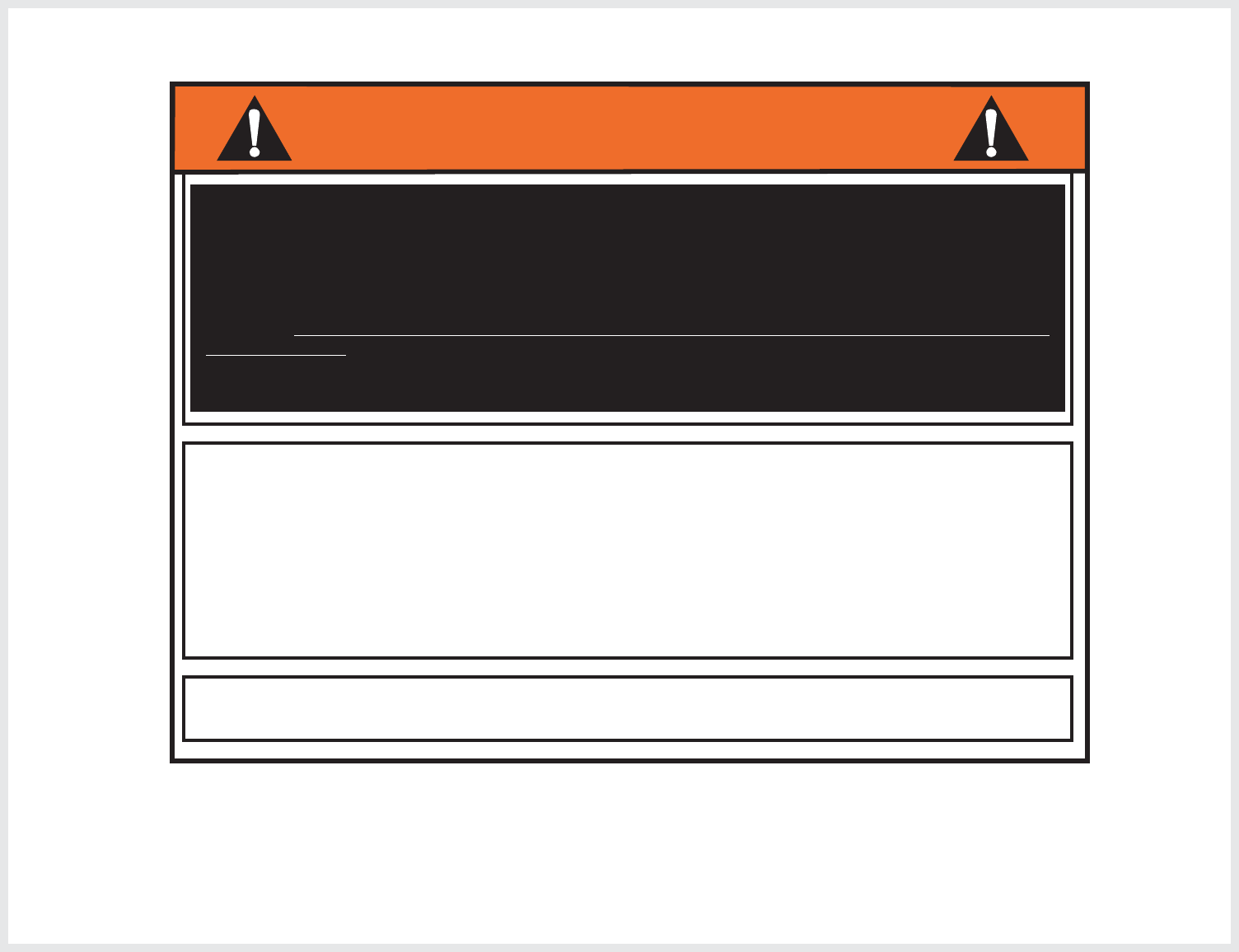
SAFETY INSTRUCTIONS
Most injuries are caused by misuse and/or not following instructions.
Use caution when using this system.
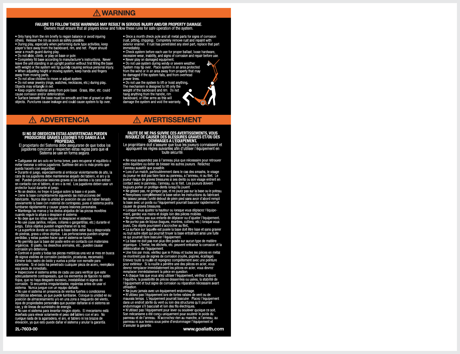
FAILURE TO FOLLOW THESE SAFETY INSTRUCTIONS MAY RESULT IN SERIOUS INJURY, PROPERTY
DAMAGE AND WILL VOID WARRANTY.
Owner must ensure that all players know and follow these rules for safe operation of the system.
To ensure safety, do not attempt to assemble this system without following the instructions carefully.
Check entire box and inside packing material for parts and/or additional instruction material. Before
beginning assembly, read the instructions and identify parts using the hardware identifier and parts list
in this document. Proper and complete assembly, use and supervision is essential for proper operation
and to reduce the risk of accident or injury. A high probability of serious injury exists if this system is not
installed, maintained, and operated properly.
4
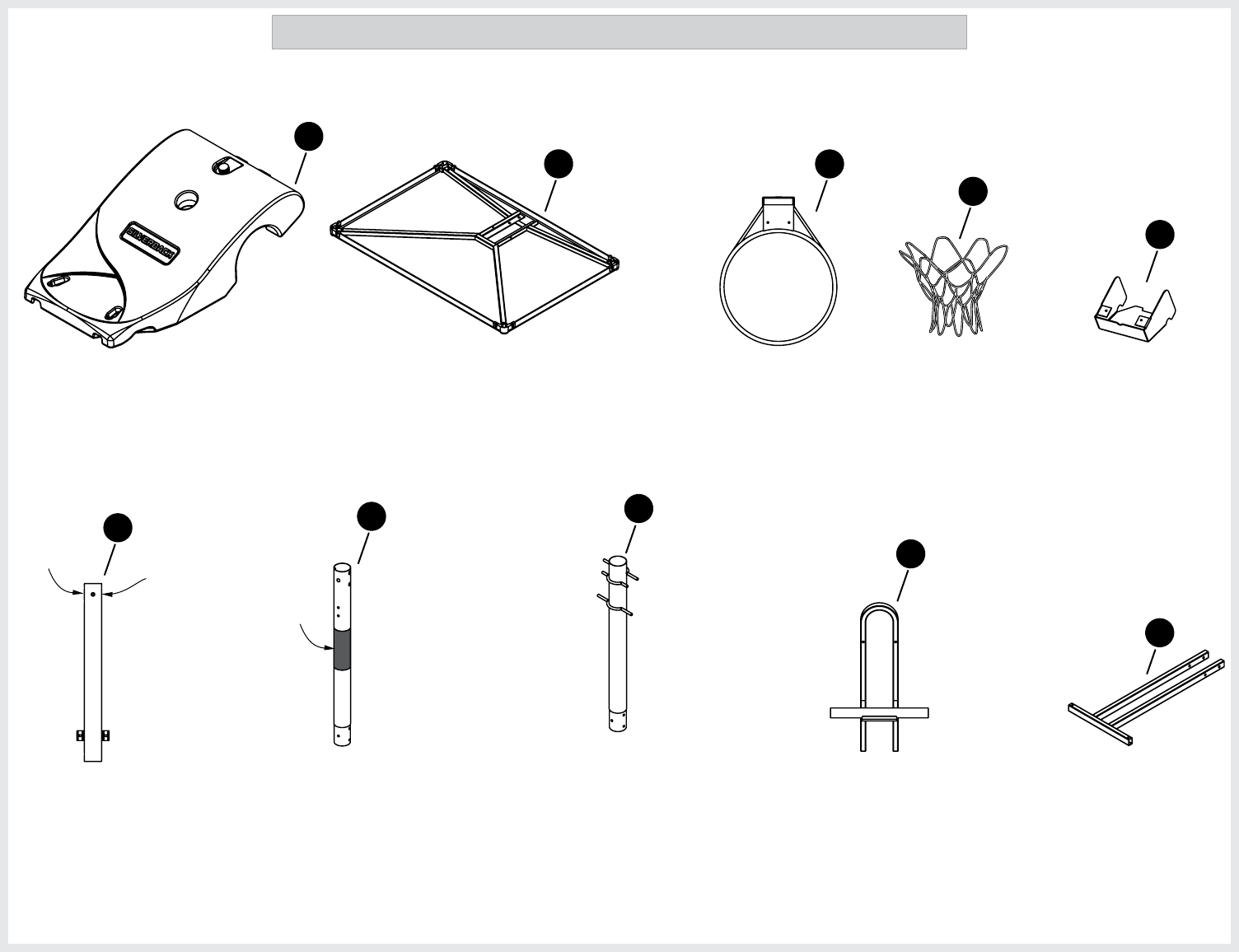
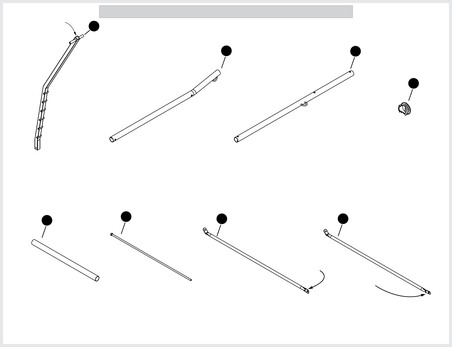
BREAK AWAY RIM
4A-8058-20
MIDDLE POLE
1A-7911-20
TOP POLE
1A-7906-20
BACKBOARD ASSEMBLY 54 X 33
4A-8057-20
LOWER POLE
1A-7910-20
ROLLING FRAME
1A-7903-20
BALLAST FRAME
1A-7904-20
54 44
51
50
12
2
3
(QTY. 1) (QTY. 1)
(QTY. 1)
(QTY. 1) (QTY. 1) (QTY. 1) (QTY. 1)
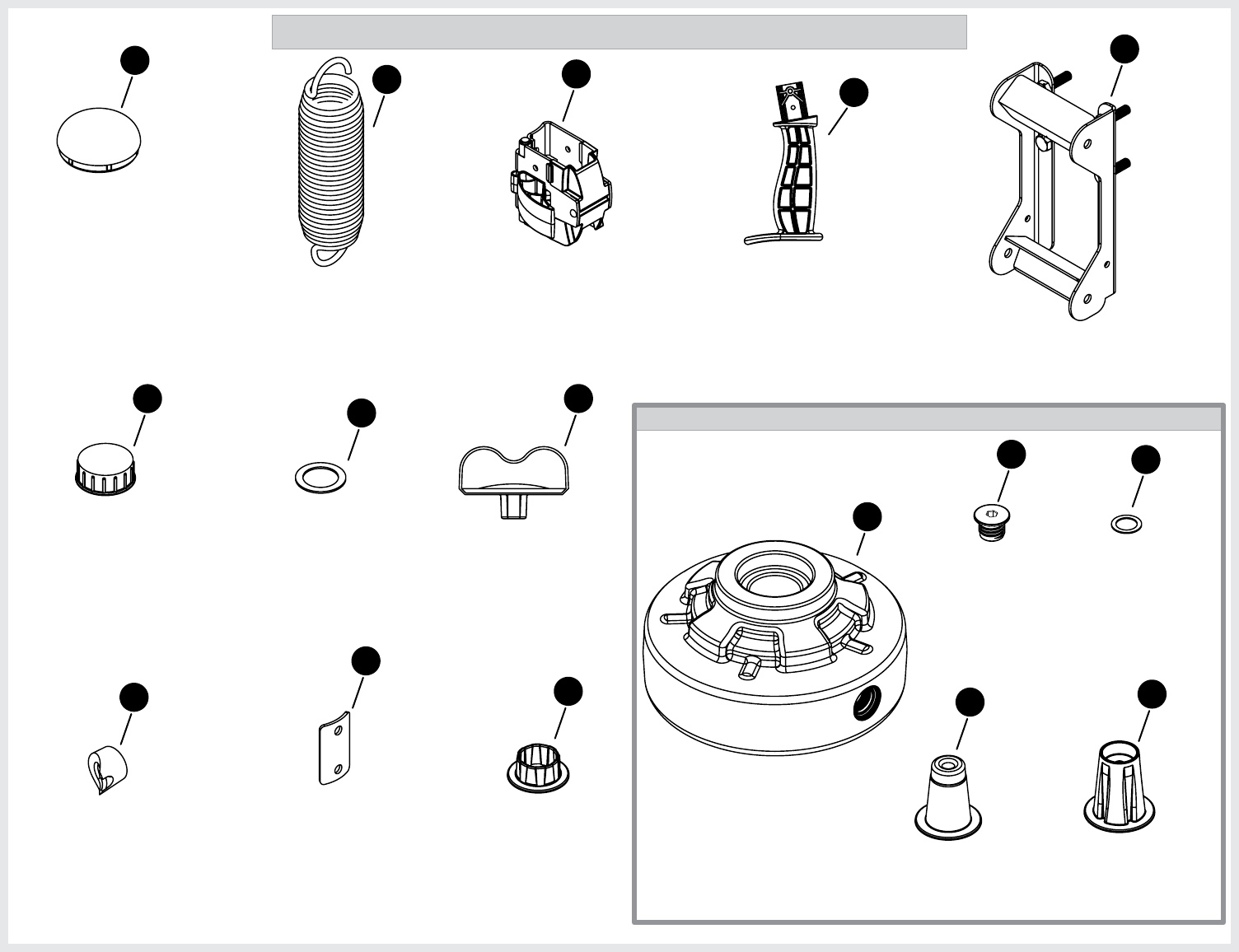
P A R T S L I S T ( N O T A C T U A L S I Z E )
RIM NET
(QTY. 1)
58
3F-6070-00
SPRING COVER PLATE
(QTY. 1)
8S-7714-00
60
Red
Sticker
Warning
Decal
1
BALLAST
3M-8991-20
(QTY. 1)
Green
sticker
5
AXLE
8S-7710-20 AXLE ROD
1B-7140-00 BRACE TUBE, RH
8S-7708-20
BRACE TUBE, LH
8S-7709-20
19
18
9
4
(QTY. 1) (QTY. 1)
(QTY. 1) (QTY. 1)
P A R T S L I S T ( N O T A C T U A L S I Z E )
BOARD ARM CAP
3M-9017-00
56
(QTY. 8)
(Pre-assembled to
Board Arms)
(Has a sticker on it)green (Has a sticker on it)red
LOWER BOARD ARM
1A-7907-20
UPPER BOARD ARM
1A-7908-20
52 49
(QTY. 2) (QTY. 2)
ACTUATOR BAR
1A-7921-20
(QTY. 1)
53
(Actuator Bar Cap
Pre-installed)
green sticker
on here
red sticker
on here
6
Wheel Assembly (Parts pre-assembled to wheel)
BALLAST CAP
3M-8996-00
BALLAST CAP WASHER
3M-8999-00
REINFORCEMENT PLATE
8S-7711-20
POLE CAP
3M-8997-00
BUSHING, BOARD ARM
3M-8994-00
AXLE BUSHING
3M-9003-00
Wheel Hub, Outside
3M-9001-00
Wheel Hub, Inside
3M-9002-00
BACKBOARD BOX
1A-7905-20
38
14
26
13
37
55
25 586
(QTY. 1)
(QTY. 1)
(QTY. 1)
(QTY. 1)
(QTY. 1)
(QTY. 2)
(QTY. 2)
(QTY. 2)
(QTY. 4)
P A R T S L I S T ( N O T A C T U A L S I Z E )
Wheel
3M-8992-00
7
(QTY. 2)
WHEEL PLUG
3M-9004-00
41
(QTY. 2)
42
O-RING
3M-8998-00
(QTY. 2)
(Pre-assembled to
Wheel Plug)
(Pre-assembled to
Ballast Cap)
Wheel Plug Key
3M-9022-00
(QTY. 1)
57
(Pre-assembled to
Top Pole) SPRING
5V-6040-00
(QTY. 2)
ACTUATOR GRIP
3M-9034-00
ACTUATOR LOCK ASSEMBLY
4A-8141-20
40 31
(QTY. 1) (QTY. 1)
(Pre-assembled to
Ballast) (3/8” Allen Wrench
can be substituted
for Wheel plug key)
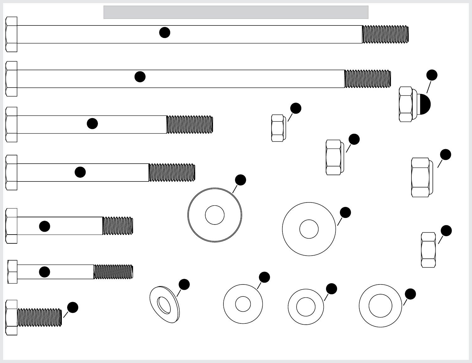
7
HEX HEAD BOLT M8-1.25 X 65mm
1B-7077-00
HEX HEAD BOLT M10-1.5 X 100mm
1B-7078-00
HEX HEAD BOLT M10-1.5 X 110mm
1B-7079-00
HEX HEAD BOLT M10-1.5 X 65mm
1B-7081-00
HEX HEAD BOLT M10-1.5 X 210mm
1B-7080-00
HEX HEAD BOLT M10-1.5 X 25mm
1B-7082-00
HEX NUT M10-1.5, WITH CAP
2B-6799-00
HEX NUT M10-1.5
2B-6796-00
WASHER _ CURVED M10
2B-6802-00
HEX LOCK NUT M12-1.75
2B-6805-00
HEX LOCK NUT M10-1.5
2B-6801-00
WASHER M8
2B-6797-00
WASHER M10 X 30mm
2B-6795-00
WASHER M10
2B-6800-00
WASHER M12 X 24mm OD
2B-6804-00
HEX HEAD BOLT M10-1.5 X 220mm
1B-7085-00
Hex Lock Nut M8-1.25
2B-6808-00
WASHER, NYLON
3M-9000-00
21
29
11
17
24
10
27
28
23
16
39
30
34
22
20
15
36
(QTY. 3)
(QTY. 1)
(QTY. 3)
(QTY. 5)
(QTY. 4)
(QTY. 5) (QTY. 22) (QTY. 4)
(QTY. 8)
(QTY. 4)
(QTY. 4)
(QTY. 14)
(QTY. 2)
(QTY. 6)
(QTY. 4)
(QTY. 1)
(QTY. 2)
H A R D W A R E I D E N T I F I E R ( A C T U A L S I Z E )
35 (QTY. 2)
8
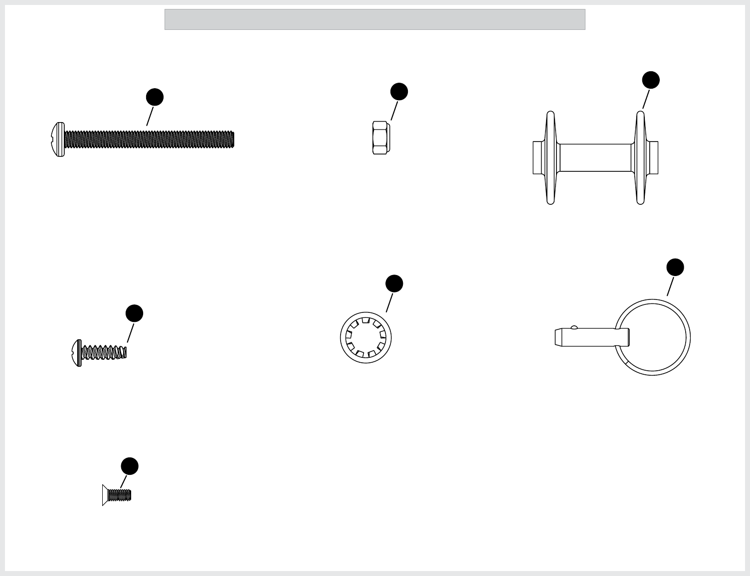
H A R D W A R E I D E N T I F I E R ( A C T U A L S I Z E )
HITCH PIN
7B-6577-00
WASHER, LOCK INTERNAL-TOOTH
2B-6806-00
#10-14 X 0.63 Trilobular Screw for Plastic
1B-7084-00
32
43
33
(QTY. 2)
(QTY. 1)
(QTY. 2)
Flat Head Screw M4-0.7 X 10mm
(QTY. 2)
1B-7100-00
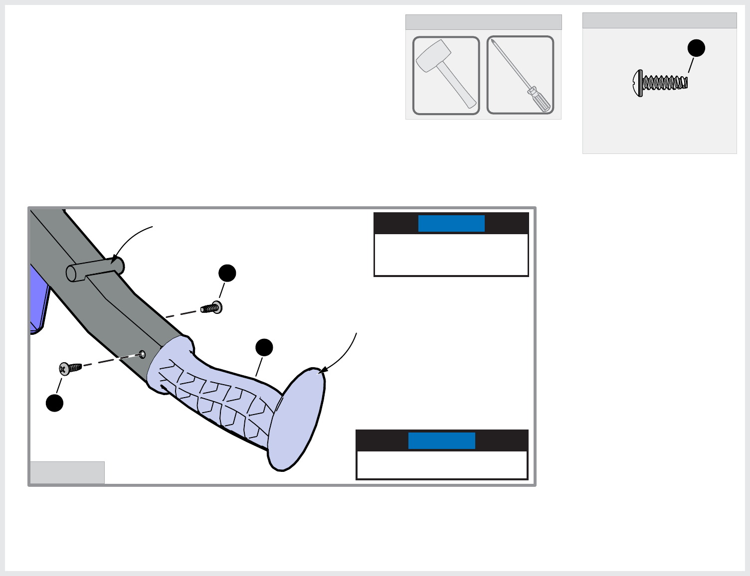
59
Philips Head Screw M6-1 X 60mm
1B-7123-00
HEX LOCK NUT M6-1
2B-6803-00
ACTUATOR ROLLER
3M-9035-00
47
48
46
(QTY. 1) (QTY. 1)
(QTY. 1)
9
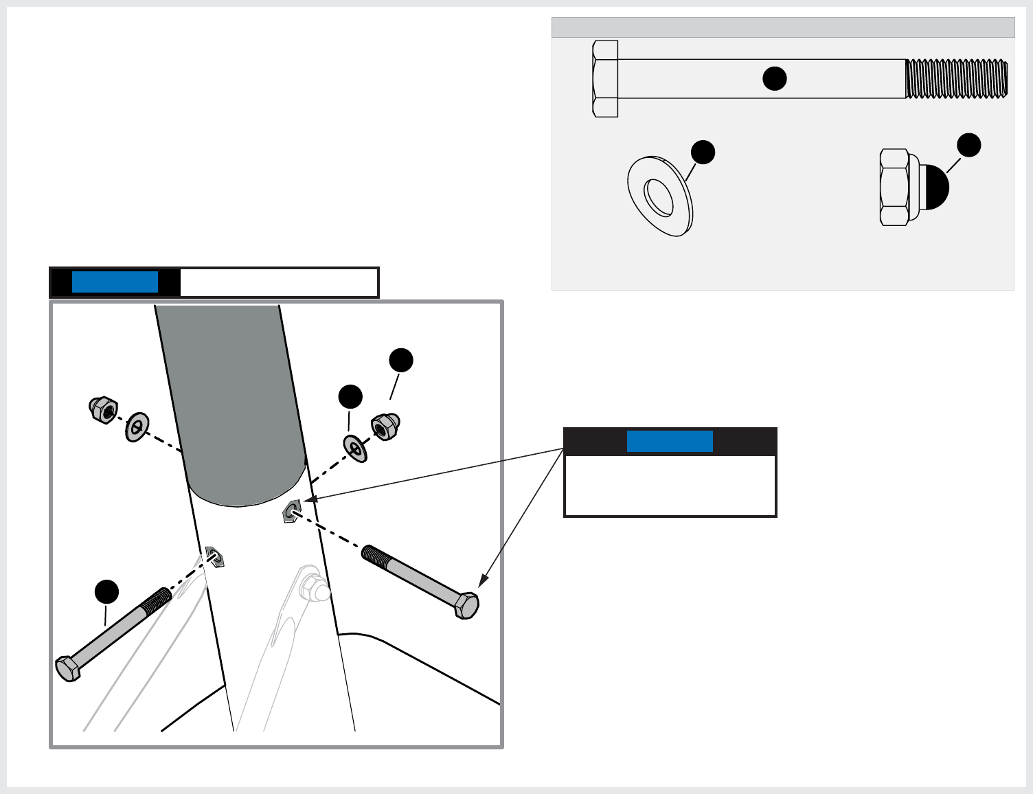
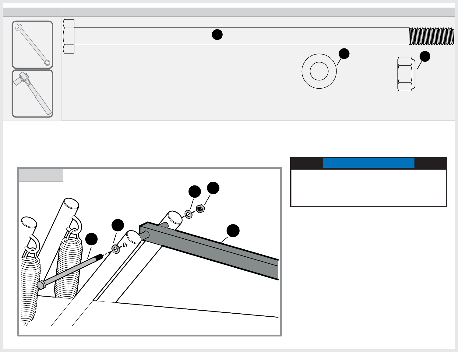
HEX HEAD BOLT M10-1.5 X 65mm
1B-7081-00
35
(QTY. 2)
23
WASHER M10
2B-6800-00
(QTY. 4)
HEX LOCK NUT M10-1.5
2B-6801-00
24
(QTY. 2)
35
23
24
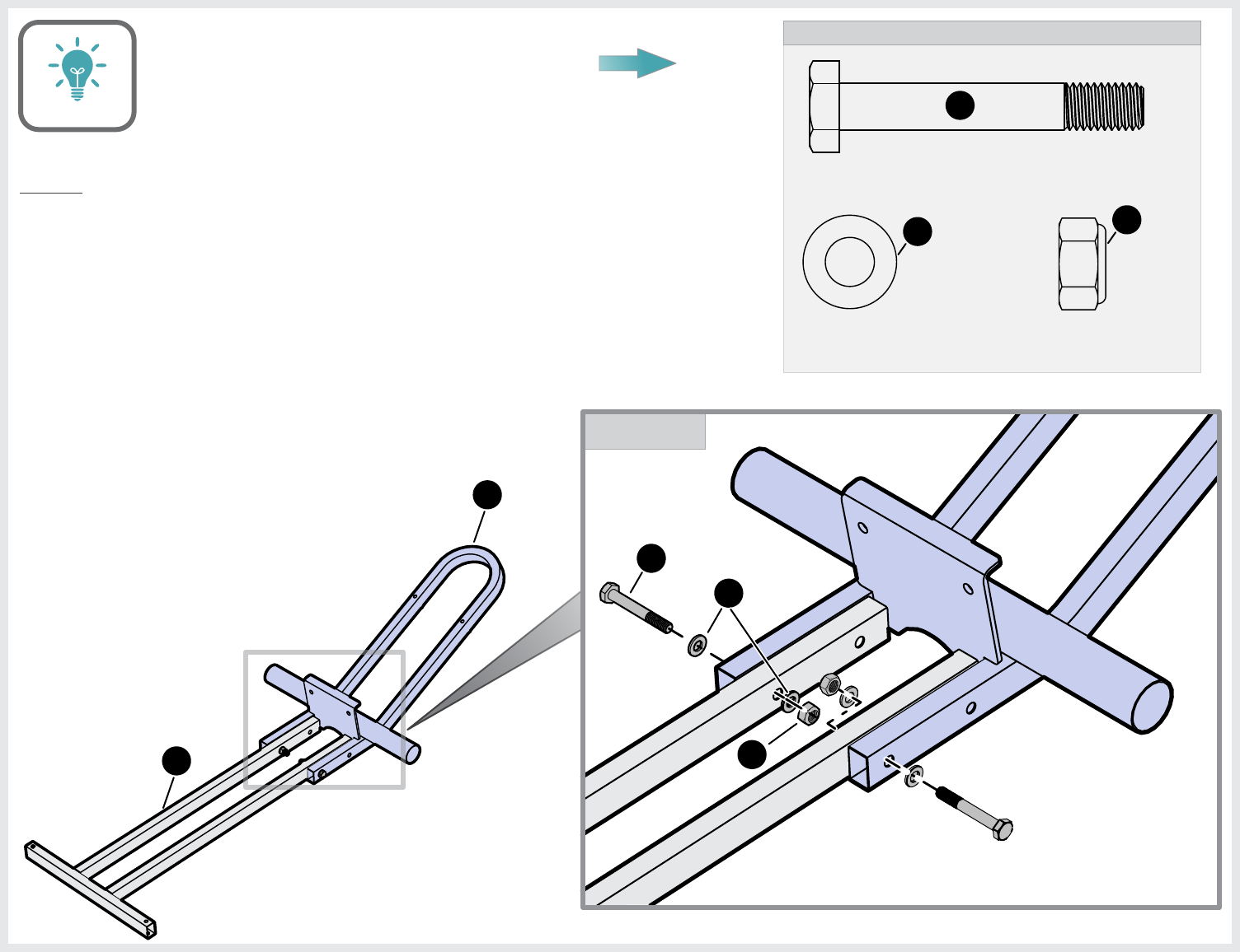
2
3
HARDWARE NEEDED (ACTUAL SIZE)
DETAIL A
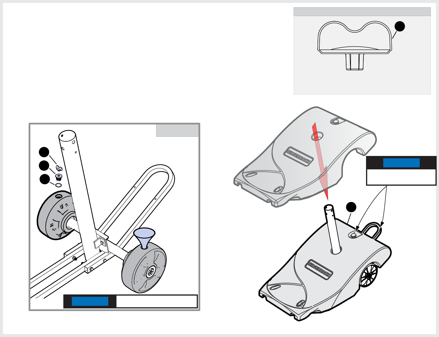
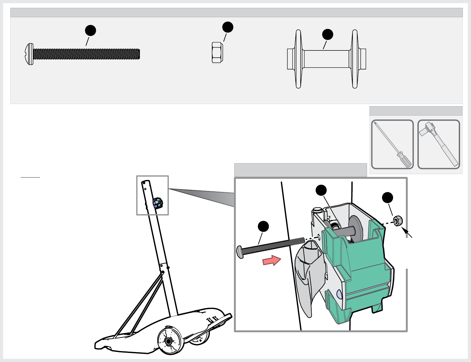
1. Assemble parts 2 & 3 as shown. Tighten hardware
finger tight only.
Prepare a flat area that is clear of debris. Keep children
away from the assembly area. Two capable adults are
needed for the following steps.
NOTE:
ASSEMBLY TIP
The following pages will have a picture of the
Hardware Needed along with the Quantity, Part
Number and Description. You can lay the hardware
on the picture to identify the hardware.
10
DETAIL A
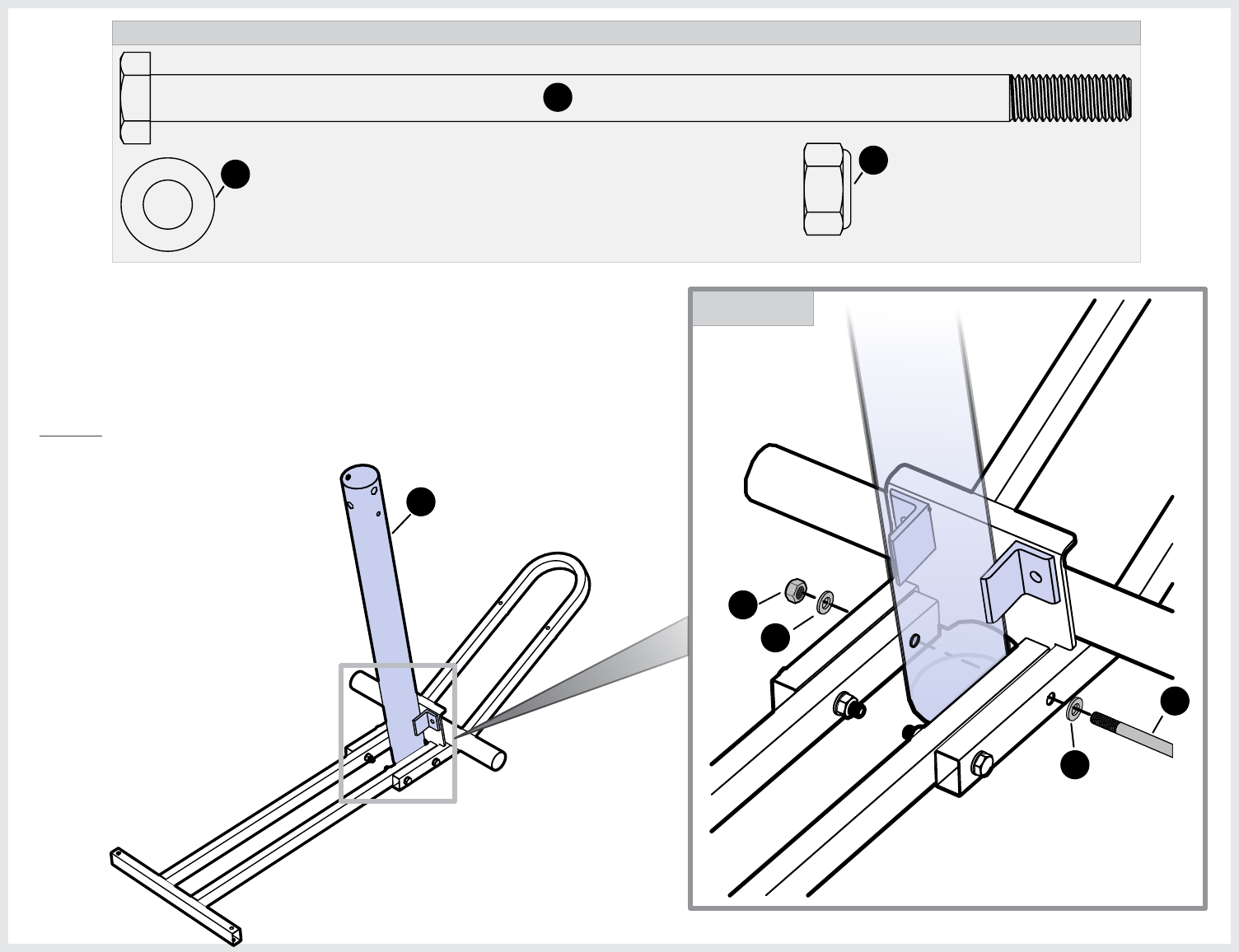
23
WASHER M10
2B-6800-00
(QTY. 2)
HEX LOCK NUT M10-1.5
2B-6801-00
24
(QTY. 1)
HARDWARE NEEDED (ACTUAL SIZE)
HEX HEAD BOLT M10-1.5 X 210mm
1B-7080-00
34
(QTY. 1)
34
23
24
23
12
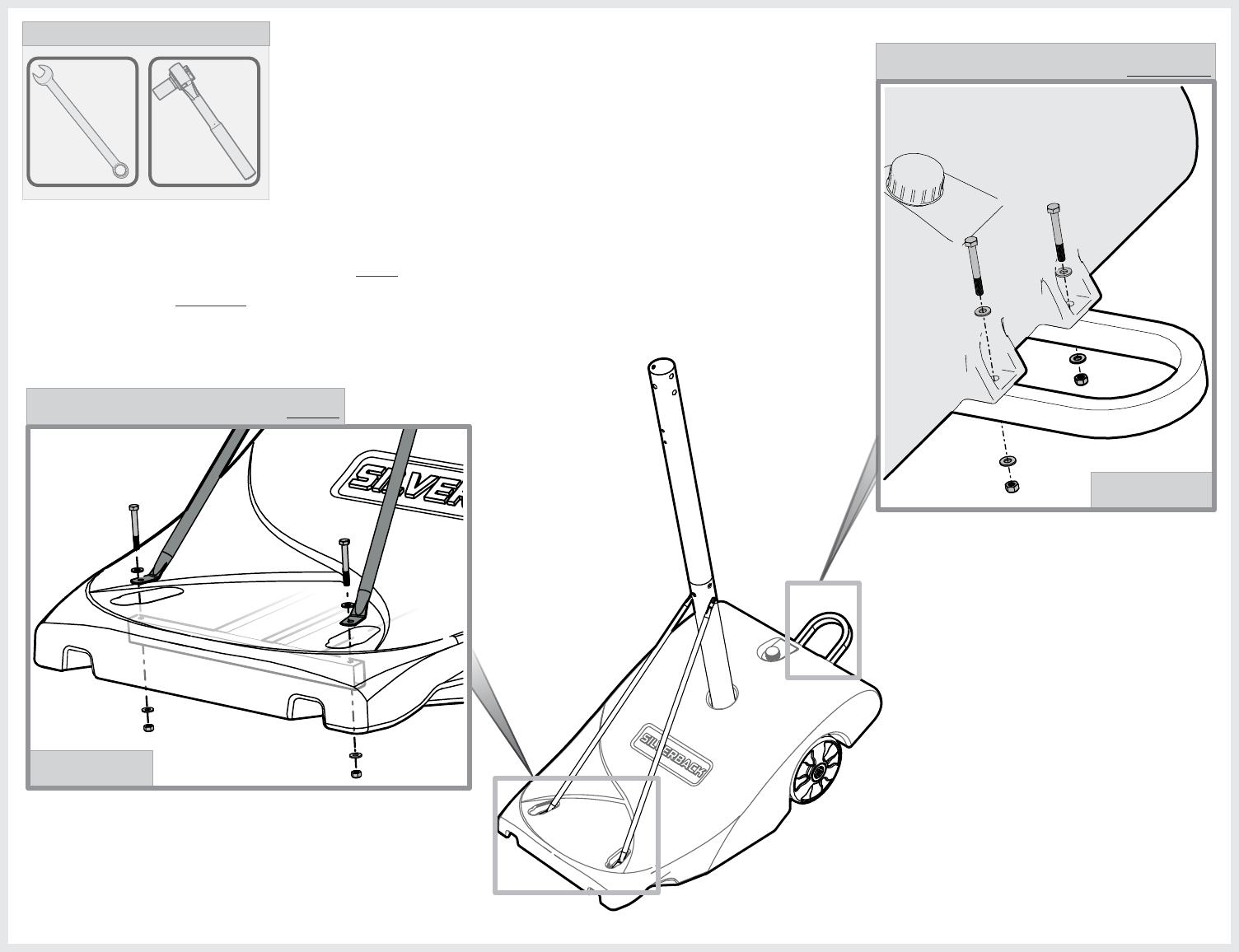
2. Attach lower pole (12) to lower assembly. Line up the holes in
the four tubes and lower pole and attach hardware as shown
in Detail A. Tighten hardware finger tight only.
You may have to wiggle the
Bolt (34) up and down and
side to side so it goes
through the whole assembly.
NOTE:
11
12
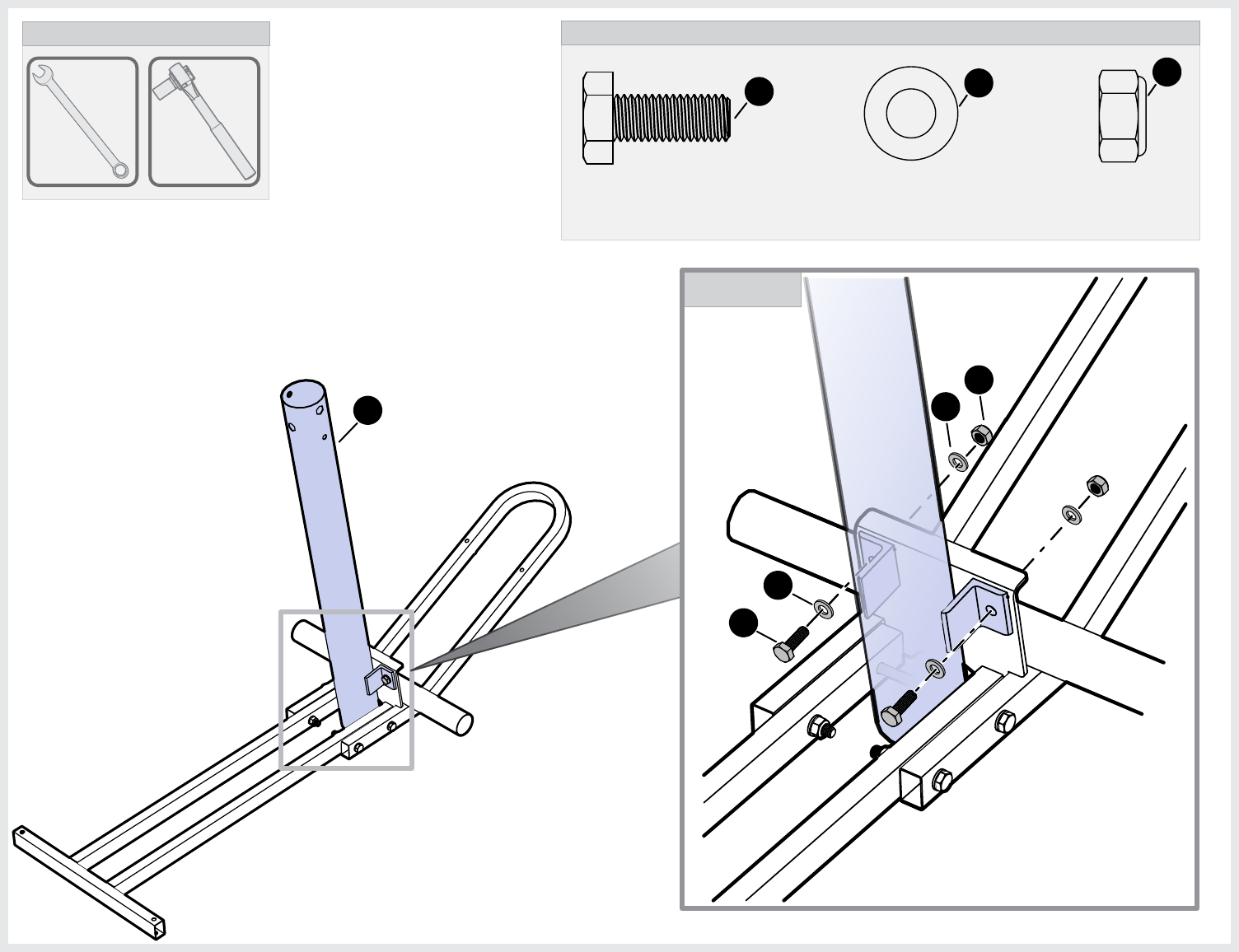
16mm
TOOLS NEEDED
16mm
23
WASHER M10
2B-6800-00
(QTY. 4)
HEX LOCK NUT M10-1.5
2B-6801-00
24
(QTY. 2)
HARDWARE NEEDED (ACTUAL SIZE)
HEX HEAD BOLT M10-1.5 X 25mm
1B-7082-00
(QTY. 2)
36
3. Finish securing lower pole (12) to lower assembly
as shown. Tighten all hardware at this time
including hardware from step 1 & 2.
DETAIL A
36
23
24
23
12
DETAIL A
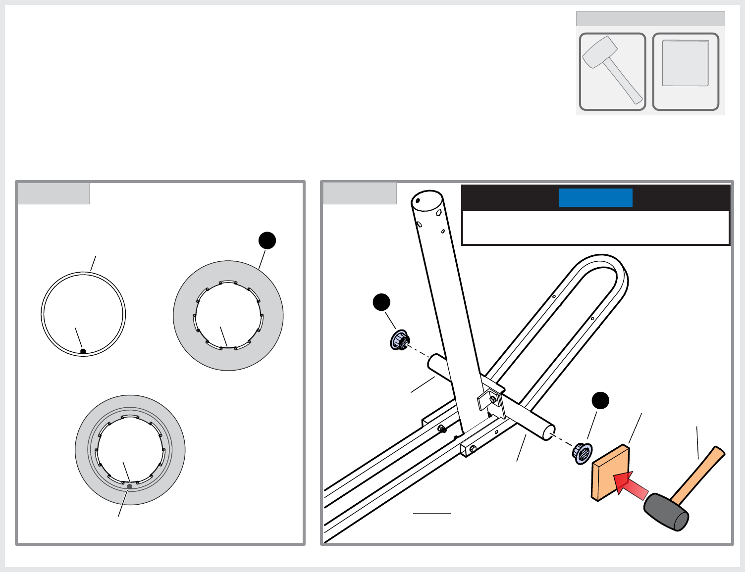
Wood
block
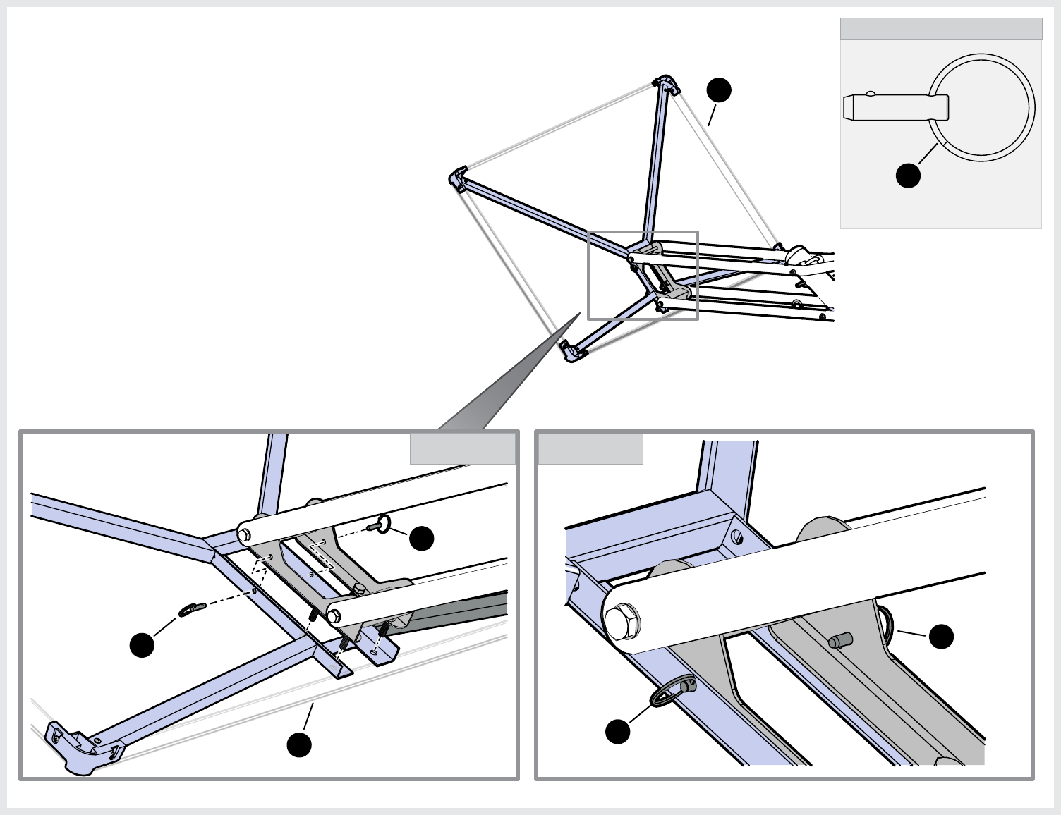
4. Before Inserting Axle Bushings (5) into the lower assembly Steel
Tube, align the bushings (5) so the groove goes over the tube
weld seam without touching it. See Detail A & Detail B.
5
5
DETAIL B
Rubber
Mallet
5
Steel
Tube
5. Use a wood block and Rubber Mallet to gently tap the Axle
Bushing into Steel Tube. Center Wood block onto Axle
bushing and tap on the center of the block, do not tap on
the edges of Axle bushing because it could damage it.
Steel
Tube
Side View of Steel tube
and Axle Bushing (5).
A B
C
Groove
Axle Bushing
inserted into
Steel Tube
Groove
Tube Weld
Seam
TOOLS NEEDED
Wood Block
Rubber
Mallet
Steel
Tube
NOTE: Make sure Axle Bushing
is completely into and flush to
the outside of Steel Tube.
Axle
Bushing
Axle
Bushing
Axle
Bushing
Tube
Weld
Seam
NOTE
Use a wood block and Rubber Mallet to
gently tap in the Axle Bushing into Steel Tube.
13
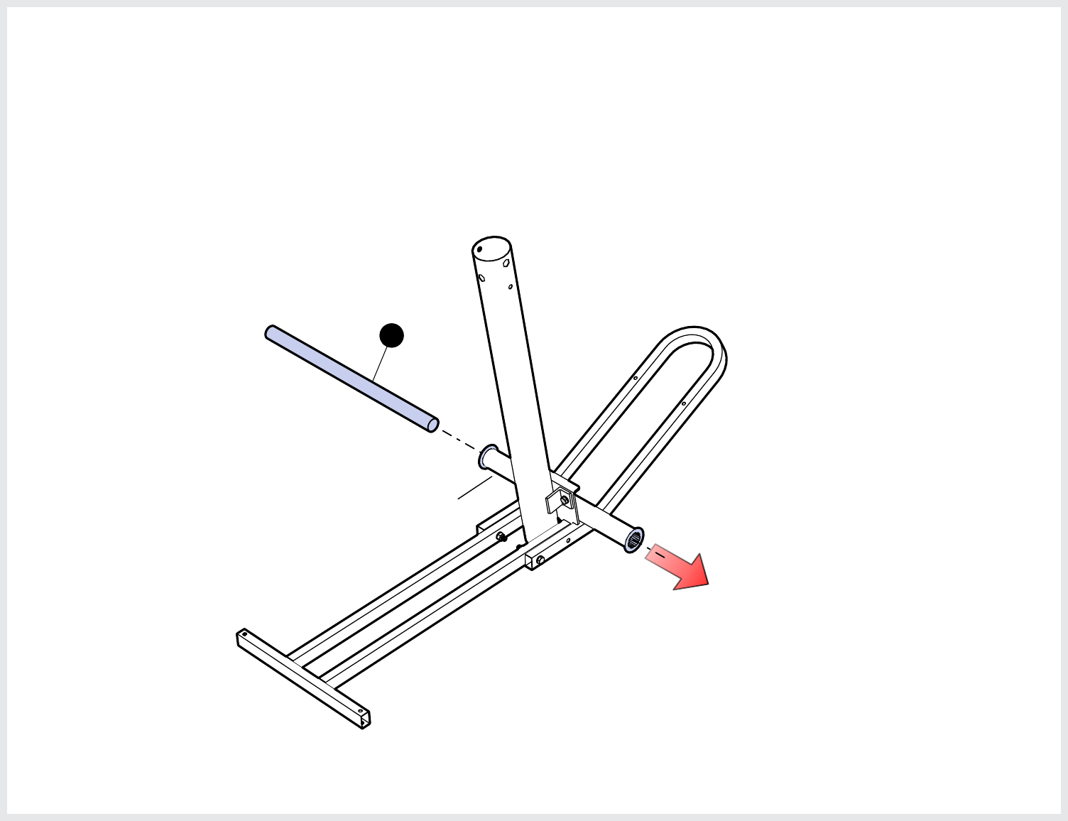
6. Insert Axle (4) into lower assembly Steel tube
until both ends of the Axle stick out about the
same distance on each side.
4
Steel
Tube
14
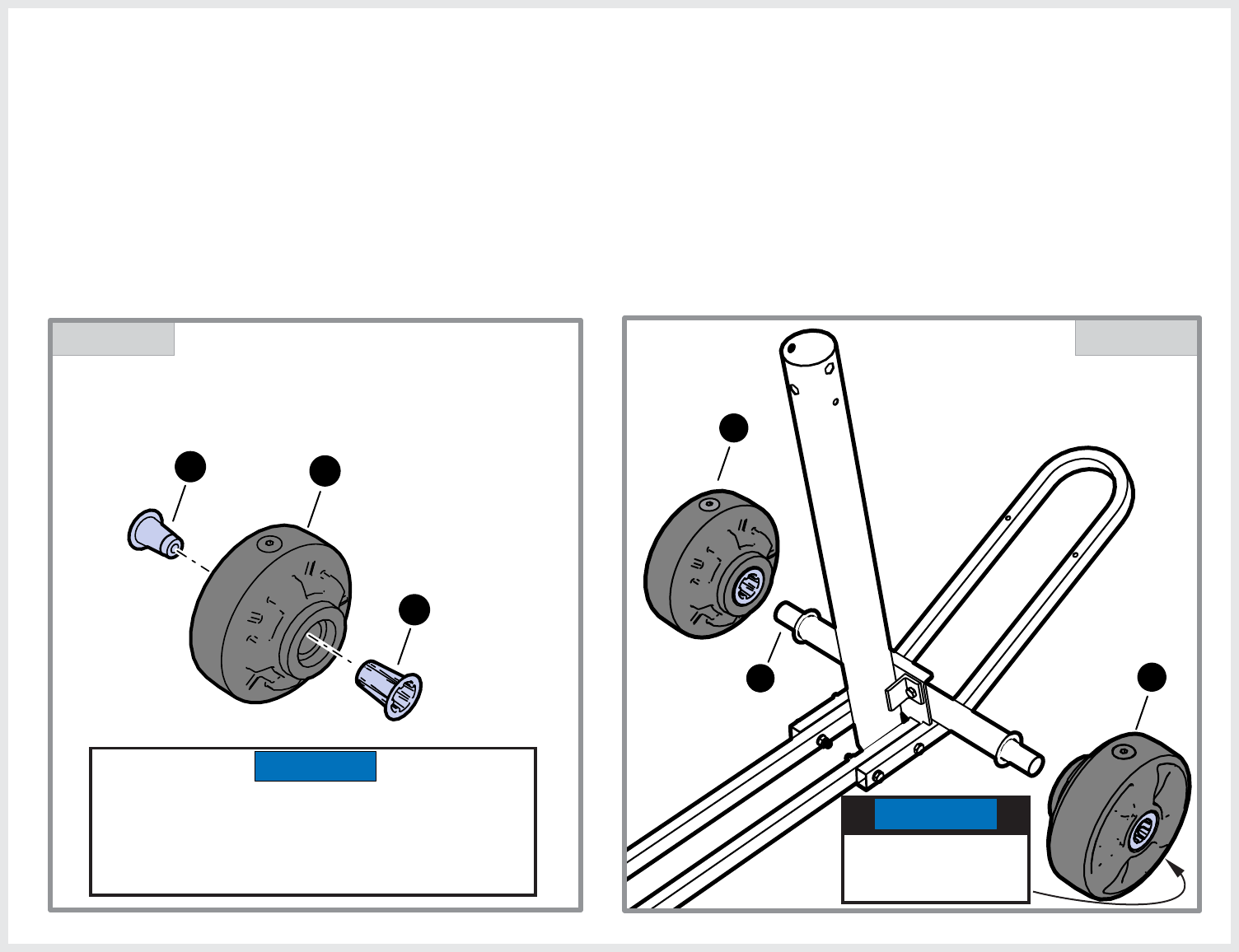
7. Slide Wheel (7) onto Axle (4). Repeat step to
install the second wheel. See Detail B.
NOTE: Inner Wheel Hub (6) and Outer wheel (8) are
pre-assembled into Wheel (7) by the factory. If
either of those parts have fallen out during
shipping re-insert parts as shown in Detail A.
87
6
DETAIL A
NOTE
Inner Wheel Hub (6) and Outer wheel (8) are
pre-assembled into Wheel (7) by the factory. If
either of those parts have fallen out during
shipping re-insert parts as shown in Detail A.
DETAIL B
7
7
4
NOTE
The flat part of the
Wheels go to the
outside.
15
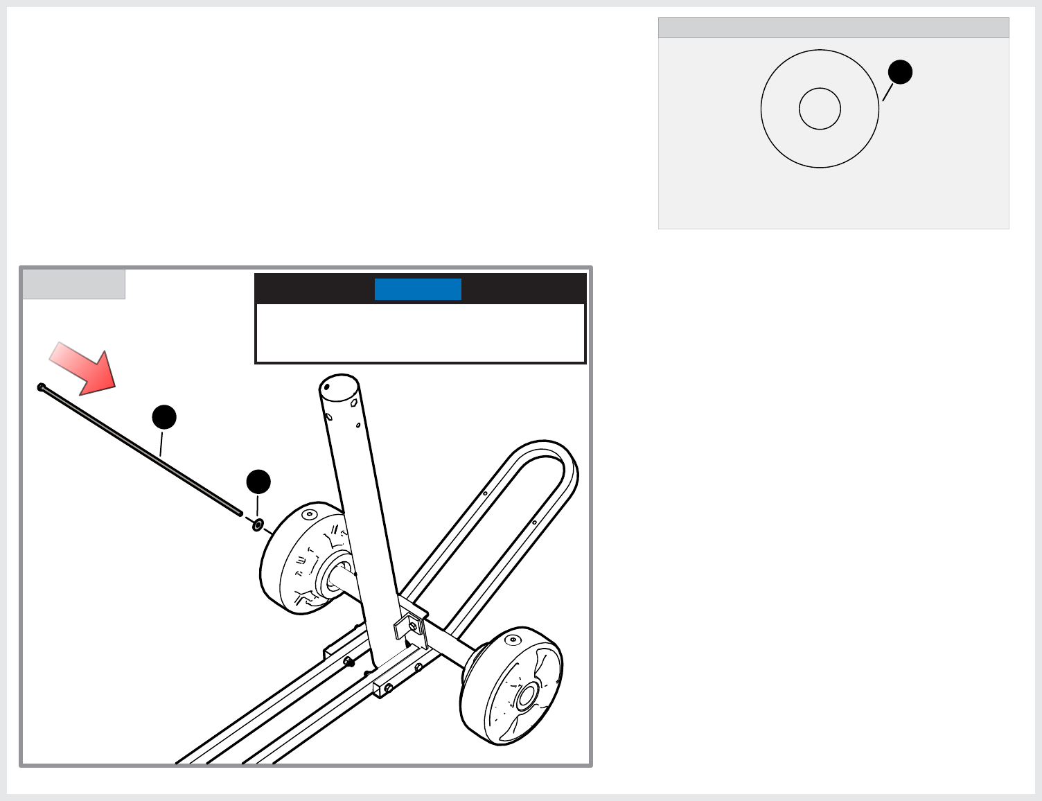
HARDWARE NEEDED (ACTUAL SIZE)
WASHER M10 X 30mm
2B-6795-00
10
(QTY. 1)
8. Insert Axle Rod (9), through Washer (10) and into
Wheel assembly and axle until it reaches the
other side of the Axle and wheel. Have a Second
person hold second Wheel.
NOTE
You may have to wiggle the Axle Rod (9)
up and down and side to side so it goes
through the second wheel.
DETAIL A
9
10
16
DETAIL A
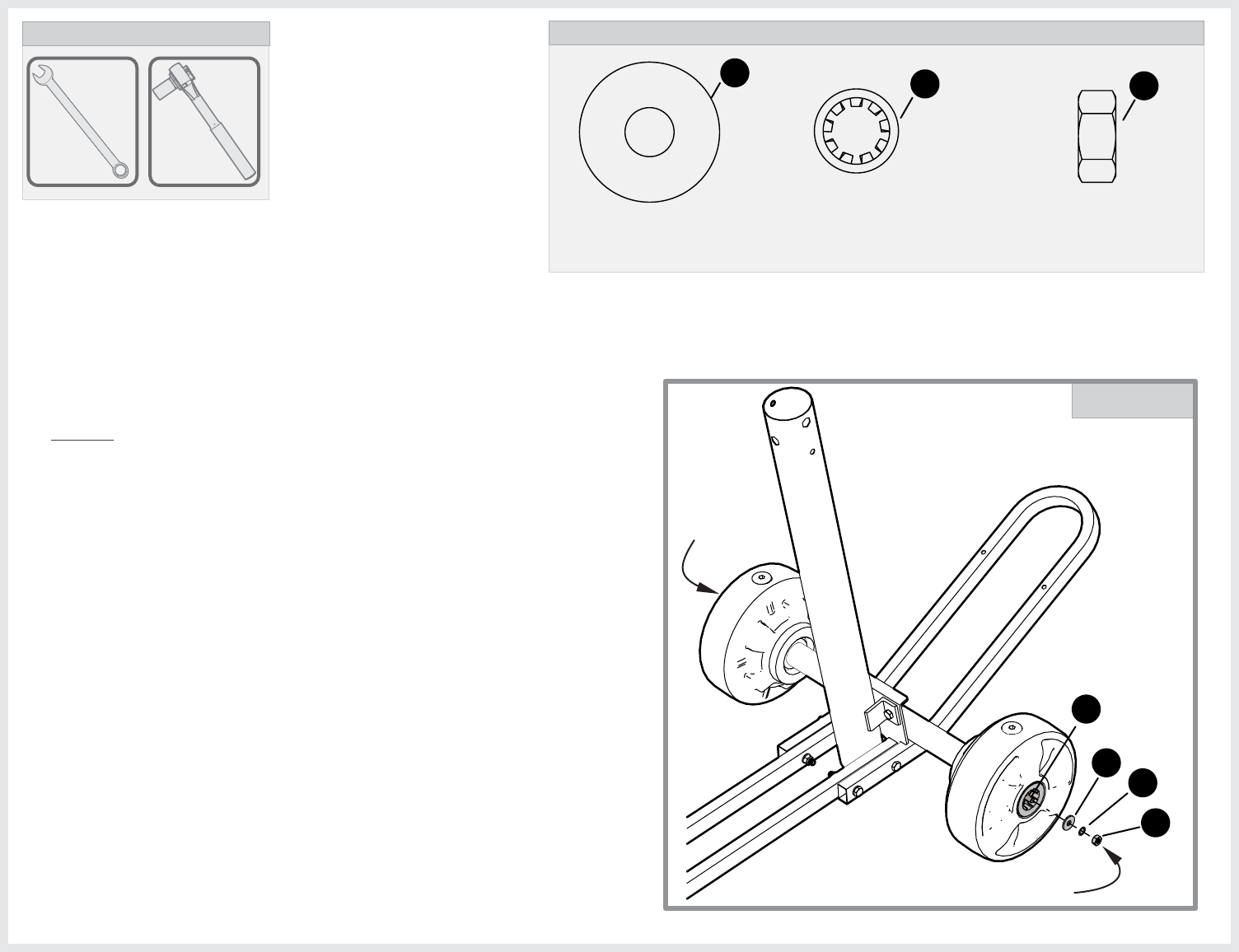
HARDWARE NEEDED (ACTUAL SIZE)
WASHER M10 X 30mm
2B-6795-00
10
(QTY. 1)
11
43
9. Secure Axle Rod (9) with Washer (10), Lock Tooth
Washer (43) and Hex Nut (11). Tighten Nut (11) until
there’s about 1/4” of thread of the Axle Rod sticking
out of nut. Do not overtighten. See Detail A.
9
HEX NUT M10-1.5
2B-6796-00
11
(QTY. 1)
WASHER, LOCK INTERNAL-TOOTH
2B-6806-00
43
(QTY. 1)
16mm
TOOLS NEEDED
16mm
NOTE: Wheels must sping freely, there should also
be some side to side play on both wheels.
Use 16mm Socket
on Nut (11).
Use 16mm
Wrench for
Axle Rod.
10
17
NOTE
DETAIL A
11. Carefully slide Ballast (1) over Lower Pole as shown.
42
41
10. Unscrew the Wheel cap (41) and remove, O-ring (42) is pre-attached to
Wheel cap. Fill both wheels with water until 75% full (approx. 1 gal.)
and screw Wheel cap back into the wheel with Wheel Plug key (57).
Make sure that O-ring is attached to Wheel Cap. See Detail A.
57
Use Funnel if necessary.
1
WHEEL PLUG KEY
3M-9022-00
(QTY. 1)
HARDWARE NEEDED
57
NOTE: 3/8”
Allen Wrench can
be substituted for
Wheel Plug Key.
NOTE
Kick Stand and Fill Cap
are on the same end.
18
DETAIL A
DETAIL B 17
16
15
16
18
19
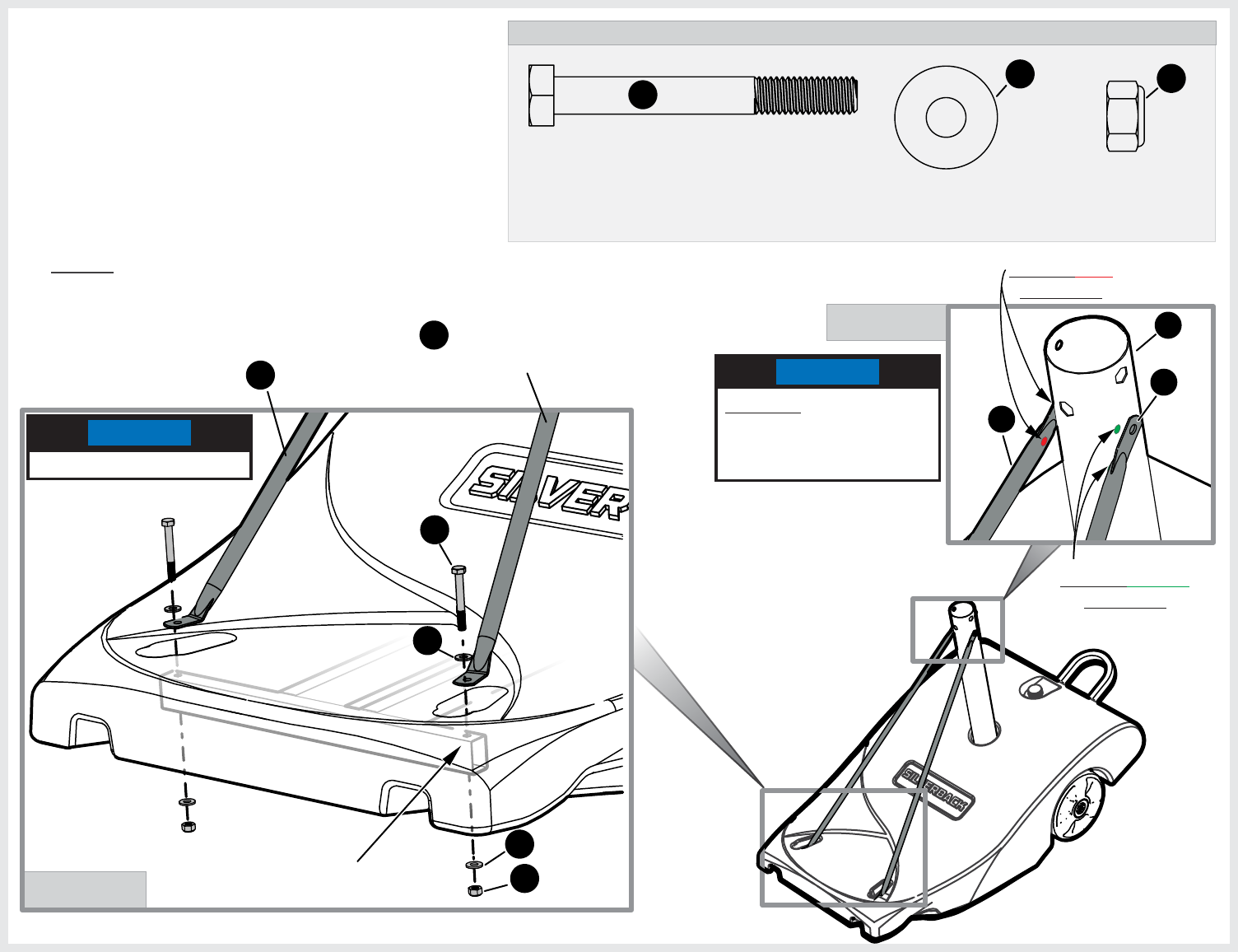
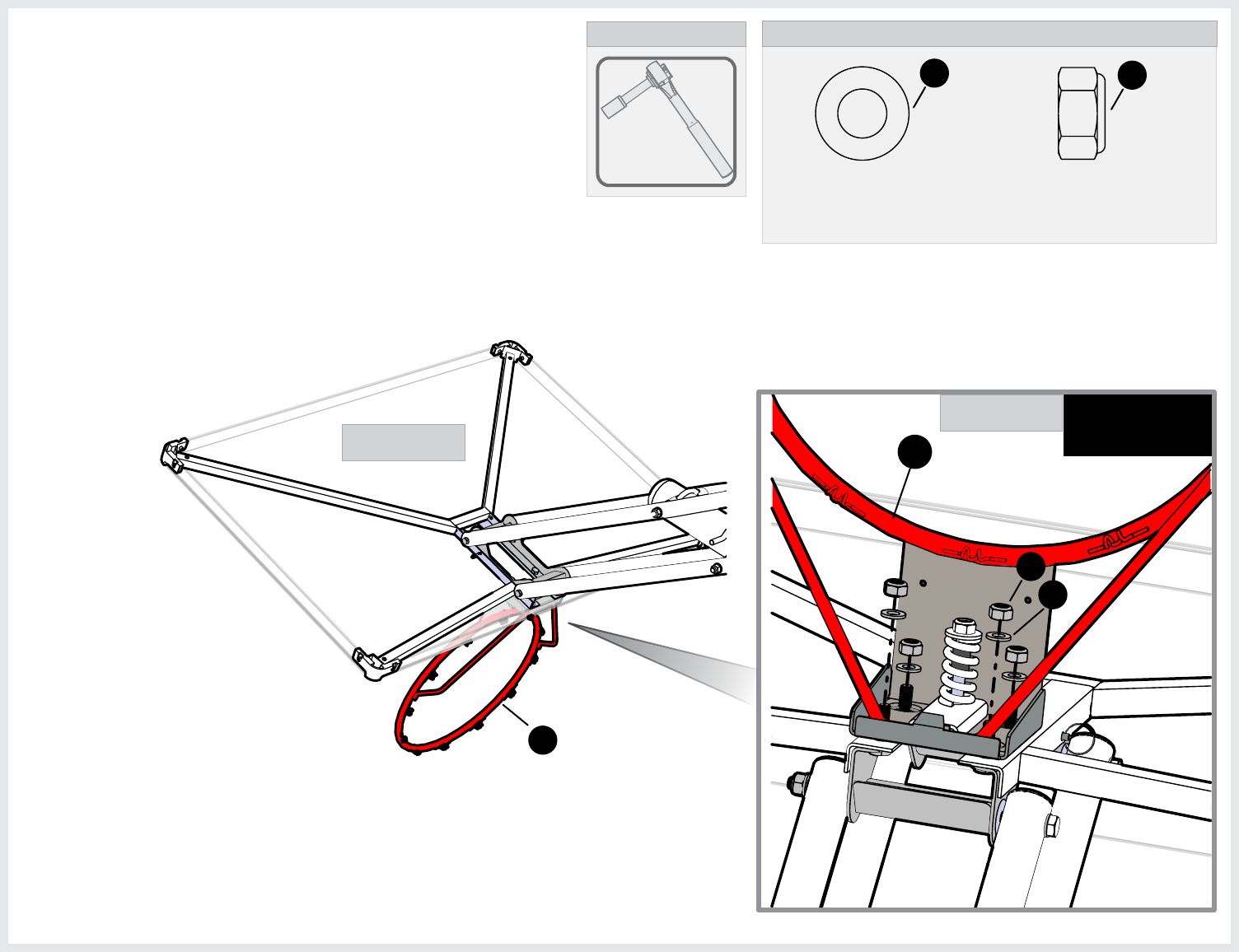
12. Attach Left Brace tube (19) and Right brace Tube
(18). Match up the color coded stickers on green
the Right Brace tube and the lower pole and
match the color stickers on the Left Brace tube Red
and Lower Pole as shown in Detail A. Insert the
hardware through brace tubes, Ballast and Frame
assembly as shown in Detail B.
BRACE TUBE, RH
BRACE TUBE, LH
Lower Frame Assembly
HARDWARE NEEDED (ACTUAL SIZE)
WASHER M8
2B-6797-00
(QTY. 4)
Hex Lock Nut M8-1.25
2B-6808-00
17
(QTY. 2)
HEX HEAD BOLT M8-1.25 X 65mm
1B-7077-00
15
(QTY. 2)
18
19
16
Match Green
Stickers.
Match Red
Stickers.
( Sticker)Green
( Sticker)Red
12
NOTE: Finger Tighten only!
NOTE
FINGER TIGHTEN ONLY!
DO NOT INSERT A BOLT
INTO LINKAGES (18,19)
OR POLE (12) UNTIL
STEP 15.
NOTE
19
HARDWARE NEEDED (ACTUAL SIZE)
HEX HEAD BOLT M8-1.25 X 65mm
1B-7077-00
15
Hex Lock Nut M8-1.25
2B-6808-00
17
(QTY. 2)
WASHER M8
2B-6797-00
(QTY. 4)
16
(QTY. 2)
DETAIL A
16
17
15
NOTE
FINGER TIGHTEN ONLY!
DETAIL B
DETAIL C
SIDE VIEW
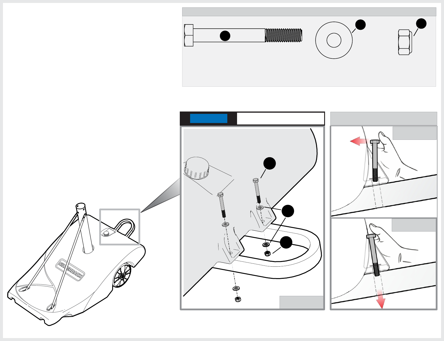
13. Secure ballast to lower assembly as shown in
Detail A. Finger Tighten hardware.
NOTE: If needed use your thumb to push bolt
forward (see Detail B) and then down
(see Detail C) so it goes in easier through
ballast tabs and kick stand tube.
20
HARDWARE NEEDED (ACTUAL SIZE)
50
50
HEX HEAD BOLT M10-1.5 X 110mm
1B-7079-00
22 (QTY. 1)
22
23
23
HEX NUT M10-1.5, WITH CAP
2B-6799-00
21
(QTY. 1)
21
WASHER M10
2B-6800-00
23
(QTY. 2)
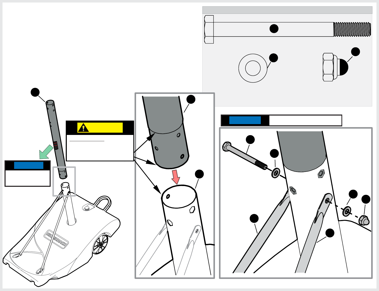
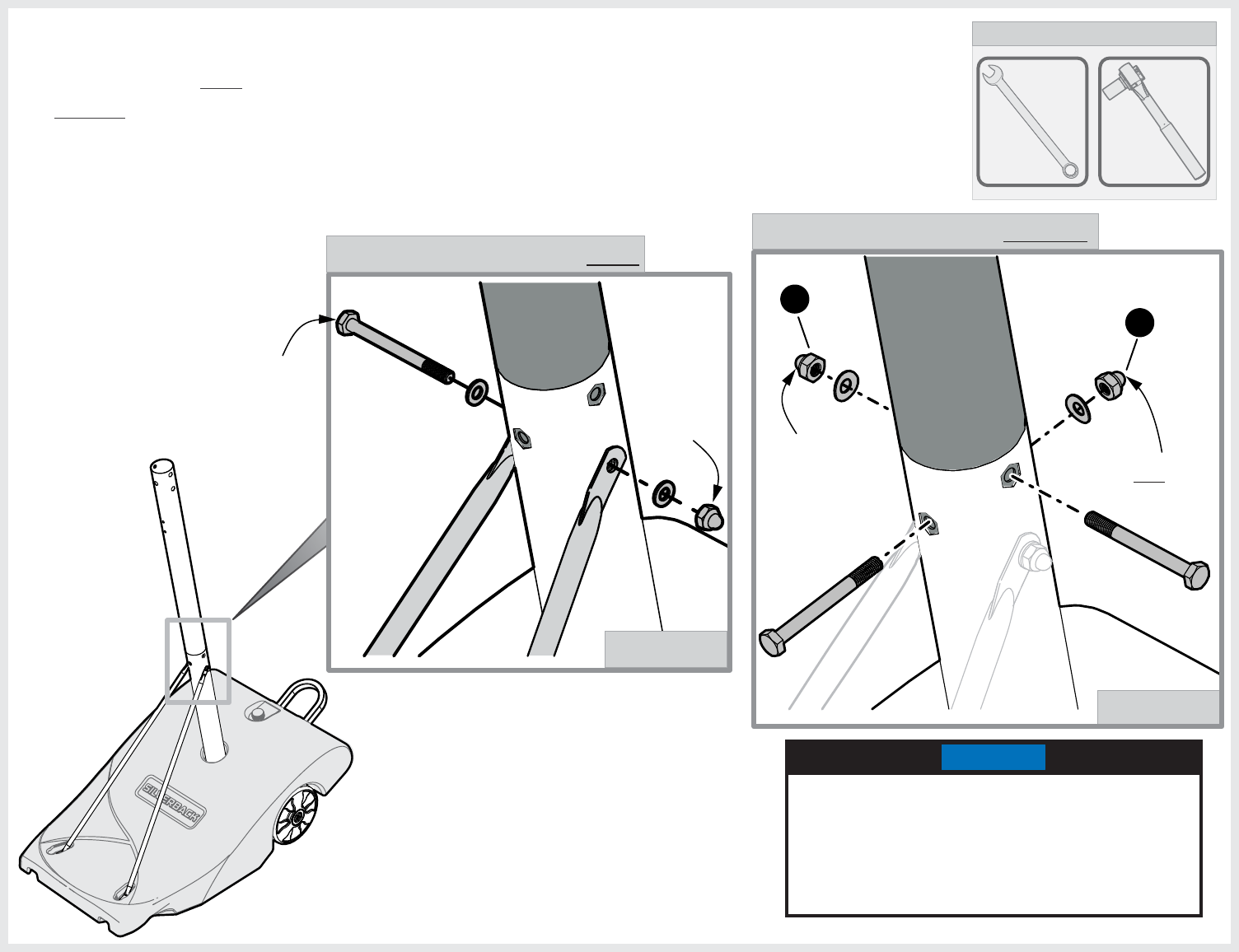
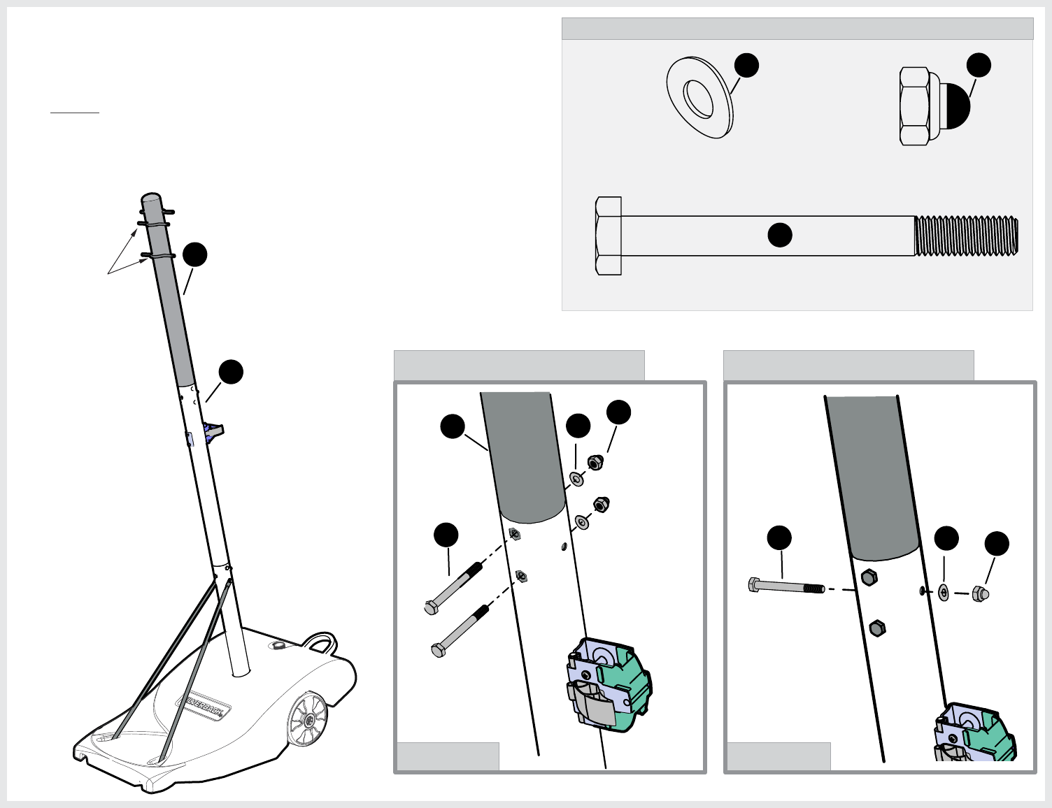
15. Insert Bolt (22) through braces 18 &19 and through both poles as
shown. Tighten hardware finger tight only.
12
18
19
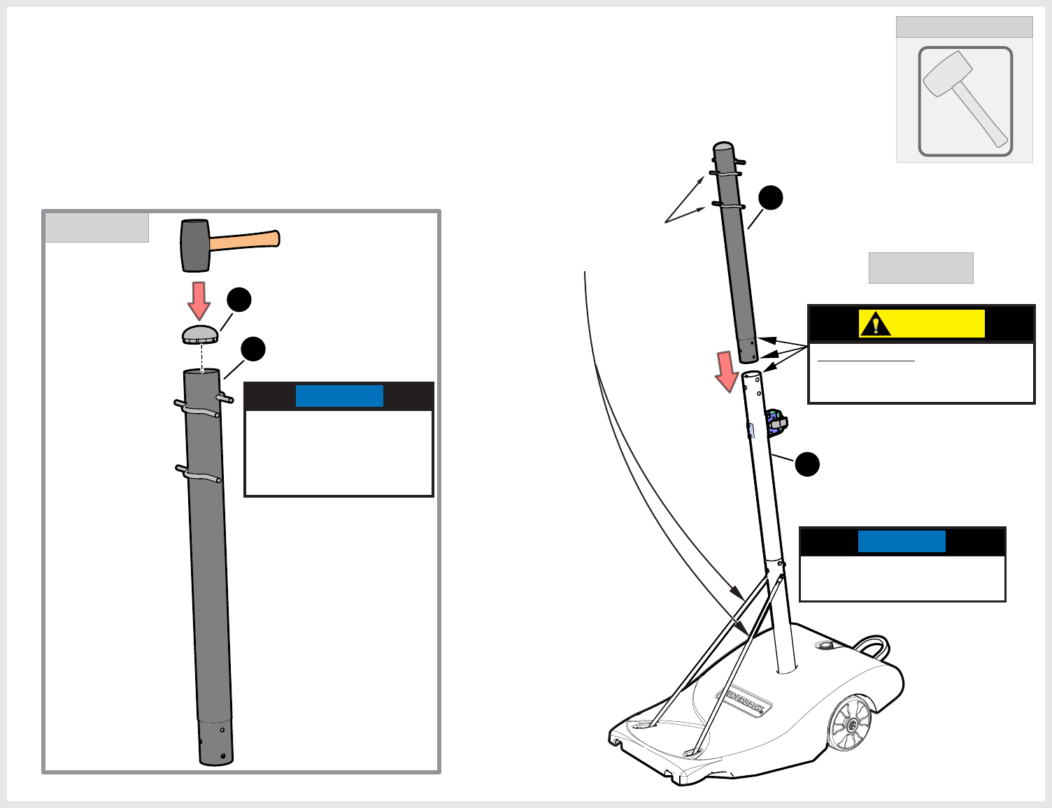
14. Position Middle pole (50) with the Warning label facing forward,
then slide Middle pole into Lower pole (12). Make sure that all
holes are aligned in both poles.
NOTE
FINGER TIGHTEN ONLY!
NOTE
warning label
should be facing
forward.
CAUTION:
PINCH POINTS! DO NOT
place your hand on any of
these three locations when
inserting the pole.
21
HARDWARE NEEDED (ACTUAL SIZE)
HEX NUT M10-1.5, WITH CAP
2B-6799-00
21
(QTY. 2)
WASHER _ CURVED M10
2B-6802-00
39
(QTY. 2)
16. Secure pole with hardware shown. Finger Tighten only.
39
21
20
HEX HEAD BOLT M10-1.5 X 100mm
1B-7078-00
20
(QTY. 2)
NOTE
FINGER TIGHTEN ONLY!
MAKE SURE HEADS OF THE
BOLTS ARE INSERTED INTO
THE CUT OUT OF THE POLE.
NOTE
22
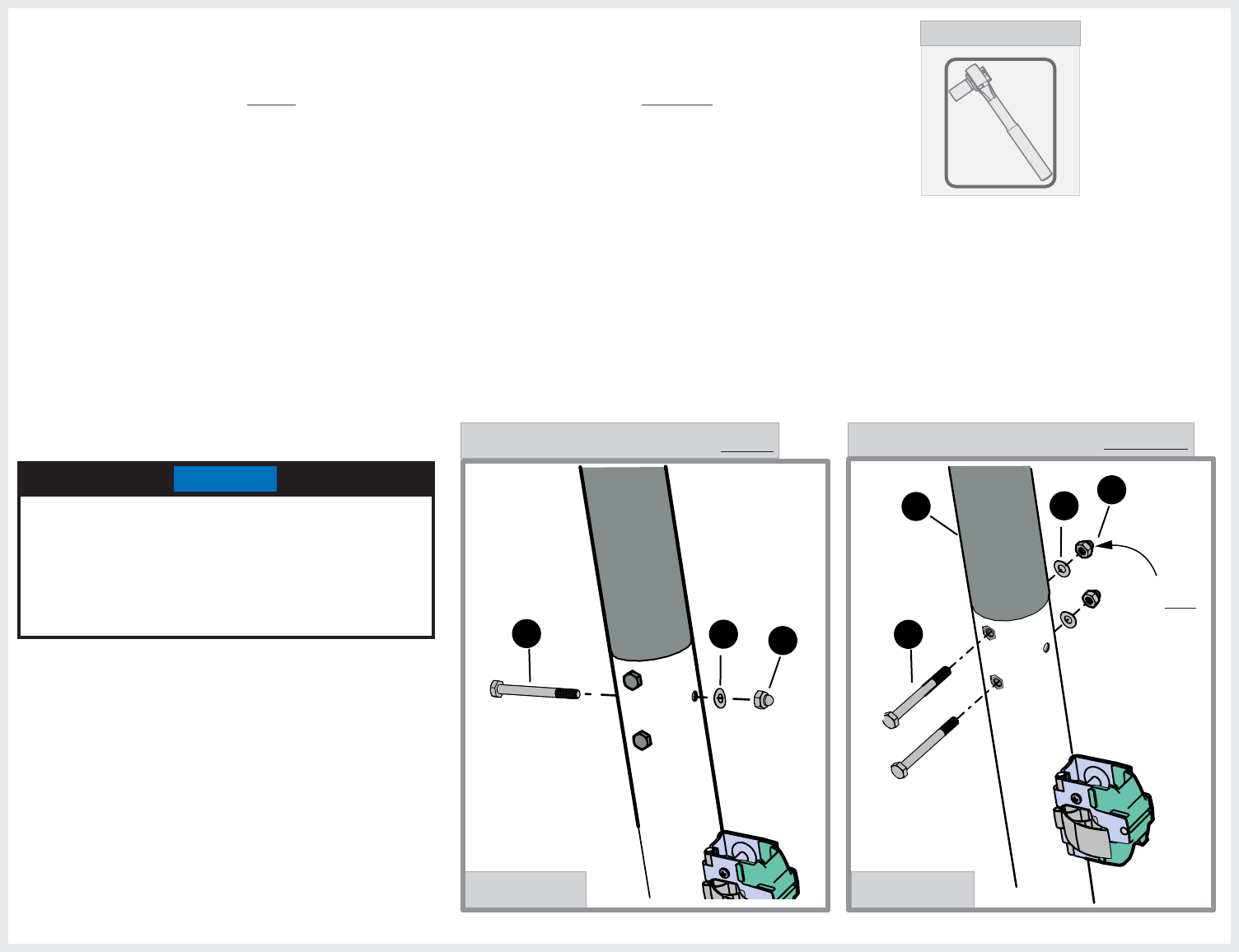
17. In this Step you will begin to tighten the hardware from previous
steps in the following sequence: First tighten hardware shown
in Detail A. Second, tighten hardware shown in Detail B.
TIGHTEN HARDWARE UNTIL SNUG.
13mm
TOOLS NEEDED
13mm
DETAIL B
TIGHTEN THIS HARDWARE SECOND.
DETAIL A
TIGHTEN THIS HARDWARE FIRST.
23
DETAIL B
17mm
TOOLS NEEDED
16mm
18. In this Step you will continue to tighten the hardware from
previous steps: First tighten hardware shown in Detail A.
Second, tighten hardware shown in Detail B. TIGHTEN
HARDWARE TIGHT BUT DO NOT CRUSH TUBE.
21
21
DETAIL A
TIGHTEN THIS
NUT LAST , use
17mm Socket.
Use 17mm Socket.
Use 17mm
Socket.
Use 16mm
Wrench
TIGHTEN THIS HARDWARE FIRST.
TIGHTEN THIS HARDWARE SECOND.
MAKE SURE HEADS OF THE BOLTS ARE
INSERTED INTO THE CUT OUT OF THE POLE, IF
NEEDED USE YOUR THUMB TO HOLD THE
BOLTS IN PLACE THEN USE A RATCHET AND
17MM SOCKET ON NUTS (21). TIGHTEN
HARDWARE TIGHT BUT DO NOT CRUSH TUBE.
NOTE
24
HARDWARE NEEDED (ACTUAL SIZE)
HEX HEAD BOLT M10-1.5 X 110mm
1B-7079-00
22
(QTY. 2)
HEX LOCK NUT M10-1.5
2B-6801-00
24
(QTY. 2)
37
24
22
BACK
OF POLE
FRONT
OF POLE
BACK
OF POLE
has the height
decal
FRONT
OF POLE
has the
Warning label
PLASTIC
LEVER ON
THIS SIDE
16mm
TOOLS NEEDED
16mm
Use ratchet
with 16mm
Socket.
Use
16mm
Wrench
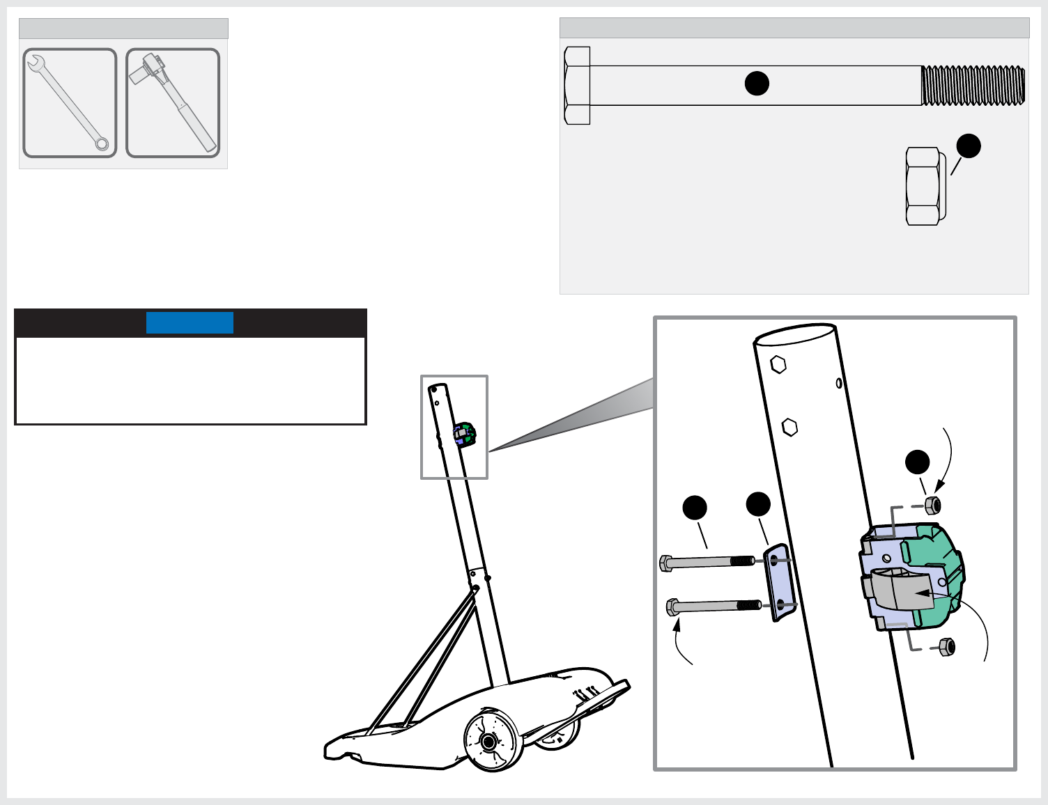
19. Attach the reinforcement plate (37) to the front of the pole
(on the side that has the Warning label) with 2 bolts (22).
Hex heads should be facing front of the unit. Slide Actuator
lock Assembly (40) and attach with Nuts (24).
NOTE
USE A 16MM WRENCH TO HOLD NUTS (24) IN
PLACE AND A RATCHET WITH 16MM SOCKET
ON BOLTS (22) TO TIGHTEN THE ASSEMBLY.
TIGHTEN UNTIL SNUG.
25
TOOLS NEEDED
10mm
Phillips
HARDWARE NEEDED (ACTUAL SIZE)
HEX LOCK NUT M6-1
2B-6803-00
47
48
(QTY. 1)
48
47
46
20. Insert Screw (46) through Actuator
bracket, Actuator Roller (48) and
through other side of Actuator
bracket. Fasten with (47) nut.
Actuator roller #48 must rotate freely.
ACTUATOR ROLLER
3M-9035-00
(QTY. 1)
PHILIPS HEAD SCREW M6-1 X 60mm
1B-7123-00
(QTY. 1)
46
NOTE:
Do not over-tighten nut #47.
There must be no more than 1-2
threads sticking out from nut.
Do not over-tighten nut
#47. There must be no
more than 1-2 threads
sticking out from nut.
26
DETAIL A
21. Set the top pole (51) on a piece of cardboard (packing material) to protect the bottom
of the pole. Insert the Pole Cap (38) at the top of the pole as shown in Detail A.
TOOLS NEEDED
Rubber
Mallet
38
51
51
22. Insert Top Pole (51) into Middle Pole (50). Make sure that the two bars on
the top pole are on the same side as the Support Linkages in the Front.
See Detail B.
DETAIL B
NOTE: If your Top Pole (51) has the Pole Cap (38) pre-installed skip step 21.
50
BOTH BARS ARE
ON THE SAME
SIDE AS THE
SUPPORT
LINKAGES
If needed use a Rubber
Mallet to tap Cap in
but be very careful not
to damage it.
NOTE
DO NOT step on the
ballast to attach top pole.
NOTE
CAUTION:
PINCH POINTS! DO NOT place
your hand on any of these three
locations when inserting the pole.
27
HARDWARE NEEDED (ACTUAL SIZE)
HEX HEAD BOLT M10-1.5 X 100mm
1B-7078-00
20
(QTY. 3)
WASHER _ CURVED M10
2B-6802-00
39
(QTY. 3)
HEX NUT M10-1.5, WITH CAP
2B-6799-00
21
(QTY. 3)
23. Insert hardware as shown in Detail A & Detail B.
FINGER TIGHTEN ONLY.
50
51
BOTH BARS ARE ON
THE SAME SIDE AS
THE SUPPORT
LINKAGES
NOTE:
MAKE SURE HEADS OF THE BOLTS ARE
INSERTED INTO THE CUT OUT OF THE POLE.
DETAIL BDETAIL A
39 21
20
51
20 39 21
FINGER TIGHTEN NUT ONLY. FINGER TIGHTEN NUT ONLY.
28
DETAIL A DETAIL B
39 21
20
51
20 39 21
TIGHTEN THIS HARDWARE FIRST.TIGHTEN THIS HARDWARE SECOND.
TIGHTEN THIS
NUT LAST.
17mm
TOOLS NEEDED
24. In this Step you will begin to tighten the hardware from previous steps in the
following sequence: First tighten hardware shown in Detail A. Second,
tighten hardware shown in Detail B.
MAKE SURE HEADS OF THE BOLTS ARE
INSERTED INTO THE CUT OUT OF THE POLE, IF
NEEDED USE YOUR THUMB TO HOLD THE
BOLTS IN PLACE THEN USE A RATCHET AND
17MM SOCKET ON NUTS (21). TIGHTEN
HARDWARE TIGHT BUT DO NOT CRUSH TUBE.
NOTE
29
2.64"
65”-70”
2.16"
4’
SIDE VIEW
4’ step ladder or
other 4‘ support
structure.
DETAIL A
Prepare a flat area that is clear of debris. Keep children away from the
assembly area. Two capable adults are needed for the following steps.
NOTE:
DETAIL B
HEIGHT DECAL
WARNING LABEL
NOTE: Rest the system above the bolts of the
actuator bracket so the ladder does not
damage the warning label.
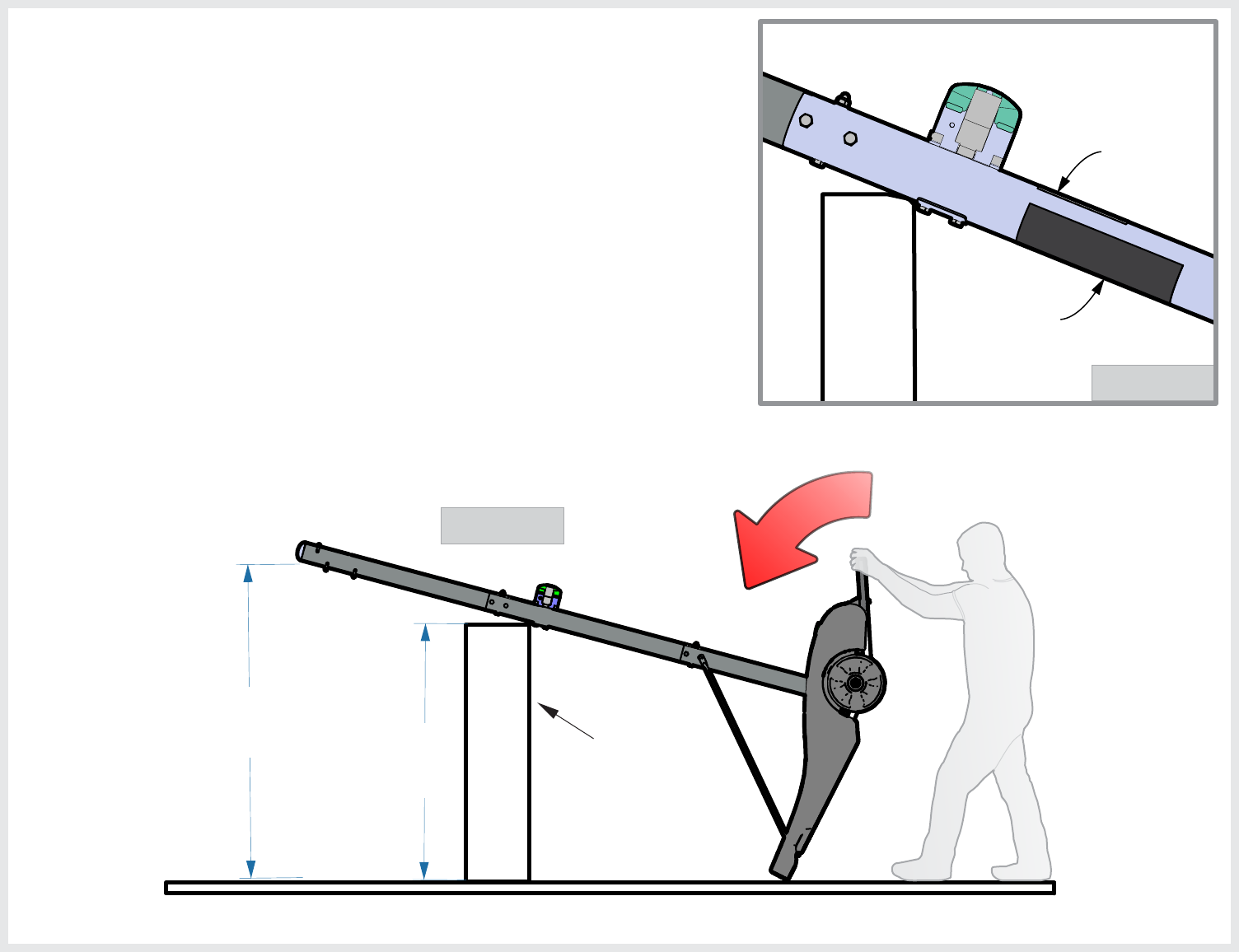
25. You will need a 4’ step ladder or something similar (4’ high) that can
support your system. Alternatively you can use the cardboard box
that your basketball system came in, just make sure that it is in good
condition, if needed tape the box together so it can support the
basketball unit.
26. With the help of another capable adult, tilt your assembly and
rest it on a 4’ step ladder, rest the system above the bolts of the
actuator bracket so the ladder does not damage the warning
label. The height of the end of the pole should be approximately
from 65-70” from the ground. See Detail A & B.
27. Do not set assembly upright until instructed to do so. Have a helper
hold the pole to keep the unit from moving until the arms are attached.
30
HARDWARE NEEDED (ACTUAL SIZE)
HEX LOCK NUT M12-1.75
2B-6805-00
29
(QTY. 4)
WASHER M12 X 24mm OD
2B-6804-00
28
(QTY. 4)
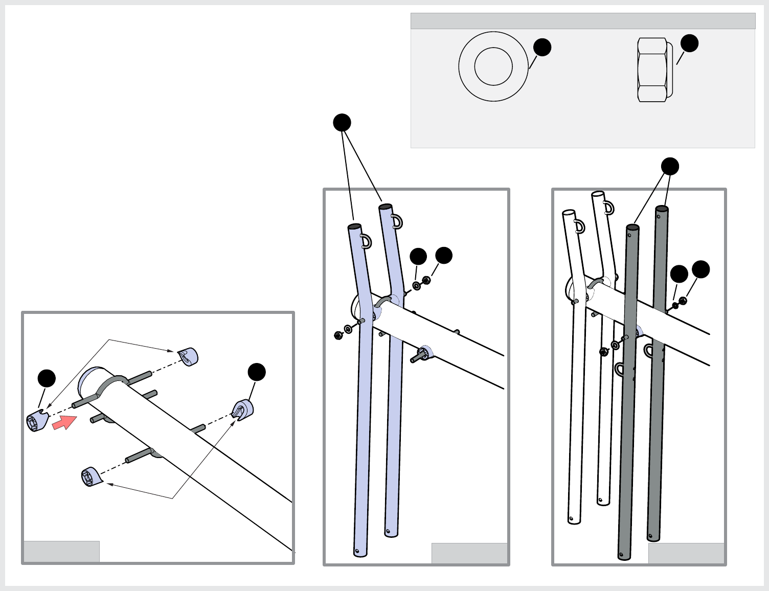
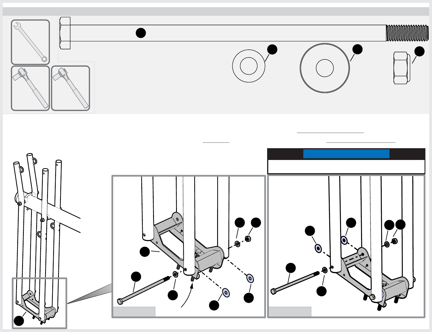
28. With a helper still holding the pole, attach the
arms to upper pole as shown in Detail A-C.
Finger Tighten Nuts (29) only, you will
tighten this hardware in the next page.
DETAIL CDETAIL B
DETAIL A
NOTCH AT TOP
NOTCH AT BOTTOM
25
25
52
49
28 29
28 29
31
DETAIL BDETAIL A
HARDWARE NEEDED (ACTUAL SIZE)
26
HEX HEAD BOLT M10-1.5 X 220mm
1B-7085-00
30
(QTY. 2)
WASHER M10
2B-6800-00
23
(QTY. 4) WASHER, NYLON
3M-9000-00
27
(QTY. 4)
HEX LOCK NUT M10-1.5
2B-6801-00
24
(QTY. 2)
24
23
30
30
24
23
27
27
23 23
27
27
29. Attach Backboard Box (26) to lower and upper arms as shown in Detail A & B. Make sure to put a (27) Nylon washer in
between the Arms and the Backboard Box. Tighten hardware from Detail A & B but back off half a turn once you feel the
hardware is snug. At this time also tighten Nuts from STEP 28 with a19mm Socket and also back off half a turn once you
feel the hardware is snug.
16mm
TOOLS NEEDED
16mm
FINGER TIGHTEN ONLY UNTIL
INSTRUCTED.
26
19mm
IMPORTANT NOTE
DO NOT over tighten hardware, parts
must be able to pivot freely.
Bolts face down
32
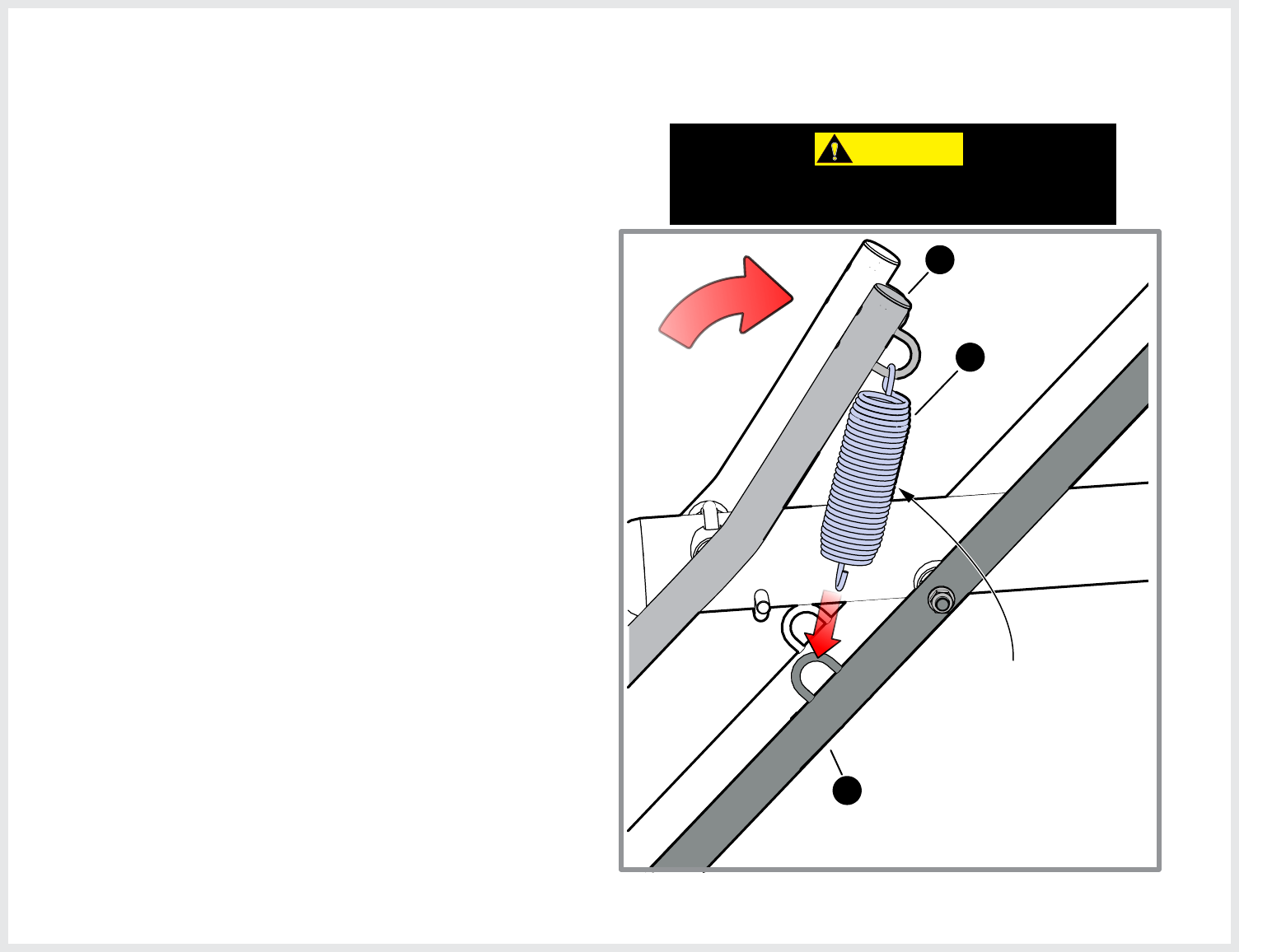
31. With the help of another person attach Spring (35) to
loop on the bottom board arms (49). With one hand
hold and push down the upper arm until the spring
gets as close as possible to the lower arm loop, then
with the other hand pull the spring toward the loop on
the Bottom arm and hook it in place. Have a second
person hold the pole so the system does not move.
Repeat Step to install a second spring.
30. Insert one end of the spring (35) into Spring loop on the
upper Arms (52).
35
52
49
KEEP FINGERS AWAY
FROM SPRING COILS
CAUTION:
BE CAREFUL WITH THE SPRING WHEN PULLING
IT BACK, KEEP FINGERS AWAY FROM COILS.
33
HARDWARE NEEDED
54
HITCH PIN
7B-6577-00
33
(QTY. 2)
32. With the assembly still facing down, attach
the backboard as shown. Have a person
hold the backboard while you insert the
Hitch pins (33) into the backboard supports.
See Details A & B. The hitch pins will keep
the backboard in place and will be
completely secure once the Rim is attached.
NOTE: If needed, the person holding the
Backboard can get on one knee while
holding the backboard.
33
33
DETAIL B
54
33
33
DETAIL ADETAIL A
34
HARDWARE NEEDED (ACTUAL SIZE)
BOTTOM
VIEW
44
WASHER M10
2B-6800-00
23
(QTY. 4)
HEX LOCK NUT M10-1.5
2B-6801-00
24
(QTY. 4)
23
24
33. With the assembly still facing down, attach the Rim
to the Backboard. Have a person hold the Rim in
place while you place Washers (23) and Nuts (24)
as shown in Details A & B. Tighten the nuts with
a ratchet with extension and 16mm socket.
NOTE: Take protective coating off the backboard
before attaching the Rim.
44
TOOLS NEEDED
DETAIL A
DETAIL B
16mm socket
with 3” Extension
35
DETAIL C
HARDWARE NEEDED
TOOLS NEEDED
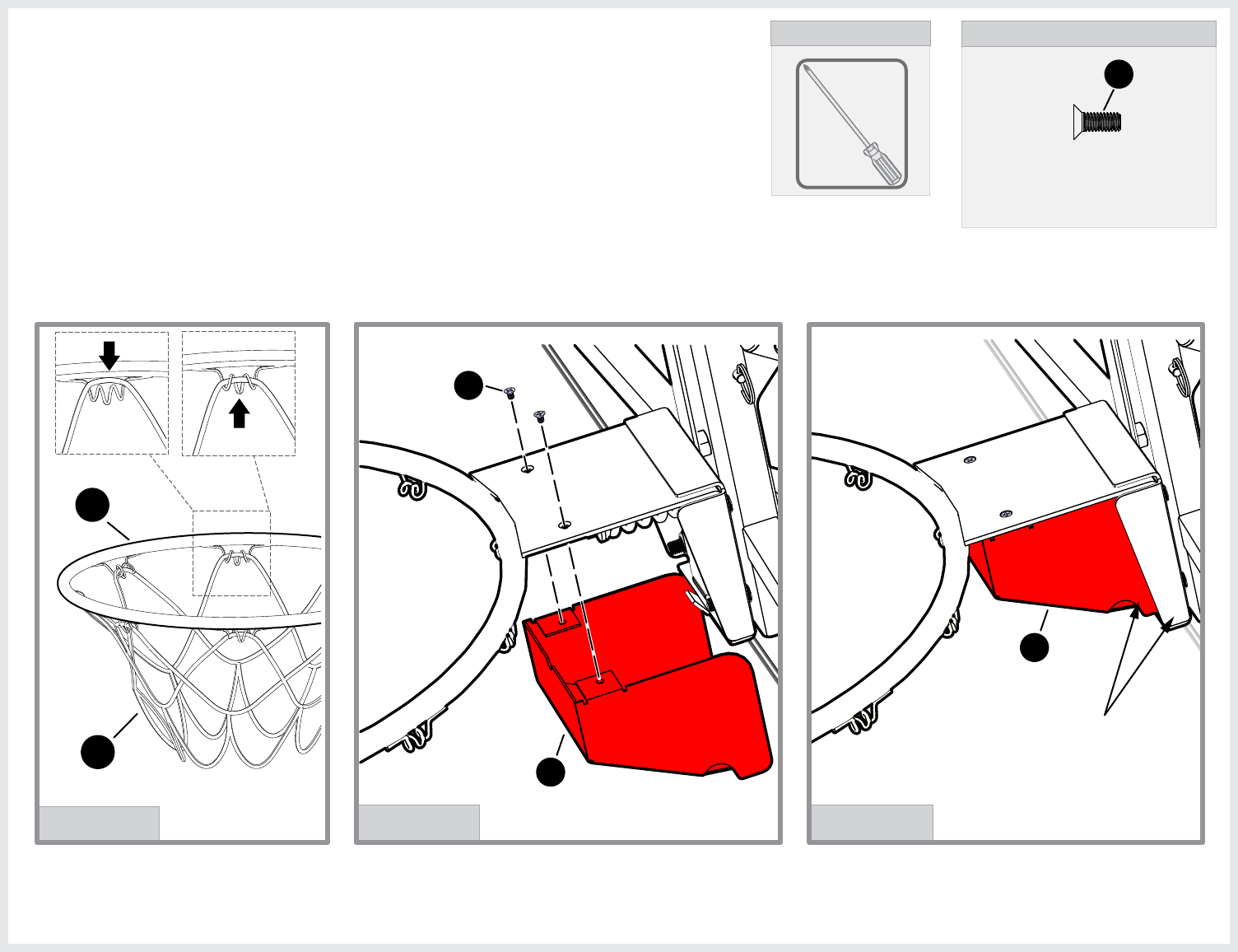
Phillips FLAT HEAD SCREW M4-0.7 X 10mm
(QTY. 2)
1B-7100-00
59
34. Attach Net (58) to Rim (44) by looping net over
metal horn and tucking under as shown in Detail A.
60
NOTE: Make sure the
Spring Cover (60) is on
the inside of the rim on
both sides.
DETAIL A
P3
44
58
DETAIL B
60
59
35. Attach Spring Cover Plate (60) to Rim with two
Screws (59). See Detail B &C.
NET NOT
SHOWN FOR
CLARITY.
NET NOT
SHOWN FOR
CLARITY.
36
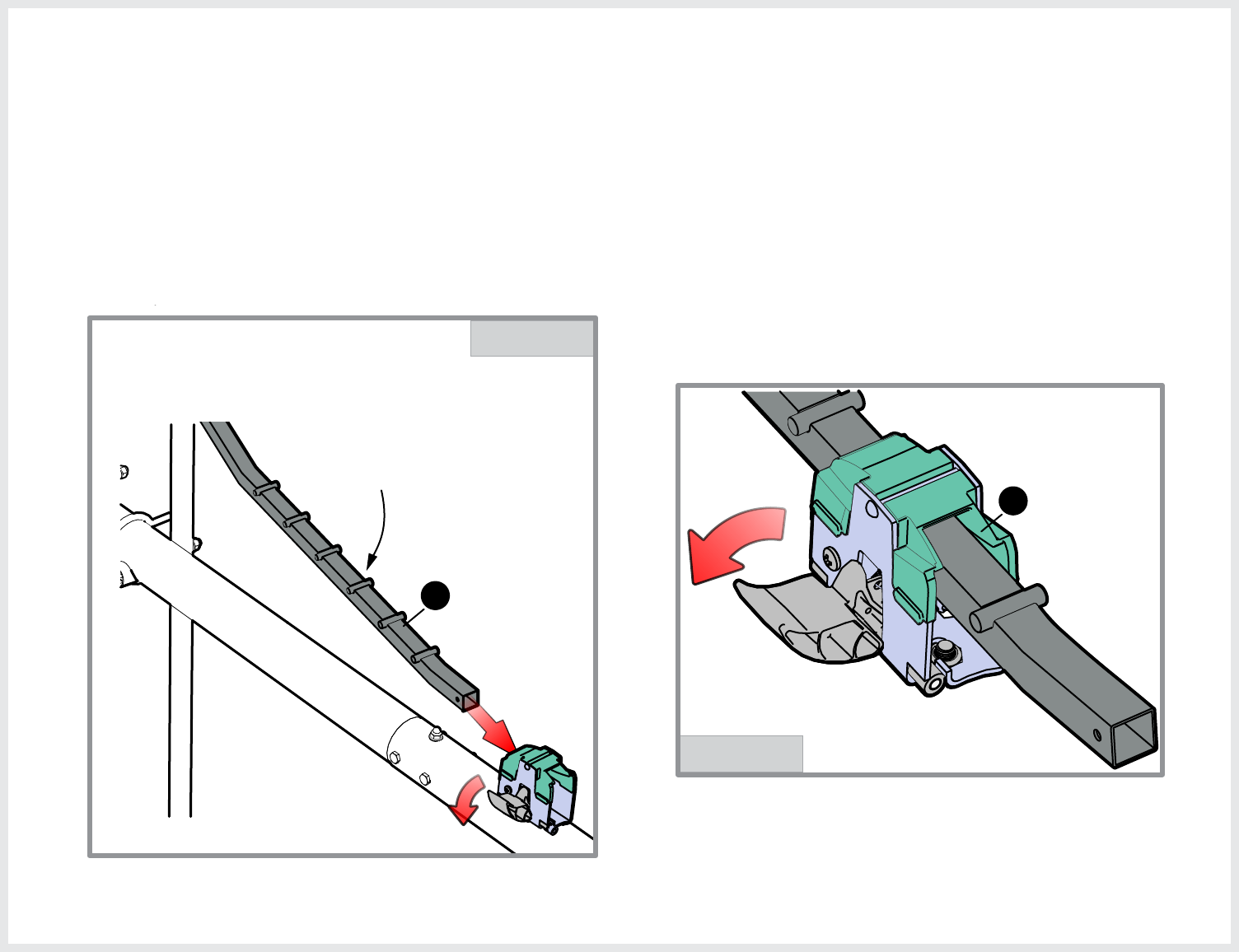
36. Slide the Actuator Bar (53) through the Actuator Bracket,
release the lever by pressing down and holding while
inserting the Actuator Bar. See Detail A & B.
37. Engage the lock by letting go of the lever and allow
actuator to lock into the bracket.
DETAIL A
DETAIL B
53
53
PINS IN ACTUATOR
BAR FACE UP.
SPRING NOT SHOWN
FOR CLARITY.
37
DETAIL A
HARDWARE NEEDED (ACTUAL SIZE)
HEX HEAD BOLT M10-1.5 X 220mm
1B-7085-00
30
(QTY. 1)
WASHER M10
2B-6800-00
23
(QTY. 2)
HEX LOCK NUT M10-1.5
2B-6801-00
24
(QTY. 1)
24
23
23 53
16mm
TOOLS NEEDED
16mm
30
38. Attach other end of the Actuator Bar (#53) to the lower arms, as shown.
You may have to pivot the arms to align actuator. See Detail A.
IMPORTANT NOTE
DO NOT over tighten Hardware, arms must
pivot freely. There should only be about
two threads sticking out past the nut.
38
39. Insert Actuator Grip (#31) into Actuator bar until
the handle is flush with the Actuator bar, then line
up the holes in the grip with the holes in the
actuator bar and secure with two Screws (#32) as
shown in Detail A. DO NOT overtighten screws.
HARDWARE NEEDED
#10-14 X 0.63 TRILOBULAR SCREW
1B-7084-00
32
(QTY. 2)
DETAIL A
HOLE IS HIGHER ON
THIS SIDE OF HANDLE
AND ACTUATOR BAR
32
31
32
LONGER LIP OF GRIP
PIN IN ACTUATOR BAR
NOTE
Longer Lip of the Actuator
Grip and the pins in Actuator
bar are on the same side.
NOTE
If needed use a rubber mallet to
tap the Grip into the Actuator bar.
Phillips
TOOLS NEEDED
Rubber
Mallet
39
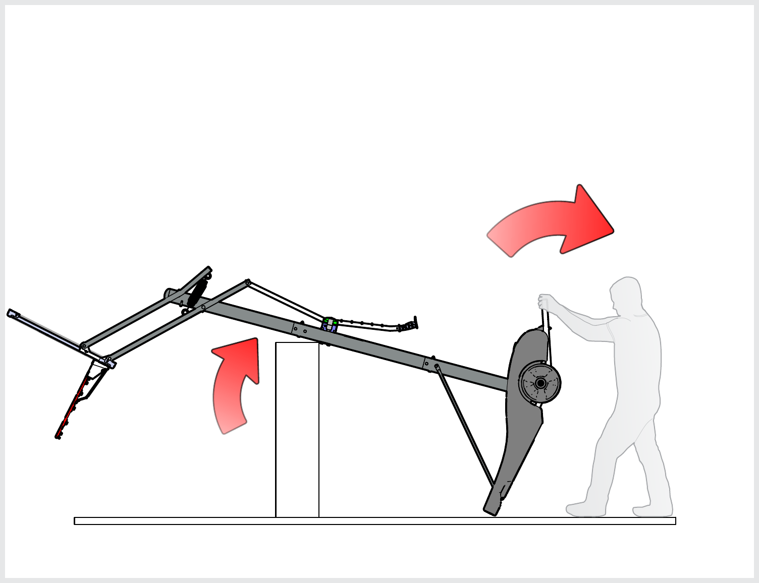
40. Adjust System height to 8 feet (second to last pin in actuator) as
shown in the height decal on the back of the pole.
41. With two capable adults slowly stand the basketball system up. One person
should hold the pole and the other the kick stand in the back of the system.
First person should
hold the pole here
and push up.
Second person should
hold the kickstand here
and pull back slowly.
NOTE: This is a good time to clean the backboard (if needed). Use a
damp microfiber towel or soft cotton cloth to clean the backboard.
Do not use paper towels, harsh chemicals or anything that could
potentially damage your backboard.
40
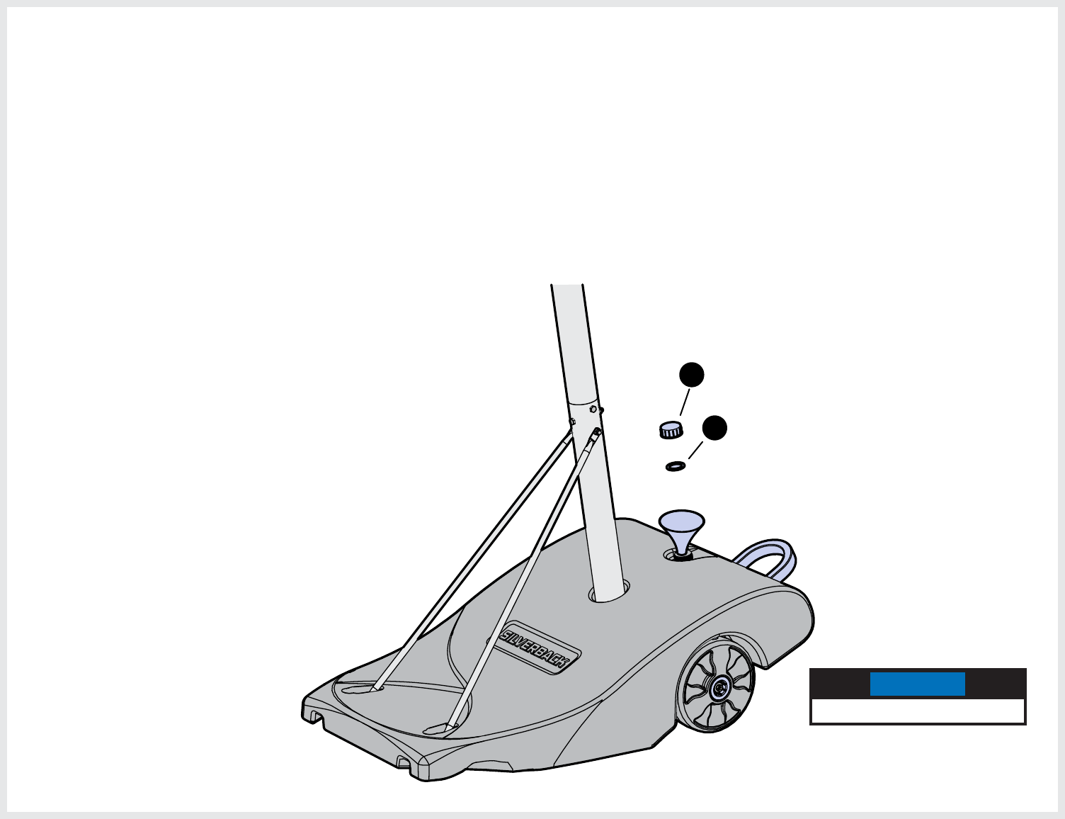
NOTE: Do not overfill ballast.
14
13
Pre-assembled to Cap (13)
(Funnel Optional)
42. Carefully move the system where you would like to place it
and then Fill the Ballast about 75% full (approx. 25 gal.) with
water. Make sure that the Ballast Cap washer (14) is in
place before Screwing cap (13) in place.
NOTE
Do not overfill the Ballast
41
LIMITED 5 YEAR WARRANTY
This consumer warranty extends to the original consumer purchase of any Escalade® Sports Product
(hereinafter referred to as the “Product”).
WARRANTY COVERAGE: Escalade Sports warrants to the original Consumer Purchaser that any Product of
its manufacture is free from defects in material and workmanship. THIS WARRANTY IS VOID IF THE
PRODUCT HAS BEEN DAMAGED BY ACCIDENT, UNREASONABLE USE, NEGLIGENCE, IMPROPER
SERVICE, FAILURE TO FOLLOW INSTRUCTIONS PROVIDED WITH THE PRODUCT OR OTHER CAUSES
NOT ARISING OUT OF DEFECTS IN MATERIAL OR WORKMANSHIP.
Subject to proper assembly, installation and normal Residential use, Escalade Sports warrants, subject to the limitations
below, to the original retail purchaser all structural components (not accessories) of the Silverback® System to be free of
defects in material and workmanship for a period of Five (5) years from the original purchase date.
Merchandise must be shipped prepaid with a copy of proof of purchase to Escalade Sports factory for examination to
determine if the basketball system needs to be repaired or replaced. Any labor costs, travel expenses and any other
changes involved in the removal, installation or replacement of the defective/repaired parts from/to your Silverback
System will be the purchaser’s responsibility. Shipping charges for replaced or warranted merchandise sent back to the
customer from Escalade Sports factory must be prepaid by the customer in advance. If not, the replacement shipment
will be sent out collect.
Escalade Sports reserves the right to examine photographs or physical evidence of merchandise claimed to be
defective, and to recover said merchandise, prior to authorization of warranty claims. A “Returned Goods
Authorization” number may be required, please call for details prior to the return of any photographs or
merchandise.
This limited 5 year warranty is expressly in lieu of all warranties, expressed or implied, including warranties of merchantability
or fitness for use. Escalade® Sports does not assume or authorize any person or representative to assume for us, any
other liability in connection with the sale of our products.
The remedy of repair or replacement stated above is Escalade Sports exclusive remedy. Escalade Sports will not be
liable for any other damages or expenses which may incur, including but not limited to incidental or consequential
damages. Escalade Sports assumes no other obligations or liability on the part of the purchaser, and Escalade
Sports neither assumes nor authorizes any other person to assume for it any other liability in connection with the
goods sold.
This warranty shall not apply in any manner to parts or accessories not manufactured by Escalade Sports.
NOT COVERED BY THIS WARRANTY
• Merchandise not intended to be in places of public assembly, such as, but not limited to, schools,
parks, public or private recreational facilities.
• Any merchandise subjected to Non-residential abuse, negligence, improper installation, vandalism,
acts of God, alteration of product, or any other events beyond the control of Escalade Sports.
• Paint or rusted parts. If rust should appear, remove loose paint, sand lightly, primer and paint with
exterior flat matte finish enamel paint.
• Hoop net will be warranted for a period of 180 days - under normal use and proper care.
• HANGING ON RIM WILL VOID THE WARRANTY: Rims are not warranted for any defects other than
workmanship. Torn back plates, damaged springs, bent rings, damaged eyebolts, and torn or distorted
rim supports result from hanging on the rim and are not warranted.
• Shipping charges both ways. Note: Any merchandise shipped to Escalade Sports collect will be
refused.
• Dealer service charges, labor charges and travel expenses associated with replacement of repair of
warranty item.
WARRANTY DISCLAIMERS: ANY IMPLIED WARRANTIES ARISING OUT OF THIS SALE, INCLUDING BUT NOT
LIMITED TO THE IMPLIED WARRANTIES OF MERCHANTABILITY AND FITNESS FOR A PARTICULAR PURPOSE,
ARE LIMITED IN DURATION. ESCALADE SPORTS SHALL NOT BE LIABLE FOR LOSS OF USE OF THE
PRODUCT OR OTHER CONSEQUENTIAL OR INCIDENTAL COSTS. EXPENSES OR DAMAGES INCURRED BY
THE CONSUMER OF ANY OTHER USE.
Some states do not allow the exclusion or limitation of implied warranties or consequential or incidental damages, so the above
limitations or exclusions may not apply to you. LEGAL REMEDIES: This warranty gives you specific legal rights, and you may
also have other rights which may vary from state to state.
WARRANTY GUIDELINES IS REQUIRED FOR ALL WARRANTY CLAIMS
1. Proof of Purchase (original retail purchaser) is required for all warranty claims.
2. Call or write Escalade Sports to receive a Return Authorization # and determine specific needs. Phone: 1-
888-USA-GOAL / Warranty Dept. Or Write Escalade Sports at: Escalade Sports - P.O. Box 889, Evansville,
IN 47706 - Attn: Warranty Dept. Or E-mail us at: basketball@escaladesports.com
