BLEADG BLE Application Developer's Guide
User Manual: Pdf
Open the PDF directly: View PDF ![]() .
.
Page Count: 138 [warning: Documents this large are best viewed by clicking the View PDF Link!]
- Introduction
- 2. Prerequisites
- 3. Host Stack initialization and APIs
- 4. Generic Access Profile (GAP) Layer
- 5. Generic Attribute Profile (GATT) Layer
- 6. GATT Database Application Interface
- 7. Creating a GATT Database
- 8. Creating a Custom Profile
- 9. Application Structure
- 10. Low-Power Management
- 11. Over the Air Programming (OTAP)
- 11.1. General Functionality
- 11.2. The BLE OTAP Service-Profile
- 11.3. The BLE OTAP Protocol
- 11.3.1. Protocol Design Considerations
- 11.3.2. The BLE OTAP Commands
- 11.3.2.1. New Image Notification Command
- 11.3.2.2. New Image Info Request Command
- 11.3.2.3. New Image Info Response Command
- 11.3.2.4. Image Block Request Command
- 11.3.2.5. Image Chunk Command
- 11.3.2.6. Image Transfer Complete Command
- 11.3.2.7. Error Notification Command
- 11.3.2.8. Stop Image Transfer Command
- 11.3.3. OTAP Client–Server Interactions
- 11.4. The BLE OTAP Image File Format
- 11.5. Building a BLE OTAP Image File from a SREC File
- 11.6. Building a BLE OTAP Image File from a BIN File
- 11.7. BLE OTAP Application Integration
- 11.8. The OTAP Bootloader
- 12. Creating a BLE Application When the BLE Host Stack is Running on Another Processor
- 13. Hybrid (Dual-Mode) Bluetooth® Low Energy and IEEE® 802.15.4 Applications
- 14. Revision history

Bluetooth® Low Energy
Application Developer’s Guide
1. Introduction
This document explains how to integrate the Bluetooth®
Low Energy (BLE) Host Stack in a BLE application and
provides detailed explanation of the most commonly used
APIs and code examples.
The document also sets out the prerequisites and the
initialization of the BLE Host Stack, followed by the
presentation of APIs grouped by layers and by application
role, as described below.
First, the Generic Access Profile (GAP) layer is divided
into two sections according to the GAP role of the device:
Central and Peripheral.
The basic setup of two such devices is explained with code
examples, such as how to prepare the devices for
connections, how to connect them together, and pairing
and bonding processes.
NXP Semiconductors
Document Number: BLE
ADG
User’s Guide
Rev.
4
,
09
/201
6
Contents
1. Introduction 1
2. Prerequisites 3
3. Host Stack initialization and APIs 6
4. Generic Access Profile (GAP) Layer 10
5. Generic Attribute Profile (GATT) Layer 30
6. GATT Database Application Interface 58
7. Creating a GATT Database 60
8. Creating a Custom Profile 67
9. Application Structure 70
10. Low-Power Management 82
11. Over the Air Programming (OTAP) 89
12. Creating a BLE Application When the BLE Host Stack is
Running on Another Processor 130
13. Hybrid (Dual-Mode) Bluetooth® Low Energy and IEEE®
802.15.4 Applications 134
14. Revision history 137

Introduction
Bluetooth® Low Energy User’s Guide Rev. 4, 09/2016
2 NXP Semiconductors
Next, the Generic Attribute Profile (GATT) layer introduces the APIs required for data transfer between
the two connected devices. Again, the chapter is divided into two sections according to the GATT role
of the device: Client and Server.
The document further describes the usage of the GATT Database APIs in the application to manipulate
the data in the GATT server database.
Then, the document shows a user-friendly method to statically build a GATT Database. The method
involves the use of a predefined set of macros that the application may include to build the database at
application compile-time.
The following section contains instructions on how to build a custom profile. The subsequent section is
dedicated to the structure of the typical application.
Additionally, the document has a chapter dedicated to low-power management and how the low-power
modes of the hardware of the software can be used by an application.
The next section contains a description of the Over The Air Programming (OTAP) capabilities offered
by the Host Stack via a dedicated Service/Profile and how to use them in an application. This section
also contains a detailed description of the components of the Framework involved in the OTAP process
and the Bootloader application, which does the actual upgrade of the image on a device.
Finally, the document has a section, which describes how to build a BLE application when the Host
Stack is running on a separate processor.

Prerequisites
Bluetooth® Low Energy User’s Guide Rev. 4, 09/2016
NXP Semiconductors 3
2. Prerequisites
The BLE Host Stack library contains a number of external references that the application must define to
provide the full functionality of the Host.
Failing to do so results in linkage errors when trying to build the application binary.
RTOS Task Queues and Events
These task queues are declared in the ble_host_tasks.h as follows:
/*! App to Host message queue for the Host Task */
extern msgQueue_t gApp2Host_TaskQueue;
/*! HCI to Host message queue for the Host Task */
extern msgQueue_t gHci2Host_TaskQueue;
/*! Event for the Host Task Queue */
extern osaEventId_t gHost_TaskEvent;
See Section 3.1 for more details about the RTOS Tasks required by the Host.
GATT Database
For memory efficiency reasons, the Host Stack does not allocate memory for the GATT Database.
Instead, the application must allocate memory, define and populate the database according to its
requirements and constraints. It may do so either statically, at application compile-time, or dynamically.
Regardless of how the GATT Database is created by the application, the following two external
references from gatt_database.h must be defined:
/*! The number of attributes in the GATT Database. */
extern uint16_t gGattDbAttributeCount_c;
/*! Reference to the GATT database */
extern gattDbAttribute_t gattDatabase[];
The attribute template is defined as shown here:
typedef struct gattDbAttribute_tag {
uint16_t handle;
/*!< Attribute handle - cannot be 0x0000; attribute handles need not be consecutive, but
must be strictly increasing. */
uint16_t permissions;
/*!< Attribute permissions as defined by ATT. */
uint32_t uuid;
/*!< The UUID should be read according to the gattDbAttribute_t.uuidType member: for 2-byte
and 4-byte UUIDs, this contains the value of the UUID; for 16-byte UUIDs, this is a pointer
to the allocated 16-byte array containing the UUID. */
uint8_t* pValue;

Prerequisites
Bluetooth® Low Energy User’s Guide Rev. 4, 09/2016
4 NXP Semiconductors
/*!< Pointer to allocated value array. */
uint16_t valueLength;
/*!< Size of the value array. */
uint16_t uuidType : 2;
/*!< Identifies the length of the UUID; the 2-bit values are interpreted according to the
bleUuidType_t enumeration. */
uint16_t maxVariableValueLength : 10;
/*!< Maximum length of the attribute value array; if this is set to 0, then the attribute's
length (valueLength) is fixed and cannot be changed. */
} gattDbAttribute_t;
Non-Volatile Memory (NVM) Access
The Host Stack contains an internal device information management that relies on accessing the Non-
Volatile Memory for storing and loading bonded devices data.
To enable this mechanism make sure:
• gAppUseNvm_d (ApplMain.h) is set to TRUE and
• gUseNVMLink_d=1 in the linker options of the toolchain.
The application developers determine the NVM access mechanism through the definition of three
functions and one variable. The functions must perform standard NVM operations (erase, write, read).
The declarations are as follows:
extern void App_NvmErase
(
void
);
extern void App_NvmWrite
(
void* pvRamSource,
uint32_t cDataSize
);
extern void App_NvmRead
(
void* pvRamDestination,
uint32_t cDataSize
);
The Host Stack assumes that all three NVM functions are executed synchronously. Additionally, the
functions use the following three symbols from the linker file for working with the NVM memory area:
• NV_STORAGE_END_ADDRESS – The address from where the Host Stack begins writing
data.
• NV_STORAGE_START_ADDRESS – The address from where the Host Stack ends writing
data.

Prerequisites
Bluetooth® Low Energy User’s Guide Rev. 4, 09/2016
NXP Semiconductors 5
Note
The reserved NVM area size must be (at least) equal to 250 bytes multiplied by
gcGapMaximumBondedDevices_d, defined in ble_constants.h. Otherwise, the Host might overwrite
some other meaningful data in the NVM.

Host Stack initialization and APIs
Bluetooth® Low Energy User’s Guide Rev. 4, 09/2016
6 NXP Semiconductors
3. Host Stack initialization and APIs
Host Tasks initialization
The application developer is required to configure the Host Task as part of the Host Stack requirement.
The task is the context for running all the Host layers (GAP, GATT, ATT, L2CAP, SM, GATTDB)
The prototype of the task function is located in the ble_host_tasks.h file:
void Host_TaskHandler(void * args);
It should be called with NULL as an argument in the task codes from the application.
Application developers are required to define task events and queues as explained in section 2.1.
The Host task always has a higher priority than the Controller task. The priority values are configured by
gHost_TaskPriority_c (ble_host_task_config.h) and gControllerTaskPriority_c
(ble_controller_task_config.h). Note that changing these values can have a significant impact on the
BLE stack.
The priority levels are defined in accordance with the OS Abstraction (OSA) priority levels, where 0 is
the maximum priority and 15 is the minimum priority. For additional information, see the Connectivity
Framework Reference Manual (document CONNFWKRM). Note that RTOS-specific priority levels
may differ from one operating system to another.
Main function to initialize the Host
The Host Stack must be initialized after platform setup is complete and all RTOS tasks have been
started.
The function that needs to be called is located in the ble_general.h file and has the following prototype:
bleResult_t Ble_HostInitialize
(
gapGenericCallback_t genericCallback,
hciHostToControllerInterface_t hostToControllerInterface
);
The genericCallback is the main callback installed by the application. It receives most of the events from
the GAP layer, which are called generic events. A generic event has a type (see
gapGenericEventType_t) and data according to the event type (a union).
The hostToControllerInterface is the HCI exit point of the Host Stack. This is the function that the Host
calls every time it tries to send an HCI message to the LE Controller.
The completion of the Host Stack initialization is signaled in the genericCallback by the
gInitializationComplete_c generic event.
Host Stack initialization and APIs
Bluetooth® Low Energy User’s Guide Rev. 4, 09/2016
NXP Semiconductors 7
After this event is received, the main application logic may be started.
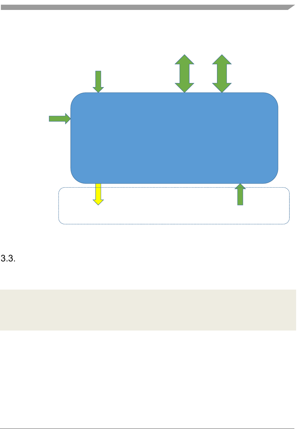
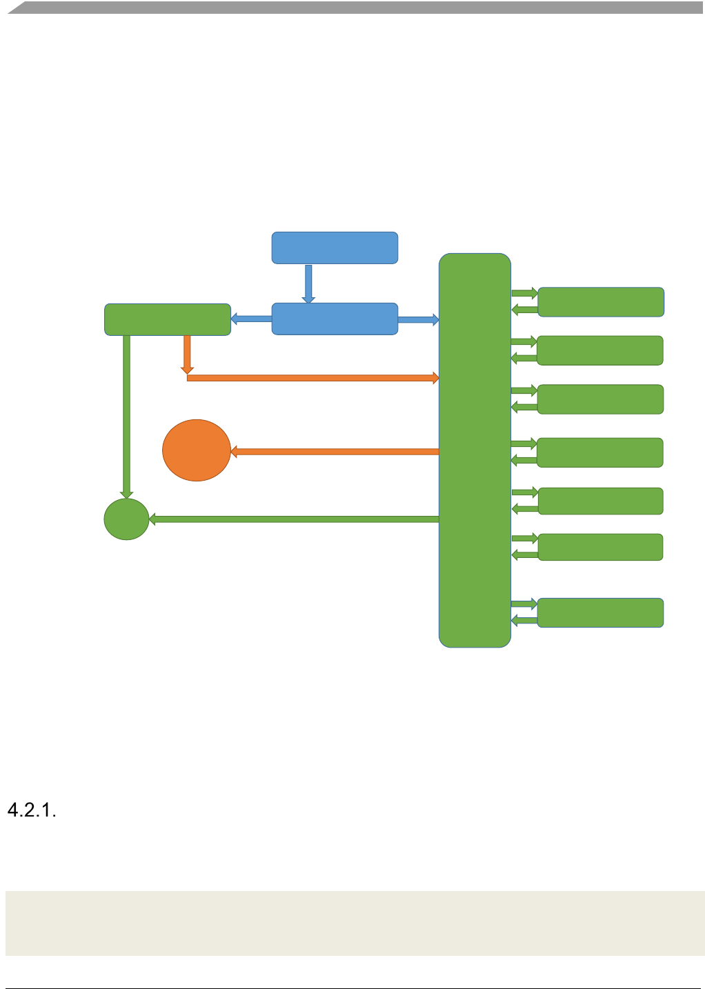
BLE Host Stack
Ble_HostInitialize
Ble_HciRecv
GAP APIs & CBs GATT APIs & CBs
hostToControllerInterface HCI
Host_TaskHandler
L2ca_TaskHandler
Figure 1. BLE Host Stack overview
HCI entry and exit points
The HCI entry point of the Host Stack is the second function located in the ble_general.h file:
void Ble_HciRecv
(
hciPacketType_t packetType,
void* pPacket,
uint16_t packetSize
);
This is the function that the application must call to insert an HCI message into the Host.
Therefore, the Ble_HciRecv function and the hostToControllerInterface parameter of the Ble_Initialize
function represent the two points that need to be connected to the LE Controller (see Figure 1), either
directly (if the Controller software runs on the same chip as the Host) or through a physical interface (for
example, UART).

Host Stack initialization and APIs
Bluetooth® Low Energy User’s Guide Rev. 4, 09/2016
8 NXP Semiconductors
Host Stack libraries and API availability
All the APIs referenced in this document are available in the Central and Peripheral libraries. For
example, ble_host_lib.a is a full-featured library with complete support for both Central and Peripheral
APIs, at GAP level, as well as Client and Server APIs, at GATT level.
However, some applications may be targeted to memory-constrained devices and do not need the full
support. In the interest of reducing code size and RAM utilization, two more libraries are provided:
• ble_host_peripheral_lib.a
o Supports only APIs for the GAP Peripheral and GAP Broadcaster roles
o Supports only APIs for the GATT Server role
• ble_host_central_lib.a
o Supports only APIs for the GAP Central and GAP Observer roles
o Supports only APIs for the GATT Client role
If one attempts to use an API that is not supported (for instance, calling Gap_Connect with the
ble_host_peripheral_lib.a), then the API returns the gBleFeatureNotSupported_c error code.
Note
See the Bluetooth Low Energy Host StackAPI Reference Manual (document BLEHSAPIRM) for
explicit information regarding API support. Each function documentation contains this
information in the Remarks section.
Synchronous and asynchronous functions
The vast majority of the GAP and GATT APIs are executed asynchronously. Calling these functions
generates an RTOS message and place is in the Host Task message queue.
Therefore, the actual result of these APIs is signaled in events triggered by specific callbacks installed
by the application. See the Bluetooth Low Energy Host StackAPI Reference Manual (document
BLEHSAPIRM) for specific information about the events that are triggered by each API.
However, there are a few APIs which are executed immediately (synchronously). This is explicitely
mentioned in the Bluetooth Low Energy Host StackAPI Reference Manual (document BLEHSAPIRM)
in the Remarks section of each function documentation.
If nothing is mentioned, then the API is asynchronous.
Radio TX Power Level
The controller interface includes APIa that can be used to set the Radio TX Power to a different level
than default.

Host Stack initialization and APIs
Bluetooth® Low Energy User’s Guide Rev. 4, 09/2016
NXP Semiconductors 9
The power level can be set differently for advertising and connection channels with the following
macros:
#define Controller_SetAdvertisingTxPowerLevel(level) \
Controller_SetTxPowerLevel(level,gAdvTxChannel_c)
and
#define Controller_SetConnectionTxPowerLevel(level) \
Controller_SetTxPowerLevel(level,gConnTxChannel_c)
The numeric power levels are distributed evenly between the minimum and maximum output power
values (in dBm). Please refer the silicon datasheet for more information.

Generic Access Profile (GAP) Layer
Bluetooth® Low Energy User’s Guide Rev. 4, 09/2016
10 NXP Semiconductors
4. Generic Access Profile (GAP) Layer
The GAP layer manages connections, security, and bonded devices.
The GAP layer APIs are built on top of the Host-Controller Interface (HCI), the Security Manager
Protocol (SMP), and the Device Database.
GAP defines four possible roles that a BLE device may have in a BLE system (see Figure 3):
• Central
o Scans for advertisers (Peripherals and Broadcasters)
o Initiates connection to Peripherals; Master at Link Layer (LL) level
o Usually acts as a GATT Client, but can also contain a GATT Database itself
• Peripheral
o Advertises and accepts connection requests from Centrals; LL Slave
o Usually contains a GATT Database and acts as a GATT Server, but may also be a Client
• Observer
o Scans for advertisers, but does not initiate connections; Transmit is optional
• Broadcaster
o Advertises, but does not accept connection requests from Centrals; Receive is optional
Generic Access Profile (GAP) Layer
Bluetooth® Low Energy User’s Guide Rev. 4, 09/2016
NXP Semiconductors 11
Broadcaster
Central
Observer
Peripheral
advertising
advertising
scanning
scanningadvertising
scanning
advertising
scanning
connection
Master
Slave
Figure 2. GAP Topology
Central setup
Usually, a Central must start scanning to find Peripherals. When the Central has scanned a Peripheral it
wants to connect to, it stops scanning and initiates a connection to that Peripheral. After the connection
has been established, it may start pairing, if the Peripheral requires it, or directly encrypt the link, if the
two devices have already bonded in the past.
Scanning
The most basic setup for a Central device begins with scanning, which is performed by the following
function from gap_interface.h:
bleResult_t Gap_StartScanning
(
gapScanningParameters_t* pScanningParameters,
gapScanningCallback_t scanningCallback
);
If the pScanningParameters pointer is NULL, the currently set parameters are used. If no parameters
have been set after a device power-up, the standard default values are used:
#define gGapDefaultScanningParameters_d \

Generic Access Profile (GAP) Layer
Bluetooth® Low Energy User’s Guide Rev. 4, 09/2016
12 NXP Semiconductors
{ \
/* type */ gGapScanTypePassive_c, \
/* interval */ gGapScanIntervalDefault_d, \
/* window */ gGapScanWindowDefault_d, \
/* ownAddressType */ gBleAddrTypePublic_c, \
/* filterPolicy */ gScanAll_c \
}
The easiest way to define non-default scanning parameters is to initialize a gapScanningParameters_t
structure with the above default and change only the required fields.
For example, to perform active scanning and only scan for devices in the White List, the following code
can be used:
gapScanningParameters_t scanningParameters = gGapDefaultScanningParameters_d;
scanningParameters.type = gGapScanTypeActive_c;
scanningParameters.filterPolicy = gScanWhiteListOnly_c;
Gap_StartScanning(&scanningParameters, scanningCallback);
The scanningCallback is triggered by the GAP layer to signal events related to scanning.
The most important event is the gDeviceScanned_c event (see an example from Section 0), which is
triggered each time an advertising device is scanned. This event’s data contains information about the
advertiser:
typedef struct gapScannedDevice_tag {
bleAddressType_t addressType;
bleDeviceAddress_t aAddress;
int8_t rssi;
uint8_t dataLength;
uint8_t* data;
bleAdvertisingReportEventType_t advEventType;
} gapScannedDevice_t;
If this information signals a known Peripheral that the Central wants to connect to, the latter must stop
scanning and connect to the Peripheral.
To stop scanning, call this function:
bleResult_t Gap_StopScanning(void);
By default, the GAP layer is configured to report all scanned devices to the application using the
gDeviceScanned_c event type. However, some use cases may require to perform specific GAP
Discovery Procedures in which the advertising reports have to be filtered by the Flags AD value from
the advertising data. Other use cases require the Host stack to automatically initiate a connection when a
specific device has been scanned.
To enable filtering based on the Flags AD value or to set device addresses for automatic connections, the
following function must be called before the scanning is started:
Generic Access Profile (GAP) Layer
Bluetooth® Low Energy User’s Guide Rev. 4, 09/2016
NXP Semiconductors 13
bleResult_t Gap_SetScanMode
(
gapScanMode_t scanMode,
gapAutoConnectParams_t* pAutoConnectParams
);
The default value for the scan mode is gNoDiscovery_c, which reports all packets regardless of their
content and does not perform any automatic connection.
To enable Limited Discovery, the gLimitedDiscovery_c value must be used, while the
gGeneralDiscovery_c value activates General Discovery.
To enable automatic connection when specific devices are scanned, the gAutoConnect_c value must be
set, in which case the pAutoConnectParams parameter must point to the structure that holds the target
device addresses and the connection parameters to be used by the Host for these devices.
Initiating and closing a connection
To connect to a scanned Peripheral, extract its address and address type from the gDeviceScanned_c
event data, stop scanning, and call the following function:
bleResult_t Gap_Connect
(
gapConnectionRequestParameters_t* pParameters,
gapConnectionCallback_t connCallback
);
An easy way to create the connection parameter structure is to initialize it with the defaults, then change
only the necessary fields. The default structure is defined as shown here:
#define gGapDefaultConnectionRequestParameters_d \
{ \
/* scanInterval */ gGapScanIntervalDefault_d, \
/* scanWindow */ gGapScanWindowDefault_d, \
/* filterPolicy */ gUseDeviceAddress_c, \
/* ownAddressType */ gBleAddrTypePublic_c, \
/* peerAddressType */ gBleAddrTypePublic_c, \
/* peerAddress */ { 0, 0, 0, 0, 0, 0 }, \
/* connIntervalMin */ gGapDefaultMinConnectionInterval_d, \
/* connIntervalMax */ gGapDefaultMaxConnectionInterval_d, \
/* connLatency */ gGapDefaultConnectionLatency_d, \
/* supervisionTimeout */ gGapDefaultSupervisionTimeout_d, \
/* connEventLengthMin */ gGapConnEventLengthMin_d, \
/* connEventLengthMax */ gGapConnEventLengthMax_d \
}
In the following example, Central scans for a specific Heart Rate Sensor with a known address. When it
finds it, it immediately connects to it.

Generic Access Profile (GAP) Layer
Bluetooth® Low Energy User’s Guide Rev. 4, 09/2016
14 NXP Semiconductors
static bleDeviceAddress_t heartRateSensorAddress = { 0xa1, 0xb2, 0xc3, 0xd4, 0xe5, 0xf6 };
static bleAddressType_t hrsAddressType = gBleAddrTypePublic_c;
static bleAddressType_t ownAddressType = gBleAddrTypePublic_c;
void gapScanningCallback(gapScanningEvent_t* pScanningEvent)
{
switch (pScanningEvent->eventType)
{
/* ... */
case gDeviceScanned_c:
{
if (hrsAddressType == pScanningEvent->eventData.scannedDevice.addressType
&& Ble_DeviceAddressesMatch(heartRateSensorAddress,
pScanningEvent->eventData.scannedDevice.aAddress))
{
gapConnectionRequestParameters_t connReqParams =
gGapDefaultConnectionRequestParameters_d;
connReqParams.peerAddressType = hrsAddressType;
Ble_CopyDeviceAddress(connReqParams.peerAddress, heartRateSensorAddress);
connReqParams.ownAddressType = ownAddressType;
bleResult_t result = Gap_StopScanning();
if (gBleSuccess_c != result)
{
/* Handle error */
}
else
{
/* There is no need to wait for the gScanStateChanged_c event because
* the commands are queued in the host task
* and executed consecutively. */
result = Gap_Connect(&connReqParams, connectionCallback);
if (gBleSuccess_c != result)
{
/* Handle error */
}
}
}
break;
}
/* ... */
}
}
The connCallback is triggered by GAP to send all events related to the active connection. It has the
following prototype:
typedef void (*gapConnectionCallback_t)
(
deviceId_t deviceId,
Generic Access Profile (GAP) Layer
Bluetooth® Low Energy User’s Guide Rev. 4, 09/2016
NXP Semiconductors 15
gapConnectionEvent_t* pConnectionEvent
);
The very first event that should be listened inside this callback is the gConnEvtConnected_c event. If the
application decides to drop the connection establishment before this event is generated, it should call the
following macro:
#define Gap_CancelInitiatingConnection()\
Gap_Disconnect(gCancelOngoingInitiatingConnection_d)
This is useful, for instance, when the application chooses to use an expiration timer for the connection
request.
Upon receiving the gConnEvtConnected_c event, the application may proceed to extract the necessary
parameters from the event data (pConnectionEvent->event.connectedEvent). The most important
parameter to be saved is the deviceId.
The deviceId is an unique 8-bit, unsigned integer, used to identify an active connection for subsequent
GAP and GATT API calls. All functions related to a certain connection require a deviceId parameter.
For example, to disconnect, call this function:
bleResult_t Gap_Disconnect
(
deviceId_t deviceId
);
Pairing and bonding
After the user has connected to a Peripheral, use the following function to check whether this device has
bonded in the past:
bleResult_t Gap_CheckIfBonded
(
deviceId_t deviceId,
bool_t* pOutIsBonded
);
If it has, link encryption can be requested with:
bleResult_t Gap_EncryptLink
(
deviceId_t deviceId,
);
If the link encryption is successful, the gConnEvtEncryptionChanged_c connection event is triggered.
Otherwise, a gConnEvtAuthenticationRejected_c event is received with the rejectReason event data
parameter set to gLinkEncryptionFailed_c.

Generic Access Profile (GAP) Layer
Bluetooth® Low Energy User’s Guide Rev. 4, 09/2016
16 NXP Semiconductors
On the other hand, if this is a new device (not bonded), pairing may be started as shown here:
bleResult_t Gap_Pair
(
deviceId_t deviceId,
gapPairingParameters_t* pPairingParameters
);
The pairing parameters are shown here:
typedef struct gapPairingParameters_tag {
bool_t withBonding;
gapSecurityModeAndLevel_t securityModeAndLevel;
uint8_t maxEncryptionKeySize;
gapIoCapabilities_t localIoCapabilities;
bool_t oobAvailable;
gapSmpKeyFlags_t centralKeys;
gapSmpKeyFlags_t peripheralKeys;
bool_t leSecureConnectionSupported;
bool_t useKeypressNotifications;
} gapPairingParameters_t;
The names of the parameters are self-explanatory. The withBonding flag should be set to TRUE if the
Central must/wants to bond.
For the Security Mode and Level, the GAP layer defines them as follows:
• Security Mode 1 Level 1 stands for no security requirements
• Except for Level 1 (which is only used with Mode 1), Security Mode 1 requires encryption,
while Security Mode 2 requires data signing
• Mode 1 Level 2 and Mode 2 Level 1 do not require authentication (in other words, they allow
Just Works pairing, which has no MITM protection), while Mode 1 Level 3 and Mode 2 Level 2
require authentication (must pair with PIN or OOB data, which provide MITM protection).
• Starting with Bluetooth specification 4.2 OOB pairing offers MITM protection only in certain
conditions. The application must inform the stack if its the OOB data exchange capabilities offer
MITM protection via a dedicated API.
• Security Mode 1 Level 4 is reserved for authenticated pairing (with MITM protection) using a
LE Secure Connections pairing method.
• If a LE Secure Connections pairing method is used but it does not offer MITM protection then
the pairing completes with Security Mode 1 level 2.

Generic Access Profile (GAP) Layer
Bluetooth® Low Energy User’s Guide Rev. 4, 09/2016
NXP Semiconductors 17
No
Security
No MITM
Protection
Legacy MITM
Protection
LE Secure
Connections
With MITM
Protection
Mode 1
(encryption)
Distributed
LTK (EDIV+
RAND) or
Generated LTK
Level 1
No
security
Level 2
Unauthenticated
Encryption
Level 3
Authenticated
Encryption
Level 4
LE SC
Authenticated
Encryption
Mode 2
(data signing)
Distributed
CSRK
-
Level 1
Unauthenticated
Data Signing
Level 2
Authenticated
Data Signing
Figure 3. GAP Security Modes and Levels
The centralKeys should have the flags set for all the keys that are available in the application. The IRK
is mandatory if the Central is using a Private Resolvable Address, while the CSRK is necessary if the
Central wants to use data signing. The LTK is provided by the Peripheral and should only be included if
the Central intends on becoming a Peripheral in future reconnections (GAP role change).
The peripheralKeys should follow the same guidelines. The LTK is mandatory if encryption is to be
performed, while the peer’s IRK should be requested if the Peripheral is using Private Resolvable
Addresses.
See Figure 4 for detailed guidelines regarding key distribution.
The first three rows are both guidelines for Pairing Parameters (centralKeys and peripheralKeys) and for
distribution of keys with Gap_SendSmpKeys.
If LE Secure Connections Pairing is performed (BLE 4.2), then the LTK is generated internally, so the
corresponding bits in the key distribution fields from the pairing parameters are ignored by the devices.
The Identity Address shall be distributed if the IRK is also distributed (its flag has been set in the Pairing
Parameters). Therefore, it can be “asked” only by asking for IRK (it does not have a separate flag in a
gapSmpKeyFlags_t structure), hence the N/A.
The negotiation of the distributed keys is as follows:
1. In the SMP Pairing Request (started by Gap_Pair), the Central sets the flags for the keys it wants
to distribute (centralKeys) and receive (peripheralKeys).

Generic Access Profile (GAP) Layer
Bluetooth® Low Energy User’s Guide Rev. 4, 09/2016
18 NXP Semiconductors
CENTRAL PERIPHERAL
Central
Keys
Peripheral
Keys
Peripheral
Keys
Central
Keys
Long Term
Key
(LTK)
+ EDIV
+ RAND
If it
wants to
be a
Peripheral in a
future
reconnection
If it wants
encryption
If it wants
encryption
If it wants to
become a
Central in a
future
reconnection
Identity
Resolving Key
(IRK)
If it uses or
intends to use
Private
Resolvable
Addresses
If Peripheral is
using a Private
Resolvable
Address
If it uses or
intends to use
Private
Resolvable
Addresses
If Central is
using a Private
Resolvable
Address
Connection
Signature
Resolving Key
(CSRK)
If it wants to
sign data as
GATT Client
If it wants the
Peripheral to
sign data as
GATT Client
If it wants to
sign data as
GATT Client
If it wants the
Central to sign
data as GATT
Client
Identity
Address
If it distributes
the IRK N/A
If it distributes
the IRK N/A
Figure 4. Key Distribution guidelines
2. The Peripheral examines the two distributions and must send an SMP Pairing Response (started
by the Gap_AcceptPairingRequest) after performing any changes it deems necessary. The
Peripheral is only allowed to set to 0 some flags that are set to 1 by the Central, but not the other
way around. For example, it cannot request/distribute keys that were not offered/requested by the
Central. If the Peripheral is adverse to the Central’s distributions, it can reject the pairing by
using the Gap_RejectPairing function.
3. The Central examines the updated distributions from the Pairing Response. If it is adverse to the
changes made by the Peripheral, it can reject the pairing (Gap_RejectPairing). Otherwise, the
pairing continues and, during the key distribution phase (the gConnEvtKeyExchangeRequest_c
event) only the final negotiated keys are included in the key structure sent with
Gap_SendSmpKeys.

Generic Access Profile (GAP) Layer
Bluetooth® Low Energy User’s Guide Rev. 4, 09/2016
NXP Semiconductors 19
4. For LE Secure Connections (Both devices set the SC bit in the AuthReq field of the Pairing
Request and Pairing Response packets) the LTK is not distribuited it is generated and the
corresponding bit in the Inittiator Key Distribution and Responder Key Distribution fields of the
Pairing Response packet shall be set to 0.
If LE Secure Connections Pairing (BLE 4.2) is used, and OOB data needs to be exchanged, the
application must obtain the local LE SC OOB Data from the host stack by calling the
Gap_LeScGetLocalOobData function. The data is contained by the generic gLeScLocalOobData_c
event.
The local LE SC OOB Data is refreshed in the following situations:
• The Gap_LeScRegeneratePublicKey function is called (the gLeScPublicKeyRegenerated_c
generic event is also generated as a result of this API).
• The device is reset (which also causes the Public Key to be regenerated).
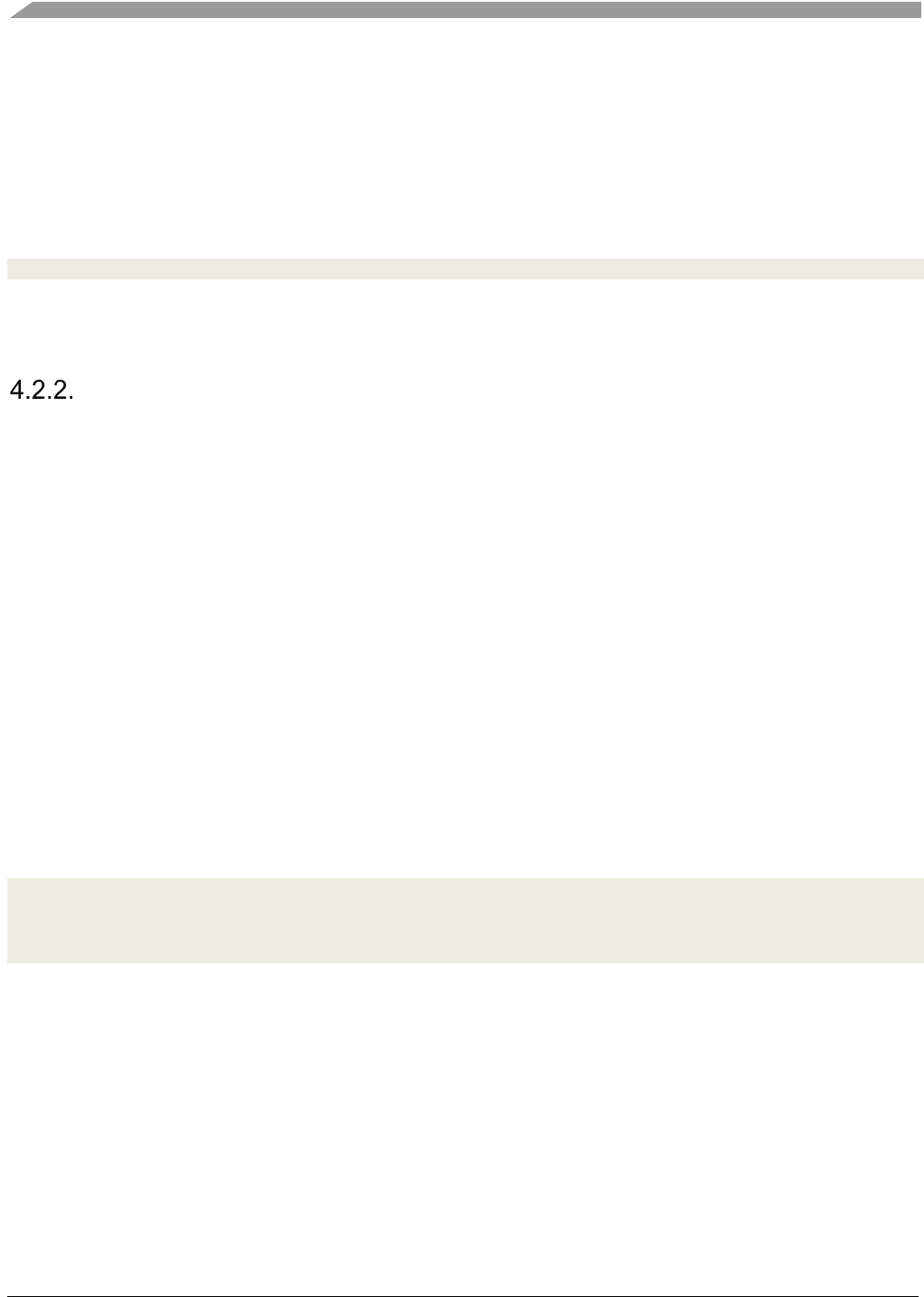
If the pairing continues, the following connection events may occur (see Figure):
• Request events
o gConnEvtPasskeyRequest_c: a PIN is required for pairing; the application must respond
with the Gap_EnterPasskey(deviceId, passkey).
o gConnEvtOobRequest_c: if the pairing started with the oobAvailable set to TRUE by both
sides; the application must respond with the Gap_ProvideOob(deviceId, oob).
o gConnEvtKeyExchangeRequest_c: the pairing has reached the key exchange phase; the
application must respond with the Gap_SendSmpKeys(deviceId, smpKeys).
o gConnEvtLeScOobDataRequest_c: the stack requests the LE SC OOB Data received
from the peer (r, Cr and Addr); the application must respond with
Gap_LeScSetPeerOobData(deviceId, leScOobData).
o gConnEvtLeScDisplayNumericValue_c: the stack requests the display and confirmation
of the LE SC Numeric Comparison Value; the application must respond with
Gap_LeScValidateNumericValue(deviceId, ncvValidated).
• Informational events
o gConnEvtKeysReceived_c: the key exchange phase is complete; keys are automatically
saved in the internal device database and are also provided to the application for
immediate inspection; application does not have to save the keys in NVM storage
because this is done internally if the withBonding was set to TRUE by both sides.
o gConnEvtAuthenticationRejected_c: the peer device rejected the pairing; the
rejectReason parameter of the event data indicates the reason that the Peripheral does not
agree with the pairing parameters (it cannot be gLinkEncryptionFailed_c because that
reason is reserved for the link encryption failure).
o gConnEvtPairingComplete_c: the pairing process is complete, either successfully, or an
error may have occurred during the SMP packet exchanges; note that this is different
from the gConnEvtKeyExchangeRequest_c event; the latter signals that the pairing was
Generic Access Profile (GAP) Layer
Bluetooth® Low Energy User’s Guide Rev. 4, 09/2016
20 NXP Semiconductors
rejected by the peer, while the former is used for failures due to the SMP packet
exchanges.
o gConnEvtLeScKeypressNotification_c: the stack informs the application that a remote
SMP Keypress Notification has been received during Passkey Entry Pairing Method.
After the link encryption or pairing is completed successfully, the Central may immediately start
exchanging data using the GATT APIs.
gConnEvtConnected_c
Gap_CheckIfBonded
YES NO
Gap_Connect
Gap_EncryptLink
Gap_Pair
+
handle
pairing
events
gConnEvtAuthentication
Rejected_c
gConnEvtEncryption
Changed_c [TRUE]
OK
Cannot
pair
gConnEvtAuthenticationRejected_c
gConnEvtPairingComplete_c
[pairingSuccessful == TRUE]
gConnEvtPairingComplete_c
[pairingSuccessful == FALSE]
gConnEvtPasskeyRequest_c
Gap_EnterPasskey
gConnEvtOobRequest_c
Gap_ProvideOob
gConnEvtKeyExchangeRequest_c
Gap_SendSmpKeys
gConnEvtKeysReceived_c
gConnEvtLeScKeypressNotification_c
/* info purposes */
gConnEvtPairingResponse_c
/* info purposes */
gConnEvtLeScOobDataRequest_c
Gap_LeScSetPeer
OobData
gConnEvtLeScDisplayNumericValue_c
Gap_LeScValidate
NumericValue
Figure 5. Central pairing flow – APIs and events
Gap_RejectPairing may be called on any pairing event
Peripheral setup
The Peripheral starts advertising and waits for scan and connection requests from other Centrals.
Advertising
Before starting advertising, the advertising parameters should be configured. Otherwise, the following
defaults are used:
#define gGapDefaultAdvertisingParameters_d \
{ \
/* minInterval */ gGapAdvertisingIntervalDefault_c, \
/* maxInterval */ gGapAdvertisingIntervalDefault_c, \

Generic Access Profile (GAP) Layer
Bluetooth® Low Energy User’s Guide Rev. 4, 09/2016
NXP Semiconductors 21
/* advertisingType */ gConnectableUndirectedAdv_c, \
/* addressType */ gBleAddrTypePublic_c, \
/* directedAddressType */ gBleAddrTypePublic_c, \
/* directedAddress */ {0, 0, 0, 0, 0, 0}, \
/* channelMap */ (gapAdvertisingChannelMapFlags_t) (gGapAdvChanMapFlag37_c |
gGapAdvChanMapFlag38_c | gGapAdvChanMapFlag39_c), \
/* filterPolicy */ gProcessAll_c \
}
To set different advertising parameters, a gapAdvertisingParameters_t structure should be allocated and
initialized with defaults. Then, the necessary fields may be modified.
After that, the following function should be called:
bleResult_t Gap_SetAdvertisingParameters
(
gapAdvertisingParameters_t* pAdvertisingParameters
);
The application should listen to the gAdvertisingParametersSetupComplete_c generic event.
Next, the advertising data should be configured and, if the advertising type supports active scanning, the
scan response data should also be configured. If either of these is not configured, they are defaulted to
empty data.
The function used to configure the advertising and/or scan response data is shown here:
bleResult_t Gap_SetAdvertisingData
(
gapAdvertisingData_t* pAdvertisingData,
gapScanResponseData_t* pScanResponseData
);
Either of the two pointers may be NULL, in which case they are ignored (the corresponding data is left
as it was previously configured, or empty if it has never been set), but not both at the same time.
The application should listen to the gAdvertisingDataSetupComplete_c generic event.
After all the necessary setup is done, advertising may be started with this function:
bleResult_t Gap_StartAdvertising
(
gapAdvertisingCallback_t advertisingCallback,
gapConnectionCallback_t connectionCallback
);
The advertisingCallback is used to receive advertising events (advertising state changed or advertising
command failed), while the connectionCallback is only used if a connection is established during
advertising.
Generic Access Profile (GAP) Layer
Bluetooth® Low Energy User’s Guide Rev. 4, 09/2016
22 NXP Semiconductors
The connection callback is the same as the callback used by the Central when calling the Gap_Connect
function.
If a Central initiates a connection to this Peripheral, the gConnEvtConnected_c connection event is
triggered.
To stop advertising while the Peripheral has not yet received any connection requests, use this function:
bleResult_t Gap_StopAdvertising(void);
This function should not be called after the Peripheral enters a connection.
Pairing and bonding
After a connection has been established to a Central, the Peripheral’s role regarding security is a passive
one. It is the Central’s responsibility to either start the pairing process or, if the devices have already
bonded in the past, to encrypt the link using the shared LTK.
If the Central attempts to access sensitive data without authenticating, the Peripheral sends error
responses (at ATT level) with proper error codes (Insufficient Authentication, Insufficient Encryption,
Insufficient Authorization, and so on), thus indicating to the Central that it needs to perform security
procedures.
All security checks are performed internally by the GAP module and the security error responses are
sent automatically. All the application developer needs to do is register the security requirements.
First, when building the GATT Database (see Chapter 6), the sensitive attributes should have the
security built into their access permissions (for example, read-only / read with authentication / write with
authentication / write with authorization, and so on.).
Second, if the GATT Database requires additional security besides that already specified in attribute
permissions (for example, certain services require higher security in certain situations), the following
function must be called:
bleResult_t Gap_RegisterDeviceSecurityRequirements
(
gapDeviceSecurityRequirements_t* pSecurity
);
The parameter is a pointer to a structure which contains a “device master security setting” and service-
specific security settings. All these security requirements are pointers to gapSecurityRequirements_t
structures. The pointers that are to be ignored should be set to NULL.
Although the Peripheral does not initiate any kind of security procedure, it can inform the Central about
its security requirements. This is usually done immediately after the connection to avoid exchanging
useless packets for requests that might be denied because of insufficient security.
The informing is performed through the Slave Security Request packet at SMP level. To use it, the
following GAP API is provided:

Generic Access Profile (GAP) Layer
Bluetooth® Low Energy User’s Guide Rev. 4, 09/2016
NXP Semiconductors 23
bleResult_t Gap_SendSlaveSecurityRequest
(
deviceId_t deviceId,
bool_t bondAfterPairing,
gapSecurityModeAndLevel_t securityModeLevel
);
The bondAfterPairing parameter indicates to the Central whether this Peripheral can bond and the
securityModeLevel informs about the required security mode and level that the Central should pair for.
See Section 4.1.3 for an explanation about security modes and levels, as defined by the GAP module.
This request expects no reply, nor any immediate action from the Central. The Central may easily
choose to ignore the Slave Security Request.
If the two devices have bonded in the past, the Peripheral should expect to receive a
gConnEvtLongTermKeyRequest_c connection event (unless LE Secure Connections Pairing was
performed, as specified in BLE 4.2), which means that the Central has also recognized the bond and,
instead of pairing, it goes directly to encrypting the link using the previously shared LTK. At this point,
the local LE Controller requests that the Host provides the same LTK it exchanged during pairing.
When the devices have been previously paired, along with the Peripheral’s LTK, the EDIV (2 bytes) and
RAND (8 bytes) values were also sent (their meaning is defined by the SMP). Therefore, before
providing the key to the Controller, the application should check that the two values match with those
received in the gConnEvtLongTermKeyRequest_c event. If they do, the application should reply with:
bleResult_t Gap_ProvideLongTermKey
(
deviceId_t deviceId,
uint8_t* aLtk,
uint8_t ltkSize
);
The LTK size cannot exceed the maximum value of 16.
If the EDIV and RAND values do not match, or if the Peripheral does not recognize the bond, it can
reject the encryption request with:
bleResult_t Gap_DenyLongTermKey
(
deviceId_t deviceId
);
If LE SC Pairing was used then the LTK is generated internally by the host stack and it is not requested
from the application during post-bonding link encryption. In this scenario, the application is only
notified of the link encryption through the gConnEvtEncryptionChanged_c connection event.
If the devices are not bonded, the Peripheral should expect to receive the gConnEvtPairingRequest_c,
indicating that the Central has initiated pairing.

Generic Access Profile (GAP) Layer
Bluetooth® Low Energy User’s Guide Rev. 4, 09/2016
24 NXP Semiconductors
If the application agrees with the pairing parameters (see Section 4.1.3 for detailed explanations), it can
reply with:
bleResult_t Gap_AcceptPairingRequest
(
deviceId_t deviceId,
gapPairingParameters_t* pPairingParameters
);
This time, the Peripheral sends its own pairing parameters, as defined by the SMP.
After sending this response, the application should expect to receive the same pairing events as the
Central (see Section 4.1.3), with one exception: the gConnEvtPasskeyRequest_c event is not called if the
application sets the Passkey (PIN) for pairing before the connection by calling the API:
bleResult_t Gap_SetLocalPasskey
(
uint32_t passkey
);
This is done because, usually, the Peripheral has a static secret PIN that it distributes only to trusted
devices. If, for any reason, the Peripheral must dynamically change the PIN, it can call the
aforementioned function every time it wants to, before the pairing starts (for example, right before
sending the pairing response with Gap_AcceptPairingRequest).
If the Peripheral application never calls Gap_SetLocalPasskey, then the gConnEvtPasskeyRequest_c
event is sent to the application as usual.
The following API can be used by the Peripheral to reject the pairing process:
bleResult_t Gap_RejectPairing
(
deviceId_t deviceId,
gapAuthenticationRejectReason_t reason
);
The reason should indicate why the application rejects the pairing. The value gLinkEncryptionFailed_c
is reserved for the gConnEvtAuthenticationRejected_c connection event to indicate the link encryption
failure rather than pairing failures. Therefore, it is not meant as a pairing reject reason.
The Gap_RejectPairing function may be called not only after the Pairing Request was received, but also
during the pairing process, when handling pairing events or asynchronously, if for any reason the
Peripheral decides to abort the pairing. This also holds true for the Central.
Generic Access Profile (GAP) Layer
Bluetooth® Low Energy User’s Guide Rev. 4, 09/2016
NXP Semiconductors 25
gConnEvtConnected_c
{ connected }
gConnEvtLongTerm
KeyRequest_c
{ advertising }
Gap_ProvideLongTermKey
gConnEvtAuthentication
Rejected_c
gConnEvtEncryption
Changed_c [TRUE]
/* info purposes */
Gap_CheckIfBonded
YES
NO
Gap_DenyLongTermKey
{ EDIV and RAND valid? }
YES
NO gConnEvtPairingRequest_c
{ pairing parameters OK? }
YES
Gap_AcceptPairing
Request
+
handle pairing
events
gConnEvtOobRequest_c
Gap_ProvideOob
gConnEvtKeyExchangeRequest_c
Gap_SendSmpKeys
gConnEvtPairingComplete_c
NO Gap_RejectPairing
{optionally}
Gap_SendSecuritySlaveRequest
gConnEvtKeysReceived_c
gConnEvtLeScKeypressNotification_c
/* info purposes */
gConnEvtLeScOobDataRequest_c
Gap_LeScSetPeer
OobData
gConnEvtLeScDisplayNumericValue_c
Gap_LeScValidate
NumericValue
Figure 6. Peripheral pairing flow – APIs and events
Gap_RejectPairing may be called on any pairing event
For both the Central and the Peripheral, bonding is performed internally and is not the application’s
concern. The application is informed about whether or not bonding occurred through the
gConnEvtPairingComplete_c event parameters.
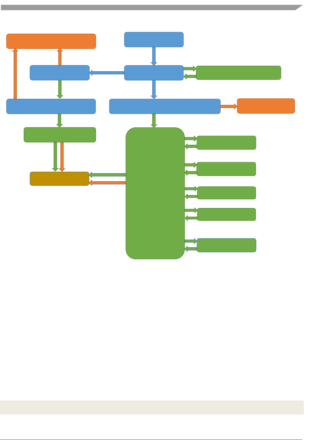
LE Data Packet Length Extension
This new feature extends the maximum data channel payload length from 27 to 251 octets.
The length management is done automatically by the link layer immediately after the connection is
established. The stack passes the default values for maximum transmission number of payload octets
and maximum packet transmission time that the application configures at compilation time in
ble_globals.c:
#ifndef gBleDefaultTxOctets_c
#define gBleDefaultTxOctets_c 0x00FB
Generic Access Profile (GAP) Layer
Bluetooth® Low Energy User’s Guide Rev. 4, 09/2016
26 NXP Semiconductors
#endif
#ifndef gBleDefaultTxTime_c
#define gBleDefaultTxTime_c 0x0848
#endif
The device can update the data length anytime, while in connection. The function that triggers this
mechanism is the following:
bleResult_t Gap_UpdateLeDataLength
(
deviceId_t deviceId,
uint16_t txOctets,
uint16_t txTime
);
After the procedure executes, a gConnEvtLeDataLengthChanged_c connection event is triggered with
the maximum values for number of payload octets and time to transmit and receive a link layer data
channel PDU. The event is send event if the remote device initiates the procedure. This procedure is
detailed below:
Figure 7. Data Length Update Procedure
Enhanced Privacy Feature
Introduction
The Bluetooth 4.2 Host Stack introduces support for the Enhanced Privacy feature.
Privacy can be enabled either in the Host or in the Controller:
2. Host Privacy consists of:
a. Periodically regenerating a random address (Resolvable or Non-Resolvable Private
Address) inside the Host and the applying it into the Controller
b. Keeping a list of peer IRKs in the Host and trying to resolve any incoming RPA
Gap_UpdateLeDataLength
gConnEvtLeDataLengthChanged c
GAP Central/Peripheral
gConnEvtLeDataLengthChanged c
GAP Central/Peripheral
LL_LENGTH_REQ
LL_LENGTH_RSP

Generic Access Profile (GAP) Layer
Bluetooth® Low Energy User’s Guide Rev. 4, 09/2016
NXP Semiconductors 27
3. Controller Privacy, introduced by Bluetooth 4.2, consists of writing the local IRK in the
Controller, together with all known peer IRKs, and letting the Controller perform hardware, fully
automatic IRK generation and resolution
Either Host Privacy or Controller Privacy can be enabled at any time. Trying to enable one while the
other is in progress generates a gBleInvalidState_c error. The same error is returned when trying to
enable the same privacy type twice, or when trying to disable privacy when it is not enabled.
Resolvable Private Addresses
A Resolvable Private Address (RPA) is a random address generated using a Identity Resolving Key
(IRK). This address appears completely random to an outside observer, so a device may periodically
regenerate its RPA to maintain privacy, as there is no correlation between any two different RPAs
generated using the same IRK.
On the other hand, an IRK can also be used to resolve an RPA, in other words, to check if this RPA has
been generated with this IRK. This process is called “resolving the identity of a device”. Whoever has
the IRK of a device can always try to resolve its identity against an RPA.
For example, let’s assume device A is frequently changing its RPA using IRKA. At some point, A bonds
with B. A must give B a way to recognize it in a subsequent connection when it (A) has a different
address. To achieve this purpose, A distributes the IRKA during the Key Distribution phase of the
pairing process. B stores the IRKA it received from A.
Later, B connects to a device X that uses RPAX. This address appears completely random, but B can try
to resolve RPAX using IRKA. If the resolving operation is successful, it means that IRKA was used to
generate RPAX, and since IRKA belongs to device A, it means that X is A. So B was able to recognize
the identity of device X, but nobody else can do that since they don’t have IRKA.
Non-Resolvable Private Addresses
A Non-Resolvable Private Address (NRPA) is a completely random address that has no generation
pattern and thus cannot be resolved by a peer.
A device that uses an NRPA that is changed frequently is impossible to track because each new address
appears to belong to a new device.
Multiple Identity Resolving Keys
If a device bonds with multiple peers, all of which are using RPAs, it needs to store the IRK of each in
order to be able to recognize them later (see previous section).
This means that whenever the device connects to a peer that uses an unknown RPA, it needs to try and
resolve the RPA with each of the stored IRKs. If the number of IRKs is large, then this introduces a lot
of computation.
Performing all these resolving operations in the Host can be costly. It is much more efficient to take
advantage of hardware acceleration and enable the Controller Privacy.

Generic Access Profile (GAP) Layer
Bluetooth® Low Energy User’s Guide Rev. 4, 09/2016
28 NXP Semiconductors
Host Privacy
To enable or disable Host Privacy, the following API may be used:
bleResult_t Gap_EnableHostPrivacy
(
bool_t enable,
uint8_t* aIrk
);
When enable is set to TRUE, the aIrk parameter defines which type of Private Address to generate. If
aIrk is NULL, then a new NRPA is generated periodically and written into the Controller. Otherwise, an
IRK is copied internally from the aIrk address and it is used to periodically generate a new RPA.
The lifetime of the Private Address (NRPA or RPA) is a number of seconds contained by the
gGapHostPrivacyTimeout external constant, which is defined in the ble_config.c source file. The default
value for this is 900 (15 minutes).
Controller Privacy
To enable or disable Controller Privacy, the following API may be used:
bleResult_t Gap_EnableControllerPrivacy
(
bool_t enable,
uint8_t* aOwnIrk,
uint8_t peerIdCount,
gapIdentityInformation_t* aPeerIdentities
);
When enable is set to TRUE, aOwnIrk parameter shall not be NULL, peerIdCount shall not be zero or
greater than gcGapControllerResolvingListSize_c, and aPeerIdentities shall not be NULL.
The IRK defined by aOwnIrk is used by the Controller to periodically generate a new RPA. The lifetime
of the RPA is a number of seconds contained by the gGapControllerPrivacyTimeout external constant,
which is defined in the ble_config.c source file. The default value for this is 900 (15 minutes).
The aPeerIdentities is an array of identity information for each bonded device. The identity information
contains the device’s identity address (public or random static address) and the device’s IRK. This array
can be obtained from the Host with the Gap_GetBondedDevicesIdentityInformation API.

Generic Access Profile (GAP) Layer
Bluetooth® Low Energy User’s Guide Rev. 4, 09/2016
NXP Semiconductors 29
Enabling Controller Privacy involves a quick sequence of commands to the Controller. When the
sequence is complete, the gControllerPrivacyStateChanged_c generic event is triggered.
Scanning & Initiating
When a Central device is scanning while Controller Privacy is enabled, the Controller actively tries to
resolve any PRA contained in the Advertising Address field of advertising packets. If any match is
found against the peer IRK list, then the advertisingAddressResolved parameter from the scanned device
structure is equal to TRUE.
In this case, the addressType and aAddress fields no longer contain the actual Advertising Address as
seen over the air, but instead they contain the identity address of the device whose IRK was able to
resolve the Advertising Address. In order to connect to this device, these fields shall be used to complete
the peerAddressType and peerAddress fields of the connection request parameter structure, and the
usePeerIdentityAddress field shall be set to TRUE.
If advertisingAddressResolved is equal to FALSE, then the advertiser is using a Public or Random Static
Address, a NRPA or a PRA that could not be resolved. Therefore, the connection to this device is
initiated as if Controller Privacy was not enabled, by setting usePeerIdentityAddress to FALSE.
Advertising
When a Peripheral starts advertising while Controller Privacy is enabled, the ownAddressType field of
the advertising parameter structure is unused. Instead, the Controller always generates an RPA and
advertises with it as Advertising Address.
Connected
When a device connects while Controller Privacy is enable, the gConnEvtConnected_c connection event
parameter structure contains more relevant fields than without Controller Privacy.
The peerRpaResolved field equals TRUE if the peer was using an RPA that was resolved using an IRK
from the list. In that case, the peerAddressType and peerAddress fields contain the identity address of
the resolved device, and the actual RPA used to create the connection (the RPA that a Central used when
initiating the connection, or the RPA that the Peripheral advertised with) is contained by the peerRpa
field.
The localRpaUsed field equals TRUE if the local Controller was automatically generating an RPA
when the connection was created, and the actual RPA is contained by the localRpa field.

Generic Attribute Profile (GATT) Layer
Bluetooth® Low Energy User’s Guide Rev. 4, 09/2016
30 NXP Semiconductors
5. Generic Attribute Profile (GATT) Layer
The GATT layer contains the APIs for discovering services and characteristics and transferring data
between devices.
The GATT layer is built on top of the Attribute Protocol (ATT), which transfers data between BLE
devices on a dedicated L2CAP channel (channel ID 0x04).
As soon as a connection is established between devices, the GATT APIs are readily available. No
initialization is required because the L2CAP channel is automatically created.
To identify the GATT peer instance, the same deviceId value from the GAP layer (obtained in the
gConnEvtConnected_c connection event) is used.
There are two GATT roles that define the two devices exchanging data over ATT:
1. GATT Server – the device that contains a GATT Database, which is a collection of services and
characteristics exposing meaningful data. Usually, the Server responds to requests and
commands sent by the Client, but it can be configured to send data on its own through
notifications and indications.
2. GATT Client – the “active” device that usually sends requests and commands to the Server to
discover Services and Characteristics on the Server’s Database and to exchange data.
There is no fixed rule deciding which device is the Client and which one is the Server. Any device may
initiate a request at any moment, thus temporarily acting as a Client, at which the peer device may
respond, provided it has the Server support and a GATT Database.
Often, a GAP Central acts as a GATT Client to discover Services and Characteristics and obtain data
from the GAP Peripheral, which usually has a GATT Database. Many standard BLE profiles assume
that the Peripheral has a database and must act as a Server. However, this is by no means a general rule.
Client APIs
A Client can configure the ATT MTU, discover Services and Characteristics, and initiate data
exchanges.
All the functions have the same first parameter: a deviceId which identifies the connected device whose
GATT Server is targeted in the GATT procedure. This is necessary because a Client may be connected
to multiple Servers at the same time.
First, however, the application must install the necessary callbacks.
Installing Client Callbacks
There are three callbacks that the Client application must install.
Generic Attribute Profile (GATT) Layer
Bluetooth® Low Energy User’s Guide Rev. 4, 09/2016
NXP Semiconductors 31
Client Procedure Callback
All the procedures initiated by a Client are asynchronous. They rely on exchanging ATT packets over
the air.
To be informed of the procedure completion, the application must install a callback with the following
signature:
typedef void (*gattClientProcedureCallback_t)
(
deviceId_t deviceId,
gattProcedureType_t procedureType,
gattProcedureResult_t procedureResult,
bleResult_t error
);
To install this callback, the following function must be called:
bleResult_t GattClient_RegisterProcedureCallback
(
gattClientProcedureCallback_t callback
);
The procedureType parameter may be used to identify the procedure that was started and has reached
completion. Only one procedure may be active at a given moment. Trying to start another procedure
while a procedure is already in progress returns the error gGattAnotherProcedureInProgress_c.
The procedureResult parameter indicates whether the procedure completes successfully or an error
occurs. In the latter case, the error parameter contains the error code.
void gattClientProcedureCallback
(
deviceId_t deviceId,
gattProcedureType_t procedureType,
gattProcedureResult_t procedureResult,
bleResult_t error
)
{
switch (procedureType)
{
/* ... */
}
}
GattClient_RegisterProcedureCallback(gattClientProcedureCallback);
Generic Attribute Profile (GATT) Layer
Bluetooth® Low Energy User’s Guide Rev. 4, 09/2016
32 NXP Semiconductors
Notification and Indication Callbacks
When the Client receives a notification from the Server, it triggers a callback with the following
prototype:
typedef void (*gattClientNotificationCallback_t)
(
deviceId_t deviceId,
uint16_t characteristicValueHandle,
uint8_t* aValue,
uint16_t valueLength
);
The deviceId identifies the Server connection (for multiple connections at the same time). The
characteristicValueHandle is the attribute handle of the Characteristic Value declaration in the GATT
Database. The Client must have discovered it previously to be able recognize it.
The callback must be installed with:
bleResult_t GattClient_RegisterNotificationCallback
(
gattClientNotificationCallback_t callback
);
Very similar definitions exist for indications.
When receiving a notification or indication, the Client uses the characteristicValueHandle to identify
which Characteristic was notified. The Client must be aware of the possible Characteristic Value
handles that can be notified/indicated at any time, because it has previously activated them by writing its
CCCD (see Section 5.1.5).
MTU Exchange
A radio packet sent over the BLE contains a maximum of 27 bytes of data for the L2CAP layer. Because
the L2CAP header is 4 bytes long (including the Channel ID), all layers above L2CAP, including ATT
and GATT, may only send 23 bytes of data in a radio packet (as per Bluetooth 4.1 Specification for
Bluetooth Low Energy).
Note
This number is fixed and cannot be increased in BLE 4.1.
To maintain a logical mapping between radio packets and ATT packets, the Standard has set the default
length of an ATT packet (the so-called ATT_MTU) also equal to 23. Thus, any ATT request fits in a
single radio packet. If the layer above ATT wishes to send more than 23 bytes of data, it needs to
fragment the data into smaller packets and issue multiple ATT requests.
However, the ATT protocol allows devices to increase the ATT_MTU, only if both can support it.
Increasing the ATT_MTU has only one effect: the application does not have to fragment long data,

Generic Attribute Profile (GATT) Layer
Bluetooth® Low Energy User’s Guide Rev. 4, 09/2016
NXP Semiconductors 33
however it can send more than 23 bytes in a single transaction. The fragmentation is moved on to the
L2CAP layer. Over the air though, there would still be more than one radio packet sent.
If the GATT Client supports a larger than default MTU, it should start an MTU exchange as soon as it
connects to any Server. During the MTU exchange, both devices would send their maximum MTU to
the other, and the minimum of the two is chosen as the new MTU.
For example, if the Client supports a maximum ATT_MTU of 250, and the Server supports maximum
120, after the exchange, both devices set the new ATT_MTU value equal to 120.
To initiate the MTU exchange, call the following function from gatt_client_interface.h:
bleResult_t result = GattClient_ExchangeMtu(deviceId);
if (gBleSuccess_c != result)
{
/* Treat error */
}
The value of the maximum supported ATT_MTU of the local device does not have to be included in the
request because it is static. It is defined in the ble_constants.h file under the name gAttMaxMtu_c. Inside
the GATT implementation, the ATT Exchange MTU Request (and Response, for Servers) uses that
value.
When the exchange is complete, the Client callback is triggered by the gGattProcExchangeMtu_c
procedure type.
void gattClientProcedureCallback
(
deviceId_t deviceId,
gattProcedureType_t procedureType,
gattProcedureResult_t procedureResult,
bleResult_t error
)
{
switch (procedureType)
{
/* ... */
case gGattProcExchangeMtu_c:
if (gGattProcSuccess_c == procedureResult)
{
/* To obtain the new MTU */
uint16_t newMtu;
bleResult_t result = Gatt_GetMtu(deviceId, &newMtu);
if (gBleSuccess_c == result)
{
/* Use the value of the new MTU */
(void) newMtu;
}
}
else
Generic Attribute Profile (GATT) Layer
Bluetooth® Low Energy User’s Guide Rev. 4, 09/2016
34 NXP Semiconductors
{
/* Handle error */
}
break;
/* ... */
}
}
Service and Characteristic Discovery
There are multiple APIs that can be used for Discovery. The application may use any of them, according
to its necessities.
Discover all Primary Services
The following API can be used to discover all the Primary Services in a Server’s database:
bleResult_t GattClient_DiscoverAllPrimaryServices
(
deviceId_t deviceId,
gattService_t* aOutPrimaryServices,
uint8_t maxServiceCount,
uint8_t* pOutDiscoveredCount
);
The aOutPrimaryServices parameter must point to an allocated array of services. The size of the array
must be equal to the value of the maxServiceCount parameter, which is passed to make sure the GATT
module does not attempt to write past the end of the array if more Services are discovered than expected.
The pOutDiscoveredCount parameter must point to a static variable because the GATT module uses it to
write the number of Services discovered at the end of the procedure. This number is less than or equal to
the maxServiceCount.
If there is equality, it is possible that the Server contains more than maxServiceCount Services, but they
could not be discovered as a result of the array size limitation. It is the application developer’s
responsibility to allocate a large enough number according to the expected contents of the Server’s
database.
In the following example, the application expects to find no more than 10 Services on the Server.
#define mcMaxPrimaryServices_c 10
static gattService_t primaryServices[mcMaxPrimaryServices_c];
uint8_t mcPrimaryServices;
bleResult_t result = GattClient_DiscoverAllPrimaryServices
(
deviceId,
primaryServices,

Generic Attribute Profile (GATT) Layer
Bluetooth® Low Energy User’s Guide Rev. 4, 09/2016
NXP Semiconductors 35
mcMaxPrimaryServices_c,
&mcPrimaryServices
);
if (gBleSuccess_c != result)
{
/* Treat error */
}
The operation triggers the Client Procedure Callback when complete. The application may read the
number of discovered services and each service’s handle range and UUID.
void gattClientProcedureCallback
(
deviceId_t deviceId,
gattProcedureType_t procedureType,
gattProcedureResult_t procedureResult,
bleResult_t error
)
{
switch (procedureType)
{
/* ... */
case gGattProcDiscoverAllPrimaryServices_c:
if (gGattProcSuccess_c == procedureResult)
{
/* Read number of discovered services */
PRINT( mcPrimaryServices );
/* Read each service's handle range and UUID */
for (int j = 0; j < mcPrimaryServices; j++)
{
PRINT( primaryServices[j].startHandle );
PRINT( primaryServices[j].endHandle );
PRINT( primaryServices[j].uuidType );
PRINT( primaryServices[j].uuid );
}
}
else
{
/* Handle error */
PRINT( error );
}
break;
/* ... */
}
}
Discover Primary Services by UUID
To discover only Primary Services of a known type (Service UUID), the following API can be used:

Generic Attribute Profile (GATT) Layer
Bluetooth® Low Energy User’s Guide Rev. 4, 09/2016
36 NXP Semiconductors
bleResult_t GattClient_DiscoverPrimaryServicesByUuid
(
deviceId_t deviceId,
bleUuidType_t uuidType,
bleUuid_t* pUuid,
gattService_t* aOutPrimaryServices,
uint8_t maxServiceCount,
uint8_t* pOutDiscoveredCount
);
The procedure is very similar to the one described in Section 5.1.3.1. The only difference is this time we
are filtering the search according to a Service UUID described by two extra parameters: pUuid and
uuidType.
This procedure is useful when the Client is only interested in a specific type of Services. Usually, it is
performed on Servers that are known to contain a certain Service, which is specific to a certain profile.
Therefore most of the times the search is expected to find a single Service of the given type. As a result,
only one structure is usually allocated.
For example, when two devices implement the Heart Rate (HR) Profile, an HR Collector connects to an
HR Sensor and may only be interested in discovering the Heart Rate Service (HRS) to work with its
Characteristics. The following code example shows how to achieve this. Standard values for Service and
Characteristic UUIDs, as defined by the Bluetooth SIG, are located in the ble_sig_defines.h file.
static gattService_t heartRateService;
static uint8_t mcHrs;
bleResult_t result = GattClient_DiscoverPrimaryServicesByUuid
(
deviceId,
gBleUuidType16_c, /* Service UUID type */
gBleSig_HeartRateService_d, /* Service UUID */
&heartRateService, /* Only one HRS is expected to be found */
1,
&mcHrs /* Will be equal to 1 at the end of the procedure
if the HRS is found, 0 otherwise */
);
if (gBleSuccess_c != result)
{
/* Treat error */
}
In the Client Procedure Callback, the application should check if any Service with the given UUID was
found and read its handle range (also perhaps proceed with Characteristic Discovery within that service
range).
Generic Attribute Profile (GATT) Layer
Bluetooth® Low Energy User’s Guide Rev. 4, 09/2016
NXP Semiconductors 37
void gattClientProcedureCallback
(
deviceId_t deviceId,
gattProcedureType_t procedureType,
gattProcedureResult_t procedureResult,
bleResult_t error
)
{
switch (procedureType)
{
/* ... */
case gGattProcDiscoverPrimaryServicesByUuid_c:
if (gGattProcSuccess_c == procedureResult)
{
if (1 == mcHrs)
{
/* HRS found, read the handle range */
PRINT( heartRateService.startHandle );
PRINT( heartRateService.endHandle );
}
else
{
/* HRS not found! */
}
}
else
{
/* Handle error */
PRINT( error );
}
break;
/* ... */
}
}
Discover Included Services
Section 5.1.3.1 shows how to discover Primary Services. However, a Server may also contain Secondary
Services, which are not meant to be used standalone and are usually included in the Primary Services.
The inclusion means that all the Secondary Service’s Characteristics may be used by the profile that
requires the Primary Service.
Therefore, after a Primary Service has been discovered, the following procedure may be used to
discover services (usually Secondary Services) included in it:
bleResult_t GattClient_FindIncludedServices
(
deviceId_t deviceId,
gattService_t* pIoService,
uint8_t maxServiceCount
);

Generic Attribute Profile (GATT) Layer
Bluetooth® Low Energy User’s Guide Rev. 4, 09/2016
38 NXP Semiconductors
The service structure that pIoService points to must have the aIncludedServices field linked to an
allocated array of services, of size maxServiceCount, chosen according to the expected number of
included services to be found. This is the application’s choice, usually following profile specifications.
Also, the service’s range must be set (the startHandle and endHandle fields), which may have already
been done by the previous Service Discovery procedure (as described in Sections 5.1.3.1 and 5.1.3.2).
The number of discovered included services is written by the GATT module in the
cNumIncludedServices field of the structure from pIoService. Obviously, a maximum of
maxServiceCount included services is discovered.
The following example assumes the Heart Rate Service was discovered using the code provided in
Section 5.1.3.2.
/* Finding services included in the Heart Rate Primary Service */
gattService_t* pPrimaryService = &heartRateService;
#define mxMaxIncludedServices_c 3
static gattService_t includedServices[mxMaxIncludedServices_c];
/* Linking the array */
pPrimaryService->aIncludedServices = includedServices;
bleResult_t result = GattClient_FindIncludedServices
(
deviceId,
pPrimaryService,
mxMaxIncludedServices_c
);
if (gBleSuccess_c != result)
{
/* Treat error */
}
When the Client Procedure Callback is triggered, if any included services are found, the application can
read their handle range and their UUIDs.
void gattClientProcedureCallback
(
deviceId_t deviceId,
gattProcedureType_t procedureType,
gattProcedureResult_t procedureResult,
bleResult_t error
)
{
switch (procedureType)
{
/* ... */
case gGattProcFindIncludedServices_c:
Generic Attribute Profile (GATT) Layer
Bluetooth® Low Energy User’s Guide Rev. 4, 09/2016
NXP Semiconductors 39
if (gGattProcSuccess_c == procedureResult)
{
/* Read included services data */
PRINT( pPrimaryService->cNumIncludedServices );
for (int j = 0; j < pPrimaryService->cNumIncludedServices; j++)
{
PRINT( pPrimaryService->aIncludedServices[j].startHandle );
PRINT( pPrimaryService->aIncludedServices[j].endHandle );
PRINT( pPrimaryService->aIncludedServices[j].uuidType );
PRINT( pPrimaryService->aIncludedServices[j].uuid );
}
}
else
{
/* Handle error */
PRINT( error );
}
break;
/* ... */
}
}
Discover all Characteristics of a Service
The main API for Characteristic Discovery has the following prototype:
bleResult_t GattClient_DiscoverAllCharacteristicsOfService
(
deviceId_t deviceId,
gattService_t* pIoService,
uint8_t maxCharacteristicCount
);
All required information is contained in the service structure pointed to by pIoService, most importantly
being the service range (startHandle and endHandle) which is usually already filled out by a Service
Discovery procedure. If not, they need to be written manually.
Also, the service structure’s aCharacteristics field must be linked to an allocated characteristic array.
The following example discovers all Characteristics contained in the Heart Rate Service discovered in
Section 5.1.3.2.
gattService_t* pService = &heartRateService;
#define mcMaxCharacteristics_c 10
static gattCharacteristic_t hrsCharacteristics[mcMaxCharacteristics_c];
pService->aCharacteristics = hrsCharacteristics;
bleResult_t result = GattClient_DiscoverAllCharacteristicsOfService
(

Generic Attribute Profile (GATT) Layer
Bluetooth® Low Energy User’s Guide Rev. 4, 09/2016
40 NXP Semiconductors
deviceId,
pService,
mcMaxCharacteristics_c
);
The Client Procedure Callback is triggered when the procedure completes.
void gattClientProcedureCallback
(
deviceId_t deviceId,
gattProcedureType_t procedureType,
gattProcedureResult_t procedureResult,
bleResult_t error
)
{
switch (procedureType)
{
/* ... */
case gGattProcDiscoverAllCharacteristics_c:
if (gGattProcSuccess_c == procedureResult)
{
/* Read number of discovered Characteristics */
PRINT(pService->cNumCharacteristics);
/* Read discovered Characteristics data */
for (uint8_t j = 0; j < pService->cNumCharacteristics; j++)
{
/* Characteristic UUID is found inside the value field
* to avoid duplication */
PRINT(pService->aCharacteristics[j].value.uuidType);
PRINT(pService->aCharacteristics[j].value.uuid);
/* Characteristic Properties indicating the supported operations:
* - Read
* - Write
* - Write Without Response
* - Notify
* - Indicate
*/
PRINT(pService->aCharacteristics[j].properties);
/* Characteristic Value Handle - used to identify
* the Characteristic in future operations */
PRINT(pService->aCharacteristics[j].value.handle);
}
}
else
{
/* Handle error */
PRINT( error );
}
break;
/* ... */

Generic Attribute Profile (GATT) Layer
Bluetooth® Low Energy User’s Guide Rev. 4, 09/2016
NXP Semiconductors 41
}
}
Discover Characteristics by UUID
This procedure is useful when the Client intends to discover a specific Characteristic in a specific
Service. The API allows for multiple Characteristics of the same type to be discovered, but most often it
is used when a single Characteristic of the given type is expected to be found.
Continuing the example from the 5.1.3.2 Section, let’s assume the Client wants to discover the Heart
Rate Control Point Characteristic inside the Heart Rate Service, as shown in the following code.
gattService_t* pService = &heartRateService;
static gattCharacteristic_t hrcpCharacteristic;
static uint8_t mcHrcpChar;
bleResult_t result = GattClient_DiscoverCharacteristicOfServiceByUuid
(
deviceId,
gBleUuidType16_c,
gBleSig_HrControlPoint_d,
pService,
&hrcpCharacteristic,
1,
&mcHrcpChar
);
This API can be used as in the previous examples, in other words, following a Service Discovery
procedure. However, the user may want to perform a Characteristic search with UUID over the entire
database, skipping the Service Discovery entirely. To do so, a dummy service structure must be defined
and its range must be set to maximum, as shown in the following example:
gattService_t dummyService;
dummyService.startHandle = 0x0001;
dummyService.endHandle = 0xFFFF;
static gattCharacteristic_t hrcpCharacteristic;
static uint8_t mcHrcpChar;
bleResult_t result = GattClient_DiscoverCharacteristicOfServiceByUuid
(
deviceId,
gBleUuidType16_c,
gBleSig_HrControlPoint_d,
&dummyService,
&hrcpCharacteristic,
1,
&mcHrcpChar
);

Generic Attribute Profile (GATT) Layer
Bluetooth® Low Energy User’s Guide Rev. 4, 09/2016
42 NXP Semiconductors
In either case, the value of the mcHrcpChar variable should be checked in the procedure callback.
void gattClientProcedureCallback
(
deviceId_t deviceId,
gattProcedureType_t procedureType,
gattProcedureResult_t procedureResult,
bleResult_t error
)
{
switch (procedureType)
{
/* ... */
case gGattProcDiscoverCharacteristicByUuid_c:
if (gGattProcSuccess_c == procedureResult)
{
if (1 == mcHrcpChar)
{
/* HRCP found, read discovered data */
PRINT(hrcpCharacteristic.properties);
PRINT(hrcpCharacteristic.value.handle);
}
else
{
/* HRCP not found! */
}
}
else
{
/* Handle error */
PRINT(error);
}
break;
/* ... */
}
}
Discover Characteristic Descriptors
To discover all descriptors of a Characteristic, the following API is provided:
bleResult_t GattClient_DiscoverAllCharacteristicDescriptors
(
deviceId_t deviceId,
gattCharacteristic_t* pIoCharacteristic,
uint16_t endingHandle,
uint8_t maxDescriptorCount
);

Generic Attribute Profile (GATT) Layer
Bluetooth® Low Energy User’s Guide Rev. 4, 09/2016
NXP Semiconductors 43
The pIoCharacteristic pointer must point to a Characteristic structure with the value.handle field set
(either by a discovery operation or by the application) and the aDescriptors field pointed to an allocated
array of Descriptor structures.
The endingHandle should be set to the handle of the next Characteristic or Service declaration in the
database to indicate when the search for descriptors must stop. The GATT Client module uses ATT Find
Information Requests to discover the descriptors, and it does so until it discovers a Characteristic or
Service declaration or until endingHandle is reached. Thus, by providing a correct ending handle, the
search for descriptors is optimized, sparing unnecessary extra air packets.
If, however, the application does not know where the next declaration lies and cannot provide this
optimization hint, the endingHandle should be set to 0xFFFF.
Continuing the example from Section 5.1.3.5, the following code assumes that the Heart Rate Control
Point Characteristic has no more than 5 descriptors and performs Descriptor Discovery.
#define mcMaxDescriptors_c 5
static gattAttribute_t aDescriptors[mcMaxDescriptors_c];
hrcpCharacteristic.aDescriptors = aDescriptors;
bleResult_t result = GattClient_DiscoverAllCharacteristicDescriptors
(
deviceId,
&hrcpCharacteristic,
0xFFFF, /* We don’t know where the next Characterstic/Service begins */
mcMaxDescriptors_c
);
if (gBleSuccess_c != result)
{
/* Handle error */
}
The Client Procedure Callback is triggered at the end of the procedure.
void gattClientProcedureCallback
(
deviceId_t deviceId,
gattProcedureType_t procedureType,
gattProcedureResult_t procedureResult,
bleResult_t error
)
{
switch (procedureType)
{
/* ... */
case gGattProcDiscoverAllCharacteristicDescriptors_c:
if (gGattProcSuccess_c == procedureResult)
{
/* Read number of discovered descriptors */
PRINT(hrcpCharacteristic.cNumDescriptors);
/* Read descriptor data */

Generic Attribute Profile (GATT) Layer
Bluetooth® Low Energy User’s Guide Rev. 4, 09/2016
44 NXP Semiconductors
for (uint8_t j = 0; j < hrcpCharacteristic.cNumDescriptors; j++)
{
PRINT(hrcpCharacteristic.aDescriptors[j].handle);
PRINT(hrcpCharacteristic.aDescriptors[j].uuidType);
PRINT(hrcpCharacteristic.aDescriptors[j].uuid);
}
}
else
{
/* Handle error */
PRINT(error);
}
break;
/* ... */
}
}
Reading and Writing Characteristics
Characteristic Value Read Procedure
The main API for reading a Characteristic Value is shown here:
bleResult_t GattClient_ReadCharacteristicValue
(
deviceId_t deviceId,
gattCharacteristic_t* pIoCharacteristic,
uint16_t maxReadBytes
);
This procedure assumes that the application knows the Characteristic Value Handle, usually from a
previous Characteristic Discovery procedure. Therefore, the value.handle field of the structure pointed
by pIoCharacteristic must be completed.
Also, the application must allocate a large enough array of bytes where the received value (from the
ATT packet exchange) is written. The maxReadBytes parameter is set to the size of this allocated array.
The GATT Client module takes care of long characteristics, whose values have a greater length than can
fit in a single ATT packet, transparently by issuing repeated ATT Read Blob Requests when needed.
The following examples assume that the application knows the Characteristic Value Handle and that the
value length is variable, but limited to 50 bytes.
gattCharacteristic_t myCharacteristic;
myCharacteristic.value.handle = 0x10AB;
#define mcMaxValueLength_c 50
static uint8_t aValue[mcMaxValueLength_c];

Generic Attribute Profile (GATT) Layer
Bluetooth® Low Energy User’s Guide Rev. 4, 09/2016
NXP Semiconductors 45
myCharacteristic.value.paValue = aValue;
bleResult_t result = GattClient_ReadCharacteristicValue
(
deviceId,
&myCharacteristic,
mcMaxValueLength_c
);
if (gBleSuccess_c != result)
{
/* Handle error */
}
Regardless of the value length, the Client Procedure Callback is triggered when the reading is complete.
The received value length is also filled in the value structure.
void gattClientProcedureCallback
(
deviceId_t deviceId,
gattProcedureType_t procedureType,
gattProcedureResult_t procedureResult,
bleResult_t error
)
{
switch (procedureType)
{
/* ... */
case gGattProcReadCharacteristicValue_c:
if (gGattProcSuccess_c == procedureResult)
{
/* Read value length */
PRINT(myCharacteristic.value.valueLength);
/* Read data */
for (uint16_t j = 0; j < myCharacteristic.value.valueLength; j++)
{
PRINT(myCharacteristic.value.paValue[j]);
}
}
else
{
/* Handle error */
PRINT(error);
}
break;
/* ... */
}
}

Generic Attribute Profile (GATT) Layer
Bluetooth® Low Energy User’s Guide Rev. 4, 09/2016
46 NXP Semiconductors
Characteristic Read By UUID Procedure
This API for this procedure is shown here:
bleResult_t GattClient_ReadUsingCharacteristicUuid
(
deviceId_t deviceId,
bleUuidType_t uuidType,
bleUuid_t* pUuid,
uint8_t* aOutBuffer,
uint16_t maxReadBytes,
uint16_t* pOutActualReadBytes
);
This provides support for an important optimization, which involves reading a Characteristic Value
without performing any Service or Characteristic Discovery.
For example, the following is the process to write an application that connects to any Server and wants
to read the device name.
The device name is contained in the Device Name Characteristic from the GAP Service. Therefore, the
necessary steps involve discovering all primary services, identifying the GAP Service by its UUID,
discovering all Characteristics of the GAP Service and identifying the Device Name Characteristic
(alternatively, discovering Characteristic by UUID inside GAP Service), and, finally, reading the device
name by using the Characteristic Read Procedure.
Instead, the Characteristic Read by UUID Procedure allows reading a Characteristic with a specified
UUID, assuming one exists on the Server, without knowing the Characteristic Value Handle.
The described example is implemented as follows:
#define mcMaxValueLength_c 20
static uint8_t aValue[2 + mcMaxValueLength_c]; //First 2 bytes are the handle
static uint16_t deviceNameLength;
bleUuid_t uuid = {
.uuid16 = gBleSig_GapDeviceName_d
};
bleResult_t result = GattClient_ReadUsingCharacteristicUuid
(
deviceId,
gBleUuidType16_c,
&uuid,
aValue,
mcMaxValueLength_c,
&deviceNameLength
);
if (gBleSuccess_c != result)
{
/* Handle error */

Generic Attribute Profile (GATT) Layer
Bluetooth® Low Energy User’s Guide Rev. 4, 09/2016
NXP Semiconductors 47
}
The Client Procedure Callback is triggered when the reading is complete. Because only one air packet is
exchanged during this procedure, it can only be used as a quick reading of Characteristic Values with
length no greater than ATT_MTU – 1.
void gattClientProcedureCallback
(
deviceId_t deviceId,
gattProcedureType_t procedureType,
gattProcedureResult_t procedureResult,
bleResult_t error
)
{
switch (procedureType)
{
/* ... */
case gGattProcReadUsingCharacteristicUuid_c:
if (gGattProcSuccess_c == procedureResult)
{
/* Read characteristic value handle */
PRINT(aValue[0] | (aValue[1] << 8));
deviceNameLength -= 2;
/* Read value length */
PRINT(deviceNameLength);
/* Read data */
for (uint8_t j = 0; j < deviceNameLength; j++)
{
PRINT(aValue[2 + j]);
}
}
else
{
/* Handle error */
PRINT(error);
}
break;
/* ... */
}
}
Characteristic Read Multiple Procedure
The API for this procedure is shown here:
bleResult_t GattClient_ReadMultipleCharacteristicValues
(
deviceId_t deviceId,

Generic Attribute Profile (GATT) Layer
Bluetooth® Low Energy User’s Guide Rev. 4, 09/2016
48 NXP Semiconductors
uint8_t cNumCharacteristics,
gattCharacteristic_t* aIoCharacteristics
);
This procedure also allows an optimization for a specific situation, which occurs when multiple
Characteristics, whose values are of known, fixed-length, can be all read in one single ATT transaction
(usually one single over-the-air packet).
The application must know the value handle and value length of each Characteristic. It must also write
the value.handle and value.maxValueLength with the aforementioned values, respectively, and then link
the value.paValue field with an allocated array of size maxValueLength.
The following example involves reading three characteristics in a single packet.
#define mcNumCharacteristics_c 3
#define mcChar1Length_c 4
#define mcChar2Length_c 5
#define mcChar3Length_c 6
static uint8_t aValue1[mcChar1Length_c];
static uint8_t aValue2[mcChar2Length_c];
static uint8_t aValue3[mcChar3Length_c];
static gattCharacteristic_t myChars[mcNumCharacteristics_c];
myChars[0].value.handle = 0x0015;
myChars[1].value.handle = 0x0025;
myChars[2].value.handle = 0x0035;
myChars[0].value.maxValueLength = mcChar1Length_c;
myChars[1].value.maxValueLength = mcChar2Length_c;
myChars[2].value.maxValueLength = mcChar3Length_c;
myChars[0].value.paValue = aValue1;
myChars[1].value.paValue = aValue2;
myChars[2].value.paValue = aValue3;
bleResult_t result = GattClient_ReadMultipleCharacteristicValues
(
deviceId,
mcNumCharacteristics_c,
myChars
);
if (gBleSuccess_c != result)
{
/* Handle error */
}
When the Client Procedure Callback is triggered, if no error occurs, each Characteristic’s value length
should be equal to the requested lengths.

Generic Attribute Profile (GATT) Layer
Bluetooth® Low Energy User’s Guide Rev. 4, 09/2016
NXP Semiconductors 49
void gattClientProcedureCallback
(
deviceId_t deviceId,
gattProcedureType_t procedureType,
gattProcedureResult_t procedureResult,
bleResult_t error
)
{
switch (procedureType)
{
/* ... */
case gGattProcReadMultipleCharacteristicValues_c:
if (gGattProcSuccess_c == procedureResult)
{
for (uint8_t i = 0; i < mcNumCharacteristics_c; i++)
{
/* Read value length */
PRINT(myChars[i].value.valueLength);
/* Read data */
for (uint8_t j = 0; j < myChars[i].value.valueLength; j++)
{
PRINT(myChars[i].value.paValue[j]);
}
}
}
else
{
/* Handle error */
PRINT(error);
}
break;
/* ... */
}
}
Characteristic Write Procedure
There is a general API that may be used for writing Characteristic Values:
bleResult_t GattClient_WriteCharacteristicValue
(
deviceId_t deviceId,
gattCharacteristic_t* pCharacteristic,
uint16_t valueLength,
uint8_t* aValue,
bool_t withoutResponse,
bool_t signedWrite,
bool_t doReliableLongCharWrites,
uint8_t* aCsrk
);

Generic Attribute Profile (GATT) Layer
Bluetooth® Low Energy User’s Guide Rev. 4, 09/2016
50 NXP Semiconductors
It has many parameters to support different combinations of Characteristic Write Procedures.
The structure pointed to by the pCharacteristic is only used for the value.handle field which indicates
the Characteristic Value Handle. The value to be written is contained in the aValue array of size
valueLength.
The withoutResponse parameter can be set to TRUE if the application wishes to perform a Write
Without Response Procedure, which translates into an ATT Write Command. If this value is selected,
the signedWrite parameter indicates whether data should be signed (Signed Write Procedure over ATT
Signed Write Command), in which case the aCsrk parameters must not be NULL and contains the
CSRK to sign the data with. Otherwise, both signedWrite and aCsrk are ignored.
Finally, doReliableLongCharWrites should be sent to TRUE if the application is writing a long
Characteristic Value (one that requires multiple air packets due to ATT_MTU limitations) and wants the
Server to confirm each part of the attribute that is sent over the air.
To simplify the application code, the following macros are defined:
#define GattClient_SimpleCharacteristicWrite(deviceId, pChar, valueLength, aValue) \
GattClient_WriteCharacteristicValue\
(deviceId, pChar, valueLength, aValue, FALSE, FALSE, FALSE, NULL)
This is the simplest usage for writing a Characteristic. It sends an ATT Write Request if the value length
does not exceed the maximum space for an over-the-air packet (ATT_MTU – 3). Otherwise, it sends
ATT Prepare Write Requests with parts of the attribute, without checking the ATT Prepare Write
Response data for consistency, and in the end an ATT Execute Write Request.
#define GattClient_CharacteristicWriteWithoutResponse(deviceId, pChar, valueLength, aValue)
\
GattClient_WriteCharacteristicValue\
(deviceId, pChar, valueLength, aValue, TRUE, FALSE, FALSE, NULL)
This usage sends an ATT Write Command. Long Characteristic values are not allowed here and trigger
a gBleInvalidParameter_c error.
#define GattClient_CharacteristicSignedWrite(deviceId, pChar, valueLength, aValue, aCsrk) \
GattClient_WriteCharacteristicValue\
(deviceId, pChar, valueLength, aValue, TRUE, TRUE, FALSE, aCsrk)
This usage sends an ATT Signed Write Command. The CSRK used to sign data must be provided.
This is a short example to write a 3-byte long Characteristic Value.
gattCharacteristic_t myChar;
myChar.value.handle = 0x00A0; /* Or maybe it was previously discovered? */
#define mcValueLength_c 3
uint8_t aValue[mcValueLength_c] = { 0x01, 0x02, 0x03 };

Generic Attribute Profile (GATT) Layer
Bluetooth® Low Energy User’s Guide Rev. 4, 09/2016
NXP Semiconductors 51
bleResult_t result = GattClient_SimpleCharacteristicWrite
(
deviceId,
&myChar,
mcValueLength_c,
aValue
);
if (gBleSuccess_c != result)
{
/* Handle error */
}
The Client Procedure Callback is triggered when writing is complete.
void gattClientProcedureCallback
(
deviceId_t deviceId,
gattProcedureType_t procedureType,
gattProcedureResult_t procedureResult,
bleResult_t error
)
{
switch (procedureType)
{
/* ... */
case gGattProcWriteCharacteristicValue_c:
if (gGattProcSuccess_c == procedureResult)
{
/* Continue */
}
else
{
/* Handle error */
PRINT(error);
}
break;
/* ... */
}
}
Reading and Writing Characteristic Descriptors
Two APIs are provided for these procedures which are very similar to Characteristic Read and Write.
The only difference is that the handle of the attribute to be read/written is provided through a pointer to
an gattAttribute_t structure (same type as the gattCharacteristic_t.value field).

Generic Attribute Profile (GATT) Layer
Bluetooth® Low Energy User’s Guide Rev. 4, 09/2016
52 NXP Semiconductors
bleResult_t GattClient_ReadCharacteristicDescriptor
(
deviceId_t deviceId,
gattAttribute_t* pIoDescriptor,
uint16_t maxReadBytes
);
The pIoDescriptor->handle is required (it may have been discovered previously by
GattClient_DiscoverAllCharacteristicDescriptors). The GATT module fills the value that was read in
the fields pIoDescriptor->aValue (must be linked to an allocated array) and pIoDescriptor-
>valueLength (size of the array).
Writing a descriptor is also performed similarly with this function:
bleResult_t GattClient_WriteCharacteristicDescriptor
(
deviceId_t deviceId,
gattAttribute_t* pDescriptor,
uint16_t valueLength,
uint8_t* aValue
);
Only the pDescriptor->handle must be filled before calling the function.
One of the most frequently written descriptors is the Client Characteristic Configuration Descriptor
(CCCD). It has a well-defined UUID (gBleSig_CCCD_d) and a 2-byte long value that can be written to
enable/disable notifications and/or indications.
In the following example, a Characteristic’s descriptors are discovered and its CCCD written to activate
notifications.
static gattCharacteristic_t myChar;
myChar.value.handle = 0x00A0; /* Or maybe it was previously discovered? */
#define mcMaxDescriptors_c 5
static gattAttribute_t aDescriptors[mcMaxDescriptors_c];
myChar.aDescriptors = aDescriptors;
/* ... */
{
bleResult_t result = GattClient_DiscoverAllCharacteristicDescriptors
(
deviceId,
&myChar,
0xFFFF,
mcMaxDescriptors_c
);
if (gBleSuccess_c != result)
{

Generic Attribute Profile (GATT) Layer
Bluetooth® Low Energy User’s Guide Rev. 4, 09/2016
NXP Semiconductors 53
/* Handle error */
}
}
/* ... */
void gattClientProcedureCallback
(
deviceId_t deviceId,
gattProcedureType_t procedureType,
gattProcedureResult_t procedureResult,
bleResult_t error
)
{
switch (procedureType)
{
/* ... */
case gGattProcDiscoverAllCharacteristicDescriptors_c:
if (gGattProcSuccess_c == procedureResult)
{
/* Find CCCD */
for (uint8_t j = 0; j < myChar.cNumDescriptors; j++)
{
if (gBleUuidType16_c == myChar.aDescriptors[j].uuidType
&& gBleSig_CCCD_d == myChar.aDescriptors[j].uuid.uuid16)
{
uint8_t cccdValue[2];
packTwoByteValue(gCccdNotification_c, cccdValue);
bleResult_t result = GattClient_WriteCharacteristicDescriptor
(
deviceId,
&myChar.aDescriptors[j],
2,
cccdValue
);
if (gBleSuccess_c != result)
{
/* Handle error */
}
break;
}
}
}
else
{
/* Handle error */
PRINT(error);
}
break;
case gGattProcWriteCharacteristicDescriptor_c:
if (gGattProcSuccess_c == procedureResult)
{
/* Notification successfully activated */

Generic Attribute Profile (GATT) Layer
Bluetooth® Low Energy User’s Guide Rev. 4, 09/2016
54 NXP Semiconductors
}
else
{
/* Handle error */
PRINT(error);
}
/* ... */
}
}
Resetting procedures
To cancel an ongoing Client Procedure, the following API can be called:
bleResult_t GattClient_ResetProcedure(void);
It resets the internal state of the GATT Client and new procedure may be started at any time.
Server APIs
Once the GATT Database has been created and the required security settings have been registered with
Gap_RegisterDeviceSecurityRequirements, all ATT Requests and Commands and attribute access
security checks are handled internally by the GATT Server module.
Besides this automatic functionality, the application may use GATT Server APIs to send Notifications
and Indication and, optionally, to intercept Clients’ attempts to write certain attributes.
The Server callback
The first GATT Server call is the installation of the Server Callback, which has the following prototype:
typedef void (*gattServerCallback_t)
(
deviceId_t deviceId, /*!< Device ID identifying the active connection. */
gattServerEvent_t* pServerEvent /*!< Server event. */
);
The callback can be installed with:
bleResult_t GattServer_RegisterCallback
(
gattServerCallback_t callback
);
Generic Attribute Profile (GATT) Layer
Bluetooth® Low Energy User’s Guide Rev. 4, 09/2016
NXP Semiconductors 55
The first member of the gattServerEvent_t structure is the eventType, an enumeration type with the
following possible values:
• gEvtMtuChanged_c : Signals that the Client-initiated MTU Exchange Procedure has completed
successfully and the ATT_MTU has been increased. The event data contains the new value of the
ATT_MTU. Is it possible that the application flow depends on the value of the ATT_MTU, for
example, there may be specific optimizations for different ATT_MTU ranges. This event is not
triggered if the ATT_MTU was not changed during the procedure.
• gEvtHandleValueConfirmation_c : A Confirmation was received from the Client after an
Indication was sent by the Server.
• gEvtAttributeWritten_c, gEvtAttributeWrittenWithoutResponse_c : See Section 5.2.3.
• gEvtCharacteristicCccdWritten_c : The Client has written a CCCD. The application should save
the CCCD value for bonded devices with Gap_SaveCccd.
• gEvtError_c : An error occurred during a Server-initiated procedure.
Sending Notifications and Indications
The APIs provided for these Server-initiated operations are very similar:
bleResult_t GattServer_SendNotification
(
deviceId_t deviceId,
uint16_t handle
);
bleResult_t GattServer_SendIndication
(
deviceId_t deviceId,
uint16_t handle
);
Only the attribute handle needs to be provided to these functions. The attribute value is automatically
retrieved from the GATT Database.
Note that is it the application developer’s responsibility to check if the Client designated by the deviceId
has previously activated Notifications/Indications by writing the corresponding CCCD value. To do that,
the following GAP APIs should be used:
bleResult_t Gap_CheckNotificationStatus
(
deviceId_t deviceId,
uint16_t handle,
bool_t* pOutIsActive
);
bleResult_t Gap_CheckIndicationStatus

Generic Attribute Profile (GATT) Layer
Bluetooth® Low Energy User’s Guide Rev. 4, 09/2016
56 NXP Semiconductors
(
deviceId_t deviceId,
uint16_t handle,
bool_t* pOutIsActive
);
Note
It is necessary to use these two functions with the Gap_SaveCccd only for bonded devices,
because the data is saved in NVM and reloaded at reconnection. For devices that do not bond,
the application may also use its own bookkeeping mechanism.
There is an important difference between sending Notifications and Indications: the latter can only be
sent one at a time and the application must wait for the Client Confirmation (signaled by the
gEvtHandleValueConfirmation_c Server event, or by a gEvtError_c event with
gGattClientConfirmationTimeout_c error code) before sending a new Indication. Otherwise, a
gEvtError_c event with gGattIndicationAlreadyInProgress_c error code is triggered. The Notifications
can be sent consecutively.
Attribute write notifications
When the GATT Client reads and writes values from/into the Server’s GATT Database, it uses ATT
Requests.
The GATT Server module implementation manages these requests and, according to the database
security settings and the Client’s security status (authenticated, authorized, and so on), automatically
sends the ATT Responses without notifying the application.
There are however some situations where the application needs to be informed of ATT packet
exchanges. For example, a lot of standard profiles define, for certain Services, some, so-called, Control-
Point Characteristics. These are Characteristics whose values are only of immediate significance to the
application. Writing these Characteristics usually triggers specific actions.
For example, consider a fictitious Smart Lamp. It has BLE connectivity in the Peripheral role and it
contains a small GATT Database with a Lamp Service (among other Services). The Lamp Service
contains two Characteristics: the Lamp State Characteristic (LSC) and the Lamp Action Characteristic
(LAC).
LSC is a “normal” Characteristic with Read and Write properties. Its value is either 0, lamp off, or 1,
lamp on). Writing the value sets the lamp in the desired state. Reading it provides its current state, which
is only useful when passing the information remotely.
The LAC has only one property, which is Write Without Response. The user can use the Write Without
Response procedure to write only the value 0x01 (all other values are invalid). Whenever the user writes
0x01 in LAC, the lamp switches its state.
The LAC is a good example of a Control-Point Characteristic for these reasons:
• Writing a certain value (in this case 0x01) triggers an action on the lamp.
• The value the user writes has immediate significance only (“0x01 switches the lamp”) and is
never used again in the future. For this reason, it does not need to be stored in the database.

Generic Attribute Profile (GATT) Layer
Bluetooth® Low Energy User’s Guide Rev. 4, 09/2016
NXP Semiconductors 57
Obviously, whenever a Control-Point Characteristic is written, the application must be notified to trigger
some application-specific action.
The GATT Server allows the application to register a set of attribute handles as “write-notifiable”, in
other words, the application wants to receive an event each time any of these attributes is written by the
peer Client.
All Control-Point Characteristics in the GATT Database must have their Value handle registered. In
fact, the application may register any other handle for write notifications for its own purposes with the
following API:
bleResult_t GattServer_RegisterHandlesForWriteNotifications
(
uint8_t handleCount,
uint16_t* aAttributeHandles
);
The handleCount is the size of the aAttributeHandles array and it cannot exceed
gcGattMaxHandleCountForWriteNotifications_c.
After an attribute handle has been registered with this function, whenever the Client attempts to write its
value, the GATT Server Callback is triggered with one of the following event types:
• gEvtAttributeWritten_c is triggered when the attribute is written with a Write procedure (ATT
Write Request). In this instance, the application has to decide whether the written value is valid
and whether it must be written in the database, and, if so, the application must write the value
with the GattDb_WriteAttribute, see Chapter 6. At this point, the GATT Server module does not
automatically send the ATT Write Response over the air. Instead, it waits for the application to
call this function:
bleResult_t GattServer_SendAttributeWrittenStatus
(
deviceId_t deviceId,
uint16_t attributeHandle,
uint8_t status
);
The value of the status parameter is interpreted as an ATT Error Code. It must be equal to the
gAttErrCodeNoError_c (0x00) if the value is valid and it is successfully processed by the
application. Otherwise, it must be equal to a profile-specific error code (in interval 0xE0-0xFF)
or an application-specific error code (in interval 0x80-0x9F).
• gEvtAttributeWrittenWithoutResponse_c is triggered when the attribute is written with a Write
Without Response procedure (ATT Write Command). Because this procedure expects no
response, the application may process it and, if necessary, write it in the database. Regardless of
whether the value is valid or not, no response is needed from the application.
• gEvtLongCharacteristicWritten_c is triggered when the Client has completed writing a Long
Characteristic value; the event data includes the handle of the Characteristic Value attribute and a
pointer to its value in the database.

GATT Database Application Interface
Bluetooth® Low Energy User’s Guide Rev. 4, 09/2016
58 NXP Semiconductors
6. GATT Database Application Interface
For over-the-air packet exchanges between a Client and a Server, the GATT Server module
automatically retrieves data from the GATT Database and responds to all ATT Requests from the peer
Client, provided it passes the security checks. This ensures that the Server application does not have to
perform any kind of searches over the database.
However, the application must have access to the database to write meaningful data into its
Characteristics. For example, a temperature sensor must periodically write the temperature, which is
measured by an external thermometer, into the Temperature Characteristic.
For these kinds of situations, a few APIs are provided in the gatt_db_app_interface.h file.
Note
All functions provided by this interface are executed synchronously. The result of the operation is
saved in the return value and it generates no event.
Writing and Reading Attributes
These are the two functions to perform basic attribute operations from the application:
bleResult_t GattDb_WriteAttribute
(
uint16_t handle,
uint16_t valueLength,
uint8_t* aValue
);
The value length must be valid, as defined when the database is created. Otherwise, a
gGattInvalidValueLength_c error is returned.
Also, if the database is created statically, as explained in chapter 7, the handle may be referenced
through the enumeration member with a friendly name defined in the gatt_db.h.
bleResult_t GattDb_ReadAttribute
(
uint16_t handle,
uint16_t maxBytes,
uint8_t* aOutValue,
uint16_t* pOutValueLength
);
The aOutValue array must be allocated with the size equal to maxBytes.

GATT Database Application Interface
Bluetooth® Low Energy User’s Guide Rev. 4, 09/2016
NXP Semiconductors 59
Finding attribute handles
Although the application should be fully aware of the contents of the GATT Database, in certain
situations it might be useful to perform some dynamic searches of certain attribute handles.
To find a specific Characteristic Value Handle in a Service whose declaration handle is known, the
following API is provided:
bleResult_t GattDb_FindCharValueHandleInService
(
uint16_t serviceHandle,
bleUuidType_t characteristicUuidType,
bleUuid_t* pCharacteristicUuid,
uint16_t* pOutCharValueHandle
);
If the return value is gBleSuccess_c, the handle is written at pOutCharValueHandle. If the
serviceHandle is invalid or not a valid Service declaration, the gBleGattDbInvalidHandle_c is returned.
Otherwise, the search is performed starting with the serviceHandle+1. If no Characteristic of the given
UUID is found, the function returns the gBleGattDbCharacteristicNotFound_c value.
To find a Characteristic Descriptor of a given type in a Characteristic, when the Characteristic Value
Handle is known, the following API is provided:
bleResult_t GattDb_FindDescriptorHandleForCharValueHandle
(
uint16_t charValueHandle,
bleUuidType_t descriptorUuidType,
bleUuid_t* pDescriptorUuid,
uint16_t* pOutDescriptorHandle
);
Similarly, the function returns gBleGattDbInvalidHandle_c is the handle is invalid. Otherwise, it starts
searching from the charValueHandle+1. Then, gBleGattDbDescriptorNotFound_c is returned if no
Descriptor of the specified type is found. Otherwise, its attribute handle is written at the
pOutDescriptorHandle and the function returns gBleSuccess_c.
One of the most commonly used Characteristic Descriptor is the Client Configuration Characteristic
Descriptor (CCCD), which has the UUID equal to gBleSig_CCCD_d. For this specific type, a special
API is used as a shortcut:
bleResult_t GattDb_FindCccdHandleForCharValueHandle
(
uint16_t charValueHandle,
uint16_t* pOutCccdHandle
);

Creating a GATT Database
Bluetooth® Low Energy User’s Guide Rev. 4, 09/2016
60 NXP Semiconductors
7. Creating a GATT Database
The GATT Database contains several GATT Services where each Service must contain at least one
GATT Characteristic.
The Attribute Database contains a collection of attributes. Each attribute has four fields:
• The attribute handle – a 2-byte database index, which starts from 0x0001 and increases with
each new attribute, not necessarily consecutive; maximum value is 0xFFFF.
• The attribute type or UUID – a 2-byte, 4-byte, or 16-byte UUID.
• The attribute permissions – 1 byte containing access flags; this defines whether the attribute’s
value can be read or written and the security requirements for each operation type
• The attribute value – an array of maximum 512 bytes.
The ATT does not interpret the UUIDs and values contained in the database. It only deals with data
transfer based on the attributes’ handles.
The GATT gives meaning to the attributes based on their UUIDs and groups them into Characteristics
and Services.
There are two possible ways of defining the GATT Database: at compile-time (statically) or at run-time
(dynamically).
Creating a static GATT Database
To define a GATT Database at compile-time, several macros are provided by the GATT_DB API. These
macros expand in many different ways at compilation, generating the corresponding Attribute Database
on which the Attribute Protocol (ATT) may operate.
This is the default way of defining the database.
The GATT Database definition is written in two files that are required to be added to the application
project together with all macro expansion files:
• gatt_db.h - contains the actual declaration of Services and Characteristics
• gat_uuid128.h – contains the declaration of Custom UUIDs (16-byte wide); these UUIDs are
given a user-friendly name that is used in gatt_db.h file instead of the entire 16-byte sequence
Declaring custom 128-bit UUIDs
All Custom 128-bit UUIDs are declared in the required file gatt_uuid128.h.
Each line in this file contains a single UUID declaration. The declaration uses the following macro:
• UUID128 (name, byte1, byte2, …, byte16)
The name parameter is the user-friendly handle that references this UUID in the gatt_db.h file.
Creating a GATT Database
Bluetooth® Low Energy User’s Guide Rev. 4, 09/2016
NXP Semiconductors 61
The 16 bytes are written in the LSB-first order each one using the 0xZZ format.
Declaring a Service
There are two types of Services:
• Primary Services
• Secondary Services - these are only to be included by other Primary or Secondary Services
The Service declaration attribute has one of these UUIDs, as defined by the Bluetooth SIG:
• 0x2800 a.k.a. <<Primary Service>> - for a Primary Service declaration
• 0x2801 a.k.a. <Secondary Service>> - for a Secondary Service declaration
The Service declaration attribute permissions are read-only and no authentication required. The Service
declaration attribute value contains the Service UUID. The Service Range starts from the Service
declaration and ends at the next service declaration. All the Characteristics declared within the Service
Range are considered to belong to that Service.
Service declaration macros
The following macros are to be used for declaring a Service:
• PRIMARY_SERVICE (name, uuid16)
o Most often used.
o The name parameter is common to all macros; it is a universal, user-friendly identifier for
the generated attribute.
o The uuid16 is a 2-byte SIG-defined UUID, written in 0xZZZZ format.
• PRIMARY_SERVICE_UUID32 (name, uuid32)
o This macro is used for a 4-byte, SIG-defined UUID, written in 0xZZZZZZZZ format.
• PRIMARY_SERVICE_UUID128 (name, uuid128)
o The uuid128 is the friendly name given to the custom UUID in the gatt_uuid128.h file.
• SECONDARY _SERVICE (name, uuid16)
• SECONDARY_SERVICE_UUID32 (name, uuid32)
• SECONDARY _SERVICE_UUID128 (name, uuid128)
o All three are similar to Primary Service declarations.
Include declaration macros
Secondary Services are meant to be included by other Services, usually by Primary Services. Primary
Services may also be included by other Primary Services. The inclusion is done using the Include
declaration macro:
• INCLUDE (service_name)
o The service_name parameter is the friendly name used to declare the Secondary Service.

Creating a GATT Database
Bluetooth® Low Energy User’s Guide Rev. 4, 09/2016
62 NXP Semiconductors
o This macro is used only for Secondary Services with a SIG-defined, 2-byte, Service
UUID.
• INCLUDE_CUSTOM (service_name)
o This macro is used for Secondary Services that have either a 4-byte UUID or a 16-byte
UUID.
The effect of the service inclusion is that the including Service is considered to contain all the
Characteristics of the included Service.
Declaring a Characteristic
A Characteristic must only be declared inside a Service. It belongs to the most recently declared Service,
so the GATT Database must always begin with a Service declaration.
The Characteristic declaration attribute has the following UUID, as defined by the Bluetooth SIG:
• 0x2803 a.k.a. <<Characteristic>>
The Characteristic declaration attribute permissions are: read-only, no authentication required.
The Characteristic declaration attribute value contains:
• the Characteristic UUID
• the Characteristic Value’s declaration handle
• the Characteristic Properties – Read, Write, Notify, and so on. (1 byte of flags)
The Characteristic Range starts from the Characteristic declaration and ends before a new Characteristic
or a Service declaration.
After the Characteristic declaration these follow:
• A Characteristic Value declaration (mandatory; immediately after the Characteristic
declaration).
• Zero or more Characteristic Descriptor declarations.
Characteristic declaration macros
The following macros are used to declare Characteristics:
• CHARACTERISTIC (name, uuid16, properties)
• CHARACTERISTIC_UUID32 (name, uuid32, properties)
• CHARACTERISTIC _UUID128 (name, uuid128, properties)
o See Service declaration for uuidXXX parameter explanation.
The properties parameter is a bit mask. The flags are defined in the
gattCharacteristicPropertiesBitFields_t.

Creating a GATT Database
Bluetooth® Low Energy User’s Guide Rev. 4, 09/2016
NXP Semiconductors 63
Declaring Characteristic Values
The Characteristic Value declaration immediately follows the Characteristic declaration and uses one of
the following macros:
• VALUE (name, uuid16, permissions, valueLength, valueByte1, valueByte2, …)
• VALUE_UUID32 (name, uuid32, permissions, valueLength, valueByte1, valueByte2, …)
• VALUE _UUID128(name, uuid128, permissions, valueLength, valueByte1, valueByte2, …)
o See Service declaration for uuidXXX parameter explanation.
o The permissions parameter is a bit mask; the flags are defined in
gattAttributePermissionsBitFields_t.
o The valueLength is the number of bytes to be allocated for the Characteristic Value. After
this parameter, exactly [valueLength] bytes follow in 0xZZ format, representing the
initial value of this Characteristic.
These macros are used to declare Characteristic Values of fixed lengths.
Some Characteristics have variable length values. For those, the following macros are used:
• VALUE_VARLEN (name, uuid16, permissions, maximumValueLength, initialValueLength,
valueByte1, valueByte2, …)
• VALUE_UUID32_VARLEN (name, uuid32, permissions, maximumValueLength,
initialValueLength, valueByte1, valueByte2, …)
• VALUE_UUID128_VARLEN (name, uuid128, permissions, maximumValueLength,
initialValueLength, valueByte1, valueByte2, …)
o The number of bytes allocated for this Characteristic Value is maximumValueLength.
o The number of valueByteXXX parameters shall be equal to initialValueLength.
Obviously, initialValueLength is, at most, equal to maximumValueLength.
Declaring Characteristic Descriptors
Characteristic’s Descriptors are declared after the Characteristic Value declaration and before the next
Characteristic declaration.
The macros used to declare Characteristic Descriptors are very similar to those used to declare fixed-
length Characteristic Values:
• DESCRIPTOR (name, uuid16, permissions, descriptorValueLength, descriptorValueByte1,
descriptorValueByte2, …)
• DESCRIPTOR_UUID32 (name, uuid32, permissions, descriptorValueLength,
descriptorValueByte1, descriptorValueByte2, …)
• DESCRIPTOR_UUID128(name, uuid128, permissions, descriptorValueLength,
descriptorValueByte1, descriptorValueByte2, …)

Creating a GATT Database
Bluetooth® Low Energy User’s Guide Rev. 4, 09/2016
64 NXP Semiconductors
A special Characteristic Descriptor that is used very often is the Client Characteristic Configuration
Descriptor (CCCD). This is the descriptor where clients write some of the bits to activate Server
notifications and/or indications. It has a reserved, 2-byte, SIG-defined UUID (0x2902), and its attribute
value consists of only 1 byte (out of which 2 bits are used for configuration, the other 6 are reserved).
Because the CCCD appears very often in Characteristic definitions for standard BLE profiles, a special
macro is used for CCCD declaration:
• CCCD (name)
This simple macro is basically equivalent to the following Descriptor declaration:
DESCRIPTOR (name,
0x2902,
(gGattAttPermAccessReadable_c
| gGattAttPermAccessWritable_c),
2, 0x00, 0x00)
Static GATT Database definition examples
The GAP Service must be present on any GATT Database. It has the Service UUID equal to 0x1800,
<<GAP Service>>, and it contains three read-only Characteristics no authentication required: Device
Name, Appearance, and Peripheral Preferred Connection Parameters. These also have well defined
UUIDs in the SIG documents.
The definition for this Service is shown here:
PRIMARY_SERVICE(service_gap, 0x1800)
CHARACTERISTIC(char_device_name, 0x2A00, (gGattCharPropRead_c) )
VALUE(value_device_name, 0x2A00, (gGattAttPermAccessReadable_c),
6, “Sensor”)
CHARACTERISTIC(char_appearance, 0x2A01, (gGattCharPropRead_c) )
VALUE(value_appearance, 0x2A01, (gGattAttPermAccessReadable_c), 2, 0xC2, 0x03)
CHARACTERISTIC(char_ppcp, 0x2A04, (gGattCharPropRead_c) )
VALUE(value_ppcp, 0x2A04, (gGattAttPermAccessReadable_c),
8, 0x0A, 0x00, 0x10, 0x00, 0x64, 0x00, 0xE2, 0x04)
Another often encountered Service is the Scan Parameters Service:
PRIMARY_SERVICE(service_scan_parameters, 0x1813)
CHARACTERISTIC(char_scan_interval_window, 0x2A4F, (gGattCharPropWriteWithoutRsp_c) )
VALUE(value_scan_interval_window, 0x2A4F, (gGattAttPermAccessWritable),
4, 0x00, 0x00, 0x00, 0x00)
CHARACTERISTIC(char_scan_refresh, 0x2A31, (gGattCharPropRead_c | gGattCharPropNotify_c) )
VALUE(value_scan_refresh, 0x2A31, (gGattAttPermAccessReadable_c), 1, 0x00)
CCCD(cccd_scan_refresh)
Note
Creating a GATT Database
Bluetooth® Low Energy User’s Guide Rev. 4, 09/2016
NXP Semiconductors 65
All “user-friendly” names given in declarations are statically defined as enum members,
numerically equal to the attribute handle of the declaration. This means that one those names can
be used in code wherever an attribute handle is required as a parameter of a function.
For example, to write the value of the Scan Refresh Characteristic from the application-level
code, use these instructions:
uint8_t scan_refresh_value = 0x12;
GattDb_WriteAttribute( char_scan_refresh, &scan_refresh_value, 1);
Creating a GATT Database dynamically
To define a GATT Database at run-time, the gGattDbDynamic_d macro must be defined in
app_preinclude.h with the value equal to 1.
Then, the application must use the APIs provided by the gatt_db_dynamic.h interface to add and remove
Services and Characteristics as needed.
See section 7.1 for a detailed description of Service and Characteristic parameters.
Initialization and release
Before anything can be added to the database, it must be initialized with an empty collection of
attributes.
The GattDbDynamic_Init() API is automatically called by the GattDb_Init() implementation provided in
the gatt_database.c source file. Application-specific code (for example, the one in app.c) does not need
to call this API again, unless at some point it destroys the database with GattDb_ReleaseDatabase().
Adding Services
The APIs that can be used to add Services are self-explanatory:
• GattDbDynamic_AddPrimaryServiceDeclaration
o The Service UUID is specified as parameter
• GattDbDynamic_AddSecondaryServiceDeclaration
o The Service UUID is specified as parameter
• GattDbDynamic_AddIncludeDeclaration
o The Service UUID and handle range are specified as parameters
The functions have an optional out parameter pOutHandle. If its value is not NULL, the execution
writes a 16-bit value in the pointed location representing the attribute handle of the added declaration.
This handle can be used by the application as parameter in some GattDbApp APIs or in the Service
removal functions.

Creating a GATT Database
Bluetooth® Low Energy User’s Guide Rev. 4, 09/2016
66 NXP Semiconductors
At least one Service needs to be added before any Characteristic.
Adding Characteristics and Descriptors
The APIs for adding Characteristics and Descriptors are enumerated below:
• GattDbDynamic_AddCharacteristicDeclarationAndValue
o The Characteristic UUID, properties, access permissions and initial value are specified as
parameters
• GattDbDynamic_AddCharacteristicDeclarationWithUniqueValue
o Multiple calls to this API allocate an unique 512-byte value buffer as an optimization for
application that deal with large value buffers that don’t always need to be stored
separately
• GattDbDynamic_AddCharacteristicDescriptor
o The Descriptor UUID, access permissions and initial value are specified as parameters
• GattDbDynamic_AddCccd
o Shortcut for a CCCD
Removing Services and Characteristics
To remove a Service or a Characteristic, the following APIs may be used, both of which only require the
declaration handle as parameter:
• GattDbDynamic_RemoveService
• GattDbDynamic_RemoveCharacteristic

Creating a Custom Profile
Bluetooth® Low Energy User’s Guide Rev. 4, 09/2016
NXP Semiconductors 67
8. Creating a Custom Profile
This chapter describes how the user can create customizable functionality over the BLE host stack by
defining profiles and services. The Temperature Profile, used by the Temeprature Sensor and Collector
applications (found in the BLE SDK) is used as a reference to explain the steps of building custom
functionality.
Defining custom UUIDs
The first step when defining a new service included in a profile is to define the custom 128-bit UUID for
the service and the included characteristics. These values are defined in gatt_uuid128.h which is located
in the application folder. For example, the Temperature Profile uses the following UUID for the service:
/* Temperature */
UUID128(uuid_service_temperature, 0xfb ,0x34 ,0x9b ,0x5f ,0x80 ,0x00 ,0x00 ,0x80 ,0x00 ,0x10 ,0x00
,0x02 ,0x00 ,0xfe ,0x00 ,0x00)
The definition of the services and characteristics are made in gattdb.h, as explained in Chapter 7. For
more details on how to structure the database check the next chapter.
Creating the Service Functionality
All defined services in the SDK have a common template which helps the application to act accordingly.
The service locally stores the device identification for the connected client. This value is changed on
subscription and non-subscription events.
/*! Temperature Service - Subscribed Client*/
static deviceId_t mTms_SubscribedClientId;
The service is initialized and changed by the application through a service configuration structure. It
usually contains the service handle, initialication values for the service (for example, the initial
temperature for the Temperature Service) and in some cases user-specific structures that can store saved
measurements (for example, the Blood Pressure Service). Below is an example for the custom
Temperature Service:
/*! Temperature Service - Configuration */
typedef struct tmsConfig_tag
{
uint16_t serviceHandle;
int16_t initialTemperature;

Creating a Custom Profile
Bluetooth® Low Energy User’s Guide Rev. 4, 09/2016
68 NXP Semiconductors
} tmsConfig_t;
The initialization of the service is made by calling the start procedure. The function requires as input a
pointer to the service configuration structure. This function is usually called when the application is
initialized. It resets the static device identification for the subscribed client and initializes both dynamic
and static characteristic values. An example for the Temperature Service (TMS) is shown below:
bleResult_t Tms_Start (tmsConfig_t *pServiceConfig)
{
mTms_SubscribedClientId = gInvalidDeviceId_c;
return Tms_RecordTemperatureMeasurement (pServiceConfig->serviceHandle,
pServiceConfig->initialTemperature);
}}
The service subscription is triggered when a device connects to the server. It requires the peer device
identification as an input parameter to update the local variable. On disconnect, the unsubscribe function
is called to reset the device identification. For the Temperature Service:
bleResult_t Tms_Subscribe(deviceId_t deviceId)
{
mTms_SubscribedClientId = deviceId;
return gBleSuccess_c;
}
bleResult_t Tms_Unsubscribe(void)
{
mTms_SubscribedClientId = gInvalidDeviceId_c;
return gBleSuccess_c;
}
Depending on the complexity of the service, the API implements additional functions. For the
Temperature Service, there is only a temperature characteristic that is notifiable by the server. The API
implements the record measurement function which saves the new measured value in the GATT
database and send the notification to the client device if possible. The function needs the service handle
and the new temperature value as input parameters:
bleResult_t Tms_RecordTemperatureMeasurement (uint16_t serviceHandle, int16_t temperature)
{
uint16_t handle;
bleResult_t result;
bleUuid_t uuid = Uuid16(gBleSig_Temperature_d);
/* Get handle of Temperature characteristic */
result = GattDb_FindCharValueHandleInService(serviceHandle,
gBleUuidType16_c, &uuid, &handle);
if (result != gBleSuccess_c)

Creating a Custom Profile
Bluetooth® Low Energy User’s Guide Rev. 4, 09/2016
NXP Semiconductors 69
return result;
/* Update characteristic value */
result = GattDb_WriteAttribute(handle, sizeof(uint16_t), (uint8_t*)&temperature);
if (result != gBleSuccess_c)
return result;
Hts_SendTemperatureMeasurementNotification(handle);
return gBleSuccess_c;
}
To accommodate some use cases where the service is reset, the stop function is called. The reset also
implies a service unsubscribe. Below is an example for the Temperature Service:
bleResult_t Tms_Stop (tmsConfig_t *pServiceConfig)
{
return Tms_Unsubscribe();
}
GATT Client Interactions
The client side of the service, which includes the service discovery, notification configuration, attribute
reads and others are left to be handled by the application. The application calls the GATT client APIs
and reacts accordingly. The only exception for this rule is that the service interface declares the client
configuration structure. This structure usually contains the service handle and the handles of all the
characteristic values and descriptors discovered. Additionally it can contain values that the client can use
to interact with the server. For the Temperature Service client, the structure is as follows:
/*! Temperature Client - Configuration */
typedef struct tmcConfig_tag
{
uint16_t hService;
uint16_t hTemperature;
uint16_t hTempCccd;
uint16_t hTempDesc;
gattDbCharPresFormat_t tempFormat;
} tmcConfig_t;
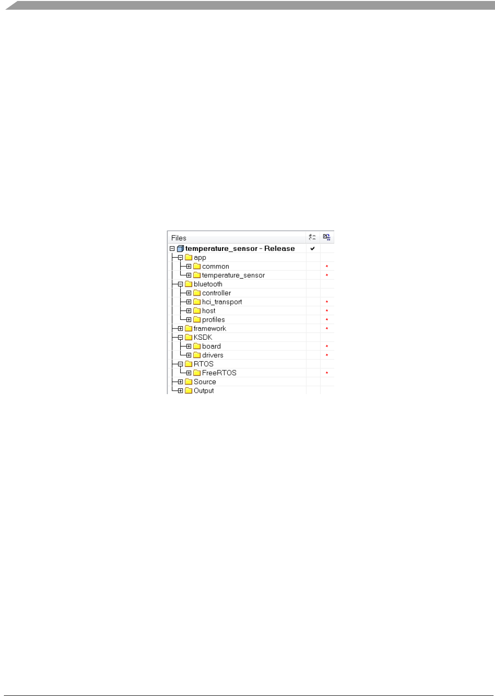
Application Structure
Bluetooth® Low Energy User’s Guide Rev. 4, 09/2016
70 NXP Semiconductors
9. Application Structure
This chapter describes the organization of the Bluetooth Low Energy demo applications that can be
found in the SDK. By familiarizing with the application structure, the user is able to quickly adapt its
design to an existing demo or create a new application.
The Temperature Sensor application is used as a reference to showcase the architecture. Folder Structure
Folder Structure
This figure shows the application folder structure:
Figure 8. Application Folder structure in workspace
The app folder follows a specific structure which is recommended for any application developed using
the BLE Host Stack:
- the common group contains the application framework shared by all profiles and demo
applications:
o Application Main Framework
o BLE Connection Manager
o BLE Stack and Task Initialization and Configuration
o GATT Database
- the temperature_sensor group contains code specific to the HRS application
The bluetooth folder/group contains:
- controller/interface and host/interface – public interfaces for the Controller and the Host;
Functionality is included in the libraries (ble_kw4xz_controller_lib.a and ble_4-
x_host_lib_[armarch].a), located in subfolders controller/lib and host/lib, not shown in the IAR
project structure, but added into the toolchain linker settings under the library category.
Application Structure
Bluetooth® Low Energy User’s Guide Rev. 4, 09/2016
NXP Semiconductors 71
- hci_transport contains header files and sources for the HCI transport, when the application uses
a serial interface to communicate with an external Controller. In example demos both the Host
and the Controller are located on the same chip.
- profiles contains profile-specific code; it is used by each demo application of standard profiles.
The framework folder/group contains framework components used by the demo applications. For
additional information, see the Connectivity Framework Reference Manual (document
CONNFWKRM).
The KSDK folder/group contains board specific configuration files.
The RTOS folder contains sources for the supported operating system or for bare metal configuration.
Application Main Framework
The Application Main module contains common code used by all the applications, such as:
- The Main Task.
- Messaging framework between the Host Stack Task and the Application Task.
- The Idle Task used in low-power enabled applications.
Main Task
The Main Task (main_task) is the first task created by the operation system and is also the one that
initializes the rest of the system. It initializes framework components (Memory Manager, Timer
Manager, etc.) and the Bluetooth Host Stack (Ble_Initialize). It also calls BleApp_Init from app.c, which
is used to initialize peripheral drivers specific to the implemented application.
The function calls App_Thread which represents the Application Task. This task reuses the stack
allocated for the Main Task and is called to process all the events and messages sent by the Host Stack.
The stack size and priority of the main task are defined in fsl_os_abstraction_config.h:
#ifndef gMainThreadStackSize_c
#define gMainThreadStackSize_c 1024
#endif
#ifndef gMainThreadPriority_c
#define gMainThreadPriority_c 7
#endif
Application Messaging
The module contains a wrapper that is used to create messages for events generated by the Host Stack in
the Host Task context and send them to be processed by the application in the context of the Application
Task.
For example, connection events generated by the Host are received by App_ConnectionCallback. The
function creates a message, places it in the Host to Application queue and signals the Application with
gAppEvtMsgFromHostStack_c. The Application Task de-queues the message and calls

Application Structure
Bluetooth® Low Energy User’s Guide Rev. 4, 09/2016
72 NXP Semiconductors
App_HandleHostMessageInput, which calls the corresponding callback implemented the application
specific code (app.c), in this example: BleApp_ConnectionCallback.
It is strongly recommended that the application developer use the app.c module to add custom code on
this type of callbacks.
Idle task
The Idle task is created when applications enable the usage of the Framework Low-Power module. It
contains code to be executed before node enters and right after it exits sleep mode. For more details on
the low-power functionality, review Chapter 10.
When running FreeRTOS as the operating system, the application will hook the idle task implemented in
the FreeRTOS library, by linking vApplicationIdleHook.
The application developer should use this function as container for application specific code:
static void App_Idle(void);
The stack size is defined in ApplMain.h:
#ifndef gAppIdleTaskStackSize_c
#define gAppIdleTaskStackSize_c (400)
#endif
BLE Connection Manager
The connection manager is a helper module that contains common application configurations and
interactions with the Bluetooth host stack. It implements the following events and methods:
- Host Stack GAP Generic Event
- Host Stack Connection Event on both GAP Peripheral and GAP Central configuration
- Host Stack configuration for GAP Peripheral or GAP Central
GAP Generic Event
The GAP Generic Event is triggered by the Host Stack and sent to the application via the generic
callback, as detailed in Chapter 3. Before any application-specific interactions, the Connection Manager
callback is called to handle common application events, such as device address storage.
void BleApp_GenericCallback (gapGenericEvent_t* pGenericEvent)
{
/* Call BLE Conn Manager */
BleConnManager_GenericEvent(pGenericEvent);
switch (pGenericEvent->eventType)
Application Structure
Bluetooth® Low Energy User’s Guide Rev. 4, 09/2016
NXP Semiconductors 73
{
...
}
}
GAP Configuration
The GAP Central or Peripheral Configuration is used to create common configurations (such as setting
the public address, registering the security requirements, adding bonds in whitelist), that can be
customized by the application afterwards. It is called inside the BleApp_Config function, before any
application-specific configuration GAP Connection Event:
static void BleApp_Config()
{
/* Configure as GAP peripheral */
BleConnManager_GapPeripheralConfig();
...
}
GAP Connection Event
The GAP Connection Event is triggered by the Host Stack and sent to the via the connection callback, as
detailed in Chapter 4. Before any application-specific interactions, the Connection Manager callback is
called to handle common application events, such as device connect, disconnect or pairing related
requests It is called inside the registered connection like below:
static void BleApp_ConnectionCallback (deviceId_t peerDeviceId, gapConnectionEvent_t*
pConnectionEvent)
{
/* Connection Manager to handle Host Stack interactions */
BleConnManager_GapPeripheralEvent(peerDeviceId, pConnectionEvent);
switch (pConnectionEvent->eventType)
{
...
}
}
It is strongly recommended that the application developer use the app.c module to add custom code.
GATT Database
The gatt_db contains a set of header files grouped in the macros subfolder. These macros are used for
static code generation for the GATT Database by expanding the contents of the gatt_db.h file in
different ways. Chapter 7 explains how to write the gatt_db.h file using user-friendly macros that define
the GATT Database.
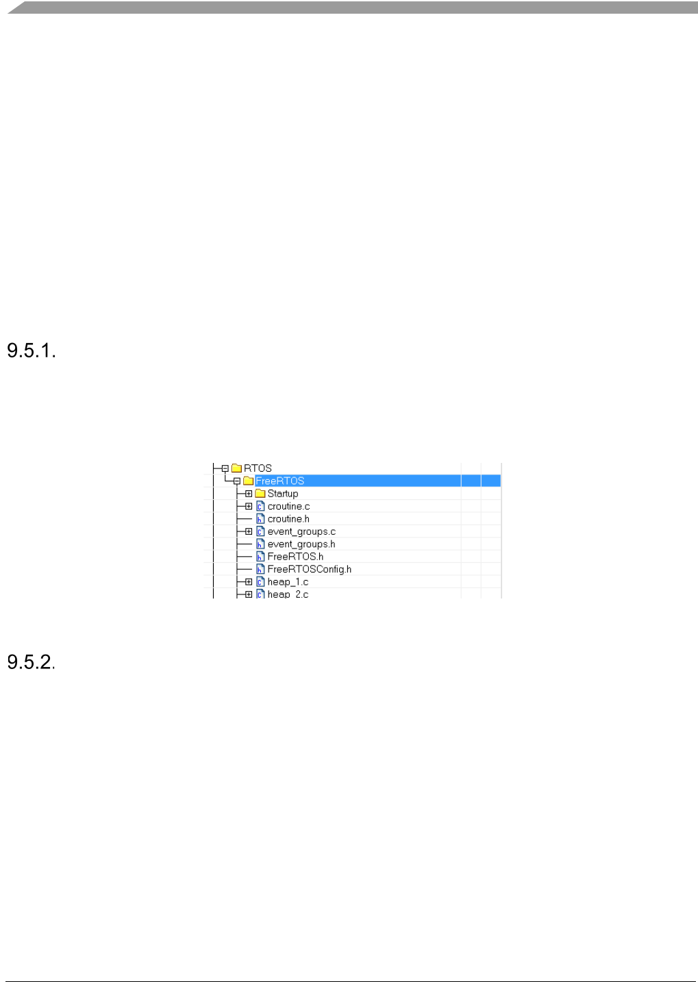
Application Structure
Bluetooth® Low Energy User’s Guide Rev. 4, 09/2016
74 NXP Semiconductors
At application compile-time, the gatt_database.c file is populated with enumerations, structures and
initialization code used to allocate and properly populate the GATT Database. In this way, the the
gattDatabase array and the gGattDbAttributeCount_c variable (see Section 2.2) are created and properly
initialized.
Note
Do not modify any of the file contained in the gatt_db folder and its subfolder.
To complete the GATT Database initialization, this demo application includes the required gatt_db.h
and gatt_uuid128.h files in its specific application folder, along with other profile-specific configuration
and code files.
RTOS Specifics
Operating System Selection
The SDK offers different projects for each supported operating system (FreeRTOS OS) and for bare
metal configuration. To switch between systems, the user needs to switch the workspace.
The RTOS source code is found in the KSDK package and is linked in the workspace in the RTOS
virtual folder, as shown below:
Figure 9. Location of FreeRTOS souce code in workspace
BLE Tasks Configuration
Application developers are provided with four files for RTOS task initialization:
• ble_controller_task_config.h and ble_controller_task.c for the Controller,
• ble_host_task_config.h, and ble_host_tasks.c for the Host.
Reusing these files is recommended because they perform all the necessary RTOS-related work. The
application developer should only modify the macros from *_config.h files whenever tasks need a
bigger stack size or different priority settings. The new values should be overrided in the
app_preinclude.h file.

Application Structure
Bluetooth® Low Energy User’s Guide Rev. 4, 09/2016
NXP Semiconductors 75
Board configuration
The configuration files for the supported boards can be found in the ConnSw/boards folder. The files
contain clock and pin configurations that are used by the drivers. The user can customize the board files
by modifying the configuration of the pins and clock source according to his design.
Figure 10. Board configuration files
BLE Initialization
The ble_init.h and ble_init.c files contain the declaration and the implementation of the following
function:
bleResult_t Ble_Initialize
(
gapGenericCallback_t gapGenericCallback
)
{
#if (gUseHciTransportDownward_d == 1)
/* Configure HCI Transport */
hcitConfigStruct_t hcitConfigStruct =
{
.interfaceType = gHcitInterfaceType_d,
.interfaceChannel = gHcitInterfaceNumber_d,
.interfaceBaudrate = gHcitInterfaceSpeed_d,
.transportInterface = Ble_HciRecv
};
/* HCI Transport Init */
if (gHciSuccess_c != Hcit_Init(&hcitConfigStruct))
{
return gHciTransportError_c;
}
/* BLE Host Tasks Init */
if (osaStatus_Success != Ble_HostTaskInit())
{
return gBleOsError_c;
}
/* BLE Host Stack Init */
return Ble_HostInitialize(gapGenericCallback,

Application Structure
Bluetooth® Low Energy User’s Guide Rev. 4, 09/2016
76 NXP Semiconductors
(hciHostToControllerInterface_t) Hcit_SendPacket);
#elif (gUseHciTransportUpward_d == 1)
if (osaStatus_Success != Controller_TaskInit())
{
return gBleOsError_c;
}
/* BLE Controller Init */
if (osaStatus_Success != Controller_Init((gHostRecvCallback_t)Hcit_SendPacket))
{
return gBleOsError_c;
}
/* Configure HCI Transport */
hcitConfigStruct_t hcitConfigStruct =
{
.interfaceType = gHcitInterfaceType_d,
.interfaceChannel = gHcitInterfaceNumber_d,
.interfaceBaudrate = gHcitInterfaceSpeed_d,
.transportInterface = Controller_RecvPacket
};
return Hcit_Init(&hcitConfigStruct);
#else
/* BLE Controller Task Init */
if (osaStatus_Success != Controller_TaskInit())
{
return gBleOsError_c;
}
/* BLE Controller Init */
if (osaStatus_Success != Controller_Init(Ble_HciRecv))
{
return gBleOsError_c;
}
/* BLE Host Tasks Init */
if (osaStatus_Success != Ble_HostTaskInit())
{
return gBleOsError_c;
}
/* BLE Host Stack Init */
return Ble_HostInitialize(gapGenericCallback,
(hciHostToControllerInterface_t) Controller_RecvPacket);
#endif
}
Note

Application Structure
Bluetooth® Low Energy User’s Guide Rev. 4, 09/2016
NXP Semiconductors 77
This function should be used by your application because it correctly performs all the
necessary BLE initialization.
Step-by-step analysis is provided below:
- First, the Ble_HostTaskInit function from ble_host_task_config.h is called. This creates the two
tasks required by the BLE Host Stack.
- Next, the initialization is split in two paths based on the gUseHciTransportDownward_d
compiler switch
o If it is activated (equal to 1), the Host stack communicates with an external Controller
through an HCI interface. In this example, the HCI interface is initialized using the Serial
Manager (USB). Then, the Ble_HostInitialize function initializes the Host with the
transport packet transmit function used as the hciHostToControllerInterface_t parameter.
o If the compiler switch is not activated (equal to 0), which is the default setting for the
demos, the Controller library is available and the Controller task is initialized by the
Controller_TaskInit. Then, the two stacks with Controller_Init and Ble_HostInitialize are
initialized linking the Controller’s HCI interface with the Host’s.
BLE Host Stack configuration
The BLE host stack is pre-configured into four available libraries:
• Peripheral Host Stack library
• Central Host Stack library
• Central and Peripheral Host Stack library
• FSCI Central and Peripheral Host Stack library
The libraries are found in the ConnSw/bluetooth/libs folder. The user should add the best matching
library for its use case to the linker options of its project. For example, the temperature sensor uses the
Peripheral Host Stack library, as shown below:
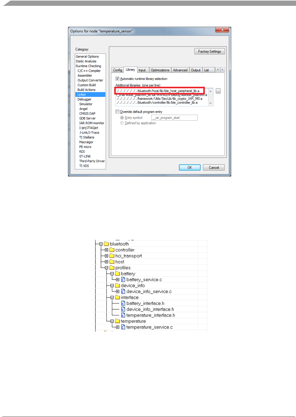
Application Structure
Bluetooth® Low Energy User’s Guide Rev. 4, 09/2016
78 NXP Semiconductors
Figure 11. Linker configuration for Temperature Sensor
Profile Configuration
The implemented profiles and services are located in ConnSw/bluetooth/profiles folder. The application
links every service source file and interface it needs to implement the profile. For example, for the
Temperature Sensor the tree looks as follows:
Figure 12. Linker configuration for Temperature Sensor
The Temperature Profile implements the custom Temperature service, the Battery, and Device
Information services.

Application Structure
Bluetooth® Low Energy User’s Guide Rev. 4, 09/2016
NXP Semiconductors 79
Application Code
The application folder (ConnSw/app)contains the common folder and the application folder.The
application folder contains the following modules:
• app.c and app.h. This module stores the application-specific functionality (APIs for specific
triggers, handling of peripherals, callbacks from the stack, handling of low-power, and so on).
Before initializing the BLE Host stack, the main task calls BleApp_Init. This functions can store
initializations of modules that work independently of the host stack. For example, the Temeprature
Sensor application initializes the temperature sensor driver:
void BleApp_Init(void)
{
TempSensor_Init();
}
After the stack is initialized, the generic callback the application calls BleApp_Config. The function
contains configurations made to the host stack after the initialization. This includes registering callbacks,
seting securityfor services, starting services, allocating timers, adding devices to white list, and so on.
For example, the temperature sensor configures the following:
static void BleApp_Config()
{
/* Configure as GAP peripheral */
BleConnManager_GapPeripheralConfig();
/* Register for callbacks*/
App_RegisterGattServerCallback(BleApp_GattServerCallback);
mAdvState.advOn = FALSE;
/* Start services */
tmsServiceConfig.initialTemperature = 100 * BOARD_GetTemperature();
Tms_Start(&tmsServiceConfig);
basServiceConfig.batteryLevel = BOARD_GetBatteryLevel();
Bas_Start(&basServiceConfig);
Dis_Start(&disServiceConfig);
/* Allocate aplication timer */
appTimerId = TMR_AllocateTimer();
#if (cPWR_UsePowerDownMode)
PWR_ChangeDeepSleepMode(3);
PWR_AllowDeviceToSleep();
#endif
}

Application Structure
Bluetooth® Low Energy User’s Guide Rev. 4, 09/2016
80 NXP Semiconductors
To start the application functionality, BleApp_Start is called. This function usually contains code to start
advertising for sensor nodes or scanning for central devices. In the example of the Temperature Sensor,
the function is the following:
void BleApp_Start(void)
{
Led1On();
if (mPeerDeviceId == gInvalidDeviceId_c)
{
/* Device is not connected and not advertising*/
if (!mAdvState.advOn)
{
BleApp_Advertise();
}
}
else
{
BleApp_SendTemperature();
}
}
• app_config.c. This file contains data structures that are used to configure the stack.
This includes advertising data, scanning data, connection parameters, advertising parameters, SMP keys,
security requirements, and so on.
• app_preinclude.h.
This header file contains macros to override the default configuration of any module in the application.
It is added as a preinclude file in the preprocessor command line in IAR:
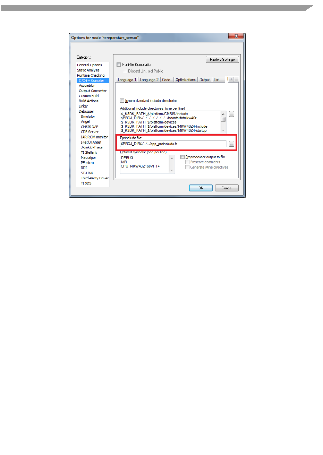
Application Structure
Bluetooth® Low Energy User’s Guide Rev. 4, 09/2016
NXP Semiconductors 81
Figure 13. Preinclude file
• gatt_db.h and gatt_uuid128.h. The two header files contain the definition of the GATT database
and the custom UUIDs used by the application. See Section 7 for more information.

Low-Power Management
Bluetooth® Low Energy User’s Guide Rev. 4, 09/2016
82 NXP Semiconductors
10. Low-Power Management
System Considerations
The ARM® Cortex®-M0+ CPU and the BLE Link Layer hardware have their own power modes. Thus, a
low-power mode for the KW4x SoC is a combination between a BLE Link Layer power mode and an
MCU low-power mode.
For the MCU, there are two types of low-power modes defined, sleep modes (based on the ARM
architecture sleep modes) and deep sleep modes (based on the ARM architecture deep sleep modes).
Only deep sleep modes are of interest in this document, and the MCU deep sleep modes used by this
component are LLS3 and VLLS0/1.
The BLE Link Layer also has a sleep and a deep sleep mode, but only deep sleep mode is used by this
component. To function, the BLE Link layer needs a clock from the RF Reference Oscillator and
requests it through a signal called BLE Sysclk Request. This signal is monitored by the RSIM module,
and, when it is asserted high an interrupt request is generated by RSIM. This interrupt can be configured
in LLWU to wake up the system. Upon entering deep sleep, the BLE Link Layer de-asserts the BLE
Sysclk Request since the RF clock is not needed in deep sleep. With a programmable timeout before
BLE reference clock register reaches the value in the BLE wakeup instant register during deep sleep, the
BLE link Layer asserts BLE Sysclk Request again. If the RSIM module is enabled to generate an
interrupt on this event, and this interrupt is configured in LLWU module to wake up the chip, the BLE
link layer wakes up the entire SoC just before it exits DSM.
When/How to Enter Low-Power
The system should enter low-power when the entire system is idle and all software layers agree on that.
For this use case, an idle task which must have the lowest priority in the system is defined and used to
enter and exit low-power. Therefore, the system enters low-power on idle task, which runs only when
there are no events for other tasks.
In that task, the low-power examples call the static function AppIdle. The following steps are made for
this example:
1. The device checks if the device can enter sleep (all software layers that called
PWR_DisallowDeviceToSleep have called back PWR_AllowDeviceToSleep).
2. The device enters low-power by calling PWR_EnterLowPower.
3. When returning from sleep, the application checks the wake up reason. If the device needs to
react on wakeup, it calls PWR_DisallowDeviceToSleep and calls the specific function. In this
example, the node handles the keyboard press that caused the wake up.
static void App_Idle(void)
{
PWRLib_WakeupReason_t wakeupReason;
if ( PWR_CheckIfDeviceCanGoToSleep() )

Low-Power Management
Bluetooth® Low Energy User’s Guide Rev. 4, 09/2016
NXP Semiconductors 83
{
/* Enter Low-Power */
wakeupReason = PWR_EnterLowPower();
#if gFSCI_IncludeLpmCommands_c
/* Send Wake Up indication to FSCI */
FSCI_SendWakeUpIndication();
#endif
#if gKBD_KeysCount_c > 0
/* Woke up on Keyboard Press */
if (wakeupReason.Bits.FromKeyBoard)
{
KBD_SwitchPressedOnWakeUp();
PWR_DisallowDeviceToSleep();
}
#endif
}
}
4. The node re-enters sleep only after PWR_AllowDeviceToSleep is called back and the idle task
runs again.
Each software layer/entity running on the system can prevent it from entering low-power by calling
PWR_DisallowDeviceToSleep. The system stays awake until all software layers that called
PWR_DisallowDeviceToSleep call back PWR_AllowDeviceToSleep and the system reaches idle task.
The MCU enters either sleep or deep sleep depending on the type of the timers started. Low-power
timers are the only timers that do not prevent the system from entering deep sleep. If any other timers
are started, the MCU enters sleep instead of deep sleep. The user should stop all timers other than the
low-power ones. Note that functions that start timers, like LED_StartFlash, prevent the system from
entering deep sleep.
Deep Sleep Modes
The component implements four low-power modes. The user can switch between them at runtime using
PWR_ChangeDeepSleepMode function. The default low-power mode is selected by the define value
cPWR_DeepSleepMode in the PWR_Configuration.h header file.
Deep Sleep Mode 1
This low-power mode was designed to be used when the BLE stack is active. An example for a node in
advertising is shown below:
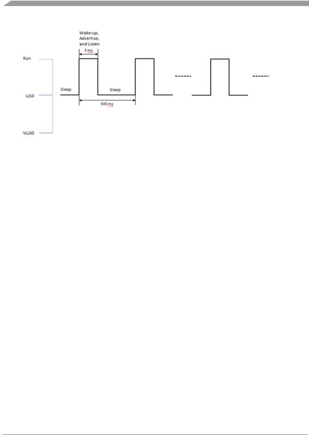
Low-Power Management
Bluetooth® Low Energy User’s Guide Rev. 4, 09/2016
84 NXP Semiconductors
Figure 14. Deep Sleep Mode 1 usage example
In this mode, the MCU enters LLS3 and BLE Link Layer enters deep sleep. The SoC wakes up from this
mode by GPIOs configured as wake-up source in BOARD_LLWU_PIN_ENABLE_BITMAP, LPTMR
timeout using LLWU module, or by BLE Link Layer wakeup interrupt (BLE_LL reference clock
reaches wake up instance register) using LLWU module. LPTMR timer is used to measure the time
MCU spends in deep sleep in order to synchronize low-power timers at wakeup. There are two ways to
use this mode:
1. The BLE stack decides it can enter low-power and calls PWR_AllowDeviceToSleep. If no other
software entity prevents the system from entering deep sleep (all software layers that called
PWR_DisallowDeviceToSleep have called back PWR_AllowDeviceToSleep) and the system
reaches idle task, PWR_EnterLowPower function is entered and the system prepares for entering
low-power mode 1. BLE Link layer status is checked and found not to be in deep sleep. A
function from BLE stack is called to get the nearest instant at which the BLE Link layer needs to
be running again and the wakeup instant register in the BLE Link layer is programmed with this
value. The BLE link layer is then put in deep sleep and the MCU enters LLS3.
2. The BLE stack decides it can enter low-power and calls PWR_BLE_EnterDSM followed by
PWR_AllowDeviceToSleep. In this way the BLE Link layer is put to deep sleep immediately, the
MCU remaining to enter LLS3 on idle task. If no other software entity prevents the system from
entering deep sleep (all software layers that called PWR_DisallowDeviceToSleep have called
back PWR_AllowDeviceToSleep) and the system reaches idle task, PWR_EnterLowPower
function is entered and the system prepares to complete entering low-power mode 1. BLE Link
layer status is checked and found to be in deep sleep, so the MCU puts itself in LLS3 and deep
sleep mode 1 finally reached.
The timeout is cPWR_BLE_LL_OscStartupDelay + cPWR_BLE_LL_OffsetToWakeupInstant before
BLE link layer reference clock register reaches the value in wakeup register, BLE Link Layer wakes up
the entire SoC and the system resumes its activity. Check PWR_Configuration.h header file for the two
defines.
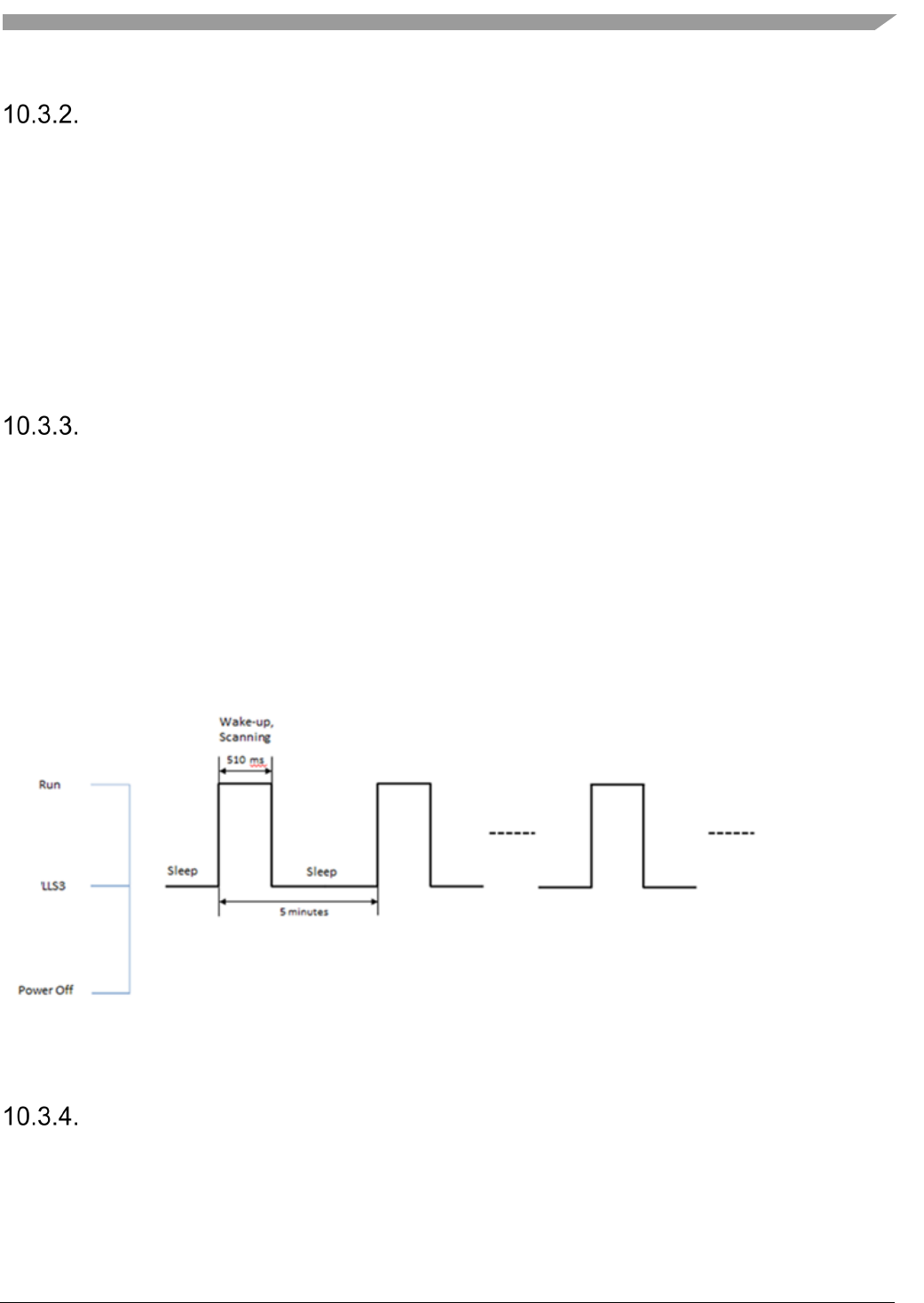
Low-Power Management
Bluetooth® Low Energy User’s Guide Rev. 4, 09/2016
NXP Semiconductors 85
Deep Sleep Mode 2
This low-power mode was designed to be used when the BLE stack is idle. In this mode, the MCU
enters LLS3 and BLE Link Layer enters deep sleep. The SoC wakes up from this mode by GPIOs
configured as wake-up source in BOARD_LLWU_PIN_ENABLE_BITMAP, or by BLE Link Layer
wakeup interrupt (BLE_LL reference clock register reaches wake up instance register) using LLWU
module. LPTMR timer is used to measure the time MCU spends in deep sleep in order to synchronize
low-power timers at wakeup. The deep sleep duration can be configured at compile time using
cPWR_DeepSleepDurationMs define in PWR_Configuration.h header file or at run time calling
PWR_SetDeepSleepTimeInMs function.
The maximum deep sleep duration is limited to 40959 ms.
Deep Sleep Mode 3
This low-power mode was designed to be used when the BLE stack is idle. In this mode, the MCU
enters LLS3 and BLE Link Layer remains idle. The SoC wakes up from this mode by GPIOs configured
as wake-up source in BOARD_LLWU_PIN_ENABLE_BITMAP, or by LPTMR timeout using LLWU
module. LPTMR timer is also used to measure the time MCU spends in deep sleep in order to
synchronize low-power timers at wakeup. The deep sleep duration can be configured at compile time
using cPWR_DeepSleepDurationMs define from PWR_Configuration.h header file or at run time calling
the PWR_SetDeepSleepTimeInMs function.
The maximum configurable deep sleep duration in this mode is 65535000ms (18.2 hours).
An example for a node which is scanning periodically is shown below:
Figure 15. Deep Sleep Mode 3 usage example
Deep Sleep Mode 4
This is the lowest power mode of all. It was designed to be used when the BLE stack is idle. In this
mode, the MCU enters VLLS0/VLLS1 and BLE Link Layer remains idle. The SoC wakes up from this
mode by GPIOs configured as wake-up source in BOARD_LLWU_PIN_ENABLE_BITMAP, using

Low-Power Management
Bluetooth® Low Energy User’s Guide Rev. 4, 09/2016
86 NXP Semiconductors
LLWU module. No synchronization for low-power timers is made since this deep sleep mode is exited
through reset sequence. There are two defines that configures this mode:
1. cPWR_DCDC_InBypass configures the VLLS mode used. If this define is TRUE the MCU
enters VLLS0, otherwise MCU enters VLLS1 since VLLS0 is not allowed in DCDC buck or
boost mode.
2. cPWR_POR_DisabledInVLLS0. This define only has meaning if cPWR_DCDC_InBypass is
TRUE so the MCU enters VLLS0 mode. If TRUE, this define disables POR circuit in VLLS0
making this deep sleep mode lowest power mode possible.
Deep Sleep Mode 5
This low-power mode was designed to be used when the BLE stack is idle. In this mode, the MCU
enters VLLS2 and BLE Link Layer remains idle. The SoC wakes up from this mode by GPIOs
configured as wake-up source in BOARD_LLWU_PIN_ENABLE_BITMAP, using LLWU module.
This mode has Partial SRAM retention. 4 KBytes of RAM (from 0x20000000 to 0x20000FFF) are
retained.
Deep Sleep Mode 6
This low-power mode was designed to be used when the BLE stack is in run or idle mode. In this mode,
the MCU enters STOP. The SoC wakes up from this mode by:
1. by GPIOs configured as wake-up source in BOARD_LLWU_PIN_ENABLE_BITMAP using
LLWU module.
2. LPTMR timeout using LLWU module. LPTMR timer is also used to measure the time MCU
spends in deep sleep in order to synchronize low-power timers at wakeup. The deep sleep
duration can be configured at compile time using cPWR_DeepSleepDurationMs define from
PWR_Configuration.h header file or at run time calling the PWR_SetDeepSleepTimeInMs
function. The maximum configurable deep sleep duration in this mode is 65535000ms (18.2
hours).
3. UART interrupt.
4. Radio interrupt from the BLE Link Layer.
Low-Power Management
Bluetooth® Low Energy User’s Guide Rev. 4, 09/2016
NXP Semiconductors 87
A summary of the available power modes can be found in the table below:
Available power modes
Low-Power
Mode
Required State Wake Up Sources
MCU BLE Link
Layer
GPIO BLE LL LPTMR DCDC** UART
1
LLS3
DSM
x
x
x
2
LLS3
DSM
x
x
3
LLS3
IDLE
x
x
x
4
VLLS0/1*
IDLE
x
x
5
VLLS2
IDLE
x
x
6
STOP
IDLE/RUN
x
x
x
x
x
* VLLS0 if DCDC bypassed/ VLLS1 otherwise
** Available in buck mode only
Low-Power Usage Examples
Using Low-Power When BLE Stack is Idle
The most efficient low-power mode to be used in this scenario, while also retaining the SRAM is deep
sleep mode 3. The application also must configure cPWR_DeepSleepDurationMs to a value that allows
the low-power timers that are running to be updated before they expire. For example, if an application
wants to wake up to do a scan every 30 seconds, the value of the macro must not exceed 30000.
To allow the device to enter sleep, call PWR_ChangeDeepSleepMode and PWR_AllowDeviceToSleep
after the stack is initialized and also on disconnect
PWR_ChangeDeepSleepMode(3);
PWR_SetDeepSleepTimeInMs(cPWR_DeepSleepDurationMs);
PWR_AllowDeviceToSleep();
Using Low-Power When Advertising
Advertising requires the BLE Link Layer to send the advertising packet and listen for connection
requests on configured interval, without the intervention of the higher layers. Thus, deep sleep mode 1 is
the best candidate for this use case.
To allow the device to enter deep sleep mode 1, call PWR_ChangeDeepSleepMode and
PWR_AllowDeviceToSleep, immediately after calling the function to start advertising. The application
also must configure cPWR_DeepSleepDurationMs to a value that allows the low-power timers that are
running to be updated before they expire.
BleApp_Advertise();
PWR_ChangeDeepSleepMode(1);
PWR_SetDeepSleepTimeInMs(cPWR_DeepSleepDurationMs);
Over the Air Programming (OTAP)
Bluetooth® Low Energy User’s Guide Rev. 4, 09/2016
88 NXP Semiconductors
PWR_AllowDeviceToSleep();
MCU enters sleep and wakes up on and when a connect request is received or on the Link Layer wakeup
timeout. The BLE enters DSM between advertising events.
When receiving a connect request, the node disallows sleep to be ready for other procedures like service
discovery.
PWR_DisallowDeviceToSleep();
Using Low-power when Scanning
Scanning requires the BLE Link Layer to be in running mode during the whole procedure. The device
can enter sleep after the scanning is finished or remain active is a suitable device is found. This is why
deep sleep modes 2 and 3 are the best candidates for this use case. The selection is made depending on
the interval between 2 successive scans, taking into account that deep sleep mode 2 has a maximum
timeout of 40959ms.
To allow the device to enter deep sleep mode 2, call PWR_ChangeDeepSleepMode and
PWR_AllowDeviceToSleep. The application also must configure cPWR_DeepSleepDurationMs to a
value that allows the low-power timers that are running to be updated before they expire.
PWR_ChangeDeepSleepMode(2);
PWR_SetDeepSleepTimeInMs(cPWR_DeepSleepDurationMs);
PWR_AllowDeviceToSleep();
This can be done on the gScanStateChanged_c event, when scanning is turned off by the controller. The
device can be woken up on a timeout from a low-power timer when it scans again.
Using Low-Power in Connection
Low-power during a connection needs to take into account the connection interval, the slave latency and
the supervision timeout. The BLE link layer must periodically send empty PDUs to maintain the
connection, so it must be in DSM. Thus, deep sleep mode 1 is the best candidate for this use case.
The functions should be called on the gConnEvtConnected_c event.
case gConnEvtConnected_c:
{
PWR_ChangeDeepSleepMode(1);
PWR_SetDeepSleepTimeInMs(cPWR_DeepSleepDurationMs);
PWR_AllowDeviceToSleep();
}

Over the Air Programming (OTAP)
Bluetooth® Low Energy User’s Guide Rev. 4, 09/2016
NXP Semiconductors 89
11. Over the Air Programming (OTAP)
This chapter contains a detailed description of the Over The Air Programming capabilities of the BLE
Host Stack enabled by dedicated GATT Service/Profile, the support modules needed for OTA
programming and the Bootloader application which performs the actual image upgrade on a device.
The image transfer is done using a dedicated protocol which is designed to run on both the BLE
transport and serial transport.
The container for the upgrade image is and image file which has a predefined format which is described
in detail. The image file format is independent of the protocol but must contain information specific to
the image upgrade infrastructure on an OTAP Client device. Detailed information on how to build an
image file starting from a generic format executable generated by an embedded cross-compiling
toolchain is shown.
The demo applications implement a typical scenario where a new image is sent from a PC via serial
interface to a BLE OTAP Server and then over the air to an OTAP Client which is the target of the
upgrade image. There are 3 applications involved in the OTAP demo: 1 PC application which builds the
image file and serves it to the embedded OTAP Server and 2 embedded applications (OTAP Server and
OTAP Client). This chapter contains enough information for building BLE OTAP applications which
implement different image upgrade scenarios specific to other use cases.
General Functionality
A BLE OTAP system consists of an OTAP Server and an OTAP Client which exchange an image file
over the air using the infrastructure provided by BLE (GAP, GATT, SM) via a custom GATT Service
and GATT Profile. Additionally, a third application may be used to serve an image to the embedded
OTAP Server.
The OTAP Server runs on the GATT Client via the BLE OTAP Profile and the OTAP Client runs on the
GATT Server via the BLE OTAP Service. For the moment the OTAP Server runs on the GAP Central
and the OTAP Client runs on the GAP Peripheral.
The diagram below shows a typical image upgrade scenario.
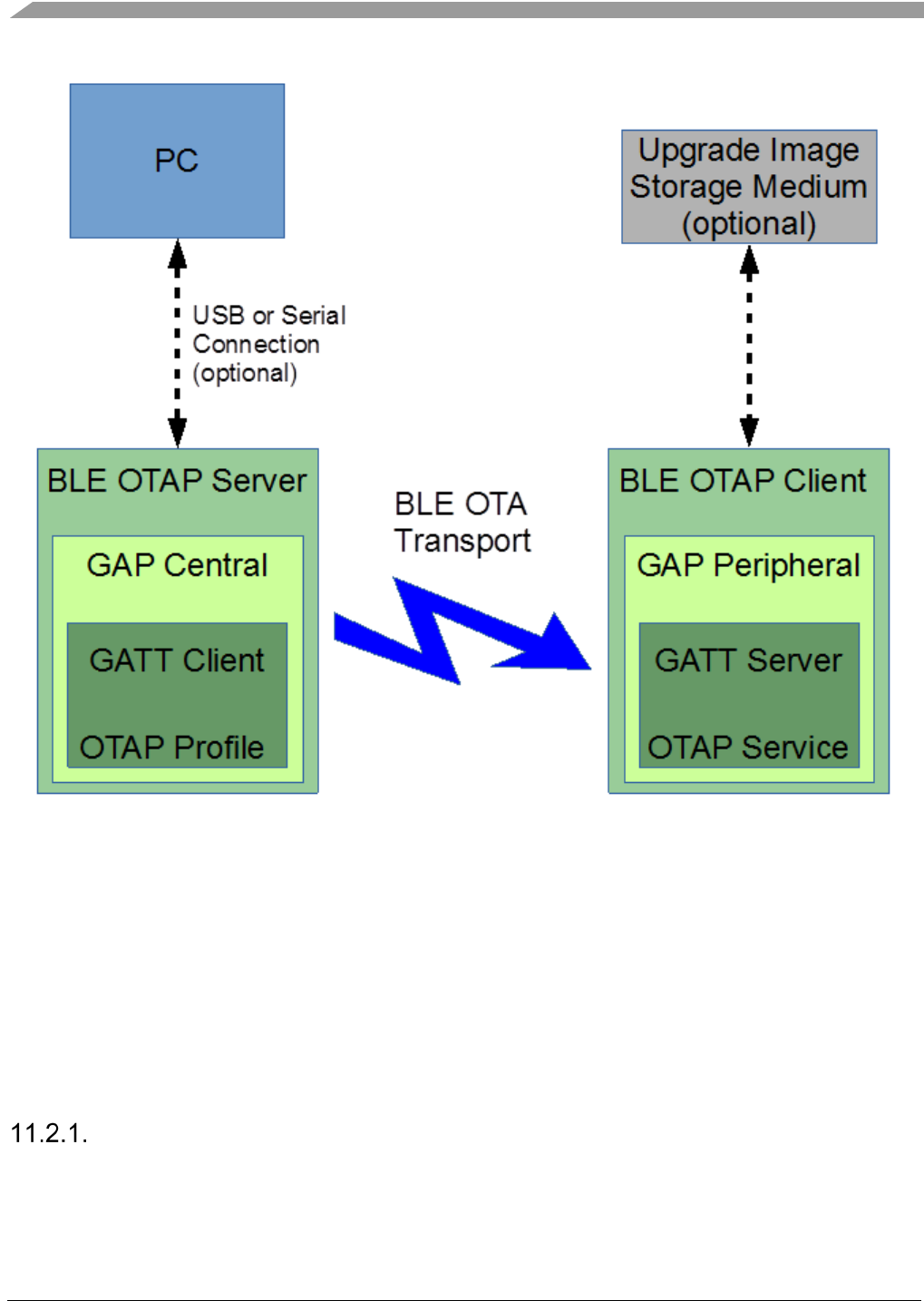
Over the Air Programming (OTAP)
Bluetooth® Low Energy User’s Guide Rev. 4, 09/2016
90 NXP Semiconductors
Figure 16. Typical BLE OTAP Image Upgrade Scenario
The BLE OTAP Service-Profile
The BLE OTAP Service is implemented using the BLE GATT Server which runs on the OTAP Client
(GAP Peripheral).
The BLE OTAP Service does not require any other BLE services. Because it is a custom service it has a
128-bit UUID. The service has 2 custom characteristics which also have 128-bit UUIDs.
The service must be included in the GATT Database of the GATT Server as described in the Creating a
GATT Database section of this document.
The OTAP Service and Characteristics
The OTAP Service has a custom 128-bit UUID which is shown below. The UUID is based on a base
128-bit UUID used for BLE custom services and characteristics. These are shown in the tables below.
Over the Air Programming (OTAP)
Bluetooth® Low Energy User’s Guide Rev. 4, 09/2016
NXP Semiconductors 91
Base BLE 128-bit UUID
Base BLE 128-bit UUID
00000000-ba5e-f4ee-5ca1-eb1e5e4b1ce0
The OTAP Service custom 128-bit UUID is built using the base UUID by replacing the most significant
4 bytes which are 0 with a value specific to the OTAP Service which is 01FF5550 in hexadecimal
format.
BLE OTAP Service UUID
Service
UUID (128-bit)
BLE OTAP Service
01ff5550-ba5e-f4ee-5ca1-eb1e5e4b1ce0
The BLE OTAP Service Characteristics UUIDs are built the same as the BLE OTAP Service UUID
starting from the base 128-bit UUID but using other values for the most significant 4 bytes.
BLE OTAP Service Characteristics
Characteristic
UUID (128-bit)
Properties
Descriptors
BLE OTAP
Control Point
01ff5551-ba5e-f4ee-5ca1-eb1e5e4b1ce0
Write, Indicate
CCC
BLE OTAP Data
01ff5552-ba5e-f4ee-5ca1-eb1e5e4b1ce0
Write Without
Response
-
Both characteristics are implemented as variable length characteristics.
The BLE OTAP Control Point Characteristic is used for exchanging OTAP commands between the
OTAP Server and the OTAP Client. The OTAP Client sends commands to the OTAP Server using ATT
Notifications for this characteristic and the OTAP Server sends commands to the OTAP Client by
making ATT Write Requests to this characteristic. Both ATT Writes and ATT Notifications are
acknowledged operations via ATT Write Responses and ATT Confirmations.
The BLE OTAP Data characteristic is used by the OTAP Server to send parts of the OTAP image file to
the OTAP Client when the ATT transfer method is chosen by the application. The ATT Write
Commands (GATT Write Without Response operation) is not an acknowledged operation.
The BLE OTAP service and characteristics 128-bit UUIDs are defined in the gatt_uuid128.h just as
shown below.
UUID128(uuid_service_otap, 0xE0, 0x1C, 0x4B, 0x5E, 0x1E, 0xEB, 0xA1, 0x5C,
0xEE, 0xF4, 0x5E, 0xBA, 0x50, 0x55, 0xFF, 0x01)
UUID128(uuid_char_otap_control_point, 0xE0, 0x1C, 0x4B, 0x5E, 0x1E, 0xEB, 0xA1, 0x5C,
0xEE, 0xF4, 0x5E, 0xBA, 0x51, 0x55, 0xFF, 0x01)
UUID128(uuid_char_otap_data, 0xE0, 0x1C, 0x4B, 0x5E, 0x1E, 0xEB, 0xA1, 0x5C,
0xEE, 0xF4, 0x5E, 0xBA, 0x52, 0x55, 0xFF, 0x01)
The service is included into the GATT database of the device. It is declared in the gatt_db.h file as
shown below.
PRIMARY_SERVICE_UUID128(service_otap, uuid_service_otap)
CHARACTERISTIC_UUID128(char_otap_control_point, uuid_char_otap_control_point,
(gGattCharPropWrite_c | gGattCharPropIndicate_c))
VALUE_UUID128_VARLEN(value_otap_control_point, uuid_char_otap_control_point,
(gPermissionFlagWritable_c), 16, 16, 0x00)
CCCD(cccd_otap_control_point)
Over the Air Programming (OTAP)
Bluetooth® Low Energy User’s Guide Rev. 4, 09/2016
92 NXP Semiconductors
CHARACTERISTIC_UUID128(char_otap_data, uuid_char_otap_data,
(gGattCharPropWriteWithoutRsp_c))
VALUE_UUID128_VARLEN(value_otap_data, uuid_char_otap_data,
(gPermissionFlagWritable_c), gAttMaxMtu_c - 3, gAttMaxMtu_c - 3, 0x00)
The BLE OTAP Control Point characteristic should be large enough for the longest command which can
be exchanged between the OTAP Server and The OTAP Client.
The BLE OTAP Data characteristic should be large enough for the longest data chunk command the
OTAP Client expects from the OTAP Server to be sent via ATT. The maximum length of the OTAP
Data Characteristic value is ATT_MTU- 3. 1 byte is used for the ATT OpCode and 2 bytes are used for
the Attribute Handle when performing a Write Without Response, the only operation permitted for this
characteristic value.
OTAP Server and OTAP Client Interactions
The OTAP Server application scans for devices advertising the OTAP Service. When it finds one it
connects to that device and notifies it of the available image files or waits for requests regarding
available image files. The behavior is specific to the each application which needs the OTAP
functionality. The BLE OTAP Protocol described below details how to do this.
After an OTAP Server (GAP Central, GATT Client) connects to an OTAP Client (GAP Peripheral,
GATT Server) it scans the device database and identifies the handles of the OTAP Control Point and
OTAP Data characteristics and their descriptors. Then it writes the CCC Descriptor of the OTAP
Control point to allow the OTAP Client to send it commands via ATT Indications. It can send
commands to the OTAP Client by using ATT Write Commands to the OTAP Control Point
characteristic.
After the connection is established, if the OTAP Client wants to use the L2CAP CoC transfer method it
must register a L2CAP PSM with the OTAP Server.
The OTAP Client only starts any image information request or image transfer request procedures only
after the OTAP Server writes the OTAP Control Point CCCD to ensure there is bidirectional
communication between the devices.
The BLE OTAP Protocol
The protocol consists of a set of commands (messages) which allow the OTAP Client to request or be
notified about the available images on an OTAP Server and to request the transfer of parts of images
from the OTAP Server.
All commands with the exception of the image data transfer commands are exchanged through the
OTAP Control Point characteristic of the OTAP Service. The data transfer commands are sent only from
the OTAP Server to the OTAP Client either via the OTAP Data characteristic of the OTAP Service or
via a dedicated Credit Based Channel assigned to a L2CAP PSM.

Over the Air Programming (OTAP)
Bluetooth® Low Energy User’s Guide Rev. 4, 09/2016
NXP Semiconductors 93
Protocol Design Considerations
The OTAP Client is a GAP Peripheral thus a device which has limited resources. This is why the OTAP
Protocol was designed in such a way that it is the discretion of the OTAP Client if, when, how fast and
how much of an available upgrade image is transferred from the OTAP Server. The OTAP Client also
decides which is the image transfer method based on its capabilities. Two image transfer methods are
supported at this moment: the ATT Transfer Method and the L2CAP PSM CoC Transfer Method.
The ATT Transfer Method is supported by all devices which support Bluetooth Low Energy but it has
the disadvantage of a small data payload size and a larger BLE stack protocols overhead leading to a
lower throughput. This disadvantage has been somewhat reduced by the introduction of the Long
Frames feature in the Bluetooth Low Energy specification 4.2 Link Layer which allows for a larger
ATT_MTU value. The L2CAP PSM CoC Transfer Method is an optional feature available for devices
running a Bluetooth stack version 4.1 and later. The protocol overhead is smaller and the data payload is
higher leading to a high throughput. The L2CAP PSM Transfer Method is the preferred transfer method
and it is available on all BLE Devices if the application requires it.
Based on application requirements and device resources and capabilities the OTAP Clients can request
blocks of OTAP images divided into chunks. To minimize the protocol overhead and maximize
throughput an OTAP Client makes a data block request specifying the block size and the chunk size and
the OTAP Server sends the requested data chunks (which have a sequence number) without waiting for
confirmation. The block size, chunk size and number of chunks per block are limited and suitable values
must be used based on application needs.
The OTAP Client can stop or restart an image block transfer at any time if the application requires it or a
transfer error occurs. The OTAP Server implementation can be almost completely stateless. The OTAP
Server does not need to remember what parts of an image have been transferred, this is the job of the
OTAP Client which can request any part of an image at any time. This allows it to download parts of the
image whenever and how fast its resources allow it. The OTAP Server simply sends image information
and image parts on request.
The BLE OTAP Protocol is designed to be used not only on BLE transport medium but on any transport
medium, for example a serial communication interface or another type of wireless interface. This may
be useful when transferring an upgrade image from a PC or a mobile device to the OTAP Server to be
sent via BLE to the OTAP Clients which require it. In the OTAP Demo Applications the embedded
OTAP Server relays OTAP commands between an OTAP Client and a PC via a serial interface and
using a FSCI type protocol. Effectively the OTAP Client downloads the upgrade image from the PC and
not from the OTAP Server. Other transfer methods may be used based on application needs.

Over the Air Programming (OTAP)
Bluetooth® Low Energy User’s Guide Rev. 4, 09/2016
94 NXP Semiconductors
The BLE OTAP Commands
The BLE OTAP Commands general format is shown below. A command consists of two parts, a
Command ID and a Command Payload as shown in the table below.
BLE OTAP General Command Format
Field Name
CmdId
CmdPayload
Size (Bytes)
1
variable
Commands are sent over the transport medium starting with the Command ID and continuing with the
Command Payload.
All multibyte command parameters in the Command Payload are sent in a least significant octet first
order (little endian).
A summary of the commands supported by the BLE OTAP Protocol is shown in the table below. Each
of the commands is then detailed in its own section.
BLE OTAP Commands Summary
CmdId Command Name
0x01
New Image Notification
0x02
New Image Info Request
0x03
New Image Info Response
0x04
Image Block Request
0x05
Image Chunk
0x06
Image Transfer Complete
0x07
Error Notification
0x08
Stop Image Transfer
New Image Notification Command
This command can be sent by an OTAP Server to an OTAP Client, usually immediately after the first
connection, to notify the OTAP Client of the available images on the OTAP Server.
New Image Notification Command Parameters
CmdId Name Dir Parameters Param Size
(Bytes) Description Total Size
(CmdId+Payload)
0x01 New Image
Notification S->C
ImageId 2
Short image identifier
used for transactions
between the OTAP
Server and OTAP
Client. Should be
unique for all images
on a server.
15
ImageVersion 8
Image file version.
Contains sufficient
information to identify
the target hardware,
stack version and build
version.
ImageFileSize 4 Image file size in bytes.

Over the Air Programming (OTAP)
Bluetooth® Low Energy User’s Guide Rev. 4, 09/2016
NXP Semiconductors 95
The ImageId parameter should not be 0x0000 which is the reserved value for the current running image
or 0xFFFF which is the reserved value for “no image available”.
New Image Info Request Command
This command can be sent by an OTAP Client to an OTAP Server to inquire about available upgrade
images on the OTAP Server.
New Image Info Request Command Parameters
CmdId Name Dir Parameters Param Size
(Bytes) Description Total Size
(CmdId+Payload)
0x02 New Image
Info Request C->S
CurrImageId 2
Id of the currently
running image. Should
be 0x0000.
11
CurrImageVer 8
Version of the
currently running
image. A value of all
zeroes signals that the
client is looking for all
images available on an
OTAP Server. A value
of all zeroes requests
information about all
images on the server.
The CurrImageId parameter should be set to 0x0000 to signify the current running image.
The CurrImageVer parameter should contain sufficient information about the target device for the
OTAP Server to determine if it has an upgrade image available for the requesting OTAP Client.
A value of all zeroes for the CurrImageVer means that an OTAP Client is requesting information about
all available images on an OTAP Server and the OTAP Server should send a New Image Info Response
for each image.
New Image Info Response Command
This command is sent by the OTAP Server to the OTAP Client as a response to a New Image
Information Request Command.
New Image Info Response Command Parameters
CmdId Name Dir Parameters Param Size
(Bytes) Description Total Size
(CmdId+Payload)
0x03
New Image
Info
Response
S->C
ImageId 2
Image Id. Value 0xFFFF
is reserved as “no
image available”
15
ImageVersion 8 Image file version.
ImageFileSize 4 Image file size.
The ImageId parameter with a value of 0xFFFF is reserved for the situation where no upgrade image is
available for the requesting device.

Over the Air Programming (OTAP)
Bluetooth® Low Energy User’s Guide Rev. 4, 09/2016
96 NXP Semiconductors
Image Block Request Command
This command is sent by the OTAP Client to the OTAP Server to request a part of the upgrade image
after it has determined the OTAP Server has an upgrade image available.
When an OTAP Server Receives this command it should stop any image file chunk transfer sequences in
progress.
Image Block Request Command Parameters
CmdId Name Dir Parameters
Param
Size
(Bytes)
Description Total Size
(CmdId+Payload)
0x04 Image Block
Request C->S
ImageId 2 Image Id
16
StartPosition 4 Start position of the image
block to be transferred.
BlockSize 4
Requested total block size in
bytes.
ChunkSize 2
Should be optimized to the
TransferChannel type. The
maximum number of chunks
per block is 256. Value is in
bytes.
TransferMeth
od 1
0x00 - ATT
0x01 – L2CAP PSM Credit
based channel
L2capChannel
OrPsm 2
0x0004 - ATT
Other values – PSM for credit
based channels
The ImageId parameter contains the ID of the upgrade image.
The StartPosition parameter specifies the location in the image upgrade file at which the requested block
starts.
The BlockSize and ChunkSize parameters specify the size in bytes of the block to be transferred and the
size of the chunks into which a block is separated. The ChunkSize value must be chosen in such a way
that the total number of chunks can be represented by the SeqNumber parameter of the Image Chunk
Command. At the moment this parameter is 1 byte in size so there are a maximum of 256 chunks per
block. The chunk sequence number goes from 0 to 255 (0x00 to 0xFF). If this condition is not met or the
requested block is not entirely into the image file bounds an error is sent to the OTAP Client when the
OTAP Server receives this misconfigured Image Block Request Command.
The maximum value of the ChunkSize parameter depends on the maximum ATT_MTU and
L2CAP_MTU supported by the BLE stack version and implementation.
The TransferMethod parameter is used to select the transfer method which can be ATT or L2CAP PSM
CoC. The L2capChannelOrPsm parameter must contain the value 0x0004 for the ATT transfer method
and another value representing the chosen PSM for the L2CAP PSM transfer method. The default PSM
for the BLE OTAP demo applications is 0x004F for both the OTAP Server and the OTAP Client
although the specification allows different values at the 2 ends of the L2CAP PSM connection. The
PSM must be in the range reserved by the Bluetooth specification which is 0x0040 to 0x007F.

Over the Air Programming (OTAP)
Bluetooth® Low Energy User’s Guide Rev. 4, 09/2016
NXP Semiconductors 97
The optimal value of the ChunkSize parameter depends on the chosen transfer method and the Link
Layer payload size. Ideally it must be chosen in such a way that full packets are sent for every chunk in
the block.
The default Link Layer payload is 27 bytes form which we subtract 4 for the L2CAP layer and 3 for the
ATT layer (1 for the ATT Cmd Opcode and 2 for the Handle) leaving us with a 20 byte OTAP protocol
payload. From these 20 bytes we subtract 1 for the OTAP CmdId and 1 for the chunk sequence number
leaving us with an optimum chink size of 18 for the ATT transfer method – which is the default in the
demo applications. For the L2CAP PSM transfer method the chosen default chunk size is 111. This was
chosen so as a chunk fits exactly 5 link layer packets. The default L2CAP payload of 23 (27 - 4)
multiplied by 5 gives us 115 from which we subtract 2 bytes for the SDU Length (which is only sent in
the first packet), 1 byte for the OTAP CmdId and 1 byte for the chunk sequence number which leaves
exactly 111 bytes for the actual payload.
If the Link layer supports Long Frames feature then the chunk size should be set according to the
negotiated ATT MTU for the ATT transfer method. From the negotiated ATT MTU (att_mtu) substract
3 bytes for the ATT layer (1 for the ATT Cmd Opcode and 2 for the Handle) then substract 2 bytes for
the OTAP protocol (1 for the CmdId and 1 for the chunk sequence number) to determine the optimum
chunk size (optimum_att_chunk_size = att_mtu – 3 – 2). For the L2CAP PSM transfer method the chunk
size can be set based on the maximum L2CAP SDU size (max_l2cap_sdu_size) from which 4 bytes
should be subtracted, 2 for the SDU Length and 2 for the OTAP protocol (optimum_l2cap_chunk_size =
max_l2cap_sdu_size – 3 – 2). In some particular cases reducing the L2CAP chunk size could lead to
better performance. If the L2CAP chunk size needs to be reduced it should be reduced so it fits exactly a
number of link layer packets. An example of how to compute an optimal reduced L2CAP chunk size is
given in the previous paragraph.
Image Chunk Command
One or more Image Chunk Commands are sent from the OTAP Server to the OTAP Client after an
Image Block Request is received by the former. The image chunks are sent via the ATT Write Without
Response mechanism if the ATT transfer method is chosen and directly via L2CAP if the L2CAP PSM
CoC transfer method is chosen.
Image Chunk Command Parameters
CmdId Name Dir Parameters Param Size
(Bytes) Description Total Size
(CmdId+Payload)
0x05 Image
Chunk S->C SeqNumber 1
In the range 0 ->
BlockSize/ChunkSize -
calculated by Server,
checked by Client.
The command code is
present even when
ATT is used.
3
or more
Data var. Actual data.
The SeqNumber parameter is the chunk sequence number and it has incremental values from 0 to 255
(0x00 to 0x FF) for a maximum of 256 chunks per block.

Over the Air Programming (OTAP)
Bluetooth® Low Energy User’s Guide Rev. 4, 09/2016
98 NXP Semiconductors
The Data parameter is an array containing the actual image part being transferred starting from the
BlockStartPosition + SeqNumber * ChunkSize position in the image file and containing ChunkSize or
less bytes depending on the position in the block. Only the last chunk in a block can have less than
ChunkSize bytes in the Image Chunk Command data payload.
Image Transfer Complete Command
This command is sent by the OTAP Client to the OTAP Server when an image file has been completely
transferred and its integrity has been checked.
Image Transfer Complete Command Parameters
CmdId Name Dir Parameters Param Size
(Bytes) Description Total Size
(CmdId+Payload)
0x06
Image
Transfer
Complete
C->S
ImageId 2 Image Id
4
Status 1
Status of the image
transfer. 0x00 - Success
The ImageId parameter contains the ID of the image file that was transferred.
The Status parameter is 0x00 (Success) if image integrity and possibly other checks have been
successfully made after the image is transferred and another value if integrity or other kind of errors
have occurred.
If the status is 0x00 the OTAP Client can trigger the Bootloader to start flashing the new image. The
image flashing should take about 15 seconds for a 160 KB flash memory.
Error Notification Command
This command can be sent by both the OTAP Server and the OTAP Client when an error of any kind
occurs. When an OTAP Server Receives this command it should stop any image file chunk transfer
sequences in progress.
Error Notification Command Parameters
CmdId Name Dir Parameters
Param
Size
(Bytes)
Description Total Size
(CmdId+Payload)
0x07 Error
Notification Bidir
CmdId 1 Id of the command which
generated the error.
3
ErrorStatus 1
Error Status:
Ex: out of image bounds,
chunk too small, chunk too
large, image verification
failure, bad command format,
image not available, unknown
command
The CmdId parameter contains the ID of the command which caused the error (if applicable).
Over the Air Programming (OTAP)
Bluetooth® Low Energy User’s Guide Rev. 4, 09/2016
NXP Semiconductors 99
The ErrorStatus parameter contains the source of the error. All error statuses are defined in the
otapStatus_t enumerated type in the otap_interface.h file.
Stop Image Transfer Command
This command is sent from the OTAP Client to the OTAP Server whenever the former wants to stop the
transfer of an image block which is currently in progress.
Stop Image Transfer Command Parameters
CmdId Name Dir Parameters Param Size
(Bytes) Description Total Size
(CmdId+Payload)
0x08
Stop Image
Transfer
C->S ImageId 2 Image Id 3
The ImageId parameter contains the ID of the image being transferred.
OTAP Client–Server Interactions
The interactions between the OTAP Server and OTAP Client start immediately after the connection,
discovery of the OTAP Service characteristics and writing of the OTAP Control Point CCC Descriptor
by the OTAP Server.
The first command sent could be a New Image Notification sent by the OTAP Server to the OTAP
Client or a New Image Info Request sent by the OTAP Client. The OTAP Server can respond with a
New Image Info response if it has a new image for the device which sent the request (this can be
determined from the ImageVerison parameter). The best strategy depends on application requirements.
After the OTAP Client has determined that the OTAP Sever has a newer image it can start downloading
the image. This is done by Sending Image Block Request commands to retrieve parts of the image file.
The OATP Server answers to these requests with one or more Image Chunk Commands via the
requested transfer method or with an Error Notification if there are improper parameters in the Image
Block Request. The OTAP Clients makes as many Image Block Requests as it is necessary to transfer
the entire image file.
The OTAP Client decides how often Image Block Request Commands are sent and can even stop a
block transfer which is in progress via the Stop Image Transfer Command. The OTAP Client is in
complete control of the image download process and can stop it and restart it at any time based on its
resources and application requirements.
A typical BLE OTAP Image Transfer scenario is shown in the message sequence chart below.
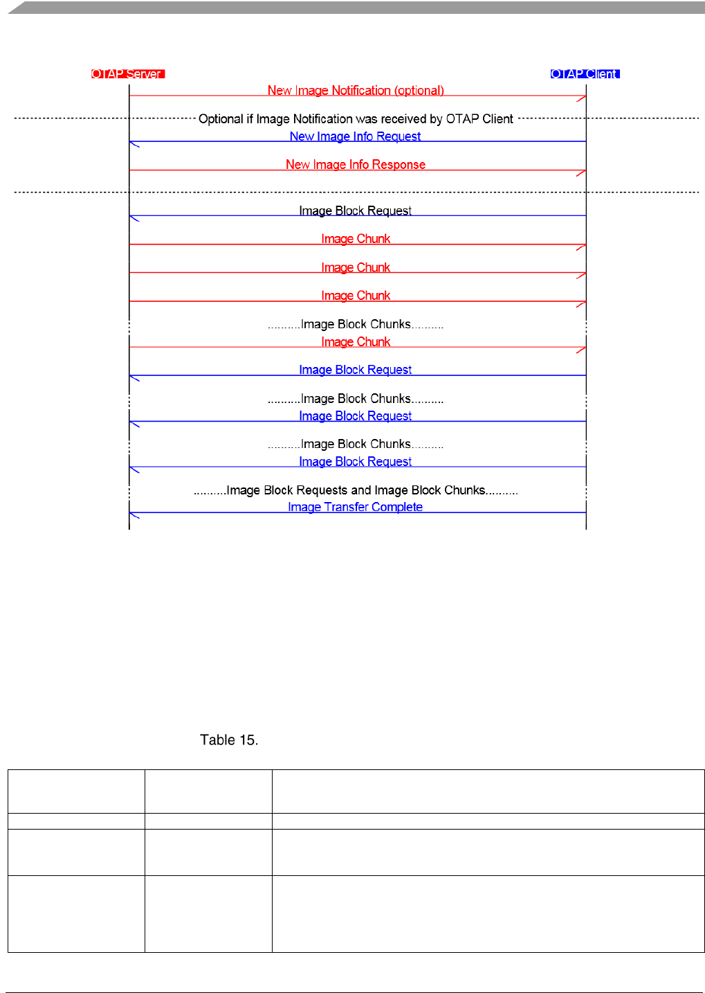
Over the Air Programming (OTAP)
Bluetooth® Low Energy User’s Guide Rev. 4, 09/2016
100 NXP Semiconductors
Figure 17. Typical BLE OTAP Image Transfer Scenario Message Sequence Chart
The BLE OTAP Image File Format
The BLE OTAP Image file has a binary file format. It is composed of a header followed by a number of
sub-elements. The header describes general information about the file. There are some predefined sub-
elements of a file but an end manufacturer could add manufacturer-specific sub-elements. The header
does not have details of the sub-elements. Each element is described by its type.
The general format of an image file is shown in the table below.
BLE OTAP Image File General Format
Image File Element Value Field Length
(bytes)
Description
Header
Variable
The header contains general information about the image file.
Upgrade Image Sub-
element
Variable
This sub-element contains the actual binary executable image which is
copied into the flash memory of the target device. The maximum size of this
sub-element depends on the target hardware.
Sector Bitmap Sub-
element
32
This sub-element contains a sector bitmap of the flash memory of the target
device which tells the bootloader which sectors to overwrite and which to
leave intact. The Bootloader can be configured not to overwrite itself
regardless of the sector bitmap settings of the flash area it resides in. The
size and granularity of this sub-element are target hardware dependent.

Over the Air Programming (OTAP)
Bluetooth® Low Energy User’s Guide Rev. 4, 09/2016
NXP Semiconductors 101
The format of this field is least significant byte first and least significant bit
first for each byte with the least significant bytes and bits standing for the
lowest memory sections of the flash.
Image File CRC Sub-
element
2
This is a 16 bit CCITT type CRC which is calculated over all elements of
the image file with the exception of the Image File CRC sub-element itself.
This must be the last sub-element in an image file.
Each sub-element in a BLE OTAP Image File has a Type-Length-Value (TLV) format. The type
identifier provides forward and backward compatibility as new sub-elements are introduced. Existing
devices that do not understand newer sub-elements may ignore the data.
The following table shows the general format of a BLE Image File sub-element.
BLE OTAP IMage File Sub-element Format
Subfield Size (Bytes) Format Description
Type 2 uint16
Type Identifier – determines the format of the data contained in
the value field.
Length 4 uint32 Length of the Value field of the sub-element.
Value var. uint8[] Data payload.
Some sub-element type identifiers are reserved while others are left for manufacturer-specific use. The
table below shows the reserved type identifiers and the manufacturer-specific ranges.
Sub-element Type Identifiers Ranges
Type Identifiers Description
0x0000 Upgrade Image
0x0001 – 0xefff Reserved
0xf000 – 0xffff Manufacturer-Specific Use
The OTAP Demo applications use two of the manufacturer-specific sub-element type identifiers while
the rest remain free to use. The two are shown in the table below along with a short description.
Manufacturer-Specific Sub-element Type Identifiers Used by OTAP Demo Applications
Manufacturer-
Specific Type
Identifiers
Sub-Element Name Notes
0xf000 Sector Bitmap Bitmap signaling the bootloader which sectors of the internal flash
to overwrite and which not.
0xf100 Image File CRC 16 bit CRC which is computed over the image file with the
exception of the CRC sub-element itself.

Over the Air Programming (OTAP)
Bluetooth® Low Energy User’s Guide Rev. 4, 09/2016
102 NXP Semiconductors
The BLE OTAP Header
The format and fields of the BLE OTAP Header are summarized in the table below.
BLE OTAP Header Fields
Octets Data Types Field Name Mandatory/Optional
4
Unsigned 32-bit integer
Upgrade File Identifier
M
2
Unsigned 16-bit integer
Header Version
M
2
Unsigned 16-bit integer
Header Length
M
2
Unsigned 16-bit integer
Header Field Control
M
2
Unsigned 16-bit integer
Company Identifier
M
2
Unsigned 16-bit integer
Image ID
M
8
8 byte array
Image Version
M
32
Character string
Header String
M
4
Unsigned 32-bit integer
Total Image File Size
(including header)
M
The fields are shown in the order they are placed in memory from the first location to the last.
The total size of the header without the optional fields (if defined by the Header Field Control) is 58
bytes.
All the fields in the header have a little endian format with the exception of the Header String field
which is an ASCII character string.
A packed structure type definition for the contents of the BLE OTAP Header can be found in the
otap_interface.h file.
Upgrade File Identifier
Fixed value 4 byte field used to identify the file as being a BLE OTAP Image File. The predefined value
is “0x0B1EF11E”.
Header Version
This 2 byte field contains the major and minor version number. The high byte contains the major version
and the low byte contains the minor version. The current value is “0x0100” with the major version “01”
and the minor version “00”. A change to the minor version means the OTA upgrade file format is still
backward compatible, while a change to the major version suggests incompatibility.
Header Length
Length of all the fields in the header including the Upgrade File Identifier field, Header Length field
and all the optional fields. The value insulates existing software against new fields that may be added to
the header. If new header fields added are not compatible with current running software, the
implementations should process all fields they understand and then skip over any remaining bytes in the
header to process the image or CRC sub-element. The value of the Header Length field depends on the
value of the Header Field Control field, which dictates which optional header fields are included.

Over the Air Programming (OTAP)
Bluetooth® Low Energy User’s Guide Rev. 4, 09/2016
NXP Semiconductors 103
Header Field Control
This is a 2 byte bit mask which indicates which optional fields are present in the OTAP Header.
At this moment no optional fields are defined, this whole field is reserved and should be set to
“0x0000”.
Company Identifier
This is the company identifier assigned by the Bluetooth SIG. The Company Identifier used for the
OTAp demo applications is “0x01FF”.
Image ID
This is a unique short identifier for the image file. It is used to request parts of an image file. This
number should be unique for all images available on a BLE OTAP Server.
The value 0x0000 is reserved for the current running image.
The value 0xFFFF is reserved as a “no image available” code for New Image Info Response commands.
This field value must be used in the ImageID field in the New Image Notification and New Image Info
Response commands.
Image Version
This is the full identifier of the image file. It should allow a BLE OTAP Client to identify the target
hardware, stack version, image file build version and other parameters if necessary. The recommended
format of this field (which is used by the OTAP Demo applications) is shown below but an end device
manufacturer could choose different format. The subfields are shown in the order they are placed in
memory from the first location to the last. Each subfield has a little endian format if applicable.
Suggested Image Version Field Format
Subfield Size (bytes) Format Description
Build Version 3 uint8[] Image build version.
Stack Version 1 uint8 0x41 for example for BLE Stack version 4.1.
Hardware ID 3 uint8[] Unique hardware identifier.
End Manufacturer Id
1
uint8
ID of the hardware–specific to the end manufacturer
This field value must be used in the ImageVersion field in the New Image Notification and New Image
Info Response commands.
Header String
This is a manufacturer-specific string that may be used to store other necessary information as seen fit
by each manufacturer. The idea is to have a human readable string that can prove helpful during the

Over the Air Programming (OTAP)
Bluetooth® Low Energy User’s Guide Rev. 4, 09/2016
104 NXP Semiconductors
development cycle. The string is defined to occupy 32 bytes of space in the OTAP Header. The default
string used for the BLE OTAP demo application is “BLE OTAP Demo Image File”.
Total Image File Size
The value represents the total image size in bytes. This is the total of data in bytes that is transferred
over-the-air from the server to the client. In most cases, the total image size of an OTAP upgrade image
file is the sum of the sizes of the OTAP Header and all the other sub-elements on the file. If the image
contains any integrity and/or source identity verification fields then the Total Image File Size also
includes the sizes of these fields.
Building a BLE OTAP Image File from a SREC File
A SREC (Motorola S-record) file is an ASCII format file which contains binary information. Common
extensions are: .srec, .s19, .s28, .s37 and others. Most modern compiler toolchains can output a SREC
format executable.
To enable the creation of a SREC file for your embedded application in IAR® EWARM open the target
properties and go to the Output Converter tab. Activate the “Generate additional output” checkbox and
choose the Motorola option from the “Output format” drop down menu. From the same pane you can
also override the name of the output file. A screenshot of the described configuration is shown below.
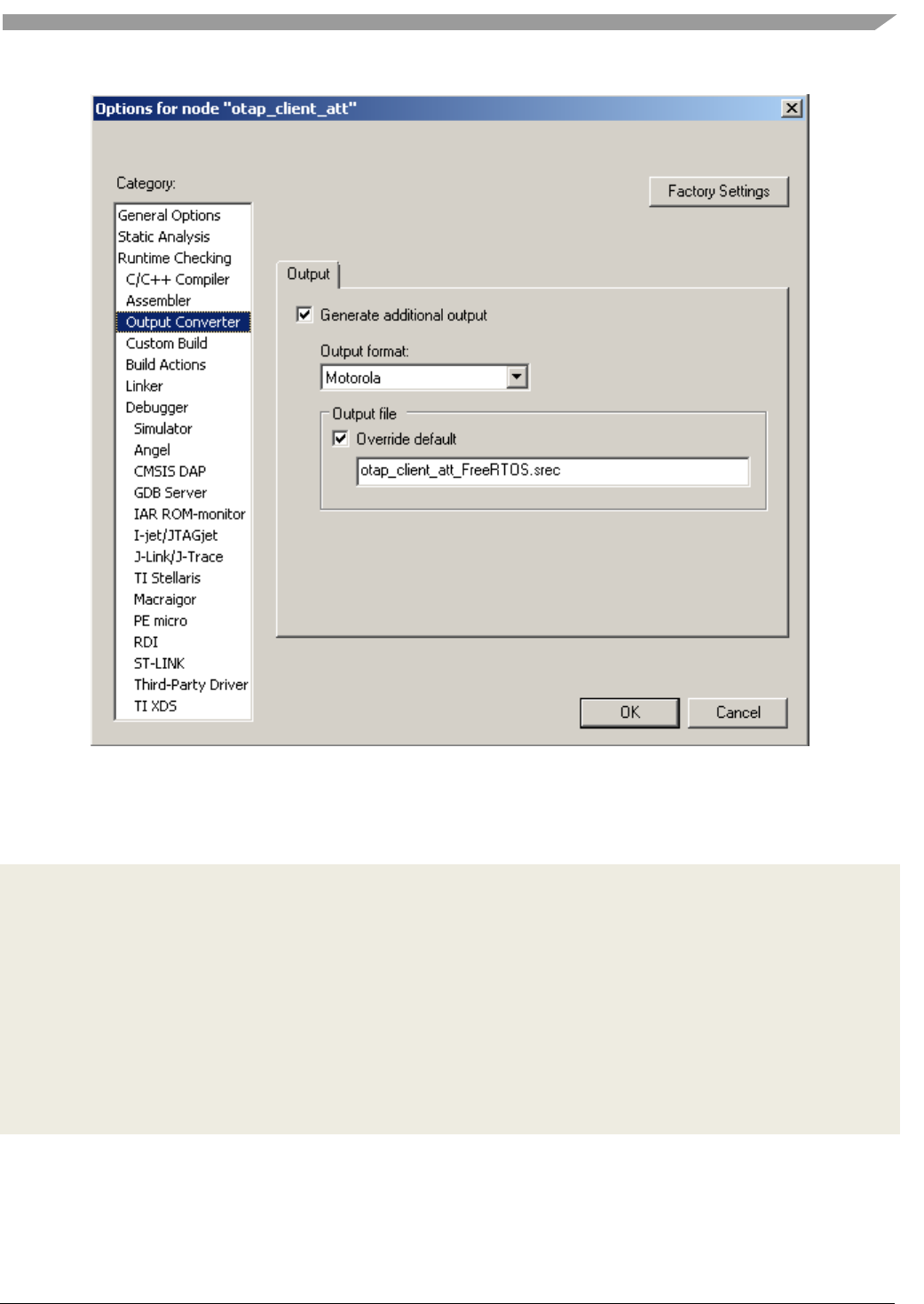
Over the Air Programming (OTAP)
Bluetooth® Low Energy User’s Guide Rev. 4, 09/2016
NXP Semiconductors 105
Figure 18. Enabling SREC Output in IAR EWARM
The format of the SREC file is very simple. It contains lines of text called records which have a specific
format. An example of the contents of a SREC file is shown below.
S02000006F7461705F636C69656E745F6174745F4672656552544F532E73726563A1
S1130000F83F0020EB0500007506000075060000AF
S113001075060000750600007506000075060000F0
S113002075060000750600007506000075060000E0
S113003075060000750600007506000075060000D0
S113004000000000000000000000000000000000AC
S1130050000000000000000000000000000000009C
.............
S2140117900121380004F05FF8002866D12A003100E4
S2140117A06846008804F022F8A689002E16D0002884
S2140117B014D12569278801A868A11022F7F782FCB1
S2140117C06B4601AA0121380004F045F800284CD1E7
S2140117D02A0031006846008804F008F8A68A002E20
All records start with the ASCII letter ‘S’ followed by an ASCII digit from ‘0’ to ‘9’. These two
characters from the record type which identifies the format of the data field of the record.

Over the Air Programming (OTAP)
Bluetooth® Low Energy User’s Guide Rev. 4, 09/2016
106 NXP Semiconductors
The next 2 ASCII characters are 2 hex digits which indicate the number of bytes (hex digit pairs) which
follow the rest of the record (address, data and checksum).
The address follows next which can have 4, 6 or 8 ASCII hex digits depending on the record type.
The data field is placed after the address and it contains 2 * n ASCII hex digits for n bytes of actual data.
The last element of the S record is the checksum which comprises of 2 ASCII hex digits. The checksum
is computed by adding all the bytes of the byte count, address and data fields then computing the ones
complement of the least significant octet of the sum.
Format of an S Record
Field Record
Type
Count Address Data Checksum Line Terminator
Format
“Sn”,
n=0..9
ASCII
hex digits
ASCII
hex digits
ASCII
hex digits
ASCII
hex digits
“\r\n”
Length
(characters)
2
2
4,6,8
Count –
len(Address) –
len(Checksum)
2
2
More details about the SREC file format can be found at this location:
en.wikipedia.org/wiki/SREC_(file_format)
We are only interested in records which contain actual data. These are S1, S2 and S3 records. The other
types of records can be ignored.
The S1, S2 and S3 records are used to build the Upgrade Image Sub-element of the image file simply by
placing the record data at the location specified by the record address in the Value field of the Sub-
element. It is recommended to fill all gaps in S record addresses with 0xFF.
To build an OTAP Image File from a SREC file follow the procedure:
1. Generate the SREC file by correctly configuring your toolchain to do so
2. Create the image file header
a. Set the Image ID field of the header to be unique on the OTAP Server.
b. Leave the Total Image File Size Field blank for the moment.
3. Create the Upgrade Image Sub-element
a. Read the S1, S2 and S3 records from the SREC file and place the binary record data to
the record addresses in the Value filed of the sub-element. Fill all address gaps in the S
records with 0xFF.
b. Fill in the Length field of the sub-element with the length of the written Value filed.
4. Create the Sector Bitmap Sub-element
a. A default working setting would be all byes 0xFF for the Value field of this sub-element
5. Create the Image File CRC Sub-element
a. Compute the total image file size as the length of the header + the length of all 3 sub-
elements and fill in the appropriate filed in the header with this value
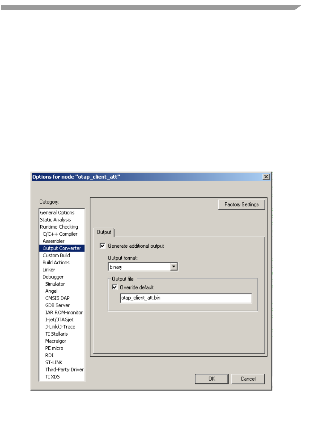
Over the Air Programming (OTAP)
Bluetooth® Low Energy User’s Guide Rev. 4, 09/2016
NXP Semiconductors 107
b. Compute and write the Value field of this sub-element using the header and all sub-
elements except this one
c. The OTA_CrcCompute() function in the OtaSupport.c file can be used to incrementally
compute the CRC
If the Image ID is not available when the image file is created then the CRC cannot be computed. It can
be computed later after the Image ID is established and written in the appropriate field in the header.
Building a BLE OTAP Image File from a BIN File
A BIN file is an binary file which contains an executable image. The most commn extension for this
type of file is .bin. Most modern compiler toolchains can output a BIN format executable.
To enable the creation of a BIN file for your embedded application in IAR EWARM open the target
properties and go to the Output Converter tab. Activate the “Generate additional output” checkbox and
choose the binary option from the “Output format” drop down menu. From the same pane you can also
override the name of the output file. A screenshot of the described configuration is shown below.
Figure 19. Enabling BIN Output in IAR EWARM

Over the Air Programming (OTAP)
Bluetooth® Low Energy User’s Guide Rev. 4, 09/2016
108 NXP Semiconductors
The format of the BIN file is very simple. It contains the executable image in binary format as is,
starting from address 0 and up to the highest address. This type of file does not have any explicit address
information.
To build an OTAP Image File from a BIN file follow the procedure:
1. Generate the BIN file by correctly configuring your toolchain to do so
2. Create the image file header
a. Set the Image ID field of the header to be unique on the OTAP Server.
b. Leave the Total Image File Size Field blank for the moment.
3. Create the Upgrade Image Sub-element
a. Compy the entire contents of the BIN file as is into the Value filed of the sub-element.
b. Fill in the Length field of the sub-element with the length of the written Value filed.
4. Create the Sector Bitmap Sub-element
a. A default working setting would be all byes 0xFF for the Value field of this sub-element
5. Create the Image File CRC Sub-element
a. Compute the total image file size as the length of the header + the length of all 3 sub-
elements and fill in the appropriate filed in the header with this value
b. Compute and write the Value field of this sub-element using the header and all sub-
elements except this one
c. The OTA_CrcCompute() function in the OtaSupport.c file can be used to incrementally
compute the CRC
If the Image ID is not available when the image file is created then the CRC cannot be computed. It can
be computed later after the Image ID is established and written in the appropriate field in the header.
BLE OTAP Application Integration
The BLE OTAP demo applications are standalone applications which only run the OTAP Server and the
OTAP Client. In practice however the OTAP Server and OTAP Client are used alongside with other
functionalities. The OTAP functionality is used as a tool alongside the main application on a device.
This section contains some guidelines on how to integrate OTAP functionality into other BLE
applications.
The OTAP Server
Before any OTAP transactions can be done the application which acts as an OTAP Server must connect
to a peer device and perform ATT service and characteristic discovery. Once the handles of the OTAP
Service, OTAP Control Point and OTAP Data characteristics and their descriptors are found then OTAP
communication can begin.
A good starting point for OTAP transactions for both the OTAP Server and The OTAP client is the
moment the Server writes the OTAP Control Point CCCD to receive ATT Indications from the OTAP
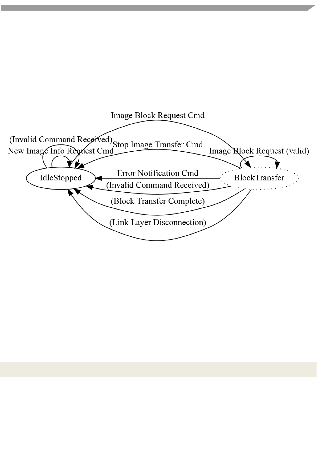
Over the Air Programming (OTAP)
Bluetooth® Low Energy User’s Guide Rev. 4, 09/2016
NXP Semiconductors 109
Client. At that point the Server can send a New Image Notification to the Client if it finds out what kind
of device the client is through other means than the OTAP server. How this can be done is entirely
application-specific. If the OTAP Server does not know exactly what kind of device is the OTAP Client
it can wait for the Client to send a New Image Info Request. Again, the best behavior depends on
application requirements.
Once OTAP communication begins then the OTAP Server just has to wait for commands from the
OTAP Client and answer them. This behavior is almost completely stateless. An example state diagram
for the OTAP Server application is shown below.
Figure 20. OTAP Server Example State Diagram
The OTAP Server waits in an idle state until a valid Image Block Request command is received and then
moves to a pseudo-state and starts sending the requested block. The transfer can be interrupted by some
commands (Error Notification, Stop Image Transfer, and so on) or other events (disconnection, user
interruption, and so on).
The otap_interface.h file contains infrastructure for sending and receiving OTAP Commands and
parsing OTAP image files. Packed structure types are defined for all OTAP commands and type
enumerations are defined for command parameter values and some configuration values like the data
payloads for the different transfer methods.
To receive ATT Indications and ATT Write Confirmations from the OTAP Client the OTAP Server
application registers a set of callbacks in the stack. This is done in the BleApp_Config() function.
App_RegisterGattClientProcedureCallback (BleApp_GattClientCallback);
App_RegisterGattClientIndicationCallback (BleApp_GattIndicationCallback);
This BleApp_GattIndicationCallback() function is called when any attribute is indicated so the handle of
the indicated attribute must be checked against a list of expected handles. In our case we are looking for
the OTAP Control Point handle which was obtained during the discovery procedure.
The BleApp_GattIndicationCallback() function from the demo calls an application-specific function
called BleApp_AttributeIndicated() in which the OTAP Commands are handled.

Over the Air Programming (OTAP)
Bluetooth® Low Energy User’s Guide Rev. 4, 09/2016
110 NXP Semiconductors
static void BleApp_AttributeIndicated
(
deviceId_t deviceId,
uint16_t handle,
uint8_t* pValue,
uint16_t length
)
{
if (handle == mPeerInformation.customInfo.otapServerConfig.hControlPoint)
{
/* Handle OTAP Commands here */
otapCommand_t* pOtaCmd = (otapCommand_t*)pValue;
App_HandleOtapCmd (pOtaCmd->cmdId,
(uint8_t*)(&(pOtaCmd->cmd)),
length);
}
else if (handle == otherHandle)
{
/* Handle other attribute indications here */
/* ... Missing code here ... */
}
else
{
/*! A GATT Client is trying to GATT Indicate an unknown attribute value.
* This should not happen. Disconnect the link. */
Gap_Disconnect (deviceId);
}
The App_HandleOtapCmd() function is the one which deals with the received command, sending
responses if necessary or starting an image block transfer.
To send OTAP Commands to the OTAP Client the application running the OTAP Server calls the
OtapServer_SendCommandToOtapClient() function which performs an ATT Write operation on the
OTAP Control Point attribute.
static void OtapServer_SendCommandToOtapClient (deviceId_t otapClientDevId,
void* pCommand,
uint16_t cmdLength)
{
/* GATT Characteristic to be written - OTAP Client Control Point */
gattCharacteristic_t otapCtrlPointChar;
bleResult_t bleResult;
/* Only the value handle element of this structure is relevant for this operation. */
otapCtrlPointChar.value.handle =
mPeerInformation.customInfo.otapServerConfig.hControlPoint;
bleResult = GattClient_SimpleCharacteristicWrite (mPeerInformation.deviceId,
&otapCtrlPointChar,
cmdLength,
pCommand);
if (gBleSuccess_c == bleResult)

Over the Air Programming (OTAP)
Bluetooth® Low Energy User’s Guide Rev. 4, 09/2016
NXP Semiconductors 111
{
otapServerData.lastCmdSentToOtapClient =
(otapCmdIdt_t)(((otapCommand_t*)pCommand)->cmdId);
}
else
{
/*! A BLE error has occured - Disconnect */
Gap_Disconnect (otapClientDevId);
}
}
The ATT Confirmation for the ATT Write is received in the BleApp_GattClientCallback() set up earlier
which receives a GATT procedure success message for a gGattProcWriteCharacteristicValue_c
procedure type.
static void BleApp_GattClientCallback (deviceId_t serverDeviceId,
gattProcedureType_t procedureType,
gattProcedureResult_t procedureResult,
bleResult_t error)
{
if (procedureResult == gGattProcError_c)
{
attErrorCode_t attError = (attErrorCode_t) (error & 0xFF);
if (attError == gAttErrCodeInsufficientEncryption_c ||
attError == gAttErrCodeInsufficientAuthorization_c ||
attError == gAttErrCodeInsufficientAuthentication_c)
{
/* Start Pairing Procedure */
Gap_Pair(serverDeviceId, &gPairingParams);
}
BleApp_StateMachineHandler(serverDeviceId, mAppEvt_GattProcError_c);
}
else if (procedureResult == gGattProcSuccess_c)
{
switch(procedureType)
{
/* ... Missing code here... */
case gGattProcWriteCharacteristicValue_c:
BleApp_HandleValueWriteConfirmations (serverDeviceId);
break;
default:
break;
}
BleApp_StateMachineHandler(serverDeviceId, mAppEvt_GattProcComplete_c);
}
}

Over the Air Programming (OTAP)
Bluetooth® Low Energy User’s Guide Rev. 4, 09/2016
112 NXP Semiconductors
The BleApp_HandleValueWriteConfirmations() function deals with ATT Write Confirmations based on
the requirements of the application.
There are 2 possible transfer methods for Image Chunks, the ATT transfer method and the L2CAP
transfer method. The OTAP server is prepared to handle both, as requested by the OTAP Client.
To be able to use the L2CAP transfer method the OTAP Server application must register a L2CAP LE
PSM and 2 callbacks: a data callback and a control callback. This is done in the BleApp_Config()
function.
/* Register OTAP L2CAP PSM */
L2ca_RegisterLePsm (gOtap_L2capLePsm_c,
gOtapCmdImageChunkCocLength_c); /*!< The negotiated MTU must be
higher than the biggest data chunk that will be sent fragmented */
...
App_RegisterLeCbCallbacks(BleApp_L2capPsmDataCallback, BleApp_L2capPsmControlCallback);
The data callback BleApp_L2capPsmDataCallback() is not used by the OTAP Server.
The control callback is used to handle L2CAP LE PSM connection requests from the OTAP Client and
other events: PSM disconnections, No peer credits, and so on. The OTAP Client must initiate the
L2CAP PSM connection if it wants to use the L2CAP transfer method.
static void BleApp_L2capPsmControlCallback(l2capControlMessageType_t messageType,
void* pMessage)
{
switch (messageType)
{
case gL2ca_LePsmConnectRequest_c:
{
l2caLeCbConnectionRequest_t *pConnReq = (l2caLeCbConnectionRequest_t
*)pMessage;
/* Respond to the peer L2CAP CB Connection request - send a connection
response. */
L2ca_ConnectLePsm (gOtap_L2capLePsm_c,
pConnReq->deviceId,
mAppLeCbInitialCredits_c);
break;
}
case gL2ca_LePsmConnectionComplete_c:
{
l2caLeCbConnectionComplete_t *pConnComplete = (l2caLeCbConnectionComplete_t
*)pMessage;
if (pConnComplete->result == gSuccessful_c)
{
/* Set the application L2CAP PSM Connection flag to TRUE beacuse there is
no gL2ca_LePsmConnectionComplete_c
* event on the responder of the PSM connection. */
otapServerData.l2capPsmConnected = TRUE;
otapServerData.l2capPsmChannelId = pConnComplete->cId;
}
break;

Over the Air Programming (OTAP)
Bluetooth® Low Energy User’s Guide Rev. 4, 09/2016
NXP Semiconductors 113
}
case gL2ca_LePsmDisconnectNotification_c:
{
l2caLeCbDisconnection_t *pCbDisconnect = (l2caLeCbDisconnection_t *)pMessage;
/* Call App State Machine */
BleApp_StateMachineHandler (pCbDisconnect->deviceId, mAppEvt_CbDisconnected_c);
otapServerData.l2capPsmConnected = FALSE;
break;
}
case gL2ca_NoPeerCredits_c:
{
l2caLeCbNoPeerCredits_t *pCbNoPeerCredits = (l2caLeCbNoPeerCredits_t
*)pMessage;
L2ca_SendLeCredit (pCbNoPeerCredits->deviceId,
otapServerData.l2capPsmChannelId,
mAppLeCbInitialCredits_c);
break;
}
case gL2ca_LocalCreditsNotification_c:
{
l2caLeCbLocalCreditsNotification_t *pMsg = (l2caLeCbLocalCreditsNotification_t
*)pMessage;
break;
}
default:
break;
}
}
The ATT transfer method is supported by default but the L2CAP transfer method only works if the
OTAP Client opens an L2CAP PSM credit oriented channel.
To send data chunks to the OTAP Client the OTAP Server application calls the
OtapServer_SendCImgChunkToOtapClient() function which delivers the chunk via the selected transfer
method. For the ATT transfer method the chunk is sent via the
GattClient_CharacteristicWriteWithoutResponse() function and for the L2CAP transfer method the
chunk is sent via the L2ca_SendLeCbData() function.
static void OtapServer_SendCImgChunkToOtapClient (deviceId_t otapClientDevId,
void* pChunk,
uint16_t chunkCmdLength)
{
bleResult_t bleResult = gBleSuccess_c;
if (otapServerData.transferMethod == gOtapTransferMethodAtt_c)
{
/* GATT Characteristic to be written without response - OTAP Client Data */
gattCharacteristic_t otapDataChar;
/* Only the value handle element of this structure is relevant for this operation.
*/

Over the Air Programming (OTAP)
Bluetooth® Low Energy User’s Guide Rev. 4, 09/2016
114 NXP Semiconductors
otapDataChar.value.handle = mPeerInformation.customInfo.otapServerConfig.hData;
bleResult = GattClient_CharacteristicWriteWithoutResponse
(mPeerInformation.deviceId,
&otapDataChar,
chunkCmdLength,
pChunk);
}
else if (otapServerData.transferMethod == gOtapTransferMethodL2capCoC_c)
{
bleResult = L2ca_SendLeCbData (mPeerInformation.deviceId,
otapServerData.l2capPsmChannelId,
pChunk,
chunkCmdLength);
}
if (gBleSuccess_c != bleResult)
{
/*! A BLE error has occured - Disconnect */
Gap_Disconnect (otapClientDevId);
}
}
The OTAP Server demo application relays all commands received from the OTAP Client to a PC
through the FSCI type protocol running over a serial interface. It also directly relays all responses from
the PC back to the OTAP Client.
Other implementations can bring the image to an external memory through other means of
communication and directly respond to the OTAP Client requests.
The OTAP Client
An application running an OTAP Client, before doing any OTAP-related operations, must wait for and
OTAP Server to connect and perform service and characteristic discovery. OTAP transactions can begin
only after the OTAP Server writes the OTAP Control point CCC Descriptor to receive ATT
Notifications. This is the point when bidirectional communication is established between the OTAP
Server and Client and it is a good point to start OTAP transactions.
The OTAP Client can advertise the OATP Service (which is done in the demo application) or the OTAP
Server may already know the advertising device has an OTAP Service based on application-specific
means. In both situations the OTAP Server must discover the handles of the OTAP Service and its
characteristics.
Besides the OTAP Service instantiated in the GATT Database the OTAP Client needs to have some
storage capabilities for the downloaded image file and a bootloader which writes the image received
over-the-air to the flash memory.
How to put the OTAP Service in the GATT Database is described in the The OTAP Service and
Characteristics section of this document.
The upgrade image storage capabilities in the demo OTAP Client applications are handled by the
OtaSupport module from the Framework which contains support modules and drivers. The OtaSupport

Over the Air Programming (OTAP)
Bluetooth® Low Energy User’s Guide Rev. 4, 09/2016
NXP Semiconductors 115
module has support for both internal storage (a part of the internal flash memory is reserved for storing
the upgrade image) and external storage (a SPI flash memory chip). The demo applications use external
storage. The internal storage is viable only if there is enough space in the internal flash for the upgrade
image – the flash in this case should be at least twice the size of the largest application. The OtaSupport
module also needs the Eeprom module from the Framework to work correctly.
A bootloader is also provided as a separate application which is available in both source code and
executable form. The OTAP Bootloader executable resides in the \tools\wireless\binaries folder for each
board, and has the following format: bootloader_otap_<BOARD>.bin.
The OTAP Bootloader project resides in the
\boards\<board>\wireless_examples\framework\bootloader_otap folder, where <BOARD> is one of
the following:
• FRDMKW40Z
• USBKW40Z
• FRDMKW41Z
• USBKW41Z
The details of the OTAP Bootloader are discussed in a separate section.
To use the OtaSupport module and the OTAP Bootloader several configuration options must be set up in
both the source files and the linker options of the toolchain.
First, the OTASupport and Eeprom module files must be included in the project. To configure the type
of storage used the gEepromType_d preprocessor definition must be given a value.
To use external storage set the gEepromType_d value to the appropriate type of EEPROM present on the
board. The correct value for KW40Z4 demo boards is gEepromDevice_AT45DB021E_c and the correct
value for KW41Z4 demo boards is gEepromDevice_AT45DB041E_c.
The valid gEepromType_d options can be found in the Eeprom.h file:
/* List of the EEPROM devices used on each of the FSL development boards */
#define gEepromDevice_None_c 0
#define gEepromDevice_InternalFlash_c 1
#define gEepromDevice_AT45DB161E_c 2 /* TWR-KW2x */
#define gEepromDevice_AT26DF081A_c 3 /* TWR-MEM */
#define gEepromDevice_AT45DB021E_c 4 /* FRDM-KW40 */
#define gEepromDevice_AT45DB041E_c 5 /* FRDM-KW41 */
The setting of the EEPROM type is done in the app_preinclude.h file for the demo applications:
/* Specifies the type of EEPROM available on the target board */
#define gEepromType_d gEepromDevice_AT45DB041E_c
To use internal storage set up the gUseInternalStorageLink_d=1 symbol in the linker configuration
window (Linker->Config tab in the IAR project properties) and set the gEepromType_d value to
gEepromDevice_InternalFlash_c in the app_preinclude.h file:
/* Specifies the type of EEPROM available on the target board */
#define gEepromType_d gEepromDevice_InternalFlash_c
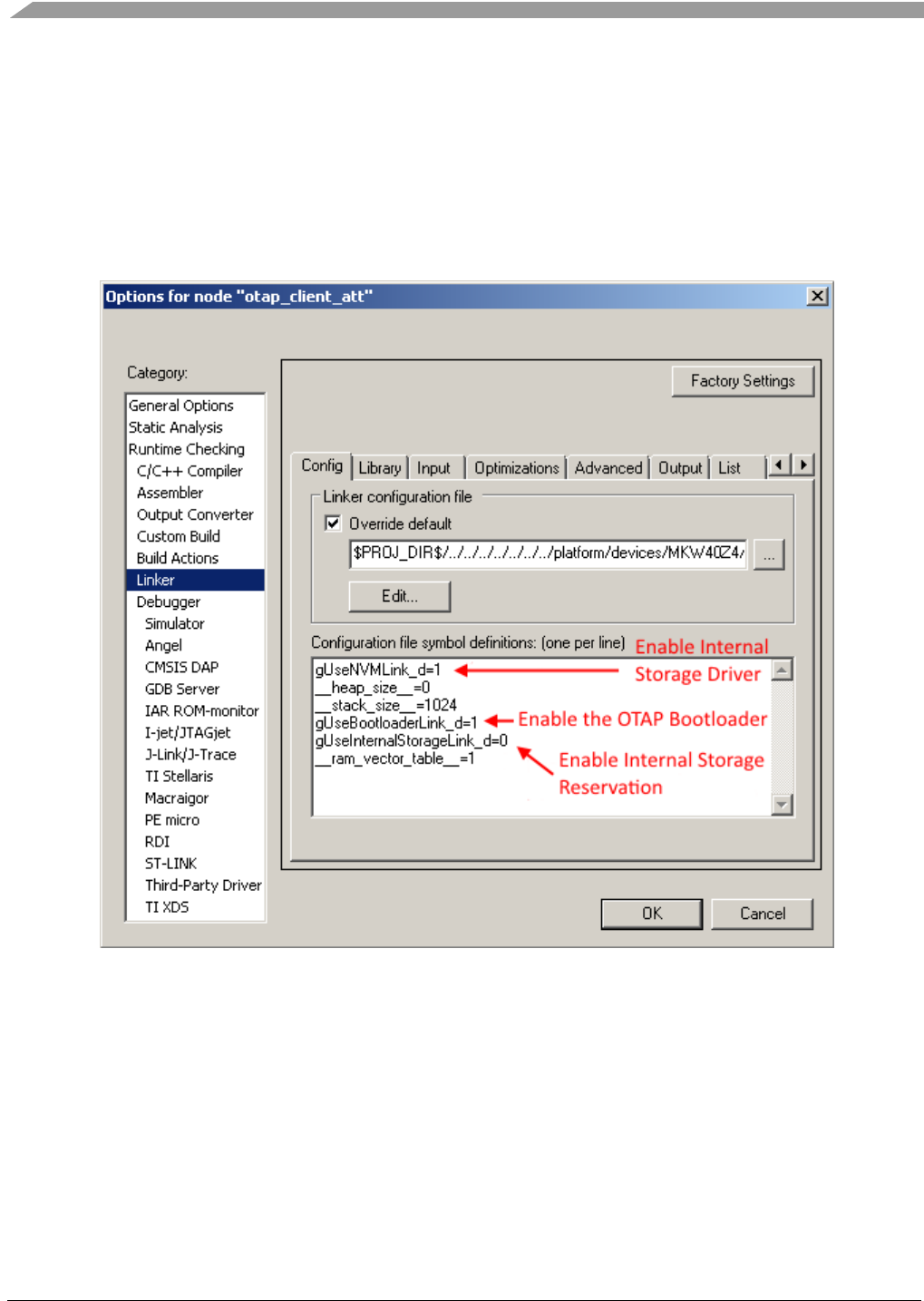
Over the Air Programming (OTAP)
Bluetooth® Low Energy User’s Guide Rev. 4, 09/2016
116 NXP Semiconductors
The OTAP demo applications for the IAR EW IDE have some settings in the Linker options tab which
must be configured to use OtaSupport and the OTAP Bootloader.
In the Project Target Options->Linker->Config tab, 3 symbols must be correctly defined. To use NVM
storage the gUseNVMLink_d symbol must be set to 1. The gUseInternalStorageLink_d symbol must be
set to 0 when OTAP external storage is used and to 1 when internal storage is used. To enable the OTAP
Bootloader linking the gUseBootloaderLink_d symbol must be set to 1 to offset the application. An
example configuration window is shown below.
Figure 21. Linker Config IAR EW IDE - OTAP Client External Storage and Bootloader Configuration
The OTAP demo applications for the KDS IDE also have some settings in the project properties which
must be configured to use OtaSupport and the OTAP Bootloader.
First, some Eclipse Build Variables must be set up just as shown in the screenshot below in the Project
Properties -> C/C++ Build -> Build Variables tab.
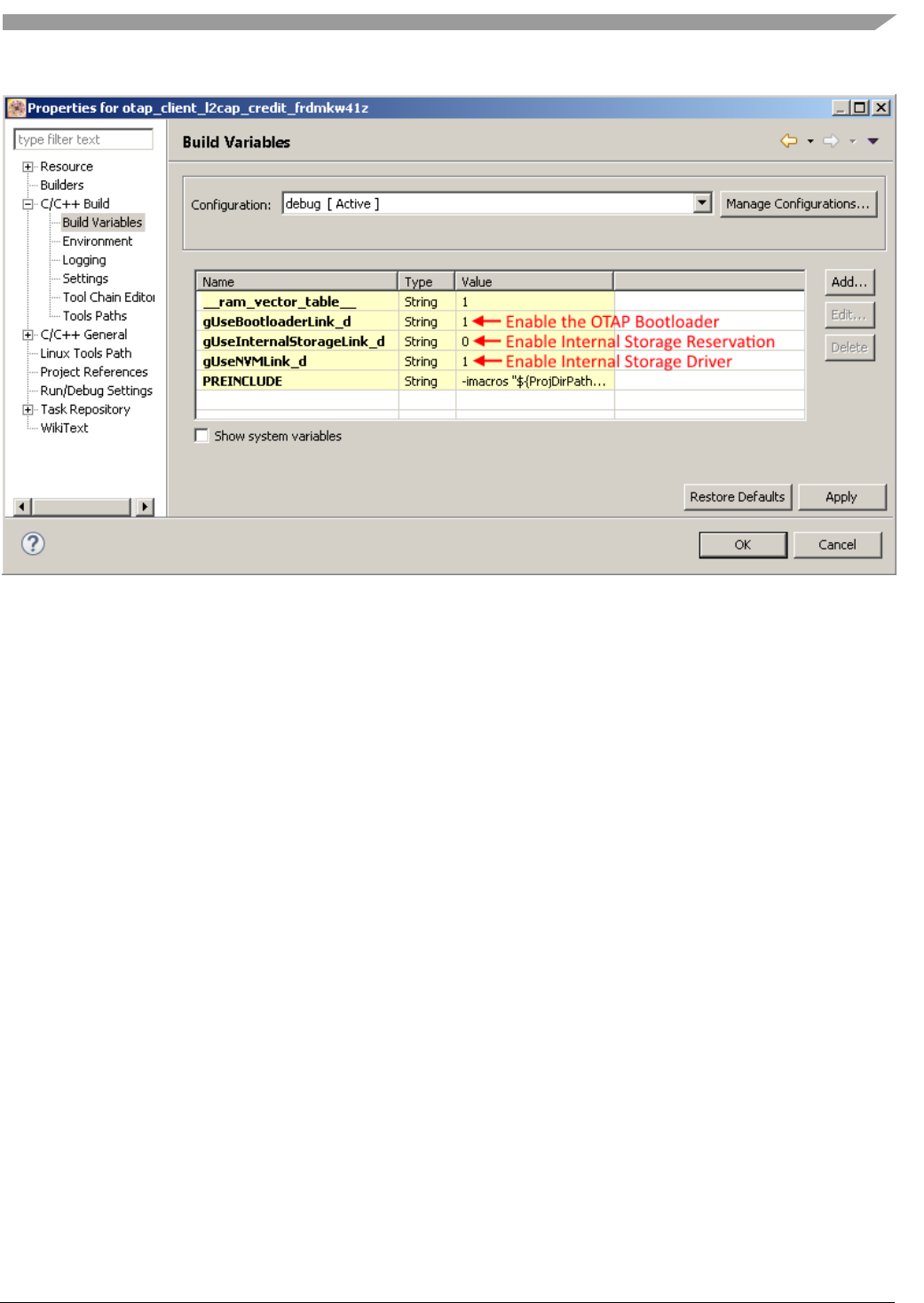
Over the Air Programming (OTAP)
Bluetooth® Low Energy User’s Guide Rev. 4, 09/2016
NXP Semiconductors 117
Figure 22. Figure 1 KDS Build Variables - OTAP Client External Storage and Bootloader Configuration
After the Build Variables, are set up they must be passed as options to the Compiler and Linker
command lines.
For the Compiler go to the Project Properties -> C/C++ Build -> Settings -> Build Steps -> Pre-build
steps -> Command text box and add -DgUseBootloaderLink_d=${gUseBootloaderLink_d} -
DgUseInternalStorageLink_d=${gUseInternalStorageLink_d} if you want to add the
gUseInternalStorageLink_d and the gUseBootloaderLink_d variables. The preprocessor definitions with
the same name as the Eclipse Build Variables are passed to the Compiler in the command line with the
value of the Eclipse Build Variables.
For the Linker go to the Project Properties -> C/C++ Build -> Settings -> Tool Settings -> Cross ARM
C Linker -> Miscellaneous -> Other Linker Flags box and add -Xlinker -defsym -Xlinker
gUseBootloaderLink_d=${gUseBootloaderLink_d} -Xlinker -defsym -Xlinker
gUseInternalStorageLink_d=${gUseInternalStorageLink_d} if you want to add the
gUseInternalStorageLink_d and the gUseBootloaderLink_d variables. The Linker Symbols with the
same name as the Eclipse Build Variables are passed to the Linker in the command line with the value
of the Eclipse Build Variables.
Once the application starts and bidirectional OTAP communication is established via the OTAP Service
then the OTAP Client must determine if the connected OTAP Server has a newer image than the one
currently present on the device. This can be done in two ways. Either the OTAP Server knows by some
application-specific means that it has a newer image and sends a New Image Notification to the OTAP
Client or the OTAP Client sends a New Image Info Request to the OTAP Server and waits for a
response. The example application uses the second method. The New Image Info Request contains
enough information about the currently running image to allow the OTAP Server to determine if it has a
newer image for the requesting device. The New Image Info Response contains enough information for
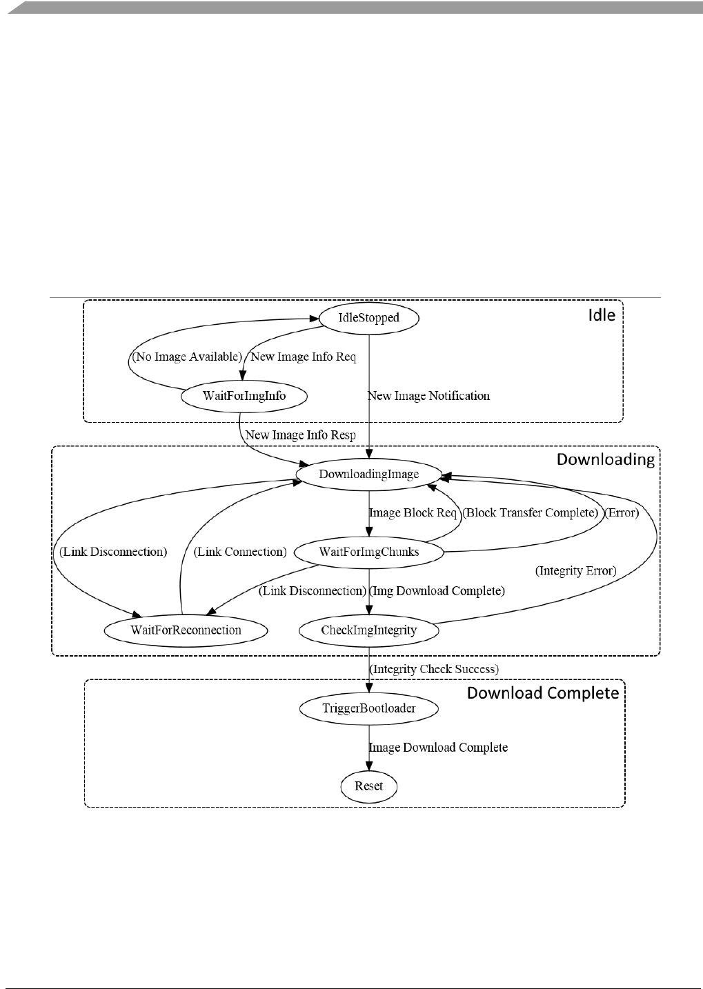
Over the Air Programming (OTAP)
Bluetooth® Low Energy User’s Guide Rev. 4, 09/2016
118 NXP Semiconductors
the OTAP Client to determine that de “advertised” image is newer and it wants to download it. The best
method is entirely dependent on application requirements.
An example function which checks if an ImageVerison field from a New Image Notification or a New
Image Info Response corresponds to a newer image (based on the suggested format of this field) is
provided in the OTAP Client demo applications. The function is called
OtapClient_IsRemoteImageNewer().
The OTAP Client application is a little more complicated than the OTAP Server application because
more state information needs to be handled (current image position, current chink sequence number,
image file parsing information, and so on). An example state diagram for the OTAP Client is shown
below. Note that some of the states may not be explicitly present in the demo applications, this diagram
is meant to emphasize the steps of the image download process.
Figure 23. OTAP Client Example State Diagram
After the OTAP Client determines that the peer OTAP Server has a suitable upgrade image available it
can start the download process. This is done by sending multiple Image Block Request messages and
waiting for the Image Chunks via the selected transfer method.
While receiving the image file blocks the OTAP Client application parses the image file and if any
parameter of an image file sub-element is invalid or the image file format is invalid it sends an Error

Over the Air Programming (OTAP)
Bluetooth® Low Energy User’s Guide Rev. 4, 09/2016
NXP Semiconductors 119
Notification to the OTAP Server and tries to restart the download process from the beginning or a
known good position.
When an Image Chunk received its sequence number is checked and its content is parsed in the context
of the image file format. If the sequence number is not as expected then the block transfer is restarted
from the last known good position. When all chunks of an Image Block are received ne next block is
requested if there are more blocks to download. When the last Image Block in an Image File is received
then the image integrity is checked (the received CRC from the Image File CRC sub-element is
compared to the computed CRC). The computed image integrity initialization and intermediary value
must be reset to 0 before starting the download of an image and when restarting the download of an
image. If the image integrity check fails then the image download process is restarted from the
beginning. If the image integrity check is successful then the Bootloader is triggered, an Image
Download Complete message is sent to the OTAP Server and the MCU is restarted. After the restart the
bootloader kicks in and writes the new image to the flash memory and gives CPU control to the newly
installed application.
If at any time during the download process a Link Layer disconnection occurs then the image download
process is restarted from the last known good position when the link is reestablished.
As noted earlier the OTAP Client application needs to handle a lot of state information. In the demo
application all this information is held in the otapClientData structure of the otapClientAppData_t type.
The type is defined and the structure is initialized in the app.c file of the application. This structure is
defined and initialized differently for the OTAP Client ATT and L2CAP example applications. Mainly
the transferMethod member of the structure is constant and has different values for the two example
applications and the L2CAP application structure has an extra member.
To receive write notifications when the OTAP Server writes the OTAP Control Point attribute and ATT
Confirmations when it indicates the OTAP Control Point attribute, the OTAP Client application must
register a GATT Server callback and enable write notifications for the OTAP Control Point attribute.
This is done in the BleApp_Config() function in the app.c file.
static uint16_t otapWriteNotifHandles[] = {value_otap_control_point,
value_otap_data};
...
static void BleApp_Config()
{
...
/* Register for callbacks*/
App_RegisterGattServerCallback (BleApp_GattServerCallback);
GattServer_RegisterHandlesForWriteNotifications
(sizeof(otapWriteNotifHandles)/sizeof(otapWriteNotifHandles[0]),
otapWriteNotifHandles);
..
}
The BleApp_GattServerCallback() function handles all incoming communication from the OTAP
Server.
static void BleApp_GattServerCallback (deviceId_t deviceId,
gattServerEvent_t* pServerEvent)
{
switch (pServerEvent->eventType)

Over the Air Programming (OTAP)
Bluetooth® Low Energy User’s Guide Rev. 4, 09/2016
120 NXP Semiconductors
{
case gEvtCharacteristicCccdWritten_c:
BleApp_CccdWritten (...) ;
break;
case gEvtAttributeWritten_c:
BleApp_AttributeWritten (...);
break;
case gEvtAttributeWrittenWithoutResponse_c:
BleApp_AttributeWrittenWithoutResponse (...);
break;
case gEvtHandleValueConfirmation_c:
BleApp_HandleValueConfirmation (...);
break;
default:
break;
}
}
When the OTAP Server Writes a CCCD the BleApp_GattServerCallback() function calls the
BleApp_CccdWritten() function which sends a New Image Info Request when the OTAP Control Point
CCCD is written it – this is the starting point of OATP transactions in the demo applications.
When an ATT Write Request is made by the OTAP Server the the BleApp_GattServerCallback()
function calls the BleApp_AttributeWritten() function which handles the data as an OTAP command.
Only writes to the OTAP Control Point are handled as OTAP commands. For each command received
from the OTAP Server there is a separate handler function which performs required OTAP operations.
These are:
• OtapClient_HandleNewImageNotification()
• OtapClient_HandleNewImageInfoResponse()
• OtapClient_HandleErrorNotification()
When an ATT Write Command (GATT Write Without Response) is sent by the OTAP Server the
BleApp_GattServerCallback() function calls the BleApp_AttributeWrittenWithoutResponse() function
which handles Data Chunks if the selected transfer method is ATT and returns an error if any problems
are encountered. Data chunks are handled by the OtapClient_HandleDataChunk() function.
static void BleApp_AttributeWrittenWithoutResponse (deviceId_t deviceId,
uint16_t handle,
uint16_t length,
uint8_t* pValue)
{
/* ... Missing code here ... */
if (handle == value_otap_data)
{
/* ... Missing code here ... */
if (otapClientData.transferMethod == gOtapTransferMethodAtt_c)
{

Over the Air Programming (OTAP)
Bluetooth® Low Energy User’s Guide Rev. 4, 09/2016
NXP Semiconductors 121
if (((otapCommand_t*)pValue)->cmdId == gOtapCmdIdImageChunk_c)
{
OtapClient_HandleDataChunk (deviceId,
length,
pValue);
}
}
/* ... Missing code here ... */
}
/* ... Missing code here ... */
}
Finally, when an ATT Confirmation is received for a previously sent ATT Indication the
BleApp_GattServerCallback() function calls the BleApp_ HandleValueConfirmation() function which
based on the last sent command to the OTAP Server performs the necessary OTAP operations. This is
done using separate confirmation handling functions for each command that is sent to the OTAP Server.
These functions are:
• OtapClient_HandleNewImageInfoRequestConfirmation()
• OtapClient_HandleImageBlockRequestConfirmation()
• OtapClient_HandleImageTransferCompleteConfirmation()
• OtapClient_HandleErrorNotificationConfirmation()
• OtapClient_HandleStopImageTransferConfirmation()
Outgoing communication from the OTAP Client to the OTAP Server are done using the
OtapCS_SendCommandToOtapServer() function. This function writes the value to be indicated to the
OTAP Control Point attribute in the GATT database and then calls the
OtapCS_SendControlPointIndication() which checks if indications are enabled for the target device and
sends the actual ATT Indication. Both functions are implemented in the otap_service.c file.
bleResult_t OtapCS_SendCommandToOtapServer (uint16_t serviceHandle,
void* pCommand,
uint16_t cmdLength)
{
uint16_t handle;
bleUuid_t* pUuid = (bleUuid_t*)&uuid_char_otap_control_point;
/* Get handle of OTAP Control Point characteristic */
GattDb_FindCharValueHandleInService (pUuid, &handle, ...);
/* Write characteristic value */
GattDb_WriteAttribute (...);
/* Send Command to the OTAP Server via ATT Indication */
return OtapCS_SendControlPointIndication (handle);
}
static bleResult_t OtapCS_SendControlPointIndication (uint16_t handle)
{
uint16_t hCccd;
bool_t isIndicationActive;

Over the Air Programming (OTAP)
Bluetooth® Low Energy User’s Guide Rev. 4, 09/2016
122 NXP Semiconductors
/* Get handle of CCCD */
GattDb_FindCccdHandleForCharValueHandle (handle, &hCccd);
Gap_CheckIndicationStatus (...);
return GattServer_SendIndication (...);
}
The otap_interface.h file contains all the necessary information for parsing and building OTAP
commands (packed command structures type definitions, command parameters enumerations, and so
on).
For the two possible image transfer methods (ATT and L2CAP) there are two separate demo
applications. To be able to use the L2CAP transfer method the OATP Client application must register a
L2CAP LE PSM and 2 callbacks: a data callback and a control callback. This is done in the
BleApp_Config() function.
/* Register OTAP L2CAP PSM */
L2ca_RegisterLePsm (gOtap_L2capLePsm_c,
gOtapCmdImageChunkCocLength_c); /*!< The negotiated MTU must be
higher than the biggest data chunk that will be sent fragmented */
...
App_RegisterLeCbCallbacks(BleApp_L2capPsmDataCallback, BleApp_L2capPsmControlCallback);
The control callback is used to handle L2CAP LE PSM-related events: PSM disconnections, PSM
Connection Complete, No peer credits, and so on.
static void BleApp_L2capPsmControlCallback(l2capControlMessageType_t messageType,
void* pMessage)
{
switch (messageType)
{
case gL2ca_LePsmConnectRequest_c:
{
l2caLeCbConnectionRequest_t *pConnReq =
(l2caLeCbConnectionRequest_t *)pMessage;
/* This message is unexpected on the OTAP Client, the OTAP Client sends L2CAP
* PSM connection requests and expects L2CAP PSM connection responses.
* Disconnect the peer. */
Gap_Disconnect (pConnReq->deviceId);
break;
}
case gL2ca_LePsmConnectionComplete_c:
{
l2caLeCbConnectionComplete_t *pConnComplete =
(l2caLeCbConnectionComplete_t *)pMessage;
/* Call the application PSM connection complete handler. */
OtapClient_HandlePsmConnectionComplete (pConnComplete);
break;
}

Over the Air Programming (OTAP)
Bluetooth® Low Energy User’s Guide Rev. 4, 09/2016
NXP Semiconductors 123
case gL2ca_LePsmDisconnectNotification_c:
{
l2caLeCbDisconnection_t *pCbDisconnect = (l2caLeCbDisconnection_t *)pMessage;
/* Call the application PSM disconnection handler. */
OtapClient_HandlePsmDisconnection (pCbDisconnect);
break;
}
case gL2ca_NoPeerCredits_c:
{
l2caLeCbNoPeerCredits_t *pCbNoPeerCredits =
(l2caLeCbNoPeerCredits_t *)pMessage;
L2ca_SendLeCredit (pCbNoPeerCredits->deviceId,
otapClientData.l2capPsmChannelId,
mAppLeCbInitialCredits_c);
break;
}
case gL2ca_LocalCreditsNotification_c:
{
l2caLeCbLocalCreditsNotification_t *pMsg =
(l2caLeCbLocalCreditsNotification_t *)pMessage;
break;
}
default:
break;
}
}
The OTAP Client must initiate the L2CAP PSM connection if it wants to use the L2CAP transfer
method. This is done using the L2ca_ConnectLePsm() function which is called by the
OtapClient_ContinueImageDownload() if the transfer method is L2CAP and the PSM is found to be
disconnected.
static void OtapClient_ContinueImageDownload (deviceId_t deviceId)
{
/* ... Missing code here ... */
/* Check if the L2CAP OTAP PSM is connected and if not try to connect and exit
immediately. */
if ((otapClientData.l2capPsmConnected == FALSE) &&
(otapClientData.state != mOtapClientStateImageDownloadComplete_c))
{
L2ca_ConnectLePsm (gOtap_L2capLePsm_c,
deviceId,
mAppLeCbInitialCredits_c);
return;
}
/* ... Missing code here ... */
}
The PSM data callback BleApp_L2capPsmDataCallback() is used by the OTAP Client to handle
incoming image file parts from the OTAP Server.

Over the Air Programming (OTAP)
Bluetooth® Low Energy User’s Guide Rev. 4, 09/2016
124 NXP Semiconductors
static void BleApp_L2capPsmDataCallback (deviceId_t deviceId,
uint8_t* pPacket,
uint16_t packetLength)
{
OtapClient_HandleDataChunk (deviceId,
packetLength,
pPacket);
}
All data chunks regardless of their source (ATT or L2CAP) are handled by the
OtapClient_HandleDataChunk() function. This function checks the validity of Image Chunk messages,
parses the image file, requests the continuation or restart of the image download and triggers the
bootloader when the image download is complete.
static void OtapClient_HandleDataChunk (deviceId_t deviceId,
uint16_t length,
uint8_t* pData);
The Image File CRC Value is computed on the fly as the image chunks are received using the
OTA_CrcCompute() function from the OtaSupport module which is called by the
OtapClient_HandleDataChunk() function. The OTA_CrcCompute() function has a parameter for the
intermediary CRC value which must be initialized to 0 every time a new image download is started.
The actual write of the received image parts to the storage medium is also done in the
OtapClient_HandleDataChunk() function using the OtaSupport module. This is achieved using the
following functions:
• OTA_StartImage() – called before the start of writing a new image to the storage medium.
• OTA_CancelImage() – called whenever an error occurs and the image download process needs
to be stopped/restarted from the beginning.
• OTA_PushImageChunk() – called to write a received image chunk to the storage medium. Note
that only the Upgrade Image Sub-element of the image file is actually written to the storage
medium.
• OTA_CommitImage() - called to set up what parts of the downloaded image are written to flash
and other information for the bootloader. The Value field of the Sector Bitmap Sub-element of
the Image File is given as a parameter to this function.
• OTA_SetNewImageFlag() – called to set bootloader flags when a new image and the sector
bitmap write to the storage medium are complete. When the MCU is restarted, the bootloader
transfers the new image from the storage medium to the program flash.
To continue the image download process after a block is transferred or to restart it after an error has
occurred the OtapClient_ContinueImageDownload() function is called. This function is used in multiple
situations during the image download process.
To summarize, an outline of the steps required to perform the image download process is shown below:
1. Wait for a connection from an OTAP Server
2. Wait for the OTAP Server to write the OTAP Control Point CCCD

Over the Air Programming (OTAP)
Bluetooth® Low Energy User’s Guide Rev. 4, 09/2016
NXP Semiconductors 125
3. Ask or wait for image information from the server
4. If a new image is available on the server start the download process using the
OtapClient_ContinueImageDownload() function.
a. If the transfer method is L2CAP CoC then initiate a PSM connection to the OTAP Server
5. Repeat while image download is not complete
a. Wait for image chunks
b. Call the OtapClient_HandleDataChunk() function for all received image chunks
regardless of the selected transfer method
i. Check image file header integrity using the
OtapClient_IsImageFileHeaderValid() function.
ii. Write the Upgrade Image Sub-element to the storage medium using OtaSupport
module functions.
iii. When the download is complete check image integrity
1. If the integrity check is successful commit the image using the Sector
Bitmap Sub-element and trigger the bootloader
2. If integrity check fails restart the image download from the beginning
iv. If the download is not complete ask for a new image chunk
c. If any error occurred during the processing of the image chunk restart the download form
the last known good position
6. If an image was successfully downloaded and transferred to the storage medium and the
bootloader triggered then reset the MCU to start the flashing process of the new image.
The OTAP Bootloader
The OTAP Bootloader is a program which resides in a reserved area of the flash memory of the device.
It starts before the application, checks some dedicated new image flags in non-volatile memory and if
they are set it proceeds to replace the current running application image with a new image received over-
the-air. The new image can be retrieved from external or internal storage depending on the configuration
and available memory resources of the device. After the bootloader copies the new image it resets the
MCU.
If the new image flags are not set then the OTAP Bootloader simply gives control of the MCU to the
current application immediately.
If the image upgrade progress is interrupted before it is finished (by a power loss for example) the
bootloader restarts the copy procedure on the next MCU reset. It uses some flags in non-volatile
memory to do this which are set only when the image copy process has been completed successfully.
The OTAP Bootloader project and source code can be found in the
\boards\<board>\wireless_examples\framework\bootloader_otap\ folder.
For each target board a different executable image is generated. For the FRDMKW41Z demo boards the
bootloader_otap_frdmkw41z.bin is the appropriate bootloader binary image file.
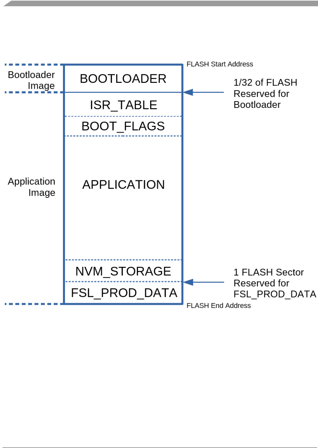
Over the Air Programming (OTAP)
Bluetooth® Low Energy User’s Guide Rev. 4, 09/2016
126 NXP Semiconductors
The next figure shows the memory layout of the device with the relevant sections and their size: the
bootloader, the application and the reserved areas for the situation where external storage is used for the
image received over-the-air.
Figure 24. Device Memory Layout – External Image Storage
The OTAP Bootloader image occupies the first part of the flash memory. In the current implementation
it has a reserved area of 1/32 of the flash size regardless of the actual size of the image.
The OTAP Bootloader is configured to not overwrite itself so any image sent over the air must not
contain the Bootloader application in the reserved section. See the The OTAP Client section which
describes how the Bootloader application can be added to your image.
A typical application image has its memory divided into multiple sections.
• The ISR_TABLE section contains the MCU interrupt table, it has a fixed reserved size.
• The BOOT_FLAGS section contains bootloader flags and the target bootloader version. The
OTAP Bootloader looks for this section immediately after the ISR_TABLE section which has a
fixed size.

Over the Air Programming (OTAP)
Bluetooth® Low Energy User’s Guide Rev. 4, 09/2016
NXP Semiconductors 127
o New Image Flag – set by the application to tell the OTAP Bootloader that a new image is
available. This flag is set by calling the OTA_SetNewImageFlag() function from the
OtaSupport module.
o Image Upgrade Complete Flag – set by the OTAP Bootloader when the new image copy
process is completed successfully.
o Bootloader Version – bootloader version expected by the application – set at compile
time.
• The APPLICATION section contains actual application code
o The optional application non-volatile memory (NVM_STORAGE) area is placed right
before the FSL_PROD_DATA section if it is present.
o The optional internal image storage area (OTAP_INTERNAL_IMAGE_STORAGE) is
placed before the non-volatile memory area if it the non-volatile memory area is present
or before the FSL_PROD_DATA section if the non-volatile memory area is not present.
• The NVM_STOARGE section contains data which the application wishes to save between
device power cycles.
• The OTAP_INTERNAL_IMAGE_STORAGE section is a reserved space where an image
received over-the-air is stored before it is copied over the APPLICATION section when the
OTAP Bootloader is triggered.
• The FSL_PROD_DATA section contains the location of the upgrade image. The location is a
32bit number which is set at compile time. It is set to 0xFFFFFFFF if external SPI flash storage
is used or to a location inside the internal flash memory (which is always smaller than
0xFFFFFFFF) if internal image storage is used. This is necessary for the OTAP Bootloader to
know the source of the upgrade image. This location in the flash memory is written with the
correct value for the type of storage used (internal or external) when the OTA_StartImage()
function is called.
When internal storage is used for the image received over-the-air the memory layout changes as shown
in the following image.
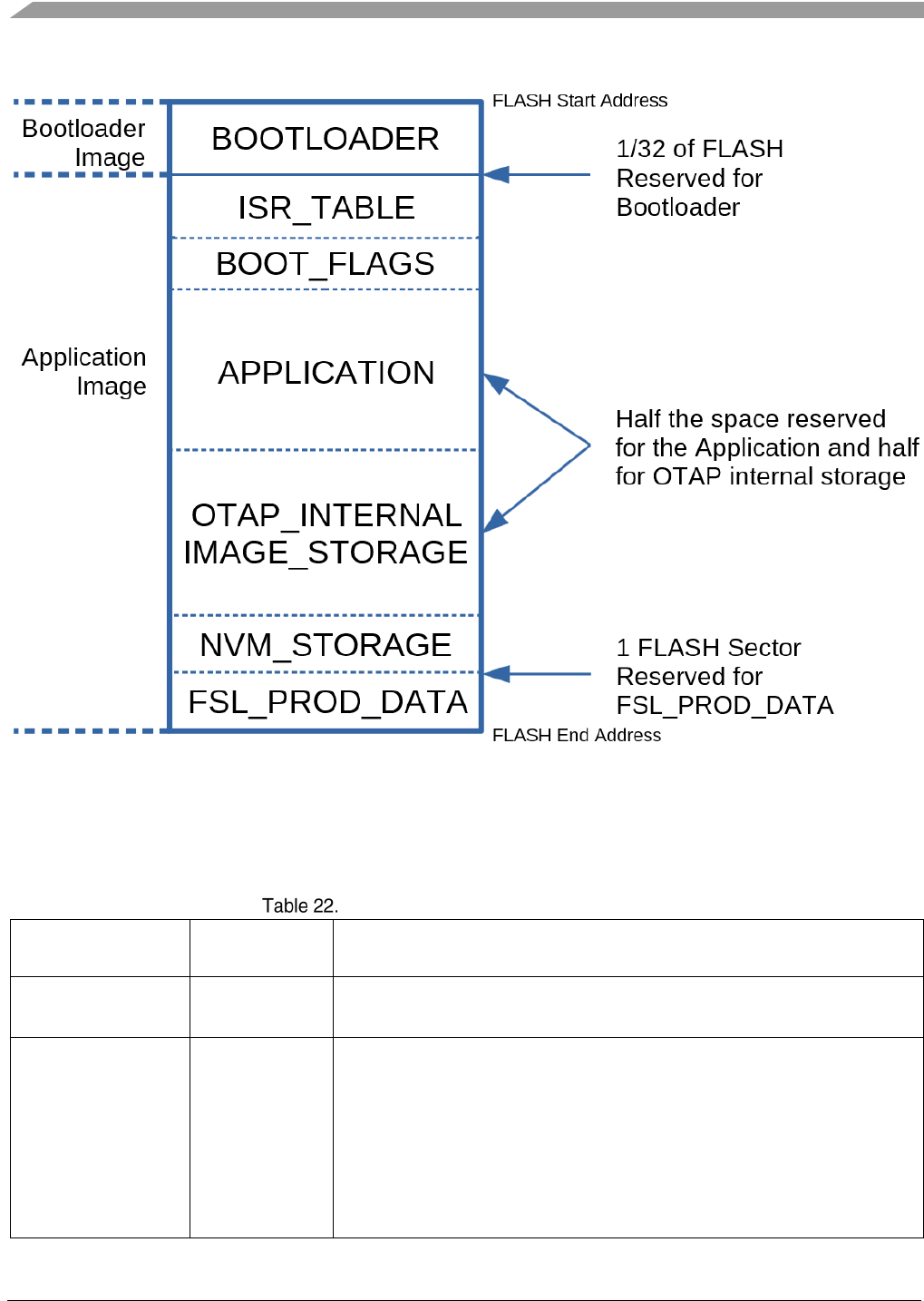
Over the Air Programming (OTAP)
Bluetooth® Low Energy User’s Guide Rev. 4, 09/2016
128 NXP Semiconductors
Figure 25. Device Memory Layout – Internal Image Storage
The OTAP Bootloader expects a certain image format in the image storage location which is identical
regardless if the storage is internal or external.
The format of the raw image is detailed in the following table.
BLE OTAP Image File General Format
Raw Image Field Field Length
(bytes)
Description
Image Size
4
This is the Image field size. It is set by the OTA_CommitImage() function from
the OtaSupport module. Its value is equal to the sum of all image parts written
using the OTA_PushImageChunk() function.
Sector Bitmap
32
This field contains a sector bitmap of the flash memory of the target device
which tells the bootloader which sectors to overwrite and which to leave intact.
This field is the Value field of the Sector Bitmap Sub-element of the image file
sent over-the-air. This field is set by the OTA_CommitImage() function from
the OtaSupport module. The format of this field is least significant byte first and
least significant bit first for each byte with the least significant bytes and bits
standing for the lowest memory sections of the flash.
The OTAP Bootloader is configured not to overwrite itself regardless of the
sector bitmap settings of the flash area it resides in. This setting can be
changed in the OTAP Bootloader application.

Over the Air Programming (OTAP)
Bluetooth® Low Energy User’s Guide Rev. 4, 09/2016
NXP Semiconductors 129
Image
Variable
This field contains the binary application which is written to the APPLICATION
section of the flash. This field is the Value field of the Upgrade Image Sub-
element of the image file sent over-the-air. This field is gradually set by each
call to the OTA_PushImageChunk() function.
Creating a BLE Application When the BLE Host Stack is Running on Another Processor
Bluetooth® Low Energy User’s Guide Rev. 4, 09/2016
130 NXP Semiconductors
12. Creating a BLE Application When the BLE Host Stack
is Running on Another Processor
This chapter describes how to create a BLE application (host), when the Bluetooth Low Energy Host
Stack is running on another processor (blackbox) and offers code exemples to explain how to achieve
this.
The supported serial interfaces between the two chips(application and the BLE Host Stack) are UART,
SPI and I2C.
The typical applications employing BLE Host Stack blackboxes are host systems such as a PC tool or an
embedded system that has an application implementation. This chapter describes an embedded
application.
See FSCI for BLE Host Stack Reference Manual (document BLEHSFSCIRM) for explicit information
on exercising the BLE Host Stack functionality through a serial communication interface to a host
system.
Serial Manager and FSCI configuration
For creating an embedded application that communicates with the BLE Host Stack using the serial
interface, the following steps must be done:
Serial Manager initialization
The function that must be called for Serial Manager initialization is located in SerialManager.h:
/* Init serial manager */
SerialManager_Init();
FSCI configuration and initialization
By default, the FSCI module is disabled. It must be enabled by setting gFsciIncluded_c to 1. Also,
gFsciLenHas2Bytes_c must set to 1 because BLE Host Stack interface commands and events need serial
packets bigger than 255 octets.
For more information on the following configuration parameters refer to the FSCI chapter of the
Connectivity Framework Reference Manual document(CONNFWKRM).
To configure the FSCI module, the following parameters can be set on both the BLE Application
project and the BLE blackbox:
/* Mandatory, enables support for FSCI Host functionality */
#define gFsciHostSupport_c 1
/* Mandatory, enables support for FSCI functionality */
#define gFsciIncluded_c 1
/* Mandatory, enables usage of 2 bytes FSCI packet length field */
#define gFsciLenHas2Bytes_c 1
/* Recommended, enables FSCI Ack transmission for each FSCI received packet */

Creating a BLE Application When the BLE Host Stack is Running on Another Processor
Bluetooth® Low Energy User’s Guide Rev. 4, 09/2016
NXP Semiconductors 131
#define gFsciTxAck_c 1
/* Recommended, enables FSCI Ack reception after each FSCI sent packet */
#define gFsciRxAck_c 1
/* Recommended, enables FSCI reception restart if no bytes are received in due time */
#define gFsciRxTimeout_c 1
/* Optional, enables FSCI reception restart by polling, used on bare metal */
#define mFsciRxTimeoutUsePolling_c 1
/* Optional, enables FSCI Rx of Ack by polling, used on bare metal */
#define gFsciRxAckTimeoutUseTmr_c 0
To perform the FSCI module initialization, the following code can be used:
#define gSerialMgrUseUart_c 1
#define gSerialMgrUseSPI_c 0
#define gSerialMgrUseIIC_c 0
#if gSerialMgrUseUart_c
#define gAppFSCIHostInterfaceBaud_d gUARTBaudRate115200_c
#define gAppFSCIHostInterfaceType_d gSerialMgrUart_c
#define gAppFSCIHostInterfaceId_d 1
#elif gSerialMgrUseSPI_c
#define gAppFSCIHostInterfaceBaud_d gSPI_BaudRate_1000000_c
#define gAppFSCIHostInterfaceType_d gSerialMgrSPIMaster_c
#define gAppFSCIHostInterfaceId_d 0
#elif gSerialMgrUseIIC_c
#define gAppFSCIHostInterfaceBaud_d gIIC_BaudRate_100000_c
#define gAppFSCIHostInterfaceType_d gSerialMgrIICMaster_c
#define gAppFSCIHostInterfaceId_d 1
#endif
/* FSCI serial configuration structure */
static const gFsciSerialConfig_t mFsciSerials[] = {
/* Baudrate, interface type, channel No,
virtual interface */
{gAppFSCIHostInterfaceBaud_d, gAppFSCIHostInterfaceType_d, gAppFSCIHostInterfaceId_d,
0},
{ APP_SERIAL_INTERFACE_SPEED, APP_SERIAL_INTERFACE_TYPE, APP_SERIAL_INTERFACE_INSTANCE,
1},
};
/* Init FSCI */
FSCI_Init((void*) mFsciSerials);
FSCI handlers (GAP, GATT and GATTDB) registration
For receiving messages from all the BLE Host Stack serial interfacing layers (GAP, GATT and
GATTDB), a function handler must be registered in FSCI for each layer:
fsciBleRegister(0);

Creating a BLE Application When the BLE Host Stack is Running on Another Processor
Bluetooth® Low Energy User’s Guide Rev. 4, 09/2016
132 NXP Semiconductors
BLE Host Stack initialization
The BLE Host Stack must be initialized when platform setup is complete and all RTOS tasks have been
started. This initialization is done by restarting the blackbox using a FSCI CPU Reset Request
command. This is performed automatically by the Ble_Initialize(App_GenericCallback) function.
/* Send FSCI CPU reset command to BlackBox */
FSCI_transmitPayload(gFSCI_ReqOpcodeGroup_c, mFsciMsgResetCPUReq_c, NULL, 0,
fsciInterface);
The completion of the BLE Host Stack initialization is signaled by the reception of the GAP-
GenericEventInitializationComplete.Indication event (over the serial communication interface, in FSCI).
The BLE-HostInitialize.Request command is not required to be sent to the blackbox (the entire
initialization is performed by the blackbox, when it resets).
GATT Database configuration
The GATT Database always resides on the same processor as the entire BLE Host Stack, so the
attributes must be added by the host application using the serial communication interface.
To create a GATT Database remotely, GATTDBDynamic commands must be used. The
GATTDBDynamic API is provided to the user that performs all the required memory allocations and
sends the FSCI commands to the blackbox. The result of the operation is returned, including optionally
the service, characteristic and cccd handles returned by the blackbox.
Current supported API for adding services is the following:
bleResult_t GattDbDynamic_AddGattService(gattServiceHandles_t* pOutServiceHandles);
bleResult_t GattDbDynamic_AddGapService(gapServiceHandles_t* pOutServiceHandles);
bleResult_t GattDbDynamic_AddIpssService(ipssServiceHandles_t* pOutServiceHandles);
bleResult_t GattDbDynamic_AddHeartRateService(heartRateServiceHandles_t*
pOutServiceHandles);
bleResult_t GattDbDynamic_AddBatteryService(batteryServiceHandles_t* pOutServiceHandles);
bleResult_t GattDbDynamic_AddDeviceInformationService(deviceInfoServiceHandles_t*
pOutServiceHandles);
The service handles are optional.
Also, a generic function is provided, so that the user can add any generic service to the database:
bleResult_t GattDbDynamic_AddServiceInDatabase(serviceInfo_t* pServiceInfo);
Usually, a BLE Application is going to be ported from a single chip solution, where the BLE App and
the BLE stack reside on the same processor and the GATT database is populated statically. The user will
need to remove all the attribute handles from any structure and replace them with
gGattDbInvalidHandle_d and then populate them after the services are added dynamically to the
database with the handles returned by the previous API.

Creating a BLE Application When the BLE Host Stack is Running on Another Processor
Bluetooth® Low Energy User’s Guide Rev. 4, 09/2016
NXP Semiconductors 133
FSCI Host Layer
The BLE GAP, GATT, GATTDB and L2CAP API included in the BLE interface is implemented as a
FSCI Host Layer that has to be added to the BLE Application project when it resides on a separate
processor than the BLE stack.
This layer is responsible for serializing API to corresponding FSCI commands, sending them to the
blackbox, receiving and deserializing FSCI statuses and events, presenting them to the BLE Application
and arbitrating access from multiple tasks to the serial interface.
All the GAP, GATT, GATTDB and L2CAP API is executed asynchronously, so the user context will
block waiting for the response from the blackbox, which may be the status of the request and optionally
a FSCI event that includes the out parameters of a synchronous function.
There are also functions with out parameters that are not executed synchronously and they will be
provided asynchronously through a later FSCI event. It is the responsibility of the FSCI Host layer to
keep the application allocated memory between the time of the request and the completion of the event
with the actual values of the out parameters and populate them accordingly.
The BLE API execution inside the FSCI Host layer will first wait for gaining access to the serial
interface through a mutex. Once the access gained, the FSCI request is sent to the serial interface to the
blackbox. Then, by default, the serial interface response is received by polling until the whole FSCI
packet is received. The other option available is to block the user task to wait for an OS event that will
be set by the FSCI module when the status is received. For more information on this, see the
Connectivity Framework document on the FSCI module.
The API can have out paramteres that are to be received immediately after the status of the request. If so
and the status of the request is success, the polling mechanism will continue to receive the whole FSCI
packet of the BLE event and get the out parameters and fill the values in the application provided
memory space. After obtaining the status and optionally the event, the execution of the request is
considered completed, the mutex to the serial interface is unlocked and the execution flow is returned to
the user calling context.
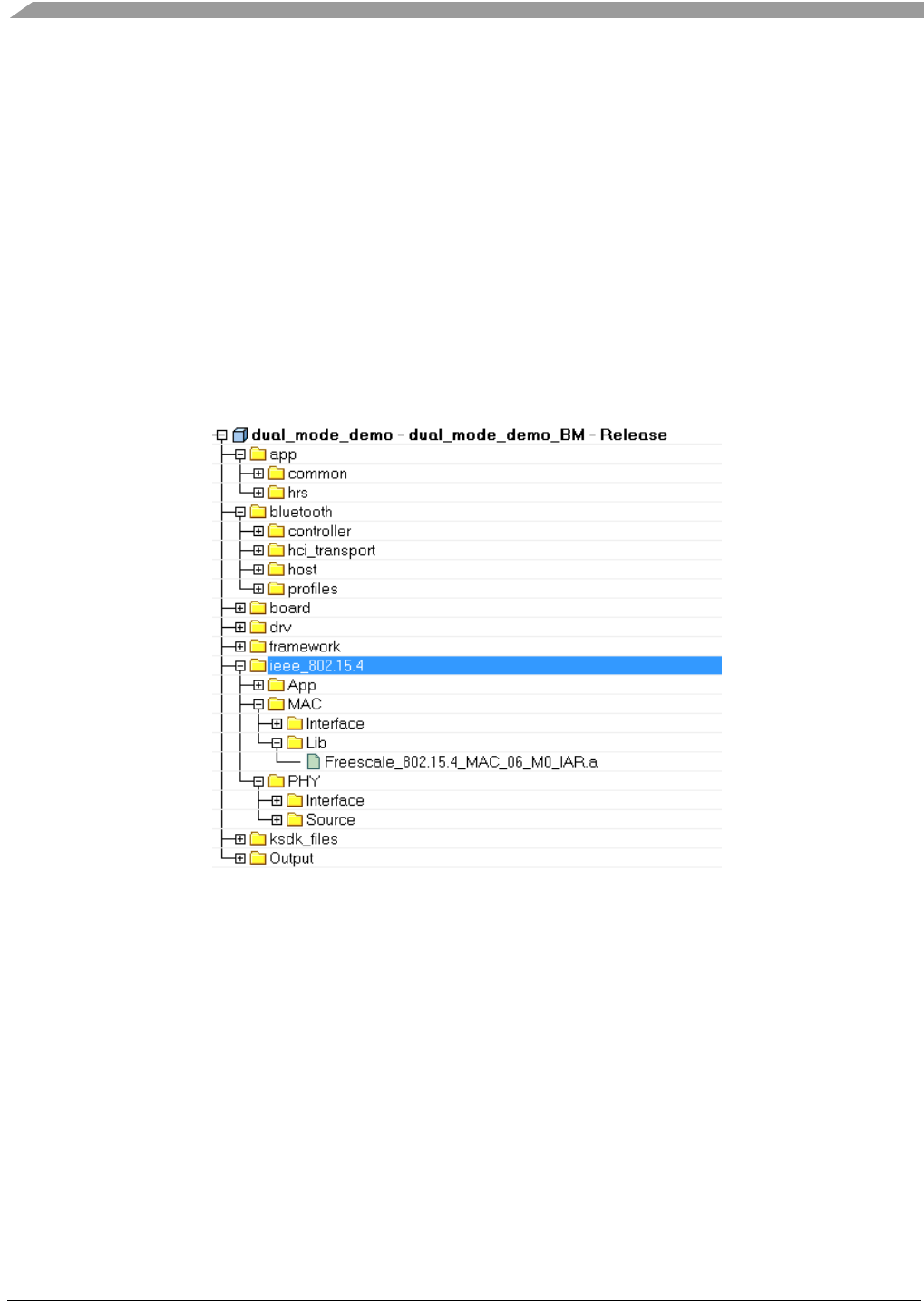
Hybrid (Dual-Mode) Bluetooth® Low Energy and IEEE® 802.15.4 Applications
Bluetooth® Low Energy User’s Guide Rev. 4, 09/2016
134 NXP Semiconductors
13. Hybrid (Dual-Mode) Bluetooth® Low Energy and IEEE®
802.15.4 Applications
This section describes how to add IEEE 802.15.4 functionality to an existing BLE application in order to
create a dual mode application.
Project structure
The project structure should follow the one from the demo applications in the examples/hybrid folder, as
illustrated by the following figure:
Figure 26. Hybrid Demo Application – Project Structure
As one can observe, the ieee_802.15.4 folder is added to the existing structure to include the Phy and
Mac functionality specific to IEEE 802.15.4. The Phy folder contains interface and sources, while the
Mac folder contains the precompiled MAC library and interface. The App folder contains global MAC
definitions.
Project options
Two important compiler defines must be added in the app_preinclude.h file:
• gMacFeatureSet_d must be defined with the value gMacFeatureSet_06M0_d
• gMWS_Enabled_d must be defined with the value 1
Bluetooth® Low Energy User’s Guide Rev. 4 09/2016
135 NXP Semiconductors
Common files for hybrid applications
All the hybrid applications should use the existing files from examples/hybrid/common without editing
them. These perform common initializations for both BLE and 802.15.4.
The BLE initializations are similar to the ones described in section Error! Reference source not
found..
In the ApplMain.c, both the BLE and 802.15.4 functionalities are enabled in the main_task function:
/* BLE Host Stack Init */
Ble_Initialize(App_GenericCallback);
/* 802.15.4 PHY and MAC initialization */
Phy_Init();
MAC_Init();
App_Init();
Application-specific files
The main logic specific to each application is defined in each app.c file.
For the BLE functionality, this file contains the definitions of all callbacks and API interactions, as
described in the previous chapters of this document.
To add specific 802.15.4 functionality, besides the initializations performed in the common files (see
previous section), the following steps must be followed:
• Include the required headers:
/* 802.15.4 */
#include "PhyInterface.h"
#include "MacInterface.h"
• Define required parameters:
/* 802.15.4 definitions */
#define mDefaultValueOfChannel_c (0x07FFF800)
#define mDefaultValueOfShortAddress_c (0xCAFE)
#define mDefaultValueOfPanId_c (0xBEEF)
#define mMacExtendedAddress_c (0x1111111111111111)
#define mMaxKeysToReceive_c (32)
• Declare and define a MAC instance and MAC SAP handlers:
uint8_t mMacInstance;
resultType_t MCPS_NWK_SapHandler (mcpsToNwkMessage_t* pMsg, instanceId_t instanceId);
resultType_t MLME_NWK_SapHandler (nwkMessage_t* pMsg, instanceId_t instanceId);
• Initialize the MAC:
mMacInstance = BindToMAC(0);
Mac_RegisterSapHandlers(MCPS_NWK_SapHandler, MLME_NWK_SapHandler, mMacInstance);

Hybrid (Dual-Mode) Bluetooth® Low Energy and IEEE® 802.15.4 Applications
Bluetooth® Low Energy User’s Guide Rev. 4 09/2016
136 NXP Semiconductors
Then the MAC APIs can be used to communicate over 802.15.4.
For example, the following functions starts the application as a MAC Coordinator:
uint8_t App_Init(void)
{
mMacInstance = BindToMAC(0);
Mac_RegisterSapHandlers(MCPS_NWK_SapHandler, MLME_NWK_SapHandler, mMacInstance);
/* Start 802.15.4 */
App_StartScan(gScanModeED_c);
}
Example of a MLME SAP to handle the MAC command responses:
resultType_t MLME_NWK_SapHandler (nwkMessage_t* pMsg, instanceId_t instanceId)
{
switch(pMsg->msgType)
{
case gMlmeScanCnf_c:
/* Process the Scan confirm. */
break;
case gMlmeStartCnf_c:
/* Process the MLME-START confirm. */
break;
case gMlmeAssociateInd_c:
/* A device sent us an Associate Request. We must send back a response. */
break;
}
MEM_BufferFree( pMsg );
return gSuccess_c;
}
Example of a MCPS SAP which handles the MAC data indications and confirms:
resultType_t MCPS_NWK_SapHandler (mcpsToNwkMessage_t* pMsg, instanceId_t instanceId)
{
switch(pMsg->msgType)
{
case gMcpsDataCnf_c:
/* The MCPS-Data confirm is sent by the MAC to the network
or application layer when data has been sent. */
break;
case gMcpsDataInd_c:
/* The MCPS-Data indication is sent by the MAC to the network
or application layer when data has been received. */
break;
}
MEM_BufferFree( pMsg );
return gSuccess_c;
}

Revision history
Bluetooth® Low Energy User’s Guide Rev. 4 09/2016
NXP Semiconductors 137
14. Revision history
This table summarizes revisions to this document.
Revision history
Revision number Date Substantive changes
0
06/2015
Initial release
1
10/2015
Added new applications
2
04/2016
Adapted the text and code extracts in OTAP chapter to
match the new BLE 4.2 implementation changes.
Added section that describes how to create an OTAP
image file from a BIN type file.
Added more detailed explanations and diagrams to the
Bootloader section.
Added LE Long Frames section.
Updated Low Power section.
Updated RTOS section.
Added Enhanced Privacy section.
Added Dynamic GATT Database section.
Updated GAP section with LE Secure Connections
references.
3
07/2016
Updated the Application Structure section.
4
09/2016
Public information

Document Number: BLEADG
Rev. 4
09/2016
How to Reach Us:
Home Page:
nxp.com
Web Support:
nxp.com/support
Information in this document is provided solely to enable system and software
implementers to use Freescale products. There are no express or implied
copyright
licenses granted hereunder to design or fabricate any integrated circuits based on the
information in this document.
Freescale reserves the right to make changes without further notice to any products
herein. Freescale makes no warranty, represen
tation, or guarantee regarding the
suitability of its products for any particular purpose, nor does Freescale assume any
liability arising out of the application or use of any product or circuit, and specifically
disclaims any and all liability, including
without limitation consequential or incidental
damages. “Typical” parameters that may be provided in Freescale data sheets and/or
specifications can and do vary in different applications, and actual performance may
vary over time. All operating parameters,
including “typicals,” must be validated for each
customer application by customer's technical experts. Freescale does not convey any
license under its patent rights nor the rights of others. Freescale sells products pursuant
to standard terms and conditio
ns of sale, which can be found at the following address:
freescale.com/SalesTermsandConditions.
Freescale, the Freescale logo, and Kinetis are trademarks of Freescale Semiconductor, Inc., Reg.
U.S. Pat. & Tm.Off. Tower is a trademark of Freescale Semicondu
ctor, Inc. All other product or
service names are the property of their respective owners. ARM, ARM powered logo, IAR, and
Cortex are registered trademarks of ARM Limited (or its subsidiaries) in the EU and/or
elsewhere. All rights reserved.
The Bluetooth
® word mark and logos are registered trademarks owned by Bluetooth SIG, Inc.
and any use of such marks by Freescale Semiconductor, Inc. is under license. Other trademarks
and trade names are those of their respective owners.
IEEE 802.15.4
is a registered trademarks of the Institute of Electrical and Electronics Engineers,
Inc. (IEEE). This product is not endorsed or approved by the IEEE.
©
2016 Freescale Semiconductor, Inc.
