Boschpva2P500 PAVIRO Amplifier User Manual
2017-03-29
User Manual: Pdf Boschpva2P500 BOSCHPVA2P500 pdf kavson.co.uk
Open the PDF directly: View PDF ![]() .
.
Page Count: 3
Communications Systems | PAVIRO Amplifier
PAVIRO Amplifier
www.boschsecurity.com
u2 ✕ 500 Watt class D amplifier
uLow power consumption in standby mode (3 Watt)
uLocal input per channel
uExcellent sound quality > 104 dB s/n ratio
The PVA-2P500 class-D amplifier is a 2 ✕ 500 W
professional audio amplifier for evacuation purposes.
It can be operated from both the mains and a DC
supply. The output voltage is galvanically insulated and
is constantly monitored for ground fault. An energy-
saving mode and temperature-controlled fans reduce
energy consumption and noise levels. The control and
monitoring functions are performed via CAN bus. This
amplifier is designed for operation in an emergency
evacuation system. The amplifiers are usually
controlled via a controller and configured using IRIS-
Net.
The power amplifier has the following features:
• Floating 100 V or 70 V power outputs
• High efficient amplifier blocks in class-D technology
• Outputs idling and short circuit-protected
• Mains operation 120–240 V (50/60 Hz) and/or 24 V
DC emergency backup
• Electronically balanced inputs
• Temperature monitoring function
• Pilot tone and ground fault monitoring function via
PVA-4CR12 controller or PVA-4R24 router
• Processor control of all functions
• Monitoring of the processor system via watchdog
circuit
• Non-volatile FLASH memory for configuration data
• Internal monitoring function
• Integrated audio relays
• Line monitoring function
The power amplifier is processor-controlled and
equipped with extensive monitoring functions. Line
monitoring for the CAN bus and for audio transmission
allows line interruptions and short-circuits to be
detected and indicated to the user.
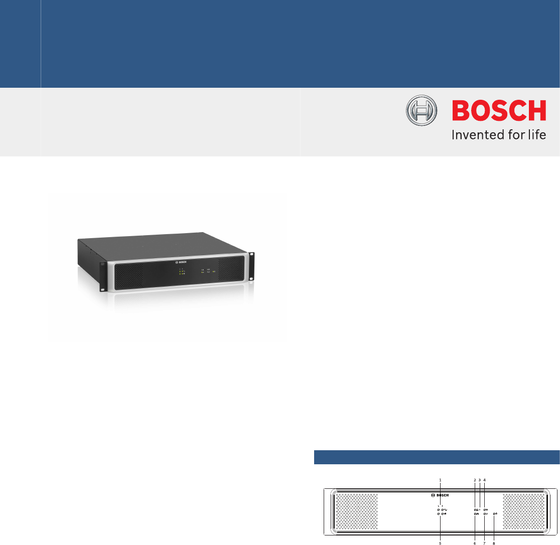
System overview
1 Signal clip indicator light
2 General fault warning indicator light
3 Recessed button
4 Ground fault indicator light
5 Audio signal indicator light
6 Network indicator light
7 Standby indicator light
8 Power indicator light

1 AC power input and power switch
2 Grounding screw
3 DC power input
4 CAN BUS port
5 CAN ADDRESS selector switch
6 LINE IN 1-4 audio input sockets (RJ-45)
7 LINE IN 1 or 2 audio input sockets (Euroblock, balanced
signal)
8 Amplifier power output sockets (70 V or 100 V)
Certifications and approvals
• EN 50130-4
• EN 50581
• EN 55103-1/2
• EN 61000-3-2/3
• EN 61000-6-3
• IEC 60065
• EN 60945
Parts included
Quantit
y
Component
1 PVA-2P500
1 Power cord 230 V AC
1 Power cord 120 V AC
1 Euroblock connector 2-pole (Phoenix, PC 5/2-STF-7,62,
1975697, F.01U.108.398) for 24 V DC
2 Euroblock connector 3-pole (Phoenix, MC 1,5/3-STF-3,81,
Nr. 1827716, F.01U.104.680) for audio input
2 Euroblock connector 6-pole (Phoenix, MC 1,5/6-ST-3,81,
1827745, F.01U.104.179) for audio outputs
4 Foot stand (self-adhesive)
1 Operation manual
1 Important safety instructions
Technical specifications
Rated load impedance (output power)
• 100 V 20 Ω (500 W)
• 70 V 10 Ω (500 W)
Rated output power, 1 kHz, THD ≤
1%
2 ✕ 500 W1
Rated input voltage +6 dBu
Max. RMS voltage swing, 1 kHz, THD ≤ 1%, without load
• 100 V 110 V
• 70 V 78 V
Voltage gain, ref. 1 kHz, fixed
• 70 V 33.2 dB
• 100 V 36.2 dB
Maximum load capacitance 2 µF
Input level, max. +18 dBu (9.75 Vrms)
Frequency response, ref. 1 kHz,
rated load, -3 dB
50 Hz to 25 kHz
Input impedance, active balanced 20 kΩ
Signal-to-noise ratio (A-weighted) > 104 dB
Output noise (A-weighted) < -62 dBu
Crosstalk , ref. 1 kHz < -85 dB
Output stage topology Class-D, transformer, floating
Power requirements
• AC 115–240 V (-10/+10%)2
• DC 21‑32 V
Power consumption, AC and DC See section “Power
consumption” in operation
manual
Inrush current 2 A
Inrush current, after five-second
power cycle
1.3 A
Mains fuse T6.3A (internally)
DC fuse 30A (internally)
Ground fault R < 50 kΩ
CAN BUS port 2 ✕ RJ-45, 10 to 500 kbit/s
Protection Audio input level limiter, RMS
output power limiter, high
temperature, DC, short circuit,
mains undervoltage protection,
DC supply undervoltage
protection, inrush current
limiter, ground fault
Cooling Front-to-rear, temperature-
controlled fans
Operating temperature -5 °C to +45 °C
Safety class Class I
Electromagnetic environment E1, E2, E3
Product dimensions (Width ✕
Height ✕ Depth)
19”, 2 HU, 483 ✕ 88.2 ✕ 391
mm
2 | PAVIRO Amplifier
Net weight 16.5 kg
Shipping weight 19 kg
1 In DC mode and in continuous alarm-signal
operation, output signal limited by 3 dB max.
2 Reduced output power at mains voltages below
115 V
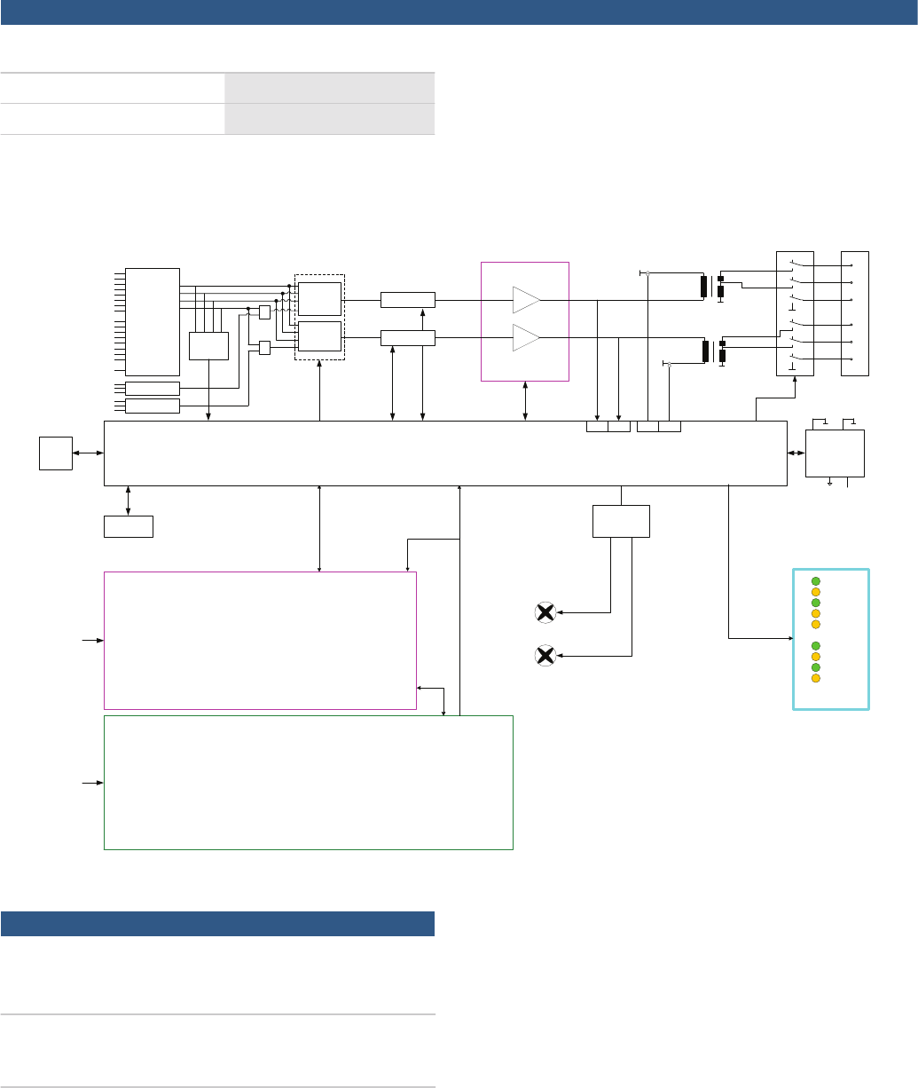
IN1+
IN1-
IN2+
IN2-
IN3+
IN4+
OUT1+
IN3-
IN4-
GNDA
OUT2+
OUT3+
OUT4+
OUT1-
OUT2-
OUT3-
OUT4-
All NF-Inputs:
+6dBu input sensitivity
+12dBu input acceptance
2.RJ45
analog audio
input 4 IN 1
Router 250W
250W
250W / 500W
Output
Transformer
Control & Supervision GND-FAULT
+15V
CAN
LED Display
1
2
1
2
1 2
250W / 500W
Output
Transformer
Output Relay
ADCADC
ADCADC
Clipper / Limiter
FAN_PWM
Power
Standby
Remote
General Fault
GND Fault
Signal CH1
Clip CH1
Signal CH2
Clip CH2
Test-Button
Watchdog
4 CH Signal
detection
(>= -50dB)
Display BUS
Phoenix Input
GNDA
GNDA
IN1+
IN1-
IN2+
IN2-
4 IN 1
Router
+
+
Phoenix Input
CH1
CH2
CH3
CH4
Local 1
Local 2
100V
70V
0V
100V
70V
0V
DC Power supply unit
AC Power supply unit
FAN
Powerstage
DC Input
AC Input
Clipper / Limiter
Circuit diagram
Ordering information
PVA-2P500 PAVIRO Power Amplifier
2 ✕ 500 Watt
Order number PVA-2P500
PVA-2P500-CN PAVIRO Power Amplifier
2 ✕ 500 Watt, chinese version
Order number PVA-2P500-CN
3 | PAVIRO Amplifier
Represented by:
Americas: Europe, Middle East, Africa: Asia-Pacific: China: America Latina:
Bosch Security Systems, Inc.
12000 Portland Avenue South
Burnsville MN 55337, USA
Phone: +1-800-392-3497
Fax: +1-800-955-6831
audiosupport@us.bosch.com
www.boschsecurity.com
Bosch Security Systems B.V.
P.O. Box 80002
5617 BA Eindhoven, The Netherlands
Phone: + 31 40 2577 284
Fax: +31 40 2577 330
emea.securitysystems@bosch.com
www.boschsecurity.com
Robert Bosch (SEA) Pte Ltd, Security
Systems
11 Bishan Street 21
Singapore 573943
Phone: +65 6571 2808
Fax: +65 6571 2699
apr.securitysystems@bosch.com
www.boschsecurity.asia
Bosch (Shanghai) Security Systems Ltd.
201 Building, No. 333 Fuquan Road
North IBP
Changning District, Shanghai
200335 China
Phone +86 21 22181111
Fax: +86 21 22182398
www.boschsecurity.com.cn
Robert Bosch Ltda Security Systems Division
Via Anhanguera, Km 98
CEP 13065-900
Campinas, Sao Paulo, Brazil
Phone: +55 19 2103 2860
Fax: +55 19 2103 2862
latam.boschsecurity@bosch.com
www.boschsecurity.com
© Bosch Security Systems 2015 | Data subject to change without notice
17562863371 | en, V2, 27. Jul 2015
