CC2640 BLE OAD User's Guide
CC2640%20BLE%20OAD%20User's%20Guide
CC2640%20BLE%20OAD%20User's%20Guide
CC2640%20BLE%20OAD%20User's%20Guide
User Manual: Pdf
Open the PDF directly: View PDF ![]() .
.
Page Count: 46
- 1 Read this Section First
- 2 Revision History
- 3 References
- 4 Definitions, Abbreviations, Acronyms
- 5 Purpose
- 6 Scope
- 7 OAD Concept Overview
- 8 Off- Chip OAD
- 9 On-Chip OAD
- 10 Appendix
- 11 Troubleshooting Guide
- 11.1 General Troubleshooting Guide Prior to BIM
- 11.2 Downloaded OAD Image Isn’t Starting
- 11.3 OAD_CRC_ERR Randomly Occurs
- 11.4 Should External Flash be Used During OAD?
- 11.5 Building Super Hex Files
- 11.6 Mobile Application Can’t Perform OAD
- 11.7 OAD_TARGET’s Merge.bat Reports Data Overlapped
- 11.8 Individually Flashing Hex Files for On-Chip OAD - App doesn’t work!

SimpleLink™ Bluetooth® low energy
CC2640 wireless MCU
Over-the-Air Download User’s Guide
For BLE-Stack™ Version: 2.2.1
Table of Contents
Table of Contents
1 Read this Section First ........................................................................................................................... 6
1.1 Document Updates ....................................................................................................................... 6
1.2 Legacy OAD Versions .................................................................................................................... 6
1.3 Supported OAD Downloaders ....................................................................................................... 6
1.4 Additional Resources .................................................................................................................... 6
2 Revision History .................................................................................................................................... 6
3 References ............................................................................................................................................ 7
4 Definitions, Abbreviations, Acronyms .................................................................................................. 7
5 Purpose ................................................................................................................................................. 8
6 Scope ..................................................................................................................................................... 8
7 OAD Concept Overview......................................................................................................................... 9
7.1 OAD Types ..................................................................................................................................... 9
7.2 OAD Topology Overview ............................................................................................................... 9
7.3 OAD Image Metadata ................................................................................................................. 10
7.3.1 CRC and CRC Shadow .......................................................................................................... 11
7.3.2 Version ................................................................................................................................ 11
7.3.3 Length ................................................................................................................................. 11
7.3.4 User Identification (UID) ..................................................................................................... 12
7.3.5 Start Address ....................................................................................................................... 12
7.3.6 Image Type .......................................................................................................................... 12
7.3.7 Image State ......................................................................................................................... 13
7.4 OAD Service Description ............................................................................................................. 13
7.4.1 OAD Image Identify (0xFFC1) .............................................................................................. 14
7.4.2 OAD Image Block Characteristic (0xFFC2) ........................................................................... 15
7.4.3 OAD Image Count Characteristic (0xFFC3) .......................................................................... 15
7.4.4 OAD Image Status (0xFFC4) ................................................................................................ 16
7.5 OAD Process ................................................................................................................................ 16
7.5.1 Initiation of the On-chip OAD Process ................................................................................ 16
7.5.2 Image Block Transfers ......................................................................................................... 18
7.5.3 Completion of the On-chip OAD Process ............................................................................ 18
7.6 OAD Reset Service ....................................................................................................................... 18
7.6.1 OAD Reset (0xFFD1) ............................................................................................................ 18
7.7 Bootloader .................................................................................................................................. 19
8 Off- Chip OAD ...................................................................................................................................... 19
8.1 Constraints and Requirements for Off-chip OAD........................................................................ 19
8.2 Out of box demo (Off-chip OAD) ................................................................................................ 20
8.3 OAD Target .................................................................................................................................. 22
8.3.1 Overview of OAD Target for Off-chip OAD ......................................................................... 22
8.3.2 BIM for Off-chip OAD .......................................................................................................... 23
8.4 Building Off-chip OAD ................................................................................................................. 24
8.4.1 Building BIM ........................................................................................................................ 24
8.4.2 Building the BLE Stack ......................................................................................................... 25
8.4.3 Building the Application Image ........................................................................................... 25
8.5 Considerations for Off-chip OAD ................................................................................................ 28
8.5.1 Adjusting Off-chip Flash Memory Layout ........................................................................... 28
8.5.2 Conditions for Rejecting Metadata ..................................................................................... 28
9 On-Chip OAD ....................................................................................................................................... 28
9.1 Constraints and Requirements for On-chip OAD ........................................................................ 28
9.2 Out of box demo ......................................................................................................................... 29
9.3 OAD Target .................................................................................................................................. 31
9.3.1 Overview of OAD Target for On-chip OAD .......................................................................... 31
9.3.2 BIM for On-chip OAD .......................................................................................................... 32
9.4 Building On-chip OAD ................................................................................................................. 33
9.4.1 Building BIM ........................................................................................................................ 33
9.4.2 Building the BLE Stack ......................................................................................................... 33
9.4.3 Building the OAD Target Application .................................................................................. 34
9.4.4 Building OAD Image B ......................................................................................................... 34
9.5 Considerations for On-chip OAD ................................................................................................. 38
9.5.1 Adjusting Stack and Application Sizes ................................................................................. 38
9.5.2 Conditions for Rejecting Metadata ..................................................................................... 38
10 Appendix ......................................................................................................................................... 38
10.1 Installing Python ......................................................................................................................... 38
10.2 TI OAD Image Tool (Python) ........................................................................................................ 39
10.2.1 Download the tool .............................................................................................................. 39
10.2.2 Dependencies ...................................................................................................................... 39
10.2.3 Using the tool ...................................................................................................................... 39
10.2.4 Building a Production Image ............................................................................................... 41
10.2.5 Automating the script ......................................................................................................... 43
10.3 RTOS RCFG Section...................................................................................................................... 44
10.4 Additional updates ...................................................................................................................... 44
11 Troubleshooting Guide ................................................................................................................... 44
11.1 General Troubleshooting Guide Prior to BIM ............................................................................. 44
11.2 Downloaded OAD Image Isn’t Starting ....................................................................................... 45
11.3 OAD_CRC_ERR Randomly Occurs ............................................................................................... 45
11.4 Should External Flash be Used During OAD? .............................................................................. 45
11.5 Building Super Hex Files .............................................................................................................. 45
11.6 Mobile Application Can’t Perform OAD ...................................................................................... 45
11.7 OAD_TARGET’s Merge.bat Reports Data Overlapped ................................................................ 46
11.8 Individually Flashing Hex Files for On-Chip OAD - App doesn’t work! ........................................ 46
Table of Figures/Diagrams
Figure 1. Two Types of OAD .......................................................................................................................... 9
Figure 2. OAD Downloader and Target ....................................................................................................... 10
Figure 3. Metadata description ................................................................................................................... 11
Figure 4. Off-chip OAD Image Types ........................................................................................................... 12
Figure 5. OAD Service Overview ................................................................................................................. 13
Figure 6. OAD Service Description .............................................................................................................. 14
Figure 7. Reject Notification in Sniffer Capture .......................................................................................... 15
Figure 8. Successful OAD Initiation Sniffer Capture .................................................................................... 15
Figure 9. Block Request/Response Sniffer Capture .................................................................................... 15
Figure 10. OAD Status Codes ...................................................................................................................... 16
Figure 11. OAD Sequence Diagram ............................................................................................................. 17
Figure 12. OAD Reset Service ...................................................................................................................... 18
Figure 13. Off-chip OAD Target Memory Partition ..................................................................................... 22
Figure 14. Functional Overview of Off-chip BIM ......................................................................................... 24
Figure 15. On-chip OAD Target Memory Partition ..................................................................................... 31
Figure 16. Functional Overview of On-chip BIM ......................................................................................... 32
Figure 17. SmartRF Flash Programmer 2 .................................................................................................... 34
Figure 18. OAD Image Tool Arguments ....................................................................................................... 40
Figure 19. OAD Image Tool Output ............................................................................................................. 41
Figure 20. OnChip OAD Production Image Example invocation. ................................................................ 42
Figure 21. OffChip OAD Production Image Example invocation ................................................................. 42
Figure 22. IAR Post-build step ..................................................................................................................... 43
Figure 23. CCS Post-build step .................................................................................................................... 44

1 Read this Section First
1.1 Document Updates
This document is constantly being improved. For the best user experience, please ensure that you are
using the latest version. Newer revisions will be posted online on the OAD User's Guide wiki page.
1.2 Legacy OAD Versions
Prior to the BLE-Stack v2.2.0 release, there were three versions of OAD supported by the SDK:
1. Off chip OAD with preserved page 0 using BIM
2. Off chip OAD without preserved page 0 using Baseloader
3. On chip OAD using BIM
In BLE-Stack SDK versions prior to 2.2.0, the SensorTag embedded project supported the baseloader
(Method 2) from above. In conjunction with the embedded project, the SensorTag mobile applications
(iOS, Android) only supported the baseloader method (Method 2). This method has been discontinued*
as of BLE-Stack v2.2.0, all projects (including the SensorTag) have now standardized on Methods 1 and 3.
This guide (and its previous versions) will describe the BIM based on On-chip and Off-chip methods
(Method 1 and Method 3 above).
*The baseloader method has been discontinued because there is a risk where a device may become
bricked (require wired JTAG access to recover) if a power loss is experienced while updating page 0*
1.3 Supported OAD Downloaders
As mentioned above, the SensorTag mobile applications supported the baseloader method prior to BLE-
Stack v2.2.0. These applications are in the process of being updated to support BIM based methods. For
the best out of box experience, TI recommends that customers use BLE Device Monitor v2.1.5 or later as
their OAD downloader, as it supports all OAD methods mentioned above.
1.4 Additional Resources
For hands on training using OAD as well as guidance on the out of the box demos, please refer to the
OAD Simple Link Academy module (coming soon):
http://software-dl.ti.com/lprf/simplelink_academy/overview.html
2 Revision History
Date
Author’s
Name
Doc
Revision
Section(s)
Summary
12/17/14
SP
1.0
5, 6, 7, 8, 9, 13, 14
Edited for correctness
2/16/2015
SP
2.0
Finalization
7/14/2015
CK
2.1
All
Reorganized chapters / Added Off-chip OAD
/ Removed OAD Manager / Added
downloading methods / Added compiler
dependencies / Added sequence diagrams

1/14/2016
ZH
2.1.1
All
Re-organized for user-friendliness /
Separate Off-chip and On-Chip OAD
chapters / Added Appendix chapter
5/17/16
ZH, SML
2.2
All
Update to BLE Stack 2.2
10/21/16
AR
2.2.1
10,11
Update to BLE Stack 2.2.1
3 References
1. Texas Instruments CC2640 Bluetooth® low energy Software Developer’s Guide
http://www.ti.com/lit/pdf/swru393
2. OAD User’s Guide Wiki Page
http://processors.wiki.ti.com/index.php/CC2640_OAD_User%27s_Guide
3. BLE Device Monitor User’s Guide
http://processors.wiki.ti.com/index.php/BLE_Device_Monitor_User_Guide
4. BLE Device Monitor Download Link
http://www.ti.com/lit/zip/swrc258
5. SimpleLink Academy
http://software-dl.ti.com/lprf/simplelink_academy/overview.html
4 Definitions, Abbreviations, Acronyms
Term
Definition
BIM
Boot Image Manager, the software bootloader
BLE
Bluetooth low energy wireless protocol
CCCD
Client Characteristic Configuration Descriptor
CCFG
Customer Configuration Area, contains lock-bits on flash page 31
CCS
Code Composer Studio
MCU
Microcontroller Unit
OAD
Over the Air Download
RCFG
RTOS in ROM Configuration Table
ROM
Read Only Memory
RTOS
Real Time Operating System
SNV
Simple Non-Volatile storage
TI
Texas Instruments
TI-RTOS
Texas Instruments Real Time Operating System

5 Purpose
This document describes the process by which a developer can enable a SimpleLink™ Bluetooth® low
energy CC2640 wireless MCU project and application to successfully implement the TI OAD Profile to
remotely upgrade the image on a CC2640 BLE device, a process further referred to as an Over-the-Air
Download (OAD). This process provides tremendous value to a BLE product solution, as a target device
does not need to be physically accessed to provide a software upgrade. Our purpose here is to make
OAD simple by providing detailed instructions from enabling OAD in an application project to receiving
the new image over the air, verifying its correctness, and running it from the bootloader.
6 Scope
This document provides instruction on how to setup a BLE-Stack™ project to be OAD enabled, such as
our example simple_peripheral project for OAD. An overview of the OAD architecture and how to build,
download, and debug the components shall be discussed here as well. Details about the BLE runtime
system on CC26xx devices and the interrupt vector tables will be discussed as is necessary to elucidate
how an OAD build differs from a project which does not provide OAD capability.
There are two different types of OAD. One is On-chip OAD which doesn’t require any additional
hardware and the other is Off-chip OAD which supports a system where an external flash memory is
equipped. In the sample application projects, it is assumed that the hardware is the CC2650 LaunchPad
where 1MB external flash memory is connected to the CC2650 via SPI.
Topics omitted from this document are reducing the size of an application which does not meet the size
limitation (see 9.1), or an On-chip OAD on the BLE stack image or the bootloader. It is important to note
that an On-chip OAD of the application image does not include an upgrade of the BLE Stack image as
well. Also OAD for the sensortag project is not specifically mentioned in this guide since it uses the same
Off-chip OAD method as the simple_peripheral project, see the SensorTag User’s Guide wiki for more
information on the SensorTag:
http://processors.wiki.ti.com/index.php/CC2650_SensorTag_User's_Guide.
Note: On-chip OAD is currently only supported by IAR with CC2640 devices, while Off-chip OAD works
with both IAR and CCS.
NOTE: This kit supports development of Bluetooth low energy applications on the following
SimpleLink wireless MCUs: CC2640 and CC2650. The multi-standard CC2650 wireless MCU
supports Bluetooth low energy as well as other wireless protocols, such as ZigBee® and
6LoWPAN. The CC2640 supports Bluetooth low energy only. All code generated from the
BLE-Stack v2.x SDK is binary compatible and exchangeable with both the CC2650 and
CC2640 wireless MCUs. Throughout this document, CC2640 and CC2650 may be used
interchangeably.
Also, it is assumed that the developer is familiar with the CC2640 Software Developer’s Guide [1],
including the dual-image architecture used by the SDK.
For additional support, please visit the following online resources:
TI Bluetooth LE Wiki-page: www.ti.com/ble-wiki
TI E2E support forum: www.ti.com/ble-forum
7 OAD Concept Overview
This section aims to explain the major concepts involved in the OAD process from a high level. The
concepts here will be expanded on further in the following sections. Some concepts, such as the Boot
Image Manager (BIM) may vary in their implementation details. Wherever possible, the concepts will be
covered in this chapter with their implementation details covered in the following chapters.
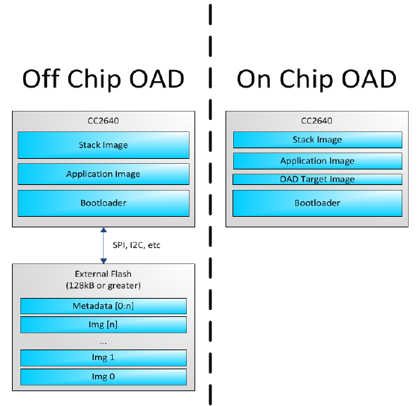
7.1 OAD Types
There are two methods of performing an over the air download: On-chip and Off-chip. The key
difference between the two methods is where the downloaded image is to be stored during the OAD. In
On-chip OAD, the downloaded image is written to internal flash, allowing for a single chip OAD solution.
Off-chip OAD stores the downloaded image in an external flash part, requiring a two chip OAD solution.
A graphic showing the different OAD methods is shown below (Figure 1). Each type of OAD has
associated tradeoffs and benefits which will be discussed in their respective sections.
Figure 1. Two Types of OAD
7.2 OAD Topology Overview
Two BLE capable devices are required for performing an OAD. The terms for the devices involved in an
OAD exchange are listed below:
OAD Target: The device whose firmware is being upgraded over the air. This is assumed to be a
CC26xx device running the TI OAD service.
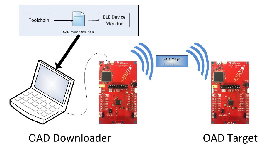
OAD Downloader: The device responsible for accepting an OAD enabled image from the
compiler and transferring it over the air to the OAD target.
OAD roles are independent of the GAP role; they are dependent on which device exposes the OAD
service. The OAD target is always the device that runs the OAD service (GATT server), and the OAD
downloader is always the device that consumes the OAD service (GATT client).
Figure 2. OAD Downloader and Target
.
All provided TI example applications (BLE Device Monitor, mobile applications, etc.) are implemented
such that the OAD Target is a peripheral device, and the OAD Downloader is a central device. For this
reason, other configurations are outside of the scope of this document.
7.3 OAD Image Metadata
There are many points in the OAD process where information must be gathered about images. This
information can be used by the OAD service to determine whether or not an image is acceptable for
download or by the bootloader to determine which image should be run. In order to prevent this
information from being calculated multiple times and to assist in the linking process, all TI OAD images
use a standard 16-byte metadata vector. This metadata vector is embedded at the beginning of the
image, occupying the first 16 bytes before the application code. This section aims to explain the various
fields within the metadata vector and what they mean. The following sections will describe how the
fields are used specifically for On-chip and Off-chip OAD.
Figure 3 below shows a description of the metadata vector.

Field
Size (in bytes)
Description
CRC
2
Cyclic Redundancy Check
CRC Shadow
2
Place holder for CRC
Version
2
Version
Length
2
Length of the image in words*
UID
4
User Identification
Start Address
2
The destination address of the image in words*
Image Type
1
The type of image to be downloaded
State
1
The status of this image
Figure 3. Metadata description
Note that the above fields that are marked with an asterisk * are measured in 32-bit words. For
example, an image length of 0x100 describes an image that is 1024 bytes in size. This OAD word size is
defined by EFL_OAD_ADDR_RESOLUTION for off chip OAD and by HAL_FLASH_WORD_SIZE for on chip
OAD.
7.3.1 CRC and CRC Shadow
The cyclic redundancy check (CRC) is a means to check an image to ensure that it has not become
corrupted. This must be done in two steps. First the CRC must be calculated when the image is
generated from the toolchain, this will be stored in the CRC field in the metadata vector. This initial CRC
will be sent over the air via the OAD service (see section 7.4). Later, the target will need to ensure that
the image has not been corrupted during transfer. The target will then re-calculate the CRC of the
downloaded image; this will be stored in the CRC shadow field of the metadata vector.
If the CRC and CRC shadow are equivalent, the target can assume that the image was not corrupted
while sending over the air.
The algorithm selected for CRC calculations is the CRC-16-CCITT, it is a 16 bit CRC calculation that boasts
a 99.9984% error detection rate in the worst case.
7.3.2 Version
The image version field is used to track revisions of images and ensure upgrade compatibility. Customers
may implement their own versioning scheme. See Section 8.5.2 and Section 9.5.2 how these version
checks are done in Off-chip and On-chip OAD, respectively.
7.3.3 Length
The length field is the length of the image in words, where the word size is defined by
EFL_OAD_ADDR_RESOLUTION and HAL_FLASH_WORD_SIZE for On-chip and Off-chip OAD respectively.
Off-chip OAD customers who are using different external flash parts may need to modify
EFL_OAD_ADDR_RESOLUTION to match the word size of their part. For On-chip OAD, the word size of
the CC2640 is fixed.

7.3.4 User Identification (UID)
This field is un-used by the TI OAD profile, but the hooks are in place for a customer to add their own
implementation of verifying images based on UID.
For on chip OAD, the convention is that Image A will embed ‘A’, ‘A’, ‘A’, ‘A’ and Image B will embed ‘B’,
‘B’, ‘B’, ‘B’. Off chip images use ‘E’, ‘E’, ‘E’, ‘E’ by default.
7.3.5 Start Address
The start address is the first address where the proposed image is to be stored in internal flash. Similar
to the length field, this is calculated in words. Off-chip OAD solutions put restrictions on the start
address based on image type (more on this in the next section).
Note that for On-chip OAD solutions, this field is reserved in the metadata as they use a fixed start
address that is based on the internal flash memory map (OAD_IMG_D_PAGE).
7.3.6 Image Type
In Off-chip OAD systems with external flash, there are multiple types of images that can be uploaded.
These image types include: App + Stack, App only, Network Processor, or Stack only.
Note: While BLE Stack only upgrades are possible, the user must be sure that the App/Stack boundary
has not changed between the resident OAD image and the proposed OAD image. Since there are no
runtime checks on the App/Stack boundary, a Stack only OAD will overwrite the resident application if
the boundary has grown. Users should exercise care when using this option.
If a boundary change is required (i.e. BLE stack is growing or shrinking), it is recommended that a user
perform a merged update (App+Stack) to ensure that the OAD image is ready to run.
Note that for on chip OAD solutions this field is reserved in the metadata as they determine image
type based on the least significant bit of the image version field as discussed above.
The supported image types are listed below:
Image Type
Value
Description
EFL_OAD_IMG_TYPE_APP
1
An application or application +
stack merged update
EFL_OAD_IMG_TYPE_STACK
2
A stack only update
EFL_OAD_IMG_TYPE_NP
3
A network processor update.
This only applies to the SimpleAP
+ SimpleNP demo
EFL_OAD_IMG_TYPE_FACTORY
4
Describes the permanently
resident production image that
runs on the device before any
OTA updates.
Figure 4. Off-chip OAD Image Types

7.3.7 Image State
The image state is a one byte metadata field that is used only by Off-chip OAD solutions. The state
informs the bootloader whether or not the image is ready to run or currently running. This prevents the
bootloader from copying the same image from external to internal flash on every boot.
Note that for On-chip OAD solutions this field is reserved in the metadata as the OAD reset service
handles switching between images in the bootloader.
7.4 OAD Service Description
The OAD service has been designed to provide a simple and customizable implementation for the
customer. In its most rudimentary form, this service is responsible for accepting/rejecting an OAD
interaction based on image header criteria, storing the image in its appropriate location, and causing a
device reset if the download is successful so that the downloaded application image is run by the BIM.
A screenshot of BLE Device Monitor displaying the OAD service is shown below.
Figure 5. OAD Service Overview
The OAD service is a primary service with four characteristics. The characteristics of the OAD service,
their UUIDs, and descriptions are listed in Figure 6.
Note that the characteristics use the 128-bit TI base UUID of the format F000XXXX-0451-4000-B000-
000000000000 where XXXX is their shortened 16bit UUID. For brevity, this document will refer to the
characteristics by their 16-bit short UUID.
UUID
Name
Description
0xFFC0
OAD Service
OAD service declaration
0xFFC1
Image Identify
Used to send image properties
(metadata) over the air so that
the OAD target device can
determine if it should accept or
reject the proposed image
0xFFC2
Image Block
Actual block of image data along
with offset into the image.
0xFFC3
Image Count
Number of complete images to
be downloaded in the OAD
session

0xFFC4
Image Status
Status of current OAD download
Figure 6. OAD Service Description
The primary method for sending data from the OAD downloader to the OAD target is the GATT writes
with no response message. GATT notifications are the primary method used to send data from the
target to the downloader. This communication scheme was selected to prevent the target device from
having to include the GATT client code required in order to receive notifications from the downloader.
The downloader shall register for notifications from any characteristic with a CCCD (by writing 01:00 to
the CCCD).
Note that both GATT notifications and GATT write with no response are non-acknowledged message
types. This means that in poor RF conditions, the OAD process may not be successful. There is an
inherent tradeoff between the speed of the OAD process and its reliability. Implementing a reliable
OAD communication protocol (with retries, acknowledgments, etc.) is outside the scope of this
document.
For a message sequence chart describing the OAD process in terms OAD service messages exchanged
between the target and downloader please see Figure 11.
7.4.1 OAD Image Identify (0xFFC1)
The Image Identify characteristic is used to exchange image metadata between downloader and target.
The OAD process begins when the downloader sends the 16 byte metadata of the proposed OAD image
to the target. Upon receiving the candidate metadata, the target will do some calculations to determine
whether or not the proposed image should be downloaded. “01:00” shall be written to the CCCD of this
characteristic so that notification for metadata rejection is enabled.
Note that the conditions under which an OAD is accepted vary slightly between the on and off chip
methods. Please see the respective sections for more information about image reject conditions.
If the target accepts the image it will continue the OAD process by sending a notification on the Image
Block characteristic requesting the first block. Otherwise the target will reject the image by sending back
a portion the currently resident image’s metadata. The reject metadata contains the Image Version,
Image version, and User ID fields. For more information about these fields, please refer to the metadata
section.
A sniffer capture of the image identify characteristic being used to reject a candidate OAD image is
shown below. Note that only image version, length, and user ID are contained in the reject notification.

Figure 7. Reject Notification in Sniffer Capture
Alternatively, a successful OAD initiation is shown in Figure 8.
Figure 8. Successful OAD Initiation Sniffer Capture
7.4.2 OAD Image Block Characteristic (0xFFC2)
The OAD Image Block characteristic is used to request and transfer a block of the OAD image. “01:00”
shall be written to the CCCD of this characteristic so that notification for block request is enabled. The
target requests the next block of the image by sending a GATT notification to the downloader with the
requested block number. The downloader will respond (GATT write no response) with the block number
and a 16 byte OAD image block. The image block contains the actual binary data from OAD image offset
by the block number. Figure 9 shows a block request/response sniffer capture.
Figure 9. Block Request/Response Sniffer Capture
In Figure 9 above, the block number field is 2 bytes (little endian) and highlighted in red. The OAD image
block is 16 bytes and highlighted in purple.
7.4.3 OAD Image Count Characteristic (0xFFC3)
The OAD Image Count characteristic is used to set the number of OAD images to be downloaded. This is
used for only Off-chip OAD and the default value of the characteristic is 1. Note On-chip OAD only
supports one image download per session. See On-chip OAD 9.1 for details.

7.4.4 OAD Image Status (0xFFC4)
The OAD image status characteristic is used to report various failures that may occur during the OAD
process. The downloader may use this information to determine why an OAD failed, so that it may
correct for the errors and try again. “01:00” shall be written to the CCCD of this characteristic so that
notification for status update is enabled. There are four OAD status messages that are defined by
default. The OAD status codes are listed in the table below:
OAD Status Code
Value
Description
OAD_SUCCESS
0
OAD succeeded
OAD_CRC_ERR
1
The downloaded image’s CRC
doesn’t match the one
expected from the metadata
OAD_FLASH_ERR
2
The external flash cannot be
opened
OAD_BUFFER_OFL
3
The block number of the
received packet doesn’t
match the one requested. An
overflow has occurred.
Figure 10. OAD Status Codes
The customer may extend these values as needed, and use the OAD_sendStatus() function to send
updates to the downloader.
7.5 OAD Process
This Profile has been designed to provide a simple and customizable OAD Profile for the customer. In its
most rudimentary form, for both On-chip and Off-chip OAD, this profile is responsible for accepting an
OAD interaction based on image header criteria, storing the image onto the flash and causing a device
reset if the download is successful so that the downloaded application image is run by the BIM.
Downloader and OAD Target perform Client role and Server role respectively.
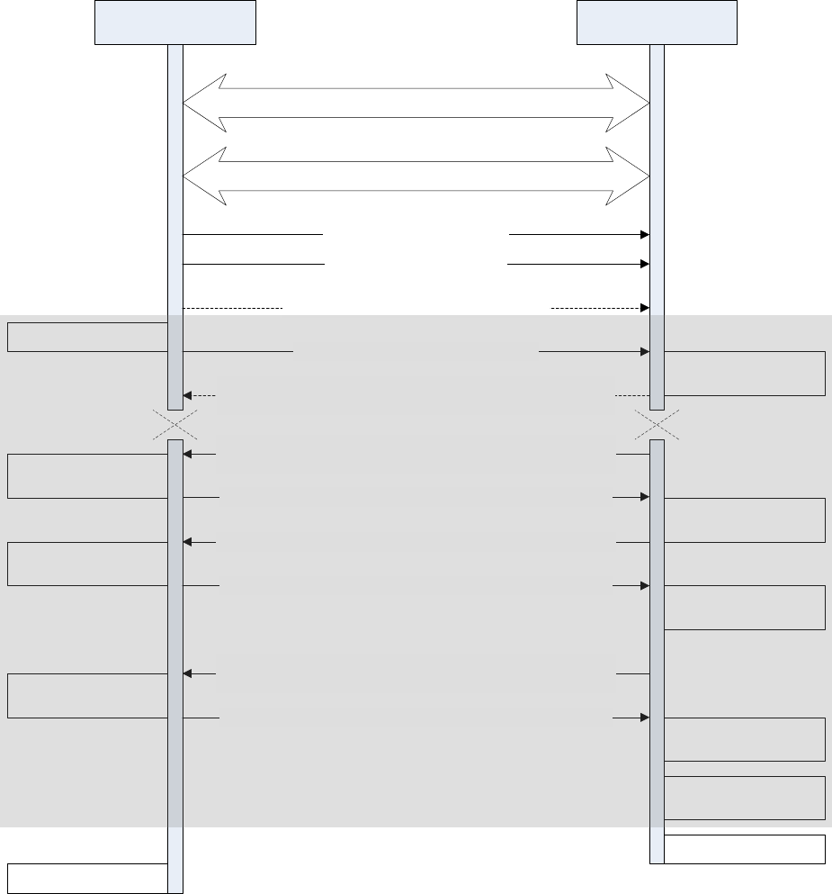
7.5.1 Initiation of the On-chip OAD Process
After establishing a new connection, updating the connection interval for a faster OAD and enabling
notifications of OAD Image Identify and OAD Image Block characteristics on the OAD Target, the
Downloader shall write to the Image Identify characteristic of the OAD Target. The message data will be
the header retrieved from the OAD Image available for OAD.
Downloader OAD Target
Configure Image Notify Char
Configure Image Block Char
Notification with the next block index from Image Block Char
(the 1st block)
Connection Establishment
Service Discovery of OAD Service
Write to Image Count Char (optional [1])
Write Metadata to Image Notify Char
Validate Metadata
Write requested block with block index to Image Block Char
Write Metadata to
off-chip flash[1]
Notification with the metadata of the current running image
from Image Notify Char (in case verification failed)
Notification with the next block index from Image Block Char
Write requested block with block index to Image Block Char
Notification with the next block index from Image Block Char
(the last block)
Write requested block with block index to Image Block Char
Write the block to
flash[2]
Write the block to
flash[2]
.
.
..
.
.
Write the block to
flash[2]
Read the block from
the image file
Read the block from
the image file
Reset
Read the block from
the image file
Generate metadata
.
.
.
Supervision timeout
[1] Applies only to Off-chip OAD
[2] Writes to on-chip flash if using On-chip OAD and off-chip flash if using Off-chip OAD
Figure 11. OAD Sequence Diagram
Upon receiving the write request to the Image Identify characteristic, the OAD Target will compare the
image available for OAD to its own running image. By default, only the image size and version number,
which implies whether the image is of type A or B, are checked to determine if the new image is
acceptable to download.

If the OAD Target determines that the image available for OAD is acceptable, the OAD Target will initiate
the OAD process by notifying the Image Block Transfer characteristic to the Downloader requesting the
first block of the new image. Otherwise, if the OAD Target finds that the new image does not meet its
criteria to begin the OAD process, it shall respond by notifying the Image Identify characteristic with its
own Image Header data as sign of rejection. In that case, the OAD procedure will end at the moment
where dotted ‘X’s are placed as depicted in Figure 11.
7.5.2 Image Block Transfers
The Image Block Transfer characteristic allows the two devices to request and respond with the OAD
image, one block at a time. The image block size is defined to be 16 bytes – see OAD_BLOCK_SIZE in
oad.h. The OAD Target will request an image block from the Downloader by notifying the OAD Image
Block characteristic with the correct block index. The Downloader shall then respond by writing to the
OAD Image Block characteristic. The message’s data will be the requested block’s index followed by the
corresponding 16-byte block of the image. Whenever the OAD Target is ready to digest another block of
the OAD image, it will notify the Image Block Transfer characteristic with the index of the desired image
block. The Downloader will then respond.
7.5.3 Completion of the On-chip OAD Process
After the OAD Target has received the final image block, it will verify that the image is correctly received
and stored by calculating the CRC over the stored OAD image. The OAD Target will then invalidate its
own image and reset so that the BIM can run the new image in-place. The burden is then on the
Downloader, which will suffer a lost BLE connection to the OAD Target during this verification and
instantiation process, to restart scanning and the to reestablish a connection and verify that the new
image is indeed running.
7.6 OAD Reset Service
The OAD reset service is only used by on chip OAD solutions. It implements a method for invalidating the
currently running image and resetting the device. This must occur because in on chip solutions the
currently running image cannot update itself. More information about the on chip OAD process will be
covered in the on chip OAD chapter. Figure 12 shows an overview of the OAD reset service and it’s
characteristic. Like the OAD service, the reset service uses the 128 bit TI base UUID with a 16 bit short
UUID of 0xFFD0.
Figure 12. OAD Reset Service
7.6.1 OAD Reset (0xFFD1)
The OAD reset is accomplished by invalidating Image B, which forces the bootloader to revert to Image A
until another successful OAD of Image B has occurred. Image B is invalidated by corrupting its CRC. After
the corruption, the reset service immediately invokes a HAL reset to jump to the bootloader. Note that a
GATT write of any value to the reset service will trigger a reset of the device/invalidation of Image B.
7.7 Bootloader
Since a running image cannot update itself, both On-chip and Off-chip OAD methods must employ a
bootloader. A bootloader is a lightweight section of code that is designed to run every time the device
resets, check the validity of newly downloaded images, and if necessary, load the new image into
internal flash. TI’s bootloader implementation is called the Boot Image Manager (BIM). BIM’s
implementation varies slightly for On-chip and Off-chip OAD solutions, thus there is a separate BIM
project for each.
/util/bim – This project implements an On-chip OAD bootloader
/util/bim_extflash – This project implements an Off-chip OAD bootloader
Note: Some BIM projects contain project configurations for a baseloader. This a legacy
implementation of BIM that is no longer used. Please see section 1.2 for more details.
BIM is always linked to page 0 and page 31 of internal flash, and will always link the CCFG section with
it.
8 Off- Chip OAD
8.1 Constraints and Requirements for Off-chip OAD
Using the internal flash of CC2640F128, the first page and the last page, or 8kB in total, of flash are
reserved for the flash interrupt vectors and the BIM. The flash page 31 or the last page starting at
address 0x1F000 where BIM is located is shared with the CCFG. Neither the first page nor the BIM is
designed to be upgraded by Off-chip OAD.
An off-chip flash component of at least 120kB plus space for a 16 byte image metadata block is required
for a full flash update. A SPI connection is used to communicate with the off-chip flash component.
The OAD image to be downloaded to the off-chip flash memory can be an application image, a stack
image, a hex merge of application plus stack, an image intended for the upgrade of a network processor,
or any type of image as far as it is supposed to eventually replace any part of the on-chip 120kB area
between the first and the last pages. More than one image can be downloaded before the system reset
followed by BIM’s copying the downloaded images from the off-chip flash memory to the on-chip flash
memory.
Since page 0 cannot be updated in Off-chip OAD, an application must include its own TI-RTOS instance in
flash without dependency on the TI-RTOS ROM implementation (see section 10.3 for more info). Also, it
must include OAD profile so that further OAD upgrades are available when it runs on the on-chip flash
memory since Off-chip OAD doesn’t require any OAD-dedicated application like Image A for On-chip
OAD.
The first and last flash pages must never be attempted to update because a power cycle during an
update of either page could render the device unresponsive until physically reprogrammed.
While On-chip OAD Target receives only one application OAD image, Off-chip OAD Target can receive up
to 3 OAD images. Usually the Downloader generates metadata of OAD images for the Off-chip OAD, but
the Python script can also embed the metadata in the image (see section 10.2 for details). The metadata
is inserted into the beginning of the Off-chip OAD Image when transferred and is also stored separately
in the off-chip flash.
8.2 Out of box demo (Off-chip OAD)
This section will go over the basic steps in building and running the Off-chip OAD simple_peripheral
project that comes with the SDK with IAR IDE.
Software requirements
BLE-Stack SDK v2.2+
Python 2.7.x (v2.7.10 or higher)
Flash Programmer 2
Device Monitor (v2.1.5 or higher)
Hardware requirements
CC2650 LaunchPad (Target)
CC2650 LaunchPad or CC2540 USB Dongle (Downloader)
The basic steps are as follows:
1. Build and download BIM project ($BLE_INSTALL$\examples\util\bim_extflash\cc2640\iar) after
choosing FlashOnly_LP configuration.
2. Open simple_peripheral project in IAR
($BLE_INSTALL$\examples\cc2650lp\simple_peripheral\iar)
a. Build and download the cc2650lp_stack – FlashROM project
b. Build and download cc2650lp_app – FlashOnly_OAD_ExtFlash project
3. Alternatively, the App project should run merge.bat file found in
\examples\cc2650lp\simple_peripheral\iar\app to create a hex merged App+BIM+Stack image
(simple_peripheral_cc2650lp_all.hex). (Note the hex file ending in “all” is used to flash the
device for the first time. Use the other generated hex files for downloading over-the-air, i.e. App
or App+Stack in Step 5 below). Then use Flash Programmer 2 to download the image to the
device.
4. Press Reset button on the CC2650 LaunchPad and verify device is advertising, default device
name should be “SimpleBLEPeripheral”
5. OAD new version of simple_peripheral App image
a. Modify cc2650lp_app – FlashOnly_OAD_ExtFlash (for example, change fields in scan
response data (scanRspData[])) and build app and generate output hex file from IAR IDE
b. (Optional) Alternatively, the Python script can be used to generate metadata in the hex
file. See section 10.2 for details. BLE Device Monitor will generate the metadata
otherwise.
c. Connect using a device with HostTest project with BLE Device Monitor and load the
hex((($BLE_INSTALL$\examples\cc2650lp\simple_peripheral\iar\app\FlashOnly_OAD_E
xtFlash\Exe\simple_peripheral_cc2650lp_app.hex)
d. Press the Start button to begin downloading the image over the air
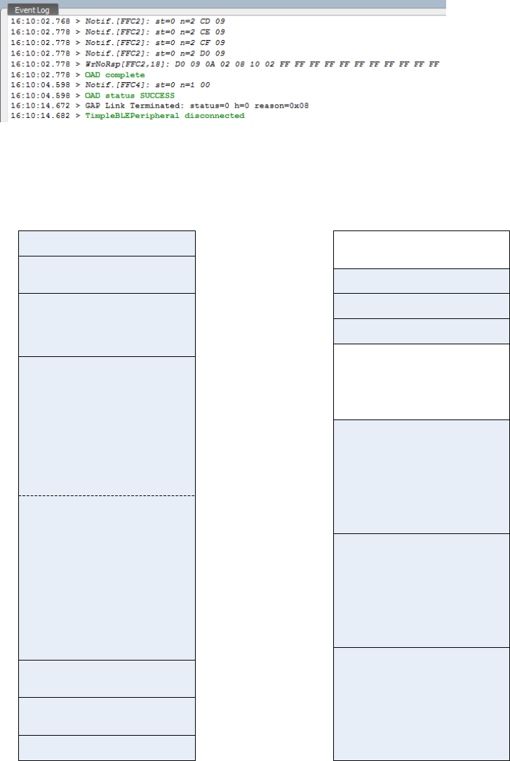
e. Device should reset and run the new image, verify link is terminated in event log as
shown in the Event Log pane below:
8.3 OAD Target
8.3.1 Overview of OAD Target for Off-chip OAD
CCFG
NV Storage Area
BLE Stack
Application
(OAD Profile embedded)
Int Vectors
0x00000
0x01000
0x1E000
0x1F000
Metadata 1
Image 1
0x00000
0x20000
0x78000
Image 2
0x40000
Image 3
Metadata 2
0x79000
Metadata 3
0x7A000
0x60000
Unused
Unused
0x7B000
0x1FFFF 0x7FFFF
On-chip
Flash Memory
Off-chip
Flash Memory
BIM
BIM
Metadata
0x01010
Boundary
Figure 13. Off-chip OAD Target Memory Partition
The Off-chip OAD Target has both on-chip flash memory and off-chip flash memory device. The on-chip
flash memory contains the Interrupt Vectors, the BLE Stack, the Application where OAD Profile is
embedded, the BLE stack image, the NV Storage Area, the BIM and the CCFG.
The off-chip flash memory contains up to 3 OAD Images and up to 3 Metadatas corresponding to the
OAD Images. The size of each OAD Image placeholder is 128kB. The memory partition of the OAD Target
for Off-chip OAD is depicted in Figure 13. Each OAD image, if it’s of either App only or App+Stack, must
support OAD Profile so that further OAD is enabled after it is downloaded to the off-chip memory,
copied to the on-chip memory and executed.
8.3.2 BIM for Off-chip OAD
The OAD solution requires that permanently resident boot code, the BIM, exists in order to provide a
fail-safe mechanism for determining whether to run the existing application image or to copy a new
image or images from off-chip flash to on-chip flash. It is assumed that a valid image exists either in off-
chip flash ready to be copied or already placed in on-chip flash at any given time. Given this assumption,
the initial image placed in internal flash which does not exist in external flash will have invalid external
image metadata, and so the bootloader will choose to jump to the existing image’s entry point.
At startup, BIM checks if the application image metadata in off-chip flash has a status indicating that the
image is to be copied to the on-chip flash. If the status is 0xFF, copies the image if a valid CRC and CRC
Shadow are found. If the status is anything other than 0xFF, assumes the application in the on-chip flash
is valid to run. If a 2 byte value is found that is neither 0x0000 nor 0xFFFF, but a 0xFFFF shadow
checksum is found, the BIM computes the CRC over the image. Image length is determined by the
metadata that is also stored contiguous with the CRC in on-chip flash that was copied over during the
original write of the image from the off-chip flash.
If off-chip flash contains a “bad” image to be downloaded, but this image is undesirable, BIM can be
programmed with symbol NO_COPY to skip image checking and jump directly into the image already
placed in on-chip flash; at which point the on-chip flash image could invalidate the bad image’s
metadata or OAD a new image in its place. BIM will not be able to load any new images while NO_COPY
is defined in the build.
BIM is only responsible for making an application image failsafe upon entry. This could mean an app and
stack image, or just the application. BIM has exactly one entrance to the application image.
The BIM occupies the last flash page with CCFG and uses the interrupt vectors at the start of flash where
the Reset Interrupt Vector calls the BIM startup routine to ensure its control of the system upon a
device reset.
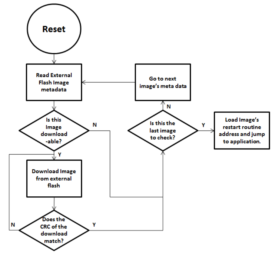
Figure 14. Functional Overview of Off-chip BIM
8.4 Building Off-chip OAD
8.4.1 Building BIM
The boot code is separately built, debugged, and programmed via the IAR or CCS IDE. The projects are
located at:
$BLE_INSTALL$\examples\util\bim_extflash\cc2640\
Choose “FlashOnly_LP” configuration and build. “FlashOnly_ST” configuration is out of scope in this
document.
By default, the symbol NO_COPY described in 8.3.2 is undefined as it is very unlikely there is a valid
image, to be copied onto the on-chip flash, in the off-chip flash for the first-time use.
8.4.2 Building the BLE Stack
There is nothing special to be done for an existing BLE Stack project to make it capable of running with
OAD-enabled application.
For IAR, the example BLE Stack project is included in the simple_peripheral workspace. For CCS, the
simple_peripheral_cc2650lp_stack project exists separately. The only change that should be made for
the stack to be flashed on the CC2650 LaunchPad platform is the Debugger setting. With IAR, select “TI
XDS110 Emulator” in Project→Options→Runtime Checking→Debugger→TI XDS→Setup→Emulator. With
CCS, select “Texas Instruments XDS110 USB Debug Probe” in
Properties→General→Main→Device→Connection.
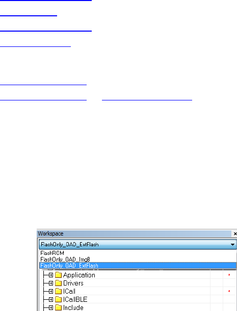
8.4.3 Building the Application Image
The simple_peripheral project contains a configuration of ‘FlashOnly_OAD_ExtFlash’ designed for the
application to run on CC2650 LaunchPad hardware platform and utilize the external flash component.
The Stack built as described in 8.4.2 works with this application.
The simple_peripheral with FlashOnly_OAD_ExtFlash configuration is made through the following
procedures. The procedures can be applied to convert any existing application to the downloadable On-
chip OAD Image. In addition to the procedures described in 8.4.3.1 and 8.4.3.2, registration and
callbacks for the OAD service should be added to the application. Changes to be made for those are
found under FEATURE_OAD in simple_peripheral.c.
The application image contains a Python script that creates a combined image of Application and Stack.
To create an image that includes Application and Stack and BIM to load the first time, see Appendix
section 10.2.
8.4.3.1 Building the Application Image using IAR
Using IAR, the Application Image can be built through the following procedure.
I. Select Project→Options→C/C++ Compiler→Preprocessor and add the following new definitions
to Defined symbols:
FEATURE_OAD
HAL_IMAGE_E
Add the following lines to Additional include directories:
$SRC_EX$/profiles/oad/cc26xx
$TI_RTOS_DRIVERS_BASE$/ti/mw/extflash
II. Select Project→Options→Linker→Config→Linker configuration file and paste the following line:
$SRC_EX$/common/cc26xx/iar/cc26xx_app_oad.icf
And add the following symbols to Configurable file symbol definitions:
APP_IMAGE_START=0x1000
Append the following in Build Actions under Pre-build command line:
--cfgArgs NO_ROM=1,OAD_IMG_E=1
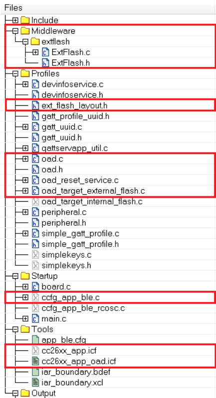
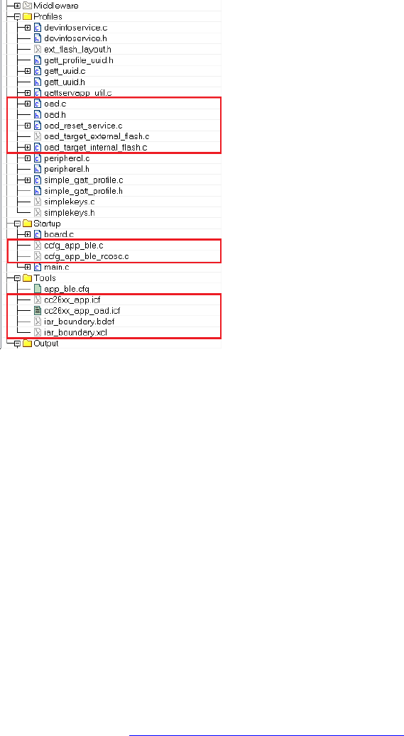
III. Under Tools, include cc26xx_app_oad.icf and exclude cc26xx_app.icf. Also exclude
ccfg_app_ble.c. Add the OAD profile modules to the PROFILES folder of the workspace. These
files are located here: $BLE_INSTALL$/src/profiles/oad/cc26xx.
8.4.3.2 Building the Application Image using CCS
Using CCS, the Application Image can be built through the following procedure.
I. Select Project→Properties→Build→ARM Compiler→Advanced Options→Predefined Symbols and
add the following to Pre-define NAME:
FEATURE_OAD
II. Select Project→Properties→Build→ARM Compiler→Include Options and add the following lines
to Add dir to #include search path:
"${SRC_EX}/profiles/oad/cc26xx"
Select Project
→
Properties
→
Build and verify the lines below in Steps
→
Post-build steps:
${CG_TOOL_HEX} -order MS --memwidth=8 --romwidth=8 --intel -o
${ProjName}.hex ${ProjName}.out

Define “NO_ROM=1,OAD_IMG_E=1" in Project→Properties→Build→XDCtools→Advanced
Options as shown below:
III. Add the OAD profile modules to the PROFILES folder of the workspace. Use
cc26xx_ble_app_oad.cmd as a linker command file instead of cc26xx_ble_app.cmd (Right-click
on the file →Exclude from Build). These files are located here:
$BLE_INSTALL$/src/profiles/oad/cc26xx.
8.5 Considerations for Off-chip OAD
8.5.1 Adjusting Off-chip Flash Memory Layout
The Off-chip OAD described in this document is based on the assumption that it is running on CC2650
LaunchPad hardware where 1MB off-chip flash memory is equipped. If the size of the off-chip flash is
different, there may be a need of changing the layout of the off-chip flash. The layout is defined in
ext_flash_layout.h and referred by both BIM and Application.
As an example, assuming the external flash size is 128kB, the OAD image and the Metadata should fit in
the 128kB space. Since the size of the OAD Image cannot exceed 120kB in Off-chip OAD design, there is
at least 8kB available space for the Metadata. We can place the Metadata in the last page of the off-chip
flash memory. This can be done by modifying EFL_ADD_META from 0x78000 to 0x1F000.
8.5.2 Conditions for Rejecting Metadata
Off-chip OAD Target checks that the new image’s version is greater than the current image’s version.
However, as a bypass mechanism, any image of version 0 will be accepted. See
OADTarget_validateNewImage() in oad_target_external_flash.c for more details.
9 On-Chip OAD
9.1 Constraints and Requirements for On-chip OAD
Using the internal flash of CC2640F128, the first 9 pages, or 36KB, of flash are, by default, reserved for
the flash interrupt vectors, the BIM and the permanently resident OAD Target App using an instance of
TI-RTOS partially implemented in ROM. BIM and the OAD Target App also use the remaining space on
flash page 31, starting at address 0x1F000, shared with the CCFG. Neither BIM nor the OAD Target App
is designed to be upgraded by On-chip OAD.
The OAD Image to be downloaded is, by default, allocated 10 flash pages, or 40KB, from address 0x9000
to 0x12FFF. Because page 0 cannot be updated, an application must include its own TI-RTOS instance in
flash without dependence on the TI-RTOS ROM implementation. This image also shares the CCFG
referenced in the above paragraph. It is not possible to update the CCFG parameters via an OAD.
The OAD Target App and the OAD image should share the same RAM range as only one is used per
device reset. The OAD Image must be a complete application image, capable of running independently
of the permanently resident OAD Target App.
The BLE protocol stack defaults to a range of 12 flash pages, or 48kB, ranging from address 0x13000 to
0x1EFFF and no SNV pages are used by default. If the OAD Image is too large to fit in its allocated space,
consider removing some features of the BLE stack to reduce its size. This will be discussed further in 9.5.
The OAD Target App, or the Image A, and the Image B shall share the same BLE stack. It is not possible to
perform an On-chip OAD of the BLE Stack image.
The first and last flash pages must never be erased as doing so puts the device in an unsafe state and a
reset at this time will “brick” the chip and prevent it from restarting without the help of a JTAG or serial
boot loader.
9.2 Out of box demo
This section will go over the basic steps in building and running the On-chip OAD simple_peripheral
project that comes with the SDK.
Software requirements
BLE-Stack SDK v2.2+
Python 2.7.x (v2.7.10 or higher)
Flash Programmer 2
Device Monitor (v2.1.5 or higher)
Hardware requirements
CC2650 LaunchPad (Target)
CC2650 LaunchPad or CC2540 USB Dongle (Downloader)
The basic steps are as follows:
1. Build the OAD Target app found in $BLE_INSTALL$\examples\cc2650lp\oad_target\iar
a. Build bim, cc2650lp_stack, and cc2650lp_app projects
2. Create the unified hex file
a. Run the merge.bat found in $BLE_INSTALL$\examples\cc2650lp\oad_target\iar\app
b. Download to the CC2650 LaunchPad with Flash Programmer 2
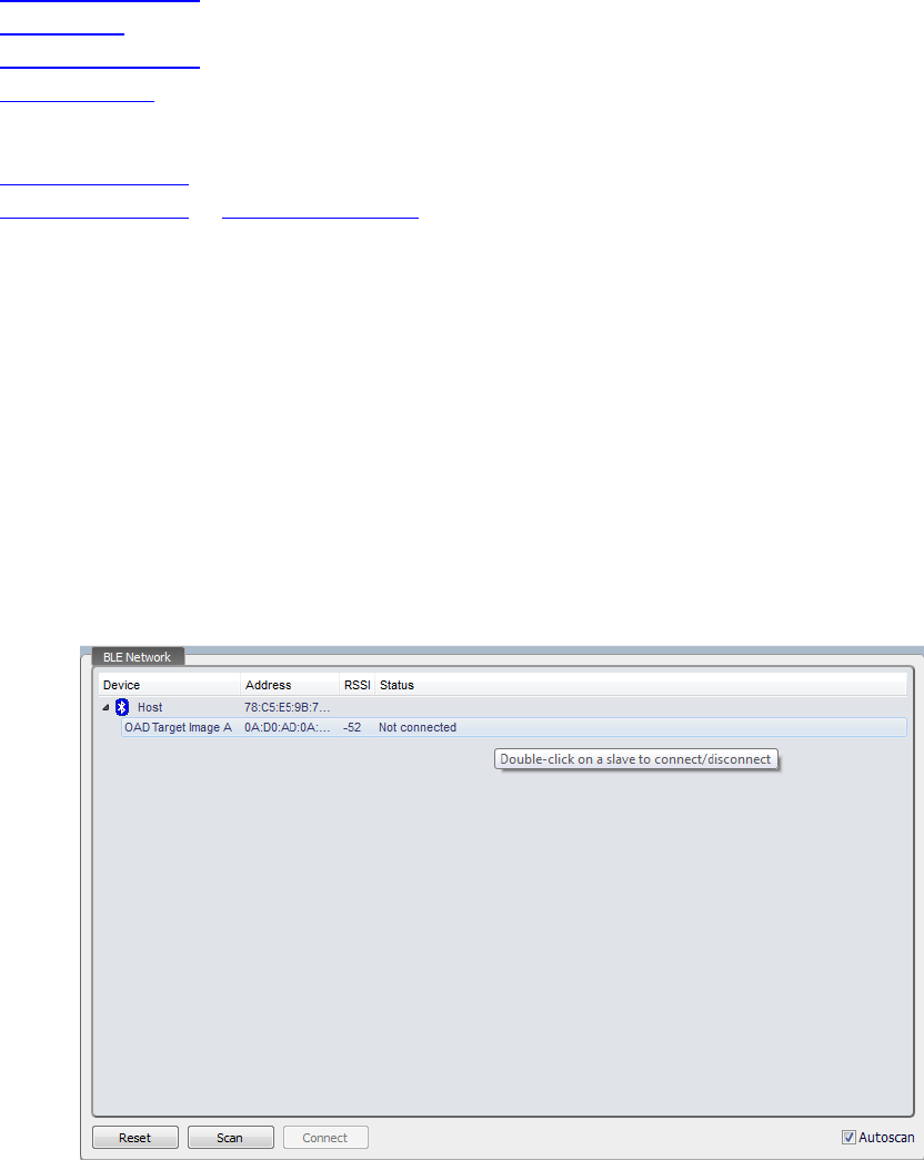
3. Connect with Device Monitor
a. Open BLE Device Monitor, connect to COM port with device running HostTest (i.e. on
devices such as CC2650 LaunchPad or CC2540 USB Dongle)
b. After scanning, click on OAD Target Image to connect to it in the BLE Network pane in
Device Monitor:
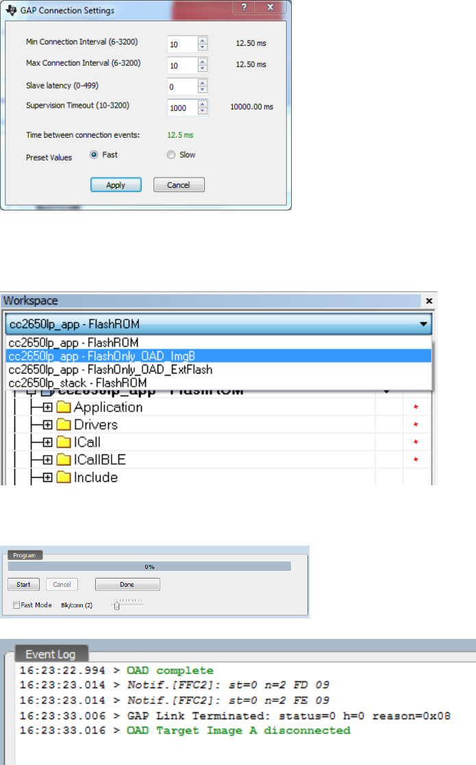
c. Go to Options -> GAP settings and click on Apply to enable fast connection interval
4. Build Image B
a. Open up simple_peripheral project in IAR found in
$BLE_INSTALL$\examples\cc2650lp\simple_peripheral\iar and choose the
FlashOnly_OAD_ImgB configuration and build the project
b. In BLE Device Monitor, open up OAD Programming tab (File -> Program (OAD)). Add the
hex image from previous step
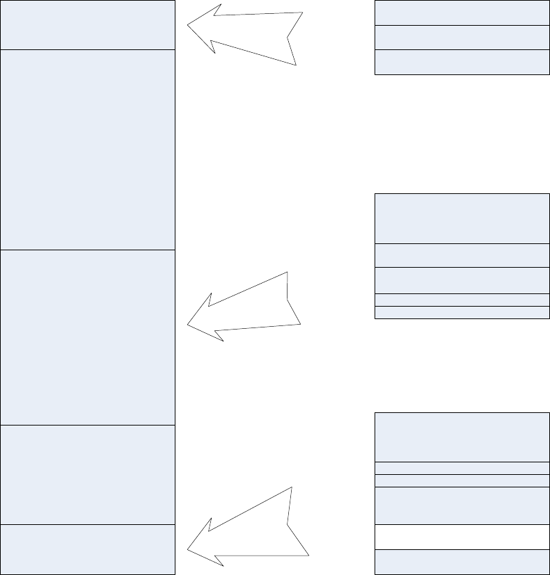
c. Press the Start button to begin programming (leave “Fast Mode” unchecked)
d. Device should reset and start running new Image B, verify in the Event Log pane below:
9.3 OAD Target
9.3.1 Overview of OAD Target for On-chip OAD
The flash memory of OAD Target for On-chip OAD contains the Interrupt Vectors, RCFG, the
permanently resident OAD Target App which is also called Image A, the Image B which is initially empty
and the place holder for the downloaded OAD Image, the BLE stack, the NV Storage Area, the BIM and
the CCFG as shown in Figure 15.
CCFG, BIM,
OAD Target App Part III
BLE Stack
OAD Image B Area
OAD Target App
Part II
OAD Target App Part I,
RCFG, Int Vectors
0x00000
0x01000
0x09000
0x13000
0x1F000
0x1FFFF CCFG
OAD Target App Part III
OAD Target App
Part I
Lookup Table for RTOS
in ROM (RCFG)
Int Vectors
0x00000
0x00100
0x00600
0x01000
0x1FB00
0x1FFA7
0x1FFFF
BIM
0x1F000
Reserved by BIM
0x0003C
On-chip
Flash Memory
Page 0
Page 31
CRC16
CRC16 Shadow
0x00604
Int Vectors
Page 9
CRC16
CRC16 Shadow
0x09000
0x09004 OAD Header
0x09010
0x09050
OAD Image B Area
0x0F000
Note: Figure not drawn to scale
Figure 15. On-chip OAD Target Memory Partition
BIM’s design offers the flexibility of having two valid images ready to run; the choice as to which image
will run is decided in the BIM. Only the OAD Image B can be downloaded. The OAD Target application,
Image A, is a permanent resident which relies on code in the first and last flash page – which if erased
during a power down would break the device. The advantage of a permanently resident Image A whose
sole purpose is to implement the BLE Stack and OAD Profile is that it increases the amount of available
flash for Image B. The developer of a custom Image B does not have to include the OAD Profile
implementation. The only reference to OAD feature that Image B needs is a valid image header
described in Figure 3. The reference to the valid image header is necessary to use OAD Reset Service
described in 7.6. Both Image A and Image B must be developed using exactly the same BLE Stack build,
linked at the same location in memory.
9.3.2 BIM for On-chip OAD
The OAD solution requires that permanently resident boot code, the BIM, exists in order to provide a
fail-safe mechanism for determining (in preferential order) the image which is ready to run. When a
valid image is found, the BIM jumps to that image at which point the image takes over execution. Either
Image A or Image B must implement the proprietary TI OAD Profile. By default, this is Image A’s role.
When an image with the OAD Profile downloads a new image, a system reset can be executed to return
to BIM to verify the correctness of the download and begin execution.
The BIM co-occupies the last flash page with CCFG and additional OAD Target application code. The OAD
Target application code is linked into a specific section of the last flash page as defined in the linker file.
BIM uses the interrupt vectors at the start of flash where the Reset Interrupt Vector calls the BIM
startup routine to ensure its control of the system upon a device reset.
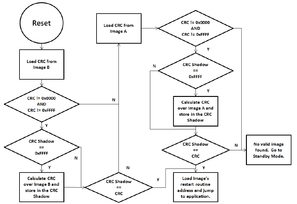
Figure 16. Functional Overview of On-chip BIM
As the permanent owner of the flash interrupt vectors, BIM provides a fail-safe mechanism for
intercepting the reset vector, putting the hardware into a safe state, and taking the most appropriate
action by reading the headers of Image A and Image B.
By default, BIM gives precedence to Image B, as Image A is only expected to be run when a newer
instance of Image B is ready to OAD or no valid Image B exists. If the preferred image is not ready to run,
then the other image is checked. If neither image is ready to run – an unlikely scenario because Image
A, the OAD Target App, need not ever be erased – then BIM puts the device into a low power Standby
mode. Also by default, a CRC check is not performed on Image A because it is expected that the OAD
Target App will be used as a fixed image. The check on Image A will only read the checksum placed by
IAR to see if an image exists, it will not calculate the CRC shadow.
In order to verify that an image is valid, a fixed 4-byte area known as the CRC and CRC-shadow will be
queried. If the 2-byte CRC16 output calculated at build time matches the 2-byte CRC16 shadow
calculated by BIM, then the image is commissioned to run immediately. If the CRC is not zero and not
the erased-flash value of 0xFFFF and the CRC-shadow is the erased-flash value of 0xFFFF, then the CRC
can be calculated over the entire image (not including this 4-byte area) and the result can be compared
to the valid CRC to determine whether the image should be commissioned as ready to run.
9.4 Building On-chip OAD
9.4.1 Building BIM
The boot code is separately built, debugged and programmed via the IAR IDE. There is a project
connection within the OAD Target workspace; however, the standalone project is located at:
$BLE_INSTALL$\examples\util\bim\cc2640\
On CC26xx, flash pages are erased before written when downloading code. This complicates the
download of BIM as it shares the last flash page with code generated by the OAD Target Application.
This is resolved by generating a hex file from the build and merging this hex file with the OAD Target
App’s hex file, as is described in 9.4.3.”
By default, BIM defines symbol FEATURE_FIXED_IMAGE as a way to bypass the CRC check on Image A, as
it is expected that a fixed image will be used. It is not suggested that this symbol be removed unless
architectural changes to OAD made by a user require a CRC check to prove the validity of Image A.
Image B will always be checked, for security and integrity reasons.
9.4.2 Building the BLE Stack
The OAD Target App and the OAD image share the BLE Stack image. This image can never be upgraded
or modified via OAD. This emphasizes the importance of developing and testing an OAD image with the
same stack that is downloaded onto the device. Like BIM, this project outputs a hex image to be merged
with the OAD Target App so all three can be downloaded simultaneously. To reduce the size of the BLE
Stack image, the NV memory storage space has been removed and does not utilize any flash pages. The
NV module is too large to fit without reducing the space reserved for the OAD image. Further
restrictions on the BLE Stack require that it uses the library with minimal features. By default, the OAD
Target’s CC2650lp_stack project is configured for these requirements and it is generally encouraged that
it be used as the shared BLE Stack image.
9.4.3 Building the OAD Target Application
The OAD Target is the permanently resident application image designed to perform OAD of an image
into the Image B area. The project is located at $BLE_INSTALL$\examples\cc2650lp\oad_target\iar”. For
simplicity, the OAD Target starts in the first flash page following its RCFG. In the BIM functional design
(Figure 16), the OAD Target app is Image A so that by default the downloaded Image B always runs, if a
valid instance exists. A separate Python script in the project directory can be executed to merge the OAD
Target image, the BLE Stack Image and BIM into one .hex file. Make sure the BLE Stack Image, BIM, and
OAD Target app is built before running the hex merge script. If any of these projects are modified, they
must be rebuilt along with the OAD Target app to update the “super” hex file. See Appendix section 10.2
on how to use Python script to merge hex files.
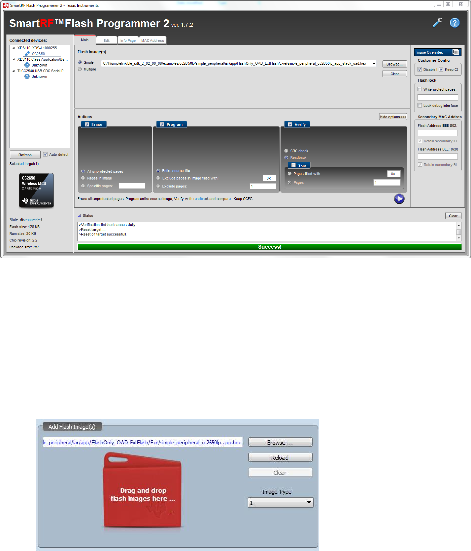
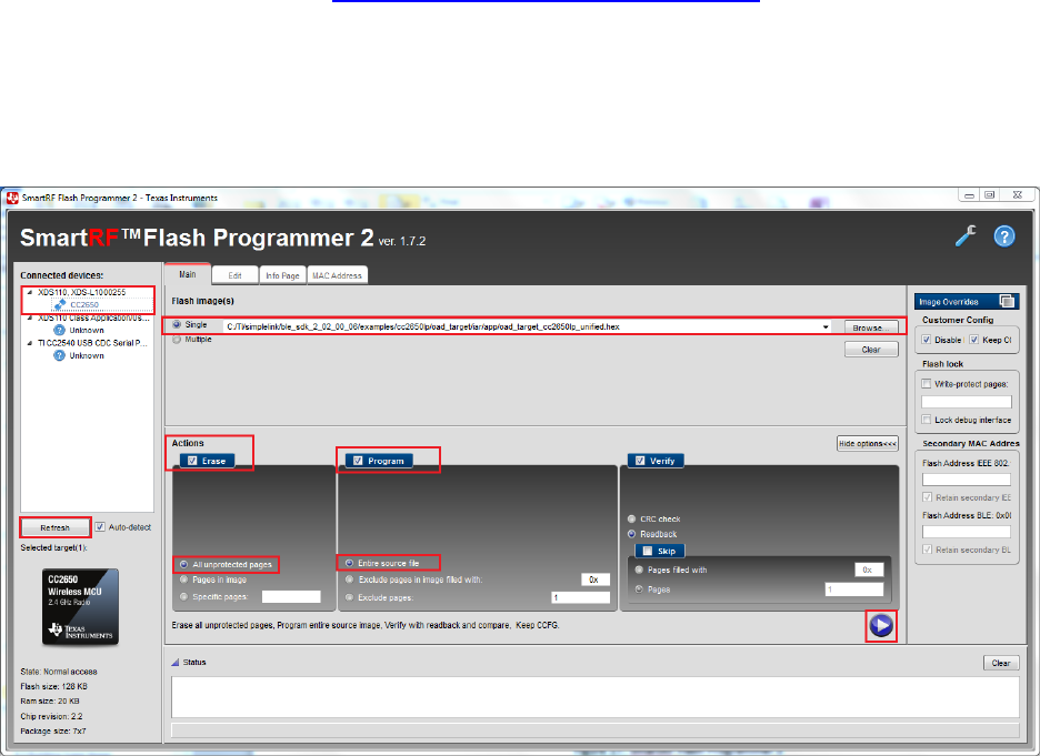
Use the Flash Programmer 2 to program the hex file onto a CC2640 device. If this tool is not already
installed, download it from here: http://www.ti.com/tool/flash-programmer. Under the main tab, click
browse, navigate to the location of the merged hex file and select it. Click “Refresh” under “Connected
devices” and if your device is connected, it should show up under “Connected devices”. Select your
device by clicking on CC2650 and it will become highlighted. Check the “Erase” box and select “All
unprotected Pages”. Check the “Program” box and select “Entire source file”. Click the play button on
the bottom right to program the device. See Figure 17 for how this should look.
Figure 17. SmartRF Flash Programmer 2
9.4.4 Building OAD Image B
Although the OAD-enabled application image is built and linked separately from the supporting BIM, it
must forever adhere to the constraints of the image boundaries and relative locations of external
interfaces (e.g. CRC and Image Header) that are expected by BIM. The OAD Target App image is also
dependent on BIM existing on the device when it is downloaded as only BIM places its interrupt vectors
at the start of flash. Without interrupt vectors at this location, the device will break and become
unusable. The example project for building an Image B included in simple_peripheral workspace as
‘FlashOnly_OAD_ImgB’ configuration can be reproduced through following procedures. The procedures
can be applied to convert any existing application to downloadable On-chip OAD Image in IAR.
I. Select Project→Options→C/C++ Compiler→Preprocessor→Defined symbols and add the
following new definitions:
FEATURE_OAD
FEATURE_OAD_ONCHIP
IMAGE_INVALIDATE
HAL_IMAGE_B
Add the following line to the “Additional include directories”:
$SRC_EX$/profiles/oad/cc26xx
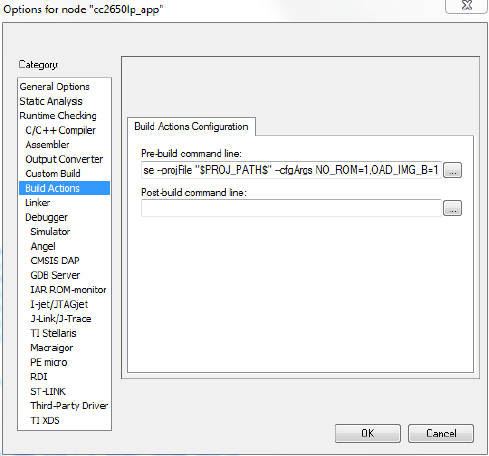
Append the following in Build Actions under Pre-build command line:
--cfgArgs NO_ROM=1,OAD_IMG_B=1
Verify in Project→Options→C/C++ Compiler→Extra Options, the correct iar_boundary.bdef file is
included:
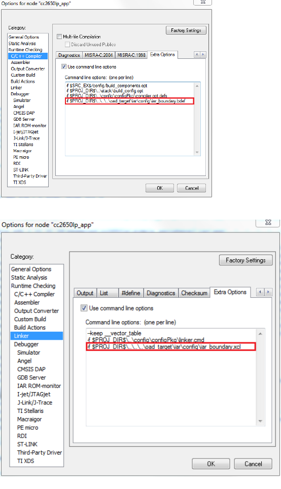
Verify in Linker -> Extra Options, the correct iar_boundary.xcl file is included:
II. Select Project→Options→Linker→Config. Paste the following line to ‘Linker configuration file’:
$SRC_EX$/common/cc26xx/iar/cc26xx_app_oad.icf
And add the following symbol to ‘Configuration file symbol definitions’:
FLASH_ONLY_BUILD=1
III. Setup the Linker for an image’s flash and RAM usage. By default the linker guarantees 10 flash
pages, or 40KB, to the OAD image starting at 0x9000 to Image B. It is generally recommended
that the values for Image B starting address are not changed from the default settings unless
OAD Target App needs to be modified in its size.
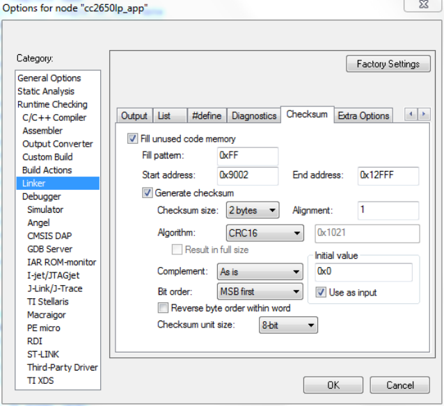
IV. Select Project→Options→Linker→Checksum to configure a CRC16 calculation over the
application image. Make sure that the start address does not include the CRC and CRC Shadow
locations and that the checksum ends at the last address of the specified image region of the
OAD Target. By default, then, the CRC covers the range 0x9004 through 0x12FFF. Make sure
that the Algorithm uses CRC16 with 0x1021. If this value is set to any other value than 0x1021, it
can be modified by setting the algorithm first to CRC polynomial, and then setting the Algorithm
back to CRC16.
V. Under Tools, include cc26xx_app_oad.icf and exclude cc26xx_app.icf. Also exclude
ccfg_app_ble.c. Add the OAD profile modules to the PROFILES folder of the workspace. These
files are located here: $BLE_INSTALL$/src/profiles/oad/cc26xx.
9.5 Considerations for On-chip OAD
9.5.1 Adjusting Stack and Application Sizes
By default, 40kB is available for Image B because the BIM, the flash interrupt vectors and the OAD
Target App occupy 40kB, the BLE protocol stack takes 48kB in the 128kB on-chip flash as shown in Figure
15. If Image B needs more flash, the only way to make it possible is to reduce the size of other
components. Since modifying BIM or OAD Target App is not an option, we can consider downsizing the
BLE Stack and/or reducing the number of SNV pages.
9.5.2 Conditions for Rejecting Metadata
The LSB of the new image’s version must not be equal to the LSB of the current image’s version. This is
to prevent redundant OAD sessions. The LSB is checked using the OAD_IMG_ID() macro. See
OADTarget_validateNewImage() in oad_target_internal_flash.c for more details.
10 Appendix
10.1 Installing Python
Python scripts are used to create hex and bin files from project output. Make sure Python 2.7.10+ is
installed and added to your system path environment variables. Also required is the Python IntelHex
(v2.1+) script hex_merge.py, freely available on the web at https://launchpad.net/intelhex/+download.
The expected location of the script is “C:\Python27\Scripts\” as the post build procedure assumes the
script is there.
For IAR, Python post build commands can be added in Project Options -> Build Actions -> Post-build
command line. For CCS, Python post build commands can be added in Project Options -> CCS Build ->
Steps -> Post-build steps. Change the above commands to include the full path of the Python executable
if a post-build issue occurs due to file path issues. See 10.2.5 for an example.

NOTE: To build the hex file, make sure Python is installed and added to your system path environment
variables.
10.2 TI OAD Image Tool (Python)
In order to accelerate the process of converting the compiler’s hex file output to an OAD ready binary
file with embedded metadata, TI has created a Python based OAD image tool. The tool supports On-chip
and Off-chip OAD implementations as well as creating super hex merges that should be flashed on the
device at production time. OAD Image Tool is provided in source and binary format.
10.2.1 Download the tool
The OAD Image Tool is hosted on TI’s SimpleLink Github account: https://github.com/ti-
simplelink/ble_examples. It can be found under the /tools/oad_image_tool folder. The binary version
can be found under the /bin folder.
10.2.2 Dependencies
The tool requires Python 2.7.10+ to run, as well as the following modules:
# Needs Python 2.7.10
from __future__ import print_function
import __builtin__
import argparse
import crcmod # pip -[--proxy <addr>] install crcmod
from intelhex import IntelHex # pip [--proxy <addr>] install intelhex, needs
latest version (v2.1+)
import struct
import textwrap
import sys
import math
import ntpath
from collections import namedtuple
When running from source, pip or another package manager should be used to import the required
modules.
Running from binary does not require any installation.
10.2.3 Using the tool
The purpose of the tool is to create OTA ready OAD images and also production images. An OTA ready
image is defined as an image that has already been processed, merged, and is ready to send to the
target device using an OAD downloader. OTA ready images have metadata embedded where necessary.
Production images are images that are intended to be flashed on the device at production time. They
contain an entire internal flash image including code that is never updated via OAD such as the BIM.
The tool is configured using a range of arguments that will allow the customer to configure the output of
the tool dynamically. The tool’s arguments are documented below in Figure 18. You may also invoke the
help menu of the script by typing:
python oad_image_tool.py –help

Argument
Acceptable input
Description
-h
--help
None
Display the help menu
-t
--oadtype
{onchip, offchip}
Whether the generated image is
for on chip or off chip OAD
-i
--imtype
{app, stack, np, production}
The type of image to be
generated. This argument is used
to set the metadata and also
enforce some imgType based
rules
-v
--imgver
Any
The version of the image. This is
used to populate the metadata
-o
--out
Valid system path
Used to specify where the script
should place the output hex file
-ob
--outbin
Valid system path
Used to specify where the script
should place the output binary
file
-f
--fill
One byte hex value
Value to fill empty addresses
within the output image with.
Default is 0xFF
-m
--metta
Any valid internal flash address
Address where the metadata
header should be placed
-r
--range
Any valid internal flash address
Ranges of addresses to be
included in the output file
-n
--dry-run
N/A
Do no produce output files, only
print information
-q
--quiet
N/A
Only produce output files, do not
print to the console
--round
Valid sector size
Round sectors up to the nearest
internal flash sector size.
--version
N/A
Print the version info of this tool
Figure 18. OAD Image Tool Arguments
Once the tool has successfully run, it will print output similar to what is shown in Figure 19.
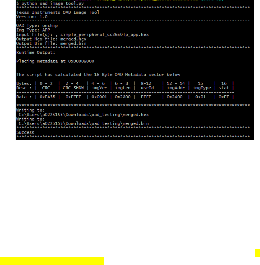
Figure 19. OAD Image Tool Output
10.2.4 Building a Production Image
The tool supports two types of production images depending on how your application will be supporting
OAD; On-Chip or Off-Chip. As previously described, On-Chip will require metadata of the image that will
be initially flashed onto the device. Review section On-Chip OAD for more information on On-Chip OAD.
Review section on Off- Chip OAD for information on required materials.
10.2.4.1 On-Chip OAD Production Image Example Usage
On-Chip OAD’s Production image is a hex merge of BIM for On-Chip OAD, Image A (the resident
Application that implements the TI OAD Profile + Uses the BLE Stack), Image B (the initial Application)
and the BLE Stack.
Once all the hex files are correctly generated– invoke the TI OAD Image Tool with:
<python> <oad_image_tool.py> <BIM hexfile> <Image A hexfile> <Stack hexfile> <Image B hexfile> -o
<Output hexfile> -i production –t onchip
Where ‘<item>’ indicate location of item on the system. The flags used in the tool are highlighted. The
output should look similar to Figure 20.

Figure 20. OnChip OAD Production Image Example invocation.
10.2.4.2 Off-Chip OAD Production Image Example Usage
Off-Chip OAD’s Production image is simply a hex merge of BIM for External Flash + Initial Application
Image + Initial Stack Image.
Once all the hex files are correctly generated – invoke the TI OAD Image Tool with:
<python> <oad_image_tool.py> <BIM hexfile> <App hexfile> <Stack hexfile> -o <Output hexfile> -i
production –t offchip
Where ‘<item>’ indicate location of item on the system. The flags used in the tool are highlighted. The
output should look similar to Figure 21.
Figure 21. OffChip OAD Production Image Example invocation
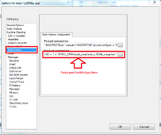
10.2.5 Automating the script
Once the script is installed, it is possible to automate the OAD file generation for rapid testing. This can
be accomplished by hooking the script into the post build steps of your tool chain. Instructions for
IAR/CCS can be found below.
IAR
Right click on the application project in IAR and select project options->Build Actions. Paste the following
code into the Post-build command line section. Be sure to replace sections in <> with actual paths from
the PC running IAR. Note that if the full path ("C:\Python27") to the Python executable has been added
to the system path environment variables, the “python” command is sufficient for the
<PYTHON_INSTALL_DIR>.
"<PYTHON_INSTALL_DIR>" "<OAD_IMAGE_TOOL_DIR>\oad_image_tool.py"
"$PROJ_DIR$\FlashOnly_OAD_ExtFlash\Exe\simple_peripheral_cc2650lp_app.hex"
"$PROJ_DIR$\..\stack\FlashROM\Exe\simple_peripheral_cc2650lp_stack.hex" -t offchip -i app -m
0x1000 -v 1 -o "$PROJ_DIR$\simple_peripheral_cc2650lp_merge.hex"
Figure 22. IAR Post-build step
CCS
Right click on the application project in CCS and select properties->Build->Steps. Paste the below code
snippet in the Post Build Steps line:
"C:/Python27/python.exe" "C:/apps_repos/scripting_tools/cc26xx/oad/oad_image_tool.py"
"${PROJECT_LOC}/FlashOnly_OAD_ExtFlash/simple_peripheral_cc2650lp_app.hex"
"${PROJECT_LOC}/../stack/FlashROM/simple_peripheral_cc2650lp_stack.hex" -t offchip -i app -m
0x1000 -v 1 -o "${PROJECT_LOC}/simple_peripheral_cc2650lp_merge.hex"
See the screenshot below for instructions on how to insert the post build steps in CCS.
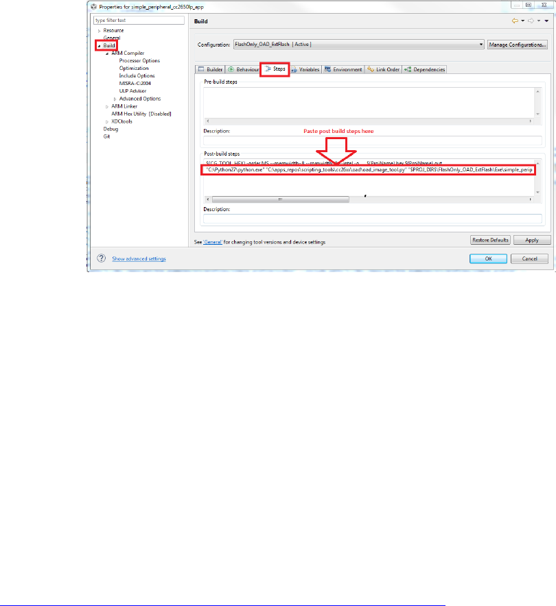
Figure 23. CCS Post-build step
10.3 RTOS RCFG Section
In order to save space, the CC26xx contains portions of the TI-RTOS kernel in its ROM image. These ROM
functions have dependencies on a data structure called the RCFG within flash page 0 of internal flash.
The RCFG section is essentially a table of function pointers (and some other kernel data) that allows the
kernel ROM functions to access certain data structures in the internal flash memory.
When building a new RTOS in ROM image, the RCFG must be updated. However, since the RCFG lies
within page 0 (which contains the vector table and thus is write protected) it cannot be updated via
OAD.
This means that all images intended to be sent over the air must use an RTOS in flash configuration
that includes their own instance of the RCFG.
10.4 Additional updates
For more up to date information or errata to this document, please check the wiki page:
http://processors.wiki.ti.com/index.php/CC2640_OAD_User%27s_Guide
11 Troubleshooting Guide
11.1 General Troubleshooting Guide Prior to BIM
There are various places where OAD can fail; use the following steps to determine where the issue is
occurring during the interaction:
Use a BLE Packet Sniffer and Record the OAD Transaction
This will verify that the profile is implemented correctly and a valid image was transferred over the
air.
o Look for a OAD Initiation
Notifications from OAD Image Notify should be requested – and the appropriate response
from the OAD Target after a GATT Write of the Candidate metadata.
o Look for OAD Image Status Characteristic
This will contain the status of the image prior to BIM launching the image.
Solutions –
Verify that the OAD Downloader supports the TI OAD Profile as a GATT Client
Verify that the OAD Downloader is sending the correct image with updated meta data
Verify that the OAD Target supports the TI OAD Profile as a GATT Server
Read external/internal flash to ensure CRC Shadow is valid and matches CRC field
This will verify that the image was received fully without errors by the OAD Target
o For Internal, various tools can be used. SmartRF Programmer 2 or using a jtag debugger and
connecting to running target and utilizing a memory viewer are possible options.
o For External, interface another MCU or another serial device to dump out the Flash.
Solutions –
Power cycle and Retry Downloading the Image
Verify that the Flash Pages, on-chip or off are not corrupt
11.2 Downloaded OAD Image Isn’t Starting
If the application doesn’t start running the downloaded firmware after a successful download, it’s a BIM
issue.
Depending on OAD type, on-chip or off-chip, refer to sections 9.3.2 or 8.3.2 respectively. Utilize how
BIM operates and a debugger to find where the issue is occurring.
11.3 OAD_CRC_ERR Randomly Occurs
CRC errors occur when the CRC of the downloaded image doesn’t match the CRC in the image header
sent by the OAD downloader. This means that an image block was corrupted. An option for debugging is
to read the external or internal flash storing the image and compare to the original hex file sent over the
air. Methods for reading external/internal flash are described in 11.1.
11.4 Should External Flash be Used During OAD?
No, External flash should not be utilized while OAD Profile is active; the Profile is designed to have
uninterrupted access to Flash, in both On-Chip and Off-Chip configurations.
11.5 Building Super Hex Files
To build merged hexfiles, there are various methods to do this. One option is to utilize the TI OAD Image
Tool (Python). Examples for building a production image, On-Chip OAD Production Image Example Usage
and Off-Chip OAD Production Image Example Usage, can be used as reference.
11.6 Mobile Application Can’t Perform OAD
Ensure the latest version of the Application is downloaded from your Phone’s Application Store and try
again.
If problem persists, please post your Phone’s Model and OS Version number along with details to
reproduce your setup on our Support Forums. Utilize BLE Monitor and verify that the OAD works
correctly.
11.7 OAD_TARGET’s Merge.bat Reports Data Overlapped
Utilize the TI OAD Image Tool with the hex files. Verify Linker configurations are correct.
11.8 Individually Flashing Hex Files for On-Chip OAD - App doesn’t work!
This is known issue with the flash tools – the issue is due to the tools being designed to work on pages
instead of on words. When two applications utilize the same page this problem manifests. For example,
in On-Chip OAD, BIM and Part of the Image A (the resident application image) share Page 0. Depending
on which application is flashed second, the information from the first image will not be preserved.
Solution –
Generate a Merged Hex File instead – this can be done with the TI OAD Image Tool. Look at Section 10.2
for more information on this tool. Then use an external flasher to flash the merged hexfile.
Utilize the .out files for debugging information and connect to the running target using IAR to verify
functionality if needed.
