CCENT ICND1 Exam Certification Guide
User Manual: Pdf
Open the PDF directly: View PDF ![]() .
.
Page Count: 685 [warning: Documents this large are best viewed by clicking the View PDF Link!]
- Foreword
- Introduction
- Part I: Networking Fundamentals
- Introduction to Computer Networking Concepts
- The TCP/IP and OSI Networking Models
- Fundamentals of LANs
- “Do I Know This Already?” Quiz
- Foundation Topics
- An Overview of Modern Ethernet LANs
- A Brief History of Ethernet
- Ethernet UTP Cabling
- Improving Performance by Using Switches Instead of Hubs
- Ethernet Data-Link Protocols
- Exam Preparation Tasks
- Review All the Key Topics
- Complete the Tables and Lists from Memory
- Definitions of Key Terms
- Fundamentals of WANs
- Fundamentals of IP Addressing and Routing
- Fundamentals of TCP/IP Transport, Applications, and Security
- Part II: LAN Switching
- Ethernet LAN Switching Concepts
- Operating Cisco LAN Switches
- Ethernet Switch Configuration
- Ethernet Switch Troubleshooting
- “Do I Know This Already?” Quiz
- Foundation Topics
- Perspectives on Network Verification and Troubleshooting
- Verifying the Network Topology with Cisco Discovery Protocol
- Analyzing Layer 1 and 2 Interface Status
- Analyzing the Layer 2 Forwarding Path with the MAC Address Table
- Exam Preparation Tasks
- Review All the Key Topics
- Complete the Tables and Lists from Memory
- Definitions of Key Terms
- Command References
- Wireless LANs
- Part III: IP Routing
- IP Addressing and Subnetting
- “Do I Know This Already?” Quiz
- Foundation Topics
- Exam Preparation Tools for Subnetting
- IP Addressing and Routing
- Math Operations Used When Subnetting
- Analyzing and Choosing Subnet Masks
- Analyzing the Subnet Mask in an Existing Subnet Design
- The Three Parts: Network, Subnet, and Host
- Binary Process: Finding the Number of Network, Subnet, and Host Bits
- Decimal Process: Finding the Number of Network, Subnet, and Host Bits
- Determining the Number of Subnets and Number of Hosts Per Subnet
- Number of Subnets: Subtract 2, or Not?
- Practice Examples for Analyzing Subnet Masks
- Choosing a Subnet Mask that Meets Design Requirements
- Practice Suggestions
- Analyzing the Subnet Mask in an Existing Subnet Design
- Analyzing Existing Subnets
- Design: Choosing the Subnets of a Classful Network
- Exam Preparation Tasks
- Review All the Key Topics
- Complete the Tables and Lists from Memory
- Definitions of Key Terms
- Read Appendix F Scenario 1, Part A
- Subnetting Questions and Processes
- Operating Cisco Routers
- “Do I Know This Already?” Quiz
- Foundation Topics
- Installing Cisco Routers
- Cisco Router IOS CLI
- Upgrading Cisco IOS Software and the Cisco IOS Software Boot Process
- Exam Preparation Tasks
- Review All the Key Topics
- Complete the Tables and Lists from Memory
- Definitions of Key Terms
- Read Appendix F Scenario 2
- Command References
- Routing Protocol Concepts and Configuration
- “Do I Know This Already?” Quiz
- Foundation Topics
- Connected and Static Routes
- Routing Protocol Overview
- Configuring and Verifying RIP-2
- Exam Preparation Tasks
- Review All the Key Topics
- Complete the Tables and Lists from Memory
- Definitions of Key Terms
- Command References
- Troubleshooting IP Routing
- “Do I Know This Already?” Quiz
- Foundation Topics
- IP Troubleshooting Tips and Tools
- A Routing Troubleshooting Scenario
- Exam Preparation Tasks
- Review All the Key Topics
- Complete the Tables and Lists from Memory
- Command Reference
- Cisco Published ICND1 Exam Topics* Covered in This Part:
- Part IV : Wide-Area Networks
- WAN Concepts
- WAN Configuration
- Part V: Final Preparation
- Final Preparation
- Part VI: Appendixes
- Answers to the “Do I Know This Already?” Quizzes
- Decimal to Binary Conversion Table
- ICND1 Exam Updates: Version 1.0
- Index

800 East 96th Street
Indianapolis, Indiana 46240 USA
Cisco Press
CCENT/CCNA ICND1
Official Exam Certification Guide,
Second Edition
Wendell Odom,
CCIE No. 1624
1828xbook.fm Page i Thursday, July 26, 2007 3:10 PM
ii
CCENT/CCNA ICND1 Official Exam Certification Guide, Second Edition
Wendell Odom
Copyright© 2008 Cisco Systems, Inc.
Published by:
Cisco Press
800 East 96th Street
Indianapolis, IN 46240 USA
All rights reserved. No part of this book may be reproduced or transmitted in any form or by any means, electronic or
mechanical, including photocopying, recording, or by any information storage and retrieval system, without written
permission from the publisher, except for the inclusion of brief quotations in a review.
Printed in the United States of America
First Printing August 2007
Library of Congress Cataloging-in-Publication Data.
Odom, Wendell.
CCENT/CCNA ICND1 official exam certification guide / Wendell Odom.
p. cm.
ISBN 978-1-58720-182-0 (hardback w/cd) 1. Electronic data processing personnel--Certification. 2. Computer net-
works--Examinations--Study guides. I. Title.
QA76.3.O358 2007
004.6--dc22
2007029241
ISBN-13: 978-1-58720-182-0
ISBN-10: 1-58720-182-8
Warning and Disclaimer
This book is designed to provide information about the Cisco ICND1 (640-822), ICND2 (640-816), and CCNA
(640-802) exams. Every effort has been made to make this book as complete and accurate as possible, but no warranty
or fitness is implied.
The information is provided on an “as is” basis. The author, Cisco Press, and Cisco Systems, Inc. shall have neither
liability nor responsibility to any person or entity with respect to any loss or damages arising from the information
contained in this book or from the use of the discs or programs that may accompany it.
The opinions expressed in this book belong to the author and are not necessarily those of Cisco Systems, Inc.
1828xbook.fm Page ii Thursday, July 26, 2007 3:10 PM
iii
Trademark Acknowledgments
All terms mentioned in this book that are known to be trademarks or service marks have been appropriately
capitalized. Cisco Press or Cisco Systems, Inc. cannot attest to the accuracy of this information. Use of a term in this
book should not be regarded as affecting the validity of any trademark or service mark.
Corporate and Government Sales
The publisher offers excellent discounts on this book when ordered in quantity for bulk purchases or special sales,
which may include electronic versions and/or custom covers and content particular to your business, training goals,
marketing focus, and branding interests. For more information, please contact:
U.S. Corporate and Government Sales
1-800-382-3419
corpsales@pearsontechgroup.com
For sales outside the United States please contact:
International Sales
international@pearsoned.com
Feedback Information
At Cisco Press, our goal is to create in-depth technical books of the highest quality and value. Each book is crafted
with care and precision, undergoing rigorous development that involves the unique expertise of members of the
professional technical community.
Reader feedback is a natural continuation of this process. If you have any comments about how we could improve
the quality of this book, or otherwise alter it to better suit your needs, you can contact us through e-mail at
feedback@ciscopress.com. Please be sure to include the book title and ISBN in your message.
We greatly appreciate your assistance.
Publisher:
Paul Boger
Copy Editor:
Gayle Johnson and Bill McManus
Associate Publisher:
Dave Dusthimer
Technical Editors:
Teri Cook, Brian D’Andrea,
and Steve Kalman
Cisco Representative:
Anthony Wolfenden
Editorial Assistant:
Vanessa Evans
Cisco Press Program Manager:
Jeff Brady
Book and Cover Designer:
Louisa Adair
Executive Editor:
Brett Bartow
Composition:
ICC Macmillan Inc.
Managing Editor:
Patrick Kanouse
Indexer:
Tim Wright
Senior Development Editor:
Christopher Cleveland
Proofreader:
Suzanne Thomas
Senior Project Editor:
San Dee Phillips and Meg Shaw
1828xbook.fm Page iii Thursday, July 26, 2007 3:10 PM
iv
About the Author
Wendell Odom
, CCIE No. 1624, has been in the networking industry since 1981. He
currently teaches QoS, MPLS, and CCNA courses for Skyline Advanced Technology
Services (http://www.skyline-ats.com). He has also worked as a network engineer,
consultant, systems engineer, instructor, and course developer. He is the author of all
previous editions of the
CCNA Exam Certification Guide
, as well as the
Cisco QOS Exam
Certification Guide
, Second Edition,
Computer Networking First-Step
,
CCIE Routing and
Switching Official Exam Certification Guide
, Second Edition, and
CCNA Video Mentor
—
all from Cisco Press.
1828xbook.fm Page iv Thursday, July 26, 2007 3:10 PM
v
About the Technical Reviewers
Teri Cook
(CCSI, CCDP, CCNP, CCDA, CCNA, MCT, and MCSE 2000/2003: Security)
has more than ten years of experience in the IT industry. She has worked with different
types of organizations in the private business and DoD sectors, providing senior-level
network and security technical skills in the design and implementation of complex
computing environments. Since obtaining her certifications, Teri has been committed to
bringing quality IT training to IT professionals as an instructor. She is an outstanding
instructor who uses real-world experience to present complex networking technologies. As
an IT instructor, Teri has been teaching Cisco classes for more than five years.
Brian D’Andrea
(CCNA, CCDA, MCSE, A+, and Net+) has 11 years of IT experience in
both medical and financial environments, where planning and supporting critical
networking technologies were his primary responsibilities. For the last five years he has
dedicated himself to technical training. Brian spends most of his time with The Training
Camp, an IT boot camp provider. Using his real-world experience and his ability to break
difficult concepts into a language that students can understand, Brian has successfully
trained hundreds of students for both work and certification endeavors.
Stephen Kalman
is a data security trainer. He is the author or tech editor of more than
20 books, courses, and CBT titles. His most recent book is
Web Security Field Guide
,
published by Cisco Press. In addition to those responsibilities he runs a consulting
company, Esquire Micro Consultants, which specializes in network security assessments
and forensics.
Mr. Kalman holds SSCP, CISSP, ISSMP, CEH, CHFI, CCNA, CCSA (Checkpoint), A+,
Network+ and Security+ certifications and is a member of the New York State Bar.
1828xbook.fm Page v Thursday, July 26, 2007 3:10 PM
vi
Dedication
For Brett Bartow. Thanks for being such a steady, insightful, and incredibly trustworthy
guide through the publishing maze.
1828xbook.fm Page vi Thursday, July 26, 2007 3:10 PM
vii
Acknowledgments
The team who helped produce this book has been simply awesome. Everyone who touched
this book has made it better, and they’ve been particularly great at helping catch the errors
that always creep into the manuscript.
Brian, Teri, and Steve all did a great job TEing the book. Besides helping a lot with
technical accuracy, Brian made a lot of good suggestions about traps that he sees when
teaching CCNA classes, helping the book avoid those same pitfalls. Teri’s ability to see
each phrase in the context of an entire chapter, or the whole book, was awesome, helping
catch things that no one would otherwise catch. Steve spent most of his TE time on the
ICND2 book, but he did lend great help with this one, particularly with his reviews of the
security-oriented topics, an area in which he’s an expert. And more so than any other book
I’ve written, the TEs really sunk their teeth into the specifics of every example, helping
catch errors. Thanks so much!
Another (ho-hum) all-star performance from Chris Cleveland, who developed the book.
Now I empathize with sports writers who have to write about the local team’s star who bats
.300, hits 40 homers, and drives in 100 runs, every year, for his whole career. How many
ways can you say he does a great job? I’ll keep it simple: Thanks, Chris.
The wonderful and mostly hidden production folks did their usual great job. When every
time I see how they reworded something, and think, “Wow; why didn’t I write that?”, it
makes me appreciate the kind of team we have at Cisco Press. The final copy edit, figure
review, and pages review process required a fair amount of juggling and effort as well –
thanks to Patrick’s team, especially San Dee, Meg, Tonya, for working so well with all the
extra quality initiatives we’ve implemented. Thanks to you all!
Additionally, several folks who didn’t have any direct stake in the book also helped it along.
Thanks to Frank Knox for the discussions on the exams, why they’re so difficult, and about
troubleshooting. Thanks to Rus Healy for the help with wireless. Thanks to the Mikes at
Skyline for making my schedule work to get this book (and the ICND2 book) out the door.
And thanks to the course and exam teams at Cisco for the great early communications and
interactions about the changes to the courses and exams.
Finally, thanks to my wife Kris for all her support with my writing efforts, her prayers,
and her understanding when the deadline didn’t quite match with our vacation plans this
summer. And thanks to Jesus Christ—all this effort is just striving after the wind without
Him.
1828xbook.fm Page vii Thursday, July 26, 2007 3:10 PM

viii
This Book Is Safari Enabled
The Safari
®
Enabled icon on the cover of your favorite technol-
ogy book means that the book is available through Safari Book-
shelf. When you buy this book, you get free access to the online
edition for 45 days.
Safari Bookshelf is an electronic reference library that lets you
easily search thousands of technical books, find code samples,
download chapters, and access technical information whenever
and wherever you need it.
To gain 45-day Safari Enabled access to this book:
■
Go to http://www.ciscopress.com/safarienabled.
■
Complete the brief registration form.
■
Enter the coupon code 6EM9-WNXL-7Z1E-9UL2-KAEC.
If you have difficulty registering on Safari Bookshelf or access-
ing the online edition, please e-mail customer-service@safari-
booksonline.com.
1828xbook.fm Page viii Thursday, July 26, 2007 3:10 PM
ix
Contents at a Glance
Foreword xxvi
Introduction xxvii
Part I Networking Fundamentals 3
Chapter 1 Introduction to Computer Networking Concepts 5
Chapter 2 The TCP/IP and OSI Networking Models 17
Chapter 3 Fundamentals of LANs 41
Chapter 4 Fundamentals of WANs 71
Chapter 5 Fundamentals of IP Addressing and Routing 93
Chapter 6 Fundamentals of TCP/IP Transport, Applications,
and Security 129
Part II LAN Switching 165
Chapter 7 Ethernet LAN Switching Concepts 167
Chapter 8 Operating Cisco LAN Switches 197
Chapter 9 Ethernet Switch Configuration 231
Chapter 10 Ethernet Switch Troubleshooting 267
Chapter 11 Wireless LANs 299
Part III IP Routing 329
Chapter 12 IP Addressing and Subnetting 331
Chapter 13 Operating Cisco Routers 399
Chapter 14 Routing Protocol Concepts and Configuration 435
Chapter 15 Troubleshooting IP Routing 471
Part IV Wide-Area Networks 509
Chapter 16 WAN Concepts 511
Chapter 17 WAN Configuration 539
1828xbook.fm Page ix Thursday, July 26, 2007 3:10 PM
x
Part V Final Preparation 563
Chapter 18 Final Preparation 565
Part VI Appendixes 575
Appendix A Answers to the “Do I Know This Already?” Quizzes 577
Appendix B Decimal to Binary Conversion Table 591
Appendix C ICND1 Exam Updates: Version 1.0 595
Glossary 599
Index 624
Part VII CD-Only
Appendix C ICND1 Exam Updates: Version 1.0
Appendix D Subnetting Practice
Appendix E Subnetting Reference Pages
Appendix F Additional Scenarios
Appendix G Subnetting Video Reference
Appendix H Memory Tables
Appendix I Memory Tables Answer Key
Appendix J ICND1 Open-Ended Questions
1828xbook.fm Page x Thursday, July 26, 2007 3:10 PM
xi
Contents
Foreword xxvi
Introduction xxvii
Part I Networking Fundamentals 3
Chapter 1 Introduction to Computer Networking Concepts 5
Perspectives on Networking 5
The Flintstones Network: The First Computer Network? 8
Chapter 2 The TCP/IP and OSI Networking Models 17
“Do I Know This Already?” Quiz 18
Foundation Topics 21
The TCP/IP Protocol Architecture 22
The TCP/IP Application Layer 23
The TCP/IP Transport Layer 25
The TCP/IP Internet Layer 27
The TCP/IP Network Access Layer 28
Data Encapsulation Terminology 30
The OSI Reference Model 32
Comparing OSI and TCP/IP 32
OSI Layers and Their Functions 34
OSI Layering Concepts and Benefits 35
OSI Encapsulation Terminology 36
Exam Preparation Tasks 38
Review all the Key Topics 38
Complete the Tables and Lists from Memory 38
Definitions of Key Terms 38
OSI Reference 39
Chapter 3 Fundamentals of LANs 41
“Do I Know This Already?” Quiz 41
Foundation Topics 45
An Overview of Modern Ethernet LANs 45
A Brief History of Ethernet 48
The Original Ethernet Standards: 10BASE2 and 10BASE5 48
Repeaters 50
Building 10BASE-T Networks with Hubs 51
Ethernet UTP Cabling 52
UTP Cables and RJ-45 Connectors 52
Transmitting Data Using Twisted Pairs 54
UTP Cabling Pinouts for 10BASE-T and 100BASE-TX 55
1000BASE-T Cabling 58
1828xbook.fm Page xi Thursday, July 26, 2007 3:10 PM
xii
Improving Performance by Using Switches Instead of Hubs 58
Increasing Available Bandwidth Using Switches 61
Doubling Performance by Using Full-Duplex Ethernet 62
Ethernet Layer 1 Summary 63
Ethernet Data-Link Protocols 63
Ethernet Addressing 64
Ethernet Framing 65
Identifying the Data Inside an Ethernet Frame 67
Error Detection 68
Exam Preparation Tasks 69
Review All the Key Topics 69
Complete the Tables and Lists from Memory 69
Definitions of Key Terms 69
Chapter 4 Fundamentals of WANs 71
“Do I Know This Already?” Quiz 71
Foundation Topics 74
OSI Layer 1 for Point-to-Point WANs 74
WAN Connections from the Customer Viewpoint 77
WAN Cabling Standards 78
Clock Rates, Synchronization, DCE, and DTE 80
Building a WAN Link in a Lab 81
Link Speeds Offered by Telcos 82
OSI Layer 2 for Point-to-Point WANs 83
HDLC 83
Point-to-Point Protocol 85
Point-to-Point WAN Summary 85
Frame Relay and Packet-Switching Services 86
The Scaling Benefits of Packet Switching 86
Frame Relay Basics 87
Exam Preparation Tasks 91
Review All the Key Topics 91
Complete the Tables and Lists from Memory 91
Definitions of Key Terms 91
Chapter 5 Fundamentals of IP Addressing and Routing 93
“Do I Know This Already?” Quiz 93
Foundation Topics 98
Overview of Network Layer Functions 98
Routing (Forwarding) 99
PC1’s Logic: Sending Data to a Nearby Router 100
R1 and R2’s Logic: Routing Data Across the Network 100
R3’s Logic: Delivering Data to the End Destination 100
1828xbook.fm Page xii Thursday, July 26, 2007 3:10 PM
xiii
Network Layer Interaction with the Data Link Layer 101
IP Packets and the IP Header 102
Network Layer (Layer 3) Addressing 103
Routing Protocols 104
IP Addressing 105
IP Addressing Definitions 105
How IP Addresses Are Grouped 106
Classes of Networks 107
The Actual Class A, B, and C Network Numbers 109
IP Subnetting 110
IP Routing 114
Host Routing 114
Router Forwarding Decisions and the IP Routing Table 115
IP Routing Protocols 118
Network Layer Utilities 121
Address Resolution Protocol and the Domain Name System 121
DNS Name Resolution 122
The ARP Process 122
Address Assignment and DHCP 123
ICMP Echo and the ping Command 125
Exam Preparation Tasks 126
Review All the Key Topics 126
Complete the Tables and Lists from Memory 127
Definitions of Key Terms 127
Chapter 6 Fundamentals of TCP/IP Transport, Applications, and Security 129
“Do I Know This Already?” Quiz 129
Foundation Topics 133
TCP/IP Layer 4 Protocols: TCP and UDP 133
Transmission Control Protocol 134
Multiplexing Using TCP Port Numbers 135
Popular TCP/IP Applications 138
Error Recovery (Reliability) 140
Flow Control Using Windowing 141
Connection Establishment and Termination 142
Data Segmentation and Ordered Data Transfer 144
User Datagram Protocol 145
TCP/IP Applications 146
QoS Needs and the Impact of TCP/IP Applications 146
The World Wide Web, HTTP, and SSL 149
Universal Resource Locators 150
Finding the Web Server Using DNS 150
Transferring Files with HTTP 152
1828xbook.fm Page xiii Thursday, July 26, 2007 3:10 PM
xiv
Network Security 153
Perspectives on the Sources and Types of Threats 154
Firewalls and the Cisco Adaptive Security Appliance (ASA) 158
Anti-x 160
Intrusion Detection and Prevention 160
Virtual Private Networks (VPN) 161
Exam Preparation Tasks 163
Review All the Key Topics 163
Complete the Tables and Lists from Memory 163
Definitions of Key Terms 163
Part II LAN Switching 165
Chapter 7 Ethernet LAN Switching Concepts 167
“Do I Know This Already?” Quiz 167
Foundation Topics 171
LAN Switching Concepts 171
Historical Progression: Hubs, Bridges, and Switches 171
Switching Logic 174
The Forward Versus Filter Decision 175
How Switches Learn MAC Addresses 177
Flooding Frames 178
Avoiding Loops Using Spanning Tree Protocol 179
Internal Processing on Cisco Switches 180
LAN Switching Summary 182
LAN Design Considerations 183
Collision Domains and Broadcast Domains 183
Collision Domains 183
Broadcast Domains 184
The Impact of Collision and Broadcast Domains on LAN Design 185
Virtual LANs (VLAN) 187
Campus LAN Design Terminology 188
Ethernet LAN Media and Cable Lengths 191
Exam Preparation Tasks 194
Review All the Key Topics 194
Complete the Tables and Lists from Memory 194
Definitions of Key Terms 195
Chapter 8 Operating Cisco LAN Switches 197
“Do I Know This Already?” Quiz 197
Foundation Topics 200
Accessing the Cisco Catalyst 2960 Switch CLI 200
Cisco Catalyst Switches and the 2960 Switch 201
1828xbook.fm Page xiv Thursday, July 26, 2007 3:10 PM
xv
Switch Status from LEDs 202
Accessing the Cisco IOS CLI 205
CLI Access from the Console 206
Accessing the CLI with Telnet and SSH 208
Password Security for CLI Access 208
User and Enable (Privileged) Modes 210
CLI Help Features 211
The debug and show Commands 213
Configuring Cisco IOS Software 214
Configuration Submodes and Contexts 215
Storing Switch Configuration Files 217
Copying and Erasing Configuration Files 220
Initial Configuration (Setup Mode) 221
Exam Preparation Tasks 226
Review All the Key Topics 226
Complete the Tables and Lists from Memory 226
Definitions of Key Terms 226
Command References 226
Chapter 9 Ethernet Switch Configuration 231
“Do I Know This Already?” Quiz 231
Foundation Topics 235
Configuration of Features in Common with Routers 235
Securing the Switch CLI 235
Configuring Simple Password Security 236
Configuring Usernames and Secure Shell (SSH) 239
Password Encryption 242
The Two Enable Mode Passwords 244
Console and vty Settings 245
Banners 245
History Buffer Commands 246
The logging synchronous and exec-timeout Commands 247
LAN Switch Configuration and Operation 248
Configuring the Switch IP Address 248
Configuring Switch Interfaces 251
Port Security 253
VLAN Configuration 256
Securing Unused Switch Interfaces 259
Exam Preparation Tasks 261
Review All the Key Topics 261
Complete the Tables and Lists from Memory 261
Definitions of Key Terms 262
Command References 262
1828xbook.fm Page xv Thursday, July 26, 2007 3:10 PM
xvi
Chapter 10 Ethernet Switch Troubleshooting 267
“Do I Know This Already?” Quiz 267
Foundation Topics 271
Perspectives on Network Verification and Troubleshooting 271
Attacking Sim Questions 271
Simlet Questions 272
Multiple-Choice Questions 273
Approaching Questions with an Organized Troubleshooting Process 273
Isolating Problems at Layer 3, and Then at Layers 1 and 2 275
Troubleshooting as Covered in This Book 276
Verifying the Network Topology with Cisco Discovery Protocol 277
Analyzing Layer 1 and 2 Interface Status 282
Interface Status Codes and Reasons for Nonworking States 282
Interface Speed and Duplex Issues 284
Common Layer 1 Problems on Working Interfaces 287
Analyzing the Layer 2 Forwarding Path with the MAC Address Table 289
Analyzing the Forwarding Path 292
Port Security and Filtering 293
Exam Preparation Tasks 295
Review All the Key Topics 295
Complete the Tables and Lists from Memory 295
Definitions of Key Terms 295
Command References 295
Chapter 11 Wireless LANs 299
“Do I Know This Already?” Quiz 299
Foundation Topics 302
Wireless LAN Concepts 302
Comparisons with Ethernet LANs 302
Wireless LAN Standards 304
Modes of 802.11 Wireless LANs 305
Wireless Transmissions (Layer 1) 307
Wireless Encoding and Nonoverlapping DSSS Channels 309
Wireless Interference 311
Coverage Area, Speed, and Capacity 311
Media Access (Layer 2) 314
Deploying WLANs 315
Wireless LAN Implementation Checklist 315
Step 1: Verify the Existing Wired Network 316
Step 2: Install and Configure the AP’s Wired and IP Details 317
Step 3: Configure the AP’s WLAN Details 317
Step 4: Install and Configure One Wireless Client 318
Step 5: Verify That the WLAN Works from the Client 319
1828xbook.fm Page xvi Thursday, July 26, 2007 3:10 PM
xvii
Wireless LAN Security 320
WLAN Security Issues 320
The Progression of WLAN Security Standards 322
Wired Equivalent Privacy (WEP) 322
SSID Cloaking and MAC Filtering 323
The Cisco Interim Solution Between WEP and 802.11i 324
Wi-Fi Protected Access (WPA) 325
IEEE 802.11i and WPA-2 325
Exam Preparation Tasks 327
Review All the Key Topics 327
Complete the Tables and Lists from Memory 327
Definitions of Key Terms 327
Part III IP Routing 329
Chapter 12 IP Addressing and Subnetting 331
“Do I Know This Already?” Quiz 331
Foundation Topics 336
Exam Preparation Tools for Subnetting 336
Suggested Subnetting Preparation Plan 337
More Practice Using a Subnet Calculator 338
IP Addressing and Routing 339
IP Addressing Review 339
Public and Private Addressing 341
IP Version 6 Addressing 342
IP Subnetting Review 343
IP Routing Review 345
Math Operations Used When Subnetting 347
Converting IP Addresses and Masks from Decimal to Binary and Back Again 347
Performing a Boolean AND Operation 349
Prefix Notation/CIDR Notation 351
Binary Process to Convert Between Dotted Decimal and Prefix Notation 352
Decimal Process to Convert Between Dotted Decimal and Prefix
Notation 353
Practice Suggestions 355
Analyzing and Choosing Subnet Masks 355
Analyzing the Subnet Mask in an Existing Subnet Design 356
The Three Parts: Network, Subnet, and Host 356
Binary Process: Finding the Number of Network, Subnet, and Host Bits 357
Decimal Process: Finding the Number of Network, Subnet, and Host Bits 358
Determining the Number of Subnets and Number of Hosts Per Subnet 359
Number of Subnets: Subtract 2, or Not? 360
Practice Examples for Analyzing Subnet Masks 361
1828xbook.fm Page xvii Thursday, July 26, 2007 3:10 PM
xviii
Choosing a Subnet Mask that Meets Design Requirements 362
Finding the Only Possible Mask 363
Finding Multiple Possible Masks 365
Choosing the Mask that Maximizes the Number of Subnets or Hosts 366
Practice Suggestions 367
Analyzing Existing Subnets 368
Finding the Subnet Number: Binary 368
Finding the Subnet Number: Binary Shortcut 371
Finding the Subnet Broadcast Address: Binary 372
Finding the Range of Valid IP Addresses in a Subnet 375
Finding the Subnet, Broadcast Address, and Range of Addresses: Decimal
Process 377
Decimal Process with Easy Masks 377
Decimal Process with Difficult Masks 378
Finding the Broadcast Address: Decimal 381
Summary of Decimal Processes to Find the Subnet, Broadcast, and Range 382
Practice Suggestions 383
Design: Choosing the Subnets of a Classful Network 384
Finding All Subnets with Fewer Than 8 Subnet Bits 384
Finding All Subnets with Exactly 8 Subnet Bits 388
Practice Suggestions 389
Finding All Subnets with More Than 8 Subnet Bits 389
More Practice Suggestions 393
Exam Preparation Tasks 394
Review All the Key Topics 394
Complete the Tables and Lists from Memory 396
Definitions of Key Terms 396
Read Appendix F Scenario 1, Part A 396
Subnetting Questions and Processes 396
Chapter 13 Operating Cisco Routers 399
“Do I Know This Already?” Quiz 399
Foundation Topics 403
Installing Cisco Routers 403
Installing Enterprise Routers 403
Cisco Integrated Services Routers 405
Physical Installation 406
Installing Internet Access Routers 407
A SOHO Installation with a Separate Switch, Router, and
Cable Modem 407
A SOHO Installation with an Integrated Switch, Router, and
DSL Modem 408
Regarding the SOHO Devices Used in This Book 409
1828xbook.fm Page xviii Thursday, July 26, 2007 3:10 PM
xix
Cisco Router IOS CLI 409
Comparisons Between the Switch CLI and Router CLI 410
Router Interfaces 411
Interface Status Codes 413
Router Interface IP Addresses 414
Bandwidth and Clock Rate on Serial Interfaces 415
Router Auxiliary (Aux) Port 417
Initial Configuration (Setup Mode) 417
Upgrading Cisco IOS Software and the Cisco IOS Software Boot Process 420
Upgrading a Cisco IOS Software Image into Flash Memory 420
The Cisco IOS Software Boot Sequence 423
The Three Router Operating Systems 425
The Configuration Register 425
How a Router Chooses Which OS to Load 426
The show version Command and Seeing the Configuration Register’s
Value 429
Exam Preparation Tasks 431
Review All the Key Topics 431
Complete the Tables and Lists from Memory 431
Definitions of Key Terms 432
Read Appendix F Scenario 2 432
Command References 432
Chapter 14 Routing Protocol Concepts and Configuration 435
“Do I Know This Already?” Quiz 435
Foundation Topics 439
Connected and Static Routes 439
Connected Routes 439
Static Routes 442
Extended ping Command 444
Default Routes 446
Routing Protocol Overview 448
RIP-2 Basic Concepts 449
Comparing and Contrasting IP Routing Protocols 450
Interior and Exterior Routing Protocols 451
Routing Protocol Types/Algorithms 452
Metrics 452
Autosummarization and Manual Summarization 454
Classless and Classful Routing Protocols 454
Convergence 455
Miscellaneous Comparison Points 455
Summary of Interior Routing Protocols 455
1828xbook.fm Page xix Thursday, July 26, 2007 3:10 PM
xx
Configuring and Verifying RIP-2 456
RIP-2 Configuration 456
Sample RIP Configuration 457
RIP-2 Verification 458
Interpreting the Output of the show ip route Command 460
Administrative Distance 461
The show ip protocols Command 462
Examining RIP Messages with debug 464
Exam Preparation Tasks 467
Review All the Key Topics 467
Complete the Tables and Lists from Memory 467
Definitions of Key Terms 468
Command References 468
Chapter 15 Troubleshooting IP Routing 471
“Do I Know This Already?” Quiz 471
Foundation Topics 475
IP Troubleshooting Tips and Tools 475
IP Addressing 475
Avoiding Reserved IP Addresses 475
One Subnet, One Mask, for Each LAN 476
Summary of IP Addressing Tips 478
Host Networking Commands 478
Troubleshooting Host Routing Problems 482
Finding the Matching Route on a Router 483
Troubleshooting Commands 485
The show ip arp Command 485
The traceroute Command 486
Telnet and Suspend 487
A Routing Troubleshooting Scenario 491
Scenario Part A: Tasks and Questions 491
Scenario Part A: Answers 494
Scenario Part B: Analyze Packet/Frame Flow 495
Scenario Part B: Answers 496
Scenario Part B: Question 1 497
Scenario Part B: Question 2 498
Scenario Part B: Question 3 499
Scenario Part B: Question 4 501
Scenario Part B: Question 5 501
Scenario Part B: Question 6 502
Scenario Part B: Question 7 503
Scenario Part C: Analyze Connected Routes 503
Scenario Part C: Answers 503
1828xbook.fm Page xx Thursday, July 26, 2007 3:10 PM
xxi
Exam Preparation Tasks 505
Review All the Key Topics 505
Complete the Tables and Lists from Memory 506
Command Reference 506
Part IV Wide-Area Networks 509
Chapter 16 WAN Concepts 511
“Do I Know This Already?” Quiz 511
Foundation Topics 514
WAN Technologies 514
Perspectives on the PSTN 514
Analog Modems 517
Digital Subscriber Line 519
DSL Types, Speeds, and Distances 521
DSL Summary 522
Cable Internet 523
Comparison of Remote-Access Technologies 525
ATM 525
Packet Switching Versus Circuit Switching 527
Ethernet as a WAN Service 527
IP Services for Internet Access 528
Address Assignment on the Internet Access Router 529
Routing for the Internet Access Router 530
NAT and PAT 531
Exam Preparation Tasks 536
Review All the Key Topics 536
Complete the Tables and Lists from Memory 536
Definitions of Key Terms 537
Chapter 17 WAN Configuration 539
“Do I Know This Already?” Quiz 539
Foundation Topics 542
Configuring Point-to-Point WANs 542
Configuring HDLC 542
Configuring PPP 545
Configuring and Troubleshooting Internet Access Routers 546
Internet Access Router: Configuration Steps 547
Step 1: Establish IP Connectivity 547
Step 2: Install and Access SDM 548
Step 3: Configure DHCP and PAT 549
Step 4: Plan for DHCP Services 554
Step 5: Configure the DHCP Server 556
Internet Access Router Verification 557
1828xbook.fm Page xxi Thursday, July 26, 2007 3:10 PM
xxii
Exam Preparation Tasks 560
Review All the Key Topics 560
Complete the Tables and Lists from Memory 560
Definitions of Key Terms 560
Command References 560
Part V Final Preparation 563
Chapter 18 Final Preparation 565
Tools for Final Preparation 565
Exam Engine and Questions on the CD 565
Install the Software from the CD 566
Activate and Download the Practice Exam 566
Activating Other Exams 567
The Cisco CCNA Prep Center 567
Subnetting Videos, Reference Pages, and Practice Problems 568
Scenarios 568
Study Plan 569
Recall the Facts 569
Practice Subnetting 570
Build Troubleshooting Skills Using Scenarios 571
Use the Exam Engine 571
Choosing Study or Simulation Mode 572
Choosing the Right Exam Option 572
Summary 573
Part VI Appendixes 575
Appendix A Answers to the “Do I Know This Already?” Quizzes 577
Chapter 2 577
Chapter 3 578
Chapter 4 578
Chapter 5 579
Chapter 6 579
Chapter 7 580
Chapter 8 581
Chapter 9 581
Chapter 10 582
Chapter 11 583
Chapter 12 584
Chapter 13 585
Chapter 14 586
Chapter 15 587
Chapter 16 588
Chapter 17 589
1828xbook.fm Page xxii Thursday, July 26, 2007 3:10 PM
xxiii
Appendix B Decimal to Binary Conversion Table 591
Appendix C ICND1 Exam Updates: Version 1.0 595
Glossary 599
Index 624
Part VII CD-only
Appendix C ICND1 Exam Updates: Version 1.0
Appendix D Subnetting Practice
Appendix E Subnetting Reference Pages
Appendix F Additional Scenarios
Appendix G Subnetting Video Reference
Appendix H Memory Tables
Appendix I Memory Tables Answer Key
Appendix J ICND1 Open-Ended Questions
1828xbook.fm Page xxiii Thursday, July 26, 2007 3:10 PM
xxiv
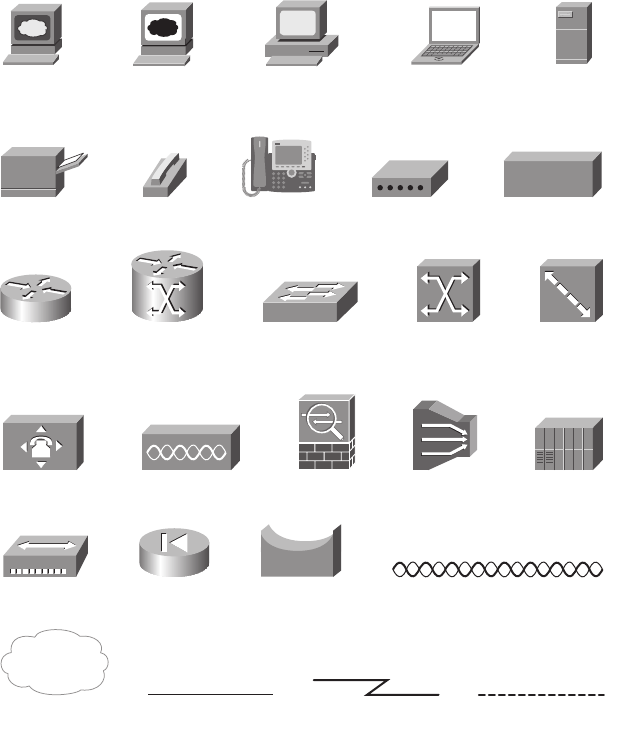
Icons Used in This Book
Network Cloud Ethernet Connection Virtual Circuit Serial Line
C
onnection
PC
Web
Server
Laptop
Web
Browser
Server
Printer
Cable Modem Phone IP Phone
CSU/DSU
Wireless Connection
PIX Firewall
Hub Bridge
Switch ATM Switch Frame Relay
Switch
Router Multiservice
Switch
DSLAM
PBX
ASA
Access Point
WAN Switch
1828xbook.fm Page xxiv Thursday, July 26, 2007 3:10 PM
xxv
Command Syntax Conventions
The conventions used to present command syntax in this book are the same conventions
used in the IOS Command Reference. The Command Reference describes these
conventions as follows:
■Bold indicates commands and keywords that are entered literally as shown. In actual
configuration examples and output (not general command syntax), bold indicates
commands that the user enters (such as a show command).
■Italic indicates arguments for which you supply actual values.
■Vertical bars (|) separate alternative, mutually exclusive elements.
■Square brackets ([ ]) indicate an optional element.
■Braces ({ }) indicate a required choice.
■Braces within brackets ([{ }]) indicate a required choice within an optional element.
1828xbook.fm Page xxv Thursday, July 26, 2007 3:10 PM
xxvi
Foreword
CCENT/CCNA ICND1 Official Exam Certification Guide, Second Edition, is an excellent
self-study resource for the CCENT and CCNA ICND1 exam. Passing the ICND1 exam
validates the knowledge and skills required to successfully install, operate, and
troubleshoot a small branch office network. It is the sole required exam for CCENT
certification and the first of two exams required for CCNA certification.
Gaining certification in Cisco technology is key to the continuing educational development
of today’s networking professional. Through certification programs, Cisco validates the
skills and expertise required to effectively manage the modern Enterprise network.
Cisco Press exam certification guides and preparation materials offer exceptional—and
flexible—access to the knowledge and information required to stay current in your field of
expertise, or to gain new skills. Whether used as a supplement to more traditional training
or as a primary source of learning, these materials offer users the information and
knowledge validation required to gain new understanding and proficiencies.
Developed in conjunction with the Cisco certifications and training team, Cisco Press
books are the only self-study books authorized by Cisco. They offer students a series of
exam practice tools and resource materials to help ensure that learners fully grasp the
concepts and information presented.
Additional authorized Cisco instructor-led courses, e-learning, labs, and simulations are
available exclusively from Cisco Learning Solutions Partners worldwide. To learn more,
visit http://www.cisco.com/go/training.
I hope that you find these materials to be an enriching and useful part of your exam
preparation.
Erik Ullanderson
Manager, Global Certifications
Learning@Cisco
August 2007
1828xbook.fm Page xxvi Thursday, July 26, 2007 3:10 PM
xxvii
Introduction
Congratulations! If you’re reading this Introduction, you’ve probably already decided
to go for your Cisco certification. If you want to succeed as a technical person in the
networking industry, you need to know Cisco. Cisco has a ridiculously high market share
in the router and switch marketplace—more than 80 percent in some markets. In many
geographies and markets around the world, networking equals Cisco. If you want to be
taken seriously as a network engineer, Cisco certification makes sense.
Historically speaking, the first entry-level Cisco certification has been the Cisco Certified
Network Associate (CCNA) certification, first offered in 1998. The first three versions of
the CCNA certification (1998, 2000, and 2002) required that you pass a single exam to
become certified. However, over time, the exam kept growing, both in the amount of
material covered and the difficulty level of the questions. So, for the fourth major revision
of the exams, announced in 2003, Cisco continued with a single certification (CCNA) but
offered two certification options: a single exam option and a two-exam option. The two-
exam option allowed people to study roughly half the material and then take and pass one
exam before moving on to the next.
Cisco announced changes to the CCNA certification and exams in June 2007. This
announcement includes many changes; here are the most notable:
■The exams collectively cover a broader range of topics.
■The exams increase the focus on proving the test taker’s skills (as compared with just
testing knowledge).
■Cisco created a new entry-level certification: Cisco Certified Entry Networking
Technician (CCENT).
For the current certifications, announced in June 2007, Cisco created the ICND1 (640-822)
and ICND2 (640-816) exams, along with the CCNA (640-802) exam. To become CCNA
certified, you can pass both the ICND1 and ICND2 exams, or just the CCNA exam. The
CCNA exam simply covers all the topics on the ICND1 and ICND2 exams, giving you two
options for gaining your CCNA certification. The two-exam path gives people with less
experience a chance to study for a smaller set of topics at one time. The one-exam option
provides a more cost-effective certification path for those who want to prepare for all the
topics at once.
Although the two-exam option is useful for some certification candidates, Cisco designed
the ICND1 exam with a much more important goal in mind. The CCNA certification grew
to the point that it tested knowledge and skills beyond what an entry-level network
technician would need. Cisco needed a certification that better reflected the skills required
1828xbook.fm Page xxvii Thursday, July 26, 2007 3:10 PM
xxviii
for entry-level networking jobs. So Cisco designed its Interconnecting Cisco Networking
Devices 1 (ICND1) course, and the corresponding ICND1 640-822 exam, to include the
knowledge and skills most needed by an entry-level technician in a small Enterprise
network. And so that you can prove that you have the skills required for those entry-level
jobs, Cisco created a new certification, CCENT.
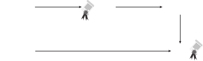
Figure I-1 shows the basic organization of the certifications and the exams used to get your
CCENT and CCNA certifications. (Note that there is no separate certification for passing
the ICND2 exam.)
Figure I-1 Cisco Entry-Level Certifications and Exams
As you can see, although you can obtain the CCENT certification by taking the ICND1
exam, you do not have to be CCENT certified before getting your CCNA certification. You
can choose to take just the CCNA exam and bypass the CCENT certification.
The ICND1 and ICND2 exams cover different sets of topics, with a minor amount of
overlap. For example, ICND1 covers IP addressing and subnetting, and ICND2 covers a
more complicated use of subnetting called variable-length subnet masking (VLSM).
Therefore, ICND2 must then cover subnetting to some degree. The CCNA exam covers all
the topics covered on both the ICND1 and ICND2 exams.
Although the popularity of the CCENT certification cannot be measured until a few years
have passed, certainly the Cisco CCNA is the most popular entry-level networking
certification program. A CCNA certification proves that you have a firm foundation in the
most important components of the Cisco product line—routers and switches. It also proves
that you have broad knowledge of protocols and networking technologies.
Format of the CCNA Exams
The ICND1, ICND2, and CCNA exams all follow the same general format. When you get
to the testing center and check in, the proctor gives you some general instructions and
then takes you into a quiet room containing a PC. When you’re at the PC, you have a few
Ta ke ICND1
(640-822) Exam
CCENT
Certified
CCNA
Certified
Ta ke ICND2
(640-816) Exam
pass
Ta ke CCNA
(640-802) Exam
pass
pass
1828xbook.fm Page xxviii Thursday, July 26, 2007 3:10 PM
xxix
things to do before the timer starts on your exam. For instance, you can take a sample quiz
to get accustomed to the PC and the testing engine. Anyone who has user-level skills in
getting around a PC should have no problems with the testing environment. Additionally,
Chapter 18, “Final Preparation,” points to a Cisco website where you can see a demo of
Cisco’s actual test engine.
When you start the exam, you are asked a series of questions. You answer them and then
move on to the next question. The exam engine does not let you go back and change your
answer. Yes, it’s true. When you move on to the next question, that’s it for the preceding
question.
The exam questions can be in one of the following formats:
■Multiple choice (MC)
■Testlet
■Drag-and-drop (DND)
■Simulated lab (sim)
■Simlet
The first three types of questions are relatively common in many testing environments. The
multiple-choice format simply requires that you point and click a circle beside the correct
answer(s). Cisco traditionally tells you how many answers you need to choose, and the
testing software prevents you from choosing too many. Testlets are questions with one
general scenario and several multiple-choice questions about the overall scenario. Drag-
and-drop questions require you to click and hold, move a button or icon to another area, and
release the mouse button to place the object somewhere else—typically in a list. For some
questions, to get the question correct, you might need to put a list of five things in the proper
order.
The last two types of questions use a network simulator to ask questions. Interestingly, the
two types actually allow Cisco to assess two very different skills. First, sim questions
generally describe a problem, and your task is to configure one or more routers and switches
to fix it. The exam then grades the question based on the configuration you changed or
added. Interestingly, sim questions are the only questions (to date) for which Cisco has
openly confirmed it gives partial credit for.
The simlet questions may well be the most difficult style of question. Simlet questions also
use a network simulator, but instead of having you answer by changing the configuration,
the question includes one or more multiple-choice questions. The questions require that you
use the simulator to examine a network’s current behavior, interpreting the output of any
1828xbook.fm Page xxix Thursday, July 26, 2007 3:10 PM

xxx
show commands you can remember to answer the question. Whereas sim questions require
you to troubleshoot problems related to a configuration, simlets require you to analyze both
working networks and networks with problems, correlating show command output with
your knowledge of networking theory and configuration commands.
What’s on the CCNA Exam(s)?
Ever since I was in grade school, whenever the teacher announced that we were having a
test soon, someone would always ask, “What’s on the test?” Even in college, people would
try to get more information about what would be on the exams. The goal is to know what
to study a lot, what to study a little, and what to not study at all.
Cisco wants the public to know the variety of topics and have an idea of the kinds of
knowledge and skills required for each topic, for every Cisco certification exam. To that
end, Cisco publishes a set of objectives for each exam. The objectives list the specific topics
such as IP addressing, RIP, and VLANs. The objectives also imply the kinds of skills
required for that topic. For example, one objective might start with “Describe...”, and
another might begin with “Describe, configure, and troubleshoot...”. The second objective
clearly states that you need a thorough understanding of that topic. By listing the topics and
skill level, Cisco helps you prepare for the exams.
Although the exam objectives are helpful, keep in mind that Cisco adds a disclaimer that
the posted exam topics for all its certification exams are guidelines. Cisco makes an effort
to keep the exam questions within the confines of the stated exam objectives. I know from
talking to those involved that every question is analyzed to ensure that it fits within the
stated exam topics.
ICND1 Exam Topics
Table I-1 lists the exam topics for the ICND1 exam. The ICND2 exam topics follow in
Table I-2. Although the posted exam topics are not numbered at Cisco.com, Cisco Press
numbers them for easier reference. The tables also note the book parts in which each exam
topic is covered. Because the exam topics may change over time, it may be worth it to
double-check the exam topics listed on Cisco.com (go to http://www.cisco.com/go/ccna).
If Cisco does happen to add exam topics at a later date, note that Appendix C, “ICND1
Exam Updates,” describes how to go to http://www.ciscopress.com and download
additional information about those newly added topics.
NOTE The table includes gray highlights that are explained in the upcoming section
“CCNA Exam Topics.”
1828xbook.fm Page xxx Thursday, July 26, 2007 3:10 PM

xxxi
Table I-1 ICND1 Exam Topics
Reference
Number
Book Part(s)
Where Topic Is
Covered Exam Topic
Describe the operation of data networks
1I Describe the purpose and functions of various network devices
2I Select the components required to meet a given network
specification
3 I, II, III Use the OSI and TCP/IP models and their associated protocols
to explain how data flows in a network
4I Describe common networking applications including web
applications
5I Describe the purpose and basic operation of the protocols in the
OSI and TCP models
6I Describe the impact of applications (Voice Over IP and Video
Over IP) on a network
7 I–IV Interpret network diagrams
8 I–IV Determine the path between two hosts across a network
9 I, III, IV Describe the components required for network and Internet
communications
10 I–IV Identify and correct common network problems at Layers 1, 2,
3, and 7 using a layered model approach
11 II, III Differentiate between LAN/WAN operation and features
Implement a small switched network
12 II Select the appropriate media, cables, ports, and connectors to
connect switches to other network devices and hosts
13 II Explain the technology and media access control method for
Ethernet technologies
14 II Explain network segmentation and basic traffic management
concepts
15 II Explain the operation of Cisco switches and basic switching
concepts
16 II Perform, save, and verify initial switch configuration tasks
including remote access management
continues
1828xbook.fm Page xxxi Thursday, July 26, 2007 3:10 PM

xxxii
17 II Verify network status and switch operation using basic utilities
(including: ping, traceroute, Telnet, SSH, ARP, ipconfig), show
and debug commands
18 II Implement and verify basic security for a switch (port security,
deactivate ports)
19 II Identify, prescribe, and resolve common switched network
media issues, configuration issues, autonegotiation, and switch
hardware failures
Implement an IP addressing scheme and IP services to
meet network requirements for a small branch office
20 I, III Describe the need for and role of addressing in a network
21 I, III Create and apply an addressing scheme to a network
22 III Assign and verify valid IP addresses to hosts, servers, and
networking devices in a LAN environment
23 IV Explain the basic uses and operation of NAT in a small network
connecting to one ISP
24 I, III Describe and verify DNS operation
25 III, IV Describe the operation and benefits of using private and public
IP addressing
26 III, IV Enable NAT for a small network with a single ISP and
connection using SDM and verify operation using CLI and ping
27 III Configure, verify, and troubleshoot DHCP and DNS operation
on a router (including: CLI/SDM)
28 III Implement static and dynamic addressing services for hosts in a
LAN environment
29 III Identify and correct IP addressing issues
Implement a small routed network
30 I, III Describe basic routing concepts (including: packet forwarding,
router lookup process)
31 III Describe the operation of Cisco routers (including: router
bootup process, POST, router components)
Table I-1 ICND1 Exam Topics (Continued)
Reference
Number
Book Part(s)
Where Topic Is
Covered Exam Topic
1828xbook.fm Page xxxii Thursday, July 26, 2007 3:10 PM

xxxiii
32 I, III Select the appropriate media, cables, ports, and connectors to
connect routers to other network devices and hosts
33 III Configure, verify, and troubleshoot RIPv2
34 III Access and utilize the router CLI to set basic parameters
35 III Connect, configure, and verify operation status of a device
interface
36 III Verify device configuration and network connectivity using
ping, traceroute, Telnet, SSH, or other utilities
37 III Perform and verify routing configuration tasks for a static or
default route given specific routing requirements
38 III Manage IOS configuration files (including: save, edit, upgrade,
restore)
39 III Manage Cisco IOS
40 III Implement password and physical security
41 III Verify network status and router operation using basic utilities
(including: ping, traceroute, Telnet, SSH, ARP, ipconfig), show
and debug commands
Explain and select the appropriate administrative tasks
required for a WLAN
42 II Describe standards associated with wireless media (including:
IEEE, Wi-Fi Alliance, ITU/FCC)
43 II Identify and describe the purpose of the components in a small
wireless network (including: SSID, BSS, ESS)
44 II Identify the basic parameters to configure on a wireless network
to ensure that devices connect to the correct access point
45 II Compare and contrast wireless security features and capabilities
of WPA security (including: open, WEP, WPA-1/2)
46 II Identify common issues with implementing wireless networks
continues
Table I-1 ICND1 Exam Topics (Continued)
Reference
Number
Book Part(s)
Where Topic Is
Covered Exam Topic
1828xbook.fm Page xxxiii Thursday, July 26, 2007 3:10 PM

xxxiv
ICND2 Exam Topics
Table I-2 lists the exam topics for the ICND2 (640-816) exam, along with the book parts in
the CCNA ICND2 Official Exam Certification Guide in which each topic is covered.
Identify security threats to a network and describe general
methods to mitigate those threats
47 I Explain today’s increasing network security threats and the need
to implement a comprehensive security policy to mitigate the
threats
48 I Explain general methods to mitigate common security threats to
network devices, hosts, and applications
49 I Describe the functions of common security appliances and
applications
50 I, II, III Describe security recommended practices including initial steps
to secure network devices
Implement and verify WAN links
51 IV Describe different methods for connecting to a WAN
52 IV Configure and verify a basic WAN serial connection
Table I-2 ICND2 Exam Topics
Reference
Number
Book Part(s)
Where Topic Is
Covered (in
ICND2) Exam Topic
Configure, verify, and troubleshoot a switch with VLANs
and interswitch communications
101 I Describe enhanced switching technologies (including: VTP,
RSTP, VLAN, PVSTP, 802.1q)
102 I Describe how VLANs create logically separate networks and
the need for routing between them
103 I Configure, verify, and troubleshoot VLANs
104 I Configure, verify, and troubleshoot trunking on Cisco switches
Table I-1 ICND1 Exam Topics (Continued)
Reference
Number
Book Part(s)
Where Topic Is
Covered Exam Topic
1828xbook.fm Page xxxiv Thursday, July 26, 2007 3:10 PM

xxxv
105 II Configure, verify, and troubleshoot interVLAN routing
106 I Configure, verify, and troubleshoot VTP
107 I Configure, verify, and troubleshoot RSTP operation
108 I Interpret the output of various show and debug commands to
verify the operational status of a Cisco switched network
109 I Implement basic switch security (including: port security,
unassigned ports, trunk access, etc.)
Implement an IP addressing scheme and IP Services to
meet network requirements in a medium-size Enterprise
branch office network
110 II Calculate and apply a VLSM IP addressing design to a network
111 II Determine the appropriate classless addressing scheme using
VLSM and summarization to satisfy addressing requirements in
a LAN/WAN environment
112 V Describe the technological requirements for running IPv6
(including: protocols, dual stack, tunneling, etc.)
113 V Describe IPv6 addresses
114 II, III Identify and correct common problems associated with IP
addressing and host configurations
Configure and troubleshoot basic operation and routing on
Cisco devices
115 III Compare and contrast methods of routing and routing protocols
116 III Configure, verify, and troubleshoot OSPF
117 III Configure, verify, and troubleshoot EIGRP
118 II, III Verify configuration and connectivity using ping, traceroute,
and Telnet or SSH
119 II, III Troubleshoot routing implementation issues
continues
Table I-2 ICND2 Exam Topics (Continued)
Reference
Number
Book Part(s)
Where Topic Is
Covered (in
ICND2) Exam Topic
1828xbook.fm Page xxxv Thursday, July 26, 2007 3:10 PM

xxxvi
CCNA Exam Topics
In the previous version of the exams, the CCNA exam covered a lot of what was in the
ICND (640-811) exam, plus some coverage of topics in the INTRO (640-821) exam. The
new CCNA exam (640-802) covers all the topics on both the ICND1 (640-822) and ICND2
(640-816) exams. One of the reasons for more-balanced coverage in the exams is that some
of the topics that used to be in the second exam have been moved to the first exam.
120 II, III, IV Verify router hardware and software operation using show and
debug commands
121 II Implement basic router security
Implement, verify, and troubleshoot NAT and ACLs in a
medium-size Enterprise branch office network
122 II Describe the purpose and types of access control lists
123 II Configure and apply access control lists based on network
filtering requirements
124 II Configure and apply an access control list to limit Telnet and
SSH access to the router
125 II Verify and monitor ACLs in a network environment
126 II Troubleshoot ACL implementation issues
127 V Explain the basic operation of NAT
128 V Configure Network Address Translation for given network
requirements using CLI
129 V Troubleshoot NAT implementation issues
Implement and verify WAN links
130 IV Configure and verify Frame Relay on Cisco routers
131 IV Troubleshoot WAN implementation issues
132 IV Describe VPN technology (including: importance, benefits,
role, impact, components)
133 IV Configure and verify PPP connection between Cisco routers
Table I-2 ICND2 Exam Topics (Continued)
Reference
Number
Book Part(s)
Where Topic Is
Covered (in
ICND2) Exam Topic
1828xbook.fm Page xxxvi Thursday, July 26, 2007 3:10 PM
xxxvii
The CCNA (640-802) exam covers all the topics in both the ICND1 and ICND2 exams. The
official CCNA 640-802 exam topics, posted at http://www.cisco.com, include all the topics
listed in Table I-2 for the ICND2 exam, plus most of the exam topics for the ICND1 exam
listed in Table I-1. The only exam topics from these two tables that are not listed as CCNA
exam topics are the topics highlighted in gray in Table I-1. However, note that the gray
topics are still covered on the CCNA 640-802 exam. Those topics are just not listed in the
CCNA exam topics because one of the ICND2 exam topics refers to the same concepts.
ICND1 and ICND2 Course Outlines
Another way to get some direction about the topics on the exams is to look at the course
outlines for the related courses. Cisco offers two authorized CCNA-related courses:
Interconnecting Cisco Network Devices 1 (ICND1) and Interconnecting Cisco Network
Devices 2 (ICND2). Cisco authorizes Certified Learning Solutions Providers (CLSP) and
Certified Learning Partners (CLP) to deliver these classes. These authorized companies can
also create unique custom course books using this material—in some cases to teach classes
geared toward passing the CCNA exam.
About the
CCENT/CCNA ICND1 Official Exam
Certification Guide
and
CCNA ICND2 Official Exam
Certification Guide
As mentioned earlier, Cisco has separated the content covered by the CCNA exam into
two parts: topics typically used by engineers who work in small Enterprise networks
(ICND1), and topics commonly used by engineers in medium-sized Enterprises (ICND2).
Likewise, the Cisco Press CCNA Exam Certification Guide series includes two books for
CCNA—CCENT/CCNA ICND1 Official Exam Certification Guide and CCNA ICND2
Official Exam Certification Guide. These two books cover the breadth of topics on each
exam, typically to a little more depth than is required for the exams, to ensure that the books
prepare you for the more difficult exam questions.
This section lists the variety of book features in both this book and the CCNA ICND2 Official
Exam Certification Guide. Both books have the same basic features, so if you are reading both
this book and the ICND2 book, there is no need to read the Introduction to the second book.
Also, if you’re using both books to prepare for the CCNA 640-802 exam (rather than taking
the two-exam option), the end of this Introduction lists a suggested reading plan.
Objectives and Methods
The most important and somewhat obvious objective of this book is to help you pass the
ICND1 exam or the CCNA exam. In fact, if the primary objective of this book were
different, the book’s title would be misleading! However, the methods used in this book to
1828xbook.fm Page xxxvii Thursday, July 26, 2007 3:10 PM
xxxviii
help you pass the exams are also designed to make you much more knowledgeable about
how to do your job.
This book uses several key methodologies to help you discover the exam topics on which
you need more review, to help you fully understand and remember those details, and to
help you prove to yourself that you have retained your knowledge of those topics. So, this
book does not try to help you pass the exams only by memorization, but by truly learning
and understanding the topics. The CCNA certification is the foundation for many of the
Cisco professional certifications, and it would be a disservice to you if this book did not
help you truly learn the material. Therefore, this book helps you pass the CCNA exam by
using the following methods:
■Helping you discover which exam topics you have not mastered
■Providing explanations and information to fill in your knowledge gaps
■Supplying exercises that enhance your ability to recall and deduce the answers to test
questions
■Providing practice exercises on the topics and the testing process via test questions on
the CD
Book Features
To help you customize your study time using these books, the core chapters have several
features that help you make the best use of your time:
■“Do I Know This Already?” Quizzes: Each chapter begins with a quiz that helps you
determine how much time you need to spend studying that chapter.
■Foundation Topics: These are the core sections of each chapter. They explain the
protocols, concepts, and configuration for the topics in that chapter.
■Exam Preparation Tasks: After the Foundation Topics section, the “Exam
Preparation Tasks” section lists a series of study activities you should perform. Each
chapter includes the activities that make the most sense for studying the topics in that
chapter. The activities include the following:
— Review All the Key Topics: The key topics icon appears next to the most
important items in the Foundation Topics section. The “Review All
the Key Topics” activity lists the key topics from the chapter and the page
on which they appear. Although the contents of the entire chapter could
be on the exam, you should definitely know the information listed in each
key topic.
1828xbook.fm Page xxxviii Thursday, July 26, 2007 3:10 PM
xxxix
— Complete the Tables and Lists from Memory: To help you memorize
some lists of facts, many of the more important lists and tables from
the chapter are included in Appendix H on the CD. This document lists
only some of the information, allowing you to complete the table or list.
Appendix I lists the same tables and lists, completed, for easy
comparison.
— Definitions of Key Terms: Although the exams may be unlikely to ask
a question such as “Define this term,” the CCNA exams do require that
you learn and know a lot of networking terminology. This section lists the
most important terms from the chapter, asking you to write a short
definition and compare your answer to the glossary at the end of the book.
— Command Reference tables: Some book chapters cover a large number
of configuration and EXEC commands. These tables list and describe the
commands introduced in the chapter. For exam preparation, use this
section for reference, but also read through the table when performing the
Exam Preparation Tasks to make sure you remember what all the
commands do.
■CD-based practice exam: The companion CD contains an exam engine (from Boson
software, http://www.boson.com) that includes a large number of exam-realistic
practice questions. You can take simulated ICND1 exams, as well as simulated CCNA
exams, using this book’s CD. (You can take simulated ICND2 and CCNA exams using
the CD in the CCNA ICND2 Official Exam Certification Guide.)
■Subnetting videos: The companion DVD contains a series of videos that show you
how to figure out various facts about IP addressing and subnetting—in particular, using
the shortcuts described in this book.
■Subnetting practice: CD Appendix D contains a large set of subnetting practice
problems, including the answers and explanations of how they were arrived at. This is
a great resource to help you get ready to do subnetting well and fast.
■CD-based practice scenarios: CD Appendix F contains several networking scenarios
for additional study. These scenarios describe various networks and requirements,
taking you through conceptual design, configuration, and verification. These scenarios
are useful for building your hands-on skills, even if you do not have lab gear.
■Companion website: The website http://www.ciscopress.com/title/1587201828 posts
up-to-the-minute materials that further clarify complex exam topics. Check this site
regularly for new and updated postings written by the author that provide further
insight into the more troublesome topics on the exam.
1828xbook.fm Page xxxix Thursday, July 26, 2007 3:10 PM
xl
How This Book Is Organized
This book contains 18 core chapters. The final one includes summary materials and
suggestions on how to approach the exams. Each chapter covers a subset of the topics on
the ICND1 exam. The chapters are organized into parts and cover the following topics:
■Part I: Networking Fundamentals
— Chapter 1, “Introduction to Computer Networking Concepts,”
provides a basic introduction in case you’re new to networking.
— Chapter 2, “The TCP/IP and OSI Networking Models,” introduces
the terminology used with two different networking architectures—
Transmission Control Protocol/Internet Protocol (TCP/IP) and Open
Systems Interconnection (OSI).
— Chapter 3, “Fundamental of LANs,” covers the concepts and
terms used with the most popular option for the data link layer for local-
area networks (LANs)—namely, Ethernet.
— Chapter 4, “Fundamentals of WANs,” covers the concepts and terms
used with the most popular options for the data link layer for wide-area
networks (WANs), including High-Level Data Link Control (HDLC),
Point-to-Point Protocol (PPP), and Frame Relay.
— Chapter 5, “Fundamentals of IP Addressing and Routing,” covers
the main network layer protocol for TCP/IP—Internet Protocol (IP).
This chapter introduces the basics of IP, including IP addressing and
routing.
— Chapter 6, “Fundamentals of TCP/IP Transport, Applications, and
Security,” covers the main transport layer protocols for TCP/IP—
Transmission Control Protocol (TCP) and User Datagram Protocol
(UDP). This chapter introduces the basics of TCP and UDP.
■Part II: LAN Switching
— Chapter 7, “Ethernet LAN Switching Concepts,” deepens and
expands the introduction to LANs from Chapter 3, completing most of
the conceptual materials for Ethernet in this book.
— Chapter 8, “Operating Cisco LAN Switches,” explains how to access,
examine, and configure Cisco Catalyst LAN switches.
— Chapter 9, “Ethernet Switch Configuration,” shows you how to
configure a variety of switch features, including duplex and speed, port
security, securing the CLI, and the switch IP address.
1828xbook.fm Page xl Thursday, July 26, 2007 3:10 PM
xli
— Chapter 10, “Ethernet Switch Troubleshooting,” focuses on how to
tell if the switch is doing what it is supposed to, mainly through the
use of show commands.
— Chapter 11, “Wireless LANs,” explains the basic operation concepts of
wireless LANs, along with addressing some of the most common
security concerns.
■Part III: IP Routing
— Chapter 12, “IP Addressing and Subnetting,” completes the
explanation of subnetting that was introduced in Chapter 5. More
importantly, it describes in detail how to perform the math and processes
to find the answers to many varieties of subnetting questions.
— Chapter 13, “Operating Cisco Routers,” is like Chapter 8, but with a
focus on routers instead of switches.
— Chapter 14, “Routing Protocol Concepts and Configuration,”
explains how routers forward (route) IP packets and how IP routing
protocols work to find all the best routes to each subnet. This chapter
includes the details of how to configure static routes and RIP version 2.
— Chapter 15, “Troubleshooting IP Routing,” suggests hints and tips
about how to troubleshoot problems related to layer 3 routing, including
a description of several troubleshooting tools.
■Part IV: Wide-Area Networks
— Chapter 16, “WAN Concepts,” completes the conceptual materials
for WANs, continuing the coverage from Chapter 4 by touching on
Internet access technologies such as DSL and cable. It also covers the
concepts of Network Address Translation (NAT).
— Chapter 17, “WAN Configuration,” completes the main technical
topics, focusing on a few small WAN configuration tasks. It also covers
the WAN configuration tasks and NAT configuration using Cisco
Security Device Manager (SDM).
■Part V: Final Preparation
— Chapter 18, “Final Preparation,” suggests a plan for final preparation
after you have finished the core parts of the book. It also explains the
many study options available in the book.
■Part VI: Appendixes (in the Book)
— Appendix A, “Answers to the “Do I Know This Already?” Quizzes,”
includes the answers to all the questions from Chapters 1 through 17.
1828xbook.fm Page xli Thursday, July 26, 2007 3:10 PM
xlii
— Appendix B, “Decimal to Binary Conversion Table,” lists decimal
values 0 through 255, along with their binary equivalents.
— Appendix C, “ICND1 Exam Updates,” covers a variety of short
topics that either clarify or expand on topics covered earlier in the
book. This appendix is updated from time to time and is posted at
http://www.ciscopress.com/ccna. The most recent version available at
the time this book was published is included in this book as Appendix C.
(The first page of the appendix includes instructions on how to check to
see if a later version of Appendix C is available online.)
— The glossary defines all the terms listed in the “Definitions of Key
Terms” section at the conclusion of Chapters 1 through 17.
■Part VII: Appendixes (on the CD)
The following appendixes are available in PDF format on the CD that accompanies
this book:
— Appendix D, “Subnetting Practice,” includes a large number of
subnetting practice problems. It gives the answers as well as explanations
of how to use the processes described in Chapter 12 to find the answers.
— Appendix E, “Subnetting Reference Pages.” Chapter 12 explains in
detail how to calculate the answers to many subnetting questions. This
appendix summarizes the process of finding the answers to several key
questions, with the details on a single page. The goal is to give you a
handy reference page to refer to when you’re practicing subnetting.
— Appendix F, “Additional Scenarios.” One method to improve your
troubleshooting and network analysis skills is to examine as many unique
network scenarios as possible, think about them, and then get some
feedback on whether you came to the right conclusions. This appendix
provides several such scenarios.
— Appendix G, “Subnetting Video Reference.” The DVD includes
several subnetting videos that show you how to use the processes covered
in Chapter 12. This appendix contains copies of the key elements from
those videos, which may be useful when you’re watching the videos
(so that you do not have to keep moving back and forth in the video).
— Appendix H, “Memory Tables,” contains the key tables and lists from
each chapter, with some of the content removed. You can print this
appendix and, as a memory exercise, complete the tables and lists. The
goal is to help you memorize facts that can be useful on the exams.
— Appendix I, “Memory Tables Answer Key,” contains the answer key
for the exercises in Appendix H.
1828xbook.fm Page xlii Thursday, July 26, 2007 3:10 PM
xliii
— Appendix J, “ICND1 Open-Ended Questions,” is a holdover from the
previous edition of this book. The first edition had some open-ended
questions to help you study for the exam, but the newer features make
these questions unnecessary. For convenience, the old questions are
included here, unedited since the last edition.
How to Use This Book to Prepare for the
ICND1 (640–822) Exam and CCENT Certification
This book was designed with two primary goals in mind: to help you study for the ICND1
exam (and get your CCENT certification), and to help you study for the CCNA exam
by using both this book and the CCNA ICND2 Official Exam Certification Guide. Using
this book to prepare for the ICND1 exam is pretty straightforward. You read each chapter
in succession and follow the study suggestions in Chapter 18.
For Chapters 1 through 17, you have some choices as to how much of the chapter you read.
In some cases, you may already know most or all of the information covered in a given
chapter. To help you decide how much time to spend on each chapter, the chapters begin
with a “Do I Know This Already?” quiz. If you get all the quiz questions correct, or if you
miss just one, you may want to skip to the “Exam Preparation Tasks” section at the end of
the chapter and perform those activities. Figure I-2 shows the overall plan.
Figure I-2 How to Approach Each Chapter of This Book
When you have completed Chapters 1 through 17, you can use the guidance listed in
Chapter 18 to perform the rest of the exam preparation tasks. That chapter includes the
following suggestions:
■Check http://www.ciscopress.com for the latest copy of Appendix C, which may
include additional topics for study.
Ta ke the “Do I Know This Already Quiz”
Read “Foundation Topics” Section
Read/do “Exam Preparation Tasks” To Next Chapter
Miss more
than 1:
Miss 1 or less, but
want more study
Miss 1 or less, want
to move on
1828xbook.fm Page xliii Thursday, July 26, 2007 3:10 PM
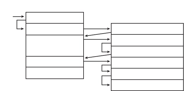
xliv
■Practice subnetting using the tools available in the CD appendixes.
■Repeat the tasks in all the chapters’ “Exam Preparation Tasks” chapter-ending
sections.
■Review the scenarios in CD Appendix F.
■Review all the “Do I Know This Already?” questions.
■Practice the exam using the exam engine.
How to Use These Books to Prepare for the
CCNA 640–802 Exam
If you plan to get your CCNA certification using the one-exam option of taking the
CCNA 640-802 exam, you can use this book with the CCNA ICND2 Official Exam
Certification Guide. If you haven’t yet bought either book, you generally can get the pair
cheaper by buying both books as a two-book set called the CCNA Certification Library.
These two books were designed to be used together when you study for the CCNA exam.
You have two good options for the order in which to read the two books. The first and most
obvious option is to read this book and then move on to the ICND2 book. The other option
is to read all of ICND1’s coverage of one topic area, and then read ICND2’s coverage of
the same topics, and then return to ICND1. Figure I-3 outlines my suggested plan for
reading the two books.
Figure I-3 Reading Plan When You’re Studying for the CCNA Exam
Both reading plan options have some benefits. Moving back and forth between books helps
you focus on one general topic at a time. However, note that there is some overlap between
the two exams, so there is some overlap between the two books as well. From reader
Network Fundamentals
Final Preparation
Wide-Area Networks
IP Routing
LAN Switching
ICND1
Exam Certification Guide
Start
here
LAN Switching
IP Routing
Routing Protocols
Wide-Area Networks
Scaling the IP Address Space
Final Preparation
ICND2
Exam Certification Guide
1828xbook.fm Page xliv Thursday, July 26, 2007 3:10 PM
xlv
comments about the previous edition of these books, readers who were new to networking
tended to do better by completing all of the first book and then moving on to the second.
Readers who had more experience and knowledge before starting the books tended to prefer
following a reading plan like the one shown in Figure I-3.
Note that for final preparation, you can use the final chapter (Chapter 18) of the ICND2
book rather than the “Final Preparation” chapter (Chapter 18) of this book. Chapter 18 of
ICND2 covers the same basic activities as does this book’s Chapter 18, with reminders of
any exam preparation materials from this book that should be useful.
In addition to the flow shown in Figure I-3, when you study for the CCNA exam (rather
than the ICND1 and ICND2 exams), it is important to master IP subnetting before moving
on to the IP routing and routing protocol parts of the ICND2 book. The ICND2 book does
not review subnetting or the underlying math, assuming that you know how to find the
answers. Those ICND2 chapters, particularly Chapter 5 (“VLSM and Route
Summarization”), are much easier to understand if you can do the related subnetting math
pretty easily.
For More Information
If you have any comments about this book, you can submit them via
http://www.ciscopress.com. Just go to the website, select Contact Us, and enter your
message.
Cisco might occasionally make changes that affect the CCNA certification. You should
always check http://www.cisco.com/go/ccna and http://www.cisco.com/go/ccent for the
latest details.
The CCNA certification is arguably the most important Cisco certification, although the
new CCENT certification might surpass CCNA in the future. CCNA certainly is the most
popular Cisco certification to date. It’s required for several other certifications, and it’s the
first step in distinguishing yourself as someone who has proven knowledge of Cisco.
The CCENT/CCNA ICND1 Official Exam Certification Guide is designed to help you attain
both CCENT and CCNA certification. This is the CCENT/CCNA ICND1 certification
book from the only Cisco-authorized publisher. We at Cisco Press believe that this book can
help you achieve CCNA certification, but the real work is up to you! I trust that your time
will be well spent.
1828xbook.fm Page xlv Thursday, July 26, 2007 3:10 PM

Cisco Published ICND1 Exam Topics* Covered in This Part:
Describe the operation of data networks
■Describe the purpose and functions of various network devices
■Select the components required to meet a given network specification
■Use the OSI and TCP/IP models and their associated protocols to explain how data flows in
a network
■Describe common networking applications including web applications
■Describe the purpose and basic operation of the protocols in the OSI and TCP models
■Describe the impact of applications (Voice Over IP and Video Over IP) on a network
■Describe the components required for network and Internet communications
■Identify and correct common network problems at Layers 1, 2, 3, and 7 using a layered
model approach
Implement an IP addressing scheme and IP services to meet network requirements for a
small branch office
■Describe the need for and role of addressing in a network
■Create and apply an addressing scheme to a network
■Describe and verify DNS operation
Implement a small routed network
■Describe basic routing concepts (including: packet forwarding, router lookup process)
■Select the appropriate media, cables, ports, and connectors to connect routers to other
network devices and hosts
Identify security threats to a network and describe general methods to mitigate those threats
■Explain today’s increasing network security threats and the need to implement a
comprehensive security policy to mitigate the threats
■Explain general methods to mitigate common security threats to network devices, hosts, and
applications
■Describe the functions of common security appliances and applications
■Describe security recommended practices including initial steps to secure network devices
*Always check http://www.cisco.com for the latest posted exam topics.
1828xbook.fm Page 2 Thursday, July 26, 2007 3:10 PM

Part I: Networking
Fundamentals
Chapter 1 Introduction to Computer Networking Concepts
Chapter 2 The TCP/IP and OSI Networking Models
Chapter 3 Fundamentals of LANs
Chapter 4 Fundamentals of WANs
Chapter 5 Fundamentals of IP Addressing and Routing
Chapter 6 Fundamentals of TCP/IP Transport, Applications, and Security
1828xbook.fm Page 3 Thursday, July 26, 2007 3:10 PM

1828xbook.fm Page 4 Thursday, July 26, 2007 3:10 PM
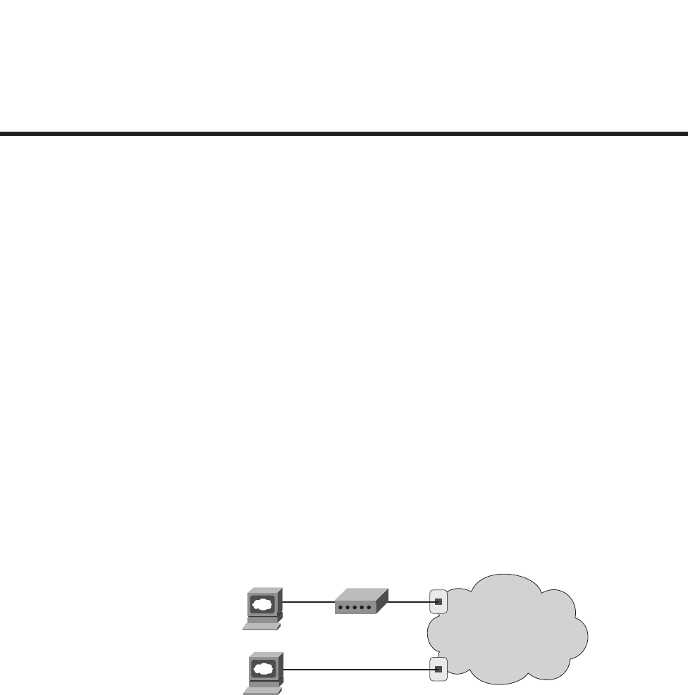
C H A P T E R1
Introduction to Computer
Networking Concepts
This chapter gives you a light-hearted perspective about networks, how they were originally
created, and why networks work the way they do. Although no specific fact from this
chapter happens to be on any of the CCNA exams, this chapter helps you prepare for the
depth of topics you will start to read about in Chapter 2, “The TCP/IP and OSI Networking
Models.” If you are brand new to networking, this short introductory chapter will help you
get ready for the details to follow. If you already understand some of the basics of TCP/IP,
Ethernet, switches, routers, IP addressing, and the like, go ahead and skip on to Chapter 2.
The rest of you will probably want to read through this short introductory chapter before
diving into the details.
Perspectives on Networking
So, you are new to networking. You might have seen or heard about different topics relating
to networking, but you are only just now getting serious about learning the details. Like
many people, your perspective about networks might be that of a user of the network, as
opposed to the network engineer who builds networks. For some, your view of networking
might be based on how you use the Internet, from home, using a high-speed Internet
connection. Others of you might use a computer at a job or at school, again connecting to
the Internet; that computer is typically connected to a network via some cable. Figure 1-1
shows both perspectives of networking.
Figure 1-1 End-User Perspective on Networks
The top part of the figure shows a typical high-speed cable Internet user. The PC connects
to a cable modem using an Ethernet cable. The cable modem then connects to a cable TV
(CATV) outlet on the wall using a round coaxial cable—the same kind of cable used to
connect your TV to the CATV wall outlet. Because cable Internet services provide service
Home User
PC with
Ethernet Card
Office User
PC with
Ethernet Card
The Internet
Ethernet
Cable
CATV
Cable
Ethernet Cable
1828xbook.fm Page 5 Thursday, July 26, 2007 3:10 PM
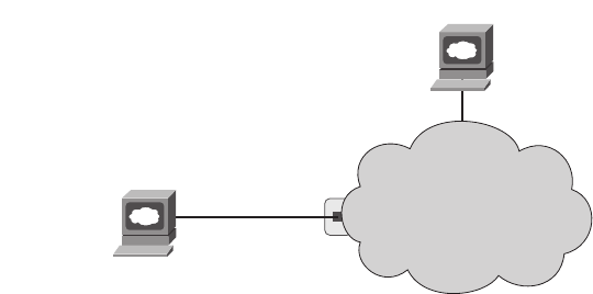
6 Chapter 1: Introduction to Computer Networking Concepts
continuously, the user can just sit down at the PC and start sending e-mail, browsing
websites, making Internet phone calls, and using other tools and applications as well.
Similarly, an employee of a company or a student at a university views the world as a
connection through a wall plug. Typically, this connection uses a type of local-area network
(LAN) called Ethernet. Instead of needing a cable modem, the PC connects directly to an
Ethernet-style socket in a wall plate (the socket is much like the typical socket used for
telephone cabling today, but the connector is a little larger). As with high-speed cable Internet
connections, the Ethernet connection does not require the PC user to do anything first to
connect to the network—it is always there waiting to be used, similar to the power outlet.
From the end-user perspective, whether at home, at work, or at school, what happens
behind the wall plug is magic. Just as most people do not really understand how cars work,
how TVs work, and so on, most people who use networks do not understand how they work.
Nor do they want to! But if you have read this much into Chapter 1, you obviously have a
little more interest in networking than a typical end user. By the end of this book, you
will have a pretty thorough understanding of what is behind that wall plug in both cases
shown in Figure 1-1.
The CCNA exams, and particularly the ICND1 (640-822) exam, focus on two major
branches of networking concepts, protocols, and devices. One of these two major branches
is called enterprise networking. An enterprise network is a network created by one
corporation, or enterprise, for the purpose of allowing its employees to communicate. For
example, Figure 1-2 shows the same type of PC end-user shown in Figure 1-1, who is now
communicating with a web server through the enterprise network (represented by a cloud)
created by Enterprise #2. The end-user PC can communicate with the web server to do
something useful for the company—for instance, the user might be on the phone with a
customer, with the user typing in the customer’s new order in the ordering system that
resides in the web server.
Figure 1-2 An Example Representation of an Enterprise Network
Office User
PC with
Ethernet Card
Ethernet Cable
Web Server
Enterprise #2
1828xbook.fm Page 6 Thursday, July 26, 2007 3:10 PM
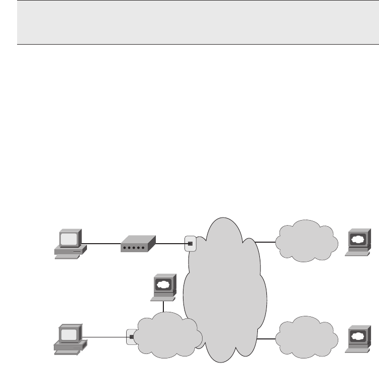
Perspectives on Networking 7
The second major branch of networking covered on the ICND1 exam is called small office/
home office, or SOHO. This branch of networking uses the same concepts, protocols, and
devices used to create enterprise networks, plus some additional features that are not
needed for enterprises. SOHO networking allows a user to connect to the Internet using
a PC and any Internet connection, such as the high-speed cable Internet connection shown
in Figure 1-1. Because most enterprise networks also connect to the Internet, the SOHO
user can sit at home, or in a small office, and communicate with servers at the enterprise
network, as well as with other hosts in the Internet. Figure 1-3 shows the concept.
Figure 1-3 SOHO User Connecting to the Internet and Other Enterprise Networks
The Internet itself consists of most every enterprise network in the world, plus billions of
devices connecting to the Internet directly through Internet service providers (ISPs). In fact,
the term itself—Internet—is formed by shortening the phrase “interconnected networks.”
To create the Internet, ISPs offer Internet access, typically using either a cable TV line, a
phone line using digital subscriber line (DSL) technology, or a telephone line with a modem.
Each enterprise typically connects to at least one ISP, using permanent connections
generally called wide-area network (WAN) links. Finally, the ISPs of the world also
connect to each other. These interconnected networks—from the smallest single-PC home
network, to cell phones and MP3 players, to enterprise networks with thousands of
devices—all connect to the global Internet.
NOTE In networking diagrams, a cloud represents a part of a network whose details
are not important to the purpose of the diagram. In this case, Figure 1-2 ignores the
details of how to create an enterprise network.
Home User
PC with
Ethernet Card
Office User
PC with
Ethernet Card
The Internet
-
Many ISPs
Ethernet
Cable
Ethernet
Cable Enterprise #2
Web Server
Enterprise #1
Enterprise #3
Web Server
Web Server
CATV
Cable
PC
PC
1828xbook.fm Page 7 Thursday, July 26, 2007 3:10 PM
8 Chapter 1: Introduction to Computer Networking Concepts
Most of the details about standards for enterprise networks were created in the last quarter
of the 20th century. You might have become interested in networking after most of the
conventions and rules used for basic networking were created. However, you might
understand the networking rules and conventions more easily if you take the time to pause
and think about what you would do if you were creating these standards. The next section
takes you through a somewhat silly example of thinking through some imaginary early
networking standards, but this example has real value in terms of exploring some of the
basic concepts behind enterprise networking and some of the design trade-offs.
The Flintstones Network: The First Computer Network?
The Flintstones are a cartoon family that, according to the cartoon, lived in prehistoric
times. Because I want to discuss the thought process behind some imaginary initial
networking standards, the Flintstones seem to be the right group of people to put in the
example.
Fred is the president of FredsCo, where his wife (Wilma), buddy (Barney), and buddy’s
wife (Betty) all work. They all have phones and computers, but they have no network
because no one has ever made up the idea of a network before. Fred sees all his employees
exchanging data by running around giving each other disks with files on them, and it seems
inefficient. So, Fred, being a visionary, imagines a world in which people can connect their
computers somehow and exchange files, without having to leave their desks. The
(imaginary) first network is about to be born.
Fred’s daughter, Pebbles, has just graduated from Rockville University and wants to join
the family business. Fred gives her a job, with the title First-Ever Network Engineer.
Fred says to Pebbles, “Pebbles, I want everyone to be able to exchange files without having
to get up from their desks. I want them to be able to simply type in the name of a file and
the name of the person, and poof! The file appears on the other person’s computer. And
because everyone changes departments so often around here, I want the workers to be able
to take their PCs with them and just have to plug the computer into a wall socket so that
they can send and receive files from the new office to which they moved. I want this network
thing to be like the electrical power thing your boyfriend, Bamm-Bamm, created for us last
year—a plug in the wall near every desk, and if you plug in, you are on the network!”
Pebbles first decides to do some research and development. If she can get two PCs to
transfer files in a lab, then she ought to be able to get all the PCs to transfer files, right? She
writes a program called Fred’s Transfer Program, or FTP, in honor of her father.
1828xbook.fm Page 8 Thursday, July 26, 2007 3:10 PM
Perspectives on Networking 9
The program uses a new networking card that Pebbles built in the lab. This networking
card uses a cable with two wires in it—one wire to send bits and one wire to receive bits.
Pebbles puts one card in each of the two computers and cables the computers together with
a cable with two wires in it. The FTP software on each computer sends the bits that
comprise the files by using the networking cards. If Pebbles types a command such as ftp
send filename, the software transfers the file called filename to the computer at the other
end of the cable. Figure 1-4 depicts the first network test at FredsCo.
Figure 1-4 Two PCs Transfer Files in the Lab
Pebbles’ new networking cards use wire 1 to send bits and wire 2 to receive bits, so the
cable used by Pebbles connects wire 1 on PC1 to wire 2 on PC2, and vice versa. That way,
both cards can send bits using wire 1, and those bits will enter the other PC on the other
PC’s wire 2.
Bamm-Bamm stops by to give Pebbles some help after hearing about the successful test. “I
am ready to start deploying the network!” she exclaims. Bamm-Bamm, the wizened one-
year veteran of FredsCo who graduated from Rockville University a year before Pebbles,
starts asking some questions. “What happens when you want to connect three computers
together?” he asks. Pebbles explains that she can put two networking cards in each
computer and cable each computer to each other. “So what happens when you connect 100
computers to the network, in each building?” Pebbles then realizes that she has a little more
work to do. She needs a scheme that allows her network to scale to more than two users.
Bamm-Bamm then offers a suggestion, “We ran all the electrical power cables from the
wall plug at each cube back to the broom closet. We just send electricity from the closet out
to the wall plug near every desk. Maybe if you did something similar, you could find a way
to somehow make it all work.”
With that bit of input, Pebbles has all the inspiration she needs. Emboldened by the fact that
she has already created the world’s first PC networking card, she decides to create a device
that will allow cabling similar to Bamm-Bamm’s electrical cabling plan. Pebble’s solution
to this first major hurdle is shown in Figure 1-5.
Network Card Network Card
Transmit
Receive
Transmit
Receive
Note: The larger black lines represent the entire cable;
the dashed lines represent the two wires inside the cable.
The network cards reside inside the computer.
1828xbook.fm Page 9 Thursday, July 26, 2007 3:10 PM
10 Chapter 1: Introduction to Computer Networking Concepts
Figure 1-5 Star Cabling to a Repeater
Pebbles follows Bamm-Bamm’s advice about the cabling. However, she needs a device into
which she can plug the cables—something that will take the bits sent by a PC, and reflect,
or repeat, the bits back to all the other devices connected to this new device. Because the
networking cards send bits using wire 1, Pebbles builds this new device in such a way that
when it receives bits coming in wire 1 on one of its ports, it repeats the same bits, but repeats
them out wire 2 on all the other ports, so that the other PCs get those bits on the receive
wire. (Therefore, the cabling does not have to swap wires 1 and 2—this new device takes
care of that.) And because she is making this up for the very first time in history, she needs
to decide on a name for this new device: She names the device a hub.
Before deploying the first hub and running a bunch of cables, Pebbles does the right thing:
She tests it in a lab, with three PCs connected to the world’s first hub. She starts FTP on
PC1, transfers the file called recipe.doc, and sees a window pop up on PC2 saying that the
file was received, just like normal. “Fantastic!” she thinks, until she realizes that PC3 also
has the same pop-up window on it. She has transferred the file to both PC2 and PC3! “Of
course!” she thinks. “If the hub repeats everything out every cable connected to it, then
when my FTP program sends a file, everyone will get it. I need a way for FTP to send a file
to a specific PC!”
At this point, Pebbles thinks of a few different options. First, she thinks that she will give
each computer the same name as the first name of the person using the computer. She will
then change FTP to put the name of the PC that the file was being sent to in front of the file
contents. In other words, to send her mom a recipe, she will use the ftp Wilma recipe.doc
command. So, even though each PC will receive the bits because the hub repeats the signal
to everyone connected to it, only the PC whose name is the one in front of the file should
actually create the file. Then her dad walks in: “Pebbles, I want you to meet Barney Fife,
our new head of security. He needs a network connection as well—you are going to be
finished soon, right?”
PC1
PC2
PC3
Hub
When bits enter any port on wire 1:
Repeat them back out the other ports
on wire 2.
1828xbook.fm Page 10 Thursday, July 26, 2007 3:10 PM

Perspectives on Networking 11
So much for using first names for the computers, now that there are two people named
Barney at FredsCo. Pebbles, being mathematically inclined and in charge of creating all the
hardware, decides on a different approach. “I will put a unique numeric address on each
networking card—a four-digit decimal number,” she exclaims. Because Pebbles created all
the cards, she will make sure that the number used on each card is unique. Also, with a four-
digit number, she will never run out of unique numbers—she has 10,000 (104) to choose
from and only 200 employees at FredsCo.
By the way, because she is making all this up for the very first time, Pebbles calls these
built-in numbers on the cards addresses. When anyone wants to send a file, they can just
use the ftp command, but with a number instead of a name. For instance, ftp 0002
recipe.doc will send the recipe.doc file to the PC whose network card has the address 0002.
Figure 1-6 depicts the new environment in the lab.
Figure 1-6 The First Network Addressing Convention
Now, with some minor updates to the Fred Transfer Program, the user can type ftp 0002
recipe.doc to send the file recipe.doc to the PC with address 0002. Pebbles tests the
software and hardware in the lab again, and although the hub forwards the frames from PC1
to both PC2 and PC3, only PC2 processes the frames and creates a copy of the file.
Similarly, when Pebbles sends the file to address 0003, only PC3 processes the received
frames and creates a file. She is now ready to deploy the first computer network.
Pebbles now needs to build all the hardware required for the network. She first creates 200
network cards, each with a unique address. She installs the FTP program on all 200 PCs
and installs the cards in each PC. Then she goes back to the lab and starts planning how
many cables she will need and how long each cable should be. At this point, Pebbles
PC1
0001
PC2
0002
PC3
0003
Hub
When bits enter any port on wire 1:
Repeat them back out the other ports
on wire 2.
ftp 0002 recipe.doc
I’m receiving bits, and they
say they’re for me, 0002. I’ll
accept the file.
I’m receiving bits, but they
say they are for 0002, not
me. I’ll ignore the file.
1828xbook.fm Page 11 Thursday, July 26, 2007 3:10 PM
12 Chapter 1: Introduction to Computer Networking Concepts
realizes that she will need to run some cables a long way. If she puts the hub in the bottom
floor of building A, the PCs on the fifth floor of building B will need a really long cable
to connect to the hub. Cables cost money, and the longer the cable is, the more expensive
the cable is. Besides, she has not yet tested the network with longer cables; she has been
using cables that are only a couple of meters long.
Bamm-Bamm walks by and sees that Pebbles is stressed. Pebbles vents a little: “Daddy
wants this project finished, and you know how demanding he is. And I didn’t think about
how long the cables will be—I will be way over budget. And I will be installing cables for
weeks!” Bamm-Bamm, being a little less stressed, having just come from a lunchtime
workout at the club, knows that Pebbles already has the solution—she is too stressed to see
it. Of course, the solution is not terribly different from how Bamm-Bamm solved a similar
problem with the electrical cabling last year. “Those hubs repeat everything they hear,
right? So, why not make a bunch of hubs. Put one hub on each floor, and run cables from
all the PCs. Then run one cable from the hub on each floor to a hub on the first floor. Then,
run one cable between the two main hubs in the two buildings. Because they repeat
everything, every PC should receive the signal when just one PC sends, whether they are
attached to the same hub or are four hubs away.” Figure 1-7 depicts Bamm-Bamm’s
suggested design.
Figure 1-7 Per-Floor Hubs, Connected Together
1828xbook.fm Page 12 Thursday, July 26, 2007 3:10 PM
Perspectives on Networking 13
Pebbles loves the idea. She builds and connects the new hubs in the lab, just to prove the
concept. It works! She makes the (now shorter) cables, installs the hubs and cables, and is
ready to test. She goes to a few representative PCs and tests, and it all works! The first
network has now been deployed.
Wanting to surprise Poppa Fred, Pebbles writes a memo to everyone in the company, telling
them how to use the soon-to-be-famous Fred Transfer Program to transfer files. Along
with the memo, she puts a list of names of people and the four-digit network address to be
used to send files to each PC. She puts the memos in everyone’s mail slot and waits for
the excitement to start.
Amazingly, it all works. The users are happy. Fred treats Pebbles and Bamm-Bamm to a
nice dinner—at home, cooked by Wilma, but a good meal nonetheless.
Pebbles thinks she did it—created the world’s first computer network, with no problems—
until a few weeks pass. “I can’t send files to Fred anymore!” exclaims Barney Rubble.
“Ever since Fred got that new computer, he is too busy to go bowling, and now I can’t even
send files to him to tell him how much we need him back on the bowling team!” Then it hits
Pebbles—Fred had just received a new PC and a new networking card. Fred’s network
address has changed. If the card fails and it has to be replaced, the address changes.
About that time, Wilma comes in to say hi. “I love that new network thing you built. Betty
and I can type notes to each other, put them in a file, and send them anytime. It is almost
like working on the same floor!” she says. “But I really don’t remember the numbers so
well. Couldn’t you make that FTP thing work with names instead of addresses?”
In a fit of inspiration, Pebbles sees the answer to the first problem in the solution to her
mom’s problem. “I will change FTP to use names instead of addresses. I will make
everyone tell me what name they want to use—maybe Barney Rubble will use BarneyR,
and Barney Fife will use BarneyF, for instance. I will change FTP to accept names as well
as numbers. Then I will tell FTP to look in a table that I will put on each PC that correlates
the names to the numeric addresses. That way, if I ever need to replace a LAN card, all I
1828xbook.fm Page 13 Thursday, July 26, 2007 3:10 PM

14 Chapter 1: Introduction to Computer Networking Concepts
have to do is update the list of names and addresses and put a copy on everyone’s PC, and
no one will know that anything has changed!” Table 1-1 lists Pebbles’ first name table.
Pebbles tries out the new FTP program and name/address table in the lab, and it works. She
deploys the new FTP software, puts the name table on everyone’s PC, and sends another
memo. Now she can accommodate changes easily by separating the physical details, such
as addresses on the networking cards, from what the end users need to know.
Like all good network engineers, Pebbles thought through the design and tested it in a lab
before deploying the network. For the problems she did not anticipate, she found a
reasonable solution to get around the problem.
So ends the story of the obviously contrived imaginary first computer network. What
purpose did this silly example really serve? First, you have now been forced to think about
some basic design issues that confronted the people who created the networking tools that
you will be learning about for the CCNA exams. Although the example with Pebbles might
have been fun, the problems that she faced are the same problems faced—and solved—by
the people who created the original networking protocols and products.
Table 1-1 Pebbles’ First Name/Address Table
Person’s Name Computer Name Network Address
Fred Flintstone Fred 0001
Wilma Flintstone Wilma 0002
Barney Rubble BarneyR 0011
Betty Rubble Betty 0012
Barney Fife BarneyF 0022
Pebbles Flintstone Netguru 0030
Bamm-Bamm Rubble Electrical-guy 0040
1828xbook.fm Page 14 Thursday, July 26, 2007 3:10 PM
Perspectives on Networking 15
The other big benefit to this story, particularly for those of you brand new to networking, is
that you already know some of the more important concepts in networking:
Ethernet networks use cards inside each computer.
The cards have unique numeric addresses, similar to Pebbles’ networking cards.
Ethernet cables connect PCs to Ethernet hubs—hubs that repeat each received signal out
all other ports.
The cabling is typically run in a star configuration—in other words, all cables run from
a cubicle to a wiring (not broom!) closet.
Applications such as the contrived Fred Transfer Program or the real-life File Transfer
Protocol (FTP) ask the underlying hardware to transfer the contents of files. Users can
use names—for instance, you might surf a website called www.fredsco.com—but the
name gets translated into the correct address.
Now on to the real chapters, with real protocols and devices, with topics that you could see
on the ICND1 exam.
1828xbook.fm Page 15 Thursday, July 26, 2007 3:10 PM

This chapter covers the following subjects:
The TCP/IP Protocol Architecture: This
section explains the terminology and concepts
behind the world’s most popular networking
model, TCP/IP.
The OSI Reference Model: This section
explains the terminology behind the OSI
networking model in comparison to TCP/IP.
1828xbook.fm Page 16 Thursday, July 26, 2007 3:10 PM

C H A P T E R2
The TCP/IP and OSI
Networking Models
The term networking model, or networking architecture, refers to an organized set of
documents. Individually, these documents describe one small function required for a
network. These documents may define a protocol, which is a set of logical rules that devices
must follow to communicate. Other documents may define some physical requirements for
networking, for example, it may define the voltage and current levels used on a particular
cable. Collectively, the documents referenced in a networking model define all the details
of how to create a complete working network.
To create a working network, the devices in that network need to follow the details
referenced by a particular networking model. When multiple computers and other
networking devices implement these protocols, physical specifications, and rules, and
the devices are then connected correctly, the computers can successfully communicate.
You can think of a networking model as you think of a set of architectural plans for building
a house. Sure, you can build a house without the architectural plans, but it will work better
if you follow the plans. And because you probably have a lot of different people working
on building your house, such as framers, electricians, bricklayers, painters, and so on, it
helps if they can all reference the same plan. Similarly, you could build your own network,
write your own software, build your own networking cards, and create a network without
using any existing networking model. However, it is much easier to simply buy and use
products that already conform to some well-known networking model. And because the
networking product vendors use the same networking model, their products should work
well together.
The CCNA exams include detailed coverage of one networking model—the Transmission
Control Protocol/Internet Protocol, or TCP/IP. TCP/IP is the most pervasively used
networking model in the history of networking. You can find support for TCP/IP on
practically every computer operating system in existence today, from mobile phones to
mainframe computers. Almost every network built using Cisco products today supports
TCP/IP. Not surprisingly, the CCNA exams focus heavily on TCP/IP.
1828xbook.fm Page 17 Thursday, July 26, 2007 3:10 PM
18 Chapter 2: The TCP/IP and OSI Networking Models
The ICND1 exam, and the ICND2 exam to a small extent, also covers a second networking
model, called the Open System Interconnection (OSI) reference model. Historically, OSI
was the first large effort to create a vendor-neutral networking model, a model that was
intended to be used by any and every computer in the world. Because OSI was the first
major effort to create a vendor-neutral networking architectural model, many of the terms
used in networking today come from the OSI model.
“Do I Know This Already?” Quiz
The “Do I Know This Already?” quiz allows you to assess if you should read the entire
chapter. If you miss no more than one of these 10 self-assessment questions, you might
want to move ahead to the “Exam Preparation Tasks” section. Table 2-1 lists the major
headings in this chapter and the “Do I Know This Already?” quiz questions covering the
material in those headings so you can assess your knowledge of these specific areas. The
answers to the “Do I Know This Already?” quiz appear in Appendix A.
1. Which of the following protocols are examples of TCP/IP transport layer protocols?
a. Ethernet
b. HTTP
c. IP
d. UDP
e. SMTP
f. TCP
2. Which of the following protocols are examples of TCP/IP network access layer
protocols?
a. Ethernet
b. HTTP
c. IP
d. UDP
e. SMTP
Table 2-1 “Do I Know This Already?” Foundation Topics Section-to-Question Mapping
Foundation Topics Section Questions
The TCP/IP Protocol Architecture 1–6
The OSI Reference Model 7–10
1828xbook.fm Page 18 Thursday, July 26, 2007 3:10 PM
“Do I Know This Already?” Quiz 19
f. TCP
g. PPP
3. The process of HTTP asking TCP to send some data and make sure that it is received
correctly is an example of what?
a. Same-layer interaction
b. Adjacent-layer interaction
c. The OSI model
d. All the other answers are correct.
4. The process of TCP on one computer marking a segment as segment 1, and the
receiving computer then acknowledging the receipt of segment 1, is an example of
what?
a. Data encapsulation
b. Same-layer interaction
c. Adjacent-layer interaction
d. The OSI model
e. None of these answers are correct.
5. The process of a web server adding a TCP header to a web page, followed by adding
an IP header, and then a data link header and trailer is an example of what?
a. Data encapsulation
b. Same-layer interaction
c. The OSI model
d. All of these answers are correct.
6. Which of the following terms is used specifically to identify the entity that is created
when encapsulating data inside data link layer headers and trailers?
a. Data
b. Chunk
c. Segment
d. Frame
e. Packet
f. None of these—there is no encapsulation by the data link layer.
1828xbook.fm Page 19 Thursday, July 26, 2007 3:10 PM
20 Chapter 2: The TCP/IP and OSI Networking Models
7. Which OSI layer defines the functions of logical network-wide addressing and routing?
a. Layer 1
b. Layer 2
c. Layer 3
d. Layer 4
e. Layer 5
f. Layer 6
g. Layer 7
8. Which OSI layer defines the standards for cabling and connectors?
a. Layer 1
b. Layer 2
c. Layer 3
d. Layer 4
e. Layer 5
f. Layer 6
g. Layer 7
9. Which OSI layer defines the standards for data formats and encryption?
a. Layer 1
b. Layer 2
c. Layer 3
d. Layer 4
e. Layer 5
f. Layer 6
g. Layer 7
10. Which of the following terms are not valid terms for the names of the seven OSI layers?
a. Application
b. Data link
c. Transmission
d. Presentation
e. Internet
f. Session
1828xbook.fm Page 20 Thursday, July 26, 2007 3:10 PM

Foundation Topics 21
Foundation Topics
It is practically impossible to find a computer today that does not support the set of
networking protocols called TCP/IP. Every Microsoft, Linux, and UNIX operating system
includes support for TCP/IP. Hand-held digital assistants and cell phones support TCP/IP.
And because Cisco sells products that create the infrastructure that allows all of these
computers to talk with each other using TCP/IP, Cisco products also include extensive
support for TCP/IP.
The world has not always been so simple. Once upon a time, there were no networking
protocols, including TCP/IP. Vendors created the first networking protocols; these protocols
supported only that vendor’s computers, and the details were not even published to the
public. As time went on, vendors formalized and published their networking protocols,
enabling other vendors to create products that could communicate with their computers.
For instance, IBM published its Systems Network Architecture (SNA) networking model
in 1974. After SNA was published, other computer vendors created products that allowed
their computers to communicate with IBM computers using SNA. This solution worked,
but it had some negatives, including the fact that it meant that the larger computer vendors
tended to rule the networking market.
A better solution was to create an open standardized networking model that all vendors
would support. The International Organization for Standardization (ISO) took on this task
starting as early as the late 1970s, beginning work on what would become known as the
Open System Interconnection (OSI) networking model. ISO had a noble goal for the OSI
model: to standardize data networking protocols to allow communication between all
computers across the entire planet. ISO worked toward this ambitious and noble goal, with
participants from most of the technologically developed nations on Earth participating in
the process.
A second, less formal effort to create a standardized, public networking model sprouted
forth from a U.S. Defense Department contract. Researchers at various universities
volunteered to help further develop the protocols surrounding the original department’s
work. These efforts resulted in a competing networking model called TCP/IP.
By the late 1980s, the world had many competing vendor-proprietary networking models
plus two competing standardized networking models. So what happened? TCP/IP won in
the end. Proprietary protocols are still in use today in many networks, but much less so than
in the 1980s and 1990s. The OSI model, whose development suffered in part because of a
slower formal standardization process as compared with TCP/IP, never succeeded in the
marketplace. And TCP/IP, the networking model created almost entirely by a bunch of
volunteers, has become the most prolific set of data networking protocols ever.
1828xbook.fm Page 21 Thursday, July 26, 2007 3:10 PM
22 Chapter 2: The TCP/IP and OSI Networking Models
In this chapter, you will read about some of the basics of TCP/IP. Although you will
learn some interesting facts about TCP/IP, the true goal of this chapter is to help you
understand what a networking model or networking architecture really is and how one
works.
Also in this chapter, you will learn about some of the jargon used with OSI. Will any of
you ever work on a computer that is using the full OSI protocols instead of TCP/IP?
Probably not. However, you will often use terms relating to OSI. Also, the ICND1 exam
covers the basics of OSI, so this chapter also covers OSI to prepare you for questions about
it on the exam.
The TCP/IP Protocol Architecture
TCP/IP defines a large collection of protocols that allow computers to communicate.
TCP/IP defines the details of each of these protocols inside documents called Requests for
Comments (RFC). By implementing the required protocols defined in TCP/IP RFCs, a
computer can be relatively confident that it can communicate with other computers that also
implement TCP/IP.
An easy comparison can be made between telephones and computers that use TCP/IP.
You go to the store and buy a phone from one of a dozen different vendors. When you get
home and plug in the phone to the same cable in which your old phone was connected,
the new phone works. The phone vendors know the standards for phones in their country
and build their phones to match those standards. Similarly, a computer that implements
the standard networking protocols defined by TCP/IP can communicate with other
computers that also use the TCP/IP standards.
Like other networking architectures, TCP/IP classifies the various protocols into different
categories or layers. Table 2-2 outlines the main categories in the TCP/IP architectural
model.
The TCP/IP model represented in column 1 of the table lists the four layers of TCP/IP,
and column 2 of the table lists several of the most popular TCP/IP protocols. If someone
Table 2-2 TCP/IP Architectural Model and Example Protocols
TCP/IP Architecture Layer Example Protocols
Application HTTP, POP3, SMTP
Transport TCP, UDP
Internet IP
Network access Ethernet, Frame Relay
1828xbook.fm Page 22 Thursday, July 26, 2007 3:10 PM
The TCP/IP Protocol Architecture 23
makes up a new application, the protocols used directly by the application would be
considered to be application layer protocols. For example, when the World Wide Web
(WWW) was first created, a new application layer protocol was created for the purpose of
asking for web pages and receiving the contents of the web pages. Similarly, the network
access layer includes protocols and standards such as Ethernet. If someone makes up a
new type of LAN, those protocols would be considered to be a part of the network access
layer. In the next several sections, you will learn the basics about each of these four layers
in the TCP/IP architecture and how they work together.
The TCP/IP Application Layer
TCP/IP application layer protocols provide services to the application software running on
a computer. The application layer does not define the application itself, but rather it defines
services that applications need—such as the capability to transfer a file in the case of HTTP.
In short, the application layer provides an interface between software running on a
computer and the network itself.
Arguably, the most popular TCP/IP application today is the web browser. Many major
software vendors either have already changed or are changing their software to support
access from a web browser. And thankfully, using a web browser is easy—you start a web
browser on your computer and select a website by typing in the name of the website, and
the web page appears.
What really happens to allow that web page to appear on your web browser?
Imagine that Bob opens his browser. His browser has been configured to automatically
ask for web server Larry’s default web page, or home page. The general logic looks like that
in Figure 2-1.
Figure 2-1 Basic Application Logic to Get a Web Page
So what really happened? Bob’s initial request actually asks Larry to send his home page
back to Bob. Larry’s web server software has been configured to know that the default
web page is contained in a file called home.htm. Bob receives the file from Larry and
displays the contents of the file in the web browser window.
BobLarry
Web
Server Web Browser
TCP/IP Network
Give Me Your Home Page
Here Is File home.htm
1828xbook.fm Page 23 Thursday, July 26, 2007 3:10 PM
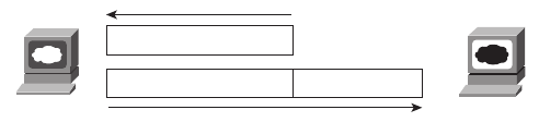
24 Chapter 2: The TCP/IP and OSI Networking Models
Taking a closer look, this example uses two TCP/IP application layer protocols. First, the
request for the file and the actual transfer of the file are performed according to the
Hypertext Transfer Protocol (HTTP). Many of you have probably noticed that most
websites’ URLs—universal resource locators (often called web addresses), the text that
identifies web pages—begin with the letters “http,” to imply that HTTP will be used to
transfer the web pages.
The other protocol used is the Hypertext Markup Language (HTML). HTML is one of
many specifications that define how Bob’s web browser should interpret the text inside the
file he just received. For instance, the file might contain directions about making certain text
be a certain size, color, and so on. In most cases, the file also includes directions about other
files that Bob’s web browser should get—files that contain such things as pictures and
animation. HTTP would then be used to get those additional files from Larry, the web
server.
A closer look at how Bob and Larry cooperate in this example reveals some details about
how networking protocols work. Consider Figure 2-2, which simply revises Figure 2-1,
showing the locations of HTTP headers and data.
Figure 2-2 HTTP Get Request and HTTP Reply
To get the web page from Larry, Bob sends something called an HTTP header to Larry. This
header includes the command to “get” a file. The request typically contains the name of the
file (home.htm in this case), or, if no filename is mentioned, the web server assumes that
Bob wants the default web page.
The response from Larry includes an HTTP header as well, with something as simple as
“OK” returned in the header. In reality, the header includes an HTTP return code, which
indicates whether the request can be serviced. For instance, if you have ever looked for a
web page that was not found, then you received an HTTP 404 “not found” error, which
means that you received an HTTP return code of 404. When the requested file is found, the
return code is 200, meaning that the request is being processed.
This simple example between Bob and Larry introduces one of the most important general
concepts behind networking models: when a particular layer on one computer wants to
communicate with the same layer on another computer, the two computers use headers to
hold the information that they want to communicate. The headers are part of what is
transmitted between the two computers. This process is called same-layer interaction.
Web BrowserWeb Server
HTTP Header: Get home.htm
HTTP OK Contents home.htm
Larry
Bob
1828xbook.fm Page 24 Thursday, July 26, 2007 3:10 PM

The TCP/IP Protocol Architecture 25
The application layer protocol (HTTP, in this case) on Bob is communicating with Larry’s
application layer. They each do so by creating and sending application layer headers to each
other—sometimes with application data following the header and sometimes not, as seen
in Figure 2-2. Regardless of what the application layer protocol happens to be, they all use
the same general concept of communicating with the application layer on the other
computer using application layer headers.
TCP/IP application layer protocols provide services to the application software running
on a computer. The application layer does not define the application itself, but rather it
defines services that applications need, such as the ability to transfer a file in the case of
HTTP. In short, the application layer provides an interface between software running on a
computer and the network itself.
The TCP/IP Transport Layer
The TCP/IP application layer includes a relatively large number of protocols, with HTTP
being only one of those. The TCP/IP transport layer consists of two main protocol options:
the Transmission Control Protocol (TCP) and the User Datagram Protocol (UDP).
To get a true appreciation for what TCP/IP transport layer protocols do, read Chapter 6,
“Fundamentals of TCP/IP Transport, Applications, and Security.” However, in this section,
you will learn about one of the key features of TCP, which enables us to cover some more
general concepts about how networking models behave.
To appreciate what the transport layer protocols do, you must think about the layer
above the transport layer, the application layer. Why? Well, each layer provides a service
to the layer above it. For example, in Figure 2-2, Bob and Larry used HTTP to transfer
the home page from Larry to Bob. But what would have happened if Bob’s HTTP get
request had been lost in transit through the TCP/IP network? Or, what would have
happened if Larry’s response, which included the contents of the home page, had been
lost? Well, as you might expect, in either case the page would not have shown up in
Bob’s browser.
So, TCP/IP needs a mechanism to guarantee delivery of data across a network. Because
many application layer protocols probably want a way to guarantee delivery of data across
a network, TCP provides an error-recovery feature to the application protocols by using
acknowledgments. Figure 2-3 outlines the basic acknowledgment logic.
NOTE The data shown in the rectangles in Figure 2-3, which includes the transport
layer header and its encapsulated data, is called a segment.
1828xbook.fm Page 25 Thursday, July 26, 2007 3:10 PM
26 Chapter 2: The TCP/IP and OSI Networking Models
Figure 2-3 TCP Services Provided to HTTP
As Figure 2-3 shows, the HTTP software asks for TCP to reliably deliver the HTTP get
request. TCP sends the HTTP data from Bob to Larry, and the data arrives successfully.
Larry’s TCP software acknowledges receipt of the data and also gives the HTTP get request
to the web server software. The reverse happens with Larry’s response, which also arrives
at Bob successfully.
Of course, the benefits of TCP error recovery cannot be seen unless the data is lost.
(Chapter 6 shows an example of how TCP recovers lost data.) For now, assume that if either
transmission in Figure 2-3 were lost, HTTP would not take any direct action, but TCP
would resend the data and ensure that it was received successfully. This example
demonstrates a function called adjacent-layer interaction, which defines the concepts of
how adjacent layers in a networking model, on the same computer, work together. The
higher-layer protocol (HTTP) needs to do something it cannot do (error recovery). So, the
higher layer asks for the next lower-layer protocol (TCP) to perform the service, and the
next lower layer performs the service. The lower layer provides a service to the layer above
it. Table 2-3 summarizes the key points about how adjacent layers work together on a single
computer and how one layer on one computer works with the same networking layer on
another computer.
Table 2-3 Summary: Same-Layer and Adjacent-Layer Interactions
Concept Description
Same-layer interaction on
different computers
The two computers use a protocol to communicate with the same
layer on another computer. The protocol defined by each layer uses a
header that is transmitted between the computers, to communicate what
each computer wants to do.
Adjacent-layer interaction
on the same computer
On a single computer, one layer provides a service to a higher layer. The
software or hardware that implements the higher layer requests that
the next lower layer perform the needed function.
Web Browser
Bob
Web Server
Larry
HTTP GET
HTTP GETTCP
TCP Acknowledgment
TCP Acknowledgment
TCP HTTP OK Web Page
Please Reliably Send
This, Mr. TCP!
1828xbook.fm Page 26 Thursday, July 26, 2007 3:10 PM
The TCP/IP Protocol Architecture 27
All the examples describing the application and transport layers ignored many details
relating to the physical network. The application and transport layers work the same way
regardless of whether the endpoint host computers are on the same LAN or are separated
by the entire Internet. The lower two layers of TCP/IP, the internet layer and the network
access layer, must understand the underlying physical network because they define the
protocols used to deliver the data from one host to another.
The TCP/IP Internet Layer
Imagine that you just wrote a letter to your favorite person on the other side of the country
and that you also wrote a letter to someone on the other side of town. It is time to send
the letters. Is there much difference in how you treat each letter? Not really. You put
a different address on the envelope for each letter because the letters need to go to two
different places. You put stamps on both letters and put them in the same mailbox. The
postal service takes care of all the details of figuring out how to get each letter to the right
place, whether it is across town or across the country.
When the postal service processes the cross-country letter, it sends the letter to another
post office, then another, and so on, until the letter gets delivered across the country. The
local letter might go to the post office in your town and then simply be delivered to
your friend across town, without going to another post office.
So what does this all matter to networking? Well, the internet layer of the TCP/IP
networking model, primarily defined by the Internet Protocol (IP), works much like the
postal service. IP defines addresses so that each host computer can have a different IP
address, just as the postal service defines addressing that allows unique addresses for each
house, apartment, and business. Similarly, IP defines the process of routing so that devices
called routers can choose where to send packets of data so that they are delivered to the
correct destination. Just as the postal service created the necessary infrastructure to be able
to deliver letters—post offices, sorting machines, trucks, planes, and personnel—the
internet layer defines the details of how a network infrastructure should be created so that
the network can deliver data to all computers in the network.
Chapter 5, “Fundamentals of IP Addressing and Routing,” describes the TCP/IP internet
layer further, with other details scattered throughout this book and the CCNA ICND2
Official Exam Certification Guide. But to help you understand the basics of the internet
layer, take a look at Bob’s request for Larry’s home page, now with some information about
IP, in Figure 2-4. The LAN cabling details are not important for this figure, so both LANs
simply are represented by the lines shown near Bob and Larry, respectively. When Bob
sends the data, he is sending an IP packet, which includes the IP header, the transport layer
header (TCP, in this example), the application header (HTTP, in this case), and any
application data (none, in this case). The IP header includes both a source and a destination
1828xbook.fm Page 27 Thursday, July 26, 2007 3:10 PM
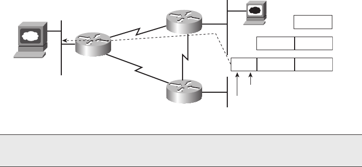
28 Chapter 2: The TCP/IP and OSI Networking Models
IP address field, with Larry’s IP address (1.1.1.1) as the destination address and Bob’s IP
address (2.2.2.2) as the source.
Figure 2-4 IP Services Provided to TCP
Bob sends the packet to R2. R2 then examines the destination IP address (1.1.1.1) and
makes a routing decision to send the packet to R1, because R2 knows enough about the
network topology to know that 1.1.1.1 (Larry) is on the other side of R1. Similarly, when
R1 gets the packet, it forwards the packet over the Ethernet to Larry. And if the link between
R2 and R1 fails, IP allows R2 to learn of the alternate route through R3 to reach 1.1.1.1.
IP defines logical addresses, called IP addresses, which allow each TCP/IP-speaking device
(called IP hosts) to have an address with which to communicate. IP also defines routing,
the process of how a router should forward, or route, packets of data.
All the CCNA exams cover IP fairly deeply. For the ICND1 exam, this book’s Chapter 5
covers more of the basics, with Chapters 11 through 15 covering IP in much more detail.
The TCP/IP Network Access Layer
The network access layer defines the protocols and hardware required to deliver data across
some physical network. The term network access refers to the fact that this layer defines
how to physically connect a host computer to the physical media over which data can be
transmitted. For instance, Ethernet is one example protocol at the TCP/IP network access
layer. Ethernet defines the required cabling, addressing, and protocols used to create an
Ethernet LAN. Likewise, the connectors, cables, voltage levels, and protocols used to
deliver data across WAN links are defined in a variety of other protocols that also fall into
the network access layer. Chapters 3 and 4 cover the fundamentals of LANs and WANs,
respectively.
NOTE The data shown in the bottom rectangle in Figure 2-4, which includes the
internet layer header and its encapsulated data, is called a packet.
Bob - 2.2.2.2
Larry - 1.1.1.1
HTTP GET
HTTP GETTCP
HTTP GETTCPIP
R1
R2
R3
Destination: 1.1.1.1
Source: 2.2.2.2
1828xbook.fm Page 28 Thursday, July 26, 2007 3:10 PM
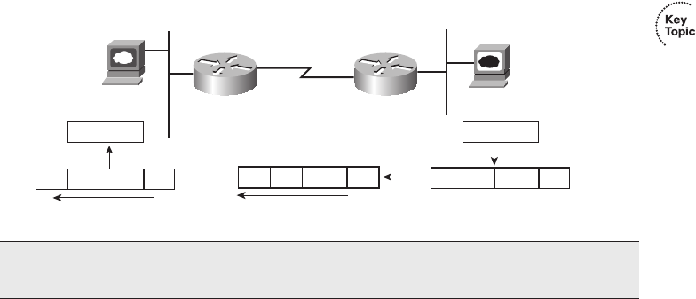
The TCP/IP Protocol Architecture 29
Just like every layer in any networking model, the TCP/IP network access layer provides
services to the layer above it in the model. The best way to understand the basics of the
TCP/IP network access layer is to examine the services that it provides to IP. IP relies on
the network access layer to deliver IP packets across a physical network. IP understands the
overall network topology, things such as which routers are connected to each other, which
host computers are connected to which physical networks, and what the IP addressing
scheme looks like. However, the IP protocol purposefully does not include the details about
each of the underlying physical networks. Therefore, the Internet layer, as implemented by
IP, uses the services of the network access layer to deliver the packets over each physical
network, respectively.
The network access layer includes a large number of protocols. For instance, the network
access layer includes all the variations of Ethernet protocols and other LAN standards. This
layer also includes the popular WAN standards, such as the Point-to-Point Protocol (PPP)
and Frame Relay. The same familiar network is shown in Figure 2-5, with Ethernet and PPP
used as the two network access layer protocols.
Figure 2-5 Ethernet and PPP Services Provided to IP
To fully appreciate Figure 2-5, first think a little more deeply about how IP accomplishes
its goal of delivering the packet from Bob to Larry. To send a packet to Larry, Bob sends
the IP packet to router R2. To do so, Bob uses Ethernet to get the packet to R2—a process
that requires Bob to follow Ethernet protocol rules, placing the IP packet (IP header and
data) between an Ethernet header and Ethernet trailer.
Because the goal of the IP routing process is to deliver the IP packet—the IP header and
data—to the destination host, R2 no longer needs the Ethernet header and trailer received
from Bob. So, R2 strips the Ethernet header and trailer, leaving the original IP packet. To
send the IP packet from R2 to R1, R2 places a PPP header in front of the IP packet and a
PPP trailer at the end, and sends this data frame over the WAN link to R1.
NOTE The data shown in several of the rectangles in Figure 2-5—those including the
Ethernet header/trailer and PPP header/trailer—are called frames.
Bob
2.2.2.2
Larry
1.1.1.1
R1 R2
DataIP
DataIPPPP PPP DataIPEth. Eth.
DataIP
DataIPEth. Eth.
1828xbook.fm Page 29 Thursday, July 26, 2007 3:10 PM

30 Chapter 2: The TCP/IP and OSI Networking Models
Similarly, after the packet is received by R1, R1 removes the PPP header and trailer because
PPP’s job is to deliver the IP packet across the serial link. R1 then decides that it should
forward the packet over the Ethernet to Larry. To do so, R1 adds a brand-new Ethernet
header and trailer to the packet and forwards it to Larry.
In effect, IP uses the network access layer protocols to deliver an IP packet to the next router
or host, with each router repeating the process until the packet arrives at the destination.
Each network access protocol uses headers to encode the information needed to
successfully deliver the data across the physical network, in much the same way as other
layers use headers to achieve their goals.
In short, the TCP/IP network access layer includes the protocols, cabling standards,
headers, and trailers that define how to send data across a wide variety of types of physical
networks.
Data Encapsulation Terminology
As you can see from the explanations of how HTTP, TCP, IP, and the network access layer
protocols Ethernet and PPP do their jobs, each layer adds its own header (and sometimes
trailer) to the data supplied by the higher layer. The term encapsulation refers to the process
of putting headers and trailers around some data. For example, the web server encapsulated
the home page inside an HTTP header in Figure 2-2. The TCP layer encapsulated the HTTP
headers and data inside a TCP header in Figure 2-3. IP encapsulated the TCP headers and
the data inside an IP header in Figure 2-4. Finally, the network access layer encapsulated
the IP packets inside both a header and a trailer in Figure 2-5.
The process by which a TCP/IP host sends data can be viewed as a five-step process. The
first four steps relate to the encapsulation performed by the four TCP/IP layers, and the
last step is the actual physical transmission of the data by the host. The steps are
summarized in the following list:
Step 1 Create and encapsulate the application data with any required application
layer headers. For example, the HTTP OK message can be returned in an
HTTP header, followed by part of the contents of a web page.
Step 2 Encapsulate the data supplied by the application layer inside a transport
layer header. For end-user applications, a TCP or UDP header is typically used.
CAUTION Many people describe the network access layer of the TCP/IP model as
two layers, the data link layer and the physical layer. The reasons for the popularity of
these alternate terms are explained in the section covering OSI, because the terms
originated with the OSI model.
1828xbook.fm Page 30 Thursday, July 26, 2007 3:10 PM
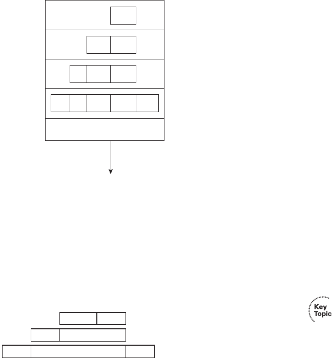
The TCP/IP Protocol Architecture 31
Step 3 Encapsulate the data supplied by the transport layer inside an internet layer
(IP) header. IP is the only protocol available in the TCP/IP network model.
Step 4 Encapsulate the data supplied by the internet layer inside a network access
layer header and trailer. This is the only layer that uses both a header and a
trailer.
Step 5 Transmit the bits. The physical layer encodes a signal onto the medium to
transmit the frame.
The numbers in Figure 2-6 correspond to the five steps in the list, graphically showing the
same concepts. Note that because the application layer often does not need to add a header,
the figure does not show a specific application layer header.
Figure 2-6 Five Steps of Data Encapsulation—TCP/IP
*The letters LH and LT stand for link header and link trailer, respectively, and refer to the data link layer header and
trailer.
Finally, take particular care to remember the terms segment, packet, and frame, and the
meaning of each. Each term refers to the headers and possibly trailers defined by a
particular layer, and the data encapsulated following that header. Each term, however, refers
to a different layer—segment for the transport layer, packet for the internet layer, and frame
for the network access layer. Figure 2-7 shows each layer along with the associated term.
Figure 2-7 Perspectives on Encapsulation and “Data”
LH IP TCP Data LT
IP TCP Data
TCP Data
Data Application
Transport
Internet
Network
Access
1.
2.
3.
4.
5. Transmit Bits
TCP Data
IP Data
LH Data LT
Segment
Packet
Frame
1828xbook.fm Page 31 Thursday, July 26, 2007 3:10 PM
32 Chapter 2: The TCP/IP and OSI Networking Models
Note that Figure 2-7 also shows the encapsulated data as simply “data.” When focusing on
the work done by a particular layer, the encapsulated data typically is unimportant. For
example, an IP packet may indeed have a TCP header after the IP header, an HTTP header
after the TCP header, and data for a web page after the HTTP header—but when discussing
IP, you probably just care about the IP header, so everything after the IP header is just called
“data.” So, when drawing IP packets, everything after the IP header is typically shown
simply as “data.”
The OSI Reference Model
To pass the ICND1 exam, you must be conversant in a protocol specification with which
you are very unlikely to ever have any hands-on experience—the OSI reference model. The
difficulty these days when discussing the OSI protocol specifications is that you have no
point of reference, because most people cannot simply walk down the hall and use a
computer whose main, or even optional, networking protocols conform to the entire OSI
model.
OSI is the Open System Interconnection reference model for communications. OSI as a
whole never succeeded in the marketplace, although some of the original protocols that
comprised the OSI model are still used. So, why do you even need to think about OSI for
the CCNA exams? Well, the OSI model now is mainly used as a point of reference for
discussing other protocol specifications. And because being either a CCENT or CCNA
requires you to understand some of the concepts and terms behind networking architecture
and models, and because other protocols (including TCP/IP) are almost always compared
to OSI, using OSI terminology, you need to know some things about OSI.
Comparing OSI and TCP/IP
The OSI reference model consists of seven layers. Each layer defines a set of typical
networking functions. When OSI was in active development in the 1980s and 1990s, the
OSI committees created new protocols and specifications to implement the functions
specified by each layer. In other cases, just as for TCP/IP, the OSI committees did not create
new protocols or standards, but instead referenced other protocols that were already
defined. For instance, the IEEE defines Ethernet standards, so the OSI committees did not
waste time specifying a new type of Ethernet; it simply referred to the IEEE Ethernet
standards.
Today the OSI model can be used as a standard of comparison to other networking models.
Figure 2-8 compares the seven-layer OSI model with the four-layer TCP/IP model. Also,
for perspective, the figure also shows some example protocols and the related layers.
1828xbook.fm Page 32 Thursday, July 26, 2007 3:10 PM

The OSI Reference Model 33
Figure 2-8 Using OSI Layers for Referencing Other Protocols
Because OSI does have a very well-defined set of functions associated with each of its
seven layers, you can examine any networking protocol or specification and make some
determination of whether it most closely matches OSI Layer 1, 2, or 3, and so on. For
instance, TCP/IP’s internet layer, as implemented mainly by IP, equates most directly to the
OSI network layer. So, most people say that IP is a network layer protocol, or a Layer 3
protocol, using OSI terminology and numbers for the layer. Of course, if you numbered the
TCP/IP model, starting at the bottom, IP would be in Layer 2—but, by convention,
everyone uses the OSI standard when describing other protocols. So, using this convention,
IP is a network layer protocol.
While Figure 2-8 seems to imply that the OSI network layer and the TCP/IP internet layer
are at least similar, the figure does not point out why they are similar. To appreciate why the
TCP/IP layers correspond to a particular OSI layer, you need to have a better understanding
of OSI. For example, the OSI network layer defines logical addressing and routing, as does
the TCP/IP internet layer. While the details differ significantly, because the OSI network
layer and TCP/IP internet layer define similar goals and features, the TCP/IP internet layer
matches the OSI network layer. Similarly, the TCP/IP transport layer defines many
functions, including error recovery, as does the OSI transport layer—so TCP is called a
transport layer, or Layer 4, protocol.
Not all TCP/IP layers correspond to a single OSI layer. In particular, the TCP/IP network
access layer defines both the physical network specifications and the protocols used to
control the physical network. OSI separates the physical network specifications into the
physical layer and the control functions into the data link layer. In fact, many people think
of TCP/IP as a five-layer model, replacing the TCP/IP’s network access layer with two
layers, namely a physical layer and a data link layer, to match OSI.
NOTE For the exams, be aware of both views about whether TCP/IP has a single
network access layer or two lower layers (data link and physical).
OSI
Application
Presentation
Session
Transport
Network
Data Link
Physical
TCP/IP
Network
Access
Application
Transport
Internet
NetWare
Mac
Protocols
HTTP, SMTP,
POP3, VoIP
SPX
IPX
1828xbook.fm Page 33 Thursday, July 26, 2007 3:10 PM

34 Chapter 2: The TCP/IP and OSI Networking Models
OSI Layers and Their Functions
Cisco requires that CCNAs demonstrate a basic understanding of the functions defined by
each OSI layer, as well as remembering the names of the layers. It is also important that,
for each device or protocol referenced throughout the book, you understand which layers
of the OSI model most closely match the functions defined by that device or protocol. The
upper layers of the OSI reference model (application, presentation, and session—Layers 7,
6, and 5) define functions focused on the application. The lower four layers (transport,
network, data link, and physical—Layers 4, 3, 2, and 1) define functions focused on end-
to-end delivery of the data. The CCNA exams focus on issues in the lower layers—in
particular, with Layer 2, upon which LAN switching is based, and Layer 3, upon which
routing is based. Table 2-4 defines the functions of the seven layers.
Table 2-4 OSI Reference Model Layer Definitions
Layer Functional Description
7 Layer 7 provides an interface between the communications software and any applications
that need to communicate outside the computer on which the application resides. It also
defines processes for user authentication.
6 This layer’s main purpose is to define and negotiate data formats, such as ASCII text,
EBCDIC text, binary, BCD, and JPEG. Encryption also is defined by OSI as a presentation
layer service.
5 The session layer defines how to start, control, and end conversations (called sessions).
This includes the control and management of multiple bidirectional messages so that the
application can be notified if only some of a series of messages are completed. This allows
the presentation layer to have a seamless view of an incoming stream of data.
4 Layer 4 protocols provide a large number of services, as described in Chapter 6 of this book.
Although OSI Layers 5 through 7 focus on issues related to the application, Layer 4 focuses
on issues related to data delivery to another computer—for instance, error recovery and
flow control.
3The network layer defines three main features: logical addressing, routing (forwarding), and
path determination. The routing concepts define how devices (typically routers) forward
packets to their final destination. Logical addressing defines how each device can have an
address that can be used by the routing process. Path determination refers to the work done by
routing protocols by which all possible routes are learned, but the best route is chosen for use.
2 The data link layer defines the rules (protocols) that determine when a device can send data
over a particular medium. Data link protocols also define the format of a header and trailer
that allows devices attached to the medium to send and receive data successfully. The data
link trailer, which follows the encapsulated data, typically defines a Frame Check Sequence
(FCS) field, which allows the receiving device to detect transmission errors.
1 This layer typically refers to standards from other organizations. These standards deal with
the physical characteristics of the transmission medium, including connectors, pins, use of
pins, electrical currents, encoding, light modulation, and the rules for how to activate and
deactivate the use of the physical medium.
1828xbook.fm Page 34 Thursday, July 26, 2007 3:10 PM

The OSI Reference Model 35
Table 2-5 lists most of the devices and protocols covered in the CCNA exams, and their
comparable OSI layers. Note that many of the devices must actually understand the
protocols at multiple OSI layers, so the layer listed in the table actually refers to the highest
layer that the device normally thinks about when performing its core work. For example,
routers need to think about Layer 3 concepts, but they must also support features at both
Layers 1 and 2.
Besides remembering the basics of the features of each OSI layer (as in Table 2-4), and
some example protocols and devices at each layer (as in Table 2-5), you should also
memorize the names of the layers. You can simply memorize them, but some people like to
use a mnemonic phrase to make memorization easier. In the following three phrases, the
first letter of each word is the same as the first letter of an OSI layer name, in the order
specified in parentheses:
■All People Seem To Need Data Processing (Layers 7 to 1)
■Please Do Not Take Sausage Pizzas Away (Layers 1 to 7)
■Pew! Dead Ninja Turtles Smell Particularly Awful (Layers 1 to 7)
OSI Layering Concepts and Benefits
Many benefits can be gained from the process of breaking up the functions or tasks of
networking into smaller chunks, called layers, and defining standard interfaces between these
layers. The layers break a large, complex set of concepts and protocols into smaller pieces,
making it easier to talk about, easier to implement with hardware and software, and easier to
troubleshoot. The following list summarizes the benefits of layered protocol specifications:
■Less Complex—Compared to not using a model, network models break the concepts
into smaller parts.
Table 2-5 OSI Reference Model—Example Devices and Protocols
Layer Name Protocols and Specifications Devices
Application, presentation,
session (Layers 5–7)
Telnet, HTTP, FTP, SMTP,
POP3, VoIP, SNMP
Firewall, intrusion detection
system
Transport (Layer 4) TCP, UDP
Network (Layer 3) IP Router
Data link (Layer 2) Ethernet (IEEE 802.3), HDLC,
Frame Relay, PPP
LAN switch, wireless access
point, cable modem, DSL modem
Physical (Layer 1) RJ-45, EIA/TIA-232, V.35,
Ethernet (IEEE 802.3)
LAN hub, repeater
1828xbook.fm Page 35 Thursday, July 26, 2007 3:10 PM
36 Chapter 2: The TCP/IP and OSI Networking Models
■Standard Interfaces—The standard interface definitions between each layer allow for
multiple vendors to create products that compete to be used for a given function, along
with all the benefits of open competition.
■Easier to learn—Humans can more easily discuss and learn about the many details of
a protocol specification.
■Easier to develop—Reduced complexity allows easier program changes and faster
product development.
■Multivendor interoperability—Creating products to meet the same networking
standards means that computers and networking gear from multiple vendors can work
in the same network.
■Modular engineering—One vendor can write software that implements higher
layers—for example, a web browser—and another vendor can write software that
implements the lower layers—for example, Microsoft’s built-in TCP/IP software in its
operating systems.
The benefits of layering can be seen in the familiar postal service analogy. A person writing
a letter does not have to think about how the postal service will deliver a letter across the
country. The postal worker in the middle of the country does not have to worry about the
contents of the letter. Likewise, layering enables one software package or hardware device
to implement functions from one layer and assume that other software/hardware will
perform the functions defined by the other layers. For instance, a web browser does not
need to think about what the network topology looks like, the Ethernet card in the PC does
not need to think about the contents of the web page, and a router in the middle of the
network does not need to worry about the contents of the web page or whether the computer
that sent the packet was using an Ethernet card or some other networking card.
OSI Encapsulation Terminology
Like TCP/IP, OSI defines processes by which a higher layer asks for services from the next
lower layer. To provide the services, the lower layer encapsulates the higher layer’s data
behind a header. The final topic of this chapter explains some of the terminology and
concepts related to OSI encapsulation.
The TCP/IP model uses terms such as segment, packet, and frame to refer to various layers
and their respective encapsulated data (see Figure 2-7). OSI uses a more generic term:
protocol data unit, or PDU. A PDU represents the bits that include the headers and trailers
for that layer, as well as the encapsulated data. For instance, an IP packet, as shown in
Figure 2-7, is a PDU. In fact, an IP packet is a Layer 3 PDU because IP is a Layer 3
1828xbook.fm Page 36 Thursday, July 26, 2007 3:10 PM
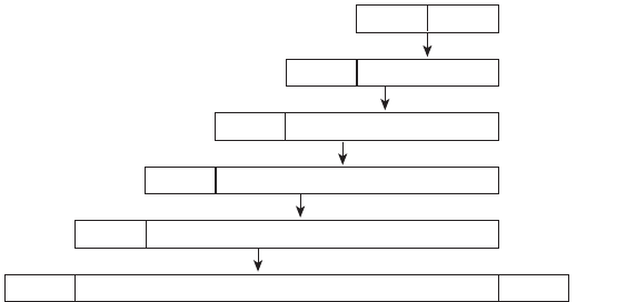
The OSI Reference Model 37
protocol. The term L3PDU is a shorter version of the phrase Layer 3 PDU. So, rather than
use the terms segment, packet, or frame, OSI simply refers to the “Layer x PDU,” with “x”
referring to the number of the layer being discussed.
OSI defines encapsulation similarly to how TCP/IP defines it. All layers except the lowest
layer define a header, with the data from the next higher layer being encapsulated behind
the header. The data link layer defines both a header and a trailer and places the Layer 3
PDU between the header and trailer. Figure 2-9 represents the typical encapsulation
process, with the top of the figure showing the application data and application layer header,
and the bottom of the figure showing the L2PDU that is transmitted onto the physical link.
Figure 2-9 OSI Encapsulation and Protocol Data Units
L7H Data
L6H Data
L5H Data
L4H Data
L3H Data
L2H Data L2T
L#H - Layer # Header
L#T - Layer # Trailer
L7PDU
L6PDU
L5PDU
L4PDU
L3PDU
L2PDU
1828xbook.fm Page 37 Thursday, July 26, 2007 3:10 PM
38 Chapter 2: The TCP/IP and OSI Networking Models
Exam Preparation Tasks
Review all the Key Topics
Review the most important topics from inside the chapter, noted with the key topics icon in
the outer margin of the page. Table 2-6 lists a reference of these key topics and the page
number on which each is found.
Complete the Tables and Lists from Memory
Print a copy of Appendix H (found on the CD), or at least the section for this chapter, and
complete the tables and lists from memory. Appendix I includes completed tables and lists
to check your work.
Definitions of Key Terms
Define the following key terms from this chapter, and check your answers in the glossary.
adjacent-layer interaction, decapsulation, encapsulation, frame, networking
model, packet, protocol data unit (PDU), same-layer interaction, segment
Table 2-6 Key Topics for Chapter 2
Description Page Number
Table 2-3 Provides definitions of same-layer and adjacent-layer interaction 26
Figure 2-5 Depicts the data-link services provided to IP for the purpose of
delivering IP packets from host to host
29
Figure 2-7 Shows the meaning of the terms segment, packet, and frame 31
Figure 2-8 Compares the OSI and TCP/IP network models 33
List Lists the benefits of using a layered networking model 35-36
1828xbook.fm Page 38 Thursday, July 26, 2007 3:10 PM

Review all the Key Topics 39
OSI Reference
You should memorize the names of the layers of the OSI model. Table 2-7 lists a summary
of OSI functions at each layer, along with some sample protocols at each layer.
Table 2-7 OSI Functional Summary
Layer Functional Description
Application (7) Interfaces between network and application software. Also includes authentication
services.
Presentation (6) Defines the format and organization of data. Includes encryption.
Session (5) Establishes and maintains end-to-end bidirectional flows between endpoints.
Includes managing transaction flows.
Transport (4) Provides a variety of services between two host computers, including connection
establishment and termination, flow control, error recovery, and segmentation
of large data blocks into smaller parts for transmission.
Network (3) Logical addressing, routing, and path determination.
Data link (2) Formats data into frames appropriate for transmission onto some physical
medium. Defines rules for when the medium can be used. Defines means by which
to recognize transmission errors.
Physical (1) Defines the electrical, optical, cabling, connectors, and procedural details required
for transmitting bits, represented as some form of energy passing over a physical
medium.
1828xbook.fm Page 39 Thursday, July 26, 2007 3:10 PM

This chapter covers the following subjects:
An Overview of Modern Ethernet LANs:
Provides some perspectives for those who have
used Ethernet at the office or school but have not
examined the details.
A Brief History of Ethernet: Examines several
old options for Ethernet cabling and devices as a
point of comparison for today’s cabling, devices,
and terminology.
Ethernet UTP Cabling: Explains the options for
cabling and cable pinouts.
Improving Performance by Using Switches
Instead of Hubs: A more detailed examination
of the performance improvements made by using
switches instead of older Ethernet hubs.
Ethernet Data-Link Protocols: Explains the
meaning and purpose of the fields in the Ethernet
header and trailer.
1828xbook.fm Page 40 Thursday, July 26, 2007 3:10 PM

C H A P T E R3
Fundamentals of LANs
Physical and data link layer standards work together to allow computers to send bits to each
other over a particular type of physical networking medium. The Open Systems
Interconnection (OSI) physical layer (Layer 1) defines how to physically send bits over a
particular physical networking medium. The data link layer (Layer 2) defines some rules
about the data that is physically transmitted, including addresses that identify the sending
device and the intended recipient, and rules about when a device can send (and when it
should be silent), to name a few.
This chapter explains some of the basics of local-area networks (LAN). The term LAN
refers to a set of Layer 1 and 2 standards designed to work together for the purpose of
implementing geographically small networks. This chapter introduces the concepts of
LANs—in particular, Ethernet LANs. More-detailed coverage of LANs appears in Part II
(Chapters 7 through 11).
“Do I Know This Already?” Quiz
The “Do I Know This Already?” quiz allows you to assess whether you should read the
entire chapter. If you miss no more than one of these 11 self-assessment questions, you
might want to move ahead to the “Exam Preparation Tasks” section. Table 3-1 lists the
major headings in this chapter and the “Do I Know This Already?” quiz questions covering
the material in those sections. This helps you assess your knowledge of these specific areas.
The answers to the “Do I Know This Already?” quiz appear in Appendix A.
Table 3-1 “Do I Know This Already?” Foundation Topics Section-to-Question Mapping
Foundation Topics Section Questions
An Overview of Modern Ethernet LANs 1
A Brief History of Ethernet 2
Ethernet UTP Cabling 3, 4
Improving Performance by Using Switches Instead of Hubs 5–7
Ethernet Data-Link Protocols 8–11
1828xbook.fm Page 41 Thursday, July 26, 2007 3:10 PM
42 Chapter 3: Fundamentals of LANs
1. Which of the following is true about the cabling of a typical modern Ethernet LAN?
a. Connect each device in series using coaxial cabling
b. Connect each device in series using UTP cabling
c. Connect each device to a centralized LAN hub using UTP cabling
d. Connect each device to a centralized LAN switch using UTP cabling
2. Which of the following is true about the cabling of a 10BASE2 Ethernet LAN?
a. Connect each device in series using coaxial cabling
b. Connect each device in series using UTP cabling
c. Connect each device to a centralized LAN hub using UTP cabling
d. Connect each device to a centralized LAN switch using UTP cabling
3. Which of the following is true about Ethernet crossover cables?
a. Pins 1 and 2 are reversed on the other end of the cable.
b. Pins 1 and 2 on one end of the cable connect to pins 3 and 6 on the other end of
the cable.
c. Pins 1 and 2 on one end of the cable connect to pins 3 and 4 on the other end of
the cable.
d. The cable can be up to 1000 meters long to cross over between buildings.
e. None of the other answers is correct.
4. Each answer lists two types of devices used in a 100BASE-TX network. If these
devices were connected with UTP Ethernet cables, which pairs of devices would
require a straight-through cable?
a. PC and router
b. PC and switch
c. Hub and switch
d. Router and hub
e. Wireless access point (Ethernet port) and switch
1828xbook.fm Page 42 Thursday, July 26, 2007 3:10 PM
“Do I Know This Already?” Quiz 43
5. Which of the following is true about the CSMA/CD algorithm?
a. The algorithm never allows collisions to occur.
b. Collisions can happen, but the algorithm defines how the computers should
notice a collision and how to recover.
c. The algorithm works with only two devices on the same Ethernet.
d. None of the other answers is correct.
6. Which of the following is a collision domain?
a. All devices connected to an Ethernet hub
b. All devices connected to an Ethernet switch
c. Two PCs, with one cabled to a router Ethernet port with a crossover cable and the
other PC cabled to another router Ethernet port with a crossover cable
d. None of the other answers is correct.
7. Which of the following describe a shortcoming of using hubs that is improved by
instead using switches?
a. Hubs create a single electrical bus to which all devices connect, causing the
devices to share the bandwidth.
b. Hubs limit the maximum cable length of individual cables (relative to switches)
c. Hubs allow collisions to occur when two attached devices send data at the same
time.
d. Hubs restrict the number of physical ports to at most eight.
8. Which of the following terms describe Ethernet addresses that can be used to
communicate with more than one device at a time?
a. Burned-in address
b. Unicast address
c. Broadcast address
d. Multicast address
1828xbook.fm Page 43 Thursday, July 26, 2007 3:10 PM
44 Chapter 3: Fundamentals of LANs
9. Which of the following is one of the functions of OSI Layer 2 protocols?
a. Framing
b. Delivery of bits from one device to another
c. Error recovery
d. Defining the size and shape of Ethernet cards
10. Which of the following are true about the format of Ethernet addresses?
a. Each manufacturer puts a unique code into the first 2 bytes of the address.
b. Each manufacturer puts a unique code into the first 3 bytes of the address.
c. Each manufacturer puts a unique code into the first half of the address.
d. The part of the address that holds this manufacturer’s code is called the MAC.
e. The part of the address that holds this manufacturer’s code is called the OUI.
f. The part of the address that holds this manufacturer’s code has no specific name.
11. Which of the following is true about the Ethernet FCS field?
a. It is used for error recovery.
b. It is 2 bytes long.
c. It resides in the Ethernet trailer, not the Ethernet header.
d. It is used for encryption.
e. None of the other answers is correct.
1828xbook.fm Page 44 Thursday, July 26, 2007 3:10 PM

An Overview of Modern Ethernet LANs 45
Foundation Topics
A typical Enterprise network consists of several sites. The end-user devices connect to a
LAN, which allows the local computers to communicate with each other. Additionally, each
site has a router that connects to both the LAN and a wide-area network (WAN), with the
WAN providing connectivity between the various sites. With routers and a WAN, the
computers at different sites can also communicate.
This chapter describes the basics of how to create LANs today, with Chapter 4,
“Fundamentals of WANs,” describing the basics of creating WANs. Ethernet is the
undisputed king of LAN standards today. Historically speaking, several competing LAN
standards existed, including Token Ring, Fiber Distributed Data Interface (FDDI), and
Asynchronous Transfer Mode (ATM). Eventually, Ethernet won out over all the competing
LAN standards, so that today when you think of LANs, no one even questions what type—
it’s Ethernet.
An Overview of Modern Ethernet LANs
The term Ethernet refers to a family of standards that together define the physical and data
link layers of the world’s most popular type of LAN. The different standards vary as to the
speed supported, with speeds of 10 megabits per second (Mbps), 100 Mbps, and 1000 Mbps
(1 gigabit per second, or Gbps) being common today. The standards also differ as far as the
types of cabling and the allowed length of the cabling. For example, the most commonly
used Ethernet standards allow the use of inexpensive unshielded twisted-pair (UTP)
cabling, whereas other standards call for more expensive fiber-optic cabling. Fiber-optic
cabling might be worth the cost in some cases, because the cabling is more secure and
allows for much longer distances between devices. To support the widely varying needs for
building a LAN—needs for different speeds, different cabling types (trading off distance
requirements versus cost), and other factors—many variations of Ethernet standards have
been created.
The Institute of Electrical and Electronics Engineers (IEEE) has defined many Ethernet
standards since it took over the LAN standardization process in the early 1980s. Most of
the standards define a different variation of Ethernet at the physical layer, with differences
in speed and types of cabling. Additionally, for the data link layer, the IEEE separates the
functions into two sublayers:
■The 802.3 Media Access Control (MAC) sublayer
■The 802.2 Logical Link Control (LLC) sublayer
1828xbook.fm Page 45 Thursday, July 26, 2007 3:10 PM

46 Chapter 3: Fundamentals of LANs
In fact, MAC addresses get their name from the IEEE name for this lower portion of the
data link layer Ethernet standards.
Each new physical layer standard from the IEEE requires many differences at the physical
layer. However, each of these physical layer standards uses the exact same 802.3 header,
and each uses the upper LLC sublayer as well. Table 3-2 lists the most commonly used
IEEE Ethernet physical layer standards.
The table is convenient for study, but the terms in the table bear a little explanation. First,
beware that the term Ethernet is often used to mean “all types of Ethernet,” but in some
cases it is used to mean “10BASE-T Ethernet.” (Because the term Ethernet sometimes can
be ambiguous, this book refers to 10-Mbps Ethernet as 10BASE-T when the specific type
of Ethernet matters to the discussion.) Second, note that the alternative name for each type
of Ethernet lists the speed in Mbps—namely, 10 Mbps, 100 Mbps, and 1000 Mbps. The T
and TX in the alternative names refer to the fact that each of these standards defines the use
of UTP cabling, with the T referring to the T in twisted pair.
To build and create a modern LAN using any of the UTP-based types of Ethernet LANs
listed in Table 3-2, you need the following components:
■Computers that have an Ethernet network interface card (NIC) installed
■Either an Ethernet hub or Ethernet switch
■UTP cables to connect each PC to the hub or switch
Figure 3-1 shows a typical LAN. The NICs cannot be seen, because they reside in the PCs.
However, the lines represent the UTP cabling, and the icon in the center of the figure
represents a LAN switch.
Table 3-2 Today’s Most Common Types of Ethernet
Common Name Speed
Alternative
Name
Name of IEEE
Standard
Cable Type,
Maximum Length
Ethernet 10 Mbps 10BASE-T IEEE 802.3 Copper, 100 m
Fast Ethernet 100 Mbps 100BASE-TX IEEE 802.3u Copper, 100 m
Gigabit Ethernet 1000 Mbps 1000BASE-LX,
1000BASE-SX
IEEE 802.3z Fiber, 550 m (SX)
5 km (LX)
Gigabit Ethernet 1000 Mbps 1000BASE-T IEEE 802.3ab 100 m
1828xbook.fm Page 46 Thursday, July 26, 2007 3:10 PM
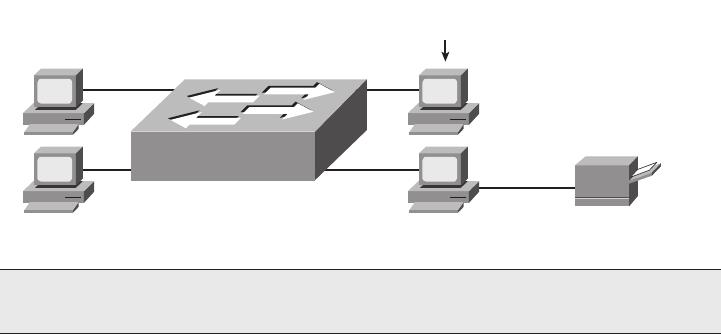
An Overview of Modern Ethernet LANs 47
Figure 3-1 Typical Small Modern LAN
Most people can build a LAN like the one shown in Figure 3-1 with practically no real
knowledge of how LANs work. Most PCs contain an Ethernet NIC that was installed at the
factory. Switches do not need to be configured for them to forward traffic between the
computers. All you have to do is connect the switch to a power cable and plug in the UTP
cables from each PC to the switch. Then the PCs should be able to send Ethernet frames to
each other.
You can use such a small LAN for many purposes, even without a WAN connection.
Consider the following functions for which a LAN is the perfect, small-scale solution:
File sharing: Each computer can be configured to share all or parts of its file system
so that the other computers can read, or possibly read and write, the files on another
computer. This function typically is simply part of the PC operating system.
Printer sharing: Computers can share their printers as well. For example, PCs A, B,
and C in Figure 3-1 could print documents on PC D’s printer. This function is also
typically part of the PC’s operating system.
File transfers: A computer could install a file transfer server, thereby allowing other
computers to send and receive files to and from that computer. For example, PC C
could install File Transfer Protocol (FTP) server software, allowing the other PCs to
use FTP client software to connect to PC C and transfer files.
Gaming: The PCs could install gaming software that allows multiple players
to play in the same game. The gaming software would then communicate using
the Ethernet.
NOTE Figure 3-1 applies to all the common types of Ethernet. The same basic design
and topology are used regardless of speed or cabling type.
A
B
C
D
FTP Server Software
Installed Here
Printer
Cable
1828xbook.fm Page 47 Thursday, July 26, 2007 3:10 PM
48 Chapter 3: Fundamentals of LANs
The goal of the first half of this chapter is to help you understand much of the theory and
practical knowledge behind simple LAN designs such as the one illustrated in Figure 3-1.
To fully understand modern LANs, it is helpful to understand a bit about the history of
Ethernet, which is covered in the next section. Following that, this chapter examines the
physical aspects (Layer 1) of a simple Ethernet LAN, focusing on UTP cabling. Then this
chapter compares the older (and slower) Ethernet hub with the newer (and faster) Ethernet
switch. Finally, the LAN coverage in this chapter ends with the data-link (Layer 2)
functions on Ethernet.
A Brief History of Ethernet
Like many early networking protocols, Ethernet began life inside a corporation that was
looking to solve a specific problem. Xerox needed an effective way to allow a new
invention, called the personal computer, to be connected in its offices. From that, Ethernet
was born. (Go to http://inventors.about.com/library/weekly/aa111598.htm for an
interesting story on the history of Ethernet.) Eventually, Xerox teamed with Intel and
Digital Equipment Corp. (DEC) to further develop Ethernet, so the original Ethernet
became known as DIX Ethernet, referring to DEC, Intel, and Xerox.
These companies willingly transitioned the job of Ethernet standards development to the IEEE
in the early 1980s. The IEEE formed two committees that worked directly on Ethernet—the
IEEE 802.3 committee and the IEEE 802.2 committee. The 802.3 committee worked on
physical layer standards as well as a subpart of the data link layer called Media Access Control
(MAC). The IEEE assigned the other functions of the data link layer to the 802.2 committee,
calling this part of the data link layer the Logical Link Control (LLC) sublayer. (The 802.2
standard applied to Ethernet as well as to other IEEE standard LANs such as Token Ring.)
The Original Ethernet Standards: 10BASE2 and 10BASE5
Ethernet is best understood by first considering the two early Ethernet specifications,
10BASE5 and 10BASE2. These two Ethernet specifications defined the details of the
physical and data link layers of early Ethernet networks. (10BASE2 and 10BASE5 differ
in their cabling details, but for the discussion in this chapter, you can consider them as
behaving identically.) With these two specifications, the network engineer installs a series
of coaxial cables connecting each device on the Ethernet network. There is no hub, switch,
or wiring panel. The Ethernet consists solely of the collective Ethernet NICs in the
computers and the coaxial cabling. The series of cables creates an electrical circuit, called
a bus, which is shared among all devices on the Ethernet. When a computer wants to send
some bits to another computer on the bus, it sends an electrical signal, and the electricity
propagates to all devices on the Ethernet.
Figure 3-2 shows the basic logic of an old Ethernet 10BASE2 network, which uses a single
electrical bus, created with coaxial cable and Ethernet cards.
1828xbook.fm Page 48 Thursday, July 26, 2007 3:10 PM

A Brief History of Ethernet 49
Figure 3-2 Small Ethernet 10BASE2 Network
The solid lines in the figure represent the physical network cabling. The dashed lines with
arrows represent the path that Larry’s transmitted frame takes. Larry sends an electrical
signal across his Ethernet NIC onto the cable, and both Bob and Archie receive the signal.
The cabling creates a physical electrical bus, meaning that the transmitted signal is received
by all stations on the LAN. Just like a school bus stops at every student’s house along a
route, the electrical signal on a 10BASE2 or 10BASE5 network is propagated to each
station on the LAN.
Because the network uses a single bus, if two or more electrical signals were sent at the
same time, they would overlap and collide, making both signals unintelligible. So,
unsurprisingly, Ethernet also defined a specification for how to ensure that only one device
sends traffic on the Ethernet at one time. Otherwise, the Ethernet would have been
unusable. This algorithm, known as the carrier sense multiple access with collision
detection (CSMA/CD) algorithm, defines how the bus is accessed.
In human terms, CSMA/CD is similar to what happens in a meeting room with many
attendees. It’s hard to understand what two people are saying at the same time, so generally,
one person talks and the rest listen. Imagine that Bob and Larry both want to reply to the
current speaker’s comments. As soon as the speaker takes a breath, Bob and Larry both try to
speak. If Larry hears Bob’s voice before Larry makes a noise, Larry might stop and let Bob
speak. Or, maybe they both start at almost the same time, so they talk over each other and no
one can hear what is said. Then there’s the proverbial “Pardon me; go ahead with what you
were saying,” and eventually Larry or Bob talks. Or perhaps another person jumps in and talks
while Larry and Bob are both backing off. These “rules” are based on your culture; CSMA/
CD is based on Ethernet protocol specifications and achieves the same type of goal.
Basically, the CSMA/CD algorithm can be summarized as follows:
■A device that wants to send a frame waits until the LAN is silent—in other words, no
frames are currently being sent—before attempting to send an electrical signal.
■If a collision still occurs, the devices that caused the collision wait a random amount
of time and then try again.
Larry Archie
Bob
Solid Lines Represent
Co-Ax Cable
10BASE2, Single Bus
1828xbook.fm Page 49 Thursday, July 26, 2007 3:10 PM

50 Chapter 3: Fundamentals of LANs
In 10BASE5 and 10BASE2 Ethernet LANs, a collision occurs because the transmitted
electrical signal travels along the entire length of the bus. When two stations send at the
same time, their electrical signals overlap, causing a collision. So, all devices on a
10BASE5 or 10BASE2 Ethernet need to use CSMA/CD to avoid collisions and to recover
when inadvertent collisions occur.
Repeaters
Like any type of LAN, 10BASE5 and 10BASE2 had limitations on the total length of a
cable. With 10BASE5, the limit was 500 m; with 10BASE2, it was 185 m. Interestingly, the
5 and 2 in the names 10BASE5 and 10BASE2 represent the maximum cable length—with
the 2 referring to 200 meters, which is pretty close to the actual maximum of 185 meters.
(Both of these types of Ethernet ran at 10 Mbps.)
In some cases, the maximum cable length was not enough, so a device called a repeater was
developed. One of the problems that limited the length of a cable was that the signal sent
by one device could attenuate too much if the cable was longer than 500 m or 185 m.
Attenuation means that when electrical signals pass over a wire, the signal strength gets
weaker the farther along the cable it travels. It’s the same concept behind why you can hear
someone talking right next to you, but if that person speaks at the same volume and you are
on the other side of a crowded room, you might not hear her because the sound waves have
attenuated.
Repeaters connect to multiple cable segments, receive the electrical signal on one cable,
interpret the bits as 1s and 0s, and generate a brand-new, clean, strong signal out the other
cable. A repeater does not simply amplify the signal, because amplifying the signal might
also amplify any noise picked up along the way.
You should not expect to need to implement 10BASE5 or 10BASE2 Ethernet LANs today.
However, for learning purposes, keep in mind several key points from this section as
you move on to concepts that relate to today’s LANs:
■The original Ethernet LANs created an electrical bus to which all devices connected.
■Because collisions could occur on this bus, Ethernet defined the CSMA/CD algorithm,
which defined a way to both avoid collisions and take action when collisions occurred.
■Repeaters extended the length of LANs by cleaning up the electrical signal and
repeating it—a Layer 1 function—but without interpreting the meaning of the
electrical signal.
NOTE Because the repeater does not interpret what the bits mean, but it does examine and
generate electrical signals, a repeater is considered to operate at Layer 1.
1828xbook.fm Page 50 Thursday, July 26, 2007 3:10 PM
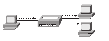
A Brief History of Ethernet 51
Building 10BASE-T Networks with Hubs
The IEEE later defined new Ethernet standards besides 10BASE5 and 10BASE2.
Chronologically, the 10BASE-T standard came next (1990), followed by 100BASE-TX
(1995), and then 1000BASE-T (1999). To support these new standards, networking devices
called hubs and switches were also created. This section defines the basics of how these
three popular types of Ethernet work, including the basic operation of hubs and switches.
10BASE-T solved several problems with the early 10BASE5 and 10BASE2 Ethernet
specifications. 10BASE-T allowed the use of UTP telephone cabling that was already
installed. Even if new cabling needed to be installed, the inexpensive and easy-to-install
UTP cabling replaced the old expensive and difficult-to-install coaxial cabling.
Another major improvement introduced with 10BASE-T, and that remains a key design
point today, is the concept of cabling each device to a centralized connection point.
Originally, 10BASE-T called for the use of Ethernet hubs, as shown in Figure 3-3.
Figure 3-3 Small Ethernet 10BASE-T Network Using a Hub
When building a LAN today, you could choose to use either a hub or a switch as the
centralized Ethernet device to which all the computers connect. Even though modern
Ethernet LANs typically use switches instead of hubs, understanding the operation of hubs
helps you understand some of the terminology used with switches, as well as some of their
benefits.
Hubs are essentially repeaters with multiple physical ports. That means that the hub simply
regenerates the electrical signal that comes in one port and sends the same signal out every
other port. By doing so, any LAN that uses a hub, as in Figure 3-3, creates an electrical bus,
just like 10BASE2 and 10BASE5. Therefore, collisions can still occur, so CSMA/CD
access rules continue to be used.
10BASE-T networks using hubs solved some big problems with 10BASE5 and 10BASE2.
First, the LAN had much higher availability, because a single cable problem could, and
probably did, take down 10BASE5 and 10BASE2 LANs. With 10BASE-T, a cable connects
each device to the hub, so a single cable problem affects only one device. As mentioned
earlier, the use of UTP cabling, in a star topology (all cables running to a centralized
connection device), lowered the cost of purchasing and installing the cabling.
Larry Archie
Bob
Solid Lines Represent
Tw isted Pair Cabling
10BASE-T, Using Shared
Hub - Acts Like Single Bus
Hub 1
1828xbook.fm Page 51 Thursday, July 26, 2007 3:10 PM
52 Chapter 3: Fundamentals of LANs
Today, you might occasionally use LAN hubs, but you will more likely use switches instead
of hubs. Switches perform much better than hubs, support more functions than hubs, and
typically are priced almost as low as hubs. However, for learning purposes, keep in mind
several key points from this section about the history of Ethernet as you move on to
concepts that relate to today’s LANs:
■The original Ethernet LANs created an electrical bus to which all devices connected.
■10BASE2 and 10BASE5 repeaters extended the length of LANs by cleaning up the
electrical signal and repeating it—a Layer 1 function—but without interpreting the
meaning of the electrical signal.
■Hubs are repeaters that provide a centralized connection point for UTP cabling—but
they still create a single electrical bus, shared by the various devices, just like
10BASE5 and 10BASE2.
■Because collisions could occur in any of these cases, Ethernet defines the CSMA/CD
algorithm, which tells devices how to both avoid collisions and take action when
collisions do occur.
The next section explains the details of the UTP cabling used by today’s most commonly
used types of Ethernet.
Ethernet UTP Cabling
The three most common Ethernet standards used today—10BASE-T (Ethernet),
100BASE-TX (Fast Ethernet, or FE), and 1000BASE-T (Gigabit Ethernet, or GE)—use
UTP cabling. Some key differences exist, particularly with the number of wire pairs needed
in each case, and in the type (category) of cabling. This section examines some of the details
of UTP cabling, pointing out differences among these three standards along the way. In
particular, this section describes the cables and the connectors on the ends of the cables,
how they use the wires in the cables to send data, and the pinouts required for proper
operation.
UTP Cables and RJ-45 Connectors
The UTP cabling used by popular Ethernet standards include either two or four pairs of
wires. Because the wires inside the cable are thin and brittle, the cable itself has an outer
jacket of flexible plastic to support the wires. Each individual copper wire also has a thin
plastic coating to help prevent the wire from breaking. The plastic coating on each wire has
a different color, making it easy to look at both ends of the cable and identify the ends of
an individual wire.
The cable ends typically have some form of connector attached (typically RJ-45 connectors),
with the ends of the wires inserted into the connectors. The RJ-45 connector has eight
1828xbook.fm Page 52 Thursday, July 26, 2007 3:10 PM
Ethernet UTP Cabling 53
specific physical locations into which the eight wires in the cable can be inserted, called
pin positions, or simply pins. When the connectors are added to the end of the cable, the
ends of the wires must be correctly inserted into the correct pin positions.
As soon as the cable has RJ-45 connectors on each end, the RJ-45 connector needs to be
inserted into an RJ-45 receptacle, often called an RJ-45 port. Figure 3-4 shows photos of
the cables, connectors, and ports.
Figure 3-4 RJ-45 Connectors and Ports
The figure shows three separate views of an RJ-45 connector on the left. The head-on view
in the upper-left part of the figure shows the ends of the eight wires in their pin positions
inside the UTP cable. The upper-right part of the figure shows an Ethernet NIC that is not
yet installed in a computer. The RJ-45 port on the NIC would be exposed on the side of the
NOTE If you have an Ethernet UTP cable nearby, it would be useful to closely examine
the RJ-45 connectors and wires as you read through this section.
NOTE The RJ-45 connector is slightly wider, but otherwise similar, to the RJ-11
connectors commonly used for telephone cables in homes in North America.
RJ-45 Connectors RJ-45 Ports
1828xbook.fm Page 53 Thursday, July 26, 2007 3:10 PM
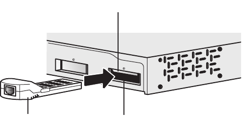
54 Chapter 3: Fundamentals of LANs
computer, making it easily accessible as soon as the NIC has been installed into a computer.
The lower-right part of the figure shows the side of a Cisco 2960 switch, with multiple
RJ-45 ports, allowing multiple devices to easily connect to the Ethernet network.
Although RJ-45 connectors and ports are popular, engineers might want to purchase Cisco
LAN switches that have a few physical ports that can be changed without having to
purchase a whole new switch. Many Cisco switches have a few interfaces that use either
Gigabit Interface Converters (GBIC) or Small-Form Pluggables (SFP). Both are small
removable devices that fit into a port or slot in the switch. Because Cisco manufactures a
wide range of GBICs and SFPs, for every Ethernet standard, the switch can use a variety of
cable connectors and types of cabling and support different cable lengths—all by just
switching to a different kind of GBIC or SFP. Figure 3-5 shows a 1000BASE-T GBIC,
ready to be inserted into a LAN switch.
Figure 3-5 1000BASE-T GBIC with an RJ-45 Connector
If a network engineer needs to use an existing switch in a new role in a campus network, the
engineer could simply buy a new 1000BASE-LX GBIC to replace the old 1000BASE-T
GBIC and reduce the extra cost of buying a whole new switch. For example, when using a
switch so that it connects only to other switches in the same building, the switch could use
1000BASE-T GBICs and copper cabling. Later, if the company moved to another location,
the switch could be repurposed by using a different GBIC that supported fiber-optic cabling,
and different connectors, using 1000BASE-LX to support a longer cabling distance.
Transmitting Data Using Twisted Pairs
UTP cabling consists of matched pairs of wires that are indeed twisted together—hence the
name twisted pair. The devices on each end of the cable can create an electrical circuit using
a pair of wires by sending current on the two wires, in opposite directions. When current
passes over any wire, that current induces a magnetic field outside the wire; the magnetic
field can in turn cause electrical noise on other wires in the cable. By twisting together the
1000BASE-T
GBIC Module
GBIC Module Slot
Metal Flap Door
1828xbook.fm Page 54 Thursday, July 26, 2007 3:10 PM

Ethernet UTP Cabling 55
wires in the same pair, with the current running in opposite directions on each wire, the
magnetic field created by one wire mostly cancels out the magnetic field created by the
other wire. Because of this feature, most networking cables that use copper wires and
electricity use twisted pairs of wires to send data.
To send data over the electrical circuit created over a wire pair, the devices use an encoding
scheme that defines how the electrical signal should vary, over time, to mean either a binary
0 or 1. For example, 10BASE-T uses an encoding scheme that encodes a binary 0 as a
transition from higher voltage to lower voltage during the middle of a 1/10,000,000th-of-a-
second interval. The electrical details of encoding are unimportant for the purposes of this
book. But it is important to realize that networking devices create an electrical circuit using
each wire pair, and vary the signal as defined by the encoding scheme, to send bits over the
wire pair.
UTP Cabling Pinouts for 10BASE-T and 100BASE-TX
The wires in the UTP cable must be connected to the correct pin positions in the RJ-45
connectors in order for communication to work correctly. As mentioned earlier, the RJ-45
connector has eight pin positions, or simply pins, into which the copper wires inside the
cable protrude. The wiring pinouts—the choice of which color wire goes into which pin
position—must conform to the Ethernet standards described in this section.
Interestingly, the IEEE does not actually define the official standards for cable
manufacturing, as well as part of the details of the conventions used for the cabling pinouts.
Two cooperating industry groups, the Telecommunications Industry Association (TIA) and
the Electronics Industry Alliance (EIA), define standards for UTP cabling, color coding for
wires, and standard pinouts on the cables. (See http://www.tiaonline.org and http://
www.eia.org.) Figure 3-6 shows two pinout standards from the EIA/TIA, with the color
coding and pair numbers listed.
Figure 3-6 EIA/TIA Standard Ethernet Cabling Pinouts
Pair 2
Pinouts
1 = G/W
2 = Green
3 = O/W
4 = Blue
5 = Blue/W
6 = Orange
7 = Brown/W
8 = Brown
Pinouts
1 = O/W
2 = Orange
3 = G/W
4 = Blue
5 = Blue/W
6 = Green
7 = Brown/W
8 = Brown
Pair 3 Pair 1 Pair 4
12345678
T568A
Pair 3
Pair 2 Pair 1 Pair 4
12345678
T568B
1828xbook.fm Page 55 Thursday, July 26, 2007 3:10 PM
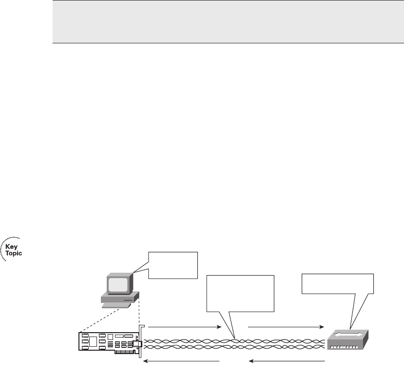
56 Chapter 3: Fundamentals of LANs
To understand the acronyms listed in the figure, note that the eight wires in a UTP cable
have either a solid color (green, orange, blue, or brown) or a striped color scheme using
white and one of the other four colors. Also, a single-wire pair uses the same base color. For
example, the blue wire and the blue/white striped wire are paired and twisted. In Figure 3-6,
the notations with a / refer to the striped wires. For example, “G/W” refers to the green-and-
white striped wire.
To build a working Ethernet LAN, you must choose or build cables that use the correct
wiring pinout on each end of the cable. 10BASE-T and 100BASE-TX Ethernet define that
one pair should be used to send data in one direction, with the other pair used to send data
in the other direction. In particular, Ethernet NICs should send data using the pair
connected to pins 1 and 2—in other words, pair 3 according to the T568A pinout standard
shown in Figure 3-6. Similarly, Ethernet NICs should expect to receive data using the pair
at pins 3 and 6—pair 2 according to the T568A standard. Knowing what the Ethernet NICs
do, hubs and switches do the opposite—they receive on the pair at pins 1,2 (pair 3 per
T568A), and they send on the pair at pins 3,6 (pair 2 per T568A).
Figure 3-7 shows this concept, with PC Larry connected to a hub. Note that the figure shows
the two twisted pairs inside the cable, and the NIC outside the PC, to emphasize that the
cable connects to the NIC and hub and that only two pairs are being used.
Figure 3-7 Ethernet Straight-Through Cable Concept
The network shown in Figure 3-7 uses a straight-through cable. An Ethernet straight-through
cable connects the wire at pin 1 on one end of the cable to pin 1 at the other end of the cable;
the wire at pin 2 needs to connect to pin 2 on the other end of the cable; pin 3 on one
end connects to pin 3 on the other; and so on. (To create a straight-through cable, both ends
of the cable use the same EIA/TIA pinout standard on each end of the cable.)
NOTE A UTP cable needs two pairs of wires for 10BASE-T and 100BASE-TX and
four pairs of wires for 1000BASE-T. This section focuses on the pinouts for two-pair
wiring, with four-pair wiring covered next.
Larry
Hub
PC1 Transmit Pair (1,2)
PC1 Receive Pair (3,6)
Hub Receive Pair (1,2)
Hub Transmit Pair (3,6)
I’ll transmit on
pins 1,2 and
receive on 3,6. I’ll receive on 1,2 and
transmit on 3,6!
The pair on 1,2 on
the left connects to
pins 1,2 on the right!
And it works!
Straight-Through Cable
NIC
1828xbook.fm Page 56 Thursday, July 26, 2007 3:10 PM
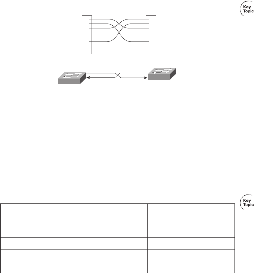
Ethernet UTP Cabling 57
A straight-through cable is used when the devices on the ends of the cable use opposite pins
when they transmit data. However, when connecting two devices that both use the same pins
to transmit, the pinouts of the cable must be set up to swap the wire pair. A cable that swaps
the wire pairs inside the cable is called a crossover cable. For example, many LANs inside
an Enterprise network use multiple switches, with a UTP cable connecting the switches.
Because both switches send on the pair at pins 3,6, and receive on the pair at pins 1,2, the cable
must swap or cross the pairs. Figure 3-8 shows several conceptual views of a crossover cable.
Figure 3-8 Crossover Ethernet Cable
The top part of the figure shows the pins to which each wire is connected. Pin 1 on the left
end connects to pin 3 on the right end, pin 2 on the left to pin 6 on the right, pin 3 on the
left to pin 1 on the right, and pin 6 on the left to pin 2 on the right. The bottom of the figure
shows that the wires at pins 3,6 on each end—the pins each switch uses to transmit—
connect to pins 1,2 on the other end, thereby allowing the devices to receive on pins 1,2.
For the exam, you should be well prepared to choose which type of cable (straight-through
or crossover) is needed in each part of the network. In short, devices on opposite ends of a
cable that use the same pair of pins to transmit need a crossover cable. Devices that use an
opposite pair of pins to transmit need a straight-through cable. Table 3-3 lists the devices
mentioned in this book and the pin pairs they use, assuming that they use 10BASE-T and
100BASE-TX.
Table 3-3 10BASE-T and 100BASE-TX Pin Pairs Used
Devices That Transmit on 1,2 and Receive on 3,6
Devices That Transmit on 3,6 and
Receive on 1,2
PC NICs Hubs
Routers Switches
Wireless Access Point (Ethernet interface) —
Networked printers (printers that connect directly to the LAN) —
RJ-45 Pins
6
3
2
1
6
3
2
1
1,2 1,2
3,6 3,6
RJ-45 Pins
1828xbook.fm Page 57 Thursday, July 26, 2007 3:10 PM
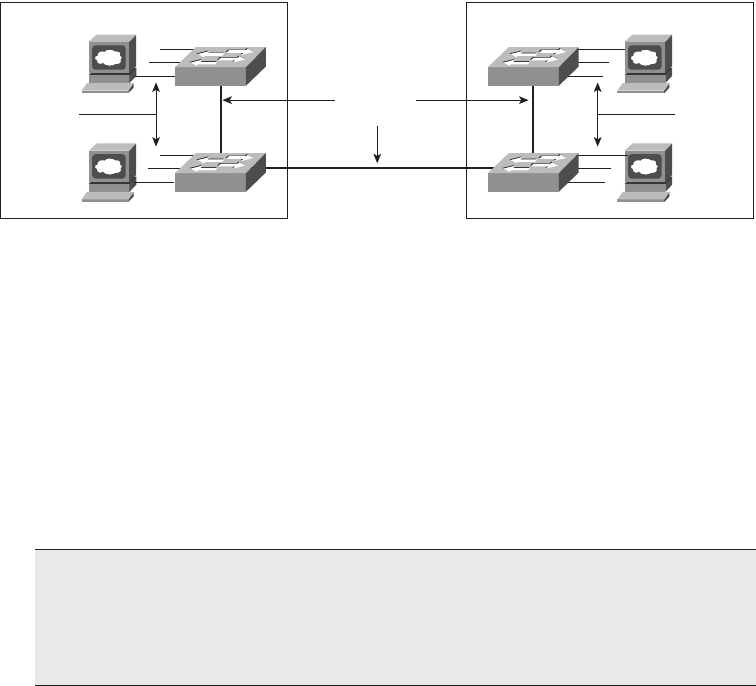
58 Chapter 3: Fundamentals of LANs
For example, Figure 3-9 shows a campus LAN in a single building. In this case, several
straight-through cables are used to connect PCs to switches. Additionally, the cables
connecting the switches—referred to as trunks—require crossover cables.
Figure 3-9 Typical Uses for Straight-Through and Crossover Ethernet Cables
1000BASE-T Cabling
As noted earlier, 1000BASE-T differs from 10BASE-T and 100BASE-TX as far as the
cabling and pinouts. First, 1000BASE-T requires four wire pairs. Also, Gigabit Ethernet
transmits and receives on each of the four wire pairs simultaneously.
However, Gigabit Ethernet does have a concept of straight-through and crossover cables,
with a minor difference in the crossover cables. The pinouts for a straight-through cable are
the same—pin 1 to pin 1, pin 2 to pin 2, and so on. The crossover cable crosses the same
two-wire pair as the crossover cable for the other types of Ethernet—the pair at pins 1,2 and
3,6—as well as crossing the two other pairs (the pair at pins 4,5 with the pair at pins 7,8).
Next, this chapter takes a closer look at LAN hubs and the need for LAN switches.
Improving Performance by Using Switches
Instead of Hubs
This section examines some of the performance problems created when using hubs,
followed by explanations of how LAN switches solve the two largest performance
problems encountered with hubs. To better appreciate the problem, consider Figure 3-10,
which shows what happens when a single device sends data through a hub.
NOTE If you have some experience with installing LANs, you might be thinking that
you have used the wrong cable before (straight-through or crossover), but the cable
worked. Cisco switches have a feature called auto-mdix that notices when the wrong
cabling pinouts are used. This feature readjusts the switch’s logic and makes the cable
work. For the exams, be ready to identify whether the correct cable is shown in figures.
Building 1
Straight-
through
Cables
Switch 11
Switch 12
Building 2
Straight-
through
Cables
Switch 21
Switch 22
Cross-over
Cables
1828xbook.fm Page 58 Thursday, July 26, 2007 3:10 PM
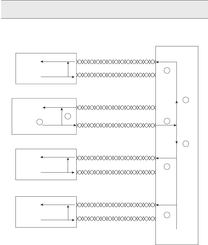
Improving Performance by Using Switches Instead of Hubs 59
Figure 3-10 Hub Creates One Shared Electrical Bus
The figure outlines how a hub creates an electrical bus. The steps illustrated in Figure 3-10
are as follows:
Step 1 The network interface card (NIC) sends a frame.
Step 2 The NIC loops the sent frame onto its receive pair internally on the card.
Step 3 The hub receives the electrical signal, interpreting the signal as bits so
that it can clean up and repeat the signal.
NOTE The figure and the logic describing it apply to any hub, whether 10BASE-T,
100BASE-TX, or even 1000BASE-T.
Hub
NIC
NIC
Collision?
Receive
Transmit
Receive Pair
2-Pair Cable
Transmit Pair
Loop
Back
NIC
NIC
5
4
4
3
1
2
5
5
PC1
PC2
PC3
PC4
Receive
Transmit
Loop
Back
Collision?
Receive
Transmit
Loop
Back
Collision?
Receive
Transmit
Loop
Back
Collision?
1828xbook.fm Page 59 Thursday, July 26, 2007 3:10 PM

60 Chapter 3: Fundamentals of LANs
Step 4 The hub’s internal wiring repeats the signal out all other ports, but not
back to the port from which the signal was received.
Step 5 The hub repeats the signal to each receive pair on all other devices.
In particular, note that a hub always repeats the electrical signal out all ports, except the port
from which the electrical signal was received. Also, Figure 3-10 does not show a collision.
However, if PC1 and PC2 sent an electrical signal at the same time, at Step 4 the electrical
signals would overlap, the frames would collide, and both frames would be either
completely unintelligible or full of errors.
CSMA/CD logic helps prevent collisions and also defines how to act when a collision does
occur. The CSMA/CD algorithm works like this:
Step 1 A device with a frame to send listens until the Ethernet is not busy.
Step 2 When the Ethernet is not busy, the sender(s) begin(s) sending the frame.
Step 3 The sender(s) listen(s) to make sure that no collision occurred.
Step 4 If a collision occurs, the devices that had been sending a frame each send
a jamming signal to ensure that all stations recognize the collision.
Step 5 After the jamming is complete, each sender randomizes a timer and waits
that long before trying to resend the collided frame.
Step 6 When each random timer expires, the process starts over with Step 1.
CSMA/CD does not prevent collisions, but it does ensure that the Ethernet works well even
though collisions may and do occur. However, the CSMA/CD algorithm does create some
performance issues. First, CSMA/CD causes devices to wait until the Ethernet is silent
before sending data. This process helps avoid collisions, but it also means that only one
device can send at any one instant in time. As a result, all the devices connected to the same
hub share the bandwidth available through the hub. The logic of waiting to send until the
LAN is silent is called half duplex. This refers to the fact that a device either sends or
receives at any point in time, but never both at the same time.
The other main feature of CSMA/CD defines what to do when collisions do occur. When a
collision occurs, CSMA/CD logic causes the devices that sent the colliding data frames to
wait a random amount of time, and then try again. This again helps the LAN to function,
but again it impacts performance. During the collision, no useful data makes it across the
LAN. Also, the offending devices have to wait longer before trying to use the LAN.
Additionally, as the load on an Ethernet increases, the statistical chance for collisions
increases as well. In fact, during the years before LAN switches became more affordable
and solved some of these performance problems, the rule of thumb was that an Ethernet’s
performance began to degrade when the load began to exceed 30 percent utilization, mainly
as a result of increasing collisions.
1828xbook.fm Page 60 Thursday, July 26, 2007 3:10 PM

Improving Performance by Using Switches Instead of Hubs 61
Increasing Available Bandwidth Using Switches
The term collision domain defines the set of devices whose frames could collide. All
devices on a 10BASE2, 10BASE5, or any network using a hub risk collisions between the
frames that they send, so all devices on one of these types of Ethernet networks are in the
same collision domain. For example, all four devices connected to the hub in Figure 3-10
are in the same collision domain. To avoid collisions, and to recover when they occur,
devices in the same collision domain use CSMA/CD.
LAN switches significantly reduce, or even eliminate, the number of collisions on a LAN.
Unlike hubs, switches do not create a single shared bus, forwarding received electrical
signals out all other ports. Instead, switches do the following:
■Switches interpret the bits in the received frame so that they can typically send the
frame out the one required port, rather than all other ports
■If a switch needs to forward multiple frames out the same port, the switch buffers the
frames in memory, sending one at a time, thereby avoiding collisions
For example, Figure 3-11 illustrates how a switch can forward two frames at the same time
while avoiding a collision. In Figure 3-11, both PC1 and PC3 send at the same time. In this
case, PC1 sends a data frame with a destination address of PC2, and PC3 sends a data frame
with a destination address of PC4. (More on Ethernet addressing is coming up later in this
chapter.) The switch looks at the destination Ethernet address and sends the frame from
PC1 to PC2 at the same instant as the frame is sent by PC3 to PC4. Had a hub been used, a
collision would have occurred; however, because the switch did not send the frames out all
other ports, the switch prevented a collision.
Buffering also helps prevent collisions. Imagine that PC1 and PC3 both send a frame to PC4
at the same time. The switch, knowing that forwarding both frames to PC4 at the same time
would cause a collision, buffers one frame (in other words, temporarily holds it in memory)
until the first frame has been completely sent to PC4.
These seemingly simple switch features provide significant performance improvements as
compared with using hubs. In particular:
■If only one device is cabled to each port of a switch, no collisions can occur.
■Devices connected to one switch port do not share their bandwidth with devices
connected to another switch port. Each has its own separate bandwidth, meaning that
a switch with 100-Mbps ports has 100 Mbps of bandwidth per port.
NOTE The switch’s logic requires that the switch look at the Ethernet header, which is
considered a Layer 2 feature. As a result, switches are considered to operate as a
Layer 2 device, whereas hubs are Layer 1 devices.
1828xbook.fm Page 61 Thursday, July 26, 2007 3:10 PM
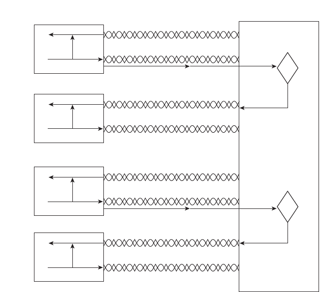
62 Chapter 3: Fundamentals of LANs
Figure 3-11 Basic Switch Operation
The second point refers to the concepts behind the terms shared Ethernet and switched
Ethernet. As mentioned earlier in this chapter, shared Ethernet means that the LAN
bandwidth is shared among the devices on the LAN because they must take turns using the
LAN because of the CSMA/CD algorithm. The term switched Ethernet refers to the fact
that with switches, bandwidth does not have to be shared, allowing for far greater
performance. For example, a hub with 24 100-Mbps Ethernet devices connected to it allows
for a theoretical maximum of 100 Mbps of bandwidth. However, a switch with 24
100-Mbps Ethernet devices connected to it supports 100 Mbps for each port, or
2400 Mbps (2.4 Gbps) theoretical maximum bandwidth.
Doubling Performance by Using Full-Duplex Ethernet
Any Ethernet network using hubs requires CSMA/CD logic to work properly. However,
CSMA/CD imposes half-duplex logic on each device, meaning that only one device can
send at a time. Because switches can buffer frames in memory, switches can completely
eliminate collisions on switch ports that connect to a single device. As a result, LAN
switches with only one device cabled to each port of the switch allow the use of full-duplex
operation. Full duplex means that an Ethernet card can send and receive concurrently.
?
?
PC1
PC2
PC3
PC4
Switch
Receive
Transmit
Receive
Transmit
Receive
Transmit
Receive
Transmit
1828xbook.fm Page 62 Thursday, July 26, 2007 3:10 PM
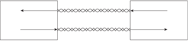
Ethernet Data-Link Protocols 63
To appreciate why collisions cannot occur, consider Figure 3-12, which shows the full-
duplex circuitry used with a single PC’s connection to a LAN switch.
Figure 3-12 Full-Duplex Operation Using a Switch
With only the switch and one device connected to each other, collisions cannot occur. When
you implement full duplex, you disable CSMA/CD logic on the devices on both ends of
the cable. By doing so, neither device even thinks about CSMA/CD, and they can go ahead
and send data whenever they want. As a result, the performance of the Ethernet on that cable
has been doubled by allowed simultaneous transmission in both directions.
Ethernet Layer 1 Summary
So far in this chapter, you have read about the basics of how to build the Layer 1 portions of
Ethernet using both hubs and switches. This section explained how to use UTP cables,
with RJ-45 connectors, to connect devices to either a hub or a switch. It also explained the
general theory of how devices can send data by encoding different electrical signals over an
electrical circuit, with the circuit being created using a pair of wires inside the UTP cable.
More importantly, this section explained which wire pairs are used to transmit and receive
data. Finally, the basic operations of switches were explained, including the potential
elimination of collisions, which results in significantly better performance than hubs.
Next, this chapter examines the data link layer protocols defined by Ethernet.
Ethernet Data-Link Protocols
One of the most significant strengths of the Ethernet family of protocols is that these
protocols use the same small set of data-link standards. For instance, Ethernet addressing
works the same on all the variations of Ethernet, even back to 10BASE5, up through
10-Gbps Ethernet—including Ethernet standards that use other types of cabling besides
UTP. Also, the CSMA/CD algorithm is technically a part of the data link layer, again
applying to most types of Ethernet, unless it has been disabled.
This section covers most of the details of the Ethernet data-link protocols—in particular,
Ethernet addressing, framing, error detection, and identifying the type of data inside the
Ethernet frame.
Full-Duplex NIC
Receive
Transmit
Switch NIC
Transmit
Receive
1828xbook.fm Page 63 Thursday, July 26, 2007 3:10 PM
64 Chapter 3: Fundamentals of LANs
Ethernet Addressing
Ethernet LAN addressing identifies either individual devices or groups of devices on a
LAN. Each address is 6 bytes long, is usually written in hexadecimal, and, in Cisco devices,
typically is written with periods separating each set of four hex digits. For example,
0000.0C12.3456 is a valid Ethernet address.
Unicast Ethernet addresses identify a single LAN card. (The term unicast was chosen
mainly for contrast with the terms broadcast, multicast, and group addresses.) Computers
use unicast addresses to identify the sender and receiver of an Ethernet frame. For instance,
imagine that Fred and Barney are on the same Ethernet, and Fred sends Barney a frame.
Fred puts his own Ethernet MAC address in the Ethernet header as the source address and
uses Barney’s Ethernet MAC address as the destination. When Barney receives the frame,
he notices that the destination address is his own address, so he processes the frame. If
Barney receives a frame with some other device’s unicast address in the destination address
field, he simply does not process the frame.
The IEEE defines the format and assignment of LAN addresses. The IEEE requires globally
unique unicast MAC addresses on all LAN interface cards. (IEEE calls them MAC
addresses because the MAC protocols such as IEEE 802.3 define the addressing details.)
To ensure a unique MAC address, the Ethernet card manufacturers encode the MAC
address onto the card, usually in a ROM chip. The first half of the address identifies the
manufacturer of the card. This code, which is assigned to each manufacturer by the IEEE,
is called the organizationally unique identifier (OUI). Each manufacturer assigns a MAC
address with its own OUI as the first half of the address, with the second half of the address
being assigned a number that this manufacturer has never used on another card.
Figure 3-13 shows the structure.
Figure 3-13 Structure of Unicast Ethernet Addresses
Many terms can be used to describe unicast LAN addresses. Each LAN card comes with a
burned-in address (BIA) that is burned into the ROM chip on the card. BIAs sometimes are
called universally administered addresses (UAA) because the IEEE universally (well, at
least worldwide) administers address assignment. Regardless of whether the BIA is used or
another address is configured, many people refer to unicast addresses as either LAN
addresses, Ethernet addresses, hardware addresses, physical addresses, or MAC addresses.
24 Bits 24 Bits
6 Hex Digits 6 Hex Digits
00 60 2F 3A 07 BC
Organizationally Unique
Identifier (OUI)
Vendor Assigned
(NIC Cards, Interfaces)
Size, in bits
Size, in hex digits
Example
1828xbook.fm Page 64 Thursday, July 26, 2007 3:10 PM

Ethernet Data-Link Protocols 65
Group addresses identify more than one LAN interface card. The IEEE defines two general
categories of group addresses for Ethernet:
■Broadcast addresses: The most often used of the IEEE group MAC addresses, the
broadcast address, has a value of FFFF.FFFF.FFFF (hexadecimal notation). The
broadcast address implies that all devices on the LAN should process the frame.
■Multicast addresses: Multicast addresses are used to allow a subset of devices on a
LAN to communicate. When IP multicasts over an Ethernet, the multicast MAC
addresses used by IP follow this format: 0100.5exx.xxxx, where any value can be used
in the last half of the address.
Table 3-4 summarizes most of the details about MAC addresses.
Ethernet Framing
Framing defines how a string of binary numbers is interpreted. In other words, framing
defines the meaning behind the bits that are transmitted across a network. The physical
layer helps you get a string of bits from one device to another. When the receiving device
gets the bits, how should they be interpreted? The term framing refers to the definition of
the fields assumed to be in the data that is received. In other words, framing defines the
meaning of the bits transmitted and received over a network.
For instance, you just read an example of Fred sending data to Barney over an Ethernet.
Fred put Barney’s Ethernet address in the Ethernet header so that Barney would know that
the Ethernet frame was meant for him. The IEEE 802.3 standard defines the location of the
destination address field inside the string of bits sent across the Ethernet.
Table 3-4 LAN MAC Address Terminology and Features
LAN Addressing Term or Feature Description
MAC Media Access Control. 802.3 (Ethernet) defines the MAC
sublayer of IEEE Ethernet.
Ethernet address, NIC address,
LAN address
Other names often used instead of MAC address. These terms
describe the 6-byte address of the LAN interface card.
Burned-in address The 6-byte address assigned by the vendor making the card.
Unicast address A term for a MAC that represents a single LAN interface.
Broadcast address An address that means “all devices that reside on this LAN
right now.”
Multicast address On Ethernet, a multicast address implies some subset of all
devices currently on the Ethernet LAN.
1828xbook.fm Page 65 Thursday, July 26, 2007 3:10 PM

66 Chapter 3: Fundamentals of LANs
The framing used for Ethernet has changed a couple of times over the years. Xerox defined
one version of the framing, which the IEEE then changed when it took over Ethernet
standards in the early 1980s. The IEEE finalized a compromise standard for framing in 1997
that includes some of the features of the original Xerox Ethernet framing, along with the
framing defined by the IEEE. The end result is the bottom frame format shown in Figure 3-14.
Figure 3-14 LAN Header Formats
Most of the fields in the Ethernet frame are important enough to be covered at some point
in this chapter. For reference, Table 3-5 lists the fields in the header and trailer, and a
brief description, for reference.
Table 3-5 IEEE 802.3 Ethernet Header and Trailer Fields
Field
Field Length
in Bytes Description
Preamble 7 Synchronization
Start Frame
Delimiter (SFD)
1 Signifies that the next byte begins the Destination MAC field
Destination
MAC address
6 Identifies the intended recipient of this frame
Source MAC
address
6 Identifies the sender of this frame
Length 2 Defines the length of the data field of the frame (either length or
type is present, but not both)
Type 2 Defines the type of protocol listed inside the frame (either
length or type is present, but not both)
Preamble
7
SFD
1
Destination
6
Source
6
Length
2
Data and Pad
46 – 1500
FCS
4
IEEE 802.3 (Original)
Preamble
8
Destination
6
Source
6
Type
2
Data and Pad
46 – 1500
FCS
4
DIX
Preamble
7
SFD
1
Destination
Bytes 6
Source
6
Length/
Type 2
Data and Pad
46 – 1500
FCS
4
IEEE 802.3 (Revised 1997)
1828xbook.fm Page 66 Thursday, July 26, 2007 3:10 PM

Ethernet Data-Link Protocols 67
*The IEEE 802.3 specification limits the data portion of the 802.3 frame to a maximum of 1500 bytes. The Data field
was designed to hold Layer 3 packets; the term maximum transmission unit (MTU) defines the maximum Layer 3
packet that can be sent over a medium. Because the Layer 3 packet rests inside the data portion of an Ethernet frame,
1500 bytes is the largest IP MTU allowed over an Ethernet.
Identifying the Data Inside an Ethernet Frame
Over the years, many different network layer (Layer 3) protocols have been designed.
Most of these protocols were part of larger network protocol models created by vendors
to support their products, such as IBM Systems Network Architecture (SNA), Novell
NetWare, Digital Equipment Corporation’s DECnet, and Apple Computer’s AppleTalk.
Additionally, the OSI and TCP/IP models also defined network layer protocols.
All these Layer 3 protocols, plus several others, could use Ethernet. To use Ethernet, the
network layer protocol would place its packet (generically speaking, its L3 PDU) into the
data portion of the Ethernet frame shown in Figure 3-14. However, when a device receives
such an Ethernet frame, that receiving device needs to know what type of L3 PDU is in the
Ethernet frame. Is it an IP packet? an OSI packet? SNA? and so on.
To answer that question, most data-link protocol headers, including Ethernet, have a field
with a code that defines the type of protocol header that follows. Generically speaking,
these fields in data-link headers are called Type fields. For example, to imply that an IP
packet is inside an Ethernet frame, the Type field (as shown in Figure 3-14) would have a
value of hexadecimal 0800 (decimal 2048). Other types of L3 PDUs would be implied by
using a different value in the Type field.
Interestingly, because of the changes to Ethernet framing over the years, another popular option
exists for the protocol Type field, particularly when sending IP packets. If the 802.3 Type/
Length field (in Figure 3-14) has a value less than hex 0600 (decimal 1536), the Type/Length
field is used as a Length field for that frame, identifying the length of the entire Ethernet frame.
In that case, another field is needed to identify the type of L3 PDU inside the frame.
To create a Type field for frames that use the Type/Length field as a Length field, either
one or two additional headers are added after the Ethernet 802.3 header but before the
Data and Pad*46–1500 Holds data from a higher layer, typically an L3 PDU (generic),
and often an IP packet
Frame Check
Sequence (FCS)
4 Provides a method for the receiving NIC to determine if the
frame experienced transmission errors
Table 3-5 IEEE 802.3 Ethernet Header and Trailer Fields (Continued)
Field
Field Length
in Bytes Description
1828xbook.fm Page 67 Thursday, July 26, 2007 3:10 PM

68 Chapter 3: Fundamentals of LANs
Layer 3 header. For example, when sending IP packets, the Ethernet frame has two
additional headers:
■An IEEE 802.2 Logical Link Control (LLC) header
■An IEEE Subnetwork Access Protocol (SNAP) header
Figure 3-15 shows an Ethernet frame with these additional headers. Note that the SNAP
header Type field has the same purpose, with the same reserved values, as the Ethernet
Type/Length field.
Figure 3-15 802.2 SNAP Headers
Error Detection
The final Ethernet data link layer function explained here is error detection. Error detection
is the process of discovering if a frame’s bits changed as a result of being sent over the
network. The bits might change for many small reasons, but generally such errors occur as
a result of some kind of electrical interference. Like every data-link protocol covered on the
CCNA exams, Ethernet defines both a header and trailer, with the trailer containing a field
used for the purpose of error detection.
The Ethernet Frame Check Sequence (FCS) field in the Ethernet trailer—the only field in
the Ethernet trailer—allows a device receiving an Ethernet frame to detect whether the bits
have changed during transmission. To detect an error, the sending device calculates a
complex mathematical function, with the frame contents as input, putting the result into the
frame’s 4-byte FCS field. The receiving device does the same math on the frame; if its
calculation matches the FCS field in the frame, no errors occurred. If the result doesn’t
match the FCS field, an error occurred, and the frame is discarded.
Note that error detection does not also mean error recovery. Ethernet defines that the errored
frame should be discarded, but Ethernet takes no action to cause the frame to be
retransmitted. Other protocols, notably TCP (as covered in Chapter 6, “Fundamentals of
TCP/IP Transport, Applications, and Security”), can notice the lost data and cause error
recovery to occur.
Preamble
7
Bytes
* To be a Length field, this value must be less than decimal 1536.
802.3 Header
802.2 LLC
Header
SNAP
Header
SFD
1
Destination
6
Source
6
Length*
2
DSAP
1
SSAP
1
CTL
1
OUI
3
Type
2
Data and Pad
46 - 1500
FCS
4
1828xbook.fm Page 68 Thursday, July 26, 2007 3:10 PM
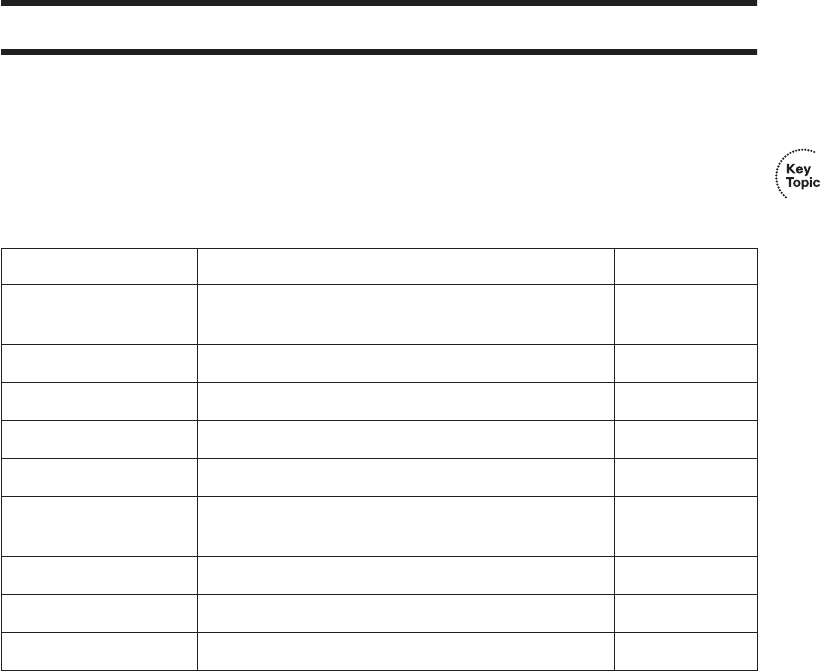
Definitions of Key Terms 69
Exam Preparation Tasks
Review All the Key Topics
Review the most important topics from this chapter, noted with the key topics icon.
Table 3-6 lists these key topics and where each is discussed.
Complete the Tables and Lists from Memory
Print a copy of Appendix H, “Memory Tables” (found on the CD), or at least the section for
this chapter, and complete the tables and lists from memory. Appendix I, “Memory Tables
Answer Key,” also on the CD, includes completed tables and lists for you to check your
work.
Definitions of Key Terms
Define the following key terms from this chapter and check your answers in the glossary.
1000BASE-T, 100BASE-TX, 10BASE-T, crossover cable, CSMA/CD, full duplex,
half duplex, hub, pinout, protocol type, shared Ethernet, straight-through cable, switch,
switched Ethernet, twisted pair
Table 3-6 Key Topics for Chapter 3
Key Topic Element Description Page Number
Table 3-2 The four most popular types of Ethernet LANs and
some details about each
46
List Summary of CSMA/CD logic 49
Figure 3-6 EIA/TIA standard Ethernet Cabling Pinouts 55
Figure 3-7 Straight-through cable concept 56
Figure 3-8 Crossover cable concept 57
Table 3-3 List of devices that transmit on wire pair 1,2 and
pair 3,6
57
List Detailed CSMA/CD logic 60
Figure 3-13 Structure of a unicast Ethernet address 64
Table 3-4 Key Ethernet addressing terms 65
1828xbook.fm Page 69 Thursday, July 26, 2007 3:10 PM

This chapter covers the following subjects:
OSI Layer 1 for Point-to-Point WANs: This
section explains the physical cabling and devices
used to create the customer portions of a leased
circuit.
OSI Layer 2 for Point-to-Point WANs: This
section introduces the data link layer protocols
used on point-to-point leased lines, namely
HDLC and PPP.
Frame Relay and Packet-Switching
Services: This section explains the concept of a
WAN packet-switching service, with particular
attention given to Frame Relay.
1828xbook.fm Page 70 Thursday, July 26, 2007 3:10 PM

C H A P T E R4
Fundamentals of WANs
In the previous chapter, you learned more details about how Ethernet LANs perform the
functions defined by the two lowest OSI layers. In this chapter, you will learn about how
wide-area network (WAN) standards and protocols also implement OSI Layer 1 (physical
layer) and Layer 2 (data link layer). The OSI physical layer details are covered, along with
three popular WAN data link layer protocols: High-Level Data Link Control (HDLC),
Point-to-Point Protocol (PPP), and Frame Relay.
“Do I Know This Already?” Quiz
The “Do I Know This Already?” quiz allows you to assess if you should read the entire
chapter. If you miss no more than one of these eight self-assessment questions, you might
want to move ahead to the “Exam Preparation Tasks” section. Table 4-1 lists the major
headings in this chapter and the “Do I Know This Already?” quiz questions covering the
material in those headings so you can assess your knowledge of these specific areas. The
answers to the “Do I Know This Already?” quiz appear in Appendix A.
1. Which of the following best describes the main function of OSI Layer 1 protocols?
a. Framing
b. Delivery of bits from one device to another
c. Addressing
d. Local Management Interface (LMI)
e. DLCI
Table 4-1 “Do I Know This Already?” Foundation Topics Section-to-Question Mapping
Foundation Topics Section Questions
OSI Layer 1 for Point-to-Point WANs 1–4
OSI Layer 2 for Point-to-Point WANs 5, 6
Frame Relay and Packet-Switching Services 7, 8
1828xbook.fm Page 71 Thursday, July 26, 2007 3:10 PM
72 Chapter 4: Fundamentals of WANs
2. Which of the following typically connects to a four-wire line provided by a telco?
a. Router serial interface
b. CSU/DSU
c. Transceiver
d. Switch serial interface
3. Which of the following typically connects to a V.35 or RS-232 end of a cable when
cabling a leased line?
a. Router serial interface
b. CSU/DSU
c. Transceiver
d. Switch serial interface
4. On a point-to-point WAN link using a leased line between two routers located
hundreds of miles apart, what devices are considered to be the DTE devices?
a. Routers
b. CSU/DSU
c. The central office equipment
d. A chip on the processor of each router
e. None of these answers are correct.
5. Which of the following functions of OSI Layer 2 is specified by the protocol standard
for PPP, but is implemented with a Cisco proprietary header field for HDLC?
a. Framing
b. Arbitration
c. Addressing
d. Error detection
e. Identifying the type of protocol that is inside the frame
1828xbook.fm Page 72 Thursday, July 26, 2007 3:10 PM
“Do I Know This Already?” Quiz 73
6. Imagine that Router1 has three point-to-point serial links, one link each to three remote
routers. Which of the following is true about the required HDLC addressing at
Router1?
a. Router1 must use HDLC addresses 1, 2, and 3.
b. Router1 must use any three unique addresses between 1 and 1023.
c. Router1 must use any three unique addresses between 16 and 1000.
d. Router1 must use three sequential unique addresses between 1 and 1023.
e. None of these answers are correct.
7. What is the name of the Frame Relay field used to identify Frame Relay virtual
circuits?
a. Data-link connection identifier
b. Data-link circuit identifier
c. Data-link connection indicator
d. Data-link circuit indicator
e. None of these answers are correct.
8. Which of the following is true about Frame Relay virtual circuits (VCs)?
a. Each VC requires a separate access link.
b. Multiple VCs can share the same access link.
c. All VCs sharing the same access link must connect to the same router on the
other side of the VC.
d. All VCs on the same access link must use the same DLCI.
1828xbook.fm Page 73 Thursday, July 26, 2007 3:10 PM

74 Chapter 4: Fundamentals of WANs
Foundation Topics
As you read in the previous chapter, the OSI physical and data link layers work together to
deliver data across a wide variety of types of physical networks. LAN standards and
protocols define how to network between devices that are relatively close together, hence
the term local-area in the acronym LAN. WAN standards and protocols define how to
network between devices that are relatively far apart—in some cases, even thousands of
miles apart—hence the term wide-area in the acronym WAN.
LANs and WANs both implement the same OSI Layer 1 and Layer 2 functions, but with
different mechanisms and details. This chapter points out the similarities between the two,
and provides details about the differences.
The WAN topics in this chapter describe mainly how enterprise networks use WANs to
connect remote sites. Part IV of this book covers a broader range of WAN topics, including
popular Internet access technologies such as digital subscriber line (DSL) and cable, along
with a variety of configuration topics. The CCNA ICND2 Official Exam Certification Guide
covers Frame Relay in much more detail than this book, as well as the concepts behind
Internet virtual private networks (VPN), which is a way to use the Internet instead of
traditional WAN links.
OSI Layer 1 for Point-to-Point WANs
The OSI physical layer, or Layer 1, defines the details of how to move data from one device
to another. In fact, many people think of OSI Layer 1 as “sending bits.” Higher layers
encapsulate the data, as described in Chapter 2, “The TCP/IP and OSI Networking
Models.” No matter what the other OSI layers do, eventually the sender of the data needs
to actually transmit the bits to another device. The OSI physical layer defines the standards
and protocols used to create the physical network and to send the bits across that network.
A point-to-point WAN link acts like an Ethernet trunk between two Ethernet switches
in many ways. For perspective, look at Figure 4-1, which shows a LAN with two
buildings and two switches in each building. As a brief review, remember that several
types of Ethernet use one twisted pair of wires to transmit and another twisted pair to
receive, in order to reduce electromagnetic interference. You typically use straight-
through Ethernet cables between end-user devices and the switches. For the trunk links
between the switches, you use crossover cables because each switch transmits on the
same pair of pins on the connector, so the crossover cable connects one device’s transmit
pair to the other device’s receive pair. The lower part of Figure 4-1 reminds you of the
basic idea behind a crossover cable.
1828xbook.fm Page 74 Thursday, July 26, 2007 3:10 PM
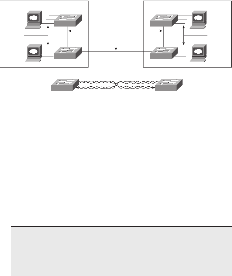
OSI Layer 1 for Point-to-Point WANs 75
Figure 4-1 Example LAN, Two Buildings
Now imagine that the buildings are 1000 miles apart instead of right next to each other. You
are immediately faced with two problems:
■Ethernet does not support any type of cabling that allows an individual trunk to run for
1000 miles.
■Even if Ethernet supported a 1000-mile trunk, you do not have the rights-of-way
needed to bury a cable over the 1000 miles of real estate between buildings.
The big distinction between LANs and WANs relates to how far apart the devices can be
and still be capable of sending and receiving data. LANs tend to reside in a single building
or possibly among buildings in a campus using optical cabling approved for Ethernet. WAN
connections typically run longer distances than Ethernet—across town or between cities.
Often, only one or a few companies even have the rights to run cables under the ground
between the sites. So, the people who created WAN standards needed to use different
physical specifications than Ethernet to send data 1000 miles or more (WAN).
To create such long links, or circuits, the actual physical cabling is owned, installed, and
managed by a company that has the right of way to run cables under streets. Because a
company that needs to send data over the WAN circuit does not actually own the cable or
line, it is called a leased line. Companies that can provide leased WAN lines typically
NOTE Besides LANs and WANs, the term metropolitan-area network (MAN) is
sometimes used for networks that extend between buildings and through rights-of-ways.
The term MAN typically implies a network that does not reach as far as a WAN,
generally in a single metropolitan area. The distinctions between LANs, MANs, and
WANs are blurry—there is no set distance that means a link is a LAN, MAN, or
WAN link.
Building 1
Straight-
through
Cables
Switch 11
Switch 12
Building 2
Straight-
through
Cables
Switch 21
Switch 22
Crossover
Cables
Crossover Cable Conceptual View
1828xbook.fm Page 75 Thursday, July 26, 2007 3:10 PM
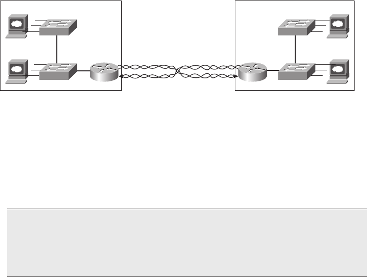
76 Chapter 4: Fundamentals of WANs
started life as the local telephone company, or telco. In many countries, the telco is still a
government-regulated or government-controlled monopoly; these companies are
sometimes called public telephone and telegraph (PTT) companies. Today, many people
use the generic term service provider to refer to a company that provides any form of WAN
connectivity, including Internet services.
Point-to-point WAN links provide basic connectivity between two points. To get a point-to-
point WAN link, you would work with a service provider to install a circuit. What the phone
company or service provider gives you is similar to what you would have if you made a
phone call between two sites, but you never hung up. The two devices on either end of the
WAN circuit could send and receive bits between each other any time they want, without
needing to dial a phone number. Because the connection is always available, a point-to-
point WAN connection is sometimes called a leased circuit or leased line because you have
the exclusive right to use that circuit, as long as you keep paying for it.
Now back to the comparison of the LAN between two nearby buildings versus the WAN
between two buildings that are 1000 miles apart. The physical details are different, but the
same general functions need to be accomplished, as shown in Figure 4-2.
Figure 4-2 Conceptual View of Point-to-Point Leased Line
Keep in mind that Figure 4-2 provides a conceptual view of a point-to-point WAN link. In
concept, the telco installs a physical cable, with a transmit and a receive twisted pair,
between the buildings. The cable has been connected to each router, and each router, in turn,
has been connected to the LAN switches. As a result of this new physical WAN link and the
logic used by the routers connected to it, data now can be transferred between the two sites.
In the next section, you will learn more about the physical details of the WAN link.
NOTE Ethernet switches have many different types of interfaces, but all the interfaces
are some form of Ethernet. Routers provide the capability to connect many different
types of OSI Layer 1 and Layer 2 technologies. So, when you see a LAN connected to
some other site using a WAN connection, you will see a router connected to each, as in
Figure 4-2.
Building 1
1000 Miles
Switch 11
Switch 12
Building 2
Switch 21
Switch 22
R2R1
1828xbook.fm Page 76 Thursday, July 26, 2007 3:10 PM
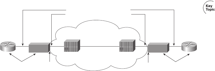
OSI Layer 1 for Point-to-Point WANs 77
WAN Connections from the Customer Viewpoint
The concepts behind a point-to-point connection are simple. However, to fully understand
what the service provider does to build its network to support your point-to-point line,
you would need to spend lots of time studying and learning technologies outside the scope
of the ICND1 exam. However, most of what you need to know about WANs for the ICND1
exam relates to how WAN connections are implemented between the telephone company
and a customer site. Along the way, you will need to learn a little about the terminology
used by the provider.
In Figure 4-2, you saw that a WAN leased line acts as if the telco gave you two twisted pairs
of wires between the two sites on each end of the line. Well, it is not that simple. Of course,
a lot more underlying technology must be used to create the circuit, and telcos use a lot of
terminology that is different from LAN terminology. The telco seldom actually runs a
1000-mile cable for you between the two sites. Instead, it has built a large network already
and even runs extra cables from the local central office (CO) to your building (a CO is just
a building where the telco locates the devices used to create its own network). Regardless
of what the telco does inside its own network, what you receive is the equivalent of a four-
wire leased circuit between two buildings.
Figure 4-3 introduces some of the key concepts and terms relating to WAN circuits.
Figure 4-3 Point-to-Point Leased Line: Components and Terminology
Typically, routers connect to a device called an external channel service unit/data service
unit (CSU/DSU). The router connects to the CSU/DSU with a relatively short cable,
typically less than 50 feet long, because the CSU/DSUs typically get placed in a rack near
the router. The much longer four-wire cable from the telco plugs into the CSU/DSU. That
cable leaves the building, running through the hidden (typically buried) cables that you
sometimes see phone company workers fixing by the side of the road. The other end of that
cable ends up in the CO, with the cable connecting to a CO device generically called a WAN
switch.
R1
WAN Switch
CSU
WAN Switch
CSU
R2
TELCO
CPE demarc CPEdemarc
Short Cables (Usually Less than 50 Feet)
Long Cables (Can Be Several Miles Long)
1828xbook.fm Page 77 Thursday, July 26, 2007 3:10 PM
78 Chapter 4: Fundamentals of WANs
The same general physical connectivity exists on each side of the point-to-point WAN link.
In between the two COs, the service provider can build its network with several competing
different types of technology, all of which is beyond the scope of any of the CCNA exams.
However, the perspective in Figure 4-2 remains true—the two routers can send and receive
data simultaneously across the point-to-point WAN link.
From a legal perspective, two different companies own the various components of the
equipment and lines in Figure 4-3. For instance, the router cable and typically the CSU/
DSU are owned by the telco’s customer, and the wiring to the CO and the gear inside the
CO are owned by the telco. So, the telco uses the term demarc, which is short for
demarcation point, to refer to the point at which the telco’s responsibility is on one side and
the customer’s responsibility is on the other. The demarc is not a separate device or cable,
but rather a concept of where the responsibilities of the telco and customer end.
In the United States, the demarc is typically where the telco physically terminates the set of
two twisted pairs inside the customer building. Typically, the customer asks the telco to
terminate the cable in a particular room, and most, if not all, the lines from the telco into
that building terminate in the same room.
The term customer premises equipment (CPE) refers to devices that are at the customer site,
from the telco’s perspective. For instance, both the CSU/DSU and the router are CPE
devices in this case.
The demarc does not always reside where it is shown in Figure 4-3. In some cases, the telco
actually could own the CSU/DSU, and the demarc would be on the router side of the CSU/
DSU. In some cases today, the telco even owns and manages the router at the customer site,
again moving the point that would be considered the demarc. Regardless of where the
demarc sits from a legal perspective, the term CPE still refers to the equipment at the telco
customer’s location.
WAN Cabling Standards
Cisco offers a large variety of different WAN interface cards for its routers, including
synchronous and asynchronous serial interfaces. For any of the point-to-point serial links
or Frame Relay links in this chapter, the router uses an interface that supports synchronous
communication.
Synchronous serial interfaces in Cisco routers use a variety of proprietary physical
connector types, such as the 60-pin D-shell connector shown at the top of the cable
drawings in Figure 4-4. The cable connecting the router to the CSU/DSU uses a connector
that fits the router serial interface on the router side, and a standardized WAN connector
1828xbook.fm Page 78 Thursday, July 26, 2007 3:10 PM
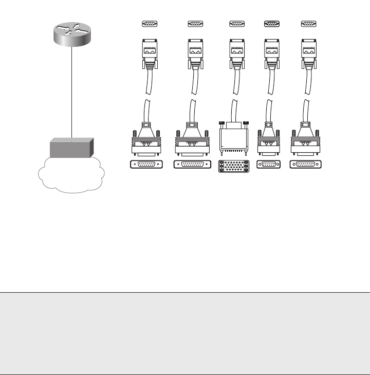
OSI Layer 1 for Point-to-Point WANs 79
type that matches the CSU/DSU interface on the CSU/DSU end of the cable. Figure 4-4
shows a typical connection, with some of the serial cabling options listed.
Figure 4-4 Serial Cabling Options
The engineer who deploys a network chooses the cable based on the connectors on the
router and the CSU/DSU. Beyond that choice, engineers do not really need to think about
how the cabling and pins work—they just work! Many of the pins are used for control
functions, and a few are used for the transmission of data. Some pins are used for clocking,
as described in the next section.
The cable between the CSU/DSU and the telco CO typically uses an RJ-48 connector to
connect to the CSU/DSU; the RJ-48 connector has the same size and shape as the RJ-45
connector used for Ethernet cables.
Many Cisco routers support serial interfaces that have an integrated internal CSU/DSU.
With an internal CSU/DSU, the router does not need a cable connecting it to an external
CSU/DSU because the CSU/DSU is internal to the router. In these cases, the serial cables
NOTE The Telecommunications Industry Association (TIA) is accredited by the
American National Standards Institute (ANSI) to represent the United States in work
with international standards bodies. The TIA defines some of the WAN cabling
standards, in addition to LAN cabling standards. For more information on these
standards bodies, and to purchase copies of the standards, refer to the websites http://
www.tiaonline.org and http://www.ansi.org.
Service
Provider
End User
Device
DTE
DCE
Router Connections
EIA/TIA-232 EIA/TIA-449 V.35 X.21 EIA-530
Network Connections at the CSU/DSU
CSU/
DSU
CSU/DSU
1828xbook.fm Page 79 Thursday, July 26, 2007 3:10 PM
80 Chapter 4: Fundamentals of WANs
shown in Figure 4-4 are not needed, and the physical line from the telco is connected to a
port on the router, typically an RJ-48 port in the router serial interface card.
Clock Rates, Synchronization, DCE, and DTE
An enterprise network engineer who wants to install a new point-to-point leased line
between two routers has several tasks to perform. First, the network engineer contacts a
service provider and orders the circuit. As part of that process, the network engineer
specifies how fast the circuit should run, in kilobits per second (kbps). While the telco
installs the circuit, the engineer purchases two CSU/DSUs, installs one at each site, and
configures each CSU/DSU. The network engineer also purchases and installs routers, and
connects serial cables from each router to the respective CSU/DSU using the cables shown
in Figure 4-4. Eventually, the telco installs the new line into the customer premises, and the
line can be connected to the CSU/DSUs, as shown in Figure 4-3.
Every WAN circuit ordered from a service provider runs at one of many possible predefined
speeds. This speed is often referred to as the clock rate, bandwidth, or link speed. The
enterprise network engineer (the customer) must specify the speed when ordering a circuit,
and the telco installs a circuit that runs at that speed. Additionally, the enterprise network
engineer must configure the CSU/DSU on each end of the link to match the defined speed.
To make the link work, the various devices need to synchronize their clocks so that they run
at exactly the same speed—a process called synchronization. Synchronous circuits impose
time ordering at the link’s sending and receiving ends. Essentially, all devices agree to try
to run at the exact same speed, but it is expensive to build devices that truly can operate at
exactly the same speed. So, the devices operate at close to the same speed and listen to the
speed of the other device on the other side of the link. One side makes small adjustments in
its rate to match the other side.
Synchronization occurs between the two CSU/DSUs on a leased line by having one CSU/
DSU (the slave) adjust its clock to match the clock rate of the other CSU/DSU (the master).
The process works almost like the scenes in spy novels in which the spies synchronize their
watches; in this case, the networking devices synchronize their clocks several times per
second.
In practice, the clocking concept includes a hierarchy of different clock sources. The telco
provides clocking information to the CSU/DSUs based on the transitions in the electrical
signal on the circuit. The two CSU/DSUs then adjust their speeds to match the clocking
signals from the telco. The CSU/DSUs each supply clocking signals to the routers so that
the routers simply react, sending and receiving data at the correct rate. So, from the routers’
perspectives, the CSU/DSU is considered to be clocking the link.
1828xbook.fm Page 80 Thursday, July 26, 2007 3:10 PM
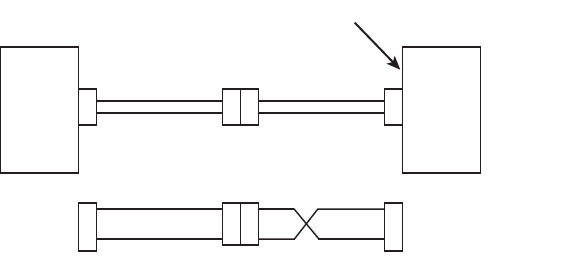
OSI Layer 1 for Point-to-Point WANs 81
A couple of other key WAN terms relate to the process of clocking. The device that provides
clocking, typically the CSU/DSU, is considered to be the data communications equipment
(DCE). The device receiving clocking, typically the router, is referred to as data terminal
equipment (DTE).
Building a WAN Link in a Lab
On a practical note, when purchasing serial cables from Cisco, you can pick either a DTE
or a DCE cable. You pick the type of cable based on whether the router is acting like DTE
or DCE. In most cases with a real WAN link, the router acts as DTE, so the router must use
a DTE cable to connect to the CSU/DSU.
You can build a serial link in a lab without using any CSU/DSUs, but to do so, one router
must supply clocking. When building a lab to study for any of the Cisco exams, you do not
need to buy CSU/DSUs or order a WAN circuit. You can buy two routers, a DTE serial cable
for one router, and a DCE serial cable for the other, and connect the two cables together.
The router with the DCE cable in it can be configured to provide clocking, meaning that
you do not need a CSU/DSU. So, you can build a WAN in your home lab, saving hundreds
of dollars by not buying CSU/DSUs. The DTE and DCE cables can be connected to each
other (the DCE cable has a female connector and the DTE cable has a male connector) and
to the two routers. With one additional configuration command on one of the routers (the
clock rate command), you have a point-to-point serial link. This type of connection
between two routers sometimes is called a back-to-back serial connection.
Figure 4-5 shows the cabling for a back-to-back serial connection and also shows that the
combined DCE/DTE cables reverse the transmit and receive pins, much like a crossover
Ethernet cable allows two directly connected devices to communicate.
Figure 4-5 Serial Cabling Uses a DTE Cable and a DCE Cable
Serial
Cable
Serial
Cable
DTE DCE
clock rate Command Goes Here
Router 1 Router 2
Tx
Rx
Tx
Rx
Tx
Rx
Tx
Rx
DTE Cable DCE Cable
1828xbook.fm Page 81 Thursday, July 26, 2007 3:10 PM

82 Chapter 4: Fundamentals of WANs
As you see in Figure 4-5, the DTE cable, the same cable that you typically use to connect
to a CSU/DSU, does not swap the Tx and Rx pins. The DCE cable swaps transmit and
receive, so the wiring with one router’s Tx pin connected to the other router’s Rx, and vice
versa, remains intact. The router with the DCE cable installed needs to supply clocking, so
the clock rate command will be added to that router to define the speed.
Link Speeds Offered by Telcos
No matter what you call them—telcos, PTTs, service providers—these companies do not
simply let you pick the exact speed of a WAN link. Instead, standards define how fast a
point-to-point link can run.
For a long time, the telcos of the world made more money selling voice services than selling
data services. As technology progressed during the mid-twentieth century, the telcos of the
world developed a standard for sending voice using digital transmissions. Digital signaling
inside their networks allowed for the growth of more profitable data services, such as leased
lines. It also allowed better efficiencies, making the build-out of the expanding voice
networks much less expensive.
The original mechanism used for converting analog voice to a digital signal is called pulse
code modulation (PCM). PCM defines that an incoming analog voice signal should be
sampled 8000 times per second, and each sample should be represented by an 8-bit code.
So, 64,000 bits were needed to represent 1 second of voice. When the telcos of the world
built their first digital networks, they chose a baseline transmission speed of 64 kbps
because that was the necessary bandwidth for a single voice call. The term digital signal
level 0 (DS0) refers to the standard for a single 64-kbps line.
Today, most telcos offer leased lines in multiples of 64 kbps. In the United States, the digital
signal level 1 (DS1) standard defines a single line that supports 24 DS0s, plus an 8-kbps
overhead channel, for a speed of 1.544 Mbps. (A DS1 is also called a T1 line.) Another
option is a digital signal level 3 (DS3) service, also called a T3 line, which holds 28 DS1s.
Other parts of the world use different standards, with Europe and Japan using standards that
hold 32 DS0s, called an E1 line, with an E3 line holding 16 E1s.
Table 4-2 lists some of the standards for WAN speeds. Included in the table are the type of
line, plus the type of signaling (for example, DS1). The signaling specifications define the
electrical signals that encode a binary 1 or 0 on the line. You should be aware of the general
idea, and remember the key terms for T1 and E1 lines in particular, for the ICND1 exam.
NOTE The combination of multiple slower-speed lines and channels into one faster-
speed line or channel—for instance, combining 24 DS0s into a single T1 line—is
generally called time-division multiplexing (TDM).
1828xbook.fm Page 82 Thursday, July 26, 2007 3:10 PM

OSI Layer 2 for Point-to-Point WANs 83
The leased circuits described so far in this chapter form the basis for the WAN services used
by many enterprises today. Next, this chapter explains the data link layer protocols used
when a leased circuit connects two routers.
OSI Layer 2 for Point-to-Point WANs
WAN protocols used on point-to-point serial links provide the basic function of data
delivery across that one link. The two most popular data link layer protocols used on point-
to-point links are High-Level Data Link Control (HDLC) and Point-to-Point Protocol
(PPP).
HDLC
Because point-to-point links are relatively simple, HDLC has only a small amount of work
to do. In particular, HDLC needs to determine if the data passed the link without any errors;
HDLC discards the frame if errors occurred. Additionally, HDLC needs to identify the type
of packet inside the HDLC frame so the receiving device knows the packet type.
To achieve the main goal of delivering data across the link and to check for errors and
identify the packet type, HDLC defines framing. The HDLC header includes an Address
field and a Protocol Type field, with the trailer containing a frame check sequence (FCS)
field. Figure 4-6 outlines the standard HDLC frame and the HDLC frame that is Cisco
proprietary.
HDLC defines a 1-byte Address field, although on point-to-point links, it is not really
needed. Having an Address field in HDLC is sort of like when I have lunch with my friend
Gary, and only Gary. I do not need to start every sentence with “Hey Gary”—he knows I
am talking to him. On point-to-point WAN links, the router on one end of the link knows
that there is only one possible recipient of the data—the router on the other end of the
link—so the address does not really matter today.
Table 4-2 WAN Speed Summary
Name(s) of Line Bit Rate
DS0 64 kbps
DS1 (T1) 1.544 Mbps (24 DS0s, plus 8 kbps overhead)
DS3 (T3) 44.736 Mbps (28 DS1s, plus management overhead)
E1 2.048 Mbps (32 DS0s)
E3 34.064 Mbps (16 E1s, plus management overhead)
J1 (Y1) 2.048 Mbps (32 DS0s; Japanese standard)
1828xbook.fm Page 83 Thursday, July 26, 2007 3:10 PM

84 Chapter 4: Fundamentals of WANs
Figure 4-6 HDLC Framing
HDLC performs error detection just like Ethernet—it uses an FCS field in the HDLC trailer.
And just like Ethernet, if a received frame has errors in it, the device receiving the frame
discards the frame, with no error recovery performed by HDLC.
HDLC also performs the function of identifying the encapsulated data, just like Ethernet.
When a router receives an HDLC frame, it wants to know what type of packet is held inside
the frame. The Cisco implementation of HDLC includes a Protocol Type field that identifies
the type of packet inside the frame. Cisco uses the same values in its 2-byte HDLC Protocol
Type field as it does in the Ethernet Protocol Type field.
The original HDLC standards did not include a Protocol Type field, so Cisco added one to
support the first serial links on Cisco routers, back in the early days of Cisco in the latter
1980s. By adding something to the HDLC header, Cisco made its version of HDLC
proprietary. So, the Cisco implementation of HDLC will not work when connecting a Cisco
router to another vendor’s router.
HDLC is very simple. There simply is not a lot of work for the point-to-point data link layer
protocols to perform.
NOTE The Address field was useful in years past, when the telco would sell multidrop
circuits. These circuits had more than two devices on the circuit, so an Address field was
needed.
Flag Address Control Data FCS
1Bytes
Proprietary Cisco HDLC (Adds Type Field)
Standard HDLC (No Type Field)
11 Variable 4
Flag Address Control Type Data FCS
1Bytes 1 1 2 Variable 4
1828xbook.fm Page 84 Thursday, July 26, 2007 3:10 PM

OSI Layer 2 for Point-to-Point WANs 85
Point-to-Point Protocol
The International Telecommunications Union (ITU), previously known as the Consultative
Committee for International Telecommunications Technologies (CCITT), first defined
HDLC. Later, the Internet Engineering Task Force (IETF) saw the need for another data
link layer protocol for use between routers over a point-to-point link. In RFC 1661 (1994),
the IETF created the Point-to-Point Protocol (PPP).
Comparing the basics, PPP behaves much like HDLC. The framing looks identical to the
Cisco proprietary HDLC framing. There is an Address field, but the addressing does not
matter. PPP does discard errored frames that do not pass the FCS check. Additionally, PPP
uses a 2-byte Protocol Type field. However, because the Protocol Type field is part of the
standard for PPP, any vendor that conforms to the PPP standard can communicate with
other vendor products. So, when connecting a Cisco router to another vendor’s router over
a point-to-point serial link, PPP is the data link layer protocol of choice.
PPP was defined much later than the original HDLC specifications. As a result, the creators
of PPP included many additional features that had not been seen in WAN data link layer
protocols up to that time, so PPP has become the most popular and feature-rich of WAN
data link layer protocols.
Point-to-Point WAN Summary
Point-to-point WAN leased lines and their associated data link layer protocols use another
set of terms and concepts beyond those covered for LANs, as outlined in Table 4-3.
Table 4-3 WAN Terminology
Term Definition
Synchronous The imposition of time ordering on a bit stream. Practically, a device tries to use the
same speed as another device on the other end of a serial link. However, by
examining transitions between voltage states on the link, the device can notice
slight variations in the speed on each end and can adjust its speed accordingly.
Clock source The device to which the other devices on the link adjust their speed when using
synchronous links.
CSU/DSU Channel service unit/data service unit. Used on digital links as an interface to the
telephone company in the United States. Routers typically use a short cable from a
serial interface to a CSU/DSU, which is attached to the line from the telco with a
similar configuration at the other router on the other end of the link.
Telco Telephone company.
continues
1828xbook.fm Page 85 Thursday, July 26, 2007 3:10 PM

86 Chapter 4: Fundamentals of WANs
Also, just for survival when talking about WANs, keep in mind that all the following terms
may be used to refer to a point-to-point leased line as covered so far in this chapter:
leased line, leased circuit, link, serial link, serial line, point-to-point link, circuit
Frame Relay and Packet-Switching Services
Service providers offer a class of WAN services, different from leased lines, that can be
categorized as packet-switching services. In a packet-switching service, physical WAN
connectivity exists, similar to a leased line. However, a company can connect a large
number of routers to the packet-switching service, using a single serial link from each
router into the packet-switching service. Once connected, each router can send packets to
all the other routers—much like all the devices connected to an Ethernet hub or switch can
send data directly to each other.
Two types of packet-switching service are very popular today, Frame Relay and Asynchronous
Transfer Mode (ATM), with Frame Relay being much more common. This section introduces
the main concepts behind packet-switching services, and explains the basics of Frame Relay.
The Scaling Benefits of Packet Switching
Point-to-point WANs can be used to connect a pair of routers at multiple remote sites.
However, an alternative WAN service, Frame Relay, has many advantages over point-to-
point links, particularly when you connect many sites via a WAN. To introduce you to
Frame Relay, this section focuses on a few of the key benefits compared to leased lines, one
of which you can easily see when considering the illustration in Figure 4-7.
Figure 4-7 Two Leased Lines to Two Branch Offices
Four-wire
circuit
A line from the telco with four wires, composed of two twisted-pair wires. Each
pair is used to send in one direction, so a four-wire circuit allows full-duplex
communication.
T1 A line from the telco that allows transmission of data at 1.544 Mbps.
E1 Similar to a T1, but used in Europe. It uses a rate of 2.048 Mbps and 32 64-kbps
channels.
Table 4-3 WAN Terminology (Continued)
Term Definition
R1
CSU/DSU CSU/DSU
CSU/DSU CSU/DSU
BO1
BO2
1828xbook.fm Page 86 Thursday, July 26, 2007 3:10 PM
Frame Relay and Packet-Switching Services 87
In Figure 4-7, a main site is connected to two branch offices, labeled BO1 and BO2. The
main site router, R1, requires two serial interfaces and two separate CSU/DSUs. But what
happens when the company grows to 10 sites? Or 100 sites? Or 500 sites? For each point-
to-point line, R1 needs a separate physical serial interface and a separate CSU/DSU. As you
can imagine, growth to hundreds of sites will take many routers, with many interfaces each,
and lots of rack space for the routers and CSU/DSUs.
Now imagine that the phone company salesperson says the following to you when you have
two leased lines, or circuits, installed (as shown in Figure 4-7):
You know, we can install Frame Relay instead. You will need only one serial interface
on R1 and one CSU/DSU. To scale to 100 sites, you might need two or three more serial
interfaces on R1 for more bandwidth, but that is it. And by the way, because your leased
lines run at 128 kbps today, we will guarantee that you can send and receive that much
data to and from each site. We will upgrade the line at R1 to T1 speed (1.544 Mbps).
When you have more traffic than 128 kbps to a site, go ahead and send it! If we have
capacity, we will forward it, with no extra charge. And by the way, did I tell you that it is
cheaper than leased lines anyway?
You consider the facts for a moment: Frame Relay is cheaper, it is at least as fast as
(probably faster than) what you have now, and it allows you to save money when you grow.
So, you quickly sign the contract with the Frame Relay provider, before the salesperson can
change their mind, and migrate to Frame Relay. Does this story seem a bit ridiculous? Sure.
The cost and scaling benefits of Frame Relay, as compared to leased lines, however, are
very significant. As a result, many networks moved from using leased lines to Frame Relay,
particularly in the 1990s, with a significantly large installed base of Frame Relay networks
today. In the next few pages, you will see how Frame Relay works and realize how Frame
Relay can provide functions claimed by the fictitious salesperson.
Frame Relay Basics
Frame Relay networks provide more features and benefits than simple point-to-point WAN
links, but to do that, Frame Relay protocols are more detailed. Frame Relay networks are
multiaccess networks, which means that more than two devices can attach to the network,
similar to LANs. To support more than two devices, the protocols must be a little more
detailed. Figure 4-8 introduces some basic connectivity concepts for Frame Relay.
Figure 4-8 reflects the fact that Frame Relay uses the same Layer 1 features as a point-to-
point leased line. For a Frame Relay service, a leased line is installed between each router
and a nearby Frame Relay switch; these links are called access links. The access links run
at the same speed and use the same signaling standards as do point-to-point leased lines.
However, instead of extending from one router to the other, each leased line runs from one
router to a Frame Relay switch.
1828xbook.fm Page 87 Thursday, July 26, 2007 3:10 PM
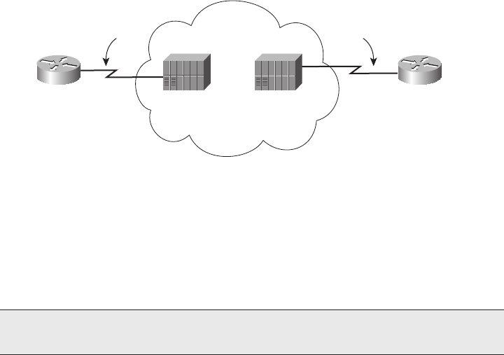
88 Chapter 4: Fundamentals of WANs
Figure 4-8 Frame Relay Components
The difference between Frame Relay and point-to-point links is that the equipment in the
telco actually examines the data frames sent by the router. Frame Relay defines its own
data-link header and trailer. Each Frame Relay header holds an address field called a data-
link connection identifier (DLCI). The WAN switch forwards the frame based on the DLCI,
sending the frame through the provider’s network until it gets to the remote-site router on
the other side of the Frame Relay cloud.
Because the equipment in the telco can forward one frame to one remote site and another
frame to another remote site, Frame Relay is considered to be a form of packet switching.
This term means that the service provider actually chooses where to send each data packet
sent into the provider’s network, switching one packet to one device, and the next packet to
another. However, Frame Relay protocols most closely resemble OSI Layer 2 protocols; the
term usually used for the bits sent by a Layer 2 device is frame. So, Frame Relay is also
called a frame-switching service, while the term packet switching is a more general term.
The terms DCE and DTE actually have a second set of meanings in the context of any
packet-switching or frame-switching service. With Frame Relay, the Frame Relay switches
are called DCE, and the customer equipment—routers, in this case—are called DTE. In this
case, DCE refers to the device providing the service, and the term DTE refers to the device
needing the frame-switching service. At the same time, the CSU/DSU provides clocking to
the router, so from a Layer 1 perspective, the CSU/DSU is still the DCE and the router is
still the DTE. It is just two different uses of the same terms.
Figure 4-8 depicted the physical and logical connectivity at each connection to the Frame
Relay network. In contrast, Figure 4-9 shows the end-to-end connectivity associated with a
virtual circuit (VC).
NOTE The Frame Relay header and trailer are defined by a protocol called Link Access
Procedure – Frame (LAPF).
DCE
Frame
Relay
Access
Link
Access
Link
DCE
Frame
Relay
Switch
DTE
Frame
Relay
Switch
R1
DTE
R2
1828xbook.fm Page 88 Thursday, July 26, 2007 3:10 PM
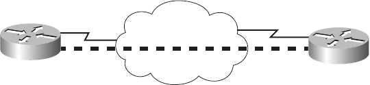
Frame Relay and Packet-Switching Services 89
Figure 4-9 Frame Relay VC Concepts
The logical path that a frame travels between each pair of routers is called a Frame Relay
VC. In Figure 4-9, a single VC is represented by the dashed line between the routers.
Typically, the service provider preconfigures all the required details of a VC; these VCs
are called permanent virtual circuits (PVC). When R1 needs to forward a packet to R2,
it encapsulates the Layer 3 packet into a Frame Relay header and trailer and then sends
the frame. R1 uses a Frame Relay address called a DLCI in the Frame Relay header,
with the DLCI identifying the correct VC to the provider. This allows the switches to
deliver the frame to R2, ignoring the details of the Layer 3 packet and looking at only
the Frame Relay header and trailer. Recall that on a point-to-point serial link, the service
provider forwards the frame over a physical circuit between R1 and R2. This transaction
is similar in Frame Relay, where the provider forwards the frame over a logical VC from
R1 to R2.
Frame Relay provides significant advantages over simply using point-to-point leased lines.
The primary advantage has to do with VCs. Consider Figure 4-10 with Frame Relay instead
of three point-to-point leased lines. Frame Relay creates a logical path (a VC) between
two Frame Relay DTE devices. A VC acts like a point-to-point circuit, but physically it is
not—it is virtual. For example, R1 terminates two VCs—one whose other endpoint is R2
and one whose other endpoint is R3. R1 can send traffic directly to either of the other two
routers by sending it over the appropriate VC, although R1 has only one physical access
link to the Frame Relay network.
VCs share the access link and the Frame Relay network. For example, both VCs
terminating at R1 use the same access link. So, with large networks with many WAN sites
that need to connect to a central location, only one physical access link is required from the
main site router to the Frame Relay network. By contrast, using point-to-point links would
require a physical circuit, a separate CSU/DSU, and a separate physical interface on the
router for each point-to-point link. So, Frame Relay enables you to expand the WAN but
add less hardware to do so.
Virtual
Circuit
DLCI X DLCI Y
R1 R2
1828xbook.fm Page 89 Thursday, July 26, 2007 3:10 PM
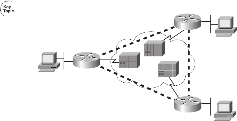
90 Chapter 4: Fundamentals of WANs
Figure 4-10 Typical Frame Relay Network with Three Sites
Many customers of a single Frame Relay service provider share that provider’s Frame
Relay network. Originally, people with leased-line networks were reluctant to migrate to
Frame Relay because they would be competing with other customers for the provider’s
capacity inside the service provider’s network. To address these fears, Frame Relay is
designed with the concept of a committed information rate (CIR). Each VC has a CIR,
which is a guarantee by the provider that a particular VC gets at least that much bandwidth.
You can think of the CIR of a VC like the bandwidth or clock rate of a point-to-point circuit,
except that it is the minimum value—you can actually send more, in most cases.
Even in this three-site network, it is probably less expensive to use Frame Relay than to use
point-to-point links. Now imagine a much larger network, with a 100 sites, that needs any-to-
any connectivity. A point-to-point link design would require 4950 leased lines! In addition, you
would need 99 serial interfaces per router. By contrast, with a Frame Relay design, you could
have 100 access links to local Frame Relay switches (1 per router) with 4950 VCs running over
the access links. Also, you would need only one serial interface on each router. As a result, the
Frame Relay topology is easier for the service provider to implement, costs the provider less,
and makes better use of the core of the provider’s network. As you would expect, that makes it
less expensive to the Frame Relay customer as well. For connecting many WAN sites, Frame
Relay is simply more cost-effective than leased lines.
Junior
Bob
Larry
R1
R2
R3
1828xbook.fm Page 90 Thursday, July 26, 2007 3:10 PM
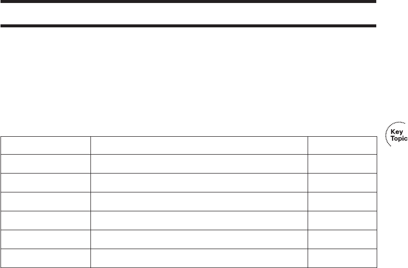
Definitions of Key Terms 91
Exam Preparation Tasks
Review All the Key Topics
Review the most important topics from inside the chapter, noted with the key topics icon in
the outer margin of the page. Table 4-4 lists a reference of these key topics and the page
numbers on which each is found.
Complete the Tables and Lists from Memory
Print a copy of Appendix H, “Memory Tables” (found on the CD-ROM), or at least the
section for this chapter, and complete the tables and lists from memory. Appendix I,
“Memory Tables Answer Key,” also on the CD-ROM, includes completed tables and lists
to check your work.
Definitions of Key Terms
Define the following key terms from this chapter, and check your answers in the glossary.
access link, back-to-back link, clocking, DTE (Layer 1), CSU/DSU, DCE (Layer 1),
DS0, DS1, Frame Relay, HDLC, leased line, packet switching, PPP, serial cable,
synchronous, T1, virtual circuit
Table 4-4 Key Topics for Chapter 4
Key Topic Element Description Page Number
Figure 4-3 Shows typical cabling diagram of CPE for a leased line 77
Table 4-2 Typical speeds for WAN leased lines 83
Figure 4-6 HDLC framing 84
Table 4-3 List of key WAN terminology 85-86
Paragraph List of synonyms for “point-to-point leased line” 86
Figure 4-10 Diagram of Frame Relay virtual circuits 90
1828xbook.fm Page 91 Thursday, July 26, 2007 3:10 PM

This chapter covers the following subjects:
Overview of Network Layer Functions: The
first section introduces the concepts of routing,
logical addressing, and routing protocols.
IP Addressing: Next, the basics of 32-bit IP
addresses are explained, with emphasis on how
the organization aids the routing process.
IP Routing: This section explains how hosts and
routers decide how to forward a packet.
IP Routing Protocols: This brief section
explains the basics of how routing protocols
populate each router’s routing tables.
Network Layer Utilities: This section
introduces several other functions useful to the
overall process of packet delivery.
1828xbook.fm Page 92 Thursday, July 26, 2007 3:10 PM

C H A P T E R5
Fundamentals of IP Addressing
and Routing
The OSI physical layer (Layer 1) defines how to transmit bits over a particular type of
physical network. The OSI data link layer (Layer 2) defines the framing, addressing,
error detection, and rules for when to use the physical medium. Although they are
important, these two layers do not define how to deliver data between devices that exist
far from each other, with many different physical networks sitting between the two
computers.
This chapter explains the function and purpose of the OSI network layer (Layer 3): the
end-to-end delivery of data between two computers. Regardless of the type of physical
network to which each endpoint computer is attached, and regardless of the types of
physical networks used between the two computers, the network layer defines how to
forward, or route, data between the two computers.
This chapter covers the basics of how the network layer routes data packets from one
computer to another. After reviewing the full story at a basic level, this chapter examines
in more detail the network layer of TCP/IP, including IP addressing (which enables efficient
routing), IP routing (the forwarding process itself), IP routing protocols (the process by
which routers learn routes), and several other small but important features of the network
layer.
“Do I Know This Already?” Quiz
The “Do I Know This Already?” quiz allows you to assess whether you should read the
entire chapter. If you miss no more than one of these 13 self-assessment questions, you
might want to move ahead to the “Exam Preparation Tasks” section. Table 5-1 lists the
major headings in this chapter and the “Do I Know This Already?” quiz questions covering
the material in those sections. This helps you assess your knowledge of these specific areas.
The answers to the “Do I Know This Already?” quiz appear in Appendix A.
1828xbook.fm Page 93 Thursday, July 26, 2007 3:10 PM

94 Chapter 5: Fundamentals of IP Addressing and Routing
1. Which of the following are functions of OSI Layer 3 protocols?
a. Logical addressing
b. Physical addressing
c. Path selection
d. Arbitration
e. Error recovery
2. Imagine that PC1 needs to send some data to PC2, and PC1 and PC2 are separated by
several routers. What are the largest entities that make it from PC1 to PC2?
a. Frame
b. Segment
c. Packet
d. L5 PDU
e. L3 PDU
f. L1 PDU
3. Imagine a network with two routers that are connected with a point-to-point HDLC
serial link. Each router has an Ethernet, with PC1 sharing the Ethernet with Router1,
and PC2 sharing the Ethernet with Router2. When PC1 sends data to PC2, which of the
following is true?
a. Router1 strips the Ethernet header and trailer off the frame received from PC1,
never to be used again.
b. Router1 encapsulates the Ethernet frame inside an HDLC header and sends the
frame to Router2, which extracts the Ethernet frame for forwarding to PC2.
Table 5-1 “Do I Know This Already?” Foundation Topics Section-to-Question Mapping
Foundation Topics Section Questions
Overview of Network Layer Functions 1 – 3
IP Addressing 4 – 8
IP Routing 9, 10
IP Routing Protocols 11
Network Layer Utilities 12, 13
1828xbook.fm Page 94 Thursday, July 26, 2007 3:10 PM
“Do I Know This Already?” Quiz 95
c. Router1 strips the Ethernet header and trailer off the frame received from PC1,
which is exactly re-created by R2 before forwarding data to PC2.
d. Router1 removes the Ethernet, IP, and TCP headers and rebuilds the appropriate
headers before forwarding the packet to Router2.
4. Which of the following are valid Class C IP addresses that can be assigned to hosts?
a. 1.1.1.1
b. 200.1.1.1
c. 128.128.128.128
d. 224.1.1.1
e. 223.223.223.255
5. What is the range of values for the first octet for Class A IP networks?
a. 0 to 127
b. 0 to 126
c. 1 to 127
d. 1 to 126
e. 128 to 191
f. 128 to 192
6. PC1 and PC2 are on two different Ethernets that are separated by an IP router. PC1’s
IP address is 10.1.1.1, and no subnetting is used. Which of the following addresses
could be used for PC2?
a. 10.1.1.2
b. 10.2.2.2
c. 10.200.200.1
d. 9.1.1.1
e. 225.1.1.1
f. 1.1.1.1
1828xbook.fm Page 95 Thursday, July 26, 2007 3:10 PM
96 Chapter 5: Fundamentals of IP Addressing and Routing
7. Each Class B network contains how many IP addresses that can be assigned to hosts?
a. 16,777,214
b. 16,777,216
c. 65,536
d. 65,534
e. 65,532
f. 32,768
g. 32,766
8. Each Class C network contains how many IP addresses that can be assigned to hosts?
a. 65,534
b. 65,532
c. 32,768
d. 32,766
e. 256
f. 254
9. Which of the following does a router normally use when making a decision about
routing TCP/IP packets?
a. Destination MAC address
b. Source MAC address
c. Destination IP address
d. Source IP address
e. Destination MAC and IP address
10. Which of the following are true about a LAN-connected TCP/IP host and its IP routing
(forwarding) choices?
a. The host always sends packets to its default gateway.
b. The host sends packets to its default gateway if the destination IP address is in a
different class of IP network than the host.
c. The host sends packets to its default gateway if the destination IP address is in a
different subnet than the host.
d. The host sends packets to its default gateway if the destination IP address is in the
same subnet as the host.
1828xbook.fm Page 96 Thursday, July 26, 2007 3:10 PM
“Do I Know This Already?” Quiz 97
11. Which of the following are functions of a routing protocol?
a. Advertising known routes to neighboring routers.
b. Learning routes for subnets directly connected to the router.
c. Learning routes, and putting those routes into the routing table, for routes adver-
tised to the router by its neighboring routers.
d. To forward IP packets based on a packet’s destination IP address.
12. Which of the following protocols allows a client PC to discover the IP address of
another computer based on that other computer’s name?
a. ARP
b. RARP
c. DNS
d. DHCP
13. Which of the following protocols allows a client PC to request assignment of an IP
address as well as learn its default gateway?
a. ARP
b. RARP
c. DNS
d. DHCP
1828xbook.fm Page 97 Thursday, July 26, 2007 3:10 PM
98 Chapter 5: Fundamentals of IP Addressing and Routing
Foundation Topics
OSI Layer 3-equivalent protocols define how packets can be delivered from the computer
that creates the packet all the way to the computer that needs to receive the packet. To reach
that goal, an OSI network layer protocol defines the following features:
Routing: The process of forwarding packets (Layer 3 PDUs).
Logical addressing: Addresses that can be used regardless of the type of physical
networks used, providing each device (at least) one address. Logical addressing
enables the routing process to identify a packet’s source and destination.
Routing protocol: A protocol that aids routers by dynamically learning about the
groups of addresses in the network, which in turn allows the routing (forwarding)
process to work well.
Other utilities: The network layer also relies on other utilities. For TCP/IP, these
utilities include Domain Name System (DNS), Dynamic Host Configuration Protocol
(DHCP), Address Resolution Protocol (ARP), and ping.
This chapter begins with an overview of routing, logical addressing, and routing protocols.
Following that, the text moves on to more details about the specifics of the TCP/IP network
layer (called the internetwork layer in the TCP/IP model). In particular, the topics of IP
addressing, routing, routing protocols, and network layer utilities are covered.
Overview of Network Layer Functions
A protocol that defines routing and logical addressing is considered to be a network layer,
or Layer 3, protocol. OSI does define a unique Layer 3 protocol called Connectionless Network
Services (CLNS), but, as usual with OSI protocols, you rarely see it in networks today. In
the recent past, you might have seen many other network layer protocols, such as Internet
Protocol (IP), Novell Internetwork Packet Exchange (IPX), or AppleTalk Datagram
Delivery Protocol (DDP). Today, the only Layer 3 protocol that is used widely is the TCP/
IP network layer protocol—specifically, IP.
The main job of IP is to route data (packets) from the source host to the destination host.
Because a network might need to forward large numbers of packets, the IP routing process
is very simple. IP does not require any overhead agreements or messages before sending a
packet, making IP a connectionless protocol. IP tries to deliver each packet, but if a router
or host’s IP process cannot deliver the packet, it is discarded—with no error recovery. The
NOTE The term path selection sometimes is used to mean the same thing as routing
protocol, sometimes is used to refer to the routing (forwarding) of packets, and
sometimes is used for both functions.
1828xbook.fm Page 98 Thursday, July 26, 2007 3:10 PM
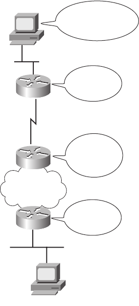
Overview of Network Layer Functions 99
goal with IP is to deliver packets with as little per-packet work as possible, which allows
for large packet volumes. Other protocols perform some of the other useful networking
functions. For example, Transmission Control Protocol (TCP), which is described in detail
in Chapter 6, “Fundamentals of TCP/IP Transport, Applications, and Security,” provides
error recovery, resending lost data, but IP does not.
IP routing relies on the structure and meaning of IP addresses, and IP addressing was
designed with IP routing in mind. This first major section of this chapter begins by
introducing IP routing, with some IP addressing concepts introduced along the way. Then,
the text examines IP addressing fundamentals.
Routing (Forwarding)
Routing focuses on the end-to-end logic of forwarding data. Figure 5-1 shows a simple
example of how routing works. The logic illustrated by the figure is relatively simple. For
PC1 to send data to PC2, it must send something to router R1, which sends it to router R2,
and then to router R3, and finally to PC2. However, the logic used by each device along the
path varies slightly.
Figure 5-1 Routing Logic: PC1 Sending to PC2
10.1.1.1
10.0.0.0
168.0.0.0
168.11.0.0
168.1.0.0
168.1.1.1
Destination Is in
Another Group; Send
to Nearby Router.
My Route
to that Group Is
Out Serial Link.
My Route
to that Group Is
Out Frame
Relay.
Send Directly
to PC2
R1
R2
R3
PC1
PC2
1828xbook.fm Page 99 Thursday, July 26, 2007 3:10 PM
100 Chapter 5: Fundamentals of IP Addressing and Routing
PC1’s Logic: Sending Data to a Nearby Router
In this example, illustrated in Figure 5-1, PC1 has some data to send to PC2. Because PC2
is not on the same Ethernet as PC1, PC1 needs to send the packet to a router that is attached
to the same Ethernet as PC1. The sender sends a data-link frame across the medium to the
nearby router; this frame includes the packet in the data portion of the frame. That frame
uses data link layer (Layer 2) addressing in the data-link header to ensure that the nearby
router receives the frame.
The main point here is that the computer that created the data does not know much about
the network—just how to get the data to some nearby router. Using a post office analogy,
it’s like knowing how to get to the local post office, but nothing more. Likewise, PC1 needs
to know only how to get the packet to R1, not the rest of the path used to send the packet
to PC2.
R1 and R2’s Logic: Routing Data Across the Network
R1 and R2 both use the same general process to route the packet. The routing table for any
particular network layer protocol contains a list of network layer address groupings. Instead
of a single entry in the routing table per individual destination network layer address, there
is one routing table entry per group. The router compares the destination network layer
address in the packet to the entries in the routing table and makes a match. This matching
entry in the routing table tells this router where to forward the packet next. The words in
the bubbles in Figure 5-1 point out this basic logic.
The concept of network layer address grouping is similar to the U.S. zip code system.
Everyone living in the same vicinity is in the same zip code, and the postal sorters just look
for the zip codes, ignoring the rest of the address. Likewise, in Figure 5-1, everyone in this
network whose IP address starts with 168.1 is on the Ethernet on which PC2 resides, so the
routers can have just one routing table entry that means “all addresses that start with 168.1.”
Any intervening routers repeat the same process: the router compares the packet’s
destination network layer (Layer 3) address to the groups listed in its routing table, and the
matched routing table entry tells this router where to forward the packet next. Eventually,
the packet is delivered to the router connected to the network or subnet of the destination
host (R3), as shown in Figure 5-1.
R3’s Logic: Delivering Data to the End Destination
The final router in the path, R3, uses almost the exact same logic as R1 and R2, but with
one minor difference. R3 needs to forward the packet directly to PC2, not to some other
router. On the surface, that difference seems insignificant. In the next section, when you
read about how the network layer uses the data link layer, the significance of the difference
will become obvious.
1828xbook.fm Page 100 Thursday, July 26, 2007 3:10 PM
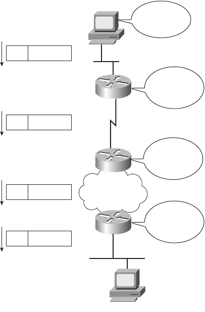
Overview of Network Layer Functions 101
Network Layer Interaction with the Data Link Layer
When the network layer protocol is processing the packet, it decides to send the packet out
the appropriate network interface. Before the actual bits can be placed onto that physical
interface, the network layer must hand off the packet to the data link layer protocols, which,
in turn, ask the physical layer to actually send the data. And as was described in Chapter 3,
“Fundamentals of LANs,” the data link layer adds the appropriate header and trailer to the
packet, creating a frame, before sending the frames over each physical network. The routing
process forwards the packet, and only the packet, end-to-end through the network,
discarding data-link headers and trailers along the way. The network layer processes
deliver the packet end-to-end, using successive data-link headers and trailers just to get the
packet to the next router or host in the path. Each successive data link layer just gets the
packet from one device to the next. Figure 5-2 points out the key encapsulation logic on
each device, using the same examples as in Figure 5-1.
Figure 5-2 Network Layer and Data Link Layer Encapsulation
10.1.1.1
10.0.0.0
168.10.0.0
168.11.0.0
168.1.0.0
Encapsulate
IP Packet in
Ethernet
Extract IP
Packet and
Encapsulate in
HDLC
Extract IP
Packet, and
Encapsulate in
Frame Relay
Extract IP
Packet, and
Encapsulate in
Ethernet
Eth. IP Packet
HDLC IP Packet
FR IP Packet
Eth IP Packet
PC1
R1
R2
R3
168.1.1.1
PC2
1828xbook.fm Page 101 Thursday, July 26, 2007 3:10 PM

102 Chapter 5: Fundamentals of IP Addressing and Routing
Because the routers build new data-link headers and trailers (trailers not shown in the
figure), and because the new headers contain data-link addresses, the PCs and routers must
have some way to decide what data-link addresses to use. An example of how the router
determines which data-link address to use is the IP Address Resolution Protocol (ARP).
ARP is used to dynamically learn the data-link address of an IP host connected to a LAN.
You will read more about ARP later in this chapter.
Routing as covered so far has two main concepts:
■The process of routing forwards Layer 3 packets, also called Layer 3 protocol data
units (L3 PDU), based on the destination Layer 3 address in the packet.
■The routing process uses the data link layer to encapsulate the Layer 3 packets into
Layer 2 frames for transmission across each successive data link.
IP Packets and the IP Header
The IP packets encapsulated in the data-link frames shown in Figure 5-2 have an IP header,
followed by additional headers and data. For reference, Figure 5-3 shows the fields inside
the standard 20-byte IPv4 header, with no optional IP header fields, as is typically seen in
most networks today.
Figure 5-3 IPv4 Header
Of the different fields inside the IPv4 header, this book, and the companion ICND2 Official
Exam Certification Guide, ignore all the fields except the Time-To-Live (TTL) (covered in
Chapter 15 in this book), protocol (Chapter 6 of the ICND2 book), and the source and
destination IP address fields (scattered throughout most chapters). However, for reference,
Table 5-2 briefly describes each field.
Version Header
Length
DS Field Packet Length
Identification Fragment Offset (13)Flags (3)
Time to Live Protocol Header Checksum
Source IP Address
Destination IP Address
0 8 16 24 31
1828xbook.fm Page 102 Thursday, July 26, 2007 3:10 PM

Overview of Network Layer Functions 103
This section next examines the concept of network layer addressing and how it aids the
routing process.
Network Layer (Layer 3) Addressing
Network layer protocols define the format and meaning of logical addresses. (The term
logical address does not really refer to whether the addresses make sense, but rather to
contrast these addresses with physical addresses.) Each computer that needs to
communicate will have (at least) one network layer address so that other computers can
send data packets to that address, expecting the network to deliver the data packet to the
correct computer.
One key feature of network layer addresses is that they were designed to allow logical
grouping of addresses. In other words, something about the numeric value of an address
implies a group or set of addresses, all of which are considered to be in the same grouping.
With IP addresses, this group is called a network or a subnet. These groupings work just
like USPS zip (postal) codes, allowing the routers (mail sorters) to speedily route (sort) lots
of packets (letters).
Table 5-2 IPv4 Header Fields
Field Meaning
Version Version of the IP protocol. Most networks use version 4 today.
IHL IP Header Length. Defines the length of the IP header, including optional fields.
DS Field Differentiated Services Field. It is used for marking packets for the purpose of
applying different quality-of-service (QoS) levels to different packets.
Packet length Identifies the entire length of the IP packet, including the data.
Identification Used by the IP packet fragmentation process; all fragments of the original
packet contain the same identifier.
Flags 3 bits used by the IP packet fragmentation process.
Fragment offset A number used to help hosts reassemble fragmented packets into the original
larger packet.
TTL Time to live. A value used to prevent routing loops.
Protocol A field that identifies the contents of the data portion of the IP packet. For example,
protocol 6 implies that a TCP header is the first thing in the IP packet data field.
Header Checksum A value used to store an FCS value, whose purpose is to determine if any bit
errors occurred in the IP header.
Source IP address The 32-bit IP address of the sender of the packet.
Destination IP
address
The 32-bit IP address of the intended recipient of the packet.
1828xbook.fm Page 103 Thursday, July 26, 2007 3:10 PM

104 Chapter 5: Fundamentals of IP Addressing and Routing
Just like postal street addresses, network layer addresses are grouped based on physical
location in a network. The rules differ for some network layer protocols, but with IP
addressing, the first part of the IP address is the same for all the addresses in one grouping.
For example, in Figures 5-1 and 5-2, the following IP addressing conventions define the
groups of IP addresses (IP networks) for all hosts on that internetwork:
■Hosts on the top Ethernet: Addresses start with 10
■Hosts on the R1-R2 serial link: Addresses start with 168.10
■Hosts on the R2-R3 Frame Relay network: Addresses start with 168.11
■Hosts on the bottom Ethernet: Addresses start with 168.1
Routing relies on the fact that Layer 3 addresses are grouped. The routing tables for each
network layer protocol can have one entry for the group, not one entry for each individual
address. Imagine an Ethernet with 100 TCP/IP hosts. A router that needs to forward packets
to any of those hosts needs only one entry in its IP routing table, with that one routing table
entry representing the entire group of hosts on the Ethernet. This basic fact is one of the key
reasons that routers can scale to allow hundreds of thousands of devices. It’s very similar
to the USPS zip code system. It would be ridiculous to have people in the same zip code
live far from each other, or to have next-door neighbors be in different zip codes. The poor
postman would spend all his time driving and flying around the country! Similarly, to make
routing more efficient, network layer protocols group addresses.
Routing Protocols
Conveniently, the routers in Figures 5-1 and 5-2 somehow know the correct steps to take to
forward the packet from PC1 to PC2. To make the correct choices, each router needs a
routing table, with a route that matches the packet sent to PC2. The routes tell the router
where to send the packet next.
In most cases, routers build their routing table entries dynamically using a routing protocol.
Routing protocols learn about all the locations of the network layer “groups” in a network
and advertise the groups’ locations. As a result, each router can build a good routing table
dynamically. Routing protocols define message formats and procedures, just like any other
protocol. The end goal of each routing protocol is to fill the routing table with all known
destination groups and with the best route to reach each group.
NOTE To avoid confusion when writing about IP networks, many resources (including
this one) use the term internetwork to refer more generally to a network made up of
routers, switches, cables, and other equipment, and the word network to refer to the more
specific concept of an IP network.
1828xbook.fm Page 104 Thursday, July 26, 2007 3:10 PM

IP Addressing 105
The terminology relating to routing protocols sometimes can get in the way. A routing
protocol learns routes and puts those routes in a routing table. A routed protocol defines the
type of packet forwarded, or routed, through a network. In Figures 5-1 and 5-2, the figures
represent how IP packets are routed, so IP would be the routed protocol. If the routers used
Routing Information Protocol (RIP) to learn the routes, RIP would be the routing protocol.
Later in this chapter, the section “IP Routing Protocols” shows a detailed example of how
routing protocols learn routes.
Now that you have seen the basic function of the OSI network layer at work, the rest of this
chapter examines the key components of the end-to-end routing process for TCP/IP.
IP Addressing
IP addressing is absolutely the most important topic for the CCNA exams. By the time
you have completed your study, you should be comfortable and confident in your
understanding of IP addresses, their formats, the grouping concepts, how to subdivide
groups into subnets, how to interpret the documentation for existing networks’ IP
addressing, and so on. Simply put, you had better know addressing and subnetting!
This section introduces IP addressing and subnetting and also covers the concepts behind
the structure of an IP address, including how it relates to IP routing. In Chapter 12,
“IP Addressing and Subnetting,” you will read about the math behind IP addressing
and subnetting.
IP Addressing Definitions
If a device wants to communicate using TCP/IP, it needs an IP address. When the device
has an IP address and the appropriate software and hardware, it can send and receive
IP packets. Any device that can send and receive IP packets is called an IP host.
IP addresses consist of a 32-bit number, usually written in dotted-decimal notation. The
“decimal” part of the term comes from the fact that each byte (8 bits) of the 32-bit IP address
is shown as its decimal equivalent. The four resulting decimal numbers are written in sequence,
with “dots,” or decimal points, separating the numbers—hence the name dotted decimal. For
instance, 168.1.1.1 is an IP address written in dotted-decimal form; the actual binary version is
10101000 00000001 00000001 00000001. (You almost never need to write down the binary
version, but you will see how to convert between the two formats in Chapter 12.)
NOTE IP Version 4 (IPv4) is the most widely used version of IP. The ICND2 Official
Exam Certification Guide covers the newer version of IP, IPv6. This book only briefly
mentions IPv6 in Chapter 12 and otherwise ignores it. So, all references to IP addresses
in this book should be taken to mean “IP version 4” addresses.
1828xbook.fm Page 105 Thursday, July 26, 2007 3:10 PM
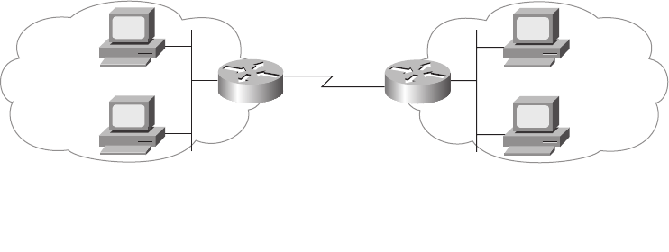
106 Chapter 5: Fundamentals of IP Addressing and Routing
Each decimal number in an IP address is called an octet. The term octet is just a vendor-
neutral term for byte. So, for an IP address of 168.1.1.1, the first octet is 168, the second
octet is 1, and so on. The range of decimal numbers in each octet is between 0 and 255,
inclusive.
Finally, note that each network interface uses a unique IP address. Most people tend to think
that their computer has an IP address, but actually their computer’s network card has an
IP address. If you put two Ethernet cards in a PC to forward IP packets through both cards,
they both would need unique IP addresses. Also, if your laptop has both an Ethernet
NIC and a wireless NIC working at the same time, your laptop will have an IP address for
each NIC. Similarly, routers, which typically have many network interfaces that forward
IP packets, have an IP address for each interface.
Now that you have some idea of the basic terminology, the next section relates IP
addressing to the routing concepts of OSI Layer 3.
How IP Addresses Are Grouped
The original specifications for TCP/IP grouped IP addresses into sets of consecutive
addresses called IP networks. The addresses in a single network have the same numeric
value in the first part of all addresses in the network. Figure 5-4 shows a simple
internetwork that has three separate IP networks.
Figure 5-4 Sample Network Using Class A, B, and C Network Numbers
The conventions of IP addressing and IP address grouping make routing easy. For
example, all IP addresses that begin with 8 are in the IP network that contains all the
hosts on the Ethernet on the left. Likewise, all IP addresses that begin with 130.4 are in
another IP network that consists of all the hosts on the Ethernet on the right. Along the
same lines, 199.1.1 is the prefix for all IP addresses on the network that includes the
Network
8.0.0.0
All IP addresses
that begin with 8
All IP addresses that
begin with 199.1.1
All IP addresses that
begin with 130.4
Network
130.4.0.0
Network
199.1.1.0
1828xbook.fm Page 106 Thursday, July 26, 2007 3:10 PM

IP Addressing 107
addresses on the serial link. (The only two IP addresses in this last grouping will be the
IP addresses on each of the two routers.) By following this convention, the routers build
a routing table with three entries—one for each prefix, or network number. For example,
the router on the left can have one route that refers to all addresses that begin with 130.4,
with that route directing the router to forward packets to the router on the right.
The example indirectly points out a couple of key points about how IP addresses are
organized. To be a little more explicit, the following two rules summarize the facts about
which IP addresses need to be in the same grouping:
■All IP addresses in the same group must not be separated by a router.
■IP addresses separated by a router must be in different groups.
As mentioned earlier in this chapter, IP addressing behaves similarly to zip codes. Everyone
in my zip code lives in a little town in Ohio. If some members of my zip code were in
California, some of my mail might be sent to California by mistake. Likewise, IP routing
relies on the fact that all IP addresses in the same group (called either a network or a subnet)
are in the same general location. If some of the IP addresses in my network or subnet were
allowed to be on the other side of the internetwork compared to my computer, the routers
in the network might incorrectly send some of the packets sent to my computer to the other
side of the network.
Classes of Networks
Figure 5-4 and the surrounding text claim that the IP addresses of devices attached to the
Ethernet on the left all start with 8 and that the IP addresses of devices attached to the
Ethernet on the right all start with 130.4. Why only one number (8) for the “prefix” on the
Ethernet on the left and two numbers (130 and 4) on the Ethernet on the right? Well, it all
has to do with IP address classes.
RFC 791 defines the IP protocol, including several different classes of networks. IP defines
three different network classes for addresses used by individual hosts—addresses called
unicast IP addresses. These three network classes are called A, B, and C. TCP/IP defines
Class D (multicast) addresses and Class E (experimental) addresses as well.
By definition, all addresses in the same Class A, B, or C network have the same numeric
value network portion of the addresses. The rest of the address is called the host portion of
the address.
Using the post office example, the network part of an IP address acts like the zip (postal)
code, and the host part acts like the street address. Just as a letter-sorting machine
three states away from you cares only about the zip code on a letter addressed to you,
1828xbook.fm Page 107 Thursday, July 26, 2007 3:10 PM

108 Chapter 5: Fundamentals of IP Addressing and Routing
a router three hops away from you cares only about the network number that your address
resides in.
Class A, B, and C networks each have a different length for the part that identifies the network:
■Class A networks have a 1-byte-long network part. That leaves 3 bytes for the rest of
the address, called the host part.
■Class B networks have a 2-byte-long network part, leaving 2 bytes for the host portion
of the address.
■Class C networks have a 3-byte-long network part, leaving only 1 byte for the host part.
For example, Figure 5-4 lists network 8.0.0.0 next to the Ethernet on the left. Network
8.0.0.0 is a Class A network, which means that only 1 octet (byte) is used for the network
part of the address. So, all hosts in network 8.0.0.0 begin with 8. Similarly, Class B network
130.4.0.0 is listed next to the Ethernet on the right. Because it is a Class B network, 2 octets
define the network part, and all addresses begin with 130.4 as the first 2 octets.
When listing network numbers, the convention is to write down the network part of the number,
with all decimal 0s in the host part of the number. So, Class A network “8,” which consists of
all IP addresses that begin with 8, is written as 8.0.0.0. Similarly, Class B network “130.4,”
which consists of all IP addresses that begin with 130.4, is written as 130.4.0.0, and so on.
Now consider the size of each class of network. Class A networks need 1 byte for the network
part, leaving 3 bytes, or 24 bits, for the host part. There are 224 different possible values in the
host part of a Class A IP address. So, each Class A network can have 224 IP addresses—except
for two reserved host addresses in each network, as shown in the last column of Table 5-3.
The table summarizes the characteristics of Class A, B, and C networks.
*There are two reserved host addresses per network.
Based on the three examples from Figure 5-4, Table 5-4 provides a closer look at the
numeric version of the three network numbers: 8.0.0.0, 130.4.0.0, and 199.1.1.0.
Table 5-3 Sizes of Network and Host Parts of IP Addresses with No Subnetting
Any Network of This
Class
Number of Network
Bytes (Bits)
Number of Host
Bytes (Bits)
Number of Addresses
Per Network*
A1 (8) 3 (24) 224 – 2
B2 (16) 2 (16) 216 – 2
C3 (24) 1 (8) 28 – 2
1828xbook.fm Page 108 Thursday, July 26, 2007 3:10 PM
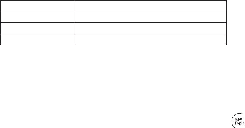
IP Addressing 109
Even though the network numbers look like addresses because of their dotted-decimal
format, network numbers cannot be assigned to an interface to be used as an IP address.
Conceptually, network numbers represent the group of all IP addresses in the network,
much like a zip code represents the group of all addresses in a community. It would be
confusing to have a single number represent a whole group of addresses and then also use
that same number as an IP address for a single device. So, the network numbers themselves
are reserved and cannot be used as an IP address for a device.
Besides the network number, a second dotted-decimal value in each network is reserved.
Note that the first reserved value, the network number, has all binary 0s in the host part of
the number (see Table 5-4). The other reserved value is the one with all binary 1s in the host
part of the number. This number is called the network broadcast or directed broadcast
address. This reserved number cannot be assigned to a host for use as an IP address. However,
packets sent to a network broadcast address are forwarded to all devices in the network.
Also, because the network number is the lowest numeric value inside that network and the
broadcast address is the highest numeric value, all the numbers between the network
number and the broadcast address are the valid, useful IP addresses that can be used to
address interfaces in the network.
The Actual Class A, B, and C Network Numbers
The Internet is a collection of almost every IP-based network and almost every TCP/IP host
computer in the world. The original design of the Internet required several cooperating
features that made it technically possible as well as administratively manageable:
■Each computer connected to the Internet needs a unique, nonduplicated IP address.
■Administratively, a central authority assigned Class A, B, or C networks to companies,
governments, school systems, and ISPs based on the size of their IP network (Class A
for large networks, Class B for medium networks, and Class C for small networks).
■The central authority assigned each network number to only one organization, helping
ensure unique address assignment worldwide.
■Each organization with an assigned Class A, B, or C network then assigned individual
IP addresses inside its own network.
Table 5-4 Sample Network Numbers, Decimal and Binary
Network Number Binary Representation, with the Host Part in Bold
8.0.0.0 00001000 00000000 00000000 00000000
130.4.0.0 10000010 00000100 00000000 00000000
199.1.1.0 11000111 00000001 00000001 00000000
1828xbook.fm Page 109 Thursday, July 26, 2007 3:10 PM

110 Chapter 5: Fundamentals of IP Addressing and Routing
By following these guidelines, as long as each organization assigns each IP address to only
one computer, every computer in the Internet has a globally unique IP address.
The organization in charge of universal IP address assignment is the Internet Corporation
for Assigned Network Numbers (ICANN, www.icann.org). (The Internet Assigned Numbers
Authority (IANA) formerly owned the IP address assignment process.) ICANN, in turn,
assigns regional authority to other cooperating organizations. For example, the American
Registry for Internet Numbers (ARIN, www.arin.org) owns the address assignment process
for North America.
Table 5-5 summarizes the possible network numbers that ICANN and other agencies could
have assigned over time. Note the total number for each network class and the number
of hosts in each Class A, B, and C network.
*The Valid Network Numbers column shows actual network numbers. Networks 0.0.0.0 (originally defined for use as
a broadcast address) and 127.0.0.0 (still available for use as the loopback address) are reserved.
Memorizing the contents of Table 5-5 should be one of the first things you do in preparation
for the CCNA exam(s). Engineers should be able to categorize a network as Class A, B,
or C with ease. Also, memorize the number of octets in the network part of Class A, B, and
C addresses, as shown in Table 5-4.
IP Subnetting
Subnetting is one of the most important topics on the ICND1, ICND2, and CCNA exams. You
need to know how it works and how to “do the math” to figure out issues when subnetting is
in use, both in real life and on the exam. Chapter 12 covers the details of subnetting concepts,
motivation, and math, but you should have a basic understanding of the concepts before
NOTE The details of address assignment have changed over time, but the general idea
described here is enough detail to help you understand the concept of different Class A,
B, and C networks.
Table 5-5 All Possible Valid Network Numbers*
Class
First Octet
Range
Valid Network
Numbers*
Total Number for This
Class of Network
Number of Hosts
Per Network
A1 to 126 1.0.0.0 to 126.0.0.0 27 – 2 (126) 224 – 2 (16,777,214)
B 128 to 191 128.0.0.0 to
191.255.0.0
214 (16,384) 216 – 2 (65,534)
C 192 to 223 192.0.0.0 to
223.255.255.0
221 (2,097,152) 28 – 2 (254)
1828xbook.fm Page 110 Thursday, July 26, 2007 3:10 PM
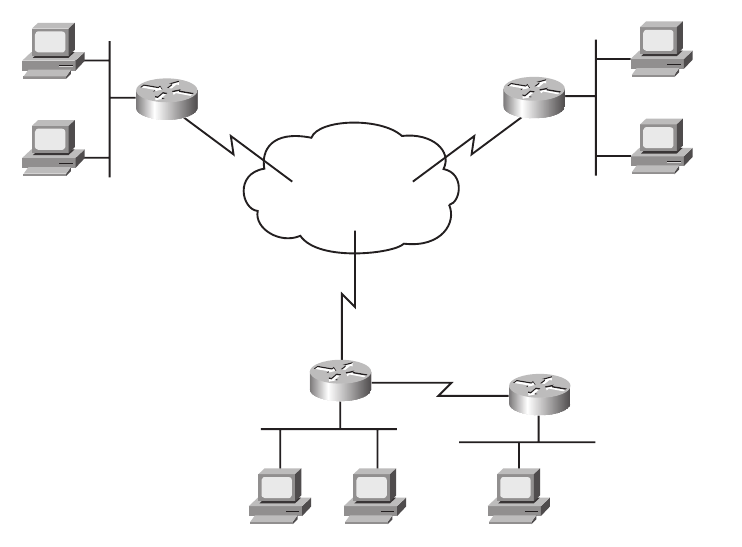
IP Addressing 111
covering the topics between here and Chapter 12. IP subnetting takes a single Class A, B, or
C network and subdivides it into a number of smaller groups of IP addresses. The Class A, B,
and C rules still exist, but now, a single Class A, B, or C network can be subdivided into many
smaller groups. Subnetting treats a subdivision of a single Class A, B, or C network as if it
were a network itself. In fact, the name “subnet” is just shorthand for “subdivided network.”
You can easily discern the concepts behind subnetting by comparing one network topology
that does not use subnetting with the same topology but with subnetting implemented.
Figure 5-5 shows such a network, without subnetting.
Figure 5-5 Backdrop for Discussing Numbers of Different Networks/Subnetworks
The design in Figure 5-5 requires six groups of IP addresses, each of which is a Class B
network in this example. The four LANs each use a single Class B network. In other
words, each of the LANs attached to routers A, B, C, and D is in a separate IP network.
Additionally, the two serial interfaces composing the point-to-point serial link between
routers C and D use one IP network because these two interfaces are not separated by a
router. Finally, the three router interfaces composing the Frame Relay network with routers
A, B, and C are not separated by an IP router and would use a sixth IP network.
Frame Relay
150.5.0.0
150.1.0.0
150.4.0.0
150.6.0.0
150.2.0.0
Ray
Kris Wendell
Fay
Hannah
Jessie
AB
CD
150.3.0.0
Vinnie
1828xbook.fm Page 111 Thursday, July 26, 2007 3:10 PM
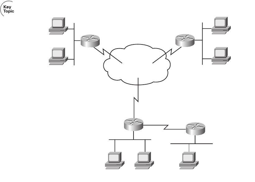
112 Chapter 5: Fundamentals of IP Addressing and Routing
Each Class B network has 216 – 2 host addresses—far more than you will ever need for each
LAN and WAN link. For example, the upper-left Ethernet should contain all addresses that
begin with 150.1. Therefore, addresses that begin with 150.1 cannot be assigned anywhere
else in the network, except on the upper-left Ethernet. So, if you ran out of IP addresses
somewhere else, you could not use the large number of unused addresses that begin with
150.1. As a result, the addressing design shown in Figure 5-5 wastes a lot of addresses.
In fact, this design would not be allowed if it were connected to the Internet. The ICANN
member organization would not assign six separate registered Class B network numbers.
In fact, you probably would not get even one Class B network, because most of the Class B
addresses are already assigned. You more likely would get a couple of Class C networks
with the expectation that you would use subnetting. Figure 5-6 illustrates a more realistic
example that uses basic subnetting.
Figure 5-6 Using Subnets
As in Figure 5-5, the design in Figure 5-6 requires six groups. Unlike Figure 5-5, this figure
uses six subnets, each of which is a subnet of a single Class B network. This design
subdivides the Class B network 150.150.0.0 into six subnets. To perform subnetting, the
third octet (in this example) is used to identify unique subnets of network 150.150.0.0.
Frame Relay
150.150.5.0
150.150.1.0
150.150.4.0
150.150.6.0
150.150.2.0
Ray
150.150.1.1
Kris
150.150.4.2
Wendell
150.150.4.1
Fay
150.150.1.2
Hannah
150.150.2.1
Jessie
150.150.2.2
AB
CD
150.150.3.0
Vinnie
150.150.3.1
1828xbook.fm Page 112 Thursday, July 26, 2007 3:10 PM

IP Addressing 113
Notice that each subnet number in the figure shows a different value in the third octet,
representing each different subnet number. In other words, this design numbers or identifies
each different subnet using the third octet.
When subnetting, a third part of an IP address appears between the network and host parts
of the address—namely, the subnet part of the address. This field is created by “stealing”
or “borrowing” bits from the host part of the address. The size of the network part of the
address never shrinks. In other words, Class A, B, and C rules still apply when defining the
size of the network part of an address. The host part of the address shrinks to make room
for the subnet part of the address. Figure 5-7 shows the format of addresses when
subnetting, representing the number of bits in each of the three parts of an IP address.
Figure 5-7 Address Formats When Subnetting Is Used (Classful)
Now, instead of routing based on the network part of an address, routers can route based
on the combined network and subnet parts. For example, when Kris (150.150.4.2) sends
a packet to Hannah (150.150.2.1), router C has an IP route that lists information that
means “all addresses that begin with 150.150.2.” That same route tells router C to forward the
packet to router B next. Note that the information in the routing table includes both the
network and subnet part of the address, because both parts together identify the group.
Note that the concepts shown in Figure 5-7, with three parts of an IP address (network,
subnet, and host), are called classful addressing. The term classful addressing refers to how
you can think about IP addresses—specifically, that they have three parts. In particular,
classful addressing means that you view the address as having a network part that is
determined based on the rules about Class A, B, and C addressing—hence the word
“classful” in the term.
Because the routing process considers the network and subnet parts of the address together,
you can take an alternative view of IP addresses called classless addressing. Instead of
three parts, each address has two parts:
■The part on which routing is based
■The host part
Network Host Class A
8x
Subnet
24 – x
Network Host Class B
16
Subnet
16 – x x
HostNetwork Class C
x
Subnet
8 – x24
1828xbook.fm Page 113 Thursday, July 26, 2007 3:10 PM
114 Chapter 5: Fundamentals of IP Addressing and Routing
This first part—the part on which routing is based—is the combination of the network and
subnet parts from the classful addressing view. This first part is often simply called the
subnet part, or sometimes the prefix. Figure 5-8 shows the concepts and terms behind
classless IP addressing.
Figure 5-8 Address Formats When Subnetting Is Used (Classless)
Finally, IP addressing with subnetting uses a concept called a subnet mask. A subnet mask
helps define the structure of an IP address, as shown in Figures 5-7 and 5-8. Chapter 12
explains the details of subnet masks.
IP Routing
In the first section of this chapter, you read about the basics of routing using a network with
three routers and two PCs. Armed with more knowledge of IP addressing, you now can
take a closer look at the process of routing IP. This section focuses on how the originating
host chooses where to send the packet, as well as how routers choose where to route or
forward packets to the final destination.
Host Routing
Hosts actually use some simple routing logic when choosing where to send a packet. This
two-step logic is as follows:
Step 1 If the destination IP address is in the same subnet as I am, send the packet directly
to that destination host.
Step 2 If the destination IP address is not in the same subnet as I am, send the
packet to my default gateway (a router’s Ethernet interface on the
subnet).
For example, consider Figure 5-9, and focus on the Ethernet LAN at the top of the figure.
The top Ethernet has two PCs, labeled PC1 and PC11, plus router R1. When PC1 sends
a packet to 150.150.1.11 (PC11’s IP address), PC1 sends the packet over the Ethernet to
PC11—there’s no need to bother the router.
Host
x
Subnet or Prefix
32 – x
1828xbook.fm Page 114 Thursday, July 26, 2007 3:10 PM
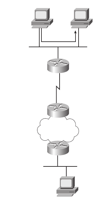
IP Routing 115
Figure 5-9 Host Routing Alternatives
Alternatively, when PC1 sends a packet to PC2 (150.150.4.10), PC1 forwards the packet to
its default gateway of 150.150.1.4, which is R1’s Ethernet interface IP address according to
Step 2 in the host routing logic. The next section describes an example in which PC1 uses
its default gateway.
Router Forwarding Decisions and the IP Routing Table
Earlier in this chapter, Figures 5-1 and 5-2 (and the associated text) described generally how
routers forward packets, making use of each successive physical network to forward
packets to the next device. To better appreciate a router’s forwarding decision, this section
uses an example that includes three different routers forwarding a packet.
150.150.1.10
150.150.1.4
150.150.2.7
150.150.3.1
E0
S0
S1
150.150.4.10
R1
R2
R3
PC1
150.150.1.11
PC11
PC2
150.150.1.0
150.150.2.0
150.150.3.0
150.150.4.0
1828xbook.fm Page 115 Thursday, July 26, 2007 3:10 PM

116 Chapter 5: Fundamentals of IP Addressing and Routing
A router uses the following logic when receiving a data-link frame—a frame that has an
IP packet encapsulated in it:
Step 1 Use the data-link FCS field to ensure that the frame had no errors; if errors
occurred, discard the frame.
Step 2 Assuming the frame was not discarded at step 1, discard the old data-link
header and trailer, leaving the IP packet.
Step 3 Compare the IP packet’s destination IP address to the routing table, and
find the route that matches the destination address. This route identifies
the outgoing interface of the router, and possibly the next-hop router.
Step 4 Encapsulate the IP packet inside a new data-link header and trailer,
appropriate for the outgoing interface, and forward the frame.
With these steps, each router sends the packet to the next location until the packet reaches
its final destination.
Next, focus on the routing table and the matching process that occurs at Step 3. The packet
has a destination IP address in the header, whereas the routing table typically has a list of
networks and subnets. To match a routing table entry, the router thinks like this:
Network numbers and subnet numbers represent a group of addresses that begin
with the same prefix. In which of the groups in my routing table does this packet’s
destination address reside?
As you might guess, routers actually turn that logic into a math problem, but the text indeed
shows what occurs. For example, Figure 5-10 shows the same network topology as
Figure 5-9, but now with PC1 sending a packet to PC2.
The following list explains the forwarding logic at each step in the figure. (Note that all
references to Steps 1, 2, 3, and 4 refer to the list of routing logic at the top of this page.)
Step A PC1 sends the packet to its default gateway. PC1 first builds the IP packet, with
a destination address of PC2’s IP address (150.150.4.10). PC1 needs to send the
packet to R1 (PC1’s default gateway) because the destination address is on a
different subnet. PC1 places the IP packet into an Ethernet frame, with a
destination Ethernet address of R1’s Ethernet address. PC1 sends the frame onto
the Ethernet.
NOTE Note that the routers all know in this case that “subnet 150.150.4.0” means “all
addresses that begin with 150.150.4.”
1828xbook.fm Page 116 Thursday, July 26, 2007 3:10 PM
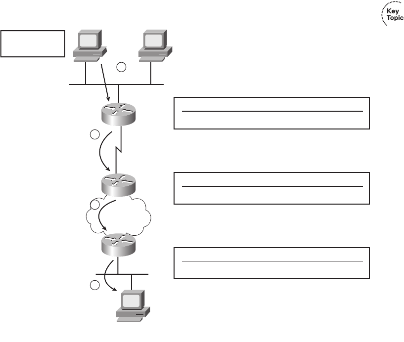
IP Routing 117
Figure 5-10 Simple Routing Example, with IP Subnets
Step B R1 processes the incoming frame and forwards the packet to R2.
Because the incoming Ethernet frame has a destination MAC of R1’s
Ethernet MAC, R1 copies the frame off the Ethernet for processing. R1
checks the frame’s FCS, and no errors have occurred (Step 1). R1 then
discards the Ethernet header and trailer (Step 2). Next, R1 compares the
packet’s destination address (150.150.4.10) to the routing table and finds the
entry for subnet 150.150.4.0—which includes addresses 150.150.4.0 through
150.150.4.255 (Step 3). Because the destination address is in this group,
R2 forwards the packet outgoing interface Serial0 to next-hop router R2
(150.150.2.7) after encapsulating the packet in an HDLC frame (step 4).
Step C R2 processes the incoming frame and forwards the packet to R3.
R2 repeats the same general process as R1 when R2 receives the HDLC
frame. R2 checks the FCS field and finds that no errors occurred (Step 1).
R2 then discards the HDLC header and trailer (Step 2). Next, R2 finds its
Default Router
150.150.1.4
150.150.1.10
150.150.1.4
150.150.2.7
150.150.3.1
E0
S0
S1
150.150.4.10
R1
R2
R3
PC1
150.150.1.11
PC11
PC2
150.150.1.0
150.150.2.0
150.150.3.0
150.150.4.0
Subnet Out Interface Next Hop IP Address
150.150.4.0 Serial0 150.150.2.7
R1 Routing Table
Subnet Out Interface Next Hop IP Address
150.150.4.0 Serial1 150.150.3.1
R2 Routing Table
Subnet Out Interface Next Hop IP Address
150.150.4.0 Ethernet0 N/A
R3 Routing Table
A
B
C
D
1828xbook.fm Page 117 Thursday, July 26, 2007 3:10 PM
118 Chapter 5: Fundamentals of IP Addressing and Routing
route for subnet 150.150.4.0—which includes the address range
150.150.4.0–150.150.4.255—and realizes that the packet’s destination
address 150.150.4.10 matches that route (Step 3). Finally, R2 sends the
packet out interface serial1 to next-hop router 150.150.3.1 (R3) after
encapsulating the packet in a Frame Relay header (Step 4).
Step D R3 processes the incoming frame and forwards the packet to PC2.
Like R1 and R2, R3 checks the FCS, discards the old data-link header
and trailer, and matches its own route for subnet 150.150.4.0. R3’s
routing table entry for 150.150.4.0 shows that the outgoing interface is
R3’s Ethernet interface, but there is no next-hop router, because R3 is
connected directly to subnet 150.150.4.0. All R3 has to do is encapsulate
the packet inside an Ethernet header and trailer, with a destination
Ethernet address of PC2’s MAC address, and forward the frame.
The routing process relies on the rules relating to IP addressing. For instance, why does
150.150.1.10 (PC1) assume that 150.150.4.10 (PC2) is not on the same Ethernet? Well,
because 150.150.4.0, PC2’s subnet, is different from 150.150.1.0, which is PC1’s subnet.
Because IP addresses in different subnets must be separated by a router, PC1 needs to send
the packet to a router—and it does. Similarly, all three routers list a route to subnet
150.150.4.0, which, in this example, includes IP addresses 150.150.4.1 to 150.150.4.254.
What if someone tried to put PC2 somewhere else in the network, still using 150.150.4.10?
The routers then would forward packets to the wrong place. So, Layer 3 routing relies on
the structure of Layer 3 addressing to route more efficiently.
Chapter 12 covers IP addressing in much more detail. Next, this chapter briefly introduces
the concepts behind IP routing protocols.
IP Routing Protocols
The routing (forwarding) process depends heavily on having an accurate and up-to-date
IP routing table on each router. IP routing protocols fill the routers’ IP routing tables with
valid, loop-free routes. Each route includes a subnet number, the interface out which to
forward packets so that they are delivered to that subnet, and the IP address of the next
router that should receive packets destined for that subnet (if needed) (as shown in the
example surrounding Figure 5-10).
Before examining the underlying logic used by routing protocols, you need to consider the
goals of a routing protocol. The goals described in the following list are common for any
IP routing protocol, regardless of its underlying logic type:
■To dynamically learn and fill the routing table with a route to all subnets in the
network.
1828xbook.fm Page 118 Thursday, July 26, 2007 3:10 PM
IP Routing Protocols 119
■If more than one route to a subnet is available, to place the best route in the routing
table.
■To notice when routes in the table are no longer valid, and to remove them from the
routing table.
■If a route is removed from the routing table and another route through another
neighboring router is available, to add the route to the routing table. (Many people view
this goal and the preceding one as a single goal.)
■To add new routes, or to replace lost routes, with the best currently available route as
quickly as possible. The time between losing the route and finding a working
replacement route is called convergence time.
■To prevent routing loops.
Routing protocols can become rather complicated, but the basic logic that they use is
relatively simple. Routing protocols follow these general steps for advertising routes in a
network:
Step 1 Each router adds a route to its routing table for each subnet directly connected
to the router.
Step 2 Each router tells its neighbors about all the routes in its routing table,
including the directly connected routes and routes learned from other
routers.
Step 3 After learning a new route from a neighbor, the router adds a route to its
routing table, with the next-hop router typically being the neighbor from
which the route was learned.
For example, Figure 5-11 shows the same sample network as in Figures 5-9 and 5-10, but
now with focus on how the three routers each learned about subnet 150.150.4.0. Note
that routing protocols do more work than is implied in the figure; this figure just focuses
on how the routers learn about subnet 150.150.4.0.
Again, follow the items A, B, C, and D shown in the figure to see how each router learns
its route to 150.150.4.0. All references to Steps 1, 2, and 3 refer to the list just before
Figure 5-11.
Step A R3 learns a route that refers to its own E0 interface because subnet 150.150.4.0 is
directly connected (Step 1).
Step B R3 sends a routing protocol message, called a routing update, to R2,
causing R2 to learn about subnet 150.150.4.0 (Step 2).
1828xbook.fm Page 119 Thursday, July 26, 2007 3:10 PM
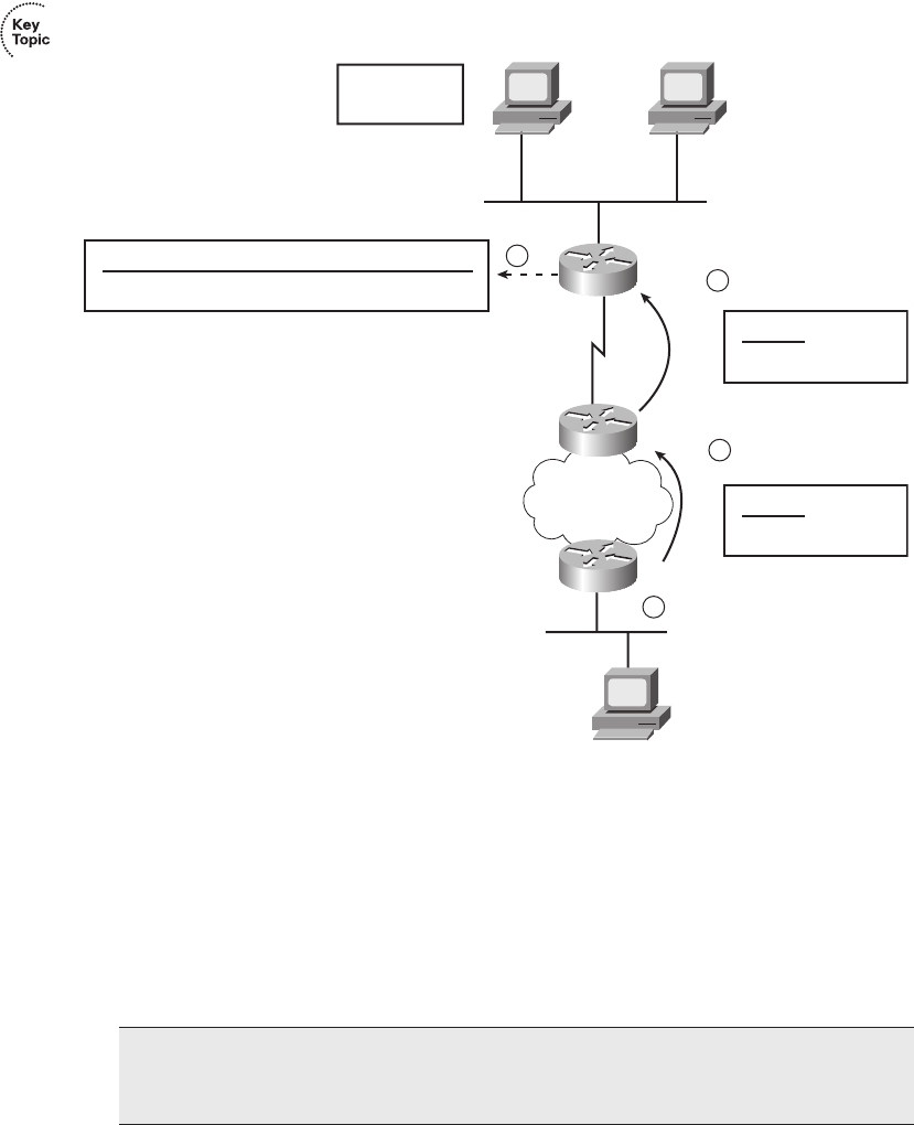
120 Chapter 5: Fundamentals of IP Addressing and Routing
Figure 5-11 Router R1 Learning About Subnet 150.150.4.0
Step C R2 sends a similar routing update to R1, causing R1 to learn about subnet
150.150.4.0 (Step 2).
Step D R1’s route to 150.150.4.0 lists 150.150.2.7 (R2’s IP address) as the next-
hop address because R1 learned about the route from R2. The route also
lists R1’s outgoing interface as Serial0, because R1 learned about the
route from the update that came in serial0 (at Step C in the figure).
Chapter 14, “Routing Protocol Concepts and Configuration,” covers routing protocols in
more detail. Next, the final major section of this chapter introduces several additional
NOTE Routes do not always refer to the neighboring router’s IP address as the next-hop
IP address, but for protocols and processes covered for the ICND1 and CCNA exams,
the routes typically refer to a neighboring router as the next hop.
Default Router
150.150.1.4
150.150.1.10
150.150.1.4
150.150.2.7
150.150.3.1
E0
S0
S1
150.150.4.10
R1
R2
R3
PC1
150.150.1.11
PC11
PC2
150.150.4.0
Subnet Out Interface Next Hop
150.150.4.0 Serial0 150.150.2.7
R1 Routing Table
Subnet
150.150.4.0
R2 Routing Table
Subnet
150.150.4.0
R3 Routing Table
A
B
C
D
1828xbook.fm Page 120 Thursday, July 26, 2007 3:10 PM
Network Layer Utilities 121
functions related to how the network layer forwards packets from source to destination
through an internetwork.
Network Layer Utilities
So far this chapter has described the main features of the OSI network layer—in particular,
the TCP/IP internetwork layer, which defines the same general features as OSI Layer 3.
To close the chapter, this section covers four tools used almost every day in almost every
TCP/IP network in the world to help the network layer with its task of routing packets from
end to end through an internetwork:
■Address Resolution Protocol (ARP)
■Domain Name System (DNS)
■Dynamic Host Configuration Protocol (DHCP)
■Ping
Address Resolution Protocol and the Domain Name System
Network designers should try to make using the network as simple as possible. At most,
users might want to remember the name of another computer with which they want to
communicate, such as remembering the name of a website. They certainly do not want to
remember the IP address, nor do they want to try to remember any MAC addresses! So,
TCP/IP needs protocols that dynamically discover all the necessary information to allow
communications, without the user knowing more than a name.
You might not even think that you need to know the name of another computer. For
instance, when you open your browser, you probably have a default home page configured
that the browser immediately downloads. You might not think of that universal resource
locator (URL) string as a name, but the URL for the home page has a name embedded in it.
For example, in a URL such as http://www.cisco.com/go/prepcenter, the www.cisco.com
part is the name of the Cisco web server. So, whether you enter the name of another
networked computer or it is implied by what you see on the screen, the user typically
identifies a remote computer by using a name.
So, TCP/IP needs a way to let a computer find the IP address of another computer based on
its name. TCP/IP also needs a way to find MAC addresses associated with other computers
on the same LAN subnet. Figure 5-12 outlines the problem.
In this example, Hannah needs to communicate with a server on PC Jessie. Hannah knows
her own name, IP address, and MAC address. What Hannah does not know are Jessie’s IP
and MAC addresses. To find the two missing facts, Hannah uses DNS to find Jessie’s IP
address and ARP to find Jessie’s MAC address.
1828xbook.fm Page 121 Thursday, July 26, 2007 3:10 PM
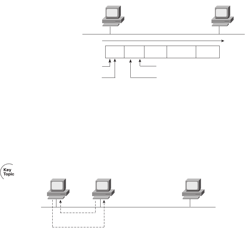
122 Chapter 5: Fundamentals of IP Addressing and Routing
Figure 5-12 Hannah Knows Jessie’s Name, Needs IP Address and MAC Address
DNS Name Resolution
Hannah knows the IP address of a DNS server because the address was either preconfigured
on Hannah’s machine or was learned with DHCP, as covered later in this chapter. As
soon as Hannah somehow identifies the name of the other computer (for example,
jessie.example.com), she sends a DNS request to the DNS, asking for Jessie’s IP address.
The DNS replies with the address, 10.1.1.2. Figure 5-13 shows the simple process.
Figure 5-13 DNS Request and Reply
Hannah simply sends a DNS request to the server, supplying the name jessie, or
jessie.example.com, and the DNS replies with the IP address (10.1.1.2 in this case). Effectively,
the same thing happens when you surf the Internet and connect to any website. Your PC sends
a request, just like Hannah’s request for Jessie, asking the DNS to resolve the name into an
IP address. After that happens, your PC can start requesting that the web page be sent.
The ARP Process
As soon as a host knows the IP address of the other host, the sending host may need to know
the MAC address used by the other computer. For example, Hannah still needs to know the
Ethernet MAC address used by 10.1.1.2, so Hannah issues something called an ARP
Hannah Jessie
?.?.?.?
????.????.????
Eth IP UDP Ad Data Eth
* Destination MAC Address =
Source MAC Address =
0200.1111.1111
* Information that Hannah Needs to Learn
* Destination IP Address =
Source IP Address = 10.1.1.1
DNS Hannah Jessie
What Is Jessie's
IP Address?
Jessie's IP Address
Is 10.1.1.2.
10.1.1.1
0200.1111.1111
10.1.1.2
0200.2222.2222
1828xbook.fm Page 122 Thursday, July 26, 2007 3:10 PM
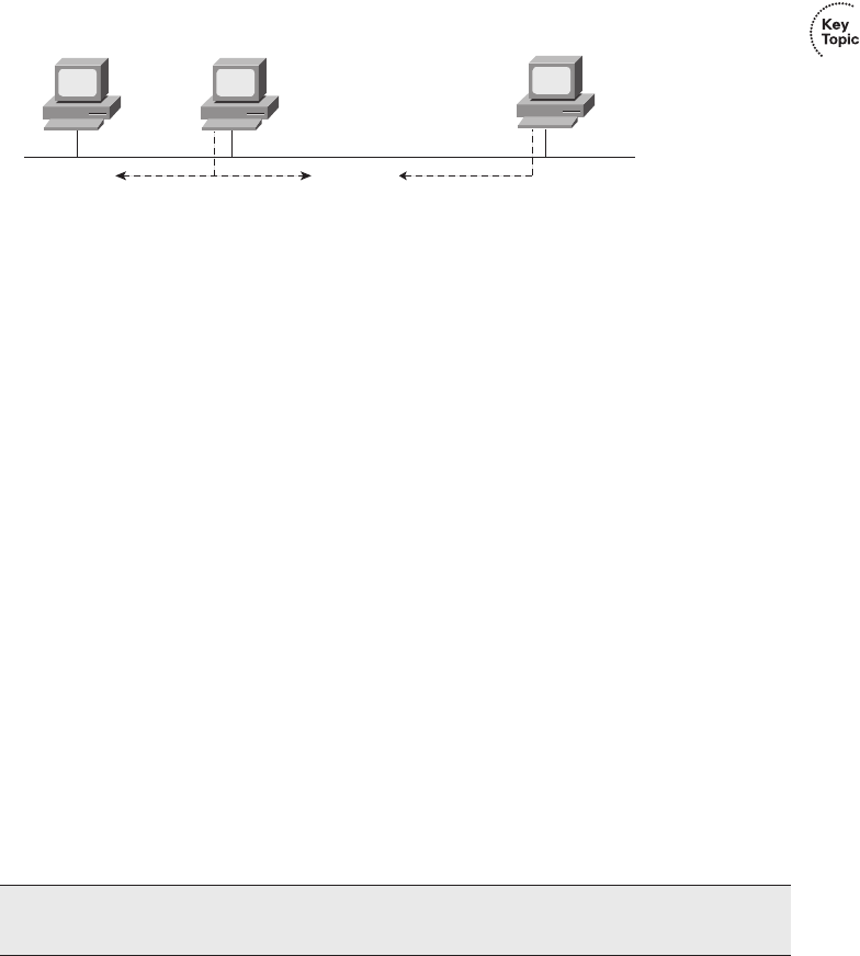
Network Layer Utilities 123
broadcast. An ARP broadcast is sent to a broadcast Ethernet address, so everyone on the LAN
receives it. Because Jessie is on the same LAN, she receives the ARP broadcast. Because
Jessie’s IP address is 10.1.1.2 and the ARP broadcast is looking for the MAC address associated
with 10.1.1.2, Jessie replies with her own MAC address. Figure 5-14 outlines the process.
Figure 5-14 Sample ARP Process
Now Hannah knows the destination IP and Ethernet addresses that she should use when
sending frames to Jessie, and the packet shown in Figure 5-12 can be sent successfully.
Hosts may or may not need to ARP to find the destination host’s MAC address based on the
two-step routing logic used by a host. If the destination host is on the same subnet, the
sending host sends an ARP looking for the destination host’s MAC address, as shown in
Figure 5-14. However, if the sending host is on a different subnet than the destination host,
the sending host’s routing logic results in the sending host needing to forward the packet to
its default gateway. For example, if Hannah and Jessie had been in different subnets in
Figures 5-12 through 5-14, Hannah’s routing logic would have caused Hannah to want to
send the packet to Hannah’s default gateway (router). In that case, Hannah would have used
ARP to find the router’s MAC address instead of Jessie’s MAC address.
Additionally, hosts need to use ARP to find MAC addresses only once in a while. Any
device that uses IP should retain, or cache, the information learned with ARP, placing the
information in its ARP cache. Each time a host needs to send a packet encapsulated in an
Ethernet frame, it first checks its ARP cache and uses the MAC address found there. If the
correct information is not listed in the ARP cache, the host then can use ARP to discover
the MAC address used by a particular IP address. Also, a host learns ARP information when
receiving an ARP as well. For example, the ARP process shown in Figure 5-14 results in
both Hannah and Jessie learning the other host’s MAC address.
Address Assignment and DHCP
Every device that uses TCP/IP—in fact, every interface on every device that uses TCP/IP—
needs a valid IP address. For some devices, the address can and should be statically
NOTE You can see the contents of the ARP cache on most PC Operating Systems by
using the arp -a command from a command prompt.
DNS Hannah Jessie
10.1.1.1
0200.1111.1111
10.1.1.2
0200.2222.2222
Hey Everybody! If You
Are 10.1.1.2, Tell Me
Your MAC Address!
I'm 10.1.1.2; My
MAC Address Is
0200.2222.2222.
1828xbook.fm Page 123 Thursday, July 26, 2007 3:10 PM

124 Chapter 5: Fundamentals of IP Addressing and Routing
assigned by configuring the device. For example, all commonly used computer operating
systems that support TCP/IP allow the user to statically configure the IP address on each
interface. Routers and switches typically use statically configured IP addresses as well.
Servers also typically use statically configured IP addresses. Using a statically configured and
seldom-changed IP address helps because all references to that server can stay the same over
time. This is the same concept that it’s good that the location of your favorite grocery store
never changes. You know where to go to buy food, and you can get there from home, on the
way home from work, or from somewhere else. Likewise, if servers have a static, unchanging
IP address, the users of that server know how to reach the server, from anywhere, consistently.
However, the average end-user host computer does not need to use the same IP address
every day. Again thinking about your favorite grocery store, you could move to a new
apartment every week, but you’d still know where the grocery store is. The workers at the
grocery store don’t need to know where you live. Likewise, servers typically don’t care that
your PC has a different IP address today as compared to yesterday. End-user hosts can have
their IP addresses dynamically assigned, and even change their IP addresses over time,
because it does not matter if the IP address changes.
DHCP defines the protocols used to allow computers to request a lease of an IP address.
DHCP uses a server, with the server keeping a list of pools of IP addresses available in each
subnet. DHCP clients can send the DHCP server a message, asking to borrow or lease
an IP address. The server then suggests an IP address. If accepted, the server notes that the
address is no longer available for assignment to any other hosts, and the client has an
IP address to use.
DHCP supplies IP addresses to clients, and it also supplies other information. For example,
hosts need to know their IP address, plus the subnet mask to use, plus what default gateway
to use, as well as the IP address(es) of any DNS servers. In most networks today, DHCP
supplies all these facts to a typical end-user host.
Figure 5-15 shows a typical set of four messages used between a DHCP server to assign
an IP address, as well as other information. Note that the first two messages are both
IP broadcast messages.
Figure 5-15 shows the DHCP server as a PC, which is typical in an Enterprise network.
However, as covered in Chapter 17, “WAN Configuration,” routers can and do provide
DHCP services as well. In fact, routers can provide a DHCP server function, dynamically
assigning IP addresses to the computers in a small or home office, using DHCP client
functions to dynamically lease IP addresses from an Internet service provider (ISP).
However, the need for these functions is closely related to features most often used with
connections to the Internet, so more details about a router’s implementation of DHCP
server and DHCP client functions are saved for Chapter 17.
1828xbook.fm Page 124 Thursday, July 26, 2007 3:10 PM
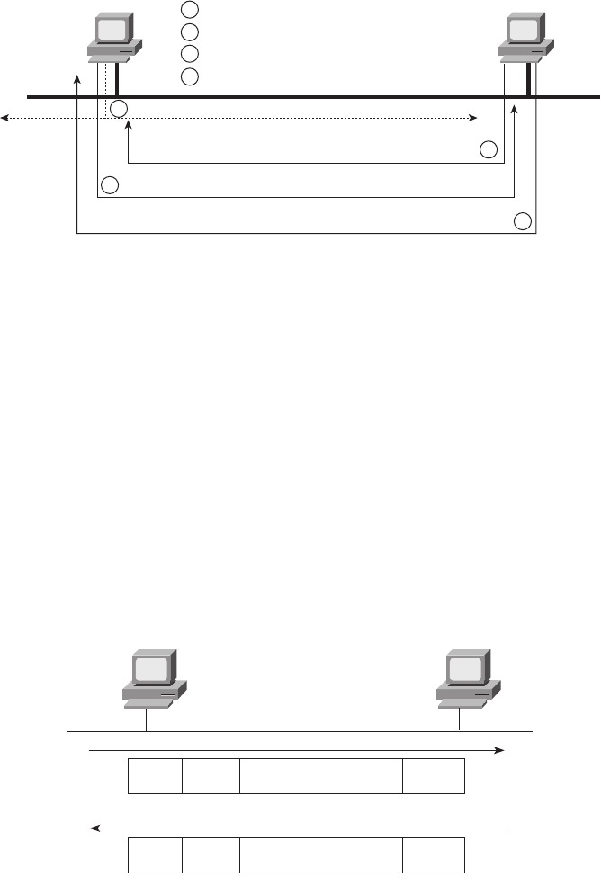
Network Layer Utilities 125
Figure 5-15 DHCP Messages to Acquire an IP Address
DHCP has become a prolific protocol. Most end-user hosts on LANs in corporate networks
get their IP addresses and other basic configuration via DHCP.
ICMP Echo and the ping Command
After you have implemented a network, you need a way to test basic IP connectivity
without relying on any applications to be working. The primary tool for testing basic
network connectivity is the ping command. ping (Packet Internet Groper) uses the Internet
Control Message Protocol (ICMP), sending a message called an ICMP echo request to
another IP address. The computer with that IP address should reply with an ICMP echo
reply. If that works, you successfully have tested the IP network. In other words, you know
that the network can deliver a packet from one host to the other, and back. ICMP does not
rely on any application, so it really just tests basic IP connectivity—Layers 1, 2, and 3 of
the OSI model. Figure 5-16 outlines the basic process.
Figure 5-16 Sample Network, ping Command
Chapter 15, “Troubleshooting IP Routing,” gives you more information about and
examples of ping and ICMP.
DHCP
Client DHCP
Serve
r
Broadcast in Order to Discover Server
Offer to Provide DHCP Service
Request Information
Acknowledgement, with the Information
(IP Address, Mask, Gateway, Etc)
1DHCP Discover Message (LAN Broadcast)
DHCP Offer Message Directed to Client
DHCP Request Message Directed to Server
DHCP Acknowledgement Directed to Client
2
3
4
1
2
3
4
Hannah Jessie
ping Jessie
Eth IP Eth
ICMP Echo Request
Eth IP Eth
ICMP Echo Reply
1828xbook.fm Page 125 Thursday, July 26, 2007 3:10 PM

126 Chapter 5: Fundamentals of IP Addressing and Routing
Exam Preparation Tasks
Review All the Key Topics
Review the most important topics from this chapter, noted with the key topics icon. Table 5-6
lists these key topics and where each is discussed.
Table 5-6 Key Topics for Chapter 5
Key Topic Element Description Page Number
List Two statements about how IP expects IP addresses to
be grouped into networks or subnets
107
Table 5-3 List of the three types of unicast IP networks and the
size of the network and host parts of each type of
network
108
Paragraph Explanation of the concept of a network broadcast or
directed broadcast address
109
Table 5-5 Details about the actual Class A, B, and C networks 110
Figure 5-6 Conceptual view of how subnetting works 112
Figure 5-7 Structure of subnetted Class A, B, and C IP
addresses, classful view
113
Figure 5-8 Structure of a subnetted unicast IP address, classless
view
114
List Two-step process of how hosts route (forward)
packets
114
List Four-step process of how routers route (forward)
packets
116
Figure 5-10 Example of the IP routing process 117
Figure 5-11 Example that shows generally how a routing
protocol can cause routers to learn new routes
120
Figure 5-13 Example that shows the purpose and process of DNS
name resolution
122
Figure 5-14 Example of the purpose and process of ARP 123
Paragraph The most important information learned by a host
acting as a DHCP client
124
1828xbook.fm Page 126 Thursday, July 26, 2007 3:10 PM
Definitions of Key Terms 127
Complete the Tables and Lists from Memory
Print a copy of Appendix H, “Memory Tables” (found on the CD), or at least the section for
this chapter, and complete the tables and lists from memory. Appendix I, “Memory Tables
Answer Key,” also on the CD, includes completed tables and lists for you to check your
work.
Definitions of Key Terms
Define the following key terms from this chapter, and check your answers in the glossary.
ARP, default gateway/default router, DHCP, DNS, host part, IP address, logical
address, network broadcast address, network number/network address, network part,
routing table, subnet broadcast address, subnet number/subnet address, subnet part
1828xbook.fm Page 127 Thursday, July 26, 2007 3:10 PM

This chapter covers the following subjects:
TCP/IP Layer 4 Protocols: TCP and UDP:
This section explains the functions and
mechanisms used by TCP and UDP, including
error recovery and port numbers.
TCP/IP Applications: This section explains the
purpose of TCP/IP application layer protocols,
focusing on HTTP as an example.
Network Security: This section provides some
perspectives on the security threats faced by
networks today, introducing some of the key tools
used to help prevent and reduce the impact of
those threats.
1828xbook.fm Page 128 Thursday, July 26, 2007 3:10 PM
C H A P T E R6
Fundamentals of TCP/IP
Transport, Applications,
and Security
The CCNA exams focus mostly on a deeper and broader examination of the topics covered
in Chapter 3 (LANs), Chapter 4 (WANs), and Chapter 5 (routing). This chapter explains the
basics of a few topics that receive less attention on the exams: the TCP/IP transport layer,
the TCP/IP application layer, and TCP/IP network security. Although all three topics are
covered on the various CCNA exams, the extent of that coverage is much less compared to
LANs, WANs, and routing.
“Do I Know This Already?” Quiz
The “Do I Know This Already?” quiz allows you to assess whether you should read the
entire chapter. If you miss no more than one of these ten self-assessment questions, you
might want to move ahead to the “Exam Preparation Tasks” section. Table 6-1 lists the
major headings in this chapter and the “Do I Know This Already?” quiz questions covering
the material in those sections. This helps you assess your knowledge of these specific areas.
The answers to the “Do I Know This Already?” quiz appear in Appendix A.
1. PC1 is using TCP and has a window size of 4000. PC1 sends four segments to PC2
with 1000 bytes of data each, with sequence numbers 2000, 3000, 4000, and 5000. PC2
replies with an acknowledgment number of 5000. What should PC1 do next?
a. Increase its window to 5000 or more segments
b. Send the next segment, with sequence number 6000
c. Resend the segment whose sequence number was 5000
d. Resend all four previously sent segments
Table 6-1 “Do I Know This Already?” Foundation Topics Section-to-Question Mapping
Foundation Topics Section Questions
TCP/IP Layer 4 Protocols: TCP and UDP 1–6
TCP/IP Applications 7, 8
Network Security 9, 10
1828xbook.fm Page 129 Thursday, July 26, 2007 3:10 PM
130 Chapter 6: Fundamentals of TCP/IP Transport, Applications, and Security
2. Which of the following are not features of a protocol that is considered to match OSI
Layer 4?
a. Error recovery
b. Flow control
c. Segmenting of application data
d. Conversion from binary to ASCII
3. Which of the following header fields identify which TCP/IP application gets data
received by the computer?
a. Ethernet Type
b. SNAP Protocol Type
c. IP Protocol Field
d. TCP Port Number
e. UDP Port Number
f. Application ID
4. Which of the following are not typical functions of TCP?
a. Windowing
b. Error recovery
c. Multiplexing using port numbers
d. Routing
e. Encryption
f. Ordered data transfer
5. Which of the following functions is performed by both TCP and UDP?
a. Windowing
b. Error recovery
c. Multiplexing using port numbers
d. Routing
e. Encryption
f. Ordered data transfer
1828xbook.fm Page 130 Thursday, July 26, 2007 3:10 PM
“Do I Know This Already?” Quiz 131
6. What do you call data that includes the Layer 4 protocol header, and data given to
Layer 4 by the upper layers, not including any headers and trailers from Layers 1 to 3?
a. Bits
b. Chunk
c. Segment
d. Packet
e. Frame
f. L4PDU
g. L3PDU
7. In the URL http://www.fredsco.com/name.html, which part identifies the web server?
a. http
b. www.fredsco.com
c. fredsco.com
d. http://www.fredsco.com
e. The file name.html includes the hostname.
8. When comparing VoIP with an HTTP-based mission-critical business application,
which of the following statements are accurate about the quality of service needed
from the network?
a. VoIP needs better (lower) packet loss.
b. HTTP needs less bandwidth.
c. HTTP needs better (lower) jitter.
d. VoIP needs better (lower) delay.
9. Which of the following is a device or function whose most notable feature is to
examine trends over time to recognize different known attacks as compared to a list of
common attack signatures?
a. VPN
b. Firewall
c. IDS
d. NAC
1828xbook.fm Page 131 Thursday, July 26, 2007 3:10 PM
132 Chapter 6: Fundamentals of TCP/IP Transport, Applications, and Security
10. Which of the following is a device or function whose most notable feature is to encrypt
packets before they pass through the Internet?
a. VPN
b. Firewall
c. IDS
d. NAC
1828xbook.fm Page 132 Thursday, July 26, 2007 3:10 PM

TCP/IP Layer 4 Protocols: TCP and UDP 133
Foundation Topics
This chapter begins by examining the functions of Transmission Control Protocol (TCP),
which are many, as compared to the functions of User Datagram Protocol (UDP), of which
there are few. The second major section of the chapter examines the TCP/IP application
layer, including some discussion of how DNS name resolution works. Finally, the third
major section examines the importance and concepts of network security, introducing some
of the core concepts, terminology, and functions important for security today.
TCP/IP Layer 4 Protocols: TCP and UDP
The OSI transport layer (Layer 4) defines several functions, the most important of which
are error recovery and flow control. Likewise, the TCP/IP transport layer protocols also
implement these same types of features. Note that both the OSI model and TCP/IP model
call this layer the transport layer. But as usual, when referring to the TCP/IP model, the
layer name and number are based on OSI, so any TCP/IP transport layer protocols are
considered Layer 4 protocols.
The key difference between TCP and UDP is that TCP provides a wide variety of services
to applications, whereas UDP does not. For example, routers discard packets for many
reasons, including bit errors, congestion, and instances in which no correct routes are
known. As you have read already, most data-link protocols notice errors (a process called
error detection) but then discard frames that have errors. TCP provides for retransmission
(error recovery) and help to avoid congestion (flow control), whereas UDP does not. As a
result, many application protocols choose to use TCP.
However, do not let UDP’s lack of services make you think that UDP is worse than TCP.
By providing few services, UDP needs fewer bytes in its header compared to TCP, resulting
in fewer bytes of overhead in the network. UDP software does not slow down data transfer
in cases where TCP may purposefully slow down. Also, some applications, notably today
voice over IP (VoIP) and video over IP, do not need error recovery, so they use UDP. So,
UDP also has an important place in TCP/IP networks today.
Table 6-1 lists the main features supported by TCP and/or UDP. Note that only the first
item listed in the table is supported by UDP, whereas all items in the table are supported
by TCP.
1828xbook.fm Page 133 Thursday, July 26, 2007 3:10 PM

134 Chapter 6: Fundamentals of TCP/IP Transport, Applications, and Security
Next, this section describes the features of TCP, followed by a brief comparison to UDP.
Transmission Control Protocol
Each TCP/IP application typically chooses to use either TCP or UDP based on the
application’s requirements. For instance, TCP provides error recovery, but to do so, it
consumes more bandwidth and uses more processing cycles. UDP does not perform error
recovery, but it takes less bandwidth and uses fewer processing cycles. Regardless of which
of the two TCP/IP transport layer protocols the application chooses to use, you should
understand the basics of how each of these transport layer protocols works.
TCP, as defined in RFC 793, accomplishes the functions listed in Table 6-2 through
mechanisms at the endpoint computers. TCP relies on IP for end-to-end delivery of the data,
including routing issues. In other words, TCP performs only part of the functions necessary
to deliver the data between applications. Also, the role that it plays is directed toward
providing services for the applications that sit at the endpoint computers. Regardless of
whether two computers are on the same Ethernet or are separated by the entire Internet,
TCP performs its functions the same way.
Figure 6-1 shows the fields in the TCP header. Although you don’t need to memorize
the names of the fields or their locations, the rest of this section refers to several of the
fields, so the entire header is included here for reference.
Table 6-2 TCP/IP Transport Layer Features
Function Description
Multiplexing using ports Function that allows receiving hosts to choose the correct
application for which the data is destined, based on the port
number.
Error recovery (reliability) Process of numbering and acknowledging data with Sequence
and Acknowledgment header fields.
Flow control using windowing Process that uses window sizes to protect buffer space and
routing devices.
Connection establishment and
termination
Process used to initialize port numbers and Sequence and
Acknowledgment fields.
Ordered data transfer and data
segmentation
Continuous stream of bytes from an upper-layer process that is
“segmented” for transmission and delivered to upper-layer
processes at the receiving device, with the bytes in the same
order.
1828xbook.fm Page 134 Thursday, July 26, 2007 3:10 PM
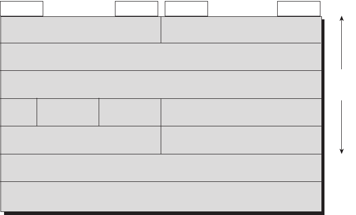
TCP/IP Layer 4 Protocols: TCP and UDP 135
Figure 6-1 TCP Header Fields
Multiplexing Using TCP Port Numbers
TCP provides a lot of features to applications, at the expense of requiring slightly more
processing and overhead, as compared to UDP. However, TCP and UDP both use a concept
called multiplexing. Therefore, this section begins with an explanation of multiplexing with
TCP and UDP. Afterward, the unique features of TCP are explored.
Multiplexing by TCP and UDP involves the process of how a computer thinks when
receiving data. The computer might be running many applications, such as a web
browser, an e-mail package, or an Internet VoIP application (for example, Skype). TCP
and UDP multiplexing enables the receiving computer to know which application to
give the data to.
Some examples will help make the need for multiplexing obvious. The sample network
consists of two PCs, labeled Hannah and Jessie. Hannah uses an application that she
wrote to send advertisements that appear on Jessie’s screen. The application sends a new
ad to Jessie every 10 seconds. Hannah uses a second application, a wire-transfer
application, to send Jessie some money. Finally, Hannah uses a web browser to access
the web server that runs on Jessie’s PC. The ad application and wire-transfer application
are imaginary, just for this example. The web application works just like it would in
real life.
Bit 0
Header
Length (4)
Sequence Number (32)
Destination Port (16)Source Port (16)
Bit 31Bit 16Bit 15
Reserved (6) Code Bits (6) Window (16)
Checksum (16) Urgent (16)
Options (0 or 32 If Any)
Data (Varies)
Acknowledgement Number (32) 20
Bytes
1828xbook.fm Page 135 Thursday, July 26, 2007 3:10 PM

136 Chapter 6: Fundamentals of TCP/IP Transport, Applications, and Security
Figure 6-2 shows the sample network, with Jessie running three applications:
■A UDP-based ad application
■A TCP-based wire-transfer application
■A TCP web server application
Figure 6-2 Hannah Sending Packets to Jessie, with Three Applications
Jessie needs to know which application to give the data to, but all three packets are from
the same Ethernet and IP address. You might think that Jessie could look at whether the
packet contains a UDP or TCP header, but, as you see in the figure, two applications (wire
transfer and web) are using TCP.
TCP and UDP solve this problem by using a port number field in the TCP or UDP header,
respectively. Each of Hannah’s TCP and UDP segments uses a different destination port
number so that Jessie knows which application to give the data to. Figure 6-3 shows an
example.
Multiplexing relies on a concept called a socket. A socket consists of three things:
■An IP address
■A transport protocol
■A port number
Hannah Jessie
Eth IP UDP Eth
Eth IP TCP Eth
Web Server
Ad Application
Wire Application
I Received Three
Packets, Each from
the Same MAC and
IP Address. What
Application Should
Get the Data in Each
Packet?
Ad Data
Wire
Transfer Data
Eth IP TCP Eth
Web Page
Data
1828xbook.fm Page 136 Thursday, July 26, 2007 3:10 PM
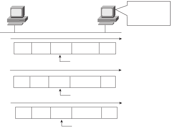
TCP/IP Layer 4 Protocols: TCP and UDP 137
Figure 6-3 Hannah Sending Packets to Jessie, with Three Applications Using Port Numbers to
Multiplex
So, for a web server application on Jessie, the socket would be (10.1.1.2, TCP, port 80)
because, by default, web servers use the well-known port 80. When Hannah’s web browser
connects to the web server, Hannah uses a socket as well—possibly one like this: (10.1.1.1,
TCP, 1030). Why 1030? Well, Hannah just needs a port number that is unique on Hannah,
so Hannah sees that port 1030 is available and uses it. In fact, hosts typically allocate
dynamic port numbers starting at 1024 because the ports below 1024 are reserved for well-
known applications, such as web services.
In Figure 6-3, Hannah and Jessie use three applications at the same time—hence, three
socket connections are open. Because a socket on a single computer should be unique, a
connection between two sockets should identify a unique connection between two
computers. This uniqueness means that you can use multiple applications at the same time,
talking to applications running on the same or different computers. Multiplexing, based on
sockets, ensures that the data is delivered to the correct applications. Figure 6-4 shows the
three socket connections between Hannah and Jessie.
Port numbers are a vital part of the socket concept. Well-known port numbers are used by
servers; other port numbers are used by clients. Applications that provide a service, such as
FTP, Telnet, and web servers, open a socket using a well-known port and listen for
connection requests. Because these connection requests from clients are required to include
both the source and destination port numbers, the port numbers used by the servers must be
Hannah Jessie
Eth IP UDP Eth
Eth IP TCP Eth
I’ll Look in the UDP
or TCP Destination
Port to Identify the
Application!
Ad Data
Wire
Transfer Data
Eth IP TCP Eth
Web Page
Data
Port 80 Web Server
Port 800 Ad Server
Port 20,100 Wire Application
Destination Port 800
Destination Port 20,100
Destination Port 80
1828xbook.fm Page 137 Thursday, July 26, 2007 3:10 PM
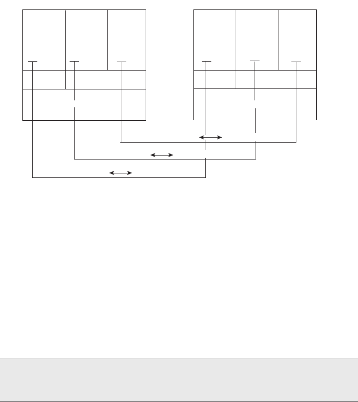
138 Chapter 6: Fundamentals of TCP/IP Transport, Applications, and Security
well-known. Therefore, each server has a hard-coded, well-known port number. The well-
known ports are listed at http://www.iana.org/assignments/port-numbers.
Figure 6-4 Connections Between Sockets
On client machines, where the requests originate, any unused port number can be allocated.
The result is that each client on the same host uses a different port number, but a server
uses the same port number for all connections. For example, 100 web browsers on the same
host computer could each connect to a web server, but the web server with 100 clients
connected to it would have only one socket and, therefore, only one port number (port 80
in this case). The server can tell which packets are sent from which of the 100 clients by
looking at the source port of received TCP segments. The server can send data to the correct
web client (browser) by sending data to that same port number listed as a destination
port. The combination of source and destination sockets allows all participating hosts to
distinguish between the data’s source and destination. Although the example explains the
concept using 100 TCP connections, the same port numbering concept applies to UDP
sessions in the same way.
Popular TCP/IP Applications
Throughout your preparation for the CCNA exams, you will come across a variety of TCP/
IP applications. You should at least be aware of some of the applications that can be used
to help manage and control a network.
NOTE You can find all RFCs online at http://www.isi.edu/in-notes/rfcxxxx.txt, where
xxxx is the number of the RFC. If you do not know the number of the RFC, you can try
searching by topic at http://www.rfc-editor.org/rfcsearch.html.
Hannah Jessie
Ad
Application
Port 1025
Wire
Application
Port 1028
Web
Browser
Port 1030
UDP TCP
IP Address 10.1.1.1
Ad
Application
Port 800
Wire
Application
Port 20,100
Web
Server
Port 80
UDP TCP
IP Address 10.1.1.2
(10.1.1.1, TCP, 1030) (10.1.1.2, TCP, 80)
(10.1.1.1, TCP, 1028) (10.1.1.2, TCP, 20100)
(10.1.1.1, UDP, 1025) (10.1.1.2, UDP, 800)
1828xbook.fm Page 138 Thursday, July 26, 2007 3:10 PM

TCP/IP Layer 4 Protocols: TCP and UDP 139
The World Wide Web (WWW) application exists through web browsers accessing the
content available on web servers. Although it is often thought of as an end-user application,
you can actually use WWW to manage a router or switch. You enable a web server function
in the router or switch and use a browser to access the router or switch.
The Domain Name System (DNS) allows users to use names to refer to computers, with
DNS being used to find the corresponding IP addresses. DNS also uses a client/server
model, with DNS servers being controlled by networking personnel, and DNS client
functions being part of most any device that uses TCP/IP today. The client simply asks the
DNS server to supply the IP address that corresponds to a given name.
Simple Network Management Protocol (SNMP) is an application layer protocol used
specifically for network device management. For instance, Cisco supplies a large variety of
network management products, many of them in the CiscoWorks network management
software product family. They can be used to query, compile, store, and display information
about a network’s operation. To query the network devices, CiscoWorks software mainly
uses SNMP protocols.
Traditionally, to move files to and from a router or switch, Cisco used Trivial File Transfer
Protocol (TFTP). TFTP defines a protocol for basic file transfer—hence the word “trivial.”
Alternatively, routers and switches can use File Transfer Protocol (FTP), which is a much
more functional protocol, to transfer files. Both work well for moving files into and out of
Cisco devices. FTP allows many more features, making it a good choice for the general
end-user population. TFTP client and server applications are very simple, making them
good tools as embedded parts of networking devices.
Some of these applications use TCP, and some use UDP. As you will read later, TCP
performs error recovery, whereas UDP does not. For instance, Simple Mail Transport
Protocol (SMTP) and Post Office Protocol version 3 (POP3), both used for transferring
mail, require guaranteed delivery, so they use TCP. Regardless of which transport layer
protocol is used, applications use a well-known port number so that clients know which port
to attempt to connect to. Table 6-3 lists several popular applications and their well-known
port numbers.
Table 6-3 Popular Applications and Their Well-Known Port Numbers
Port Number Protocol Application
20 TCP FTP data
21 TCP FTP control
22 TCP SSH
continues
1828xbook.fm Page 139 Thursday, July 26, 2007 3:10 PM
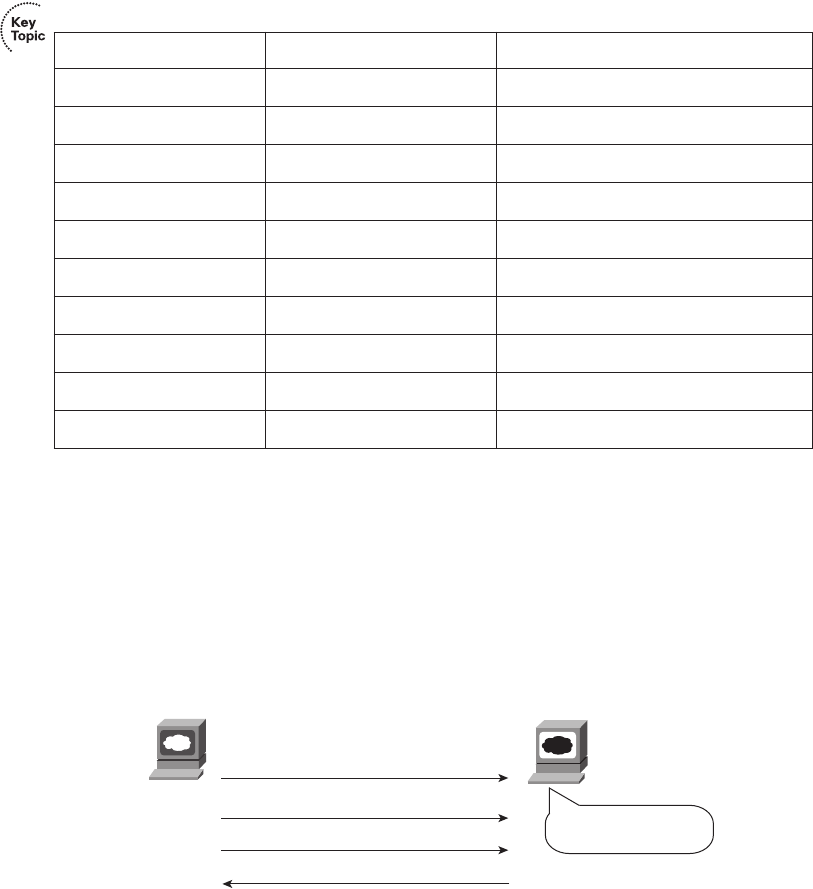
140 Chapter 6: Fundamentals of TCP/IP Transport, Applications, and Security
Error Recovery (Reliability)
TCP provides for reliable data transfer, which is also called reliability or error recovery,
depending on what document you read. To accomplish reliability, TCP numbers data bytes
using the Sequence and Acknowledgment fields in the TCP header. TCP achieves reliability
in both directions, using the Sequence Number field of one direction combined with the
Acknowledgment field in the opposite direction. Figure 6-5 shows the basic operation.
Figure 6-5 TCP Acknowledgment Without Errors
In Figure 6-5, the Acknowledgment field in the TCP header sent by the web client (4000)
implies the next byte to be received; this is called forward acknowledgment. The
sequence number reflects the number of the first byte in the segment. In this case, each
TCP segment is 1000 bytes long; the Sequence and Acknowledgment fields count the
number of bytes.
23 TCP Telnet
25 TCP SMTP
53 UDP, TCP DNS
67, 68 UDP DHCP
69 UDP TFTP
80 TCP HTTP (WWW)
110 TCP POP3
161 UDP SNMP
443 TCP SSL
16,384–32,767 UDP RTP-based Voice (VoIP) and Video
Table 6-3 Popular Applications and Their Well-Known Port Numbers (Continued)
Port Number Protocol Application
Web
Browser
Web
Server
1000 Bytes of Data, Sequence = 1000
1000 Bytes of Data, Sequence = 2000
1000 Bytes of Data, Sequence = 3000
No Data, Acknowledgment = 4000
I Got All 3000 Bytes.
Send ACK!
1828xbook.fm Page 140 Thursday, July 26, 2007 3:10 PM
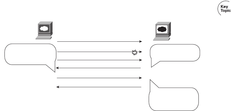
TCP/IP Layer 4 Protocols: TCP and UDP 141
Figure 6-6 depicts the same scenario, but the second TCP segment was lost or is in error.
The web client’s reply has an ACK field equal to 2000, implying that the web client is
expecting byte number 2000 next. The TCP function at the web server then could recover
lost data by resending the second TCP segment. The TCP protocol allows for resending just
that segment and then waiting, hoping that the web client will reply with an
acknowledgment that equals 4000.
Figure 6-6 TCP Acknowledgment with Errors
Although not shown, the sender also sets a retransmission timer, awaiting acknowledgment,
just in case the acknowledgment is lost or all transmitted segments are lost. If that timer
expires, the TCP sender sends all segments again.
Flow Control Using Windowing
TCP implements flow control by taking advantage of the Sequence and Acknowledgment
fields in the TCP header, along with another field called the Window field. This Window
field implies the maximum number of unacknowledged bytes that are allowed to be
outstanding at any instant in time. The window starts small and then grows until errors
occur. The size of the window changes over time, so it is sometimes called a dynamic
window. Additionally, because the actual sequence and acknowledgment numbers grow
over time, the window is sometimes called a sliding window, with the numbers sliding
(moving) upward. When the window is full, the sender does not send, which controls the
flow of data. Figure 6-7 shows windowing with a current window size of 3000. Each TCP
segment has 1000 bytes of data.
Notice that the web server must wait after sending the third segment because the window
is exhausted. When the acknowledgment has been received, another window can be sent.
Because no errors have occurred, the web client grants a larger window to the server, so now
4000 bytes can be sent before the server receives an acknowledgment. In other words, the
Web
Browser
Web
Server
1000 Bytes of Data, Sequence = 1000
1000 Bytes of Data, Sequence = 2000
1000 Bytes of Data, Sequence = 3000
No Data, Acknowledgment = 4000
No Data, Acknowledgment = 2000
1000 Bytes of Data, Sequence = 2000
I Probably Lost One.
ACK What I Got in
Order!
I Just Got 2000-2999,
and I Already Had
3000-3999. Ask for
4000 Next.
He Lost the Segment
with Sequence =
2000. Resend It!
1828xbook.fm Page 141 Thursday, July 26, 2007 3:10 PM
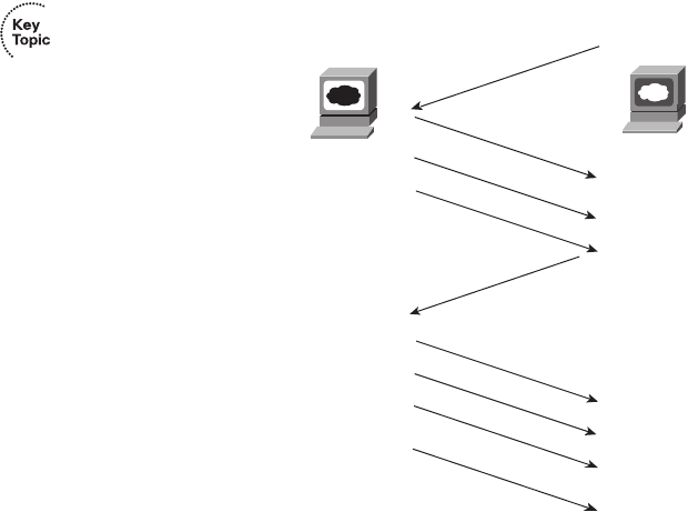
142 Chapter 6: Fundamentals of TCP/IP Transport, Applications, and Security
receiver uses the Window field to tell the sender how much data it can send before it must
stop and wait for the next acknowledgment. As with other TCP features, windowing is
symmetrical. Both sides send and receive, and, in each case, the receiver grants a window
to the sender using the Window field.
Figure 6-7 TCP Windowing
Windowing does not require that the sender stop sending in all cases. If an acknowledgment
is received before the window is exhausted, a new window begins, and the sender continues
sending data until the current window is exhausted. (The term Positive Acknowledgment
and Retransmission [PAR] is sometimes used to describe the error recovery and windowing
processes that TCP uses.)
Connection Establishment and Termination
TCP connection establishment occurs before any of the other TCP features can begin their
work. Connection establishment refers to the process of initializing sequence and
acknowledgment fields and agreeing on the port numbers used. Figure 6-8 shows an
example of connection establishment flow.
This three-way connection establishment flow must end before data transfer can begin. The
connection exists between the two sockets, although the TCP header has no single socket
field. Of the three parts of a socket, the IP addresses are implied based on the source and
destination IP addresses in the IP header. TCP is implied because a TCP header is in use,
SEQ=1000
SEQ=2000
SEQ=3000
SEQ=4000
SEQ=5000
SEQ=6000
ACK=4000
Window=4000
ACK=1000
Window=3000
SEQ=7000
Web
Server
Web
Browser
1828xbook.fm Page 142 Thursday, July 26, 2007 3:10 PM
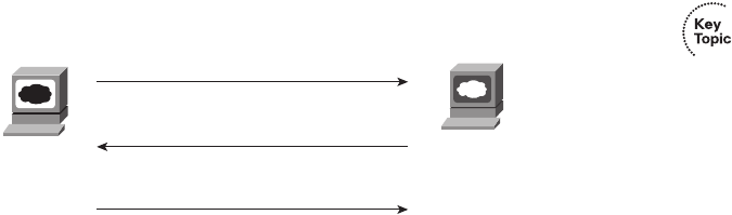
TCP/IP Layer 4 Protocols: TCP and UDP 143
as specified by the protocol field value in the IP header. Therefore, the only parts of the
socket that need to be encoded in the TCP header are the port numbers.
Figure 6-8 TCP Connection Establishment
TCP signals connection establishment using 2 bits inside the flag fields of the TCP header.
Called the SYN and ACK flags, these bits have a particularly interesting meaning. SYN
means “Synchronize the sequence numbers,” which is one necessary component in
initialization for TCP. The ACK field means “The Acknowledgment field is valid in this
header.” Until the sequence numbers are initialized, the Acknowledgment field cannot be
very useful. Also notice that in the initial TCP segment in Figure 6-8, no acknowledgment
number is shown; this is because that number is not valid yet. Because the ACK field must
be present in all the ensuing segments, the ACK bit continues to be set until the connection
is terminated.
TCP initializes the Sequence Number and Acknowledgment Number fields to any number
that fits into the 4-byte fields; the actual values shown in Figure 6-8 are simply sample
values. The initialization flows are each considered to have a single byte of data, as reflected
in the Acknowledgment Number fields in the example.
Figure 6-9 shows TCP connection termination. This four-way termination sequence is
straightforward and uses an additional flag, called the FIN bit. (FIN is short for “finished,”
as you might guess.) One interesting note: Before the device on the right sends the third
TCP segment in the sequence, it notifies the application that the connection is coming
down. It then waits on an acknowledgment from the application before sending the third
segment in the figure. Just in case the application takes some time to reply, the PC on the
right sends the second flow in the figure, acknowledging that the other PC wants to take
down the connection. Otherwise, the PC on the left might resend the first segment
repeatedly.
Web
Browser
Web
Server
SYN, DPORT=80, SPORT=1027
SYN, ACK, DPORT=1027, SPORT=80
ACK, DPORT=80, SPORT=1027
SEQ=200
SEQ=1450, ACK=201
SEQ=201, ACK=1451
1828xbook.fm Page 143 Thursday, July 26, 2007 3:10 PM
144 Chapter 6: Fundamentals of TCP/IP Transport, Applications, and Security
Figure 6-9 TCP Connection Termination
TCP establishes and terminates connections between the endpoints, whereas UDP does not.
Many protocols operate under these same concepts, so the terms connection-oriented and
connectionless are used to refer to the general idea of each. More formally, these terms can
be defined as follows:
■Connection-oriented protocol: A protocol that requires an exchange of messages
before data transfer begins or that has a required preestablished correlation between
two endpoints
■Connectionless protocol: A protocol that does not require an exchange of messages
and that does not require a preestablished correlation between two endpoints
Data Segmentation and Ordered Data Transfer
Applications need to send data. Sometimes the data is small—in some cases, a single byte.
In other cases, such as with a file transfer, the data might be millions of bytes.
Each different type of data-link protocol typically has a limit on the maximum transmission
unit (MTU) that can be sent inside a data link layer frame. In other words, the MTU is the
size of the largest Layer 3 packet that can sit inside a frame’s data field. For many data-link
protocols, Ethernet included, the MTU is 1500 bytes.
TCP handles the fact that an application might give it millions of bytes to send by
segmenting the data into smaller pieces, called segments. Because an IP packet can often be
no more than 1500 bytes because of the MTU restrictions, and because IP and TCP headers
are 20 bytes each, TCP typically segments large data into 1460-byte chunks.
The TCP receiver performs reassembly when it receives the segments. To reassemble the
data, TCP must recover lost segments, as discussed previously. However, the TCP receiver
PC
ACK, FIN SEQ=1000
PC
ACK ACK=1471
ACK ACK=1001
ACK, FIN ACK=1001
SEQ=1470
1828xbook.fm Page 144 Thursday, July 26, 2007 3:10 PM
TCP/IP Layer 4 Protocols: TCP and UDP 145
must also reorder segments that arrive out of sequence. Because IP routing can choose to
balance traffic across multiple links, the actual segments may be delivered out of order. So,
the TCP receiver also must perform ordered data transfer by reassembling the data into the
original order. The process is not hard to imagine: If segments arrive with the sequence
numbers 1000, 3000, and 2000, each with 1000 bytes of data, the receiver can reorder them,
and no retransmissions are required.
You should also be aware of some terminology related to TCP segmentation. The TCP
header and the data field together are called a TCP segment. This term is similar to a data-
link frame and an IP packet in that the terms refer to the headers and trailers for the
respective layers, plus the encapsulated data. The term L4PDU also can be used instead of
the term TCP segment because TCP is a Layer 4 protocol.
User Datagram Protocol
UDP provides a service for applications to exchange messages. Unlike TCP, UDP is
connectionless and provides no reliability, no windowing, no reordering of the received
data, and no segmentation of large chunks of data into the right size for transmission.
However, UDP provides some functions of TCP, such as data transfer and multiplexing
using port numbers, and it does so with fewer bytes of overhead and less processing
required than TCP.
UDP data transfer differs from TCP data transfer in that no reordering or recovery is
accomplished. Applications that use UDP are tolerant of the lost data, or they have some
application mechanism to recover lost data. For example, VoIP uses UDP because if a voice
packet is lost, by the time the loss could be noticed and the packet retransmitted, too much
delay would have occurred, and the voice would be unintelligible. Also, DNS requests use
UDP because the user will retry an operation if the DNS resolution fails. As another
example, the Network File System (NFS), a remote file system application, performs
recovery with application layer code, so UDP features are acceptable to NFS.
Figure 6-10 shows TCP and UDP header formats. Note the existence of both Source Port
and Destination Port fields in the TCP and UDP headers, but the absence of Sequence
Number and Acknowledgment Number fields in the UDP header. UDP does not need these
fields because it makes no attempt to number the data for acknowledgments or
resequencing.
UDP gains some advantages over TCP by not using the Sequence and Acknowledgment
fields. The most obvious advantage of UDP over TCP is that there are fewer bytes of
overhead. Not as obvious is the fact that UDP does not require waiting on acknowledgments
or holding the data in memory until it is acknowledged. This means that UDP applications
1828xbook.fm Page 145 Thursday, July 26, 2007 3:10 PM

146 Chapter 6: Fundamentals of TCP/IP Transport, Applications, and Security
are not artificially slowed by the acknowledgment process, and memory is freed more
quickly.
Figure 6-10 TCP and UDP Headers
TCP/IP Applications
The whole goal of building an Enterprise network, or connecting a small home or office
network to the Internet, is to use applications—applications such as web browsing, text
messaging, e-mail, file downloads, voice, and video. This section examines a few issues
related to network design in light of the applications expected in an internetwork. This is
followed by a much deeper look at one particular application—web browsing using
Hypertext Transfer Protocol (HTTP).
QoS Needs and the Impact of TCP/IP Applications
The needs of networked applications have changed and grown significantly over the years.
When networks first became popular in Enterprises in the 1970s, the network typically
supported only data applications, mainly text-only terminals and text-only printers. A
single user might generate a few hundred bytes of data for the network every time he or she
pressed the Enter key, maybe every 10 seconds or so.
The term quality of service (QoS) refers to the entire topic of what an application needs
from the network service. Each type of application can be analyzed in terms of its QoS
requirements on the network, so if the network meets those requirements, the application
will work well. For example, the older text-based interactive applications required only a
small amount of bandwidth, but they did like low delay. If those early networks supported
a round-trip delay of less than 1 second, users were generally happy, because they had to
wait less than 1 second for a response.
The QoS needs of data applications have changed over the years. Generally speaking,
applications have tended to need more bandwidth, with lower delay as well. From those
Source
Port
Dest.
Port
Sequence
Number
Ack.
Number Offset Reserved Flags Window
Size Checksum Urgent Options PAD
2
22 2 2
TCP Header
Source
Port
Dest.
Port Length Checksum
UDP Header
*
Unless Specified, Lengths Shown
Are the Numbers of Bytes
24 44 bits 6 bits 6 bits 2 2 2 3 1
1828xbook.fm Page 146 Thursday, July 26, 2007 3:10 PM
TCP/IP Applications 147
early days of networking to the present, here are some of the types of data applications that
entered the marketplace, and their impact on the network:
■Graphics-capable terminals and printers, which increased the required bytes for the
same interaction as the old text-based terminals and printers
■File transfers, which introduced much larger volumes of data, but with no significant
response time requirements
■File servers, which allow users to store files on a server—which might require a large
volume of data transfer, but with a much smaller end-user response time requirement
■The maturation of database technology, making vast amounts of data available to
casual users, vastly increasing the number of users wanting access to data
■The migration of common applications to web browsers, which encourages more users
to access data
■The general acceptance of e-mail as both a personal and business communications
service, both inside companies and with other companies
■The rapid commercialization of the Internet, enabling companies to offer data directly
to their customers via the data network rather than via phone calls
Besides these and many other trends in the progression of data applications over the years,
voice and video are in the middle of a migration onto the data network. Before the mid-to-
late 1990s, voice and video typically used totally separate networking facilities. The
migration of voice and video to the data network puts even more pressure on the data
network to deliver the required quality of network service. Most companies today have
either begun or plan on a migration to use IP phones, which pass voice traffic over the data
network inside IP packets using application protocols generally referred to as voice over IP
(VoIP). Additionally, several companies sell Internet phone service, which sends voice
traffic over the Internet, again using VoIP packets. Figure 6-11 shows a few of the details of
how VoIP works from a home high-speed Internet connection, with a generic voice adapter
(VA) converting the analog voice signal from the normal telephone to an IP packet.
Figure 6-11 Converting from Sound to Packets with a VA
VolIP Packet
4
3
1
IP UDP RTP Digital Voice Bits
Human
Speech
Phone #1
2Analog Electricity CODEC
Cable or
DSL
VA R1
1828xbook.fm Page 147 Thursday, July 26, 2007 3:10 PM

148 Chapter 6: Fundamentals of TCP/IP Transport, Applications, and Security
A single VoIP call that passes over a WAN typically takes less than 30 kbps of bandwidth,
which is not a lot compared with many data applications today. In fact, most data
applications consume as much bandwidth as they can grab. However, VoIP traffic has
several other QoS demands on the network before the VoIP traffic will sound good:
■Low delay: VoIP requires a very low delay between the sending phone and the
receiving phone—typically less than 200 milliseconds (.2 seconds). This is a much
lower delay than what is required by typical data applications.
■Low jitter: Jitter is the variation in delay. VoIP requires very low jitter as well, whereas
data applications can tolerate much higher jitter. For example, the jitter for consecutive
VoIP packets should not exceed 30 milliseconds (.03 seconds), or the quality degrades.
■Loss: If a VoIP packet is lost in transit because of errors or because a router doesn’t
have room to store the packet while waiting to send it, the VoIP packet is not delivered
across the network. Because of the delay and jitter issues, there is no need to try to
recover the lost packet. It would be useless by the time it was recovered. Lost packets
can sound like a break in the sound of the VoIP call.
Video over IP has the same performance issues, except that video requires either more
bandwidth (often time 300 to 400 kbps) or a lot more bandwidth (3 to 10 Mbps per video).
The world of video over IP is also going through a bit of transformation with the advent of
high-definition video over IP, again increasing demands on the bandwidth in the network.
For perspective, Table 6-4 summarizes some thoughts about the needs of various types of
applications for the four main QoS requirements—bandwidth, delay, jitter, and packet loss.
Memorizing the table is not important, but it is important to note that although VoIP
requires relatively little bandwidth, it also requires low delay/jitter/loss for high quality. It
is also important to note that video over IP has the same requirements, except for medium
to large amounts of bandwidth.
Table 6-4 Comparing Applications’ Minimum Needs
Type of Application Bandwidth Delay Jitter Loss
VoIP Low Low Low Low
Two-way video over IP (such as
videoconferencing)
Medium/high Low Low Low
One-way video over IP (such as
security cameras)
Medium Medium Medium Low
Interactive mission-critical data
(such as web-based payroll)
Medium Medium High High
1828xbook.fm Page 148 Thursday, July 26, 2007 3:10 PM

TCP/IP Applications 149
To support the QoS requirements of the various applications, routers and switches can be
configured with a wide variety of QoS tools. They are beyond the scope of the CCNA
exams (but are covered on several of the Cisco professional-level certifications). However,
the QoS tools must be used for a modern network to be able to support high-quality VoIP
and video over IP.
Next we examine the most popular application layer protocol for interactive data
applications today—HTTP and the World Wide Web (WWW). The goal is to show one
example of how application layer protocols work.
The World Wide Web, HTTP, and SSL
The World Wide Web (WWW) consists of all the Internet-connected web servers in the
world, plus all Internet-connected hosts with web browsers. Web servers, which consist of
web server software running on a computer, store information (in the form of web pages)
that might be useful to different people. Web browsers, which is software installed on an
end user’s computer, provide the means to connect to a web server and display the web
pages stored on the web server.
For this process to work, several specific application-layer functions must occur. The user
must somehow identify the server, the specific web page, and the protocol used to get the
data from the server. The client must find the server’s IP address, based on the server’s
name, typically using DNS. The client must request the web page, which actually consists
of multiple separate files, and the server must send the files to the web browser. Finally, for
electronic commerce (e-commerce) applications, the transfer of data, particularly sensitive
financial data, needs to be secure, again using application layer features. The following
sections address each of these functions.
Interactive business data (such as
online chat with a coworker)
Low/medium Medium High High
File transfer (such as backing up
disk drives)
High High High High
Nonbusiness (such as checking
the latest sports scores)
Medium High High High
NOTE Although most people use the term web browser, or simply browser, web
browsers are also called web clients, because they obtain a service from a web server.
Table 6-4 Comparing Applications’ Minimum Needs (Continued)
Type of Application Bandwidth Delay Jitter Loss
1828xbook.fm Page 149 Thursday, July 26, 2007 3:10 PM

150 Chapter 6: Fundamentals of TCP/IP Transport, Applications, and Security
Universal Resource Locators
For a browser to display a web page, the browser must identify the server that has the
web page, plus other information that identifies the particular web page. Most web
servers have many web pages. For example, if you use a web browser to browse
http://www.cisco.com, and you click around that web page, you’ll see another web page.
Click again, and you’ll see another web page. In each case, the clicking action identifies the
server’s IP address and the specific web page, with the details mostly hidden from you. (These
clickable items on a web page, which in turn bring you to another web page, are called links.)
The browser user can identify a web page when you click something on a web page or when
you enter a Universal Resource Locator (URL) (often called a web address) in the
browser’s address area. Both options—clicking a link and entering a URL—refer to a URL,
because when you click a link on a web page, that link actually refers to a URL.
Each URL defines the protocol used to transfer data, the name of the server, and the
particular web page on that server. The URL can be broken into three parts:
■The protocol is listed before the //.
■The hostname is listed between the // and the /.
■The name of the web page is listed after the /.
For example:
http://www.cisco.com/go/prepcenter
In this case, the protocol is Hypertext Transfer Protocol (HTTP), the hostname is
www.cisco.com, and the name of the web page is go/prepcenter. This URL is particularly
useful, because it is the base web page for the Cisco CCNA Prep Center.
Finding the Web Server Using DNS
As mentioned in Chapter 5, “Fundamentals of IP Addressing and Routing,” a host can
use DNS to discover the IP address that corresponds to a particular hostname. Although
URLs may include the IP address of the web server instead of the name of the web server,
URLs typically list the hostname. So, before the browser can send a packet to the web
server, the browser typically needs to resolve the name in the URL to that name’s
corresponding IP address.
NOTE To see the hidden URL referenced by a link, open a browser to a web page, hover
the mouse pointer over a link, right-click, and select Properties. The pop-up window
should display the URL to which the browser would be directed if you clicked that link.
1828xbook.fm Page 150 Thursday, July 26, 2007 3:10 PM
TCP/IP Applications 151
To pull together several concepts, Figure 6-12 shows the DNS process as initiated by a
web browser, as well as some other related information. From a basic perspective, the user
enters the URL (http://www.cisco.com/go/prepcenter), resolves the www.cisco.com name
into the correct IP address, and starts sending packets to the web server.
Figure 6-12 DNS Resolution and Requesting a Web Page
The steps shown in the figure are as follows:
1. The user enters the URL, http://www.cisco.com/go/prepcenter, into the browser’s
address area.
2. The client sends a DNS request to the DNS server. Typically, the client learns the DNS
server’s IP address via DHCP. Note that the DNS request uses a UDP header, with a
destination port of the DNS well-known port of 53. (See Table 6-3, earlier in this
chapter, for a list of popular well-known ports.)
3. The DNS server sends a reply, listing IP address 198.133.219.25 as www.cisco.com’s
IP address. Note also that the reply shows a destination IP address of 64.100.1.1,
the client’s IP address. It also shows a UDP header, with source port 53; the source port
is 53 because the data is sourced, or sent by, the DNS server.
IP Header UDP Header DNS Request
DNS Server
192.31.7.1
www.cisco.comWeb Server
198.133.219.25
Client
64.100.1.1
2
1
Source 64.100.1.1
Dest. 192.31.7.1
What is IP address
of www.cisco.com?
Source 1030
Dest. Port 53
IP Header UDP Header DNS Request
3
Source 192.31.7.1
Dest. 64.100.1.1
IP address is
198.133.219.25.
Source 53
Dest. 1030
Name Resolution Request
IP Header TCP Header
4
Source 64.100.1.1
Dest. 192.133.219.25
Source 1035
Dest. Port 80, SYN
TCP Connection Setup
Name Resolution Reply
The human typed this URL:
http://www.cisco.com/go/prepcenter
1828xbook.fm Page 151 Thursday, July 26, 2007 3:10 PM

152 Chapter 6: Fundamentals of TCP/IP Transport, Applications, and Security
4. The client begins the process of establishing a new TCP connection to the web server.
Note that the destination IP address is the just-learned IP address of the web server.
The packet includes a TCP header, because HTTP uses TCP. Also note the destination
TCP port is 80, the well-known port for HTTP. Finally, the SYN bit is shown, as a
reminder that the TCP connection establishment process begins with a TCP segment
with the SYN bit turned on (binary 1).
At this point in the process, the web browser is almost finished setting up a TCP connection
to the web server. The next section picks up the story at that point, examining how the
web browser then gets the files that comprise the desired web page.
Transferring Files with HTTP
After a web client (browser) has created a TCP connection to a web server, the client can
begin requesting the web page from the server. Most often, the protocol used to transfer the
web page is HTTP. The HTTP application-layer protocol, defined in RFC 2616, defines
how files can be transferred between two computers. HTTP was specifically created for the
purpose of transferring files between web servers and web clients.
HTTP defines several commands and responses, with the most frequently used being the
HTTP GET request. To get a file from a web server, the client sends an HTTP GET request
to the server, listing the filename. If the server decides to send the file, the server sends an
HTTP GET response, with a return code of 200 (meaning “OK”), along with the file’s
contents.
Web pages typically consist of multiple files, called objects. Most web pages contain text
as well as several graphical images, animated advertisements, and possibly voice or video.
Each of these components is stored as a different object (file) on the web server. To get
them all, the web browser gets the first file. This file may (and typically does) include
references to other URLs, so the browser then also requests the other objects. Figure 6-13
shows the general idea, with the browser getting the first file and then two others.
In this case, after the web browser gets the first file—the one called “/go/ccna” in the
URL—the browser reads and interprets that file. Besides containing parts of the web page,
the file refers to two other files, so the browser issues two additional HTTP get requests.
NOTE Many return codes exist for HTTP requests. For instance, when the server does
not have the requested file, it issues a return code of 404, which means “file not found.”
Most web browsers do not show the specific numeric HTTP return codes, instead
displaying a response such as “page not found” in reaction to receiving a return code of
404.
1828xbook.fm Page 152 Thursday, July 26, 2007 3:10 PM
Network Security 153
Note that, even though it isn’t shown in the figure, all these commands flow over one
(or possibly more) TCP connections between the client and the server. This means that TCP
would provide error recovery, ensuring that the data was delivered.
Figure 6-13 Multiple HTTP Get Requests/Responses
This chapter ends with an introduction to network security.
Network Security
In years past, security threats came from geniuses or nerdy students with lots of time. The
numbers of these people were relatively small. Their main motivation was to prove that they
could break into another network. Since then, the number of potential attackers and the
sophistication of the attacks have increased exponentially. Attacks that once required
attackers to have an advanced degree in computing now can be done with easily
downloaded and freely available tools that the average junior-high student can figure out
how to use. Every company and almost every person connects to the Internet, making
essentially the whole world vulnerable to attack.
The biggest danger today may be the changes in attackers’ motivation. Instead of looking
for a challenge, or to steal millions, today’s attackers can be much more organized and
motivated. Organized crime tries to steal billions by extorting companies by threatening a
denial of service (DoS) attack on the companies’ public web servers. Or they steal identity
and credit card information for sometimes hundreds of thousands of people with one
sophisticated attack. Attacks might come from nation-states or terrorists. Not only might
they attack military and government networks, but they might try to disrupt infrastructure
services for utilities and transportation and cripple economies.
HTTP GET (/go/ccna)
HTTP GET /graphics/logo1.gif
HTTP GET /graphics/ad1.gif
HTTP OK data: /go/ccna
HTTP OK data: logo1.gif
HTTP OK data: ad1.gif
Web
Browser
(Client)
www.cisco.com
User typed:
http://www.cisco.com/go/ccna
1828xbook.fm Page 153 Thursday, July 26, 2007 3:10 PM
154 Chapter 6: Fundamentals of TCP/IP Transport, Applications, and Security
Security is clearly a big issue, and one that requires serious attention. For the purposes of
this book, and for the ICND1 exam, the goal is to know some of the basic terminology, types
of security issues, and some of the common tools used to mitigate security risks. To that
end, this final section of the chapter gives you some perspectives on attacks, and then it
introduces four classes of security tools. Beyond this introduction, this book also examines
device security—the securing of access to routers and switches in this case—as part of
Chapter 8, “Operating Cisco LAN Switches,” and Chapter 13, “Operating Cisco Routers.”
Perspectives on the Sources and Types of Threats
Figure 6-14 shows a common network topology with a firewall. Firewalls are probably
the best-known security appliance, sitting between the Enterprise network and the dark,
cold, unsecure Internet. The firewall’s role is to stop packets that the network or security
engineer has deemed unsafe. The firewall mainly looks at the transport layer port numbers
and the application layer headers to prevent certain ports and applications from getting
packets into the Enterprise.
Figure 6-14 Typical Enterprise Internet Connection with a Firewall
Figure 6-14 might give an average employee of the Enterprise a false sense of security. He
or she might think the firewall provides protection from all the dangers of connecting to
Internet
www.example.com
Firewall
Access
Point
C2
C1
C3
Enterprise IP Network
1828xbook.fm Page 154 Thursday, July 26, 2007 3:10 PM

Network Security 155
the Internet. However, a perimeter firewall (a firewall on the edge, or perimeter, of the
network) does not protect the Enterprise from all the dangers possible through the Internet
connection. Not only that, a higher percentage of security attacks actually come from inside
the Enterprise network, and the firewall does not even see those packets.
To appreciate a bit more about the dangers inside the Enterprise network, it helps to
understand a bit more about the kinds of attacks that might occur:
■Denial of service (DoS) attacks: An attack whose purpose is to break things. DoS
attacks called destroyers try to harm the hosts, erasing data and software. DoS attacks
called crashers cause harm by causing hosts to fail or causing the machine to no longer
be able to connect to the network. Also, DoS attacks called flooders flood the network
with packets to make the network unusable, preventing any useful communications
with the servers.
■Reconnaissance attacks: This kind of attack may be disruptive as a side effect, but its
goal is gathering information to perform an access attack. An example is learning IP
addresses and then trying to discover servers that do not appear to require encryption
to connect to the server.
■Access attacks: An attempt to steal data, typically data for some financial advantage,
for a competitive advantage with another company, or even for international espionage.
Computer viruses are just one tool that can be used to carry out any of these attacks. A virus
is a program that is somehow transferred onto an unsuspecting computer, possibly through
an e-mail attachment or website download. A virus could just cause problems on the
computer, or it could steal information and send it back to the attacker.
Today, most computers use some type of anti-virus software to watch for known viruses
and prevent them from infecting the computer. Among other activities, the anti-virus
software loads a list of known characteristics of all viruses, with these characteristics being
known as virus signatures. By periodically downloading the latest virus signatures, the
anti-virus software knows about all the latest viruses. By watching all packets entering
the computer, the anti-virus software can recognize known viruses and prevent the
computer from being infected. These programs also typically run an automatic periodic
scan of the entire contents of the computer disk drives, looking for any known viruses.
To appreciate some of the security risks inherent in an Enterprise network that already has
a quality perimeter firewall, consider Figure 6-15. The list following the figure explains
three ways in which the Enterprise network is exposed to the possibility of an attack
from within.
1828xbook.fm Page 155 Thursday, July 26, 2007 3:10 PM
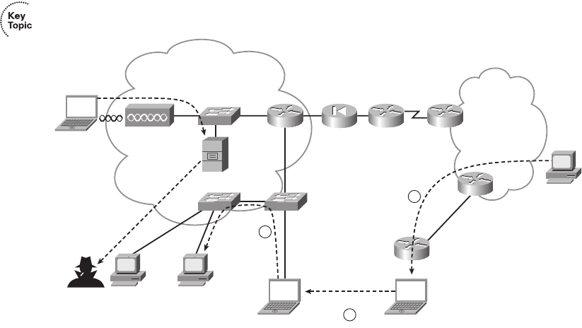
156 Chapter 6: Fundamentals of TCP/IP Transport, Applications, and Security
Figure 6-15 Common Security Issues in an Enterprise
The following types of problems could commonly occur in this Enterprise:
■Access from the wireless LAN: Wireless LANs allow users to access the rest of the
devices in the Enterprise. The wireless radio signals might leave the building, so an
unsecured wireless LAN allows the user across the street in a coffee shop to access the
Enterprise network, letting the attacker (PC1) begin the next phase of trying to gain
access to the computers in the Enterprise.
■Infected mobile laptops: When an employee brings his or her laptop (PC2) home,
with no firewall or other security, the laptop may become infected with a virus. When
the user returns to the office in the morning, the laptop connects to the Enterprise
network, with the virus spreading to other PCs, such as PC3. PC3 may be vulnerable
in part because the users may have avoided running the daily anti-virus software scans
that, although useful, can annoy the user.
■Disgruntled employees: The user at PC4 is planning to move to a new company. He
steals information from the network and loads it onto an MP3 player or USB flash
drive. This allows him to carry the entire customer database in a device that can be
easily concealed and removed from the building.
Internet
Enterprise IP Network
Firewall
PC2
Home
(Evenings)
DSL
Virus
Server with
Customer
List
Tr ies to Break In
C3
Attacker
1
2
Virus
3
PC2
PC3 PC4
(Outdated Antivirus
Signatures)
Commute to
Steals
Customer
List
Office in the AM
PC2
Coffee
Shop
1828xbook.fm Page 156 Thursday, July 26, 2007 3:10 PM
Network Security 157
These attacks are just a few examples; a large number of variations and methods exist. To
prevent such problems, Cisco suggests a security model that uses tools that automatically
work to defend the network, with security features located throughout the network. Cisco
uses the term security in depth to refer to a security design that includes security tools
throughout the network, including features in routers and switches. Cisco also uses the term
“self-defending network” to refer to automation in which the network devices
automatically react to network problems.
For example, Network Admission Control (NAC) is one security tool to help prevent two
of the attacks just described. Among other things, NAC can monitor when devices first
connect to a LAN, be they wireless or wired. The NAC feature, partly implemented by
features in the LAN switches, would prevent a computer from connecting to the LAN
until its virus definitions were updated, with a requirement for a recent full virus scan.
NAC also includes a requirement that the user supply a username and password before
being able to send other data into the LAN, helping prevent the guy at the coffee shop
from gaining access. However, NAC does not prevent a disgruntled employee from
causing harm, because the employee typically has a working username/password to be
authenticated with NAC.
Besides viruses, many other tools can be used to form an attack. The following list
summarizes some of the more common terms for the tools in an attacker’s toolkit:
■Scanner: A tool that sends connection requests to different TCP and UDP ports, for
different applications, in an attempt to discover which hosts run which IP services, and
possibly the operating system used on each host.
■Spyware: A virus that looks for private or sensitive information, tracking what the user
does with the computer, and passing the information back to the attacker in the
Internet.
■Worm: A self-propagating program that can quickly replicate itself around Enterprise
networks and the Internet, often performing DoS attacks, particularly on servers.
■Keystroke logger: A virus that logs all keystrokes, or possibly just keystrokes from
when secure sites are accessed, reporting the information to the attacker. Loggers
can actually capture your username and password to secure sites before the
information leaves the computer, which could give the attacker access to your favorite
financial websites.
1828xbook.fm Page 157 Thursday, July 26, 2007 3:10 PM
158 Chapter 6: Fundamentals of TCP/IP Transport, Applications, and Security
■Phishing: The attacker sets up a website that outwardly looks like a legitimate website,
often for a bank or credit card company. The phisher sends e-mails listing the
illegitimate website’s URL but making it look like the real company (for example,
“Click here to update the records for your credit card to make it more secure.”). The
phisher hopes that a few people will take the bait, connect to the illegitimate website,
and enter information such as their name, address, credit card number, social security
number (in the U.S.), or other national government ID number. The best defense for
phishing attacks may well be better user training and more awareness about the
exposure.
■Malware: This refers to a broad class of malicious viruses, including spyware.
The solution to these and the many other security issues not mentioned here is to provide
security in depth throughout the network. The rest of this section introduces a few of the
tools that can be used to provide that in-depth security.
Firewalls and the Cisco Adaptive Security Appliance (ASA)
Firewalls examine all packets entering and exiting a network for the purpose of filtering
unwanted traffic. Firewalls determine the allowed traffic versus the disallowed traffic based
on many characteristics of the packets, including their destination and source IP addresses
and the TCP and UDP port numbers (which imply the application protocol). Firewalls also
examine the application layer headers.
The term firewall is taken from the world of building and architecture. A firewall in a
building has two basic requirements. It must be made of fire-resistant materials, and the
architect limits the number of openings in the wall (doors, conduits for wires and
plumbing), limiting the paths through which the fire can spread. Similarly, a network
firewall must itself be hardened against security attacks. It must disallow all packets unless
the engineer has configured a firewall rule that allows the traffic—a process often called
“opening a hole,” again with analogies to a firewall in a building.
Firewalls sit in the packet-forwarding path between two networks, often with one LAN
interface connecting to the secure local network, and one to the other, less-secure network
(often the Internet). Additionally, because some hosts in the Enterprise need to be
accessible from the Internet—an inherently less secure practice—the firewall typically also
has an interface connected to another small part of the Enterprise network, called the
demilitarized zone (DMZ). The DMZ LAN is a place to put devices that need to be
accessible, but that access puts them at higher risk. Figure 6-16 shows a sample design, with
a firewall that has three interfaces.
1828xbook.fm Page 158 Thursday, July 26, 2007 3:10 PM
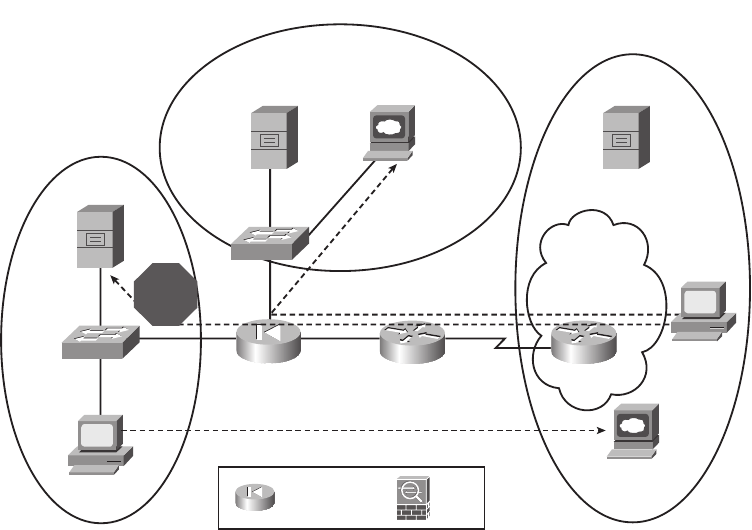
Network Security 159
Figure 6-16 Common Internet Design Using a Firewall
To do its job, the firewall needs to be configured to know which interfaces are connected to
the inside, outside, and DMZ parts of the network. Then, a series of rules can be configured
that tell the firewall which traffic patterns are allowed and which are not. The figure shows
two typically allowed flows and one typical disallowed flow, shown with dashed lines:
■Allow web clients on the inside network (such as PC1) to send packets to web servers
(such as the www.example.com web server)
■Prevent web clients in the outside network (such as PC5) from sending packets to web
servers in the inside network (such as the internal web server int.fredsco.com)
■Allow web clients in the outside network (such as PC5) to connect to DMZ web servers
(such as the www.fredsco.com web server)
In years past, Cisco sold firewalls with the trade name PIX firewall. A few years ago, Cisco
introduced a whole new generation of network security hardware using the trade name
Adaptive Security Appliance (ASA). ASA hardware can act as a firewall, in other security
roles, and in a combination of roles. So, when speaking about security, the term firewall still
refers to the functions, but today the Cisco product may be an older still-installed PIX
firewall or a newer ASA. (Figure 6-16 shows the ASA icon at the bottom.)
int.fredsco.com
mail.fredsco.com
PIX Firewall
or ASA
Mail
www.fredsco.com
EXT
PC1
PC5
PIX Firewall ASA
mail.isp1.net
Inside
Outside
ISP1
DMZ
www.example.com
STOP
1828xbook.fm Page 159 Thursday, July 26, 2007 3:10 PM
160 Chapter 6: Fundamentals of TCP/IP Transport, Applications, and Security
Anti-x
A comprehensive security plan requires several functions that prevent different known
types of problems. For example, host-based anti-virus software helps prevent the spread of
viruses. Cisco ASA appliances can provide or assist in the overall in-depth security design
with a variety of tools that prevent problems such as viruses. Because the names of several
of the individual tools start with “anti-,” Cisco uses the term anti-x to refer to the whole
class of security tools that prevent these various problems, including the following:
■Anti-virus: Scans network traffic to prevent the transmission of known viruses based
on virus signatures.
■Anti-spyware: Scans network traffic to prevent the transmission of spyware programs.
■Anti-spam: Examines e-mail before it reaches the users, deleting or segregating junk
e-mail.
■Anti-phishing: Monitors URLs sent in messages through the network, looking for the
fake URLs inherent in phishing attacks, preventing the attack from reaching the users.
■URL filtering: Filters web traffic based on URL to prevent users from connecting to
inappropriate sites.
■E-mail filtering: Provides anti-spam tools. Also filters e-mails containing offensive
materials, potentially protecting the Enterprise from lawsuits.
The Cisco ASA appliance can be used to perform the network-based role for all these anti-x
functions.
Intrusion Detection and Prevention
Some types of attacks cannot be easily found with anti-x tools. For example, if a known
virus infects a computer solely through an e-mail attachment of a file called this-is-a-
virus.exe, the anti-virus software on the ASA or the end-user computer can easily identify
and delete the virus. However, some forms of attacks can be more sophisticated. The attacks
may not even include the transfer of a file, instead using a myriad of other, more-
challenging methods, often taking advantage of new bugs in the operating system.
The world of network security includes a couple of types of tools that can be used to help
prevent the more sophisticated kinds of attacks: Intrusion Detection Systems (IDS) and
Intrusion Prevention Systems (IPS). IDS and IPS tools detect these threats by watching for
trends, looking for attacks that use particular patterns of messages, and other factors. For
instance, an IDS or IPS can track sequences of packets between hosts to look for a file being
sent to more and more hosts, as might be done by a worm trying to spread inside a network.
1828xbook.fm Page 160 Thursday, July 26, 2007 3:10 PM
Network Security 161
IDS and IPS systems differ mainly in how they monitor the traffic and how they can respond
to a perceived threat. IDS tools typically receive a copy of packets via a monitoring port,
rather than being part of the packets’ forwarding path. The IDS can then rate and report on
each potential threat, and potentially ask other devices, such as firewalls and routers, to help
prevent the attack (if they can). IPS tools often sit in the packets’ forwarding path, giving
the IPS the capability to perform the same functions as the IDS, but also to react and filter
the traffic. The ability to react is important with some threats, such as the Slammer worm
in 2003, which doubled the number of infected hosts every 9 seconds or so, infecting
75,000 hosts in the first 10 minutes of the attack. This kind of speed requires the use of
reactive tools, rather than waiting on an engineer to see a report and take action.
Virtual Private Networks (VPN)
The last class of security tool introduced in this chapter is the virtual private network
(VPN), which might be better termed a virtual private WAN. A leased line is inherently
secure, effectively acting like an electrical circuit between the two routers. VPNs send
packets through the Internet, which is a public network. However, VPNs make the
communication secure, like a private leased line.
Without VPN technology, the packets sent between two devices over the Internet are
inherently unsecure. The packets flowing through the Internet could be intercepted by
attackers in the Internet. In fact, along with the growth of the Internet, attackers found ways
to redirect packets and examine the contents, both to see the data and to find additional
information (such as usernames and passwords) as part of a reconnaissance attack.
Additionally, users and servers might not be able to tell the difference between a legitimate
packet from an authentic user and a packet from an attacker who is trying to gain even more
information and access.
VPNs provide a solution to allow the use of the Internet without the risks of unknowingly
accepting data from attacking hosts and without the risk of others reading the data in transit.
VPNs authenticate the VPN’s endpoints, meaning that both endpoints can be sure that the
other endpoint of the VPN connection is legitimate. Additionally, VPNs encrypt the original
IP packets so that even if an attacker managed to get a copy of the packets as they pass
through the Internet, he or she cannot read the data. Figure 16-17 shows the general idea,
with an intranet VPN and an access VPN.
The figure shows an example of two types of VPNs: an access VPN and a site-to-site
intranet VPN. An access VPN supports a home or small-office user, with the remote office’s
PC typically encrypting the packets. A site-to-site intranet VPN typically connects two
sites of the same Enterprise, effectively creating a secure connection between two different
parts inside (intra) the same Enterprise network. For intranet VPNs, the encryption could
be done for all devices using different kinds of hardware, including routers, firewalls,
1828xbook.fm Page 161 Thursday, July 26, 2007 3:10 PM
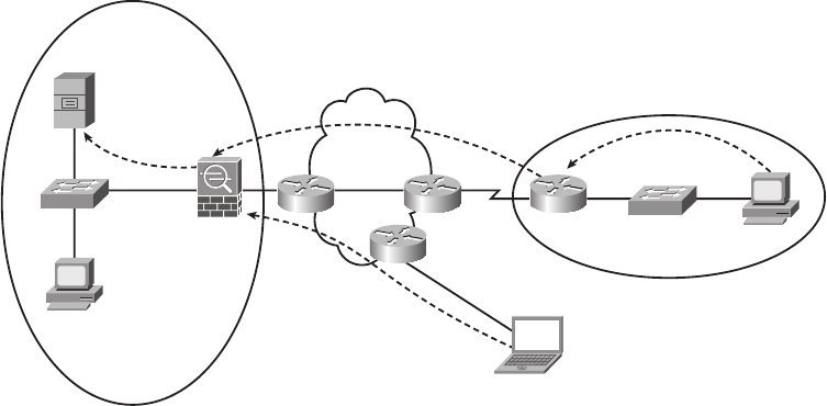
162 Chapter 6: Fundamentals of TCP/IP Transport, Applications, and Security
purpose-built VPN concentrator hardware, or ASAs, as shown in the main site of the
Enterprise.
Figure 6-17 Sample VPNs
Figure 6-17 shows how VPNs can use end-to-end encryption, in which the data remains
encrypted while being forwarded through one or more routers. Additionally, link
encryption can be used to encrypt data at the data link layer, so the data is encrypted only
as it passes over one data link. Chapter 11, “Wireless LANs,” shows an example of link
encryption.
Unencrypted
Packets
ASA
PC1
PC2
Enterprise
Central Site
Encrypted
Packets
Unencrypted Packets
Encrypted
Packets
Internet
PC2
Home Office
Branch Office
1828xbook.fm Page 162 Thursday, July 26, 2007 3:10 PM
Definitions of Key Terms 163
Exam Preparation Tasks
Review All the Key Topics
Review the most important topics from this chapter, noted with the key topics icon.
Table 6-5 lists these key topics and where each is discussed.
Complete the Tables and Lists from Memory
Print a copy of Appendix H, “Memory Tables” (found on the CD), or at least the section for
this chapter, and complete the tables and lists from memory. Appendix I, “Memory Tables
Answer Key,” also on the CD, includes completed tables and lists for you to check your work.
Definitions of Key Terms
Define the following key terms from this chapter and check your answers in the glossary:
Anti-x, connection establishment, DoS, error detection, error recovery, firewall, flow
control, forward acknowledgment, HTTP, Intrusion Detection System, Intrusion
Prevention System, ordered data transfer, port, Positive Acknowledgment and
Retransmission (PAR), segment, sliding windows, URL, virtual private network, VoIP,
web server
Table 6-5 Key Topics for Chapter 6
Key Topic Element Description
Page
Number
Table 6-2 Functions of TCP and UDP 134
Table 6-3 Well-known TCP and UDP port numbers 139-140
Figure 6-6 Example of TCP error recovery using forward
acknowledgments
141
Figure 6-7 Example of TCP sliding windows 142
Figure 6-8 Example of TCP connection establishment 143
List Definitions of connection-oriented and connectionless 144
List QoS requirements for VoIP 148
List Three types of attacks 155
Figure 6-15 Examples of common security exposures in an Enterprise 156
1828xbook.fm Page 163 Thursday, July 26, 2007 3:10 PM

Cisco Published ICND1 Exam Topics* Covered in This Part:
Describe the operation of data networks.
■Use the OSI and TCP/IP models and their associated protocols to explain how data flows in
a network
■Interpret network diagrams
■Determine the path between two hosts across a network
■Identify and correct common network problems at Layers 1, 2, 3, and 7 using a layered
model approach
■Differentiate between LAN/WAN operation and features
Implement a small switched network
■Select the appropriate media, cables, ports, and connectors to connect switches to other
network devices and hosts
■Explain the technology and media access control method for Ethernet technologies
■Explain network segmentation and basic traffic management concepts
■Explain the operation of Cisco switches and basic switching concepts
■Perform, save, and verify initial switch configuration tasks including remote access management
■Verify network status and switch operation using basic utilities (including: ping, traceroute,
Telnet, SSH, ARP, ipconfig), show and debug commands
■Implement and verify basic security for a switch (port security, deactivate ports)
■Identify, prescribe, and resolve common switched network media issues, configuration
issues, autonegotiation, and switch hardware failures
Explain and select the appropriate administrative tasks required for a WLAN
■Describe standards associated with wireless media (including: IEEE Wi-Fi Alliance, ITU/FCC)
■Identify and describe the purpose of the components in a small wireless network (including:
SSID, BSS, ESS)
■Identify the basic parameters to configure on a wireless network to ensure that devices
connect to the correct access point
■Compare and contrast wireless security features and capabilities of WPA security
(including: open, WEP, WPA-1/2)
■Identify common issues with implementing wireless networks
Identify security threats to a network and describe general methods to mitigate those threats
■Describe security recommended practices including initial steps to secure network devices
*Always recheck http://www.cisco.com for the latest posted exam topics.
1828xbook.fm Page 164 Thursday, July 26, 2007 3:10 PM

Part II: LAN Switching
Chapter 7 Ethernet LAN Switching Concepts
Chapter 8 Operating Cisco LAN Switches
Chapter 9 Ethernet Switch Configuration
Chapter 10 Ethernet Switch Troubleshooting
Chapter 11 Wireless LANs
1828xbook.fm Page 165 Thursday, July 26, 2007 3:10 PM
This chapter covers the following subjects:
LAN Switching Concepts: Explains the basic
processes used by LAN switches to forward
frames.
LAN Design Considerations: Describes the
reasoning and terminology for how to design a
switched LAN that operates well.
1828xbook.fm Page 166 Thursday, July 26, 2007 3:10 PM
C H A P T E R7
Ethernet LAN Switching
Concepts
Chapter 3, “Fundamentals of LANs,” covered the conceptual and physical attributes of
Ethernet LANs in a fair amount of detail. That chapter explains a wide variety of Ethernet
concepts, including the basics of UTP cabling, the basic operation of and concepts behind
hubs and switches, comparisons of different kinds of Ethernet standards, and Ethernet data
link layer concepts such as addressing and framing.
The chapters in Part II, “LAN Switching,” complete this book’s coverage of Ethernet
LANs, with one additional chapter (Chapter 11) on wireless LANs. This chapter explains
most of the remaining Ethernet concepts that were not covered in Chapter 3. In particular,
it contains a more detailed examination of how switches work, as well as the LAN design
implications of using hubs, bridges, switches, and routers. Chapters 8 through 10 focus on
how to access and use Cisco switches. Chapter 8, “Operating Cisco LAN Switches,”
focuses on the switch user interface. Chapter 9, “Ethernet Switch Configuration,” shows
you how to configure a Cisco switch. Chapter 10, “Ethernet Switch Troubleshooting,”
shows you how to troubleshoot problems with Cisco switches. Chapter 11, “Wireless
LANs,” concludes Part II with a look at the concepts behind wireless LANs.
“Do I Know This Already?” Quiz
The “Do I Know This Already?” quiz allows you to assess whether you should read the
entire chapter. If you miss no more than one of these eight self-assessment questions, you
might want to move ahead to the “Exam Preparation Tasks” section. Table 7-1 lists the
major headings in this chapter and the “Do I Know This Already?” quiz questions covering
the material in those sections. This helps you assess your knowledge of these specific areas.
The answers to the “Do I Know This Already?” quiz appear in Appendix A.
Table 7-1 “Do I Know This Already?” Foundation Topics Section-to-Question Mapping
Foundation Topics Section Questions
LAN Switching Concepts 1–5
LAN Design Considerations 6–8
1828xbook.fm Page 167 Thursday, July 26, 2007 3:10 PM
168 Chapter 7: Ethernet LAN Switching Concepts
1. Which of the following statements describes part of the process of how a switch
decides to forward a frame destined for a known unicast MAC address?
a. It compares the unicast destination address to the bridging, or MAC address,
table.
b. It compares the unicast source address to the bridging, or MAC address, table.
c. It forwards the frame out all interfaces in the same VLAN except for the incom-
ing interface.
d. It compares the destination IP address to the destination MAC address.
e. It compares the frame’s incoming interface to the source MAC entry in the MAC
address table.
2. Which of the following statements describes part of the process of how a LAN switch
decides to forward a frame destined for a broadcast MAC address?
a. It compares the unicast destination address to the bridging, or MAC address,
table.
b. It compares the unicast source address to the bridging, or MAC address, table.
c. It forwards the frame out all interfaces in the same VLAN except for the incoming
interface.
d. It compares the destination IP address to the destination MAC address.
e. It compares the frame’s incoming interface to the source MAC entry in the MAC
address table.
3. Which of the following statements best describes what a switch does with a frame
destined for an unknown unicast address?
a. It forwards out all interfaces in the same VLAN except for the incoming inter-
face.
b. It forwards the frame out the one interface identified by the matching entry in the
MAC address table.
c. It compares the destination IP address to the destination MAC address.
d. It compares the frame’s incoming interface to the source MAC entry in the MAC
address table.
1828xbook.fm Page 168 Thursday, July 26, 2007 3:10 PM
“Do I Know This Already?” Quiz 169
4. Which of the following comparisons does a switch make when deciding whether a new
MAC address should be added to its bridging table?
a. It compares the unicast destination address to the bridging, or MAC address,
table.
b. It compares the unicast source address to the bridging, or MAC address, table.
c. It compares the VLAN ID to the bridging, or MAC address, table.
d. It compares the destination IP address’s ARP cache entry to the bridging, or
MAC address, table.
5. PC1, with MAC address 1111.1111.1111, is connected to Switch SW1’s Fa0/1
interface. PC2, with MAC address 2222.2222.2222, is connected to SW1’s Fa0/2
interface. PC3, with MAC address 3333.3333.3333, connects to SW1’s Fa0/3
interface. The switch begins with no dynamically learned MAC addresses, followed by
PC1 sending a frame with a destination address of 2222.2222.2222. If the next frame
to reach the switch is a frame sent by PC3, destined for PC2’s MAC address of
2222.2222.2222, which of the following are true?
a. The switch forwards the frame out interface Fa0/1.
b. The switch forwards the frame out interface Fa0/2.
c. The switch forwards the frame out interface Fa0/3.
d. The switch discards (filters) the frame.
6. Which of the following devices would be in the same collision domain as PC1?
a. PC2, which is separated from PC1 by an Ethernet hub
b. PC3, which is separated from PC1 by a transparent bridge
c. PC4, which is separated from PC1 by an Ethernet switch
d. PC5, which is separated from PC1 by a router
7. Which of the following devices would be in the same broadcast domain as PC1?
a. PC2, which is separated from PC1 by an Ethernet hub
b. PC3, which is separated from PC1 by a transparent bridge
c. PC4, which is separated from PC1 by an Ethernet switch
d. PC5, which is separated from PC1 by a router
1828xbook.fm Page 169 Thursday, July 26, 2007 3:10 PM
170 Chapter 7: Ethernet LAN Switching Concepts
8. Which of the following Ethernet standards support a maximum cable length of longer
than 100 meters?
a. 100BASE-TX
b. 1000BASE-LX
c. 1000BASE-T
d. 100BASE-FX
1828xbook.fm Page 170 Thursday, July 26, 2007 3:10 PM
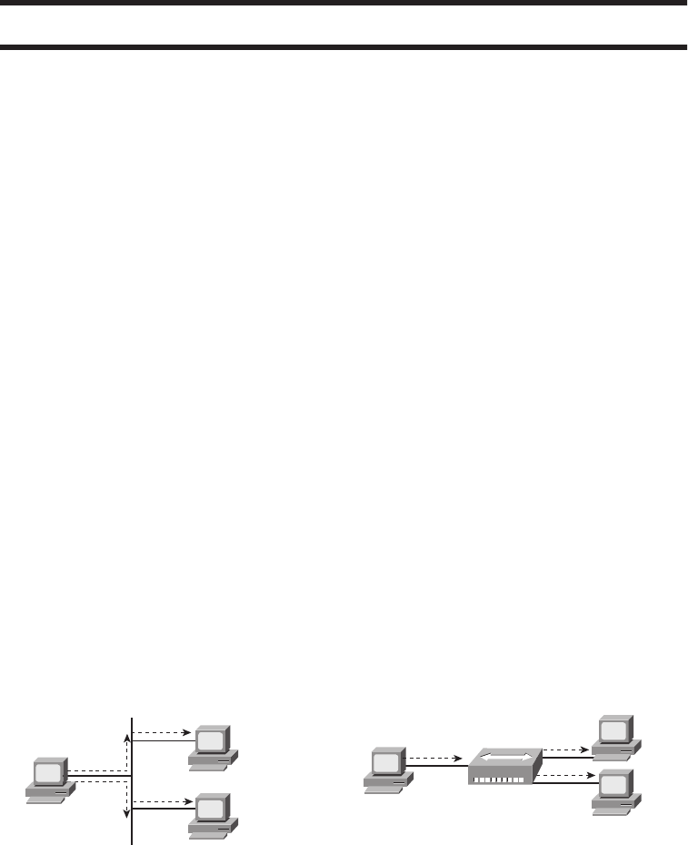
LAN Switching Concepts 171
Foundation Topics
This chapter begins by covering LAN concepts—in particular, the mechanics of how LAN
switches forward Ethernet frames. Following that, the next major section focuses on
campus LAN design concepts and terminology. It includes a review of some of the Ethernet
types that use optical cabling and therefore support longer cabling distances than do the
UTP-based Ethernet standards.
LAN Switching Concepts
Chapter 3 introduced Ethernet, including the concept of LAN hubs and switches. When
thinking about how LAN switches work, it can be helpful to think about how earlier
products (hubs and bridges) work. The first part of this section briefly looks at why switches
were created. Following that, this section explains the three main functions of a switch, plus
a few other details.
Historical Progression: Hubs, Bridges, and Switches
As mentioned in Chapter 3, Ethernet started out with standards that used a physical
electrical bus created with coaxial cabling. 10BASE-T Ethernet came next. It offered
improved LAN availability, because a problem on a single cable did not affect the rest of
the LAN—a common problem with 10BASE2 and 10BASE5 networks. 10BASE-T
allowed the use of unshielded twisted-pair (UTP) cabling, which is much cheaper than
coaxial cable. Also, many buildings already had UTP cabling installed for phone service,
so 10BASE-T quickly became a popular alternative to 10BASE2 and 10BASE5 Ethernet
networks. For perspective and review, Figure 7-1 depicts the typical topology for 10BASE2
and for 10BASE-T with a hub.
Figure 7-1 10BASE2 and 10BASE-T (with a Hub) Physical Topologies
Larry Archie
Bob
Solid Lines Represent
Co-ax Cable
10BASE2, Single Bus
Larry Archie
Bob
Solid Lines Represent
Twisted Pair Cabling
10BASE-T, Using Shared
Hub - Acts like Single Bus
Hub 1
1828xbook.fm Page 171 Thursday, July 26, 2007 3:10 PM
172 Chapter 7: Ethernet LAN Switching Concepts
Although using 10BASE-T with a hub improved Ethernet as compared to the older
standards, several drawbacks continued to exist, even with 10BASE-T using hubs:
■Any device sending a frame could have the frame collide with a frame sent by any other
device attached to that LAN segment.
■Only one device could send a frame at a time, so the devices shared the (10-Mbps)
bandwidth.
■Broadcasts sent by one device were heard by, and processed by, all other devices on
the LAN.
When these three types of Ethernet were introduced, a shared 10 Mbps of bandwidth was
a huge amount! Before the introduction of LANs, people often used dumb terminals, with
a 56-kbps WAN link being a really fast connection to the rest of the network—and that
56 kbps was shared among everyone in a remote building. So, in the days when 10BASE-T
was first used, getting a connection to a 10BASE-T Ethernet LAN was like getting a Gigabit
Ethernet connection for your work PC today. It was more bandwidth than you thought you
would ever need.
Over time, the performance of many Ethernet networks started to degrade. People
developed applications to take advantage of the LAN bandwidth. More devices were added
to each Ethernet. Eventually, an entire network became congested. The devices on the
same Ethernet could not send (collectively) more than 10 Mbps of traffic because they all
shared the 10 Mbps of bandwidth. In addition, the increase in traffic volumes increased
the number of collisions. Long before the overall utilization of an Ethernet approached
10 Mbps, Ethernet began to suffer because of increasing collisions.
Ethernet bridges were created to solve some of the performance issues. Bridges solved the
growing Ethernet congestion problem in two ways:
■They reduced the number of collisions that occurred in the network.
■They added bandwidth to the network.
Figure 7-2 shows the basic premise behind an Ethernet transparent bridge. The top part
of the figure shows a 10BASE-T network before adding a bridge, and the lower part shows
the network after it has been segmented using a bridge. The bridge creates two separate
collision domains. Fred’s frames can collide with Barney’s, but they cannot collide with
Wilma’s or Betty’s. If one LAN segment is busy, and the bridge needs to forward a frame
onto the busy segment, the bridge simply buffers the frame (holds the frame in memory)
until the segment is no longer busy. Reducing collisions, and assuming no significant
change in the number of devices or the load on the network, greatly improves network
performance.
1828xbook.fm Page 172 Thursday, July 26, 2007 3:10 PM
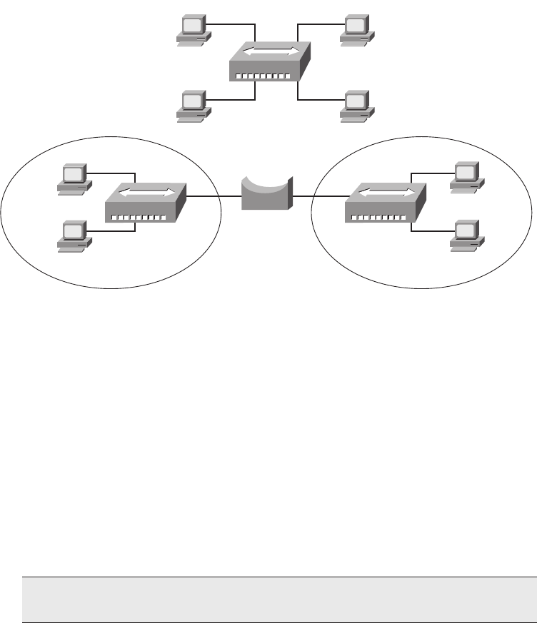
LAN Switching Concepts 173
Figure 7-2 Bridge Creates Two Collision Domains and Two Shared Ethernets
Adding a bridge between two hubs really creates two separate 10BASE-T networks—one
on the left and one on the right. The 10BASE-T network on the left has its own 10 Mbps to
share, as does the network on the right. So, in this example, the total network bandwidth is
doubled to 20 Mbps, as compared with the 10BASE-T network at the top of the figure.
LAN switches perform the same basic core functions as bridges, but with many enhanced
features. Like bridges, switches segment a LAN into separate parts, each part being a
separate collision domain. Switches have potentially large numbers of interfaces, with
highly optimized hardware, allowing even small Enterprise switches to forward millions of
Ethernet frames per second. By creating a separate collision domain for each interface,
switches multiply the amount of available bandwidth in the network. And, as mentioned in
Chapter 3, if a switch port connects to a single device, that Ethernet segment can use full-
duplex logic, essentially doubling the speed on that segment.
Figure 7-3 summarizes some of these key concepts, showing the same hosts as in Figure 7-2,
but now connected to a switch. In this case, all switch interfaces are running at 100 Mbps,
with four collision domains. Note that each interface also uses full duplex. This is possible
NOTE A switch’s effect of segmenting an Ethernet LAN into one collision domain per
interface is sometimes called microsegmentation.
1 Collision Domain
Sharing 10 Mbps
1 Collision Domain
Sharing 10 Mbps
1 Collision Domain
Sharing 10 Mbps
Bridge
Fred Wilma
Barney
Fred
Barney
Wilma
Betty
Betty
1828xbook.fm Page 173 Thursday, July 26, 2007 3:10 PM
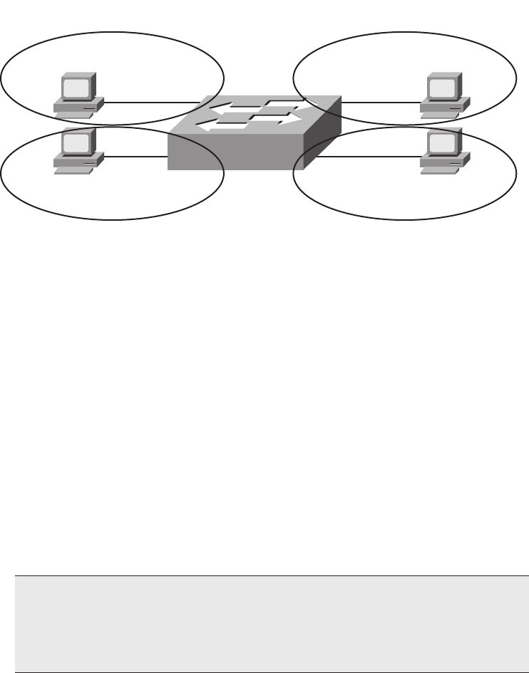
174 Chapter 7: Ethernet LAN Switching Concepts
because only one device is connected to each port, essentially eliminating collisions for the
network shown.
Figure 7-3 Switch Creates Four Collision Domains and Four Ethernet Segments
The next section examines how switches forward Ethernet frames.
Switching Logic
Ultimately, the role of a LAN switch is to forward Ethernet frames. To achieve that goal,
switches use logic—logic based on the source and destination MAC address in each frame’s
Ethernet header. To help you appreciate how switches work, first a review of Ethernet
addresses is in order.
The IEEE defines three general categories of Ethernet MAC addresses:
■Unicast addresses: MAC addresses that identify a single LAN interface card.
■Broadcast addresses: A frame sent with a destination address of the broadcast address
(FFFF.FFFF.FFFF) implies that all devices on the LAN should receive and process the
frame.
■Multicast addresses: Multicast MAC addresses are used to allow a dynamic subset of
devices on a LAN to communicate.
NOTE The IP protocol supports the multicasting of IP packets. When IP multicast
packets are sent over an Ethernet, the multicast MAC addresses used in the Ethernet
frame follow this format: 0100.5exx.xxxx, where a value between 00.0000 and 7f.ffff can
be used in the last half of the address. Ethernet multicast MAC addresses are not covered
in this book.
Fa0/4
Fa0/3
Fred
0200.1111.1111
Barney
0200.2222.2222
Fa0/2
Fa0/1
Wilma
0200.3333.3333
Betty
0200.4444.4444
Each Circle Is 1 Collision Domain, 100 Mbps Each
1828xbook.fm Page 174 Thursday, July 26, 2007 3:10 PM

LAN Switching Concepts 175
The primary job of a LAN switch is to receive Ethernet frames and then make a decision:
either forward the frame out some other port(s), or ignore the frame. To accomplish this
primary mission, transparent bridges perform three actions:
1. Deciding when to forward a frame or when to filter (not forward) a frame, based on the
destination MAC address
2. Learning MAC addresses by examining the source MAC address of each frame
received by the bridge
3. Creating a (Layer 2) loop-free environment with other bridges by using Spanning Tree
Protocol (STP)
The first action is the switch’s primary job, whereas the other two items are overhead
functions. The next sections examine each of these steps in order.
The Forward Versus Filter Decision
To decide whether to forward a frame, a switch uses a dynamically built table that lists
MAC addresses and outgoing interfaces. Switches compare the frame’s destination MAC
address to this table to decide whether the switch should forward a frame or simply ignore
it. For example, consider the simple network shown in Figure 7-4, with Fred sending a
frame to Barney.
Figure 7-4 shows an example of both the forwarding decision and the filtering decision.
Fred sends a frame with destination address 0200.2222.2222 (Barney’s MAC address). The
switch compares the destination MAC address (0200.2222.2222) to the MAC address table,
finding the matching entry. This is the interface out which a frame should be sent to deliver
it to that listed MAC address (0200.2222.2222). Because the interface in which the frame
arrived (Fa0/1) is different than the listed outgoing interface (Fa0/2), the switch decides to
forward the frame out interface Fa0/2, as shown in the figure’s table.
The key to anticipating where a switch should forward a frame is to examine and
understand the address table. The table lists MAC addresses and the interface the switch
should use when forwarding packets sent to that MAC address. For example, the table lists
0200.3333.3333 off Fa0/3, which is the interface out which the switch should forward
frames sent to Wilma’s MAC address (0200.3333.3333).
NOTE A switch’s MAC address table is also called the switching table, or bridging
table, or even the Content Addressable Memory (CAM), in reference to the type of
physical memory used to store the table.
1828xbook.fm Page 175 Thursday, July 26, 2007 3:10 PM
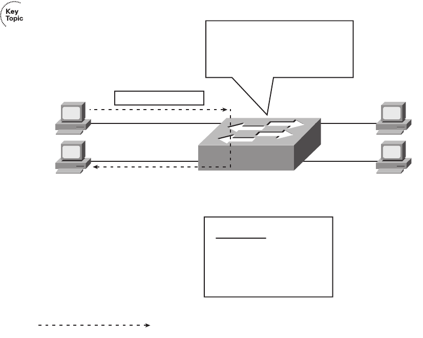
176 Chapter 7: Ethernet LAN Switching Concepts
Figure 7-4 Sample Switch Forwarding and Filtering Decision
Figure 7-5 shows a different perspective, with the switch making a filtering decision. In this
case, Fred and Barney connect to a hub, which is then connected to the switch. The switch’s
MAC address table lists both Fred’s and Barney’s MAC addresses off that single switch
interface (Fa0/1), because the switch would forward frames to both Fred and Barney out its
FA0/1 interface. So, when the switch receives a frame sent by Fred (source MAC address
0200.1111.1111) to Barney (destination MAC address 0200.2222.2222), the switch thinks
like this: “Because the frame entered my Fa0/1 interface, and I would send it out that same
Fa0/1 interface, do not send it (filter it), because sending it would be pointless.”
Fa0/4
Fa0/3
Fred
Barney
0200.2222.2222
Fa0/2
Fa0/1
Wilma
0200.3333.3333
Betty
0200.4444.4444
Dest 0200.2222.2222
Frame Sent to 0200.2222.2222…
Came in Fa0/1
Forward Out Fa0/2
Filter (Do Not Send) on Fa0/3, Fa0/4
Address Table
0200.1111.1111
0200.2222.2222
0200.3333.3333
0200.4444.4444
Fa0/1
Fa0/2
Fa0/3
Fa0/4
Path of Frame Transmission
1828xbook.fm Page 176 Thursday, July 26, 2007 3:10 PM
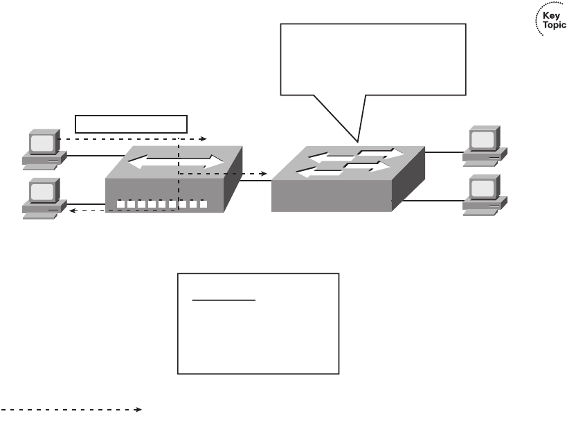
LAN Switching Concepts 177
Figure 7-5 Sample Switch Filtering Decision
Note that the hub simply regenerates the electrical signal out each interface, so the hub
forwards the electrical signal sent by Fred to both Barney and the switch. The switch
decides to filter (not forward) the frame, noting that the MAC address table’s interface for
0200.2222.2222 (Fa0/1) is the same as the incoming interface.
How Switches Learn MAC Addresses
The second main function of a switch is to learn the MAC addresses and interfaces to put
into its address table. With a full and accurate MAC address table, the switch can make
accurate forwarding and filtering decisions.
Switches build the address table by listening to incoming frames and examining the source
MAC address in the frame. If a frame enters the switch and the source MAC address is not
in the MAC address table, the switch creates an entry in the table. The MAC address is
placed in the table, along with the interface from which the frame arrived. Switch learning
logic is that simple.
Fa0/4
Fa0/3
Fred
Barney
0200.2222.2222
Fa0/1
Wilma
0200.3333.3333
Betty
0200.4444.4444
Dest 0200.2222.2222
Frame Sent to 0200.2222.2222…
MAC table entry lists Fa0/1…
Frame came in Fa0/1, so:
Filter (do not forward anywhere)
Address Table
0200.1111.1111
0200.2222.2222
0200.3333.3333
0200.4444.4444
Fa0/1
Fa0/1
Fa0/3
Fa0/4
Path of Frame Transmission
1828xbook.fm Page 177 Thursday, July 26, 2007 3:10 PM
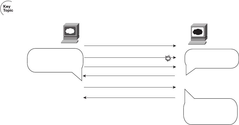
178 Chapter 7: Ethernet LAN Switching Concepts
Figure 7-6 depicts the same network as Figure 7-4, but before the switch has built any
address table entries. The figure shows the first two frames sent in this network—first a
frame from Fred, addressed to Barney, and then Barney’s response, addressed to Fred.
Figure 7-6 Switch Learning: Empty Table and Adding Two Entries
As shown in the figure, after Fred sends his first frame (labeled “1”) to Barney, the switch
adds an entry for 0200.1111.1111, Fred’s MAC address, associated with interface Fa0/1.
When Barney replies in Step 2, the switch adds a second entry, this one for 0200.2222.2222,
Barney’s MAC address, along with interface Fa0/2, which is the interface in which the
switch received the frame. Learning always occurs by looking at the source MAC address
in the frame.
Flooding Frames
Now again turn your attention to the forwarding process, using Figure 7-6. What do you
suppose the switch does with Fred’s first frame in Figure 7-6, the one that occurred when
there were no entries in the MAC address table? As it turns out, when there is no matching
entry in the table, switches forward the frame out all interfaces (except the incoming
interface). Switches forward these unknown unicast frames (frames whose destination
MAC addresses are not yet in the bridging table) out all other interfaces, with the hope that
the unknown device will be on some other Ethernet segment and will reply, allowing the
switch to build a correct entry in the address table.
For example, in Figure 7-6, the switch forwards the first frame out Fa0/2, Fa0/3, and
Fa0/4, even though 0200.2222.2222 (Barney) is only off Fa0/2. The switch does not
forward the frame back out Fa0/1, because a switch never forwards a frame out the same
Web
Browser
Web
Server
1000 Bytes of Data, Sequence = 1000
1000 Bytes of Data, Sequence = 2000
1000 Bytes of Data, Sequence = 3000
No Data, Acknowledgment = 4000
No Data, Acknowledgment = 2000
1000 Bytes of Data, Sequence = 2000
I Probably Lost One.
ACK What I Got in
Order!
I Just Got 2000-2999,
and I Already Had
3000-3999. Ask for
4000 Next.
He Lost the Segment
with Sequence =
2000. Resend It!
1828xbook.fm Page 178 Thursday, July 26, 2007 3:10 PM

LAN Switching Concepts 179
interface on which it arrived. (As a side note, Figure 7-6 does not show the frame
being forwarded out interfaces Fa0/3 and Fa0/4, because this figure is focused on the
learning process.) When Barney replies to Fred, the switch correctly adds an entry for
0200.2222.2222 (Fa0/2) to its address table. Any later frames sent to destination address
0200.2222.2222 will no longer need to be sent out Fa0/3 and Fa0/4, only being forwarded
out Fa0/2.
The process of sending frames out all other interfaces, except the interface on which the
frame arrived, is called flooding. Switches flood unknown unicast frames as well as
broadcast frames. Switches also flood LAN multicast frames out all ports, unless the switch
has been configured to use some multicast optimization tools that are not covered in this
book.
Switches keep a timer for each entry in the MAC address table, called an inactivity timer.
The switch sets the timer to 0 for new entries. Each time the switch receives another frame
with that same source MAC address, the timer is reset to 0. The timer counts upward, so
the switch can tell which entries have gone the longest time since receiving a frame from
that device. If the switch ever runs out of space for entries in the MAC address table, the
switch can then remove table entries with the oldest (largest) inactivity timers.
Avoiding Loops Using Spanning Tree Protocol
The third primary feature of LAN switches is loop prevention, as implemented by Spanning
Tree Protocol (STP). Without STP, frames would loop for an indefinite period of time in
Ethernet networks with physically redundant links. To prevent looping frames, STP blocks
some ports from forwarding frames so that only one active path exists between any pair of
LAN segments (collision domains). The result of STP is good: frames do not loop infinitely,
which makes the LAN usable. However, although the network can use some redundant
links in case of a failure, the LAN does not load-balance the traffic.
To avoid Layer 2 loops, all switches need to use STP. STP causes each interface on a switch
to settle into either a blocking state or a forwarding state. Blocking means that the interface
cannot forward or receive data frames. Forwarding means that the interface can send and
receive data frames. If a correct subset of the interfaces is blocked, a single currently active
logical path exists between each pair of LANs.
A simple example makes the need for STP more obvious. Remember, switches flood
frames sent to both unknown unicast MAC addresses and broadcast addresses.
NOTE STP behaves identically for a transparent bridge and a switch. Therefore,
the terms bridge, switch, and bridging device all are used interchangeably when
discussing STP.
1828xbook.fm Page 179 Thursday, July 26, 2007 3:10 PM
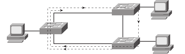
180 Chapter 7: Ethernet LAN Switching Concepts
Figure 7-7 shows that a single frame, sent by Larry to Bob, loops forever because the
network has redundancy but no STP.
Figure 7-7 Network with Redundant Links But Without STP: The Frame Loops Forever
Larry sends a single unicast frame to Bob’s MAC address, but Bob is powered off, so none
of the switches has learned Bob’s MAC address yet. Bob’s MAC address would be an
unknown unicast address at this point in time. Therefore, frames destined for Bob’s MAC
address are forwarded by each switch out every port. These frames loop indefinitely.
Because the switches never learn Bob’s MAC address (remember, he’s powered off and can
send no frames), they keep forwarding the frame out all ports, and copies of the frame go
around and around.
Similarly, switches flood broadcasts as well, so if any of the PCs sent a broadcast, the
broadcast would also loop indefinitely.
One way to solve this problem is to design the LAN with no redundant links. However,
most network engineers purposefully design LANs to use physical redundancy between the
switches. Eventually, a switch or a link will fail, and you want the network to still be
available by having some redundancy in the LAN design. The right solution includes
switched LANs with physical redundancy, while using STP to dynamically block some
interface(s) so that only one active path exists between two endpoints at any instant in time.
Chapter 2, “Spanning Tree Protocol,” in the CCNA ICND2 Official Exam Certification
Guide covers the details of how STP prevents loops.
Internal Processing on Cisco Switches
This chapter has already explained how switches decide whether to forward or filter a
frame. As soon as a Cisco switch decides to forward a frame, the switch can use a couple
of different types of internal processing variations. Almost all of the more recently released
switches use store-and-forward processing, but all three types of these internal processing
methods are supported in at least one type of currently available Cisco switch.
Bob
Powered Off!
Archie
Larry
1828xbook.fm Page 180 Thursday, July 26, 2007 3:10 PM

LAN Switching Concepts 181
Some switches, and transparent bridges in general, use store-and-forward processing. With
store-and-forward, the switch must receive the entire frame before forwarding the first
bit of the frame. However, Cisco also offers two other internal processing methods for
switches: cut-through and fragment-free. Because the destination MAC address occurs very
early in the Ethernet header, a switch can make a forwarding decision long before the
switch has received all the bits in the frame. The cut-through and fragment-free processing
methods allow the switch to start forwarding the frame before the entire frame has been
received, reducing time required to send the frame (the latency, or delay).
With cut-through processing, the switch starts sending the frame out the output port as soon
as possible. Although this might reduce latency, it also propagates errors. Because the frame
check sequence (FCS) is in the Ethernet trailer, the switch cannot determine if the frame
had any errors before starting to forward the frame. So, the switch reduces the frame’s
latency, but with the price of having forwarded some frames that contain errors.
Fragment-free processing works similarly to cut-through, but it tries to reduce the number
of errored frames that it forwards. One interesting fact about Ethernet carrier sense multiple
access with collision detection (CSMA/CD) logic is that collisions should be detected
within the first 64 bytes of a frame. Fragment-free processing works like cut-through logic,
but it waits to receive the first 64 bytes before forwarding a frame. The frames experience
less latency than with store-and-forward logic and slightly more latency than with cut-
through, but frames that have errors as a result of collisions are not forwarded.
With many links to the desktop running at 100 Mbps, uplinks at 1 Gbps, and faster
application-specific integrated circuits (ASIC), today’s switches typically use store-and-
forward processing, because the improved latency of the other two switching methods is
negligible at these speeds.
The internal processing algorithms used by switches vary among models and vendors;
regardless, the internal processing can be categorized as one of the methods listed in Table 7-2.
Table 7-2 Switch Internal Processing
Switching Method Description
Store-and-forward The switch fully receives all bits in the frame (store) before
forwarding the frame (forward). This allows the switch to
check the FCS before forwarding the frame.
Cut-through The switch forwards the frame as soon as it can. This
reduces latency but does not allow the switch to discard
frames that fail the FCS check.
Fragment-free The switch forwards the frame after receiving the first 64
bytes of the frame, thereby avoiding forwarding frames that
were errored due to a collision.
1828xbook.fm Page 181 Thursday, July 26, 2007 3:10 PM

182 Chapter 7: Ethernet LAN Switching Concepts
LAN Switching Summary
Switches provide many additional features not offered by older LAN devices such as hubs
and bridges. In particular, LAN switches provide the following benefits:
■Switch ports connected to a single device microsegment the LAN, providing dedicated
bandwidth to that single device.
■Switches allow multiple simultaneous conversations between devices on different
ports.
■Switch ports connected to a single device support full duplex, in effect doubling the
amount of bandwidth available to the device.
■Switches support rate adaptation, which means that devices that use different Ethernet
speeds can communicate through the switch (hubs cannot).
Switches use Layer 2 logic, examining the Ethernet data-link header to choose how to
process frames. In particular, switches make decisions to forward and filter frames, learn
MAC addresses, and use STP to avoid loops, as follows:
Step 1 Switches forward frames based on the destination address:
a. If the destination address is a broadcast, multicast, or unknown destination
unicast (a unicast not listed in the MAC table), the switch floods the frame.
b. If the destination address is a known unicast address (a unicast address found
in the MAC table):
i. If the outgoing interface listed in the MAC address table is different from the
interface in which the frame was received, the switch forwards the frame out
the outgoing interface.
ii. If the outgoing interface is the same as the interface in which the frame was
received, the switch filters the frame, meaning that the switch simply ignores
the frame and does not forward it.
Step 2 Switches use the following logic to learn MAC address table entries:
a. For each received frame, examine the source MAC address and note the
interface from which the frame was received.
b. If they are not already in the table, add the address and interface, setting the
inactivity timer to 0.
c. If it is already in the table, reset the inactivity timer for the entry to 0.
Step 3 Switches use STP to prevent loops by causing some interfaces to block,
meaning that they do not send or receive frames.
1828xbook.fm Page 182 Thursday, July 26, 2007 3:10 PM
LAN Design Considerations 183
LAN Design Considerations
So far, the LAN coverage in this book has mostly focused on individual functions of LANs.
For example, you have read about how switches forward frames, the details of UTP cables
and cable pinouts, the CSMA/CD algorithm that deals with the issue of collisions, and
some of the differences between how hubs and switches operate to create either a single
collision domain (hubs) or many collision domains (switches).
This section now takes a broader look at LANs—particularly, how to design medium to
larger LANs. When building a small LAN, you might simply buy one switch, plug in cables
to connect a few devices, and you’re finished. However, when building a medium to large
LAN, you have more product choices to make, such as when to use hubs, switches, and
routers. Additionally, you must weigh the choice of which LAN switch to choose (switches
vary in size, number of ports, performance, features, and price). The types of LAN media
differ as well. Engineers must weigh the benefits of UTP cabling, like lower cost and
ease of installation, versus fiber optic cabling options, which support longer distances
and better physical security.
This section examines a variety of topics that all relate to LAN design in some way. In
particular, this section begins by looking at the impact of the choice of using a hub, switch,
or router to connect parts of LANs. Following that, some Cisco design terminology is
covered. Finishing this section is a short summary of some of the more popular types of
Ethernet and cabling types, and cable length guidelines for each.
Collision Domains and Broadcast Domains
When creating any Ethernet LAN, you use some form of networking devices—typically
switches today—a few routers, and possibly a few hubs. The different parts of an Ethernet
LAN may behave differently, in terms of function and performance, depending on which
types of devices are used. These differences then affect a network engineer’s decision when
choosing how to design a LAN.
The terms collision domain and broadcast domain define two important effects of the
process of segmenting LANs using various devices. This section examines the concepts
behind Ethernet LAN design. The goal is to define these terms and to explain how hubs,
switches, and routers impact collision domains and broadcast domains.
Collision Domains
As mentioned earlier, a collision domain is the set of LAN interfaces whose frames could
collide with each other, but not with frames sent by any other devices in the network. To
review the core concept, Figure 7-8 illustrates collision domains.
1828xbook.fm Page 183 Thursday, July 26, 2007 3:10 PM
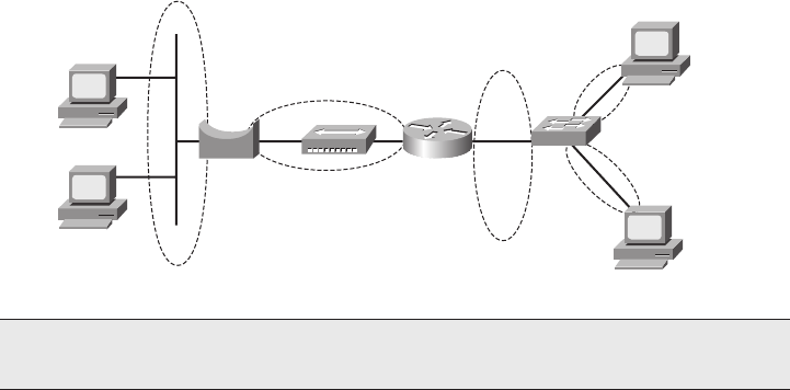
184 Chapter 7: Ethernet LAN Switching Concepts
Figure 7-8 Collision Domains
Each separate segment, or collision domain, is shown with a dashed-line circle in the figure.
The switch on the right separates the LAN into different collision domains for each port.
Likewise, both bridges and routers also separate LANs into different collision domains
(although this effect with routers was not covered earlier in this book). Of all the devices in
the figure, only the hub near the center of the network does not create multiple collision
domains for each interface. It repeats all frames out all ports without any regard for
buffering and waiting to send a frame onto a busy segment.
Broadcast Domains
The term broadcast domain relates to where broadcasts can be forwarded. A broadcast
domain encompasses a set of devices for which, when one of the devices sends a broadcast,
all the other devices receive a copy of the broadcast. For example, switches flood broadcasts
and multicasts on all ports. Because broadcast frames are sent out all ports, a switch creates
a single broadcast domain.
Conversely, only routers stop the flow of broadcasts. For perspective, Figure 7-9 provides
the broadcast domains for the same network depicted in Figure 7-8.
Broadcasts sent by a device in one broadcast domain are not forwarded to devices in
another broadcast domain. In this example, there are two broadcast domains. For instance,
the router does not forward a LAN broadcast sent by a PC on the left to the network segment
on the right. In the old days, the term broadcast firewall described the fact that routers did
not forward LAN broadcasts.
NOTE The LAN design in Figure 7-8 is not a typical design today. Instead, it simply
provides enough information to help you compare hubs, switches, and routers.
1828xbook.fm Page 184 Thursday, July 26, 2007 3:10 PM
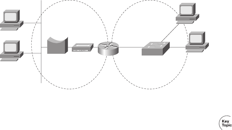
LAN Design Considerations 185
Figure 7-9 Broadcast Domains
General definitions for a collision domain and a broadcast domain are as follows:
■A collision domain is a set of network interface cards (NIC) for which a frame sent by
one NIC could result in a collision with a frame sent by any other NIC in the same
collision domain.
■A broadcast domain is a set of NICs for which a broadcast frame sent by one NIC is
received by all other NICs in the same broadcast domain.
The Impact of Collision and Broadcast Domains on LAN Design
When designing a LAN, you need to keep in mind the trade-offs when choosing the number
of devices in each collision domain and broadcast domain. First, consider the devices in a
single collision domain for a moment. For a single collision domain:
■The devices share the available bandwidth.
■The devices may inefficiently use that bandwidth due to the effects of collisions,
particularly under higher utilization.
For example, you might have ten PCs with 10/100 Ethernet NICs. If you connect all ten PCs
to ten different ports on a single 100-Mbps hub, you have one collision domain, and the PCs
in that collision domain share the 100 Mbps of bandwidth. That may work well and meet
the needs of those users. However, with heavier traffic loads, the hub’s performance would
be worse than it would be if you had used a switch. Using a switch instead of a hub, with
the same topology, would create ten different collision domains, each with 100 Mbps of
bandwidth. Additionally, with only one device on each switch interface, no collisions would
occur. This means that you could enable full duplex on each interface, effectively giving
each interface 200 Mbps, and a theoretical maximum of 2 Gbps of bandwidth—a
considerable improvement!
1828xbook.fm Page 185 Thursday, July 26, 2007 3:10 PM

186 Chapter 7: Ethernet LAN Switching Concepts
Using switches instead of hubs seems like an obvious choice given the overwhelming
performance benefits. Frankly, most new installations today use switches exclusively.
However, vendors still offer hubs, mainly because hubs are still slightly less expensive than
switches, so you may still see hubs in networks today.
Now consider the issue of broadcasts. When a host receives a broadcast, the host must
process the received frame. This means that the NIC must interrupt the computer’s CPU,
and the CPU must spend time thinking about the received broadcast frame. All hosts need
to send some broadcasts to function properly. (For example, IP ARP messages are LAN
broadcasts, as mentioned in Chapter 5, “Fundamentals of IP Addressing and Routing.”) So,
broadcasts happen, which is good, but broadcasts do require all the hosts to spend time
processing each broadcast frame.
Next, consider a large LAN, with multiple switches, with 500 PCs total. The switches
create a single broadcast domain, so a broadcast sent by any of the 500 hosts should
be sent to, and then processed by, all 499 other hosts. Depending on the number of
broadcasts, the broadcasts could start to impact performance of the end-user PCs.
However, a design that separated the 500 PCs into five groups of 100, separated from each
other by a router, would create five broadcast domains. Now, a broadcast by one host
would interrupt only 99 other hosts, and not the other 400 hosts, resulting in generally
better performance on the PCs.
The choice about when to use a hub versus a switch was straightforward, but the choice of
when to use a router to break up a large broadcast domain is more difficult. A meaningful
discussion of the trade-offs and options is beyond the scope of this book. However, you
should understand the concepts behind broadcast domains—specifically, that a router
breaks LANs into multiple broadcast domains, but switches and hubs do not.
More importantly for the CCNA exams, you should be ready to react to questions in
terms of the benefits of LAN segmentation instead of just asking for the facts related
to collision domains and broadcast domains. Table 7-3 lists some of the key benefits.
The features in the table should be interpreted within the following context: “Which of
the following benefits are gained by using a hub/switch/router between Ethernet
devices?”
NOTE Using smaller broadcast domains can also improve security, due to limiting
broadcasts, and due to robust security features in routers.
1828xbook.fm Page 186 Thursday, July 26, 2007 3:10 PM
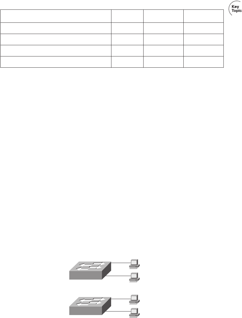
LAN Design Considerations 187
Virtual LANs (VLAN)
Most every Enterprise network today uses the concept of virtual LANs (VLAN). Before
understanding VLANs, you must have a very specific understanding of the definition of a
LAN. Although you can think about and define the term “LAN” from many perspectives,
one perspective in particular will help you understand VLANs:
A LAN consists of all devices in the same broadcast domain.
Without VLANs, a switch considers all interfaces on the switch to be in the same broadcast
domain. In other words, all connected devices are in the same LAN. (Cisco switches
accomplish this by putting all interfaces in VLAN 1 by default.) With VLANs, a switch can
put some interfaces into one broadcast domain and some into another based on some simple
configuration. Essentially, the switch creates multiple broadcast domains by putting some
interfaces into one VLAN and other interfaces into other VLANs. These individual
broadcast domains created by the switch are called virtual LANs.
So, instead of all ports on a switch forming a single broadcast domain, the switch separates
them into many, based on configuration. It’s really that simple.
The next two figures compare two LANs for the purpose of explaining a little more about
VLANs. First, before VLANs existed, if a design specified two separate broadcast domains,
two switches would be used—one for each broadcast domain, as shown in Figure 7-10.
Figure 7-10 Sample Network with Two Broadcast Domains and No VLANs
Table 7-3 Benefits of Segmenting Ethernet Devices Using Hubs, Switches, and Routers
Feature Hub Switch Router
Greater cabling distances are allowed Yes Yes Yes
Creates multiple collision domains No Yes Yes
Increases bandwidth No Yes Yes
Creates multiple broadcast domains No No Yes
Dino
Fred
Wilma
Betty
1828xbook.fm Page 187 Thursday, July 26, 2007 3:10 PM
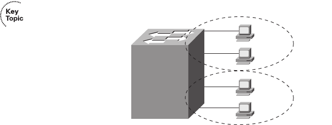
188 Chapter 7: Ethernet LAN Switching Concepts
Alternately, you can create multiple broadcast domains using a single switch. Figure 7-11
shows the same two broadcast domains as in Figure 7-10, now implemented as two
different VLANs on a single switch.
Figure 7-11 Sample Network with Two VLANs Using One Switch
In a network as small as the one shown in Figure 7-11, you might not really need to use
VLANs. However, there are many motivations for using VLANs, including the following:
■To create more flexible designs that group users by department, or by groups that work
together, instead of by physical location
■To segment devices into smaller LANs (broadcast domains) to reduce overhead caused
to each host in the VLAN
■To reduce the workload for STP by limiting a VLAN to a single access switch
■To enforce better security by keeping hosts that work with sensitive data on a separate
VLAN
■To separate traffic sent by an IP phone from traffic sent by PCs connected to the phones
The CCNA ICND2 Official Exam Certification Guide explains VLAN configuration and
troubleshooting.
Campus LAN Design Terminology
The term campus LAN refers to the LAN created to support larger buildings, or multiple
buildings in somewhat close proximity to one another. For instance, a company might lease
office space in several buildings in the same office park. The network engineers can then
build a campus LAN that includes switches in each building, plus Ethernet links between
the switches in the buildings, to create a larger campus LAN.
When planning and designing a campus LAN, the engineers must consider the types of
Ethernet available and the cabling lengths supported by each type. The engineers also need
to choose the speeds required for each Ethernet segment. Additionally, some thought needs
Dino
Fred
Wilma
Betty
VLAN1
VLAN2
1828xbook.fm Page 188 Thursday, July 26, 2007 3:10 PM
LAN Design Considerations 189
to be given to the idea that some switches should be used to connect directly to end-user
devices, whereas other switches might need to simply connect to a large number of these
end-user switches. Finally, most projects require that the engineer consider the type of
equipment that is already installed and whether an increase in speed on some segments is
worth the cost of buying new equipment.
For example, the vast majority of PCs that are already installed in networks today have
10/100 NICs, with many new PCs today having 10/100/1000 NICs built into the PC.
Assuming that the appropriate cabling has been installed, a 10/100/1000 NIC can use
autonegotiation to use either 10BASE-T (10 Mbps), 100BASE-TX (100 Mbps), or
1000BASE-T (1000 Mbps, or 1 Gbps) Ethernet, each using the same UTP cable. However,
one trade-off the engineer must make is whether to buy switches that support only 10/100
interfaces or that support 10/100/1000 interfaces. At the time this book was published
(summer 2007), the price difference between switches that support only 10/100 interfaces,
versus 10/100/1000 interfaces, was still large enough to get management’s attention.
However, spending the money on switches that include 10/100/1000 interfaces allows you
to connect pretty much any end-user device. You’ll also be ready to migrate from 100 Mbps
to the desktop device to 1000 Mbps (gigabit) as new PCs are bought.
To sift through all the requirements for a campus LAN, and then have a reasonable
conversation about it with peers, most Cisco-oriented LAN designs use some common
terminology to refer to the design. For this book’s purposes, you should be aware of some
of the key campus LAN design terminology. Figure 7-12 shows a typical design of a large
campus LAN, with the terminology included in the figure. Explanations of the terminology
follow the figure.
Cisco uses three terms to describe the role of each switch in a campus design: access,
distribution, and core. The roles differ mainly in two main concepts:
■Whether the switch should connect to end-user devices
■Whether the switch should forward frames between other switches by connecting to
multiple different switches
Access switches connect directly to end users, providing access to the LAN. Under normal
circumstances, access switches normally send traffic to and from the end-user devices to
which they are connected. However, access switches should not, at least by design, be
expected to forward traffic between two other switches. For example, in Figure 7-12, switch
Access1 normally would not forward traffic going from PCs connected to switch Access3
to a PC off switch Access4. Because access layer switches support only the traffic for the
locally attached PCs, access switches tend to be smaller and less expensive, often
supporting just enough ports to support a particular floor of a building.
1828xbook.fm Page 189 Thursday, July 26, 2007 3:10 PM
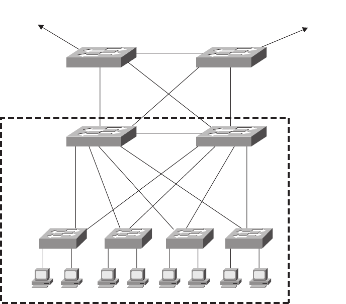
190 Chapter 7: Ethernet LAN Switching Concepts
Figure 7-12 Campus LAN with Design Terminology Listed
In larger campus LANs, distribution switches provide a path through which the access
switches can forward traffic to each other. By design, each of the access switches connects
to at least one distribution switch. However, designs use at least two uplinks to two different
distribution switches (as shown in Figure 7-12) for redundancy.
Using distribution switches provides some cabling advantages and potential performance
advantages. For example, if a network had 30 access layer switches, and the network
engineer decided that each access layer switch should be cabled directly to every other
access layer switch, the LAN would need 435 cables between switches! Furthermore, that
design includes only one segment between each pair of switches. A possibly worse side
effect is that if a link fails, the access layer switches may forward traffic to and from other
switches, stressing the performance of the access switch, which typically is a less expensive
but less powerful switch. Instead, by connecting each of the 30 access switches to two
different distribution switches, only 60 cables are required. Well-chosen distribution
switches, with faster forwarding rates, can handle the larger amount of traffic between
switches. Additionally, the design with two distribution switches, with two uplinks from
Access1 Access2 Access3 Access4
Dist1 Dist2
Core1 Core2
Core
Links
Uplinks
To Other
Building
Blocks
To Other
Building
Blocks
Access
Links
Building
Block
Access
Switches
Distribution
Switches
Core
Switches
1828xbook.fm Page 190 Thursday, July 26, 2007 3:10 PM
LAN Design Considerations 191
each access switch to the distribution switches, actually has more redundancy and therefore
better availability.
Core switches provide even more aggregation benefits than do the distribution switches.
Core switches provide extremely high forwarding rates—these days into the hundreds of
millions of frames per second. The reasons for core switches are generally the same as for
distribution switches. However, medium to smaller campus LANs often forego the concept
of core switches.
The following list summarizes the terms that describe the roles of campus switches:
■Access: Provides a connection point (access) for end-user devices. Does not forward
frames between two other access switches under normal circumstances.
■Distribution: Provides an aggregation point for access switches, forwarding frames
between switches, but not connecting directly to end-user devices.
■Core: Aggregates distribution switches in very large campus LANs, providing very
high forwarding rates.
Ethernet LAN Media and Cable Lengths
When designing a campus LAN, an engineer must consider the length of each cable run and
then find the best type of Ethernet and cabling type that supports that length of cable. For
example, if a company leases space in five buildings in the same office park, the engineer
needs to figure out how long the cables between the buildings need to be and then pick the
right type of Ethernet.
The three most common types of Ethernet today (10BASE-T, 100BASE-TX, and
1000BASE-T) have the same 100-meter cable restriction, but they use slightly different
cables. The EIA/TIA defines Ethernet cabling standards, including the cable’s quality. Each
Ethernet standard that uses UTP cabling lists a cabling quality category as the minimum
category that the standard supports. For example, 10BASE-T allows for Category 3 (CAT3)
cabling or better, whereas 100BASE-TX calls for higher-quality CAT5 cabling, and
1000BASE-TX requires even higher-quality CAT5e or CAT6 cabling. If an engineer plans
on using existing cabling, he or she must be aware of the types of UTP cables and the speed
restrictions implied by the type of Ethernet the cabling supports.
Several types of Ethernet define the use of fiber-optic cables. UTP cables include copper
wires over which electrical currents can flow, whereas optical cables include ultra-thin
strands of glass through which light can pass. To send bits, the switches can alternate
between sending brighter and dimmer light to encode 0s and 1s on the cable.
1828xbook.fm Page 191 Thursday, July 26, 2007 3:10 PM

192 Chapter 7: Ethernet LAN Switching Concepts
Optical cables support a variety of much longer distances than the 100 meters supported by
Ethernet on UTP cables. Optical cables experience much less interference from outside
sources as compared to copper cables. Additionally, switches can use lasers to generate the
light, as well as light-emitting diodes (LED). Lasers allow for even longer cabling
distances, up to 100 km today, at higher cost, whereas less-expensive LEDs may well
support plenty of distance for campus LANs in most office parks.
Finally, the type of optical cabling can also impact the maximum distances per cable. Of
the two types, multimode fiber supports shorter distances, but it is generally cheaper
cabling, and it works fine with less-expensive LEDs. The other optical cabling type, single-
mode fiber, supports the longest distances but is more expensive. Also note that the
switch hardware to use LEDs (often with multimode fiber) is much less expensive than the
switch hardware to support lasers (often with single-mode fiber).
Table 7-4 lists the more common types of Ethernet and their cable types and length
limitations.
Table 7-4 Ethernet Types, Media, and Segment Lengths (Per IEEE)
Ethernet Type Media Maximum Segment Length
10BASE-T TIA/EIA CAT3 or better, two pair 100 m (328 feet)
100BASE-TX TIA/EIA CAT5 UTP or better, two pair 100 m (328 feet)
100BASE-FX 62.5/125-micron multimode fiber 400 m (1312.3 feet)
1000BASE-CX STP 25 m (82 feet)
1000BASE-T TIA/EIA CAT5e UTP or better, four pair 100 m (328 feet)
1000BASE-SX Multimode fiber 275 m (853 feet) for 62.5-micron
fiber
550 m (1804.5 feet) for 50-micron
fiber
1000BASE-LX Multimode fiber 550 m (1804.5 feet) for 50- and
62.5-micron fiber
1000BASE-LX 9-micron single-mode fiber 10 km (6.2 miles)
1828xbook.fm Page 192 Thursday, July 26, 2007 3:10 PM
LAN Design Considerations 193
Most engineers simply remember the general distance limitations and then use a reference
chart (such as Table 7-4) to remember each specific detail. An engineer must also consider
the physical paths that the cables will use to run through a campus or building and the
impact on the required cable length. For example, a cable might have to run from one end
of the building to the other, and then through a conduit that connects the floors of the
building, and then horizontally to a wiring closet on another floor. Often those paths are not
the shortest way to get from one place to the other. So the chart’s details are important to
the LAN planning process and the resulting choice of LAN media.
1828xbook.fm Page 193 Thursday, July 26, 2007 3:10 PM

194 Chapter 7: Ethernet LAN Switching Concepts
Exam Preparation Tasks
Review All the Key Topics
Review the most important topics from this chapter, noted with the key topics icon.
Table 7-5 lists these key topics and where each is discussed.
Complete the Tables and Lists from Memory
Print a copy of Appendix H, “Memory Tables” (found on the CD), or at least the section for
this chapter, and complete the tables and lists from memory. Appendix I, “Memory Tables
Answer Key,” also on the CD, includes completed tables and lists for you to check
your work.
Table 7-5 Key Topics for Chapter 7
Key Topic Element Description Page Number
List Some of the benefits of switching 175
Figure 7-4 Example of switch forwarding logic 176
Figure 7-5 Example of switch filtering logic 177
Figure 7-6 Example of how a switch learns MAC
addresses
178
Table 7-2 Summary of three switch internal forwarding
options
181
List Some of the benefits of switching 182
List Summary of logic used to forward and filter
frames and to learn MAC addresses
182
List Definitions of collision domain and broadcast
domain
185
Table 7-3 Four LAN design feature comparisons with
hubs, switches, and routers
187
Figure 7-11 Illustration of the concept of a VLAN 188
1828xbook.fm Page 194 Thursday, July 26, 2007 3:10 PM
Definitions of Key Terms 195
Definitions of Key Terms
Define the following key terms from this chapter, and check your answers in the glossary:
broadcast domain, broadcast frame, collision domain, cut-through switching, flooding,
fragment-free switching, microsegmentation, segmentation, Spanning Tree Protocol
(STP), store-and-forward switching, unknown unicast frame, virtual LAN
1828xbook.fm Page 195 Thursday, July 26, 2007 3:10 PM

This chapter covers the following subjects:
Accessing the Cisco Catalyst 2960
Switch CLI: This section examines Cisco 2960
switches and shows you how to gain access to the
command-line interface (CLI) from which you
can issue commands to the switch.
Configuring Cisco IOS Software: This section
shows you how to tell the switch different
operational parameters using the CLI.
1828xbook.fm Page 196 Thursday, July 26, 2007 3:10 PM

C H A P T E R8
Operating Cisco LAN Switches
LAN switches may be the most common networking device found in the Enterprise today.
Most new end-user computers sold today include a built-in Ethernet NIC of some kind.
Switches provide a connection point for the Ethernet devices so that the devices on the LAN
can communicate with each other and with the rest of an Enterprise network or with the
Internet.
Cisco routers also happen to use the exact same user interface as the Cisco Catalyst
switches described in this chapter. So, even though this chapter is called “Operating Cisco
LAN Switches,” keep in mind that the user interface of Cisco routers works the same way.
Chapter 13, “Operating Cisco Routers,” begins by summarizing the features covered in this
chapter that also apply to routers.
“Do I Know This Already?” Quiz
The “Do I Know This Already?” quiz allows you to assess whether you should read the
entire chapter. If you miss no more than one of these seven self-assessment questions, you
might want to move ahead to the “Exam Preparation Tasks” section. Table 8-1 lists the
major headings in this chapter and the “Do I Know This Already?” quiz questions covering
the material in those sections. This helps you assess your knowledge of these specific areas.
The answers to the “Do I Know This Already?” quiz appear in Appendix A.
Table 8-1 “Do I Know This Already?” Foundation Topics Section-to-Question Mapping
Foundation Topics Section Questions
Accessing the Cisco Catalyst 2960 Switch CLI 1–3
Configuring Cisco IOS Software 4–7
1828xbook.fm Page 197 Thursday, July 26, 2007 3:10 PM
198 Chapter 8: Operating Cisco LAN Switches
1. In what modes can you execute the command show mac-address-table?
a. User mode
b. Enable mode
c. Global configuration mode
d. Setup mode
e. Interface configuration mode
2. In which of the following modes of the CLI could you issue a command to reboot the
switch?
a. User mode
b. Enable mode
c. Global configuration mode
d. Interface configuration mode
3. Which of the following is a difference between Telnet and SSH as supported by a Cisco
switch?
a. SSH encrypts the passwords used at login, but not other traffic; Telnet encrypts
nothing.
b. SSH encrypts all data exchange, including login passwords; Telnet encrypts
nothing.
c. Telnet is used from Microsoft operating systems, and SSH is used from UNIX
and Linux operating systems.
d. Telnet encrypts only password exchanges; SSH encrypts all data exchanges.
4. What type of switch memory is used to store the configuration used by the switch when
it is up and working?
a. RAM
b. ROM
c. Flash
d. NVRAM
e. Bubble
1828xbook.fm Page 198 Thursday, July 26, 2007 3:10 PM
“Do I Know This Already?” Quiz 199
5. What command copies the configuration from RAM into NVRAM?
a. copy running-config tftp
b. copy tftp running-config
c. copy running-config start-up-config
d. copy start-up-config running-config
e. copy startup-config running-config
f. copy running-config startup-config
6. Which mode prompts the user for basic configuration information?
a. User mode
b. Enable mode
c. Global configuration mode
d. Setup mode
e. Interface configuration mode
7. A switch user is currently in console line configuration mode. Which of the following
would place the user in enable mode?
a. Using the exit command once
b. Using the exit command twice in a row
c. Pressing the Ctrl-z key sequence
d. Using the quit command
1828xbook.fm Page 199 Thursday, July 26, 2007 3:10 PM

200 Chapter 8: Operating Cisco LAN Switches
Foundation Topics
When you buy a Cisco Catalyst switch, you can take it out of the box, power on the switch
by connecting the power cable to the switch and a power outlet, and connect hosts to the
switch using the correct UTP cables, and the switch works. You do not have to do anything
else, and you certainly do not have to tell the switch to start forwarding Ethernet frames.
The switch uses default settings so that all interfaces will work, assuming that the right
cables and devices connect to the switch, and the switch forwards frames in and out of each
interface.
However, most Enterprises will want to be able to check on the switch’s status, look at
information about what the switch is doing, and possibly configure specific features of the
switch. Engineers will also want to enable security features that allow them to securely
access the switches without being vulnerable to malicious people breaking into the
switches. To perform these tasks, a network engineer needs to connect to the switch’s user
interface.
This chapter explains the details of how to access a Cisco switch’s user interface, how to
use commands to find out how the switch is currently working, and how to configure the
switch to tell it what to do. This chapter focuses on the processes, as opposed to examining
a particular set of commands. Chapter 9, “Ethernet Switch Configuration,” then takes a
closer look at the variety of commands that can be used from the switch user interface.
Cisco has two major brands of LAN switching products. The Cisco Catalyst switch brand
includes a large collection of switches, all of which have been designed with Enterprises
(companies, governments, and so on) in mind. The Catalyst switches have a wide range of
sizes, functions, and forwarding rates. The Cisco Linksys switch brand includes a variety
of switches designed for use in the home. The CCNA exams focus on how to implement
LANs using Cisco Catalyst switches, so this chapter explains how to gain access to a
Cisco Catalyst switch to monitor, configure, and troubleshoot problems. However, both the
Catalyst and Linksys brands of Cisco switches provide the same base features, as covered
earlier in Chapters 3 and 7.
Note that for the rest of this chapter, all references to a “Cisco switch” refer to Cisco
Catalyst switches, not Cisco Linksys switches.
Accessing the Cisco Catalyst 2960 Switch CLI
Cisco uses the same concept of a command-line interface (CLI) with its router products and
most of its Catalyst LAN switch products. The CLI is a text-based interface in which the
user, typically a network engineer, enters a text command and presses Enter. Pressing Enter
1828xbook.fm Page 200 Thursday, July 26, 2007 3:10 PM
Accessing the Cisco Catalyst 2960 Switch CLI 201
sends the command to the switch, which tells the device to do something. The switch
does what the command says, and in some cases, the switch replies with some messages
stating the results of the command.
Before getting into the details of the CLI, this section examines the models of Cisco
LAN switches typically referenced for CCNA exams. Then this section explains how a
network engineer can get access to the CLI to issue commands.
Cisco Catalyst Switches and the 2960 Switch
Within the Cisco Catalyst brand of LAN switches, Cisco produces a wide variety of switch
series or families. Each switch series includes several specific models of switches that have
similar features, similar price-versus-performance trade-offs, and similar internal
components.
Cisco positions the 2960 series (family) of switches as full-featured, low-cost wiring
closet switches for Enterprises. That means that you would expect to use 2960 switches
as access switches, as shown in Figure 7-12 in Chapter 7, “Ethernet LAN Switching
Concepts.” Access switches provide the connection point for end-user devices, with
cabling running from desks to the switch in a nearby wiring closet. 2960 access switches
would also connect to the rest of the Enterprise network using a couple of uplinks, often
connecting to distribution layer switches. The distribution layer switches are often from
a different Cisco switch family, typically a more powerful and more expensive product
family.
Figure 8-1 shows a photo of the 2960 switch series from Cisco. Each switch is a different
specific model of switch inside the 2960 series. For example, the top switch in Figure 8-1
(model WS-2960-24TT-L) has 24 RJ-45 UTP 10/100 ports, meaning that these ports can
negotiate the use of 10BASE-T or 100BASE-TX Ethernet. The WS-2960-24TT-L switch
has two additional RJ-45 ports on the right that are 10/100/1000 interfaces, intended to
connect to the core of an Enterprise campus LAN.
Cisco refers to a switch’s physical connectors as either interfaces or ports. Each interface
has a number in the style x/y, where x and y are two different numbers. On a 2960, the
number before the / is always 0. The first 10/100 interface on a 2960 is numbered starting
at 0/1, the second is 0/2, and so on. The interfaces also have names; for example, “interface
FastEthernet 0/1” is the first of the 10/100 interfaces. Any Gigabit-capable interfaces would
be called “GigabitEthernet” interfaces. For example, the first 10/100/1000 interface on a
2960 would be “interface gigabitethernet 0/1.”
1828xbook.fm Page 201 Thursday, July 26, 2007 3:10 PM
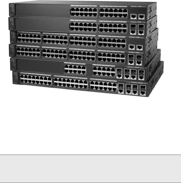
202 Chapter 8: Operating Cisco LAN Switches
Figure 8-1 Cisco 2960 Catalyst Switch Series
Cisco supports two major types of switch operating systems: Internetwork Operating
System (IOS) and Catalyst Operating System (Cat OS). Most Cisco Catalyst switch series
today run only Cisco IOS, but for some historical reasons, some of the high-end Cisco LAN
switches support both Cisco IOS and Cat OS. For the purposes of the CCNA exams, you
can ignore Cat OS, focusing on Cisco IOS. However, keep in mind that you might see
terminology and phrasing such as “IOS-based switch,” referring to the fact that the switch
runs Cisco IOS, not Cat OS.
Switch Status from LEDs
When an engineer needs to examine how a switch is working to verify its current status
and to troubleshoot any problems, the vast majority of the time is spent using commands
from the Cisco IOS CLI. However, the switch hardware does include several LEDs that
provide some status and troubleshooting information, both during the time right after the
switch has been powered on and during ongoing operations. Before moving on to discuss
the CLI, this brief section examines the switch LEDs and their meanings.
NOTE For the real world, note that Cisco’s most popular core switch product, the
6500 series, can run either Cisco IOS or Cat OS. Cisco also uses the term hybrid to refer
to 6500 switches that use Cat OS and the term native to refer to 6500 switches that use
Cisco IOS.
1828xbook.fm Page 202 Thursday, July 26, 2007 3:10 PM
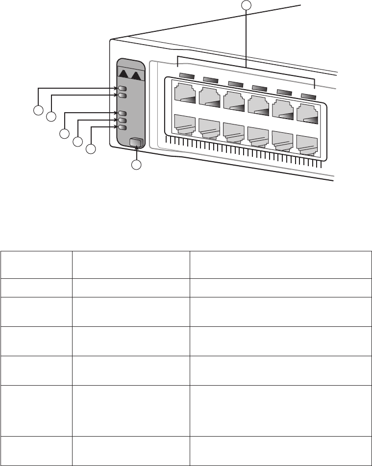
Accessing the Cisco Catalyst 2960 Switch CLI 203
Most Cisco Catalyst switches have some LEDs, including an LED for each physical
Ethernet interface. For example, Figure 8-2 shows the front of a 2960 series switch, with
five LEDs on the left, one LED over each port, and a mode button.
Figure 8-2 2960 LEDs and a Mode Button
The figure points out the various LEDs, with various meanings. Table 8-2 summarizes the
LEDs, and additional explanations follow the table.
Table 8-2 LEDs in Figure 8-2
Number in
Figure 8-2 Name Description
1 SYST (system) Implies the overall system status
2 RPS (Redundant Power
Supply)
Suggests the status of the extra (redundant)
power supply
3STAT (Status) If on (green), implies that each port LED
implies that port’s status
4 DUPLX (duplex) If on (green), each port LED implies that port’s
duplex (on/green is full; off means half)
5 SPEED If on (green), each port LED implies the speed
of that port, as follows: off means 10 Mbps,
solid green means 100 Mbps, and flashing green
means 1 Gbps.
7 Port Has different meanings, depending on the port
mode as toggled using the mode button
12
3
45
7
SYST
1X
1X
Cisco Systems
RPS
STAT
DUPLX
SPEED
MODE
6
2
14
36
58
710
912
11
1828xbook.fm Page 203 Thursday, July 26, 2007 3:10 PM
204 Chapter 8: Operating Cisco LAN Switches
A few specific examples can help make sense of the LEDs. For example, consider the SYST
LED for a moment. This LED provides a quick overall status of the switch, with three
simple states on most 2960 switch models:
■Off: The switch is not powered on
■On (green): The switch is powered on and operational (Cisco IOS has been loaded)
■On (amber): The switch’s Power-On Self Test (POST) process failed, and the Cisco
IOS did not load.
So, a quick look at the SYST LED on the switch tells you whether the switch is working
and, if it isn’t, whether this is due to a loss of power (the SYST LED is off) or some
kind of POST problem (LED amber). In this last case, the typical response is to power the
switch off and back on again. If the same failure occurs, a call to the Cisco Technical
Assistance Center (TAC) is typically the next step.
Besides the straightforward SYST LED, the port LEDs—the LEDs sitting above or below
each Ethernet port—means something different depending on which of three port LED
modes is currently used on the switch. The switches have a mode button (labelled with
number 6 in Figure 8-2) that, when pressed, cycles the port LEDs through three modes:
STAT, DUPLX, and SPEED. The current port LED mode is signified by a solid green STAT,
DUPLX, or SPEED LED (the lower three LEDs on the left part of Figure 8-2, labeled 3, 4,
and 5). To move to another port LED mode, the engineer simply presses the mode button
another time or two.
Each of the three port LED modes changes the meaning of the port LEDs associated
with each port. For example, in STAT (status) mode, each port LED implies status
information about that one associated port. For example:
■Off: The link is not working.
■Solid green: The link is working, but there’s no current traffic.
■Flashing green: The link is working, and traffic is currently passing over the interface.
■Flashing amber: The interface is administratively disabled or has been dynamically
disabled for a variety of reasons.
In contrast, in SPEED port LED mode, the port LEDs imply the operating speed of the
interface, with a dark LED meaning 10 Mbps, a solid green light meaning 100 Mbps, and
flashing green meaning 1000 Mbps (1 Gbps).
The particular details of how each LED works differ between different Cisco switch
families and with different models inside the same switch family. So, memorizing the
1828xbook.fm Page 204 Thursday, July 26, 2007 3:10 PM
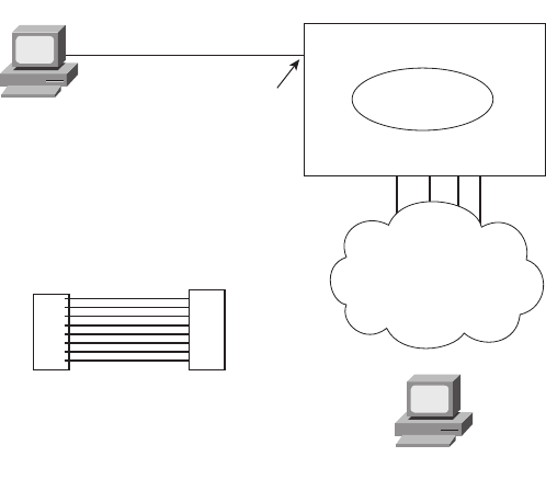
Accessing the Cisco Catalyst 2960 Switch CLI 205
specific meaning of particular LED combinations is probably not required, and this chapter
does not attempt to cover all combinations for even a single switch. However, it is important
to remember the general ideas, the concept of a mode button that changes the meaning of
the port LEDs, and the three meanings of the SYST LED mentioned earlier in this section.
The vast majority of the time, switches power up just fine and load Cisco IOS, and then the
engineer simply accesses the CLI to operate and examine the switch. Next, the chapter
focuses on the details of how to access the CLI.
Accessing the Cisco IOS CLI
Cisco IOS Software for Catalyst switches implements and controls logic and functions
performed by a Cisco switch. Besides controlling the switch’s performance and behavior,
Cisco IOS also defines an interface for humans called the CLI. The Cisco IOS CLI allows
the user to use a terminal emulation program, which accepts text entered by the user. When
the user presses Enter, the terminal emulator sends that text to the switch. The switch
processes the text as if it is a command, does what the command says, and sends text back
to the terminal emulator.
The switch CLI can be accessed through three popular methods—the console, Telnet, and
Secure Shell (SSH). Two of these methods (Telnet and SSH) use the IP network in which
the switch resides to reach the switch. The console is a physical port built specifically to
allow access to the CLI. Figure 8-3 depicts the options.
Figure 8-3 CLI Access
Console
User Mode
Interface
2960 Switch
Telnet
and SSH
(Short) Console Cable
RJ-45
1
Console Cable - Rollover
RJ-45RJ-45
8 1
8
1828xbook.fm Page 205 Thursday, July 26, 2007 3:10 PM
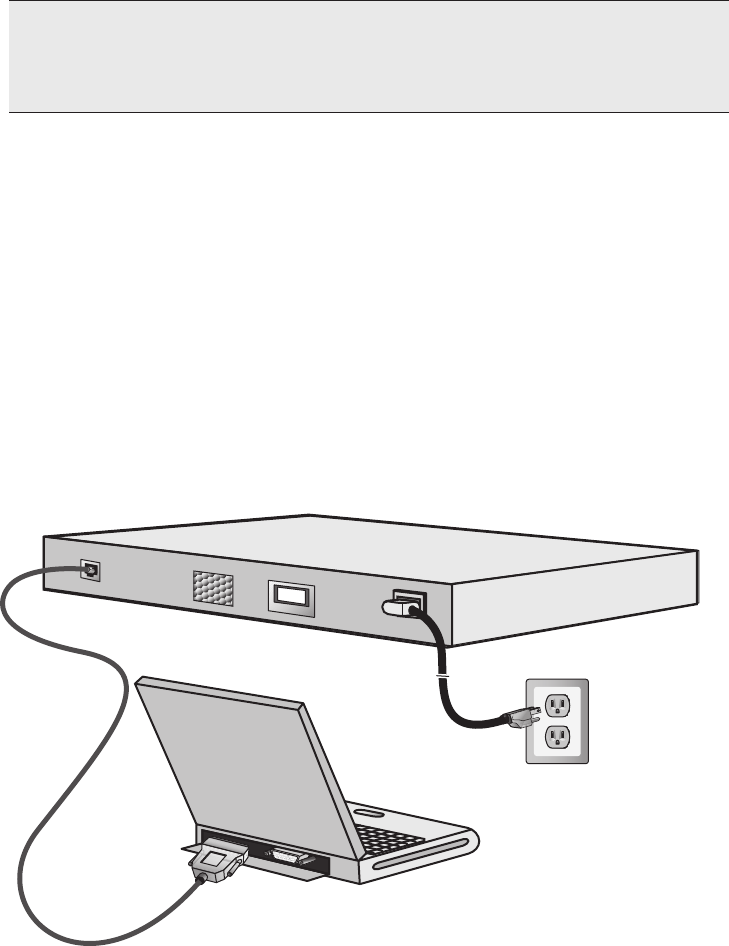
206 Chapter 8: Operating Cisco LAN Switches
Next, this section examines each of these three access methods in more detail.
CLI Access from the Console
The console port provides a way to connect to a switch CLI even if the switch has not been
connected to a network yet. Every Cisco switch has a console port, which is physically an
RJ-45 port. A PC connects to the console port using a UTP rollover cable, which is also
connected to the PC’s serial port. The UTP rollover cable has RJ-45 connectors on each
end, with pin 1 on one end connected to pin 8 on the other, pin 2 to pin 7, pin 3 to pin 6, and
pin 4 to pin 5. In some cases, a PC’s serial interface does not use an RJ-45 connector, an
adapter must be used to convert from the PC’s physical interface—typically either a nine-
pin connector or a USB connector—to an RJ-45. Figure 8-4 shows the RJ-45 end of the
console cable connected to a switch and the DB-9 end connected to a laptop PC.
Figure 8-4 Console Connection to a Switch
As soon as the PC is physically connected to the console port, a terminal emulator software
package must be installed and configured on the PC. Today, terminal emulator software
includes support for Telnet and Secure Shell (SSH), which can be used to access the switch
CLI via the network, but not through the console.
NOTE You can also use a web browser to configure a switch, but the interface is not the
CLI interface. This interface uses a tool called either the Cisco Device Manager (CDM)
or Cisco Security Device Manager (SDM). Some SDM coverage is included in Chapter 17,
“WAN Configuration,” in relation to configuring a router.
1828xbook.fm Page 206 Thursday, July 26, 2007 3:10 PM
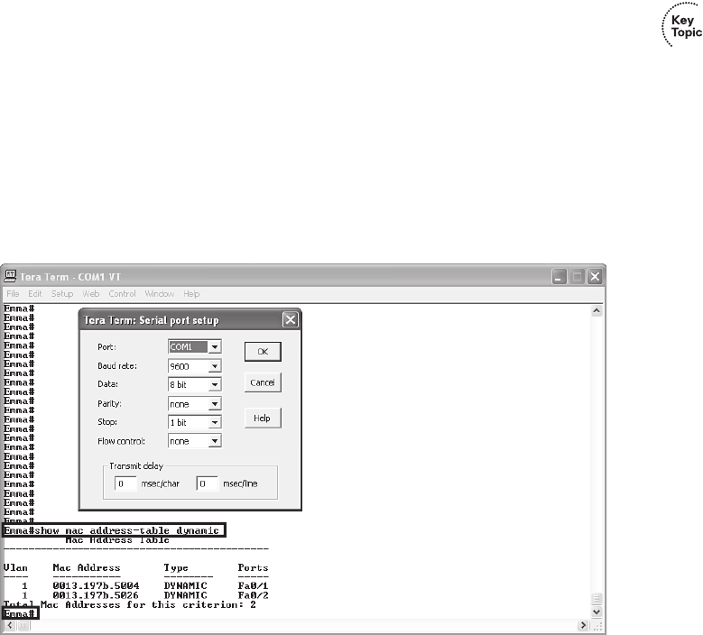
Accessing the Cisco Catalyst 2960 Switch CLI 207
Figure 8-5 shows the window created by the Tera Term Pro software package (available
free from http://www.ayera.com). The emulator must be configured to use the PC’s serial
port, matching the switch’s console port settings. The default console port settings on a
switch are as follows:
■9600 bits/second
■No hardware flow control
■8-bit ASCII
■No stop bits
■1 parity bit
Note that the last three parameters are referred to collectively as “8N1.”
Figure 8-5 Terminal Settings for Console Access
Figure 8-5 shows a terminal emulator window with some command output. It also shows
the configuration window for the settings just listed.
The figure shows the window created by the emulator software. Note that the first
highlighted portion shows the text Emma#show mac address-table dynamic. The
Emma# part is the command prompt, which typically shows the hostname of the switch
(Emma in this case). The prompt is text created by the switch and sent to the emulator. The
show mac address-table dynamic part is the command that the user entered. The text
1828xbook.fm Page 207 Thursday, July 26, 2007 3:10 PM
208 Chapter 8: Operating Cisco LAN Switches
shown beneath the command is the output generated by the switch and sent to the emulator.
Finally, the lower highlighted text Emma# shows the command prompt again, as sent
to the emulator by the switch. The window would remain in this state until the user entered
something else at the command line.
Accessing the CLI with Telnet and SSH
The TCP/IP Telnet application allows a terminal emulator to communicate with a device,
much like what happens with an emulator on a PC connected to the console. However,
Telnet uses an IP network to send and receive the data, rather than a specialized cable and
physical port on the device. The Telnet application protocols call the terminal emulator a
Telnet client and the device that listens for commands and replies to them a Telnet server.
Telnet is a TCP-based application layer protocol that uses well-known port 23.
To use Telnet, the user must install a Telnet client software package on his or her PC. (As
mentioned earlier, most terminal emulator software packages today include both Telnet and
SSH client functions.) The switch runs Telnet server software by default, but the switch
does need to have an IP address configured so that it can send and receive IP packets.
(Chapter 9 covers switch IP address configuration in greater detail.) Additionally, the
network between the PC and switch needs to be up and working so that the PC and switch
can exchange IP packets.
Many network engineers habitually use a Telnet client to monitor switches. The engineer
can sit at his or her desk without having to walk to another part of the building—or go to
another state or country—and still get into the CLI of that device. Telnet sends all data
(including any username and password for login to the switch) as clear-text data, which
presents a potential security risk.
Secure Shell (SSH) does the same basic things as Telnet, but in a more secure manner by
using encryption. Like the Telnet model, the SSH client software includes a terminal
emulator and the capability to send and receive the data using IP. Like Telnet, SSH uses
TCP, while using well-known port 22 instead of Telnet’s 23. As with Telnet, the SSH server
(on the switch) receives the text from each SSH client, processes the text as a command,
and sends messages back to the client. The key difference between Telnet and SSH lies in
the fact that all the communications are encrypted and therefore are private and less prone
to security risk.
Password Security for CLI Access
By default, a Cisco switch is very secure as long as the switch is locked inside a room.
By default, a switch allows only console access, but no Telnet or SSH access. From the
console, you can gain full access to all switch commands, and if so inclined, you can stop
1828xbook.fm Page 208 Thursday, July 26, 2007 3:10 PM

Accessing the Cisco Catalyst 2960 Switch CLI 209
all functions of the switch. However, console access requires physical access to the
switch, so allowing console access for switches just removed from the shipping boxes is
reasonable.
Regardless of the defaults, it makes sense to password-protect console access, as well as
Telnet and SSH access. To add basic password checking for the console and for Telnet, the
engineer needs to configure a couple of basic commands. The configuration process is
covered a little later in this chapter, but you can get a general idea of the commands by
looking in the last column of Table 8-3. The table lists the two commands that configure the
console and vty passwords. After it is configured, the switch supplies a simple password
prompt (as a result of the login command), and the switch expects the user to enter the
password listed in the password command.
Cisco switches refer to the console as a console line—specifically, console line 0. Similarly,
switches support 16 concurrent Telnet sessions, referenced as virtual terminal (vty) lines 0
through 15. (The term vty refers to an old name for terminal emulators.) The line vty 0 15
configuration command tells the switch that the commands that follow apply to all 16
possible concurrent virtual terminal connections to the switch, which includes Telnet as
well as SSH access.
After adding the configuration shown in Table 8-3, a user connecting to the console would
be prompted for a password, and he or she would have to supply the word faith in this
case. New Telnet users would also be prompted for a password, with love being the
required password. Also, with this configuration, no username is required—just a simple
password.
Configuring SSH requires a little more effort than the console and Telnet password
configuration examples shown in Table 8-3. SSH uses public key cryptography to exchange
Table 8-3 CLI Password Configuration: Console and Telnet
Access From Password Type Sample Configuration
Console Console password line console 0
login
password faith
Telnet vty password line vty 0 15
login
password love
NOTE Some older versions of switch software supported only five vty lines,
0 through 4.
1828xbook.fm Page 209 Thursday, July 26, 2007 3:10 PM
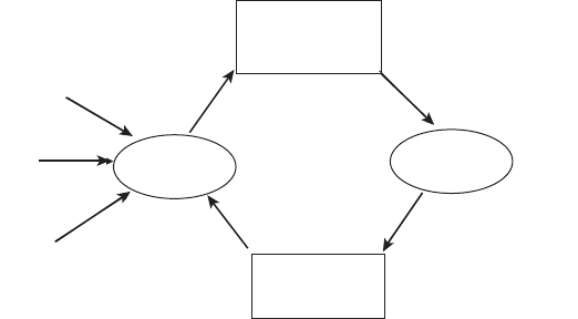
210 Chapter 8: Operating Cisco LAN Switches
a shared session key, which in turn is used for encryption—much like the Secure Sockets
Layer (SSL) security processes covered in Chapter 6, “Fundamentals of TCP/IP Transport,
Applications, and Security.” Additionally, SSH requires slightly better login security,
requiring at least a password and a username. The section “Configuring Usernames and
Secure Shell (SSH)” in Chapter 9 shows the configuration steps and a sample configuration
to support SSH.
User and Enable (Privileged) Modes
All three CLI access methods covered so far (console, Telnet, and SSH) place the user in
an area of the CLI called user EXEC mode. User EXEC mode, sometimes also called user
mode, allows the user to look around but not break anything. The “EXEC mode” part of the
name refers to the fact that in this mode, when you enter a command, the switch executes
the command and then displays messages that describe the command’s results.
Cisco IOS supports a more powerful EXEC mode called enable mode (also known as
privileged mode or privileged EXEC mode). Enable mode is so named because the enable
command is used to reach this mode, as shown in Figure 8-6. Privileged mode earns its
name because powerful, or privileged, commands can be executed there. For example, you
can use the reload command, which tells the switch to reinitialize or reboot Cisco IOS, only
from enable mode.
Figure 8-6 User and Privileged Modes
User
Mode
Privileged
Mode*
router>enable
password: zzzzz
router#
router#disable
router>
*Also Called
Enable Mode
Console
SSH
Telnet
1828xbook.fm Page 210 Thursday, July 26, 2007 3:10 PM

Accessing the Cisco Catalyst 2960 Switch CLI 211
The preferred configuration command for configuring the password for reaching enable
mode is the enable secret password command, where password is the text of the password.
Note that if the enable password is not configured (the default), Cisco IOS prevents Telnet
and SSH users from getting into enable mode, but Cisco IOS does allow a console user to
reach enable mode. This default action is consistent with the idea that, by default, users
outside the locked room where the switch sits cannot get access without additional
configuration by the engineer.
So far, this chapter has pointed out some of the first things you should know when
unpacking and installing a switch. The switch will work without any configuration—just
plug in the power and Ethernet cables, and it works. However, you should at least connect
to the switch console port and configure passwords for the console, Telnet, SSH, and the
enable secret password.
Next, this chapter examines some of the CLI features that exist regardless of how you
access the CLI.
CLI Help Features
If you printed the Cisco IOS Command Reference documents, you would end up with a
stack of paper several feet tall. No one should expect to memorize all the commands—and
no one does. You can use several very easy, convenient tools to help remember commands
and save time typing. As you progress through your Cisco certifications, the exams will
cover progressively more commands. However, you should know the methods of getting
command help.
Table 8-4 summarizes command-recall help options available at the CLI. Note that, in
the first column, command represents any command. Likewise, parm represents a
command’s parameter. For instance, the third row lists command ?, which means that
commands such as show ? and copy ? would list help for the show and copy commands,
respectively.
NOTE If the command prompt lists the hostname followed by a >, the user is in
user mode; if it is the hostname followed by the #, the user is in enable mode.
NOTE The commands that can be used in either user (EXEC) mode or enable (EXEC)
mode are called EXEC commands.
1828xbook.fm Page 211 Thursday, July 26, 2007 3:10 PM

212 Chapter 8: Operating Cisco LAN Switches
When you enter the ?, the Cisco IOS CLI reacts immediately; that is, you don’t need to press the Enter key or any
other keys. The device running Cisco IOS also redisplays what you entered before the ? to save you some keystrokes.
If you press Enter immediately after the ?, Cisco IOS tries to execute the command with only the parameters you have
entered so far.
command represents any command, not the word command. Likewise, parm represents a command’s parameter, not
the word parameter.
The information supplied by using help depends on the CLI mode. For example, when ? is
entered in user mode, the commands allowed in user mode are displayed, but commands
available only in enable mode (not in user mode) are not displayed. Also, help is available
in configuration mode, which is the mode used to configure the switch. In fact,
configuration mode has many different subconfiguration modes, as explained in the section
“Configuration Submodes and Contexts.” So, you can get help for the commands available
in each configuration submode as well.
Cisco IOS stores the commands that you enter in a history buffer, storing ten commands by
default. The CLI allows you to move backward and forward in the historical list of
commands and then edit the command before reissuing it. These key sequences can help
you use the CLI more quickly on the exams. Table 8-5 lists the commands used to
manipulate previously entered commands.
Table 8-4 Cisco IOS Software Command Help
What You Enter What Help You Get
?Help for all commands available in this mode.
help Text describing how to get help. No actual command help is given.
command ?Text help describing all the first parameter options for the command.
com? A list of commands that start with com.
command parm?This style of help lists all parameters beginning with parm. (Notice that
there is no space between parm and the ?.)
command parm<Tab> If you press the Tab key midword, the CLI either spells the rest of this
parameter at the command line or does nothing. If the CLI does nothing,
it means that this string of characters represents more than one possible
next parameter, so the CLI does not know which one to spell out.
command parm1 ?If a space is inserted before the question mark, the CLI lists all the next
parameters and gives a brief explanation of each.
1828xbook.fm Page 212 Thursday, July 26, 2007 3:10 PM

Accessing the Cisco Catalyst 2960 Switch CLI 213
The debug and show Commands
By far, the single most popular Cisco IOS command is the show command. The show
command has a large variety of options, and with those options, you can find the status of
almost every feature of Cisco IOS. Essentially, the show command lists the currently
known facts about the switch’s operational status. The only work the switch does in reaction
to show commands is to find the current status and list the information in messages sent to
the user.
A less popular command is the debug command. Like the show command, debug has
many options. However, instead of just listing messages about the current status, the debug
command asks the switch to continue monitoring different processes in the switch. The
switch then sends ongoing messages to the user when different events occur.
Table 8-5 Key Sequences for Command Edit and Recall
Keyboard Command What Happens
Up arrow or Ctrl-p This displays the most recently used command. If you press it again,
the next most recent command appears, until the history buffer is
exhausted. (The p stands for previous.)
Down arrow or Ctrl-n If you have gone too far back into the history buffer, these keys take
you forward to the more recently entered commands. (The n stands for
next.)
Left arrow or Ctrl-b This moves the cursor backward in the currently displayed command
without deleting characters. (The b stands for back.)
Right arrow or Ctrl-f This moves the cursor forward in the currently displayed command
without deleting characters. (The f stands for forward.)
Backspace This moves the cursor backward in the currently displayed command,
deleting characters.
Ctrl-a This moves the cursor directly to the first character of the currently
displayed command.
Ctrl-e This moves the cursor directly to the end of the currently displayed
command.
Ctrl-r This redisplays the command line with all characters. It’s useful when
messages clutter the screen.
Ctrl-d This deletes a single character.
Esc-b This moves back one word.
Esc-f This moves forward one word.
1828xbook.fm Page 213 Thursday, July 26, 2007 3:10 PM
214 Chapter 8: Operating Cisco LAN Switches
The effects of the show and debug commands can be compared to a photograph and a
movie. Like a photo, a show command shows what’s true at a single point in time, and it
takes little effort. The debug command shows what’s true over time, but it requires more
effort. As a result, the debug command requires more CPU cycles, but it lets you watch
what is happening in a switch while it is happening.
Cisco IOS handles the messages created with the debug command much differently than
with the show command. When any user issues a debug command, the debug options in
the command are enabled. The messages Cisco IOS creates in response to all debug
commands, regardless of which user(s) issued the debug commands, are treated as a special
type of message called a log message. Any remote user can view log messages by simply
using the terminal monitor command. Additionally, these log messages also appear at the
console automatically. So, whereas the show command lists a set of messages for that
single user, the debug command lists messages for all interested users to see, requiring
remote users to ask to view the debug and other log messages.
The options enabled by a single debug command are not disabled until the user takes action
or until the switch is reloaded. A reload of the switch disables all currently enabled debug
options. To disable a single debug option, repeat the same debug command with those
options, prefaced by the word no. For example, if the debug spanning-tree command was
been issued earlier, issue the no debug spanning-tree command to disable that same
debug. Also, the no debug all and undebug all commands disable all currently enabled
debugs.
Be aware that some debug options create so many messages that Cisco IOS cannot process
them all, possibly resulting in a crash of Cisco IOS. You might want to check the current
switch CPU utilization with the show process command before issuing any debug
command. To be more careful, before enabling an unfamiliar debug command option, issue
a no debug all command, and then issue the debug that you want to use. Then quickly
retrieve the no debug all command using the up arrow or Ctrl-p key sequence twice. If the
debug quickly degrades switch performance, the switch may be too busy to listen to what
you are typing. The process described in this paragraph saves a bit of typing and may be the
difference between preventing the switch from failing, or not.
Configuring Cisco IOS Software
You must understand how to configure a Cisco switch to succeed on the exam and in real
networking jobs. This section covers the basic configuration processes, including the
concept of a configuration file and the locations in which the configuration files can be
stored. Although this section focuses on the configuration process, and not on the
configuration commands themselves, you should know all the commands covered in this
chapter for the exams, in addition to the configuration processes.
1828xbook.fm Page 214 Thursday, July 26, 2007 3:10 PM
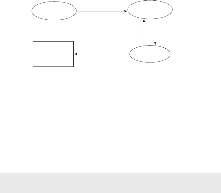
Configuring Cisco IOS Software 215
Configuration mode is another mode for the Cisco CLI, similar to user mode and privileged
mode. User mode lets you issue nondisruptive commands and displays some information.
Privileged mode supports a superset of commands compared to user mode, including
commands that might harm the switch. However, none of the commands in user or
privileged mode changes the switch’s configuration. Configuration mode accepts
configuration commands—commands that tell the switch the details of what to do, and how
to do it. Figure 8-7 illustrates the relationships among configuration mode, user EXEC
mode, and privileged EXEC mode.
Figure 8-7 CLI Configuration Mode Versus Exec Modes
Commands entered in configuration mode update the active configuration file. These
changes to the configuration occur immediately each time you press the Enter key at the end
of a command. Be careful when you enter a configuration command!
Configuration Submodes and Contexts
Configuration mode itself contains a multitude of subcommand modes. Context-setting
commands move you from one configuration subcommand mode, or context, to another.
These context-setting commands tell the switch the topic about which you will enter the
next few configuration commands. More importantly, the context tells the switch the topic
you care about right now, so when you use the ? to get help, the switch gives you help about
that topic only.
The interface command is one of the most commonly used context-setting configuration
commands. For example, the CLI user could enter interface configuration mode by entering
the interface FastEthernet 0/1 configuration command. Asking for help in interface
configuration mode displays only commands that are useful when configuring Ethernet
interfaces. Commands used in this context are called subcommands—or, in this specific
NOTE Context setting is not a Cisco term—it’s just a term used here to help make sense
of configuration mode.
User EXEC Mode Privileged EXEC
Mode
Configuration
Mode
RAM
(Active Config)
Each Command
enable
in Succession
Ctrl-Z
or
exit
config t
1828xbook.fm Page 215 Thursday, July 26, 2007 3:10 PM

216 Chapter 8: Operating Cisco LAN Switches
case, interface subcommands. When you begin practicing with the CLI with real
equipment, the navigation between modes can become natural. For now, consider
Example 8-1, which shows the following:
■Movement from enable mode to global configuration mode by using the configure
terminal EXEC command
■Using a hostname Fred global configuration command to configure the switch’s name
■Movement from global configuration mode to console line configuration mode (using
the line console 0 command)
■Setting the console’s simple password to hope (using the password hope line
subcommand)
■Movement from console configuration mode to interface configuration mode (using
the interface command)
■Setting the speed to 100 Mbps for interface Fa0/1 (using the speed 100 interface
subcommand)
■Movement from console line configuration mode back to global configuration mode
(using the exit command)
The text inside parentheses in the command prompt identifies the configuration mode. For
example, the first command prompt after you enter configuration mode lists (config),
meaning global configuration mode. After the line console 0 command, the text expands to
(config-line), meaning line configuration mode. Table 8-6 shows the most common
command prompts in configuration mode, the names of those modes, and the context
setting commands used to reach those modes.
Example 8-1 Navigating Between Different Configuration Modes
Switch#cc
ccoo
oonn
nnff
ffii
iigg
gguu
uurr
rree
ee
tt
ttee
eerr
rrmm
mmii
iinn
nnaa
aall
ll
Switch(config)#hh
hhoo
ooss
sstt
ttnn
nnaa
aamm
mmee
ee
FF
FFrr
rree
eedd
dd
Fred(config)#ll
llii
iinn
nnee
ee
cc
ccoo
oonn
nnss
ssoo
ooll
llee
ee
00
00
Fred(config-line)#pp
ppaa
aass
ssss
ssww
wwoo
oorr
rrdd
dd
hh
hhoo
oopp
ppee
ee
Fred(config-line)#ii
iinn
nntt
ttee
eerr
rrff
ffaa
aacc
ccee
ee
FF
FFaa
aass
sstt
ttEE
EEtt
tthh
hhee
eerr
rrnn
nnee
eett
tt
00
00//
//11
11
Fred(config-if)#ss
sspp
ppee
eeee
eedd
dd
11
1100
0000
00
Fred(config-if)#ee
eexx
xxii
iitt
tt
Fred(config)#
1828xbook.fm Page 216 Thursday, July 26, 2007 3:10 PM

Configuring Cisco IOS Software 217
No set rules exist for what commands are global commands or subcommands. Generally,
however, when multiple instances of a parameter can be set in a single switch, the command
used to set the parameter is likely a configuration subcommand. Items that are set once for
the entire switch are likely global commands. For example, the hostname command is a
global command because there is only one hostname per switch. Conversely, the duplex
command is an interface subcommand to allow the switch to use a different setting on the
different interfaces.
Both the Ctrl-z key sequence and the end command exit the user from any part of
configuration mode and go back to privileged EXEC mode. Alternatively, the exit
command backs you out of configuration mode one subconfiguration mode at a time.
Storing Switch Configuration Files
When you configure a switch, it needs to use the configuration. It also needs to be able to
retain the configuration in case the switch loses power. Cisco switches contain Random
Access Memory (RAM) to store data while Cisco IOS is using it, but RAM loses its
contents when the switch loses power. To store information that must be retained when the
switch loses power, Cisco switches use several types of more permanent memory, none of
which has any moving parts. By avoiding components with moving parts (such as
traditional disk drives), switches can maintain better uptime and availability.
The following list details the four main types of memory found in Cisco switches, as well
as the most common use of each type.
■RAM: Sometimes called DRAM for Dynamic Random-Access Memory, RAM is
used by the switch just as it is used by any other computer: for working storage. The
running (active) configuration file is stored here.
■ROM: Read-Only Memory (ROM) stores a bootstrap (or boothelper) program that is
loaded when the switch first powers on. This bootstrap program then finds the full
Cisco IOS image and manages the process of loading Cisco IOS into RAM, at which
point Cisco IOS takes over operation of the switch.
Table 8-6 Common Switch Configuration Modes
Prompt Name of Mode Context-setting Command(s) to Reach This Mode
hostname(config)# Global None—first mode after configure terminal
hostname(config-line)# Line line console 0
line vty 0 15
hostname(config-if)# Interface interface type number
1828xbook.fm Page 217 Thursday, July 26, 2007 3:10 PM

218 Chapter 8: Operating Cisco LAN Switches
■Flash memory: Either a chip inside the switch or a removable memory card, Flash
memory stores fully functional Cisco IOS images and is the default location where the
switch gets its Cisco IOS at boot time. Flash memory also can be used to store any
other files, including backup copies of configuration files.
■NVRAM: Nonvolatile RAM (NVRAM) stores the initial or startup configuration file
that is used when the switch is first powered on and when the switch is reloaded.
Figure 8-8 summarizes this same information in a briefer and more convenient form for
memorization and study.
Figure 8-8 Cisco Switch Memory Types
Cisco IOS stores the collection of configuration commands in a configuration file. In fact,
switches use multiple configuration files—one file for the initial configuration used when
powering on, and another configuration file for the active, currently used running
configuration as stored in RAM. Table 8-7 lists the names of these two files, their purpose,
and their storage location.
Essentially, when you use configuration mode, you change only the running-config file.
This means that the configuration example earlier in this chapter (Example 8-1) updates
only the running-config file. However, if the switch lost power right after that example, all
that configuration would be lost. If you want to keep that configuration, you have to copy
the running-config file into NVRAM, overwriting the old startup-config file.
Table 8-7 Names and Purposes of the Two Main Cisco IOS Configuration Files
Configuration
Filename Purpose Where It Is Stored
Startup-config Stores the initial configuration used any time the switch
reloads Cisco IOS.
NVRAM
Running-config Stores the currently used configuration commands.
This file changes dynamically when someone enters
commands in configuration mode.
RAM
RAM
(Working
Memory and
Running
Configuration)
Flash
(Cisco IOS
Software)
ROM
(Bootstrap
Program)
NVRAM
(Startup
Configuration)
1828xbook.fm Page 218 Thursday, July 26, 2007 3:10 PM

Configuring Cisco IOS Software 219
Example 8-2 demonstrates that commands used in configuration mode change only the
running configuration in RAM. The example shows the following concepts and steps:
Step 1 The original hostname command on the switch, with the startup-config file
matching the running-config file.
Step 2 The hostname command changes the hostname, but only in the running-
config file.
Step 3 The show running-config and show startup-config commands are
shown, with only the hostname commands displayed for brevity, to make
the point that the two configuration files are now different.
Example 8-2 How Configuration Mode Commands Change the Running-config File, not the
Startup-config File
! Step 1 next (two commands)
!
hannah#ss
sshh
hhoo
ooww
ww
rr
rruu
uunn
nnnn
nnii
iinn
nngg
gg--
--cc
ccoo
oonn
nnff
ffii
iigg
gg
! (lines omitted)
hostname hannah
! (rest of lines omitted)
hannah#ss
sshh
hhoo
ooww
ww
ss
sstt
ttaa
aarr
rrtt
ttuu
uupp
pp--
--cc
ccoo
oonn
nnff
ffii
iigg
gg
! (lines omitted)
hostname hannah
! (rest of lines omitted)
! Step 2 next. Notice that the command prompt changes immediately after
! the hh
hhoo
ooss
sstt
ttnn
nnaa
aamm
mmee
ee command.
!hannah#cc
ccoo
oonn
nnff
ffii
iigg
gguu
uurr
rree
ee
tt
ttee
eerr
rrmm
mmii
iinn
nnaa
aall
ll
hannah(config)#hh
hhoo
ooss
sstt
ttnn
nnaa
aamm
mmee
ee
jj
jjee
eess
ssss
ssii
iiee
ee
jessie(config)#ee
eexx
xxii
iitt
tt
! Step 3 next (two commands)
!
jessie#ss
sshh
hhoo
ooww
ww
rr
rruu
uunn
nnnn
nnii
iinn
nngg
gg--
--cc
ccoo
oonn
nnff
ffii
iigg
gg
! (lines omitted)
hostname jessie
! (rest of lines omitted - notice that the running configuration reflects the
! changed hostname)
jessie# ss
sshh
hhoo
ooww
ww
ss
sstt
ttaa
aarr
rrtt
ttuu
uupp
pp--
--cc
ccoo
oonn
nnff
ffii
iigg
gg
! (lines omitted)
hostname hannah
! (rest of lines omitted - notice that the changed configuration is not
! shown in the startup config)
1828xbook.fm Page 219 Thursday, July 26, 2007 3:10 PM
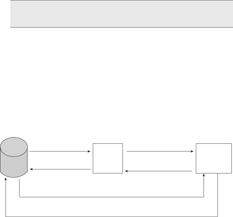
220 Chapter 8: Operating Cisco LAN Switches
Copying and Erasing Configuration Files
If you reload the switch at the end of Example 8-2, the hostname reverts to Hannah, because
the running-config file has not been copied into the startup-config file. However, if you want
to keep the new hostname of jessie, you would use the command copy running-config
startup-config, which overwrites the current startup-config file with what is currently in
the running configuration file. The copy command can be used to copy files in a switch,
most typically a configuration file or a new version of Cisco IOS Software. The most basic
method for moving configuration files in and out of a switch is to use the copy command
to copy files between RAM or NVRAM on a switch and a TFTP server. The files can be
copied between any pair, as shown in Figure 8-9.
Figure 8-9 Locations for Copying and Results from Copy Operations
The commands for copying Cisco IOS configurations can be summarized as follows:
cc
ccoo
oopp
ppyy
yy
{tt
ttff
fftt
ttpp
pp
|
rr
rruu
uunn
nnnn
nnii
iinn
nngg
gg--
--cc
ccoo
oonn
nnff
ffii
iigg
gg
|
ss
sstt
ttaa
aarr
rrtt
ttuu
uupp
pp--
--cc
ccoo
oonn
nnff
ffii
iigg
gg} {tt
ttff
fftt
ttpp
pp
|
rr
rruu
uunn
nnnn
nnii
iinn
nngg
gg--
--cc
ccoo
oonn
nnff
ffii
iigg
gg
|
ss
sstt
ttaa
aarr
rrtt
ttuu
uupp
pp--
--cc
ccoo
oonn
nnff
ffii
iigg
gg}
The first set of parameters enclosed in braces ({}) is the “from” location; the next set of
parameters is the “to” location.
The copy command always replaces the existing file when the file is copied into NVRAM
or into a TFTP server. In other words, it acts as if the destination file was erased and the new
file completely replaced the old one. However, when the copy command copies a
configuration file into the running-config file in RAM, the configuration file in RAM is not
replaced, but is merged instead. Effectively, any copy into RAM works just as if you
entered the commands in the “from” configuration file in the order listed in the config file.
NOTE Cisco uses the term reload to refer to what most PC operating systems call
rebooting or restarting. In each case, it is a reinitialization of the software. The reload
exec command causes a switch to reload.
RAM NVRAM
copy tftp running-config copy running-config startup-config
copy startup-config running-config
copy running-config tftp
copy tftp startup-config
copy startup-config tftp
TFTP
1828xbook.fm Page 220 Thursday, July 26, 2007 3:10 PM

Configuring Cisco IOS Software 221
Who cares? Well, we do. If you change the running config and then decide that you want to
revert to what’s in the startup-config file, the result of the copy startup-config running-
config command may not cause the two files to actually match. The only way to guarantee
that the two configuration files match is to issue the reload command, which reloads, or
reboots, the switch, which erases RAM and then copies the startup-config into RAM as part
of the reload process.
You can use three different commands to erase the contents of NVRAM. The write
erase and erase startup-config commands are older, whereas the erase nvram: command
is the more recent, and recommended, command. All three commands simply erase the
contents of the NVRAM configuration file. Of course, if the switch is reloaded at this
point, there is no initial configuration. Note that Cisco IOS does not have a command that
erases the contents of the running-config file. To clear out the running-config file, simply
erase the startup-config file, and then reload the switch.
Although startup-config and running-config are the most common names for the two
configuration files, Cisco IOS defines a few other more formalized names for these files.
These more formalized filenames use a format defined by the Cisco IOS File System (IFS),
which is the name of the file system created by Cisco IOS to manage files. For example, the
copy command can refer to the startup-config file as nvram:startup-config. Table 8-8 lists
the alternative names for these two configuration files.
Initial Configuration (Setup Mode)
Cisco IOS Software supports two primary methods of giving a switch an initial basic
configuration—configuration mode, which has already been covered in this chapter, and
setup mode. Setup mode leads a switch administrator to a basic switch configuration
by using questions that prompt the administrator for basic configuration parameters.
Because configuration mode is required for most configuration tasks, most networking
NOTE Making a copy of all current switch and router configurations should be part of
any network’s overall security strategy, mainly so that you can replace a device’s
configuration if an attack changes the configuration.
Table 8-8 IFS Filenames for the Startup and Running Config Files
Config File Common Name Alternative Names
startup-config nvram:
nvram:startup-config
running-config system:running-config
1828xbook.fm Page 221 Thursday, July 26, 2007 3:10 PM
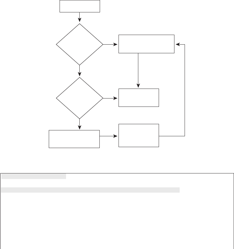
222 Chapter 8: Operating Cisco LAN Switches
personnel do not use setup at all. However, new users sometimes like to use setup mode,
particularly until they become more familiar with the CLI configuration mode.
Figure 8-10 and Example 8-3 describe the process used by setup mode. Setup mode is used
most frequently when the switch boots, and it has no configuration in NVRAM. You can
also enter setup mode by using the setup command from privileged mode.
Figure 8-10 Getting into Setup Mode
Example 8-3 Initial Configuration Dialog Example
--- System Configuration Dialog ---
Would you like to enter the initial configuration dialog? [yes/no]: yy
yyee
eess
ss
At any point you may enter a question mark '?' for help.
Use ctrl-c to abort configuration dialog at any prompt.
Default settings are in square brackets '[]'.
Basic management setup configures only enough connectivity
for management of the system, extended setup will ask you
Tu rn on switch
Move New
Configuration
into NVRAM
Complete IOS
Initialization
Is NVRAM
Empty?
Do You
Want to
Enter Setup
Mode?
Yes
Yes
No
No
Answer the Questions
in Setup Mode
Copy startup-config to
running-config
1828xbook.fm Page 222 Thursday, July 26, 2007 3:10 PM

Configuring Cisco IOS Software 223
to configure each interface on the system
Would you like to enter basic management setup? [yes/no]: yy
yyee
eess
ss
Configuring global parameters:
Enter host name [Switch]: ff
ffrr
rree
eedd
dd
The enable secret is a password used to protect access to
privileged EXEC and configuration modes. This password, after
entered, becomes encrypted in the configuration.
Enter enable secret: cc
ccii
iiss
sscc
ccoo
oo
The enable password is used when you do not specify an
enable secret password, with some older software versions, and
some boot images.
Enter enable password: nn
nnoo
oott
ttcc
ccii
iiss
sscc
ccoo
oo
The virtual terminal password is used to protect
access to the switch over a network interface.
Enter virtual terminal password: ww
wwii
iill
llmm
mmaa
aa
Configure SNMP Network Management? [no]:
Current interface summary
Any interface listed with OK? value "NO" does not have a valid configuration
Interface IP-Address OK? Method Status Protocol
Vlan1 unassigned NO unset up up
FastEthernet0/1 unassigned YES unset up up
FastEthernet0/2 unassigned YES unset up up
FastEthernet0/3 unassigned YES unset up up
!
!Lines ommitted for brevity
!
GigabitEthernet0/1 unassigned YES unset down down
GigabitEthernet0/2 unassigned YES unset down down
The following configuration command script was created:
hostname fred
enable secret 5 $1$wNE7$4JSktD3uN1Af5FpctmPz11
enable password notcisco
line vty 0 15
password wilma
no snmp-server
continues
Example 8-3 Initial Configuration Dialog Example (Continued)
1828xbook.fm Page 223 Thursday, July 26, 2007 3:10 PM

224 Chapter 8: Operating Cisco LAN Switches
Setup behaves as shown in Example 8-3, regardless of whether Setup was reached by
booting with an empty NVRAM or whether the setup privileged EXEC command was
used. First, the switch asks whether you want to enter the initial configuration dialog.
Answering y or yes puts you in setup mode. At that point, the switch keeps asking
questions, and you keep answering, until you have answered all the setup questions.
!
!
interface Vlan1
shutdown
no ip address
!
interface FastEthernet0/1
!
interface FastEthernet0/2
!
interface FastEthernet0/3
!
interface FastEthernet0/4
!
interface FastEthernet0/5
!
! Lines ommitted for brevity
!
interface GigabitEthernet0/1
!
interface GigabitEthernet0/2
!
end
[0] Go to the IOS command prompt without saving this config.
[1] Return back to the setup without saving this config.
[2] Save this configuration to nvram and exit.
Enter your selection [2]: 22
22
Building configuration...
[OK]
Use the enabled mode 'configure' command to modify this configuration.
Press RETURN to get started!
Example 8-3 Initial Configuration Dialog Example (Continued)
1828xbook.fm Page 224 Thursday, July 26, 2007 3:10 PM
Configuring Cisco IOS Software 225
When you are finished answering the configuration questions, the switch asks you to
choose from one of three options:
0: Do not save any of this configuration, and go to the CLI command prompt.
1: Do not save any of this configuration, but start over in setup mode.
2: Save the configuration in both the startup-config and the running-config, and go to
the CLI command prompt.
You can also abort the setup process before answering all the questions, and get to a
CLI prompt, by pressing Ctrl-C. Note that answer 2 actually writes the configuration to
both the startup-config and running-config file, whereas configuration mode changes only
the running-config file.
1828xbook.fm Page 225 Thursday, July 26, 2007 3:10 PM

226 Chapter 8: Operating Cisco LAN Switches
Exam Preparation Tasks
Review All the Key Topics
Review the most important topics from this chapter, noted with the key topics icon. Table 8-9
lists these key topics and where each is discussed.
Complete the Tables and Lists from Memory
Print a copy of Appendix H, “Memory Tables” (found on the CD), or at least the section for
this chapter, and complete the tables and lists from memory. Appendix I, “Memory Tables
Answer Key,” also on the CD, includes completed tables and lists for you to check
your work.
Definitions of Key Terms
Define the following key terms from this chapter and check your answers in the glossary:
command-line interface (CLI), Secure Shell (SSH), enable mode, user mode,
configuration mode, startup-config file, running-config file, setup mode
Command References
Table 8-10 lists and briefly describes the configuration commands used in this
chapter.
Table 8-9 Key Topics for Chapter 8
Key Topic Element Description
Page
Number
List A Cisco switch’s default console port settings 207
Table 8-6 A list of configuration mode prompts, the name of the
configuration mode, and the command used to reach each
mode
217
Figure 8-8 Types of memory in a switch 218
Table 8-7 The names and purposes of the two configuration files in a
switch or router
218
1828xbook.fm Page 226 Thursday, July 26, 2007 3:10 PM

Command References 227
Table 8-10 Chapter 8 Configuration Commands
Command Mode and Purpose
line console 0 Global command that changes the context to console
configuration mode.
line vty 1st-vty 2nd-vty Global command that changes the context to vty
configuration mode for the range of vty lines listed in the
command.
login Line (console and vty) configuration mode. Tells IOS to
prompt for a password (no username).
password pass-value Line (console and vty) configuration mode. Lists the
password required if the login command (with no other
parameters) is configured.
interface type port-number Global command that changes the context to interface
mode—for example, interface Fastethernet 0/1.
shutdown
no shutdown
Interface subcommand that disables or enables the interface,
respectively.
hostname name Global command that sets this switch’s hostname, which is
also used as the first part of the switch’s command prompt.
enable secret pass-value Global command that sets the automatically encrypted enable
secret password. The password is used for any user to reach
enable mode.
enable password pass-value Global command that sets the clear-text enable password,
which is used only when the enable secret password is not
configured.
exit Moves back to the next higher mode in configuration mode.
end Exits configuration mode and goes back to enable mode from
any of the configuration submodes.
Ctrl-Z This is not a command, but rather a two-key combination (the
Ctrl key and the letter z) that together do the same thing as the
end command.
1828xbook.fm Page 227 Thursday, July 26, 2007 3:10 PM

228 Chapter 8: Operating Cisco LAN Switches
Table 8-11 lists and briefly describes the EXEC commands used in this chapter.
Table 8-11 Chapter 8 EXEC Command Reference
Command Purpose
no debug all
undebug all
Enable mode EXEC command to disable all currently
enabled debugs.
show process EXEC command that lists statistics about CPU utilization.
terminal monitor EXEC command that tells Cisco IOS to send a copy of all
syslog messages, including debug messages, to the Telnet
or SSH user who issues this command.
reload Enable mode EXEC command that reboots the switch or
router.
copy from-location to-location Enable mode EXEC command that copies files from one
file location to another. Locations include the startup-
config and running-config files, files on TFTP and RPC
servers, and flash memory.
copy running-config startup-config Enable mode EXEC command that saves the active
config, replacing the startup-config file used when the
switch initializes.
copy startup-config running-config Enable mode EXEC command that merges the startup
config file with the currently active config file in RAM.
show running-config Lists the contents of the running-config file.
write erase
erase startup-config
erase nvram:
All three enable mode EXEC commands erase the startup-
config file.
setup Enable mode EXEC command that places the user in
setup mode, in which Cisco IOS asks the user for input on
simple switch configurations.
quit EXEC command that disconnects the user from the CLI
session.
show system:running-config Same as the show running-config command.
show startup-config Lists the contents of the startup-config (initial config) file.
1828xbook.fm Page 228 Thursday, July 26, 2007 3:10 PM

Command References 229
show nvram:startup-config
show nvram:
Same as the show startup-config command.
enable Moves the user from user mode to enable (privileged)
mode and prompts for an enable password if configured.
disable Moves the user from enable mode to user mode.
configure terminal Enable mode command that moves the user into
configuration mode.
Table 8-11 Chapter 8 EXEC Command Reference (Continued)
Command Purpose
1828xbook.fm Page 229 Thursday, July 26, 2007 3:10 PM

This chapter covers the following subjects:
Configuration Features in Common with
Routers: This section explains how to configure
a variety of switch features that happen to be
configured exactly like the same feature on Cisco
routers.
LAN Switch Configuration and Operation:
This section explains how to configure a variety
of switch features that happen to be unique to
switches, and are not used on routers, or are
configured differently than the configuration on
Cisco routers.
1828xbook.fm Page 230 Thursday, July 26, 2007 3:10 PM

C H A P T E R9
Ethernet Switch Configuration
Chapter 3, “Fundamentals of LANs,” and Chapter 7, “Ethernet LAN Switching Concepts,”
have already explained the most common Ethernet LAN concepts. Those chapters
explained how Ethernet cabling and switches work, including the concepts of how switches
forward Ethernet frames based on the frames’ destination MAC addresses.
Cisco LAN switches perform their core functions without any configuration. You can buy
a Cisco switch, plug in the right cables to connect various devices to the switch, plug in the
power cable, and the switch works. However, in most networks, the network engineer needs
to configure and troubleshoot various switch features. This chapter explains how to
configure various switch features, and Chapter 10, “Ethernet Switch Troubleshooting,”
explains how to troubleshoot problems on Cisco switches.
“Do I Know This Already?” Quiz
The “Do I Know This Already?” quiz allows you to assess whether you should read the
entire chapter. If you miss no more than one of these eight self-assessment questions, you
might want to move ahead to the “Exam Preparation Tasks” section. Table 9-1 lists the
major headings in this chapter and the “Do I Know This Already?” quiz questions covering
the material in those sections. This helps you assess your knowledge of these specific areas.
The answers to the “Do I Know This Already?” quiz appear in Appendix A.
Table 9-1 “Do I Know This Already?” Foundation Topics Section-to-Question Mapping
Foundation Topics Section Questions
Configuration of Features in Common with Routers 1–3
LAN Switch Configuration and Operation 4–8
1828xbook.fm Page 231 Thursday, July 26, 2007 3:10 PM
232 Chapter 9: Ethernet Switch Configuration
1. Imagine that you have configured the enable secret command, followed by the enable
password command, from the console. You log out of the switch and log back in at the
console. Which command defines the password that you had to enter to access
privileged mode?
a. enable password
b. enable secret
c. Neither
d. The password command, if it’s configured
2. An engineer had formerly configured a Cisco 2960 switch to allow Telnet access so
that the switch expected a password of mypassword from the Telnet user. The engineer
then changed the configuration to support Secure Shell. Which of the following
commands could have been part of the new configuration?
a. A username name password password command in vty config mode
b. A username name password password global configuration command
c. A transport input ssh command in vty config mode
d. A transport input ssh global configuration command
3. The following command was copied and pasted into configuration mode when a user
was telnetted into a Cisco switch:
bb
bbaa
aann
nnnn
nnee
eerr
rr
ll
lloo
oogg
ggii
iinn
nn
tt
tthh
hhii
iiss
ss
ii
iiss
ss
tt
tthh
hhee
ee
ll
lloo
oogg
ggii
iinn
nn
bb
bbaa
aann
nnnn
nnee
eerr
rr
Which of the following are true about what occurs the next time a user logs in from the
console?
a. No banner text is displayed.
b. The banner text “his is” is displayed.
c. The banner text “this is the login banner” is displayed.
d. The banner text “Login banner configured, no text defined” is displayed.
4. Which of the following is not required when configuring port security without sticky
learning?
a. Setting the maximum number of allowed MAC addresses on the interface with
the switchport port-security maximum interface subcommand
b. Enabling port security with the switchport port-security interface subcommand
1828xbook.fm Page 232 Thursday, July 26, 2007 3:10 PM
“Do I Know This Already?” Quiz 233
c. Defining the allowed MAC addresses using the switchport port-security mac-
address interface subcommand
d. All of the other answers list required commands
5. An engineer’s desktop PC connects to a switch at the main site. A router at the main
site connects to each branch office via a serial link, with one small router and switch at
each branch. Which of the following commands must be configured, in the listed
configuration mode, to allow the engineer to telnet to the branch office switches?
a. The ip address command in VLAN 1 configuration mode
b. The ip address command in global configuration mode
c. The ip default-gateway command in VLAN 1 configuration mode
d. The ip default-gateway command in global configuration mode
e. The password command in console line configuration mode
f. The password command in vty line configuration mode
6. Which of the following describes a way to disable IEEE standard autonegotiation on a
10/100 port on a Cisco switch?
a. Configure the negotiate disable interface subcommand
b. Configure the no negotiate interface subcommand
c. Configure the speed 100 interface subcommand
d. Configure the duplex half interface subcommand
e. Configure the duplex full interface subcommand
f. Configure the speed 100 and duplex full interface subcommands
7. In which of the following modes of the CLI could you configure the duplex setting for
interface fastethernet 0/5?
a. User mode
b. Enable mode
c. Global configuration mode
d. Setup mode
e. Interface configuration mode
1828xbook.fm Page 233 Thursday, July 26, 2007 3:10 PM
234 Chapter 9: Ethernet Switch Configuration
8. The show vlan brief command lists the following output:
2 my-vlan active Fa0/13, Fa0/15
Which of the following commands could have been used as part of the configuration
for this switch?
a. The vlan 2 global configuration command
b. The name MY-VLAN vlan subcommand
c. The interface range Fa0/13 - 15 global configuration command
d. The switchport vlan 2 interface subcommand
1828xbook.fm Page 234 Thursday, July 26, 2007 3:10 PM

Configuration of Features in Common with Routers 235
Foundation Topics
Many Cisco Catalyst switches use the same Cisco IOS Software command-line interface
(CLI) as Cisco routers. In addition to having the same look and feel, the switches and
routers sometimes support the exact same configuration and show commands. Additionally,
as mentioned in Chapter 8, the some of same commands and processes shown for Cisco
switches work the same way for Cisco routers.
This chapter explains a wide variety of configurable items on Cisco switches. Some topics
are relatively important, such as the configuration of usernames and passwords so that any
remote access to a switch is secure. Some topics are relatively unimportant, but useful, such
as the ability to assign a text description to an interface for documentation purposes.
However, this chapter does contain the majority of the switch configuration topics for this
book, with the exception of Cisco Discovery Protocol (CDP) configuration commands in
Chapter 10.
Configuration of Features in Common with Routers
This first of the two major sections of this chapter examines the configuration of several
features that are configured the exact same way on both switches and routers. In particular,
this section examines how to secure access to the CLI, plus various settings for the console.
Securing the Switch CLI
To reach a switch’s enable mode, a user must reach user mode either from the console or
from a Telnet or SSH session, and then use the enable command. With default
configuration settings, a user at the console does not need to supply a password to reach
user mode or enable mode. The reason is that anyone with physical access to the switch or
router console could reset the passwords in less than 5 minutes by using the password
recovery procedures that Cisco publishes. So, routers and switches default to allow the
console user access to enable mode.
NOTE To see the password recovery/reset procedures, go to Cisco.com and search on
the phrase “password recovery.” The first listed item probably will be a web page with
password recovery details for most every product made by Cisco.
1828xbook.fm Page 235 Thursday, July 26, 2007 3:10 PM
236 Chapter 9: Ethernet Switch Configuration
To reach enable mode from a vty (Telnet or SSH), the switch must be configured with
several items:
■An IP address
■Login security on the vty lines
■An enable password
Most network engineers will want to be able to establish a Telnet or SSH connection to each
switch, so it makes sense to configure the switches to allow secure access. Additionally,
although someone with physical access to the switch can use the password recovery process
to get access to the switch, it still makes sense to configure security even for access from
the console.
This section examines most of the configuration details related to accessing enable mode
on a switch or router. The one key topic not covered here is the IP address configuration,
which is covered later in this chapter in the section “Configuring the Switch IP Address.”
In particular, this section covers the following topics:
■Simple password security for the console and Telnet access
■Secure Shell (SSH)
■Password encryption
■Enable mode passwords
Configuring Simple Password Security
An engineer can reach user mode in a Cisco switch or router from the console or via either
Telnet or SSH. By default, switches and routers allow a console user to immediately access
user mode after logging in, with no password required. With default settings, Telnet users
are rejected when they try to access the switch, because a vty password has not yet been
configured. Regardless of these defaults, it makes sense to password protect user mode for
console, Telnet, and SSH users.
A user in user mode can gain access to enable mode by using the enable command, but with
different defaults depending on whether the user is at the console or has logged in remotely
using Telnet or SSH. By default, the enable command allows console users into enable
mode without requiring a password, but Telnet users are rejected without even a chance to
1828xbook.fm Page 236 Thursday, July 26, 2007 3:10 PM

Configuration of Features in Common with Routers 237
supply a password. Regardless of these defaults, it makes sense to password protect enable
mode using the enable secret global configuration command.
Example 9-1 shows a sample configuration process that sets the console password, the vty
(Telnet) password, the enable secret password, and a hostname for the switch. The example
shows the entire process, including command prompts, which provide some reminders of
the different configuration modes explained in Chapter 8, “Operating Cisco LAN
Switches.”
NOTE The later section “The Two Enable Mode Passwords” explains two options for
configuring the password required by the enable command, as configured with the
enable secret and enable password commands, and why the enable secret command is
preferred.
Example 9-1 Configuring Basic Passwords and a Hostname
Switch>ee
eenn
nnaa
aabb
bbll
llee
ee
Switch#cc
ccoo
oonn
nnff
ffii
iigg
gguu
uurr
rree
ee
tt
ttee
eerr
rrmm
mmii
iinn
nnaa
aall
ll
Switch(config)#ee
eenn
nnaa
aabb
bbll
llee
ee
ss
ssee
eecc
ccrr
rree
eett
tt
cc
ccii
iiss
sscc
ccoo
oo
Switch(config)#hh
hhoo
ooss
sstt
ttnn
nnaa
aamm
mmee
ee
EE
EEmm
mmmm
mmaa
aa
Emma(config)#ll
llii
iinn
nnee
ee
cc
ccoo
oonn
nnss
ssoo
ooll
llee
ee
00
00
Emma(config-line)#pp
ppaa
aass
ssss
ssww
wwoo
oorr
rrdd
dd
ff
ffaa
aaii
iitt
tthh
hh
Emma(config-line)#ll
lloo
oogg
ggii
iinn
nn
Emma(config-line)#ee
eexx
xxii
iitt
tt
Emma(config)#ll
llii
iinn
nnee
ee
vv
vvtt
ttyy
yy
00
00
11
1155
55
Emma(config-line)#pp
ppaa
aass
ssss
ssww
wwoo
oorr
rrdd
dd
ll
lloo
oovv
vvee
ee
Emma(config-line)#ll
lloo
oogg
ggii
iinn
nn
Emma(config-line)#ee
eexx
xxii
iitt
tt
Emma(config)#ee
eexx
xxii
iitt
tt
Emma#
! The next command lists the switch’s current configuration (running-config)
Emma#ss
sshh
hhoo
ooww
ww
rr
rruu
uunn
nnnn
nnii
iinn
nngg
gg--
--cc
ccoo
oonn
nnff
ffii
iigg
gg
!
Building configuration...
Current configuration : 1333 bytes
!
version 12.2
no service pad
service timestamps debug uptime
service timestamps log uptime
!
hostname Emma
!
enable secret 5 $1$YXRN$11zOe1Lb0Lv/nHyTquobd.
continues
1828xbook.fm Page 237 Thursday, July 26, 2007 3:10 PM

238 Chapter 9: Ethernet Switch Configuration
Example 9-1 begins by showing the user moving from enable mode to configuration mode
by using the configure terminal EXEC command. As soon as the user is in global
configuration mode, he enters two global configuration commands (enable secret and
hostname) that add configuration that applies to the whole switch.
For instance, the hostname global configuration command simply sets the one and only
name for this switch (in addition to changing the switch’s command prompt). The enable
secret command sets the only password used to reach enable mode, so it is also a global
command. However, the login command (which tells the switch to ask for a text password,
!
spanning-tree mode pvst
spanning-tree extend system-id
!
interface FastEthernet0/1
!
interface FastEthernet0/2
!
! Several lines have been omitted here - in particular, lines for FastEthernet
! interfaces 0/3 through 0/23.
!
interface FastEthernet0/24
!
interface GigabitEthernet0/1
!
interface GigabitEthernet0/2
!
interface Vlan1
no ip address
no ip route-cache
!
ip http server
ip http secure-server
!
control-plane
!
!
line con 0
password faith
login
line vty 0 4
password love
login
line vty 5 15
password love
login
Example 9-1 Configuring Basic Passwords and a Hostname (Continued)
1828xbook.fm Page 238 Thursday, July 26, 2007 3:10 PM

Configuration of Features in Common with Routers 239
but no username) and the password command (which defines the required password) are
shown in both console and vty line configuration submodes. So, these commands are
subcommands in these two different configuration modes. These subcommands define
different console and vty passwords based on the configuration submodes in which the
commands were used, as shown in the example.
Pressing the Ctrl-z key sequence from any part of configuration mode takes you all the way
back to enable mode. However, the example shows how to repeatedly use the exit command
to move back from a configuration submode to global configuration mode, with another
exit command to exit back to enable mode. The end configuration mode command
performs the same action as the Ctrl-z key sequence, moving the user from any part of
configuration mode back to privileged EXEC mode.
The second half of Example 9-1 lists the output of the show running-config command.
This command shows the currently used configuration in the switch, which includes the
changes made earlier in the example. The output highlights in gray the configuration
commands added due to the earlier configuration commands.
Configuring Usernames and Secure Shell (SSH)
Telnet sends all data, including all passwords entered by the user, as clear text. The Secure
Shell (SSH) application provides the same function as Telnet, displaying a terminal
emulator window and allowing the user to remotely connect to another host’s CLI.
However, SSH encrypts the data sent between the SSH client and the SSH server, making
SSH the preferred method for remote login to switches and routers today.
To add support for SSH login to a Cisco switch or router, the switch needs several
configuration commands. For example, SSH requires that the user supply both a username
and password instead of just a password. So, the switch must be reconfigured to use one of
two user authentication methods that require both a username and password: one method
with the usernames and passwords configured on the switch, and the other with the
usernames and passwords configured on an external server called an Authentication,
Authorization, and Accounting (AAA) server. (This book covers the configuration using
locally configured usernames/passwords.) Figure 9-1 shows a diagram of the configuration
and process required to support SSH.
NOTE The output of the show running-config command lists five vty lines (0 through
4) in a different location than the rest (5 through 15). In earlier IOS releases, Cisco IOS
routers and switches had five vty lines, numbered 0 through 4, which allowed five
concurrent Telnet connects to a switch or router. Later, Cisco added more vty lines (5
through 15), allowing 16 concurrent Telnet connections into each switch and router.
That’s why the command output lists the two vty line ranges separately.
1828xbook.fm Page 239 Thursday, July 26, 2007 3:10 PM
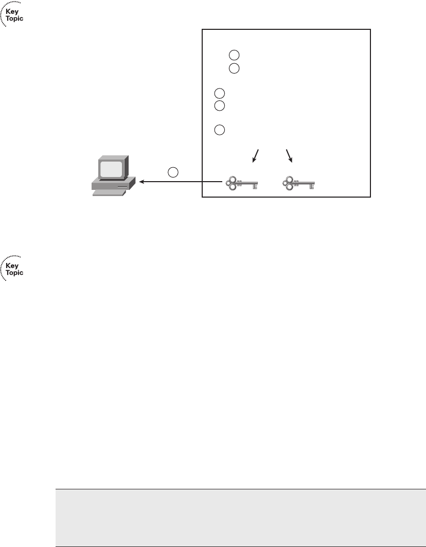
240 Chapter 9: Ethernet Switch Configuration
Figure 9-1 SSH Configuration Concepts
The steps in the figure, explained with the matching numbered list that follows, detail the
required transactions before an SSH user can connect to the switch using SSH:
Step 1 Change the vty lines to use usernames, with either locally configured usernames
or an AAA server. In this case, the login local subcommand defines the use of local
usernames, replacing the login subcommand in vty configuration mode.
Step 2 Tell the switch to accept both Telnet and SSH with the transport input
telnet ssh vty subcommand. (The default is transport input telnet,
omitting the ssh parameter.)
Step 3 Add one or more username name password pass-value global
configuration commands to configure username/password pairs.
Step 4 Configure a DNS domain name with the ip domain-name name global
configuration command.
Step 5 Configure the switch to generate a matched public and private key pair,
as well as a shared encryption key, using the crypto key generate rsa
global configuration command.
Step 6 Although no switch commands are required, each SSH client needs a
copy of the switch’s public key before the client can connect.
NOTE This book contains several step lists that refer to specific configuration steps,
such as the one shown here for SSH. You do not need to memorize the steps for the
exams; however, the lists can be useful for study—in particular, to help you remember
all the required steps to configure a certain feature.
SSH Client
line vty 0 15
login local
transport input telnet ssh
username wendell password hope
ip domain-name example.com
crypto key generate rsa
(Switch Generates Keys)
Cisco Switch
Public Key Private Key
1
2
3
4
5
6
1828xbook.fm Page 240 Thursday, July 26, 2007 3:10 PM

Configuration of Features in Common with Routers 241
Example 9-2 shows the same switch commands shown in Figure 9-1, entered in
configuration mode.
Example 9-2 SSH Configuration Process
Emma#
Emma#cc
ccoo
oonn
nnff
ffii
iigg
gguu
uurr
rree
ee
tt
ttee
eerr
rrmm
mmii
iinn
nnaa
aall
ll
Enter configuration commands, one per line. End with CNTL/Z.
Emma(config)#ll
llii
iinn
nnee
ee
vv
vvtt
ttyy
yy
00
00
11
1155
55
! Step 1’s command happens next
Emma(config-line)#ll
lloo
oogg
ggii
iinn
nn
ll
lloo
oocc
ccaa
aall
ll
! Step 2’s command happens next
Emma(config-line)#tt
ttrr
rraa
aann
nnss
sspp
ppoo
oorr
rrtt
tt
ii
iinn
nnpp
ppuu
uutt
tt
tt
ttee
eell
llnn
nnee
eett
tt
ss
ssss
sshh
hh
Emma(config-line)#ee
eexx
xxii
iitt
tt
! Step 3’s command happens next
Emma(config)#uu
uuss
ssee
eerr
rrnn
nnaa
aamm
mmee
ee
ww
wwee
eenn
nndd
ddee
eell
llll
ll
pp
ppaa
aass
ssss
ssww
wwoo
oorr
rrdd
dd
hh
hhoo
oopp
ppee
ee
! Step 4’s command happens next
Emma(config)#ii
iipp
pp
dd
ddoo
oomm
mmaa
aaii
iinn
nn--
--nn
nnaa
aamm
mmee
ee
ee
eexx
xxaa
aamm
mmpp
ppll
llee
ee..
..cc
ccoo
oomm
mm
! Step 5’s command happens next
Emma(config)#cc
ccrr
rryy
yypp
pptt
ttoo
oo
kk
kkee
eeyy
yy
gg
ggee
eenn
nnee
eerr
rraa
aatt
ttee
ee
rr
rrss
ssaa
aa
The name for the keys will be: Emma.example.com
Choose the size of the key modulus in the range of 360 to 2048 for your
General Purpose Keys. Choosing a key modulus greater than 512 may take
a few minutes.
How many bits in the modulus [512]: 11
1100
0022
2244
44
% Generating 1024 bit RSA keys ...[OK]
00:03:58: %SSH-5-ENABLED: SSH 1.99 has been enabled
Emma(config)#^^
^^ZZ
ZZ
! Next, the contents of the public key are listed; the key will be needed by the SSH
client.
Emma#ss
sshh
hhoo
ooww
ww
cc
ccrr
rryy
yypp
pptt
ttoo
oo
kk
kkee
eeyy
yy
mm
mmyy
yypp
ppuu
uubb
bbkk
kkee
eeyy
yy
rr
rrss
ssaa
aa
% Key pair was generated at: 00:03:58 UTC Mar 1 1993
Key name: Emma.example.com
Usage: General Purpose Key
Key is not exportable.
Key Data:
30819F30 0D06092A 864886F7 0D010101 05000381 8D003081 89028181 00DB43DC
49C258FA 8E0B8EB2 0A6C8888 A00D29CE EAEE615B 456B68FD 491A9B63 B39A4334
86F64E02 1B320256 01941831 7B7304A2 720A57DA FBB3E75A 94517901 7764C332
A3A482B1 DB4F154E A84773B5 5337CE8C B1F5E832 8213EE6B 73B77006 BA8782DE
180966D9 9A6476D7 C9164ECE 1DC752BB 955F5BDE F82BFCB2 A273C58C 8B020301 0001
% Key pair was generated at: 00:04:01 UTC Mar 1 1993
Key name: Emma.example.com.server
Usage: Encryption Key
Key is not exportable.
continues
1828xbook.fm Page 241 Thursday, July 26, 2007 3:10 PM

242 Chapter 9: Ethernet Switch Configuration
The example shows a gray highlighted comment just before the configuration commands
at each step. Also, note the public key created by the switch, listed in the highlighted portion
of the output of the show crypto key mypubkey rsa command. Each SSH client needs a
copy of this key, either by adding this key to the SSH client’s configuration beforehand, or
by letting the switch send this public key to the client when the SSH client first connects to
the switch.
For even tighter security, you might want to disable Telnet access completely, requiring all
the engineers to use SSH to remotely log in to the switch. To prevent Telnet access, use the
transport input ssh line subcommand in vty configuration mode. If the command is given
only the SSH option, the switch will no longer accept Telnet connections.
Password Encryption
Several of the configuration commands used to configure passwords store the passwords in
clear text in the running-config file, at least by default. In particular, the simple passwords
configured on the console and vty lines, with the password command, plus the password
in the username command, are all stored in clear text by default. (The enable secret
command automatically hides the password value.)
To prevent password vulnerability in a printed version of the configuration file, or in a
backup copy of the configuration file stored on a server, you can encrypt or encode the
passwords using the service password-encryption global configuration command. The
presence or absence of the service password-encryption global configuration command
dictates whether the passwords are encrypted as follows:
■When the service password-encryption command is configured, all existing console,
vty, and username command passwords are immediately encrypted.
■If the service password-encryption command has already been configured, any future
changes to these passwords are encrypted.
■If the no service password-encryption command is used later, the passwords remain
encrypted, until they are changed—at which point they show up in clear text.
Key Data:
307C300D 06092A86 4886F70D 01010105 00036B00 30680261 00AC339C D4916728
6ACB627E A5EE26A5 00946AF9 E63FF322 A2DB4994 9E37BFDA AB1C503E AAF69FB3
2A22A5F3 0AA94454 B8242D72 A8582E7B 0642CF2B C06E0710 B0A06048 D90CBE9E
F0B88179 EC1C5EAC D551109D 69E39160 86C50122 9A37E954 85020301 0001
Example 9-2 SSH Configuration Process (Continued)
1828xbook.fm Page 242 Thursday, July 26, 2007 3:10 PM

Configuration of Features in Common with Routers 243
Example 9-3 shows an example of these details.
NOTE The show running-config | begin line vty command, as used in Example 9-3,
lists the running configuration, beginning with the first line, which contains the text line
vty. This is just a shorthand way to see a smaller part of the running configuration.
Example 9-3 Encryption and the service password-encryption Command
Switch3#ss
sshh
hhoo
ooww
ww
rr
rruu
uunn
nnnn
nnii
iinn
nngg
gg--
--cc
ccoo
oonn
nnff
ffii
iigg
gg
|
bb
bbee
eegg
ggii
iinn
nn
ll
llii
iinn
nnee
ee
vv
vvtt
ttyy
yy
line vty 0 4
password cisco
login
Switch3#cc
ccoo
oonn
nnff
ffii
iigg
gguu
uurr
rree
ee
tt
ttee
eerr
rrmm
mmii
iinn
nnaa
aall
ll
Enter configuration commands, one per line. End with CNTL/Z.
Switch3(config)#ss
ssee
eerr
rrvv
vvii
iicc
ccee
ee
pp
ppaa
aass
ssss
ssww
wwoo
oorr
rrdd
dd--
--ee
eenn
nncc
ccrr
rryy
yypp
pptt
ttii
iioo
oonn
nn
Switch3(config)#^^
^^ZZ
ZZ
Switch3#ss
sshh
hhoo
ooww
ww
rr
rruu
uunn
nnnn
nnii
iinn
nngg
gg--
--cc
ccoo
oonn
nnff
ffii
iigg
gg
|
bb
bbee
eegg
ggii
iinn
nn
ll
llii
iinn
nnee
ee
vv
vvtt
ttyy
yy
line vty 0 4
password 7 070C285F4D06
login
end
Switch3#cc
ccoo
oonn
nnff
ffii
iigg
gguu
uurr
rree
ee
tt
ttee
eerr
rrmm
mmii
iinn
nnaa
aall
ll
Enter configuration commands, one per line. End with CNTL/Z.
Switch3(config)#nn
nnoo
oo
ss
ssee
eerr
rrvv
vvii
iicc
ccee
ee
pp
ppaa
aass
ssss
ssww
wwoo
oorr
rrdd
dd--
--ee
eenn
nncc
ccrr
rryy
yypp
pptt
ttii
iioo
oonn
nn
Switch3(config)#^^
^^ZZ
ZZ
Switch3#ss
sshh
hhoo
ooww
ww
rr
rruu
uunn
nnnn
nnii
iinn
nngg
gg--
--cc
ccoo
oonn
nnff
ffii
iigg
gg
|
bb
bbee
eegg
ggii
iinn
nn
ll
llii
iinn
nnee
ee
vv
vvtt
ttyy
yy
line vty 0 4
password 7 070C285F4D06
login
end
Switch3#cc
ccoo
oonn
nnff
ffii
iigg
gguu
uurr
rree
ee
tt
ttee
eerr
rrmm
mmii
iinn
nnaa
aall
ll
Enter configuration commands, one per line. End with CNTL/Z.
Switch3(config)#ll
llii
iinn
nnee
ee
vv
vvtt
ttyy
yy
00
00
44
44
Switch3(config-line)#pp
ppaa
aass
ssss
ssww
wwoo
oorr
rrdd
dd
cc
ccii
iiss
sscc
ccoo
oo
Switch3(config-line)#^^
^^ZZ
ZZ
Switch3#ss
sshh
hhoo
ooww
ww
rr
rruu
uunn
nnnn
nnii
iinn
nngg
gg--
--cc
ccoo
oonn
nnff
ffii
iigg
gg
|
bb
bbee
eegg
ggii
iinn
nn
ll
llii
iinn
nnee
ee
vv
vvtt
ttyy
yy
line vty 0 4
password cisco
login
NOTE The encryption type used by the service password-encryption command, as
noted with the “7” in the password commands, refers to one of several underlying
password encryption algorithms. Type 7, the only type used by the service password-
encryption command, is a weak encryption algorithm, and the passwords can be easily
decrypted.
1828xbook.fm Page 243 Thursday, July 26, 2007 3:10 PM

244 Chapter 9: Ethernet Switch Configuration
The Two Enable Mode Passwords
The enable command moves you from user EXEC mode (with a prompt of hostname>) to
privileged EXEC mode (with a prompt of hostname#). A router or switch can be configured
to require a password to reach enable mode according to the following rules:
■If the global configuration command enable password actual-password is used, it
defines the password required when using the enable EXEC command. This password
is listed as clear text in the configuration file by default.
■If the global configuration command enable secret actual-password is used, it defines
the password required when using the enable EXEC command. This password is listed
as a hidden MD5 hash value in the configuration file.
■If both commands are used, the password set in the enable secret command defines
which password is required.
When the enable secret command is configured, the router or switch automatically hides
the password. While it is sometimes referenced as being encrypted, the enable secret
password is not actually encrypted. Instead, IOS applies a mathematical function to the
password, called a Message Digest 5 (MD5) hash, storing the results of the formula in the
configuration file. IOS references this style of encoding the password as type 5 in the output
in Example 9-4. Note that the MD5 encoding is much more secure than the encryption
used for other passwords with the service password-encryption command. The example
shows the creation of the enable secret command, its format, and its deletion.
When you use the (recommended) enable secret command, rather than the enable
password command, the password is automatically encrypted. Example 9-4 uses the
enable secret fred command, setting the password text to fred. However, the syntax enable
Example 9-4 Encryption and the enable secret Command
Switch3(config)#ee
eenn
nnaa
aabb
bbll
llee
ee
ss
ssee
eecc
ccrr
rree
eett
tt
??
??
0 Specifies an UNENCRYPTED password will follow
5 Specifies an ENCRYPTED secret will follow
LINE The UNENCRYPTED (cleartext) ‘enable’ secret
level Set exec level password
Switch3(config)#ee
eenn
nnaa
aabb
bbll
llee
ee
ss
ssee
eecc
ccrr
rree
eett
tt
ff
ffrr
rree
eedd
dd
Switch3(config)#^^
^^ZZ
ZZ
Switch3#ss
sshh
hhoo
ooww
ww
rr
rruu
uunn
nnnn
nnii
iinn
nngg
gg--
--cc
ccoo
oonn
nnff
ffii
iigg
gg
! all except the pertinent line has been omitted!
enable secret 5 $1$ZGMA$e8cmvkz4UjiJhVp7.maLE1
Switch3#cc
ccoo
oonn
nnff
ffii
iigg
gguu
uurr
rree
ee
tt
ttee
eerr
rrmm
mmii
iinn
nnaa
aall
ll
Enter configuration commands, one per line. End with CNTL/Z.
Switch3(config)#nn
nnoo
oo
ee
eenn
nnaa
aabb
bbll
llee
ee
ss
ssee
eecc
ccrr
rree
eett
tt
Switch3(config)#^^
^^ZZ
ZZ
1828xbook.fm Page 244 Thursday, July 26, 2007 3:10 PM

Configuration of Features in Common with Routers 245
secret 0 fred could have been used, with the 0 implying that the password that followed
was clear text. IOS then takes the command, applies the encryption type used by the enable
secret command (type 5 in this case, which uses an MD5 hash), and stores the encrypted
or encoded value in the running configuration. The show running-configuration
command shows the resulting configuration command, listing encryption type 5, with the
gobbledygook long text string being the encrypted/encoded password.
Thankfully, to delete the enable secret password, you can simply use the no enable secret
command, without even having to enter the password value. For instance, in Example 9-4,
the command no enable secret deletes the enable secret password. Although you can delete
the enable secret password, more typically, you will want to change it to a new value, which
can be done with the enable secret another-password command, with another-password
simply meaning that you put in a new text string for the new password.
Console and vty Settings
This section covers a few small configuration settings that affect the behavior of the CLI
connection from the console and/or vty (Telnet and SSH).
Banners
Cisco routers and switches can display a variety of banners depending on what a router or
switch administrator is doing. A banner is simply some text that appears on the screen
for the user. You can configure a router or switch to display multiple banners, some before
login and some after. Table 9-2 lists the three most popular banners and their typical use.
The banner global configuration command can be used to configure all three types of these
banners. In each case, the type of banner is listed as the first parameter, with MOTD being
the default option. The first nonblank character after the banner type is called a beginning
delimiter character. The banner text can span several lines, with the CLI user pressing
Enter at the end of each line. The CLI knows that the banner has been configured as soon
as the user enters the same delimiter character again.
Table 9-2 Banners and Their Use
Banner Typical Use
Message of the Day (MOTD) Shown before the login prompt. For temporary messages that
may change from time to time, such as “Router1 down for
maintenance at midnight.”
Login Shown before the login prompt but after the MOTD banner. For
permanent messages such as “Unauthorized Access Prohibited.”
Exec Shown after the login prompt. Used to supply information that
should be hidden from unauthorized users.
1828xbook.fm Page 245 Thursday, July 26, 2007 3:10 PM

246 Chapter 9: Ethernet Switch Configuration
Example 9-5 shows all three types of banners from Table 9-2, with a user login that shows
the banners in use. The first banner in the example, the MOTD banner, omits the banner
type in the banner command as a reminder that motd is the default banner type. The first
two banner commands use a # as the delimiter character. The third banner command uses
a Z as the delimiter, just to show that any character can be used. Also, the last banner
command shows multiple lines of banner text.
History Buffer Commands
When you enter commands from the CLI, the last several commands are saved in the
history buffer. As mentioned in Chapter 8, you can use the up-arrow key, or Ctrl-p, to move
Example 9-5 Banner Configuration
! Below, the three banners are created in configuration mode. Note that any
! delimiter can be used, as long as the character is not part of the message
! text.
SW1(config)#bb
bbaa
aann
nnnn
nnee
eerr
rr
##
##
Enter TEXT message. End with the character ‘#’.
SS
SSww
wwii
iitt
ttcc
cchh
hh
dd
ddoo
ooww
wwnn
nn
ff
ffoo
oorr
rr
mm
mmaa
aaii
iinn
nntt
ttee
eenn
nnaa
aann
nncc
ccee
ee
aa
aatt
tt
11
1111
11PP
PPMM
MM
TT
TToo
oodd
ddaa
aayy
yy
##
##
SW1(config)#bb
bbaa
aann
nnnn
nnee
eerr
rr
ll
lloo
oogg
ggii
iinn
nn
##
##
Enter TEXT message. End with the character ‘#’.
UU
UUnn
nnaa
aauu
uutt
tthh
hhoo
oorr
rrii
iizz
zzee
eedd
dd
AA
AAcc
cccc
ccee
eess
ssss
ss
PP
PPrr
rroo
oohh
hhii
iibb
bbii
iitt
ttee
eedd
dd!!
!!!!
!!!!
!!!!
!!
##
##
SW1(config)#bb
bbaa
aann
nnnn
nnee
eerr
rr
ee
eexx
xxee
eecc
cc
ZZ
ZZ
Enter TEXT message. End with the character ‘Z’.
CC
CCoo
oomm
mmpp
ppaa
aann
nnyy
yy
pp
ppii
iicc
ccnn
nnii
iicc
cc
aa
aatt
tt
tt
tthh
hhee
ee
pp
ppaa
aarr
rrkk
kk
oo
oonn
nn
SS
SSaa
aatt
ttuu
uurr
rrdd
ddaa
aayy
yy
DD
DDoo
oonn
nn’’
’’tt
tt
tt
ttee
eell
llll
ll
oo
oouu
uutt
ttss
ssii
iidd
ddee
eerr
rrss
ss!!
!!
ZZ
ZZ
SW1(config)#^^
^^ZZ
ZZ
! Below, the user of this router quits the console connection, and logs back in,
! seeing the motd and login banners, then the password prompt, and then the
! exec banner.
SW1#qq
qquu
uuii
iitt
tt
SW1 con0 is now available
Press RETURN to get started.
SS
SSww
wwii
iitt
ttcc
cchh
hh
dd
ddoo
ooww
wwnn
nn
ff
ffoo
oorr
rr
mm
mmaa
aaii
iinn
nntt
ttee
eenn
nnaa
aann
nncc
ccee
ee
aa
aatt
tt
11
1111
11PP
PPMM
MM
TT
TToo
oodd
ddaa
aayy
yy
UU
UUnn
nnaa
aauu
uutt
tthh
hhoo
oorr
rrii
iizz
zzee
eedd
dd
AA
AAcc
cccc
ccee
eess
ssss
ss
PP
PPrr
rroo
oohh
hhii
iibb
bbii
iitt
ttee
eedd
dd!!
!!!!
!!!!
!!!!
!!
User Access Verification
Username: fred
Password:
CC
CCoo
oomm
mmpp
ppaa
aann
nnyy
yy
pp
ppii
iicc
ccnn
nnii
iicc
cc
aa
aatt
tt
tt
tthh
hhee
ee
pp
ppaa
aarr
rrkk
kk
oo
oonn
nn
SS
SSaa
aatt
ttuu
uurr
rrdd
ddaa
aayy
yy
dd
ddoo
oonn
nn’’
’’tt
tt
tt
ttee
eell
llll
ll
oo
oouu
uutt
ttss
ssii
iidd
ddee
eerr
rrss
ss!!
!!
SW1>
1828xbook.fm Page 246 Thursday, July 26, 2007 3:10 PM

Configuration of Features in Common with Routers 247
back in the history buffer stack to retrieve a command you entered a few commands ago.
This feature makes it very easy and fast to use a set of commands repeatedly. Table 9-3 lists
some of the key commands related to the history buffer.
The logging synchronous and exec-timeout Commands
The console automatically receives copies of all unsolicited syslog messages on a switch or
router; that feature cannot be disabled. The idea is that if the switch or router needs to tell
the network administrator some important and possibly urgent information, the
administrator may be at the console and may notice the message. Normally a switch or
router puts these syslog messages on the console’s screen at any time—including right in
the middle of a command you are entering, or in the middle of the output of a show
command.
To make using the console a little easier, you can tell the switch to display syslog messages
only at more convenient times, such as at the end of output from a show command or to
prevent the interruption of a command text input. To do so, just configure the logging
synchronous console line subcommand.
You can also make using the console or vty lines more convenient by setting a different
inactivity timeout on the console or vty. By default, the switch or router automatically
disconnects users after 5 minutes of inactivity, for both console users and users who connect
to vty lines using Telnet or SSH. When you configure the exec-timeout minutes seconds
line subcommand, the switch or router can be told a different inactivity timer. Also, if you
set the timeout to 0 minutes and 0 seconds, the router never times out the console
connection. Example 9-6 shows the syntax for these two commands.
Table 9-3 Commands Related to the History Buffer
Command Description
show history Lists the commands currently held in the history buffer.
history size xFrom console or vty line configuration mode, sets the default
number of commands saved in the history buffer for the user(s) of
the console or vty lines, respectively.
terminal history size xFrom EXEC mode, this command allows a single user to set, just for
this one connection, the size of his or her history buffer.
Example 9-6 Defining Console Inactivity Timeouts and When to Display Log Messages
ll
llii
iinn
nnee
ee
cc
ccoo
oonn
nnss
ssoo
ooll
llee
ee
00
00
ll
lloo
oogg
ggii
iinn
nn
pp
ppaa
aass
ssss
ssww
wwoo
oorr
rrdd
dd
cc
ccii
iiss
sscc
ccoo
oo
ee
eexx
xxee
eecc
cc--
--tt
ttii
iimm
mmee
eeoo
oouu
uutt
tt
00
00
00
00
ll
lloo
oogg
gggg
ggii
iinn
nngg
gg
ss
ssyy
yynn
nncc
cchh
hhrr
rroo
oonn
nnoo
oouu
uuss
ss
1828xbook.fm Page 247 Thursday, July 26, 2007 3:10 PM
248 Chapter 9: Ethernet Switch Configuration
LAN Switch Configuration and Operation
One of the most convenient facts about LAN switch configuration is that Cisco switches
work without any configuration. Cisco switches ship from the factory with all interfaces
enabled (a default configuration of no shutdown) and with autonegotiation enabled for
ports that run at multiple speeds and duplex settings (a default configuration of duplex auto
and speed auto). All you have to do is connect the Ethernet cables and plug in the power
cord to a power outlet, and the switch is ready to work—learning MAC addresses, making
forwarding/filtering decisions, and even using STP by default.
The second half of this chapter continues the coverage of switch configuration, mainly
covering features that apply only to switches and not routers. In particular, this section
covers the following:
■Switch IP configuration
■Interface configuration (including speed and duplex)
■Port security
■VLAN configuration
■Securing unused switch interfaces
Configuring the Switch IP Address
To allow Telnet or SSH access to the switch, to allow other IP-based management protocols
such as Simple Network Management Protocol (SNMP) to function as intended, or to allow
access to the switch using graphical tools such as Cisco Device Manager (CDM), the switch
needs an IP address. Switches do not need an IP address to be able to forward Ethernet
frames. The need for an IP address is simply to support overhead management traffic, such
as logging into the switch.
A switch’s IP configuration essentially works like a host with a single Ethernet interface.
The switch needs one IP address and a matching subnet mask. The switch also needs to
know its default gateway—in other words, the IP address of some nearby router. As with
hosts, you can statically configure a switch with its IP address/mask/gateway, or the switch
can dynamically learn this information using DHCP.
An IOS-based switch configures its IP address and mask on a special virtual interface called
the VLAN 1 interface. This interface plays the same role as an Ethernet interface on a PC.
In effect, a switch’s VLAN 1 interface gives the switch an interface into the default VLAN
1828xbook.fm Page 248 Thursday, July 26, 2007 3:10 PM

LAN Switch Configuration and Operation 249
used on all ports of the switch—namely, VLAN 1. The following steps list the commands
used to configure IP on a switch:
Step 1 Enter VLAN 1 configuration mode using the interface vlan 1 global configuration
command (from any config mode).
Step 2 Assign an IP address and mask using the ip address ip-address mask
interface subcommand.
Step 3 Enable the VLAN 1 interface using the no shutdown interface
subcommand.
Step 4 Add the ip default-gateway ip-address global command to configure the
default gateway.
Example 9-7 shows a sample configuration.
Of particular note, this example shows how to enable any interface, VLAN interfaces
included. To administratively enable an interface on a switch or router, you use the no
shutdown interface subcommand. To administratively disable an interface, you would use
the shutdown interface subcommand. The messages shown in Example 9-7, immediately
following the no shutdown command, are syslog messages generated by the switch stating
that the switch did indeed enable the interface.
To verify the configuration, you can again use the show running-config command to view
the configuration commands and confirm that you entered the right address, mask, and
default gateway.
For the switch to act as a DHCP client to discover its IP address, mask, and default gateway,
you still need to configure it. You use the same steps as for static configuration, with the
following differences in Steps 2 and 4:
Step 2: Use the ip address dhcp command, instead of the ip address ip-address mask
command, on the VLAN 1 interface.
Example 9-7 Switch Static IP Address Configuration
Emma#cc
ccoo
oonn
nnff
ffii
iigg
gguu
uurr
rree
ee
tt
ttee
eerr
rrmm
mmii
iinn
nnaa
aall
ll
Emma(config)#ii
iinn
nntt
ttee
eerr
rrff
ffaa
aacc
ccee
ee
vv
vvll
llaa
aann
nn
11
11
Emma(config-if)#ii
iipp
pp
aa
aadd
dddd
ddrr
rree
eess
ssss
ss
11
1199
9922
22..
..11
1166
6688
88..
..11
11..
..22
2200
0000
00
22
2255
5555
55..
..22
2255
5555
55..
..22
2255
5555
55..
..00
00
Emma(config-if)#nn
nnoo
oo
ss
sshh
hhuu
uutt
ttdd
ddoo
ooww
wwnn
nn
00:25:07: %LINK-3-UPDOWN: Interface Vlan1, changed state to up
00:25:08: %LINEPROTO-5-UPDOWN: Line protocol on Interface Vlan1, changed
state to up
Emma(config-if)#ee
eexx
xxii
iitt
tt
Emma(config)#ii
iipp
pp
dd
ddee
eeff
ffaa
aauu
uull
lltt
tt--
--gg
ggaa
aatt
ttee
eeww
wwaa
aayy
yy
11
1199
9922
22..
..11
1166
6688
88..
..11
11..
..11
11
1828xbook.fm Page 249 Thursday, July 26, 2007 3:10 PM

250 Chapter 9: Ethernet Switch Configuration
Step 4: Do not configure the ip default-gateway global command.
Example 9-8 shows an example of configuring a switch to use DHCP to acquire an IP
address.
When configuring a static interface IP address, you can use the show running-config
command to see the IP address. However, when using the DHCP client, the IP address is
not in the configuration, so you need to use the show dhcp lease command to see the
(temporarily) leased IP address and other parameters.
Example 9-8 Switch Dynamic IP Address Configuration with DHCP
Emma#cc
ccoo
oonn
nnff
ffii
iigg
gguu
uurr
rree
ee
tt
ttee
eerr
rrmm
mmii
iinn
nnaa
aall
ll
Enter configuration commands, one per line. End with CNTL/Z.
Emma(config)#ii
iinn
nntt
ttee
eerr
rrff
ffaa
aacc
ccee
ee
vv
vvll
llaa
aann
nn
11
11
Emma(config-if)#ii
iipp
pp
aa
aadd
dddd
ddrr
rree
eess
ssss
ss
dd
ddhh
hhcc
ccpp
pp
Emma(config-if)#nn
nnoo
oo
ss
sshh
hhuu
uutt
ttdd
ddoo
ooww
wwnn
nn
Emma(config-if)#^^
^^ZZ
ZZ
Emma#
00:38:20: %LINK-3-UPDOWN: Interface Vlan1, changed state to up
00:38:21: %LINEPROTO-5-UPDOWN: Line protocol on Interface Vlan1, changed state to up
Emma#
Interface Vlan1 assigned DHCP address 192.168.1.101, mask 255.255.255.0
Emma#ss
sshh
hhoo
ooww
ww
dd
ddhh
hhcc
ccpp
pp
ll
llee
eeaa
aass
ssee
ee
Temp IP addr: 192.168.1.101 for peer on Interface: Vlan1
Temp sub net mask: 255.255.255.0
DHCP Lease server: 192.168.1.1, state: 3 Bound
DHCP transaction id: 1966
Lease: 86400 secs, Renewal: 43200 secs, Rebind: 75600 secs
Temp default-gateway addr: 192.168.1.1
Next timer fires after: 11:59:45
Retry count: 0 Client-ID: cisco-0019.e86a.6fc0-Vl1
Hostname: Emma
Emma#ss
sshh
hhoo
ooww
ww
ii
iinn
nntt
ttee
eerr
rrff
ffaa
aacc
ccee
ee
vv
vvll
llaa
aann
nn
11
11
Vlan1 is up, line protocol is up
Hardware is EtherSVI, address is 0019.e86a.6fc0 (bia 0019.e86a.6fc0)
Internet address is 192.168.1.101/24
MTU 1500 bytes, BW 1000000 Kbit, DLY 10 usec,
reliability 255/255, txload 1/255, rxload 1/255
! lines omitted for brevity
NOTE Some older models of Cisco IOS switches might not support the DHCP client
function on the VLAN 1 interface. Example 9-8 was taken from a 2960 switch running
Cisco IOS Software Release 12.2.
1828xbook.fm Page 250 Thursday, July 26, 2007 3:10 PM

LAN Switch Configuration and Operation 251
Finally, the output of the show interface vlan 1 command, shown at the end of Example 9-8,
lists two very important details related to switch IP addressing. First, this show command
lists the interface status of the VLAN 1 interface—in this case, “up and up.” If the VLAN 1
interface is not up, the switch cannot use its IP address to send and receive traffic. Notably,
if you forget to issue the no shutdown command, the VLAN 1 interface remains in its
default shutdown state and is listed as “administratively down” in the show command
output. Second, note that the output lists the interface’s IP address on the third line of the
output. If the switch fails to acquire an IP address with DHCP, the output would instead list
the fact that the address will (hopefully) be acquired by DHCP. As soon as an address has
been leased using DHCP, the output of the command looks like Example 9-8. However,
nothing in the show interface vlan 1 command output mentions that the address is either
statically configured or DHCP-leased.
Configuring Switch Interfaces
IOS uses the term interface to refer to physical ports used to forward data to and from other
devices. Each interface may be configured with several settings, each of which might differ
from interface to interface.
IOS uses interface subcommands to configure these settings. For instance, interfaces can be
configured to use the duplex and speed interface subcommands to configure those settings
statically, or an interface can use autonegotiation (the default). Example 9-9 shows how to
configure duplex and speed, as well as the description command, which is simply a text
description of what an interface does.
Example 9-9 Interface Configuration Basics
Emma#cc
ccoo
oonn
nnff
ffii
iigg
gguu
uurr
rree
ee
tt
ttee
eerr
rrmm
mmii
iinn
nnaa
aall
ll
Enter configuration commands, one per line. End with CNTL/Z.
Emma(config)#ii
iinn
nntt
ttee
eerr
rrff
ffaa
aacc
ccee
ee
FF
FFaa
aass
sstt
ttEE
EEtt
tthh
hhee
eerr
rrnn
nnee
eett
tt
00
00//
//11
11
Emma(config-if)#dd
dduu
uupp
ppll
llee
eexx
xx
ff
ffuu
uull
llll
ll
Emma(config-if)#ss
sspp
ppee
eeee
eedd
dd
11
1100
0000
00
Emma(config-if)#dd
ddee
eess
sscc
ccrr
rrii
iipp
pptt
ttii
iioo
oonn
nn
SS
SSee
eerr
rrvv
vvee
eerr
rr11
11
cc
ccoo
oonn
nnnn
nnee
eecc
cctt
ttss
ss
hh
hhee
eerr
rree
ee
Emma(config-if)#ee
eexx
xxii
iitt
tt
Emma(config)#ii
iinn
nntt
ttee
eerr
rrff
ffaa
aacc
ccee
ee
rr
rraa
aann
nngg
ggee
ee
FF
FFaa
aass
sstt
ttEE
EEtt
tthh
hhee
eerr
rrnn
nnee
eett
tt
00
00//
//11
1111
11
--
--
22
2200
00
Emma(config-if-range)#dd
ddee
eess
sscc
ccrr
rrii
iipp
pptt
ttii
iioo
oonn
nn
ee
eenn
nndd
dd--
--uu
uuss
ssee
eerr
rrss
ss
cc
ccoo
oonn
nnnn
nnee
eecc
cctt
tt__
__hh
hhee
eerr
rree
ee
Emma(config-if-range)#^^
^^ZZ
ZZ
Emma#
Emma#ss
sshh
hhoo
ooww
ww
ii
iinn
nntt
ttee
eerr
rrff
ffaa
aacc
ccee
eess
ss
ss
sstt
ttaa
aatt
ttuu
uuss
ss
Port Name Status Vlan Duplex Speed Type
Fa0/1 Server1 connects h notconnect 1 full 100 10/100BaseTX
Fa0/2 notconnect 1 auto auto 10/100BaseTX
Fa0/3 notconnect 1 auto auto 10/100BaseTX
continues
1828xbook.fm Page 251 Thursday, July 26, 2007 3:10 PM

252 Chapter 9: Ethernet Switch Configuration
You can see some of the details of interface configuration with both the show running-
config command (not shown in the example) and the handy show interfaces status
command. This command lists a single line for each interface, the first part of the interface
description, and the speed and duplex settings. Note that interface FastEthernet 0/1
(abbreviated as Fa0/1 in the command output) lists a speed of 100, and duplex full, as
configured earlier in the example. Compare those settings with Fa0/2, which does not have
any cable connected yet, so the switch lists this interface with the default setting of auto,
meaning autonegotiate. Also, compare these settings to interface Fa0/4, which is physically
connected to a device and has completed the autonegotiation process. The command output
lists the results of the autonegotiation, in this case using 100 Mbps and full duplex. The
a- in a-full and a-100 refers to the fact that these values were autonegotiated.
Also, note that for the sake of efficiency, you can configure a command on a range of
interfaces at the same time using the interface range command. In the example, the
interface range FastEthernet 0/11 - 20 command tells IOS that the next subcommand(s)
apply to interfaces Fa0/11 through Fa0/20.
Fa0/4 connected 1 a-full a-100 10/100BaseTX
Fa0/5 notconnect 1 auto auto 10/100BaseTX
Fa0/6 connected 1 a-full a-100 10/100BaseTX
Fa0/7 notconnect 1 auto auto 10/100BaseTX
Fa0/8 notconnect 1 auto auto 10/100BaseTX
Fa0/9 notconnect 1 auto auto 10/100BaseTX
Fa0/10 notconnect 1 auto auto 10/100BaseTX
Fa0/11 end-users connect notconnect 1 auto auto 10/100BaseTX
Fa0/12 end-users connect notconnect 1 auto auto 10/100BaseTX
Fa0/13 end-users connect notconnect 1 auto auto 10/100BaseTX
Fa0/14 end-users connect notconnect 1 auto auto 10/100BaseTX
Fa0/15 end-users connect notconnect 1 auto auto 10/100BaseTX
Fa0/16 end-users connect notconnect 1 auto auto 10/100BaseTX
Fa0/17 end-users connect notconnect 1 auto auto 10/100BaseTX
Fa0/18 end-users connect notconnect 1 auto auto 10/100BaseTX
Fa0/19 end-users connect notconnect 1 auto auto 10/100BaseTX
Fa0/20 end-users connect notconnect 1 auto auto 10/100BaseTX
Fa0/21 notconnect 1 auto auto 10/100BaseTX
Fa0/22 notconnect 1 auto auto 10/100BaseTX
Fa0/23 notconnect 1 auto auto 10/100BaseTX
Fa0/24 notconnect 1 auto auto 10/100BaseTX
Gi0/1 notconnect 1 auto auto 10/100/1000BaseTX
Gi0/2 notconnect 1 auto auto 10/100/1000BaseTX
Emma#
Example 9-9 Interface Configuration Basics (Continued)
1828xbook.fm Page 252 Thursday, July 26, 2007 3:10 PM

LAN Switch Configuration and Operation 253
Port Security
If the network engineer knows what devices should be cabled and connected to particular
interfaces on a switch, the engineer can use port security to restrict that interface so that
only the expected devices can use it. This reduces exposure to some types of attacks in
which the attacker connects a laptop to the wall socket that connects to a switch port that
has been configured to use port security. When that inappropriate device attempts to send
frames to the switch interface, the switch can issue informational messages, discard frames
from that device, or even discard frames from all devices by effectively shutting down the
interface.
Port security configuration involves several steps. Basically, you need to make the port an
access port, which means that the port is not doing any VLAN trunking. You then need to
enable port security and then configure the actual MAC addresses of the devices allowed to
use that port. The following list outlines the steps, including the configuration commands
used:
Step 1 Make the switch interface an access interface using the switchport mode access
interface subcommand.
Step 2 Enable port security using the switchport port-security interface
subcommand.
Step 3 (Optional) Specify the maximum number of allowed MAC addresses
associated with the interface using the switchport port-security
maximum number interface subcommand. (Defaults to one MAC
address.)
Step 4 (Optional) Define the action to take when a frame is received from a
MAC address other than the defined addresses using the switchport
port-security violation {protect | restrict | shutdown} interface
subcommand. (The default action is to shut down the port.)
Step 5A Specify the MAC address(es) allowed to send frames into this interface
using the switchport port-security mac-address mac-address
command. Use the command multiple times to define more than one
MAC address.
Step 5B Alternatively, instead of Step 5A, use the “sticky learning” process to
dynamically learn and configure the MAC addresses of currently
connected hosts by configuring the switchport port-security mac-
address sticky interface subcommand.
For example, in Figure 9-2, Server 1 and Server 2 are the only devices that should ever be
connected to interfaces FastEthernet 0/1 and 0/2, respectively. When you configure port
security on those interfaces, the switch examines the source MAC address of all frames
1828xbook.fm Page 253 Thursday, July 26, 2007 3:10 PM
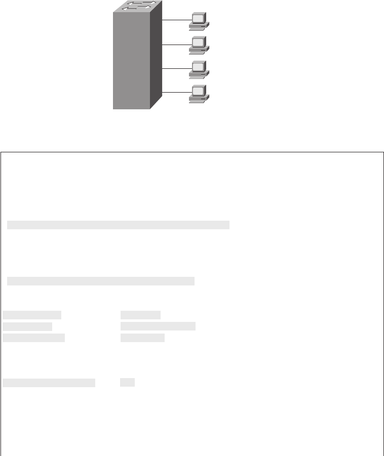
254 Chapter 9: Ethernet Switch Configuration
received on those ports, allowing only frames sourced from the configured MAC addresses.
Example 9-10 shows a sample port security configuration matching Figure 9-2, with
interface Fa0/1 being configured with a static MAC address, and with interface Fa0/2 using
sticky learning.
Figure 9-2 Port Security Configuration Example
Example 9-10 Using Port Security to Define Correct MAC Addresses of Particular
Interfaces
fred#ss
sshh
hhoo
ooww
ww
rr
rruu
uunn
nnnn
nnii
iinn
nngg
gg--
--cc
ccoo
oonn
nnff
ffii
iigg
gg
(Lines omitted for brevity)
interface FastEthernet0/1
switchport mode access
switchport port-security
switchport port-security mac-address 0200.1111.1111
!
interface FastEthernet0/2
switchport mode access
switchport port-security
switchport port-security mac-address sticky
fred#ss
sshh
hhoo
ooww
ww
pp
ppoo
oorr
rrtt
tt--
--ss
ssee
eecc
ccuu
uurr
rrii
iitt
ttyy
yy
ii
iinn
nntt
ttee
eerr
rrff
ffaa
aacc
ccee
ee
ff
ffaa
aass
sstt
ttEE
EEtt
tthh
hhee
eerr
rrnn
nnee
eett
tt
00
00//
//11
11
Port Security : Enabled
Port Status : Secure-shutdown
Violation Mode : Shutdown
Aging Time : 0 mins
Aging Type : Absolute
SecureStatic Address Aging : Disabled
Maximum MAC Addresses : 1
Total MAC Addresses : 1
Configured MAC Addresses : 1
Sticky MAC Addresses : 0
Last Source Address:Vlan : 0013.197b.5004:1
Security Violation Count : 1
fred#ss
sshh
hhoo
ooww
ww
pp
ppoo
oorr
rrtt
tt--
--ss
ssee
eecc
ccuu
uurr
rrii
iitt
ttyy
yy
ii
iinn
nntt
ttee
eerr
rrff
ffaa
aacc
ccee
ee
ff
ffaa
aass
sstt
ttEE
EEtt
tthh
hhee
eerr
rrnn
nnee
eett
tt
00
00//
//22
22
Company
Comptroller
Server 1
0200.1111.1111
Fa0/1
Fa0/2
Fa0/3
Fa0/4
Server 2
0200.2222.2222
User1
1828xbook.fm Page 254 Thursday, July 26, 2007 3:10 PM

LAN Switch Configuration and Operation 255
For FastEthernet 0/1, Server 1’s MAC address is configured with the switchport port-
security mac-address 0200.1111.1111 command. For port security to work, the 2960 must
think that the interface is an access interface, so the switchport mode access command is
required. Furthermore, the switchport port-security command is required to enable port
security on the interface. Together, these three interface subcommands enable port security,
and only MAC address 0200.1111.1111 is allowed to use the interface. This interface uses
defaults for the other settings, allowing only one MAC address on the interface, and causing
the switch to disable the interface if the switch receives a frame whose source MAC address
is not 0200.1111.111.
Interface FastEthernet 0/2 uses a feature called sticky secure MAC addresses. The
configuration still includes the switchport mode access and switchport port-security
commands for the same reasons as on FastEthernet 0/1. However, the switchport port-
security mac-address sticky command tells the switch to learn the MAC address from the
first frame sent to the switch and then add the MAC address as a secure MAC to the running
configuration. In other words, the first MAC address heard “sticks” to the configuration,
so the engineer does not have to know the MAC address of the device connected to the
interface ahead of time.
The show running-config output at the beginning of Example 9-10 shows the
configuration for Fa0/2, before any sticky learning occurred. The end of the example
shows the configuration after an address was sticky-learned, including the switchport
Port Security : Enabled
Port Status : Secure-up
Violation Mode : Shutdown
Aging Time : 0 mins
Aging Type : Absolute
SecureStatic Address Aging : Disabled
Maximum MAC Addresses : 1
Total MAC Addresses : 1
Configured MAC Addresses : 1
Sticky MAC Addresses : 1
Last Source Address:Vlan : 0200.2222.2222:1
Security Violation Count : 0
fred#ss
sshh
hhoo
ooww
ww
rr
rruu
uunn
nnnn
nnii
iinn
nngg
gg--
--cc
ccoo
oonn
nnff
ffii
iigg
gg
(Lines omitted for brevity)
interface FastEthernet0/2
switchport mode access
switchport port-security
switchport port-security mac-address sticky
switchport port-security mac-address sticky 0200.2222.2222
Example 9-10 Using Port Security to Define Correct MAC Addresses of Particular
Interfaces (Continued)
1828xbook.fm Page 255 Thursday, July 26, 2007 3:10 PM

256 Chapter 9: Ethernet Switch Configuration
port-security mac-address sticky 0200.2222.2222 interface subcommand, which the
switch added to the configuration. If you wanted to save the configuration so that only
0200.2222.2222 is used on that interface from now on, you would simply need to use the
copy running-config startup-config command to save the configuration.
As it turns out, a security violation has occurred on FastEthernet 0/1 in Example 9-10, but
no violations have occurred on FastEthernet 0/2. The show port-security interface
fastethernet 0/1 command shows that the interface is in a secure-shutdown state, which
means that the interface has been disabled due to port security. The device connected to
interface FastEthernet 0/1 did not use MAC address 0200.1111.1111, so the switch received
a frame in Fa0/1 with a different source MAC, causing a violation.
The switch can be configured to use one of three actions when a violation occurs. All three
configuration options cause the switch to discard the offending frame, but some of the
configuration options include additional actions. The actions include the sending of syslog
messages to the console and SNMP trap message to the network management station, as
well as whether the switch should shut down (err-disable) the interface. The shutdown
option actually puts the interface in an error disabled (err-disabled) state, making it
unusable. An interface in err-disabled state requires that someone manually shutdown the
interface and then use the no shutdown command to recover the interface. Table 9-4 lists
the options on the switchport port-security violation command and which actions each
option sets.
*shutdown is the default setting.
VLAN Configuration
Cisco switch interfaces are considered to be either access interfaces or trunk interfaces. By
definition, access interfaces send and receive frames only in a single VLAN, called the
access VLAN. Trunking interfaces send and receive traffic in multiple VLANs. The concept
and configuration for VLAN trunking is beyond the scope of this book, but it is covered in
detail in the ICND2 Official Exam Certification Guide, Chapters 1 and 3. This book focuses
on VLAN configuration for access interfaces, which by definition must be assigned to a
single VLAN.
Table 9-4 Actions When Port Security Violation Occurs
Option on the switchport port-security
violation Command Protect Restrict Shutdown*
Discards offending traffic Yes Yes Yes
Sends log and SNMP messages No Yes Yes
Disables the interface, discarding all traffic No No Yes
1828xbook.fm Page 256 Thursday, July 26, 2007 3:10 PM
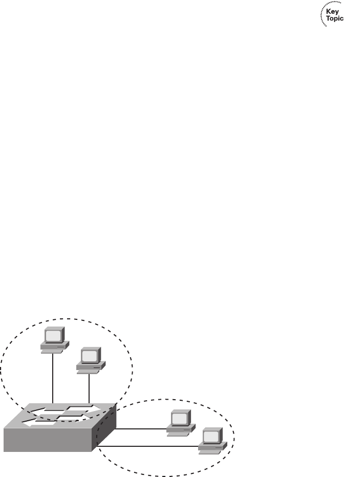
LAN Switch Configuration and Operation 257
For a Cisco switch to forward frames on access interfaces in a particular VLAN, the switch
must be configured to believe that the VLAN exists. Additionally, the switch must have one
or more access interfaces assigned to the VLAN. By default, Cisco switches already have
VLAN 1 configured, and all interfaces default to be assigned to VLAN 1. However, to add
another VLAN, and assign access interfaces to be in that VLAN, you can follow these steps:
Step 1 To configure a new VLAN:
a. From configuration mode, use the vlan vlan-id global configuration command
to create the VLAN and move the user into VLAN configuration mode.
b. (Optional) Use the name name VLAN subcommand to list a name for the
VLAN. If not configured, the VLAN name is VLANZZZZ, where ZZZZ is the
four-digit decimal VLAN ID.
Step 2 To configure a VLAN for each access interface:
a. Use the interface command to move into interface configuration mode for each
desired interface.
b. Use the switchport access vlan id-number interface subcommand to specify
the VLAN number associated with that interface.
c. (Optional) To disable trunking so that the switch will not dynamically decide to
use trunking on the interface, and it will remain an access interface, use the
switchport mode access interface subcommand.
Example 9-11 shows the configuration process to add a new VLAN and assign access
interfaces to it. Figure 9-3 shows the network used in the example, with one LAN switch
(SW1) and two hosts in each of two VLANs (1 and 2). Example 9-11 shows the details of the
two-step configuration process for VLAN 2 and the two access interfaces assigned to VLAN 2.
Figure 9-3 Network with One Switch and Two VLANs
Fa0/14Fa0/13
Fa0/11
Fa0/12
SW1
VLAN1
VLAN2
1828xbook.fm Page 257 Thursday, July 26, 2007 3:10 PM

258 Chapter 9: Ethernet Switch Configuration
Example 9-11 Configuring VLANs and Assigning Them to Interfaces
! to begin, 5 VLANs exist, with all interfaces assigned to VLAN 1 (default setting)
SW1#ss
sshh
hhoo
ooww
ww
vv
vvll
llaa
aann
nn
bb
bbrr
rrii
iiee
eeff
ff
VLAN Name Status Ports
---- -------------------------------- --------- -------------------------------
1 default active Fa0/1, Fa0/2, Fa0/3, Fa0/4
Fa0/5, Fa0/6, Fa0/7, Fa0/8
Fa0/9, Fa0/10, Fa0/11, Fa0/12
Fa0/13, Fa0/14, Fa0/15, Fa0/16
Fa0/17, Fa0/18, Fa0/19, Fa0/20
Fa0/21, Fa0/22, Fa0/23, Fa0/24
Gi0/1, Gi0/2
1002 fddi-default act/unsup
1003 token-ring-default act/unsup
1004 fddinet-default act/unsup
1005 trnet-default act/unsup
! Above, VLAN 2 did not yet exist. Below, VLAN 2 is added, with name Freds-vlan,
! with two interfaces assigned to VLAN 2.
SW1#cc
ccoo
oonn
nnff
ffii
iigg
gguu
uurr
rree
ee
tt
ttee
eerr
rrmm
mmii
iinn
nnaa
aall
ll
Enter configuration commands, one per line. End with CNTL/Z.
SW1(config)#vv
vvll
llaa
aann
nn
22
22
SW1(config-vlan)#nn
nnaa
aamm
mmee
ee
FF
FFrr
rree
eedd
ddss
ss--
--vv
vvll
llaa
aann
nn
SW1(config-vlan)#ee
eexx
xxii
iitt
tt
SW1(config)#ii
iinn
nntt
ttee
eerr
rrff
ffaa
aacc
ccee
ee
rr
rraa
aann
nngg
ggee
ee
ff
ffaa
aass
sstt
ttee
eett
tthh
hhee
eerr
rrnn
nnee
eett
tt
00
00//
//11
1133
33
--
--
11
1144
44
SW1(config-if)#ss
ssww
wwii
iitt
ttcc
cchh
hhpp
ppoo
oorr
rrtt
tt
aa
aacc
cccc
ccee
eess
ssss
ss
vv
vvll
llaa
aann
nn
22
22
SW1(config-if)#ee
eexx
xxii
iitt
tt
! Below, the ss
sshh
hhoo
ooww
ww
rr
rruu
uunn
nnnn
nnii
iinn
nngg
gg--
--cc
ccoo
oonn
nnff
ffii
iigg
gg command lists the interface subcommands on
! interfaces Fa0/13 and Fa0/14. The vv
vvll
llaa
aann
nn
22
22 and nn
nnaa
aamm
mmee
ee
FF
FFrr
rree
eedd
ddss
ss--
--vv
vvll
llaa
aann
nn commands do
! not show up in the running-config.
SW1#ss
sshh
hhoo
ooww
ww
rr
rruu
uunn
nnnn
nnii
iinn
nngg
gg--
--cc
ccoo
oonn
nnff
ffii
iigg
gg
! lines omitted for brevity
interface FastEthernet0/13
switchport access vlan 2
switchport mode access
!
interface FastEthernet0/14
switchport access vlan 2
switchport mode access
!
SW1#ss
sshh
hhoo
ooww
ww
vv
vvll
llaa
aann
nn
bb
bbrr
rrii
iiee
eeff
ff
VLAN Name Status Ports
---- -------------------------------- --------- -------------------------------
1 default active Fa0/1, Fa0/2, Fa0/3, Fa0/4
Fa0/5, Fa0/6, Fa0/7, Fa0/8
Fa0/9, Fa0/10, Fa0/11, Fa0/12
Fa0/15, Fa0/16, Fa0/17, Fa0/18
1828xbook.fm Page 258 Thursday, July 26, 2007 3:10 PM

LAN Switch Configuration and Operation 259
The example begins with the show vlan brief command confirming the default settings of
five nondeletable VLANs (VLANs 1 and 1002–1005), with all interfaces assigned to
VLAN 1. In particular, note that this 2960 switch has 24 Fast Ethernet ports (Fa0/1–Fa0/24)
and two Gigabit Ethernet ports (Gi0/1 and Gi0/2), all of which are listed as being assigned
to VLAN 1.
Following the first show vlan brief command, the example shows the entire configuration
process. The configuration shows the creation of VLAN 2, named “Freds-vlan,” and the
assignment of interfaces Fa0/13 and Fa0/14 to VLAN 2. Note in particular that the example
uses the interface range command, which causes the switchport access vlan 2 interface
subcommand to be applied to both interfaces in the range, as confirmed in the show
running-config command output at the end of the example.
After the configuration has been added, to list the new VLAN, the example repeats the show
vlan brief command. Note that this command lists VLAN 2, named “Freds-vlan,” and the
interfaces assigned to that VLAN (Fa0/13 and Fa0/14).
Securing Unused Switch Interfaces
Cisco originally chose the default interface configuration settings on Cisco switches
so that the interfaces would work without any overt configuration. The interfaces
automatically negotiate the speed and duplex, and each interface begins in an enabled
(no shutdown) state, with all interfaces assigned to VLAN 1. Additionally, every
interface defaults to negotiate to use VLAN features called VLAN trunking and VLAN
Trunking Protocol (VTP), which are covered in more detail in Chapter 2 of the CCNA
ICND2 Official Exam Certification Guide.
The good intentions of Cisco for “plug and play” operation have an unfortunate side effect
in that the defaults expose switches to some security threats. So, for any currently unused
switch interfaces, Cisco makes some general recommendations to override the default
Fa0/19, Fa0/20, Fa0/21, Fa0/22
Fa0/23, Fa0/24, Gi0/1, Gi0/2
2 Freds-vlan active Fa0/13, Fa0/14
1002 fddi-default act/unsup
1003 token-ring-default act/unsup
1004 fddinet-default act/unsup
1005 trnet-default act/unsup
Example 9-11 Configuring VLANs and Assigning Them to Interfaces (Continued)
1828xbook.fm Page 259 Thursday, July 26, 2007 3:10 PM

260 Chapter 9: Ethernet Switch Configuration
interface settings to make the unused ports more secure. The recommendations for unused
interfaces are as follows:
■Administratively disable the interface using the shutdown interface subcommand.
■Prevent VLAN trunking and VTP by making the port a nontrunking interface using the
switchport mode access interface subcommand.
■Assign the port to an unused VLAN using the switchport access vlan number
interface subcommand.
Frankly, if you just shut down the interface, the security exposure goes away, but the other
two tasks prevent any immediate problems if someone else comes around and enables the
interface by configuring a no shutdown command.
1828xbook.fm Page 260 Thursday, July 26, 2007 3:10 PM
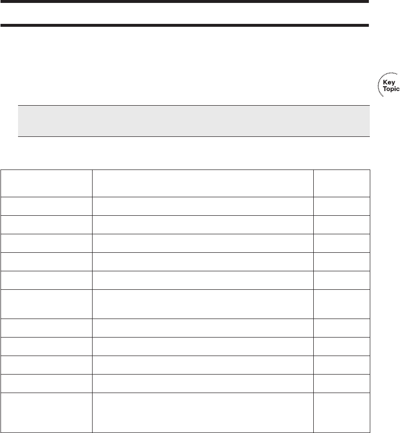
Complete the Tables and Lists from Memory 261
Exam Preparation Tasks
Review All the Key Topics
Review the most important topics from this chapter, noted with the key topics icon.
Table 9-5 describes these key topics and where each is discussed.
Complete the Tables and Lists from Memory
Print a copy of Appendix H, “Memory Tables” (found on the CD), or at least the section
for this chapter, and complete the tables and lists from memory. Appendix I, “Memory
Tables Answer Key,” also on the CD, includes completed tables and lists for you to check
your work.
NOTE There is no need to memorize any configuration step list referenced as a key
topic; these lists are just study aids.
Table 9-5 Key Topics for Chapter 9
Key Topic Element Description
Page
Number
Example 9-1 Example showing basic password configuration 237-238
Figure 9-1 Five-step SSH configuration process example 240
List Five-step list for SSH configuration 240
List Key points about enable secret and enable password 244
Table 9-3 List of commands related to the command history buffer 247
List Configuration checklist for a switch’s IP address and default
gateway configuration
249
List Port security configuration checklist 253
Table 9-4 Port security actions and the results of each action 256
List VLAN configuration checklist 257
List Suggested security actions for unused switch ports 260
Table 9-7 show and debug command reference (at the end of the
chapter). This chapter describes many small but important
commands!
265
1828xbook.fm Page 261 Thursday, July 26, 2007 3:10 PM

262 Chapter 9: Ethernet Switch Configuration
Definitions of Key Terms
Define the following key terms from this chapter and check your answers in the glossary:
access interface, trunk interface
Command References
Table 9-6 lists and briefly describes the configuration commands used in this chapter.
Table 9-6 Chapter 9 Configuration Command Reference
Command Mode/Purpose/Description
Basic Password Configuration
The following four commands are related to basic password configuration.
line console 0 Changes the context to console configuration mode.
line vty 1st-vty 2nd-vty Changes the context to vty configuration mode for the range of
vty lines listed in the command.
login Console and vty configuration mode. Tells IOS to prompt for a
password.
password pass-value Console and vty configuration mode. Lists the password
required if the login command (with no other parameters) is
configured.
Username/Password and SSH Configuration
The following four commands are related to username/password and SSH configuration.
login local Console and vty configuration mode. Tells IOS to prompt for a
username and password, to be checked against locally
configured username global configuration commands on this
switch or router.
username name password pass-
value
Global command. Defines one of possibly multiple usernames
and associated passwords, used for user authentication. Used
when the login local line configuration command has been
used.
1828xbook.fm Page 262 Thursday, July 26, 2007 3:10 PM

Command References 263
crypto key generate rsa Global command. Creates and stores (in a hidden location in
flash memory) the keys required by SSH.
transport input {telnet | ssh} vty line configuration mode. Defines whether Telnet and/or
SSH access is allowed into this switch. Both values can be
configured on one command to allow both Telnet and SSH
access (the default).
IP Address Configuration
The following four commands are related to IP address configuration.
interface vlan number Changes the context to VLAN interface mode. For VLAN 1,
allows the configuration of the switch’s IP address.
ip address ip-address subnet-mask VLAN interface mode. Statically configures the switch’s IP
address and mask.
ip address dhcp VLAN interface mode. Configures the switch as a DHCP client
to discover its IP address, mask, and default gateway.
ip default-gateway address Global command. Configures the switch’s default gateway IP
address. Not required if the switch uses DHCP.
Interface Configuration
The following six commands are related to interface configuration.
interface type port-number Changes context to interface mode. The type is typically
FastEthernet or gigabitEthernet. The possible port numbers
vary depending on the model of switch—for example, Fa0/1,
Fa0/2, and so on.
interface range type port-range Changes the context to interface mode for a range of
consecutively numbered interfaces. The subcommands that
follow then apply to all interfaces in the range.
shutdown
no shutdown
Interface mode. Disables or enables the interface, respectively.
speed {10 | 100 | 1000 | auto} Interface mode. Manually sets the speed to the listed speed or,
with the auto setting, automatically negotiates the speed.
continues
Table 9-6 Chapter 9 Configuration Command Reference (Continued)
Command Mode/Purpose/Description
1828xbook.fm Page 263 Thursday, July 26, 2007 3:10 PM

264 Chapter 9: Ethernet Switch Configuration
duplex {auto | full | half} Interface mode. Manually sets the duplex to half or full, or to
autonegotiate the duplex setting.
description text Interface mode. Lists any information text that the engineer
wants to track for the interface, such as the expected device on
the other end of the cable.
Miscellaneous
The remaining commands are related to miscellaneous configuration topics.
hostname name Global command. Sets this switch’s hostname, which is also
used as the first part of the switch’s command prompt.
enable secret pass-value Global command. Sets this switch’s password that is required
for any user to reach enable mode.
history size length Line config mode. Defines the number of commands held in
the history buffer, for later recall, for users of those lines.
switchport port-security mac-
address mac-address
Interface configuration mode command that statically adds a
specific MAC address as an allowed MAC address on the
interface.
switchport port-security mac-
address sticky
Interface subcommand that tells the switch to learn MAC
addresses on the interface and add them to the configuration
for the interface as secure MAC addresses.
switchport port-security
maximum value
Interface subcommand that sets the maximum number of static
secure MAC addresses that can be assigned to a single
interface.
switchport port-security violation
{protect | restrict | shutdown}
Interface subcommand that tells the switch what to do if an
inappropriate MAC address tries to access the network through
a secure switch port.
Table 9-6 Chapter 9 Configuration Command Reference (Continued)
Command Mode/Purpose/Description
1828xbook.fm Page 264 Thursday, July 26, 2007 3:10 PM

Command References 265
Table 9-7 lists and briefly describes the EXEC commands used in this chapter.
Table 9-7 Chapter 9 EXEC Command Reference
Command Purpose
show mac address-table dynamic Lists the dynamically learned entries in the switch’s address
(forwarding) table.
show dhcp lease Lists any information the switch acquires as a DHCP client.
This includes IP address, subnet mask, and default gateway
information.
show crypto key mypubkey rsa Lists the public and shared key created for use with SSH using
the crypto key generate rsa global configuration command.
show interfaces status Lists one output line per interface, noting the description,
operating state, and settings for duplex and speed on each
interface.
show interfaces vlan 1 Lists the interface status, the switch’s IP address and mask, and
much more.
show port-security interface type
number
Lists an interface’s port security configuration settings and
security operational status.
1828xbook.fm Page 265 Thursday, July 26, 2007 3:10 PM

This chapter covers the following subjects:
Perspectives on Network Verification and
Troubleshooting: This is the first chapter
dedicated to troubleshooting, and this section
introduces the concept of troubleshooting
computer networks.
Verifying the Network Topology with Cisco
Discovery Protocol: This section focuses on
CDP—specifically, how it can be used to verify
network documentation.
Analyzing Layer 1 and 2 Interface Status:
This section explains how to find and interpret
interface status and how to find problems even
when the interface appears to be working.
Analyzing the Layer 2 Forwarding Path with
the MAC Address Table: This section
examines how to link the concepts of how
switches forward frames with the output of
switch show commands.
1828xbook.fm Page 266 Thursday, July 26, 2007 3:10 PM

C H A P T E R10
Ethernet Switch Troubleshooting
This chapter has two main goals. First, it covers the remaining Ethernet-oriented topics for
this book—specifically, some of the commands and concepts related to verifying that a
switched Ethernet LAN works. If the network doesn’t work, this chapter suggests tools you
can use to find out why. Additionally, this chapter suggests some troubleshooting methods
and practices that might improve your troubleshooting skills. Although the troubleshooting
processes explained in this book are not directly tested on the exams, they can help you
prepare to correctly answer some of the more difficult exam questions.
“Do I Know This Already?” Quiz
The “Do I Know This Already?” quiz allows you to assess whether you should read the
entire chapter. If you miss no more than one of these eight self-assessment questions, you
might want to move ahead to the “Exam Preparation Tasks” section. Table 10-1 lists the
major headings in this chapter and the “Do I Know This Already?” quiz questions covering
the material in those sections. This helps you assess your knowledge of these specific areas.
The answers to the “Do I Know This Already?” quiz appear in Appendix A.
Table 10-1 “Do I Know This Already?” Foundation Topics Section-to-Question Mapping
Foundation Topics Section Questions
Perspectives on Network Verification and Troubleshooting —
Verifying the Network Topology with Cisco Discovery Protocol 1, 2
Analyzing Layer 1 and 2 Interface Status 3–6
Analyzing the Layer 2 Forwarding Path with the MAC Address Table 7, 8
1828xbook.fm Page 267 Thursday, July 26, 2007 3:10 PM
268 Chapter 10: Ethernet Switch Troubleshooting
1. Imagine that a switch connects via an Ethernet cable to a router, and the router’s
hostname is Hannah. Which of the following commands could tell you information
about the IOS version on Hannah without establishing a Telnet connection to Hannah?
a. show neighbor Hannah
b. show cdp
c. show cdp neighbor
d. show cdp neighbor Hannah
e. show cdp entry Hannah
f. show cdp neighbor detail
2. Which of the following CDP commands could identify a neighbor’s model of hardware?
a. show neighbors
b. show neighbors Hannah
c. show cdp
d. show cdp interface
e. show cdp neighbors
f. show cdp entry hannah
3. The output of the show interfaces status command on a 2960 switch shows interface
Fa0/1 in a “disabled” state. Which of the following is true about interface Fa0/1?
a. The interface is configured with the shutdown command.
b. The show interfaces fa0/1 command will list the interface with two status codes
of administratively down and down.
c. The show interfaces fa0/1 command will list the interface with two status codes
of up and down.
d. The interface cannot currently be used to forward frames.
e. The interface can currently be used to forward frames.
4. Switch SW1 uses its gigabit 0/1 interface to connect to switch SW2’s gigabit 0/2
interface. SW2’s Gi0/2 interface is configured with the speed 1000 and duplex full
commands. SW1 uses all defaults for interface configuration commands on its Gi0/1
interface. Which of the following is true about the link after it comes up?
a. The link works at 1000 Mbps (1 Gbps).
b. SW1 attempts to run at 10 Mbps because SW2 has effectively disabled IEEE
standard autonegotiation.
1828xbook.fm Page 268 Thursday, July 26, 2007 3:10 PM
“Do I Know This Already?” Quiz 269
c. The link runs at 1 Gbps, but SW1 uses half duplex, and SW2 uses full duplex.
d. Both switches use full duplex.
5. The following line of output was taken from a show interfaces fa0/1 command:
Full-duplex, 100Mbps, media type is 10/100BaseTX
Which of the following is/are true about the interface?
a. The speed was definitely configured with the speed 100 interface subcommand.
b. The speed may have been configured with the speed 100 interface subcommand.
c. The duplex was definitely configured with the duplex full interface
subcommand.
d. The duplex may have been configured with the duplex full interface
subcommand.
6. Switch SW1, a Cisco 2960 switch, has all default settings on interface Fa0/1, the
speed 100 command configured on Fa0/2, and both the speed 100 and duplex half
commands on Fa0/3. Each interface is cabled to a 10/100 port on different Cisco 2960
switches, with those switches using all default settings. Which of the following is true
about the interfaces on the other 2960 switches?
a. The interface connected to SW1’s Fa0/1 runs at 100 Mbps and full duplex.
b. The interface connected to SW1’s Fa0/2 runs at 100 Mbps and full duplex.
c. The interface connected to SW1’s Fa0/3 runs at 100 Mbps and full duplex.
d. The interface connected to SW1’s Fa0/3 runs at 100 Mbps and half duplex.
e. The interface connected to SW1’s Fa0/2 runs at 100 Mbps and half duplex.
7. A frame just arrived on interface Fa0/2, source MAC address 0200.2222.2222,
destination MAC address 0200.2222.2222. (The frame was created as part of a
security attack; it is not normal to see frames with the same source and destination
MAC address.) Interface Fa0/2 is assigned to VLAN 2. Consider the following
command output:
SW2#ss
sshh
hhoo
ooww
ww
mm
mmaa
aacc
cc
aa
aadd
dddd
ddrr
rree
eess
ssss
ss--
--tt
ttaa
aabb
bbll
llee
ee
dd
ddyy
yynn
nnaa
aamm
mmii
iicc
cc
Mac Address Table
-------------------------------------------
Vlan Mac Address Type Ports
---- ----------- -------- -----
1 0200.1111.1111 DYNAMIC Gi0/2
1 0200.2222.2222 DYNAMIC Fa0/13
Total Mac Addresses for this criterion: 2
1828xbook.fm Page 269 Thursday, July 26, 2007 3:10 PM
270 Chapter 10: Ethernet Switch Troubleshooting
Which of the following describes how the switch will forward the frame if the
destination address is 0200.2222.2222?
a. The frame will likely be flooded on all other interfaces in VLAN 2, unless the
switch has a static entry for 0200.2222.2222, VLAN 2, in the MAC address table.
b. The frame will be flooded out all other interfaces in VLAN 2.
c. The switch will add an entry to its MAC address table for MAC address
0200.2222.2222, interface Fa0/2, and VLAN 2.
d. The switch will replace the existing entry for 0200.2222.2222 with an entry for
address 0200.2222.2222, interface Fa0/2, and VLAN 2.
8. Which of the following commands list the MAC address table entries for MAC
addresses configured by port security?
a. show mac address-table dynamic
b. show mac address-table
c. show mac address-table static
d. show mac address-table port-security
1828xbook.fm Page 270 Thursday, July 26, 2007 3:10 PM

Perspectives on Network Verification and Troubleshooting 271
Foundation Topics
This chapter contains the first specific coverage of topics related to verification and
troubleshooting. Verification refers to the process of examining a network to confirm that
it is working as designed. Troubleshooting refers to examining the network to determine
what is causing a particular problem so that it can be fixed.
As mentioned in the Introduction to this book, over the years, the CCNA exams have been
asking more and more questions related to verification and troubleshooting. Each of
these questions typically uses a unique topology. They typically require you to apply
networking knowledge to unique problems, rather than just being ready to answer questions
about lists of facts you’ve memorized. (For more information and perspectives on these
types of exam questions, go back to the Introduction to this book, in the section titled
“Format of the CCNA Exams.”)
To help you prepare to answer questions that require troubleshooting skills, this book and
the CCNA ICND2 Official Exam Certification Guide devote several chapters, plus sections
of other chapters, to verification and troubleshooting. This chapter is the first such chapter
in either book, so this chapter begins with some perspectives on troubleshooting
networking problems. Following this coverage, the chapter examines three major topics
related to troubleshooting networks built with LAN switches.
Perspectives on Network Verification
and Troubleshooting
You need several skills to be ready to answer the more challenging questions on today’s
CCNA exams. However, the required skills differ when comparing the different types of
questions. This section starts with some perspectives on the various question types,
followed by some general comments on troubleshooting.
Attacking Sim Questions
Sim questions provide a text description of a network, a network diagram, and software that
simulates the network. Regardless of the details, sim questions can be reduced to the
following: “The network is not working completely, so either complete the configuration,
NOTE The information in this section is a means to help you learn troubleshooting
skills. However, the specific processes and comments in this section, up to the next major
heading (“Verifying the Network Topology with Cisco Discovery Protocol”), do not
cover any specific exam objective for any of the CCNA exams.
1828xbook.fm Page 271 Thursday, July 26, 2007 3:10 PM
272 Chapter 10: Ethernet Switch Troubleshooting
or find a problem with the existing configuration and fix it.” In short, the solution to a sim
question is by definition a configuration change.
One plan of attack for these problems is to use a more formalized troubleshooting process
in which you examine each step in how data is forwarded from the sending host to the
destination host. However, studies and experience show that when engineers think that the
configuration might have a problem, the first troubleshooting step is to look at the various
configuration files. To find and solve Sim questions on the exam, quickly comparing the
router and/or switch configuration to what you remember about the normal configuration
needed (based on the question text) might be all you require.
Sim questions do allow you to have more confidence about whether your answer is correct,
at least for the technologies covered on the CCNA exams. The correct answer should solve
the original problem. For example, if the sim question essentially states “Router R1 cannot
ping router R2; fix it,” you can use pings to test the network and confirm that your
configuration changes solved the problem.
If you cannot find the problem by looking at the configuration, a more detailed process is
required, mainly using show commands. The troubleshooting chapters and sections in this
book and in the CCNA ICND2 Official Exam Certification Guide combine to provide the
details of the more complex processes for examining different types of problems.
Simlet Questions
Simlet questions can force the exam taker to interpret the meaning of various show and
debug commands. Simlet questions might not tell you the enable password, so you cannot
even look at the configuration, removing the option to simply look at the configuration
to find the root cause of a problem. In that case, the question text typically states the details
of the scenario, requiring you to remember or find the right show commands, use them,
and then interpret the output. Also, because simlet questions might not allow you to change
the configuration, you do not get the positive feedback that your answer is correct.
For example, a simlet question may show a diagram of a switched LAN, stating that PC1
can ping PC2 but not PC3. You would need to remember the correct show commands to use
(or take the time to find the commands using the ? key) to find the root cause of the problem.
You can use several different approaches to attack these types of problems; no single way
is necessarily better than another. The first step is to think about what should normally occur
in the network, based on any network diagram and information in the question. Then,
many people start by trying the show commands (that they remember) that are somehow
related to the question. The question text probably gives some hints as to the problem area.
For example, maybe the problem is related to port security. Many people then just try the
1828xbook.fm Page 272 Thursday, July 26, 2007 3:10 PM

Perspectives on Network Verification and Troubleshooting 273
commands they know that are related to that topic, such as show port-security, just to see
if the answer jumps out at them—and that’s a reasonable plan of attack. This plan uses
common sense, and intuition to some degree, and it can work well and quickly.
If the answer does not become obvious when you look at the most obvious commands, a
more organized approach may be useful. The troubleshooting chapters in this book, and
large troubleshooting sections of other chapters, review technology and suggest a more
organized approach to each topic—approaches that may be useful when the answer does
not quickly become obvious.
Multiple-Choice Questions
Like simlets, multiple-choice questions can force the exam taker to interpret the meaning
of various show and debug commands. Multiple-choice questions might simply list the
output of some commands, along with a figure, and ask you to identify what would happen.
For example, a multiple-choice question might show the show mac address-table
dynamic command that lists a switch’s dynamically learned MAC table entries. The
question may then require you to predict how that switch would forward a frame sent by
one device, destined for another device. This would require you to apply the concepts of
LAN switching to the output shown in the command.
Multiple-choice questions that list show and debug command output require much of the
same thinking as simlet questions. As with simlet questions, the first step for some multiple-
choice questions is to think about what should normally occur in the network, based on any
network diagram and information in the question. Next, compare the information in the
question text, including the sample command output, to see if it confirms that the network
is working normally, or if there is a problem. (The network might be working correctly,
and the question is designed to confirm that you know why a particular command confirms
that a particular part of the network is working well.) The big difference in this case,
however, is that the multiple-choice questions do not require you to remember the commands
to use. The command output is either supplied in the question, or it is not.
Approaching Questions with an Organized Troubleshooting Process
If the answer to a sim, simlet, or multiple-choice question is not obvious after you use the
more obvious and quicker options just discussed, you need to implement a more thorough
and organized thought process. This more organized process may well be what a typical
network engineer would do when faced with more complex real-world problems.
NOTE Refer to http://www.cisco.com/web/learning/wwtraining/certprog/training/
cert_exam_tutorial.html for a tutorial about the various types of CCNA exam questions.
1828xbook.fm Page 273 Thursday, July 26, 2007 3:10 PM
274 Chapter 10: Ethernet Switch Troubleshooting
Unfortunately, the exams are timed, and thinking through the problem in more detail
requires more time.
By thinking through the troubleshooting process as you prepare for the exam, you can be
better prepared to attack problems on the exam. To that end, this book includes many
suggested troubleshooting processes. The troubleshooting processes are not ends unto
themselves, so you do not need to memorize them for the exams. They are a learning tool,
with the ultimate goal being to help you correctly and quickly find the answers to the more
challenging questions on the exams.
This section gives an overview of a general troubleshooting process. As you progress
through this book, the process will be mentioned occasionally as it relates to other
technology areas, such as IP routing. The three major steps in this book’s organized
troubleshooting process are as follows:
Step 1 Analyzing/predicting normal operation: Predict the details of what should
happen if the network is working correctly, based on documentation, configuration,
and show and debug command output.
Step 2 Problem isolation: Determine how far along the expected path the
frame/packet goes before it cannot be forwarded any further, again based
on documentation, configuration, and show and debug command output.
Step 3 Root cause analysis: Identify the underlying causes of the problems
identified in the preceding step—specifically, the causes that have a
specific action with which the problem can be fixed.
Following this process requires a wide variety of learned skills. You need to remember the
theory of how networks should work, as well as how to interpret the show command output
that confirms how the devices are currently behaving. This process requires the use of
testing tools, such as ping and traceroute, to isolate the problem. Finally, this approach
requires the ability to think broadly about everything that could affect a single component.
For example, imagine a simple LAN with two switches connected to each other, and two
PCs (PC1 and PC2) each connected to one of the switches. Originally, PC1 could ping PC2
successfully, but the ping now fails. You could examine the documentation, as well as
show command output, to confirm the network topology and predict its normal working
behavior based on your knowledge of LAN switching. As a result, you could predict where
a frame sent by PC1 to PC2 should flow. To isolate the problem, you could look in the
switch MAC tables to confirm the interfaces out which the frame should be forwarded,
possibly then finding that the interface connected to PC2 has failed. However, knowing that
the interface has failed does not identify the root cause of the problem. So you would then
need to broaden your thinking to any and all reasons why an interface might fail—from an
1828xbook.fm Page 274 Thursday, July 26, 2007 3:10 PM
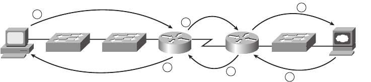
Perspectives on Network Verification and Troubleshooting 275
unplugged cable, to electrical interference, to port security disabling the interface. show
commands can either confirm that a specific root cause is the problem, or at least give some
hints as to the root cause.
Isolating Problems at Layer 3, and Then at Layers 1 and 2
Before moving to the specific topics on Ethernet LAN troubleshooting, it is helpful to
consider the larger picture. Most troubleshooting in real IP networks today begins with
what the end user sees and experiences. From there, the analysis typically moves quickly
to an examination of how well Layer 3 is working. For example, imagine that the user
of PC1 in Figure 10-1 can usually connect to the web server on the right by entering
www.example.com in PC1’s web browser, but the connection to the web server currently
fails. The user calls the help desk, and the problem is assigned to a network engineer
to solve.
Figure 10-1 Layer 3 Problem Isolation
After knowing about the problem, the engineer can work to confirm that PC1 can resolve
the hostname (www.example.com) into the correct IP address. At that point, the Layer 3 IP
problem isolation process can proceed, to determine which of the six routing steps shown
in the figure has failed. The routing steps shown in Figure 10-1 are as follows:
Step 1 PC1 sends the packet to its default gateway (R1) because the destination IP
address is in a different subnet.
Step 2 R1 forwards the packet to R2 based on R1’s routing table.
Step 3 R2 forwards the packet to the web server based on R2’s routing table.
Step 4 The web server sends a packet back toward PC1 based on the web
server’s default gateway setting (R2).
Step 5 R2 forwards the packet destined for PC1 by forwarding the packet to R1
according to R2’s routing table.
Step 6 R1 forwards the packet to PC1 based on R1’s routing table.
R2 SW3
PC1
R1
SW1 SW2
1
2
3
654
Example.com
Web Server
1828xbook.fm Page 275 Thursday, July 26, 2007 3:10 PM
276 Chapter 10: Ethernet Switch Troubleshooting
Chapter 15, “Troubleshooting IP Routing,” examines this process in much greater detail.
For now, consider what happens if the Layer 3 problem isolation process discovers that
Step 1, 3, 4, or 6 is the step that fails. Further isolating the problem would require more
Layer 3 analysis. However, at some point, all the potential problems at Layer 3 might be
ruled out, so the next problem isolation step would be to figure out why the Layer 1 and 2
details at that routing step do not work.
For example, imagine that the Layer 3 analysis determined that PC1 cannot even send a
packet to its default gateway (R1), meaning that Step 1 in Figure 10-1 fails. To further
isolate the problem and find the root causes, the engineer would need to determine the
following:
■The MAC address of PC1 and of R1’s LAN interface
■The switch interfaces used on SW1 and SW2
■The interface status of each interface
■The expected forwarding behavior of a frame sent by PC1 to R1 as the destination
MAC address
By gathering and analyzing these facts, the engineer can most likely isolate the problem’s
root cause and fix it.
Troubleshooting as Covered in This Book
This book has three main troubleshooting chapters or sections, plus a few smaller
troubleshooting sections interspersed in other chapters. The main coverage is as follows:
■Chapter 10, “Ethernet Switch Troubleshooting”
■Chapter 15, “Troubleshooting IP Routing”
■Chapter 17, “WAN Configuration”
Essentially, Chapter 15 covers the analysis of problems related to Layer 3, as generally
shown in Figure 10-1. This chapter covers some of the details of how to attack problems as
soon as you know that the problem may be related to a LAN. Chapter 17 covers the
troubleshooting steps in cases where the problem might be with a WAN link.
These three troubleshooting chapters spend some time on the more formalized
troubleshooting process, but as a means to an end—focusing on predicting normal
behavior, isolating problems, and determining the root cause. The end goal is to help you
know the tools, concepts, configuration commands, and how to analyze a network based on
show commands to solve a problem.
1828xbook.fm Page 276 Thursday, July 26, 2007 3:10 PM
Verifying the Network Topology with Cisco Discovery Protocol 277
If you have both this book and the CCNA ICND2 Official Exam Certification Guide, the
ICND2 book provides even more details about troubleshooting and how to use a more
formalized troubleshooting process, if needed. The reason for putting more detail in the
ICND2 book is that by the time you reach the troubleshooting topics in that book, you will
have completed all the CCNA-level materials for a particular technology area. Because
troubleshooting requires interpreting a broad range of concepts, configuration, and
command output, the ICND2 book’s troubleshooting chapters/sections occur at the end
of each major topic, summarizing the important materials and helping show how the topics
are interrelated.
The rest of this chapter examines three major topics, each of which has something to do
with at least one of the three major components of the formalized troubleshooting process:
■Cisco Discovery Protocol (CDP): Used to confirm the documentation, and learn
about the network topology, to predict normal operation of the network.
■Examining interface status: Interfaces must be in a working state before a switch will
forward frames on the interface. You must determine if an interface is working, as
well as determine the potential root causes for a failed switch interface.
■Analyzing where frames will be forwarded: You must know how to analyze a
switch’s MAC address table and how to then predict how a switch will forward a
particular frame.
Verifying the Network Topology
with Cisco Discovery Protocol
The proprietary Cisco Discovery Protocol (CDP) discovers basic information about
neighboring routers and switches without needing to know the passwords for the
neighboring devices. To discover information, routers and switches send CDP messages out
each of their interfaces. The messages essentially announce information about the device
that sent the CDP message. Devices that support CDP learn information about others by
listening for the advertisements sent by other devices.
From a troubleshooting perspective, CDP can be used to either confirm or fix the
documentation shown in a network diagram, or even discover the devices and interfaces
used in a network. Confirming that the network is actually cabled to match the network
diagram is a good step to take before trying to predict the normal flow of data in a network.
On media that support multicasts at the data link layer, CDP uses multicast frames; on other
media, CDP sends a copy of the CDP update to any known data-link addresses. So, any
CDP-supporting device that shares a physical medium with another CDP-supporting device
can learn about the other device.
1828xbook.fm Page 277 Thursday, July 26, 2007 3:10 PM

278 Chapter 10: Ethernet Switch Troubleshooting
CDP discovers several useful details from the neighboring Cisco devices:
■Device identifier: Typically the hostname
■Address list: Network and data-link addresses
■Local interface: The interface on the router or switch issuing the show cdp command
with which the neighbor was discovered
■Port identifier: Text that identifies the port used by the neighboring device to send
CDP messages to the local device
■Capabilities list: Information on what type of device it is (for instance, a router or a
switch)
■Platform: The model and OS level running in the device
Table 10-2 lists the show cdp EXEC commands that include at least some of the details
from the preceding list.
Like many switch and router features that are enabled by default, CDP actually creates a
security exposure when enabled. To avoid the possibility of allowing an attacker to learn
details about each switch, CDP can be easily enabled. Cisco recommends that CDP be
disabled on all interfaces that do not have a specific need for it. The most likely interfaces
to need to use CDP are interfaces connected to other Cisco routers and switches and
interfaces connected to Cisco IP Phones. Otherwise, CDP can be enabled per interface
using the no cdp enable interface subcommand. (The cdp enable interface subcommand
re-enables CDP.) Alternatively, the no cdp run global command disables CDP for the entire
switch, with the cdp run global command re-enabling CDP globally.
Figure 10-2 shows a small network with two switches, one router, and a couple of PCs.
Example 10-1 shows the show commands listed in Table 10-2, as well as several commands
that list information about CDP itself, rather than about neighboring devices.
Table 10-2 show cdp Commands That List Information About Neighbors
Command Description
show cdp neighbors [type number] Lists one summary line of information about each neighbor,
or just the neighbor found on a specific interface if an
interface was listed.
show cdp neighbors detail Lists one large set (approximately 15 lines) of information,
one set for every neighbor.
show cdp entry name Lists the same information as the show cdp neighbors detail
command, but only for the named neighbor (case-sensitive).
1828xbook.fm Page 278 Thursday, July 26, 2007 3:10 PM
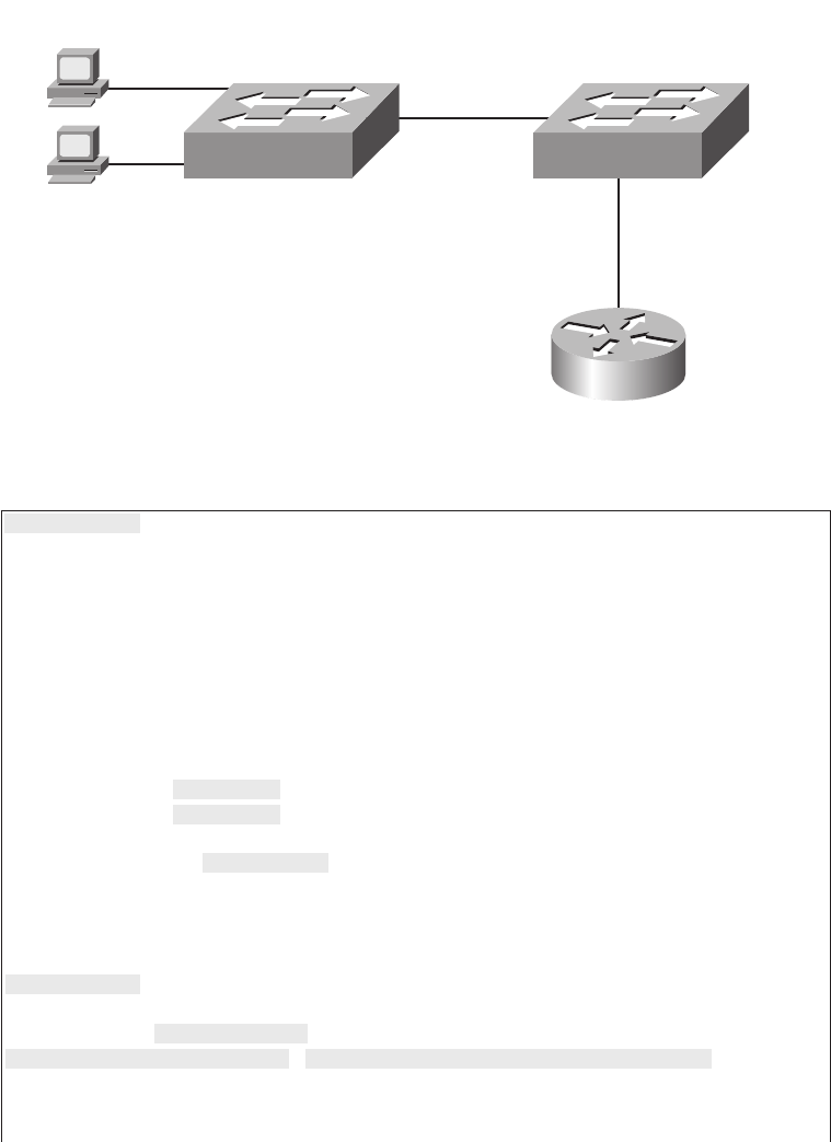
Verifying the Network Topology with Cisco Discovery Protocol 279
Figure 10-2 Small Network Used in CDP Examples
Example 10-1 show cdp Command Examples: SW2
SW2#ss
sshh
hhoo
ooww
ww
cc
ccdd
ddpp
pp
??
??
entry Information for specific neighbor entry
interface CDP interface status and configuration
neighbors CDP neighbor entries
traffic CDP statistics
| Output modifiers
<cr>
! Next, the ss
sshh
hhoo
ooww
ww
cc
ccdd
ddpp
pp
nn
nnee
eeii
iigg
gghh
hhbb
bboo
oorr
rrss
ss command lists SW2’s local interface, and both R1’s
! and SW1’s interfaces (in the “port” column), along with other details.
!
SW2#ss
sshh
hhoo
ooww
ww
cc
ccdd
ddpp
pp
nn
nnee
eeii
iigg
gghh
hhbb
bboo
oorr
rrss
ss
Capability Codes: R - Router, T - Trans Bridge, B - Source Route Bridge
S - Switch, H - Host, I - IGMP, r - Repeater, P - Phone
Device ID Local Intrfce Holdtme Capability Platform Port ID
SW1 Gig 0/2 173 S I WS-C2960-2Gig 0/1
R1 Fas 0/13 139 R S I 1841 Fas 0/1
SW2#ss
sshh
hhoo
ooww
ww
cc
ccdd
ddpp
pp
nn
nnee
eeii
iigg
gghh
hhbb
bboo
oorr
rrss
ss
dd
ddee
eett
ttaa
aaii
iill
ll
-------------------------
Device ID: SW1
Entry address(es):
Platform: cisco WS-C2960-24TT-L, Capabilities: Switch IGMP
Interface: GigabitEthernet0/2, Port ID (outgoing port): GigabitEthernet0/1
Holdtime : 167 sec
continues
Gi0/1 Gi0/2
Barney
0200.2222.2222
Fa0/12 SW1 SW2
Fa0/9
Fa0/13
Fa0/1 0200.5555.55555
Cisco 2960 Switch
(WS-2960-24TT-L)
Cisco 1841 Router
R1
1828xbook.fm Page 279 Thursday, July 26, 2007 3:10 PM

280 Chapter 10: Ethernet Switch Troubleshooting
Version :
Cisco IOS Software, C2960 Software (C2960-LANBASEK9-M), Version 12.2(25)SEE2, RELEASE
SOFTWARE (fc1)
Copyright (c) 1986-2006 by Cisco Systems, Inc.
Compiled Fri 28-Jul-06 11:57 by yenanh
advertisement version: 2
Protocol Hello: OUI=0x00000C, Protocol ID=0x0112; payload len=27,
value=00000000FFFFFFFF010221FF000
0000000000019E86A6F80FF0000
VTP Management Domain: ‘fred’
Native VLAN: 1
Duplex: full
Management address(es):
! The info for router R1 follows.
-------------------------
Device ID: R1
Entry address(es):
IP address: 10.1.1.1
Platform: Cisco 1841, Capabilities: Router Switch IGMP
Interface: FastEthernet0/13, Port ID (outgoing port): FastEthernet0/1
Holdtime : 131 sec
Version :
Cisco IOS Software, 1841 Software (C1841-ADVENTERPRISEK9-M), Version 12.4(9)T, RELEASE
SOFTWARE (fc1)
Technical Support: http://www.cisco.com/techsupport
Copyright (c) 1986-2006 by Cisco Systems, Inc.
Compiled Fri 16-Jun-06 21:26 by prod_rel_team
advertisement version: 2
VTP Management Domain: ‘’
Duplex: full
Management address(es):
!
! Note that the ss
sshh
hhoo
ooww
ww
cc
ccdd
ddpp
pp
ee
eenn
nntt
ttrr
rryy
yy
RR
RR11
11 command repeats the same information shown in
! the ss
sshh
hhoo
ooww
ww
cc
ccdd
ddpp
pp
nn
nnee
eeii
iigg
gghh
hhbb
bboo
oorr
rrss
ss
dd
ddee
eett
ttaa
aaii
iill
ll command, but just for R1.
SW2#ss
sshh
hhoo
ooww
ww
cc
ccdd
ddpp
pp
ee
eenn
nntt
ttrr
rryy
yy
RR
RR11
11
-------------------------
Device ID: R1
Entry address(es):
IP address: 10.1.1.1
Platform: Cisco 1841, Capabilities: Router Switch IGMP
Interface: FastEthernet0/13, Port ID (outgoing port): FastEthernet0/1
Holdtime : 176 sec
Example 10-1 show cdp Command Examples: SW2 (Continued)
1828xbook.fm Page 280 Thursday, July 26, 2007 3:10 PM

Verifying the Network Topology with Cisco Discovery Protocol 281
A little more than the first half of the example shows a comparison of the output of the three
commands listed in Table 10-2. The show cdp neighbors command lists one line per
neighbor, but with lots of key details such as the local device’s interface used to connect to
the neighbor and the neighboring device’s interface (under the Port heading). For example,
SW2’s show cdp neighbors command lists an entry for SW1, with SW2’s local interface
of Gi0/2, and SW1’s interface of Gi0/1 (see Figure 10-2 for reference). The show cdp
neighbors output also lists the platform, so if you know the Cisco product line to some
degree, you know the specific model of the neighboring router or switch. So, even using
this basic information, you could either construct a figure like Figure 10-2 or confirm that
the details in the figure are correct.
Version :
Cisco IOS Software, 1841 Software (C1841-ADVENTERPRISEK9-M), Version 12.4(9)T, RELEASE
SOFTWARE (fc1)
Technical Support: http://www.cisco.com/techsupport
Copyright (c) 1986-2006 by Cisco Systems, Inc.
Compiled Fri 16-Jun-06 21:26 by prod_rel_team
advertisement version: 2
VTP Management Domain: ‘’
Duplex: full
Management address(es):
SW2#ss
sshh
hhoo
ooww
ww
cc
ccdd
ddpp
pp
Global CDP information:
Sending CDP packets every 60 seconds
Sending a holdtime value of 180 seconds
Sending CDPv2 advertisements is enabled
SW2#ss
sshh
hhoo
ooww
ww
cc
ccdd
ddpp
pp
ii
iinn
nntt
ttee
eerr
rrff
ffaa
aacc
ccee
eess
ss
FastEthernet0/1 is administratively down, line protocol is down
Encapsulation ARPA
Sending CDP packets every 60 seconds
Holdtime is 180 seconds
FastEthernet0/2 is administratively down, line protocol is down
Encapsulation ARPA
Sending CDP packets every 60 seconds
Holdtime is 180 seconds
!
! Lines omitted for brevity
!
SW2#ss
sshh
hhoo
ooww
ww
cc
ccdd
ddpp
pp
tt
ttrr
rraa
aaff
ffff
ffii
iicc
cc
CDP counters :
Total packets output: 54, Input: 49
Hdr syntax: 0, Chksum error: 0, Encaps failed: 0
No memory: 0, Invalid packet: 0, Fragmented: 0
CDP version 1 advertisements output: 0, Input: 0
CDP version 2 advertisements output: 54, Input: 49
Example 10-1 show cdp Command Examples: SW2 (Continued)
1828xbook.fm Page 281 Thursday, July 26, 2007 3:10 PM

282 Chapter 10: Ethernet Switch Troubleshooting
Take a few moments to examine the output of the show cdp neighbors detail command
and the show cdp entry R1 commands in Example 10-1. Both commands supply the exact
same messages, with the first supplying the information for all neighbors, rather than for
one neighbor at a time. Note that the output of these two commands lists additional details,
such as the full name of the model of switch (WS-2960-24TT-L) and the IP address
configured on the 1841 router. (Had SW1’s IP address been configured, it would also have
been displayed.)
The bottom portion of Example 10-1 lists sample output from some of the show cdp
commands that identify information about how CDP is operating. These commands do not
list any information about neighbors. Table 10-3 lists these commands and their purpose for
easy reference.
Analyzing Layer 1 and 2 Interface Status
A Cisco switch interface must be in a working state before the switch will process frames
received on the interface or send frames out the interface. Additionally, the interface might
be in a working state, but intermittent problems might still be occurring. So, a somewhat
obvious troubleshooting step is to examine the interface state, ensure that each interface is
working, and also verify that no intermittent problems are occurring. This section examines
the show commands you can use to determine the status of each interface, the reasons why
an interface might not be working, and some issues that can occur even when the interfaces
are in a working state.
Interface Status Codes and Reasons for Nonworking States
Cisco switches actually use two different sets of interface status codes—one set of two
codes (words) that use the same conventions as do router interface status codes, and another
set with a single code (word). Both sets of status codes can determine whether an interface
is working.
Table 10-3 Commands Used to Verify CDP Operations
Command Description
show cdp States whether CDP is enabled globally, and lists the
default update and holdtime timers.
show cdp interface [type number] States whether CDP is enabled on each interface, or a
single interface if the interface is listed, and states
update and holdtime timers on those interfaces.
show cdp traffic Lists global statistics for the number of CDP
advertisements sent and received.
1828xbook.fm Page 282 Thursday, July 26, 2007 3:10 PM

Analyzing Layer 1 and 2 Interface Status 283
The switch show interfaces and show interfaces description commands list the two-code
status just like routers. The two codes are named the line status and protocol status. They
generally refer to whether Layer 1 is working (line status) and whether Layer 2 is working
(protocol status). LAN switch interfaces typically show an interface with both codes with
the same value, either “up” or “down.”
The show interfaces status command lists a different single interface status code. This
single interface status code corresponds to different combinations of the traditional two-
code interface status codes and can be easily correlated to those codes. For example, the
show interfaces status command lists a “connect” state for working interfaces. It
corresponds to the up/up state seen with the show interfaces and show interfaces
description commands.
Any interface state other than connect or up/up means that the switch will not forward or
receive frames on the interface. Each nonworking interface state has a small set of root
causes. Also, note that the exams could easily ask a question that showed only one or the
other type of status code, so be prepared to see both types of status codes on the exams, and
know the meanings of both. Table 10-4 lists the code combinations and some root causes
that could have caused a particular interface status.
NOTE This book refers to these two status codes in shorthand by just listing the two
codes with a slash between them, such as “up/up.”
Table 10-4 LAN Switch Interface Status Codes
Line Status Protocol Status Interface Status Typical Root Cause
Administratively
Down
Down disabled The interface is configured with the
shutdown command.
Down Down notconnect No cable; bad cable; wrong cable
pinouts; the speeds are mismatched on
the two connected devices; the device
on the other end of the cable is
powered off or the other interface is
shutdown.
Up Down notconnect An interface up/down state is not
expected on LAN switch interfaces.
Down down
(err-disabled)
err-disabled Port security has disabled the
interface.
Up Up connect The interface is working.
1828xbook.fm Page 283 Thursday, July 26, 2007 3:10 PM

284 Chapter 10: Ethernet Switch Troubleshooting
Most of the reasons for the notconnect state were covered earlier in this book. For example,
to troubleshoot problems, you should remember the cabling pinout details explained in
Chapter 3, “Fundamentals of LANs.” However, one topic can be particularly difficult to
troubleshoot—the possibility for both speed and duplex mismatches, as explained in the
next section.
Interface Speed and Duplex Issues
Switch interfaces can find their speed and duplex settings in several ways. Many interfaces
that use copper wiring are capable of multiple speeds, and duplex settings use the IEEE
standard (IEEE 802.3X) autonegotiation process. These same network interface cards
(NIC) and interfaces can also be configured to use a specific speed or duplex setting rather
than using autonegotiation. On switches and routers, the speed {10 | 100 | 1000} interface
subcommand and the duplex {half | full} interface subcommand set these values. Note that
configuring both speed and duplex on a switch interface disables the IEEE-standard
autonegotiation process on that interface.
The show interfaces and show interfaces status commands list both the speed and duplex
settings on an interface, as demonstrated in Example 10-2.
Example 10-2 Displaying Speed and Duplex Settings on Switch Interfaces
SW1#ss
sshh
hhoo
ooww
ww
ii
iinn
nntt
ttee
eerr
rrff
ffaa
aacc
ccee
eess
ss
ss
sstt
ttaa
aatt
ttuu
uuss
ss
Port Name Status Vlan Duplex Speed Type
Fa0/1 notconnect 1 auto auto 10/100BaseTX
Fa0/2 notconnect 1 auto auto 10/100BaseTX
Fa0/3 notconnect 1 auto auto 10/100BaseTX
Fa0/4 connected 1 a-full a-100 10/100BaseTX
Fa0/5 connected 1 a-full a-100 10/100BaseTX
Fa0/6 notconnect 1 auto auto 10/100BaseTX
Fa0/7 notconnect 1 auto auto 10/100BaseTX
Fa0/8 notconnect 1 auto auto 10/100BaseTX
Fa0/9 notconnect 1 auto auto 10/100BaseTX
Fa0/10 notconnect 1 auto auto 10/100BaseTX
Fa0/11 connected 1 a-full 10 10/100BaseTX
Fa0/12 connected 1 half 100 10/100BaseTX
Fa0/13 connected 1 a-full a-100 10/100BaseTX
Fa0/14 disabled 1 auto auto 10/100BaseTX
Fa0/15 notconnect 3 auto auto 10/100BaseTX
Fa0/16 notconnect 3 auto auto 10/100BaseTX
Fa0/17 connected 1 a-full a-100 10/100BaseTX
Fa0/18 notconnect 1 auto auto 10/100BaseTX
Fa0/19 notconnect 1 auto auto 10/100BaseTX
Fa0/20 notconnect 1 auto auto 10/100BaseTX
Fa0/21 notconnect 1 auto auto 10/100BaseTX
1828xbook.fm Page 284 Thursday, July 26, 2007 3:10 PM

Analyzing Layer 1 and 2 Interface Status 285
Although both commands in the example can be useful, only the show interfaces status
command implies how the switch determined the speed and duplex settings. The command
output lists autonegotiated settings with a prefix of a-. For example, a-full means full
duplex as autonegotiated, whereas full means full duplex but as manually configured. The
example shades the command output that implies that the switch’s Fa0/12 interface’s speed
and duplex were not found through autonegotiation, but Fa0/13 did use autonegotiation.
Note that the show interfaces fa0/13 command (without the status option) simply lists the
speed and duplex for interface FastEthernet0/13, with nothing implying that the values
were learned through autonegotiation.
Fa0/22 notconnect 1 auto auto 10/100BaseTX
Fa0/23 notconnect 1 auto auto 10/100BaseTX
Fa0/24 notconnect 1 auto auto 10/100BaseTX
Gi0/1 connected trunk full 1000 10/100/1000BaseTX
Gi0/2 notconnect 1 auto auto 10/100/1000BaseTX
SW1#ss
sshh
hhoo
ooww
ww
ii
iinn
nntt
ttee
eerr
rrff
ffaa
aacc
ccee
eess
ss
ff
ffaa
aa00
00//
//11
1133
33
FastEthernet0/13 is up, line protocol is up (connected)
Hardware is Fast Ethernet, address is 0019.e86a.6f8d (bia 0019.e86a.6f8d)
MTU 1500 bytes, BW 100000 Kbit, DLY 100 usec,
reliability 255/255, txload 1/255, rxload 1/255
Encapsulation ARPA, loopback not set
Keepalive set (10 sec)
Full-duplex, 100Mbps, media type is 10/100BaseTX
input flow-control is off, output flow-control is unsupported
ARP type: ARPA, ARP Timeout 04:00:00
Last input 00:00:05, output 00:00:00, output hang never
Last clearing of “show interface” counters never
Input queue: 0/75/0/0 (size/max/drops/flushes); Total output drops: 0
Queueing strategy: fifo
Output queue: 0/40 (size/max)
5 minute input rate 0 bits/sec, 0 packets/sec
5 minute output rate 0 bits/sec, 0 packets/sec
85022 packets input, 10008976 bytes, 0 no buffer
Received 284 broadcasts (0 multicast)
0 runts, 0 giants, 0 throttles
0 input errors, 0 CRC, 0 frame, 0 overrun, 0 ignored
0 watchdog, 281 multicast, 0 pause input
0 input packets with dribble condition detected
95226 packets output, 10849674 bytes, 0 underruns
0 output errors, 0 collisions, 1 interface resets
0 babbles, 0 late collision, 0 deferred
0 lost carrier, 0 no carrier, 0 PAUSE output
0 output buffer failures, 0 output buffers swapped out
Example 10-2 Displaying Speed and Duplex Settings on Switch Interfaces (Continued)
1828xbook.fm Page 285 Thursday, July 26, 2007 3:10 PM
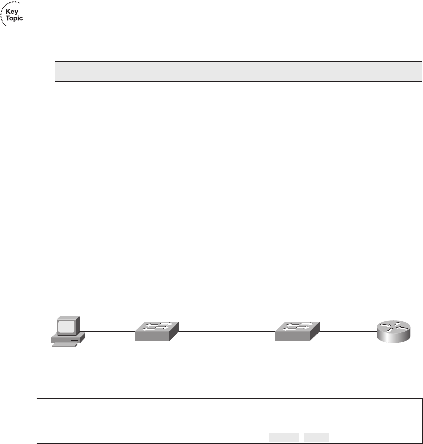
286 Chapter 10: Ethernet Switch Troubleshooting
When the IEEE autonegotiation process works on both devices, both devices agree to the
fastest speed supported by both devices. Additionally, the devices use full duplex if it is
supported by both devices, or half duplex if it is not. However, when one device has
disabled autonegotiation, and the other device uses autonegotiation, the device using
autonegotiation chooses the default duplex setting based on the current speed. The defaults
are as follows:
■If the speed is not known, use 10 Mbps, half duplex.
■If the speed is somehow known to be 10 or 100 Mbps, default to use half duplex.
■If the speed is somehow known to be 1000 Mbps, default to use full duplex.
Cisco switches can determine speed in a couple of ways even when IEEE standard
autonegotiation fails. First, the switch knows the speed if the speed interface subcommand
was manually configured. Additionally, even when IEEE autonegotiation fails, Cisco
switches can automatically sense the speed used by the device on the other end of the cable,
and can use that speed based on the electrical signals on the cable.
For example, in Figure 10-3, imagine that SW2’s Gi0/2 interface was configured with the
speed 100 and duplex half commands (not recommended settings on a gigabit-capable
interface, by the way). SW2 would use those settings and disable the IEEE-standard
autonegotiation process, because both the speed and duplex commands have been
configured. If SW1’s Gi0/1 interface did not have a speed command configured, SW1
would still recognize the speed (100 Mbps)—even though SW2 would not use
IEEE-standard negotiation—and SW1 would also use a speed of 100 Mbps. Example 10-3
shows the results of this specific case on SW1.
Figure 10-3 Sample Network Showing Ethernet Autonegotiation Defaults
NOTE Ethernet interfaces using speeds faster than 1 Gbps always use full duplex.
Example 10-3 Displaying Speed and Duplex Settings on Switch Interfaces
SW1#ss
sshh
hhoo
ooww
ww
ii
iinn
nntt
ttee
eerr
rrff
ffaa
aacc
ccee
eess
ss
gg
ggii
ii00
00//
//11
11
ss
sstt
ttaa
aatt
ttuu
uuss
ss
Port Name Status Vlan Duplex Speed Type
Gi0/1 connected trunk a-half a-100 10/100/1000BaseTX
PC1
R1
SW1 SW2
0200.1111.1111 0200.0101.0101
Fa0/11 Fa0/1Gi0/1 Fa0/10Gi0/2
1828xbook.fm Page 286 Thursday, July 26, 2007 3:10 PM
Analyzing Layer 1 and 2 Interface Status 287
The speed and duplex still show up with a prefix of a- in the output, implying
autonegotiation. The reason is that in this case, the speed was found automatically, and the
duplex setting was chosen because of the default values used by the IEEE autonegotiation
process. SW1 sensed the speed without using IEEE standard autonegotiation, because SW2
disabled autonegotiation. SW1 then defaulted to use half duplex based on the IEEE default
recommendation for links running at 100 Mbps.
This example shows one case of a duplex mismatch, because SW1 uses half duplex and
SW2 uses full duplex. Finding a duplex mismatch can be much more difficult than finding
a speed mismatch, because if the duplex settings do not match on the ends of an Ethernet
segment, the switch interface will still be in a connect (up/up) state. In this case, the
interface works, but it may work poorly, with poor performance, and with symptoms of
intermittent problems. The reason is that the device using half duplex uses CSMA/CD
logic, waiting to send when receiving a frame, believing collisions occur when they
physically do not—and actually stopping sending a frame because the switch thinks a
collision occurred. With enough traffic load, the interface could be in a connect state, but
it’s essentially useless for passing traffic.
To identify duplex mismatch problems, check the duplex setting on each end of the link,
and watch for incrementing collision and late collision counters, as explained in the next
section.
Common Layer 1 Problems on Working Interfaces
Some Layer 1 problems prevent a switch interface from ever reaching the connect (up/up)
state. However, when the interface reaches the connect state, the switch tries to use the
interface and keep various interface counters. These interface counters can help identify
problems that can occur even though the interface is in a connect state. This section explains
some of the related concepts and a few of the most common problems.
First, consider a couple of common reasons why Ethernet frames experience errors during
transmission. When an Ethernet frame passes over a UTP cable, the electrical signal may
encounter problems. The cable could be damaged, for example, if it lies under carpet. If
the user’s chair keeps squashing the cable, eventually the electrical signal can degrade.
Additionally, many sources of electromagnetic interference (EMI) exist; for example, a
nearby electrical power cable can cause EMI. EMI can change the electrical signal on the
Ethernet cable.
Regardless of the root cause, whenever the electrical signal degrades, the receiving device
may receive a frame whose bits have changed value. These frames do not pass the error
detection logic as implemented in the FCS field in the Ethernet trailer, as covered in
Chapter 3. The receiving device discards the frame and counts it as some kind of input error.
1828xbook.fm Page 287 Thursday, July 26, 2007 3:10 PM

288 Chapter 10: Ethernet Switch Troubleshooting
Cisco switches list this error as a CRC error (cyclic redundancy check [CRC] is an older
term referring to the frame check sequence [FCS] concept), as highlighted in Example 10-4.
Next, consider the concept of an Ethernet collision versus a late collision, both of which
are tracked with interface counters by Cisco switches. Collisions occur as a normal part
of the half-duplex logic imposed by CSMA/CD, so a switch interface with an increasing
collisions counter may not even have a problem. However, if a LAN design follows cabling
guidelines, all collisions should occur by the end of the 64th byte of any frame. When a
switch has already sent 64 bytes of a frame, and the switch receives a frame on that same
interface, the switch senses a collision. In this case, the collision is a late collision, and the
switch increments the late collision counter in addition to the usual CSMA/CD actions
to send a jam signal, wait a random time, and try again. (Note that the collision counters
are actually listed in the output counters section of the command output.)
Three common LAN problems can be found using these counters: excessive interference
on the cable, a duplex mismatch, and jabber. Excessive interference on the cable can cause
the various input error counters to keep growing larger, especially the CRC counter. In
particular, if the CRC errors grow, but the collisions counters do not, the problem may
simply be interference on the cable. (The switch counts each collided frame as one form
of input error as well.)
Both duplex mismatches and jabber can be partially identified by looking at the collisions
and late collision counters. Jabber refers to cases in which the NIC ignores Ethernet rules
and sends frame after frame without a break between the frames. With both problems,
the collisions and late collision counters could keep growing. In particular, a significant
problem exists if the collision counters show that more than .1% of all the output frames
have collided. Duplex mismatch problems can be further isolated by using the show
interface command options shown in the earlier section “Interface Speed and Duplex
Example 10-4 Interface Counters for Layer 1 Problems
SW1#ss
sshh
hhoo
ooww
ww
ii
iinn
nntt
ttee
eerr
rrff
ffaa
aacc
ccee
eess
ss
ff
ffaa
aa00
00//
//11
1133
33
! lines omitted for brevity
Received 284 broadcasts (0 multicast)
0 runts, 0 giants, 0 throttles
0 input errors, 0 CRC, 0 frame, 0 overrun, 0 ignored
0 watchdog, 281 multicast, 0 pause input
0 input packets with dribble condition detected
95226 packets output, 10849674 bytes, 0 underruns
0 output errors, 0 collisions, 1 interface resets
0 babbles, 0 late collision, 0 deferred
0 lost carrier, 0 no carrier, 0 PAUSE output
0 output buffer failures, 0 output buffers swapped out
1828xbook.fm Page 288 Thursday, July 26, 2007 3:10 PM
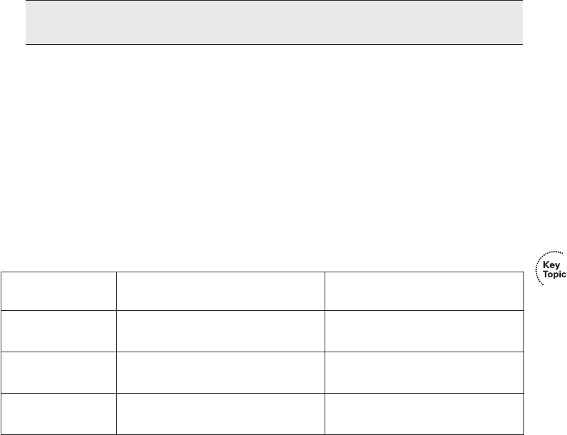
Analyzing the Layer 2 Forwarding Path with the MAC Address Table 289
Issues.” Isolating jabber problems requires much more effort, typically using more
specialized LAN cabling troubleshooting tools.
Finally, an incrementing late collisions counter typically means one of two things:
■The interface is connected to a collision domain whose cabling exceeds Ethernet cable
length standards.
■The interface is using half duplex, and the device on the other end of the cable is using
full duplex.
Table 10-5 summarizes the main points about these three general types of interface
problems that occur even when the interface is in a connect (up/up) state.
Analyzing the Layer 2 Forwarding Path with the MAC
Address Table
As explained in Chapter 7, “Ethernet LAN Switching Concepts,” switches learn MAC
addresses and then use the entries in the MAC address table to make a forwarding/filtering
decision for each frame. To know exactly how a particular switch will forward an Ethernet
frame, you need to examine the MAC address table on a Cisco switch.
The show mac address-table EXEC command displays the contents of a switch’s MAC
address table. This command lists all MAC addresses currently known by the switch. The
output includes some static overhead MAC addresses used by the switch and any statically
configured MAC addresses, such as those configured with the port security feature. The
command also lists all dynamically learned MAC addresses. If you want to see only the
NOTE To find the percentage of collisions versus output frames, divide the collisions
counter by the “packets output” counter, as highlighted in Example 10-4.
Table 10-5 Common LAN Layer 1 Problem Indicators
Type of Problem
Counter Values Indicating This
Problem Common Root Causes
Excessive noise Many input errors, few collisions Wrong cable category (Cat 5, 5E, 6);
damaged cables; EMI
Collisions More than roughly .1% of all frames
are collisions
Duplex mismatch (seen on the
half-duplex side); jabber; DoS attack
Late collisions Increasing late collisions Collision domain or single cable too
long; duplex mismatch
1828xbook.fm Page 289 Thursday, July 26, 2007 3:10 PM

290 Chapter 10: Ethernet Switch Troubleshooting
dynamically learned MAC address table entries, simply use the show mac address-table
dynamic EXEC command.
The more formal troubleshooting process begins with a prediction of what should happen
in a network, followed by an effort to isolate any problems that prevent the normal expected
results. As an exercise, go back and review Figure 10-2, and try to create a MAC address
table on paper for each switch. Include the MAC addresses for both PCs, as well as the
Fa0/1 MAC address for R1. Then predict which interfaces would be used to forward a frame
sent by Fred, Barney, and R1 to every other device. Even though the path the frames should
take may be somewhat obvious in this exercise, it might be worthwhile, because it forces
you to correlate what you’d expect to see in the MAC address table with how the switches
forward frames. Example 10-5 shows the MAC address tables on both switches from
Figure 10-2 so that you can check your answers.
The next step in the troubleshooting process is to isolate any problems with forwarding
frames. Example 10-5 shows an example using the small network depicted in Figure 10-2,
with no problems occurring. This example shows the MAC address table of both SW1 and
SW2. Also, for this example, SW1 has been configured to use port security on its Fa0/9
interface, for MAC address 0200.1111.1111 (Fred’s MAC address), just so the example can
point out the differences between dynamically learned MAC addresses and statically
configured MAC addresses.
Example 10-5 Examining SW1’s and SW2’s MAC Address Tables
SW1#ss
sshh
hhoo
ooww
ww
mm
mmaa
aacc
cc
aa
aadd
dddd
ddrr
rree
eess
ssss
ss--
--tt
ttaa
aabb
bbll
llee
ee
Mac Address Table
-------------------------------------------
Vlan Mac Address Type Ports
---- ----------- -------- -----
All 0100.0ccc.cccc STATIC CPU
All 0100.0ccc.cccd STATIC CPU
All 0180.c200.0000 STATIC CPU
All 0180.c200.0001 STATIC CPU
All 0180.c200.0002 STATIC CPU
All 0180.c200.0003 STATIC CPU
All 0180.c200.0004 STATIC CPU
All 0180.c200.0005 STATIC CPU
All 0180.c200.0006 STATIC CPU
All 0180.c200.0007 STATIC CPU
All 0180.c200.0008 STATIC CPU
All 0180.c200.0009 STATIC CPU
All 0180.c200.000a STATIC CPU
All 0180.c200.000b STATIC CPU
1828xbook.fm Page 290 Thursday, July 26, 2007 3:10 PM

Analyzing the Layer 2 Forwarding Path with the MAC Address Table 291
All 0180.c200.000c STATIC CPU
All 0180.c200.000d STATIC CPU
All 0180.c200.000e STATIC CPU
All 0180.c200.000f STATIC CPU
All 0180.c200.0010 STATIC CPU
All ffff.ffff.ffff STATIC CPU
1 0019.e859.539a DYNAMIC Gi0/1
! The next three entries are for Fred (statically-configured due to port security),
! Barney (dynamically learned), and router R1 (dynamically learned)
!
1 0200.1111.1111 STATIC Fa0/9
1 0200.2222.2222 DYNAMIC Fa0/12
1 0200.5555.5555 DYNAMIC Gi0/1
Total Mac Addresses for this criterion: 24
!
! The next command just lists dynamically learned MAC addresses, so it does not list
Fred’s
! MAC address, because it is considered static due to the port security configuration.
!
SW1#ss
sshh
hhoo
ooww
ww
mm
mmaa
aacc
cc
aa
aadd
dddd
ddrr
rree
eess
ssss
ss--
--tt
ttaa
aabb
bbll
llee
ee
dd
ddyy
yynn
nnaa
aamm
mmii
iicc
cc
Mac Address Table
-------------------------------------------
Vlan Mac Address Type Ports
---- ----------- -------- -----
1 0019.e859.539a DYNAMIC Gi0/1
1 0200.2222.2222 DYNAMIC Fa0/12
1 0200.5555.5555 DYNAMIC Gi0/1
Total Mac Addresses for this criterion: 3
! The same command on SW2 lists the same MAC addresses, but SW2’s interfaces used
! to reach those addresses.
SW2#ss
sshh
hhoo
ooww
ww
mm
mmaa
aacc
cc
aa
aadd
dddd
ddrr
rree
eess
ssss
ss--
--tt
ttaa
aabb
bbll
llee
ee
dd
ddyy
yynn
nnaa
aamm
mmii
iicc
cc
Mac Address Table
-------------------------------------------
Vlan Mac Address Type Ports
---- ----------- -------- -----
1 0019.e86a.6f99 DYNAMIC Gi0/2
1 0200.1111.1111 DYNAMIC Gi0/2
1 0200.2222.2222 DYNAMIC Gi0/2
1 0200.5555.5555 DYNAMIC Fa0/13
Total Mac Addresses for this criterion: 4
! The highlighted line above for 0200.5555.5555 will be used in the explanations
! following this example.
Example 10-5 Examining SW1’s and SW2’s MAC Address Tables (Continued)
1828xbook.fm Page 291 Thursday, July 26, 2007 3:10 PM

292 Chapter 10: Ethernet Switch Troubleshooting
When predicting the MAC address table entries, you need to imagine a frame sent by a
device to another device on the other side of the LAN and then determine which switch
ports the frame would enter as it passes through the LAN. For example, if Barney sends a
frame to router R1, the frame would enter SW1’s Fa0/12 interface, so SW1 has a MAC table
entry that lists Barney’s 0200.2222.2222 MAC address with Fa0/12. SW1 would forward
Barney’s frame to SW2, arriving on SW2’s Gi0/2 interface, so SW2’s MAC table lists
Barney’s MAC address (0200.2222.2222) with interface Gi0/2.
After you predict the expected contents of the MAC address tables, you can then examine
what is actually happening on the switches, as described in the next section.
Analyzing the Forwarding Path
To analyze the actual path taken by a frame in this network, a few reminders are necessary.
As mentioned earlier, this book’s coverage of VLANs assumes that no trunks exist, so all
interfaces are access interfaces—meaning that they are assigned to be in a single VLAN.
So, although it isn’t shown in Example 10-5, assume that the show vlan brief command
lists all the interfaces on each switch as being assigned to default VLAN 1.
The switch forwarding logic can be summarized as follows:
Step 1 Determine the VLAN in which the frame should be forwarded. On access
interfaces this is based on the access VLAN associated with the incoming
interface.
Step 2 Look for the frame’s destination MAC address in the MAC address table,
but only for entries in the VLAN identified in Step 1. If the destination
MAC is...
A. Found (unicast), forward the frame out the only interface listed in the
matched address table entry.
NOTE The MAC table entries in Example 10-5 list several additional entries, entries
that list a port of “CPU” and refer to MAC addresses used by the switch for overhead
traffic such as CDP and STP. These entries tell the switch to send frames destined
for these MAC addresses to the switch’s CPU.
1828xbook.fm Page 292 Thursday, July 26, 2007 3:10 PM

Analyzing the Layer 2 Forwarding Path with the MAC Address Table 293
B. Not found (unicast), flood the frame out all other access ports (except the
incoming port) in that same VLAN.
C. Broadcast or multicast, flood the frame out all other access ports (except the
incoming port) in that same VLAN.
Using this process as a guide, consider a frame sent by Barney to its default gateway, R1
(0200.5555.5555). Using the same switch forwarding logic steps, the following occurs:
Step 1 SW1 receives the frame on its Fa0/12 interface and sees that it is assigned to access
VLAN 1.
Step 2 SW1 looks for its MAC table entry for 0200.5555.5555, in the incoming
interface’s VLAN (VLAN 1), in its MAC address table.
A. SW1 finds an entry, associated with VLAN 1, outgoing interface Gi0/1, so
SW1 forwards the frame only out interface Gi0/1.
At this point, the frame with source 0200.2222.2222 (Barney) is on its way to SW2. You
can then pick up SW2’s logic, with the following explanation numbered to match the
forwarding process summary:
Step 1 SW2 receives the frame on its Gi0/2 interface and sees that Gi0/2 is assigned to
access VLAN 1.
Step 2 SW2 looks for its MAC table entry for 0200.5555.5555, in the incoming
interface’s VLAN (VLAN 1), in its MAC address table.
A. SW2 finds an entry, associated with VLAN 1, outgoing interface Fa0/13, so
SW2 forwards the frame only out interface Fa0/13.
At this point, the frame should be on its way, over the Ethernet cable between SW2 and R1.
Port Security and Filtering
Frankly, in real life, you will likely find any switching-related problems before you get to
the point of having to think about every possible interface out which a switch forwards a
frame. However, the exam can easily test you on the forwarding logic used in switches.
When it appears that all interfaces are up and working, and the switching table would allow
a frame to be delivered, but the frame still does not arrive, the problem is likely to be related
to some kind of filtering. LAN switches can be configured with access control lists (ACL),
NOTE Chapter 3 in the ICND2 Official Exam Certification Guide includes a more
extensive summary of the forwarding process, including comments on the impact of
VLAN trunking and STP on the forwarding process.
1828xbook.fm Page 293 Thursday, July 26, 2007 3:10 PM
294 Chapter 10: Ethernet Switch Troubleshooting
which filter frames. Additionally, routers can configure and use ACLs, so if a router is either
the sender or receiver of a frame, the router’s ACL might be filtering the frame. However,
switch ACLs are not covered for the CCNA exams, although router ACLs are covered as
part of the CCNA ICND2 Exam Certification Guide.
This book does cover one filtering tool that could make it appear that a frame can be
delivered (according to the MAC address tables), but the switch discards the frame. With
port security enabled with a violate action to shut down the interface, the switch may
discard frames. Because of the shutdown violating action, the switch would disable the
interface, making it easy to discover the reason why the frame was discarded by simply
looking at the interface status. However, with either the protect or restrict violation action
configured, the switch discards the offending traffic, but it leaves the port in a connect (up/
up) state. So, a simple show interface or show interface status command does not identify
the reason for the problem.
For example, imagine that Barney (0200.2222.2222) is again sending a frame to router R1
(0200.5555.5555), but SW1 has been configured for port security in a way that disallows
traffic from MAC address 0200.2222.2222 on port Fa0/12 of SW1, with a protect action.
An analysis of the MAC address table on both SW1 and SW2 might well look exactly like
it does in Example 10-5, with SW1’s entry for 0200.5555.5555 referring out interface Gi0/
1, and SW2’s entry referring to Fa0/13. However, SW1 never even attempts to forward the
frame because of the port security violation based on the source MAC address of Barney’s
frame as it enters SW1’s Fa0/12 interface.
1828xbook.fm Page 294 Thursday, July 26, 2007 3:10 PM
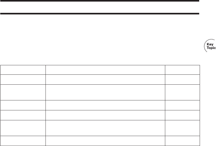
Command References 295
Exam Preparation Tasks
Review All the Key Topics
Review the most important topics from this chapter, noted with the key topics icon.
Table 10-6 describes these key topics and where each is discussed.
Complete the Tables and Lists from Memory
Print a copy of Appendix H, “Memory Tables” (found on the CD), or at least the section for
this chapter, and complete the tables and lists from memory. Appendix I, “Memory Tables
Answer Key,” also on the CD, includes completed tables and lists for you to check your
work.
Definitions of Key Terms
Define the following key terms from this chapter, and check your answers in the glossary:
CDP neighbor, up and up, error disabled, problem isolation, root cause
Command References
Tables 10-7 and 10-8 list only commands specifically mentioned in this chapter, but the
command references at the end of Chapters 8 and 9 also cover some related commands.
Table 10-7 lists and briefly describes the configuration commands used in this chapter.
Table 10-6 Key Topics for Chapter 10
Key Topic Element Description Page Number
List Information gathered by CDP 278
Table 10-2 Three CDP show commands that list information about
neighbors
278
Table 10-4 Two types of interface state terms and their meanings 283
List Defaults for IEEE autonegotiation 286
Table 10-5 Common reasons for Layer 1 LAN problems even when the
interface is up
289
List Summary of switch forwarding steps 292
1828xbook.fm Page 295 Thursday, July 26, 2007 3:10 PM

296 Chapter 10: Ethernet Switch Troubleshooting
Table 10-8 lists and briefly describes the EXEC commands used in this chapter.
Table 10-7 Commands for Catalyst 2950 Switch Configuration
Command Description
shutdown
no shutdown
Interface subcommands that administratively disable
and enable an interface, respectively.
switchport port-security violation
{protect | restrict | shutdown}
Interface subcommand that tells the switch what to do
if an inappropriate MAC address tries to access the
network through a secure switch port.
cdp run
no cdp run
Global commands that enable and disable,
respectively, CDP for the entire switch or router.
cdp enable
no cdp enable
Interface subcommands that enable and disable,
respectively, CDP for a particular interface.
speed {10 | 100 | 1000} Interface subcommand that manually sets the interface
speed.
duplex {auto | full | half} Interface subcommand that manually sets the interface
duplex.
Table 10-8 Chapter 10 EXEC Command Reference
Command Description
show mac address-table [dynamic | static]
[address hw-addr] [interface interface-id]
[vlan vlan-id]
Displays the MAC address table. The security option
displays information about the restricted or static
settings.
show port-security [interface interface-id]
[address]
Displays information about security options
configured on an interface.
show cdp neighbors [type number] Lists one summary line of information about each
neighbor, or just the neighbor found on a specific
interface if an interface was listed.
show cdp neighbors detail Lists one large set of information (approximately
15 lines) for every neighbor.
show cdp entry name Displays the same information as the show cdp
neighbors detail command, but only for the named
neighbor.
show cdp States whether CDP is enabled globally, and lists the
default update and holdtime timers.
1828xbook.fm Page 296 Thursday, July 26, 2007 3:10 PM

Command References 297
show cdp interface [type number] States whether CDP is enabled on each interface, or a
single interface if the interface is listed, and states
update and holdtime timers on those interfaces.
show cdp traffic Displays global statistics for the number of CDP
advertisements sent and received.
show interfaces [type number] Displays detailed information about interface status,
settings, and counters.
show interfaces status [type number] Displays summary information about interface status
and settings, including actual speed and duplex, and
whether the interface was autonegotiated.
Table 10-8 Chapter 10 EXEC Command Reference (Continued)
1828xbook.fm Page 297 Thursday, July 26, 2007 3:10 PM

This chapter covers the following subjects:
Wireless LAN Concepts: This section explains
the basic theory behind transmitting data with
radio waves using wireless LAN standards.
Deploying WLANs: This section lists a set of
generic steps for installing small WLANs, with
no product-specific details.
Wireless LAN Security: This section explains
the various WLAN security options that have
progressed through the years.
1828xbook.fm Page 298 Thursday, July 26, 2007 3:10 PM

C H A P T E R11
Wireless LANs
So far, this book has dedicated a lot of attention to (wired) Ethernet LANs. Although they
are vitally important, another style of LAN, wireless LANs (WLAN), fills a particularly
important role in providing network access to end users. In particular, WLANs allow the
user to communicate over the network without requiring any cables, enabling mobile
devices while removing the expense and effort involved in running cables. This chapter
examines the basic concepts, standards, installation, and security options for some of the
most common WLAN technologies today.
As a reminder if you’re following the optional reading plan listed in the Introduction to this
book, you will be moving on to Chapter 1 of the CCNA ICND2 Official Exam Certification
Guide following this chapter.
“Do I Know This Already?” Quiz
The “Do I Know This Already?” quiz allows you to assess whether you should read the
entire chapter. If you miss no more than one of these nine self-assessment questions, you
might want to move ahead to the “Exam Preparation Tasks” section. Table 11-1 lists the
major headings in this chapter and the “Do I Know This Already?” quiz questions covering
the material in those sections. This helps you assess your knowledge of these specific areas.
The answers to the “Do I Know This Already?” quiz appear in Appendix A.
Table 11-1 “Do I Know This Already?” Foundation Topics Section-to-Question Mapping
Foundation Topics Section Questions
Wireless LAN Concepts 1–4
Deploying WLANs 5–7
Wireless LAN Security 8, 9
1828xbook.fm Page 299 Thursday, July 26, 2007 3:10 PM
300 Chapter 11: Wireless LANs
1. Which of the following IEEE wireless LAN standards uses only the U-NII band of
frequencies (around 5.4 GHz)?
a. 802.11a
b. 802.11b
c. 802.11g
d. 802.11i
2. Which of the following answers is the correct maximum speed at which two IEEE
WLAN devices can send data with a particular standard?
a. 802.11b, using OFDM, at 54 Mbps
b. 802.11g, using OFDM, at 54 Mbps
c. 802.11a, using DSSS, at 54 Mbps
d. 802.11a, using DSSS, at 11 Mbps
3. Which of the following lists the nonoverlapping channels when using 802.1b DSSS in
the U.S.?
a. 1, 2, 3
b. 1, 5, 9
c. 1, 6, 11
d. a, b, g
e. 22, 33, 44
4. Which of the following terms refers to a WLAN mode that allows a laptop to roam
between different access points?
a. ESS
b. BSS
c. IBSS
d. None of the other answers are correct.
5. When configuring a wireless access point, which of the following are typical
configuration choices?
a. SSID
b. The speed to use
1828xbook.fm Page 300 Thursday, July 26, 2007 3:10 PM
“Do I Know This Already?” Quiz 301
c. The wireless standard to use
d. The size of the desired coverage area
6. Which of the following is true about an ESS’s connections to the wired
Ethernet LAN?
a. The AP connects to the Ethernet switch using a crossover cable.
b. The various APs in the same WLAN need to be assigned to the same VLAN by
the Ethernet switches.
c. The APs must have an IP address configured to forward traffic.
d. The APs using mixed 802.11g mode must connect via a Fast Ethernet or faster
connection to an Ethernet switch.
7. Which of the following are not common reasons why a newly installed
WLAN does not allow a client to connect through the WLAN into the wired
infrastructure?
a. The AP is installed on top of a metal filing cabinet.
b. The client is near a fast-food restaurant’s microwave oven.
c. The client is sitting on top of a big bundle of currently used Cat5 Ethernet cables.
d. The AP was configured to use DSSS channel 1 instead of the default channel 6,
and no one configured the client to use channel 6.
8. Which of the following WLAN security standards refer to the IEEE standard?
a. WPA
b. WPA2
c. WEP
d. 802.11i
9. Which of the following security features were not in the original WEP security
standard but are now in the WPA2 security standard?
a. Dynamic key exchange
b. Preshared Keys (PSK)
c. 802.1x authentication
d. AES encryption
1828xbook.fm Page 301 Thursday, July 26, 2007 3:10 PM

302 Chapter 11: Wireless LANs
Foundation Topics
This chapter examines the basics of WLANs. In particular, the first section introduces
the concepts, protocols, and standards used by many of the most common WLAN
installations today. The chapter then examines some basic installation steps. The last major
section looks at WLAN security, which is particularly important because the WLAN signals
are much more susceptible to being intercepted by an attacker than Ethernet LANs.
Wireless LAN Concepts
Many people use WLANs on a regular basis today. PC sales continue to trend toward more
laptop sales versus desktop computers, in part to support a more mobile workforce. PC
users need to connect to whatever network they are near, whether at work, at home, in a
hotel, or at a coffee shop or bookstore. The migration toward a work model in which you
find working moments wherever you are, with a need to be connected to the Internet at any
time, continues to push the growth of wireless LANs.
For example, Figure 11-1 shows the design of a LAN at a retail bookstore. The bookstore
provides free Internet access via WLANs while also supporting the bookstore’s devices
via a wired LAN.
The wireless-capable customer laptops communicate with a WLAN device called an access
point (AP). The AP uses wireless communications to send and receive frames with the
WLAN clients (the laptops). The AP also connects to the same Ethernet LAN as the
bookstore’s own devices, allowing both customers and employees to communicate with
other sites.
This section begins the chapter by explaining the basics of WLANs, starting with a
comparison of similarities between Ethernet LANs and WLANs. The rest of the section
then explores some of the main differences.
Comparisons with Ethernet LANs
WLANs are similar to Ethernet LANs in many ways, the most important being that
WLANs allow communications to occur between devices. The IEEE defines standards for
both, using the IEEE 802.3 family for Ethernet LANs and the 802.11 family for WLANs.
Both standards define a frame format with a header and trailer, with the header including
a source and destination MAC address field, each 6 bytes in length. Both define rules
about how the devices should determine when they should send frames and when they
should not.
1828xbook.fm Page 302 Thursday, July 26, 2007 3:10 PM
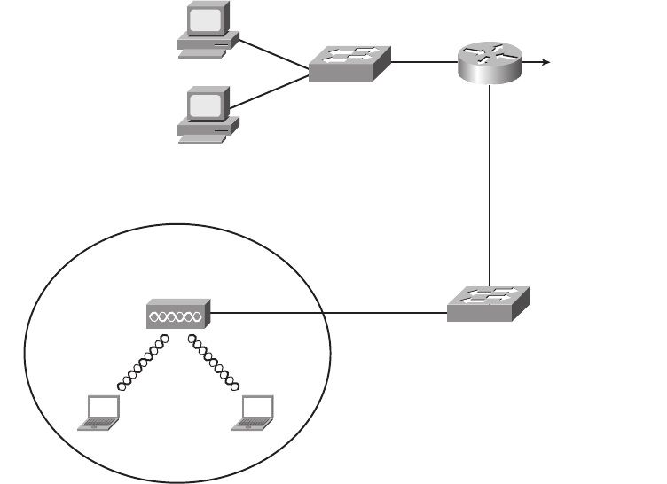
Wireless LAN Concepts 303
Figure 11-1 Sample WLAN at a Bookstore
The biggest difference between the two lies in the fact that WLANs use radiated energy
waves, generally called radio waves, to transmit data, whereas Ethernet uses electrical
signals flowing over a cable (or light on optical cabling). Radio waves pass through space,
so technically there is no need for any physical transmission medium. In fact, the presence
of matter—in particular, walls, metal objects, and other obstructions—gets in the way of
the wireless radio signals.
Several other differences exist as well, mainly as a side effect of the use of wireless instead
of wires. For example, Chapter 7, “Ethernet LAN Switching Concepts,” explains how
Ethernet can support full-duplex (FDX) communication if a switch connects to a single
device rather than a hub. This removes the need to control access to the link using carrier
sense multiple access collision detect (CSMA/CD). With wireless, if more than one device
at a time sends radio waves in the same space at the same frequency, neither signal is
intelligible, so a half-duplex (HDX) mechanism must be used. To arbitrate the use of the
frequency, WLANs use the carrier sense multiple access with collision avoidance
(CSMA/CA) algorithm to enforce HDX logic and avoid as many collisions as possible.
Access
Point
Radio
Cell
PC2PC1
Employee
PC
Cash
Register
SW1
SW2
To the Rest of the
Network and the
Internet
Ethernet
Cable
1828xbook.fm Page 303 Thursday, July 26, 2007 3:10 PM

304 Chapter 11: Wireless LANs
Wireless LAN Standards
At the time this book was published, the IEEE had ratified four major WLAN standards:
802.11, 802.11a, 802.11b, and 802.11g. This section lists the basic details of each
WLAN standard, along with information about a couple of other standards bodies. This
section also briefly mentions the emerging 802.1n standard, which the IEEE had not yet
ratified by the time this book was published.
Four organizations have a great deal of impact on the standards used for wireless LANs
today. Table 11-2 lists these organizations and describes their roles.
Of the organizations listed in this table, the IEEE develops the specific standards for the
different types of WLANs used today. Those standards must take into account the
frequency choices made by the different worldwide regulatory agencies, such as
the FCC in the U.S. and the ITU-R, which is ultimately controlled by the United
Nations (UN).
The IEEE introduced WLAN standards with the creation of the 1997 ratification of the
802.11 standard. This original standard did not have a suffix letter, whereas later WLAN
standards do. This naming logic, with no suffix letter in the first standard, followed by other
standards with a suffix letter, is like the original IEEE Ethernet standard. That standard was
802.3, with later, more-advanced standards having a suffix, such as 802.3u for Fast
Ethernet.
The original 802.11 standard has been replaced by more-advanced standards. In order of
ratification, the standards are 802.11b, 802.11a, and 802.11g. Of note, the 802.11n standard
is likely to be ratified by the end of 2008, with prestandard products available in 2007.
Table 11-3 lists some key points about the currently ratified standards.
Table 11-2 Organizations That Set or Influence WLAN Standards
Organization Standardization Role
ITU-R Worldwide standardization of communications that use radiated energy,
particularly managing the assignment of frequencies
IEEE Standardization of wireless LANs (802.11)
Wi-Fi Alliance An industry consortium that encourages interoperability of products
that implement WLAN standards through their Wi-Fi certified program
Federal Communications
Commission (FCC)
The U.S. government agency with that regulates the usage of various
communications frequencies in the U.S.
1828xbook.fm Page 304 Thursday, July 26, 2007 3:10 PM
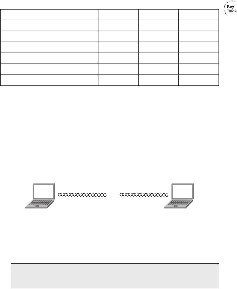
Wireless LAN Concepts 305
*These values assume a WLAN in the U.S.
This table lists a couple of features that have not yet been defined but that are described in
this chapter.
Modes of 802.11 Wireless LANs
WLANs can use one of two modes—ad hoc mode or infrastructure mode. With ad hoc
mode, a wireless device wants to communicate with only one or a few other devices
directly, usually for a short period of time. In these cases, the devices send WLAN frames
directly to each other, as shown in Figure 11-2.
Figure 11-2 Ad Hoc WLAN
In infrastructure mode, each device communicates with an AP, with the AP connecting via
wired Ethernet to the rest of the network infrastructure. Infrastructure mode allows the
WLAN devices to communicate with servers and the Internet in an existing wired network,
as shown earlier in Figure 11-1.
Table 11-3 WLAN Standards
Feature 802.11a 802.11b 802.11g
Year ratified 1999 1999 2003
Maximum speed using DSSS — 11 Mbps 11 Mbps
Maximum speed using OFDM 54 Mbps — 54 Mbps
Frequency band 5 GHz 2.4 GHz 2.4 GHz
Channels (nonoverlapped)*23 (12) 11 (3) 11 (3)
Speeds required by standard (Mbps) 6, 12, 24 1, 2, 5.5, 11 6, 12, 24
NOTE Devices in an infrastructure WLAN cannot send frames directly to each other;
instead, they send frames to the AP, which can then in turn forward the frames to
another WLAN device.
PC1 PC2
1828xbook.fm Page 305 Thursday, July 26, 2007 3:10 PM
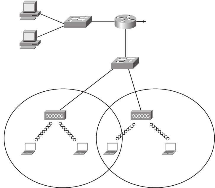
306 Chapter 11: Wireless LANs
Infrastructure mode supports two sets of services, called service sets. The first, called a
Basic Service Set (BSS), uses a single AP to create the wireless LAN, as shown in
Figure 11-1. The other, called Extended Service Set (ESS), uses more than one AP, often
with overlapping cells to allow roaming in a larger area, as shown in Figure 11-3.
Figure 11-3 Infrastructure Mode BSS and ESS WLANs
The ESS WLANs allow roaming, which means that users can move around inside the
coverage area and stay connected to the same WLAN. As a result, the user does not need to
change IP addresses. All the device has to do is sense when the radio signals from the
current AP are getting weaker; find a new, better AP with a stronger or better signal; and
start using the new AP.
PC2PC1
Employee
PC
Cash
Register
SW1
SW2
To the Rest of the
Network and the
Internet
Radio
Cell
Radio
Cell
Ethernet
Cable
AP1
PC4PC3
Ethernet
Cable
AP2
1828xbook.fm Page 306 Thursday, July 26, 2007 3:10 PM
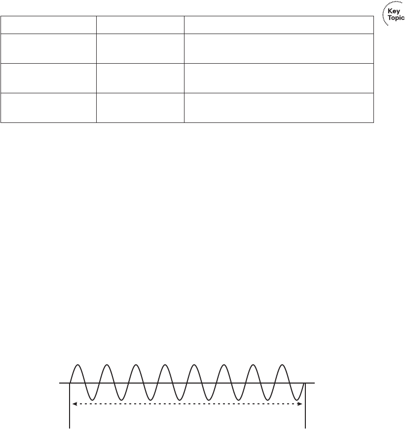
Wireless LAN Concepts 307
Table 11-4 summarizes the WLAN modes for easy reference.
Wireless Transmissions (Layer 1)
WLANs transmit data at Layer 1 by sending and receiving radio waves. The WLAN
network interface cards (NIC), APs, and other WLAN devices use a radio and its antenna
to send and receive the radio waves, making small changes to the waves to encode data.
Although the details differ significantly compared to Ethernet, the idea of encoding data
by changing the energy signal that flows over a medium is the same idea as Ethernet
encoding.
Similar to electricity on copper wires and light over optical cables, WLAN radio waves
have a repeating signal that can be graphed over time, as shown in Figure 11-4. When
graphed, the curve shows a repeating periodic waveform, with a frequency (the number
of times the waveform repeats per second), amplitude (the height of the waveform,
representing signal strength), and phase (the particular point in the repeating waveform).
Of these items, frequency, measured in hertz (Hz), is the most important in discussions of
WLANs.
Figure 11-4 Graph of an 8-KHz Signal
Many electronic devices radiate energy at varying frequencies, some related to the device’s
purpose (for example, a wireless LAN or a cordless telephone). In other cases the radiated
energy is a side effect. For example, televisions give off some radiated energy. To prevent
Table 11-4 Different WLAN Modes and Names
Mode Service Set Name Description
Ad hoc Independent Basic
Service Set (IBSS)
Allows two devices to communicate directly.
No AP is needed.
Infrastructure (one AP) Basic Service
Set (BSS)
A single wireless LAN created with an AP and
all devices that associate with that AP.
Infrastructure (more
than one AP)
Extended Service Set
(ESS)
Multiple APs create one wireless LAN, allowing
roaming and a larger coverage area.
.001 Seconds
Frequency = 8000 Hz
1828xbook.fm Page 307 Thursday, July 26, 2007 3:10 PM

308 Chapter 11: Wireless LANs
the energy radiated by one device from interfering with other devices, national government
agencies, regulate and oversee the frequency ranges that can be used inside that country.
For example, the Federal Communications Commission (FCC) in the U.S. regulates the
electromagnetic spectrum of frequencies.
The FCC or other national regulatory agencies specify some ranges of frequencies, called
frequency bands. For example, in the U.S., FM and AM radio stations must register with
the FCC to use a particular range (band) of frequencies. A radio station agrees to transmit
its radio signal at or under a particular power level so that other radio stations in other
cities can use the same frequency band. However, only that one radio station can use a
particular frequency band in a particular location.
A frequency band is so named because it is actually a range of consecutive frequencies. An
FM radio station needs about 200 kilohertz (KHz) of frequency in which to send a radio
signal. When the station requests a frequency from the FCC, the FCC assigns a base
frequency, with 100 KHz of bandwidth on either side of the base frequency. For example,
an FM radio station that announces something like “The greatest hits are at 96.5 FM” means
that the base signal is 96.5 megahertz (MHz), with the radio transmitter using the frequency
band between 96.4 MHz and 96.6 MHz, for a total bandwidth of .2 MHz, or 200 KHz.
The wider the range of frequencies in a frequency band, the greater the amount of
information that can be sent in that frequency band. For example, a radio signal needs about
200 KHz (.2 MHz) of bandwidth, whereas a broadcast TV signal, which contains a lot more
information because of the video content, requires roughly 4.5 MHz.
The FCC, and equivalent agencies in other countries, license some frequency bands,
leaving some frequency bands unlicensed. Licensed bands are used for many purposes; the
most common are AM and FM radio, shortwave radio (for example, for police department
communications), and mobile phones. Unlicensed frequencies can be used by all kinds of
devices; however, the devices must still conform to the rules set up by the regulatory
agency. In particular, a device using an unlicensed band must use power levels at or below
a particular setting. Otherwise, the device might interfere too much with other devices
sharing that unlicensed band. For example, microwave ovens happen to radiate energy in
the 2.4 gigahertz (GHz) unlicensed band as a side effect of cooking food. That same
unlicensed band is used by some WLAN standards and by many cordless telephones. In
some cases, you cannot hear someone on the phone or surf the Internet using a WLAN
when someone’s heating up dinner.
NOTE The use of the term bandwidth to refer to speeds of network interfaces is just a
holdover from the idea that the width (range) of a frequency band is a measurement of
how much data can be sent in a period of time.
1828xbook.fm Page 308 Thursday, July 26, 2007 3:10 PM

Wireless LAN Concepts 309
The FCC defines three unlicensed frequency bands. The bands are referenced by a
particular frequency in the band, although by definition, a frequency band is a range of
frequencies. Table 11-5 lists the frequency bands that matter to some degree for WLAN
communications.
Wireless Encoding and Nonoverlapping DSSS Channels
When a WLAN NIC or AP sends data, it can modulate (change) the radio signal’s
frequency, amplitude, and phase to encode a binary 0 or 1. The details of that encoding are
beyond the scope of this book. However, it is important to know the names of three general
classes of encoding, in part because the type of encoding requires some planning and
forethought for some WLANs.
Frequency Hopping Spread Spectrum (FHSS) uses all frequencies in the band, hopping
to different ones. By using slightly different frequencies for consecutive transmissions,
a device can hopefully avoid interference from other devices that use the same
unlicensed band, succeeding at sending data at some frequencies. The original 802.11
WLAN standards used FHSS, but the current standards (802.11a, 802.11b, and 802.11g)
do not.
Direct Sequence Spread Spectrum (DSSS) followed as the next general class of encoding
type for WLANs. Designed for use in the 2.4 GHz unlicensed band, DSSS uses one of
several separate channels or frequencies. This band has a bandwidth of 82 MHz, with a
range from 2.402 GHz to 2.483 GHz. As regulated by the FCC, this band can have 11
different overlapping DSSS channels, as shown in Figure 11-5.
Although many of the channels shown in the figure overlap, three of the channels (the
channels at the far left and far right, and the channel in the center) do not overlap enough
to impact each other. These channels (channels 1, 6, and 11) can be used in the same space
for WLAN communications, and they won’t interfere with each other.
Table 11-5 FCC Unlicensed Frequency Bands of Interest
Frequency Range Name Sample Devices
900 KHz Industrial, Scientific,
Mechanical (ISM)
Older cordless telephones
2.4 GHz ISM Newer cordless phones and 802.11,
802.11b, 802.11g WLANs
5 GHz Unlicensed National Information
Infrastructure (U-NII)
Newer cordless phones and 802.11a,
802.11n WLANs
1828xbook.fm Page 309 Thursday, July 26, 2007 3:10 PM
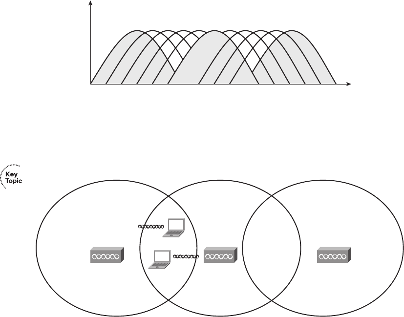
310 Chapter 11: Wireless LANs
Figure 11-5 Eleven Overlapping DSSS Channels at 2.4 GHz
The significance of the nonoverlapping DSSS channels is that when you design an ESS
WLAN (more than one AP), APs with overlapping coverage areas should be set to use
different nonoverlapping channels. Figure 11-6 shows the idea.
Figure 11-6 Using Nonoverlapping DSSS 2.4-GHz Channels in an ESS WLAN
In this design, the devices in one BSS (devices communicating through one AP) can send
at the same time as the other two BSSs and not interfere with each other, because each uses
the slightly different frequencies of the nonoverlapping channels. For example, PC1 and
PC2 could sit beside each other and communicate with two different APs using two
different channels at the exact same time. This design is typical of 802.11b WLANs, with
each cell running at a maximum data rate of 11 Mbps. With the nonoverlapping channels,
each half-duplex BSS can run at 11 Mbps, for a cumulative bandwidth of 33 Mbps in this
case. This cumulative bandwidth is called the WAN’s capacity.
The last of the three categories of encoding for WLANs is called Orthogonal Frequency
Division Multiplexing (OFDM). Like DSSS, WLANs that use OFDM can use multiple
nonoverlapping channels. Table 11-6 summarizes the key points and names of the main
three options for encoding.
123456
RF Channels
2.4 GHz Frequency Spectrum
7 8 9 10 11
AP3
Channel 11
AP2
Channel 6
AP1
Channel 1 PC2
PC1
1828xbook.fm Page 310 Thursday, July 26, 2007 3:10 PM

Wireless LAN Concepts 311
Wireless Interference
WLANs can suffer from interference from many sources. The radio waves travel through
space, but they must pass through whatever matter exists inside the coverage area, including
walls, floors, and ceilings. Passing through matter causes the signal to be partially absorbed,
which reduces signal strength and the size of the coverage area. Matter can also reflect and
scatter the waves, particularly if there is a lot of metal in the materials, which can cause
dead spots (areas in which the WLAN simply does not work), and a smaller coverage area.
Additionally, wireless communication is impacted by other radio waves in the same
frequency range. The effect is the same as trying to listen to a radio station when you’re
taking a long road trip. You might get a good clear signal for a while, but eventually you
drive far enough from the radio station’s antenna that the signal is weak, and it is hard to hear
the station. Eventually, you get close enough to the next city’s radio station that uses the
same frequency range, and you cannot hear either station well because of the interference.
With WLANs, the interference may simply mean that the data only occasionally makes it
through the air, requiring lots of retransmissions, and resulting in poor efficiency.
One key measurement for interference is the Signal-to-Noise Ratio (SNR). This calculation
measures the WLAN signal as compared to the other undesired signals (noise) in the
same space. The higher the SNR, the better the WLAN devices can send data successfully.
Coverage Area, Speed, and Capacity
A WLAN coverage area is the space in which two WLAN devices can successfully send
data. The coverage area created by a particular AP depends on many factors, several of
which are explained in this section.
First, the transmit power by an AP or WLAN NIC cannot exceed a particular level based on
the regulations from regulatory agencies such as the FCC. The FCC limits the transmit
power to ensure fairness in the unlicensed bands. For example, if two neighbors bought
Linksys APs and put them in their homes to create a WLAN, the products would conform
Table 11-6 Encoding Classes and IEEE Standard WLANs
Name of Encoding Class What It Is Used By
Frequency Hopping Spread Spectrum (FHSS) 802.11
Direct Sequence Spread Spectrum (DSSS) 802.11b
Orthogonal Frequency Division Multiplexing (OFDM) 802.11a, 802.11g
NOTE The emerging 802.11n standard uses OFDM as well as multiple antennas, a
technology sometimes called multiple input multiple output (MIMO).
1828xbook.fm Page 311 Thursday, July 26, 2007 3:10 PM

312 Chapter 11: Wireless LANs
to FCC regulations. However, if one person bought and installed high-gain antennas for her
AP, and greatly exceeded the FCC regulations, she might get a much wider coverage area—
maybe even across the whole neighborhood. However, it might prevent the other person’s
AP from working at all because of the interference from the overpowered AP.
The materials and locations of the materials near the AP also impact an AP’s coverage area.
For example, putting the AP near a large metal filing cabinet increases reflections and
scattering, which shrinks the coverage area. Certainly, concrete construction with steel rebar
reduces the coverage area in a typical modern office building. In fact, when a building’s
design means that interference will occur in some areas, APs may use different types of
antennas that change the shape of the coverage area from a circle to some other shape.
As it turns out, weaker wireless signals cannot pass data at higher speeds, but they can pass
data at lower speeds. So, WLAN standards support the idea of multiple speeds. A device
near the AP may have a strong signal, so it can transmit and receive data with the AP at
higher rates. A device at the edge of the coverage area, where the signals are weak, may still
be able to send and receive data—although at a slower speed. Figure 11-7 shows the idea
of a coverage area, with varying speeds, for an IEEE 802.11b BSS.
The main ways to increase the size of the coverage area of one AP are to use specialized
antennas and to increase the power of the transmitted signal. For example, you can increase
the antenna gain, which is the power added to the radio signal by the antenna. To double the
coverage area, the antenna gain must be increased to quadruple the original gain. Although
this is useful, the power output (the EIRP) must still be within FCC rules (in the U.S.).
The actual size of the coverage area depends on a large number of factors that are beyond
the scope of this book. Some of the factors include the frequency band used by the
WLAN standard, the obstructions between and near the WLAN devices, the interference
from other sources of RF energy, the antennas used on both the clients and APs, and the
options used by DSSS and OFDM when encoding data over the air. Generally speaking,
WLAN standards that use higher frequencies (U-NII band standards 802.11a and the future
802.11n) can send data faster, but with the price of smaller coverage areas. To cover all
the required space, an ESS that uses higher frequencies would then require more APs,
driving up the cost of the WLAN deployment.
NOTE The power of an AP is measured based on the Effective Isotropic Radiated
Power (EIRP) calculation. This is the radio’s power output, plus the increase in power
caused by the antenna, minus any power lost in the cabling. In effect, it’s the power of
the signal as it leaves the antenna.
1828xbook.fm Page 312 Thursday, July 26, 2007 3:10 PM
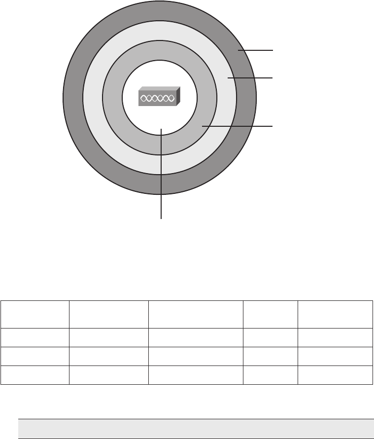
Wireless LAN Concepts 313
Figure 11-7 Coverage Area and Speed
Table 11-7 lists the main IEEE WLAN standards that had been ratified at the time this book
was published, the maximum speed, and the number of nonoverlapping channels.
*The speeds listed in bold text are required speeds according to the standards. The other speeds are optional.
Finally, note that the number of (mostly) nonoverlapping channels supported by a standard,
as shown in Figures 11-5 and 11-6, affects the combined available bandwidth. For example,
in a WLAN that exclusively uses 802.11g, the actual transmissions could occur at 54 Mbps.
But three devices could sit beside each other and send at the same time, using three different
Table 11-7 WLAN Speed and Frequency Reference
IEEE Standard
Maximum Speed
(Mbps)
Other Speeds*
(Mbps) Frequency
Nonoverlapping
Channels
802.11b 11 Mbps 1, 2, 5.5 2.4 GHz 3
802.11a 54 Mbps 6, 9, 12, 18, 24, 36, 48 5 GHz 12
802.11g 54 Mbps Same as 802.11a 2.4 GHz 3
NOTE The original 802.11 standard supported speeds of 1 and 2 Mbps.
1 Mbps
2 Mbps
5.5 Mbps
11 Mbps
1828xbook.fm Page 313 Thursday, July 26, 2007 3:10 PM
314 Chapter 11: Wireless LANs
channels, to three different APs. Theoretically, that WLAN could support a throughput of
3 * 54 Mbps, or 162 Mbps, for these devices in that part of the WLAN. Along the same line
of reasoning, an 802.11a WLAN can transmit data at 54 Mbps, but with 12 nonoverlapping
channels, for a theoretical maximum of 12 * 54 Mbps = 648 Mbps of bandwidth capacity.
Media Access (Layer 2)
Ethernet LANs began life using a shared medium (a coaxial cable), meaning that only one
device could send data at a time. To control access to this half-duplex (HDX) medium,
Ethernet defined the use of the CSMA/CD algorithm. As Ethernet progressed with
continually improved standards, it started using switches, with one device cabled to each
switch port, allowing the use of full duplex (FDX). With FDX, no collisions can occur, so
the CSMA/CD algorithm is disabled.
With wireless communications, devices cannot be separated onto different cable segments
to prevent collisions, so collisions can always occur, even with more-advanced WLAN
standards. In short, if two or more WLAN devices send at the same time, using overlapping
frequency ranges, a collision occurs, and none of the transmitted signals can be understood
by those receiving the signal. To make matters worse, the device that is transmitting data
cannot concurrently listen for received data. So, when two WLAN devices send at the same
time, creating a collision, the sending devices do not have any direct way to know the
collision occurred.
The solution to the media access problem with WLANs is to use the carrier sense multiple
access with collision avoidance (CSMA/CA) algorithm. The collision avoidance part
minimizes the statistical chance that collisions could occur. However, CSMA/CA does not
prevent collisions, so the WLAN standards must have a process to deal with collisions
when they do occur. Because the sending device cannot tell if its transmitted frame collided
with another frame, the standards all require an acknowledgment of every frame. Each
WLAN device listens for the acknowledgment, which should occur immediately after the
frame is sent. If no acknowledgment is received, the sending device assumes that the frame
was lost or collided, and it resends the frame.
The following list summarizes the key points about the CSMA/CA algorithm, omitting
some of the details for the sake of clarity:
Step 1 Listen to ensure that the medium (space) is not busy (no radio waves currently are
being received at the frequencies to be used).
Step 2 Set a random wait timer before sending a frame to statistically reduce the
chance of devices all trying to send at the same time.
Step 3 When the random timer has passed, listen again to ensure that the
medium is not busy. If it isn’t, send the frame.
1828xbook.fm Page 314 Thursday, July 26, 2007 3:10 PM

Deploying WLANs 315
Step 4 After the entire frame has been sent, wait for an acknowledgment.
Step 5 If no acknowledgment is received, resend the frame, using CSMA/CA
logic to wait for the appropriate time to send again.
This concludes the brief introduction to wireless LAN concepts. Next, this chapter covers
the basics of what you should do when installing a new wireless LAN.
Deploying WLANs
WLAN security is one of the more important features of WLANs, and for good reason.
The same security exposures exist on WLANs as for Ethernet LANs, plus WLANs
are exposed to many more vulnerabilities than wired Ethernet LANs. For example,
someone could park outside a building and pick up the WLAN signals from inside the
building, reading the data. Therefore, all production WLAN deployments should include
the currently best security options for that WLAN.
Although security is vitally important, the installation of a new WLAN should begin with
just getting the WLAN working. As soon as a single wireless device is talking to an AP,
security configuration can be added and tested. Following that same progression, this
section examines the process of planning and implementing a WLAN, with no security
enabled. The final major section of this chapter, “Wireless LAN Security,” examines the
concepts behind WLAN security.
Wireless LAN Implementation Checklist
The following basic checklist can help guide the installation of a new BSS WLAN:
Step 1 Verify that the existing wired network works, including DHCP services, VLANs,
and Internet connectivity.
Step 2 Install the AP and configure/verify its connectivity to the wired network,
including the AP’s IP address, mask, and default gateway.
Step 3 Configure and verify the AP’s wireless settings, including Service Set
Identifier (SSID), but no security.
Step 4 Install and configure one wireless client (for example, a laptop), again
with no security.
Step 5 Verify that the WLAN works from the laptop.
Step 6 Configure wireless security on the AP and client.
Step 7 Verify that the WLAN works again, in the presence of the security
features.
1828xbook.fm Page 315 Thursday, July 26, 2007 3:10 PM
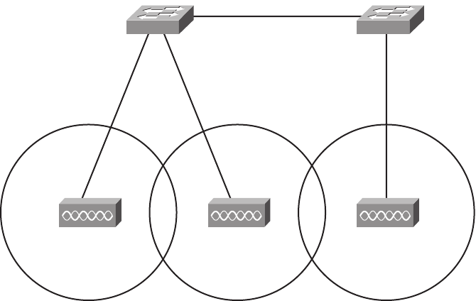
316 Chapter 11: Wireless LANs
This section examines the first five tasks. The last major section of this chapter discusses
the concepts behind WLAN security but does not explain the large number of detailed
options for configuring WLAN security.
Step 1: Verify the Existing Wired Network
Most of the other chapters in this book explain the details of how to understand, plan,
design, and implement the switches and routers that create the rest of the network, so there
is no need to repeat those details here. However, it can be helpful to consider a couple of
items related to testing an existing wired network before connecting a new WLAN.
First, the Ethernet switch port to which the AP’s Ethernet port connects typically is a
switch access port, meaning that it is assigned to a particular VLAN. Also, in an ESS
design with multiple APs, all the Ethernet switch ports to which the APs attach should be
in the same VLAN. Figure 11-8 shows a typical ESS design for a WLAN, with the VLAN
IDs listed.
Figure 11-8 ESS WLAN with All APs in Ethernet VLAN 2
To test the existing network, you could simply connect a laptop Ethernet NIC to the same
Ethernet cable that will be used for the AP. If the laptop can acquire an IP address, mask,
and other information using DHCP, and communicate with other hosts, the existing wired
network is ready to accept the AP.
AP1
Channel 1
AP2
Channel 6
AP3
SW2
VLAN 2
SW1
VLAN 2
VLAN Trunk
VLAN 2
Channel 11
1828xbook.fm Page 316 Thursday, July 26, 2007 3:10 PM
Deploying WLANs 317
Step 2: Install and Configure the AP’s Wired and IP Details
Just like an Ethernet switch, wireless APs operate at Layer 2 and do not need an IP address
to perform their main functions. However, just as an Ethernet switch in an Enterprise
network should have an IP address so that it can be easily managed, APs deployed in an
Enterprise network should also have an IP address.
The IP configuration details on an AP are the same items needed on an Ethernet switch, as
covered in the section “Configuring the Switch IP Address” in Chapter 9, “Ethernet Switch
Configuration.” In particular, the AP needs an IP address, subnet mask, default gateway
IP address, and possibly the IP address of a DNS server.
The AP uses a straight-through Ethernet cable to connect to the LAN switch. Although any
speed Ethernet interface works, when using the faster WLAN speeds, using a Fast Ethernet
interface on a switch helps improve overall performance.
Step 3: Configure the AP’s WLAN Details
Most of the time, WLAN APs can be installed with no configuration, and they work. For
example, many homes have consumer-grade wireless APs installed, connected to a high-
speed Internet connection. Often, the AP, router, and cable connection terminate in the same
device, such as the Linksys Dual-Band Wireless A+G Broadband Router. (Linksys is a
division of Cisco Systems that manufactures and distributes consumer networking devices.)
Many people just buy these devices, plug in the power and the appropriate cables for the
wired part of the connection, and leave the default WLAN settings, and the AP works.
Both consumer-grade and Enterprise-grade APs can be configured with a variety of
parameters. The following list highlights some of the features mentioned earlier in this
chapter that may need to be configured:
■IEEE standard (a, b, g, or multiple)
■Wireless channel
■Service Set Identifier (SSID, a 32-character text identifier for the WLAN)
■Transmit power
This chapter has already explained most of the concepts behind these four items, but
the SSID is new. Each WLAN needs a unique name to identify the WLAN. Because a
simple WLAN with a single AP is called a Basic Service Set (BSS), and a WLAN with
multiple APs is called an Extended Service Set (ESS), the term for the identifier of a WLAN
is the Service Set Identifier (SSID). The SSID is a 32-character ASCII text value. When
you configure an ESS WLAN, each of the APs should be configured with the same SSID,
which allows for roaming between APs, but inside the same WLAN.
1828xbook.fm Page 317 Thursday, July 26, 2007 3:10 PM
318 Chapter 11: Wireless LANs
Also note that many APs today support multiple WLAN standards. In some cases, they can
support multiple standards on the same AP at the same time. However, these mixed-mode
implementations, particularly with 802.11b/g in this same AP, tend to slow down the
WLAN. In practice, deploying some 802.11g-only APs and some mixed-mode b/g APs in
the same coverage area may provide better performance than using only APs configured
in b/g mixed mode.
Step 4: Install and Configure One Wireless Client
A wireless client is any wireless device that associates with an AP to use a WLAN. To be a
WLAN client, the device simply needs a WLAN NIC that supports the same WLAN
standard as the AP. The NIC includes a radio, which can tune to the frequencies used by
the supported WLAN standard(s), and an antenna. For example, laptop computer
manufacturers typically integrate a WLAN NIC into every laptop, and you can then use
a laptop to associate with an AP and send frames.
The AP has several required configuration settings, but the client may not need anything
configured. Typically, clients by default do not have any security enabled. When the client
starts working, it tries to discover all APs by listening on all frequency channels for the
WLAN standards it supports by default. For example, if a client were using the WLAN
shown in Figure 11-6, with three APs, each using a different channel, the client might
actually discover all three APs. The client would then use the AP from which the client
receives the strongest signal. Also, the client learns the SSID from the AP, again removing
the need for any client configuration.
WLAN clients may use wireless NICs from a large number of vendors. To help ensure that
the clients can work with Cisco APs, Cisco started the Cisco Compatible Extensions
Program (CCX). This Cisco-sponsored program allows any WLAN manufacturer to
send its products to a third-party testing lab, with the lab performing tests to see if
the WLAN NIC works well with Cisco APs. Cisco estimates that 95 percent of the
wireless NICs on the market have been certified through this program.
With Microsoft operating systems, the wireless NIC may not need to be configured because
of the Microsoft Zero Configuration Utility (ZCF). This utility, part of the OS, allows the
PC to automatically discover the SSIDs of all WLANs whose APs are within range on
the NIC. The user can choose the SSID to connect to. Or the ZCF utility can automatically
pick the AP with the strongest signal, thereby automatically connecting to a wireless LAN
without the user’s needing to configure anything.
Note that most NIC manufacturers also provide software that can control the NIC instead
of the operating system’s built-in tools such as Microsoft ZCF.
1828xbook.fm Page 318 Thursday, July 26, 2007 3:10 PM

Deploying WLANs 319
Step 5: Verify That the WLAN Works from the Client
The first step to verify proper operation of the first WLAN client is to check whether the
client can access the same hosts used for testing in Step 1 of this installation process.
(The laptop’s wired Ethernet connection should be disconnected so that the laptop uses
only its WLAN connection.) At this point, if the laptop can get a response from another
host, such as by pinging or browsing a web page on a web server, the WLAN at least works.
If this test does not work, a wide variety of tasks could be performed. Some of the tasks
relate to work that is often done in the planning stages, generally called a site survey. During
a wireless site survey, engineers tour the site for a new WLAN, looking for good AP
locations, transmitting and testing signal strength throughout the site. In that same line of
thinking, if the new client cannot communicate, you might check the following:
■Is the AP at the center of the area in which the clients reside?
■Is the AP or client right next to a lot of metal?
■Is the AP or client near a source of interference, such as a microwave oven or gaming
system?
■Is the AP’s coverage area wide enough to reach the client?
In particular, you could take a laptop with a wireless card and, using the NIC’s tools, walk
around while looking at signal quality measurement. Most WLAN NIC software shows
signal strength and quality, so by walking around the site with the laptop, you can gauge
whether any dead spots exist and where clients should have no problems hearing from
the AP.
Besides the site survey types of work, the following list notes a few other common
problems with a new installation:
■Check to make sure that the NIC and AP’s radios are enabled. In particular, most
laptops have a physical switch with which to enable or disable the radio, as well as a
software setting to enable or disable the radio. This allows the laptop to save power
(and extend the time before it must be plugged into a power outlet again). It also can
cause users to fail to connect to an AP, just because the radio is turned off.
■Check the AP to ensure that it has the latest firmware. AP firmware is the OS that runs
in the AP.
■Check the AP configuration—in particular, the channel configuration—to ensure that
it does not use a channel that overlaps with other APs in the same location.
1828xbook.fm Page 319 Thursday, July 26, 2007 3:10 PM
320 Chapter 11: Wireless LANs
This completes the explanations of the first five steps of installing a simple wireless LAN.
The final major section of this chapter examines WLAN security, which also completes the
basic installation steps.
Wireless LAN Security
All networks today need good security, but WLANs have some unique security
requirements. This section examines some of the security needs for WLANs and the
progression and maturation of the WLAN security options. It also discusses how to
configure the security features.
WLAN Security Issues
WLANs introduce a number of vulnerabilities that do not exist for wired Ethernet LANs.
Some of these vulnerabilities give hackers an opportunity to cause harm by stealing
information, accessing hosts in the wired part of the network, or preventing service through
a denial-of-service (DoS) attack. Other vulnerabilities may be caused by a well-meaning
but uninformed employee who installs an AP without the IT department’s approval, with
no security. This would allow anyone to gain access to the rest of the Enterprise’s network.
The Cisco-authorized CCNA-related courses suggest several categories of threats:
■War drivers: The attacker often just wants to gain Internet access for free. This person
drives around, trying to find APs that have no security or weak security. The attacker
can use easily downloaded tools and high-gain directional antennas (easily purchased
and installed).
■Hackers: The motivation for hackers is to either find information or deny services.
Interestingly, the end goal may be to compromise the hosts inside the wired network,
using the wireless network as a way to access the Enterprise network without having
to go through Internet connections that have firewalls.
■Employees: Employees can unwittingly help hackers gain access to the Enterprise
network in several ways. An employee could go to an office supply store and buy an
AP for less than $100, install the AP in his office, using default settings of no security,
and create a small wireless LAN. This would allow a hacker to gain access to the rest
of the Enterprise from the coffee shop across the street. Additionally, if the client does
not use encryption, company data going between the legitimate employee client PC
and the Enterprise network can be easily copied and understood by attackers outside
the building.
■Rogue AP: The attacker captures packets in the existing wireless LAN, finding the
SSID and cracking security keys (if they are used). Then the attacker can set up her own
AP, with the same settings, and get the Enterprise’s clients to use it. In turn, this can
1828xbook.fm Page 320 Thursday, July 26, 2007 3:10 PM

Wireless LAN Security 321
cause the individuals to enter their usernames and passwords, aiding in the next phase
of the attacker’s plan.
To reduce the risk of such attacks, three main types of tools can be used on a WLAN:
■Mutual authentication
■Encryption
■Intrusion tools
Mutual authentication should be used between the client and AP. The authentication
process uses a secret password, called a key, on both the client and the AP. By using some
sophisticated mathematical algorithms, the AP can confirm that the client does indeed
know the right key value. Likewise, the client can confirm that the AP also has the right
key value. The process never sends the key through the air, so even if the attacker is
using a network analysis tool to copy every frame inside the WLAN, the attacker cannot
learn the key value. Also, note that by allowing mutual authentication, the client can
confirm that the AP knows the right key, thereby preventing a connection to a rogue AP.
The second tool is encryption. Encryption uses a secret key and a mathematical formula to
scramble the contents of the WLAN frame. The receiving device then uses another formula
to decrypt the data. Again, without the secret encryption key, an attacker may be able to
intercept the frame, but he or she cannot read the contents.
The third class of tools includes many options, but this class generally can be called
intrusion tools. These tools include Intrusion Detection Systems (IDS) and Intrusion
Prevention Systems (IPS), as well as WLAN-specific tools. Cisco defines the Structured
Wireless-Aware Network (SWAN) architecture. It includes many tools, some of which
specifically address the issue of detecting and identifying rogue APs, and whether they
represent threats. Table 11-8 lists the key vulnerabilities, along with the general solution.
Table 11-8 WLAN Vulnerabilities and Solutions
Vulnerability Solution
War drivers Strong authentication
Hackers stealing information in a WLAN Strong encryption
Hackers gaining access to the rest of the network Strong authentication
Employee AP installation Intrusion Detection Systems (IDS), including
Cisco SWAN
Rogue AP Strong authentication, IDS/SWAN
1828xbook.fm Page 321 Thursday, July 26, 2007 3:10 PM
322 Chapter 11: Wireless LANs
The Progression of WLAN Security Standards
WLAN standards have progressed over the years in response to a growing need for stronger
security and because of some problems in the earliest WLAN security standard. This
section examines four significant sets of WLAN security standards in chronological order,
describing their problems and solutions.
The initial security standard for WLANs, called Wired Equivalent Privacy (WEP), had
many problems. The other three standards covered here represent a progression of
standards whose goal in part was to fix the problems created by WEP. In chronological
order, Cisco first addressed the problem with some proprietary solutions. Then the Wi-Fi
Alliance, an industry association, helped fix the problem by defining an industry-wide
standard. Finally, the IEEE completed work on an official public standard, 802.11i.
Table 11-9 lists these four major WLAN security standards.
The word standard is used quite loosely in this chapter when referring to WLAN security.
Some of the standards are true open standards from a standards body—namely, the IEEE.
Some of the standards flow from the Wi-Fi Alliance, making them de facto industry
standards. Additionally, Cisco created several proprietary interim solutions for its products,
making the use of the word more of a stretch. However, all of these standards helped
improve the original WEP security, so the text will take a closer look at each standard.
Wired Equivalent Privacy (WEP)
WEP was the original 802.11 security standard, providing authentication and encryption
services. As it turns out, WEP provided only weak authentication and encryption, to the
NOTE WLAN standards address the details of how to implement the authentication and
encryption parts of the security puzzle, and they are covered in this section. The
intrusion-related tools (IDS and IPS) fall more into an Enterprise-wide security
framework and are not covered in this chapter.
Table 11-9 WLAN Security Standards
Name Year Who Defined It
Wired Equivalent Privacy (WEP) 1997 IEEE
The interim Cisco solution while awaiting
802.11i
2001 Cisco, IEEE 802.1x Extensible
Authentication Protocol (EAP)
Wi-Fi Protected Access (WPA) 2003 Wi-Fi Alliance
802.11i (WPA2) 2005+ IEEE
1828xbook.fm Page 322 Thursday, July 26, 2007 3:10 PM
Wireless LAN Security 323
point that its authentication and encryption can be cracked by a hacker today, using easily
downloaded tools. The main problems were as follows:
■Static Preshared Keys (PSK): The key value had to be configured on each client and
each AP, with no dynamic way to exchange the keys without human intervention.
As a result, many people did not bother to change the keys on a regular basis, especially
in Enterprises with a large number of wireless clients.
■Easily cracked keys: The key values were short (64 bits, of which only 40 were the
actual unique key). This made it easier to predict the key’s value based on the frames
copied from the WLAN. Additionally, the fact that the key typically never changed
meant that the hacker could gather lots of sample authentication attempts, making it
easier to find the key.
Because of the problems with WEP, and the fact that the later standards include much better
security features, WEP should not be used today.
SSID Cloaking and MAC Filtering
Because of WEP’s problems, many vendors included a couple of security-related features
that are not part of WEP. However, many people associated these features with WEP just
because of the timing with which the features were announced. Neither feature provides
much real security, and they are not part of any standard, but it is worth discussing the
concepts in case you see them mentioned elsewhere.
The first feature, SSID cloaking, changes the process by which clients associate with an AP.
Before a client can communicate with the AP, it must know something about the AP—in
particular, the AP’s SSID. Normally, the association process occurs like this:
Step 1 The AP sends a periodic Beacon frame (the default is every 100 ms) that lists the
AP’s SSID and other configuration information.
Step 2 The client listens for Beacons on all channels, learning about all APs in
range.
Step 3 The client associates with the AP with the strongest signal (the default),
or with the AP with the strongest signal for the currently preferred SSID.
Step 4 The authentication process occurs as soon as the client has associated
with the AP.
Essentially, the client learns about each AP and its associated SSIDs via the Beacon
process. This process aids in the roaming process, allowing the client to move around and
reassociate with a new AP when the old AP’s signal gets weaker. However, the Beacons
allow an attacker to easily and quickly find out information about the APs to begin trying
to associate and gain access to the network.
1828xbook.fm Page 323 Thursday, July 26, 2007 3:10 PM

324 Chapter 11: Wireless LANs
SSID cloaking is an AP feature that tells the AP to stop sending periodic Beacon frames.
This seems to solve the problem with attackers easily and quickly finding all APs. However,
clients still need to be able to find the APs. Therefore, if the client has been configured with
a null SSID, the client sends a Probe message, which causes each AP to respond with its
SSID. In short, it is simple to cause all the APs to announce their SSIDs, even with cloaking
enabled on the APs, so attackers can still find all the APs.
The second extra feature often implemented along with WEP is MAC address filtering. The
AP can be configured with a list of allowed WLAN MAC addresses, filtering frames sent
by WLAN clients whose MAC address is not in the list. As with SSID cloaking, MAC
address filtering may prevent curious onlookers from accessing the WLAN, but it does not
stop a real attack. The attacker can use a WLAN adapter that allows its MAC address to be
changed, copy legitimate frames out of the air, set its own MAC address to one of the
legitimate MAC addresses, and circumvent the MAC address filter.
The Cisco Interim Solution Between WEP and 802.11i
Because of the problems with WEP, vendors such as Cisco, and the Wi-Fi Alliance industry
association, looked to solve the problem with their own standards, concurrent with the
typically slower IEEE standardization process. The Cisco answer included some
proprietary improvements for encryption, along with the IEEE 802.1x standard for end-
user authentication. The main features of Cisco enhancements included the following:
■Dynamic key exchange (instead of static preshared keys)
■User authentication using 802.1x
■A new encryption key for each packet
The use of a dynamic key exchange process helps because the clients and AP can then
change keys more often, without human intervention. As a result, if the key is discovered,
the exposure can be short-lived. Also, when key information is exchanged dynamically,
a new key can be delivered for each packet, allowing encryption to use a different key each
time. That way, even if an attacker managed to discover a key used for a particular packet,
he or she could decrypt only that one packet, minimizing the exposure.
Cisco created several features based on the then-to-date known progress on the
IEEE 802.11i WLAN security standard. However, Cisco also added user authentication
to its suite of security features. User authentication means that instead of authenticating the
NOTE Enterprises often use SSID cloaking to prevent curious people from trying to
access the WLAN. Public wireless hotspots tend to let their APs send Beacon frames so
that the customers can easily find their APs.
1828xbook.fm Page 324 Thursday, July 26, 2007 3:10 PM

Wireless LAN Security 325
device by checking to see if the device knows a correct key, the user must supply a
username and password. This extra authentication step adds another layer of security. That
way, even if the keys are temporarily compromised, the attacker must also know a person’s
username and password to gain access to the WLAN.
Wi-Fi Protected Access (WPA)
The Cisco solution to the difficulties of WEP included proprietary protocols as well as
IEEE standard 802.1x. After Cisco integrated its proprietary WLAN security standards
into Cisco APs, the Wi-Fi Alliance created a multivendor WLAN security standard. At the
same time, the IEEE was working on the future official IEEE WLAN security standard,
802.11i, but the WLAN industry needed a quicker solution than waiting on the IEEE
standard. So, the Wi-Fi alliance took the current work-in-progress on the 802.11i committee,
made some assumptions and predictions, and defined a de facto industry standard. The
Wi-Fi Alliance then performed its normal task of certifying vendors’ products as to whether
they met this new industry standard, calling it Wi-Fi Protected Access (WPA).
WPA essentially performed the same functions as the Cisco proprietary interim solution,
but with different details. WPA includes the option to use dynamic key exchange, using
the Temporal Key Integrity Protocol (TKIP). (Cisco used a proprietary version of TKIP.)
WPA allows for the use of either IEEE 802.1X user authentication or simple device
authentication using preshared keys. And the encryption algorithm uses the Message
Integrity Check (MIC) algorithm, again similar to the process used in the Cisco-proprietary
solution.
WPA had two great benefits. First, it improved security greatly compared to WEP. Second,
the Wi-Fi Alliance’s certification program had already enjoyed great success when WPA
came out, so vendors had great incentive to support WPA and have their products become
WPA-certified by the Wi-Fi Alliance. As a result, PC manufacturers could choose from
many wireless NICs, and customers could buy APs from many different vendors, with
confidence that WPA security would work well.
IEEE 802.11i and WPA-2
The IEEE ratified the 802.11i standard in 2005; additional related specifications arrived
later. Like the Cisco-proprietary solution, and the Wi-Fi Alliance’s WPA industry standard,
802.11i includes dynamic key exchange, much stronger encryption, and user authentication.
However, the details differ enough so that 802.11i is not backward-compatible with either
WPA or the Cisco-proprietary protocols.
NOTE The Cisco-proprietary solutions and the WPA industry standard are
incompatible.
1828xbook.fm Page 325 Thursday, July 26, 2007 3:10 PM

326 Chapter 11: Wireless LANs
One particularly important improvement over the interim Cisco and WPA standards is the
inclusion of the Advanced Encryption Standard (AES) in 802.11i. AES provides even better
encryption than the interim Cisco and WEP standards, with longer keys and much more
secure encryption algorithms.
The Wi-Fi Alliance continues its product certification role for 802.11i, but with a twist on
the names used for the standard. Because of the success of the WPA industry standard and
the popularity of the term “WPA,” the Wi-Fi Alliance calls 802.11i WPA2, meaning the
second version of WPA. So, when buying and configuring products, you will more likely
see references to WPA2 rather than 802.11i.
Table 11-10 summarizes the key features of the various WLAN security standards.
Table 11-10 Comparisons of WLAN Security Features
Standard
Key
Distribution
Device
Authentication
User
Authentication Encryption
WEP Static Yes (weak) None Yes (weak)
Cisco Dynamic Yes Yes (802.1x) Yes (TKIP)
WPA Both Yes Yes (802.1x) Yes (TKIP)
802.11i (WPA2) Both Yes Yes (802.1x) Yes (AES)
1828xbook.fm Page 326 Thursday, July 26, 2007 3:10 PM
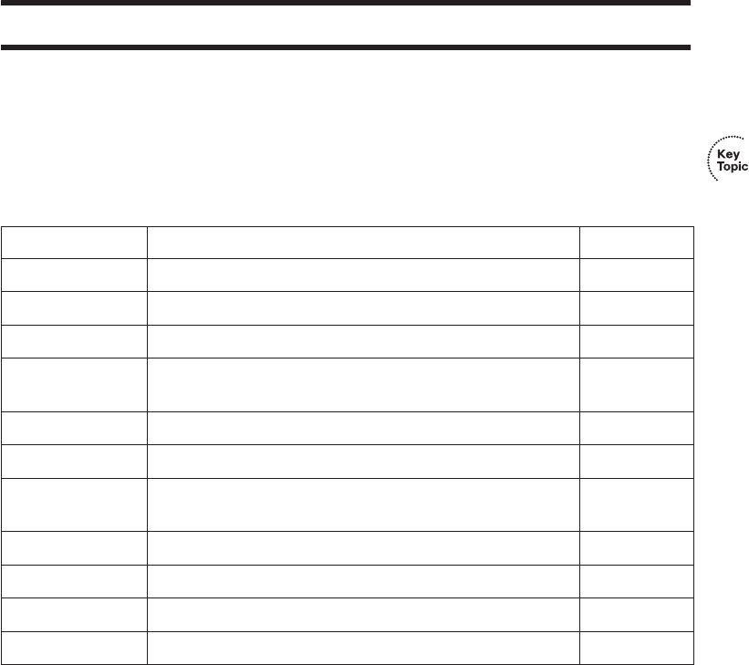
Review All the Key Topics 327
Exam Preparation Tasks
Review All the Key Topics
Review the most important topics from this chapter, noted with the key topics icon.
Table 11-11 lists these key topics and where each is discussed.
Complete the Tables and Lists from Memory
Print a copy of Appendix H, “Memory Tables” (found on the CD), or at least the section for
this chapter, and complete the tables and lists from memory. Appendix I, “Memory Tables
Answer Key,” also on the CD, includes completed tables and lists for you to check your work.
Definitions of Key Terms
Define the following key terms from this chapter and check your answers in the glossary:
802.11a, 802.11b, 802.11g, 802.11i, 802.11n, access point, ad hoc mode, Basic
Service Set (BSS), CSMA/CA, Direct Sequence Spread Spectrum, Extended Service
Set (ESS), Frequency Hopping Spread Spectrum, infrastructure mode, Orthogonal
Frequency Division Multiplexing, Service Set Identifier (SSID), Wi-Fi Alliance, Wi-Fi
Protected Access (WPA), wired equivalent privacy (WEP), WLAN client, WPA2
Table 11-11 Key Topics for Chapter 11
Key Topic Element Description Page Number
Table 11-2 WLAN standards organizations and their roles 304
Table 11-3 Comparison of 802.11a, 802.11b, and 802.11g 305
Table 11-4 WLAN modes, their formal names, and descriptions 307
Table 11-5 Unlicensed bands, their general names, and the list of
standards to use each band
309
Figure 11-6 DSSS frequencies, showing the three nonoverlapping channels 310
List WLAN configuration checklist 315
List Common WLAN installation problems related to the work
done in the site survey
319
List Other common WLAN installation problems 319
Table 11-8 Common WLAN security threats 321
Table 11-9 WLAN security standards 322
Table 11-10 Comparison of WLAN security standards 326
1828xbook.fm Page 327 Thursday, July 26, 2007 3:10 PM

Cisco Published ICND1 Exam Topics* Covered in This Part:
Describe the operation of data networks
■Use the OSI and TCP/IP models and their associated protocols to explain how data flows in a network
■Interpret network diagrams
■Determine the path between two hosts across a network
■Describe the components required for network and Internet communications
■Identify and correct common network problems at Layers 1, 2, 3, and 7 using a layered model approach
■Differentiate between LAN/WAN operation and features
Implement an IP addressing scheme and IP services to meet network requirements for a small branch office
■Describe the need and role of addressing in a network
■Create and apply an addressing scheme to a network
■Assign and verify valid IP addresses to hosts, servers, and networking devices in a LAN environment
■Describe and verify DNS operation
■Describe the operation and benefits of using private and public IP addressing
■Enable NAT for a small network with a single ISP and connection using SDM and verify operation
using CLI and ping
■Configure, verify, and troubleshoot DHCP and DNS operation on a router (including: CLI/SDM)
■Implement static and dynamic addressing services for hosts in a LAN environment
■Identify and correct IP addressing issues
Implement a small routed network
■Describe basic routing concepts (including: packet forwarding, router lookup process)
■Describe the operation of Cisco routers (including: router bootup process, POST, router components)
■Select the appropriate media, cables, ports, and connectors to connect routers to other network devices
and hosts
■Configure, verify, and troubleshoot RIPv2
■Access and utilize the router CLI to set basic parameters
■Connect, configure, and verify operation status of a device interface
■Verify device configuration and network connectivity using ping, traceroute, Telnet, SSH, or other utilities
■Perform and verify routing configuration tasks for a static or default route given specific routing
requirements
■Manage IOS configuration files (including: save, edit, upgrade, restore)
■Manage Cisco IOS
■Implement password and physical security
■Verify network status and router operation using basic utilities (including: ping, traceroute, Telnet,
SSH, ARP, ipconfig), show and debug commands
Identify security threats to a network and describe general methods to mitigate those threats
■Describe security recommended practices including initial steps to secure network devices
*Always recheck http://www.cisco.com for the latest posted exam topics.
1828xbook.fm Page 328 Thursday, July 26, 2007 3:10 PM

Part III: IP Routing
Chapter 12 IP Addressing and Subnetting
Chapter 13 Operating Cisco Routers
Chapter 14 Routing Protocol Concepts and Configuration
Chapter 15 Troubleshooting IP Routing
1828xbook.fm Page 329 Thursday, July 26, 2007 3:10 PM

This chapter covers the following subjects:
Exam Preparation Tools for Subnetting: This
section lists the various tools that can help you
practice your subnetting skills.
IP Addressing and Routing: This section
moves beyond the basic concepts in Chapter 5,
“Fundamentals of IP Addressing and Routing,”
introducing the purpose and meaning of the
subnet mask.
Math Operations Used When Subnetting:
This section explains how to convert between IP
address and subnet mask formats.
Analyzing and Choosing Subnet Masks: This
section explains the meaning behind subnet
masks, how to choose a subnet mask to meet
stated design goals, and how to interpret a mask
chosen by someone else.
Analyzing Existing Subnets: This section
shows how to determine an IP address’s resident
subnet, broadcast address, and range of addresses
in the subnet.
Design: Choosing the Subnets of a Classful
Network: This section explains how to find all
subnets of a single classful network.
1828xbook.fm Page 330 Thursday, July 26, 2007 3:10 PM

C H A P T E R12
IP Addressing and Subnetting
The concepts and application of IP addressing and subnetting may well be the most
important topics to understand both for being a well-prepared network engineer and for
being ready to do well on the ICND1, ICND2, and CCNA exams. To design a new network,
engineers must be able to begin with some IP address range and break it into subdivisions
called subnets, choosing the right size of each subnet to meet design requirements.
Engineers need to understand subnet masks, and how to pick the right masks to implement
the designs that were earlier drawn on paper. Even more often, engineers need to
understand, operate, and troubleshoot pre-existing networks, tasks that require mastery of
addressing and subnetting concepts and the ability to apply those concepts from a different
perspective than when designing the network.
This chapter begins Part III of the book, which is focused on the role of routers in an
internetwork. As introduced in Chapter 5, the network layer defines and uses addressing,
routing, and routing protocols to achieve its main goals. After this chapter goes into depth
on addressing, the rest of the chapters in Part III focus on how to implement IP addresses,
routing, and routing protocols inside Cisco routers.
All the topics in this chapter have a common goal, which is to help you understand IP
addressing and subnetting. To prepare you for both real jobs and the exams, this chapter
goes far beyond the concepts as covered on the exam, preparing you to apply these concepts
when designing a network and when you operate and troubleshoot a network. Additionally,
this chapter creates a structure from which you can repeatedly practice the math processes
used to get the answers to subnetting questions.
“Do I Know This Already?” Quiz
The “Do I Know This Already?” quiz allows you to assess if you should read the entire
chapter. If you miss no more than one of these 14 self-assessment questions, you might
want to move ahead to the “Exam Preparation Tasks” section. Table 12-1 lists the major
headings in this chapter and the “Do I Know This Already?” quiz questions covering the
material in those headings so you can assess your knowledge of these specific areas. The
answers to the “Do I Know This Already?” quiz appear in Appendix A.
1828xbook.fm Page 331 Thursday, July 26, 2007 3:10 PM

332 Chapter 12: IP Addressing and Subnetting
1. Which of the following are private IP networks?
a. 172.31.0.0
b. 172.32.0.0
c. 192.168.255.0
d. 192.1.168.0
e. 11.0.0.0
2. Which of the following is the result of a Boolean AND between IP address
150.150.4.100 and mask 255.255.192.0?
a. 1001 0110 1001 0110 0000 0100 0110 0100
b. 1001 0110 1001 0110 0000 0000 0000 0000
c. 1001 0110 1001 0110 0000 0100 0000 0000
d. 1001 0110 0000 0000 0000 0000 0000 0000
3. Which of the following shows the equivalent of subnet mask 255.255.248.0, but in
prefix notation?
a. /248
b. /24
c. /28
d. /21
e. /20
f. /23
Table 12-1 “Do I Know This Already?” Foundation Topics Section-to-Question Mapping
Foundation Topics Section Questions
Exam Preparation Tools for Subnetting None
IP Addressing and Routing 1
Math Operations Used When Subnetting 2, 3
Analyzing and Choosing Subnet Masks 4–8
Analyzing Existing Subnets 9–12
Design: Choosing the Subnets of a Classful Network 13, 14
1828xbook.fm Page 332 Thursday, July 26, 2007 3:10 PM
“Do I Know This Already?” Quiz 333
4. If mask 255.255.255.128 were used with a Class B network, how many subnets could
exist, with how many hosts per subnet, respectively?
a. 256 and 256
b. 254 and 254
c. 62 and 1022
d. 1022 and 62
e. 512 and 126
f. 126 and 510
5. A Class B network needs to be subnetted such that it supports 100 subnets and 100
hosts/subnet. For this design, if multiple masks meet those design requirements, the
engineer should choose the mask that maximizes the number of hosts per subnet.
Which of the following masks meets the design criteria?
a. 255.255.255.0
b. /23
c. /26
d. 255.255.252.0
6. If mask 255.255.255.240 were used with a Class C network, how many subnets could
exist, with how many hosts per subnet, respectively?
a. 16 and 16
b. 14 and 14
c. 16 and 14
d. 8 and 32
e. 32 and 8
f. 6 and 30
7. Which of the following subnet masks lets a Class B network have up to 150 hosts per
subnet, and supports 164 subnets?
a. 255.0.0.0
b. 255.255.0.0
c. 255.255.255.0
d. 255.255.192.0
e. 255.255.240.0
f. 255.255.252.0
1828xbook.fm Page 333 Thursday, July 26, 2007 3:10 PM
334 Chapter 12: IP Addressing and Subnetting
8. Which of the following subnet masks let a Class A network have up to 150 hosts per
subnet and supports 164 subnets?
a. 255.0.0.0
b. 255.255.0.0
c. 255.255.255.0
d. 255.255.192.0
e. 255.255.252.0
f. 255.255.255.192
9. Which of the following IP addresses are not in the same subnet as 190.4.80.80, mask
255.255.255.0?
a. 190.4.80.1
b. 190.4.80.50
c. 190.4.80.100
d. 190.4.80.200
e. 190.4.90.1
f. 10.1.1.1
10. Which of the following IP addresses is not in the same subnet as 190.4.80.80, mask
255.255.240.0?
a. 190.4.80.1
b. 190.4.80.50
c. 190.4.80.100
d. 190.4.80.200
e. 190.4.90.1
f. 10.1.1.1
11. Which of the following IP addresses are not in the same subnet as 190.4.80.80/25?
a. 190.4.80.1
b. 190.4.80.50
c. 190.4.80.100
d. 190.4.80.200
e. 190.4.90.1
f. 10.1.1.1
1828xbook.fm Page 334 Thursday, July 26, 2007 3:10 PM
“Do I Know This Already?” Quiz 335
12. Each of the following answers lists a dotted decimal number and a subnet mask. The
dotted decimal number might be a valid IP address that can be used by a host or it might
be a subnet number or broadcast address. Which of the answers show an address that
can be used by a host?
a. 10.0.0.0, 255.0.0.0
b. 192.168.5.160, 255.255.255.192
c. 172.27.27.27, 255.255.255.252
d. 172.20.49.0, 255.255.254.0
13. Which of the following are valid subnet numbers in network 180.1.0.0 when using
mask 255.255.248.0?
a. 180.1.2.0
b. 180.1.4.0
c. 180.1.8.0
d. 180.1.16.0
e. 180.1.32.0
f. 180.1.40.0
14. Which of the following are not valid subnet numbers in network 180.1.0.0 when using
mask 255.255.255.0?
a. 180.2.2.0
b. 180.1.4.0
c. 180.1.8.0
d. 180.1.16.0
e. 180.1.32.0
f. 180.1.40.0
1828xbook.fm Page 335 Thursday, July 26, 2007 3:10 PM

336 Chapter 12: IP Addressing and Subnetting
Foundation Topics
This chapter is fundamentally different from the other chapters in this book. Like the other
chapters, this chapter explains a related set of concepts—in this case, the concepts, thought
processes, and math used to attack IP addressing and subnetting questions on the CCNA
exams. However, more so than for any other chapter in this book, you must practice the
concepts and math in this chapter before you take the exam(s). It is very much like math
classes in school—if you do not do the homework, you probably will not do as well on
the test.
This chapter begins with a few comments about how to prepare for subnetting questions on
the exam. Then the chapter spends a few pages reviewing what has been covered already in
regard to IP addressing and routing, two topics that are tightly linked. The rest of the major
sections of the chapter tackle a particular type of subnetting question in depth, with each
section ending with a list of suggested steps to take to practice your subnetting skills.
Exam Preparation Tools for Subnetting
To help you prepare for the exam, this chapter explains the subnetting concepts and shows
multiple examples. Each section also lists the specific steps required to solve a particular
type of problem. Often, two sets of steps are provided, one that uses binary math, and
another that uses only decimal math.
More so than for any other single chapter in this book, you should also practice and review
the topics in this chapter until you have mastered the concepts. To that end, this book
includes several tools, some of which are located on the CD-ROM that comes with this
book, in addition to this chapter:
■Appendix D, “Subnetting Practice”: This large appendix lists numerous practice
problems, with solutions that show how to use the processes explained in this chapter.
■Appendix E, “Subnetting Reference Pages”: This short appendix includes a few
handy references, including a 1-page summary of each of the subnetting processes
listed in this chapter.
■Subnetting videos (DVD): Several of the most important subnetting processes
described in this chapter are explained in videos on the DVD in the back of this book.
The goal of these videos is to ensure that you understand these key processes
completely, and hopefully move you quickly to the point of mastering the process.
■Cisco Binary Game at the Cisco CCNA Prep Center: If you want to use the
processes that use binary math, you can use the Cisco Binary Game to practice your
1828xbook.fm Page 336 Thursday, July 26, 2007 3:10 PM
Exam Preparation Tools for Subnetting 337
binary-to-decimal and decimal-to-binary conversion accuracy and speed. The CCNA
Prep Center is at http://www.cisco.com/go/prepcenter. The binary game is also
included on the CD in the back of the book.
■Subnetting Game at the Cisco CCNA Prep Center: As of the time of writing this
chapter, the CCNA Prep Center had a Beta version of the Subnetting Game available.
The game requires that you choose a mask, pick subnets, calculate the subnet number
and broadcast address of the subnets, and assign IP addresses in the subnets.
■Subnetting calculators: You can make up your own practice problems, and use a
subnetting calculator to find the answers to check your work. This allows you to have
unlimited amounts of practice to get better and get faster. The CCNA Prep Center also
has the Cisco Subnet Calculator for free download.
■Glossary: The topics of IP addressing and subnetting use a wide variety of
terminology. The glossary in the back of this book includes the subnetting terms used
in this book.
Suggested Subnetting Preparation Plan
Over the years, some readers have asked for a suggested subnetting study plan. At the same
time, the CCNA exam questions have been getting more difficult. To help you better
prepare, the following list outlines a suggested study plan:
Step 1 If you have not done so already, load the CD-ROM and get familiar with its user
interface, install the exam engine software, and verify that you can find the tools
listed in the preceding list. You may want to go ahead and print Appendix E, and
if you expect you will want to use a printed version of Appendix D, print that as
well (be warned, Appendix D is almost 100 pages in length).
Step 2 Keep reading this chapter through the end of the second major section,
“IP Addressing and Routing.”
Step 3 For each subsequent major section, read the section and then follow the
instructions in the subsection “Practice Suggestions.” This short part of
each major section points you to the items that would be of the most help
to stop and practice at that point. These suggestions include the use of the
tools listed earlier. The following major sections include a “Practice
Suggestions” subsection:
• Math Operations Used When Subnetting
• Analyzing and Choosing Subnet Masks
• Analyzing Existing Subnets
• Design: Choosing the Subnets of a Classful Network
1828xbook.fm Page 337 Thursday, July 26, 2007 3:10 PM
338 Chapter 12: IP Addressing and Subnetting
Step 4 When finished with the chapter, if you feel the need for more practice,
make up your own practice problems, and check your answers using a
subnet calculator (more information is provided after this list). I
recommend the Cisco Subnet Calculator because its user interface
displays the information in a convenient format for doing extra questions.
Step 5 At any point in your study, feel free to visit the CCNA Prep Center
(http://www.cisco.com/go/prepcenter) to use both the Cisco Binary
Game and the Subnetting Game. Both help you build skills for doing
subnetting problems. (The CCNA Prep Center requires you to log in with
a Cisco.com User ID; if you do not have one, the preceding URL has a
link to Cisco.com registration.) Once in the CCNA Prep Center, you can
find the games under the Additional Information tab.
You can certainly deviate from this plan to suit your personal preferences, but at the end of
this process, you should be able to confidently answer straightforward subnetting questions,
such as those in Appendix D. In fact, you should be able to answer in 10–12 seconds a
straightforward question such as, “In what subnet does IP address 10.143.254.17, with
mask 255.255.224.0, reside?” That is a subjective time period, based on my experience
teaching classes, but the point is that you need to understand it all, and practice to the point
of being pretty fast.
However, perfecting your subnetting math skills is not enough. The exams ask questions
that require you to prove you have the skills to attack real-life problems, problems such as
how to design an IP network by subnetting a classful network, how to determine all the
subnets of a classful network, and how to pick subnets to use in an internetwork design. The
wording of the exam problems, in some cases, is similar to that of the math word problems
back in school—many people have trouble translating the written words into a math
problem that can be worked. Likewise, the exam questions may well present a scenario, and
then leave it to you to figure out what subnetting math is required to find the answer.
To prepare for these skills-based questions, Chapter 15, “Troubleshooting IP Routing,”
covers a wide variety of topics that help you analyze a network to solve subnetting-related
problems. These extra tips help you sift through the wording in problems, and tell you how
to approach the problems, so that you can then find the answers. So, in addition to this
chapter, read through Chapter 15 as well, which includes coverage of tips for
troubleshooting IP addressing problems.
More Practice Using a Subnet Calculator
If you want even more practice, you can essentially get unlimited practice using a subnet
calculator. For the purpose of CCNA study, I particularly like the Cisco Subnet Calculator,
which can be downloaded from the Cisco CCNA Prep Center. You can then make up your
1828xbook.fm Page 338 Thursday, July 26, 2007 3:10 PM

IP Addressing and Routing 339
own problems like those found in this chapter, work the problem, and then check your work
using the calculator.
For example, you could pick an IP network and mask. Then, you could find all subnets of
that network, using that single mask. To check your work, you could type in the network
number and mask in the Cisco Subnet Calculator, and click the Subnets/hosts tab, which
then displays all the subnet numbers, from which you can check your answers. As another
example, you could pick an IP address and mask, try to find the subnet number, broadcast
address, and range of addresses, and then check your work with the calculator using the
Subnet tab. After you have typed the IP address and mask, this tab displays the subnet
number, broadcast address, and range of usable addresses. And yet another example: You
can even choose an IP address and mask, and try to find the number of network, subnet, and
host bits—and again check your work with the calculator. In this case, the calculator even
uses the same format as this chapter to represent the mask, with N, S, and H for the network,
subnet, and host parts of the address.
Now that you have a study plan, the next section briefly reviews the core IP addressing and
routing concepts covered previously in Chapter 5. Following that, four major sections
describe the various details of IP addressing and subnetting.
IP Addressing and Routing
This section primarily reviews the addressing and routing concepts found in earlier chapters
of this book, particularly in Chapter 5. It also briefly introduces IP Version 6 (IPv6)
addressing and the concept of private IP networks.
IP Addressing Review
The vast majority of IP networks today use a version of the IP protocol called IP Version 4
(IPv4). Rather than refer to it as IPv4, most texts, this one included, simply refer to it as IP.
This section reviews IPv4 addressing concepts as introduced in Chapter 5.
Many different Class A, B, and C networks exist. Table 12-2 summarizes the possible
network numbers, the total number of each type, and the number of hosts in each Class A,
B, and C network.
NOTE In Table 12-2, the “Valid Network Numbers” row shows actual network
numbers. There are several reserved cases. For example, network 0.0.0.0 (originally
defined for use as a broadcast address) and network 127.0.0.0 (still available for use as
the loopback address) are reserved.
1828xbook.fm Page 339 Thursday, July 26, 2007 3:10 PM
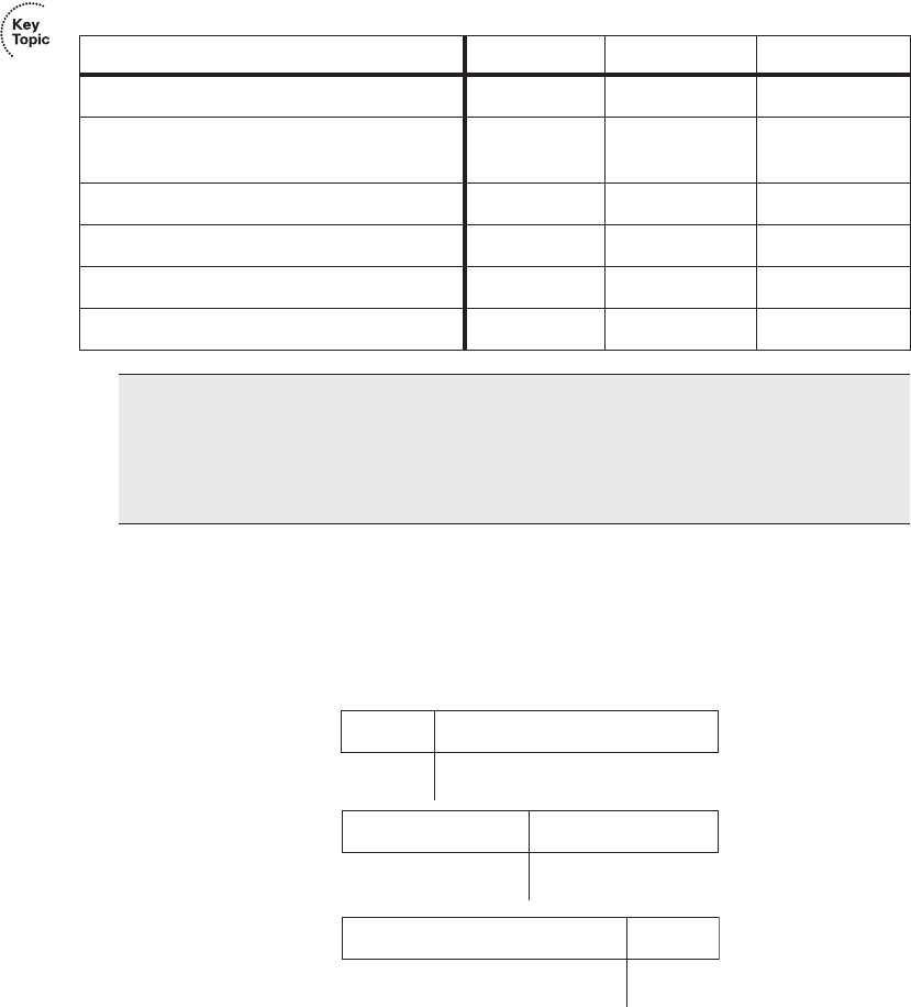
340 Chapter 12: IP Addressing and Subnetting
Figure 12-1 shows the structure of three IP addresses, each from a different network, when
no subnetting is used. One address is in a Class A network, one is in a Class B network, and
one is in a Class C network.
Figure 12-1 Class A, B, and C IP Addresses and Their Formats
By definition, an IP address that begins with 8 in the first octet is in a Class A network, so
the network part of the address is the first byte, or first octet. An address that begins
with 130 is in a Class B network. By definition, Class B addresses have a 2-byte network
part, as shown. Finally, any address that begins with 199 is in a Class C network, which has
Table 12-2 List of All Possible Valid Network Numbers
Class A Class B Class C
First Octet Range 1 to 126 128 to 191 192 to 223
Valid Network Numbers 1.0.0.0 to
126.0.0.0
128.0.0.0 to
191.255.0.0
192.0.0.0 to
223.255.255.0
Number of Networks in This Class 27 – 2 214 2
21
Number of Hosts Per Network 224 – 2 216 – 2 28 – 2
Size of Network Part of Address (Bytes) 12 3
Size of Host Part of Address (Bytes) 32 1
NOTE This chapter uses the term network to refer to a classful network—in other
words, a Class A, B, or C network. This chapter also uses the term subnet to refer to
smaller parts of a classful network. However, note that many people use these terms more
loosely, interchanging the words network and subnet, which is fine for general
conversation, but can be problematic when trying to be exact.
Class A
Class B
Class C
Network
(8) Host (24)
Network (16) Host (16)
Network (24)
100 .1
130 .4.
199 .1 .1.1
Host (8)
81 .4.5
.
1828xbook.fm Page 340 Thursday, July 26, 2007 3:10 PM

IP Addressing and Routing 341
a 3-byte network part. Also by definition, a Class A address has a 3-byte host part, Class B
has a 2-byte host part, and Class C has a 1-byte host part.
Humans can simply remember the numbers in Table 12-2 and the concepts in Figure 12-1
and then quickly determine the network and host parts of an IP address. Computers,
however, use a mask to define the size of the network and the host parts of an address. The
logic behind the mask results in the same conventions of Class A, B, and C networks that
you already know, but the computer can deal with it better as a binary math problem.
The mask is a 32-bit binary number, usually written in dotted decimal format. The purpose
of the mask is to define the structure of an IP address. In short, the mask defines the size
of the host part of an IP address, representing the host part of the IP address with binary 0s
in the mask. The first part of the mask contains binary 1s, which represents the network
part of the addresses (if no subnetting is used), or both the network and subnet parts of the
addresses (if subnetting is used).
When subnetting is not used, each class of IP address uses the default mask for that class.
For example, the default Class A mask ends with 24 bits of binary 0s, which means that
the last three octets of the mask are 0s, representing the 3-byte host part of Class A
addresses. Table 12-3 summarizes the default masks and reflects the sizes of the two parts
of an IP address.
Public and Private Addressing
The ICANN (formerly IANA) and its member organizations manage the process of
assigning IP network numbers, or even smaller ranges of IP addresses, to companies that
want to connect to the Internet. After a company is assigned a range of IP addresses, only
that company can use that range. Additionally, the routers in the Internet can then learn
routes to reach these networks, so that everyone in the entire Internet can forward packets
to that IP network. Because these IP addresses can be reached by packets in the public
Internet, these networks are often called public networks, and the addresses in these
networks are called public addresses.
Table 12-3 Class A, B, and C Networks: Network and Host Parts and Default Masks
Class of
Address
Size of Network Part of
Address in Bits
Size of Host Part of
Address in Bits
Default Mask for Each
Class of Network
A8 24 255.0.0.0
B1616 255.255.0.0
C248255.255.255.0
1828xbook.fm Page 341 Thursday, July 26, 2007 3:10 PM

342 Chapter 12: IP Addressing and Subnetting
Some computers will never be connected to the Internet. So, engineers building a network
consisting of only such computers could use IP addresses that are duplicates of registered
public IP addresses in the Internet. So, when designing the IP addressing convention for
such a network, an organization could pick and use any network number(s) that it wanted,
and all would be well. For instance, you can buy a few routers, connect them together in
your office, and configure IP addresses in network 1.0.0.0 and make it work, even though
some company also uses Class A network 1 as its registered public IP network. The IP
addresses that you use might be duplicates of real IP addresses in the Internet, but if all you
want to do is learn on the lab in your office, all is well.
However, using the same IP addresses used by another company is unnecessary in this
situation, because TCP/IP RFC 1918 defines a set of private networks that can be used for
internetworks that do not connect to the Internet. More importantly, this set of private
networks will never be assigned by ICANN to any organization for use as registered public
network numbers. So, when building a private network, like one in a lab, you can use
numbers in a range that is not used by anyone in the public Internet. Table 12-4 shows the
private address space defined by RFC 1918.
In other words, any organization can use these network numbers. However, no organization
is allowed to advertise these networks using a routing protocol on the Internet.
Many of you might be wondering, “Why bother reserving special private network numbers
when it does not matter whether the addresses are duplicates?” Well, as it turns out, private
networks can be used inside a company and that company can still connect to the Internet
today, using a function called Network Address Translation (NAT). Chapter 16, “WAN
Concepts,” and Chapter 17, “WAN Configuration,” expand on the concepts of NAT and
private addressing, and how the two work together.
IP Version 6 Addressing
IPv6 defines many improvements over IPv4. However, the primary goal of IPv6 is to
significantly increase the number of available IP addresses. To that end, IPv6 uses a 128-bit
IP address, rather than the 32 bits defined by IPv4. To appreciate the size of the address
structure, a 128-bit address structure provides well over 1038 possible IP addresses. If you
Table 12-4 RFC 1918 Private Address Space
Private IP Networks Class of Networks Number of Networks
10.0.0.0 through 10.0.0.0 A 1
172.16.0.0 through 172.31.0.0 B 16
192.168.0.0 through 192.168.255.0 C 256
1828xbook.fm Page 342 Thursday, July 26, 2007 3:10 PM

IP Addressing and Routing 343
consider the fact that the Earth currently has less than 1010 people, you can see that you
could have literally billions, trillions, or gazillions of IP addresses per person and still not
run out.
IPv6 has been defined since the mid-1990s, but the migration from IPv4 to IPv6 has been
rather slow. IPv6 was created to solve an overcrowding problem in the IPv4 address space.
Some other short-term solutions in IPv4 (notably, NAT, as covered in Chapter 16) helped
relieve the IPv4 overcrowding. However, in 2007, IPv6 deployment has started to quicken.
Many large service providers have migrated to IPv6 to support the large number of mobile
devices that can connect to the Internet, and the U.S. government has mandated migration
to IPv6 for its member agencies.
The 128-bit IPv6 address is written in hexadecimal notation, with colons between each
quartet of symbols. Even in hexadecimal, the addresses can be long. However, IPv6 also
allows for abbreviations, as is shown in Table 12-5. The table also summarizes some of the
pertinent information comparing IPv4 addresses with IPv6.
IP Subnetting Review
IP subnetting creates larger numbers of smaller groups of IP addresses compared with
simply using Class A, B, and C conventions. You can still think about the Class A, B, and
C rules, but now a single Class A, B, or C network can be subdivided into many smaller
groups. Subnetting treats a subdivision of a single Class A, B, or C network as if it were a
network itself. By doing so, a single Class A, B, or C network can be subdivided into many
nonoverlapping subnets.
NOTE In case you are wondering, IP Version 5 was defined for experimental reasons
but was never deployed. To avoid confusion, the next attempt to update the IP protocol
was named IPv6.
Table 12-5 IPv4 Versus IPv6
Feature IPv4 IPv6
Size of address (bits or bytes
per octets)
32 bits, 4 octets 128 bits, 16 octets
Example address 10.1.1.1 0000:0000:0000:0000:FFFF:FFFF:0A01:0101
Same address, abbreviated — ::FFFF:FFFF:0A01:0101
Number of possible addresses,
ignoring reserved values
232, (roughly 4
billion)
2128, or roughly 3.4 × 1038
1828xbook.fm Page 343 Thursday, July 26, 2007 3:10 PM
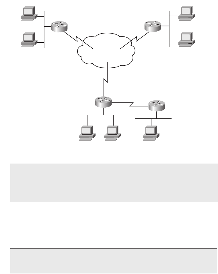
344 Chapter 12: IP Addressing and Subnetting
Figure 12-2 shows a reminder of the basics of how to subnet a classful network, using the
same internetwork shown in Figure 5-6 in Chapter 5. This figure shows Class B network
150.150.0.0, with a need for six subnets.
Figure 12-2 Same Network Topology Using One IP Network with Six Subnets
This design subnets Class B network 150.150.0.0. The IP network designer has chosen a
mask of 255.255.255.0, the last octet of which implies 8 host bits. Because it is a Class B
network, there are 16 network bits. Therefore, there are 8 subnet bits, which happen to be
bits 17 through 24—in other words, the third octet.
NOTE The term network might be used to refer to a Class A, B, or C IP network, or
might be used to simply refer to a collection of switches, routers, cables, and end-user
devices. To avoid confusion, this chapter uses the term internetwork to refer to the
collection of networking devices (internetwork meaning “interconnected networks”), and
the term network specifically for a Class A, B, or C IP network.
NOTE Note that the next major section explains the use and purpose of subnet masks,
so do not be concerned at this point if the analysis in this paragraph does not yet make
sense.
Frame Relay
150.150.5.0
150.150.1.0
S0/0
150.150.4.0
150.150.5.3
150.150.6.0
150.150.2.0
Ray
150.150.1.1
Kris
150.150.4.2
Wendell
150.150.4.1
Fay
150.150.1.2
Hannah
150.150.2.1
Jessie
150.150.2.2
AB
CD
150.150.3.0
Vinnie
150.150.3.1
1828xbook.fm Page 344 Thursday, July 26, 2007 3:10 PM

IP Addressing and Routing 345
The network parts (the first two octets in this example) all begin with 150.150, meaning that
each of the six subnets is a subnet of Class B network 150.150.0.0.
With subnetting, the third part of an IP address—namely, the subnet part—appears in the
middle of the address. This field is created by “stealing” or “borrowing” bits from the host
part of the address. The size of the network part of the address never shrinks. In other words,
Class A, B, and C rules still apply when you define the size of the network part of an
address. However, the host part of the address shrinks to make room for the subnet part of
the address. Figure 12-3 shows the format of addresses when subnetting is used.
Figure 12-3 Address Formats When Subnetting Is Used
IP Routing Review
IP routing and IP addressing were designed with each other in mind. IP routing presumes
the structure of IP subnetting, in which ranges of consecutive IP addresses reside in a single
subnet. IP addressing RFCs define subnetting so that consecutively numbered IP addresses
can be represented as a subnet number (subnet address) and a subnet mask. This allows
routers to succinctly list subnets in their routing tables.
Routers need a good way to list the subnet number in their routing tables. This information
must somehow imply the IP addresses in the subnet. For example, the subnet at the bottom
of figure 12-2, which contains host Kris, can be described as follows:
All IP addresses that begin with 150.150.4; more specifically, the numbers 150.150.4.0
through 150.150.4.255.
Although true, the preceding statement is not very succinct. Instead, a router’s routing table
would list the subnet number and subnet mask as follows:
150.150.4.0, 255.255.255.0
The subnet number and mask together means the same thing as the earlier long text
statement, but just using numbers. This chapter explains how to examine a subnet number
and mask and figure out the range of consecutive IP addresses that comprises the subnet.
Network Host Class A
8x
Subnet
24 – x
Network Host Class B
16
Subnet
16 – x x
HostNetwork Class C
x
Subnet
8 – x24
1828xbook.fm Page 345 Thursday, July 26, 2007 3:10 PM
346 Chapter 12: IP Addressing and Subnetting
One reason you need to be able to figure out the range of addresses in a subnet is to
understand, analyze, and troubleshoot routing problems. To see why, again consider router
A’s route for subnet 150.150.4.0, 255.255.255.0 in Figure 12-2. Each route in a router’s
routing table lists the destination (a subnet number and mask), plus instructions on how the
router should forward packets to that subnet. The forwarding instructions typically include
the IP address of the next router to which the packet should be forwarded, and the local
router’s interface to use when forwarding the packet. For example, router A’s route to that
subnet would look like the information in Table 12-6.
Now, to see how this information is related to subnetting, consider a packet sent by Ray to
Kris (150.150.4.2). Ray sends the packet to router A because Ray knows that 150.150.4.2
is in a different subnet, and Ray knows that router A is Ray’s default gateway. Once
router A has the packet, it compares the destination IP address (150.150.4.2) to A’s routing
table. Router A typically will not find the address 150.150.4.2 in the routing table—instead,
the router has a list of subnets (subnet numbers and corresponding subnet masks), like the
route listed in Table 12-6. So, the router must ask itself the following:
Of the subnets in my routing table, which subnet’s range of IP addresses includes the
destination IP address of this packet?
In other words, the router must match the packet’s destination address to the correct subnet.
In this case, the subnet listed in Table 12-6 includes all addresses that begin with 150.150.4,
so the packet destined to Kris (150.150.4.2) matches the route. In this case, router A
forwards the packet to router C (150.150.5.3), with router A using its S0/0 interface to
forward the packet.
This chapter explains many features of IP addressing and subnetting, as an end to itself. The
next section focuses on some basic math tools. The section following that, “Analyzing and
Choosing Subnet Masks,” examines the meaning of the subnet mask and how it represents
the structure of an IP address—both from a design perspective and the perspective of
analyzing an existing internetwork. Following that, the next section, “Analyzing Existing
Table 12-6 Routing Table Entry in Router A
Subnet and Mask Next-hop Router Outgoing Interface
150.150.4.0, 255.255.255.0 150.150.5.3 S0/0
NOTE The exams might expect you to apply this knowledge to solve a routing problem.
For example, you might be asked to determine why PC1 cannot ping PC2, and the
problem is that the second of three routers between PC1 and PC2 does not have a route
that matches the destination IP address of PC2.
1828xbook.fm Page 346 Thursday, July 26, 2007 3:10 PM

Math Operations Used When Subnetting 347
Subnets,” explains the processes by which you can analyze an existing IP internetwork, and
find the subnet numbers, broadcast addresses, and range of IP addresses in each subnet.
Finally, the last section, “Design: Choosing the Subnets of a Classful Network,” explains
how to go about designing a subnetting scheme for a Class A, B, or C network, including
how to find all possible subnets.
Math Operations Used When Subnetting
Computers, especially routers, think about IP addresses in terms of 32-bit binary numbers.
This is fine, because technically that is what IP addresses are. Also, computers use a subnet
mask to define the structure of these binary IP addresses. Acquiring a full understanding of
what this means is not too difficult with a little reading and practice. However, getting
accustomed to doing the binary math in your head can be challenging, particularly if you
do not do it every day.
In this section, you will read about three key math operations that will be used throughout
the discussion of answering CCNA addressing and subnetting questions:
■Converting IP addresses and masks from binary to decimal, and decimal to binary
■Performing a binary math operation called a Boolean AND
■Converting between two formats for subnet masks: dotted decimal and prefix notation
Converting IP Addresses and Masks from Decimal to Binary
and Back Again
If you already know how binary works, how binary-to-decimal and decimal-to-binary
conversion work, and how to convert IP addresses and masks from decimal to binary and
back, skip to the next section, “Performing a Boolean AND Operation.”
IP addresses are 32-bit binary numbers written as a series of decimal numbers separated by
periods (called dotted decimal format). To examine an address in its true form, binary, you
need to convert from decimal to binary. To put a 32-bit binary number in the decimal form
that is needed when configuring a router, you need to convert the 32-bit number back to
decimal 8 bits at a time.
NOTE This chapter includes many summarized processes of how to do some work with
IP addresses and subnets. There is no need to memorize the processes. Most people find
that after practicing the processes sufficiently to get good and fast enough to do well on
the exams, they internalize and memorize the important steps as a side effect of the
practice.
1828xbook.fm Page 347 Thursday, July 26, 2007 3:10 PM

348 Chapter 12: IP Addressing and Subnetting
One key to the conversion process for IP addresses is remembering these facts:
When you convert from one format to the other, each decimal number represents 8 bits.
When you convert from decimal to binary, each decimal number converts to an 8-bit
number.
When you convert from binary to decimal, each set of 8 consecutive bits converts to
one decimal number.
Consider the conversion of IP address 150.150.2.1 to binary. The number 150, when
converted to its 8-bit binary equivalent, is 10010110. (You can refer to the conversion chart
in Appendix B, “Decimal to Binary Conversion Table,” to easily convert the numbers.) The
next byte, another decimal 150, is converted to 10010110. The third byte, decimal 2, is
converted to 00000010. Finally, the fourth byte, decimal 1, is converted to 00000001. The
combined series of 8-bit numbers is the 32-bit IP address—in this case, 10010110
10010110 00000010 00000001.
If you start with the binary version of the IP address, you first separate it into four sets of
eight digits. Then you convert each set of eight binary digits to its decimal equivalent. For
example, writing an IP address as follows is correct, but not very useful:
10010110100101100000001000000001
To convert this number to a more-convenient decimal form, first separate it into four sets of
eight digits:
10010110 10010110 00000010 00000001
Then look in the conversion chart in Appendix B. You see that the first 8-bit number
converts to 150, and so does the second. The third set of 8 bits converts to 2, and the fourth
converts to 1, giving you 150.150.2.1.
Using the chart in Appendix B makes this much easier, but you will not have the chart at
the exam, of course! So, you have two main options. First, you can learn and practice how
to do the conversion. This may not be as hard as it might seem at first, particularly if you
are willing to practice. The Cisco CCNA Prep Center has a Binary Game that helps you
practice the conversions, and its very effective. The second option is to use the decimal-
math-only processes listed in this chapter, which removes the need to be good at doing the
conversions. However, you do not need to decide right now whether to get really good at
doing the conversions—keep reading, understand both methods, and then pick which way
works best for you.
1828xbook.fm Page 348 Thursday, July 26, 2007 3:10 PM
Math Operations Used When Subnetting 349
Keep in mind that with subnetting, the subnet and host parts of the address might span only
part of a byte of the IP address. But when you convert from binary to decimal and decimal
to binary, the rule of always converting an 8-bit binary number to a decimal number is
always true. However, when thinking about subnetting, you need to ignore byte boundaries
and think of IP addresses as 32-bit numbers without specific byte boundaries. This is
explained more in the section “Finding the Subnet Number: Binary.”
Here are some websites that might help you if you want more information:
■For a description of the conversion process, try http://doit.ort.org/course/inforep/135.htm.
■For another, try http://www.wikihow.com/Convert-from-Binary-to-Decimal and
http://www.wikihow.com/Convert-from-Decimal-to-Binary.
■To practice the conversions, use the Cisco Binary Game at the CCNA Prep Center
(http://www.cisco.com/go/prepcenter).
Performing a Boolean AND Operation
George Boole, a mathematician who lived in the 1800s, created a branch of mathematics
that came to be called Boolean math after its creator. Boolean math has many applications
in computing theory. In fact, you can find subnet numbers given an IP address and subnet
mask using a Boolean AND.
A Boolean AND is a math operation performed on a pair of one-digit binary numbers. The
result is another one-digit binary number. The actual math is even simpler than those first
two sentences! The following list shows the four possible inputs to a Boolean AND, and the
result:
■0 AND 0 yields a 0
■0 AND 1 yields a 0
■1 AND 0 yields a 0
■1 AND 1 yields a 1
In other words, the input to the equation consists of two one-digit binary numbers, and the
output of the equation is one single-digit binary number. The only time the result is a binary
1 is when both input numbers are also binary 1; otherwise, the result of a Boolean AND
operation is a 0.
You can perform a Boolean AND operation on longer binary numbers, but you are really
just performing an AND operation on each pair of numbers. For instance, if you wanted to
1828xbook.fm Page 349 Thursday, July 26, 2007 3:10 PM

350 Chapter 12: IP Addressing and Subnetting
AND together two four-digit numbers, 0110 and 0011, you would perform an AND on the
first digit of each number and write down the answer. Then you would perform an AND
operation on the second digit of each number, and so on, through the four digits. Table 12-7
shows the general idea.
This table separates the four digits of each original number to make the point more obvious.
Look at the “First Digit” column. The first digit of the first number is 0, and the first digit
of the second number is also 0. 0 AND 0 yields a binary 0, which is listed as the Boolean
AND operation result in that same column. Similarly, the second digits of the two original
numbers are 1 and 0, respectively, so the Boolean AND operation result in the “Second
Digit” column shows a 0. For the third digit, the two original numbers’ third digits are 1
and 1, so the AND result this time shows a binary 1. Finally, the fourth digits of the two
original numbers are 0 and 1, so the Boolean AND result is 0 for that column.
When you Boolean AND together two longer binary numbers, you perform what is called
a bitwise Boolean AND. This term simply means that you do what the previous example
shows: you AND together the first digits from each of the two original numbers, and then
the second digits, and then the third, and so on, until each pair of single-digit binary
numbers has been ANDed.
IP subnetting math frequently uses a Boolean AND operation between two 32-bit binary
numbers. The actual operation works just like the example in Table 12-7, except it is 32 bits
long.
To discover the subnet number in which a particular IP address resides, you perform a
bitwise AND operation between the IP address and the subnet mask. Although humans can
sometimes look at an IP address and mask in decimal and derive the subnet number, routers
and other computers use a bitwise Boolean AND operation between the IP address and the
subnet mask to find the subnet number, so you need to understand this process. In this
chapter, you will also read about a process by which you can find the subnet number
without using binary conversion or Boolean ANDs. Table 12-8 shows an example of the
derivation of a subnet number.
Table 12-7 Bitwise Boolean AND Between Two Four-Digit Numbers
Four-Digit
Binary First Digit
Second
Digit Third Digit
Fourth
Digit
First Number 0110 0110
Second Number 0011 0011
Boolean AND Result 0010 0010
1828xbook.fm Page 350 Thursday, July 26, 2007 3:10 PM
Math Operations Used When Subnetting 351
First, focus only on the third column of the table. The binary version of the IP address
150.150.2.1 is listed first. The next row shows the 32-bit binary version of the subnet mask
(255.255.255.0). The last row shows the results of a bitwise AND of the two numbers. In
other words, the first bit in each number is ANDed, and then the second bit in each number,
and then the third, and so on, until all 32 bits in the first number have been ANDed with the
bit in the same position in the second number.
The resulting 32-bit number is the subnet number in which 150.150.2.1 resides. All you
have to do is convert the 32-bit number back to decimal 8 bits at a time. The subnet number
in this case is 150.150.2.0.
While this process may seem long, and make you want to avoid converting all these
numbers, do not worry. By the end of this chapter you will see how that, even using binary,
you can use a small shortcut so that you only have to convert one octet to binary and back
in order to find the subnet. For now, just be aware of the conversion table in Appendix B,
and remember the Boolean AND process.
Prefix Notation/CIDR Notation
Subnet masks are actually 32-bit numbers, but for convenience, they are typically written
as dotted decimal numbers—for example, 255.255.0.0. However, another way to represent
a mask, called prefix notation, and sometimes referred to as CIDR notation, provides an
even more succinct way to write, type, or speak the value of a subnet mask. To understand
prefix notation, it is important to know that all subnet masks have some number of
consecutive binary 1s, followed by binary 0s. In other words, a subnet mask cannot have 1s
and 0s interspersed throughout the mask. The mask always has some number of binary 1s,
followed only by binary 0s.
For the purpose of writing or typing the subnet mask, prefix notation simply denotes
the number of binary 1s in a mask, preceded by a /. For example, for subnet mask
255.255.255.0, whose binary equivalent is 11111111 11111111 11111111 00000000,
the equivalent prefix notation is /24, because there are 24 consecutive binary 1s in
the mask.
Table 12-8 Bitwise Boolean AND Example
Decimal Binary
Address 150.150.2.1 1001 0110 1001 0110 0000 0010 0000 0001
Mask 255.255.255.0 1111 1111 1111 1111 1111 1111 0000 0000
Result of AND 150.150.2.0 1001 0110 1001 0110 0000 0010 0000 0000
1828xbook.fm Page 351 Thursday, July 26, 2007 3:10 PM

352 Chapter 12: IP Addressing and Subnetting
When talking about subnets, you can say things like “That subnet uses a slash 24 prefix” or
“That subnet has a 24-bit prefix” instead of saying something like “That subnet uses a mask
of two-fifty-five dot two-fifty-five dot two-fifty-five dot two-fifty-five.” As you can tell,
the prefix notation alternative—simply saying something like “slash twenty-four”—is
much easier.
Binary Process to Convert Between Dotted Decimal and Prefix Notation
To be prepared for both real networking jobs and the exams, you should be able to convert
masks between dotted decimal and prefix notation. Routers display masks in both formats,
depending on the show command, and configuration commands typically require dotted
decimal notation. Also, you might see written documentation with different mask formats.
Practically speaking, network engineers simply need to be able to convert between the two
often.
This section describes the relatively straightforward process of converting between the two
formats, using binary math, with the following section explaining how to convert using only
decimal math. To convert from dotted decimal to prefix notation, you can follow this simple
binary process:
Step 1 Convert the dotted decimal mask to binary.
Step 2 Count the number of binary 1s in the 32-bit binary mask; this is the value
of the prefix notation mask.
For example, the dotted decimal mask of 255.255.240.0 converts to 11111111 11111111
11110000 00000000 in binary. The mask has 20 binary 1s, so the prefix notation of the
same mask is /20.
To convert from prefix notation to a dotted decimal number, you can follow what is
essentially the reverse process, as follows:
Step 1 Write down x binary 1s, where x is the value listed in the prefix version of the
mask.
Step 2 Write down binary 0s after the binary 1s until you have written down a
32-bit number.
Step 3 Convert this binary number, 8 bits at a time, to decimal, to create a dotted
decimal number; this value is the dotted decimal version of the subnet
mask.
For example, with a /20 prefix, you would first write:
11111111 11111111 1111
1828xbook.fm Page 352 Thursday, July 26, 2007 3:10 PM

Math Operations Used When Subnetting 353
Then, you would write binary 0s, to complete the 32-bit number, as follows:
11111111 11111111 11110000 00000000
At the third step, you would convert this number, 8 bits at a time, back to decimal, resulting
in a dotted decimal mask of 255.255.240.0.
Decimal Process to Convert Between Dotted Decimal and Prefix Notation
The binary process for converting masks between dotted decimal format and prefix format
is relatively easy, particularly once you can do the binary/decimal conversions quickly.
However, due to the time pressure on the exam, practice that process until you can do it
quickly. Some people might be able to work more quickly using a decimal shortcut, so this
section describes a shortcut. In either case, you should practice using either binary or the
decimal process listed here until you can find the answer quickly, and with confidence.
The decimal processes assume you have access to the information in Table 12-9. This table
lists the nine possible decimal numbers that can be used in a subnet mask, along with the
binary equivalent. And just to make it obvious, the table also lists the number of binary 0s
and binary 1s in the binary version of these decimal numbers.
For the exams, you will want to memorize the table. As it turns out, if you practice
subnetting problems enough to get really good and fast, then you will probably end up
memorizing the table as a side effect of all the practice. So, don’t just sit and memorize—
wait until you have practiced subnetting, and then decide if you really need to work on
memorizing the table or not.
Table 12-9 Nine Possible Decimal Numbers in a Subnet Mask
Subnet Mask’s
Decimal Octet
Binary
Equivalent
Number of
Binary 1s
Number of
Binary 0s
000000000 08
128 10000000 17
192 11000000 26
224 11100000 35
240 11110000 44
248 11111000 53
252 11111100 62
254 1111111071
255 11111111 8 0
1828xbook.fm Page 353 Thursday, July 26, 2007 3:10 PM

354 Chapter 12: IP Addressing and Subnetting
To convert a mask from dotted decimal to prefix format, use the following process:
Step 1 Start with a prefix value of 0.
Step 2 For each dotted decimal octet, add the number of binary 1s listed for that
decimal value in Table 12-9.
Step 3 The prefix length is /x, where x is the sum calculated at Step 2.
For example, with a mask of 255.255.240.0 again, for Step 1, you start with a value of 0.
At Step 2, you add the following:
Because of the first octet value of 255, add 8.
Because of the second octet value of 255, add 8.
Because of the third octet value of 240, add 4.
Because of the fourth octet value of 0, add 0.
The end result, 20, is the prefix length, written as /20.
Converting from prefix format to dotted decimal may be somewhat intuitive, but the written
process is a bit more laborious than the previous process. The process refers to the prefix
value as x; the process is as follows:
Step 1 Divide x by 8 (x/8), noting the number of times 8 fully goes into x (the dividend,
represented as a d), and the number left over (the remainder, represented as an r).
Step 2 Write down d octets of value 255. (This in effect begins the mask with 8,
16, or 24 binary 1s.)
Step 3 For the next octet, find the decimal number that begins with r binary 1s,
followed by all binary 0s. (Table 12-9 will be useful for this step.)
Step 4 For any remaining octets, write down a decimal 0.
The steps may not be so obvious as written, so an example can help. If the prefix length is
20, then at Step 1, 20/8 should be interpreted as “a dividend of 2, with a remainder of 4.”
At Step 2, you would write down two octets of decimal 255, as follows:
255.255
Then, for Step 3, you will find from Table 12-9 that decimal 240’s binary equivalent begins
with four binary 1s, so you would write down an octet of value 240:
255.255.240
For Step 4, you would complete the subnet mask, 255.255.240.0.
1828xbook.fm Page 354 Thursday, July 26, 2007 3:10 PM

Analyzing and Choosing Subnet Masks 355
No matter whether you use the binary or decimal shortcut to make these conversions, you
should practice until you can make the conversions quickly, confidently, and correctly. To
that end, CD-only Appendix D lists some sample questions, with answers.
Practice Suggestions
Before moving on to the next major section, consider taking the time now to practice a few
items from this section. First, pick at least one of the processes (binary or decimal) for
converting between mask formats, and practice until you can quickly and easily find the
right answer. To that end, you can use this chapter, the practice questions in (CD-ROM)
Appendix D. Also, if you begin to think that you will want to use the binary process, use
the Binary Game at the CCNA Prep Center to refine your skills.
Now that the basic tools have been covered, the next section explains how to use these tools
to understand and choose subnet masks.
Analyzing and Choosing Subnet Masks
The process of subnetting subdivides a classful network—a Class A, B, or C network—into
smaller groups of addresses, called subnets. When an engineer designs an internetwork, the
engineer often chooses to use a single subnet mask in a particular classful network. The
choice of subnet mask revolves around some key design requirements—namely, the need
for some number of subnets, and some number of hosts per subnet. The choice of subnet
mask then defines how many subnets of that classful network can exist, and how many host
addresses exist in each subnet, as well as the specific subnets.
The first part of this section examines how to analyze the meaning of subnet masks once
some other network engineer has already chosen the classful network and mask used in an
internetwork. The second part of this section describes how an engineer could go about
choosing which subnet mask to use when designing a new internetwork. Note that in real
life, the first task, analyzing the meaning of the mask someone else chose, is the more
common task.
NOTE For those of you using or intending to use Appendix E, the processes covered in
this section are summarized in reference pages RP-1A and RP-1B in that appendix.
NOTE This section assumes a single mask in each classful network, a convention
sometimes called static length subnet masking (SLSM). The ICND2 Official Exam
Certification Guide covers the details of an alternative, using different masks in a single
classful network, called variable-length subnet masking (VLSM).
1828xbook.fm Page 355 Thursday, July 26, 2007 3:10 PM

356 Chapter 12: IP Addressing and Subnetting
Analyzing the Subnet Mask in an Existing Subnet Design
The engineer’s choice of using a particular classful network, with a particular single subnet
mask, determines the number of possible subnets and number of hosts per subnet. Based
on the network number and subnet mask, you should be able to figure out how many
network, subnet, and host bits are used with that subnetting scheme. From those facts, you
can easily figure out how many hosts exist in the subnet and how many subnets you can
create in that network using that subnet mask.
This section begins with a general discussion of how to analyze an IP subnetting design,
particularly how to determine the number of network, subnet, and host bits used in the
design. Then, the text describes two different formal processes to find these facts, one using
binary math, and the other using decimal math. As usual, you should read about both, but
you should practice one of these processes until it becomes second nature. Finally, this
section ends with the description of how to find the number of possible subnets, and number
of possible hosts per subnet.
The Three Parts: Network, Subnet, and Host
You have already learned that Class A, B, and C networks have 8, 16, or 24 bits in their
network fields, respectively. Those rules do not change. You have also read that, without
subnetting, Class A, B, and C addresses have 24, 16, or 8 bits in their host fields,
respectively. With subnetting, the network part of the address does not shrink or change, but
the host field shrinks to make room for the subnet field. So the key to answering these types
of questions is to figure out how many host bits remain after the engineer has implemented
subnetting by choosing a particular subnet mask. Then you can tell the size of the subnet
field, with the rest of the answers following from those two facts.
The following facts tell you how to find the sizes of the network, subnet, and host parts of
an IP address:
■The network part of the address is always defined by class rules.
■The host part of the address is always defined by the subnet mask. The number of
binary 0s in the mask (always found at the end of the mask) defines the number of host
bits in the host part of the address.
■The subnet part of the address is what is left over in the 32-bit address.
NOTE The preceding list assumes a classful approach to IP addressing, which can be
useful for learning subnetting. However, a classless view of addressing, which combines
the network and subnet fields into one field, can be used as well. For consistency, this
chapter uses a classful view of addressing.
1828xbook.fm Page 356 Thursday, July 26, 2007 3:10 PM

Analyzing and Choosing Subnet Masks 357
Table 12-10 shows an example, with the last three rows showing the analysis of the three
parts of the IP address based on the three rules just listed. (If you have forgotten the ranges
of values in the first octet for addresses in Class A, B, and C networks, refer to Table 12-2.)
This example has 8 network bits because the address is in a Class A network, 8.0.0.0. There
are 16 host bits because 255.255.0.0 in binary has 16 binary 0s—the last 16 bits in the
mask. (Feel free to convert this mask to binary as a related exercise.) The size of the subnet
part of the address is what is left over, or 8 bits.
Two other examples with easy-to-convert masks might help your understanding. Consider
address 130.4.102.1 with mask 255.255.255.0. First, 130.4.102.1 is in a Class B network,
so there are 16 network bits. A subnet mask of 255.255.255.0 has only eight binary 0s,
implying 8 host bits, which leaves 8 subnet bits in this case.
As another example, consider 199.1.1.100 with mask 255.255.255.0. This example does
not even use subnetting! 199.1.1.100 is in a Class C network, which means that there are
24 network bits. The mask has eight binary 0s, yielding 8 host bits, with no bits remaining
for the subnet part of the address. In fact, if you remembered that the default mask for
Class C networks is 255.255.255.0, you might have already realized that no subnetting was
being used in this example.
Binary Process: Finding the Number of Network, Subnet, and Host Bits
You probably can calculate the number of host bits easily if the mask uses only decimal
255s and 0s, because it is easy to remember that decimal 255 represents eight binary 1s and
decimal 0 represents eight binary 0s. So, for every decimal 0 in the mask, there are 8 host
bits. However, when the mask uses decimal values besides 0 and 255, deciphering the
number of host bits is more difficult.
Table 12-10 First Example, with Rules for Learning the Network, Subnet, and Host Part Sizes
Step Example Rules to Remember
Address 8.1.4.5
Mask 255.255.0.0
Number of Network Bits 8Always defined by Class A, B, C
Number of Host Bits 16 Always defined as the number of binary 0s in
the mask
Number of Subnet Bits 8 32 – (network size + host size)
1828xbook.fm Page 357 Thursday, July 26, 2007 3:10 PM

358 Chapter 12: IP Addressing and Subnetting
Examining the subnet masks in binary helps overcome the challenge because the binary
mask directly defines the number of network and subnet bits combined, and the number of
host bits, as follows:
■The mask’s binary 1s define the combined network and subnet parts of the addresses.
■The mask’s binary 0s define the host part of the addresses.
■The class rules define the size of the network part.
Appling these three facts to a binary mask allows you to easily find the size of the network,
subnet, and host parts of addresses in a particular subnetting scheme. For example, consider
the addresses and masks, including the binary versions of the masks, shown in Table 12-11.
The number of host bits implied by a mask becomes more apparent after you convert the
mask to binary. The first mask, 255.255.252.0, has ten binary 0s, implying a 10-bit host
field. Because that mask is used with a Class B address (130.4.102.1), implying 16 network
bits, there are 6 remaining subnet bits. In the second example, the mask has only five binary
0s, for 5 host bits. Because the mask is used with a Class C address, there are 24 network
bits, leaving only 3 subnet bits.
The following list formalizes the steps you can take, in binary, to find the sizes of the
network, subnet, and host parts of an address:
Step 1 Compare the first octet of the address to the table of Class A, B, C addresses; write
down the number of network bits depending on the address class.
Step 2 Find the number of hosts bits by:
a. Converting the subnet mask to binary.
b. Counting the number of binary 0s in the mask.
Step 3 Calculate the number of subnet bits by subtracting the number of
combined network and host bits from 32.
Decimal Process: Finding the Number of Network, Subnet, and Host Bits
It is very reasonable to use the binary process to find the number of network, subnet, and
host bits in any IP address. With a little practice, and mastery of the binary/decimal
conversion process, the process should be quick and painless. However, some people prefer
Table 12-11 Two Examples Using More-Challenging Masks
Mask in Decimal Mask in Binary
130.4.102.1, mask 255.255.252.0 1111 1111 1111 1111 1111 1100 0000 0000
199.1.1.100, mask 255.255.255.224 1111 1111 1111 1111 1111 1111 1110 0000
1828xbook.fm Page 358 Thursday, July 26, 2007 3:10 PM

Analyzing and Choosing Subnet Masks 359
processes that use more decimal math, and less binary math. To that end, this section briefly
outlines an alternative decimal process, as follows:
Step 1 (Same as Step 1 in the binary process.) Compare the first octet of the address to
the table of Class A, B, C addresses; write down the number of network bits
depending on the address class.
Step 2 If the mask is in dotted decimal format, convert the mask to prefix format.
Step 3 To find the number of host bits, subtract the prefix length value from 32.
Step 4 (Same as Step 4 in the binary process.) Calculate the number of subnet
bits by subtracting the number of combined network and host bits
from 32.
The key to this process is that the mask in prefix format lists the number of binary 1s in
the mask, so it is easy to figure out how many binary 0s are in the mask. For example, a
mask of 255.255.224.0, converted to prefix format, is /19. Knowing that the mask has
32 bits in it, and knowing that /19 means “19 binary 1s,” you can easily calculate the
number of binary 0s as 32 – 19 = 13 host bits. The rest of the process follows the same
logic used in the binary process, but these steps do not require any binary math.
Determining the Number of Subnets and Number of Hosts Per Subnet
Both in real networking jobs and for the exams, you should be able to answer questions
such as the following:
Given an address (or classful network number), and a single subnet mask that is used
throughout the classful network, how many subnets could exist in that classful
network? And how many hosts are there in each subnet?
Two simple formulas provide the answers. If you consider the number of subnet bits to be
s, and the number of host bits to be h, the following formulas provide the answers:
Number of subnets = 2s
Number of hosts per subnet = 2h – 2
Both formulas are based on the fact that to calculate the number of things that can be
numbered using a binary number, you take 2 to the power of the number of bits used. For
example, with 3 bits, you can create 23 = 8 unique binary numbers: 000, 001, 010, 011, 100,
101, 110, and 111.
IP addressing conventions reserve two IP addresses per subnet: the first/smallest number
(which has all binary 0s in the host field) and the last/largest number (which has all binary
1s in the host field). The smallest number is used as the subnet number, and the largest
number is used as the subnet broadcast address. Because these numbers cannot be assigned
1828xbook.fm Page 359 Thursday, July 26, 2007 3:10 PM
360 Chapter 12: IP Addressing and Subnetting
to a host to use as an IP address, the formula to calculate the number of hosts per subnet
includes the “minus 2.”
Number of Subnets: Subtract 2, or Not?
Before seeing more of the math, this chapter needs to explain a bit of related information
about which math to use when calculating the number of possible subnets. In some cases,
two of the subnets in a single classful IP network are reserved, and should not be used. In
other cases, these two subnets are not reserved, and can be used. This section describes
these two subnets, and explains when they can be used, and when they cannot be used.
The first of the two possibly reserved subnets in a network is called the zero subnet, or
subnet zero. Of all the subnets of the classful network, it has the smallest numeric value.
The subnet number of the zero subnet also happens to always be the exact same number as
the classful network number itself. For example, for Class B network 150.150.0.0, the zero
subnet number would be 150.150.0.0—which creates a bit of ambiguity at first glance. This
ambiguity is one of the reasons that the zero subnet was first reserved.
The other of the two possibly reserved subnets is called the broadcast subnet. It is the
largest numeric subnet number in a network. The reason why this subnet was not used at
one point in time relates to the fact that this subnet’s broadcast address—used to send one
packet to all hosts in the subnet—happens to be the same number as the network-wide
broadcast address. For example, a packet sent to address 150.150.255.255 might mean
“send this packet to all hosts in Class B network 150.150.0.0,” but in other cases mean that
the packet should be delivered to just all the hosts in a single subnet. This ambiguity in the
meaning of a broadcast address is the reason why such subnets were avoided.
To succeed in real networking jobs and on the exams, you need to be able to determine
when a zero subnet and broadcast subnet can be used. If allowed, the formula for the
number of subnets is 2s, where s is the number of subnet bits; if not allowed, the formula
for the number of subnets is 2s – 2, which essentially does not count these two special
subnets. Also, the exams might ask you to pick subnets to use, and part of that question
might require you to figure out which subnets are zero subnets and broadcast subnets, and
to know if these should be used.
For the exams, three main factors dictate when you can use these two subnets, and when
you cannot. First, if the routing protocol is classless, use these two subnets, but if the
routing protocol is classful, do not use these two subnets. (Chapter 14, “Routing Protocol
Concepts and Configuration,” explains the terms classless routing protocol and classful
routing protocol; the details are not important for now.) Additionally, if the question uses
VLSM—the practice of using different masks in the same classful network—then the two
special subnets are allowed.
1828xbook.fm Page 360 Thursday, July 26, 2007 3:10 PM

Analyzing and Choosing Subnet Masks 361
The third factor that defines whether the two special subnets should be used is based on a
global configuration command: ip subnet zero. If configured, this command tells the router
that an IP address in a zero subnet can be configured on an interface. If the opposite is
configured—the no ip subnet zero command—then an IP address in a zero subnet cannot
be configured. Note that the ip subnet zero command is a default setting in Cisco IOS,
meaning that IOS allows the zero subnet by default. So, if the ip subnet zero command is
configured, or not listed, then the zero subnet and the other special subnet, the broadcast
subnet, are both allowed.
For the exams, any time that the zero subnet or broadcast subnet may impact the answer to
the question, use the information in Table 12-12 to help you decide whether to allow these
two special subnets.
Of particular importance, for the CCNA exams, if a question simply does not give any clues
as to whether to allow these two special subnets or not, assume you can use these subnets,
and use the 2s formula.
Now, back to the core purpose of this chapter. The remainder of the chapter will assume
that these two special subnets can be used, but it will also point out how to identify these
two special subnets to prepare you for the exam.
Practice Examples for Analyzing Subnet Masks
This chapter will use five different IP addresses and masks as examples for various parts of
the subnetting analysis. For practice right now, go ahead and determine the number of
network, subnet, and host bits, and the number of subnets and the number of hosts per
subnet, for each of the following five example problems:
■8.1.4.5/16
Table 12-12 When to Use Which Formula for the Number of Subnets
Use the 2
s
– 2 formula, and avoid the zero
and broadcast subnet, if…
Use the 2
s
formula, and use the zero and
broadcast subnet, if…
Classful routing protocol Classless routing protocol
RIP Version 1 or IGRP as the routing protocol RIP Version 2, EIGRP, or OSPF as the routing
protocol
The no ip subnet zero command is configured The ip subnet zero command is configured or
omitted (default)
VLSM is used
No other clues provided
1828xbook.fm Page 361 Thursday, July 26, 2007 3:10 PM

362 Chapter 12: IP Addressing and Subnetting
■130.4.102.1/24
■199.1.1.100/24
■130.4.102.1/22
■199.1.1.100/27
Table 12-13 lists the answers for reference.
Choosing a Subnet Mask that Meets Design Requirements
This chapter’s previous discussions about subnet masks assumed that an engineer had
already chosen the subnet mask. However, someone has to choose which mask to use. This
section describes the concepts related to choosing an appropriate subnet mask, based on a
set of design requirements.
When a network engineer designs a new internetwork, the engineer must choose a subnet
mask to use, based on the requirements for the new internetwork. The mask needs to define
enough host and subnet bits so that the design allows for enough hosts in each subnet (based
on the 2h – 2 formula) and enough different subnets (based on the 2s or the 2s – 2 formula,
Table 12-13 Five Examples of Addresses/Masks, with the Number of Network, Subnet, and
Host Bits
Address 8.1.4.5/16 130.4.102.1/24 199.1.1.100/24 130.4.102.1/22 199.1.1.100/27
Mask 255.255.0.0 255.255.255.0 255.255.255.0 255.255.252.0 255.255.255.224
Number
of
Network
Bits
8 16 24 16 24
Number
of Host
Bits
16 8 8 10 5
Number
of Subnet
Bits
88 0 6 3
Number
of Hosts
Per
Subnet
216 – 2, or
65,534
28 – 2, or 254 28 – 2, or 254 210 – 2, or 1022 25 – 2, or 30
Number
of Subnets
28, or 256 28, or 256 0 26, or 64 23, or 8
1828xbook.fm Page 362 Thursday, July 26, 2007 3:10 PM

Analyzing and Choosing Subnet Masks 363
depending on whether the zero and broadcast subnets can be used). The exams might test
this same skill, asking questions like this:
You are using Class B network X, and you need 200 subnets, with at most 200 hosts
per subnet. Which of the following subnet masks can you use? (This is followed by
some subnet masks from which you choose the answer.)
To find the correct answers to these types of questions, you first need to decide how many
subnet bits and host bits you need to meet the requirements. Basically, the number of hosts
per subnet is 2h – 2, where h is the number of host bits as defined by the subnet mask.
Likewise, the number of subnets in a network, assuming that the same subnet mask is used
all over the network, is 2s, but with s being the number of subnet bits. Alternately, if the
question implies that the two special subnets (zero subnet and broadcast subnet) should not
be used, you would use the 2s – 2 formula. As soon as you know how many subnet bits and
host bits are required, you can figure out what mask or masks meet the stated design goals
in the question.
In some cases, the design requirements only allow for a single possible subnet mask,
whereas in other cases, several masks may meet the design requirements. The next section
shows an example for which only one possible mask could be used, followed by a section
that uses an example where multiple masks meet the design requirements.
Finding the Only Possible Mask
Next, consider the following question, which happens to lead you to only one possible
subnet mask that meets the requirements:
Your network can use Class B network 130.1.0.0. What subnet masks meet the
requirement that you plan to allow at most 200 subnets, with at most 200 hosts per
subnet?
First you need to figure out how many subnet bits allow for 200 subnets. You can use the
formula 2s and plug in values for s until one of the numbers is at least 200. In this case, s
turns out to be 8, because 27 = 128, which is not enough subnets, but 28 = 256, which
provides enough subnets. In other words, you need at least 8 subnet bits to allow for 200
subnets.
Similarly, to find the number of required host bits, plug in values for h in the formula
2h – 2 until you find the smallest value of h that results in a value of 200 or more. In this
case, h = 8.
NOTE The questions may not be that straightforward, but still ask that you do the same
reasoning to find the answers.
1828xbook.fm Page 363 Thursday, July 26, 2007 3:10 PM

364 Chapter 12: IP Addressing and Subnetting
If you do not want to keep plugging values into the formulas based on 2x, you can instead
memorize Table 12-14.
As you can see, if you already have the powers of 2 memorized, you really do not need to
memorize the table—just remember the formulas.
Continuing this same example with Class B network 130.1.0.0, you need to decide what
mask(s) to use, knowing that you must have at least 8 subnet bits and 8 host bits to meet the
design requirements. In this case, because the network is a Class B network, you know you
will have 16 network bits. Using the letter N to represent network bits, the letter S to
represent subnet bits, and the letter H to represent host bits, the following shows the sizes
of the various fields in the subnet mask:
NNNNNNNN NNNNNNNN SSSSSSSS HHHHHHHH
In this example, because there are 16 network bits, 8 subnet bits, and 8 host bits already
defined, you have already allocated all 32 bits of the address structure. Therefore, only one
Table 12-14 Maximum Number of Subnets/Hosts
Number of Bits in the
Host or Subnet Field
Maximum Number
of Hosts (2
h
– 2)
Maximum Number
of Subnets (2
s
)
102
224
368
4 14 16
5 30 32
6 62 64
7 126 128
8 254 256
9 510 512
10 1022 1024
11 2046 2048
12 4094 4096
13 8190 8192
14 16,382 16,384
1828xbook.fm Page 364 Thursday, July 26, 2007 3:10 PM

Analyzing and Choosing Subnet Masks 365
possible subnet mask works. To figure out the mask, you need to write down the 32-bit
subnet mask, applying the following fact and subnet masks:
The network and subnet bits in a subnet mask are, by definition, all binary 1s.
Similarly, the host bits in a subnet mask are, by definition, all binary 0s.
So, the only valid subnet mask, in binary, is
11111111 11111111 11111111 00000000
When converted to decimal, this is 255.255.255.0, or /24 in prefix format.
Finding Multiple Possible Masks
In some cases, more than one mask may meet the design requirements. This section shows
an example, with some ideas about how to find all the possible subnet masks. This section
also uses an example question, in this case with multiple subnet masks meeting the criteria,
as follows:
Your internetwork design calls for 50 subnets, with the largest subnet having 200 hosts.
The internetwork uses a class B network, and will not get any larger. What subnet
masks meet these requirements?
For this design, you need 16 network bits, because the design uses a Class B network. You
need at least 8 host bits, because 27 – 2 = 126 (not enough), but 28 – 2 = 254, which does
provide enough hosts per subnet. Similarly, you now need only 6 subnet bits, because 6
subnet bits allows for 26, or 64, subnets, whereas 5 subnet bits only allows for 32 subnets.
If you follow the same process of noting network, subnet, and host bits with the letters N,
S, and H, you get the following format:
NNNNNNNN NNNNNNNN SSSSSS_ _ HHHHHHHH
This format represents the minimum number of network (16), subnet (6), and host (8) bits.
However, it leaves 2 bit positions empty, namely, the last 2 bits in the third octet. For these
bit positions, write an X for “wildcard” bits—bits that can be either subnet or host bits. In
this example:
NNNNNNNN NNNNNNNN SSSSSSXX HHHHHHHH
The wildcard bits, shown as X in the structure, can be either subnet or host bits, while still
meeting the design requirements. In this case, there are 2 bits, so you might think that four
possible answers exist; however, only three valid answers exist, because of a very important
fact about subnet masks:
All masks must start with one unbroken consecutive string of binary 1s, followed by
one unbroken consecutive string of binary 0s.
1828xbook.fm Page 365 Thursday, July 26, 2007 3:10 PM

366 Chapter 12: IP Addressing and Subnetting
This statement makes more sense by applying the concept to a particular example.
Continuing the same example, the following list includes the three correct answers, all of
which show consecutive 1s and 0s. The list also includes one invalid combination of
wildcard bits—an answer which shows nonconsecutive binary 1s and 0s. Note that the
wildcard bits (the bits that could either be subnet bits or host bits) are shown in bold.
11111111 11111111 11111111 00000000 (8 subnet, 8 host)
11111111 11111111 11111110 00000000 (7 subnet, 9 host)
11111111 11111111 11111100 00000000 (6 subnet, 10 host)
11111111 11111111 11111101 00000000 illegal (nonconsecutive 1s)
The first three lines maintain the requirement of an unbroken string of binary 1s followed
by one unbroken string of binary 0s. However, the last line in the list shows 22 binary 1s,
then a binary 0, followed by another binary 1, which makes this value illegal for use as a
subnet mask.
The final answer to this problem is to list the three valid subnet masks in decimal or prefix
format, as follows:
255.255.255.0 /24 8 subnet bits, 8 host bits
255.255.254.0 /23 7 subnet bits, 9 host bits
255.255.252.0 /22 6 subnet bits, 10 host bits
Choosing the Mask that Maximizes the Number of Subnets or Hosts
Finally, on the exams, a question might ask you to find the subnet mask that meets the stated
requirements, but either maximizes or minimizes the number of subnets. Alternately, the
question might ask that you pick the mask that either maximizes or minimizes the number
of hosts per subnet. To pick among the various subnet masks, simply keep the following in
mind when comparing the multiple masks that meet the stated design requirements:
■The mask with the most subnet bits: The mask for which the wildcard bits were set
to binary 1, thereby making the subnet part of the addresses larger, maximizes the
number of subnets and minimizes the number of hosts per subnet.
■The mask with the most host bits: The mask for which the wildcard bits were set to
binary 0, thereby making the host part of the addresses larger, maximizes the number
of hosts per subnet and minimizes the number of subnets.
Completing this same example, with three possible masks, mask 255.255.255.0 (/24)—
with 8 subnet bits and 8 host bits—both maximizes the number of subnets and minimizes
the number of hosts per subnet (while still meeting the design requirements). Conversely,
1828xbook.fm Page 366 Thursday, July 26, 2007 3:10 PM

Analyzing and Choosing Subnet Masks 367
the mask of 255.255.252.0 (/22)—with 6 subnet bits and 10 host bits—maximizes the
number of hosts per subnet and minimizes the number of subnets, again while still meeting
the design requirements.
For reference, the following list summarizes the steps to choose a new subnet mask, based
on a set of requirements, assuming that the zero and broadcast subnet can be used.
Step 1 Find the number of network bits (N) based on Class A, B, C rules.
Step 2 Find the number of subnet bits (S) based on the formula 2s, such that
2s => the required number of subnets.
Step 3 Find the number of host bits (H) based on the formula 2h – 2, such that
2h – 2 => the required number of hosts per subnet.
Step 4 Write down, starting on the left, N + S binary 1s.
Step 5 Write down, starting on the right, H binary 0s.
Step 6 If the number of binary 1s and 0s together adds up to less than 32:
a. Fill in the remaining “wildcard” bit positions—between the binary 1s and 0s—
with the letter X.
b. Find all combinations of bits for the wildcard bit positions that meet the
requirements for only having one consecutive string of binary 1s in the binary
mask.
Step 7 Convert the mask(s) to decimal or prefix format as appropriate.
Step 8 To find the mask that maximizes the number of subnets, pick the mask
that has the most binary 1s in it. To find the mask that maximizes the
number of hosts per subnet, pick the mask that has the largest number of
binary 0s in it.
Practice Suggestions
Before moving on to the next major section, take a few moments and practice the processes
covered in this section. In particular:
■Refer to Appendix E, specifically the following processes, which summarize the
processes covered in this section:
— RP-2: Analyzing Unsubnetted IP Addresses
— RP-3A: Analyzing an Existing Subnet Mask: Binary Version
— RP-3B: Analyzing an Existing Subnet Mask: Decimal Version
— RP-4: Choosing a Subnet Mask
1828xbook.fm Page 367 Thursday, July 26, 2007 3:10 PM
368 Chapter 12: IP Addressing and Subnetting
■Do the following problem sets from Appendix D:
— Problem Set 2, which covers how to analyze an unsubnetted IP address
— Problem Set 3, which covers how to analyze the meaning of an existing
subnet mask
— Problem Set 4, which covers how to choose a new subnet mask to use
You should practice these problems until you can look at a given IP network and mask and
determine the number of hosts per subnet, and the number of subnets, in around 15 seconds.
You should also practice the design-oriented process of choosing a new subnet mask, given
an IP network and a set of requirements for the number of hosts and subnets, within about
30 seconds. (These timings are admittedly subjective and are meant to give you a goal to
help reduce the time pressure you may feel on exam day.)
Analyzing Existing Subnets
One of the most common subnetting-related tasks—both in real networking jobs and for the
exams—is to analyze and understand some key facts about existing subnets. You might be
given an IP address and subnet mask, and you need to then answer questions about the
subnet in which the address resides—sometimes referred to as the resident subnet. The
question might be straightforward, like “What is the subnet number in which the address
resides?” or it might be more subtle, like “Which of the following IP addresses are in the
same subnet as the stated address?” In either case, if you can dissect an IP address as
described in this chapter, you can answer any variation on this type of question.
This section describes how to find three key facts about any subnet, once you know an
IP address and subnet mask for a host in that subnet:
■The subnet number (subnet address)
■The subnet broadcast address for that subnet
■The range of usable IP addresses in that subnet
This section begins by showing how to use binary-based processes to find all three of these
facts about a subnet. Following that, the text describes a decimal-based process that helps
you find the same answers, but with a little practice, the decimal-based process will help
you find these answers much more quickly.
Finding the Subnet Number: Binary
A subnet number, or subnet address, is a dotted decimal number that represents a subnet.
You most often see subnet numbers in written documentation and in routers’ routing tables.
Each subnet might contain hundreds of consecutively numbered IP addresses, but a router
1828xbook.fm Page 368 Thursday, July 26, 2007 3:10 PM

Analyzing Existing Subnets 369
typically represents that range of IP addresses as a subnet number and mask in its IP routing
table. Listing the subnet number and mask in the routing table allows a router to concisely
refer to the subnet—a consecutive range of IP addresses—without requiring a routing table
entry for every individual host address.
Earlier in this chapter, you learned that computers perform a Boolean AND of an IP address
and mask to find the resident subnet number. Humans can certainly use the same process,
formalized as follows:
Step 1 Convert the IP address from decimal to binary.
Step 2 Convert the subnet mask to binary, writing this number down below the
IP address from Step 1.
Step 3 Perform a bitwise Boolean AND of the two numbers. To do so:
a. AND the first bit of the address with the first bit of the subnet mask, recording
the result below those numbers.
b. AND the second bit of each number, recording the result below those numbers.
c. Repeat for each pair of bits, resulting in a 32-bit binary number.
Step 4 Convert the resulting binary number, 8 bits at a time, back to decimal.
This value is the subnet number.
Tables 12-15 through 12-19 show the results of all four steps, for five different examples.
The tables include the binary version of the address and mask and the results of the
Boolean AND.
Table 12-15 Boolean AND Calculation for the Subnet with Address 8.1.4.5, Mask 255.255.0.0
Address 8.1.4.5 00001000 00000001 00000100 00000101
Mask 255.255.0.0 11111111 11111111 00000000 00000000
AND Result 8.1.0.0 00001000 00000001 00000000 00000000
Table 12-16 Boolean AND Calculation for the Subnet with Address 130.4.102.1, Mask
255.255.255.0
Address 130.4.102.1 10000010 00000100 01100110 00000001
Mask 255.255.255.0 11111111 11111111 11111111 00000000
AND Result 130.4.102.0 10000010 00000100 01100110 00000000
1828xbook.fm Page 369 Thursday, July 26, 2007 3:10 PM

370 Chapter 12: IP Addressing and Subnetting
The last step in the formalized process—converting the binary number back to decimal—
causes problems for many people new to subnetting. The confusion typically arises when
the boundary between the subnet and host part of the address is in the middle of a byte,
which occurs when the subnet mask has a value besides 0 or 255 decimal. For example,
with 130.4.102.1, mask 255.255.252.0 (Table 12-18), the first 6 bits of the third octet
comprise the subnet field, and the last 2 bits of the third octet, plus the entire fourth octet,
comprise the host field. Because of these facts, some people convert the 6-bit subnet part
from binary to decimal, and then they convert the 10-bit host part to decimal. However,
when converting binary to decimal, to find the dotted decimal IP address, you always
convert the entire octet—even if part of the octet is in the subnet part of the address and part
is in the host part of the address.
So, in the example shown in Table 12-18, the subnet number (130.4.100.0) in binary is 1000
0010 0000 0100 0110 0100 0000 0000. The entire third octet is shown in bold, which
Table 12-17 Boolean AND Calculation for the Subnet with Address 199.1.1.100, Mask
255.255.255.0
Address 199.1.1.100 11000111 00000001 00000001 01100100
Mask 255.255.255.0 11111111 11111111 11111111 00000000
AND Result 199.1.1.0 11000111 00000001 00000001 00000000
Table 12-18 Boolean AND Calculation for the Subnet with Address 130.4.102.1, Mask
255.255.252.0
Address 130.4.102.1 10000010 00000100 01100110 00000001
Mask 255.255.252.0 11111111 11111111 11111100 00000000
AND Result 130.4.100.0 10000010 00000100 01100100 00000000
Table 12-19 Boolean AND Calculation for the Subnet with Address 199.1.1.100, Mask
255.255.255.224
Address 199.1.1.100 11000111 00000001 00000001 01100100
Mask 255.255.255.224 11111111 11111111 11111111 11100000
AND Result 199.1.1.96 11000111 00000001 00000001 01100000
1828xbook.fm Page 370 Thursday, July 26, 2007 3:10 PM
Analyzing Existing Subnets 371
converts to 100 in decimal. When you convert the whole number, each set of 8 bits is
converted to decimal, giving you 130.4.100.0.
Finding the Subnet Number: Binary Shortcut
Even if you tend to prefer the binary processes for subnetting, you might still find it a bit
laborious to convert two dotted decimal numbers to binary, do the Boolean AND for 32 bits,
and then convert the result back into dotted decimal. However, as you practice this process,
you should start to notice some important trends, which can help you optimize and simplify
the binary process. This section specifically notes these trends and shows how you can
reduce the Boolean AND process down to a single octet’s worth of effort.
First, think about each octet separately. Any single octet of any IP address, when ANDed
with a string of eight binary 1s from the mask, yields the same number you started with in
the address. Of course, when the mask has an octet of value decimal 255, that number
represents eight binary 1s. As a result, for any octet in which the mask shows a decimal
value of 255, the result of the Boolean AND leaves the IP address’s corresponding octet
unchanged.
For example, the first octet of the example in Table 12-19 (199.1.1.100, mask
255.255.255.224) has an IP address value of 199, with a mask value of 255. After
converting the IP address value of decimal 199 to binary 11000111, and the mask value of
decimal 255 to binary 11111111, and ANDing the two numbers, you still end up with
11000111—or decimal 199. So, although you can convert the whole IP address and mask
to binary, for any mask octets of value 255, you can almost ignore that octet, knowing that
the subnet number matches the original IP address for this octet.
Similarly, as you consider each octet separately again, you will notice that any IP address
octet, ANDed with eight binary 0s, yields an octet of eight binary 0s. Of course, a mask
octet of value decimal 0 represents eight binary 0s. As a result, for any octet in which the
mask shows a value of decimal 0, the result of the Boolean AND is a decimal 0.
For example, in Table 12-15 (8.1.4.5, mask 255.255.0.0), the last octet has an IP address
value of decimal 5, or 00000101 in binary. The fourth octet of the mask has a value of
decimal 0, or binary 00000000. The Boolean AND for that octet yields a value of all binary
0s, or decimal 0.
1828xbook.fm Page 371 Thursday, July 26, 2007 3:10 PM

372 Chapter 12: IP Addressing and Subnetting
These two facts may help you start developing a few shortcuts of your own. Summarizing,
if you want to find the resident subnet by using an AND on the IP address and mask,
you could follow this shortcut:
Step 1 Record the decimal mask in the first row of a table and the decimal IP address in
the second row.
Step 2 For any mask octets of value decimal 255, copy the IP address’s octet
value for the same octet of the decimal subnet number.
Step 3 Similarly, for any mask octets of value decimal 0, write down a decimal
0 for the same octet of the subnet number.
Step 4 If the subnet number still has one remaining octet to be filled in, do the
following for that one octet:
a. Convert that one remaining octet of the IP address to binary.
b. Convert that one remaining octet of the mask to binary.
c. AND the two 8-bit numbers together.
d. Convert the 8-bit number to decimal, and place that value in the one remaining
octet of the subnet number.
Using this logic, when the mask only has 255s and 0s in it, you can find the subnet number
without any binary math. In other cases, you can find three of the four octets easily, and then
just Boolean AND the address and mask values for the remaining octet, to complete the
subnet number.
Finding the Subnet Broadcast Address: Binary
The subnet broadcast address, sometimes called the directed broadcast address, can be
used to send a packet to every device in a single subnet. For example, subnet 8.1.4.0/24 has
a subnet broadcast address of 8.1.4.255. A packet sent to a destination address of 8.1.4.255
will be forwarded across the internetwork, until it reaches a router connected to that subnet.
That final router, when forwarding the packet onto the subnet, encapsulates the packet in a
data-link broadcast frame. For instance, if this subnet existed on an Ethernet LAN, the
packet would be forwarded inside an Ethernet frame with a destination Ethernet address of
FFFF.FFFF.FFFF.
Although interesting as an end to itself, a more interesting use for the subnet broadcast
address today is that it helps you more easily calculate the largest valid IP address in the
subnet, which is an important part of answering subnetting questions. The next section,
“Finding the Range of Valid IP Addresses in a Subnet,” explains the details. By definition,
a subnet’s broadcast address has the same value as the subnet number in the network and
subnet parts of the address, but all binary 1s in the host part of the broadcast address.
1828xbook.fm Page 372 Thursday, July 26, 2007 3:10 PM

Analyzing Existing Subnets 373
(The subnet number, by definition, happens to have all binary 0s in the host part.) In other
words, the subnet number is the lower end of the range of addresses, and the subnet
broadcast address is the high end of the range.
There is a binary math operation to calculate the subnet broadcast address based on the
subnet number, but there is a much easier process for humans, especially if you already
have the subnet number in binary:
To calculate the subnet broadcast address, if you already know the binary version of
the subnet number, change all the host bit values in the subnet number to binary 1s.
You already know how to identify the host bits, based on the mask’s bits of value binary 0.
You can examine the simple math behind calculating the subnet broadcast address in
Tables 12-20 through 12-24. The host parts of the addresses, masks, subnet numbers, and
broadcast addresses are in bold.
Table 12-20 Calculating the Broadcast Address: Address 8.1.4.5, Mask 255.255.0.0
Address 8.1.4.5 00001000 00000001 00000100 00000101
Mask 255.255.0.0 11111111 11111111 00000000 00000000
AND Result 8.1.0.0 00001000 00000001 00000000 00000000
Broadcast 8.1.255.255 00001000 00000001 11111111 11111111
Table 12-21 Calculating the Broadcast Address: Address 130.4.102.1, Mask 255.255.255.0
Address 130.4.102.1 10000010 00000100 01100110 00000001
Mask 255.255.255.0 11111111 11111111 11111111 00000000
AND Result 130.4.102.0 10000010 00000100 01100110 00000000
Broadcast 130.4.102.255 10000010 00000100 01100110 11111111
Table 12-22 Calculating the Broadcast Address: Address 199.1.1.100, Mask 255.255.255.0
Address 199.1.1.100 11000111 00000001 00000001 01100100
Mask 255.255.255.0 11111111 11111111 11111111 00000000
AND Result 199.1.1.0 11000111 00000001 00000001 00000000
Broadcast 199.1.1.255 11000111 00000001 00000001 11111111
1828xbook.fm Page 373 Thursday, July 26, 2007 3:10 PM

374 Chapter 12: IP Addressing and Subnetting
By examining the subnet broadcast addresses in binary, you can see that they are identical
to the subnet numbers, except that all host bits have a value of binary 1 instead of binary 0.
(Look for the bold digits in the examples.)
For reference, the following process summarizes the concepts described in this section for
how to find the subnet broadcast address:
Step 1 Write down the subnet number (or IP address), and subnet mask, in binary form.
Make sure that the binary digits line up directly on top of the other.
Step 2 Separate the host part of these numbers from the network/subnet part by
drawing a vertical line. Place this line between the rightmost binary 1
in the mask and the leftmost binary 0. Extend this line up and down an
inch or two.
Step 3 To find the subnet broadcast address, in binary:
a. Copy the bits of the subnet number (or IP address) that are to the left of the
vertical line.
Table 12-23 Calculating the Broadcast Address: Address 130.4.102.1, Mask 255.255.252.0
Address 130.4.102.1 10000010 00000100 01100110 00000001
Mask 255.255.252.0 11111111 11111111 11111100 00000000
AND Result 130.4.100.0 10000010 00000100 01100100 00000000
Broadcast 130.4.103.255 10000010 00000100 01100111 11111111
Table 12-24 Calculating the Broadcast Address: Address 199.1.1.100, Mask 255.255.255.224
Address 199.1.1.100 11000111 00000001 00000001 01100100
Mask 255.255.255.224 11111111 11111111 11111111 11100000
AND Result 199.1.1.96 11000111 00000001 00000001 01100000
Broadcast 199.1.1.127 11000111 00000001 00000001 01111111
NOTE In case you want to know the Boolean math, to derive the broadcast address,
start with the subnet number and mask in binary. Invert the mask (change all the 1s to 0s
and all the 0s to 1s), and then do a bitwise Boolean OR between the two 32-bit numbers.
(An OR yields a 0 when both bits are 0 and yields a 1 in any other case.) The result is
the subnet broadcast address.
1828xbook.fm Page 374 Thursday, July 26, 2007 3:10 PM

Analyzing Existing Subnets 375
b. Write down binary 1s for the bits to the right of the vertical line.
Step 4 Convert the 32-bit binary subnet broadcast address to decimal, 8 bits at a
time, ignoring the vertical line.
Finding the Range of Valid IP Addresses in a Subnet
You also need to be able to figure out which IP addresses are in a particular subnet and
which are not. You already know how to do the hard part of finding that answer. In every
subnet, two numbers are reserved and cannot be used as IP addresses by hosts: the subnet
number itself and the subnet broadcast address. The subnet number is the numerically
smallest number in the subnet, and the broadcast address is the numerically largest number.
So, the range of valid IP addresses starts with the IP address that is 1 more than the subnet
number, and ends with the IP address that is 1 less than the broadcast address. It is that
simple.
Here is a formal definition of the “algorithm” to find the first and last IP addresses in a
subnet when you know the subnet number and broadcast addresses:
Step 1 To find the first IP address, copy the subnet number, but add 1 to the fourth octet.
Step 2 To find the last IP address, copy the subnet broadcast address, but
subtract 1 from the fourth octet.
The math for this process is pretty obvious; however, take care to add 1 (Step 1) and
subtract 1 (Step 2) only in the fourth octet—no matter what the class of network and no
matter what subnet mask is used. Tables 12-25 through 12-29 summarize the answers for
the five examples used throughout this chapter.
Table 12-25 Subnet Chart: 8.1.4.5/255.255.0.0
Octet 1234
Address 8145
Mask 255 255 0 0
Subnet Number 8100
First Address 8101
Broadcast 81255 255
Last Address 81255 254
1828xbook.fm Page 375 Thursday, July 26, 2007 3:10 PM

376 Chapter 12: IP Addressing and Subnetting
Table 12-26 Subnet Chart: 130.4.102.1/255.255.255.0
Octet 1234
Address 130 4 102 1
Mask 255 255 255 0
Subnet Number 130 4 102 0
First Address 130 4 102 1
Broadcast 130 4 102 255
Last Address 130 4 102 254
Table 12-27 Subnet Chart: 199.1.1.100/255.255.255.0
Octet 1234
Address 199 1 1 100
Mask 255 255 255 0
Subnet Number 199 1 1 0
First Address 199 1 1 1
Broadcast 199 1 1 255
Last Address 199 1 1 254
Table 12-28 Subnet Chart: 130. 4.102.1/255.255.252.0
Octet 1234
Address 130 4 102 1
Mask 255 255 252 0
Subnet Number 130 4 100 0
First Address 130 4 100 1
Broadcast 130 4 103 255
Last Address 130 4 103 254
1828xbook.fm Page 376 Thursday, July 26, 2007 3:10 PM

Analyzing Existing Subnets 377
Finding the Subnet, Broadcast Address, and Range of Addresses:
Decimal Process
Using the binary math required to find the subnet number and broadcast address forces
you to think about subnetting, which really does help you understand subnetting better.
However, many people feel too much time pressure on the exam when they have to do a
lot of binary math. This section describes some decimal processes for finding the subnet
number and subnet broadcast address. From there, you can easily find the range of
assignable addresses in the subnet, as described in the previous section.
Decimal Process with Easy Masks
Of all the possible subnet masks, only three masks—255.0.0.0, 255.255.0.0, and
255.255.255.0—use only 255s and 0s. I call these masks “easy masks” because you
can find the subnet number and broadcast address easily, without any real math tricks.
In fact, many people intuitively see how to find the answers with easy masks, so feel
free to skip to the next section, “Decimal Process with Difficult Masks,” if you already
see how to find the subnet number and broadcast address.
Of these three easy masks, 255.0.0.0 does not cause any subnetting. Therefore, this section
describes only how to use the two easy masks that can be used for subnetting—255.255.0.0
and 255.255.255.0.
The process is simple. To find the subnet number when given an IP address and a mask of
255.255.0.0 or 255.255.255.0, do the following:
Step 1 For each subnet mask octet of value 255, copy the IP address octet value.
Step 2 For the remaining octets, write down a 0.
Table 12-29 Subnet Chart: 199.1.1.100/255.255.255.224
Octet 1234
Address 199 1 1 100
Mask 255 255 255 224
Subnet Number 199 1 1 96
First Address 199 1 1 97
Broadcast 199 1 1 127
Last Address 199 1 1 126
1828xbook.fm Page 377 Thursday, July 26, 2007 3:10 PM

378 Chapter 12: IP Addressing and Subnetting
Yes, it is that easy. Finding the subnet broadcast address is just as easy:
Perform the same Step 1 as when finding the subnet number, but at Step 2, write down
255s instead of 0s.
As soon as you know the subnet number and broadcast address, you can easily find the first
and last IP addresses in the subnet using the same simple logic covered earlier:
■To find the first valid IP address in the subnet, copy the subnet number, but add 1 to the
fourth octet.
■To find the last valid IP address in the subnet, copy the broadcast address, but subtract
1 from the fourth octet.
Decimal Process with Difficult Masks
When the subnet mask is not 255.0.0.0, 255.255.0.0, or 255.255.255.0, I consider the mask
to be difficult. Why is it difficult? Well, it is difficult only in that most people cannot easily
derive the subnet number and broadcast address without using binary math.
You can always use the binary processes covered earlier in this chapter, all the time,
whether the mask is easy or difficult—and consistently find the right answers. However,
most people can find the correct answer much more quickly by spending some time
practicing the decimal process described in this section.
The decimal process uses a table to help organize the problem, an example of which is
found in Table 12-30. The text refers to this table as a subnet chart.
The following steps list the formal process for finding the subnet number, using a decimal
process, assuming a difficult mask is used.
Step 1 Write down the subnet mask in the first empty row of the subnet chart and the
IP address in the second empty row.
Table 12-30 Generic Subnet Chart
Octet 1 2 34
Mask
Address
Subnet Number
First Address
Last Address
Broadcast Address
1828xbook.fm Page 378 Thursday, July 26, 2007 3:10 PM
Analyzing Existing Subnets 379
Step 2 Find the octet for which the subnet mask’s value is not 255 or 0. This
octet is called the interesting octet. Draw a dark rectangle around the
interesting octet’s column of the table, top to bottom.
Step 3 Record the subnet number’s value for the uninteresting octets, as follows:
a. For each octet to the left of the rectangle drawn in Step 2: Copy the IP address’s
value in that same octet.
b. For each octet to the right of the rectangle: Write down a decimal 0.
Step 4 At this point, the subnet number row of the subnet chart has three octets
filled in, with only the interesting octet remaining. To find the subnet
number’s value for this interesting octet:
a. Calculate the magic number by subtracting the subnet mask’s interesting octet
value from 256.
b. Calculate the multiples of the magic number, starting at 0, up through 256.
c. Find the subnet number’s interesting octet’s value, as follows: find the multiple
of the magic number that is closest to, but not greater than, the IP address’s
interesting octet value.
As you can see, the process itself seems a bit detailed, but do not let the detail deter you
from trying this process. The majority of the first three steps—other than drawing a
rectangle around the interesting octet—use the same logic used with easy masks. The fourth
step is detailed, but it can be learned, mastered, and forgotten once you see the decimal
patterns behind subnetting. Also, note that you do not need to memorize the process as an
end to itself. If you practice this process long enough to get good and fast at finding the right
answer, then you will likely internalize the process to the point that you make the process
your own, and then you can ignore the specific steps listed here.
The best way to understand this process is to see it in action. The DVD that comes with this
book includes three video examples of how to use the process described here. This would
be an excellent place to pause and at least watch subnetting video 1. Video 1 describes a full
treatment of the process. You can also watch subnetting videos 2 and 3, which provide
additional examples.
You can also learn the process just by reading the examples in this book. For example,
consider 130.4.102.1, with mask 255.255.252.0. Because the third octet of the mask is not
a 0 or 255, the third octet is where the interesting part of this decimal process takes place.
For Step 1, you create a subnet chart and fill in the mask and address in the first two rows.
For Step 2, just draw a rectangle around the third octet’s column in the subnet chart. For
Step 3, fill in the first two octets of the subnet number by copying the IP address’s first two
octets and writing a zero in the fourth octet. Table 12-31 shows the results of these steps.
1828xbook.fm Page 379 Thursday, July 26, 2007 3:10 PM

380 Chapter 12: IP Addressing and Subnetting
The last (fourth) step is the only step that may seem a little odd, but at least it lets you use
decimal math, and no binary, to find the subnet number. First you find what I call the “magic
number”: 256 minus the mask’s interesting octet. In this case, the magic number is 256 – 252,
or 4. Then you find the multiple of the magic number that is closest to the address’s interesting
octet, but less than or equal to it. In this example, 100 is a multiple of the magic number
(4 × 25), and this multiple is less than or equal to 102. The next-higher multiple of the magic
number, 104, is, of course, more than 102, so that is not the right number. So, to complete this
example, simply plug in 100 for the third octet of the subnet number in Table 12-30.
As soon as you know the subnet number, you can easily find the first valid IP address in the
subnet:
To find the first valid IP address in the subnet, copy the subnet number, but add 1 to the
fourth octet.
That is all. Table 12-32 continues the same example, but with the subnet number and first
valid IP address.
Table 12-31 Subnet Chart: 130.4.102.1/255.255.252.0, Through Step 3A
Octet 1 2 34
Mask 255 255 252 0
Address 130 4 102 1
Subnet Number 130 4 0
First Address
Last Address
Broadcast Address
Table 12-32 Subnet Chart: 130.4.102.1/255.255.252.0 with Subnet and First IP Address
Octet 1 2 3 4 Comments
Mask 255 255 252 1
Address 130 4 102 1
Subnet Number 130 4 100 0 Magic number = 256 – 252 = 4;
100 is the multiple of 4 closest
to, but not higher than, 102.
First Address 130 4 100 1 Add 1 to the subnet’s last octet.
Last Address
Broadcast Address
1828xbook.fm Page 380 Thursday, July 26, 2007 3:10 PM

Analyzing Existing Subnets 381
Finding the Broadcast Address: Decimal
If you used the decimal process to find the subnet number, finding the subnet broadcast
address using only decimal math is easy. Once you find the broadcast address, you already
know how to find the last usable IP address in the subnet: You simply subtract 1 from the
fourth octet of the broadcast address. To find the subnet broadcast address after finding the
subnet number, assuming a difficult mask, use the following process:
Step 1 Fill in the subnet broadcast address octets to the left of the rectangle by copying
the subnet number’s same octets.
Step 2 Fill in the subnet broadcast address octets to the right of the rectangle
with decimal 255s.
Step 3 Find the value for the interesting octet by adding the subnet number’s
value in the interesting octet to the magic number, and subtract 1.
The only possibly tricky part of the process again relates to the interesting octet. To fill in
the interesting octet of the broadcast address, you again use the magic number. The magic
number is 256 minus the mask’s interesting octet. In this example, the magic number is 4
(256 – 252). Then you add the magic number to the interesting octet value of the subnet
number and subtract 1. The result is the broadcast address’s value in the interesting octet.
In this case, the value is
100 (subnet number’s third octet) + 4 (magic number) – 1 = 103.
Table 12-33 shows the completed answers, with annotations.
Table 12-33 Subnet Chart: 130.4.102.1/255.255.252.0 Completed
Octet 1 2 3 4 Comments
Mask 255 255 252 0
Address 130 4 102 1
Subnet Number 130 4 100 0 Magic number = 256 – 252 = 4. 4 × 25 = 100,
the closest multiple <= 102.
First Address 130 4 100 1 Add 1 to the subnet’s last octet.
Last Address 130 4 103 254 Subtract 1 from the broadcast address’s
fourth octet.
Broadcast 130 4 103 255 Subnet’s interesting octet, plus the magic
number, minus 1 (100 + 4 – 1).
1828xbook.fm Page 381 Thursday, July 26, 2007 3:10 PM

382 Chapter 12: IP Addressing and Subnetting
Summary of Decimal Processes to Find the Subnet, Broadcast, and Range
The entire process of dissecting IP addresses that use difficult masks is now complete. The
following list summarizes the tasks in each step:
Step 1 Write down the subnet mask in the first empty row of the subnet chart and the IP
address in the second empty row.
Step 2 Find the octet for which the subnet mask’s value is not 255 or 0. This
octet is called the interesting octet. Draw a dark rectangle around the
interesting octet’s column of the table, top to bottom.
Step 3 Record the subnet number’s value for the uninteresting octets, as follows:
a. For each octet to the left of the rectangle drawn in Step 2: Copy the IP address’s
value in that same octet.
b. For each octet to the right of the rectangle: Write down a decimal 0.
Step 4 To find the subnet number’s value for this interesting octet:
a. Calculate the magic number by subtracting the subnet mask’s interesting octet
value from 256.
b. Calculate the multiples of the magic number, starting at 0, up through 256.
c. Write down the interesting octet’s value, calculated as follows: Find the multiple
of the magic number that is closest to, but not greater than, the IP address’s
interesting octet value.
Step 5 Find the subnet broadcast address, as follows:
a. For each subnet mask octet to the left of the rectangle: Copy the IP address octet
value.
b. For each subnet mask octet to the right of the rectangle: Write down 255.
c. Find the value for the interesting octet by adding the subnet number’s value in
the interesting octet to the magic number, and subtract 1.
Step 6 To find the first IP address, copy the decimal subnet number, but add 1 to
the fourth octet.
NOTE Subnetting videos 4, 5, and 6 continue the examples shown in videos 1, 2, and
3, respectively, focusing on finding the broadcast address and range of valid addresses. If
this process is not clear, take the time now to stop and watch the videos.
1828xbook.fm Page 382 Thursday, July 26, 2007 3:10 PM

Analyzing Existing Subnets 383
Step 7 To find the last IP address, copy the decimal subnet broadcast address,
but subtract 1 from the fourth octet.
Practice Suggestions
Becoming proficient at both the binary and decimal processes to find the subnet number,
broadcast address, and range of valid addresses takes some practice. The binary process is
relatively straightforward, but requires conversions between binary and decimal. The
decimal process has much easier math, but requires repetition to internalize the details of
the many steps.
If you are using the decimal process, please practice it until you no longer think about
the process as stated in this book. You should practice it until the concept is obvious, and
second nature. It is the same idea as how you learn and master multiplication. For example,
as an adult, multiplying 22 times 51 is simple enough that it would take you much longer
to explain how to do it than to actually do it. Through practice, you should become equally
familiar with the decimal process to find the subnet number.
Appendix D contains practice problems that ask you to find the subnet number, broadcast
address, and range of addresses for a given IP address and mask. Regardless of whether
you use binary or decimal processes, you should strive to be able to answer each problem
within about 10–15 seconds after you have finished reading the problem.
The following list outlines the specific tools that may be useful for practicing the processes
covered in this section:
■Refer to Appendix E, specifically the following processes:
— RP-5A and RP-5A-shortcut, which focus on the binary process to find the
subnet number
— RP-5B and RP-5C, which focus on the decimal process to find the subnet
number
— RP-6A, which focuses on the binary process to find the broadcast address and
range of addresses in a subnet
— RP-6B and RP-6C, which focus on the decimal process to find the broadcast
address and range of addresses in a subnet
NOTE For those of you using the subnetting reference pages in Appendix E, note that
instead of the preceding seven-step process, RP-5C and RP-6C separate the process into
two parts—one to find the subnet number (Steps 1–4 from the preceding list), and one to
find the rest of the information (Steps 5–7 from the preceding list).
1828xbook.fm Page 383 Thursday, July 26, 2007 3:10 PM
384 Chapter 12: IP Addressing and Subnetting
■Do Appendix D Problem Set 5, which includes 25 problems that require that
you find the subnet number, broadcast address, and range of usable addresses in
each subnet.
■For more practice, make up problems and check your answers using a subnet
calculator.
The final major section of this chapter examines the processes by which a network engineer
might choose a single subnet mask for a particular classful IP network and determine
the subnets that can be used based on that design.
Design: Choosing the Subnets
of a Classful Network
The final general type of IP addressing and subnetting question covered in this chapter asks
you to list all the subnets of a particular classful network. You could use a long process that
requires you to count in binary and convert many numbers from binary to decimal.
However, because most people either learn the decimal shortcut or use a subnet calculator
in their jobs, I decided to just show you the shortcut method for this particular type of
question.
First, the question needs a better definition—or at least a more complete one. The question
might be better stated like this:
If the same subnet mask is used for all subnets of one Class A, B, or C network, what
are the valid subnets?
This general type of question assumes that the internetwork uses static-length subnet
masking (SLSM), although variable-length subnet masking (VLSM) may also be used.
This chapter shows you how to approach questions using SLSM. Chapter 5, “VLSM and
Route Summarization,” in the CCNA ICND2 Official Exam Certification Guide examines
this problem in light of VLSM.
The decimal process to find all subnets can be a bit wordy. To make learning a little easier,
the text first shows the process with an additional constraint—the process as first explained
here only works when there are fewer than 8 subnet bits. This assumption allows the
wording in the formal process and upcoming examples to be a bit briefer. Then, once you
know the process, the text will describe the more general cases.
Finding All Subnets with Fewer Than 8 Subnet Bits
The following easy decimal process lists all the valid subnets, assuming both that SLSM
is used and that fewer than 8 subnet bits are used. First, the process uses another table
1828xbook.fm Page 384 Thursday, July 26, 2007 3:10 PM

Design: Choosing the Subnets of a Classful Network 385
or chart, called a list-all-subnets chart in this book. Like the subnet chart used earlier in
this chapter, the chart is simply a tool to help you organize the information found by a
particular process.
Table 12-34 presents a generic version of the list-all-subnets chart.
The process starts with the assumption that you already know the classful network number
and subnet mask (dotted decimal format). If the question gives you an IP address and
mask instead of the network number and mask, just write down the network number of
which that IP address is a member. If the mask is in prefix format, go ahead and convert it
to dotted decimal.
The key to this decimal process is the following:
The various subnet numbers’ interesting octet values are multiples of the magic number.
For example, as you read in the previous section, with Class B network 130.4.0.0, mask
255.255.252.0, the magic number is 256 – 252 = 4. So, the subnets of 130.4.0.0/
255.255.252.0, in the third octet, are multiples of 4—namely, 130.4.0.0 (zero subnet),
130.4.4.0, 130.4.8.0, 130.4.12.0, 130.4.16.0, and so on, up through 130.4.252.0 (broadcast
subnet).
If that intuitively makes sense to you, great, you are ahead of the game. If not, the rest of
this section details the steps of the process, from which you can practice until you master
Table 12-34 Generic List-All-Subnets Chart
Octet 1234
Mask
Magic Number
Network Number/Zero Subnet
Next Subnet
Next Subnet
Last Subnet
Broadcast Subnet
Out of Range (Used by Process)
1828xbook.fm Page 385 Thursday, July 26, 2007 3:10 PM

386 Chapter 12: IP Addressing and Subnetting
the process. For reference, the process for finding all subnets of a classful network,
assuming SLSM with 8 or fewer subnet bits, is as follows:
Step 1 Write down the subnet mask, in decimal, in the first empty row of the table.
Step 2 Identify the interesting octet, which is the one octet of the mask with a
value other than 255 or 0. Draw a rectangle around the column of the
interesting octet.
Step 3 Calculate the magic number by subtracting the subnet mask’s interesting
octet from 256. (Record this number in the list-all-subnets chart, inside
the rectangle, for easy reference.)
Step 4 Write down the classful network number, which is the same number as
the zero subnet, in the next empty row of the list-all-subnets chart.
Step 5 To find each successive subnet number:
a. For the three uninteresting octets, copy the previous subnet number’s values.
b. For the interesting octet, add the magic number to the previous subnet number’s
interesting octet.
Step 6 Once the sum calculated in Step 5b reaches 256, stop the process. The
number with the 256 in it is out of range, and the previous subnet number
is the broadcast subnet.
Again, the written process is long, but with practice, most people can find the answers much
more quickly than by using binary math.
Before you see a few examples, you should know that in every case, the classful network
number is the exact same number as the zero subnet number. Subnet zero, or the zero
subnet, is numerically the first subnet, and it is one of the two possibly reserved subnet
numbers, as mentioned earlier in this chapter. Interestingly, a network’s zero subnet always
has the exact same numeric value as the network itself—which is the main reason why the
zero subnet was originally avoided.
Now on to some examples. Table 12-35 shows the results of the process for finding all
subnets, through Step 4. In particular, at Steps 1 and 2, the subnet mask is recorded, with
a box being drawn around the third octet because of the mask’s value of 252 in the third
octet. At Step 3, the magic number—256 minus the mask’s interesting octet value of 252,
NOTE Subnetting video 7 describes an example of using this process to list all subnets.
This would be an excellent time to pause to view that video.
1828xbook.fm Page 386 Thursday, July 26, 2007 3:10 PM

Design: Choosing the Subnets of a Classful Network 387
or 4—is written on the next row. At Step 4, the classful network number, which is also the
same number as the zero subnet, is recorded.
Next, Step 5 continues the process, finding a new subnet number each time Step 5 is
repeated. Per Step 5A, octets 1, 2, and 4 are copied from the subnet zero row. For Step 5B,
the magic number (4) is added to the zero subnet’s interesting octet value of 0, completing
the subnet number of 130.4.4.0. By repeating this process, you end up with 130.4.8.0 next,
130.4.12.0 after that, and so on. Table 12-36 lists all the values, including the last few
values from which you can determine when to stop the process.
Table 12-35 List-All-Subnets Chart: 130.4.0.0/22—After Finding the Zero Subnet
Octet 1234
Mask 255 255 252 0
Magic Number 4
Classful Network/Subnet Zero 130 4 0 0
Table 12-36 List-All-Subnets Chart: 130.4.0.0/22—After Finding Where to Stop the Process
Octet 1 2 34
Mask 255 255 252 0
Magic Number 4
Classful Network/Subnet Zero 130 4 0 0
First Nonzero Subnet 130 4 4 0
Next Subnet 130 4 8 0
Next Subnet 130 4 12 0
Next Subnet 130 4 16 0
Next Subnet 130 4 20 0
Next Subnet 130 4 24 0
(Skipping many subnets—shorthand) 130 4 X 0
Largest Numbered Nonbroadcast Subnet 130 4 248 0
Broadcast Subnet 130 4 252 0
Invalid—Used by Process 130 4 256 0
1828xbook.fm Page 387 Thursday, July 26, 2007 3:10 PM

388 Chapter 12: IP Addressing and Subnetting
The six-step process directs you to create a new subnet by repeating Step 5 continually,
but you need to know when to stop. Basically, you keep going until the interesting octet
is 256. The number written in that row is invalid, and the number before it is the
broadcast subnet.
Finding All Subnets with Exactly 8 Subnet Bits
When exactly 8 subnet bits exist, the process of finding all subnets can be somewhat
intuitive. In fact, consider Class B network 130.4.0.0, mask 255.255.255.0 for a moment.
If you think about what subnets should exist in this network and then check your answers
against upcoming Table 12-37, you may realize that you intuitively know how to get the
answer. If so, great—move on to the next section in this chapter. However, if not, consider
a few brief words that will hopefully unlock the process.
With exactly 8 subnet bits, the mask will be either a 255.255.0.0 mask used with a Class A
network or a 255.255.255.0 mask used with a Class B network. In each case, the subnet
part of the address is one entire octet. Inside that octet, the subnet numbers begin with a
number identical to the classful network number (the zero subnet), and increment by 1 in
that one subnet octet. For example, for 130.4.0.0, mask 255.255.255.0, the entire third octet
is the subnet field. The zero subnet is 130.4.0.0, the next subnet is 130.4.1.0 (adding 1 in
the third octet), the next subnet is 130.4.2.0, and so on.
You can think about the problem in the same terms as the process used when fewer than
8 subnet bits exist. One change is required, however, when exactly 8 subnet bits exist,
because the interesting octet is not easily identified. So, with exactly 8 subnet bits, to find
the interesting octet:
The interesting octet is the octet in which all 8 subnet bits reside.
For example, consider network 130.4.0.0/255.255.255.0 again. As stated earlier, the
entire third octet is the subnet part of the addresses, making the third octet the
interesting octet. From that point, just use the same basic process used when fewer than
8 subnet bits exist. For example, the magic number is 1, because 256 minus 255 (the
mask’s third octet value) is 1. The zero subnet is equal to the Class B network number
(130.4.0.0), with each successive subnet being 1 larger in the third octet, because the
NOTE Depending on the exam question, you may or may not be able to use the zero
subnet and broadcast subnet. If you do not recall the details, refer to the section “Number
of Subnets: Subtract 2, or Not?” earlier in this chapter.
1828xbook.fm Page 388 Thursday, July 26, 2007 3:10 PM

Design: Choosing the Subnets of a Classful Network 389
magic number is 1. Table 12-37 lists the work in progress for this example, with all
steps completed.
Practice Suggestions
The process to find all subnets of a network, assuming SLSM is used and assuming more
than 8 subnet bits exist, requires some imagination on your part. So, before tackling that
problem, it is helpful to master the process to find all subnets when the process is more
concise. To that end, take the time now to do Appendix D Problem Set 6, which includes
problems about finding all subnets of a network, using a mask that implies fewer than 8
subnet bits. You can refer to Appendix E reference page RP-7A as well, which summarizes
the process in this chapter.
Also, if you have not yet done so, feel free to watch subnetting video 7, which explains this
same process.
Finding All Subnets with More Than 8 Subnet Bits
When reading this section, particularly for the first time, consider the fact that when more
than 8 subnet bits exist, there will be a lot of subnets. Also, note that the subnet part of the
addresses exists in at least two different octets, possibly three octets. So, the process will
need to work in multiple octets.
Table 12-37 List-All-Subnets Chart: 130.4.0.0/24
Octet 1 2 34
Mask 255 255 255 0
Magic Number 1
Classful Network/Subnet Zero 130 4 0 0
First Nonzero Subnet 130 4 1 0
Next Subnet 130 4 2 0
Next Subnet 130 4 3 0
(Skipping many subnets—shorthand) 130 4 X 0
Largest Numbered Nonbroadcast Subnet 130 4 254 0
Broadcast Subnet 130 4 255 0
Invalid—Used by Process 130 4 256 0
1828xbook.fm Page 389 Thursday, July 26, 2007 3:10 PM

390 Chapter 12: IP Addressing and Subnetting
The explanation works better by starting with an example. (At your option, you may choose
to go ahead and watch subnetting video 8, which also explains the process shown here.)
The first example in this written chapter is using Class B network 130.4.0.0 again, now with
10 subnet bits, meaning a mask of 255.255.255.192. The following list notes the first
13 subnets:
■130.4.0.0 (zero subnet)
■130.4.0.64
■130.4.0.128
■130.4.0.192
■130.4.1.0
■130.4.1.64
■130.4.1.128
■130.4.1.192
■130.4.2.0
■130.4.2.64
■130.4.2.128
■130.4.2.192
■130.4.3.0
You can see some obvious patterns in the subnet numbers. For example, each successive
subnet number is larger than the previous subnet number. The last octet’s values repeat over
time (0, 64, 128, and 192 in this case), whereas the third octet seems to be growing steadily
by 1 for each set of four subnets.
Now, consider the following version of the full process for finding all subnets. The process
follows the same first five steps of the process used when there are fewer than 8 subnet bits.
However, instead of the old Step 6, do the following:
Step 6 When any step’s addition results in a sum of 256:
a. For the octet whose sum would have been 256, write down a 0.
b. For the octet to the left, add 1 to the previous subnet’s value in that octet.
1828xbook.fm Page 390 Thursday, July 26, 2007 3:10 PM

Design: Choosing the Subnets of a Classful Network 391
c. For any other octets copy the values of the same octets in the previous
subnet number.
d. Start again with RP-7A Step 5.
Step 7 Each time the process results in a sum of 256, repeat step 6 of this RP-7B
process.
Step 8 Repeat until the addition in Step 6b would actually change the value of
the network portion of the subnet number.
For example, consider this revised process, now applied to 130.4.0.0/255.255.255.192.
In this case, the fourth octet is the interesting octet. Table 12-38 shows the work in
progress, up through the point at which a 256 is recorded, triggering the new and
revised Step 6.
According to Step 6 of the process listed just before the table, you should not have written
down the contents in the last row of Table 12-38. Instead, you should have
Written a 0 in the fourth octet.
Added 1 to the value in the octet to the left (third octet in this case), for a total of 1.
Table 12-39 shows the revised entry, and the next three subnets (found by continuing Step 5,
which adds the magic number in the interesting octet). The table lists the subnets up to the
point that the next step would again generate a sum of 256.
Table 12-38 Incorrect Entry in the List-All-Subnets Chart: First Addition to 256
Octet 1 2 34
Mask 255 255 255 192
Magic Number (256 – 192 = 64) 64
Classful Network/Subnet Zero 130 4 0 0
First Nonzero Subnet 130 4 0 64
Next Subnet 130 4 0 128
Next Subnet 130 4 0 192
A 256 in the Fourth Octet… 130 4 0 256
1828xbook.fm Page 391 Thursday, July 26, 2007 3:10 PM

392 Chapter 12: IP Addressing and Subnetting
If you continued the process using the last row in the table, and added the magic number
(64) to the interesting (fourth) octet yet again, the sum would total 256 again. With the
revised Step 6, that means you would again instead write a 0 for the interesting octet, and
add 1 to the octet to the left—in this case resulting in 130.4.2.0.
If you continue with this process, you will find all subnet numbers. However, as usual, it
helps to know when to stop. In this case, you would eventually get to subnet 130.4.255.192.
Then, when adding the magic number (64) to the interesting (fourth) octet, you would get
256—so instead, you would write down a 0 in the interesting octet, and add 1 to the octet
to the left. However, the third octet would then be a value of 256. If you look at the literal
wording in the process, any time you try to add, and the result is 256, you should instead
write down a 0, and add 1 to the octet to the left. In this case, the next result would then be
130.5.0.0
As you can see, this value is in a totally different Class B network, because one of the two
Class B network octets has been changed. So, when the network octets are changed by the
process, you should stop. The previous subnet—in this case 130.4.255.192—is the
broadcast subnet.
Table 12-39 Correct Entry in the List-All-Subnets Chart: First Addition to 256
Octet 1 2 34
Mask 255 255 255 192
Magic Number 64
Classful Network/Subnet Zero 130 4 0 0
First Nonzero Subnet 130 4 0 64
Next Subnet 130 4 0 128
Next Subnet 130 4 0 192
Correct Next Subnet (found by writing 0 in the
fourth octet, and adding 1 to the third octet)
130 4 1 0
Next Subnet 130 4 1 64
Next Subnet 130 4 1 128
Next Subnet 130 4 1 192
1828xbook.fm Page 392 Thursday, July 26, 2007 3:10 PM
Design: Choosing the Subnets of a Classful Network 393
More Practice Suggestions
Now that you have seen the even more involved process when the length of the subnet field
is more than 8 bits, you can do a few more practice problems. To practice this process a
few times, take the time now to do Appendix D Problem Set 7, which includes problems
about finding all subnets of a network, using a mask that implies at least 8 subnet bits. You
can refer to Appendix E reference page RP-7B as well, which summarizes the process in
this chapter.
Also, if you have not yet done so, feel free to watch subnetting video 8, which explains this
same process.
1828xbook.fm Page 393 Thursday, July 26, 2007 3:10 PM

394 Chapter 12: IP Addressing and Subnetting
Exam Preparation Tasks
Review All the Key Topics
Review the most important topics from inside the chapter, noted with the key topics icon
in the outer margin of the page. Table 12-40 lists a reference of these key topics and the
page numbers on which each is found.
This chapter contains a lot of lists that summarize the process used to find a particular
answer. These processes do not need to be memorized. Instead, practice your chosen
method to find each set of facts about IP addressing, whether it is one of the binary or
decimal processes found in this chapter, or elsewhere. The processes are listed here as key
topics for easier study and reference. Note that the topics that could be helpful to memorize
or study as an end to themselves are shaded in the table.
Table 12-40 Key Topics for Chapter 12
Key Topic
Element Description
Page
Number
Table 12-2 Reference table for the number of networks, size of the
network part, and size of the host part, for Class A, B, and C
IP networks
340
Table 12-3 Class A, B, and C networks with their default masks 341
Table 12-4 Reference table of the private (RFC 1918) IP networks 342
List Tips for doing binary-to-decimal and decimal-to-binary
conversion for IP addresses
348
Process list Binary process for converting a mask from dotted decimal to
prefix notation
352
Process list Binary process for converting a mask from prefix to dotted
decimal notation
352
Table 12-9 Nine decimal values allowed in subnet masks, with the binary
equivalent values
353
Process list Decimal process for converting a mask from dotted decimal to
prefix notation
354
Process list Decimal process for converting a mask from prefix to dotted
decimal notation
354
1828xbook.fm Page 394 Thursday, July 26, 2007 3:10 PM

Review All the Key Topics 395
List Facts about how to analyze and find the size of the network,
subnet, and host parts of an IP address
356
List Facts about how the subnet mask identifies part of the structure of
an IP address
358
Process list Binary process to find the structure (network, subnet, and host
parts) of an IP address
358
Process list Decimal process to find the structure (network, subnet, and host
parts) of an IP address
359
List Key facts about how to calculate the number of subnets and
number of hosts per subnet
359
Table 12-12 How to determine which formula to use to calculate the number
of available subnets
361
Paragraph Important fact about the binary values in subnet masks 365
List Tips for understanding how to find the mask that provides the
most subnets or most hosts per subnet
366
Process list Summarizes how to choose a subnet mask based on a set of
requirements
367
Process list Binary process, with no binary shortcuts, to find an address’s
resident subnet by using a Boolean AND
369
Process list Binary process to find a subnet broadcast address 372
Process list Decimal process to find the range of addresses in a subnet, after
having found the subnet number and subnet broadcast address
374
Process list Fnding the range of valid IP addresses in a subnet 375
Process list Decimal process to find the subnet number, broadcast address,
and range of addresses in a subnet
382
Paragraph A note that the subnet numbers of a classful network are multiples
of the magic number
385
Process list Decimal process to find all subnets of a classful network, with one
mask and fewer than 8 subnet bits
386
Process list Decimal process to find all subnets of a classful network, with one
mask and more than 8 subnet bits
390
Table 12-40 Key Topics for Chapter 12 (Continued)
Key Topic
Element Description
Page
Number
1828xbook.fm Page 395 Thursday, July 26, 2007 3:10 PM
396 Chapter 12: IP Addressing and Subnetting
Complete the Tables and Lists from Memory
Print a copy of Appendix H, “Memory Tables” (found on the CD-ROM), or at least the
section for this chapter, and complete the tables and lists from memory. Appendix I,
“Memory Tables Answer Key,” also on the CD-ROM, includes completed tables and lists
to check your work.
Definitions of Key Terms
Define the following key terms from this chapter and check your answers in the glossary.
bitwise Boolean AND, Boolean AND, broadcast subnet, classful network, default
mask, prefix notation/CIDR notation, private IP address, public IP address, subnet,
subnet mask, subnet number/subnet address, zero subnet
Read Appendix F Scenario 1, Part A
Appendix F, “Additional Scenarios,” contains two detailed scenarios that give you a chance
to analyze different designs, problems, and command output, as well as show you how
concepts from several different chapters interrelate. Reviewing Appendix F Scenario 1,
Part A, would be useful at this time because it provides an opportunity to practice IP
address planning.
Subnetting Questions and Processes
This chapter contains a large number of explanations on how to find a particular piece of
information about a subnet, along with formalized processes. These formalized processes
provide a clear method for practicing the process to get the correct answer.
The specific processes themselves are not the focus of the chapter. Instead, through
practice, you should understand the various tasks, and use the processes to find the right
answer, until it begins to become natural. At that point, you probably will not think about
the specific steps listed in this chapter—the process will be integrated into how you think
about IP addressing and subnetting. By the time you have finished this chapter, and the
associated suggested practice throughout the chapter, you should be able to answer the
following types of questions. Read over the following questions, and if the process by
which you would find the answer is not clear, please refer back to the corresponding section
of this chapter, listed with each question, for additional review and practice.
1. For IP address a.b.c.d, what is the classful IP network in which it reside? (“IP
Addressing Review”)
2. For mask e.f.g.h, what is the same value in prefix notation? (“Prefix Notation/CIDR
Notation”)
1828xbook.fm Page 396 Thursday, July 26, 2007 3:10 PM
Subnetting Questions and Processes 397
3. For prefix /x, what is the same value in dotted decimal notation? (“Prefix Notation/
CIDR Notation”)
4. For IP address a.b.c.d, mask e.f.g.h, how many network bits exist? Subnet bits? Host
bits? (“Analyzing the Subnet Mask in an Existing Subnet Design”)
5. For a particular classful network, with mask e.f.g.h, how many subnets are supported?
How many hosts per subnet? (“Analyzing the Subnet Mask in an Existing Subnet
Design”)
6. For a given classful network, with a need for X subnets, and Y hosts per subnet,
assuming the same mask is used throughout the network, what masks meet the
requirements? (“Choosing a Subnet Mask that Meets Design Requirements”)
7. For a given classful network, with a need for X subnets, and Y hosts per subnet, of the
masks that meet these requirements, which mask maximizes the number of hosts per
subnet? Which mask maximizes the number of subnets? (“Choosing a Subnet Mask
that Meets Design Requirements”)
8. Given IP address a.b.c.d, mask e.f.g.h, what is the resident subnet? Broadcast address?
Range of addresses in the subnet? (“Analyzing Existing Subnets”)
9. Which of the following subnets are subnets of a given classful network, using mask
e.f.g.h for all subnets? (“Design: Choosing the Subnets of a Classful Network”)
1828xbook.fm Page 397 Thursday, July 26, 2007 3:10 PM

This chapter covers the following subjects:
Installing Cisco Routers: This section gives
some perspectives on the purpose of enterprise-
class routers and consumer-grade routers, and
how the routers connect users to a network.
Cisco Router IOS CLI: This section examines
the similarities between the Cisco IOS router CLI
and the Cisco IOS switch CLI (introduced in
Chapter 8, “Operating Cisco LAN Switches”)
and also covers some of the features that are
unique to routers.
Upgrading Cisco IOS Software and the Cisco
IOS Software Boot Process: This section
examines how a router boots, including how a
router chooses which Cisco IOS software image
to load.
1828xbook.fm Page 398 Thursday, July 26, 2007 3:10 PM

C H A P T E R13
Operating Cisco Routers
Routers differ from switches in terms of their core purposes. Switches forward Ethernet
frames by comparing the frame’s destination MAC address to the switch’s MAC address
table, whereas routers forward packets by comparing the destination IP address to the
router’s IP routing table. Ethernet switches today typically have only one or more types of
Ethernet interfaces, whereas routers have Ethernet interfaces, serial WAN interfaces, and
other interfaces with which to connect via cable and digital subscriber line (DSL) to the
Internet. Routers understand how to forward data to devices connected to these different
types of interfaces, whereas Ethernet switches focus solely on forwarding Ethernet frames
to Ethernet devices. So, while both switches and routers forward data, the details of what
can be forwarded, and to what devices, differ significantly.
Even though their core purposes differ, Cisco routers and switches use the same CLI.
This chapter covers the CLI features on routers that differ from the features on switches,
particularly features that differ from the switch CLI features as covered in Chapter 8. This
chapter also explains more details about the physical installation of Cisco routers, along
with some details about how routers choose and load IOS.
“Do I Know This Already?” Quiz
The “Do I Know This Already?” quiz allows you to assess if you should read the entire
chapter. If you miss no more than one of these nine self-assessment questions, you might
want to move ahead to the “Exam Preparation Tasks” section. Table 13-1 lists the major
headings in this chapter and the “Do I Know This Already?” quiz questions covering the
material in those headings so you can assess your knowledge of these specific areas. The
answers to the “Do I Know This Already?” quiz appear in Appendix A.
Table 13-1 “Do I Know This Already?” Foundation Topics Section-to-Question Mapping
Foundation Topics Section Questions
Installing Cisco Routers 1, 2
Cisco Router IOS CLI 3–7
Upgrading Cisco IOS Software and the Cisco IOS Software Boot Process 8, 9
1828xbook.fm Page 399 Thursday, July 26, 2007 3:10 PM
400 Chapter 13: Operating Cisco Routers
1. Which of the following installation steps are typically required on a Cisco router, but
not typically required on a Cisco switch?
a. Connect Ethernet cables
b. Connect serial cables
c. Connect to the console port
d. Connect the power cable
e. Turn the on/off switch to “on”
2. Which of the following roles does a SOHO router typically play in regards to
IP address assignment?
a. DHCP server on the interface connected to the ISP
b. DHCP server on the interface connected to the PCs at the home/office
c. DHCP client on the interface connected to the ISP
d. DHCP client on the interface connected to the PCs at the home/office
3. Which of the following features would you typically expect to be associated with the
router CLI, but not with the switch CLI?
a. The clock rate command
b. The ip address address mask command
c. The ip address dhcp command
d. The interface vlan 1 command
4. You just bought two Cisco routers for use in a lab, connecting each router to a different
LAN switch with their Fa0/0 interfaces. You also connected the two routers’ serial
interfaces using a back-to-back cable. Which of the following steps is not required to
be able to forward IP on both routers’ interfaces?
a. Configuring an IP address on each router’s FastEthernet and serial interfaces
b. Configuring the bandwidth command on one router’s serial interface
c. Configuring the clock rate command on one router’s serial interface
d. Setting the interface description on both the FastEthernet and serial interface of
each router
1828xbook.fm Page 400 Thursday, July 26, 2007 3:10 PM
“Do I Know This Already?” Quiz 401
5. The output of the show ip interface brief command on R1 lists interface status codes
of “down” and “down” for interface Serial 0/0. Which of the following could be true?
a. The shutdown command is currently configured for that interface.
b. R1’s serial interface has been configured to use Frame Relay, but the router on
the other end of the serial link has been configured to use PPP.
c. R1’s serial interface does not have a serial cable installed.
d. Both routers have been cabled to a working serial link (CSU/DSUs included), but
only one router has been configured with an IP address.
6. Which of the following commands does not list the IP address and mask of at least one
interface?
a. show running-config
b. show protocols type number
c. show ip interface brief
d. show interfaces
e. show version
7. Which of the following is different on the Cisco switch CLI as compared with the
Cisco router CLI?
a. The commands used to configure simple password checking for the console
b. The number of IP addresses configured
c. The types of questions asked in setup mode
d. The configuration of the device’s host name
e. The configuration of an interface description
8. Which of the following could cause a router to change the IOS that is loaded when the
router boots?
a. reload EXEC command
b. boot EXEC command
c. reboot EXEC command
d. boot system configuration command
e. reboot system configuration command
f. configuration register
1828xbook.fm Page 401 Thursday, July 26, 2007 3:10 PM
402 Chapter 13: Operating Cisco Routers
9. Which of the following hexadecimal values in the last nibble of the configuration
register would cause a router to not look in Flash memory for an IOS?
a. 0
b. 2
c. 4
d. 5
e. 6
1828xbook.fm Page 402 Thursday, July 26, 2007 3:10 PM

Installing Cisco Routers 403
Foundation Topics
Installing Cisco Routers
Routers collectively provide the main feature of the network layer—the capability
to forward packets end-to-end through a network. As introduced in Chapter 5,
“Fundamentals of IP Addressing and Routing,” routers forward packets by connecting to
various physical network links, like Ethernet, serial links, and Frame Relay, and then
using Layer 3 routing logic to choose where to forward each packet. As a reminder,
Chapter 3, “Fundamentals of LANs,” covered the details of making those physical
connections to Ethernet networks, while Chapter 4, “Fundamentals of WANs,” covered
the basics of cabling with WAN links.
This section examines some of the details of router installation and cabling, first from
the enterprise perspective, and then from the perspective of connecting a typical small
office/home office (SOHO) to an ISP using high-speed Internet.
Installing Enterprise Routers
A typical enterprise network has a few centralized sites as well as lots of smaller remote
sites. To support devices at each site (the computers, IP phones, printers, and other devices),
the network includes at least one LAN switch at each site. Additionally, each site has a
router, which connects to the LAN switch and to some WAN link. The WAN link provides
connectivity from each remote site, back to the central site, and to other sites via the
connection to the central site.
Figure 13-1 shows one way to draw part of an enterprise network. The figure shows a
typical branch office on the left, with a router, some end-user PCs, and a nondescript
generic drawing of an Ethernet. The central site, on the right, has basically the same
components, with a point-to-point serial link connecting the two routers. The central
site includes a server farm with two servers, with one of the main purposes of this
internetwork being to provide remote offices with access to the data stored on
these servers.
Figure 13-1 purposefully omits several details to show the basic concepts. Figure 13-2
shows the same network, but now with more detail about the cabling used at each site.
1828xbook.fm Page 403 Thursday, July 26, 2007 3:10 PM
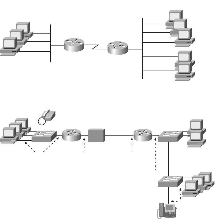
404 Chapter 13: Operating Cisco Routers
Figure 13-1 Generic Enterprise Network Diagram
Figure 13-2 More Detailed Cabling Diagram for the Same Enterprise Network
Figure 13-2 shows the types of LAN cables (UTP), with a couple of different WAN cables.
The LAN connections all use UTP straight-through cabling pinouts, except for the UTP
cable between the two switches, which is a crossover cable.
The serial link in the figure shows the two main options for where the channel service unit/
digital service unit (CSU/DSU) hardware resides: either outside the router (as shown at the
branch office in this case) or integrated into the router’s serial interface (as shown at the
PC4
PC5
PC1
PC2
PC3
PC6
S1
S2
R1 R2
Branch Office Central Site
Servers
End Users
S1
S2
PC4
PC5
PC1
PC2
PC3
PC6
R1 R2
Branch Office Central Site
Leased
Line
UTP Cables
UTP Cables
UTP (Crossover)
Servers
Serial Interface With
Integrated CSU/DSU
Serial CableUTP Cables
CSU/
DSU
IP
1828xbook.fm Page 404 Thursday, July 26, 2007 3:10 PM
Installing Cisco Routers 405
central site). Most new installations today include the CSU/DSU in the router’s serial
interface. The WAN cable installed by the telco typically has an RJ-48 connector, which is
the same size and shape as an RJ-45 connector. The telco cable with the RJ-48 connector
inserts into the CSU/DSU, meaning it connects directly into the central site router in this
case, but into the external CSU/DSU at the branch office router. At the branch, the external
CSU/DSU would then be cabled, using a serial cable, to the branch router’s serial port. (See
Figure 4-4 in Chapter 4 for a reminder of WAN serial cables.)
Cisco Integrated Services Routers
Product vendors, including Cisco, typically provide several different types of router
hardware, including some routers that just do routing, with other routers that serve other
functions in addition to routing. A typical enterprise branch office needs a router for WAN/
LAN connectivity, and a LAN switch to provide a high-performance local network and
connectivity into the router and WAN. Many branches also need Voice over IP (VoIP)
services, and several security services as well. (One popular security service, virtual private
networking (VPN), is covered in Chapter 6, “Fundamentals of TCP/IP Transport,
Applications, and Security.”) Rather than require multiple separate devices at one site, as
shown in Figure 13-2, Cisco offers single devices that act as both router and switch, and
provide other functions as well.
Following that concept further, Cisco offers several router model series in which the
routers support many other functions. In fact, Cisco has several router product series
called Integrated Services Routers (ISR), with the name emphasizing the fact that many
functions are integrated into a single device. If you have not seen Cisco routers before,
you can go to http://www.cisco.com/go/isr and click any of the 3D Product Demonstration
links to see interactive views of a variety of Cisco ISR routers. However, for the sake of
learning and understanding the different functions, the CCNA exams focus on using a
separate switch and separate router, which provides a much cleaner path for learning
the basics.
Figure 13-3 shows a couple of pictures taken from the interactive demo of the Cisco 1841
ISR, with some of the more important features highlighted. The top part of the figure
shows a full view of the back of the router. It also shows a magnified view of the back of
the router, with a clearer view of the two FastEthernet interfaces, the console and auxiliary
ports, and a serial card with an internal CSU/DSU. (You can find the interactive demo from
which these photos were taken at the same ISR web page mentioned in the previous
paragraph.)
1828xbook.fm Page 405 Thursday, July 26, 2007 3:10 PM
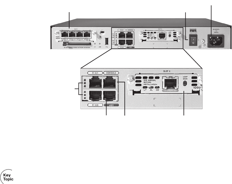
406 Chapter 13: Operating Cisco Routers
Figure 13-3 Photos of a Model 1841 Cisco Integrated Services Router (ISR)
Physical Installation
Armed with the planning information shown in Figure 13-2, and the perspectives shown in
Figure 13-3, you can physically install a router. To install a router, follow these steps:
Step 1 Connect any LAN cables to the LAN ports.
Step 2 If using an external CSU/DSU, connect the router’s serial interface to the
CSU/DSU, and the CSU/DSU to the line from the telco.
Step 3 If using an internal CSU/DSU, connect the router’s serial interface to the
line from the telco.
Step 4 Connect the router’s console port to a PC (using a rollover cable), as
needed, to configure the router.
Step 5 Connect a power cable from a power outlet to the power port on the
router.
Step 6 Turn on the router.
Note that the steps generally follow the same steps used for installation of LAN switches—
install the cables for the interfaces, connect the console (as needed), and connect the power.
However, note that most of the Cisco Catalyst switches do not have a power on/off switch—
once the switch is connected to power, the switch is on. However, Cisco routers do have on/
off switches.
On/Off Switch
Console
Aux Serial Interface with Integrated CSU/DSU
Two FastEthernet
Interfaces
Additional Modular Interface Card
Power Socket
1828xbook.fm Page 406 Thursday, July 26, 2007 3:10 PM
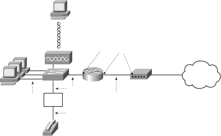
Installing Cisco Routers 407
Installing Internet Access Routers
Routers play a key role in SOHO networks, connecting the LAN-attached end-user devices
to a high-speed Internet access service. Once connected to the Internet, SOHO users can
send packets to and from their enterprise network at their company or school.
As in the enterprise networking market, product vendors tend to sell integrated networking
devices that perform many functions. However, in keeping with the CCNA strategy of
understanding each function separately, this section first examines the various networking
functions needed at a typical SOHO network, using a separate device for each function.
Following that, a more realistic example is shown, with the functions combined into a
single device.
A SOHO Installation with a Separate Switch, Router, and Cable Modem
Figure 13-4 shows an example of the devices and cables used in a SOHO network to
connect to the Internet using cable TV (CATV) as the high-speed Internet service. For now,
keep in mind that the figure shows one alternative for the devices and cables, whereas many
variations are possible.
Figure 13-4 Devices in a SOHO Network with High-Speed CATV Internet
This figure has many similarities to Figure 13-2, which shows a typical enterprise branch
office. The end-user PCs still connect to a switch, and the switch still connects to a router’s
Ethernet interface. The router still provides routing services, forwarding IP packets. The
voice details differ slightly between Figure 13-2 and Figure 13-4, mainly because
PC1
PC1
CATV Cable
Cable Modem
PC1
PC2
R1 ISP/Internet
UTP
Cables
UTP
Cable
Ethernet Interfaces
UTP
Cables
Wireless
SOHO
Phone
Cable
Voice
Adapter
1828xbook.fm Page 407 Thursday, July 26, 2007 3:10 PM
408 Chapter 13: Operating Cisco Routers
Figure 13-4 shows a typical home-based Internet phone service, which uses a normal
analog phone and a voice adapter to convert from analog voice to IP.
The main differences between the SOHO connection in Figure 13-4 and the enterprise
branch in Figure 13-2 relate to the connection into the Internet. An Internet connection that
uses CATV or DSL needs a device that converts between the Layer 1 and 2 standards used
on the CATV cable or DSL line, and the Ethernet used by the router. These devices,
commonly called cable modems and DSL modems, respectively, convert electrical signals
between an Ethernet cable and either CATV or DSL.
In fact, while the details differ greatly, the purpose of the cable modem and DSL modem
is similar to a CSU/DSU on a serial link. A CSU/DSU converts between the Layer 1 standards
used on a telco’s WAN circuit and a serial cable’s Layer 1 standards—and routers can
use serial cables. Similarly, a cable modem converts between CATV signals and a Layer 1
(and Layer 2) standard usable by a router—namely, Ethernet. Similarly, DSL modems
convert between the DSL signals over a home telephone line and Ethernet.
To physically install a SOHO network with the devices shown in Figure 13-4, you basically
need the correct UTP cables for the Ethernet connections, and either the CATV cable (for
cable Internet services) or a phone line (for DSL services). Note that the router used in
Figure 13-4 simply needs to have two Ethernet interfaces—one to connect to the LAN
switch, and one to connect to the cable modem. Thinking specifically just about the router
installation, you would need to use the following steps to install this SOHO router:
Step 1 Connect a UTP straight-through cable from the router to the switch.
Step 2 Connect a UTP straight-through cable from the router to the cable
modem.
Step 3 Connect the router’s console port to a PC (using a rollover cable), as
needed, to configure the router.
Step 4 Connect a power cable from a power outlet to the power port on the router.
Step 5 Turn on the router.
A SOHO Installation with an Integrated Switch, Router, and DSL Modem
Today, most new SOHO installations use an integrated device rather than the separate
devices shown in Figure 13-4. In fact, you can buy SOHO devices today that include all of
these functions:
■Router
■Switch
■Cable or DSL modem
1828xbook.fm Page 408 Thursday, July 26, 2007 3:10 PM
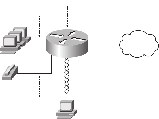
Cisco Router IOS CLI 409
■Voice Adapter
■Wireless AP
■Hardware-enabled encryption
The CCNA exams do indeed focus on separate devices to aid the learning process.
However, a newly installed high-speed SOHO Internet connection today probably looks
more like Figure 13-5, with an integrated device.
Figure 13-5 SOHO Network, Using Cable Internet and an Integrated Device
Regarding the SOHO Devices Used in This Book
Cisco sells products to both enterprise customers and consumers. Cisco sells its consumer
products using the Linksys brand. These products are easily found online and in office
supply stores. Cisco mainly sells enterprise products either directly to its customers or
through Cisco Channel Partners (resellers). However, note that the CCNA exams do not use
Linksys products or their web-based user interface, instead focusing on the IOS CLI used
by Cisco enterprise routing products.
Cisco Router IOS CLI
Cisco routers use the same switch IOS CLI as described in Chapter 8. However, because
routers and switches perform different functions, the actual commands differ in some cases.
This section begins by listing some of the key features that work exactly the same on both
switches and routers, and then lists and describes in detail some of the key features that
differ between switches and routers.
PC1
PC1
UTP Cables
CATV Cable
PC1
PC2
R1
ISP/Internet
Integrated Device
Phone
Cable
Wireless
1828xbook.fm Page 409 Thursday, July 26, 2007 3:10 PM

410 Chapter 13: Operating Cisco Routers
Comparisons Between the Switch CLI and Router CLI
The following list details the many items covered in Chapter 8 for which the router CLI
behaves the same. If these details are not fresh in your memory, it might be worthwhile to
spend a few minutes briefly reviewing Chapter 8.
The configuration commands used for the following features are the same on both routers
and switches:
■User and Enable (privileged) mode
■Entering and exiting configuration mode, using the configure terminal, end, and exit
commands, and the Ctrl-Z key sequence
■Configuration of console, Telnet, and enable secret passwords
■Configuration of SSH encryption keys and username/password login credentials
■Configuration of the host name and interface description
■Configuration of Ethernet interfaces that can negotiate speed, using the speed and
duplex commands
■Configuring an interface to be administratively disabled (shutdown) and
administratively enabled (no shutdown)
■Navigation through different configuration mode contexts using commands like line
console 0 and interface
■CLI help, command editing, and command recall features
■The meaning and use of the startup-config (in NVRAM), running-config (in RAM),
and external servers (like TFTP), along with how to use the copy command to copy the
configuration files and IOS images
■The process of reaching setup mode either by reloading the router with an empty
startup-config or by using the setup command
At first glance, this list seems to cover most everything covered in Chapter 8—and it does
cover most of the details. However, a couple of topics covered in Chapter 8 do work
differently with the router CLI as compared to the switch CLI, namely:
■The configuration of IP addresses differs in some ways.
■The questions asked in setup mode differ.
■Routers have an auxiliary (Aux) port, intended to be connected to an external modem
and phone line, to allow remote users to dial into the router, and access the CLI, by
making a phone call.
1828xbook.fm Page 410 Thursday, July 26, 2007 3:10 PM
Cisco Router IOS CLI 411
Beyond these three items from Chapter 8, the router CLI does differ from a switch CLI just
because switches and routers do different things. For instance, Example 10-5 in Chapter 10,
“Ethernet Switch Troubleshooting,” shows the output of the show mac address-table
dynamic command, which lists the most important table that a switch uses for forwarding
frames. The router IOS does not support this command—instead, routers support the show
ip route command, which lists the IP routes known to the router, which of course is the
most important table that a router uses for forwarding packets. As you might imagine, the
Cisco Layer 2 switches covered on the CCNA exams do not support the show ip route
command because they do not do any IP routing.
The rest of this section explains a few of the differences between the router IOS CLI and
the switch IOS CLI. Chapter 14, “Routing Protocol Concepts and Configuration,” goes on
to show even more items that differ, in particular how to configure router interface IP
addresses and IP routing protocols. For now, this chapter examines the following items:
■Router interfaces
■Router IP address configuration
■Router setup mode
Router Interfaces
The CCNA exams refer to two general types of physical interfaces on routers: Ethernet
interfaces and serial interfaces. The term Ethernet interface refers to any type of Ethernet
interface. However, on Cisco routers, the name referenced by the CLI refers to the fastest
speed possible on the interface. For example, some Cisco routers have an Ethernet interface
capable of only 10 Mbps, so to configure that type of interface, you would use the interface
ethernet number configuration command. However, other routers have interfaces capable
of 100 Mbps, or even of auto-negotiating to use 10 Mbps or 100 Mbps, so routers refer to
these interfaces by the fastest speed, with the interface fastethernet number command.
Similarly, interfaces capable of Gigabit Ethernet speeds are referenced with the interface
gigabitethernet number command.
Serial interfaces are the second major type of physical interface on routers. As you may
recall from Chapter 4, point-to-point leased lines and Frame Relay access links both use the
same underlying Layer 1 standards. To support those same standards, Cisco routers use
serial interfaces. The network engineer then chooses which data link layer protocol to use,
such as High-Level Data Link Control (HDLC) or Point-to-Point Protocol (PPP) for leased
lines or Frame Relay for Frame Relay connections, and configures the router to use the
correct data link layer protocol. (Serial interfaces default to use HDLC as the data link layer
protocol.)
1828xbook.fm Page 411 Thursday, July 26, 2007 3:10 PM

412 Chapter 13: Operating Cisco Routers
Routers use numbers to distinguish between the different interfaces of the same type. On
routers, the interface numbers might be a single number, or two numbers separated by a
slash, or three numbers separated by slashes. For example, all three of the following
configuration commands are correct on at least one model of Cisco router:
ii
iinn
nntt
ttee
eerr
rrff
ffaa
aacc
ccee
ee
ee
eett
tthh
hhee
eerr
rrnn
nnee
eett
tt
00
00
ii
iinn
nntt
ttee
eerr
rrff
ffaa
aacc
ccee
ee
ff
ffaa
aass
sstt
ttEE
EEtt
tthh
hhee
eerr
rrnn
nnee
eett
tt
00
00//
//11
11
ii
iinn
nntt
ttee
eerr
rrff
ffaa
aacc
ccee
ee
ss
ssee
eerr
rrii
iiaa
aall
ll
11
11//
//00
00//
//11
11
You can view information about interfaces by using several commands. To see a brief list
of interfaces, use the show ip interface brief command. To see brief details about a
particular interface, use the show protocols type number command. (Note that the show
protocols command is not available in all versions of Cisco IOS Software.) You can also
see a lot of detail about each interface, including statistics about the packets flowing in and
out of the interface, by using the show interfaces command. Optionally, you can include
the interface type and number on many commands, for example, show interfaces type
number, to see details for just that interface. Example 13-1 shows sample output from these
three commands.
Example 13-1 Listing the Interfaces in a Router
Albuquerque#ss
sshh
hhoo
ooww
ww
ii
iipp
pp
ii
iinn
nntt
ttee
eerr
rrff
ffaa
aacc
ccee
ee
bb
bbrr
rrii
iiee
eeff
ff
Interface IP-Address OK? Method Status Protocol
FastEthernet0/0 unassigned YES unset up up
FastEthernet0/1 unassigned YES unset administratively down down
Serial0/0/0 unassigned YES unset administratively down down
Serial0/0/1 unassigned YES unset up up
Serial0/1/0 unassigned YES unset up up
Serial0/1/1 unassigned YES unset administratively down down
Albuquerque#ss
sshh
hhoo
ooww
ww
pp
pprr
rroo
oott
ttoo
oocc
ccoo
ooll
llss
ss
ff
ffaa
aa00
00//
//00
00
FastEthernet0/0 is up, line protocol is up
Albuquerque#ss
sshh
hhoo
ooww
ww
ii
iinn
nntt
ttee
eerr
rrff
ffaa
aacc
ccee
eess
ss
ss
ss00
00//
//11
11//
//00
00
Serial0/1/0 is up, line protocol is up
Hardware is GT96K Serial
MTU 1500 bytes, BW 1544 Kbit, DLY 20000 usec,
reliability 255/255, txload 1/255, rxload 1/255
Encapsulation HDLC, loopback not set
Keepalive set (10 sec)
CRC checking enabled
Last input 00:00:03, output 00:00:01, output hang never
Last clearing of “show interface” counters never
Input queue: 0/75/0/0 (size/max/drops/flushes); Total output drops: 0
Queueing strategy: weighted fair
Output queue: 0/1000/64/0 (size/max total/threshold/drops)
Conversations 0/1/256 (active/max active/max total)
Reserved Conversations 0/0 (allocated/max allocated)
Available Bandwidth 1158 kilobits/sec
1828xbook.fm Page 412 Thursday, July 26, 2007 3:10 PM

Cisco Router IOS CLI 413
Interface Status Codes
Each of the commands in Example 13-1 lists two interface status codes. For a router to use
an interface, the two interface status codes on the interface must be in an “up” state. The
first status code refers essentially to whether Layer 1 is working, and the second status
code mainly (but not always) refers to whether the data link layer protocol is working.
Table 13-2 summarizes these two status codes.
Four combinations of settings exist for the status codes when troubleshooting a network.
Table 13-3 lists the four combinations, along with an explanation of the typical reasons why
an interface would be in that state. As you review the list, note that if the line status (the first
status code) is not “up,” the second will always be “down,” because the data link layer
functions cannot work if the physical layer has a problem.
5 minute input rate 0 bits/sec, 0 packets/sec
5 minute output rate 0 bits/sec, 0 packets/sec
70 packets input, 6979 bytes, 0 no buffer
Received 70 broadcasts, 0 runts, 0 giants, 0 throttles
0 input errors, 0 CRC, 0 frame, 0 overrun, 0 ignored, 0 abort
36 packets output, 4557 bytes, 0 underruns
0 output errors, 0 collisions, 8 interface resets
0 output buffer failures, 0 output buffers swapped out
13 carrier transitions
DCD=up DSR=up DTR=up RTS=up CTS=up
NOTE Commands that refer to router interfaces can be significantly shortened by
truncating the words. For example, sh int fa0/0 can be used instead of show interfaces
fastethernet 0/0. In fact, many network engineers, when looking over someone’s
shoulder, would say something like “just do a show int F-A-oh-oh command” in this case,
rather than speaking the long version of the command.
Table 13-2 Interface Status Codes and Their Meanings
Name Location General Meaning
Line
status
First status
code
Refers to the Layer 1 status—for example, is the cable installed, is it the
right/wrong cable, is the device on the other end powered on?
Protocol
status
Second
status code
Refers generally to the Layer 2 status. It is always down if the line status
is down. If the line status is up, a protocol status of down usually is caused
by mismatched data link layer configuration.
Example 13-1 Listing the Interfaces in a Router (Continued)
1828xbook.fm Page 413 Thursday, July 26, 2007 3:10 PM

414 Chapter 13: Operating Cisco Routers
Router Interface IP Addresses
As has been mentioned many times throughout this book, routers need an IP address on
each interface. If no IP address is configured, even if the interface is in an up/up state, the
router will not attempt to send and receive IP packets on the interface. For proper operation,
for every interface a router should use for forwarding IP packets, the router needs an
IP address.
The configuration of an IP address on an interface is relatively simple. To configure the
address and mask, simply use the ip address address mask interface subcommand.
Example 13-2 shows an example configuration of IP addresses on two router interfaces, and
the resulting differences in the show ip interface brief and show interfaces commands
from Example 13-1. (No IP addresses were configured when the output in Example 13-1
was gathered.)
Table 13-3 Typical Combinations of Interface Status Codes
Line and Protocol Status Typical Reasons
Administratively down,
down
The interface has a shutdown command configured on it.
down, down The interface has a no shutdown command configured, but the physical
layer has a problem. For example, no cable has been attached to the
interface, or with Ethernet, the switch interface on the other end of the
cable is shut down, or the switch is powered off.
up, down Almost always refers to data link layer problems, most often configuration
problems. For example, serial links have this combination when one
router was configured to use PPP, and the other defaults to use HDLC.
up, up All is well, interface is functioning.
Example 13-2 Configuring IP Addresses on Cisco Routers
Albuquerque#cc
ccoo
oonn
nnff
ffii
iigg
gguu
uurr
rree
ee
tt
ttee
eerr
rrmm
mmii
iinn
nnaa
aall
ll
Enter configuration commands, one per line. End with CNTL/Z.
Albuquerque (config)#ii
iinn
nntt
ttee
eerr
rrff
ffaa
aacc
ccee
ee
FF
FFaa
aa00
00//
//00
00
Albuquerque (config-if)#ii
iipp
pp
aa
aadd
dddd
ddrr
rree
eess
ssss
ss
11
1100
00..
..11
11..
..11
11..
..11
11
22
2255
5555
55..
..22
2255
5555
55..
..22
2255
5555
55..
..00
00
Albuquerque (config-if)#ii
iinn
nntt
ttee
eerr
rrff
ffaa
aacc
ccee
ee
SS
SS00
00//
//00
00//
//11
11
Albuquerque (config-if)#ii
iipp
pp
aa
aadd
dddd
ddrr
rree
eess
ssss
ss
11
1100
00..
..11
11..
..22
22..
..11
11
22
2255
5555
55..
..22
2255
5555
55..
..22
2255
5555
55..
..00
00
Albuquerque (config-if)#^^
^^ZZ
ZZ
Albuquerque#ss
sshh
hhoo
ooww
ww
ii
iipp
pp
ii
iinn
nntt
ttee
eerr
rrff
ffaa
aacc
ccee
ee
bb
bbrr
rrii
iiee
eeff
ff
Interface IP-Address OK? Method Status Protocol
FastEthernet0/0 10.1.1.1 YES manual up up
FastEthernet0/1 unassigned YES NVRAM administratively down down
Serial0/0/0 unassigned YES NVRAM administratively down down
Serial0/0/1 10.1.2.1 YES manual up up
Serial0/1/0 unassigned YES NVRAM up up
Serial0/1/1 unassigned YES NVRAM administratively down down
1828xbook.fm Page 414 Thursday, July 26, 2007 3:10 PM

Cisco Router IOS CLI 415
Bandwidth and Clock Rate on Serial Interfaces
Ethernet interfaces use either a single speed or one of a few speeds that can be auto-
negotiated. However, as mentioned in Chapter 4, WAN links can run at a wide variety
of speeds. To deal with the wide range of speeds, routers physically slave themselves to the
speed as dictated by the CSU/DSU through a process called clocking. As a result, routers
can use serial links without the need for additional configuration or autonegotiation to
sense the serial link’s speed. The CSU/DSU knows the speed, the CSU/DSU sends clock
pulses over the cable to the router, and the router reacts to the clocking signal. In effect, the
CSU/DSU tells the router when to send the next bit over the cable, and when to receive
the next bit, with the router just blindly reacting to the CSU/DSU for that timing.
The physical details of how clocking works prevent routers from sensing and measuring
the speed used on a link with CSU/DSUs. So, routers use two different interface
configuration commands that specify the speed of the WAN link connected to a serial
interface, namely the clock rate and bandwidth interface subcommands.
The clock rate command dictates the actual speed used to transmit bits on a serial link,
but only when the physical serial link is actually created with cabling in a lab. The lab
networks used to build the examples in this book, and probably in any labs engineers use
to do proof-of-concept testing, or even labs you use in CCNA classes, use back-to-back
serial cables (see the Chapter 4 section “Building a WAN Link in a Lab” for a reminder).
Back-to-back WAN connections do not use a CSU/DSU, so one router must supply the
clocking, which defines the speed at which bits are transmitted. The other router works as
usual when CSU/DSUs are used, slaving itself to the clocking signals received from the
other router. Example 13-3 shows an example configuration for a router named
Albuquerque, with a couple of important commands related to WAN links.
Albuquerque#ss
sshh
hhoo
ooww
ww
ii
iinn
nntt
ttee
eerr
rrff
ffaa
aacc
ccee
eess
ss
ff
ffaa
aa00
00//
//00
00
FastEthernet0/0 is up, line protocol is up
Hardware is Gt96k FE, address is 0013.197b.5004 (bia 0013.197b.5004)
Internet address is 10.1.1.1/24
! lines omitted for brevity
NOTE Example 13-3 omits some of the output of the show running-config command,
specifically the parts that do not matter to the information covered here.
Example 13-3 Albuquerque Router Configuration with clock rate Command
Albuquerque#ss
sshh
hhoo
ooww
ww
rr
rruu
uunn
nnnn
nnii
iinn
nngg
gg--
--cc
ccoo
oonn
nnff
ffii
iigg
gg
! lines omitted for brevity
interface Serial0/0/1
clock rate 128000
continues
Example 13-2 Configuring IP Addresses on Cisco Routers (Continued)
1828xbook.fm Page 415 Thursday, July 26, 2007 3:10 PM

416 Chapter 13: Operating Cisco Routers
The clock rate speed interface subcommand sets the rate in bits per second on the router that
has the DCE cable plugged into it. If you do not know which router has the DCE cable in
it, you can find out by using the show controllers command, which lists whether the attached
cable is DCE (as shown in Example 13-3) or DTE. Interestingly, IOS accepts the clock
rate command on an interface only if the interface already has a DCE cable installed, or if
no cable is installed. If a DTE cable has been plugged in, IOS silently rejects the command,
meaning that IOS does not give you an error message, but IOS ignores the command.
The second interface subcommand that relates to the speed of the serial link is the
bandwidth speed command, as shown on interface serial 0/1/0 in Example 13-3. The
bandwidth command tells IOS the speed of the link, in kilobits per second, regardless of
whether the router is supplying clocking. However, the bandwidth setting does not change
the speed at which bits are sent and received on the link. Instead, the router uses it for
documentation purposes, in calculations related to the utilization rates of the link, and for
many other purposes. In particular, the EIGRP and OSPF routing protocols use the interface
bandwidth settings to set their default metrics, with the metrics impacting a router’s choice
of the best IP route to reach each subnet. (The CCNA ICND2 Official Exam Certification
Guide covers these two routing protocols, including how the bandwidth command impacts
the routing protocol metrics.)
Every router interface has a default setting of the bandwidth command that is used when
there is no bandwidth command configured on the interface. For serial links, the default
bandwidth is 1544, meaning 1544 kbps, or 1.544 Mbps—in other words, the speed of a T1
line. Router Ethernet interfaces default to a bandwidth setting that reflects the current speed
of the interface. For example, if a router’s FastEthernet interface is running at 100 Mbps,
the bandwidth is 100,000 (kbps); if the interface is currently running at 10 Mbps, the router
automatically changes the bandwidth to 10,000 kbps. Note that the configuration of the
bandwidth command on an interface overrides these defaults.
!
interface Serial0/1/0
clock rate 128000
bandwidth 128
!
interface FastEthernet0/0
! lines omitted for brevity
Albuquerque#ss
sshh
hhoo
ooww
ww
cc
ccoo
oonn
nntt
ttrr
rroo
ooll
llll
llee
eerr
rrss
ss
ss
ssee
eerr
rrii
iiaa
aall
ll
00
00//
//00
00//
//11
11
Interface Serial0
Hardware is PowerQUICC MPC860
DCE V.35, clock rate 128000
idb at 0x8169BB20, driver data structure at 0x816A35E4
! Lines omitted for brevity
Example 13-3 Albuquerque Router Configuration with clock rate Command (Continued)
1828xbook.fm Page 416 Thursday, July 26, 2007 3:10 PM

Cisco Router IOS CLI 417
Router Auxiliary (Aux) Port
Routers have an auxiliary (Aux) port that allows access to the CLI by using a terminal
emulator. Normally, the Aux port is connected via a cable (RJ-45, 4 pair, with straight-
through pinouts) to an external analog modem. The modem connects to a phone line. Then,
the engineer uses a PC, terminal emulator, and modem to call the remote router. Once
connected, the engineer can use the terminal emulator to access the router CLI, starting in
user mode as usual.
Aux ports can be configured beginning with the line aux 0 command to reach aux line
configuration mode. From there, all the commands for the console line, covered mostly in
Chapter 8, can be used. For example, the login and password passvalue commands could
be used to set up simple password checking when a user dials in.
Cisco switches do not have an Aux port.
Initial Configuration (Setup Mode)
The processes related to setup mode in routers follow the same rules as for switches. You
can refer to the Chapter 8 section “Initial Configuration Using Setup Mode” for more
details, but the following statements summarize some of the key points, all of which are true
on both switches and routers:
■Setup mode is intended to allow basic configuration by prompting the CLI user via a
series of questions.
■You can reach setup mode either by booting a router after erasing the startup-config file
or by using the setup enable-mode EXEC command.
■At the end of the process, you get three choices (0, 1, or 2), to either ignore the answers
and go back to the CLI (0); ignore the answers but begin again in setup mode (1);
or to use the resulting configuration (2).
■If you tire of the process, the Ctrl-C key combination will eject the user out of setup
mode and back to the previous CLI mode.
■If you select to use the resulting configuration, the router writes the configuration to
the startup-config file, as well as the running-config file.
The main difference between the setup mode on switches and routers relates to the
information requested while in setup mode. For example, routers need to know the IP
NOTE The clock rate command uses a unit of bps, whereas the bandwidth command
uses a unit of kbps. In other words, a show command that lists bandwidth as 10,000
means 10,000 kbps, or 10 Mbps.
1828xbook.fm Page 417 Thursday, July 26, 2007 3:10 PM

418 Chapter 13: Operating Cisco Routers
address and mask for each interface on which you want to configure IP, whereas switches
have only one IP address. To be complete, Example 13-4 demonstrates the use of setup
mode. If you do not have a router with which to practice setup mode, take the time to review
the example, and see the kinds of information requested in the various questions.
NOTE The questions asked, and the default answers, differ on some routers in part due
to the IOS revision, feature set, and router model.
Example 13-4 Router Setup Configuration Mode
--- System Configuration Dialog ---
Would you like to enter the initial configuration dialog? [yes/no]: yy
yyee
eess
ss
At any point you may enter a question mark ‘?’ for help.
Use ctrl-c to abort configuration dialog at any prompt.
Default settings are in square brackets ‘[]’.Basic management setup configures
only enough connectivity
for management of the system, extended setup will ask you
to configure each interface on the system
Would you like to enter basic management setup? [yes/no]: nn
nnoo
oo
First, would you like to see the current interface summary? [yes]:
Any interface listed with OK? value “NO” does not have a valid configuration
Interface IP-Address OK? Method Status Protocol
Ethernet0 unassigned NO unset up down
Serial0 unassigned NO unset down down
Serial1 unassigned NO unset down down
Configuring global parameters:
Enter host name [Router]: RR
RR11
11
The enable secret is a password used to protect access to
privileged EXEC and configuration modes. This password, after
entered, becomes encrypted in the configuration.
Enter enable secret: cc
ccii
iiss
sscc
ccoo
oo
The enable password is used when you do not specify an
enable secret password, with some older software versions, and
some boot images.
Enter enable password: ff
ffrr
rree
eedd
dd
The virtual terminal password is used to protect
access to the router over a network interface.
Enter virtual terminal password: bb
bbaa
aarr
rrnn
nnee
eeyy
yy
Configure SNMP Network Management? [yes]: nn
nnoo
oo
Configure bridging? [no]:
Configure DECnet? [no]:
Configure AppleTalk? [no]:
Configure IPX? [no]:
1828xbook.fm Page 418 Thursday, July 26, 2007 3:10 PM

Cisco Router IOS CLI 419
Configure IP? [yes]:
Configure RIP routing? [yes]:
Configure CLNS? [no]:
Configure bridging? [no]:
Configuring interface parameters:
Do you want to configure Ethernet0 interface? [yes]:
Configure IP on this interface? [yes]:
IP address for this interface: 11
1177
7722
22..
..11
1166
66..
..11
11..
..11
11
Subnet mask for this interface [255.255.0.0] : 22
2255
5555
55..
..22
2255
5555
55..
..22
2255
5555
55..
..00
00
Class B network is 172.16.0.0, 24 subnet bits; mask is /24
Do you want to configure Serial0 interface? [yes]:
Configure IP on this interface? [yes]:
Configure IP unnumbered on this interface? [no]:
IP address for this interface: 11
1177
7722
22..
..11
1166
66..
..11
1122
22..
..11
11
Subnet mask for this interface [255.255.0.0] : 22
2255
5555
55..
..22
2255
5555
55..
..22
2255
5555
55..
..00
00
Class B network is 172.16.0.0, 24 subnet bits; mask is /24
Do you want to configure Serial1 interface? [yes]:
Configure IP on this interface? [yes]:
Configure IP unnumbered on this interface? [no]:
IP address for this interface: 11
1177
7722
22..
..11
1166
66..
..11
1133
33..
..11
11
Subnet mask for this interface [255.255.0.0] : 22
2255
5555
55..
..22
2255
5555
55..
..22
2255
5555
55..
..00
00
Class B network is 172.16.0.0, 24 subnet bits; mask is /24
The following configuration command script was created:
hostname R1
enable secret 5 $1$VOLh$pkIe0Xjx2sgjgZ/Y6Gt1s.
enable password fred
line vty 0 4
password barney
no snmp-server
!
ip routing
!
interface Ethernet0
ip address 172.16.1.1 255.255.255.0
!
interface Serial0
ip address 172.16.12.1 255.255.255.0
!
interface Serial1
ip address 172.16.13.1 255.255.255.0
!
router rip
network 172.16.0.0
!
continues
Example 13-4 Router Setup Configuration Mode (Continued)
1828xbook.fm Page 419 Thursday, July 26, 2007 3:10 PM

420 Chapter 13: Operating Cisco Routers
Upgrading Cisco IOS Software and the Cisco IOS
Software Boot Process
Engineers need to know how to upgrade IOS to move to a later release or version of IOS.
Typically, a router has one IOS image in Flash memory, and that is the IOS image that is
used. (The term IOS image simply refers to a file containing IOS.) The upgrade process
might include steps such as copying a newer IOS image into Flash memory, configuring the
router to tell it which IOS image to use, and deleting the old one when you are confident
that the new release works well. Alternately, you could copy a new image to a TFTP server,
with some additional configuration on the router to tell it to get the new IOS from the TFTP
server the next time the router is reloaded.
This section shows how to upgrade IOS by copying a new IOS file into Flash memory and
telling the router to use the new IOS. Because the router decides which IOS to use when
the router boots, this is also a good place to review the process by which routers boot
(initialize). Switches follow the same basic process as described here, with some minor
differences, as specifically noted.
Upgrading a Cisco IOS Software Image into Flash Memory
Routers and switches typically store IOS images in Flash memory. Flash memory is
rewriteable, permanent storage, which is ideal for storing files that need to be retained when
the router loses power. Cisco purposefully uses Flash memory instead of disk drives in its
products because there are no moving parts in Flash memory, so there is a smaller chance
of failure as compared with disk drives. Additionally, the IOS image can be placed on an
end
[0] Go to the IOS command prompt without saving this config.
[1] Return back to the setup without saving this config.
[2] Save this configuration to nvram and exit.
Enter your selection [2]: 22
22
Building configuration...
[OK]Use the enabled mode ‘configure’ command to modify this configuration.
Press RETURN to get started!
NOTE Although not shown in this example, routers that use an IOS feature set that
includes additional security features will also ask the user if they want to configure Cisco
Auto Secure. This feature automatically configures many router security best practice
settings, for example, disabling CDP.
Example 13-4 Router Setup Configuration Mode (Continued)
1828xbook.fm Page 420 Thursday, July 26, 2007 3:10 PM
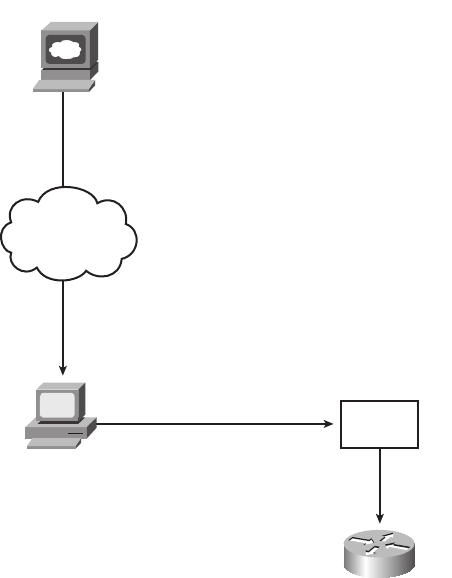
Upgrading Cisco IOS Software and the Cisco IOS Software Boot Process 421
external TFTP server, but using an external server typically is done for testing; in
production, practically every Cisco router loads an IOS image stored in the only type of
large, permanent memory in a Cisco router—Flash memory.
Figure 13-6 illustrates the process to upgrade an IOS image into Flash memory:
Step 1 Obtain the IOS image from Cisco, typically by downloading the IOS image from
Cisco.com using HTTP or FTP.
Step 2 Place the IOS image into the default directory of a TFTP server that is
accessible from the router.
Step 3 Issue the copy command from the router, copying the file into Flash
memory.
You also can use an FTP or remote copy (rcp) server, but the TFTP feature has been around
a long time and is a more likely topic for the exams.
Figure 13-6 Complete Cisco IOS Software Upgrade Process
FTP/HTTP
(Any Convenient Method)
Copy tftp
flash
Internet
www.cisco.com
TFTP
Server
1828xbook.fm Page 421 Thursday, July 26, 2007 3:10 PM

422 Chapter 13: Operating Cisco Routers
Example 13-5 provides an example of the final step, copying the IOS image into Flash
memory. Note that the copy tftp flash command shown here works much like the copy tftp
startup-config command that can be used to restore a backup copy of the configuration file
into NVRAM.
During this process of copying the IOS image into Flash memory, the router needs to
discover several important facts:
1. What is the IP address or host name of the TFTP server?
2. What is the name of the file?
3. Is space available for this file in Flash memory?
4. Does the server actually have a file by that name?
5. Do you want the router to erase the old files?
The router will prompt you for answers, as necessary. For each question, you should either
type an answer or press Enter if the default answer (shown in square brackets at the end
Example 13-5 copy tftp flash Command Copies the IOS Image to Flash Memory
R1#cc
ccoo
oopp
ppyy
yy
tt
ttff
fftt
ttpp
pp
ff
ffll
llaa
aass
sshh
hh
System flash directory:
File Length Name/status
1 7530760 c4500-d-mz.120-2.bin
[7530824 bytes used, 857784 available, 8388608 total]
Address or name of remote host [255.255.255.255]? 11
1133
3344
44..
..11
1144
4411
11..
..33
33..
..33
3333
33
Source file name? cc
cc44
4455
5500
0000
00--
--dd
dd--
--mm
mmzz
zz..
..11
1122
2200
00--
--55
55..
..bb
bbii
iinn
nn
Destination file name [c4500-d-mz.120-5.bin]?
Accessing file c4500-d-mz.120-5.bin ‘ on 134.141.3.33...
Loading c4500-d-mz.120-5.bin from 134.141.3.33 (via Ethernet0): ! [OK]
Erase flash device before writing? [confirm]
Flash contains files. Are you sure you want to erase? [confirm]
Copy ‘c4500-d-mz.120-5.bin ‘ from server
as ‘c4500-d-mz.120-5.bin ‘ into Flash WITH erase? [yes/no]yy
yy
Erasing device... eeeeeeeeeeeeeeeeeeeeeeeeeeeeeeee ...erased
Loading c4500-d-mz.120-5.bin from 134.141.3.33 (via Ethernet0):
!!!!!!!!!!!!!!!!!!!!!!!!!!!!!!!!!!!!!!!!!!!!!!!!!!!!!!!!!!!!!!!!!!!!!!!!!!!!!!!!
!!!!!!!!!!!!!!!!!!!!!!!!!!!!!!!!!!!!!!!!!!!!! (leaving out lots of exclamation points)
[OK 7530760/8388608 bytes]
Verifying checksum... OK (0xA93E)
Flash copy took 0:04:26 [hh:mm:ss]
1828xbook.fm Page 422 Thursday, July 26, 2007 3:10 PM

Upgrading Cisco IOS Software and the Cisco IOS Software Boot Process 423
of the question) is acceptable. Afterward, the router erases Flash memory if directed, copies
the file, and then verifies that the checksum for the file shows that no errors occurred in
transmission. You can then use the show flash command to verify the contents of Flash
memory, as demonstrated in Example 13-6. (The show flash output can vary among router
families. Example 13-6 is output from a 2500 series router.)
The shaded line in Example 13-6 lists the amount of Flash memory, the amount used,
and the amount of free space. When copying a new IOS image into Flash, the copy
command will ask you if you want to erase Flash, with a default answer of [yes]. If you
reply with an answer of no, and IOS realizes that not enough available Flash memory
exists, the copy will fail. Additionally, even if you answer yes, and erase all of Flash
memory, the new Flash IOS image must be of a size that fits into flash memory; if not,
the copy command will fail.
Once the new IOS has been copied into Flash, the router must be reloaded to use the
new IOS image. The next section, which covers the IOS boot sequence, explains the details
of how to configure a router so that it loads the right IOS image.
The Cisco IOS Software Boot Sequence
Cisco routers perform the same types of tasks that a typical computer performs when
you power it on or reboot (reload) it. Most computers have a single operating system
(OS) installed, and that OS boots by default. However, a router can have multiple IOS
images available both in Flash memory and on external TFTP servers, so the router
needs to know which IOS image to load. This section examines the entire boot process,
with extra emphasis on the options that impact a router’s choice of what IOS image
to load.
Example 13-6 Verifying Flash Memory Contents with the show flash Command
fred#ss
sshh
hhoo
ooww
ww
ff
ffll
llaa
aass
sshh
hh
System flash directory:
File Length Name/status
1 13305352 c2500-ds-l.122-1.bin
[13305416 bytes used, 3471800 available, 16777216 total]
16384K bytes of processor board System flash (Read ONLY)
NOTE The boot sequence details in this section, particularly those regarding the
configuration register and the ROMMON OS, differ from Cisco LAN switches, but they
do apply to most every model of Cisco router. This book does not cover the equivalent
options in Cisco switches.
1828xbook.fm Page 423 Thursday, July 26, 2007 3:10 PM
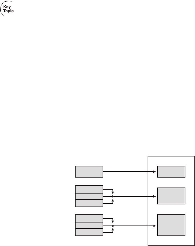
424 Chapter 13: Operating Cisco Routers
When a router first powers on, it follows these four steps:
1. The router performs a power-on self-test (POST) to discover the hardware components
and verify that all components work properly.
2. The router copies a bootstrap program from ROM into RAM, and runs the bootstrap
program.
3. The bootstrap program decides which IOS image (or other OS) to load into RAM, and
loads that OS. After loading the IOS image, the bootstrap program hands over
control of the router hardware to the newly loaded OS.
4. If the bootstrap program loaded IOS, IOS finds the configuration file (typically the
startup-config file in NVRAM) and loads it into RAM as the running-config.
All routers attempt all four steps each time that the router is powered on or reloaded. The
first two steps do not have any options to choose; these steps either work or the router
initialization fails and you typically need to call the Cisco Technical Assistance Center
(TAC) for support. However, Steps 3 and 4 have several configurable options that tell the
router what to do next. Figure 13-7 depicts those options, referencing Steps 2 through 4
shown in the earlier boot process.
Figure 13-7 Loading the Cisco IOS
As you can see, the router can get the IOS image from three locations and can get the initial
configuration from three locations as well. Frankly, routers almost always load the
configuration from NVRAM (the startup-config file), when it exists. There is no real
advantage to storing the initial configuration anywhere else except NVRAM. So, this
chapter will not look further into the options of Step 4. However, there are good reasons
for putting multiple IOS images in Flash, and keeping images on external servers, so
RAM
Bootstrap
Cisco
IOS
Running
Config
File
ROM
Flash
TFTP
ROM
NVRAM
TFTP
Console
Step 2
Step 3
Step 4
1828xbook.fm Page 424 Thursday, July 26, 2007 3:10 PM
Upgrading Cisco IOS Software and the Cisco IOS Software Boot Process 425
the rest of this section examines Step 3 in more detail. In particular, the next few pages
explain a few facts about some alternate router operating systems besides IOS, and a
router feature called the configuration register, before showing how a router chooses which
IOS image to load.
The Three Router Operating Systems
A router typically loads and uses a Cisco IOS image that allows the router to perform its
normal function of routing packets. However, Cisco routers can use a different OS to
perform some troubleshooting, to recover router passwords, and to copy new IOS files into
Flash when Flash has been inadvertently erased or corrupted. In the more recent additions
to the Cisco router product line (for example, 1800 and 2800 series routers), Cisco
routers use only one other OS, whereas older Cisco routers (for example, 2500 series
routers) actually had two different operating systems to perform different subsets of these
same functions. Table 13-4 lists the other two router operating systems, and a few details
about each.
Because the RxBoot OS is only available in older routers and is no longer needed in the
newer routers, this chapter will mainly refer to the OS that continues to be available for
these special functions, the ROMMON OS.
The Configuration Register
The configuration register is a special 16-bit number that can be set on any Cisco router.
The configuration register’s bits control different settings for some low-level operating
characteristics of the router. For example, the console runs at a speed of 9600 bps by
default, but that console speed is based on the default settings of a couple of bits in the
configuration register.
You can set the configuration register value with the config-register global configuration
command. Engineers set the configuration register to different values for many
reasons, but the most common are to help tell the router what IOS image to load, as
NOTE The IOS image is typically a compressed file so that it consumes less space in
Flash memory. The router decompresses the IOS image as is it loaded into RAM.
Table 13-4 Comparing ROMMON and RxBoot Operating Systems
Operating Environment Common Name Stored In Used in…
ROM Monitor ROMMON ROM Old and new routers
Boot ROM RxBoot, boot helper ROM Only in older routers
1828xbook.fm Page 425 Thursday, July 26, 2007 3:10 PM

426 Chapter 13: Operating Cisco Routers
explained in the next few pages, and in the password recovery process. For example,
the command config-register 0x2100 sets the value to hexadecimal 2100, which causes
the router to load the ROMMON OS instead of IOS—a common practice when
recovering lost passwords. Interestingly, this value is automatically saved when you
press Enter at the end of the config-register command—you do not need to save the
running-config file into the startup-config file after changing the configuration register.
However, the configuration register’s new value is not used until the next time the
router is reloaded.
How a Router Chooses Which OS to Load
A router chooses the OS to load based on the low-order 4 bits in the configuration register
and the details configured in any boot system global configuration commands found in
the startup-config file. The low-order 4 bits (the 4th hex digit) in the configuration register
are called the boot field, with the value of these bits being the first value a router examines
when choosing which OS to try and load. The boot field’s value when the router is powered
on or reloaded tells the router how to proceed with choosing which OS to load.
The process to choose which OS to load, on more modern routers that do not have
an RxBoot OS, happens as follows (note that “boot” refers to the boot field in the
configuration register):
Step 1 If boot field = 0, use the ROMMON OS.
Step 2 If boot field = 1, load the first IOS file found in Flash memory.
Step 3 If boot field = 2-F:
a. Try each boot system command in the startup-config file, in order, until one
works.
b. If none of the boot system commands work, load the first IOS file found in
Flash memory.
TIP The show version command, shown near the end of this chapter in Example 13-7,
shows the configuration register’s current value and, if different, the value that will be
used once the router is reloaded.
NOTE On most Cisco routers, the default configuration register setting is
hexadecimal 2102.
NOTE Cisco represents hexadecimal values by preceding the hex digit(s) with 0x—for
example, 0xA would mean a single hex digit A.
1828xbook.fm Page 426 Thursday, July 26, 2007 3:10 PM

Upgrading Cisco IOS Software and the Cisco IOS Software Boot Process 427
The first two steps are pretty straightforward, but Step 3 then tells the router to look to the
second major method to tell the router which IOS to load: the boot system global
configuration command. This command can be configured multiple times on one router,
with details about files in Flash memory, and filenames and IP addresses of servers, telling
the router where to look for an IOS image to load. The router tries to load the IOS images,
in the order of the configured boot system commands. Once the router succeeds in loading
one of the referenced IOS images, the process is complete, and the router can ignore the
remaining boot system commands. If the router fails to load an IOS based on the boot
system commands, the router then tries what Step 1 suggests, which is to load the first IOS
file found in Flash memory.
Both Step 2 and Step 3b refer to a concept of the “first” IOS file, a concept which needs a
little more explanation. Routers number the files stored in Flash memory, with each new
file typically getting a higher and higher number. When a router tries Step 2 or Step 3b from
the preceding list, the router will look in Flash memory, starting with file number 1, and
then file number 2, and so on, until it finds the lowest numbered file that happens to be an
IOS image. The router will then load that file.
Interestingly, most routers end up using Step 3b to find their IOS image. From the factory,
Cisco routers do not have any boot system commands configured; in fact, they do not
have any configuration in the startup-config file at all. Cisco loads Flash memory with a
single IOS when it builds and tests the router, and the configuration register value is set to
0x2102, meaning a boot field of 0x2. With all these settings, the process tries Step 3
(because boot = 2), finds no boot system commands (because the startup-config is empty),
and then looks for the first file in Flash memory at Step 3b.
Figure 13-8 shows a diagram that summarizes the key concepts behind how a router
chooses the OS to load.
NOTE The actual step numbers are not important—the list is just numbered for easier
reference.
1828xbook.fm Page 427 Thursday, July 26, 2007 3:10 PM
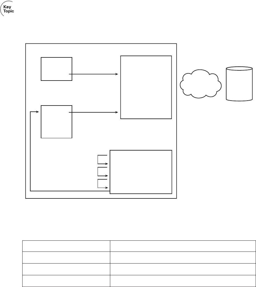
428 Chapter 13: Operating Cisco Routers
Figure 13-8 Choices for Choosing the OS at Boot Time: Modern Cisco Router
The boot system commands need to refer to the exact file that the router should load.
Table 13-5 shows several examples of the commands.
In some cases, a router fails to load on OS based on the three-step process listed earlier in
this section. For example, someone might accidentally erase all the contents of Flash,
including the IOS image. So, routers need more options to help recover from these
unexpected but possible scenarios. If no OS is found by the end of Step 3, the router will
send broadcasts looking for a TFTP server, guess at a filename for the IOS image, and load
Table 13-5 Sample boot system Commands
Boot System Command Result
boot system flash The first file from Flash memory is loaded.
boot system flash filename IOS with the name filename is loaded from Flash memory.
boot system tftp filename 10.1.1.1 IOS with the name filename is loaded from the TFTP server.
Bootstrap
and
ROMMON
ROM
BOOT = 0
BOOT = 1
FTP Server Software
Installed Here
RAM
IP Network TFTP
1st IOS file
2nd IOS file
•
•
Last IOS file
Flash
BOOT = 2..F
NVRAM (Startup-config)
Boot system (1)
Boot system (2)
•
•
Last boot system command
Repeat
until
success
1828xbook.fm Page 428 Thursday, July 26, 2007 3:10 PM

Upgrading Cisco IOS Software and the Cisco IOS Software Boot Process 429
an IOS image (assuming that a TFTP server is found). In practice it is highly unlikely to
work. The final step is to simply load ROMMON, which is designed in part to provide tools
to recover from these unexpected types of problems. For example, an IOS image can be
copied into Flash from a TFTP server while using ROMMON.
For older models of Cisco router that have an RxBoot (boot helper) OS in ROM, the process
to choose which OS to load works generally the same, with two differences. When the
boot field is 0x1, the router loads the RxBoot OS stored in ROM. Also, in the final efforts
to find an OS as described in the previous paragraph, if the effort to find an image from a
TFTP server fails, and the router has an RxBoot image, the router first tries to load RxBoot
before trying to load the ROM Monitor OS.
The show version Command and Seeing the Configuration Register’s Value
The show version command supplies a wide variety of information about a router,
including both the current value of the configuration register and the expected value at the
next reload of the router. The following list summarizes some of the other very interesting
information in this command:
1. The IOS version
2. The uptime (the length of time that has passed since the last reload)
3. The reason for the last reload of IOS (reload command, power off/on, software failure)
4. The time of the last loading of IOS (if the router’s clock has been set)
5. The source from which the router loaded the current IOS
6. The amount of RAM memory
7. The number and types of interfaces
8. The amount of NVRAM memory
9. The amount of Flash memory
10. The configuration register’s current and future setting (if different)
Example 13-7 demonstrates output from the show version command, highlighting the key
pieces of information. Note that the preceding list is in the same order in which the
highlighted information appears in the example.
Example 13-7 show version Command Output
Albuquerque#ss
sshh
hhoo
ooww
ww
vv
vvee
eerr
rrss
ssii
iioo
oonn
nn
Cisco IOS Software, 1841 Software (C1841-ADVENTERPRISEK9-M), Version 12.4(9)T, RELEASE
SOFTWARE (fc1)
Technical Support: http://www.cisco.com/techsupport
Copyright (c) 1986-2006 by Cisco Systems, Inc.
continues
1828xbook.fm Page 429 Thursday, July 26, 2007 3:10 PM

430 Chapter 13: Operating Cisco Routers
Most of the information highlighted in the example can be easily found in comparison to
the list preceding Example 13-7. However, note that the amount of RAM, listed as
354304K/38912K, shows the RAM in two parts. The sum of these two parts is the total
amount of available RAM, about 72 MB in this case.
Compiled Fri 16-Jun-06 21:26 by prod_rel_team
ROM: System Bootstrap, Version 12.3(8r)T8, RELEASE SOFTWARE (fc1)
Albuquerque uptime is 5 hours, 20 minutes
System returned to ROM by reload at 13:12:26 UTC Wed Jan 17 2007
System restarted at 13:13:38 UTC Wed Jan 17 2007
System image file is “flash:c1841-adventerprisek9-mz.124-9.T.bin”
This product contains cryptographic features and is subject to United
States and local country laws governing import, export, transfer and
use. Delivery of Cisco cryptographic products does not imply
third-party authority to import, export, distribute or use encryption.
Importers, exporters, distributors and users are responsible for
compliance with U.S. and local country laws. By using this product you
agree to comply with applicable laws and regulations. If you are unable
to comply with U.S. and local laws, return this product immediately.
A summary of U.S. laws governing Cisco cryptographic products may be found at:
http://www.cisco.com/wwl/export/crypto/tool/stqrg.html
If you require further assistance please contact us by sending email to
export@cisco.com.
Cisco 1841 (revision 4.1) with 354304K/38912K bytes of memory.
Processor board ID FTX0906Y03T
2 FastEthernet interfaces
4 Serial(sync/async) interfaces
1 Virtual Private Network (VPN) Module
DRAM configuration is 64 bits wide with parity disabled.
191K bytes of NVRAM.
125440K bytes of ATA CompactFlash (Read/Write)
Configuration register is 0x2102 (will be 0x2101 at next reload)
Example 13-7 show version Command Output (Continued)
1828xbook.fm Page 430 Thursday, July 26, 2007 3:10 PM
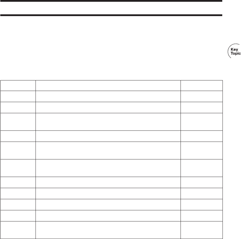
Complete the Tables and Lists from Memory 431
Exam Preparation Tasks
Review All the Key Topics
Review the most important topics from inside the chapter, noted with the key topics icon
in the outer margin of the page. Table 13-6 lists a reference of these key topics and the
page numbers on which each is found.
Complete the Tables and Lists from Memory
Print a copy of Appendix H, “Memory Tables” (found on the CD-ROM), or at least the
section for this chapter, and complete the tables and lists from memory. Appendix I,
“Memory Tables Answer Key,” also on the CD-ROM, includes completed tables and lists
to check your work.
Table 13-6 Key Topics for Chapter 13
Key Topic Description Page Number
List Steps required to install a router 406
List Similarities between router CLI and switch CLI 410
List Items covered for switches in Chapter 8 that differ in some way
on routers
410
Table 13-2 Router interface status codes and their meanings 413
Table 13-3 Combinations of the two interface status codes and the likely
reasons for each combination
414
List Summary of important facts about the initial configuration dialog
(setup mode)
417
List The four steps a router performs when booting 424
Table 13-4 Comparison of ROMMON and RxBoot operating systems 425
List Steps a router uses to choose which IOS image to load 426
Figure 13-8 Diagram of how a router chooses which IOS image to load 428
List A list of the many important facts that can be seen in the output
from the show version command
429
1828xbook.fm Page 431 Thursday, July 26, 2007 3:10 PM

432 Chapter 13: Operating Cisco Routers
Definitions of Key Terms
Define the following key terms from this chapter and check your answers in the glossary.
bandwidth, boot field, clock rate, configuration register, IOS image, power-on self-test
(POST), ROMMON, RxBoot
Read Appendix F Scenario 2
Appendix F, “Additional Scenarios,” contains two detailed scenarios that give you a chance
to analyze different designs, problems, and command output, as well as show you how
concepts from several different chapters interrelate. At this point in your reading,
Appendix F scenario 2, which shows how to use Cisco Discovery Protocol (CDP), would
be particularly useful to read.
Command References
Although you should not necessarily memorize the information in the tables in this section,
this section does include a reference for the configuration commands (Table 13-7) and
EXEC commands (Table 13-8) covered in this chapter. Practically speaking, you should
memorize the commands as a complement to reading the chapter and doing all the activities
in this exam preparation section. To check to see how well you have memorized the
commands, cover the left side of the table with a piece of paper, read the descriptions in the
right side, and see if you remember the command.
Table 13-7 Chapter 13 Configuration Command Reference
Command Description
bandwidth kbps Interface command that sets the router’s perception of bandwidth
of the interface, in a unit of kbps.
clock rate rate Interface command that sets the speed at which the router
supplies a clocking signal, applicable only when the router has a
DCE cable installed. The unit is bits/second.
config-register value Global command that sets the hexadecimal value of the
configuration register.
boot system {file-url | filename} Global command that identifies an externally located IOS image
using a URL.
boot system flash [flash-fs:]
[filename]
Global command that identifies the location of an IOS image in
Flash memory.
1828xbook.fm Page 432 Thursday, July 26, 2007 3:10 PM

Command References 433
boot system rom Global command that tells the router to load the RxBoot OS
found in ROM, if one exists.
boot system {rcp | tftp | ftp}
filename [ip-address]
Global command that identifies an external server, protocol, and
filename to use to load an IOS from an external server.
Table 13-8 Chapter 13 EXEC Command Reference
Command Purpose
show interfaces [type number] Lists a large set of informational messages about each interface,
or about the one specifically listed interface.
show ip interface brief Lists a single line of information about each interface, including
the IP address, line and protocol status, and the method with
which the address was configured (manual or DHCP).
show protocols type number Lists a single line of information about the listed interface,
including the IP address, mask, and line/protocol status.
show controllers [type number] Lists many lines of information per interface, or for one
interface, for the hardware controller of the interface. On serial
interfaces, this command identifies the cable as either a DCE or
DTE cable.
show version Lists the IOS version, as well as a large set of other useful
information (see Example 13-7).
setup Starts the setup (initial configuration) dialog in which the router
prompts the user for basic configuration settings.
copy source-url destination-url Copies a file from the first listed URL to the destination URL.
show flash Lists the names and size of the files in Flash memory, as well as
noting the amount of Flash memory consumed and available.
reload Enable mode command that reinitializes (reboots) the router.
Table 13-7 Chapter 13 Configuration Command Reference (Continued)
Command Description
1828xbook.fm Page 433 Thursday, July 26, 2007 3:10 PM

This chapter covers the following subjects:
Connected and Static Routes: This section
covers the basics of how routers learn routes to
connected subnets and how to configure static
routes.
Routing Protocol Overview: This section
explains the terminology and theory related to
routing protocols in general and Routing
Information Protocol (RIP) in particular.
Configuring and Verifying RIP-2: This section
explains how to configure RIP Version 2 (RIP-2)
and how to confirm that RIP-2 is working
correctly.
1828xbook.fm Page 434 Thursday, July 26, 2007 3:10 PM

C H A P T E R14
Routing Protocol Concepts
and Configuration
The United States Postal Service routes a huge number of letters and packages each day. To
do so, the postal sorting machines run fast, sorting lots of letters. Then the letters are placed
in the correct container and onto the correct truck or plane to reach the final destination.
However, if no one programs the letter-sorting machines to know where letters to each ZIP
code should be sent, the sorter cannot do its job. Similarly, Cisco routers can route many
packets, but if the router does not know any routes—routes that tell the router where to send
the packets—the router cannot do its job.
This chapter introduces the basic concepts of how routers fill their routing tables with
routes. Routers learn routes by being directly connected to local subnets, by being statically
configured with information about routes, and by using dynamic routing protocols.
As you might guess by now, to fully appreciate the nuances of how routing protocols work,
you need a thorough understanding of routing—the process of forwarding packets—as well
as subnetting. So, this chapter includes a few additional comments on routing and
subnetting, to link the ideas from Chapter 5, “Fundamentals of IP Addressing and Routing,”
Chapter 12, “IP Addressing and Subnetting,” and Chapter 13, “Operating Cisco Routers,”
together so you can better understand dynamic routing protocols.
“Do I Know This Already?” Quiz
The “Do I Know This Already?” quiz allows you to assess if you should read the
entire chapter. If you miss no more than one of these ten self-assessment questions, you
might want to move ahead to the “Exam Preparation Tasks” section. Table 14-1 lists
the major headings in this chapter and the “Do I Know This Already?” quiz questions
covering the material in those headings so you can assess your knowledge of these specific
areas. The answers to the “Do I Know This Already?” quiz appear in Appendix A.
Table 14-1 “Do I Know This Already?” Foundation Topics Section-to-Question Mapping
Foundation Topics Section Questions
Connected and Static Routes 1, 2
Routing Protocol Overview 3–6
Configuring and Verifying RIP-2 7–10
1828xbook.fm Page 435 Thursday, July 26, 2007 3:10 PM
436 Chapter 14: Routing Protocol Concepts and Configuration
1. Which of the following must be true for a static route to be installed in a router’s IP
routing table?
a. The outgoing interface associated with the route must be in an “up and up” state.
b. The router must receive a routing update from a neighboring router.
c. The ip route command must be added to the configuration.
d. The outgoing interface’s ip address command must use the special keyword.
2. Which of the following commands correctly configures a static route?
a. ip route 10.1.3.0 255.255.255.0 10.1.130.253
b. ip route 10.1.3.0 serial 0
c. ip route 10.1.3.0 /24 10.1.130.253
d. ip route 10.1.3.0 /24 serial 0
3. Which of the following routing protocols are considered to use distance vector logic?
a. RIP
b. IGRP
c. EIGRP
d. OSPF
4. Which of the following routing protocols are considered to use link-state logic?
a. RIP
b. RIP-2
c. IGRP
d. EIGRP
e. OSPF
f. Integrated IS-IS
5. Which of the following routing protocols support VLSM?
a. RIP
b. RIP-2
c. IGRP
d. EIGRP
e. OSPF
f. Integrated IS-IS
1828xbook.fm Page 436 Thursday, July 26, 2007 3:10 PM
“Do I Know This Already?” Quiz 437
6. Which of the following routing protocols are considered to be capable of converging
quickly?
a. RIP
b. RIP-2
c. IGRP
d. EIGRP
e. OSPF
f. Integrated IS-IS
7. Router1 has interfaces with addresses 9.1.1.1 and 10.1.1.1. Router2, connected to
Router1 over a serial link, has interfaces with addresses 10.1.1.2 and 11.1.1.2. Which
of the following commands would be part of a complete RIP Version 2 configuration
on Router2, with which Router2 advertises out all interfaces, and about all routes?
a. router rip
b. router rip 3
c. network 9.0.0.0
d. version 2
e. network 10.0.0.0
f. network 10.1.1.1
g. network 10.1.1.2
h. network 11.0.0.0
i. network 11.1.1.2
8. Which of the following network commands, following a router rip command, would
cause RIP to send updates out two interfaces whose IP addresses are 10.1.2.1 and
10.1.1.1, mask 255.255.255.0?
a. network 10.0.0.0
b. network 10.1.1.0 10.1.2.0
c. network 10.1.1.1. 10.1.2.1
d. network 10.1.0.0 255.255.0.0
e. network 10
f. You cannot do this with only one network command.
1828xbook.fm Page 437 Thursday, July 26, 2007 3:10 PM
438 Chapter 14: Routing Protocol Concepts and Configuration
9. What command(s) list(s) information identifying the neighboring routers that are
sending routing information to a particular router?
a. show ip
b. show ip protocol
c. show ip routing-protocols
d. show ip route
e. show ip route neighbor
f. show ip route received
10. Review the snippet from a show ip route command on a router:
R 10.1.2.0 [120/1] via 10.1.128.252, 00:00:13, Serial0/0/1
Which of the following statements are true regarding this output?
a. The administrative distance is 1.
b. The administrative distance is 120.
c. The metric is 1.
d. The metric is not listed.
e. The router added this route to the routing table 13 seconds ago.
f. The router must wait 13 seconds before advertising this route again.
1828xbook.fm Page 438 Thursday, July 26, 2007 3:10 PM

Connected and Static Routes 439
Foundation Topics
Connected and Static Routes
Routers need to have routes in their IP routing tables for the packet forwarding process
(routing) to work. Two of the most basic means by which a router adds routes to its routing
table are by learning about the subnets connected to its interfaces, and by configuring a
route by using a global configuration command (called a static route). This section explains
both, with the remainder of the chapter focusing on the third method of learning routes—
dynamic routing protocols.
Connected Routes
A router adds routes to its routing table for the subnets connected to each of the router’s
interfaces. For this to occur, the router must have an IP address and mask configured on the
interface (statically with the ip address command or dynamically using Dynamic Host
Configuration Protocol [DHCP]) and both interface status codes must be “up.” The concept
is simple: if a router has an interface in a subnet, the router has a way to forward packets
into that subnet, so the router needs a route in its routing table.
Figure 14-1 illustrates a sample internetwork that will be used in Example 14-1 to show
some connected routes and some related show commands. Figure 14-1 shows an
internetwork with six subnets, with each of the three routers having three interfaces in use.
Each of the LANs in this figure could consist of one switch, one hub, or lots of switches
and/or hubs together—but for the purposes of this chapter, the size of the LAN does not
matter. Once the interfaces have been configured as shown in the figure, and once each
interface is up and working, each of the routers should have three connected routes in their
routing tables.
Example 14-1 shows the connected routes on Albuquerque after its interfaces have been
configured with the addresses shown in Figure 14-1. The example includes several
comments, with more detailed comments following the example.
1828xbook.fm Page 439 Thursday, July 26, 2007 3:10 PM
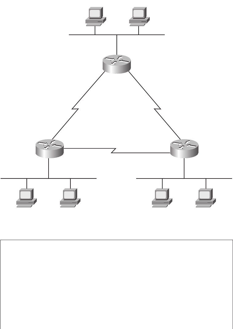
440 Chapter 14: Routing Protocol Concepts and Configuration
Figure 14-1 Sample Internetwork Used Throughout Chapter 14
Example 14-1 Albuquerque Connected Routes
! The following command just lists the IP address configuration on Albuquerque.
! The output has been edited to show only the three interfaces used in Figure
! 14-1.
!
Albuquerque#ss
sshh
hhoo
ooww
ww
rr
rruu
uunn
nnnn
nnii
iinn
nngg
gg--
--cc
ccoo
oonn
nnff
ffii
iigg
gg
interface FastEthernet0/0
ip address 10.1.1.251 255.255.255.0
!
interface Serial 0/0/1
ip address 10.1.128.251 255.255.255.0
!
interface Serial 0/1/0
ip address 10.1.130.251 255.255.255.0
Sam Emma
Fa0/010.1.2.252
Bugs Daffy
Elmer Red
Fa0/0
Fa0/0
10.1.1.251
S0/1/0S0/0/1
S0/1/0
S0/0/1
10.1.130.25110.1.128.251
10.1.129.252
10.1.128.252
S0/0/1
10.1.130.252
S0/1/0
10.1.129.253
10.1.3.253
10.1.1.0/24
10.1.1.130.0/24
10.1.128.0/24
Albuquerque
SevilleYosemite
10.1.129.0/24
10.1.3.0/2410.1.2.0/24
1828xbook.fm Page 440 Thursday, July 26, 2007 3:10 PM

Connected and Static Routes 441
! Lines omitted for brevity
! The next command lists the interfaces, and confirms that Albuquerque’s three
! interfaces shown in Figure 14-1 are in an “up and up” status.
!
Albuquerque#ss
sshh
hhoo
ooww
ww
ii
iipp
pp
ii
iinn
nntt
ttee
eerr
rrff
ffaa
aacc
ccee
ee
bb
bbrr
rrii
iiee
eeff
ff
Interface IP-Address OK? Method Status Protocol
FastEthernet0/0 10.1.1.251 YES manual up up
FastEthernet0/1 unassigned YES manual administratively down down
Serial0/0/0 unassigned YES NVRAM administratively down down
Serial0/0/1 10.1.128.251 YES NVRAM up up
Serial0/1/0 10.1.130.251 YES NVRAM up up
Serial0/1/1 unassigned YES NVRAM administratively down down
!
! The next command lists the routes known by Albuquerque – all connected routes
!
Albuquerque#ss
sshh
hhoo
ooww
ww
ii
iipp
pp
rr
rroo
oouu
uutt
ttee
ee
Codes: C - connected, S - static, I - IGRP, R - RIP, M - mobile, B - BGP
D - EIGRP, EX - EIGRP external, O - OSPF, IA - OSPF inter area
N1 - OSPF NSSA external type 1, N2 - OSPF NSSA external type 2
E1 - OSPF external type 1, E2 - OSPF external type 2, E - EGP
i - IS-IS, L1 - IS-IS level-1, L2 - IS-IS level-2, ia - IS-IS inter area
* - candidate default, U - per-user static route, o - ODR
P - periodic downloaded static route
Gateway of last resort is not set
10.0.0.0/24 is subnetted, 3 subnets
C 10.1.1.0 is directly connected, FastEthernet0/0
C 10.1.130.0 is directly connected, Serial0/1/0
C 10.1.128.0 is directly connected, Serial0/0/1
!
! The next command changes the mask format used by the ss
sshh
hhoo
ooww
ww
ii
iipp
pp
rr
rroo
oouu
uutt
ttee
ee command
!
Albuquerque#tt
ttee
eerr
rrmm
mmii
iinn
nnaa
aall
ll
ii
iipp
pp
nn
nnee
eett
ttmm
mmaa
aass
sskk
kk--
--ff
ffoo
oorr
rrmm
mmaa
aatt
tt
dd
ddee
eecc
ccii
iimm
mmaa
aall
ll
Albuquerque#ss
sshh
hhoo
ooww
ww
ii
iipp
pp
rr
rroo
oouu
uutt
ttee
ee
Codes: C - connected, S - static, I - IGRP, R - RIP, M - mobile, B - BGP
D - EIGRP, EX - EIGRP external, O - OSPF, IA - OSPF inter area
N1 - OSPF NSSA external type 1, N2 - OSPF NSSA external type 2
E1 - OSPF external type 1, E2 - OSPF external type 2, E - EGP
i - IS-IS, L1 - IS-IS level-1, L2 - IS-IS level-2, ia - IS-IS inter area
* - candidate default, U - per-user static route, o - ODR
P - periodic downloaded static route
Gateway of last resort is not set
10.0.0.0 255.255.255.0 is subnetted, 3 subnets
C 10.1.1.0 is directly connected, FastEthernet0/0
C 10.1.130.0 is directly connected, Serial0/1/0
C 10.1.128.0 is directly connected, Serial0/0/1
Example 14-1 Albuquerque Connected Routes (Continued)
1828xbook.fm Page 441 Thursday, July 26, 2007 3:10 PM

442 Chapter 14: Routing Protocol Concepts and Configuration
To begin, the show ip interface brief command in Example 14-1 confirms that
Albuquerque’s three interfaces meet the requirements to have their connected subnets
added to the routing table. Note that all three interfaces are in an “up and up” state and have
an IP address configured.
The output of the show ip route command confirms that Albuquerque indeed added a route
to all three subnets to its routing table. The output begins with a single-letter code legend,
with “C” meaning “connected.” The individual routes begin with a code letter on the far
left—in this case, all three routes have the letter C. Also, note that the output lists the mask
in prefix notation by default. Additionally, in cases when one mask is used throughout a
single classful network—in other words, static-length subnet masking (SLSM) is used—
the show ip route command output lists the mask on a heading line above the subnets of
that classful network. For example, the lines with 10.1.1.0, 10.1.128.0, and 10.1.130.0 do
not show the mask, but the line just above those three lines does list classful network
10.0.0.0 and the mask, as highlighted in the example.
Finally, you can change the format of the display of the subnet mask in show commands,
for the duration of your login session to the router, using the terminal ip netmask-format
decimal EXEC command, as shown at the end of Example 14-1.
Static Routes
Although the connected routes on each router are important, routers typically need other
routes to forward packets to all subnets in an internetwork. For example, Albuquerque can
successfully ping the IP addresses on the other end of each serial link, or IP addresses on
its local connected LAN subnet (10.1.1.0/24). However, a ping of an IP address in a subnet
besides the three connected subnets will fail, as demonstrated in Example 14-2. Note that
this example assumes that Albuquerque still only knows the three connected routes shown
in Example 14-1.
NOTE To be well prepared for the exams, you should look at all items in the output of
the show ip interface brief and show ip route commands in each example in this
chapter. Example 14-6, later in this chapter, provides more detailed comments about the
show ip route command’s output.
Example 14-2 Albuquerque Pings—Works to Connected Subnets Only
! This first ping is a ping of Yosemite’s S0/0/1 interface
Albuquerque#pp
ppii
iinn
nngg
gg
11
1100
00..
..11
11..
..11
1122
2288
88..
..22
2255
5522
22
Type escape sequence to abort.
Sending 5, 100-byte ICMP Echos to 10.1.128.252, timeout is 2 seconds:
!!!!!
Success rate is 100 percent (5/5), round-trip min/avg/max = 4/4/8 ms
1828xbook.fm Page 442 Thursday, July 26, 2007 3:10 PM
Connected and Static Routes 443
The ping command sends an ICMP echo request packet to the stated destination address.
The TCP/IP software at the destination then replies to the ping echo request packet with a
similar packet, called an ICMP echo reply. The ping command sends the first packet and
waits on the response. If a response is received, the command displays a “!”. If no response
is received within the default timeout of 2 seconds, the ping command displays a “.”. The
Cisco IOS software ping command sends five of these packets by default.
In Example 14-2, the ping 10.1.128.252 command works (showing all !’s), because
Albuquerque’s route to 10.1.128.0/24 matches the destination address of 10.1.128.252.
However, the ping to 10.1.2.252 does not work, because Albuquerque does not have a route
for the subnet in which 10.1.2.252 resides, subnet 10.1.2.0/24. As a result, Albuquerque
cannot even send the five ping packets, so the output lists five periods.
The simple and typical solution to this problem is to configure a routing protocol on all
three routers. However, you can configure static routes instead. Example 14-3 shows two
ip route global configuration commands on Albuquerque, which add static routes for the
two LAN subnets connected to Yosemite and Seville. The addition of the first of the two ip
route commands makes the failed ping from Example 14-2 work.
The ip route global configuration command supplies the subnet number, mask, and the
next-hop IP address. One ip route command defines a route to 10.1.2.0 (mask
255.255.255.0), which is located off Yosemite, so the next-hop IP address as configured
on Albuquerque is 10.1.128.252, which is Yosemite’s Serial0/0/1 IP address. Similarly,
Albuquerque’s route to 10.1.3.0/24, the subnet off Seville, points to Seville’s Serial0/0/1
IP address, 10.1.130.253. Note that the next-hop IP address should be an IP address in
! This next ping is a ping of Yosemite’s Fa0/0 interface
Albuquerque#pp
ppii
iinn
nngg
gg
11
1100
00..
..11
11..
..22
22..
..22
2255
5522
22
Type escape sequence to abort.
Sending 5, 100-byte ICMP Echos to 10.1.2.252, timeout is 2 seconds:
.....
Success rate is 0 percent (0/5)
Example 14-3 Static Routes Added to Albuquerque
Albuquerque#cc
ccoo
oonn
nnff
ffii
iigg
gguu
uurr
rree
ee
tt
ttee
eerr
rrmm
mmii
iinn
nnaa
aall
ll
Albuquerque(config)#ii
iipp
pp
rr
rroo
oouu
uutt
ttee
ee
11
1100
00..
..11
11..
..22
22..
..00
00
22
2255
5555
55..
..22
2255
5555
55..
..22
2255
5555
55..
..00
00
11
1100
00..
..11
11..
..11
1122
2288
88..
..22
2255
5522
22
Albuquerque(config)#ii
iipp
pp
rr
rroo
oouu
uutt
ttee
ee
11
1100
00..
..11
11..
..33
33..
..00
00
22
2255
5555
55..
..22
2255
5555
55..
..22
2255
5555
55..
..00
00
11
1100
00..
..11
11..
..11
1133
3300
00..
..22
2255
5533
33
Albuquerque#ss
sshh
hhoo
ooww
ww
ii
iipp
pp
rr
rroo
oouu
uutt
ttee
ee
ss
sstt
ttaa
aatt
ttii
iicc
cc
10.0.0.0/24 is subnetted, 5 subnets
S 10.1.3.0 [1/0] via 10.1.130.253
S 10.1.2.0 [1/0] via 10.1.128.252
Example 14-2 Albuquerque Pings—Works to Connected Subnets Only (Continued)
1828xbook.fm Page 443 Thursday, July 26, 2007 3:10 PM
444 Chapter 14: Routing Protocol Concepts and Configuration
a directly connected subnet. Now Albuquerque knows how to forward routes to
both subnets.
Whereas you can see all routes using the show ip route command, the show ip route static
command lists only statically configured IP routes. The “S” in the first column means that
these two routes were statically configured. Also, to actually be added to the IP routing
table, the ip route command must be configured, and the outgoing interface implied by the
next-hop router IP address must be in an “up and up” state. For example, the next-hop
address on the first ip route command is 10.1.128.252, which is in the subnet connected to
Albuquerque’s S0/0/1 interface. If Albuquerque’s S0/0/1 interface is not currently in an “up
and up” state, this static route would not be listed in the IP routing table.
The ip route command allows a slightly different syntax on point-to-point serial links. For
such links, you can configure the outgoing interface instead of the next-hop IP address. For
instance, you could have configured ip route 10.1.2.0 255.255.255.0 serial0/0/1 for the
first route in Example 14-3.
Unfortunately, adding these two static routes to Albuquerque does not solve all the
network’s routing problems—you would also need to configure static routes on the other
two routers as well. Currently, the static routes help Albuquerque deliver packets to these
two remote LAN subnets, but the other two routers do not have enough routing information
to forward packets back toward Albuquerque’s LAN subnet (10.1.1.0/24). For instance, PC
Bugs cannot ping PC Sam in this network yet. The problem is that although Albuquerque
has a route to subnet 10.1.2.0, where Sam resides, Yosemite does not have a route to
10.1.1.0, where Bugs resides. The ping request packet goes from Bugs to Sam correctly, but
Sam’s ping response packet cannot be routed by the Yosemite router back through
Albuquerque to Bugs, so the ping fails.
Extended ping Command
In real life, you might not be able to find a user, like Bugs, to ask to test your network by
pinging, and it might be impractical to physically travel to some other site just to type a few
ping commands on some end-user PCs. A better alternative might be to telnet to a router
connected to that user’s subnet, and use the IOS ping command to try similar tests.
However, to make the ping command on the router more closely resemble a ping issued by
the end user requires the extended ping command.
The extended IOS ping command, available from privileged EXEC mode, allows the CLI
user to change many options for what the ping command does, including the source IP
address used for the ICMP echo requests sent by the command. To see the significance of
this option, Example 14-4 shows Albuquerque with the working standard ping 10.1.2.252
command, but with an extended ping command that works similarly to a ping from Bugs
1828xbook.fm Page 444 Thursday, July 26, 2007 3:10 PM

Connected and Static Routes 445
to Sam—a ping that fails in this case, because router Yosemite cannot send the ICMP echo
reply back to Albuquerque.
The simple (standard) ping 10.1.2.252 command works for one obvious reason and one
not-so-obvious reason. First, Albuquerque can forward a packet to subnet 10.1.2.0 because
of the static route. The return packet, sent by Yosemite, is sent to address 10.1.128.251—
Albuquerque’s Serial0/0/1 IP address. Why? Well, the following points are true about the
ping command on a Cisco router:
■The Cisco ping command uses, by default, the output interface’s IP address as the
packet’s source address, unless otherwise specified in an extended ping. The first ping
in Example 14-4 uses a source of 10.1.128.251, because Albuquerque’s route used to
send the packet to 10.1.2.252 refers to interface Serial0/0/1 as the outgoing interface—
and Albuquerque’s S0/0/1 interface IP address is 10.1.128.251.
Example 14-4 Albuquerque: Working Ping After Adding Default Routes, Plus Failing
Extended ping
Albuquerque#ss
sshh
hhoo
ooww
ww
ii
iipp
pp
rr
rroo
oouu
uutt
ttee
ee
ss
sstt
ttaa
aatt
ttii
iicc
cc
10.0.0.0/24 is subnetted, 5 subnets
S 10.1.3.0 [1/0] via 10.1.130.253
S 10.1.2.0 [1/0] via 10.1.128.252
Albuquerque#pp
ppii
iinn
nngg
gg
11
1100
00..
..11
11..
..22
22..
..22
2255
5522
22
Type escape sequence to abort.
Sending 5, 100-byte ICMP Echos to 10.1.2.252, timeout is 2 seconds:
!!!!!
Success rate is 100 percent (5/5), round-trip min/avg/max = 4/4/8 ms
Albuquerque#pp
ppii
iinn
nngg
gg
Protocol [ip]:
Target IP address: 10.1.2.252
Repeat count [5]:
Datagram size [100]:
Timeout in seconds [2]:
Extended commands [n]: y
Source address or interface: 10.1.1.251
Type of service [0]:
Set DF bit in IP header? [no]:
Validate reply data? [no]:
Data pattern [0xABCD]:
Loose, Strict, Record, Timestamp, Verbose[none]:
Sweep range of sizes [n]:
Type escape sequence to abort.
Sending 5, 100-byte ICMP Echos to 10.1.2.252, timeout is 2 seconds:
. . . . .
Success rate is 0 percent (0/5)
1828xbook.fm Page 445 Thursday, July 26, 2007 3:10 PM
446 Chapter 14: Routing Protocol Concepts and Configuration
■Ping response packets reverse the IP addresses used in the original ping request. So, in
this example, Albuquerque used 10.1.128.251 as the source IP address of the original
packet, so Yosemite uses 10.1.128.251 as the destination of the ping response packet—
and Yosemite has a connected route to reach subnet 10.1.128.0/24, which includes
address 10.1.128.251.
When you troubleshoot this internetwork, you can use the extended ping command to act
like you issued a ping from a computer on that subnet, without having to call a user and ask
to enter a ping command for you on the PC. The extended version of the ping command
can be used to refine the problem’s underlying cause by changing several details of what
the ping command sends in its request. In real networks, when a ping from a router works,
but a ping from a host does not, the extended ping could help you re-create the problem
without needing to work with the end user on the phone.
For example, in Example 14-4, the extended ping command on Albuquerque uses a source
IP address of 10.1.1.251 (Albuquerque’s Fa0/0 interface IP address), destined to 10.1.2.252
(Yosemite’s Fa0/0 IP address). According to the command output, no ping response was
received by Albuquerque. Normally, Albuquerque’s ping would be sourced from the IP
address of the outgoing interface. With the use of the extended ping source address option,
the source IP address of the echo packet is set to Albuquerque’s Fa0/0 IP address,
10.1.1.251. Because the ICMP echo generated by the extended ping is sourced from an
address in subnet 10.1.1.0, the packet looks more like a packet from an end user in that
subnet. Yosemite builds a reply, with destination 10.1.1.251—but Yosemite does not have a
route to subnet 10.1.1.0/24. So, Yosemite cannot send the ping reply packet back to
Albuquerque, causing the ping to fail.
The solution in this case is pretty simple: either add a static route on Yosemite for subnet
10.1.1.0/24, or enable a routing protocol on all three routers.
Default Routes
As part of the routing (forwarding) process, a router compares each packet’s destination IP
address to the router’s routing table. If the router does not match any routes, the router
discards the packet, and makes no attempt to recover from the loss.
A default route is a route that is considered to match all destination IP addresses. With a
default route, when a packet’s destination IP address does not match any other routes, the
router uses the default route for forwarding the packet.
Default routes work best when only one path exists to a part of the network. For example,
in Figure 14-2, R1 is a branch office router with a single serial link connecting it to the
rest of the enterprise network. There may be hundreds of subnets located outside R1’s
1828xbook.fm Page 446 Thursday, July 26, 2007 3:10 PM
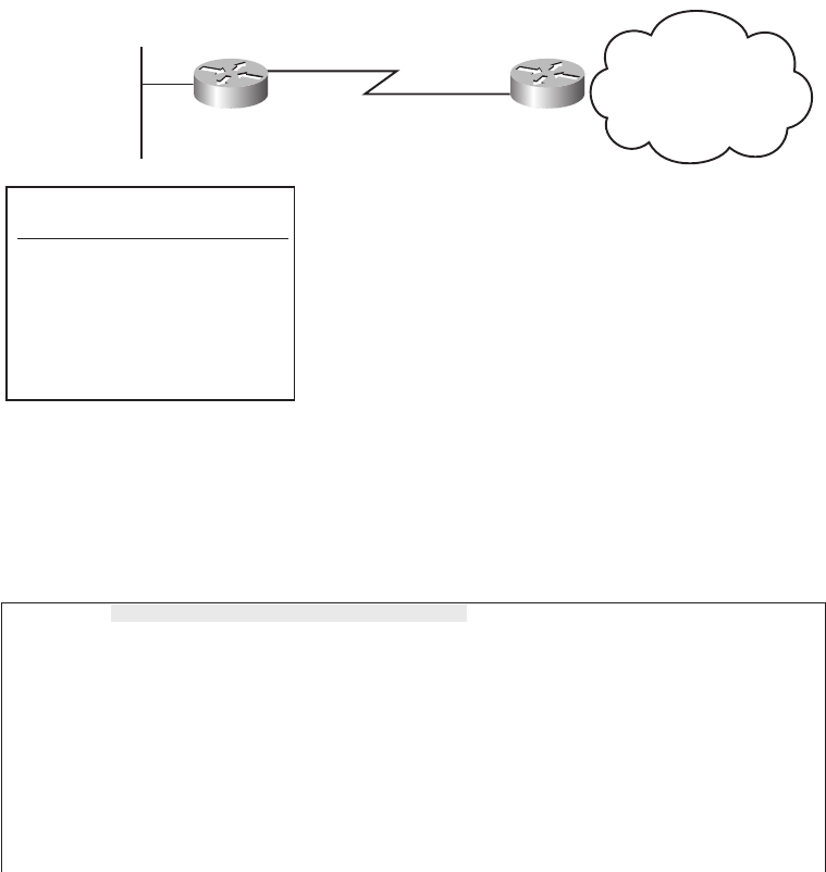
Connected and Static Routes 447
branch office. The engineer has three main options for helping R1 know routes to reach all
the rest of the subnets:
■Configure hundreds of static routes on R1—but all of those routes would use S0/1 as
R1’s outgoing interface, with next-hop IP address 172.16.3.2 (R2).
■Enable a routing protocol on the routers to learn the routes.
■Add a default route to R1 with outgoing interface S0/1.
Figure 14-2 Sample Network in Which a Default Route Is Useful
By coding a special static route called a default route, R1 can have a single route that
forwards all packets out its S0/1 interface toward R2. The ip route command lists a special
subnet and mask value, each 0.0.0.0, which means “match all packets.” Example 14-5
shows the default static route on R1, pointing to R2 (172.16.3.2) as the next-hop router.
Example 14-5 R1 Static Default Route Configuration and Routing Table
R1(config)#ii
iipp
pp
rr
rroo
oouu
uutt
ttee
ee
00
00..
..00
00..
..00
00..
..00
00
00
00..
..00
00..
..00
00..
..00
00
11
1177
7722
22..
..11
1166
66..
..33
33..
..22
22
R1#ss
sshh
hhoo
ooww
ww
ii
iipp
pp
rr
rroo
oouu
uutt
ttee
ee
Codes: C - connected, S - static, I - IGRP, R - RIP, M - mobile, B - BGP
D - EIGRP, EX - EIGRP external, O - OSPF, IA - OSPF inter area
N1 - OSPF NSSA external type 1, N2 - OSPF NSSA external type 2
E1 - OSPF external type 1, E2 - OSPF external type 2, E - EGP
i - IS-IS, L1 - IS-IS level-1, L2 - IS-IS level-2, ia - IS-IS inter area
* - candidate default, U - per-user static route, o - ODR
P - periodic downloaded static route
continues
S0/1 172.16.3.2
Subnet 1 Subnet 2
Subnet 3
172.16.3.0/24
The Rest of the
Enterprise; Hundreds
of Subnets
R1 R2
Fa0/0
R1 Routing Table
Subnet Outgoing Interface
Subnet 1 S0/1
Subnet 2 S0/1
Subnet 3 S0/1
• S0/1
• S0/1
• S0/1
1828xbook.fm Page 447 Thursday, July 26, 2007 3:10 PM

448 Chapter 14: Routing Protocol Concepts and Configuration
The show ip route command shows a couple of interesting facts about this special default
route. The output lists a code of “S” just like other static routes, but with an * as well. The
* means that the route might be used as the default route, meaning it will be used for packets
that do not match any other routes in the routing table. Without a default route, a router
discards packets that do not match the routing table. With a default route, the router
forwards packets that do not match any other routes, as in the case in this example.
You could use static routes, including static default routes, on all routers in an internetwork.
However, most enterprises use a dynamic routing protocol to learn all the routes. The
next section covers some additional concepts and terminology for routing protocols, with
the remainder of the chapter focusing on how to configure RIP-2.
Routing Protocol Overview
IP routing protocols have one primary goal: to fill the IP routing table with the current best
routes it can find. The goal is simple, but the process and options can be complicated.
Routing protocols help routers learn routes by having each router advertise the routes it
knows. Each router begins by knowing only connected routes. Then, each router sends
messages, defined by the routing protocol, that list the routes. When a router hears a routing
update message from another router, the router hearing the update learns about the subnets
and adds routes to its routing table. If all the routers participate, all the routers can learn
about all subnets in an internetwork.
When learning routes, routing protocols must also prevent loops from occurring. A loop
occurs when a packet keeps coming back to the same router due to errors in the routes in
the collective routers’ routing tables. These loops can occur with routing protocols, unless
the routing protocol makes an effort to avoid the loops.
This section starts by explaining how RIP-2 works in a little more detail than was covered
in Chapter 5. Following that, the various IP routing protocols are compared.
Gateway of last resort is 172.16.3.2 to network 0.0.0.0
172.16.0.0/24 is subnetted, 3 subnets
C 172.16.1.0 is directly connected, FastEthernet0/0
C 172.16.3.0 is directly connected, Serial0/1
S* 0.0.0.0/0 [1/0] via 172.16.3.2
NOTE Chapter 4, “IP Routing,” in the CCNA ICND2 Official Exam Certification
Guide, explains default routes in more detail.
Example 14-5 R1 Static Default Route Configuration and Routing Table (Continued)
1828xbook.fm Page 448 Thursday, July 26, 2007 3:10 PM
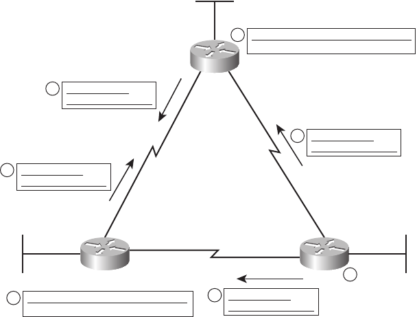
Routing Protocol Overview 449
RIP-2 Basic Concepts
Routers using RIP-2 advertise a small amount of simple information about each subnet to
their neighbors. Their neighbors in turn advertise the information to their neighbors, and so
on, until all routers have learned the information. In fact, it works a lot like how rumors
spread in a neighborhood, school, or company. You might be out in the yard, stop to talk to
your next-door neighbor, and tell your neighbor the latest gossip. Then, that neighbor sees
his other next-door neighbor, and tells them the same bit of gossip—and so on, until
everyone in the neighborhood knows the latest gossip. Distance vector protocols work the
same way, but hopefully, unlike rumors in a real neighborhood, the rumor has not changed
by the time everyone has heard about it.
For example, consider what occurs in Figure 14-3. The figure shows RIP-2 advertising a
subnet number, mask (shown in prefix notation), and metric to its neighbors.
Figure 14-3 Example of How RIP-2 Advertises Routes
For the sake of keeping the figure less cluttered, Figure 14-3 only shows how the
routers advertise and learn routes for subnet 172.16.3.0/24, even though the routers
do advertise about other routes as well. Following the steps in the figure:
1. Router R2 learns a connected route for subnet 172.16.3.0/24.
2. R2 sends a routing update to its neighbors, listing a subnet (172.16.3.0), mask (/24),
and a distance, or metric (1 in this case).
FA0/1
S0/0
S0/1
S0/1
S0/0
172.16.3.252
FA0/0
172.16.1.251
S0/1
172.16.6.252
S0/0
172.16.2.252
R3
172.16.5.253
FA0/0
R1 R2
I have a route to
172.16.3.0/24, metric 2.
I have a route to
172.16.3.0/24, metric 1.
I have a route to
172.16.3.0/24, metric 2.
I have a route to
172.16.3.0/24, metric 1.
R1 IP Routing Table
Subnet Out Int. Next-Hop Metric
172.16.3.0 S0/0 172.16.2.252 1
2
2
1
5
5
4
R3 IP Routing Table
Subnet Out Int. Next-Hop Metric
172.16.3.0 S0/1 172.16.6.252 1
3
1828xbook.fm Page 449 Thursday, July 26, 2007 3:10 PM
450 Chapter 14: Routing Protocol Concepts and Configuration
3. R3 hears the routing update, and adds a route to its routing table for subnet 172.16.3.0/24,
referring to R2 as the next-hop router.
4. Around the same time, R1 also hears the routing update sent directly to R1 by R2. R1
then adds a route to its routing table for subnet 172.16.3.0/24, referring to R2 as the
next-hop router.
5. R1 and R3 then send a routing update to each other, for subnet 172.16.3.0/24, metric 2.
By the end of this process, both R1 and R3 have heard of two possible routes to reach subnet
172.16.3.0/24—one with metric 1, and one with metric 2. Each router uses its respective
lower-metric (metric 1) routes to reach 172.16.3.0.
Interestingly, distance vector protocols such as RIP-2 repeat this process continually on
a periodic basis. For example, RIP routers send periodic routing updates about every
30 seconds by default. As long as the routers continue to hear the same routes, with the
same metrics, the routers’ routing tables do not need to change. However, when something
changes, the next routing update will change or simply not occur due to some failure, so
the routers will react and converge to use the then-best working routes.
Now that you have seen the basics of one routing protocol, the next section explains a wide
variety of features of different routing protocols for the sake of comparison.
Comparing and Contrasting IP Routing Protocols
IP’s long history and continued popularity has driven the need for several different
competing routing protocols over time. So, it is helpful to make comparisons between the
different IP routing protocols to see their relative strengths and weaknesses. This section
describes several technical points on which the routing protocols can be compared. Then,
this chapter examines RIP-2 in more detail; the CCNA ICND2 Official Exam Certification
Guide explains OSPF and EIGRP in more detail.
One of the first points of comparison is whether the protocol is defined in RFCs, making
it a public standard, or whether it is Cisco proprietary. Another very important
consideration is whether the routing protocol supports variable-length subnet masking
(VLSM). Although the details of VLSM are not covered in this book, but instead are
covered in the CCNA ICND2 Official Exam Certification Guide, VLSM support is an
important consideration today. This section introduces several different terms and concepts
used to compare the various IP routing protocols, with Table 14-4 at the end of this
section summarizing the comparison points for many of the IP routing protocols.
1828xbook.fm Page 450 Thursday, July 26, 2007 3:10 PM

Routing Protocol Overview 451
Interior and Exterior Routing Protocols
IP routing protocols fall into one of two major categories:
■Interior Gateway Protocol (IGP): A routing protocol that was designed and intended
for use inside a single autonomous system
■Exterior Gateway Protocol (EGP): A routing protocol that was designed and
intended for use between different autonomous systems
These definitions use another new term: autonomous system. An autonomous system is an
internetwork under the administrative control of a single organization. For instance, an
internetwork created and paid for by a single company is probably a single autonomous
system, and an internetwork created by a single school system is probably a single
autonomous system. Other examples include large divisions of a state or national
government, where different government agencies may be able to build their own separate
internetworks.
Some routing protocols work best inside a single autonomous system, by design, so
these routing protocols are called IGPs. Conversely, only one routing protocol, Border
Gateway Protocol (BGP), is used today to exchange routes between routers in different
autonomous systems, so it is called an EGP.
Each autonomous system can be assigned a number, called (unsurprisingly) an
autonomous system number (ASN). Like public IP addresses, the Internet Corporation for
Assigned Network Numbers (ICANN) controls the worldwide rights to assign ASNs,
delegating that authority to other organizations around the planet, typically to the same
organizations that assign public IP addresses. By assigning each autonomous organization
an ASN, BGP can ensure that packets do not loop around the global Internet by making
sure that packets do not pass through the same autonomous system twice.
Figure 14-4 shows a small view into the worldwide Internet. Two companies and three ISPs
use IGPs (OSPF and EIGRP) inside their own networks, with BGP being used between
the ASNs.
NOTE The terms IGP and EGP include the word gateway because routers used to be
called gateways.
1828xbook.fm Page 451 Thursday, July 26, 2007 3:10 PM
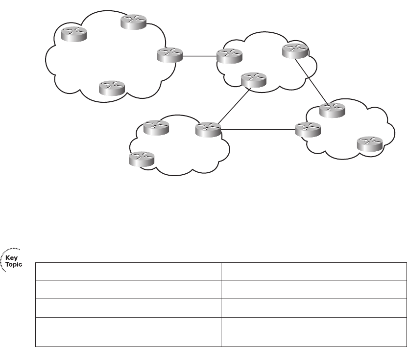
452 Chapter 14: Routing Protocol Concepts and Configuration
Figure 14-4 Comparing Locations for Using IGPs and EGPs
Routing Protocol Types/Algorithms
Each IGP can be classified as using a particular class, or type, of underlying logic. Table 14-2
lists the three options, noting which IGPs use which class of algorithm.
The CCNA ICND2 Official Exam Certification Guide covers the theory behind each of
these classes of routing protocols. However, because the only IGP this book covers to any
level of detail is RIP-2, most of the conceptual materials in this chapter actually show how
distance vector protocols work.
Metrics
Routing protocols must have some way to decide which route is best when a router learns
of more than one route to reach a subnet. To that end, each routing protocol defines a metric
that gives an objective numeric value to the “goodness” of each route. The lower the metric,
the better the route. For example, earlier, in Figure 14-3, R1 learned a metric 1 route for
subnet 172.16.3.0/24 from R2, and a metric 2 route for that same subnet from R3, so R1
chose the lower-metric (1) route through R2.
Table 14-2 Routing Protocol Classes/Algorithms and Protocols that Use Them
Class/Algorithm IGPs
Distance vector RIP-1, RIP-2, IGRP
Link-state OSPF, Integrated IS-IS
Balanced hybrid (also called advanced distance
vector)
EIGRP
Enterprise 1
Subnets of Network 9.0.0.0
EIGRP
ISP3
OSPF
ISP2
EIGRP
BGP
ASN 100
ASN 200
ASN 400
ASN 300
BGP
BGP
BGP
ISP4
EIGRP
1828xbook.fm Page 452 Thursday, July 26, 2007 3:10 PM
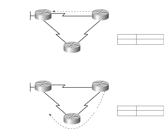
Routing Protocol Overview 453
Some metrics work better than others. To see why, consider Figure 14-5. The figure shows
two analyses of the same basic internetwork, focusing on router B’s choice of a route to
reach subnet 10.1.1.0, which is on the LAN on the left side of router A. In this case, the link
between A and B is only a 64-kbps link, whereas the other two links are T1s, running at
1.544 Mbps each. The top part of the figure shows router B’s choice of route when using
RIP (Version 1 or Version 2), whereas the bottom part of the figure shows router B’s choice
when the internetwork uses EIGRP.
Figure 14-5 Comparing the Effect of the RIP and EIGRP Metrics
RIP uses a metric called hop count, which measures the number of routers (hops)
between a router and a subnet. With RIP, router B would learn two routes to reach subnet
10.1.1.0: a one-hop route through router A, and a two-hop route first through router C and
then to router A. So, router B, using RIP, would add a route for subnet 10.1.1.0 pointing to
router A as the next-hop IP address (represented as the dashed line in Figure 14-5).
EIGRP, on the other hand, uses a metric that (by default) considers both the interface
bandwidth and interface delay settings as input into a mathematical formula to calculate the
metric. If routers A, B, and C were configured with correct bandwidth interface
T/1 T/1
S1
S0
Subnet 10.1.1.0
RIP, Regardless of Bandwidth
Bandwidth 64
64 kbps
Bandwidth 1544 Bandwidth 1544 10.1.1.0
Routing Table
S0
Subnet Output Interface
A
C
B
T/1 T/1
S1
S0
Subnet 10.1.1.0
EIGRP
Bandwidth 64
64 kbps
Bandwidth 1544 Bandwidth 1544 10.1.1.0
Routing Table
S1
Subnet Output Interface
A
C
B
1828xbook.fm Page 453 Thursday, July 26, 2007 3:10 PM

454 Chapter 14: Routing Protocol Concepts and Configuration
subcommands, as listed in Figure 14-5, EIGRP would add a route for subnet 10.1.1.0 to its
routing table, but with router C as the next-hop router, again shown with a dashed line.
Autosummarization and Manual Summarization
Routers generally perform routing (forwarding) more quickly with smaller routing
tables, and less quickly with larger routing tables. Route summarization helps shorten
the routing table while retaining all the needed routes in the network.
Two general types of route summarization can be done, with varying support for these
two types depending on the routing protocol. The two types, both of which are introduced
in this section, are called autosummarization and manual summarization. Manual
summarization gives the network engineer a great deal of control and flexibility, allowing
the engineer to choose what summary routes to advertise, instead of just being able to
summarize with a classful network. As a result, support for manual summarization is the
more useful feature as compared to autosummarization.
Chapter 5 in the CCNA ICND2 Official Exam Certification Guide explains both
autosummarization and manual summarization in great detail.
Classless and Classful Routing Protocols
Some routing protocols must consider the Class A, B, or C network number that a subnet
resides in when performing some of its tasks. Other routing protocols can ignore Class A,
B, and C rules altogether. Routing protocols that must consider class rules are called
classful routing protocols; those that do not need to consider class rules are called classless
routing protocols.
Classless routing protocols and classful routing protocols are identified by the same three
criteria, as summarized in Table 14-3.
NOTE For a review of the bandwidth command, refer to the section “Bandwidth and
Clock Rate on Serial Interfaces” in Chapter 13, “Operating Cisco Routers.”
Table 14-3 Comparing Classless and Classful Routing Protocols
Feature Classless Classful
Supports VLSM Yes No
Sends subnet mask in routing updates Yes No
Supports manual route summarization Yes No
1828xbook.fm Page 454 Thursday, July 26, 2007 3:10 PM
Routing Protocol Overview 455
Convergence
The term convergence refers to the overall process that occurs with routing protocols
when something changes in a network topology. When a link comes up or fails, or when a
router fails or is first turned on, the possible routes in the internetwork change. The
processes used by routing protocols to recognize the changes, to figure out the now-best
routes to each subnet, and to change all the routers’ routing tables, is called convergence.
Some routing protocols converge more quickly than others. As you might imagine, the
capability to converge quickly is important, because in some cases, until convergence
completes, users might not be able to send their packets to particular subnets. (Table 14-4
in the next section summarizes the relative convergence speed of various IP routing
protocols, along with other information.)
Miscellaneous Comparison Points
Two other minor comparison points between the various IGPs are interesting as well.
First, the original routing protocol standards defined that routing updates should be sent
to the IP all-local-hosts broadcast address of 255.255.255.255. After those original routing
protocols were defined, IP multicast emerged, which allowed newer routing protocols to
send routing updates only to other interested routers by using various IP multicast IP
addresses.
The earlier IGPs did not include any authentication features. As time went on, it
became obvious that attackers could form a denial-of-service (DoS) attack by causing
problems with routing protocols. For example, an attacker could connect a router to a
network and advertise lots of lower-metric routes for many subnets, causing the packets
to be routed to the wrong place—and possibly copied by the attacker. The later-defined
IGPs typically support some type of authentication, hoping to mitigate the exposure
to these types of DoS attacks.
Summary of Interior Routing Protocols
For convenient comparison and study, Table 14-4 summarizes the most important features
of interior routing protocols. Note that the most important routing protocol for the ICND1
exam is RIP, specifically RIP-2. The ICND2 and CCNA exams include more detailed
coverage of RIP-2 theory, as well as the theory, configuration, and troubleshooting of OSPF
and EIGRP.
1828xbook.fm Page 455 Thursday, July 26, 2007 3:10 PM
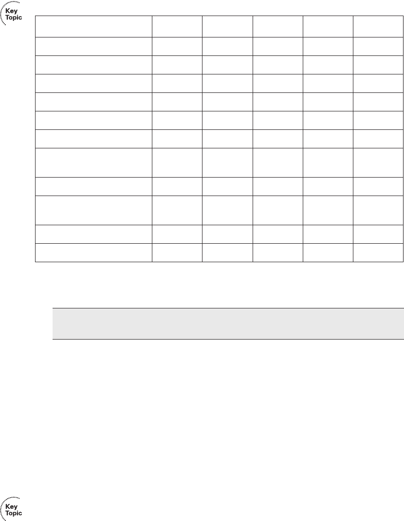
456 Chapter 14: Routing Protocol Concepts and Configuration
1. EIGRP is often described as a balanced hybrid routing protocol, instead of link-state or distance vector. Some
documents refer to EIGRP as an advanced distance vector protocol.
Configuring and Verifying RIP-2
RIP-2 configuration is actually somewhat simple as compared to the concepts related to
routing protocols. The configuration process uses three required commands, with only one
command, the network command, requiring any real thought. You should also know the
more-popular show commands for helping you analyze and troubleshoot routing protocols.
RIP-2 Configuration
The RIP-2 configuration process takes only the following three required steps, with the
possibility that the third step might need to be repeated:
Step 1 Use the router rip configuration command to move into RIP configuration mode.
Step 2 Use the version 2 RIP subcommand to tell the router to use RIP Version
2 exclusively.
Table 14-4 Interior IP Routing Protocols Compared
Feature RIP-1 RIP-2 EIGRP OSPF IS-IS
Classless No Yes Yes Yes Yes
Supports VLSM No Yes Yes Yes Yes
Sends mask in update No Yes Yes Yes Yes
Distance vector Yes Yes No1No No
Link-state No No No1Yes Yes
Supports autosummarization No Yes Yes No No
Supports manual
summarization
No Yes Yes Yes Yes
Proprietary No No Yes No No
Routing updates sent to a
multicast IP address
No Yes Yes Yes N/A
Supports authentication No Yes Yes Yes Yes
Convergence Slow Slow Very fast Fast Fast
NOTE For reference, IGRP has the same characteristics as RIP-1 in Table 14-4, with the
exception that IGRP is proprietary and RIP-1 is not.
1828xbook.fm Page 456 Thursday, July 26, 2007 3:10 PM
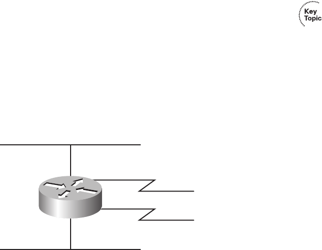
Configuring and Verifying RIP-2 457
Step 3 Use one or more network net-number RIP subcommands to enable RIP
on the correct interfaces.
Step 4 (Optional) As needed, disable RIP on an interface using the passive-
interface type number RIP subcommand.
Of the required first three steps, only the third step—the RIP network command—
requires much thought. Each RIP network command enables RIP on a set of interfaces.
The RIP network command only uses a classful network number as its one parameter.
For any of the router’s interface IP addresses in that entire classful network, the router
does the following three things:
■The router multicasts routing updates to a reserved IP multicast IP address, 224.0.0.9.
■The router listens for incoming updates on that same interface.
■The router advertises about the subnet connected to the interface.
Sample RIP Configuration
Keeping these facts in mind, now consider how to configure RIP on a single router.
Examine Figure 14-6 for a moment and try to apply the first three configuration steps to this
router and anticipate the configuration required on the router to enable RIP on all interfaces.
Figure 14-6 RIP-2 Configuration: Sample Router with Four Interfaces
The first two configuration commands are easy, router rip, followed by version 2, with no
parameters to choose. Then you need to pick which network commands need to be
configured at Step 3. To match interface S0/0, you have to figure out that address 199.1.1.1
is in Class C IP network 199.1.1.0, meaning you need a network 199.1.1.0 RIP
subcommand. Similarly, to match interface S0/1, you need a network 199.1.2.0 command,
because IP address 199.1.2.1 is in Class C network 199.1.2.0. Finally, both of the LAN
interfaces have an IP address in Class A network 10.0.0.0, so a single network 10.0.0.0
command matches both interfaces. Example 14-6 shows the entire configuration process,
with all five configuration commands.
10.1.2.3 S0/0 199.1.1.1
S0/1 199.1.2.1
10.4.3.2
Fa0/0
Fa0/1
R1
1828xbook.fm Page 457 Thursday, July 26, 2007 3:10 PM

458 Chapter 14: Routing Protocol Concepts and Configuration
With this configuration, R1 starts using RIP—sending RIP updates, listening for incoming
RIP updates, and advertising about the connected subnet—on each of its four interfaces.
However, imagine that for some reason you wanted to enable RIP on R1’s Fa0/0 interface,
but did not want to enable RIP on Fa0/1’s interface. Both interfaces are in network 10.0.0.0,
so both are matched by the network 10.0.0.0 command.
RIP configuration does not provide a way to enable RIP on only some of the interfaces in
a single Class A, B, or C network. So, if you needed to enable RIP only on R1’s Fa0/0
interface, and not on the Fa0/1 interface, you would actually need to use the network
10.0.0.0 command to enable RIP on both interfaces, and then disable the sending of RIP
updates on Fa0/1 using the passive-interface type number RIP subcommand. For example,
to enable RIP on all interfaces of router R1 in Figure 14-6, except for Fa0/1, you could use
the same configuration in Example 14-6, but then also add the passive-interface fa0/1
subcommand while in RIP configuration mode. This command tells R1 to stop sending RIP
updates out its Fa0/1 interface, disabling one of the main functions of RIP.
One final note on the network command: IOS will actually accept a parameter besides a
classful network number on the command, and IOS does not supply an error message,
either. However, IOS, knowing that the parameter must be a classful network number,
changes the command. For example, if you typed network 10.1.2.3 in RIP configuration
mode, IOS would accept the command, with no error messages. However, when you look
at the configuration, you would see a network 10.0.0.0 command, and the network
10.1.2.3 command that you had typed would not be there. The network 10.0.0.0 command
would indeed match all interfaces in network 10.0.0.0.
RIP-2 Verification
IOS includes three primary show commands that are helpful to confirm how well RIP-2 is
working. Table 14-5 lists the commands and their main purpose.
Example 14-6 Sample Router Configuration with RIP Enabled
R1#cc
ccoo
oonn
nnff
ffii
iigg
gguu
uurr
rree
ee
tt
ttee
eerr
rrmm
mmii
iinn
nnaa
aall
ll
R1(config)#rr
rroo
oouu
uutt
ttee
eerr
rr
rr
rrii
iipp
pp
R1(config-router)#vv
vvee
eerr
rrss
ssii
iioo
oonn
nn
22
22
R1(config-router)#nn
nnee
eett
ttww
wwoo
oorr
rrkk
kk
11
1199
9999
99..
..11
11..
..11
11..
..00
00
R1(config-router)#nn
nnee
eett
ttww
wwoo
oorr
rrkk
kk
11
1199
9999
99..
..11
11..
..22
22..
..00
00
R1(config-router)#nn
nnee
eett
ttww
wwoo
oorr
rrkk
kk
11
1100
00..
..00
00..
..00
00..
..00
00
NOTE The passive-interface command only stops the sending of RIP updates on the
interface. Other features outside the scope of this book could be used to disable the
processing of received updates and the advertisement of the connected subnet.
1828xbook.fm Page 458 Thursday, July 26, 2007 3:10 PM

Configuring and Verifying RIP-2 459
To better understand these commands, this section uses the internetwork shown in
Figure 14-1. First, consider the RIP-2 configuration required on each of the three routers.
All three interfaces on all three routers are in classful network 10.0.0.0. So each router
needs only one network command, network 10.0.0.0, to match all three of its interfaces.
The configuration needs to be the same on all three routers, as follows:
rr
rroo
oouu
uutt
ttee
eerr
rr
rr
rrii
iipp
pp
vv
vvee
eerr
rrss
ssii
iioo
oonn
nn
22
22
nn
nnee
eett
ttww
wwoo
oorr
rrkk
kk
11
1100
00..
..00
00..
..00
00..
..00
00
Now, to focus on the show commands, Example 14-7 lists a couple of variations of the
show ip route command, with some explanations in the example, and some following the
example. Following that, Example 14-8 focuses on the show ip protocols command. Note
that Example 14-1, earlier in this chapter, shows the output from the show ip interfaces
brief command on the Albuquerque router, so it is not repeated here.
Table 14-5 RIP Operational Commands
Command Purpose
show ip interface brief Lists one line per router interface, including the IP address and
interface status; an interface must have an IP address, and be in an “up
and up” status, before RIP begins to work on the interface.
show ip route [rip] Lists the routing table, including RIP-learned routes, and optionally
just RIP-learned routes.
show ip protocols Lists information about the RIP configuration, plus the IP addresses of
neighboring RIP routers from which the local router has learned
routes.
Example 14-7 The show ip route Command
Albuquerque#ss
sshh
hhoo
ooww
ww
ii
iipp
pp
rr
rroo
oouu
uutt
ttee
ee
Codes: C - connected, S - static, R - RIP, M - mobile, B - BGP
D - EIGRP, EX - EIGRP external, O - OSPF, IA - OSPF inter area
N1 - OSPF NSSA external type 1, N2 - OSPF NSSA external type 2
E1 - OSPF external type 1, E2 - OSPF external type 2
i - IS-IS, su - IS-IS summary, L1 - IS-IS level-1, L2 - IS-IS level-2
ia - IS-IS inter area, * - candidate default, U - per-user static route
o - ODR, P - periodic downloaded static route
Gateway of last resort is not set
10.0.0.0/24 is subnetted, 6 subnets
R 10.1.3.0 [120/1] via 10.1.130.253, 00:00:16, Serial0/1/0
R 10.1.2.0 [120/1] via 10.1.128.252, 00:00:09, Serial0/0/1
C 10.1.1.0 is directly connected, FastEthernet0/0
continues
1828xbook.fm Page 459 Thursday, July 26, 2007 3:10 PM

460 Chapter 14: Routing Protocol Concepts and Configuration
Interpreting the Output of the show ip route Command
Example 14-7 shows the show ip route command, which lists all IP routes, the show ip
route rip command, which lists only RIP-learned routes, and the show ip route address
command, which lists details about the route matched for packets sent to the listed IP
address. Focusing on the show ip route command, note that the legend lists “R,” which
means that a route has been learned by RIP, and that three of the routes list an R beside
them. Next, examine the details in the route for subnet 10.1.3.0/24, highlighted in the
example. The important details are as follows:
■The subnet number is listed, with the mask in the heading line above.
■The next-hop router’s IP address, 10.1.130.253, which is Seville’s S0/0/1 IP address.
C 10.1.130.0 is directly connected, Serial0/1/0
R 10.1.129.0 [120/1] via 10.1.130.253, 00:00:16, Serial0/1/0
[120/1] via 10.1.128.252, 00:00:09, Serial0/0/1
C 10.1.128.0 is directly connected, Serial0/0/1
!
! The next command lists just the RIP routes, so no code legend is listed
!
Albuquerque#ss
sshh
hhoo
ooww
ww
ii
iipp
pp
rr
rroo
oouu
uutt
ttee
ee
rr
rrii
iipp
pp
10.0.0.0/24 is subnetted, 6 subnets
R 10.1.3.0 [120/1] via 10.1.130.253, 00:00:20, Serial0/1/0
R 10.1.2.0 [120/1] via 10.1.128.252, 00:00:13, Serial0/0/1
R 10.1.129.0 [120/1] via 10.1.130.253, 00:00:20, Serial0/1/0
[120/1] via 10.1.128.252, 00:00:13, Serial0/0/1
!
! The next command lists the route matched by this router for packets going to the
! listed IP address 10.1.2.1.
!
Albuquerque#ss
sshh
hhoo
ooww
ww
ii
iipp
pp
rr
rroo
oouu
uutt
ttee
ee
11
1100
00..
..11
11..
..22
22..
..11
11
Routing entry for 10.1.2.0/24
Known via “rip”, distance 120, metric 1
Redistributing via rip
Last update from 10.1.128.252 on Serial0/0/1, 00:00:18 ago
Routing Descriptor Blocks:
* 10.1.128.252, from 10.1.128.252, 00:00:18 ago, via Serial0/0/1
Route metric is 1, traffic share count is 1
!
! The same command again, but for an address that does not have a matching route in
! the routing table.
Albuquerque#ss
sshh
hhoo
ooww
ww
ii
iipp
pp
rr
rroo
oouu
uutt
ttee
ee
11
1100
00..
..11
11..
..77
77..
..11
11
% Subnet not in table
Albuquerque#
Example 14-7 The show ip route Command (Continued)
1828xbook.fm Page 460 Thursday, July 26, 2007 3:10 PM
Configuring and Verifying RIP-2 461
■Albuquerque’s S0/1/0 interface is the outgoing interface.
■The length of time since Albuquerque last heard about this route in a periodic RIP
update, 16 seconds ago in this case.
■The RIP metric for this route (1 in this case), listed as the second number in the square
brackets. For example, between Albuquerque and subnet 10.1.3.0/24, one other router
(Seville) exists.
■The administrative distance of the route (120 in this case; the first number in brackets).
Take the time now to review the other two RIP routes, noting the values for these various
items in those routes. As you can see, the show ip route rip command output lists the
routes in the exact same format, the difference being that only RIP-learned routes are
shown, and the legend is not displayed at the top of the command output. The show ip
route address command lists more detailed output about the route that matches the
destination IP address listed in the command, with the command output supplying more
detailed information about the route.
Administrative Distance
When an internetwork has redundant links, and uses a single routing protocol, each
router may learn multiple routes to reach a particular subnet. As stated earlier in this
chapter, the routing protocol then uses a metric to choose the best route, and the router
adds that route to its routing table.
In some cases, internetworks use multiple IP routing protocols. In such cases, a router
might learn of multiple routes to a particular subnet using different routing protocols. In
these cases, the metric does not help the router choose which route is best, because each
routing protocol uses a metric unique to that routing protocol. For example, RIP uses the
hop count as the metric, but EIGRP uses a math formula with bandwidth and delay as
inputs. A route with RIP metric 1 might need to be compared to an EIGRP route, to the
same subnet, but with metric 4,132,768. (Yes, EIGRP metrics tend to be large numbers.)
Because the numbers have different meanings, there is no real value in comparing the
metrics.
The router still needs to choose the best route, so IOS solves this problem by assigning a
numeric value to each routing protocol. IOS then chooses the route whose routing protocol
has the lower number. This number is called the administrative distance (AD). For example,
EIGRP defaults to use an AD of 90, and RIP defaults to use the value of 120, as seen in the
routes in Example 14-7. So, an EIGRP route to a subnet would be chosen instead of a
competing RIP route. Table 14-6 lists the AD values for the most common sources of
routing information.
1828xbook.fm Page 461 Thursday, July 26, 2007 3:10 PM

462 Chapter 14: Routing Protocol Concepts and Configuration
While this may be a brief tangent away from RIP and routing protocols, now that this
chapter has explained administrative distance, the concept behind a particular type of static
route, called a backup static route, can be explained. Static routes have a default AD that is
better than all routing protocols, so if a router has a static route defined for a subnet, and the
routing protocol learns a route to the same subnet, the static route will be added to the
routing table. However, in some cases, the static route is intended to be used only if the
routing protocol fails to learn a route. In these cases, an individual static route can be
configured with an AD higher than the routing protocol, making the routing protocol more
believable.
For example, the ip route 10.1.1.0 255.255.255.0 10.2.2.2 150 command sets this static
route’s AD to 150, which is higher than all the default AD settings in Table 14-6. If RIP-2
learned a route to 10.1.1.0/24 on this same router, the router would place the RIP-learned
route into the routing table, assuming a default AD of 120, which is better than the static
route’s AD in this case.
The show ip protocols Command
The final command for examining RIP operations is the show ip protocols command.
This command identifies some of the details of RIP operation. Example 14-8 lists the
output of this command, again on Albuquerque. Due to the variety of information in the
command output, the example includes many comments inside the example.
Table 14-6 IOS Defaults for Administrative Distance
Route Source Administrative Distance
Connected routes 0
Static routes 1
EIGRP 90
IGRP 100
OSPF 110
IS-IS 115
RIP (V1 and V2) 120
Unknown or unbelievable 255
1828xbook.fm Page 462 Thursday, July 26, 2007 3:10 PM

Configuring and Verifying RIP-2 463
Of particular importance for real-life troubleshooting and for the exam, focus on both the
version information and the routing information sources. If you forget to configure the
version 2 command on one router, that router will send only RIP-1 updates by default, and
the column labeled “Send” would list a 1 instead of a 2. The other routers, only listening
for Version 2 updates, could not learn routes from this router.
Example 14-8 The show ip protocols Command
Albuquerque#ss
sshh
hhoo
ooww
ww
ii
iipp
pp
pp
pprr
rroo
oott
ttoo
oocc
ccoo
ooll
llss
ss
Routing Protocol is “rip”
Outgoing update filter list for all interfaces is not set
Incoming update filter list for all interfaces is not set
!
! The next line identifies the time interval for periodic routing updates, and when this
! router will send its next update.
Sending updates every 30 seconds, next due in 22 seconds
Invalid after 180 seconds, hold down 180, flushed after 240
Redistributing: rip
!
! The next few lines result from the vv
vvee
eerr
rrss
ssii
iioo
oonn
nn
22
22
command being configured
Default version control: send version 2, receive version 2
Interface Send Recv Triggered RIP Key-chain
FastEthernet0/0 2 2
Serial0/0/1 2 2
Serial0/1/0 2 2
Automatic network summarization is in effect
Maximum path: 4
!
! The next two lines reflect the fact that this router has a single nn
nnee
eett
ttww
wwoo
oorr
rrkk
kk command,
! namely nn
nnee
eett
ttww
wwoo
oorr
rrkk
kk
11
1100
00..
..00
00..
..00
00..
..00
00. If other nn
nnee
eett
ttww
wwoo
oorr
rrkk
kk commands were configured, these networks
! would also be listed.
Routing for Networks:
10.0.0.0
!
! The next section lists the IP addresses of neighboring routers from which Albuquerque
! has received routing updates, and the time since this router last heard from the
! neighbors. Note 10.1.130.253 is Seville, and 10.1.128.252 is Yosemite.
Routing Information Sources:
Gateway Distance Last Update
10.1.130.253 120 00:00:25
10.1.128.252 120 00:00:20
Distance: (default is 120)
1828xbook.fm Page 463 Thursday, July 26, 2007 3:10 PM

464 Chapter 14: Routing Protocol Concepts and Configuration
Also, a quick way to find out if the local router is hearing RIP updates from the correct
routers is to look at the list of routing information sources listed at the end of the show ip
protocols command. For example, given the internetwork in Figure 14-1, you should
expect Albuquerque to receive updates from two other routers (Yosemite and Seville). The
end of Example 14-8 shows exactly that, with Albuquerque having heard from both routers
in the last 30 seconds. If only one router was listed in this command’s output, you could
figure out which one Albuquerque was hearing from, and then investigate the problem with
the missing router.
Examining RIP Messages with debug
The best way to understand whether RIP is doing its job is to use the debug ip rip
command. This command enables a debug option that tells the router to generate log
messages each time the router sends and receives a RIP update. These messages include
information about every subnet listed in those advertisements as well, and the meaning of
the messages is relatively straightforward.
Example 14-9 shows the output generated by the debug ip rip command on the
Albuquerque router, based on Figure 14-1. Note that to see these messages, the user needs
to be connected to the console of the router, or use the terminal monitor privileged mode
EXEC command if using Telnet or SSH to connect to the router. The notes inside the
example describe some of the meaning of the messages, in five different groups. The first
three groups of messages describe Albuquerque’s updates sent on each of its three RIP-
enabled interfaces; the fourth group includes messages generated when Albuquerque
receives an update from Seville; and the last group describes the update received from
Yosemite.
Example 14-9 Example RIP Debug Output
Albuquerque#dd
ddee
eebb
bbuu
uugg
gg
ii
iipp
pp
rr
rrii
iipp
pp
RIP protocol debugging is on
Albuquerque#
! Update sent by Albuquerque out Fa0/0:
! The next two messages tell you that the local router is sending a version 2 update
! on Fa0/0, to the 224.0.0.9 multicast IP address. Following that, 5 lines list the
! 5 subnets listed in the advertisement.
*Jun 9 14:35:08.855: RIP: sending v2 update to 224.0.0.9 via FastEthernet0/0 (10.1.1.251)
*Jun 9 14:35:08.855: RIP: build update entries
*Jun 9 14:35:08.855: 10.1.2.0/24 via 0.0.0.0, metric 2, tag 0
*Jun 9 14:35:08.855: 10.1.3.0/24 via 0.0.0.0, metric 2, tag 0
*Jun 9 14:35:08.855: 10.1.128.0/24 via 0.0.0.0, metric 1, tag 0
*Jun 9 14:35:08.855: 10.1.129.0/24 via 0.0.0.0, metric 2, tag 0
*Jun 9 14:35:08.855: 10.1.130.0/24 via 0.0.0.0, metric 1, tag 0
1828xbook.fm Page 464 Thursday, July 26, 2007 3:10 PM

Configuring and Verifying RIP-2 465
First, if you take a broader look at the five sets of messages, it helps reinforce the expected
updates that Albuquerque should both send and receive. The messages state that
Albuquerque is sending updates on Fa0/0, S0/0/1, and S0/1/0, on which RIP should be
enabled. Additionally, other messages state that the router received updates on interface
S0/1/0, which is the link connected to Seville, and S0/0/1, which is the link connected to
Yosemite.
! The next 5 debug messages state that this local router is sending an update on its
! S0/1/0 interface, listing 3 subnets/masks
*Jun 9 14:35:10.351: RIP: sending v2 update to 224.0.0.9 via Serial0/1/0 (10.1.130.251)
*Jun 9 14:35:10.351: RIP: build update entries
*Jun 9 14:35:10.351: 10.1.1.0/24 via 0.0.0.0, metric 1, tag 0
*Jun 9 14:35:10.351: 10.1.2.0/24 via 0.0.0.0, metric 2, tag 0
*Jun 9 14:35:10.351: 10.1.128.0/24 via 0.0.0.0, metric 1, tag 0
! The next 5 debug messages state that this local router is sending an update on its
! S0/0/1 interface, listing 3 subnets/masks
*Jun 9 14:35:12.443: RIP: sending v2 update to 224.0.0.9 via Serial0/0/1 (10.1.128.251)
*Jun 9 14:35:12.443: RIP: build update entries
*Jun 9 14:35:12.443: 10.1.1.0/24 via 0.0.0.0, metric 1, tag 0
*Jun 9 14:35:12.443: 10.1.3.0/24 via 0.0.0.0, metric 2, tag 0
*Jun 9 14:35:12.443: 10.1.130.0/24 via 0.0.0.0, metric 1, tag 0
! The next 4 messages are about a RIP version 2 (v2) update received by Albuquerque
! from Seville (S0/1/0), listing three subnets. Note the mask is listed as /24.
*Jun 9 14:35:13.819: RIP: received v2 update from 10.1.130.253 on Serial0/1/0
*Jun 9 14:35:13.819: 10.1.2.0/24 via 0.0.0.0 in 2 hops
*Jun 9 14:35:13.819: 10.1.3.0/24 via 0.0.0.0 in 1 hops
*Jun 9 14:35:13.819: 10.1.129.0/24 via 0.0.0.0 in 1 hops
! The next 4 messages are about a RIP version 2 (v2) update received by Albuquerque
! from Yosemite (S0/0/1), listing three subnets. Note the mask is listed as /24.
*Jun 9 14:35:16.911: RIP: received v2 update from 10.1.128.252 on Serial0/0/1
*Jun 9 14:35:16.915: 10.1.2.0/24 via 0.0.0.0 in 1 hops
*Jun 9 14:35:16.915: 10.1.3.0/24 via 0.0.0.0 in 2 hops
*Jun 9 14:35:16.915: 10.1.129.0/24 via 0.0.0.0 in 1 hops
Albuquerque#uu
uunn
nndd
ddee
eebb
bbuu
uugg
gg
aa
aall
llll
ll
All possible debugging has been turned off
Albuquerque#ss
sshh
hhoo
ooww
ww
pp
pprr
rroo
oocc
ccee
eess
ssss
ss
CPU utilization for five seconds: 0%/0%; one minute: 0%; five minutes: 0%
PID QTy PC Runtime (ms) Invoked uSecs Stacks TTY Process
1 Cwe 601B2AE8 0 1 0 5608/6000 0 Chunk Manager
Example 14-9 Example RIP Debug Output (Continued)
1828xbook.fm Page 465 Thursday, July 26, 2007 3:10 PM

466 Chapter 14: Routing Protocol Concepts and Configuration
Most of the details in the messages can be easily guessed. Some messages mention “v2,”
for RIP Version 2, and the fact that the messages are being sent to multicast IP address
224.0.0.9. (RIP-1 sends updates to the 255.255.255.255 broadcast address.) The majority
of the messages in the example describe the routing information listed in each update,
specifically the subnet and prefix length (mask), and the metric.
A close examination of the number of subnets in each routing update shows that the routers
do not advertise all routes in the updates. In Figure 14-1, six subnets exist. However, the
updates in the example have either three or five subnets listed. The reason has to do with
the theory behind RIP, specifically a feature called split horizon. This loop-avoidance
feature, which is described in Chapter 8 of the ICND2 book, limits which subnets are
advertised in each update to help avoid some forwarding loops.
Finally, a few comments about the debug command itself can be helpful. First, before using
the debug command, it is helpful to look at the router’s CPU utilization with the show
process command, as shown at the end of Example 14-9. This command lists the router’s
CPU utilization as a rolling average over three short time periods. On routers with a higher
CPU utilization, generally above 30 to 40 percent, be very cautious when enabling debug
options, as this may drive the CPU to the point of impacting packet forwarding. Also, you
might have noticed the time stamps on the debug messages; to make the router generate
time stamps, you need to configure the service timestamps global configuration command.
NOTE Chapter 8, “Routing Protocol Theory,” in the CCNA ICND2 Official Exam
Certification Guide covers split horizon in greater detail.
1828xbook.fm Page 466 Thursday, July 26, 2007 3:10 PM
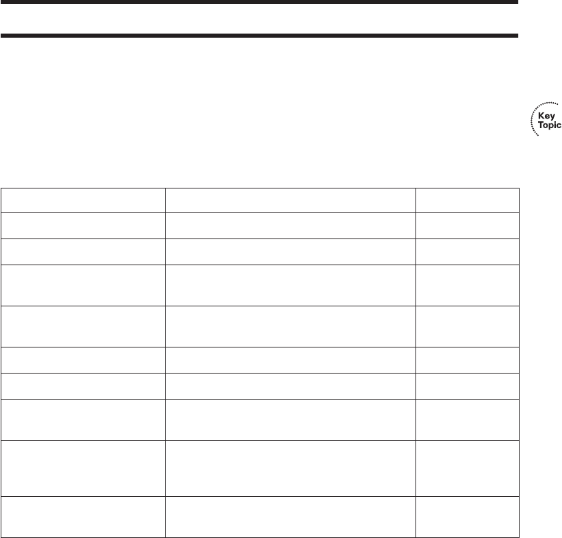
Complete the Tables and Lists from Memory 467
Exam Preparation Tasks
Review All the Key Topics
Review the most important topics in the chapter, noted with the key topics icon in the outer
margin of the page. Table 14-7 lists a reference of these key topics and the page numbers
on which each is found.
Complete the Tables and Lists from Memory
Print a copy of Appendix H, “Memory Tables” (found on the CD-ROM), or at least the
section for this chapter, and complete the tables and lists from memory. Appendix I,
“Memory Tables Answer Key,” also on the CD-ROM, includes completed tables and lists
to check your work.
Table 14-7 Key Topics for Chapter 14
Key Topic Element Description Page Number
Example 14-3 Shows how to configure static routes 443
Definitions IGP and EGP 451
Table 14-2 List of IGP algorithms and the IGPs that use
them
452
Table 14-3 Comparison points for classless and classful
routing protocols
454
Table 14-4 Summary of comparison points for IGPs 456
List RIP-2 configuration checklist 456-457
List The three things that occur on an interface
matched by a RIP network command
457
Table 14-6 List of routing protocols and other routing
sources and their default administrative
distance settings
462
Example 14-8 Lists the show ip protocol command and how
it can be used to troubleshoot RIP problems
463
1828xbook.fm Page 467 Thursday, July 26, 2007 3:10 PM

468 Chapter 14: Routing Protocol Concepts and Configuration
Definitions of Key Terms
Define the following key terms from this chapter and check your answers in the glossary.
administrative distance, autonomous system, backup static route, balanced hybrid,
classful routing protocol, classless routing protocol, convergence, default route,
distance vector, Exterior Gateway Protocol (EGP), Interior Gateway Protocol (IGP),
link state, metric, routing update, variable-length subnet masking (VLSM)
Command References
Although you should not necessarily memorize the information in the tables in this section,
this section does include a reference for the configuration commands (Table 14-8) and
EXEC commands (Table 14-9) covered in this chapter. Practically speaking, you should
memorize the commands as a side effect of reading the chapter and doing all the activities
in this exam preparation section. To check to see how well you have memorized the
commands, cover the left side of the table with a piece of paper, read the descriptions in the
right side, and see if you remember the command.
Table 14-8 Chapter 14 Configuration Command Reference
Command Description
router rip Global command that moves the user into RIP configuration
mode.
network network-number RIP subcommand that lists a classful network number, enabling
RIP on all of that router’s interfaces in that classful network.
version {1 | 2} RIP subcommand that sets the RIP version.
passive-interface [default]
{interface-type interface-
number}
RIP subcommand that tells RIP to no longer advertise RIP
updates on the listed interface.
ip address ip-address mask Interface subcommand that sets the router’s interface IP address
and mask.
ip route prefix mask {ip-address |
interface-type interface-number}
Global command that defines a static route.
service timestamps Global command that tells the router to put a timestamp on log
messages, including debug messages.
1828xbook.fm Page 468 Thursday, July 26, 2007 3:10 PM

Command References 469
Table 14-9 Chapter 14 EXEC Command Reference
Command Purpose
show ip interface brief Lists one line per router interface, including the IP address and
interface status; an interface must have an IP address, and be in an
“up and up” status, before RIP begins to work on the interface.
show ip route [rip | static |
connected]
Lists the routing table, including RIP-learned routes, and
optionally just RIP-learned routes.
show ip route ip-address Lists details about the route the router would match for a packet
sent to the listed IP address.
show ip protocols Lists information about the RIP configuration, plus the IP
addresses of neighboring RIP routers from which the local router
has learned routes.
show process Lists information about the various processes running in IOS, and
most importantly, overall CPU utilization statistics.
terminal ip netmask-format
decimal
For the length of the user’s session, causes IOS to display mask
information in dotted-decimal format instead of prefix format.
debug ip rip Tells the router to generate detailed messages for each sent and
received RIP update.
1828xbook.fm Page 469 Thursday, July 26, 2007 3:10 PM

This chapter covers the following subjects:
IP Troubleshooting Tips and Tools: This
section suggests some tips for how to approach
host routing issues, routing related to routers, and
IP addressing problems, including how to use
several additional tools not covered elsewhere in
this book.
A Troubleshooting Scenario: This section
shows a three-part scenario, with tasks for each
part that can be performed before seeing the
answers.
1828xbook.fm Page 470 Thursday, July 26, 2007 3:10 PM

C H A P T E R15
Troubleshooting IP Routing
This chapter has two main goals. First, this chapter covers some topics that are not covered
elsewhere in this book, namely some troubleshooting commands on both hosts and
routers. Second, this chapter reviews the core concepts of addressing and routing, but with
a focus on how to approach new problems to analyze and understand how to troubleshoot
any problems. Additionally, this chapter includes a troubleshooting scenario that shows
how to use some of the tools and concepts from earlier in this chapter, with an opportunity
for you to try and discover the problems before the text explains the answers.
For those of you following the reading plan using both this book and the CCNA ICND2
Official Exam Certification Guide, note that after this chapter, you should proceed to
the ICND2 book and read the chapters in Parts II and III.
“Do I Know This Already?” Quiz
The “Do I Know This Already?” quiz allows you to assess if you should read the entire
chapter. If you miss no more than one of these nine self-assessment questions, you might
want to move ahead to the “Exam Preparation Tasks” section. Table 15-1 lists the major
headings in this chapter and the “Do I Know This Already?” quiz questions covering the
material in those headings so you can assess your knowledge of these specific areas. The
answers to the “Do I Know This Already?” quiz appear in Appendix A.
Table 15-1 “Do I Know This Already?” Foundation Topics Section-to-Question Mapping
Foundation Topics Section Questions
IP Troubleshooting Tips and Tools 1–6
A Routing Troubleshooting Scenario 7–9
1828xbook.fm Page 471 Thursday, July 26, 2007 3:10 PM
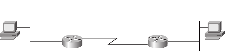
472 Chapter 15: Troubleshooting IP Routing
1. An internetwork diagram shows a router, R1, with the ip subnet-zero command
configured. The engineer has typed several configuration commands into a word
processor for later pasting into the router’s configuration. Which of the following IP
addresses could not be assigned to the router’s Fa0/0 interface?
a. 172.16.0.200 255.255.255.128
b. 172.16.0.200 255.255.255.0
c. 225.1.1.1 255.255.255.0
d. 10.43.53.63 255.255.255.192
2. Which of the following is a useful command on some Microsoft OSs for discovering a
host’s current IP address and mask?
a. tracert
b. ipconfig /all
c. arp –a
d. ipconfig /displaydns
3. Examine the following command output. If the user typed the resume command, what
would happen?
R1#ss
sshh
hhoo
ooww
ww
ss
ssee
eess
ssss
ssii
iioo
oonn
nnss
ss
Conn Host Address Byte Idle Conn Name
1 Fred 10.1.1.1 0 0 Fred
* 2 Barney 10.1.2.1 0 0 Barney
a. The command would be rejected, and the R1 CLI command prompt would be
displayed again.
b. The CLI user would be connected to a suspended Telnet connection to the router
with IP address 10.1.1.1.
c. The CLI user would be connected to a suspended Telnet connection to the router
with IP address 10.1.2.1.
d. The result cannot be accurately predicted from the information shown.
Refer to the following figure for questions 4–9:
Default Gateway
10.1.1.1
Default Gateway
172.16.2.4
10.1.13.1/30
10.1.1.1/24 S0/0 10.1.13.3/30
S0/1 172.16.2.4
Fa0/0
R1 R2
PC1 PC2
10.1.1.10/24 172.16.2.7
Fa0/0
1828xbook.fm Page 472 Thursday, July 26, 2007 3:10 PM
“Do I Know This Already?” Quiz 473
4. If PC3 were added to the LAN on the left, with IP address 10.1.1.130/25, default
gateway 10.1.1.1, which of the following would be true?
a. If PC1 issued a ping 10.1.1.130 command, PC1 would use ARP to learn PC3’s
MAC address.
b. If PC3 issued a ping 10.1.1.10 command, PC3 would ARP trying to learn PC1’s
MAC address.
c. If PC1 issued a ping 10.1.13.1 command, PC1 would ARP trying to learn the
MAC address of 10.1.13.1.
d. If R1 issued a ping 10.1.1.130 command, R1 would ARP trying to learn the
MAC address of 10.1.1.130.
5. A new network engineer is trying to troubleshoot a problem for the user of PC1. Which
of the following tasks and results would most likely point to a Layer 1 or 2 Ethernet
problem on the LAN on the left side of the figure?
a. A ping 10.1.1.1 command on PC1 did not succeed.
b. A ping 10.1.13.3 command from PC1 succeeded, but a ping 172.16.2.4 did not.
c. A ping 10.1.1.1 command from PC1 succeeded, but a ping 10.1.13.1 did not.
d. A ping 10.1.1.10 command from PC1 succeeded.
6. The PC2 user issues the tracert 10.1.1.10 command. Which of the following IP
addresses could be shown in the command output?
a. 10.1.1.10
b. 10.1.1.1
c. 10.1.13.1
d. 10.1.13.3
e. 172.16.2.4
7. All the devices in the figure just booted, and none of the devices has yet sent any data
frames. Both PCs use statically configured IP addresses. Then PC1 successfully pings
PC2. Which of the following ARP table entries would you expect to see?
a. An entry on PC1’s ARP cache for IP address 172.16.2.7
b. An entry on PC1’s ARP cache for IP address 10.1.1.1
c. An entry on R1’s ARP cache for IP address 10.1.1.10
d. An entry on R1’s ARP cache for IP address 172.16.2.7
1828xbook.fm Page 473 Thursday, July 26, 2007 3:10 PM
474 Chapter 15: Troubleshooting IP Routing
8. All the devices in the figure just booted, and none of the devices has yet sent any data
frames. Both PCs use statically configured IP addresses. Then PC1 successfully pings
PC2. Which of the following ARP requests would you expect to occur?
a. PC1 would send an ARP broadcast looking for R1’s MAC address of the
interface with IP address 10.1.1.1.
b. PC2 would send an ARP broadcast looking for R2’s MAC address of the
interface with IP address 172.16.2.4.
c. R1 would send an ARP broadcast looking for PC1’s MAC address.
d. R2 would send an ARP broadcast looking for PC2’s MAC address.
e. PC1 would send an ARP broadcast looking for PC2’s MAC address.
9. PC1 is successfully pinging PC2 in the figure. Which of the following is true about the
packets?
a. The frame going left-to-right, as it crosses the left-side LAN, has a destination
MAC address of R1’s MAC address.
b. The frame going left-to-right, as it crosses the right-side LAN, has a destination
MAC address of R2’s MAC address.
c. The frame going left-to-right, as it crosses the serial link, has a destination IP
address of PC2’s IP address.
d. The frame going right-to-left, as it crosses the left-side LAN, has a source MAC
address of PC2’s MAC address.
e. The frame going right-to-left, as it crosses the right-side LAN, has a source MAC
address of PC2’s MAC address.
f. The frame going right-to-left, as it crosses the serial link, has a source MAC
address of R2’s MAC address.
1828xbook.fm Page 474 Thursday, July 26, 2007 3:10 PM

IP Troubleshooting Tips and Tools 475
Foundation Topics
IP Troubleshooting Tips and Tools
The primary goal of this chapter is to better prepare you for the more challenging exam
problems that involve potential Layer 3 problems. These problems often require the same
thought processes and tools that you would use to troubleshoot networking problems in a
real job. The first half of this chapter reviews the main types of problems that can occur,
mainly related to addressing, host routing, and a router’s routing logic. The second half of
the chapter shows a scenario that explains one internetwork that has several problems,
giving you a chance to first analyze the problems, and then showing how to solve the
problems.
IP Addressing
This section includes some reminders relating to some of the basic features of IP
addressing. More importantly, the text includes some tips on how to apply this basic
knowledge to a given exam question, helping you know how to attack a particular type
of problem.
Avoiding Reserved IP Addresses
One of the first things to check in an exam question that includes a larger scenario is
whether the IP addresses are reserved and should not be used as unicast IP addresses. These
reserved addresses can be categorized into one of three groups:
■Addresses that are always reserved
■Two addresses that are reserved in each subnet
■Addresses in two special subnets of each classful network, namely the zero subnet and
broadcast subnet.
The first category of reserved addresses includes two Class A networks that are always
reserved, plus all Class D (multicast) and Class E (experimental) IP addresses. You can
easily recognize these IP addresses based on the value of their first octet, as follows:
■0 (because network 0.0.0.0 is always reserved)
■127 (because network 127.0.0.0 is always reserved)
■224–239 (all Class D multicast IP addresses)
■240–255 (all Class E experimental IP addresses)
1828xbook.fm Page 475 Thursday, July 26, 2007 3:10 PM

476 Chapter 15: Troubleshooting IP Routing
The second category of reserved IP addresses includes the two reserved addresses inside
each subnet. When subnetting, each subnet reserves two numbers—the smallest and largest
numbers in the subnet—otherwise known as
■The subnet number
■The subnet’s broadcast address
So the ability to quickly and confidently determine the subnet number and subnet broadcast
address has yet another application, when attempting to confirm that the addresses shown
in a question can be legally used.
The third category of reserved IP addresses may or may not apply to a particular
internetwork or question. For a given classful network, depending on several factors, the
following two subnets may not be allowed to be used:
■The zero subnet
■The broadcast subnet
If an exam question includes an address in the zero subnet or broadcast subnet, you must
then consider whether the question allows neither subnet to be used, or both. Table 15-2
summarizes the clues to look for in exam questions to determine whether a question allows
the use of both subnets or not.
One Subnet, One Mask, for Each LAN
The hosts on a single LAN or VLAN (a single broadcast domain) should all be in the same
subnet. As a result, each host, each router interface attached to the LAN, and each switch
management address in that LAN should also use the same mask.
Table 15-2 Determining Whether a Question Allows the Use of the Zero and Broadcast Subnets
Clues in the Question Subnets Reserved?
Says nothing about it (default for the exam) No
Lists the ip subnet-zero configuration command No
Uses a classless routing protocol (RIP-2, EIGRP, OSPF) No
Lists the no ip subnet-zero configuration command Yes
Uses a classful routing protocol (RIP-1) Yes
1828xbook.fm Page 476 Thursday, July 26, 2007 3:10 PM
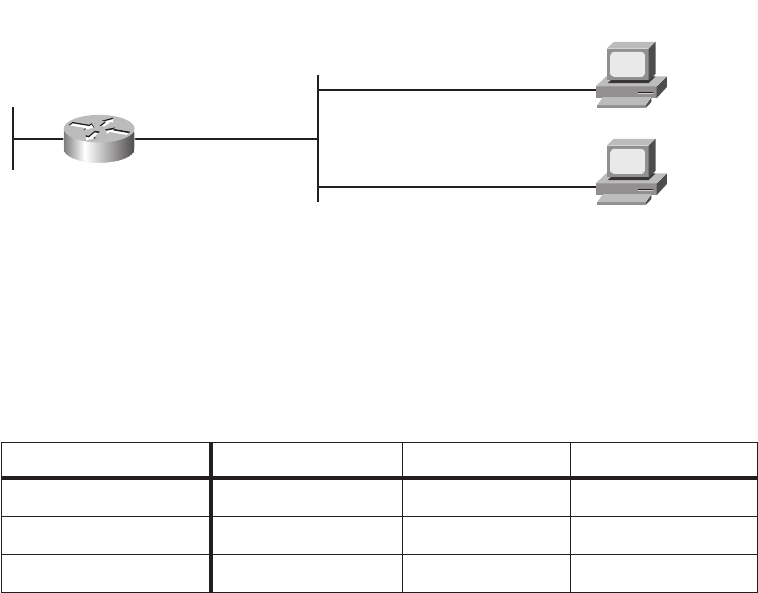
IP Troubleshooting Tips and Tools 477
For the exam, you should check all the details documented in the question to determine the
mask used by the various devices on the same LAN. Oftentimes, a question that is intended
to test your knowledge will not just list all the information in a nice organized figure.
Instead, you might have to look at the configuration and diagrams and use show commands
to gather the information, and then apply the subnetting math explained in Chapter 12, “IP
Addressing and Subnetting.”
Figure 15-1 shows an example of a LAN that could be part of a test question. For
convenience, the figure lists several details about IP addresses and masks, but for a given
question, you might have to gather some of the facts from a figure, a simulator, and from
an exhibit that lists command output.
Figure 15-1 One LAN with Three Different Opinions About the Subnet
From the information in Figure 15-1, you can quickly tell that the two PCs use different
masks (listed in prefix notation). In this case, you would need to know to look in the
configuration for the subnet mask in the ip address interface subcommand, and then
convert that mask to prefix notation to compare it with the other masks in this example.
Table 15-3 lists the three differing opinions about the subnet.
In this case, several problem symptoms occur. For example, PC1 thinks 172.16.1.253 (R1)
is in the same subnet, and PC1 thinks that it can forward packets to R1 over the LAN.
However, R1 does not think that PC1 (172.16.1.1) is in the same subnet, so R1’s connected
Table 15-3 Different Opinions About the Subnet in Figure 15-1
R1 Fa0/0 PC1 PC2
Mask 255.255.255.128 255.255.255.0 255.255.255.128
Subnet number 172.16.1.128 172.16.1.0 172.16.1.0
Broadcast address 172.16.1.255 172.16.1.255 172.16.1.127
172.16.1.1/24
GW = 172.16.1.253
172.16.1.2/25
GW = 172.16.1.253
Fa0/1
172.16.2.253
Fa0/0
interface Fa0/0
ip address 172.16.1.253 255.255.255.128
R1
PC1
PC2
1828xbook.fm Page 477 Thursday, July 26, 2007 3:10 PM

478 Chapter 15: Troubleshooting IP Routing
route on the LAN interface (172.16.1.128/25) will not provide a route that R1 can use to
forward packets back to PC1. For the exam, recognizing the fact that the hosts on the same
LAN do not have the same opinion about the subnet should be enough to either answer the
question, or to know what to fix in a Sim question. Table 15-4, found a little later in this
chapter, summarizes the router commands that can be used to find the information required
to analyze such problems.
Summary of IP Addressing Tips
Generally speaking, keep the following tips and facts in mind when you approach the exam
questions that include details about IP addresses:
1. Check the mask used on each device in the same LAN; if different, then the devices
cannot have the same view of the range of addresses in the subnet.
2. On point-to-point WAN links, check the IP addresses and masks on both ends of the
link, and confirm that the two IP addresses are in the same subnet.
3. When checking to confirm that hosts are in the same subnet, do not just examine the
subnet number. Also check the subnet mask, and the implied range of IP addresses.
4. Be ready to use the commands summarized in Table 15-4 to quickly find the IP
addresses, masks, and subnet numbers.
The next section, in addition to reviewing a host’s routing logic, introduces some
commands on Microsoft operating systems that list the host’s IP address and mask.
Host Networking Commands
Chapter 5, “Fundamentals of IP Addressing and Routing,” explained the simple two-step
logic a host uses when forwarding packets, in addition to how a host typically uses DHCP,
DNS, ARP, and ICMP. These details can be summarized as follows:
Routing: If the packet’s destination is on the same subnet, send the packet directly; if
not, send the packet to the default gateway.
Address assignment: Before sending any packets, the host may use DHCP client
services to learn its IP address, mask, default gateway, and DNS IP addresses. The host
could also be statically configured with these same details.
Name resolution: When the user directly or indirectly references a host name, the host
typically uses DNS name resolution requests to ask a DNS to identify that host’s IP
address unless the host already has that information in its name cache.
IP-to-MAC resolution: The host uses ARP requests to find the other host’s MAC
address, or the default gateway’s IP address, unless the information is already in the
host’s ARP cache.
1828xbook.fm Page 478 Thursday, July 26, 2007 3:10 PM
IP Troubleshooting Tips and Tools 479
Of these four items, note that only the routing (forwarding) process happens for each
packet. The address assignment function usually happens once, soon after booting. Name
resolution and ARPs occur as needed, typically in reaction to something done by the user.
To analyze how well a host has accomplished these tasks, to troubleshoot problems, and to
do the equivalent for exam questions, it is helpful to know a few networking commands
on a host. Table 15-4 lists several of the commands on Microsoft Windows XP, but other
similar commands exist for other operating systems. Example 15-1 following the table
shows the output from some of these commands.
Example 15-1 shows an example of the ping www.cisco.com command on a host running
Windows XP, just after the ARP cache and hostname cache have been deleted (flushed). The
example first shows the DHCP-learned addressing and DNS details, and then shows the
flushing of the two caches. At that point, the example shows the ping www.cisco.com
command, which forces the host to use DNS to learn the IP address of the Cisco web server,
and then ARP to learn the MAC address of the default gateway, before sending an ICMP
echo request to the Cisco web server.
Table 15-4 Microsoft Windows XP Network Command Reference
Command Function
ipconfig /all Displays detailed IP configuration information for all interfaces,
including IP address, mask, default gateway, and DNS IP addresses
ipconfig /release Releases any DHCP-leased IP addresses
ipconfig /renew Acquires an IP address and related information using DHCP
nslookup name Sends a DNS request for the listed name
arp –a Lists the host’s ARP cache
ipconfig /displaydns Lists the host’s name cache
ipconfig /flushdns Removes all DNS-found name cache entries
arp -d Flushes (empties) the host’s ARP cache
netstat -rn Displays a host’s routing table
NOTE The ping fails in this example, probably due to ACLs on routers or firewalls in
the Internet. However, the ping command still drives the DNS and ARP processes as
shown in the example. Also, the text is from a DOS window in Windows XP.
1828xbook.fm Page 479 Thursday, July 26, 2007 3:10 PM

480 Chapter 15: Troubleshooting IP Routing
Example 15-1 Example Use of Host Networking Commands
C:\>ii
iipp
ppcc
ccoo
oonn
nnff
ffii
iigg
gg
//
//aa
aall
llll
ll
! Some lines omitted for brevity
Ethernet adapter Local Area Connection:
Connection-specific DNS Suffix . : cinci.rr.com
Description . . . . . . . . . . . : Broadcom NetXtreme 57xx Gigabit Cont
roller
Physical Address. . . . . . . . . : 00-11-11-96-B5-13
Dhcp Enabled. . . . . . . . . . . : Yes
Autoconfiguration Enabled . . . . : Yes
IP Address. . . . . . . . . . . . : 192.168.1.102
Subnet Mask . . . . . . . . . . . : 255.255.255.0
Default Gateway . . . . . . . . . : 192.168.1.1
DHCP Server . . . . . . . . . . . : 192.168.1.1
DNS Servers . . . . . . . . . . . : 65.24.7.3
65.24.7.6
Lease Obtained. . . . . . . . . . : Thursday, March 29, 2007 6:32:59 AM
Lease Expires . . . . . . . . . . : Friday, March 30, 2007 6:32:59 AM
! Next, the ARP and name cache are flushed.
C:\>aa
aarr
rrpp
pp
--
--dd
dd
C:\>ii
iipp
ppcc
ccoo
oonn
nnff
ffii
iigg
gg
//
//ff
ffll
lluu
uuss
sshh
hhdd
ddnn
nnss
ss
Windows IP Configuration
Successfully flushed the DNS Resolver Cache.
! The pp
ppii
iinn
nngg
gg command lists the IP address (198.133.219.25), meaning that the DNS request
worked.
! However, the ping does not complete, probably due to ACLs filtering ICMP traffic.
C:\>pp
ppii
iinn
nngg
gg
ww
wwww
wwww
ww..
..cc
ccii
iiss
sscc
ccoo
oo..
..cc
ccoo
oomm
mm
Pinging www.cisco.com [198.133.219.25] with 32 bytes of data:
Request timed out.
Request timed out.
Request timed out.
Request timed out.
Ping statistics for 192.133.219.25:
Packets: Sent = 4, Received = 0, Lost = 4 (100% loss),
! Next, the ARP cache lists an entry for the default gateway.
C:\>aa
aarr
rrpp
pp
--
--aa
aa
Interface: 192.168.1.102 --- 0x2
Internet Address Physical Address Type
192.168.1.1 00-13-10-d4-de-08 dynamic
! Next, the local name cache lists the name used in the pp
ppii
iinn
nngg
gg
command and the IP address
continues
1828xbook.fm Page 480 Thursday, July 26, 2007 3:10 PM
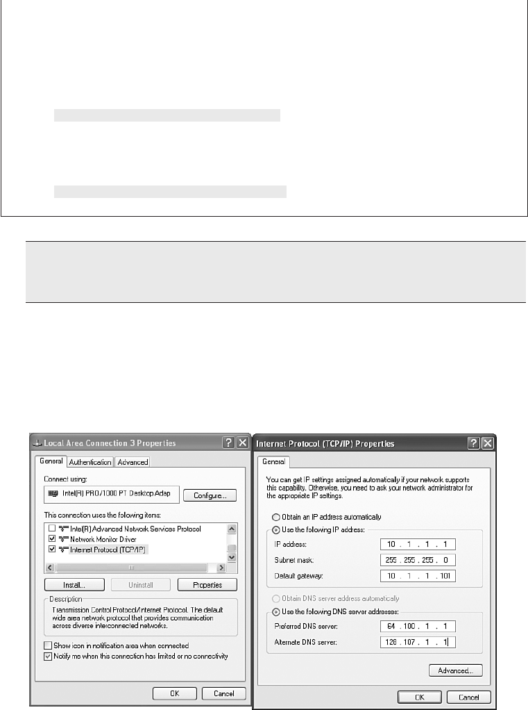
IP Troubleshooting Tips and Tools 481
In addition to these commands, Figure 15-2 shows an example of the windows used to
statically configure a host’s IP address, mask, default gateway, and DNS server IP
addresses. These details can be configured with commands as well, but most people prefer
the easier graphical interface.
Figure 15-2 Configuring Static IP Addresses on Windows XP
! learned from the DNS server.
C:\>ii
iipp
ppcc
ccoo
oonn
nnff
ffii
iigg
gg
//
//dd
ddii
iiss
sspp
ppll
llaa
aayy
yydd
ddnn
nnss
ss
Windows IP Configuration
www.cisco.com
----------------------------------------
Record Name . . . . . : www.cisco.com
Record Type . . . . . : 1
Time To Live . . . . : 26190
Data Length . . . . . : 4
Section . . . . . . . : Answer
A (Host) Record . . . : 198.133.219.25
! Lines omitted for brevity
NOTE At press time, the simulator used on the Cisco exams did not include host
networking commands; however, the exam can still require you to interpret the output of
host commands, and the simulator could include these commands in the future.
Example 15-1 Example Use of Host Networking Commands (Continued)
1828xbook.fm Page 481 Thursday, July 26, 2007 3:10 PM

482 Chapter 15: Troubleshooting IP Routing
Troubleshooting Host Routing Problems
Troubleshooting host routing problems should begin with the same two-step routing logic
used by a host. The first question to ask is whether the host can ping other hosts inside
the same subnet. If a ping of a same-subnet host fails, the root cause typically falls into one
of two categories:
■The two hosts have incorrect IP address and mask configurations, typically so that at
least one of the two hosts thinks it is in a different subnet.
■The two hosts have correct IP address and mask configurations, but the underlying
Ethernet has a problem.
For the exam, start by looking at the host’s addresses and masks, and determine the subnet
number and range of addresses for each. If the subnets are the same, then move on to
Layer 1 and 2 Ethernet troubleshooting as covered in Chapter 10, “Ethernet Switch
Troubleshooting,” and in the CCNA ICND2 Exam Certification Guide, Chapter 3,
“Troubleshooting LAN Switching.”
If the host can ping other hosts in the same subnet, the next step is to confirm if the host can
ping IP addresses in other subnets, thereby testing the second branch of a host’s routing
logic. Two different pings can be helpful at this step:
■Ping the default gateway IP address to confirm that the host can send packets over the
LAN to and from the default gateway.
■Ping a different IP address on the default gateway/router, but not the IP address on the
same LAN.
For example, in Figure 15-1 earlier in this chapter, PC1 could first issue the ping
172.16.1.253 command to confirm whether PC1 can send packets to and from its presumed
default gateway. If the ping was successful, PC1 could use a ping 172.16.2.253 command,
which forces PC1 to use its default gateway setting, because PC1 thinks that 172.16.2.253
is in a different subnet.
So, when a host can ping other hosts in the same subnet, but not hosts in other subnets, the
root cause typically ends up being one of a few items, as follows:
■There is some mismatch between the host’s default gateway configuration and the
router acting as default gateway. The problems include mismatched masks between the
host and the router, which impacts the perceived range of addresses in the subnet, or
the host simply referring to the wrong router IP address.
■If the default gateway settings are all correct, but the ping of the default gateway IP
address fails, there is probably some Layer 1 or 2 problem on the LAN.
1828xbook.fm Page 482 Thursday, July 26, 2007 3:10 PM

IP Troubleshooting Tips and Tools 483
■If the default gateway settings are all correct and the ping of the default gateway works,
but the ping of one of the other router interface IP addresses fails (like the ping
172.16.2.253 command based on Figure 15-1), then the router’s other interface may
have failed.
While all the details in this section can be helpful when troubleshooting problems on
hosts, keep in mind that many of the problems stem from incorrect IP address and mask
combinations. For the exam, be ready to find the IP address and masks, and apply the math
from Chapter 12 to quickly determine where these types of problems exist.
Finding the Matching Route on a Router
Chapter 5 summarized the process by which a router forwards a packet. A key part of that
process is how a router compares the destination IP address of each packet with the existing
contents of that router’s IP routing table. The route that matches the packet’s destination
tells the router out which interface to forward the packet and, in some cases, the IP address
of the next-hop router.
In some cases, a particular router’s routing table might have more than one route that
matches an individual destination IP address. Some legitimate and normal reasons for the
overlapping routes in a routing table include auto-summary, route summarization, and
the configuration of static routes.
The exams can test your understanding of IP routing by asking questions about which route
would be matched for a packet sent to particular IP addresses. To answer such questions,
you should keep the following important facts in mind:
■When a particular destination IP address matches more than one route in a router’s
routing table, the router uses the most specific route—in other words, the route with
the longest prefix length.
■Although the router uses binary math to compare the destination IP address to the
routing table entries, you can simply compare the destination IP address to each subnet
in the routing table. If a subnet’s implied address range includes the packet’s
destination address, the route matches the packet’s destination.
■If the question includes a simulator, you can easily find the matched route by using the
show ip route address command, which lists the route matched for the IP address
listed in the command.
Example 15-2 shows a sample IP routing table for a router, with many overlapping routes.
Read the example, and before reading the explanations after the example, predict which
route this router would match for packets destined to the following IP addresses:
172.16.1.1, 172.16.1.2, 172.16.2.2, and 172.16.4.3.
1828xbook.fm Page 483 Thursday, July 26, 2007 3:10 PM

484 Chapter 15: Troubleshooting IP Routing
For the exam, to find the matching route, all you need to know is the destination IP address
of the packet and the router’s IP routing table. By examining each subnet and mask in the
routing table, you can determine the range of IP addresses in each subnet. Then, you can
compare the packet’s destination to the ranges of addresses, and find all matching routes.
In cases where a particular destination IP address falls within the IP address range for
multiple routes, then you pick the route with the longest prefix length. In this case:
■Destination address 172.16.1.1 matches all five routes, but the host route for specific
IP address 172.16.1.1, prefix length /32, has the longest prefix length.
■Destination address 172.16.1.2 matches four of the routes (all except the host route for
172.16.1.1), but the route to 172.16.1.0/24 has the longest prefix.
■Destination address 172.16.2.2 matches the last three routes listed in R1’s routing table
in the example, with the route for 172.16.0.0/22 having the longest prefix length.
■Destination address 172.16.4.3 matches the last two routes listed in R1’s routing table
in the example, with the route for 172.16.0.0/16 having the longest prefix length.
Example 15-2 show ip route Command with Overlapping Routes
R1#ss
sshh
hhoo
ooww
ww
ii
iipp
pp
rr
rroo
oouu
uutt
ttee
ee
rr
rrii
iipp
pp
Codes: C - connected, S - static, R - RIP, M - mobile, B - BGP
D - EIGRP, EX - EIGRP external, O - OSPF, IA - OSPF inter area
N1 - OSPF NSSA external type 1, N2 - OSPF NSSA external type 2
E1 - OSPF external type 1, E2 - OSPF external type 2
i - IS-IS, su - IS-IS summary, L1 - IS-IS level-1, L2 - IS-IS level-2
ia - IS-IS inter area, * - candidate default, U - per-user static route
o - ODR, P - periodic downloaded static route
Gateway of last resort is not set
172.16.0.0/16 is variably subnetted, 5 subnets, 4 masks
R 172.16.1.1/32 [120/1] via 172.16.25.2, 00:00:04, Serial0/1/1
R 172.16.1.0/24 [120/2] via 172.16.25.129, 00:00:09, Serial0/1/0
R 172.16.0.0/22 [120/1] via 172.16.25.2, 00:00:04, Serial0/1/1
R 172.16.0.0/16 [120/2] via 172.16.25.129, 00:00:09, Serial0/1/0
R 0.0.0.0/0 [120/3] via 172.16.25.129, 00:00:09, Serial0/1/0
R1#ss
sshh
hhoo
ooww
ww
ii
iipp
pp
rr
rroo
oouu
uutt
ttee
ee
11
1177
7722
22..
..11
1166
66..
..44
44..
..33
33
Routing entry for 172.16.0.0/16
Known via "rip", distance 120, metric 2
Redistributing via rip
Last update from 172.16.25.129 on Serial0/1/0, 00:00:19 ago
Routing Descriptor Blocks:
* 172.16.25.129, from 172.16.25.129, 00:00:19 ago, via Serial0/1/0
Route metric is 2, traffic share count is 1
1828xbook.fm Page 484 Thursday, July 26, 2007 3:10 PM

IP Troubleshooting Tips and Tools 485
Finally, note the output of the show ip route 172.16.4.3 command at the end of Example
15-2. This command shows which route the router would match to reach IP address
172.16.4.3—a very handy command for both real life and for Sim questions on the exams.
In this case, a packet sent to IP address 172.16.4.3 would match the route for the entire
Class B network 172.16.0.0/16, as highlighted near the end of the example.
Troubleshooting Commands
The most popular troubleshooting command on a router or switch is the ping command.
Chapter 14, “Routing Protocol Concepts and Configuration,” already introduced this
command, in both its standard form and the extended form. Basically, the ping command
sends a packet to another host, and the receiving host sends back a packet to the original
host, testing to see if packets can be routed between the two hosts.
This section introduces three additional Cisco IOS commands that can be useful when
troubleshooting routing problems, namely the show ip arp, traceroute, and telnet commands.
The show ip arp Command
The show ip arp command lists the contents of a router’s ARP cache. Example 15-3 lists
sample output from this command, taken from router R1 in Figure 15-1, after the router and
hosts were changed to all use a /24 mask.
The most important parts of each entry are the IP address, MAC address, and interface.
When a router needs to send a packet out a particular interface, the router will only use
entries associated with that interface. For example, for R1 to send a packet to host PC1 in
Figure 15-1 (address 172.16.1.1), R1 needs to forward the packet out its Fa0/0 interface,
so R1 will only use ARP cache entries associated with Fa0/0.
Additionally, the Age heading includes a few interesting facts. If it lists a number, the Age
value represents the number of minutes since the router last received a packet from the
host. For example, it had been 8 minutes since R1 had received a packet from host PC1,
source IP address 172.16.1.1, source MAC address 0013.197b.2f58. The Age does not
mean how long it has been since the ARP request/reply; the timer is reset to 0 each time a
matching packet is received. If the Age is listed as a dash, the ARP entry actually represents
an IP address assigned to the router—for example, R1’s Fa0/0 interface in Figure 15-1 is
shown as 172.16.1.251, which is the second entry in Example 15-3.
Example 15-3 Sample show ip arp Command Output
R1#ss
sshh
hhoo
ooww
ww
ii
iipp
pp
aa
aarr
rrpp
pp
Protocol Address Age (min) Hardware Addr Type Interface
Internet 172.16.1.1 8 0013.197b.2f58 ARPA FastEthernet0/0
Internet 172.16.1.251 - 0013.197b.5004 ARPA FastEthernet0/0
Internet 172.16.2.253 - 0013.197b.5005 ARPA FastEthernet0/1
1828xbook.fm Page 485 Thursday, July 26, 2007 3:10 PM

486 Chapter 15: Troubleshooting IP Routing
The traceroute Command
The Cisco IOS traceroute command, like the Cisco IOS ping command, tests the route
between a router and another host or router. However, the traceroute command also
identifies the IP addresses of the routers in the route. For example, consider Figure 15-3 and
Example 15-4. The figure shows an internetwork with three routers, with the traceroute
172.16.2.7 command being used on router R1. The arrowed lines show the three IP
addresses identified by the command output, which is shown in Example 15-4.
Figure 15-3 Internetwork Used in traceroute Example
The example shows a working traceroute command. However, if a routing problem exists,
the command will not complete. For example, imagine that R1 had a route that matched
172.16.2.7, so R1 could forward packets to R2. However, R2 does not have a route that
matches destination 172.16.2.7. In that case, the traceroute command would list the first
line that refers to a router (highlighted in Example 15-4). However, no other routers would
be listed, and the user would have to stop the command, typically by pressing the Ctrl-Shift-6
key sequence a few times. However, 10.1.13.3 is an IP address on the router that has a
routing problem (R2), so the next step would be to telnet to R2 and find out why it does not
have a route matching destination 172.16.2.7.
It is important to note that the traceroute command lists the IP addresses considered to
be the next-hop device. For example, in Example 15-4, the first IP address (R2, 10.1.13.3)
is the next-hop IP address in the route R1 uses to route the packet. Similarly, the next IP
Example 15-4 Sample traceroute Command Output
R1#tt
ttrr
rraa
aacc
ccee
eerr
rroo
oouu
uutt
ttee
ee
11
1177
7722
22..
..11
1166
66..
..22
22..
..77
77
Type escape sequence to abort.
Tracing the route to 172.16.2.7
1 10.1.13.3 8 msec 4 msec 4 msec
2 172.16.1.4 24 msec 25 msec 26 msec
3 172.16.2.7 26 msec 26 msec 28 msec
Default Gateway
10.1.1.1
172.16.2.7
10.1.13.1
172.16.1.3 172.16.2.4
10.1.1.1
10.1.13.3 172.16.1.4
R1 R2 R3
PC1
10.1.1.10 PC4
Fa0/0 Fa0/0
traceroute 172.16.2.7
1828xbook.fm Page 486 Thursday, July 26, 2007 3:10 PM

IP Troubleshooting Tips and Tools 487
address (R3, 172.16.1.4) is the next-hop router in the route used by R2. (Chapter 7,
“Troubleshooting IP Routing,” in the CCNA ICND2 Official Exam Certification Guide
explains how the traceroute command finds these IP addresses.)
Telnet and Suspend
Many engineers troubleshoot network problems sitting at their desks. To get access to a
router or switch, the engineer just needs to use Telnet or SSH on their desktop PC to connect
to each router or switch, oftentimes opening multiple Telnet or SSH windows to connect to
multiple devices. As an alternative, the engineer could connect to one router or switch using
a Telnet or SSH client on their desktop computer, and then use the telnet or ssh Cisco IOS
EXEC commands to connect to other routers and switches. These commands acts as a
Telnet or SSH client, respectively, so that you can easily connect to other devices when
troubleshooting. When finished, the user could just use the exit command to disconnect the
Telnet or SSH session.
Frankly, many people who rarely troubleshoot just use multiple windows on their desktop
and ignore the Cisco IOS telnet and ssh commands. However, those who do a lot more
troubleshooting tend to use these commands because, with practice, they enable you to
move between routers and switches more quickly.
One of the most important advantages of using the Cisco IOS telnet and ssh commands is
the suspend feature. The suspend feature allows a Telnet or SSH connection to remain
active while creating another Telnet or SSH connection, so that you can make many
concurrent connections, and then easily switch between the connections. Figure 15-4 shows
a sample internetwork with which the text will demonstrate the suspend feature and its
power.
The router administrator is using the PC named Bench to telnet into the Cincy router. When
connected to the Cincy CLI, the user telnets to router Milwaukee. When in Milwaukee, the
user suspends the Telnet session by pressing Ctrl-Shift-6, followed by pressing the letter x.
The user then telnets to New York and again suspends the connection. At the end of the
example, the user is concurrently telnetted into all three routers, with the ability to switch
between the connections with just a few keystrokes. Example 15-5 shows example output,
with annotations to the side.
NOTE Many operating systems have a similar command, including the Microsoft OS
tracert command, which achieves the same goal.
1828xbook.fm Page 487 Thursday, July 26, 2007 3:10 PM

488 Chapter 15: Troubleshooting IP Routing
Figure 15-4 Telnet Suspension
Example 15-5 Telnet Suspensions
Cincy#tt
ttee
eell
llnn
nnee
eett
tt
mm
mmii
iill
llww
wwaa
aauu
uukk
kkee
eeee
ee (User issues command to Telnet to Milwaukee)
Trying Milwaukee (10.1.4.252)... Open
User Access Verification
Password: (User plugs in password, can type commands at Milwaukee)
Milwaukee>
Milwaukee>
Milwaukee>
(Note: User pressed CC
CCtt
ttrr
rrll
ll--
--SS
SShh
hhii
iiff
fftt
tt--
--66
66 and then xx
xx)
Cincy#tt
ttee
eell
llnn
nnee
eett
tt
NN
NNee
eeww
wwYY
YYoo
oorr
rrkk
kk (User back at Cincy because Telnet was suspended)
Trying NewYork (10.1.6.253)... Open
(User is getting into New York now, based on tt
ttee
eell
llnn
nnee
eett
tt
NN
NNee
eeww
wwYY
YYoo
oorr
rrkk
kk command)
User Access Verification
continues
Berra
Bench
Cincy
New YorkMilwaukee
Uecker
Frame
Relay
1828xbook.fm Page 488 Thursday, July 26, 2007 3:10 PM

IP Troubleshooting Tips and Tools 489
Password:
NewYork> (User can now type commands on New York)
NewYork>
NewYork>
NewYork>
(Note: User pressed CC
CCtt
ttrr
rrll
ll--
--SS
SShh
hhii
iiff
fftt
tt--
--66
66 and then xx
xx)
Cincy#ss
sshh
hhoo
ooww
ww
ss
ssee
eess
ssss
ssii
iioo
oonn
nnss
ss (This command lists suspended Telnet sessions)
Conn Host Address Byte Idle Conn Name
1 Milwaukee 10.1.4.252 0 0 Milwaukee
* 2 NewYork 10.1.6.253 0 0 NewYork
Cincy#ww
wwhh
hhee
eerr
rree
ee (ww
wwhh
hhee
eerr
rree
ee does the same thing as ss
sshh
hhoo
ooww
ww
ss
ssee
eess
ssss
ssii
iioo
oonn
nnss
ss)
Conn Host Address Byte Idle Conn Name
1 Milwaukee 10.1.4.252 0 0 Milwaukee
* 2 NewYork 10.1.6.253 0 0 NewYork
Cincy#rr
rree
eess
ssuu
uumm
mmee
ee
11
11 (Resume connection 1 (see show session) to Milwaukee)
[Resuming connection 1 to milwaukee ... ]
Milwaukee> (User can type commands on Milwaukee)
Milwaukee>
Milwaukee>
! (Note: User pressed CC
CCtt
ttrr
rrll
ll--
--SS
SShh
hhii
iiff
fftt
tt--
--66
66 and then xx
xx, because the user wants to
! go back to Cincy)
Cincy# (WOW! User just pressed Enter and resumes the last Telnet)
[Resuming connection 1 to milwaukee ... ]
Milwaukee>
Milwaukee>
Milwaukee>
(Note: User pressed CC
CCtt
ttrr
rrll
ll--
--SS
SShh
hhii
iiff
fftt
tt--
--66
66 and then xx
xx)
Cincy#dd
ddii
iiss
sscc
ccoo
oonn
nnnn
nnee
eecc
cctt
tt
11
11 (No more need to use Milwaukee Telnet terminated!)
Closing connection to milwaukee [confirm] (User presses Enter to confirm)
Cincy#
[Resuming connection 2 to NewYork ... ]
(Pressing Enter resumes most recently suspended active Telnet)
NewYork>
NewYork>
NewYork>
(Note: User pressed CC
CCtt
ttrr
rrll
ll--
--SS
SShh
hhii
iiff
fftt
tt--
--66
66 and then xx
xx)
Cincy#dd
ddii
iiss
sscc
ccoo
oonn
nnnn
nnee
eecc
cctt
tt
22
22 (Done with New York, terminate Telnet)
Closing connection to NewYork [confirm] (Just press Enter to confirm)
Cincy#
Example 15-5 Telnet Suspensions (Continued)
1828xbook.fm Page 489 Thursday, July 26, 2007 3:10 PM
490 Chapter 15: Troubleshooting IP Routing
The play-by-play notes in the example explain most of the details. Example 15-5 begins
with the Cincy command prompt that would be seen in the Telnet window from host Bench.
After telnetting to Milwaukee, the Telnet connection was suspended because the user
pressed Ctrl-Shift-6, let go, and then pressed x and let go. Then, after establishing a Telnet
connection to New York, that connection was suspended with the same key sequence.
The two connections can be suspended or resumed easily. The resume command can be
used to resume any suspended connection. To reconnect to a particular session, the resume
command can list a connection ID, which is shown in the show sessions command. (The
where command provides the same output.) If the resume command is used without a
connection ID, the command reconnects the user to the most recently suspended
connection. Also, instead of using the resume command, you can just use the session
number as a command. For instance, just typing the command 2 does the same thing as
typing the command resume 2.
The interesting and potentially dangerous nuance here is that if a Telnet session is
suspended and you simply press Enter, Cisco IOS Software resumes the connection to the
most recently suspended Telnet connection. That is fine, until you realize that you tend to
press the Enter key occasionally to clear some of the clutter from the screen. With a
suspended Telnet connection, pressing Enter a few times to unclutter the screen might
reconnect to another router. This is particularly dangerous when you are changing the
configuration or using potentially damaging EXEC commands, so be careful about what
router you are actually using when you have suspended Telnet connections.
If you want to know which session has been suspended most recently, look for the session
listed in the show sessions command that has an asterisk (*) to the left of the entry. The
asterisk marks the most recently suspended session.
In addition to the commands in Example 15-5 that show how to suspend and resume Telnet
and SSH connections, two other commands can list useful information about sessions for
users logged into a router. The show users command lists all users logged into the router
on which the command is used. This command lists all sessions, including users at the
console, and those connecting using both Telnet and SSH. The show ssh command lists the
same kind of information, but only for users that connected using SSH. Note that these
commands differ from the show sessions command, which lists suspended Telnet/SSH
sessions from the local router to other devices.
This concludes the first half of the chapter. The remainder of the chapter focuses on how to
apply many of the troubleshooting tips covered earlier in this chapter by analyzing an
internetwork that has a few problems.
1828xbook.fm Page 490 Thursday, July 26, 2007 3:10 PM
A Routing Troubleshooting Scenario 491
A Routing Troubleshooting Scenario
This section describes a three-part scenario. Each part (A, B, and C) uses figures, examples,
and text to explain part of what is happening in an internetwork and asks you to complete
some tasks and answer some questions. For each part, the text shows sample answers for
the tasks and questions.
The goal of this scenario is to demonstrate how to use some of the troubleshooting tips
covered earlier in this chapter. The scenario is not designed to match any particular type of
question you might see on the CCNA exams. Instead, it is just one more tool to help you
learn how to apply your knowledge to new unique scenarios, which is exactly what the
exam will require you to do.
Note that Appendix F, “Additional Scenarios,” has two additional scenarios about other
topics in this book. Appendix F, “Additional Scenarios,” in the ICND2 Official Exam
Certification Guide has five additional scenarios, again with the goal of providing more
practice with troubleshooting and analysis skills for new scenarios.
Scenario Part A: Tasks and Questions
The scenario begins with an internetwork that has just been installed, but the documentation
is incomplete. Your job is to examine the existing documentation (in the form of an
internetwork diagram), along with the output of several show commands. From that
information, you should
■Determine the IP address and subnet mask/prefix length of each router interface.
■Calculate the subnet number for each subnet in the diagram.
■Complete the internetwork diagram, listing router IP addresses and prefix lengths, as
well as the subnet numbers.
■Identify any existing problems with the IP addresses or subnets shown in the existing
figure.
■Suggest solutions to any problems you find.
Examples 15-6 through 15-8 list command output from routers R1, R2, and R3 in Figure 15-5.
Example 15-9 lists commands as typed into a text editor, which were later pasted into
R4’s configuration mode.
1828xbook.fm Page 491 Thursday, July 26, 2007 3:10 PM
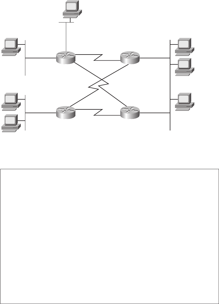
492 Chapter 15: Troubleshooting IP Routing
Figure 15-5 Scenario 3: Incomplete Network Diagram
Example 15-6 Scenario Output: Router R1
R1#ss
sshh
hhoo
ooww
ww
ii
iipp
pp
ii
iinn
nntt
ttee
eerr
rrff
ffaa
aacc
ccee
ee
bb
bbrr
rrii
iiee
eeff
ff
Interface IP-Address OK? Method Status Protocol
FastEthernet0/0 10.10.24.1 YES NVRAM up up
FastEthernet0/1 10.10.15.1 YES NVRAM up up
Serial0/0/0 unassigned YES NVRAM administratively down down
Serial0/0/1 192.168.1.1 YES NVRAM up up
Serial0/1/0 unassigned YES NVRAM administratively down down
Serial0/1/1 192.168.1.13 YES NVRAM up up
R1#ss
sshh
hhoo
ooww
ww
pp
pprr
rroo
oott
ttoo
oocc
ccoo
ooll
llss
ss
Global values:
Internet Protocol routing is enabled
FastEthernet0/0 is up, line protocol is up
Internet address is 10.10.24.1/21
FastEthernet0/1 is up, line protocol is up
Internet address is 10.10.15.1/21
Serial0/0/0 is administratively down, line protocol is down
Serial0/0/1 is up, line protocol is up
Internet address is 192.168.1.1/30
Serial0/1/0 is administratively down, line protocol is down
Serial0/1/1 is up, line protocol is up
Internet address is 192.168.1.13/30
Fa0/1
Fa0/0
10.10.10.12 /21
192.168.4.21 /28
Def. Gw = 192.168.4.29
S0/0/1
S0/1/1 S0/1/0
S0/0/1
192.168.4.29
Fa0/0
R1 R2
12
10.10.23.11 /21 11
21
22
Fa0/0
172.31.5.100 /25
172.31.5.200 /25
192.168.4.22 /28
Def. Gw = 192.168.4.29
192.168.4.23 /28
Def. Gw = 192.168.4.30
S0/1/0
S0/1/1
S0/1/1
S0/0/1
192.168.4.30
Fa0/1
R1
31
32
23
R2
1828xbook.fm Page 492 Thursday, July 26, 2007 3:10 PM

A Routing Troubleshooting Scenario 493
Example 15-7 Scenario Output: Router R2
R2#ss
sshh
hhoo
ooww
ww
pp
pprr
rroo
oott
ttoo
oocc
ccoo
ooll
llss
ss
Global values:
Internet Protocol routing is enabled
FastEthernet0/0 is up, line protocol is up
Internet address is 192.168.4.29/28
FastEthernet0/1 is administratively down, line protocol is down
Serial0/0/0 is administratively down, line protocol is down
Serial0/0/1 is up, line protocol is up
Internet address is 192.168.1.2/30
Serial0/1/0 is up, line protocol is up
Internet address is 192.168.1.6/30
Serial0/1/1 is administratively down, line protocol is down
Example 15-8 Scenario Output: Router R3
R3#ss
sshh
hhoo
ooww
ww
ii
iipp
pp
ii
iinn
nntt
ttee
eerr
rrff
ffaa
aacc
ccee
ee
bb
bbrr
rrii
iiee
eeff
ff
Interface IP-Address OK? Method Status Protocol
FastEthernet0/0 172.31.5.1 YES NVRAM up up
FastEthernet0/1 unassigned YES NVRAM administratively down down
Serial0/0/0 unassigned YES NVRAM administratively down down
Serial0/0/1 unassigned YES NVRAM administratively down down
Serial0/1/0 192.168.1.5 YES NVRAM up up
Serial0/1/1 192.168.1.18 YES NVRAM up up
R3#ss
sshh
hhoo
ooww
ww
ii
iipp
pp
rr
rroo
oouu
uutt
ttee
ee
cc
ccoo
oonn
nnnn
nnee
eecc
cctt
ttee
eedd
dd
172.31.0.0/25 is subnetted, 1 subnets
C 172.31.5.0 is directly connected, FastEthernet0/0
192.168.1.0/24 is variably subnetted, 5 subnets, 2 masks
C 192.168.1.4/30 is directly connected, Serial0/1/0
C 192.168.1.16/30 is directly connected, Serial0/1/1
Example 15-9 Scenario Output: Router R4
! The following commands are in a text editor, and will be pasted into
! configuration mode on R4.
ii
iinn
nntt
ttee
eerr
rrff
ffaa
aacc
ccee
ee
ff
ffaa
aa00
00//
//11
11
ii
iipp
pp
aa
aadd
dddd
ddrr
rree
eess
ssss
ss
11
1199
9922
22..
..11
1166
6688
88..
..22
22..
..22
2233
33
22
2255
5555
55..
..22
2255
5555
55..
..22
2255
5555
55..
..22
2244
4400
00
!
ii
iinn
nntt
ttee
eerr
rrff
ffaa
aacc
ccee
ee
ss
ssee
eerr
rrii
iiaa
aall
ll
00
00//
//00
00//
//00
00
ii
iipp
pp
aa
aadd
dddd
ddrr
rree
eess
ssss
ss
11
1199
9922
22..
..11
1166
6688
88..
..11
11..
..11
1144
44
22
2255
5555
55..
..22
2255
5555
55..
..22
2255
5555
55..
..22
2255
5522
22
!
ii
iinn
nntt
ttee
eerr
rrff
ffaa
aacc
ccee
ee
ss
ssee
eerr
rrii
iiaa
aall
ll
00
00//
//11
11//
//00
00
ii
iipp
pp
aa
aadd
dddd
ddrr
rree
eess
ssss
ss
11
1199
9922
22..
..11
1166
6688
88..
..11
11..
..11
1199
99
22
2255
5555
55..
..22
2255
5555
55..
..22
2255
5555
55..
..22
2255
5522
22
!
! The following three lines correctly configure RIP Version 2
rr
rroo
oouu
uutt
ttee
eerr
rr
rr
rrii
iipp
pp
vv
vvee
eerr
rrss
ssii
iioo
oonn
nn
22
22
nn
nnee
eett
ttww
wwoo
oorr
rrkk
kk
11
1199
9922
22..
..11
1166
6688
88..
..11
11..
..00
00
nn
nnee
eett
ttww
wwoo
oorr
rrkk
kk
11
1199
9922
22..
..11
1166
6688
88..
..44
44..
..00
00
1828xbook.fm Page 493 Thursday, July 26, 2007 3:10 PM
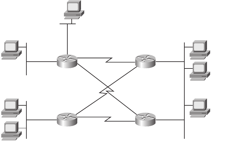
494 Chapter 15: Troubleshooting IP Routing
Scenario Part A: Answers
Examples 15-6, 15-7, and 15-8 list the IP addresses of each interface on routers R1, R2, and
R3, respectively. However, some of the commands used in the examples do not provide
mask information. In particular, the show ip interface brief command—a great command
for getting a quick look at interfaces, their IP addresses, and the status—does not list the
mask. The show protocols command lists that same information, as well as the subnet mask.
Example 15-8 (R3) does list the mask information directly, but it may take a little work to
find it. You can see the interfaces and their configured IP addresses in the show ip
interfaces brief command output, and then compare that information to the output of the
show ip route connected command. This command does list the mask information, and
the subnet number connected to an interface. A router determines the subnet number and
mask for each connected route based on the configured ip address interface subcommand on
each interface. From these facts, you can determine the mask used on each of R3’s interfaces.
Finally, Example 15-9 lists configuration commands that will be pasted into router R4.
These commands explicitly list the IP addresses and subnet masks in the various ip address
configuration commands.
Figure 15-6 shows the answers to the first three tasks in Part A, listing the IP addresses and
masks of each interface, as well as the subnet numbers.
Figure 15-6 Scenario Part A: Subnet Numbers
Fa0/1
Fa0/0
10.10.24.1 /21
192.168.1.1 /30 192.168.1.2 /30
10.10.15.1/21
192.168.1.5 /30
192.168.1.13 /30 192.168.1.6 /30
192.168.1.19 /30
192.168.1.18 /30
172.31.5.1 /25
10.10.10.12 /21
192.168.4.21 /28
Def. Gw = 192.168.4.29
S0/0/1
S0/1/1 S0/1/0
S0/0/1
192.168.4.29 /28
Fa0/0
R1 R2
12
10.10.23.11 /21
Subnet 10.10.24.0 /21 Subnet 192.168.4.16 /24
Subnet 192.168.1.4 /30
192.168.1.14 /30
Subnet 192.168.1.12 /30
Subnet 10.10.8.0 /21
Subnet 172.31.5.0 /25
Subnet 192.168.1.16 /30
Subnet 192.168.1.0 /30
11
21
22
Fa0/0
172.31.5.100 /25
172.31.5.200 /25
192.168.4.22 /28
Def. Gw = 192.168.4.29
192.168.4.23 /28
Def. Gw = 192.168.4.30
S0/1/0
S0/1/1
S0/1/1
S0/0/1
192.168.4.30 /28
Fa0/1
R3
31
32
23
R4
1828xbook.fm Page 494 Thursday, July 26, 2007 3:10 PM
A Routing Troubleshooting Scenario 495
With all the information listed in one internetwork diagram, you can use the suggestions
and tips from earlier in this chapter to analyze the IP addresses and subnets. In this case,
you should have found two different addressing problems. The first of the two IP addressing
problems is the disagreement between PC31 and PC32 regarding the subnet numbers
and range of addresses on the lower-left LAN in Figure 15-6. In this case, PC32, with IP
address 172.31.5.200 and a prefix length of /25, thinks it is in subnet 172.31.5.128/25, with
a range of addresses from 172.31.5.129 to 172.31.5.254. PC31 and R3, attached to the same
LAN, think they are attached to subnet 172.31.5.0/25, with the range of addresses being
172.31.5.1–172.31.5.126.
This particular problem results in R3 not being able to forward packets to PC32, because
R3’s connected route for that interface will refer to subnet 172.31.25.0/25. As a result,
packets sent to PC32’s IP address would not match that connected route. Additionally,
PC32’s setting for its default gateway IP address (172.31.5.1) is invalid, because the default
gateway IP address should be in the same subnet as the host.
The second addressing problem in this scenario is that on the serial link between routers
R3 and R4, R4’s IP address and mask (192.168.1.19/30) is actually a broadcast address in
subnet 192.168.1.16/30. Subnet 192.168.1.16/30 has an address range of 192.168.1.17–
192.168.1.18, with a subnet broadcast address of 192.168.1.19. Note that the scenario
suggested that the commands in Example 15-9 would be pasted into R4’s configuration
mode; R4 would actually reject the ip address 192.168.1.19 255.255.255.252 command
because it is a subnet broadcast address.
Several possible working solutions exist for both problems, but the simple solution in
each case is to assign a valid but unused IP address from the correct subnets. In PC32’s
case, any IP address between 172.31.25.1 and 172.31.25.126, not already used by PC31 or
R3, would work fine. For R4, IP address 192.168.1.17 would be the only available IP
address, because R3 has already been assigned 192.168.1.18.
Scenario Part B: Analyze Packet/Frame Flow
Part B of this scenario continues with the network shown in Figure 15-6—including the
IP addressing errors from Part A. However, no other problems exist. In this case, all
physical connections and links are working, and RIP-2 has been correctly configured, and
is functional.
With those assumptions in mind, answer the following questions. Note that to answer some
questions, you need to refer to MAC addresses that are not otherwise specified. In these
cases, a pseudo MAC address is listed—for example, R1-Fa0/1-MAC for R1’s Fa0/1
interface’s MAC address.
1828xbook.fm Page 495 Thursday, July 26, 2007 3:10 PM

496 Chapter 15: Troubleshooting IP Routing
1. When PC12 successfully pings PC21, assuming the packet goes over the R1-R2 serial
link, what ARP table entries are required on PC12? R1? R2? PC21?
2. Assume when PC12 pings PC23 that the ICMP echo request goes over the R1-R4 path.
What ARP table entries are required on PC12? R1? R4?
3. Assume when PC12 pings PC23 that the ICMP echo request goes over the R1-R2 path.
What ARP table entries are required in support of the ICMP echo reply from PC23,
on PC23? R2? R4? R1?
4. PC31 sends a packet to PC22. When the packet passes over the Ethernet on the right
side of the figure, what is the source MAC address? Destination MAC address? Source
IP address? Destination IP address?
5. PC31 sends a packet to PC22. When the packet passes over the serial link between R3
and R2, what is the source MAC address? Destination MAC address? Source IP
address? Destination IP address?
6. PC21 sends a packet to PC12, with the packet passing over the R2-R1 path. When the
packet passes over the Ethernet on the right side of the figure, what is the source
MAC address? Destination MAC address? Source IP address? Destination IP address?
7. PC21 sends a packet to PC12, with the packet passing over the R2-R1 path. When
the packet passes over the Ethernet on the left side of the figure, what is the source
MAC address? Destination MAC address? Source IP address? Destination IP
address?
Scenario Part B: Answers
Scenario Part B requires that you think about the theory behind the IP forwarding process.
That process includes many details covered in Chapter 5. In particular, to answer the
questions in Part B correctly, you need to remember the following key facts:
■The IP packet flows from the sending host to the receiving host.
■The data link header and trailer, which encapsulate the packet, do not flow over
the complete end-to-end route—instead, each individual data link helps move the
packet from a host to a router, between two routers, or from a router to the
destination host.
■For the process to work, the data link frame’s destination address lists the next device’s
data link address.
1828xbook.fm Page 496 Thursday, July 26, 2007 3:10 PM
A Routing Troubleshooting Scenario 497
■The IP header lists the IP address of the sending host and receiving host.
■Routers discard the data link header and trailer for received frames and build a new
data link header and trailer—appropriate for the outgoing interface—before
forwarding the frame.
■On LANs, hosts and routers use ARP to discover the Ethernet MAC address used by
other devices on the same LAN.
■On point-to-point WAN links, ARP is not needed, and the data link addressing is
uninteresting and can be ignored.
If your reading of this list caused you to doubt some of your answers, feel free to go back
and reevaluate your answers before looking at the actual answers.
Scenario Part B: Question 1
This question focuses on the packet flow from PC12 to PC21, assuming the packet passes
over the R1-R2 link. The fact that the packet is created due to a ping command, and
contains an ICMP echo request, does not impact the answer at all. The question specifically
asks about which ARP table entries must be used by each device.
To answer the question, you need to remember how a host or router will choose to which
device it sends the frame. PC12 sends the frame to R1 because the destination IP address is
in a different subnet than PC12. R1 then sends a new frame to R2. Finally, R2 sends yet
another new frame (with new data link header and trailer) to PC21. Figure 15-7 shows the
frames, with just the destination MAC address and destination IP address shown.
To analyze the frame sent by PC12, remember that PC12’s logic is basically “the
destination IP address is on another subnet, so send this packet to my default gateway.” To
do so, PC12 needs to encapsulate the IP packet in an Ethernet frame so that the frame
arrives at R1, PC12’s default gateway. So, PC12 must find the MAC address of its default
gateway (10.10.15.1) in PC12’s ARP table. If the ARP table entry exists, PC12 can
immediately build the frame shown in Figure 15-7 at step 1. If not, PC12 must first send an
ARP broadcast, and receive a reply, to build the correct entry in its ARP table.
Also, note that PC12 does not need to know PC21’s MAC address, because PC12 is not
trying to send the packet directly to PC21. Instead, PC12 is trying to send the packet to its
default gateway, so PC12 needs to know its default gateway’s MAC address.
1828xbook.fm Page 497 Thursday, July 26, 2007 3:10 PM
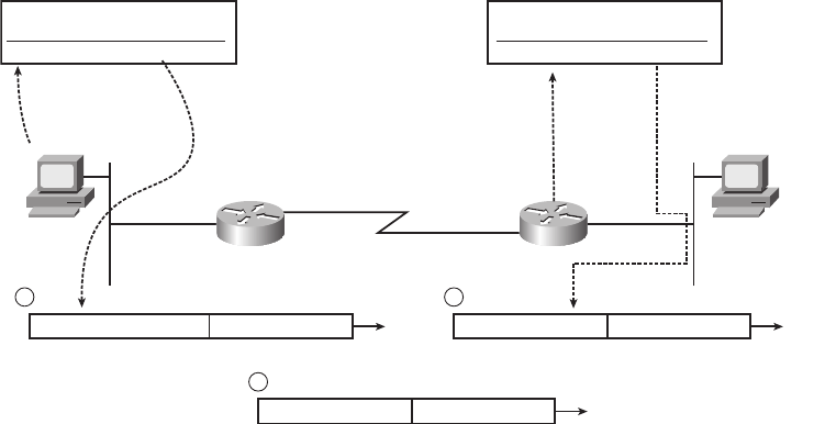
498 Chapter 15: Troubleshooting IP Routing
Figure 15-7 Scenario Part B: Answer to Question 1
Step 2, as marked in Figure 15-7, shows the frame after R1 has stripped off the incoming
frame’s Ethernet header and trailer, R1 has decided to forward the packet out R1’s S0/0/1
interface to R2 next, and R1 has added a (default) HDLC header and trailer to encapsulate
the IP packet. The packet’s destination IP address (192.168.4.21) is unchanged. HDLC,
used only on point-to-point links, does not use MAC addresses, so it does not need ARP
at all. So, no ARP table entries are needed on R1 for forwarding this packet.
Finally, step 3 again shows the frame after the router (R2) has stripped off the incoming
HDLC frame’s header and trailer and built the new Ethernet header and trailer. R2 needs to
forward the packet out R2’s Fa0/0 interface, directly to PC21, so R2 builds a header with
PC21’s MAC address as the destination. To make that happen, R2 needs an ARP table
entry listing PC21’s IP address (192.168.4.21) and its corresponding MAC address. Again,
if R2 does not have an ARP table entry for IP address 192.168.4.21, R2 will send an ARP
request (broadcast), and wait for a reply, before R2 would forward the packet.
Scenario Part B: Question 2
The answer to question 2 uses the same logic and reasoning as the answer to question 1.
In this case, PC12, R1, and R4 will forward the packet in three successive steps, as follows:
1. PC12 decides to send the packet to its default gateway, because the destination
(192.16.4.23) is on a different subnet than PC12. So, PC12 needs an ARP table entry
listing the MAC address of its default gateway (10.10.15.1, or R1).
Fa0/1
10.10.10.12 /21
Def. Gw 10.10.15.1
192.168.4.21 /28
Def. Gw = 192.168.4.29
192.168.1.1 /30
10.10.15.1 /21
S0/0/1 192.168.1.2 /30
S0/0/1
192.168.4.29
Fa0/0
R1 R2
12 21
1
D_MAC=R1-Fa0/1-MAC D_IP=192.168.4.21
3
D_MAC=PC21-MAC D_IP=192.168.4.21
2
D_MAC=NA D_IP=192.168.4.21
PC12 ARP Table:
IP Address MAC Address
10.10.15.1 R1-Fa0/1-MAC
R2 ARP Table:
IP Address MAC Address
192.168.4.21 PC21-MAC
1828xbook.fm Page 498 Thursday, July 26, 2007 3:10 PM
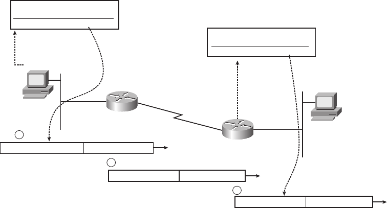
A Routing Troubleshooting Scenario 499
2. R1 receives the frame, strips off the data link header and trailer, and decides to
forward the packet over the serial link to R4. The link uses HDLC, so R1 does not
need ARP at all.
3. R4 receives the frame and strips off the incoming frame’s HDLC header and trailer. R4
then decides to forward the packet directly to PC23, out R4’s Fa0/1 interface, so R4
needs an ARP table entry listing the MAC address of host 192.168.4.23 (PC23).
Figure 15-8 shows the ARP table entries required for the flow of a packet from PC12 to
PC23. Note that the figure also shows the correlation between the next-hop IP address and the
MAC address, with the MAC address then being added to a new Ethernet data link header.
Figure 15-8 Required ARP Table Entries: Question 2
Scenario Part B: Question 3
The tricky part of this particular question relates to the fact that two routers connect to the
subnet on the right of Figure 15-6, so PC23 appears to have two possible routers to use as
its default gateway. The question suggests that an ICMP echo request packet goes from
PC12, through R1, then R2, and over the LAN to PC23. PC23 then needs to send the ICMP
echo reply to PC12, so to answer the question fully, you need to understand where the
packet flows, and then determine the required ARP table entries on each device.
PC23 still uses the same familiar host logic when sending a packet—if the destination is
on a different subnet, PC23 will send the packet to its default gateway. In this case, PC23
Fa0/1
10.10.10.12 /21
Def. Gw 10.10.15.1
192.168.4.23 /28
Def. Gw = 192.168.4.30
192.168.1.13 /30
10.10.15.1 /21
S0/0/1 192.168.1.14 /30
S0/0/1
192.168.4.30
Fa0/1
R1
R4
12
23
1
D_MAC=R1-Fa0/1-MAC D_IP=192.168.4.23
2
D_MAC=N/A D_IP=192.168.4.23
3
D_MAC=PC23-MAC D_IP=192.168.4.23
PC12 ARP Table:
IP Address MAC Address
10.10.15.1 R1-Fa0/1-MAC
R4 ARP Table:
IP Address MAC Address
192.168.4.23 PC23-MAC
1828xbook.fm Page 499 Thursday, July 26, 2007 3:10 PM
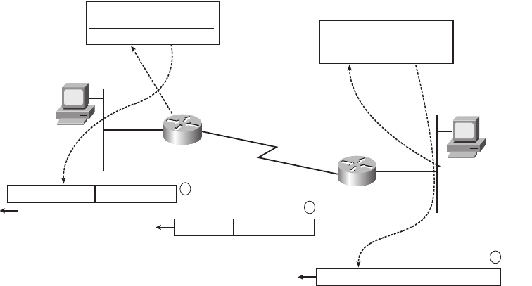
500 Chapter 15: Troubleshooting IP Routing
needs to send the ICMP echo reply to PC12, which is in another subnet, so PC23 will send
the packet to 192.168.4.30 (R4)—PC23’s configured default gateway. Presumably, R4
would then forward the packet to R1, and then R1 would forward the packet directly to PC12.
The ARP entries required for sending packets from PC23, to R4, to R1, and then to PC12
are as follows:
1. PC23 decides to send the packet to its default gateway, R4. So, PC23 needs an ARP
table entry listing the MAC address of its default gateway (192.168.4.30).
2. R4 receives the frame, strips off the data link header and trailer, and decides to forward
the packet over the serial link to R1. This links uses HDLC, so R4 does not need
ARP at all.
3. R1 receives the frame from R1 and strips off the incoming frame’s HDLC header
and trailer. R1 then decides to forward the packet directly to PC12, out R1’s Fa0/1
interface, so R1 needs an ARP table entry listing the MAC address of host 10.10.10.12
(PC12).
Figure 15-9 shows the ARP table entries required for the flow of a packet from PC23 to
PC12. Note that the figure also shows the correlation between the next-hop IP address and
the MAC address, with the MAC address then being added to a new Ethernet data link
header.
Figure 15-9 Required ARP Table Entries: Question 3
Fa0/1
10.10.10.12 /21
Def. Gw 10.10.15.1
192.168.4.23 /28
Def. Gw = 192.168.4.30
192.168.1.13 /30
10.10.15.1 /21
S0/0/1 192.168.1.14 /30
S0/0/1
192.168.4.30
Fa0/1
R1
R4
12
23
3
D_MAC=PC12-MAC D_IP=10.10.10.12
2
D_MAC=N/A D_IP=10.10.10.12
1
D_MAC=R4-Fa0/1-MAC D_IP=10.10.10.12
R1 ARP Table:
IP Address MAC Address
10.10.10.12 PC12-MAC PC23 ARP Table:
IP Address MAC Address
192.168.4.30 R4-Fa0/1-MAC
1828xbook.fm Page 500 Thursday, July 26, 2007 3:10 PM
A Routing Troubleshooting Scenario 501
Scenario Part B: Question 4
This question uses a packet sent from PC31 to PC22, but with the question focusing on the
packet as it crosses the LAN on the right side of Figure 15-6. To answer this question fully,
you need to recall that while the source and destination IP addresses of the packet remain
unchanged from sending host to receiving host, the data link source and destination
addresses change each time a router builds a new data link header when forwarding a
packet. Additionally, you need to realize that the R3→R4 serial link has been
misconfigured (R4’s proposed IP address of 192.168.1.19 was invalid), so no IP packets can
be forwarded over the link between R1 and R4. As a result, the packet will go over this path:
PC31→R3→R2→PC22.
The packet in question here (from PC31 to PC22) passes over the LAN on the right side
of the figure when R2 forwards the packet over the LAN to PC22. In this case, R2 will
build a new Ethernet header, with a source MAC address of R2’s Fa0/0 interface MAC
address. The destination MAC address will be PC22’s MAC address. The source and
destination IP addresses of 172.31.5.100 (PC31) and 192.168.4.22 (PC22), respectively,
remain unchanged.
Figure 15-10 shows both data link addresses and both network layer addresses in each
frame sent from PC31 to PC22. Note that the figure shows the addresses in the data link and
network layer headers for each stage of its passage from PC31 to PC22.
Scenario Part B: Question 5
This question uses the same packet flow as question 4, but it focuses on the frame that
passes the serial link between R3 and R2. The question can be easily answered as long as
you remember that the router discards the data link headers of received frames, and then
encapsulates the packet in a new data link header and trailer before forwarding the packet.
This new data link header and trailer must be appropriate for the outgoing interface.
In this case, the routers use HDLC, which is the default point-to-point serial data link
protocol on Cisco routers. HDLC headers do not include MAC addresses at all—in fact,
HDLC addressing is completely uninteresting, because any frame sent by R3 on that link
must be destined for R2, because R2 is the only other device on the other end of the link.
As a result, there are no MAC addresses, but the source and destination IP addresses of
172.31.5.100 (PC31) and 192.168.4.22 (PC22), respectively, remain unchanged. Figure 15-9,
found in the previous answer, shows a representation of the HDLC frame, mainly pointing
out that it does not contain MAC addresses.
1828xbook.fm Page 501 Thursday, July 26, 2007 3:10 PM
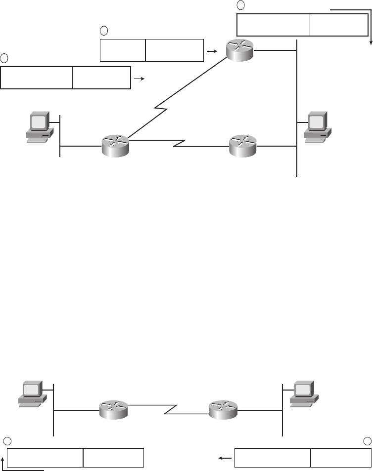
502 Chapter 15: Troubleshooting IP Routing
Figure 15-10 Required ARP Table Entries: Question 4
Scenario Part B: Question 6
This question focuses on a packet sent from PC21 to PC12, as the packet crosses the LAN
on the right side of Figure 15-6. Also, the question tells you that the packet goes from
PC21 to R2, then to R1, then to PC12.
In this case, PC21 forwards the packet, encapsulated in an Ethernet frame, to R2. To do so,
the Ethernet header lists PC21 as the source MAC address, and R2’s Fa0/0 interface MAC
address as the destination MAC address. The IP addresses—a source of 192.168.4.21
(PC21) and a destination of 10.10.10.12 (PC12)—remain the same for the entire journey
from PC21 to PC12. Figure 15-11 summarizes the frame contents for both this question and
the next.
Figure 15-11 Required ARP Table Entries: Questions 6 and 7
192.168.1.5/30
192.168.1.6/30
192.168.1.19/30
192.168.1.18/30
172.31.5.1/25
S0/1/0
192.168.4.29
Fa0/0
R2
192.168.1.14/30
Fa0/0
172.31.5.100/25
Def. GW 172.31.5.1
192.168.4.22/28
Def. Gw = 192.168.4.30
S0/1/0
S0/1/1 S0/1/1
S0/0/0
192.168.4.30
Fa0/1
R3
31 22
R4
3
D_MAC=PC22-MAC
S_MAC=R2-Fa0/0-MAC
D_IP=192.168.4.22
S_IP=172.31.5.100
2
D_MAC=N/A
S_MAC=N/A
D_IP=192.168.4.22
S_IP=172.31.5.100
1
D_MAC=R3-Fa0/0-MAC
S_MAC=PC31-MAC
D_IP=192.168.4.22
S_IP=172.31.5.100
Fa0/1
10.10.10.12/21
Def. Gw 10.10.15.1
192.168.4.21/28
Def. Gw = 192.168.4.29
192.168.1.1/30
10.10.15.1/21
S0/0/1
192.168.1.2/30
S0/0/1
192.168.4.29
Fa0/0
R1 R2
12 21
3
D_MAC=PC12-MAC
S_ MAC=R1-Fa0/1-MAC
D_IP=10.10.10.12
S_IP=192.168.4.21
1
D_MAC=R2-Fa0/0-MAC
S_ MAC=PC21-MAC
D_IP=10.10.10.12
S_IP=192.168.4.21
1828xbook.fm Page 502 Thursday, July 26, 2007 3:10 PM

A Routing Troubleshooting Scenario 503
Scenario Part B: Question 7
Question 7 continues question 6 by examining the same packet, sent from PC21 to PC12,
as the packet crosses the LAN on the upper-left part of Figure 15-6. The route taken by
this packet is from PC21 to R2, then to R1, then to PC12.
To begin, PC21 sends the IP packet, with a source of 192.168.4.21 (PC21) and a destination
of 10.10.10.12 (PC12). To send this packet, PC21 encapsulates the packet in an Ethernet
frame to deliver the packet to its default gateway (R2). R2 strips off the Ethernet header of
the received frame, and before forwarding the packet to R1, R2 encapsulates the packet in
an HDLC frame. When R1 receives the HDLC frame, R1 removes the HDLC header and
trailer, deciding to forward the packet out R1’s Fa0/1 interface to PC12. As usual, the
packet’s source and destination address do not change at all during this process.
Before R1 forwards the packet out its Fa0/1 interface, R1 adds an Ethernet header and
trailer. The source MAC address is R1’s Fa0/1 interface MAC address, and the destination,
found in R1’s ARP table, is PC12’s MAC address. Note that Figure 15-10, shown in the
previous section, shows this frame on the left side of the figure.
Scenario Part C: Analyze Connected Routes
For Part C of this scenario, predict the output that would be displayed of the show ip route
connected command on R4 and R1. You may continue to assume that any IP addressing
problems found in Part A still have not been corrected. You may refer back to Example 15-5
through Example 15-9, as well as the completed IP address reference of Figure 15-6, for
reference.
Scenario Part C: Answers
Routers add connected IP routes to their IP routing tables, referencing the subnet that is
connected to an interface, assuming the following are true:
■The interface’s two status codes are “up” and “up.”
■The interface has an IP address correctly configured.
For each interface meeting these two requirements, the router calculates the subnet number
based on the IP address and subnet mask listed in the ip address interface subcommand.
Based on details included in Parts A and B of this scenario, all router interfaces shown in
Figure 15-5 have an IP address and are up/up, with the exception of R4’s S0/1/1 interface.
This one serial interface was to be assigned an IP address that was really a subnet broadcast
address, so the router would have rejected the ip address command. Table 15-5 lists the
location and connected routes added to R1 and R4.
1828xbook.fm Page 503 Thursday, July 26, 2007 3:10 PM

504 Chapter 15: Troubleshooting IP Routing
To see the connected routes in a concise command, you can use the show ip route
connected EXEC command. This command simply lists a subset of the routes in the
routing table—those that are connected routes. Example 15-10 and Example 15-11
show the contents of the show ip route connected command on both R1 and R4,
respectively.
If you compare the highlighted portions of Example 15-11 with Example 15-9’s ip address
192.168.4.30 255.255.255.240 command, a subcommand under R4’s Fa0/1 interface, you
can correlate the information. The mask from the ip address command can be used to
determine the prefix notation version of the same mask—/28. The address and mask
together can be used to determine the subnet number of 192.168.4.16. These same pieces
of information are highlighted in the output of the show ip route connected command
in Example 15-11.
Table 15-5 Connected Routes Added to R1 and R4
Location IP Address Subnet Outgoing Interface
R1 Fa0/0 10.10.24.1/21 10.10.24.0/21 Fa0/0
R1 Fa0/1 10.10.15.1/21 10.10.8.0/21 Fa0/1
R1 S0/0/1 192.168.1.1/30 192.168.1.0/30 S0/0/1
R1 S0/1/1 192.168.1.13/30 192.168.1.12/30 S0/1/1
R4 S0/0/1 192.168.1.14/30 192.168.1.12/30 S0/0/1
R4 Fa0/1 192.168.4.30/28 192.168.4.16/28 Fa0/1
Example 15-10 show ip route connected Command Output for R1
R1#ss
sshh
hhoo
ooww
ww
ii
iipp
pp
rr
rroo
oouu
uutt
ttee
ee
cc
ccoo
oonn
nnnn
nnee
eecc
cctt
ttee
eedd
dd
10.0.0.0/21 is subnetted, 2 subnets
C 10.10.8.0 is directly connected, FastEthernet0/0
C 10.10.24.0 is directly connected, FastEthernet0/1
192.168.1.0/24 is variably subnetted, 5 subnets, 2 masks
C 192.168.1.12/30 is directly connected, Serial0/1/1
C 192.168.1.0/30 is directly connected, Serial0/0/1
Example 15-11 show ip route connected Command on R4
R4#ss
sshh
hhoo
ooww
ww
ii
iipp
pp
rr
rroo
oouu
uutt
ttee
ee
cc
ccoo
oonn
nnnn
nnee
eecc
cctt
ttee
eedd
dd
192.168.4.0/28 is subnetted, 1 subnets
C 192.168.4.16 is directly connected, FastEthernet0/1
192.168.1.0/24 is variably subnetted, 5 subnets, 2 masks
C 192.168.1.12/30 is directly connected, Serial0/0/1
1828xbook.fm Page 504 Thursday, July 26, 2007 3:10 PM

Review All the Key Topics 505
Exam Preparation Tasks
Review All the Key Topics
Review the most important topics from inside the chapter, noted with the key topics icon in
the outer margin of the page. Table 15-6 lists a reference of these key topics and the page
numbers on which each is found.
Table 15-6 Key Topics for Chapter 15
Key Topic Element Description
Page
Number
List First octet values of addresses that are always reserved and
cannot be assigned to hosts
475
Table 15-2 Summary of reasons why an exam question should or should
not allow the use of the zero and broadcast subnets
476
List Summary of four tips when approaching IP addressing
related questions on the exams
478
List Summary of how a host thinks about routing, address
assignment, name resolution, and ARP
478
List Two typical reasons why a host cannot ping other hosts in the
same subnet
482
List Three typical reasons why a host can ping other hosts in the
same subnet, but not hosts in other subnets
482-483
List Tips regarding how a router matches a packet’s destination IP
address as part of the routing process
483
Figure 15-3 Shows the IP addresses discovered by the Cisco IOS
traceroute command
486
List Reminders that are helpful when thinking about the source
and destination MAC and IP addresses used at various points
in an internetwork
496
List Two key requirements for a router to add a connected route 503
1828xbook.fm Page 505 Thursday, July 26, 2007 3:10 PM

506 Chapter 15: Troubleshooting IP Routing
Complete the Tables and Lists from Memory
Print a copy of Appendix H, “Memory Tables” (found on the CD-ROM), or at least the
section for this chapter, and complete the tables and lists from memory. Appendix I,
“Memory Tables Answer Key,” also on the CD-ROM, includes completed tables and lists
to check your work.
Command Reference
Table 15-7 lists the EXEC commands used in this chapter and a brief description of their
use. Additionally, you might want to review the host commands listed earlier in the chapter
in Table 15-4. (This chapter did not introduce any new configuration commands.)
Table 15-7 Chapter 15 show and debug Command Reference
Command Purpose
show sessions Lists the suspended Telnet and SSH session on the router from which the
Telnet and SSH sessions were created
where Does the same thing as the show sessions command
telnet {hostname |
ip_address}
Connects the CLI to another host using Telnet
ssh –l username
{hostname |
ip_address}
Connects the CLI to another host using SSH
disconnect
[connection_number]
Disconnects a currently suspended Telnet or SSH connection, based on the
connection number as seen with the show sessions command
resume
[connection_number]
Connects the CLI to a currently suspended Telnet or SSH connection, based
on the connection number as seen with the show sessions command
traceroute
{hostname |
ip_address}
Discovers if a path from the router to a destination IP address is working,
listing each next-hop router in the route
Ctrl-Shift-6, x The key sequence required to suspend a Telnet or SSH connection
show ip arp Lists the contents of the router’s ARP cache
show arp Lists the contents of the router’s ARP cache
show ssh Lists information about the users logged in to the router using SSH
show users Lists information about users logged in to the router, including Telnet, SSH,
and console users
1828xbook.fm Page 506 Thursday, July 26, 2007 3:10 PM
1828xbook.fm Page 507 Thursday, July 26, 2007 3:10 PM

Cisco Published ICND1 Exam Topics* Covered in This Part:
Describe the operation of data networks
■Interpret network diagrams
■Determine the path between two hosts across a network
■Describe the components required for network and Internet communications
■Identify and correct common network problems at Layers 1, 2, 3, and 7 using a layered
model approach
■Differentiate between LAN/WAN operation and features
Implement an IP addressing scheme and IP services to meet network requirements for a
small branch office
■Explain the basic uses and operation of NAT in a small network connecting to one ISP
■Describe the operation and benefits of using private and public IP addressing
■Enable NAT for a small network with a single ISP and connection using SDM and verify
operation using CLI and ping
Implement and verify WAN links
■Describe different methods for connecting to a WAN
■Configure and verify a basic WAN serial connection
*Always recheck http://www.cisco.com for the latest posted exam topics.
1828xbook.fm Page 508 Thursday, July 26, 2007 3:10 PM

Part IV: Wide-Area Networks
Chapter 16 WAN Concepts
Chapter 17 WAN Configuration
1828xbook.fm Page 509 Thursday, July 26, 2007 3:10 PM

This chapter covers the following subjects:
WAN Technologies: This section examines
several additional WAN technologies that were
not covered in Chapter 4, namely modems, DSL,
cable, and ATM.
IP Services for Internet Access: This section
examines how an Internet access router uses
DHCP client and server functions, as well
as NAT.
1828xbook.fm Page 510 Thursday, July 26, 2007 3:10 PM

C H A P T E R16
WAN Concepts
Chapter 4, “Fundamentals of WANs,” introduced two important WAN technologies
common in enterprise networks today:
■Leased lines, which use either High-Level Data Link Control (HDLC) or Point-to-
Point Protocol (PPP)
■Frame Relay
Part IV of this book covers the remainder of the WAN-specific topics in this book. In
particular, this chapter examines a broader range of WAN technologies, including
commonly used Internet access technologies. Chapter 17, “WAN Configuration,” focuses
on how to implement several features related to WAN connections, including several
Layer 3 services required for a typical Internet connection from a small office or home
(SOHO) today.
“Do I Know This Already?” Quiz
The “Do I Know This Already?” quiz allows you to assess if you should read the entire
chapter. If you miss no more than one of these eight self-assessment questions, you might
want to move ahead to the “Exam Preparation Tasks” section. Table 16-1 lists the major
headings in this chapter and the “Do I Know This Already?” quiz questions covering the
material in those headings so you can assess your knowledge of these specific areas. The
answers to the “Do I Know This Already?” quiz appear in Appendix A.
Table 16-1 “Do I Know This Already?” Foundation Topics Section-to-Question Mapping
Foundation Topics Section Questions
WAN Technologies 1–5
IP Services for Internet Access 6–8
1828xbook.fm Page 511 Thursday, July 26, 2007 3:10 PM
512 Chapter 16: WAN Concepts
1. Which of the following best describes the function of demodulation by a modem?
a. Encoding an incoming analog signal from the PC as a digital signal for transmis-
sion into the PSTN
b. Decoding an incoming digital signal from the PSTN into an analog signal
c. Encoding a set of binary digits as an analog electrical signal
d. Decoding an incoming analog electrical signal from the PSTN into a digital
signal
e. Encoding a set of binary digits as a digital electrical signal
2. Which of the following standards has a limit of 18,000 feet for the length of the
local loop?
a. ADSL
b. Analog modems
c. ISDN
d. Cable Internet service
3. Which of the following is true regarding the location and purpose of a DSLAM?
a. Typically used at a home or small office to connect the phone line to a DSL router
b. Typically used at a home or small office instead of a DSL router
c. Typically used inside the telco’s CO to prevent any voice traffic from reaching the
ISP’s router
d. Typically used inside the telco’s CO to separate the voice traffic from the data
traffic
4. Which of the following remote-access technologies support specifications that allow
both symmetric speeds and asymmetric speeds?
a. Analog modems
b. WWW
c. DSL
d. Cable modems
1828xbook.fm Page 512 Thursday, July 26, 2007 3:10 PM
“Do I Know This Already?” Quiz 513
5. Which of the following remote-access technologies, when used to connect to an ISP, is
considered to be an “always on” Internet service?
a. Analog modems
b. DSL
c. Cable modems
d. All of these answers are correct.
6. For a typical Internet access router, using either cable or DSL, which of the following
does the router typically do on the router interface connected to the LAN with the
PCs in the small or home office?
a. Acts as a DHCP server
b. Acts as a DHCP client
c. Performs NAT/PAT for the source address of packets that exit the interface
d. Acts as DNS server
7. For a typical Internet access router, using either cable or DSL, which of the following
does the router typically do on the router interface connected toward the Internet?
a. Acts as a DHCP server
b. Acts as a DHCP client
c. Performs NAT/PAT for the source address of packets that exit the interface
d. Acts as DNS server
8. This question examines a home-based network with a PC, a DSL router, and a DSL
line. The DSL router uses typical default settings and functions. The PC connected to
the router has IP address 10.1.1.1. This PC opens a browser and connects to the
www.cisco.com web server. Which of the following are true in this case?
a. The web server can tell it is communicating with a host at IP address 10.1.1.1.
b. The PC learns the IP address of the www.cisco.com web server as a public IP
address.
c. The 10.1.1.1 address would be considered an inside local IP address.
d. The 10.1.1.1 address would be considered an inside global IP address.
1828xbook.fm Page 513 Thursday, July 26, 2007 3:10 PM

514 Chapter 16: WAN Concepts
Foundation Topics
WANs differ from LANs in several ways. Most significantly, WAN links typically go much
longer distances, with the WAN cabling being installed underground in many cases to
prevent accidental damage by people walking on them or cars driving over them.
Governments typically do not let the average person dig around other people’s property, so
WAN connections use cabling installed by a service provider, with the service provider
having permission from the appropriate government agencies to install and maintain the
cabling. The service provider then sells the WAN services to various enterprises. This
difference between WANs and LANs can be summed up with the old adage “You own
LANs, but you lease WANs.”
This chapter has two major sections. The first section examines a broad range of WAN
connectivity options, including switched circuits, DSL, cable, and ATM. The second half
then explains how Internet connections from a home or small office often need several
Layer 3 services before the WAN connection can be useful. The second section goes on to
explain why DHCP and NAT are needed for routers connecting to the Internet, with
particular attention to the NAT function.
WAN Technologies
This section introduces four different types of WAN technologies in addition to the leased-
line and Frame Relay WANs introduced in Chapter 4. The first of these technologies, analog
modems, can be used to communicate between most any two devices, and can be used to
connect to the Internet through an ISP. The next two technologies, DSL and cable Internet,
are almost exclusively used for Internet access. The last of these, ATM, is a packet-
switching service used like Frame Relay to connect enterprise routers, as well as for other
purposes not discussed in this book.
Before introducing each of these types of WANs, this section starts by explaining a few
details about the telco’s network, particularly because modems and DSL use the phone line
installed by the telco.
Perspectives on the PSTN
The term Public Switched Telephone Network (PSTN) refers to the equipment and
devices that telcos use to create basic telephone service between any two phones in the
world. This term refers to the combined networks of all telephone companies. The
“public” part of PSTN refers to the fact that it is available for public use (for a fee), and
the “switched” part refers to the fact that you can change or switch between phone calls
1828xbook.fm Page 514 Thursday, July 26, 2007 3:10 PM
WAN Technologies 515
with different people at will. Although the PSTN was originally built to support voice
traffic, two of the three Internet access technologies covered in this chapter happen to use
the PSTN to send data, so a basic understanding of the PSTN can help you appreciate
how modems and DSL work.
Sound waves travel through the air by vibrating the air. The human ear hears the sound
because the ear vibrates as a result of the air inside the ear moving, which, in turn, causes
the brain to process the sounds that were heard by the ear.
The PSTN, however, cannot forward sound waves. Instead, a telephone includes a
microphone, which simply converts the sound waves into an analog electrical signal. (The
electrical signal is called analog because it is analogous to the sound waves.) The PSTN can
send the analog electrical signal between one phone and another using an electrical circuit.
On the receiving side, the phone converts the analog electrical signal back to sound waves
using a speaker that is inside the part of the phone that you put next to your ear.
The original PSTN predated the invention of the digital computer by quite a while, with the
first telephone exchanges being created in the 1870s, soon after the invention of the
telephone by Alexander Graham Bell. In its original form, a telephone call required an
electrical circuit between the two phones. With the advent of digital computers, however,
in the mid-1950s telcos began updating the core of the PSTN to use digital electrical
signals, which gave the PSTN many advantages in speed, quality, manageability, and
capability to scale to a much larger size.
Next, consider what the telco has to do to make your home phone work. Between your
home and some nearby telco central office (CO), the telco typically installs a cable with a
pair of wires, called the local loop. (In the United States, if you have ever seen a two- to
three-foot-high light-green post in your neighborhood, that is the collection point for the
local loop cables that connect to the houses on that street.) One end of the cable enters your
house and connects to the phone outlets in your house. The other end (possibly miles away)
connects to a computer in the CO, generically called a voice switch. Figure 16-1 shows the
concept, along with some other details.
The local loop supports analog electrical signals to create a voice call. The figure shows
two local loops, one connected to Andy’s phone, and the other connected to Barney’s.
Andy and Barney happen to live far enough apart that their local loops connect to
different COs.
1828xbook.fm Page 515 Thursday, July 26, 2007 3:10 PM
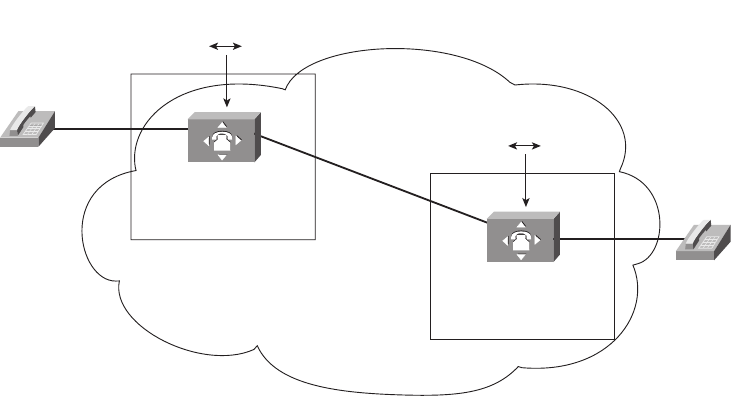
516 Chapter 16: WAN Concepts
Figure 16-1 Analog Voice Calls Through a Digital PSTN
When Andy calls Barney, the phone call works, but the process is more complicated than
just setting up an electrical circuit between the two phones. In particular, note that
■The phones use analog electrical signals only.
■The voice switches use a digital circuit to forward the voice (a T1 in this case).
■The voice switch must convert between analog electricity and digital electricity in both
directions.
To make it all work, the phone company switch in the Mayberry CO performs analog-to-
digital (A/D) conversion of Andy’s incoming analog voice. When the switch in Raleigh gets
the digital signal from the Mayberry switch, before sending it out the analog line to
Barney’s house, the Raleigh switch reverses the A/D process, converting the digital signal
back to analog. The analog signal going over the local line to Barney’s house is roughly the
same analog signal that Andy’s phone sent over his local line; in other words, it is the same
sounds.
The original standard for converting analog voice to a digital signal is called pulse-code
modulation (PCM). PCM defines that an incoming analog voice signal should be sampled
8000 times per second by the A/D converter, using an 8-bit code for each sample. As a
result, a single voice call requires 64,000 bits per second—which amazingly fits perfectly
into 1 of the 24 available 64-kbps DS0 channels in a T1. (As you may recall from Chapter 4,
a T1 holds 24 separate DS0 channels, 64 kbps each, plus 8 kbps of management overhead,
for a total of 1.544 Mbps.)
Local
Loop
(Analog)
Local
Loop
(Analog)
Digital T1 Line
(24 Seperate
64 Kbps DS0
Channels)
PCM Codec Converts
Analog Digital
PCM Codec Converts
Analog Digital
Telco Voice
Switch
Raleigh CO
Telco Voice
Switch
Mayberry CO
Barney’s
Phone
Andy’s
Phone
PSTN
1828xbook.fm Page 516 Thursday, July 26, 2007 3:10 PM
WAN Technologies 517
The details and complexity of the PSTN as it exists today go far beyond this brief
introduction. However, these few pages do introduce a few key points that will give you
some perspectives on how other WAN technologies work. In summary:
■The telco voice switch in the CO expects to send and receive analog voice over the
physical line to a typical home (the local loop).
■The telco voice switch converts the received analog voice to the digital equivalent
using a codec.
■The telco converts the digital voice back to the analog equivalent for transmission over
the local loop at the destination.
■The voice call, with the PCM codec in use, consumes 64 kbps through the digital part
of the PSTN (when using links like T1s and T3s inside the telco).
Analog Modems
Analog modems allow two computers to send and receive a serial stream of bits over the
same voice circuit normally used between two phones. The modems can connect to a
normal local phone line (local loop), with no physical changes required on the local loop
cabling and no changes required on the voice switch at the telco’s CO. Because the switch
in the CO expects to send and receive analog voice signals over the local loop, modems
simply send an analog signal to the PSTN and expect to receive an analog signal from the
PSTN. However, that analog signal represents some bits that the computer needs to send to
another computer, instead of voice created by a human speaker. Similar in concept to a
phone converting sound waves into an analog electrical signal, a modem converts a string
of binary digits on a computer into a representative analog electrical signal.
To achieve a particular bit rate, the sending modem could modulate (change) the analog
signal at that rate. For instance, to send 9600 bps, the sending modem would change the
signal (as necessary) every 1/9600th of a second. Similarly, the receiving modem would
sample the incoming analog signal every 1/9600th of a second, interpreting the signal as a
binary 1 or 0. (The process of the receiving end is called demodulation. The term modem is
a shortened version of the combination of the two words modulation and demodulation.)
Because modems represent data as an analog electrical signal, modems can connect to a
PSTN local loop, make the equivalent of a phone call to another site that has a modem
connected to its phone line, and send data. As a result, modems can be used at most any
location that has a phone line installed.
The PSTN refers to a communications path between the two modems as a circuit. Because
the modems can switch to a different destination just by hanging up and dialing another
1828xbook.fm Page 517 Thursday, July 26, 2007 3:10 PM
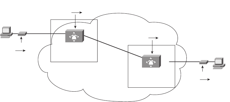
518 Chapter 16: WAN Concepts
phone number, this type of WAN service is called a switched circuit. Figure 16-2 shows an
example, now with Andy and Barney connecting their PCs to their home phone lines
using a modem.
Figure 16-2 Basic Operation of Modems over PSTN
Once the circuit has been established, the two computers have a Layer 1 service, meaning
that they can pass bits between each other. The computers also need to use some data
link layer protocol on the circuit, with PPP being a popular option today. The telco has no
need to try and interpret what the bits sent by the modem mean—in fact, the telco does not
even care to know if the signal represents voice or data.
To be used as an Internet access WAN technology, the home-based user connects via a
modem to a router owned by an ISP. The home user typically has a modem in their
computer (internal modem) or outside the computer (external modem). The ISP typically
has a large bank of modems. The ISP then publishes a phone number for the phone lines
installed into the ISP router’s modem bank, and the home user dials that number to connect
to the ISP’s router.
The circuit between two modems works and acts like a leased line in some regards;
however, the link differs in regards to clocking and synchronization. The CSU/DSUs on
the ends of a leased line create what is called a synchronous circuit, because not only do the
CSU/DSUs try to run at the same speed, they adjust their speeds to match or synchronize
with the other CSU/DSU. Modems create an asynchronous circuit, which means that
the two modems try to use the same speed, but they do not adjust their clock rates to match
the other modem.
Local Loop
(Analog)
Local Loop
(Analog)
Digital T1 Line
(1 DS0
Channel Used)
PCM Codec Converts
Analog Digital
Modem Converts
Digital Analog
Modem Converts
Analog Digital
PCM Codec Converts
Digital Analog
Telco Voice
Switch
Raleigh CO
Telco Voice
Switch
Mayberry CO
Barney’s
PC
Andy’s
PC
PSTN
1828xbook.fm Page 518 Thursday, July 26, 2007 3:10 PM

WAN Technologies 519
Modems have the great advantage of being the most pervasively available remote-access
technology, usable most anywhere that a local phone line is available. The cost is relatively
low, particularly if the phone line is already needed for basic voice service; however,
modems run at a relatively slow speed. Even with modern compression technologies, the
bit rate for modems is only a little faster than 100 kbps. Additionally, you cannot
concurrently talk on the phone and send data with a modem on the same phone line.
Digital Subscriber Line
By the time digital subscriber line (DSL) came around in the mid- to late 1990s, the main
goal for remote-access WAN technology had changed. The need to connect to any other
computer anywhere had waned, but the need to connect to the Internet was growing quickly.
In years past, modems were used to dial a large variety of different computers, which was
useful. Today you can think of the Internet as a utility, just like you think of the electric
company, the gas company, and so on. The Internet utility provides IP connectivity to the
rest of the world, so if you can just get connected to the Internet, you can communicate with
anyone else in the world.
Because most people today just want access to the utility—in other words, the Internet—
DSL was defined a little differently than modems. In fact, DSL was designed to provide
high-speed access between a home or business and the local CO. By limiting the scope of
where DSL needed to work, design engineers were able to define DSL to support much
faster speeds than modems.
DSL’s basic services have some similarities, as well as differences, to analog modems.
Some of the key features are as follows:
■DSL allows analog voice signals and digital data signals to be sent over the same local
loop wiring at the same time.
■The local loop must be connected to something besides a traditional voice switch at the
local CO, in this case a device called a DSL access multiplexer (DSLAM).
■DSL allows for a concurrent voice call to be up at the same time as the data connection.
■Unlike modems, DSL’s data component is always on; in other words, you do not have
to signal or dial a phone number to set up a data circuit.
DSL really does provide some great benefits—you can use the same old phones that you
already have, you can keep the same phone number, and, once DSL is installed, you can
just sit down and start using your “always on” Internet service without having to dial a
number. Figure 16-3 shows some of the details of a typical DSL connection.
1828xbook.fm Page 519 Thursday, July 26, 2007 3:10 PM
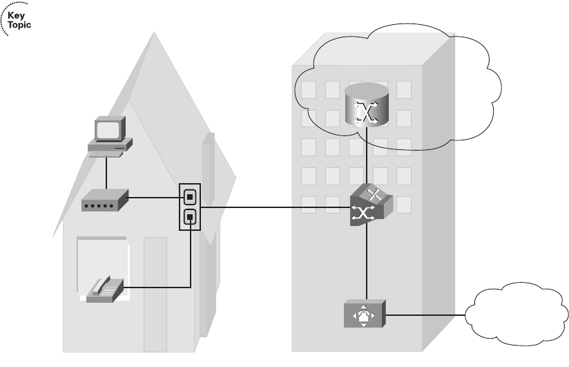
520 Chapter 16: WAN Concepts
Figure 16-3 DSL Connection from the Home to an ISP
The figure shows a generic-looking device labeled “DSL Router/Modem” which connects
via a standard telephone cable to the same phone jack on the wall. Many options exist
for the DSL hardware at the home: There could be a separate router and DSL modem, the
two could be combined as shown in the figure, or the two could be combined along with a
LAN switch and a wireless AP. (Figure 13-4 and Figure 13-5 in Chapter 13, “Operating
Cisco Routers,” show a couple of the cabling options for the equivalent design when using
cable Internet, which has the same basic hardware options.)
In the home, a DSL modem or DSL-capable router is connected to the phone line (the local
loop) using a typical telephone cable, as shown on the left side of Figure 16-3. The same
old analog telephones can be connected to any other available phone jacks, at the same
time. The cable from the phone or DSL modem to the telephone wall jack uses RJ-11
connectors, as is typical for a cable for an analog phone or a modem.
DSL supports concurrent voice and data, so you can make a phone call without disrupting
the always-on DSL Internet connection. The phone generates an analog signal at frequency
ranges between 0 and 4000 Hz; the DSL modem uses frequencies higher than 4000 Hz so
that the phone and DSL signals do not interfere with each other very much. You typically
need to put a filter, a small device about the size of a small packet of chewing gum, between
each phone and the wall socket (not shown) to prevent interference from the higher-
frequency DSL signals.
Voice Switch w/PCM
DSL
Router/
Modem
Ethernet
Andy’s
Analog
phone
Andy’s
PC
DTMF Tones,
Analog Voice,
0 – 4000 Hz
Digital
Signals >
4000 Hz
Analog Voice
Split to Voice
Switch
Andy’s House Mayberry CO
Local Loop
DSLAM
IP Traffic
Split to ISP
Router
IP Network
Owned by ISP
PSTN
1828xbook.fm Page 520 Thursday, July 26, 2007 3:10 PM
WAN Technologies 521
The DSLAM at the local CO plays a vitally important role in allowing the digital data and
analog voice to be processed correctly. When migrating a customer from just using voice
to instead support voice and DSL, the phone company has to disconnect the local loop cable
from the old voice switch and move it to a DSLAM. The local loop wiring itself does not
have to change. The DSLAM directs (multiplexes) the analog voice signal—the frequency
range between 0 Hz and 4000 Hz—to a voice switch, and the voice switch treats that signal
just like any other analog voice line. The DSLAM multiplexes the data traffic to a router
owned by the ISP providing the service in Figure 16-3.
The design with a local loop, DSLAM, and ISP router enables a business model in which
you buy Internet services from an ISP that is not the local phone company. The local telco
owns the local loop. However, many ISPs that are not a local telco sell DSL Internet access.
The way it works is that you pay the ISP a monthly fee for DSL service, and the ISP works
with the telco to get your local loop connected to the telco’s DSLAM. The telco then
configures the DSLAM to send data traffic from your local loop to that ISP’s router. You
pay the ISP for high-speed DSL Internet service, and the ISP keeps part of the money and
gives part of the money to the local telco.
DSL Types, Speeds, and Distances
DSL technology includes many options at many speeds, with some variations getting more
attention in the marketplace. So, it is helpful to consider at least a few of the options.
One key difference in the types of DSL is whether the DSL service is symmetric or
asymmetric. Symmetric DSL means that the link speed in each direction is the same,
whereas asymmetric means that the speeds are different. As it turns out, SOHO users tend
to need to receive much more data than they need to send. For example, a home user might
type in a URL in a browser window, sending a few hundred bytes of data to the ISP. The
web page returned from the Internet may be many megabytes large. Asymmetric DSL
allows for much faster downstream (Internet toward home) speeds, but with lower upstream
(home toward Internet) speeds, as compared with symmetric DSL. For example, an ADSL
connection might use a 1.5-Mbps speed downstream (toward the end user), and a 384-Kbps
speed upstream toward the Internet. Table 16-2 lists some of the more popular types of
DSL, and whether each is asymmetric or symmetric.
Table 16-2 DSL Types
AcronymSpelled Out Type
ADSL Asymmetric DSL Asymmetric
CDSL (G.lite) Consumer DSL Asymmetric
VDSL Very-high-data-rate DSL Asymmetric
continues
1828xbook.fm Page 521 Thursday, July 26, 2007 3:10 PM
522 Chapter 16: WAN Concepts
Typically, most consumer DSL installations in the United States use ADSL.
The speed of a DSL line is a difficult number to pin down. DSL standards list maximum
speeds, but in practice the speed can vary widely, based on many factors, including:
■The distance between the CO and the consumer (the longer the distance, the slower the
speed)
■The quality of the local loop cabling (the worse the wiring, the slower the speed)
■The type of DSL (each standard has different maximum theoretical speeds)
■The DSLAM used in the CO (older equipment may not have recent improvements that
allow for faster speeds on lower-grade local loops)
For example, ADSL has theoretical downstream speeds of close to 10 Mbps, with the Cisco
ICND1 course currently making a minor reference to a maximum of 8.192 Mbps. However,
most ISPs, if they quote any numbers at all, state that the lines will run at about 1.5 Mbps
downstream, and 384 kbps upstream—numbers much more realistic compared to the actual
speeds experienced by their customers. Regardless of the actual speeds, these speeds are
significantly faster than modem speeds, making DSL very popular in the marketplace for
high-speed Internet access.
Besides the factors that limit the speed, DSL lines typically do not work at all if the local
loop exceeds that particular DSL standard’s maximum cabling length. For example, ADSL
has become popular in part because it supports local loops that are up to 18,000 feet (a little
over 3 miles/5 kilometers). However, if you live in the country, far away from the CO,
chances are DSL is not an option.
DSL Summary
DSL brings high-speed remote-access capabilities to the home. It supports concurrent voice
and data, using the same old analog phones and same old local loop cabling. The Internet
data service is always on—no dialing required. Furthermore, the speed of the DSL service
itself does not degrade when more users are added to the network.
SDSL Symmetric DSL Symmetric
HDSL High-data-rate DSL Symmetric
IDSL ISDN DSL Symmetric
Table 16-2 DSL Types (Continued)
AcronymSpelled Out Type
1828xbook.fm Page 522 Thursday, July 26, 2007 3:10 PM

WAN Technologies 523
DSL has some obvious drawbacks. DSL simply will not be available to some people,
particularly those in rural areas, based on the distance from the home to the CO. The local
telco must have DSL equipment in the CO before it, or any ISP, can offer DSL services.
Even when the home is close enough to the CO, sites farther from the CO might run slower
than sites closer to the CO.
Cable Internet
Of all the Internet access technologies covered in this chapter, cable modem technology is
the only one that does not use a phone line from the local telco for physical connectivity.
Many homes also have a cable TV service supplied by a coaxial cable—in other words, over
the cable TV (CATV) cabling. Cable modems provide an always-on Internet access service,
while allowing you to surf the Internet over the cable and make all the phone calls you want
over your telephone line—and you can watch TV at the same time!
Cable modems (and cable routers with integrated cable modems, similar in concept to DSL)
use some of the capacity in the CATV cable that otherwise might have been allocated for
new TV channels, using those frequency bands for transferring data. It is a little like having
an “Internet” channel to go along with CNN, TBS, ESPN, The Cartoon Network, and all
your other favorite cable channels.
To appreciate how cable modems work, you need a little perspective on some cable TV
terminology. Cable TV traditionally has been a one-way service—the cable provider sends
electrical signals down the cable for all the channels. All you have to do, after the physical
installation is complete, is choose the channel you want to watch. While you are watching
The Cartoon Network, the electrical signals for CNN still are coming into your house over
the cable—your TV is just ignoring that part of the signal. If you have two TVs in your
house, you can watch two different channels because the signals for all the channels are
being sent down the cable.
Cable TV technology has its own set of terminology, just like most of the other access
technologies covered in this chapter. Figure 16-4 outlines some of the key terms.
The cable modem or cable router connects to the CATV cable, shown as a dotted line in the
figure. In a typical house or apartment, there are several cable wall plates installed, so the
cable modem/router just connects to one of those wall jacks. And like DSL modems/
routers, the cable modem/router connects to the PCs in the home using an Ethernet
connection.
NOTE Cable companies today also offer digital voice services, competing with the
local telcos. The voice traffic also passes over the same CATV cable.
1828xbook.fm Page 523 Thursday, July 26, 2007 3:10 PM
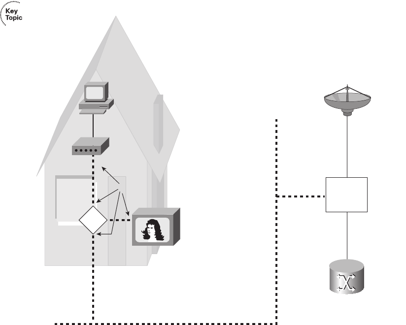
524 Chapter 16: WAN Concepts
Figure 16-4 Cable TV Terminology
The other end of the cable connects to equipment in the cable company’s facilities,
generally called the head-end. Equipment on the head-end can split the channels used for
Internet over to an ISP router, much like a DSLAM splits data off the telco local loop over
to an ISP’s router. That same equipment collects TV signals (typically from a satellite array)
and feeds those over other channels on the cable to provide TV service.
Cable Internet service has many similarities to DSL services. It is intended to be used to
access some ISP’s router, with that service being always on and available. It is asymmetric,
with much faster downstream speeds. The SOHO user needs a cable modem and router,
which may be in a single device or in separate devices.
There are some key differences, as you might imagine. Cable Internet service runs faster
than DSL, with practical speeds from two to five times faster than the typically quoted
1.5 Mbps for DSL. Cable speeds do not degrade due to the length of the cable (distance
from the cable company’s facilities). However, the effective speed of cable Internet does
Ethernet
F-connectors
Head-end
Andy’s House
Mayberry CATV
Drop Cable
Distribution Cables
Andy’s
PC
Spilt
Cable Modem
1828xbook.fm Page 524 Thursday, July 26, 2007 3:10 PM
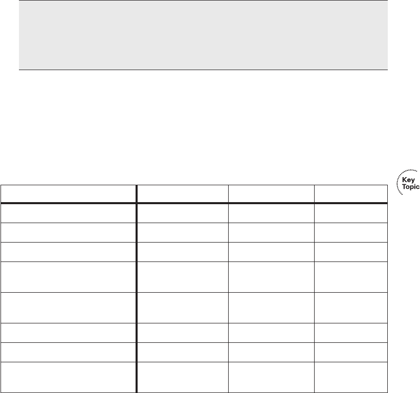
WAN Technologies 525
degrade as more and more traffic is sent over the cable by other users, because the cable is
shared among users in certain parts of the CATV cable plant, whereas DSL does not suffer
from this problem. To be fair, the cable companies can engineer around these contention
problems and improve the effective speed for those customers.
Comparison of Remote-Access Technologies
This chapter scratches the surface of how modems, cable, and DSL work. Consumers
choose between these options for Internet access all the time, and network engineers choose
between these options for supporting their work-at-home users as well. So, Table 16-3 lists
some of the key comparison points for these options.
ATM
The other WAN technologies introduced in this book can all be used for Internet access
from the home or a small office. Asynchronous Transfer Mode (ATM) is most often used
today either as a packet-switching service, similar in purpose to Frame Relay, or as a
NOTE Pinning down exact answers to the questions “how fast is cable?” and “how fast
is DSL?” is difficult because the speeds vary depending on many factors. However, you
can test the actual amount of data transferred using one of many speed-testing websites.
I tend to use CNET’s website, which can be found by searching the web for “Internet
speed test CNET” or at http://reviews.cnet.com/7004-7254_7-0.html.
Table 16-3 Comparison of Modems, DSL, and Cable
Analog Modems DSL Cable Modems
Transport Telco local loop Telco local loop CATV cable
Supports symmetric speeds Yes Yes No
Supports asymmetric speeds Yes Yes Yes
Typical practical speeds
(may vary)
Up to 100 kbps 1.5 Mbps
downstream
3 to 6 Mbps
downstream
Allows concurrent voice
and data
No Yes Yes
Always-on Internet service No Yes Yes
Local loop distance issues No Yes No
Throughput degrades under
higher loads
No No Yes
1828xbook.fm Page 525 Thursday, July 26, 2007 3:10 PM
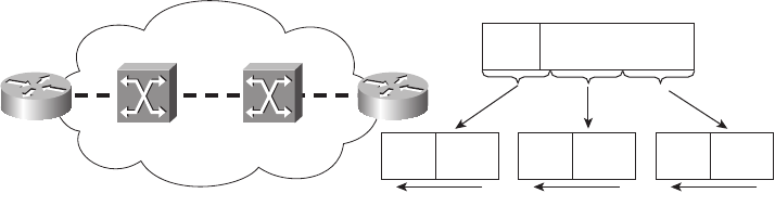
526 Chapter 16: WAN Concepts
switching technology used inside the core network built by telcos. This section introduces
ATM as a packet-switching service.
To use ATM, routers connect to an ATM service via an access link to an ATM switch inside
the service provider’s network—basically the same topology as Frame Relay. For multiple
sites, each router would need a single access link to the ATM network, with a virtual circuit
(VC) between sites as needed. ATM can use permanent VCs (PVC) like Frame Relay.
Of course, there are differences between Frame Relay and ATM; otherwise, you would not
need both! First, ATM typically supports much higher-speed physical links, especially
those using a specification called Synchronous Optical Network (SONET). The other big
difference is that ATM does not forward frames—it forwards cells. A cell, just like a packet
or frame, is a string of bits sent over some network. The difference is that while packets
and frames can vary in size, ATM cells are always a fixed 53 bytes in length.
ATM cells contain 48 bytes of payload (data) and a 5-byte header. The header contains two
fields that together act like the data-link connection identifier (DLCI) for Frame Relay by
identifying each VC. The two fields are named Virtual Path Identifier (VPI) and Virtual
Channel Identifier (VCI). Just like Frame Relay switches forward frames based on the
DLCI, devices called ATM switches, resident in the service provider network, forward cells
based on the VPI/VCI pair.
The end users of a network typically connect using Ethernet, and Ethernet devices do not
create cells. So, how do you get traffic off an Ethernet and onto an ATM network? A router
connects both to the LAN and to the ATM WAN service via an access link. When a router
receives a packet from the LAN and decides to forward the packet over the ATM network,
the router creates the cells by breaking the packet into smaller pieces. This cell-creation
process involves breaking up a data link layer frame into 48-byte-long segments. Each
segment is placed in a cell along with the 5-byte header. Figure 16-5 shows the general idea,
as performed on R2.
Figure 16-5 ATM Segmentation and Reassembly
ATM Network Frame
Header Packet
Cell
Header
48-byte
Payload
Cell Headers Include Correct VPI/VCI for the VC to R1
Cell
Header
48-byte
Payload
Cell
Header
48-byte
Payload
R1 R2
1828xbook.fm Page 526 Thursday, July 26, 2007 3:10 PM
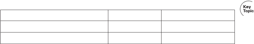
WAN Technologies 527
R1 actually reverses the segmentation process after receiving all the cells—a process called
reassembly. The entire concept of segmenting a frame into cells, and reassembling them, is
called segmentation and reassembly (SAR). Cisco routers use specialized ATM interfaces
to support ATM. The ATM cards include special hardware to perform the SAR function
quickly. They also often include special hardware to support SONET.
Because of its similar function to Frame Relay, ATM also is considered to be a type of
packet-switching service. However, because it uses fixed-length cells, it more often is
called a cell-switching service.
Packet Switching Versus Circuit Switching
Many WAN technologies can be categorized as either a circuit-switching service or a
packet-switching service. In traditional telco terminology, a circuit provides the physical
ability to send voice or data between two endpoints. The origins of the term circuit relate
to how the original phone systems actually created an electrical circuit between two
telephones in order to carry the voice signal. The leased lines explained in Chapter 4 are
circuits, providing the physical ability to transfer bits between two endpoints.
Packet switching means that the devices in the WAN do more than pass the bits or electrical
signal from one device to another. With packet switching, the provider’s networking
devices interpret the bits sent by the customers by reading some type of address field in the
header. The service makes choices, switching one packet to go in one direction, and the next
packet to go in another direction to another device. Table 16-4 summarizes a few of the key
comparison points between these two types of WANs.
Ethernet as a WAN Service
Before moving on to a discussion of some Internet access issues, it is useful to note a major
development in WAN services: Ethernet as a WAN service, or Metropolitan Ethernet
(Metro E). To supply a Metro E service, the service provider provides an Ethernet cable,
oftentimes optical to meet the longer distance requirements, into the customer site. The
customer can then connect the cable to a LAN switch or router.
Additionally, the service provider can offer both Fast Ethernet and Gigabit Ethernet speeds,
but, like Frame Relay, offer a lower committed information rate (CIR). For example, a
Table 16-4 Comparing Circuits and Packet Switching
Feature Circuits Packet Switching
Service implemented as OSI layer . . . 1 2
Point-to-point (two devices) or more Point-to-point Multipoint (more than two)
1828xbook.fm Page 527 Thursday, July 26, 2007 3:10 PM
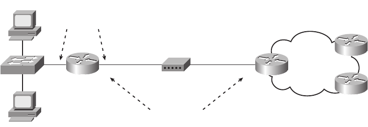
528 Chapter 16: WAN Concepts
customer might need 20 Mbps of bandwidth between routers located at large data centers
on either side of a city. The provider installs a Fast Ethernet link between the sites,
contracting with the customer for 20 Mbps. The customer then configures the routers so that
they will purposefully send only 20 Mbps, on average, using a feature called shaping. The
end result is that the customer gets the bandwidth, typically at a better price than other
options (like using a T3).
Metro E offers many design options as well, including simply connecting one customer
site to an ISP, or connecting all of a customer’s sites to each other using various VLANs
over a single Ethernet access link. Although the details are certainly beyond the CCNA
exams, it is an interesting development to watch as it becomes more popular in the
marketplace.
Next, this chapter changes focus completely, examining several features that are required
for a typical Internet connection using DSL and cable.
IP Services for Internet Access
DSL and cable Internet access have many similar features. In particular, both use a router,
with that router being responsible for forwarding packets from the computers in the home
or office to a router on the other side of the cable/DSL line, and vice versa. This second
major section of this chapter examines several IP-related functions that must be performed
by the DSL/cable router, in particular a couple of ways to use DHCP, as well as a feature
called Network Address Translation (NAT).
The equipment used at a SOHO to connect to the Internet using DSL or cable may be a
single integrated device, or several separate devices, as introduced in Figures 13-4 and 13-5
in Chapter 13. For the sake of explaining the details in this chapter, the figures will show
separate devices, as in Figure 16-6.
Figure 16-6 Internet Access Equipment, Separate Devices
PC1
PC2
R1 ISP1
ISP/Internet
Cable Modem CATV CableF0/1
IP Addresses
are in same
Subnet
SOHO
Fa0/0
FastEthernet
Interfaces
1828xbook.fm Page 528 Thursday, July 26, 2007 3:10 PM

IP Services for Internet Access 529
Thinking about the flow of data left-to-right in the figure, a PC sends data to its default
gateway, which is the local access router. The LAN switch just forwards frames to the
access router. The router makes a routing decision to forward the packet to the ISP router
as the next-hop router. Then, the cable modem converts the Ethernet frame received from
the router to meet cable specifications, the details of which are beyond the scope of this
book. Finally, the ISP router has a routing table for all routes in the Internet, so it can
forward the packet to wherever the packet needs to go.
Of the three devices at the small office, this section examines the router in detail. Besides
basic routing, the access router needs to perform three additional important functions,
as will be explained in this section: assign addresses, learn routes, and translate
addresses (NAT).
Address Assignment on the Internet Access Router
The Internet access router in Figure 16-6 has two LAN interfaces—one facing the
Internet and one facing the devices at that site. As was mentioned in Part III of this book
on many occasions, to be able to route packets on those two interfaces, the router needs
an IP address on each interface. However, instead of choosing and statically configuring
the IP addresses with the ip address interface subcommand, the IP addresses are chosen
per the following rules:
■The Internet-facing interface needs one public IP address so that the routers in the
Internet know how to route packets to the access router.
■The ISP typically assigns that public (and globally routable) IP address dynamically,
using DHCP.
■The local PCs typically need to dynamically learn IP addresses with DHCP, so the
access router will act as a DHCP server for the local hosts.
■The router needs a statically configured IP address on the local subnet, using a private
network number.
■The local LAN subnet will use addresses in a private network number.
Figure 16-7 shows the net results of the DHCP exchanges between the various devices,
ignoring some of the cabling details.
NOTE The section “Public and Private Addressing” in Chapter 12, “IP Addressing
and Subnetting,” introduces the concept of private networks and lists the ranges of
addresses in private networks.
1828xbook.fm Page 529 Thursday, July 26, 2007 3:10 PM
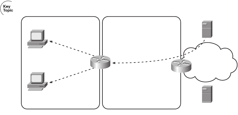
530 Chapter 16: WAN Concepts
Figure 16-7 DHCP Server and Client Functions on an Internet Access Router
For the process in Figure 16-7 to work, the access router (R1) needs a statically configured
IP address on the local interface, a DHCP server function enabled on that interface, and a
DHCP client function enabled on the Internet interface. R1 learns its Internet interface IP
address from the ISP, in this case 64.100.1.1. After being configured with IP address
192.168.1.1/24 on the local interface, R1 starts answering DHCP requests, assigning IP
addresses in that same subnet to PC1 and PC2. Note that R1’s DHCP messages list the DNS
IP address (198.133.219.2) learned from the ISP’s DHCP server.
Routing for the Internet Access Router
Besides the IP address details, router R1 needs to be able to route packets to and from
the Internet. R1 has two connected routes, as normal. However, instead of learning all the
routes in the global Internet using a routing protocol, R1 can use a default route. In fact,
the topology is a classic case for using a default route—the access router has one possible
physical route to use to reach the rest of the Internet, namely the route connecting the access
router to the ISP’s router.
Instead of requiring a static route configuration, the access router can add a default route
based on the default gateway learned by the DHCP client function. For example, in
Figure 16-7, R1 learned a default gateway IP address of 64.100.1.2, which is router ISP1’s
interface connected to the DSL or cable service. The access router creates a default route
with that default gateway IP address as the next-hop router. Figure 16-8 shows this default
route, along with a few other important routes, as solid lines with arrows.
PC1
PC2
R1 ISP1
ISP/Internet
R1 as DHCP Server
192.168.1.1
IP = 192.168.1.101/24
GW = 192.168.1.1
DNS = 198.133.219.2
R1 as DHCP Client
IP = 64.100.1.1/30
GW = 64.100.1.2
DNS = 198.133.219.2
64.100.1.2
IP = 192.168.1.102/24
GW = 192.168.1.1
DNS = 198.133.219.2
ISP’s DNS Server-
198.133.219.2
ISP’s DHCP Server
1828xbook.fm Page 530 Thursday, July 26, 2007 3:10 PM
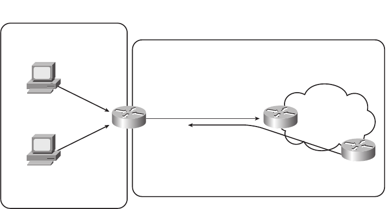
IP Services for Internet Access 531
Figure 16-8 Routing in an Internet Access Router
The default gateway settings on the local PCs, along with the default route on the access
router (R1), allow the PCs to send packets that reach the Internet. At that point, the Internet
routers should be able to forward the packets anywhere in the Internet. However, the routes
pointing in the reverse direction, from the Internet back to the small office, seem incomplete
at this point. Because R1’s Internet-facing IP address (64.100.1.1 in Figure 16-8) is from
the public registered IP address range, all the routers in the Internet should have a matching
route, enabling them to forward packets to that address. However, Internet routers should
never have any routes for private IP addresses, like those in private networks, such as private
network 192.168.1.0/24 as used in Figure 16-8.
The solution to this problem is not related to routing; instead, the solution is to make the
local hosts on the LAN look as if they are using R1’s publicly registered IP address by using
NAT and PAT. Hosts in the Internet will send the packets to the access router’s public IP
address (64.100.1.1 in Figure 16-8), and the access router will translate the address to match
the correct IP address on the hosts on the local LAN.
NAT and PAT
Before getting to the details of how NAT and Port Address Translation (PAT) solve this last
part of the puzzle, a few other related perspectives can help you to understand NAT and
PAT—one related to IP address conservation, and one related to how TCP and UDP
use ports.
PC1
PC2
R1 ISP1 ISP/Internet
Private IP Addresses–
Network 192.168.1.0
192.168.1.1
IP = 192.168.1.101
GW = 192.168.1.1
DNS = 198.133.219.2
Public IP Addresses, Globally Routable
Default route
learned via DHCP:
– 64.100.1.2
Route That Matches 64.100.1.1
64.100.1.1
64.100.1.2
IP = 192.168.1.102/24
GW = 192.168.1.1
DNS = 198.133.219.2
1828xbook.fm Page 531 Thursday, July 26, 2007 3:10 PM
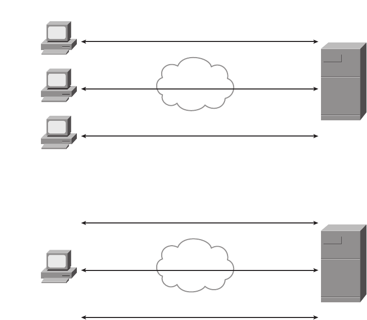
532 Chapter 16: WAN Concepts
First, the Internet Corporation for Assigned Names and Numbers (ICANN) manages the
process of assigning public IP addresses in the global IPv4 address space—and we are
slowly running out of addresses. So, when an ISP adds a new DSL or cable customer, the
ISP wants to assign as few public IP addresses to that customer as possible. Additionally,
the ISP prefers to assign the address dynamically, so if a customer decides to move to
another ISP, the ISP can quickly reclaim and reuse the IP address for another customer. So,
for a typical DSL or cable connection to the Internet, the ISP assigns a single publicly
routable IP address, using DHCP, as was shown earlier in Figure 16-7. In particular, the ISP
does not want to assign multiple public IP addresses to each PC (like PC1 and PC2 in
Figure 16-7), again to conserve the public IPv4 address space.
The second thing to think about is that, from a server’s perspective, there is no important
difference between some number of TCP connections from different hosts, versus the same
number of TCP connections from the same host. Figure 16-9 details an example that helps
make the logic behind PAT more obvious.
Figure 16-9 Three TCP Connections: From Three Different Hosts, and from One Host
Internet
Server
128.107.1.1
Three Connections from Three PCs
Server
128.107.1.1
64.100.1.1
64.100.1.1, port 1024 128.107.1.1, port 80
64.100.1.2
64.100.1.2, port 1024 128.107.1.1, port 80
64.100.1.3
64.100.1.3, port 1033 128.107.1.1, port 80
Internet
Three Connections from One PC
64.100.1.1, port 1024 128.107.1.1, port 80
64.100.1.1
64.100.1.1, port 1025 128.107.1.1, port 80
64.100.1.1, port 1026 128.107.1.1, port 80
1828xbook.fm Page 532 Thursday, July 26, 2007 3:10 PM
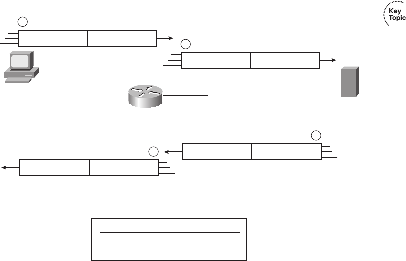
IP Services for Internet Access 533
The top part of the figure shows a network with three different hosts connecting to a web
server using TCP. The bottom half of the figure shows the same network later in the day,
with three TCP connections from one client. All six connections connect to the server IP
address (128.107.1.1) and port (80, the well-known port for web services). In each case, the
server is able to differentiate between the various connections because each has a unique
combination of IP address and port number.
Keeping the address conservation and port number concepts in mind, next examine how
PAT allows the local hosts to use private IP addresses while the access router uses a single
public IP address. PAT takes advantage of the fact that a server really does not care if it has
one connection each to three different hosts or three connections to a single host IP address.
So, to support lots of local hosts at the small office, using a single publicly routable IP
address on the router, PAT translates the local hosts’ private IP addresses to the one
registered public IP address. To tell which packets need to be sent back to which local host,
the router keeps track of both the IP address and TCP or UDP port number. Figure 16-10
shows an example, using the same IP addresses and routers shown previously in
Figure 16-7.
Figure 16-10 PAT Function on an Internet Access Router
The figure shows a packet sent by PC1 to the server in the Internet on the right. The top part
of the figure (steps 1 and 2) shows the packet’s source IP address and source port both
Server
128.107.1.1
PC1
64.100.1.1: 1024
64.100.1.1: 1025
NAT Translation Table
Inside Local Inside Global
192.168.1.101:1024
192.168.1.102:1024
SA 192.168.1.101 S. Port 1024
1
SA 64.100.1.1 S. Port 1024
2
DA 64.100.1.1 D. Port 1024
3
DA 192.168.1.101 D. Port 1024
4
64.100.1.1
R1
1828xbook.fm Page 533 Thursday, July 26, 2007 3:10 PM

534 Chapter 16: WAN Concepts
before and after R1 performs PAT. The lower part of the figure (steps 3 and 4) shows the
return packet from the server, which shows the destination IP address and destination port,
again both before and after R1 performs the PAT function. (The server, when replying to a
packet with a particular source IP address and port, uses those same values in the response
packet.) The numbered steps in the figure follow this logic:
1. PC1 sends a packet to server 128.107.1.1 and, per PC1’s default gateway setting, sends
the packet to access router R1.
2. R1 performs PAT, based on the details in the router’s NAT translation table, changing
the local host’s IP from the private IP address used on the local LAN to the one
globally routable public IP address available to R1, namely 64.100.1.1 in this case.
R1 forwards the packet based on its default route.
3. When the server replies to the packet sent from PC1, the server sends the packet to
destination address 64.100.1.1, destination port 1024, because those were the values in
the source fields of the packet at step 2. The Internet routers know how to forward this
packet back to R1, because the destination is a globally routable public IP address.
4. R1 changes the destination IP address and port per the NAT table, switching from
destination address/port 64.100.1.1/1024 to 192.168.1.101/1024. R1 knows a route to
reach 192.168.1.101, because this address is in a subnet connected to R1.
More generally, the PAT feature causes the router to translate the source IP address and port
for packets leaving the local LAN, and to translate the destination IP address and port on
packets returning to the local LAN. The end result is that, as far as hosts in the Internet are
concerned, all the packets coming from this one customer are from one host (64.100.1.1 in
Figure 16-10), for which all the routers in the Internet should have a matching route. This
allows the ISP to conserve public IPv4 addresses.
The terms inside local and inside global, as listed in the NAT translation table in Figure 16-10,
have some very specific and important meanings in the world of NAT. When speaking of
NAT, the terms have the perspective of the enterprise network engineer, rather than
someone working at the ISP. Keeping that in mind, NAT uses the following terms (and
many others):
Inside host: Refers to a host in the enterprise network, like PC1 and PC2 in the last
few figures.
Inside local: Refers to an IP address in an IP header, with that address representing a
local host as the packet passes over the local enterprise network (not the Internet). In
this case, 192.168.1.101 and .102 are inside local IP addresses, and the packets at steps
1 and 4 in Figure 16-10 show inside local IP addresses.
1828xbook.fm Page 534 Thursday, July 26, 2007 3:10 PM
IP Services for Internet Access 535
Inside global: Refers to an IP address in an IP header, with that address representing
a local host as the packet passes over the global Internet (not the enterprise). In this
case, 64.100.1.1 is the one inside global IP address, and the packets at steps 2 and 3 in
Figure 16-10 show the inside global IP address.
Inside interface: The router interface connected to the same LAN as the inside hosts.
Outside interface: The router interface connected to the Internet.
Now that you have seen an example of how PAT works, a more exact definition of the terms
NAT and PAT can be described. So, when using the terms in a very specific, formal manner,
NAT refers to the translation of network layer (IP) addresses, with no translation of ports,
whereas PAT refers to the translation of IP addresses as well as transport layer (TCP and
UDP) port numbers. However, with a broader definition of the term NAT, PAT is simply one
of several ways to configure and use NAT. In real life, in fact, most people refer to this
broader definition of NAT. So, an engineer might say “we use NAT with our Internet
connection to conserve our public IP addresses”; technically the function is PAT, but most
everyone simply calls it NAT.
In closing, some of you who have installed a cable router or DSL router in your home may
have found that it was easy to get that router to work—much easier than trying to understand
the details explained in this chapter. If you buy a consumer-grade cable router or DSL router,
it comes preconfigured to use a DHCP client, DHCP server, and PAT as described in this
section. (In fact, your product may have one RJ-45 port labeled “Internet” or “Uplink”—that
is the port that by default acts as a DHCP client, and it would be the Internet-facing interface
in the figures presented toward the end of this chapter.) So, these functions happen, but they
happen with no effort required on your part. However, to do the same functions with an
enterprise-class Cisco router, the router needs to be configured, because the Cisco enterprise
routers ship from the factory with no initial configuration. Chapter 17 will show how to
configure the features described in this section on Cisco routers.
1828xbook.fm Page 535 Thursday, July 26, 2007 3:10 PM
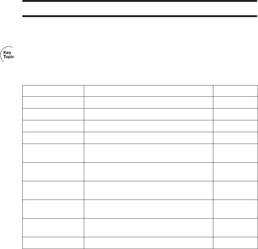
536 Chapter 16: WAN Concepts
Exam Preparation Tasks
Review All the Key Topics
Review the most important topics from inside the chapter, noted with the key topics icon in
the outer margin of the page. Table 16-5 lists a reference of these key topics and the page
numbers on which each is found.
Complete the Tables and Lists from Memory
Print a copy of Appendix H, “Memory Tables” (found on the CD-ROM), or at least the
section for this chapter, and complete the tables and lists from memory. Appendix I,
“Memory Tables Answer Key,” also on the CD-ROM, includes completed tables and lists
to check your work.
Table 16-5 Key Topics for Chapter 16
Key Topic Element Description Page Number
List Comparison points between DSL and modems 519
Figure 16-3 Typical topology and devices used for DSL 520
List Factors that affect the speed of a DSL line 522
Figure 16-4 Typical topology and devices used for cable 524
Table 16-3 Comparison points for Internet access
technologies
525
Table 16-4 Comparison of circuit switching and packet
switching
527
List Factors that impact the IP addresses used by Internet
access routers
529
Figure 16-7 Depicts DHCP client and server functions in an
Internet access router
530
Figure 16-10 Shows how PAT translates IP addresses in Internet
access routers
533
List Definitions of several key NAT terms 534
1828xbook.fm Page 536 Thursday, July 26, 2007 3:10 PM
Definitions of Key Terms 537
Definitions of Key Terms
Define the following key terms from this chapter and check your answers in
the glossary.
ADSL, asymmetric, ATM, DSL, inside global, inside local, modem, NAT,
PAT, PSTN, symmetric, telco
1828xbook.fm Page 537 Thursday, July 26, 2007 3:10 PM

This chapter covers the following subjects:
Configuring Point-to-Point WANs: This
section examines how to configure leased lines
between two routers using HDLC and PPP.
Configuring and Troubleshooting Internet
Access Routers: This section shows how to
configure DHCP client, DHCP server, and PAT
functions on an Internet access router using SDM.
1828xbook.fm Page 538 Thursday, July 26, 2007 3:10 PM

C H A P T E R17
WAN Configuration
This chapter examines the configuration details for how to configure a few of the types
of wide-area networks (WANs) covered in Chapter 4, “Fundamentals of WANs,” and
Chapter 16, “WAN Concepts.” The first section of this chapter examines leased-line
configuration using both High-Level Data Link Control (HDLC) and Point-to-Point
Protocol (PPP). The second section of the chapter shows how to configure the Layer 3
features required for an Internet access router to connect to the Internet, specifically
Dynamic Host Configuration Protocol (DHCP) and Network Address Translation/Port
Address Translation (NAT/PAT). However, the configuration in the second half of the
chapter does not use the command-line interface (CLI), but instead focuses on using the
web-based router Security Device Manager (SDM) interface.
For those of you preparing specifically for the CCNA 640-802 exam by using the reading
plan in the introduction to this book, note that you should move on to Part IV of the CCNA
ICND2 Official Exam Certification Guide after completing this chapter.
“Do I Know This Already?” Quiz
The “Do I Know This Already?” quiz allows you to assess if you should read the entire
chapter. If you miss no more than one of these seven self-assessment questions, you might
want to move ahead to the “Exam Preparation Tasks” section. Table 17-1 lists the major
headings in this chapter and the “Do I Know This Already?” quiz questions covering the
material in those headings so you can assess your knowledge of these specific areas. The
answers to the “Do I Know This Already?” quiz appear in Appendix A.
Table 17-1 “Do I Know This Already?” Foundation Topics Section-to-Question Mapping
Foundation Topics Section Questions
Configuring and Troubleshooting Point-to-Point WANs 1–3
Configuring and Troubleshooting Internet Access Routers 4–7
1828xbook.fm Page 539 Thursday, July 26, 2007 3:10 PM
540 Chapter 17: WAN Configuration
1. Routers R1 and R2 connect using a leased line, with both routers using their respective
Serial 0/0 interfaces. The routers can currently route packets over the link, which uses
HDLC. Which of the following commands would be required to migrate the
configuration to use PPP?
a. encapsulation ppp
b. no encapsulation hdlc
c. clock rate 128000
d. bandwidth 128000
2. Routers R1 and R2 have just been installed in a new lab. The routers will connect using
a back-to-back serial link, using interface serial 0/0 on each router. Which of the
following is true about how to install and configure this connection?
a. If the DCE cable is installed in R1, the clock rate command must be configured
on R2’s serial interface.
b. If the DTE cable is installed in R1, the clock rate command must be configured
on R2’s serial interface.
c. If the clock rate 128000 command is configured on R1, the bandwidth 128
command must be configured on R2.
d. None of the answers are correct.
3. Two brand new Cisco routers have been ordered and installed in two different sites, 100
miles apart. A 768-kbps leased line has been installed between the two routers. Which
of the following commands is required on at least one of the routers in order to forward
packets over the leased line, using PPP as the data link protocol?
a. no encapsulation hdlc
b. encapsulation ppp
c. clock rate 768000
d. bandwidth 768
e. description this is the link
4. When configuring a DHCP server on an Internet access router using SDM, which of
the following settings is typically configured on the Internet access router?
a. The MAC addresses of the PCs on the local LAN
b. The IP address of the ISP’s router on the common cable or DSL link
1828xbook.fm Page 540 Thursday, July 26, 2007 3:10 PM
“Do I Know This Already?” Quiz 541
c. The range of IP addresses to be leased to hosts on the local LAN
d. The DNS server IP address(es) learned via DHCP from the ISP
5. When configuring an access router with SDM, to use DHCP client services to learn
an IP address from an ISP, and configure PAT at the same time, which of the following
is true?
a. The SDM configuration wizard requires PAT to be configured if the DHCP client
function has been chosen to be configured.
b. The SDM configuration wizard considers any interfaces that already have IP
addresses configured as candidates to become inside interfaces for PAT.
c. The SDM configuration wizard assumes the interface on which DHCP client
services have been enabled should be an inside interface.
d. None of the answers are correct.
6. Which of the following is true about the configuration process using SDM?
a. SDM uses an SSH connection via the console or an IP network to configure a
router.
b. SDM uses a web interface from the IP network or from the console.
c. SDM loads configuration commands into a router at the end of each wizard (after
the user clicks the Finish button), saving the configuration in the running-config
and startup-config files.
d. None of these answers are correct.
7. Which of the following are common problems when configuring a new Internet access
router’s Layer 3 features?
a. Omitting commonly used but optional information from the DHCP server
features—for example, the IP address(es) of the DNS server(s)
b. Setting the wrong interfaces as the NAT inside and outside interfaces
c. Forgetting to configure the same routing protocol that the ISP uses
d. Forgetting to enable CDP on the Internet-facing interface
1828xbook.fm Page 541 Thursday, July 26, 2007 3:10 PM

542 Chapter 17: WAN Configuration
Foundation Topics
Configuring Point-to-Point WANs
This brief section explains how to configure leased lines between two routers, using
both HDLC and PPP. The required configuration is painfully simply—for HDLC, do
nothing, and for PPP, add one interface subcommand on each router’s serial interface
(encapsulation ppp). However, several optional configuration steps can be useful, so
this section explains those optional steps and their impact on the links.
Configuring HDLC
Considering the lowest three layers of the OSI reference model on router Ethernet
interfaces for a moment, there are no required configuration commands related to Layers 1
and 2 for the interface to be up and working, forwarding IP traffic. The Layer 1 details occur
by default once the cabling has been installed correctly. Router IOS defaults to use Ethernet
as the data link protocol on all types of Ethernet interfaces, so no Layer 2 commands are
required. To make the interface operational for forwarding IP packets, the router needs one
command to configure an IP address on the interface, and possibly a no shutdown
command if the interface is in an “administratively down” state.
Similarly, serial interfaces on Cisco routers that use HDLC typically need no specific
Layer 1 or 2 configuration commands. The cabling needs to be completed as described in
Chapters 4 and 16, but there are no required configuration commands related to Layer 1.
IOS defaults to use HDLC as the data link protocol, so there are no required commands that
relate to Layer 2. As on Ethernet interfaces, the only required command to get IP working
on the interface is the ip address command and possibly the no shutdown command.
However, many optional commands exist for serial links. The following list outlines some
configuration steps, listing the conditions for which some commands are needed, plus
commands that are purely optional:
Step 1 Configure the interface IP address using the ip address interface subcommand.
Step 2 The following tasks are required only when the specifically listed
conditions are true:
a. If an encapsulation protocol interface subcommand that lists a protocol
besides HDLC already exists on the interface, use the encapsulation hdlc
interface subcommand to enable HDLC.
NOTE This chapter assumes all serial links use an external channel service unit/data
service unit (CSU/DSU). The configuration details of the external CSU/DSU, or an
internal CSU/DSU, are beyond the scope of the book.
1828xbook.fm Page 542 Thursday, July 26, 2007 3:10 PM
Configuring Point-to-Point WANs 543
b. If the interface line status is administratively down, enable the interface
using the no shutdown interface subcommand.
c. If the serial link is a back-to-back serial link in a lab (or a simulator), config-
ure the clocking rate using the clock rate speed interface subcommand, but
only on the one router with the DCE cable (per the show controllers serial
number command).
Step 3 The following steps are always optional, and have no impact on whether
the link works and passes IP traffic:
a. Configure the link’s speed using the bandwidth speed-in-kbps interface
subcommand.
b. For documentation purposes, configure a description of the purpose of the
interface using the description text interface subcommand.
In practice, when you configure a Cisco router with no pre-existing interface configuration,
and install a normal production serial link with CSU/DSUs, the ip address command is
likely the one configuration command you would need. Figure 17-1 shows a sample
internetwork, and Example 17-1 shows the configuration. In this case, the serial link was
created with a back-to-back serial link in a lab, requiring Steps 1 (ip address) and 2c (clock
rate) from the preceding list, plus optional Step 3b (description).
Figure 17-1 Typical Serial Link Between Two Routers
Example 17-1 HDLC Configuration
R1#ss
sshh
hhoo
ooww
ww
rr
rruu
uunn
nnnn
nnii
iinn
nngg
gg--
--cc
ccoo
oonn
nnff
ffii
iigg
gg
! Note – only the related lines are shown
interface FastEthernet0/0
ip address 192.168.1.1 255.255.255.0
!
interface Serial0/1/1
ip address 192.168.2.1 255.255.255.0
description link to R2
clockrate 1536000
continues
192.168.1.1
192.168.1.0/24 192.168.2.0/24 192.168.4.0/24
192.168.2.1
Fa0/0 S0/1/1
192.168.4.2
Fa0/1
192.168.2.2
S0/0/1
R1 R2
1828xbook.fm Page 543 Thursday, July 26, 2007 3:10 PM

544 Chapter 17: WAN Configuration
!
router rip
version 2
network 192.168.1.0
network 192.168.2.0
!
R1#ss
sshh
hhoo
ooww
ww
cc
ccoo
oonn
nntt
ttrr
rroo
ooll
llll
llee
eerr
rrss
ss
ss
ssee
eerr
rrii
iiaa
aall
ll
00
00//
//11
11//
//11
11
Interface Serial0/1/1
Hardware is GT96K
DCE V.35, clock rate 1536000
! lines omitted for brevity
R1#ss
sshh
hhoo
ooww
ww
ii
iinn
nntt
ttee
eerr
rrff
ffaa
aacc
ccee
eess
ss
ss
ss00
00//
//11
11//
//11
11
Serial0/1/1 is up, line protocol is up
Hardware is GT96K Serial
Description: link to R2
Internet address is 192.168.2.1/24
MTU 1500 bytes, BW 1544 Kbit, DLY 20000 usec,
reliability 255/255, txload 1/255, rxload 1/255
Encapsulation HDLC, loopback not set
Keepalive set (10 sec)
Last input 00:00:06, output 00:00:03, output hang never
Last clearing of "show interface" counters never
Input queue: 0/75/0/0 (size/max/drops/flushes); Total output drops: 0
Queueing strategy: weighted fair
Output queue: 0/1000/64/0 (size/max total/threshold/drops)
Conversations 0/1/256 (active/max active/max total)
Reserved Conversations 0/0 (allocated/max allocated)
Available Bandwidth 1158 kilobits/sec
5 minute input rate 0 bits/sec, 0 packets/sec
5 minute output rate 0 bits/sec, 0 packets/sec
70 packets input, 4446 bytes, 0 no buffer
Received 50 broadcasts, 0 runts, 0 giants, 0 throttles
0 input errors, 0 CRC, 0 frame, 0 overrun, 0 ignored, 0 abort
73 packets output, 5280 bytes, 0 underruns
0 output errors, 0 collisions, 5 interface resets
0 output buffer failures, 0 output buffers swapped out
0 carrier transitions
DCD=up DSR=up DTR=up RTS=up CTS=up
R1#ss
sshh
hhoo
ooww
ww
ii
iipp
pp
ii
iinn
nntt
ttee
eerr
rrff
ffaa
aacc
ccee
ee
bb
bbrr
rrii
iiee
eeff
ff
Interface IP-Address OK? Method Status Protocol
FastEthernet0/0 192.168.1.1 YES manual up up
FastEthernet0/1 unassigned YES NVRAM administratively down down
Serial0/0/0 unassigned YES NVRAM administratively down down
Serial0/0/1 unassigned YES manual administratively down down
Serial0/1/0 unassigned YES manual administratively down down
Serial0/1/1 192.168.2.1 YES manual up up
Example 17-1 HDLC Configuration (Continued)
1828xbook.fm Page 544 Thursday, July 26, 2007 3:10 PM

Configuring Point-to-Point WANs 545
The configuration on R1 is relatively simple. The matching configuration on R2’s S0/0/1
interface simply needs an ip address command, plus the default settings of encapsulation
hdlc and no shutdown. The clock rate command would not be needed on R2, as R1 has
the DCE cable, so R2 must be connected to a DTE cable.
The rest of the example lists the output of a few show commands. First, the output from
the show controllers command for S0/1/1 confirms that R1 indeed has a DCE cable
installed. The show interfaces S0/1/1 command lists the various configuration settings near
the top, including the default encapsulation value (HDLC) and default bandwidth setting
on a serial interface (1544, meaning 1544 kbps or 1.544 Mbps). At the end of the example,
the show ip interface brief and show interfaces description commands display a short
status of the interfaces, with both listing the line status and protocol status codes.
Configuring PPP
Configuring the basics of PPP is just as simple as for HDLC, except that whereas HDLC is
the default serial data-link protocol and requires no additional configuration, you must
configure the encapsulation ppp command for PPP. Other than that, the list of possible and
optional configuration steps is exactly the same as for HDLC. So, to migrate from a
working HDLC link to a working PPP link, the only command needed is an encapsulation
ppp command on each of the two routers’ serial interfaces. Example 17-2 shows the serial
interface configuration on both R1 and R2 from Figure 17-1, this time using PPP.
R1#ss
sshh
hhoo
ooww
ww
ii
iinn
nntt
ttee
eerr
rrff
ffaa
aacc
ccee
eess
ss
dd
ddee
eess
sscc
ccrr
rrii
iipp
pptt
ttii
iioo
oonn
nn
Interface Status Protocol Description
Fa0/0 up up
Fa0/1 admin down down
Se0/0/0 admin down down
Se0/0/1 admin down down
Se0/1/0 admin down down
Se0/1/1 up up link to R2
Example 17-2 PPP Configuration
R1#ss
sshh
hhoo
ooww
ww
rr
rruu
uunn
nnnn
nnii
iinn
nngg
gg--
--cc
ccoo
oonn
nnff
ffii
iigg
gg
ii
iinn
nntt
ttee
eerr
rrff
ffaa
aacc
ccee
ee
ss
ss00
00//
//11
11//
//11
11
Building configuration...
Current configuration : 129 bytes
!
interface Serial0/1/1
description link to R2
ip address 192.168.2.1 255.255.255.0
encapsulation ppp
continues
Example 17-1 HDLC Configuration (Continued)
1828xbook.fm Page 545 Thursday, July 26, 2007 3:10 PM

546 Chapter 17: WAN Configuration
The example lists a new variation on the show running-config command as well as the
PPP-related configuration. The show running-config interface S0/1/1 command on R1
lists the interface configuration for interface S0/1/1, and none of the rest of the running-
config. Note that on both routers, the encapsulation ppp command has been added; it
is important that both routers use the same data link protocol, or the link will not work.
Configuring and Troubleshooting Internet
Access Routers
As covered in Chapter 16, Internet access routers often connect to the Internet using one
LAN interface, and to the local LAN using another interface. Routers that are built
specifically for consumers as Internet access routers ship from the factory with DHCP
client services enabled on the Internet-facing interface, DHCP server functions enabled on
the local interface, and PAT functions enabled. Enterprise routers, which have many
features and may not necessarily be used as Internet access routers, ship from the factory
without these features enabled by default. This section shows how to configure these
functions on a Cisco enterprise-class router.
Cisco routers support another configuration method besides using the CLI. In keeping with
the exam topics published by Cisco for the ICND1 exam, this chapter shows how to
configure the rest of the features in this chapter using this alternative tool, called Cisco
Router and Security Device Manager (SDM). Instead of using Telnet or SSH, the user
connects to the router using a web browser. (To support the web browser, the router must
first be configured from the CLI with at least one IP address, typically on the local LAN,
so that the engineer’s computer can connect to the router.) From there, SDM allows the
engineer to configure a wide variety of router features, including the DHCP client, DHCP
server, and PAT.
clockrate 1536000
end
! R2's configuration next
R2#ss
sshh
hhoo
ooww
ww
rr
rruu
uunn
nn
ii
iinn
nntt
ttee
eerr
rrff
ffaa
aacc
ccee
ee
ss
ss00
00//
//00
00//
//11
11
Building configuration...
Current configuration : 86 bytes
!
interface Serial0/0/1
ip address 192.168.2.2 255.255.255.0
encapsulation ppp
end
Example 17-2 PPP Configuration (Continued)
1828xbook.fm Page 546 Thursday, July 26, 2007 3:10 PM

Configuring and Troubleshooting Internet Access Routers 547
Note that the features configured through SDM in the remainder of this chapter can also be
done with the CLI.
Internet Access Router: Configuration Steps
You can configure the DHCP client, DHCP server, and PAT functions with SDM using the
following five major steps:
Step 1 Establish IP connectivity. Plan and configure (from the CLI) IP addresses on the
local LAN so that a PC on the LAN can ping the router’s LAN interface.
Step 2 Install and access SDM. Install SDM on the router and access the router
SDM interface using a PC that can ping the router’s IP address (as
implemented at Step 1).
Step 3 Configure DHCP and PAT. Use SDM to configure both DHCP client
services and the PAT service on the router.
Step 4 Plan for DHCP services. Plan the IP addresses to be assigned by the
router to the hosts on the local LAN, along with the DNS IP addresses,
domain name, and default gateway settings that the router will advertise.
Step 5 Configure the DHCP server. Use SDM to configure the DHCP server
features on the router.
The sections that follow examine each step in order in greater detail. The configuration will
use the same internetwork topology that was used in the Chapter 16 discussion of Internet
access routers, repeated here as Figure 17-2.
Step 1: Establish IP Connectivity
The Internet access router needs to use a private IP network on the local LAN, as mentioned
in Chapter 16. For this step, you should choose the following details:
Step a Choose any private IP network number.
Step b Choose a mask that allows for enough hosts (typically the default mask
is fine).
Step c Choose a router IP address from that network.
NOTE Cisco switches also allow web access for configuration, using a tool called
Cisco Device Manager (CDM). The general concept of CDM matches the concepts
of SDM.
1828xbook.fm Page 547 Thursday, July 26, 2007 3:10 PM
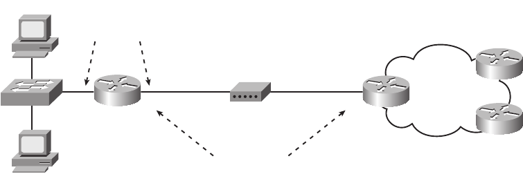
548 Chapter 17: WAN Configuration
Figure 17-2 Internet Access Router: Sample Network
It does not really matter which private network you use, as long as it is a private network.
Many consumer access routers use Class C network 192.168.1.0, as will be used in this
chapter, and the default mask. If you work at a small company with a few sites, all
connecting to the Internet, you can use the same private network at each site, because NAT/
PAT will translate the addresses anyway.
Step 2: Install and Access SDM
To be able to install the SDM software on the router (if it is not already installed on the
router), and to allow the engineer’s host to access the router using a web browser, the
engineer needs to use a host with IP connectivity to reach the router. Typically, the engineer
would use a host on the local LAN, configure the router’s local LAN interface with the IP
address planned at Step 1, and configure the host with another IP address in that same
network. Note that SDM does not use Telnet or SSH, and the PC must be connected via an
IP network—the console can only be used to access the CLI.
The network engineer must configure several additional commands on the router before a
user can access and use it, the details of which are beyond the scope of this book. If you are
curious, you can look for more details by searching www.cisco.com for “SDM installation.”
This configuration step was listed just in case you try using SDM with your own lab gear,
to make you aware that there is more work to do. By the end of the process, a web browser
should be able to connect to the router and see the SDM Home page for that router, like the
example shown in Figure 17-3.
PC1
PC2
R1 ISP1
ISP/Internet
Cable Modem CATV CableF0/1
IP Addresses
are in same
Subnet
SOHO
Fa0/0
FastEthernet
Interfaces
1828xbook.fm Page 548 Thursday, July 26, 2007 3:10 PM
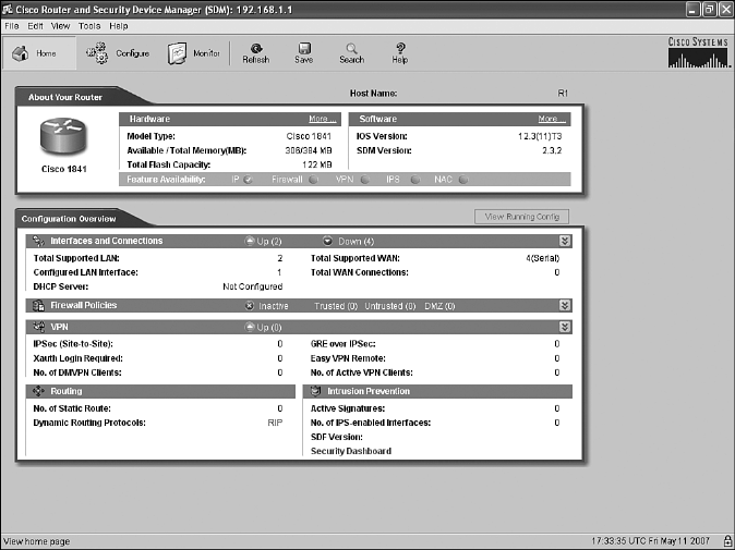
Configuring and Troubleshooting Internet Access Routers 549
Figure 17-3 SDM Home Page
Step 3: Configure DHCP and PAT
The SDM user interface has a wide variety of configuration wizards that guide you through
a series of web pages, asking for input. At the end of the process, SDM loads the
corresponding configuration commands into the router.
One such wizard allows you to configure the DHCP client feature on the Internet-facing
interface and, optionally, configure the PAT feature. This section shows sample windows
for the configuration of router R1 in Figure 17-2.
From the SDM Home page shown in Figure 17-3:
1. Click Configure near the top of the window.
2. Click Interfaces and Connections at the top of the Tasks pane on the left side of the
window.
Figure 17-4 shows the resulting Interfaces and Connections window, with the Create
Connection tab displayed. (Note that the heavy arrowed lines are overlaid on the image of
the page to point out the items referenced in the text.)
1828xbook.fm Page 549 Thursday, July 26, 2007 3:10 PM
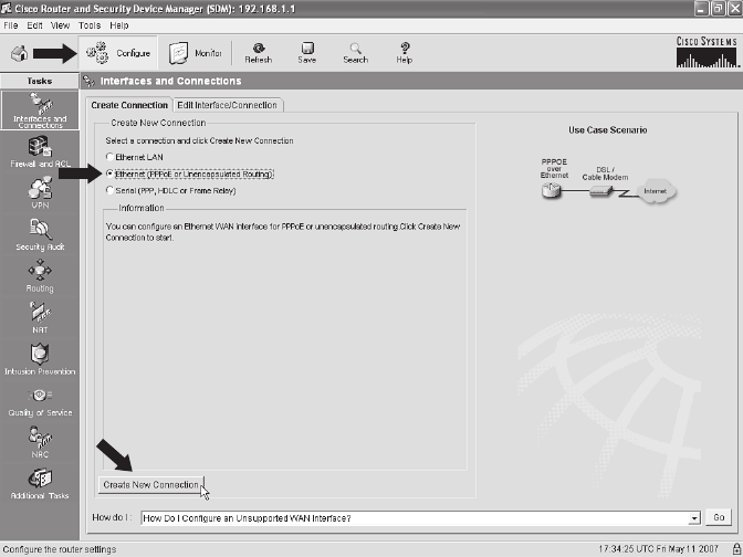
550 Chapter 17: WAN Configuration
Figure 17-4 SDM Configure Interfaces and Connections Window
The network topology on the right side of this tab should look familiar, as it basically
matches Figure 17-2, with a router connected to a cable or DSL modem. On the Create
Connection tab, do the following:
1. Choose the Ethernet (PPPoE or Unencapsulated Routing) radio button.
2. Click the Create New Connection button near the bottom of the tab.
These actions open the SDM Ethernet Wizard, shown in Figure 17-5. The page in Figure 17-5
has no options to choose, so just click Next to keep going.
The next page of the wizard, shown in Figure 17-6, has only one option, a check box that,
if checked, enables the protocol PPP over Ethernet (PPPoE). If the ISP asks that you use
PPPoE, then check this box. Ordinarily, you simply leave this box unchecked, which
implies unencapsulated routing. (Unencapsulated routing means that the router forwards
Ethernet frames onto the interface, with an IP packet inside the Ethernet frame, as was
covered in several places in Part III of this book.)
1828xbook.fm Page 550 Thursday, July 26, 2007 3:10 PM
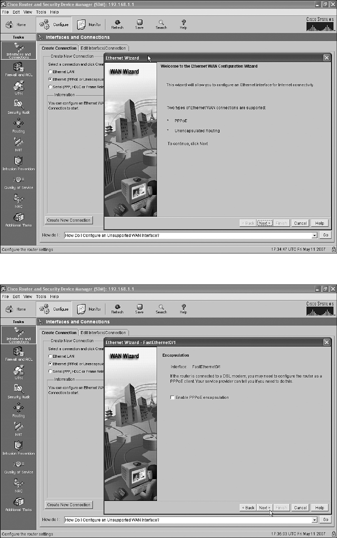
Configuring and Troubleshooting Internet Access Routers 551
Figure 17-5 SDM Ethernet Wizard Welcome Page
Figure 17-6 SDM Ethernet Wizard: Choice to Use Encapsulation with PPPoE
1828xbook.fm Page 551 Thursday, July 26, 2007 3:10 PM
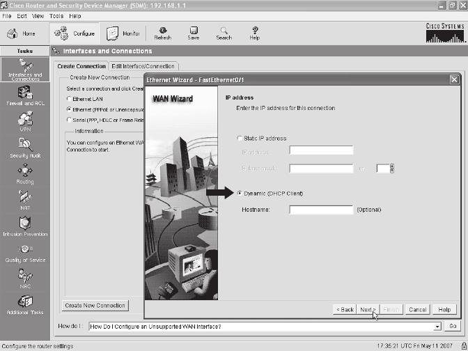
552 Chapter 17: WAN Configuration
As you can see near the top of Figure 17-6, the wizard picked a Fast Ethernet interface,
Fa0/1 in this case, as the interface to configure. The router used in this example has two
LAN interfaces, one of which already has an IP address assigned from Step 1 (Fa0/0).
Because this wizard will be configuring DHCP client services on this router, the wizard
picked the only LAN interface that did not already have an IP address, namely Fa0/1, as the
interface on which it will enable the DHCP client function. This choice is particularly
important when troubleshooting a new installation, because this must be the LAN interface
connected to the cable or DSL modem. This is also the NAT/PAT outside interface.
Click Next. Figure 17-7 shows the next page of the wizard, the IP Address page. This page
gives you the option of statically configuring this interface’s IP address. However, as
explained in Chapter 16, the goal is to use a dynamically assigned IP address from the
ISP—an address that happens to come from the globally routable IP address space. So, you
want to use the default radio button option of Dynamic (DHCP Client).
Figure 17-7 SDM Ethernet Wizard: Static or DHCP Address Assignment
Click Next to move to the Advanced Options page, shown in Figure 17-8. This page asks
if you want to enable PAT, which of course is also desired on an Internet access router.
Simply click the Port Address Translation check box. If you do not want to enable PAT
for some reason, do not check this box.
1828xbook.fm Page 552 Thursday, July 26, 2007 3:10 PM
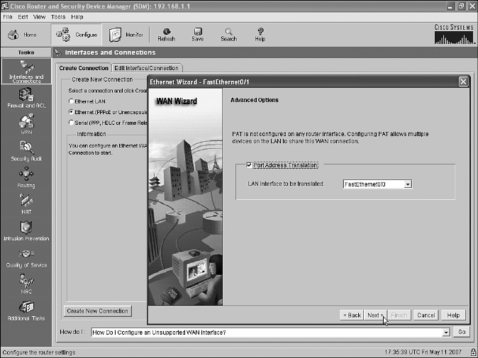
Configuring and Troubleshooting Internet Access Routers 553
Figure 17-8 SDM Ethernet Wizard: Enable PAT and Choose Inside Interface
It is particularly important to note the LAN Interface to Be Translated drop-down box
near the middle of the page. In NAT terminology, this box lists the inside interface, which
means that the listed interface is connected to the local LAN. This example shows
FastEthernet0/0 as the inside interface, as intended. Almost as important in this case is
that the interface being configured for the DHCP client by this wizard, in this case
FastEthernet0/1, is assumed to be the outside interface by the NAT feature, again exactly
as intended.
Click Next to move to the Summary page shown in Figure 17-9, which summarizes the
choices you made when using this wizard. The text on the screen is particularly useful, as
it reminds you that:
■The interface being configured is FastEthernet0/1.
■FastEthernet0/1 will use DHCP client services to find its IP address.
■PPPoE encapsulation is disabled, which means that unencapsulated routing is used.
■PAT is enabled, with FastEthernet0/0 as the inside interface, and FastEthernet0/1 as the
outside interface.
1828xbook.fm Page 553 Thursday, July 26, 2007 3:10 PM
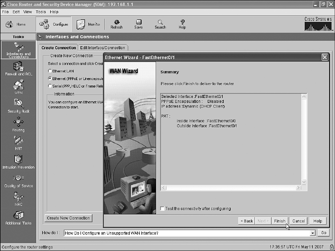
554 Chapter 17: WAN Configuration
Figure 17-9 SDM Ethernet Wizard: Request that the Configuration Changes Be Made
Click Finish. SDM builds the configuration and loads it into the router’s running-config
file. If you want to save the configuration, click the save button near the top of the SDM
home page to make the router do a copy running-config startup-config command to save
the configuration. However, without this extra action, the configuration will only be added
to the running-config file.
At this point, the DHCP client and PAT functions have been configured. The remaining
tasks are to plan the details of what to configure for the DHCP server function on the router
for the local LAN, and to use SDM to configure that feature.
Step 4: Plan for DHCP Services
Before configuring the DHCP server function on the router, to support the local LAN, you
need to plan a few of the values to be configured in the server. In particular, you need to
choose the subset of the private IP network on the local LAN that you intend to allow to be
assigned using DHCP. For the example in this chapter, part of the work at Step 1 was to
choose a private IP network for the local LAN, in this case 192.168.1.0, and default mask
255.255.255.0. It makes sense to allow only a subset of the IP addresses in this network to
be assigned with DHCP, leaving some IP addresses for static assignment. For example,
router R1’s Fa0/0 interface, connected to the local LAN, has already been configured with
IP address 192.168.1.1, so that address should not be included in the range of addresses
allowed to be assigned by the DHCP server.
1828xbook.fm Page 554 Thursday, July 26, 2007 3:10 PM

Configuring and Troubleshooting Internet Access Routers 555
The following list outlines the key items that you need to gather before you configure the
router as a DHCP server. The first two items in the list relate to planning on the local LAN,
and the last two items are just values learned from the ISP that need to be passed on to the
hosts on the local LAN.
1. Recall the private IP network and mask used on the local LAN and then choose a subset
of that network that can be assigned to hosts using DHCP.
2. Make a note of the router’s IP address in that network; this address will be the local
hosts’ default gateway.
3. Find the DNS server IP addresses learned by the router using DHCP client services,
using the show dhcp server EXEC command; the routers will then be able to inform
the DHCP clients on the local LAN about the DNS server IP address(es).
4. Find the domain name, again with the show dhcp server EXEC command.
For the example in this chapter, the first two items, IP network 192.168.1.0 with mask /24,
have already been chosen back in Step 1 of the overall configuration process. The range
192.168.1.101–192.168.1.254 has been reserved for DHCP clients, leaving range
192.168.1.1–192.168.1.100 for static IP addresses. The router’s 192.168.1.1 IP address,
which was configured back at Step 1 so that the engineer could connect to the router using
SDM, will be assigned as the local hosts’ default gateway.
For the last two items in the planning list, the DNS server IP addresses and the domain
name, Example 17-3 shows how to find those values using the show dhcp server
command. This command lists information on a router acting as a DHCP client,
information learned from each DHCP server from which the router has learned an IP
address. The pieces of information needed for the DHCP server SDM configuration are
highlighted in the example.
NOTE Cisco uses the term DHCP pool for the IP addresses that can be assigned using
DHCP.
Example 17-3 Finding the DNS Server IP Addresses and Domain Name
R1#ss
sshh
hhoo
ooww
ww
dd
ddhh
hhcc
ccpp
pp
ss
ssee
eerr
rrvv
vvee
eerr
rr
DHCP server: ANY (255.255.255.255)
Leases: 8
Offers: 8 Requests: 8 Acks: 8 Naks: 0
Declines: 0 Releases: 21 Bad: 0
DNS0: 198.133.219.2, DNS1: 0.0.0.0
Subnet: 255.255.255.252 DNS Domain: example.com
1828xbook.fm Page 555 Thursday, July 26, 2007 3:10 PM
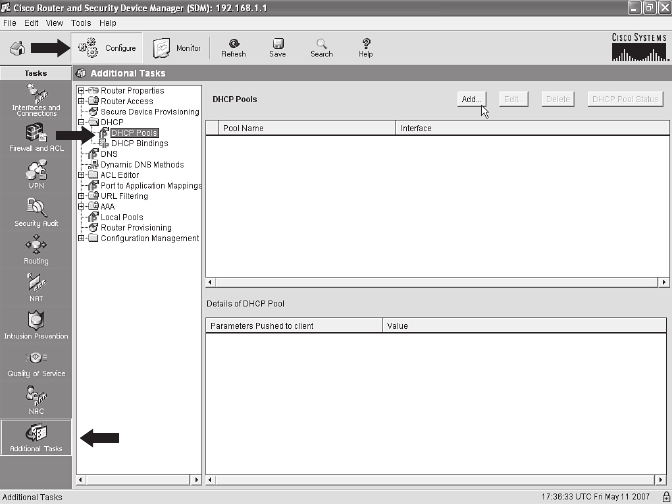
556 Chapter 17: WAN Configuration
Step 5: Configure the DHCP Server
To configure the DHCP server with SDM, click Configure near the top of the SDM window
and then click Additional Tasks at the bottom of the Tasks pane to open the Additional
Tasks window, shown in Figure 17-10.
Figure 17-10 SDM Additional Tasks Configuration Window
Select the DHCP Pools option on the left (as noted with one of the heavy arrows) and then
click the Add button to open the Add DHCP Pool dialog box, shown in Figure 17-11.
This dialog box has a place to type all the information gathered in the previous step, along
with other settings. Figure 17-11 shows the screen used to configure router R1 in the
ongoing example in this chapter.
The four planning items discussed in the previous overall configuration step (Step 4) are
typed in obvious places in this dialog box:
■Range of addresses to be assigned with DHCP
■DNS server IP addresses
■Domain name
■Default router settings
1828xbook.fm Page 556 Thursday, July 26, 2007 3:10 PM
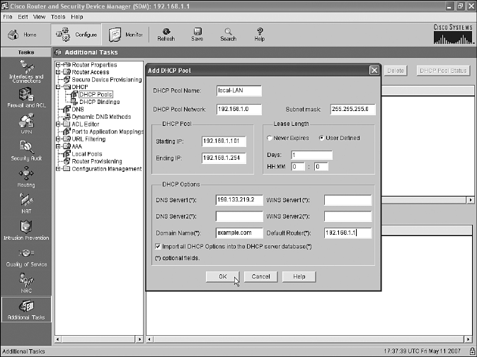
Configuring and Troubleshooting Internet Access Routers 557
Figure 17-11 SDM DHCP Pool Dialog Box
Additionally, the dialog box wants to know the subnet number and mask used on the subnet
in which the addresses will be assigned. Also, you need to make up a name for this pool of
DHCP addresses—the name can be most anything, but choose a meaningful name for that
installation.
Whew! Configuring an Internet access router with SDM might seem to require a lot of steps
and navigating through a lot of windows; however, it is certainly less detailed than
configuring the same features from the CLI. The next section examines a few small
verification and troubleshooting tasks.
Internet Access Router Verification
The choice to cover SDM configuration for DHCP and NAT/PAT, instead of the CLI
configuration commands, has both some positives and negatives. The positives include the
fact that the ICND1 exam, meant for entry-level network engineers, can cover a common
set of features seen on Internet access routers, which are commonly used by smaller
companies. Also, because the underlying configuration can be large (the configuration
added by SDM for the examples in this chapter required about 20 configuration
commands), the use of SDM avoided the time and effort to go over a lot of configuration
options, keeping the topic a little more focused.
1828xbook.fm Page 557 Thursday, July 26, 2007 3:10 PM

558 Chapter 17: WAN Configuration
One negative of using SDM is that troubleshooting becomes a little more difficult because
the configuration has not been covered in detail. As a result, true troubleshooting requires
a review of the information you intended to type or click when using the SDM wizards, and
double-checking that configuration from SDM. Showing all the SDM screens used to check
each item would itself be a bit laborious. Instead of showing all those SDM screens, this
section points out a few of the most common oversights when using SDM to configure
DHCP and PAT, and then it closes with some comments about a few key CLI EXEC
commands related to these features.
To perform some basic verification of the installation of the access router, try the following:
Step 1 Go to a PC on the local LAN and open a web browser. Try your favorite Internet-
based website (for example, www.cisco.com). If a web page opens, that is a good
indication that the access router configuration worked. If not, go to Step 2.
Step 2 From a local PC with a Microsoft OS, open a command prompt and use the
ipconfig /all command to find out if the PC learned an IP address, mask,
default gateway, and DNS IP addresses as configured in the DHCP server
configuration on the router. If not, use the commands listed in the Chapter
15 section “Host Networking Commands” to try and successfully lease an
IP address from a host.
Step 3 Check the cabling between the router and the local LAN, and between the
router and the cable or DSL modem, noting which router interface connects
to which part of the network. Then check the SDM configuration to ensure
that the inside interface per the PAT configuration is the interface connected
to the local LAN, and the outside interface per the PAT configuration is
connected to the DSL/cable modem.
Step 4 Test the PAT function by generating traffic from a local PC to a host in the
Internet. (More details on this item are given in the next few pages.)
The last item in the list provides a good opportunity to examine a few EXEC commands
from the CLI. Example 17-4 lists the output of several CLI commands related to the access
router configuration in this chapter, with some comments following the example.
Example 17-4 Interesting EXEC Commands on the Access Router
R1#ss
sshh
hhoo
ooww
ww
ii
iipp
pp
dd
ddhh
hhcc
ccpp
pp
bb
bbii
iinn
nndd
ddii
iinn
nngg
gg
Bindings from all pools not associated with VRF:
IP address Client-ID/Hardware address/User name Lease expiration Type
192.168.1.101 0063.6973.636f.2d May 12 2007 08:24 PM Automatic
192.168.1.111 0100.1517.1973.2c May 12 2007 08:26 PM Automatic
R1#ss
sshh
hhoo
ooww
ww
ii
iipp
pp
nn
nnaa
aatt
tt
tt
ttrr
rraa
aann
nnss
ssll
llaa
aatt
ttii
iioo
oonn
nnss
ss
Pro Inside global Inside local Outside local Outside global
tcp 64.100.1.1:36486 192.168.1.101:36486 192.168.7.1:80 192.168.7.1:80
udp 64.100.1.1:1027 192.168.1.111:1027 198.133.219.2:53 198.133.219.2:53
1828xbook.fm Page 558 Thursday, July 26, 2007 3:10 PM

Configuring and Troubleshooting Internet Access Routers 559
The show ip dhcp binding command output lists information about the IP addresses
assigned to hosts on the local LAN by the DHCP server function in the access router. This
command output can be compared to the results when trying to get hosts on the local LAN
to acquire an IP address from the router’s DHCP server function.
The show ip nat translations command output provides a few insights that confirm the
normal operation of NAT and PAT. The output shown in Example 17-4 lists one heading
line plus two actual NAT translation table entries. The two highlighted parts of the heading
line refer to the inside global address and the inside local address. The inside local address
should always be the IP address of a host on the local LAN, in this case 192.168.1.101. The
router translates that IP address to the one globally routable public address known to the
router—the 64.100.1.1 IP address learned via DHCP from the ISP.
The last command in the example, clear ip nat translation *, can be useful when the
problem symptom is that some users’ connections that need to use NAT work fine, and
other users’ connection that need to use NAT do not work at all. NAT table entries might
need to be removed before a host can start sending data again, although this is probably a
rare occurrence today. However, this command clears out all the entries in the table, and
then the router creates new entries as the ensuing packets arrive. Note that this clear
command could impact some applications.
R1#cc
ccll
llee
eeaa
aarr
rr
ii
iipp
pp
nn
nnaa
aatt
tt
tt
ttrr
rraa
aann
nnss
ssll
llaa
aatt
ttii
iioo
oonn
nn
**
**
R1#ss
sshh
hhoo
ooww
ww
ii
iipp
pp
nn
nnaa
aatt
tt
tt
ttrr
rraa
aann
nnss
ssll
llaa
aatt
ttii
iioo
oonn
nnss
ss
R1#
Example 17-4 Interesting EXEC Commands on the Access Router (Continued)
1828xbook.fm Page 559 Thursday, July 26, 2007 3:10 PM

560 Chapter 17: WAN Configuration
Exam Preparation Tasks
Review All the Key Topics
Review the most important topics from inside the chapter, noted with the key topics icon in
the outer margin of the page. Table 17-2 lists a reference of these key topics and the page
numbers on which each is found.
Complete the Tables and Lists from Memory
Print a copy of Appendix H, “Memory Tables” (found on the CD-ROM), or at least the
section for this chapter, and complete the tables and lists from memory. Appendix I,
“Memory Tables Answer Key,” also on the CD-ROM, includes completed tables and lists
to check your work.
Definitions of Key Terms
Define the following key terms from this chapter, and check your answers in the glossary.
Cisco Router and Security Device Manager
Command References
Although you should not necessarily memorize the information in the tables in this section,
this section does include a reference for the configuration commands (Table 17-3) and
EXEC commands (Table 17-4) covered in this chapter. Practically speaking, you should
memorize the commands as a side effect of reading the chapter and doing all the activities
Table 17-2 Key Topics for Chapter 17
Key Topic
Element Description Page Number
List Optional and required configuration steps for a serial link between
two routers
542
List IP addressing details planned and configured on the local LAN for
an Internet access router
547
List Planning items before configuring the DHCP server 555
List Common items to check when troubleshooting access router
installation
558
1828xbook.fm Page 560 Thursday, July 26, 2007 3:10 PM

Command References 561
in this exam preparation section. To check to see how well you have memorized the
commands as a side effect of your other studies, cover the left side of the table with a piece
of paper, read the descriptions in the right side, and see if you remember the command.
Table 17-3 Chapter 17 Configuration Command Reference
Command Description
encapsulation {hdlc |
ppp | frame-relay}
Serial interface subcommand that defines the data-link protocol to use on
the link
clock rate speed Serial interface subcommand that, when used on an interface with a DCE
cable, sets the clock speed in bps
bandwidth speed-kbps Interface subcommand that sets the router’s opinion of the link speed, in
kbps, but has no effect on the actual speed
description text Interface subcommand that can set a text description of the interface
Table 17-4 Chapter 17 EXEC Command Reference
Command Description
show ip nat translations Lists the NAT/PAT translation table entries
show dhcp server Lists information learned from a DHCP server, by a router acting as a
DHCP client
clear ip nat translation * Clears (removes) all dynamic entries in the NAT table
show interfaces Lists several important settings on serial links, including encapsulation,
bandwidth, keepalives, the two status codes, description, and IP address/
mask
show controllers serial
number
Lists whether a cable is connected to the interface, and if so, whether it is
a DTE or DCE cable
show interfaces [type
number] description
Lists a single line per interface (or if the interface is included, just one
line of output total) that lists the interface status and description
show ip interface brief Lists a single line per interface, listing the IP address and interface status
1828xbook.fm Page 561 Thursday, July 26, 2007 3:10 PM

1828xbook.fm Page 562 Thursday, July 26, 2007 3:10 PM

Part V: Final Preparation
Chapter 18 Final Preparation
1828xbook.fm Page 563 Thursday, July 26, 2007 3:10 PM

1828xbook.fm Page 564 Thursday, July 26, 2007 3:10 PM

C H A P T E R18
Final Preparation
The first 17 chapters of this book cover the technologies, protocols, commands, and
features you need to understand to pass the ICND2 exam. Although these chapters supply
the detailed information, most people need more preparation than simply reading the
first 17 chapters. This chapter details a set of tools and a study plan to help you complete
your preparation for the exams.
If you’re preparing for the CCNA exam by reading both this book and the CCNA ICND2
Official Exam Certification Guide, you know that both books have a final preparation
chapter. However, you can refer to just this chapter to read about the suggested study plan,
because this chapter refers to the tools in both this book and the ICND2 book. Just look
for the text highlighted in gray, like this sentence, for suggestions that apply to CCNA
(640-802) exam preparation, but not to ICND1 (640-816) exam preparation.
This short chapter has two main sections. The first section lists the exam preparation
tools that can be useful at this point in your study process. The second section lists a
suggested study plan now that you have completed all the earlier chapters.
To ols for Final Preparation
This section lists some information about the available tools and how to access them.
Exam Engine and Questions on the CD
The CD includes an exam engine—software that displays and then grades a set of exam-
realistic questions. These include simulation (sim) questions, drag-and-drop, and many
scenario-based questions that require the same level of analysis as the questions on
the ICND1 and CCNA exams. Using the exam engine, you can either practice with the
questions in Study Mode or take a simulated (timed) ICND1 or CCNA exam.
NOTE This chapter refers to many of the book’s chapters and appendixes, as well as
tools available on the CD. Some of the appendixes, beginning with Appendix D, are
included only on the CD that comes with this book. To access those, just insert the CD
and make the appropriate selection from the opening interface.
1828xbook.fm Page 565 Thursday, July 26, 2007 3:10 PM

566 Chapter 18: Final Preparation
The installation process has two major steps. The CD includes a recent copy of the exam
engine software, supplied by Boson Software (http://www.boson.com). The practice
exam—the database of ICND1 exam questions—is not on the CD. Instead, the practice
exam resides on the http://www.boson.com web server, so the second major step is to
activate and download the practice exam.
Install the Software from the CD
The software installation process is pretty routine as compared with other software
installation processes. The following steps outline the process:
Step 1 Insert the CD into your PC.
Step 2 The software that automatically runs is the Cisco Press software to access
and use all CD-based features, including the exam engine, viewing a PDF
file of this book, and viewing the CD-only appendixes. From the main
menu, click the option to Install the Exam Engine.
Step 3 Respond to prompt windows, as you would with any typical software
installation process.
The installation process might give you the option to register the software. This process
requires that you establish a login at the http://www.boson.com website. You will need this
login to activate the exam, so feel free to register when prompted. If you already have a
login at the http://www.boson.com site, you don’t need to register again. Just use your
existing login.
Activate and Download the Practice Exam
After the exam engine is installed, you should activate the exam associated with this book:
Step 1 Start the Boson Exam Environment (BEE) software from the Start menu. It should
be installed in a Cisco Press folder on your computer.
Step 2 The first time you start the software, it should ask you to either log in or
register an account. If you do not already have an account with Boson,
select the option to register a new account. (You must register to
download and use the exam.)
Step 3 After you are registered, the software might prompt you to download the
latest version of the software, which you should do. Note that this process
updates the exam engine software (formally called the Boson Exam
Environment). It doesn’t activate the practice exam.
NOTE The cardboard CD case in the back of this book includes the CD and a piece
of paper. The paper lists the activation key for the practice exam associated with this
book. Do not lose the activation key.
1828xbook.fm Page 566 Thursday, July 26, 2007 3:10 PM
To ols for Final Preparation 567
Step 4 To activate and download the exam associated with this book, from the
exam engine main window, click the Exam Wizard button.
Step 5 From the Exam Wizard pop-up window, select Activate a purchased
exam and click the Next button. (Although you did not purchase the
exam directly, you purchased it indirectly when you purchased this
book.)
Step 6 On the next screen, enter the Activation Key from the paper inside the
cardboard CD holder, and click the Next button.
Step 7 The activation process downloads the practice exam. When this is done,
the main exam engine menu should list a new exam, with a name such as
“ExSim for Cisco Press ICND1 ECG.” If you do not see the exam, be
sure you have selected the My Exams tab on the menu. You may need to
click the plus sign icon (+) to expand the menu and see the exam.
At this point, the software and practice exam are ready to use.
Activating Other Exams
You need to go through the exam software installation process and the registration process
only once. After that, for each new exam, only a few steps are required. For instance, if
you bought both this book and the CCNA ICND2 Official Exam Certification Guide, you
could follow the steps just listed to install the software and activate the exam associated
with this book. Then, for the practice exam associated with the ICND2 book, which has
about 150 exam-realistic ICND2 questions, you need to follow only a few more steps. All
you have to do is start the Boson exam environment (if it is not still up and running) and
follow Steps 4 through 6 in the preceding list. In fact, if you purchase other Cisco Press
books, or purchase a practice exam from Boson, you just need to activate each new exam
as described in Steps 4 through 6.
You can also purchase additional practice exams from Boson directly from its website.
When you purchase an exam, you receive an activation key, and then you can activate and
download the exam—again without requiring any additional software installation.
The Cisco CCNA Prep Center
Cisco provides a wide variety of CCNA preparation tools at a Cisco Systems website called
the CCNA Prep Center. The CCNA Prep Center includes demonstrations of the exam’s
user interface, sample questions, informational videos, discussion forums, and other tools.
To use the CCNA Prep Center, you need a registered login at http://www.cisco.com.
To register, simply go to http://www.cisco.com, click Register at the top of the page, and
supply some information. (You do not need to work for Cisco or one of its partners to get
a login.)
1828xbook.fm Page 567 Thursday, July 26, 2007 3:10 PM
568 Chapter 18: Final Preparation
After you have registered, proceed to http://www.cisco.com/go/prepcenter, and look for the
link to the CCNA Prep Center. There you can log in and explore the many features.
Subnetting Videos, Reference Pages, and Practice Problems
Being able to analyze the IP addressing and subnetting used in any IPv4 network may be
the single most important skill for all the CCNA exams. This book’s Chapter 12, “IP
Addressing and Subnetting,” covers most of those details. The ICND2 book’s Chapter 5,
“VLSM and Route Summarization,” adds to the puzzle by explaining VLSM.
This book includes several tools to help you practice and refine your subnetting skills:
■Subnetting reference pages: CD-only Appendix E, “Subnetting Reference Pages,”
summarizes the binary and decimal shortcut processes explained in Chapter 12. Each
reference page lists a single process related to subnetting, along with reference
information useful for that process. These summarized processes may be a more
convenient tool when you’re practicing subnetting, as compared to flipping pages in
the subnetting chapters, looking for the correct process.
■Subnetting videos: The DVD included with this book has a series of subnetting
videos. These videos show you how to use the shortcut processes to find the answers
to popular subnetting questions. You can select and play the videos from a simple menu
that starts when you insert the DVD into a DVD drive.
■Subnetting practice: CD-only Appendix D, “Subnetting Practice,” contains a variety
of subnetting practice problems, including 25 problems for which you need to find the
subnet number, subnet broadcast address, and range of valid IP addresses. This
appendix shows you how to use both binary and shortcut processes to find the answers.
Scenarios
As mentioned in the Introduction to this book, some of the exam questions require you to
use the same skills commonly used to troubleshoot problems in real networks. The
troubleshooting sections and chapters of both the ICND1 and ICND2 books help prepare
you for those kinds of questions.
Another way to prepare for troubleshooting questions on the exams is to think through
many different network scenarios, predicting what should occur, and investigating
whether the network is performing as it should. Appendix F, “Additional Scenarios,” in
both books includes some tasks that you should attempt before reading the suggested
solutions listed later in the appendix. By reading these scenarios and doing the exercises,
you can practice some of the skills required when analyzing and troubleshooting
networks.
1828xbook.fm Page 568 Thursday, July 26, 2007 3:10 PM

Study Plan 569
Study Plan
You could simply study using all the available tools, as mentioned earlier in this chapter.
However, this section suggests a particular study plan, with a sequence of tasks that
may work better than just using the tools randomly. However, feel free to use the tools
in any way and at any time that helps you fully prepare for the exam.
If you are preparing for only the ICND1 exam, you can ignore the gray highlighted portions
of this study plan. If you are studying for the CCNA exam by using the ICND2 book as
well, include the tasks highlighted in gray.
The suggested study plan separates the tasks into four categories:
■Recall the facts. Activities that help you remember all the details from the first
17 chapters of this book.
■Practice subnetting. You must master subnetting to succeed on the ICND1, ICND2, and
CCNA exams. This category lists the items you can use to practice subnetting skills.
■Build troubleshooting skills using scenarios. To answer some exam questions that
present a scenario, you may need to recall facts, do subnetting math quickly and
accurately, and use a hands-on simulator—all to answer a single question. This plan
section suggests activities that help you pull together these different skills.
■Use the exam engine to practice realistic questions. You can use the exam engine on
the CD to study using a bank of unique exam-realistic questions available only with
this book.
Recall the Facts
As with most exams, you must recall many facts, concepts, and definitions to do well on the
test. This section suggests a couple of tasks that should help you remember all the details:
Step 1 Review and repeat, as needed, the activities in the “Exam Preparation Tasks”
section at the end of each chapter. Most of these activities help you refine
your knowledge of a topic while also helping you memorize the facts. For CCNA
exam preparation, do this for Chapters 2 through 17 in this book as well as
Chapters 1 through 17 in the ICND2 book.
Step 2 Review all the “Do I Know This Already?” quiz questions at the beginning of
the chapters. Although the questions may be familiar, reading through them again
will help improve your recall of the topics covered in the questions. Also, the
DIKTA questions tend to cover the most important topics from the chapter, and it
never hurts to drill on those topics.
1828xbook.fm Page 569 Thursday, July 26, 2007 3:10 PM

570 Chapter 18: Final Preparation
Practice Subnetting
Without question, absolutely the most important skill you need to succeed in passing the
ICND1, ICND2, and CCNA exams is to be able to accurately, confidently, and quickly
answer subnetting questions. The CCNA exams all have some element of time pressure; the
most stressful questions are the sim, simlet, and subnetting questions. So, you should
practice subnetting math and processes until you can consistently find the correct answer
in a reasonable amount of time.
Before I suggest how you should prepare for subnetting questions, please note that there are
many alternative methods for finding the answers to subnetting questions. For example, you
can use binary math for all 32 bits of the addresses and subnet numbers. Alternatively, you
could recognize that 3 of the 4 octets in most subnetting problems are easily predicted
without binary math, and then use binary math in the final interesting octet. Another option
would be to use decimal shortcuts. (This topic is covered in this book’s Chapter 12, which
is included in the ICND2 book’s Appendix H.) Shortcuts require no binary math but do
require you to practice a process until you’ve memorized it. You can even use variations on
these processes as taught in other books or classes.
Whichever process you prefer, you should practice it until you can use it accurately,
confidently, and quickly.
The following list of suggested activities includes practice activities that you can use
regardless of the process you choose. In some cases, this list includes items that help you
learn the shortcuts included with this book:
Step 1 View or Print Appendix E, “Subnetting Reference Pages.” This short CD-only
appendix includes a series of single-page summaries of the subnetting processes
found in Chapter 12. Appendix E includes reference pages that summarize both
the binary and decimal shortcut subnetting processes.
Step 2 Watch the subnetting videos found on the CCNA video DVD found in the
back of this book. These videos show examples of how to use some of the more
detailed shortcut processes to help ensure that you know how to use the processes.
CCNA exam candidates: The subnetting videos are on DVDs included with both
books. They are identical, so you can watch the videos from either DVD.
Step 3 View or print Appendix D, “Subnetting Practice.” This CD-only appendix
includes enough subnetting practice problems so that, through repetition, you can
significantly improve your speed and internalize the shortcut processes. Plan on
working on these problems until you can consistently get the right answer,
quickly, and you no longer have to sit back and think about the process for finding
the answer. The goal is to make the process of finding the answers to such
1828xbook.fm Page 570 Thursday, July 26, 2007 3:10 PM

Study Plan 571
problems automatic. CCNA exam candidates: The ICND2 Appendix D contains
all the problems from ICND1’s Appendix D, plus a few others, so use ICND2’s
Appendix D.
Step 4 Practice subnetting with Cisco’s subnetting game. Cisco has a subnetting
game, available at the Cisco CCNA Prep Center. It prompts you with various
subnetting scenarios and makes practicing subnetting fun. Just go to the CCNA
Prep Center (http://www.cisco.com/go/prepcenter), log in with your Cisco.com
User ID, select the Additional Information tab, and look for the link to download
the game. (If you do not have a login, you can establish one from this web page.)
Step 5 Develop your own practice problems using a subnet calculator. You can
download many free subnet calculators from the Internet, including one available
from Cisco as part of the CCNA Prep Center. You can make up your own
subnetting problems like those in Appendix D, do the problems, and then test your
answers by using the subnet calculator.
Build Troubleshooting Skills Using Scenarios
Just as a real problem in a real network may be caused by a variety of issues—a routing
protocol, a bad cable, spanning tree, an incorrect ACL, or even errors in your
documentation about the internetwork—the exam makes you apply a wide range of
knowledge to answer individual questions. The one activity for this section is as follows:
■Review the scenarios included in Appendix F of this book. These scenarios make
you think about issues covered in multiple chapters of the book. They also require more
abstract thought to solve the problem. CCNA exam candidates should review the
scenarios in Appendix F of both books.
Use the Exam Engine
The exam engine includes two basic modes:
■Study mode is most useful when you want to use the questions to learn and practice.
In study mode, you can select options such as whether you want to randomize the order
of the questions, randomize the order of the answers, automatically see the answers,
refer to specific sections of the text that reside on the CD, and many other options.
■Simulation mode presents questions in a timed environment, providing you with a
more exam-realistic experience. However, it restricts your ability to see your score as
you progress through the exam, view the answers as you are taking the exam, and refer
to sections of the text. These timed exams not only allow you to study for the
actual ICND1 and CCNA exams, they also help you simulate the time pressure of the
actual exam.
1828xbook.fm Page 571 Thursday, July 26, 2007 3:10 PM
572 Chapter 18: Final Preparation
Choosing Study or Simulation Mode
Both study mode and simulation mode are useful for preparing for the exams. It’s easy to
choose one of the modes from the exam engine’s user interface. The following steps
show you how to move to the screen where you select study or simulation mode:
Step 1 Click the Choose Exam button. The exam should be listed under the title ExSim
for Cisco Press ICND1 ECG.
Step 2 Click the exam’s name to highlight it.
Step 3 Click the Load Exam button.
The engine should display a window. Here you can choose Study Mode or Simulation
Mode using the radio buttons.
Choosing the Right Exam Option
The exam engine has many options. You need to choose from one of the three listed exams
on the left side of the window, and select either simulation or study mode. Additionally,
depending on these two choices, you can potentially modify many other small settings.
Although this is a useful tool, it can be difficult to figure out which options to choose to
perform the following four primary tasks:
■Study for the ICND1 exam
■Study for the CCNA exam
■Simulate the ICND1 exam
■Simulate the CCNA exam
To support the ability to study for and simulate both the ICND1 and CCNA exams, the
practice test includes two separate question banks. The first bank includes about 150
unique questions written specifically for the ICND1 exam. The second bank includes a
subset of the ICND2 question bank written for the CCNA ICND2 Official Exam
Certification Guide.
When studying for or simulating the CCNA exam, you have to choose an option that includes
both the ICND2 and ICND1 questions. To study for or simulate the ICND1 exam, you need
to choose an exam option that includes only ICND1 questions. The following list outlines the
three options on the menu and the questions served by the exam engine for each choice:
■Cisco ICND1 Exam: ICND1 questions only
■Custom Exam: ICND1 questions only
■Full CCNA Exam: Both ICND1 and ICND2 questions
1828xbook.fm Page 572 Thursday, July 26, 2007 3:10 PM

Summary 573
You might want to experiment with some of the options. After you have chosen to either
study using these questions or simulate an exam, Table 18-1 lists the four main options,
along with how to pick the right options from the user interface.
In addition to these main four study options, the custom exam option has a particularly
useful feature for exam study. With this option, by clicking the Modify Settings button, you
can select the questions to study by chapter. So, if you want to use the question bank for
study, and you are studying by chapter or groups of chapters, you can select the questions
associated with those chapters.
Summary
The tools and suggestions listed in this chapter were designed with one goal in mind: to help
you develop the skills required to pass the ICND1 and CCNA exams. This book, and its
companion ICND2 book, were developed not just to tell you the facts, but to help you learn
how to apply the facts. No matter what your experience level when you take the exams, it
is our hope that the broad range of preparation tools, and even the structure of the books
and the focus on troubleshooting, will help you pass the exams with ease. I wish you well
on the exams.
Table 18-1 Directions for What to Choose from the Menu to Study or Simulate the Exam
If you want to: . . . choose this exam: . . . and this mode:
. . . and modify these
additional settings:
Study for ICND1 Cisco ICND1 CD Exam Study No specific settings are
required.
Simulate ICND1 Custom Exam — Select the timed exam
option, 55 questions,
75 minutes. Deselect Show
current score during
exam, and select Never
under Show answers and
explanations.
Study for CCNA Full CCNA Exam Study No specific settings are
required.
Simulate CCNA Full CCNA Exam Simulation No specific settings are
required.
1828xbook.fm Page 573 Thursday, July 26, 2007 3:10 PM

1828xbook.fm Page 574 Thursday, July 26, 2007 3:10 PM

Part VI: Appendixes
Appendix A Answers to the “Do I Know This Already?” Quizzes
Appendix B Decimal to Binary Conversion Table
Appendix C ICND1 Exam Updates: Version 1.0
Glossary
1828xbook.fm Page 575 Thursday, July 26, 2007 3:10 PM

1828xbook.fm Page 576 Thursday, July 26, 2007 3:10 PM

A P P E N D I XA
Answers to the “Do I Know
This Already?” Quizzes
Chapter 2
“Do I Know This Already?”
1. D and F
2. A and G
3. B. Adjacent-layer interaction occurs on one computer, with two adjacent layers in the
model. The higher layer requests services from the next lower layer, and the lower
layer provides the services to the next higher layer.
4. B. Same-layer interaction occurs on multiple computers. The functions defined by
that layer typically need to be accomplished by multiple computers—for example, the
sender setting a sequence number for a segment, and the receiver acknowledging
receipt of that segment. A single layer defines that process, but the implementation of
that layer on multiple devices is required to accomplish the function.
5. A. Encapsulation is defined as the process of adding a header in front of data supplied
by a higher layer (and possibly adding a trailer as well).
6. D
7. C
8. A
9. F
10. C and E. OSI includes the transport layer (not transmission layer) and the network
layer (not Internet layer).
1828xbook.fm Page 577 Thursday, July 26, 2007 3:10 PM
578 Appendix A: Answers to the “Do I Know This Already?” Quizzes
Chapter 3
“Do I Know This Already?”
1. D
2. A
3. B
4. B, D, and E. Routers, wireless access point Ethernet ports, and PC NICs all send using
pins 1 and 2, whereas hubs and switches send using pins 3 and 6. Straight-through cables
are used when connecting devices that use the opposite pairs of pins to transmit data.
5. B
6. A
7. A and C
8. C and D
9. A
10. B, C, and E
11. C
Chapter 4
“Do I Know This Already?”
1. B
2. B
3. B
4. A
5. E
6. E. Although HDLC has an Address field, its value is immaterial on a point-to-point
link, as there is only one intended recipient, the device on the other end of the circuit.
7. A
8. B. One of the main advantages of Frame Relay is that a router can use a single access
link to support multiple VCs, with each VC allowing the router to send data to a
different remote router. To identify each VC, the router must use a different DLCI,
because the DLCI identifies the VC.
1828xbook.fm Page 578 Thursday, July 26, 2007 3:10 PM
Chapter 6 579
Chapter 5
“Do I Know This Already?”
1. A and C. The network layer defines logical addressing, in contrast to physical
addressing. The logical address structure allows for easy grouping of addresses, which
makes routing more efficient. Path selection refers to the process of choosing the
best routes to use in the network. Physical addressing and arbitration typically are data
link layer functions, and error recovery typically is a transport layer function.
2. C and E
3. A
4. B. 224.1.1.1 is a class D address. 223.223.223.255 is the network broadcast address
for class C network 223.223.223.0, so it cannot be assigned to a host.
5. D
6. D and F. Without any subnetting in use, all addresses in the same network as
10.1.1.1—all addresses in Class A network 10.0.0.0—must be on the same LAN.
Addresses separated from that network by some router cannot be in network 10.0.0.0.
So, the two correct answers are the only two answers that list a valid unicast IP address
that is not in network 10.0.0.0.
7. D
8. F
9. C
10. B and C
11. A and C
12. C
13. D
Chapter 6
“Do I Know This Already?”
1. C. TCP uses a concept called forward acknowledgment, in which the acknowledgment
field in the header lists the next-expected byte, not the last-received byte. An
acknowledgment of 5000 in this case means that the TCP segment with sequence
number 5000 was lost, so PC1 should resend that TCP segment.
2. D
3. D and E
1828xbook.fm Page 579 Thursday, July 26, 2007 3:10 PM
580 Appendix A: Answers to the “Do I Know This Already?” Quizzes
4. D and E
5. C. TCP, not UDP, performs windowing, error recovery, and ordered data transfer.
Neither performs routing or encryption.
6. C and F. The terms packet and L3PDU refer to the data encapsulated by Layer 3.
Frame and L2PDU refer to the data encapsulated by Layer 2.
7. B. Note that the hostname is all the text between the // and the /. The text before the //
identifies the application layer protocol, and the text after the / represents the name
of the web page.
8. A and D. VoIP flows need better delay, jitter, and loss, with better meaning less delay,
jitter, and loss, as compared with all data applications. VoIP typically requires less
bandwidth than data applications.
9. C. Intrusion Detection Systems (IDS) monitor packets, comparing the contents of
single packets, or multiple packets, to known combinations (signatures) that typically
imply that a network attack is occurring.
10. A. A virtual private network (VPN) is a security feature in which two endpoints
encrypt data before forwarding it through a public network such as the Internet,
providing privacy of the data inside the packets.
Chapter 7
“Do I Know This Already?”
1. A. A switch compares the destination address to the MAC address table. If a matching
entry is found, the switch knows out which interface to forward the frame. If no
matching entry is found, the switch floods the frame.
2. C. A switch floods broadcast frames, multicast frames (if no multicast optimizations
are enabled), and unknown unicast destination frames (frames whose destination MAC
address is not in the MAC address table).
3. A. A switch floods broadcast frames, multicast frames (if no multicast optimizations
are enabled), and unknown unicast destination frames (frames whose destination MAC
address is not in the MAC address table).
4. B. Switches learn MAC table entries by noting the source MAC address of each
received frame and the interface in which the frame was received, adding an entry that
contains both pieces of information (MAC address and interface).
5. A and B. When the frame sent by PC3 arrives at the switch, the switch has learned
a MAC address table entry for only 1111.1111.1111, PC1’s MAC address. PC3’s
1828xbook.fm Page 580 Thursday, July 26, 2007 3:10 PM
Chapter 9 581
frame, addressed to 2222.2222.2222, is flooded, which means it is forwarded out all
interfaces except for the interface on which the frame arrived.
6. A. A collision domain contains all devices whose frames could collide with frames
sent by all the other devices in the domain. Bridges, switches, and routers separate or
segment a LAN into multiple collision domains, whereas hubs and repeaters do not.
7. A, B, and C. A broadcast domain contains all devices whose sent broadcast frames
should be delivered to all the other devices in the domain. Hubs, repeaters, bridges,
and switches do not separate or segment a LAN into multiple broadcast domains,
whereas routers do.
8. B and D
Chapter 8
“Do I Know This Already?”
1. A and B
2. B
3. B
4. A
5. F
6. D
7. B and C
Chapter 9
“Do I Know This Already?”
1. B. If both commands are configured, IOS accepts only the password as configured in
the enable secret command.
2. B and C
3. B. The first nonblank character after the banner login phrase is interpreted as the
beginning delimiter character. In this case, it’s the letter “t.” So, the second letter “t”—
the first letter in “the”—is interpreted as the ending delimiter. The resulting login
banner is the text between these two “t”s—namely, “his is.”
4. A. The setting for the maximum number of MAC addresses has a default of 1, so the
switchport port-security maximum command does not have to be configured.
1828xbook.fm Page 581 Thursday, July 26, 2007 3:10 PM
582 Appendix A: Answers to the “Do I Know This Already?” Quizzes
5. A, D, and F. To allow access via Telnet, the switch must have password security enabled,
at a minimum using the password vty line configuration subcommand. Additionally,
the switch needs an IP address (configured under the VLAN 1 interface) and a default
gateway when the switch needs to communicate with hosts in a different subnet.
6. F
7. E
8. A. VLAN names are case-sensitive, so the name MY-VLAN command, while using
the correct syntax, would set a different VLAN name than the name shown in the
question. The interface range command in one of the answers includes interfaces
Fa0/13, Fa0/14, and Fa0/15. Because Fa0/14 is not assigned to VLAN 2, this command
would not have allowed the right VLAN assignment. To assign a port to a VLAN, the
switchport access vlan 2 command would have been required (not the switchport
vlan 2 command, which is syntactically incorrect).
Chapter 10
“Do I Know This Already?”
1. E and F. CDP discovers information about neighbors. show cdp gives you several
options that display more or less information, depending on the parameters used.
2. E and F
3. A, B, and D. The disabled state in the show interfaces status command is the same
as an “administratively down and down” state shown in the show interfaces command.
The interface must be in a connect state (per the show interfaces status command)
before the switch can send frames out the interface.
4. A and D. SW2 has effectively disabled IEEE standard autonegotiation by configuring
both speed and duplex. However, Cisco switches can detect the speed used by the
other device, even with autonegotiation turned off. Also, at 1 Gbps, the IEEE
autonegotiation standard says to use full duplex if the duplex setting cannot be
negotiated, so both ends use 1 Gbps, full duplex.
5. B and D. The show interfaces command lists the actual speed and duplex setting, but
it does not imply anything about how the settings were configured or negotiated.
The show interfaces status command lists a prefix of a- in front of the speed and
duplex setting to imply that the setting was autonegotiated, leaving off this prefix if the
setting was configured.
6. A, B, and D. For Fa0/1, autonegotiation should work normally, with both switches
choosing the faster speed (100) and better duplex setting (full). Autonegotiation also
works on SW1’s Fa0/2, with both switches choosing the 100 Mbps and FDX setting.
1828xbook.fm Page 582 Thursday, July 26, 2007 3:10 PM
Chapter 11 583
Fa0/3 disables autonegotiation as a result of having both the speed and duplex
configured. The other switch still automatically senses the speed (100 Mbps), but the
autonegotiation failure results in the other switch using half duplex.
7. A and C. Switch forwarding logic and MAC table entries are separated per VLAN.
Because the frame came in an interface in VLAN 2, it will only be forwarded based on
VLAN 2’s MAC table entries, and it will only cause the addition of MAC table entries
in VLAN 2. The output from the show mac address-table dynamic command lists
only dynamic MAC table entries, so you cannot definitively state how the frame will
be forwarded, because the static entries are not listed.
8. B and C. IOS adds MAC addresses configured by the port security feature as static
MAC addresses, so they do not show up in the output of the show mac address-table
dynamic command. show mac address-table port-security is not a valid command.
Chapter 11
“Do I Know This Already?”
1. A. 802.11b uses only the ISM band (around 2.4 GHz), and 802.11g can use both ISM
and U-NII. 802.11i is a security standard.
2. B. 802.11a uses only OFDM, and 802.11b uses only DSSS. 802.11g runs at a
maximum of 54 Mbps using OFDM encoding.
3. C
4. A. The Extended Service Set (ESS) mode uses multiple access points, which then
allows roaming between the APs. BSS uses a single AP, and IBSS (ad hoc mode) does
not use an AP, so roaming between different APs cannot be done with BSS and IBSS.
5. A and C. APs need to know the SSID for the WLAN the AP is supporting and, if an
AP is capable of multiple standards, the wireless standard to use. The AP uses the best
speed to each device based on the signal quality between the AP and that device; the
speed can vary from device to device. The size of the coverage area is not configured;
instead, it is impacted by antenna choice, antenna gain, interference, and the
wireless standard used.
6. B. The AP connects to a LAN switch using a straight-through cable, just like an
end-user device. All APs in the same ESS should connect to the same VLAN, because
all clients connected to the same WLAN should be in the same subnet. Like LAN
switches, APs do not need IP configuration to forward traffic, although it is useful for
managing and accessing the AP. The standard or speed used on the WLAN does not
require any particular Ethernet speed on the wired side of the AP, although overall
performance is better when using faster WLAN speeds by using at least 100-Mbps
Ethernet.
1828xbook.fm Page 583 Thursday, July 26, 2007 3:10 PM
584 Appendix A: Answers to the “Do I Know This Already?” Quizzes
7. C and D. Ethernet cabling does not typically give off any radio frequency interference,
so the cabling should not affect the WLAN communications. Clients discover APs
by listening on all channels, so a configuration setting to a particular channel on an
AP does not prevent the client from discovering the AP.
8. B and D. The standard is IEEE 802.11i. The Wi-Fi alliance defined the term WPA2 to
refer to that same standard.
9. A, C, and D
Chapter 12
“Do I Know This Already?”
1. A and C
2. B
3. D
4. E. Class B networks imply 16 network bits; the mask implies 7 host bits (7 binary 0s in
the mask), leaving 9 subnet bits. 29 yields 512 subnets, and 27 – 2 yields 126 hosts
per subnet.
5. B. The design requirements mean that at least 7 subnet bits are needed, because 26 =
64 and 27 = 128. Similarly, 7 host bits are also needed, because 26 – 2 = 62 (not enough)
and 27 – 2 = 126 (enough). Masks of /23, /24, and /25 (255.255.254.0, 255.255.255.0,
and 255.255.255.128, respectively), when used with a Class B network, have at
least 7 subnet bits and 7 host bits. The /23 mask maximizes the number of host bits
(9 host bits in this case).
6. C. Class C networks imply 24 network bits; the mask implies 4 host bits (4 binary 0s
in the mask), leaving 4 subnet bits. 24 yields 16 subnets, and 24 – 2 yields 14 hosts
per subnet.
7. C. You need 8 bits to number up to 150 hosts because 27 – 2 is less than 150, but 28 –
2 is greater than 150. Similarly, you need 8 subnet bits, because 27 is less than 164, but
28 is greater than 164. The only valid Class B subnet mask with 8 host and 8 subnet
bits is 255.255.255.0.
8. B, C, D, and E. To meet these requirements, the mask needs at least 8 subnet bits,
because 28 = 256, but 27 = 128, which is not enough subnets. The mask also needs
at least 8 host bits, because 28 – 2 = 254, but 27 – 2 = 126, which is not enough hosts
per subnet. Because a Class A network is in use, the mask needs 8 network bits. As
a result, the first 16 bits in the mask must be binary 1s, and the last 8 bits binary 0s,
with any valid combination in the third octet.
1828xbook.fm Page 584 Thursday, July 26, 2007 3:10 PM
Chapter 13 585
9. E and F. IP address 190.4.80.80, with mask 255.255.255.0, is in subnet number
190.4.80.0, with broadcast address 190.4.80.255, and a range of valid addresses of
190.4.80.1 through 190.4.80.254.
10. F. 190.4.80.80, mask 255.255.240.0, is in subnet 190.4.80.0, broadcast address
190.4.95.255, with a range of valid addresses of 190.4.80.1 through 190.4.95.254.
11. D, E, F. 190.4.80.80, mask 255.255.255.128 (/25), is in subnet 190.4.80.0, broadcast
address 190.4.80.127, with a range of valid addresses of 190.4.80.1 through
190.4.80.126.
12. B and D. To find the answer, you should use the presumed address and mask and try
to find the subnet number and subnet broadcast address of that subnet. If the subnet
number or broadcast address happens to be the same number you started with, as listed
in the answer, then you have identified the fact that the number is a subnet number or
broadcast address. For this question, note that 10.0.0.0 is a Class A network number,
which is the same value as the zero subnet, no matter what mask is used—so it is
definitely reserved. For 172.27.27.27, mask 255.255.255.252, you will find subnet
172.27.27.24, valid address range 172.27.27.25–26, and a subnet broadcast address of
172.27.27.27.
13. C, D, E, and F. In this case, the subnet numbers begin with 180.1.0.0 (subnet zero),
and then 180.1.8.0, 180.1.16.0, 180.1.24.0, and so on, increasing by 8 in the third octet,
up to 180.1.248.0 (broadcast subnet).
14. A. In this case, the subnet numbers begin with 180.1.0.0 (subnet zero), and then
180.1.1.0, 180.1.2.0, 180.1.3.0, and so on, increasing by 1 in the third octet, up to
180.1.255.0 (broadcast subnet).
Chapter 13
“Do I Know This Already?”
1. B and E. Cisco routers have an on/off switch, but Cisco switches generally do not.
2. B and C. SOHO routers oftentimes expect to connect users to the Internet, so they use
DHCP client services to learn a publicly routable IP address from an ISP, and then
use DHCP server functions to lease IP addresses to the hosts in the small office.
3. A. Both switches and routers configure IP addresses, so the ip address address mask
and ip address dhcp commands could be used on both routers and switches. The
interface vlan 1 command applies only to switches.
4. B and D. To route packets, a router interface must have an IP address assigned and
be in an “up and up” interface state. For a serial link created in a lab, without using
1828xbook.fm Page 585 Thursday, July 26, 2007 3:10 PM
586 Appendix A: Answers to the “Do I Know This Already?” Quizzes
CSU/DSUs, one router must be configured with a clock rate command to the speed
of the link. The bandwidth and description commands are not required to make a link
operational.
5. C. If the first of the two status codes is “down,” it typically means that a Layer 1
problem exists (for example, the physical cable is not connected to the interface).
6. C and E
7. B and C. A router has one IP address for each interface in use, whereas a LAN switch
has a single IP address that is just used for accessing the switch. Setup mode prompts
for some different details in routers and switches; in particular, routers ask for IP
addresses and masks for each interface.
8. D and F. The router boot process considers the low-order 4 bits of the configuration
register, called the boot field, as well as any configured boot system global
configuration commands. This process allows an engineer to specify which IOS is
loaded when the router is initialized.
9. A
Chapter 14
“Do I Know This Already?”
1. A and C. A router will add a static route to the routing table as long as the outgoing
interface or next-hop information is currently valid.
2. A
3. A and B
4. E and F
5. B, D, E, and F
6. D, E, and F
7. A, D, E, and H. The configuration consists of the router rip command, the version 2
command, and the network 10.0.0.0 and network 11.0.0.0 commands. The network
command uses classful network numbers as the parameter, and the version 2 command
is required to make the router use only RIP Version 2. Router2 does not need a network
9.0.0.0 command, because a router needs only network commands that match directly
connected subnets.
8. A. The network command uses classful network numbers as the parameter, matching
all of that router’s interfaces whose addresses are in the classful network. The
parameter must list the full network number, not just the network octets.
1828xbook.fm Page 586 Thursday, July 26, 2007 3:10 PM
Chapter 15 587
9. B
10. B and C. The bracketed numbers include first the administrative distance, and then the
metric. The time counter (value 00:00:13) is an increasing counter that lists the time
since this route was last included in a received RIP update. The counter resets to
00:00:00 upon receipt of each periodic routing update.
Chapter 15
1. C and D. Addresses that begin with 225 are Class D multicast IP addresses, so they
cannot be assigned to interfaces to be used as unicast IP addresses. 10.43.53.63
255.255.255.192 is actually a subnet broadcast address for subnet 10.43.53.0
255.255.255.192.
2. B
3. C. The asterisk beside connection 2 identifies the connection number to which the
resume command will connect the user if the resume command does not have any
parameters.
4. A and D. LAN-based hosts ARP to find the MAC addresses of other hosts they perceive
to be in the same subnet. PC1 thinks that 10.1.1.130 is in the same subnet, so PC1 will
ARP looking for that host’s MAC address. PC3 would not ARP for 10.1.1.10, because
PC3’s subnet, per its address and mask, is 10.1.1.128/25, range 10.1.1.129–10.1.1.254.
R1 would have a connected route for subnet 10.1.1.0/24, range 10.1.1.1–10.1.1.254,
so R1 would ARP looking for 10.1.1.130’s MAC address.
5. A. A ping of a host’s own IP address does not test whether the LAN is working or not,
because the packet does not have to traverse the LAN. A ping that requires the packet
to go from PC1 to the default gateway (R1) proves the LAN works, at least between
PC1 and R1. The only answer that lists a command that causes a packet to need to cross
the LAN from PC1 to R1 (although that process fails) is the ping 10.1.1.1 command.
6. A, C, and E. The tracert (Microsoft operating systems) and traceroute (Cisco IOS
Software) commands list the IP address of the intermediate routers and end host.
The commands list the router’s IP address closest to the host that issued the command.
7. B and C. A host only ARPs to find MAC addresses of other hosts in the same subnet.
PC1 would need its default gateway’s MAC address, and likewise, R1 would need
PC1’s MAC address in its ARP cache to send the return packet.
8. A and D. A host only ARPs to find MAC addresses of other hosts in the same subnet.
However, a host learns the IP address to MAC address mapping information from a
received ARP request. PC1 would send an ARP broadcast for R1’s 10.1.1.1 IP address,
which would cause PC1 to learn about R1’s MAC address, and R1 to learn PC1’s MAC
address. Similarly, because the first packet is going from PC1 to PC2, R2 will need
1828xbook.fm Page 587 Thursday, July 26, 2007 3:10 PM
588 Appendix A: Answers to the “Do I Know This Already?” Quizzes
to send an ARP broadcast looking for PC2’s MAC address, through which PC2 will
learn R2’s MAC address, meaning that PC2 does not need to send an ARP broadcast
looking for R2’s MAC address.
9. A, C, and E. The IP header has a source IP address of 10.1.1.10 and a destination of
172.16.2.7 for the packets going left-to-right, with those addresses reversed for the
ping reply packets that go right-to-left. The MAC addresses always represent the
addresses of the devices on that local LAN. Note that HDLC, on the serial link, does
not use MAC addresses.
Chapter 16
“Do I Know This Already?”
1. D. Modems demodulate an analog signal sent by the phone company into a digital
signal. The goal is to re-create the original bits sent by the other modem, so the
demodulation function converts the analog signal into the bits that it was intended
to represent.
2. A. Of the Internet access options covered in this book, only DSL has distance
limitations based on the length of the local telco loop.
3. D. The DSLAM separates, or multiplexes, the voice traffic from the data, splitting
the voice traffic off to a voice switch, and the data traffic to a router.
4. A and C. Cable Internet supports only asymmetric speeds.
5. B and C
6. A. The router acts as a DHCP server on the local LAN segment, with a static IP address
on the interface. It performs NAT/PAT, changing the source IP address of packets
entering the interface. It does not act as a DNS server; although as DHCP server, it does
tell the PCs on the local LAN the IP address(es) of any known DNS servers.
7. B and C. The router acts as a DHCP server on the local LAN segment, and as a DHCP
client on the Internet-facing interface. It performs NAT/PAT, changing the source IP
address of packets entering the local LAN interface and exiting the Internet-facing
interface. It does not act as a DNS server; although as DHCP server, it does tell the PCs
on the local LAN the IP address(es) of any known DNS servers.
8. B and C. In a typical installation, the router translates (with NAT/PAT) the local hosts’
IP addresses, so the server would receive packets from a public IP address (known to
the access router) instead of from private IP address 10.1.1.1. The PC user will use
normal DNS services to learn the IP address of www.cisco.com, which would be a
public IP address in the Internet. In NAT terminology, the inside local IP address is the
1828xbook.fm Page 588 Thursday, July 26, 2007 3:10 PM
Chapter 17 589
private IP address for a local host in the enterprise network, whereas the inside global
IP address is the public Internet IP address to which the inside local IP address is
translated by NAT/PAT.
Chapter 17
1. A. The encapsulation command resets the encapsulation (data-link), so only the
encapsulation ppp command is required. The clock rate command only matters if a
back-to-back serial link is used, and if that link already works, that means the clock
rate command has already been configured. The bandwidth command is never
required to make the link work.
2. B. For a back-to-back serial link, the clock rate command is required on the router
with the DCE cable installed. If R1 connects to a DTE cable, R2 must use a DCE cable,
requiring the clock rate command on R2. The bandwidth command is never needed
to make any interface work; it is merely a reference for other functions, such as for
defaults for choosing routing protocol metrics for EIGRP and OSPF.
3. B. The clock rate command is needed only when a back-to-back serial link is created
in a lab, and this link uses a real leased line installed by a telco. Although the
bandwidth command may be recommended, it is not required to make the link work.
Because the routers are brand new, having not been configured before, the serial
interfaces still have their default encapsulation of HDLC, so the encapsulation ppp
command is required, on both routers, to make PPP operational.
4. C and D. Other settings include the DHCP clients’ default gateway, which is the
access router’s local LAN interface IP address, the subnet number, and subnet mask.
5. B. The SDM configuration wizard allows DHCP client services to be configured, with
an option to add PAT configuration or not. The PAT configuration option assumes
all interfaces that already have IP addresses are candidates to be inside interfaces, with
DHCP-client interfaces assumed to be outside interfaces.
6. D. SDM uses a web browser on a PC and a web server function on the router, requiring
the user to connect through an IP network rather than from the console. SDM does
not use SSH at all. SDM loads the configuration into the router only after the user
clicks the Finish button on any of the configuration wizards, but the configuration is
added only to the running-config file.
7. A and B. To enable a local host user to type names instead of IP addresses to access
the Internet, the access router DHCP server needs to be configured with several details,
including the IP addresses of the DNS servers advertised by the ISPs. Also, mixing
up which interface should be the inside interface and which should be the outside
interface is common. The other two answers have nothing to do with the required
configuration on an Internet access router.
1828xbook.fm Page 589 Thursday, July 26, 2007 3:10 PM

1828xbook.fm Page 590 Thursday, July 26, 2007 3:10 PM

A P P E N D I X B
Decimal to Binary
Conversion Table
This appendix provides a handy reference for converting between decimal and binary
formats for the decimal numbers 0 through 255. Feel free to refer to this table when
practicing any of the subnetting problems found in this book and on the CD-ROM.
Although this appendix is useful as a reference tool, note that if you plan to convert values
between decimal and binary when doing the various types of subnetting problems on the
exams, instead of using the shortcut processes that mostly avoid binary math, you will
likely want to practice converting between the two formats before the exam. For practice,
just pick any decimal value between 0 and 255, convert it to 8-bit binary, and then use this
table to find out if you got the right answer. Also, pick any 8-bit binary number, convert it
to decimal, and again use this table to check your work.
1828xbook.fm Page 591 Thursday, July 26, 2007 3:10 PM

592 Appendix B: Decimal to Binary Conversion Table
Decimal
Value
Binary
Value
Decimal
Value
Binary
Value
Decimal
Value
Binary
Value
Decimal
Value
Binary
Value
0 00000000 32 00100000 64 01000000 96 01100000
1 00000001 33 00100001 65 01000001 97 01100001
2 00000010 34 00100010 66 01000010 98 01100010
3 00000011 35 00100011 67 01000011 99 01100011
4 00000100 36 00100100 68 01000100 100 01100100
5 00000101 37 00100101 69 01000101 101 01100101
6 00000110 38 00100110 70 01000110 102 01100110
7 00000111 39 00100111 71 01000111 103 01100111
8 00001000 40 00101000 72 01001000 104 01101000
9 00001001 41 00101001 73 01001001 105 01101001
10 00001010 42 00101010 74 01001010 106 01101010
11 00001011 43 00101011 75 01001011 107 01101011
12 00001100 44 00101100 76 01001100 108 01101100
13 00001101 45 00101101 77 01001101 109 01101101
14 00001110 46 00101110 78 01001110 110 01101110
15 00001111 47 00101111 79 01001111 111 01101111
16 00010000 48 00110000 80 01010000 112 01110000
17 00010001 49 00110001 81 01010001 113 01110001
18 00010010 50 00110010 82 01010010 114 01110010
19 00010011 51 00110011 83 01010011 115 01110011
20 00010100 52 00110100 84 01010100 116 01110100
21 00010101 53 00110101 85 01010101 117 01110101
22 00010110 54 00110110 86 01010110 118 01110110
23 00010111 55 00110111 87 01010111 119 01110111
24 00011000 56 00111000 88 01011000 120 01111000
25 00011001 57 00111001 89 01011001 121 01111001
26 00011010 58 00111010 90 01011010 122 01111010
27 00011011 59 00111011 91 01011011 123 01111011
28 00011100 60 00111100 92 01011100 124 01111100
29 00011101 61 00111101 93 01011101 125 01111101
30 00011110 62 00111110 94 01011110 126 01111110
31 00011111 63 00111111 95 01011111 127 01111111
1828xbook.fm Page 592 Thursday, July 26, 2007 3:10 PM

Appendix B: Decimal to Binary Conversion Table 593
Decimal
Value
Binary
Value
Decimal
Value
Binary
Value
Decimal
Value
Binary
Value
Decimal
Value
Binary
Value
128 10000000 160 10100000 192 11000000 224 11100000
129 10000001 161 10100001 193 11000001 225 11100001
130 10000010 162 10100010 194 11000010 226 11100010
131 10000011 163 10100011 195 11000011 227 11100011
132 10000100 164 10100100 196 11000100 228 11100100
133 10000101 165 10100101 197 11000101 229 11100101
134 10000110 166 10100110 198 11000110 230 11100110
135 10000111 167 10100111 199 11000111 231 11100111
136 10001000 168 10101000 200 11001000 232 11101000
137 10001001 169 10101001 201 11001001 233 11101001
138 10001010 170 10101010 202 11001010 234 11101010
139 10001011 171 10101011 203 11001011 235 11101011
140 10001100 172 10101100 204 11001100 236 11101100
141 10001101 173 10101101 205 11001101 237 11101101
142 10001110 174 10101110 206 11001110 238 11101110
143 10001111 175 10101111 207 11001111 239 11101111
144 10010000 176 10110000 208 11010000 240 11110000
145 10010001 177 10110001 209 11010001 241 11110001
146 10010010 178 10110010 210 11010010 242 11110010
147 10010011 179 10110011 211 11010011 243 11110011
148 10010100 180 10110100 212 11010100 244 11110100
149 10010101 181 10110101 213 11010101 245 11110101
150 10010110 182 10110110 214 11010110 246 11110110
151 10010111 183 10110111 215 11010111 247 11110111
152 10011000 184 10111000 216 11011000 248 11111000
153 10011001 185 10111001 217 11011001 249 11111001
154 10011010 186 10111010 218 11011010 250 11111010
155 10011011 187 10111011 219 11011011 251 11111011
156 10011100 188 10111100 220 11011100 252 11111100
157 10011101 189 10111101 221 11011101 253 11111101
158 10011110 190 10111110 222 11011110 254 11111110
159 10011111 191 10111111 223 11011111 255 11111111
1828xbook.fm Page 593 Thursday, July 26, 2007 3:10 PM

1828xbook.fm Page 594 Thursday, July 26, 2007 3:10 PM

A P P E N D I X C
ICND1 Exam Updates:
Version 1.0
Over time, reader feedback allows Cisco Press to gauge which topics give our readers the
most problems when taking the exams. Additionally, Cisco may make small changes in the
breadth of exam topics or in emphasis of certain topics. To assist readers with those topics,
the author creates new materials clarifying and expanding upon those troublesome exam
topics. As mentioned in the introduction, the additional content about the exam is contained
in a PDF document on this book’s companion website at http://www.ciscopress.com/title/
1587201828. The document you are viewing is Version 1.0 of this appendix.
This appendix presents all the latest update information available at the time of this
book’s printing. To make sure you have the latest version of this document, you should be
sure to visit the companion website to see if any more recent versions have been posted
since this book went to press.
This appendix attempts to fill the void that occurs with any print book. In particular, this
appendix does the following:
1. Mentions technical items that might not have been mentioned elsewhere in the book
2. Covers new topics when Cisco adds topics to the ICND1 or CCNA exam blueprints
3. Provides a way to get up-to-the-minute current information about content for the exam
Always Get the Latest at the Companion Website
You are reading the version of this appendix that was available when your book was printed.
However, given that the main purpose of this appendix is to be a living, changing document,
it is very important that you look for the latest version online at the book’s companion
website. To do so:
1. Browse to http://www.ciscopress.com/title/1587201828.
2. Select the Downloads option under the More Information box.
3. Download the latest “ICND1 Appendix C” document.
1828xbook.fm Page 595 Thursday, July 26, 2007 3:10 PM

596 Appendix C: ICND1 Exam Updates: Version 1.0
Te chnical Content
The current version of this appendix does not contain any additional technical coverage.
This appendix is here simply to provide the instructions to check online for a later version
of this appendix.
NOTE Note that the downloaded document has a version number. If the version of
the PDF on the website is the same version as this appendix in your book, your book
has the latest version, and there is no need to download or use the online version.
1828xbook.fm Page 596 Thursday, July 26, 2007 3:10 PM
1828xbook.fm Page 597 Thursday, July 26, 2007 3:10 PM

1828xbook.fm Page 598 Thursday, July 26, 2007 3:10 PM

G L O S S A R Y
10BASE-T The 10-Mbps baseband Ethernet specification using two pairs of
twisted-pair cabling (Categories 3, 4, or 5): One pair transmits data and the other
receives data. 10BASE-T, which is part of the IEEE 802.3 specification, has a distance
limit of approximately 100 m (328 feet) per segment.
100BASE-TX A name for the IEEE Fast Ethernet standard that uses two-pair copper
cabling, a speed of 100 Mbps, and a maximum cable length of 100 meters.
1000BASE-T A name for the IEEE Gigabit Ethernet standard that uses four-pair
copper cabling, a speed of 1000 Mbps (1 Gbps), and a maximum cable length of 100
meters.
802.1Q The IEEE standardized protocol for VLAN trunking.
802.11a The IEEE standard for wireless LANs using the U-NII spectrum, OFDM
encoding, at speeds of up to 54 Mbps.
802.11b The IEEE standard for wireless LANs using the ISM spectrum, DSSS
encoding, and speeds of up to 11 Mbps.
802.11g The IEEE standard for wireless LANs using the ISM spectrum, OFDM or
DSSS encoding, and speeds of up to 54 Mbps.
802.11i The IEEE standard for wireless LAN security, including authentication and
encryption.
A
AAA Authentication, Authorization, and Accounting. Authentication confirms the
identity of the user or device. Authorization determines what the user or device is
allowed to do. Accounting records information about access attempts, including
inappropriate requests.
1828xbook.fm Page 599 Thursday, July 26, 2007 3:10 PM
access interface A LAN network design term that refers to a switch interface
connected to end-user devices.
access link In Frame Relay, the physical serial link that connects a Frame Relay
DTE device, usually a router, to a Frame Relay switch. The access link uses the same
physical layer standards as do point-to-point leased lines.
access point A wireless LAN device that provides a means for wireless clients to
send data to each other and to the rest of a wired network, with the AP connecting to
both the wireless LAN and the wired Ethernet LAN.
accounting In security, the recording of access attempts. See AAA.
ad hoc mode In wireless LANs, a method or mode of operation in which clients
send data directly to each other without the use of a wireless access point (AP).
adjacent-layer interaction The general topic of how on one computer, two adjacent
layers in a networking architectural model work together, with the lower layer
providing services to the higher layer.
administrative distance In Cisco routers, a means for one router to choose between
multiple routes to reach the same subnet when those routes were learned by different
routing protocols. The lower the administrative distance, the better the source of the
routing information.
ADSL Asymmetric digital subscriber line. One of many DSL technologies, ADSL is
designed to deliver more bandwidth downstream (from the central office to the
customer site) than upstream.
Anti-X The term used by Cisco to refer to a variety of security tools that help prevent
various attacks, including antivirus, anti-phishing, and anti-spam.
ARP Address Resolution Protocol. An Internet protocol used to map an IP address
to a MAC address. Defined in RFC 826.
asymmetric A feature of many Internet access technologies, including DSL, cable,
and modems, in which the downstream transmission rate is higher than the upstream
transmission rate.
asynchronous The lack of an imposed time ordering on a bit stream. Practically,
both sides agree to the same speed, but there is no check or adjustment of the rates if
600 access interface
1828xbook.fm Page 600 Thursday, July 26, 2007 3:10 PM
they are slightly different. However, because only 1 byte per transfer is sent, slight
differences in clock speed are not an issue.
ATM Asynchronous Transfer Mode. The international standard for cell relay in
which multiple service types (such as voice, video, and data) are conveyed in fixed-
length (53-byte) cells. Fixed-length cells allow cell processing to occur in hardware,
thereby reducing transit delays.
authentication In security, the verification of the identity of a person or a process.
See AAA.
authorization In security, the determination of the rights allowed for a particular
user or device. See AAA.
autonomous system An internetwork in the administrative control of one
organization, company, or governmental agency, inside which that organization
typically runs an Interior Gateway Protocol (IGP).
auxiliary port A physical connector on a router that is designed to be used to allow
a remote terminal, or PC with a terminal emulator, to access a router using an analog
modem.
B
back-to-back link A serial link between two routers, created without CSU/DSUs, by
connecting a DTE cable to one router and a DCE cable to the other. Typically used in
labs to build serial links without the expense of an actual leased line from the telco.
balanced hybrid A term that refers to a general type of routing protocol algorithm,
the other two being distance vector and link state. The Enhanced Interior Gateway
Routing Protocol (EIGRP) is the only routing protocol that Cisco classifies as using a
balanced hybrid algorithm.
bandwidth A reference to the speed of a networking link. Its origins come from
earlier communications technology in which the range, or width, of the frequency band
dictated how fast communications could occur.
basic service set (BSS) In wireless LANs, a WLAN with a single access point.
bitwise Boolean AND A Boolean AND between two numbers of the same length in
which the first bit in each number is ANDed, and then the second bit in each number,
and then the third, and so on.
ATM 601
1828xbook.fm Page 601 Thursday, July 26, 2007 3:10 PM
Boolean AND A math operation performed on a pair of one-digit binary numbers.
The result is another one-digit binary number. 1 AND 1 yields 1; all other combinations
yield a 0.
boot field The low-order 4 bits of the configuration register in a Cisco router. The
value in the boot field in part tells the router where to look for a Cisco IOS image to
load.
BRI Basic Rate Interface. An ISDN interface composed of two 64-kbps bearer (B)
channels and one 16-kbps data (D) channel for circuit-switched communication of
voice, video, and data.
broadcast address See subnet broadcast address.
broadcast domain A set of all devices that receive broadcast frames originating
from any device within the set. Devices in the same VLAN are in the same broadcast
domain.
broadcast frame An Ethernet frame sent to destination address FFFF.FFFF.FFFF,
meaning that the frame should be delivered to all hosts on that LAN.
broadcast subnet When subnetting a Class A, B, or C network, the one subnet in
each classful network for which all subnet bits have a value of binary 1. The subnet
broadcast address in this subnet has the same numeric value as the classful network’s
network-wide broadcast address.
bus A common physical signal path composed of wires or other media across which
signals can be sent from one part of a computer to another.
C
CDP Cisco Discovery Protocol. A media- and protocol-independent device-
discovery protocol that runs on most Cisco-manufactured equipment, including
routers, access servers, and switches. Using CDP, a device can advertise its existence
to other devices and receive information about other devices on the same LAN or on
the remote side of a WAN.
CDP neighbor A device on the other end of some communications cable that is
advertising CDP updates.
CIDR notation See prefix notation.
602 Boolean AND
1828xbook.fm Page 602 Thursday, July 26, 2007 3:10 PM
circuit switching A generic reference to network services, typically WAN services,
in which the provider sets up a (layer 1) circuit between two devices, and the provider
makes no attempt to interpret the meaning of the bits. See also packet switching.
classful network An IPv4 Class A, B, or C network; called a classful network
because these networks are defined by the class rules for IPv4 addressing.
classful routing protocol Does not transmit the mask information along with the
subnet number, and therefore must consider Class A, B, and C network boundaries and
perform autosummarization at those boundaries. Does not support VLSM.
classless routing protocol An inherent characteristic of a routing protocol,
specifically that the routing protocol does send subnet masks in its routing updates,
thereby removing any need to make assumptions about the addresses in a particular
subnet or network, making it able to support VLSM and manual route summarization.
CLI Command-line interface. An interface that enables the user to interact with the
operating system by entering commands and optional arguments.
clock rate The speed at which a serial link encodes bits on the transmission medium.
clock source The device to which the other devices on the link adjust their speed
when using synchronous links.
clocking The process of supplying a signal over a cable, either on a separate pin on
a serial cable or as part of the signal transitions in the transmitted signal, so that the
receiving device can keep synchronization with the sending device.
codec Coder-decoder. An integrated circuit device that transforms analog voice
signals into a digital bit stream and then transforms digital signals back into analog
voice signals.
collision domain A set of network interface cards (NICs) for which a frame sent by
one NIC could result in a collision with a frame sent by any other NIC in the same
collision domain.
command-line interface See CLI.
configuration mode A part of the Cisco IOS Software CLI in which the user can
type configuration commands that are then added to the device’s currently used
configuration file (running-config).
circuit switching 603
1828xbook.fm Page 603 Thursday, July 26, 2007 3:10 PM
configuration register In Cisco routers, a 16-bit, user-configurable value that
determines how the router functions during initialization. In software, the bit position
is set by specifying a hexadecimal value using configuration commands.
connection establishment The process by which a connection-oriented protocol
creates a connection. With TCP, a connection is established by a three-way
transmission of TCP segments.
console port A physical socket on a router or switch to which a cable can be
connected between a computer and the router/switch, for the purpose of allowing the
computer to use a terminal emulator and use the CLI to configure, verify, and
troubleshoot the router/switch.
convergence The time required for routing protocols to react to changes in the
network, removing bad routes and adding new, better routes so that the current best
routes are in all the routers’ routing tables.
CPE Customer premises equipment. Any equipment related to communications that
is located at the customer site, as opposed to inside the telephone company’s network.
crossover cable An Ethernet cable that swaps the pair used for transmission on one
device to a pair used for receiving on the device on the opposite end of the cable. In
10BASE-T and 100BASE-TX networks, this cable swaps the pair at pins 1,2 to pins
3,6 on the other end of the cable, and the pair at pins 3,6 to pins 1,2 as well.
CSMA/CA Carrier sense multiple access with collision avoidance. A media-access
mechanism that defines how devices decide when they can send, with a goal of
avoiding collisions as much as possible. IEEE WLANs use CSMA/CA.
CSMA/CD Carrier sense multiple access collision detect. A media-access
mechanism in which devices ready to transmit data first check the channel for a carrier.
If no carrier is sensed for a specific period of time, a device can transmit. If two devices
transmit at once, a collision occurs and is detected by all colliding devices. This
collision subsequently delays retransmissions from those devices for some random
length of time.
CSU/DSU Channel service unit/digital service unit. A device that understands the
Layer 1 details of serial links installed by a telco and how to use a serial cable to
communicate with networking equipment such as routers.
604 configuration register
1828xbook.fm Page 604 Thursday, July 26, 2007 3:10 PM
cut-through switching One of three options for internal processing on some models
of Cisco LAN switches in which the frame is forwarded as soon as possible, including
forwarding the first bits of the frame before the whole frame is received.
D
DCE Data communications equipment. From a physical layer perspective, the
device providing the clocking on a WAN link, typically a CSU/DSU, is the DCE. From
a packet-switching perspective, the service provider’s switch, to which a router might
connect, is considered the DCE.
decapsulation On a computer that receives data over a network, the process in which
the device interprets the lower-layer headers and, when finished with each header,
removes the header, revealing the next-higher-layer PDU.
default gateway/default router On an IP host, the IP address of some router to
which the host sends packets when the packet’s destination address is on a subnet other
than the local subnet.
default mask The mask used in a Class A, B, or C network that does not create any
subnets; specifically, mask 255.0.0.0 for Class A networks, 255.255.0.0 for Class B
networks, and 255.255.255.0 for Class C networks.
default route On a router, the route that is considered to match all packets that are
not otherwise matched by some more specific route.
demarc The legal term for the demarcation or separation point between the telco’s
equipment and the customer’s equipment.
denial of service (DoS) A type of attack whose goal is to cause problems by
preventing legitimate users from being able to access services, thereby preventing the
normal operation of computers and networks.
DHCP Dynamic Host Configuration Protocol. A protocol used by hosts to
dynamically discover and lease an IP address, and learn the correct subnet mask,
default gateway, and DNS server IP addresses.
Direct Sequence Spread Spectrum (DSSS) A method of encoding data for
transmission over a wireless LAN in which the device uses 1 of 11 (in the USA) nearby
frequencies in the 2.4-GHz range.
cut-through switching 605
1828xbook.fm Page 605 Thursday, July 26, 2007 3:10 PM
directed broadcast address See subnet broadcast address.
distance vector The logic behind the behavior of some interior routing protocols,
such as RIP. Distance vector routing algorithms call for each router to send its entire
routing table in each update, but only to its neighbors. Distance vector routing
algorithms can be prone to routing loops but are computationally simpler than link-
state routing algorithms.
DNS Domain Name System. An application layer protocol used throughout the
Internet for translating hostnames into their associated IP addresses.
DS0 Digital signal level 0. A 64-kbps line or channel of a faster line inside a telco
whose origins are to support a single voice call using the original voice (PCM) codecs.
DS1 Digital signal level 1. A 1.544-Mbps line from the telco, with 24 DS0 channels
of 64 kbps each, plus an 8-kbps management and framing channel. Also called a T1.
DSL Digital subscriber line. Public network technology that delivers high bandwidth
over conventional telco local-loop copper wiring at limited distances. Typically used
as an Internet access technology, connecting a user to an ISP.
DTE Data terminal equipment. From a Layer 1 perspective, the DTE synchronizes
its clock based on the clock sent by the DCE. From a packet-switching perspective, the
DTE is the device outside the service provider’s network, typically a router.
E
E1 Similar to a T1, but used in Europe. It uses a rate of 2.048 Mbps and 32 64-kbps
channels, with one channel reserved for framing and other overhead.
enable mode A part of the Cisco IOS CLI in which the user can use the most
powerful and potentially disruptive commands on a router or switch, including the
ability to then reach configuration mode and reconfigure the router.
encapsulation The placement of data from a higher-layer protocol behind the header
(and in some cases, between a header and trailer) of the next-lower-layer protocol. For
example, an IP packet could be encapsulated in an Ethernet header and trailer before
being sent over an Ethernet.
encryption Applying a specific algorithm to data to alter the appearance of the data,
making it incomprehensible to those who are not authorized to see the information.
606 directed broadcast address
1828xbook.fm Page 606 Thursday, July 26, 2007 3:10 PM
error detection The process of discovering whether or not a data-link level frame
was changed during transmission. This process typically uses a Frame Check
Sequence (FCS) field in the data-link trailer.
error disabled An interface state on LAN switches that is the result of one of many
security violations.
error recovery The process of noticing when some transmitted data was not
successfully received and resending the data until it is successfully received.
Ethernet A series of LAN standards defined by the IEEE, originally invented by
Xerox Corporation and developed jointly by Xerox, Intel, and Digital Equipment
Corporation.
Extended Service Set (ESS) In wireless LANs, a WLAN with multiple access
points to create one WLAN, allowing roaming between the APs.
Exterior Gateway Protocol (EGP) A routing protocol that was designed to
exchange routing information between different autonomous systems.
F
filter Generally, a process or a device that screens network traffic for certain
characteristics, such as source address, destination address, or protocol, and
determines whether to forward or discard that traffic based on the established criteria.
firewall A device that forwards packets between the less secure and more secure
parts of the network, applying rules that determine which packets are allowed to pass,
and which are not.
Flash A type of read/write permanent memory that retains its contents even with no
power applied to the memory, and uses no moving parts, making the memory less
likely to fail over time.
flooding The result of the LAN switch forwarding process for broadcasts and
unknown unicast frames. Switches forward these frames out all interfaces, except the
interface in which the frame arrived. Switches also forward multicasts by default,
although this behavior can be changed.
flow control The process of regulating the amount of data sent by a sending
computer toward a receiving computer. Several flow control mechanisms exist,
including TCP flow control, which uses windowing.
error detection 607
1828xbook.fm Page 607 Thursday, July 26, 2007 3:10 PM
forward To send a frame received in one interface out another interface, toward its
ultimate destination.
forward acknowledgment A process used by protocols that do error recovery in
which the number that acknowledges data lists the next data that should be sent, not
the last data that was successfully received.
four-wire circuit A line from the telco with four wires, composed of two twisted-
pair wires. Each pair is used to send in one direction, so a four-wire circuit allows full-
duplex communication.
fragment-free switching One of three internal processing options on some Cisco
LAN switches in which the first bits of the frame may be forwarded before the entire
frame is received, but not until the first 64 bytes of the frame are received, in which
case, in a well-designed LAN, collision fragments should not occur as a result of this
forwarding logic.
frame A term referring to a data-link header and trailer, plus the data encapsulated
between the header and trailer.
Frame Relay An international standard data-link protocol that defines the
capabilities to create a frame-switched (packet-switched) service, allowing DTE
devices (typically routers) to send data to many other devices using a single physical
connection to the Frame Relay service.
Frequency Hopping Spread Spectrum A method of encoding data on a wireless
LAN in which consecutive transmissions occur on different nearby frequency bands as
compared with the prior transmission. Not used in modern WLAN standards.
full duplex Generically, any communication in which two communicating devices
can concurrently send and receive data. In Ethernet LANs, the allowance for both
devices to send and receive at the same time, allowed when both devices disable their
CSMA/CD logic.
full mesh A network topology in which more than two devices can physically
communicate and, by choice, all pairs of devices are allowed to communicate directly.
H
half duplex Generically, any communication in which only one device at a time can
send data. In Ethernet LANs, the normal result of the CSMA/CD algorithm that
enforces the rule that only one device should send at any point in time.
608 forward
1828xbook.fm Page 608 Thursday, July 26, 2007 3:10 PM
HDLC High-Level Data Link Control. A bit-oriented synchronous data link layer
protocol developed by the International Organization for Standardization (ISO).
head end The upstream, transmit end of a cable TV (CATV) installation.
host Any device that uses an IP address.
host address The IP address assigned to a network card on a computer.
host part A term used to describe a part of an IPv4 address that is used to uniquely
identify a host inside a subnet. The host part is identified by the bits of value 0 in the
subnet mask.
host route A route with a /32 mask, which by virtue of this mask represents a route
to a single host IP address.
HTML Hypertext Markup Language. A simple document-formatting language that
uses tags to indicate how a given part of a document should be interpreted by a viewing
application, such as a web browser.
HTTP Hypertext Transfer Protocol. The protocol used by web browsers and web
servers to transfer files, such as text and graphic files.
hub A LAN device that provides a centralized connection point for LAN cabling,
repeating any received electrical signal out all other ports, thereby creating a logical
bus. Hubs do not interpret the electrical signals as a frame of bits, so hubs are
considered to be Layer 1 devices.
I
ICMP Internet Control Message Protocol. A TCP/IP network layer protocol that
reports errors and provides other information relevant to IP packet processing.
IEEE Institute of Electrical and Electronics Engineers. A professional organization
that develops communications and network standards, among other activities.
IEEE 802.2 An IEEE LAN protocol that specifies an implementation of the LLC
sublayer of the data link layer.
IEEE 802.3 A set of IEEE LAN protocols that specifies the many variations of what
is known today as an Ethernet LAN.
HDLC 609
1828xbook.fm Page 609 Thursday, July 26, 2007 3:10 PM
inactivity timer For switch MAC address tables, a timer associated with each entry,
which counts time upwards from 0 and is reset to 0 each time a switch receives a frame
with the same MAC address. The entries with the largest timers can be removed to
make space for additional MAC address table entries.
infrastructure mode A mode of wireless LAN (WLAN) operation in which WLAN
clients send and receive data with an access point (AP), which allows the clients to
communicate with the wired infrastructure through the AP. Clients do not send data to
each other directly; the AP must receive the data from one client, and then send the data
to the other WLAN client.
inside global For packets sent to and from a host that resides inside the trusted part
of a network that uses NAT, a term referring to the IP address used in the headers of
those packets when those packets traverse the global (public) Internet.
inside local For packets sent to and from a host that resides inside the trusted part of
a network that uses NAT, a term referring to the IP address used in the headers of those
packets when those packets traverse the Enterprise (private) part of the network.
Interior Gateway Protocol (IGP) See interior routing protocol.
interior routing protocol A routing protocol designed for use within a single
organization.
intrusion detection system (IDS) A security function that examines more complex
traffic patterns against a list of both known attack signatures and general characteristics
of how attacks may be carried out, rating each perceived threat and reporting the
threats.
intrusion prevention system (IPS) A security function that examines more
complex traffic patterns against a list of both known attack signatures and general
characteristics of how attacks may be carried out, rating each perceived threat and
reacting to prevent the more significant threats.
IOS Cisco operating system software that provides the majority of a router’s or
switch’s features, with the hardware providing the remaining features.
IOS Image A file that contains the IOS.
IP Internet Protocol. The network layer protocol in the TCP/IP stack, providing
routing and logical addressing standards and services.
610 inactivity timer
1828xbook.fm Page 610 Thursday, July 26, 2007 3:10 PM
IP address In IP Version 4 (IPv4), a 32-bit address assigned to hosts using TCP/IP.
Each address consists of a network number, an optional subnetwork number, and a host
number. The network and subnetwork numbers together are used for routing, and the
host number is used to address an individual host within the network or subnetwork.
ISDN Integrated Services Digital Network. A service offered by telephone
companies that permits telephone networks to carry data, voice, and other traffic. Often
used as an Internet access technology, as well as dial backup when routers lose their
normal WAN communications links.
ISL Inter-Switch Link. A Cisco-proprietary protocol that maintains VLAN
information as traffic flows between switches and routers.
ISO International Organization for Standardization. An international organization
that is responsible for a wide range of standards, including many standards relevant to
networking. The ISO developed the OSI reference model, a popular networking
reference model.
K
keepalive A proprietary feature of Cisco routers in which the router sends messages
on a periodic basis as a means of letting the neighboring router know that the first
router is still alive and well.
L
L4PDU The data compiled by a Layer 4 protocol, including Layer 4 headers and
encapsulated high-layer data, but not including lower-layer headers and trailers.
Layer 3 protocol A protocol that has characteristics like OSI Layer 3, which defines
logical addressing and routing. IP, IPX, and AppleTalk DDP are all Layer 3 protocols.
learning The process used by switches for discovering MAC addresses, and their
relative location, by looking at the source MAC address of all frames received by a
bridge or switch.
leased line A serial communications circuit between two points, provided by some
service provider, typically a telephone company (telco). Because the telco does not sell
a physical cable between the two endpoints, instead charging a monthly fee for the
ability to send bits between the two sites, the service is considered to be a leased
service.
IP address 611
1828xbook.fm Page 611 Thursday, July 26, 2007 3:10 PM
link state A classification of the underlying algorithm used in some routing
protocols. Link-state protocols build a detailed database that lists links (subnets) and
their state (up, down), from which the best routes can then be calculated.
LLC Logical Link Control. The higher of the two data link layer sublayers defined
by the IEEE. Synonymous with IEEE 802.2.
local loop A line from the premises of a telephone subscriber to the telephone
company CO.
logical address A generic reference to addresses as defined by Layer 3 protocols,
which do not have to be concerned with the physical details of the underlying physical
media. Used mainly to contrast these addresses with data-link addresses, which are
generically considered to be physical addresses because they differ based on the type
of physical medium.
M
MAC Media Access Control. The lower of the two sublayers of the data link layer
defined by the IEEE. Synonymous with IEEE 802.3 for Ethernet LANs.
MAC address A standardized data link layer address that is required for every
device that connects to a LAN. Ethernet MAC addresses are 6 bytes long and are
controlled by the IEEE. Also known as a hardware address, a MAC layer address, and
a physical address.
metric A unit of measure used by routing protocol algorithms to determine the best
route for traffic to use to reach a particular destination.
microsegmentation The process in LAN design by which every switch port
connects to a single device, with no hubs connected to the switch ports, creating a
separate collision domain per interface. The term’s origin relates to the fact that one
definition for the word “segment” is “collision domain,” with a switch separating each
switch port into a separate collision domain or segment.
modem Modulator-demodulator. A device that converts between digital and analog
signals so that a computer may send data to another computer using analog telephone
lines. At the source, a modem converts digital signals to a form suitable for
transmission over analog communication facilities. At the destination, the analog
signals are returned to their digital form.
612 link state
1828xbook.fm Page 612 Thursday, July 26, 2007 3:10 PM
multimode A type of fiber-optic cabling with a larger core than single-mode cabling,
allowing light to enter at multiple angles. Such cabling has lower bandwidth than
single-mode fiber but requires a typically cheaper light source, such as an LED rather
than a laser.
N
name server A server connected to a network that resolves network names into
network addresses.
NAT Network Address Translation. A mechanism for reducing the need for globally
unique IP addresses. NAT allows an organization with addresses that are not globally
unique to connect to the Internet by translating those addresses into public addresses
in the globally routable address space.
network A collection of computers, printers, routers, switches, and other devices
that can communicate with each other over some transmission medium.
network address See network number.
network broadcast address In IPv4, a special address in each classful network that
can be used to broadcast a packet to all hosts in that same classful network.
Numerically, the address has the same value as the network number in the network part
of the address, and all 255s in the host octets—for example, 10.255.255.255 is the
network broadcast address for classful network 10.0.0.0.
network number A number that uses dotted decimal notation like IP addresses, but
the number itself represents all hosts in a single Class A, B, or C IP network.
network part The portion of an IPv4 address that is either 1, 2, or 3 octets/bytes
long, based on whether the address is in a Class A, B, or C network.
networking model A generic term referring to any set of protocols and standards
collected into a comprehensive grouping that, when followed by the devices in a
network, allows all the devices to communicate. Examples include TCP/IP and OSI.
NVRAM Nonvolatile RAM. A type of random-access memory (RAM) that retains
its contents when a unit is powered off.
multimode 613
1828xbook.fm Page 613 Thursday, July 26, 2007 3:10 PM
O
ordered data transfer A networking function, included in TCP, in which the
protocol defines how the sending host should number the data transmitted, defines how
the receiving device should attempt to reorder the data if it arrives out of order, and
specifies to discard the data if it cannot be delivered in order.
Orthogonal Frequency Division Multiplexing A method of encoding data in
wireless LANs that allows for generally higher data rates than the earlier FHSS and
DSSS encoding methods.
OSI Open System Interconnection reference model. A network architectural model
developed by the ISO. The model consists of seven layers, each of which specifies
particular network functions, such as addressing, flow control, error control,
encapsulation, and reliable message transfer.
P
packet A logical grouping of information that includes the network layer header and
encapsulated data, but specifically does not include any headers and trailers below the
network layer.
packet switching A generic reference to network services, typically WAN services,
in which the service examines the contents of the transmitted data to make some type
of forwarding decision. This term is mainly used to contrast with the WAN term circuit
switching, in which the provider sets up a (Layer 1) circuit between two devices, and
the provider makes no attempt to interpret the meaning of the bits.
partial mesh A network topology in which more than two devices could physically
communicate but, by choice, only a subset of the pairs of devices connected to the
network is allowed to communicate directly.
PCM Pulse code modulation. A technique of encoding analog voice into a 64-kbps
data stream by sampling with 8-bit resolution at a rate of 8000 times per second.
PDU Protocol data unit. An OSI term to refer generically to a grouping of
information by a particular layer of the OSI model. More specifically, an LxPDU
would imply the data and headers as defined by Layer x.
ping Packet Internet groper. An Internet Control Message Protocol (ICMP) echo
message and its reply; ping often is used in IP networks to test the reachability of a
network device.
614 ordered data transfer
1828xbook.fm Page 614 Thursday, July 26, 2007 3:10 PM
pinout The documentation and implementation of which wires inside a cable
connect to each pin position in any connector.
port In TCP and UDP, a number that is used to uniquely identify the application
process that either sent (source port) or should receive (destination port) data. In LAN
switching, another term for switch interface.
Port Address Translation (PAT) A NAT feature in which one inside global IP
address supports over 65,000 concurrent TCP and UDP connections.
port number A field in a TCP or UDP header that identifies the application that
either sent (source port) or should receive (destination port) the data inside the data
segment.
positive acknowledgment and retransmission (PAR) A generic reference to how
the error recovery feature works in many protocols, including TCP, in which the
receiver must send an acknowledgment that either implies that the data was (positively)
received, or send an acknowledgement that implies that some data was lost, so the
sender can then resend the lost data.
Power-on Self Test (POST) The process on any computer, including routers and
switches, in which the computer hardware first runs diagnostics on the required
hardware before even trying to load a bootstrap program.
PPP Point-to-Point Protocol. A protocol that provides router-to-router and host-to-
network connections over synchronous point-to-point and asynchronous point-to-
point circuits.
prefix notation A shorter way to write a subnet mask in which the number of binary
1s in the mask is simply written in decimal. For instance, /24 denotes the subnet mask
with 24 binary 1 bits in the subnet mask. The number of bits of value binary 1 in the
mask is considered to be the prefix length.
PRI Primary Rate Interface. An Integrated Services Digital Network (ISDN)
interface to primary rate access. Primary rate access consists of a single 64-kbps D
channel plus 23 (T1) or 30 (E1) B channels for voice or data.
private addresses IP addresses in several Class A, B, and C networks that are set
aside for use inside private organizations. These addresses, as defined in RFC 1918, are
not routable through the Internet.
pinout 615
1828xbook.fm Page 615 Thursday, July 26, 2007 3:10 PM
problem isolation The part of the troubleshooting process in which the engineer
attempts to rule out possible causes of the problem until the root cause of the problem
can be identified.
protocol data unit (PDU) A generic term referring to the header defined by some
layer of a networking model, and the data encapsulated by the header (and possibly
trailer) of that layer, but specifically not including any lower-layer headers and trailers.
Protocol Type field A field in a LAN header that identifies the type of header that
follows the LAN header. Includes the DIX Ethernet Type field, the IEEE 802.2 DSAP
field, and the SNAP protocol Type field.
PSTN Public Switched Telephone Network. A general term referring to the variety
of telephone networks and services in place worldwide. Sometimes called POTS, or
Plain Old Telephone Service.
PTT Post, telephone, and telegraph. A government agency that provides telephone
services. PTTs exist in most areas outside of North America and provide both local and
long-distance telephone services.
public IP address An IP address that is part of a registered network number, as
assigned by an Internet Assigned Numbers Authority (IANA) member agency, so that
only the organization to which the address is registered is allowed to use the address.
Routers in the Internet should have routes allowing them to forward packets to all the
publicly registered IP addresses.
R
RAM Random-access memory. A type of volatile memory that can be read and
written by a microprocessor.
RFC Request For Comments. A document used as the primary means for
communicating information about the TCP/IP protocols. Some RFCs are designated
by the Internet Architecture Board (IAB) as Internet standards, and others are
informational. RFCs are available online from numerous sources, including http://
www.rfc-editor.org/.
RIP Routing Information Protocol. An Interior Gateway Protocol (IGP) that uses
distance vector logic and router hop count as the metric. RIP Version 1 (RIP-1) has
become unpopular, with RIP Version 2 (RIP-2) providing more features, including
support for VLSM.
616 problem isolation
1828xbook.fm Page 616 Thursday, July 26, 2007 3:10 PM
RJ-45 A popular type of cabling connector used for Ethernet cabling. It is similar to
the RJ-11 connector used for telephone wiring in homes in the United States. RJ-45
allows the connection of eight wires.
ROM Read-only memory. A type of nonvolatile memory that can be read but not
written by the microprocessor.
ROMMON A shorter name for ROM Monitor, which is a low-level operating
system that can be loaded into Cisco routers for several seldom needed maintenance
tasks, including password recovery and loading a new IOS when Flash memory has
been corrupted.
root cause A troubleshooting term that refers to the reason why a problem exists,
specifically a reason for which, if changed, the problem would either be solved or
changed to a different problem.
routed protocol A protocol which defines packets that can be routed by a router.
Examples of routed protocols include AppleTalk, DECnet, and IP.
Router Security Device Manager The administrative web-based interface on a
router that allows for configuration and monitoring of the router, including the
configuration of DHCP and NAT/PAT.
routing protocol A set of messages and processes with which routers can exchange
information about routes to reach subnets in a particular network. Examples of routing
protocols include the Enhanced Interior Gateway Routing Protocol (EIGRP), the Open
Shortest Path First (OSPF) protocol, and the Routing Information Protocol (RIP).
routing table A list of routes in a router, with each route listing the destination
subnet and mask, the router interface out which to forward packets destined to that
subnet, and, as needed, the next-hop router’s IP address.
routing update A generic reference to any routing protocol’s messages in which it
sends routing information to a neighbor.
running-config file In Cisco IOS switches and routers, the name of the file that
resides in RAM memory, holding the device’s currently used configuration.
RxBoot A limited-function version of IOS stored in ROM in some older models of
Cisco routers, for the purpose of performing some seldom needed low-level functions,
including loading a new IOS into Flash memory when Flash has been deleted or
corrupted.
RJ-45 617
1828xbook.fm Page 617 Thursday, July 26, 2007 3:10 PM
S
same-layer interaction The communication between two networking devices for
the purposes of the functions defined at a particular layer of a networking model, with
that communication happening by using a header defined by that layer of the model.
The two devices set values in the header, send the header and encapsulated data, with
the receiving device(s) interpreting the header to decide what action to take.
Secure Shell (SSH) A TCP/IP application layer protocol that supports terminal
emulation between a client and server, using dynamic key exchange and encryption to
keep the communications private.
segment In TCP, a term used to describe a TCP header and its encapsulated data
(also called an L4PDU). Also in TCP, the process of accepting a large chunk of data
from the application layer and breaking it into smaller pieces that fit into TCP
segments. In Ethernet, a segment is either a single Ethernet cable or a single collision
domain (no matter how many cables are used).
segmentation The process of breaking a large piece of data from an application into
pieces appropriate in size to be sent through the network.
serial cable A type of cable with many different styles of connectors used to connect
a router to an external CSU/DSU on a leased-line installation.
Service Set Identifier (SSID) A text value used in wireless LANs to uniquely
identify a single WLAN.
setup mode An option on Cisco IOS switches and routers that prompts the user for
basic configuration information, resulting in new running-config and startup-config files.
shared Ethernet An Ethernet that uses a hub, or even the original coaxial cabling,
which results in the devices having to take turns sending data, sharing the available
bandwidth.
single-mode A type of fiber-optic cabling with a narrow core that allows light to
enter only at a single angle. Such cabling has a higher bandwidth than multimode fiber
but requires a light source with a narrow spectral width (such as a laser).
sliding windows For protocols such as TCP that allow the receiving device to dictate
the amount of data the sender can send before receiving an acknowledgment—a
concept called a window—a reference to the fact that the mechanism to grant future
windows is typically just a number that grows upwards slowly after each
acknowledgment, sliding upward.
618 same-layer interaction
1828xbook.fm Page 618 Thursday, July 26, 2007 3:10 PM
SONET Synchronous Optical Network. A standard format for transporting a wide
range of digital telecommunications services over optical fiber.
Spanning Tree Protocol A bridge protocol that uses the Spanning Tree algorithm,
allowing a switch to dynamically work around loops in a network topology by creating
a spanning tree. Switches exchange bridge protocol data unit (BPDU) messages with
other bridges to detect loops and then remove the loops by shutting down selected
bridge interfaces.
star A network topology in which endpoints on a network are connected to a
common central device by point-to-point links.
startup-config file In Cisco IOS switches and routers, the name of the file that
resides in NVRAM memory, holding the device’s configuration that will be loaded into
RAM as the running-config file when the device is next reloaded or powered on.
store-and-forward switching One of three internal processing options on some
Cisco LAN switches in which the Ethernet frame must be completely received before
the switch can begin forwarding the first bit of the frame.
STP Shielded twisted pair. Shielded twisted-pair cabling has a layer of shielded
insulation to reduce electromagnetic interference (EMI).
straight-through cable In Ethernet, a cable that connects the wire on pin 1 on one
end of the cable to pin 1 on the other end of the cable, pin 2 on one end to pin 2 on the
other end, and so on.
subnet Subdivisions of a Class A, B, or C network, as configured by a network
administrator. Subnets allow a single Class A, B, or C network to be used instead of
multiple networks, and still allow for a large number of groups of IP addresses, as is
required for efficient IP routing.
subnet address See subnet number.
subnet broadcast address A special address in each subnet, specifically the largest
numeric address in the subnet, designed so that packets sent to this address should be
delivered to all hosts in that subnet.
subnet mask A 32-bit number that numerically describes the format of an IP address
by representing the combined network and subnet bits in the address with mask bit
values of 1, and representing the host bits in the address with mask bit values of 0.
SONET 619
1828xbook.fm Page 619 Thursday, July 26, 2007 3:10 PM
subnet number In IP v4, a dotted decimal number that represents all addresses in a
single subnet. Numerically, the smallest value in the range of numbers in a subnet,
reserved so that it cannot be used as a unicast IP address by a host.
subnet part In a subnetted IPv4 address, interpreted with classful addressing rules,
one of three parts of the structure of an IP address, with the subnet part uniquely
identifying different subnets of a classful IP network.
subnetting The process of subdividing a Class A, B, or C network into smaller
groups called subnets.
switch A network device that filters, forwards, and floods Ethernet frames based on
the destination address of each frame.
switched Ethernet An Ethernet that uses a switch, and particularly not a hub, so that
the devices connected to one switch port do not have to contend to use the bandwidth
available on another port. This term contrasts with shared Ethernet, in which the
devices must share bandwidth, whereas switched Ethernet provides much more
capacity, as the devices do not have to share the available bandwidth.
symmetric A feature of many Internet access technologies in which the downstream
transmission rate is the same as the upstream transmission rate.
synchronous The imposition of time ordering on a bit stream. Practically, a device
will try to use the same speed as another device on the other end of a serial link.
However, by examining transitions between voltage states on the link, the device can
notice slight variations in the speed on each end and can adjust its speed accordingly.
T
T1 A line from the telco that allows transmission of data at 1.544 Mbps, with the
ability to treat the line as 24 different 64-kbps DS0 channels (plus 8 kbps of overhead).
TCP Transmission Control Protocol. A connection-oriented transport layer TCP/IP
protocol that provides reliable data transmission.
TCP/IP Transmission Control Protocol/Internet Protocol. A common name for the
suite of protocols developed by the U.S. Department of Defense in the 1970s to support
the construction of worldwide internetworks. TCP and IP are the two best-known
protocols in the suite.
telco A common abbreviation for telephone company.
620 subnet number
1828xbook.fm Page 620 Thursday, July 26, 2007 3:10 PM
Telnet The standard terminal-emulation application layer protocol in the TCP/IP
protocol stack. Telnet is used for remote terminal connection, enabling users to log in
to remote systems and use resources as if they were connected to a local system. Telnet
is defined in RFC 854.
trace Short for traceroute. A program available on many systems that traces the path
that a packet takes to a destination. It is used mostly to debug routing problems
between hosts.
transparent bridge The name of a networking device that was a precursor to
modern LAN switches. Bridges forward frames between LAN segments based on the
destination MAC address. Transparent bridging is so named because the presence of
bridges is transparent to network end nodes.
trunk interface On a LAN switch, an interface that is currently using either 802.1Q
or ISL trunking.
trunking Also called VLAN trunking. A method (using either the Cisco ISL protocol
or the IEEE 802.1q protocol) to support multiple VLANs that have members on more
than one switch.
twisted pair Transmission medium consisting of two insulated wires, with the wires
twisted around each other in a spiral. An electrical circuit flows over the wire pair, with
the current in opposite directions on each wire, which significantly reduces the
interference between the two wires.
U
UDP User Datagram Protocol. Connectionless transport layer protocol in the
TCP/IP protocol stack. UDP is a simple protocol that exchanges datagrams without
acknowledgments or guaranteed delivery.
unknown unicast frame An Ethernet frame whose destination MAC address is not
listed in a switch’s MAC address table, so the switch must flood the frame.
up and up Jargon referring to the two interface states on a Cisco IOS router or
switch (line status and protocol status), with the first “up” referring to the line status,
and the second “up” referring to the protocol status. An interface in this state should be
able to pass data-link frames.
update timer A timer used by a router to indicate when to send the next routing
update.
Telnet 621
1828xbook.fm Page 621 Thursday, July 26, 2007 3:10 PM
URL Universal Resource Locator. A standard for how to refer to any piece of
information retrievable via a TCP/IP network, most notably used to identify web
pages. For example, http://www.cisco.com/univercd is a URL that identifies the
protocol (HTTP), hostname (www.cisco.com), and web page (/univercd).
user mode A mode of the user interface to a router or switch in which the user can
type only nondisruptive EXEC commands, generally just to look at the current status,
but not to change any operational settings.
UTP Unshielded twisted pair. A type of cabling, standardized by the Electronics
Industry Alliance (EIA) and Telecommunications Industry Association (TIA), that
holds twisted pairs of copper wires (typically four pair), and does not contain any
shielding from outside interference.
V
variable-length subnet masks (VLSM) The capability to specify a different subnet
mask for the same Class A, B, or C network number on different subnets. VLSM can
help optimize available address space.
virtual circuit In packet-switched services like Frame Relay, VC refers to the ability
of two DTE devices (typically routers) to send and receive data directly to each other,
which supplies the same function as a physical leased line (leased circuit), but doing
so without a physical circuit. This term is meant as a contrast with a leased line or
leased circuit.
virtual LAN (VLAN) A group of devices, connected to one or more switches, with
the devices grouped into a single broadcast domain through switch configuration.
VLANs allow switch administrators to separate the devices connected to the switches
into separate VLANs without requiring separate physical switches, gaining design
advantages of separating the traffic without the expense of buying additional hardware.
virtual private network (VPN) The process of securing communication between
two devices whose packets pass over some public and unsecured network, typically the
Internet. VPNs encrypt packets so that the communication is private and authenticate
the identity of the endpoints.
VoIP Voice over IP. The transport of voice traffic inside IP packets over an IP
network.
622 URL
1828xbook.fm Page 622 Thursday, July 26, 2007 3:10 PM
W
web server Software, running on some computer, that stores web pages and sends
those web pages to web clients (web browsers) that request the web pages.
well-known port A TCP or UDP port number reserved for use by a particular
application. The use of well-known ports allows a client to send a TCP or UDP
segment to a server, to the correct destination port for that application.
Wi-Fi Alliance An organization formed by many companies in the wireless industry
(an industry association) for the purpose of getting multivendor certified-compatible
wireless products to market in a more timely fashion than would be possible by simply
relying on standardization processes.
Wi-Fi Protected Access (WPA) A trademarked name of the Wi-Fi Alliance that
represents a set of security specifications that predated the standardization of the IEEE
802.11i security standard.
window The term window represents the number of bytes that can be sent without
receiving an acknowledgment.
wired equivalent privacy (WEP) An early WLAN security specification that used
relatively weak security mechanisms, using only preshared keys and either no
encryption or weak encryption.
WLAN client A wireless device that wants to gain access to a wireless access point
for the purpose of communicating with other wireless devices or other devices
connected to the wired internetwork.
WPA2 The Wi-Fi Alliance trademarked name for the same set of security
specifications defined in the IEEE 802.11i security standard.
Z
zero subnet For every classful IPv4 network that is subnetted, the one subnet whose
subnet number has all binary 0s in the subnet part of the number. In decimal, the zero
subnet can be easily identified because it is the same number as the classful network
number.
web server 623
1828xbook.fm Page 623 Thursday, July 26, 2007 3:10 PM

Index
Numerics
1000BASE-T cabling, 58
100BASE-TX, cabling pinouts, 55–58
10BASE2 Ethernet, 48
10BASE5 Ethernet, 49–50
10BASE-T networks, 171
bridges, 172
building, 51–52
cabling pinouts, 55–58
hubs, 172
switches, 173–174
A
A/D conversion, PCM, 516
access
attacks, 155
links, 87
switches, 189
access points (AP), 302
configuring, 317–318
rogue APs, 320
transmit power, 311
accessing
CLI on Cisco IOS Software, 205
enable mode, 211
from console port, 206–208
password security, 208–210
user EXEC mode, 210
with SSH, 208
with Telnet, 208
practice exam, 566
setup mode, 222
ACK flag (TCP), 143
acknowledgments, 25
AD (administrative distance), 461–462
ad hoc WLANs, 305
Address field (HDLC), 83
address translation
NAT, 531–535
PAT, 531–535
addressing, network layer, 103–104
adjacent-layer interaction, 26–27
AES (Advanced Encryption Standard), 326
analog modems, 517–519
demodulation, 517
analyzing
Layer 2 forwarding path, 289–293
subnet masks, 356–357
practice examples, 361
AND operations, 349–350
bitwise Boolean ANDing, 350–351
ANDing, 369–370
ANSI (American National Standards
Institute), 79
anti-x, 160
application layer (TCP/IP architectural
model), 23–25
applications, TCP/IP, 138
DNS, 139
FTP, 139
QoS needs, 146–147
SNMP, 139
TCP, 139
well-known port numbers, 139
WWW, 139, 149–152
APs (access point), 302
configuring, 317–318
rogue APs, 320
transmit power, 311
architectural models, 24–25. See also OSI
reference model; TCP/IP architectural
model
ARIN (American Registry for Internet
Numbers), 110
1828xbook.fm Page 624 Thursday, July 26, 2007 3:10 PM

ARP (Address Resolution Protocol),
102, 122–123
ASN (autonomous system number), 451
asymmetric DSL, 521
ATM (asynchronous transfer mode), 525
cells, 526
versus Frame Relay, 526
PVCs, 526
SAR, 527
attacks
anti-x, 160
tools used to generate, 157
attenuation, 50
autonegotiation, troubleshooting, 285–287
autonomous systems, 451
autosummarization, 454
Aux ports, 417
avoiding reserved IP addresses, 475–476
B
back-to-back serial connections, 81
balanced hybrid routing protocols, 452
bandwidth on interfaces, configuring,
415–417
bandwidth command, calculating EIGRP
metric, 453
banners, configuring on Cisco Catalyst
switches, 245–246
BGP (Border Gateway Protocol), 451
BIA (burned-in address), 64
binary-to-decimal conversion, 347–348
converting to decimal, 369–371
Internet resources, 349
bitwise Boolean ANDing, 350–351
blocking state (STP), 179
Boole, George, 349
Boolean AND operator, 369–370
boot sequence of Cisco IOS Software, 423–425
configuration register, 425
configuration register value, displaying,
429–430
OS selection process, 426–429
boot system commands, 428
bridges, 172
broadcast addresses, 65, 174–175
decimal process, locating, 377–383
broadcast domains, 184
impact on LAN design, 185–186
broadcast subnets, 360–361
feasibility of use, 360–361
BSS (Basic Service Set), 306–307, 317
building
10BASE-T networks, 51–52
WANs for practice lab, 81
bytes, 106
C
cable Internet, 523
head-end, 524
line speeds, 524
cabling
1000BASE-T, 58
crossover cabling, 57
distance limitations on campus LANs,
191–193
fiber-optic, 45
straight-through cables, 56
twisted pair, encoding schemes, 54
UTP, 45, 52
pin positions, 53
RJ-45 connectors, 53
for WANS, serial cabling, 78–81
1828xbook.fm Page 625 Thursday, July 26, 2007 3:10 PM
626
calculating
hosts per subnet, 359–360
number of host bits in subnet masks,
357– 359
subnet broadcast address, 372–375
campus LANs, 188–189
access switches, 189
core switches, 191
distribution switches, 190
maximum cable lengths, 191–193
Cat OS (Catalyst Operating System), 202
Catalyst switches
banners, configuring, 245–246
CLI
EXEC mode, 244–245
securing, 235–236
passwords
encryption, configuring, 242–243
security, configuring, 236–238
SSH, configuring, 239–242
usernames, configuring, 239–242
CCX (Cisco Compatible Extensions
Program), 318
CDs, installing, 565–566
CDP (Cisco Discovery Protocol), as
troubleshooting tool, 277–282
cells, 526
SAR, 527
checking for updated information, 595–596
CIDR notation. See prefix notation
CIR (committed information rate), 90
circuit switching, 527
Cisco ASA hardware, 159–160
Cisco Catalyst switches
CLI
comparing to router CLI, 410–411
history buffer commands, 246
interfaces
configuring, 251–252
securing, 259–260
IP addresses, configuring, 248–251
LEDs, 203–204
mode button, 204
ports
LED modes, switching between, 204
security, configuring, 253–256
VLANs, configuring, 256–259
Cisco CCNA Prep Center, 567
Cisco IOS Software
boot sequence, 423–425
configuration register, 425
configuration register value,
displaying, 429–430
OS selection process, 426–429
CLI, 410–411
Aux port, 417
commands, recalling, 211–212
router interfaces, 411–413
configuring, 214–217
images, upgrading into Flash memory,
420–423
interfaces
bandwidth, configuring, 415–417
clock rate, configuring, 415–417
IP addresses, configuring, 414
status codes, 413–414
setup mode, 417–420
configuring, 221, 225
Cisco ISR, installing, 405–406
Cisco routers
enterprise routers, installing, 403–406
Internet access routers, installing, 407–408
operating systems, 425
Cisco switches
CLI
accessing, 205
accessing with console port, 206–208
accessing with SSH, 208
accessing with Telnet, 208
enable mode, 211
password security, 208-210
user EXEC mode, 210
memory, types of, 217
reloading, 220
supported operating systems, 202
CiscoWorks software, 139
classes of IP addresses, 107–110
subnetting, 110–114
classful addressing, subnetting
broadcast subnet, 360–361
hosts per subnet, calculating, 359– 360
overview of, 113
practicing, 383–384
resident subnet, 368
subnet broadcast address, calculating,
372–375
valid IP address range, locating, 375–383
calculating
1828xbook.fm Page 626 Thursday, July 26, 2007 3:10 PM
627
wildcard bits, 365
zero subnet, 360
classful networks, 340
network mask, 341
subnetting, 344
subnet masks, analyzing, 356–361
subnet masks, selecting, 355–367
subnets, locating, 384–392
classful routing protocols, 454
classless addressing, 113
classless routing protocols, 454
clear ip nat translation * command, 559
CLI (command line interface), 200
accessing on Cisco switches, 205
from console port, 206–208
password security, 208–210
with SSH, 208
with Telnet, 208
banners, configuring, 245–246
configuration mode, 212
enable mode, 211
EXEC mode, 244–245
help system commands, recalling, 211–212
history buffer commands, 246
passwords
encryption, configuring, 242–243
security, configuring, 236–238
securing, 235–236
SSH, configuring, 239–242
user EXEC mode, 210, 244–245
usernames, configuring, 239–242
clock rate
command, 82
on interfaces, configuring, 415–417
clock sources, 85
clock speed
CIR, 90
synchronization, 80
clocking, 415
clouds, 7
CO (central office), 77
collision domains, 61, 172, 183
impact on LAN design, 185–186
collisions
full-duplex Ethernet, 62–63
troubleshooting, 288–289
between WLAN devices, 314
commands, 529
boot system, 428
clear ip nat translation *, 559
clock rate, 82
configure terminal, 238
context-setting, 215
copy, 220
copy running-config startup-config, 220
debug, 213–214
debug ip rip, 464–466
enable, 235
enable secret, 238
encapsulation ppp, 545
exec-timeout, 247
exit, 239
extended ping, 444–446
history buffer-related, 246
interface, 215
interface range, 252
ip address, 542
ip route, 443
ip subnet zero, 361
logging synchronous, 247
Microsoft Windows XP network command
reference, 479
ping, 442–444, 479
recalling, 211–212
resume, 490
service password-encryption, 242
show, 213–214
show cdp, role in troubleshooting, 278–282
show dhcp server, 555
show interfaces status, 283–284
show ip arp, 485
show ip dhcp binding, 558–559
show ip interface brief, 442
show ip nat translations, 559
show ip protocols, 462–466
show ip route, 460
show mac address-table, 289
show running-config, 239, 543–544
show sessions, 490
show ssh, 490
show users, 490
show version, 429–430
show vlan brief, 292–293
subcommands, 215
telnet, 487
traceroute, 486–487
commands
1828xbook.fm Page 627 Thursday, July 26, 2007 3:10 PM
628
comparing
Ethernet LANs and WLANs, 302
interior routing protocols, 455–456
IPv4 and IPv6, 343
LANs and WANs, 76
OSI and TCP/IP architectural models,
32– 33
switch and router CLI, 410–411
configuration files
copying, 220–221
erasing, 220–221
storage on Cisco switches, 218
configuration mode, 212–216
navigating between, 216
configuration register, 425
value, displaying, 429– 430
configure terminal command, 238
configuring
Cisco Catalyst switches
banners, 245–246
CLI, securing, 235–236
interfaces, 251–252
IP address, 248–251
password encryption, 242–243
password recovery, 236–238
passwords, 244–245
port security, 253–256
SSH, 239–242
usernames, 239–242
VLANs, 256–259
Cisco IOS Software, 214–217
context-setting commands, 215
setup mode, 221, 225
default routes, 447–448
interfaces, IP address, 414
Internet access routers, 547
connectivity, 547–548
DHCP, 549–557
PAT, 552
verifying configuration, 557–559
password protection for console access,
208–210
point-to-point WANs
HDLC, 542–545
PPP, 545–546
RIP-2, 456–458
verifying configuration, 458–466
serial interfaces
bandwidth, 415–417
clock rate, 415–417
WLANs
APs, 317–318
wireless clients, 318
connected routes, 439, 442
connection establishment and termination,
142–143
connectionless protocols, 144
connection-oriented protocols, 144
connectivity, testing with extended ping
command, 444– 446
connectors
pinouts, 55–58
RJ-48, 79
for WANs, 78
console inactivity timeouts, defining, 247
console line 0, 209
console ports, accessing, 206–208
convergence, 455
convergence time, 119
converting
binary to decimal, 347–348, 369–371, 591
Internet resources, 349
decimal to binary, 347–348
Internet resources, 349
between dotted decimal notation and prefix
notation
binary process, 352–353
decimal process, 353–355
copy command, 220
copy running-config startup-config
command, 220
copying
configuration files, 220–221
images into Flash memory, 420–423
core switches, 191
coverage area (WLANs), 311
increasing size of, 312
CPE (customer premises equipment), 78
crashers, 155
crossover cables, 57, 74
CSMA/CA (Carrier Sense Multiple Access
With Collision Avoidance), 314
CSMA/CD (Carrier Sense Multiple Access
With Collision Detection), 49, 303
performance issues, 60
comparing
1828xbook.fm Page 628 Thursday, July 26, 2007 3:10 PM
629
CSU/DSU (channel service unit/data service
unit), 77, 85
clocking the link, 80
internal versus external, 79
synchronization, 80
cut-through processing, 181
D
data encapsulation, 30–32
data link frames, 116
data link layers, 34, 100
addressing, 103–104
encapsulation, 102
interaction with network layer, 101
protocols, 63
error detection, 68
Ethernets, 64–67
HDLC, 83–84
PPP, 85
DCE (data communications equipment), 81,
88
debug commands, 213–214
debug ip rip command, 464, 466
decimal-to-binary conversion, 347–348
Internet resources, 349
tables, 591
default gateway, 114
default routes, 446, 530–531
configuring, 447–448
demarc (demarcation point), 78
demodulation, 517
deploying WLANs, 315–320
design requirements for subnet selection,
362–367
destination port numbers, 136
devices
hubs, 51–52
performance issues, 58–60
repeaters, 50
switches, 61
DHCP (Dynamic Host Control Protocol),
123–125
configuring on Internet access router,
549–557
IP address, configuring on Cisco Catalyst
switches, 248–251
planning for on Internet access router, 554
verifying configuration on Internet access
router, 557–559
directed broadcast address, 109
displaying
configuration register value, 429–430
interfaces
information, 412
speed and duplex settings, 284–287
status codes, 283–284
log messages, 247
MAC address table contents, 289
URL link properties, 150
distance vector protocols, RIP-2
configuring, 456–458
verifying configuration, 458–466
distribution switches, 190
DIX Ethernet, 48
DLCI (data link connection identifier), 89
DMZ (demilitarized zone), 158
DNS (Domain Name Service), 122, 139
resolution, 150–152
DoS (denial of service) attacks, 155
dotted decimal notation, 105–106, 109, 347
binary process, 352–353
decimal process, 353–355
downloading practice exams, 566–567
DS0 (digital signal level 0), 82
DS1 service, 82
DS3 service, 82
DSL (digital subscriber line), 519–520
line speed, 522
types of, 522
DSLAM (DSL access multiplexer), 519–521
DSSS (Direct Sequence Spread Spectrum),
309
DTE (data termination equipment), 81, 88
duplex mismatches, effect on Layer 1
interface operation, 288
duplex settings, displaying, 284–287
duplex transmission issues, troubleshooting,
284–287
dynamic port numbers, 137
E
E1 lines, 82, 86
E3 lines, 82
EGPs, 451
EGPs
1828xbook.fm Page 629 Thursday, July 26, 2007 3:10 PM
630
EIRP (Effective Isotropic Radiated Power),
312
EMI (electromagnetic interference), effect on
interfaces, 287
enable command, 235
enable mode, 211
enable secret command, 238
encapsulation, 30–32, 36, 101
PDUs, 37
encapsulation ppp command, 545
encoding
schemes, 54
types for WLANs, 309–310
encryption, configuring on Cisco Catalyst
switches, 242–243
enterprise networking, 6–8
Enterprise networks
security, 154
threats to, 155–156
enterprise routers
Cisco ISR, installing, 405–406
installing, 403–405
erasing configuration files, 220–221
errors
detection, 68, 133
recovery, 133, 140–141
ESS (Extended Service Set), 306–307, 317
Ethernet
1000BASE-T, cabling, 58
100BASE-TX, cabling pinouts, 56–58
10BASE-T, 171
bridges, 172
cabling pinouts, 55–58
hubs, 172
switches, 173–174
data-link protocols, 63
error detection, 68
Ethernet addressing, 64–65
framing, 65–67
frames, Type fields, 67–68
full-duplex, 62–63
header/trailer fields, 66
history of, 48–50
hubs, 51–52
performance issues, 58–60
IEEE standards, 45
LAN components, 46
repeaters, 50
switches, 242. See also Catalyst switches
switching, 61
UTP cabling, 52
pin positions, 53
RJ-45 connectors, 53
Ethernet interfaces, 411–413
EXEC commands. See commands
EXEC mode, 244–245
exec-timeout command, 247
exit command, 239
extended ping command, 444–446
exterior routing protocols, 451
F
FCC (Federal Communications Commission)
frequency band regulation, 308–309
FCS (Frame Check Sequence) field, 68
FCS field (HDLC), 84
feasibility of using zero/broadcast subnets,
360–361
FHSS (Frequency Hopping Spread
Spectrum), 309
fiber-optic cabling, 45
filtering, 293
versus forwarding, 175–177
problems, identifying, 294
final preparation for ICND2 exam, 565
firewalls, 154, 158
Flintstones example network, 8–15
flooding frames, 178–179
flow control, 141
forward acknowledgments, 140
forwarding
data-link frames, 116–118
versus filtering, 175–177
packets, 115
state (STP), 179
four-wire circuits, 86
fragment-free processing, 181
Frame Relay, 87
access links, 87
LAPF, 88
scaling benefits of, 87
VCs, 89–90
CIR, 90
versus ATM, 526
frames, 29, 88
forwarding logic on switches, 174
flooding, 178–179
EIRP (Effective Isotropic Radiated Power)
1828xbook.fm Page 630 Thursday, July 26, 2007 3:10 PM
631
forwarding versus filtering, 175–177
internal switch processing, 180–181
loop avoidance, 179–180
MAC address learning process,
177– 178
Type fields, 67–68
framing, 65–67
HDLC, 83
PPP, 85
frequency bands, 308–309
FTP (File Transfer Protocol), 139
full-duplex Ethernet, 62–63
G
GBIC (Gigabit Interface Converters), 54
GET request (HTTP), 152
group addresses, 65
grouping IP addresses, 107
H
hacker tools, 157
half duplex transmission, 60
HDLC (High-Level Data Link Control), 83
configuring, 542–545
error detection, 84
FCS field, 84
Protocol Type field, 84
head-end, 524
headers
fields for Ipv4, 102–103
trailer fields (Ethernet), 66
UDP, 145
hexadecimal IPv6 notation, 343
history buffer commands, 246
history of Ethernet, 48
10BASE2 networks, 48
10BASE5 networks, 49–50
hop count, 453
host bits, calculating number in subnet
masks, 357–359
host portion of IP addresses, 107–109
host routing, 114
troubleshooting, 482–483
hosts per subnet, calculating, 359–360
HTML (Hypertext Markup Language), 24
HTTP (Hypertext Transfer Protocol), 152
GET requests/responses, 152
hubs, 51–52
10BASE-T topologies, 172
performance issues, 58–60
collisions, 61
hybrid 6500 switches, 202
I
IBM, SNA, 21
ICANN (Internet Corporation for Assigned
Names and Numbers), 110, 532
IP address assignment, 341
ICMP (Internet Control Management
Protocol) echoes, 125
identifying filtering problems, 294
IDS (Intrusion Detection), 160–161, 321
IEEE (Institute for Electrical and Electronic
Engineers)
Ethernet standards, 45
WLAN standards, 304
IEEE 802.11, 305. See also WLANs
IEEE 802.11i standard, 325
IEEE 802.2 committee, 48
IEEE 802.3 committee, 48
IGPs (Interior Gateway Protocols), 451
images, upgrading into Flash memory,
420– 423
impetus for IPv6 development, 343
inactivity timer, 179
increasing size of WLAN coverage area, 312
infrastructure mode WLANs, 305
service sets, 306–307
inside global addresses, 535
inside hosts, 534
inside interfaces, 535
inside local addresses, 534
installing
CDs, 565–566
enterprise routers, 403–405
Cisco ISR, 405–406
Internet access routers, 407–408
SDM, 548
interesting octet, 379
interface command, 215
interface range command, 252
interfaces, 201
bandwidth, configuring, 415–417
Cisco Catalyst switches, configuring,
251–252
interfaces
1828xbook.fm Page 631 Thursday, July 26, 2007 3:10 PM
632
CLI. See CLI
clock rate, configuring, 415–417
displaying, 283–284
Ethernet, 411–413
IP addresses, configuring, 414
Layer 1 problems, troubleshooting,
287–289
serial interfaces, 411–413
speed issues, troubleshooting, 284–287
status codes, 282, 413–414
unused, securing, 259–260
interference
EMI. See EMI
effect on Layer 1 interface operation, 288
in wireless communication, 311
interior routing protocols, 451
comparing, 455–456
Internet access routers
configuring, 547
connectivity, configuring, 547–548
default routes, 530–531
DHCP
configuring, 549–557
services, planning for, 554
verifying configuration, 557–559
installing, 407–408
PAT, configuring, 552
Internet layer (TCP/IP architectural model),
27–28
internetworks, 104
IP (Internet Protocol), 27, 98
ip address command, 529, 542
IP addressing, 28, 105, 339
assignment on Internet access routers,
529–530
Cisco Catalyst switches, configuring,
248–251
classes of, 109–110
classful networks, 340
decimal-to-binary address conversion,
347–348
Internet resources, 349
DNS resolution, 150, 152
dotted-decimal notation, 105–106, 347
grouping, 107
host portion, 107–109
IPv6, 342
on interfaces, configuring, 414
networks
masks, 341
numbers, 107–109
preparing for exams, best practices, 478
private address space, 342
public addresses, 341
reserved addresses, 339, 475–476
subnetting, 110–114, 344
AND operations, 349–351
broadcast subnet, 360–361
connected routes, 442
converting between dotted decimal
notation and prefix notation,
352– 355
exam, preparing for, 476–478
hosts per subnet, calculating,
359– 360
interesting octet, 379
practicing, 383–384, 568–571
prefix notation, 351–352
preparing for exam, 337–338
resident subnet, 368
subnet broadcast address, calculating,
372–375
subnet calculator, practicing with,
338–339
subnet masks, analyzing, 356–357,
361
subnet masks, selecting, 355, 362–367
subnets, locating within classful
network, 384–392
valid IP address range, locating,
375–383
wildcard bits, 365
zero subnet, 360
IP hosts, 105
IP networks, 106
ip route command, 443
IP routing
forwarding decisions, 115–118
as foundation for understanding subnetting,
345–347
host routing, 114
matching routes, locating, 483–485
troubleshooting scenario, 491–504
ip subnet zero command, 361
IPS, 160–161
IPv4 (Internet Protocol version 4), 339
header fields, 102–103
interfaces
1828xbook.fm Page 632 Thursday, July 26, 2007 3:10 PM
633
IPv6 (Internet Protocol version 6), 342
hexadecimal notation, 343
impetus for development, 343
ISM (Industrial, Scientific, Mechanical )
frequency band, 309
ISO (International Organization for
Standardization), 21
isolating problems, 274
at specific OSI layers, 275–276
ITU (International Telecommunications
Union), 85
J-K-L
jitter, 148
keystroke logging, 157
L3PDUs, 37
LANs (local-area networks)
broadcast domains, 184–186
campus LANs, 188–189
access switches, 189
core switches, 191
distribution switches, 190
maximum cable lengths, 191–193
collision domains, 61, 183–186
comparing to WANs, 76
Ethernet
addressing, 64–65
error detection, 68
framing, 65–67
history of, 48–50
hubs, 51–52
repeaters, 50
required components, 46
UTP cabling, 52–53
frame forwarding logic, 174
flooding, 178–179
forwarding versus filtering, 175–177
internal switch processing, 180–181
loop avoidance, 179–180
MAC address learning process,
177– 178
Small, uses for, 47
switching, 61
versus WANs, 75
LAPF (Link Access Procedure – Frame), 88
late collisions, effect on Layer 1 interface
operation, 289
Layer 1, 34
interfaces, troubleshooting, 287–289
WLAN operations, 307–309
Layer 2, 34
WLAN operation, 314–315
Layer 2 forwarding path
analyzing, 289–293
Layer 3, 34. See also Network Layer
problem isolation, 275–276
Layer 4, 34
TCP, 134
connection establishment and
termination, 142–143
data segmentation, 144–145
error recovery, 133, 140–141
flow control, 141
multiplexing using TCP port numbers,
135–137
ordered data transfer, 144–145
primary function of, 133
UDP, 145
Layer 5, 34
Layer 6, 34
Layer 7, 34
layers
adjacent-layer interaction, 26–27
data encapsulation, 30–32
of OSI reference model, 34–35
benefits of layering, 35–36
encapsulation, 36–37
problem isolation, 275–276
same-layer interaction, 24–25
of TCP/IP architectural model
application layer, 23–25
Internet layer, 27–28
network access layer, 28–30
transport layer, 25–27
leased circuits, 76
leased lines, 75
CSU/DSU synchronization, 80
LEDs on Cisco Catalyst switches, 203–204
legal ownership of point-to-point WAN
devices, 78
line speeds
of cable Internet, 524
of DSL, 522
line status, verifying on interfaces, 413–414
line status, verifying on interfaces
1828xbook.fm Page 633 Thursday, July 26, 2007 3:10 PM
634
links, 150
speeds, 82
URL properties, displaying, 150
links-state routing protocols, 452
list-all-subnets charts, 385
LLC (Logical Link Control) sublayer, 45, 48
local loop, 515
locating
matching routes in routing table, 483–485
resident subnet, 372
subnets
broadcast address, 372, 375
within classful network, 384–392
valid IP address range in subnet, 375
decimal process, 377–383
log messages, displaying, 247
logging synchronous command, 247
logical addressing, 103
loop avoidance, STP, 179–180
M
MAC (Media Access Control) , 65, 174–175
address tables
contents, displaying, 289
Layer 2 forwarding path, analyzing,
289–293
filtering on WLANs, 324
role in frame forwarding process, 177–178
sticky secure MAC addresses, 255
sublayer, 45, 48
malware, 158
MAN (metropolitan-area network), 75
manual summarization, 454
masks. See subnet masks
maximum cable lengths on campus LANs,
191–193
memory on Cisco switches, types of, 217
Metro E (Metropolitan Ethernet), 527–528
microsegmentation, 173
Microsoft Windows XP network command
reference, 479
Microsoft ZCF (Zero Configuration Utility),
318
MIMO (multiple input multiple output), 311
Mnemonics, remembering OSI layers, 35
mode button on Cisco Catalyst switches, 204
MOTD banners, configuring on Cisco
Catalyst switches, 245–246
MTU (maximum transmission unit), 144
multicast addresses, 65, 174–175
multiple-choice questions, strategies for
solving, 273
multiplexing, 135–136
port numbers, 137
sockets, 136
N
NAC (Network Admission Control), 157
NAT (Network Address Translation), 531, 535
native 6500 switches, 202
network access layer (TCP/IP architectural
model), 28–30
network architecture models
adjacent-layer interaction, 26–27
data encapsulation, 30–32
network broadcast address, 109
network layer, 34, 98–99
encapsulation, 102
routing protocols, 118–121
utilities, 121
ARP, 122–123
DHCP, 123–125
DNS, 122
ping, 125
network layer functions
addressing, 103–104
interaction with data link layer, 101
routing, 99
across network, 100
routing protocols, 104
network mask, 341
network number of IP addresses, 107, 109
networking, 5
architecture, 17
diagrams, clouds, 7
enterprise networking, 6–8
Flintstones example, 8–15
SOHO networks, 7
NFS (Network File System), 145
nonoverlapping channels, effect on available
bandwidth, 313
nonoverlapping DSSS, 309
links
1828xbook.fm Page 634 Thursday, July 26, 2007 3:10 PM
635
O
objects, 152
octets, 106
interesting octet, 379
OFDM (Orthogonal Frequency Division
Multiplexing), 310
operating systems on Cisco routers, 425
operators
AND operations, 349–350
bitwise Boolean ANDing, 350–351
ordered data transfer, 144–145
OSI networking model, 21
OSI reference model, 32
comparing to TCP/IP architectural model,
32–33
layers, 34–35
benefits of, 35–36
encapsulation, 36–37
mnemonics, 35
network layer, 98–99
addressing, 103–104
interaction with data link layer, 101
routing, 99–100
routing protocols, 104
utilities, 121–125
OUI (organizationally unique identifier), 64
output of show ip route command,
interpreting, 460
outside interfaces, 535
P
packets, 28, 527
acknowledgments, 25
Frame Relay, 87
access links, 87
LAPF, 88
VCs, 89–90
scaling benefits, 86–87
services, 86
PAR (Positive Acknowledgment and
Retransmission), 142
passwords
configuring on Catalyst switches, 244–245
encryption, configuring on Cisco Catalyst
switches, 242–243
password-protecting switch console access,
208–210
recovery, configuring on Cisco Catalyst
switches, 236–238
PAT (Port Address Translation), 531, 535
configuring on Internet access router, 552
path selection, 98
PCM (pulse code modulation), 82, 516
PDUs (protocol data units), 36–37
phishing attacks, 158
physical connectivity of point-to-point WANs,
78
pin positions, 53
ping command, 125, 442–444, 479
pinouts, 55–58
point-to-point WANs
cabling
RJ-48 connectors, 79
serial cabling, 78, 80
demarc, 78
devices, legal ownership of, 78
HDLC, configuring, 542–545
Layer 1 operation, 74
Layer 2
HDLC, 83–84
PPP, 85
link speeds, 82
physical connectivity, 78
PPP, configuring, 545–546
port LED, 204
port numbers, 137
port security, 293
configuring on Cisco Catalyst switches,
253–256
PPP (Point-to-Point Protocol), 85
configuring, 545–546
practice exams
accessing, 566
downloading, 566–567
practice labs, 81
practicing
with subnet calculator, 338–339
subnetting, 383–384, 570–571
practice examples, 361
prefix notation, 351–352
binary process, 352–353
decimal process, 353–355
preparing for exams
ICND1 exam
Cisco CCNA Prep Center, 567
recommended study plan, 569–573
preparing for exams
1828xbook.fm Page 635 Thursday, July 26, 2007 3:10 PM
636
scenarios, 568
subnetting skills, 568
ICND2 exam, 565
IP addressing questions, 478
multiple-choice questions, solving, 273
recommended subnetting preparation plan,
337–338
sim questions, solving, 271
simlet questions, solving, 272–273
for subnetting questions, 476–478
presentation layer (OSI model), 34
primary functions of TCP
connection establishment and termination,
142–143
data segmentation, 144–145
error recovery, 140–141
flow control, 141
multiplexing using TCP port numbers,
135–137
ordered data transfer, 144–145
private networks, 342
problem isolation, 274
at specific OSI layers, 275–276
protocol status, verifying on interfaces,
413–414
Protocol Type field (HDLC), 84
protocols of TCP/IP application layer,
HTML, 24
PSTN (Public Switched Telephone Network),
514
PTT (public telephone and telegraph)
companies, 76
public addresses, 341
PVC (permanent virtual circuit), 89, 526
Q-R
QoS (quality of service), 146–147
TCP/IP application requirements, 148–149
VoIP requirements, 148
reassembly, 527
recalling commands, 211–212
history buffer, 246
recommended study plan, 569–573
recommended subnetting preparation plan,
337–338
reconnaissance attacks, 155
reliability, 140
reloading Cisco switches, 220
repeaters, 50
requirements
of TCP/IP applications for QoS, 148–149
of VoIP for QoS, 148
reserved IP addresses, 339
avoiding, 475–476
resident subnet, 368
locating, 372
resume command, 490
resuming suspended telnet sessions, 490
RIP (Routing Information Protocol), 453
RIP-2
administrative distance, 461–462
configuring, 456–458
verifying configuration, 458–466
RIP-2 XE, 450
RJ-45 connectors, 53
pinouts, 55–58
RJ-48 connectors, 79
rogue APs, 320
ROMMON operating system, 425
route summarization, 454
routed protocols, 105
routers
clock speed, defining, 82
internal CSU/DSU, 79
synchronous serial interfaces, 78
routing, 99
across network, 100
as foundation for understanding subnetting,
345–347
routing protocols, 104, 118–121, 450
administrative distance, 461–462
balanced hybrid, 452
classful, 454
classless, 454
convergence, 455
exterior, 451
interior, 451
comparing, 455–456
link-state, 452
metrics, 452
RIP-2, 450
configuring, 456–458
verifying configuration, 458–466
route summarization, 454
routing tables
connected routes, 439–442
preparing for exams
1828xbook.fm Page 636 Thursday, July 26, 2007 3:10 PM
637
default routes, 446
configuring, 447–448
matching routes, locating, 483–485
static routes, 442–444
running-config, storage on Cisco switches,
218
RxBoot operating system, 425
S
same-layer interaction, 24–25
sample RIP-2 configuration, 457–458
SAR (segmentation and reassembly), 527
saving Internet access router configurations,
554
scaling packet-switched WANs, 86–87
scanners, 157
scenarios
preparing for ICND1 exam, 568
for troubleshooting IP routing, 491–504
SDM (Cisco Router and Security Device
Manager), 546
installing, 548
Internet access routers
configuring, 547–557
verifying configuring, 557–559
secure-shutdown state, 256
security, 157
anti-x, 160
CLI, 235–236
VPNs, 161–162
on WLANs, 320–321
IEEE 802.11i, 325
MAC address filtering, 324
SSID cloaking, 323–324
WEP, 322–324
WPA, 325
segmentation, 144–145
segments, 144
selecting subnet masks, 355, 362–367
serial cabling, 78
back-to-back serial connections, 81
serial interfaces, 411–413. See also interfaces
bandwidth, configuring, 415–417
clock rate, configuring, 415–417
service password-encryption command, 242
service providers, 76
service sets, 306–307
session layer (OSI model), 34
setup mode, 221, 225, 417–420
shared Ethernet, 62
shortcut for locating resident subnet, 372
show cdp command, role in troubleshooting,
278–282
show commands, 213–214
show dhcp server command, 555
show interfaces status command, 283–284
show ip arp command, 485
show ip dhcp binding command, 558–559
show ip interface brief command, 442
show ip nat translations command, 559
show ip protocols command, 462–466
show ip route command, 460
show mac address-table command, 289
show running-config command, 239, 543–544
show sessions command, 490
show ssh command, 490
show users command, 490
show version command, 429–430
show vlan brief command, 292–293
sim questions, strategies for solving, 271
simlet questions, strategies for solving,
272–273
simulation mode (exam engine), 572–573
site surveys, 319
site-to-site intranet VPNs, 161
sliding window, 141
small LANs, uses for, 47
SNA (Systems Networking Architecture), 21
SNMP (Simple Network Management
Protocol), 139
SNR (Signal-to-Noise Ratio), 311
sockets, 136
port numbers, 137
SOHO networks, 7
solving
multiple-choice questions, 273
sim questions, 271
simlet questions, 272–273
source MAC addresses, 177
sources of interference in wireless
communication, 311
speed settings, displaying, 284–287
SPF (Small-Form Pluggables), 54
spyware, 157
SSH (Secure Shell)
CLI, accessing, 208
SSH (Secure Shell)
1828xbook.fm Page 637 Thursday, July 26, 2007 3:10 PM
638
configuring on Cisco Catalyst switches,
239–242
SSID cloaking, 323–324
standards bodies, 79
WLAN standards, 304
startup-config, storage on Cisco switches, 218
static routes, 442–444
configuring, 447–448
default routes, 446
stick secure MAC addresses, 255
storing configuration files, 218
STP (Spanning Tree Protocol), loop
avoidance, 179–180
straight-through cables, 56
study mode (exam engine), 572–573
subcommands, 215
subnet broadcast address, calculating,
372–375
subnet calculator, practicing with, 338–339
subnet masks
analyzing, 356–357
practice examples, 361
Boolean AND operation, 369–370
converting binary to decimal, 369–371
number of host bits, calculating, 357–359
selecting, 355–367
subnet portion of IP address, 345
subnetting, 103, 110–114, 344
AND operations, 349–350
bitwise Boolean ANDing, 350–351
broadcast subnet, 360
feasibility of using, 361
connected routes, 442
converting between dotted decimal notation
and prefix notation
binary process, 352–353
decimal process, 353–355
decimal to binary conversion table, 591
hosts
routing problems, troubleshooting,
482–483
per subnet, calculating, 359–360
interesting octet, 379
number of host bits, calculating, 357–359
practicing, 383–384, 568–571
prefix notation, 351–352
preparing for exam, 337–338, 476–478
reserved IP addresses, avoiding, 476
resident subnet, 368
locating, 372
routing as foundational knowledge,
345–347
subnet broadcast address, calculating,
372–375
subnet masks
analyzing, 356–361
converting binary to decimal,
369–371
selecting, 355, 362–367
subnets, locating with classful network,
384–392
valid IP address range, locating, 375
decimal process, 377–383
wildcard bits, 365
zero subnet, 360
feasibility of using, 360–361
summarization, 454
suspended telnet sessions, resuming, 490
suspending telnet sessions, 487–489
SWAN (Structured Wireless-Aware
Network), 321
switched circuits, 518
switched Ethernet, 62
switches, 61, 173–174
flooding, 178–179
forwarding versus filtering, 175–177
internal switch processing, 180–181
loop avoidance, 179–180
MAC address learning process, 177– 178
switching, 61
between configuration modes, 216
VLANs, 187–188
symmetric DSL, 521
SYN flags (TCP), 143
synchronization, 80
synchronous circuits, 80
synchronous serial interfaces, 78–80
SYST LED, 204
T
T1 lines, 82, 86
TCP (Transmission Control Protocol),
134, 139
headers, 145
SSH (Secure Shell)
1828xbook.fm Page 638 Thursday, July 26, 2007 3:10 PM
639
primary functions of, 133
connection establishment and
termination, 142–143
data segmentation, 144–145
error recovery, 140–141
flow control, 141
multiplexing using TCP port numbers,
135–137
ordered data transfer, 144–145
segments, 144
TCP/IP (Transmission Control Protocol/
Internet Protocol), 21–22
adjacent-layer interaction, 26–27
application layer, 23–25
applications
DNS, 139
FTP, 139
QoS needs, 146–147
SNMP, 139
TCP, 139
well-known port numbers, 139
WWW, 139, 149–152
comparing to TCP/IP architectural model,
32–33
data encapsulation, 31–32
Internet layer, 27–28
network access layer, 28–30
QoS, need for, 148–149
transport layer, 25–27
TDM (time-division multiplexing), 82
telcos, 76, 85
CO, 77
demarc, 78
local loop, 515
PSTN, 514
telnet
CLI, accessing, 208
commands, 487
resuming suspended sessions, 490
suspending, 487–489
Tera Term Pro software package, 207
terminal emulators, Tera Term Pro, 207
testing network connectivity with extended
ping command, 444–446
threats
to Enterprise networks, 155–156
to WLAN security, 320–321
TIA (Telecommunications Industry
Association), 79
tools for generating network attacks, 157
traceroute command, 486–487
transmit power of APs, 311
transport layers. See also Layer 4
OSI model, 34
TCP/IP architectural model, 25–27
troubleshooting
with CDP, 277–282
host routing problems, 482–483
interfaces
Layer 1 problems, 287–289
speed/duplex issues, 284–287
status codes, 282–284
IP routing scenarios, 491–504
problem isolation at specific OSI layers,
274–276
trunks, 58
twisted pair, 54
Type fields, 67–68
U
UAA (universally administered addresses), 64
UDP (User Datagram Protocol), 145
headers, 145
multiplexing, 135
unicast addresses, 174–175
unknown unicast frames, 178
unused interfaces, securing, 259–260
updates for ICND1 exam, 595–596
upgrading images into Flash memory,
420–423
URL (Uniform Resource Locator), 150
user EXEC mode, 210, 244–245
usernames, configuring on Cisco Catalyst
switches, 239–242
utilities, network layer, 121
ARP, 122–123
DHCP, 123–125
DNS, 122
ping, 125
UTP (unshielded twisted pair) cabling, 45, 52
pin positions, 53
RJ-45 connectors, 53
UTP (unshielded twisted pair) cabling
1828xbook.fm Page 639 Thursday, July 26, 2007 3:10 PM
640
V
VCI (Virtual Channel Identifier) field (ATM),
526
VCs (virtual circuits), 89–90
verifying
CDP operations, 282
RIP-2 configuration, 458–466
WLAN configuration, 319–320
VLAN (virtual LAN), 187–188
configuring on Cisco Catalyst switches,
256–259
VoIP (Voice over IP), 147
QoS, need for, 148
VPI (Virtual Path Identifier) field (ATM), 526
VPN (virtual private network), 161–162
vulnerabilities
of Enterprise networks, 155–156
of WLANs, 320–321
W
WAN (wide-area network)
analog modems, 517–519
demodulation, 517
ATM, 525
cells, 526
PVCs, 526
SAR, 527
building for practice lab, 81
cable Internet, 523
head-end, 524
line speeds, 524
cabling
RJ-48 connectors, 79
serial cabling, 78–80
circuit switching, 527
comparing to LANs, 76
DSL, 519–520
line speed, 522
types of, 522
Internet access routers
address assignment, 529–530
default routes, 530–531
leased lines, 75
Metro E, 527–528
packet switching, 527
packet-switched
Frame Relay, 87–90
scaling benefits, 86–87
packet-switching, 86
physical connectivity connectors, 78
point-to-point
demarc, 78
devices, legal ownership of, 78
HDLC, configuring, 542–545
Layer 1 operation, 74
Layer 2, 83–85
link speeds, 82
physical connectivity, 78
PPP, configuring, 545–546
speed-testing websites, 525
switched circuits, 518
telcos, 516
local loop, 515
PSTN, 514
war drivers, 320
web browsers, 149
web page objects, 152
web servers, 149
websites, IP address conversion, 349
well-known port numbers, 137
for TCP/IP applications, 139
WEP (Wired Equivalent Privacy), 322
enhancements to, 324
wildcard bits, 365
windowing, 141
wireless clients, configuring, 318
wizards, SDM Ethernet wizard
DHCP, configuring on Internet access
router, 550
Summary page, 553
WLAN (wireless LAN)
ad hoc, 305
APs, 302
configuring, 317–318
rogue APs, 320
transmit power, 311
BSS, 317
collisions, 314
comparing with Ethernet LANs, 302
coverage area, 311
deploying, 315–320
encoding types, 309–310
ESS, 317
IEEE standards, 304
VCI (Virtual Channel Identifier) field (ATM)
1828xbook.fm Page 640 Thursday, July 26, 2007 3:10 PM
641
infrastructure mode, 305
service sets, 306–307
interference, 311
Layer 1 operation, 307–309
Layer 2 operation, 314–315
MAC address filtering, 324
nonoverlapping channels, 313
security
IEEE 802.11i, 325
issues, 320–321
SSID, 323–324
verifying configuration, 319–320
WEP, 322
enhancements to, 324
wireless clients, configuring, 318
WPA, 325
worms, 157
WPA (Wi-Fi Protected Access), 325
WPA-2, 325
WWW (World Wide Web), 139, 149
DNS resolution, 150–152
HTTP, 152
URLs, 150
Z
ZCF (Zero Configuration Utility), 318
zero subnets, 360
feasibility of use, 360–361
zero subnets
1828xbook.fm Page 641 Thursday, July 26, 2007 3:10 PM
