CDM User Guide
User Manual: Pdf
Open the PDF directly: View PDF ![]() .
.
Page Count: 193 [warning: Documents this large are best viewed by clicking the View PDF Link!]
- PowerDesigner CDM User's Guide
- Contents
- About This Manual
- Conceptual Data Model Basics
- Using Business Rules in a CDM
- Building Conceptual Data Models
- Defining data items in a CDM
- Defining domains in a CDM
- Defining entities in a CDM
- Defining entity attributes in a CDM
- Defining identifiers in a CDM
- Defining relationships in a CDM
- Relationship properties
- Creating a relationship
- Creating a reflexive relationship
- Modifying relationship properties
- Defining a code option for relationships
- Defining cardinality for relationships
- Defining a mandatory relationship
- Defining a dependent relationship
- Defining a dominant relationship
- Changing a relationship into an associative entity
- Creating an associative entity using the Change to Entity Wizard
- Sorting the list of relationships
- Relationship examples
- Modifying the relationship display preferences
- Modifying a relationship graphically
- Defining associations in a CDM
- Association properties in CDM
- Association link properties
- Creating an association in a CDM
- Creating an association link
- Creating a reflexive association in a CDM
- Defining cardinality for an association link
- Defining a dependent association in a CDM
- Changing an association into an associative entity
- Creating an association attribute
- Modifying the association display preferences in a CDM
- Modifying the association link display preferences
- Defining inheritances in a CDM
- Inheritance properties
- Creating an inheritance link
- Adding a child entity to an inheritance link
- Making inheritance links mutually exclusive
- Generation mode properties
- Defining generation mode
- Specifying entity attribute properties
- Defining a specifying entity attribute
- Modifying the inheritance display preferences
- Defining check parameters in a CDM
- Working with Conceptual Data Models
- Checking a CDM
- Object parameters verified by Check model
- Business Rule check in a CDM
- Package check
- Domain check
- Data item check
- Entity check
- Entity attribute check
- Entity identifier check
- Relationship check
- Association check
- Association name and code uniqueness
- Association has at least two links
- Association has two links with identifier link
- Association has no more than one identifier link
- Absence of properties with identifier links
- Bijective association between two entities
- Maximum cardinality links
- Reflexive identifier links
- Name unicity constraint between many-to-many associations and entities
- Inheritance check
- File object check
- Replication check
- Extended object check
- Extended link check
- Opening a PAM into a CDM
- Generating from a Conceptual Data Model
- CDM Glossary
- Index

Conceptual Data Model
User’s Guide
Sybase®PowerDesigner®
12.0
Windows

Part number: DC38084-01-1200-01
Last modified: December 2005
Copyright © 1991-2005 Sybase, Inc. and its subsidiaries. All rights reserved.
Information in this manual may change without notice and does not represent a commitment on the part of Sybase, Inc. and its subsidiaries.
Sybase, Inc. provides the software described in this manual under a Sybase License Agreement. The software may be used only in accordance with
the terms of the agreement.
No part of this publication may be reproduced, transmitted, or translated in any form or by any means, electronic, mechanical, manual, optical, or
otherwise, without the prior written permission of Sybase, Inc. and its subsidiaries.
Use, duplication, or disclosure by the government is subject to the restrictions set forth in subparagraph (c)(1)(ii) of DFARS 52.227-7013 for the
DOD and as set forth in FAR 52.227-19(a)-(d) for civilian agencies.
Sybase, SYBASE (logo), ADA Workbench, Adaptable Windowing Environment, Adaptive Component Architecture, Adaptive Server, Adaptive
Server Anywhere, Adaptive Server Enterprise, Adaptive Server Enterprise Monitor, Adaptive Server Enterprise Replication, Adaptive Server
Everywhere, Afaria, Answers Anywhere, Applied Meta, Applied Metacomputing, AppModeler, APT Workbench, APT-Build, APT-Edit,
APT-Execute, APT-Translator, APT-Library, ASEP, Avaki, Avaki (Arrow Design), Avaki Data Grid, Avaki (Swirl Design), AvantGo,Backup Server,
BayCam, Bit-Wise, BizTracker, Certified PowerBuilder Developer, Certified SYBASE Professional, Certified SYBASE Professional Logo,
ClearConnect, Client-Library, Client Services, CodeBank, Column Design, ComponentPack, Connection Manager, Convoy/DM, Copernicus, CSP,
Data Pipeline, Data Workbench, DataArchitect, Database Analyzer, DataExpress, DataServer, DataWindow, DB-Library, dbQueue, Developers
Workbench, DirectConnect Anywhere, DirectConnect, Distribution Director, Dynamic Mobility Model, e-ADK, E-Anywhere, e-Biz Integrator,
E-Whatever, EC Gateway, ECMAP, ECRTP, eFulfillment Accelerator, EII Plus, Electronic Case Management, Embedded SQL, EMS, Enterprise
Application Studio, Enterprise Client/Server, Enterprise Connect, Enterprise Data Studio, Enterprise Manager, Enterprise Portal (logo), Enterprise
SQL Server Manager, Enterprise Work Architecture, Enterprise Work Designer, Enterprise Work Modeler, eProcurement Accelerator, eremote,
Everything Works Better When Everything Works Together, EWA, Financial Fusion, Financial Fusion (and design), Financial Fusion Server,
Formula One, Fusion Powered e-Finance, Fusion Powered Financial Destinations, Fusion Powered STP, Gateway Manager, GeoPoint, GlobalFIX,
iAnywhere, iAnywhere Solutions, ImpactNow, Industry Warehouse Studio, InfoMaker, Information Anywhere, Information Everywhere,
InformationConnect, InstaHelp, Intelligent Self-Care, InternetBuilder, iremote, iScript, Jaguar CTS, jConnect for JDBC, KnowledgeBase, Legion,
Logical Memory Manager, M2M Anywhere, Mach Desktop, Mail Anywhere Studio, Mainframe Connect, Maintenance Express, Manage Anywhere
Studio, MAP, M-Business Anywhere, M-Business Channel, M-Business Network, M-Business Suite, MDI Access Server, MDI Database Gateway,
media.splash, Message Anywhere Server, MetaWorks, MethodSet, mFolio, Mirror Activator, ML Query, MobiCATS, MySupport, Net-Gateway,
Net-Library, New Era of Networks, Next Generation Learning, Next Generation Learning Studio, O DEVICE, OASiS, OASiS logo, ObjectConnect,
ObjectCycle, OmniConnect, OmniSQL Access Module, OmniSQL Toolkit, Open Biz, Open Business Interchange, Open Client, Open
ClientConnect, Open Client/Server, Open Client/Server Interfaces, Open Gateway, Open Server, Open ServerConnect, Open Solutions, Optima++,
Pharma Anywhere, Partnerships that Work, PB-Gen, PC APT Execute, PC DB-Net, PC Net Library, PhysicalArchitect, Pocket PowerBuilder,
PocketBuilder, Power++, Power Through Knowledge, power.stop, PowerAMC, PowerBuilder, PowerBuilder Foundation Class Library,
PowerDesigner, PowerDimensions, PowerDynamo, Powering the New Economy, PowerScript, PowerSite, PowerSocket, Powersoft, PowerStage,
PowerStudio, PowerTips, Powersoft Portfolio, Powersoft Professional, PowerWare Desktop, PowerWare Enterprise, ProcessAnalyst, Pylon, Pylon
Anywhere, Pylon Application Server, Pylon Conduit, Pylon PIM Server, Pylon Pro, QAnywhere, Rapport, Relational Beans, RemoteWare,
RepConnector, Report Workbench, Report-Execute, Replication Agent, Replication Driver, Replication Server, Replication Server Manager,
Replication Toolkit, Resource Manager, RFID Anywhere, RW-DisplayLib, RW-Library, SAFE, SAFE/PRO, Search Anywhere, SDF, Search
Anywhere, Secure SQL Server, Secure SQL Toolset, Security Guardian, SKILS, smart.partners, smart.parts, smart.script, SOA Anywhere
Trademark,SQL Advantage, SQL Anywhere, SQL Anywhere Studio, SQL Code Checker, SQL Debug, SQL Edit, SQL Edit/TPU, SQL
Everywhere, SQL Modeler, SQL Remote, SQL Server, SQL Server Manager, SQL SMART, SQL Toolset, SQL Server/CFT, SQL Server/DBM,
SQL Server SNMP SubAgent, SQL Station, SQLJ, Stage III Engineering, Startup.Com, STEP, SupportNow, S.W.I.F.T. Message Format Libraries,
Sybase Central, Sybase Client/Server Interfaces, Sybase Development Framework, Sybase Financial Server, Sybase Gateways, Sybase IQ, Sybase
Learning Connection, Sybase MPP, Sybase SQL Desktop, Sybase SQL Lifecycle, Sybase SQL Workgroup, Sybase Synergy Program, Sybase
Virtual Server Architecture, Sybase User Workbench, SybaseWare, Syber Financial, SyberAssist, SybFlex, SybMD, SyBooks, System 10, System
11, System XI (logo), SystemTools, Tabular Data Stream, The Enterprise Client/Server Company, The Extensible Software Platform, The Future Is
Wide Open, The Learning Connection, The Model For Client/Server Solutions, The Online Information Center, The Power of One, TotalFix,
TradeForce, Transact-SQL, Translation Toolkit, Turning Imagination Into Reality, UltraLite, UltraLite.NET, UNIBOM, Unilib, Uninull, Unisep,
Unistring, URK Runtime Kit for UniCode, Viewer, VisualWriter, VQL, WarehouseArchitect, Warehouse Control Center, Warehouse Studio,
Warehouse WORKS, Watcom, Watcom SQL, Watcom SQL Server, Web Deployment Kit, Web.PB, Web.SQL, WebSights, WebViewer, Work As
One, WorkGroup SQL Server, XA-Library, XA-Server, XcelleNet, and XP Server are trademarks of Sybase, Inc. or its subsidiaries.
All other trademarks are the property of their respective owners.
ii
Contents
About This Manual v
1 Conceptual Data Model Basics 1
WhatisaCDM? ......................... 2
Defining the CDM environment . . . . . . . . . . . . . . . . . 4
DefiningaCDM.......................... 13
Defining packages in a CDM . . . . . . . . . . . . . . . . . . 18
2 Using Business Rules in a CDM 21
What is a business rule in CDM? . . . . . . . . . . . . . . . . 22
Defining a business rule in a CDM . . . . . . . . . . . . . . . 23
Working with business rules in a CDM . . . . . . . . . . . . . 27
3 Building Conceptual Data Models 29
Defining data items in a CDM . . . . . . . . . . . . . . . . . . 30
Defining domains in a CDM . . . . . . . . . . . . . . . . . . . 40
Defining entities in a CDM . . . . . . . . . . . . . . . . . . . . 52
Defining entity attributes in a CDM . . . . . . . . . . . . . . . 59
Defining identifiers in a CDM . . . . . . . . . . . . . . . . . . 69
Defining relationships in a CDM . . . . . . . . . . . . . . . . . 75
Defining associations in a CDM . . . . . . . . . . . . . . . . . 95
Defining inheritances in a CDM . . . . . . . . . . . . . . . . . 110
Defining check parameters in a CDM . . . . . . . . . . . . . . 123
4 Working with Conceptual Data Models 129
CheckingaCDM......................... 130
Object parameters verified by Check model . . . . . . . . . . 136
Opening a PAM into a CDM . . . . . . . . . . . . . . . . . . . 151
5 Generating from a Conceptual Data Model 153
Generationbasics ........................ 154
Generating a Conceptual Data Model from a Conceptual
DataModel ......................... 155
Generating a Physical Data Model from a Conceptual Data
Model ............................ 157
Generating an Object Oriented Model from a Conceptual
DataModel ......................... 171
6 CDM Glossary 177
iii

Index 179
iv

About This Manual
Subject
This book describes the PowerDesigner Conceptual Data Model data
modeling environment. It shows you how to do the following:
♦Build a Conceptual Data Model (CDM)
♦Create and use business rules and other model objects
♦Verify the model and import an ERwin model
♦Generate other models from the CDM
Audience
This book is for anyone who will be building data models with the
PowerDesigner Conceptual Data Model. Although it does not assume you
have knowledge about any particular topic, having some familiarity with
relational databases, SQL, and design methodology is helpful. For more
information, see the Bibliography section at the end of this chapter.
Documentation primer
The PowerDesigner modeling environment supports several types of models:
♦Conceptual Data Model (CDM) to model the overall logical structure of
a database, independent from any software or data storage structure
considerations
♦Physical Data Model (PDM) to model the overall physical structure of a
database, taking into account DBMS software or data storage structure
considerations
♦Object Oriented Model (OOM) to model a software system using an
object-oriented approach for Java or other object languages
♦Business Process Model (BPM) to model the means by which one or
more processes are accomplished in operating business practices
♦XML Model (XSM) to model the structure of an XML file using a DTD
or an XML schema
♦Requirements Model (RQM) to list and document the customer needs
that must be satisfied during a development process
v

♦Information Liquidity Model (ILM) to model the replication of
information from a source database to one or several remote databases
using replication engines
♦Free Model (FEM) to create any kind of chart diagram, in a context-free
environment
This book only explains the Conceptual Data Model. For information on
other models or aspects of PowerDesigner, consult the following books:
General Features Guide To get familiar with the PowerDesigner interface
before learning how to use any of the models.
Physical Data Model User’s Guide To work with the PDM.
Object Oriented Model User’s Guide To work with the OOM.
Business Process Model User’s Guide To work with the BPM.
XML Model User’s Guide To work with an XSM.
Information Liquidity Model User’s Guide To work with an ILM.
Requirements Model User’s Guide To work with an RQM.
Reports User’s Guide To create reports for any or all models.
Repository User’s Guide To work in a multi-user environment using a
central repository.
Typographic conventions
PowerDesigner documentation uses specific typefaces to help you readily
identify specific items:
♦monospace text (normal and bold)
Used for: Code samples, commands, compiled functions and files,
references to variables.
Example: declare user_defined..., the BeforeInsertTrigger
template.
♦bold text
Any new term.
Example: A shortcut has a target object.
♦SMALL CAPS
Any key name.
Example: Press the ENTER key.
vi

Bibliography
Data Modeling Essentials
Graeme Simsion, Van Nostrand Reinhold, 1994, 310 pages; paperbound;
ISBN 1850328773
Information Engineering
James Martin, Prentice Hall, 1990, three volumes of 178, 497, and 625
pages respectively; clothbound, ISBN 0-13-464462-X (vol. 1),
0-13-464885-4 (vol. 2), and 0-13-465501-X (vol. 3).
Celko95
Joe Celko, Joe Celko’s SQL for Smarties (Morgan Kaufmann Publishers,
Inc., 1995), 467 pages; paperbound; ISBN 1-55860-323-9.
vii

viii


What is a CDM?
What is a CDM?
When designing a database, the design process normally starts at the
conceptual level. At the conceptual level, you do not need to consider the
details of actual physical implementation.
A CDM represents the overall logical structure of a database, which is
independent of any software or data storage structure. A conceptual model
often contains data objects not yet implemented in the physical database. It
gives a formal representation of the data needed to run an enterprise or a
business activity.
CDM roles
The CDM allows you to:
♦Represent the organization of data in a graphic format to create Entity
Relationship Diagrams (ERD)
♦Verify the validity of data design
♦Generate a Physical Data Model (PDM), which specifies the physical
implementation of the database
♦Generate an Object-Oriented Model (OOM), which specifies an object
representation of the CDM using the UML standard
♦Generate a Conceptual Data Model (CDM), to create another model
version in order to represent different design stages
+For more information on ERD, see the following book
Information
Engineering
, James Martin, Prentice Hall, 1990, three volumes of 178, 497,
and 625 pages respectively
Logical model
The logical model allows you to design the database structure and perform
some database denormalization actions.
In PowerDesigner, you design a logical model using a PDM with the
<Logical Model>DBMS. This PDM is a physical model with standard
objects, and without DBMS specific physical options and generation
capabilities.
In the database design process, you use a logical model as an intermediary
step between conceptual and physical design:
♦Start with a CDM containing entities, attributes, relationships, domains,
data items and business rules
2
Chapter 1. Conceptual Data Model Basics
♦Generate a logical model (PDM with the <Logical Model>DBMS).
Create indexes and specify FK column names and other common features
♦Generate a set of PDMs, each targeted to a specific DBMS
implementation
If need be, you may develop the CDM in several design steps starting from a
high level model to a low level CDM.
This design process allows you to keep everything consistent in a large
development effort.
+For more information on the physical data model, see the
PDM User’s
Guide
.
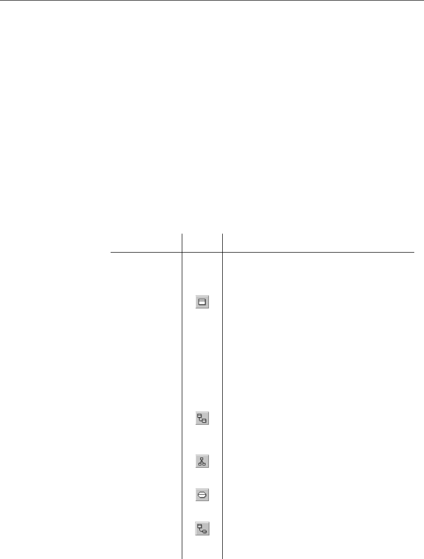
Objects in a CDM
A CDM represents the interaction of the following objects:
Object Tool Description
Domain — Set of values for which a data item is valid
Data item — Elementary piece of information
Entity Person, place, thing, or concept that has charac-
teristics of interest to the enterprise and about
which you want to store information
Entity attribute — Elementary piece of information attached to an
entity
Identifier — Entity attribute, or a combination of entity at-
tributes, whose values uniquely identify each
occurrence of the entity
Relationship Named connection or relation between entities
(Entity Relationship (ER) modeling methodol-
ogy)
Inheritance Special relationship that defines an entity as a
special case of a more general entity
Association Named connection or association between enti-
ties (Merise modeling methodology)
Association
link
Link that connects an association to an entity and
on which you define the cardinality an entity has
relative to another
3

Defining the CDM environment
Defining the CDM environment
The CDM environment includes a set of parameters and configuration
options that define various aspects of the model content and behavior. You
can set these parameters:
♦At model creation
♦After creating a model with default options and parameters
♦When creating a model template
CDM options
♦You can set the following CDM options:
♦All Objects, see section “All objects” on page 5
♦Notation, see section “Notation” on page 6
♦Data item, see section “Data item” on page 9
♦Relationship, see section “Relationship” on page 10
♦Domain/attribute, see section “Domain and attribute” on page 10
4
Chapter 1. Conceptual Data Model Basics
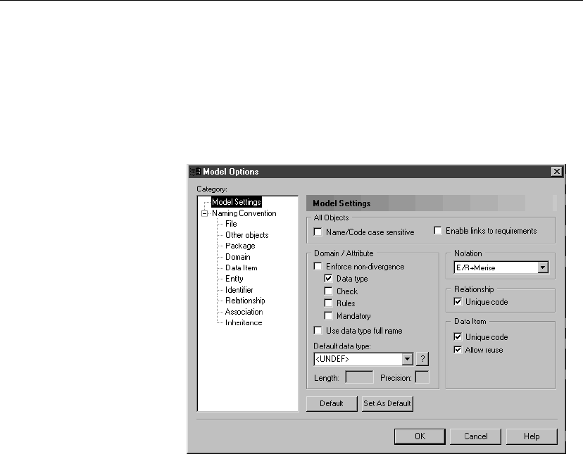
vTo define CDM options
1. Select Tools äModel options.
or
Right-click the diagram background, and select Model Options from the
contextual menu.
The Model Options dialog box opens to the Model Settings page.
2. Select CDM options in the different groupboxes.
3. Click OK.
All objects
Name/Code case
sensitive
You can define the case sensitivity of names and codes for all objects in the
current model. When this check box is selected, it implies that you can have
two objects with identical name or code but different case in the same
namespace.
Unlike other model options, you can modify the name and code case
sensitivity during the design process. However, if you do so, make sure you
run the check model feature to verify if the model does not contain any
duplicate object.
Enable links to
requirements
Requirements are descriptions of customer needs that must be satisfied
during development processes.
You can enable links to requirements for all objects in the current model.
When this check box is selected, it implies that the Requirements tab
5

Defining the CDM environment
appears in the objects property sheet. The Requirements page allows you to
attach requirements to objects; these requirements are defined in the
Requirements models open in the workspace. Attached requirements and
Requirements models are synchronized.
+For more information on requirements, see the
Requirements Model
User’s Guide
.
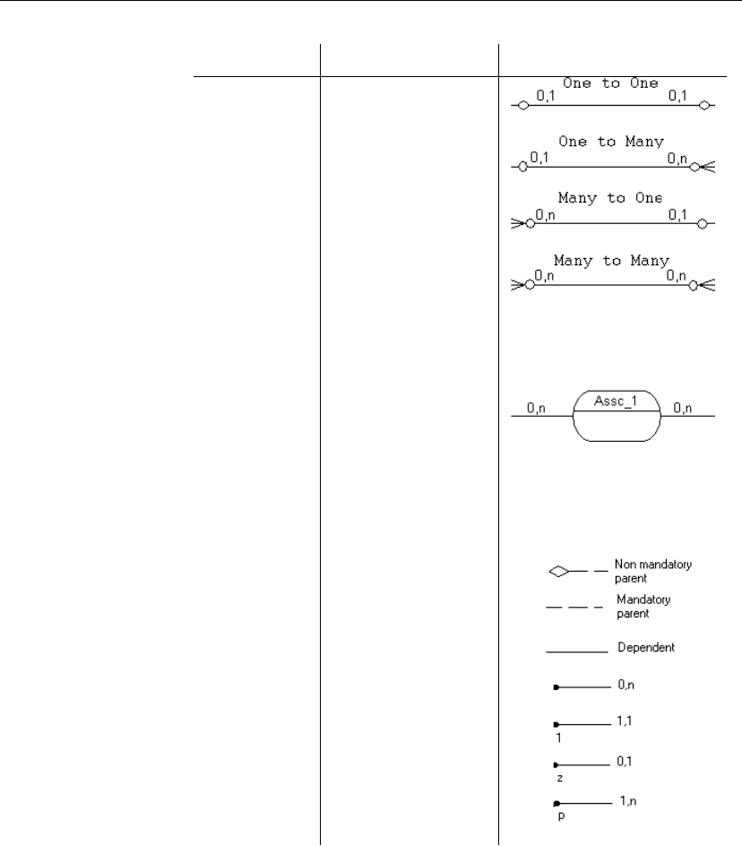
Notation
You can choose to use one or both of the following notation types in the
current model:
6
Chapter 1. Conceptual Data Model Basics
Option Description Symbols
Entity / Rela-
tionships
Entity/relationship no-
tation connects entities
with links representing
one of four relationships
between them. These
relationships have prop-
erties that apply to both
entities involved in the
relationship
Merise Merise notation uses
associations instead of
relationships
E/R + Merise Both entity/relationship
and Merise are used in
the same model
Both types of symbols
IDEF1X Data modeling notation
for relationships and en-
tities. In this notation,
each set of relationship
symbols describes a
combination of the op-
tionality and cardinality
of the entity next to it
The Entity / Relationships notation is the default notation used in this
manual.
When you change notation, all symbols in all diagrams are updated
accordingly.
IDEF1X notation Entities display rounded rectangles when they depend on another entity
7
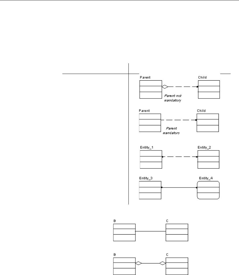
Defining the CDM environment
either through an inheritance link or when the relationship has the dependent
property selected.
Relationships: unlike the other notations, relationship symbols cannot be
parsed in terms of optionality and cardinality independently. Each set of
symbols describes a combination of the optionality and cardinality of the
entity next to it.
Cardinality Representation
One - Many
One - One or Many - Many
One - One dependent dis-
plays a continuous line and
entity with rounded angles
PowerDesigner does not support the following notation:
or
Sub-type or inheritance symbol changes according to the Complete
property:
8
Chapter 1. Conceptual Data Model Basics
Complete Symbol
Yes
No
Data item
You can choose to use one or both of the following data item options in the
current model:
Option Description
Unique code When selected, requires that data items have unique codes
Allow reuse When selected, makes it possible to reuse one data item
as an attribute for more than one entity provided the
attributes have same name and data type and do not
belong to a primary key.
When deselected or when the attribute belongs to a
primary key, the data item cannot be reused. In this case,
if the Unique code check box is selected, a new data
item with identical name but different code is created,
otherwise a new data item with identical name and code
is created
Deleting entity attributes When you delete an entity or entity attributes, data item options determine
whether or not the corresponding data items are also deleted.
The following rules apply to deleted entity attributes:
Data item options Result of deleting an entity attribute
Unique Code
Allow Reuse
Deletes entity attribute
Does not delete corresponding data item
Unique Code only Deletes entity attribute
Does not delete corresponding data item
Allow Reuse only Deletes entity attribute
Deletes corresponding data item if it is not used by
another entity
None Deletes entity attribute
Deletes corresponding data item
9

Defining the CDM environment
Relationship
You can choose to select or clear the Unique code option. When selected, it
requires that relationships have unique codes.
Domain and attribute
From the Attribute and Domain groupbox in Model Options, you can choose
to enforce non-divergence between a domain definition and the attributes
using the domain, for the following attribute properties:
Property Attributes in the domain cannot have divergent
Data type Data type, length, and precision
Check Check parameters
Rules Business rules
Mandatory Entity, association and inheritance attribute mandatory
property
Enforce non-divergence
selected
In this mode, the selected attribute properties must be consistent with the
domain properties.
When you apply the Enforce non-divergence options You are asked if
you want to apply domain properties to attributes attached to the domain in
the current model.
♦If you accept to apply domain properties, the attribute properties are
modified in order to be consistent with domain properties. However, if
the check parameters, business rules, and mandatory value of an attribute
are more constrained than those of the domain, these properties will not
be modified. You may indeed need to define a shorter range of values in
the attribute check parameters, or set an attribute as mandatory while the
domain is not
♦If you refuse to apply domain properties, the attribute is detached from
the domain
When you modify the properties of a domain The properties of the
attributes attached to the domain are updated provided these properties are
selected in the Model Options dialog box.
Attributes cannot be modified When you select an attribute property
under Enforce non-divergence, each instance of that attribute property in the
lists of attributes and the property sheets of attributes appears grayed and can
not be modified.
10

Chapter 1. Conceptual Data Model Basics
If you want to modify an attribute property that is defined as non-divergent,
you must detach the attribute from its domain, or clear the Enforce
non-divergence check box in Model Options.
Enforce non-divergence
deselected
In this mode, it is still possible to select attribute properties under Enforce
non-divergence.
If you select one or more of the attribute properties When you modify
an attribute property so that it diverges from its current domain definition,
you are asked if you want to keep the modifications and diverge from the
domain.
If you do not select attribute properties When you modify an attribute or
domain property resulting in a divergence, you are not warned, and you can
no longer cascade the change on the attribute properties.
Default data type In a CDM, you can select a Default data type to apply to domains and
attributes if no data type is selected for them.
If you modify CDM options, these options apply only to the current CDM.
+For information on other model options, see chapter Working with
Models.
CDM extended model definitions
An extended model definition allows you to expand object definitions and
complement the generation targets and commands. Extended model
definitions are created and saved in files with the XEM extension. You can
create or attach one or several extended model definitions to a model.
Extended model definitions may contain:
♦Extended attributes for applicable objects in order to further define their
properties
Stereotypes to define extended dependencies established between model
objects
+For more information on extended dependencies, see “CDM extended
dependencies” on page 12.
♦Generation targets and commands to complement the generation of an
object model, or to perform an extended generation
+For more information on extended model definitions, see chapter
Extended Model Definitions Reference Guide in the Advanced User
Documentation.
11

Defining the CDM environment
CDM extended dependencies
Extended dependencies are links between CDM objects. These links help to
make object relationships clearer but are not interpreted and checked by
PowerDesigner, as they are meant to be used for documentation purposes
only.
You can complement these links by applying stereotypes. Stereotypes are
used to define extended dependencies between objects in the CDM.
You can type stereotypes directly in the Stereotype column of the object
property sheet or select a value from the dropdown listbox if you have
previously defined stereotypes in an embedded or imported extended model
definition (.XEM).
+For more information on extended dependencies, see section Using
Extended Dependencies in chapter Using the PowerDesigner Interface in the
General Features Guide.
12

Chapter 1. Conceptual Data Model Basics
Defining a CDM
You can create a new CDM, or open an existing CDM.
CDM properties
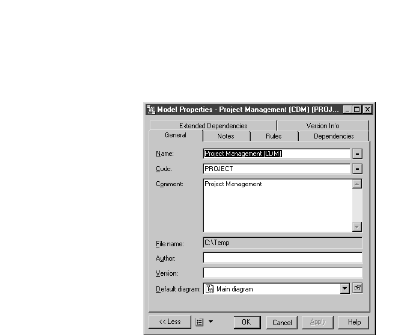
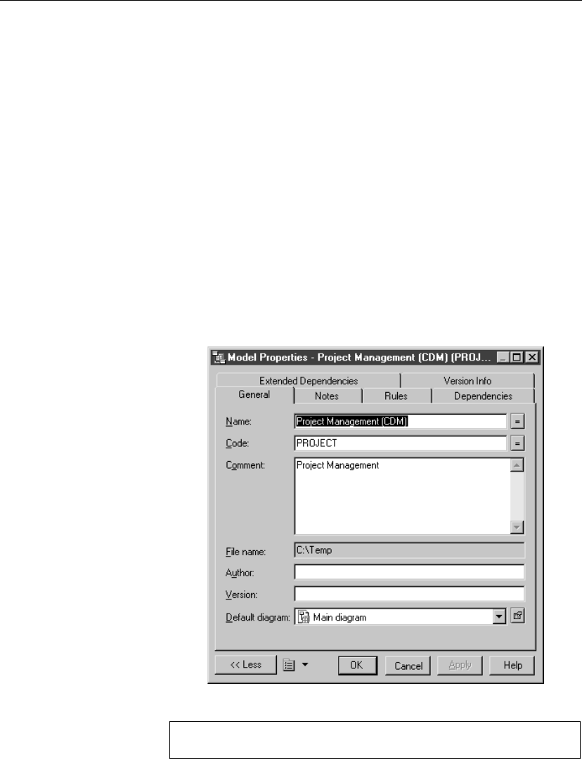
The Model property sheet displays the definition of the current model. From
this property sheet you can modify the model definition.
A CDM has the following model properties:
Property Description
Name The name of the item which should be clear and meaningful,
and should convey the item’s purpose to non-technical users
Code The technical name of the item used for generating code or
scripts, which may be abbreviated, and should not generally
include spaces
Comment Descriptive label for the model
Filename Location of the model file. This box is empty if the model has
never been saved
Author Author of the model. You can insert a name, a space, or nothing.
If you insert a space, the Author field in the title box remains
empty.
If you intentionally leave the box empty, the Author field in the
title box displays the user name from the Version Info page of
the model property sheet
Version Version of the model. You can use this box to display the
repository version or a user defined version of the model. This
parameter is defined in the Title page of the model display
preferences
Default
diagram
Diagram displayed by default when you open the model
vTo modify CDM properties
1. Select Model äModel Properties.
or
Right-click the diagram background, and select Properties from the
contextual menu.
13
Defining a CDM
or
If you have inserted a title box, click the Property tool and then click the
title box.
The model property sheet appears.
2. Type changes to model properties.
3. Click OK.
Creating a CDM
There are several ways to create a CDM:
♦Create a new CDM
♦Create a new CDM using a template
♦Create a new CDM using existing elements (importing one or more
CDMs, importing a ProcessAnalyst Model (.PAM) or an ERwin model
(.ERX) or generating from a PDM or OOM, etc.)
Creating a CDM using the New model option
14
Chapter 1. Conceptual Data Model Basics
vTo create a new CDM using the New model option
1. Select File äNew to display the New dialog box.
2. Select Conceptual Data Model in the list of model types.
3. Select the New model radio button in the upper right part of the dialog
box.
4. Type a model name in the Model name box. The code of the model,
which may be used for script or code generation, is derived from this
name according to the model naming conventions.
5. Click OK.
A new CDM is created in the Workspace.
6. Select Model äModel Properties.
The model property sheet appears.
7. Modify the name and code of the model.
8. Click OK.
Demo example
An example of a CDM is available in the Examples directory.
15
Defining a CDM
Creating a CDM using the New model from template option
vTo create a new CDM using the New model from template option
1. Select File äNew to display the New dialog box.
2. Select Conceptual Data Model in the list of model types.
3. Select the New model from template radio button in the upper right part
of the dialog box.
4. Select a model template from the list.
List of templates
You can select user-defined model templates (use the Change User-
Defined Model Templates Folder tool to specify the user templates
folder) and copy some existing models as model templates using the
Copy Model to User-Defined Model Templates Folder tool.
+For more information on model templates, see section Creating a
model in chapter Managing Models, in the
General Features Guide.
5. Click OK.
A new CDM is created in the Workspace.
6. Select Model äModel Properties.
The model property sheet appears.
7. Type a model name and code.
8. Click OK.
Demo example
An example of an CDM is available in the Examples directory.
Opening an existing CDM
A Conceptual Data Model has the file extension .CDM.
vTo open an existing CDM
1. Select File äOpen to display a standard open file dialog box.
2. Select a file with the .CDM extension.
16

Chapter 1. Conceptual Data Model Basics
3. Click Open.
The model appears in the Browser and the diagram opens in the diagram
window.
Detaching a CDM from the workspace
You can detach a CDM from a workspace. When a CDM is detached from a
Workspace its node is removed from the Browser and it is no longer defined
in the workspace, but the file is not deleted from your operating environment.
vTo detach a CDM from a workspace
1. Right-click the CDM node in the Browser and select Detach From
Workspace from the contextual menu.
A confirmation box asks if you want to save the CDM.
2. Click Yes if you want to save modifications to the CDM.
Select or browse to a directory.
Type a name for the file and click the Save button.
or
Click No if you do not want to save modifications to the file.
The CDM is removed from the workspace.
Saving and closing a CDM
You save a CDM by selecting File äSave.
You close a CDM by selecting File äClose.
17
Defining packages in a CDM
Defining packages in a CDM
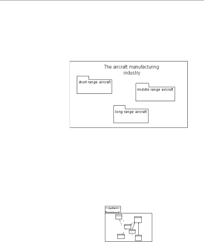
A package is a piece of a model.
+When working with a large model, you can split the model into smaller
subdivisions to avoid manipulating the entire set of model objects. Packages
can be useful to assign portions of a model, representing different tasks and
subject areas, to different development teams.
Package hierarchy You can create several packages at the same hierarchical level within a
model or decompose a package into other packages and continue this
process without limitation in decomposition depth. Each package appears
with a default diagram window. At each level of decomposition you can
create several diagrams.
+For more information on packages, see the
General Features Guide
.
Composite view You can expand a package to have a global view of the whole diagram
content.
To do so, you have to right-click a package and select Composite View from
the contextual menu. You must resize the composite package symbol to
visualize its content:
To return to the package normal view, re-select the Composite View
command in the contextual menu of the expanded package.
Note that if you double-click the composite view, you automatically open
the sub-package diagram.
18

Chapter 1. Conceptual Data Model Basics
+For more information on the composite view feature, see section
Expanding the symbol of a composite object in chapter Model Graphics in
the General Features Guide.
CDM package properties
Packages have properties displayed on property sheets. All packages share
the following common properties:
Property Description
Name The name of the item which should be clear and meaningful,
and should convey the item’s purpose to non-technical users
Code The technical name of the item used for generating code or
scripts, which may be abbreviated, and should not generally
include spaces
Comment Optional label that describes a package and provides additional
information
Stereotype Sub-classification used to extend the semantics of an object
without changing its structure; it can be predefined or user-
defined
Default dia-
gram
Diagram displayed by default when you open the package
Use Parent
Namespace
Defines the package as being the area in which the name of an
object must be unique in order to be used.
Creating a CDM package
A package always belongs to a model. You create a package like any other
model objects.
The name of each package must be unique in the model.
There are several ways to create a package:
♦From a diagram
♦From the Browser
♦From the list of packages
At creation, a package has a default name including a number, this number is
assigned in the order of creation.
19

Defining packages in a CDM
+For more information on the different ways to create a package, see
section Creating an object in chapter managing Objects.
Modifying package display preference
You can modify the following display preference for packages using the
Tools äDisplay Preferences command:
Preference Description
Stereotype Displays the stereotype of the package
20


What is a business rule in CDM?
What is a business rule in CDM?
A business rule is a rule that your business follows. A business rule could be
a government-imposed law, a customer requirement, or an internal guideline.
Starts as an observation Business rules often start as simple observations, for example “customers
call toll-free numbers to place orders.” During the design process they
develop into more detailed expressions, for example what information a
customer supplies when placing an order or how much a customer can spend
based on a credit limit.
Guides modeling Business rules guide and document the creation of a model. For example,
the rule “an employee belongs to only one division” can help you
graphically build the link between an employee and a division.
Complements graphics Business rules complement model graphics with information that is not
easily represented graphically. For example, some rules specify physical
concerns in the form of formulas and validation rules. These technical
expressions do not have a graphical representation.
CDM to PDM generation During generation of a Physical Data Model (PDM), or an Object-Oriented
Model (OOM), from a CDM, the business rules transfer directly into the
PDM or OOM. In the generated model, you further specify business rules to
suit physical concerns.
22

Chapter 2. Using Business Rules in a CDM
Defining a business rule in a CDM
You can define a business rule which can be attached to CDM objects.
Business rule properties in a CDM
A business rule definition includes the following properties:
Property Description
Name The name of the item which should be clear and meaningful,
and should convey the item’s purpose to non-technical users
Code The technical name of the item used for generating code or
scripts, which may be abbreviated, and should not generally
include spaces
Comment Descriptive label for the rule
Stereotype Sub-classification used to extend the semantics of an object
without changing its structure; it can be predefined or user-
defined
Type Indicates whether the rule is a definition, a fact, a formula, or
a validation
A business rule definition also includes the following properties, each with
their respective page:
Property Description
Expression Presence of associated expression
Notes Presence of associated notes
Types of business rule in an CDM
The different business rule types that you can define in a CDM are described
below:
23

Defining a business rule in a CDM
Rule type Describes Example
Definition Properties of the element in
the information system
A customer is a person identi-
fied by a name and an address
Fact Certainty, existence in the
information system
A client may place one or
more orders
Formula Calculation used in the in-
formation system
The total order is the sum of
all the order line costs
Requirement Functional specification in
the information system
The model is designed so that
total losses do not exceed 10%
of total sales
Validation Constraint on a value in the
information system
The sum of all orders for a
client must not be greater than
that client’s allowance
Constraint Additional check constraint
on a value. Constraint busi-
ness rules are used in the
PDM, they are generated in
the database
The start date should be in-
ferior to the end date of a
project
+For more information on constraint type, see section Using constraint
business rules in a PDM in chapter Using Business Rules in a PDM in the
Physical Data Model User’s Guide
.
Creating a business rule in a CDM
Before you create business rules, formulate your rules by asking yourself the
following questions:
♦What business problems do I want to address?
♦Are there any procedures that my system must respect?
♦Do any specifications dictate the scope of my project?
♦Do any constraints limit my options?
♦How do I describe each of these procedures, specifications, and
constraints?
♦How do I classify these descriptions: as definitions, facts, formulas, or
validation rules?
24
Chapter 2. Using Business Rules in a CDM
vTo create a business rule in a CDM
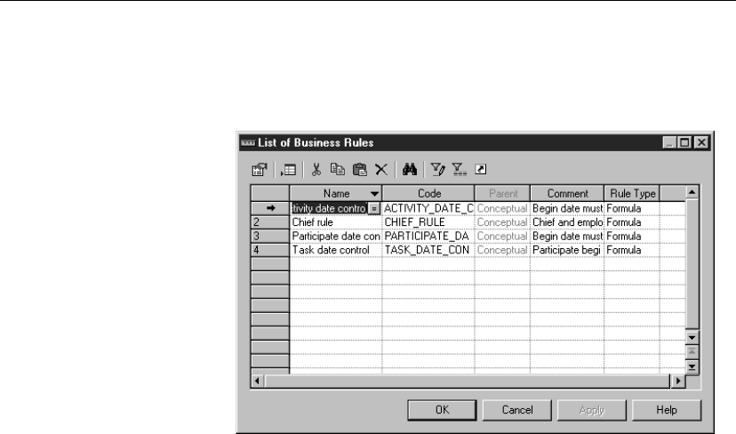
1. Select Model äBusiness Rules to display the List of Business Rules. It
displays the business rules defined for the model.
2. Click a blank line in the list.
or
Click the Add a Row tool.
An arrow appears at the beginning of the line.
3. Type a name and a code for the business rule.
4. Click Apply.
The creation of the new business rule is committed.
5. Click the new business rule line.
An arrow appears at the beginning of the line.
6. Click the Properties tool.
or
Double click the arrow at the beginning of the line.
The property sheet for the new business rule appears.
7. Click the General tab and select a business rule type from the Type
dropdown listbox.
8. Click OK in each of the dialog boxes.
25

Defining a business rule in a CDM
Attaching an expression to a business rule in a CDM
A business rule typically starts out as a description. As you develop your
model and analyze your business problem, you can complete a rule by
adding a technical expression. The syntax of expressions depends on the
target database.
Each business rule can include two types of expression:
♦Server
♦Client
Only the server expression can be generated to a database. You can generate
server expressions as check parameters if they are attached to tables,
domains, or columns.
A client expression is used mainly for documentation purposes. However,
you can insert both types of expression into a trigger or a stored procedure.
vTo attach an expression to a business rule in a CDM
1. Select Model äBusiness Rules to display the List of Business Rules.
2. Double-click the new business rule line to display the business rule
property sheet.
3. Click the Expression tab to display the Expression page.
4. Click the Server tab at the bottom of the page to define a server
expression.
or
Click the Client tab at the bottom of the page to define a client expression.
5. Type an expression in the Expression textbox.
6. Click OK in each of the dialog boxes.
26
Chapter 2. Using Business Rules in a CDM
Working with business rules in a CDM
You can apply a business rule to an object from its property sheet.
Applying a business rule to the current CDM object
You can choose a rule to apply to the current object from its property sheet.
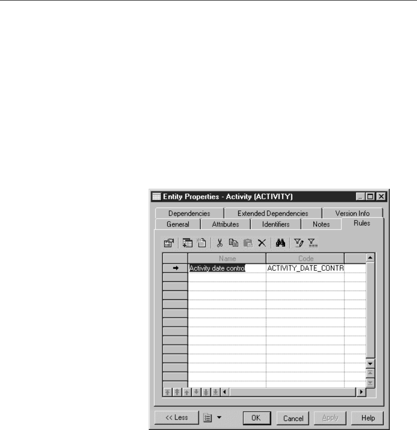
vTo apply a business rule to the current CDM object
1. Double-click an object in the diagram to display the object property sheet.
2. Click the Rules tab to display the Rules page showing any business rules
attached to the object.
3. Click the Add Objects tool to display a selection list of business rules.
It contains a list of all the business rules of the model, except the rules
that already belong to the object.
4. Select the business rules you want to add to the object.
5. Click OK.
The business rules are added to the object and appear in the list of
business rules for the object.
27
Working with business rules in a CDM
6. Click OK.
U Column in the List of business rules
When you apply a business rule to an object, the U (Used) column
beside this business rule is automatically checked in the List of business
rules to indicate that the business rule is used by at least one object in
the model. The U column allows you to visualize unused business rules,
you can then delete them if necessary.
28

CHAPTER 3
Building Conceptual Data Models
About this chapter This chapter describes how to build a Conceptual Data Model (CDM). It
explains the role of each object in a conceptual model and shows how to
modify them in a conceptual diagram.
Contents Topic: page
Defining data items in a CDM 30
Defining domains in a CDM 40
Defining entities in a CDM 52
Defining entity attributes in a CDM 59
Defining identifiers in a CDM 69
Defining relationships in a CDM 75
Defining associations in a CDM 95
Defining inheritances in a CDM 110
Defining check parameters in a CDM 123
29

Defining data items in a CDM
Defining data items in a CDM
Adata item is an elementary piece of information in a model. It represents
a fact or a definition in an information system, which may or may not have
any eventual existence as a modeled object.
You can attach a data item to an entity. It then becomes an entity attribute of
that entity. When a physical data model (PDM) is generated from a CDM,
an entity attribute generates a column in a table.
You can also define a data item, but not attach it to an entity. It remains
defined in the model and can be attached to an entity at any time.
Depending on its defined model options, a data item can be unique in the
model, or unique only for a particular entity. In the latter case, a data item is
equivalent to an entity attribute.
Example In the information system for a publishing company, the last names for
authors and customers are both important pieces of business information.
The data item LAST NAME is created to represent this information. It is
attached to the entities AUTHOR and CUSTOMER, and becomes entity
attributes of those entities.
Another piece of information is the date of birth of each author. The data
item BIRTH DATE is created in the CDM, but as there is no immediate need
for this information in the model, it remains in the CDM, but is not attached
to any entity.
Data item properties
You can access data item properties from the list of data items. Each data
item definition includes the following general properties:
Property Description
Name The name of the item which should be clear and meaningful,
and should convey the item’s purpose to non-technical users
Code The technical name of the item used for generating code or
scripts, which may be abbreviated, and should not generally
include spaces
Comment Descriptive label for the data item
Stereotype Sub-classification used to extend the semantics of an object
without changing its structure; it can be predefined or user-
defined
30

Chapter 3. Building Conceptual Data Models
Property Description
Data type Code indicating the data format, such as N for numeric or A
for alphanumeric, followed by the number of characters
Length Maximum number of characters
Precision Number of places after the decimal point, for data values that
can take a decimal point
Domain Name of the associated domain
A data item definition also includes the following properties, each with their
own respective property sheets:
Property Description
Standard checks Check parameters defined for the domain
Additional checks Domain constraints or validation rules not defined by
standard check parameters
Rules Business rules attached to the domain
Creating a data item
There are several ways to create a data item:
♦From the list of data items
♦From the Browser
At creation, a data item has a default name including a number. This number
is assigned in the order of creation of objects.
+For more information on the different ways to create a data item, see
section Creating an object in chapter Managing objects in the
General
Features Guide
.
31
Defining data items in a CDM
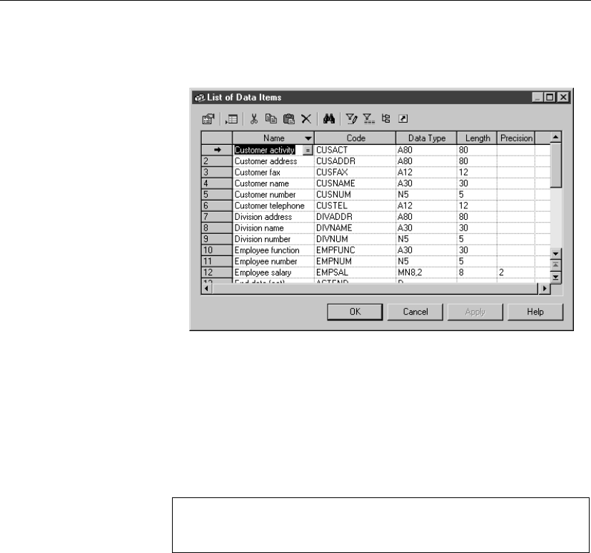
vTo create a data item from the list of data items
1. Select Model äData Items to display the list of data items.
2. Click a blank line in the list.
or
Click the Add a Row tool.
An arrow appears at the beginning of the line.
3. Type a data item name and a data item code.
4. (Optional) Click the Data Type column for the same row.
Display the column you need
If you do not see the column you need, display it with the Customize
Columns and Filter tool. For details, see the
General Features Guide
.
Click the down arrowhead and select a data type from the dropdown
listbox.
or
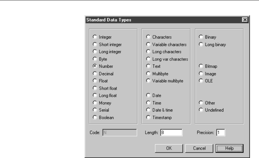
Click the ellipsis button to display the list of standard data types and click
the radio button corresponding to the data type you want to apply.
Type the maximum number of characters for the data item in the Length
box.
If the data type can include values that take a decimal point, type the
number of places after the decimal point in the Precision box.
Click OK.
32
Chapter 3. Building Conceptual Data Models
5. (Optional) Click the Domain column for the same row.
Select a domain from the dropdown listbox.
6. Click OK.
+For more information on selecting a data type for a domain see section
“Selecting a data type for a domain in a CDM” on page 42.
+For information on indicating data type length and precision, see section
“Indicating data type, length, and precision in a CDM” on page 42.
+For more information on attaching a data item to a domain, see section
“Attaching a data item to a domain” on page 36.
Deleting a data item
You delete a data item from the list of data items. When you delete a data
item you also delete all entity attributes using that data item.
vTo delete a data item
1. Select äModel äData Items to display the list of data items.
2. Click a data item in the list.
An arrow appears at the beginning of the line.
33
Defining data items in a CDM
Selecting a line in a list
You can select a line in a list by clicking the number at the beginning of
the line. An arrow replaces the number and the line is selected.
3. Click the arrow at the beginning of the line.
The line is selected.
4. Click the Delete tool.
or
Press DELETE.
The data item and all entity attributes using the data item are deleted.
5. Click OK.
Copying a data item in the list
You can copy and paste a data item in the list of data items. Copying a data
item creates a new data item.
Same code for different data items
If you do not choose the Unique Code data item option, you can use the
same code for different data items as long as each of these data items is
attached to a different entity. You access data item options by selecting
Tools äModel Options.
vTo copy a data item in the list
1. Select Model äData Items to display the list of data items.
It lists the data items defined in the model.
2. Click the line for the data item that you want to copy.
An arrow appears at the beginning of the line.
3. Click the arrow at the beginning of the line.
The line is selected.
4. Click the Copy tool.
5. Click the Paste tool.
The data item is copied to the next line in the list. If the Unique code data
item option is selected in Model Options, the copied data item is
renamed.
34
Chapter 3. Building Conceptual Data Models
Defining code and reuse options for data items
You can define the following options for data items:
Option Result when selected Result when cleared
Unique code Each data item has a unique
code
Different data items can
have the same code
Allow reuse One data item can be an entity
attribute for more than one
entity
One data item can be an
entity attribute for only one
entity
If you do not select Unique Code, two data items can have the same code. In
this case, you differentiate the data items by the entities that use them. The
entities are listed in the Dependencies column of the list of data items.
Item not visible in list
To make an item visible in a list, click the Customize Columns and Filter
tool in the list toolbar, select the appropriate check box from the list of filter
options that appears, and click OK.
vTo define code and reuse options for data items
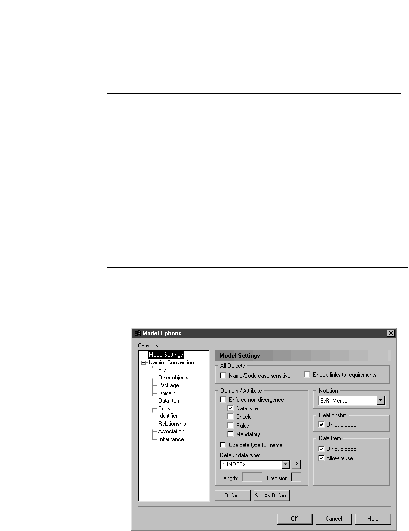
1. Select Tools äModel Options.
The Model Options dialog box opens to the Model Settings page.
35
Defining data items in a CDM
2. Select the Unique Code check box in the Data Item groupbox to require a
unique code for each data item.
or
Clear the Unique Code check box in the Data Item groupbox to allow
more than one data item to have the same code.
3. Select the Allow Reuse check box to allow the one data item to be an
entity attribute for more than one entity.
or
Clear the Allow Reuse check box to prohibit the one data item from
being an entity attribute for more than one entity.
4. Click OK.
Error message The following error message appear when you select the Unique Code, when
it is incompatible with the current CDM:
Error message Solution
Unique Code option could not be
selected because two data items have
the same code:
data_item_code
.
Assign unique codes to all data
items
Attaching a data item to a domain
If you attach a data item to a domain, the domain supplies the data type and
related data characteristics.
The domain applies a standard data type to the data item. It can also apply
length, decimal precision, and check parameters.
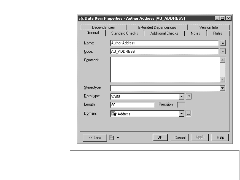
vTo attach a data item to a domain
1. Select Model äData Items to display the list of data items.
2. Click the data item to define.
An arrow appears at the beginning of the line.
3. Click the Properties tool.
or
Double-click the arrow at the beginning of the line.
The data item property sheet opens to the General page.
36
Chapter 3. Building Conceptual Data Models
Opening property sheets at last accessed page
You can choose to open property sheets at the last accessed page by
selecting Tools äGeneral Options äDialog, and selecting the option
Keep Last Tab in the Property Sheets groupbox.
4. Select a domain from the Domain dropdown listbox at the bottom of the
dialog box and click OK.
or
Click the Ellipsis button at the end of the Domain dropdown listbox.
Select a domain from the list that appears and click OK.
You return to the list of data items. In the Data Type column, the data type
for the domain replaces the data type previously defined for the data item.
5. Click OK.
Selecting a data type for a data item
There are two ways to select a data type for a data item.
♦Attach the data item to a domain The domain dictates a standard
data type, a length, and a level of precision, as well as optional check
parameters
♦Manually select a data type You select a standard data type along
with a length, a level of precision, and optional check parameters
37
Defining data items in a CDM
+For more information on attaching a data item to a domain, see
section “Attaching a data item to a domain” on page 36.
About check parameters
Check parameters indicate data ranges and validation rules. You can attach
check parameters to entity attributes, data items, or domains.
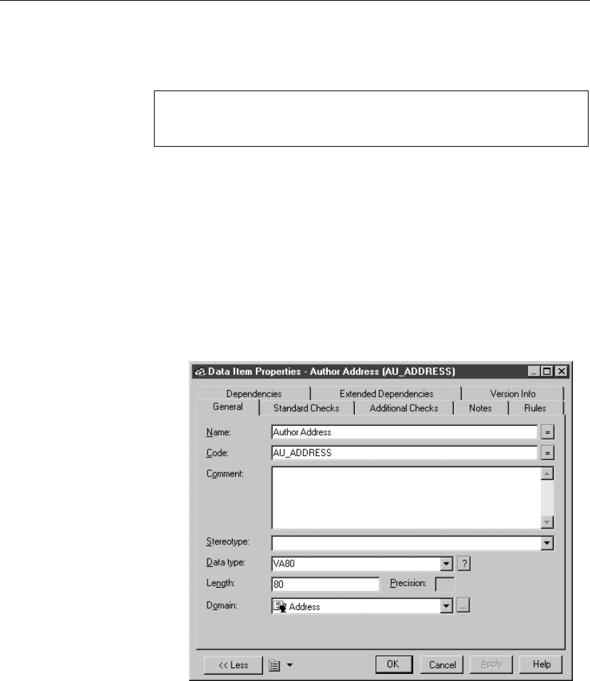
vTo select a data type for a data item
1. Select Model äData Items to display the list of data items.
2. Click the data item to define.
An arrow appears at the beginning of the line.
3. Click the Properties tool.
or
Double-click the arrow at the beginning of the line.
The data item property sheet opens to the General page.
4. Select a data type from the Data Type dropdown listbox.
or
Click the Question mark button at the end of the Data Type dropdown
listbox.
38
Chapter 3. Building Conceptual Data Models
A list of standard data types appears.
Select the radio button corresponding to the data type you want to apply.
Click OK.
Undefined data type
If you do not want to select a data type immediately, you can choose the
<UNDEF>data type.
5. Type the maximum number of characters for the data type in the Length
box.
6. If the data type can include values that take a decimal point, type the
number of places after the decimal point in the Precision box.
7. Click OK.
The new data type appears in the list of data items.
Configuring the display of the list of data items
You can sort the data items in the list:
♦By any property that appears in the column header in the lists
♦Alphabetical or reverse alphabetical order
The listed order is indicated by an arrowhead that appears in the property
column header. Each time you click a column header, you change the listed
order for that column, according to the displayed arrow.
Each arrow type corresponds to the following list orders:
Arrow type Listed order
Down arrow Alphabetically
Up arrow Reverse alphabetically
For example, when you click the column header Name, the data items are
listed by name alphabetically when the Down arrow is indicated, and in
reverse order when the Up arrow is indicated.
vTo configure the display of the list of data items
1. Select Model äData Items to display the list of data items.
2. Click a property title bar.
The listed columns are ordered by the indicated property.
3. Click OK.
39

Defining domains in a CDM
Defining domains in a CDM
Domains help you identify the types of information in your model. Applying
domains to data items makes it easier to standardize data characteristics for
entity attributes in different entities.
In a CDM, you can associate the following information with the domain:
♦Data type, length, and precision
♦Check parameters
♦Business rules
♦Mandatory
Domain properties in a CDM
You can access domain properties from the list of domains.
Each domain definition includes the following general properties:
Property Description
Name The name of the item which should be clear and meaningful,
and should convey the item’s purpose to non-technical users
Code The technical name of the item used for generating code or
scripts, which may be abbreviated, and should not generally
include spaces
Comment Descriptive label for the domain
Stereotype Sub-classification used to extend the semantics of an object
without changing its structure; it can be predefined or user-
defined
Data type Form of the data corresponding to the domain, such as
numeric, alphanumeric, boolean, or others
Length Maximum number of characters
Precision Number of places after the decimal point, for data values that
can take a decimal point
Mandatory Domain values are mandatory for all entity attributes using
that domain
A domain definition can also include the following properties, which have
40
Chapter 3. Building Conceptual Data Models
associated values or information used by entity attributes using the domain:
Property Description
Standard checks Check parameters defined for the domain
Additional checks Domain constraints or validation rules not defined by
standard check parameters
Rules Business rules attached to the domain
Creating a domain in a CDM
There are several ways to create a domain:
♦From the list of domains
♦From the Browser
At creation, a domain has a default name including a number. This number
is assigned in the order of creation of objects.
+For more information on the different ways to create a domain, see
section Creating an object in chapter Managing objects in the
General
Features Guide
.
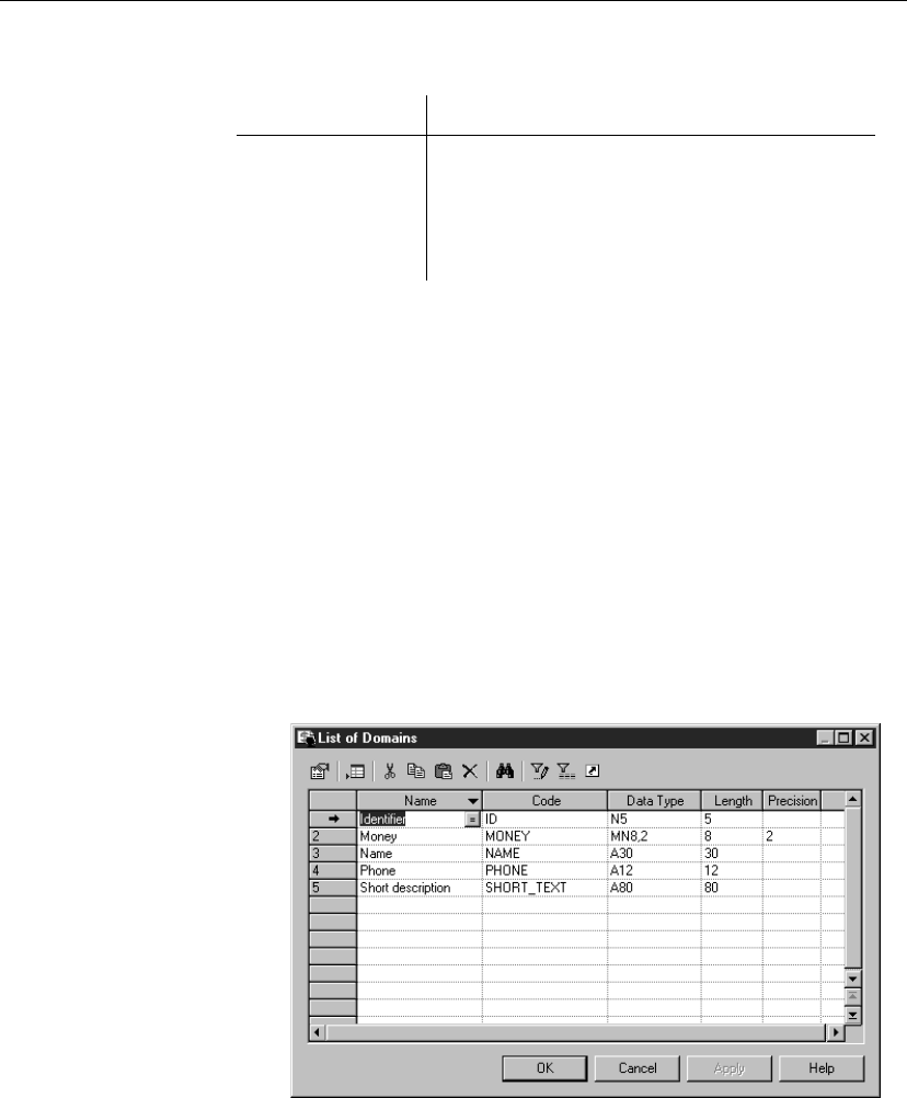
vTo create a domain in a CDM from the list of domain
1. Select Model äDomains to display the list of domains.
2. Click a blank line in the list.
or
Click the Add a Row tool.
41

Defining domains in a CDM
An arrow appears at the beginning of the line.
3. Type a domain name and a domain code.
4. Click Apply.
5. Click the Properties tool.
or
Double-click the arrow at the beginning of the line.
6. Select a data type from the dropdown listbox.
7. Specify length and precision as required.
8. Click OK in each of the dialog boxes.
Indicating data type, length, and precision in a CDM
Length and precision The properties length and precision do not apply to all data types.
Depending on data type, length may indicate a maximum or a fixed number
of characters.
In the list of available data types, a variable indicates where you have to type
a length or precision, as follows:
Variable Replace with
%n Length
%s Length with precision
%p Decimal precision
For example, if you are using Sybase Adaptive Server Anywhere and you
choose the data type char(%n), you can choose a length of ten by typing
char(10).
Undefined data type All target DBMS allow you to select the <undefined>data type. The
<undefined>data type indicates which domains remain without data types.
If an <undefined>data type is present when you generate your database, it
is replaced by the default data type for your database.
Selecting a data type for a domain in a CDM
You can select a data type for a domain in two ways:
♦From the list of domains
♦From the domain property sheet
42
Chapter 3. Building Conceptual Data Models
The list of standard data
types
When you select a data type for a domain from its property sheet, you can
choose from a list of standard data types. This list presents the available data
types in full details instead of the abbreviated format used in the data type
dropdown listbox in the list of domains.
Selecting a data type for a CDM domain from the list
vTo select a data type for a CDM domain from the list
1. Select Model äDomains to display the list of domains.
2. Click the domain to define.
An arrow appears at the beginning of the line.
3. Click the Data Type column.
4. Select a data type from the Data Type dropdown listbox.
Defining a data type later
If you do not want to select a data type immediately, you can choose the
<UNDEF>data type.
5. Click OK.
The data type appears in the Data Type column of the list of domains.
Selecting a data type for a CDM domain from its property sheet
vTo select a data type for a CDM domain from its property sheet
1. Select Model äDomains to display the list of domains.
2. Click the domain to define.
An arrow appears at the beginning of the line.
3. Click the Properties tool.
or
Double-click the arrow at the beginning of the line.
The domain property sheet appears.
4. Select a data type from the Data Type dropdown listbox.
Selecting a data type from a list of standard data types
To select a data type from a list of standard data types, click the Question
Mark button at the end of the Data Type dropdown listbox, and select
the radio button for a data type from the list that appears.
43
Defining domains in a CDM
5. Type the maximum number of characters for the data item in the Length
box.
6. If the data type can include values that take a decimal point, type the
number of places after the decimal point in the Precision box.
7. Click OK.
The change of data type appears in the list of domains.
Undefined data type
If you do not want to select a data type immediately, you can choose the
<Undefined>data type.
Selecting a data type from a list of standard data types in a CDM
You can select a data type from a list of standard data types. This is the same
list that is available in the Physical Data Model. PowerDesigner
automatically maps the standard data type to a conceptual data type.
The length and precision are properties that do not apply to all data types.
Furthermore, depending on data type, length may indicate a maximum or a
fixed number of characters.
The tables below indicates the data types for which you can specify:
♦Fixed length
♦Maximum length
♦Decimal precision
Numeric data types
Conceptual data
type
Physical data type
(depending on the
DBMS)
Content Length
Integer int / INTEGER 32-bit integer —
Short Integer smallint / SMALL-
INT
16-bit integer —
Long Integer int / INTEGER 32-bit integer —
Byte tinyint / SMALLINT 256 values —
Number numeric / NUMBER Numbers with
a fixed deci-
mal point
Fixed
44

Chapter 3. Building Conceptual Data Models
Conceptual data
type
Physical data type
(depending on the
DBMS)
Content Length
Decimal decimal / NUMBER Numbers with
a fixed deci-
mal point
Fixed
Float float / FLOAT 32-bit floating
point numbers
Fixed
Short Float real / FLOAT Less than 32-
bit point deci-
mal number ♦—
Long Float double precision /
BINARY DOUBLE
64-bit floating
point numbers
—
Money money / NUMBER Numbers with
a fixed deci-
mal point
Fixed
Serial numeric / NUMBER Automatically
incremented
numbers
Fixed
Boolean bit / SMALLINT Two oppos-
ing values
(true/false;
yes/no; 1/0)
—
Character data types
45

Defining domains in a CDM
Conceptual data
type
Physical data
type (depend-
ing on the
DBMS)
Content Length
Characters char / CHAR Character strings Fixed
Variable Charac-
ters
varchar / VAR-
CHAR2
Character strings Maximum
Long Characters varchar /
CLOB
Character strings Maximum
Long Var Charac-
ters
text / CLOB Character strings Maximum
Text text / CLOB Character strings Maximum
Multibyte nchar /
NCHAR
Multibyte character
strings
Fixed
Variable Multibyte nvarchar /
NVARCHAR2
Multibyte character
strings
Maximum
Time data types
Conceptual data type Physical data type
(depending on the
DBMS)
Content
Date date / DATE Day, month, year
Time time / DATE Hour, minute, and second
Date & Time datetime / DATE Date and time
Timestamp timestamp / TIMES-
TAMP
System date and time
Other data types
46

Chapter 3. Building Conceptual Data Models
Conceptual data
type
Physical data
type (depend-
ing on the
DBMS)
Content Length
Binary binary / RAW Binary strings Maximum
Long Binary image / BLOB Binary strings Maximum
Bitmap image / BLOB Images in bitmap
format (BMP)
Maximum
Image image / BLOB Images Maximum
OLE image / BLOB OLE links Maximum
Other — User-defined data
type
—
Undefined undefined Not yet defined data
type
—
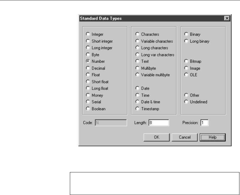
vTo select a data type from a list of standard data types in a CDM
1. Select Model äDomains to display the list of domains.
2. Click the domain to define and display an arrow at the beginning of the
line.
3. Click the Properties tool.
or
Double-click the arrow at the beginning of the line.
The domain property sheet appears.
4. Click the Question Mark button next to the Data Type dropdown listbox.
Selecting from the Data Type dropdown listbox
You can also select a data type directly from the Data Type dropdown
listbox.
A list of standard data types appears.
47
Defining domains in a CDM
5. Click the radio button corresponding to the data type you want to apply.
The code for the data type appears in the Code box.
Undefined data type
If you do not want to select a data type immediately, you can choose the
Undefined data type.
6. Type the maximum number of characters for the data type in the Length
box.
7. If the data type includes values after a decimal point, type the number of
places after the decimal point in the Precision box.
8. Click OK.
The change of data type appears in the Data Type box.
Modifying domain properties in a CDM
You can modify domain properties from the domain property sheet.
When you modify domain properties, a confirmation box appears asking if
you want to modify the data items and attributes currently using the domain.
48
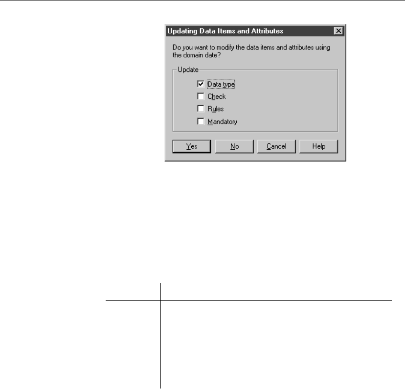
Chapter 3. Building Conceptual Data Models
The Data Type check box is automatically selected and available for an
update, depending on the options set to enforce non-divergence from a
domain.
For information on domain divergence, see section “Enforcing
non-divergence from domains in a CDM” on page 50.
You can also select other properties (Check, Rules) that will be updated in
their use of the domain.
You can now click one of the following buttons with the following effects:
Button Effect
Yes The data items currently using the domain are modified
according to the update
No The data items currently using the domain are not modified
according to the update but the current modification is accepted
if domain divergence is allowed in the model options
Cancel The update is cancelled and nothing is changed
vTo modify domain properties in a CDM
1. Select Model äDomains to display the list of domains.
2. Click a domain from the list.
An arrow appears at the beginning of the line.
3. Click the Properties tool.
or
Double-click the arrow at the beginning of the line.
The Domain property sheet appears.
49

Defining domains in a CDM
4. Type changes to domain properties.
or
Click on a page tab.
Type or select domain properties as required.
5. Click OK.
If the domain is used by one or more data items, an update confirmation
box appears asking if you want to modify domain properties for the data
items using the domain.
6. Select the properties that you want to update for all data items using the
domain.
7. Click Yes.
Enforcing non-divergence from domains in a CDM
From the Model Options dialog box, you can choose to enforce
non-divergence between a domain and the data items and attributes that use
the domain.
+For more information on non-divergence enforcement, see section
Defining CDM Options in chapter Conceptual Data Model Basics.
50
Chapter 3. Building Conceptual Data Models
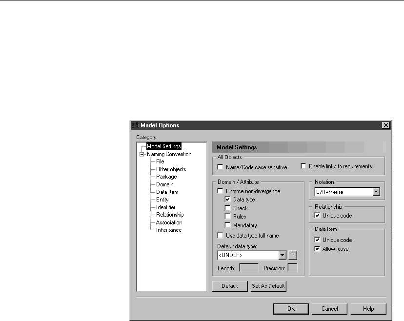
vTo enforce domain non-divergence in a CDM
1. Select Tools äModel Options.
or
Right click the diagram background.
Select Model Options from the contextual menu.
The Model Options dialog box opens to the Model Settings page.
2. Select the Enforce non-divergence check box in the Domain/Attribute
groupbox.
3. Select check boxes for the entity attribute properties that are not
permitted to diverge from the domain definition.
4. Click OK.
51

Defining entities in a CDM
Defining entities in a CDM
An entity represents an object defined within the information system about
which you want to store information. For example, in a model concerning
employees and divisions, the entities are Employee and Division.
An occurrence of an entity is an individual element belonging to the entity.
For example, the employee Martin is one occurrence of the entity Employee.
Entity properties
You can double-click any entity symbol in the diagram to display its
property sheet:
Property Description
Name The name of the item which should be clear and meaning-
ful, and should convey the item’s purpose to non-technical
users
Code The technical name of the item used for generating code or
scripts, which may be abbreviated, and should not generally
include spaces
Comment Descriptive label for the entity
Stereotype Sub-classification used to extend the semantics of an object
without changing its structure; it can be predefined or
user-defined
Number Estimated number of occurrences in the physical database
for the entity (the number of records)
Generate Indicates if the entity will generate a table in a PDM
An entity definition also includes the following properties, each with their
own respective property sheets that can be accessed independently of the
entity:
♦Attributes
♦Identifiers
♦Rules
Creating an entity
There are several ways to create an entity:
♦From a diagram
52
Chapter 3. Building Conceptual Data Models
♦From the Browser
♦From the list of entities
At creation, an entity has a default name including a number. This number is
assigned in the order of creation of objects.
+For more information on the different ways to create an entity, see
section Creating an object in chapter Managing objects in the
General
Features Guide
.
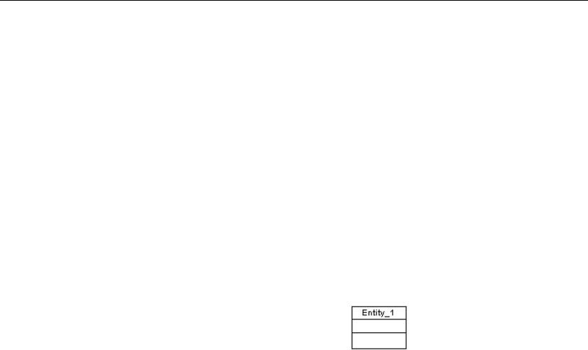
vTo create an entity from a diagram
1. Click the Entity tool in the Palette.
2. Click anywhere in the diagram.
The following symbol appears at the click position:
3. Click the Pointer tool.
or
Click the right mouse button.
You release the Entity tool.
4. Double-click the new entity symbol in the diagram to display the entity
property sheet.
5. Type a name and a code.
53
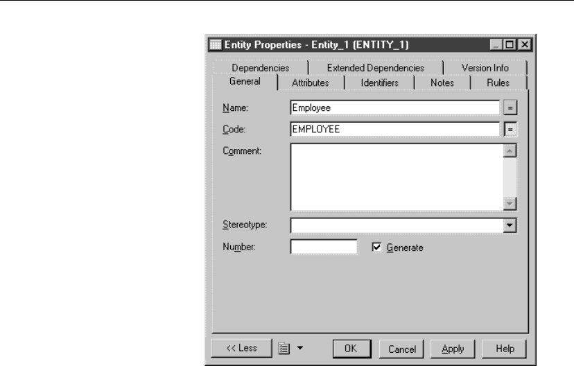
Defining entities in a CDM
6. Click OK.
Modifying entity properties
You can modify the entity properties using the following methods:
♦From the entity property sheet
♦From the list of entities
+For more information on the different ways to modify the entity
properties, see section Modifying object properties in chapter Managing
objects in the
General Features Guide
.
Copying an entity
You can make a copy of an entity within the same model or between models.
When you copy an entity, the selections for the model options Unique code
and Allow reuse determine the way that identifiers and entity attributes are
copied and named.
The following rules apply to copied entities. The indicated selections for
Unique code and Allow reuse apply to the model that receives the copied
entity:
54

Chapter 3. Building Conceptual Data Models
Data item options
selected
Result of copying an entity
Unique Code
Allow Reuse
New entity with new name and code
New identifier with new name code
Reuses other entity attributes
Unique Code only New entity with new name and code
New identifier with new name and code
New attributes with new names and codes
Allow Reuse only New entity with new name and code
New identifier with same name and code
Reuses other entity attributes
None New entity with new name and code
New identifier with same name code
New entity attributes with same names and codes
vTo copy an entity within a model
1. Select an entity in the CDM.
2. Select Edit äCopy.
Select Edit äPaste.
or
Press CTRL and drag the entity to a new position in the diagram.
The new entity appears in the diagram
vTo copy an entity to a different model
1. Select an entity in a CDM.
2. Select Edit äCopy.
Click in the diagram of the target model.
Select Edit äPaste.
or
Press CTRL and drag the entity to the diagram of the target model.
The new entity appears in the diagram of the target model.
55
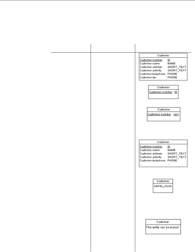
Defining entities in a CDM
Modifying the entity display preferences
You can modify the following display preferences for an entity using the
Tools äDisplay Preferences command:
Preference Display description Examples
All attributes All attributes includ-
ing all identifying
attributes
Primary attributes Only entity attributes
that are primary iden-
tifier attributes
Identifying at-
tributes
All attributes that are
defined as identifier
attributes for the en-
tity, including primary
identifier attributes
Display limit (x) Number of entity
attributes shown de-
pending on defined
value of x. In the
example, x is 5
Identifiers All identifier attributes
for the entity are listed
at the bottom of the
entity symbol
Stereotype Stereotype of the en-
tity
—
Comment Comment of the entity.
When selected, all
other check boxes are
deselected, except for
Stereotype
56
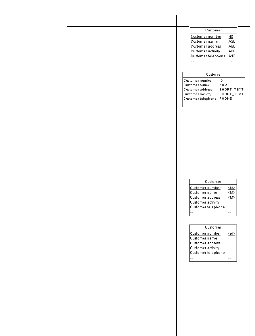
Chapter 3. Building Conceptual Data Models
Preference Display description Examples
Data types Data type for each
entity attribute
Replace by Do-
mains
Domain for each entity
attribute. You can only
display domains when
the Data type check
box is selected
Domains Domain of an attribute
in an entity. This dis-
play option interacts
with the selection for
Data types. As a re-
sult, there are four
display options
See Display domain and data
type for options and examples
Mandatory The letter <
M
>be-
side each entity at-
tribute when it is
mandatory
Identifier indicators <
pi
>indicators next
to attributes that are
primary identifier at-
tributes
<
ai
>indicators next
to identifier attributes
that are not primary
identifier attributes
Stereotype (Entity
attributes)
Stereotype of the en-
tity attributes
—
Stereotype (Entity
identifiers)
Stereotype of the en-
tity identifiers
—
57
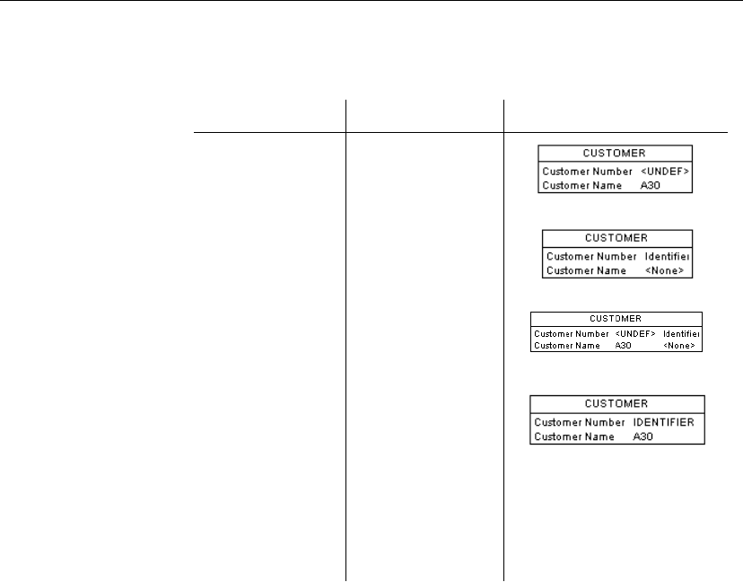
Defining entities in a CDM
Display domain and data
type
You can display the domain of an attribute in the symbol of an entity. There
are four display options available:
Selected check box Result Symbol
Data type Displays only the
data type, if it exists
Domains Displays only the
domain, if it exists
Data types
Domains
Displays both data
type and domain, if
they exist
Data types
Replace by domains
If domain exists and
data type does not
exist, then displays
domain.
If domain does not
exist and data type
exists, then displays
data type.
58

Chapter 3. Building Conceptual Data Models
Defining entity attributes in a CDM
Entity attributes are data items attached to an entity. When you generate a
Physical Data Model (PDM) from a Conceptual Data Model (CDM), entity
attributes are generated as columns in tables (entities).
Entity attribute properties
You can access entity attribute properties from the list of entity attributes or
from the entity property sheet.
Each entity attribute definition includes the following properties:
Property Description
Name The name of the item which should be clear and meaningful,
and should convey the item’s purpose to non-technical users
Code The technical name of the item used for generating code or
scripts, which may be abbreviated, and should not generally
include spaces
Comment Descriptive label for the entity attribute
Stereotype Sub-classification used to extend the semantics of an object
without changing its structure; it can be predefined or user-
defined
Data type Form of the data corresponding to the entity attribute, such as
numeric, alphanumeric, boolean, or others
Length Maximum length of the data type
Precision Maximum number of places after the decimal point
Domain Name of the associated domain
Primary
Identifier
Indicates whether or not the entity attribute is the primary
identifier of the current entity
Displayed When selected, the attribute is displayed in the entity symbol.
When cleared, the attribute is not displayed in the entity symbol
Mandatory Indicates whether or not this entity attribute must be assigned a
value
An entity attribute also includes the following properties:
59
Defining entity attributes in a CDM
Property Description
Rules Business rules associated with entity attribute
Standard
Checks
Common data constraints
Additional
Checks
Customized rules for data validation
Notes Description associated with entity
Creating an entity attribute
There are several ways to create an entity attribute:
♦From a data item used as an entity attribute
♦From the attribute list for an entity
At creation, an entity attribute has a default name including a number. This
number is assigned in the order of creation of objects.
Using a data item as an entity attribute
You can use the data item as an entity attribute by attaching it to an entity.
This choice does not create a new data item. The resulting entity attribute
has the same code as the data item.
Reusing a data item as
an entity attribute
If you select Allow Reuse as a data item option, the same data item can be
an entity attribute for more than one entity. However, you cannot reuse a
data item that is an identifier.
Reusing a data item does not create a new data item. The data item and the
corresponding entity attributes have the same code.
Setting data item options
You set data item options by selecting Tools äModel Options.
A new data item can be added by creating a new one or copying an existing
one as the basis for a new one. The following specific tools are available to
add data items:
60
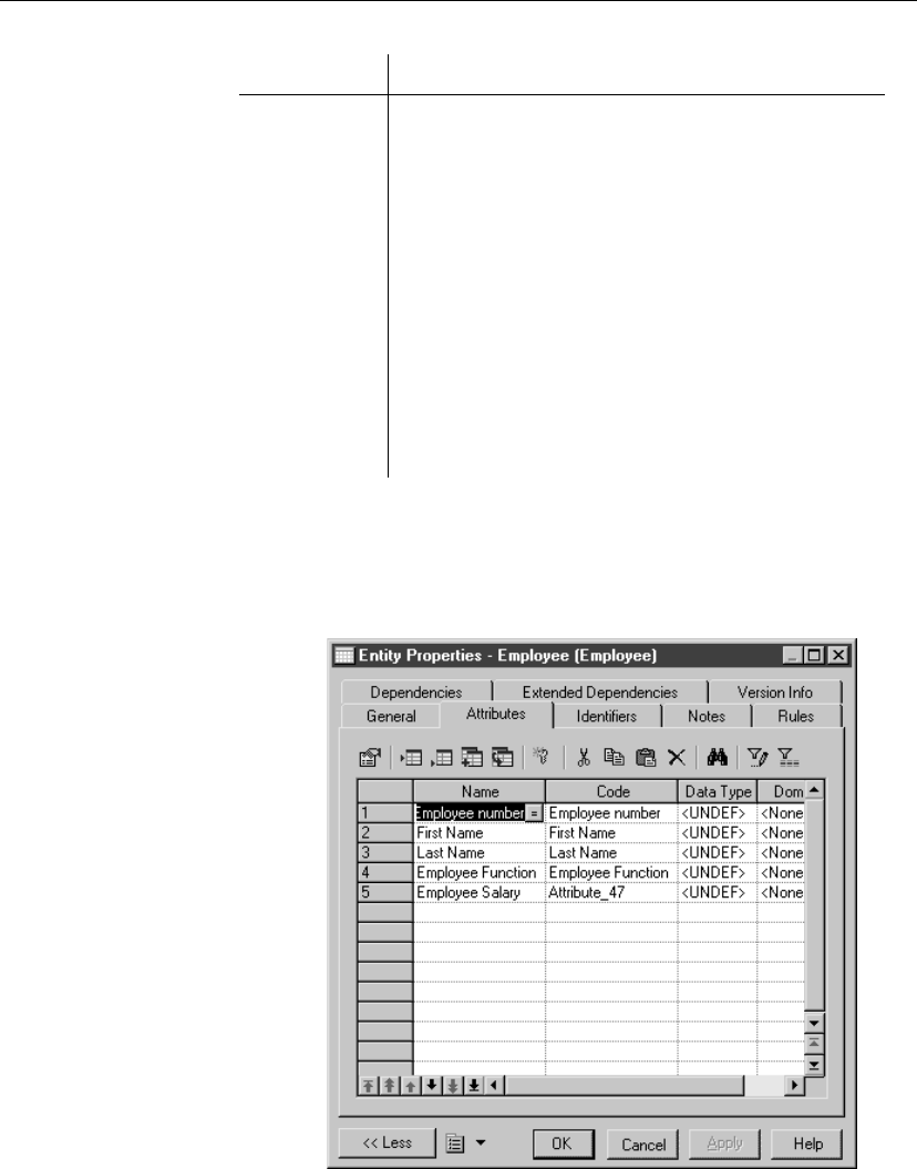
Chapter 3. Building Conceptual Data Models
Tool Description/Effect of Model Options
Add Data Item This tool is only available if the Allow Reuse option is
selected in Model Options.
This tool displays all model data items. If you click this
tool and select a data item that is unused in the list of entity
attributes, a new data item is created and added to the list.
If you click this tool and select a currently used data item,
the data item is copied and used as the basis for a new data
item
Reuse Data
Item
No new unused data item can be created with this tool.
This tool displays all model data items. If you click this
tool and select a data item that is used in the list of entity
attributes, the data item is copied, added to the list and used
as the basis for a new data item
vTo use a data item as an entity attribute
1. Select the Attributes tab in the entity property sheet to display the
corresponding page.
It lists entity attributes associated with the entity.
2. Click the Add Data Item tool.
61
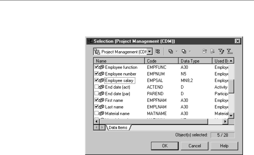
Defining entity attributes in a CDM
A Selection box appears listing all of the available data items.
3. Select one or more data items.
4. Click OK.
The selected data items are added to the list of entity attributes.
5. Click OK in each of the dialog boxes.
Creating an entity attribute from the list of entity attributes
You can create an entity attribute directly in the list of entity attributes for an
entity. When you create an entity attribute, it is automatically added to the
list of data items. If you select Allow Reuse as a model option, the new data
item can be used as an entity attribute for other entities.
vTo create an entity attribute from the list of entity attributes
1. Select the Attributes tab in the entity property sheet to display the
corresponding page.
It lists entity attributes associated with the entity.
2. Click a blank line in the list.
or
Click the Add a Row tool.
An arrow appears at the beginning of the line.
62

Chapter 3. Building Conceptual Data Models
3. Type an entity attribute name and an entity attribute code.
Automatically reuse a data item
If you select the data item options Allow Reuse and Unique Code and
you type the name of a data item that is already in use, you automatically
reuse the data item.
4. Click OK.
Attaching an entity attribute to a domain
If you attach an entity attribute to a domain, the domain supplies the data
type and related data characteristics. It may also indicate check parameters
and business rules.
vTo attach an entity attribute to a domain
1. Double-click an entity in the diagram to display its property sheet.
2. Click the Attributes tab to display the corresponding page.
It list entity attributes associated with the entity.
3. Click an entity attribute to define.
An arrow appears at the beginning of the line.
4. Click the Properties tool.
or
Double-click the arrow at the beginning of the line.
The entity attribute property sheet opens to the General page.
63
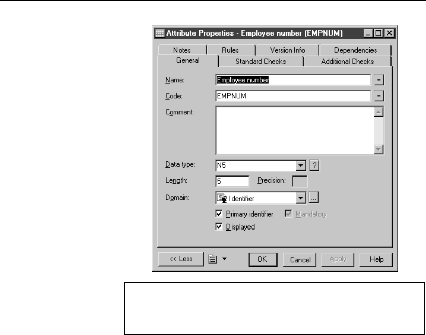
Defining entity attributes in a CDM
Opening property sheets at last accessed page
You can choose to open property sheets at the last accessed page by
selecting Tools äGeneral Options äDialog, and selecting the option
Keep Last Tab in the Property Sheets groupbox.
5. Select a domain from the Domain dropdown listbox at the bottom of the
dialog box.
or
Click the Ellipsis button at the end of the Domain dropdown listbox.
The list of domains appears.
Select a domain from the list.
Click OK.
6. Click OK.
You return to the Entity attributes page. In the Data Type column, the
data type of the domain replaces the data type previously defined for the
entity attribute.
7. Click OK.
Selecting a data type for an entity attribute
There are two ways to select a data type for an entity attribute:
64
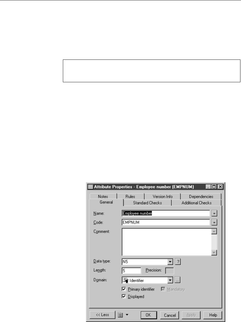
Chapter 3. Building Conceptual Data Models
♦Attach the entity attribute to a domain The domain dictates a
standard data type, a length, and a level of precision, as well as optional
check parameters.
♦Manually select the data type You select a standard data type along
with a length, a level of precision, and optional check parameters
About check parameters
Check parameters indicate data ranges and validation rule. You can attach
check parameters to entity attributes, data items, or domains.
vTo select a data type for an entity attribute
1. Double-click an entity in the diagram to display the entity property sheet.
2. Click the Attributes tab to display the corresponding page.
It lists entity attributes associated with the entity.
3. Click the Entity attribute to define.
An arrow appears at the beginning of the line.
4. Click the Properties tool.
or
Double-click the arrow at the beginning of the line.
The entity attribute property sheet opens to the General page.
65
Defining entity attributes in a CDM
5. Select a data type from the Data Type dropdown listbox.
or
Click the Question mark button at the end of the Data Type dropdown
listbox.
A list of standard data types supported by PowerDesigner appears.
Select the radio button corresponding to the data type you want to apply.
Undefined data type
If you do not want to select a data type immediately, you can choose the
<UNDEF>data type.
6. Type the maximum number of characters for the data type in the Length
box.
7. If the data type can include values that take a decimal point, type the
number of places after the decimal point in the Precision box.
8. Click OK.
You return to the Entity attributes page. The change of data type appears
in the list of entity attributes.
Defining an entity attribute as mandatory or optional
If an entity attribute is mandatory, every entity occurrence must have a value
for that entity attribute. If an entity attribute is optional, entity occurrences
do not have to have a value for that entity attribute.
By default all identifiers are mandatory.
vTo define an entity attribute as mandatory or optional
1. Double-click an entity in the diagram to display the entity property sheet.
2. Click the Attributes tab to display the corresponding page.
It lists entity attributes associated with the entity.
3. Click the Entity attribute to define.
An arrow appears at the beginning of the line.
4. Click the Properties tool.
or
Double-click the arrow at the beginning of the line.
The entity attribute property sheet opens to the General page.
66

Chapter 3. Building Conceptual Data Models
5. Select the Mandatory check box at the bottom of the dialog box to make
the entity attribute mandatory.
or
Clear the Mandatory check box to make the entity attribute optional.
You cannot clear the Mandatory check box for an identifier because it
must always be mandatory.
6. Click OK in each of the dialog boxes.
Deleting entity attributes
When you delete an entity or entity attributes, data item options determine
whether or not the corresponding data items are also deleted.
The following rules apply to deleted entity attributes:
Data item options Result of deleting an entity attribute
Unique Code
Allow Reuse
Deletes entity attribute
Does not delete corresponding data item
Unique Code only Deletes entity attribute
Does not delete corresponding data item
Allow Reuse only Deletes entity attribute
Deletes corresponding data item if it is not used by
another entity
None Deletes entity attribute
Deletes corresponding data item
Arranging a list of entity attributes
Each entity has its own list of entity attributes.
In a list of entity attributes, you can arrange items in any order. When you
generate a PDM, the order of entity attributes becomes the order of column
generation.
vTo arrange a list of entity attributes
1. Double-click an entity symbol to display the entity property sheet.
2. Click the Attributes tab to display the corresponding page.
67

Defining entity attributes in a CDM
It lists the data items attached to the entity.
3. Select one or more entity attributes in the list.
4. Use the arrow buttons at the bottom left corner of the list to move the
items in the list.
5. Click OK.
68

Chapter 3. Building Conceptual Data Models
Defining identifiers in a CDM
An identifier is an entity attribute, or a combination of entity attributes,
whose values uniquely identify each occurrence of the entity. An identifier is
the CDM equivalent of a primary key or an alternate key in a physical data
model (PDM).
Each entity must have at least one identifier. If an entity has only one
identifier, it is designated by default as the primary identifier for the entity. A
primary identifier is the main identifier for an entity.
Designating an identifier
You designate an identifier from the Identifiers page of the entity property
sheet.
+For information on how to display identifiers in an entity symbol, see
section “Modifying the entity display preferences” on page 56.
You can also create an identifier from the list of entity attributes: click the
Attributes tab in the entity property sheet, select one or more attributes to
include into the identifier and click the Create Identifier tool.
vTo designate an identifier
1. Double-click an entity in the diagram to display the entity property sheet.
2. Click the Identifiers tab to display the corresponding page.
It lists identifiers defined for the entity.
69
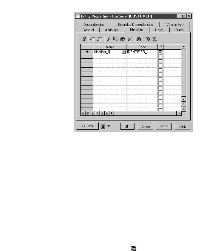
Defining identifiers in a CDM
3. Click a blank line in the list.
or
Click the Add a Row tool.
An arrow appears at the beginning of the line.
4. Type an identifier name and code.
5. Click Apply.
The constraint name and code are committed.
6. Double-click the new identifier name to display the identifier property
sheet.
7. Click the Attributes tab to display the corresponding page.
It lists all entity attributes defined for the identifier. At identifier creation,
the list is empty.
8. Click the Add Attributes tool.
A list of entity attributes defined for the entity appears.
70
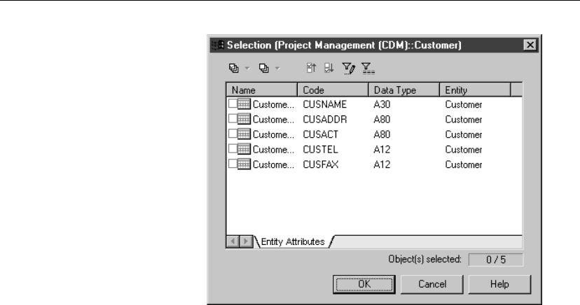
Chapter 3. Building Conceptual Data Models
9. Select check boxes for one or more entity attributes that you want to
designate as an identifier.
10. Click OK in each of the dialog boxes.
Adding attributes to an entity identifier
You can add attributes to an entity identifier.
71
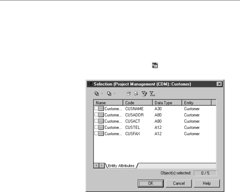
Defining identifiers in a CDM
vTo add attributes to an identifier
1. Click the Attributes tab in the identifier property sheet to display the
corresponding page.
It lists the attributes currently defined for the identifier.
2. Click the Add Attributes tool.
A list of entity attributes defined for the entity appears.
3. Select check boxes for one or more entity attributes that you want to
designate as an identifier.
4. Click OK in each of the dialog boxes.
Designating a primary identifier
Aprimary identifier is an identifier that has been designated as the main
identifier for the entity. It generates a primary key in a PDM.
vTo designate a primary identifier
1. Double-click an entity in the diagram to display the entity property sheet.
2. Click the Identifiers tab to display the corresponding page.
It lists the Identifiers defined for the entity.
3. Select an identifier from the list.
An arrow appears at the beginning of the line.
72
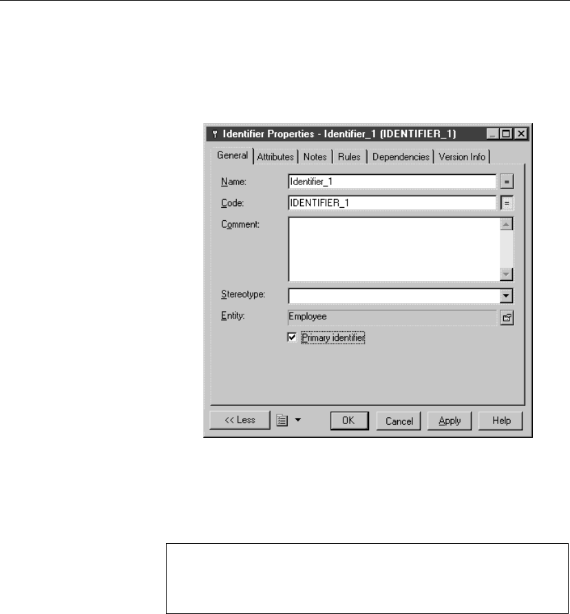
Chapter 3. Building Conceptual Data Models
4. Click the Property tool.
or
Double-click the arrow at the beginning of the line.
The identifier property sheet appears.
5. Select the Primary Identifier check box.
6. Click OK.
You return to the Identifiers page. The P column is selected for the new
primary identifier.
Item not visible in list
To make an item visible in a list, click the Customize Columns and
Filter tool in the list toolbar, select the appropriate check box from the
list of filter options that appears, and click OK.
7. Click OK.
Modifying an identifier name or code from the list
You can modify an identifier name and code using the following methods:
♦From the identifier property sheet accessible from the entity property
sheet
73

Defining identifiers in a CDM
♦From the list of identifiers
+For more information on the different ways to modify the identifier
properties, see section Modifying object properties in chapter Managing
objects in the
General Features Guide
.
74

Chapter 3. Building Conceptual Data Models
Defining relationships in a CDM
A relationship is a link between entities. For example, in a CDM that
manages human resources, the relationship Member links the entities
Employee and Team, because employees can be members of teams. This
relationship expresses that each employee works in a team and that each
team has employees.
An occurrence of a relationship corresponds to one instance of each of the
two entities involved in the relationship. For example,
the employee Martin
working in the Marketing team
is one occurrence of the relationship
Member.
Relationships and
association
Relationships are used in the Entity Relationship (ER) and IDEF1X
modeling methodologies. In PowerDesigner you can also use associations
used in the Merise methodology to link entities. You can use either
relationships or associations exclusively, or combine the two methodologies
in the same model.
+For more information on using associations, see section “Defining
associations in a CDM” on page 95.
This section analyzes relationships in the Entity Relationship methodology,
for more information on IDEF1X, see section CDM Options in chapter
Conceptual Data Model Basics.
Relationship properties
You can double-click any relationship symbol in the diagram to display its
properties:
Property Description
Name The name of the item which should be clear and meaningful,
and should convey the item’s purpose to non-technical users
Code The technical name of the item used for generating code or
scripts, which may be abbreviated, and should not generally
include spaces
Comment Descriptive label for the relationship
Stereotype Sub-classification used to extend the semantics of an object
without changing its structure; it can be predefined or user-
defined
Entity1
Entity2
The two entities linked by the relationship
75
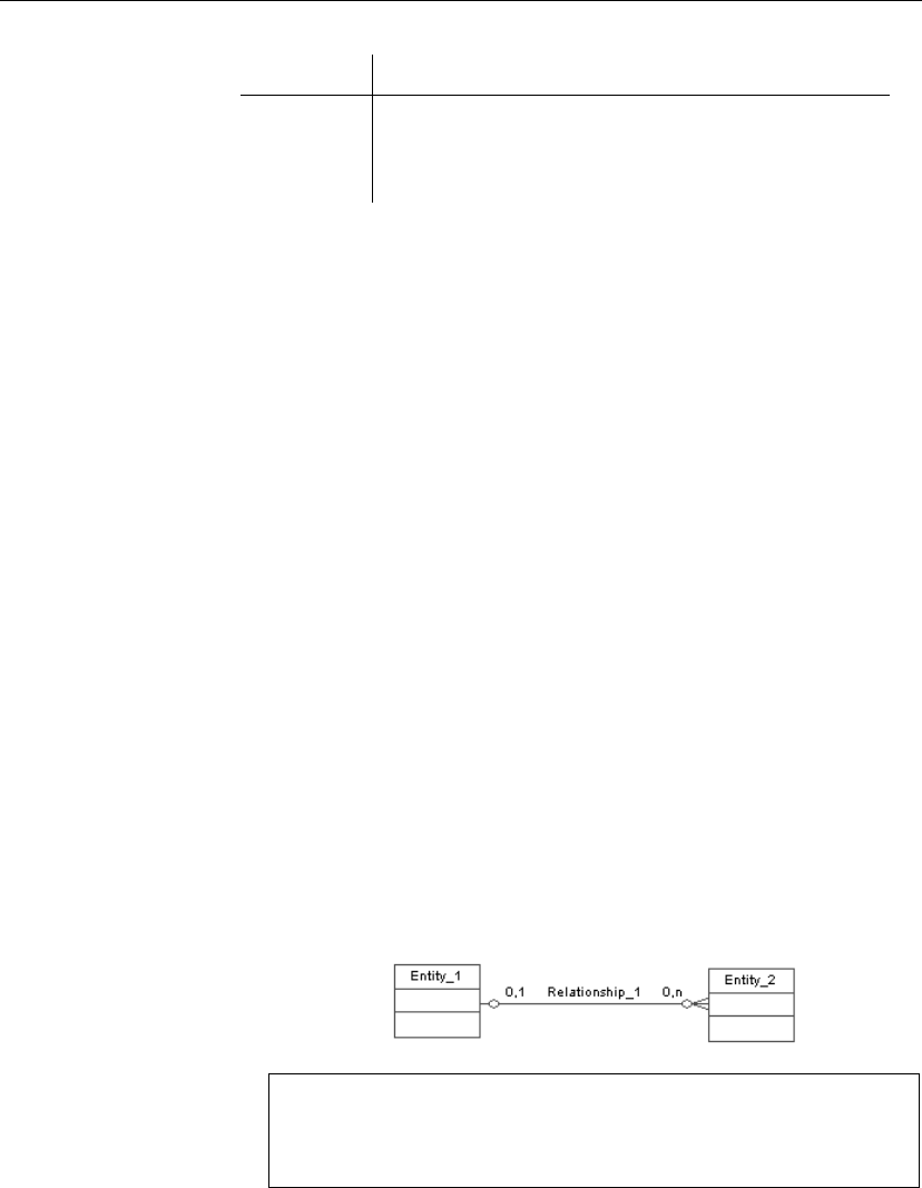
Defining relationships in a CDM
Property Description
Generate Indicates to generate a reference in PDM
Cardinalities Contains data about cardinality as the number of instances of
one entity in relation to another entity
Creating a relationship
There are several ways to create a relationship between entities:
♦From a diagram
♦From the Browser
♦From the list of relationships
At creation, a relationship has a default name including a number. This
number is assigned in the order of creation of objects.
When you create a relationship from the Browser or from the list of
relationships, you must previously define source and destination objects for
the relationship.
+For more information on the different ways to create a relationship, see
section Creating an object in chapter Managing objects in the
General
Features Guide
.
vTo create a relationship from a diagram
1. Click the Relationship tool in the Palette.
2. Click inside the first entity and while continuing to hold down the mouse
button, drag the cursor to a second entity. Release the mouse button
inside the second entity.
A relationship symbol appears between the two entities.
Dragging a relationship to a different entity
You change the entity at either end of a relationship by clicking the
relationship to select it, holding the CTRL key down, and dragging one
of the attach points to a different entity.
76
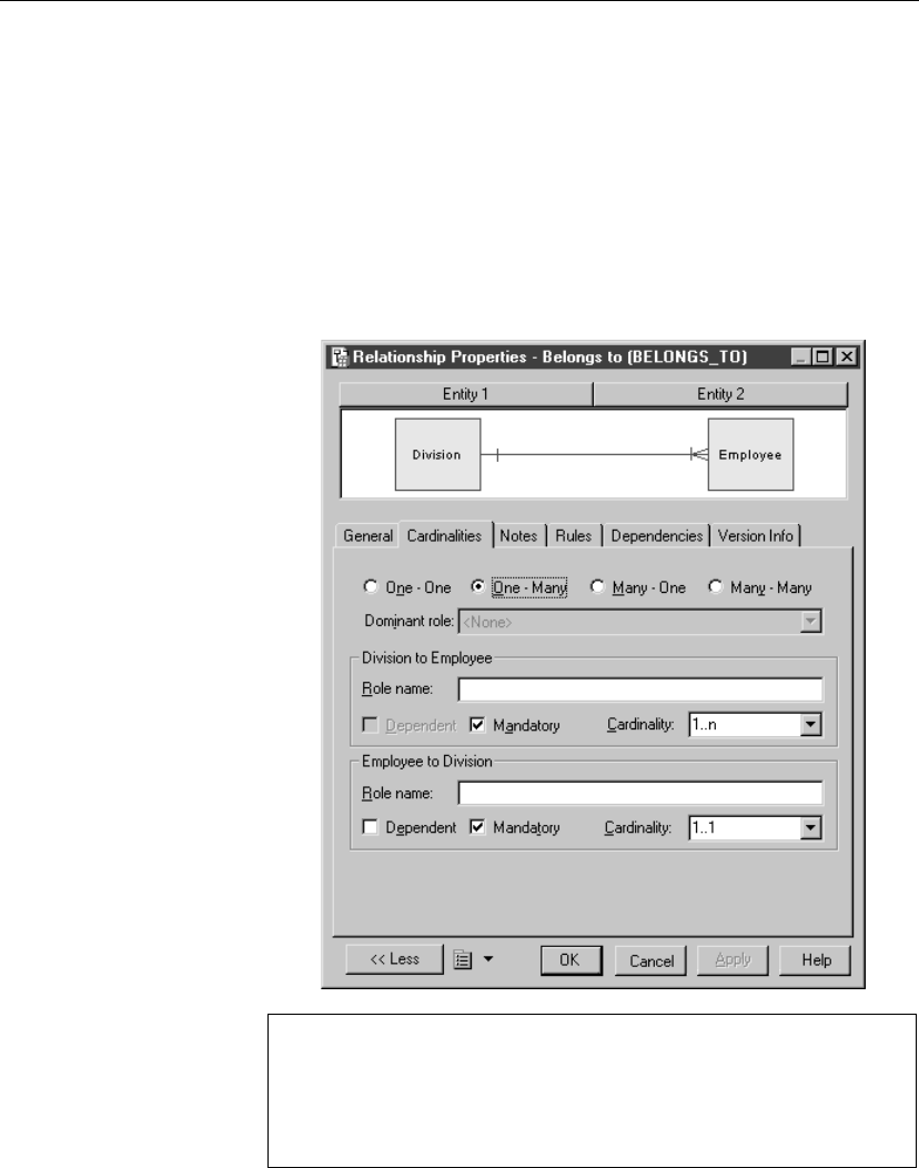
Chapter 3. Building Conceptual Data Models
3. Click the Pointer tool.
or
Click the right mouse button.
You release the Relationship tool.
4. Double-click the new relationship symbol in the diagram to display the
relationship property sheet. It displays the definition of the selected
relationship.
5. Type a relationship name and a relationship code.
Opening the property sheet of objects at ends
You can open the property sheet of the source and destination objects
by clicking the Entity 1 and Entity 2 buttons located in the upper part of
the flow property sheet.
6. Type or select relationship properties as required in the tabbed pages.
77
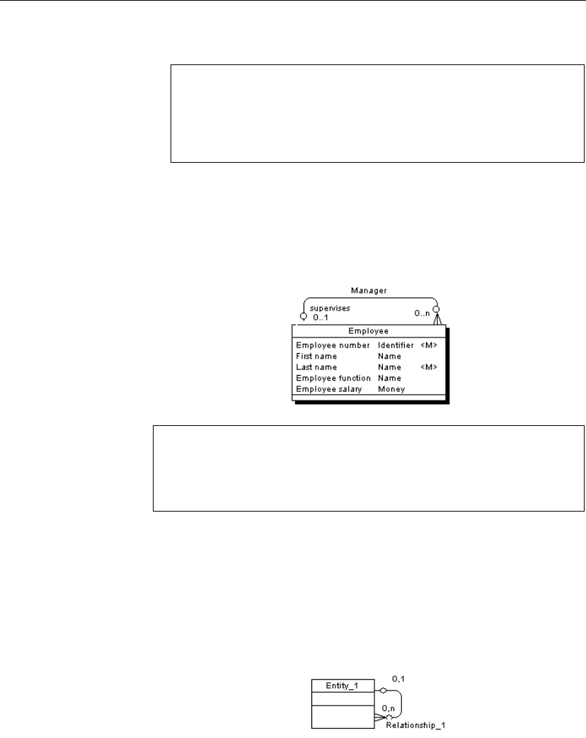
Defining relationships in a CDM
7. Click OK.
Displaying relationships from the entity property sheet
Relationships linked to an entity are also displayed in the entity property
sheet. You can display those relationships from the Relationships tabbed
page of the Dependencies page.
Creating a reflexive relationship
A reflexive relationship is a relationship between an entity and itself.
Example The reflexive relationship
Supervise
expresses that an employee (Manager)
can supervise other employees.
Getting neat relationship lines
To obtain clean lines with rounded corners when you create a reflexive
relationship, select Display Preferences äFormat äRelationship and
modify the Line Style with the appropriate type from the Corners dropdown
listbox.
vTo create a reflexive relationship
1. Click the Relationship tool in the Palette.
2. Click inside the first entity and while continuing to hold down the mouse
button, drag the cursor to a space next to the entity.
3. Click the entity.
A relationship symbol loops back to the same entity.
78
Chapter 3. Building Conceptual Data Models
Entity dependencies
In the Dependencies page of the entity, you can see two identical occur-
rences of the relationship, this is to indicate that the relationship is reflexive
and serves as origin and destination for the link
Modifying relationship properties
You can modify the relationship properties using the following methods:
♦From the relationship property sheet
♦From the list of relationships
+For more information on the different ways to modify the relationship
properties, see section Modifying object properties in chapter Managing
objects in the
General Features Guide
.
Defining a code option for relationships
You can define the following code option for relationships:
Option Result when selected Result when cleared
Unique code Each relationship has a
unique code
Different relationships can have
the same code
If you do not select Unique Code, two relationships can have the same code.
In this case, you differentiate the relationships by the entities they link.
Error message The following error message appears when the option you choose is
incompatible with the current CDM:
Error message Solution
Unique Code option could not be
selected because at least two re-
lationships have the same code:
relationship_code
.
Change the code of one relationship
79
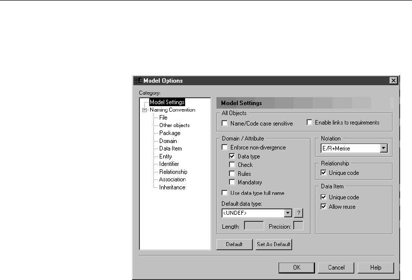
Defining relationships in a CDM
vTo define a code option for relationships
1. Select Tools äModel Options.
The Model Options dialog box opens to the Model Settings page.
2. Select the Unique Code check box in the Relationship groupbox to
require a unique code for each relationship.
or
Clear the Unique Code check box in the Relationship groupbox to allow
more than one relationship to have the same code.
3. Click OK.
Defining cardinality for relationships
Cardinality indicates the number of instances (none, one, or many) of an
entity in relation to another entity. You can select the following values for
cardinality:
80

Chapter 3. Building Conceptual Data Models
Cardinality Symbol Description
One-to-one <1..1>One instance of the first entity can correspond
to only one instance of the second entity
One-to-many <1..n>One instance of the first entity can correspond
to more than one instance of the second entity
Many-to-one <n..1>More than one instance of the first entity can
correspond to the same one instance of the
second entity
Many-to-many <n..n>More than one instance of the first entity can
correspond to more than one instance of the
second entity
The Cardinalities page contains a groupbox for each direction of the
relationship. The title of the groupbox takes the following form:
’EntityA’to ’EntityB’
The following properties apply to each direction of the relationship:
Property Description
Dominant role In a One to One relationship, indicates to generate a
reference in the PDM for this direction of the relationship
only
Role name Text that describes the relationship of EntityA to EntityB
Dependent Indicates that each instance of the EntityA is identified by
an instance of EntityB
Mandatory Indicates that each instance of the EntityA requires an
instance of the EntityB
Cardinality Maximum and minimum number of instances of EntityA
in relation to EntityB (if mandatory, at least 1). You can
indicate the following cardinalities:
0..1
0..n
1..1
1..n
Termination points In a diagram, termination points indicate cardinality at each end of a
relationship. A termination with a single contact point denotes a cardinality
81

Defining relationships in a CDM
of one. A termination with three contact points denotes a cardinality of
many.
Termination point Cardinality
One
Many
+For more information on IDEF1X cardinality notation, see section CDM
options in chapter Conceptual Data Model Basics.
vTo define cardinality
1. Double-click the relationship to display the relationship property sheet.
It displays the definition of the selected relationship.
2. Click the Cardinalities tab to display the corresponding page.
3. Select one of the cardinality radio buttons.
4. Click OK.
Example The Cardinalities page below indicates that an employee must belong to one
and only one division, while a division must include one or more employees.
82
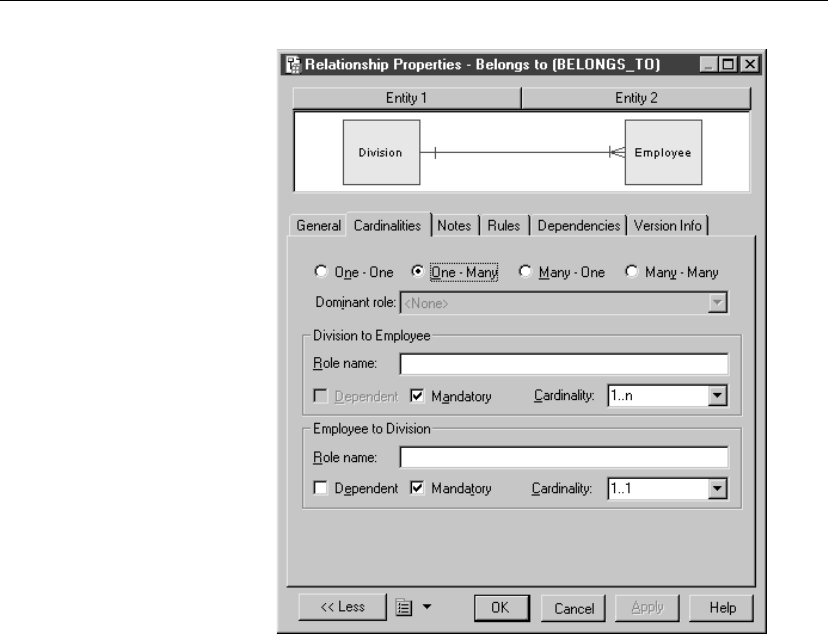
Chapter 3. Building Conceptual Data Models
Defining a mandatory relationship
The property Mandatory indicates whether the relationship between entities
is mandatory or optional. You define options from the point of view of both
entities in the relationship.
Termination points In the resulting relationship symbol, a bar represents a mandatory
relationship. A circle represents an optional relationship.
83
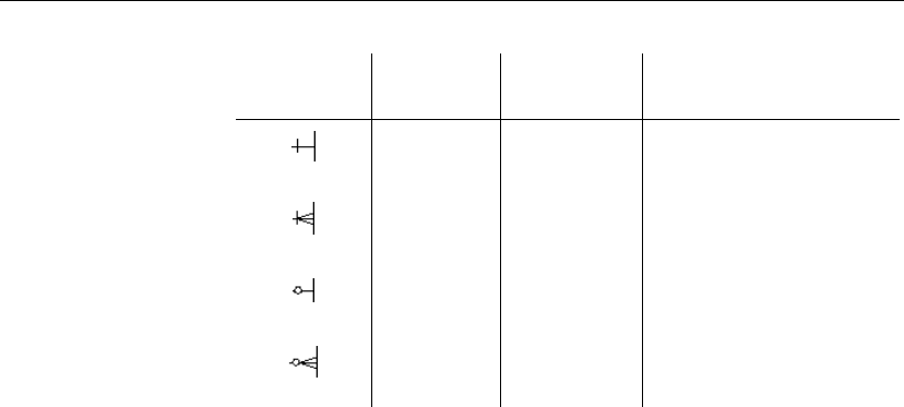
Defining relationships in a CDM
Termination
point
Existence Cardinality Description
Mandatory One Must exist one and only one
Mandatory Many Must exist one or more
Optional One May exist one, or none
Optional Many May exist one or more, or
none
+For more information on IDEF1X existence notation, see section CDM
options in chapter Conceptual Data Model Basics.
vTo define a mandatory relationship
1. Double-click the relationship symbol to display the relationship property
sheet.
2. Click the Cardinalities tab to display the corresponding page.
3. Select the Mandatory check box in one or both of the groupboxes
corresponding to a relationship direction.
4. Click OK.
Example The Cardinalities page below indicates that the subcontract relationship is
optional from customer to project, and mandatory from project to customer.
Each project must have a customer, while each customer does not have to
have a project.
84
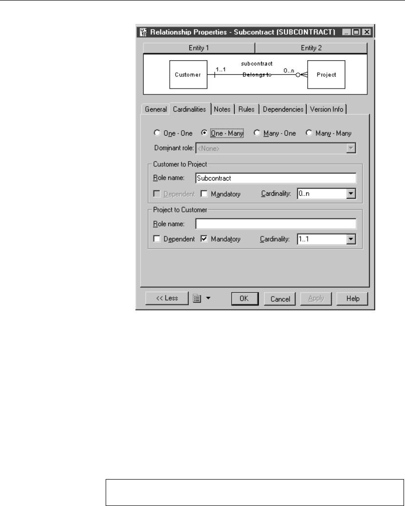
Chapter 3. Building Conceptual Data Models
Defining a dependent relationship
In a dependent relationship, one entity is partially identified by another.
Each entity must have an identifier. In some cases, however, the attributes of
an entity are not sufficient to identify an occurrence of the entity. For these
entities, their identifiers incorporate the identifier of another entity with
which they have a dependent relationship.
Example An entity named Task has two entity attributes, TASK NAME and TASK
COST. A task may be performed in many different projects and the task cost
will vary with each project. To identify each occurrence of TASK COST the
unique Task entity identifier is the compound of its
Task name
entity
attribute and the
Project number
identifier from the Project entity.
Many to many relationship
A many-to-many relationship cannot be a dependent relationship.
Termination points In the resulting model, a triangle just before the termination point of the
relationship indicates a dependent relationship. The triangle points away
85

Defining relationships in a CDM
from the dependent entity.
For example, here Entity B depends on Entity A.
The bar indicates that the relationship in not only dependent, but also
mandatory. The single contact point indicates the one-to-one cardinality of
the relationship. In this case, for each occurrence of Entity B there must be
only one occurrence of Entity A.
The tip of the triangle shown above has a bar to note a mandatory
relationship: every occurrence of Entity A requires an occurrence of Entity
B.
+For more information on IDEF1X notation, see section CDM options in
chapter Conceptual Data Model Basics.
vTo define a dependent relationship
1. Double-click the relationship symbol to display the relationship property
sheet.
It displays the definition of the selected relationship.
2. Click the Cardinalities tab to display the corresponding page.
3. Select or clear the Dependent check box in each groupbox corresponding
to a relationship direction.
4. Click OK.
Example The property sheet below shows that the Task entity is dependent on the
Project entity.
86
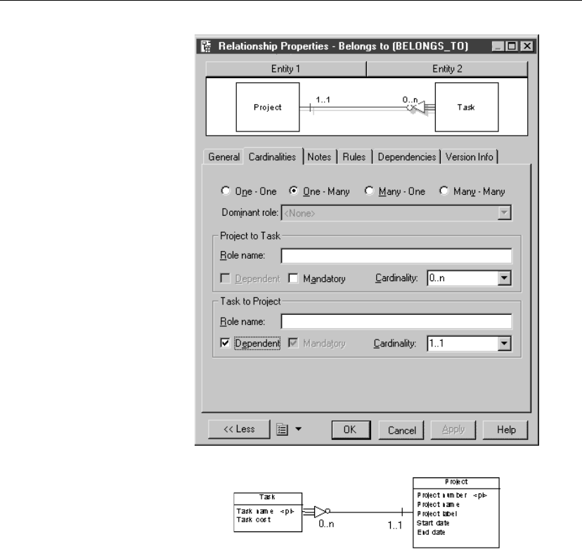
Chapter 3. Building Conceptual Data Models
The relationship pictured here expresses this dependency.
The circle at the tip of the triangle indicates that occurrences of the Project
entity do not require an occurrence of the Task entity. But an occurrence of
the Task entity requires an occurrence of the Project entity on which it
depends.
Defining a dominant relationship
In a one-to-one relationship, you can define one direction of the relationship
as dominant. If you define a dominant direction, the one-to-one relationship
generates one reference in the PDM. The dominant entity becomes the
parent table. If you do not define a dominant direction, the one-to-one
relationship generates two references.
87
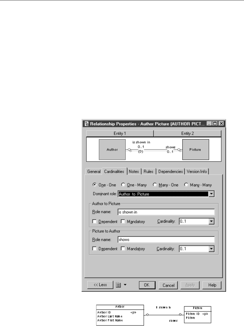
Defining relationships in a CDM
vTo define a dominant relationship
1. Double-click a relationship symbol in the diagram to display the
relationship property sheet.
It displays the definition of the selected relationship.
2. Click the Cardinalities tab to display the corresponding page.
3. Select the One to One check box.
4. Select the direction for the dominance from the Dominant Role
dropdown listbox.
5. Click OK.
Example For example, in the property sheet below, the Author to Picture direction is
dominant in the relationship.
The relationship pictured here shows the one-to-one relationship.
88
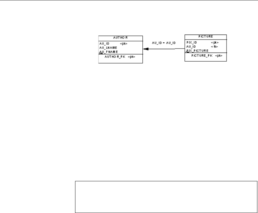
Chapter 3. Building Conceptual Data Models
In a PDM, this relationship generates the following reference: Author is the
parent table, and its primary key migrates to the Picture table as foreign key.
Changing a relationship into an associative entity
You can transform a relationship into an associative entity linked by two
relationships. Next, you can attach entity attributes to this associative entity,
that you could not attach to the relationship.
The associative entity gets the name and code of the relationship. The two
new relationships handle cardinality properties.
vTo change a relationship into an associative entity
1. Right-click a relationship symbol.
The relationship contextual menu appears.
2. Select Change to Entity äStandard from the contextual menu.
Customizing entity wizard
You can also select Change to Entity äWizard from the contextual
menu. A step by step wizard takes you through a more detailed
procedure for defining an associative entity.
An associative entity with two relationships replaces the relationship.
The associative entity takes the name of the original relationship.
Creating an associative entity using the Change to Entity Wizard
You can use the Change to Entity wizard to transform a relationship into an
associative entity linked by two relationships.
You create the associative entity in three stages. Each stage corresponds to a
page in the wizard process. You move through each stage by clicking the
Next button.
You can enter the following information for each stage of the wizard:
89

Defining relationships in a CDM
Stage Description
Customizing
entity
You type the name and code for the new entity. You can also
type a description in the Comment box
Customizing
Relationship
(New entity
to first entity)
You type the name and code for the relationship that will
be created between the first entity and the new entity. The
first entity is defined as Entity 1 in the property sheet for the
original relationship. You can also enter a role name for the
relationship and a cardinality value
Customizing
Relationship
(New entity
to second
entity)
You type the name and code for the relationship that will be
created between the new entity and the second entity. The
second entity is defined as Entity 2 in the property sheet for
the original relationship. You can also enter a role name for
the relationship and a cardinality value
vTo create an associative entity using the Change to Entity Wizard
1. Right-click a relationship symbol.
A contextual menu appears.
2. Select äChange to Entity äWizard to display the Customizing Entity
page.
3. Type an entity name and an entity code.
4. Click Next.
The Customizing Relationship page appears.
5. Fill in details for the first entity to new entity relationship.
6. Click Next.
The second Customizing Relationship page appears.
7. Fill in details for the new entity to second entity relationship.
8. Click Finish.
The associative entity with two relationships replaces the relationship.
Sorting the list of relationships
You can sort the list of relationships alphabetically or in reverse alphabetical
order by any list property.
The listed order is indicated by an arrowhead that appears at the end of the
column heading for the property as follows:
90
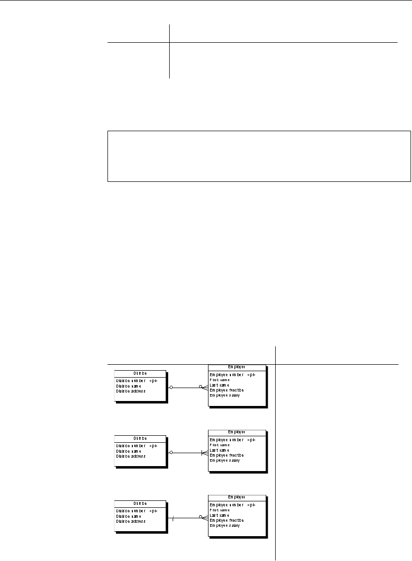
Chapter 3. Building Conceptual Data Models
Arrow type Listed order
Down arrow Alphabetically
Up arrow Reverse alphabetically
For example, when you click the column heading Name, the relationships
are listed by relationship name alphabetically when the down arrow is
indicated, and in reverse order when the up arrow is indicated.
Item not visible in list
To make an item visible in a list, click the Customize Columns and Filter
tool in the list, and from the list of filter options that appears, select the
appropriate item check box and click OK.
vTo sort the list of relationships
1. Select Model äRelationships to display the list of relationships.
2. Click a column header.
The listed references are ordered by the indicated property.
3. Click OK.
Relationship examples
This section shows the graphic representation of various relationship
properties.
One-to-many relationship Description
Each division may have zero
or more employees
Each employee may belong to
zero or one division
Each division must have one or
more employees
Each employee may belong to
zero or one division
Each division may have zero
or more employees
Each employee must belong to
one and only one division
91
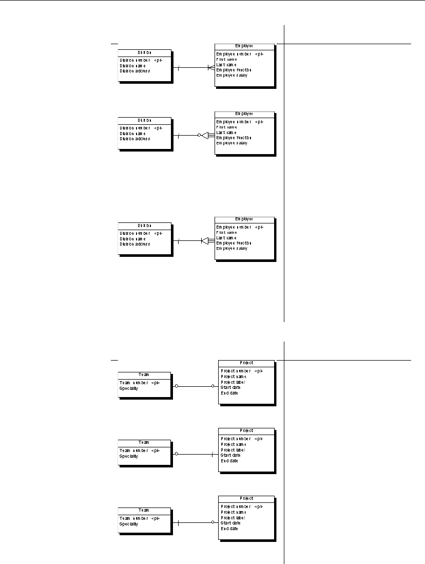
Defining relationships in a CDM
One-to-many relationship Description
Each division must have one or
more employees
Each employee must belong to
one and only one division
Each division may have zero
or more employees
Each employee must belong to
one and only one division
Each employee is identified
uniquely by division number
and employee number
Each division must have one or
more employees
Each employee must belong to
one and only one division
Each employee is identified
uniquely by division number
and employee number
One-to-one relationship Description
Each team works on zero or
one project
Each project is managed by
zero or one team
Each team works on one and
one project only
Each project is managed by
zero or one team
Each team works on zero or
one project
Each project is managed by
one and one team only
92
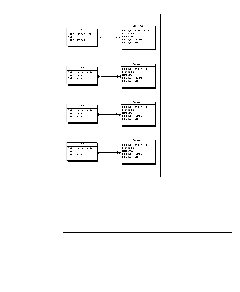
Chapter 3. Building Conceptual Data Models
Many-to-many relationship Description
Each division may have zero
or more employees
Each employee may belong to
zero or more divisions
Each division must have one or
more employees
Each employee may belong to
zero or more divisions
Each division may have zero
or more employees
Each employee must belong to
one or more divisions
Each division must have one or
more employees
Each employee must belong to
one or more divisions
Modifying the relationship display preferences
You can modify the following display preferences for a relationship using
the Tools äDisplay Preferences command:
Preference Display description
Name Name or code of the relationship*
Role Role of each direction in the relationship
Cardinality Minimum and maximum number of instances that the
first entity can have relative to the second entity
Dominance Letter
D
on the dominant entity side of the relationship
Stereotype Stereotype of the relationship
*Displayed text depends on whether the Name or Code radio button is
selected.
93

Defining relationships in a CDM
Modifying a relationship graphically
From the CDM graphic, you can modify a relationship as follows:
♦Bend a relationship symbol
♦Straighten a relationship symbol
♦Drag a relationship to a different entity
Bending a relationship symbol
vTo bend a relationship symbol
1. Press CTRL while you click a point on the relationship to insert an angle.
The point becomes a handle.
2. Release CTRL.
3. Drag and drop the handle to create the bend.
Straightening a relationship symbol
vTo straighten a relationship symbol
1. Click a relationship symbol that has angles.
Handles appear on the relationship symbol.
2. Press CTRL while you click a handle.
The handle and its angle disappear.
Dragging a relationship to a different entity
vTo drag a relationship to a different entity
1. Click a relationship.
2. Press CTRL while you drag one of its attach points to a different entity.
94
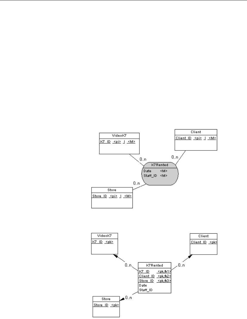
Chapter 3. Building Conceptual Data Models
Defining associations in a CDM
An association is a connection between entities. In the Merise modeling
methodology an association is used to connect several entities that each
represents clearly defined objects, but are linked by an event, which may not
be so clearly represented by another entity.
Each instance of an association corresponds to an instance of each entity
linked to the association.
Example Three entities VIDEOK7, CLIENT, and STORE contain video cassette,
client, and store information. They are linked by an association which
represents a video cassette rental (K7RENTAL). The K7RENTAL
association also contains the attributes DATE and STAFF_ID, which give
the date of the rental, and the identity of the staff member who rented out the
video cassette.
When you generate a PDM, K7RENTED is generated as a table with five
columns, STORE_ID,K7_ID, CLIENT_ID, DATE, and STAFF_ID.
95

Defining associations in a CDM
In PowerDesigner you can use associations exclusively in your CDM, or use
both associations and relationships in the same model.
Association links An association is connected to an entity by an association link. An
Association Link symbolizes the role and the cardinality between an
association and an entity.
Association properties in CDM
You can double-click any association symbol in the diagram to display its
properties:
Property Description
Name The name of the item which should be clear and meaningful,
and should convey the item’s purpose to non-technical users
Code The technical name of the item used for generating code or
scripts, which may be abbreviated, and should not generally
include spaces
Comment Descriptive label for the association
Stereotype Sub-classification used to extend the semantics of an object
without changing its structure; it can be predefined or user-
defined
Number Estimated number of occurrences in the physical database for
the association (the number of records)
Generate Indicates if the association will generate a table in a PDM
Attributes Data item attached to an association
Rules Business rules associated with the association
Association link properties
You can double-click any association link symbol in the diagram to display
its properties:
96
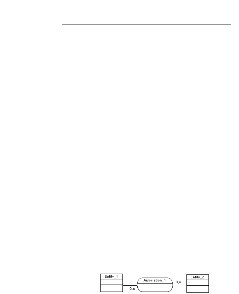
Chapter 3. Building Conceptual Data Models
Property Description
Entity Entity connected by the association link
Associa-
tion
Association connected by the association link
Role Label indicating the role of the association link
Identifier Indicates if the entity is dependent on the other entity
Cardinality Number of occurrences (one or many) of one entity to another
entity
Stereotype Sub-classification used to extend the semantics of an object
without changing its structure; it can be predefined or user-
defined
Creating an association in a CDM
There are several ways to create an association:
♦From a diagram
♦From the Browser
♦From the list of associations
At creation, an association has a default name including a number. This
number is assigned in the order of creation of objects.
+For more information on the different ways to create an association, see
section Creating an object in chapter Managing objects in the
General
Features Guide
.
vTo create an association from a diagram
1. Click the Association Link tool in the Palette.
2. Click inside the first entity and while continuing to hold down the mouse
button, drag the cursor to a second entity. Release the mouse button.
An association symbol is created between the two entities.
3. Double-click the new association symbol in the diagram to display the
association property sheet.
97
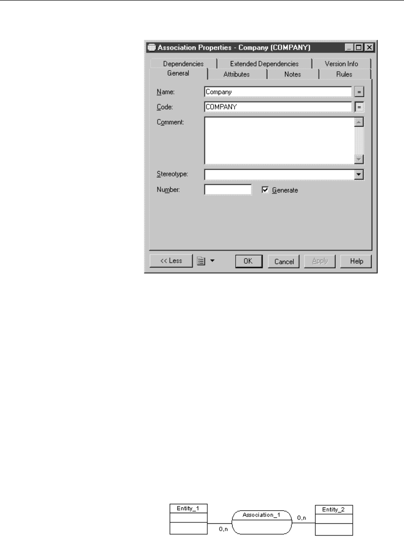
Defining associations in a CDM
4. Type an association name and an association code.
5. Click OK.
Creating an association link
There are several ways to create an association link between an entity and an
association:
♦From a diagram
♦From the list of associations links
Creating an association link from a diagram:
vTo create an association link from a diagram
1. Click the Association Link tool in the Palette.
2. Click inside the first entity and while continuing to hold down the mouse
button, drag the cursor to a second entity. Release the mouse button.
An association symbol with two associations links is created between the
two entities.
98
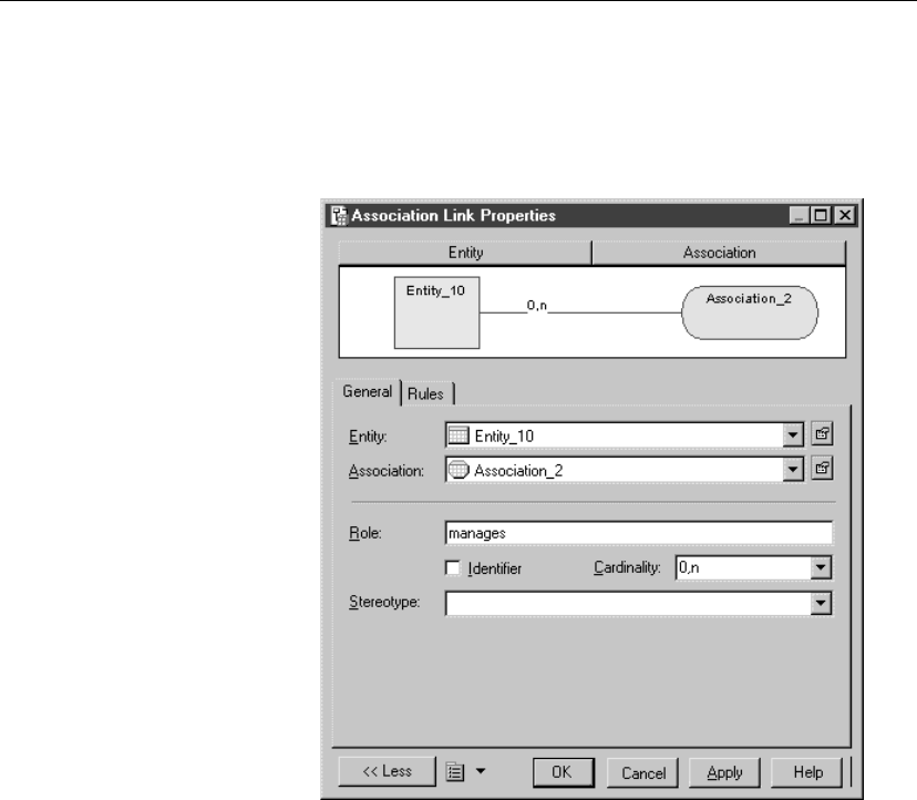
Chapter 3. Building Conceptual Data Models
3. Double-click one of the two associations links symbols in the diagram to
open the association link property sheet.
It displays the definition of the selected association link.
4. Type or select association link properties as required.
5. Click OK.
Creating an association link from the list of associations links
vTo create an association link from the list of associations links
1. Select Model äLinks to display the list of associations links.
2. Click a blank line in the list.
or
Click the Add a Row tool.
An arrow appears at the beginning of the line. <None>is displayed by
default in the Entity and Association columns.
99
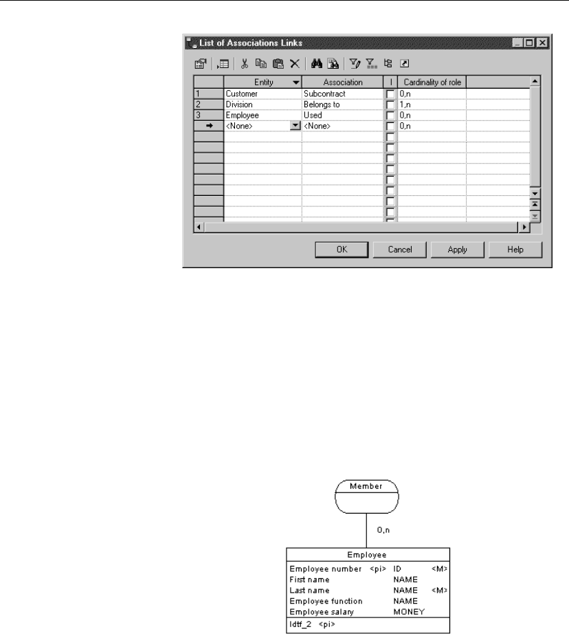
Defining associations in a CDM
3. Click the down arrowhead in the Entity column and select an entity from
the dropdown listbox.
4. Click the Association column to display the down arrowhead and select
an association from the dropdown listbox.
5. Click the Cardinality of role column to display the down arrowhead and
select a cardinality from the dropdown listbox.
6. Click OK.
A symbol for this association link is created between the entity and the
association in the current diagram.
Creating a reflexive association in a CDM
A reflexive association is a relationship between an entity and itself.
Example The reflexive association Manager expresses that an employee (Manager)
can manage other employees.
100
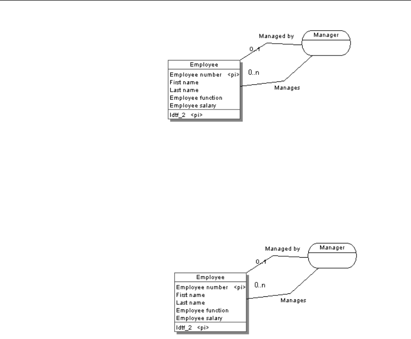
Chapter 3. Building Conceptual Data Models
vTo create a reflexive association
1. Click the Association Link tool in the Palette.
2. Click inside the entity and while continuing to hold down the mouse
button, drag the cursor to a space next to the entity.
3. Click the entity.
An association symbol loops back to the same entity.
Defining cardinality for an association link
Cardinality indicates the number of occurrences (one or many) that one
entity has relative to another. You define the cardinality for each association
link between the association and the entity.
The cardinality of an association link can have the following values:
101

Defining associations in a CDM
Cardinality Description
0,1 There can be zero or one occurrence of the association in
relation to one instance of the entity. The association is not
mandatory
0,n There can be zero or many occurrences of the association in
relation to one instance of the entity. The association is not
mandatory
1,1 One occurrence of the entity can be related to only one
occurrence of the association. The association is mandatory
1,n One occurrence of the entity can be related to one or many
occurrences of the association. The association is mandatory
You can change the default format of cardinalities from the registry:
HKEY_CURRENT_USER\Software\Sybase\PowerDesigner 11\ModelOptions\
Conceptual Options
CardinalityNotation=1 (0..1) or 2 (0,1)
vTo define cardinality for an association link
1. Double-click the association link between an association and an entity to
display the association link property sheet.
102
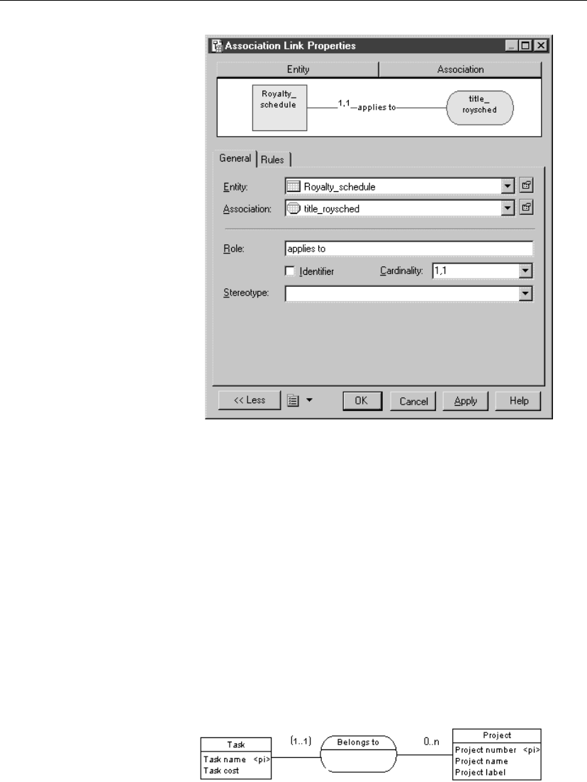
Chapter 3. Building Conceptual Data Models
2. Select a cardinality from the Cardinality dropdown listbox.
3. Click OK.
You can repeat the procedure for each association link.
Defining a dependent association in a CDM
In a dependent association, one entity is partially identified by another. Each
entity must have an identifier. In some cases, however, the attributes of an
entity are not sufficient to identify an occurrence of the entity. For these
entities, their identifiers incorporate the identifier of another entity with
which they have a dependent association.
Example An entity named Task has two entity attributes, TASK NAME and TASK
COST. A task may be performed in many different projects and the task cost
will vary with each project. To identify each occurrence of TASK COST the
unique Task entity identifier is the compound of its
Task name
entity
attribute and the
Project number
identifier from the Project entity.
103
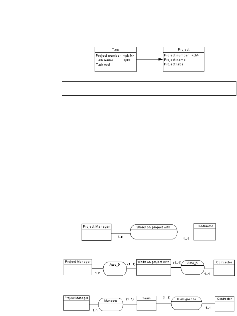
Defining associations in a CDM
When you generate a PDM, the TASK table contains the PROJECT
NUMBER column as a foreign key, which is also a primary key column.
The primary key therefore consists of both PROJECT NUMBER and TASK
NAME columns.
Association link identifiers and associations
The same association can not have two identifier association links.
vTo define a dependent association
1. Double-click an association link symbol to display the association link
property sheet.
2. Select the Identifier check box.
3. Click OK.
The cardinality of the association link is enclosed in parenthesis to
indicate that the association link is an identifier.
Changing an association into an associative entity
You can transform an association into an associative entity linked by two
associations. The associative entity gets the name and code of the
association. The two new associations handle cardinality properties.
Example Two entities PROJECT MANAGER and CONTRACTOR are linked by the
association WORKS ON PROJECT WITH:
You can represent this association with an associative entity:
The two new associations can be represented as follows:
104

Chapter 3. Building Conceptual Data Models
vTo change an association into an associative entity
1. Right-click an association symbol.
The association contextual menu appears.
2. Select Change to Entity from the contextual menu.
An associative entity that is linked to two associations replaces the
original association. The associative entity takes the name of the original
association.
Creating an association attribute
There are several ways to create an association attribute:
♦From a data item used as an association attribute
♦From the attribute list for an association
At creation, an association attribute has a default name including a number.
This number is assigned in the order of creation of objects.
Using a data item as an association attribute
You can use a data item defined in the model as an attribute for an
association.
Allow Reuse
If the model option Allow Reuse is not selected, you can not create an
association attribute by reusing an existing data item. In this case the Add
Data Items tool is not available.
105
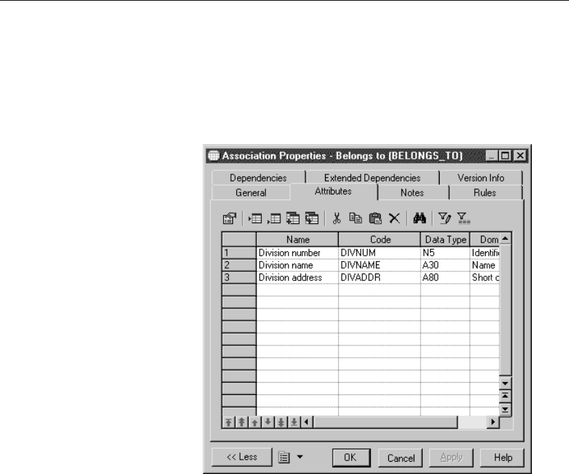
Defining associations in a CDM
vTo use a data item as an association attribute
1. Double-click the association in the diagram to display the association
property sheet.
2. Click the Attributes tab to display the corresponding page.
It lists attributes associated with the association.
3. Click the Add Data items tool.
A Selection box appears listing all of the available data items.
4. Select one or more data items.
106
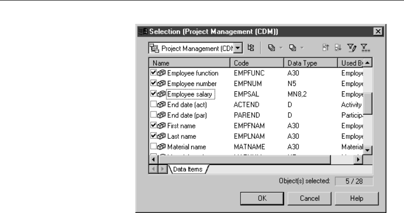
Chapter 3. Building Conceptual Data Models
5. Click OK.
The selected data items are added to the list of attributes for the
association.
6. Click OK in each of the dialog boxes.
Creating an association attribute from the list of association attributes
You can create an association attribute directly in the list of attributes for an
association. When you create an association attribute, it is automatically
added to the list of data items. If you select Allow Reuse as a model option,
the new data item can be used as an attribute for other associations or
entities.
vTo create an association attribute from the list of association at-
tributes
1. Double-click the association to display the association property sheet.
2. Click the Attributes tab to display the corresponding page.
It lists association attributes associated with the association.
3. Click a blank line in the list.
or
Click the Add a Row tool.
An arrow appears at the beginning of the line.
107
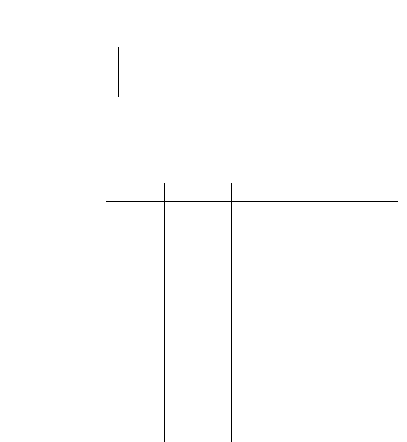
Defining associations in a CDM
4. Type an association attribute name and an association attribute code.
Automatically reuse a data item
If you select the data item model options Allow Reuse and Unique
Code and you type the name of a data item that is already in use, you
automatically reuse the data item.
5. Click OK.
Modifying the association display preferences in a CDM
You can modify the following display preferences of an association using
the Tools äDisplay Preferences command:
Group box Preference Display description
Association Attributes Name or code of the association*
Display Limit Maximum number of attributes displayed in
symbol
Stereotype Stereotype of the association
Comment Comment of the association. When se-
lected, all other check boxes are deselected,
except for Stereotype
Association
attributes
Data types Data type of association attribute
Replace by
domains
Domain for each association attribute. You
can only display domains when the Data
types check box is selected
Domains Domain of each association attribute
Mandatory Letter
M
beside each mandatory association
attribute
Stereotype Stereotype of the association attributes
*Displayed text depends on whether the Name or Code radio button is
selected.
Display domain and data
type
You can display the domain and data types in the symbol of an association.
There are four display options available:
108
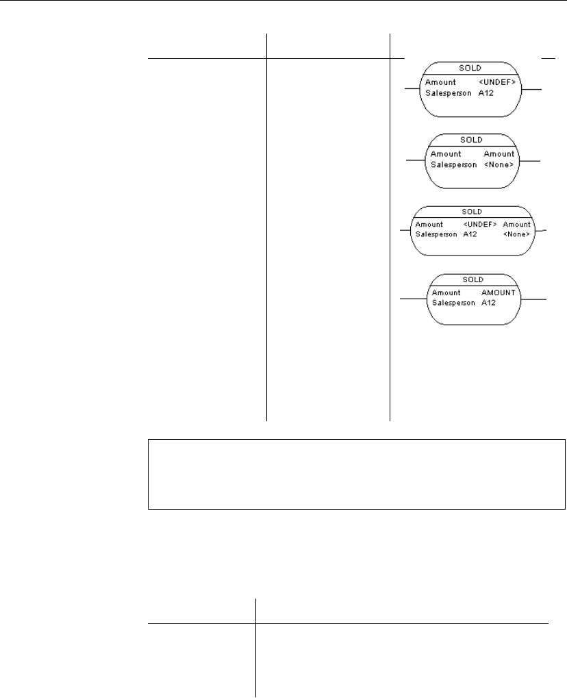
Chapter 3. Building Conceptual Data Models
Selected checkbox Result Symbol
Data types Displays only the
data type, if it exists
Domains Displays only the
domain, if it exists
Data types
Domains
Displays both data
type and domain, if
they exist
Data types
Replace by domains
If domain exists and
data type does not
exist, then displays
domain.
If domain does not
exist and data type
exists, then displays
data type.
Moving text on a relationship symbol
When a relationship symbol displays text, the text position is based on the
position of handles. You can add a handle on the relationship symbol by
pressing CTRL while you click the symbol.
Modifying the association link display preferences
You can modify the following display preferences of an association link
using the Tools äDisplay Preferences command:
Preference Description
Role Displays the role of the association link
Cardinality Displays the cardinality of the association link
Stereotype Stereotype of the association link
109
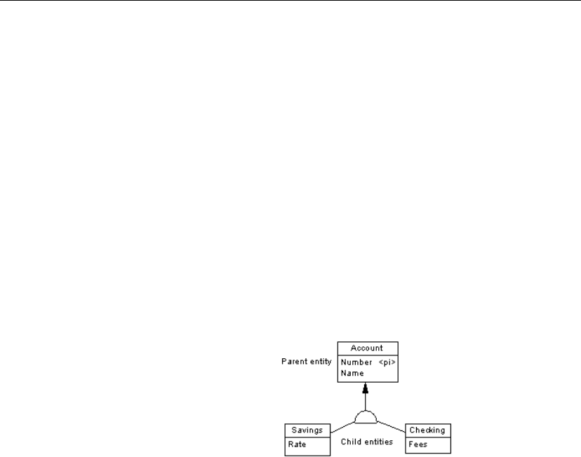
Defining inheritances in a CDM
Defining inheritances in a CDM
Inheritance allows you to define an entity as a special case of a more
general entity. The entities involved in an inheritance have many similar
characteristics but are nonetheless different. The general entity is known as a
supertype (or parent) entity and contains all of the common characteristics.
The special case entity is known as a subtype (or child), entity and contains
all of the particular characteristics.
Between entities, it is also possible to define an inheritance link. In an
inheritance link, one or more subtype (or child) entities inherit, at the
physical level, all or part of the entity attributes carried by one supertype (or
parent) entity.
The Account entity below represents all the bank accounts in the
information system. It includes two subtypes: checking accounts and
savings accounts. The notion of inheritance represents the entities Checking
and Savings as specialized types of the parent entity Account.
Inheritance properties
You can double-click any inheritance symbol in the diagram to display its
properties:
110
Chapter 3. Building Conceptual Data Models
Property Description
Name The name of the item which should be clear and mean-
ingful, and should convey the item’s purpose to non-
technical users
Code The technical name of the item used for generating code
or scripts, which may be abbreviated, and should not
generally include spaces
Comment Descriptive label for the inheritance link
Stereotype Sub-classification used to extend the semantics of
an object without changing its structure; it can be
predefined or user-defined
Parent Name of the parent entity
Mutually exclu-
sive children
Indicates if only one child can exist for one occurrence
of the parent entity.
Complete Indicates that all instances of the parent entity (surtype)
must belong to one of the children (subtypes). For ex-
ample, entity Person has 2 sub-types Male and Female;
each instance of entity Person is either a male or a
female
An inheritance link definition also includes the following properties, which
are defined on associated property sheets:
Property Description
Generation Group of properties that affect physical implementation
Children List of child entities
Notes Description associated with inheritance link
Rules Business rules attached to the inheritance link
Inheritance display Depending on the model notation, the inheritance symbol displays the
inheritance status:
111

Defining inheritances in a CDM
IDEF1X E/R and Merise notation Description
Standard
— Mutually exclusive
inheritance
Complete inheritance
— Mutually exclusive and
complete inheritance
Creating an inheritance link
You can create an inheritance link graphically in the diagram by dragging
and dropping an inheritance link symbol from the child entity to the parent
entity using the Inheritance tool.
vTo create an inheritance link
1. Click the Inheritance tool in the Palette.
2. Click the child entity, while continuing to hold down the mouse button,
drag the cursor to the parent entity. Release the mouse button inside the
child entity.
The link appears between the two entities and has a half-circle in the
middle and an arrowhead that points to the parent entity.
3. If you want to create additional child entities for the same link, drag and
drop an inheritance link from the half-circle to the additional child entity.
The symbol links all the child entities to the parent.
112
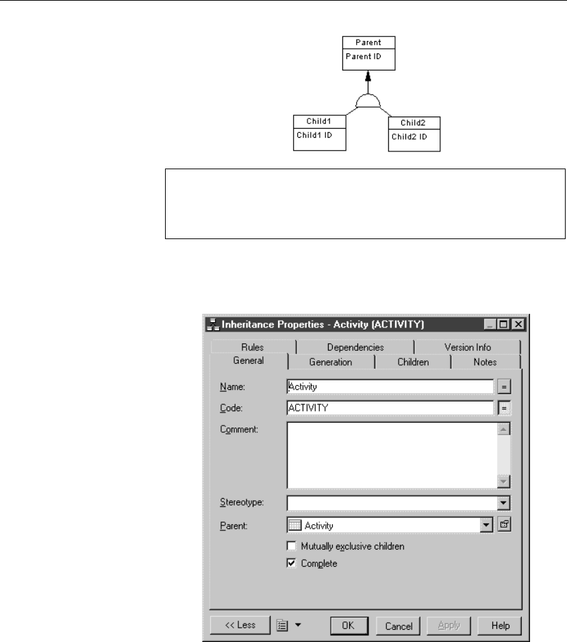
Chapter 3. Building Conceptual Data Models
Dragging an inheritance link to a different child entity
You can change the child entity at the end of an inheritance link by
clicking the inheritance link and holding down CTRL as you drag one of
its attach points to a different entity.
4. Double-click the new link in the diagram to display the inheritance
property sheet.
5. Type an inheritance name and an inheritance code.
6. Click OK.
Adding a child entity to an inheritance link
You can add a child entity to an inheritance link.
113
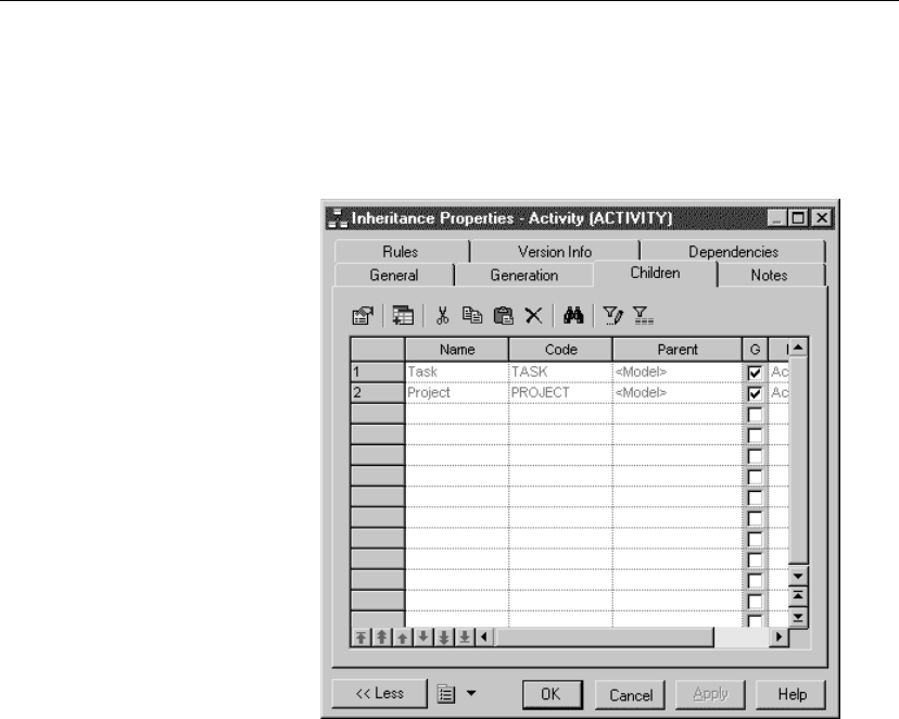
Defining inheritances in a CDM
vTo add a child entity to an inheritance link
1. Double-click an inheritance symbol to display the inheritance property
sheet.
2. Click the Children tab to display the corresponding page.
3. Click the Add Children tool.
A selection box appears. It lists the entities available in the model.
4. Select one or more entities.
114
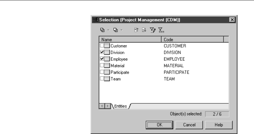
Chapter 3. Building Conceptual Data Models
5. Click OK.
The new entity is added to the list of child entities on the Children page.
6. Click OK.
The new child entity is linked to the inheritance symbol in the diagram.
Making inheritance links mutually exclusive
When an inheritance link is mutually exclusive between children, one
occurrence of the parent entity cannot be matched to more than one child
entity.
This information is for documentation only and has no impact in generating
the PDM.
115
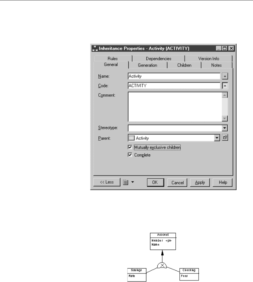
Defining inheritances in a CDM
vTo make an inheritance link mutually exclusive
1. Double-click the inheritance link in the diagram to display the inheritance
link property sheet.
2. Select the Mutually Exclusive Children check box.
3. Click OK.
The mutually exclusive inheritance links display an X on the half-circle
symbol.
The inheritance link shown above is mutually exclusive. It means that an
account is either checking or savings, never both.
Generation mode properties
Generation mode defines the physical implementation of an inheritance
structure.
116

Chapter 3. Building Conceptual Data Models
In the CDM, the generation mode indicates which entities in an inheritance
structure should correspond to tables in the PDM, as follows:
Generation mode Generates table(s)
corresponding to
Which have the following
properties
Generate parent Parent entity Inherits entity attributes of
each child entity
Is affected by child entity
relationships.
Contains reference to any
table which has a many-to-
one relationship with child
entity
Generate children
Inherit all attributes
Each child entity Inherits all entity attributes of
the parent entity
Generate children
Inherit only primary
attributes
Each child entity Inherits only the identifier of
the parent entity
Primary keys for child tables
When you generate a child table, its primary key is the concatenation of the
child entity identifier and the parent entity identifier.
Defining generation mode
You define the generation mode which specifies the physical implementation
of an inheritance structure.
Generating specifying
attributes
In the case of parent only generation, you can choose to define a specifying
attribute to differentiate occurrences of a child.
+For more information on specifying attribute properties see section
“Specifying entity attribute properties” on page 118.
+For more information on defining a specifying attribute, see section
“Defining a specifying entity attribute” on page 120.
vTo define generation mode
1. Double-click the inheritance link in the diagram to display the inheritance
property sheet.
2. Click the Generation tab to display the corresponding page.
117
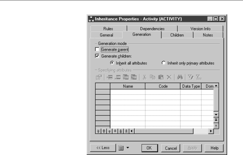
Defining inheritances in a CDM
3. Select Generate Parent.
or
Select Generate Children.
or
Select both Generate Parent and Generate Children.
4. If you selected Generate Children, do one of the following actions:
Click the Inherit All Attributes radio button.
or
Click the Only Primary Attributes radio button. Primary attributes are the
attributes defined in the primary identifier.
5. Click OK.
Specifying entity attribute properties
Aspecifying entity attribute is an entity attribute that is defined for a
parent entity which differentiates occurrences of each child. It only applies
to parent only generation.
Example In the example below, the TITLE entity has two children,
NONPERIODICAL and PERIODICAL.
118
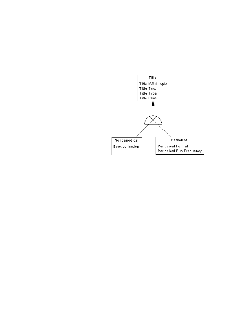
Chapter 3. Building Conceptual Data Models
As only the parent table TITLE will be generated in a PDM, a specifying
entity attribute PERIODICAL is defined for the inheritance link to
differentiate between the two child entities.
In the PDM, each of the child entity attributes will generate columns in the
table TITLE, however the specifying entity attribute PERIODICAL will
generate a corresponding column PERIODICAL. The values of this column
indicate whether an instance of TITLE is a periodical or not.
You can specify the following properties for a specifying entity attribute:
Property Description
Name The name of the item which should be clear and meaningful,
and should convey the item’s purpose to non-technical users
Code The technical name of the item used for generating code or
scripts, which may be abbreviated, and should not generally
include spaces
Comment Descriptive label for the specifying entity attribute
Data type Data type that you want to apply to the specifying entity
attribute
Length Maximum length of the data type
Precision Number of places after the decimal point, for data values that
can take a decimal point
Domain Name of the associated domain
Mandatory Indicates whether or not the specifying entity attribute must be
assigned a value
119
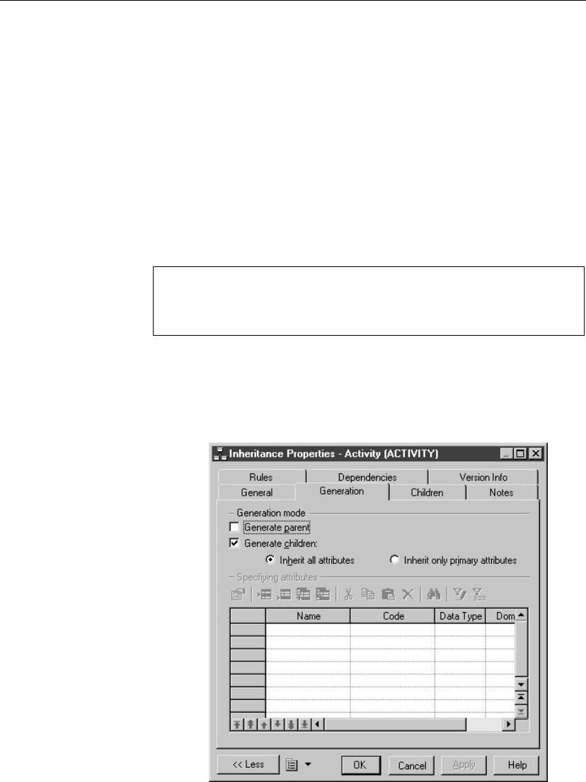
Defining inheritances in a CDM
Defining a specifying entity attribute
You define a specifying entity attribute only in the case of parent only
generation. In a PDM the specifying attribute differentiates occurrences of
each child. There are several ways to create a specifying attribute:
♦From a data item used as a specifying attribute
♦From the specifying attribute list for an inheritance
Using a data item as a specifying attribute
You can use a data item defined in the model as an specifying attribute.
Allow Reuse
If the model option Allow Reuse is not selected, you can not create an
specifying attribute by reusing an existing data item. In this case the Add
Data Item tool is not available.
vTo use a data item as a specifying attribute
1. Double-click an inheritance symbol to display the inheritance property
sheet.
2. Click the Generation tab to display the corresponding page.
120

Chapter 3. Building Conceptual Data Models
3. Select the Generate Parent check box.
4. Clear the Generate Children check box.
5. Click the Add Data items tool.
A Selection box appears listing all of the available data items.
6. Select a data item.
7. Click OK.
The selected data item is added to the list of specifying attributes for the
inheritance.
8. Click OK.
Using the Generate option
The option Generate Children generates a table for each child in the
inheritance. If you do not select Generate Children, you can control the
generation of child tables using the option Generate in the property sheet
of each child entity.
Creating a specifying attribute from the specifying attributes list for an inheritance
You can create a specifying attribute directly in the list of specifying
attributes for an inheritance. When you create an specifying attribute, it is
automatically added to the list of data items. If you select Allow Reuse as a
model option, the new data item is available to be re-used as an attribute for
an entity, association, or inheritance.
vTo create a specifying attribute from the specifying attributes list
for an inheritance
1. Double-click the inheritance symbol to display the inheritance property
sheet.
2. Click the Generation tab to display the corresponding page.
3. Select the Generate Parent check box.
4. Clear the Generate Children check box.
5. Click a blank line in the list.
or
Click the Add a Row tool.
An arrow appears at the beginning of the line.
121

Defining inheritances in a CDM
6. Type a specifying attribute name and a specifying attribute code.
7. Click Apply.
You commit the creation of the new attribute.
8. Click the new attribute line.
An arrow appears at the beginning of the line.
9. Click the Properties tool.
or
Double-click the arrow at the beginning of the line.
The attribute property sheet appears.
10. Type or select attribute properties.
11. Click OK.
Modifying the inheritance display preferences
You can modify the following display preference of an inheritance using the
Tools äDisplay Preferences command:
Preference Description
Name Displays the name of the inheritance
Stereotype Stereotype of the inheritance
122
Chapter 3. Building Conceptual Data Models
Defining check parameters in a CDM
Check parameters are set of conditions which data must satisfy to remain
valid.
There are three types of check parameters:
Parameter type Description Can be at-
tached to
Standard check
parameters
Common data constraints which
define a data range. For example
minimum and maximum values for a
column
Entity attributes
Domains
Additional check
parameters
SQL expression defining a data con-
straint using the %MINMAX%,
%LISTVAL%, and %RULES% vari-
ables that are instantiated with stan-
dard parameter values
Entity attributes
Domains
Validation rule Business rule that is defined as a
server expression, and is attached to
one of the following listed objects
Entities
Entity attributes
Domains
Setting standard parameters for objects in a CDM
Standard parameters indicate common data constraints. The following table
lists standard parameters:
Parameter Description
Minimum Lowest acceptable numeric value
Maximum Highest acceptable numeric value
Default Value assigned in absence of an expressly entered value
Unit Standard measure
Format Data format (for example, 9999.99)
Lowercase Forces all alphabetical characters to lowercase
Uppercase Forces all alphabetical characters to uppercase
Cannot Modify Protects from changes, results in a non-modifiable column
in the physical data table
123
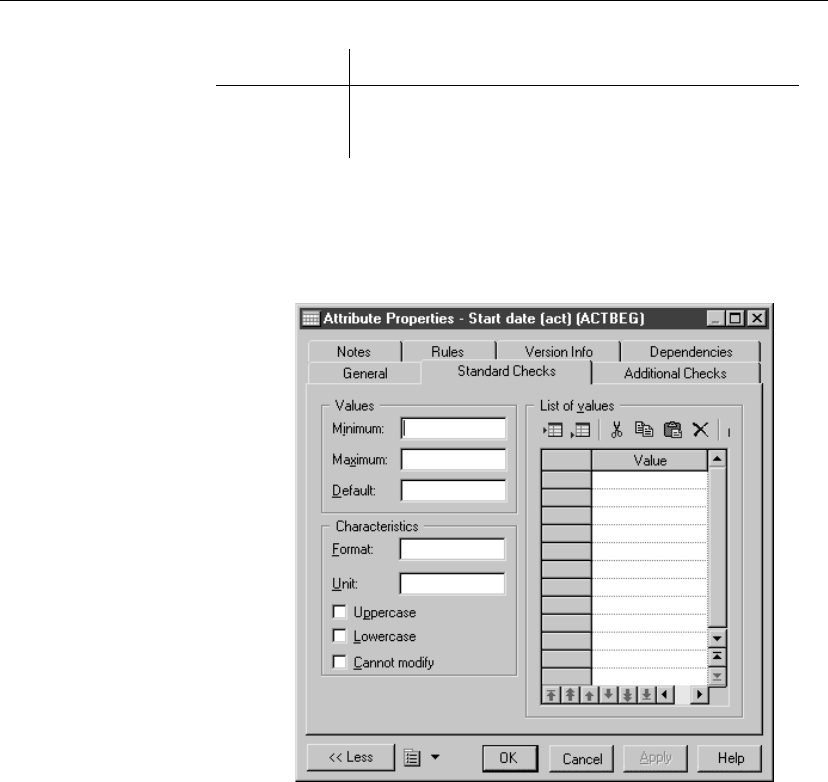
Defining check parameters in a CDM
Parameter Description
List of Values Authorized values
Label String that identifies an authorized value in the list
vTo set standard parameters for objects in a CDM
1. Click the Standard Checks tab in the property sheet of a domain or an
entity attribute to display the corresponding page.
2. Type your choice of Standard Parameters.
3. Click OK.
Defining additional check parameters for objects in a CDM
You can write an SQL statement using the following standard variables
defined as standard check parameters and validation rules:
124

Chapter 3. Building Conceptual Data Models
Variable Description
%MINMAX%, Minimum and maximum values defined in Values group-
box on Standard Checks page
%LISTVAL% Customized values defined in List Values groupbox on
Standard Checks page
%RULES% Validation rule expression defined on Expression page of
the Rules property sheet
You define additional check parameters for data constraints where standard
check parameters are not sufficient.
Example An entity in a data model for a clothing shop may contain check parameters
defined for an entity attribute SIZE, which depend on the check parameters
defined for another entity attribute COUNTRY, as clothing size for a skirt in
France may be different from the same size in the United States.
In this case an expression is required to create a constraint which uses check
parameters defined for both entity attributes.
vTo define additional check parameters for objects
1. Click the Additional Checks tab in the property sheet of a domain or an
entity attribute to display the corresponding page.
2. Type SQL expression using the variables %MINMAX%, %LISTVAL%,
and %RULES%.
125
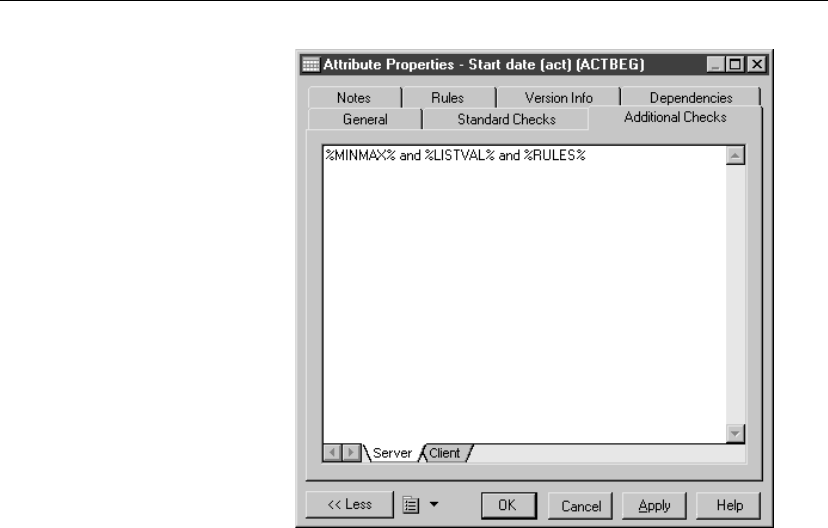
Defining check parameters in a CDM
3. Click OK.
Using a validation rule in check parameters in a CDM
A validation rule is a rule that validates data based on a corresponding
business rule. A validation rule can be generated as a check parameter when
the following conditions apply:
♦Validation rule is attached to an entity, entity attribute, or domain
♦Validation rule is defined as a server expression
At generation, validation rule variables are instantiated with the following
values:
126

Chapter 3. Building Conceptual Data Models
Variable Value
%COLUMN% Code of the column to which the business rule applies
%DOMAIN% Code of the domain to which the business rule applies
%TABLE% Code of the table to which the business rule applies
%MINMAX% Minimum and maximum values for the entity attribute
or domain
%LISTVAL% List values for the entity attribute or domain
%RULES% Server validation rules for the entity attribute or domain
+For more information on defining business rules, see section Defining a
business rule in a CDM in chapter Using Business Rules in a CDM.
vTo use a validation rule in check parameters
1. Click the Rules tab in the property sheet of a domain, an entity or an
entity attribute to display the corresponding page.
2. Click the Add Rules tool.
A list appears displaying the available business rules in the model.
3. Select a business rule in the list.
4. Click OK in each of the dialog boxes.
Validation rule expressions
You must click the Rules button to modify the expression attached to a
validation rule. You can also modify validation rule expressions from
the list of business rules, by clicking the Define button.
127

CHAPTER 4
Working with Conceptual Data Models
About this chapter This chapter describes how to check the validity of a Conceptual Data Model
and how you can import an ERwin model into a CDM. It also gives
information on how you can open a ProcessAnalyst Model (PAM) into a
CDM.
Contents Topic: page
Checking a CDM 130
Object parameters verified by Check model 136
Opening a PAM into a CDM 151
129

Checking a CDM
Checking a CDM
You can use the Check Model to check the validity of a CDM at any time.
A valid CDM conforms to the following rules:
♦Each object name must be unique
♦Each entity must have at least one attribute
♦Each relationship must be attached to at least one entity
CDM check options
When you check a CDM, you can define levels of severity for problems that
Check model finds and have certain problems automatically corrected.
Levels of problem
severity
You can set a level of problem severity for each object parameter that is
verified by the Check model. This severity level can depend on the degree of
normalization that you want to achieve in a your model.
When you check a CDM, you can display an invalid parameter with one of
two types of messages, depending on the degree of problem severity you
assigned to that parameter:
Message Description
Error Major problem that impedes database generation
Warning Minor problem or recommendation
Automatic correction You can choose to have certain problems corrected automatically by
PowerDesigner. Automatic correction primarily fixes non-unique names in
the CDM. However, before using automatic correction, make sure you
understand how it will affect your model.
+As automatic correction is not available for most object parameters, they
must be corrected manually.
+For more information on manual and automatic correction, see “Object
parameters verified by Check model” on page 136.
Setting problem severity
and automatic correction
You can use the following tools from the Check Model Parameters dialog
box to set either an error or warning level of problem severity, and also if
you want PowerDesigner to automatically correct an error:
130
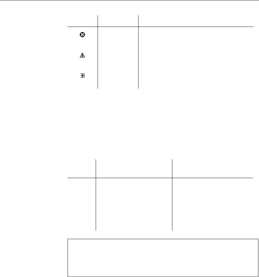
Chapter 4. Working with Conceptual Data Models
Tool Indicates Description
Error Indicates a major problem that impedes database
generation
Warning Indicates a minor problem or recommendation
Automatic
correction
Indicates that PowerDesigner will correct the
problem automatically
CDM object selection in the Check Model
You select objects to be checked from the Selection page of the Check
Model Parameters dialog box (Tools äCheck Model).
You can list all objects created in the current model, current package, or
sub-packages by selecting the Include Sub-Objects tool.
You have the following selection options:
Parent
object
Include Sub-Objects se-
lected
Include Sub-Objects not se-
lected
Model All objects created in model
including those in packages
and sub-packages
All objects created in model
except those in packages and
sub-packages
Package All objects created in pack-
age including those in sub-
packages
All objects created in package
except those in sub-packages
Selecting objects in the diagram
If you graphically select objects in your diagram before starting the Check
Model, they can be automatically selected for verification by the Check
Model by clicking the Use Graphical Selection tool in the Selection page
toolbar.
Checking a global CDM
131
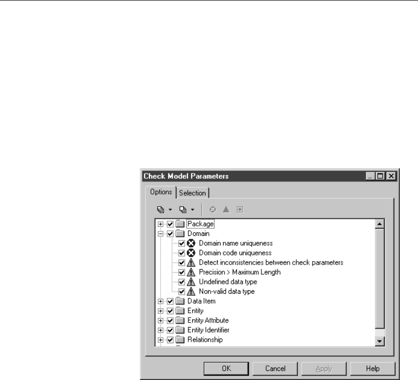
Checking a CDM
vTo check a global CDM
1. Select Tools äCheck Model.
or
Right-click the diagram background and select Check Model from the
contextual menu.
The Check Model Parameters dialog box opens to the Options page.
2. Expand an object parameter node.
The object parameters which are verified by the Check Model are
displayed with the symbols indicating a degree of problem severity.
3. If you want to change a degree of problem severity, select the object
parameter and then select either the Error or Warning tool.
The symbol changes to the appropriate severity level.
4. If you want PowerDesigner to automatically correct a problem, select the
object parameter and then select the Automatic Correction tool.
The Automatic Correction symbol appears superimposed on the Error or
Warning symbol for that object parameter.
5. Click the Selection tab to display the corresponding page.
6. Select a model from the dropdown list at the top of the dialog box.
132
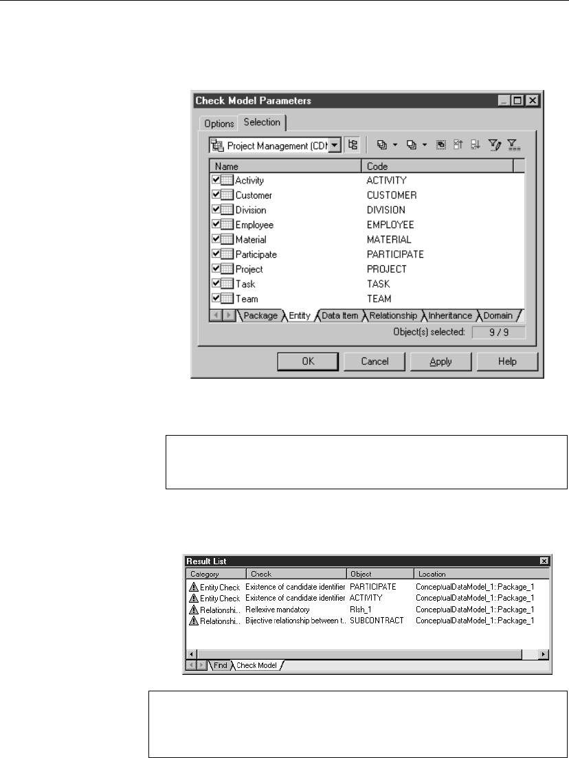
Chapter 4. Working with Conceptual Data Models
7. Click an object tab.
The corresponding object page displays all the objects in the current
CDM.
8. Select check boxes for objects that you want to be checked.
Clear check boxes for objects that you do not want to be checked.
Selecting all or clearing all check boxes
You can select all object check boxes by clicking the Select All tool.
You can clear all object check boxes by clicking the Deselect All tool.
9. Click OK.
The Check Model Result List dialog box displays errors and warnings,
based on your choice of check options.
Dockable result window
When you right-click an object parameter a menu appears listing correction
options. Among these, you can also select options to clear, dock or hide
the result window.
133
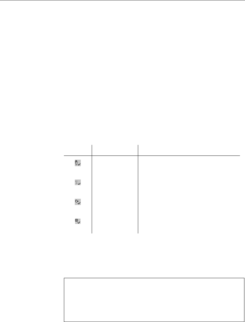
Checking a CDM
Displaying previously applied check options
If you click the Apply button in the Check Model Parameters dialog box, all
error and warning selections are stored in memory.
vTo display errors and warnings selected in the last check
1. Select Tools äCheck Model.
The Check Model Parameters dialog box opens to the Options page. The
object parameters are displayed with the Error or Warning icons selected
in the last check.
Making corrections based on CDM check results
You can use the Check Model to locate and correct problems in the CDM.
You can choose one of the following correction options from the Check
toolbar:
Symbol Option Description
Manual correction Displays property sheet of problem object
Display help Displays description of the error and sugges-
tion for correction
Check again Checks selected object parameter, normally
after a correction has been done
Automatic correc-
tion
Automatically corrects certain errors
Navigating in the error list The Check tool bar also contains navigation tools that you can use to move
to the first, previous, next, or last errors that are listed. You can also navigate
in the list of errors by right-clicking an object parameter and selecting Go To
First error, Previous error, Next error, or Last error from the contextual
menu.
Contextual menu
When you right-click an object parameter in the Result List to open
a contextual menu that lists the following correction options: Correct
(manual correction), Help (error description), Check again, and Automatic
Correction. You can also select options to navigate among errors, clear the
Result List, dock and hide the result window.
134

Chapter 4. Working with Conceptual Data Models
Making manual corrections to a CDM
vTo make manual corrections to a CDM
1. Select an object parameter from the Result List.
2. Right-click the object parameter and select Correct from the contextual
menu.
The object property sheet appears.
3. Select the appropriate tab and make the necessary correction.
4. Close the property sheet.
5. Re-select the object parameter.
6. Right-click the object parameter and select Check again from the
contextual menu.
Verify that the problem has been corrected.
Making automatic corrections to a CDM
vTo make automatic corrections to a CDM
1. Select an object parameter, from the Result List.
2. Right-click the object parameter and select Automatic Correction from
the contextual menu.
3. Right-click the object parameter and select Check again from the
contextual menu.
Verify that the problem has been corrected.
135
Object parameters verified by Check model
Object parameters verified by Check model
The Check Model verifies the validity of the following CDM objects.
When errors are encountered during a check model, corrections can be made
manually or automatically. Manual corrections depend on how you are using
your model.
Use the Help command to select object control options
When you right-click a CDM object control in the Check Model Parameters
page, a menu appears listing several options. The Help command opens
a contextual help page explaining the checks performed for the selected
object type.
Business Rule check in a CDM
During a business rule check, the following object controls are made.
Business rule name and code uniqueness
A model cannot contain two business rules with identical name and/or code.
Manual correction Automatic correction
Modify the duplicated business
rule name/code
Modifies the business rule name/code of
a selected object by appending a number
to its current name
Unused business rule
The business rule you have created is not used in the model.
Manual correction Automatic correction
Apply the business rule to an
object in the model
—
Package check
During a package check, the following object controls are made.
Circular dependency
A circular dependency occurs when an entity depends on another and so on
until a dependency loop is created between entities. A package cannot
contain circular dependencies.
136
Chapter 4. Working with Conceptual Data Models
Manual correction Automatic correction
Clear the Dependent check box
for the link or delete an inheri-
tance link
—
Circularity with mandatory links
A circular dependency occurs when an entity depends on another and so on
until a dependency loop is created between entities through mandatory links.
Manual correction Automatic correction
Clear the Mandatory parent
check box or delete a depen-
dency on a relationship
—
Shortcut code uniqueness
Two shortcuts with the same code cannot be in the same namespace.
Manual correction Automatic correction
Change the code of one of the
shortcuts
—
Shortcut potentially generated as child table of a reference
The package should not contain associations or relationships with an
external shortcut as child entity. Although this can be tolerated in the CDM,
the association or relationship will not be generated in a PDM if the external
shortcut is generated as a shortcut.
Manual correction Automatic correction
Modify the design of your model
in order to create the association or
relationship in the package where
the child entity is defined
—
Domain check
During a domain check, the following object controls are made.
137
Object parameters verified by Check model
Domain name and code uniqueness
Domain names and codes cannot be used more than once in the model.
Manual correction Automatic correction
Modify the duplicate domain
name/code
Modifies the domain name/code of a
selected object by appending a number
to its current name
Inconsistency in check parameters
The values entered in the check parameters page are inconsistent for numeric
and string data types: default does not respect minimum and maximum
values, or default does not belong to list of values, or values in list are not
included in minimum and maximum values, or minimum is greater than
maximum value. Check parameters must be defined consistently.
Manual correction Automatic correction
Modify default, minimum, maxi-
mum or list of values in the check
parameters page
—
Data type precision and length
The data type precision should not be greater than or equal to the length.
Manual correction Automatic correction
Make the data type length greater
than or equal to the precision
—
Undefined data type
Undefined data types for domains exist. To be complete, a model should
have all its domain data types defined.
Manual correction Automatic correction
While undefined data types are
tolerated, you must select data
types for currently undefined data
types before you can generate a
PDM
—
138
Chapter 4. Working with Conceptual Data Models
Non-valid data type
Invalid data types for domains exist. To be complete, a model should have
all its domain data types correctly defined.
Manual correction Automatic correction
While tolerated, you must select
valid data types for currently
non-valid data types to generate
the PDM
—
Data item check
During a data item check, the following object controls are made.
Data item name and code uniqueness
Data item names and codes cannot be used more than once in the namespace.
Manual correction Automatic correction
Modify the duplicate data item
name/code
Modifies the data item name/code of a
selected object by appending a number
to its current name
Unused data items
There are unused data items. These are useless for PDM generation.
Manual correction Automatic correction
To use a data item, add it to an
entity. If you do not need an
unused data item, delete it to
allow PDM generation
—
Re-used data items
There are entities using the same data items. This can be tolerated if you
defined this check as a warning.
139
Object parameters verified by Check model
Manual correction Automatic correction
Take care to ensure consistency
when defining data item proper-
ties
—
Data item and domain divergence
There is a divergence between data items and associated domains. This can
be tolerated if you defined this check as a warning.
Manual correction Automatic correction
Ensure consistency when defin-
ing data item properties
Restores divergent attributes from do-
main to data items (domain values over-
write data item values)
Inconsistency in check parameters
The values entered in the check parameters page are inconsistent for numeric
and string data types: default does not respect minimum and maximum
values, or default does not belong to list of values, or values in list are not
included in minimum and maximum values, or minimum is greater than
maximum value. Check parameters must be defined consistently.
Manual correction Automatic correction
Modify default, minimum, maxi-
mum or list of values in the check
parameters page
—
Data type precision and length
The data type precision should not be greater than or equal to the length.
Manual correction Automatic correction
Make the data type length greater
than or equal to the precision
—
Undefined data type
Undefined data types for data items exist. To be complete, a model should
have all its data items data types defined.
140
Chapter 4. Working with Conceptual Data Models
Manual correction Automatic correction
While undefined data types are
tolerated, you must select data
types for currently undefined data
types before you can generate a
PDM
—
Non-valid data type
Invalid data types for data items exist. To be complete, a model should have
all its data types for data items correctly defined.
Manual correction Automatic correction
While tolerated, you must select
valid data types for currently
non-valid data types to generate
the PDM
—
Entity check
During an entity check, the following object controls are made.
Entity name and code uniqueness
Entity names and codes cannot be used more than once in the namespace.
Manual correction Automatic correction
Modify the duplicate entity
name/code
Modifies the entity name/code of a se-
lected object by appending a number to
its current name
Entity name and code length
The entity name and code length are limited to a maximum length of 254
characters specified in the naming conventions of the model options.
Manual correction Automatic correction
Modify the entity name/code
length to meet this requirement
Truncates the entity name/code length
to the maximum length specified in the
naming conventions
141
Object parameters verified by Check model
Existence of attributes
An entity must always contain at least one attribute.
Manual correction Automatic correction
Add an attribute to the entity or
delete the entity
—
Number of serial types greater than 1
An entity cannot have more than one serial type attribute. Serial types are
automatically calculated values.
Manual correction Automatic correction
Change the types of the appropri-
ate entity attributes to have only
one serial type attribute
—
Existence of identifiers
An entity must contain at least one identifier.
Manual correction Automatic correction
Add an identifier to the entity or
delete the entity
—
Existence of relationship or association link
An entity must have at least one relationship or association link.
Manual correction Automatic correction
Add a relationship or an associ-
ation link to the entity or delete
the entity
—
Redundant inheritance
An entity inherits from another entity more than once. This is redundant and
adds nothing to the model.
Manual correction Automatic correction
Delete redundant inheritances —
142
Chapter 4. Working with Conceptual Data Models
Multiple inheritance
An entity has multiple inheritance. This is unusual but can be tolerated if
you defined this check as a warning.
Manual correction Automatic correction
Make sure that the multiple in-
heritance is necessary in your
model
—
Parent of several inheritances
An entity is the parent of multiple inheritances. This is unusual but can be
tolerated if you defined this check as a warning.
Manual correction Automatic correction
Verify if the multiple inheritances
could not be merged
—
Entity attribute check
During an entity attribute check, the following object controls are made.
Entity attribute name and code uniqueness
Attribute names and codes cannot be used more than once in the entity.
Manual correction Automatic correction
Modify the duplicate entity at-
tribute name/code
Modifies the entity attribute name/code
of a selected object by appending a
number to its current name
Entity identifier check
During an entity identifier check, the following object controls are made.
Entity identifier name and code uniqueness
Entity identifier names and codes cannot be used more than once in the
namespace.
143
Object parameters verified by Check model
Manual correction Automatic correction
Modify duplicate entity identifier
names and codes
Modifies the entity identifier name/code
of a selected object by appending a
number to its current name
Existence of an attribute
At least one attribute must exist for an entity identifier.
Manual correction Automatic correction
Add an attribute to the entity
identifier or delete the identifier
—
Identifier inclusion
An identifier cannot include another one.
Manual correction Automatic correction
Delete the identifier that includes
an existing identifier
—
Relationship check
During a relationship check, the following object controls are made.
Relationship name and code uniqueness
Relationship names and codes cannot be used more than once in the model.
Manual correction Automatic correction
Modify the duplicate relationship
name/code
Modifies the relationship name/code of
a selected object by appending a number
to its current name
Reflexive dependency
A dependency means that one entity is defined through a relationship with
another. A dependent relationship cannot therefore be reflexive.
Manual correction Automatic correction
Change or delete the reflexive
dependency
—
144
Chapter 4. Working with Conceptual Data Models
Reflexive mandatory relationship
A reflexive mandatory relationship exists.
Manual correction Automatic correction
Deselect the Mandatory check
boxes for the relationship to be
non-mandatory
—
Bijective relationship between two entities
There is a bijective relationship between two entities when there is a
two-way one to one relationship between the entities. This is equivalent to a
merge of two entities.
Manual correction Automatic correction
Merge the entities or modify the
relationship
—
Name uniqueness constraint for many to many relationships and entities
A many-to-many relationship and an entity cannot have the same name or
code.
Manual correction Automatic correction
Change the name or code of the
many-to-many relationship or the
name or code of the entity. If
you do not, PDM generation will
rename the generated table
—
Consistency between dominant and dependent relationships
A dependent relationship between entities cannot also be a dominant
relationship.
Manual correction Automatic correction
Select the Dominant check box
on the other (correct) side of the
relationship
—
145
Object parameters verified by Check model
Association check
During an association check, the following object controls are made.
Association name and code uniqueness
Association names and codes cannot be used more than once in the
namespace.
Manual correction Automatic correction
Modify the duplicate association
name/code
Modifies the association name/code of a
selected object by appending a number
to its current name
Association has at least two links
An association is isolated and therefore does not define a relationship
between entities.
Manual correction Automatic correction
Define at least two links between
the isolated association and one
or several entities
—
Association has two links with identifier link
An identifier link introduces a dependency between two entities. An
association with this type of link must be binary.
Manual correction Automatic correction
Delete the unnecessary links or
clear the Identifier check box for
a link
—
Association has no more than one identifier link
An identifier link introduces a dependency between two entities. There can
only be one identifier link between two entities otherwise a circular
dependency is created.
146
Chapter 4. Working with Conceptual Data Models
Manual correction Automatic correction
Clear the Identifier check box for
one of the links
—
Absence of properties with identifier links
An association with an identifier link cannot have any properties.
Manual correction Automatic correction
Move the association properties
into the dependent entity (the one
linked to the association with an
identifier link)
—
Bijective association between two entities
There are bijective associations between two entities when a two-way one to
one association between the entities exist. This is equivalent to a merge of
two entities.
Manual correction Automatic correction
Merge the entities or modify the
cardinality links
—
Maximum cardinality links
An association with more than two links can only have links with a
maximum cardinality greater than one.
Manual correction Automatic correction
Change the maximum cardinality
of such links to be greater than 1
—
Reflexive identifier links
An identifier link introduces a dependency between two entities. An
association with this type of link cannot therefore be reflexive.
Manual correction Automatic correction
Change the relationship between
the entities or clear the Identifier
check box for a link
—
147
Object parameters verified by Check model
Name unicity constraint between many-to-many associations and entities
A many-to-many association and an entity cannot have the same name or
code.
Manual correction Automatic correction
Change the name or code of the
many-to-many association or the
name or code of the entity. If
you do not, PDM generation will
rename the generated table
—
Inheritance check
During an inheritance check, the following object controls are made.
Inheritance name and code uniqueness
Inheritance names and codes cannot be used more than once in the model.
Manual correction Automatic correction
Modify the duplicate inheritance
name/code
Modifies the inheritance name/code of a
selected object by appending a number
to its current name
Existence of inheritance link
An inheritance must have at least one inheritance link, from the inheritance
to the parent entity.
Manual correction Automatic correction
Define the inheritance link or
delete the inheritance
—
File object check
During a file object check, the following object controls are made.
Embedded file name uniqueness
You cannot have two embedded file objects with the same name in a model.
148
Chapter 4. Working with Conceptual Data Models
Manual correction Automatic correction
Rename one of the embedded
file objects
Renames the file object by appending a
number to its name
Existence of external file location
External file objects must have a valid location path.
Manual correction Automatic correction
Define a valid path location —
Replication check
During a replication check, the following object controls are made.
Partial replication
A replica object is partially synchronized with its replicated object.
Manual correction Automatic correction
Modify the list of replicated
attributes from the replication
property sheet
Enforces the replication of desynchro-
nized attributes of the replica object in
the replication property sheet
Extended object check
During an extended object check, the following object controls are made.
Extended object name and code uniqueness
Extended object names and codes must be unique in the namespace.
Manual correction Automatic correction
Modify the duplicate extended ob-
ject name/code
Modifies the extended object name or
code of a selected object by appending
a number to its current name or code
Extended link check
During an extended link check, the following object controls are made.
149

Object parameters verified by Check model
Extended link name and code uniqueness
Extended link names and codes must be unique in the namespace.
Manual correction Automatic correction
Modify the duplicate extended link
name/code
Modifies the extended link name or
code of a selected object by appending
a number to its current name or code
150
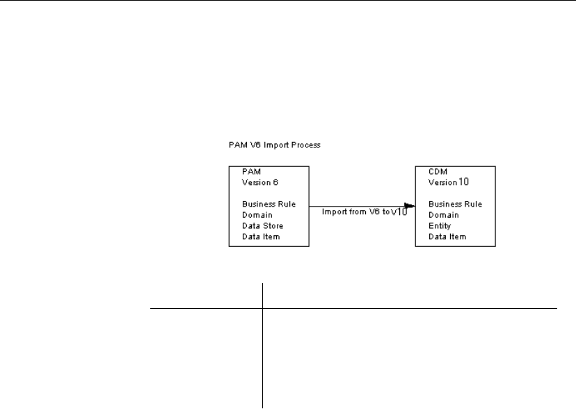
Chapter 4. Working with Conceptual Data Models
Opening a PAM into a CDM
You can recover process model information into a conceptual model by
opening a PAM into a CDM.
You will then retrieve PAM objects into your CDM.
The open process translates PAM objects into CDM objects as follows:
Object in a PAM Imported object in a CDM
Business rule Business rule
Domain Domain
Data store Entity
Data item Data item
When opening a PAM, you are asked to choose between opening into a BPM
or opening into a CDM knowing that opening a PAM into a BPM allows you
to recover processes.
+For more information on opening a PAM into a BPM, see the
BPM
User’s Guide
.
vTo open a PAM into a CDM
1. Select File äOpen.
An open file dialog box appears.
2. Select or browse to the folder that contains the PAM file.
3. Select ProcessAnalyst Model (*.pam) file from the Files As Type
dropdown list box to display only PAM files.
The available PAM files are listed.
4. Select a file.
5. Click Open.
The Formats for ProcessAnalyst Model window appears.
151
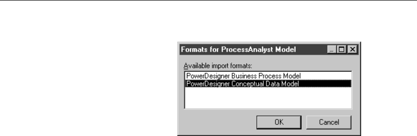
Opening a PAM into a CDM
6. Select PowerDesigner Conceptual Data Model and click OK.
The Output window displays a message following the successful import
and the default diagram of the model appears. Each imported object type
can be viewed from its respective list.
152

CHAPTER 5
Generating from a Conceptual Data Model
About this chapter This chapter describes how you can generate a CDM, a PDM, and an OOM
from a Conceptual Data Model.
Contents Topic: page
Generation basics 154
Generating a Conceptual Data Model from a Conceptual Data
Model
155
Generating a Physical Data Model from a Conceptual Data Model 157
Generating an Object Oriented Model from a Conceptual Data
Model
171
153

Generation basics
Generation basics
You can generate a CDM, a PDM, or an OOM from a CDM.
+For more information on model to model or inter-model generation
common features, see the “Linking and Synchronizing Models in
PowerDesigner” chapter in the
General Features Guide
.
154

Chapter 5. Generating from a Conceptual Data Model
Generating a Conceptual Data Model from a
Conceptual Data Model
This section explains how to generate a Conceptual Data Model from a
Conceptual Data Model.
Why generate a CDM into a CDM?
You can generate a CDM into a CDM when you need to keep two models
synchronized during the design process.
This kind of generation allows you to create a copy of a given model and
define generation links between objects in the source CDM and their
equivalent in the generated CDM. When changes are made to the source
model, they can then be easily propagated to the generated models using the
Update Existing Model generation mode.
The generated model is the one that usually contains more information.
Generating and updating a CDM
To generate a CDM, you must choose between one of the following
methods:
♦Generate new Conceptual Data Model
♦Update existing Conceptual Data Model
You must indicate the following parameters when you generate a new CDM:
Parameter Description
Name File name for the resulting CDM
Code Reference code for the resulting CDM
Configure
Model Options
Lets you define the model options for the new CDM
+For more information, see the “Linking and Synchronizing Models in
PowerDesigner” chapter in the
General Features Guide
.
Defining CDM generation options
You can set the following general generation options:
155
Generating a Conceptual Data Model from a Conceptual Data Model
Option Description
Check Model When selected, verifies the model before generating the
CDM, and stops generation if an error is found
Save Genera-
tion Dependen-
cies
When selected, PowerDesigner keeps track of the identity
of the origin of each generated object. It is useful when
merging two CDM which have been generated from the
same CDM. Objects can be compared and recognized as
the same object, even if the object has been modified in
the merged CDM. If not selected, origin objects have no
link with generated objects
Enable transfor-
mations
This button is used to activate transformations during
generation.
When you click this button, the Pre-generation tab appears
if the source model contains transformations. You can
select the transformations to execute before generation.
The Extended Model Definitions tab also appears for you
to select extended model definition files to attach to the
generated model. These files may contain post-generation
transformations, in this case, the Post-Generation tab
appears to let you select the transformations you want
to be executed in the generated model. If the generation
is an update, and the generated model contains extended
model definitions with post-generation transformations,
the Post-generation tab automatically appears as soon as
you click the Enable Transformations button
Check model before generation
If you select the Check Model option, the procedure to generate a CDM
starts by checking the validity of the CDM . A CDM results when no errors
are found. You can set check options by selecting Tools äCheck Model.
156
Chapter 5. Generating from a Conceptual Data Model
Generating a Physical Data Model from a
Conceptual Data Model
This section explains how to generate a Physical Data Model from a
Conceptual Data Model.
Generating PDM objects
When you generate a physical data model (PDM) from a CDM,
PowerDesigner converts CDM objects and data types to PDM objects and
data types supported by the current DBMS.
Converting CDM to PDM objects
PDM generation converts conceptual objects into physical objects as
follows:
CDM objects Generated object in a PDM
Entity Table
Entity attribute Table column
Primary identifier Primary or foreign key depending on independent or
dependent relationship
Identifier Alternate key
Relationship Reference
Changing the name of a column automatically
Two columns in the same table cannot have the same name. If column
names conflict due to foreign key migration, PowerDesigner automatically
renames the migrated columns. The new name is composed of the first
three letters of the original entity name followed by the code of the attribute.
Generating keys from identifiers
Primary identifiers generate primary and foreign keys in the PDM.
Identifiers that are not primary identifiers generate alternate keys.
The type of key that is generated in the PDM depends on the cardinality and
type of dependency defined for a relationship in the CDM.
Aprimary key is a column or columns whose values uniquely identify a
row in a table.
157
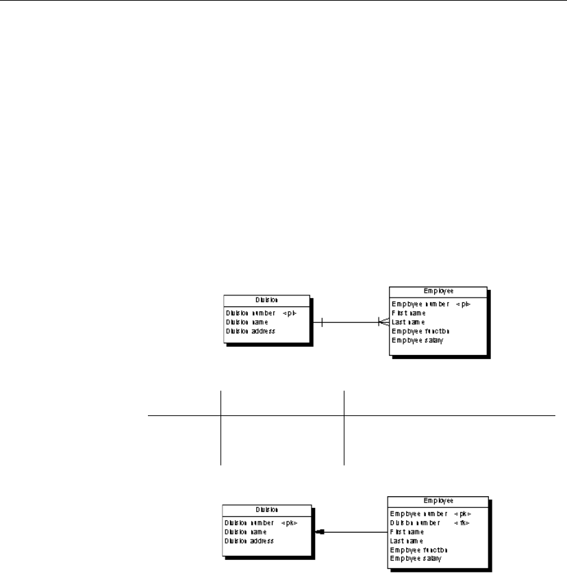
Generating a Physical Data Model from a Conceptual Data Model
Aforeign key is a column or columns that depend on and migrate from a
primary key column in another table.
An alternate key is a column or columns whose values uniquely identify a
row in a table, and is not a primary key.
Independent
one-to-many
relationships
In independent one-to-many relationships, the primary identifier of the entity
on the one side of the relationship becomes a:
♦Primary key in the table generated by the entity on the one side of the
relationship
♦Foreign key in the table generated by the entity on the many side of the
relationship
The CDM below shows an independent relationship. Each division contains
one or more employees:
The CDM above generates two tables:
Table Primary key Foreign key
Division Division number —
Employee Employee number Division number
The following PDM results from generation:
Dependent one-to-many
relationships
In dependent relationships, the primary identifier of the nondependent entity
becomes a primary/foreign key in the table generated by the dependent
entity.
The migrated column is integrated into the primary key if it already exists.
The CDM below shows a dependent relationship. Each task must have a
project number.
158
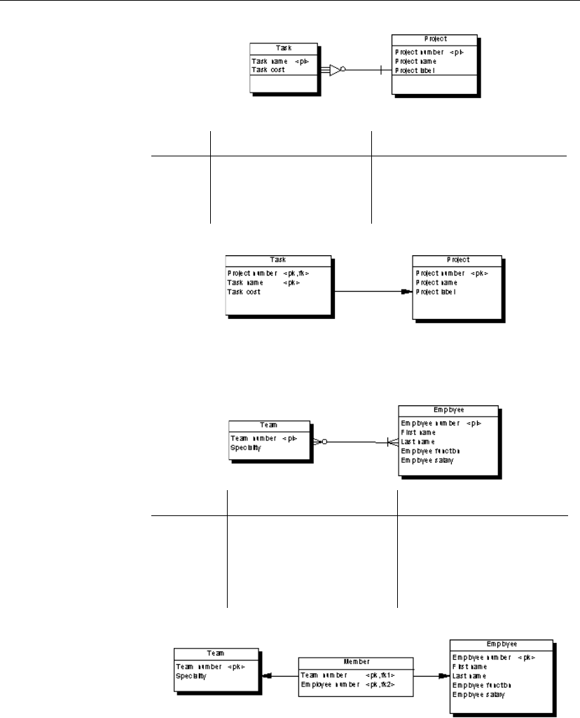
Chapter 5. Generating from a Conceptual Data Model
The CDM above generates two tables:
Table Primary key Foreign key
Project Project number —
Task Project number/Task num-
ber
Project number
The following PDM results from generation.
Independent
many-to-many
relationships
In independent many-to-many relationships, the primary identifiers of both
entities migrate to a join table as primary/foreign keys. The CDM below
shows an independent relationship. Each employee can be a member of one
or more teams, and each team can have one or more employees as members.
Table Primary key Foreign key
Team Team number —
Employee Employee number —
Member Team number/Employee num-
ber
Team number/Employee num-
ber
The following PDM results from generation.
Independent one-to-one
relationships
In independent one-to-one relationships, the primary identifier of one entity
migrates to the other generated table as a foreign key.
159
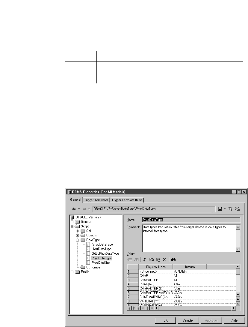
Generating a Physical Data Model from a Conceptual Data Model
Generating tables from entities with inheritance links
Two properties influence the generation of tables from entities with
inheritance links.
Object Property When selected generates
Entity Generate table Table for the entity (parent or child)
Inheritance Generation mode Parent and/or children as indicated
Converting CDM to PDM data types
PowerDesigner supports both conceptual and physical data types. Data types
that you select in the CDM are not always supported by the current DBMS.
In this case, the data type is converted to a data type supported by the current
DBMS when you generate the PDM.
Accessing the DBMS to define data type conversions
Each DBMS contains rules for data type conversion.
The correspondence between the PowerDesigner data type and the physical
data type for the current DBMS is listed under the Data Type node, under the
Script node in the DBMS tree view.
160

Chapter 5. Generating from a Conceptual Data Model
The Physical Model column lists the data types for the current DBMS and
the Internal column lists the PowerDesigner equivalent. You can modify the
definition of an existing physical data type by making modifications directly
to either of the two columns.
Modifying the DBMS
You should only modify a copy of the DBMS shipped with PowerDesigner.
Once a modification has been committed in the DBMS you cannot return
to the default value for the data type.
+For more information on modifying a DBMS, see chapter DBMS Basics
in the Physical Data Model User’s Guide.
vTo access a DBMS
1. Select Tools äResources äDBMS to display the List of DBMS.
2. Select a DBMS from the list.
Click the Properties tool.
or
Double-click a DBMS name in the list.
The DBMS property sheet appears.
3. From the General page, expand the Script node, then expand the Data
Type node.
4. Select the item PhysDataType.
The values for the DBMS data types and the corresponding
PowerDesigner data types appear in the Value pane to the left of the tree
view.
5. Click OK.
Converting conceptual data types
The following table lists the conceptual data types to which the DBMS
assigns conversions:
Numeric data types
Conceptual
data type
Code in
DBMS
What it stores Conversion example
for SQL Anywhere
Integer I 32-bit integer integer
Short Integer SI 16-bit integer smallint
161

Generating a Physical Data Model from a Conceptual Data Model
Conceptual
data type
Code in
DBMS
What it stores Conversion example
for SQL Anywhere
Long Integer LI 32-bit integer integer
Byte BT 256 values smallint
Number N Numbers with a fixed
decimal point
numeric
Decimal DC Numbers with a fixed
decimal point
decimal
Float F 32-bit floating point
decimal numbers
float
Short Float SF Less than 32-bit float-
ing point decimal num-
ber
real
Long Float LF 64-bit floating point
decimal numbers
double
Money MN Numbers with a fixed
decimal point
numeric
Serial NO Automatically incre-
mented numbers
numeric
Boolean BL Two opposing values
(true/false; yes/no;
1/0)
numeric(1)
Character data types
162

Chapter 5. Generating from a Conceptual Data Model
Conceptual
data type
DBMS What it stores Conversion example for
SQL Anywhere
Characters A Character strings char
Variable
Characters
VA Character strings varchar
Long Charac-
ters
LA Character strings varchar
Long Var
Characters
LVA Character strings long varchar
Text TXT Character strings long varchar
Multibyte MB Multibyte charac-
ter strings
char
Variable
Multibyte
VMB Multibyte charac-
ter strings
varchar
Time data types
Conceptual
data type
DBMS What it stores Conversion example
for SQL Anywhere
Date D Day, month, year date
Time T Hour, minute, and
second
time
Date & Time DT Date and time timestamp
Timestamp TS System date and time timestamp
Other data types
163
Generating a Physical Data Model from a Conceptual Data Model
Conceptual
data type
DBMS What it stores Conversion example
for SQL Anywhere
Binary BIN Binary strings binary
Long Binary LBIN Binary strings long binary
Image PIC Images long binary
Bitmap BMP Images in bitmap
format (BMP)
long binary
OLE OLE OLE links long binary
Other * User-defined data
type
char(10)
Undefined
<UNDEF>
Not yet defined data
type
<undefined>
Generating and updating a PDM
To generate a PDM, you must choose between one of the following methods:
♦Generate new Physical Data Model
♦Update existing Physical data Model
You must indicate the following parameters when you generate a new PDM:
Parameter Description
DBMS Database Management System definition (DBMS) for the
resulting PDM
Share The resulting PDM uses a shared DBMS definition file
stored in the DBMS library
Copy The resulting PDM uses a copy of the DBMS definition
file stored in the model
Name File name for the resulting PDM
Code Reference code for the resulting PDM
Configure
Model Options
Lets you define the model options for the new PDM
+For more information, see the “Linking and Synchronizing Models in
PowerDesigner” chapter in the
General Features Guide
.
164

Chapter 5. Generating from a Conceptual Data Model
Configuring the generated PDM options
When you configure the options of a PDM to generate, you may define
options diverging from the CDM options.
To avoid conflicts, PowerDesigner applies the following rule for default
values of PDM options: an option defined for the generated PDM should
respect the equivalent option of the CDM.
Equivalent options are model options found in both models. The Enforce
non-divergence option exists in both CDM and PDM.
CDM option PDM option Result in generated PDM
4En-
force non-
divergence
— Enforce non-divergence in model ac-
cording to CDM options. Columns
attached to the domain cannot have
divergent definitions
—4Enforce non-
divergence
Enforce non-divergence in model ac-
cording to PDM options defined using
the Configure Model Options feature
References unique code Unique Code for references is not selected by default in the PDM options.
However, if you select Unique Code for references in the PDM options,
relationships are renamed during the generation of a CDM to a PDM.
Options with no equivalent, like Use Data Type Full Name in the CDM
without any corresponding option in a PDM, are generated using default
values found in the registry.
Defining PDM generation options
You can set the following general generation options from the Detail page:
165

Generating a Physical Data Model from a Conceptual Data Model
Option Description
Check Model When selected, checks the model before generating the
PDM, and stops generation if an error is found
Save Genera-
tion Dependen-
cies
When selected, PowerDesigner keeps track of the identity
of the origin of each generated object. This is useful when
merging two PDM which have been generated from the
same CDM. Objects can be compared and recognized as
the same object, even if the object has been modified in
the target PDM. If not selected, origin objects have no link
with generated objects
Convert Names
into Codes
When selected, object codes are generated from names
using the corresponding conversion script. This is useful
when generating models with very different naming con-
ventions . For example a Java class attribute code may be
“customerName” whereas a PDM table column code may
be “CUSTOMER_NAME”. With this option selected,
both objects will have their codes generated from their
names. If you do not select this option, generated object
codes will be copied from original object codes
Rebuild Trig-
gers
When selected, allows to build triggers with preservation
option, after the PDM generation. Rebuild takes place
after merge if you are updating an existing PDM
Enable transfor-
mations
This button is used to activate transformations during
generation.
When you click this button, the Pre-generation tab appears
if the source model contains transformations. You can
select the transformations to execute before generation.
The Extended Model Definitions tab also appears for you
to select extended model definition files to attach to the
generated model. These files may contain post-generation
transformations, in this case, the Post-Generation tab
appears to let you select the transformations you want
to be executed in the generated model. If the generation
is an update, and the generated model contains extended
model definitions with post-generation transformations,
the Post-generation tab automatically appears as soon as
you click the Enable Transformations button
+For more information conversion scripts, see section Using a conversion
script in chapter Managing models in the
General Features Guide
.
166
Chapter 5. Generating from a Conceptual Data Model
Check model before generation
If you select the Check Model option, the procedure to generate a PDM
starts by checking the validity of the CDM . A PDM results when no errors
are found. You can set check options by selecting Tools äCheck Model.
Table parameters The following parameter defines the naming convention for tables:
Parameter Description
Table Prefix Prefix for the names of tables generated from entities in the
CDM
Reference parameters The following parameters define default referential integrity constraints:
Parameter Description
Update Rule Default update constraint for referential integrity
Delete Rule Default delete constraint for referential integrity
Foreign key name By default, the name of the migrated foreign keys generated in a PDM is
identical to the name of the primary key. In case of column name conflict,
the first 3 letters of the name of the parent table are added before the name of
the migrated column.
You can modify this default behavior and use templates for naming the
migrated foreign keys. In the Reference groupbox, you can select one of the
predefined templates in the FK Column Name Template dropdown listbox.
These templates are saved in the registry, you can modify them, but their
default value is preserved.
You can also create your own foreign key naming templates by typing a
template directly in the FK Column Name Template box using the following
variables:
167

Generating a Physical Data Model from a Conceptual Data Model
Variable Value
%REFR% Name / Code of the reference
%PARENT% Name / Code of the parent table
%COLUMN% Name / Code of the parent column
%KEY% Name / Code of the key constraint attached to the
reference
%CONSTNAME% Name of the key constraint attached to the reference
(same as %KEY%)
%PROLE% Role of the entity that generated the parent table, this
variable proceeds from the conceptual environment.
If no role is defined on the relationship or association,
%PROLE% takes the content of %PARENT% to
avoid generating a column with no name
You can use the default PowerDesigner formatting variables in the template
as explained in section List of PowerDesigner formatting variables in
chapter Variables in PowerDesigner in the
PDM User’s Guide
.
You can also use square brackets [ ] for evaluating optional variables as
explained in “Optional strings and variables” in the “DBMS Reference
Guide” chapter in the
Advanced User Documentation
.
Customized naming templates reappear in the generation dialog box the next
time you open it, but are not saved in the registry thus not added to the
dropdown list of predefined templates.
For example, if you define the template %PROLE%, the name of the foreign
key will be made of the role beside the entity that generated the parent table
containing the primary key. If the parent table contains multiple keys, the
foreign key names will be automatically renamed.
Other example:
[%PROLE%=%PARENT%?%.3:PARENT%_%COLUMN%:%PROLE%]
This checks the %PROLE% value; if it is equal to the parent name (which is
the replacement value) then the template “%.3:PARENT%_%COLUMN%”
will be used, otherwise template “%PROLE%” will be used because the user
has entered a parent role for the relationship.
In the Reference groupbox, you can select the Always Use Template radio
button to always use the default or customized template for naming FK
168

Chapter 5. Generating from a Conceptual Data Model
columns, even if there is no conflict with an existing column.
Index parameters The following parameters define naming conventions for indexes:
Parameter Description
PK index names Naming convention for primary keys, by default
%TABLE%_PK
Key index names Naming convention for alternate keys, by default
%TABLE%_AK
FK index names Naming convention for foreign keys, by default
%REFR%_FK
FK threshold Minimum number of estimated occurrences of an entity
necessary to create an index on a foreign key
If you enter a value for the index threshold, indexes on foreign keys are only
generated if the number of estimated occurrences is greater than the
threshold. The estimated number of occurrences is an entity property that
you can include in the entity definition.
If the entity has no specified number of occurrences, the foreign key indexes
are generated by default.
PK index name variables You can use the following variables in the PK index names and Key Index
Names fields:
Variable Value
%TABLE% Generated code of the table. This is the table code that is
generated in the database. It may or may not be truncated
if the code contains characters not supported by the
DBMS
%TNAME% Table name
%TCODE% Table code
%TLABL% Table comment
FK index name variables You can use the following variables in the FK index name field. The
generated code of a variable is the code defined in the object property sheet,
but which may or may not be truncated when generated if the code contains
characters not supported by the DBMS
Variable Value
%REFR% Generated code of the reference
169
Generating a Physical Data Model from a Conceptual Data Model
Variable Value
%REFNAME% Reference name
%REFRCODE% Reference code
%PARENT% Generated code of the parent table
%PNAME% Parent table name
%PCODE% Parent table code
%CHILD% Generated code of the child
%CNAME% Child table name
%CCODE% Child table code
%PQUALI-
FIER%
Parent table qualifier
%CQUALI-
FIER%
Child table qualifier
Preserving a modified primary key
If you modify a primary key in a PDM, then regenerate the PDM from a
CDM, the modified primary key is not preserved. If you want to preserve a
modified primary key, you need to modify the identifier in the CDM before
regeneration.
170
Chapter 5. Generating from a Conceptual Data Model
Generating an Object Oriented Model from a
Conceptual Data Model
This section explains how to generate an Object Oriented Model from a
Conceptual Data Model.
Generating OOM Objects
When you generate an Object Oriented Model (OOM) from a CDM,
PowerDesigner converts CDM objects into specified object language objects
as follows:
CDM Objects Generated object in an OOM
Entity Class
Attribute Attribute
Association Relationship or association
Binary association with at-
tributes
Association class
Inheritance Generalization
Persistent entities All entities are generated as persistent classes with the “Generate table”
persistence mode.
When the Generate check box of an entity is not selected, the generated class
has the “Migrate columns” persistence mode.
OOM naming conventions
If the code of the generated OOM objects does not correspond to the target
language naming conventions, you can define a code naming convention
script to convert object names into codes. For more information on
conversion scripts, see section .convert_name & .convert_code macros in
chapter Managing Models in the
General Features Guide.
Converting CDM to OOM data types
PowerDesigner supports both conceptual and object language data types.
The following table lists the conceptual data types to which the object
language definition assigns conversions:
171

Generating an Object Oriented Model from a Conceptual Data Model
Conceptual
data type
Code in
CDM
What it stores Conversion exam-
ple with Java
Characters A Character strings Char
Boolean BL Two opposing values
(true/false; yes/no; 1/0)
Boolean
Byte BT 256 values Byte
Short Integer SI 16-bit integer Short
Long Integer LI 32 bit integer Long integer
Integer I 32 bit integer Integer
Float F 32 floating decimal num-
bers
Float
Number N Numbers with a fixed deci-
mal point
Double
Text TXT Character strings *
Generating and updating an OOM
To generate an OOM, you must choose between one of the following
methods:
♦Generate new Object-Oriented Model
♦Update existing Object-Oriented Model
You must indicate the following parameters when you generate a new OOM:
172
Chapter 5. Generating from a Conceptual Data Model
Parameter Description
Object Language Target object language
Share Object language for the resulting OOM uses a shared
Object language definition file stored in the Object
language library
Copy Object language for the resulting OOM uses a copy of
the Object language definition file stored in the Object
language library
Name File name for the resulting OOM
Code Reference code for the resulting OOM
Configure Model
Options
Lets you define the model options for the new OOM,
you can select the naming conventions corresponding
to the target language for example
+For more information, see the “Linking and Synchronizing Models in
PowerDesigner” chapter in the
General Features Guide
.
Configuring the generated OOM options
When you configure the options of an OOM to generate, you may define
options diverging from the CDM options.
To avoid conflicts, PowerDesigner applies the following rule for default
values of OOM options: an option defined for the generated OOM should
respect the equivalent option of the CDM.
Equivalent options are model options found in both models. The Enforce
non-divergence option exists in both CDM and OOM.
CDM option OOM option Result in generated OOM
4En-
force non-
divergence
— Enforce non-divergence in model ac-
cording to CDM options
—4Enforce non-
divergence
Enforce non-divergence in model ac-
cording to OOM options defined using
the Configure Model Options feature
Options with no equivalent, like Use Data Type Full Name in the CDM
without any corresponding option in an OOM, are generated using default
values found in the registry.
173

Generating an Object Oriented Model from a Conceptual Data Model
Defining OOM generation options
You can set the following general generation options from the Detail page:
Option Description
Check Model When selected, checks the model before generating the
OOM, and stops generation if an error is found
Save Genera-
tion Dependen-
cies
When selected, PowerDesigner keeps track of the identity
of the origin of each generated object. It is useful when
merging two OOM which have been generated from the
same CDM. Objects can be compared and recognized as
the same object, even if the object has been modified in the
target OOM. If not selected, origin objects have no link
with generated objects
Convert Names
into Codes
When selected, object codes are generated from names
using the corresponding conversion script. This is use-
ful when generating models with very different naming
conventions since conversion macros are used to modify
codes. For example a Java class attribute code may be
“customerName” whereas a PDM table column may be
“CUSTOMER_NAME”. With this option selected, both
objects will have their codes generated from their names.
If you do not select this option, generated object codes
will be copied from original object codes
Enable transfor-
mations
This button is used to activate transformations during
generation.
When you click this button, the Pre-generation tab appears
if the source model contains transformations. You can
select the transformations to execute before generation.
The Extended Model Definitions tab also appears for you
to select extended model definition files to attach to the
generated model. These files may contain post-generation
transformations, in this case, the Post-Generation tab
appears to let you select the transformations you want
to be executed in the generated model. If the generation
is an update, and the generated model contains extended
model definitions with post-generation transformations,
the Post-generation tab automatically appears as soon as
you click the Enable Transformations button
Class Prefix Prefix for a class. It can help identify a class in a model
174
Chapter 5. Generating from a Conceptual Data Model
+For more information conversion scripts, see section Using a conversion
script in chapter Managing models in the
General Features Guide
.
Check model before generation
If you select the Check Model option, the procedure to generate an OOM
starts by checking the validity of the CDM . An OOM results when no
errors are found. You can set check options by selecting Tools äCheck
Model.
175

CHAPTER 6
CDM Glossary
association In the Merise modeling methodology an association is a connection between
entities
business rule Written statement specifying what the information system must do or how it
must be structured to support business needs
column Data structure that contains an individual data item within a row in a PDM
Conceptual Data Model
(CDM)
Entity-relationship diagram that models the information system without
considering the details of physical implementation
constraint Named check that enforces data requirements, default values, or referential
integrity on an entity or a entity attribute
data item Elementary piece of information
domain Set of values for which a data item is valid
entity Person, place, thing, or concept that has characteristics of interest to the
enterprise and about which you want to store information
entity attribute Elementary piece of information attached to an entity
foreign key Column or columns in a PDM whose values depend on and migrate from a
primary key, or an alternate key, in another table
Identifier Entity attribute, or a combination of entity attributes, whose values uniquely
identify each occurrence of the entity
Inheritance Special relationship that defines an entity as a special case of a more general
entity
Object-Oriented Model
(OOM)
Structure that is the logical design view of a software system. An OOM is a
conceptual model of a software system
Physical Data Model
(PDM)
Table-reference diagram that models the information system including the
details of physical implementation
primary key Column or columns whose values uniquely identify a row in a table in PDM
property sheet Window that displays the properties of an object
reference Link between a parent table and a child table in a PDM. A reference can link
177

tables by shared keys or by specified columns
referential integrity Rules governing data consistency, specifically the relationships among
primary keys and foreign keys of different tables in a PDM
relationship Named connection or association between entities
stereotype Sub-classification used to extend the semantics of an object without
changing its structure; it can be predefined or user-defined
table Collection of rows (records) in a PDM that have associated columns (fields)
178

Index
A
All Objects option 5
association (CDM) 3
cardinality 101
change to entity 104
check model 146
create from Browser 97
create from diagram 97
create from list 97
define 95, 104
dependent 103
display preferences 108
entity 104
entity attribute 104
properties 96
reflexive 100
validity check 136
association attribute (CDM)
create 105
create from list 107
list 105
validity check 136
association link
cardinality 101
create from diagram 98
create from list 98, 99
define 96
display preferences 109
drag 98
properties 96
symbol 98
attribute (CDM) 3
association 105
enforce coherence 10
B
bibliography vii
binary data type 46, 163
bitmap data type 46, 163
boolean data type 44, 161
business rule (CDM) 22, 23
apply 27, 126
check model 136
create 24
definition 23
domain (CDM) 50
expression 26, 126
fact 23
formula 23
properties 23
requirement 23
type 23
validation 23
validation rule 126
byte data type 44, 161
C
cardinality
association (CDM) 101
change format 101
change from the registry 101
define 80
define for an association link 101
many to many 80
many to one 80
one to many 80
one to one 80
relationship 80, 91
CDM
check 130, 131, 135
check options 130
check results 134
close 17
correct 134, 135
create 14
data type 161
define 2, 13
detach from workspace 17
domain 40
enable transformations 155
enforce domain 4
Entity Relationship Diagram 2
ERD 2
179

Index
error 36, 79, 130, 131, 134, 135
extended dependency 12
extended model definition 11
generate 154, 155
generation option 155
generation parameter 155
logical model 2
modify properties 13
object 3, 157, 171
open 16
open PAM 151
option 11, 35, 79
package 18
role 2
save 17
validate 130
warning 130, 131, 134, 135
CDM environment 4
Change to Entity Wizard 89
check model
association (CDM) check 146
automatic correction 130
business rule (CDM) 136
CDM 130, 131, 135
correct 134, 135
data item check 139
domain check 137
entity attribute check 143
entity check 141
entity identifier check 143
error severity 130
extended link 149
extended object 149
file object 148
global model 131
inheritance check 148
model 136
object parameters 136
option 130, 131, 136
package (CDM) check 136
relationship 144
replication (CDM) check 149
set error severity 130
warning 130
check parameter
column 123, 126
data type 37, 65
define 123
domain (CDM) 50, 123, 126
properties 123
standard 123
type 123
validation rule 22, 123, 126
client
business rule (CDM) 26
expression 26, 126
close CDM 17
code
data item 35
option 79
package (CDM) 19
relationship 79
unique 35, 79
code naming convention 171
column
check parameter 123, 126
generate 157
rename 157
validation rule 126
variable 126
composite view 18
configure
OOM options 173
PDM options 165
convert
CDM to OOM objects 171
CDM to PDM objects 157, 160
data type 160, 171
correct
automatic 130
CDM 134, 135
check 134, 135
error 130
manual 135
D
data item 3
add as entity attribute 34, 60
associate domain 36
association 105
check model 139
code 35
copy 54
create from Browser 31
180

Index
create from list 31
data type 37, 66
define 30
delete 33, 67
domain (CDM) 36
duplicate 34
error 36
non-divergence 50
option 34, 54
properties 30
reuse 4, 35, 60, 67
sort list 39
unique 4
unique code 35
use as entity attribute 60
validity check 136
data type 42, 44
binary 46, 163
bitmap 46, 163
boolean 44, 161
byte 44, 161
character 45
conceptual 161
conversion in DBMS 160
convert to OOM 171
convert to PDM 160
data item 37, 66
date 46, 163
decimal 44, 161
default 4
define 160
domain (CDM) 42, 43, 48, 50
entity attribute 64
float 44, 161
image 46, 163
integer 44, 161
length 42, 44
map to OOM 171
map to PDM 160
money 44, 161
number 44, 161
OLE 46, 163
precision 42, 44
select 37, 64
select from list 42
select from property sheet 42, 43
select from the list 43
serial 44, 161
show full name 4
time 46, 163
undefined 37, 42, 43, 46, 48, 66, 163
Data Type Full Name option 10
date data type 46, 163
DBMS data type conversion 160
decimal data type 44, 161
Default Data Type option 11
delete data item 67
dependent association (CDM) 103
detach CDM from workspace 17
display preference
association (CDM) 108
association link 109
entity 56
inheritance 122
package (CDM) 20
relationship 93
diverge from domain 10
domain (CDM) 3
business rule 50
CDM 40
check model 137
check parameter 50, 123, 126
create from Browser 41
create from list 41
data item 36
data type 42–44, 48, 50
define 40
diverge from 10
enforce 50
enforce coherence 4, 10
entity attribute 50, 63
length 42, 44
modify properties 48
non-divergence 50
precision 42, 44
properties 40
use 50
validation rule 126
validity check 136
variable 126
Domain and Attribute option 10
dominant relationship 87
duplicate data item 34
181

Index
E
E/R + Merise 6
enforce domain (CDM) 50
entity 3
add to inheritance 113
association 104
associative 89
change from association 104
change from relationship 89
check model 141
copy 54
create from Browser 52
create from diagram 52
create from list 52
define 52
delete 67
display preferences 56
entity attribute 54, 67
generate table 160
identifier 54, 67, 69
inheritance 110, 160
modify from list 54
modify from property sheet 54
properties 52, 54
validity check 136
wizard 89
entity attribute
add 34, 60
add to identifier 71
associate domain 63
association 104
attach to domain 63
check model 143
copy 54
create 62
create from data item 60
create from list 60
data item 34, 60
data type 64
define 59
delete 67
domain (CDM) 50, 63
entity 67
identifier 54, 67, 69
inheritance 118
list 62, 67
mandatory 66
optional 66
properties 59, 118
relationship 89
reuse 60, 67
specifying entity attribute 118, 120
validity check 136
entity identifier check 143
entity/relationship 6
notation 4
ERD
CDM 2
Entity Relationship Diagram 2
Relationship tool 3
error
check model 130
severity 130
error message
CDM 130, 131, 134
data item 36
display 134
relationship 79
unique code 36, 79
expression
business rule (CDM) 26, 126
client 26, 126
server 26, 126
extended dependency (CDM) 12
extended link
check 149
code uniqueness 150
name uniqueness 150
extended model definition (CDM) 11
extended object
check 149
code uniqueness 149
name uniqueness 149
F
file object
check 148
external 149
name uniqueness 148
float data type 44, 161
foreign key 167
generate 169
generate from identifier 157
index 169
182

Index
name 169
name template for generation 167
G
general option 35, 79
generate
CDM 154, 155
CDM from CDM 155
column 157
configure OOM options 173
configure PDM options 165
foreign key 157, 169
foreign key name 167
index parameter 169
inheritance 160
new CDM 155
new model 154
new OOM 172
new PDM 164
OOM 172–174
OOM from CDM 171
OOM object 171
OOM object conversion 171
PDM 164, 165
PDM from CDM 157
PDM object 157
PDM object conversion 160
PDM option 165
primary key 157, 169
reference parameter 167
table 160
table parameter 167
update existing CDM 155
update model 154
validation rule 126
global model
CDM 131
check 131
I
IDEF1X 6
identifier 69
child 117
copy 54
define 69
delete 67
designate 69
entity attribute 54, 67, 71
generate key 157
modify from list 73
modify from property sheet 73
parent 117
primary identifier 72
image data type 46, 163
Include Sub-Objects tool 131
index
foreign key 169
generate 169
primary key 169
inheritance 3
add child entity 113
check model 148
child 116
complete 110
create 112
define 110, 117, 120
display preferences 122
entity attribute 118
generate 116
generation mode 116, 117
link 112
mutually exclusive 115
parent 116
primary key 117
properties 110, 116
specifying entity attribute 120
validity check 136
integer data type 44, 161
L
list
arrange 67
order 67
location for file object 149
logical model 2
M
manual correction 135
map
CDM to OOM 171
CDM to PDM 160
Merise 6
association (CDM) 95
notation 4
183

Index
model
object selection 131
OOM options 173
open 151
option 35, 79
PDM options 165
sub-object 131
model option
all objects 5
data item 9
data type full name 10
default data type 11
domain and attribute 10
notation 6
relationship 10
money data type 44, 161
N
name
file object 148
foreign key 169
package (CDM) 19
primary key 169
name uniqueness
extended link 150
extended object 149
Name/Code Case Sensitive option 4
namespace for package (CDM) 19
non-divergence
data item 50
domain (CDM) 50
notation
Entity/Relationship 4
Merise 4
Notation option 6
number data type 44, 161
O
object
business rule (CDM) 27
CDM 3
object selection
check 131
model 131
package 131
OLE data type 46, 163
OOM
code naming convention 171
enable transformations 174
generate object 171
generation option 174
generation parameter 172
map CDM object 171
object 171
option
CDM 35, 79
check 130, 131, 136
code 79
configure for generated OOM 173
configure for generated PDM 165
data item 34, 54
general 35, 79
model 35, 79
relationship 79
P
package (CDM)
CDM 18
check model 136
code 19
comment 19
composite view 18
create 19
define 18
display preferences 20
name 19
namespace 19
object selection 131
properties 19
shortcut code uniqueness 137
shortcut generated as child table 137
validity check 136
PAM opened into CDM 151
PDM
enable transformations 165
generate 164
generate object 157
generation option 165
generation parameter 164
map CDM object 160
object 157
update 164
precision 42, 44
primary identifier 72
184

Index
primary key
child 117
generate 169
generate from identifier 157
index 169
inheritance 117
name 169
R
reference
foreign key name 167
generate 167
reflexive association (CDM) 100
relationship 3
associative entity 89
bend 94
cardinality 80, 91
change to entity 89
check model 144
code 79
create 78
create from Browser 76
create from diagram 76
create from list 76
define 75, 85, 87, 89
dependent 85
display 94
display preferences 93
dominant 87
drag 94
entity attribute 89
ERD 3
error 79
example 91
mandatory 83
modify 94
modify from list 79
modify from property sheet 79
option 79
optional 83
properties 75, 79
reflexive 78
sort list 90
termination point 81, 83
unique code 4, 79
Relationship option 10
replication (CDM) check 149
rule 23
S
save CDM 17
serial data type 44, 161
server
business rule (CDM) 26
expression 26, 126
shortcut code uniqueness in package 137
shortcut generated as child table 137
specifying attribute
create 120, 121
list 120, 121
specifying entity attribute 118, 120
standard data type list 44
sub-object check 131
Sybase SQL Anywhere data types 161
T
table generation 160, 167
time data type 46, 163
type of business rule (CDM) 23
typographic conventions vi
U
undefined data type 37, 42, 43, 48, 66
V
validation rule 123
apply 126
business rule (CDM) 126
check parameter 126
column 126
domain (CDM) 126
generate 126
variable
column 126
domain (CDM) 126
W
warning in CDM check 130, 131, 134, 135
warning message of last check 134
185
