Core Flight System (CFS) Health & Safety (HS) Application User's Guide CFS HS User Doc No 582 2013 002
CFS%20HS%20User%20Guide%20Doc%20No%20582-2013-002
CFS%20HS%20User%20Guide%20Doc%20No%20582-2013-002
CFS%20HS%20User%20Guide%20Doc%20No%20582-2013-002
CFS%20HS%20User%20Guide%20Doc%20No%20582-2013-002
CFS%20HS%20User%20Guide%20Doc%20No%20582-2013-002
User Manual: Pdf
Open the PDF directly: View PDF ![]() .
.
Page Count: 135 [warning: Documents this large are best viewed by clicking the View PDF Link!]
Core Flight System (CFS)
Health and Safety (HS)
Version 2.3.0.0
APPLICATION USER’S GUIDE
for Flight Operations Team
CFS Health and Safety (HS) monitors applications and events;
manages the watchdog timer; and reports on CPU utilization,
CPU aliveness, and execution counters
Flight Software Systems Branch – Code 582
Version 1.1 – 09/20/16
582-2013-002
Goddard Space Flight Center
Greenbelt, Maryland
National Aeronautics and
Space Administration

CFS HS APPLICATION USER’S GUIDE - 582-2013-002, Ver. 1.0, 03/24/14 Page ii
The controlled copy of this document is located online at https://fsb.gsfc.nasa.gov/CFS/
FORWORD
This is a generic, reusable guide. It is set up to be easily tailored for any mission. Remove or replace
the type in this orange color during tailoring.
This Core Flight System (CFS) Health and Safety (HS) Application User’s Guide provides
guidance for the Flight Operations Team (FOT) for the CFS HS Application.
This is one of a set of enhanced User Guides for the CFS Product Documentation Suite. While the
main audience is the FOT, the Guides also help serve the needs of flight software developers; Flight
Software Sustaining Engineering (FSSE), Integration and Test (I&T), and others who support
missions which use CFS.

CFS HS APPLICATION USER’S GUIDE - 582-2013-002, Ver. 1.0, 03/24/14 Page iii
The controlled copy of this document is located online at https://fsb.gsfc.nasa.gov/CFS/
The signatures on this page apply to the document as distributed before mission tailoring.
AUTHOR
_____________________________________ ________________
Gary M Smith Date
Technical Writer
APPROVALS
_____________________________________ ________________
Susanne Strege / 582 Date
Core Flight Executive (cFE) Core Flight System (CFS) / Product Development Lead (PDL)
_____________________________________ ________________
Charles Wildermann / 582 Date
Flight Software Systems Branch (FSB) / Head
CFS HS APPLICATION USER’S GUIDE - 582-2013-002, Ver. 1.0, 03/24/14 Page iv
The controlled copy of this document is located online at https://fsb.gsfc.nasa.gov/CFS/
UPDATE HISTORY
Version
Date
Description
Affected Pages
Draft 0.1
5/10/13
Rough Draft
All
Draft 0.2
8/30/13
Rewrite Based on Draft Review
All
Draft 0.3
01/10/14
Rewrite Based on 0.2 Review
All
Draft 0.4
01/16/14
Resolve Known Issues prior to Formal Document
Review
iv to xi; 1-2 to 1-
4; 2-2 to 2-3; 2-
14, 2-25; 2-33,
2-38, 2-41 to
end; headers of
all pages
1.0
3/24/14
Final Version
All
1.1
9/20/16
Removed use of the term ‘critical’ when referencing
application and event monitoring
2-7, 2-11, 2-18,
A-9, A-10, A-18,
A-51, A-52, A-
55, A-64
CFS HS APPLICATION USER’S GUIDE - 582-2013-002, Ver. 1.0, 03/24/14 Page v
The controlled copy of this document is located online at https://fsb.gsfc.nasa.gov/CFS/
CONTENTS
CHAPTER 1. INTRODUCTION TO THE CFS HS USER’S GUIDE ............... 1-1
1.1 Purpose and Scope of this Guide ................................................................ 1-1
1.2 Acknowledgements ...................................................................................... 1-1
1.3 Conventions and Terminology ................................................................... 1-1
1.4 Related Documents ...................................................................................... 1-2
1.5 Assumptions ................................................................................................. 1-3
1.5.1 Personnel ....................................................................................................... 1-3
1.5.2 Software......................................................................................................... 1-3
1.6 How to Use this Document .......................................................................... 1-4
1.6.1 Hyperlinks in this Document ......................................................................... 1-4
1.6.2 Printing this Document .................................................................................. 1-5
1.6.3 Providing Feedback ....................................................................................... 1-5
1.7 Acronyms and Abbreviations ..................................................................... 1-5
CHAPTER 2. INTRODUCTION TO THE CFS HS APPLICATION................. 2-1
2.1 Heritage ........................................................................................................ 2-1
2.2 CFS HS High Level Overview .................................................................... 2-1
2.2.1 Inputs to CFS HS ........................................................................................... 2-2
2.2.2 Outputs from CFS HS ................................................................................... 2-2
2.2.3 CFS HS Software Context ............................................................................. 2-3
2.3 CFS HS Detailed Overview......................................................................... 2-2
2.3.1 Summary of Tables Used by CFS HS ........................................................... 2-2
2.3.2 Program Flow ................................................................................................ 2-3
2.3.3 Application Monitoring ................................................................................. 2-4
Detailed Overview .................................................................................... 2-5
2.3.3.1.1 An Example: Application Monitoring and Execution Counters ........ 2-5
Application Monitor Table ....................................................................... 2-7
Updates to the Application Monitor Table ............................................... 2-9
Monitoring and Responding to Nonrunning Applications ....................... 2-9
Application Monitoring Considerations ................................................. 2-10
Telemetry, Configuration Parameters, Commands, and Events ............. 2-11
2.3.4 Event Monitoring ........................................................................................ 2-14
Detailed Overview .................................................................................. 2-14
Event Monitor Table ............................................................................... 2-14
Updates to the Event Monitor Table ....................................................... 2-16
Event Monitoring - Order of Operation .................................................. 2-17
CFS HS APPLICATION USER’S GUIDE - 582-2013-002, Ver. 1.0, 03/24/14 Page vi
The controlled copy of this document is located online at https://fsb.gsfc.nasa.gov/CFS/
Event Monitoring Considerations ........................................................... 2-17
Telemetry, Configuration Parameters, Commands, and Events ............. 2-18
2.3.5 Message Actions .......................................................................................... 2-21
Detailed Overview .................................................................................. 2-21
Message Actions Table ........................................................................... 2-21
Updates to the Message Actions Table ................................................... 2-22
Telemetry, Configuration Parameters, and Events ................................. 2-22
2.3.6 Watchdog Timer Management .................................................................... 2-24
Telemetry, Configuration Parameters, Commands, and Events ............. 2-25
2.3.7 Execution Counter Reporting ...................................................................... 2-26
Detailed Overview .................................................................................. 2-26
2.3.7.1.1 Housekeeping Packet Slots for Execution Counters ........................ 2-27
Execution Counter Table ........................................................................ 2-27
Updates to the Execution Counter Table ................................................ 2-28
Telemetry, Error and Informational Events ............................................ 2-28
2.3.8 Processor Reset Limiting ............................................................................. 2-30
Detailed Overview .................................................................................. 2-30
Telemetry, Configuration Parameters and Events .................................. 2-30
2.3.9 CPU Management and Reporting ................................................................ 2-32
CPU Aliveness Indicator ........................................................................ 2-32
2.3.9.1.1 Telemetry, Configuration Parameters, Commands, and Events ...... 2-32
Monitoring of CPU Utilization and Hogging ......................................... 2-33
2.3.9.2.1 Telemetry, Configuration Parameters, Commands, and Events ...... 2-34
2.3.9.2.2 CPU Utilization and CPU Hogging Considerations ........................ 2-36
2.3.9.2.3 Determining CPU Utilization Monitoring Settings .......................... 2-37
CHAPTER 3. CFS HS NORMAL OPERATIONS ........................................... 3-1
3.1 CFS HS Modes of Operation ...................................................................... 3-1
3.2 Initialization ................................................................................................. 3-1
3.2.1 cFE Power-On Reset ..................................................................................... 3-1
3.2.2 cFE Processor Reset ...................................................................................... 3-1
3.3 CFS HS Order of Operation ....................................................................... 3-2
CHAPTER 4. ADDITIONAL CFS HS OPERATIONAL CONSIDERATIONS 4-1
4.1 Dependence on cFE Services ...................................................................... 4-1
4.2 Execution Counter Reporting .................................................................... 4-1
4.3 Application and Event Monitoring ............................................................ 4-1
4.3.1 Startup ........................................................................................................... 4-1
4.3.2 Application Name Validation ........................................................................ 4-1
4.3.3 Updating the Application or Event Monitor Table ........................................ 4-2
CHAPTER 5. FREQUENTLY ASKED QUESTIONS (FAQS) ........................ 5-1

CFS HS APPLICATION USER’S GUIDE - 582-2013-002, Ver. 1.0, 03/24/14 Page vii
The controlled copy of this document is located online at https://fsb.gsfc.nasa.gov/CFS/
5.1 What happens when CFS HS is commanded to disable Event Monitoring
and there is a failure in unsubscribing to event messages? ..................... 5-1
5.2 Why is there no option to start an RTS in response to Application
Monitoring failure or Event Monitoring detection? ................................ 5-1
5.3 What if no Message Actions are needed? .................................................. 5-1
5.4 What if no events need to be monitored? .................................................. 5-2
5.5 Applications monitor their own child tasks, so why does the Execution
Counter Table allow entries for application child tasks? ........................ 5-2
5.6 Can mission developers use generic execution counters in CFS HS? ..... 5-2
5.7 Why does CFS HS exit if there is a software bus problem instead of
continuing to monitor applications? .......................................................... 5-2
APPENDIX A CFS HS REFERENCE ............................................................ A-1
A.1 Command, Housekeeping, and Wakeup Messaging Identifiers ................................. A-1
A.2 Telemetry ......................................................................................................................... A-3
A.3 Configuration Parameters ............................................................................................. A-9
A.4 CFS HS Commands ...................................................................................................... A-27
A.5 Event Messages ............................................................................................................. A-39
A.5.1 Event Messages - CRITICAL ................................................................................. A-39
A.5.2 Event Messages - ERROR ....................................................................................... A-40
A.5.3 Event Messages - INFORMATION ........................................................................ A-59
A.5.4 Event Messages - DEBUG ...................................................................................... A-63
APPENDIX B DOCUMENT NOTES .............................................................. B-1
B.1 Mission-Specific Conventions ........................................................................................ B-1
B.2 Updating This Document ............................................................................................... B-1
TABLE OF FIGURES
Figure 1 CFS HS Typical Software Context ................................................................................ 2-1
Figure 2 CFS HS Overall Internal Program Flow ........................................................................ 2-3
Figure 3 CFS HS Flow Control Detail (A) – Process CFS HS Monitors ..................................... 2-4
Figure 4 CFS HS Flow Control Detail (B) – Process Event ........................................................ 2-4
Figure 5 Application Monitoring Execution Counter Operation, Simplified ............................... 2-6
Figure 6 CFS HS Typical Program Flow - Application Monitoring .......................................... 2-10

CFS HS APPLICATION USER’S GUIDE - 582-2013-002, Ver. 1.0, 03/24/14 Page viii
The controlled copy of this document is located online at https://fsb.gsfc.nasa.gov/CFS/
TABLES
Table 1 Related Documents.......................................................................................................... 1-3
Table 2 Acronyms and Abbreviations .......................................................................................... 1-5
Table 3 Software Context Detail .................................................................................................. 2-1
Table 4 Application Monitor Table – Contents and Validation ................................................... 2-7
Table 5 Application Monitor Table – Action Type Elements ...................................................... 2-8
Table 6 Application Monitoring Summary – Telemetry ............................................................ 2-11
Table 7 Application Monitoring Summary – Configuration Parameters ................................... 2-11
Table 8 Application Monitoring Summary – Commands .......................................................... 2-12
Table 9 Application Monitoring Summary – Error Messages.................................................... 2-12
Table 10 Application Monitoring Summary – Informational Messages .................................... 2-13
Table 11 Application Monitoring Summary – Debug Messages ............................................... 2-13
Table 12 Event Monitor Table – Contents and Validation ......................................................... 2-14
Table 13 Event Monitor Table – Action Type Elements ............................................................ 2-15
Table 14 Event Monitoring – Telemetry Summary .................................................................... 2-18
Table 15 Event Monitoring – Configuration Parameter Summary ............................................ 2-18
Table 16 Event Monitoring – Command Summary ................................................................... 2-19
Table 17 Event Monitoring – Error Message Summary ............................................................. 2-19
Table 18 Event Monitoring – Informational Message Summary ............................................... 2-20
Table 19 Event Monitoring – Debug Message Summary .......................................................... 2-20
Table 20 Message Actions Table – Contents and Validation ..................................................... 2-21
Table 21 Message Actions – Telemetry ..................................................................................... 2-23
Table 22 Message Actions – Configuration Parameters ............................................................ 2-23
Table 23 Message Actions – Error Message Summary .............................................................. 2-23
Table 24 Message Actions – Informational Message Summary ................................................ 2-24
Table 25 Watchdog Timer – Telemetry Summary ..................................................................... 2-25
Table 26 Watchdog Timer – Configuration Parameter Summary .............................................. 2-25
Table 27 Watchdog Timer – Command Summary ..................................................................... 2-26
Table 28 Watchdog Timer – Error Message Summary .............................................................. 2-26
Table 29 Execution Counter Table – Contents and Validation .................................................. 2-27
Table 30 Execution Counter Table – Resource Type Elements ................................................. 2-28
Table 31 Execution Counters – Telemetry Summary ................................................................ 2-28
Table 32 Execution Counters – Configuration Parameter Summary ......................................... 2-29
Table 33 Execution Counters – Error Message Summary ......................................................... 2-29
Table 34 Execution Counters – Informational Message Summary ............................................ 2-29
Table 35 Processor Reset Limiting – Telemetry Summary ........................................................ 2-30
Table 36 Processor Reset Limiting – Configuration Parameter Summary ................................. 2-30
Table 37 Processor Reset Limiting – Command Summary ....................................................... 2-31
Table 38 Processor Reset Limiting – Debug Message Summary .............................................. 2-31
Table 39 CPU Aliveness Indicator – Telemetry Summary ........................................................ 2-32
Table 40 CPU Aliveness Indicator – Configuration Parameter Summary ................................. 2-32
Table 41 CPU Aliveness Indicator – Command Summary ........................................................ 2-33
Table 42 CPU Aliveness Indicator – Debug Message Summary ............................................... 2-33
Table 43 Monitoring of CPU Utilization and Hogging – Telemetry Summary ......................... 2-34
Table 44 Monitoring of CPU Utilization and Hogging – Configuration Parameter Summary .. 2-34
Table 45 Monitoring of CPU Utilization and Hogging – Command Summary ......................... 2-36
Table 46 Monitoring of CPU Utilization and Hogging – Error Message Summary .................. 2-36
Table 47 Monitoring of CPU Utilization and Hogging – Debug Message Summary ................ 2-36

CFS HS APPLICATION USER’S GUIDE - 582-2013-002, Ver. 1.0, 03/24/14 Page ix
The controlled copy of this document is located online at https://fsb.gsfc.nasa.gov/CFS/
Table 48 Message ID – Commands to CFS HS .......................................................................... A-1
Table 49 Message ID – Housekeeping Packet Request to CFS HS ............................................ A-1
Table 50 Message ID – Wake Up CFS HS ................................................................................. A-1
Table 51 Message ID – Housekeeping Telemetry From CFS HS ............................................... A-2
Table 52 Telemetry Data – CFS HS Application Command Counter......................................... A-3
Table 53 Telemetry Data – CFS HS Application Command Error Counter ............................... A-3
Table 54 Telemetry Data – Status – CFS HS Application Monitoring ....................................... A-3
Table 55 Telemetry Data – Status – CFS HS Event Monitor ...................................................... A-4
Table 56 Telemetry Data – Status – CFS HS Aliveness Indicator .............................................. A-4
Table 57 Telemetry Data – Status – CPU Hogging Indicator ..................................................... A-4
Table 58 Telemetry Data – Internal Status .................................................................................. A-4
Table 59 Telemetry Data – CFS HS Performed Processor Reset Counter .................................. A-5
Table 60 Telemetry Data – CFS HS Maximum Processor Reset Count ..................................... A-6
Table 61 Telemetry Data – Total Count – Event Messages Monitored ...................................... A-6
Table 62 Telemetry Data – Total Count – Invalid Event Monitors ............................................. A-6
Table 63 Telemetry Data – Array – Application Monitor Table Entry Enable States ................ A-6
Table 64 Telemetry Data – CFS HS Number of Message Actions Executed ............................. A-7
Table 65 Telemetry Data – CPU Utilization – Average .............................................................. A-7
Table 66 Telemetry Data – CPU Utilization – Peak ................................................................... A-7
Table 67 Telemetry Data – Array – Execution Counts ............................................................... A-8
Table 68 Configuration Parameter – Application Monitor Table Filename ................................ A-9
Table 69 Configuration Parameter – Application Monitoring – Default State ........................... A-9
Table 70 Configuration Parameter – Application Monitoring – Max Apps to Monitor.............. A-9
Table 71 Configuration Parameter – CFS HS Application Name ............................................. A-10
Table 72 Configuration Parameter – CFS HS Application Version No. - Mission Specific ..... A-10
Table 73 Configuration Parameter – CPU Aliveness Indicator – Default State ........................ A-11
Table 74 Configuration Parameter – CPU Aliveness Indicator – Output Period ...................... A-11
Table 75 Configuration Parameter – CPU Aliveness Indicator – Output String ....................... A-11
Table 76 Configuration Parameter – CPU Average Utilization Number of Intervals ............... A-12
Table 77 Configuration Parameter – CPU Hogging Indicator Default State ............................ A-12
Table 78 Configuration Parameter – CPU Peak Utilization Number of Intervals..................... A-12
Table 79 Configuration Parameter – CPU Utilization Calls per Mark ...................................... A-13
Table 80 Configuration Parameter – CPU Utilization – Conversion Factor Division .............. A-13
Table 81 Configuration Parameter – CPU Utilization – Conversion Factor Multiplication 1 .. A-14
Table 82 Configuration Parameter – CPU Utilization – Conversion Factor Multiplication 2 .. A-14
Table 83 Configuration Parameter – CPU Utilization – Cycles per Interval ............................ A-14
Table 84 Configuration Parameter – CPU Utilization – Diagnostics Array Configuration ...... A-15
Table 85 Configuration Parameter – CPU Utilization – Diagnostics Mask .............................. A-15
Table 86 Configuration Parameter – CPU Utilization – Hogging Timeout .............................. A-15
Table 87 Configuration Parameter – CPU Utilization – Hogging Utils per Interval ................ A-16
Table 88 Configuration Parameter – CPU Utilization – Time Diagnostic Array Length ......... A-16
Table 89 Configuration Parameter – CPU Utilization – Time Diagnostic Array Mask ............ A-16
Table 90 Configuration Parameter – CPU Utilization – Total Utils per Interval ...................... A-17
Table 91 Configuration Parameter – Event Monitoring – Event Monitor Table Filename ....... A-17
Table 92 Configuration Parameter – Event Monitoring – Default State ................................... A-17
Table 93 Configuration Parameter – Event Monitoring – Maximum Number of Events ......... A-18
Table 94 Configuration Parameter – Execution Counter Table Filename ................................ A-18
Table 95 Configuration Parameter – Execution Counters Maximum Reported Number .......... A-19
Table 96 Configuration Parameter – Idle Child Task – Parameter Name ................................. A-19
Table 97 Configuration Parameter – Idle Child Task – Flags ................................................... A-19
Table 98 Configuration Parameter – Idle Child Task – Priority ............................................... A-20

CFS HS APPLICATION USER’S GUIDE - 582-2013-002, Ver. 1.0, 03/24/14 Page x
The controlled copy of this document is located online at https://fsb.gsfc.nasa.gov/CFS/
Table 99 Configuration Parameter – Idle Child Task – Stack Pointer ...................................... A-20
Table 100 Configuration Parameter – Idle Child Task – Stack Size ......................................... A-20
Table 101 Configuration Parameter – Message Action – Maximum Size ................................ A-21
Table 102 Configuration Parameter – Message Action – Maximum Types ............................. A-21
Table 103 Configuration Parameter – Message Actions – Table Filename .............................. A-22
Table 104 Configuration Parameter – Processor Reset – Activation Wait Time ...................... A-22
Table 105 Configuration Parameter – Processor Resets – Maximum CFS HS Number ........... A-22
Table 106 Configuration Parameter – Processor Resets – cFE Maximum Processor Resets .... A-23
Table 107 Configuration Parameter – Software Bus – Command Pipe Depth ......................... A-24
Table 108 Configuration Parameter – Software Bus – Event Pipe Depth ................................. A-24
Table 109 Configuration Parameter – Software Bus – Wakeup Message Timeout .................. A-24
Table 110 Configuration Parameter – Software Bus – Wakeup Pipe Depth ............................. A-25
Table 111 Configuration Parameter – Time to Wait after Performing Processing ................... A-25
Table 112 Configuration Parameter – Time to Wait for All Applications to be Started ........... A-26
Table 113 Configuration Parameter – Watchdog Timeout Value ............................................. A-26
Table 114 Command 0 – Noop ................................................................................................. A-27
Table 115 Command 1 – Reset Counters .................................................................................. A-28
Table 116 Command 2 – Application Monitoring – Enable ..................................................... A-29
Table 117 Command 3 – Application Monitoring – Disable .................................................... A-30
Table 118 Command 4 – Event Monitoring – Enable ............................................................... A-31
Table 119 Command 5 – Event Monitoring – Disable .............................................................. A-32
Table 120 Command 6 – CPU Aliveness Indicator – Enable ................................................... A-33
Table 121 Command 7 – CPU Aliveness Indicator – Disable .................................................. A-34
Table 122 Command 8 – Processor Resets – Reset Count Performed ...................................... A-35
Table 123 Command 9 – Processor Resets – Set Max .............................................................. A-36
Table 124 Command 10 – CPU Hogging Indicator – Enable ................................................... A-37
Table 125 Command 11 – CPU Hogging Indicator – Disable .................................................. A-38
Table 126 Event ID 2 (CRITICAL) – Application Terminating ............................................... A-39
Table 127 Event ID 3 (Error) – Failed to Restore Data from CDS ........................................... A-40
Table 128 Event ID 4 (Error) – Creating – SB Command Pipe ................................................ A-40
Table 129 Event ID 5 (Error) – Creating – SB Event Pipe ....................................................... A-40
Table 130 Event ID 6 (Error) – Creating – SB Wakeup Pipe ................................................... A-41
Table 131 Event ID 7 (Error) – Subscribing – to Events .......................................................... A-41
Table 132 Event ID 8 (Error) – Subscribing – to HK Request .................................................. A-42
Table 133 Event ID 9 (Error) – Subscribing – to Ground Commands ...................................... A-42
Table 134 Event ID 10 (Error) – Registering – Application Monitor Table ............................. A-42
Table 135 Event ID 11 (Error) – Registering – Event Monitor Table....................................... A-43
Table 136 Event ID 12 (Error) – Registering – Execution Counter Table ................................ A-43
Table 137 Event ID 13 (Error) – Registering – Message Actions Table ................................... A-43
Table 138 Event ID 14 (Error) – Loading – Application Monitor Table .................................. A-44
Table 139 Event ID 15 (Error) – Loading – Event Monitor Table ............................................ A-44
Table 140 Event ID 16 (Error) – Loading – Execution Counter Table ..................................... A-44
Table 141 Event ID 17 (Error) – Loading – Message Actions Table ........................................ A-45
Table 142 Event ID 18 (Error) – Data in CDS was Corrupt, Initializing Resets Data .............. A-45
Table 143 Event ID 19 (Error) – Invalid – Command Code ..................................................... A-45
Table 144 Event ID 20 (Error) – Invalid – Command Pipe Message ID .................................. A-46
Table 145 Event ID 21 (Error) – Invalid – HK Request Message Length ................................ A-46
Table 146 Event ID 22 (Error) – Invalid – Ground Command Message Length ...................... A-46
Table 147 Event ID 33 (Error) – Getting Table Address – Application Monitor ..................... A-47
Table 148 Event ID 34 (Error) – Getting Table Address – Event Monitor ............................... A-47
Table 149 Event ID 35 (Error) – Getting Table Address – Execution Counter ........................ A-48

CFS HS APPLICATION USER’S GUIDE - 582-2013-002, Ver. 1.0, 03/24/14 Page xi
The controlled copy of this document is located online at https://fsb.gsfc.nasa.gov/CFS/
Table 150 Event ID 37 (Error) – Processor Reset Action – Limit Reached .............................. A-48
Table 151 Event ID 38 (Error) – Application Monitoring – Application Name Not Found ..... A-48
Table 152 Event ID 39 (Error) – Application Monitoring – Failure Action – Restart App ...... A-49
Table 153 Event ID 40 (Error) – Call to Restart Application Failed......................................... A-49
Table 154 Event ID 41 (Error) – Application Monitoring Failure Action – Event Only .......... A-49
Table 155 Event ID 42 (Error) – Application Monitoring Failure Action – Processor Reset ... A-50
Table 156 Event ID 43 (Error) – Application Monitoring Failure Action – Message Action .. A-50
Table 157 Event ID 44 (Error) – Event Action – Message Action ........................................... A-51
Table 158 Event ID 45 (Error) – Event Action – Processor Reset ............................................ A-51
Table 159 Event ID 46 (Error) – Event Action – Restart Application ...................................... A-51
Table 160 Event ID 47 (Error) – Call to Restart Application Failed......................................... A-52
Table 161 Event ID 48 (Error) – Event Action – Delete Application ....................................... A-52
Table 162 Event ID 49 (Error) – Call to Delete Application Failed ......................................... A-53
Table 163 Event ID 51 (Error) – Verify Error – Application Monitor Table ............................ A-53
Table 164 Event ID 53 (Error) – Verify Error – Event Monitor Table ..................................... A-53
Table 165 Event ID 55 (Error) – Verify Error – Execution Counter Table .............................. A-54
Table 166 Event ID 57 (Error) – Verify Error – Message Actions Table ................................. A-54
Table 167 Event ID 58 (Error) – Disabled – Application Monitoring ...................................... A-55
Table 168 Event ID 59 (Error) – Disabled – Event Monitoring ................................................ A-55
Table 169 Event ID 60 (Error) – Subscribing to Wakeup ......................................................... A-55
Table 170 Event ID 61 (Error) – CPU Hogging Detected ........................................................ A-56
Table 171 Event ID 66 (Error) – Event Monitoring Enable – Error Subscribing to Events ..... A-56
Table 172 Event ID 67 (Error) – Event Monitoring Disable – Error
Unsubscribing from Events ................................................................................................ A-57
Table 173 Event ID 68 (Error) – Unsubscribing from Events .................................................. A-57
Table 174 Event ID 1 (Informational) – HS Initialized Version ............................................... A-59
Table 175 Event ID 23 (Informational) – No-op Command Version ....................................... A-59
Table 176 Event ID 50 (Informational) – Verify Results – Application Monitoring ................ A-60
Table 177 Event ID 52 (Informational) – Verify Results – Event Monitoring ......................... A-60
Table 178 Event ID 54 (Informational) – Verify Results – Execution Counter Table Load .... A-60
Table 179 Event ID 56 (Informational) – Verify Results – Message Actions .......................... A-61
Table 180 Event ID 24 (Debug) – Reset Counters Command .................................................. A-63
Table 181 Event ID 25 (Debug) – Application Monitoring – Enabled ..................................... A-63
Table 182 Event ID 26 (Debug) – Application Monitoring – Disabled .................................... A-63
Table 183 Event ID 27 (Debug) – Event Monitoring – Enabled ............................................... A-63
Table 184 Event ID 28 (Debug) – Event Monitoring – Disabled.............................................. A-64
Table 185 Event ID 29 (Debug) – CPU Aliveness Indicator – Enabled ................................... A-64
Table 186 Event ID 30 (Debug) – CPU Aliveness Indicator – Disabled .................................. A-64
Table 187 Event ID 31 (Debug) – HS Processor Resets Counter has been Reset ..................... A-65
Table 188 Event ID 32 (Debug) – Max Resets Performable by HS Has Been Set ................... A-65
Table 189 Event ID 64 (Debug) – CPU Hogging Indicator – Enabled ..................................... A-65
Table 190 Event ID 65 (Debug) – CPU Hogging Indicator – Disabled .................................... A-66
Table 191 Internal Document Styles ........................................................................................... B-2

CFS HS APPLICATION USER’S GUIDE - 582-2013-002, Ver. 1.0, 03/24/14 Page xii
The controlled copy of this document is located online at https://fsb.gsfc.nasa.gov/CFS/
This page deliberately left blank.

CFS HS APPLICATION USER’S GUIDE - 582-2013-002, Ver. 1.0, 03/24/14 Page 1-1
The controlled copy of this document is located online at https://fsb.gsfc.nasa.gov/CFS/
Chapter 1. Introduction to the CFS HS User’s Guide
1.1 Purpose and Scope of this Guide
The primary purpose of this Application User’s Guide is to help the Flight Operations Team (FOT)
understand the CFS Health and Safety (HS) application.
Many other purposes may be found for this Guide, including helping mission flight software (FSW)
personnel populate the ground system Record Definition Language (RDL) files in the ground
system used later by the FOT, via Advanced Spacecraft Integration & System Test software
(ASIST).
Further purposes of this Guide are to help mission developers, system I&T team members, and
FSSE to understand CFS HS for their own needs, such as using the software to perform certain
hardware tests.
As delivered, this is a generic document ready to insert mission defined values to serve the needs
of specific missions.
1.2 Acknowledgements
This Application User’s Guide relies heavily on the content of earlier heritage HS publications,
presentations, and interviews with FSW engineers. Appendix A is based on information from HS
source code and reformatted for this publication. Thank you to developer Alex Schoening who built
out the legacy code and who patiently guided us to understanding. This publication is a team effort
- thank you to the developers, the cFE/CFS and Code 582 management team, the Magnetospheric
Multiscale (MMS) and Global Precipitation Measurement (GPM) missions that provided resources
and comments, and the entire review team.
1.3 Conventions and Terminology
In this document:
Italics are used for emphasis when important information might be overlooked.
Application in this document refers to a set of data and functions that is treated as a
single entity by the Core Flight Executive (cFE). cFE resources are allocated on a
per-application basis. Applications are made up of a main task and zero or more child
tasks.
Application Monitor Table refers to the table that contains entries for the applications
to be monitored and the actions to be taken if the application’s execution counter(s)
do not increment as expected.
CFS Health and Safety application, the CFS HS application, CFS HS, and HS are
used interchangeably.

CFS HS APPLICATION USER’S GUIDE - 582-2013-002, Ver. 1.0, 03/24/14 Page 1-2
The controlled copy of this document is located online at https://fsb.gsfc.nasa.gov/CFS/
Core Flight Executive is abbreviated cFE (lower case “c”).
Event ID xx and event message xx, where xx is a number, are used interchangeably.
Event Monitoring is used in this document to refer to the Health and Safety Event
Monitoring function as a whole; in this document Event Monitor is used to refer only
to the Event Monitor Table.
Flight Operations Team (FOT), also known as Mission Operations Team (MOT)
refers to spacecraft operations personnel.
HK refers specifically to the CFS Housekeeping application, while Housekeeping
data refers to periodic data sent over the Software Bus by HS and intended to be
viewed or monitored on the ground.
Operating System Abstraction Layer (OSAL) refers to the set of functions supplied as
part of the CFS that isolate the calling application from operating system
dependencies.
Processor reset and processor restart are used interchangeably.
Message refers to an inter-application communication sent via the cFE Software Bus
application. Messages may be commands, (‘command messages’), housekeeping
telemetry (‘housekeeping messages’), wakeup or other requests from a scheduler
application such as housekeeping requests (‘schedule messages’ or ‘wakeup request
messages’), telemetry (‘telemetry messages’), events (‘event messages’), or internal
messages (see definition below). Event messages can be any of a number of subtypes,
i.e., ‘critical event’, ‘error message’, informational message’, or ‘debug message’
types. Schedule messages are typically internal messages. Command, telemetry,
housekeeping, and event messages, however, are typically external/ground, although
they can be both internal and external/ground messages.
Internal message refers to messages that are passed between applications, and not
intended to be passed to or from the ground. Internal means the messages do not get
sent outside, where outside usually means to/from the ground system, but could mean
other processors on a spacecraft depending on the mission or project. Unlike ground
command messages (this description includes command messages sent by the Stored
Command application or the CFS HS Message Action Table) internal messages are
not designed to be tracked by the command execution counter telemetry, and may not
be reflected in any telemetry at all, especially if the message occurs at an expected
periodic rate. Note that internal message may not be well defined, and is not
necessarily consistent from application to application or project to project.
1.4 Related Documents
Documents used in the preparation of this Guide are listed in the table below.
CFS HS APPLICATION USER’S GUIDE - 582-2013-002, Ver. 1.0, 03/24/14 Page 1-3
The controlled copy of this document is located online at https://fsb.gsfc.nasa.gov/CFS/
Table 1 Related Documents
Item
No.
Document ID
Document Source
1
N/A
Schoening, Alex. Core Flight System Health and Safety (HS) Application
Design As Built (2.2.0.0 and later). Greenbelt, MD: Goddard Space
Flight Center, Code 582 (Flight Software Branch), 5 Nov 2012. [Design
Presentation] PPT.
2
N/A
Strege, Susanne. CFS Health and Safety (HS) User's Guide. Greenbelt:
NASA Goddard Space Flight Center, Code 582, CFS Product
Development Team, 29 April 2013. [Doxygen compiled user guide]
HTML.
3
582-2008-037
CFS Health and Safety (HS) Requirements Document, Version 1.4.
Greenbelt: NASA Goddard Space Flight Center, Code 582, Flight
Software Systems Branch, 1 August 2011. PDF.
4
582-2007-TBD
Core Flight System (CFS) Health and Safety Application Heritage
Analysis, Version 1.1. Greenbelt: NASA Goddard Space Flight Center,
Code 582, Flight Software Systems Branch, 13 November 2007. DOC
5
582-2007-028
CFS Health and Safety (HS) and Housekeeping (HK) Heritage Analysis
Presentation. Greenbelt: NASA Goddard Space Flight Center, Code
582, Flight Software Systems Branch, 13 November 2007. PPT
6
582-2007-043
David L. Kobe, The Hammers Company, Inc. Core Flight System (CFS)
Development Standards Document, Version 1.3. Greenbelt: NASA
Goddard Space Flight Center, Code 582, Flight Software Systems
Branch, 1 June 2012. DOC
1.5 Assumptions
1.5.1 Personnel
This Application User’s Guide assumes the reader is a member of the FOT or is performing the
equivalent role.
1.5.2 Software
The following list summarizes the assumptions made about CFS HS as documented in this Guide:
Source Code and Configuration
The HS code has not been modified.
HS has been configured using the standard HS configuration parameters.
The cFE Application Programming Interface (API) and the OSAL are being used.
Missions relying on HS to perform application check-in have configured their
applications to use cFE Executive Services. In order to maintain the execution counters,
applications and application child tasks are using the appropriate cFE APIs.
The command mnemonics shown in this Guide were developed for, and assume the use
of, ASIST ground control software.
CFS HS APPLICATION USER’S GUIDE - 582-2013-002, Ver. 1.0, 03/24/14 Page 1-4
The controlled copy of this document is located online at https://fsb.gsfc.nasa.gov/CFS/
Application Child Tasks
CFS HS assumes responsibility only for monitoring applications. If an application
spawns child tasks, CFS HS assumes the application is monitoring them.
CFS HS assumes that the Watchdog Timeout Value configuration parameter
(HS_WATCHDOG_TIMEOUT_VALUE) is set large enough to allow the system to start
up without the Watchdog Timer expiring.
Doxygen
References in this document to Doxygen compiled hypertext markup language (HTML)
user guide for developers and FSSE assume that the HTML has been compiled from
mission-specific source files. See How to Use this Document, below.
1.6 How to Use this Document
Experienced flight controllers may only need to browse this Guide, and use the Appendix as
needed. New flight controllers may wish to get more familiar with the entire Guide
Chapters 1 through 5 of this Guide are intended as a learning tool before launch, while the Appendix
is intended as a reference tool after launch. Specific references are embedded throughout the
document to make it more searchable by key terms.
For a more detailed understanding from a developer or FSSE standpoint, review the separate
Doxygen compiled HTML user guide, or review the source files directly. Doxygen is the Code 582
standard tool for generating an on-line documentation browser in HTML from CFS and cFE source
code and embedded developer comments. In contrast to this CFS HS Application User’s Guide, the
Doxygen compiled HTML user guide is primarily targeted to developers and FSSE.
If searching this document for a particular event message that appears on the ground FSW (i.e.,
ASIST) screen, search using the English language portion of the event message string. One and
two digit sequential identifiers from the source code are used for convenience within this document
to organize and identify event messages. However, these handles are not visible while the
application is running and message IDs in hexadecimal are not generally provided in this Guide
because they are generally mission-specific.
1.6.1 Hyperlinks in this Document
Hyperlinks are embedded in the Microsoft Word
version of this document. Look for a small pop-
up message (and a change in your cursor, as
shown in the red oval in the figure to the right),
when hovering over embedded reference links:
When you see the pop-up message, hold down
the <CTRL> key in MS Word and the cursor will
change to a hand, as shown in the red oval in the
figure to the right. Select <CTRL> <Left-click>
to move to the linked text.
To return to the previous view, select <ALT>
<> (Alt key and left arrow key).
CFS HS APPLICATION USER’S GUIDE - 582-2013-002, Ver. 1.0, 03/24/14 Page 1-5
The controlled copy of this document is located online at https://fsb.gsfc.nasa.gov/CFS/
Notes: (1) Hyperinks are not available when the document is converted to Wiki format.
(2) Hyperlinks have been tested on the Windows version of MS Word.
1.6.2 Printing this Document
Should you choose to print this document, consider printing it double sided to conserve paper. The
original Word document is formatted for double sided printing.
1.6.3 Providing Feedback
If you find an error in this Guide, want to provide suggestions, or want to be informed of any
updates, please email the cFE/CFS PDL. As of the date of publication, the cFE/CFS PDL is Susie
Strege (susanne.L.strege@nasa.gov).
1.7 Acronyms and Abbreviations
Acronyms and abbreviations in this publication are shown in Table 2 below. Telemetry, command
mnemonics, and similar terms are omitted.
Table 2 Acronyms and Abbreviations
Abbreviation
or Acronym
Description
API
Application Programming Interface
AMT
Application Monitor Table
ASIST
Advanced System for Integration and Spacecraft Test
BAT
Burst Alert Telescope
BSP
Board Support Package
CDS
Critical Data Store
cFE, CFE
Core Flight Executive
CFS
Core Flight System
CI
Command Ingest Application
CPU
Central Processing Unit
DS
Data Storage Application
EID
Event ID
EMT
Event Monitor Table
ES
cFE Executive Services Application
EVS
cFE Event Services Application
FAQ
Frequently Asked Questions
FOT
Flight Operations Team
FSB
Flight Software Systems Branch
FSSE
Flight Software Sustaining Engineering
FSW
Flight Software
CFS HS APPLICATION USER’S GUIDE - 582-2013-002, Ver. 1.0, 03/24/14 Page 1-6
The controlled copy of this document is located online at https://fsb.gsfc.nasa.gov/CFS/
Abbreviation
or Acronym
Description
FS
cFE File Services Application
GPM
Global Precipitation Measurement
HK
Housekeeping Application
HS
CFS Health and Safety Application
HTML
Hypertext Markup Language
ID
Identification or Identifier
ISR
Interrupt Service Routine
I&T
Integration and Test
LRO
Lunar Reconnaissance Orbiter
MAT
Message Actions Table
MID
Message ID
MM
Memory Manager
MMS
Magnetospheric Multiscale Mission
MOT
Mission Operations Team
ms
Millisecond
NOOP, No-Op
No Operation
No.
Number
OS
Operating System
OSAL
Operating System Abstraction Layer
PDF
Portable Document Format
PDL
Product Development Lead
PPT
PowerPoint
RDL
Record Definition Language
RTS
Relative Time Tagged Command Sequence
SB
cFE Software Bus Application
SCH
Scheduler Application
SC
Stored Command Application
SDO
Solar Data Observatory
TBL
cFE Table Services Application
TIME
cFE Time Services
TO
Telemetry Output Application
UART
Universal Asynchronous Receiver/Transmitter
XCT
Execution Counter Table

CFS HS APPLICATION USER’S GUIDE - 582-2013-002, Ver. 1.0, 03/24/14 Page 2-1
The controlled copy of this document is located online at https://fsb.gsfc.nasa.gov/CFS/
Chapter 2. Introduction to the CFS HS Application
2.1 Heritage
The requirements for CFS HS began with an August 2007 Heritage analysis review of existing
Health and Safety implementations from the Lunar Reconnaissance Orbiter (LRO), Solar Data
Observatory (SDO), and the Burst Alert Telescope (BAT) instrument software for the SWIFT
spacecraft.
At the end of Heritage analysis review it was decided that CFS HS would use tables to define
applications and events that needed to be monitored; include central processing unit (CPU)
utilization in telemetry; and include an indicator of CPU aliveness. It was also decided that CFS
HS would report the execution counters in telemetry for all table specified applications. The cFE
ES would manage the execution counters and CFS HS would report them. It was also decided to
leave Data Types packet, Exception tests, and memory test out of CFS HS. It was also decided that
the cFE would be updated to support execution counters for applications, child tasks, and device
drivers; CPU utilization information; and a Watchdog Timer.
After design review, a Message Action type for messages on the software bus was added for
Application and Event Monitoring, allowing the sending of a table defined message as an action.
For information on why these decisions were made, see the CFS Health and Safety (HS) and
Housekeeping (HK) Heritage Analysis Presentation, released November 13, 2007; and the Core
Flight System Health and Safety (HS) Application Design As Built (2.2.0.0 and later), revised
October 24, 2011.
While the CFS team took the heritage software and made it CFS compliant, adding configuration
parameters and making other changes to conform to the larger CFS architecture, the majority of its
current functionality was built by the CFS team.
2.2 CFS HS High Level Overview
CFS HS provides functionality for Application Monitoring, Event Monitoring, Management of the
Watchdog Timer, CPU Management and Reporting, and Execution Counter Reporting.
Application Monitoring
CFS HS monitors applications to detect when a table-specified application is not running.
CFS HS then performs a table-specified action.
Event Monitoring
CFS HS monitors all events to detect table-specified events, and takes a table-specified
action.
Management of the Watchdog Timer
The Watchdog Timer is a countdown timer that resets the processor when the count gets to
zero. The Watchdog Timer must be reloaded with a value periodically to prevent it from

CFS HS APPLICATION USER’S GUIDE - 582-2013-002, Ver. 1.0, 03/24/14 Page 2-2
The controlled copy of this document is located online at https://fsb.gsfc.nasa.gov/CFS/
expiring. CFS HS initializes and services the watchdog. CFS HS withholds servicing of
the watchdog if certain conditions are not met.
Message Actions
Message Actions allows Application Monitoring or Event Monitoring to command an
action by sending a message via the Software Bus application. A mission can implement
this by specifying a Send Message Action Type in the Application Monitor Table or Event
Monitor Table, respectively. Along with the Action Type, one specifies a specific Message
Action number, which is an index into the Message Action Table.
Execution Counter Reporting
CFS HS reports execution counters for a table-specified list of applications, application
child tasks, interrupt service routines and device drivers.
Processor Reset Limiting
CFS HS limits the number of Processor Resets that it will perform to prevent the system
from getting into an infinite reset loop.
CPU Management and Reporting
CFS HS provides a CPU Aliveness Indicator and monitors and reports CPU utilization and
hogging.
Application Monitoring, Event Monitoring, and Execution Counter Reporting are configurable via
table while the application is running. New tables can be loaded while CFS HS is running.
Application Monitoring, Event Monitoring and CPU Aliveness Indicator can be disabled or enabled
by ground command message, and can be configured to be disabled or enabled (if a table is
provided) on startup.
2.2.1 Inputs to CFS HS
Inputs to CFS HS include:
Internal command messages and external (ground) command messages to CFS HS
Application execution counter information from cFE ES
Other inputs from cFE. Similar to other applications running on cFE, these may include
return codes from cFE Executive Services (ES), cFE Software Bus (SB), cFE Event
Services (EVS), cFE Table Services (TBL), and Time Services (TIME) API library
function calls or others.
Housekeeping and wakeup request messages from a Scheduler (SCH) Application
Event messages
Table management requests from cFE TBL
Idle counter from CFS HS child task
2.2.2 Outputs from CFS HS
Outputs from CFS HS include:
Housekeeping messages
CFS HS Event messages
CFS HS Action messages
CPU aliveness indicator to the universal asynchronous receiver/transmitter (UART)
Reset requests

CFS HS APPLICATION USER’S GUIDE - 582-2013-002, Ver. 1.0, 03/24/14 Page 2-3
The controlled copy of this document is located online at https://fsb.gsfc.nasa.gov/CFS/
Watchdog servicing
Function calls to cFE APIs, including cFE ES, cFE SB, cFE EVS, cFE TBL, and cFE
TIME.
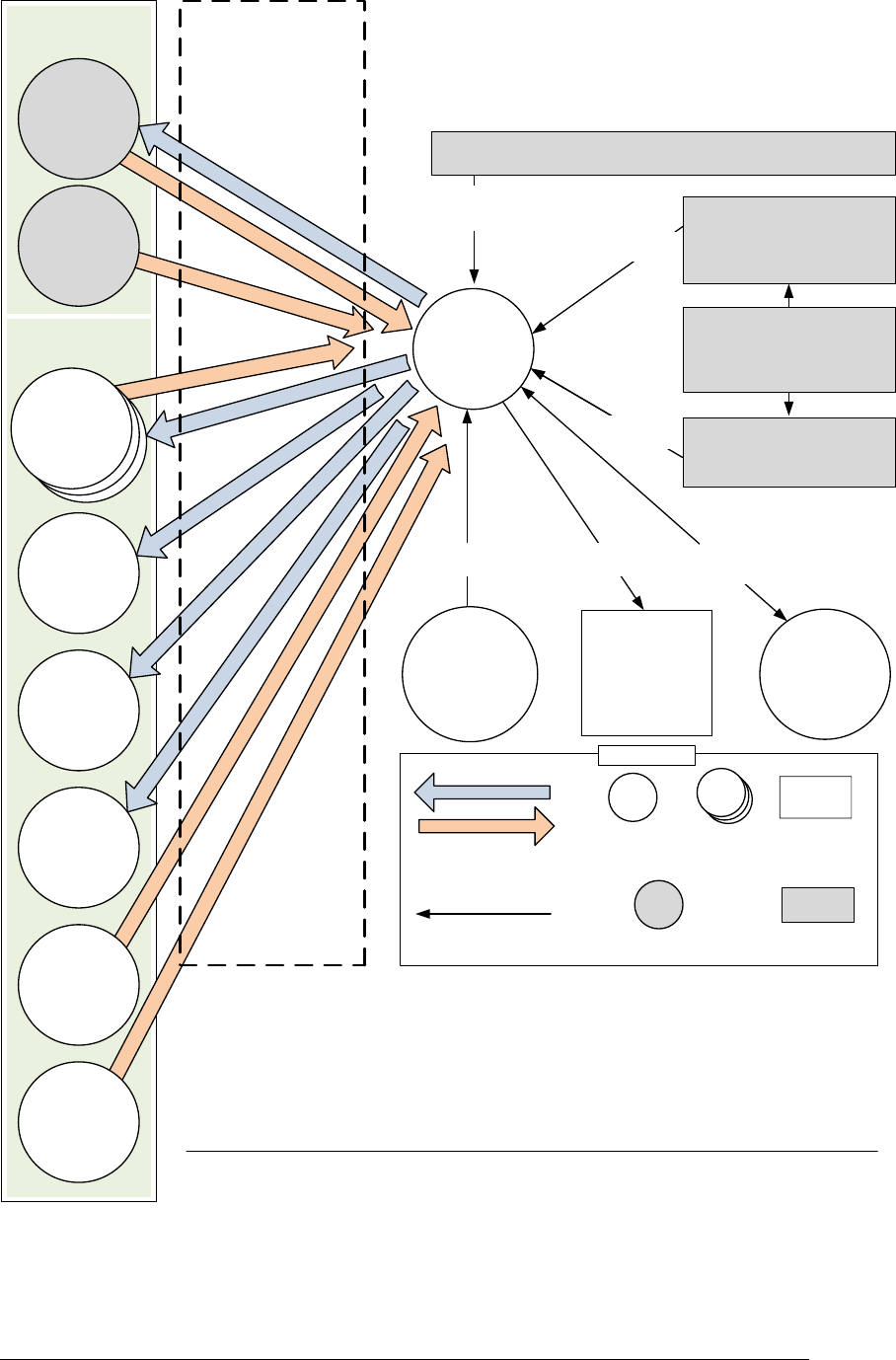
2.2.3 CFS HS Software Context
Figure 1 below shows a typical software context for CFS HS.
CFS HS APPLICATION USER’S GUIDE - 582-2013-002, Ver. 1.0, 03/24/14 Page 2-1
The controlled copy of this document is located online at https://fsb.gsfc.nasa.gov/CFS/
Figure 1 CFS HS Typical Software Context
Event messages may be routed to HS from any application.
Message actions are most commonly command messages to start a relative time sequence (RTS).
Message actions, however, may be any message routed to any application subscribing to them.
DS
Messages from
CFS HS may be
routed to a data
storage app
SB
cFE Software Bus
(SB) provides a
messaging system for
commands, telemetry,
and
inter-application
communication.
TO
Messages from
CFS HS may be
routed to a
telemetry output
application Hardware UART
CFS HS sends CPU
Aliveness Indicator
(a “heartbeat” of
predefined
characters at
predefined rate) to
hardware UART
Mission-Specific
Applications
Application
Monitoring
Execution
Counter
Reporting
CPU Aliveness
Indicator
OSAL API
Operating System
Abstraction Layer
(OSAL) API provides
interface, ability to
set watchdog
timeout
cFE
Applications
House Keeping
Reset Calls
Event Msgs and Housekeeping
Event Msgs and Housekeeping
Idle Child
CFS HS creates an
Idle child task to
determine the portion
of CPU utilization not
being used by other
applications.
Idle
Counter
A Typical CFS HS
Software Context
Msg Actions
Execution Counter Table
Specifies execution counters that CFS HS must report in housekeeping
Message
Actions
Message Actions Table
Specifies options for message
actions that Application Monitoring
or Event Monitoring can send via
cFE Software Bus
Event Monitor Table
Specifies events that CFS HS must
monitor and actions CFS HS must
take on receipt of those events
Application Monitor Table
Specifies the applications whose
execution counters are monitored
by CFS HS, and actions to take if
counters fail to increment
Notes
The cFE applications, and everything to the right of the software bus in this diagram, is designed
to be the same for CFS HS on every mission.
Below the cFE applications on this diagram are mission-specific applications; CFS HS only
requires the cFE (including ES and TBL shown). This diagram shows an example of SC, TO, DS,
HK, SCH, and CI also being used.
All messaging is done over the Software Bus. Any application could be on the receiving end as
long as it has subscribed to the appropriate messages.
The CFS is highly configurable. This diagram shows one possible configuration, but mission
configurations may differ widely.
Legend
SB (Software Bus)
Communications
Non -Software Bus
Information Flow
Exec Ctrs, Reset Type, App Info
cFE ES
CFS HS sends
reset calls to cFE
ES; gets execution
cntrs, reset type,
app info
from it
Watchdog Timer
Management
Event
Monitoring
CFS HS Table Updates
cFE TBL
CFS HS learns of
ground updates to
its tables via cFE
Table Services
application.
Wakeup and House Keeping Requests
Ground Commands
SCH
A scheduler
application sends
periodic commands
to “wake up”
CFS HS
CI
A command ingest
(CI) application
may route ground
commands to
CFS HS *
CFS HS
HK
Messages from
CFS HS may be
routed to a
housekeeping
app
cFE Applications
External
Hardware Entity
or Data Store
CFS HS
Table
System
Application
or task
Multiple
System
Applications
or tasks
**
**
Event Messages
SC
Relative Time
Sequence (RTS)
can be started by
Message Actions if
mission uses
CFS SC
*
CFS HS APPLICATION USER’S GUIDE - 582-2013-002, Ver. 1.0, 03/24/14 Page 2-1
The controlled copy of this document is located online at https://fsb.gsfc.nasa.gov/CFS/
The figure above shows a typical software context, with CFS system applications as configured for
a particular mission communicating via the cFE Software Bus application with both CFS
applications and mission-created applications that GSFC typically utilizes.
Table 3 Software Context Detail
Application
Software Context
SB and System
Applications
CFS System applications as configured for a particular mission may
communicate with CFS HS via the cFE Software Bus application.
Typically, Stored Command (SC) command messages, SCH
schedule messages, and Command Ingest (CI) ground command
messages would provide incoming messages received by CFS HS.
Telemetry Output (TO), Data Storage (DS), and HK telemetry would
be the application interfaces receiving outgoing messages sent by
CFS HS.
In addition, Message Actions can cause command messages to be
directed virtually anywhere, though the typical suggested use is for
command messages to SC to start Relative Time tagged command
Sequence (RTS) commands.
cFE
When using any CFS application, the cFE is required. Missions can
choose the CFS applications that will be used in the Flight Software
system. These may or may not include other CFS applications
and/or new mission specific CFS applications.
CI
Ground command messages are typically routed through a CI
application that is provided by the mission.
SB
Message packets for CFS HS are received via the cFE SB
application. CFS applications communicate with CFS HS via SB.
SCH
CFS HS is typically awakened by a wakeup request message from a
scheduler (SCH) application provided by the mission. The wakeup
request message defines the monitor cycles.
However, even if no wakeup request message is received, CFS HS
will still time out and automatically wake up. Housekeeping requests
are processed only when CFS HS wakes up, and only when
requests are pending.
Note that other messages that CFS HS is subscribed to, such as
event messages for Event Monitoring and CFS HS ground
command messages (see Appendix, section A.4) are also only
processed when CFS HS is already running due to a wakeup
message or timeout. The Software Bus Wakeup Message Timeout
configuration parameter (HS_WAKEUP_TIMEOUT) default is 1200
ms, or as set by the mission.
TBL
CFS HS learns of any ground updates to the CFS HS tables through
the cFE TBL application.
HK, TO, DS, SC
Any messages generated by CFS HS are routed to whatever
mission-specific applications subscribe to them, such as the HK,
TO, DS and/or SC applications.
cFE TIME application
(not shown)
The cFE TIME application distributes spacecraft time of day data.

CFS HS APPLICATION USER’S GUIDE - 582-2013-002, Ver. 1.0, 03/24/14 Page 2-2
The controlled copy of this document is located online at https://fsb.gsfc.nasa.gov/CFS/
2.3 CFS HS Detailed Overview
2.3.1 Summary of Tables Used by CFS HS
CFS HS contains multiple tables, which are summarized below, and detailed throughout the rest
of this chapter.
Application Monitor Table – specifies the applications that CFS HS will monitor and
action CFS HS will take if the application is not running.
Event Monitor Table – specifies the events that CFS HS will monitor and action CFS HS
will take upon receipt of the event.
Execution Counter Table – specifies the applications and application child tasks for
which CFS HS needs to report execution counters. The execution counters themselves are
maintained by cFE ES.
Message Actions Table – specifies command messages that Application Monitoring or
Event Monitoring can send as an action via cFE SB.
CFS HS supports enabling or disabling Application Monitoring and Event Monitoring by
command message for software maintenance or other special use.
Additional Application Monitoring and Event Monitoring changes are available via table upload.
For example, for Application Monitoring, one can add or remove the applications to be
monitored, or change the action performed on an application via upload of the Application
Monitor Table. Similarly, for Event Monitoring, one can add or remove specific events to be
monitored and their associated action via upload of the Event Monitor Table.
Note: FOT should become familiar with the values set for configuration parameters for
Application Monitoring and Event Monitoring, as those parameters define their respective
nominal operational states.
Note that all CFS HS tables (the Application Monitor Table, Event Monitor Table, Execution
Counter Table, and Message Actions Table) are loadable and can be changed while CFS HS is
running. New CFS HS tables can be uplinked via the cFE TBL application.
CFS HS APPLICATION USER’S GUIDE - 582-2013-002, Ver. 1.0, 03/24/14 Page 2-3
The controlled copy of this document is located online at https://fsb.gsfc.nasa.gov/CFS/
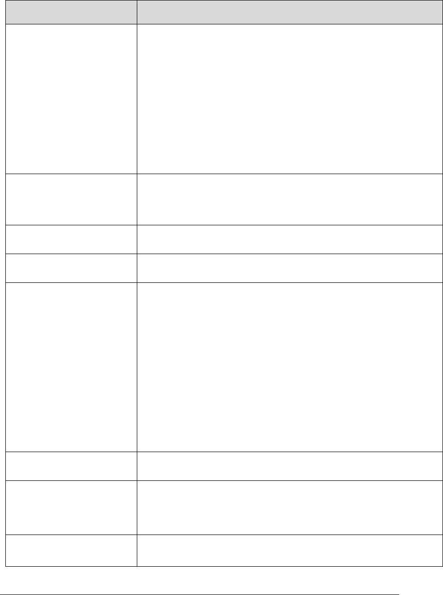
2.3.2 Program Flow
Figure 2 below shows the overall internal program flow of CFS HS.
Figure 2 CFS HS Overall Internal Program Flow
No
Start
Pend on
1 Hz
message*
No Yes
Initialization
Exit
Run
Exit
application
Event
?
Process
CFS HS
command
Send
error
event
Tables
updated
?
Process
CFS HS
table
update
Send
error
event
No No
Yes Yes Yes
API
Error
Yes
No
*1 Hz message is the only message
that shows up on this pipe, and is a
pend with timeout.
Command
?
HK Req
?
Process
event
B
SB packet
?
Process
CFS HS
monitors A
Process
CFS HS
house-
keeping
ES
RunLoop
CFS HS APPLICATION USER’S GUIDE - 582-2013-002, Ver. 1.0, 03/24/14 Page 2-4
The controlled copy of this document is located online at https://fsb.gsfc.nasa.gov/CFS/
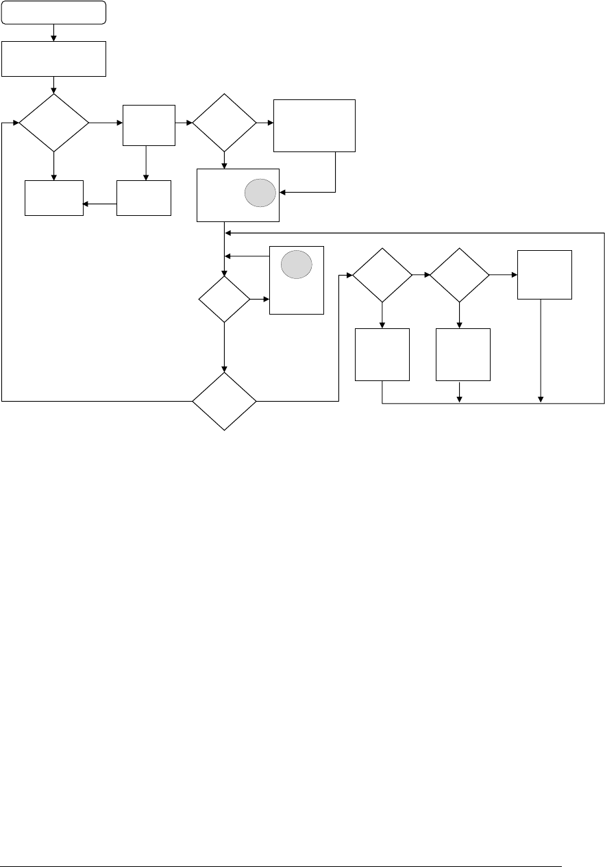
Figure 3 below shows the flow control of CFS HS for Process CFS HS Monitors.
Figure 3 CFS HS Flow Control Detail (A) – Process CFS HS Monitors
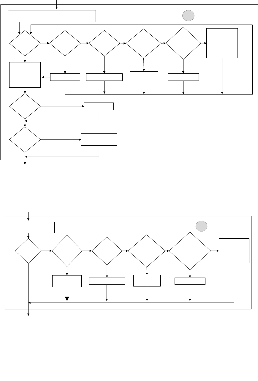
Figure 4 below shows the flow control of CFS HS for Process Event.
Figure 4 CFS HS Flow Control Detail (B) – Process Event
2.3.3 Application Monitoring
CFS HS monitors applications defined in the Application Monitor Table. From the CFS HS point
of view, whether the application is a cFE application, a reused CFS application, or a newly
From Table Processing
No
Yes
Service the
Watchdog Timer
Yes
No
Send event
AProcess HS Monitors
No No NoYes No
CFS
HS resets
>= CFS HS max
resets?
Restart
application
action
type?
Send
event action
type?
Send
message action
type?
Action
required
?
No
•Increment
CFS HS
resets
•Send event
•Call ES to
restart cFE
Restart
application
Yes Yes Yes
Send message
Yes
Watchdog
Timer
enabled?
Is CPU
hogged?
•Output CPU
aliveness
•Calculate
CPU
Utilization
Application Monitoring processing:
Update application missing counters
Send eventSend event
From Event Message
BProcess Event
No No NoYes No
CFS HS resets
>= CFS HS max
resets?
Restart
application
action
Type?
Message
action
type?
Delete
application
action
Type?
Event
found?
No
•Increment
HS resets
•Send event
•Call ES to
restart cFE
Restart
application Send event
Yes Yes Yes
Delete application
Yes
Send
message
Search Event Monitor
Table for event message
CFS HS APPLICATION USER’S GUIDE - 582-2013-002, Ver. 1.0, 03/24/14 Page 2-5
The controlled copy of this document is located online at https://fsb.gsfc.nasa.gov/CFS/
developed mission-specific application does not matter. CFS HS uses the Application Monitor
Table to determine which applications to monitor, and what actions to take. For elements of the
Application Monitor Table, see Table 4, Application Monitor Table – Contents and Validation,
below.
Detailed Overview
CFS HS monitors applications using execution counters maintained by cFE Executive Services
(ES). CFS HS Application Monitoring takes action when an application listed in the Application
Monitor Table fails to increment its execution counter for the number of cycles specified by Cycle
Count in the Application Monitor Table.
CFS HS maintains internal counters (“application missing” counters) for each application that it is
monitoring. These counters are initialized to the Cycle Count value, and they count down to zero.
They count down only if the cFE ES execution counter has not incremented since the last CFS HS
wakeup request message.
Once each CFS HS cycle, Application Monitoring checks the execution counter for each
application defined in the Application Monitor Table. If the current value of the execution counter
for that application matches the value of the counter during the previous cycle then its "application
missing" counter is decremented. Otherwise the "application missing" counter is reset to the Cycle
Count value defined in the Application Monitor Table.
If the "application missing" counter reaches zero, then an action is taken that is defined in the
Application Monitor Table. There are five possible actions: (1) perform no action; (2) perform a
cFE processor reset; (3) restart the application that generated the event; (4) send an event message;
or (5) send a table-specified cFE Software Bus message.
The cFE Software Bus Messages to send as actions (“Message Actions”) are specified in the
Message Actions Table (for more on the Message Actions Table, see section 2.3.5.2, Message
Actions Table). The Application Monitor Table indexes the Message Actions Table when the action
is to send a cFE Software Bus message.
Once the "application missing" counter reaches zero and the action is taken, that table entry is
disabled until Application Monitoring (as a whole) is commanded to be enabled, or a new
Application Monitor Table is loaded. It does not matter if Application Monitoring is disabled first.
An application may appear in the Application Monitor Table more than once, allowing it to have
multiple actions. One of the multiple actions might be to attempt to restart an application, and
failing that (having a larger Cycle Count value) perform a processor reset. Another use might be to
take another action (perhaps a Message Action causing a power-on reset) if the CFS HS Max
Processor Resets limit has been reached. The ability to have multiple actions might also be used
for sending multiple Message Actions.
CFS HS will not start monitoring applications until system startup is complete. Completing system
startup means that the startup sync CFE_ES_WaitForStartupSync provided by the cFE has been
received, either because the system finished starting up, or because it timed out.
2.3.3.1.1 An Example: Application Monitoring and Execution Counters
CFS HS maintains internal “application missing” counters for each application that it is monitoring.
These counters are initialized to the cycle count value specified in the Application Monitor Table,
and they count down to zero. However, they only count down if the cFE ES execution counter
associated with the application has not incremented since the last CFS HS wakeup request message.
Once a counter hit zero, the action is taken.
CFS HS APPLICATION USER’S GUIDE - 582-2013-002, Ver. 1.0, 03/24/14 Page 2-6
The controlled copy of this document is located online at https://fsb.gsfc.nasa.gov/CFS/
To take an example, imagine an internal “application missing” counter hits zero. This is when CFS
HS determines that the application is missing. When an application is missing, the action (specified
in the Application Monitor Table for the missing application) is taken.
Once the counter hits zero and the action is taken, CFS HS sets the application monitoring state (in
its AppMonEnables telemetry point for that application) to disabled. The AppMonEnables
telemetry point is an array containing the Application Monitoring Enable state for each entry in the
Application Monitor Table. During the next CFS HS cycle, CFS HS will not monitor this
application’s execution counters.
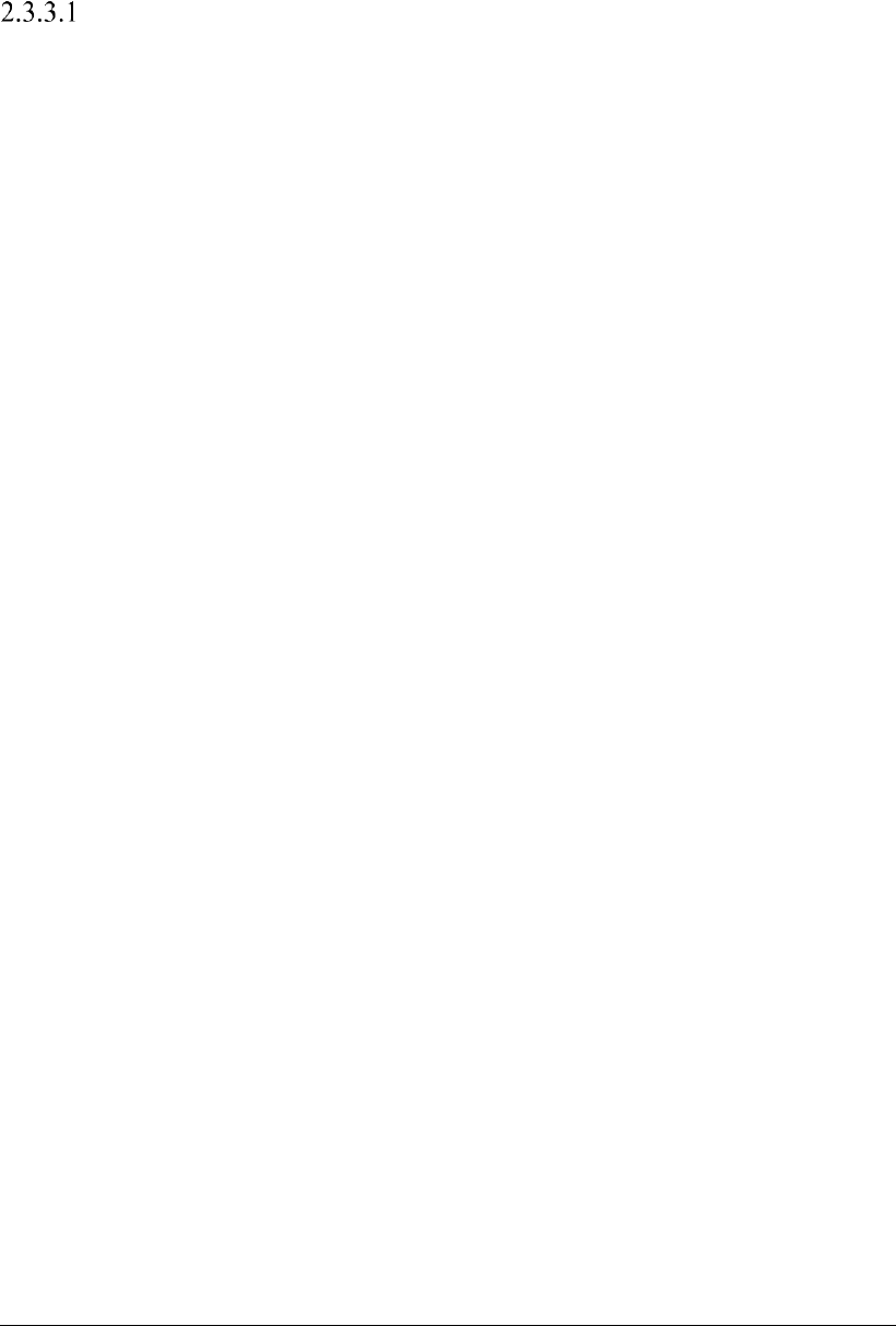
Figure 5 Application Monitoring Execution Counter Operation, Simplified
This simplified flow shows that the “application missing” counter decrements to zero when an
application stops running. (See also Figure 6, CFS HS Typical Program Flow - Application
Monitoring)
Let us continue with this example. Let us say the action was to restart the application and that was
successful. The ES execution counter associated with that application is now incrementing again.
What is the concern at this point?
The concern is that CFS HS doesn’t automatically re-enable the application in the Application
Monitoring Table. The Application Monitoring Table only specifies what to do (the action) to
recover from the application’s ES execution counter not incrementing.) FOT will need to monitor
the effect of the action and then will need to determine what to do next. What to do next may be as
simple as enabling the Application Monitoring Table (by sending an Application Monitoring
CFS HS APPLICATION USER’S GUIDE - 582-2013-002, Ver. 1.0, 03/24/14 Page 2-7
The controlled copy of this document is located online at https://fsb.gsfc.nasa.gov/CFS/
Enable command message - see Table 116 Command 2 – Application Monitoring – Enable).
Sending an Application Monitoring Enable command message in effect will re-enable the
Application that was disabled when CFS HS took action.
While issues should be resolved by the CFS HS table defined action, the action’s outcome should
be closely monitored by FOT to ensure that all issues have been resolved. Additional action might
be needed and FSSE may need to be contacted to resolve any FSW issues.
Application Monitor Table
The Application Monitor Table contains a list of applications that need to be monitored, and
specifies what actions to take and when to take them.
CFS HS verifies that each application listed in the Application Monitor Table is executing. If CFS
HS detects that the execution counters for a monitored application have failed to increment as
expected, CFS HS uses Cycle Count and Action Type specified in each entry in the Application
Monitor Table, shown below, to determine the action to take and when to take it. Tables are used
so that the list can be easily configured for a mission and can be changed by the mission when
required.
Some applications have fewer dependencies or are otherwise considered less important than others,
so the Application Monitor Table allows those applications to have less drastic responses when
their execution counters fail to increment as expected. On the other hand, some applications are
considered very important and require strong responses. Possible responses are No Action, cFE
Processor Reset, Restart Application, Event Message, or a table-specified cFE Software Bus
message, as listed in Table 5 Application Monitor Table – Action Type Elements.
CFS HS will monitor up to the number of applications specified by the configuration parameter
(HS_MAX_MONITORED_APPS). The configured number determines the Application Monitor
Table size, and should be set to allow room for future expansion.
The Application Monitor Table fields and their validation are shown below:
Table 4 Application Monitor Table – Contents and Validation
Element
Description
Valid Entries
Validation
Application Name
The application to be
monitored.
Text string of the
application to be
monitored, as the
system knows it, up
to the length
specified by the
OSAL.
No validation.
If an application is not
found as named, it will
be considered missing
(nonresponsive).
Null Terminator
This exists as a quick
method to make sure
that the Application
Name strings in the table
are no longer than the
maximum length.
Zero (0)
N/A
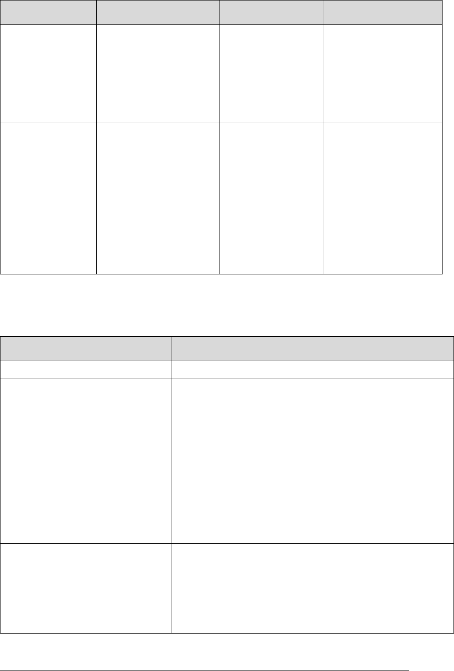
CFS HS APPLICATION USER’S GUIDE - 582-2013-002, Ver. 1.0, 03/24/14 Page 2-8
The controlled copy of this document is located online at https://fsb.gsfc.nasa.gov/CFS/
Element
Description
Valid Entries
Validation
Cycle Count
This is the number of
CFS HS monitor cycles
before the application is
considered missing. In
this Guide, it is assumed
that the Cycle Count
period is 1 Hertz, but it
could be faster.
No validation
Action Type
This is the action to take
if the application stops
incrementing execution
counters as expected.
No Action
cFE processor
reset
Restart
Application
Event Message
Table-specified
cFE Software
Bus Message
For details see table
below
Must be No Action or a
defined action
Table entries with the
action to take as No
action will be
considered unused
(disabled).
The Action Type is the action to take, as shown below:
Table 5 Application Monitor Table – Action Type Elements
Element
Description
No Action (0)
For a disabled entry. No action is taken.
cFE Processor Reset (1)
For an entry that on failure causes a cFE processor reset.
If the specified action is to perform a cFE processor reset
and the number of cFE processor resets is less than the
configured maximum number, then CFS HS will increment
the number of cFE processor resets; set the internal
Service_watchdog flag to false; and initiate cFE processor
reset.
If the specified action is to perform a cFE processor reset
and the number of cFE processor resets is greater than or
equal to the configured maximum, CFS HS will send an
event message, but no cFE processor reset will be
performed. This prevents an infinite reset loop.
Restart Application (2)
For an entry that on failure attempts to restart the named
application.
HS will attempt to restart the application. If restarting the
application does not fix the problem, CFS HS will act to
prevent an infinite restart loop by disabling the entry in the
Application Monitor Table. This disables monitoring of that
application.
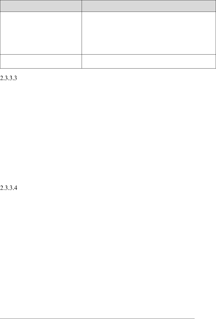
CFS HS APPLICATION USER’S GUIDE - 582-2013-002, Ver. 1.0, 03/24/14 Page 2-9
The controlled copy of this document is located online at https://fsb.gsfc.nasa.gov/CFS/
Element
Description
Event Message (3)
For an entry that on failure only generates an event
message.
If the entry in the table references an unresolvable
application, i.e., one that is not registered with cFE, CFS HS
issues an event message. This would be the case where an
application is unknown to the cFE – perhaps because of a
misspelled application name.
Table-specified cFE Software Bus
Message (num)
For an entry in the table that generates a Message Action,
where 'num' is the index into the Message Actions Table.
Updates to the Application Monitor Table
Upon receipt of an Application Monitor Table update indication, and at initialization, CFS HS
validates the Application Monitor Table for a valid action type field. CFS HS also checks that the
null termination field zero (0) is present to protect against unterminated Application Name strings.
At initialization, if the Application Monitor Table fails these table validations:
Application Monitoring will be disabled.
CFS HS reports the “Status of CFS HS Application Monitoring” in Housekeeping
telemetry (CurrentAppMonState) as disabled.
CFS HS issues an event message listing the number of the Application Monitor Table
entry, the ID of the error that occurred, the action listed for the entry, and the application
name specified in the table.
As long as no valid Application Monitor Table is loaded, Application Monitoring will
remain disabled.
During normal operation, if the Application Monitor Table fails these table validations, CFS HS
will still monitor the application with the currently loaded table.
Monitoring and Responding to Nonrunning Applications
Applications use a cFE ES API function to increment their individual execution counters to let the
system know they are active. Each application must therefore be active at the minimum rate
specified by Cycle Count in the Application Monitor Table in order for CFS HS to consider it active
and running.
If an application has not executed for the number of CFS HS execution cycles specified by Cycle
Count in the Application Monitor Table, CFS HS will execute one of the actions specified by Action
Type in its entry in the Application Monitor Table, as shown in Table 5 Application Monitor Table
– Action Type Elements above.
Figure 6 below shows the flow for monitoring a typical application. (See also Figure 5, Application
Monitoring Execution Counter Operation, Simplified.)
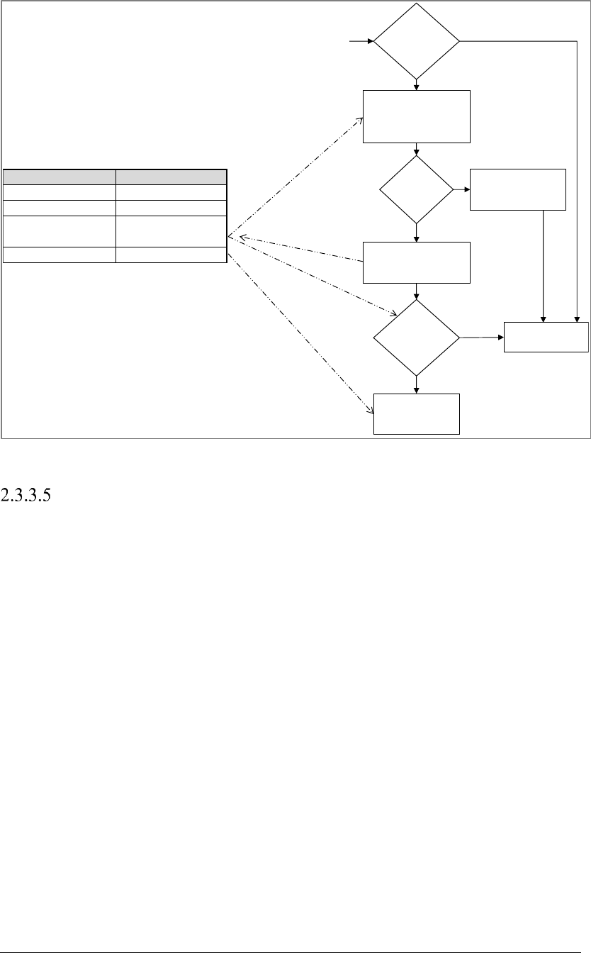
CFS HS APPLICATION USER’S GUIDE - 582-2013-002, Ver. 1.0, 03/24/14 Page 2-10
The controlled copy of this document is located online at https://fsb.gsfc.nasa.gov/CFS/
Figure 6 CFS HS Typical Program Flow - Application Monitoring
Application Monitoring Considerations
Application Monitoring is subject to the following considerations:
1. To understand application monitoring, it is important to remember that Application
Monitoring occurs once per CFS HS cycle, and that the scheduler application wakeup request
message defines those cycles, as described above in “SCH” in Table 3, Software Context
Detail.
2. Application Monitoring does not start until all applications have started. The cFE provides a
startup synchronization API (CFE_ES_WaitForStartupSync) to make this possible.
3. CFS HS checks the Application Monitor Table to make sure that the Action Type field
contains a valid value, and that the Null Terminator field is 0 (null) to protect against
unterminated strings.
4. Application Monitoring of a child task is the responsibility of the parent application.
5. An application with a long execution cycle (the time between calls for the application to start
its main execution loop) must be assigned a larger Cycle Count. For example, an application
that is supposed to start its main execution loop four times a second may only have a Cycle
Count of one (1). Similarly, an application that only is supposed to start its main execution
loop once every ten seconds may have a Cycle Count of 20. While the Cycle Count in this
example could be set to some higher number, it must always be set to at least 10 or the
monitoring check will always show the application as missing. However, note that one should
not assume all applications run at the same rate as CFS HS.
Field Value
Application name
QQ_APPLICATION
Cycle Count 6
“Application
missing” counter 5
Action Restart application
Check next
application
Perform action,
stop monitoring
this application
“Application
Missing”
counter = 0?
Read the
QQ_APPLICATION
execution counter (not
shown)
Decrement
“Application missing”
counter
“Application
Missing”
counter = 0?
Static?
Yes
Yes
Yes
No
No
No
Reset “Application
missing” counter to
threshold
Typical application
monitoring
Start
End
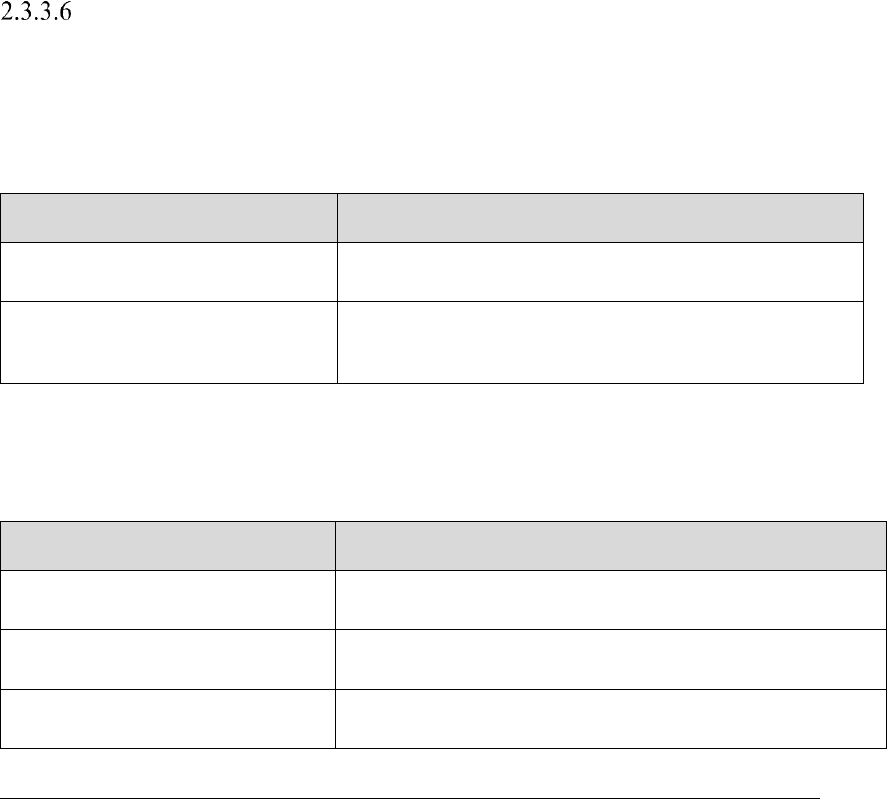
CFS HS APPLICATION USER’S GUIDE - 582-2013-002, Ver. 1.0, 03/24/14 Page 2-11
The controlled copy of this document is located online at https://fsb.gsfc.nasa.gov/CFS/
6. If an application is not currently running on the system, it will not be incrementing any
execution counters. CFS HS does not know whether the Application is legitimately missing,
or was incorrectly specified in the table, so it assumes that it is a real, missing application. If
Processor Reset Limiting is not set properly, such an application missing at startup could
even lead to an infinite reset loop.
7. Infinite reset loops are normally prevented by limiting cFE processor resets to a maximum
defined by the Processor Resets Maximum HS Number configuration parameter
(HS_MAX_RESTART_ACTIONS).
8. A cFE processor reset will cause CFS HS to restart and then re-enable monitoring
automatically, but only if the Application Monitoring Default State configuration parameter
(HS_APPMON_DEFAULT_STATE) is set to HS_STATE_ENABLED.
9. The following would be a very unusual situation and would probably require ground action.
If the action specified by an Application Monitor Table entry that fails is processor reset, and
no more processor resets are allowed [meaning the number of cFE processor resets is greater
than or equal to the maximum specified by the Processor Resets Maximum HS Number
configuration parameter (HS_MAX_RESTART_ACTIONS)], CFS HS will not perform a
processor reset. However, it will generate an error event message 'Processor Reset Action
Limit Reached: No Reset Performed' each time it receives the Application Monitor Table
entry request.
Telemetry, Configuration Parameters, Commands, and Events
This section identifies all the telemetry, configuration parameters, commands; and error,
informational, and debug event messages related to Application Monitoring.
The table below identifies the telemetry data related to Application Monitoring. For full details on
this telemetry, see Appendix section A.2.
Table 6 Application Monitoring Summary – Telemetry
Telemetry Data
Description
CurrentAppMonState
Contains the status (enabled or disabled) of Application
Monitoring.
AppMonEnables
Contains the Application Monitor Enable state for each
entry in the Application Monitor Table. Note that this
telemetry data is an array.
The table below identifies configuration parameters related to Application Monitoring. For full
details on these parameters, see Appendix section A.3.
Table 7 Application Monitoring Summary – Configuration Parameters
Configuration Parameter
Description
HS_AMT_FILENAME
Specifies the default file from which to load the Application
Monitor Table during power-on reset.
HS_APPMON_DEFAULT_STATE
Specifies whether Application Monitoring will be enabled or
disabled at startup.
HS_MAX_MONITORED_APPS
Specifies the maximum number of applications that can be
monitored.
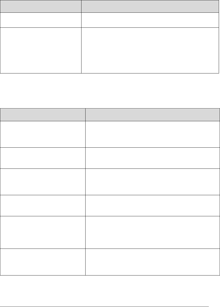
CFS HS APPLICATION USER’S GUIDE - 582-2013-002, Ver. 1.0, 03/24/14 Page 2-12
The controlled copy of this document is located online at https://fsb.gsfc.nasa.gov/CFS/
The table below identifies commands related to Application Monitoring. For full details on these
commands, see Appendix section A.4.
Table 8 Application Monitoring Summary – Commands
Command
Description
Application Monitoring – Enable
Enables all entries in the Application Monitor Table, and
then executes the table.
Application Monitoring – Disable
Stops processing of the Application Monitor Table.
This allows maintenance to be done on a monitored
application. Typically one would disable Application
Monitoring, modify/load the application, and then enable
Application Monitoring again. Note that nothing is
preserved between a disable command message and an
enable command message.
The table below identifies error messages related to Application Monitoring. For full details on
these error messages, see Appendix section A.5.2.
Table 9 Application Monitoring Summary – Error Messages
Event
Description
Event ID 10 (Error) – Registering –
Application Monitor Table
Issued when CFS HS is unable to register its Application
Monitor Table with cFE TBL via the CFE_TBL_Register
API. Specifies the return code from the
CFE_TBL_Register API call.
Event ID 14 (Error) – Loading –
Application Monitor Table
Issued when the call to CFE_TBL_Load for the
Application Monitor Table returns a value other than
CFE_SUCCESS.
Event ID 33 (Error) – Getting Table
Address – Application Monitor
Issued when the address cannot be obtained from cFE
TBL for the Application Monitor Table. Specifies the
return code from the CFE_TBL_GetAddress function call
that generated the error.
Event ID 38 (Error) – Application
Monitoring – Application Name Not
Found
Issued when a monitored application name cannot be
resolved into an application ID by the OS. Specifies the
name in the table that was not found in the system.
Event ID 39 (Error) – Application
Monitoring – Failure Action –
Restart App
Issued when a monitored application fails to increment
its execution counter in the table-specified number of
cycles, and the specified action type is Restart
Application. Specifies the name of the application being
monitored.
Event ID 41 (Error) – Application
Monitoring Failure Action – Event
Only
Issued when a monitored application fails to increment
its execution counter in the table-specified number of
cycles, and the specified action type is Event Only.
Specifies the name of the application being monitored.
CFS HS APPLICATION USER’S GUIDE - 582-2013-002, Ver. 1.0, 03/24/14 Page 2-13
The controlled copy of this document is located online at https://fsb.gsfc.nasa.gov/CFS/
Event
Description
Event ID 42 (Error) – Application
Monitoring Failure Action –
Processor Reset
Issued when a monitored application fails to increment
its execution counter in the table-specified number of
cycles, and the specified action type is processor reset.
Specifies the name of the application being monitored.
Event ID 43 (Error) – Application
Monitoring Failure Action –
Message Action
Issued when a monitored application fails to increment
its execution counter in the table-specified number of
cycles, and the specified action type is a Message
Action. Specifies the name of the application being
monitored and the Message Action number.
Event ID 51 (Error) – Verify Error –
Application Monitor Table
Issued on the first error when a table validation fails for
an Application Monitor Table load. Specifies the number
of the Application Monitor Table entry, the id of the error
that occurred, the action listed for the entry, and the
application name specified in the table.
Event ID 58 (Error) – Disabled –
Application Monitoring
Issued when Application Monitoring has been disabled
due to a table load failure.
The table below identifies informational event messages related to Application Monitoring. For
full details on these informational event messages, see Appendix section A.5.3.
Table 10 Application Monitoring Summary – Informational Messages
Event
Description
Event ID 50 (Informational) – Verify
Results – Application Monitoring
Issued when a table validation has been completed for
an Application Monitor Table load. Specifies the number
of entries that passed, the number of entries that failed,
and the number of entries that weren't checked because
they were marked unused.
The table below identifies debug messages related to Application Monitoring. For full details on
these debug messages, see Appendix section A.5.4.
Table 11 Application Monitoring Summary – Debug Messages
Event
Description
Event ID 25 (Debug) – Application
Monitoring – Enabled
Issued when an Application Monitoring – Enable
command message has been received.
Event ID 26 (Debug) – Application
Monitoring – Disabled
Issued when an Application Monitoring – Disable
command message has been received.
CFS HS APPLICATION USER’S GUIDE - 582-2013-002, Ver. 1.0, 03/24/14 Page 2-14
The controlled copy of this document is located online at https://fsb.gsfc.nasa.gov/CFS/
2.3.4 Event Monitoring
Detailed Overview
CFS HS Event Monitoring takes action when an application specified in the Event Monitor Table
generates an event with an Event ID number that is also specified in the Event Monitor Table.
CFS HS will not start monitoring events until system startup has been completed. Completing
system startup means that the startup sync CFE_ES_WaitForStartupSync provided by the cFE has
been received, either because the system finished starting up, or because it timed out.
Event Monitoring does not monitor the contents of events, only the generation of them, as identified
by their Event ID number and application that sent the event.
Event Monitoring can only monitor events that have not been filtered by cFE ES. If cFE ES filters
out an event, it will not be sent out, and so CFS HS will never receive it.
Once each CFS HS cycle, Event Monitoring checks the events generated during the previous cycle.
For each event received, the Event ID number is checked against each Event ID number in the
Event Monitor Table. If the Event ID number matches, then the Application Name is compared,
and if it also matches, then Event Monitoring takes the action specified in the Event Monitor table.
There are five possible actions: (1) perform no action; (2) perform a cFE processor reset; (3) restart
the application that generated the event; (4) delete the application that generated the event; or (5)
send a cFE Software Bus message.
An Event ID and Application Name number pair may appear in the Event Monitor Table more than
once, allowing it to have multiple actions. One of the multiple actions might be to attempt to restart
an application, and failing that (having a larger Cycle Count value) perform a processor reset.
Event Monitoring can be turned on with an Event Monitoring – Enable command message or off
with an Event Monitoring – Disable command message. The state of Event Monitoring at startup
is defined by the Event Monitoring Default State (HS_EVENTMON_DEFAULT_STATE)
configuration parameter.
Event Monitor Table
The Event Monitor Table (EMT) contains an array of records of events that CFS HS needs to
monitor and the actions that CFS HS must take upon receipt of that event. The table fields and
their validation are shown below:
Table 12 Event Monitor Table – Contents and Validation
Element
Description
Valid Entries
Validation
Application Name
The application that
generates the event
message.
Text string of the
application that sent
the event, as the
system knows it, up
to the length
specified by the
Operating System
(OS) configuration
parameter
OS_MAX_API_NA
ME.
No validation at
load time, but a
count of
unresolvable
application names
is computed each
HK cycle
CFS HS APPLICATION USER’S GUIDE - 582-2013-002, Ver. 1.0, 03/24/14 Page 2-15
The controlled copy of this document is located online at https://fsb.gsfc.nasa.gov/CFS/
Element
Description
Valid Entries
Validation
Null Terminator
This exists as a quick method
to make sure that the
Application Name strings in
the table are no longer than
the maximum length.
Zero (0)
EID
ID of the event to be
monitored.
Numerical ID
No validation
Action Type
The action to take when
event message is received by
CFS HS.
None (for a
disabled entry)
cFE Processor
Reset
Restart the
named
Application
Delete the
named
Application
Send Software
Bus Message
(num)
Must be a defined
action or set to No
Action
The Action Type is the action to take, as shown below:
Table 13 Event Monitor Table – Action Type Elements
Element
Description
No Action
For a disabled entry. No action is taken.
CFS HS APPLICATION USER’S GUIDE - 582-2013-002, Ver. 1.0, 03/24/14 Page 2-16
The controlled copy of this document is located online at https://fsb.gsfc.nasa.gov/CFS/
Element
Description
cFE Processor Reset
For an entry that on failure causes a cFE processor
reset.
If the specified action is to perform a cFE processor
reset and the number of cFE processor resets is less
than the configured maximum number, then CFS HS
will:
increment the number of cFE processor resets
set the internal Service_watchdog flag to false;
and
initiate cFE processor reset.
If the specified action is to perform a cFE processor
reset and the number of cFE processor resets is
greater than or equal to the configured maximum, CFS
HS will send an event message, but no cFE processor
reset will be performed. This prevents an infinite reset
loop.
Restart Application
For an entry that on failure attempts to restart the
named application.
HS will attempt to restart the application. If restarting
the application does not fix the problem, CFS HS will
act to prevent an infinite restart loop by disabling the
entry in the Application Monitor Table. This disables
monitoring of that application.
Delete the named Application
For an entry that on failure deletes the named
application.
Send Software Bus Message
(num)
Send Software Bus Message (num) where 'num' is the
index into the Message Actions Table
Updates to the Event Monitor Table
Upon receipt of an Event Monitor Table update indication, CFS HS validates the Event Monitor
Table action field; all other fields are checked when CFS HS is running.
Note that if the Event Monitor Table fails to pass validation at startup, Event Monitoring will be
disabled. It will be disabled again if an attempt to enable it is made.
Event Monitor Table validation failure would preclude activation, and the current table would
continue being used.
CFS HS APPLICATION USER’S GUIDE - 582-2013-002, Ver. 1.0, 03/24/14 Page 2-17
The controlled copy of this document is located online at https://fsb.gsfc.nasa.gov/CFS/
Event Monitoring - Order of Operation
Event Monitoring checks all generated events once each CFS HS cycle, checking the events
generated during the previous cycle.
1. For each event received, the event ID (EID) is checked against each EID in the Event
Monitor Table; if the EIDs match, then the application name is compared, and if it also
matches, then Event Monitoring takes the table-specified action.
2. If the specified action is to perform a cFE processor reset and the number of cFE processor
resets is less than the maximum specified by the Processor Resets Maximum HS Number
configuration parameter (HS_MAX_RESTART_ACTIONS), then CFS HS does the
following:
Increments the number of cFE processor resets counter
Sets the internal Service_watchdog flag to false (as a failsafe in the event that the cFE
processor reset cannot be performed).
Initiates a cFE processor reset.
3. If the Event Monitor Table contains multiple instances of an Application Name/EID pair,
then multiple actions will be taken in the order listed in the table.
4. If one of the multiple actions is a cFE processor reset action, and CFS HS has not reached the
configured maximum number of cFE processor reset attempts, a reset occurs, and then no
further actions are taken.
5. CFS HS compares each received event message with the events specified in the Event
Monitor Table, up to the number of events specified by the Event Monitoring Maximum
Number of Events configuration parameter (HS_MAX_CRITICIAL_EVENTS).
Event Monitoring Considerations
Event Monitoring is subject to the following considerations:
1. Event Monitoring can only see events that have not been filtered by cFE Event Services. If
cFE Event Services filters out an event, it will not be sent out on the cFE Software Bus, and
so CFS HS will never receive it.
2. If the Application defined in the Event Monitor table is unknown, CFS HS increments the
telemetry counter Total Count of Invalid Event Monitors (InvalidEventMonCount). This
informs ground that there is an entry in the table with an unknown application.
3. CFS HS uses the Event Monitor Table to define the events to be monitored. In order to make
an event unique, the application and the EID fields are both required.
4. The following would be a very unusual situation and would probably require ground action.
If the action specified by an Event Monitor Table entry that fails is processor reset, and no
more processor resets are allowed [meaning the number of cFE processor resets is greater
than or equal to the maximum specified by the Processor Resets Maximum HS Number
configuration parameter (HS_MAX_RESTART_ACTIONS)], CFS HS will not perform a
processor reset. However, it will generate an error event message 'Processor Reset Action
Limit Reached: No Reset Performed' each time it receives the Event Monitor Table entry
request.
CFS HS APPLICATION USER’S GUIDE - 582-2013-002, Ver. 1.0, 03/24/14 Page 2-18
The controlled copy of this document is located online at https://fsb.gsfc.nasa.gov/CFS/
Telemetry, Configuration Parameters, Commands, and Events
This section identifies all the telemetry, configuration parameters, command messages; and error,
informational, and debug event messages related to Event Monitoring.
The table below identifies the telemetry data related to Event Monitoring. For full details, see
Appendix section A.2.
Table 14 Event Monitoring – Telemetry Summary
Telemetry
Description
CurrentEventMonState
Contains the status (enabled or disabled) of Event
Monitoring.
EventsMonitoredCount
Contains the total count of event messages monitored by
Event Monitoring.
InvalidEventMonCount
Contains the number of entries in the Event Monitor
Table that have unresolvable application names.
The table below identifies the configuration parameters related to Event Monitoring. For full
details, see Appendix section A.3.
Table 15 Event Monitoring – Configuration Parameter Summary
Configuration Parameter
Description
HS_EMT_FILENAME
Specifies the default file from which to load the
Event Monitor Table during a power-on reset
sequence.
HS_EVENTMON_DEFAULT_STATE
Specifies the default state (enabled or disabled) of
Event Monitoring when CFS HS starts.
HS_MAX_MONITORED_EVENTS
Specifies the maximum number of events that can
be monitored. The value of this parameter will
dictate the size of the Event Monitor Table.
HS_EVENT_PIPE_DEPTH
Used during initialization to specify the depth of the
Software Bus pipe that CFS HS uses for Event
Monitoring. This should be set to supply sufficient
room for the expected event message load per
second.
HS_WAKEUP_TIMEOUT
Can specify CFE_SB_POLL,
CFE_SB_PEND_FOREVER, or a timeout value in
milliseconds.
HS_WAKEUP_PIPE_DEPTH
Specifies the depth of the Software Bus pipe that
CFS HS uses for wakeup request messages. Used
during initialization in the call to
CFE_SB_CreatePipe.
CFS HS APPLICATION USER’S GUIDE - 582-2013-002, Ver. 1.0, 03/24/14 Page 2-19
The controlled copy of this document is located online at https://fsb.gsfc.nasa.gov/CFS/
The table below identifies the commands related to Event Monitoring. For full details, see
Appendix section A.4.
Table 16 Event Monitoring – Command Summary
Command
Description
Event Monitoring – Enable
Enables Event Monitoring and begins processing the
Event Monitor Table.
Event Monitoring – Disable
Disables Event Monitoring and stops executing the
Event Monitor Table. This command is useful for
making table updates.
The table below identifies the error messages related to Event Monitoring. For full details, see
Appendix section A.5.2.
Table 17 Event Monitoring – Error Message Summary
Event
Description
Event ID 7 (Error) – Subscribing –
to Events
Issued when the call to CFE_SB_Subscribe for the
CFE_EVS_EVENT_MSG_MID, during initialization
returns a value other than CFE_SUCCESS.
Event ID 11 (Error) – Registering
– Event Monitor Table
Issued when CFS HS is unable to register its Event
Monitor Table with cFE TBL via the CFE_TBL_Register
API.
Event ID 15 (Error) – Loading –
Event Monitor Table
Issued when the call to CFE_TBL_Load for the Event
Monitor Table returns a value other than
CFE_SUCCESS.
Event ID 34 (Error) – Getting
Table Address – Event Monitor
Issued when the address cannot be obtained from cFE
TBL for the Event Monitor Table.
Event ID 44 (Error) – Event
Action – Message Action
Issued when an event is detected, and the specified action
type is a Message Action. Specifies the name of the
application that sent the Message Action, the Event ID in
the message, and the Message Action number.
Event ID 45 (Error) – Event
Action – Processor Reset
Issued when an event is received that matches an event in
the Event Monitor Table that specifies processor reset as
the action type.
Event ID 46 (Error) – Event
Action – Restart Application
Issued when an event is received that matches an event in
the Event Monitor Table that specifies Restart
Application as the action type.
Event ID 47 (Error) – Call to
Restart Application Failed
Issued when Event Monitoring attempts to restart an
application but is unable to.
Event ID 48 (Error) – Event
Action – Delete Application
Issued when an event is received that matches an event in
the Event Monitor Table that specifies Delete Application
as the action type.
CFS HS APPLICATION USER’S GUIDE - 582-2013-002, Ver. 1.0, 03/24/14 Page 2-20
The controlled copy of this document is located online at https://fsb.gsfc.nasa.gov/CFS/
Event
Description
Event ID 49 (Error) – Call to
Delete Application Failed
Issued when Event Monitoring attempts to delete an
application but is unable to do so.
Event ID 53 (Error) – Verify Error
– Event Monitor Table
Issued on the first error when a table validation fails for
an Event Monitor Table load.
Event ID 59 (Error) – Disabled –
Event Monitoring
Issued when Event Monitoring has been disabled due to a
table load failure.
Event ID 66 (Error) – Event
Monitoring Enable – Error
Subscribing to Events
Issued when a ground command message is received to
enable Event Monitoring while it is disabled, and there is
an error subscribing to the event Message ID.
Event ID 67 (Error) – Event
Monitoring Disable – Error
Unsubscribing from Events
Issued when a ground command message is received to
disable Event Monitoring while it is enabled, and there is
an error unsubscribing from the event message ID.
See FAQ Section 5.1.
Event ID 68 (Error) –
Unsubscribing from Events
Issued if when acquiring the Event Monitor Table from
cFE TBL, it is bad and Event Monitoring is disabled, but
there is a failure unsubscribing from the event message
ID.
See FAQ Section 5.1.
The table below identifies the informational messages related to Event Monitoring. For full
details, see Appendix section A.5.3.
Table 18 Event Monitoring – Informational Message Summary
Event
Description
Event ID 52 (Informational) –
Verify Results – Event Monitoring
Issued when a table validation has been completed for an
Event Monitor Table load. Specifies the number of
entries that passed, the number of entries that failed, and
the number of entries that weren't checked because they
were marked unused.
The table below identifies the debug messages related to Event Monitoring. For full details, see
section Appendix A.5.4.
Table 19 Event Monitoring – Debug Message Summary
Event
Description
Event ID 27 (Debug) – Event
Monitoring – Enabled
Issued when an Event Monitoring – Enable command
message has been received.
Event ID 28 (Debug) – Event
Monitoring – Disabled
Issued when an Event Monitoring – Disable command
message has been received.
CFS HS APPLICATION USER’S GUIDE - 582-2013-002, Ver. 1.0, 03/24/14 Page 2-21
The controlled copy of this document is located online at https://fsb.gsfc.nasa.gov/CFS/
2.3.5 Message Actions
Detailed Overview
Message Actions allows Application Monitoring or Event Monitoring to send a message via the
Software Bus application. A mission can implement this by specifying a Send Message Action Type
in the Application Monitor Table or Event Monitor Table, respectively. Along with the Action
Type, one must specify a specific Message Action number, which is an index into the Message
Action Table.
While a Message Action would typically be used to send a command message, it is also possible
to use it to send a telemetry message. Each Message Action only sends a single message, but the
Application Monitor Table or Event Monitor Tables can be set up to send multiple messages, i.e.,
to perform multiple actions for the same application or event if multiple messages are needed. Each
Message Action has its own action type.
The Message Actions table can specify a cooldown for each message it can send; the cooldown
determines how many cycles must be waited before the message can be sent again. For example, if
a message has a cooldown value of 4, and is sent due to a monitored event, then if the same event
is received again in the next three cycles, no message would be sent. If it is received again on the
4th cycle or later, the message will be sent again. A cooldown value of 1 means the message can
be sent once per cycle. A cooldown value of 0 means the message can be sent multiple times per
cycle.
Message Actions Table
The Message Actions Table allows the specification of a message that will be sent on the cFE
Software Bus as the result of either an Application Monitoring failure or Event Monitoring
detection as specified in the tables associated with those monitors.
The Message Actions Table contains message content and metadata (such as Message ID,
enabled/disabled state, and cool down value) for “Message Action” type messages. The elements
of the table, with a description, summary of valid entries, and validation, are shown below:
Table 20 Message Actions Table – Contents and Validation
Element
Description
Valid Entries
Validation
Enabled State
Determines whether the Message Action in
that record can be sent:
Disabled – no message, no event
Enabled – will send a message and
generate an event when sent
Enabled with no event – will send a
message but not generate an event
Disabled
Enabled
Enabled with
no Event.
Must be a
valid state
CFS HS APPLICATION USER’S GUIDE - 582-2013-002, Ver. 1.0, 03/24/14 Page 2-22
The controlled copy of this document is located online at https://fsb.gsfc.nasa.gov/CFS/
Element
Description
Valid Entries
Validation
Cool Down
Cool down value determines how many
cycles CFS HS must wait before a message
can be sent again.
Value of 0 means the message can
be sent multiple times in one CFS
HS cycle.
Value of 1 means the message can
only be sent once per CFS HS
cycle.
A value of 2 means the message
could only be sent every other CFS
HS cycle.
No validation
Message ID
Message ID sent by Application Monitoring
or Event Monitoring
Tip: Keep byte-swapping issues in mind
when populating this field.
An array which
contains the
message to be
sent, no longer
than the length
specified by the
HS_MAX_MSG
_ACT_SIZE
configuration
parameter.
Message ID
(MID) is
validated to be
not greater
than the value
of the cFE
Configuration
Parameter
CFE_SB_HIG
HEST_VALID_
MSGID
Updates to the Message Actions Table
Upon receipt of a Message Actions Table update indication, CFS HS validates the Message Actions
Table. Validations include making sure that the Enabled State field is Enabled, Disabled or No
Event; that the message Id of the packet is between the mission defined lowest and highest message
ID value, and that the length field specified in the packet does not indicate a packet larger than the
buffer (as defined in the CFS HS platform configuration as HS_MAX_MSG_ACT_SIZE) can hold.
Message Actions Table validation failure would preclude activation, and the current table would
continue being used. If the Message Actions table fails to pass validation at startup, no Message
Actions will be sent.
Use caution when updating the Message Actions Table (MAT) as the Application Monitor Table
(AMT) and Event Monitor Table (EMT) have indices into the MAT. Updates to the MAT could
potentially affect both the AMT and EMT.
Telemetry, Configuration Parameters, and Events
This section identifies all the telemetry, configuration parameters, and error and informational
event messages related to Message Actions. Commands related to Message Actions are
specific to Application Monitoring and Event Monitoring. For these commands, see the
Application Monitoring and Event Monitoring sections (specifically, Section 2.3.3.6 Telemetry,
Configuration Parameters, Commands, and Events and Section 2.3.4.6, Telemetry, Configuration
Parameters, Commands, and Events.)
CFS HS APPLICATION USER’S GUIDE - 582-2013-002, Ver. 1.0, 03/24/14 Page 2-23
The controlled copy of this document is located online at https://fsb.gsfc.nasa.gov/CFS/
The table below identifies the telemetry data related to Message Actions. For full details, see
Appendix section A.2.
Table 21 Message Actions – Telemetry
Telemetry Data
Description
MsgActExec
Contains the number of Message Actions executed.
Events are internally transmitted and received via cFE
Software Bus messages. Event messages generated by
actions will not be counted, but in most cases will result
in a cFE Software Bus message (the event) being sent.
The table below identifies the configuration parameters related to Message Actions. For full
details, see Appendix section A.3.
Table 22 Message Actions – Configuration Parameters
Configuration Parameter
Description
HS_MAX_MSG_ACT_SIZE
Specifies the maximum length in bytes of a Software
Bus message that can be sent using a “Message Action
type”.
HS_MAX_MSG_ACT_TYPES
Specifies the maximum number of Message Action
types. Significant limits apply; see Table 102
Configuration Parameter – Message Action – Maximum
Types.
HS_MAT_FILENAME
Contains the name and path of the default file from
which to load the Message Actions Table during power-
on reset.
The table below identifies the error messages related to Message Actions. For full details, see
Appendix section A.5.2.
Table 23 Message Actions – Error Message Summary
Event
Description
Event ID 13 (Error) – Registering –
Message Actions Table
Issued when CFS HS is unable to register its Message
Actions Table with cFE TBL via the CFE_TBL_Register
API. Includes the return code from the
CFE_TBL_Register API call.
Event ID 17 (Error) – Loading –
Message Actions Table
Issued when the call to CFE_TBL_Load for the Message
Actions Table returns a value other than
CFE_SUCCESS.
Event ID 44 (Error) – Event Action
– Message Action
Issued when an event is detected, and the specified
action type is a Message Action. Includes the name of
the application that sent the message, the Event ID in
the message, and the Message Action number.

CFS HS APPLICATION USER’S GUIDE - 582-2013-002, Ver. 1.0, 03/24/14 Page 2-24
The controlled copy of this document is located online at https://fsb.gsfc.nasa.gov/CFS/
Event
Description
Event ID 57 (Error) – Verify Error –
Message Actions Table
This event message is issued on the first error when a
table validation fails for a Message Actions Table load.
Includes the number of the Message Actions table entry,
the ID of the error that occurred, the length of the
message, and the Message ID of the message.
The table below identifies the informational messages related to Message Actions. For full
details, see Appendix section A.5.3.
Table 24 Message Actions – Informational Message Summary
Events
Description
Event ID 54 (Informational) – Verify
Results – Execution Counter Table
Load
Issued when a table validation has been completed for a
Message Actions Table load. Includes the number of
entries that passed, the number of entries that failed,
and the number of entries that were not checked
because they were marked unused.
2.3.6 Watchdog Timer Management
The Watchdog Timer is a countdown timer that resets the processor when the count gets to zero.
Once enabled, the Watchdog Timer must be serviced, i.e., reloaded with a value periodically to
prevent it from reaching a count of zero, and thus causing the processor to reset.
CFS HS enables and initializes the timeout value of the hardware watchdog once at startup.
CFS HS then services the Watchdog Timer once every CFS HS execution cycle. CFS HS will only
disable this periodic servicing of the Watchdog Timer when it attempts to perform a cFE processor
reset (in response to Event or Application Monitoring); nominally the cFE processor reset will
reinitialize CFS HS which will once again initialize and service the Watchdog Timer.
The OSAL supplies a set timeout function (though it is not typically used by CFS HS on most
missions), as well as Watchdog Timer API functions.
The Watchdog Timer must be initialized at startup, and CFS HS uses the Watchdog Timer OSAL
functions to program the Watchdog Timer to the value specified by the Watchdog Timout Value
configuration parameter (HS_WATCHDOG_TIMEOUT_VALUE).
After startup, the Watchdog Timer must be serviced as long as the internal Service_watchdog flag
is true. If HS stops running, the Watchdog Timer will expire, causing a reset of the CPU. As long
as the maximum number of processor resets has not been reached, the watchdog will not be serviced
in the case of either of the following:
Application Monitoring detects the failure of an application that has a specified action of
cFE processor reset in the Application Monitor Table;
Event Monitoring detects an event that has been specified for cFE processor reset in the
Event Monitor Table.
If CFS HS stops running, the Watchdog Timer will expire, ensuring reset of the CPU.
CFS HS APPLICATION USER’S GUIDE - 582-2013-002, Ver. 1.0, 03/24/14 Page 2-25
The controlled copy of this document is located online at https://fsb.gsfc.nasa.gov/CFS/
CFS HS will not service the Watchdog Timer (although other applications can still service it) if
there is an Application Monitoring failure, and the application monitoring action is to perform a
processor reset.) This should be enough to restart the system before the Watchdog Timer expires.
There should be few, if any, FOT concerns with the Watchdog Timer. If a Watchdog Timer reset
occurs it is because some other thing went wrong, not because of the Watchdog Timer itself. Even
knowing that the reset was a Watchdog Timer would only provide information that either CFS HS
wasn't running, or was blocked from running by something with a +higher priority.
The configuration parameter HS_WATCHDOG_TIMEOUT_VALUE describes the number of
milliseconds before a Watchdog Timer timeout occurs. Otherwise, the Watchdog Timer is mostly
internal to the functionality of CFS HS. It should always be serviced if the software is running, so
CFS HS services it every time it runs.
If the Watchdog Timer times out due to not being serviced, then the CPU will reset. The cFE
Executive Services may report this as a reset subtype if the hardware provides enough information
to distinguish it. There are no event messages directly associated with it, as it occurs due to the
software NOT running.
Telemetry, Configuration Parameters, Commands, and Events
This section identifies all the telemetry, configuration parameters, command messages, and error
event messages related to the Watchdog Timer.
The table immediately below identifies the telemetry data related to the Watchdog Timer. For full
details, see Appendix section A.2.
Table 25 Watchdog Timer – Telemetry Summary
Telemetry
Description
ResetsPerformed
Contains the number of processor resets CFS HS has
performed since the last power-on reset.
MaxResets
Contains the maximum number of cFE processor resets
CFS HS is allowed to perform.
The table below identifies the configuration parameters related to the Watchdog Timer. For full
details, see Appendix section A.3.
Table 26 Watchdog Timer – Configuration Parameter Summary
Configuration Parameter
Description
HS_WATCHDOG_TIMEOUT_VALUE
Specifies the number of milliseconds before a
Watchdog Timer timeout occurs.
The table below identifies the commands related to the Watchdog Timer. For full details, see
Appendix section A.4.
CFS HS APPLICATION USER’S GUIDE - 582-2013-002, Ver. 1.0, 03/24/14 Page 2-26
The controlled copy of this document is located online at https://fsb.gsfc.nasa.gov/CFS/
Table 27 Watchdog Timer – Command Summary
Commands
Description
Processor Resets – Reset Count
Performed
Sets the number of cFE processor resets commanded
by CFS HS to zero. CFS HS keeps track of the number
of cFE processor resets it performs in order to avoid an
infinite reset loop. Resetting this count allows CFS HS to
continue to perform resets up to the internally set
maximum.
Processor Resets – Set Max
Sets the Maximum number of cFE processor resets
commanded by CFS HS to the command-specified
value, allowing the ground to modify the default value
specified in a configuration file without having to
recompile.
The table below identifies the error messages related to the Watchdog Timer. For full details, see
Appendix section A.5.2.
Table 28 Watchdog Timer – Error Message Summary
Events
Description
Event ID 37 (Error) – Processor
Reset Action – Limit Reached
Issued when the action specified by an Application or
Event monitor entry that fails is processor reset, and no
more processor resets are allowed.
2.3.7 Execution Counter Reporting
Detailed Overview
In telemetry, CFS HS can report execution counters for applications and any running software such
as application child tasks, Interrupt Service Routines (ISRs), and device drivers. The execution
counters themselves are maintained by cFE Executive Services. Each mission defines the items for
which CFS HS maintains counters. The items must use the appropriate cFE API and function, and
be set up via the Execution Counter Table in order for CFS HS to report the execution counter for
an item.
Execution counter telemetry reporting functionality is optional, and is not included in the build
process if no counters will be reported. In this case the Execution Counter Table to support this
functionality would also not exist.
If the item contained in the Execution Counter Table is unknown, the system assumes that either:
The application didn’t initialize properly and exited its run loop. Or:
If the application or child task specified in the Execution Counter Table entry can’t be
found (either due to absence or improper naming), or if no application or task is specified,
the telemetry associated with that entry will read 0xFFFFFFFF. If no table is present, then
all associated telemetry will read 0xFFFFFFFF.
The table contained an invalid item reference, e.g., invalid application or invalid
application child task. CFS HS sets the Execution Counter value for that entry to
CFS HS APPLICATION USER’S GUIDE - 582-2013-002, Ver. 1.0, 03/24/14 Page 2-27
The controlled copy of this document is located online at https://fsb.gsfc.nasa.gov/CFS/
0x’FFFFFFFF’. Reporting ‘FFFFFFFF’ gives the ground an indication that something isn’t
correct. Note that the table must be dumped to verify this information.
2.3.7.1.1 Housekeeping Packet Slots for Execution Counters
The Housekeeping packet for CFS HS has a fixed number of slots for execution counters. The
maximum number of slots is set by the configuration parameter Execution Counters Maximum
Reported Number (HS_MAX_EXEC_CNT_SLOTS).
On every Housekeeping request, CFS HS copies the execution counters specified in the Execution
Counter Table into the CFS HS Housekeeping packet.
Execution Counter Table
The Execution Counter Table contains the list of execution counters that CFS HS will report in
housekeeping. The Execution Counter Table consists of an array of records. Each record contains
a field for Resource Name, Null Terminator, and Resource Type.
The Null Terminator must be 0: this exists as quick method to ensure that the Resource Name
strings in the table are no longer than the maximum length.
The maximum number of records is set by the Execution Counters Maximum Reported Number
configuration parameter (HS_MAX_EXEC_CNT_SLOTS).
Note: The Execution Counter Table will not be created if the configuration parameter specifies a
null (zero) number of slots, so a value of zero is typically used if a mission does not want to include
execution counters.
The table fields and their validation are shown below:
Table 29 Execution Counter Table – Contents and Validation
Element
Description
Valid Entries
Validation
Resource name
Execution counter to be
reported in HK telemetry.
Text string of the
name of the
application,
application child
task, or interrupt
service routine
being monitored, as
the system knows
it, up to the OSAL-
specified length.
No validation.
If a resource is not
found as named, its
counter will be
reported as
0xFFFFFFFF.
Null Terminator
This exists as a quick method
to make sure that the strings
in the table are no longer than
the maximum length.
Zero (0)
CFS HS APPLICATION USER’S GUIDE - 582-2013-002, Ver. 1.0, 03/24/14 Page 2-28
The controlled copy of this document is located online at https://fsb.gsfc.nasa.gov/CFS/
Element
Description
Valid Entries
Validation
Resource Type
Type of resource being
monitored.
No Type
Application
Application child
task
Device driver
Interrupt service
routine
For details see
table below.
Must be a defined
type or set to No
Type.
Table 30 Execution Counter Table – Resource Type Elements
Element
Description
No type (0)
For a disabled entry.
Application (1)
For an application counter.
Application child task (2)
For an application child task counter.
Device driver (3)
For a device driver counter.
Interrupt service routine (4)
For an interrupt service routine Counter.
Updates to the Execution Counter Table
Upon receipt of an Execution Counter Table update indication, CFS HS validates the Execution
Counter Table to make sure that the resource type is valid (NoType, Application, Application child
task, Device, or Interrupt service routine), and that the null termination field is zero (0) to protect
against unterminated strings.
Note that if the Execution Counter Table fails this validation, Table Services will not allow the
table to be activated, so the current table would remain.
If there are unresolvable counter names then telemetry would report 0xFFFFFFFF, exactly as it
would if there were “No Type” (disabled) entries.
Telemetry, Error and Informational Events
This section identifies all the telemetry, configuration parameter; and error and informational
event messages related to Execution Counters. Note that no command messages or debug event
messages are associated with Execution Counters.
The table immediately below identifies the telemetry data related to Execution Counters. For full
details, see Appendix section A.2.
Table 31 Execution Counters – Telemetry Summary
Telemetry
Description
ExeCounts
This array contains the current Execution Counter values
for each counter specified in the Execution Counter
Table.
CFS HS APPLICATION USER’S GUIDE - 582-2013-002, Ver. 1.0, 03/24/14 Page 2-29
The controlled copy of this document is located online at https://fsb.gsfc.nasa.gov/CFS/
The table below identifies the configuration parameters related to Execution Counters. For full
details, see Appendix section A.3.
Table 32 Execution Counters – Configuration Parameter Summary
Parameter
Description
HS_MAX_EXEC_CNT_SLOTS
Dictates the size of the Execution Counter Table (XCT).
Effectively, this sets the maximum number of execution
counters to be reported in telemetry.
The table below identifies the error messages related to Execution Counters. For full details, see
Appendix section A.5.2.
Table 33 Execution Counters – Error Message Summary
Event
Description
Table 136 Event ID 12 (Error) –
Registering – Execution Counter
Table
Issued when CFS HS is unable to register its Message
Actions Table with cFE TBL via the CFE_TBL_Register
API. Includes the return code from the
CFE_TBL_Register API call.
Event ID 16 (Error) – Loading –
Execution Counter Table
Issued when the call to CFE_TBL_Load for the
Execution Counter Table returns a value other than
CFE_SUCCESS.
Event ID 35 (Error) – Getting Table
Address – Execution Counter
Issued when the address cannot be obtained from cFE
TBL for the Execution Counter Table.
Event ID 55 (Error) – Verify Error –
Execution Counter Table
Issued on the first error when a table validation fails for
an Execution Counter Table load. The event message
lists the number of the Execution Counter Table entry,
the id of the error that occurred, the resource type for the
entry, and the resource name specified in the table.
The table below identifies the informational messages related to Execution Counters. For full
details, see Appendix section A.5.3.
Table 34 Execution Counters – Informational Message Summary
Event
Description
Event ID 56 (Informational) – Verify
Results – Message Actions
Issued when a table validation has been completed for a
Message Actions Table load. Lists the number of entries
that passed; the number of entries that failed; and the
number of entries that weren't checked because they
were marked unused.
CFS HS APPLICATION USER’S GUIDE - 582-2013-002, Ver. 1.0, 03/24/14 Page 2-30
The controlled copy of this document is located online at https://fsb.gsfc.nasa.gov/CFS/
2.3.8 Processor Reset Limiting
Detailed Overview
CFS HS limits the number of processor resets that it will perform to prevent the system from getting
into an infinite reset loop. CFS HS keeps track of how many processor resets it has performed in a
Critical Data Store (CDS); if this CDS is corrupt or does not exist (due to design or power on reset)
then CFS HS assumes zero (0) resets have been performed by CFS HS.
Using cFE Executive Services, the mission can limit the number of processor resets before a power
on reset occurs. The cFE Executive Services will perform a power-on reset after a defined number
of processor resets have occurred. The number of processor resets is defined by the cFE
configuration parameter CFE_ES_MAX_PROCESSOR_RESETS.
The HS_MAX_RESTART_ACTIONS configuration parameter was included in CFS HS to avoid
continuous power on restarts. If the mission is using Processor Reset Limiting, the mission should
set the value of configuration parameter HS_MAX_RESTART_ACTIONS to less than the value
of configuration parameter CFE_ES_MAX_PROCESSOR_RESETS. Conversely, if the mission
does not want to use Processor Reset Limiting, the value of HS_MAX_RESTART_ACTIONS
should be set higher than the value of CFE_ES_MAX_PROCESSOR_RESETS. A
CFE_ES_MAX_PROCESSOR_RESETS value of zero (0) means that CFS HS will never attempt
to perform a Processor Reset.
If there is the desire to bypass Processor Reset Limiting for some but not all situations (especially
if a power on reset might be necessary), then Message Actions can be used to command a reset via
cFE ES. CFS HS will not consider this a CFS HS caused processor reset and will not increment its
processor reset counter for this.
Telemetry, Configuration Parameters and Events
This section identifies all the telemetry, configuration parameters, commands, and debug event
messages related to Processor Reset Limiting.
The table below identifies telemetry related to Processor Reset Limiting. For full details, see
Appendix section A.2.
Table 35 Processor Reset Limiting – Telemetry Summary
Telemetry
Description
MaxResets
Contains the maximum number of cFE processor resets
CFS HS is allowed to perform.
ResetsPerformed
Contains the number of processor resets CFS HS has
performed since the last power-on reset
The table below identifies configuration parameters related to Processor Reset Limiting. For full
details, see Appendix section A.3.
Table 36 Processor Reset Limiting – Configuration Parameter Summary
Configuration Parameter
Description
HS_MAX_RESTART_ACTIONS
Specifies the maximum number of times that CFS
HS will attempt a processor reset as the result of
CFS HS APPLICATION USER’S GUIDE - 582-2013-002, Ver. 1.0, 03/24/14 Page 2-31
The controlled copy of this document is located online at https://fsb.gsfc.nasa.gov/CFS/
either an Application Monitoring or Event
Monitoring failure.
CFE_ES_MAX_PROCESSOR_RESETS
Specifies the number of processor resets before a
power on reset occurs.
Note - this is cFE ES configuration parameter, not
CFS HS.
HS_RESET_TASK_DELAY
Specifies the time to wait before a processor reset.
Specifies in milliseconds the length of the task
delay performed prior to calling
CFE_ES_ResetCFE to allow for any event
message to go out.
The table below identifies commands related to Processor Reset Limiting. For full details, see
Appendix section A.4.
Table 37 Processor Reset Limiting – Command Summary
Command
Description
Processor Resets – Reset Count
Performed
Sets the number of cFE processor resets commanded
by CFS HS to zero. CFS HS keeps track of the number
of cFE processor resets it performs in order to avoid an
infinite reset loop. Resetting this count allows CFS HS to
continue to perform resets up to the internally set
maximum.
Processor Resets – Set Max
Sets the Maximum number of cFE processor resets
commanded by CFS HS to the command-specified
value. This allows the ground to modify the default value
specified in a configuration file without having to
recompile the FSW. This is primarily used in order to be
consistent with cFE. Note that this limit is different than
the limit that the cFE maintains.
The table below identifies the debug messages related to CPU Resets. For full details, see
Appendix section A.5.4.
Table 38 Processor Reset Limiting – Debug Message Summary
Event
Description
Event ID 31 (Debug) – HS
Processor Resets Counter has
been Reset
Issued when a Processor Resets – Reset Count
Performed command message has been received.
Event ID 32 (Debug) – Max Resets
Performable by HS Has Been Set
Issued when a Processor Resets – Set Max command
message has been received. The value the max resets
count has been set to is listed in the event.
CFS HS APPLICATION USER’S GUIDE - 582-2013-002, Ver. 1.0, 03/24/14 Page 2-32
The controlled copy of this document is located online at https://fsb.gsfc.nasa.gov/CFS/
2.3.9 CPU Management and Reporting
As part of its CPU Management, CFS HS provides a CPU Aliveness Indicator, and reports CPU
Utilization and Hogging.
CPU Aliveness Indicator
CFS HS provides a CPU Aliveness Indicator for use by developers and flight software systems
engineers when building the flight software system. It is recommended that the CPU Aliveness
Indicator be disabled in flight.
The CPU Aliveness Indicator will, if enabled (either by command message or by configuration
parameter), continuously output a software heartbeat (a character or string), to the UART to give
an indication that the system is running.
2.3.9.1.1 Telemetry, Configuration Parameters, Commands, and Events
This section identifies telemetry, configuration parameters, command messages, and debug event
messages related to the CPU Aliveness Indicator.
The table below identifies telemetry data. For full details, see Appendix section A.2.
Table 39 CPU Aliveness Indicator – Telemetry Summary
Telemetry
Description
CurrentAlivenessState
Contains the status (enabled or disabled) of the CPU
Aliveness Indicator.
The table below identifies the configuration parameters related to the CPU Aliveness Indicator.
For full details, see Appendix section A.3.
Table 40 CPU Aliveness Indicator – Configuration Parameter Summary
Configuration Parameter
Description
HS_ALIVENESS_DEFAULT_STATE
Specifies the state the CPU Aliveness Indicator will be
set when CFS HS starts.
HS_CPU_ALIVE_PERIOD
Specifies how often to output the CPU Aliveness
Indicator. Units are the number of CFS HS cycles at
which the HS_CPU_ALIVE_STRING is output to the
UART.
HS_CPU_ALIVE_STRING
Specifies the string to output to the UART periodically if
the CPU Aliveness Indicator is enabled.
The table below identifies the commands related to the CPU Aliveness Indicator. For full details,
see Appendix section A.4.
CFS HS APPLICATION USER’S GUIDE - 582-2013-002, Ver. 1.0, 03/24/14 Page 2-33
The controlled copy of this document is located online at https://fsb.gsfc.nasa.gov/CFS/
Table 41 CPU Aliveness Indicator – Command Summary
Command
Description
CPU Aliveness Indicator – Enable
Enables the CPU Aliveness Indicator UART output; upon
receipt, CFS HS begins sending the configured number
of heartbeat character(s) to the UART port.
Command 7 – CPU Aliveness
Indicator – Disable
Stops sending the configured number of heartbeat
characters to the UART port. May be useful during
integration and testing when the mission may want to
turn off the heartbeat characters being sent to the UART
without reconfiguring and recompiling the code. Normally
a mission would turn off the CPU Aliveness Indicator
during flight.
The table below identifies the debug messages related to the CPU Aliveness Indicator. For full
details, see section Appendix A.5.4.
Table 42 CPU Aliveness Indicator – Debug Message Summary
Event
Description
Event ID 29 (Debug) – CPU Aliveness
Indicator – Enabled
Issued when a CPU Aliveness Indicator – Enable
command message has been received.
Event ID 30 (Debug) – CPU Aliveness
Indicator – Disabled
Issued when a CPU Aliveness Indicator – Disable
command message has been received.
Monitoring of CPU Utilization and Hogging
To determine the portion of CPU utilization not being used by other applications, CFS HS creates
an Idle child task, at a low priority. The priority is specified by the Idle Child Task Priority
configuration parameter (HS_IDLE_TASK_PRIORITY).
Each CFS HS cycle, the non-Idle child task utilization that occurred during the previous cycle is
computed and CFS HS will (1) report average utilization, (2) report peak utilization, and (3)
determine if the processor (CPU) is being hogged.
The Idle child task continually increments a counter. Normally a cFE TIME Application callback
function is used to latch the counter at 1 Hz. The Idle child task requires calibration to perform
properly, and provides the ability to perform the necessary calibrations using the software itself.
These calibrations are normally done before launch. For calibration details see the “Health and
Safety Deployment Guide” in the Doxygen compiled HTML user guide (CFS Health and Safety
(HS) User's Guide).
To allow a mission to track CPU performance, average utilization is calculated during the CFS HS
cycle over the number of intervals specified by the CPU Average Utilization Number of Intervals
configuration parameter (HS_UTIL_AVERAGE_NUM_INTERVAL).
Similarly, peak utilization is calculated during the CFS HS cycle over the number of intervals
specified by the CPU Peak Utilization Number of Intervals configuration parameter
(HS_UTIL_PEAK_NUM_INTERVAL). Peak is the highest average number over the given time
period.
CFS HS APPLICATION USER’S GUIDE - 582-2013-002, Ver. 1.0, 03/24/14 Page 2-34
The controlled copy of this document is located online at https://fsb.gsfc.nasa.gov/CFS/
To allow the mission to track CPU hogging, CFS HS provides a CPU Hogging Indicator in the
form of an event message. The CPU Hogging Indicator event message indicates how much CPU
time is not being used that could be allocated to useful purposes.
The CPU Hogging Indicator event message is issued if the current utilization has exceeded the full
utilization specified by the CPU Utilization Hogging Utils per Interval configuration parameter
(HS_UTIL_PER_INTERVAL_HOGGING) for the number of CFS HS cycles (intervals) specified
by the CPU Utilization Hogging Timeout configuration Parameter
(HS_UTIL_HOGGING_TIMEOUT).
This event message can be used by CFS HS Event Monitoring to perform whatever action the
mission requires.
2.3.9.2.1 Telemetry, Configuration Parameters, Commands, and Events
This section identifies telemetry; configuration parameters; commands; and error and debug event
messages related to monitoring of CPU utilization and hogging.
The table below identifies the telemetry data related to monitoring of CPU utilization and
hogging. For full details, see Appendix section A.2.
Table 43 Monitoring of CPU Utilization and Hogging – Telemetry Summary
Telemetry
Description
CurrentCPUHogState
Contains the status (enabled or disabled) of the CPU Hogging
Indicator Event Message.
UtilCpuAvg
Contains the current CPU Utilization Average.
UtilCpuPeak
Contains the current CPU peak utilization.
The table below identifies the configuration parameters related to monitoring of CPU utilization
and hogging. For full details, see Appendix section A.3.
Table 44 Monitoring of CPU Utilization and Hogging – Configuration Parameter Summary
Configuration Parameter
Description
HS_UTIL_AVERAGE_NUM_INTERVAL
Specifies the number of intervals over which to report
the average CPU utilization.
HS_CPUHOG_DEFAULT_STATE
Specifies the state in which the CPU Hogging
Indicator is set when CFS HS starts.
HS_UTIL_PEAK_NUM_INTERVAL
Specifies the number of intervals over which to report
the peak utilization value.
HS_UTIL_CALLS_PER_MARK
Specifies the number of 1 Hz calls between capturing
the Idle task count (number of times the Mark function
must be called before it actually marks the time.)
HS_UTIL_CONV_DIV
Specifies the division conversion factor. Utilization =
Full Utilization – (((Idle task cycles * MULT1) / DIV) *
MULT2). The Number of idle ticks is divided by this
value after it has been multiplied by
HS_UTIL_CONV_MULT1.
CFS HS APPLICATION USER’S GUIDE - 582-2013-002, Ver. 1.0, 03/24/14 Page 2-35
The controlled copy of this document is located online at https://fsb.gsfc.nasa.gov/CFS/
Configuration Parameter
Description
HS_UTIL_CONV_MULT1
Specifies the first multiplication conversion factor.
Utilization = Full Utilization – (((Idle task cycles *
MULT1) / DIV) * MULT2). The number of idle ticks is
multiplied this value first when converting to utils.
HS_UTIL_CONV_MULT2
Specifies the second multiplication conversion factor.
Utilization = Full Utilization – (((Idle task cycles *
MULT1) / DIV) * MULT2)
The number of idle ticks is multiplied by this value
after being divided by HS_UTIL_CONV_DIV after
being multiplied by HS_UTIL_CONV_MULT1 when
converting to utils.
HS_UTIL_CYCLES_PER_INTERVAL
Specifies the number of CFS HS cycles it takes to
complete a CPU utilization Interval (the number of
CFS HS cycles between calculating CPU utilization).
CFS HS will monitor the utilization after this number of
CFS HS wakeup cycles.
HS_UTIL_TIME_DIAG_ARRAY_POWER
Specifies the exponent to which 2 is raised to
determine the array size.
Time will be marked into an array of subseconds. As
such, large values will require significant memory
usage.
HS_UTIL_DIAG_MASK
Specifies the count mask for calibration of CPU
Utilization Monitoring. Time will be marked when
(Counts & Mask) == Mask.
HS_UTIL_HOGGING_TIMEOUT
Specifies the number of intervals in which the hogging
limit must be exceeded before the CPU Hogging
Indicator Event Message is sent.
HS_UTIL_PER_INTERVAL_HOGGING
Specifies the number that will signify that the CPU is
being hogged. The number is expressed in terms of
full utilization (number of Utils, or counts, equal to
utilization which is considered hogging during one
interval). A greater number of counts is also
considered hogging.
HS_UTIL_TIME_DIAG_ARRAY_LENGTH
Specifies the diagnostic array length of the Idle child
task used for CPU Utilization Monitoring.
HS_UTIL_TIME_DIAG_ARRAY_MASK
Specifies the diagnostic array mask of the Idle child
task used for CPU Utilization Monitoring.
HS_UTIL_PER_INTERVAL_TOTAL
Specifies the number that will signify full utilization
during one period (number of Utils, or counts, equal to
full utilization.) This allows for higher resolution than
percentages, and non-decimal based values.
The table below identifies the commands related to monitoring of CPU utilization and hogging.
For full details, see Appendix section A.4.
CFS HS APPLICATION USER’S GUIDE - 582-2013-002, Ver. 1.0, 03/24/14 Page 2-36
The controlled copy of this document is located online at https://fsb.gsfc.nasa.gov/CFS/
Table 45 Monitoring of CPU Utilization and Hogging – Command Summary
Command
Description
CPU Hogging Indicator – Enable
Enables the CPU Hogging Indicator Event Message.
This command only affects Event ID 61 (Error) – CPU
Hogging Detected. CPU Utilization Monitoring itself
cannot be turned off.
CPU Hogging Indicator – Disable
Disables the CPU Hogging Indicator Event Message.
This command only affects Event ID 61 (Error) – CPU
Hogging Detected. CPU Utilization Monitoring itself
cannot be turned off.
The table below identifies the error messages related to monitoring of CPU utilization and
hogging. For full details, see Appendix section A.5.2.
Table 46 Monitoring of CPU Utilization and Hogging – Error Message Summary
Event
Description
Event ID 61 (Error) – CPU Hogging
Detected
Issued when CPU Utilization Monitoring detects that
CPU utilization has exceeded the CPU Hogging
threshold for longer than the CPU Hogging duration.
The table below identifies the debug messages related to monitoring of CPU utilization and
hogging. For full details, see Appendix section A.5.4.
Table 47 Monitoring of CPU Utilization and Hogging – Debug Message Summary
Event
Description
Event ID 64 (Debug) – CPU
Hogging Indicator – Enabled
Issued when Command 10 – CPU Hogging Indicator –
Enable has been received.
Event ID 65 (Debug) – CPU
Hogging Indicator – Disabled
Issued when Command 11 – CPU Hogging Indicator –
Disable has been received.
2.3.9.2.2 CPU Utilization and CPU Hogging Considerations
CPU Utilization and the CPU Hogging Indicator are subject to the following considerations:
CPU utilization requires calibration to work properly. This is normally set up before launch
and is beyond the scope of this User’s Guide.
Commands can also be used to adjust CPU Utilization and the CPU Hogging Indicator.
Using cFE TIME Application command messages, system time can be captured after a
given number of Idle child task cycles (16, 32, 128, 256, etc.), and the minimum cycle time
can be determined. (See example below.) The Idle child task cycle time of a non-capturing
cycle can be determined by the difference of two different sets (for example minimums of
(256 – 128) / 128). Scaling factors can be used to specify how Idle child task cycles per
second are reported in telemetry (and can be set by command message). For details see the
“Health and Safety Deployment Guide” in the Doxygen compiled HTML user guide (CFS
Health and Safety (HS) User's Guide).

CFS HS APPLICATION USER’S GUIDE - 582-2013-002, Ver. 1.0, 03/24/14 Page 2-37
The controlled copy of this document is located online at https://fsb.gsfc.nasa.gov/CFS/
CPU Utilization and the CPU Hogging Indicator may have different implementations on
different platforms.
2.3.9.2.3 Determining CPU Utilization Monitoring Settings
For information on using commands to calibrate CPU Utilization and the CPU Hogging Indicator
settings using a logic analyzer before launch, see the “Health and Safety Deployment Guide” in the
Doxygen compiled HTML user guide (CFS Health and Safety (HS) User's Guide).

CFS HS APPLICATION USER’S GUIDE - 582-2013-002, Ver. 1.0, 03/24/14 Page 3-1
The controlled copy of this document is located online at https://fsb.gsfc.nasa.gov/CFS/
Chapter 3. CFS HS Normal Operations
3.1 CFS HS Modes of Operation
A subset of CFS HS features (Application Monitoring, Event Monitoring, CPU Aliveness
Indicator, and CPU Hogging Indicator) can be configured individually to start up enabled or
disabled. (See Table 69 Configuration Parameter – Application Monitoring – Default State; Table
92 Configuration Parameter – Event Monitoring – Default State; Table 73 Configuration
Parameter – CPU Aliveness Indicator – Default State, and Table 77 Configuration Parameter –
CPU Hogging Indicator Default State, respectively.)
In contrast, the Watchdog Timer, Execution Counter Reporting, and Message Actions are always
on.
While typically run once per CFS HS cycle, or once per second, CFS HS can be configured to run
at a slower, limited rate. To do this, a delay in milliseconds can be configured for CFS HS to wait
after performing processing, before checking the cFE Software Bus for a wakeup request message.
(See Table 111 Configuration Parameter – Time to Wait after Performing Processing.)
3.2 Initialization
Initialization is shown as a box near the top of Figure 2, CFS HS Overall Internal Program Flow.
Sections 3.2.1 and 3.2.2 below provide details of what goes on inside that box.
3.2.1 cFE Power-On Reset
On cFE power-on reset, CFS HS performs a cFE application-specific initialization:
Performs cFE application initialization
Initializes Housekeeping telemetry
Sets max cFE processor resets count for CFS HS to the configuration parameter-specified
value.
Sets cFE processor resets count for CFS HS to zero (0).
3.2.2 cFE Processor Reset
The cFE processor reset functions the same as cFE power-on reset except that cFE processor
reset counters are restored from a Critical Data Store (CDS).
CFS HS limits the number of cFE processor resets that it will perform to prevent the system from
going into an infinite reset loop. CFS HS keeps track of how many processor resets it has performed
in a CDS.
If this CDS is unreadable or does not exist (due to design or cFE power-on reset) then the system
assumes that no cFE processor resets (zero) have been performed by CFS HS.
For details about initiating cFE Processor Reset from Application Monitoring, see cFE Processor
Reset in Table 5 Application Monitor Table – Action Type Elements.

CFS HS APPLICATION USER’S GUIDE - 582-2013-002, Ver. 1.0, 03/24/14 Page 3-2
The controlled copy of this document is located online at https://fsb.gsfc.nasa.gov/CFS/
3.3 CFS HS Order of Operation
CFS HS normal order of operation after initialization is as follows:
1. First, CFS HS checks to see if a table update is pending based on any table loads that
occurred during the previous HS cycle (see Figure 2, CFS HS Overall Internal Program
Flow).
2. Next, CFS HS performs Application Monitoring, if enabled, in the order listed in the
Application Monitor Table, taking actions if necessary (see Figure 3, CFS HS Flow
Control Detail (A) – Process CFS HS Monitors).
3. Next CFS HS performs the CPU Utilization check.
4. Next, CFS HS outputs the CPU Aliveness Indicator if enabled and if it is time to do so.
This will only be seen on the ground with a UART terminal connected.
5. Next, CFS HS checks all events received during the previous cycle, if Event Monitoring
is enabled. CFS HS does this in the order listed in the Event Monitor Table and takes
actions if necessary (See Figure 4, CFS HS Flow Control Detail (B) – Process Event).
6. Next, CFS HS processes all command messages and housekeeping message requests
received during the previous cycle, if a housekeeping message request was received (see
Figure 2, CFS HS Overall Internal Program Flow). CFS HS performs Execution Counter
Reporting during this time.
7. Finally, the Watchdog Timer is serviced.
8. CFS HS waits until the next CFS HS cycle wakeup to begin the process again.

CFS HS APPLICATION USER’S GUIDE - 582-2013-002, Ver. 1.0, 03/24/14 Page 4-1
The controlled copy of this document is located online at https://fsb.gsfc.nasa.gov/CFS/
Chapter 4. Additional CFS HS
Operational Considerations
4.1 Dependence on cFE Services
At start-up, CFS HS depends on cFE services for the following:
Registering tables with the cFE TBL application;
Subscribing to the cFE Event Services application; and
Creating pipes and subscribing with the cFE Software Bus application.
4.2 Execution Counter Reporting
Execution Counter Reporting functionality is optional. Neither the functionality, nor the Execution
Counter Table to support this functionality, is included when the HS application is built if no
counters are to be reported and if the configuration parameter HS_MAX_EXEC_CNT_SLOTS is
set to zero [0]). If HS_MAX_EXEC_CNT_SLOTS is set to greater than 0, then the table and
functionality will be included, even if the table is ‘empty’.
This is the only CFS HS table that has this behavior. All other CFS HS tables and associated
functionality are included when the CFS HS application is built.
4.3 Application and Event Monitoring
4.3.1 Startup
Events received prior to all applications starting up (technically, until the startup sync provided by
the cFE is received by CFS HS) are not monitored.
4.3.2 Application Name Validation
Application names are not validated by Application Monitoring or Event monitoring, so CFS HS
cannot distinguish between invalid (i.e. misspelled) and missing applications.
This allows the Event Monitor Table to contain monitoring for events from applications that are
not currently running, but may start running at some point. Telemetry reports the number of
unresolvable application names in the Event Monitor Table at the time of the last event message
processed.
Caution: If an application is incorrectly specified in the table, CFS HS does not know whether the
application is legitimately missing, or was incorrectly specified in the table, so it assumes that it is
a real, missing application. If CFS HS processor reset limiting (see Section 2.3.8) is not set
properly, such an application missing at startup could even lead to an infinite reset loop.

CFS HS APPLICATION USER’S GUIDE - 582-2013-002, Ver. 1.0, 03/24/14 Page 4-2
The controlled copy of this document is located online at https://fsb.gsfc.nasa.gov/CFS/
4.3.3 Updating the Application or Event Monitor Table
While the typical scenario for changing the Application Monitor Table or Event Monitor Table
might involve disabling the respective Monitoring type, the software does support loading while
CFS HS is running, i.e., without disabling the respective Monitoring type.
Tip: Good practice is to disable, load, and then re-enable the table in its entirety.
Note: Loading while running will reset Application Monitoring or Event Monitoring, respectively,
even if the same or a similar table is loaded.

CFS HS APPLICATION USER’S GUIDE - 582-2013-002, Ver. 1.0, 03/24/14 Page 5-1
The controlled copy of this document is located online at https://fsb.gsfc.nasa.gov/CFS/
Chapter 5. Frequently Asked Questions (FAQs)
5.1 What happens when CFS HS is commanded to disable
Event Monitoring and there is a failure in unsubscribing to
event messages?
In this very unlikely scenario, CFS HS Event Monitoring will remain enabled and CFS HS will
still process any events that are received. A Memory Manager (MM) poke command message
could be issued to disable the flag that tells CFS HS that Event Monitoring is enabled. However,
the unsubscribe errors indicate that there may be severe Software Bus issues. The failed Software
Bus call to unsubscribe from the event messages means that the Software Bus was unable to
validate the call’s input parameters; these are the same parameters that are necessary for the
Software Bus to work properly. This improbable event calls into question the integrity of the
entire system and the Flight Software/Flight Software Sustaining Engineering team should be
contacted immediately.
5.2 Why is there no option to start an RTS in response to
Application Monitoring failure or Event Monitoring
detection?
Message Actions Message Actions are included in CFS HS in order to integrate with those
missions that do not use the standard CFS SC application. Also in order to integrate with those
missions that do not use the standard CFS SC application, the option to start an RTS in response
to Application Monitoring failure or Event Monitoring detection is not included. Message
Actions provide a more generic solution than starting an RTS.
RTSs may still be started using Message Actions, provided the mission utilizes the SC application
or another similar application with RTS capabilities.
5.3 What if no Message Actions are needed?
The Message Actions Table must exist (it must be of non-zero length), but all entries in it can be
disabled and the size of the table can be configured to hold only one entry.
Message Actions are never turned on or off. Instead, they are an option for actions that
Application Monitoring or Event Monitoring can take. Application Monitoring and Event
Monitoring can either use them or not.
Message Actions may always be useful at some point in the future life of a mission, so the
mission should be sure that enough spare entries are available (even if all entries are spares).

CFS HS APPLICATION USER’S GUIDE - 582-2013-002, Ver. 1.0, 03/24/14 Page 5-2
The controlled copy of this document is located online at https://fsb.gsfc.nasa.gov/CFS/
5.4 What if no events need to be monitored?
The Event Monitor Table must exist (it must be of non-zero length), but Event Monitoring can be
disabled by default via the configuration parameter HS_EVENTMON_DEFAULT_STATE and
the size of the table can be configured to hold only one entry.
Event Monitoring may always be useful at some point in the future life of a mission, so mission
developers should leave spare entries available, even if all entries are spares.
5.5 Applications monitor their own child tasks, so why does the
Execution Counter Table allow entries for application child
tasks?
Application child tasks provide execution counters, so those can be reported by CFS HS, even
though Application Monitoring doesn't monitor them. Note that the cFE ES application does not
report these values.
There are no “child applications”; application child tasks are part of the parent application. CFS
HS is only responsible for making sure applications run, not that application child tasks run.
5.6 Can mission developers use generic execution counters in
CFS HS?
Yes. FOT should be aware that CFS HS can report both Application counters and generic
counters. Technically, CFS HS can be used to report anything the developer sets them up to
count, including device drivers or ISRs. Application counters include both Applications and
Application Child Tasks.
Generic counters can be used for anything that is running, including ISRs and device drivers: they
have a name and keep a count that can be incremented or reported.
Mission developers should be aware that child tasks need to be set up to use the
CFE_ES_IncrementTaskCounter() function to increment this counter, while it is incremented
automatically in an Application during the runloop call.
Technically, HS_XCT_TYPE_APP_MAIN or HS_XCT_TYPE_APP_CHILD as the counter type
will attempt to resolve the name as a task name to get a task counter (in the actual code they end
up doing exactly the same thing).
HS_XCT_TYPE_DEVICE or HS_XCT_TYPE_ISR as the counter type will attempt to resolve the
name as a generic counter name and report the generic counter value (once again, the code for both
types is exactly the same).
5.7 Why does CFS HS exit if there is a software bus problem
instead of continuing to monitor applications?
In the CFS HS function to process events and command messages, if there is a Software Bus
problem on the events pipe or the command pipe then the CFS HS application will exit. Even with
a problem on these two pipes, CFS HS could theoretically continue to do application monitoring
or other tasks. If CFS HS exits then the watchdog will eventually fire causing a processor reset.

CFS HS APPLICATION USER’S GUIDE - 582-2013-002, Ver. 1.0, 03/24/14 Page 5-3
The controlled copy of this document is located online at https://fsb.gsfc.nasa.gov/CFS/
Mission developers should be aware that from a design standpoint, the software was intentionally
designed this way.
A software bus error on a receive call implies that the software bus is not working properly (a
problem at the OS / queue level; one assumes that the parameter error returns should either always
or never happen when CFS HS uses static parameters. A software bus error on a receive call implies
that the inter-application communication is broken. This means that the ground may not be able to
get a command message into the system to fix the problem.
It is likely that other applications would stop running and CFS HS would reset the system, if the
system is configured to cause a reset if applications stop. It is also likely that a spacecraft has
alternate methods of resetting the processor (hardware special commands) that do not require the
software bus.
Even so, CFS doesn't assume either of these are the case: inter-application communication was
considered a critical enough feature to the health and safety of the system, and the failure of the
receive call as a strong enough indication of a massive systemic problem, that the choice was made
that CFS HS would exit and let the watchdog reset the system. This assumes there is a watchdog,
but the functions for the watchdog can be attached to something of a similar nature, not requiring
an actual hardware watchdog if one is unavailable.

CFS HS APPLICATION USER’S GUIDE - 582-2013-002, Ver. 1.0, 03/24/14 Page 5-4
The controlled copy of this document is located online at https://fsb.gsfc.nasa.gov/CFS/
This page deliberately left blank.
CFS HS APPLICATION USER’S GUIDE - 582-2013-002, Ver. 1.0, 03/24/14 Page A-1
The controlled copy of this document is located online at https://fsb.gsfc.nasa.gov/CFS/
Appendix A CFS HS Reference
A.1 Command, Housekeeping, and Wakeup Messaging
Identifiers
Table 48 Message ID – Commands to CFS HS
Message ID*
CFS HS Default: 0x18AE
Description
Message ID for command messages to CFS HS.
CFS applications typically requires a single command Message ID
* Message ID allocation is determined by the mission, and may include multiple values if CFS HS runs
simultaneously on multiple processors
Table 49 Message ID – Housekeeping Packet Request to CFS HS
Message ID*
CFS HS Default: 0x18AF
Description
Message ID to request housekeeping packet (input).
CFS applications typically requires a single Housekeeping Request
Message ID
“Housekeeping Packet Request to CFS HS” usually originates from
a scheduler application. It is not intended to be sent as a ground
command message.
* Message ID allocation is determined by the mission, and may include multiple values if CFS HS runs
simultaneously on multiple processors
Table 50 Message ID – Wake Up CFS HS
Message ID*
CFS HS Default: 0x18B0
CFS HS APPLICATION USER’S GUIDE - 582-2013-002, Ver. 1.0, 03/24/14 Page A-2
The controlled copy of this document is located online at https://fsb.gsfc.nasa.gov/CFS/
Description
Message ID to wake up CFS HS.
Typically received from a scheduling application such as SCH at a
frequency of 1 Hz.
Drives CFS HS
Often referred to as 1 Hz message.
“Wakeup CFS HS” usually originates from a scheduler application;
it is not intended to be sent as a ground command message.
* Message ID allocation is determined by the mission, and may include multiple values if CFS HS runs
simultaneously on multiple processors
Table 51 Message ID – Housekeeping Telemetry From CFS HS
Message ID*
CFS HS Default: 0x08AD
Description
HK telemetry.
A CFS application typically has one housekeeping message and
any number of additional telemetry messages containing additional
data as required by the particular application.
“Housekeeping Telemetry From CFS HS” would generally be
downlinked or stored, but it might be only going to the HK application
which builds other packets from it.
* Message ID allocation is determined by the mission, and may include multiple values if CFS HS runs
simultaneously on multiple processors
CFS HS APPLICATION USER’S GUIDE - 582-2013-002, Ver. 1.0, 03/24/14 Page A-3
The controlled copy of this document is located online at https://fsb.gsfc.nasa.gov/CFS/
A.2 Telemetry
For CFS HS, all outgoing telemetry data is contained in the housekeeping packet.
Trending and Monitoring
The telemetry data that has been trended or monitored by past missions has been marked in the
following tables. Missions are responsible for updating the tables appropriately for their mission.
Further, if missions intend to monitor or trend additional telemetry, it is the mission’s
responsibility to update this guide appropriately, adding rows and red, yellow, and green limits
when appropriate, to any tables that will be trended or monitored that have not been identified in
the past.
It is suggested that the mission delete this text after the guide has been updated.
Table 52 Telemetry Data – CFS HS Application Command Counter
Name
CmdCount
Data Type
Unsigned eight bit integer
Description
CmdCount contains the count of valid command messages
received.
Units: Counts
Telemetry
Mnemonic(s)
CFS HS Default: $sc_$cpu_HS_CMDPC
Table 53 Telemetry Data – CFS HS Application Command Error Counter
Name
CmdErrCount
Description
CmdErrCount contains the count of invalid command messages
received.
Units: Counts
Data Type
Unsigned eight bit integer
Telemetry
Mnemonic(s)
CFS HS Default: $sc_$cpu_HS_CMDEC
Table 54 Telemetry Data – Status – CFS HS Application Monitoring
Name
CurrentAppMonState
Data Type
Unsigned eight bit integer
Description
CurrentAppMonState contains the status (enabled or disabled) of
Application Monitoring.
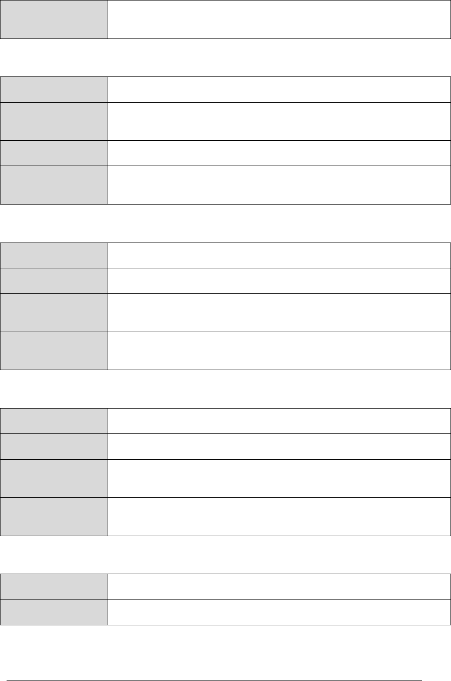
CFS HS APPLICATION USER’S GUIDE - 582-2013-002, Ver. 1.0, 03/24/14 Page A-4
The controlled copy of this document is located online at https://fsb.gsfc.nasa.gov/CFS/
Telemetry
Mnemonic(s)
CFS HS Default: $sc_$cpu_HS_AppMonState
Table 55 Telemetry Data – Status – CFS HS Event Monitor
Name
CurrentEventMonState
Description
CurrentEventMonState contains the status (enabled or disabled) of
Event Monitoring.
Data Type
Unsigned eight bit integer
Telemetry
Mnemonic(s)
CFS HS Default: $sc_$cpu_HS_EventMonState
Table 56 Telemetry Data – Status – CFS HS Aliveness Indicator
Name
CurrentAlivenessState
Data Type
Unsigned eight bit integer
Description
CurrentAlivenessState contains the status (enabled or disabled) of
the CPU Aliveness Indicator.
Telemetry
Mnemonic(s)
CFS HS Default: $sc_$cpu_HS_CPUAliveState
Table 57 Telemetry Data – Status – CPU Hogging Indicator
Name
CurrentCPUHogState
Data Type
Unsigned eight bit integer
Description
CurrentCPUHogState contains the status (enabled or disabled) of
the CPU Hogging Indicator Event Message.
Telemetry
Mnemonic(s)
CFS HS Default: $sc_$cpu_HS_CPUHoggingState
Table 58 Telemetry Data – Internal Status
Name
StatusFlags
Data Type
Unsigned 8 bit integer
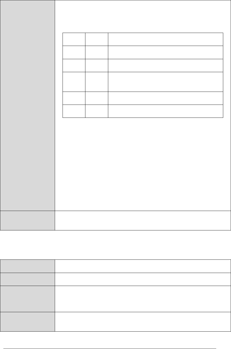
CFS HS APPLICATION USER’S GUIDE - 582-2013-002, Ver. 1.0, 03/24/14 Page A-5
The controlled copy of this document is located online at https://fsb.gsfc.nasa.gov/CFS/
Description
Each bit in the StatusFlags value represents a status of internal
CFS HS states. One (1) in the appropriate bit indicates success
and zero (0) indicates the opposite. The bits are assigned as
follows:
Item.
Bit
Description
1
0x01
CFS HS Loaded Execution Counter Table
2
0x02
CFS HS Loaded Message Actions Table
3
0x04
CFS HS Loaded Application Monitoring
Table
4
0x08
CFS HS Loaded Event Monitoring Table
5
0x10
CFS HS Critical Data Store In Use
For items 1 to 4, ‘Loaded’ refers to whether the table was
successfully loaded and is accessible. Loading normally should
happen at startup. Tables should remain accessible after
loading, but in the unusual event that TBL services can no
longer provide an address to the table then the table would be
inaccessible.
Item 1, the Execution Counter Table, may not be loaded if
execution counting is not being used; in that case that bit would
not be set (remain zero).
Item 5, the CFS HS Critical Data Store In Use flag, indicates
whether CFS HS is using the CDS or not. If CDS creation
failed, CFS HS is not using the CDS. Otherwise CFS HS is
using the CDS.
Telemetry
Mnemonic(s)
CFS HS Default: $sc_$cpu_HS_StatusFlags
Table 59 Telemetry Data – CFS HS Performed Processor Reset Counter
Name
ResetsPerformed
Data Type
Unsigned 16 bit integer
Description
CFS HS Performed Processor Reset Counter contains the number
of processor resets CFS HS has performed since the last power-on
reset.
Telemetry
Mnemonic(s)
CFS HS Default: $sc_$cpu_HS_PRResetCtr
CFS HS APPLICATION USER’S GUIDE - 582-2013-002, Ver. 1.0, 03/24/14 Page A-6
The controlled copy of this document is located online at https://fsb.gsfc.nasa.gov/CFS/
Table 60 Telemetry Data – CFS HS Maximum Processor Reset Count
Name
MaxResets
Data Type
Unsigned 16 bit integer
Description
CFS HS Maximum Processor Reset Count contains the maximum
number of cFE processor resets CFS HS is allowed to perform.
Telemetry
Mnemonic(s)
CFS HS Default: $sc_$cpu_HS_MaxResetCnt
Table 61 Telemetry Data – Total Count – Event Messages Monitored
Name
EventsMonitoredCount
Data Type
Unsigned 32 bit integer
Description
EventsMonitoredCount contains the total count of event messages
monitored by Event Monitoring.
Telemetry
Mnemonic(s)
CFS HS Default: $sc_$cpu_HS_EVTMonCnt
Table 62 Telemetry Data – Total Count – Invalid Event Monitors
Name
InvalidEventMonCount
Data Type
Unsigned 32 bit integer
Description
InvalidEventMonCount contains the number of entries in the Event
Monitor Table that have unresolvable application names.
Telemetry
Mnemonic(s)
CFS HS Default: $sc_$cpu_HS_InvalidEVTAppCnt
Table 63 Telemetry Data – Array – Application Monitor Table Entry Enable States
Name
AppMonEnables
Data Type
Unsigned 32 bit integer array
Description
The AppMonEnables array contains the Application Monitor Enable
state for each entry in the Application Monitor Table.

CFS HS APPLICATION USER’S GUIDE - 582-2013-002, Ver. 1.0, 03/24/14 Page A-7
The controlled copy of this document is located online at https://fsb.gsfc.nasa.gov/CFS/
Telemetry
Mnemonic(s)
CFS HS Default: $sc_$cpu_HS_AppStatus
Table 64 Telemetry Data – CFS HS Number of Message Actions Executed
Name
MsgActExec
Description
MsgActExec contains the number of Message Actions executed.
Events are internally transmitted and received via cFE Software
Bus messages.
Event messages generated by actions will not be counted, but in
most cases will result in a cFE Software Bus event message being
sent.
Data Type
Unsigned 32 bit integer
Telemetry
Mnemonic(s)
CFS HS Default: $sc_$cpu_HS_MsgActCtr
Table 65 Telemetry Data – CPU Utilization – Average
Name
UtilCpuAvg
Data Type
Unsigned 32 bit integer
Description
Current CPU Utilization Average.
Telemetry
Mnemonic(s)
CFS HS Default: $sc_$cpu_HS_CPUUtilAvg
Trending and
Monitoring
This mission [does or does not] trend the data from this telemetry
point. This mission [does or does not] monitor the data from this
telemetry point. It is recommended that missions insert the red,
yellow, and green limits for the monitor here.
Table 66 Telemetry Data – CPU Utilization – Peak
Name
UtilCpuPeak
Data Type
Unsigned 32 bit integer
Description
UtilCpuPeak contains the current CPU peak utilization.
Telemetry
Mnemonic(s)
CFS HS Default: $sc_$cpu_HS_CPUUtilPeak
CFS HS APPLICATION USER’S GUIDE - 582-2013-002, Ver. 1.0, 03/24/14 Page A-8
The controlled copy of this document is located online at https://fsb.gsfc.nasa.gov/CFS/
Trending and
Monitoring
This mission [does or does not] trend the data from this telemetry
point. This mission [does or does not] monitor the data from this
telemetry point. It is recommended that missions insert the red,
yellow, and green limits for the monitor here.
Table 67 Telemetry Data – Array – Execution Counts
Name
ExeCounts
Data Type
Unsigned 32 bit integer array
Description
The ExeCounts array contains the current Execution Counter
values for each counter specified in the Execution Counter Table.
Note that this telemetry point is optional; it only appears if the
configuration parameter HS_MAX_EXEC_CNT_SLOTS is
nonzero.
Telemetry
Mnemonic(s)
CFS HS Default: $sc_$cpu_HS_ExecutionCtr
CFS HS APPLICATION USER’S GUIDE - 582-2013-002, Ver. 1.0, 03/24/14 Page A-9
The controlled copy of this document is located online at https://fsb.gsfc.nasa.gov/CFS/
A.3 Configuration Parameters
Configuration parameters within a CFS application are mission- and platform-specific definitions
that bound the CFS application to a certain size, as well as optional features that may or may not
be added to a particular instance of a CFS application.
This section shows the CFS HS configuration parameters provided as a default by CFS HS.
Missions should replace the orange text. While configuration parameters cannot be changed by the
FOT, and are generally never changed after launch except by FSSE, the FOT needs to know the
mission-specific values that have been incorporated into the software at the time the software was
finalized and compiled.
Table 68 Configuration Parameter – Application Monitor Table Filename
Configuration
Parameter
HS_AMT_FILENAME
Value
CFS HS Default: "/cf/apps/hs_amt.tbl"
Purpose
Application Monitor Table filename
Description
This parameter specifies the default file to load the Application Monitor Table
during power-on reset.
Limits
This string should be no longer than specified by OS_MAX_PATH_LEN.
Table 69 Configuration Parameter – Application Monitoring – Default State
Configuration
Parameter
HS_APPMON_DEFAULT_STATE
Value
CFS HS Default: HS_STATE_ENABLED
Purpose
Default state of Application Monitoring
Description
This parameter specifies the state in which Application Monitoring is set when
CFS HS starts.
Limits
Must be HS_STATE_ENABLED (1) or HS_STATE_DISABLED (0).
Table 70 Configuration Parameter – Application Monitoring – Max Apps to Monitor
Configuration
Parameter
HS_MAX_MONITORED_APPS
Value
CFS HS Default: 32
Purpose
Maximum number of applications to monitor.
CFS HS APPLICATION USER’S GUIDE - 582-2013-002, Ver. 1.0, 03/24/14 Page A-10
The controlled copy of this document is located online at https://fsb.gsfc.nasa.gov/CFS/
Description
This parameter specifies the maximum number of applications that can be
monitored.
Limits
This parameter cannot be larger than an unsigned 32 bit integer
(4294967295).
This parameter must be greater than 0.
This parameter will dictate the size of the Application Monitor Table
(AMT):
AMT Size = HS_MAX_MONITORED_APPS * sizeof(HS_AMTEntry_t)
The total size of this table should not exceed the cFE size limit for a
single buffered table set by the CFE_TBL_MAX_SNGL_TABLE_SIZE
parameter.
Table 71 Configuration Parameter – CFS HS Application Name
Configuration
Parameter
HS_APP_NAME
Value
CFS HS Default: "HS"
Purpose
Define the application name
Description
This definition must match the name used at startup by the cFE Executive
Services when creating the CFS HS application. Note that application names
are also an argument to certain cFE command messages. For example, the
application name is needed to access tables via cFE Table Services
command messages.
Limits
CFS HS requires that this name be defined, but otherwise places no limits on
the definition. Refer to CFE Executive Services documentation for specific
information on limits related to application names.
Table 72 Configuration Parameter – CFS HS Application Version No. - Mission Specific
Configuration
Parameter
HS_MISSION_REV
Value
CFS HS Default: 0
Purpose
Mission-specific version number for CFS HS
CFS HS APPLICATION USER’S GUIDE - 582-2013-002, Ver. 1.0, 03/24/14 Page A-11
The controlled copy of this document is located online at https://fsb.gsfc.nasa.gov/CFS/
Description
This parameter specifies the mission-specific CFS HS application version
number.
The application version number consists of four parts:
1. Major version number
2. Minor version number
3. Revision number
4. Mission-specific revision number.
Limits
Must be defined as a numeric value that is greater than or equal to zero.
Table 73 Configuration Parameter – CPU Aliveness Indicator – Default State
Configuration
Parameter
HS_ALIVENESS_DEFAULT_STATE
Value
CFS HS Default: HS_STATE_ENABLED
Purpose
Default state of the CPU Aliveness Indicator
Description
This parameter specifies the state the CPU Aliveness Indicator will be set
when CFS HS starts.
Limits
Must be HS_STATE_ENABLED (1) or HS_STATE_DISABLED (0)
Table 74 Configuration Parameter – CPU Aliveness Indicator – Output Period
Configuration
Parameter
HS_CPU_ALIVE_PERIOD
Value
CFS HS Default: 5
Purpose
CPU Aliveness Indicator output period
Description
This parameter specifies how often to output the CPU Aliveness Indicator.
Units are the number of CFS HS cycles at which the
HS_CPU_ALIVE_STRING is output to the UART.
Limits
This parameter cannot be larger than an unsigned 32 bit integer
(4294967295).
Table 75 Configuration Parameter – CPU Aliveness Indicator – Output String
Configuration
Parameter
HS_CPU_ALIVE_STRING
Value
CFS HS Default: “.”
CFS HS APPLICATION USER’S GUIDE - 582-2013-002, Ver. 1.0, 03/24/14 Page A-12
The controlled copy of this document is located online at https://fsb.gsfc.nasa.gov/CFS/
Purpose
CPU Aliveness Indicator output string
Description
This parameter specifies the string to output to the UART periodically if the
CPU Aliveness Indicator is enabled.
Limits
None
Table 76 Configuration Parameter – CPU Average Utilization Number of Intervals
Configuration
Parameter
HS_UTIL_AVERAGE_NUM_INTERVAL
Value
CFS HS Default: 4
Purpose
CPU average utilization number of intervals
Description
This parameter specifies the number of intervals over which to report the
average CPU utilization.
Limits
This parameter cannot be larger than HS_UTIL_PEAK_NUM_INTERVAL.
Table 77 Configuration Parameter – CPU Hogging Indicator Default State
Configuration
Parameter
HS_CPUHOG_DEFAULT_STATE
Value
CFS HS Default: HS_STATE_ENABLED
Purpose
Default state of CPU Hogging Indicator
Description
This parameter specifies the state that CPU Hogging Indicator is set to when
CFS HS starts.
Limits
Must be HS_STATE_ENABLED (1) or HS_STATE_DISABLED (0)
Table 78 Configuration Parameter – CPU Peak Utilization Number of Intervals
Configuration
Parameter
HS_UTIL_PEAK_NUM_INTERVAL
Value
CFS HS Default: 64
Purpose
CPU peak utilization number of intervals
Description
This parameter specifies the number of intervals over which to report the peak
utilization value.
CFS HS APPLICATION USER’S GUIDE - 582-2013-002, Ver. 1.0, 03/24/14 Page A-13
The controlled copy of this document is located online at https://fsb.gsfc.nasa.gov/CFS/
Limits
This parameter cannot be larger than an unsigned 32 bit integer
(4294967295).
This parameter controls the size of the array which stores previously
measured utilization values.
Table 79 Configuration Parameter – CPU Utilization Calls per Mark
Configuration
Parameter
HS_UTIL_CALLS_PER_MARK
Value
CFS HS Default: 1
Purpose
CPU utilization calls per mark
Description
This parameter specifies the number of 1 Hz calls between capturing the Idle
task count (number of times the Mark function must be called before it actually
marks the time.)
This parameter influences the interval size.
Limits
The function calling the Mark function may not run at the same rate as
the CFS HS cycle (or CFS HS may not want to monitor utilization every
cycle) so this interval has to be at least as long as a CFS HS cycle.
This parameter cannot be larger than an unsigned 32 bit integer
(4294967295).
Table 80 Configuration Parameter – CPU Utilization – Conversion Factor Division
Configuration
Parameter
HS_UTIL_CONV_DIV
Value
CFS HS Default: 50505 (Mission value determined by calibration.)
Purpose
CPU utilization conversion factor division
Description
Division conversion factor.
Utilization = Full Utilization – (((Idle task cycles * MULT1) / DIV) * MULT2)
Number of idle ticks is divided by this value after it has been multiplied
by HS_UTIL_CONV_MULT1.
Limits
There may be processor dependent limits on value.
The result of the conversion must be less than an unsigned 32 bit integer
(4294967295).
CFS HS APPLICATION USER’S GUIDE - 582-2013-002, Ver. 1.0, 03/24/14 Page A-14
The controlled copy of this document is located online at https://fsb.gsfc.nasa.gov/CFS/
Table 81 Configuration Parameter – CPU Utilization – Conversion Factor Multiplication 1
Configuration
Parameter
HS_UTIL_CONV_MULT1
Value
CFS HS Default: 2500
Purpose
CPU utilization conversion factor multiplication 1
Description
First multiplication conversion factor.
Utilization = Full Utilization – (((Idle task cycles * MULT1) / DIV) * MULT2)
Number of idle ticks is multiplied by this value first when converting to
utils.
Limits
There may be processor dependent limits on value.
The result of the conversion must be less than an unsigned 32 bit integer
(4294967295).
Table 82 Configuration Parameter – CPU Utilization – Conversion Factor Multiplication 2
Configuration
Parameter
HS_UTIL_CONV_MULT2
Value
CFS HS Default: 1 (Mission value determined by calibration)
Purpose
CPU utilization conversion factor multiplication 2
Description
Second multiplication conversion factor.
Utilization = Full Utilization – (((Idle task cycles * MULT1) / DIV) * MULT2)
Number of idle ticks is multiplied by this value after being divided by
HS_UTIL_CONV_DIV after being multiplied by
HS_UTIL_CONV_MULT1 when converting to utils.
Limits
There may be processor dependent limits on value.
The result of the conversion must be less than an unsigned 32 bit integer
(4294967295).
Table 83 Configuration Parameter – CPU Utilization – Cycles per Interval
Configuration
Parameter
HS_UTIL_CYCLES_PER_INTERVAL
Value
CFS HS Default: 1
Purpose
CPU utilization cycles per interval

CFS HS APPLICATION USER’S GUIDE - 582-2013-002, Ver. 1.0, 03/24/14 Page A-15
The controlled copy of this document is located online at https://fsb.gsfc.nasa.gov/CFS/
Description
This parameter specifies the number of CFS HS cycles it takes to complete a
CPU utilization Interval (the number of CFS HS cycles between calculating
CPU utilization). CFS HS will monitor the utilization after this number of CFS
HS wakeup cycles.
Limits
This parameter cannot be larger than an unsigned 32 bit integer
(4294967295).
Table 84 Configuration Parameter – CPU Utilization – Diagnostics Array Configuration
Configuration
Parameter
HS_UTIL_TIME_DIAG_ARRAY_POWER
Value
CFS HS Default: 4
Purpose
CPU utilization diagnostics array configuration.
Used for calibration (how many time recordings are stored).
Description
This parameter specifies the exponent to which 2 is raised to determine the
array size.
Time will be marked into an array of subseconds. As such, large values will
require significant memory usage.
Limits
This parameter must be less than 32 and may not be negative.
Table 85 Configuration Parameter – CPU Utilization – Diagnostics Mask
Configuration
Parameter
HS_UTIL_DIAG_MASK
Value
CFS HS Default: 0xFFFFFFFF
Purpose
CPU utilization diagnostics mask. Used for calibration (how frequently to
record time).
Description
This parameter specifies the count mask for calibration of CPU Utilization
Monitoring. Time will be marked when (Counts & Mask) == Mask.
Limits
This parameter cannot be larger than an unsigned 32 bit integer
(4294967295).
Table 86 Configuration Parameter – CPU Utilization – Hogging Timeout
Configuration
Parameter
HS_UTIL_HOGGING_TIMEOUT
CFS HS APPLICATION USER’S GUIDE - 582-2013-002, Ver. 1.0, 03/24/14 Page A-16
The controlled copy of this document is located online at https://fsb.gsfc.nasa.gov/CFS/
Value
CFS HS Default: 5
Purpose
CPU utilization hogging timeout
Description
This parameter specifies the number of intervals in which the hogging limit
must be exceeded before the CPU Hogging Indicator Event Message is sent.
Limits
This parameter cannot be larger than an unsigned 32 bit integer
(4294967295).
Table 87 Configuration Parameter – CPU Utilization – Hogging Utils per Interval
Configuration
Parameter
HS_UTIL_PER_INTERVAL_HOGGING
Value
CFS HS Default: 9900
Purpose
CPU Utilization hogging utils per interval
Description
This parameter specifies the number that will signify that the CPU is being
hogged. The number is expressed in terms of full utilization (number of Utils,
or counts, equal to utilization which is considered hogging during one interval).
A greater number of counts is also considered hogging.
Limits
This parameter cannot be larger than HS_UTIL_PER_INTERVAL_TOTAL.
Table 88 Configuration Parameter – CPU Utilization – Time Diagnostic Array Length
Configuration
Parameter
HS_UTIL_TIME_DIAG_ARRAY_LENGTH
Value
CFS HS Default:
Purpose
Define the Idle child task diagnostic array length
Description
This parameter is used to set the diagnostic array length of the Idle child task
used for CPU Utilization Monitoring.
Limits
This parameter should not be changed by the user. It is derived from
HS_UTIL_TIME_DIAG_ARRAY_POWER, and only that parameter should be
changed.
Table 89 Configuration Parameter – CPU Utilization – Time Diagnostic Array Mask
Configuration
Parameter
HS_UTIL_TIME_DIAG_ARRAY_MASK

CFS HS APPLICATION USER’S GUIDE - 582-2013-002, Ver. 1.0, 03/24/14 Page A-17
The controlled copy of this document is located online at https://fsb.gsfc.nasa.gov/CFS/
Value
CFS HS Default:
Purpose
Define the Idle child task diagnostic array mask
Description
This parameter is used to set the diagnostic array mask of the Idle child task
used for CPU Utilization Monitoring.
Limits
This parameter should not be changed by the user. It is derived from
HS_UTIL_TIME_DIAG_ARRAY_POWER, and only that parameter should be
changed.
Table 90 Configuration Parameter – CPU Utilization – Total Utils per Interval
Configuration
Parameter
HS_UTIL_PER_INTERVAL_TOTAL
Value
CFS HS Default: 10,000
Purpose
CPU Utilization total utils per interval
Description
This parameter specifies the number that will signify full utilization during one
period (number of Utils, or counts, equal to full utilization.) This allows for
higher resolution than percentages, and non-decimal based values.
Limits
This parameter cannot be larger than an unsigned 32 bit integer
(4294967295).
Table 91 Configuration Parameter – Event Monitoring – Event Monitor Table Filename
Configuration
Parameter
HS_EMT_FILENAME
Value
CFS HS Default: "/cf/apps/hs_emt.tbl"
Purpose
Event Monitor Table filename
Description
Default file from which to load the Event Monitor Table during a power-on
reset sequence.
Limits
This string shouldn't be longer than OS_MAX_PATH_LEN for the target
platform in question.
Table 92 Configuration Parameter – Event Monitoring – Default State
Configuration
Parameter
HS_EVENTMON_DEFAULT_STATE
CFS HS APPLICATION USER’S GUIDE - 582-2013-002, Ver. 1.0, 03/24/14 Page A-18
The controlled copy of this document is located online at https://fsb.gsfc.nasa.gov/CFS/
Value
CFS HS Default: HS_STATE_ENABLED
Purpose
Default state of Event Monitoring
Description
This parameters specifies the default state of Event Monitoring when CFS HS
starts.
Limits
Must be HS_STATE_ENABLED or HS_STATE_DISABLED
Table 93 Configuration Parameter – Event Monitoring – Maximum Number of Events
Configuration
Parameter
HS_MAX_MONITORED_EVENTS
Value
CFS HS Default: 16
Purpose
Maximum number of events
Description
This parameter specifies the maximum number of events that can be
monitored.
Limits
This parameter cannot be larger than an unsigned 32 bit integer
(4294967295).
This parameter must be greater than 0.
The value of this parameter will dictate the size of the Event Monitor
table (EMT):
EMT Size = HS_MAX_MONITORED_EVENTS *
sizeof(HS_EMTEntry_t)
The total size of this table should not exceed the cFE size limit for a
single buffered table set by the CFE_TBL_MAX_SNGL_TABLE_SIZE
parameter
Table 94 Configuration Parameter – Execution Counter Table Filename
Configuration
Parameter
HS_XCT_FILENAME
Value
CFS HS Default: "/cf/apps/hs_xct.tbl"
Purpose
Execution Counter Table filename
Description
This parameter specifies the default file from which to load the Execution
Counter Table during a power-on reset sequence
Limits
This string shouldn't be longer than OS_MAX_PATH_LEN for the target
platform.
CFS HS APPLICATION USER’S GUIDE - 582-2013-002, Ver. 1.0, 03/24/14 Page A-19
The controlled copy of this document is located online at https://fsb.gsfc.nasa.gov/CFS/
Table 95 Configuration Parameter – Execution Counters Maximum Reported Number
Configuration
Parameter
HS_MAX_EXEC_CNT_SLOTS
Value
CFS HS Default: 32
Purpose
Maximum reported execution counters
Description
This parameter dictates the size of the Execution Counter Table (XCT).
Effectively, this sets the maximum number of execution counters to be
reported in telemetry.
Limits
This parameter cannot be larger than an unsigned 32 bit integer
(4294967295).
This parameter will dictate the size of the Execution Counter Table
(XCT):
XCT Size = HS_MAX_EXEC_CNT_SLOTS * sizeof(HS_XCTEntry_t)
The total size of this table should not exceed the cFE size limit for a
single buffered table set by the CFE_TBL_MAX_SNGL_TABLE_SIZE
parameter.
Table 96 Configuration Parameter – Idle Child Task – Parameter Name
Configuration
Parameter
HS_IDLE_TASK_NAME
Value
CFS HS Default: "HS_IDLE_TASK"
Purpose
Set Idle child task parameter name
Description
This parameter specifies the name of the parameter used by
CFE_ES_CreateChildTask.
Limits
Limits will vary by platform and available resources.
Table 97 Configuration Parameter – Idle Child Task – Flags
Configuration
Parameter
HS_IDLE_TASK_FLAGS
Value
CFS HS Default: 0
Purpose
Define the Idle child task flags
CFS HS APPLICATION USER’S GUIDE - 582-2013-002, Ver. 1.0, 03/24/14 Page A-20
The controlled copy of this document is located online at https://fsb.gsfc.nasa.gov/CFS/
Description
This parameter is used to set the flags of the Idle child task used for CPU
Utilization Monitoring. It is used as an input to a call to
CFE_ES_CreateChildTask().
Limits
Limits will vary by platform and available resources.
Table 98 Configuration Parameter – Idle Child Task – Priority
Configuration
Parameter
HS_IDLE_TASK_PRIORITY
Value
CFS HS Default: 252
Purpose
Idle Child Task Priority
Description
This parameter is used to set the priority of the Idle child task used for CPU
Utilization Monitoring.
Should be higher than all other user created tasks.
May need to be set lower than the maximum value if an OS uses its
own minimum priority task.
Limits
This parameter cannot be larger than 255.
Table 99 Configuration Parameter – Idle Child Task – Stack Pointer
Configuration
Parameter
HS_IDLE_TASK_STACK_PTR
Value
CFS HS Default: 0
Purpose
Specify stack pointer
Description
This parameter is used to set the pointer to the location where the child task's
stack pointer should start. Used as an input to a call to
CFE_ES_CreateChildTask().
Limits
Not all underlying operating systems support this parameter.
Table 100 Configuration Parameter – Idle Child Task – Stack Size
Configuration
Parameter
HS_IDLE_TASK_STACK_SIZE
Value
CFS HS Default: 4096
Purpose
Define stack size

CFS HS APPLICATION USER’S GUIDE - 582-2013-002, Ver. 1.0, 03/24/14 Page A-21
The controlled copy of this document is located online at https://fsb.gsfc.nasa.gov/CFS/
Description
This parameter is used to set the number of bytes to allocate for stack size of
the new Idle child task used for CPU Utilization Monitoring. Used as an input
to a call to CFE_ES_CreateChildTask().
Limits
Table 101 Configuration Parameter – Message Action – Maximum Size
Configuration
Parameter
HS_MAX_MSG_ACT_SIZE
Value
CFS HS Default: 16
Purpose
Maximum size of Message Action message.
Description
This parameter specifies the maximum length in bytes of a Software Bus
message that can be sent using a “Message Action type”.
Limits
This parameter cannot be larger than CFE_SB_MAX_SB_MSG_SIZE.
This parameter cannot be smaller than a packet header.
This parameter will influence the size of the Message Actions table
(MAT):
MAT Size = HS_MAX_MSG_ACT_TYPES *
(HS_MAX_MSG_ACT_SIZE + 4)
The total size of the Message Actions table should not exceed the cFE
size limit for a single buffered table set by the
CFE_TBL_MAX_SNGL_TABLE_SIZE parameter.
Table 102 Configuration Parameter – Message Action – Maximum Types
Configuration
Parameter
HS_MAX_MSG_ACT_TYPES
Value
CFS HS Default: 8
Purpose
Maximum Message Action types
Description
This parameter specifies the maximum number of Message Action types.
CFS HS APPLICATION USER’S GUIDE - 582-2013-002, Ver. 1.0, 03/24/14 Page A-22
The controlled copy of this document is located online at https://fsb.gsfc.nasa.gov/CFS/
Limits
This parameter cannot be
larger than 4 less than an unsigned 16 bit integer (65531).
This parameter must be greater than 0.
This parameter will influence the size of the Message Actions table
(MAT):
MAT Size = HS_MAX_MSG_ACT_TYPES *
(HS_MAX_MSG_ACT_SIZE + 4)
The total size of the Message Actions table should not exceed the cFE
size limit for a single buffered table set by the
CFE_TBL_MAX_SNGL_TABLE_SIZE parameter.
Table 103 Configuration Parameter – Message Actions – Table Filename
Configuration
Parameter
HS_MAT_FILENAME
Value
CFS HS Default: "/cf/apps/hs_mat.tbl"
Purpose
Message Actions Table filename
Description
This parameter contains the name and path of the default file from which to
load the Message Actions Table during power-on reset.
Limits
This string shouldn't be longer than OS_MAX_PATH_LEN for the target
platform in question.
Table 104 Configuration Parameter – Processor Reset – Activation Wait Time
Configuration
Parameter
HS_RESET_TASK_DELAY
Value
CFS HS Default: 50
Purpose
Time to wait before a processor reset (in milliseconds)
Description
This parameter specifies in milliseconds the length of the task delay performed
prior to calling CFE_ES_ResetCFE to allow for any event message to go out.
Limits
This parameter cannot be larger than an unsigned 32 bit integer
(4294967295).
Table 105 Configuration Parameter – Processor Resets – Maximum CFS HS Number
Configuration
Parameter
HS_MAX_RESTART_ACTIONS
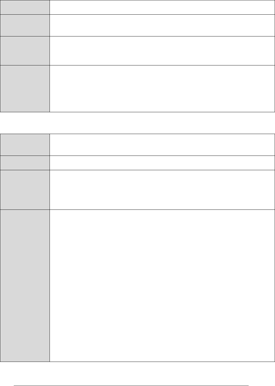
CFS HS APPLICATION USER’S GUIDE - 582-2013-002, Ver. 1.0, 03/24/14 Page A-23
The controlled copy of this document is located online at https://fsb.gsfc.nasa.gov/CFS/
Value
CFS HS Default: 3
Purpose
Max number of CFS HS processor resets that can be performed by a monitor
failure.
Description
This parameter specifies the maximum number of times that CFS HS will
attempt a processor reset as the result of either an Application Monitoring or
Event Monitoring failure.
Limits
This parameter cannot be larger than an unsigned 16 bit integer (65535).
Although not enforced, if this parameter is greater than or equal to
CFE_ES_MAX_PROCESSOR_RESETS then a power-on reset will occur
before the max count is reached, resetting the remaining actions to the value
set here.
Table 106 Configuration Parameter – Processor Resets – cFE Maximum Processor Resets
Configuration
Parameter
CFE_ES_MAX_PROCESSOR_RESETS
Value
See cFE ES documentation
Purpose
Specifies the number of processor resets before a power on reset occurs.
This is cFE ES configuration parameter, not CFS HS, but is included here for
reference, because of its interaction with HS_MAX_RESTART_ACTIONS for
processor reset limiting.
Description
The cFE Executive Services will perform a power-on reset after a defined
number of processor resets have occurred. The number of processor resets is
defined by the cFE configuration parameter
CFE_ES_MAX_PROCESSOR_RESETS.
The HS_MAX_RESTART_ACTIONS configuration parameter was added to
avoid continuous power on restarts. If the mission is using Processor Reset
Limiting, the mission should set the value of configuration parameter
HS_MAX_RESTART_ACTIONS to less than the value of configuration
parameter CFE_ES_MAX_PROCESSOR_RESETS. Conversely, if the
mission does not want to use Processor Reset Limiting, the value of
HS_MAX_RESTART_ACTIONS should be set higher than the value of
CFE_ES_MAX_PROCESSOR_RESETS. A
CFE_ES_MAX_PROCESSOR_RESETS value of zero (0) means that CFS
HS will never attempt to perform a Processor Reset.
If there is the desire to bypass Processor Reset Limiting for some but not all
situations (especially if a power on reset might be necessary), then Message
Actions can be used to command a reset via cFE ES. CFS HS will not
consider this a CFS HS caused processor reset and will not increment its
processor reset counter for this.
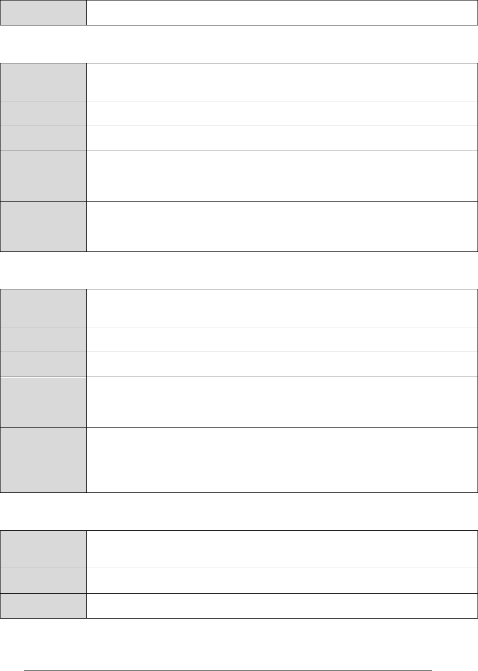
CFS HS APPLICATION USER’S GUIDE - 582-2013-002, Ver. 1.0, 03/24/14 Page A-24
The controlled copy of this document is located online at https://fsb.gsfc.nasa.gov/CFS/
Limits
See cFE ES documentation
Table 107 Configuration Parameter – Software Bus – Command Pipe Depth
Configuration
Parameter
HS_CMD_PIPE_DEPTH
Value
CFS HS Default: 12
Purpose
cFE Software Bus command pipe depth
Description
This parameter specifies the depth of the Software Bus pipe that CFS HS
uses for command messages and HK request messages. It is used during
initialization in the call to CFE_SB_CreatePipe.
Limits
This parameter cannot be larger than CFE_SB_MAX_PIPE_DEPTH.
This parameter must be greater than 0.
Table 108 Configuration Parameter – Software Bus – Event Pipe Depth
Configuration
Parameter
HS_EVENT_PIPE_DEPTH
Value
CFS HS Default: 32
Purpose
Software Bus event pipe depth
Description
This parameter specifies the depth of the Software Bus pipe that CFS HS
uses for Event Monitoring. It is used during initialization in the call to
CFE_SB_CreatePipe.
Limits
This should be set to supply sufficient room for the expected event
message load per second.
This parameter cannot be larger than CFE_SB_MAX_PIPE_DEPTH.
This parameter must be greater than 0.
Table 109 Configuration Parameter – Software Bus – Wakeup Message Timeout
Configuration
Parameter
HS_WAKEUP_TIMEOUT
Value
CFS HS Default: 1200
Purpose
Wakeup message Software Bus timeout
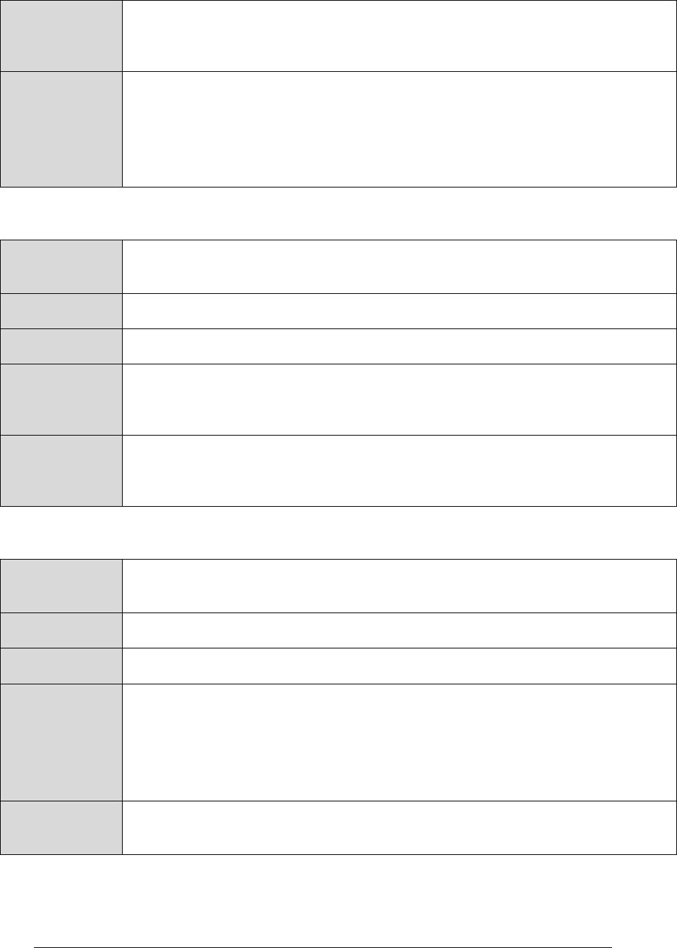
CFS HS APPLICATION USER’S GUIDE - 582-2013-002, Ver. 1.0, 03/24/14 Page A-25
The controlled copy of this document is located online at https://fsb.gsfc.nasa.gov/CFS/
Description
This parameter is passed into CFE_SB_RcvMsg as the timeout value. It can
specify CFE_SB_POLL, CFE_SB_PEND_FOREVER, or a timeout value in
milliseconds.
Limits
This Parameter must be CFE_SB_POLL, CFE_SB_PEND_FOREVER, or
greater than 0 and less than 2^31 - 1
As a timeout, this parameter should be less than
(HS_WATCHDOG_TIMEOUT_VALUE * 1000) - HS runtime in milliseconds.
Otherwise HS may not be able to service the Watchdog Timer in time.
Table 110 Configuration Parameter – Software Bus – Wakeup Pipe Depth
Configuration
Parameter
HS_WAKEUP_PIPE_DEPTH
Value
CFS HS Default: 1
Purpose
Software Bus wakeup pipe depth
Description
This parameter specifies the depth of the Software Bus pipe that CFS HS
uses for wakeup request messages. Used during initialization in the call to
CFE_SB_CreatePipe.
Limits
This parameter cannot be larger than CFE_SB_MAX_PIPE_DEPTH
This parameter must be greater than 0.
Table 111 Configuration Parameter – Time to Wait after Performing Processing
Configuration
Parameter
HS_POST_PROCESSING_DELAY
Value
CFS HS Default: 0
Purpose
Time to wait after performing processing (in milliseconds)
Description
This parameter specifies the length of a task delay performed prior to checking
the Software Bus for a wakeup request message.
This ensures that CFS HS will run no more often than a certain rate.
If this parameter is set to 0, no task delay will be performed. Time is in
milliseconds.
Limits
This parameter cannot be larger than an unsigned 32 bit integer
(4294967295).
CFS HS APPLICATION USER’S GUIDE - 582-2013-002, Ver. 1.0, 03/24/14 Page A-26
The controlled copy of this document is located online at https://fsb.gsfc.nasa.gov/CFS/
Table 112 Configuration Parameter – Time to Wait for All Applications to be Started
Configuration
Parameter
HS_STARTUP_SYNC_TIMEOUT
Value
CFS HS Default: 65,000
Purpose
Time to wait for all applications to be started (in milliseconds)
Description
Dictates the timeout for the CFE_ES_WaitForStartupSync call that CFS HS
uses to wait for all of the applications specified in the startup script to finish
initialization.
CFS HS will wait this amount of time before assuming all startup script
applications have been started and will then begin nominal processing.
Limits
This parameter cannot be larger than an unsigned 32 bit integer
(4294967295).
This should be greater than or equal to the cFE startup sync timeout for any
application in the Application Monitor Table.
Table 113 Configuration Parameter – Watchdog Timeout Value
Configuration
Parameter
HS_WATCHDOG_TIMEOUT_VALUE
Value
CFS HS Default: 10,000
Purpose
Watchdog timeout value
Description
This parameter specifies the number of milliseconds before a Watchdog Timer
timeout occurs.
Limits
This parameter cannot be larger than an unsigned 32 bit integer
(4294967295).
This parameter must be greater than 0.
CFS HS APPLICATION USER’S GUIDE - 582-2013-002, Ver. 1.0, 03/24/14 Page A-27
The controlled copy of this document is located online at https://fsb.gsfc.nasa.gov/CFS/
A.4 CFS HS Commands
The tables in this section show detailed descriptions of all the standard command messages
available to ground controllers for use with CFS HS.
Table 114 Command 0 – Noop
CFS HS
Command Code
0
Command Name
Noop
Description
A No Operation (Noop) command message will increment
the command execution counter and send an event
message containing the CFS HS version number.
A No Operation (Noop) command message is often used
as a general test to verify that CFS HS is still running and
responsive.
Command
Mnemonic(s)
CFS HS Default: $sc_$cpu_HS_NOOP
Command
Verification
Successful execution of this command may be verified with the
following telemetry:
$sc_$cpu_HS_CMDPC - command execution counter will
increment
The Event ID 23 No-op Command Version informational
event message (No-op Command Version) will be sent
Error Conditions
This command may fail for the following reason(s):
Command packet length not as expected
Failure Evidence
Evidence of failure may be found in the following telemetry:
$sc_$cpu_HS_CMDEC (or as defined by the mission) -
command error counter will increment
Error-specific event message 22.
Criticality
None

CFS HS APPLICATION USER’S GUIDE - 582-2013-002, Ver. 1.0, 03/24/14 Page A-28
The controlled copy of this document is located online at https://fsb.gsfc.nasa.gov/CFS/
Table 115 Command 1 – Reset Counters
CFS HS
Command Code
1
Command Name
Reset Counters
Description
Resets the CFS HS housekeeping counters
Command
Mnemonic(s)
CFS HS Default: $sc_$cpu_HS_ResetCtrs
Command
Verification
Successful execution of this command may be verified with the
following telemetry:
$sc_$cpu_HS_CMDPC (or as defined by the mission) -
command counter will be cleared
$sc_$cpu_HS_CMDEC (or as defined by the mission) -
command error counter will be cleared
$sc_$cpu_HS_EVTMonCnt (or as defined by the mission)
- events monitored counter will be cleared
The Event ID 24 Reset Counters command debug event
message (Reset Counters command) will be generated
when the command is executed, unless debug messages
are turned off.
Error Conditions
This command may fail for the following reason(s):
Command packet length not as expected
Failure Evidence
Evidence of failure may be found in the following telemetry:
$sc_$cpu_HS_CMDEC (or as defined by the mission) -
command error counter will increment
Error-specific event message 22.
Criticality
None

CFS HS APPLICATION USER’S GUIDE - 582-2013-002, Ver. 1.0, 03/24/14 Page A-29
The controlled copy of this document is located online at https://fsb.gsfc.nasa.gov/CFS/
Table 116 Command 2 – Application Monitoring – Enable
CFS HS
Command Code
2
Command Name
Application Monitoring – Enable
Description
Enables Application Monitoring.
Upon receipt of an Application Monitoring – Enable
command message, CFS HS enables all entries in the
Application Monitor Table, and then executes the table.
This allows maintenance to be done on a monitored
application. Typically one would disable Application
Monitoring, modify/load the application, then enable
Application Monitoring again.
Note: Nothing is preserved between a disable command message
and an enable command message.
Command
Mnemonic(s)
CFS HS Default: $sc_$cpu_HS_EnableAppMon
Command
Verification
Successful execution of this command may be verified with the
following telemetry:
$sc_$cpu_HS_CMDPC (or as defined by the mission) -
command counter will increment
$sc_$cpu_HS_AppMonState (or as defined by the
mission) - will be set to Enabled
The Event ID 25 Application Monitoring Enabled debug
event message (Application Monitoring Enabled) will be
generated when the command is executed, unless debug
messages are turned off.
Error Conditions
This command may fail for the following reason(s):
Command and packet length not as expected
Failure Evidence
Evidence of failure may be found in the following telemetry:
$sc_$cpu_HS_CMDEC (or as defined by the mission) -
command error counter will increment
Error-specific event message 22.
Criticality
None
CFS HS APPLICATION USER’S GUIDE - 582-2013-002, Ver. 1.0, 03/24/14 Page A-30
The controlled copy of this document is located online at https://fsb.gsfc.nasa.gov/CFS/
Table 117 Command 3 – Application Monitoring – Disable
CFS HS
Command Code
3
Command Name
Application Monitoring – Disable
Description
Disables Application Monitoring.
Upon receipt of an Application Monitoring – Disable
command message, CFS HS stops processing the
Application Monitor Table.
This allows maintenance to be done on a monitored
application.
Command
Mnemonic(s)
CFS HS Default: $sc_$cpu_HS_DisableAppMon
Command
Verification
Successful execution of this command may be verified with the
following telemetry:
$sc_$cpu_HS_CMDPC (or as defined by the mission) -
command counter will increment
$sc_$cpu_HS_AppMonState (or as defined by the
mission) - will be set to Disabled
The Event ID 26 Application Monitoring Disabled debug
event message (Application Monitoring Disabled) will be
generated when the command is executed, unless debug
messages are turned off.
Error Conditions
This command may fail for the following reason(s):
Command packet length not as expected
Failure Evidence
Evidence of failure may be found in the following telemetry:
$sc_$cpu_HS_CMDEC (or as defined by the mission) -
command error counter will increment
Error-specific event message 22.
Criticality
None
CFS HS APPLICATION USER’S GUIDE - 582-2013-002, Ver. 1.0, 03/24/14 Page A-31
The controlled copy of this document is located online at https://fsb.gsfc.nasa.gov/CFS/
Table 118 Command 4 – Event Monitoring – Enable
CFS HS
Command Code
4
Command Name
Event Monitoring – Enable
Description
Enables Event Monitoring.
If CFS HS receives an Event Monitoring – Enable command
message, CFS HS enables Event Monitoring and begins
processing the Event Monitor Table.
Command
Mnemonic(s)
CFS HS Default: $sc_$cpu_HS_EnableEvtMon
Command
Verification
Successful execution of this command may be verified with the
following telemetry:
$sc_$cpu_HS_CMDPC (or as defined by the mission) -
command counter will increment
$sc_$cpu_HS_EventMonState (or as defined by the
mission) - will be set to enabled
The Event ID 27 debug event message will be generated
when the command is executed, unless debug messages
are turned off.
Error Conditions
This command may fail for the following reason(s):
Command packet length not as expected
Failure Evidence
Evidence of failure may be found in the following telemetry:
$sc_$cpu_HS_CMDEC (or as defined by the mission) -
command error counter will increment
Error-specific event message 22.
Criticality
None
CFS HS APPLICATION USER’S GUIDE - 582-2013-002, Ver. 1.0, 03/24/14 Page A-32
The controlled copy of this document is located online at https://fsb.gsfc.nasa.gov/CFS/
Table 119 Command 5 – Event Monitoring – Disable
CFS HS
Command Code
5
Command Name
Event Monitoring – Disable
Description
Disables Event Monitoring.
This command is useful for making table updates.
Upon receipt of an Event Monitoring – Disable command
message, CFS HS:
Sets Event Monitoring to disabled
Stops executing the Event Monitor Table.
Command
Mnemonic(s)
CFS HS Default: $sc_$cpu_HS_DisableEvtMon
Command
Verification
Successful execution of this command may be verified with the
following telemetry:
$sc_$cpu_HS_CMDPC (or as defined by the mission) -
command counter will increment
$sc_$cpu_HS_EventMonState (or as defined by the
mission) - will be set to disabled
The Event ID 28 Event Monitoring Disabled debug event
message (Event Monitoring Disabled) will be generated
when the command is executed, unless debug messages
are turned off.
Error Conditions
This command may fail for the following reason(s):
Command packet length not as expected
Failure Evidence
Evidence of failure may be found in the following telemetry:
$sc_$cpu_HS_CMDEC (or as defined by the mission) -
command error counter will increment
Error-specific event message 22.
Criticality
None
CFS HS APPLICATION USER’S GUIDE - 582-2013-002, Ver. 1.0, 03/24/14 Page A-33
The controlled copy of this document is located online at https://fsb.gsfc.nasa.gov/CFS/
Table 120 Command 6 – CPU Aliveness Indicator – Enable
CFS HS
Command Code
6
Command Name
CPU Aliveness Indicator – Enable
Description
Enables the CPU Aliveness Indicator UART output.
Upon receipt of a CPU Aliveness Indicator – Enable
command message, CFS HS begins sending the
configured number of heartbeat character(s) to the UART
port.
Command
Mnemonic(s)
CFS HS Default: $sc_$cpu_HS_EnableCPUAlive
Command
Verification
Successful execution of this command may be verified with the
following telemetry:
$sc_$cpu_HS_CMDPC (or as defined by the mission) -
command counter will increment
$sc_$cpu_HS_CPUAliveState (or as defined by the
mission) - will be set to enabled
The Event ID 29 CPU Aliveness Indicator Enabled debug
event message (CPU Aliveness Indicator Enabled) will be
generated when the command is executed, unless debug
messages are turned off.
Error Conditions
This command may fail for the following reason(s):
Command packet length not as expected
Failure Evidence
Evidence of failure may be found in the following telemetry:
$sc_$cpu_HS_CMDEC (or as defined by the mission) -
command error counter will increment
Error-specific event message 22.
Criticality
None

CFS HS APPLICATION USER’S GUIDE - 582-2013-002, Ver. 1.0, 03/24/14 Page A-34
The controlled copy of this document is located online at https://fsb.gsfc.nasa.gov/CFS/
Table 121 Command 7 – CPU Aliveness Indicator – Disable
CFS HS
Command Code
7
Command Name
CPU Aliveness Indicator – Disable
Description
Disables the CPU Aliveness Indicator UART output.
Upon receipt of a CPU Aliveness Indicator – Disable
command message, CFS HS stops sending the
configured number of heartbeat characters to the UART
port.
This may be useful during integration and testing since
the mission may want to turn off the heartbeat characters
being sent to the UART without reconfiguring and
recompiling the code. Normally a mission would turn off
the CPU Aliveness Indicator during flight.
Command
Mnemonic(s)
CFS HS Default: $sc_$cpu_HS_DisableCPUAlive
Command
Verification
Successful execution of this command may be verified with the
following telemetry:
$sc_$cpu_HS_CMDPC (or as defined by the mission) -
command counter will increment
$sc_$cpu_HS_CPUAliveState (or as defined by the
mission) - will be set to disabled
The Event ID 30 CPU Aliveness Indicator Disabled debug
event message (CPU Aliveness Indicator Disabled) will
be generated when the command is executed, unless
debug messages are turned off.
Error Conditions
This command may fail for the following reason(s):
Command packet length not as expected
Failure Evidence
Evidence of failure may be found in the following telemetry:
$sc_$cpu_HS_CMDEC (or as defined by the mission) -
command error counter will increment
Error-specific event message 22.
Criticality
None
CFS HS APPLICATION USER’S GUIDE - 582-2013-002, Ver. 1.0, 03/24/14 Page A-35
The controlled copy of this document is located online at https://fsb.gsfc.nasa.gov/CFS/
Table 122 Command 8 – Processor Resets – Reset Count Performed
CFS HS
Command Code
8
Command Name
Processor Resets – Reset Count Performed
Description
Resets the count of CFS HS performed resets maintained by
CFS HS.
Upon receipt of a Processor Resets – Reset Count
Performed command message, CFS HS sets the number
of cFE processor resets commanded by CFS HS to zero.
CFS HS keeps track of the number of cFE processor
resets it performs in order to avoid an infinite reset loop.
Resetting this count allows CFS HS to continue to
perform resets up to the internally set maximum.
Command
Mnemonic(s)
CFS HS Default: $sc_$cpu_HS_ResetPRCtr
Command
Verification
Successful execution of this command may be verified with the
following telemetry:
$sc_$cpu_HS_CMDPC (or as defined by the mission) -
command counter will increment
$sc_$cpu_HS_PRResetCtr (or as defined by the
mission) - will be set to 0
The debug event message (HS Processor Resets
Counter has been Reset) will be generated when the
command is executed, unless debug messages are
turned off
Error Conditions
This command may fail for the following reason(s):
Command packet length not as expected
Failure Evidence
Evidence of failure may be found in the following telemetry:
$sc_$cpu_HS_CMDEC (or as defined by the mission) -
command error counter will increment
Error-specific event message 22
Criticality
None
CFS HS APPLICATION USER’S GUIDE - 582-2013-002, Ver. 1.0, 03/24/14 Page A-36
The controlled copy of this document is located online at https://fsb.gsfc.nasa.gov/CFS/
Table 123 Command 9 – Processor Resets – Set Max
CFS HS
Command Code
9
Command Name
Processor Resets – Set Max
Description
Sets the max allowable count of processor resets to the provided
value.
Upon receipt of a Processor Resets – Set Max command
message, CFS HS sets the Maximum number of cFE
processor resets commanded by CFS HS to the
command-specified value.
This allows the ground to modify the default value
specified in a configuration file without having to
recompile.
This is primarily used in order to be consistent with cFE.
Note: This limit is different than the limit that the cFE
maintains.
Command
Mnemonic(s)
CFS HS Default: $sc_$cpu_HS_SetMaxResetCnt
Command
Verification
Successful execution of this command may be verified with the
following telemetry:
$sc_$cpu_HS_CMDPC (or as defined by the mission) -
command counter will increment
$sc_$cpu_HS_MaxResetCnt (or as defined by the
mission) - will be set to the provided value
The Event ID 32 (Max Resets Performable by HS Has
Been Set) debug event message will be generated when
the command is executed, unless debug messages are
turned off.
Error Conditions
This command may fail for the following reason(s):
Command packet length not as expected
Evidence of
Failure
Evidence of failure may be found in the following telemetry:
$sc_$cpu_HS_CMDEC (or as defined by the mission) -
command error counter will increment
Error-specific event message 22.
Criticality
None

CFS HS APPLICATION USER’S GUIDE - 582-2013-002, Ver. 1.0, 03/24/14 Page A-37
The controlled copy of this document is located online at https://fsb.gsfc.nasa.gov/CFS/
Table 124 Command 10 – CPU Hogging Indicator – Enable
CFS HS
Command Code
10
Command Name
CPU Hogging Indicator – Enable
Description
Enables the CPU Hogging Indicator Event Message.
This command only affects the CPU Hogging Indicator
Event Message.
CPU Utilization Monitoring itself cannot be turned off.
Command
Mnemonic(s)
CFS HS Default: (N/A)
Command
Verification
Successful execution of this command may be verified with the
following telemetry:
$sc_$cpu_HS_CMDPC (or as defined by the mission) -
command counter will increment
$sc_$cpu_HS_CPUHoggingState (or as defined by the
mission) - will be set to enabled
The Event ID 64 event message (CPU Hogging Indicator
Enabled) will be generated when the command is
executed, unless debug messages are turned off.
Error Conditions
This command may fail for the following reason(s):
Command packet length not as expected
Failure Evidence
Evidence of failure may be found in the following telemetry:
$sc_$cpu_HS_CMDEC (or as defined by the mission) -
command error counter will increment
Error-specific event message 22.
Criticality
None
CFS HS APPLICATION USER’S GUIDE - 582-2013-002, Ver. 1.0, 03/24/14 Page A-38
The controlled copy of this document is located online at https://fsb.gsfc.nasa.gov/CFS/
Table 125 Command 11 – CPU Hogging Indicator – Disable
CFS HS
Command Code
11
Command Name
CPU Hogging Indicator – Disable
Description
Disables the CPU Hogging Indicator Event Message.
This command only affects the CPU Hogging Indicator
Event Message.
CPU Utilization Monitoring itself cannot be turned off.
Command
Mnemonic(s)
CFS HS Default: (N/A)
Command
Verification
Successful execution of this command may be verified with the
following te lemetry:
$sc_$cpu_HS_CMDPC (or as defined by the mission) -
command counter will increment
$sc_$cpu_HS_CPUHoggingState (or as defined by the
mission) - will be set to disabled
The Event ID 65 (Debug) – event message (CPU
Hogging Indicator Disabled) will be generated when the
command is executed, unless debug messages are
turned off.
Error Conditions
This command may fail for the following reason(s):
Command packet length not as expected
Failure Evidence
Evidence of failure may be found in the following telemetry:
$sc_$cpu_HS_CMDEC (or as defined by the mission) -
command error counter will increment
Error-specific event message 22.
Criticality
None

CFS HS APPLICATION USER’S GUIDE - 582-2013-002, Ver. 1.0, 03/24/14 Page A-39
The controlled copy of this document is located online at https://fsb.gsfc.nasa.gov/CFS/
A.5 Event Messages
This section shows event messages. Event messages are text generated by an application in
response to command messages, software errors, hardware errors, application initialization, etc.
Event messages are sent to alert that a significant event on board has occurred. Event messages
may also be sent for debugging application code during development, maintenance, and testing.
Event Messages are sent to ground and storage, so they are considered external messages. However,
CFS HS receives these for the Event Monitor, so from the CFS HS perspective event messages are
also treated as internal messages.
Event messages are not mission-specific. Generally the event messages shown below should appear
in telemetry on ground FSW systems (e.g., ASIST), no matter the mission.
There are four levels of event types:
Critical
Error
Information
Debug
The levels are not used for programmatic control by CFS HS. In other words, CFS HS does not
treat the level labels differently. However, ASIST or other ground flight control software may
display event messages in different colors or otherwise differentiate them.
A.5.1 Event Messages - CRITICAL
The tables in this section show critical event messages for CFS HS. Events of this type are
notifications of error conditions that CFS HS is unable to correct or compensate for. These might
be uncorrectable memory errors, hardware failures, etc.
Table 126 Event ID 2 (CRITICAL) – Application Terminating
Event ID Number
2
Event name
Application Terminating
Event Message
'Application Terminating, err = [Err]'
Where:
[Err] is the return status from the cFE call that caused CFS HS to
terminate.
Type
CRITICAL
Cause
This critical event message is issued when CFS HS exits due to a fatal
error condition.
CFS HS APPLICATION USER’S GUIDE - 582-2013-002, Ver. 1.0, 03/24/14 Page A-40
The controlled copy of this document is located online at https://fsb.gsfc.nasa.gov/CFS/
A.5.2 Event Messages - ERROR
The tables in this section show error event messages for CFS HS. Events of this type are
notifications of abnormal behavior. However, they represent error conditions that have been
identified and corrected for by the flight software. These typically represent things like erroneous
commands, illegal mode change attempts, switching to redundant hardware, etc.
Table 127 Event ID 3 (Error) – Failed to Restore Data from CDS
Event ID Number
3
Event name
Failed to Restore Data from CDS
Event Message
'Failed to restore data from CDS (Err=[Err], initializing resets data'
Where:
[Err] contains the return status from the CFE_ES_RestoreFromCDS
call that generated the error.
Type
ERROR
Cause
This error event message is issued when CFS HS is unable to restore data
from its critical data store
Table 128 Event ID 4 (Error) – Creating – SB Command Pipe
Event ID Number
4
Event name
Error Creating SB Command Pipe
Event Message
'Error Creating SB Command Pipe,RC=[RC]'
Where:
[RC] contains the return status from the CFE_SB_CreatePipe call
that generated the error.
Type
ERROR
Cause
This error event message is issued when CFS HS is unable to create its
command pipe via the CFE_SB_CreatePipe API.
Table 129 Event ID 5 (Error) – Creating – SB Event Pipe
Event ID Number
5
Event name
Error Creating SB Event Pipe
CFS HS APPLICATION USER’S GUIDE - 582-2013-002, Ver. 1.0, 03/24/14 Page A-41
The controlled copy of this document is located online at https://fsb.gsfc.nasa.gov/CFS/
Event Message
'Error Creating SB Event Pipe,RC=[RC]’
Where:
[RC] contains the return status from the CFE_SB_CreatePipe call
that generated the error.
Type
ERROR
Cause
This error event message is issued when CFS HS is unable to create its
event pipe via the CFE_SB_CreatePipe API.
Table 130 Event ID 6 (Error) – Creating – SB Wakeup Pipe
Event ID Number
6
Event name
Error Creating SB Wakeup Pipe
Event Message
'Error Creating SB Wakeup Pipe,RC=[RC]’
Where:
[RC] contains the return status from the CFE_SB_CreatePipe call
that generated the error.
Type
ERROR
Cause
This error event message is issued when CFS HS is unable to create its
wakeup pipe via the CFE_SB_CreatePipe API.
Table 131 Event ID 7 (Error) – Subscribing – to Events
Event ID Number
7
Event name
Error Subscribing to Events
Event Message
'Error Subscribing to Events,RC=[RC]'
Where:
[RC] contains the return status from the CFE_SB_Subscribe call
that generated the error.
Type
ERROR
Cause
This error event message is issued when the call to CFE_SB_Subscribe for
the CFE_EVS_EVENT_MSG_MID, during initialization returns a value
other than CFE_SUCCESS.
CFS HS APPLICATION USER’S GUIDE - 582-2013-002, Ver. 1.0, 03/24/14 Page A-42
The controlled copy of this document is located online at https://fsb.gsfc.nasa.gov/CFS/
Table 132 Event ID 8 (Error) – Subscribing – to HK Request
Event ID Number
8
Event name
Error Subscribing to HK Request
Event Message
'Error Subscribing to HK Request,RC=[RC]'
Where:
[RC] contains the return status from the CFE_SB_Subscribe call
that generated the error.
Type
ERROR
Cause
This error event message is issued when the call to CFE_SB_Subscribe for
the HS_SEND_HK_MID, during initialization returns a value other than
CFE_SUCCESS.
Table 133 Event ID 9 (Error) – Subscribing – to Ground Commands
Table 134 Event ID 10 (Error) – Registering – Application Monitor Table
Event ID Number
10
Event Name
Error Registering Application Monitor Table
Event Message
'Error Registering AppMon Table, RC=[RC]'
Where:
[RC] contains the return status from the CFE_TBL_Register API call
that generated the error.
Type
ERROR
Event ID Number
9
Event name
Error Subscribing to Ground Commands
Event Message
'Error Subscribing to Gnd Cmds,RC=[RC]'
Where:
[RC] contains the return status from the CFE_SB_Subscribe call
that generated the error.
Type
ERROR
Cause
This error event message is issued when the call to CFE_SB_Subscribe
for the HS_CMD_MID during initialization returns a value other than
CFE_SUCCESS.
CFS HS APPLICATION USER’S GUIDE - 582-2013-002, Ver. 1.0, 03/24/14 Page A-43
The controlled copy of this document is located online at https://fsb.gsfc.nasa.gov/CFS/
Cause
This error event message is issued when CFS HS is unable to register its
Application Monitor Table with cFE TBL via the CFE_TBL_Register API.
Table 135 Event ID 11 (Error) – Registering – Event Monitor Table
Event ID Number
11
Event name
Error Registering Event Monitor Table
Event Message
'Error Registering EventMon Table,RC=[RC]'
Where:
[RC] contains the return status from the CFE_TBL_Register API call
that generated the error.
Type
ERROR
Cause
This error event message is issued when CFS HS is unable to register its
Event Monitor Table with cFE TBL via the CFE_TBL_Register API.
Table 136 Event ID 12 (Error) – Registering – Execution Counter Table
Event ID Number
12
Event name
Error Registering Execution Counter Table
Event Message
'Error Registering ExeCount Table,RC=[RC]'
Where:
[RC] contains the return status from the CFE_TBL_Register API call
that generated the error.
Type
ERROR
Cause
This error event message is issued when CFS HS is unable to register its
Execution Counter Table with cFE TBL via the CFE_TBL_Register API.
Table 137 Event ID 13 (Error) – Registering – Message Actions Table
Event ID Number
13
Event name
Error Registering Message Actions Table
Event Message
'Error Registering MsgActs Table,RC=[RC]'
Where:
[RC] is the return code from the CFE_TBL_Register API call.
CFS HS APPLICATION USER’S GUIDE - 582-2013-002, Ver. 1.0, 03/24/14 Page A-44
The controlled copy of this document is located online at https://fsb.gsfc.nasa.gov/CFS/
Type
ERROR
Cause
This error event message is issued when CFS HS is unable to register its
Message Actions Table with cFE TBL via the CFE_TBL_Register API.
Table 138 Event ID 14 (Error) – Loading – Application Monitor Table
Event ID Number
14
Event Name
Error Loading Application Monitor Table
Event Message
'Error Loading AppMon Table,RC=[RC]]'
Where:
[RC] is the return code from the CFE_TBL_Load API call.
Type
ERROR
Cause
This error event message is issued when the call to CFE_TBL_Load for the
Application Monitor Table returns a value other than CFE_SUCCESS.
Table 139 Event ID 15 (Error) – Loading – Event Monitor Table
Event ID Number
15
Event name
Error Loading Event Monitor Table
Event Message
'Error Loading EventMon Table,RC=[RC]'
Where:
[RC] is the return code from the CFE_TBL_Load API call.
Type
ERROR
Cause
This error event message is issued when the call to CFE_TBL_Load for the
Event Monitor Table returns a value other than CFE_SUCCESS.
Table 140 Event ID 16 (Error) – Loading – Execution Counter Table
Event ID Number
16
Event name
Error Loading Execution Counter Table
Event Message
'Error Loading ExeCount Table,RC=[RC]'
Where:
[RC] is the return code from the CFE_TBL_Load API call.
CFS HS APPLICATION USER’S GUIDE - 582-2013-002, Ver. 1.0, 03/24/14 Page A-45
The controlled copy of this document is located online at https://fsb.gsfc.nasa.gov/CFS/
Type
ERROR
Cause
This error event message is issued when the call to CFE_TBL_Load for the
Execution Counter Table returns a value other than CFE_SUCCESS.
Table 141 Event ID 17 (Error) – Loading – Message Actions Table
Event ID Number
17
Event name
Error Loading Message Actions Table
Event Message
'Error Loading MsgActs Table,RC=[RC]'
Where [RC] is the return code from the CFE_TBL_Load API call.
Type
ERROR
Cause
This error event message is issued when the call to CFE_TBL_Load for the
Message Actions Table returns a value other than CFE_SUCCESS.
Table 142 Event ID 18 (Error) – Data in CDS was Corrupt, Initializing Resets Data
Event ID Number
18
Event name and
Message
'Data in CDS was corrupt, initializing resets data'
Type
ERROR
Cause
This error event message is issued when CFS HS restores data from the
CDS that does not pass validation.
Table 143 Event ID 19 (Error) – Invalid – Command Code
Event ID Number
19
Event name
Invalid Command Code
Event Message
'Invalid command code: ID = [ID], CC = [CC]'
Where
[ID] contains the message ID
[CC] contains the command code that generated the error.
Type
ERROR
CFS HS APPLICATION USER’S GUIDE - 582-2013-002, Ver. 1.0, 03/24/14 Page A-46
The controlled copy of this document is located online at https://fsb.gsfc.nasa.gov/CFS/
Cause
This error event message is issued when a Software Bus message is
received with an invalid command code.
Table 144 Event ID 20 (Error) – Invalid – Command Pipe Message ID
Event ID Number
20
Event name
Invalid Command Pipe Message ID
Event Message
'Invalid command pipe message ID: [ID]'
Where:
[ID] contains the message ID that generated the error
Type
ERROR
Cause
This error event message is issued when a Software Bus message is
received with an invalid message ID.
Table 145 Event ID 21 (Error) – Invalid – HK Request Message Length
Event ID Number
21
Event name
Invalid Housekeeping Request Message Length
Event Message
'Invalid HK request msg length: ID = [ID], CC = [CC], Len = [Len], Expected
= [Expected] '
Where:
[ID] contains the message ID.
[CC] contains the command code.
[Len] is the actual length returned by the
CFE_SB_GetTotalMsgLength call.
[Expected] is the expected length for the message.
Type
ERROR
Cause
This error event message is issued when a housekeeping request is
received with a message length that doesn't match the expected value.
Table 146 Event ID 22 (Error) – Invalid – Ground Command Message Length
Event ID Number
22
Event name
Invalid Ground Command Message Length
CFS HS APPLICATION USER’S GUIDE - 582-2013-002, Ver. 1.0, 03/24/14 Page A-47
The controlled copy of this document is located online at https://fsb.gsfc.nasa.gov/CFS/
Event Message
'Invalid msg length: ID = [ID], CC = [CC], Len = [Len], Expected =
[Expected]'
Where:
[ID] contains the message ID.
[CC] contains the command code.
[Len] is the actual length returned by the
CFE_SB_GetTotalMsgLength call.
[Expected] is the expected length for the message.
Type
ERROR
Cause
This error event message is issued when a ground command message is
received with a message length that doesn't match the expected value.
Table 147 Event ID 33 (Error) – Getting Table Address – Application Monitor
Event ID Number
33
Event name
Error Getting Application Monitor Table Address
Event Message
'Error getting AppMon Table address, RC=[RC], Application Monitoring
Disabled'
Where:
[RC] is the return code from the CFE_TBL_GetAddress function call
that generated the error.
Type
ERROR
Cause
This error event message is issued when the address cannot be obtained
from cFE TBL for the Application Monitor Table..
Table 148 Event ID 34 (Error) – Getting Table Address – Event Monitor
Event ID Number
34
Event name
Error Getting Event Monitor Table Address
Event Message
'Error getting EventMon Table address, RC=[RC], Event Monitoring
Disabled'
Where:
[RC] is the return code from the CFE_TBL_GetAddress function call
that generated the error.
Type
ERROR
CFS HS APPLICATION USER’S GUIDE - 582-2013-002, Ver. 1.0, 03/24/14 Page A-48
The controlled copy of this document is located online at https://fsb.gsfc.nasa.gov/CFS/
Cause
This error event message is issued when the address cannot be obtained
from cFE TBL for the Event Monitor Table.
Table 149 Event ID 35 (Error) – Getting Table Address – Execution Counter
Event ID Number
35
Event name
Error Getting Execution Counter Table Address
Event Message
'Error getting ExeCount Table address, RC=[RC] '
Where:
[RC] is the return code from the CFE_TBL_GetAddress function call
that generated the error.
Type
ERROR
Cause
This error event message is issued when the address cannot be obtained
from cFE TBL for the Execution Counter Table.
Table 150 Event ID 37 (Error) – Processor Reset Action – Limit Reached
Event ID Number
37
Event name
Processor Reset: Action: Limit Reached
Event Message
'Processor Reset Action Limit Reached: No Reset Performed'
Type
ERROR
Cause
This error event message is issued when the action specified by an
Application or Event monitor entry that fails is processor reset, and no more
processor resets are allowed.
Table 151 Event ID 38 (Error) – Application Monitoring – Application Name Not Found
Event ID Number
38
Event name
Application Monitoring Application Name Not Found
Event Message
'App Monitor App Name not found: APP:[APP]'
Where:
[APP] is the application name in the table that was not found in the
system
Type
ERROR

CFS HS APPLICATION USER’S GUIDE - 582-2013-002, Ver. 1.0, 03/24/14 Page A-49
The controlled copy of this document is located online at https://fsb.gsfc.nasa.gov/CFS/
Cause
This error event message is issued when a monitored application name
cannot be resolved into an application ID by the OS.
Table 152 Event ID 39 (Error) – Application Monitoring – Failure Action – Restart App
Event ID Number
39
Event name
Application Monitoring Failure: Action: Restart Application
Event Message
'App Monitor Failure: APP:[APP]: Action: Restart Application'
Where:
[APP] is the name of the application being monitored
Type
ERROR
Cause
This error event message is issued when a monitored application fails to
increment its execution counter in the table-specified number of cycles, and
the specified action type is Restart Application. .
Table 153 Event ID 40 (Error) – Call to Restart Application Failed
Event ID Number
40
Event name
Call to Restart Application Failed
Event Message
'Call to Restart App Failed: APP:[APP] ERR: [ERR]'
Where:
[APP] is the name of the application that was being restarted
[ERR] is the return code from the CFE_ES_RestartApp,
CFE_ES_GetAppInfo or CFE_ES_GetAppIDByName
function call that generated the error
Type
ERROR
Cause
This error event message is issued when Application Monitoring attempts
to restart an application but is unable to.
Table 154 Event ID 41 (Error) – Application Monitoring Failure Action – Event Only
Event ID Number
41
Event name
Application Monitoring Failure: Action: Event Only

CFS HS APPLICATION USER’S GUIDE - 582-2013-002, Ver. 1.0, 03/24/14 Page A-50
The controlled copy of this document is located online at https://fsb.gsfc.nasa.gov/CFS/
Event Message
'App Monitor Failure: APP:[APP]: Action: Event Only'
Where:
[APP] specifies the name of the application being monitored
Type
ERROR
Cause
This error event message is issued when a monitored application fails to
increment its execution counter in the table-specified number of cycles, and
the specified action type is Event Only.
Table 155 Event ID 42 (Error) – Application Monitoring Failure Action – Processor Reset
Event ID Number
42
Event name
Application Monitoring Failure: Action: Processor Reset
Event Message
'App Monitor Failure: APP:[APP]: Action: Processor Reset'
Where:
[APP] specifies the name of the application being monitored
Type
ERROR
Cause
This error event message is issued when a monitored application fails to
increment its execution counter in the table-specified number of cycles, and
the specified action type is processor reset.
Table 156 Event ID 43 (Error) – Application Monitoring Failure Action – Message Action
Event ID Number
43
Event name
Application Monitoring Failure: Action: Message Action
Event Message
'App Monitor Failure: APP:[APP]: Action: Message Action Index: [MAN]'
Where:
[APP] specifies the name of the application being monitored
[MAN] specifies the Message Action number
Type
ERROR
Cause
This error event message is issued when a monitored application fails to
increment its execution counter in the table-specified number of cycles, and
the specified action type is a Message Action.

CFS HS APPLICATION USER’S GUIDE - 582-2013-002, Ver. 1.0, 03/24/14 Page A-51
The controlled copy of this document is located online at https://fsb.gsfc.nasa.gov/CFS/
Table 157 Event ID 44 (Error) – Event Action – Message Action
Event ID Number
44
Event name
Event: Action: Message Action
Event Message
'Event Monitor: APP:[APP] EID:[EID]: Action: Message Action Index: [MAI]'
Where:
[APP] specifies the name of the application that sent the
message
[EID] specifies the Event ID in the message
[MAI] specifies the Message Action number
Type
ERROR
Cause
This error event message is issued when a monitored event is detected,
and the specified action type is a Message Action.
Table 158 Event ID 45 (Error) – Event Action – Processor Reset
Event ID Number
45
Event name
Event: Action: Processor Reset
Event Message
'Event Monitor: APP:[APP] EID:[EID]: Action: Processor Reset'
Where:
[APP] specifies the name of the application that issued the
event and is being restarted
[EID] specifies the Event ID of that message
Type
ERROR
Cause
This error event message is issued when an event is received that matches
an event in the Event Monitor Table that specifies processor reset as the
action type.
Table 159 Event ID 46 (Error) – Event Action – Restart Application
Event ID Number
46
Event name
Event: Action: Restart Application

CFS HS APPLICATION USER’S GUIDE - 582-2013-002, Ver. 1.0, 03/24/14 Page A-52
The controlled copy of this document is located online at https://fsb.gsfc.nasa.gov/CFS/
Event Message
'Event Monitor: APP:[APP] EID:[EID]: Action: Restart Application'
Where:
[APP] specifies the name of the application that issued the
event and is being restarted
[EID] specifies the Event ID of that message
Type
ERROR
Cause
This error event message is issued when an event is received that matches
an event in the Event Monitor Table that specifies Restart Application as
the action type.
Table 160 Event ID 47 (Error) – Call to Restart Application Failed
Event ID Number
47
Event name
Call to Restart Application Failed
Event Message
'Call to Restart App Failed: APP:[APP] ERR: [ERR]'
Where:
[APP] is the name of the application that was being restarted
[ERR] is the return code from the CFE_ES_RestartApp
function call that generated the error
Type
ERROR
Cause
This error event message is issued when Event Monitoring attempts to
restart an application but is unable to.
Table 161 Event ID 48 (Error) – Event Action – Delete Application
Event ID Number
48
Event name
Event: Action: Delete Application
Event Message
'Event Monitor: APP:[APP] EID:[EID]: Action: Delete Application'
Where:
[APP] specifies the name of the application that issued the
event, and is being deleted.
[EID] specifies the Event ID of that message.
Type
ERROR
CFS HS APPLICATION USER’S GUIDE - 582-2013-002, Ver. 1.0, 03/24/14 Page A-53
The controlled copy of this document is located online at https://fsb.gsfc.nasa.gov/CFS/
Cause
This error event message is issued when an event is received that matches
an event in the Event Monitor Table that specifies Delete Application as the
action type.
Table 162 Event ID 49 (Error) – Call to Delete Application Failed
Event ID Number
49
Event name
Call to Delete Application Failed
Event Message
'Call to Delete App Failed: APP:[APP] ERR: [ERR]'
Where:
[APP] is the name of the application that was being deleted
[ERR] is the return code from the CFE_ES_DeleteApp
function call that generated the error
Type
ERROR
Cause
This error event message is issued when Event Monitoring attempts to
delete an application but is unable to do so.
Table 163 Event ID 51 (Error) – Verify Error – Application Monitor Table
Event ID Number
51
Event Name
Application Monitor Table Verify Error
Event Message
'AppMon verify err: Entry = [Entry], Err = [Err], Action = [Action], App =
[App]'
Where:
[Entry] is the number of the Application Monitor Table entry
[Err] is the id of the error that occurred
[Action] is the action listed for the entry
[App] is the application name specified in the table
Type
ERROR
Cause
This error event message is issued on the first error when a table validation
fails for an Application Monitor Table load.
Table 164 Event ID 53 (Error) – Verify Error – Event Monitor Table
Event ID Number
53
Event name
Event Monitor Table Verify Error
CFS HS APPLICATION USER’S GUIDE - 582-2013-002, Ver. 1.0, 03/24/14 Page A-54
The controlled copy of this document is located online at https://fsb.gsfc.nasa.gov/CFS/
Event Message
'EventMon verify err: Entry = [Entry], Err = [Err], Action = [Action], ID = [ID]
App = [App]'
Where:
[Entry] is the number of the Event Monitor Table entry
[Err] is the id of the error that occurred
[Action] is the action listed for the entry
[ID] is the Event ID listed in the table
[App] is the application name specified in the table
Type
ERROR
Cause
This error event message is issued on the first error when a table validation
fails for an Event Monitor Table load.
Table 165 Event ID 55 (Error) – Verify Error – Execution Counter Table
Event ID Number
55
Event name
Execution Counter Table Verify Error
Event Message
'ExeCount verify err: Entry = [Entry] Err = [Err], Type = [Type], Name =
[Name]'
Where:
[Entry] is the number of the Execution Counter Table entry
[Err] is the id of the error that occurred
[Type] is the resource type for the entry
[Name] is the resource name specified in the table
Type
ERROR
Cause
This error event message is issued on the first error when a table validation
fails for an Execution Counter Table load.
Table 166 Event ID 57 (Error) – Verify Error – Message Actions Table
Event ID Number
57
Event name
Message Actions Table Verify Error
CFS HS APPLICATION USER’S GUIDE - 582-2013-002, Ver. 1.0, 03/24/14 Page A-55
The controlled copy of this document is located online at https://fsb.gsfc.nasa.gov/CFS/
Event Message
'MsgActs verify err: Entry = [Entry]d, Err = [Length = [Length], ID = [ID]'
Where:
[Entry] is the number of the Message Actions Table entry
[Err] is the id of the error that occurred
[Length] is the length of the message
[ID] is the Message ID
Type
ERROR
Cause
This error event message is issued on the first error when a table validation
fails for a Message Actions Table load.
Table 167 Event ID 58 (Error) – Disabled – Application Monitoring
Event ID Number
58
Event name
Application Monitoring Disabled
Event Message
'Application Monitoring Disabled due to Table Load Failure'
Type
ERROR
Cause
This error event message is issued when Application Monitoring has been
disabled due to a table load failure.
Table 168 Event ID 59 (Error) – Disabled – Event Monitoring
Event ID Number
59
Event name
Event Monitoring Disabled
Event Message
'Event Monitoring Disabled due to Table Load Failure'
Type
ERROR
Cause
This error event message is issued when Event Monitoring has been
disabled due to a table load failure.
Table 169 Event ID 60 (Error) – Subscribing to Wakeup
Event ID Number
60
Event name
Error Subscribing to Wakeup

CFS HS APPLICATION USER’S GUIDE - 582-2013-002, Ver. 1.0, 03/24/14 Page A-56
The controlled copy of this document is located online at https://fsb.gsfc.nasa.gov/CFS/
Event Message
'Error Subscribing to Wakeup,RC=[RC]'
Where:
[RC] is the return code from the CFE_SB_Subscribe for the
HS_WAKEUP_MID function call that generated the error
Type
ERROR
Cause
This error event message is issued when the call to CFE_SB_Subscribe for
the HS_WAKEUP_MID during initialization returns a value other than
CFE_SUCCESS.
Table 170 Event ID 61 (Error) – CPU Hogging Detected
Event ID Number
61
Event name and
Message
CPU Hogging Detected
Type
ERROR
Cause
This error event message is issued when CPU Utilization Monitoring
detects that CPU utilization has exceeded the CPU Hogging threshold for
longer than the CPU Hogging duration.
Table 171 Event ID 66 (Error) – Event Monitoring Enable – Error Subscribing to Events
Event ID Number
66
Event name
Event Monitoring Enable: Error Subscribing to Events
Event Message
'Event Monitoring Enable: Error Subscribing to Events,RC=[Status]'
Where:
[Status] indicates the error status passed from the subscribe
call.
Type
ERROR
Cause
This error event message is issued when a ground command message is
received to enable Event Monitoring while it is disabled, and there is an
error subscribing to the event Message ID.
CFS HS APPLICATION USER’S GUIDE - 582-2013-002, Ver. 1.0, 03/24/14 Page A-57
The controlled copy of this document is located online at https://fsb.gsfc.nasa.gov/CFS/
Table 172 Event ID 67 (Error) – Event Monitoring Disable – Error Unsubscribing from
Events
Event ID Number
67
Event name
Event Monitoring Disable: Error Unsubscribing from Events
Event Message
'Event Monitor Disable: Error Unsubscribing from Events,RC=[RC]'
Where:
[RC] indicates the error status passed from the unsubscribe
call
Type
ERROR
Cause
This error event message is issued when a ground command message is
received to disable Event Monitoring while it is enabled, and there is an
error unsubscribing from the event message ID.
See FAQ “What happens when CFS HS is commanded to disable Event
Monitoring and there is a failure in unsubscribing to event messages?” in
Section in 5.1.
Table 173 Event ID 68 (Error) – Unsubscribing from Events
Event ID Number
68
Event name
Error Unsubscribing from Events
Event Message
'Error Unsubscribing from Events,RC=[RC]'
Where:
[RC] indicates the error status passed from the unsubscribe
call.
Type
ERROR
Cause
This error event message is issued if when acquiring the Event Monitor
Table from cFE TBL, it is bad and Event Monitoring is disabled, but there is
a failure unsubscribing from the event message ID.
See FAQ “What happens when CFS HS is commanded to disable Event
Monitoring and there is a failure in unsubscribing to event messages?” in
Section in 5.1.

CFS HS APPLICATION USER’S GUIDE - 582-2013-002, Ver. 1.0, 03/24/14 Page A-58
The controlled copy of this document is located online at https://fsb.gsfc.nasa.gov/CFS/
This page deliberately left blank.
CFS HS APPLICATION USER’S GUIDE - 582-2013-002, Ver. 1.0, 03/24/14 Page A-59
The controlled copy of this document is located online at https://fsb.gsfc.nasa.gov/CFS/
A.5.3 Event Messages - INFORMATION
The tables in this section show informational event messages for CFS HS.
Table 174 Event ID 1 (Informational) – HS Initialized Version
Event ID Number
1
Event name
HS Initialized Version
Event Message
'HS Initialized. Version [Major].[Minor].[Revision].[Mission]'
Where:
[Major] is the major version identifier
[Minor] is the minor version identifier
[Revision] is the revision identifier
[Mission] is the mission revision identifier.
Type
INFORMATION
Cause
This informational event message is issued when CFS HS has completed
initialization.
Table 175 Event ID 23 (Informational) – No-op Command Version
Event ID Number
23
Event name
No-op Command Version
Event Message
'No-op command: Version [Major].[Minor].[Revision].[Mission]'
Where:
[Major] is the major version identifier
[Minor] is the minor version identifier
[Revision] is the revision identifier
[Mission] is the mission revision identifier.
Type
INFORMATION
Cause
This informational event message is issued when a NOOP (no operation)
Command has been received.

CFS HS APPLICATION USER’S GUIDE - 582-2013-002, Ver. 1.0, 03/24/14 Page A-60
The controlled copy of this document is located online at https://fsb.gsfc.nasa.gov/CFS/
Table 176 Event ID 50 (Informational) – Verify Results – Application Monitoring
Event ID Number
50
Event name
Application Monitor Table Verify Results
Event Message
'AppMon verify results: good = [good], bad = [bad], unused = [unused]'
Where:
[good] is number of entries that passed
[bad] field is number of entries that failed
[unused] field is the number of entries that weren't checked
because they were marked unused
Type
INFORMATION
Cause
This informational event message is issued when a table validation has
been completed for an Application Monitor Table load.
Table 177 Event ID 52 (Informational) – Verify Results – Event Monitoring
Event ID Number
52
Event name
Event Monitoring Verify Results
Event Message
'EventMon verify results: good = [good], bad = [bad], unused = [unused]'
Where:
[good] is number of entries that passed
[bad] field is number of entries that failed
[unused] field is the number of entries that weren't checked
because they were marked unused
Type
INFORMATION
Cause
This informational event message is issued when a table validation has
been completed for an Event Monitor Table load.
Table 178 Event ID 54 (Informational) – Verify Results – Execution Counter Table Load
Event ID Number
54
Event name
Execution Counter Table Load Verify Results
CFS HS APPLICATION USER’S GUIDE - 582-2013-002, Ver. 1.0, 03/24/14 Page A-61
The controlled copy of this document is located online at https://fsb.gsfc.nasa.gov/CFS/
Event Message
'ExeCount verify results: good = [good], bad = [bad], unused = [unused]'
Where:
[good] is number of entries that passed
[bad] field is number of entries that failed
[unused] field is the number of entries that weren't checked
because they were marked unused
Type
INFORMATION
Cause
This informational event message is issued when a table validation has
been completed for an Execution Counter Table load.
Table 179 Event ID 56 (Informational) – Verify Results – Message Actions
Event ID Number
56
Event name
Message Actions Verify Results
Event Message
'MsgActs verify results: good = [good], bad = [bad], unused = [unused]'
Where:
[good] is number of entries that passed
[bad] field is number of entries that failed
[unused] field is the number of entries that weren't checked
because they were marked unused
Type
INFORMATION
Cause
This informational event message is issued when a table validation has
been completed for a Message Actions Table load.

CFS HS APPLICATION USER’S GUIDE - 582-2013-002, Ver. 1.0, 03/24/14 Page A-62
The controlled copy of this document is located online at https://fsb.gsfc.nasa.gov/CFS/
This page deliberately left blank.

CFS HS APPLICATION USER’S GUIDE - 582-2013-002, Ver. 1.0, 03/24/14 Page A-63
The controlled copy of this document is located online at https://fsb.gsfc.nasa.gov/CFS/
A.5.4 Event Messages - DEBUG
The tables in this section show debug event messages for CFS HS. Events of this type are primarily
for the mission developer. The messages contain specific references to code and are of limited use
to FOT. Typically these types of event messages are disabled during flight.
Table 180 Event ID 24 (Debug) – Reset Counters Command
Event ID Number
24
Event name and
Message
Reset Counters Command
Type
DEBUG
Cause
This debug event message is issued when a Reset Counters command
message has been received.
Table 181 Event ID 25 (Debug) – Application Monitoring – Enabled
Event ID Number
25
Event name and
Message
Application Monitoring Enabled
Type
DEBUG
Cause
This debug event message is issued when an Application Monitoring –
Enable command message has been received.
Table 182 Event ID 26 (Debug) – Application Monitoring – Disabled
Event ID Number
26
Event name and
Message
Application Monitoring Disabled
Type
DEBUG
Cause
This debug event message is issued when an Application Monitoring –
Disable command message has been received.
Table 183 Event ID 27 (Debug) – Event Monitoring – Enabled
Event ID Number
27
Event name
Event Monitoring Enabled
CFS HS APPLICATION USER’S GUIDE - 582-2013-002, Ver. 1.0, 03/24/14 Page A-64
The controlled copy of this document is located online at https://fsb.gsfc.nasa.gov/CFS/
Event Message
'Event Monitoring Enabled'
Type
DEBUG
Cause
This debug event message is issued when an Event Monitoring – Enable
command message has been received.
Table 184 Event ID 28 (Debug) – Event Monitoring – Disabled
Event ID Number
28
Event name
Event Monitoring Disabled
Event Message
'Event Monitoring Disabled'
Type
DEBUG
Cause
This debug event message is issued when an Event Monitoring – Disable
command message has been received.
Table 185 Event ID 29 (Debug) – CPU Aliveness Indicator – Enabled
Event ID Number
29
Event name
CPU Aliveness Indicator Enabled
Event Message
CPU 'Aliveness Indicator Enabled'
Type
DEBUG
Cause
This debug event message is issued when a CPU Aliveness Indicator –
Enable command message has been received.
Table 186 Event ID 30 (Debug) – CPU Aliveness Indicator – Disabled
Event ID Number
30
Event name
CPU Aliveness Indicator Disabled
Event Message
'Aliveness Indicator Disabled'
Type
DEBUG
Cause
This debug event message is issued when a CPU Aliveness Indicator –
Disable command message has been received.

CFS HS APPLICATION USER’S GUIDE - 582-2013-002, Ver. 1.0, 03/24/14 Page A-65
The controlled copy of this document is located online at https://fsb.gsfc.nasa.gov/CFS/
Table 187 Event ID 31 (Debug) – HS Processor Resets Counter has been Reset
Event ID Number
31
Event name
HS Processor Resets Counter has been Reset
Event Message
'Processor Resets Performed by HS Counter has been Reset'
Type
DEBUG
Cause
This debug event message is issued when a Processor Resets – Reset
Count Performed command message has been received.
Table 188 Event ID 32 (Debug) – Max Resets Performable by HS Has Been Set
Event ID Number
32
Event name
Max Resets Performable by HS Has Been Set
Event Message
'Max Resets Performable by HS has been set to [Max]'
Where:
[Max] indicates the error status passed from the subscribe
call.
Type
DEBUG
Cause
This debug event message is issued when a Processor Resets – Set Max
command message has been received.
The value the max resets count has been set to is listed in the event.
Table 189 Event ID 64 (Debug) – CPU Hogging Indicator – Enabled
Event ID Number
64
Event name and
Message
CPU Hogging Indication Enabled
Type
DEBUG
Cause
This debug event message is issued when a CPU Hogging Indicator –
Enable command message has been received.
CFS HS APPLICATION USER’S GUIDE - 582-2013-002, Ver. 1.0, 03/24/14 Page A-66
The controlled copy of this document is located online at https://fsb.gsfc.nasa.gov/CFS/
Table 190 Event ID 65 (Debug) – CPU Hogging Indicator – Disabled
Event ID Number
65
Event name and
Message
CPU Hogging Indication Disabled
Type
DEBUG
Cause
This debug event message is issued when a CPU Hogging Indicator –
Disable command message has been received.

CFS HS APPLICATION USER’S GUIDE - 582-2013-002, Ver. 1.0, 03/24/14 Page B-1
The controlled copy of this document is located online at https://fsb.gsfc.nasa.gov/CFS/
Appendix B Document Notes
B.1 Mission-Specific Conventions
This document presents selected information that should be removed when tailoring this
document for a mission in a dark orange font.
The nomenclature of command and telemetry mnemonics is highly mission-specific, so
this document does not attempt to include the actual command and telemetry database
names in advance. For example, for the Magnetospheric Multiscale (MMS) mission the
telemetry mnemonics are defined in an RDL file for ASIST, and they will not exactly match
the mnemonics in this Guide.
Specifically, this document as delivered to the mission has names that may be replaced by
the mission when the mission creates the ground system RDL database. In particular, the
suggested names start with $sc_$CPU_HS which indicate a global setting for spacecraft,
processor selection, and the CFS HS subsystem. This has meaning if the mission has
multiple spacecraft, each with a copy of cFE/CFS applications being executed, and/or
multiple processors per spacecraft, each with a copy of cFE/CFS applications being
executed. Most missions have neither and they do not prepend a $sc_$cpu_ selection to the
front of the command name. However it is common for missions to differentiate the
spacecraft subsystem commands from instrument commands by prepending several
characters (e.g. pw for power system) to all the command and telemetry names for that
subsystem.
B.2 Updating This Document
This section is for anyone updating this Guide in the future.
When tailoring this document for a particular mission, remove text appearing in this dark orange
font.
Review figures to be sure there is no conflict with mission configurations. Edit figures with
Microsoft Visio or PowerPoint if necessary.
Add mission-defined values in Appendix A.
Regenerate the table of contents.
Remove this Appendix [Appendix B].
This Guide is formatted using Microsoft Word styles. When adding new sections to the Guide,
assign paragraphs to the styles shown in the table below. Center all tables and figures horizontally
on the page. Use 15% grayscale in new table headings. For bullets in tables, assign the style shown
below to set vertical spacing, then assign bullets using the bullet icons menu. Tables in Appendix
A use direct formatting instead of styles, as shown below.
TOC, Figures, and Tables can be updated automatically. To update all figure and table references
in the document, when using the PC version of Word, select all, then choose F9.

CFS HS APPLICATION USER’S GUIDE - 582-2013-002, Ver. 1.0, 03/24/14 Page B-2
The controlled copy of this document is located online at https://fsb.gsfc.nasa.gov/CFS/
Table 191 Internal Document Styles
Type
Style to be Used
Justification
Chapter titles, subtitles,
and subsections.
Heading 1 through 6
Left
First level bullets
“List Bullet 1” style.
Left
Second level bullets
“List Bullet 2” style
Left
Numbered lists
“Style List Enum 0”
Left
Names of code modules
Code
N/A
All text not otherwise
tagged
“Body Text”
Full justification
Tables & Figures
First row of tables
Table Header
Center
All other cells of tables
Table Cells
Left
Figure captions
Caption Figure
Center
Table captions
Caption Table
Center
Bullets in table cells
“Style Table Cells Vertical” + bullet
Left
Appendix Tables
Table headers
“AppTableHeader”
(Arial 11 point, cell 15% grey)
Center
Table data
“AppTableCell”
(Arial 11 point)
Left
