Captured Hip Screw Surg Technique
2016-04-01
: Pdf Captured Hip Screw Surg Technique Captured_Hip_Screw_Surg_Technique 3 2016 pdf
Open the PDF directly: View PDF ![]() .
.
Page Count: 24
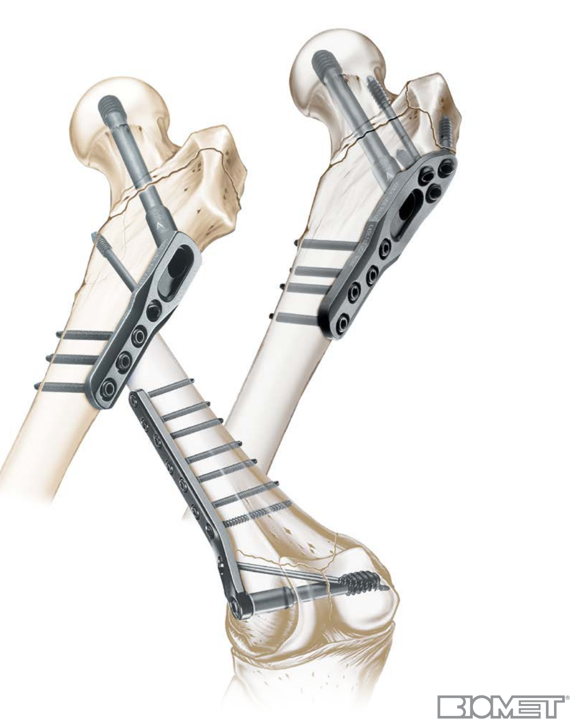
Surgical Technique
Options:
Supracondylar Plate
Trochanteric Plate
Captured Hip®
Screw System
TRAUMA

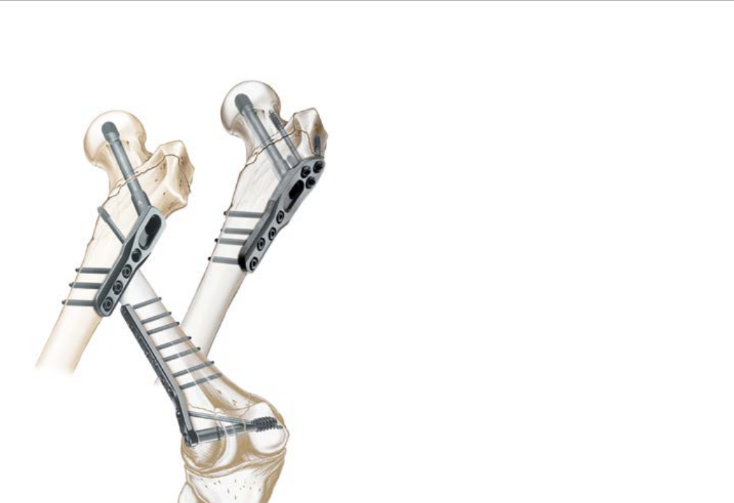
Captured Hip® Screw System
Contents
Introduction .................................................................................................................................................................. 1
Femoral Neck and Intertrochanteric Fractures of the Femur ...................................................................................... 3
Supracondylar Fractures and Fractures of the Lower Third Femur ............................................................................ 9
Catalog Numbers and Descriptions ........................................................................................................................... 18
Ordering Information .................................................................................................................................................. 20
2
Written by Richard F. Kyle, MD
The implants in the Captured Hip Screw with Trochanteric
and Supracondylar Plate System are made of Ti-6Al/4V.
Titanium alloy, when compared to 316L stainless steel,
offers biocompatibility, and strength.1
The captured hip screw is very simple to insert. It is a keyless
system. A single instrument is used to insert the assembled
captured hip screw and plate in one step. This concept has
been carried forward into the design of the instruments for
the keyed supracondylar plate. Following placement of the
central lag screw, the plate is simply guided over the driver
onto the lag screw and against the bone.
Introduction
The captured hip screw uses the principle of sliding
impaction, rather than compression with a compression
screw. By firmly impacting the fracture after placement of
the hip screw, a compressive load that is approximately four
times greater than that of a compression screw is applied to
close the fracture site.² This method eliminates the potential
of stripping the lag screw threads in osteoporotic bone and
avoids the need for a compression screw.
The supracondylar plate utilizes screw-controlled
compression. Since the load is perpendicular to the sliding
mechanism, distal femoral fractures do not impact naturally.
A keyed mechanism is utilized to enhance rotational stability.
This system provides simple solutions to the surgeon’s
common hip and knee fracture needs. All implants,
screws and instruments fit into one tray. The system is
sensibly designed to address ease of use and inventory
reduction, two important cost factors when considering
managed care.
The Captured Hip Screw System System was designed and developed in
conjunction with Richard F. Kyle, M.D.
This hip fracture surgical technique is utilized by Richard F. Kyle, M.D. Biomet
as the manufacturer of this device, does not practice medicine and does not
recommend this device or technique. Each surgeon is responsible for determining
the appropriate device and technique to utilize on each individual patient.
1

Description
The captured hip screw system is designed for use in
intertrochanteric fractures. Intracapsular fractures may
be managed with the addition of solid or cannulated
cancellous screws to prevent rotation.
Subtrochanteric fractures may be treated with the device
provided that a good medial buttress is achieved and
weight-bearing is not allowed until the fracture shows
evidence of union.
The trochanteric plate option can be used to control
comminution of the greater trochanter as well as reverse
oblique and high subtrochanteric fractures by preventing
medialization of the femoral shaft.
The supracondylar plate is designed for use in
supracondylar fractures, and fractures and osteotomies of
the proximal and distal femur.
Captured Hip® Screw System
2
Surgical Technique
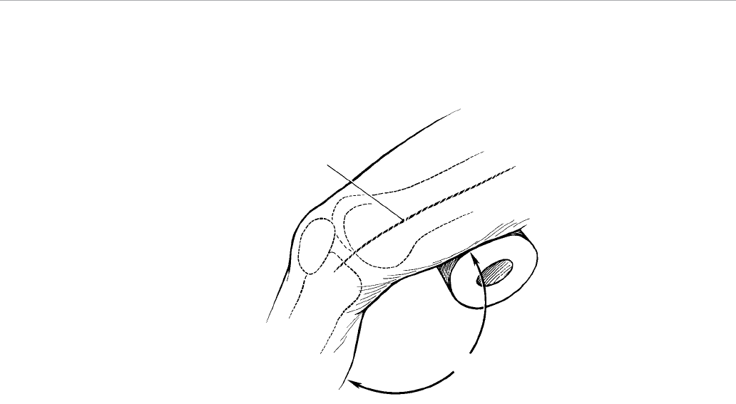
Patient Positioning
Place the patient supine on a standard fracture table.
Reduce and align the fracture using traction with external
rotation followed by approximately 20 degrees of internal
rotation to compress the fracture (Figure 1). Verify reduction
using dual-plane image intensification. Prepare and drape
the hip in the usual manner.
Incision
Make a 10 cm incision in the lateral aspect of the hip, with
dissection beginning at the flare of the greater trochanter
and extending distally (Figure 1). Carry the dissection
sharply down through the skin and subcutaneous tissue to
the fascia lata. Split the fascia lata longitudinally, exposing
the vastus lateralis. Retract the vastus lateralis anteriorly
and expose the lateral aspect of the femoral shaft.
Femoral Neck and Intertrochanteric Fractures of the Femur
20°
Traction
Incision
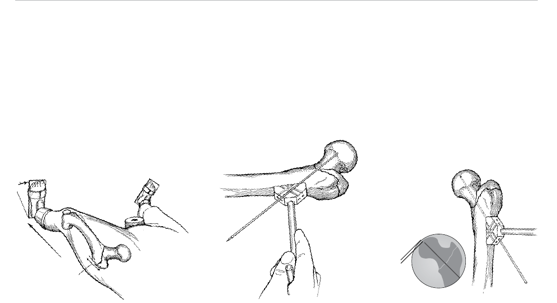
Guide Pin Positioning
Place a 3.2 mm guide pin on the anterior aspect of the
femoral shaft and neck, 3-4 cm distal to the flare of the
greater trochanter. Grooves are provided on the outer
surfaces of the guide pin jig to indicate the pin angle
options (and the subsequent captured screw assembly
angle) and thus the proper placement of the hole for the
internal guide pin. The guide pin should lie at the highest
angle necessary to position the pin next to the medial
cortex and in the center of the femoral head in the anterior/
posterior (A/P) plane (Figure 2).
Drill the 3.2 mm guide pin through the corresponding hole
in the guide pin jig. Advance it into the center of the femoral
head under image control in both the A/P and lateral planes
to within 5-7 mm of the subchondral bone (Figure 3).
Note: Central placement of the guide pin is the single
most important step in secure fixation of the proximal
fragment.
Figure 2Figure 1 Figure 3
5–7 mm
3
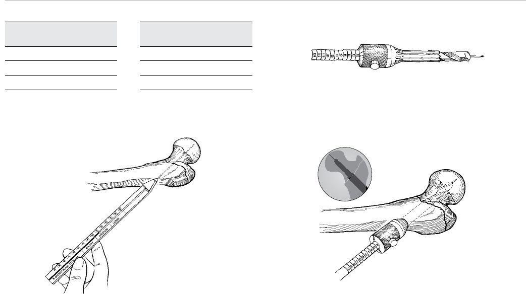
Guide Pin Depth
Gauge Reading
70–100 mm
100–130 mm
130–160 mm
Table 1 Figure 5
Figure 6
Figure 4
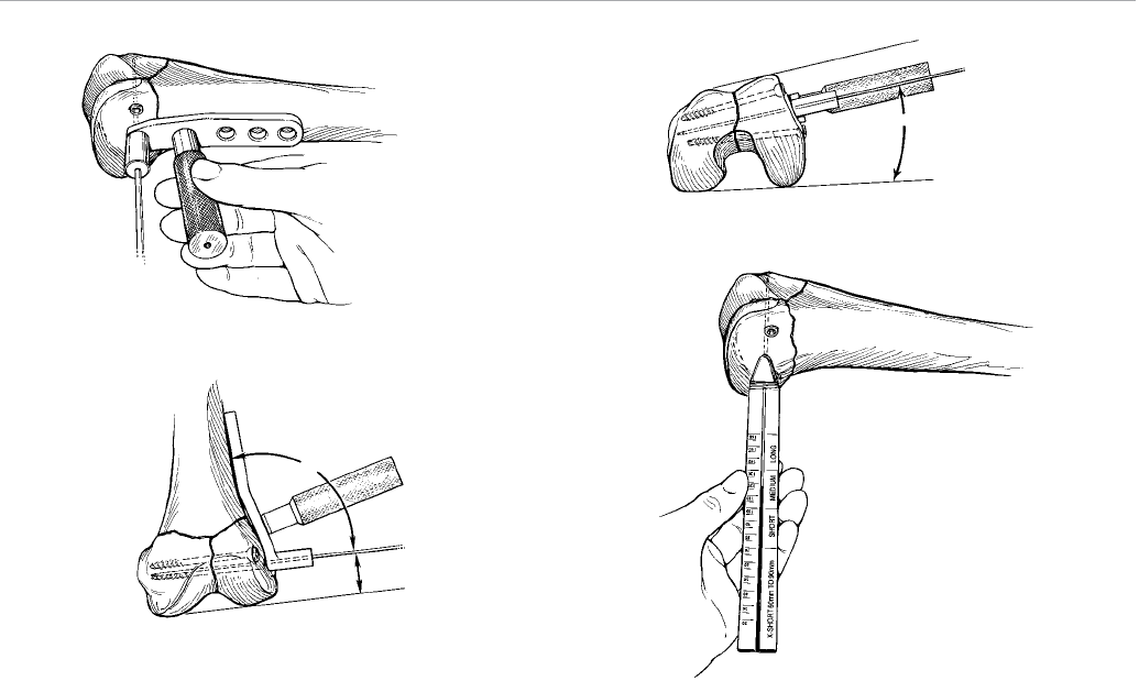
Captured Screw Assembly Selection
Place the guide pin depth gauge over the pin up to the
femoral cortex (Figure 4). The measurement read at the
end of the guide pin is a direct measurement of the length
of the pin that extends into the femoral neck and head.
Using this measurement, select the proper length screw.
Table 1 provides screw selection for corresponding depth
gauge readings.
Note: In some cases a reading between 60 and 70 mm
may be taken. In this situation, a special short barrel
hip screw should be utilized. This special captured
screw assembly is available in a 135-degree angle.
Once the measurement is read and the proper captured
screw assembly is determined, advance the guide pin
into subchondral bone, thereby anchoring it for reaming
and tapping.
Reaming and Tapping
The long adjustable reamer and calibrated tap can be set in
5 mm increments. In patients with healthy bone, set the
reamer at 10 mm less than the position just below the
actual guide pin depth gauge reading (i.e., a reading
between 90 and 95 mm means that the reamer should
be set at 80 mm). This ensures that the reamer never
advances closer than 1 cm to the subchondral bone.
Note: In patients with osteoporotic bone, set the
reamer at 70 mm (Figure 5).
Place the reamer over the guide pin and advance it into
the proximal femur under image control, assuring that the
guide pin does not move (Figure 6).
Note: The conical portion of the reamer only needs
to remove bone in the distal part of the lateral hole to
prepare the bone for the captured screw assembly.
Recommended Captured
Screw Assembly Length
100 mm
130 mm
160 mm
Captured Hip® Screw System
4
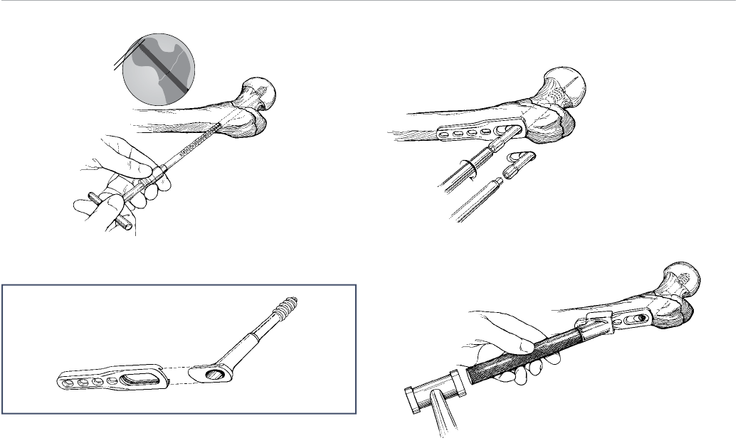
Figure 9
Figure 10
5–7 mm
Figure 7
Note: To set the reamer to the desired depth, depress
the button and slide the reamer head until the arrows
line up with the matching value.
Set the calibrated tap at the position just below the actual
guide pin depth gauge reading (i.e., a reading between
90 and 95 mm means that the tap should be set at
90 mm). Place the calibrated tap over the guide pin and
tap the neck and head of the femur to within 5–7 mm of
subchondral bone under image control (Figure 7).
Hip Screw Insertion
Ensure that the side plate is long enough to allow for the
placement of four screws (eight cortices) below the most
proximal extent of the fracture. While this makes the four-
hole plate the most common selection, a two-hole plate
may be selected for a nondisplaced femoral neck fracture.
Assemble the side plate and captured screw assembly by
sliding the barrel flange into the plate slot (Figure 8).
Figure 8
Insert the T-wrench inserter into the hexagonal base of the
hip screw and place the entire assembly over the central
guide pin into the prepared lateral cortex.
Advance the hip screw by turning the T-wrench inserter
in a clockwise manner (Figure 9). While the side plate can
remain loose during initial advancement, it is important
to hold the plate parallel to the femoral shaft as it nears
the bone. Verify the depth of the hip screw using image
intensification. Remove the guide pin.
To ensure that the barrel portion of the captured screw
assembly is fully seated, position the assembled captured
hip screw impactor head and impactor handle onto the
angled superior portion of the plate. With a mallet, lightly
tap the impactor (Figure 10).
5
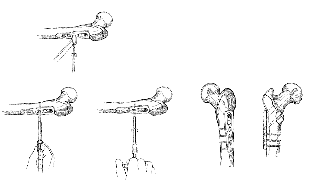
Figure 11
Figure 14a Figure 14bFigure 12 Figure 13
Caution: Only light tapping of the screw is necessary.
Forceful use of the impactor after the barrel has been
inserted into the femoral shaft and prior to fixation of
the side plate to the lateral aspect of the shaft may
result in greater trochanteric comminution.
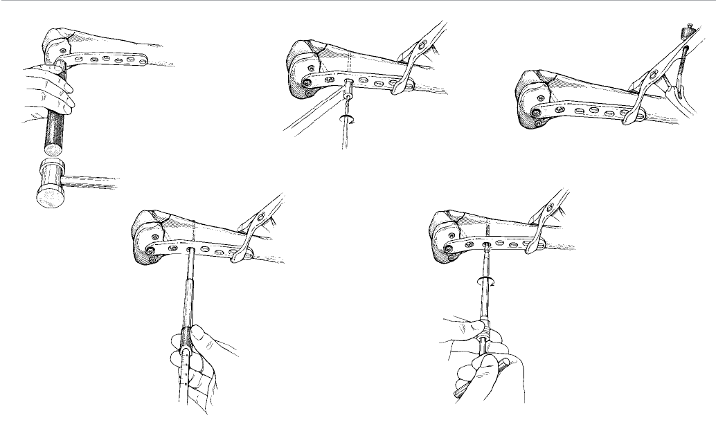
Screw Placement
Ensuring that the side plate or trochanteric plate is fully
engaged to the captured screw assembly, place the 3.8
mm drill guide into the proximal screw slot. Drill both
cortices using a 3.8 mm drill bit (Figure 11).
Measure the proper screw length using the hook depth
gauge (Figure 12).
Assemble the power adaptor or quick couple T-handle to
the 4.5 mm solid hex driver shank and drive the 4.5 mm
self-tapping screw through the hole, securing the plate to
the femoral shaft (Figure 13).
Note: In osteoporotic bone or in the metaphyseal
portion of the distal femur, 5.0 mm cancellous bone
screws are provided for fixation.
Always perform final tightening by hand. Using this
technique, place the screws in succession in the plate
slots to fasten the plate to the bone (Figure 14a).
Note: The proximal hole in the side plate may be used to
place an angled 6.5 mm solid or cannulated cancellous
bone screw if lagging of medial bone fragment is
required (Figure 14b).
Captured Hip® Screw System
6
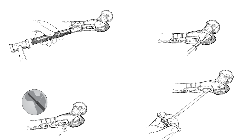
Figure 17
Figure 18Figure 16
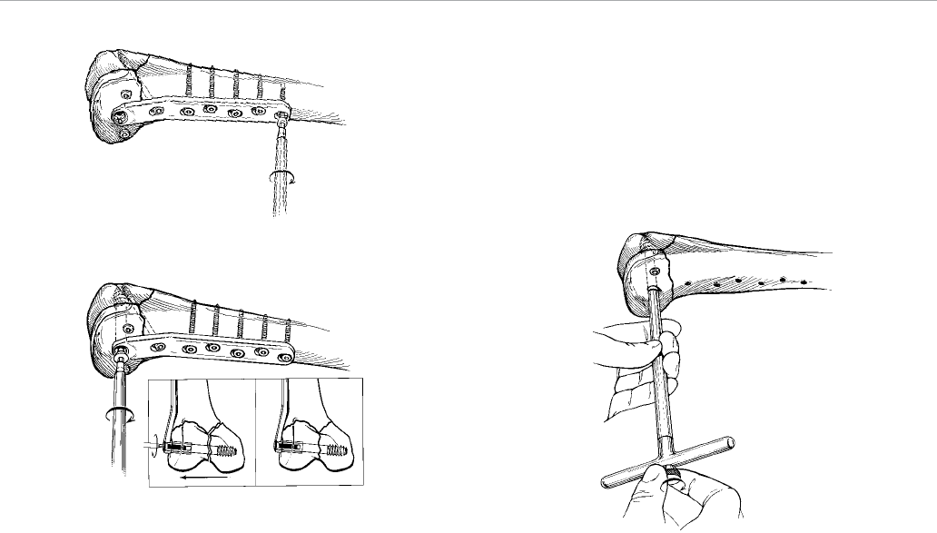
Final Seating and Impaction of the Hip Screw
Following fixation of the side plate to the femoral shaft,
attain final seating of the hip screw into the femoral head
by using the T-wrench inserter. Locate the tip of the hip
screw within 5-7 mm of subchondral bone as verified
by image intensification. Release traction from the
effected hip.
Impact the fracture by placing the assembled impactor
over the proximal aspect of the plate and applying three to
four firm blows with a mallet (Figure 15).
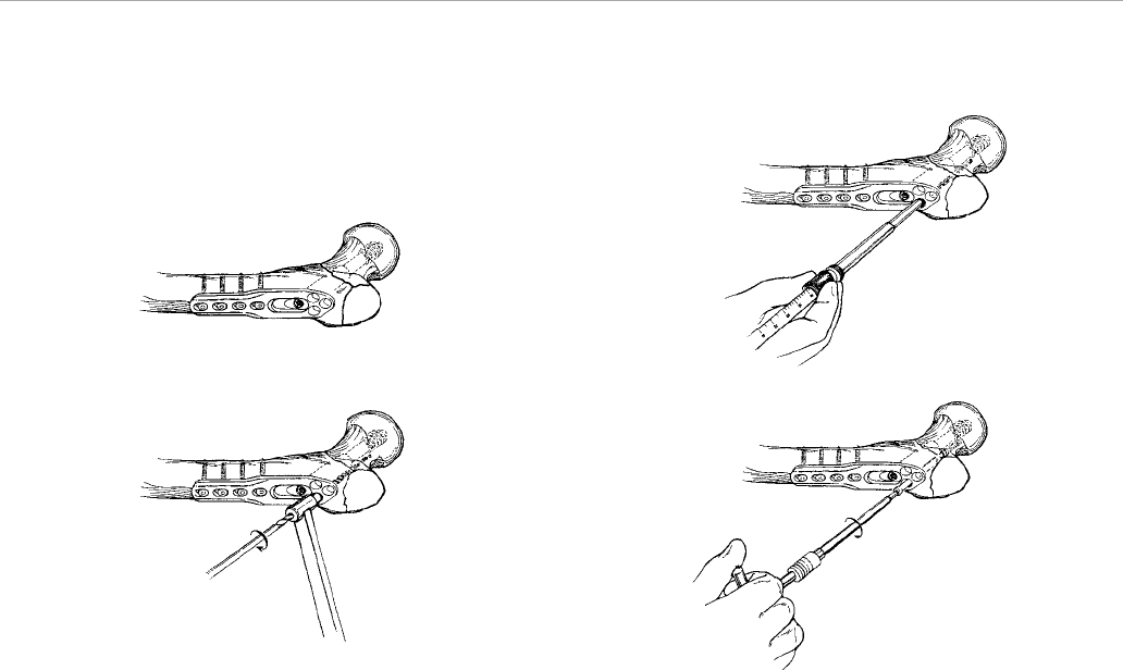
Note: 6.5 mm cannulated cancellous screws are
provided in the system if additional fixation is desired
anterior or posterior to the captured screw assembly.
Place a 3.2 mm guide wire under image intensification
(Figure 16).
Insert the self-drilling, self-tapping cannulated screw over
the guide wire using the assembled 6.5 mm hex driver
Figure 15
shank and T-handle (Figure 17). Cannulated drills and taps
are available if hard, dense bone is encountered.
Optional Compression
Alternatively, compression may be applied by placing the
T-wrench inserter into the screw and locking it there with
the extractor lock. Grasp the T-wrench inserter and pull on
it forcefully to compress the fracture (Figure 18).
7

Caution: In patients with intertrochanteric fractures
with subtrochanteric components, weight-bearing
is prohibited until callus formation is apparent on
the X-ray.
Extraction
After performing a routine opening exposure, use the
4.5 mm solid and 6.5 mm hex driver shanks to remove
the screws fixing the side plate to the shaft of the femur.
Attach the extractor lock through the T-wrench inserter
to the captured screw assembly. Remove the hip screw
by turning the T-wrench inserter in a counter-clockwise
manner. Close in a routine fashion.
Captured Hip® Screw System
8
Screw Placement with
Trochanteric Side Plate Option
Control comminution of the greater trochanter by using the
trochanteric side plate (Figure 19). This plate also benefits
reverse oblique and high subtrochanteric fractures by
preventing medialization of the femur shaft.
Reduce the bony fragments using forceps or clamps and
proceed in the same fashion as the side plate fixation. The
quantity and sequence of screw placement in the proximal
flare is physician dependent.
The most proximal screw hole provides fixation for the
greater trochanter and the two distal screw holes also
provide greater trochanter fixation. The two distal screw
holes may also be used for anti-rotation of the femoral
head, reverse oblique and subtrochanteric fractures to
prevent medialization of the femoral shaft.
Figure 19 Figure 21
Figure 22Figure 20
Place the 3.8 mm drill guide into one of the flared screw
holes and drill to the desired depth using a 3.8 mm drill bit
(Figure 20).
Measure the proper screw length using the hook depth
gauge (Figure 21).
Caution: When using the hook depth gauge in a blind
hole (i.e., one that does not go through both corticies),
select a screw 2 mm less (or the next smaller size)
than indicated.
Assemble the power adaptor or quick couple T-handle
to the solid hex driver shank and drive the 6.5 mm self-
tapping screw through the hole securing the plate to the
bone (Figure 22).
9
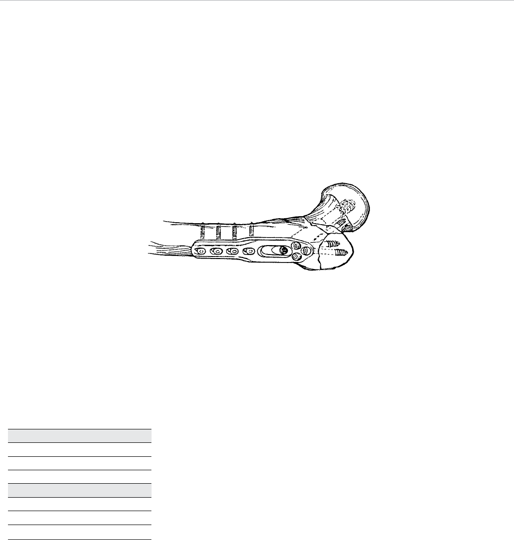
Figure 23
Note: For placement of the 6.5mm screws, use the
respective drivers below.
Always perform final tightening by hand. An example
of screw placement for the fracture indicated is shown
(Figure 23).
Note: For final seating and impaction of the hip screw,
please see next section.
Caution: In patients with intertrochanteric fractures
with subtrochanteric components, weight-bearing is
prohibited until callus formation is apparent on the
X-ray.
Extraction
After performing a routine opening exposure, use the
4.5 mm solid and 6.5 mm hex driver shanks to remove
the screws fixing the side plate to the shaft of the femur.
Attach the extractor lock through the T-wrench inserter
to the captured screw assembly. Remove the hip screw
by turning the T-wrench inserter in a counter-clockwise
manner. Close in a routine fashion.
Discontinued Cat. Nos. Driver
14520-xx 14616
14521-xx
14522-xx
Active Cat. Nos. Driver
8157-61-xxx 14541
8157-62-xxx
8157-64-xxx
Captured Hip® Screw System
10
Supracondylar Fractures and
Fractures of the Lower Third Femur
Patient Positioning
Pay careful attention to the positioning of the patient on
the standard operating table. Place a sandbag under
the buttock of the operated extremity with the patient in
the supine position. This effectively rotates the extremity
internally and facilitates the surgical approach. Use a roll
under the leg to provide 20–30 degrees flexion (Figure
24). The same positioning can also be achieved using a
fracture table.
Incision
Perform a standard lateral exposure starting at the lateral
femoral epicondyle and extend it proximally.
Note: The initial incision over the femoral epicondyle may
be limited to allow insertion of the lag screw and later
extended for plate application. This reduces overall wound
exposure and blood loss.
A straight lateral incision allows extension distally and
proximally for an extensile exposure. Incise the suprapatellar
pouch at the edge of the epicondyle and reflect medially
in order to expose the intercondylar notch. The lateral
superior genicula artery requires cauterization or ligation.
Retract the vastus lateralis muscle anteriorly to expose the
fracture. Place a retractor posterior to the femur to protect
the posterior neurovascular structures.
Convert a three-part fracture into two parts by reducing the
intercondylar component. Hold the reduction temporarily
with 3.2 mm Kirschner wires and bone-holding clamps or
reduction forceps. Take care in placing the K-wires so as
not to interfere with the placement of the supercondylar lag
screw. Cannulated screws may be used to permanently
secure the fragments.
Figure 24
Incision
20 - 30 degrees flexion
Supracondylar Fractures
and Fractures of the Lower Third Femur
11
Guide Pin
10 degrees
Guide Pin Positioning
Assemble the central pin guide handle to the central pin
guide and place against the lateral wall of the femoral
condyles. Drive a 3.2 mm threaded guide pin through
the guide and extend to, but not through, the medial
cortex (Figure 25).
Note: This pin should pass 2 cm from the articular
cartilage.
It is important that the 3.2 mm guide pin is positioned at
95 degrees to the shaft and parallel to the joint axis
angled about 10 degrees (parallel to the inclination of
the patellofemoral joint) anteriolateral to posteriomedial
(Figures 26a, 26b). Verify the pin position with image
intensification. Remove the central pin guide.
Lag Screw Size Selection
Measure the central guide pin depth using the guide pin
depth gauge to determine the appropriate lag screw length
(Figure 27). Lag screws are provided in 10 mm increments.
When using the depth gauge, the reading will fall within a
10 mm range (i.e., between 70-80 mm). If the depth gauge
reading falls in the lower half of the 10 mm range, select
a screw size 10 mm shorter than the lowest mark in the
range. For example, if the reading is between 70 and 75
mm, use a size 60 mm screw.
Using the shorter screw ensures that the screw will not
pass through the medial condyle and that there will be
adequate length to compress the fracture. If the depth
gauge reading falls in the upper half of the 10 mm range,
select a screw the same size as the lowest reading in
the range. For example, if the reading is between 75 and
80 mm use a 70 mm screw. This method allows for a
minimum of 5 mm of compression for most every screw
size.
Note: If the measurement falls between 50 and 55 mm,
then the 50 mm screw must be used.
Figure 25
Figure 26a
Guide Pin
2 cm
Figure 26b
Figure 27
Captured Hip® Screw System
12
Reaming and Tapping
The short adjustable reamer and calibrated tap can be set in
5 mm increments. If the guide pin depth gauge reads in the
lower half of the 10 mm range, set the reamer and tap at the
lower reading (i.e., set at 70 mm if the reading is between
70 and 75 mm). If the depth gauge reads in the upper half
of the 10 mm range, set the reamer or tap at a mid-range
setting (i.e., 75 mm for a reading between 75 and 80 mm).
For clarity, Table 2 provides instrument settings and lag
screw selection for corresponding depth gauge readings.
Note: Perform reaming and tapping under image
intensification to ensure that the far cortex is not
compromised.
Note: In osteoporotic bone, set the reamer at its
shortest depth because additional reaming is not
necessary.
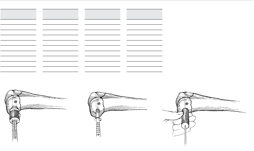
Advance the step reamer over the guide pin and drill the
hole (Figure 28).
Assemble the tap to the quick couple T-handle and use it
to prepare the femoral condyle for placement of the lag
screw (Figure 29).
In the event that the guide pin comes out in either the
reaming or tapping step, a guide pin centralizer (same as
the central pin guide handle) is provided for replacement
of the guide pin (Figure 30).
Figure 28 Figure 29 Figure 30
Guide Pin Depth
Gauge Reading
50-55 mm
55-60 mm
60-65 mm
65-70 mm
70-75 mm
75-80 mm
80-85 mm
85-90 mm
90-95 mm
95-100 mm
Reamer or
Tap Setting
50 mm
55 mm
60 mm
65 mm
70 mm
75 mm
80 mm
85 mm
90 mm
95 mm
Recommended
Lag Screw Length
50 mm
50 mm
50 mm
60 mm
60 mm
70 mm
70 mm
80 mm
80 mm
90 mm
Maximum
Compression
0 mm
5 mm
10 mm
5 mm
10 mm
5 mm
10 mm
5 mm
10 mm
5 mm
Table 2
13
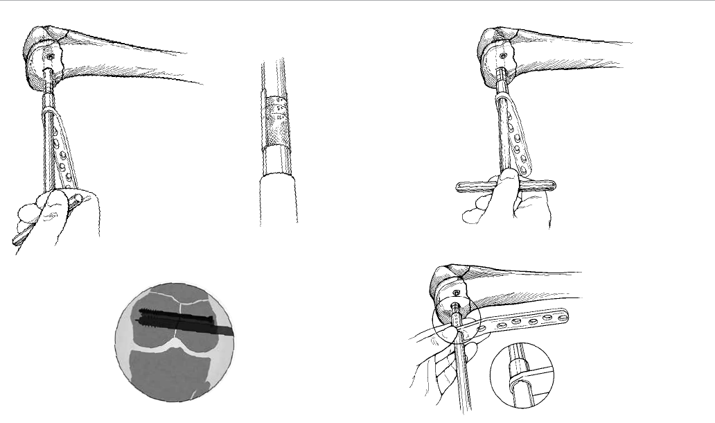
Plate and Lag Screw Insertion
Ensure that the supracondylar plate is long enough to
allow for the placement of four screws (eight cortices)
above the most proximal extent of the fracture. Slide
the chosen supracondylar plate onto the shaft of the lag
screwdriver. Begin driving the lag screw using the lag
screwdriver (Figure 31).
To assist in determining the insertion of the lag screw,
0, +5 and +10 mm lines are indicated on the lag screwdriver.
CAUTION: Never advance the lag screwdriver past the
+10 mm line to ensure proper engagement of the barrel
over the screw (Figure 32).
Note: In good quality bone, the lag screw can simply
engage the cancellous bone of the femoral condyle.
In osteoporotic bone, it is beneficial to engage one
thread of the lag screw in the cortical bone of the
medial condyle.
Drive the lag screw to the proper depth, making sure that
the T-handle of the lag screwdriver is parallel to the
femoral shaft and plate. This positioning ensures that
the supracondylar plate will align with the femoral shaft
(Figure 33).
Note: When the handle is parallel to the plate, this
ensures proper alignment of the keys on the screw to
the keyways in the barrel.
Verify the position of the lag screw using the image
intensifier (Figure 34).
Using the driver shank as a guide, slide the supracondylar
plate along the driver and onto the lag screw (Figure 35).
Ensure that the plate lines up with the femoral shaft. A
standard plate impactor head has been provided for
impaction through the barrel hole. Thread the standard
Figure 35
Figure 33
Figure 34
Figure 31 Figure 32
Captured Hip® Screw System
14
impactor head onto the impactor handle. Prior to
impaction, ensure that the lag screw does not extend
outside of the lateral surface of the bone. Gently impact
the supracondylar plate against the femoral condyle using
the assembled impactor (Figure 36).
Screw Placement
Hold the supracondylar plate in place with one or twobone
clamps after re-establishing the proper bone length.
Perform minimal to no periosteal stripping. If there is shaft
comminution and indirect reduction has been used, use
four screws in the proximal four slots to fix the plate to the
shaft. Screws may also be incorporated for adjunct fixation
in the region of comminution where good purchase can
be obtained without periosteal stripping. If there is little or
no comminution and compression of the shaft is desired,
place the distal screws first.
Note: The distal hole in the neck of the plate may be used
to place a 6.5 mm solid or cannulated cancellous bone
screw if lagging of metaphysical bone to the femur is
required (Figure 37).
Note: In hard or dense bone, tap with the solid or
cannulated 6.5 mm cancellous tap.
Place the 3.8 mm drill guide into a screw slot (Figure 38).
Drill both cortices using a 3.8 mm drill bit. Measure the
proper screw length using the hook depth gauge (Figure 39).
Assemble the power adaptor or quick couple T-handle to the
6.5 mm hex driver shank and drive the 6.5 mm self-tapping
screw through the hole, securing the plate to the femoral
shaft (Figure 40). Always perform final tightening by hand.
Figure 39 Figure 40
Figure 37 Figure 38
Figure 36
15
In a similar fashion, use the 4.5 mm solid hex driver shank
to place 4.5 mm cortical bone screws in succession in the
plate slots to fasten the plate (Figure 41).
Note: In osteoporotic bone or in the metaphyseal
portion of the distal femur, 5.0 mm cancellous screws
are provided for fixation.
Compressing a Condylar Fracture
Insert the short compression screw into the lag screw and
turn it clockwise using the 6.5 mm hex driver shank until
the compression screw engages the supracondylar plate
(Figure 42). Continue turning clockwise until the condylar
fracture has closed the desired amount (insets a and b) as
viewed under image intensification.
Closure and Postoperative Instructions
Confirm final positioning of the implant and proper fracture
reduction using X-ray or image intensification. If significant
medial comminution exists, consider bone grafting
medially. Close in a routine fashion.
Early motion of the knee is preferable if fracture repair
is stable. Delay weight-bearing until callus formation is
identified by X-ray.
Extraction
After performing a routine opening exposure, use the
4.5 mm solid and 6.5 mm hex driver shanks to remove
screws fixing the plate to the shaft of the femur. Use the
6.5 mm hex driver to remove the short compression screw.
Remove the supracondylar plate. Attach the extraction rod
through the lag screwdriver to the lag screw (Figure 43).
Remove the lag screw. Close in a routine fashion.
Figure 41
Figure 42
AB
Figure 43
Captured Hip® Screw System
16
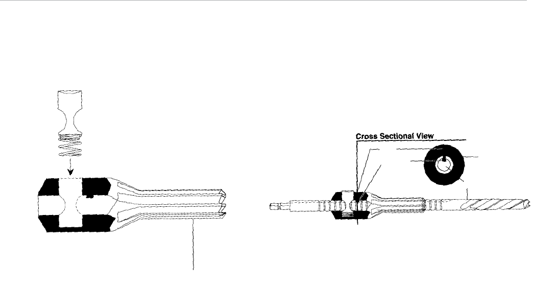
Figure 44a Figure 44b
Reamer Shaft
Keyway
Key
Reamer Head
Reamer Disassembly
Depress the button and slide the reamer head along the
shaft away from the drill flutes.
Once the reamer head is off, remove the button for cleaning
purposes (Figure 44a).
Do not disassemble the button and spring from one another.
Reamer Assembly
Depress the button and slide the reamer shaft through the
hole of the reamer head.
Take care to align the keyway slot of the reamer shaft with
the key inside the reamer head (Figure 44b).
Button
Spring
Reamer Head
17
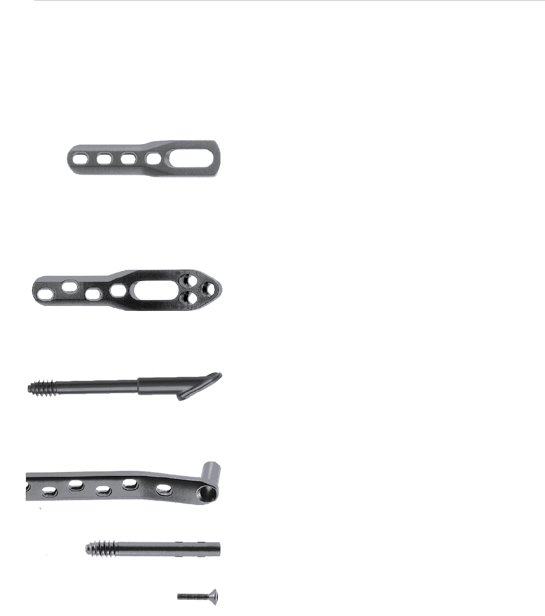
Captured Hip Screw Implants
Side Plate (Cat. Nos. 140xx)
• Available in two – 14-hole configurations (two-hole
increments)
• Flexibility allows plate conformity to the femur
• Low profile design
• Oval compression plate screw holes allow optimum
positioning of the bone screws (important in the securing of
medial fragments)
• Proximal hole allows for use of 6.5 mm screw
Trochanteric Side Plate (Cat. Nos. 14252-4, 6)
• Available in four and six-hole configurations
• Same features as standard side plate
• Added benefit of proximal buttress flange that conforms to
the greater trochanter
• Proximal screw holes to stabilize severe comminution of
greater trochanter and for reverse oblique fracture patterns
Captured Screw Assembly (Cat. Nos. 14033-x, Cat. Nos. 14007-x)
• Angled barrels available in 135, 140, 145 and 150 degrees
• Captured screws for each angle accommodate lengths of 90
to 160 mm in three assemblies, thus reducing inventory
• Short barrel accommodating 60 to 90 mm length available in
the most commonly used 135-degree angle
Supracondylar Plate Implants
95-degree Standard Supracondylar Plate (Cat. Nos. 14552-xx)
• Available in six – 14-hole configurations (two-hole increments)
• Low profile plate
• Distal hole allows for use of 6.5 mm screw
Standard Lag Screw (Cat. Nos. 14553-xx)
• Available in 50 to 90 mm lengths (10 mm increments)
• Unitized insertion with the supracondylar plate
Short Compression Screw (Cat. Nos. 8113-05-003)
• Facilitates up to 10 mm of compression
• Smooth radiused compression screw/plate profile
Captured Hip Screw with Supracondylar and Trochanteric Plate System
Catalog Numbers and Descriptions
Captured Hip® Screw System
18
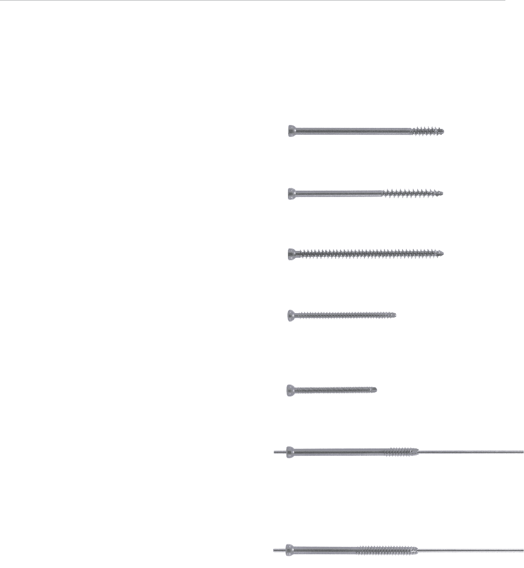
Self-Tapping Solid Screws
6.5 mm Solid 22 mm Threaded Cancellous Lag Screw
(Cat. Nos. 8157-62-xxx)
• Available in 5 mm increments from 40–120 mm lengths
6.5 mm Solid 40 mm Threaded Cancellous Lag Screw
(Cat. Nos. 8157-64-xxx)
• Available in 5 mm increments from 60–120 mm lengths
6.5 mm Solid Fully-Threaded Cancellous Bone Screw
(Cat. Nos. 8157-61-xxx)
• Available in 5 mm increments from 25–120 mm lengths
5.0 mm Solid Cancellous Fully-Threaded Bone Screw
(Cat. Nos. 14224-xx)
• Available in 2 mm increments from 20–60 mm lengths
and 5 mm increments from 65–80 mm lengths
4.5 mm Solid Cortical Fully-Threaded Bone Screw
(Cat. Nos. 14022-xx)
• Available in 2 mm increments from 26–58 mm lengths
• Double lead thread design for bone
Self-Tapping, Self-Drilling Cannulated Screws
6.5 mm Cannulated 22 mm Thread Cancellous Lag Screw
(Cat. Nos. 14196-xx)
• Available in 5 mm increments from 25–120 mm lengths
• Self-drilling and self-tapping
• Reverse radial tapping flutes for ease of removal
• 3.2 mm guide wire
6.5 mm Cannulated 40 mm Thread Cancellous Lag Screw
(Cat. Nos. 14197-xx)
• Available in 5 mm increments from 40–120 mm lengths
• Self-drilling and self-tapping
• Reverse radial tapping flutes for ease of removal
• 3.2 mm guide wire
19

Captured Screw Assemblies
Cat. No. Description Length mm
14033-0 135° 90
14033-1 135° 100
14033-2 135° 130
14033-3 135° 160
14007-1 140° 100
14007-2 140° 130
14007-3 140° 160
14033-4 145° 100
14033-5 145° 130
14033-6 145° 160
14007-4 150° 100
14007-5 150° 130
14007-6 150° 160
Side Plates
14027 2 Hole Plate 67
14000 4 Hole Plate 97
14029 6 Hole Plate 128
14030 8 Hole Plate 158
14031 10 Hole Plate 189
14034 12 Hole Plate 220
14032 14 Hole Plate 250
142524 Troch Plate 4 hole 112
142526 Troch Plate 6 hole 114
95° Standard Supracondylar Plates
14552-6 6 slot 131
14552-8 8 slot 161
14552-10 10 slot 203
14552-12 12 slot 239
14552-14 14 slot 275
Lag Screws
Cat. No. Length mm
14553-50 50
14553-60 60
14553-70 70
14553-80 80
14553-90 90
Compression Screw
Cat. No. Description
8113-05-003 Short Compression Screw
Screws
Cat. No. Description
4.5 mm Solid Cortical Fully-Threaded Bone Screws*
14022-xx 26 – 58 mm (2 mm increments)
5.0 mm Solid Cancellous Fully-Threaded Bone Screws*
14224-xx 20 – 60 mm (2 mm increments)
14224-xx0 65 – 80 mm (5 mm increments)
6.5 mm Solid 22 mm Thread Cancellous Lag Screws*
8157-62-xxx 40 – 110 mm (5 mm increments)
6.5 mm Solid 40 mm Thread Cancellous Lag Screws*
8157-64-xxx 60 – 110 mm (5 mm increments)
6.5 mm Solid Cancellous Fully-Threaded Bone Screws*
8157-61-xxx 25 – 110 mm (5 mm increments)
6.5 mm Cannulated 22 mm Thread Cancellous Lag Screws*
14196-xx 25 – 120 mm (5 mm increments)
6.5 mm Cannulated 40 mm Thread Cancellous Lag Screws*
14197-xx 40 – 120 mm (5 mm increments)
Instruments
Cat. No. Description
14008 T-wrench Inserter
14011 Extractor Lock
14052 Guide Pin Jig
14142 Guide Pin Depth Gauge
14315 Power Adaptor
14316 T-handle
8242-00-120 Hook Depth Gauge
14540 3.8 mm Drill Guide
14541 4.5 mm Solid Hex Driver Shank
14549 Central Pin Guide - Standard
14566 Extraction Rod
14569 Calibrated Lag Screw Tap
14570 Lag Screw Driver
14577 Central Pin Guide Handle/Repositioner
14578 Impactor Handle
14580 Captured Hip Screw Impactor Head
14581 Standard Plate Impactor Head
14585-1 Adjustable Reamer - Short
14585-3 Adjustable Reamer - Long
14616 6.5 mm Hex Driver Shank
Disposables
14012-9 3.2 mm x 9 in. Guide Pin
14545 3.8 mm Solid Twist Drill, 7 in.
14584 6.5 mm Solid Cancellous Tap
14627 6.5 mm Cancellous Tap
14629 5.0 mm Cannulated Drill
Modules and Cases
14530 Solid and Cannulated Screw Module
14532 Captured Hip Screw Module
14533 Standard Supracondylar Plate Module
14534 General Instruments Module
14535 Screw Instruments Module
14602 Sterilization Case (10 in. x 10 in. x 5 in.)
14603 Sterilization Case (10.5 in. x 20 in. x 5 in.)
Ancillary Part
14599 Reamer Button Spring Assembly
*
Warning: This device is not approved for screw attachment or fixation
to the posterior (pedicles) of the cervical, thoracic or lumbar spine.
Ordering Information
Captured Hip® Screw System
20
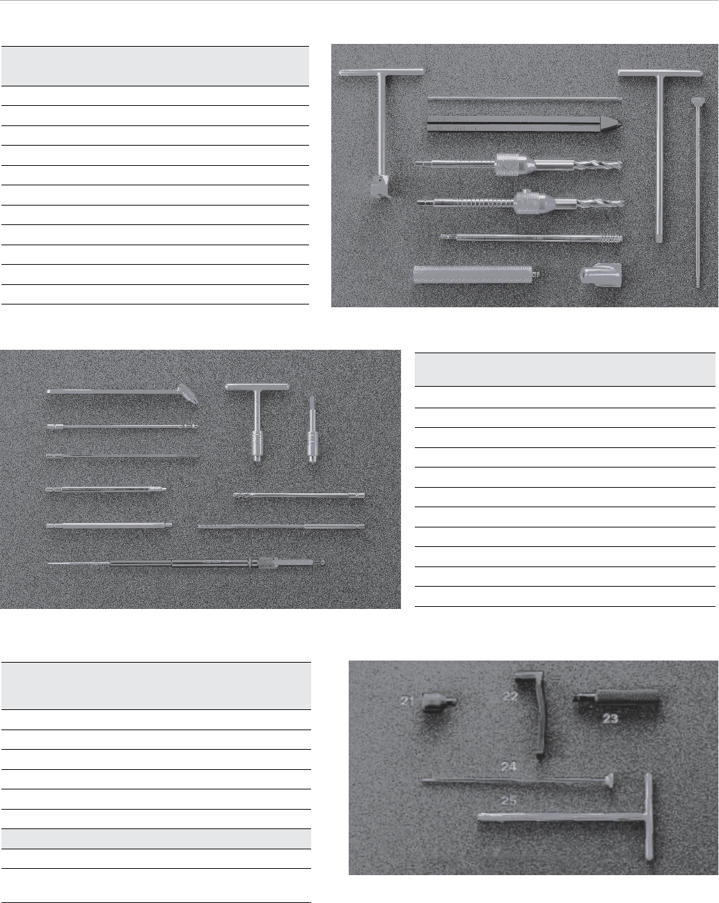
General Instruments Module
Cat. No.14534
Cat. No. Description
1 14052 Guide Pin Jig
2 14012-9 3.2 mm X 9 In. Guide Pin*
3 14142 Guide Pin Depth Gauge
4 14585-3 Adjustable Reamer - Long
5 14585-1 Adjustable Reamer - Short
6 14569 Calibrated Lag Screw Tap
7 14578 Impactor Handle
8 14580 Captured Hip Screw Impactor Head
9 14008 T-Wrench Inserter
10 14011 Extractor Lock
12
3
4
10
9
7
5
6
8
11
16 17
18
15
14
19
20
Instruments Contained In
Standard Supracondylar Plate Module
Cat. No. 14533
Cat. No. Description
21 14581 Standard Plate Impactor Head
22 14549 Central Pin Guide - Standard
23 14577 Central Pin Guide Handle/Repositioner
24 14566 Extraction Rod
25 14570 Lag Screwdriver
Ancillary Parts
Cat. No. Description
14599 Reamer Button Spring Assembly
(Not Shown)
Screw Instruments Module
Cat. No. 14535
Cat. No. Description
11 14540 3.8 mm Drill Guide
12 14545 3.8 mm Solid Twist Drill, 7 in.*
13 14584 6.5 mm Solid Cancellous Tap*
14 14541
4.5 mm Solid Hex Driver Shank
15 14616 6.5 mm Hex Driver Shank
16 14316 T-handle
17 14315 Power Adaptor
18 14629 5.0 mm Cannulated Drill*
19 14627 6.5 mm Cancellous Tap*
20 8242-00-120 Hook Depth Gauge
* Disposables
21

All trademarks herein are the property of Biomet, Inc. or its subsidiaries unless
otherwise indicated.
This material is intended for the sole use and benefit of the Biomet sales force and
physicians. It is not to be redistributed, duplicated or disclosed without the express
written consent of Biomet.
For product information, including indications, contraindications, warnings,
precautions and potential adverse effects, see the package insert.
Responsible Manufacturer
Biomet Trauma
P.O. Box 587
56 E. Bell Drive
Warsaw, Indiana 46581-0587
USA
www.biomet.com
©2014 Biomet Trauma • Form No. BMET0134.0 • REV0814
References
1. DVA-107504-DVER.
2. Massie, William K. “Fractures of the Hip.” Journal of Bone and Joint
Surgery, April 1964: 669.
Important: This Essential Product Information does not include all of the informa-
tion necessary for selection and use of a device. Please see full labeling for all
necessary information.
The use of metallic surgical appliances provides the orthopaedic surgeon a means
of bone fixation and helps generally in the management of fractures and reconstruc-
tive surgeries. These implants are intended as a guide to normal healing, and are
NOT intended to replace normal body structure or bear the weight of the body in the
presence of incomplete bone healing. Delayed unions or nonunions in the presence
of load bearing or weight bearing might eventually cause the implant to break due
to metal fatigue. All metal surgical implants are subjected to repeated stress in use,
which can result in metal fatigue.
Indications: The Captured Hip Screw is for the internal fixation of hip fractures. The
Supracondylar plate systems is intended only for fractures and osteotomies of the
proximal and distal femur. The Trochanteric Side Plate is used in conjunction with
the Captured Hip Screw and is designed for use in osteotomies, arthrodesis and hip
fractures; including intertrochanteric, intracapsular and subtrochanteric
Contraindications: Screws, plates, nails, compression hip screws, pins and
wires are contraindicated in: active infection; conditions which tend to retard
healing such as blood supply limitations, previous infections; insufficient quantity
or quality of bone to permit stabilization of the fracture complex; conditions that
restrict the patient’s ability or willingness to follow postoperative instructions during
the healing process; foreign body sensitivity; and cases where the implant(s) would
cross open epiphyseal plates in skeletally immature patients.
Additional Contraindication for Orthopaedic Screws and Plates only: Cases with
malignant primary or metastatic tumors which preclude adequate bone support or
screw fixations, unless supplemental fixation or stabilization methods are utilized.
Additional Contraindications for Compression Hip Screws only: Inadequate implant
support due to the lack of medial buttress.
Additional Contraindications for Retrograde Femoral Nailing only: A history of septic
arthritis of the knee; knee extension contracture with inability to attain at least 45°
of flexion.
Warnings and Precautions: In using partial weight bearing or nonweight bearing ap-
pliances (orthopaedic devices other than prostheses), a surgeon should be aware
that no partial weight bearing or nonweight bearing device can be expected to
withstand the unsupported stresses of full weight bearing.
Adverse Events: The following are possible adverse events after fixation with ortho-
paedic screws, plates, nails, compression hip screws, pins and wires: loosening,
bending, cracking or fracture of the components or loss of fixation in bone attribut-
able to nonunion, osteoporosis, markedly unstable comminuted fractures; loss of
anatomic position with nonunion or malunion with rotation or angulation; infection,
both deep and superficial; and allergies and other reactions to the device material.
Additional Adverse Events for Compression Hip Screw only: Screw cutout of the
femoral head (usually associated with osteoporotic bone).
