CCT14010032FR 报告 Report
2016-04-08
: Pdf Cct14010032Fr- Report CCT14010032FR-_report CertsReports 207409 ProductFiles
Open the PDF directly: View PDF ![]() .
.
Page Count: 25

Shenzhen CCT Technical Services Co., Ltd.
Report No.: CCT14010032FR
Page 2 of 25
TABLE OF CONTENTS
1 TEST RESULT CERTIFICATION........................................................................................3
2 EUT DESCRIPTION...................................................................................................................4
3 TEST METHODOLOGY ......................................................................................................6
3.1. DECISION OF FINAL TEST MODE....................................................................................................6
3.2. EUT SYSTEM OPERATION ...............................................................................................................6
4 SETUP OF EQUIPMENT UNDER TEST.............................................................................7
4.1. DESCRIPTION OF SUPPORT UNITS................................................................................................7
4.2. CONFIGURATION OF SYSTEM UNDER TEST ................................................................................7
5 FACILITIES AND ACCREDITATIONS................................................................................8
5.1. FACILITIES..........................................................................................................................................8
5.2. ACCREDITATIONS.............................................................................................................................8
5.3. MEASUREMENT UNCERTAINTY......................................................................................................8
6 CONDUCTED EMISSION MEASUREMENT.............................................................................9
6.1. LIMITS OF CONDUCTED EMISSION MEASUREMENT.......................................................................9
6.2. TEST INSTRUMENTS ............................................................................................................................9
6.3.TEST PROCEDURES............................................................................................................................10
6.4.TEST SETUP .........................................................................................................................................11
6.5. TEST RESULTS....................................................................................................................................11
7 RADIATED EMISSION MEASUREMENT.........................................................................14
7.1. LIMITS OF RADIATED EMISSION MEASUREMENT......................................................................14
7.2. TEST INSTRUMENTS ......................................................................................................................14
7.3. TEST PROCEDURES .......................................................................................................................15
7.4. TEST SETUP.....................................................................................................................................17
7.5. TEST RESULTS................................................................................................................................17
8 PHOTOGRAPHS OF THE TEST CONFIGURATION .......................................................20
9 PHOTOGRAPHS OF EUT.................................................................................................21
Shenzhen CCT Technical Services Co., Ltd.
Report No.: CCT14010032FR
Page 3 of 25
1 TEST RESULT CERTIFICATION
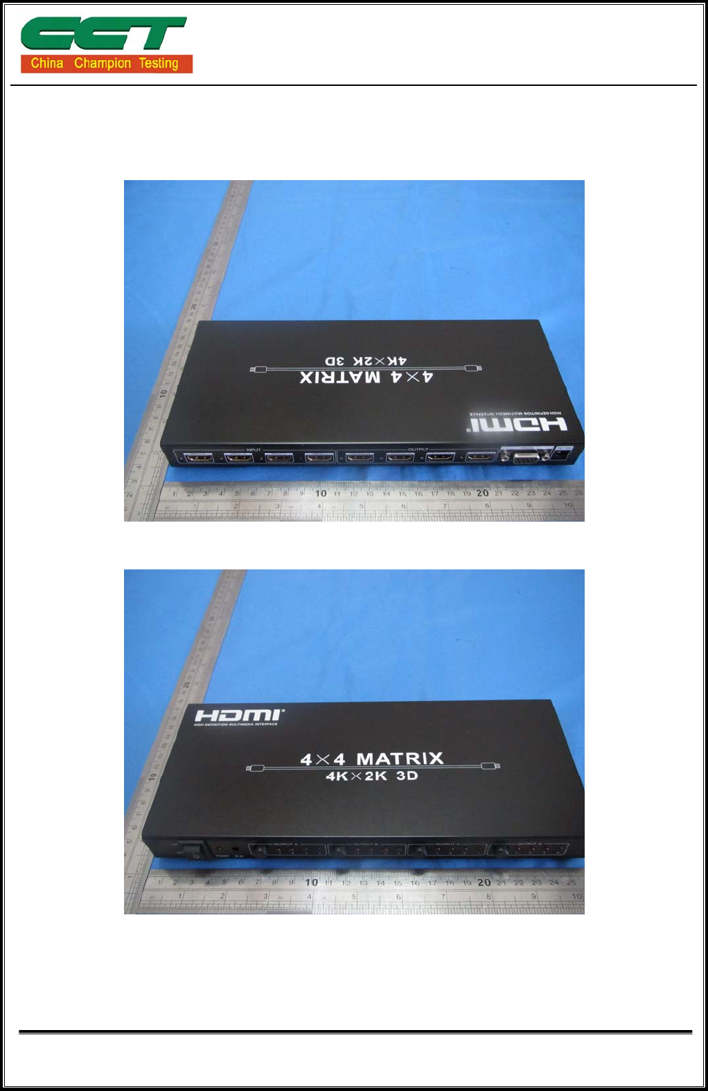
Product: HDMI Product
Model:
HDV-944,HDV-914HBT100,HDV-914HBT70,HDV-918A,HDV-918HBT70,HDV-918HBT100,
HDS-931,HDS-931A,HDS-931V,HDS-931P,HDS-951,HDS-941A,HDS-941P,HDS-941V,
HDM-922A,HDM-942A,HDM-942V,HDM-942E,HDM922E,HDM-988,HDM-944F,HDV-W500,
HBT-E100P,HDV-620,HDV-621,HDV-622,HDV-623,HDV-625,HDV-626,HDM-944V,
HDM-944H100,HDM-944H70,HDM-944S50,HDM-944D50,HDV-E50S2,HDV-E50S,
HDV-E50IR,HDV-E30D,HDV-E50D,HBT-E100,HBT-E70,HBT-E150,HDV-C100,HDV-C100P,
HDV-C100IR,HDV-PN100B,HDV-S008,HDV-S007,HDV-S009,HDV-P688,HDV-P600,
HDV-P2000,HDV-P312,HDV-912H,HDV-918H,HDV-914H
Applicant: HONGKONG HDCVT TECHNOLOGY CO., LIMITED.
FLAT/RM T78, G/F, BANGKOK BANK BLDG, 18 BONHAM STRAND WEST
Manufactur
er: SHENZHEN HDCVT TECHNOLOGY CO., LIMITED.
Floor 7, Building 5, Lihe Industrial part, SongBai Rd., Nanshan District , Shenzhen,
Guangdong, China 518108
Tested
Date: January 02~13, 2014
Test Volta
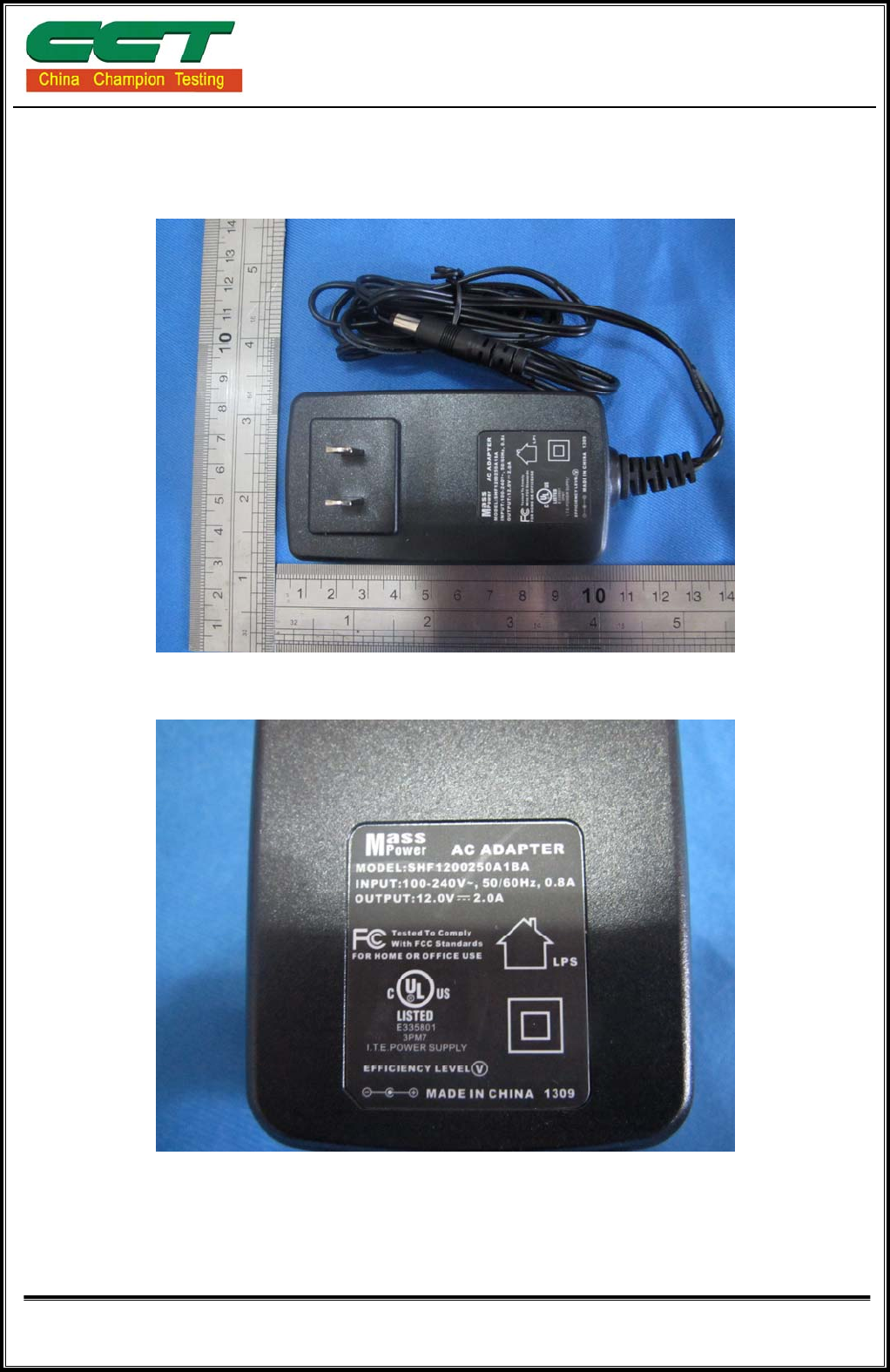
ge: DC12V 2.0A (supplied by adaptor)
EMISSION
Standard Item Result Remarks
Conducted (Main Port) PASS Meet Class B limit
FCC CFR Title 47 Part 15
Subpart B: 2012
Radiated PASS Meet Class B limit
Note: 1. The test result judgment is decided by the limit of measurement standard
2. The information of measurement uncertainty is available upon the customer’s request.
Deviation from Applicable Standard
None

Shenzhen CCT Technical Services Co., Ltd.
Report No.: CCT14010032FR
Page 4 of 25
2 EUT DESCRIPTION
Product HDMI Product
Brand Name N/A
Model
HDV-944,HDV-914HBT100,HDV-914HBT70,HDV-918A,HDV-918HBT70,H
DV-918HBT100,HDS-931,HDS-931A,HDS-931V,HDS-931P,HDS-951,
HDS-941A,HDS-941P,HDS-941V,HDM-922A,HDM-942A,HDM-942V,
HDM-942E,HDM922E,HDM-988,HDM-944F,HDV-W500,HBT-E100P,
HDV-620,HDV-621,HDV-622,HDV-623,HDV-625,HDV-626,HDM-944V,
HDM-944H100,HDM-944H70,HDM-944S50,HDM-944D50,HDV-E50S2,
HDV-E50S,HDV-E50IR,HDV-E30D,HDV-E50D,HBT-E100,HBT-E70,
HBT-E150,HDV-C100,HDV-C100P,HDV-C100IR,HDV-PN100B,HDV-S008
HDV-S007,HDV-S009,HDV-P688,HDV-P600,HDV-P2000,HDV-P312,
HDV-912H,HDV-918H,HDV-914H
Applicant HONGKONG HDCVT TECHNOLOGY CO., LIMITED.
Housing material Metal
EUT Type Engineering Sample. Product Sample,
Mass Product Sample.
Serial Number N/A
EUT Power Rating DC12V 2.0A
DC Line Unshielded, 1.50m (From adapter)
I/O PORT
I/O PORT TYPES Q’TY TESTED WITH
Input DC Jack 1 1
Input HDMI 4 4
Output HDMI 4 4
RS232 1 1
Model difference
No. Model Number Tested With No. Model Number Tested With
1 HDV-944 29 HDV-626
2 HDV-914HBT100 30 HDM-944V
3 HDV-914HBT70 31 HDM-944H100
Shenzhen CCT Technical Services Co., Ltd.
Report No.: CCT14010032FR
Page 5 of 25
4 HDV-918A 32 HDM-944H70
5 HDV-918HBT70 33 HDM-944S50
6 HDV-918HBT100 34 HDM-944D50
7 HDS-931 35 HDV-E50S2
8 HDS-931A 36 HDV-E50S
9 HDS-931V 37 HDV-E50IR
10 HDS-931P 38 HDV-E30D
11 HDS-951 39 HDV-E50D
12 HDS-941A 40 HBT-E100
13 HDS-941P 41 HBT-E70
14 HDS-941V 42 HBT-E150
15 HDM-922A 43 HDV-C100
16 HDM-942A 44 HDV-C100P
17 HDM-942V 45 HDV-C100IR
18 HDM-942E 46 HDV-PN100B
19 HDM922E 47 HDV-S008
20 HDM-988 48 HDV-S007
21 HDM-944F 49 HDV-S009
22 HDV-W500 50 HDV-P688
23 HBT-E100P 51 HDV-P600
24 HDV-620 52 HDV-P2000
25 HDV-621 53 HDV-P312
26 HDV-622 54 HDV-912H
27 HDV-623 55 HDV-918H
28 HDV-625 56 HDV-914H
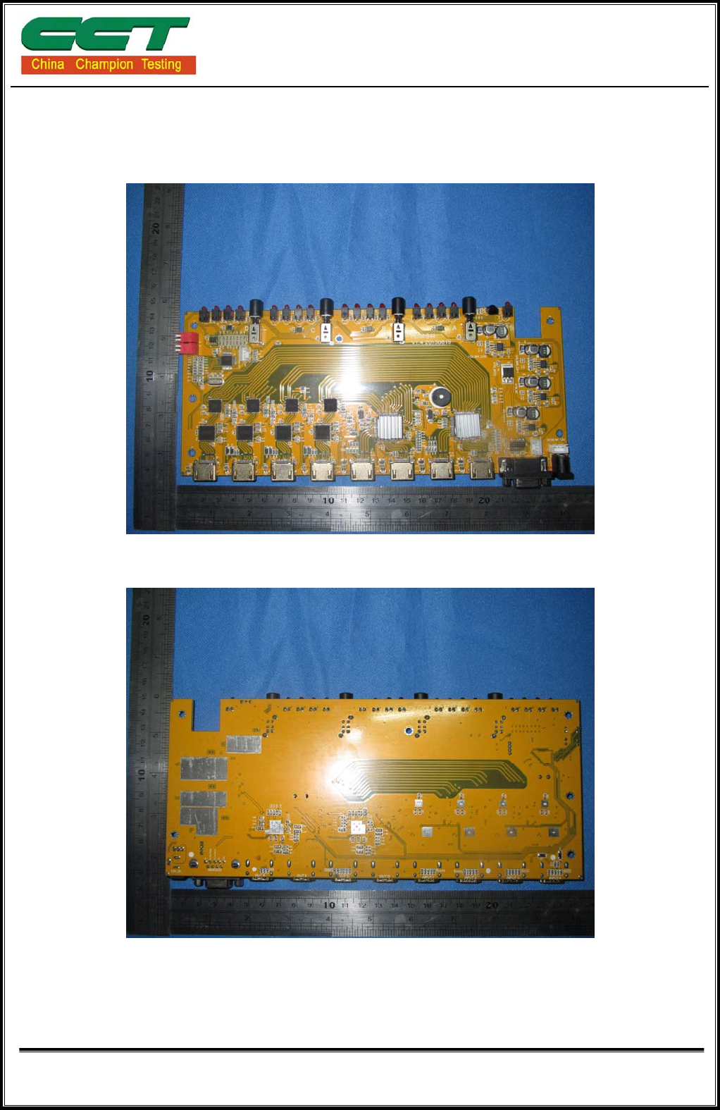
Note: HDV-944 is tested model, other model are derivative models, The models are Identical in circuit and
PCB layout, only different on the model names, So the test data of HDV-944 can represent the
remaining models.
Shenzhen CCT Technical Services Co., Ltd.
Report No.: CCT14010032FR
Page 6 of 25
3 TEST METHODOLOGY
3.1. DECISION OF FINAL TEST MODE
The EUT was tested together with the above additional components, and a
configuration, which produced the worst emission levels, was selected and recorded in
this report.
The following test mode(s) were scanned during the preliminary test:
Pre-Test Mode
Conducted Emission Mode 1: Running Mode
Emission Radiated Emission Mode 1: Running
After the preliminary scan, the following test mode was found to produce the highest
emission level.
Final Test Mode
Conducted Emission Mode 1: Running Mode
Emission Radiated Emission Mode 1: Running
Then, the EUT configuration and cable configuration of the above highest emission
mode was chosen for all final test items.
3.2. EUT SYSTEM OPERATION
1. Set up EUT with the relative support equipments.
2. Make sure the EUT worked normally during the test.
Shenzhen CCT Technical Services Co., Ltd.
Report No.: CCT14010032FR
Page 7 of 25
4 SETUP OF EQUIPMENT UNDER TEST
4.1. DESCRIPTION OF SUPPORT UNITS
The EUT has been tested as an independent unit together with other necessary
accessories or support units. The following support units or accessories were used to form
a representative test configuration during the tests.
No. Equipment Model No. Serial No. FCC ID Trade Name Data Cable Power Cord
1 LCD Monitor AOC T942we N/A N/A AOC Unshielded
1.0m N/A
2 DVD BDP-140 3D N/A N/A pioneer
Unshielded
1.0m N/A
Note:
1) All the equipment/cables were placed in the worst-case configuration to maximize the emission during the
test.
2) Grounding was established in accordance with the manufacturer’s requirements and conditions for the
intended use.
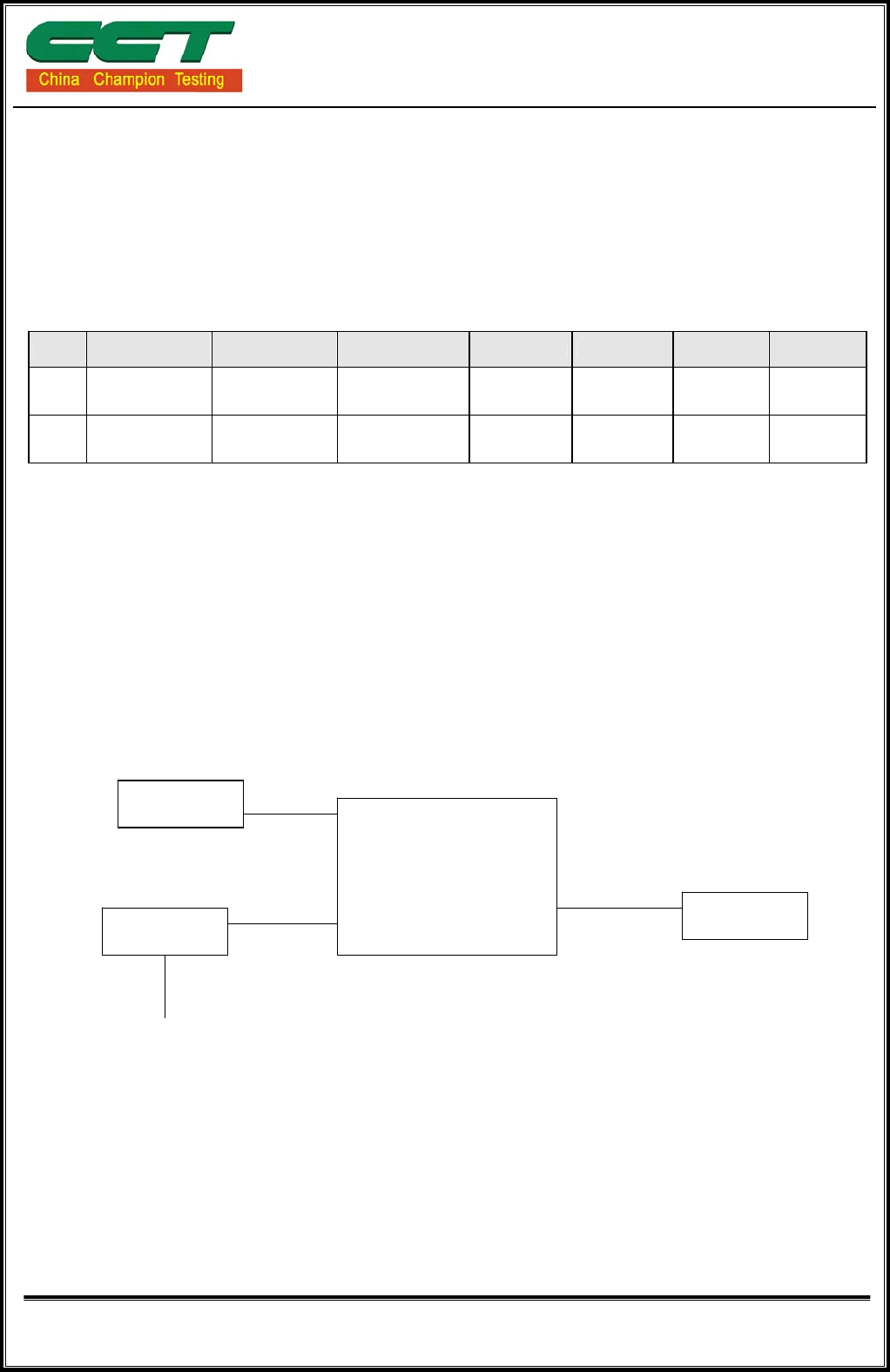
4.2. CONFIGURATION OF SYSTEM UNDER TEST
AC Mains
(HDMI Product)
Adapter
DVD
LCD Monitor
HDV-944
(EUT)
Shenzhen CCT Technical Services Co., Ltd.
Report No.: CCT14010032FR
Page 8 of 25
5 FACILITIES AND ACCREDITATIONS
5.1. FACILITIES
All measurement facilities used to collect the measurement data are located at
7nd Floor, Hongyuan Building, Baoyuan Road, Bao'an district, Shenzhen, China
The sites are constructed in conformance with the requirements of ANSI C63.4 and CISPR
Publication 22. All receiving equipment conforms to CISPR Publication 16-1, “Radio
Interference Measuring Apparatus and Measurement Methods.”
5.2. ACCREDITATIONS
Our laboratories are accredited and approved by the following approval agencies according
to ISO/IEC 17025.
FCC –Registration No.:222294
EMC Laboratory has been registered and fully described in a report filed with the (FCC)
Federal Communications Commission .The acceptance letter from the FCC is maintained
In our files . Registration 222294
TUV Accredited
EMC Laboratory has been Accredited by TUV Rheinland Shenzhen 2010.9 , The laboratory
has been assessed according to the requirements ISO/IEC 17025
Copies of granted accreditation certificates are available for downloading from our web site,
http://www.ccttest.com
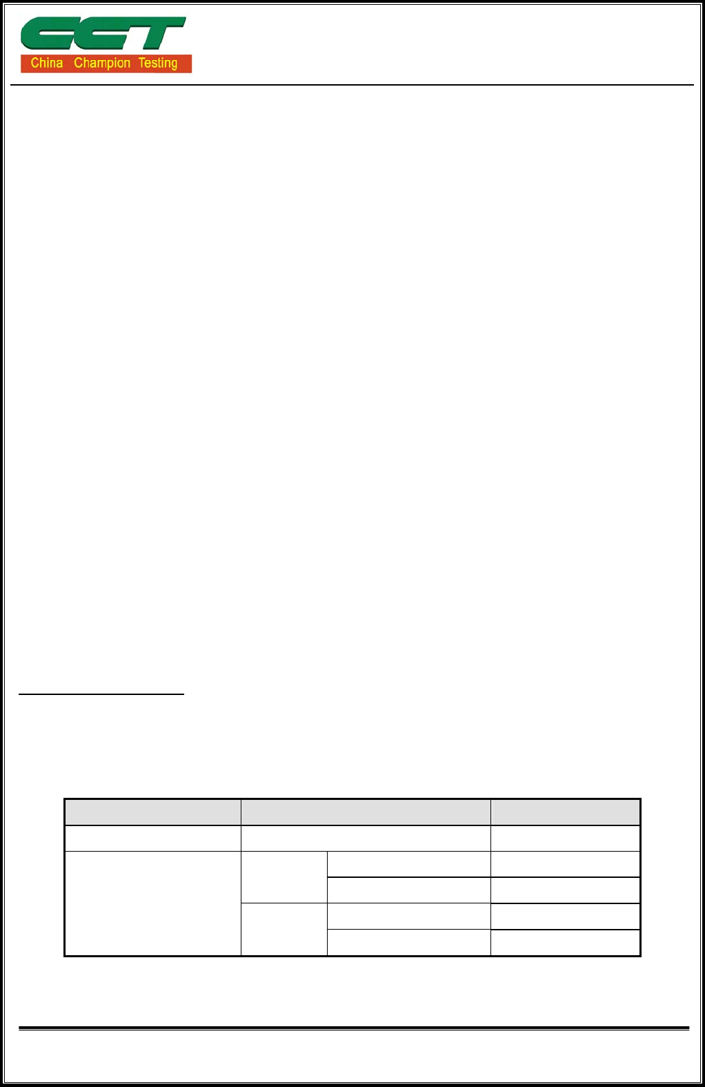
5.3. MEASUREMENT UNCERTAINTY
Where relevant, the following measurement uncertainty levels have been estimated for
tests performed on the EUT as specified in CISPR 16-4-2:
Measurement Frequency Uncertainty
Conducted emissions 9kHz~30MHz +/- 3.59dB
30MHz ~ 200MHz +/- 4.77dB
Horizontal 200MHz ~1000MHz +/- 4.93dB
30MHz ~ 200MHz +/- 5.04dB
Radiated emissions
Vertical 200MHz ~1000MHz +/- 4.93dB
This uncertainty represents an expanded uncertainty expressed at approximately the
95% confidence level using a coverage factor of k=2.
Shenzhen CCT Technical Services Co., Ltd.
Report No.: CCT14010032FR
Page 9 of 25
6 CONDUCTED EMISSION MEASUREMENT
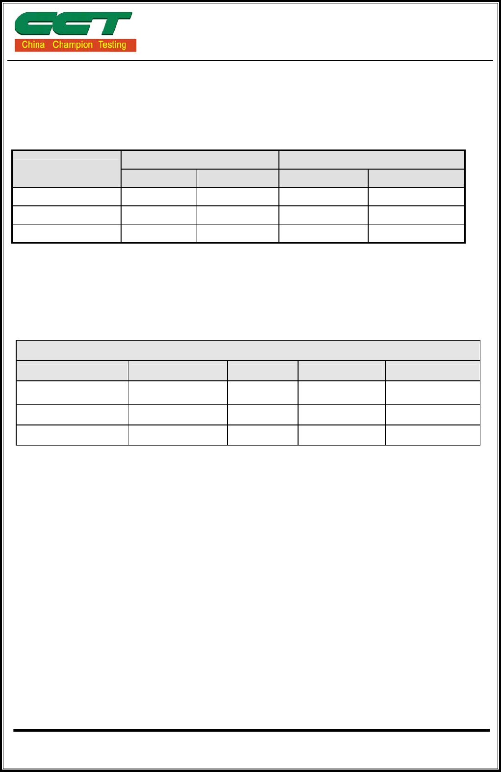
6.1. LIMITS OF CONDUCTED EMISSION MEASUREMENT
Class A (dBuV) Class B (dBuV)
FREQUENCY (MHz) Quasi-peak Average Quasi-peak Average
0.15 - 0.5 79 66 66 - 56 56 - 46
0.50 - 5.0 73 60 56 46
5.0 - 30.0 73 60 60 50
NOTE:
(1) The lower limit shall apply at the transition frequencies.
(2) The limit decreases in line with the logarithm of the frequency in the range of 0.15 to 0.50 MHz.
(3) All emanations from a class A/B digital device or system, including any network of conductors and
apparatus connected thereto, shall not exceed the level of field strengths specified above.
6.2. TEST INSTRUMENTS
Conducted Emission Test Site Shielding Room (743)
Name of Equipment Manufacturer Model Serial Number Calibration Due
EMI Test Receiver ROHDE&SCHWARZ ESCI 100005 06/23/2014
LISN AFJ LS16 16010222119 06/02/2014
LISN Meestec AN3016 04/10040 06/02/2014
NOTE: 1. The calibration interval of the above test instruments is 12 months and the calibrations are traceable
to International system of unit (SI).
2. N.C.R = No Calibration Request.

Shenzhen CCT Technical Services Co., Ltd.
Report No.: CCT14010032FR
Page 10 of 25
6.3.TEST PROCEDURES
Procedure of Preliminary Test
z The EUT and Support equipment, if needed, was set up as per the test configuration
to simulate typical usage per the user’s manual. When the EUT is a tabletop system, a
wooden table with a height of 0.8 meters is used and is placed on the ground plane as
per ANSI C63.4 (see Test Facility for the dimensions of the ground plane used). When
the EUT is a floor standing equipment, it is placed on the ground plane, which has a
3-12 mm non-conductive covering to insulate the EUT from the ground plane.
z All I/O cables were positioned to simulate typical actual usage as per ANSI C63.4.
z The EUT received DC 12V from adaptor ,and adaptor received AC120V/60Hz
through a Line Impedance Stabilization Network (LISN), which supplied power source
and was grounded to the ground plane.
z All support equipment power received from a second LISN.
z The EUT test program was started. Emissions were measured on each current
carrying line of the EUT using an EMI Test Receiver connected to the LISN powering
the EUT.
z The Receiver scanned from 150kHz to 30MHz for emissions in each of the test
modes.
z During the above scans, the emissions were maximized by cable manipulation.
z The test mode(s) described in Item 3.1 were scanned during the preliminary test.
z After the preliminary scan, we found the test mode described in Item 3.1 producing
the highest emission level.
z The EUT configuration and worse cable configuration of the above highest emission
levels were recorded for reference of the final test.
Procedure of Final Test
z EUT and support equipment were set up on the test bench as per the configuration
with highest emission level in the preliminary test.
z A scan was taken on both power lines, Line 1 and Line 2, recording at least the six
highest emissions. Emission frequency and amplitude were recorded into a computer
in which correction factors were used to calculate the emission level and compare
reading to the applicable limit.
z The test data of the worst-case condition(s) was recorded.
Shenzhen CCT Technical Services Co., Ltd.
Report No.: CCT14010032FR
Page 11 of 25
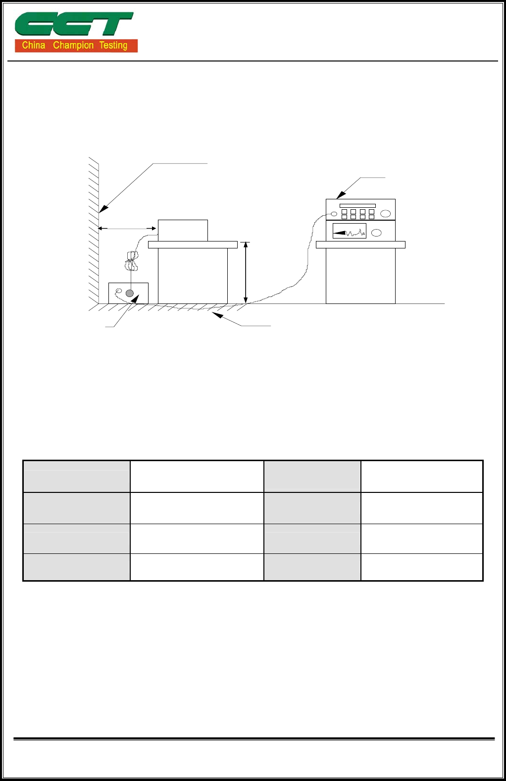
6.4.TEST SETUP
z For the actual test configuration, please refer to the related item – Photographs of
the Test Configuration.
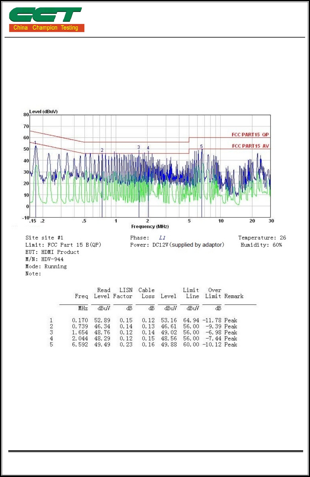
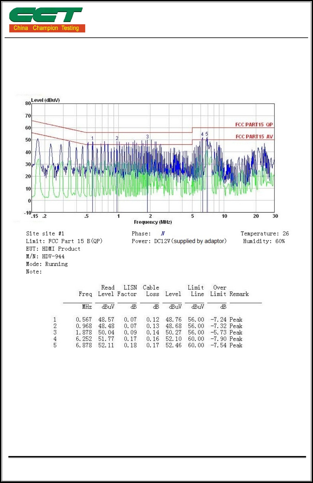
6.5. TEST RESULTS
Model No. HDV-944 6dB
Bandwidth 10 KHz
Environmental
Conditions 24°C, 51% RH Test Mode Running
Detector Function Peak / Quasi-peak/AV Test Result Pass
Test By Koma Wong
NOTE: 1. L1 = Line One (Live Line) / L2 = Line Two (Neutral Line).
2. “---” denotes the emission level was or more than 2dB below the Average limit,
so no re-check anymore.
Freq. = Emission frequency in MHz
Reading level(dBuV) = Receiver reading
Corr. Factor (dB) = Antenna factor + Cable loss
Level (dBuV) = Reading level(dBuV) + Corr. Factor (dB)
Limit (dBuV) = Limit stated in standard
Margin (dB) = Level (dBuV) – Limits (dBuV)
Q.P.=Quasi-Peak
EUT
LISN
EMI receive
r
Reference ground plane
Vert. reference plane
40cm
80cm
Shenzhen CCT Technical Services Co., Ltd.
Report No.: CCT14010032FR
Page 12 of 25
Please refer to following diagram for individual
L:
Shenzhen CCT Technical Services Co., Ltd.
Report No.: CCT14010032FR
Page 13 of 25
N:
Shenzhen CCT Technical Services Co., Ltd.
Report No.: CCT14010032FR
Page 14 of 25
7 RADIATED EMISSION MEASUREMENT
7.1. LIMITS OF RADIATED EMISSION MEASUREMENT
Maximum permissible level of Radiated Emission measured at 3 meter
dBuV/m (At 3m) FREQUENCY (MHz)
Class B
30~88 40.00
88~216 43.50
216~960 46.00
960~1000 54.00
NOTE: (1) The lower limit shall apply at the transition frequencies.
(2) Emission level (dBuV/m) = 20 log Emission level (uV/m).
7.2. TEST INSTRUMENTS
Radiated Emission Test Site 966
Name of Equipment Manufacturer Model Serial Number Calibration Due
EMI Test Receiver ROHDE&SCHWARZ ESCI 100005 06/23/2014
Pre Amplifier H.P. HP8447E 2945A02715 06/15/2014
Bilog Antenna SUNOL Sciences JB3 A021907 06/10/2014
Cable TIME MICROWAVE LMR-400 N-TYPE04 06/09/2014
System-Controller CCS N/A N/A N.C.R
Turn Table CCS N/A N/A N.C.R
Antenna Tower CCS N/A N/A N.C.R
NOTE: 1. The calibration interval of the above test instruments is 12 months and the calibrations are traceable to
International system of unit (SI).
2. N.C.R = No Calibration Request.

Shenzhen CCT Technical Services Co., Ltd.
Report No.: CCT14010032FR
Page 15 of 25
7.3. TEST PROCEDURES
Procedure of Preliminary Test
The equipment was set up as per the test configuration to simulate typical usage per the
user’s manual. When the EUT is a tabletop system, a wooden turntable with a height of
0.8 meters is used which is placed on the ground plane. When the EUT is a floor
standing equipment, it is placed on the ground plane which has a 3-12 mm
non-conductive covering to insulate the EUT from the ground plane.
Support equipment, if needed, was placed as per ANSI C63.4.
All I/O cables were positioned to simulate typical usage as per ANSI C63.4.
Mains cables, telephone lines or other connections to auxiliary equipment located
outside the test are shall drape to the floor, be fitted with ferrite clamps or ferrite tubes
placed on the floor at the point where the cable reaches the floor and then routed to the
place where they leave the turntable. No extension cords shall be used to mains
receptacle.
The antenna was placed at 3 meter away from the EUT as stated in ANSI C63.4. The
antenna connected to the Spectrum Analyzer via a cable and at times a pre-amplifier
would be used.
The Analyzer / Receiver quickly scanned from 30MHz to 1000MHz. The EUT test
program was started. Emissions were scanned and measured rotating the EUT to 360
degrees and positioning the antenna 1 to 4 meters above the ground plane, in both the
vertical and the horizontal polarization, to maximize the emission reading level.
The test mode(s) described in Item 3.1 were scanned during the preliminary test:
After the preliminary scan, we found the test mode described in Item 3.1 producing the
highest emission level.
The EUT and worse cable configuration, antenna position, polarization and turntable
position of the above highest emission level were recorded for the final test.
When measuring emissions above 1GHz, the frequencies of maximum emission shall be
determined by manually positioning the antenna close to the EUT and by moving the
antenna over all sides of the EUT while observing a spectral display. It will be advantageous
to have prior knowledge of the frequencies of emissions above 1GHz.If the EUT is a device
with dimensions approximately equal to that of the measurement antenna beam width, the
measurement antenna shall be aligned with the EUT.

Shenzhen CCT Technical Services Co., Ltd.
Report No.: CCT14010032FR
Page 16 of 25
Procedure of Final Test
z EUT and support equipment were set up on the turntable as per the configuration
with highest emission level in the preliminary test.
z The Analyzer / Receiver scanned from 30MHz to 1000MHz. Emissions were
scanned and measured rotating the EUT to 360 degrees, varying cable placement and
positioning the antenna 1 to 4 meters above the ground plane, in both the vertical and
the horizontal polarization, to maximize the emission reading level.
z Recorded at least the six highest emissions. Emission frequency, amplitude, antenna
position, polarization and turntable position were recorded into a computer in which
correction factors were used to calculate the emission level and compare reading to
the applicable limit and only Q.P. reading is presented.
For the measurement above 1GHz, use the cable, EUT arrangement, and mode of
operation determined in the exploratory testing to produce the emission that has the highest
amplitude relative to the limit.
Place the measurement antenna away from each area of the EUT determined to be a
source of emissions at the specified measurement distance, while keeping the antenna in
the “cone of radiation” from that area and pointed at the area both in azimuth and elevation,
with polarization oriented for maximum response.
The antenna may have to be higher or lower than the EUT, depending on the EUT’s size
and mounting height, but the antenna should be restricted to a range of height of from 1m to
4m above the ground or reference ground plane.
If the transmission line for the measurement antenna restricts its range of height and
polarization, the steps needed to ensure the correct measurement of the maximum
emissions, shall be described in detail in the report of the measurements.
1) using the procedures above to measure with peak detector function, if the result comply
with the average limit specified by the appropriate regulation, record the EUT
arrangement, mode of operation, and cable positions used for final radiated emission
measurement , this can be done with either diagrams or photographs.
2) Set the detector function of the measuring instrument to average mode, using the
procedures above and remeasure only those emissions that complied with the peak
limits but exceeded the average limits.
Recorded at least the six highest emissions.
Shenzhen CCT Technical Services Co., Ltd.
Report No.: CCT14010032FR
Page 17 of 25
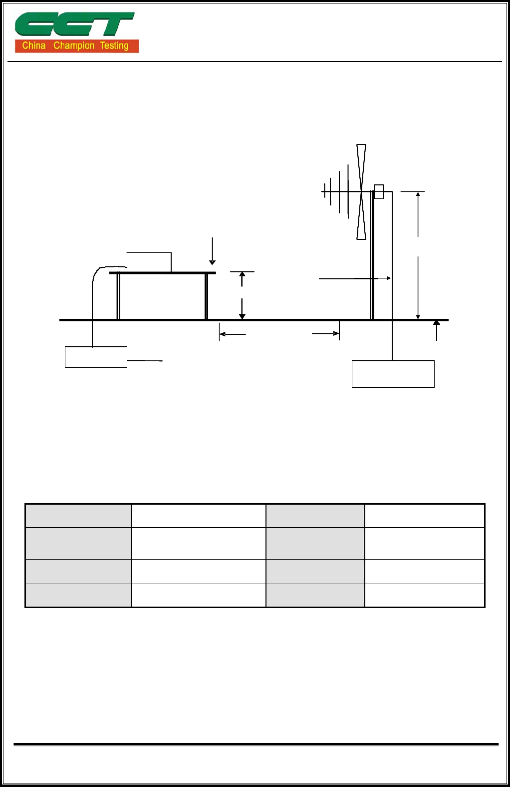
Filter
Filter
Filter To Powe
r
EUT
Ground Plane
3 m
0.8 m
Coaxial Cable
Test table & Turntable
1m ~ 4m
Powe
r
Cable
EMI
Receive
r
7.4. TEST SETUP
z For the actual test configuration, please refer to the related item – Photographs of the
Test Configuration
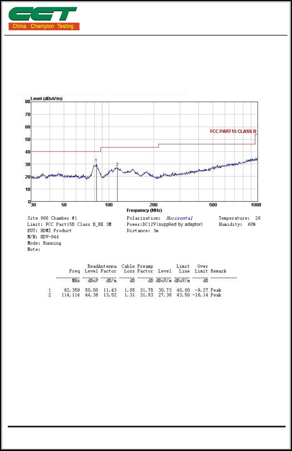
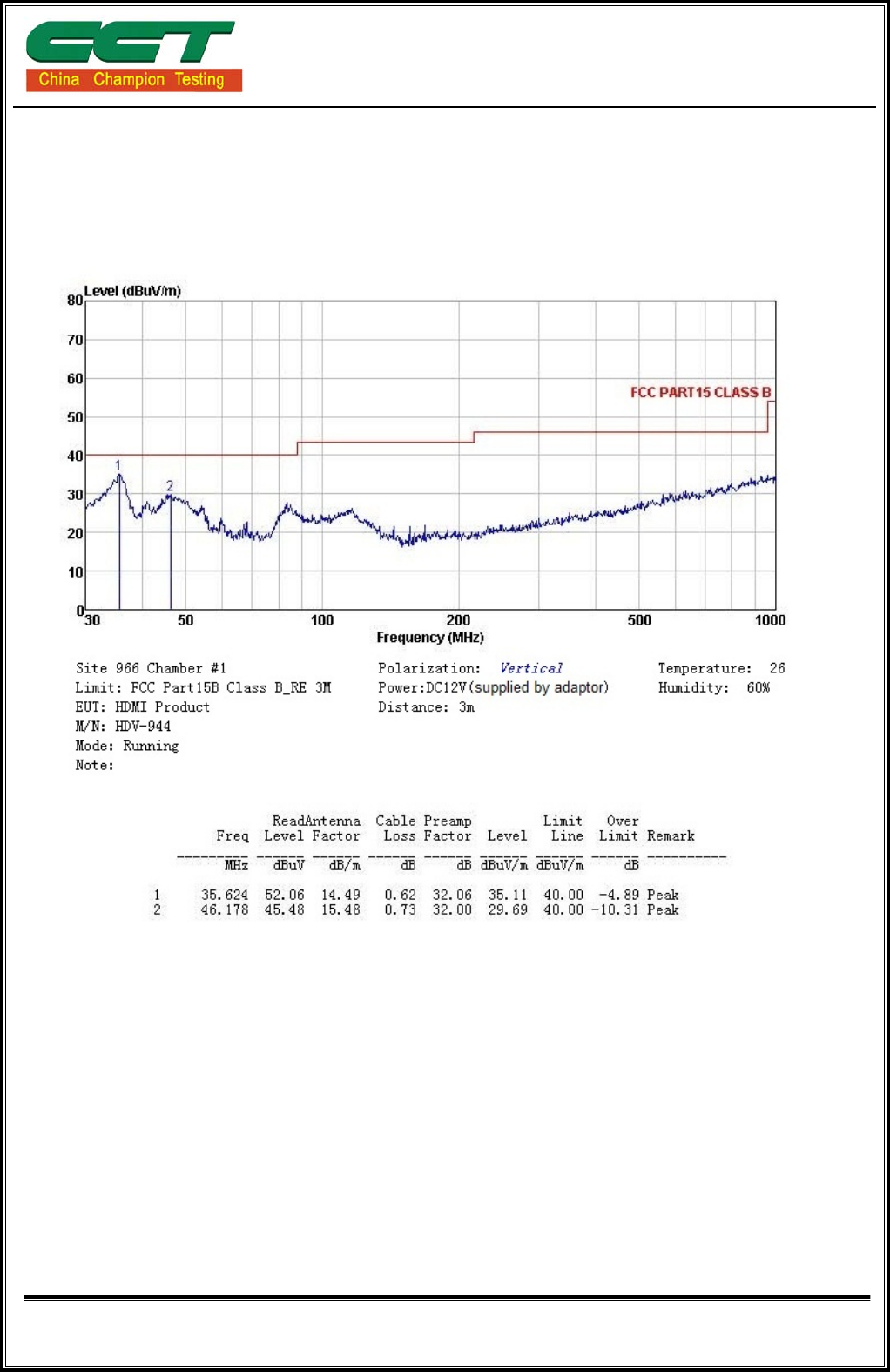
7.5. TEST RESULTS
Model No. HDV-944 Test Mode Running
Environmental
Conditions 24°C, 51% RH 6dB
Bandwidth 120 KHz
Antenna Pole Vertical / Horizontal Antenna Distance 3m
Detector Function Peak / Quasi-peak Tested by Koma Wong
Freq. = Emission frequency in MHz
Reading level(dBuV) = Receiver reading
Corr. Factor (dB) = Antenna factor + Cable loss
Measurement (dBuV) = Reading level(dBuV) + Corr. Factor (dB)
Limit (dBuV) = Limit stated in standard
Margin (dB) = Measurement (dBuV) – Limits (dBuV)
Shenzhen CCT Technical Services Co., Ltd.
Report No.: CCT14010032FR
Page 18 of 25
Please refer to following diagram for individual
H:
Shenzhen CCT Technical Services Co., Ltd.
Report No.: CCT14010032FR
Page 19 of 25
V:
Shenzhen CCT Technical Services Co., Ltd.
Report No.: CCT14010032FR
Page 20 of 25
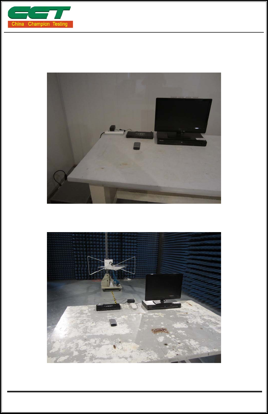
8 PHOTOGRAPHS OF THE TEST CONFIGURATION
CONDUCTED EMISSION TEST
RADIATED EMISSION TEST
Shenzhen CCT Technical Services Co., Ltd.
Report No.: CCT14010032FR
Page 21 of 25
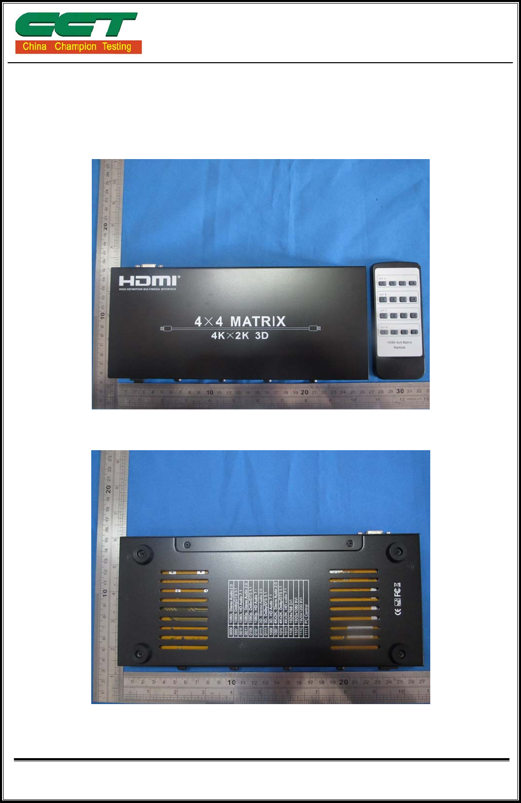
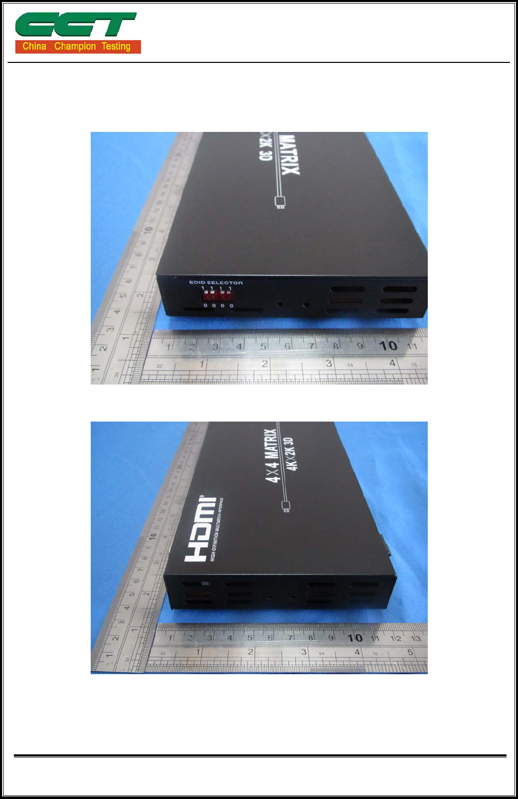
9 PHOTOGRAPHS OF EUT
Shenzhen CCT Technical Services Co., Ltd.
Report No.: CCT14010032FR
Page 22 of 25
Shenzhen CCT Technical Services Co., Ltd.
Report No.: CCT14010032FR
Page 23 of 25
Shenzhen CCT Technical Services Co., Ltd.
Report No.: CCT14010032FR
Page 24 of 25
Shenzhen CCT Technical Services Co., Ltd.
Report No.: CCT14010032FR
Page 25 of 25
