CE980825H03
2016-04-11
: Pdf Ce980825H03 CE980825H03 CertsReports 502054 ProductFiles
Open the PDF directly: View PDF ![]() .
.
Page Count: 75
Report No.: CE980825H03 1 Report Format Version 3.0.1
CE EMC TEST REPORT
REPORT NO. :
CE980825H03
MODEL NO. :
F108Q, CG-SW8PS
RECEIVED :
Aug. 25, 2009
TESTED :
Aug. 26 to 28, 2009
ISSUED :
Sep. 29, 2009
APPLICANT :
NETRONIX , INC.
ADDRESS :
No. 945, Boai St., Jubei City, Hsin-Chu,302,
Taiwan, R.O.C.
ISSUED BY :
Bureau Veritas Consumer Products Services
(H.K.) Ltd., Taoyuan Branch
LAB LOCATION :
No. 81-1, Lu Liao Keng, 9th Ling, Wu Lung Tsuen,
Chiung Lin Hsiang, Hsin Chu Hsien 307, Taiwan
This test report consists of 75 pages in total. It may be duplicated completely for legal use with the
approval of the applicant. It should not be reproduced except in full, without the written approval of
our laboratory. The client should not use it to claim product endorsement by TAF, NVLAP or any
government agencies. The test results in the report only apply to the tested sample.

Report No.: CE980825H03 2 Report Format Version 3.0.1
Table of Contents
1 CERTIFICATION.................................................................................................5
2 SUMMARY OF TEST RESULTS........................................................................7
2.1 MEASUREMENT UNCERTAINTY.....................................................................8
3 GENERAL INFORMATION.................................................................................9
3.1 GENERAL DESCRIPTION OF EUT..................................................................9
3.2 GENERAL DESCRIPTION OF TEST MODE..................................................10
3.3 GENERAL DESCRIPTION OF APPLIED STANDARDS.................................11
3.4 DESCRIPTION OF SUPPORT UNITS.............................................................12
3.5 CONFIGURATION OF SYSTEM UNDER TEST.............................................13
4 EMISSION TEST..............................................................................................16
4.1 CONDUCTED EMISSION MEASUREMENT..................................................16
4.1.1 LIMITS OF CONDUCTED EMISSION MEASUREMENT...............................16
4.1.2 TEST INSTRUMENTS......................................................................................16
4.1.3 TEST PROCEDURE.........................................................................................17
4.1.4 DEVIATION FROM TEST STANDARD............................................................17
4.1.5 TEST SETUP....................................................................................................17
4.1.6 EUT OPERATING CONDITIONS.....................................................................18
4.1.7 TEST RESULTS................................................................................................19
4.2 CONDUCTED EMISSION MEASUREMENT AT TELECOMMUNICATION
PORTS..............................................................................................................21
4.2.1 LIMIT OF CONDUCTED COMMON MODE DISTURBANCE AT
TELECOMMUNICATION PORTS....................................................................21
4.2.2 TEST INSTRUMENTS......................................................................................22
4.2.3 TEST PROCEDURE.........................................................................................23
4.2.4 DEVIATION FROM TEST STANDARD............................................................24
4.2.5 TEST SETUP....................................................................................................24
4.2.6 EUT OPERATING CONDITIONS.....................................................................24
4.2.7 TEST RESULTS................................................................................................25
4.3 RADIATED EMISSION MEASUREMENT........................................................26
4.3.1 LIMITS OF RADIATED EMISSION MEASUREMENT.....................................26
4.3.2 TEST INSTRUMENTS......................................................................................27
4.3.3 TEST PROCEDURE.........................................................................................27
4.3.4 DEVIATION FROM TEST STANDARD............................................................28
4.3.5 TEST SETUP....................................................................................................29
4.3.6 EUT OPERATING CONDITIONS.....................................................................29
4.3.7 TEST RESULTS................................................................................................30
4.4 HARMONICS CURRENT MEASUREMENT...................................................32
4.4.1 LIMITS OF HARMONICS CURRENT MEASUREMENT................................32
4.4.2 TEST INSTRUMENTS......................................................................................32
4.4.3 TEST PROCEDURE.........................................................................................33
4.4.4 TEST SETUP....................................................................................................33
4.4.5 EUT OPERATING CONDITIONS.....................................................................34
4.4.6 TEST RESULTS................................................................................................35
4.5 VOLTAGE FLUCTUATION AND FLICKER MEASUREMENT........................36
4.5.1 LIMITS OF VOLTAGE FLUCTUATION AND FLICKER MEASUREMENT.....36
4.5.2 TEST INSTRUMENTS......................................................................................36

Report No.: CE980825H03 3 Report Format Version 3.0.1
4.5.3 TEST PROCEDURE.........................................................................................37
4.5.4 TEST SETUP....................................................................................................37
4.5.5 EUT OPERATING CONDITIONS.....................................................................37
4.5.6 TEST RESULTS................................................................................................38
5 IMMUNITY TEST..............................................................................................39
5.1 GENERAL DESCRIPTION...............................................................................39
5.2 GENERAL PERFORMANCE CRITERIA DESCRIPTION...............................40
5.3 EUT OPERATING CONDITION.......................................................................40
5.4 ELECTROSTATIC DISCHARGE IMMUNITY TEST (ESD).............................41
5.4.1 TEST SPECIFICATION.....................................................................................41
5.4.2 TEST INSTRUMENTS......................................................................................41
5.4.3 TEST PROCEDURE.........................................................................................42
5.4.4 DEVIATION FROM TEST STANDARD............................................................43
5.4.5 TEST SETUP....................................................................................................43
5.4.6 TEST RESULTS................................................................................................44
5.5 RADIATED, RADIO-FREQUENCY, ELECTROMAGNETIC FIELD IMMUNITY
TEST (RS).........................................................................................................47
5.5.1 TEST SPECIFICATION.....................................................................................47
5.5.2 TEST INSTRUMENTS......................................................................................47
5.5.3 TEST PROCEDURE.........................................................................................48
5.5.4 TEST SETUP....................................................................................................48
5.5.5 TEST RESULTS................................................................................................49
5.6 ELECTRICAL FAST TRANSIENT/BURST IMMUNITY TEST (EFT)..............50
5.6.1 TEST SPECIFICATION.....................................................................................50
5.6.2 TEST INSTRUMENTS......................................................................................50
5.6.3 TEST PROCEDURE.........................................................................................50
5.6.4 DEVIATION FROM TEST STANDARD............................................................51
5.6.5 TEST SETUP....................................................................................................51
5.6.6 TEST RESULTS................................................................................................52
5.7 SURGE IMMUNITY TEST................................................................................53
5.7.1 TEST SPECIFICATION.....................................................................................53
5.7.2 TEST INSTRUMENTS......................................................................................53
5.7.3 TEST PROCEDURE.........................................................................................54
5.7.4 DEVIATION FROM TEST STANDARD............................................................54
5.7.5 TEST SETUP....................................................................................................54
5.7.6 TEST RESULTS................................................................................................55
5.8 IMMUNITY TO CONDUCTED DISTURBANCES INDUCED BY RF FIELDS
(CS)...................................................................................................................56
5.8.1 TEST SPECIFICATION.....................................................................................56
5.8.2 TEST INSTRUMENTS......................................................................................56
5.8.3 TEST PROCEDURE.........................................................................................57
5.8.4 TEST SETUP....................................................................................................58
5.8.5 TEST RESULTS................................................................................................59
5.9 POWER FREQUENCY MAGNETIC FIELD IMMUNITY TEST.......................60
5.9.1 TEST SPECIFICATION.....................................................................................60
5.9.2 TEST INSTRUMENTS......................................................................................60
5.9.3 TEST PROCEDURE.........................................................................................60
5.9.4 TEST SETUP....................................................................................................61

Report No.: CE980825H03 4 Report Format Version 3.0.1
5.9.5 TEST RESULTS................................................................................................62
5.10 VOLTAGE DIP/SHORT INTERRUPTIONS/VOLTAGE VARIATIONS (DIP)
IMMUNITY TEST..............................................................................................63
5.10.1 TEST SPECIFICATION.....................................................................................63
5.10.2 TEST INSTRUMENTS......................................................................................63
5.10.3 TEST PROCEDURE.........................................................................................63
5.10.4 TEST SETUP....................................................................................................64
5.10.5 TEST RESULTS................................................................................................65
6 PHOTOGRAPHS OF THE TEST CONFIGURATION......................................66
7 APPENDIX - INFORMATION ON THE TESTING LABORATORIES..............75

Report No.: CE980825H03 5 Report Format Version 3.0.1
1 CERTIFICATION
Reference No.:930203H01
PRODUCT: 8 Port 10/100Mbps Switch
BRAND NAME: NETRONIX, Corega
MODEL NO.: F108Q, CG-SW8PS
TESTED: Aug. 26 to 28, 2009
TEST SAMPLE: ENGINEERING SAMPLE
APPLICANT: NETRONIX , INC.
STANDARDS: EN 55022:2006+A1:2007, Class B EN 55024:1998+A1:2001
AS/NZS CISPR 22:2006, Class B +A2:2003
EN 61000-3-2: 2006, Class A IEC 61000-4-2: 2008 ED.2.0
(see note * no next page) IEC 61000-4-3: 2006+A1:2007
EN 61000-3-3: 1995+A1:2001 ED.3.0
+A2:2005 IEC 61000-4-4: 2004 ED.2.0
IEC 61000-4-5: 2005 ED.2.0
IEC 61000-4-6: 2008 ED.3.0
IEC 61000-4-8: 2001 ED.1.1
IEC 61000-4-11: 2004 ED.2.0
The above equipment (Model: F108Q) has been tested by Bureau Veritas
Consumer Products Services (H.K.) Ltd., Taoyuan Branch, and found
compliance with the requirement of the above standards.
Approval signature – on next page

Report No.: CE980825H03 6 Report Format Version 3.0.1
CERTIFICATION - Continued
The test record, data evaluation & Equipment Under Test (EUT) configurations
represented herein are true and accurate accounts of the measurements of the
sample’s
PREPARED BY :
, DATE:
Sep. 29, 2009
( Carol Liao, Specialist )
TECHNICAL
ACCEPTANCE
:
, DATE:
Sep. 29, 2009
Responsible for EMI
( Mike Hsieh, Supervisor )
TECHNICAL
ACCEPTANCE
:
, DATE:
Sep. 29, 2009
Responsible for EMS
( Ray Yeh, Deputy Manager )
APPROVED BY
:
, DATE:
Sep. 29, 2009
( May Chen, Deputy Manager )
Note *: The power consumption of EUT is 2.043W, which is less than 75W and no limits apply.
Therefore it is deemed to comply with EN 61000-3-2 without any testing.

Report No.: CE980825H03 7 Report Format Version 3.0.1
2 SUMMARY OF TEST RESULTS
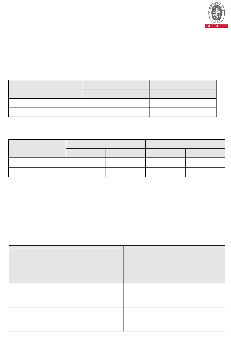
The EUT has been tested according to the following specifications:
EMISSION
Standard Test Type Result
Remarks
Conducted Test PASS
Meets Class B Limit
Minimum passing margin is
-8.98 dB at 1.027 MHz
Telecom port
conducted emission
test
PASS
Meets Class B Limit
Minimum passing margin is
-13.13 dB at 1.023 MHz
EN 55022:2006
+A1:2007, Class B
Radiated Test PASS
Meets Class B Limit
Minimum passing margin is
-6.21 dB at 250.00 MHz
EN 61000-3-2: 2006,
Class A
Harmonic current
emissions PASS
The power consumption of
EUT is less than 75W and no
limits apply
EN 61000-3-3: 1995
+A1:2001+A2:2005
Voltage fluctuations &
flicker PASS
Meets the requirements.
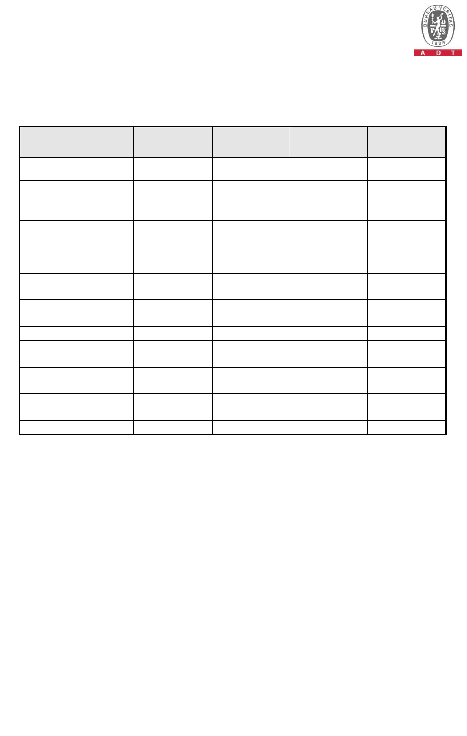
IMMUNITY (EN 55024:1998+A1:2001+A2:2003)
Standard Test Type Result
Remarks
IEC 61000-4-2 : 2008
ED.2.0
Electrostatic discharge
immunity test PASS
Meets the requirements of
Performance Criterion A
IEC 61000-4-3: 2006
+A1:2007 ED.3.0
Radiated,
radio-frequency,
electromagnetic field
immunity test
PASS
Meets the requirements of
Performance Criterion A
IEC 61000-4-4: 2004
ED.2.0
Electrical fast transient
/ burst immunity test. PASS
Meets the requirements of
Performance Criterion A
IEC 61000-4-5: 2005
ED.2.0 Surge immunity test
PASS
Meets the requirements of
Performance Criterion A
IEC 61000-4-6: 2008
ED.3.0
Immunity to conducted
disturbances, induced
by radio-frequency
fields
PASS
Meets the requirements of
Performance Criterion A
IEC 61000-4-8: 2001
ED. 1.1
Power frequency
magnetic field
immunity test.
PASS
Meets the requirements of
Performance Criterion A
IEC 61000-4-11:
2004 ED.2.0
Voltage dips, short
interruptions and
voltage variations
immunity tests
PASS
Meets the requirements of
Voltage Dips:
1. >95% reduction -
Performance Criterion A
2. 30% reduction -
Performance Criterion A
Voltage Interruptions:
1. >95% reduction -
Performance Criterion B
Report No.: CE980825H03 8 Report Format Version 3.0.1
2.1 MEASUREMENT UNCERTAINTY
Where relevant, the following measurement uncertainty levels have been estimated
for tests performed on the EUT as specified in CISPR 16-4-2:
This uncertainty represents an expanded uncertainty expressed at approximately the
95% confidence level using a coverage factor of k=2.
Measurement Value
Conducted emissions 2.45 dB
Conducted Emission at Telecommunication port (T8)
3.694 dB
Radiated emissions(30MHz-1GHz) 3.83 dB
Report No.: CE980825H03 9 Report Format Version 3.0.1
3 GENERAL INFORMATION
3.1 GENERAL DESCRIPTION OF EUT
PRODUCT 8 Port 10/100Mbps Switch
MODEL NO. F108Q, CG-SW8PS
POWER SUPPLY Power Adapter, Class II
POWER CORD DC Output cable (unshielded, 1.75m)
DATA CABLE
SUPPLIED NA
I/O PORT RJ45 port x 8
ASSOCIATED
DEVICES Adapter x 1
Note:
1. The EUT has two brand names and two model names which are identical to
each other in all aspects except for the following:
Brand Model No. Difference
NETRONIX F108Q
Corega CG-SW8PS For marketing requirement
From the above models, model: F108Q was selected as representative
model for the test and its data was recorded in this report.
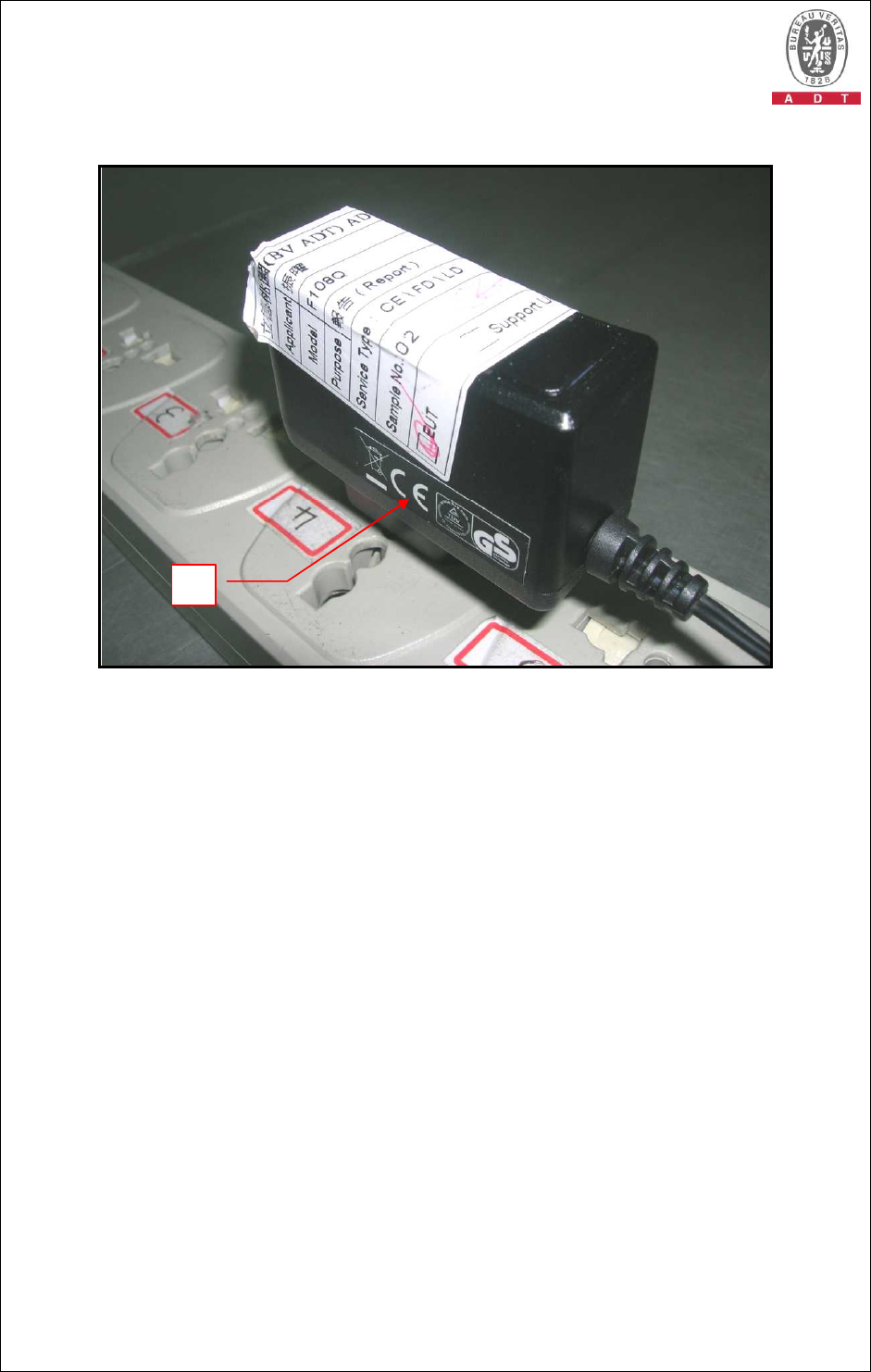
2. The EUT must be supplied with a power adapter as following:
Brand SIL
Model SSA-5W-05 EU 050060N
Input power AC :100-240 V 50-60 Hz, 0.2A
Output power DC:5.0V 600mA
Report No.: CE980825H03 10 Report Format Version 3.0.1
3. The EUT was pre-tested under the following modes:
Conducted and Radiated test
Pre-test Mode Communication speed
Mode A Level-set – 10 Mbps + 10 Mbps
Mode B Tower-set – 10 Mbps + 10 Mbps
Mode C Level-set – 100 Mbps + 100 Mbps
Telecommunication ports conducted test
Pre-test Mode Communication speed
Mode D LAN: 10Mbps
Mode E LAN: 100Mbps
The worst conducted and radiated emission was found in Mode C. The worse
telecommunication ports conducted test was found in Mode D. Therefore only
the test data of the modes were recorded in this report.
4. For a more detailed features description, please refer to the manufacturer's
specifications or the User's Manual.
3.2 GENERAL DESCRIPTION OF TEST MODE
The EUT was tested under following test modes:
Telecommunication ports conducted test
Test Mode Description
Mode 1 LAN: 10 Mbps
Other test items
Test Mode Description
Mode 1 Level-set – 100 Mbps + 100 Mbps

Report No.: CE980825H03 11 Report Format Version 3.0.1
3.3 GENERAL DESCRIPTION OF APPLIED STANDARDS
The EUT is a kind of IT equipment and, according to the specifications of the
manufacturers, must comply with the requirements of the following standards:
EN 55022:2006+A1:2007, Class B EN 55024:1998+A1:2001
AS/NZS CISPR 22:2006, Class B +A2:2003
EN 61000-3-2: 2006, Class A IEC 61000-4-2: 2008 ED.2.0
EN 61000-3-3: 1995+A1:2001 IEC 61000-4-3: 2006+A1:2007 ED.3.0
+ A2:2005 IEC 61000-4-4: 2004 ED.2.0
IEC 61000-4-5: 2005 ED.2.0
IEC 61000-4-6: 2008 ED.3.0
IEC 61000-4-8: 2001 ED.1.1
IEC 61000-4-11: 2004 ED.2.0
All tests have been performed and recorded as per the above standards.
Report No.: CE980825H03 12 Report Format Version 3.0.1
3.4 DESCRIPTION OF SUPPORT UNITS
The EUT has been tested as an independent unit together with other necessary
accessories or support units. The following support units or accessories were used to
form a representative test configuration during the tests.
Conducted / Telecommunication ports conducted / Radiated test
No.
Product Brand Model No. Serial No. FCC ID
1
NOTEBOOK
COMPUTER DELL PP18L 12252644560 FCC DoC
2
NOTEBOOK
COMPUTER DELL PPT 17044664176 E2K24GBRL
3
NOTEBOOK
COMPUTER DELL PP18L 12252644560 FCC DoC
4
NuStreams xtramus NuStreams-600 05NS06C00004 NA
Harmonics Current / Voltage Fluctuation & Flicker / Immunity test
No.
Product Brand Model No. Serial No. FCC ID
1
NOTEBOOK
COMPUTER DELL PP18L 4799903248 FCC DoC
2
NOTEBOOK
COMPUTER ASUS A2400H 49NG038455 FCC DoC
Conducted / Telecommunication ports conducted / Radiated test
No.
Signal cable description
1
10 m UTP cable.
2
10 m UTP cable.
3
3 m UTP cable.
4
10 m UTP cable.
Harmonics Current / Voltage Fluctuation & Flicker / Immunity test
No.
Signal cable description
1
10 m UTP cable.
2
10 m UTP cable.
Note: The power cords of the above support units were unshielded (1.8m).
Report No.: CE980825H03 13 Report Format Version 3.0.1
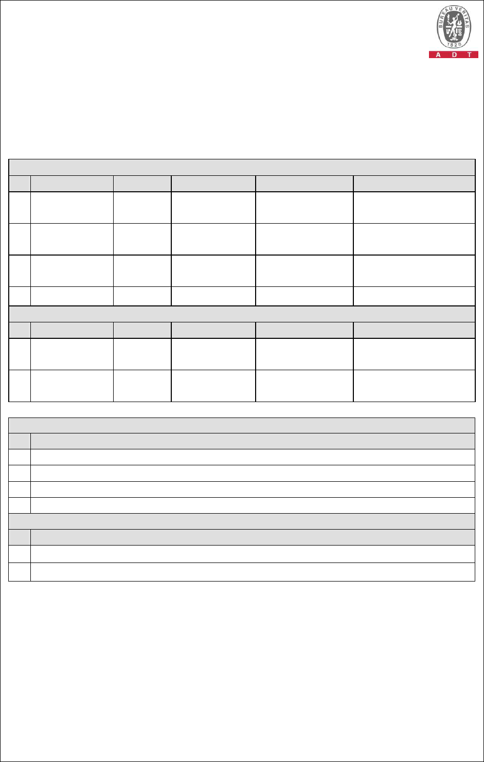
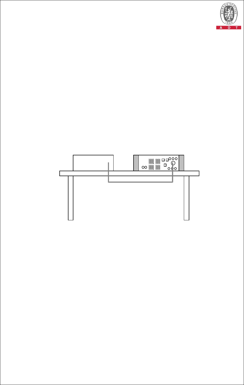
3.5 CONFIGURATION OF SYSTEM UNDER TEST
For Conducted / Telecommunication ports conducted test:
NOTE: 1. Support units 3-4 were kept in the control room during the test.
CONTROL ROOM
TEST TABLE
UTP Cable (10m x 6) UTP Cable (10m x 2)
4. NuStreams Load 100 Ω 3. NOTEBOOK
COMPUTER
EUT
Adapter
(On test table)
Report No.: CE980825H03 14 Report Format Version 3.0.1
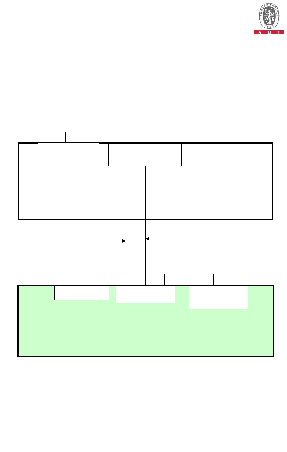
For Radiated test :
NOTE: 1. Support units 1-2 were kept in the control room during the test.
CONTROL ROOM
TEST TABLE
UTP Cable (3m x 6)
UTP Cable (10m)
UTP Cable (10m)
1. NOTEBOOK
COMPUTER
Load 100 Ω 2. NOTEBOOK
COMPUTER
EUT
Adapter
(On test table)
Report No.: CE980825H03 15 Report Format Version 3.0.1
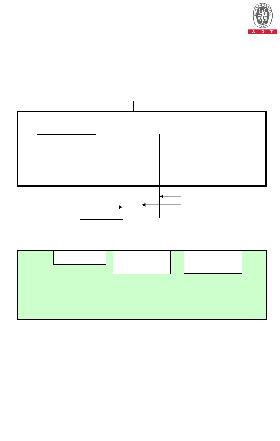
For Harmonics Current / Voltage Fluctuation & Flicker / Immunity test :
NOTE: 1. Support units 1-2 were kept in the control room during the test.
CONTROL ROOM
TEST TABLE
UTP Cable (10m)
UTP Cable (10m)
2. NOTEBOOK
COMPUTER
EUT
1. NOTEBOOK
COMPUTER
Report No.: CE980825H03 16 Report Format Version 3.0.1
2. Item A is the remote control of EUT.
4 EMISSION TEST
4.1 CONDUCTED EMISSION MEASUREMENT
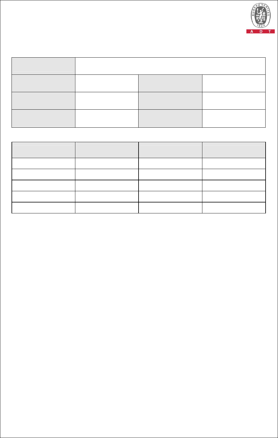
4.1.1 LIMITS OF CONDUCTED EMISSION MEASUREMENT
TEST STANDARD: EN 55022
Class A (dBuV) Class B (dBuV)
FREQUENCY (MHz)
Quasi-peak
Average Quasi-peak
Average
0.15 - 0.5 79 66 66 - 56 56 - 46
0.50 - 5.0 73 60 56 46
5.0 - 30.0 73 60 60 50
NOTE: (1) The lower limit shall apply at the transition frequencies.
(2) The limit decreases in line with the logarithm of the frequency in the range of 0.15
to 0.50 MHz.
(3) All emanations from a class A/B digital device or system, including any network of
conductors and apparatus connected thereto, shall not exceed the level of field
strengths specified above.
4.1.2 TEST INSTRUMENTS
DESCRIPTION &
MANUFACTURER MODEL NO. SERIAL NO.
CALIBRATED
DATE
CALIBRATED
UNTIL
ROHDE & SCHWARZ
Test Receiver ESCS 30 100287 Mar. 05, 2009 Mar. 04, 2010
Line-Impedance
Stabilization Network
(for EUT)
KNW-407 8-1395-12 May 04, 2009 May 03, 2010
Line-Impedance
Stabilization Network
(for Peripheral)
ENV-216 100072 June 08, 2009 June 07, 2010
RF Cable (JYEBAO) 5DFB COACAB-001
Dec 15, 2008 Dec 14, 2009
50 ohms Terminator 50 3 Nov. 05, 2008 Nov. 04, 2009
Software BV ADT_
Cond_V7.3.7 NA NA NA
Note:
1.
The calibration interval of the above test instruments is 12 months and the calibrations are
traceable to NML/ROC and NIST/USA.
2.
The test was performed in Shielded Room No. A.
3
The VCCI Con A Registration No. is C-817.
Report No.: CE980825H03 17 Report Format Version 3.0.1
4.1.3 TEST PROCEDURE
a. The EUT was placed 0.4 meters from the conducting wall of the shielded room
with EUT being connected to the power mains through a line impedance
stabilization network (LISN). Other support units were connected to the power
mains through another LISN. The two LISNs provide 50 Ohm/ 50uH of coupling
impedance for the measuring instrument.
b. Both lines of the power mains connected to the EUT were checked for maximum
conducted interference.
c. The frequency range from 150 kHz to 30 MHz was searched. Emission levels over
10dB under the prescribed limits could not be reported.
4.1.4 DEVIATION FROM TEST STANDARD
No deviation
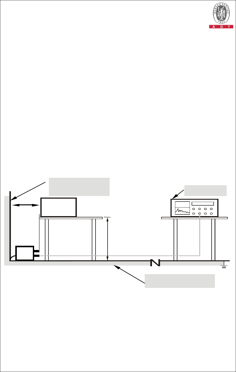
4.1.5 TEST SETUP
Note: 1.Support units were connected to second LISN.
2.Both of LISNs (AMN) are 80 cm from EUT and at least 80
from other units and other metal planes
Vertical Reference
Ground Plane
40cm
80cm
Test Receiver
Horizontal
Reference
Ground Plane
EUT
LISN
For the actual test configuration, please refer to the related item – Photographs of the
Test Configuration.

Report No.: CE980825H03 18 Report Format Version 3.0.1
4.1.6 EUT OPERATING CONDITIONS
1. Turn on the power of all equipment.
2. Support unit 3 (Notebook Computer) runs “NuLite.exe” program to enable of
EUT via support unit 4 (NuStreams).
3. Support unit 4 (NuStreams) transmitted messages to and received messages
of EUT via UTP cables.
4. Repeat steps 2-3.
1. EUT reads audio messages from Optical Drives and sends these messages to
speaker.
Report No.: CE980825H03 19 Report Format Version 3.0.1
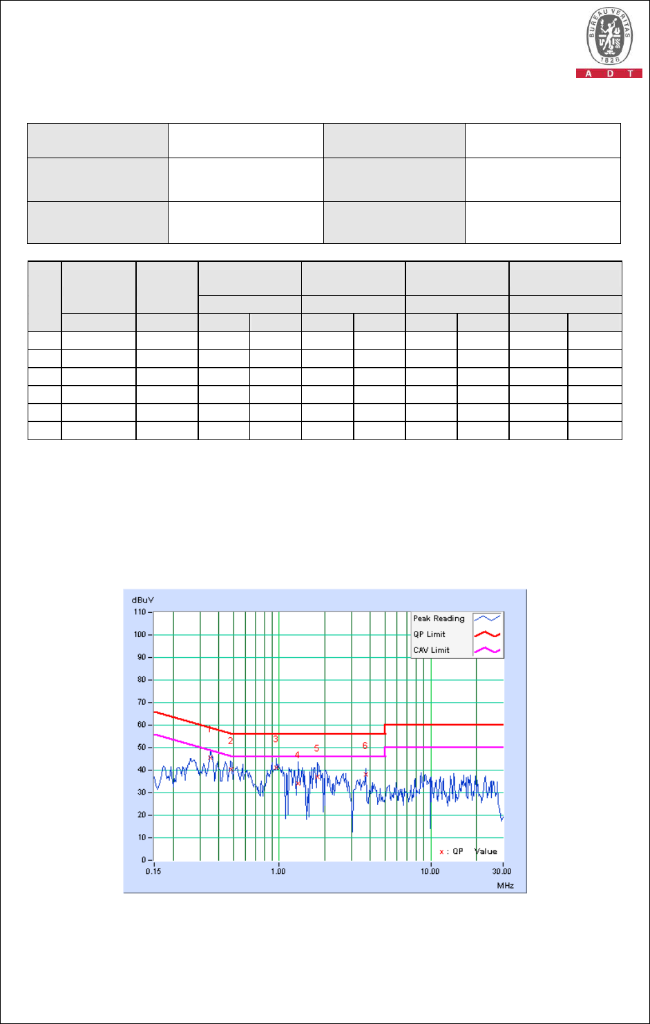
4.1.7 TEST RESULTS
TEST MODE Mode 1 PHASE Line (L)
INPUT POWER 230Vac, 50 Hz 6dB BANDWIDTH 9 kHz
ENVIRONMENTAL
CONDITIONS
25 deg. C, 61 % RH,
965 hPa TESTED BY Andy Ho
Freq. Corr. Reading Value
Emission
Level Limit Margin
No
Factor
[dB (uV)] [dB (uV)] [dB (uV)] (dB)
[MHz] (dB) Q.P. AV. Q.P. AV. Q.P. AV. Q.P. AV.
1 0.349 0.10 45.32
- 45.42
- 58.98
48.98
-13.56
-
2 0.480 0.08 40.12
- 40.20
- 56.33
46.33
-16.14
-
3 0.963 0.06 41.03
- 41.09
- 56.00
46.00
-14.91
-
4 1.340 0.06 34.04
- 34.10
- 56.00
46.00
-21.90
-
5 1.797 0.07 36.95
- 37.02
- 56.00
46.00
-18.98
-
6 3.754 0.13 38.18
- 38.31
- 56.00
46.00
-17.69
-
REMARKS: 1. Q.P. and AV. are abbreviations of quasi-peak and average individually.
2. "-": The Quasi-peak reading value also meets average limit and
measurement with the average detector is unnecessary.
3. The emission levels of other frequencies were very low against the limit.
4. Margin value = Emission level - Limit value
5. Correction factor = Insertion loss + Cable loss
6. Emission Level = Correction Factor + Reading Value.
Report No.: CE980825H03 20 Report Format Version 3.0.1
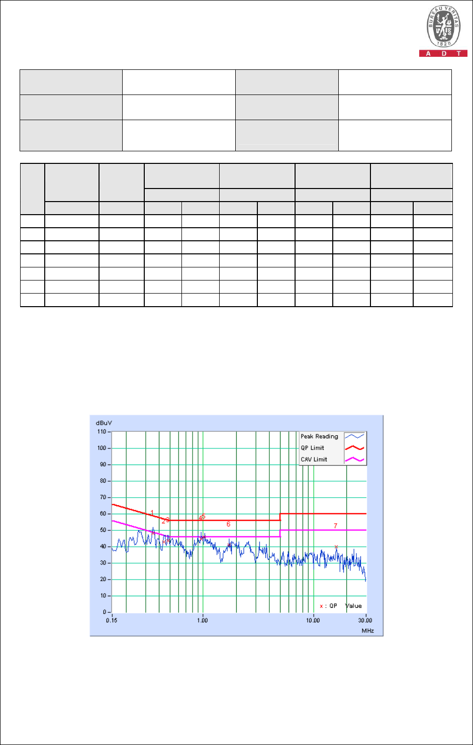
TEST MODE Mode 1 PHASE Neutral (N)
INPUT POWER 230Vac, 50 Hz 6dB BANDWIDTH 9 kHz
ENVIRONMENTAL
CONDITIONS
25 deg. C, 61 % RH,
965 hPa TESTED BY Andy Ho
Freq. Corr. Reading Value
Emission
Level Limit Margin
No
Factor
[dB (uV)] [dB (uV)] [dB (uV)] (dB)
[MHz] (dB) Q.P. AV. Q.P. AV. Q.P. AV. Q.P. AV.
1 0.353 0.11 48.21
- 48.32
- 58.89
48.89
-10.57
-
2 0.443 0.09 42.80
- 42.89
- 57.01
47.01
-14.12
-
3 0.483 0.09 43.74
- 43.83
- 56.28
46.28
-12.45
-
4 0.963 0.08 44.91
- 44.99
- 56.00
46.00
-11.01
-
5 1.027 0.08 46.03
36.94
46.11
37.02
56.00
46.00
-9.89 -8.98
6 1.730 0.09 41.04
- 41.13
- 56.00
46.00
-14.87
-
7 16.168 0.42 39.73
- 40.15
- 60.00
50.00
-19.85
-
REMARKS: 1. Q.P. and AV. are abbreviations of quasi-peak and average individually.
2. "-": The Quasi-peak reading value also meets average limit and
measurement with the average detector is unnecessary.
3. The emission levels of other frequencies were very low against the limit.
4. Margin value = Emission level - Limit value
5. Correction factor = Insertion loss + Cable loss
6. Emission Level = Correction Factor + Reading Value.
Report No.: CE980825H03 21 Report Format Version 3.0.1
4.2 CONDUCTED EMISSION MEASUREMENT AT
TELECOMMUNICATION PORTS
4.2.1 LIMIT OF CONDUCTED COMMON MODE DISTURBANCE AT
TELECOMMUNICATION PORTS
FOR CLASS A EQUIPMENT
FREQUENCY
Voltage Limit (dBuV) Current Limit (dBuA)
(MHz) Quasi-peak
Average Quasi-peak
Average
0.15 - 0.5 97 - 87 84 - 74 53 - 43 40 - 30
0.5 - 30.0 87 74 43 30
FOR CLASS B EQUIPMENT
FREQUENCY
Voltage Limit (dBuV) Current Limit (dBuA)
(MHz) Quasi-peak
Average Quasi-peak
Average
0.15 - 0.5 84 - 74 74 - 64 40 - 30 30 - 20
0.5 - 30.0 74 64 30 20
NOTE: (1) The limits decrease linearly with the logarithm of the frequency in the range
0.15 MHz to 0.5 MHz.
Report No.: CE980825H03 22 Report Format Version 3.0.1
4.2.2 TEST INSTRUMENTS
DESCRIPTION &
MANUFACTURER MODEL NO. SERIAL NO.
CALIBRATED
DATE
CALIBRATED
UNTIL
ROHDE & SCHWARZ
Test Receiver ESCS 30 100287 Mar. 05, 2009 Mar. 04, 2010
Line-Impedance
Stabilization Network
(for EUT)
KNW-407 8-1395-12 May 04, 2009 May 03, 2010
Line-Impedance
Stabilization Network
(for Peripheral)
ENV-216 100072 June 08, 2009 June 07, 2010
FCC ISN
(FCC-TLISN-T4-02) FCC-TLISN-T4-02 20172 Oct. 07, 2008 Oct. 06, 2009
FCC ISN
(FCC-TLISN-T2-02) FCC-TLISN-T2-02 20171 Oct. 07, 2008 Oct. 06, 2009
FCC ISN
(FCC-TLISN-T8-02) FCC-TLISN-T8-02 20173 Oct. 07, 2008 Oct. 06, 2009
FCC ISN
(FCC-TLISN-S8-RJ45)
FCC-TLISN-S8-RJ45 20610 July 13, 2009 July 12, 2010
FCC ISN
(FCC-TLISN-C1-BNC-5
0)
FCC-TLISN-C1-BNC-5
0 20609 July 10, 2009 July 09, 2010
RF Cable (JYEBAO) 5DFB COACAB-001
Dec.15, 2008 Dec. 14, 2009
CURRENT PROBE SMZ 11 18001 Aug. 17, 2009 Aug. 16, 2010
Capacitive Voltage
Probe CVP 2200 18312 Aug. 17, 2009 Aug. 16, 2010
RF Current Probe F-35 455 July 31, 2009 July 30, 2010
RF- ABSORBING
CLAMP KEMA 801 16617 NA NA
NOTE: 1. The calibration interval of the above test instruments is 12 months and the calibrations
are traceable to NML/ROC and NIST/USA.
2. The test was performed in Shielded Room No. A.
3. The VCCI ISN A Registration No. is T-1545.

Report No.: CE980825H03 23 Report Format Version 3.0.1
4.2.3 TEST PROCEDURE
a. The EUT was placed 0.4 meters from the conducting wall of the shielded room
and connected to the power mains through a line impedance stabilization
network (LISN). Other support units were connected to the power mains through
another LISN.
b. The measurement at telecommunication ports of EN 55022, clause 9.6.3, was
apply.
c. The disturbance levels and the frequencies of at least six highest disturbances
were recorded from each telecommunication port which comprises the EUT.
Report No.: CE980825H03 24 Report Format Version 3.0.1
4.2.4 DEVIATION FROM TEST STANDARD
No deviation
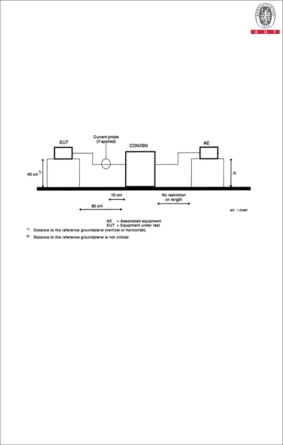
4.2.5 TEST SETUP
NOTE:
1. The methods of conformance testing were selected according to the EN 55022, section: 9.6.1 of
measurement method using an ISN with a longitudinal conversion loss (LCL) as defined in rule.
2. When measurements were performed on a single unscreened balanced pair, an adequate ISN for
two wires were used; when performed on unscreened cables containing two balanced pairs, an
adequate ISN for four wires were used; when performed on unscreened cables containing four
balanced pairs, an adequate ISN for eight wires were used.
3. 3. The communication function of EUT was executed and ISN was connected between EUT and
associated equipment and the ISN was connected directly to reference ground plane.
4.2.6 EUT OPERATING CONDITIONS
Same as 4.1.6
Report No.: CE980825H03 25 Report Format Version 3.0.1
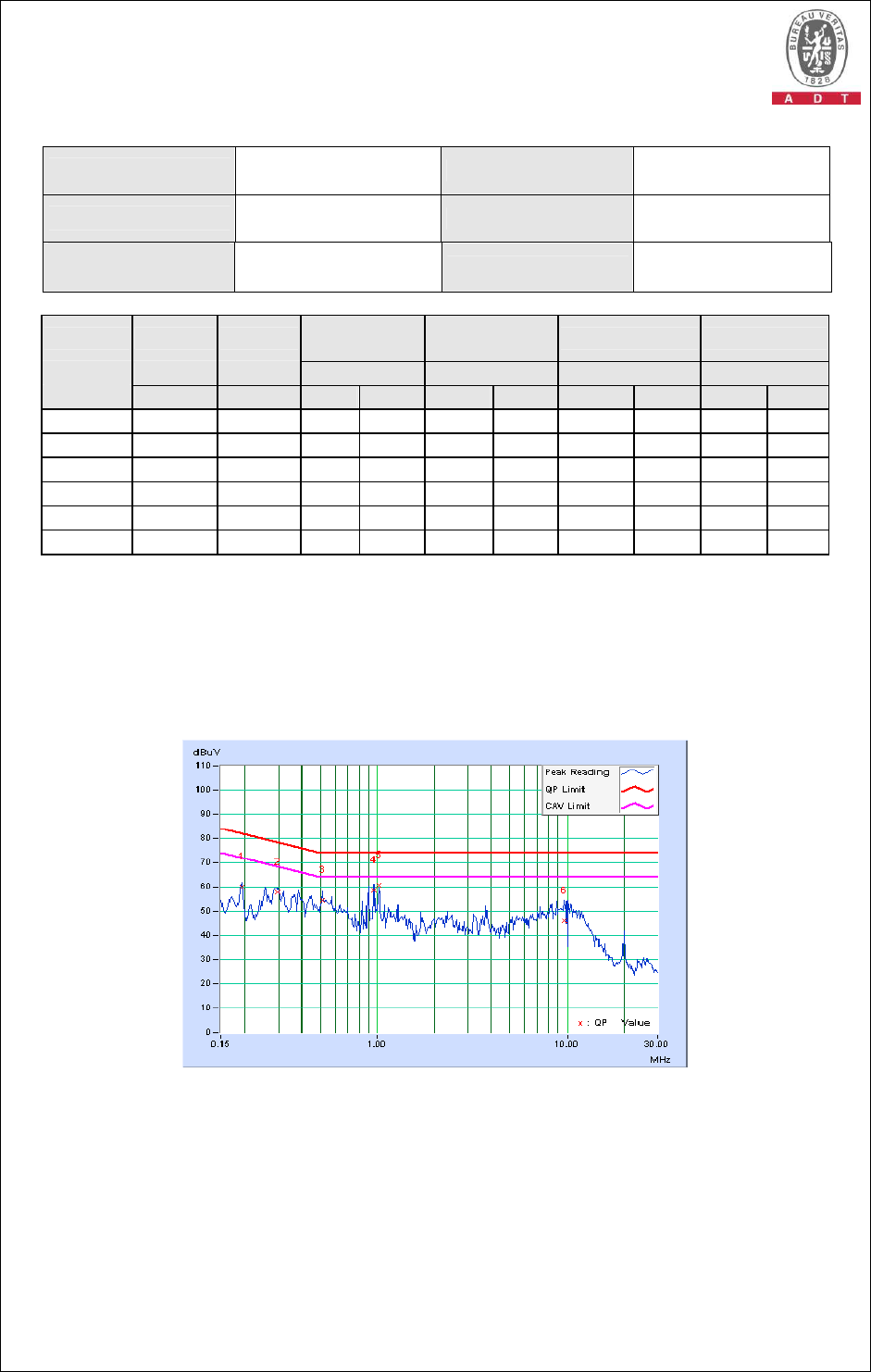
4.2.7 TEST RESULTS
TEST MODE Mode 1 INPUT POWER 230Vac, 50 Hz
TELECOM PORT LAN Port , 10Mbps 6dB BANDWIDTH 9 kHz
ENVIRONMENTAL
CONDITIONS
27deg. C, 61%RH,
965hPa TESTED BY Andy Ho
Freq. Corr. Reading
Value Emission
Level Limit Margin
No Factor
[dB (uV)] [dB (uV)] [dB (uV)] (dB)
[MHz] (dB) Q.P.
AV. Q.P. AV. Q.P. A.V.
Q.P.
A.V.
1 0.193 9.98 50.06
- 60.04
- 81.91
71.91
-21.87
-
2 0.298 9.96 47.70
- 57.66
- 78.29
68.29
-20.63
-
3 0.513 9.92 44.63
- 54.55
- 74.00
64.00
-19.45
-
4 0.959 9.88 48.60
- 58.48
- 74.00
64.00
-15.52
-
5 1.023 9.88 50.99
- 60.87
- 74.00
64.00
-13.13
-
6 9.672 9.96 35.87
- 45.83
- 74.00
64.00
-28.17
-
REMARKS: 1. Q.P. and AV. are abbreviations of quasi-peak and average individually.
2. "-": The Quasi-peak reading value also meets average limit and
measurement with the average detector is unnecessary.
3. The emission levels of other frequencies were very low against the limit.
4. Margin value = Emission level - Limit value
5. Correction factor = Insertion loss + Cable loss
6. Emission Level = Correction Factor + Reading Value.
Report No.: CE980825H03 26 Report Format Version 3.0.1
4.3 RADIATED EMISSION MEASUREMENT
4.3.1 LIMITS OF RADIATED EMISSION MEASUREMENT
TEST STANDARD: EN 55022
FOR FREQUENCY BELOW 1000 MHz
FREQUENCY Class A (at 10m) Class B (at 10m)
(MHz) dBuV/m dBuV/m
30 – 230 40 30
230 – 1000 47 37
FOR FREQUENCY ABOVE 1000 MHz
Class A (dBuV/m) (at 3m) Class B (dBuV/m) (at 3m)
FREQUENCY (GHz)
PEAK AVERAGE PEAK AVERAGE
1 to 3 76 56 70 50
3 to 6 80 60 74 54
NOTE: (1) The lower limit shall apply at the transition frequencies.
(2) Emission level (dBuV/m) = 20 log Emission level (uV/m).
(3) All emanation from a class A/B digital device or system, including
any network of conductors and apparatus connected thereto, shall not
exceed the level of field strengths specified above.
FREQUENCY RANGE OF RADIATED MEASUREMENT
(For unintentional radiators)
Highest frequency generated or
Upper frequency of measurement
used in the device or on which the
device operates or tunes (MHz)
Range (MHz)
Below 108 1000
108 – 500 2000
500 – 1000 5000
Above 1000
Up to 5 times of the highest
frequency or 6 GHz, whichever is
less
Report No.: CE980825H03 27 Report Format Version 3.0.1
4.3.2 TEST INSTRUMENTS
DESCRIPTION &
MANUFACTURER MODEL NO. SERIAL NO. CALIBRATED
DATE
CALIBRATED
UNTIL
ADVANTEST Spectrum
Analyzer U3751 170100022 Nov. 17, 2008 Nov. 16, 2009
ADVANTEST Spectrum
Analyzer U3772 160100280 July 25, 2009 July 24, 2010
HP Pre_Amplifier 8449B 3008A01922 Sep. 25, 2008 Sep. 24, 2009
ROHDE & SCHWARZ
Test Receiver ESVS 30 841977/002 Nov. 03, 2008 Nov. 02, 2009
SCHAFFNER(CHASE)
Broadband Antenna CBL6112B 2798 April 29, 2009 April 28, 2010
Schwarzbeck
Horn_Antenna BBHA9120-D1
D123 Sep. 30, 2008 Sep. 29, 2009
Schwarzbeck
Horn_Antenna BBHA 9170 BBHA9170153
Jan. 23, 2009 Jan. 22, 2010
RF Switches MP59B 6100175593 Sep. 02, 2008 Sep. 01, 2009
RF Cable 8DFB STBCAB-30M-
1GHz Sep. 02, 2008 Sep. 01, 2009
Software ADT_Radiated_
V7.6.15.9.2 NA NA NA
CT Antenna Tower &
Turn Table NA NA NA NA
CORCOM AC Filter MRI2030 024/019 NA NA
Note: 1. The calibration interval of the above test instruments is 12 months and the calibrations are
traceable to NML/ROC and NIST/USA.
2. The horn antenna, HP preamplifier (model: 8449B) and Spectrum Analyzer (model: U3772)
are used only for the measurement of emission frequency above 1GHz if tested.
3. The test was performed in Open Site No. B.
4. The VCCI Site Registration No. is R-847.
5. The FCC Site Registration No. is 92753.
6. The CANADA Site Registration No. is IC 7450G-2.

Report No.: CE980825H03 28 Report Format Version 3.0.1
4.3.3 TEST PROCEDURE
a. The EUT was placed on the top of a rotating table at a 10 meters open field
site. The table was rotated 360 degrees to determine the position of the
highest radiation.
b. The EUT was set 10 meters away from the interference-receiving antenna,
which was mounted on the top of a variable-height antenna tower.
c. The antenna is a broadband antenna, and its height is varied from one meter
to four meters above the ground to determine the maximum value of the field
strength. Both horizontal and vertical polarizations of the antenna are set to
make the measurement.
d. For each suspected emission, the EUT was arranged to its worst case and
then the antenna was tuned to heights from 1 meter to 4 meters and the
rotatable table was turned from 0 degrees to 360 degrees to find the maximum
reading.
e. The test-receiver system was set to quasi-peak detect function and specified
bandwidth with maximum hold mode when the test frequency is below 1 GHz.
NOTE: 1. The resolution bandwidth and video bandwidth of test receiver/spectrum analyzer is 120 kHz
for quasi-peak detection (QP) at frequency 30MHz to 1GHz.
4.3.4 DEVIATION FROM TEST STANDARD
No deviation
Report No.: CE980825H03 29 Report Format Version 3.0.1
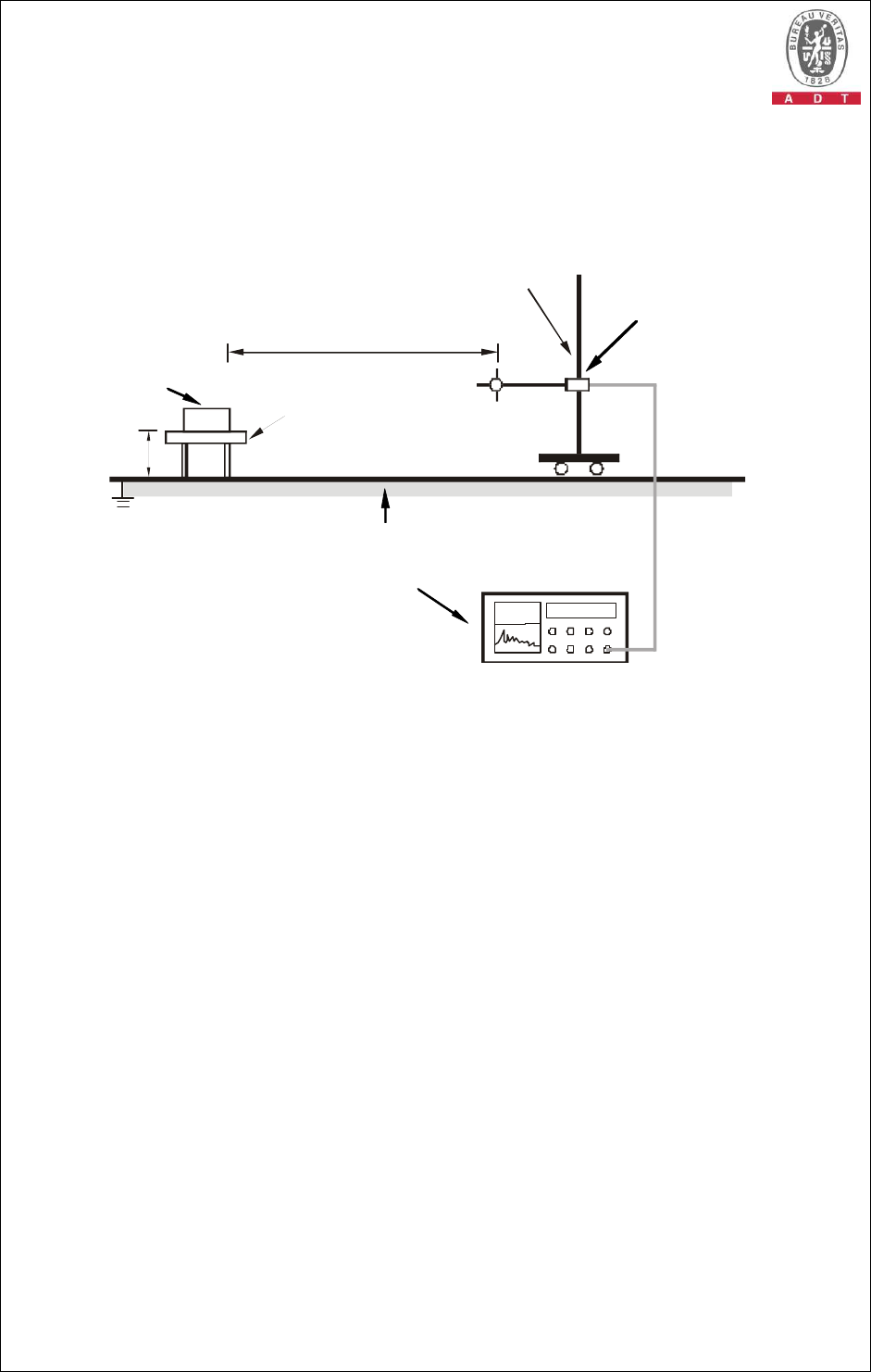
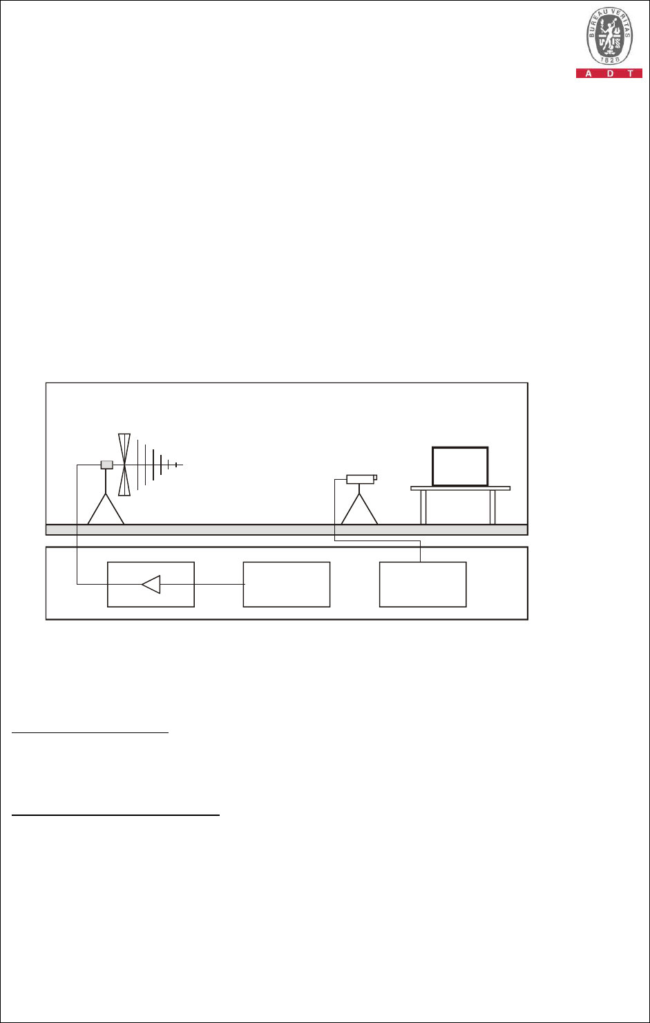
4.3.5 TEST SETUP
10m
Ant. Tower
1
-
4m
Variable
Turn Table
EUT&
Support Units
Ground Plane
Test Receiver
80cm
3m-above 1GHz
For the actual test configuration, please refer to the related item – Photographs of the
Test Configuration.
4.3.6 EUT OPERATING CONDITIONS
1. Turn on the power of all equipment.
2. Support unit 1 (Notebook Computer) run “Tfgen .exe” and “Ping.exe” program
to enable all functions of EUT via Support unit 2 (Notebook Computer).
Report No.: CE980825H03 30 Report Format Version 3.0.1
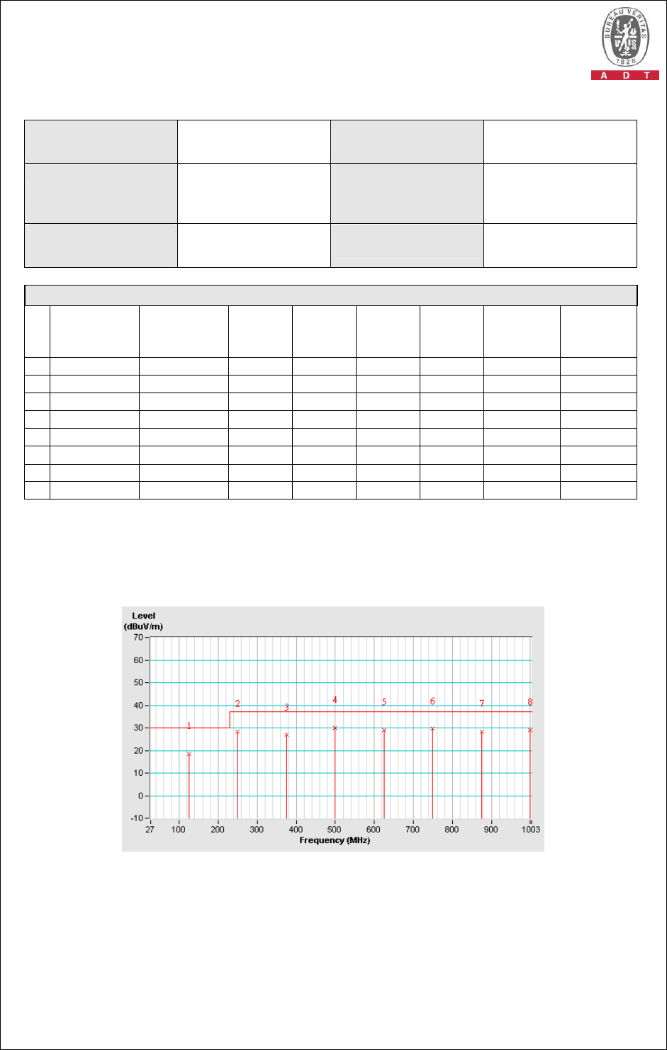
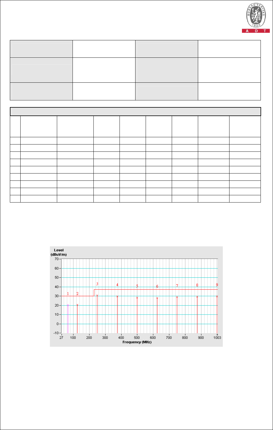
4.3.7 TEST RESULTS
TEST MODE Mode 1 INPUT POWER 230Vac, 50Hz
FREQUENCY RANGE
30-1000 MHz
DETECTOR
FUNCTION &
BANDWIDTH
Quasi-Peak,
120kHz
ENVIRONMENTAL
CONDITIONS
25 deg. C, 60 % RH,
965 hPa TESTED BY Max Tseng
ANTENNA POLARITY & TEST DISTANCE: HORIZONTAL AT 10 M
No.
Freq.
(MHz)
Emission
Level
(dBuV/m)
Limit
(dBuV/m)
Margin
(dB)
Antenna
Height
(m)
Table
Angle
(Degree)
Raw
Value
(dBuV)
Correction
Factor
(dB/m)
1
125.00 18.62 QP 30.00 -11.37 4.00 H 36 5.53 13.10
2
250.00 28.33 QP 37.00 -8.67 4.00 H 250 13.41 14.92
3
375.00 26.83 QP 37.00 -10.17 2.40 H 278 8.17 18.66
4
500.00 30.03 QP 37.00 -6.97 1.69 H 95 7.79 22.24
5
625.00 28.97 QP 37.00 -8.03 1.50 H 177 5.08 23.89
6
750.08 29.56 QP 37.00 -7.44 1.00 H 323 4.25 25.31
7
875.00 28.46 QP 37.00 -8.54 1.00 H 254 1.37 27.09
8
1000.00 29.15 QP 37.00 -7.85 1.00 H 19 0.81 28.34
REMARKS: 1. Emission level(dBuV/m)=Raw Value(dBuV) + Correction Factor(dB/m)
2. Correction Factor(dB/m) = Antenna Factor (dB/m) + Cable Factor (dB)
3. The other emission levels were very low against the limit.
4. Margin value = Emission level – Limit value.
Report No.: CE980825H03 31 Report Format Version 3.0.1
TEST MODE Mode 1 INPUT POWER 230Vac, 50Hz
FREQUENCY RANGE
30-1000 MHz
DETECTOR
FUNCTION &
BANDWIDTH
Quasi-Peak,
120kHz
ENVIRONMENTAL
CONDITIONS 25 deg. C, 60 % RH,
965 hPa TESTED BY Max Tseng
ANTENNA POLARITY & TEST DISTANCE: VERTICAL AT 10 M
No.
Freq.
(MHz)
Emission
Level
(dBuV/m)
Limit
(dBuV/m)
Margin
(dB)
Antenna
Height
(m)
Table
Angle
(Degree)
Raw
Value
(dBuV)
Correction
Factor
(dB/m)
1
66.58 20.28 QP 30.00 -9.72 1.00 V 206 12.96 7.32
2
125.00 20.39 QP 30.00 -9.61 1.00 V 201 7.29 13.10
3
250.00 30.79 QP 37.00 -6.21 1.00 V 295 15.87 14.92
4
375.00 29.75 QP 37.00 -7.25 1.00 V 262 11.09 18.66
5
500.05 28.40 QP 37.00 -8.60 1.00 V 125 6.16 22.24
6
625.00 28.08 QP 37.00 -8.92 2.58 V 202 4.19 23.89
7
750.00 28.83 QP 37.00 -8.17 2.32 V 321 3.52 25.31
8
875.00 29.39 QP 37.00 -7.61 1.91 V 185 2.31 27.09
9
1000.00 29.58 QP 37.00 -7.42 1.58 V 77 1.24 28.34
REMARKS: 1. Emission level(dBuV/m)=Raw Value(dBuV) + Correction Factor(dB/m)
2. Correction Factor(dB/m) = Antenna Factor (dB/m) + Cable Factor (dB)
3. The other emission levels were very low against the limit.
4. Margin value = Emission level – Limit value.
Report No.: CE980825H03 32 Report Format Version 3.0.1
4.4 HARMONICS CURRENT MEASUREMENT
4.4.1 LIMITS OF HARMONICS CURRENT MEASUREMENT
TEST STANDARD: EN 61000-3-2
Limits for Class A equipment
Limits for Class D equipment
Harmonics
Order
n
Max. permissible
harmonics current
A
Harmonics
Order
n
Max. permissible
harmonics current per
watt mA/W
Max. permissible
harmonics current
A
Odd harmonics Odd Harmonics only
3 2.30 3 3.4 2.30
5 1.14 5 1.9 1.14
7 0.77 7 1.0 0.77
9 0.40 9 0.5 0.40
11 0.33 11 0.35 0.33
13 0.21 13 0.30 0.21
15<=n<=39
0.15x15/n 15<=n<=39 3.85/n 0.15x15/n
Even harmonics
2 1.08
4 0.43
6 0.30
8<=n<=40
0.23x8/n
NOTE: 1. The classifications of equipment are defined in Section 5 of EN 61000-3-2.
2. The above limits for all equipment except for lighting equipment are for all applications
having an active input power > 75 W. No limits apply for equipment with an active input
power up to and including 75 W.
4.4.2 TEST INSTRUMENTS
DESCRIPTION &
MANUFACTURER MODEL NO. SERIAL
NO.
CALIBRATED
DATE
CALIBRATED
UNTIL
EMC PARTNER
EMC Emission Tester HAR1000-1P 086 June 03, 2009 June 02, 2010
EMC Partner(Software) HARCS_V4.16
NA NA NA
NOTE: 1. The calibration interval of the above test instruments is 12 months and the calibrations are
traceable to NML/ROC and NIST/USA.
2. The test was performed in EMS room.
Report No.: CE980825H03 33 Report Format Version 3.0.1
4.4.3 TEST PROCEDURE
a. The EUT was placed on the top of a wooden table 0.8 meters above the ground
and operated to produce the maximum harmonic components under normal
operating conditions for each successive harmonic component in turn.
b. The classification of EUT is according to section 5 of EN 61000-3-2.
The EUT is classified as follows:
Class A: Balanced three-phase equipment, Household appliances excluding equipment as
Class D, Tools excluding portable tools, Dimmers for incandescent lamps, audio
equipment, equipment not specified in one of the three other classes.
Class B: Portable tools.; Arc welding equipment which is not professional equipment
Class C: Lighting equipment.
Class D: Equipment having a specified power less than or equal to 600 W of the following
types: Personal computers and personal computer monitors and television
receivers.
c. The correspondent test program of test instrument to measure the current
harmonics emanated from EUT is chosen. The measure time shall be not less
than the time necessary for the EUT to be exercised.
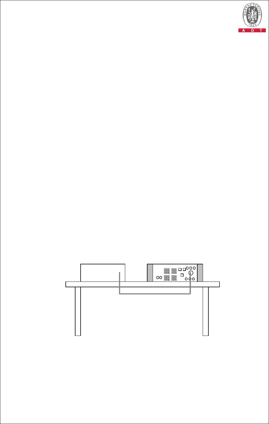
4.4.4 TEST SETUP
EUT
For the actual test configuration, please refer to the related item – Photographs of the
Test Configuration.

Report No.: CE980825H03 34 Report Format Version 3.0.1
4.4.5 EUT OPERATING CONDITIONS
1. Turn on the power of all equipment.
2. Support unit 1 (Notebook Computer) run “Ping .exe” program to enable all
functions of EUT via Support unit 2 (Notebook Computer).
2. EUT reads audio messages from Optical Drives and sends these messages to
speaker.
3. PC sends audio messages to speaker (support unit 6) via EUT.

Report No.: CE980825H03 35 Report Format Version 3.0.1
4.4.6 TEST RESULTS
TEST MODE Mode 1
FUNDAMENTAL
VOLTAGE/AMPERE 230.7 Vrms /
0.019 Arms
POWER
FREQUENCY 50.013 Hz
POWER
CONSUMPTION 2.043 W POWER FACTOR 0.465
ENVIRONMENTAL
CONDITIONS 25 deg. C, 65% RH,
965 hPa TESTED BY Tony Chen
1. Limits are not specified for equipment with a rated power of 75W or
less (other than lighting equipment).
2. According to EN 61000-3-2 the manufacturer shall specify the
power of the apparatus. This value shall be used for establishing limits.
The specified power shall be within +/-10% of the measured power.
Report No.: CE980825H03 36 Report Format Version 3.0.1
4.5 VOLTAGE FLUCTUATION AND FLICKER MEASUREMENT
4.5.1 LIMITS OF VOLTAGE FLUCTUATION AND FLICKER
MEASUREMENT
TEST STANDARD: EN 61000-3-3
TEST ITEM LIMIT NOTE
Pst 1.0 Pst means short-term flicker indicator.
Plt 0.65 Plt means long-term flicker indicator.
Tdt (ms) 500 Tdt means maximum time that dt
exceeds 3.3 %.
dmax (%) 4% dmax
means maximum relative voltage
change.
dc (%) 3.3% dc means relative steady-
state voltage
change
4.5.2 TEST INSTRUMENTS
DESCRIPTION &
MANUFACTURER MODEL NO. SERIAL
NO.
CALIBRATED
DATE
CALIBRATED
UNTIL
EMC PARTNER
EMC Emission Tester HAR1000-1P 086 June 03, 2009 June 02, 2010
EMC Partner(Software) HARCS_V4.16
NA NA NA
NOTE: 1. The calibration interval of the above test instruments is 12 months and the calibrations are
traceable to NML/ROC and NIST/USA.
2. The test was performed in EMS room.
Report No.: CE980825H03 37 Report Format Version 3.0.1
4.5.3 TEST PROCEDURE
a. The EUT was placed on the top of a wooden table 0.8 meters above the ground
and operated to produce the most unfavorable sequence of voltage changes
under normal operating conditions.
b. During the flick measurement, the measure time shall include that part of whole
operation cycle in which the EUT produce the most unfavorable sequence of
voltage changes. The observation period for short-term flicker indicator is 10
minutes and the observation period for long-term flicker indicator is 2 hours.
4.5.4 TEST SETUP
EUT
For the actual test configuration, please refer to the related item – Photographs of the
Test Configuration.
4.5.5 EUT OPERATING CONDITIONS
Same as 4.4.5
Report No.: CE980825H03 38 Report Format Version 3.0.1
4.5.6 TEST RESULTS
TEST MODE Mode 1
FUNDAMENTAL
VOLTAGE/AMPERE 230.7 Vrms /
0.019 Arms
POWER
FREQUENCY 50.013 Hz
OBSERVATION
PERIOD (TP) 10 min. POWER FACTOR 0.465
ENVIRONMENTAL
CONDITIONS 25 deg. C, 65 % RH,
965 hPa TESTED BY Tony Chen
TEST PARAMETER
MEASUREMENT
VALUE LIMIT REMARKS
Pst 0.072 1.00 Pass
Plt 0.072 0.65 Pass
Tdt (ms) 0.000 500 Pass
dmax (%) 0.000 4% Pass
dc (%) 0.000 3.3% Pass
NOTE: (1) P
st means short-term flicker indicator.
(2) P
lt means long-term flicker indicator.
(3) T
dt means maximum time that dt exceeds 3.3 %.
(4) d
max means maximum relative voltage change.
(5) dc means relative steady-state voltage change.

Report No.: CE980825H03 39 Report Format Version 3.0.1
5 IMMUNITY TEST
5.1 GENERAL DESCRIPTION
Product Standard:
EN 55024:1998+A1:2001+A2:2003
IEC 61000-4-2
Electrostatic Discharge - ESD:
8kV air discharge, 4kV Contact discharge,
Performance Criterion B
IEC 61000-4-3
Radio-Frequency Electromagnetic Field
Susceptibility Test - RS:
80-1000 MHz, 3V/m, 80% AM (1kHz),
Performance Criterion A
IEC 61000-4-4
Electrical Fast Transient/Burst - EFT,
Power line: 1kV, Signal line: 0.5kV,
Performance Criterion B
IEC 61000-4-5
Surge Immunity Test:
1.2/50 us Open Circuit Voltage, 8 /20 us
Short Circuit Current, Power Line - 1 kV, line
to earth - 2kV, Signal line: 1kV
Performance Criterion B
IEC 61000-4-6
Conducted Radio Frequency Disturbances
Test - CS:
0.15-80 MHz, 3V, 80% AM, 1kHz,
Performance Criterion A
IEC 61000-4-8
Power Frequency Magnetic Field Test,
50 Hz, 1A/m,
Performance Criterion A
Basic Standard,
Specification, and
Performance
Criteria:
IEC 61000-4-11
Voltage Dips:
i) >95% reduction -0.5 period,
Performance Criteria B
ii) 30% reduction - 25 period,
Performance Criterion C
Voltage Interruptions:
i) >95% reduction - 250 period,
Performance Criterion C

Report No.: CE980825H03 40 Report Format Version 3.0.1
5.2 GENERAL PERFORMANCE CRITERIA DESCRIPTION
According to Clause 7.1 of EN 55024 standard, the following describes
the general performance criteria.
CRITERION A
The equipment shall continue to operate as intended without
operator intervention. No degradation of performance or loss of
function is allowed below a performance level specified by the
manufacturer when the equipment is used as intended. The
performance level may be replaced by a permissible loss of
performance. If the minimum performance level or the
permissible performance loss is not specified by the
manufacturer, then either of these may be derived from the
product description and documentation, and by what the user
may reasonably expect from the equipment if used as intended.
CRITERION B
After the test, the equipment shall continue to operate as
intended without operator intervention. No degradation of
performance or loss of function is allowed, after the application
of the phenomenon below a performance level specified by the
manufacturer, when the equipment is used as intended. The
performance level may be replaced by a permissible loss of
performance.
During the test, degradation of performance is allowed. However,
no change of operating state if stored data is allowed to persist
after the test. If the minimum performance level (or the
permissible performance loss) is not specified by the
manufacturer, then either of these may be derived from the
product description and documentation, and by what the user
may reasonably expect from the equipment if used as intended.
CRITERION C
Loss of function is allowed, provided the function is
self-recoverable, or can be restored by the operation of the
controls by the user in accordance with the manufacturer’s
instructions.
Functions, and/or information stored in non-volatile memory, or
protected by a battery backup, shall not be lost.
5.3 EUT OPERATING CONDITION
Same as 4.4.5
Report No.: CE980825H03 41 Report Format Version 3.0.1
5.4 ELECTROSTATIC DISCHARGE IMMUNITY TEST (ESD)
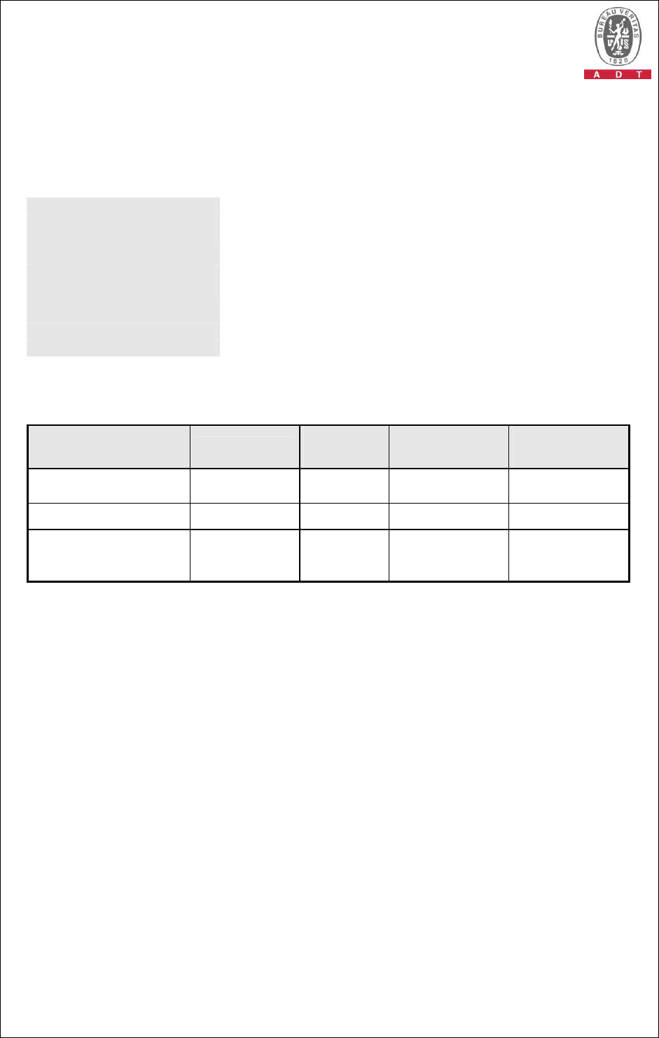
5.4.1 TEST SPECIFICATION
Basic Standard: IEC 61000-4-2
Discharge Impedance:
330 ohm / 150 pF
Discharge Voltage: Air Discharge – 2, 4, 8kV (Direct)
Contact Discharge – 2, 4kV (Direct / Indirect)
Polarity: Positive / Negative
Number of Discharge: Air Discharge: min. 20 times at each test point
Contact Discharge: min. 50 times at each test point
Discharge Mode: Single Discharge
Discharge Period: 1-second minimum
5.4.2 TEST INSTRUMENTS
DESCRIPTION &
MANUFACTURER MODEL NO. SERIAL
NO.
CALIBRATED
DATE
CALIBRATED
UNTIL
NoiseKen, ESD
Simulator ESS-100L(A) 0189C01491
July 17, 2009 July 16, 2010
Key Tek, ESD Simulator
MZ-15/EC 9906323 June 09, 2009 June 08, 2010
NoiseKen, ESD
Simulator ESS-2002 ESS062521
2/244
May 11, 2009 May 10, 2010
NOTE: 1. The calibration interval of the above test instruments is 12 months and the calibrations are
traceable to NML/ROC and NIST/USA.
2. The test was performed in ESD room A.

Report No.: CE980825H03 42 Report Format Version 3.0.1
5.4.3 TEST PROCEDURE
The discharges shall be applied in two ways:
a. Contact discharges to the conductive surfaces and coupling planes:
The EUT shall be exposed to at least 200 discharges, 100 each at negative
and positive polarity, at a minimum of four test points. One of the test points
shall be subjected to at least 50 indirect discharges to the center of the front
edge of the horizontal coupling plane. The remaining three test points shall
each receive at least 50 direct contact discharges. If no direct contact test
points are available, then at least 200 indirect discharges shall be applied in
the indirect mode. Test shall be performed at a maximum repetition rate of one
discharge per second.
b. Air discharges at slots and apertures and insulating surfaces:
On those parts of the EUT where it is not possible to perform contact discharge
testing, the equipment should be investigated to identify user accessible points
where breakdown may occur. Such points are tested using the air discharge
method. This investigation should be restricted to those area normally handled
by the user. A minimum of 10 single air discharges shall be applied to the
selected test point for each such area.
The basic test procedure was in accordance with IEC 61000-4-2:
a. Electrostatic discharges were applied only to those points and surfaces of the
EUT that are accessible to users during normal operation.
b. The test was performed with at least ten single discharges on the pre-selected
points in the most sensitive polarity.
c. The time interval between two successive single discharges was at least 1
second.
d. The ESD generator was held perpendicularly to the surface to which the
discharge was applied and the return cable was at least 0.2 meters from the
EUT.
e. Contact discharges were applied to the non-insulating coating, with the pointed
tip of the generator penetrating the coating and contacting the conducting
substrate.
f. Air discharges were applied with the round discharge tip of the discharge
electrode approaching the EUT as fast as possible (without causing
mechanical damage) to touch the EUT. After each discharge, the ESD
generator was removed from the EUT and re-triggered for a new single
discharge. The test was repeated until all discharges were complete.
g. At least ten single discharges (in the most sensitive polarity) were applied to
the Horizontal Coupling Plane at points on each side of the EUT. The ESD
generator was positioned at a distance of 0.1 meters from the EUT with the
discharge electrode touching the HCP.
h. At least ten single discharges (in the most sensitive polarity) were applied to
the center of one vertical edge of the Vertical Coupling Plane in sufficiently
different positions that the four faces of the EUT were completely illuminated.
The VCP (dimensions 0.5m x 0.5m) was placed vertically to and 0.1 meters
from the EUT.
Report No.: CE980825H03 43 Report Format Version 3.0.1
5.4.4 DEVIATION FROM TEST STANDARD
No deviation
As per client requests, the following discharge level was applied:
Contact Discharge – 6, 8kV for direct/indirect contact discharge.
Air Discharge – 15kV for direct air discharge.
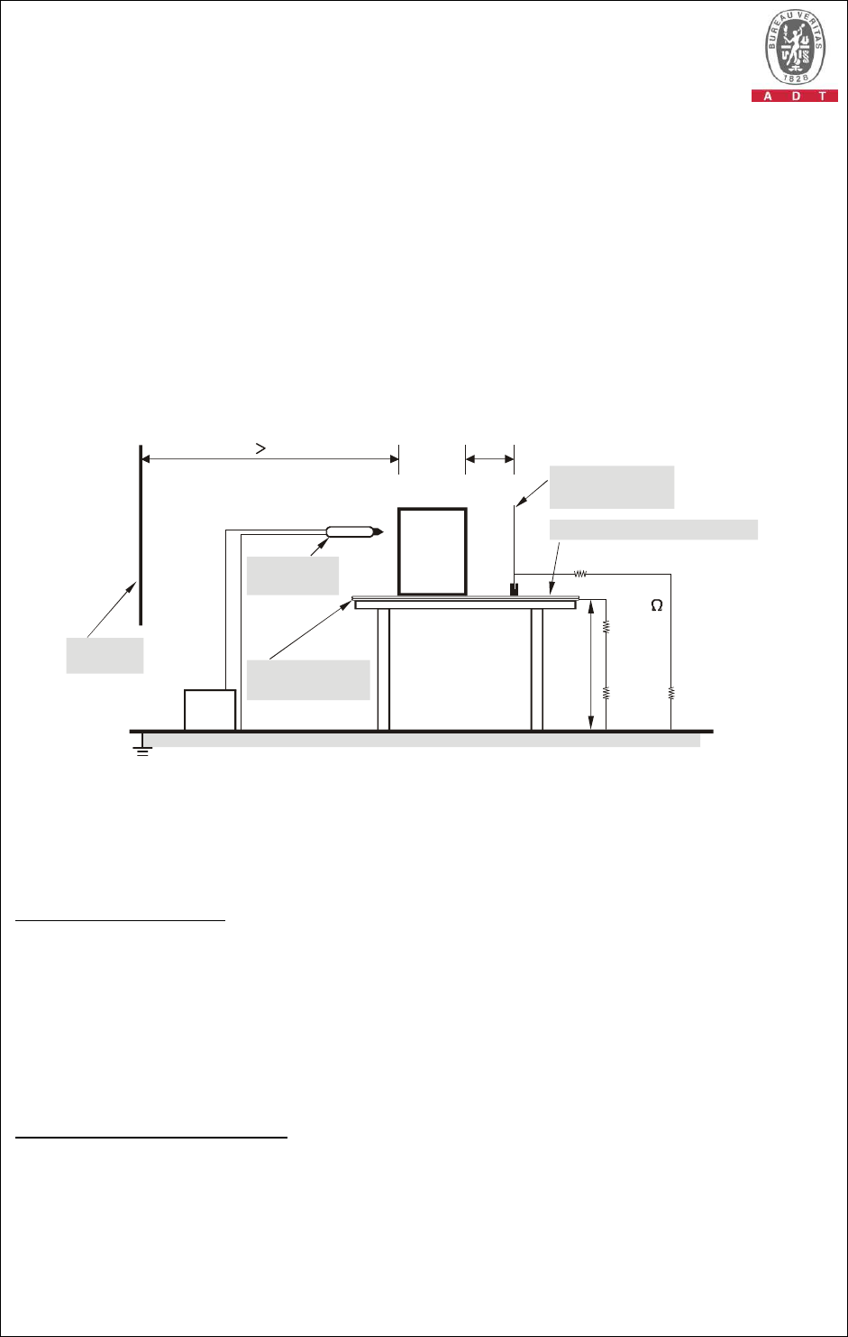
5.4.5 TEST SETUP
PS
EUT
Vertical
coupling plane
0.5mm Isolation Support
ESD
Generator
Nearest
Wall Horizontal
coupling plane
Reference Ground Plane
0.1m
1m
470k
X4
80cm
For the actual test configuration, please refer to the related item – Photographs of the
Test Configuration.
NOTE:
TABLE-TOP EQUIPMENT
The configuration consisted of a wooden table 0.8 meters high standing on the Ground Reference
Plane. The GRP consisted of a sheet of aluminum at least 0.25mm thick, and 2.5 meters square
connected to the protective grounding system. A Horizontal Coupling Plane (1.6m x 0.8m) was placed
on the table and attached to the GRP by means of a cable with 940kΩ total impedance. The
equipment under test, was installed in a representative system as described in section 7 of IEC
61000-4-2, and its cables were placed on the HCP and isolated by an insulating support of 0.5mm
thickness. A distance of 1-meter minimum was provided between the EUT and the walls of the
laboratory and any other metallic structure.
FLOOR-STANDING EQUIPMENT
The equipment under test was installed in a representative system as described in section 7 of IEC
61000-4-2, and its cables were isolated from the Ground Reference Plane by an insulating support of
0.1-meter thickness. The GRP consisted of a sheet of aluminum that is at least 0.25mm thick, and 2.5
meters square connected to the protective grounding system and extended at least 0.5 meters from
the EUT on all sides.
Report No.: CE980825H03 44 Report Format Version 3.0.1
5.4.6 TEST RESULTS
TEST MODE Mode 1 INPUT POWER 230Vac, 50 Hz
ENVIRONMENTAL
CONDITIONS 24 deg. C, 40 % RH,
965 hPa TESTED BY Jason Huang
TEST RESULTS OF DIRECT APPLICATION
Discharge
Level (kV)
Polarity
(+/-) Test Point Contact
Discharge
Air Discharge
Performance
Criterion
2, 4 +/- 1 Note (1) NA A
2, 4, 8 +/- 2 ~ 6 NA Note (1) A
Note: No conductive surfaces found, therefore no contact discharge was executed.
Description of test point: Please refer to following page for representative mark only.
TEST RESULTS OF INDIRECT APPLICATION
Discharge
Level (kV)
Polarity
(+/-) Test Point
Horizontal
Coupling
Plane
Vertical
Coupling
Plane
Performance
Criterion
2, 4 +/- 1 ~ 4 Note (1) Note (1) A
Description of test point:
1. Front side 2. Right side 3. Left side 4. Rear side
NOTE: (1) There was no change compared with initial operation during the test.
(2) The shaking and dot flash on the screen during the test, but could be
self-recoverable after the test.
The air discharge level which over 8kV and contact
discharge which over 4kV is not required by EN 55024 for
IT equipment. It is according to the requirement of the
manufacturer; the data of test result is only for
manufacture’s reference.
The air discharge level which over 8 kV is not required by EN
55024 for IT equipment. It is according to the requirement of
the manufacturer; the data of test result is only for
manufacture’s reference.
Report No.: CE980825H03 45 Report Format Version 3.0.1
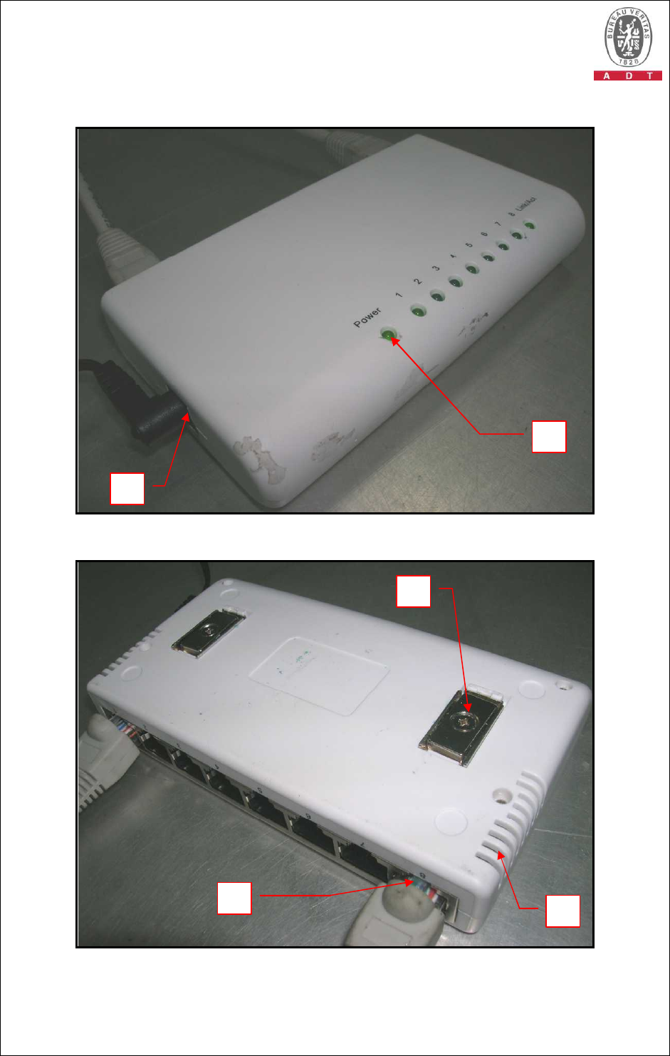
DESCRIPTION OF TEST POINT
1
2
5 4
3
Report No.: CE980825H03 46 Report Format Version 3.0.1
6
Report No.: CE980825H03 47 Report Format Version 3.0.1
5.5 RADIATED, RADIO-FREQUENCY, ELECTROMAGNETIC FIELD
IMMUNITY TEST (RS)
5.5.1 TEST SPECIFICATION
Basic Standard: IEC 61000-4-3
Frequency Range:
80 MHz - 1000 MHz
Field Strength: 3 V/m, 5 V/m
Modulation: 1kHz Sine Wave, 80%, AM Modulation
Frequency Step: 1 % of fundamental
Polarity of
Antenna: Horizontal and Vertical
Antenna Height: 1.5m
Dwell Time: 3 seconds
5.5.2 TEST INSTRUMENTS
DESCRIPTION &
MANUFACTURER MODEL NO. SERIAL
NO.
CALIBRATED
DATE
CALIBRATED
UNTIL
AR Power Amplifier 150W1000M3
311567 NA NA
AR Power Amplifier 60S1G3M1 306171 NA NA
AR LOG ANTENNA AT5080ANT 309740 NA NA
BOONTON RF Voltage
Meter 4232A 93801 Dec. 26, 2008 Dec. 25, 2009
R&S Signal Generator SML03 101159 Jan. 09, 2009 Jan. 08, 2010
Electric Field Probe FP6001 308178 Oct. 26, 2008 Oct. 25, 2009
ADT RS Test
Workbench(Software) ADT_RS_V7.5
NA NA NA
NOTE: 1. The calibration interval of the above test instruments is 12 months and the calibrations are
traceable to NML/ROC and NIST/USA.
2. The test was performed in Chamber Room No. B.
3. The transmit antenna was located at a distance of 2.0m meters from the EUT.
Report No.: CE980825H03 48 Report Format Version 3.0.1
5.5.3 TEST PROCEDURE
The test procedure was in accordance with IEC 61000-4-3
a. The testing was performed in a fully-anechoic chamber.
b. The frequency range is swept from 80 MHz to 1000 MHz, with the signal 80%
amplitude modulated with a 1kHz sine wave.
c. The dwell time at each frequency shall be not less than the time necessary for
the EUT to be able to respond, but shall in no case be less than 0,5s.
d. The field strength level was 3V/m.
e. The test was performed with the EUT exposed to both vertically and horizontally
polarized fields on each of the four sides.
5.5.4 TEST SETUP
For the actual test configuration, please refer to the related item – Photographs of the
Test Configuration.
NOTE:
TABLETOP EQUIPMENT
The EUT installed in a representative system as described in section 7 of IEC 61000-4-3 was placed
on a non-conductive table 0.8 meters in height. The system under test was connected to the power
and signal wire according to relevant installation instructions.
FLOOR STANDING EQUIPMENT
The EUT installed in a representative system as described in section 7 of IEC 61000-4-3 was placed
on a non-conductive wood support 0.1 meters in height. The system under test was connected to the
power and signal wire according to relevant installation instructions.
EUT
RF Amplifier
RF Generator
and
control system
Monitoring
system

Report No.: CE980825H03 49 Report Format Version 3.0.1
5.5.5 TEST RESULTS
TEST MODE Mode 1 INPUT POWER 230Vac, 50 Hz
ENVIRONMENTAL
CONDITIONS 23 deg. C, 50 % RH,
965 hPa TESTED BY Anderson Chen
Frequency
(MHz) Result
Polarity
Azimuth
Field
Strength
(V/m)
Obser-
vation Performance
Criterion
80 -1000 PASS V&H 0 3
80 -1000 PASS V&H 90 3
80 -1000 PASS V&H 180 3
80 -1000 PASS V&H 270 3
Note A
NOTE: There was no change compared with the initial operation during the test.
Report No.: CE980825H03 50 Report Format Version 3.0.1
5.6 ELECTRICAL FAST TRANSIENT/BURST IMMUNITY TEST (EFT)
5.6.1 TEST SPECIFICATION
Basic Standard: IEC 61000-4-4
Test Voltage: Power Line - 1 kV, 2kV
Signal/Control Line – 0.5 kV
Polarity: Positive/Negative
Impulse
Frequency: 5 kHz
Impulse
Wave shape : 5/50 ns
Burst Duration: 15 ms
Burst Period: 300 ms
Test Duration: 1 min.
5.6.2 TEST INSTRUMENTS
DESCRIPTION &
MANUFACTURER MODEL NO. SERIAL NO.
CALIBRATED
DATE
CALIBRATED
UNTIL
EMC PARTNER,
TRANSIENT TRA1Z332N 683 April 21, 2009 April 20, 2010
EMC PARTNER,
CN-EFT100 CN-EFT1000
352 NA NA
Adapter (EMC Partner)
NA SU1ADA-002
NA NA
EMC Partner(Software)
Test
Manger_V1.53
NA NA NA
NOTE: 1. The calibration interval of the above test instruments is 12 months and the calibrations are
traceable to NML/ROC and NIST/USA.
2. The test was performed in EMS room B.
5.6.3 TEST PROCEDURE
a. Both positive and negative polarity discharges were applied.
b. The length of the “hot wire” from the coaxial output of the EFT generator to the
terminals on the EUT should be 0.5m±0.05m.
c. The duration time of each test sequential was 1 minute.
d. The transient/burst waveform was in accordance with IEC 61000-4-4, 5/50ns.
Report No.: CE980825H03 51 Report Format Version 3.0.1
5.6.4 DEVIATION FROM TEST STANDARD
No deviation
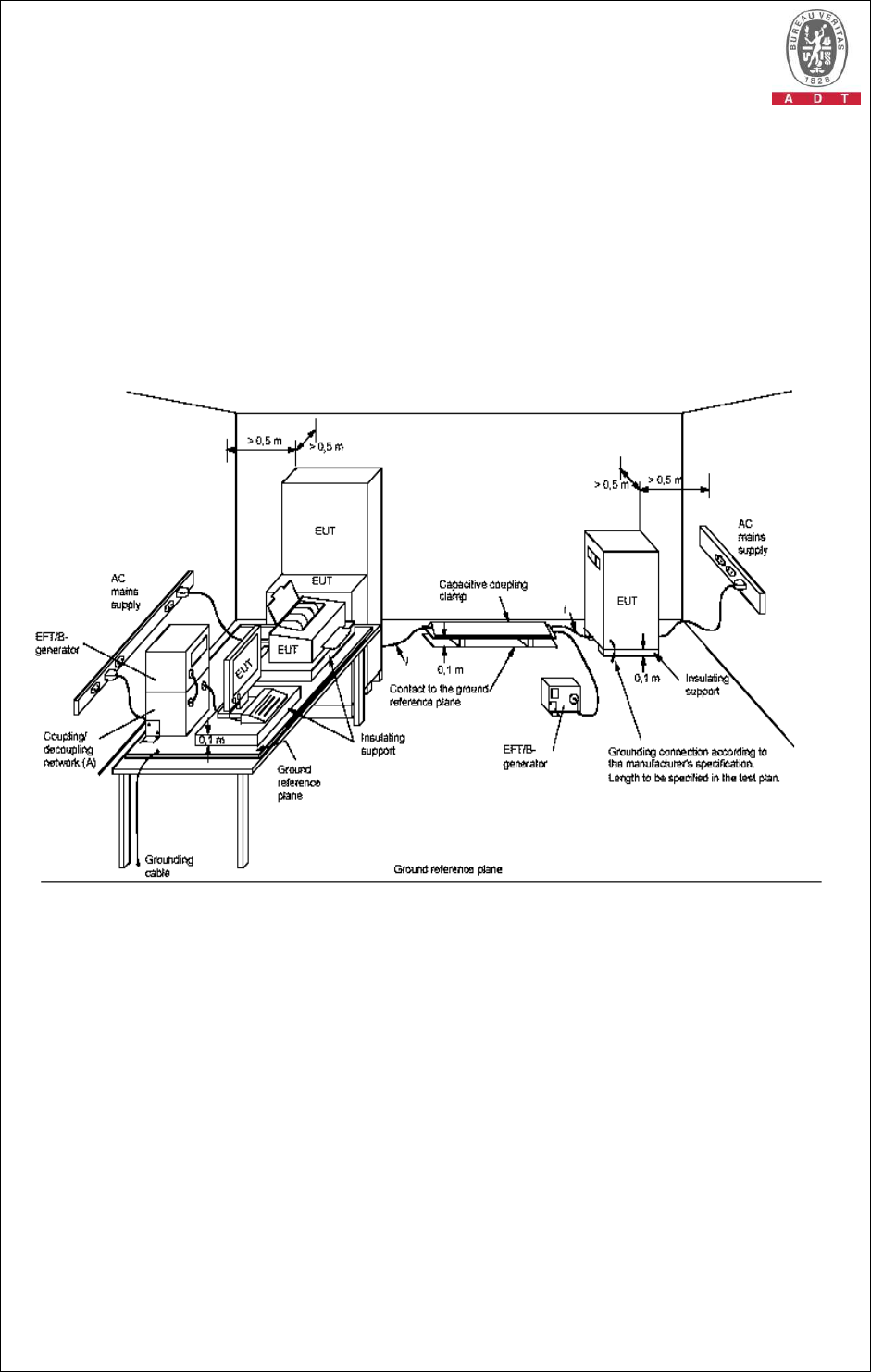
5.6.5 TEST SETUP
NOTE:
l length between clamp and the EUT to be tested (should be 0.5
±
0.05m)
(A) location for supply line coupling
(B) location for signal lines coupling
For the actual test configuration, please refer to the related item – Photographs of the
Test Configuration.
NOTE:
EUTs, whether stationary floor-mounted or table top, and equipment designed to be mounted in other
configurations, shall be placed on a ground reference plane and shall be insulated from it by an
insulating support 0,1 m ± 0,01 m thick. A minimum distance of 0.5m was provided between the EUT
and the walls of the laboratory or any other metallic structure.
Report No.: CE980825H03 52 Report Format Version 3.0.1
5.6.6 TEST RESULTS
TEST MODE Mode 1 INPUT POWER 230Vac, 50 Hz
ENVIRONMENTAL
CONDITIONS 26 deg. C, 45 % RH,
965 hPa TESTED BY Barry Lee
I. POWER PORT
VOLTAGE
(kV) TEST POINT
POLARITY
(+/-) OBSERVATION
PERFORMANCE
CRITERION
1 L1 +/- Note (1) A
1 L2 +/- Note (1) A
1 L1 - L2 +/- Note (1) A
II. SIGNAL PORTS AND CONTROL PORTS
VOLTAGE
(kV) TEST POINT
POLARITY
(+/-) OBSERVATION
PERFORMANCE
CRITERION
0.5 LAN +/- Note (1) A
NOTE:(1) There was no change compared with the initial operation during the test.
(2) The EUT request time out during the test, but could be
self-recoverable after the test.
Report No.: CE980825H03 53 Report Format Version 3.0.1
5.7 SURGE IMMUNITY TEST
5.7.1 TEST SPECIFICATION
Basic Standard: IEC 61000-4-5
Wave-Shape: Combination Wave
1.2/50 us Open Circuit Voltage
8 /20 us Short Circuit Current
Test Voltage: Power Line –0.5 kV / 1 kV / 2 kV / 2.5Kv
Signal Line –0.5 kV / 1 kV / 2
Surge Input/Output: L1-L2 / L1-G / L2-G / L1, L2-G
Generator Source
Impedance: 2 ohm between networks
12 ohm between network and ground
Polarity: Positive/Negative
Phase Angle (degree):
0 / 90 / 180 / 270
Pulse Repetition Rate:
1 time / 20 sec.
Number of Tests: 5 positive and 5 negative at selected points
5.7.2 TEST INSTRUMENTS
DESCRIPTION &
MANUFACTURER MODEL NO. SERIAL NO.
CALIBRATED
DATE
CALIBRATED
UNTIL
EMC PARTNER,
TRANSIENT TRA1Z332N 683 April 21, 2009 April 20, 2010
EMC PARTNER,
CDN-UTP8 CDN-UTP8 012 April 22, 2009 April 21, 2010
Adapter (EMC
PARTNER) NA SU1ADA-002
NA NA
EMC Partner(Software) Test
Manger_V1.53 NA NA NA
KeyTek, EMS Simulator
EMC Pro 9712339 Mar. 24, 2009 Mar. 23, 2010
Adapter (EMC Pro) NA SU1ADA-001
NA NA
KeyTek(Software) CEWare32_V3.0
NA NA NA
NOTE: 1. The calibration interval of the above test instruments is 12 months and the calibrations are
traceable to NML/ROC and NIST/USA.
2. The test was performed in EMS room B.

Report No.: CE980825H03 54 Report Format Version 3.0.1
5.7.3 TEST PROCEDURE
a. For EUT power supply:
The surge is to be applied to the EUT power supply terminals via the capacitive
coupling network. Decoupling networks are required in order to avoid possible
adverse effects on equipment not under test that may be powered by the same
lines, and to provide sufficient decoupling impedance to the surge wave. The
power cord between the EUT and the coupling/decoupling networks shall be 2
meters in length (or shorter).
b. For test applied to unshielded unsymmetrically operated interconnection lines of
EUT:
The surge is applied to the lines via the capacitive coupling. The coupling /
decoupling networks shall not influence the specified functional conditions of the
EUT. The interconnection line between the EUT and the coupling/decoupling
networks shall be 2 meters in length (or shorter).
c. For test applied to unshielded symmetrically operated interconnection /
telecommunication lines of EUT:
The surge is applied to the lines via gas arrestors coupling. Test levels below the
ignition point of the coupling arrestor cannot be specified. The interconnection
line between the EUT and the coupling/decoupling networks shall be 2 meters in
length (or shorter).
5.7.4 DEVIATION FROM TEST STANDARD
No deviation
5.7.5 TEST SETUP
EUT
Combination
Wave Generator
Coupling &
DecouplingNetwork
AC Power Line
L 2m
For the actual test configuration, please refer to the related item – Photographs of the
Test Configuration.

Report No.: CE980825H03 55 Report Format Version 3.0.1
5.7.6 TEST RESULTS
TEST MODE Mode 1 INPUT POWER 230Vac, 50 Hz
ENVIRONMENTAL
CONDITIONS 26 deg. C, 45 % RH,
965 hPa TESTED BY Barry Lee
I. POWER PORT
VOLTAGE
(kV) TEST
POINT POLARITY
(+/-) OBSERVATION
PERFORMANCE
CRITERION
0.5, 1 L1-L2 +/- NOTE (1) A
NOTE: (1) There was no change compared with the initial operation during the
test.
(2) The EUT sound function held during the test, but could be
self-recoverable after the test.
NOTE: (1) There is shaking and dot flashing disturbance on screen, but could
be self-recoverable after the test.
(2) The EUT power was shut down during the test but could
self-recoverable after the test.
Report No.: CE980825H03 56 Report Format Version 3.0.1
5.8 IMMUNITY TO CONDUCTED DISTURBANCES INDUCED BY RF
FIELDS (CS)
5.8.1 TEST SPECIFICATION
Basic Standard: IEC 61000-4-6
Frequency Range:
0.15 MHz - 80 MHz
Voltage Level: 3 V
Modulation: 1kHz Sine Wave, 80%, AM Modulation
Frequency Step: 1 % of fundamental
Coupled Cable: Power Mains, Unshielded
Signal / Control Line
Coupling Device: CDN-M2(2 wires), CDN-T4, clamp
Dwell Time 3 seconds
5.8.2 TEST INSTRUMENTS
DESCRIPTION &
MANUFACTURER MODEL NO. SERIAL
NO.
CALIBRATED
DATE
CALIBRATE
D UNTIL
R&S Signal Generator SML 01 102731 Dec. 23, 2008
Dec. 22, 2009
AR Amplifier 75A250AM2 307297 NA NA
BOONTON RF Voltage Meter
4232A 93801 Dec. 26, 2008
Dec. 25, 2009
LUTHIE EM Injection Clamp EM-101 35453 May 07, 2009
May 06, 2010
FCC CDN M2 FCC-801-M2-16A
03048 Jan. 12, 2009
Jan. 11, 2010
FCC CDN M3 FCC-801-M3-16A
03055 Jan. 12, 2009
Jan. 11, 2010
Fischer Custom
Communications Inc
Coupling Decoupling Network
FCC-801-T2 02025 Oct. 28, 2008 Oct. 27, 2009
Fischer Custom
Communications Inc
Coupling Decoupling Network
FCC-801-T4 02030 Oct. 28, 2008 Oct. 27, 2009
Fischer Custom
Communications Inc
Coupling Decoupling Network
FCC-801-T8 02036 Oct. 28, 2008 Oct. 27, 2009
ADT CS Test
Workbench(Software)
ADT_CS_V7.4.2
NA NA NA
NOTE: 1. The calibration interval of the above test instruments is 12 months and the calibrations are
traceable to NML/ROC and NIST/USA.
2. The test was performed in Chamber Room No. B.

Report No.: CE980825H03 57 Report Format Version 3.0.1
5.8.3 TEST PROCEDURE
a. The EUT shall be tested within its intended operating and climatic conditions.
b. The test shall be performed with the test generator connected to each of the
coupling and decoupling devices in turn, while the other non-excited RF input
ports of the coupling devices are terminated by a 50-ohm load resistor.
c. The frequency range is swept from 150 kHz to 80 MHz, using the signal level
established during the setting process and with a disturbance signal of 80 %
amplitude. The signal is modulated with a 1 kHz sine wave, pausing to adjust the
RF signal level or the switch coupling devices as necessary. Where the
frequency is swept incrementally, the step size shall not exceed 1 % of the
preceding frequency value.
d. The dwell time at each frequency shall not be less than the time necessary for
the EUT to be exercised, and able to respond. Sensitive frequencies such as
clock frequency(ies) and harmonics or frequencies of dominant interest, shall be
analyzed separately.
e. Attempts should be made to fully exercise the EUT during testing, and to fully
interrogate all exercise modes selected for susceptibility.
Report No.: CE980825H03 58 Report Format Version 3.0.1
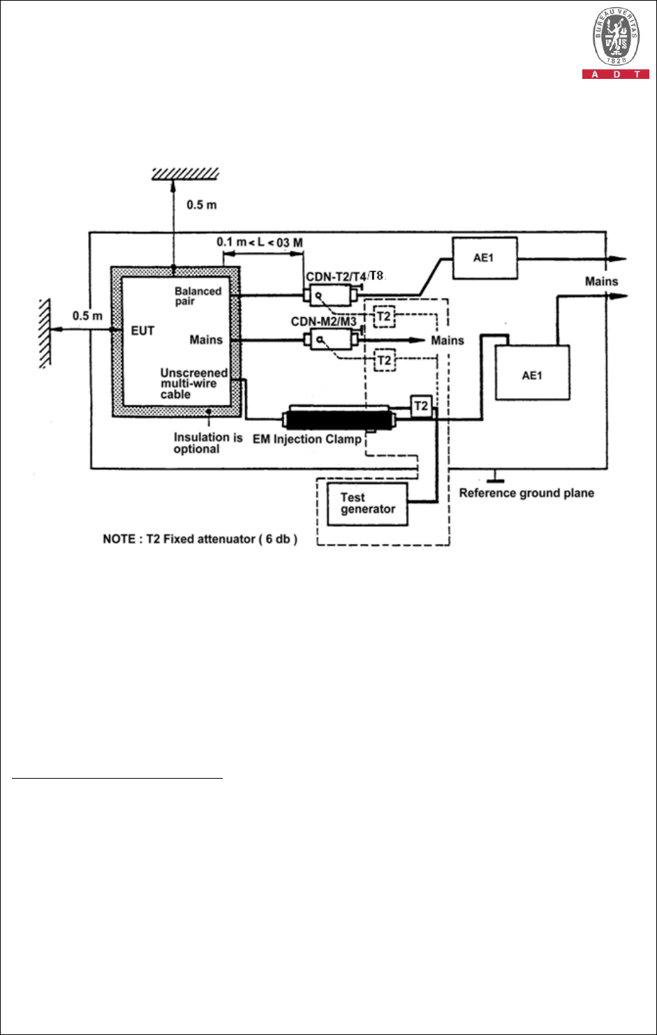
5.8.4 TEST SETUP
NOTE: 1. The EUT clearance from any metallic obstacles shall be at least 0.5m.
2. All non-excited input ports of the CDNs shall be terminated by 50Ω loads.
3. The EUT is setup 0.1m above Reference Ground Plane
4. The CDNs and / or EM clamp used for real test depends on ports and cables
configuration of EUT.
For the actual test configuration, please refer to the related item – Photographs of the
Test Configuration.
NOTE:
FLOOR-STANDING EQUIPMENT
The equipment to be tested is placed on an insulating support of 0.1 meters height above a ground
reference plane. All relevant cables shall be provided with the appropriate coupling and decoupling
devices at a distance between 0.1 meters and 0.3 meters from the projected geometry of the EUT on
the ground reference plane.

Report No.: CE980825H03 59 Report Format Version 3.0.1
5.8.5 TEST RESULTS
TEST MODE Mode 1 INPUT POWER 230Vac, 50 Hz
ENVIRONMENTAL
CONDITIONS 23 deg. C, 50 % RH,
965 hPa TESTED BY Anderson Chen
FOR MAINS POWER:
Frequency
(MHz)
Voltage
Level
(Vr.m.s.) Cable Injection
Method Obser-vati
on Performance
Criterion
0.15 –80 3 AC power line CDN-M2
Note (1) A
FOR SIGNAL / CONTROL LINE:
Frequency
(MHz)
Voltage
Level
(Vr.m.s.)
Cable Injection
Method Obser-vati
on Performance
Criterion
0.15 – 80 3 LAN port CDN-T4
Note (1) A
NOTE: (1) There is no change compared with the initial operation during the test.
NOTE: (1) There was no change compared with the initial operation during the test.

Report No.: CE980825H03 60 Report Format Version 3.0.1
5.9 POWER FREQUENCY MAGNETIC FIELD IMMUNITY TEST
5.9.1 TEST SPECIFICATION
Basic Standard: IEC 61000-4-8
Frequency Range:
50Hz
Field Strength: 1 A/m
Observation Time:
1 minute
Inductance Coil: Helmholtz coil, diameter 1.5m
5.9.2 TEST INSTRUMENTS
DESCRIPTION &
MANUFACTURER MODEL NO. SERIAL
NO.
CALIBRATED
DATE
CALIBRATED
UNTIL
BELL, Triaxial Elf
Magnetic Field Meter 4090 NA Feb. 18, 2009 Feb. 17, 2010
MONTENA, Helmholt
Coil HC150-360 NA NA NA
NOTE: 1. The calibration interval of the above test instruments is 12 months and the calibrations are
traceable to NML/ROC and NIST/USA.
2. The test was performed in EMS room.
5.9.3 TEST PROCEDURE
a. The equipment is configured and connected to satisfy its functional requirements.
b. The power supply, input and output circuits shall be connected to the sources of
power supply, control and signal.
c. The cables supplied or recommended by the equipment manufacturer shall be
used. 1 meter of all cables used shall be exposed to the magnetic field.
Report No.: CE980825H03 61 Report Format Version 3.0.1
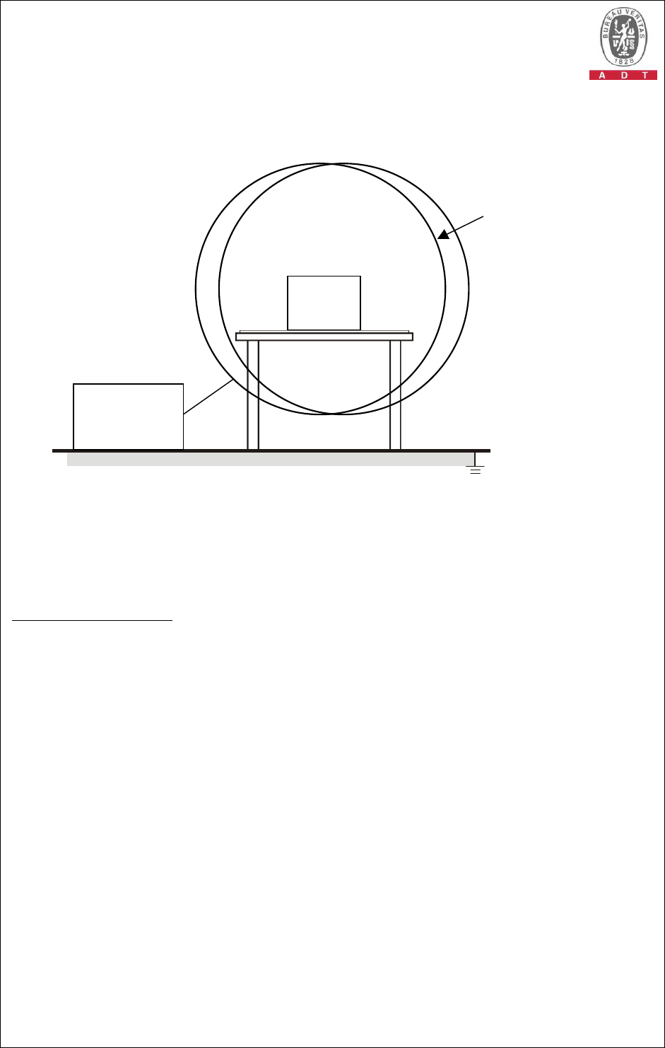
5.9.4 TEST SETUP
Reference Ground Plane
1,5m Double induction Coil
EUT
Test Generator
For the actual test configuration, please refer to the related item – Photographs of the
Test Configuration.
NOTE:
TABLETOP EQUIPMENT
The equipment shall be subjected to the test magnetic field by using the induction coil of standard
dimension (diameter 1.5m). The EUT placement shall then be rotated by 90 degrees in order to
expose to the test field with different orientations.
Report No.: CE980825H03 62 Report Format Version 3.0.1
5.9.5 TEST RESULTS
TEST MODE Mode 1 INPUT POWER 230Vac, 50 Hz
ENVIRONMENTAL
CONDITIONS 25 deg. C, 54 % RH,
965 hPa TESTED BY Tony Chen
DIRECTION
RESULTS
OBSERVATION PERFORMANCE CRITERION
X PASS Note A
Y PASS Note A
Z PASS Note A
NOTE: There was no change compared with the initial operation during the test.
Report No.: CE980825H03 63 Report Format Version 3.0.1
5.10 VOLTAGE DIP/SHORT INTERRUPTIONS/VOLTAGE
VARIATIONS (DIP) IMMUNITY TEST
5.10.1 TEST SPECIFICATION
Basic Standard: IEC 61000-4-11
Test Duration Time: Minimum three test events in sequence
Interval between Event: Minimum ten seconds
Phase Angle (degree): 0 / 180
Test Cycle: 3 times
5.10.2 TEST INSTRUMENTS
DESCRIPTION &
MANUFACTURER MODEL NO. SERIAL NO.
CALIBRATED
DATE
CALIBRATED
UNTIL
EMC PARTNER,
TRANSIENT TRA1Z332N 683 April 21, 2009
April 20, 2010
Adapter (EMC
PARTNER) NA SU1ADA-002
NA NA
EMC Partner(Software) Test
Manger_V1.53
NA NA NA
KeyTek, EMS Simulator
EMC Pro 9712339 Mar. 24, 2009
Mar. 23, 2010
Adapter (EMC Pro) NA SU1ADA-001
NA NA
KeyTek(Software) CEWare32_V3.0
NA NA NA
NOTE: 1. The calibration interval of the above test instruments is 12 months and the calibrations are
traceable to NML/ROC and NIST/USA.
2. The test was performed in EMS room B.
5.10.3 TEST PROCEDURE
The EUT shall be tested for each selected combination of test levels and duration
with a sequence of tree dips/interruptions with intervals of 10 s minimum (between
each test event). Each representative mode of operation shall be tested. Abrupt
changes in supply voltage shall occur at zero crossings of the voltage waveform.

Report No.: CE980825H03 64 Report Format Version 3.0.1
5.10.4 TEST SETUP
EUT
Voltage
Dips
Generator AC Power Line
For the actual test configuration, please refer to the related item – Photographs of the
Test Configuration.
Report No.: CE980825H03 65 Report Format Version 3.0.1
5.10.5 TEST RESULTS
TEST MODE Mode 1 INPUT POWER 240Vac / 230Vac /
100Vac, 50 Hz
ENVIRONMENTAL
CONDITIONS 26 deg. C, 45 % RH,
965 hPa TESTED BY Barry Lee
Input Power for testing: 240Vac, 50 Hz (Maximum Voltage)
VOLTAGE
% REDUCTION
PERIODS
RESULTS
OBSERVAT
ION
PERFORMANCE
CRITERION
>95 0.5 PASS Note (1) A
30 25 PASS Note (1) A
>95 250 PASS Note (2) B
Input Power for testing: 230Vac, 50 Hz (Normal Voltage)
VOLTAGE
% REDUCTION
PERIODS
RESULTS
OBSERVATION
PERFORMANCE
CRITERION
>95 0.5 PASS Note (1) A
30 25 PASS Note (1) A
>95 250 PASS Note (2) B
Input Power for testing: 100Vac, 50 Hz (Minimum Voltage)
VOLTAGE
% REDUCTION
PERIODS
RESULTS
OBSERVATION
PERFORMANCE
CRITERION
>95 0.5 PASS Note (1) A
30 25 PASS Note (1) A
>95 250 PASS Note (2) B
NOTES: (1) There was no change compared with initial operation during the test.
(2) The EUT reboot during the test, but could be self-recoverable after
the test.
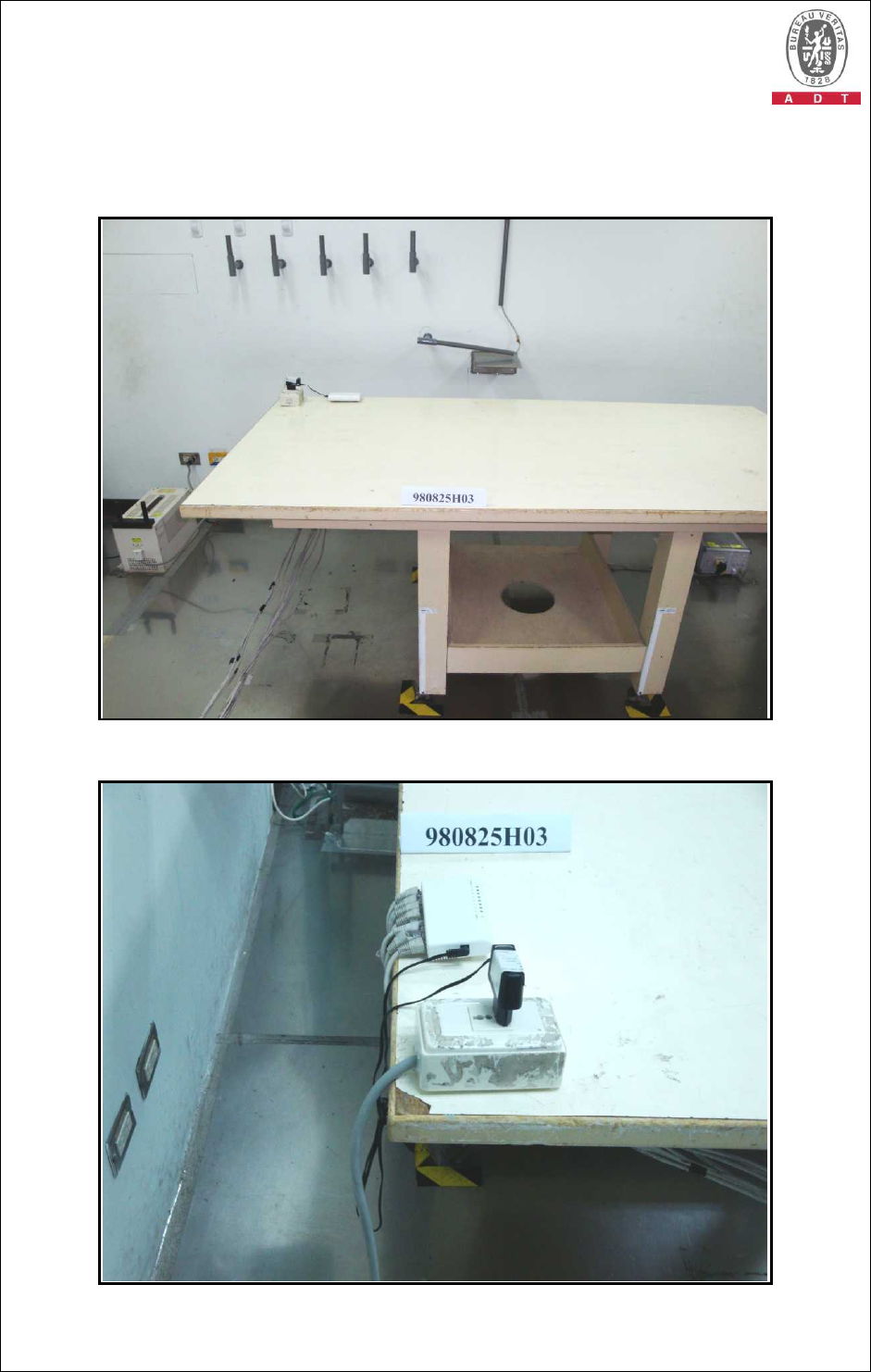
Report No.: CE980825H03 66 Report Format Version 3.0.1
6 PHOTOGRAPHS OF THE TEST CONFIGURATION
CONDUCTED EMISSION TEST
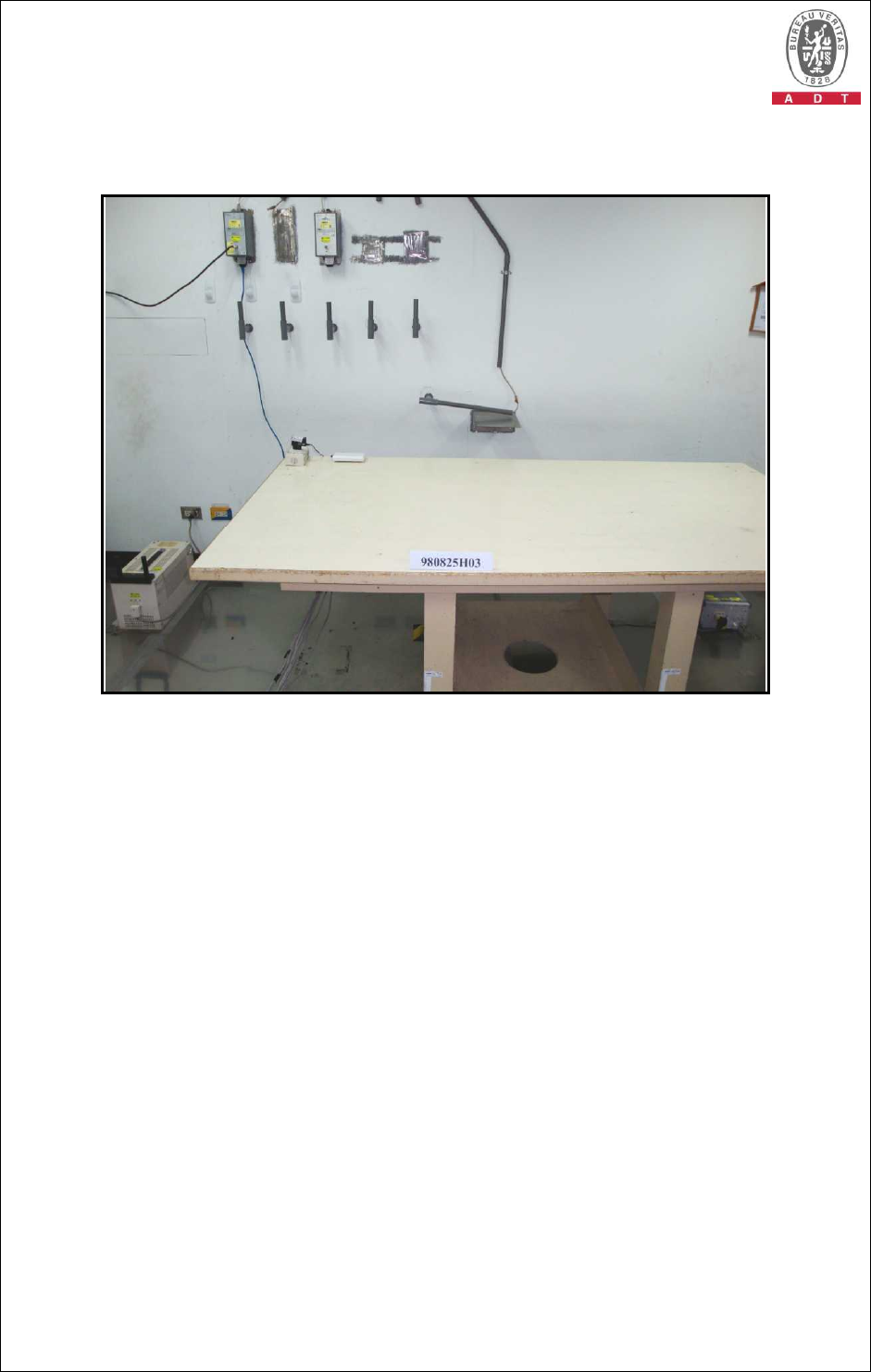
Report No.: CE980825H03 67 Report Format Version 3.0.1
TELECOMMUNICATION PORT OF
CONDUCTED EMISSION TEST
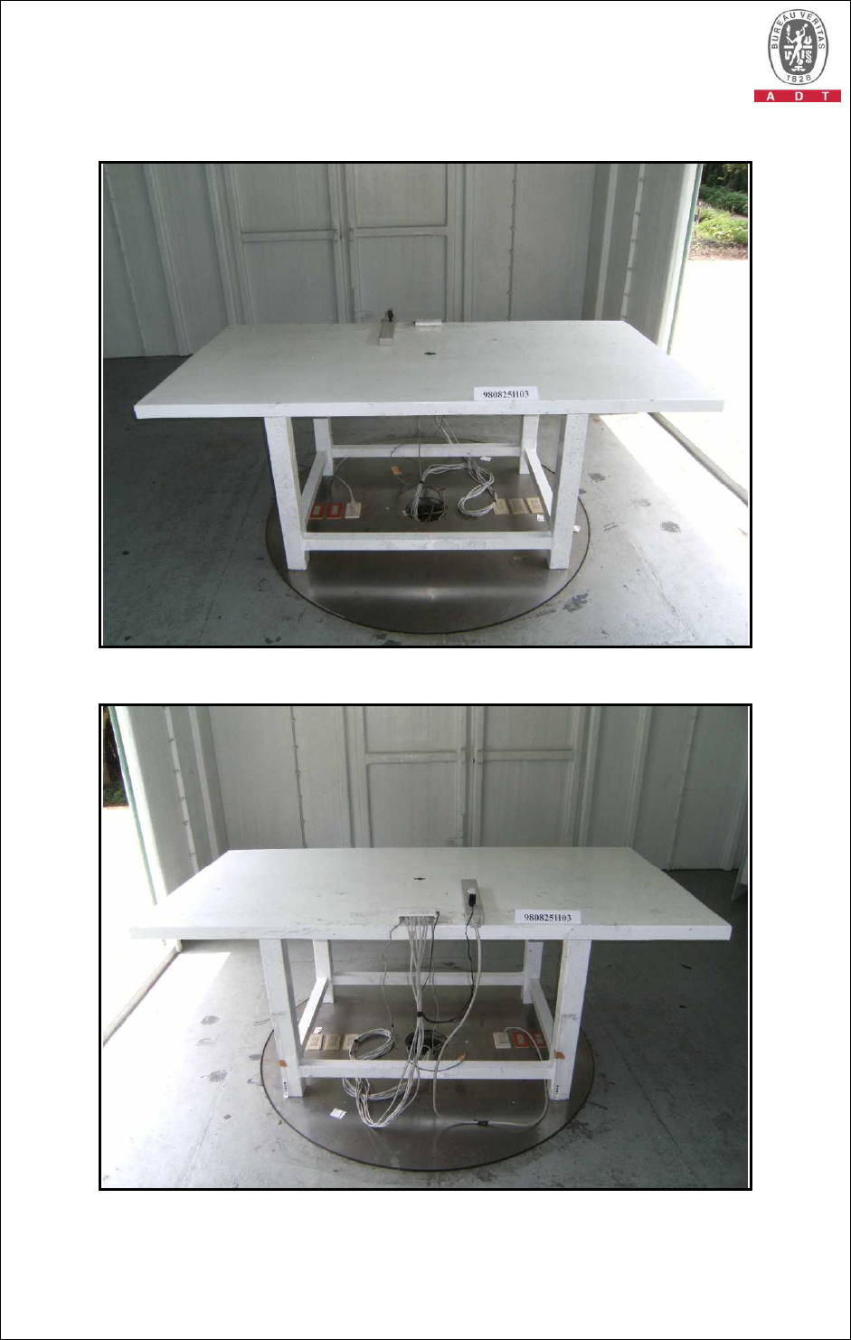
Report No.: CE980825H03 68 Report Format Version 3.0.1
RADIATED EMISSION TEST
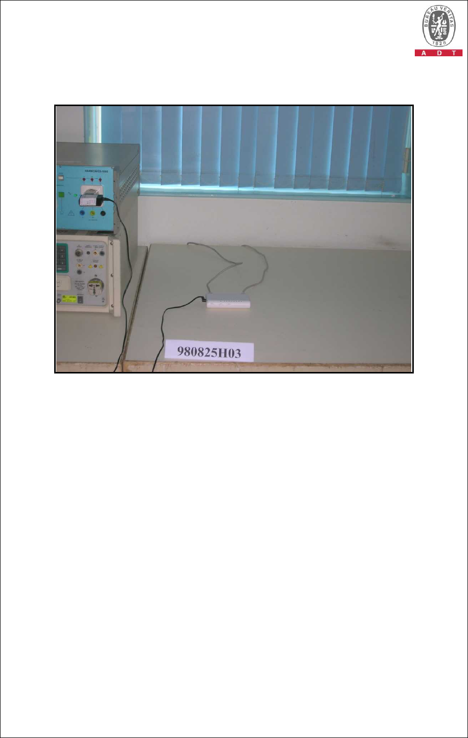
Report No.: CE980825H03 69 Report Format Version 3.0.1
HARMONICS EMISSION TEST & VOLTAGE
FLUCTUATIONS AND FLICKER TEST)
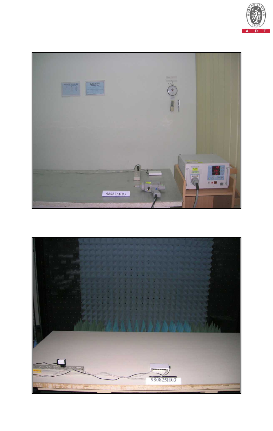
Report No.: CE980825H03 70 Report Format Version 3.0.1
ESD TEST
RS TEST
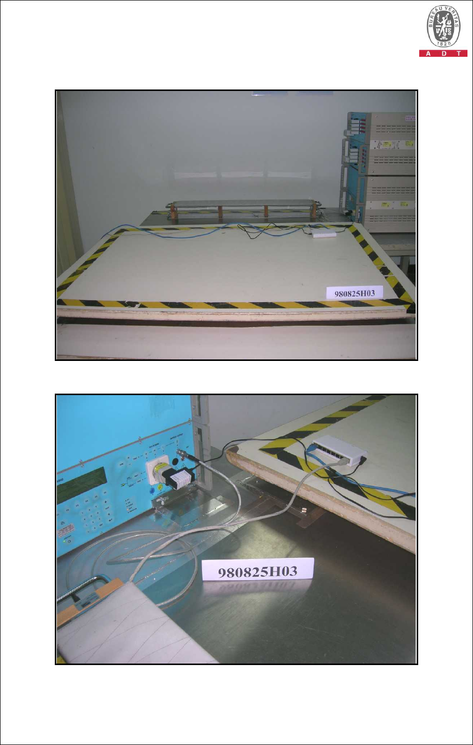
Report No.: CE980825H03 71 Report Format Version 3.0.1
EFT TEST
EFT TEST (LAN Port)
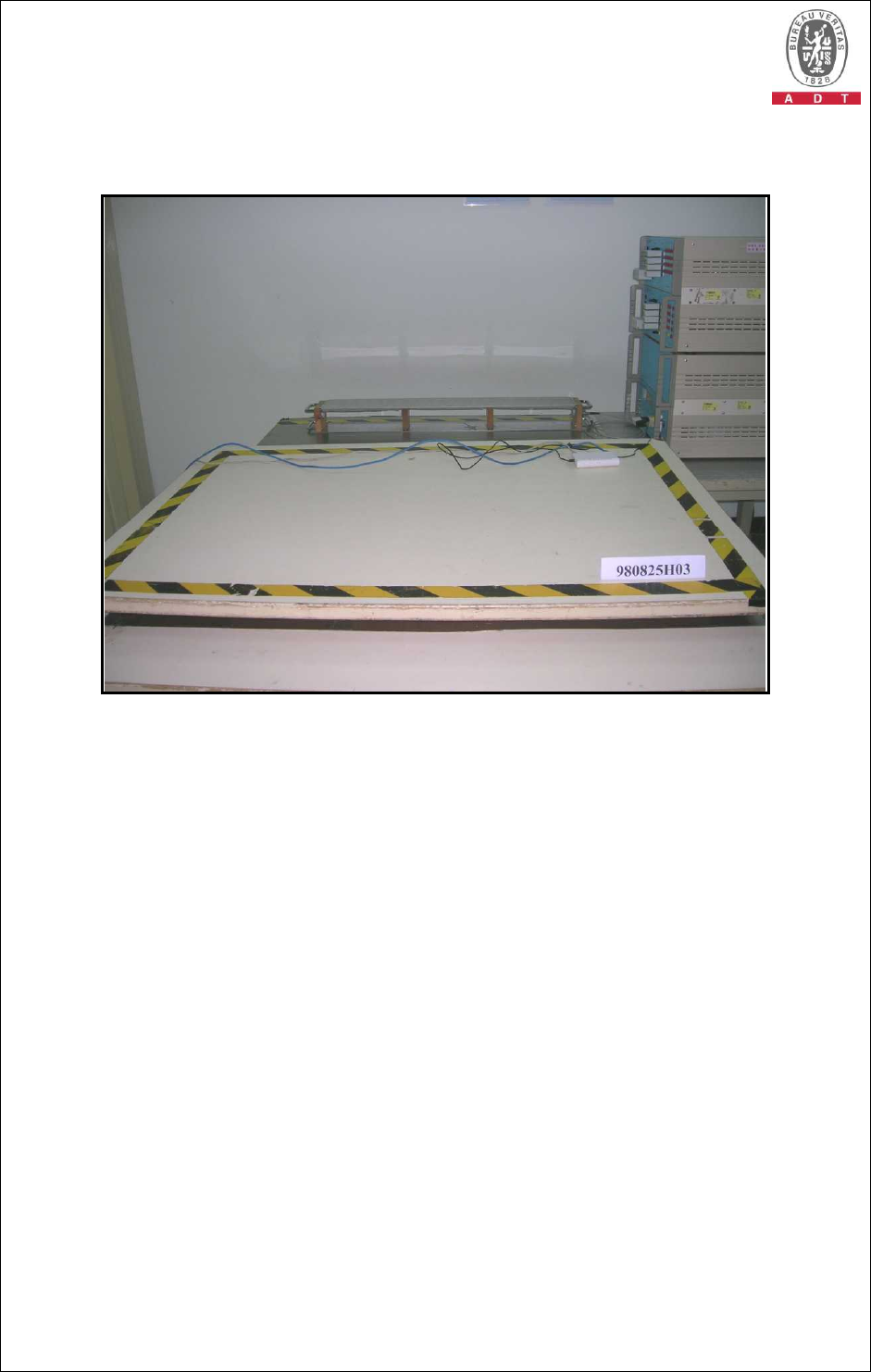
Report No.: CE980825H03 72 Report Format Version 3.0.1
SURGE & VOLTAGE DIPS
AND INTERRUPTIONS TEST
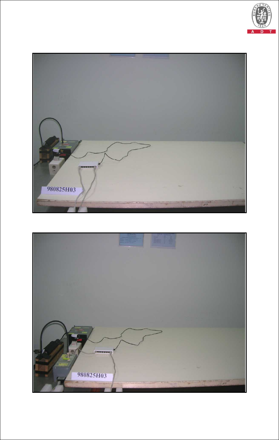
Report No.: CE980825H03 73 Report Format Version 3.0.1
CONDUCTED SUSCEPTIBILITY TEST
CONDUCTED SUSCEPTIBILITY TEST (LAN Port)
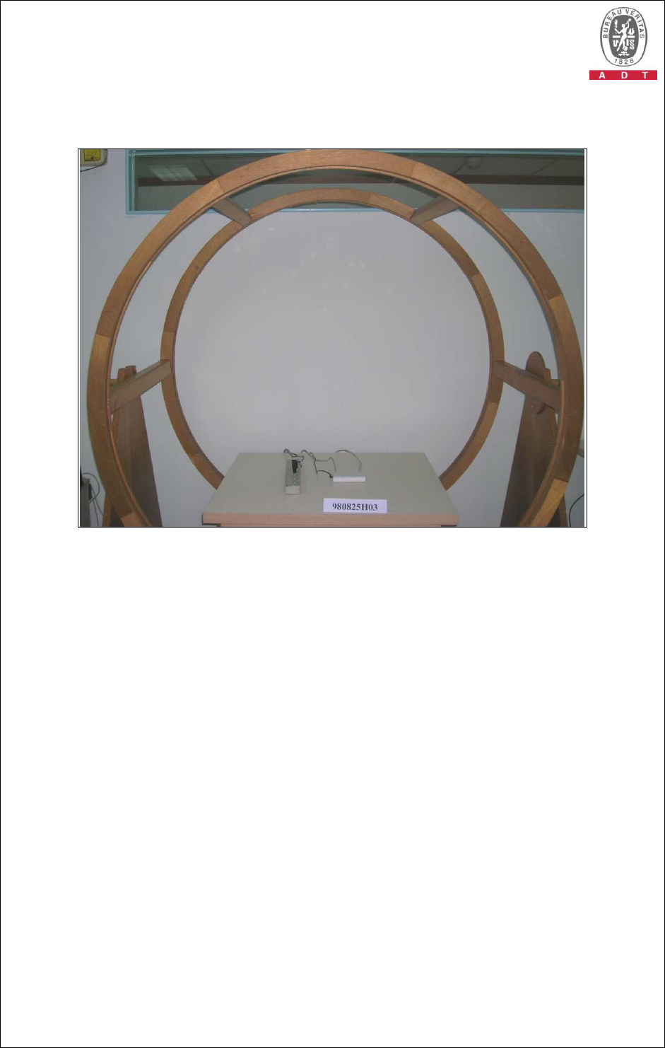
Report No.: CE980825H03 74 Report Format Version 3.0.1
POWER-FREQUENCY MAGNETIC
FIELDS TEST

Report No.: CE980825H03 75 Report Format Version 3.0.1
7 APPENDIX - INFORMATION ON THE TESTING LABORATORIES
We, Bureau Veritas Consumer Products Services (H.K.) Ltd., Taoyuan Branch, were
founded in 1988 to provide our best service in EMC, Radio, Telecom and Safety
consultation. Our laboratories are accredited and approved by the following
approval agencies according to ISO/IEC 17025:
USA FCC, NVLAP
Germany TUV Rheinland
Japan VCCI
Norway NEMKO
Canada INDUSTRY CANADA, CSA
R.O.C. TAF, BSMI, NCC
Netherlands Telefication
Singapore GOST-ASIA (MOU)
Russia CERTIS (MOU)
Copies of accreditation certificates of our laboratories obtained from approval
agencies can be downloaded from our web site: www.adt.com.tw/index.5/phtml.
If you have any comments, please feel free to contact us at the following:
Linko EMC/RF Lab:
Tel: 886-2-26052180
Fax: 886-2-26052943
Hsin Chu EMC/RF Lab:
Tel: 886-3-5935343
Fax: 886-3-5935342
Hwa Ya EMC/RF/Safety/Telecom Lab:
Tel: 886-3-3183232
Fax: 886-3-3185050
Email: service@adt.com.tw
Web Site: www.adt.com.tw
The address and road map of all our labs can be found in our web site also.
--- END ---
