Chapter 1. Basic Structure Of Computers 2 Machine Instructions Programs
User Manual: Pdf
Open the PDF directly: View PDF ![]() .
.
Page Count: 107 [warning: Documents this large are best viewed by clicking the View PDF Link!]

Machine Instructions
and Programs
1

Signed Integer Representations
3 major representations:
Sign and magnitude
One’s complement
Two’s complement
Assumptions for the next example:
4-bit machine word
16 different values can be represented
Roughly half are positive, half are negative
2

Sign and Magnitude Representation
High order bit is sign: 0 = positive(or zero), 1 = negative
Three low order bits is the magnitude: 0 (000) through 7 (111)
Number range for n bits = +/- ( -1)
Problems: two representations for 0 (0000 is +0, 1000 is –0)
Some complexities in addition, subtraction
3

One’s Complement Representation
- x = 1’s complement of x
1’s complement is invert 0 to 1 and 1 to 0
Two representations for 0(0000 is +0, 1111 is -0) causes
some problems
Some complexities in addition, subtraction
Subtraction (X-Y) implemented by addition & 1's complement
(x –y = x + 1’s complement of y = x + )
4

Two’s Complement Representation
- x = 2’s complement of x
Like 1's complement except negative numbers shifted one
position clockwise
2’s complement is just 1’s complement + 1
Only one representation for 0 ( 0000 => 1111+1 => 10000 =>
0000 in 4 bits, ignore the carry out / MSB 1)
Addition, subtraction very simple
One more negative number than positive number
5

Signed Integer Representations
Binary Sign and
Magnitude
1’s Complement 2’s Complement
0111 +7 +7 +7
0110 +6 +6 +6
0101 +5 +5 +5
0100 +4 +4 +4
0011 +3 +3 +3
0010 +2 +2 +2
0001 +1 +1 +1
0000 +0 +0 +0
1000 -0 -7 -8
1001 -1 -6 -7
1010 -2 -5 -6
1011 -3 -4 -5
1100 -4 -3 -4
1101 -5 -2 -3
1110 -6 -1 -2
1111 -7 -0 -1
6

Addition and Subtraction –2’s
Complement
4
+ 3
7
0100
0011
0111
-4
+ (-3)
-7
1100
1101
11001
4
- 3
1
0100
1101
10001
-4
+ 3
-1
1100
0011
1111
If carry-in to the high
order bit =carry-out
then ignore carry
If carry-in differs from
carry-out then overflow
Simpler addition scheme makes 2’s complement the most common
choice for integer number systems within digital systems
7

2’s-complement Add and Subtract
Operations
1 1 0 1
0 1 1 1
0 1 0 0
0 0 1 0
1 1 0 0
1 1 1 0
0 1 1 0
1 1 0 1
0 0 1 1
1 0 0 1
0 1 0 1
1 1 1 0
1 0 0 1
1 1 1 1
1 0 0 0
0 0 1 0
0 0 1 1
0 1 0 1
4+( )
2-( )
3+( )
2-( )
8-( )
5+
( )
+
+
+
+
+
+
1 1 1 0
0 1 0 0
1 0 1 0
0 1 1 1
1 1 0 1
0 1 0 0
6-( )
2-( )
4+( )
3-( )
4+( )
7+
( )
+
+
(b)
(d)
1 0 1 1
1 1 1 0
1 0 0 1
1 1 0 1
1 0 0 1
0 0 1 0
0 1 0 0
0 1 1 0
0 0 1 1
1 0 0 1
1 0 1 1
1 0 0 1
0 0 0 1
0 0 1 0
1 1 0 1
0 1 0 1
0 0 1 0
0 0 1 1
5-( )
2+( )
3+
( )
5+( )
2+( )
4+
( )
2-( )
7-( )
3-( )
7-( )
6+( )
3+( )
1+( )
7-( )
5-( )
7-( )
2+( )
3-( )
+
+
-
-
-
-
-
-
(a)
(c)
(e)
(f)
(g)
(h)
(i)
(j)
2's-complement add and subtract operations.
8

Overflow Condition
Add two positive numbers to get a negative number or two
negative numbers to get a positive number
Sum of +5(0101) and +3(0011) is 1000 which is the 2’s
complement result of -8
Sum of -7(1001) and -2(1100) is 10111(0111) which is the 2’s
complement result of +7
Two ways to detect overflow:
Overflow can occur only when adding two numbers that have the
same sign. Add two positive numbers to get a negative number or,
add two negative numbers to get a positive number
When carry-in to the MSB (most significant bit) does not equal carry
out from MSB
9

Overflow Condition: Carry-in to
MSB ≠ Carry-out from MSB
5
3
-8
0 1 1 1
0 1 0 1
0 0 1 1
1 0 0 0
-7
-2
7
1 0 0 0
1 0 0 1
1 1 0 0
1 0 1 1 1
5
2
7
0 0 0 0
0 1 0 1
0 0 1 0
0 1 1 1
-3
-5
-8
1 1 1 1
1 1 0 1
1 0 1 1
1 1 0 0 0
Overflow Overflow
No
overflow No overflow
10

Sign Extension
Task:
Given w-bit signed integer x
Convert it to w+k bit integer with same value
Rule:
Make k copies of sign bit:
X’ = xw–1 ,…, xw–1 , xw–1 , xw–2 ,…, x0
Kcopies of MSB •••
X
X’ ••• •••
•••
w
w
k
11
Sign Extension Example
short int x = 15213;
int ix = (int) x;
short int y = -15213;
int iy = (int) y;
Decimal
Hex Binary
x
15213
3B 6D
00111011 01101101
ix
15213
00 00 C4 92
00000000 00000000 00111011 01101101
y
-15213
C4 93
11000100 10010011
iy
-15213
FF FF C4 93
11111111 11111111 11000100 10010011
12

Characters
Computer must be able to handle non numeric text
information consisting of characters
Characters can be letters of alphabet, decimal digits,
punctuations marks etc.
They are represented by codes that are usually eight bits long
One of the widely used codes are ASCII codes
13

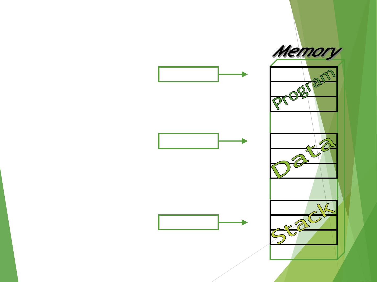
Memory Location, Addresses and
Operation
Memory consists of many
millions of storage cells, each of
which stores one bit.
Data is usually accessed in n-bit
groups, called a “word”.
N is called word length.
Typically n=32 or 64 bits etc.
(Such systems called 32-bit
systems, like:32-bit CPU or 64-
bit OS)
second word
first word
Memory words.
n bits
last word
I th word
.
.
.
.
.
.
14

Memory Location, Addresses and
Operation
32-bit word length example
Four characters
32 bits
…b0
b1
b30
b31
Sign bit : b31 = 0 for positive numbers
b31 = 1 for negative numbers
A signed integer
8 bits 8 bits 8 bits 8 bits
15

Memory Location, Addresses and
Operation
To retrieve information from memory, either for one word or one
byte (8-bit), addresses for each location needed.
Each byte (8-bit group) in the memory are addressable. This is called
byte addressable.
A k-bit addressed memory chip has 2kmemory locations, namely 0 –
2k-1, called memory space.
Example: 4 bit : addresses 0000 to 1111 = 0 to 15 = 0 to 24-1
1KB = 210 = 1024 bytes.
1MB = 1024KB = 210 * 210 = 220 bytes
1GB = 1024MB = 210 * 220 = 230bytes
1TB = 240 bytes, peta=, exa=, zetta=, yotta=
24-bit memory: 224 = 24 *220=16*1MB = 16MB
32-bit memory: 232 = 22*230 = 4*1GB = 4GB
16

Memory Location, Addresses and
Operation
It is impractical to assign distinct addresses to individual bit
locations in the memory.
The most practical assignment is to have successive addresses
refer to successive byte locations in the byte-addressable memory.
Byte locations have addresses 0, 1, 2, 3 and so on.
If word length is 32 bits (4 bytes), then successive words are
located at addresses 0, 4, 8 and so on.
16-bit word: word addresses: 0, 2, 4, 6, 8, …. bytes
32-bit word: word addresses: 0, 4, 8, 12, 16, …. bytes
64-bit word: word addresses: 0, 8,16, 24, 32, …. bytes
17

Big-endian Assignment of Memory
Addresses
Big-endian: higher (bigger) byte addresses are used for the least
significant bytes of the word. Bytes are numbered starting with most
significant byte of a word. Word is given the same address as its most
significant byte.
Word
Address
Byte
Address
0 0 1 2 3
4 4 5 6 7
.
.
.
2k-4
2
k-
4
2k-3
2
k-
2
2
k-
1
Big-endian assignment
18

Little-endian Assignment of Memory
Addresses
Little-endian: lower byte addresses are used for the less significant
bytes of the word. Bytes are numbered from least significant byte of
a word. Word is given the address of its least significant byte.
Word
Address
Byte
Address
0 3 2 1 0
4 7 6 5 4
.
.
.
2k-4
2
k-
1
2k-2
2
k-
3
2
k-
4
Little-endian assignment
19

Memory Location, Addresses and
Operation
Ordering of bytes: little endian and big endian schemes
Word alignment
Words are said to be aligned in memory if they begin at a byte address. That is a
multiple of the number of bytes in a word.
16-bit word: word addresses: 0, 2, 4, 6, 8, …, bytes
32-bit word: word addresses: 0, 4, 8, 12, 16, …, bytes
64-bit word: word addresses: 0, 8,16, 24, 32, …, bytes
Access numbers, characters and character strings
20

Memory Operation
LOAD (or read or fetch)
Copy content from memory to a register. The memory content doesn’t
change.
CPU places the required address in MAR register, then places the read
control signal to the memory chip, then waits, until it receives the desired
data into the MDR register.
Store (or write)
Write content from register to memory. Overwrite the content in memory
CPU places the address and data in MAR and MDR registers respectively,
sends the write control signal to the memory chip. Upon completion, the
memory chip sends back MFC (memory function complete) signal.
21

“Must-perform” Operations
Data transfers between the memory and the processor registers
Arithmetic and logic operations on data
Program sequencing and control
I/O transfers
22

Register Transfer Notation
Identify a location by a symbolic name standing for its
hardware binary address (LOC, R0, DATAIN etc.)
R0, R1, R2, .... => always indicates registers
Any other symbol => indicates memory location.
Example: X, Y, Z, A, B, M, LOC, LOCA, LOCB
Contents of a location are denoted by placing square
brackets around the name of the location (R1←[LOC],
R3 ←[R1]+[R2])
In Register Transfer Notation (RTN), the right hand side
always denotes a value and the left hand side express
the name of a location where the value is to be placed.
23

Assembly Language Notation
Represent machine instructions and programs.
Move LOC, R1 = R1←[LOC]
Add R1, R2, R3 = R3 ←[R1]+[R2]
Instructions like ADD A,B to make like B ←A+B is not
possible, because both operands can’t be memory
locations, at least one must be register. Besides the
content of B should not be overwritten.
24

CPU Organization
Controls how its instructions use the operand(s)
Single accumulator (AC) CPU organization
Result usually goes to the accumulator
Accumulator has to be saved to memory quite often
General register CPU organization
Registers hold operands thus reduce memory traffic
All registers functionally identical.
Stack
no registers, but CPU-internal stack memory holds operands and result are
always in the stack
25

Basic Instruction Types
Three-address instructions (operation source_1,source_2,destination)
Usually for RISC architecture
Add R2, R3, R1 R1 ←R2 + R3
Two-address instructions (operation source ,destination)
Add R2, R1 R1 ←R1 + R2
One-address instructions (operation operand)
Usually for single accumulator CPU organization
AC register is always an implicit operand
Add LOCA AC ←AC + LOCA(AR)
Zero-address instructions (operation)
Usually for stack CPU organization
No explicit operands, both operands are implicit
Add TOS ←TOS + (TOS –1)
RISC instructions
RISC can use 3 registers in a single instruction
Only the LOAD and STORE instructions can access memory
26

Instruction Formats
Example: evaluate X ←(A+B) (C+D)
Three-address format
1. ADD A, B, R1 ; R1 ←[A] + [B]
2. ADD C, D, R2 ; R2 ←[C] + [D]
3. MUL R1, R2, X ; X ←[R1] [R2]
27

Instruction Formats
Example: evaluate X←(A+B) (C+D)
Two-address instruction format
1. MOV A, R1 ; R1 ←[A]
2. ADD B, R1 ; R1 ←[R1] + [B]
3. MOV C, R2 ; R2 ←[C]
4. ADD D, R2 ; R2 ←[R2] + [D]
5. MUL R2, R1 ; R1 ←[R1] [R2]
6. MOV R1, X ; X ←R1
28

Instruction Formats
Example: evaluate X ←(A+B) (C+D)
One-address instruction format
1. LOAD A ; AC ←[A]
2. ADD B ; AC ←[AC] + [B]
3. STORE T ; T ←[AC]
4. LOAD C ; AC ←[C]
5. ADD D ; AC ←[AC] + [D]
6. MUL T ; AC ←[AC] [T]
7. STORE X ; M[X] ←[AC]
29

Instruction Formats
Example: evaluate X = (A+B) (C+D)
Zero-address instruction format
1. PUSH A ; TOS ←A
2. PUSH B ; TOS ←B
3. ADD ; TOS ←(A + B)
4. PUSH C ; TOS ←C
5. PUSH D ; TOS ←D
6. ADD ; TOS ←(C + D)
7. MUL ; TOS ←(C+D)(A+B)
8. POP X ; M[X] ←TOS
30

Instruction Formats
Example: evaluate X = (A+B) (C+D)
RISC
1. LOAD R1, A ; R1 ←M[A]
2. LOAD R2, B ; R2 ←M[B]
3. LOAD R3, C ; R3 ←M[C]
4. LOAD R4, D ; R4 ←M[D]
5. ADD R1, R1, R2 ; R1 ←R1 + R2
6. ADD R3, R3, R4 ; R3 ←R3 + R4
7. MUL R1, R1, R3 ; R1 ←R1 R3
8. STORE X, R1 ; M[X] ←R1
31

Using Registers
Registers are faster
Shorter instructions
The number of registers is smaller (e.G. 32 registers
need 5 bits to represent itself)
Potential speedup
Minimize the frequency with which data is moved back
and forth between the memory and processor registers.
32

Instruction Execution and Straight-
line Sequencing
Address
Contents
i Move A,R0
i+4 Add B,R0
i+8 Move R0,C
.
.
A
.
.
B
.
.
C
3-instruction
program segment
Data for the
program
A program for C [A] + [B]
33

Instruction Execution and Straight-line
Sequencing
Assumptions:
One memory operand per instruction
32-bit word length
Memory is byte addressable
Each instruction fits in one word(full memory address can
be directly specified in a single-word instruction)
Two-phase procedure
Instruction fetch
Instruction execute
34

Instruction Execution and Straight-
line Sequencing
The address of the first instruction i must be placed into the PC
Processor control circuits use the information of PC to fetch and
execute instruction one at a time in order of increasing order of
address known as straight-line sequencing
Execution is a two phase procedure known as instruction fetch
and instruction execute
The instruction fetched from the memory location whose address is
in the PC. This instruction is placed in IR in the processor
Instruction in IR is examined to determine the required operation
to be performed. Then the operation performed by processor
35

Branching
i
Move NUM1,R0
i+4 Add NUM2,R0
i+8 Add NUM3,R0
.
i+4n
-
4
Add NUMn,R0
i+4n Move R0,SUM
.
SUM
NUM1
NUM2
.
.
NUMn
Assuming a program for adding
an array of numbers without
using any loop(straight line
program)
36

Branching
Move N,R1
Clear R0
Loop Determine address of “next” number
and add “next” number to R0
Decrement R1
Branch > 0 Loop
Move R0,SUM
.
SUM
N n
NUM1
NUM2
.
NUMn
Program
loop
37

Generating Memory Addresses
To specify the address of branch target we can not give
the memory operand address directly in a single add
instruction in the loop. We have to use a register to
hold the address of NUM1; then increment by 4 on each
pass through the loop.
38

Show the Execution of the Following
Instructions
0001 = Load R0 from memory
0010 = Store R0 to memory
0101 = Add to R0 from memory
300 1940
301 5941
302 2941
940 0003
941 0002
Memory
PC
R0
IR
39

Show the Execution of the Following
Instructions
300 1940
301 5941
302 2941
940 0003
941 0002
Memory
PC=300
R0
IR=1940
40

Show the Execution of the Following
Instructions
300 1940
301 5941
302 2941
940 0003
941 0002
Memory
PC=301
R0=0003
IR=1940
As 0001=1 means load R0
from memory
41

Show the Execution of the Following
Instructions
300 1940
301 5941
302 2941
940 0003
941 0002
Memory
PC=301
R0=0003
IR=5941
42

Show the Execution of the Following
Instructions
300 1940
301 5941
302 2941
940 0003
941 0002
Memory
PC=302
R0=0005
IR=5941
As 0101=5 means add R0 to
memory
43

Show the Execution of the Following
Instructions
300 1940
301 5941
302 2941
940 0003
941 0002
Memory
PC=302
R0=0005
IR=2941
44

Show the Execution of the Following
Instructions
300 1940
301 5941
302 2941
940 0003
941 0005
Memory
PC=303
R0=0005
IR=2941
As 0010=2 means store R0
to memory
45

Condition Codes / Status Flags
The processor keeps track of information about the results of various
operations
This is accomplished by recording the required information in individual
bits called condition code flags
These flags grouped together in a special processor register called the
condition code register or status register
They are affected by the most recent ALU operations
Flags are set to 1 or cleared to 0
46

Condition Codes / Status Flags
Different instructions affect different flags
N (negative) or S (sign) flag
Is set to 1 if the result of most recent arithmetic operation is negative otherwise
clears to 0
Is used by some instructions, such as: branch<0 LOOP
Z (zero) flag
Is set to 1 if the result of the most recent arithmetic operation is zero
Used by some instructions, like: branch==0 LABEL
C (carry) flag
Is set if a carry out from most recent operation
V (overflow flag)
Is set if overflow occurs in most recent operation.
N Z V C
47

How Condition Codes or Status Flags
Set/Reset
Example:
A: 1 1 1 1 0 0 0 0 (-16)
B: 0 0 0 1 0 1 0 0 ( 20)
So, A –B = -36
A: 1 1 1 1 0 0 0 0
+(−B): 1 1 1 0 1 1 0 0
11 1 0 1 1 1 0 0
C = 1
N = 1
V = 0
Z = 0
48

Circuit: How to Generate the Status
Bits / Condition Codes
A and B are n bit numbers
A = <An-1An-2 ... A2A1A0> and B = <Bn-1Bn-2 ... B2B1B0 >
Sign Bits An-1 and Bn-1.
Result = < Fn-1Fn-2 ... F2F1F0 >
Cnis the carry out from An-1+ Bn-1.
Zero Flag : Z = (Fn-1 + Fn-2 + ... + F1 + F0)
Sign Flag : N = Fn-1
Carry Flag : C = Cn;
Overflow Flag : V = Cn (XOR) Cn-1
49
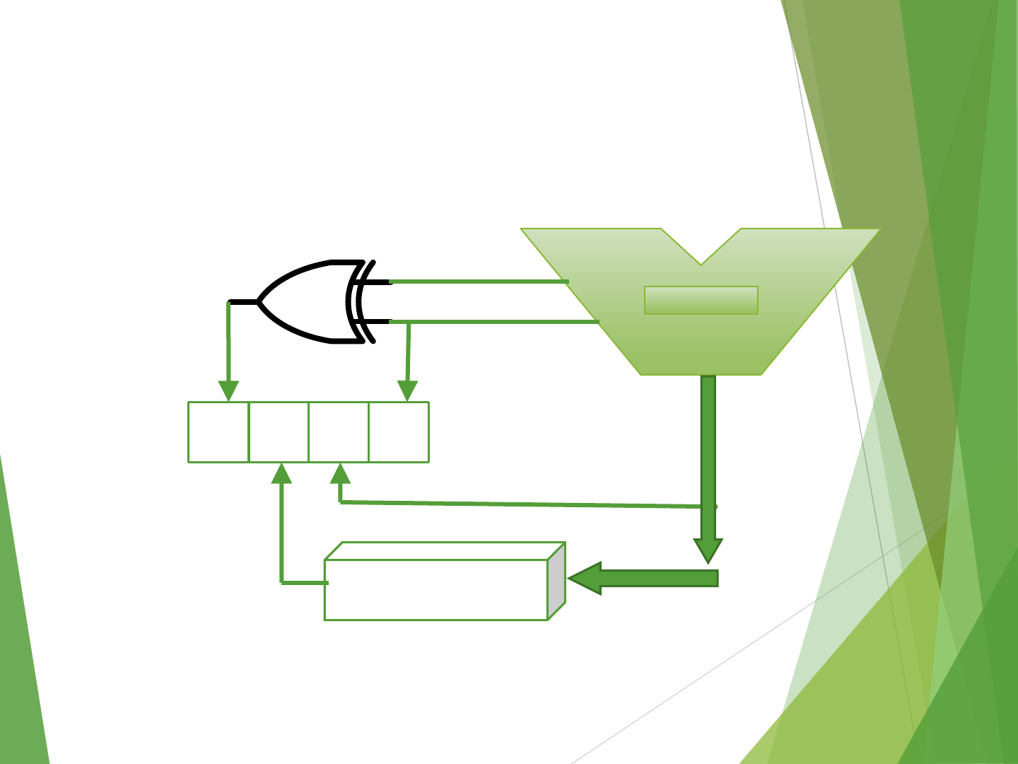
Circuit: How to Generate the Status
Bits / Condition Codes
ALU
V Z S C
Zero Check
Cn
Cn-1
Fn-1
A B
F
F
50

Addressing Modes
The different ways in which the location of an operand is
specified in an instruction are referred to as addressing modes.
Instruction: opcode source_operand destination_operand
MOV R1, A => source in register direct mode, destination in
memory direct mode
MOV R1, (A) => source in register direct mode, destination in
memory indirect mode
In an instruction, both the source and destination operands have
their addressing modes(i.e., How their location (or, say, address)
is specified)
51

Addressing Modes
Name Assembler Syntax Addressing
Function
Immediate #value Operand=value
Register Ri EA=Ri
Absolute(Direct) LOC EA=LOC
Indirect (Ri)/(LOC) EA=[Ri]/[LOC]
Index X(Ri) EA=[Ri]+X
Base with Index (Ri,Rj) EA=[Ri]+[Rj]
Base with Index
and Offset
X(Ri,Rj) EA=[Ri]+[Rj]+X
Relative X(PC) EA=[PC]+X
Auto Increment (Ri)+ EA=[Ri] and
increment Ri
Auto Decrement -(Ri)
Decrement Ri and
EA=[Ri]
52

Immediate Mode
Immediate mode
Operand is part of instruction
Operand = address field
Example : MOVE #200,R0
200
OP CODE
Operand
R0
Register
53

Register Mode
Register mode
Operand is the content of a processor register
The name of the register is given in the instruction
Example : MOVE R1,R2
OP CODE
Address
2
2
Register
R1
R2
2
0
Register
R1
R2
Before After
54

Absolute Mode
Absolute mode
Address field contains address of operand
Effective address = address field
Also known as direct mode
The operand is in a memory location
Example : ADD A
OP CODE
Address
Operand A
Memory
55

Indirect Mode
Indirect mode
Indicate the memory location that holds the address of the memory
location that holds the data
Instruction does not give the operand or its address explicitly
Provides the effective address of the operand
Example : Add (A),R0
OP CODE
Address
A
2
Register
R0
Memory
B
2
A
B
56

Indirect Addressing to Compute the
Array Sum
Contents
Move N,R1
Move #NUM1,R2
Clear R0
Add (R2),R0
Add #4,R2
Decrement R1
Branch>0 LOOP
Move R0,SUM
Address
Loop
Initialization
57

Index Mode
Index mode
The effective address of the operand is generated by adding a constant
value to the contents of a register
X (Ri) = X + [Ri].
The constant X may be given either as an explicit number or as a symbolic
name representing a numerical value
X could be the starting address of an array and Ri could be incremented
inside a loop to access the elements of the array sequentially
Example : Add 20(R1),R2
OP CODE
Address
A
2
Memory
1000
1020
1000
2
Register
R1
R2
58

Index Mode
N
n
LIST
Student Id
LIST
+ 4 Test 1
LIST
+ 8 Test 2
LIST + 12
Test 3
LIST
+ 16 Student Id
Test 1
Test 2
Test 3
.
.
.
Student 1
Student 2
59

Index Addressing in Accessing the Test
Scores
Loop
Move
#LIST,R0
Clear
R1
Clear
R2
Clear
R3
Move
N,R4
Add
4(R0),R1
Add
8(R0),R2
Add
12(R0),R3
Add
#16,R0
Decrement
R4
Branch>0
LOOP
Move
R1,SUM1
Move
R2,SUM2
Move
R3,SUM3
60

Index Mode
In general, the index mode facilitates access to an operand whose
location is defined relative to a reference point within the data
structure in which the operand appears.
If X is shorter than a word, sign-extension is needed.
Several variations:
Base with index register mode
(RI, RJ): EA = [RI] + [RJ]
Base with index and offset addressing mode
X(RI, RJ): EA = X + [RI] + [RJ]
61

Relative Mode
Relative mode
The effective address is determined by the index mode using the
program counter in place of general purpose register
X(PC) –note that X is a signed number
This mode can be used to access data operands
Most common use is to specify the target address in branch instructions
This location is computed by specifying it as an offset from the current
value of PC.
Branch target may be either before or after the branch instruction, the
offset is given as a signed number.
Example : -16(PC)
1016 1000
PC PC
Before After
62

Auto Increment Mode
Auto increment mode
The effective address of the operand is the contents of a register
specified in the instruction
After accessing the operand the contents of this register are
automatically incremented to point to the next item in the list
The increment is 1 for byte-sized operands, 2 for 16-bit operands,
and 4 for 32-bit operands.
Example : (Ri)+
63

Auto Increment Addressing to
Compute the Array Sum
Move N,R1
Move #NUM1,R2
Clear R0
Add (R2)+,R0
Decrement R1
Branch>0 LOOP
Move R0,SUM
Loop
Initialization
64

Auto Decrement Mode
Auto decrement mode
The contents of a register specified in the instruction are
first automatically decremented and then used as the
effective address of the operand
Example : -(Ri)
65

Addressing Modes
66
Implied addressing mode
AC is implied in “ADD B” in “one-address” instruction (ACAC+M[B]).
Similarly, TOS and TOS-1 are implied in “ADD” in “zero-address”
instruction
Immediate addressing mode
The use of a constant in “MOV #5, R1”, i.e. R1 ←5
Here, source is in immediate addressing mode, destination in register
direct mode
Register direct addressing mode
Directly indicates which register holds the operand
MOV R1, R2 both source and destination in register direct mode

Addressing Modes
Register indirect addressing mode
Indicate the register that holds address of the memory location (or, another
register)
MOV (R2), R1
Here, source operand in register indirect mode
Auto-increment/auto-decrement
MOV (R1)+, R2 and MOV -(R3), R4
both source operands; access and update in 1 instruction
Absolute/direct/memory direct (MD) mode
memory location given explicitly
MOV LOCA, R1 (source operand in md mode)
MOV R2, LOCB (destination operand md mode)
67

Addressing Modes
Memory indirect addressing mode
Indicate the memory location that holds the address of the memory
location that holds the data
MOV (LOCA), R2
LOCA is a memory address, where the address of the operand can
be found
MOV A, R1: source operand memory direct mode
MOV (A), R1: source operand memory indirect mode
And destination in register direct mode for both the instructions.
68

Addressing Modes
Relative addressing mode
Branch X or JMP X
Effective address (EA) of operand = PC + X
Branch>0 label EA = PC + label
Here the only operand is in the relative addressing mode
X (or, label) is called the relative address
Relative to PC register
MOV X(PC), R2
Assembly language => used for branch instructions, PC is implicit, JMP 120
means jump to address PC+120
69

Indexed addressing mode
EA = index register (XR) + relative address (RA)
MOV X(R1), R2 => source operand is in indexed mode. X could be positive or
negative
MOV 20(R1), R2 here source operand is in indexed addressing mode and
the effective address (EA) of source operand is 20+R1
Base with index register mode
Two different registers are used
EA = base register (BR) + index register (XR)
MOV (BR, XR), R1 and MOV (R2, R3), R1
In both of the above examples, the source operand is in(base with index
register) addressing mode
Addressing Modes
70

Addressing Modes
Base with index and offset address mode (BIO)
Two different registers and an offset value are used
EA = base register (BR) + index register (XR)+ offset value
MOV X(BR, XR), R1source in BIO mode, destination register direct mode
MOV X(Ri, Rj), (R2)source BIO mode, destination register indirect mode
MOV 40(R1,R2), LOCA source in BIO, destination memory direct mode
MOV 50(R1,R2), (LOCA)source in BIO, destination memory Indirect mode
Sample question: identify the addressing modes of both source and
destination operands of the following instructions:
LOAD #20, 20(R1) ; STORE (R1,R2), (R3) ; ADD (R1), LOCA
MUL C ; MUL 10(R1), (LOCB) ; DIV (LOCA), LOCA
ADD ; SUB (R2)+ ; BR #72
SHL (R1), #8 ; ROL (LOCA), R2
71

Computing Dot Product of Two
Vectors
In calculations that involve vectors and matrices it is
often necessary to compute the dot product of two
vectors.
Let A and B be two vectors of length n. Their dot
product is defined by
72

Computing Dot Product of Two
Vectors
Move
#AVEC,R1
R1 points to vector A
Move
#BVEC,R2
R2 points to vector B
Move
N,R3
R3 serves as a counter
Clear
R0
R0 accumulates the dot
product
LOOP
Move
(R1)+,R4
Compute the product of
Multiply
(R2)+,R4
next components
Add
R4,R0
Add to previous sum
Decrement
R3
Decrement the counter
Branch>
0
LOOP
Loop again if not done
Move
R0,DOTPROD
Store dot product in
memory
73

Types of Instructions
Data transfer instructions
Name Mnemonic
Load LD
Store ST
Move MOV
Exchange XCH
Input IN
Output OUT
Push PUSH
Pop POP
74

Data Transfer Instructions
Mode Assembly Register Transfer
Direct address LD ADR AC ←M[ADR]
Indirect address LD @ADR AC ←M[M[ADR]]
Relative address LD $ADR AC ←M[PC+ADR]
Immediate
operand LD #NBR AC ←NBR
Index addressing LD ADR(X) AC ←M[ADR+XR]
Register LD R1 AC ←R1
Register indirect LD (R1) AC ←M[R1]
Autoincrement LD (R1)+ AC ←M[R1], R1 ←R1+1
75

Data Manipulation Instructions
Arithmetic
Name Mnemonic
Increment INC
Decrement DEC
Add ADD
Subtract SUB
Multiply MUL
Divide DIV
Add with carry ADDC
Subtract with
borrow SUBB
Negate NEG
76

Data Manipulation Instructions
Logical and bit manipulation
Name Mnemonic
Clear CLR
Complement COM
AND AND
OR OR
Exclusive-OR XOR
Clear carry CLRC
Set carry SETC
Complement
carry COMC
Enable interrupt EI
Disable interrupt DI
77

Data Manipulation Instructions
Shift
Name Mnemonic
Logical shift right SHR
Logical shift left SHL
Arithmetic shift right SHRA
Arithmetic shift left SHLA
Rotate right ROR
Rotate left ROL
Rotate right through
carry RORC
Rotate left through carry ROLC
78

Program Control Instructions
Name Mnemonic
Branch BR
Jump JMP
Skip SKP
Call CALL
Return RET
Compare
(Subtract) CMP
Test (AND) TST
79
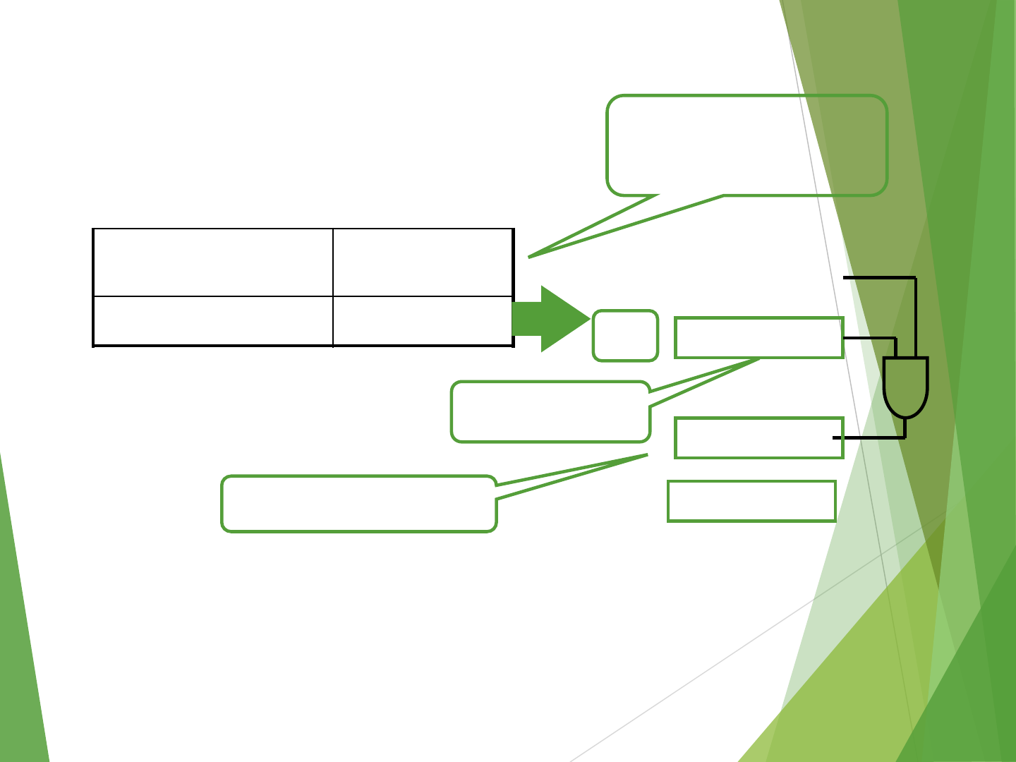
x x x x 0x x x
Mask: all bi’s=0,
except b3=1
Will be zero if A3is 0
Program Control Instructions
Compare
(Subtract) CMP
Test (AND) TST
Subtract A – B but don’t
store the result
0 0 0 0 10 0 0
0 0 0 0 00 0 0
A =
80

Conditional Branch Instructions
Mnemonic Branch Condition Tested Condition
BZ Branch if zero Z = 1
BNZ Branch if not zero Z = 0
BC Branch if carry C = 1
BNC Branch if no carry C = 0
BP Branch if plus S = 0
BM Branch if minus S = 1
BV Branch if overflow V = 1
BNV Branch if no
overflow V = 0
81

I/O
The data on which the instructions operate are not
necessarily already stored in memory.
Data need to be transferred between processor and outside
world (disk, keyboard, etc.)
I/O operations are essential, the way they are performed can
have a significant effect on the performance of the computer.
82

Program-controlled I/O Example
Read in character input from a keyboard and produces character
output on a display screen.
Rate of data transfer from the keyboard to a computer is limited by the
typing speed of the user.
Rate of output transfers from the computer to the display is much higher
Difference in speed between processor and I/O device creates the need
for mechanisms to synchronize the transfer of data.
Solution: on output, the processor sends the first character and then
waits for a signal from the display that the character has been
received. It then sends the second character. Input is sent from the
keyboard in a similar way.
83

Program-controlled I/O Example
Processor DATAIN DATAOUT
Keyboard Display
SIN SOUT
Bus connection for processor, keyboard and display
Bus
- Registers
- Flags
- Device interface
84

Program-controlled I/O Example
(I/O Space Separate from Memory Space)
Machine instructions that can check the state of the status flags and
transfer data:
READWAIT Branch to READWAIT if SIN = 0
Input from DATAIN to R1
WRITEWAIT Branch to WRITEWAIT if SOUT = 0
Output from R1 to DATAOUT
85

Memory Mapped I/O
I/O device registers are just like memory operands, I/O devices share
the memory, some memory address values are used to refer to
peripheral device buffer registers.
No special instructions are needed. Also device status registers used
just as memory operands.
READWAIT Testbit #3, INSTATUS
Branch=0 READWAIT
MoveByte DATAIN, R1
WRITEWAIT Testbit #3, OUTSTATUS
Branch=0 WRITEWAIT
MoveByte R1, DATAOUT xxxx0x x x
0 0 0 0 1 0 0 0
Mask: all bi’s=0,
except b3=1
86

Program-controlled I/O Example
Assumption
The initial state of SIN is 0 and the initial state of SOUT is 1.
Drawback of this mechanism in terms of efficiency
Two wait loops processor execution time is wasted
Alternate solution is
Interrupt
87

Stack CPU Organization
LIFO (Last In First Out)
Historically, Stack always grows upwards (from higher to lower memory
addresses). No reason. Just a convention/established Practice
SP(Stack Pointer Register) :Always points to the Top Of the Stack(TOS)
SP
Stack Bottom
Current
Top of Stack
TOS
0
1
2
3
4
7
8
9
10
5
6
Stack
0 0 5 5
0 0 0 8
0 0 2 5
0 0 1 5
0 1 2 3
88
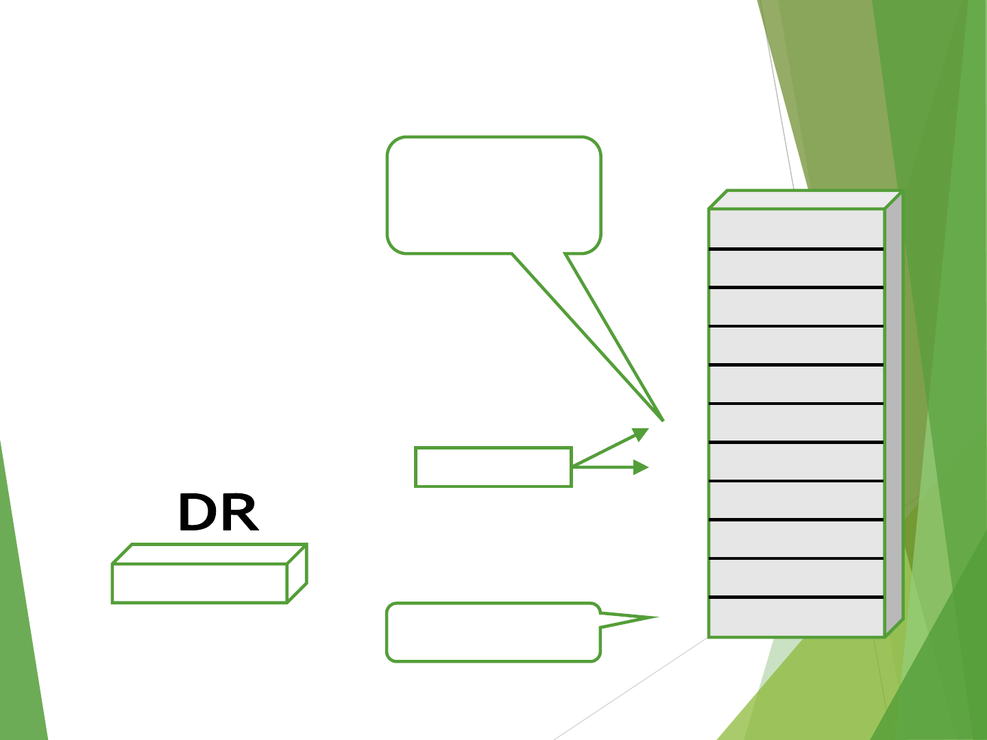
Stack Organization for CPU
PUSH
SP ←SP –1
M[SP] ←DR
EMPTY ←0
If (SP == 0) then (FULL ←1)
SP
Stack Bottom
0
1
2
3
4
7
8
9
10
5
6
Stack
0 0 5 5
0 0 0 8
0 0 2 5
0 0 1 5
0 1 2 3
1 6 9 0
1 6 9 0
Current
Top of Stack
TOS
89

Stack Organization for CPU
POP
DR ←M[SP]
SP ←SP + 1
FULL ←0
If (SP == MAX) then (EMPTY ←1)
SP
Stack Bottom
Current
Top of Stack
TOS 0
1
2
3
4
7
8
9
10
5
6
Stack
0 0 5 5
0 0 0 8
0 0 2 5
0 0 1 5
0 1 2 3
1 6 9 01 6 9 0
90
0
1
2
102
202
201
200
100
101
Stack Organization
Memory Stack
PUSH (summary)
SP ←SP –1
M[SP] ←DR
POP (summary)
DR ←M[SP]
SP ←SP + 1
PC
AR
SP
91

Reverse Polish Notation
Infix Notation:
Operand_1 Operator Operand_2
A + B
Prefix or Polish Notation:
Operator Operand_1 Operand_2
A + B Prefix + A B
Postfix or Reverse Polish Notation (RPN):
Operand_1 Operand_2 Operator
A + B Postfix A B +
A * B + C * D A B * C D * +
Example : (A + B) [C (D + E) + F]
2*4+3*3
RPN=> (2) (4) (3) (3) +
(8) (3) (3) +
(8) (9) +
17
92

Reverse Polish Notation
Example
(A+ B) [C(D+E) + F]
RPN Is unambiguous. So, you can just discard all parentheses at the end
(A + B) * [ {C * (D + E) } + F ]
[(AB+) [ { (DE+) C * } F +] * ] => AB+DE+C*F+*
Postfix/RPN notation (of an expression) and stack operations (to evaluate
the expression on stack-CPU) are identical.
(A B +) (D E +) C F +
93

Reverse Polish Notation
Stack Operation to evaluate 3 * 4 + 5 * 6
(3) (4) (5) (6) +
PUSH 3
PUSH 4
MULT
PUSH 5
PUSH 6
MULT
ADD
94

Reverse Polish Notation
4
312
6
5
12
30
1242
95

Subroutines
In a given program it is often necessary to perform a particular
subtask many times on different data values. Such a subtask is called
a subroutine
When a program branches to a subroutine it is said that it is calling
the subroutine. The instruction that performs this branch operation is
named a call instruction.
After a subroutine has been executed the calling program must
resume execution continuing immediately after the instruction that
called the subroutine
The subroutine is said to return to the program that called it by
executing a return instruction
The way in which a computer makes it possible to call and return
from subroutines is referred to subroutine linkage method
Linkage register holds the address of PC
96

Subroutines
The call instruction is just a special branch instruction
Store the contents of the PC in the link register
Branch to the target address specified by the instruction
The return instruction is another special branch instruction
Branch to the address contained in the link register
Memory
Location
Calling
Program
Memory
Location
Subroutine
SUB
. .
200 Call SUB 1000 First
instruction
204 Next
instruction
.
. Return
97

Parameter Passing
When calling a subroutine a program must provide to the
subroutine the parameters, that is the operands or their
addresses, to be used in the computation.
Later the subroutine returns other parameters, in this case, the
result of the computation.
This exchange of information between a calling program and a
subroutine is referred to as parameter passing.
98

Parameter Passing
Move N,R1
Move #NUM1,R2
Call LISTADD
Move R0,SUM
LISTADD Clear R0
LOOP Add (R2)+,R0
Decrement
R1
Branch>0 LOOP
Return
Calling
Program
Subroutine
99

Logical Shifts
Logical shift –shifting left (LShiftL) and shifting right (LShiftR)
C
R0
0
Before
0
0 1 1 1 0 … … … 0 1 1
after
1
1 1 0 … … … 0 1 1 0 0
Logical shift left LShiftL #2,R0
0
R0
C
Before
0 1 1 1 0 … … … 0 1 1
0
after
0 0 0 1 1 1 0
… … … 0
1
Logical shift right LShiftR #2,R0
100

Arithmetic Shifts
R0
C
Before
1 0 0 1 1 … … … 0 1 0
0
after
1 1 1 0 0 1 1 … … … 0
1
Arithmetic shift right AShiftR #2,R0
101

Rotate Left With or Without Carry
CR0
Before 0 0 1 1 1 0 … … … 0 1 1
After 1 1 1 0 … … … 0 1 1 0 1
Rotate left without carry RotateL #2,R0
Rotate left with carry RotateLC #2,R0
CR0
Before 0 0 1 1 1 0 … … … 0 1 1
After 1 1 1 0 … … … 0 1 1 0 0
102

Rotate Right With or Without Carry
R0 C
Before 0 1 1 1 0 … …
… 0 1 1
0
After 1 1 0 1 1 1 0 … … … 0 1
Rotate right without carry RotateR #2,R0
Rotate right with carry RotateRC #2,R0
R0 C
Before 0 1 1 1 0 … … … 0 1 1 0
After 1 0 0 1 1 1 0 … … … 0 1
103

Multiplication and Division
Not very popular (especially division)
Multiply RI, RJ
RJ←[RI] Х[RJ]
2n-bit product case: high-order half in R(j+1)
Divide RI, RJ
RJ←[RI] / [RJ]
Quotient is in Rj, remainder may be placed in R(j+1)
104

Encoding of Machine Instructions
Assembly language program needs to be converted (i.e., Encoded) into
machine instructions.
(ADD = 0100 in ARM instruction set)
In the previous section, an assumption was made that all instructions are one
word in length.
OPCODE: The type of operation (such as: ADD, MUL, MOV, XOR, etc.) that can
be performed on the source and destination operands and the type of
operands used may be specified using an encoded binary pattern
Suppose 32-bit word length, 8-bit OP code that is we have 28=256 sets of
instructions, 16 registers in total each of 4 bits and 8 possible addressing
modes (3 bits as addressing Mode indicator)
Add R1, R2
Move 24(R0), R5
LshiftR #2, R0
Move #3A, R1
Branch>0 LOOP
If LOOP is encoded in the remaining 10 bits (i.e., other info), then maximum
possible value of LOOP is 210-1 = 1023. So, branch target can’t be more than
1023 bytes distant from the current instruction (Branch instruction or
roughly the PC value)
One-word instruction
OPCODE
SOURCE
DESTINATION
OTHER INFO
8 Bits
7 Bits(4+3)
7 Bits(4+3) 10 Bits
105

Encoding of Machine Instructions
Suppose we want to specify a memory operand using the absolute
addressing mode
MOV R2, LOC
We know 17-bits (=32 –8 –7 bits) to represent LOC is insufficient. So we
have to use two words
Suppose we have an instruction in which two operands can be specified
using the absolute addressing mode
MOV LOC1, LOC2
The solution is to use two additional words. This approach results in
instructions of variable length. Complex instructions can be implemented,
closely resembling operations in high-level programming languages –
Complex Instruction Set Computer (CISC)
OP Code Source Destination Other Info
Memory Address / Immediate Operand
Two-word instruction
106

Encoding of Machine Instructions
If we insist that all instructions must fit into a single 32-bit word, it is not
possible to provide a 32-bit address or a 32-bit immediate operand within
the instruction.
It is still possible to define a highly functional instruction set, which makes
extensive use of processor registers.
ADD R1, R2, R3 ,allowed in RISC(8+(4+3=7)*3 bits => still less than 32 bits)
ADD LOC, R2 ,not allowed
In RISC, replace it with two instructions LOAD LOC, R1; then ADD R1,R2 (as,
only RISC LOAD and STORE instructions can access memory, not ADD
instruction)
ADD (R3),R2 ,not allowed
Replace it by LOAD (R3),R1; ADD R1,R2
In RISC, the only exceptions are the LOAD and STORE instructions involve
memory operands. Such instructions require more than one word. Other
instructions can fit within a single word (as, they involve registers only)
107
