Cloudmpa240 Ut 1 User Manual
Cloudmpa240D3 CLOUDMPA240D3 CLOUDMPA240D3 pdf kavson.co.uk
2017-03-29
User Manual: Pdf Cloudmpa240 CLOUDMPA240 pdf kavson.co.uk
Open the PDF directly: View PDF ![]() .
.
Page Count: 4
General Description
• 6 Line inputs, stereo inputs summed to mono
• Line inputs via RCA phono’s with input gain controls
adjacent to connectors
• Source select via front panel rotary selector or remotely via RSL6
• Line input level via front panel control or remotely via RL1 or RSL6
• Line 6 priority selectable by internal jumper, release
time 3s/6s/12s selectable by internal jumper
• Music EQ by tamperproof LF & HF presets on rear panel
• 4 Microphone Inputs, low impedance balanced
via phoenix style connectors
• Microphone EQ by tamperproof LF & HF presets on rear panel
• 100Hz HP dedicated filter on Microphone inputs
• Phantom power selected by internal jumper for each microphone
• Limiter dedicated to microphone inputs with LED indication
• Mic 1 has access triggered priority over Mics 2 – 4
• All mics have VOX priority over music signals, providing
30dB of attenuation (on/off by jumper)
• Integrated chime triggered by access control of Mic 1
(on/off by jumper and level by internal preset)
• Compatible with Bose®SeriesIIS EQ Cards
• Remote Music Mute configurable for NO or NC operation
• Overall “Peak Limiter” with LED indication on front panel
Amplifier features:
• 63Hz HP Filter for 25/70/100V operation
•Variable speed fan cooling
• Switch on delay
• DC protection
• IV Limiting
• 2U Rack chassis fitted with removable rack ears.
Cloud Electronics Limited
140 Staniforth Road, Sheffield S9 3HF. England. Telephone: +44 (0)114 244 7051 Fax: +44 (0)114 242 5462 Web: www.cloud.co.uk E-mail: info@cloud.co.uk
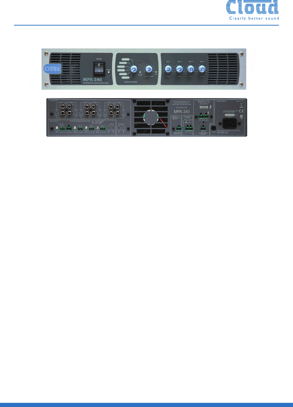
MPA240/MPA120/MPA60 :General Purpose Mixer Amplifier
Shown without rack ears
The increase in demand for higher quality mixed impedance output
amplifiers for general installer applications has instigated the launch of
Cloud Electronics new MPA Series, MPA240, MPA120 and MPA60, 6 line
+ 4 microphone inputs into a single zone with configurable 25/70 or 100Volt
internal transformer plus the industry standard wall mount remote
controllers (RL1 & RSL6) make the MPA Series the most flexible and
reliable installer amps in the market.
Line Inputs
Frequency Response 20Hz +0dB -1dB, 63Hz -3dB
3rd order filter, selectable by jumper
20kHz -1dB low impedance output,
20kHz -2dB 100/70/25V line outputs
Distortion <0.03% low impedance output
<0.04% 25/70/100V outputs
@ 1kHz 1dB below full power
80kHz bandwidth
Sensitivity 195mV (-12dBu) to 2V (+8dBu)
Input Gain Control 20dB range
Input Impedance 47kΩ
Headroom >-20dB
Noise -90dBr 22kHz bandwidth, 0dB input
Relative to full power output.
Equalisation HF: ±10dB/10kHz
LF: ±10dB/50Hz
Microphone Inputs
Frequency Response 100Hz / -3dB(3rd order filter)
20kHz +0, -1dB low impedance output
20kHz -2dB 100/70/25V line outputs
Distortion <0.03% @ 1kHz -1dB below full power
80kHz bandwidth
Gain Range 10dB - 50dB
Input Impedance >2kΩ(balanced)
Phantom Power +15V (PCB jumper for on/off)
Headroom >20dB
Input Noise -127dB EIN 22Hz - 22kHz (150Ω)
Equalisation HF: ±10dB/5kHz
LF: ±10dB/100Hz
Power Output
MPA240 240 Watts, any output @1kHz,
<0.07%THD+N
MPA120 120 Watts, any output @1kHz,
<0.07%THD+N
MPA60 60 Watts, any output @1kHz,
<0.07%THD+N
Power Supply
Power supply 230V/115/100VAC Depending on version
Mains Fuse rating 230V version 100/115V version
(20mm x 5mm)
MPA240 T4A H T8A H
MPA120 T2A H T4A H
MPA60 T1A H T2A H
Cooling & Protection
Cooling Variable speed fan cooling, air intake
on the front of the product, exhaust
on the rear
Protection Fixed level signal limiter with a max gain
reduction of 20dB, DC protection,
IV limiting & short circuit protection,
Switch on delay
Physical
Dimensions 482.6mm (19 inch)x 88.0mm (2U)
x 344.5 mm deep (+ connectors & knobs)
Weight MPA240 12.6 kg net
MPA120 10.5kg net
MPA60 9.0kg net
Technical Specifications
Input1
Input2
Input3
Input4
Input5
Input6
Mic1
Access(Mic1)
Mic2
Mic3
Output
Mic4
Remote
Output
CDPlayer1
CDPlayer2
Organ
Automatic
Source
MPA60/120or240
100Vlineoutput
RSL-6
Mic1 Mic2
RadioMic3
Lectern1 Lectern2
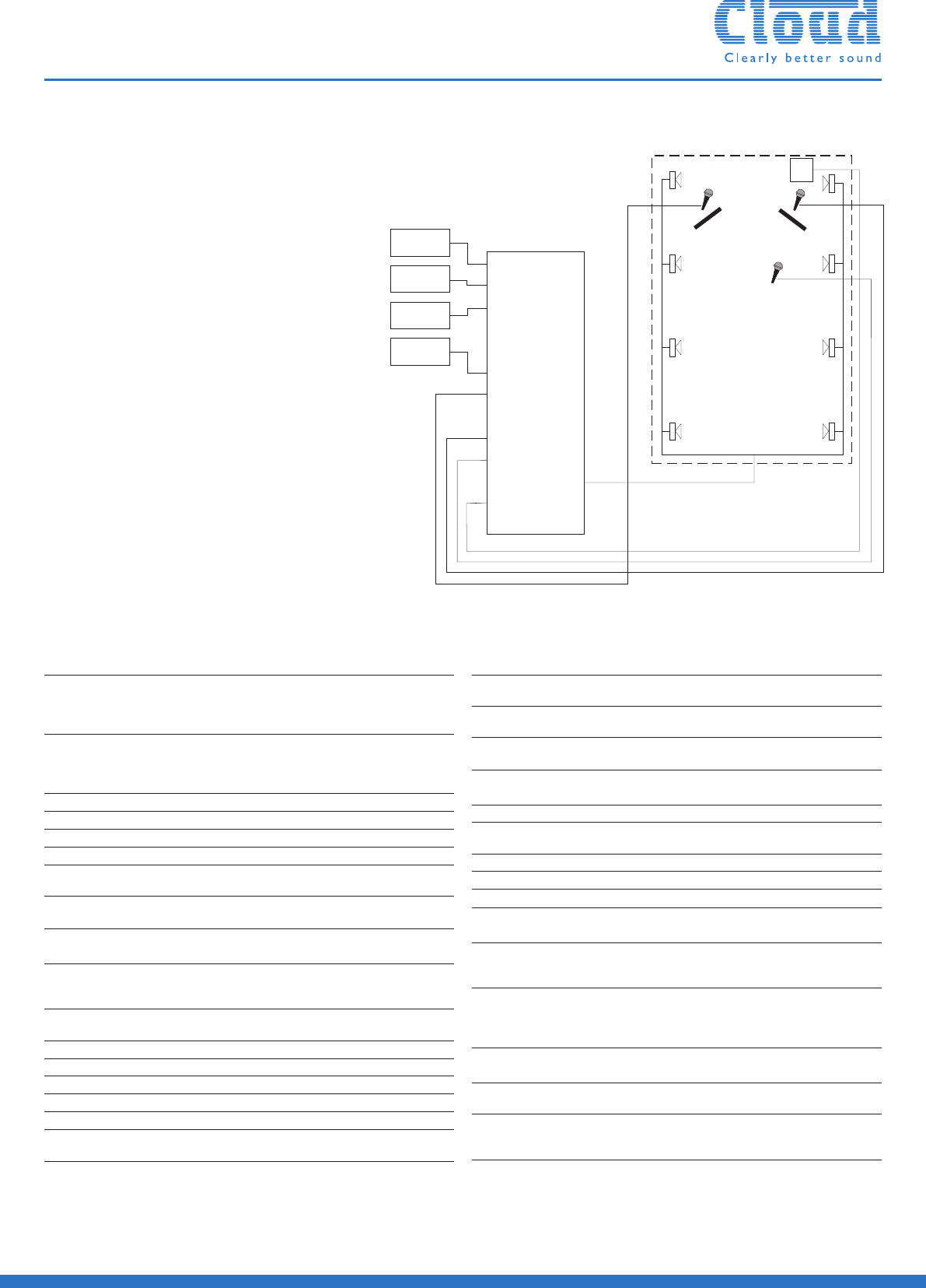
• The single area has two fixed mic points,
lectern 1 & 2 and a Radio Mic to allow
the presenter mobility.
• Any of the input sources can be selected
and the music level controlled by the RSL-6
at the back of the area.
• The Automatic Source is on line 6 to give
priority over all other inputs.
• Dependent on the size of the area the
MPA60 (60W), MPA120 (120W)
or MPA240 (240W) can be used.
• The output can be configured as 100V/70V
or 25V line output (as shown)
or low impedence.
System Example – House of Worship (MPA240/120 or 60)
Cloud Electronics Ltd MPA240 Constant Voltage Frequency Response
-40
+2
-38
-36
-34
-32
-30
-28
-26
-24
-22
-20
-18
-16
-14
-12
-10
-8
-6
-4
-2
-0
d
B
r
20 20k50 100 200 500 1k 2k 5k 10k
Hz
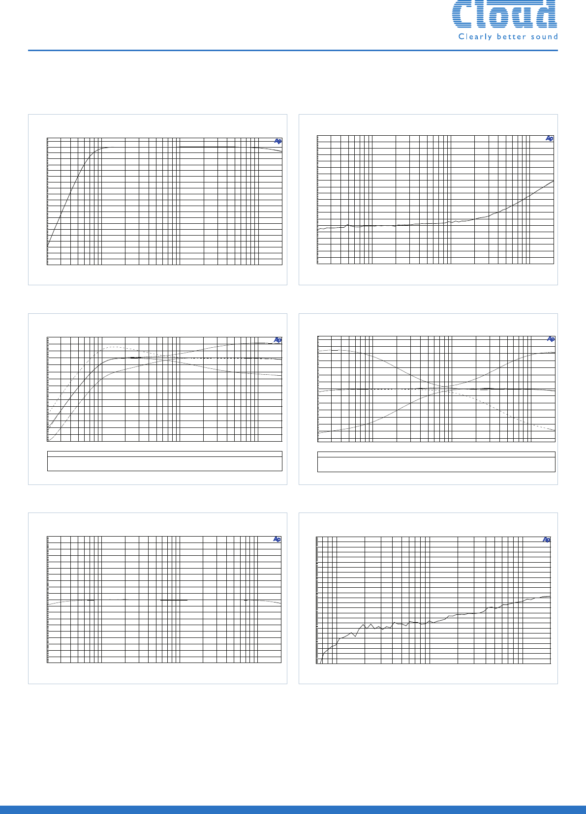
Cloud Electronics Ltd Microphone EQ Curves
Color
Sweep Trace Line Style Thick Data Axi s Co mm ent
1 1 Black Solid 1 Anlr.Level A Left HF Boos t
2 1 Black Da sh 1 Anlr.Level A Left HF Cut
3 1 Black Da sh Dot 1 Anlr.Level A Le ft LF Cut
4 1 Black Do t 1 Anlr.Level A Left LF Boo st
-60
+15
-55
-50
-45
-40
-35
-30
-25
-20
-15
-10
-5
+0
+5
+10
d
B
r
20 20k50 100 200 500 1k 2k 5k 10k
Hz
Cloud Electronics Ltd MPA240 Line Input Crosstalk
-100
-60
-98
-96
-94
-92
-90
-88
-86
-84
-82
-80
-78
-76
-74
-72
-70
-68
-66
-64
-62
d
B
r
20 20k50 100 200 500 1k 2k 5k 10k
Hz
Cloud Electronics Ltd MPA240 Music EQ Curves
ColorSweep Trace Line Style Thi ck Data Axis Co mm ent
1 1 Bla ck Solid 1 Anl r .Am p l Le ft LFCut
2 1 Bla ck Dash 1 Anl r .Am p l Left LF Boo st
3 1 Bla ck Da sh Dot 1 Anl r .Am p l Left H F Boost
4 1 Bla ck Dot 1 Anl r .Am p l Le ft HFCut
-14
+14
-12
-10
-8
-6
-4
-2
+0
+2
+4
+6
+8
+10
+12
d
B
r
20 20k50 100 200 500 1k 2k 5k 10k
Hz
Graphs
MPA240 100/70/25V Output Frequency Response MPA240 Line Input Crosstalk
MPA240 Microphone EQ Curves MPA240 Music EQ Curves
Cloud Electronics Ltd MPA240 Line Input Frequency Response
-10
+10
-9
-8
-7
-6
-5
-4
-3
-2
-1
-0
+1
+2
+3
+4
+5
+6
+7
+8
+9
d
B
r
20 20k50 100 200 500 1k 2k 5k 10k
Hz
Cloud Electronics Ltd MPA240 Crosstalk: Adjacent Microphone Channels
-110
-60
-108
-106
-104
-102
-100
-98
-96
-94
-92
-90
-88
-86
-84
-82
-80
-78
-76
-74
-72
-70
-68
-66
-64
-62
d
B
r
70 20k100 200 500 1k 2k 5k 10k
Hz
TTTTTT
MPA240 Line Input Frequency Response MPA240 Crosstalk:Adjacent Microphone Channels
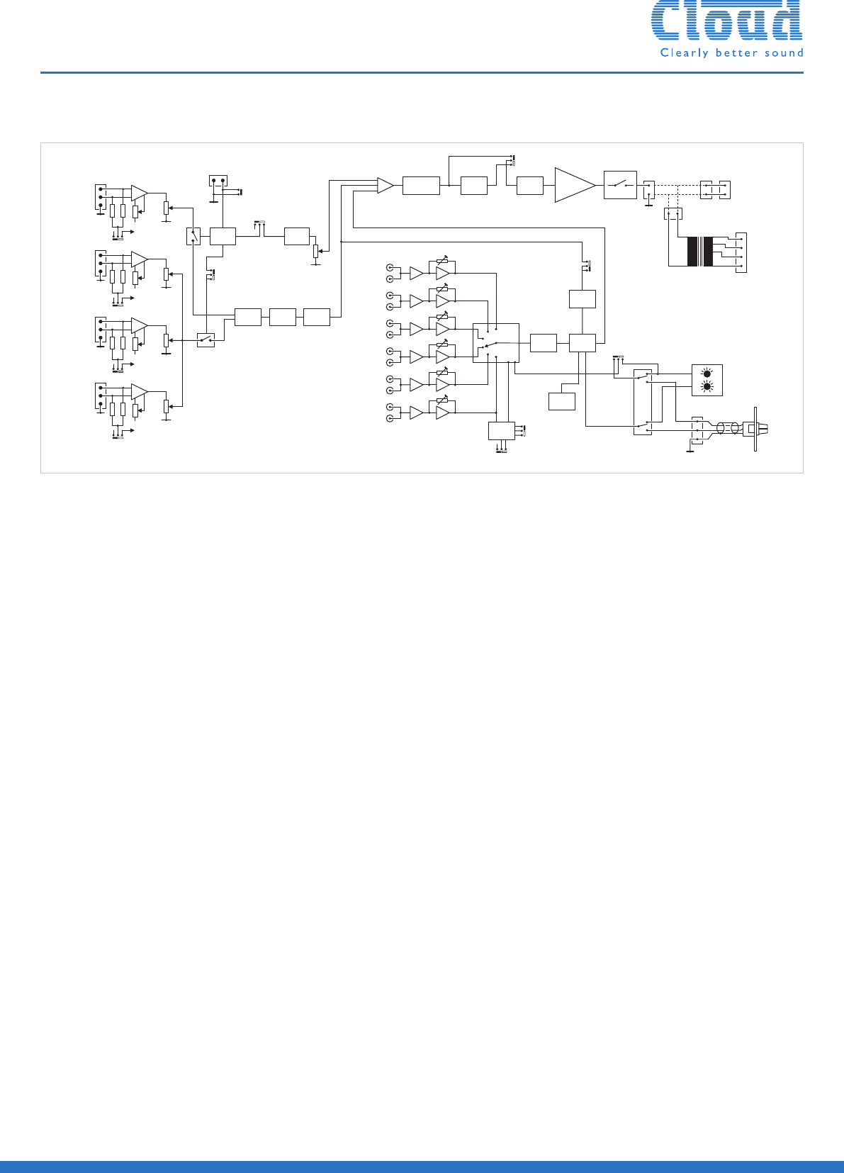
The mono mixer-amplifier shall be equipped with six unbalanced stereo
music inputs on phono sockets (RCA jacks) and four balanced microphone
inputs on multipin connectors.The music input to be used shall be selectable
by a 6-position front panel rotary switch.The four mic inputs shall be mixed
to a mono signal and summed with a mono (L+R) sum of the selected
music input. Each mic input shall have its own front panel level control.
It shall be possible to control the level of the music source independently
of the mic levels. Each music input and each mic input shall also have a rear
panel gain control. 2-band equalisation adjustment shall be provided
independently for the selected music source and summed mic signals.
A control input shall be provided to activate one mic input (Mic 1)
by external contact closure; it shall be possible to configure the mixer-amplifier
such that this function is overriden and Mic 1 is always active. It shall be
possible to configure the mixer-amplifier to perform the following additional
functions: i) when activated by its control input, Mic 1 will take priority
over any other mic input in use; ii) detection of a signal on any mic input
will automatically reduce the music level by 30dB, iii) one line input will
automatically override all others, even if unselected. Optional remote control
panels shall be available to permit control of music level only or music level
and input selection; it shall be possible to retrofit these to the mixer-amplifier
at any time. An external control input shall be provided to allow muting
of the music source by a fire alarm or other external emergency system.
The mixer-amplifier will include a chime generator circuit triggered
by a signal on Mic 1 input; it shall be possible to internally disable/enable
this function.
The microphone mixer stage shall include a high-pass filter to remove
background LF noise below 100Hz (-3dB).
A second high-pass filter shall be included to remove LF content below
65Hz (-3dB) from the mixed music and mic signals to minimise transformer
saturation in 100v/70v/25v line systems; this filter shall be internally by-passable.
Two separate internal fixed limiter circuits shall be fitted; these shall be located
at i) the output of the microphone mixer stage and ii) at the input of the
power amplifier stage. Operation of either limiter shall be indicated by a front
panel LED.The mixer-amplifier shall incorporate protection circuitry that
isolates the output i) during power-up, ii) in the event of DC being detected
at the amplifier output, iii) if the internal heatsink temperature exceeds
90C (194F).
The mixer-amplifier shall be available in three models with different output
powers of 240W, 120W or 60W , into a 4 ohm load.The mixer-amplifier
shall be capable of driving either low impedance (4 ohms or higher) loads,
or 100V, 70V or 25V line systems via an internal transformer fitted as
standard. It shall not be possible to use both types of output
simultaneously.
The 100V, 70V and 25V transformer outputs shall be available on separate
rear panel output terminals, shrouded by a screw-attached safety cover.
The mixer-amplifier shall accept internal Bose™ Series IIS plug-in equaliser
cards to permit use with compatible Bose™ loudspeakers.The mixer-amplifier
shall be built in a 2U steel chassis for mounting in a standard 19” rack.
Temperature-controlled forced-air fan cooling with front-to-rear airflow
shall be employed.The amplifier will be fitted with a front-panel power
switch with LED indication.
The mixer-amplifier shall be the Cloud MPA240 (240W output),
the Cloud MPA120 (120W output) or the Cloud MPA60 (60W output).
E&OE
Architect’s and Engineer’s Specification
MIC1MIC 1
MIC2MIC 2
MIC3MIC 3
MIC4MIC 4
0V0V
0V0V
0V0V
0V0V
+15V+15V
+15V+15V
+15V+15V
+15V+15V
PHANTOM
POWER
PHANTOM
POWER
GAINGAIN
GAINGAIN
GAINGAIN
GAINGAIN
PHANTOM
POWER
PHANTOM
POWER
PHANTOM
POWER
PHANTOM
POWER
PHANTOM
POWER
PHANTOM
POWER
MIC1
ACCESS
MIC 1
ACCESS CHIMECHIME
ACCESS
INPUTS
ACCESS
INPUTS
CONNECT INPUT
TO 0V TOOPEN
MICCHANNEL
CONNECT INPUT
TO 0V TO OPEN
MIC CHANNEL
ACCESSBYPASSACCESS BYPASS
0V0V
MIC1 ACCESS
TRIGGERSCHIME
MIC 1 ACCESS
TRIGGERS CHIME
MIC1OVER
MIC2,3&4
PRIORITY
MIC 1 OVER
MIC 2, 3 & 4
PRIORITY
RELEASE TIME
12s-NOJUMPER
RELEASE TIME
12s - NO JUMPER
HIGH
PASS
FILTER
HIGH
PASS
FILTER
HIGH
PASS
FILTER
HIGH
PASS
FILTER
MIC
EQ
MIC
EQ
AUTO
VOICEOVER
AUTO
VOICE OVER
MUSIC
EQ
MUSIC
EQ
AVOAVO
VCAVCA
LINE1LINE 1
LINE2LINE 2
LINE3LINE 3
LINE4LINE 4
LINE5LINE 5
LINE6LINE 6
LIMITERLIMITER
LIMITERLIMITER
++SPEAKEREQ
SOCKET
SPEAKER EQ
SOCKET
3s3s
6s6s
LINE6
PRIORITY
LINE 6
PRIORITY
MUSIC
MUTE
MUSIC
MUTE
ON/OFFON / OFF
POWER
AMPLIFIER
POWER
AMPLIFIER
PROTECTPROTECT
0V0V
MINLOAD
4OHMS
MIN LOAD
4OHMS
OUTPUTOUTPUT
100V100V
70V70V
50V50V
COMCOM
FORCEFRONT PANEL
SOURCESELECT
FORCE FRONT PANEL
SOURCE SELECT
HIGHPASSFILTER
BYPASS
HIGH PASS FILTER
BYPASS
FRONT PANEL
MUSICSOURCE ANDLEVEL
CONTROLS
FRONT PANEL
MUSIC SOURCE AND LEVEL
CONTROLS
0V0V
11
2
2
33
REMOTE
LEVEL
CONNECTOR
REMOTE
LEVEL
CONNECTOR
FRONT PANEL /
REMOTESWITCH
FRONT PANEL /
REMOTE SWITCH
RSL-6
OPTIONAL REMOTE
SOURCE ANDLEVEL
RSL-6
OPTIONAL REMOTE
SOURCE AND LEVEL
LINEOUTPUT
TRANSFORMER
LINE OUTPUT
TRANSFORMER
Block Diagram
