CM Coded Magnetic Safety Interlock Switches And Controllers Datasheet Series
2016-05-20
: Pdf Cm Series CM Series Spec Sheets Omron
Open the PDF directly: View PDF ![]() .
.
Page Count: 14
G
G-63
www.sti.com/info
Conforms to EN292, EN60204-1, EN954-1,
EN1088, EN60947-5-3, EN947-5-3,
EN50081, EN50082, EN61000-6-2,
ISO 13849-1
UL and C-UL listed, TUV certified
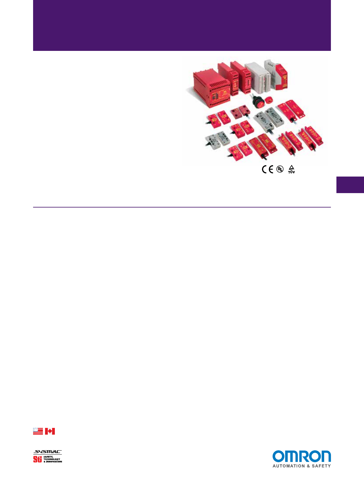
Most Diverse and Flexible Line of
Coded Magnetic Safety Interlock
Switches and Controllers
• Combine door switch monitoring and E-stop monitoring by using
the CM-S41 controller
• Monitor is single switch to CAT4 with the CM-S30 controller
• Monitor multiple switches to CAT3 using CM-S4 or CM-S30
controllers
• Monitoring multiple switches on individual channels can be
achieved by using the CM-S21 or CM-S41 controllers. Easily
expand your system by using the CM-SE expansion module.
• All CM switches are rated IP67
• Stainless steel switches are available for harsh environments
• A Rapid Delivery Product: Select models are available for ship-
ment today or within 3 to 5 days
Safety Interlock Switches
CM Series
Description
The CM series of controllers and coded magnetic switches
offers the most flexibility and widest range of options available.
The CM series is comprised of two basic technologies.
Controller Technologies
2-Wire Single Channel Controllers
The CM-S41 and CM-S21 controllers monitor the 2-wire
magnetically coded switches. The CM-S41 and CM-S21 control-
lers use a patented technology which allows them to monitor the
2-wire or single channel switches up to Category 3. The ability to
monitor just a single channel enables the CM-S41 and CM-S21 to
easily monitor multiple switches and provide individual status of
each channel. Both of these controllers are compatible with the
CM-SE expansion module.
Dual Channel Controllers
The CM-S4 and CM-S30 controllers are designed to monitor
conventional read-style, magnetically-coded switches with 1 N/O
+ 1 N/C contacts. The CM-S4 controller can monitor up to four
switches to category 3. The CM-S4 controller offers status indica-
tion for each individual switch. The CM-S30 controller can monitor
one switch to category 4, or two switches to category 3. The CM-
S30 control unit is capable of monitoring up to 30 conventional
read style switches in series, but does not conform to category 3
when used with more than two switches.
Switch Categories
The CM series of switches are all magnetically coded.
The CM series of switches fall into three main categories:
1. 2-wire Coded Magnetic
2. Conventional Read Style 1 N/C + 1 N/O contacts
3. Universal Read Style 2 N/C + 1 N/O contacts
The 2-wire Coded Magnetic Switches are only compatible with
the CM-S21, CM-S41 and CM-SE control units and expansion
module. The Conventional Read Style Switches are compatible
with the CM-S4 and CM-S30 controllers. The Universal Read
Style Switches are unique in design, all three contacts are rated
for safety. This means that Universal Read Style switches can
be used with the CM-S4 or CM-S30 Controllers, or conventional
safety monitoring relays such as the G9SA, SR103 or G9SX-AD,
-BC. This allows the Universal Read Style Switches to be run in
series with E-stop switches or other mechanical door switches.
Typically a category 2 rating would be applied to a system that
incorporates multiple switches wired in series to a standard safety
monitoring relay. A risk assessment should always be performed
by properly trained and authorized personnel.
Select models are available for Rapid Delivery.
Visit this product on www.sti.com for details.
R
C US
G
G-64
www.sti.com/info
Switch Specifications
Electrical
CM-S1, CM-S2,
CM-S3 CM-S5, CM-S6
CM-S221, CM-
S521, CM-S621 CM-S11 CM-S31
CM-S321,
CM-S421
Safety Contacts: 1 N/C + 1 N/O 1 N/C + 1 N/O 2 N/C + 1 N/O Current Sensing
Circuit
Current Sensing
Circuit
2 N/C + 1 N/O
N/C Operating Distance: CM-S1 —
On = 3 mm;
Off = 8 mm
CM-S2 and
CM-S3 —
On = 6 mm;
Off = 13 mm
On = 7 mm;
Off = 10 mm
On = 7 mm;
Off = 10 mm
On = 5-7 mm; Off
= 8-12 m
On = 5-7 mm; Off
= 8-12 mm
On = 7 mm;
Off = 10 mm
Minimum Gap: 1 mm 1 mm 1 mm 1 mm 1 mm 1 mm
Max Switched Current/
Voltage:
500 mA / 24 V 300 mA / 24 V 300 mA / 24 V 300 mA / 24 V
Mechanical
Mounting: 2 x M4
screws supplied
2 x M4
screws supplied
2 x M4
screws supplied
2 x M4
screws supplied
2 x M4
screws supplied
3 x M4
screws supplied
Case Material: Glass filled PPS ABS ABS ABS 316 stainless
steel
316 stainless
steel
Max Wire Size: Pre-wired cable
to 5 m
Pre-wired cable
to 10 m
Pre-wired cable
to 10 m
Pre-wired cable
to 10 m
Pre-wired cable
to 10 m
Pre-wired
cable to 5 m,
6-pin micro AC
connector
Weight: 230 g (8.1 oz.) 207 g (8.1 oz.) 230 g (8.1 oz.) 207 g (7.3 oz.) 265 g (9.3 oz.) 545 g (19.2 oz.)
Color: Red Red Red Red Stainless Stainless
Mechanical Life: 106106106106106106
Environmental
Protection: IP67 (NEMA 6) IP67 (NEMA 6) IP67 (NEMA 6) IP67 (NEMA 6) IP67 (NEMA 6) IP67 (NEMA 6)
Operating Temperature: -10 to 55°C
(14 to 131°F)
-10 to 55°C
(14 to 131°F)
-10 to 55°C
(14 to 131°F)
-10 to 55°C
(14 to 131°F)
-10 to 55°C
(14 to 131°F)
Connector
Models:
-10 to 55°C
(14 to 131°F)
Integrated
Cables:
-10 to 95°C
(14 to 203°F)
Humidity: 95% RH at 55°C (131°F)
Compliance
Standards: EN292, EN60204-1, EN954-1, EN1088, EN60947-5-3, EN947-5-3, EN50081, EN50082, EN61000-6-2
Approvals/Listings: CE marked for all applicable directives, UL and C-UL.
TUV certified: CM-S1, CM-S2, CM-S3, CM-S11 and CM-S31.
Specifications are subject to change without notice.
Note: The safety contacts of the STI switches are described as normally closed (N/C) i.e., with the guard closed, actuator in place, and
the machine able to be started.
CM Series Safety Interlock Switches
Select models are available for Rapid Delivery.
Visit this product on www.sti.com for details.
G
G-65
www.sti.com/info
CM Series Safety Interlock Switches
Control Unit Specifications
Electrical CM-S4 CM-S30 CM-S41, CM-S21 & CM-SE
Power Supply: 24 VAC/DC ± 10% 24 VAC/DC ± 10% CM-S41 — 24 VAC/DC, 110/230 VAC
CM-S21 & CM-SE — 24 VAC/DC
Power Consumption: 2.4 VA typical, 0.25 A quick acting 120 mA CM-S41 — 6 VA;
CM-S21 & CM-SE — 3 VA
Input Fuse: 500 mA resetable 750 mA resetable 500 mA resetable
Safety Inputs: 1 N/O + 1 N/C 1 N/O + 1 N/C CM-S41 —
4 CM-S11 or CM-S31 switches
CM-S21 —
2 CM-S11 or CM-S31 switches
CM-SE — 5 CM-S11 or CM-S31 switches
Max Cable Length: — — 100 m (328 ft.)
Max Input Resistance: Contact factory Contact factory Contact factory
Relay Outputs: 1 N/O safety + 1 N/O aux. 2 N/O safety + 1 N/C aux. CM-S41 & CM-S21 — 2 N/O;
CM-SE — N/A
Max Switched Current/Voltage: 4 A / 24 VAC/DC 3 A / 24 VAC/DC 4 A / 230 VAC; 2 A / 24 VDC (resistive)
Min Switched Current/Voltage: 4 mA / 12 V 4 mA / 12 V 10 V / 10 mA
Impulse Withstand Voltage: 250 V 250 V 250 V
Max Drop-Out Time: 18 ms 18 ms Deactivation by sensor 13 mS
Max Output Fuse: 4 A quick acting 4 A quick acting AC = 5 A; DC = 2.5 A; quick acting
Reset Mode: Automatic Automatic/Manual, monitored Monitored manual or automatic
External Device Monitoring: N/C loop between Y1 and Y2 Between Y1, Y2, Y3 N/C loop between X1 and X2
Mechanical
Mounting: 35 mm (1.38 in.) DIN rail 35 mm (1.38 in.) DIN rail 35 mm (1.38 in.) DIN rail
Case Material: Polyamid PA6.6 Polyamid PA6.6 Polycarbonate
Max Wire Size: 2 x 2.5 mm2 (12 AWG) 1 x 2.5 mm2 (14 AWG) 1 x 2.5 mm2 stranded, 1 x 4 mm2 solid
Weight: 240 g (8.5 oz.) 230 g (8.1 oz.) CM-S41 — 575 g (20.3 oz.)
CM-S21 — 183 g (6.5 oz.)
CM-SE — 135 g (4.8 oz.)
Color: Grey Red/Grey Red
Indication: U: Green = On
Outputs Open: Red = On
Outputs Closed: Green = On
D11, D12, D21, D22: Green = Gate closed
D31, D32, D41, D42: Red = Gate open
Green = Power On
Green = K1 On
Green = K2 On
Power = Red
Outputs Closed: Green = On
Outputs Open: No Light = Off
Gate Closed: Yellow = On
Gate Open: No Light = Off
Mechanical Life: 3 x 10⁷ 1 x 1071 x 106
Environmental
Protection: Housing IP40, Terminals IP20 Housing IP40, Terminals IP20 Housing IP40, Terminals IP20
Operating Temperature: 0 to 50°C (32 to 122°F) 0 to 55°C (32 to 131°F) 10 to 55°C (50 to 131°F)
Humidity: 95% 93% 85%
Compliance
Standards: EN292, EN60204-1, ISO 13849-1, EN1088, EN60947-5-3, EN947-5-3,
EN50081, EN50082, EN61000-6-2
EN292, EN60204-1, EN954-1,EN1088,
EN60947-5-3, EN947-5-3, EN50081,
EN50082, EN61000-6-2
Approvals/Listings: CE marked for all applicable directives, UL and C-UL, TUV (TUV pending for CM-S30)
Safety Category: Cat 3 per EN954-1
(internal operation)
Cat 4 per ISO 13894-1
(internal operation)
Cat 3 per EN954-1
(internal operation)
Specifications are subject to change without notice.
Note: The safety contacts of the STI switches are described as normally closed (N/C) i.e., with the guard closed, actuator in place, and the machine able to
be started.
Select models are available for Rapid Delivery.
Visit this product on www.sti.com for details.
G
G-66
www.sti.com/info
CM Series Safety Interlock Switches
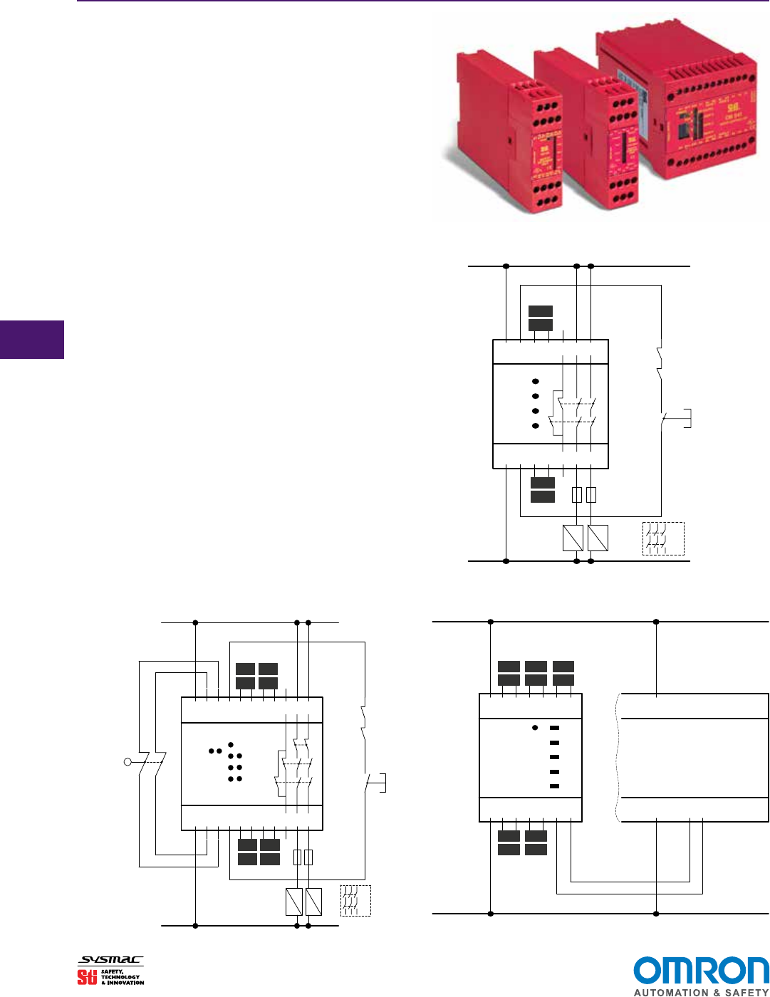
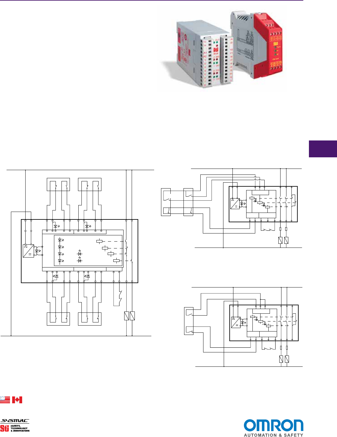
2-Wire Single Channel Controllers
CM-S41 Control Unit
The CM-S41 is a combined Safety Switch and E-Stop control
unit. Along with the ability to monitor up to four, 2-wire CM Series
safety switches, it can also monitor the normally closed contacts
of emergency stop buttons or mechanical safety switches in dual
channel control circuits.
The CM-S41 has 2 normally open safety contact outputs and 1
normally closed auxiliary output, an external reset/proving circuit
and LED indication for “Power”, “Run” and the status of each
activated gate switch.
CM-S21 Control Unit
The CM-S21 control unit is a 24 VAC/DC system that can moni-
tor up to 2 CM Series safety switches.
The CM-S21 has 2 normally open safety contact outputs and 1
normally closed auxiliary output, an external reset/proving circuit
and LED indication for “Power”, “Run” and the status of each
activated gate switch.
CM-SE Extender Module
The CM-SE expansion module is a 24 VAC/DC unit that can be
added to either the CM-S41 or CM-S21 to monitor an additional
5 CM Series safety switches. Connection to the main control
unit is by a simple 2-wire bus connection. The status of each
guard switch is shown by the YELLOW LED’s. Additional CMS-E
modules can be added to monitor larger systems.
Applications
CM-S21 Application Diagram
CM-S41 Application Diagram CM-SE Application Diagram
RUN
POWER
GATE 4GATE 3
4
3
2
1
GATE 4
GATE 3
GATE 2
DE-SELECT
A1
S13 S23
X1 BL DR BL DR 31 13
23
A2
S14 S24
X2 BL DR BL DR 32 14 24
GATE 2GATE 1
GS3GS4
GS1GS2
K1 K2
MECHANICA
L
SAFETY
SWITCHES
or
EMERGENCY
STOP
K1
K2
MANUAL
RE-SET
L (+ve)
N (-ve)
K1
K2
F1
F2
A1 BLDR
GATE 1
GS1
24 V
+ve
0 V
-ve
BLDR BLDR
GATE 2GATE 3
GS2 GS3
A2 BLDR
GATE 4
GS4
BLDR BLDR
GATE 5BUS
GS5
IND 1
IND 2
IND 3
IND 4
IND 5
2-WIRE BUS CONNECTION
POWER
BL DRA2
A1
ISIS-4 or ISIS-2
CONTROL UNIT
Connect the ISIS-E
Bus connection to
Extender Module Control Unit
CM-S41 / CM-S21 Control
Units:
Connect the CM-SE Bus
connection to an active
gate input.
GATE 2
A1 X1 BL DR 31 13 23
A2 X2 BL DR 32 14 24
GATE 1
GS2
GS1
K1 K2
K1
K2
24V
(+ve
)
0V
(-ve)
K1
K2
F1
F2
POWER
IND 1
IND 2
RUN
MANUAL
RE-SET
G
G-67
www.sti.com/info
Dual Channel Controllers
CM-S4 Control Unit
The CM-S4 controller is capable of monitoring up to four,
magnetically coded switches with 1 N/O + 1 N/C contacts up to
category 3 according to EN954-1. The CM-S4 has a dedicated
dual channel input for each switch and has LED status indicators
for each channel. The CM-S4 has 1 N/O safety contact and 1 N/O
Aux contact. External Device Monitoring (EDM) is available using
Y1,Y2 inputs.
CM-S30 Control Unit
The CM-S30 controller is capable of monitoring one magneti-
cally coded switch with 1 N/O + 1 N/C contacts up to category
4, or two switches to category 3 according to ISO 13489-1. The
CM-S30 control unit is capable of monitoring up to 30 convention-
al read style switches in series, but does not conform to category
4 when used with more than two switches. The CM-S30 controller
has 2 N/O safety contacts and 1 N/C Auxiliary contact. External
Device Monitoring (EDM) is available using Y1,Y2 inputs.
Applications (continued)
CM Series Safety Interlock Switches
CM-S4 Application Diagram CM-S30 Application Diagram (Cat 3)
CM-S30 Application Diagram (Cat 4)
WH
K1
K1
K1 K2
UB
K1 K1 F2
K2
START/
FEEDBACK LOOP
MONITORED AUTO
RESTART
K3
CHANNEL 1
CHANNEL 21
BRN
YE
GN
24VAC/DC
N (0 Volt)
A1 A2 HL1
H73 H74 Y1 Y2 Y3 14 24 32
HL2 H22 13 23 31
WH
BRN
YE
GN
GN
GN GN
CM-S30
WH
A1 A2 HL1
K1
K1
K1 K2
UB
K1 K1 F2
K2
H73 H74 Y1 Y2 Y3 14 24 32
MONITORED AUTO
RESTART
K3
CHANNEL 1
HL2 H22 13 23 31
BRN
YE
GN
READ HEAD 1
N (0 Volt)
24VAC/DC
START/
FEEDBACK LOOP
CHANNEL 21
GN
GN GN
CMS-S30
Select models are available for Rapid Delivery.
Visit this product on www.sti.com for details.
K1
K1
K2
K2
UB
D12
D12
D11
K1
control logic
READ HEAD 1
CHANNEL 1
CHANNEL 3 CHANNEL 4
FEEEDBACK LOOP
YE
A1 A2 1 2 3 4
GN WH BN
GN
RD
RD
RD
GN
CHANNEL 2
D21
OUT
GN
ID
GN
D31
GN
D41
GN
D12
READ HEAD 2
READ HEAD 3 READ HEAD 4
MONITORED AUTO RESTART
YE
5 6 7 8
9 10 11 12 15
16 17 18 14 24Y1 Y2
13
GN WH BN
BN WH YE GN BN WH YE GN
24VAC/DC
N (0 Volt)
K2
K3
K4
23
D42
RD
CM-S4
*23-24 should not be used as safety output.
G
G-68
www.sti.com/info
CM Series Safety Interlock Switches
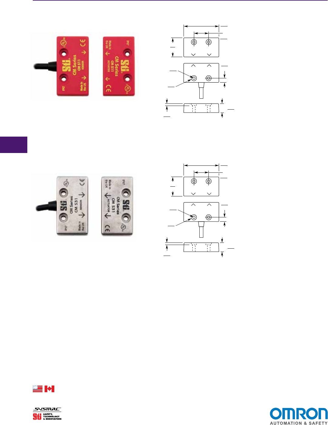
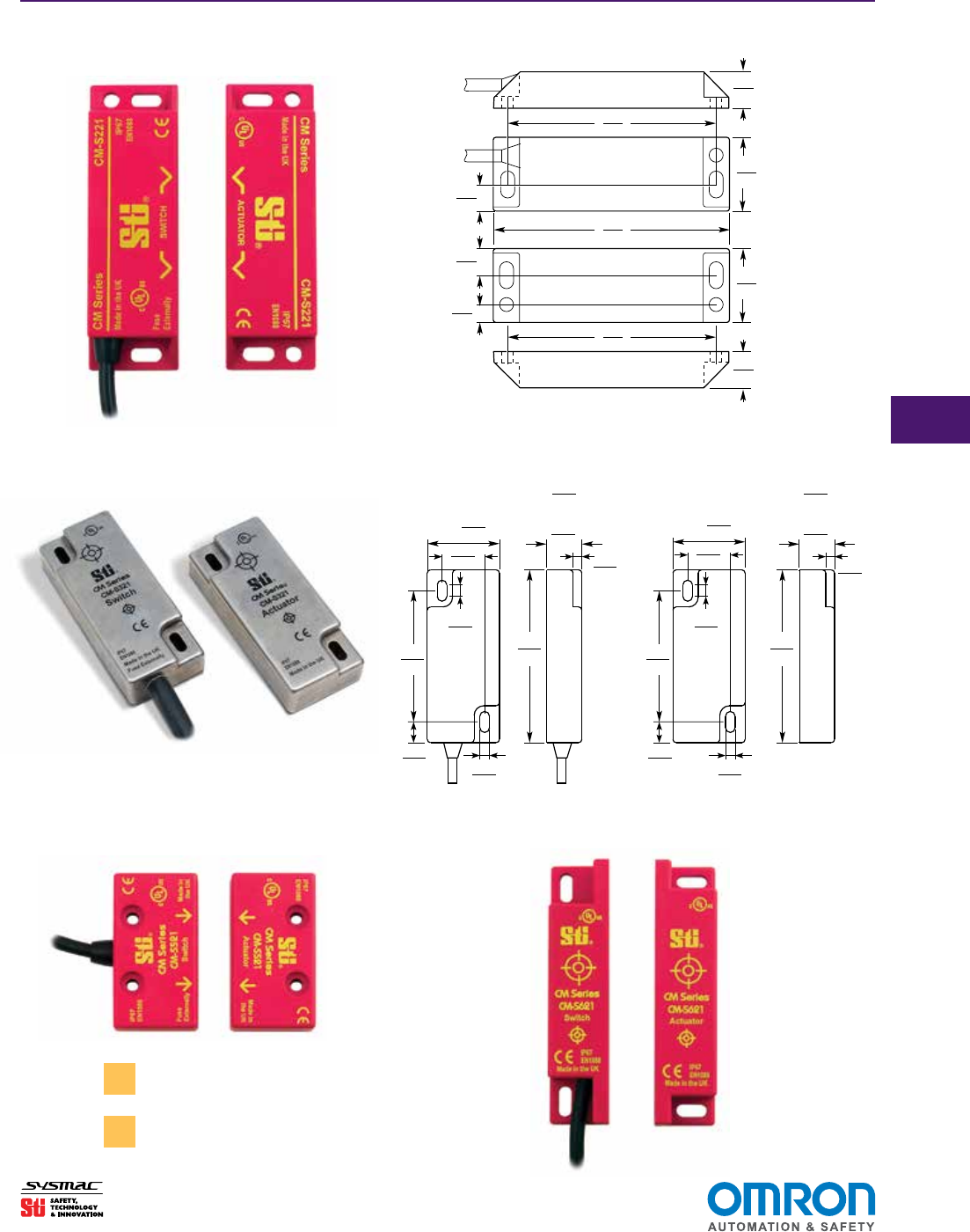
Dimensions (mm/in.)
2-Wire Coded Magnetic Switches
CM-S11
CM-S31
CM-S11 Switch
SIDE
Ø4.2
0.16
Ø8.1
0.32
3
0.11
14
0.55
6.4
0.25
28
1.1
52
2.04
22
0.86
CM-S31 Switch
SIDE
Ø4.2
0.16
Ø8.1
0.32
3
0.11
13.5
0.53
6.4
0.25
28
1.1
53
2.08
22
0.86
Select models are available for Rapid Delivery.
Visit this product on www.sti.com for details.
G
G-69
www.sti.com/info
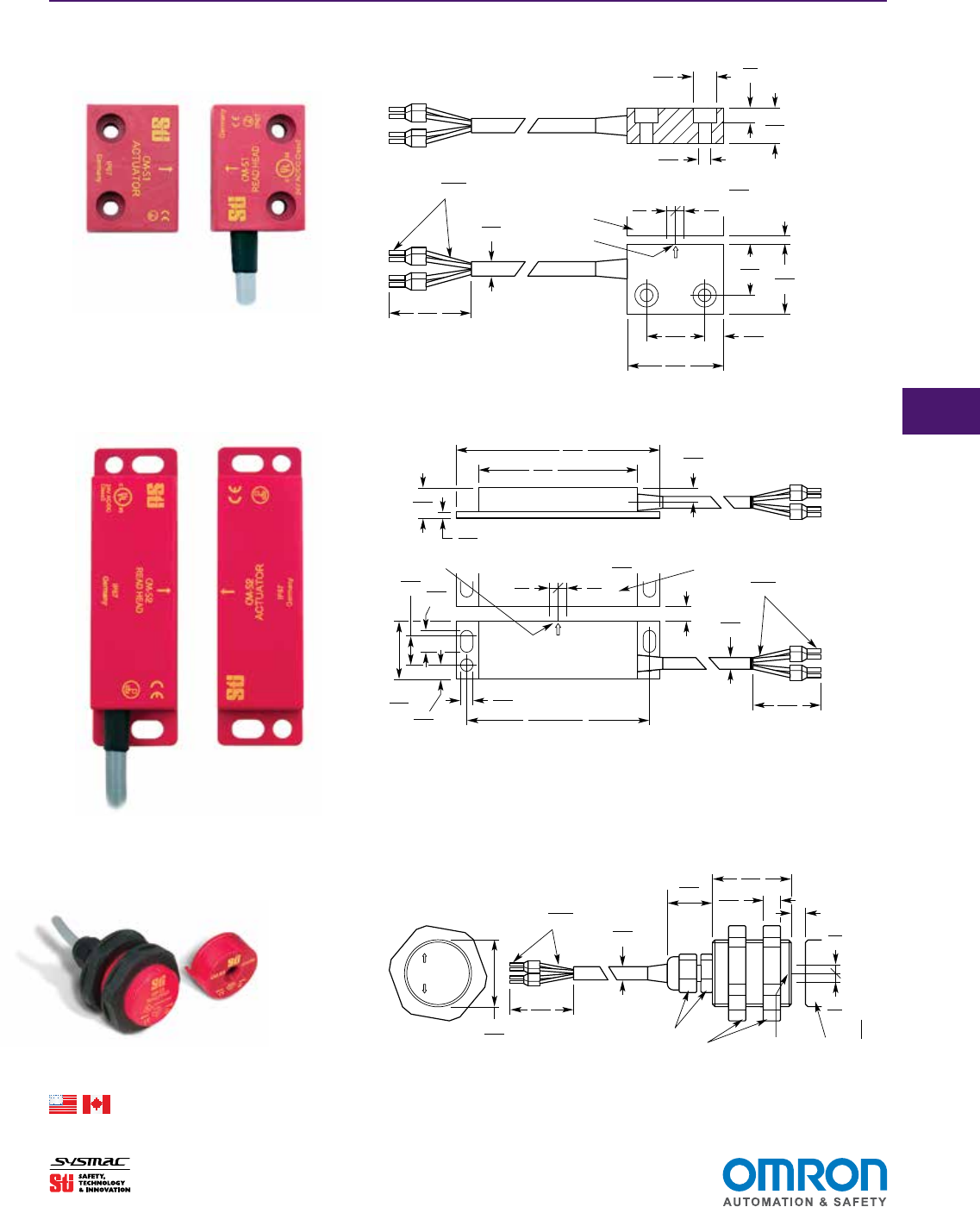
CM Series Safety Interlock Switches
Conventional Read Style Switches
Dimensions (continued) (mm/in.)
CM-S1
CM-S2
CM-S3
1.5
0.06
20
0.79
36
1.42
8
0.31
0.34
0.013
42
1.65
CM-S3 Switch
Ø5.8
0.23
ca.
SW15
3
0.12
Center Offset m at s =
Son
SW40
M30 x
2.5
0.1
2.5
0.1
Active Area Actuator
12
0.47 9.5
0.374
24.5
0.97 6
0.24
Ø5.5
0.22
13
0.51
2.5
0.1
67.5
2.66
87.5
3.44 6
0.24
CM-S2 Switch
NOTE: Actuator is same
dimension as switch.
Ø5.8
0.23
ca.
0.34
0.013
42
1.65
2.5
0.1
2.5
0.1
3
0.12
Center Offset m at s =
Active Area Actuator
Son
78 ± 1
3.07 ± 0.04
8.5
0.334
4.5
in
13
0.51
26.2
1.03
19.2
0.755
5
0.2
Ø5.8
0.23
2.5
0.1
2.5
0.1
3
0.12
0.34
0.013
42
1.65
36
1.42
22
0.87
7
0.28
CM-S1 Switch
Son
Center Offset m at s =
Active Area
Actuator
NOTE: Actuator is same
dimension as switch.
ca.
Select models are available for Rapid Delivery.
Visit this product on www.sti.com for details.
G
G-70
www.sti.com/info
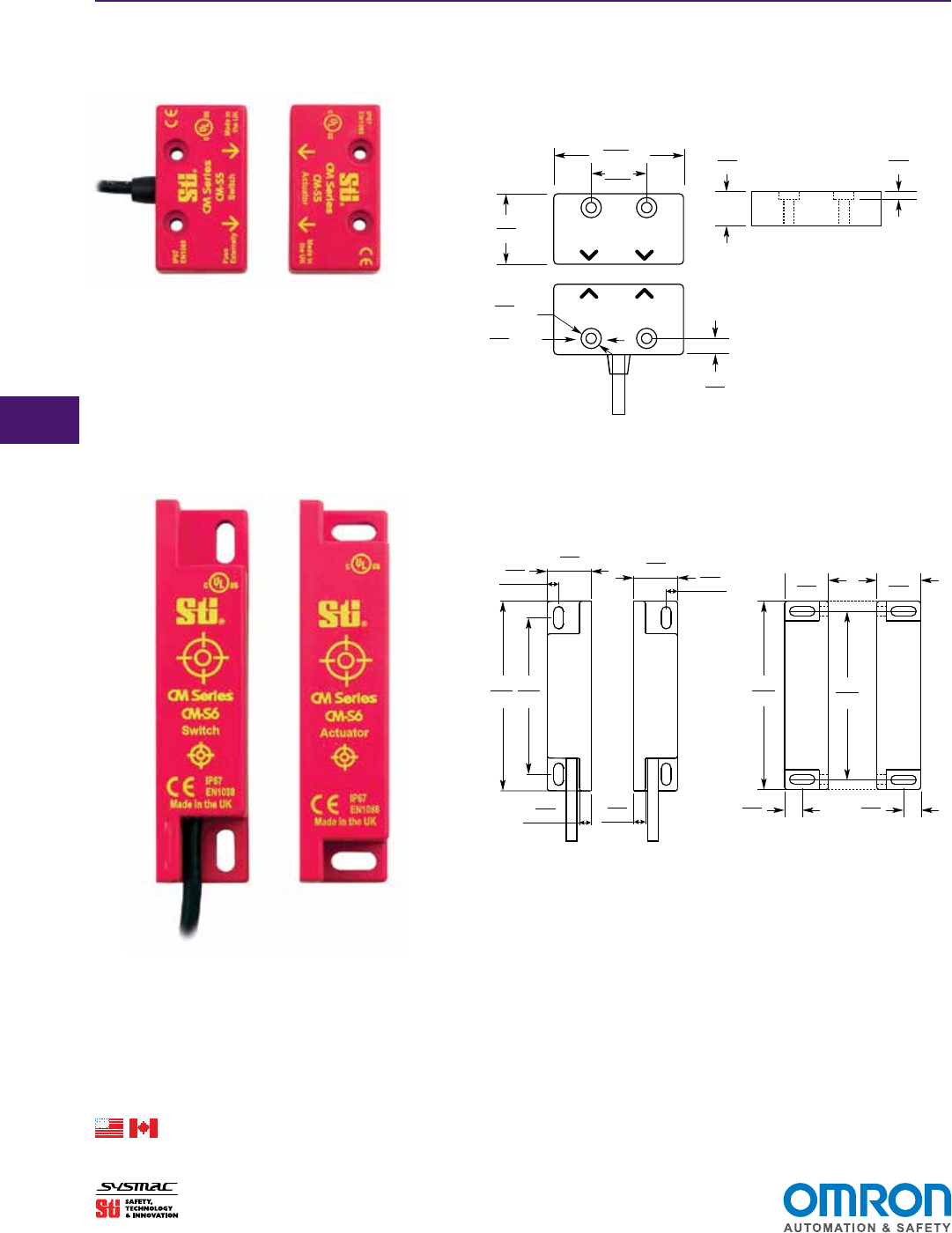
Conventional Read Style Switches (continued)
Dimensions (continued) (mm/in.)
CM-S5
CM-S6
CM Series Safety Interlock Switches
52.0
2.05
22.0
0.87
28.0
1.10
4.2
0.17 dia.
8.1
0.32 dia.
14.0
0.55
3.0
0.12
6.4
0.25
CM-S5 and CM-S521
SIDE VIEW
4.9
0.19
5.0
0.20
5.0
0.20
7.2
0.28
4.9
0.19
82.5
3.25
82.5
3.25
73.0
2.87
68.0
2.68
19.0
0.75
19.0
0.75
19.0
0.75
19.0
0.75
7.2
0.28
CM-S6 and CM-S621
SWITCH ACTUATOR
Select models are available for Rapid Delivery.
Visit this product on www.sti.com for details.
G
G-71
www.sti.com/info
CM Series Safety Interlock Switches
Universal Read Style Switches
Dimensions (continued) (mm/in.)
CM-S221
For CM-S521 dimensions, please refer to the
CM-S5 dimensions on the previous page.
✎
CM-S221 Switch
78.0
3.07
87.5
3.44
78.0
3.07
13.5
0.53
27.2
1.07
9.8
0.39
9.8
0.39
6.6
0.26
Switch
Actuator
13.5
0.53
27.2
1.07
CM-S321/CM-S421
60.0
2.36
79.0
3.11
33.0
1.30 16.0
0.63
19.5
0.77
5.3
0.21
9.5
0.37 4.4
0.17
4.0
0.16
79.0
3.11
4.4
0.17
5.3
0.21
60.0
2.36
9.5
0.37
33.0
1.30
19.5
0.77
16.0
0.63
17.8
0.70
4.0
0.16
CM-S321 and CM-S421
Note: The CM-S321 includes a backing plate (not shown).
SWITCH ACTUATOR
with backing
plate
17.8
0.70 with backing
plate
CM-S521 CM-S621
For CM-S621 dimensions, please refer to the
CM-S6 dimensions on the previous page.
✎
G
G-72
www.sti.com/info
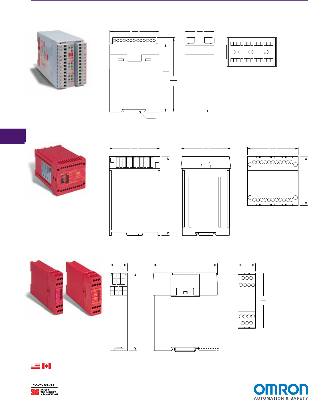
CM Series Safety Interlock Switches
Dimensions (continued) (mm/in.)
Control Units
CM-S4
CM-S41
CM-S21 & CM-SE
105
4.13
35
1.38
114.7
4.515
75
2.95
75
2.95
45
1.77
CM-S4
CM-S41
CM-S21/SE
For DIN rail
75
2.95
74
2.91
74
2.91
84
3.3
119
4.68
119
4.68
22.5
0.88
22.5
0.88
84
3.3
105
4.13
35
1.38
114.7
4.515
75
2.95
75
2.95
45
1.77
CM-S4
CM-S41
CM-S21/SE
For DIN rail
75
2.95
74
2.91
74
2.91
84
3.3
119
4.68
119
4.68
22.5
0.88
22.5
0.88
84
3.3
105
4.13
35
1.38
114.7
4.515
75
2.95
75
2.95
45
1.77
CM-S4
CM-S41
CM-S21/SE
For DIN rail
75
2.95
74
2.91
74
2.91
84
3.3
119
4.68
119
4.68
22.5
0.88
22.5
0.88
84
3.3
Select models are available for Rapid Delivery.
Visit this product on www.sti.com for details.
G
G-73
www.sti.com/info
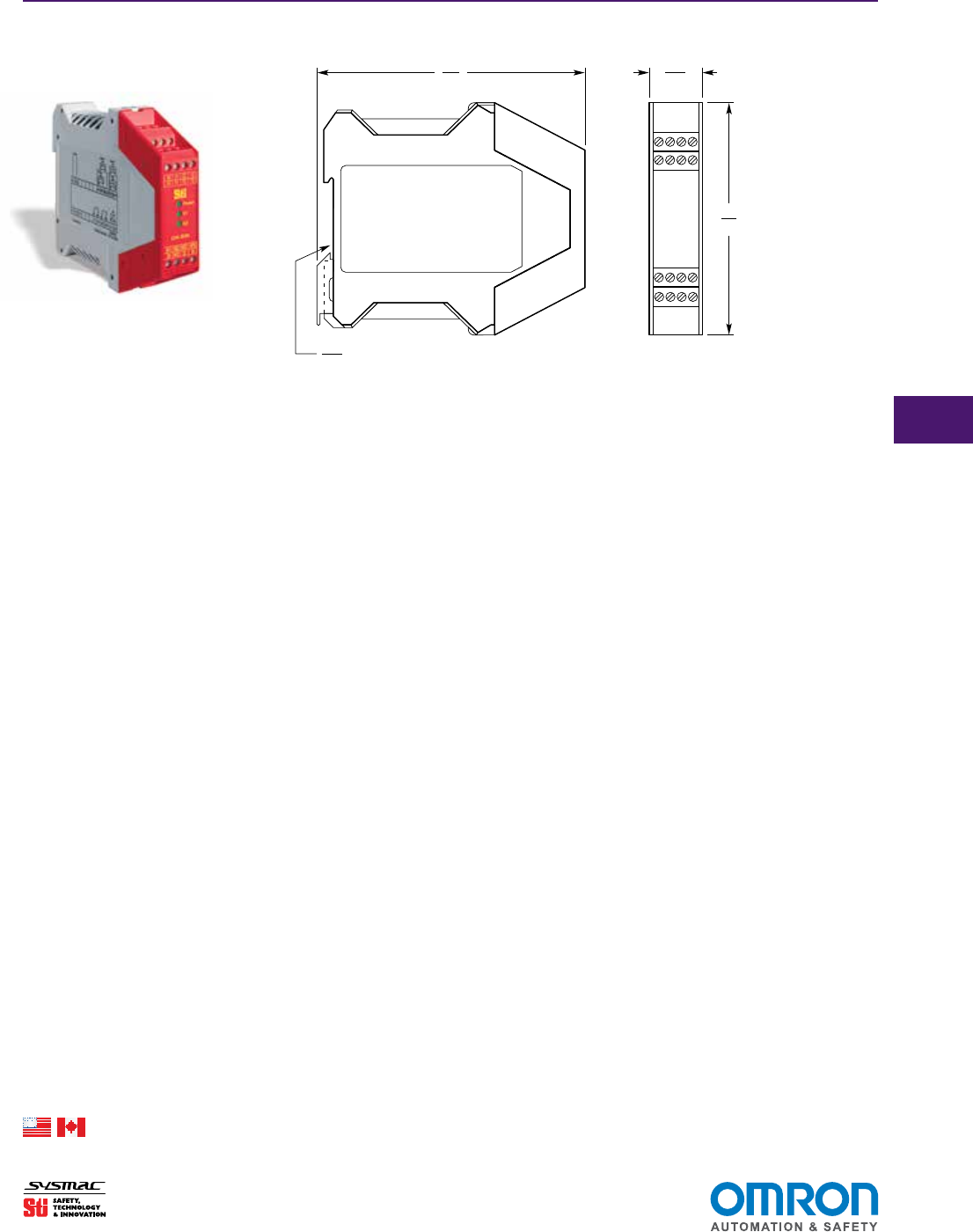
CM Series Safety Interlock Switches
Dimensions (continued) (mm/in.)
Control Units (continued)
CM-S30
DIN RAIL MOUNTING
35
1.38
99
3.9
114
4.5
22.5
0.885
CM-S30
Select models are available for Rapid Delivery.
Visit this product on www.sti.com for details.
G
G-74
www.sti.com/info
CM Series Safety Interlock Switches
Universal Mounting Brackets can be used with
this product. See page G-210 for details.
✎
Model
Switch
Construction Contacts Wiring Entry Part No.
Control Units for 2-Wire Switches
CM-S21-24 (24 VAC/DC) 44536-0120
CM-S41-24 (24 VAC/DC) 44536-0140
CM-S41-110 (110 VAC or 230 VAC) 44536-0141
CM-SE-24 (24 VAC/DC) 44536-0170
2-Wire Switches
CM-S11-PC3 Plastic 2-wire system 3 m cable 44536-1100
CM-S11-PC5 Plastic 2-wire system 5 m cable 44536-1105
CM-S11-PC10 Plastic 2-wire system 10 m cable 44536-1110
CM-S11-PCC5 Plastic 2-wire system connector + 5 m cable 44536-1159
CM-S31SC3 Stainless Steel 2-wire system 3 m cable 44536-3100
CM-S31SC5 Stainless Steel 2-wire system 5 m cable 44536-3105
CM-S31SCC5 Stainless Steel 2-wire system connector + 5 m cable 44536-3159
Control Units for 1 N/C + 1 N/O Reed Style Switches
CM-S30 (24 VAC/DC) 44536-0030
CM-S4 (24 VAC/DC) 44536-0040
1 N/C + 1 N/O Reed Style Switches
CM-S1PC3 Plastic 1 N/C + 1 N/O 3 m cable 44536-0100
CM-S1PC5 Plastic 1 N/C + 1 N/O 5 m cable 44536-0105
CM-S2PC3 Plastic 1 N/C + 1 N/O 3 m cable 44536-0200
CM-S2PC5 Plastic 1 N/C + 1 N/O 5 m cable 44536-0205
CM-S3PC3 Plastic 1 N/C + 1 N/O 3 m cable 44536-0300
CM-S3PC5 Plastic 1 N/C + 1 N/O 5 m cable 44536-0305
CM-S5PC5 Plastic 1 N/C + 1 N/O 5 m cable 44536-0505
CM-S5PC10 Plastic 1 N/C + 1 N/O 10 m cable 44536-0510
CM-S6PC5 Plastic 1 N/C + 1 N/O 5 m cable 44536-0605
CM-S6PC10 Plastic 1 N/C + 1 N/O 10 m cable 44536-0610
Universal Reed Style Switches
(can be used with safety monitoring relays that accept 1N/C + 1N/O or 2NC switch contacts except the SR203, SR208, SR209)
CAUTION! Universal reed switches may be operated with a coded or non-coded actuator when using 2 NC contacts with a safety monitoring relay.
CM-S221PC5 Plastic 2 N/C + 1 N/O 5 m cable 44536-0221
CM-S221PCC5 Plastic 2 N/C + 1 N/O connector + 5 m cable 44536-0225
CM-S221PCC Plastic 2 N/C + 1 N/O no cable 44536-0226
CM-S521PC5 Plastic 2 N/C + 1 N/O 5 m cable 44536-0521
CM-S521PC10 Plastic 2 N/C + 1 N/O 10 m cable 44536-1521
CM-S621PC5 Plastic 2 N/C + 1 N/O 5 m cable 44536-0621
CM-S621PC10 Plastic 2 N/C + 1 N/O 10 m cable 44536-1621
CM-S321SC5 Stainless Steel 2 N/C + 1 N/O 5 m cable 44536-3221
CM-S321SCC5 Stainless Steel,
backing plate 2 N/C + 1 N/O M12 connector
+ 5 m cable 44536-3229
CM-S321SCC Stainless Steel,
backing plate 2 N/C + 1 N/O M12 connector,
no cable 44536-3220
CM-S421SC5 Stainless Steel, No
backing plate 2 N/C + 1 N/O 5 m cable 44536-4221
CM-S421SCC5 Stainless Steel, No
backing plate 2 N/C + 1 N/O M12 connector
+ 5 m cable 44536-4229
Recommended Safety Monitoring Relays for Universal Reed Style Switches
CM-S4, CM-S30, G9SA series, G9SX-AD, G9SX-BC, SR series
Spare Actuators/Accessories
Replacement Actuator for CM-S1, Red ABS Plastic 44536-0710
Replacement Actuator for CM-S2, Red ABS Plastic 44536-0720
Replacement Actuator for CM-S3, Red ABS Plastic 44536-0730
Replacement Actuator for CM-S5,CM-S521 Red ABS Plastic 44536-0750
Replacement Actuator for CM-S6, CM-S621 Red ABS Plastic 44536-0760
Replacement Actuator for CM-S11, Red ABS Plastic 44536-0711
Replacement Actuator for CM-S31, Red ABS Plastic 44536-0731
Replacement Actuator for CM-S221, Red ABS Plastic 44536-0721
Replacement Actuator for CM-S321, Stainless Steel, backing plate 44536-0741
Replacement Actuator for CM-S421, Stainless Steel, No backing Plate 44536-0751
Mounting Bracket for CM-S3 44536-0800
Ordering
Select models are available for Rapid Delivery.
Visit this product on www.sti.com for details.

Terms and Conditions of Sale
1. Offer; Acceptance. These terms and conditions (these "Terms") are deemed
part of all quotes, agreements, purchase orders, acknowledgments, price lists,
catalogs, manuals, brochures and other documents, whether electronic or in
writing, relating to the sale of products or services (collectively, the "Products")
by Omron Electronics LLC and its subsidiary companies (“Omron”). Omron
objects to any terms or conditions proposed in Buyer’s purchase order or other
documents which are inconsistent with, or in addition to, these Terms.
2. Prices; Payment Terms. All prices stated are current, subject to change with-
out notice by Omron. Omron reserves the right to increase or decrease prices
on any unshipped portions of outstanding orders. Payments for Products are
due net 30 days unless otherwise stated in the invoice.
3. Discounts. Cash discounts, if any, will apply only on the net amount of invoices
sent to Buyer after deducting transportation charges, taxes and duties, and will
be allowed only if (i) the invoice is paid according to Omron’s payment terms
and (ii) Buyer has no past due amounts.
4. Interest. Omron, at its option, may charge Buyer 1-1/2% interest per month or
the maximum legal rate, whichever is less, on any balance not paid within the
stated terms.
5. Orders. Omron will accept no order less than $200 net billing.
6. Governmental Approvals. Buyer shall be responsible for, and shall bear all
costs involved in, obtaining any government approvals required for the impor-
tation or sale of the Products.
7. Taxes. All taxes, duties and other governmental charges (other than general
real property and income taxes), including any interest or penalties thereon,
imposed directly or indirectly on Omron or required to be collected directly or
indirectly by Omron for the manufacture, production, sale, delivery, importa-
tion, consumption or use of the Products sold hereunder (including customs
duties and sales, excise, use, turnover and license taxes) shall be charged to
and remitted by Buyer to Omron.
8. Financial. If the financial position of Buyer at any time becomes unsatisfactory
to Omron, Omron reserves the right to stop shipments or require satisfactory
security or payment in advance. If Buyer fails to make payment or otherwise
comply with these Terms or any related agreement, Omron may (without liabil-
ity and in addition to other remedies) cancel any unshipped portion of Prod-
ucts sold hereunder and stop any Products in transit until Buyer pays all
amounts, including amounts payable hereunder, whether or not then due,
which are owing to it by Buyer. Buyer shall in any event remain liable for all
unpaid accounts.
9. Cancellation; Etc. Orders are not subject to rescheduling or cancellation
unless Buyer indemnifies Omron against all related costs or expenses.
10. Force Majeure. Omron shall not be liable for any delay or failure in delivery
resulting from causes beyond its control, including earthquakes, fires, floods,
strikes or other labor disputes, shortage of labor or materials, accidents to
machinery, acts of sabotage, riots, delay in or lack of transportation or the
requirements of any government authority.
11. Shipping; Delivery. Unless otherwise expressly agreed in writing by Omron:
a. Shipments shall be by a carrier selected by Omron; Omron will not drop ship
except in “break down” situations.
b. Such carrier shall act as the agent of Buyer and delivery to such carrier shall
constitute delivery to Buyer;
c. All sales and shipments of Products shall be FOB shipping point (unless oth-
erwise stated in writing by Omron), at which point title and risk of loss shall
pass from Omron to Buyer; provided that Omron shall retain a security inter-
est in the Products until the full purchase price is paid;
d. Delivery and shipping dates are estimates only; and
e. Omron will package Products as it deems proper for protection against nor-
mal handling and extra charges apply to special conditions.
12. Claims. Any claim by Buyer against Omron for shortage or damage to the
Products occurring before delivery to the carrier must be presented in writing
to Omron within 30 days of receipt of shipment and include the original trans-
portation bill signed by the carrier noting that the carrier received the Products
from Omron in the condition claimed.
13. Warranties. (a) Exclusive Warranty. Omron’s exclusive warranty is that the
Products will be free from defects in materials and workmanship for a period of
twelve months from the date of sale by Omron (or such other period expressed
in writing by Omron). Omron disclaims all other warranties, express or implied.
(b) Limitations. OMRON MAKES NO WARRANTY OR REPRESENTATION,
EXPRESS OR IMPLIED, ABOUT NON-INFRINGEMENT, MERCHANTABIL-
ITY OR FITNESS FOR A PARTICULAR PURPOSE OF THE PRODUCTS.
BUYER ACKNOWLEDGES THAT IT ALONE HAS DETERMINED THAT THE
PRODUCTS WILL SUITABLY MEET THE REQUIREMENTS OF THEIR
INTENDED USE. Omron further disclaims all warranties and responsibility of
any type for claims or expenses based on infringement by the Products or oth-
erwise of any intellectual property right. (c) Buyer Remedy. Omron’s sole obli-
gation hereunder shall be, at Omron’s election, to (i) replace (in the form
originally shipped with Buyer responsible for labor charges for removal or
replacement thereof) the non-complying Product, (ii) repair the non-complying
Product, or (iii) repay or credit Buyer an amount equal to the purchase price of
the non-complying Product; provided that in no event shall Omron be responsi-
ble for warranty, repair, indemnity or any other claims or expenses regarding
the Products unless Omron’s analysis confirms that the Products were prop-
erly handled, stored, installed and maintained and not subject to contamina-
tion, abuse, misuse or inappropriate modification. Return of any Products by
Buyer must be approved in writing by Omron before shipment. Omron Compa-
nies shall not be liable for the suitability or unsuitability or the results from the
use of Products in combination with any electrical or electronic components,
circuits, system assemblies or any other materials or substances or environ-
ments. Any advice, recommendations or information given orally or in writing,
are not to be construed as an amendment or addition to the above warranty.
See http://www.omron247.com or contact your Omron representative for pub-
lished information.
14. Limitation on Liability; Etc. OMRON COMPANIES SHALL NOT BE LIABLE
FOR SPECIAL, INDIRECT, INCIDENTAL, OR CONSEQUENTIAL DAMAGES,
LOSS OF PROFITS OR PRODUCTION OR COMMERCIAL LOSS IN ANY
WAY CONNECTED WITH THE PRODUCTS, WHETHER SUCH CLAIM IS
BASED IN CONTRACT, WARRANTY, NEGLIGENCE OR STRICT LIABILITY.
Further, in no event shall liability of Omron Companies exceed the individual
price of the Product on which liability is asserted.
15. Indemnities. Buyer shall indemnify and hold harmless Omron Companies and
their employees from and against all liabilities, losses, claims, costs and
expenses (including attorney's fees and expenses) related to any claim, inves-
tigation, litigation or proceeding (whether or not Omron is a party) which arises
or is alleged to arise from Buyer's acts or omissions under these Terms or in
any way with respect to the Products. Without limiting the foregoing, Buyer (at
its own expense) shall indemnify and hold harmless Omron and defend or set-
tle any action brought against such Companies to the extent based on a claim
that any Product made to Buyer specifications infringed intellectual property
rights of another party.
16. Property; Confidentiality. Any intellectual property in the Products is the exclu-
sive property of Omron Companies and Buyer shall not attempt to duplicate it
in any way without the written permission of Omron. Notwithstanding any
charges to Buyer for engineering or tooling, all engineering and tooling shall
remain the exclusive property of Omron. All information and materials supplied
by Omron to Buyer relating to the Products are confidential and proprietary,
and Buyer shall limit distribution thereof to its trusted employees and strictly
prevent disclosure to any third party.
17. Export Controls. Buyer shall comply with all applicable laws, regulations and
licenses regarding (i) export of products or information; (iii) sale of products to
“forbidden” or other proscribed persons; and (ii) disclosure to non-citizens of
regulated technology or information.
18. Miscellaneous. (a) Waiver. No failure or delay by Omron in exercising any right
and no course of dealing between Buyer and Omron shall operate as a waiver
of rights by Omron. (b) Assignment. Buyer may not assign its rights hereunder
without Omron's written consent. (c) Law. These Terms are governed by the
law of the jurisdiction of the home office of the Omron company from which
Buyer is purchasing the Products (without regard to conflict of law princi-
ples). (d) Amendment. These Terms constitute the entire agreement between
Buyer and Omron relating to the Products, and no provision may be changed
or waived unless in writing signed by the parties. (e) Severability
. If any provi-
sion hereof is rendered ineffective or invalid, such provision shall not invalidate
any other provision. (f) Setoff. Buyer shall have no right to set off any amounts
against the amount owing in respect of this invoice. (g) Definitions. As used
herein, “including” means “including without limitation”; and “Omron Compa-
nies” (or similar words) mean Omron Corporation and any direct or indirect
subsidiary or affiliate thereof.
Certain Precautions on Specifications and Use
1. Suitability of Use. Omron Companies shall not be responsible for conformity
with any standards, codes or regulations which apply to the combination of the
Product in the Buyer’s application or use of the Product. At Buyer’s request,
Omron will provide applicable third party certification documents identifying
ratings and limitations of use which apply to the Product. This information by
itself is not sufficient for a complete determination of the suitability of the Prod-
uct in combination with the end product, machine, system, or other application
or use. Buyer shall be solely responsible for determining appropriateness of
the particular Product with respect to Buyer’s application, product or system.
Buyer shall take application responsibility in all cases but the following is a
non-exhaustive list of applications for which particular attention must be given:
(i) Outdoor use, uses involving potential chemical contamination or electrical
interference, or conditions or uses not described in this document.
(ii) Use in consumer products or any use in significant quantities.
(iii) Energy control systems, combustion systems, railroad systems, aviation
systems, medical equipment, amusement machines, vehicles, safety equip-
ment, and installations subject to separate industry or government regulations.
(iv) Systems, machines and equipment that could present a risk to life or prop-
erty. Please know and observe all prohibitions of use applicable to this Prod-
uct.
NEVER USE THE PRODUCT FOR AN APPLICATION INVOLVING SERIOUS
RISK TO LIFE OR PROPERTY OR IN LARGE QUANTITIES WITHOUT
ENSURING THAT THE SYSTEM AS A WHOLE HAS BEEN DESIGNED TO
ADDRESS THE RISKS, AND THAT THE OMRON’S PRODUCT IS PROP-
ERLY RATED AND INSTALLED FOR THE INTENDED USE WITHIN THE
OVERALL EQUIPMENT OR SYSTEM.
2. Programmable Products. Omron Companies shall not be responsible for the
user’s programming of a programmable Product, or any consequence thereof.
3. Performance Data. Data presented in Omron Company websites, catalogs
and other materials is provided as a guide for the user in determining suitabil-
ity and does not constitute a warranty. It may represent the result of Omron’s
test conditions, and the user must correlate it to actual application require-
ments. Actual performance is subject to the Omron’s Warranty and Limitations
of Liability.
4. Change in Specifications. Product specifications and accessories may be
changed at any time based on improvements and other reasons. It is our prac-
tice to change part numbers when published ratings or features are changed,
or when significant construction changes are made. However, some specifica-
tions of the Product may be changed without any notice. When in doubt, spe-
cial part numbers may be assigned to fix or establish key specifications for
your application. Please consult with your Omron’s representative at any time
to confirm actual specifications of purchased Product.
5. Errors and Omissions. Information presented by Omron Companies has been
checked and is believed to be accurate; however, no responsibility is assumed
for clerical, typographical or proofreading errors or omissions.

OMRON CANADA, INC. • HEAD OFFICE
Toronto, ON, Canada • 416.286.6465 • 866.986.6766 • www.omron247.com
OMRON ELECTRONICS DE MEXICO • HEAD OFFICE
México DF • 52.
55.59.01.43.00
• 01-800-226-6766 • mela@omron.com
OMRON ELECTRONICS DE MEXICO • SALES OFFICE
Apodaca, N.L. • 52.81.11.56.99.20 • 01-800-226-6766 • mela@omron.com
OMRON ELETRÔNICA DO BRASIL LTDA • HEAD OFFICE
São Paulo, SP, Brasil • 55.11.2101.6300 • www.omron.com.br
OMRON ARGENTINA • SALES OFFICE
Cono Sur • 54.11.4783.5300
OMRON CHILE • SALES OFFICE
Santiago • 56.9.9917.3920
OTHER OMRON LATIN AMERICA SALES
54.11.4783.5300
Authorized Distributor:
C42I-E-01 08/14 Note: Specifications are subject to change. © 2014 Omron Electronics LLC Printed in U.S.A.
Printed on recycled paper.
Automation Control Systems
• Machine Automation Controllers (MAC) • Programmable Controllers (PLC)
• Operator interfaces (HMI) • Distributed I/O • Software
Drives & Motion Controls
• Servo & AC Drives • Motion Controllers & Encoders
Temperature & Process Controllers
• Single and Multi-loop Controllers
Sensors & Vision
• Proximity Sensors • Photoelectric Sensors • Fiber-Optic Sensors
• Amplified Photomicrosensors • Measurement Sensors
• Ultrasonic Sensors • Vision Sensors
Industrial Components
• RFID/Code Readers • Relays • Pushbuttons & Indicators
• Limit and Basic Switches • Timers • Counters • Metering Devices
• Power Supplies
Safety
• Laser Scanners • Safety Mats • Edges and Bumpers • Programmable Safety
Controllers • Light Curtains • Safety Relays • Safety Interlock Switches
OMRON AUTOMATION AND SAFETY • THE AMERICAS HEADQUARTERS • Chicago, IL USA • 847.843.7900 • 800.556.6766 • www.omron247.com
OMRON EUROPE B.V. •
Wegalaan 67-69, NL-2132 JD, Hoofddorp, The Netherlands.
•
+31 (0) 23 568 13 00
•
www.industrial.omron.eu
