Communications_Control_Program_Ver_3_Ref_Man_60471400G_May81 Communications Control Program Ver 3 Ref Man 60471400G May81
User Manual: Pdf Communications_Control_Program_Ver_3_Ref_Man_60471400G_May81
Open the PDF directly: View PDF ![]() .
.
Page Count: 160 [warning: Documents this large are best viewed by clicking the View PDF Link!]
60471400
CONTRPL DATA
CORPORATION
NETWORK PRODUCTS
COMMUNICATIONS CONTROL PROGRAM
VERSION 3
REFERENCE MANUAL
0gv&®*\
CDC® COMPUTER SYSTEMS:
255X SERIES
NETWORK PROCESSING UNIT
REVISION RECORD
Revision
A (11/10/76)
B (04/28/78)
C (12/01/78)
D (06/30/79)
E (05/22/80)
F (10/09/80)
G (05/29/81)
Description
Initial release under NOS lj level 438.
?!fXisi?? e?,!?CP i'lf Cycle 34 plus °Ptioi»al minitape corrective code: PSRs 755, 718A,
729, 757, 773, 784, 828, 834, 835.
Revised to include corrective code release, cycles 35, 36, 37; PSRs 257, 275, 710, 726,
Ion' l*Z\ ?oLth^,76^ 7?3' 779' 784' 792' 800' 801» 803» 804> 807 thru 810, 813, 818,
891 921 853 thrU 855' 858' 862' 865' 869' 87°' 8?2' 8?8 thrU 88i' 883'
Revised to CCP 3.2 PSR level 497. This revision obsoletes all previous editions.
Revised to reflect PSR level 518.
Revised for CCP release level 3.3, PSR level 528.
Revised for CCP release level 3.4, PSR level 541. Includes PRU interface with Binary
Synchronous Communications TIP and 2780/3780 terminal support. This is a complete
reprint.
/•sSis
^f£$S.
REVISION LETTERS I, 0, Q, AND X ARE NOT USED
©COPYRIGHT CONTROL DATA CORPORATION
1976, 1978, 1979, 1980, 1981
All Rights Reserved
Printed in the United States of America
Address comments concerning this manual to:
CONTROL DATA CORPORATION
Publications and Graphics Division
215 MOFFETT PARK DRIVE
SUNNYVALE, CALIFORNIA 94086
or use Comment Sheet in the back of this manual
<*=weS!V
60471400 G
LIST OF EFFECTIVE PAGES
New features, as well as changes, deletions, and additions to information in this manual are indicated by bars
in the margins or by a dot near the page number if the entire page is affected. A bar by the page number
indicates pagination rather than content has changed.
Page Revision
Front Cover
Title Page
ii
iii/iv
v
vi
vii
v i i i
1-1
1-2
1-3
1-4
1-5 thru 1-20
2-1 thru 2-37
3-1
3-2
3-3
3-4 thru 3-7
4-1
A-l thru A-41
B-l
B-2
B-3
B-4
B-5
B-6
B-7
B-8
B-9
B-10
B-ll
B-12
C-l th ru C-9
D-l th ru D-3
E-l
F-l
G-l thru G-4
H-l thru H-3
Index-1
Index-2
Comment !Sheet
Mailer
Back Cover
60471400 G iii/iv

y^^K
<#
PREFACE
This manual is intended to provide overview information
concerning the role of the CDC® Communications Control
Program Version 3.4 (CCP) in network processing, and to
describe the functions which CCP provides for the
network.
CONVENTIONS USED
Throughout this manual, the following conventions are used
in the presentation of statement formats, operator
type-ins, and diagnostic messages:
ALN Uppercase letters indicate words, acronyms,
or mnemonics either required by the network
software as input to it, or produced as output.
aln Lowercase letters identify variables for which
values are supplied by NAM or the terminal
user, or by the network software as output.
Ellipsis indicates that the omitted entities
repeat the form and function of the entity last
given.
[ ] Square brackets enclose entities that are
optional; if omission of any entity causes the
use of a default entity, the default is
underlined.
{ } Braces enclose entities from which one must
be chosen.
Unless otherwise specified, all references to numbers are
to decimal values; all references to bytes are to 8-bit
bytes; all references to characters are to 8-bit ASCII coded
characters.
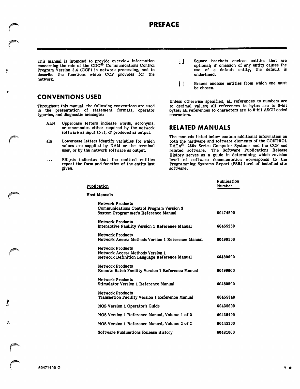
RELATED MANUALS
The manuals listed below contain additional information on
both the hardware and software elements of the CONTROL
DATA® 255x Series Computer Systems and the CCP and
related software. The Software Publications Release
History serves as a guide in determining which revision
level of software documentation corresponds to the
Programming Systems Report (PSR) level of installed site
software.
Publication
Host Manuals
Network Products
Communications Control Program Version 3
System Programmer's Reference Manual
Network Products
Interactive Facility Version 1 Reference Manual
Network Products
Network Access Methods Version 1 Reference Manual
Network Products
Network Access Methods Version 1
Network Definition Language Reference Manual
Network Products
Remote Batch Facility Version 1 Reference Manual
Network Products
Stimulator Version 1 Reference Manual
Network Products
Transaction Facility Version 1 Reference Manual
NOS Version 1 Operator's Guide
NOS Version 1 Reference Manual, Volume 1 of 2
NOS Version 1 Reference Manual, Volume 2 of 2
Software Publications Release History
Publication
Number
60474500
60455250
60499500
60480000
60499600
60480500
60455340
60435600
60435400
60445300
60481000
Avx^S.
60471400 G V •
Language Manuals
CYBER Cross System Version 1
Build Utilities Reference Manual
CYBER Cross System Version 1
Macro Assembler Reference Manual
CYBER Cross System Version 1
Micro Assembler Reference Manual
CYBER Cross System Version 1
PASCAL Compiler Reference Manual
State Programming Language Reference Manual
Update Version 1 Reference Manual
NPU Manuals
MSMP Diagnostic Reference Manual
Network Processing Unit (NPU)
Hardware Reference Manual
Operational Diagnostic System (ODS) Version 2
Reference Manual
60471200
96836500
96836400
96836100
60472200
60449900
96700000
60472800
96768410
yX^rtWf^f.
CDC manuals can be ordered from Control Data Corporation, Literature and
Distribution Services, 308 North Dale Street, St. Paul, Minnesota 55103.
This product is intended for use only as described in
this document. Control Data cannot be responsible for
the proper functioning of undescribed features or
parameters.
• vi 60471400 G
CONTENTS
i. INTRODUCTION TO CCP AND NETWORK
CONCEPTS
Network Concepts
Communications Network Overview
Computer Network Overview
Computer Network Products
Network Host Products
Network Access Method
Network Definition
Network Supervision
NAM Applications Programs
Communications Network Products
255X Series NPU
Communications Control Program
CCP Coding Languages
Message Movement in a Network
Simplified Input Message Processing
Simplified Output Message Processing
CCP Role in Network Processing
Multiplexing Operation
Base System Software
Block Interface Package (BIP)
Host Interface Package
Link Interface Package
Terminal Interface Packages
CCP Software Languages
255X Hardware
Communications Processor
Multiplex Subsystem
Communications Console
2558-3 Channel Coupler
Communications Line Adapters
2560 Series Synchronous Communications
Line Adapters
Sample Configurations
Terminals Supported
2. OVERVIEW OF CCP FUNCTIONS
Multiplexing, Switching and Data Conversion
Interfaces
Transmission Media
Initialization
Base System Software
System Monitor
Buffer Handling
Worklist Services
Queuing Mechanisms
Direct Program Calls (Switching Services)
Interrupt Handling
Timing Services
Globals
Control Block Services
Directory Maintenance
Standard Subroutines
Multiplex Subsystem Operation
Input Multiplexing
Output Multiplexing
Trunk Multiplexing
Demultiplexing
Block Interface Package (BIP)
Block Routing
Service Module
Interactive Virtual Terminal Commands
Batch Terminal PRU Commands 2-9
1-1 Routing 2-9
Block Acknowledgment and Data Flow Control 2-9
1-1 Processing Special Characters and
1-1 IVT Commands 2-9
1-1 Processing Autoinput 2-9
1-2 Common TIP Subroutines 2-9
1-2 Failure and Recovery 2-10
1-2 Host Failure 2-10
1-3 NPU Failure 2-10
1-4 Logical Link Failure 2-10
1-4 Trunk Failure 2-10
1-6 Line Failure 2-10
1-6 Terminal Failure 2-10
1-7 Diagnostics 2-10
1-7 Interface Packages 2-10
1-7 Hardware Used by Interface Packages 2-11
1-7 Software Used by Interface Packages 2-11
1-8 Host Interface Package 2-11
1-9 Micromemory Start and Stop Commands 2-12
1-10 Control Word Transfers 2-12
1-10 Status Word Transfers 2-18
1-11 Data Transfers 2-18
1-11 Link Interface Package 2-18
1-12 Loading/Dumping of Remote NPU 2-19
1-13 Trunk Transmission Priorities and
1-15 Regulation 2-19
1-17 Transmission Assurance 2-19
1-17 Terminal Interface Packages 2-19
1-18 Async TIP 2-20
1-19 Input Processing 2-20
1-19 Output Processing 2-21
1-19 User Interface 2-21
MODE 4 TIP 2-21
1-19 Mode 4 Autorecognition 2-22
1-19 Mode 4 Data Handling 2-22
1-19 Host Interface 2-22
IVT Interface 2-22
Card Reader Interface 2-23
2-1 Printer Interface 2-24
Binary Synchronous Communications (BSC) TIP 2-24
2-1 Terminal Device Selection 2-24
2-3 Batch Input Characteristics of 2780
2-3 and 3780 Terminals 2-25
2-4 Batch Output Characteristics of 2780
2-5 and 3780 Terminals 2-25
2-5 Interactive Input and Output Mode 2-26
2-5 Autorecognition 2-27
2-5 IVT Commands 2-27
2-6 HASP Multileaving TIP 2-27
2-6 Summary of HASP Protocol 2-27
2-6 Protocol Operation 2-28
2-6 Control Blocks 2-28
2-7 Data Blocks 2-28
2-7 Error Handling 2-28
2-7 Data Conversion 2-28
2-7 HASP Input Batch Data 2-28
2-7 HASP Printer Output Data 2-29
2-7 HASP Card Punch Output Data 2-30
2-7 HASP Plotter Output Data 2-30
2-7 HASP Error Recovery Procedures 2-30
2-8 HASP Terminal Start-up and Termination 2-30
2-8 X.25 TIP/PAD SubTIP 2-30
2-9 X.25 Input Sequence 2-31
2-9 X.25 Output Sequence 2-31
2-9 Supported Terminal Classes 2-32
/#^v
60471400 G vu •
Transparent Mode
Autoinput
Parity
Typeahead Input from the Terminal
Block Mode
Backspacing from the Terminal
Cancel Input
Break Key Processing
Formatting on Output
IVT Commands
Build-Time Selections
Message Priorities and Input Regulation
Message Priorities
Input Regulation
Host Interface Regulation
Trunk Interface Regulation
Terminal Interface Regulation
Logical Link Regulation
Upline Data
Downline Data
3. INITIALIZING THE NPU
Load/Dump Phases for Local NPUs
Local NPU Loading
Load File Format
Local NPU Dumping, 2551 NPU
Remote NPU Loading
Remote NPU Dumping
Configuring NPUs
4. FAILURE, RECOVERY, AND DIAGNOSTICS
APPENDIXES
A Coded Character Data Input, Output, and
Central Memory Representation
B Diagnostics
C Glossary
D CCP Mnemonics
E Sample Main Memory Map for NPU
F CCP Naming Conventions
G Terminal Commands and Messages
H NPU Operating Instructions
2-32 INI
2-32
2-32
2-32 FIG
2-32
2-32 1-1
2-33 1-2
2-33 1-3
2-33 1-4
2-33 1-5
2-33 1-6
2-33 1-7
2-33 1-8
2-35
2-35 2-1
2-35 2-2
2-35 2-3
2-36 2-4
2-36 2-5
2-37
/^^v
3-1
2-6
2-7
3-1 3-1
3-1 3-2
3-1 3-3
3-2
3-2
3-6
3-7 TAB
2-1
4-1 2-2
2-3
2-4
2-5
2-6
A-l 2-7
B-l
C-l 2-8
D-l 2-9
E-l 2-10
F-l
G-l 2-11
H-l 3-1
CYBER Network, Overview of Functions 1-2
Network Host Products 1-3
Network Supervisor Functions 1-5
Communications Supervisor Functions 1-6
Simplified Input Message Processing 1-8
Simplified Output Message Processing 1-9
CCP Software Levels l-n
Sample NPU/Peripheral Hardware
Configurations 1-20
Simplified NPU Buffered Transfers 2-1
Base Elements of the Multiplex Subsystem 2-8
Functions of a LIP 2-11
Functions of a TIP (not X.25 TIP) 2-12
Comparison of TIP/LIP and X.25 TIP
Functions 2-12
Sample Logical Link Connections (Shown
for Local and Remote NPUs) 2-37
Buffer Availability Threshold Levels
for Regulation 2-37
Load File Format 3-3
Format of 2551 Dump 3-4
Format of Words in Dumps 3-4
Buffer Assignment/Release in NPU 2-2
Interface/Protocol Relationships 2-3
Hardware Used by Interface Packages 2-13
Interface Package Software
Characteristics 2-14
Mode 4 Components 2-21
Mode 4 Terminology 2-21
X.25/PAD TIP and PDN Transfer
Characteristics 2-31
X.25/PAD SubTIP Terminal Classes 2-32
Parity Actions 2-32
CCITT PAD Parameters and Recommended
Settings 2-34
Regulation 2-36
Load/Dump Phases 3-1
• viii 60471400 G
/ £ ^ ! ^ V
INTRODUCTION TO CCP AND NETWORK CONCEPTS
The Communications Control Program (CCP) provides the
software necessary to process data (messages) through the
network communications portion of a Control Data Net
work. As will be described later in greater detail, the
network communications function allows an applications
program in the main computer (a CYBER 70/170, called
the host computer in a network) to process data as if the
program were attached directly to a virtual terminal
connected directly to a CYBER port. Since virtual
terminals can be of only two types, interactive or batch, the
host processing becomes essentially independent of terminal
type.
Minimizing terminal type dependency, as well as removing
many of the terminal switching operations from the host,
frees the CYBER computer to process data efficiently in the
manner in which it was designed: as a high-speed, high-
powered processor. As a result of this division of labor, the
host can accommodate many more terminals, terminal
types, and applications programs. Naturally, the host also
processes applications programs more rapidly and with
greater flexibility since it is not burdened with I/O functions
that are better performed elsewhere.
The network communications function, thus removed from
the CYBER computer, is made resident in the Network
Processing Unit (NPU). The NPU is a minicomputer system
resident in a 255x Host Communications Processor and its
associated multiplexing and coupling hardware. The types of
operations performed by the NPU are:
• multiplexing data to/from the numerous terminals
• demultiplexing data and storing it in buffers for
buffered high-speed transfers to/from the host
computer
• converting the numerous terminal protocols into
either an interactive or a batch virtual terminal
protocol; the converse operation is performed for
output operations to terminals
• regulation of the volume of traffic handled
Communications network processing not only relieves the
host computer of most I/O overhead; it also relieves
applications programmers of the need to concern themselves
with terminal characteristics other than the characteristics
of the virtual terminals.
Since it is necessary to know the basic concepts of network
message processing to understand the structure of the CCP
software, this introduction includes a description of the
network and the distribution of network tasks between the
host and the NPUs.
The CCP is itself functionally divided into three software
groups:
• base system software which includes the NPU
operating system: monitor, timing and interrupt
services, initialization, space allocation, and other
general service routines; the multiplexing sub
system is also a part of the base system software
• block interface package (BIP) software: block
formation (PRU or IVT), routing, control and status
processing, hardware configuration control
• other interface packages: the host interface, the
link interface to a remote NPU (if one exists in the
network), and the standard terminal interfaces
(ASYNC, BSC, HASP, Mode 4, X.25 with PAD
subTIP)
NETWORK CONCEPTS
Network products provide effective data-processing services
to terminal users. These services consist primarily of
applications programs written to perform specific functions.
The applications programs are executed in the host
computer.
Network products are designed to achieve functional separa
tion between the host system services to terminal users, and
the communications equipment software required to inter
connect the host computer and its terminals. This has led to
the concept of viewing the complete network as consisting
of two separate networks, a communications network and a
computer network, with well-defined hardware and software
boundaries between them as shown in figure 1-1.
COMMUNICATIONS NETWORK OVERVIEW
The communications network includes a set of Network
Processing Units (NPUs) interconnected by communications
lines. Its purpose is to transport blocks of data between the
host computer and terminals. To perform this function, the
NPU presents an interface (represented by a set of proto
cols) to the host computer on the one side and to each
terminal on the other side. Messages are carried in buffers
of data and are transferred to/from the host at channel
speeds. At the terminal interface, messages are transferred
one character at a time at communications line speeds.
The host interface is insensitive to the detailed topology of
the communications network, so that the network may be
either a simple network with a single local NPU or a
network with one local NPU and one or more remote NPUs.
COMPUTER NETWORK OVERVIEW
The computer network includes host computers and termi
nals, the host software associated with network communica
tions, and the applications programs providing services to
60471400 G 1-1

COMPUTER NETWORK
yCOMMUNICATIONS NETWORK "N
HOST
LOCAL
PROCESSOR
NODE
ITERMINALS
USERS
Figure 1-1. CYBER Network, Overview of Functions
the terminal users. The software in each host computer
meets the interface presented by the communications
network on the one side, and in turn presents a standard
interface to applications programs written to use the
network on the other side. In this way, the communications
network is isolated from the applications programs so that it
may be changed without disturbing the applications-level
software.
COMPUTER NETWORK PRODUCTS
The computer network uses the communications network
along with host computer software and possibly terminal
software to interface between terminal users and appli
cations programs in a host computer system.
The major network host product is the Network Access
Method (NAM). Other network host products which execute
as applications to NAM provide standard support of time
sharing, remote batch handling, and transaction processing
for the terminal user.
NETWORK HOST PRODUCTS
The CYBER Network Operating System (NOS) provides the
operational environment and control for the computer
network software. The Network Access Method (NAM)
provides a standard interface between the communications
network and the applications programs executing in the host.
The remaining network host products execute as network
applications programs in the host; all use NAM to commu
nicate with the communications network and with each
other.
The network and communications supervisors are responsible
for the network coordination and control-oriented activities
of the CYBER host computer.
Standard NAM applications programs are provided to support
various user applications environments such as timesharing,
remote batch and transaction processing. User-provided
applications may be added to meet special requirements.
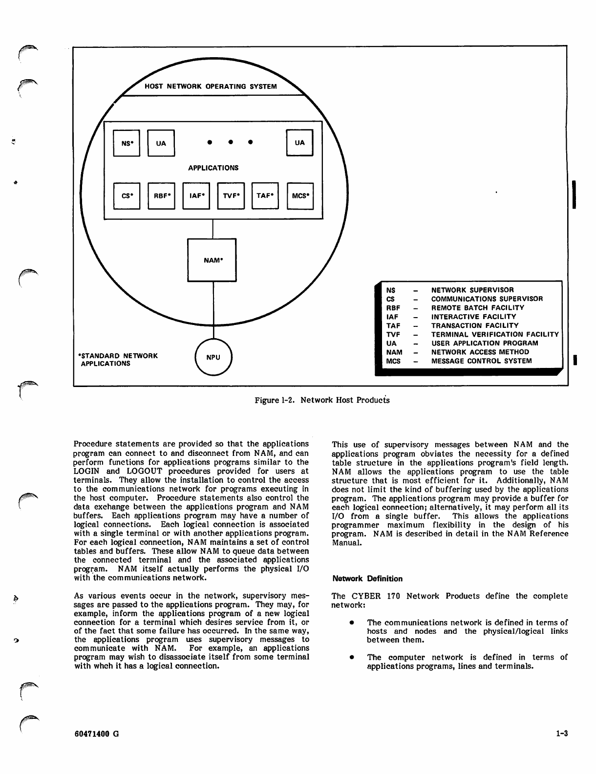
Network Access Method
The Network Access Method (NAM) provides a generalized
method for CYBER applications programs to access the
communications network. Figure 1-2 illustrates this
relationship.
NAM provides a centralized queuing mechanism for
accessing the communications network and a subroutine
package that resides in each network applications program's
field length. This subroutine package allows the appli
cations to interface to NAM with CALL/ENTER-type
procedure statements.
1-2 60471400 B
HOST NETWORK OPERATING SYSTEM
NS* UA • • UA
APPLICATIONS
CS* RBF* IAF« TVF» TAF» MCS*
NAM*
•STANDARD NETWORK
APPLICATIONS
NPU
NS NETWORK SUPERVISOR
CS COMMUNICATIONS SUPERVISOR
RBF REMOTE BATCH FACILITY
IAF INTERACTIVE FACILITY
TAF TRANSACTION FACILITY
TVF TERMINAL VERIFICATION FACILITY
UA USER APPLICATION PROGRAM
NAM NETWORK ACCESS METHOD
MCS MESSAGE CONTROL SYSTEM
Figure 1-2. Network Host Products
Procedure statements are provided so that the applications
program can connect to and disconnect from NAM, and can
perform functions for applications programs similar to the
LOGIN and LOGOUT procedures provided for users at
terminals. They allow the installation to control the access
to the communications network for programs executing in
the host computer. Procedure statements also control the
data exchange between the applications program and NAM
buffers. Each applications program may have a number of
logical connections. Each logical connection is associated
with a single terminal or with another applications program.
For each logical connection, NAM maintains a set of control
tables and buffers. These allow NAM to queue data between
the connected terminal and the associated applications
program. NAM itself actually performs the physical I/O
with the communications network.
As various events occur in the network, supervisory mes
sages are passed to the applications program. They may, for
example, inform the applications program of a new logical
connection for a terminal which desires service from it, or
of the fact that some failure has occurred. In the same way,
the applications program uses supervisory messages to
communicate with NAM. For example, an applications
program may wish to disassociate itself from some terminal
with whch it has a logical connection.
This use of supervisory messages between NAM and the
applications program obviates the necessity for a defined
table structure in the applications program's field length.
NAM allows the applications program to use the table
structure that is most efficient for it. Additionally, NAM
does not limit the kind of buffering used by the applications
program. The applications program may provide a buffer for
each logical connection; alternatively, it may perform all its
I/O from a single buffer. This allows the applications
programmer maximum flexibility in the design of his
program. NAM is described in detail in the NAM Reference
Manual.
Network Definition
The CYBER 170 Network Products define the complete
network:
• The communications network is defined in terms of
hosts and nodes and the physical/logical links
between them.
The computer network is defined in terms
applications programs, lines and terminals.
of
60471400 G 1-3
Network definition is provided by a language called the
network definition language (NDL) which consists of a series
of statements that describe the network. These statements
generate a network configuration file (NCF), a local
configuration file (LCF) and a printed output. NCF and LCF
are used by the network host products in establishing,
initiating, operating and controlling the network. The
printed output provides documentation of the network
configuration. NDL is described in detail in the NDL
Reference Manual.
Network Supervision
The following paragraphs describe the network supervisor
and the communications supervisor.
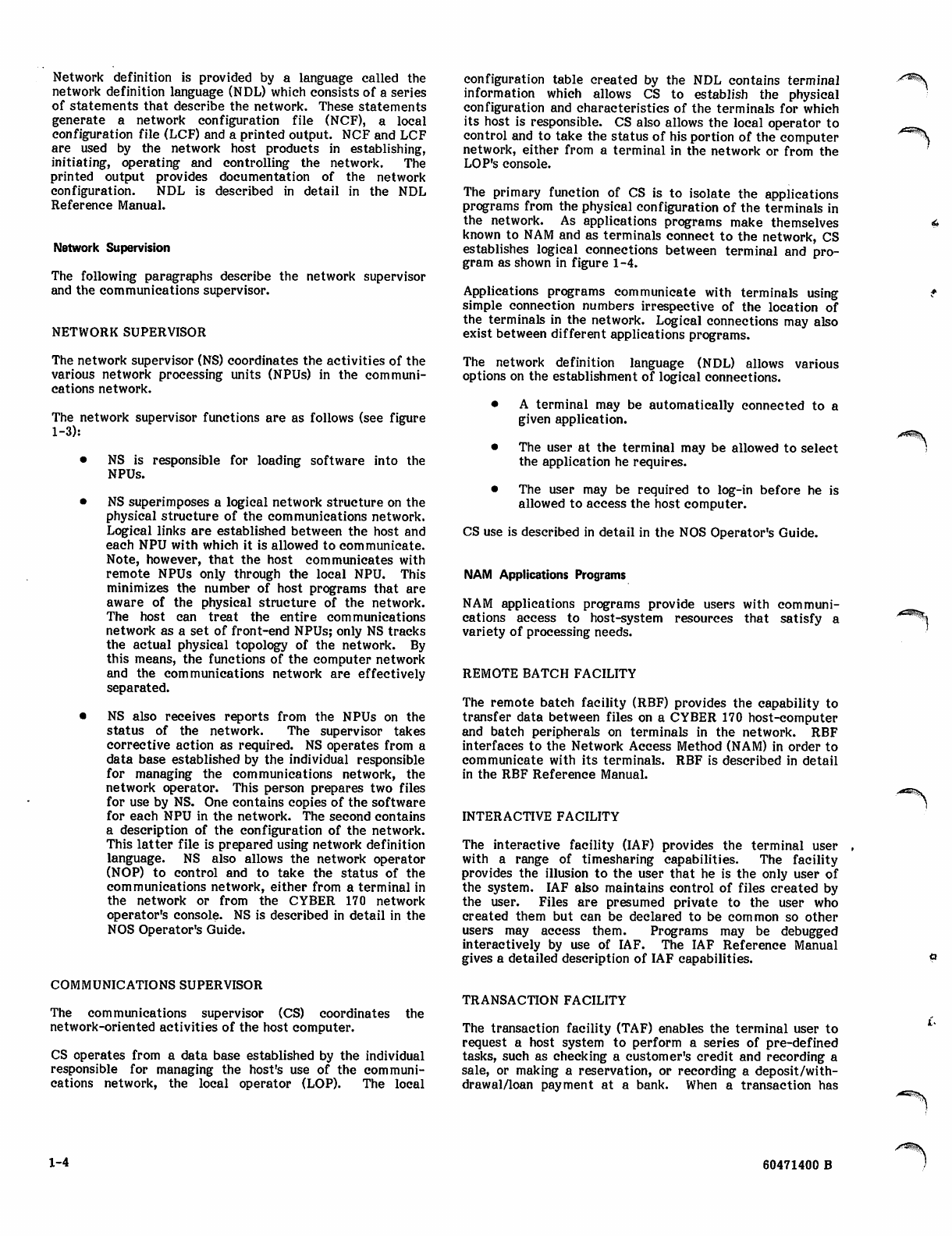
NETWORK SUPERVISOR
The network supervisor (NS) coordinates the activities of the
various network processing units (NPUs) in the communi
cations network.
The network supervisor functions are as follows (see figure
1-3):
• NS is responsible for loading software into the
NPUs.
• NS superimposes a logical network structure on the
physical structure of the communications network.
Logical links are established between the host and
each NPU with which it is allowed to communicate.
Note, however, that the host communicates with
remote NPUs only through the local NPU. This
minimizes the number of host programs that are
aware of the physical structure of the network.
The host can treat the entire communications
network as a set of front-end NPUs; only NS tracks
the actual physical topology of the network. By
this means, the functions of the computer network
and the communications network are effectively
separated.
• NS also receives reports from the NPUs on the
status of the network. The supervisor takes
corrective action as required. NS operates from a
data base established by the individual responsible
for managing the communications network, the
network operator. This person prepares two files
for use by NS. One contains copies of the software
for each NPU in the network. The second contains
a description of the configuration of the network.
This latter file is prepared using network definition
language. NS also allows the network operator
(NOP) to control and to take the status of the
communications network, either from a terminal in
the network or from the CYBER 170 network
operator's console. NS is described in detail in the
NOS Operator's Guide.
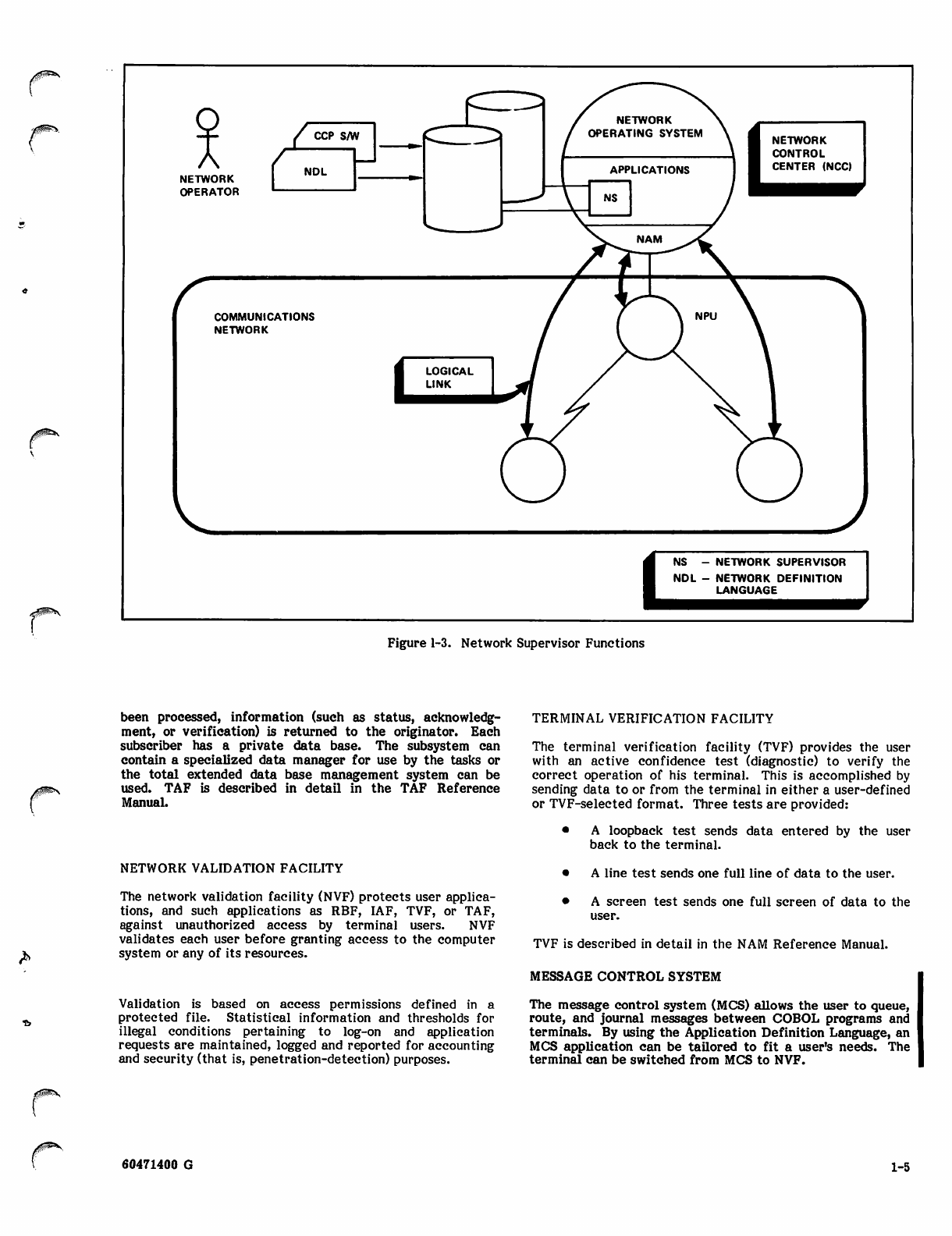
COMMUNICATIONS SUPERVISOR
The communications supervisor (CS) coordinates
network-oriented activities of the host computer.
the
CS operates from a data base established by the individual
responsible for managing the host's use of the communi
cations network, the local operator (LOP). The local
configuration table created by the NDL contains terminal
information which allows CS to establish the physical
configuration and characteristics of the terminals for which
its host is responsible. CS also allows the local operator to
control and to take the status of his portion of the computer
network, either from a terminal in the network or from the
LOP's console.
The primary function of CS is to isolate the applications
programs from the physical configuration of the terminals in
the network. As applications programs make themselves
known to NAM and as terminals connect to the network, CS
establishes logical connections between terminal and pro
gram as shown in figure 1-4.
Applications programs communicate with terminals using
simple connection numbers irrespective of the location of
the terminals in the network. Logical connections may also
exist between different applications programs.
The network definition language (NDL) allows various
options on the establishment of logical connections.
• A terminal may be automatically connected to a
given application.
• The user at the terminal may be allowed to select
the application he requires.
• The user may be required to log-in before he is
allowed to access the host computer.
CS use is described in detail in the NOS Operator's Guide.
NAM Applications Programs
NAM applications programs provide users with communi
cations access to host-system resources that satisfy a
variety of processing needs.
REMOTE BATCH FACILITY
The remote batch facility (RBF) provides the capability to
transfer data between files on a CYBER 170 host-computer
and batch peripherals on terminals in the network. RBF
interfaces to the Network Access Method (NAM) in order to
communicate with its terminals. RBF is described in detail
in the RBF Reference Manual.
INTERACTIVE FACILITY
The interactive facility (IAF) provides the terminal user
with a range of timesharing capabilities. The facility
provides the illusion to the user that he is the only user of
the system. IAF also maintains control of files created by
the user. Files are presumed private to the user who
created them but can be declared to be common so other
users may access them. Programs may be debugged
interactively by use of IAF. The IAF Reference Manual
gives a detailed description of IAF capabilities.
TRANSACTION FACILITY
The transaction facility (TAF) enables the terminal user to
request a host system to perform a series of pre-defined
tasks, such as checking a customer's credit and recording a
sale, or making a reservation, or recording a deposit/with
drawal/loan payment at a bank. When a transaction has
1-4 60471400 B
NETWORK
OPERATOR
/ CCP s/w I
NDL
rCOMMUNICATIONS
NETWORK
NS - NETWORK SUPERVISOR
NDL - NETWORK DEFINITION
LANGUAGE
Figure 1-3. Network Supervisor Functions
*
been processed, information (such as status, acknowledg
ment, or verification) is returned to the originator. Each
subscriber has a private data base. The subsystem can
contain a specialized data manager for use by the tasks or
the total extended data base management system can be
used. TAF is described in detail in the TAF Reference
Manual.
NETWORK VALIDATION FACILITY
The network validation facility (NVF) protects user applica
tions, and such applications as RBF, IAF, TVF, or TAF,
against unauthorized access by terminal users. NVF
validates each user before granting access to the computer
system or any of its resources.
Validation is based on access permissions defined in a
protected file. Statistical information and thresholds for
illegal conditions pertaining to log-on and application
requests are maintained, logged and reported for accounting
and security (that is, penetration-detection) purposes.
TERMINAL VERIFICATION FACILITY
The terminal verification facility (TVF) provides the user
with an active confidence test (diagnostic) to verify the
correct operation of his terminal. This is accomplished by
sending data to or from the terminal in either a user-defined
or TVF-selected format. Three tests are provided:
• A loopback test sends data entered by the user
back to the terminal.
• A line test sends one full line of data to the user.
• A screen test sends one full screen of data to the
user.
TVF is described in detail in the NAM Reference Manual.
MESSAGE CONTROL SYSTEM
The message control system (MCS) allows the user to queue,
route, and journal messages between COBOL programs and
terminals. By using the Application Definition Language, an
MCS application can be tailored to fit a user's needs. The
terminal can be switched from MCS to NVF.
60471400 G 1-5
NOL-NETWORK DEFINITION LANGUAGE
CS -COMMUNICATIONS SUPERVISOR
RBF-REMOTE BATCH FACILITY
IAF - INTERACTIVE FACILITY
/r^S,
y^sv
Figure 1-4. Communications Supervisor Functions
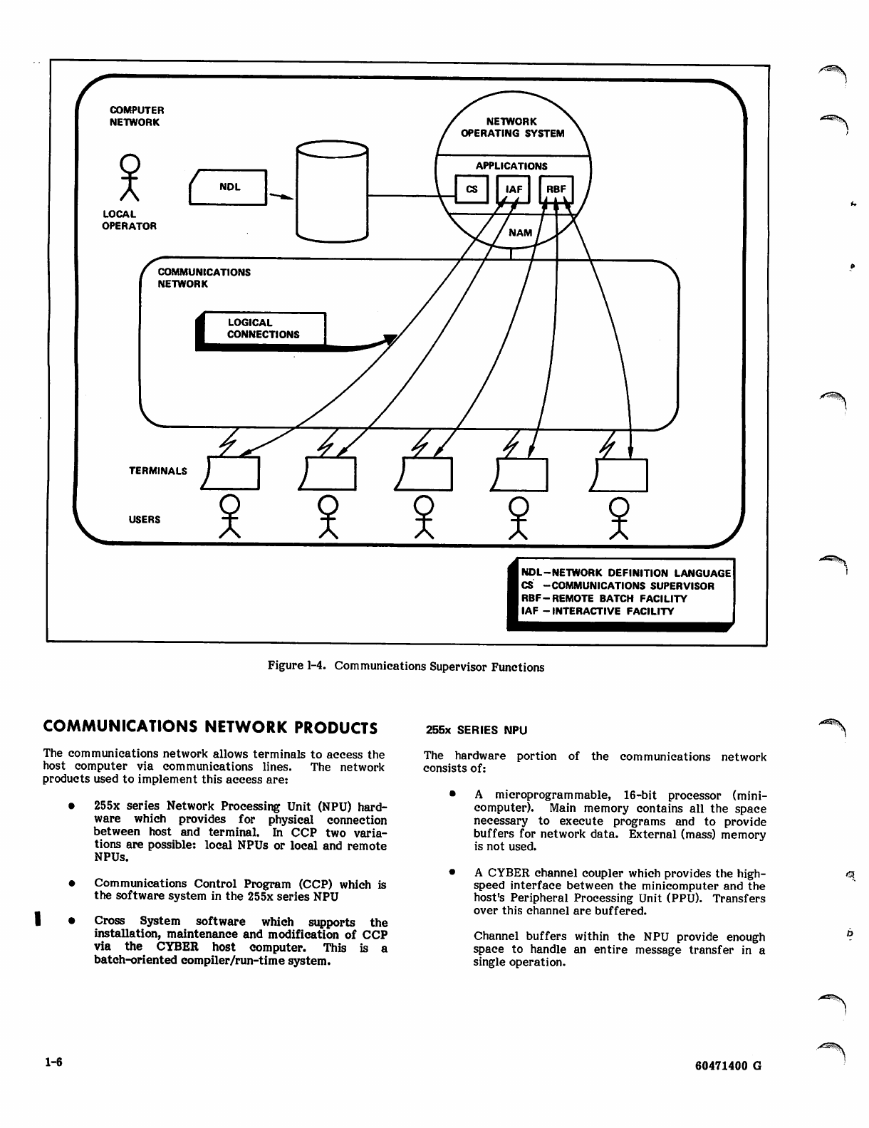
COMMUNICATIONS NETWORK PRODUCTS
The communications network allows terminals to access the
host computer via communications lines. The network
products used to implement this access are:
• 255x series Network Processing Unit (NPU) hard
ware which provides for physical connection
between host and terminal. In CCP two varia
tions are possible: local NPUs or local and remote
NPUs.
• Communications Control Program (CCP) which is
the software system in the 255x series NPU
I • Cross System software which supports the
installation, maintenance and modification of CCP
via the CYBER host computer. This is a
batch-oriented compiler/run-time system.
255x SERIES NPU
The hardware portion of the communications network
consists of:
• A microprogrammable, 16-bit processor (mini
computer). Main memory contains all the space
necessary to execute programs and to provide
buffers for network data. External (mass) memory
is not used.
• A CYBER channel coupler which provides the high
speed interface between the minicomputer and the
host's Peripheral Processing Unit (PPU). Transfers
over this channel are buffered.
Channel buffers within the NPU provide enough
space to handle an entire message transfer in a
single operation.
^&S\
1-6 60471400 G
J ^ s
yams
NOTE
The host/NPU coupler interface passes
data upline to the host in one of three
formats: interactive virtual terminal for
interactive devices, physical record unit
(PRU) for batch devices, or transparent.
Blocks are received from the host in the
same formats.
A multiplex subsystem consisting of:
A Multiplex Loop Interface Adapter (MLIA)
which controls the input and output multiplex
loops
Individual loop multiplexers (LMs) which
attach to the input and output multiplex loop
on one side and to individual Communications
Line Adapters (CLAs) on the other. The CLAs
provide line-by-line interface compatibility
with the modems attached to terminals or to
remote NPUs.
NOTE
At the interface of the NPU to the lines,
data passes to/from the terminals in a
format (protocol) compatible to the ter
minal. A remote NPU is treated as a
special type of terminal.
COMMUNICATIONS CONTROL PROGRAM
The three major parts of the Communications Control
Program (CCP) are:
• The base system which includes the OPS-monitor,
interrupt handlers, multiplex subsystem, software
and firmware, timing services, initialization (the
NPU is downline-loaded from the host), space
allocation, program-to-program calls and data
transfers, standard subroutines, text processing,
and error checking.
• Block interface package (BIP) software, which
provides block formation (PRU or IVT), routing,
control and status processing, and hardware
configuration controL
NOTE
Inline diagnostics are provided as part of
CCP. If the customer elects to purchase
a CDC maintenance contract, on-line
diagnostics are provided. Also provided in
the maintenance program are some host-
based applications programs which simpl
ify the use of inline diagnostics.
Interface software. Three standard types of
interfaces are provided:
Host interface package (HIP) supports the
high-speed, buffered channel interface to the
host computer. Data is assumed to be in IVT
or PRU format.
Link interface package (LIP) supports the
local/remote NPU transfers. The remote NPU
collects data from its terminals and formats it
prior to passing the data upline to a local NPU.
This interface uses the CDC Communications
Procedure (CDCCP) protocol.
Terminal interface packages (TIPs). Five
standard TIPs handle transfers for terminals
using interactive modes (ASYNC or X25 with
PAD subTIP), or both batch and interactive
modes (Mode 4, BSC, and HASP).
CCP Coding Languages
For ease in programming the NPU, the programmer can code
his source language routines in PASCAL, an ALGOL-like
language. The Cross system programs are run on the host,
and the principal output is an NPU machine language load
file which resides in host mass storage. This load file
contains all of the CCP modules in NPU image format
(including overlays). This file is used to load the NPU
(remote or local) following an NPU or host failure. The
Cross system is described at the end of this section.
A few common programs are coded in the macro assembler
language. A.special subset of this language, called state
programs, uses a set of specially-defined macrocommands to
process messages on the microprocessing level. Each TIP
contains message conversion programs written in the state
programming language. All programs, regardless of source
language, are included in the host's load file.
Message Movement in a Network
The basic procedures for upline and downline message
movement are discussed next. Note that the procedures
given are highly summarized. Acknowledgment procedures
are also highly summarized. It is assumed that terminals are
connected through a single NPU.
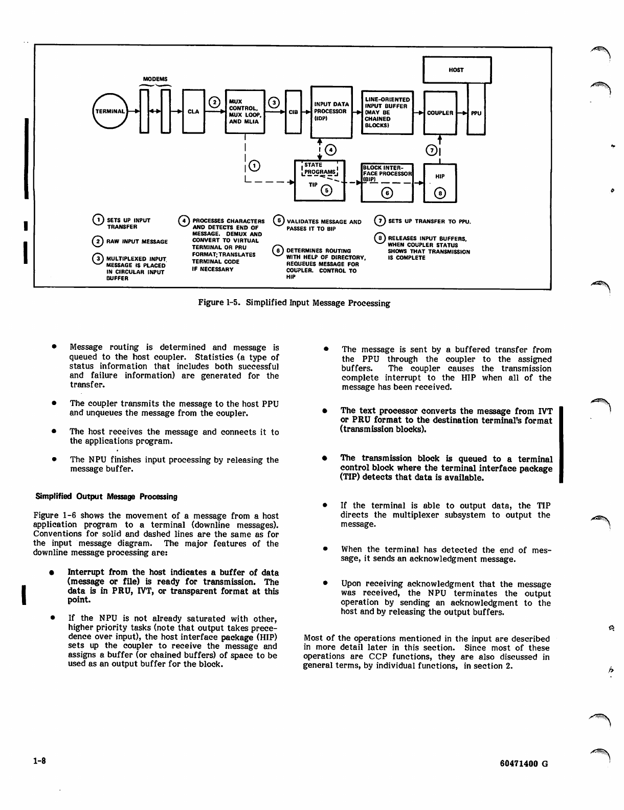
Simplified Input Message Processing
Figure 1-5 shows the movement of a message from a
terminal to the host applications program. Solid lines
indicate message (and acknowledgment message) pathways,
dashed lines indicate principal control functions. The major
features of the upline message processing are:
• Some synchronous terminals are polled to find
if the terminal has data ready to send; an
asynchronous terminal sends data when it is ready
• Setting up of multiplex subsystem and buffers when
terminal indicates it has data to send upline
• Collecting all data from this (and all other active
terminals) in a circular input buffer (CIB)
• Demultiplexing data and converting it to a host
compatible format (IVT or PRU). Demultiplexed
data is collected in a block which uses one or more
chained buffers and is called a line-related input
buffer. If code conversion is necessary (such as
EBCDIC to ASCII for interactive data or EBCDIC
to display code for batch data), this is also
accomplished.
• When input buffer is full (that is, the message is
complete), message is validated.
60471400 G 1-7
[terminal I—t*
MUX
CONTROL.
MUX LOOP.
AND MLIA
INPUT DATA
PROCESSOR
HOP)
LINE-ORIENTED
INPUT BUFFER
(MAY BE
CHAINED
BLOCKS)
i©
I
BLOCK INTER
FACE PROCESSOR
(BIP)
©
©
©
SETS UP INPUT
TRANSFER
RAW INPUT MESSAGE
MULTIPLEXED INPUT
MESSAGE IS PLACED
IN CIRCULAR INPUT
BUFFER
(7) PROCESSES CHARACTERS
v-x ANO DETECTS END OF
MESSAGE. DEMUX AND
CONVERT TO VIRTUAL
TERMINAL OR PRU
FORMAT; TRANSLATES
TERMINAL CODE
IF NECESSARY
(&) VALIDATES MESSAGE AND
PASSES IT TO BIP
SETS UP TRANSFER TO PPU.
©DETERMINES ROUTING
WITH HELP OF DIRECTORY.
REQUEUES MESSAGE FOR
COUPLER. CONTROL TO
HIP
(a) RELEASES INPUT BUFFERS,
^-^ WHEN COUPLER STATUS
SHOWS THAT TRANSMISSION
IS COMPLETE
Figure 1-5. Simplified Input Message Processing
Message routing is determined and message is
queued to the host coupler. Statistics (a type of
status information that includes both successful
and failure information) are generated for the
transfer.
The coupler transmits the message to the host PPU
and unqueues the message from the coupler.
The host receives the message and connects it to
the applications program.
The NPU finishes input processing by releasing the
message buffer.
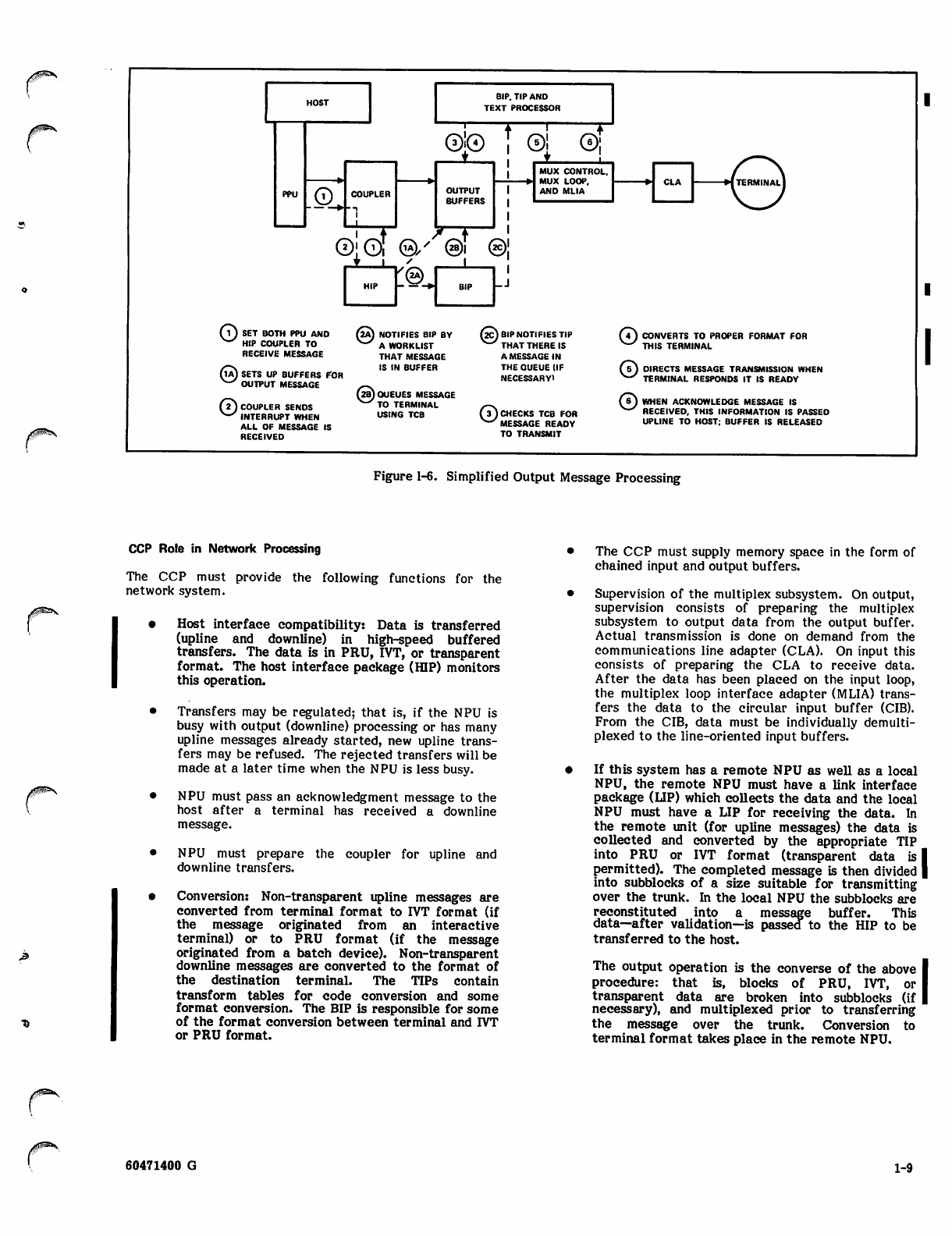
Simplified Output Message Processing
Figure 1-6 shows the movement of a message from a host
application program to a terminal (downline messages).
Conventions for solid and dashed lines are the same as for
the input message diagram. The major features of the
downline message processing are:
• Interrupt from the host indicates a buffer of data
(message or file) is ready for transmission. The
data is in PRU, IVT, or transparent format at this
point.
• If the NPU is not already saturated with other,
higher priority tasks (note that output takes prece
dence over input), the host interface package (HIP)
sets up the coupler to receive the message and
assigns a buffer (or chained buffers) of space to be
used as an output buffer for the block.
The message is sent by a buffered transfer from
the PPU through the coupler to the assigned
buffers. The coupler causes the transmission
complete interrupt to the HIP when all of the
message has been received.
The text processor converts the message from IVT
or PRU format to the destination terminal's format
(transmission blocks).
The transmission block is queued to a terminal
control block where the terminal interface package
(TIP) detects that data is available.
• If the terminal is able to output data, the TIP
directs the multiplexer subsystem to output the
message.
• When the terminal has detected the end of mes
sage, it sends an acknowledgment message.
Upon receiving acknowledgment that the message
was received, the NPU terminates the output
operation by sending an acknowledgment to the
host and by releasing the output buffers.
Most of the operations mentioned in the input are described
in more detail later in this section. Since most of these
operations are CCP functions, they are also discussed in
general terms, by individual functions, in section 2.
1-8 60471400 G
>«!tasjx
/^^v
BIP. TIP AND
TEXT PROCESSOR
©
®[©T
I L
©;© ©! ®;
OUTPUT
BUFFERS
MUX CONTROL.
MUX LOOP,
AND MLIA
©/'©I ©'
_j
©SET BOTH PPU ANO
HIP COUPLER TO
RECEIVE MESSAGE
(Ia) SETS UP 8UFFERS FOR
N-' OUTPUT MESSAGE
©COUPLER SENDS
INTERRUPT WHEN
ALL OF MESSAGE IS
RECEIVED
(2A) NOTIFIES BIP BY
V^ A WORKLIST
THAT MESSAGE
IS IN BUFFER
(2B)0UEUES MESSAGE
^^ TO TERMINAL
USING TCB
f2Cj BIP NOTIFIES TIP
V"^ THAT THERE IS
A MESSAGE IN
THE QUEUE (IF
NECESSARY)
(7) CHECKS TCB FOR
V-' MESSAGE READY
TO TRANSMIT
CONVERTS TO PROPER FORMAT FOR
THIS TERMINAL
DIRECTS MESSAGE TRANSMISSION WHEN
TERMINAL RESPONDS IT IS READY
WHEN ACKNOWLEDGE MESSAGE IS
RECEIVED. THIS INFORMATION IS PASSED
UPLINE TO HOST; BUFFER IS RELEASED
Figure 1-6. Simplified Output Message Processing
&
CCP Role in Network Processing
The CCP must provide the following functions for the
network system.
• Host interface compatibility: Data is transferred
(upline and downline) in high-speed buffered
transfers. The data is in PRU, IVT, or transparent
format. The host interface package (HIP) monitors
this operation.
• Transfers may be regulated; that is, if the NPU is
busy with output (downline) processing or has many
upline messages already started, new upline trans
fers may be refused. The rejected transfers will be
made at a later time when the NPU is less busy.
• NPU must pass an acknowledgment message to the
host after a terminal has received a downline
message.
• NPU must prepare the coupler for upline and
downline transfers.
• Conversion: Non-transparent upline messages are
converted from terminal format to IVT format (if
the message originated from an interactive
terminal) or to PRU format (if the message
originated from a batch device). Non-transparent
downline messages are converted to the format of
the destination terminal. The TIPs contain
transform tables for code conversion and some
format conversion. The BIP is responsible for some
of the format conversion between terminal and IVT
or PRU format.
The CCP must supply memory space in the form of
chained input and output buffers.
Supervision of the multiplex subsystem. On output,
supervision consists of preparing the multiplex
subsystem to output data from the output buffer.
Actual transmission is done on demand from the
communications line adapter (CLA). On input this
consists of preparing the CLA to receive data.
After the data has been placed on the input loop,
the multiplex loop interface adapter (MLIA) trans
fers the data to the circular input buffer (CIB).
From the CIB, data must be individually demulti
plexed to the line-oriented input buffers.
If this system has a remote NPU as well as a local
NPU, the remote NPU must have a link interface
package (LIP) which collects the data and the local
NPU must have a LIP for receiving the data. In
the remote unit (for upline messages) the data is
collected and converted by the appropriate TIP
into PRU or IVT format (transparent data is I
permitted). The completed message is then divided |
into subblocks of a size suitable for transmitting
over the trunk. In the local NPU the subblocks are
reconstituted into a message buffer. This
data—after validation—is passed to the HIP to be
transferred to the host.
The output operation is the converse of the above I
procedure: that is, blocks of PRU, IVT, or I
transparent data are broken into subblocks (if |
necessary), and multiplexed prior to transferring
the message over the trunk. Conversion to
terminal format takes place in the remote NPU.
60471400 G 1-9
Physical placement of the CLA in the NPU cabinet
determines the frequency with which the line has
access to the multiplex loop. CLAs for lines
assigned to trunks are placed in the first slot (or
slots) so that these lines have first chance to use
the multiplex loop.
Terminal interface packages (TIPs) are responsible
for setting up the messages so that the terminal
protocols for starting, stopping, acknowledging,
and message formatting are satisfied. The TIP also
converts data from host codes (ASCII for IVT;
ASCII or display code for PRU) to the terminal's
internal code, if necessary.
Multiplexing Operation
The multiplex subsystem has two major functions, both of
them hardware related:
• Physical line characteristics vary for the different
types of lines. To relieve the TIPs of having to
process each line type according to that line's
special physical characteristics, the multiplex sub
system handles the characteristics by translating
logical line commands/status into physical line
command/status. This makes most physical line
characteristics transparent to the TIP.
• The high-speed host works most efficiently if given
a full block of data to process. A terminal, on the
other hand, is often low-speed, and data is trans
ferred to/from the terminal one character at a
time. The multiplex subsystem interfaces the high
speed characteristics of the host/NPU with the
"low-speed characteristics of the lines/terminals.
The multiplex interface to the TIPs is described in the
System Programmer's Reference Manual.
INPUT MULTIPLEXING
Each line has a communciations line adapter (CLA). The
CLA for each active line is sampled in sequence. If a
character is ready, it is placed on the input multiplex loop
together with information identifying the source (line) and,
in some cases, control information. All input multiplex loop
data is routed to a circular input buffer (CIB). The
demultiplexing operation picks data from this buffer, recon
stitutes the messages in data buffers, and passes these
buffers to the appropriate processor for this terminal (line).
OUTPUT MULTIPLEXING
After the NPU has received a full message from the host
and the appropriate terminal interface package (TIP) has
converted the code to real terminal format, the multiplex
subsystem can output the message. The multiplex
subsystem picks the characters from the line's output
message buffer in response to an output data demand (ODD)
generated by the CLA. The ODD signal is the CLA's
indication that it is ready to transmit another character.
The outgoing characters are placed on the output multiplex
loop, along with such control characters as are needed and
an address that will be recognized by the CLA connected to
that terminal. The CLA for the line picks the data from the
output loop via the loop multiplexer. When the contents of
the entire output buffer for the line have been transmitted
successfully, the message buffers are released. Many output
data buffers can be serviced at the same time.
TRUNK MULTIPLEXING
If a remote NPU is included in the network, transmissions
between the local NPU and the remote NPU take place over
a trunk. A trunk is a communications line. In the local
NPU, a link interface package (LIP) sets up the output
buffer. In the remote NPU, the downline messages are
treated similarly to upline messages in a local NPU; that is,
the message goes through the CIB and is then demultiplexed
for the TIP. After the TIP converts the code to terminal
format, the message is treated as an output message in a
local NPU; that is, the message is transmitted through the
multiplex subsystem.
Input messages (upline traffic) are reformatted from
terminal to IVT or PRU format as in a local NPU, but are
then sent by the LIP through the remote NPU's multiplex
subsystem, received by the local NPU's multiplex subsystem,
and reconstructed into complete messages in the local NPU
by that NPU's LIP.
DEMULTIPLEXING
The multiplex subsystem is responsible for picking data from
the CIB as well as putting it into that buffer. When the
message reception starts, the multiplex subsystem firmware
reserves a data buffer for the message. The data words for
that line are picked from the CIB and are packed into the
reserved buffer. Control and tag information is discarded.
If a buffer is filled before the message is complete, another
buffer is assigned and is chained to the first.
When the end of text is detected, the TIP which is
appropriate for the terminal type is called to continue the
processing.
The demultiplexing of a downline transfer is a terminal
function; that is, the message is reconstituted in a buffer for
the screen, printer, or other output device.
Base System Software
The base system software, which includes the multiplex
subsystem, is a basic, relatively invariant, set of CCP
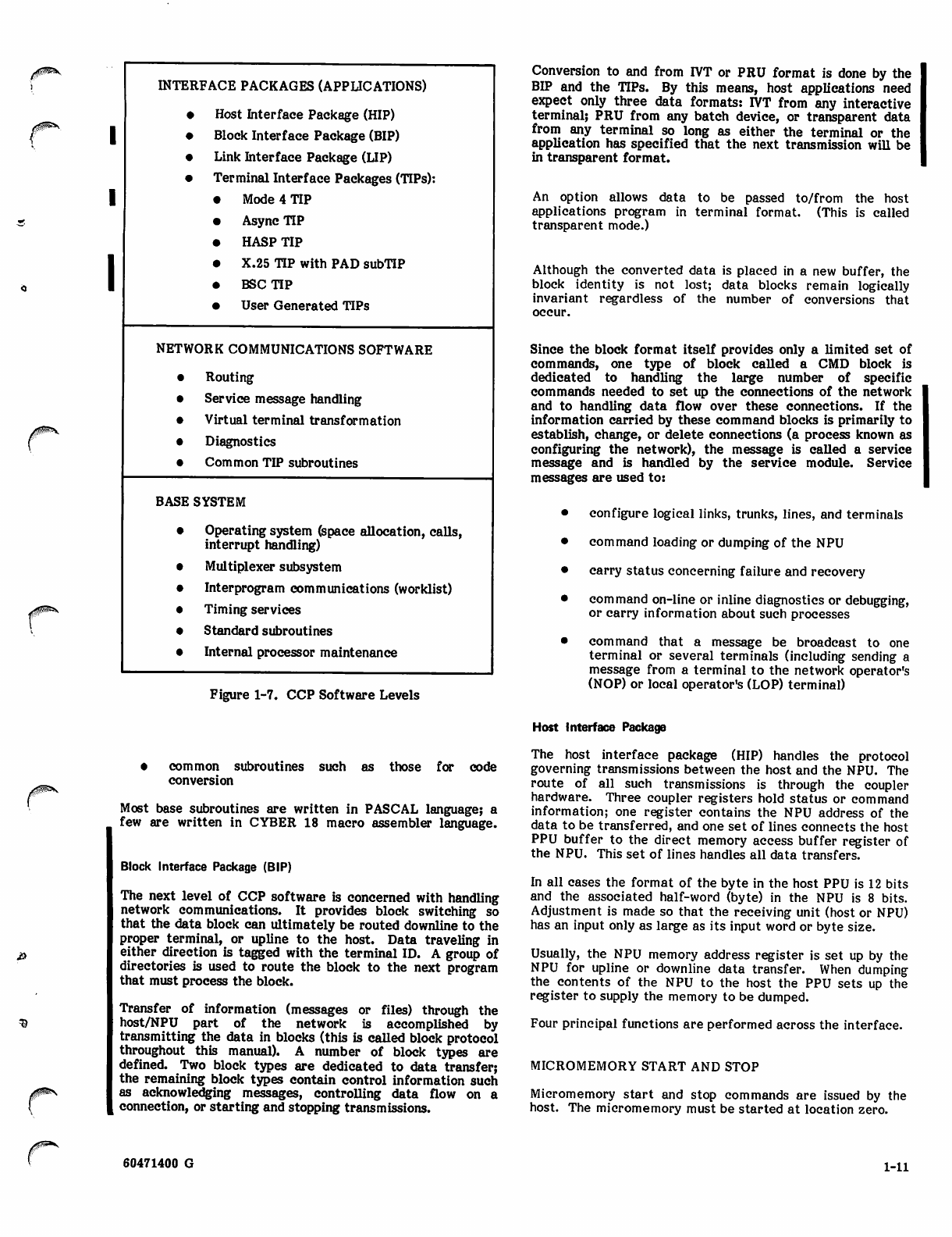
programs. As figure 1-7 shows, CCP software belongs to
one of three levels:
• base system software
• network communications software
• interface packages (TIPs, LIP, HIP)
The primary functions supplied by the base system are:
• basic operating system functions such as interrupt
handling, calling program (queuing requests), allo
cating space (buffers) to requesting programs,
handling the passing of parameters from the calling
to the called program (worklist processing), timing
services, common areas, and control block services
• some initialization processing
• multiplex subsystem including the command driver
which interfaces between the multiplex subsystem
(software and hardware) and the TIPs or LIP
A ^ S
jiSSS.
1-10 60471400 G
INTERFACE PACKAGES (APPLICATIONS)
•Host Interface Package (HIP)
1•Block Interface Package (BIP)
•Link Interface Package (LIP)
•Terminal Interface Packages (TIPs):
1
1
• Mode 4 TIP
• Async TIP
• HASP TIP
• X.25 TIP with PAD subTIP
• BSC TIP
• User Generated TIPs
NETWORK COMMUNICATIONS SOFTWARE
•Routing
•Service message handling
•Virtual terminal transformation
•Diagnostics
•Common TIP subroutines
BASE SYSTEM
•Operating system (space allocation, calls,
interrupt handling)
•Multiplexer subsystem
•Interprogram communications (worklist)
•Timing services
•Standard subroutines
•Internal processor maintenance
Figure 1-7. CCP Software Levels
Conversion to and from IVT or PRU format is done by the
BIP and the TIPs. By this means, host applications need
expect only three data formats: IVT from any interactive
terminal; PRU from any batch device, or transparent data
from any terminal so long as either the terminal or the
application has specified that the next transmission will be
in transparent format.
An option allows data to be passed to/from the host
applications program in terminal format. (This is called
transparent mode.)
Although the converted data is placed in a new buffer, the
block identity is not lost; data blocks remain logically
invariant regardless of the number of conversions that
occur.
Since the block format itself provides only a limited set of
commands, one type of block called a CMD block is
dedicated to handling the large number of specific
commands needed to set up the connections of the network
and to handling data flow over these connections. If the
information carried by these command blocks is primarily to
establish, change, or delete connections (a process known as
configuring the network), the message is called a service
message and is handled by the service module. Service
messages are used to:
• configure logical links, trunks, lines, and terminals
• command loading or dumping of the NPU
• carry status concerning failure and recovery
• command on-line or inline diagnostics or debugging,
or carry information about such processes
• command that a message be broadcast to one
terminal or several terminals (including sending a
message from a terminal to the network operator's
(NOP) or local operator's (LOP) terminal)
• common subroutines such as those for code
conversion
Most base subroutines are written in PASCAL language; a
few are written in CYBER 18 macro assembler language.
Block Interface Package (BIP)
The next level of CCP software is concerned with handling
network communications. It provides block switching so
that the data block can ultimately be routed downline to the
proper terminal, or upline to the host. Data traveling in
either direction is tagged with the terminal ID. A group of
directories is used to route the block to the next program
that must process the block.
Transfer of information (messages or files) through the
host/NPU part of the network is accomplished by
transmitting the data in blocks (this is called block protocol
throughout this manual). A number of block types are
defined. Two block types are dedicated to data transfer;
the remaining block types contain control information such
as acknowledging messages, controlling data flow on a
connection, or starting and stopping transmissions.
Host Interface Package
The host interface package (HIP) handles the protocol
governing transmissions between the host and the NPU. The
route of all such transmissions is through the coupler
hardware. Three coupler registers hold status or command
information; one register contains the NPU address of the
data to be transferred, and one set of lines connects the host
PPU buffer to the direct memory access buffer register of
the NPU. This set of lines handles all data transfers.
In all cases the format of the byte in the host PPU is 12 bits
and the associated half-word (byte) in the NPU is 8 bits.
Adjustment is made so that the receiving unit (host or NPU)
has an input only as large as its input word or byte size.
Usually, the NPU memory address register is set up by the
NPU for upline or downline data transfer. When dumping
the contents of the NPU to the host the PPU sets up the
register to supply the memory to be dumped.
Four principal functions are performed across the interface.
MICROMEMORY START AND STOP
Micromemory start and stop commands are issued by the
host. The micromemory must be started at location zero.
60471400 G 1-11
CONTROL WORD TRANSFERS
The NPU sets function commands to the coupler, allowing
the coupler to chain buffers of data during transfer, to clear
the coupler registers, to read the other status registers, to
ready the PPU to read the status registers, and to set the
memory address register prior to starting a data transfer.
The PPU sets functions to clear the coupler or NPU, to start
or stop the NPU, to input or output a program during the
load/dump phase of NPU initialization, to load the memory
address for dump operations, and to set or read the other
two status-type registers.
STATUS WORDS
One status word is used for regulation. There are four
regulation levels: (1) to transmit all messages to the NPU,
(2) to transmit all but messages for batch-type devices, (3)
to transmit only service messages, and (4) to transmit no
messages. Regulation is a function of the availability of
NPU buffers to receive input messages.
DATA TRANSFERS
For downline transfers, the NPU assigns the next data
buffer, sets up buffer chaining, if necessary, and switches
the block to the proper internal handling or terminal/-
line/TIP.
For upline transfers, when the full message is ready, the
NPU makes the address of the first buffer in the chain
available. When one buffer is transferred, the starting
address of the next chained buffer is provided by the coupler
hardware. This continues until the full message is
transmitted.
Since the DMA/PPU buffer channel is half-duplex (data can
be sent in only one direction at a time), contention for
channel use is normally resolved in favor of outputting
blocks from the PPU. However, following this transfer, the
protocol provides a short period during which the NPU can
request channel use without the PPU contending for channel
use.
No attempt is made to retransmit data in anything less than
a full block. When a bad block is rejected, the entire
message is rejected and must be retransmitted in its
entirety.
Link Interface Package
Since the link interface package (LIP) handles transmission
and reception on both ends of a trunk, a copy of the LIP is
required in both the local and the remote NPU.
Two major types of operations are handled by the LIP:
loading/dumping the remote NPU, and processing data
transmissions over the trunk. Data message transmissions
across the trunk use a unit called a trunk transmission frame
(TTF or frame).
There are three types of frames:
• unnumbered frames which establish the basic trans
mission states between the two nodes (such as
initialization, disconnect, command rejected)
• supervisory frames that establish whether trans
mission/reception is currently possible (ready for
data/not ready for data/rejected last data sent)
• information frames used to transmit message data;
this class of frames includes frames that are
carrying service messages
Both frame size and data block size are customization time
selections. The information frames themselves are com
posed of one or more subblocks. Each subblock is a buffer
of information related to a single message so that the
frame may be considered as a packet of information
subblocks contaning one or more message parts for one or
more terminals.
Either end of the link may initiate data transmission when
conditions warrant. Once the interfacing LIPs have
established the normal mode, data transmission can begin.
A remote NPU has no coupler to the host, and therefore no
HIP. Terminal data passes through the multiplex subsystem
of the remote NPU twice: once as it passes between the
terminal and the NPU, and once as it passes between local
and remote NPUs. Upline data in the remote NPU is
demultiplexed and passed to the appropriate TIP for
conversion. Completed, converted messages are passed to
the LIP for framing and then passed through the multiplex
subsystem, over the trunk to the local NPU. Trunk
transmission rate is up to 19.2 Kbps.
In the local NPU, upline data from the trunk is received by
the LIP and reconstructed into a message in data buffers.
Then it is passed to the HIP for transmission to the host.
Downline data is taken from a message data buffer,
assembled into frame format by the LIP, and sent to the
remote NPU. Once it is demultiplexed by the
LlP/multiplex subsystem, it is ready to be passed to the
appropriate TIP for conversion to terminal format.
LOADING/DUMPING OF REMOTE NPU
The local NPU processes the load/dump operation in its
overlay area. The program information is transmitted
to/from the local NPU overlay area in block form. The
local LIP passes the programs (downline) and receives the
dumped main memory contents (upline) in frame format.
The remote NPU LIP is responsible for stripping the frame
information from the downline subblocks and loading these
subblocks (parts of programs) at the location indicated by
the host. For dumping, the LIP is responsible for placing
the main memory contents (starting at the address
indicated by the host) into frames and sending the frames
to the local NPU.
Configuring the remote NPU is handled by service
messages, as in the case of configuring a local NPU. The
service messages are transmitted across the trunk in the
same manner as any other message data.
TRUNK TRANSMISSION PRIORITIES AND REGULATION
A high or a low priority is assigned to each subblock. High
priority is associated with interactive terminals and low
priority is associated with batch terminals. Each time a
new frame can be transmitted the LIP scans the high and
low priority queues. If high priority data is waiting, it is
always transmitted ahead of low priority data.
On input (in either the local or the remote NPU), data can
be rejected if the number of available buffers has dropped
to the threshold level. First low-priority traffic is
rejected, then high-priority traffic. Supervisory frames are
not included in this priority scheme. These frames contain
some command/status information, but do not include most
service message instructions which are treated as high
^s
1-12 60471400 G
priority. Thus, during regulation, some command/status
information can be rejected while other command/status
information passes over the trunk.
TRANSMISSION ASSURANCE
The CDCCP protocol requires that each frame be
acknowledged. Since several frames may have been
transmitted before a negative acknowledgment for a given
frame is generated, all frames up to and including the last
properly acknowledged frame are retransmitted. No frame
is released from the sending NPU until it is properly
acknowledged. Frame checking is provided by a cyclic
redundancy checksum (CRC) which is generated by the
sending CLA and included at the end of each frame.
Several OPS-levels: The X.25 TIP uses one
OPS-level to supervise protocol/terminals, another
to control packet flow (related to connections
between host applications and terminals), a third to
control frame flow (related to the connection
between the CDC network or the X.25 public data
network), and a fourth (called a sub-TIP) to handle
the format conversions.
ASYNCHRONOUS TIP
The asynchronous TIP supports dedicated and dial-up asyn
chronous lines. The TIP provides software support for most
teletypewriter-like terminals. The interface format
between the host and the TIP is handled by the interactive
virtual terminal and user interface.
3
Terminal Interface Packages
A terminal interface package (TIP) interfaces the terminal
data (messages) to the network. The terminal interface is
processed through the multiplex subsystem; the system
interface is processed through the line control blocks (LCBs)
and terminal control blocks (TCBs). Five standard TIPs can
be included in a system:
• An async (asynchronous) TIP either in normal or
extended format. This handles only interactive
data.
• A binary synchronous communication (BSC) TIP
that handles both batch and interactive data.
• A synchronous TIP for HASP workstations that
handles both batch and interactive data.
• A Mode 4 (synchronous) TIP which processes data
from both batch and interactive devices.
• An X.25 (synchronous) TIP with a packet handling
(PAD) subTIP. This handles only interactive data
that arrives through a public data network.
Each TIP handles the protocol level for its terminal type.
Specialized additional information for the connection is
contained in the LCB, the logical channel control block
(LCCB), and the TCB. The software portion of a TIP is
written on several levels:
• One or more OPS-levels control message transfer,
including major error (transmission failures)
processing, transfer setup, and transfer
completion. Code and format translation are
controlled by an OPS-level.
4 A mux-2 level is occasionally used for error
processing.
• One or more microprocessing (firmware) levels
perform upline/downline text processing and
demultiplex upline messages.
A number of OPS-levels exist; standard TIPs are written on:
• A single OPS-level: The async TIP uses one
OPS-level to control message flow, error checking,
and code/format translation.
• Two OPS-levels: The Mode 4, HASP, and BSC TIPs
use one OPS level to control code/format
conversion of blocks. Another OPS-level controls
message flow.
The asynchronous TIP supports a terminal-to-virtual trans
form for eight types of terminals. To expand the usefulness
of this TIP, a method is provided for the user at a terminal
or a connected application to vary parameters and operating
modes for any of the eight terminal types. This provides
service for terminals which may differ from the eight
terminal types.
Line types supported are:
• dedicated or dial-up
• two or four-wire
• full-duplex
The TIP is prepared to receive input at all times and
attempts to deliver output whenever available, unless input
is currently active. When input is detected during output,
the TIP suspends output. This output is sent later. All input
and output is converted between the terminal and virtual
terminal characteristics.
The TIP provides an auto-recognition feature for each line.
The result of this feature is a service message from the TIP
informing the host of the line speed. For the 2741 terminal,
the TIP provides code recognition. Several parity options
are provided, and paper tape input/output is supported.
MODE 4 TIP
The Mode 4 TIP interfaces with devices using Mode 4A or
4C protocols. A typical Mode 4 device would be the card
reader, printer, keyboard, and CRT of a CDC 200 user
terminal (UT).
Interactive data is exchanged with a host application in IVT
format; batch data is exchanged in PRU block (PRUB)
format.
The TIP is insensitive to line speeds; it supports synchronous
lines operating at rates up to 9600 baud. Lines may be
dedicated (with or without a transceiver) or switched (dial-
up) with a modem. All lines are considered to be half-
duplex.
Each line may have more than one cluster of equipment and
each equipment cluster may have more than one terminal.
Lines with multiple clusters must be dedicated.
The TIP performs auto-recognition when requested by the
host. Auto-recognition causes the TIP to return a service
message to the host which contains information on terminal
type, cluster address, terminal address, and device type.
Multi-cluster auto-recognition is not supported.
60471400 G 1-13
The Mode 4 TIP supports remote batch terminals as separate
but dependent devices.
The TIP polls the terminal to determine when data should be
sent.
The TIP performs recovery for line or terminal errors. Any
error from which an immediate recovery is not possible is
reported to the host.
The Mode 4 TIP counts all lines of batch output data sent to
a terminal and all card images of batch data sent to the
host. When a batch file or device connection is terminated,
this data (called accounting data) is fowarded to the host to
be merged with host usage accounting data.
BINARY SYNCHRONOUS COMMUNICATIONS (BSC) TIP
The BSC TIP provides data interchange between a host
application program and a remote IBM 2780, 3780 or
compatible batch terminal. The TIP provides batch and
interactive capabilities. The interactive console is
simulated by accepting input from the card reader and
sending output to the line printer.
Exchange of information between the NPU and a terminal
uses the point-to-point binary synchronous communications
protocol with contention resolution. Batch devices
communicate with host applications using PRUB format;
interactive data uses IVT blocks. The normal code of a
2780/3780 is EBCDIC; transparent mode is permitted.
BSC terminals can be attached to an NPU through dedicatee
or dial-in synchronous lines operating at speeds up to 19200
bps. A terminal consists of a required card reader, a
required line printer, and an optional card punch.
BSC input devices have precedence over output devices and
interactive devices have precedence over batch devices.
For non-transparent line printer output, the TIP supplies
appropriate carriage control transformations (format
effector processing). The host can supply preprint or
postprint format effectors; BSC terminals support only
postprint carriage controls.
A print message (PM) in the output stream to a printer stops
the batch output and allows the host to send an interactive
output message to the printer.
Autorecognition allows the terminal to report its own type,
cluster address, and terminal address. The terminal address
is used for the optional card punch.
HASP MULTILEAVING TIP
The TIP provides network interfacing to a HASP multi-
leaving-type of terminal which may contain both interactive
and batch devices. These terminals have computer-like
functions.
The basic element of multileaving transmission is a
character string which is embedded in a data (message)
block. One or more character strings are formed from the
smallest external element of transmission—the physical
record.
The transmitting program segments the data to be trans
mitted into an optimum number of character strings. The
receiving program reconstructs the original record for
processing. Multiple physical records of various types can
be grouped together in a single transmission block. Multi-
leaving allows for two computers to exchange transmission
blocks containing multiple data streams in an interleaved
fashion. For optimum use of this capability, the system
controls the flow of one data stream while continuing
normal transmission of others. To meter the flow of
individual data streams, a function control sequence (FCS) is
added to each block.
Error detection and correction information are also
provided.
Protocol Operation - After the communications line is
initialized and the terminal is signed on, the NPU and the
terminal transmit idle blocks until a function is desired. The
process initiating the function transmits a request to
initiate; the receiving process transmits permission to
initiate. The requesting process then transmits data until an
EOF is encountered. To transmit more data, the request to
initiate must be repeated.
Data blocks are transmitted one block at a time. Before
another block can be transmitted, the receiving process
must transmit a positive response.
Console functions (operator messages/commands) do not
follow the request-to-initiate/permission-to-initiate
sequence. A console function may be initiated at almost any
time.
The following errors are recognized: cyclic redundancy
check (CRC) errors, illegal block format, unknown
responses, timeouts over the line, and a break in the
sequence of transmitted blocks.
For bad downline data, the TIP attempts to retransmit the
block three times. On the fourth failure, the TIP forces a
line inoperative status on the terminal.
For upline data, the NPU attempts to receive a bad block
four times. On the fourth failure, the TIP forces a line
inoperative status on the terminal.
Data Conversion and Compression - HASP terminals
normally use EBCDIC code. Interactive data is exchanged
with application programs in the host which use ASCn code
in IVT format. Batch data is exchanged with applications
programs which use display code in PRU format. In either
case, the TIP makes the required format and code
conversions. Transparent data is allowed in batch mode.
Data compression is allowed in both transparent and
non-transparent modes.
,^!SS£\
/^ss.
The term multileaving describes the computer-to-computer
communciations technique used by a HASP terminal. The
system uses fully-synchronized, pseudo-simultaneous,
bidirectional transmission of a variable number of data
streams between two computers and requires binary syn
chronous communications facilities. In this configuration,
the multileaving capability is used only in the upline
direction.
HASP Console - The HASP console data is handled by the
IVT. Auto-input is permitted.
The HASP TIP accounts for all batch data exchanged with a
terminal, including data sent in transparent mode to the
plotters. When a batch file or device connection is
terminated, this accounting data is fowarded to the host to
be merged with other host usage accounting data.
<a
0£$?&$S
1-14 60471400 G

X.25 TIP WITH PAD SUBTIP PASCAL LANGUAGE/CCP SUPPORT SOFTWARE
The X.25 TIP with the packet assembly/disassembly (PAD)
subTIP interfaces a NOS network to selected TTY-type
terminals which are attached to an X.25 network. The
connection between the X.25 network and the NOS network
is handled using a data movement protocol similar to that
used by the LIP to connect local and remote NPUs.
The terminals must use ASCII code, but can be attached to
dial-up or dedicated lines. The interface format between
the host and the subTIP is handled by the interactive
virtual terminal. Terminals are also supported in trans
parent mode.
This TIP operates on several levels:
• A subTIP level that interfaces the IVT format
required by the host to the ASCII packet format
required by the PAD subTIP. Packet charac
teristics are governed by the PAD access portion of
the X.25 network.
• A packet handling level that interfaces to the
packet transmission and reception requirements of
the X.25 network's PAD access.
The support software for CCP is called the CYBER Cross
System. It consists of the following programs:
• PASCAL Compiler
• Macro Assembler
• Micro Assembler
• Load-File Build Utilities
Additionally, one more program is provided for CCP support:
• UPDATE: a program for maintaining source decks
in a conveniently compressed format
The support software operates on a host computer, and the
principal output is the CCP load file which resides on host
mass storage, and which is available to load and initialize
the NPU in the network.
The source language, PASCAL, was chosen to simplify
coding for the NPU microprocessor, which would otherwise
use the relatively low level 1700 source language.
• A frame handling level that interfaces the X.25
network's high-speed data transmission and
reception requirements.
PASCAL Compiler - The PASCAL language is defined in
detail in the CYBER CROSS System PASCAL Reference
Manual. Important aspects of the language are summarized
here.
CHANGES REQUIRED TO WRITE A NON-STANDARD TIP
Any programmer desiring to write his own TIP should use the
CCP System Programmer's Reference Manual so that he
may understand, in detail, the functions CCP must provide
to interface a terminal to a host applications program.
The State Programming Reference Manual provides a
description of the microcode necessary to write the micro
code portion of the TIP.
PASCAL is a high-level programming language patterned
after ALGOL 60. The PASCAL user defines the task in
statements that are processed by the compiler to yield a
variable number of actual program instructions.
The PASCAL source language consists of two essential
parts:
• description of actions to be performed
• description of data on which actions are performed
CCP Software Languages
CCP programs and routines are written in one of three types
of source code:
• PASCAL language: This type of source code is
used to write the bulk of CCP programs.
• Macro assembler code: A few frequently used
routines and subroutines are coded in this assembly
language. All of these routines are base systems or
network communications modules. TIPs do not use
this source code.
Macro Assembler (CLASS) - The CLASS macro assembler is
desihbed m detail in the CYBER Cross System Macro
Assembler Reference Manual. Here, the macro assembler
functions are discussed in terms of the source program and
the output. A few base system and network communications
modules have been written in this language to speed
processing. It is assumed that these programs are invariant.
The macro assembler language allows definition of macros.
A set of these macros has been predefined for CCP to form
the state programming language. All modules written in
macro assembler language can be found in an assembly
listing.
a
State programming language: A group of
macroassembler macro commands has been defined
as the state programming language. This
communications-oriented language is used by TIPs
to convert message code/format on the
microprocessing level. Each TIP provides a set of
upline programs (input state programs and in some
cases upline text processing programs) to
demultiplex incoming data and to convert terminal
code/format to IVT or PRU format. Each TIP also
provides a set of programs (called downline text
processing programs) to convert downline data
from PRU or IVT code/format to terminal
code/format.
CLASS Source - A source program consists of one or more
subprograms. Each subprogram is a set of source statements
preceded by a NAM card and followed by an END card.
Each subprogram may be assembled independently, or
several may be assembled as a group. The main subprogram
of a group is the one to which initial control is given; it need
not be the first subprogram in the group.
Communication between subprograms is accomplished by
subprogram linkage pseudo-instructions and by the use of
com mon and data storage.
A source statement consists of location, instruction,
address, comment, and sequence fields, respectively.
60471400 G 1-15
Pseudo instructions control the assembler, provide subpro
gram linkage, control output listing, reserve storage, and
convert data. They may be placed anywhere in a source
language subprogram, but NAM must be the first statement
of a subprogram and MON or END must be the last
statement.
A frequently used set of instructions may be grouped
together to form a macro. Once a macro is defined, it may
be used as a pseudo instruction. The CLASS assembler
includes two types of macros:
• Programmer-defined: macros declared and defined
by MAC pseudo instructions; each macro may be
defined anywhere in the program prior to the first
reference to it; comment cards may be placed
anywhere in the macro definition
• Library: definitions contained on the system
library that may be called from any subprogram
CLASS Output - There are two principal CLASS outputs:
• A relocatable binary output: The assembler out
puts relocatable binary format records of variable
length with a maximum of 120 characters from any
peripheral device in the system. The driver for
the input device verifies that the block is read
correctly.
• Listed output: A number of listed output options
are available, including mapping options. The
assembly list output by CLASS consists of descrip
tive information related to the source statement,
followed by a listing of the source statement.
Three types of Cross reference maps can be obtained:
• a complete Cross reference map
• a short Cross reference map
• a macro Cross reference map
Micro Assembler - The micro assembler is described in
detail in the CYBER Cross Micro Assembler Reference
Manual.
The assembler for the microprogram mable processors pro
vides the mnemonic language necessary for the programmer
to write a microprogram. The assembler translates symbolic
source program instructions into object machine instructions
and provides a listing of assembly results. Here, the micro
assembler is discussed in terms of input and output.
• Input: A source input statement to the micro
assembler consists of 11 fields. Of these fields, the
location and comment fields are used to improve
the documentation of the assembled microinstruc
tions, while the eight remaining fields correspond
to the eight fields of the microinstruction. Mne
monic instructions allow the programmer to use
convenient names to specify the binary information
to be inserted in each field of a macroinstruction.
Pseudo instructions fall into five classes: assem
bler control, listing control, memory management,
data definition, and object code output pseudo
instructions.
• Output: The output consists of an assembly listing
including diagnostics if errors occur, a zero loca
tion map, an origin location map, and a relocatable
object image.
CYBER Cross Build Utilities - Four build utitilies are used
to generate a load module for an NPU. This load module is
processed by the NOS installation utilities into a load file
that is downline-loaded into an NPU to provide its on-line
system. The utilities are:
• An Expand utility defines the characteristics of the
variant that is to be used in a given NPU; that is, it
defines the memory size of the NPU, the TIPs to be
used, the NPU's identifier to the network, whether
it is a local or remote NPU, the maximum number
of lines that the NPU supports, and identifiers for
any trunks that are used.
A second portion of the Expand utility defines the
variant for the NOS load file generator.
• An Autolink utility generates the directives that
are used by the Link utility. One of the inputs to
this utility is a file containing the object code for
CCP programs. This is the code that was produced
by the macroassembler or by the PASCAL
compiler. These object code modules can be
retrieved from a library. During its processing, the
Autolink utility locates CCP programs so that a
maximum amount of memory space is available for
message handling in the on-line system.
• A Link utility generates two files: a memory
image load module file and a symbol table file.
Programs in the memory image load module are
placed at the absolute locations where they will
execute. The symbol table provides addresses of
all entry points to these programs. These two files
are used by the Edit utility.
• An Edit utility allows the user to initialize values
in selected variables and fields. The output of the
Edit utility is an initialized memory image load
module. This module is presented to the NOS load
file generator, along with variant information from
the Expand utility. The load file generator
produces the NPU load file.
All of these utilities are used in the CCP installation
procedures. See the CYBER Cross Build Utilities
Reference Manual for details of these utilities. The build
procedures themselves are described in the NOS
Installation Handbook.
UPDATE
UPDATE provides a means of maintaining source decks in
conveniently updatable compressed format. The program is
described in the UPDATE Reference Manual.
By using UPDATE, a user initially transfers a collection of
source decks to a file known as a program library. Each
card of each deck is assigned a unique identifier when it is
placed on the library. This allows each card to be directly
referenced during an UPDATE correction run. During
correction runs, cards are inserted into or deleted from the
program library according to sequence identification. How
ever, the image of a card, even though deleted, is
maintained permanently on the program library with its
current status (active or inactive) and a chronological
history of modifications to the status. If the history lists
the card as being currently inactive, the card has been
deleted and is, in effect, removed from the deck. If the
status of the card is active, the card is in the deck; either it
has never been deleted or has been deleted and restored.
During a single UPDATE correction run, a card may undergo
one or more modifications or no modifications.
| 1-16 60471400 G
The UPDATE purge feature can be used to permanently and
irrevocably remove cards from the program library. Once a
purge has been performed on a program library, it cannot be
restored to an earlier level. A set of corrections also has an
identifier associated with it. Any cards affected by the
correction set can be referenced, relative to the correction
set. In later correction runs, all or part of a correction set
can be removed (yanked). Yanking differs from purging in
that it is a logical operation. The effects of a yank can be
reversed.
With UPDATE directives and control card options, the user
directs the process of creating a program library, correcting
it, and copying the updated programs to a compile file for
subsequent use by assemblers and compilers.
The compile file is a primary output of an UPDATE run.
This output contains only the active cards of non-common
decks requested by the user.
A second type of output is a new program library. This
contains updated decks requested by the user in program
library format for use as an old program library in
subsequent UPDATE runs. This is a required form of output
during an UPDATE creation run. It may become an old
program library on subsequent correction runs.
A third type of UPDATE output is in the form of an
UPDATE source file. This file resembles the decks
originally used to create the program library. It contains
active source cards of the decks and common decks taken
from the updated program library. The source file provides
a means of obtaining a back-up copy of the library, of
purging all inactive cards, and of resequencing the library.
A source deck can be assigned common status at the time it
is first incorporated into a program library file. Common
decks can be called from within other decks as they are
being written on the compile file. On the compile file,
UPDATE replaces the card calling a common deck with a
copy of the deck, provided that the call occurs within a deck
or within a common deck called within a deck.
Source decks can be added to a program library during a
creation UPDATE run or during a correction run provided
that all common source decks precede any source decks in
which they are called.
UPDATE permits two program libraries to be merged. In
this mode, UPDATE alters any deck on the merge file having
a name that duplicates a name already on the primary
program library by assigning it a deck name that is unique.
255x HARDWARE
The basic product group for the NPU and associated
hardware is:
2551 Network Processing Unit. This consists of a
communications processor with a recommended I
minimum of 96K words of main memory, 2K words |
of micromemory, a maintenance panel, a cyclic
encoder, a multiplex loop interface adapter
(MLIA), and a loop multiplexer (LM).
Optional main memory expansion units (2554-16 for
16K words of added memory or 2554-32 for 32K
words of added memory) are available. Maximum
main memory size is 128K words.
• 2580-4 Autostart System Module is required if the
NPU is used as a remote unit. This uses a tape
cassette.
• At the terminal interface, one or more communica
tions line adapters (256x) are required.
Communications Processor
The communications processor is a microprogrammed 16-bit
processor. Its program instructions are stored in main
memory while the microcode, which dictates how they are
to be executed, is stored in micromemory. This microcode
provides additional power for character and field manipula
tion, indexing and other communications-oriented processes.
MAJOR FEATURES
• Microprogrammed and macroprogrammed
• 96K to 128K words of 16-bit (plus parity and |
protect) MOS main memory
Eight memory-addressing modes
Memory word and region protection
Main memory parity detection
High-speed I/O data transfer
Programmable cyclic encoder
STATE PROGRAMMING LANGUAGE
The set of macro assembler macrocommands making up this
language comprises the entire language. No other macro
assembler code is included in state programs.
The language is used for speeding code/format conversion of
data. Standard interface routines between PASCAL-coded
(OPS-level) programs and the state programs are provided.
The state program source code can be found in an assembly
listing for the appropriate TIP. The language and its use are
described in the State Programming Language Reference
Manual.
MACROINSTRUCTION REPERTOIRE
The communications processor incorporates the CDC
CYBER 18 Series instruction set plus extensions. Some
instructions are immediate (literal), resulting in a saving of
operand storage space and execution time. Multiword
instructions, like indirect addressing, are a means of
addressing locations which cannot be accessed directly.
To aid in programming, most CCP programs are written
using PASCAL language rather than macro assembler lan
guage.
0PS
60471400 G 1-17
REGISTERS TAPE CASSETTE
The communications processor emulates a total of 12
registers. Eight registers are used in the execution of the
CYBER 18 instruction set while four general-purpose regis
ters have been added to support the extended instruction
set. There are also three special-purpose registers used
exclusively for machine control.
INPUT/OUTPUT
The communications processor features both a direct mem
ory access (DMA) interface and an internal data channel
(IDC) interface to peripherals. Using the IDC interface, the
program controls the data transfer, employing the Q register
to address the desired peripheral and the A register to
transfer data, commands, or status between- CPU and
peripheral. The IDC transfer rate is 1.6 x 10 bytes per
second. The DMA interface permits direct transfer of data
between the peripherals and main memory, bypassing the
communications processor main registers. The DMA trans
fer rate is 2.8 x 10 bytes per second. Coupler transfers to
the host use the DMA channel.
PROGRAM PROTECTION
The communications processor offers two modes of protec
tion from the damage which may be done by programs
accessing memory outside of their own region:
• Individual words are declared protected by setting
a bit in memory associated with that word.
• Upper and lower bounds to define an unprotected
region. This has the same effect as word protec
tion, except that a large unprotected area can be
defined more quickly. This method is provided by
the 255x software.
INTERRUPT SYSTEM
The interrupt system is implemented through microprogram
and consists of 16 levels of external macrointerrupt, and 16
levels of internal microinterrupt. Macrointerrupts are the
traditional CYBER 18-style interrupts; microinterrupts are
primarily used internally to control the execution of
micromemory instructions associated with the real-time
processing of input/output data.
BREAKPOINT
The breakpoint facility insures the termination of a program
at a predetermined location in memory. Breakpoint is useful
in program debugging. This feature is activated through the
NPU maintenance panel and can be used at either the macro
or microcode level.
AUTOLOAD
The loading of programs is provided by this feature. The
operator can downline-load the NPU from an associated host
computer.
A tape cassette is provided as part of the remote NPU
configurations. The tape cassette is used as a load device
for auto-start purposes.
NPU MAIN MEMORY
The NPU uses high-speed MOS memory. All memory
configurations feature the use of 18-bit storage words
comprised of:
• 16 data bits
• 1 parity bit
• 1 program protect bit
Communications processor microcode allows full, direct
access to 65K words of memory. Use of larger memory
(over 65K) is restricted to applications modules, i.e., TIPs,
on-line diagnostics, etc. Features of this large memory use
are:
• virtual memory space of 65 K at any instant in time
• 32-page registers to allow mapping of each 2K page
in virtual memory space to any 2K physical page
• 2 sets of page registers to allow for rapid switching
Multiplex Subsystem
This system utilizes demand-driven multiplexing. Processor
intervention is required only when incoming data characters
are received or when output data blocks require servicing.
The multiplex subsystem components include:
• multiplex loop interface adapter (MLIA)
• loop multiplexer (LM)
• communications line adapters (CLAs)
The first two are an integral part of the 255x although the
communications processor treats them as peripheral devices.
The CLAs are peripheral devices attached to the input/
output multiplex loops.
MULTIPLEX LOOP INTERFACE ADAPTER
The multiplex loop interface adapter (MLIA) connects the
communications processor to the loop multiplexers via the
multiplex loop. It initiates and terminates the input and
output multiplex loop requests. It also provides basic
timing and control. The MLIA provides serial-to-parallel
and parallel-to-serial data conversions, loop control and
error monitoring.
LOOP MULTIPLEXER
The loop multiplexer (LM) provides the electrical and
mechanical interface between the multiplex loop and
communications line adapters (CLA) which reside within
the loop multiplexer. Additional loop multiplexers are
available as 2556-11 Loop Multiplexer Line Expansion
Modules. A total of eight loop multiplexers will connect
up to 254 communications lines.
^t&s.
^sj£sv
| 1-18 60471400 G
Communications Console
Two standard types of console may be used for offline
operations (consoles are not used online):
• 713-10 CRT, variable speeds up to 30 characters
per second
• 752-10 Display Terminal, variable speeds up to
9600 bits per second
Other compatible terminals (such as teletypewriter
devices with similar line speed and I/O characteristics)
can be used.
The 2561 CLA provides for the connection of two
asynchronous communications lines at all standard speeds up
to 9600 bits per second. There is one model: the 2561-1.
The 2561-1 provides for the termination of two lines
conforming to EIA RS-232-C or CCITT V.24 standards. It is
compatible with AT&T 103/113/212 data sets or their |
equivalent. Local connection without a modem is available.
A 2563 series CLA is required for the communications line
connecting local and remote NPUs. This line (trunk) uses
the Control Data Communications Control Procedure
(CDCCP) at speeds up to 20000 bits per second. The line is |
connected via modems (data sets) conforming to the EIA
RS-232-C or CCITT V.24 interface standards.
yrn^t
2558-3 Channel Coupler
The channel coupler provides a direct link between a host
computer and the communications processor. The primary
function of the coupler is to pass 8-bit data characters
directly between the computer memories with minimum
software supervision. There are four additional control
bits associated with each character. The coupler provides
the means for transfers between a CYBER peripheral
processing unit (PPU) and an NPU at CYBER-channel
transfer rates. Supervision is provided by both PPU and
NPU software commands and by control words in the NPU
buffer. Buffer chaining in NPU memory is provided.
All coupler operations are initiated by PPU function
commands and/or NPU I/O commands. The transfer of
data between computers requires additional PPU I/O
instructions and control words in NPU memory.
Communications Line Adapters
The 256x series of communications line adapters (CLAs)
are used to interface the NPU to various types of
terminals or communications facilities. The CLA provides
the electrical interface, isolation, control, and interim
character buffering.
There are three classes of 256x CLAs:
• 2560 Series Synchronous Communications Line
Adapters
• 2561 Series Asynchronous Communications Line
Adapters
• 2563 Series CDCCP Communications Line Adapt
ers (used with remote NPUs)
Sample Configurations
Figure 1-8 shows a typical configuration for a local 2551-1.
The 2551-1 is intended as a local NPU or a remote NPU. In
the remote format the coupler is absent and a trunk-
connection links the local and remote NPUs. The unit is
limited to a maximum of 32 input lines.
The 2551-2 is intended as a local NPU or a remote NPU. In
the remote format, the coupler is absent and a trunk
connection links the local and remote NPUs. This unit can
connect up to 254 communications lines.
Terminals Supported
The NPU/terminal interface is supported by one of several
standard terminal interface programs: the asynchronous
TIP, the Mode 4 (synchronous) TIP, the BSC TIP, the HASP
(synchronous) TIP, and the X.25 TIP. The classes of
terminals typically supported by each of these types are as
follows:
Mode 4 TIP
CDC 200 User Terminal
Card readers
Line printers
Tektronix Synchronous 4014
CDC 714-30 User Terminal
711
714
CDC 734 Terminal
Terminal code may be ASCII, EBCDIC, external
BCD, or correspondence code. Terminals may use
Mode 4A or 4C protocol.
Terminal
Class
10
10
10
10
11
12
13
15
2560 Series Synchronous Communications Line Adapter
The 2560 series CLA provides for the connection of two
synchronous communications lines.
A 2560 series CLA provides for the connection via modems
(data sets) of lines conforming to the EIA RS-232-C or
CCITT V.24 interface standard. The CLA is compatible
with AT&T 201/208 data sets and provides for the
termination of two communications lines.
Terminal
X.25 and Asynchronous TIP Class
T T Y M 3 3 , 3 5 , 3 7 , 3 8 1
C D C 7 1 3 2
IBM 2741 (asynchronous only) 4
T T Y M 4 0 5
Hazeltine 2000 6
C D C 7 5 1 7
Te kt ro ni x A sy nc h r o n o us 40 1 4 8
All X.25 terminals use ASCII code only.
60471400 G 1-19
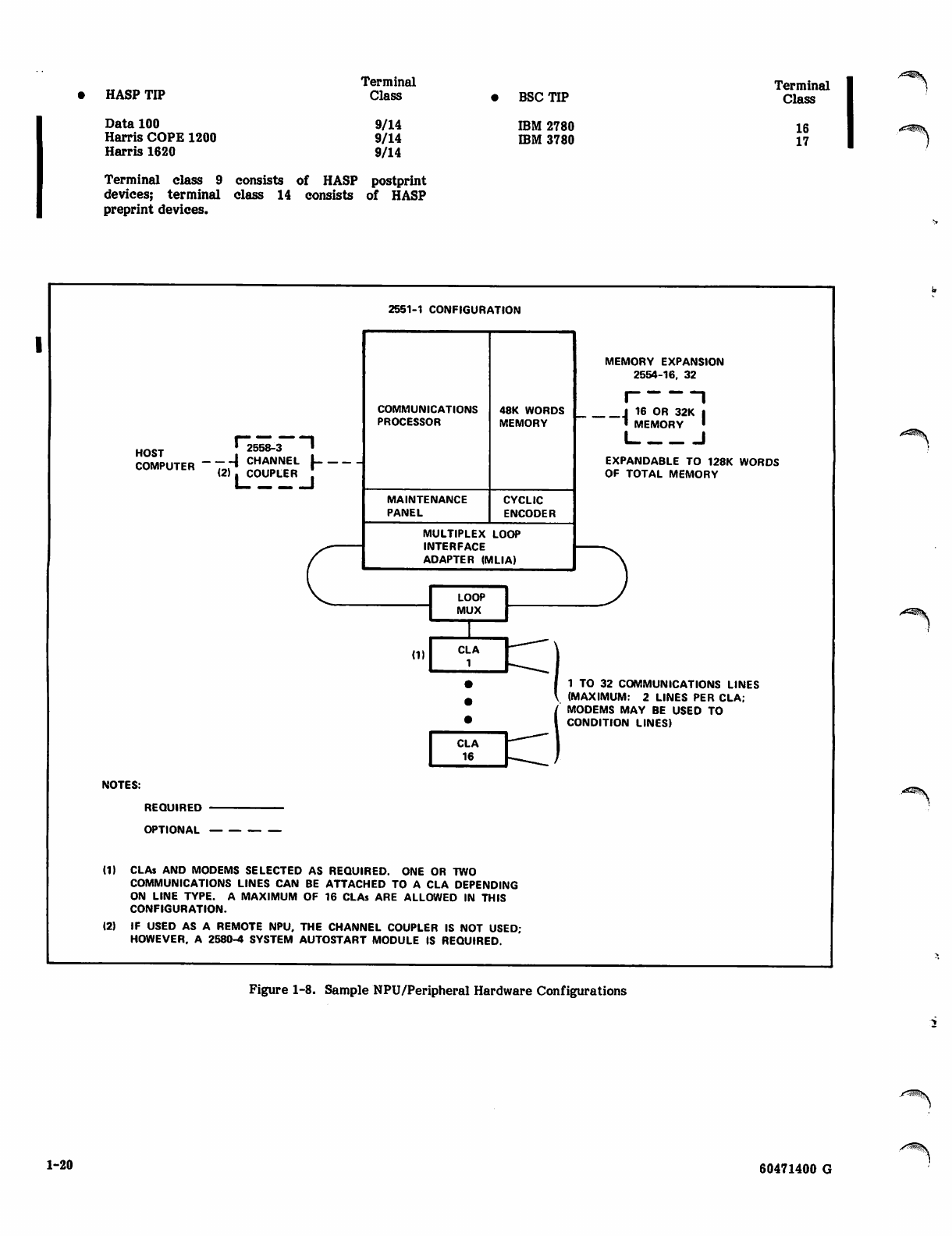
HASP TIP
Data 100
Harris COPE 1200
Harris 1620
Terminal
Class
9/14
9/14
9/14
BSC TIP
IBM 2780
IBM 3780
Terminal
Class
16
17
Terminal class 9 consists of HASP postprint
devices; terminal class 14 consists of HASP
preprint devices.
2551-1 CONFIGURATION
HOST l~2558-3 "~l
COMPUTER ~tJ ™A™EJ- I
(2) . COUPLER
COMMUNICATIONS
PROCESSOR
MAINTENANCE
PANEL
48K WORDS
MEMORY
CYCLIC
ENCODER
MULTIPLEX LOOP
INTERFACE
ADAPTER (MLIA)
MEMORY EXPANSION
2554-16, 32
I 1
J 16 OR 32K I
• MEMORY ■
I I
EXPANDABLE TO 128K WORDS
OF TOTAL MEMORY
1 TO 32 COMMUNICATIONS LINES
(MAXIMUM: 2 LINES PER CLA;
MODEMS MAY BE USED TO
CONDITION LINES)
NOTES:
REQUIRED
OPTIONAL
(1) CLAs AND MODEMS SELECTED AS REQUIRED. ONE OR TWO
COMMUNICATIONS LINES CAN BE ATTACHED TO A CLA DEPENDING
ON LINE TYPE. A MAXIMUM OF 16 CLAs ARE ALLOWED IN THIS
CONFIGURATION.
(2) IF USED AS A REMOTE NPU, THE CHANNEL COUPLER IS NOT USED;
HOWEVER. A 2580-4 SYSTEM AUTOSTART MODULE IS REQUIRED.
Figure 1-8. Sample NPU/Peripheral Hardware Configurations
1-20 60471400 G
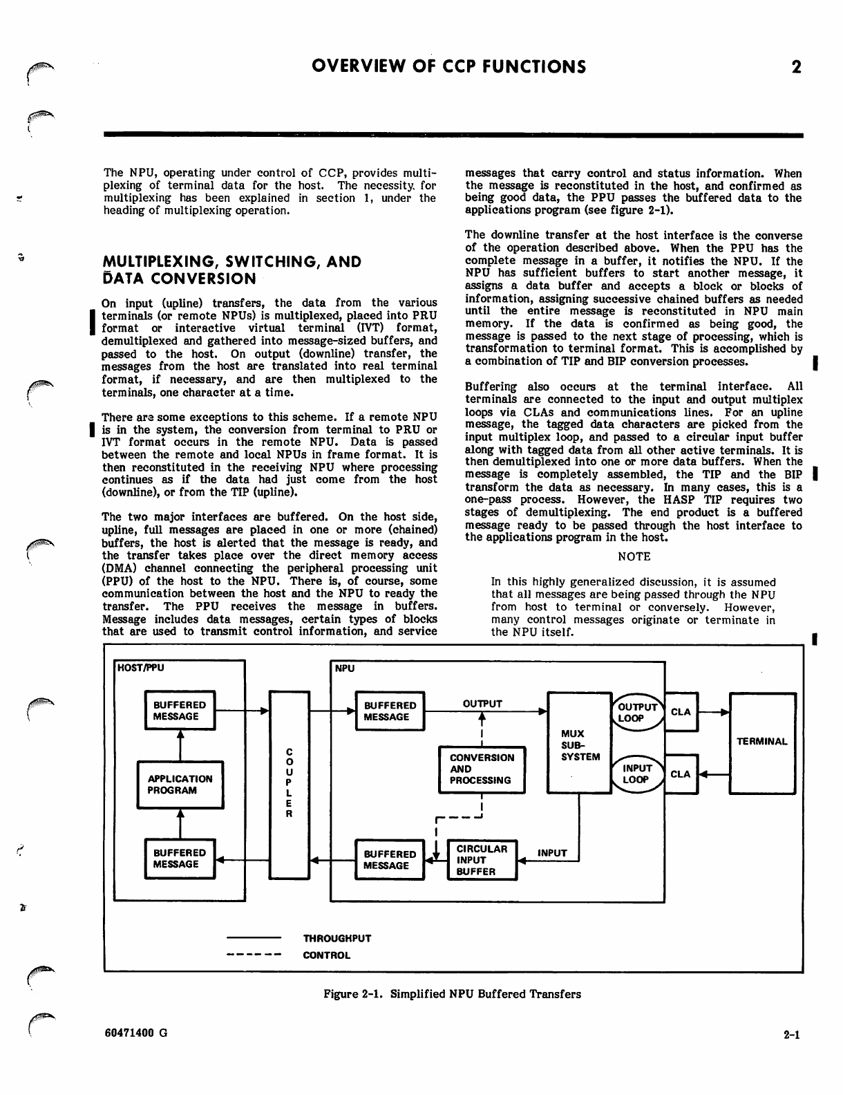
OVERVIEW OF CCP FUNCTIONS
A$$^\
yms
The NPU, operating under control of CCP, provides multi
plexing of terminal data for the host. The necessity, for
multiplexing has been explained in section 1, under the
heading of multiplexing operation.
MULTIPLEXING, SWITCHING, AND
DATA CONVERSION
On input (upline) transfers, the data from the various
terminals (or remote NPUs) is multiplexed, placed into PRU
format or interactive virtual terminal (IVT) format,
demultiplexed and gathered into message-sized buffers, and
passed to the host. On output (downline) transfer, the
messages from the host are translated into real terminal
format, if necessary, and are then multiplexed to the
terminals, one character at a time.
There are some exceptions to this scheme. If a remote NPU
is in the system, the conversion from terminal to PRU or
IVT format occurs in the remote NPU. Data is passed
between the remote and local NPUs in frame format. It is
then reconstituted in the receiving NPU where processing
continues as if the data had just come from the host
(downline), or from the TIP (upline).
The two major interfaces are buffered. On the host side,
upline, full messages are placed in one or more (chained)
buffers, the host is alerted that the message is ready, and
the transfer takes place over the direct memory access
(DMA) channel connecting the peripheral processing unit
(PPU) of the host to the NPU. There is, of course, some
communication between the host and the NPU to ready the
transfer. The PPU receives the message in buffers.
Message includes data messages, certain types of blocks
that are used to transmit control information, and service
messages that carry control and status information. When
the message is reconstituted in the host, and confirmed as
being good data, the PPU passes the buffered data to the
applications program (see figure 2-1).
The downline transfer at the host interface is the converse
of the operation described above. When the PPU has the
complete message in a buffer, it notifies the NPU. If the
NPU has sufficient buffers to start another message, it
assigns a data buffer and accepts a block or blocks of
information, assigning successive chained buffers as needed
until the entire message is reconstituted in NPU main
memory. If the data is confirmed as being good, the
message is passed to the next stage of processing, which is
transformation to terminal format. This is accomplished by
a combination of TIP and BIP conversion processes.
Buffering also occurs at the terminal interface. All
terminals are connected to the input and output multiplex
loops via CLAs and communications lines. For an upline
message, the tagged data characters are picked from the
input multiplex loop, and passed to a circular input buffer
along with tagged data from all other active terminals. It is
then demultiplexed into one or more data buffers. When the
message is completely assembled, the TIP and the BIP
transform the data as necessary. In many cases, this is a
one-pass process. However, the HASP TIP requires two
stages of demultiplexing. The end product is a buffered
message ready to be passed through the host interface to
the applications program in the host.
NOTE
In this highly generalized discussion, it is assumed
that all messages are being passed through the NPU
from host to terminal or conversely. However,
many control messages originate or terminate in
the NPU itself.
HOST/PPU
BUFFERED
MESSAGE
APPLICATION
PROGRAM
BUFFERED
MESSAGE
NPU
BUFFERED
MESSAGE
OUTPUT
CONVERSION
AND
PROCESSING
MUX
SUB
SYSTEM
BUFFERED
MESSAGE
CIRCULAR
INPUT
BUFFER
INPUT
CLA
CLA
TERMINAL
THROUGHPUT
CONTROL
Figure 2-1. Simplified NPU Buffered Transfers
60471400 G 2-1
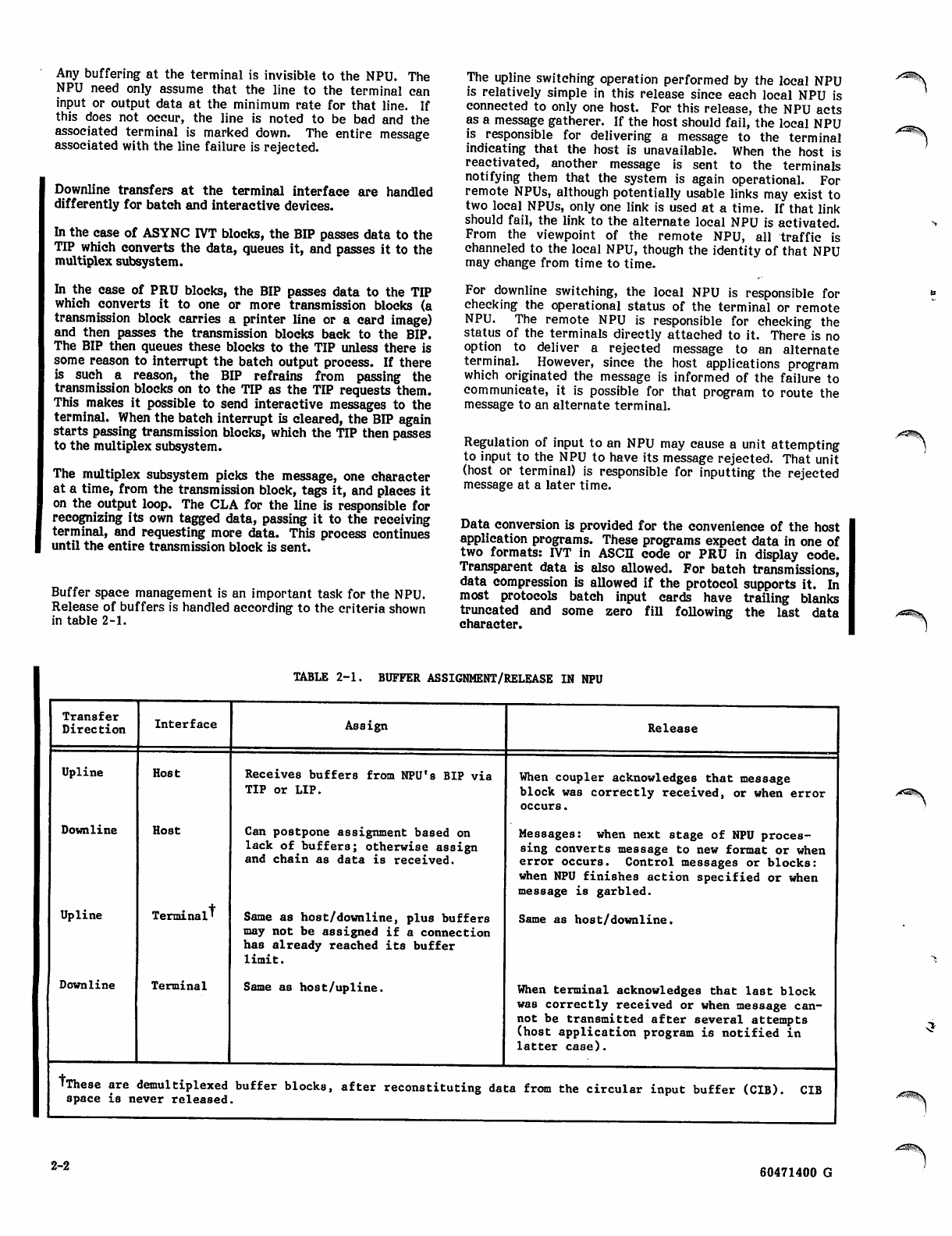
Any buffering at the terminal is invisible to the NPU. The
NPU need only assume that the line to the terminal can
input or output data at the minimum rate for that line. If
this does not occur, the line is noted to be bad and the
associated terminal is marked down. The entire message
associated with the line failure is rejected.
Downline transfers at the terminal interface are handled
differently for batch and interactive devices.
In the case of ASYNC IVT blocks, the BIP passes data to the
TIP which converts the data, queues it, and passes it to the
multiplex subsystem.
In the case of PRU blocks, the BIP passes data to the TIP
which converts it to one or more transmission blocks (a
transmission block carries a printer line or a card image)
and then passes the transmission blocks back to the BIP.
The BIP then queues these blocks to the TIP unless there is
some reason to interrupt the batch output process. If there
is such a reason, the BIP refrains from passing the
transmission blocks on to the TIP as the TIP requests them.
This makes it possible to send interactive messages to the
terminal. When the batch interrupt is cleared, the BIP again
starts passing transmission blocks, which the TIP then passes
to the multiplex subsystem.
The multiplex subsystem picks the message, one character
at a time, from the transmission block, tags it, and places it
on the output loop. The CLA for the line is responsible for
recognizing its own tagged data, passing it to the receiving
terminal, and requesting more data. This process continues
until the entire transmission block is sent.
Buffer space management is an important task for the NPU.
Release of buffers is handled according to the criteria shown
in table 2-1.
The upline switching operation performed by the local NPU
is relatively simple in this release since each local NPU is
connected to only one host. For this release, the NPU acts
as a message gatherer. If the host should fail, the local NPU
is responsible for delivering a message to the terminal
indicating that the host is unavailable. When the host is
reactivated, another message is sent to the terminals
notifying them that the system is again operational. For
remote NPUs, although potentially usable links may exist to
two local NPUs, only one link is used at a time. If that link
should fail, the link to the alternate local NPU is activated.
From the viewpoint of the remote NPU, all traffic is
channeled to the local NPU, though the identity of that NPU
may change from time to time.
For downline switching, the local NPU is responsible for
checking the operational status of the terminal or remote
NPU. The remote NPU is responsible for checking the
status of the terminals directly attached to it. There is no
option to deliver a rejected message to an alternate
terminal. However, since the host applications program
which originated the message is informed of the failure to
communicate, it is possible for that program to route the
message to an alternate terminal.
Regulation of input to an NPU may cause a unit attempting
to input to the NPU to have its message rejected. That unit
(host or terminal) is responsible for inputting the rejected
message at a later time.
Data conversion is provided for the convenience of the host
application programs. These programs expect data in one of
two formats: IVT in ASCII code or PRU in display code.
Transparent data is also allowed. For batch transmissions,
data compression is allowed if the protocol supports it. In
most protocols batch input cards have trailing blanks
truncated and some zero fill following the last data
character.
/ < ^ S
TABLE 2-1. BUFFER ASSIGNMENT/RELEASE IN NPU
Transfer
Direction
Upline
Downline
Upline
Downline
Interface
Host
Host
Terminal'
Terminal
Assign
Receives buffers from NPU's BIP via
TIP or LIP.
Can postpone assignment based on
lack of buffers; otherwise assign
and chain as data is received.
Same as host/downline, plus buffers
may not be assigned if a connection
has already reached its buffer
limit.
Same as host/upline,
Release
When coupler acknowledges that message
block was correctly received, or when error
occurs.
Messages: when next stage of NPU proces
sing converts message to new format or when
error occurs. Control messages or blocks:
when NPU finishes action specified or when
message is garbled.
Same as host/downline.
When terminal acknowledges that last block
was correctly received or when message can
not be transmitted after several attempts
(host application program is notified in
l a t t e r c a se) .
TThese are demultiplexed buffer blocks, after reconstituting data from the circular input buffer (CIB),
space is never released. CIB
/«^K
^
2-2 60471400 G
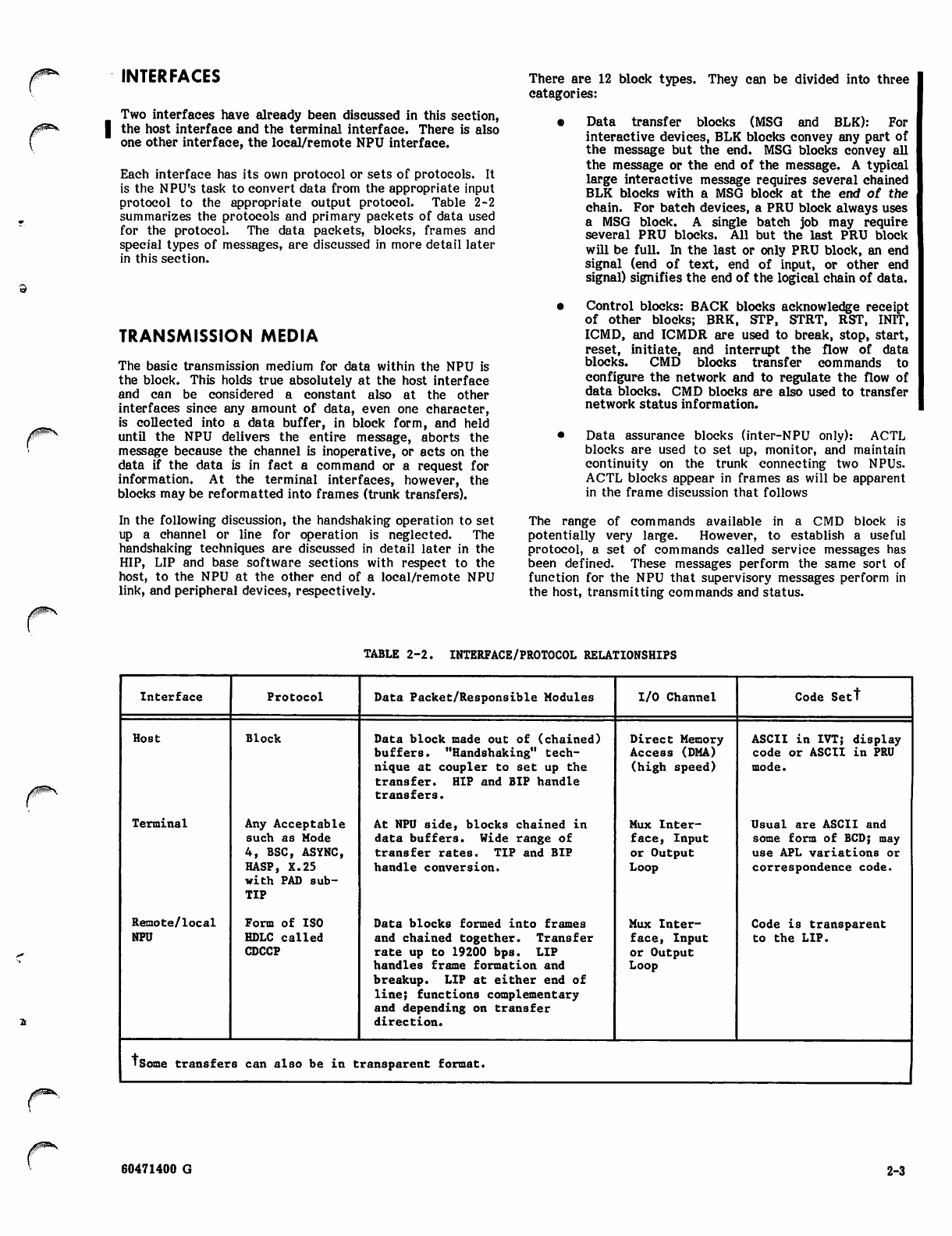
j g ^ S
INTERFACES
Two interfaces have already been discussed in this section,
the host interface and the terminal interface. There is also
one other interface, the local/remote NPU interface.
Each interface has its own protocol or sets of protocols. It
is the NPU's task to convert data from the appropriate input
protocol to the appropriate output protocol. Table 2-2
summarizes the protocols and primary packets of data used
for the protocol. The data packets, blocks, frames and
special types of messages, are discussed in more detail later
in this section.
TRANSMISSION MEDIA
The basic transmission medium for data within the NPU is
the block. This holds true absolutely at the host interface
and can be considered a constant also at the other
interfaces since any amount of data, even one character,
is collected into a data buffer, in block form, and held
until the NPU delivers the entire message, aborts the
message because the channel is inoperative, or acts on the
data if the data is in fact a command or a request for
information. At the terminal interfaces, however, the
blocks may be reformatted into frames (trunk transfers).
In the following discussion, the handshaking operation to set
up a channel or line for operation is neglected. The
handshaking techniques are discussed in detail later in the
HIP, LIP and base software sections with respect to the
host, to the NPU at the other end of a local/remote NPU
link, and peripheral devices, respectively.
There are 12 block types. They can be divided into three
catagories:
• Data transfer blocks (MSG and BLK): For
interactive devices, BLK blocks convey any part of
the message but the end. MSG blocks convey all
the message or the end of the message. A typical
large interactive message requires several chained
BLK blocks with a MSG block at the end of the
chain. For batch devices, a PRU block always uses
a MSG block. A single batch job may require
several PRU blocks. All but the last PRU block
will be full. In the last or only PRU block, an end
signal (end of text, end of input, or other end
signal) signifies the end of the logical chain of data.
• Control blocks: BACK blocks acknowledge receipt
of other blocks; BRK, STP, STRT, RST, INIT,
ICMD, and ICMDR are used to break, stop, start,
reset, initiate, and interrupt the flow of data
blocks. CMD blocks transfer commands to
configure the network and to regulate the flow of
data blocks. CMD blocks are also used to transfer
network status information.
• Data assurance blocks (inter-NPU only): ACTL
blocks are used to set up, monitor, and maintain
continuity on the trunk connecting two NPUs.
ACTL blocks appear in frames as will be apparent
in the frame discussion that follows
The range of commands available in a CMD block is
potentially very large. However, to establish a useful
protocol, a set of commands called service messages has
been defined. These messages perform the same sort of
function for the NPU that supervisory messages perform in
the host, transmitting commands and status.
TABLE 2-2. INTERFACE/PROTOCOL RELATIONSHIPS
Interface Protocol Data Packet/Responsible Modules I/O Channel Code Sett
Host Bl ock Data block made out of (chained) Direct Memory ASCII in IVT; display
buffe rs. "Ha nds hak ing " tec h Access (DMA) code or ASCII in PRU
nique at coupler to set up the (high speed) mode.
transfer. HIP and BIP handle
transfers.
Terminal Any Acceptable At NPU side, blocks chained in Mux Inter Usual are ASCII and
such as Mode data buffers. Wide range of fac e, Inp u t some form of BCD; may
4, BSC, ASYNC, trans fer rates. TIP and BIP or Output use APL variations or
HASP, X.25 handle conversion. Loop correspondence code.
with PAD sub
TIP
Remote/local Form of ISO Data blocks formed into frames Mux Inter Code is transparent
NPU HDLC called and chain ed togethe r. Transfer f ace , I npu t to the LIP.
CDCCP rate up to 19200 bps. LIP
handles frame formation and
breakup. LIP at either end of
line; functions complementary
and depending on transfer
direction.
or Output
Loop
'Some transfer8 can also be in transparent format.
60471400 G 2-3
Comparable service and supervisory messages exist; some of
these are, in essence, transforms of one another. In the
host, the NAM, NS, and CS modules receive, generate, and
process service messages. In the NPU, most service
message processing is handled by a service module (SVM).
Service messages ordinarily do not go through the NPU as
such, although they may be transmitted intact over a trunk
(remote NPU/host messages), or they may carry with them a
character data message to be displayed at a terminal or at a
console (network operator (NOP), local operator (LOP)).
Service messages are summarized in the System
Programmer's Reference Manual.
A typical incoming service message solicits a response and
causes the NPU to generate an appropriate response service
message. Examples of this would be a configuration
message, answered by a response that the device specified
has been configured as requested, or a status request
answered by a message carrying the requested status. In
some cases, the NPU generates a so-called unsolicited
response message. This somewhat confusing terminology
indicates that the NPU has used the normal response form of
a service message to generate a warning that the system is
not operating as configured. An example is the unsolicited
line status request response. That is, in fact, a report that
the line specified in the message has been marked down, and
further attempts to output messages to the terminal using
this line will be rejected. The host must therefore take
action to have the line repaired or reconfigured.
Although blocks retain some of the basic transmission
format when sent over trunks connecting local and remote
NPUs, a new unit of transmission called a frame is also
defined. As in the case of blocks, there are different
categories of frames:
• Command frames: Two types are defined, S
(supervisory) frames and U (unnumbered) frames
monitor channel communications.
• Data frames: I (information) frames transmit data.
Data is placed in the frame in units of subblocks. A
subblock may be a full block or only a portion of a block.
Normal frame size for CCP (an installation-time parameter)
is 259 bytes (8 bit characters).
An example may clarify this: Suppose three messages are
waiting to be sent upline from a remote NPU. The lengths
are 32 bytes, 256 bytes, and 32 bytes, and are queued in that
order. The 256-byte message is contained in two 128-byte
data buffers. The first 32-byte message and the first buffer
of the 256-byte message require together: 32 + 128 + 2
(frame overhead) + 2x2 (two bytes of frame overhead per
subblock) = 166 bytes. The next subblock is 128 (+2) bytes.
166 + 130 > 259 so the frame is closed and transmitted with
166 bytes. The next frame will contain the second half of
the 256-byte message and the other 32-byte message. Since
no other messages are waiting to be transmitted, this frame
is also closed and sent.
NOTE
This simplified example ignores such factors as
checking frames on the receiving side, acknowledg
ing them, and requiring retransmission of all
frames since the last acknowledged good frame in
the event that a frame transmission fails.
As soon as the frame is stripped off in the receiving NPU,
the various messages are reassembled into data blocks and
all traces of frames disappear.
INITIALIZATION
Since the terminals connected through the NPU must be
configured to match the host's image of the network
configuration, and since the NPU has no mass memory, the
NPU image is kept on host mass storage and the NPU is
downline-loaded from the host. After the baseline system is
loaded, the host directs the NPU to configure its links, lines,
and terminals by means of a series of service messages. The
three steps of the initialization are:
• (optional) dump the NPU so that contents can be
used for later analysis to determine cause of
failure
• load the NPU from the host with the baseline
program
• configure the NPU by establishing the parameters
of the logical links, lines and terminals connected
to this NPU
Differences in the initialization cycle result from hardware
differences. The two formats required are for:
• 2551 local NPUs
• 2551 remote NPUs
The host normally attempts to load/dump an NPU only if
the NPU fails or if the network operator specifically
requests a load. If the host itself fails, the NPU must also
be reloaded when the host comes back on-line. In the case
of an NPU failure, the host (optionally) first dumps the
NPU contents. The NPU is then loaded. If the first
attempt to load the NPU fails, another dump is taken. On
subsequent consecutive attempts to load, dumping is inhib
ited. After a set number of times, the NPU is marked
down. Failure of a local NPU is detected by the host PPU
channel.
NPUs that are local to the host are loaded and dumped via
the CYBER Coupler under the control of the PPU. The
remote NPU requires an overlay process in the local NPU.
When a remote NPU fails, the deadman timer is activated.
A bootstrap load/dump program is read into the NPU from
the system autostart module cassette, and that bootstrap
program starts execution. The remote NPU then establishes
contact with the local NPU. The local NPU communicates
with the remote NPU using a restricted set of the
communications protocol during this load/dump procedure.
From this point forward, the load/dump procedure is
controlled by the host, using an overlay in the local NPU.
After the NPU is loaded, the host configures the unit by
establishing all logical links and logical connections for that
NPU. A logical connection is the association of two
elements made by the assignment of a network logical
address. The network logical address is a set of three
numbers: two node IDs followed by a connection number.
These three numbers are used together to trace through a
set of increasingly specific directories: the destination node
directory, the source node directory, and the connection
directory. This process ultimately points to a terminal
control block (TCB). The directories also have information
concerning the logical link control block (LLCB), the line
control block (LCB), and the logical channel control block
(LCCB). It is these three control blocks that are the subject
of the NPU configuration process.
y^BSv
2-4 60471400 G
The network supervisor (NS) program and the communica
tions supervisor (CS) program in the host are responsible for
the control of logical links and connections, respectively, in
the network. All logical links and connections are explicitly
configured, reconfigured and deleted by NS/CS using service
messages (SM). Configuration proceeds in three stages:
• establishing logical links
• configuring lines
• connecting terminal over the lines
NS establishes all logical links which the current state of the
network permits. NS notifies CS of each logical link to be
established and the initial regulation level for the logical
link. CS configures the lines and attempts to connect each
terminal on the line.
To connect the terminal, the line must be enabled. The
terminal is connected by the NPU building the terminal
control block (TCB) for the terminal. When the configure or
reconfigure action has been performed, the block protocol is
initiated and the connection is in use.
BASE SYSTEM SOFTWARE
The base system software consists of most of those portions
of the CCP that are normally associated with a
comprehensive operating system together with the
associated standard utilities. The base system, plus the
block interface package (BIP), and the other interface
packages (HIP, UP, and all TIPs) constitute the standard
CCP software. Initialization and configuration was
ibed previously. The major features of the base systemdesc
are:
system monitor
buffer handling
worklist services
queuing mechanisms
direct program calls (switching services)
interrupt handling
timing services
globals
control block services
directory maintenance
standard subroutines for code translation, and
special arithmetic functions
multiplex subsystem operation
SYSTEM MONITOR
The NPU is a multiple interrupt level processor. Interrupts
are serviced in a priority scheme in which all lower priority
interrupts are disabled during execution of a program
operating at a higher priority level. When no interrupt is in
effect, the processor runs at its lowest priority, known as
the operations monitor (OPS) level. Programs on the OPS
level communicate with one another using worklists. Para
meters for the requested task are stored in a worklist and
the worklist is placed in a first-in/first-out queue for the
program to be called. The monitor scans the list of all
programs capable of having worklist queues. If the monitor
scan discovers a program with one or more worklists in its
queue, control is passed to the program, together with the
worklist which defines the parameters for the task. It is
possible to pass control to a program for execution of more
than one worklist, if that program is designated as being
allowed to process more than one task before releasing
control. In this case, the maximum number of queued tasks
(worklists) are executed by the program before the program
returns control to the monitor. When the task or tasks are
completed, control returns to the monitor which resumes the
scan at the next program on the list.
Each time a program completes, a timer is advanced. This
timer is checked by the interrupt level timer routine at
specific system-defined intervals. If the timer expires, it
indicates that some OPS-level program has been abnormally
delayed. Monitor execution is then terminated and the NPU
is stopped.
BUFFER HANDLING
The buffer handler allocates the four types of buffers and
recovers buffers for the four free buffer pools when users
are finished with them. Buffers are potentially available in
six sizes: 4, 8, 16, 32, 64, and 128 words. At installation
time, the user chooses any four contiguous sizes; for
instance, 8, 16, 32, and 64 words. The largest size is
designated as the data buffer size.
Buffers are assigned one at a time; buffers can be released
singly or in a chain of buffers.
In conjunction with testing buffer availability to assure a
minimum threshold number, buffer maintenance periodically
attempts to adjust distribution of buffer sizes by using
buffer mating or buffer splitting to replenish any buffer pool
that is at threshold level.
WORKLIST SERVICES
Worklists provide a convenient method of handling communi
cations between software modules that do not use direct
calls. The list services function manipulates worklists by
making worklist entries from any priority level (including
OPS level).
Characteristics of the queued worklists are:
• first in, first out
• one to six-word entries, but all entries in any one
list of equal length
• lists exist in dynamically assigned space
• No limit in the number of lists serviced
If there is contention between priority interrupt levels when
making an entry, this conflict is resolved by use of an
intermediate worklist array.
60471400 G 2-5
QUEUING MECHANISMS
I Several major queues are defined:
• terminal control block (TCB) queue which controls
input messages from the various terminals
I* TCB output queues which control messages to be
passed downline to the terminal
• timing queue
DIRECT PROGRAM CALLS (Switching Services)
Most OPS-level programs call other programs and subpro
grams directly. One subroutine is provided for these direct
calls. The same program also is the final step in the
worklist calling sequence. It provides switching for pro
grams on different main memory pages, timed and periodic
calls, service message switching, and overlay execution, as
well as actual passing of control for programs called by the
monitor.
The input data processor (IDP) services the inter
rupt produced when the MLIA places a data
character or CLA status into the circular input
buffer. The IDP (part of the multiplex subsystem)
uses the designated input state program to process
the character according to the requirements of the
protocol and to transfer the characters to the line-
oriented input buffer.
The timing services firmware processes the 3.3-
millisecond clock interrupt which is used for the
time base of all timed NPU functions.
TIMING SERVICES
Timing services provide the means for running those
programs or functions which must be executed periodically
or following a specific lapse of time. These timing services
are available:
• A firmware program handles the 3.3-millisecond
microinterrupt to provide a 100-millisecond timing
interval.
/^^t\
INTERRUPT HANDLING
The NPU can recognize 16 different macrointerrupts. Each
has its own address to which control is transferred when the
interrupt is acknowledged. When the computer is processing
a particular interrupt, it is defined as being in the interrupt
state (state 00 through 15). However, before the computer
can recognize an interrupt, the corresponding mask bit in
the interrupt mask register must be set and the interrupt
system must be activated.
Upon recognizing an interrupt, the hardware stores the
appropriate program return address to ensure that the
software can return to the interrupted program after
interrupt processing.
The interrupt handler that is activated also saves selected
NPU registers for the interrupted program. The interrupt
mask is then loaded with a mask to be used while in this
interrupt state. The program then saves the current
software priority level, sets the new software level, acti
vates the interrupt system, and processes the interrupt.
During interrupt processing, an interrupt request with a
higher priority may interrupt this program. Such higher
level interrupts also store return address links and registers
to permit sequential interrupt processing according to
priority level with eventual return to the main-stream
computer program.
The computer exits from an interrupt state when processing
is completed. The handler inhibits interrupts, restores the
registers, and retrieves the return address of the interrupted
program. Control is transferred to the return address and
the interrupt system is again activated.
Three microinterrupts are also serviced:
• The output data processor (ODP) services the
output data demand (ODD) interrupt which each
CLA generates to indicate that it is ready to
output another character. The ODP (part of the
multiplex subsystem) gets the next character from
the appropriate line-oriented output buffer and
puts the character on the output loop. The
requesting CLA picks the character from the loop
and transmits it.
• Every 100 milliseconds, a timing routine searches a x-«sv
chai n o f t i me-lap se entrie s . If any entry ' s time ■
period has elapsed, that entry is deleted from the
chain and a worklist entry is sent to the program
for which the delayed call was requested. Timing
services also handle adding delay requests to this
delay request chain.
• Every 500 milliseconds, a timing routine checks the
deadman timer. The timer is reset and the monitor
timeout routine is checked. If the monitor timer
has expired, it indicates that the monitor has spent
too long in one OPS-level program. The NPU is
stopped. /^«k
• Every 100 milliseconds, a timing routine scans the
list of active line control blocks (LCBs) for ASYNC I
TIP terminals. If a character has been received, |
the timeout is reset for the next character. If the
character has timed out (no character received
within 100 milliseconds), the LCB is removed from
the active list and the ASYNC TIP is notified.
• A 500-millisecond program time has these principal
functions:
Every second, a timing routine checks all 1
active outputting lines to see if an output data
demand (ODD) has been generated for the next
character to output. If a second has expired
with no new ODD interrupt, the multiplex
event worklist processor is called to declare a
hardware failure for the line.
Every 500 milliseconds, a timing routine scans
all active lines for periodic requests. If the
period has elapsed, the TIP is called using a
worklist. Input or output can be terminated
for the line if this is requested. Inactive LCBs
are unchained from the set of active LCBs.
Timer services also provide the means of
chaining LCBs to this list of LCBs requiring
periodic action. 3
A time-of-day routine is called every second.
The time of day is incremented and, if
necessary, recycled to start of day (00 hour, 00
minute, 00 second). <*s^
2-6 60471400 G
GLOBALS controls modems and analyzes status
PASCAL-coded programs can use global variables, tables,
and constants. PASCAL globals are defined in the CYBER
Cross PASCAL Compiler Reference Manual. The principal
globals used by standard CCP programs are described in the
CCP System Programmer's Reference Manual.
CONTROL BLOCK SERVICES
The line control blocks (LCBs) are a vital part of the
configuration data. The blocks consist of a series of entries,
one for each line. LCBs are chained together and are
therefore handled as a series of active, chained blocks.
Entries that are no longer active are flagged. If an entire
block has no active entries, the block is unchained and
released. New blocks are added as needed. The LCB space,
however, is dedicated and cannot be used for other purposes.
DIRECTORY MAINTENANCE
This set of modules sets up and maintains the directories
which are used for block routing.
STANDARD SUBROUTINES
This group of subroutines provides handling to:
convert and handle numbers
handle interrupt masks
maintain paging registers
save/restore registers
set/clear protect bits
code conversions
perform miscellaneous other tasks
MULTIPLEX SUBSYSTEM OPERATION
The multiplex subsystem has two principal tasks:
• relieve the TIPs of having to process lines accord
ing the the physical line characteristics (most line
characteristics are invisible to the TIPs as a result
of multiplex subsystem processing)
• multiplex the data to match the low-speed charac
teristics of individual terminals with the high-speed
characteristics of the NPU and the host
The principal multiplex subsystem functions are:
• receives serial data from communications lines,
places it in a circular input buffer, demultiplexes it
and places it into line-oriented input buffers
• transmits serial data to communications lines from
line-oriented output buffers
• detects and processes special characters
• translates code on input
• checks CRC
• checks and generates character parity
• detects breaks
• assembles input data into blocks
• chains data buffers as necessary to create data
blocks
• processes commands issued by the communications
system software
• dynamically alters the input character processing
characteristics as a function of the connected
terminal
Figure 2-2 shows the basic multiplex subsystem elements.
Input Multiplexing
Each line has a communications line adapter (CLA). The
CLA for each active line is sampled in sequence and if a
character is ready, it is placed on the input multiplexer loop
together with information identifying the source (line) and,
in some cases, the nature of the character (for instance, this
type may contain control information rather than a charac
ter of message data). All information on the input multiplex
loop is routed to a circular input buffer (CIB) which is
usually 512 words long. The demultiplexing operation picks
data from this buffer and reconstitutes the messages on a
line input basis.
Output Multiplexing
When the NPU has received a message block from the host
and a TIP has transformed the code/format from IVT or
PRU to terminal format, the TIP notifies the multiplex
subsystem that the transmission block is ready for output.
The multiplex subsystem picks the characters from the line's
output message buffer one at a time, whenever a new output
data demand (ODD) is generated by the CLA. (The ODD
indicates the terminal is ready to receive another
character.) The outgoing characters are placed on the
output multiplex loop, along with such control characters as
are needed, and an address that will be recognized by the
active line for that terminal. The CLA for the line
recognizes the address, picks that data from the output
loop, and marks it as being sent. When the contents of the
entire output buffer for the line have been transmitted, and
the message has been acknowledged as received by the
terminal, the multiplex subsystem notifies the TIP. The TIP
releases the message buffers and notifies the host of a
successful transmission. In some cases the TIP discards the
output message even if it was not successfully transmitted.
Trunk Multiplexing
If a remote NPU is included in the network, transmissions
between the local NPU (see previous subsection on 255x
hardware) and the remote NPU take place over a trunk. In
the local NPU, a link interface package (LIP) sets up the
output buffer, and the message in that buffer remains in IVT
or PRU format while being transmitted over the
trunk. In the remote NPU, the downline messages are
treated similarly to upline messages in a local NPU; that is,
the message goes through the CIB and is then demultiplexed
by the LIP for the TIP. After the TIP translates the code
from virtual terminal format to terminal format, the
message is treated as an output message in a local NPU;
that is, the message is multiplexed for transmission, is sent,
and is acknowledged. The acknowledgment must be for
matted then as any other input message: remultiplexed, and
sent upline through the local NPU to the host.
^ms
60471400 G 2-7
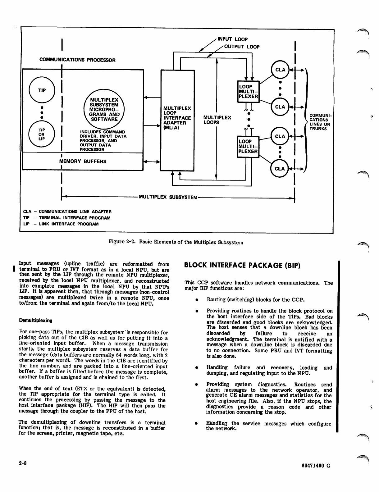
INPUT LOOP
COMMUNICATIONS PROCESSOR
MULTIPLEX
SUBSYSTEM
MICROPRO
GRAMS AND
SOFTWARE
INCLUDES COMMAND
DRIVER, INPUT DATA
PROCESSOR, AND
OUTPUT DATA
PROCESSOR
MEMORY BUFFERS
I
<0L OUTPUT LOOP
MULTIPLEX
LOOP
INTERFACE
ADAPTER
(MLIA)
"t
tt v
LOOP
MULTI
PLEXER
IT
&v
MULTIPLEX
LOOPS
nQiA4-*l
V |
V y l
( CLA W4—▶
COMMUNI
CATIONS
LINES OR
TRUNKS
LOOP
MULTI
PLEXER
■MULTIPLEX SUBSYSTEM-
CLA - COMMUNICATIONS LINE ADAPTER
TIP - TERMINAL INTERFACE PROGRAM
LIP - LINK INTERFACE PROGRAM
r^ms.
Figure 2-2. Basic Elements of the Multiplex Subsystem ^3iS3K
Input messages (upline traffic) are reformatted from
terminal to PRU or IVT format as in a local NPU, but are
then sent by the LIP through the remote NPU multiplexer,
received by the local NPU multiplexer, and reconstructed
into complete messages in the local NPU by that NPU's
LIP. It is apparent then, that through messages (non-control
messages) are multiplexed twice in a remote NPU, once
to/from the terminal and again from/to the local NPU.
Demultiplexing
For one-pass TIPs, the multiplex subsystem is responsible for
picking data out of the CIB as well as for putting it into a
line-oriented input buffer. When a message transmission
starts, the multiplex subsystem reserves a data buffer for
the message (data buffers are normally 64 words long, with 2
characters per word). The words in the CIB are identified by
the line number, and are packed into a line-oriented input
buffer. If a buffer is filled before the message is complete,
another buffer is assigned and is chained to the first.
When the end of text (ETX or the equivalent) is detected,
the TIP appropriate for the terminal type is called. It
continues the processing by passing the message to the
host interface package (HIP). The HIP will then pass the
message through the coupler to the PPU of the host.
The demultiplexing of downline transfers is a terminal
function; that is, the message is reconstituted in a buffer
for the screen, printer, magnetic tape, etc.
BLOCK INTERFACE PACKAGE (BIP)
This CCP software handles network communications. The
major BIP functions are:
• Routing (switching) blocks for the CCP.
• Providing routines to handle the block protocol on
the host interface side of the TIPs. Bad blocks
are discarded and good blocks are acknowledged.
The host senses that a downline block has been
discarded by failure to receive an
acknowledgment. The terminal is notified with a
message when a downline block is discarded due
to no connection. Some PRU and IVT formatting
is also done.
• Handling failure and recovery, loading and
dumping, and regulating input to the NPU.
• Providing system diagnostics. Routines send
alarm messages to the network operator, and
generate CE alarm messages and statistics for the
host engineering file. Also, if the NPU stops, the
diagnostics provide a reason code and other
information concerning the stop.
• Handling the service messages which configure
the network.
2-8 60471400 G
BLOCK ROUTING ROUTING
A major portion of this processing provides block switching
so that the data block can ultimately be routed downline to
the proper terminal or upline to the host.
Data traveling in either direction is tagged by the
terminal ID. A group of directories are provided which
assures that the block control information (contained in a
header) is decoded. The block is attached, through control
blocks for that line/trunk and terminal, to the next
program that must process the block.
SERVICE MODULE
The block format itself allows only a limited set of
commands. Most of the large number of specific
commands transmitted throughout the system are handled
by the special type of command block called a service
message. These messages are handled by the service
module. There is a large variety of service messages (one
type for each command, with a related normal response
and a related error response):
• Configuring logical links, trunks, lines, and
terminals, as well as the basic load/dump NPU
service messages, are described in the initiali
zation section (section 3). These messages
originate in the NS or CS modules of the host for
normal configuration and reconfiguration. Mal
functioning of a line or any component of the line
may generate an upline service message indicating
that the line or component is no longer usable. NS
or CS will then reconfigure the network accord
ingly.
• Service messages regarding failure and recovery,
and those that support diagnostics are discussed in
section 4 (failure, recovery and diagnostics).
• The remaining service messages provide com
mands for such things as status, broadcasting a
message to a terminal, or sending a message from
a terminal to the network operator's (NOP) or
local operator's (LOP) terminal.
INTERACTIVE VIRTUAL TERMINAL COMMANDS
Interactive virtual terminals are capable of changing some
of their operating characteristics such as page width, page
length, the character to be used for breaks, backspacing,
aborts and other terminal features. These command
messages can originate from the host or from the
terminal The BIP supplies routines to validate the
commands and to start implementation of the commands.
BATCH TERMINAL PRU COMMANDS
Batch device operating characteristics can also be
changed. There are two types of changes: those which
change device characteristics (page width or length, PRU
block length, and sub device type) and those which change
file characteristics (file type, file limit, carriage control,
punch and lace card control). Both types are sent downline
from the host; the code type (026/029 punch) and
transparent/non-transparent mode can also be changed by
BSC/HASP batch devices. The BIP supplies routines to
validate the commands and to start the implementation of
the commands.
Routing routines check the blocks for validity and queue
the block to the TCBs if necessary. These routines also
purge the data block queues when the network or a
connection is reconfigured. Collectively some of the
routing and queue maintenance routines are known as
downline TIP services and upline TIP services.
BLOCK ACKNOWLEDGMENT AND DATA
FLOW CONTROL
The BIP acknowledges downline blocks (examples: a BACK
block is generated to inform the host that a message was
successfully output to a terminal by the responsible TIP, or
accounting data is sent for a PRU block indicating the
block was successfully sent to the terminal). Accounting
data is formatted for the host when an EOI occurs.
PROCESSING SPECIAL CHARACTERS AND IVT
COMMANDS
The BIP provides routines to check special characters
(cancels, breaks, interrupts) in an upline message. If such
characters are found, the BIP takes the necessary action on
the current message (such as discarding the current data).
If IVT commands are found, the BIP calls the IVT processor
to execute the command, to change the network
configuration, and to notify the host if necessary.
The programs also handle all the other kinds of control
blocks except the CMD blocks which are handled by the
service module.
PROCESSING AUTOINPUT
The BIP saves the first 20 characters of an autoinput
message from the host so that these characters can be used
to preface the autoinput reply from the terminal.
COMMON TIP SUBROUTINES
A number of common TIP subroutines are provided to:
queue output blocks. The TIP is notified that
output needs to be processed.
Handle upline break signals from a terminal.
Output operations are halted and the host is
notified to stop sending output data on this line.
Handle downline break from the host. The TIP will
not send more input data to the host until the host
is again ready to receive data for this line.
Handle a request from the TIP to stop output data
from the host for a given line.
Handle requests from a TIP to escape to firmware
processing. This is used for the text-processing
operation.
Find the number of characters to be processed.
Save and restore TIP processing entry points so
that a TIP can temporarily suspend processing
while waiting for some external event to occur.
The TIP may be simultaneously suspended for one
output and one input operation.
60471400 G 2-9
Handle a common control relinquishing request.
This assures that return of control to the OPS-
monitor is complete and correct.
FAILURE AND RECOVERY
Several types of failure are possible,
recovery or avoidance technique.
Each requires its own
Host Failure
If a host fails, the NPU and its software must necessarily
stop message processing. Host unavailability is communi
cated to the other ends of all logical links. Also, the NPU
sends an informative service message to all connected,
interactive terminals (and to some other types of terminals)
informing the terminal that the host is unavailable. After
recovery, all logical links are reinitialized and new connec
tions are made.
The host recovers the existing configuration status by means
of status requests to the NPU. Initialization requires the
downline-loading technique described above, followed by
complete reconfiguration using the status information
recovered from the NPU.
NPU Failure
If an NPU fails, it must be reloaded and reconfigured from
the host. Off-line diagnostic tests may be desirable during
this period to help identify the cause of failure. Failure is
detected by means of a 10-second timeout across the
coupler. The NPU is forced to generate a request for load
message.
Recovery consists of a dump (optional), load, and recon
figure operation. If the initial two load operations fail, the
host does not request a dump after the second or any
subsequent attempt to reload. After n successive attempts
to load, the loading operation is aborted, and the NPU is
ignored until manually reactivated. If the NPU is success
fully loaded and initialized, NS and CS in the host set up all
logical links, lines, and terminals for that NPU which the
present state of the network allows.
Logical Link Failure
Host failure, one of the causes of link failure, was
mentioned previously. Link protocol failure leads to higher
and higher levels of regulation until message traffic ceases
on the link.
A logical link may recover spontaneously (regulation level
drops), or may be reinitialized by the host. In the case of
spontaneous recovery, the logical link protocol allows a
restart without loss of data. Otherwise, all logical connec
tions must be remade. Trunks connecting neighboring NPUs
are a special class of links. Trunk recovery protocol is
handled by the LIP.
Trunk Failure
A trunk failure (such as the trunk connecting the NOS
network to the Public Data Network) is detected by a
failure of the trunk protocol. All data queued for
transmission on the trunk is discarded. The failure is
reported to the host. The trunk protocol detects the trunk
recovery. The logical link protocol determines when the
trunk can again be used for data block transmissions.
Line Failure
Lines are disconnected and terminal control blocks (TCBs)
associated with the lines are deleted. A line failure is
detected by abnormal modem status or by line protocol
failure. The change of status is reported to CS in the host.
A line cannot recover spontaneously. CS (which owns the
lines) deletes the supported TCBs. Then CS disables and
reenables the line, using the appropriate service messages.
When line status changes to operational and this is reported
to CS, CS attempts to configure the supported terminals.
Terminal Failure
Terminal status is reported and messages are discarded.
TCBs are not released. Once terminal failure has been
detected, possible terminal recovery is monitored by a
periodic status check or diagnostic poll made from the NPU
to the terminal. Terminal recovery status is reported to CS.
DIAGNOSTICS
Three types of diagnostics are associated with the NPU:
inline, on-line, and off-line. Only the inline diagnostics are
a part of CCP. The on-line and off-line diagnostics are a
part of the network maintenance package, which is optional.
• Inline diagnostics include CE error and alarm
messages, statistics messages concerning hardware
performance, halt code messages that specify the
reason for a NPU failure, and off-line dumps.
• On-line diagnostics provide closed-loop testing of
the circuits connecting the NPUs to the terminals.
These tests are available for installations pur
chasing a maintenance contract.
• Off-line diagnostics are hardware tests for NPU
circuits. They are described in detail in the
Network Processor Unit Hardware Maintenance
Manual.
INTERFACE PACKAGES
CCP provides seven standard interface packages:
• A host interface package (HIP) handles the
host/NPU channel. This channel uses high-speed
transfers to move 16 bits of data at a time
between the PPU and NPU memories. These
parallel data transfers do not use data assurance
techniques since the channel's noise level is low.
Data on this channel is in IVT/PRU format. The
code is transparent to the HIP, except that an 8-bit
byte is assumed. The interface requires a CYBER
70/170 host coupler hardware unit.
• A LIP uses a high-speed link to move messages
from any kind of a terminal between a local and a
remote NPU. The functions of a LIP are shown in
figure 2-3.
• An ASYNC TIP services TTY-type asynchronous
terminals connected to the network on low/
medium-speed voice-grade lines. Terminals must
be asynchronous. The TIP supports ASCII, IBM
extended BCD, APL, correspondence code, and
variants of these.
^&H^S
.^Sejy
2-10 60471400 G
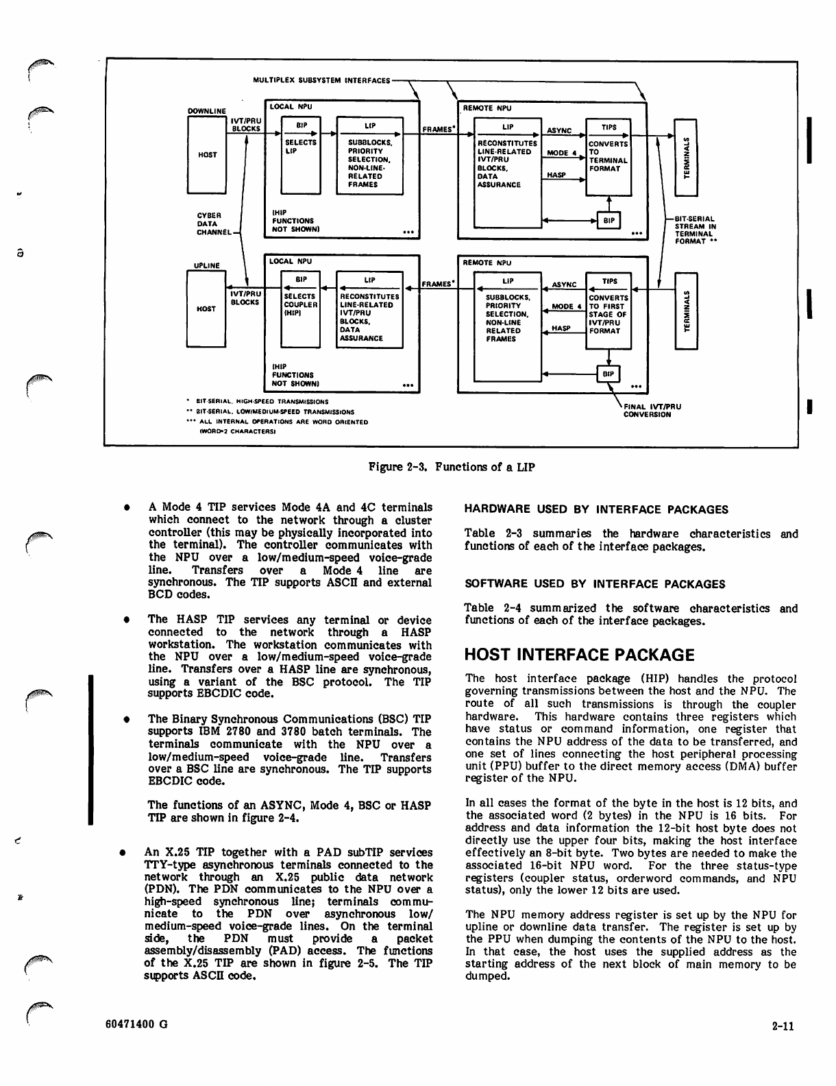
00&Ss*
MULTIPLEX SUBSYSTEM INTERFACES
UPLINE LOCAL NPU
FRAMES*
REMOTE NPU
_ ASYNC
HOST
BIP LIP LIP TIPS
tc
Ul
»-
IVT/PRU
BLOCKS
SELECTS
COUPLER
(HIP)
RECONSTITUTES
LINE-RELATED
IVT/PRU
BLOCKS.
OATA
ASSURANCE
SUBBLOCKS,
PRIORITY
SELECTION.
NON-LINE
RELATED
FRAMES
- MODE 4 CONVERTS
TO FIRST
STAGE OF
IVT/PRU
FORMAT
HASP
(H JL
—JJKPJ
NU T SHOWN) ...
BIT-SERIAL. HIGH SPEED TRANSMISSIONS
BIT-SERIAL. LOW/MEOIUM-SPEED TRANSMISSIONS
• ALL INTERNAL OPERATIONS ARE WORD ORIENTED
IWORO-2 CHARACTERS)
'FINAL IVT/PRU
CONVERSION
Figure 2-3. Functions of a LIP
A Mode 4 TIP services Mode 4A and 4C terminals
which connect to the network through a cluster
controller (this may be physically incorporated into
the terminal). The controller communicates with
the NPU over a low/medium-speed voice-grade
line. Transfers over a Mode 4 line are
synchronous. The TIP supports ASCII and external
BCD codes.
The HASP TIP services any terminal or device
connected to the network through a HASP
workstation. The workstation communicates with
the NPU over a low/medium-speed voice-grade
line. Transfers over a HASP line are synchronous,
using a variant of the BSC protocol. The TIP
supports EBCDIC code.
The Binary Synchronous Communications (BSC) TIP
supports IBM 2780 and 3780 batch terminals. The
terminals communicate with the NPU over a
low/medium-speed voice-grade line. Transfers
over a BSC line are synchronous. The TIP supports
EBCDIC code.
The functions of an ASYNC, Mode 4, BSC or HASP
TIP are shown in figure 2-4.
• An X.25 TIP together with a PAD subTIP services
TTY-type asynchronous terminals connected to the
network through an X.25 public data network
(PDN). The PDN communicates to the NPU over a
high-speed synchronous line; terminals commu
nicate to the PDN over asynchronous low/
medium-speed voice-grade lines. On the terminal
side, the PDN must provide a packet
assembly/disassembly (PAD) access. The functions
of the X.25 TIP are shown in figure 2-5. The TIP
supports ASCII code.
HARDWARE USED BY INTERFACE PACKAGES
Table 2-3 summaries the hardware characteristics and
functions of each of the interface packages.
SOFTWARE USED BY INTERFACE PACKAGES
Table 2-4 summarized the software characteristics and
functions of each of the interface packages.
HOST INTERFACE PACKAGE
The host interface package (HIP) handles the protocol
governing transmissions between the host and the NPU. The
route of all such transmissions is through the coupler
hardware. This hardware contains three registers which
have status or command information, one register that
contains the NPU address of the data to be transferred, and
one set of lines connecting the host peripheral processing
unit (PPU) buffer to the direct memory access (DMA) buffer
register of the NPU.
In all cases the format of the byte in the host is 12 bits, and
the associated word (2 bytes) in the NPU is 16 bits. For
address and data information the 12-bit host byte does not
directly use the upper four bits, making the host interface
effectively an 8-bit byte. Two bytes are needed to make the
associated 16-bit NPU word. For the three status-type
registers (coupler status, orderword commands, and NPU
status), only the lower 12 bits are used.
The NPU memory address register is set up by the NPU for
upline or downline data transfer. The register is set up by
the PPU when dumping the contents of the NPU to the host.
In that case, the host uses the supplied address as the
starting address of the next block of main memory to be
dumped.
60471400 G 2-11
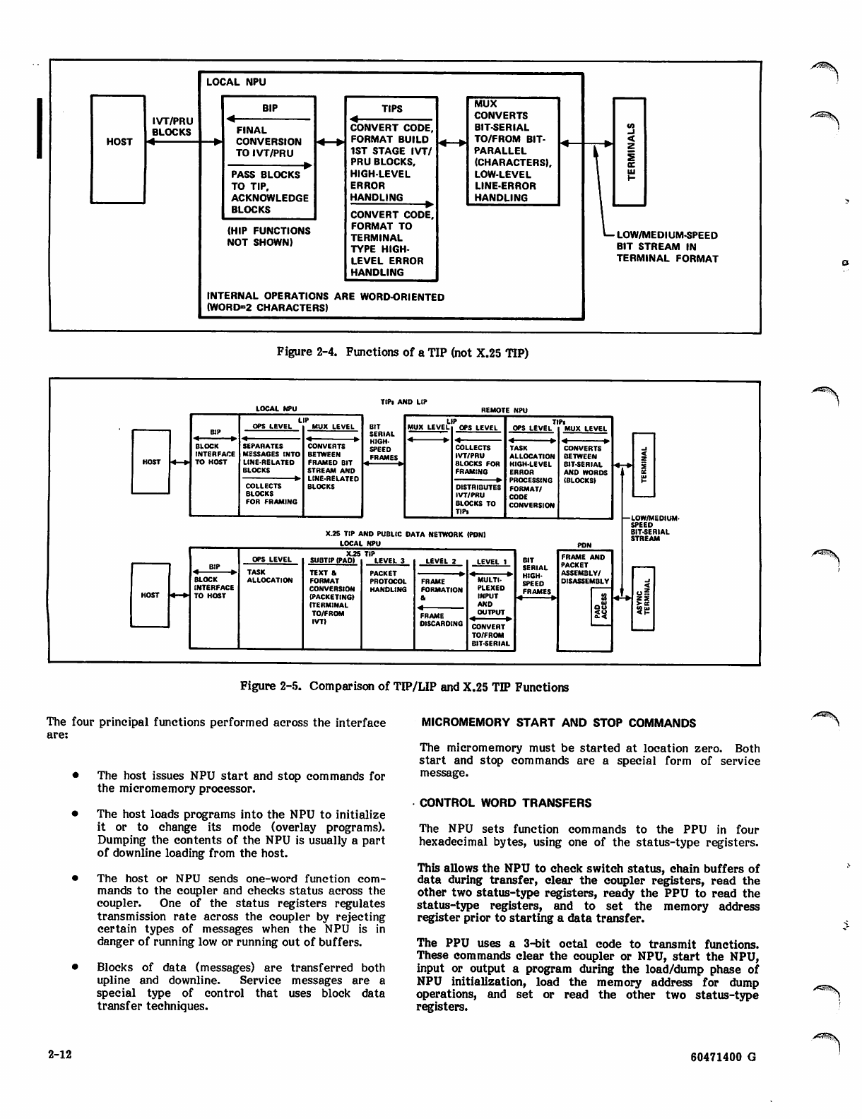
LOCAL NPU
HOST
IVT/PRU
BLOCKS
BIP TIPS MUX
CONVERTS
BIT-SERIAL
TO/FROM BIT-
PARALLEL
(CHARACTERS),
LOW-LEVEL
LINE-ERROR
HANDLING
in
<
z
I
UJ
FINAL
CONVERSION
TO IVT/PRU
CONVERT CODE,
FORMAT BUILD
1ST STAGE IVT/
PRU BLOCKS,
HIGH-LEVEL
ERROR
HANDLING
PASS BLOCKS
TO TIP,
ACKNOWLEDGE
BLOCKS CONVERT CODE,
FORMAT TO
TERMINAL
TYPE HIGH-
LEVEL ERROR
HANDLING
(HIP FUNCTIONS
NOT SHOWN) *— LOW/MEDIUM-SPEED
BIT STREAM IN
TERMINAL FORMAT
INTERNAL OPERATIONS ARE WORD-ORIENTED
(WORD=2 CHARACTERS)
A^&^ts.
Figure 2-4. Functions of a TIP (not X.25 TIP)
LOCAL NPU TIPl AND LIP
OPS LEVEL
BIP
BLOCK SEPARATES
INTERFACE MESSAGES INTO
TO HOST LINE-RELATED
BLOCKS
COLLECTS
BLOCKS
FOR FRAMINC
MUX LEVEL
CONVERTS
BETWEEN
FRAMED BIT
STREAM AND
LINE-RELATED
BLOCKS
BIT
SERIAL
HIGH
SPEED
FRAMES
MUX LEVEL
COLLECTS
IVT/PRU
BLOCKS FOR
FRAMING
DISTRIBUTES
IVT/PRU
BLOCKS TO
TIPl
TASK CONVERTS
ALLOCATION BETWEEN
HIGH-LEVEL BIT-SERIAL
ERROR AND WORDS
PROCESSING (BLOCKS)
FORMAT/
COOE
CONVERSION
X.2S TIP AND PUBLIC DATA NETWORK (PON)
LOCAL NPU PDN
TASK
ALLOCATION
SUBTIP (PAD)
TEXT ft
FORMAT
CONVERSION
(PACKETINGI
(TERMINAL
TO/FROM
IVT)
PACKET
PROTOCOL
HANDLING
FRAME
FORMATION
FRAME
DISCARDING
LEVEL 1
MULTI
PLEXED
INPUT
AND
OUTPUT
CONVERT
TO/FROM
BIT-SERIAL
BIT
SERIAL
HIGH-
SPEEO
FRAMES
FRAME AND
PACKET
ASSEMBLY/
DISASSEMBLY
-LOW/MEDIUM-
SPEED
BIT-SERIAL
STREAM
r38»y
Figure 2-5. Comparison of TIP/LIP and X.25 TIP Functions
The four principal functions performed across the interface
are:
• The host issues NPU start and stop commands for
the micromemory processor.
• The host loads programs into the NPU to initialize
it or to change its mode (overlay programs).
Dumping the contents of the NPU is usually a part
of downline loading from the host.
• The host or NPU sends one-word function com
mands to the coupler and checks status across the
coupler. One of the status registers regulates
transmission rate across the coupler by rejecting
certain types of messages when the NPU is in
danger of running low or running out of buffers.
• Blocks of data (messages) are transferred both
upline and downline. Service messages are a
special type of control that uses block data
transfer techniques.
MICROMEMORY START AND STOP COMMANDS
The micromemory must be started at location zero. Both
start and stop commands are a special form of service
message.
CONTROL WORD TRANSFERS
The NPU sets function commands to the PPU in four
hexadecimal bytes, using one of the status-type registers.
This allows the NPU to check switch status, chain buffers of
data during transfer, clear the coupler registers, read the
other two status-type registers, ready the PPU to read the
status-type registers, and to set the memory address
register prior to starting a data transfer.
The PPU uses a 3-bit octal code to transmit functions.
These commands clear the coupler or NPU, start the NPU,
input or output a program during the load/dump phase of
NPU initialization, load the memory address for dump
operations, and set or read the other two status-type
registers.
^*3$tv
2-12 60471400 G
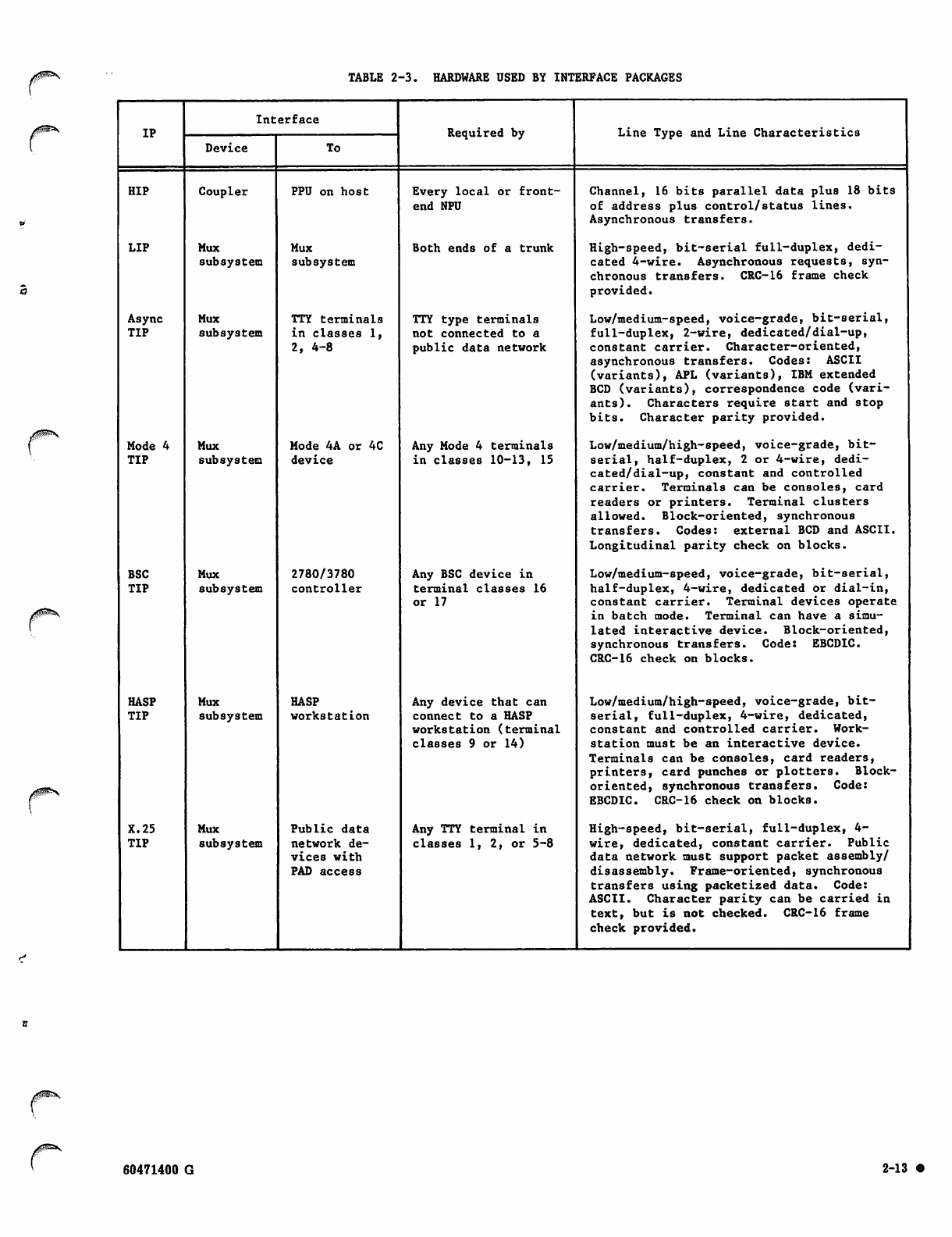
TABLE 2-3. HARDWARE USED BY INTERFACE PACKAGES
Interface
IP Required by Line Type and Line Characteristics
Device To
HIP Coupler PPU on host Every local or front-
end NPU
Channel, 16 bits parallel data plus 18 bits
of address plus control/status lines.
Asynchronous transfers.
LIP Mux Mux Both ends of a trunk High-speed, bit-serial full-duplex, dedi
subsystem subsystem cated 4-wire. Asynchronous requests, syn
chronous transfers. CRC-16 frame check
provided.
Async Mux TTY terminals TTY type terminals Low/medium-speed, voice-grade, bit-serial,
TIP subsystem in classes 1, not connected to a full-duplex, 2-wire, dedicated/dial-up,
2, 4-8 public data network constant carrier. Character-oriented,
asynchronous transfers. Codes: ASCII
(variants), APL (variants), IBM extended
BCD (variants), correspondence code (vari
ant s) . Cha racte rs req uir e s tar t a nd sto p
bits. Character parity provided.
Mode 4 Mux Mode 4A or 4C Any Mode 4 terminals Low/medium/high-speed, voice-grade, bit-
TIP subsystem device in classes 10-13, 15 serial, half-duplex, 2 or 4-wire, dedi
cated/dial-up, constant and controlled
carrier. Terminals can be consoles, card
readers or printers. Terminal clusters
allowed. Block-oriented, synchronous
transfers. Codes: external BCD and ASCII.
Longitudinal parity check on blocks.
BSC Mux 2780/3780 Any BSC device in Low/medium-speed, voice-grade, bit-serial,
TIP subsystem controller terminal classes 16
or 17 half-duplex, 4-wire, dedicated or dial-in,
constant carrier. Terminal devices operate
in batch mode. Terminal can have a simu
lated interactive device. Block-oriented,
synchronous transfers. Code: EBCDIC.
CRC-16 check on blocks.
HASP Mux HASP Any device that can Low/medium/high-speed, voice-grade, bit-
TIP subsystem workstation connect to a HASP
works tat ion (te rm ina l
classes 9 or 14)
serial, full-duplex, 4-wire, dedicated,
constant and controlled carrier. Work
station must be an interactive device.
Terminals can be consoles, card readers,
printers, card punches or plotters. Block-
or ie nted, sy nc hronous tr ansfers. Code:
EBCDIC. CRC-16 check on blocks.
X.25 Mux Public data Any TTY terminal in High-speed, bit-serial, full-duplex, 4-
TIP subsystem network de
vi ces w ith
PAD access
classes 1, 2, or 5-8 wire, dedicated, constant carrier. Public
data network must support packet assembly/
disassembly. Frame-oriented, synchronous
transfers using packetized data. Code:
AS CI I. Characte r p ar ity can b e carried in
text, but is not checked. CRC-16 frame
check provided.
60471400 G 2-13 •
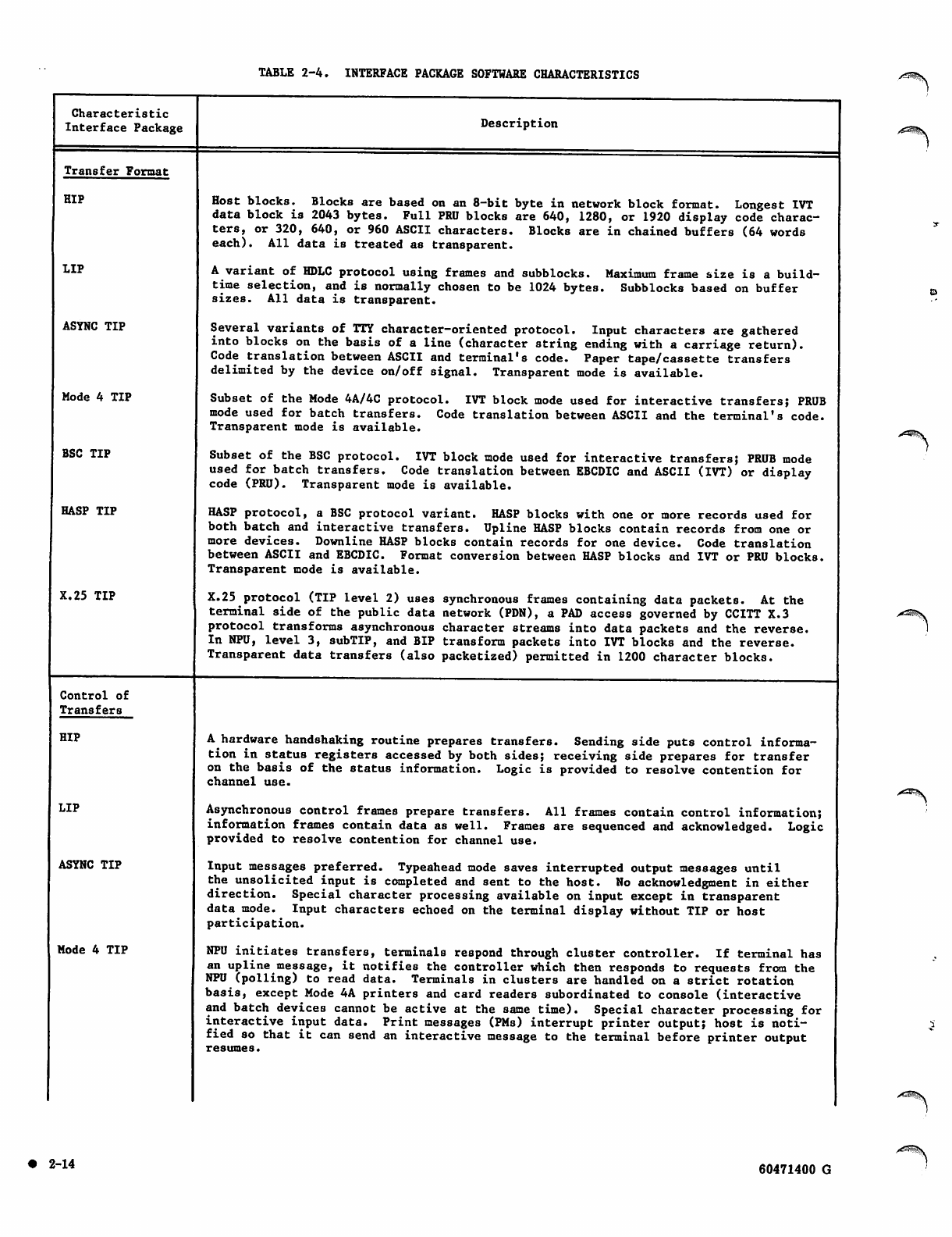
TABLE 2-4. INTERFACE PACKAGE SOFTWARE CHARACTERISTICS
Characteristic
Interface Package
Transfer Format
HIP
LIP
ASYNC TIP
Mode 4 TIP
BSC TIP
HASP TIP
X.25 TIP
Control of
Transfers
HIP
LIP
ASYNC TIP
Mode 4 TIP
Description
Host blocks. Blocks are based on an 8-bit byte in network block format. Longest IVT
data block is 2043 bytes. Full PRU blocks are 640, 1280, or 1920 display code charac
ters, or 320, 640, or 960 ASCII characters. Blocks are in chained buffers (64 words
each). All data is treated as transparent.
A variant of HDLC protocol using frames and subblocks. Maximum frame size is a build-
time selection, and is normally chosen to be 1024 bytes. Subblocks based on buffer
sizes. All data is transparent.
Several variants of TTY character-oriented protocol. Input characters are gathered
into blocks on the basis of a line (character string ending with a carriage return).
Code translation between ASCII and terminal's code. Paper tape/cassette transfers
delimited by the device on/off signal. Transparent mode is available.
Subset of the Mode 4A/4C protocol. IVT block mode used for interactive transfers; PRUB
mode used for batch transfers. Code translation between ASCII and the terminal's code.
Transparent mode is available.
Subset of the BSC protocol. IVT block mode used for interactive transfers; PRUB mode
used for batch transfers. Code translation between EBCDIC and ASCII (IVT) or display
code (PRU). Transparent mode is available.
HASP protocol, a BSC protocol variant. HASP blocks with one or more records used for
both batch and interactive transfers. Upline HASP blocks contain records from one or
more devices. Downline HASP blocks contain records for one device. Code translation
between ASCII and EBCDIC. Format conversion between HASP blocks and IVT or PRU blocks.
Transparent mode is available.
X.25 protocol (TIP level 2) uses synchronous frames containing data packets. At the
terminal side of the public data network (PDN), a PAD access governed by CCITT X.3
protocol transforms asynchronous character streams into data packets and the reverse.
In NPU, level 3, subTIP, and BIP transform packets into IVT blocks and the reverse.
Transparent data transfers (also packetized) permitted in 1200 character blocks.
A hardware handshaking routine prepares transfers. Sending side puts control informa
tion in status registers accessed by both sides; receiving side prepares for transfer
on the basis of the status information. Logic is provided to resolve contention for
channel use.
Asynchronous control frames prepare transfers. All frames contain control information;
information frames contain data as well. Frames are sequenced and acknowledged. Logic
provided to resolve contention for channel use.
Input messages preferred. Typeahead mode saves interrupted output messages until
the unsolicited input is completed and sent to the host. No acknowledgment in either
direction. Special character processing available on input except in transparent
data mode. Input characters echoed on the terminal display without TIP or host
participation.
NPU initiates transfers, terminals respond through cluster controller. If terminal has
an upline message, it notifies the controller which then responds to requests from the
NPU (polling) to read data. Terminals in clusters are handled on a strict rotation
basis, except Mode 4A printers and card readers subordinated to console (interactive
and batch devices cannot be active at the same time). Special character processing for
interactive input data. Print messages (PMs) interrupt printer output; host is noti
fied so that it can send an interactive message to the terminal before printer output
resumes.
• 2 - 1 4 60471400 G
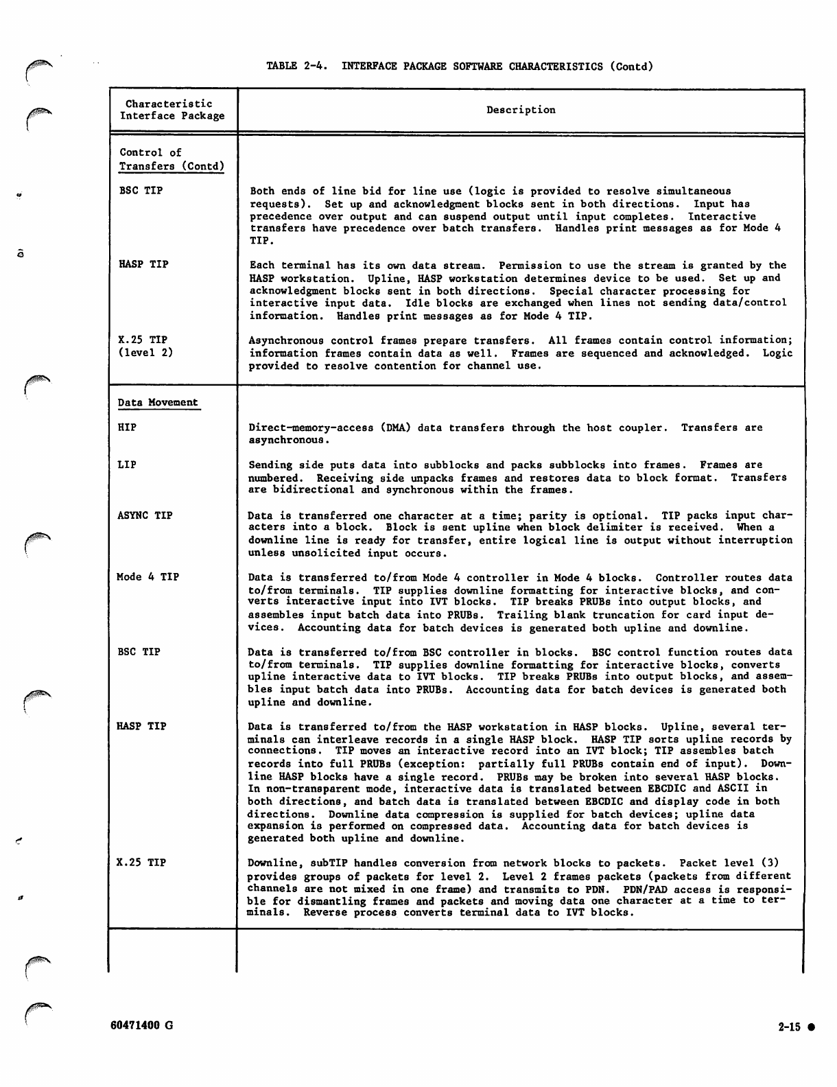
TABLE 2-4. INTERFACE PACKAGE SOFTWARE CHARACTERISTICS (Contd)
Characteristic
Interface Package
Control of
Transfers (Contd)
BSC TIP
HASP TIP
X.25 TIP
(level 2)
Data Movement
HIP
LIP
ASYNC TIP
Mode 4 TIP
BSC TIP
HASP TIP
X.25 TIP
Description
Both ends of line bid for line use (logic is provided to resolve simultaneous
requests). Set up and acknowledgment blocks sent in both directions. Input has
precedence over output and can suspend output until input completes. Interactive
transfers have precedence over batch transfers. Handles print messages as for Mode 4
TIP.
Each terminal has its own data stream. Permission to use the stream is granted by the
HASP workstation. Upline, HASP workstation determines device to be used. Set up and
acknowledgment blocks sent in both directions. Special character processing for
interactive input data. Idle blocks are exchanged when lines not sending data/control
information. Handles print messages as for Mode 4 TIP.
Asynchronous control frames prepare transfers. All frames contain control information;
information frames contain data as well. Frames are sequenced and acknowledged. Logic
provided to resolve contention for channel use.
Direct-memory-access (DMA) data transfers through the host coupler,
asynchronous.
Transfers are
Sending side puts data into subblocks and packs subblocks into frames. Frames are
numbered. Receiving side unpacks frames and restores data to block format. Transfers
are bidirectional and synchronous within the frames.
Data is transferred one character at a time; parity is optional. TIP packs input char
acters into a block. Block is sent upline when block delimiter is received. When a
downline line is ready for transfer, entire logical line is output without interruption
unless unsolicited input occurs.
Data is transferred to/from Mode 4 controller in Mode 4 blocks. Controller routes data
to/from terminals. TIP supplies downline formatting for interactive blocks, and con
verts interactive input into IVT blocks. TIP breaks PRUBs into output blocks, and
assembles input batch data into PRUBs. Trailing blank truncation for card input de
vices. Accounting data for batch devices is generated both upline and downline.
Data is transferred to/from BSC controller in blocks. BSC control function routes data
to/from terminals. TIP supplies downline formatting for interactive blocks, converts
upline interactive data to IVT blocks. TIP breaks PRUBs into output blocks, and assem
bles input batch data into PRUBs. Accounting data for batch devices is generated both
upline and downline.
Data is transferred to/from the HASP workstation in HASP blocks. Upline, several ter
minals can interleave records in a single HASP block. HASP TIP sorts upline records by
connections. TIP moves an interactive record into an IVT block; TIP assembles batch
records into full PRUBs (e xception: partially full PRUBs conta in e nd o f input). Down
line HASP blocks have a single record. PRUBs may be broken into several HASP blocks.
In non-transparent mode, interactive data is translated between EBCDIC and ASCII in
both directions, and batch data is translated between EBCDIC and display code in both
directions. Downline data compression is supplied for batch devices; upline data
expansion is performed on compressed data. Accounting data for batch devices is
generated both upline and downline.
Downline, subTIP handles conversion from network blocks to packets. Packet level (3)
provides groups of packets for level 2. Level 2 frames packets (packets from different
channels are not mixed in one frame) and transmits to PDN. PDN/PAD access is responsi
ble for dismantling frames and packets and moving data one character at a time to ter
minals. Reverse process converts terminal data to IVT blocks.
60471400 G 2-15 •
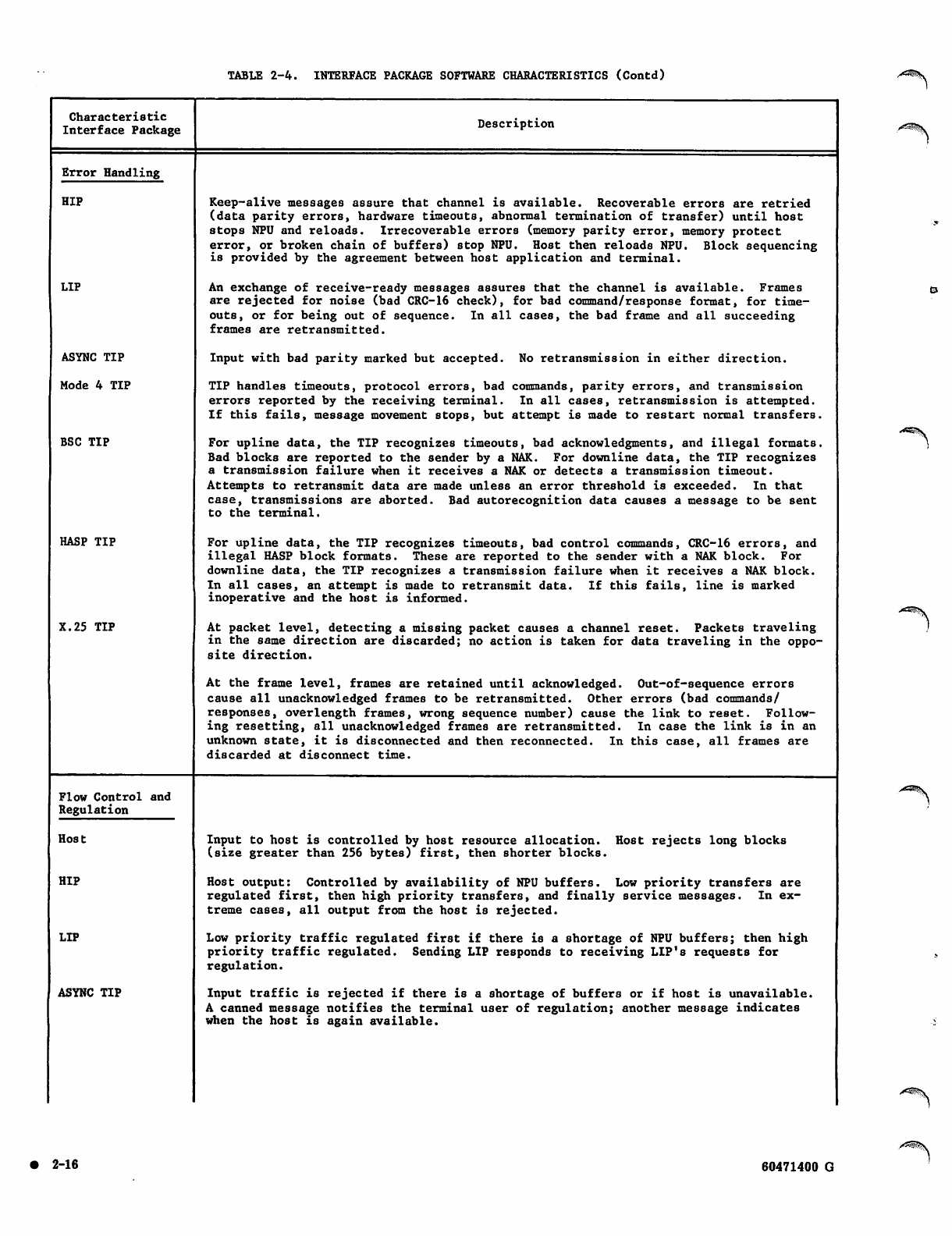
TABLE 2-4. INTERFACE PACKAGE SOFTWARE CHARACTERISTICS (Contd)
Characteristic
Interface Package Description
Error Handling
HIP
LIP
ASYNC TIP
Mode 4 TIP
BSC TIP
HASP TIP
X.25 TIP
Keep-alive messages assure that channel is available. Recoverable errors are retried
(data parity error s, h ardware timeouts, abnormal termination of tr ansfer) until host
stops NPU and reloads. Irrecoverable errors (memory parity error, memory protect
error, or broken chain of buffers) stop NPU. Host then reloads NPU. Block sequencing
is provided by the agreement between host application and terminal.
An exchange of receive-ready messages assures that the channel is available. Frames
are rejected for noise (bad CRC-16 check), for bad command/response format, for time
outs, or for being out of sequence. In all cases, the bad frame and all succeeding
frames are retransmitted.
Input with bad parity marked but accepted. No retransmission in either direction.
TIP handles timeouts, protocol errors, bad commands, parity errors, and transmission
errors reported by the receiving terminal. In all cases, retransmission is attempted.
If this fails, message movement stops, but attempt is made to restart normal transfers.
For upline data, the TIP recognizes timeouts, bad acknowledgments, and illegal formats.
Bad blocks are reported to the sender by a NAK. For downline data, the TIP recognizes
a transmission failure when it receives a NAK or detects a transmission timeout.
Attempts to retransmit data are made unless an error threshold is exceeded. In that
case, transmissions are aborted. Bad autorecognition data causes a message to be sent
to the terminal.
For upline data, the TIP recognizes timeouts, bad control commands, CRC-16 errors, and
illegal HASP block formats. These are reported to the sender with a NAK block. For
downline data, the TIP recognizes a transmission failure when it receives a NAK block.
In all cases, an attempt is made to retransmit data. If this fails, line is marked
inoperative and the host is informed.
At packet level, detecting a missing packet causes a channel reset. Packets traveling
in the same direction are discarded; no action is taken for data traveling in the oppo
site direction.
At the frame level, frames are retained until acknowledged. Out-of-sequence errors
cause all unacknowledged frames to be retransmitted. Other errors (bad commands/
responses, overlength frames, wrong sequence number) cause the link to reset. Follow
ing resetting, all unacknowledged frames are retransmitted. In case the link is in an
unknown state, it is disconnected and then reconnected. In this case, all frames are
discarded at disconnect time.
Flow Control and
Regulation
Host
HIP
LIP
ASYNC TIP
Input to host is controlled by host resource allocation. Host rejects long blocks
(size greater than 256 bytes) first, then shorter blocks.
Host output: Controlled by availability of NPU buffers. Low priority transfers are
regulated first, then high priority transfers, and finally service messages. In ex
treme cases, all output from the host is rejected.
Lo w priori ty tr af fic re gulated fir st if there is a s hortage of NPU buffers; t he n high
priority traffic regulated. Sending LIP responds to receiving LIP's requests for
regulation.
Input traffic is rejected if there is a shortage of buffers or if host is unavailable.
A canned message notifies the terminal user of regulation; another message indicates
when the host is again available.
• 2 - 1 6 60471400 G
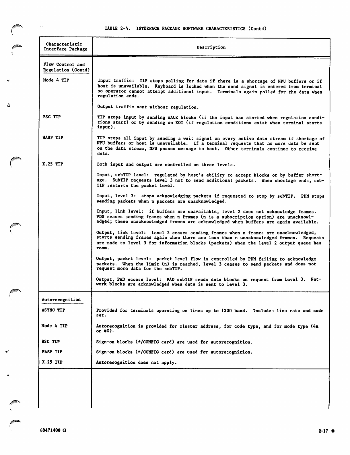
TABLE 2-4. INTERFACE PACKAGE SOFTWARE CHARACTERISTICS (Contd)
Characteristic
Interface Package
Flow Control and
Regulation (Contd)
Mode 4 TIP
BSC TIP
HASP TIP
X.25 TIP
Description
In put traffic: TI P st op s polling f or data if ther e is a s ho rt ag e of NP U buff er s or if
host is unavailable. Keyboard is locked when the send signal is entered from terminal
so operator cannot attempt additional input. Terminals again polled for the data when
regulation ends.
Output traffic sent without regulation.
TIP stops input by sending WACK blocks (if the input has started when regulation condi
tions start) or by sending an EOT (if regulation conditions exist when terminal starts
input).
TIP stops all input by sending a wait signal on every active data stream if shortage of
NPU buffers or host is unavailable. If a terminal requests that no more data be sent
on the data stream, NPU passes message to host. Other terminals continue to receive
data.
Both input and output are controlled on three levels.
Input, subTIP level: regulated by host's ability to accept blocks or by buffer short
age. SubTIP requests level 3 not to send additional packets. When shortage ends, sub
TIP restarts the packet level.
Input, level 3: stops acknowledging packets if requested to stop by subTIP. PDN stops
sending packets when n packets are unacknowledged.
Input, link level: if buffers are unavailable, level 2 does not acknowledge frames.
PDN ceases sending frames when n frames (n is a subscription option) are unacknowl
edged; these unacknowledged frames are acknowledged when buffers are again available.
Output, link level: level 2 ceases sending frames when n frames are unacknowledged;
starts sending frames again when there are less than n unacknowledged frames. Requests
are made to level 3 for information blocks (packets) when the level 2 output queue has
room.
Output, packet level: packet level flow is controlled by PDN failing to acknowledge
packets. When the limit (n) is reached, level 3 ceases to send packets and does not
request more data for the subTIP.
Output, PAD access level: PAD subTIP sends data blocks on request from level 3.
work blocks are acknowledged when data is sent to level 3.
Net-
Autorecognition
ASYNC TIP
Mode 4 TIP
BSC TIP
HASP TIP
X.25 TIP
Provided for terminals operating on lines up to 1200 baud. Includes line rate and code
set.
Autorecognition is provided for cluster address, for code type, and for mode type (4A
or 4C).
Sign-on blocks (*/C0NFIG card) are used for autorecognition.
Sign-on blocks (*/CONFIG card) are used for autorecognition.
Autorecognition does not apply.
60471400 G 2-1 7 •
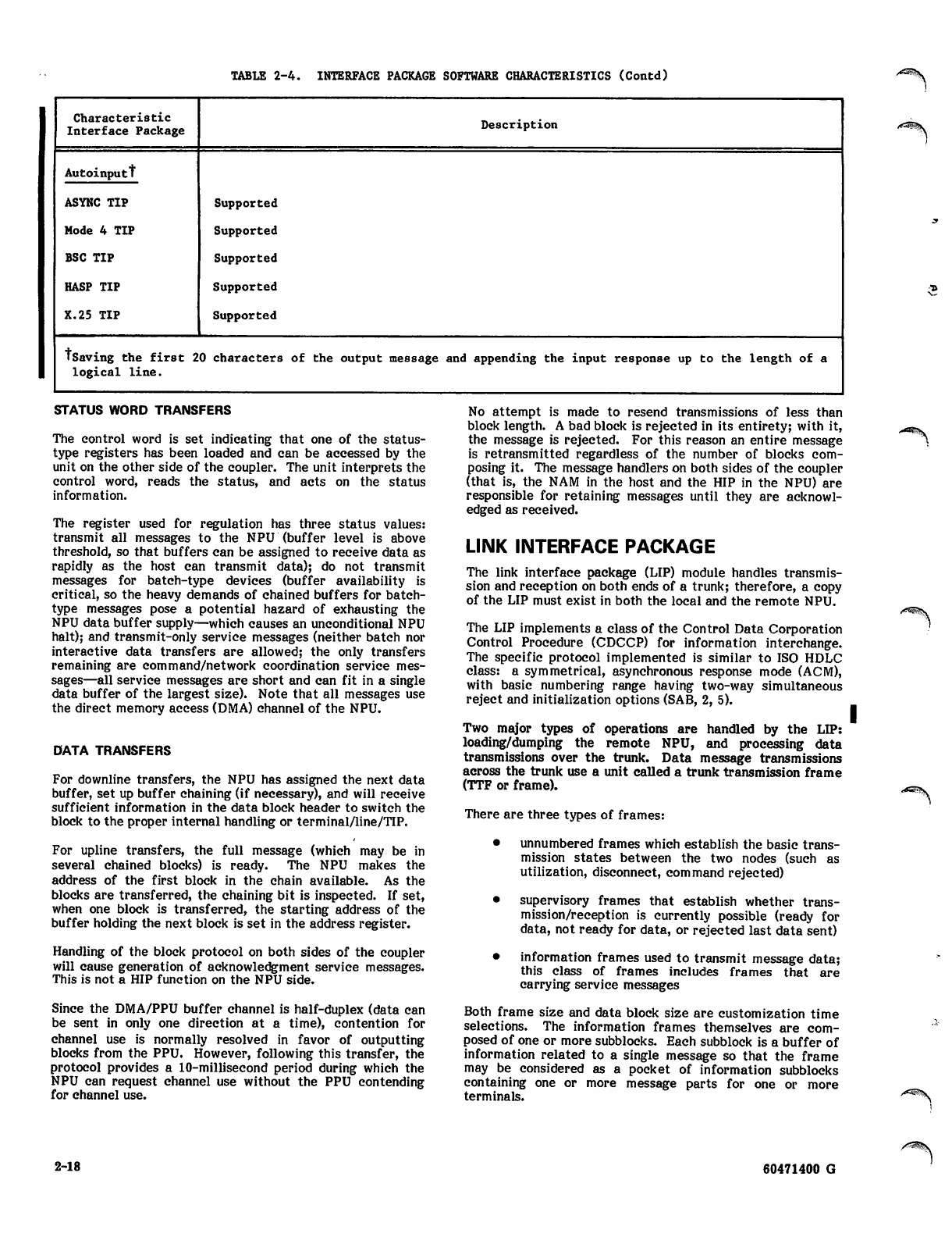
TABLE 2-4. INTERFACE PACKAGE SOFTWARE CHARACTERISTICS (Contd) /tfG^^v
Characteristic
Interface Package
Autoinputt
ASYNC TIP
Mode 4 TIP
BSC TIP
HASP TIP
X.25 TIP
Description
Supported
Supported
Supported
Supported
Supported
•Saving the first 20 characters of the output message and appending the input response up to the length of a
logical line.
STATUS WORD TRANSFERS
The control word is set indicating that one of the status-
type registers has been loaded and can be accessed by the
unit on the other side of the coupler. The unit interprets the
control word, reads the status, and acts on the status
information.
The register used for regulation has three status values:
transmit all messages to the NPU (buffer level is above
threshold, so that buffers can be assigned to receive data as
rapidly as the host can transmit data); do not transmit
messages for batch-type devices (buffer availability is
critical, so the heavy demands of chained buffers for batch-
type messages pose a potential hazard of exhausting the
NPU data buffer supply—which causes an unconditional NPU
halt); and transmit-only service messages (neither batch nor
interactive data transfers are allowed; the only transfers
remaining are command/network coordination service mes
sages—all service messages are short and can fit in a single
data buffer of the largest size). Note that all messages use
the direct memory access (DMA) channel of the NPU.
DATA TRANSFERS
For downline transfers, the NPU has assigned the next data
buffer, set up buffer chaining (if necessary), and will receive
sufficient information in the data block header to switch the
block to the proper internal handling or terminal/line/TIP.
For upline transfers, the full message (which may be in
several chained blocks) is ready. The NPU makes the
address of the first block in the chain available. As the
blocks are transferred, the chaining bit is inspected. If set,
when one block is transferred, the starting address of the
buffer holding the next block is set in the address register.
Handling of the block protocol on both sides of the coupler
will cause generation of acknowledgment service messages.
This is not a HIP function on the NPU side.
Since the DMA/PPU buffer channel is half-duplex (data can
be sent in only one direction at a time), contention for
channel use is normally resolved in favor of outputting
blocks from the PPU. However, following this transfer, the
protocol provides a 10-millisecond period during which the
NPU can request channel use without the PPU contending
for channel use.
No attempt is made to resend transmissions of less than
block length. A bad block is rejected in its entirety; with it,
the message is rejected. For this reason an entire message
is retransmitted regardless of the number of blocks com
posing it. The message handlers on both sides of the coupler
(that is, the NAM in the host and the HIP in the NPU) are
responsible for retaining messages until they are acknowl
edged as received.
LINK INTERFACE PACKAGE
The link interface package (LIP) module handles transmis
sion and reception on both ends of a trunk; therefore, a copy
of the LIP must exist in both the local and the remote NPU.
The LIP implements a class of the Control Data Corporation
Control Procedure (CDCCP) for information interchange.
The specific protocol implemented is similar to ISO HDLC
class: a symmetrical, asynchronous response mode (ACM),
with basic numbering range having two-way simultaneous
reject and initialization options (SAB, 2, 5).
Two major types of operations are handled by the LIP:
loading/dumping the remote NPU, and processing data
transmissions over the trunk. Data message transmissions
across the trunk use a unit called a trunk transmission frame
(TTF or frame).
There are three types of frames:
• unnumbered frames which establish the basic trans
mission states between the two nodes (such as
utilization, disconnect, command rejected)
• supervisory frames that establish whether trans
mission/reception is currently possible (ready for
data, not ready for data, or rejected last data sent)
• information frames used to transmit message data;
this class of frames includes frames that are
carrying service messages
Both frame size and data block size are customization time
selections. The information frames themselves are com
posed of one or more subblocks. Each subblock is a buffer of
information related to a single message so that the frame
may be considered as a pocket of information subblocks
containing one or more message parts for one or more
terminals.
2-18 60471400 G
Use of overlay areas is controlled by the host, using
information from the NPU. During normal processing, the
NPU uses all of main memory. However, for rarely used
operations such as initialization, a portion of the main
memory which is normally reserved for assignable buffers is .
instead reserved for special programs. These programs are
temporarily overlaid in memory and are executed on-line.
Terminal message data is always in virtual terminal format
when it is placed in a frame; that is, upline data must be
processed by a TIP in the remote NPU before it is sent over
the trunk, and downline data is not processed by a TIP until
after it is transmitted over the trunk.
Either end of the link may initiate data transmission when
conditions warrant. Once the interfacing LIPs have estab
lished the normal mode, data transmission can begin.
To understand the LIP requirements for message processing,
it must be remembered that a remote NPU has no coupler to
the host, and therefore no HIP. Terminal data passes
through the multiplexer twice: once in terminal format as
it passes between the terminal and the NPU, and once in r/T
or PRU as it passes between local and remote NPUs. Upline
data in the remote NPU is demultiplexed and passed to the
appropriate TIP for conversion to IVT or PRU format.
Completed, converted messages are passed to the LIP for
framing and then passed through the multiplex subsystem,
over the trunk to the local NPU. Trunk transmission rate is
up to 19200 bps.
In this local NPU, upline data from the trunk is received by
the LIP and reconstructed into a message in (chained)
buffers. Then it is passed to the HIP for transmission to the
host. Downline data is taken from a trunk message data
buffer, assembled into frame format by the LLP and sent to
the remote NPU. Once it is demultiplexed by the
LIP/multiplex subsystem, it is in r/T or PRU format and is
ready to be passed to the appropriate TIP for conversion to
terminal format and processing.
LOADING/DUMPING OF REMOTE NPU
The local NPU must process the load/dump operation in its
overlay area. The program information is transmitted
to/from the local NPU overlay area in block form. The local
LIP passes the programs (downline) and receives main
memory contents (upline) in frame format. The remote NPU
LIP is responsible for stripping the frame information from
the downline subblocks and loading these subblocks (parts of
programs) at the location indicated by the host. For
dumping, the LIP is responsible for placing the main memory
contents, starting at the address indicated by the host, into
frames and sending the frames to the local NPU.
Configuring the remote NPU is handled by service messages,
as in the case of configuring a local NPU. The service
messages are transmitted across the trunk in the same
manner as any other message data.
TRUNK TRANSMISSION PRIORITIES AND
REGULATION
A high or low priority is assigned to each frame. This is the
same priority scheme discussed previously for NPU regula
tion: high priority is associated with interactive terminals
and low priority is associated with batch terminals. Each
time a new frame can be transmitted the LIP scans the high
and low priority queues. If high priority data is waiting, it is
always transmitted ahead of low priority data.
On input (in either the local or the remote NPU), data from
the multiplex subsystem which services the trunk can be
rejected if the number of available buffers has dropped to
the threshold level. First low-priority traffic is rejected,
then high-priority traffic. Supervisory frames are not
included in this priority scheme. These frames contain some
command/status information, but do not include most
service message instructions which are treated as high
priority. Thus, some service messages can be rejected while
other command/status information still passes over the
trunk.
TRANSMISSION ASSURANCE
The CDCCP protocol requires that each frame be acknowl
edged. Since several frames may have been transmitted
before an acknowledgment for a given frame is generated,
all frames up to and including the last properly acknowl
edged frame are retransmitted. No frame is released from
the sending NPU until it is properly acknowledged. Frame
checking is provided by a cyclic redundancy checksum (CRC)
which is generated by the sending LIP and included at the
end of each frame.
TERMINAL INTERFACE PACKAGES
A terminal interface package (TIP) interfaces the terminal
data (messages) to the network. The TIP's interface to the
terminal or a controlling device is through the hardware,
firmware, and software of the multiplex subsystem. The
TIP's interface to the system is through line control blocks
(LCBs) and terminal control blocks (TCBs). A user
interface allows the terminal operator to change an
interactive terminal's parameters (such as page width and
length, cancel and break characters, and others).
Each TIP has the general ability to handle the protocol for
its terminal type. Specialized additional information for
any real terminals that do not fit the basic TIP processing
pattern is contained in the TCB for that terminal. This
gives the standard TIPs sufficient flexibility to handle
many terminal variations.
A TIP includes both hardware and software elements. In
interfacing with the communications network, the
principal concerns of the TIP are mode control and error
control with most of the software elements devoted to
exception processing.
Batch and interactive protocols are treated differently:
• For interactive output in TIPs which support only
interactive devices, TVT data is queued to the TIP
which converts format and code and then passes
the information directly to the terminal (ASYNC
TIP) or to another network (X.25 TIP).
• For other protocols, downline rVT blocks or PRUBs
are transformed into terminal transmission blocks
and are then returned to the BIP. The BIP
requeues the blocks to the terminals in interactive
or batch queues. The TIPs pass the blocks to the
terminals through the multiplex subsystem.
• One upline TIP (ASYNC) converts input data
directly into IVT blocks and passes this to the
host. Other TIPs have multistage upline
processing. During the first stage, data is
collected. During later stages data is formatted in
PRUBs or IVT blocks as appropriate. At the same
time, data on channels which service more than
one device have the data segregated by connection
number.
60471400 G 2-19
Methods are supplied for either the terminal user
or the host to interrupt messages.
ASYNC TIP
The asynchronous TIP supports dedicated and dial-up
asynchronous lines servicing teletypewriter-like terminals
operating at standard rates in the range 110 to S600 baud.
The TIP supports the following codes: ASCII, Tele
typewriter-paired APL ASCII, Bit-paired APL ASCII,
External BCD, External BCD APL, Correspondence, and
Correspondence APL. Transparent mode is also available.
The TIP provides software support for teletypewriters, for
2741 terminals, and for teletypewriter-compatible CRTs
operating in an interactive mode with host applications
programs.
There is a build-time option that excludes support of the
IBM 2741 terminals and terminals which use APL code.
This option makes a considerable amount of additional
NPU memory available for message processing. If the
user attempts to use APL features that were not included
in the build, a rejection message is generated by CCP.
The interface between the host and the TIP is handled by
the interactive virtual terminal. The TIP handles the
interface to the terminal through the multiplex subsystem.
The Async TIP supports a terminal-to-virtual transform
for seven types of terminals. To expand the usefulness of
this TIP, a method is provided for the user at a terminal
or a connected application to vary parameters and
operating modes for any of the seven terminal types. This
provides terminals which differ in detail from the
terminal types. The terminals explicitly supported by the
Async TIP and the seven associated classes are:
Terminal Model
Class Manufacturer Number
1Teletype M33, 35, 37, 38
2CDC 713-10
4IBM 2741
5Teletype M40/2
6Hazeltine 2000
7CDC LIAT 751, 752, 756
8 Tektronix 4014
Line types supported are:
• dedicated or dial-up
• two- or four-wire
• full-duplex
The terminal type is supplied by the user at the terminal
or by the host software, as are any further variable
parameters or modes. The TIP is prepared to receive
input at all times (type ahead mode); therefore, the TIP
attempts to deliver output whenever available, unless
input is currently active, a page-wait condition exists, or
an auto-input block has been output and the reply
information (which must be placed in the output block) has
not been returned with the requested information. When
input is detected during an output cycle, the TIP suspends
output operation. Later, this output is sent from the
beginning of the logical line, unless the input was one of
the user break commands.
IBM 2741 keyboards are locked after each logical line is
input and the TIP does not unlock the keyboard until one
or more messages have been output. Therefore, if an
operator at a 2741 terminal wishes to use the type ahead
mode when the keyboard is locked, he must press the
ATTN key to unlock the keyboard so that the type ahead
data can be entered.
Operators at all terminals have the responsibility for not
using the type ahead feature if either auto-input or
special edit mode (see appendix H) are currently being
used.
All input and output in the character mode is transformed
between the terminal and virtual terminal characteristics
(code conversions, format effectors, format effector
delays, line delimiters, special character recognitions,
etc.). The transparent mode is available to suppress this
transform where desired.
Autorecognition allows the TIP to determine both the
terminal's transmission rate (if the rate is between 110
and 1200 baud) and the terminal's current code set. To
activate the autorecognition function, the user at the
terminal presses the carriage return key after the
connection is established. This generates the appropriate
character at the terminal, which is placed on the line at
the terminal's normal line speed. The TIP samples the line
at 800 baud. Depending on the speed of the line, one or
more different characters will be sensed by the TIP. The
TIP uses the received character to detect the true
transmission speed of the terminal.
After the TIP resets the communications line adapter to
the correct baud rate, the TIP sends the terminal two line
feeds to inform the operator that character set
recognition can begin. The operator responds by pressing
the ) key and then a carriage return (ASCII terminal
operators have the option of pressing only the carriage
return).
If the TIP detects a terminal using a code set that is
supported by the TIP but not available in the current
variant, the terminal receives the message,
"UNSUPPORTED CODE SET." This message is sent in the
terminal's code set.
After determining the code set, the TIP sends two more
line feeds to the terminal to inform the operator that
autorecognition is complete. At the same time, the TIP
sends a line operational service message to the host. This
message contains the line speed and terminal character
set. See appendix C of the CCP System Programmer's
Reference Manual.
The user has one minute to enter each of the requested
responses. If he fails to do so in this period, or if the code
set is unsupported in the CCP variant, the line 4s
disconnected.
Any terminal operating at a speed greater than 1200 baud
must be dialed into a port where the communications line
adapter is designed to operate at that particular speed.
Input Processing
The basic input is the logical line (data followed by line
feed/carriage return) or a physical line width of the
device (number of characters in the line; for instance an
80-character line width on the CRT). Output is allowed
only when input processing has a pause longer than 200
milliseconds following a line end. Output is interrupted if
input starts during an output operation.
s^S.
4&?Sk.
2-20 60471400 G
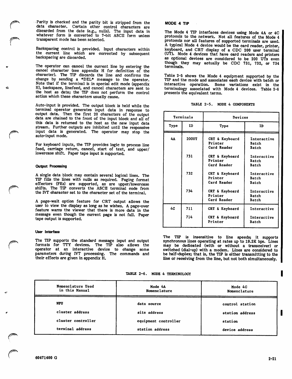
Jt^ffins
/§ms
y ^ s
Parity is checked and the parity bit is stripped from the
data character. Certain other control characters are
discarded from the date (e.g., nulls). The input data in
whatever form is converted to 7-bit ASCII form unless
transparent mode has been selected.
Backspacing control is provided. Input characters within
the current line which are corrected by subsequent
backspacing are discarded.
The operator can cancel the current line by entering the
cancel character (see appendix H for definition of the
character). The TIP discards the line and confirms the
change by sending a *DEL* message to the operator.
Note that if the terminal is in special edit mode (appendix
H), backspace, linefeed, and cancel characters are sent to
the host as data; the TIP does not perform the control
action which these characters usually cause.
Auto-input is provided. The output block is held while the
terminal operator generates input data in response to
output data. Then the first 20 characters of the output
data are chained to the front of the input block and all of
this data is returned to the host as the new input data
stream. Further outputs are inhibited until the responsive
input data is generated. The operator may stop the
auto-input mode.
For keyboard inputs, the TIP provides logic to process line
feed, carriage return, cancel, start of text, and upper/
lowercase shift. Paper tape input is supported.
Output Processing
A single data block may contain several logical lines. The
TIP fills the lines with nulls as required. Paging format
effectors (FEs) are supported, as are upper/lowercase
shifts. The TIP converts the ASCII terminal code from
the r/T character set to the character set of the terminal.
A page-wait option feature for CRT output allows the
user to view the display as long as he wishes. A page-over
feature warns the viewer that there is more data in the
message even though the current page is not full. Paper
tape output is supported.
User Interface
The TIP supports the standard message input and output
formats for TTY devices. The TIP also allows the
operator at an interactive device to change some
parameters during IVT processing. The commands and
their effects are given in appendix H.
MODE 4 TIP
The Mode 4 TIP interfaces devices using Mode 4A or 4C
protocols to the network. Not all features of the Mode 4
protocols nor all features of supported terminals are used.
A typical Mode 4 device would be the card reader, printer,
keyboard, and CRT display of a CDC 200 user terminal
(UT). Mode 4 devices that have card readers and printers
as optional devices are considered to be 200 UTs even
though they may actually be CDC 731, 732, or 734
terminals.
Table 2-5 shows the Mode 4 equipment supported by the
TIP and the mode and associates each device with batch or
interactive operation. Some variations exist in the
terminology associated with Mode 4 devices. Table 2-6
presents the equivalent terms.
TABLE 2-5. MODE 4 COMPONENTS
Terminals Devices
Type ID Type ID
4A 200UT
731
732
734
CRT & Keyboard
Printer
Card Reader
CRT & Keyboard
Printer
Card Reader
CRT & Keyboard
Printer
Card Reader
CRT & Keyboard
Printer
Card Reader
Interactive
Batch
Batch
Interactive
Batch
Batch
Interactive
Batch
Batch
Interactive
Batch
Batch
4C 711
714
CRT & Keyboard
CRT & Keyboard
Printer
Interactive
Interactive
Batch
The TIP is insensitive to line speeds; it supports
synchronous lines operating at rates up to 19.2K bps. Lines
may be dedicated (with or without a transceiver) or
switched (dial-up) with a modem. Lines are considered to
be half-duplex; that is, the TIP is either transmitting to the
line or receiving from the line, but not both simultaneously.
TABLE 2-6. MODE 4 TERMINOLOGY
Nomenclature Used
in this Manual Mode 4A
Nomenclature
Mode 4C
Nomenclature
NPU
cluster address
cluster controller
terminal address
data source
site address
equipment controller
station address
control station
station address
station
device address
60471400 G 2-21
Each line can have more than one cluster of equipment and
each equipment cluster can have more than one terminal.
Lines with multiple clusters must be dedicated. Where
multiple terminals are on a line, the TIP services each
terminal in sequential order without priority.
All Mode 4 terminals can have both interactive and batch
devices attached. The Mode 4 TIP supports remote batch
terminals as separate but dependent devices. The
dependencies are reported to the host on demand when a
conflict occurs.
Mode 4 Autorecognition
The TIP performs autorecognition when requested by the
host. This procedure determines the code set of the
terminal (ASCII or external BCD) and mode (Mode 4A or
4C). Autorecognition causes the TIP to return a service
message to the host which contains the following
information:
terminal type
cluster address
terminal address
device type
Multicluster autorecognition is not supported.
Autorecognition first determines the cluster address. A
poll message allows the caller to hear an audible tone. The
modem is allowed time to stabilize after the Modem Data
switch is depressed.
To complete autorecognition during dial-up procedures, the
remote operator presses the SEND key on at least one of
the displays in the cluster. This allows code set
recognition through the use of an escape code in a read
message.
If the terminal uses BCD code, autorecognition is complete
at this point. If the terminal uses ASCII code, the TIP
sends a configuration poll. An error response or no
response indicates the terminal is Mode 4A. A read
response indicates the terminal is Mode 4C.
A line status (operational) service message is sent to the
host to complete autorecognition.
Mode 4 Data Handling
Interactive data is passed to/from the IVT interface; batch
data is passed to/from the PRU interface.
• Input data: the TIP polls the terminal to collect
data that is ready to be input. The host requests
polling, but the TIP controls the actual polling for
data. A further throttling of input can occur if
the NPU is regulating data input as a result of a
low buffer availability condition.
• Output data: the TIP delivers interactive output
to the display and batch output to a printer.
Output is delayed if the printer is not ready.
• Error processing: the TIP performs recovery for
line or terminal errors. If immediate recovery is
not possible, the TIP reports the error to the host.
Host Interface
rVT or PRU blocks are used at the host interface. The TIP
processes each line as an independent data channel.
Devices on a terminal are checked for data in the sequence
the devices were configured. The card reader and printer
of the 200 UT are treated as separate terminals, but the
console must be configured before the card reader and
printer can be configured.
The terminal status of Mode 4C terminals is solicited
before the TIP services devices on the terminal. The
terminal returns the status of all the connected devices
when requested. Console status indicates whether a read
message is requested. Printer status indicates ready or
busy condition. Status is saved in the TCB and is used to
determine the action to be taken when subsequent events
occur.
IVT Interface
The IVT interface to the Mode 4 TIP supports the CRT and
keyboard which are collectively referenced as one device,
the console.
Selecting the Mode 4 Console
Console activity is started by a start input command,
console output data, or an input batch interrupt for the
console. Console activity remains active and the TIP polls
for input. Upon arrival of batch start or resume
commands, console activity ceases and batch activity
commences. When batch activity ceases due to normal
processing of end of data and no further data is present,
the TIP sends a clear write to the console and starts polling
the console for input.
For the Mode 4A terminals, using the console interrupts
the card reader connection and the printer connection.
The TIP inhibits any further batch input or output activity
until it receives a resume type of command from the host.
yaVuZOt^S
Mode 4 Interactive Input
When a start input command is issued to a Mode 4A
terminal, the cursor is moved to the left-most character
position. This command also clears the terminal
transmission buffer of any previous card or print block.
Polling for input continues until the terminal is deleted
from the system configuration, an error occurs, buffer
regulation occurs, logical link regulation occurs, or a stop
input command is received. A stop (STP) block is sent
whenever a communication error is detected; a start
(STRT) block is subsequently sent when the error condition
disappears.
The TIP polls the Mode 4C console for input only when a
read request is indicated in the terminal's status.
It is possible for parts of a message to repeat on a 711
terminal in certain types of error conditions.
The operator can cancel part of a line by using the CN
character (see appendix H). If this capability is used, the
TIP confirms the cancellation by sending a *DEL* message
to the interactive device. See appendix H for the
alterations to the IVT interface which may be entered from
a terminal.
2-22 60471400 G
Interactive input from the console can include multiple
logical lines. The lines are separated by CRs.
The TIP allows autoinput. The first 20 characters of the
autoinput message from the host are saved and are
prefixed to the reply from the console.
The TIP supports transparent input, but this input applies
only to the first message following transparent selection.
The Mode 4 frame control characters are removed, but no
other translation occurs. The cursor is not repositioned to
the left margin following each input, and the keyboard is
not unlocked. Since any further polling would result in
retransmission of previous data, polling ceases. The host
must request that polling resume by sending output or a
start input command.
The TIP removes any E2 or E3 codes from Mode 4A cluster
transparent data. The data is processed without
transforms. E-codes and MTIs for Mode 4 protocol are
described in the CCP System Programmer's Reference
Manual.
An operator at a Mode 4 console can change the following
r/T parameters for his terminal:
• Terminal class
• Page width and page length
• The characters used for cancel, r/T control, and
user breaks one and two
• Input device for transparent mode (Mode 4C only)
• Page wait feature
The operator can also send a message to the NOP console.
Each IVT command (including the message to the NOP
console) is preceded by the control character and followed
by a carriage return or an end of message. Multiple line
inputs can have an IVT command only in the first line. If
the IVT command in a multiline input is a request for
transparent input, transparency will not be applied to the
current set of input lines, but will be applied to the next
message.
Mode 4 Interactive Output
The cursor is returned to the left margin following each
output of a logical line. For a Mode 4A console, any ASCII
control character is replaced with a blank, and lower case
characters are folded into upper case. For a Mode 4C
console, a full 128 ASCII character set is supported.
The format effector transforms performed by the TIP for
both interactive and batch devices is given in the CCP
System Programmer's Reference Manual.
The IVT transform is not performed on transparent output
data. However, the Mode 4 frame control is added to the
data, but no code or format effector conversion is
performed. The parity bit for each character is also added
before the data reaches the line. Autoinput and page wait
are supported for transparent data. However, page wait
occurs following each MSG block only.
The console operator requests a message break by using
either the user break one or two character.
The page wait feature assures that output is delivered at a
readable rate. Data from the host is displayed on the
screen until the end of page is reached. Page turning is
accomplished whenever the console operator responds with
a request for the next data display.
Card Reader Interface
The Mode 4A card reader is activated by sending a
command to the TIP to start accepting input. The TIP
polls the card reader for data.
Upline data is translated and trailing spaces are stripped to
the first even character boundary following the last data
character. The data is stored in buffers which are
subsequently passed to the BIP. The BIP builds the PRUBs
to be transmitted to the host.
The TIP indicates end of card in standard host file format.
If the last non-blank character is on an odd character
boundary, one blank is inserted. Two to ten binary zeros
are then added to insure that the host can decode end of
card and also to insure that the data stream ends on a
modulo ten character boundary. If the last data character
of the card is a colon in the 64 character set, the TIP
inserts one or two spaces.
The TIP counts each card. Polling continues until an abort
input occurs, a slipped card is detected, a console interrupt
occurs, the card reader becomes not ready, or an EOI card
is read (6, 7, 8, 9 punch in column 1 or /*EOI in columns
1-5). The TIP handles these events as follows:
• Abort input: card reading stops and accounting
data is sent to the host. If the printer is not
active, the TIP polls the console. If the printer is
active, the cluster remains in batch mode. Card
reader input restarts upon receipt of a start input
command from the host.
• Slipped card: host is informed with an input
stopped, card slip command.
• Card reader not ready and last card read not an
EOI card: the TIP stops polling and notifies the
host. Polling resumes when the TIP receives
another start input command from the host.
• Console interrupt: the TIP reports that input is
stopped and sends a batch interrupt to the host.
Card reading resumes when the host sends a
resume input command.
• EOR card read: TIP checks columns 2/3 or 6/7 for
level number and adds this information to the
PRUB. Since an EOI or EOR card ends a PRUB, it
is possible for a short PRUB to be sent to the host.
• EOI card read: the current data, including
accounting data (card count), is sent to the BIP.
The BIP passes the data to the host in a PRUB and
the TIP continues polling. If an EOI is read and
the card reader is found to be not ready (empty),
the TIP notifies the host that the card reader is at
end of a data stream. To get more card data, the
host sends another start input command to the
TIP.
j S v ,
60471400 G 2 - 2 3 •
Printer Interface
The printer is activated by sending downline PRUB data to
the BIP. The BIP passes the PRUB to the TIP. The TIP
transforms the PRUB into transmission blocks (blocks of
data that fit the particular printer buffer being addressed)
and returns it to the BIP. The BIP adds the transmission
blocks to the TIP's queue and, if necessary, notifies the TIP
that data is ready for the printer.
As the TIP sends blocks to the printer, the BIP monitors
the queue. When necessary, the BIP notifies the host. The
host can send another PRUB if one is available.
When Mode 4A printing has completed and the accounting
message has been generated, the TIP returns to polling of
the console for inout if the card reader is not active.
Otherwise, the terminal remains in batch mode.
Skipping Printer Data
Interrupt commands from the host can cause the TIP to
skip a specified portion of the printer data. The point in
the data stream where the skip is to end is marked. After
receiving the interrupt, the TIP continues to receive data,
but discards all of it until the end skip marker is received.
Then the TIP sends accounting data to the host.
Printer Busy
Busy status permits the operator to stop printing, to
inspect the printed output, and to resume printing without
console input.
If a printer is ready but busy, the TIP holds data and
periodically checks status. When the printer is again
ready, the TIP resumes printing. The host is not notified.
Since some Mode 4A printers do not always report printer
not ready status, a different method is used. To interrupt
printing or to generate a ready status, the operator presses
the interrupt key. This toggles the printer between ready
and busy status.
Mode 4C printer status is determined by the terminal
status request. Printer not ready condition is not reported
to the host; printing automatically resumes when the
printer becomes ready.
In no case does the remote terminal operator receive a
console message indicating that the printer is not ready.
The printer should normally be left in the ready state to
avoid unnecessary recovery processing.
Page Eject
Two types of Mode 4C printers are supported: impact and
nonimpact.
The impact printer supports page eject and is controlled by
vertical carriage control characters.
The nonimpact printer does not support page eject, so the
TIP formats a virtual page image. The number of lines on
the page is specified when the device is configured. Sixty
lines is the default page length; six lines separate pages.
Therefore, the TIP varies the number of line feeds it
generates to support page eject.
Print Message
If a print message is received (TIP detects PM at the
beginning of a print line), the TIP builds a separate PM
message and sends it to the BIP, which in turn sends it to
the host. This allows the host to send messages to the
console before continuing the printed output. When the
host sends an interrupt resume command, the TIP restarts
printing with the print line following the PM line.
Mode 4 Error Handling
When the TIP detects a failure that cannot be corrected by
a set number of retry attempts, the terminal is reported as
failed and long-term error recovery begins. For Mode 4A
terminals, failure of one device causes failure of all
devices on the cluster.
Recovery attempts occur every 10 seconds during
long-term error recovery.
BINARY SYNCHRONOUS COMMUNICATIONS
(BSC) TIP
The BSC TIP provides data interchange between a host
application program and a remote IBM 2780, 3780 or
compatible batch terminal. In addition to the terminal's
batch capabilities, BSC terminals simulate an interactive
console device by sending interactive input from the card
reader and receiving interactive output on the line printer.
Exchange of information between the NPU and a terminal
uses the point-to-point binary synchronous communications
protocol with contention resolution (not all features of that
protocol are supported). The NPU converts BSC batch data
to/from PRUB format, and BSC interactive data to/from
IVT blocks. The normal code of a 2780/3780 is EBCDIC.
Provision is made for transmitting to or receiving from
these terminals in transparent mode.
2780 and 3780 have unique subTIP types. For the purposes
of the application interface, the 2780 and the 3780
terminals have exactly the same attributes as HASP
terminals.
BSC terminals can be attached to an NPU through
dedicated or dial-up lines. The TIP is insensitive to line
speeds; it supports synchronous lines operating at speeds up
to 19200 bps. All lines are treated as half-duplex, that is,
the TIP is either transmitting or receiving but not both
simultaneously. Each BSC line is connected to one 2780 or
3780 terminal. A terminal consists of:
• A required card reader which sends interactive as
well as batch input data
• A required line printer which receives interactive
as well as batch output data
• An optional card punch
Terminal Device Selection
The following rules apply to terminal device selection:
• Input has precedence over output
• Interactive data has precedence over batch data
yzMgfigK
y^S^V
• 2 - 2 4 60471400 G
<a
Batch card reader input is allowed if the simulated console
input is not active. Batch output can be interrupted to
accept card reader input; the interrupted output is resumed
when input ends. Card reader input (either batch or
interactive) is not interruptable.
A new batch output can be started if no input is active and
no simulated console data is queued. If the terminal user
interrupts to send card reader input, the batch output is
suspended. Batch output restarts when an upline end of
transmission (EOT) is received, and continues until the end
of job (EOJ) before any new batch output can be started.
There is one exception: a print message (PM). Print
messages are explained in the Mode 4 TIP description.
Batch Input Characteristics of 2780
and 3780 Terminals
Terminals normally operate in non-transparent mode. If
the feature is supported by the terminal, a terminal can
operate in transparent mode. Five types of batch input are
supported:
2780 non-transparent
2780 transparent
3780 non-transparent
3780 transparent
2780/3780 transparent
The BSC TIP checks for data mode information (026, 029)
in columns 79/80 of job deck and EOR cards.
If the host becomes unavailable or the NPU reaches buffer
saturation, the TIP stops or delays input until the reason
for input regulation is removed. If input is already active,
the TIP can delay input by sending a wait/acknowledgment
(WACK). If the regulation occurs before the first input
data arrives, the TIP stops input by sending an EOT.
The 3780 non-transparent characteristics are the same as
the 2780 non-transparent characteristics except:
o Job cannot be terminated by an ETX in column 80
of last card.
• For multiple jobs, the last job must be input with
the EOF toggle switch on.
• Trailing blanks are truncated
• Data can be compressed
• Transmission block is limited by character count
(usually 512) rather than record count
The 3780 transparent characteristics are the same as the
3780 non-transparent characteristics except:
• Transparent switch is on
• 80 characters transmitted per card (no truncation
or compression)
The TIP provides another batch input transparent mode for
both 2780 and 3780 terminals. This mode of input can be
specified only when a terminal is operating in the 2780 or
3780 transparent mode. Characteristics of this transparent
mode are:
• Mode activates when TIP detects TR in columns
79/80 of an EOR card
• Neither EOR or EOI cards are recognized
• Input file is terminated by setting the EOF toggle
switch on
• Terminal transparent switch must remain on until
the file is ended
The 2780 non-transparent characteristics are:
• First card is assumed to be a job card
• Job is terminated by (1) /*EOI, in columns 1-5, or
(2) an ETX in column 80 of the last card or in
column 1 of the next card, or (3) last card is sent
with the EOF toggle switch on.
• Trailing blanks are transmitted except after EM
or ETX
Blank compression is accepted
Up to seven records per transmission block
Multiple batch jobs can be stacked in the reader.
Each job terminates with a /*EOL Blank cards,
/♦EOR cards and extra /*EOI cards after a /*EOI
are discarded.
The 2780 transparent characteristics are the same as the
2780 non-transparent characteristics except:
• Transparent switch is on
• A full 80 characters are transferred for each card
(one record)
• One record per transmission block.
• The TIP returns to the non-transparent mode for
the next batch job.
• Data is stored in a PRUB without marking record
boundaries (such as 80 column card boundary) or
transmission block boundaries
• Transmission block can be split between PRUBs
Batch Output Characteristics of 2780
and 3780 Terminals
Four types of batch output are supported:
• 2780 non-transparent
• 2780 transparent
• 3780 non-transparent
• 3780 transparent
The BSC TIP bids for the line whenever the host sends
downline data and the line is available. Once downline
data transfer starts, it continues until an EOJ PRUB is sent
from the host or a print message (PM) is detected on the
print stream.
For non-transparent output, the TIP supplies appropriate
carriage control transformations (format effector
processing). The host can supply preprint or postprint
format effectors; BSC terminals support only postprint
carriage controls. The BSC format effector transforms are
given in the CCP System Programmer's Reference ManuaL
60471400 G 2-25 •
Card punch and printer connections appear the same to the
TIP except for punching a lace card and changing data
mode. Punching a lace card and changing data mode are
activated by a batch device file command from the host.
Three card punch modes are available: 026, 029 and
transparent. PRUBs containing EOR or EOI cause a 7/8/9
card with level numbers or /*EOI card to be punched.
Print message and carriage control are not supported on
card punch connections.
The 2780 non-transparent output characteristics are:
• Streams directed to line printer or card punch
(provided punch option is present)
• Host determines device to receive output
(separate connections for each device)
• TIP converts PRUB data to EBCDIC 64/96
character set
• TIP formats print lines into BSC transmission
blocks
• 1 to 7 print lines (records) per transmission block
• Maximum transmission block size (default is 400
characters)
• Print line is never split across transmission block
boundaries
• Short line is terminated by unit separator (US)
• Transmission block is terminated at the last data
character of a PRUB block that is marked as an
EOR, EOI, or EOJ block
• Blank compression if terminal supports that
feature
The 2780 transparent output characteristics are:
• Transparent output only if output is specified as
transparent (designated transparent by a
preceding command)
• No code conversion or carriage control transforms
• PRUB characters packed into transmission block
until maximum size or EOR/EOI packed (no
record markers)
• Characters in transmission block formatted into
records; record size defined by page width (if
page width field is zero, record size limited only
by transmission block size)
• EOR PRUB terminates only the transmission
block; next transmission continues with next
PRUB block and a new transmission block
• EOI PRUB terminates the file
• No EOR or EOI cards punched on card punch
connection.
The 3780 non-transparent output characteristics are the
same as the 2780 characteristics except:
• Number of print line records or card records
limited only by the transmission block size
(normally 512 characters). Short records (print
lines or cards) terminated by the EBCDIC IRS
character
• Trailing blanks in the PRUB record are truncated
The 3780 transparent output characteristics are identical
to the 2780 transparent output characteristics.
Print Message (PM)
The characters PM at the beginning of a print line activate
the print message logic. If the TIP detects a PM, the print
line prior to the PM is sent to the line printer. Output is
then stopped and the host is notified with a message of 80
or fewer characters. This enables the host to send an
interactive output message to the printer. Batch output to
the printer does not resume until ICMD, resume, or
terminate output command is received.
Interactive Input and Output Mode
The interactive virtual terminal input mode characteristics
are:
• All interactive cards begin with /*; the TIP strips
this interactive card indicator
• r/T commands from the terminal have the special
control character CT=% in the third character
position
• Input is sent to the host as a MSG block
• Interactive input is on a separate card stream
from batch input (inputs must be separated by
EOT)
• No transparent data mode
The interactive virtual terminal output mode
characteristics are:
• Message output preceded by triple space to
position the message for reading
• Message output followed by double space to
position the message for reading
• Interactive output is single spaced
• Message output occurs at input and output file
boundaries or when the printer is stopped for PM
message; all interactive output messages in queue
are delivered before any more batch output
• No transparent data mode
• 2 - 2 6 60471400 G
Autorecognition Summary of HASP Protocol
Autorecognition allows the terminal to report its own type,
cluster address, and terminal address (the latter is used for
the optional card punch). A /*CONFIG card must be the
fi r s t c a r d r e c e iv e d f r o m a t e r m i n a l a f t e r a n
autorecognition line is enabled. Information from this card
is extracted by the TIP and passed to the host. If the TIP
detects a card error, it sends an error message to the
printer. Then the TIP waits for retransmission of the
correct card. The /*CONFIG card format is:
/♦CONFIG, terminal, CO=M, CR=1, LP=1, CP=N
where:
terminal
M
N
subTIP (2780 or 3780; default is
2780)
Cluster Address
default = 0) (range 1-255;
Card punch (1 = none, 2 or 3 =
terminal address of punch; default =
1)
Any input immediately following a configuration card is
discarded; input is allowed only after the input connection
is established and started.
IVT Commands
The TIP supports these IVT commands:
• MS, Operator message
• CT, Change control character
An error message is returned to any terminal which sends
an illegal IVT command.
Downline File/Device Commands
The TIP supports the following output file types:
LP - Display code, ASCII - 96
CP - 026, 029
HASP MULTILEAVING TIP
The TIP provides network interfacing to a HASP
multileaving workstation. A workstation can contain both
interactive and batch devices and has computer-like
functions. The term multileaving describes the
computer-to-computer communications technique used by
a HASP terminal. The system uses fully synchronized,
pseudo-simultaneous bidirectional transmission of several
data streams between computers and requires BSC protocol
as a basis for transmitting HASP blocks.
A HASP terminal consists of a required console, one to
seven card readers, one to seven printers, and one to seven
card punches or plotters (in combination). Each device has
a separate data stream identification.
The basic element of multileaved transmission is a
character string which is embedded in a data (message)
block. One or more character strings are formed from the
smallest external element of transmission - the physical
record. The physical records, which serve as input data,
may be of any normal record types (card images, printed
lines, mass storage records, etc.). For efficiency in
transmission, each record is reduced to a series of
character strings of two basic types: a variable-length
nonidentical series of characters or a variable number of
identical characters. Since blanks appear frequently, a
special case of the identical character string is the string
of blanks. A string control byte (SCB) precedes each
character string to identify the type and length of the
string. A nonduplicate character string is represented by
an SCB followed by the nonduplicate characters. A
consecutive, duplicate, nonblank character string is repre
sented by an SCB (which contains the character count) and
a single character. For an all-blank character string, only
the SCB itself is required.
The transmitting program segments the data record to be
transmitted into an optimum number of character strings, a
number determined to take full advantage of the identical
character compression. A special SCB indicates the
grouping of character strings which compose the original
physical record. The receiving program then reconstructs
the original record for processing.
In order to allow multiple physical records of various types
to be grouped together in a single transmission block, a
record control byte (RCB) precedes the group of character
strings representing the original physical record. The RCB
identifies the general type and function of the physical
record (input stream, print stream, Data Set, etc.). A
particular RCB type is designated to allow the passage of
control information between the various systems. To
provide for simultaneous transmission of similar functions
(multiple input streams), a stream identification code is
included in the RCB. A subrecord control byte (SRCB) is
also included immediately following the RCB. The SRCB
supplies additional information concerning the record to
the receiving program. (For example, if the transmitted
data is to be printed, the SRCB can hold carriage control
information.)
For a multileaving transmission, a variable number of
records may be combined into a variable block size; e.g.,
RCB,SRCB,SCBl,SCB2,...SCBn,RCB,SRCB,SCBl,... Multi-
leaving allows two computers to exchange transmission
blocks containing multiple data streams in an interleaved
fashion. For optimum use of this capability, a system must
be able to control the flow of one data stream while
continuing normal transmission of others. This requirement
is obvious in the case of simultaneous transmission of two
data streams to a system for immediate transcription to
physical I/O devices with differing speeds, such as two
print streams. To meter the flow of individual data
streams, a function control sequence (FCS) is added to each
block. The FCS is a sequence of bits, each one
representing a particular transmission stream. The
receiver of several data streams can temporarily stop the
transmission of a particular stream by setting the
corresponding FCS bit OFF in the next transmission to the
sender of that stream. The stream can subsequently be
resumed by setting the bit ON. In this release multileaving
is used only by the HASP terminal. The host does not
regulate device data; rather the host's output is regulated
by the devices' use of FCS bits.
60471400 G 2-27
For error detection and correction purposes, a block
control byte (BCB) is added as the first character of each
block transmitted. The BCB contains control information
and a block sequence count. This count is maintained and
verified both by the sending and by the receiving systems
to control lost or duplicated transmission blocks.
In addition to the normal binary synchronous text control
characters (STX, ETB, etc.), multileaving uses two
acknowledgment signals, ACKO and NAK. ACKO is the
normal block received acknowledgment and it is also
utilized as a filler by all systems to maintain communi
cations when data is not available for transmission. NAK is
used as the negative response; it indicates that the previous
transmission was not successfully received.
Information blocks are of two types:
• control blocks which contain control information
and the SCB
• data blocks which contain data and the other
control bytes described above
Protocol Operation
The terminal software is loaded and the communications
line is initialized. After the sign-on command is
transmitted, the NPU and the terminal transmit idle blocks
until a function is desired.
When a function other than a console message or console
command is desired, the process initiating the function
transmits a request to initiate function transmission RCB.
The receiving process transmits a permission to initiate
function transmission RCB if the data from the requesting
process can be processed. If the data cannot be processed,
or the function is now in process, the request to initiate a
function transmission RCB is ignored.
When permission to initiate a function transmission RCB is
received, the requesting process begins transmitting data
blocks to the other process. Data blocks are transmitted
until an EOF is encountered. If more data blocks on the
same device stream are to be transmitted following an end
of file (EOF), the request to initiate function transmission
RCB sequence must be reinitiated. If a request to initiate
a function transmission is not received before data blocks
are received, the data blocks are ignored.
Data blocks are transmitted one at a time. Before another
block can be transmitted, the receiving process must
transmit a positive response in the form of an acknowledge
control block or a data block.
Console functions (operator messages/commands) do not
have to follow the request to initiate-permission to initiate
sequence. A console function may be initialized at any
time when the wait flag in the FCS is not set and the
remote console flag is set.
Control Blocks
Four types of control blocks are used in the multileaving
protocol. These control blocks are:
• acknowledge blocks which contain synchronous
control, data link escape control, and positive ac
knowledgment information
negative acknowledge blocks which contain syn
chronous control and negative acknowledgment
information
enquiry blocks which contain synchronous control,
start of header and enquiring control information
idle blocks which maintain communications; an idle
block is transmitted at least once every two
seconds in the absence of data transmissions
Data Blocks
In addition to the control bytes described earlier, data
blocks contain synchronous, escape, start of header or text,
end of block transmission, and cyclic redundancy check
(CRC) information.
Special short blocks are defined for:
• operator console blocks which deliver console
messages in addition to other control information
• EOF blocks (sign-off indication)
• FCS mode change blocks (for instance, a low-speed
printer has all the information it can currently
handle as input)
•sign-on blocks
• BCB error blocks
Error Handling
Errors are recognized for:
• CRC errors
• illegal block format
• unknown responses
• timeout over the line
• BCB-recognized errors (break in sequence of
transmitted blocks)
For bad downline data, the TIP attempts to retransmit the
block three times. On the fourth failure, the TIP forces a
line inoperative status on the terminal. For upline data,
the TIP will attempt to receive a bad block four times. On
the fourth failure, the TIP forces a line-inoperative status
on the terminal.
Data Conversion
HASP terminals use EBCDIC code; host programs use ASCII
code in IVT blocks and display or ASCII code in PRUBs
(transparent data is permitted for both batch and
interactive devices). Upline, the TIP performs code
conversions at the same time that the data is transformed
to IVT or PRUB format. Downline, the TIP converts data to
EBCDIC when the HASP transmission blocks are generated.
Note that there is no code conversion and minimum
formatting conversion if the message data is transparent.
z^SBs
2-28 60471400 G
HASP Console Conversions
Downline, the TIP accepts IVT messages from the host and
delivers them to the console. Upline messages received
from the console are converted to ASCII IVT format and
sent to the host.
If the last data character is a colon in the 64 character set,
one or two spaces are inserted (depending on character
boundary). In 64-character set, contiguous colons on input
cards should be avoided since two binary zeros signal the
end of card.
HASP IVT Commands
An operator at a HASP console can change the following IVT
parameters for his terminal:
• Page width
• The characters used for cancel, r/T control, and
user breaks one and two
The operator can also send a message to the NOP console.
Card Reader Transparent Mode
Transparent 8-bit characters are expanded from the HASP
compressed format and are stored in the PRUB without
translation or marking card boundaries. Records or
transmission blocks are stored contiguously within the PRUB
and can be split across PRUB boundaries. Data is stored
until an EOF block is received. The PRUB receiving the
EOF is marked as the end of input.
The card reader stream remains in the transparent data
mode. The TIP waits for a start input command to
determine the next input data mode.
r
HASP Input Batch Data
The card reader is the only HASP batch input device. The
reader is activated by a start input command. A card
reader stream remains active unless terminated by:
• An EOF block from the reader
• An abort input command from the host
• A terminal reconfiguration command from the host
• A workstation or line failure
All data following an abort is discarded until a start input
command is received from the host.
A l*EOl card or EOF block indicates normal termination of
a job; the TIP/BIP terminates the PRUB and sends the
(short) PRUB to the host. The TIP discards any /^Ed cards
following an end of file.
The HASP workstation does not report a card reader not
ready condition.
Card reader data is transformed to PRUB format in either
transparent or non-transparent mode. Transparent mode is
selected by one of two methods:
• TR in columns 79/80 of an EOR card
• A start transparent input command from the host
If a TR is detected in the input stream, the host is notified.
In this transparent mode neither /♦EOR (7/8/9 punch) nor
/♦EOI cards are recognized. The file is read until an EOF
block is received.
The HASP TIP examines columns 79/80 of all job and EOR
cards to determine if the code translation should be the 026
or 029 character set (26 specifies 026 set; 29 specifies 029
set). Code translation reverts to the terminal's default code
(a terminal configuration parameter) after a l*EOl card or
EOF block is detected.
Card Reader Accounting Data
Accounting data consists of the number of input cards
received by the TIP. In non-transparent mode, standard text
cards are counted; in transparent mode, the number of
characters received is divided by 80 to calculate the number
of cards.
Accounting data is sent to the host when an EOI is
recognized or when the host aborts the input data stream.
HASP Printer Output Data
Output to the printer is activated by the host sending a
downline data block (PRUB) to a printer. Subsequent PRUBs
are converted to output transmission blocks according to the
BSC point-to-point and the HASP multileaving protocols.
The terminal mode (transparent or non-transparent) has
been previously determined and saved in the TCB. Data is
converted accordingly.
The TIP checks file limits. If a file limit is reached, the
host is notified. The BD? does not send more transmission
blocks to the TIP unless the host restarts the data stream.
The host also has the option of terminating the stream.
Note that file limits can be changed by a batch file
command from the host.
HASP Printer Non-Transparent Mode
Non-transparent output data is deemed to have the form of
print lines. The end of each line is marked by an FFig. If
the print line from the PRUB exceeds printer line width, the
excess characters are printed on the next line. Print lines
are never split across transmission blocks. The first
character of each line is normally interpreted as a carriage
control character.
EOR cards are examined for level numbers. The level
number is stored in the PRUB.
Card Reader Non-Transparent Mode
In non-transparent data mode, card reader characters are
expanded from HASP compressed format, translated to
display code, and stored in PRUB blocks. The TIP indicates
an end of card in standard host format (insertion of blank
fill to an even character boundary, then filling with two or
more zeros to reach card character count divisible by 10).
Output of files is continuous as long as the printer is
available and ready or the last block of a file is transmitted
and acknowledged. When the terminal acknowledges the
last block of a file, accounting data is sent to the host. The
host interprets this accounting data as delivery assurance.
If the HASP TIP detects PM at the beginning of a print line,
the TIP terminates the current transmission block and
generates a print message for the host. No more batch data
is sent to the terminal until the host sends the print message
to the HASP console. The host then restarts the print
stream.
60471400 G 2-29
HASP Printer Transparent Mode
Print lines are not detected within the PRUB. Characters
are placed in the transmission block without code
conversion, carriage control, or end of line processing.
However, characters are compressed whenever possible.
Transparent transmission blocks are filled to the device
width, except for the final data record, which may be short.
Printer Accounting Data
Accounting data for a printer consists of the number of
output lines sent to the device. An output line is based on
device width (the host can change device width with a PRU
command). Accounting data is sent to the host after the
EOI block is transmitted and acknowledged or when the host
interrupts and terminates the output stream. In the
termination case, all further output data is discarded until
the TIP receives the terminate marker (see the skipped data
description in the BSC TIP).
HASP Postprint Carriage Control
Files for the HASP printer can have either preprint or
postprint carriage control format effectors. The HASP TIP
converts the pre/post print format effectors to pre/post
print SRCBs, depending on whether the printer has been
configured as preprint or postprint. Note that some HASP
printers cannot suppress carriage control. These printers
will sometimes generate extra spaces on output and will not
overprint.
HASP Card Punch Output Data
Card Punch output is processed in a manner similar to print
output except:
• There is no carriage control
• Output records have a maximum of 80 characters
• In some cases, a lace card (80 columns of punches
in rows 8, 9,11, and 12) is punched.
Transparent data can be sent to the punch. Transparent
mode is specified in the same manner as for the printer.
Files are handled as for transparent line printer files except
a lace card is punched in place of a printer banner page.
Accounting data handling and file limit checking are handled
in the same manner as for printer files. The device width
for the punch is 80 characters.
The workstation has similar retransmission ability for failed
upline transmissions. If the TIP receives the same block
incorrectly on several successive attempts, the TD? marks
the line as inoperative.
HASP Terminal Start-Up and Termination
Terminal start-up is accomplished by a three-step process:
• Terminal initialization
• Communication line initialization
• Sign-on
Terminal Initialization
Terminal software is loaded into the workstation and
executed. For an autorecognition line, the workstation
sends a signon record (a /♦CONFIG or /♦SIGNON card). The
signon record format is described in the CCP System
Programmer's Reference Manual.
Communications Line Initialization
The configure line service message from the host starts line
initialization. Communications between the HASP TD? and
the terminal are established by the following procedure:
• The terminal sends an ENQ
• The TIP returns an ACK
• The terminal sends a sign-on record. If the TIP
detects an error in the card, it sends a message to
the HASP console detailing the error. Then the
TIP waits for resubmission of the card. The TIP
acknowledges a good signon record with an ACK.
The terminal is then ready to do normal processing.
• The HASP TIP passes configuration parameters to
other NPU modules. Then it waits for the batch
devices to be configured. After each device is
configured, the HASP TIP allows output data
streams processing. Input data streams processing
does not begin until start input commands are
received from the host.
Signoff Record
A /♦SIGNOFF card from the terminal has the same effect as
an EOF block if the card reader is active; otherwise, it is
ignored.
/^^V
HASP Plotter Output Data
Plotter output is processed in a manner similar to
transparent printer output. Accounting data handling and
file limit checking are similar to that described for printer
files.
HASP Error Recovery Procedures
A NAK block informs the
transmission error. receiving process of a
For output errors, the TD? saves the last downline data block
so that it can retransmit the data if necessary. If
retransmission continues to fail after several successive
attempts, the TD? forces the line into inoperative status.
X.25 TIP/PAD SUBTIP
A public data network (PDN) uses the CCITT X.25 protocol
to transfer data over a high-speed link.
The packet assembly/disassembly (PAD) access of the PDN
uses CCITT X.3 protocol to process data from TTY-type
terminals connected to the PDN. Processing consists of
collecting individual characters into packets (upline) or
extracting individual characters from packets to send over
the voice-grade terminal lines (downline). Parameter
variations for PAD access transforms are governed by the
CCITT X.28 and X.29 protocols.
Level 2 of the X.25 TIP provides the NPU's interface to the
PDN for transferring information (level 2 is assisted by the
NPU's multiplex subsystem).
• 2 - 3 0 60471400 G
S&^S
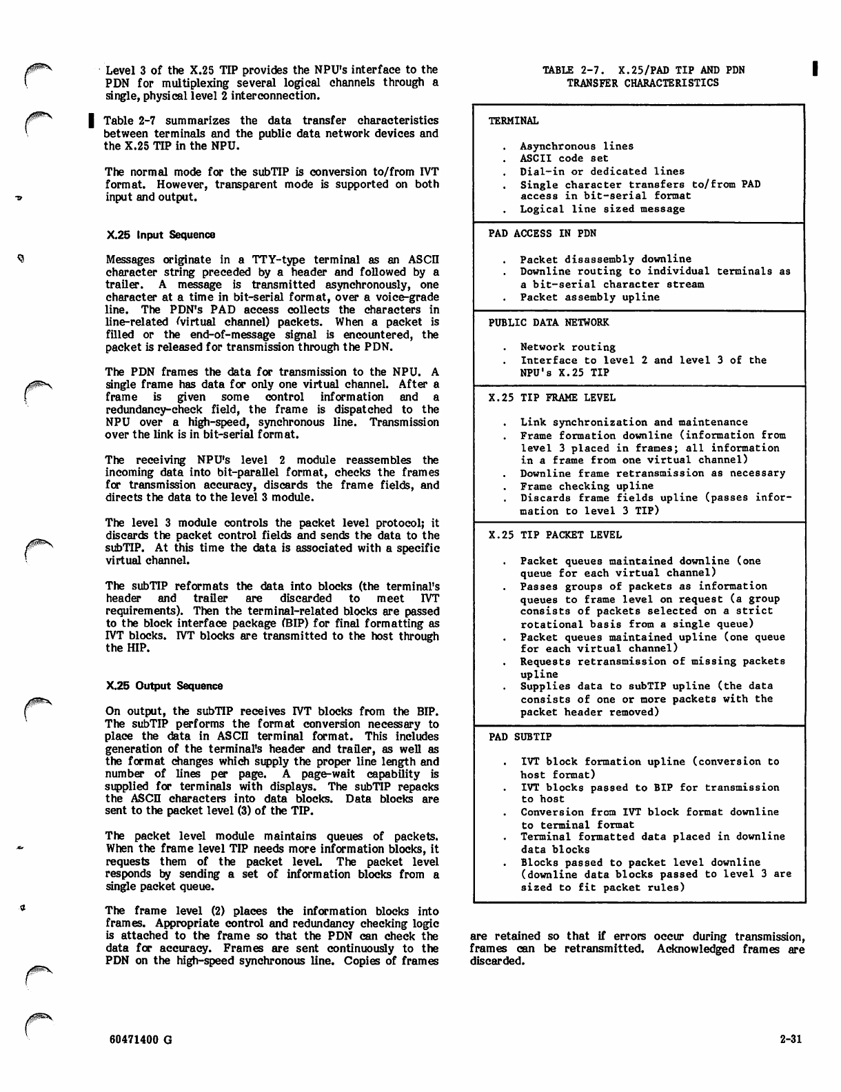
0m*s.
Level 3 of the X.25 TIP provides the NPU's interface to the
PDN for multiplexing several logical channels through a
single, physical level 2 interconnection.
| Table 2-7 summarizes the data transfer characteristics
between terminals and the public data network devices and
the X.25 TD? in the NPU.
The normal mode for the subTIP is conversion to/from IVT
format. However, transparent mode is supported on both
input and output.
X.25 Input Sequence
Messages originate in a TTY-type terminal as an ASCD
character string preceded by a header and followed by a
trailer. A message is transmitted asynchronously, one
character at a time in bit-serial format, over a voice-grade
line. The PDN's PAD access collects the characters in
line-related ^virtual channel) packets. When a packet is
filled or the end-of-message signal is encountered, the
packet is released for transmission through the PDN.
The PDN frames the data for transmission to the NPU. A
single frame has data for only one virtual channel. After a
frame is given some control information and a
redundancy-check field, the frame is dispatched to the
NPU over a high-speed, synchronous line. Transmission
over the link is in bit-serial format.
The receiving NPU's level 2 module reassembles the
incoming data into bit-parallel format, checks the frames
for transmission accuracy, discards the frame fields, and
directs the data to the level 3 module.
The level 3 module controls the packet level protocol; it
discards the packet control fields and sends the data to the
subTIP. At this time the data is associated with a specific
virtual channel.
The subTIP reformats the data into blocks (the terminal's
header and trailer are discarded to meet IVT
requirements). Then the terminal-related blocks are passed
to the block interface package (BIP) for final formatting as
IVT blocks. IVT blocks are transmitted to the host through
the HIP.
X.25 Output Sequence
On output, the subTIP receives r/T blocks from the BIP.
The subTD? performs the format conversion necessary to
place the data in ASCD terminal format. This includes
generation of the terminal's header and trailer, as well as
the format changes which supply the proper line length and
number of lines per page. A page-wait capability is
supplied for terminals with displays. The subTIP repacks
the ASCII characters into data blocks. Data blocks are
sent to the packet level (3) of the TIP.
The packet level module maintains queues of packets.
When the frame level TD? needs more information blocks, it
requests them of the packet level. The packet level
responds by sending a set of information blocks from a
single packet queue.
The frame level (2) places the information blocks into
frames. Appropriate control and redundancy checking logic
is attached to the frame so that the PDN can check the
data for accuracy. Frames are sent continuously to the
PDN on the high-speed synchronous line. Copies of frames
TABLE 2-7. X.25/PAD TIP AND PDN
TRANSFER CHARACTERISTICS
TERMINAL
Asynchronous lines
ASCII code set
Dial-in or dedicated lines
Single character transfers to/from PAD
access in bit-serial format
Logical line sized message
PAD ACCESS IN PDN
Packet disassembly downline
Downline routing to individual terminals as
a bit-serial character stream
Packet assembly upline
PUBLIC DATA NETWORK
Network routing
Interface to level
NPU's X.25 TIP
2 and level 3 of the
X.25 TIP FRAME LEVEL
Link synchronization and maintenance
Frame formation downline (information from
level 3 placed in frames; all information
in a frame from one virtual channel)
Downline frame retransmission as necessary
Frame checking upline
Discards frame fields upline (passes infor
mation to level 3 TIP)
X.25 TIP PACKET LEVEL
Packet queues maintained downline (one
queue for each virtual channel)
Passes groups of packets as information
queues to frame level on request (a group
consists of packets selected on a strict
rotational basis from a single queue)
Packet queues maintained upline (one queue
for each virtual channel)
Requests retransmission of missing packets
upline
Supplies data to subTIP upline (the data
consists of one or more packets with the
packet header removed)
PAD SUBTIP
IVT block formation upline (conversion to
host format)
IVT blocks passed to BIP for transmission
to host
Conversion from IVT block format downline
to terminal format
Terminal formatted data placed in downline
data blocks
Blocks passed to packet level downline
(downline data blocks passed to level 3 are
sized to fit packet rules)
are retained so that if errors occur during transmission,
frames can be retransmitted. Acknowledged frames are
discarded.
60471400 G 2-31
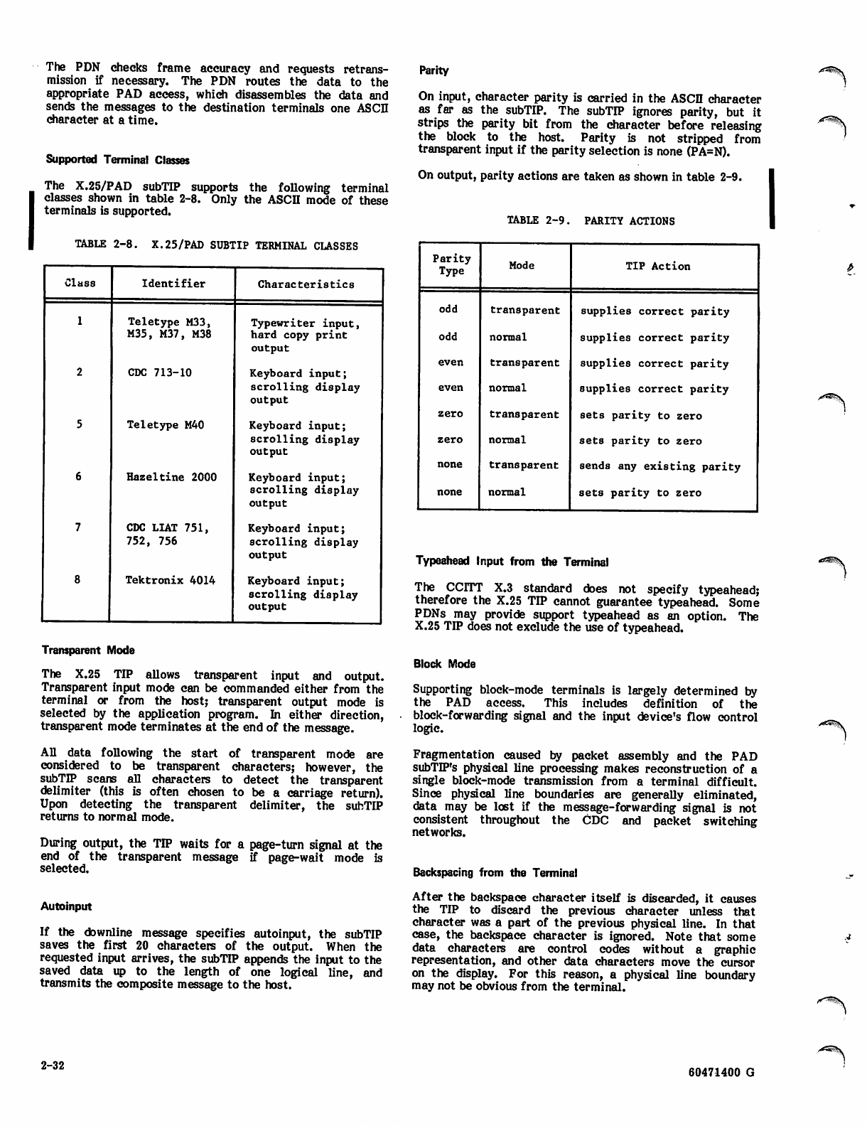
The PDN checks frame accuracy and requests retrans
mission if necessary. The PDN routes the data to the
appropriate PAD access, which disassembles the data and
sends the messages to the destination terminals one ASCII
character at a time.
Supported Terminal Classes
The X.25/PAD subTIP supports the following terminal
classes shown in table 2-8. Only the ASCD mode of these
terminals is supported.
TABLE 2-8. X.25/PAD SUBTIP TERMINAL CLASSES
Class Identifier Characteristics
1
2
5
6
7
8
Teletype M33,
M35, M37, M38
CDC 713-10
Teletype M40
Hazeltine 2000
CDC LIAT 751,
752, 756
Tektronix 4014
Typewriter input,
hard copy print
output
Keyboard input;
scrolling display
output
Keyboard input;
scrolling display
output
Keyboard input;
scrolling display
output
Keyboard input;
scrolling display
output
Keyboard input;
scrolling display
output
Transparent Mode
The X.25 TIP allows transparent input and output.
Transparent input mode can be commanded either from the
terminal or from the host; transparent output mode is
selected by the application program. In either direction,
transparent mode terminates at the end of the message.
All data following the start of transparent mode are
considered to be transparent characters; however, the
subTTP scans all characters to detect the transparent
delimiter (this is often chosen to be a carriage return).
Upon detecting the transparent delimiter, the subTIP
returns to normal mode.
During output, the Tn? waits for a page-turn signal at the
end of the transparent message if page-wait mode is
selected.
Autoinput
If the downline message specifies autoinput, the subTIP
saves the first 20 characters of the output. When the
requested input arrives, the subTIP appends the input to the
saved data up to the length of one logical line, and
transmits the composite message to the host.
2-32
Parity
On input, character parity is carried in the ASCII character
as far as the subTIP. The subTD? ignores parity, but it
strips the parity bit from the character before releasing
the block to the host. Parity is not stripped from
transparent input if the parity selection is none (PA=N).
On output, parity actions are taken as shown in table 2-9.
TABLE 2-9. PARITY ACTIONS
Parity
Type Mode TIP Action
odd transparent supplies correct parity
odd normal supplies correct parity
even transparent supplies correct parity
even normal supplies correct parity
zero transparent sets parity to zero
zero normal se ts pa ri ty to zero
none transparent sends any existing parity
none normal se ts pa ri ty to zero
Typeahead Input from the Terminal
The CCITT X.3 standard does not specify typeahead;
therefore the X.25 TIP cannot guarantee typeahead. Some
PDNs may provide support typeahead as an option. The
X.25 TIP does not exclude the use of typeahead.
Block Mode
Supporting block-mode terminals is largely determined by
the PAD access. This includes definition of the
block-forwarding signal and the input device's flow control
logic.
Fragmentation caused by packet assembly and the PAD
subTD^'s physical line processing makes reconstruction of a
single block-mode transmission from a terminal difficult.
Since physical line boundaries are generally eliminated,
data may be lost if the message-forwarding signal is not
consistent throughout the CDC and packet switching
networks.
Backspacing from the Terminal
After the backspace character itself is discarded, it causes
the TIP to discard the previous character unless that
character was a part of the previous physical line. In that
case, the backspace character is ignored. Note that some
data characters are control codes without a graphic
representation, and other data characters move the cursor
on the display. For this reason, a physical line boundary
may not be obvious from the terminal.
60471400 G
y $ P ^ \ , Cancel Input
An input line can be cancelled by the terminal operator
entering the cancel character followed by the forwarding
character. The input line is discarded and a ♦DEL^
message is returned to the terminal. If part of the line has
already been sent to the host, a cancel messaage is sent to
the host.
Break Key Processing
Break processing occurs in the PAD access and in the PAD
subTff if the CCITT X.3 break option is chosen.
On the PAD access level, aD data queued for the terminal
and all subsequent data received from the PSN is
discarded. The PAD access notifies the subTD?.
The subTIP suspends output until the next input is received
from the terminal. The PAD subTTP notifies the PAD
access to allow subsequent output messages.
At the PAD subTIP, processing differs according to
whether the input following the break key is a user break or
not:
Command
TC - terminal class
PW - page width
PL - page length
PA - parity
CN - cancel
Bl - user break 1
B2 - user break 2
CT - control character
CI - CR idle count
LI - LF idle count
DL - transparent text
delimiter
IN - Input device
MS - message to net
work console
operator
PG - page-wait mode
Build-Time Selections
Allowable Value
1, 2, 5 - 8.
0-255
0-255
Z (zero), O (odd), E (even), N
(none)
Any keyboard character
Any keyboard character
Any keyboard character
Any keyboard character
0-255
0-255
Xhh where hh is the
character's hexadecimal value
X (transparent keyboard), K
(keyboard), XK (transparent
keyboard)
Any text up to 50 characters
in length
Y (yes), N (no)
• Not a user break: output to the terminal resumes
after input. Data discarded by the PAD access is
lost. Recovery of data is the responsibility of
higher level processes.
• User breaks: subTD? discards data and notifies the
host.
USER BREAKS
A user break can occur during any input message; it need
not follow an indication of a break key from the PAD
access.
Formatting on Output
For a given output message, formatting occurs on either a
preprint or a postprint basis, but never both.
Some formatting can occur as a result of the subTIP
converting format effectors to the appropriate number of
carriage returns, line feeds, escape characters, and the like.
For displays, the subTIP supplies the appropriate line
length, the number of lines on a display, and a pause at the
end of a display page. The terminal operator must answer
the pause by requesting a page turn. When this occurs, the
TD? sends the next full page of data.
For printers, the subTD? supplies the appropriate line
length, the number of lines on a page* and the proper
formatting to advance the form-feed mechanism to the top
of the next page.
At the time the user subscribes to the public data network,
he purchases certain interface options. In several cases,
these options effect the network definition language (NDL)
selections required by the NOS network. Table 2-10 defines
these parameters and gives the recommended settings for
use with the NOS network.
MESSAGE PRIORITIES AND
INPUT REGULATION
Messages are defined to be high or low priority as a function
of the type of terminal which handles the message.
Regulation of messages is provided because all messages
require buffer space, and it is possible that combined peak
load demands from terminals, from the host, and from
neighboring NPUs (if any) may require more buffers than the
NPU can assign.
To prevent NPU stoppage for lack of buffers, the NPU is
allowed to reject input messages on the basis of priority or
because the channel seeking to input the messages already
has its maximum share of buffers assigned. For terminals
which are polled for input, regulation is handled indirectly:
the NPU does not poll the terminals until more buffers are
available. As current messages are processed and output,
more buffers become available and the regulation level can
change to accept message types previously rejected. Two
types of regulation are provided:
• Input message regulations: Varying criteria apply
according to the message source: host, neighboring
NPU, or terminal.
• Logical link regulation: Varying criteria apply
according to traffic direction: upline or downline.
IVT Commands
The user can alter any of the IVT parameters shown below
at the terminal. These altered values remain a part of the
TIP's processing until changed from the terminal, or by a
host program. When the NPU is stopped and restarted, the
default rvT parameters are again used.
MESSAGE PRIORITIES
Three levels of message priority are defined for CCP:
• Service message traffic (priority 0): This level
handles much of the node-to-node command/reply/
status information.
60471400 G 2-33
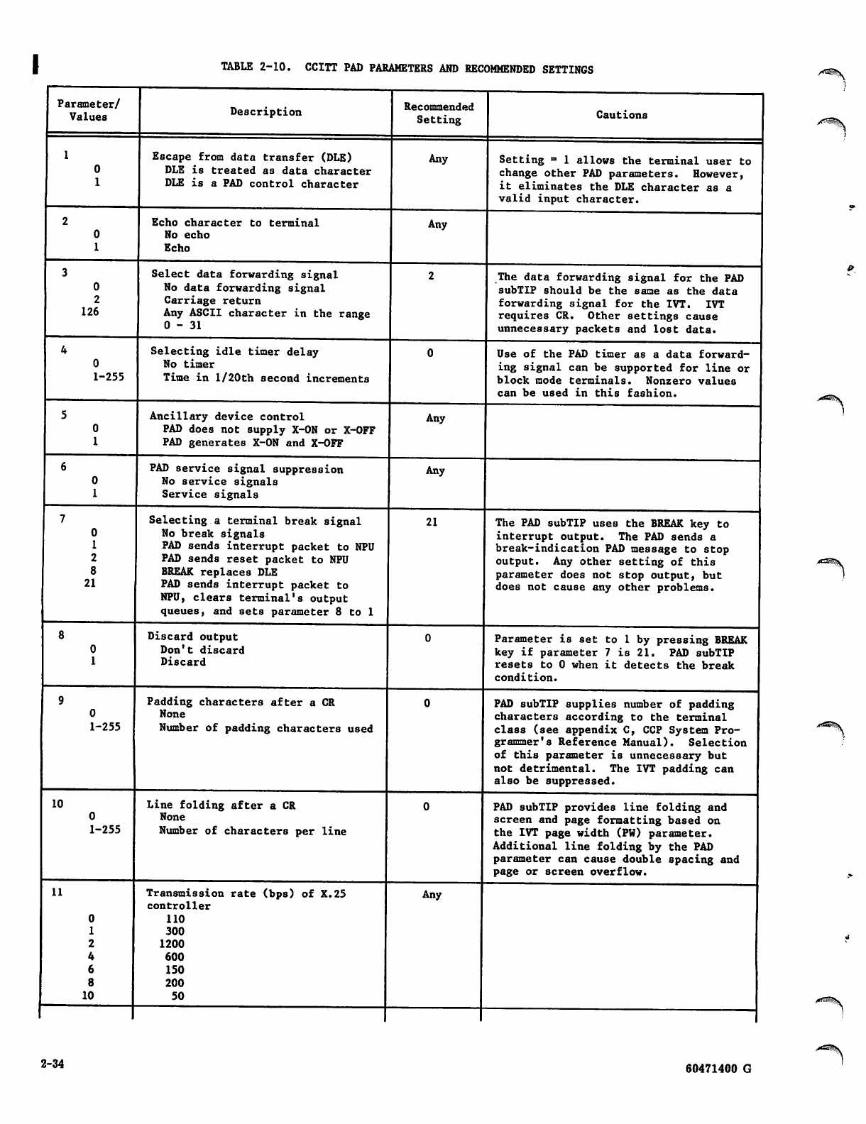
TABLE 2-10. CCITT PAD PARAMETERS AND RECOMMENDED SETTINGS
Parameter/
Values Description Recommended
Setting Cautions
1
0
1
Escape from data transfer (DLE)
DLE is treated as data character
DLE is a PAD control character
Any Setting = 1 allows the terminal user to
change other PAD parameters. However,
it eliminates the DLE character as a
val i d i n put c har a cte r.
2
0
1
Echo character to terminal
No echo
Echo
Any
3
0
2
126
Select data forwarding signal
No data forwarding signal
Carriage return
Any ASCII character in the range
0-31
The data forwarding signal for the PAD
subTIP should be the same as the data
for war din g sig nal f or the I VT. IVT
requires CR. Other settings cause
unnecessary packets and lost data.
4
0
1-255
Selecting idle timer delay
No timer
Time in l/20th second increments
Use of the PAD timer as a data forward
ing signal can be supported for line or
block mode terminals. Nonzero values
can be used in this fashion.
5
0
1
Ancillary device control
PAD does not supply X-ON or X-OFF
PAD generates X-ON and X-OFF
Any
6
0
1
PAD service signal suppression
No service signals
Service signals
Any
7
0
1
2
8
21
Selecting a terminal break signal
No break signals
PAD sends interrupt packet to NPU
PAD sends reset packet to NPU
BREAK replaces DLE
PAD sends interrupt packet to
NPU, clears terminal's output
queues, and sets parameter 8 to 1
21 The PAD subTIP uses the BREAK key to
interrupt output. The PAD sends a
break-indication PAD message to stop
output. Any other setting of this
parameter does not stop output, but
does not cause any other problems.
8
0
1
Discard output
Don't discard
Discard
Parameter is set to 1 by pressing BREAK
key if parameter 7 is 21. PAD subTIP
resets to 0 when it detects the break
condition.
9
0
1-255
Padding characters after a CR
None
Number of padding characters used
PAD subTIP supplies number of padding
characters according to the terminal
class (see appendix C, CCP System Pro
grammer's Reference Manual). Selection
of this parameter is unnecessary but
not detrimental. The IVT padding can
also be suppressed.
10
1-255
Line folding after a CR
None
Number of characters per line
PAD subTIP provides line folding and
screen and page formatting based on
the IVT page width (PW) parameter.
Additional line folding by the PAD
parameter can cause double spacing and
page or screen overflow.
11
10
Transmission rate (bps) of X.25
controller
110
300
1200
600
150
200
50
Any
2-34 60471400 G
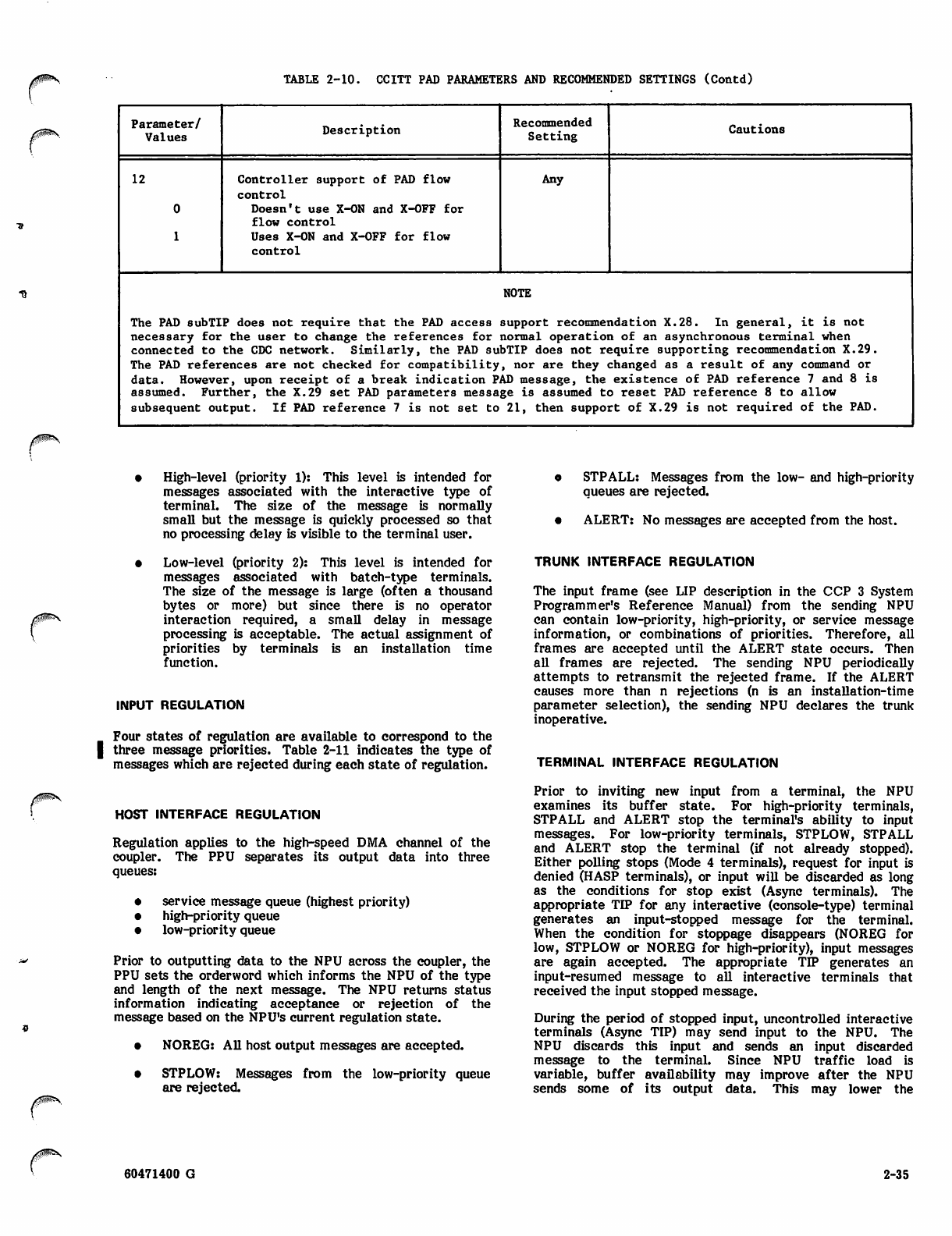
TABLE 2-10. CCITT PAD PARAMETERS AND RECOMMENDED SETTINGS (Contd)
Parameter/
Values Description Recommended
Setting Cautions
12 Controller support of PAD flow
control
Doesn't use X-ON and X-OFF for
flow control
Uses X-ON and X-OFF for flow
control
Any
NOTE
The PAD subTIP does not require that the PAD access support recommendation X.28. In general, it is not
necessary for the user to change the references for normal operation of an asynchronous terminal when
connected to the CDC network. Similarly, the PAD subTIP does not require supporting recommendation X.29.
The PAD references are not checked for compatibility, nor are they changed as a result of any command or
data. However, upon receipt of a break indication PAD message, the existence of PAD reference 7 and 8 is
assumed. Further, the X.29 set PAD parameters message is assumed to reset PAD reference 8 to allow
subsequent output. If PAD reference 7 is not set to 21, then support of X.29 is not required of the PAD.
High-level (priority 1): This level is intended for
messages associated with the interactive type of
terminal. The size of the message is normally
small but the message is quickly processed so that
no processing delay is visible to the terminal user.
Low-level (priority 2): This level is intended for
messages associated with batch-type terminals.
The size of the message is large (often a thousand
bytes or more) but since there is no operator
interaction required, a small delay in message
processing is acceptable. The actual assignment of
priorities by terminals is an installation time
function.
INPUT REGULATION
Four states of regulation are available to correspond to the
three message priorities. Table 2-11 indicates the type of
messages which are rejected during each state of regulation.
HOST INTERFACE REGULATION
Regulation applies to the high-speed DMA channel of the
coupler. The PPU separates its output data into three
queues:
• service message queue (highest priority)
• high-priority queue
• low-priority queue
Prior to outputting data to the NPU across the coupler, the
PPU sets the orderword which informs the NPU of the type
and length of the next message. The NPU returns status
information indicating acceptance or rejection of the
message based on the NPU's current regulation state.
• NOREG: All host output messages are accepted.
• STPLOW: Messages from the low-priority queue
are rejected.
o STPALL: Messages from the low- and high-priority
queues are rejected.
• ALERT: No messages are accepted from the host.
TRUNK INTERFACE REGULATION
The input frame (see LIP description in the CCP 3 System
Programmer's Reference Manual) from the sending NPU
can contain low-priority, high-priority, or service message
information, or combinations of priorities. Therefore, all
frames are accepted until the ALERT state occurs. Then
all frames are rejected. The sending NPU periodically
attempts to retransmit the rejected frame. If the ALERT
causes more than n rejections (n is an installation-time
parameter selection), the sending NPU declares the trunk
inoperative.
TERMINAL INTERFACE REGULATION
Prior to inviting new input from a terminal, the NPU
examines its buffer state. For high-priority terminals,
STPALL and ALERT stop the terminal's ability to input
messages. For low-priority terminals, STPLOW, STPALL
and ALERT stop the terminal (if not already stopped).
Either polling stops (Mode 4 terminals), request for input is
denied (HASP terminals), or input will be discarded as long
as the conditions for stop exist (Async terminals). The
appropriate TD? for any interactive (console-type) terminal
generates an input-stopped message for the terminal.
When the condition for stoppage disappears (NOREG for
low, STPLOW or NOREG for high-priority), input messages
are again accepted. The appropriate TIP generates an
input-resumed message to all interactive terminals that
received the input stopped message.
During the period of stopped input, uncontrolled interactive
terminals (Async TIP) may send input to the NPU. The
NPU discards this input and sends an input discarded
message to the terminal. Since NPU traffic load is
variable, buffer availability may improve after the NPU
sends some of its output data. This may lower the
60471400 G 2-35
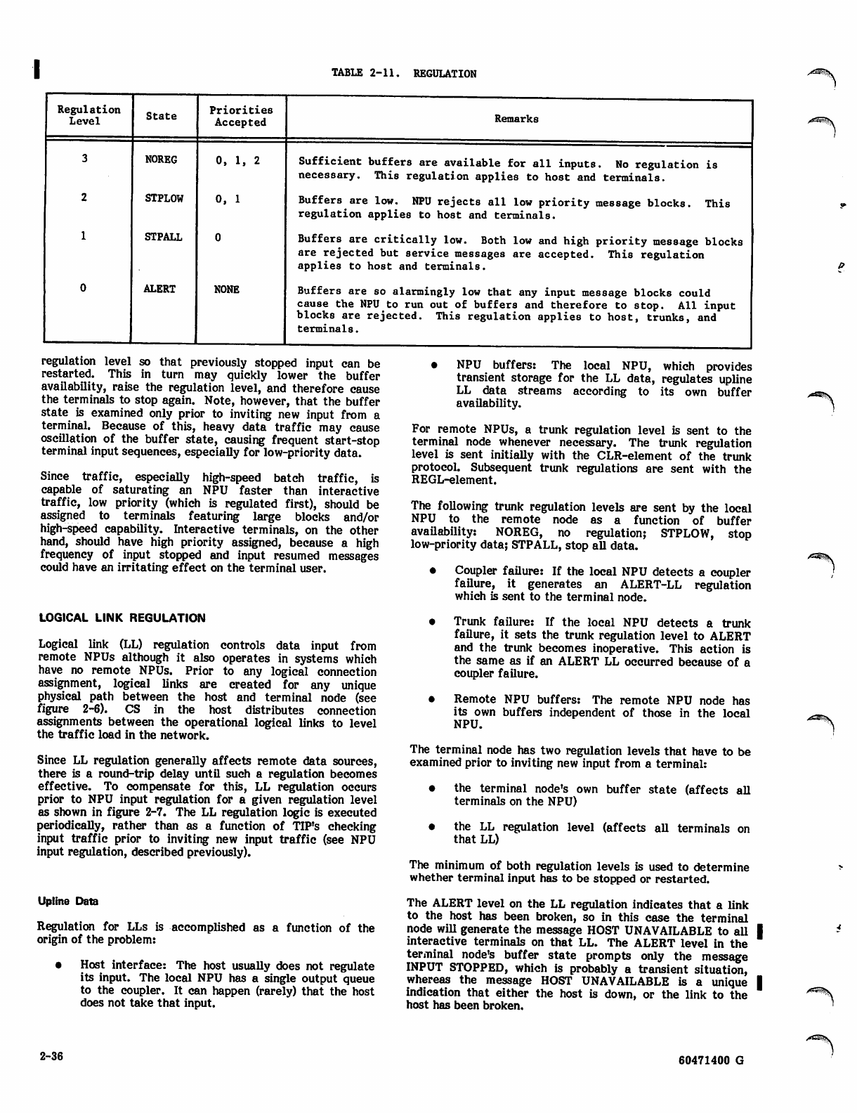
TABLE 2-11. REGULATION
Regulation
Level State
NOREG
STPLOW
STPALL
ALERT
Priorities
Accepted
0, 1, 2
0, 1
0
NONE
Remarks
Sufficient buffers are available for all inputs. No regulation is
necessary. This regulation applies to host and terminals.
Buffers are low. NPU rejects all low priority message blocks,
regulation applies to host and terminals. This
Buffers are critically low. Both low and high priority message blocks
are rejected but service messages are accepted. This regulation
applies to host and terminals.
Buffers are so alarmingly low that any input message blocks could
cause the NPU to run out of buffers and therefore to stop. All input
blocks are rejected. This regulation applies to host, trunks, and
terminals.
regulation level so that previously stopped input can be
restarted. This in turn may quickly lower the buffer
availability, raise the regulation level, and therefore cause
the terminals to stop again. Note, however, that the buffer
state is examined only prior to inviting new input from a
terminal. Because of this, heavy data traffic may cause
oscillation of the buffer state, causing frequent start-stop
terminal input sequences, especially for low-priority data.
Since traffic, especiaUy high-speed batch traffic, is
capable of saturating an NPU faster than interactive
traffic, low priority (which is regulated first), should be
assigned to terminals featuring large blocks and/or
high-speed capability. Interactive terminals, on the other
hand, should have high priority assigned, because a high
frequency of input stopped and input resumed messages
could have an irritating effect on the terminal user.
LOGICAL LINK REGULATION
Logical link (LL) regulation controls data input from
remote NPUs although it also operates in systems which
have no remote NPUs. Prior to any logical connection
assignment, logical links are created for any unique
physical path between the host and terminal node (see
figure 2-6). CS in the host distributes connection
assignments between the operational logical links to level
the traffic load in the network.
Since LL regulation generaUy affects remote data sources,
there is a round-trip delay until such a regulation becomes
effective. To compensate for this, LL regulation occurs
prior to NPU input regulation for a given regulation level
as shown in figure 2-7. The LL regulation logic is executed
periodically, rather than as a function of TIP's checking
input traffic prior to inviting new input traffic (see NPU
input regulation, described previously).
Upline Data
Regulation for LLs is accomplished as a function of the
origin of the problem:
• Host interface: The host usually does not regulate
its input. The local NPU has a single output queue
to the coupler. It can happen (rarely) that the host
does not take that input.
• NPU buffers: The local NPU, which provides
transient storage for the LL data, regulates upline
LL data streams according to its own buffer
availability.
For remote NPUs, a trunk regulation level is sent to the
terminal node whenever necessary. The trunk regulation
level is sent initiaUy with the CLR-element of the trunk
protocol. Subsequent trunk regulations are sent with the
REGL-element.
The following trunk regulation levels are sent by the local
NPU to the remote node as a function of buffer
availability: NOREG, no regulation; STPLOW, stop
low-priority data; STPALL, stop all data.
• Coupler failure: If the local NPU detects a coupler
failure, it generates an ALERT-LL regulation
which is sent to the terminal node.
• Trunk failure: If the local NPU detects a trunk
failure, it sets the trunk regulation level to ALERT
and the trunk becomes inoperative. This action is
the same as if an ALERT LL occurred because of a
coupler failure.
• Remote NPU buffers: The remote NPU node has
its own buffers independent of those in the local
NPU.
The terminal node has two regulation levels that have to be
examined prior to inviting new input from a terminal:
• the terminal node's own buffer state (affects aU
terminals on the NPU)
• the LL regulation level (affects all terminals on
that LL)
The minimum of both regulation levels is used to determine
whether terminal input has to be stopped or restarted.
The ALERT level on the LL regulation indicates that a link
to the host has been broken, so in this case the terminal
node wiU generate the message HOST UNAVAILABLE to all I
interactive terminals on that LL. The ALERT level in the
terminal node's buffer state prompts only the message
INPUT STOPPED, which is probably a transient situation,
whereas the message HOST UNAVAILABLE is a unique I
indication that either the host is down, or the link to the
host has been broken.
^z^s.
^*^y
2-36 60471400 G
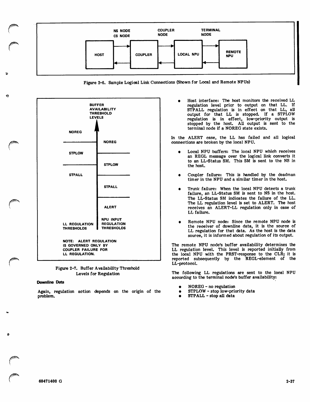
NS NODE
CS NODE
COUPLER
NODE
TERMINAL
NODE
HOST COUPLER LOCAL NPU REMOTE
NPU
Figure 2-6. Sample Logical Link Connections (Shown for Local and Remote NPUs)
^
BUFFER
AVAILABILITY
THRESHOLD
LEVELS
1
NOREG "
NOREG
STPLOW
STPLOW
STPALL
STPALL
LL REGULATION
THRESHOLDS
ALERT
NPU INPUT
REGULATION
THRESHOLDS
NOTE: ALERT REGULATION
IS GOVERNED ONLY BY
COUPLER FAILURE FOR
LL REGULATION.
Figure 2-7. Buffer Availability Threshold
Levels for Regulation
Downline Data
Again, regulation action depends on the origin of the
problem.
• Host interface: The host monitors the received LL
regulation level prior to output on that LL. If
STPALL regulation is in effect on that LL, all
output for that LL is stopped. If a STPLOW
regulation is in effect, low-priority output is
stopped by the host. All output is sent to the
terminal node if a NOREG state exists.
In the ALERT case, the LL has failed and all logical
connections are broken by the local NPU.
• Local NPU buffers: The local NPU which receives
an REGL message over the logical link converts it
to an LL-Status SM. This SM is sent to the NS in
the host.
• Coupler failure: This is handled by the deadman
timer in the NPU and a similar timer in the host.
• Trunk failure: When the local NPU detects a trunk
failure, an LL-Status SM is sent to NS in the host.
The LL-Status SM indicates the failure of the LL.
The LL regulation level is set to ALERT. The host
receives an ALERT-LL regulation only in case of
LL failure.
• Remote NPU node: Since the remote NPU node is
the receiver of downline data, it is the source of
LL regulation for that data. As the host is the data
source, it is informed about regulation of its output.
The remote NPU node's buffer availability determines the
LL regulation level. This level is reported initially from
the local NPU with the PRST-response to the CLR; it is
reported subsequently by the REGL-element of the
LL-protocol.
The foUowing LL regulations are sent to the local NPU
according to the terminal node's buffer availability:
• NOREG - no regulation
• STPLOW - stop low-priority data
• STPALL - stop all data
60471400 G 2-37

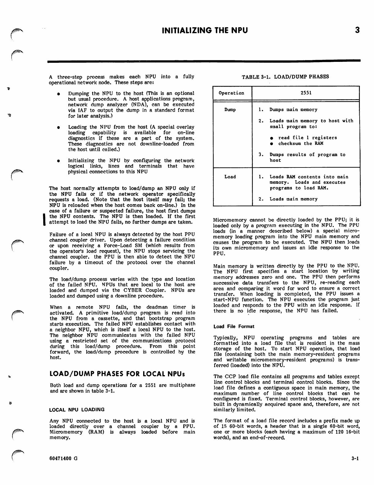
Jptf££3y
INITIALIZING THE NPU
A three-step process makes each NPU into a fully
operational network node. These steps are:
• Dumping the NPU to the host (This is an optional
but usual procedure. A host applications program,
network dump analyzer (NDA), can be executed
via IAF to output the dump in a standard format
for later analysis.)
• Loading the NPU from the host (A special overlay
loading capability is available for on-line
diagnostics if these are a part of the system.
These diagnostics are not downline-loaded from
the host until called.)
• Initializing the NPU by configuring the network
logical links, lines and terminals that have
physical connections to this NPU
The host normally attempts to load/dump an NPU only if
the NPU fails or if the network operator specifically
requests a load. (Note that the host itself may fail; the
NPU is reloaded when the host comes back on-line.) In the
case of a failure or suspected failure, the host first dumps
the NPU contents. The NPU is then loaded. If the first
attempt to load the NPU fails, no further dumps are taken.
Failure of a local NPU is always detected by the host PPU
channel coupler driver. Upon detecting a failure condition
or upon receiving a Force-Load SM (which results from
the operator's load request), the NPU stops servicing the
channel coupler, the PPU is then able to detect the NPU
failure by a timeout of the protocol over the channel
coupler.
The load/dump process varies with the type and location
of the failed NPU. NPUs that are local*to the host are
loaded and dumped via the CYBER Coupler. NPUs are
loaded and dumped using a downline procedure.
When a remote NPU fails, the deadman timer is
activated. A primitive load/dump program is read into
the NPU from a cassette, and that bootstrap program
starts execution. The failed NPU establishes contact with
a neighbor NPU, which is itself a local NPU to the host.
The neighbor NPU communicates with the failed NPU
using a restricted set of the communications protocol
during this load/dump procedure. From this point
forward, the load/dump procedure is controlled by the
host.
LOAD/DUMP PHASES FOR LOCAL NPUs
Both load and dump operations for a 2551 are multiphase
and are shown in table 3-1.
LOCAL NPU LOADING
Any NPU connected to the host is a local NPU and is
loaded directly over a channel coupler by a PPU.
Micromemory (RAM) is always loaded before main
memory.
TABLE 3-1. LOAD/DUMP PHASES
Operation 2551
Dump 1. Dumps main memory
2. Loads main memory to host with
small program to:
• read file 1 registers
• checksum the RAM
3. Dumps results of program to
host
Load 1. Loads RAM contents into main
memory. Loads and executes
programs to load RAM.
2. Loads main memory
Micromemory cannot be directly loaded by the PPU; it is
loaded only by a program executing in the NPU. The PPU
loads (in a manner described below) a special micro-
memory loading program into the NPU main memory and
causes the program to be executed. The NPU then loads
its own micromemory and issues an idle response to the
PPU.
Main memory is written directly by the PPU to the NPU.
The NPU first specifies a start location by writing
memory addresses zero and one. The PPU then performs
successive data transfers to the NPU, re-reading each
area and comparing it word for word to ensure a correct
transfer. When loading is completed, the PPU issues a
start-NPU function. The NPU executes the program just
loaded and responds to the PPU with an idle response. If
there is no idle response, the NPU has failed.
Load File Format
Typically, NPU operating programs and tables are
formatted into a load file that is resident in the mass
storage of the host. To start NPU operation, that load
file (containing both the main memory-resident programs
and writable micromemory-resident programs) is trans
ferred (loaded) into the NPU.
The CCP load file contains all programs and tables except
line control blocks and terminal control blocks. Since the
load file defines a contiguous space in main memory, the
maximum number of line control blocks that can be
configured is fixed. Terminal control blocks, however, are
built in dynamically acquired space and, therefore, are not
similarly limited.
The format of a load file record includes a prefix made up
of 15 60-bit words, a header that is a single 60-bit word,
one or more blocks (each having a maximum of 120 16-bit
words), and an end-of-record.
60471400 G 3-1
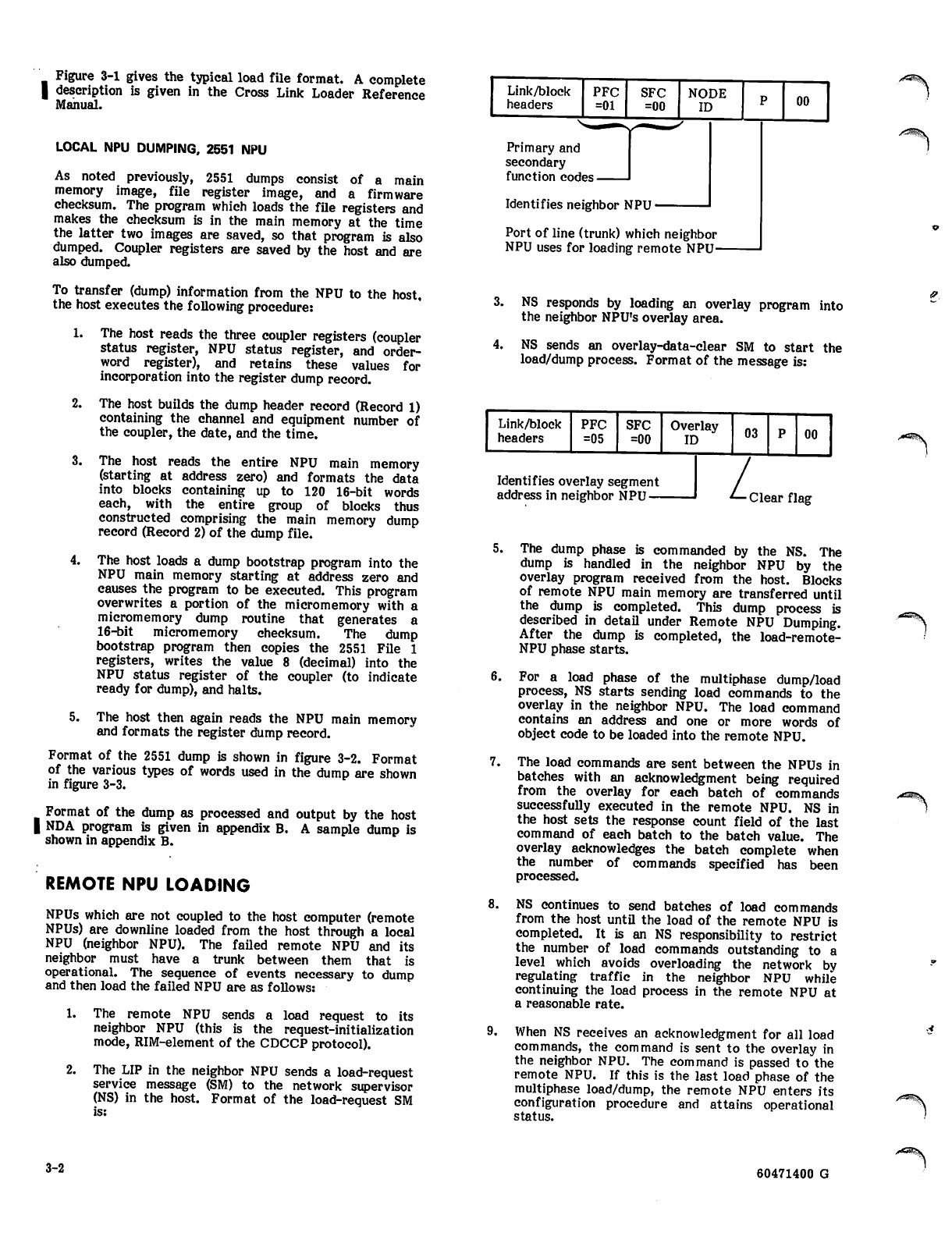
Figure 3-1 gives the typical load file format. A complete
I description is given in the Cross Link Loader Reference
Manual.
LOCAL NPU DUMPING, 2551 NPU
As noted previously, 2551 dumps consist of a main
memory image, file register image, and a firmware
checksum. The program which loads the file registers and
makes the checksum is in the main memory at the time
the latter two images are saved, so that program is also
dumped. Coupler registers are saved by the host and are
also dumped.
To transfer (dump) information from the NPU to the host,
the host executes the following procedure:
1.
2.
3.
4.
The host reads the three coupler registers (coupler
status register, NPU status register, and order-
word register), and retains these values for
incorporation into the register dump record.
The host builds the dump header record (Record 1)
containing the channel and equipment number of
the coupler, the date, and the time.
The host reads the entire NPU main memory
(starting at address zero) and formats the data
into blocks containing up to 120 16-bit words
each, with the entire group of blocks thus
constructed comprising the main memory dump
record (Record 2) of the dump file.
The host loads a dump bootstrap program into the
NPU main memory starting at address zero and
causes the program to be executed. This program
overwrites a portion of the micromemory with a
micromemory dump routine that generates a
16-bit micromemory checksum. The dump
bootstrap program then copies the 2551 File 1
registers, writes the value 8 (decimal) into the
NPU status register of the coupler (to indicate
ready for dump), and halts.
5. The host then again reads the NPU main memory
and formats the register dump record.
Format of the 2551 dump is shown in figure 3-2. Format
of the various types of words used in the dump are shown
in figure 3-3.
Format of the dump as processed and output by the host
| NDA program is given in appendix B. A sample dump is
shown in appendix B.
REMOTE NPU LOADING
NPUs which are not coupled to the host computer (remote
NPUs) are downline loaded from the host through a local
NPU (neighbor NPU). The failed remote NPU and its
neighbor must have a trunk between them that is
operational. The sequence of events necessary to dump
and then load the failed NPU are as follows:
1. The remote NPU sends a load request to its
neighbor NPU (this is the request-initialization
mode, RIM-element of the CDCCP protocol).
2. The LIP in the neighbor NPU sends a load-request
service message (SM) to the network supervisor
(NS) in the host. Format of the load-request SM
is:
Link/block
headers PFC
=01 SFC
=00 NODE
ID
Primary and
secondary
function codes.
Identifies neighbor NPU
Port of line (trunk) which neighbor
NPU uses for loading remote NPU-
00
3. NS responds by loading an overlay program into
the neighbor NPU's overlay area.
4. NS sends an overlay-data-clear SM to start the
load/dump process. Format of the message is:
Link/block
headers PFC
=05 SFC
=00 Overlay
ID
Identifies overlay segment
address in neighbor NPU —
03
L
00
Clear flag
5.
7.
8.
9.
The dump phase is commanded by the NS. The
dump is handled in the neighbor NPU by the
overlay program received from the host. Blocks
of remote NPU main memory are transferred until
the dump is completed. This dump process is
described in detail under Remote NPU Dumping.
After the dump is completed, the load-remote-
NPU phase starts.
For a load phase of the multiphase dump/load
process, NS starts sending load commands to the
overlay in the neighbor NPU. The load command
contains an address and one or more words of
object code to be loaded into the remote NPU.
The load commands are sent between the NPUs in
batches with an acknowledgment being required
from the overlay for each batch of commands
successfully executed in the remote NPU. NS in
the host sets the response count field of the last
command of each batch to the batch value. The
overlay acknowledges the batch complete when
the number of commands specified has been
processed.
NS continues to send batches of load commands
from the host until the load of the remote NPU is
completed. It is an NS responsibility to restrict
the number of load commands outstanding to a
level which avoids overloading the network by
regulating traffic in the neighbor NPU while
continuing the load process in the remote NPU at
a reasonable rate.
When NS receives an acknowledgment for all load
commands, the command is sent to the overlay in
the neighbor NPU. The command is passed to the
remote NPU. If this is the last load phase of the
multiphase load/dump, the remote NPU enters its
configuration procedure and attains operational
status.
/A^^\
3-2 60471400 G
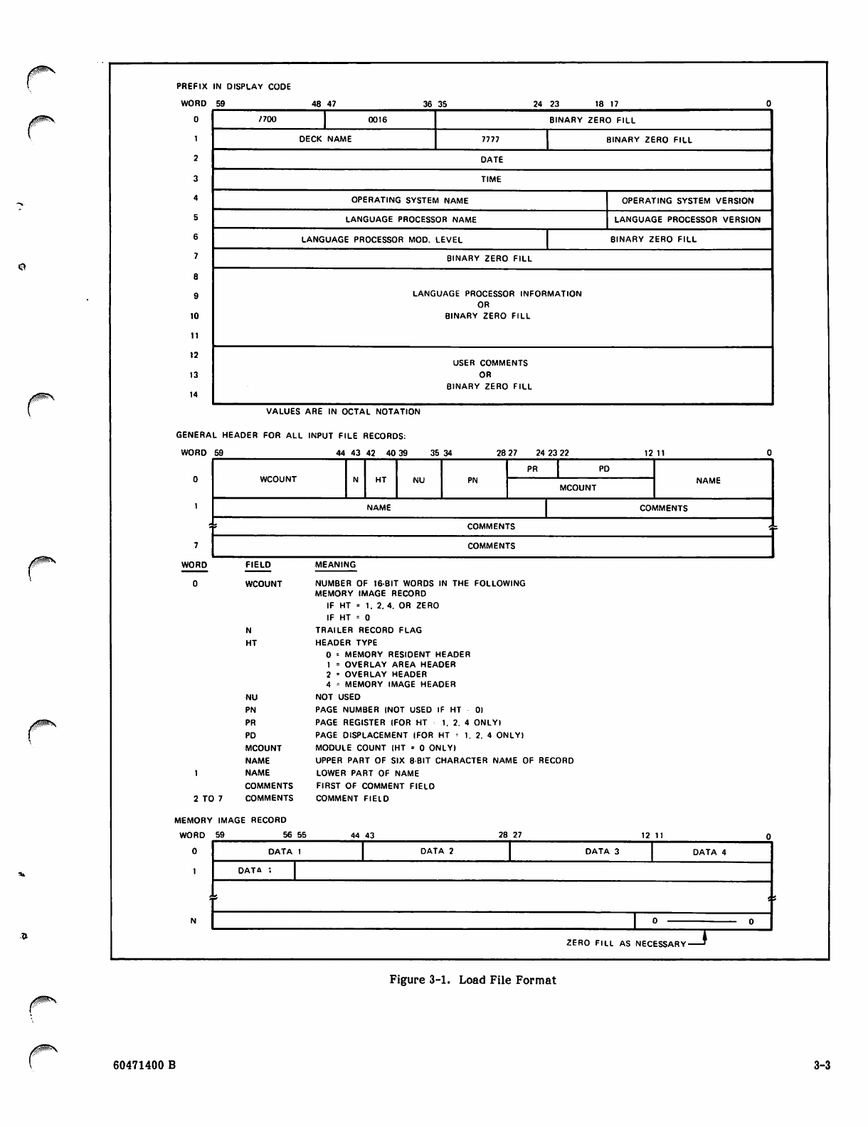
PREFIX
WORD
0
1
2
3
4
5
6
7
8
9
10
11
12
13
14
IN DISPLAY CODE
59 48 4 7 3 6 3 5 2 4 2 3 1 8 1 7 0
7700 0016 BINARY ZERO FILL
DECK NAME 7777 BINARY ZERO FILL
DATE
TIME
OPERATING SYSTEM NAME OPERATING SYSTEM VERSION
LANGUAGE PROCESSOR NAME LANGUAGE PROCESSOR VERSION
LANGUAGE PROCESSOR MOD. LEVEL BINARY ZERO FILL
BINARY ZERO FILL
LANGUAGE PROCESSOR INFORMATION
OR
BINARY ZERO FILL
USER COMMENTS
OR
BINARY ZERO FILL
VALUES ARE IN OCTAL NOTATION
GENERAL HEADER FOR ALL INPUT FILE RECORDS:
W O R D 5 9 4 4 4 3 4 2 4 0 3 9 35 34 28 27 24 23 22 12 11
WCOUNT HT NU PN
PR PD
NAME
MCOUNT
NAME COMMENTS
s COMMENTS '.
COMMENTS
WORD FIELO
WCOUNT
N
HT
NU
PN
PR
PO
MCOUNT
NAME
1 N A M E
COMMENTS
2 TO 7 COMME NTS
MEMORY IMAGE RECORD
W O R D 5 9 5 6 5 5
0
1
MEANING
NUMBER OF 16-BIT WORDS IN THE FOLLOWING
MEMORY IMAGE RECORD
IF HT = 1. 2.4. OR ZERO
IF HT = 0
TRAILER RECORO FLAG
HEADER TYPE
0 * MEMORY RESIDENT HEADER
1 = OVERLAY AREA HEADER
2 • OVERLAY HEADER
4 ■-■ MEMORY IMAGE HEADER
NOT USED
PAGE NUMBER (NOT USED IF HT
PAGE REGISTER (FOR HT 1. 2. 4
PAGE DISPLACEMENT IFOR HT - 1.
MODULE COUNT (HT = 0 ONLY)
UPPER PART OF SIX 8-BIT CHARACTER NAME OF RECORD
LOWER PART OF NAME
FIRST OF COMMENT FIELO
COMMENT FIELD
44 43
01
ONLYI
2. 4 ONLY)
DATA 1 DATA 2 DATA 3 DATA 4
DATA ;
ZERO FILL AS NECESSARYzr
Figure 3-1. Load File Format
60471400 B 3-3
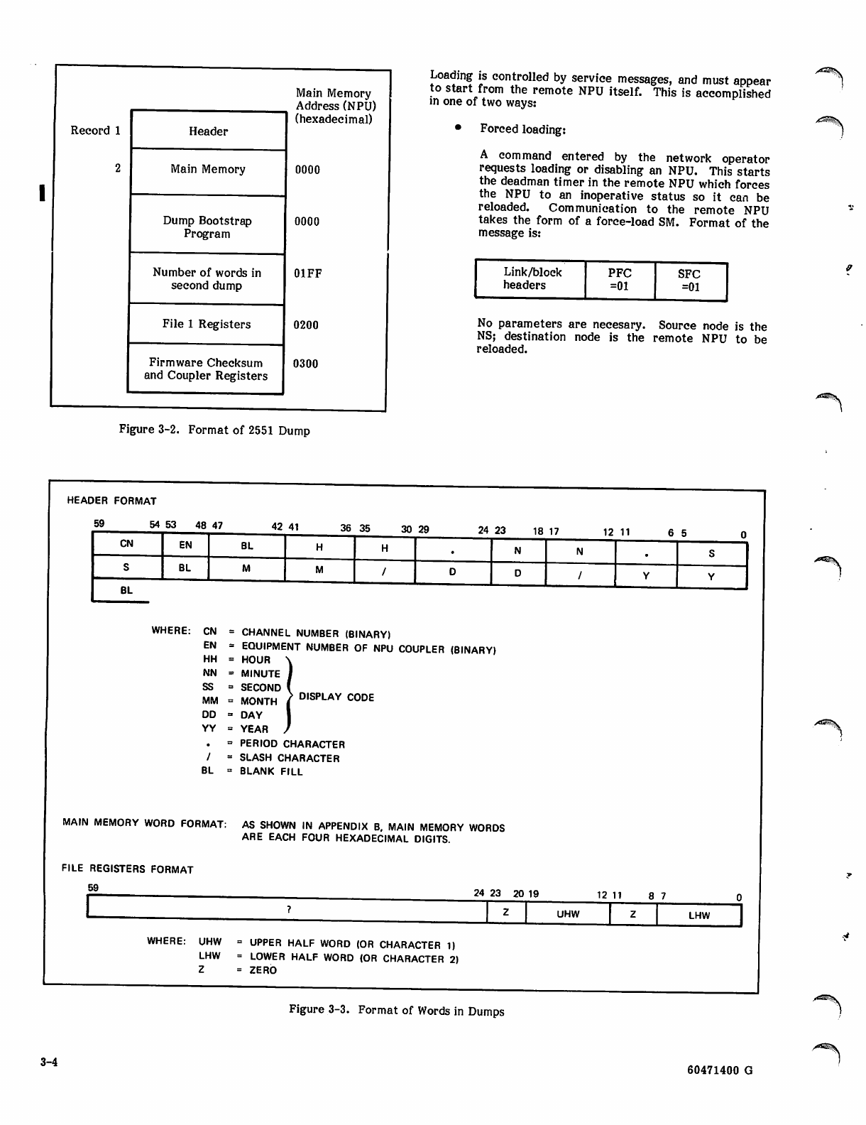
Record 1 Header
2Main Memory
Dump Bootstrap
Program
Number of words in
second dump
File 1 Registers
Firmware Checksum
and Coupler Registers
Main Memory
Address (NPU)
(hexadecimal)
0000
0000
01FF
0200
0300
Loading is controlled by service messages, and must appear
to start from the remote NPU itself. This is accomplished
in one of two ways:
• Forced loading:
A command entered by the network operator
requests loading or disabling an NPU. This starts
the deadman timer in the remote NPU which forces
the NPU to an inoperative status so it can be
reloaded. Communication to the remote NPU
takes the form of a force-load SM. Format of the
message is:
rLink/block
headers PFC
=01
SFC
=01
No parameters are necesary. Source node is the
NS; destination node is the remote NPU to be
reloaded.
Figure 3-2. Format of 2551 Dump
HEADER FORMAT
5 9 5 4 5 3 4 8 47 42 41 36 35 30 29 24 2 3 1 8 17 12 11
CN EN BL
SBL
BL
WHERE: CN = CHANNEL NUMBER (BINARY)
EN = EQUIPMENT NUMBER OF NPU COUPLER (BINARY)
H H = H O U R \
N N = M I N U T E J
S S = S E C O N D (
MM = MONTH / DISPLAY C0DE
D D = D A Y I
Y Y = Y E A R /
. = PERIOD CHARACTER
/ = SLASH CHARACTER
BL = BLANK FILL
MAIN MEMORY WORD FORMAT: AS SHOWN IN APPENDIX B. MAIN MEMORY WORDS
ARE EACH FOUR HEXADECIMAL DIGITS.
FILE REGISTERS FORMAT
59 24 23 20 19 1 2 1 1 8 7
UHW LHW
WHERE: UHW = UPPER HALF WORD (OR CHARACTER 1)
L H W = LO WE R H A LF W O R D ( O R C HA RA C T E R 2 )
Z = Z E R O
Figure 3-3. Format of Words in Dumps
3-4 60471400 G
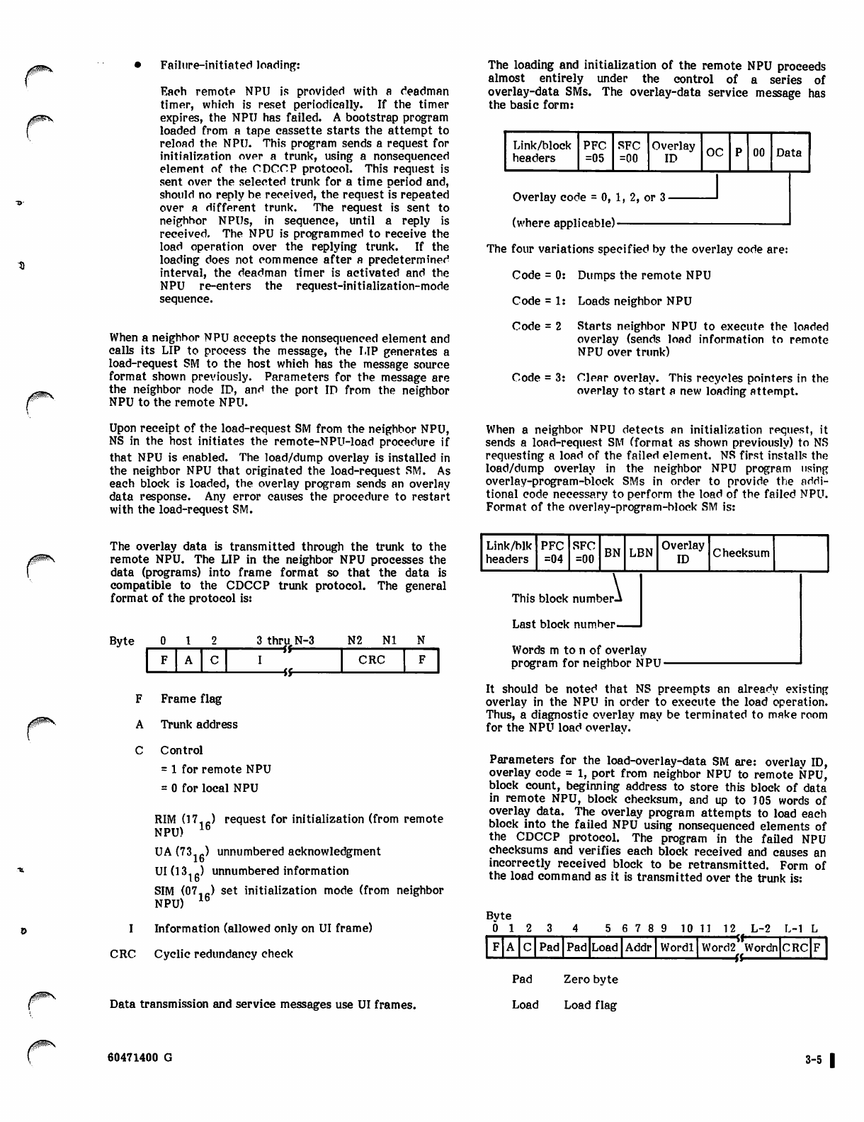
Failure-initiated loading:
Each remote NPU is provided with a deadman
timer, which is reset periodically. If the timer
expires, the NPU has failed. A bootstrap program
loaded from a tape cassette starts the attempt to
reload the NPU. This program sends a request for
initialization over a trunk, using a nonsequenced
element of the CDCCP protocol. This request is
sent over the selected trunk for a time period and,
should no reply be received, the request is repeated
over a different trunk. The request is sent to
neighbor NPUs, in sequence, until a reply is
received. The NPU is programmed to receive the
load operation over the replying trunk. If the
loading does not commence after a predetermined
interval, the deadman timer is activated and the
NPU re-enters the request-initialization-mode
sequence.
When a neighbor NPU accepts the nonsequenced element and
calls its LIP to process the message, the MP generates a
load-request SM to the host which has the message source
format shown previously. Parameters for the message are
the neighbor node ID, and the port ID from the neighbor
NPU to the remote NPU.
Upon receipt of the load-request SM from the neighbor NPU,
NS in the host initiates the remote-NPU-load procedure if
that NPU is enabled. The load/dump overlay is installed in
the neighbor NPU that originated the load-request SM. As
each block is loaded, the overlay program sends an overlay
data response. Any error causes the procedure to restart
with the load-request SM.
The loading and initialization of the remote NPU proceeds
almost entirely under the control of a series of
overlay-data SMs. The overlay-data service message has
the basic form:
Link/block
headers
PFC
=05
SFC
=00 Overlay
ID OC 00 Data
Overlay code = 0, 1, 2, or 3
(where applicable)
The four variations specified by the overlay code are:
Code = 0: Dumps the remote NPU
Code = 1: Loads neighbor NPU
Code = 2 Starts neighbor NPU to execute the loaded
overlay (sends load information to remote
NPU over trunk)
Code = 3: Clear overlay. This recycles pointers in the
overlay to start a new loading attempt.
When a neighbor NPU detects an initialization request, it
sends a load-request SM (format as shown previously) to NS
requesting a load of the failed element. NR first installs the
load/dump overlay in the neighbor NPU program using
overlay-program-block SMs in order to provide the addi
tional code necessary to perform the load of the failed NPU.
Format of the overlay-program-block SM is:
The overlay data is transmitted through the trunk to the
remote NPU. The LIP in the neighbor NPU processes the
data (programs) into frame format so that the data is
compatible to the CDCCP trunk protocol. The general
format of the protocol is:
Byte 3 thru.N-3 N 2 N I
F A C I CRC
F Frame flag
A Trunk address
CControl
= 1 for remote NPU
= 0 for loca 1 NPU
I
RIM (17.. J request for initialization (from remote
NPU) lb
UA (73-fi) unnumbered acknowledgment
UI(131fi) unnumbered information
SIM (07.. J set initialization mode (from neighbor
NPU) 16
Information (allowed only on UI frame)
CRC Cyclic redundancy check
Data transmission and service messages use UI frames.
Link/blk
headers
PFC
=04
SFC
=00 BN LBN Overlay
ID Checksum
\
This block number
Last block number-
Words m to n of overlay
program for neighbor NPU ■
It should be noted that NS preempts an already existing
overlay in the NPU in order to execute the load operation.
Thus, a diagnostic overlay may be terminated to make room
for the NPU load overlay.
Parameters for the load-overlay-data SM are: overlay ID,
overlay code = 1, port from neighbor NPU to remote NPU,
block count, beginning address to store this block of data
in remote NPU, block checksum, and up to 105 words of
overlay data. The overlay program attempts to load each
block into the failed NPU using nonsequenced elements of
the CDCCP protocol. The program in the failed NPU
checksums and verifies each block received and causes an
incorrectly received block to be retransmitted. Form of
the load command as it is transmitted over the trunk is:
Bvte
6 1 6 7 8 9 10 11 12 L-2 L-l
F A CPad Pad Load Addr Wordl Word2 Wordn CRC
Pad Zero byte
Loac iLoad flag
60471400 G 3-5 |
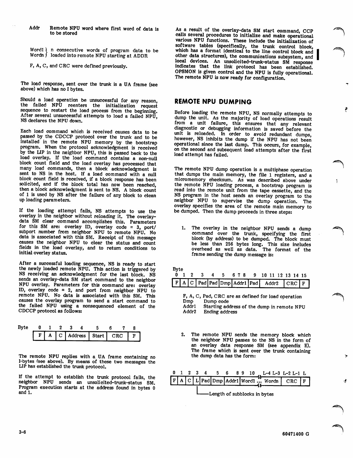
Addr
Wordl
Wordn
Remote NPU word where first word of data is
to be stored
) n consecutive words of program data to be
/ lo
loaded into remote NPU starting at ADDR
F, A, C, and CRC were defined previously.
The load response, sent over the trunk is a UA frame (see
above) which has no I bytes.
Should a load operation be unsuccessful for any reason,
the failed NPU reenters the initialization request
sequence to restart the load process from the beginning.
After several unsuccessful attempts to load a failed NPU,
NS declares the NPU down.
Each load command which is received causes data to be
passed by the CDCCP protocol over the trunk and to be
installed in the remote NPU memory by the bootstrap
program. When the protocol acknowledgment is received
by the UP in the neighbor NPU, this is passed back to the
load overlay. If the load command contains a non-null
block count field and the load overlay has processed that
many load commands, then a block acknowledgment is
sent to NS in the host. If a load command with a null
block count field is received, if a block response has been
solicited, and if the block total has now been reached,
then a block acknowledgment is sent to NS. A block count
of 1 is used by NS after the failure of any block to clean
up loading parameters.
If the loading attempt fails, NS attempts to use the
overlay in the neighbor without reloading it. The overlay-
data SM clear command accomplishes this. Parameters
for this SM are: overlay ID, overlay code = 3, port/
subport number from neighbor NPU to remote NPU. No
data is associated with this SM. Receipt of this message
causes the neighbor NPU to clear the status and count
fields in the load overlay, and to return conditions to
initial overlay status.
After a successful loading sequence, NS is ready to start
the newly loaded remote NPU. This action is triggered by
NS receiving an acknowledgment for the last block. NS
sends an overlay-data SM start command to the neighbor
NPU overlay. Parameters for this command are: overlay
ID, overlay code = 2, and port from neighbor NPU to
remote NPU. No data is associated with this SM. This
causes the overlay program to send a start command to
the failed NPU using a nonsequenced element of the
CDCCP protocol as follows:
As a result of the overlay-data SM start command, CCP
calls several procedures to initialize and make operational
various NPU functions. These include the initialization of
software tables (specifically, the trunk control block,
which has a format identical to the line control block and
other data structures), the communications subsystem, and
local devices. An unsolicited-trunk-status SM response
indicates that the link protocol has been established.
OPSMON is given control and the NPU is fully operational.
The remote NPU is now ready for configuration.
REMOTE NPU DUMPING
Before loading the remote NPU, NS normally attempts to
dump the unit. As the majority of load operations result
from a unit failure, this ensures that any relevant
diagnostic or debugging information is saved before the
unit is reloaded. In order to avoid redundant dumps,
however, NS inhibits the dump if the NPU has not been
operational since the last dump. This occurs, for example,
on the second and subsequent load attempts after the first
load attempt has failed.
The remote NPU dump operation is a multiphase operation
that dumps the main memory, the file 1 registers, and a
micromemory checksum. As was described above under
the remote NPU loading process, a bootstrap program is
read into the remote unit from the tape cassette, and the
NS program in the host sends an overlay program to the
neighbor NPU to supervise the dump operation. The
overlay specifies the area of the remote main memory to
be dumped. Then the dump proceeds in three steps:
1.
Byte
0 1
The overlay in the neighbor NPU sends a dump
command over the trunk, specifying the first
block (by address) to be dumped. The block must
be less than 256 bytes long. This size includes
overhead as well as data. The format of the
frame sending the dump message is:
6 7 8 9 10 11 12 13 14 15
F A C Pad Pad Dmp Addri Pad Addr2 CRC
HD
F, A, C, Pad, CRC are as defined for load operation
Dmp Dump code
Addri Starting address of the dump in remote NPU
Addr2 Ending address
0123 4 6 7
F A C Address Start CRC
Byte
The remote NPU replies with a UA frame containing no
I-bytes (see above). By means of these two messages the
LIP has established the trunk protocol.
If the attempt to establish the trunk protocol fails, the
neighbor NPU sends an unsolicited-trunk-status SM.
Program execution starts at the address found in bytes 0
and 1.
2. The remote NPU sends the memory block which
the neighbor NPU passes to the NS in the form of
an overlay data response SM (see appendix E).
The frame which is sent over the trunk containing
the dump data has the form:
0 1 2 3 4 8 9 10 . L-4 L-3 L-2 L-l L
Pad Dmp Addri •Vr
Wordl ... Wordn
«CRC
-Length of subblocks in bytes
3-6 60471400 G
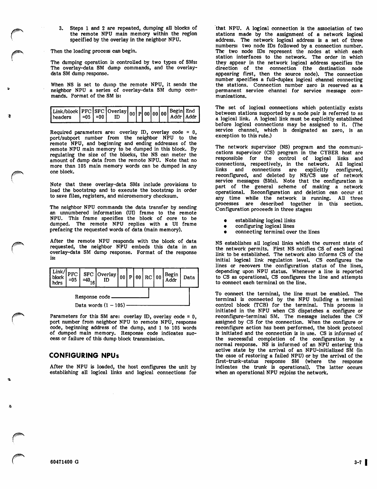
j0m$S
3. Steps 1 and 2 are repeated, dumping all blocks of
the remote NPU main memory within the region
specified by the overlay in the neighbor NPU.
Then the loading process can begin.
The dumping operation is controlled by two types of SMs:
The overlay-data SM dump commands, and the overlay-
data SM dump response.
When NS is set to dump the remote NPU, it sends the
neighbor NPU a series of overlay-data SM dump com
mands. Format of the SM is:
Link/block
headers
PFC
=05
SFC
=00 Overlay
ID 00 00 00 00 Begin
Addr
End
Addr
Required parameters are: overlay ID, overlay code = 0,
port/subport number from the neighbor NPU to the
remote NPU, and beginning and ending addresses of the
remote NPU main memory to be dumped in this block. By
regulating the size of the blocks, the NS can meter the
amount of dump data from the remote NPU. Note that no
more than 105 main memory words can be dumped in any
one block.
Note that these overlay-data SMs include provisions to
load the bootstrap and to execute the bootstrap in order
to save files, registers, and micromemory checksum.
The neighbor NPU commands the data transfer by sending
an unnumbered information (UI) frame to the remote
NPU. This frame specifies the block of core to be
dumped. The remote NPU replies with a UI frame
prefacing the requested words of data (main memory).
After the remote NPU responds with the block of data
requested, the neighbor NPU embeds this data in an
overlay-data SM dump response. Format of the response
Link/
block
hdrs
PFC
=05 SFC Overlay
ID 00 00 RC 00 Begin
Addr Data
Response code
Data words (1 - 105)
Parameters for this SM are: overlay ID, overlay code = 0,
port number from neighbor NPU to remote NPU, response
code, beginning address of the dump, and 1 to 105 words
of dumped main memory. Response code indicates suc
cess or failure of this dump block transmission.
CONFIGURING NPUs
After the NPU is loaded, the host configures the unit by
establishing all logical links and logical connections for
that NPU. A logical connection is the association of two
stations made by the assignment of a network logical
address. The network logical address is a set of three
numbers: two node IDs followed by a connection number.
The two node IDs represent the nodes at which each
station interfaces to the network. The order in which
they appear in the network logical address specifies the
direction of the connection (the destination node
appearing first, then the source node). The connection
number specifies a full-duplex logical channel connecting
the stations. Connection number zero is reserved as a
permanent service channel for service message com
munications.
The set of logical connections which potentially exists
between stations supported by a node pair is referred to as
a logical link. A logical link must be explicitly established
before logical connections may be assigned to it. (The
service channel, which is designated as zero, is an
exception to this rule.)
The network supervisor (NS) program and the communi
cations supervisor (CS) program in the CYBER host are
responsible for the control of logical links and
connections, respectively, in the network. All logical
links and connections are explicitly configured,
reconfigured, and deleted by NS/CS use of network
service messages (SMs). Note that the configuration is
part of the general scheme of making a network
operational. Reconfiguration and deletion can occur at
any time while the network is running. All three
processes are described together in this section.
Configuration proceeds in three stages:
• establishing logical links
• configuring logical lines
• connecting terminal over the lines
NS establishes all logical links which the current state of
the network permits. First NS notifies CS of each logical
link to be established. The network also informs CS of the
initial logical link regulation level. CS configures the
lines or recovers the configuration status of the lines,
depending upon NPU status. Whenever a line is reported
to CS as operational, CS configures the line and attempts
to connect each terminal on the line.
To connect the terminal, the line must be enabled. The
terminal is connected by the NPU building a terminal
control block (TCB) for the terminal. This process is
initiated in the NPU when CS dispatches a configure or
reconfigure-terminal SM. The message includes the CN
assigned by CS for the connection. When the configure or
reconfigure action has been performed, the block protocol
is initiated and the connection is in use. CS is informed of
the successful completion of the configuration by a
normal response. NS is informed of an NPU entering this
active state by the arrival of an NPU-initialized SM (in
the case of restoring a failed NPU) or by the arrival of the
first-trunk-status response SM (where the response
indicates the trunk is operational). The latter occurs
when an operational NPU rejoins the network.
60471400 G 3-7 |

/"*%
y*%
FAILURE, RECOVERY, AND DIAGNOSTICS
Failure and recovery of CCP depends on a number of
factors:
• Host failure: If a host fails, the NPU and its
software must necessarily stop message processing.
o NPU failure: If an NPU fails, it must be reloaded
and reinitiated from the host. Off-line diagnostic
tests may be desirable during this period to help
identify the cause of failure.
• Logical link failure: Host failure was mentioned
above. Link CDCCP protocol failure leads to
higher and higher levels of regulation until message
traffic ceases on the link.
• Line failure: Lines are disconnected and terminal
control blocks (TCBs) associated with the lines are
deleted.
• Terminal failure: Terminal status is reported and
message is discarded.
To aid recovery and to assure dependable network operations
that involve the CCP, three sets of diagnostic programs are
available.
• Inline diagnostics. These include CE error and
alarm messages, statistics messages, halt code
messages that specify the reason for an NPU
failure, and off-line dumps.
• Optional on-line diagnostic tests that allow check
ing of circuits to terminals. These aids are
available only if a network maintenance contract
is purchased.
• Off-line diagnostics. These hardware tests for
NPU circuits are described in detail in the Network
Processor Unit Hardware Maintenance Manual.
The diagnostic commands are summarized in appendix B.
60471400 D 4-1

/*%!
**%
|/S?%
/^^L
CODED CHARACTER DATA INPUT, OUTPUT, AND
CENTRAL MEMORY REPRESENTATION
><*\
/ g f c j y
This appendix describes the code and character sets used
by host computer operating system local batch device
drivers, magnetic tape drivers, and terminal
communication products. Some software products assume
that certain graphic or control characters are associated
with specific binary code values for collating or syntax
processing purposes. This appendix does not describe those
associations for all products.
All references within this manual to the ASCII character
set or the ASCII code set refer to the character set and
code set defined in the American National Standard Code
for Information Interchange (ASCII, ANSI Standard
X3.4-1977). References in this manual to the ASCII
character set do not necessarily apply to the ASCII
code set.
CHARACTER SETS AND CODE SETS
A character set differs from a code set. A character set is
a set of graphic and/or control characters. A code set is a
set of codes used to represent each character within a
character set. Characters exist outside the computer
system and communication network; codes are received,
stored, retrieved, and transmitted within the computer
system and network.
GRAPHIC AND CONTROL CHARACTERS
A graphic character can be displayed at a terminal or
printed by a line printer. Examples of graphic characters
are the characters A through Z, a blank, and the digits 0
through 9. A control character initiates, modifies, or stops
a control operation. An example of a control character is
the backspace character, which moves the terminal
carriage or cursor back one space. Although a control
character is not a graphic character, some terminals can
produce a graphic representation when they receive a
control character.
CODED AND BINARY CHARACTER
DATA
Character codes can be interpreted as coded character
data or as binary character data. Coded character data is
converted from one code set representation to another as
it enters or leaves the computer system; for example, data
received from a terminal or sent to a magnetic tape unit is
converted. Binary character data is not converted as it
enters or leaves the system. Character codes are not
converted when moved within the system; for example,
data transferred to or from mass storage is not converted.
The distinction between coded character data and binary
character data is important when reading or punching cards
and when reading or writing magnetic tape. Only coded
character data can be properly reproduced as characters on
a line printer. Only binary character data can properly
represent characters on a punched card when the data
cannot be stored as display code.
The distinction between binary character data and
characters represented by binary data (such as peripheral
equipment instruction codes) is also important. Only such
binary noncharacter data can properly reproduce
characters on a plotter.
FORMATTED AND UNFORMATTED
CHARACTER DATA
Character codes can be interpreted by a product as
formatted character data or as unformatted character
data. Formatted data can be stored or retrieved by a
product in the form of the codes described for coded
character data in the remainder of this appendix, or
formatted data can be altered to another form during
storage or retrieval; for example, 1 can be stored as a
character code or as an integer value. Treatment of
unformatted data by a product includes both coded
character data and binary character data as described in
this appendix.
NETWORK OPERATING SYSTEM
The Network Operating System (NOS) supports the
following character sets:
CDC graphic 64-character set
CDC graphic 63-character set
ASCII graphic 64-character set
ASCII graphic 63-character set
ASCII graphic 95-character set
ASCII 128-character graphic and control set
Each installation must select either a 64-character set or a
63-character set. The differences between the codes of a
63-character set and the codes of a 64-character set are
described under Character Set Anomalies. Any reference
in this appendix to a 64-character set implies either a 63-
or 64-character set unless otherwise stated.
To represent its six listed character sets in central
memory, NOS supports the following code sets:
• 6-bit display code
• 12-bit ASCII code
• 6/12-bit display code
The 6-bit display code is a set of 6-bit codes from OOg
to 778.
The 12-bit ASCII code is the ASCII 7-bit code (as defined
by ANSI Standard X3.4-1977) right-justified in a 12-bit
byte. Assuming that the bits are numbered from the right
starting with 0, bits 0 through 6 contain the ASCII code,
bits 7 through 10 contain zeros, and bit 11 distinguishes the
12-bit ASCII OOOOg code from the end-of-line byte. The
12-bit codes are OOOlg through 01778 and 40008.
60471400 G A-l •
The 6/12-bit display code is a combination of 6-bit codes
and 12-bit codes. The 6-bit codes are 008 through 77s,
excluding 74g and 76g. (The interpretation of the
OOg and 63g codes is described under Character Set
Anomalies later in this appendix.) The 12-bit codes begin
with either 74g or 76g and are followed by a 6-bit
code. Thus, 74g and 76g are considered escape codes
and are never used as 6-bit codes within the 6/12-bit
display code set. The 12-bit codes are 7401g, 7402g,
7404g, 7407a, and 7601g through 7677g. All other
12-bit codes (74xx8 and 7600g) are undefined.
CHARACTER SET ANOMALIES
The operating system input/output software and some
products interpret two codes differently when the
installation selects a 63-character set rather than a
64-character set. If an installation uses a 63-character
set, the colon graphic character is always represented by a
63g code, display code OOg is undefined (it has no
associated graphic or punched card code), and the %
graphic does not exist.
If the installation uses a 64-character set, output of a
7404g 6/12-bit display code or a OOg display code
produces a colon. A colon can be input only as a 7404g
6/12-bit display code. The use of undefined 6/12-bit
display codes in output files produces unpredictable results
and should be avoided.
Two consecutive OOg codes can be confused with an
end-of-line byte and should be avoided.
CHARACTER SET TABLES
The character set tables A-l and A-2 are designed so that
the user can find the character represented by a code (such
as in a dump) or find the code that represents a character.
To find the character represented by a code, the user looks
up the code in the column listing the appropriate code set
and then finds the character on that line in the column
listing the appropriate character set. To find the code that
represents a character, the user looks up the character and
then finds the code on the same line in the appropriate
column.
Conversational Terminal Users
Table A-l shows the character sets and code sets available
to an Interactive Facility (IAF) user at an ASCII code
terminal using an ASCII character set. Table A-9 (later in
this appendix) shows the octal and hexadecimal 7-bit ASCII
code for each ASCII character, and can be used to convert
codes from octal to hexadecimal. (Under NOS using
network product software, certain Terminal Interface
Program commands require specification of an ASCII code.)
IAF Usage
When in normal time-sharing mode (specified by the IAF
NORMAL command), IAF assumes the ASCII graphic
64-character set is used and translates all input and output
to or from display code. When in ASCII time-sharing mode
(specified by the IAF ASCII command), IAF assumes the
ASCII 128-character set is used and translates all input and
output to or from 6/12-bit display code.
The IAF user can convert a 6/12-bit code file to a 12-bit
ASCII code file using the NOS FCOPY control statement.
The resulting 12-bit ASCII file can be routed to a line
printer but cannot be output through IAF.
IAF supports both character mode and transparent mode
transmissions through the network. These transmission
modes are described under Network Access Method
Terminal Transmission Code Sets in this appendix. IAF
treats character mode transmissions as coded character
data; IAF converts these transmissions to or from either
6-bit or 6/12-bit display code. IAF treats transparent
mode transmissions as binary character data; transparent
mode communication between IAF and ASCII terminals
using any parity setting occurs in the 12-bit ASCII code
shown in table A-l.
Local Batch Users
Table A-2 lists the CDC graphic 64-character set, the
ASCII graphic 64-character set, and the ASCII graphic
95-character set. This table also lists the code sets and
card keypunch codes (026 and 029) that represent the
characters.
The 64-character sets use display code as their code set;
the 95-character set uses 12-bit ASCII code. The
95-character set is composed of all the characters in the
ASCII 128-character set that can be printed at a line
printer (refer to Line Printer Output). Only 12-bit ASCII
code files can be printed using the ASCII graphic
95-character set. To print a 6/12-bit display code file
(usually created in IAF ASCII mode), the user must convert
the file to 12-bit ASCII code. To do this, the NOS FCOPY
control statement must be issued. The 95-character set is
represented by the 12-bit ASCII codes 0040g
through 0176g.
Line Printer Output
The batch character set printed depends on the print train
used on the line printer to which the file is sent. The
following are the print trains corresponding to each of the
batch character sets:
,*SSv
Character Set
CDC graphic 64-character set
ASCII graphic 64-character set
ASCII graphic 95-character set
Print Train
596-1
596-5
596-6
The characters of the default 596-1 print train are listed in
the table A-2 column labeled CDC Graphic (64-Character);
the 596-5 print train characters are listed in the table A-2
column labeled ASCII Graphic (64-Character); and the
596-6 print train characters are listed in the table A-2
column labeled ASCII Graphic (95-Character).
If a transmission error occurs during the printing of a line,
NOS prints the line again. The CDC graphic print train
prints a concatenation symbol (r*) in the first printable
column of a line containing errors. The ASCII print trains
print an underline instead of the concatenation symbol.
If an unprintable character exists in a line (that is, a 12-bit
ASCII code outside of the range 0040g through 0176g),
the number sign (#) appears in the first printable column of
a print line and a space replaces the unprintable character.
/ * S ^ V
A-2 60471400 G
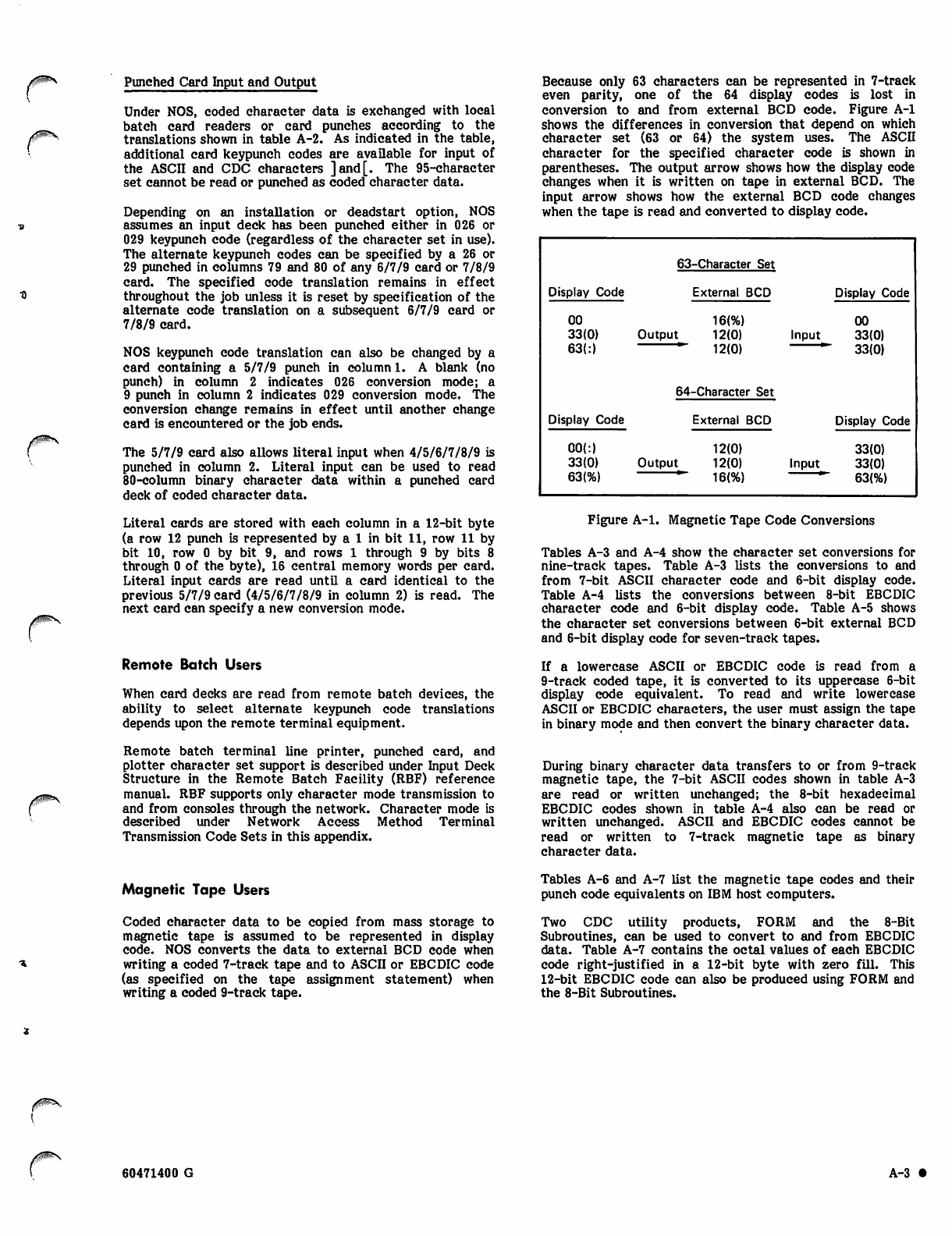
^p\
Punched Card Input and Output
Under NOS, coded character data is exchanged with local
batch card readers or card punches according to the
translations shown in table A-2. As indicated in the table,
additional card keypunch codes are available for input of
the ASCII and CDC characters ]and[. The 95-character
set cannot be read or punched as coded character data.
Depending on an installation or deadstart option, NOS
assumes an input deck has been punched either in 026 or
029 keypunch code (regardless of the character set in use).
The alternate keypunch codes can be specified by a 26 or
29 punched in columns 79 and 80 of any 6/7/9 card or 7/8/9
card. The specified code translation remains in effect
throughout the job unless it is reset by specification of the
alternate code translation on a subsequent 6/7/9 card or
7/8/9 card.
NOS keypunch code translation can also be changed by a
card containing a 5/7/9 punch in column 1. A blank (no
punch) in column 2 indicates 026 conversion mode; a
9 punch in column 2 indicates 029 conversion mode. The
conversion change remains in effect until another change
card is encountered or the job ends.
The 5/7/9 card also allows literal input when 4/5/6/7/8/9 is
punched in column 2. Literal input can be used to read
80-column binary character data within a punched card
deck of coded character data.
Literal cards are stored with each column in a 12-bit byte
(a row 12 punch is represented by a 1 in bit 11, row 11 by
bit 10, row 0 by bit 9, and rows 1 through 9 by bits 8
through 0 of the byte), 16 central memory words per card.
Literal input cards are read until a card identical to the
previous 5/7/9 card (4/5/6/7/8/9 in column 2) is read. The
next card can specify a new conversion mode.
Remote Batch Users
When card decks are read from remote batch devices, the
ability to select alternate keypunch code translations
depends upon the remote terminal equipment.
Remote batch terminal line printer, punched card, and
plotter character set support is described under Input Deck
Structure in the Remote Batch Facility (RBF) reference
manual. RBF supports only character mode transmission to
and from consoles through the network. Character mode is
described under Network Access Method Terminal
Transmission Code Sets in this appendix.
Because only 63 characters can be represented in 7-track
even parity, one of the 64 display codes is lost in
conversion to and from external BCD code. Figure A-l
shows the differences in conversion that depend on which
character set (63 or 64) the system uses. The ASCII
character for the specified character code is shown in
parentheses. The output arrow shows how the display code
changes when it is written on tape in external BCD. The
input arrow shows how the external BCD code changes
when the tape is read and converted to display code.
63-Character Set
Display Code External BCD Display Code
00
33(0)
63(:>
16(%)
Output 12(0)
12(0)
64-Character Set
Input
00
33(0)
33(0)
Display Code
00(:)
33(0)
63(%)
External BCD
12(0)
Output 12(0)
16{%)
Input
Display Code
33(0)
33(0)
63(%)
Figure A-l. Magnetic Tape Code Conversions
Tables A-3 and A-4 show the character set conversions for
nine-track tapes. Table A-3 lists the conversions to and
from 7-bit ASCII character code and 6-bit display code.
Table A-4 lists the conversions between 8-bit EBCDIC
character code and 6-bit display code. Table A-5 shows
the character set conversions between 6-bit external BCD
and 6-bit display code for seven-track tapes.
If a lowercase ASCII or EBCDIC code is read from a
9-track coded tape, it is converted to its uppercase 6-bit
display code equivalent. To read and write lowercase
ASCII or EBCDIC characters, the user must assign the tape
in binary mode and then convert the binary character data.
During binary character data transfers to or from 9-track
magnetic tape, the 7-bit ASCII codes shown in table A-3
are read or written unchanged; the 8-bit hexadecimal
EBCDIC codes shown in table A-4 also can be read or
written unchanged. ASCII and EBCDIC codes cannot be
read or written to 7-track magnetic tape as binary
character data.
Magnetic Tape Users
Coded character data to be copied from mass storage to
magnetic tape is assumed to be represented in display
code. NOS converts the data to external BCD code when
writing a coded 7-track tape and to ASCII or EBCDIC code
(as specified on the tape assignment statement) when
writing a coded 9-track tape.
Tables A-6 and A-7 list the magnetic tape codes and their
punch code equivalents on IBM host computers.
Two CDC utility products, FORM and the 8-Bit
Subroutines, can be used to convert to and from EBCDIC
data. Table A-7 contains the octal values of each EBCDIC
code right-justified in a 12-bit byte with zero fill. This
12-bit EBCDIC code can also be produced using FORM and
the 8-Bit Subroutines.
60471400 G A-3 •
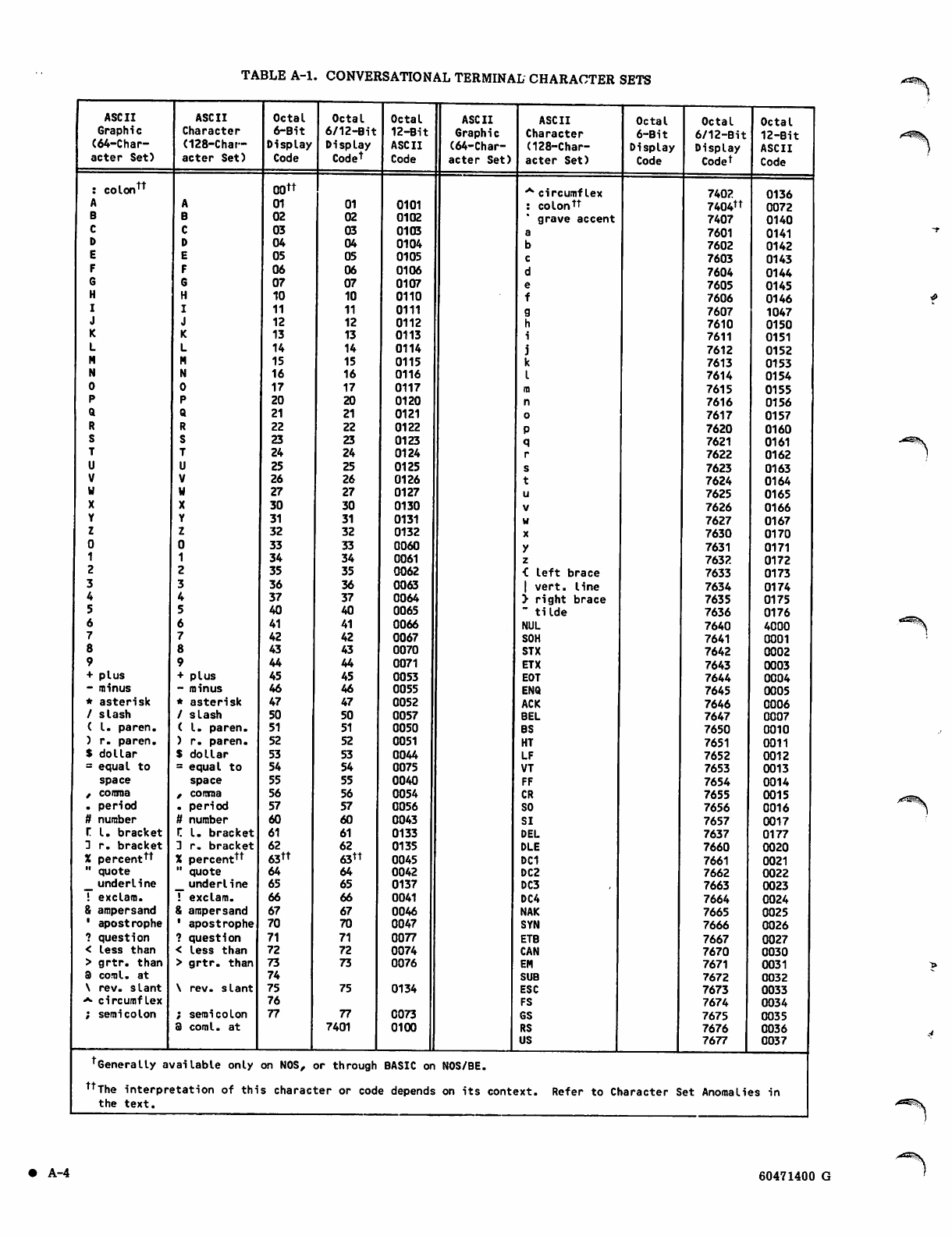
TABLE A-l. CONVERSATIONAL TERMINAL CHARACTER SETS
ASCII
Graphic
(64-Char
acter Set)
colon™
plus
- minus
* asterisk
/ slash
( I. paren.
) r. p a r e n .
$ dollar
= equal to
space
f comma
. period
tt number
r I. bracket
3 r. b ra c k et
X percent tt
" quote
__ underline
! exclam.
8 ampersand
1 apostrophe
? question
< less than
> g r t r . t h a n
3 comI. at
\ r e v. s l a n t
•** circumflex
; semi colo n
ASCII
Character
(128-Char-
acter Set)
A
B
C
D
E
F
G
H
I
J
K
L
M
N
0
P
Q
R
S
T
U
V
u
X
Y
Z
0
1
2
3
4
5
6
7
8
9
+ plus
- minus
* asterisk
/ slash
(I. paren.
) r. paren.
$ dollar
= equal to
space
, comma
. period
tt number
r. I. bracket
3 r. b r a c k e t
X percenttt
" quote
_ underline
! exclam.
S ampersand
* apostrophe
? question
< less than
> grtr. than
\ rev. slant
; semi colo n
3 coml. at
Octal
6-Bit
Display
Code
oott
01
02
03
04
05
06
07
10
11
12
13
14
15
16
17
20
21
22
23
24
25
26
27
30
31
32
33
34
35
36
37
40
41
42
43
44
45
46
47
50
51
52
53
54
55
56
57
60
61
62
63tt
64
65
66
67
70
71
72
73
74
75
76
77
O c t a l
6/12-Bit
Display
Codet
01
02
03
04
05
06
07
10
11
12
13
14
15
16
17
20
21
22
23
24
25
26
27
30
31
32
33
34
35
36
37
40
41
42
43
44
45
46
47
50
51
52
53
54
55
56
57
60
61
62
63tt
64
65
66
67
70
71
72
73
75
77
7401
Octal
12-Bit
ASCII
Code
0101
0102
0103
0104
0105
0106
0107
0110
0111
0112
0113
0114
0115
0116
0117
0120
0121
0122
0123
0124
0125
0126
0127
0130
0131
0132
0060
0061
0062
0063
0064
0065
0066
0067
0070
0071
0053
0055
0052
0057
0050
0051
0044
0075
0040
0054
0056
0043
0133
0135
0045
0042
0137
0041
0046
0047
0077
0074
0076
0134
0073
0100
ASCII
Graphic
(64-Char
acter Set)
ASCII
Character
(128-Char-
acter Set)
**" circumflex
: colontt
grave accent
a
b
c
d
e
f
g
h
i
j
k
I
m
n
o
P
q
r
s
t
u
V
w
X
y
z
< left brace
| vert, line
> right brace
" tilde
NUL
SOH
STX
ETX
EOT
ENQ
ACK
BEL
BS
HT
LF
VT
FF
CR
SO
SI
DEL
DLE
DC1
DC2
DC3
DC4
NAK
SYN
ETB
CAN
EM
SUB
ESC
FS
GS
RS
US
Octal
6-Bit
Display
Code
Octal
6/12-Bit
Display
Codet
Octal
12-Bit
ASCII
Code
7402 0136
7404tt 0072
7407 0140
7601 0141
7602 0142
7603 0143
7604 0144
7605 0145
7606 0146
7607 1047
7610 0150
7611 0151
7612 0152
7613 0153
7614 0154
7615 0155
7616 0156
7617 0157
7620 0160
7621 0161
7622 0162
7623 0163
7624 0164
7625 0165
7626 0166
7627 0167
7630 0170
7631 0171
7632 0172
7633 0173
7634 0174
7635 0175
7636 0176
7640 4000
7641 0001
7642 0002
7643 0003
7644 0004
7645 0005
7646 0006
7647 0007
7650 0010
7651 0011
7652 0012
7653 0013
7654 0014
7655 0015
7656 0016
7657 0017
7637 0177
7660 0020
7661 0021
7662 0022
7663 0023
7664 0024
7665 0025
7666 0026
7667 0027
7670 0030
7671 0031
7672 0032
7673 0033
7674 0034
7675 0035
7676 0036
7677 0037
tGenerally available only on NOS, or through BASIC on NOS/BE.
ttThe interpretation of this character or code depends on its context. Refer to Character Set Anomalies in
the text.
• A - 4 60471400 G
^VCE^v
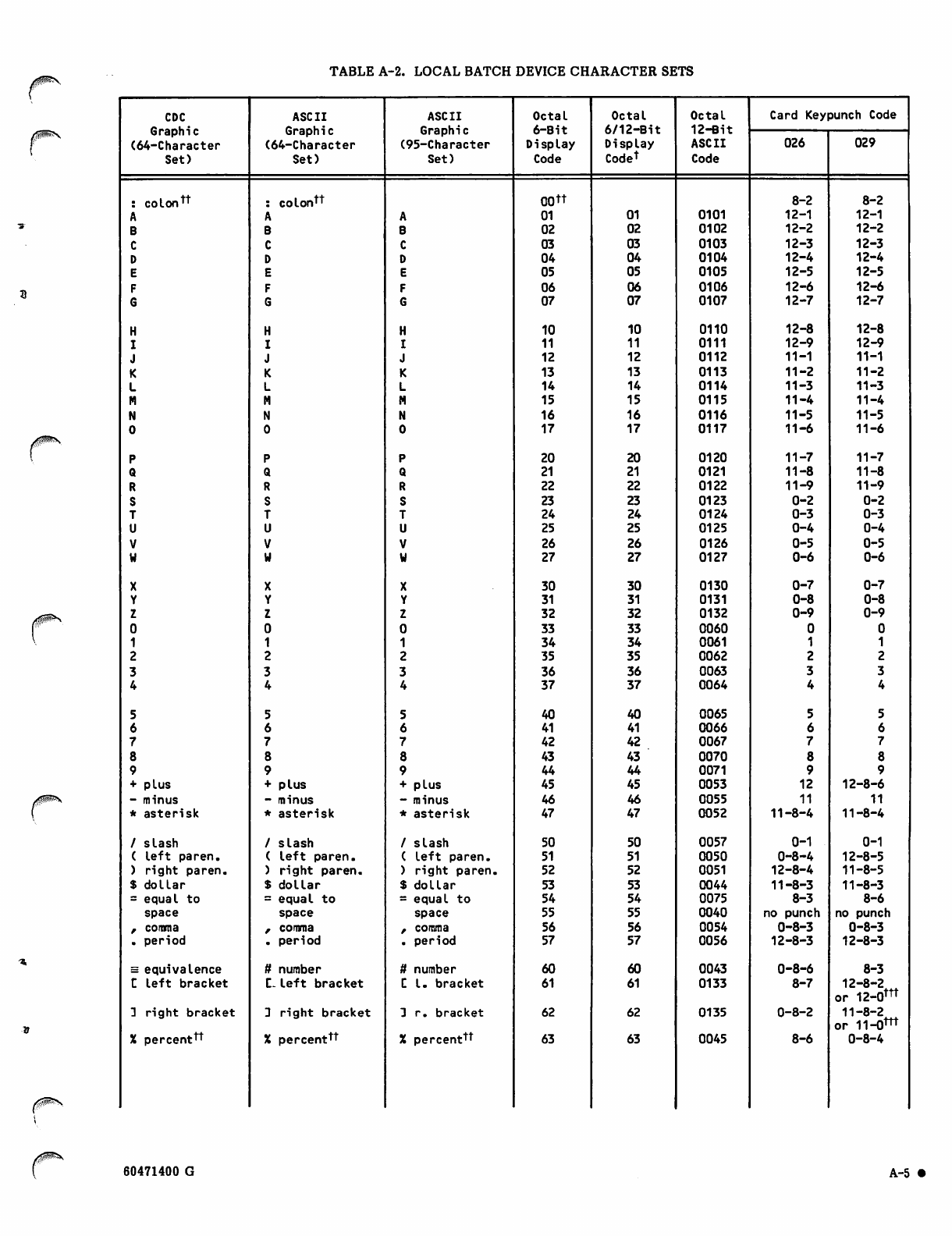
TABLE A-2. LOCAL BATCH DEVICE CHARACTER SETS
CDC ASCII ASCII Octal Octal Octal Card Keypunch Code
Graphic Graphic Graphic 6 - B i t 6/12-Bit 12-Bit
(64-Character (64-Character (95-Character Display Display ASCII 026 029
Set) Set) Set) Code Codet Code
: c o lon tt : colontt 00 tt 8-2 8-2
A A A 01 01 0101 12-1 12-1
BBB 02 02 0102 12-2 12-2
C C C 03 03 0103 12-3 12-3
D D D 04 04 0104 12-4 12-4
E E E 05 05 0105 12-5 12-5
F F F 06 06 0106 12-6 12-6
G G G07 07 0107 12-7 12-7
H H H 10 10 0110 12-8 12-8
I I I 11 11 0111 12-9 12-9
J J J 12 12 0112 11-1 11-1
KKK 13 13 0113 11-2 11-2
L L L 14 14 0114 11-3 11-3
M M M 15 15 0115 11- 4 11-4
N N N 16 16 0116 11-5 11-5
0 0 0 17 17 0117 11-6 11-6
P P P 20 20 0120 11-7 11-7
Q Q Q21 21 0121 11-8 11-8
R R R 22 22 0122 11-9 11-9
S S S 23 23 0123 0-2 0-2
T T T 24 24 0124 0-3 0-3
UUU25 25 0125 0-4 0-4
V V V 26 26 0126 0-5 0-5
w u u 27 27 0127 0-6 0-6
X X X 30 30 0130 0-7 0-7
Y Y Y 31 31 0131 0-8 0-8
Z Z Z 32 32 0132 0-9 0-9
0 0 0 33 33 0060
1 1 1 34 34 0061
22235 35 0062
3 3 3 36 36 0063
4 4 4 37 37 0064
5 5 5 40 40 0065
66 6 41 41 0066
777 42 42 0067
8 8 8 43 43 0070
9 9 9 44 44 0071
+ plus + plus + plus 45 45 0053 12 12-8-6
- minus - minus - minus 46 46 0055 11 11
* a s teri s k * a ste r i sk * a s teri s k 47 47 0052 11-8-4 11-8 -4
/ slash / sla sh / s la sh 50 50 0057 0-1 0-1
( lef t par en . ( l e ft p a ren. ( left paren. 51 51 0050 0-8-4 12-8-5
) right paren. ) right paren. ) right paren. 52 52 0051 12-8-4 11-8-5
$ d ol lar $ d o l l a r $ dol la r 53 53 0044 11-8-3 11-8-3
= equal to = equal to = equal to 54 54 0075 8-3 8-6
space space space 55 55 0040 no punch no punch
, comma , comma z comma 56 56 0054 0-8-3 0-8-3
. period . pe riod . period 57 57 0056 12-8-3 12-8-3
= equivalence ft number ft number 60 60 0043 0-8-6 8-3
C left bracket C- left bracket C I. bracket 61 61 0133 8-7 12-8-2
or 12-0nt
3 ri ght bra cke t 3 rig ht bra ck et 3 r. bracket 62 62 0135 0-8-2 11-8-2
or 11-0™t
% percent™ X percent™ % percent™ 63 63 0045 8-6 0-8-4
60471400 G A-5 •
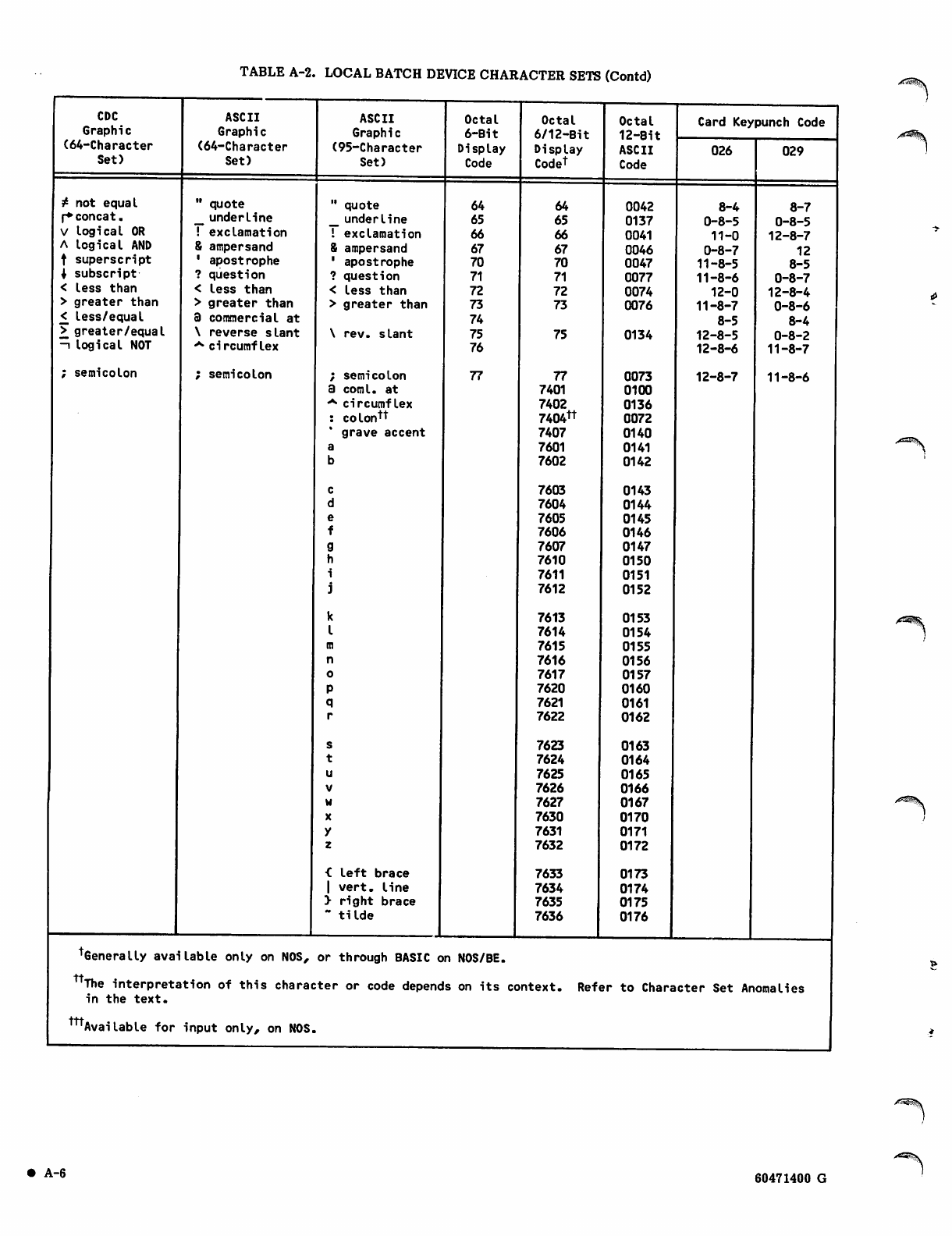
TABLE A-2. LOCAL BATCH DEVICE CHARACTER SETS (Contd)
CDC
Graphic
(64-Character
Set)
* not equal
f*concat.
V togical OR
A logical AND
t superscript
i s u bscr i pt
< less than
> greater than
< less/equal
> greater/equal
-i logical NOT
; semicolon
ASCII
Graphic
(64-Character
Set)
" quote
__ underline
! exclamation
8 ampersand
1 apostrophe
? question
< less than
> greater than
3 commercial at
\ reverse slant
**• circumflex
; semicolon
ASCII
Graphic
(95-Character
Set)
" quote
_ underline
! exclamation
& ampersand
1 apostrophe
? question
< less than
> greater than
\ rev. slant
; semicolon
3 comI. at
**• circumflex
: colon™
* grave accent
a
b
c
d
e
f
g
h
i
j
k
I
m
n
o
P
q
r
s
t
u
v
w
X
y
z
< left brace
| vert, line
> right brace
" tilde
Octal
6-Bit
Display
Code
64
65
66
67
70
71
72
73
74
75
76
77
Generally available only on NOS, or through BASIC on NOS/BE.
Octal
6/12-Bit
Display
Codet
64
65
66
67
70
71
72
73
75
77
7401
7402
7404™
7407
7601
7602
7603
7604
7605
7606
7607
7610
7611
7612
7613
7614
7615
7616
7617
7620
7621
7622
7623
7624
7625
7626
7627
7630
7631
7632
7633
7634
7635
7636
Octal
12-Bit
ASCII
Code
0042
0137
0041
0046
0047
0077
0074
0076
0134
0073
0100
0136
0072
0140
0141
0142
0143
0144
0145
0146
0147
0150
0151
0152
0153
0154
0155
0156
0157
0160
0161
0162
0163
0164
0165
0166
0167
0170
0171
0172
0173
0174
0175
0176
Card Keypunch Code
026
8-4
0-8-5
11-0
0-8-7
11-8-5
11-8-6
12-0
11-8-7
8-5
12-8-5
12-8-6
12-8-7
029
8-7
0-8-5
12-8-7
12
8-5
0-8-7
12-8-4
0-8-6
8-4
0-8-2
11-8-7
11-8-6
tt
ttt
The interpretation of this character or code depends on its context. Refer to Character Set Anomalies
in the text.
Available for input only, on NOS.
• A-6 60471400 G
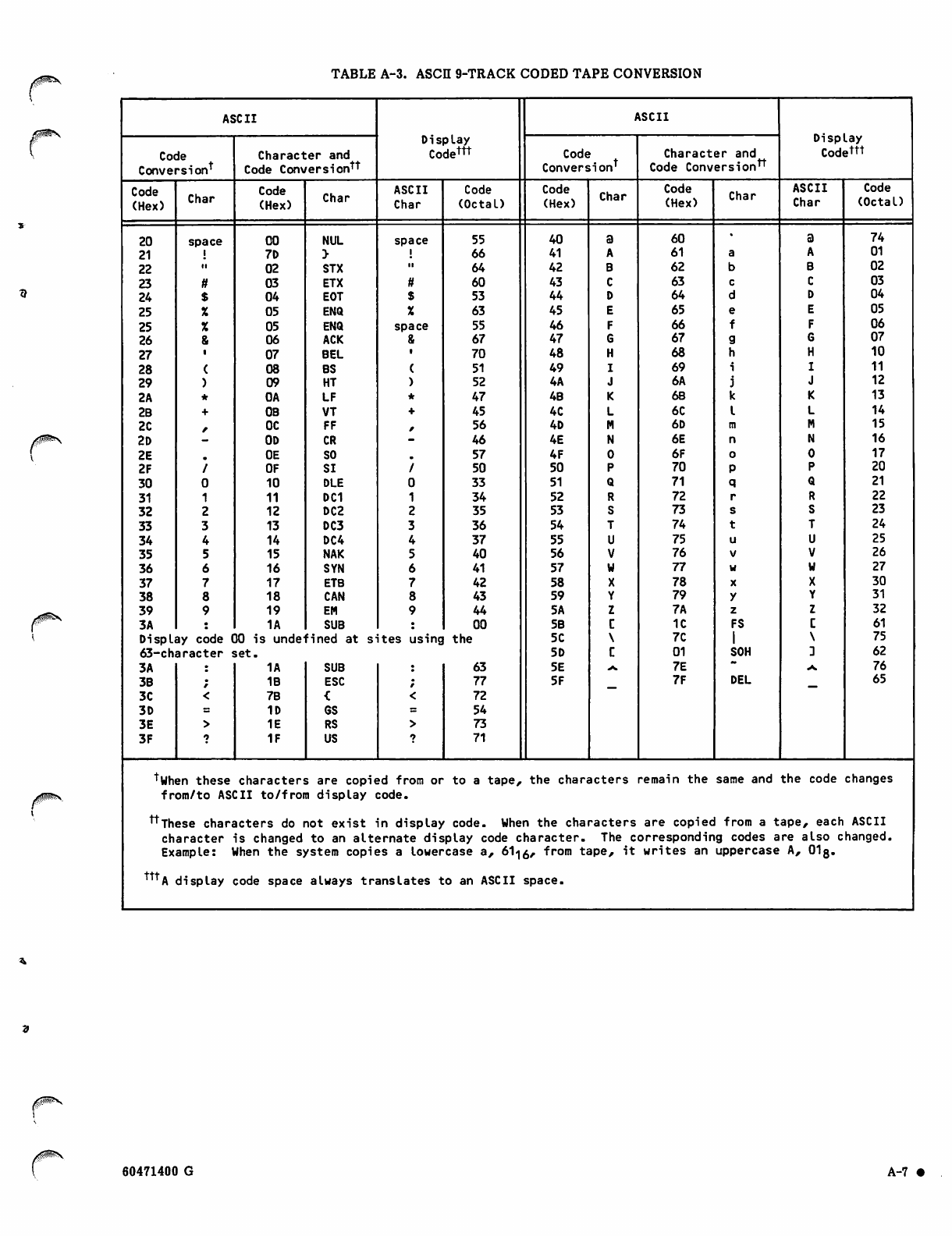
TABLE A-3. ASCII 9-TRACK CODED TAPE CONVERSION
ASCII ASCII
Display Display
Code Character and Codet™ Code Character and Codettt
Conversiont Code Conversion™ Conversiont Code Conversion™
Code
(Hex) Char Code
(Hex) Char ASCII
Char
Code
(Octal)
Code
(Hex) Char Code
(Hex) Char ASCII
Char
Code
(Octal)
20 space 00 NUL space 55 40 60 74
21 7D 66 41 61 01
22 ii 02 STX 64 42 62 02
23 tt 03 ETX ft 60 43 63 03
24 04 EOT 53 44 64 04
25 05 ENQ 63 45 65 05
25 05 ENQ space 55 46 66 06
26 06 ACK 67 47 67 07
27 07 BEL 70 48 68 10
28 08 BS 51 49 69 11
29 09 HT 52 4A 6A 12
2A 0A LF 47 4B 68 13
2B 0B VT 45 4C 6C 14
2C 0C FF 56 4D 6D 15
2D 0D CR 46 4E 6E 16
2E 0E SO 57 4F 6F 17
2F OF SI 50 50 70 20
30 10 DLE 33 51 71 21
31 11 DC1 34 52 72 22
32 12 DC2 35 53 73 23
33 13 DC3 36 54 74 24
34 14 DC4 37 55 75 25
35 15 NAK 40 56 76 26
36 16 SYN 41 57 77 27
37 17 ETB 42 58 78 30
38 18 CAN 43 59 79 31
39 19 EM 44 5A 7A 32
3A 1A SUB 00 5B 1C FS 61
Display code 00 is undefined at sites using the 5C 7C 75
63-character set. 5D 01 SOH 62
3A 1A SUB 63 5E *. 7E ** At. 76
3B 1B ESC 77 5F 7F DEL 65
3C 7B 72
3D 1D GS 54
3E 1E RS 73
3F 1F US 71
tyhen these characters are copied from or to a tape, the characters remain the same and the code changes
from/to ASCII to/from display code.
™These characters do not exist in display code. When the characters are copied from a tape, each ASCII
character is changed to an alternate display code character. The corresponding codes are also changed.
Example: When the system copies a lowercase a, 61^, from tape, it writes an uppercase A, 01g.
™*A display code space always translates to an ASCII space.
r60471400 G A-7
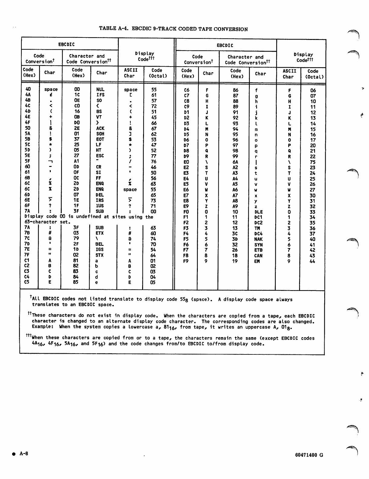
TABLE A-4. EBCDIC 9-TRACK CODED TAPE CONVERSION
EBCDIC
Code
Conversiont
Code
(Hex) Char
40
4A
4B
4C
4D
4E
4F
50
5A
5B
5C
5D
5E
5F
60
61
6B
6C
6C
6D
6E
6F
7 A | :
Display code
63-character
7A
space
t
<
(
+
I
&
i
$
*
)
Character and
Code Conversion™
Code
(Hex)
7B
7C
7D
7E
7F
C1
C2
C3
C4
C5
00
1C
0E
CO
16
0B
DO
2E
01
37
25
05
27
A1
0D
OF
OC
2D
2D
07
1E
1F
3F
00 is undefi
set.
3F
03
79
2F
1D
02
81
82
83
84
85
Char
Display
Codettt
ASCII
Char
NUL
IFS
SO
C
BS
VT
>
ACK
SOH
EOT
LF
HT
ESC
CR
SI
FF
ENQ
ENQ
DEL
IRS
IUS
SUB
ned at
SUB
ETX
\
BEL
IGS
STX
a
b
c
d
e
space
r.
<
(
+
I
s
$
*
)
%
space
Code
(Octal)
sites using
55
61
57
72
51
45
66
67
62
53
47
52
77
76
46
50
56
63
55
65
73
71
00
the
63
60
74
70
54
64
01
02
03
04
05
EBCDIC
Code
Conversiont
Code
(Hex)
C6
C7
C8
C9
D1
D2
D3
D4
D5
D6
D7
D8
D9
EO
E2
E3
E4
E5
E6
E7
E8
E9
FO
F1
F2
F3
F4
F5
F6
F7
F8
F9
Char
Character and
Code Conversion™
Code
(Hex)
86
87
88
89
91
92
93
94
95
96
97
98
99
6A
A2
A3
A4
A5
A6
A7
A8
A9
10
11
12
13
3C
3D
32
26
18
19
Char
f
g
h
i
j
k
I
m
n
o
P
q
r
I
s
t
u
V
w
X
y
z
DLE
DC1
DC2
TM
DC4
NAK
SYN
ETB
CAN
EM
Display
Codettt
ASCII
Char
Code
(Octal)
06
07
10
11
12
13
14
15
16
17
20
21
22
75
23
24
25
26
27
30
31
32
33
34
35
36
37
40
41
42
43
44
ALL EBCDIC codes not listed translate to display code 55g (space). A display code space always
translates to an EBCDIC space.
™These characters do not exist in display code. When the characters are copied from a tape, each EBCDIC
character is changed to an alternate display code character. The corresponding codes are also changed.
Example: When the system copies a lowercase a, &li0, from tape, it writes an uppercase A, OI3.
ttt
'When these characters are copied from or to a tape, the characters remain the same (except EBCDIC codes
^16/ 4r"l6/ 5A«|6, and 5F-|0) and the code changes from/to EBCDIC to/from display code.
• A - 8 60471400 G
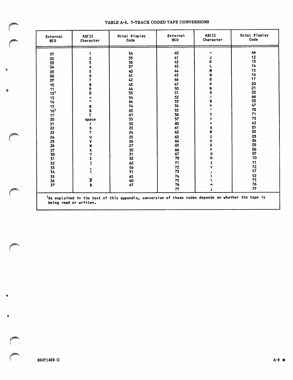
TABLE A-5. 7-TRACK CODED TAPE CONVERSIONS
External ASCII Octal Display External ASCII Octal Display
BCD Character Code BCD Character Code
01 34 40 46
02 35 41 12
03 36 42 13
04 37 43 14
05 40 44 15
06 41 45 16
07 42 46 17
10 43 47 20
11 44 50 21
12* 33 51 22
13 54 52 66
14 ■i64 53 53
15 74 54 47
16t 63 55 70
17 61 56 71
20 space 55 57 73
21 50 60 45
22 23 61 01
23 24 62 02
24 25 63 03
25 26 64 04
26 27 65 05
27 30 66 06
30 31 67 07
31 32 70 10
32 62 71 11
33 56 72 72
34 51 73 57
35 65 74 52
36 60 75 75
37 67 76 .A. 76
77 77
TAs explained in the text of this appendix, convers ion of these codes depends on whether the tape is
being read or written.
60471400 G A-9 •
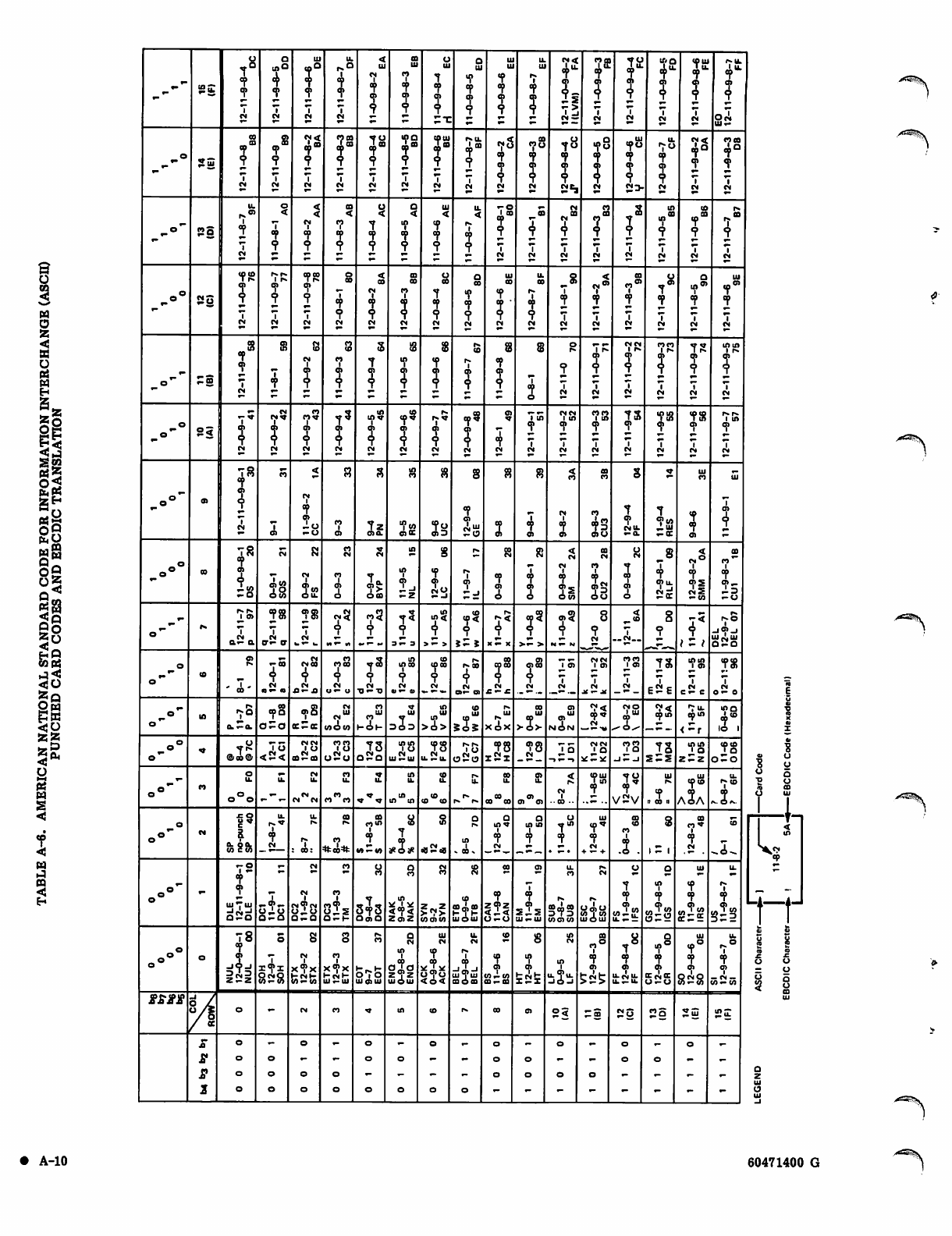
85
<
B
O
PS
w
H
5-
So
wg
°^
SB
5°
*°
•^3
Ow
SI
*§
o
s
W
s
w
CQ
<S
E-
^--S£
i8
7
7
IM CM
Ul
r
2
CM
u.
4
2
7
CM
Ul
CM
7
I
IU
7
7
I
UJ
7
7
?
Ul
7
7
I
Ul
Ul
?
I
u.
Ul
7
7
J
tf<
4'
?-
Is
->
2«
I
7
CM
70
in
CM
1 T'0
1 oS)"-
7
CM
IO Ul
T . U .
7
J
7
CM
• U .
s5
o25
09
m f fl
I
T
CM CM
4°
?
7
CM
78
7
2
7
CM
xfta
7
2
7
CM
too
!"
CM
7g
I
7
CM
cyu.
I
7
CM
f3
?
CM CM
t8
7
?
ing
7
?
CM
Ul
I0O
7
7
7
£!>
7o
7
7
7
CM
7<
So
7
7
7
CM
?8
2
7
CM
o*" "§
CM
CM
1
7
7
CD
<
7
?
UJ
<
7
7
7
U.
<
1
7
7
•■o
7
7
i
CM CM
CM
?"
1
CM
CT
?
IM CM
in
CO
in
1
7
1
CM
10
m
?
1
CM
?"
1
CM
po8 So
72
i
fM
i r»
7
?
7
CM
7S
7
2
7
CM
eo
7
7
7
CM
es
?
7
CM
aa
00
CT
?
CM
00
7
7
7
CM
00
7
?
CM
Ul
00
7
I
CM
u.
es
t
CM
-8
7
7
CM
7*
7
7
CM
CT*
1
7
CM
7*
7
7
CM
70>
2
7
CM
Ul
7W
7
7
CM
o"" •-S CM
S3
7
7
CM
ct
7
?
1".
<0
?CM
1 r *
f
7
CM
CM CM
1 r»
I
7
CM
CTCT
1 !«•
1
7
CM
7S
7
2
7
CM
mm
1 r»
I
CM
o
o"" 2§
CM
CM
C M ^
?
CM CM CM
mS
CM
to!?
?
CM
7*
?
CM
op™
?
CM
0)
?
CM
75
7
7
CM
CM CM
i m
7
7
CM
on
CM
7S
7
CM
78
7
CM
78
7
7
CM
r » r « .
1 m
7
CM
^o°~ 0)
78
7
I
7
CM
CM
1
7
7
-O
-o
CO1
0) 0)0. ence 7«
cn3 CM1"
tO ca
CT
CM
1
7
01
00
CT
CT 43
0)0 Set 7s
- c c
Ul
CT
7
7
01
ui
cn
4
„o«° OS
78
7
?
CM
4s
OM
CM
22
CM
O
i
CM
ooo
IO
i
!-. CA
o
CM
7
7
OOT
09
CM
7
7
S3
CM
?
I
-8
7
7
o>u.
CM°
1
7
imS
— OT
CO
CT*"
4
o> —
tZX
— 0
o*~ r»
1 0)
a2a CM
or— er
785
7
CM
co<
t7?
2
3 f 3
in
in<
j
> T >
(0
V
i T i >— >
c.2
7CM
— *
7
— C M _ _ i - /
7S
_jo>_i
SSo
o
o"* co - 5- 45
CM
o — a
CM
CMOS
4
CM
.0—JS
CT
coco
7
CM
S I T o
xtSO
7
CM
•Qt-O
in
in co
7
CM
(0
CM
i»
r»0B
7
CM
0»— O)
00
cj"
CM
£ — £
CM
75
7
CM
1 0 1
7
CM
JtTjt
CTCT
1 0 1
7
CM
7S
eSe
mm
1 cn
CM
e— c
7$
7
CM
O — 0
o"" l "
c u t a .
OS
OOO
O-O (C-CC
CM
2"
wow
CT
CT1" ,£ in
7
>ei>
<0
Ul Ul
i^
xox
OS
>2>
0)
NON
op«
CM
CMO
J,tU ap in
fu.
m i n 2§
1,
o*" 1*
©CO® < — <
CM CM
1 C J
0,2a,
coco
qSd 78
uiSu. 78
u.Su. o2o 78
i2i 78
CM 75 CM CM
' o
xt-xc
CTCT
1 a
-1 — -1 ts
s-s
mm
1 O
ZtZ 7g
0-0
o°~ CT u.
o ° o
u. CM
U.
CM
C M C M
p»
u.
CT
C T C O
u. IA
U.
in
i n u i
(0
u.
(0
( 0 ( 0
u. 00
IL
00
0 0 C O
0)
U.
cn
0 ) 0 ) ■ ■CO •■
SO Ul
7v 2 v
Ul
7
11 a 11
III
t o g
A 2 A
u.
r ^ t n
1
o
IM 15
cl
u.
I
CM
U.
7
: 0 0 :
CO
7
CO
CT<n
i
7
tn — t/i #o# «S<a
in
» to
i n v
i
7
CM
i n i n
iJ" Ul
7'
7
CM
+ — +
CO
1
2. 1 - 1
7*
7
CM
o°°'
— O
1 —
7
2
UJ —UJ
a** -q>-
tlr-tl
O - O
CM
CM
sis
O-O
CT
CT
s!5
O-t-
CT
3?3
OenO <7<
z«z W01M
to
CM
7
CO m CO
UIOUJ
OS
7
Z9z
< T <
cn
7
7
°?
5J.5
U J — U J
u.
CT
l»
co oo as
OTC0OT
CM
U(j|U
WTW
UIOUI
cn
si? «»7w
O t x 2
Ul
7
7
OT7w
cc-£
u.
r«
1
7
S?2
oo"°
78
7
A-
= C M = 8~8
CM
tests
CT
HCNt-
ui-ui
CT
o7o
UJ01UI
CM
in
l
a a t a
z?z
UJOUI
UJ
CM
7
v T w
<o<
U.
CM
7
Sl7u
ooooo
(0
?
O T — W
ffi— oa
in
7
»"CM^
CM
m
as
«°
i
7
an
T8
7
7
It Sit
7°
4
7
KcmOC
O - O
2§
Ul
7°
7
0)
828
22
u.
4
Ol
— CM —
W — O T
tfSXX
CM CT in ID r» CO cn s< —s -2
2
o
o
o
o
o
o
o
O
o
o
o
o
o
o
o
O
o
O
OO
o
o
o
o
o
o
oo
0
0
/*S*?!\
ui
-In
^2
rr
.^-*^s
A-10 60471400 G
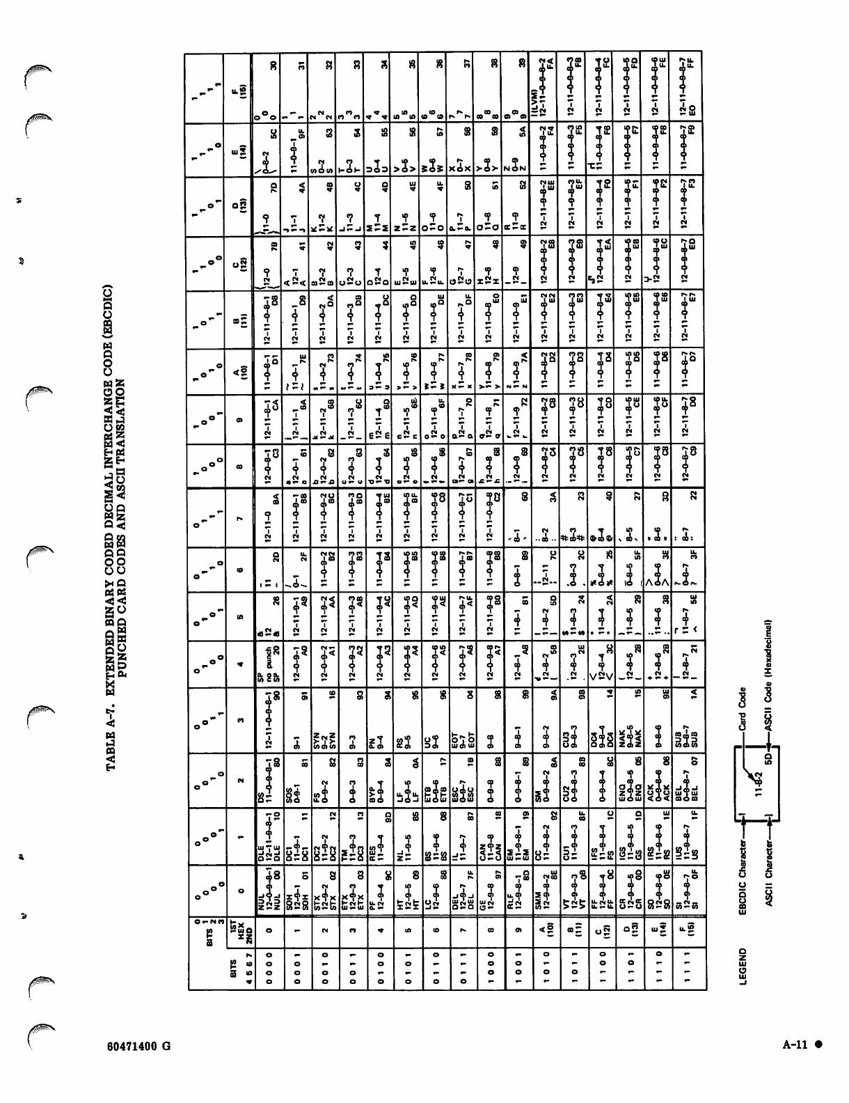
0 ^ S gg
£^
Og
w<
BB
gg
Q9
oo
oo
*9
curt
cap
gg
En tti
r<
H
o«
«s
4s
IO
WOW
<
._— ._ Jt — 4t
to it -
{2 IO
3 i n
|8
&
OT C W
4*
I
UJ —ui
O - O
IS
is8
4
8S8
-2. =2=
7
s-s
ZCMZ
> 1 >
M O W
■ik
x4x
teste
**8
x4x
l-CM»-
Ul —U l
eSe
>2> 5 i S
z7
0.05 22
£st
XO)
ul2tu
5s°
Ul*"
NON
5-
7
2=5
'CO'
33
..CO =*»=«=
8=
17
Ss
<s
ss
2C
7
7
7S
>S
SsS
7*
7
vsv
3?3
OoiQ
Siffi
co.
z7z
UIO UI
3?«3
o™
I u.
7
A 2 A
2?8
8S8
t a x :
4
rs <
7
-im-)
UITUI
COO CO
Sis
i ?
I Q
-I-
Q
m
t o b
I I
o o
o =
5 «
60471400 G A - l l •
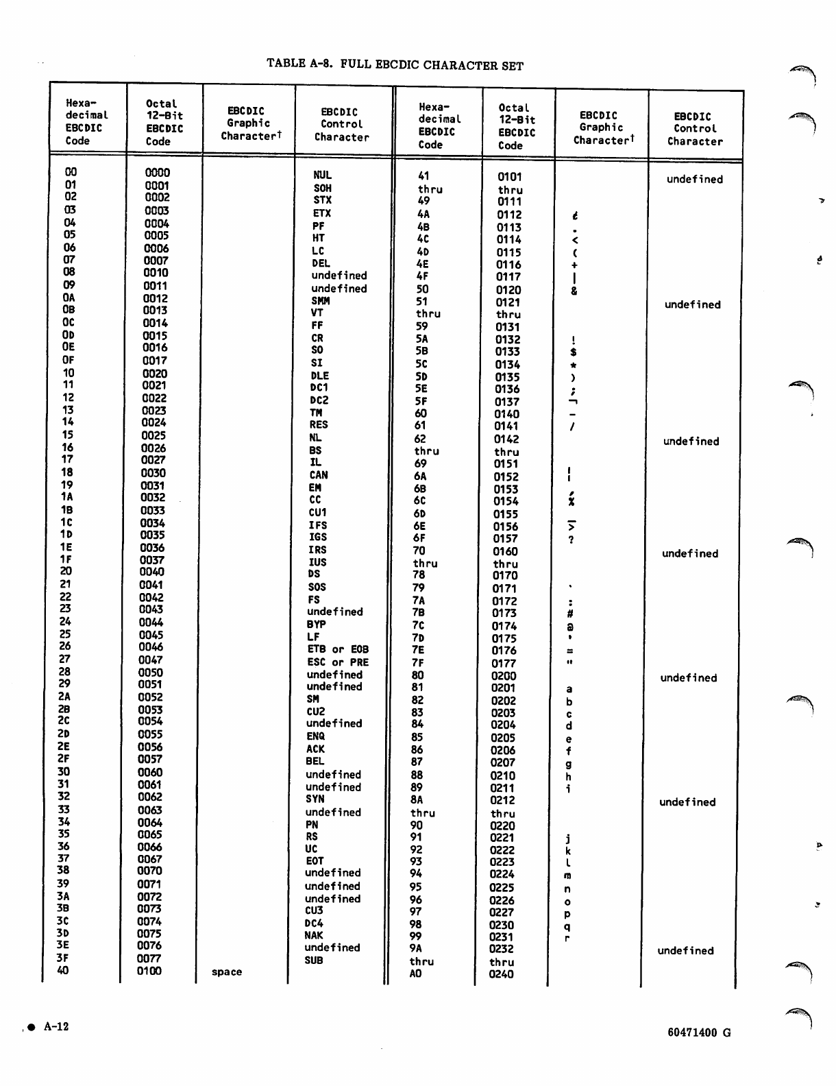
TABLE A-8. FULL EBCDIC CHARACTER SET
Hexa
decimal
EBCDIC
Code
Octal
12-Bit
EBCDIC
Code
EBCDIC
Graphic
Charactert
EBCDIC
Control
Character
Hexa
decimal
EBCDIC
Code
Octal
12-Bit
EBCDIC
Code
EBCDIC
Graphic
Character1
EBCDIC
Control
Character
00 0000 NUL 41 0101 undefined
01 0001 SOH thru t h r u
02 0002 STX 49 0111
03 0003 ETX 4A 0112
04 0004 PF 4B 0113
05 0005 HT 4C 0114
06 0006 LC 4D 0115
07 0007 DEL 4E 0116
08 0010 undefined 4F 0117
09 0011 undefined 50 0120
OA
OB
0012
0013 SMM
VT
51
t h r u
0121
thru
undefined
OC 0014 FF 59 0131
OD 0015 CR 5A 0132
OE 0016 SO 5B 0133
OF 0017 SI 5C 0134
10 0020 DLE SD 0135
11 0021 DC1 5E 0136
12 0022 DC2 5F 0137 -i
13 0023 TM 60 0140
14 0024 RES 61 0141
15 0025 NL 62 0142 undefined
16 0026 BS t h r u t h r u
17 0027 IL 69 0151
18 0030 CAN 6A 0152
19 0031 EM 6B 0153
1A 0032 CC 6C 0154
1B 0033 CU1 6D 0155
1C 0034 IFS 6E 0156 >"
1D 0035 IGS 6F 0157
1E 0036 IRS 70 0160 undefined
1F 0037 IUS thru t h r u
20 0040 DS 78 0170
21 0041 SOS 79 0171
22 0042 FS 7A 0172
23 0043 undefined 7B 0173
24 0044 BYP 7C 0174
25 0045 LF 7D 0175
26 0046 ETB or EOB 7E 0176
27 0047 ESC or PRE 7F 0177 •i
28 0050 undefined 80 0200 undefined
29 0051 undefined 81 0201
2A 0052 SM 82 0202
2B 0053 CU2 83 0203
2C 0054 undefined 84 0204
2D 0055 ENQ 85 0205
2E 0056 ACK 86 0206
2F 0057 BEL 87 0207
30 0060 undefined 88 0210
31 0061 undefined 89 0211
32 0062 SYN 8A 0212 undefined
33 0063 undefined t h r u thru
34 0064 PN 90 0220
35 0065 RS 91 0221
36 0066 UC 92 0222
37 0067 EOT 93 0223
38 0070 undefined 94 0224
39 0071 undefined 95 0225
3A 0072 undefined 96 0226
3B 0073 CU3 97 0227
3C 0074 DC4 98 0230
3D 0075 NAK 99 0231
3E 0076 undefined 9A 0232 undefined
3F 0077 SUB t h r u thru
40 0100 space AO 0240
><^^V
• A-12 60471400 G
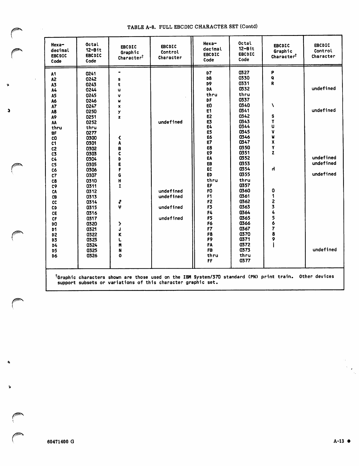
TABLE A-8. FULL EBCDIC CHARACTER SET (Contd)
/g|ps\
Hexa Octal EBCDIC EBCDIC Hexa Octal EBCDIC EBCDIC
decimal
EBCDIC
Code
12-Bit
EBCDIC
Code
Graphic
Character*
Control
Character
decimal
EBCDIC
Code
12-Bit
EBCDIC
Code
Graphic
Character1
Control
Character
A1 0241 D7 0327
A2 0242 D8 0330
A3 0243 D9 0331
A4 0244 DA 0332 undefined
A5 0245 t h r u t h r u
A6 0246 DF 0337
A7 0247 EO 0340
A8 0250 E1 0341 undefined
A9 0251 E2 0342
AA 0252 undefined E3 0343
thru thru E4 0344
BF 0277 E5 0345
CO 0300 E6 0346
C1 0301 E7 0347
C2 0302 E8 0350
C3 0303 E9 0351
C4 0304 EA 0352 undefined
C5 0305 EB 0353 undefined
C6 0306 EC 0354 rl
C7 0307 ED 0355 undefined
C8 0310 t h r u t h r u
C9 0311 EF 0357
CA 0312 undefined FO 0360
CB 0313 undefined F1 0361
CC 0314 •P F2 0362
CD 0315 undefined F3 0363
CE 0316 F4 0364
CF 0317 undefined F5 0365
DO 0320 F6 0366
D1 0321 F7 0367
D2 0322 F8 0370
D3 0323 F9 0371
D4 0324 FA 0372
D5 0325 FB 0373 undefined
D6 0326 t h r u
FF
t h r u
0377
TGraphic characters sshown are those used on the IBM System/370 standard (PN) print train. Other devices
support subsets or vva ri at ions of th i s character g raphic se t.
60471400 G A-13 •
NETWORK ACCESS METHOD
TERMINAL TRANSMISSION CODE SETS
There are two modes in which coded character data can be
exchanged with a network terminal console. These two
modes, character mode and transparent mode, correspond
to the type of character code editing and translation
performed by the network software during input and output
operations. The transmission mode used by the network
software for input can be selected by the terminal
operator, using a Terminal Interface Program command
(sometimes referred to as a terminal definition command).
The transmission mode used by the network software for
output can be selected by the application program
providing the terminal facility service.
Character Mode Transmissions
Character mode is the initial and default mode used for
both input and output transmissions. When the network
software services the terminal in character mode, it
translates input characters from the transmission code
used by the terminal into the ASCII code shown in
table A-9. The translation of a specific transmission code
to a specific ASCII code depends on the terminal class the
network software associates with the terminal. In
character mode input, the parity of the terminal
transmission code is not preserved in the corresponding
ASCII code; the ASCII code received by the
terminal-servicing facility program always has its eighth
bit set to zero.
Character mode output is translated in a similar manner.
The network software provides the parity bit setting
appropriate for the terminal being serviced, even though
translating from ASCII characters with zero parity bit
settings.
Tables A-10 through A-21 show the character mode
translations performed for each terminal class. The parity
shown in the terminal transmission codes is the parity used
as a default for the terminal class. The parity setting
actually used by a terminal can be identified to the
network software through a TIP command.
Tables A-10 through A-21 contain the graphic and control
characters associated with the transmission codes used by
the terminal because of the terminal class and code set in
use. The network ASCII graphic and control characters
shown are those of the standard ASCII character set
associated with the ASCII transmission codes of table A-9.
The general case for code translations of character mode
data is summarized in the following paragraphs. This
generalized description permits use of only table A-9 to
explain all specific cases. The reader can logically extend
this generalized description to allow use of tables A-l
through A-8 as descriptions of character set mapping for
various functions initiated from a terminal. Tables A-l
through A-8 are provided for the reader's use while coding
an application program to run under the operating system.
They do not describe character transmissions between an
application program and the network.
Table A-9 contains the ASCII 128-character set supported
by the Network Access Method. A 96-character subset
consists of the rightmost six columns and includes the
95-character graphic subset referenced previously in this
appendix; the deletion character (DEL) is not a graphic
character. A 64-character subset consists of the middle
four columns. Note that 6-bit display code equivalents
exist for the characters in this 64-character subset only.
Although the network supports the 128-character set, some
terminals restrict output to a smaller subset. This
restriction is supported by replacing the control characters
in columns 0 and 1 of table A-9 with blanks to produce the
96-character subset, and, additionally, replacing the
characters in columns 6 and 7 with the corresponding
characters from columns 4 and 5, respectively, to produce
the 64-character subset.
Similarly, input from a device may be limited to a smaller
subset by the device itself because the device cannot
produce the full 128-character set. A character input from
a device using a character set other than ASCII is
converted to an equivalent ASCII character; characters
without ASCII character equivalents are replaced by the
ASCII blank character.
An application can also cause character replacement (as
described previously for output) as well as character
conversion, by requesting display-coded input from the
network.
The 7-bit hexadecimal code value for each character
consists of the character's column number in the table,
followed by its row number. For example, N is in row E of
column 4, so its value is 4E1g.
Transparent Mode Transmissions
Transparent mode is selected separately for input and
output transmissions. During transparent mode input, the
parity bit is stripped from each terminal transmission code
(unless the N parity option has been selected by a Terminal
Interface Program command), and the transmission code is
placed in an 8-bit byte without translation to 7-bit ASCII
code. Line transmission protocol characters are deleted
from a mode 4C terminal input stream.
When the 8-bit bytes arrive in the host computer, a
terminal servicing facility program such as the Interactive
Facility can right-justify the bytes within a 12-bit byte.
Upon transmission of 12-bit bytes from the host computer,
the leftmost 4 bits (bits 11 through 8) are discarded.
During transparent mode output, processing similar to that
performed for input occurs. The code in each 8-bit byte
received by the network software from the terminal
servicing facility program is not translated. The parity bit
appropriate for the terminal class being used is altered as
indicated by the parity option in effect for the terminal.
The codes are then output in transmission bytes
appropriate for the codes associated with the terminal
class being used. Line transmission protocol characters are
inserted into a mode 4C terminal output stream.
• A-14 60471400 G
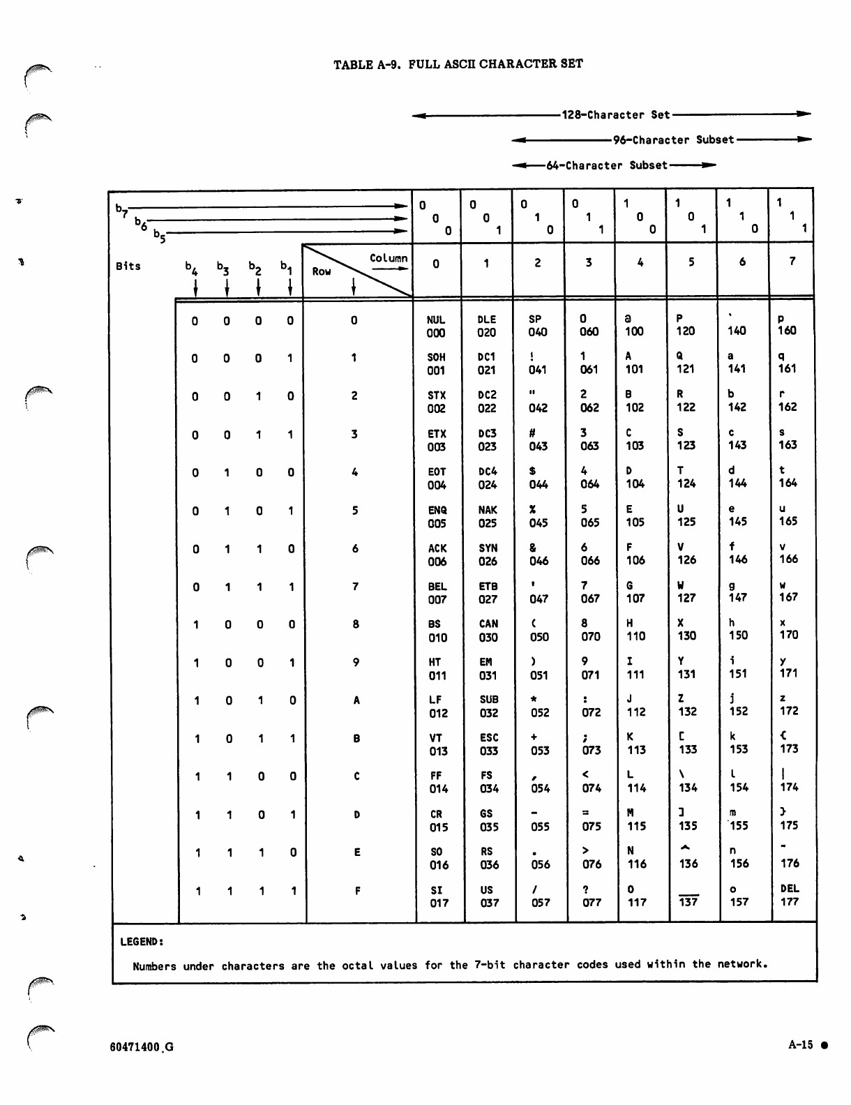
TABLE A-9. FULL ASCII CHARACTER SET
■128-Character Set-
•96-Character Subset-
■64-Character Subset ***■
00m*_
B i t s b ^ b j b 2 b , , Column
tttt
oooo
0 0 0 1
0 0 1 0
0 0 1 1
0 1 0 0
0 1 0 1
0 1 1 0
0 1 1 1
0 0 0
0 0 1
0 1 0
0 1 1
1 0 0
1 0 1
1 1 0
1 1 1
NUL
000
SOH
001
STX
002
ETX
003
EOT
004
ENQ
005
ACK
006
BEL
007
BS
010
HT
011
LF
012
VT
013
FF
014
CR
015
SO
016
SI
017
DLE
020
DC1
021
DC2
022
DC3
023
DC4
024
NAK
025
SYN
026
ETB
027
CAN
030
EM
031
SUB
032
ESC
033
FS
034
GS
035
RS
036
US
037
SP
040
i
041
042
tt
043
$
044
X
045
&
046
047
(
050
)
051
*
052
+
053
054
055
056
/
057
060
1
061
2
062
3
063
4
064
5
065
6
066
7
067
8
070
9
071
072
073
<
074
075
>
076
?
077
100
A
101
B
102
C
103
D
104
E
105
F
106
G
107
H
11 0
I
111
J
11 2
K
113
L
11 4
M
115
N
11 6
0
117
120
Q
121
R
122
S
123
T
124
U
125
V
126
W
127
X
130
Y
131
Z
132
C
133
\
134
:
135
136
137
140
a
141
b
142
c
143
d
144
e
145
f
146
9
147
h
150
i
151
j
152
k
153
I
154
m
155
n
156
o
157
160
q
161
r
162
s
163
t
164
u
165
v
166
w
167
x
170
y
171
z
172
<
173
174
>
175
176
DEL
177
LEGEND:
Numbers under characters are the octal values for the 7-bit character codes used within the network.
60471400 G A-15 •
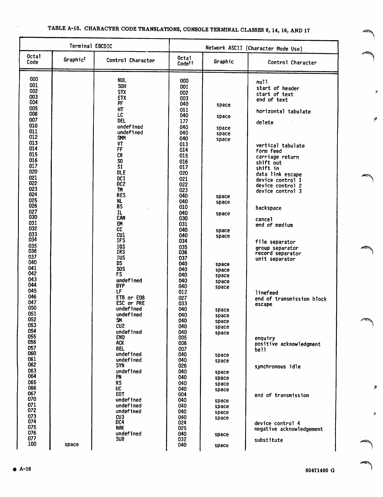
TABLE A-10. CHARACTER CODE TRANSLATIONS, CONSOLE TERMINAL CLASSES 9, 14, 16, AND 17
Terminal EBCDIC Network ASCII Character Mode Use)
Octal
Code Graphict Control Character Octal
Codett Graphic Control Character
000 NUL 000 null
001
002 SOH 001 start of header
STX 002 start of text
003
004 ETX
PF 003
040 space
end of text
005
006 HT
LC Oil
040 space
horizontal tabulate
007 DEL 177 delete
010 undefined 040 space
011 undefined 040 space
012 smm 040 space
013 VT 013 vertical tabulate
014 FF 014 form feed
015 CR 015 carriage return
016 SO 016 shift out
017 SI 017 shift in
020 DLE 020 data link escape
021 DC1 021 device control 1
022 DC2 022 device control 2
023 TM 023 device control 3
024 RES 040 space
025 NL 040 space
026 BS 010 backspace
027 IL 040 space
030 CAN 030 cancel
031 EM 031 end of medium
032 CC 040 space
033 CU1 040 space
034 IFS 034 file separator
035
036 IGS 035 group separator
IRS 036 record separator
037
040 IUS
DS 037
040 space
unit separator
041 SOS 040 space
042 FS 040 space
043 undefined 040 space
044 BYP 040 space
045 LF 012 linefeed
046 ETB or EOB 027 end of transmission block
047 ESC or PRE 033 escape
050 undefined 040 space
051 undefi ned 040 space
052 SM 040 space
053 CU2 040 space
054 undefined 040 space
055 ENO 005 enquiry
056 ACK 006 positive acknowledgment
057 BEL 007 bell
060 undefined 040 space
061 undefi ned 040 space
062 SYN 026 synchronous idle
063 undefi ned 040 space
064 PN 040 space
065 RS 040 space
066 UC 040 space
067 EOT 004 end of transmission
070 undefined 040 space
071 undefined 040 space
072 undefined 040 space
073 CU3 040 space
074 DC4 024 device control 4
075 NAK 025 negative acknowledgement
076 undefined 040 space
077 SUB 032 substitute
100 space 040 space
A-16 60471400 G
y ^ K v
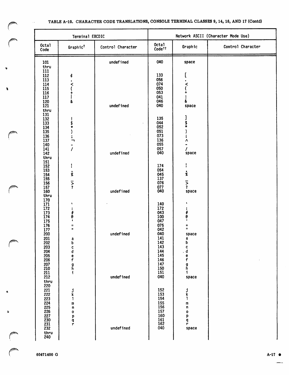
TABLE A-10. CHARACTER CODE TRANSLATIONS, CONSOLE TERMINAL CLASSES 9, 14,16, AND 17 (Contd)
Terminal EBCDIC Network ASCII (Character Mode Use)
Octal
Code Graphic* Control Character Octal
Codett Graphic Control Character
101 undefined 040 space
thru
111
112 133
113 056
114 074
115 050
116 053
117 041
120 046
121 undefined 040 space
thru
131
132 135
133 044
134 052
135 051
136 073
137 -i 136
140 055
141 057
142 undefined 040 space
thru
151
152 174
153 054
154 045
155 137
156 076
157 077
160 undefined 040 space
thru
170
171 140
172 172
173 043
174 100
175 047
176 075
177 ii 042 ii
200 undefined 040 space
201 141
202 142
203 143
204 144 . d
205 145
206 146
207 147
210 150
211 151
212 undefined 040 space
thru
220
221 152
222 153
223 154
224 155
225 156
226 157
227 160
230 161
231 162
232 undefined 040 space
thru
240
60471400 G A-17 •
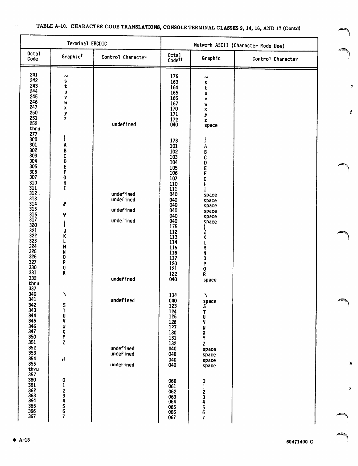
TABLE A-10. CHARACTER CODE TRANSLATIONS, CONSOLE TERMINAL CLASSES 9, 14, 16, AND 17 (Contd)
Octal
Code
241
242
243
244
245
246
247
250
251
252
thru
277
300
301
302
303
304
305
306
307
310
311
312
313
314
315
316
317
320
321
322
323
324
325
326
327
330
331
332
thru
337
340
341
342
343
344
345
346
347
350
351
352
353
354
355
thru
357
360
361
362
363
364
365
366
367
Terminal EBCDIC
Graphic1 Control Character
undefined
undefined
undefined
undefined
undefined
undefined
undefined
undefined
undefined
undefined
Network ASCII (Character Mode Use)
Octal
Codett
176
163
164
165
166
167
170
171
172
040
173
101
102
103
104
105
106
107
110
111
040
040
040
040
040
040
175
112
113
114
115
116
117
120
121
122
040
134
040
123
124
125
126
127
130
131
132
040
040
040
040
060
061
062
063
064
065
066
067
Graphic
s
t
u
v
w
x
y
z
space
A
B
C
D
E
F
G
H
I
space
space
space
space
space
space
J
K
L
M
N
0
P
Q
R
space
\
space
S
T
U
V
w
X
Y
Z
space
space
space
space
Control Character
aZSS
A*%S
A ^ S
A-18 60471400 G
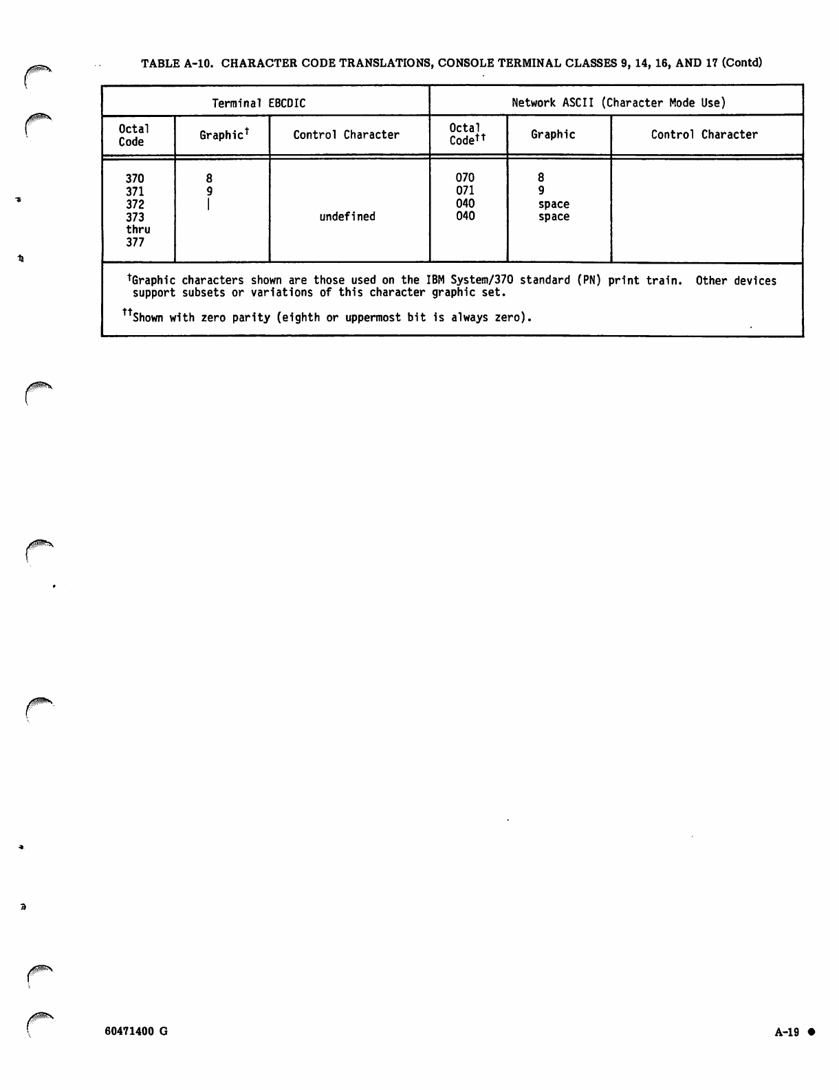
TABLE A-10. CHARACTER CODE TRANSLATIONS, CONSOLE TERMINAL CLASSES 9, 14, 16, AND 17 (Contd)
0<$M^x\
y$f^\
Terminal EBCDIC Network ASCII (Character Mode Use)
Octal
Code Graphic1 Control Character Octal
Codett Graphic Control Character
370
371
372
373
thru
377
undefined
070
071
040
040 space
space
tGraphic characters shown are those used on the IBM System/370 standard (PN) print train. Other devices
support subsets or variations of this character graphic set.
Shown with zero parity (eighth or uppermost bit is always zero).
60471400 G A-19
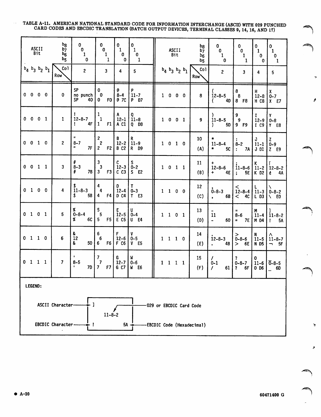
TABLE A-ll. AMERICAN NATIONAL STANDARD CODE FOR INFORMATION INTERCHANGE (ASCH) WITH 029 PUNCHED
CARD CODES AND EBCDIC TRANSLATION (BATCH OUTPUT DEVICES, TERMINAL CLASSES 9, 14, 16, AND 17)
ASCII
Bit
b4 b3 b2 bx
h8
h7
b6
b5
ASCII
Bit
b4 b3 b2 bx
S7 b6
b5
\ c o l
RowN.
\ C o l
Row\
0 0 0 0 SP
no punch
S P 4 0 F0
8-4
9 7C
11-7
P 07
1 0 0 0 12-8-5
( 4 D 8 F8
12-8
H C8 0-7
X E7
0 0 0 1 12-8-7
! 4 F Fl
12-1
A Cl
11-8
Q D8
1 0 0 1 11-8-5
) 5 D 9 F9
12-9
I C9
0-8
Y E8
0 0 1 0
ii
8-7
7F F2
12-2
B C2
11-9
R D9
1 0 1 0
10
(A)
11-8-4
* 5 C 8-2
: 7 A
11-1
J Dl
0-9
Z E9
0 0 1 1 8-3
# 7 B F3
12-3
C C3
0-2
S E2
1 0 1 1
11
(B)
12-8-6
+ 4 E 11-8-6
; 5 E
11-2
K D2 12-8-2
t 4 A
0 1 0 0 11-8-3
$ 5 B F4
12-4
D C4
0-3
T E3 1 1 0 0
12
(C)
6-8-3
6B
12-8-4
< 4 C 11-3
L D3
0-8-2
\ E0
0 1 0 1 0-8-4
% 6 C F5
12-5
E C5
0-4
U E4
1 1 0 1
13
(D)
ii
60
8-6
= 7 E 11-4
M D4
11-8-2
! 5 A
0 1 1 0 12
& 5 0 F6
12-6
F C6
0-5
V E5 1 1 1 0
14
(E)
12-8-3
4B
0-8-6
> 6 E
11-5
N D5 11-8-7
- i 5 F
0 1 1 1 8-5
7D F7
12-7
G C7
0-6
W E6 1111
15
(F)
0-1
/ 6 1
0-8-7
? 6 F
11-6
0 D6
0-8-5
6D
LEGEND:
ASCII
EBCDIC
Characte
Characte
or EBCDIC Card
DIC Code (Hexad
Code
ecimal)
Ij
11-8
1 _
i
/
-2
5A — c a r *
'■" * t B L
A-20 60471400 G
■*^5?v
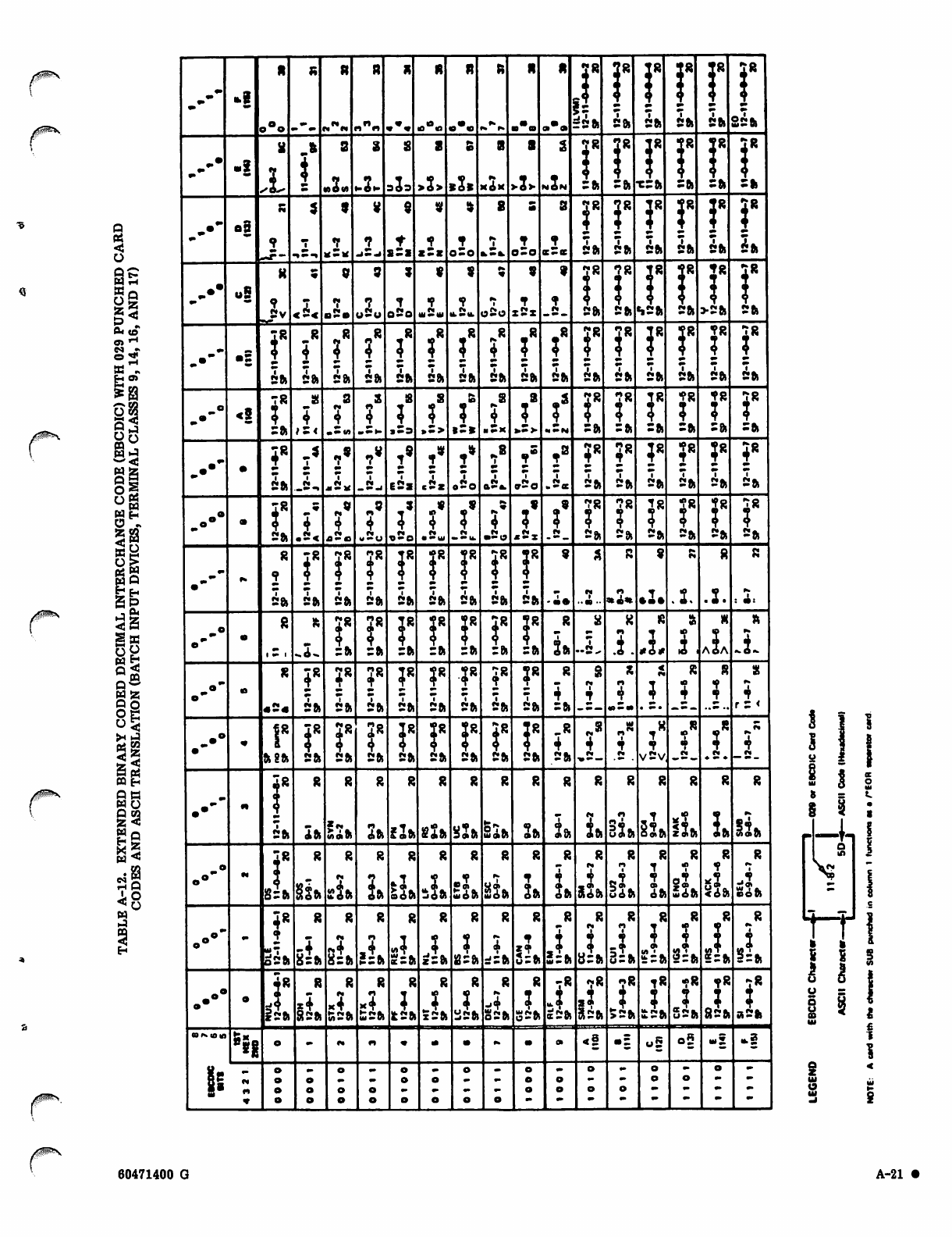
/!$W*P^S
Ct
<
o
as
oS
04 <0
SS .,
tt ax
8
085
8*
§3
SB
Sp
1 0*
Ss
Bo
w£
WZ
QO
o§
§|
S Oj
S£
Q»
WO
gS
6§
B3
fH Q
H
rr
9
»!
ft ft ft ft ft
1?
t8
o°o m m N^M «■%» »*• -•\. •*• ■ a••• £st. 2 f t 2ft 2 f t 2ft
2 f t
-•
^
^-I
MOM 343 >2> MON :ft
78
*ft XSfc
J8
Sft
28
2 f t
_ • - 08
»
_<2.j 0-0 a, to. 0-0 Ss. 5ft 5ft 2ft 2 f t 2 f t
K 9 9999t. 2» J8 JR JR
„•• u5 •? K.
5v <i< o2o r,*r\ w2w . 5 . »2o x 2 x 2 f t 2 f t «»2fc 2ft >2fc 2 f t
■5?8 ?* !R !'
^2 f t 2 f t 2 f t 2 f t 2ft 2ft 2ft 2 f t 2ft 2 f t 2 f t 2ft 2ft 2ft 2 f t
78 „s i" 28 "?8 J"
<5
Stl c< «s«» »Ss »£> » = * ■ Sx >z> ••••M =& =ft Sft 2ft Sft 2 f t
i8
..•• iR ,5
1i« 2* j' 2* J* .8
1IB 1* ?8
4i8 i" J"
^-2* .5j E2s c2, «2o a2«. c/2o 2 f t 2 f t 2 f t 2ft 2fc 2 f t
78 «* _. • .9 «• 2s 2s 2» 28 -R
.•• 5ft .5< *2« «2o .So IS •20 .:< 2 f t 2 f t 2 f t 2ft 2 f t 2ft
^f»
2R JR i8 r\
i»
M
•
2ft 2ft 2 f t 2 f t 2 f t ift 5ft 2 f t 2 f t • •• ■•a ■•*a« »2. .2. .2.
0
o"
1«»1
ft i: i: i: =ft
J8
=ft ift .-!L i.
XX
.1 i.A 2 A
ft
_•» XX 4* ?R ?■?R 4R ;r <9
o- «s« 2 f t 2 f t =» 2ft 2ft 2ft 2ft 2ft Cft •»-•» . s. —-..-.. r = <
_.° I8 "0 n0 iR -R
4.a
4i8
i>
p.
4
ft 8ft 2& 2ft 2ft 2ft 2 f t 2 f t 2ft 2ft 2ft •»—— V2v ♦ ^ •
f888888888888 8 8
mm «t
•
2 f t Itt IAAOI cjift ;2ft £2ft ^ f t ti 1 m. aft «8l I, uaft oaft 5?
zaft 2ft Kaft
4Ra•- r»
o°~ 8=fc Sift sift 1* caoft ^ift .3
Lift lil oft 3ft 3ft loft SSft eft uioft < i f t nod
4*
. • • " -4 <* ,4 -? 4. 5ff
IM
5? Ox si* 2 = fc
*2fc 8 = ft 8=fc i=fc £=ft gzft t i r b 5=ft t w ^ f t y=ft d=ft Ssft 5 = fc
/
8888 8 8 8 83R 28 28 T« 78 t« 7R
.-•• t4 .? *4 -4 -J -*
rf5ft sift S»2ft £2* It 2ft sin 32ft
•
Ssft IMISIL a2ft 42ft 52fc £2ft 52ft y2ft a2ft
COK 10 M)
* ! | <§ • : u5 o9 w| *!
^0r.
8 5 « •• ••
g» « rr
<» ""
1 ] j
i ! !
S = C
S 3 ;
o
rr
i i
60471400 G A-21 •
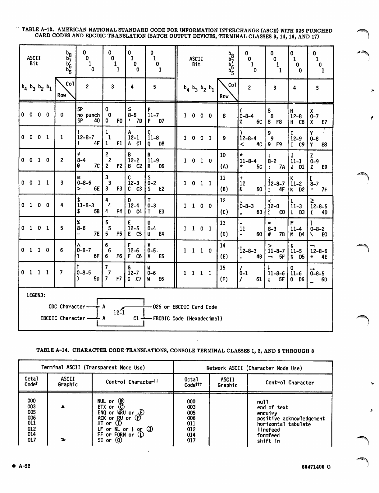
TABLE A-13. AMERICAN NATIONAL STANDARD CODE FOR INFORMATION INTERCHANGE (ASCII) WITH 026 PUNCHED
CARD CODES AND EBCDIC TRANSLATION (BATCH OUTPUT DEVICES, TERMINAL CLASSES 9, 14, 16, AND 17)
ASCII
Bit
b4 b3 b2 bj
b5
ASCII
Bit
b4 b3 b2 bl
bb8
h7
b5
\ Col
Row\
\ C o l
Row\
0 0 0 0
SP
no punch
S P 4 0 F0
8-5
« 7D 11-7
P D7
1 0 0 0-8-4
% 6 C 8 F8
12-8
H C8 0-7
X E 7
0 0 0 1 i2-8-7
! 4 F Fl
12-1
A Cl
11-8
Q D8
1 0 0 12-8-4
< 4 C 9 F9
12-9
I C9
0-8
Y E 8
0 0 1 0 8-4
9 7 C F2 12-2
B C2
11-9
R D 9
1 0 1 10
(A)
11-8-4
* 5 C 8-2
: 7 A 11-1
J Dl
0-9
Z E 9
0 0 1 1 0-8-6
> 6 E F3 12-3
C C3
0-2
S E 2
1 0 1
11
(B)
12
& 5 0 12-8-7
J 4 F
11-2
K D2
8-7
" 7 F
0 1 0 0 11-8-3
$ 5 B F4
12-4
D C4
0-3
T E 3
1 1 0
12
(C)
6-8-3 6B
12-0
{ C O
11-3
L D3
12-8-5
( 4 D
0 1 0 1 8-6
7E F5 12-5
E C5
0-4
U E4 1 1 0
13
(D)
11
60
8-3
# 7 B
11-4
M D4
0-8-2
\ E 0
0 1 1 0 0-8-7
? 6 F F6 12-6
F C6
0-5
V E 5
1 1 1 14
(E)
i2-8-3
4B
11-8-7
- i 5 F 11-5
N D5
12-8-6
+ 4 E
0 1 1 1 0-8-5
) 5 D F7 12-7
G C7
0-6
W E6
1 1 1 15
(F)
0-1
/ 6 1
11-8-6
; 5 E
11-6
0 D6
£-8-5
6D
LEGEND:
CD
EBCDI
C Chara(
C Charac
noc «w r BCDIC Card Code
ode (Hexadecima1)
A
A
1
j r . U L U U l L
12-1 n — 1 c o r r t T r r
IL.t3\,Ultr t,
TABLE A-14. CHARACTER CODE TRANSLATIONS, CONSOLE TERMINAL CLASSES 1, 2, AND 5 THROUGH 8
Terminal ASCII (Transparent Mode Use) Network ASCII (Character Mode Use)
Octal
Codet
ASCII
Graphic Control Character^ Octal
Codettt
ASCII
Graphic Control Character
000
003
005
006
011
012
014
017
NUL or ®
ETX or ©
ENQ or WRU or J)
ACK or RU or ©
HT or 0
LF or NL or 1 or 0
FF or FORM or 0
SI or ®
000
003
005
006
Oil
012
014
017
null
end of text
enquiry
positive acknowledgement
horizontal tabulate
linefeed
formfeed
shift in
• A-22 60471400 G
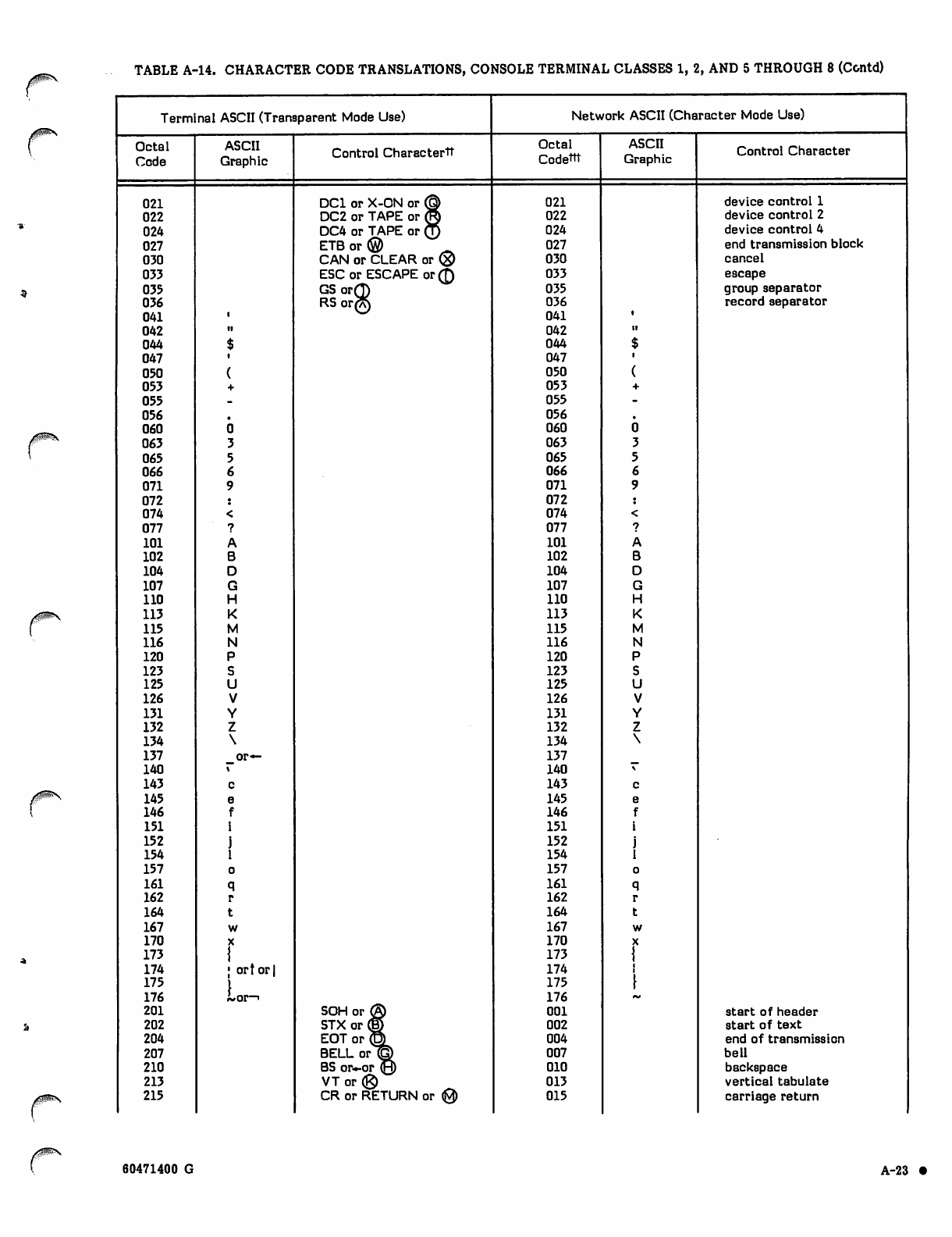
ygS&N. TABLE A-14. CHARACTER CODE TRANSLATIONS, CONSOLE TERMINAL CLASSES 1, 2, AND 5 THROUGH 8 (Contd)
Terminal ASCII (Transparent Mode Use) Network ASCII (Character Mode Use)
Octal
Code
ASCII
Graphic Control Charactertt Octal
Codettt
ASCII
Graphic Control Character
021 DC1 or X-ON or @ 021 device control 1
022 DC2 or TAPE or (ft 022 device control 2
024 DC4 or TAPE or Q 024 device control 4
027 E T B o r © _ 027 end transmission block
030 CAN or CLEAR or ® 030 cancel
033 ESC or ESCAPE or 0 033 escape
035 GS orQ 035 group separator
036 RS or?A) 036 record separator
041 041
042 •i 042 ii
044 044
047 047
050 050
053 053
055 055
056 056
060 060
063 063
065 065
066 066
071 071
072 072
074 074
077 077
101 101
102 102
104 104
107 107
110 110
113 113
115 115
116 116
120 120
123 123
125 125
126 126
131 131
132 132
134 134
137 _or— 137
140 140
143 143
145 145
146 146
151 151
152 152
154 154
157 157
161 161
162 162
164 164
167 167
170 170
173 173
174 | ort or | 174
175
Lor-i
175
176 176
201 SOH or ® 001 start of header
202 STX or © 002 start of text
204 EOT or (P) 004 end of transmission
207 BELL or <g) 007 bell
210 BS or—or (JH) 010 backspace
213 VTo r ® 013 vertical tabulate
215 CR or RETURN or (0) 015 carriage return
60471400 G A-23 •
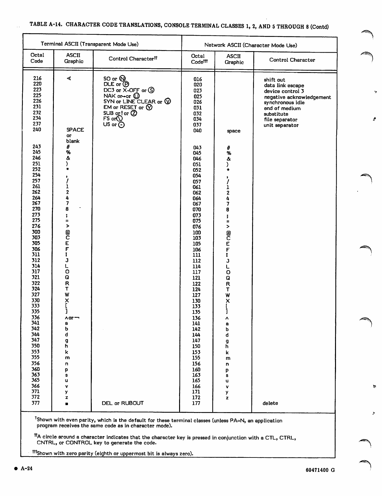
TABLE A-14. CHARACTER CODE TRANSLATIONS, CONSOLE TERMINAL CLASSES 1, 2, AND 5 THROUGH 8 (Contd)
Terminal ASCII (Transparent Mode Use)
Octal ASCII
Code Graphic
216
220
223
225
226
231
232
234
237
240 SPACE
or
blank
243 //
245
246
251
252
254
257
261
262
264
267
270
273
275
276
300
303
305
306
311
312
314
317
321
322
324
327
330
333
335
336 Aor—'
341
342
344
347
350
353
355
356
360
363
365
366
371
372
377
Control Charactertt
SO or (Q)
DLE or ®
DC3 or X-OFF or 0
NAK or-or (Q) _
SYN or LINE CLEAR or 0
EM or RESET or 0
SUB or tor®
FSor0
USor0
DEL or RUBOUT
Network ASCII (Character Mode Use)
Octal
Codettt
016
020
023
025
026
031
032
034
037
040
043
045
046
051
052
054
057
061
062
064
067
070
073
075
076
100
103
105
106
111
112
114
117
121
122
124
127
130
133
135
136
141
142
144
147
150
153
155
156
160
163
165
166
171
172
177
ASCII
Graphic
space
%
&
C
E
F
I
J
L
O
Q
R
T
W
X
[
]
A
a
b
d
g
h
k
m
n
P
s
u
V
y
z
Control Character
shift out
data link escape
device control 3
negative acknowledgement
synchronous idle
end of medium
substitute
file separator
unit separator
delete
Shown with even parity, which is the default for these terminal classes (unless PA=N, an application
program receives the same code as in character mode).
"A circle around a character indicates that the character key is pressed in conjunction with a CTL, CTRL,
CNTRL, or CONTROL key to generate the code.
tttshown with zero parity (eighth or uppermost bit is always zero).
A^S\
A-24 60471400 G
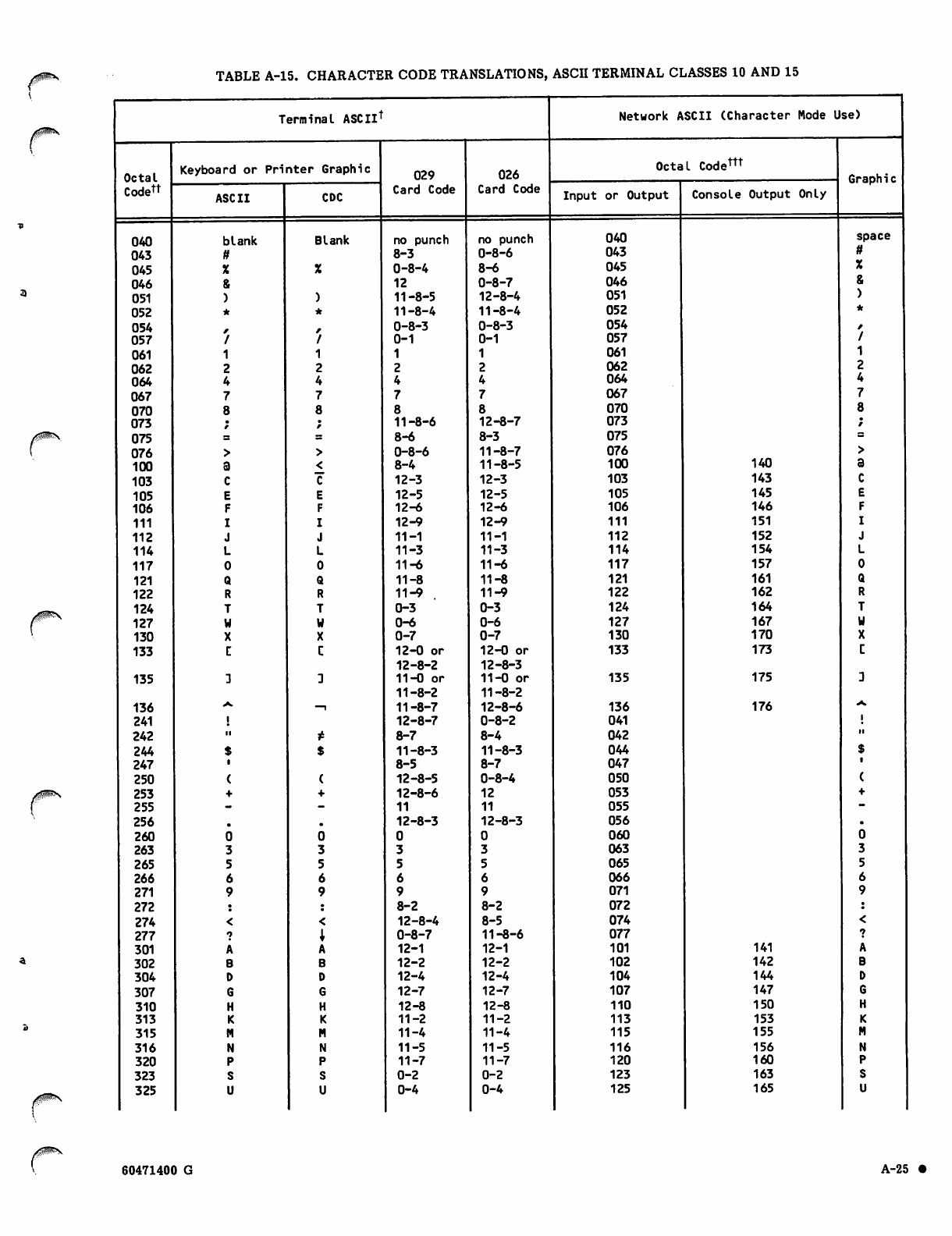
TABLE A-15. CHARACTER CODE TRANSLATIONS, ASCII TERMINAL CLASSES 10 AND 15
Terminal ASCIlt
Octal
Codett
040
043
045
046
051
052
054
057
061
062
064
067
070
073
075
076
100
103
105
106
111
112
114
117
121
122
124
127
130
133
135
136
241
242
244
247
250
253
255
256
260
263
265
266
271
272
274
277
301
302
304
307
310
313
315
316
320
323
325
Keyboard or Printer Graphic
ASCII
blank
ff
X
&
)
*
A
I
1
2
4
7
8
CDC
Blank
( (
+ +
m.
0 0
33
5 5
6 6
99
< <
i1
A A
B B
D D
6 G
H H
K K
M M
N N
P P
S S
U U
029
Card Code
no punch
8-3
0-8-4
12
11-8-5
11-8-4
0-8-3
0-1
1
2
4
7
8
11-8-6
8-6
0-8-6
8-4
12-3
12-5
12-6
12-9
11-1
11-3
11 - *
11-8
11-9
0-3
0-6
0-7
12-0 or
12-8-2
11-0 or
11-8-2
11-8-7
12-8-7
8-7
11-8-3
8-5
12-8-5
12-8-6
11
12-8-3
0
3
5
6
9
8-2
12-8-4
0-8-7
12-1
12-2
12-4
12-7
12-8
11-2
11-4
11-5
11-7
0-2
0-4
026
Card Code
no punch
0-8-6
8-6
0-8-7
12-8-4
11-8-4
0-8-3
0-1
1
2
4
7
8
12-8-7
8-3
11-8-7
11-8-5
12-3
12-5
12-6
12-9
11-1
11-3
11-6
11-8
11-9
0-3
0-6
0-7
12-0 or
12-8-3
11-0 or
11-8-2
12-8-6
0-8-2
8-4
11-8-3
8-7
0-8-4
12
11
12-8-3
0
3
5
6
9
8-2
8-5
11-8-6
12-1
12-2
12-4
12-7
12-8
11-2
11-4
11-5
11-7
0-2
0-4
Network ASCII (Character Mode Use)
Octal Codem
Input or Output Console Output Only
040
043
045
046
051
052
054
057
061
062
064
067
070
073
075
076
100
103
105
106
111
112
114
117
121
122
124
127
130
133
135
136
041
042
044
047
050
053
055
056
060
063
065
066
071
072
074
077
101
102
104
107
110
113
115
116
120
123
125
140
143
145
146
151
152
154
157
161
162
164
167
170
173
175
176
Graphic
141
142
144
147
150
153
155
156
160
163
165
space
ft
X
&
)
60471400 G A-25 •
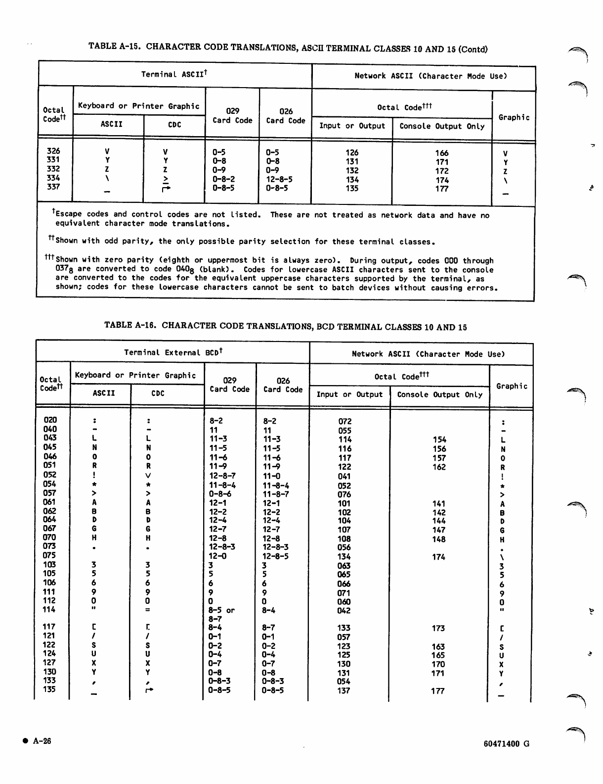
TABLE A-15. CHARACTER CODE TRANSLATIONS, ASCH TERMINAL CLASSES 10 AND 15 (Contd)
Terminal ASCIlt Network ASCII (Character Mode Use)
Octal
Codett
Keyboard or Printer Graphic 029
Card Code
026
Card Code
Octal Codettt
Graphic
ASCII CDC Input or Output Console Output Only
326
331
332
334
337 r*
0-5
0-8
0-9
0-8-2
0-8-5
0-5
0-8
0-9
12-8-5
0-8-5
126
131
132
134
135
166
171
172
174
177
'Escape codes and control codes are not listed. These are not treated as network data and have no
equivalent character mode translations.
tt Shown with odd parity, the only possible parity selection for these terminal classes.
tttshown with zero parity (eighth or uppermost bit is always zero). During output, codes 000 through
0373 are converted to code 040g (blank). Codes for lowercase ASCII characters sent to the console
are converted to the codes for the equivalent uppercase characters supported by the terminal, as
shown; codes for these lowercase characters cannot be sent to batch devices without causing errors.
I
A^i^S.
TABLE A-16. CHARACTER CODE TRANSLATIONS, BCD TERMINAL CLASSES 10 AND 15
Terminal External BCDt Network ASCII (Character Mode Use)
Octal
Codett
Keyboard or Printer Graphic 029
Card Code
026
Card Code
Octal Codem
Graphic
ASCII CDC Input or Output Console Output Only
020 8-2 8-2 072
040 11 11 055
043 11-3 11-3 114 154
045 11-5 11-5 116 156
046 11-6 11-6 117 157
051 11-9 11-9 122 162
052 12-8-7 11-0 041
054 11-8-4 11-8-4 052
057 0-8-6 11-8-7 076
061 12-1 12-1 101 141
062 12-2 12-2 102 142
064 12-4 12-4 104 144
067 12-7 12-7 107 147
070 12-8 12-8 108 148
073 12-8-3 12-8-3 056
075 12-0 12-8-5 134 174
103 063
105 065
106 066
111 071
112 060
114 11 8-5 or
8-7 8-4 042 ii
117 r. 8-4 8-7 133 173
121 0-1 0-1 057
122 0-2 0-2 123 163
124 0-4 0-4 125 165
127 0-7 0-7 130 170
130 0-8 0-8 131 171
133 0-8-3 0-8-3 054
135 r* 0-8-5 0-8-5 137 177
• A-26 60471400 G
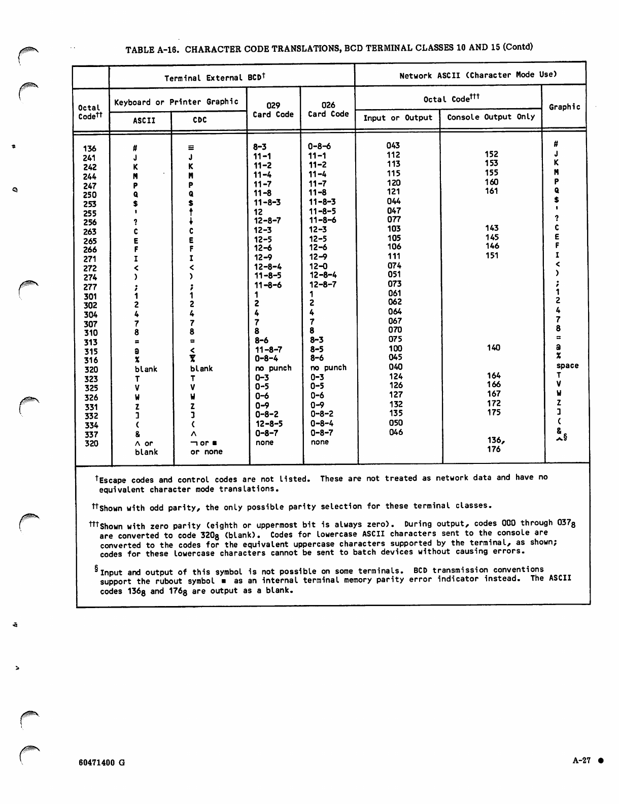
TABLE A-16. CHARACTER CODE TRANSLATIONS, BCD TERMINAL CLASSES 10 AND 15 (Contd)
Octal
Codett
136
241
242
244
247
250
253
255
256
263
265
266
271
272
274
277
301
302
304
307
310
313
315
316
320
323
325
326
331
332
334
337
320
Terminal External BCDt
Keyboard or Printer Graphic
ASCII
X
blank
T
V
W
Z
3
(
&
A or
blank
CDC
J
K
M
P
Q
$
t
X
C
E
F
I
<
)
/
1
2
4
7
8
<
Y
blank
T
V
U
z
3
(
A
-i or ■
or none
029
Card Code
8-3
11-1
11-2
11-4
11-7
11-8
11-8-3
12
12-8-7
12-3
12-5
12-6
12-9
12-8-4
11-8-5
11-8-6
1
2
4
7
8
8-6
11-8-7
0-8-4
no punch
0-3
0-5
0-6
0-9
0-8-2
12-8-5
0-8-7
none
026
Card Code
0-8-6
11-1
11-2
11-4
11-7
11-8
11-8-3
11-8-5
11-8-6
12-3
12-5
12-6
12-9
12-0
12-8-4
12-8-7
1
2
4
7
8
8-3
8-5
8-6
no punch
0-3
0-5
0-6
0-9
0-8-2
0-8-4
0-8-7
none
Network ASCII (Character Mode Use)
Octal Codem
Input or Output Console Output Only
043
112
113
115
120
121
044
047
077
103
105
106
111
074
051
073
061
062
064
067
070
075
100
045
040
124
126
127
132
135
050
046
152
153
155
160
161
143
145
146
151
140
164
166
167
172
175
136,
176
Graphic
ft
J
K
M
P
Q
$
•
1
C
E
F
I
<
)
/
1
2
4
7
8
a
%
space
T
V
w
z
:
(
is
tEscape codes and control codes are not listed. These are not treated as network data and have no
equivalent character mode translations.
ttshown with odd parity, the only possible parity selection for these terminal classes.
mshown with zero parity (eighth or uppermost bit is always zero). During output, codes 000 through 0378
are converted to code 320g (blank). Codes for lowercase ASCII characters sent to the console are
converted to the codes for the equivalent uppercase characters supported by the terminal, as shown;
codes for these lowercase characters cannot be sent to batch devices without causing errors.
* Input and output of this symbol is not possible on some terminals. BCD transmission conventions
support the rubout symbol ■ as an internal terminal memory parity error indicator instead. The ASCII
codes 136g and 176g are output as a blank.
60471400 G A-27 •
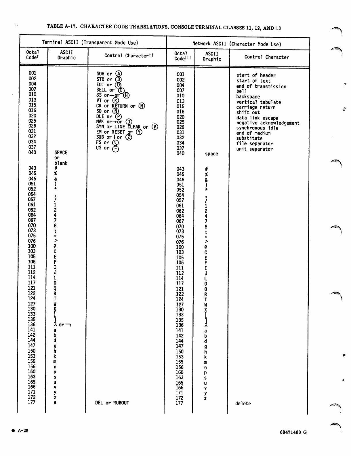
TABLE A-17. CHARACTER CODE TRANSLATIONS, CONSOLE TERMINAL CLASSES 11, 12, AND 13
Terminal ASCII (Transparent Mode Use)
Octal
Codet
001
002
004
007
010
013
015
016
020
025
026
031
032
034
037
040
043
045
046
051
052
054
057
061
062
064
067
070
073
075
076
100
103
105
106
111
112
114
117
121
122
124
127
130
133
135
136
141
142
144
147
150
153
155
156
160
163
165
166
171
172
177
ASCII
Graphic
SPACE
or
blank
#
%
&
C
E
F
I
J
L
0
Q
R
T
W
X
[
]
a or
a
b
d
9
h
k
m
n
P
s
u
v
y
z
Control Charactertt
SOH or
STX or
EOT or
BELL or
BS or-or®
VT or ®
CR or RETURN or ®
SO or (N)
DLE or (P)
NAK or—or ®
SYN or LINE CLEAR or ®
EM or RESET or ®
SUB or t or ®
FS or ®
US or ^
DEL or RUBOUT
Octal
Codettt
Network ASCII (Character Mode Use)
T
001
002
004
007
010
013
015
016
020
025
026
031
032
034
037
040
043
045
046
051
052
054
057
061
062
064
067
070
073
075
076
100
103
105
106
111
112
114
117
121
122
124
127
130
133
135
136
141
142
144
147
150
153
155
156
160
163
165
166
171
172
177
ASCII
Graphic Control Character
space
start of header
start of text
end of transmission
bell
backspace
vertical tabulate
carriage return
shift out
data link escape
negative acknowledgement
synchronous idle
end of medium
substitute
file separator
unit separator
delete
• A-28 60471400 G
A^E&S.
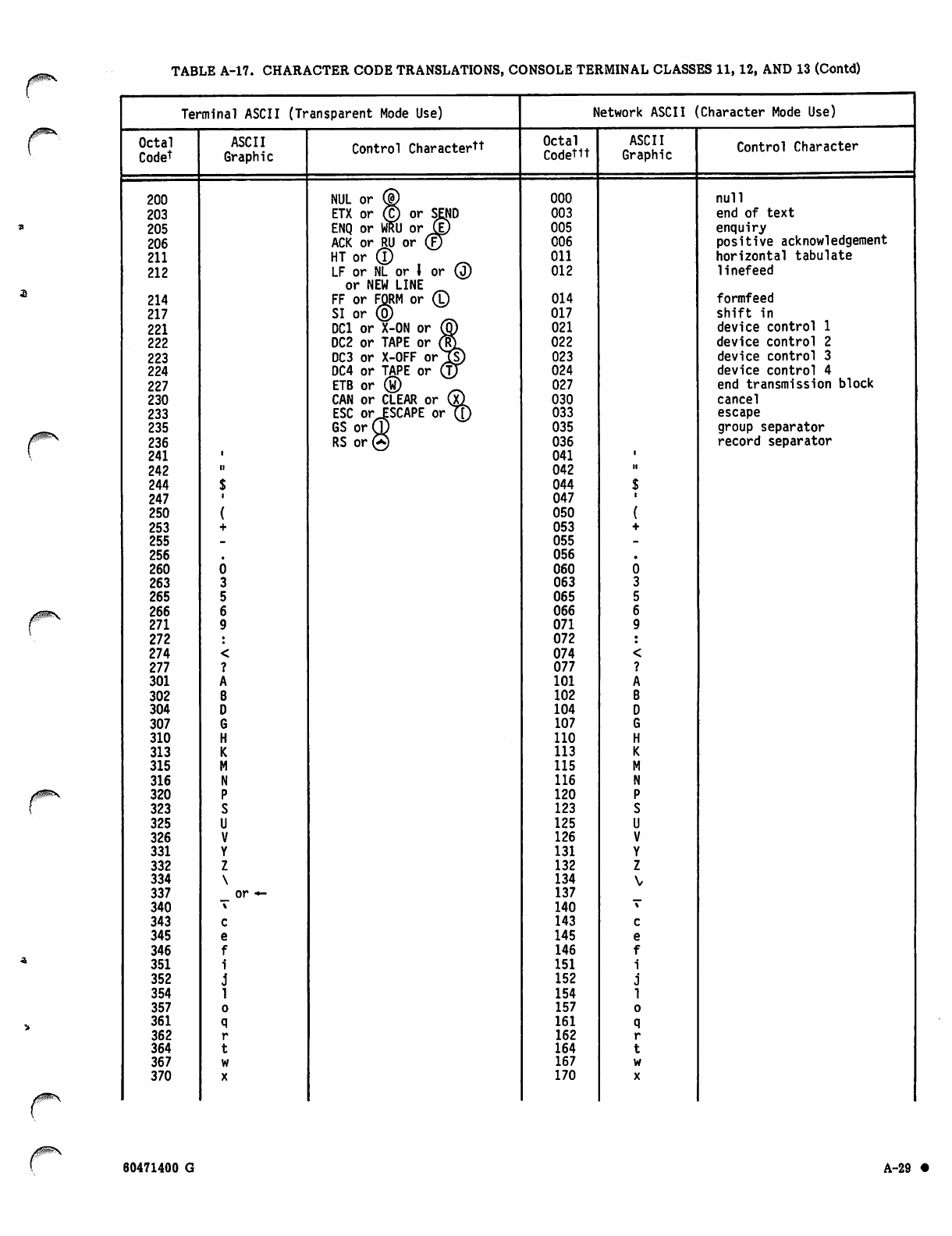
TABLE A-17. CHARACTER CODE TRANSLATIONS, CONSOLE TERMINAL CLASSES 11,12, AND 13 (Contd)
Terminal ASCII (Transparent Mode Use) Network ASCII ( Character Mode Use)
Octal
Codet
ASCII
Graphic Control Charactertt Octal
Codettt
ASCII
Graphic Control Character
200 NUL or ® 000 null
203 ETX or © or SEND 003 end of text
205 ENQ or WRU or J© 005 enquiry
206 ACK or RU or (J) 006 positive acknowledgement
211 H T o r ® ^ Oil horizontal tabulate
212 LF or NL or 1 or Q)
or NEW LINE 012 linefeed
214 FF or FORM or ©
SI or ® 014 formfeed
217 017 shift in
221 DC1 or X-ON or ® 021 device control 1
222 DC2 or TAPE or (F?L 022 device control 2
223 DC3 or X-OFF or l|) 023 device control 3
224 DC4 or TAPE or ®f 024 device control 4
227 ETB or ® 027 end transmission block
230 CAN or CLEAR or (x) 030 cancel
233 ESC or ESCAPE orTf) 033 escape
235 GS or® 035 group separator
236 RS or® 036 record separator
241 041
242 042 ii
244 044
247 047
250 050
253 053
255 055
256 056
260 060
263 063
265 065
266 066
271 071
272 072
274 074
277 077
301 101
302 102
304 104
307 107
310 110
313 113
315 115
316 116
320 120
323 123
325 125
326 126
331 131
332 132
334 134
337 _ or *~ 137
340 140
343 143
345 145
346 146
351 151
352 152
354 154
357 157
361 161
362 162
364 164
367 167
370 170
60471400 G A-29 •
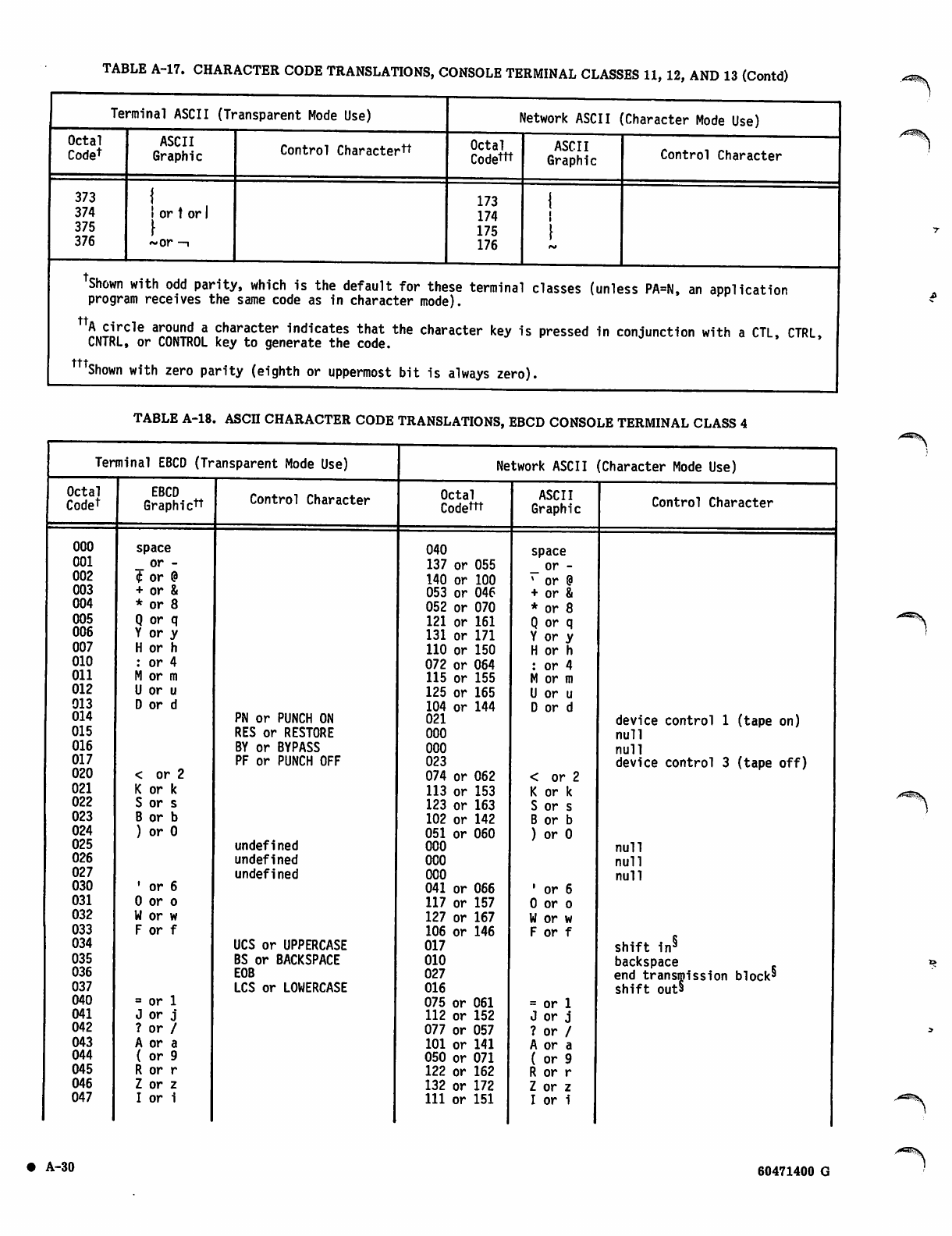
TABLE A-17. CHARACTER CODE TRANSLATIONS, CONSOLE TERMINAL CLASSES 11, 12, AND 13 (Contd)
Terminal ASCII (Transparent Mode Use)
Octal
Codet
373
374
375
376
ASCII
Graphic
I or t or
t
~or -i
Control Charactertt
Network ASCII (Character Mode Use)
Octal
Codettt
173
174
175
176
ASCII
Graphic Control Character
Shown with odd parity, which is the default for these terminal classes (unless PA=N, an application
program receives the same code as in character mode).
"5.,™ cle a!£u™„a character indicates that the character key is pressed in conjunction with a CTL, CTRL,
CNTRL, or CONTROL key to generate the code.
mShown with zero parity (eighth or uppermost bit is always zero).
TABLE A-18. ASCII CHARACTER CODE TRANSLATIONS,
_, 1
EBCD CONSOLE TERMINAL CLASS 4
Terminal EBCD (Transparent Mode Use) Network ASCII (Character Mode Use)
Octal
Codet EBCD
Graphictt Control Character Octal
Codettt ASCII
Graphic Control Character
000 space 040 space
001 or - 137 or 055 or -
002 t or @ 140 or 100 * or @
003 + or & 053 or 046 + or &
004 * or 8 052 or 070 * or 8
005 Q or q 121 or 161 Q or q
006 Y or y 131 or 171 Y or y
007 H or h 110 or 150 H or h
010 : or 4 072 or 064 : or 4
011 M or m 115 or 155 M or m
012 U or u 125 or 165 U or u
013 D or d 104 or 144 D or d
014 PN or PUNCH ON 021 device control 1 (tape on)
015 RES or RESTORE 000 null
016 BY or BYPASS 000 null
017 PF or PUNCH OFF 023 device control 3 (tape off)
020 < or 2 074 or 062 < or 2
021 K or k 113 or 153 K or k
022 S or s 123 or 163 S or s
023 B or b 102 or 142 B or b
024 ) or 0 051 or 060 ) or 0
025 undefined 000 null
026 undefined 000 null
027 undefined 000 null
030 • or 6 041 or 066 ' or 6
031 0 or o 117 or 157 0 or o
032 W or w 127 or 167 W or w
033 F or f 106 or 146 F or f
034 UCS or UPPERCASE 017 shift in§
035 BS or BACKSPACE 010 backspace
036 EOB 027 end transmission block§
shift out§
037 LCS or LOWERCASE 016
040 = or 1 075 or 061 = or 1
041 J or j 112 or 152 J or j
042 ? or / 077 or 057 ? or /
043 A or a 101 or 141 A or a
044 ( or 9 050 or 071 ( or 9
045 R or r 122 or 162 R or r
046 Z or z 132 or 172 Z or z
047 I or i 111 or 151 I or i
• A-30 60471400 G
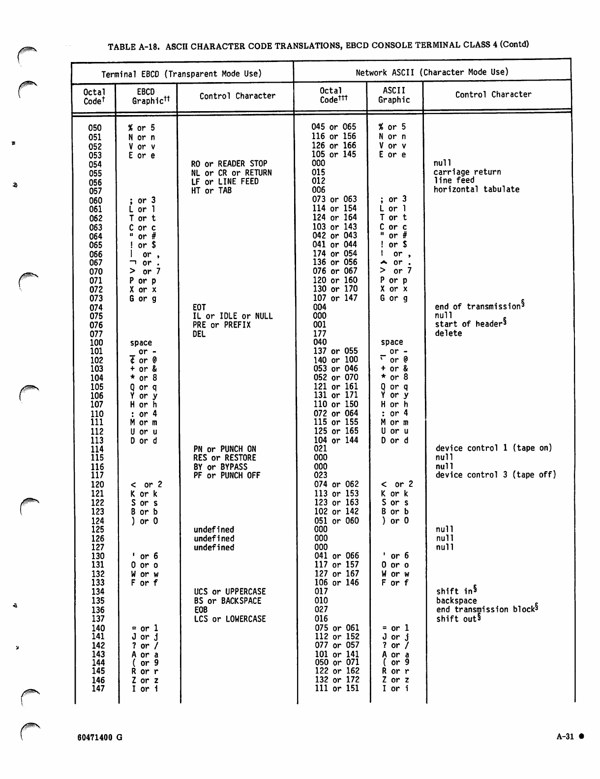
TABLE A-18. ASCII CHARACTER CODE TRANSLATIONS, EBCD CONSOLE TERMINAL CLASS 4 (Contd)
Terminal EBCD (Transparent Mode Use) Network ASCII (Character Mode Use)
Octal
Codet
EBCD
Graphictt Control Character Octal
Codettt
ASCII
Graphic Control Character
050 % or 5 045 or 065 % or 5
051 N or n 116 or 156 N or n
052 V or v 126 or 166 V or v
053 E or e 105 or 145 E or e
054 R0 or READER STOP 000 null
055 NL or CR or RETURN 015 carriage return
056 LF or LINE FEED 012 line feed
057 HT or TAB 006 horizontal tabulate
060 ; or 3 073 or 063 ; or 3
061 L or 1 114 or 154 L or 1
062 T or t 124 or 164 T or t
063 C or c 103 or 143 C or c
064 " or # 042 or 043 " or #
065 ! or $ 041 or 044 ! or $
066 1 or , 174 or 054 i o r ,
067 ~i or . 136 or 056 «*• or .
070 > or 7 076 or 067 > or 7
071 P or p 120 or 160 P or p
072 X or x 130 or 170 X or x
073 G or g 107 or 147 G or g
end of transmission'
074 EOT 004
075 IL or IDLE or NULL 000 n u l l .
start of header5
076 PRE or PREFIX 001
077 DEL 177 delete
100 space 040 space
101 _ or - 137 or 055 or -
102 4 or ? 140 or 100 * or @
103 + or & 053 or 046 + or &
104 * or 8 052 or 070 * or 8
105 Q or q 121 or 161 Q or q
106 Y or y 131 or 171 Y or y
107 H or h 110 or 150 H or h
110 : or 4 072 or 064 : or 4
111 M or m 115 or 155 M or m
112 U or u 125 or 165 U or u
113 D or d 104 or 144 D or d
114 PN or PUNCH ON 021 device control 1 (tape on)
115 RES or RESTORE 000 null
116 BY or BYPASS 000 null
117 PF or PUNCH OFF 023 device control 3 (tape off)
120 < or 2 074 or 062 < or 2
121 K or k 113 or 153 K or k
122 S or s 123 or 163 S or s
123 B or b 102 or 142 B or b
124 ) or 0 051 or 060 ) or 0
125 undefined 000 null
126 undefined 000 null
127 undefined 000 null
130 1 or 6 041 or 066 ' or 6
131 0 or o 117 or 157 0 or o
132 W or w 127 or 167 W or w
133 F or f 106 or 146 F or f
shift in*
134 UCS or UPPERCASE 017
135 BS or BACKSPACE 010 backspace .
end transmission block5136 EOB 027
137 LCS or LOWERCASE 016 shift out§
140 = or 1 075 or 061 = or 1
141 J or j 112 or 152 J or j
142 ? or / 077 or 057 ? or /
143 A or a 101 or 141 A or a
144 ( or 9 050 or 071 ( or 9
145 R or r 122 or 162 R or r
146 Z or z 132 or 172 Z or z
147 I or i 111 or 151 I or i
60471400 A-31

TABLE A-18. ASCII CHARACTER CODE TRANSLATIONS, EBCD CONSOLE TERMINAL CLASS 4 (Contd)
Terminal EBCD (Transparent Mode Use)
Octal
Codet
150
151
152
153
154
155
156
157
160
161
162
163
164
165
166
167
170
171
172
173
174
175
176
177
000
000
000
000
175
175
175
175
175
175
175
175
175
EBCD
Graphic1"1"
% or 5
N or n
V or v
E or e
or 3
or 1
or t
or c
or #
or $
or ,
—i or .
> or 7
P or p
X or x
G or g
space*
spacej
space*
space5
Control Character
R0 or READER STOP
NL or CR or RETURN
LF or LINE FEED
HT or TAB
EOT
IL or IDLE or NULL
PRE or PREFIX
DEL
IL or IDLE or NULLff
IL or IDLE or NULL§§
IL or IDLE or NULL§§
IL or IDLE or NULLff
IL or IDLE or NULL§§
IL or IDLE or NULLff
IL or IDLE or NULL§§
IL or IDLE or NULL§§
IL or IDLE or NULL§§
Network ASCII (Character Mode Use)
Octal
Codettt
045 or 065
116 or 156
126 or 166
105 or 145
000
015
012
006
073 or 063
114 or 154
124 or 164
103 or 143
042 or 043
041 or 044
174 or 054
136 or 056
076 or 067
120 or 160
130 or 170
107 or 147
004
000
001
177
133 thru
135
140
173
175 or 176
002
003
005
007
013 or 014
020
022
024 thru
026
030 thru
037
ASCII
Graphic
% or 5
N or n
V or v
E or e
Control Character
or 3
or 1
or t
or c
or #
or $
! or ,
^ or .
> or 1
P or p
X or x
G or g
[ or \
or ]
null
carriage return
line feed
horizontal tabulate
or *~
end of transmission^
null
start of header9
delete
start of text
end of text
enquire
bell
vertical tabulate
or form feed
data link escape
device control 2
device control 4,
negative acknowledge,
or synchronize
cancel, end of media,
substitute, escape,
file separator, group
separator, record
separator, or unit
separator
TShown with odd and even parity; odd parity is the default for this terminal class,
the application program receives the same code as in character mode.) (Unless PA=N,
Each input line is assumed to begin in lowercase. Input characters are translated to lowercase ASCII
characters unless prefixed by the UCS code. Once a case shift occurs, it remains in effect until
another case shift code is received, the page width is reached, or the line is transmitted to
the host computer. During output, case is preserved by insertion of case shift codes where needed.
mShown with zero parity (eighth or uppermost bit is always zero).
c
sNot transmitted to the host computer after translation during input.
^Output translation only.
s^ErS.
A-32 60471400 G
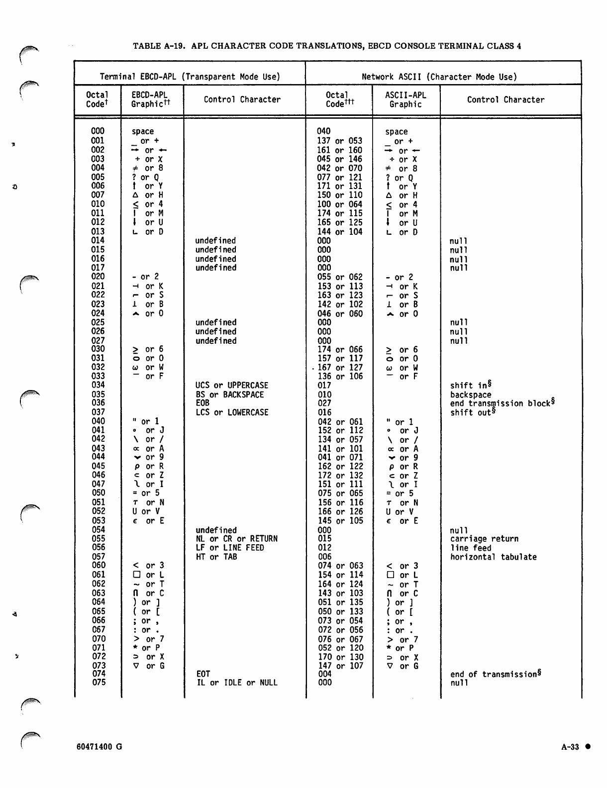
TABLE A-19. APL CHARACTER CODE TRANSLATIONS, EBCD CONSOLE TERMINAL CLASS 4
Terminal EBCD-APL (Transparent Mode Use) Network ASCII (Character Mode Use)
Octal
Codet
EBCD-APL
Graphictt Control Character Octal
Codem ASCII-APL
Graphic Control Character
000 space 040 space
001 _ or + 137 or 053 _ or +
002 — or *- 161 or 160 -*■ or —
003 + or X 045 or 146 + or X
004 * or 8 042 or 070 * or 8
005 ? or Q 077 or 121 ? or Q
006 t or Y 171 or 131 t or Y
007 A or H 150 or 110 A or H
010 < or 4 100 or 064 < or 4
011 1 or M 174 or 115 1 or M
012 \ or U 165 or 125 \ or U
013 u or D 144 or 104 l or D
014 undefined 000 null
015 undefined 000 null
016 undefined 000 null
017 undefined 000 null
020 - or 2 055 or 062 - or 2
021 h or K 153 or 113 -i or K
022 i- or S 163 or 123 i- or S
023 1 or B 142 or 102 1 or B
024 a or 0 046 or 060 a or 0
025 undefined 000 null
026 undefined 000 null
027 undefined 000 null
030 > or 6 174 or 066 > or 6
031 o or 0 157 or 117 o or 0
032 w or W - 167 or 127 w or W
033 ~ or F 136 or 106 — or F
034 UCS or UPPERCASE 017 shift in§
035 BS or BACKSPACE 010 backspace
036 E0B 027 end transmission block§
037 LCS or LOWERCASE 016 shift out§
040 " or 1 042 or 061 " or 1
041 o or J 152 or 112 o or J
042 \ or / 134 or 057 \ or /
043 oc or A 141 or 101 oc or A
044 v or 9 041 or 071 v or 9
045 p or R 162 or 122 p or R
046 = or Z 172 or 132 c or Z
047 \ or I 151 or 111 \ or I
050 = or 5 075 or 065 = or 5
051 t or N 156 or 116 t or N
052 U or V 166 or 126 U or V
053 € or E 145 or 105 € or E
054 undefined 000 null
055 NL or CR or RETURN 015 carriage return
056 LF or LINE FEED 012 line feed
057 HT or TAB 006 horizontal tabulate
060 < or 3 074 or 063 < or 3
061 □ or L 154 or 114 □ or L
062 ~ or T 164 or 124 - or T
063 n or C 143 or 103 n or C
064 ) or ] 051 or 135 ) or ]
065 ( or [ 050 or 133 ( or [
066 ; or , 073 or 054 ; or ,
067 : or . 072 or 056 : or .
070 > or 7 076 or 067 > or 7
071 * or P 052 or 120 * or P
072 => or X 170 or 130 = or X
073 V or G 147 or 107 V or G
074 EOT 004 end of transmission^
075 IL or IDLE or NULL 000 null
60471400 G A-33 •
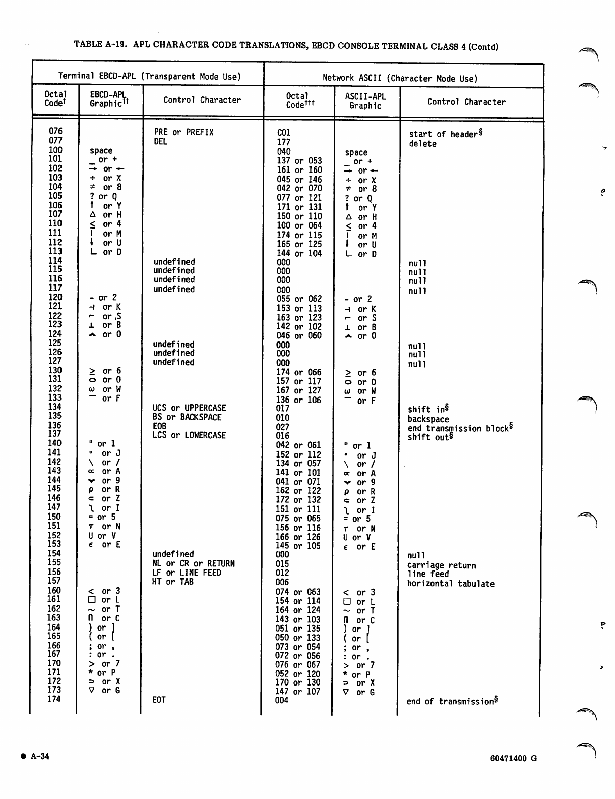
TABLE A-19. APL CHARACTER CODE TRANSLATIONS, EBCD CONSOLE TERMINAL CLASS 4 (Contd)
Terminal EBCD-APL (Transparent Mode Use)
Octal
Codet
076
077
100
101
102
103
104
105
106
107
110
111
112
113
114
115
116
117
120
121
122
123
124
125
126
127
130
131
132
133
134
135
136
137
140
141
142
143
144
145
146
147
150
151
152
153
154
155
156
157
160
161
162
163
164
165
166
167
170
171
172
173
174
EBCD-APL
Graphictt
space
_ or +
-* or —
+ or X
or 8
or Q
or Y
or H
or 4
or M
or U
or D
- or 2
h or K
«- or ,S
l or B
^ or 0
> or 6
o or 0
co or W
— or F
" or 1
0 or J
\ o r
oc or
•v or
p o r
c o r
\ o r I
= or 5
t or N
U or V
€ or E
or 3
or L
or T
or C
or J
or (
; or ,
: or .
> or 7
* or P
= or X
V or G
<
D
n
)
(
Control Character
PRE or PREFIX
DEL
undefined
undefined
undefined
undefined
undefined
undefined
undefined
UCS or UPPERCASE
BS or BACKSPACE
E0B
LCS or LOWERCASE
undefined
NL or CR or RETURN
LF or LINE FEED
HT or TAB
Network ASCII (Character Mode Use)
Octal
Codem
EOT
001
177
040
137 or 053
161 or 160
045 or 146
042 or 070
077 or 121
171 or 131
150 or 110
100 or 064
174 or 115
165 or 125
144 or 104
000
000
000
000
055 or 062
153 or 113
163 or 123
142 or 102
046 or 060
000
000
000
174 or 066
157 or 117
167 or 127
136 or 106
017
010
027
016
042 or 061
152 or 112
134 or 057
141 or 101
041 or 071
162 or 122
172 or 132
151 or 111
075 or 065
156 or 116
166 or 126
145 or 105
000
015
012
006
074 or 063
154 or 114
164 or 124
143 or 103
051 or 135
050 or 133
073 or 054
072 or 056
076 or 067
052 or 120
170 or 130
147 or 107
004
ASCII-APL
Graphic
space
_ or +
-* or f
+ or X
* or 8
? or Q
or Y
or H
or 4
or M
or U
or D
- or 2
-i or K
•- or S
i or B
a or 0
> or 6
o or 0
w or W
~ or F
" or 1
° or J
\ o r
cc or
v or
p or
<= or
\ o r I
= or 5
t or N
U or V
e or E
or 3
or L
or T
or C
or 1
or [
or ,
or .
or 7
or P
or X
or G
Control Character
start of header^
delete
null
null
null
null
null
null
null
shift in§
backspace
end transmission block§
shift out§
null
carriage return
line feed
horizontal tabulate
end of transmission^
A-34 60471400 G
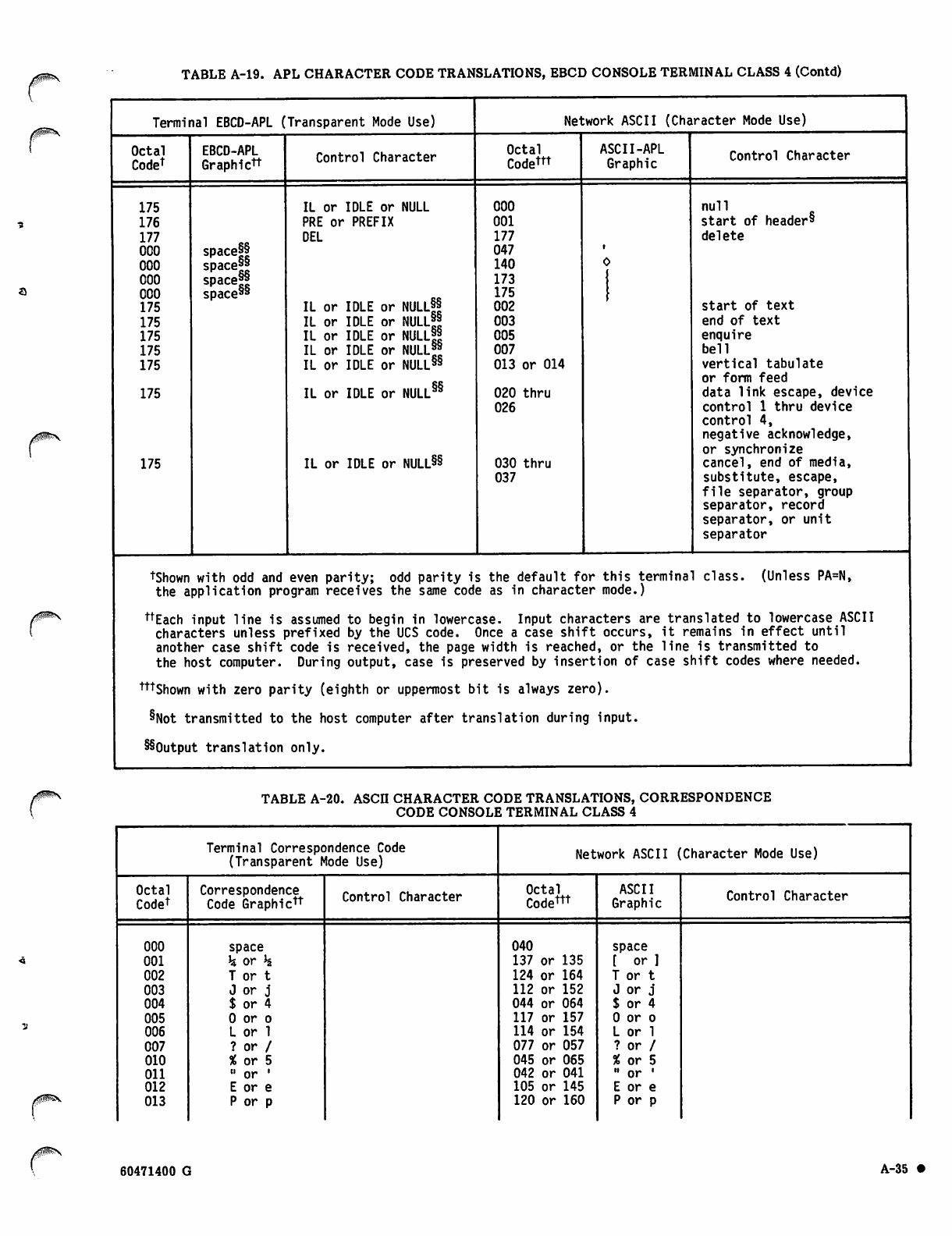
TABLE A-19. APL CHARACTER CODE TRANSLATIONS, EBCD CONSOLE TERMINAL CLASS 4 (Contd)
Terminal EBCD-APL (Transparent Mode Use) Network ASCII (Character Mode Use)
Octal
Code1
EBCD-APL
Graphictt Control Character Octal
Codem
ASCII-APL
Graphic Control Character
175 IL or IDLE or NULL 000 null
176 PRE or PREFIX 001 start of header*
177 DEL 177 delete
000 space|§ 047
000 space99 140
000 space9' 173
000 space99 175
175 IL or IDLE or NULLff 002 start of text
175 IL or IDLE or NULL99
IL or IDLE or NULL9|
IL or IDLE or NULL!9
003 end of text
175 005 enquire
175 007 bell
175 IL or IDLE or NULL99
IL or IDLE or NULL§§
013 or 014 vertical tabulate
or form feed
175 020 thru data link escape, device
026 control 1 thru device
control 4,
negative acknowledge,
or synchronize
175 IL or IDLE or NULL§§ 030 thru
037 cancel, end of media,
substitute, escape,
file separator, group
separator, record
separator, or unit
separator
tShown with odd and even parity; odd parity i s the default for this terminal class. (Unless PA=N,
the application program receives the same cod e as in character mode.)
ttEach input line is assumed to begin in lowerc ase. Input characters are translated to lowercase ASCII
characters unless prefixed by the UCS code. Once a case shift occurs, it remains in effect until
another case shift code is received, the page width is reached, or the line is transmitted to
the host computer. During output, case is preserved by insertion of case shift codes where needed.
tttshown with zero parity (eighth or uppermost b it is always zero).
§Not transmitted to the host computer after translation during input.
§§0utput translation only.
yg^s TABLE A-20. ASCII CHARACTER CODE TRANSLATIONS, CORRESPONDENCE
CODE CONSOLE TERMINAL CLASS 4
Terminal Correspondence Code
(Transparent Mode Use) Network ASCII (Character Mode Use)
Octal
Codet Correspondence
Code Graphictt Control Character Octal
Codettt
ASCII
Graphic Control Character
000 space 040 space
001 h or h 137 or 135 [ or ]
002 T or t 124 or 164 T or t
003 J or j 112 or 152 J or j
004 $ or 4 044 or 064 $ or 4
005 0 or o 117 or 157 0 or o
006 L or 1 114 or 154 L or 1
007 ? or / 077 or 057 ? or /
010 % or 5 045 or 065 % or 5
011 " or ' 042 or 041 •• or .
012 E or e 105 or 145 E or e
013 P or p 120 or 160 P or p
60471400 G A-35 •
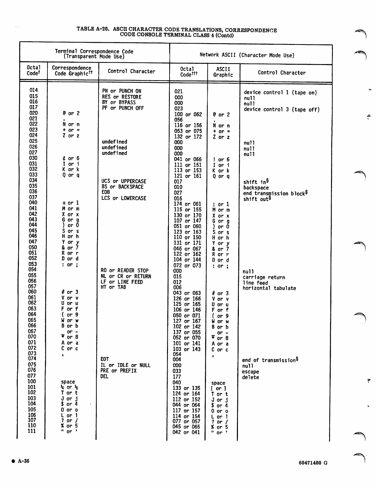
TABLE A-20. ASCH CHARACTER CODE TRANSLATIONS, CORRESPONDENCE
CODE CONSOLE TERMINAL CLASS 4 (Contd)
Terminal Correspondence Code
(Transparent Mode Use) Network ASCII (Character Mode Use)
Octal
Codet Correspondence
Code Graphic^ Control Character Octal
Codettt
ASCII
Graphic Control Character
014 PN or PUNCH ON 021 device control 1 (tape on)
015 RES or RESTORE 000 null
016 BY or BYPASS 000 null
017 PF or PUNCH OFF 023 device control 3 (tape off)
020 @ or 2 100 or 062 @ or 2
021 056
022 N or n 116 or 156 N or n
023 + or = 053 or 075 + or =
024 Z or z 132 or 172 Z or z
025 undefined 000 null
026 undefined 000 null
027 undefined 000 null
030 i or 6 041 or 066 ! or 6
031 I or i 111 or 151 I or i
032 K or k 113 or 153 K or k
033 Q or q 121 or 161 Q or q
034 UCS or UPPERCASE 017 shift in§
035 BS or BACKSPACE 010 backspace
036 EOB 027 end transmission block§
shift out8
037 LCS or LOWERCASE 016
040 ± or 1 174 or 061 I or 1
041 M or m 115 or 155 M or m
042 X or x 130 or 170 X or x
043 G or g 107 or 147 G or g
044 ) or 0 051 or 060 ) or 0
045 S or s 123 or 163 S or s
046 H or h 110 or 150 H or h
047 Y or y 131 or 171 Y or y
050 & or 7 046 or 067 & or 7
051 R or r 122 or 162 R or r
052 D or d 104 or 144 D or d
053 : or ; 072 or 073 : or ;
054 RO or READER STOP 000 null
055 NL or CR or RETURN 015 carriage return
056 LF or LINE FEED 012 line feed
057 HT or TAB 006 horizontal tabulate
060 # or 3 043 or 063 # or 3
061 V or v 126 or 166 V or v
062 U or u 125 or 165 U or u
063 F or f 106 or 146 F or f
064 ( or 9 050 or 071 ( or 9
065 W or w 127 or 167 W or w
066 B or b 102 or 142 B or b
067 or - 137 or 055 or -
070 * or 8 052 or 070 w or 8
071 A or a 101 or 141 A or a
072 C or c 103 or 143 C or c
073 054
074 EOT 004 end of transmission^
075 IL or IDLE or NULL 000 null
076 PRE or PREFIX 033 escape
077 DEL 177 delete
100 space 040 space
101 h or h 133 or 135 I or ]
102 T or t 124 or 164 T or t
103 J or j 112 or 152 J or j
104 $ or 4 044 or 064 $ or 4
105 0 or o 117 or 157 0 or o
106 L or 1 114 or 154 L or 1
107 ? or / 077 or 057 ? or /
110 % or 5 045 or 065 % or 5
111 " or ' 042 or 041 .. or .
\-36 60471400 G
,/*^s$.
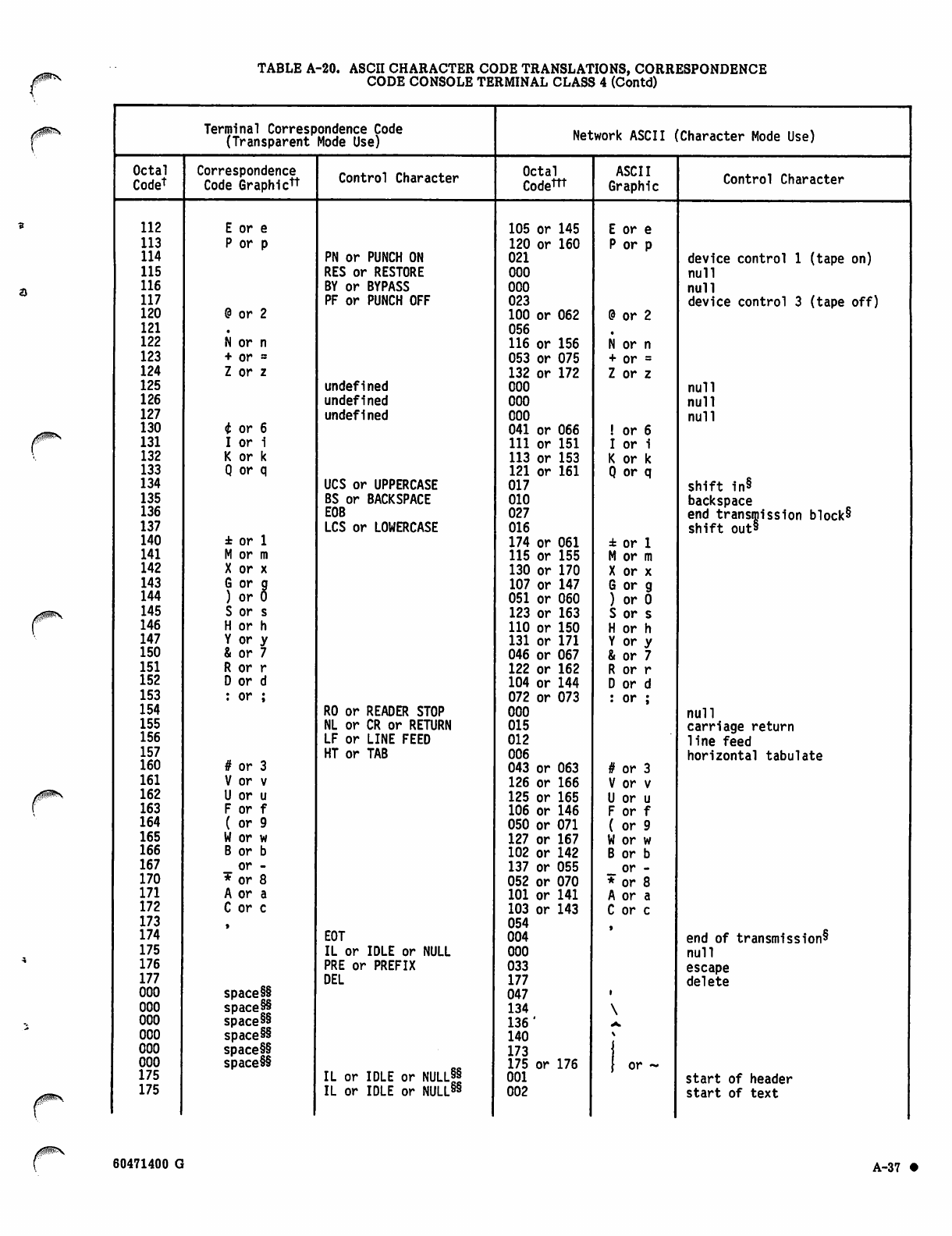
TABLE A-20. ASCII CHARACTER CODE TRANSLATIONS, CORRESPONDENCE
CODE CONSOLE TERMINAL CLASS 4 (Contd)
Terminal Correspondence Code
(Transparent Mode Use) Network ASCII 'Character Mode Use)
Octal
Codet Correspondence
Code Graphictt Control Character Octal
Codem
ASCII
Graphic Control Character
112 E or e 105 or 145 E or e
113 P or p 120 or 160 P or p
114 PN or PUNCH ON 021 device control 1 (tape on)
115 RES or RESTORE 000 null
116 BY or BYPASS 000 null
117 PF or PUNCH OFF 023 device control 3 (tape off)
120 @ or 2 100 or 062 @ or 2
121 056
122 N or n 116 or 156 N or n
123 + or = 053 or 075 + or =
124 Z or z 132 or 172 Z or z
125 undefined 000 null
126 undefined 000 null
127 undefined 000 null
130 t or 6 041 or 066 ! or 6
131 I or i 111 or 151 I or i
132 K or k 113 or 153 K or k
133 Q or q 121 or 161 Q or q
134 UCS or UPPERCASE 017 shift in§
135 BS or BACKSPACE 010 backspace
136 EOB 027 end transmission block§
shift out§
137 LCS or LOWERCASE 016
140 ± or 1 174 or 061 ± or 1
141 M or m 115 or 155 M or m
142 X or x 130 or 170 X or x
143 G or g
) or 0 107 or 147 G or g
144 051 or 060 ) or 0
145 S or s 123 or 163 S or s
146 H or h 110 or 150 H or h
147 Y or y 131 or 171 Y or y
150 & or 7 046 or 067 & or 7
151 R or r 122 or 162 R or r
152 D or d 104 or 144 D or d
153 : or ; 072 or 073 : or ;
154 RO or READER STOP 000 null
155 NL or CR or RETURN 015 carriage return
156 LF or LINE FEED 012 line feed
157 HT or TAB 006 horizontal tabulate
160 # or 3 043 or 063 # or 3
161 V or v 126 or 166 V or v
162 U or u 125 or 165 U or u
163 F or f 106 or 146 F or f
164 ( or 9 050 or 071 ( or 9
165 W or w 127 or 167 W or w
166 B or b 102 or 142 B or b
167 or - 137 or 055 or -
170 * or 8 052 or 070 * or 8
171 A or a 101 or 141 A or a
172 C or c 103 or 143 C or c
173 054
174 EOT 004 end of transmission^
175 IL or IDLE or NULL 000 null
176 PRE or PREFIX 033 escape
177 DEL 177 delete
000 space§§ 047
000 space§§ 134
000 space§§ 136' a.
000 space§§ 140
000 space§§ 173
000 space§§ 175 or 176 } or ~
175 IL or IDLE or NULLff 001 start of header
175 IL or IDLE or NULL§§ 002 start of text
60471400 G A-37 •
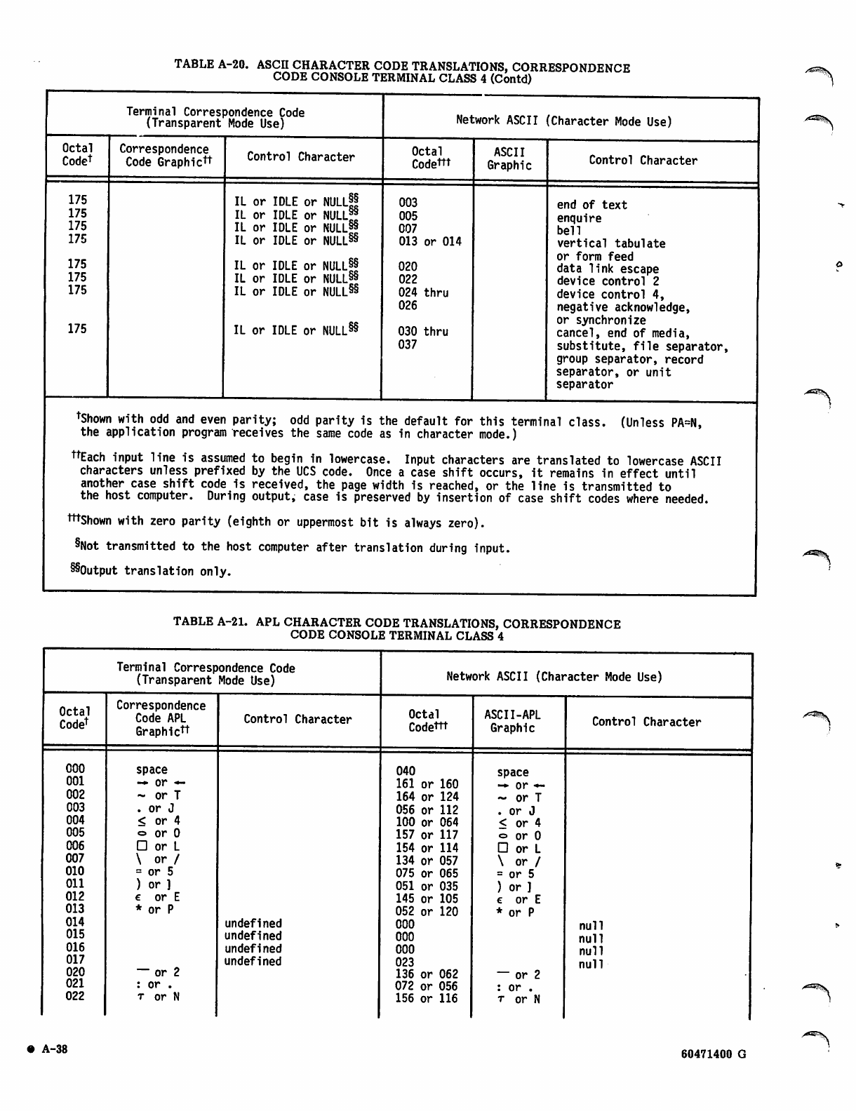
TABLE A-20. ASCII CHARACTER CODE TRANSLATIONS, CORRESPONDENCE
CODE CONSOLE TERMINAL CLASS 4 (Contd)
Terminal Correspondence Code
(Transparent Mode Use) Network ASCII (Character Mode Use)
Octal
Codet Correspondence
Code Graphictt Control Character Octal
Codettt ASCII
Graphic Control Character
175
175
175
175
175
175
175
175
IL or IDLE or NULLff
IL or IDLE or NULLff
IL or IDLE or NULL98
IL or IDLE or NULL85
IL or IDLE or NULL88
IL or IDLE or NULL88
IL or IDLE or NULL88
IL or IDLE or NULL88
003
005
007
013 or 014
020
022
024 thru
026
030 thru
037
end of text
enquire
bell
vertical tabulate
or form feed
data link escape
device control 2
device control 4,
negative acknowledge,
or synchronize
cancel, end of media,
substitute, file separator,
group separator, record
separator, or unit
separator
tShown with odd and even parity; odd parity is the default for this terminal class. (Unless PA=N,
the application program receives the same code as in character mode.)
nEach input line is assumed to begin in lowercase. Input characters are translated to lowercase ASCII
characters unless prefixed by the UCS code. Once a case shift occurs, it remains in effect until
another case shift code is received, the page width is reached, or the line is transmitted to
the host computer. During output, case is preserved by insertion of case shift codes where needed.
mShown with zero parity (eighth or uppermost bit is always zero).
8Not transmitted to the host computer after translation during input.
^Output translation only.
TABLE A-21. APL CHARACTER CODE TRANSLATIONS, CORRESPONDENCE
CODE CONSOLE TERMINAL CLASS 4
Terminal Correspondence Code
(Transparent Mode Use) Network ASCII (Character Mode Use)
Octal
Codet
Correspondence
Code APL
Graphictt
Control Character Octal
Codettt ASCII-APL
Graphic Control Character
000
001
002
003
004
005
006
007
010
Oil
012
013
014
015
016
017
020
021
022
space
-* or —
- or T
. or J
< or 4
o or 0
□ or L
\ or /
= or 5
) or ]
€ or E
* or P
~ or 2
: or .
t or N
undefined
undefined
undefined
undefined
040
161 or 160
164 or 124
056 or 112
100 or 064
157 or 117
154 or 114
134 or 057
075 or 065
051 or 035
145 or 105
052 or 120
000
000
000
023
136 or 062
072 or 056
156 or 116
space
-♦ or *-
— or T
. or J
< or 4
o or 0
□ or L
\ or /
= or 5
) or ]
e or E
* or P
— or 2
: or .
t or N
null
null
null
null
• A-38 60471400 G
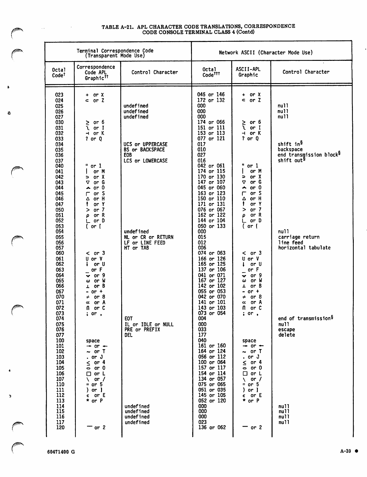
TABLE A-21. APL CHARACTER CODE TRANSLATIONS, CORRESPONDENCE
CODE CONSOLE TERMINAL CLASS 4 (Contd)
Terminal Correspondence Code
(Transparent Mode Use) Network ASCII (Character Mode Use)
Octal
Codet
Correspondence
Code APL
Graph icft
Control Character Octal
Codettt
ASCII-APL
Graphic Control Character
023 + or X 045 or 146 + or X
024 c or Z 172 or 132 <= or Z
025 undefined 000 null
026 undefined 000 null
027 undefined 000 null
030 > or 6 174 or 066 > or 6
031 \ or I 151 or 111 \ o r I
032 h or K 153 or 113 h or K
033 ? or Q 077 or 121 ? or Q
034 UCS or UPPERCASE 017 shift in8
035 BS or BACKSPACE 010 backspace k8
036 E0B 027 end transmission bloc
shift out8
037 LCS or LOWERCASE 016
040 " or 1 042 or 061 " or 1
041 1 or M 174 or 115 I or M
042 => or X 170 or 130 » or X
043 V or G 147 or 107 V or G
044 ^ or 0 045 or 060 a or 0
045 r or S 163 or 123 r or S
046 A or H 150 or 110 A or H
047 t or Y 171 or 131 t or Y
050 > or 7 076 or 067 > or 7
051 p or R 162 or 122 p or R
052 L or D 144 or 104 L or D
053 ( or [ 050 or 133 ( or [
054 undefined 000 null
055 NL or CR or RETURN 015 carriage return
056 LF or LINE FEED 012 line feed
057 HT or TAB 006 horizontal tabulate
060 < or 3 074 or 063 < or 3
061 U or V 166 or 126 U or V
062 \ or U 165 or 125 \ or U
063 _ or F 137 or 106 _ or F
064 v or 9 041 or 071 ■^ or 9
065 co or W 167 or 127 co or W
066 l or B 142 or 102 x or B
067 - or + 055 or 053 - or +
070 ^ o r 8 042 or 070 # or 8
071 oc or A 141 or 101 cc or A
072 n or C 143 or 103 n or C
073 ; or , 073 or 054 ; or ,
074 EOT 004 end of transmission8
075 IL or IDLE or NULL 000 null
076 PRE or PREFIX 033 escape
077 DEL 177 delete
100 space 040 space
101 — or — 161 or 160 -•• or —
102 - or T 164 or 124 - or T
103 . or J 056 or 112 . or J
104 < or 4 100 or 064 < or 4
105 o or 0 157 or 117 o or 0
106 D or L 154 or 114 □ or L
107 \ or / 134 or 057 \ or /
110 = or 5 075 or 065 = or 5
111 ) or ] 051 or 035 ) or ]
112 e or E 145 or 105 e or E
113 * or P 052 or 120 * or P
114 undefined 000 null
115 undefined 000 null
116 undefined 000 null
117 undefined 023 null
120 " o r 2 136 or 062 — or 2
0^S
60471400 G A-39 •
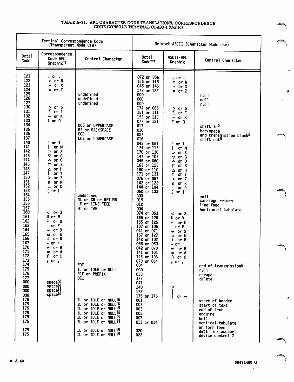
TABLE A-21. APL CHARACTER CODE TRANSLATIONS, CORRESPONDENCE
CODE CONSOLE TERMINAL CLASS 4 (Contd) a^^S
Terminal Correspondence Code
(Transparent Mode Use) Network ASCII (Character Mode Use)
Octal
Codet
Correspondence
Code APL
Graphictt
Control Character Octal
Codettt
ASCII-APL
Graphic Control Character
121 : or . 072 or 056 : or .
122 t or N 156 or 116 t or N
123 + or X 045 or 146 + or X
124 <= or Z 172 or 132 c or Z
125 undefined 000 null
126 undefined 000 null
127 undefined 000 null
130 > or 6 174 or 066 > or 6
131 \ or I 151 or 111 \ o r I
132 h or K 153 or 113 norK
133 ? or Q 077 or 121 ? or Q
134 UCS or UPPERCASE 017 shift in8
135 BS or BACKSPACE 010 backspace
136 E0B 027 end transmission block8
137 LCS or LOWERCASE 016 shift out8
140 " or 1 042 or 061 " or 1
141 1 or M 174 or 115 1 or M
142 => or X 170 or 130 = or X
143 V or G 147 or 107 V or G
144 *• or 0 045 or 060 ^ or 0
145 r or S 163 or 123 r or S
146 A or H 150 or 110 A or H
147 t or Y 171 or 131 t or Y
150 > or 7 076 or 067 > or 7
151 p or R 162 or 122 p or R
152 L or D 144 or 104 L or D
153 ( or [ 050 or 133 ( or [
154 undefined 000 null
155 NL or CR or RETURN 015 carriage return
156 LF or LINE FEED 012 line feed
157 HT or TAB 006 horizontal tabulate
160 < or 3 074 or 063 < or 3
161 U or V 166 or 126 U or V
162 * or U 165 or 125 \ or U
163 _ or F 137 or 106 _ or F
164 v o r 9 041 or 071 v o r 9
165 co or W 167 or 127 co or W
166 1 or B 142 or 102 1 or B
167 - or + 055 or 053 - or +
170 # o r 8 042 or 070 # or 8
171 oc or A 141 or 101 oc or A
172 n or C 143 or 103 n or C
173 ; or , 073 or 054 ; or ,
174 EOT 004 end of transmission8
175 IL or IDLE or NULL 000 null
176 PRE or PREFIX 033 escape
177 DEL 177 delete
000 spaceff 047
000 space||
space||
space88
140
000 173
000 175 or 176 I or r-
175 IL or IDLE or NULL88 001 start of header
175 IL or IDLE or NULL88 002 start of text
175 IL or IDLE or NULL88 003 end of text
175 IL or IDLE or NULL88 005 enquire
175 IL or IDLE or NULL88 007 bell
175 IL or IDLE or NULL88 013 or 014 vertical tabulate
175 IL or IDLE or NULL88 020 or form feed
data link escape
175 IL or IDLE or NULL88 022 device control 2
r^^S
A^^Su
• A-40 60471400 G
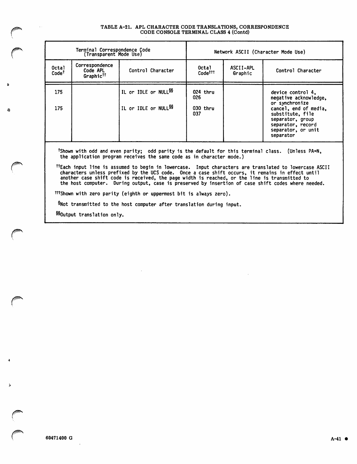
TABLE A-21. APL CHARACTER CODE TRANSLATIONS, CORRESPONDENCE
CODE CONSOLE TERMINAL CLASS 4 (Contd)
y/S^
Terminal Correspondence Code
(Transparent Mode Use) Network ASCII (Character Mode Use)
Octal
Codet
Correspondence
Code APL
Graphictt
Control Character Octal
Codettt ASCII-APL
Graphic Control Character
175
175
IL or IDLE or NULL88
IL or IDLE or NULL88
024 thru
026
030 thru
037
device control 4,
negative acknowledge,
or synchronize
cancel, end of media,
substitute, file
separator, group
separator, record
separator, or unit
separator
tShown with odd and even parity; odd parity is the default for this terminal class. (Unless PA=N,
the application program receives the same code as in character mode.)
ttEach input line is assumed to begin in lowercase. Input characters are translated to lowercase ASCII
characters unless prefixed by the UCS code. Once a case shift occurs, it remains in effect until
another case shift code is received, the page width is reached, or the line is transmitted to
the host computer. During output, case is preserved by insertion of case shift codes where needed.
tttshown with zero parity (eighth or uppermost bit is always zero).
8Not transmitted to the host computer after translation during input.
SSOutput translation only.
60471400 G A-41 •

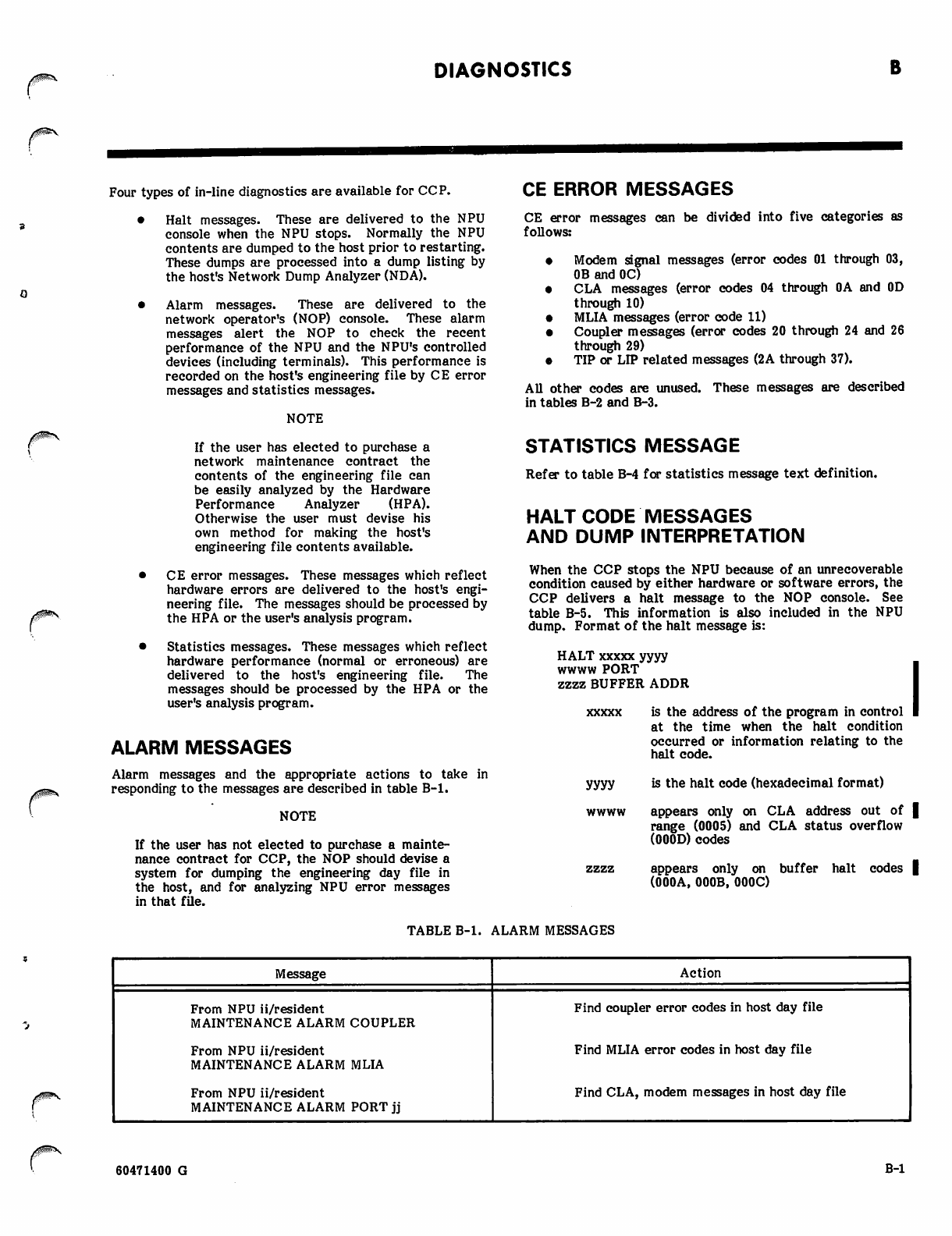
DIAGNOSTICS
Four types of in-line diagnostics are available for CCP.
• Halt messages. These are delivered to the NPU
console when the NPU stops. Normally the NPU
contents are dumped to the host prior to restarting.
These dumps are processed into a dump listing by
the host's Network Dump Analyzer (NDA).
• Alarm messages. These are delivered to the
network operator's (NOP) console. These alarm
messages alert the NOP to check the recent
performance of the NPU and the NPU's controlled
devices (including terminals). This performance is
recorded on the host's engineering file by CE error
messages and statistics messages.
NOTE
If the user has elected to purchase a
network maintenance contract the
contents of the engineering file can
be easily analyzed by the Hardware
Performance Analyzer (HPA).
Otherwise the user must devise his
own method for making the host's
engineering file contents available.
• CE error messages. These messages which reflect
hardware errors are delivered to the host's engi
neering file. The messages should be processed by
the HPA or the user's analysis program.
• Statistics messages. These messages which reflect
hardware performance (normal or erroneous) are
delivered to the host's engineering file. The
messages should be processed by the HPA or the
user's analysis program.
ALARM MESSAGES
Alarm messages and the appropriate actions to take in
responding to the messages are described in table B-l.
NOTE
If the user has not elected to purchase a mainte
nance contract for CCP, the NOP should devise a
system for dumping the engineering day file in
the host, and for analyzing NPU error messages
in that file.
CE ERROR MESSAGES
CE error messages can be divided into five categories as
follows:
Modem signal messages (error codes 01 through 03,
OB and OC)
CLA messages (error codes 04 through OA and OD
through 10)
MLIA messages (error code 11)
Coupler messages (error codes 20 through 24 and 26
through 29)
TIP or LIP related messages (2A through 37).
All other codes are unused. These messages are described
in tables B-2 and B-3.
STATISTICS MESSAGE
Refer to table B-4 for statistics message text definition.
HALT CODE MESSAGES
AND DUMP INTERPRETATION
When the CCP stops the NPU because of an unrecoverable
condition caused by either hardware or software errors, the
CCP delivers a halt message to the NOP console. See
table B-5. This information is also included in the NPU
dump. Format of the halt message is:
HALT xxxxx yyyy
w w w w P O R T I
zzzz BUFFER ADDR I
xxxxx is the address of the program in control I
at the time when the halt condition
occurred or information relating to the
halt code.
yyyy is the halt code (hexadecimal format)
wwww appears only on CLA address out of |
range (0005) and CLA status overflow
(000D) codes
zzzz appears only on buffer halt codes |
(000A, 000B, 000C)
TABLE B-l. ALARM MESSAGES
Message Action
From NPU ii/resident
MAINTENANCE ALARM COUPLER
From NPU ii/resident
MAINTENANCE ALARM MLIA
From NPU ii/resident
MAINTENANCE ALARM PORT jj
Find coupler error codes in host day file
Find MLIA error codes in host day file
Find CLA, modem messages in host day file
60471400 G B-l
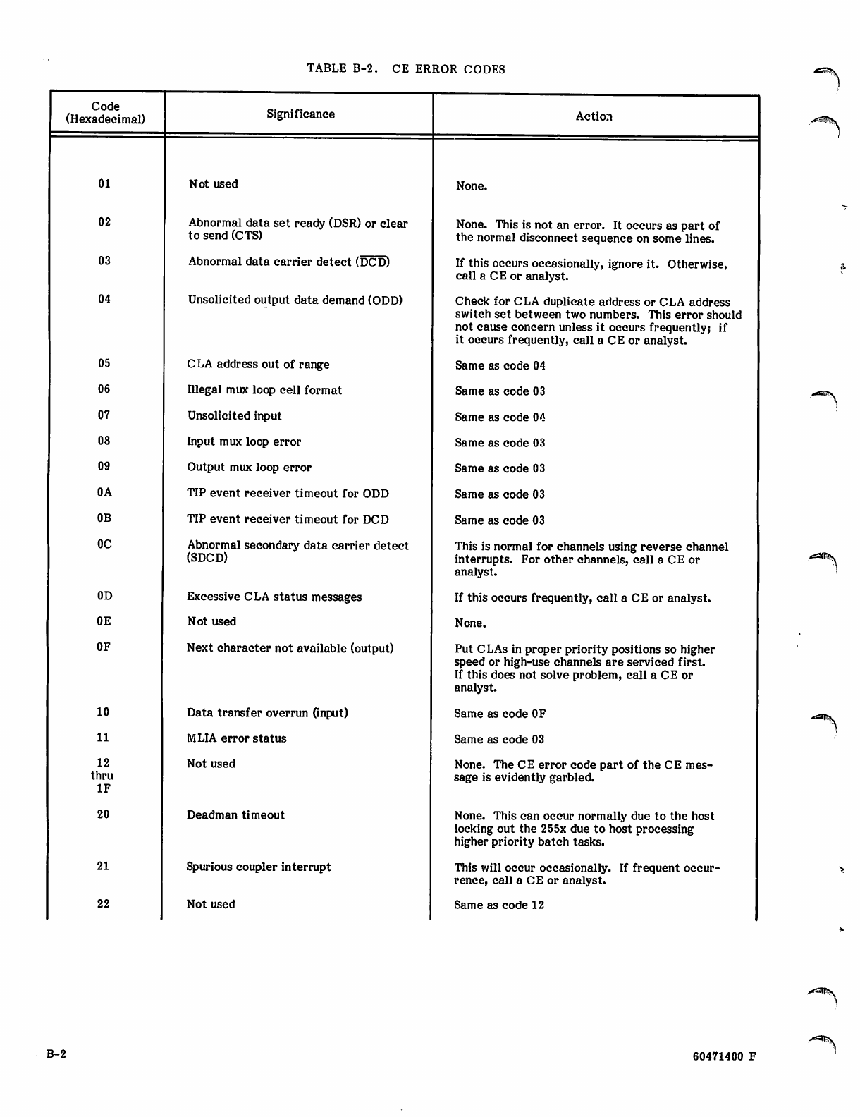
TABLE B-2. CE ERROR CODES
Code
(Hexadecimal) Significance Action
01 Not used None.
02 Abnormal data set ready (DSR) or clear
to send (CTS) None. This is not an error. It occurs as part of
the normal disconnect sequence on some lines.
03 Abnormal data carrier detect (DCD) If this occurs occasionally, ignore it. Otherwise,
call a CE or analyst.
04 Unsolicited output data demand (ODD) Check for CLA duplicate address or CLA address
switch set between two numbers. This error should
not cause concern unless it occurs frequently; if
it occurs frequently, call a CE or analyst.
05 C LA address out of range Same as code 04
06 Illegal mux loop cell format Same as code 03
07 Unsolicited input Same as code 04
08 Input mux loop error Same as code 03
09 Output mux loop error Same as code 03
OA TIP event receiver timeout for ODD Same as code 03
OB TIP event receiver timeout for DCD Same as code 03
OC Abnormal secondary data carrier detect
(SDCD)
This is normal for channels using reverse channel
interrupts. For other channels, call a CE or
analyst.
0D Excessive CLA status messages If this occurs frequently, call a CE or analyst.
0E Not used None.
OF Next character not available (output) Put CLAs in proper priority positions so higher
speed or high-use channels are serviced first.
If this does not solve problem, call a CE or
analyst.
10 Data transfer overrun (input) Same as code OF
11 MLIA error status Same as code 03
12
thru
IF
Not used None. The CE error code part of the CE mes
sage is evidently garbled.
20 Deadman timeout None. This can occur normally due to the host
locking out the 255x due to host processing
higher priority batch tasks.
21 Spurious coupler interrupt This will occur occasionally. If frequent occur
rence, call a CE or analyst.
22 Not used Same as code 12
B-2 60471400 F
-"filPv
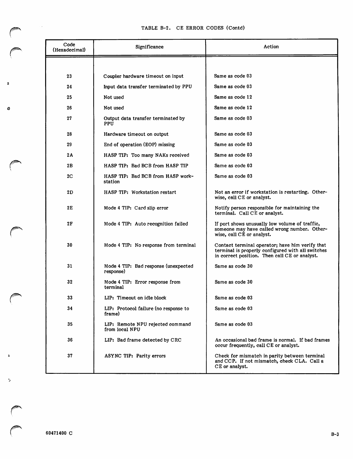
TABLE B-2. CE ERROR CODES (Contd)
Code
(Hexadecimal) Significance Action
23 Coupler hardware timeout on input Same as code 03
24 Input data transfer terminated by PPU Same as code 03
25 Not used Same as code 12
26 Not used Same as code 12
27 Output data transfer terminated by
PPU
Same as code 03
28 Hardware timeout on output Same as code 03
29 End of operation (EOP) missing Same as code 03
2A HASP TIP: Too many NAKs received Same as code 03
2B HASP TIP: Bad BCB from HASP TIP Same as code 03
2C HASP TIP: Bad BCB from HASP work
station
Same as code 03
2D HASP TIP: Workstation restart Not an error if workstation is restarting. Other
wise, call CE or analyst.
2E Mode 4 TIP: Card slip error Notify person responsible for maintaining the
terminal. Call CE or analyst.
2F Mode 4 TIP: Auto recognition failed If port shows unusually low volume of traffic,
someone may have called wrong number. Other
wise, call CE or analyst.
30 Mode 4 TIP: No response from terminal Contact terminal operator; have him verify that
terminal is properly configured with all switches
in correct position. Then call CE or analyst.
31 Mode 4 TIP: Bad response (unexpected
response)
Same as code 30
32 Mode 4 TIP: Error response from
terminal
Same as code 30
33 LIP: Timeout on idle block Same as code 03
34 LIP: Protocol failure (no response to
frame)
Same as code 03
35 LIP: Remote NPU rejected command
from local NPU
Same as code 03
36 LIP: Bad frame detected by CRC An occasional bad frame is normal. If bad frames
occur frequently, call CE or analyst.
37 ASYNC TIP: Parity errors Check for mismatch in parity between terminal
and CCP. If not mismatch, check CLA. Call a
CE or analyst.
60471400 C B-3
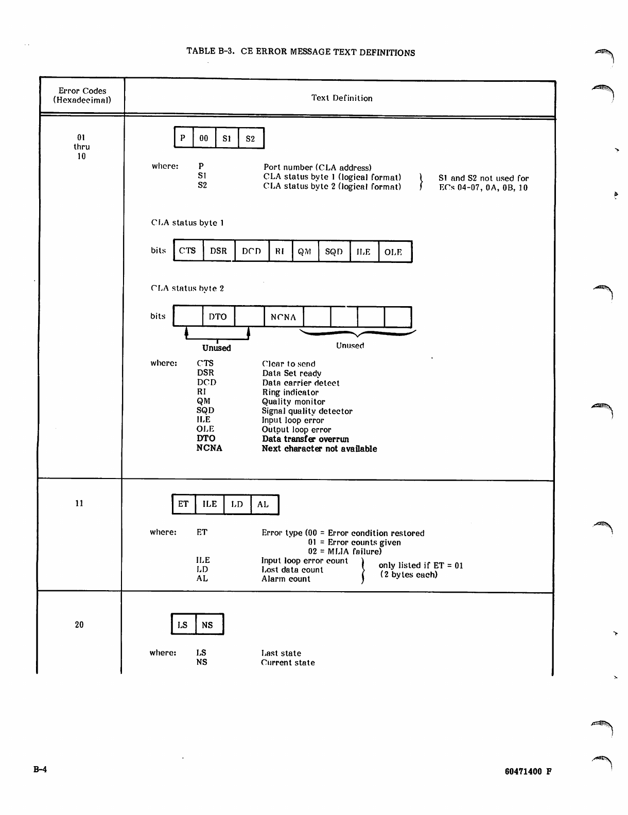
TABLE B-3. CE ERROR MESSAGE TEXT DEFINITIONS jtfaE^v
Error Codes
(Hexadecimal) Text Definition
01
thru
10
00 Sl S2
where:
Sl
S2
Port number (CLA address)
CLA status byte 1 (logical format)
CLA status byte 2 (logical format)
SI and S2 not used for
ECs 04-07, 0A, 0B, 10
CLA status bvte 1
bits
PLA status bvte 2
CTS DSR DCP RI QM SQD ILE OLF
11
20
bits
where:
DTO NCNA
I
Unused Unused
CTS Clear to send
DSR Data Set readv
DCD Data carrier detect
RI Ring indicator
QM Qualitv monitor
SQD Signal quality detector
ILE Input loop error
OLE OutDut loop error
DTO Data transfer overrun
NCNA Next character not available
ET ILE LD AL
where: ET
ILE
LD
AL
Error type (00 = Error condition restored
01 = Error counts given
02 = MLIA failure)
Input loop error count ) , ,. . . ... _.- _,
Lost data count "ft 1'sled ,fhf = 01
Alarm count ( <2 bV^ each)
LS NS
where: LS
NS Last state
Current state
B-4 60471400 F
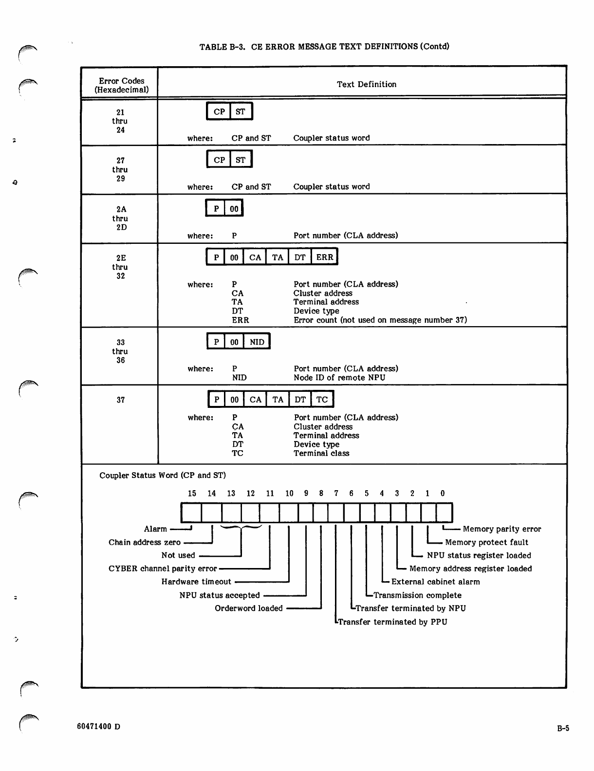
TABLE B-3. CE ERROR MESSAGE TEXT DEFINITIONS (Contd)
Error Codes
(Hexadecimal) Text Definition
21
thru
24
EH ST
where: CP and ST Coupler status word
27
thru
29
| CP | ST |
where: CP and ST Coupler status word
2A
thru
2D
1 P 1 oo I
w h e r e : P Port number (CLA address)
2E
thru
32
00 CA TA DT ERR
where:
CA
TA
DT
ERR
Port number (CLA address)
Cluster address
Terminal address
Device type
Error count (not used on message number 37)
33
thru
36
00 NID
where:
NID
Port number (CLA address)
Node ID of remote NPU
37 00 CA TA DT TC
where:
CA
TA
DT
TC
Port number (CLA address)
Cluster address
Terminal address
Device type
Terminal class
Coupler Status Word (CP and ST)
1 5 1 4 1 3 1 2 1 1 1 0 9 8 7 6 5 4 3 2 1 0
Alarm —
Chain address zero
Not used
CYBER channel parity error ■
Hardware timeout
NPU status accepted
Order word loaded
Ll Memory parity error
Memory protect fault
L— NPU status register loaded
•— Memory address register loaded
L- External cabinet alarm
•—Transmission complete
^■Transfer terminated by NPU
••Transfer terminated by PPU
60471400 D B-5
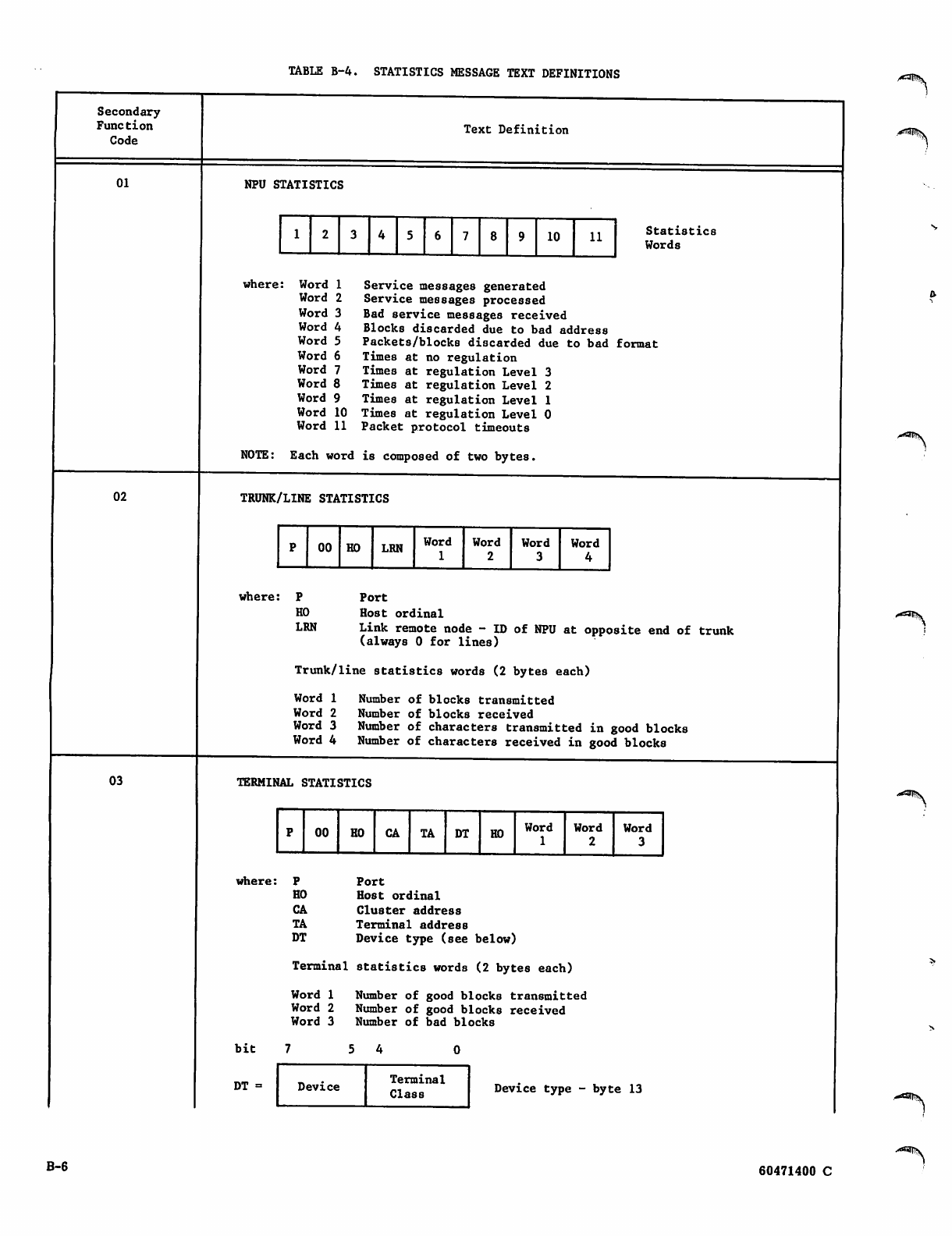
TABLE B-4. STATISTICS MESSAGE TEXT DEFINITIONS
Secondary
Function
Code
01
Text Definition
NPU STATISTICS
1 2 10 11 Statistics
Words
where:
02
Word 1
Word 2
Word
Word
Word
Word
Word
Word 8
Word 9
Word 10
Word 11
Service messages generated
Service messages processed
Bad service messages received
Blocks discarded due to bad address
Packets/blocks discarded due to bad format
Times at no regulation
Times at regulation Level 3
Times at regulation Level 2
Times at regulation Level 1
Times at regulation Level 0
Packet protocol timeouts
NOTE: Each word is composed of two bytes,
TRUNK/LINE STATISTICS
p00 HO LRN Word
1
Word
2
Word
3
Word
4
where:
HO
LRN
Port
Host ordinal
Link remote node - ID of NPU at opposite end of trunk
(always 0 for lines)
03
Trunk/line statistics words (2 bytes each)
Word 1 Number of blocks transmitted
Word 2 Number of blocks received
Word 3 Number of characters transmitted in good blocks
Word 4 Number of characters received in good blocks
TERMINAL STATISTICS
p00 K0 CA TA DT HO Word
1
Word
2
Word
3
^s
where: P P o r t
HO Host ordinal
C A C l u s t e r a d d r e s s
TA Terminal address
DT Device type (see below)
Terminal statistics words (2 bytes each)
Word 1 Number of good blocks transmitted
Word 2 Number of good blocks received
Word 3 Number of bad blocks
bit
DT = Device Terminal
Class Device type - byte 13
B-6 60471400 C
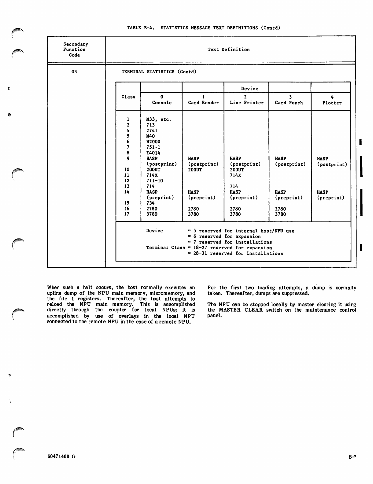
TABLE B-4. STATISTICS MESSAGE TEXT DEFINITIONS (Contd)
jrGUP*^
Secondary
Function Te x t D e fi n i t i o n
Code
03 TERMINAL STATISTICS (Contd)
Class
Device
0 1 2
Console Card Reader L i ne P r inte r Card Punch Plotter
1M33, etc.
2713
42741
5M40
6H2000
7751-1
8T4014
9HASP HASP HASP HASP HASP
(postprint) (postprint) ( p o s t p r i n t ) (postprint) (postprint)
10 200UT 200UT 200UT
11 714X 714X
12 711-10
13 714 714
14 HASP HASP HASP HASP HASP
( p r e p r i n t ) ( p r e p r i n t ) ( p r e p r i n t ) ( p r e p r i n t ) ( p r e p r i n t )
15 734
16 2780 2780 2780 2780
17 3780 3780 3780 3780
Device = 5 reserved for internal host/NPU use
= 6 reserved for expansion
= 7 reserved for installations
Terminal Class = 18-27 reserved for expansion
= 28-31 reserved for installations
y ^ s
When such a halt occurs, the host normally executes an
upline dump of the NPU main memory, micromemory, and
the file 1 registers. Thereafter, the host attempts to
reload the NPU main memory. This is accomplished
directly through the coupler for local NPUs; it is
accomplished by use of overlays in the local NPU
connected to the remote NPU in the case of a remote NPU.
For the first two loading attempts, a dump is normally
taken. Thereafter, dumps are suppressed.
The NPU can be stopped locally by master clearing it using
the MASTER CLEAR switch on the maintenance control
panel.
60471400 G B-7
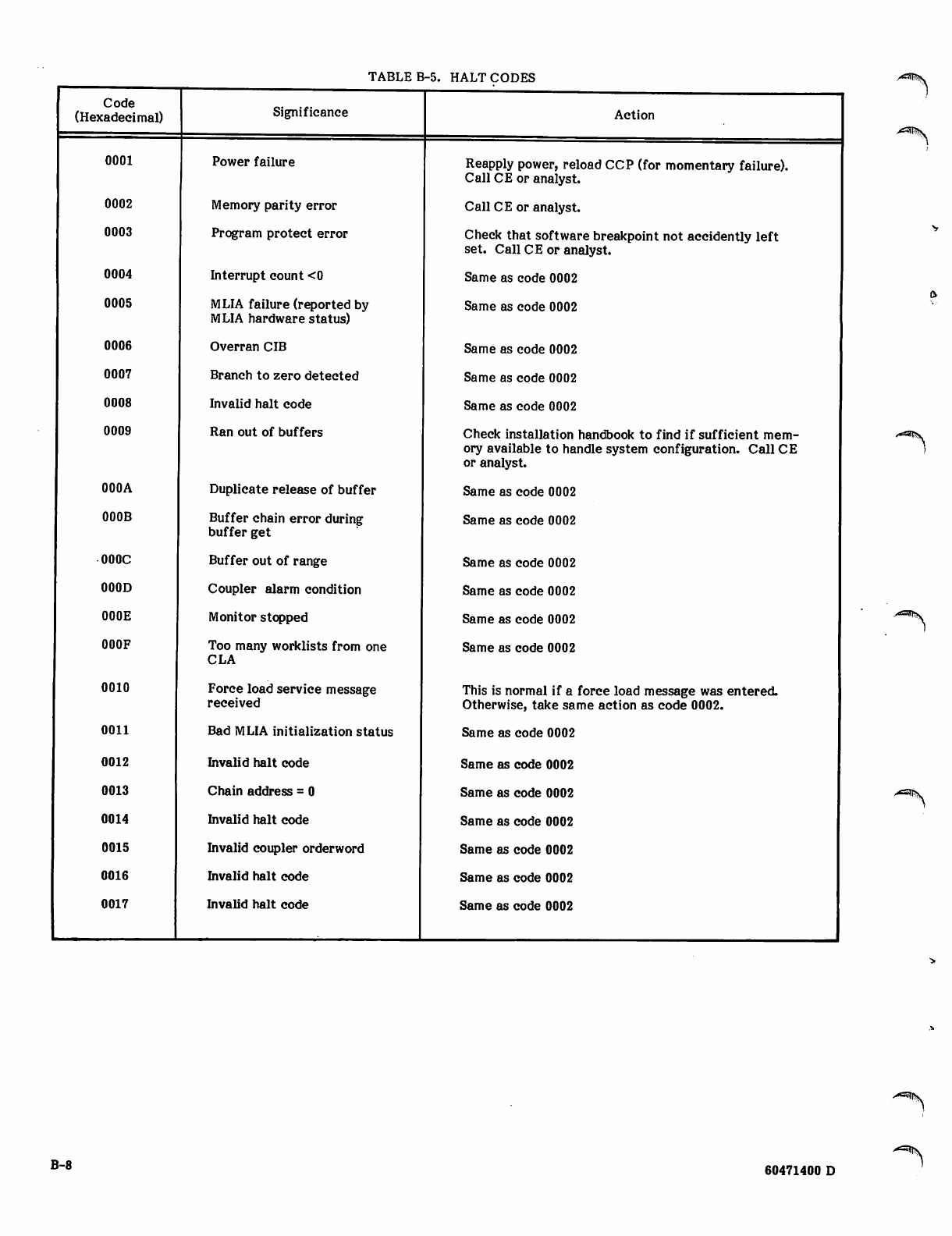
TABLE B-5. HALT CODES
Code
(Hexadecimal)
0001
0002
0003
0004
0005
0006
0007
0008
0009
000A
000B
000C
000D
000E
000F
0010
0011
0012
0013
0014
0015
0016
0017
Significance
Power failure
Memory parity error
Program protect error
Interrupt count <0
MLIA failure (reported by
MLIA hardware status)
Overran CIB
Branch to zero detected
Invalid halt code
Ran out of buffers
Duplicate release of buffer
Buffer chain error during
buffer get
Buffer out of range
Coupler alarm condition
Monitor stopped
Too many worklists from one
CLA
Force load service message
received
Bad MLIA initialization status
Invalid halt code
Chain address = 0
Invalid halt code
Invalid coupler orderword
Invalid halt code
Invalid halt code
Action
Reapply power, reload CCP (for momentary failure).
Call CE or analyst.
Call CE or analyst.
Check that software breakpoint not accidently left
set. Call CE or analyst.
Same as code 0002
Same as code 0002
Same as code 0002
Same as code 0002
Same as code 0002
Check installation handbook to find if sufficient mem
ory available to handle system configuration. Call CE
or analyst.
Same as code 0002
Same as code 0002
Same as code 0002
Same as code 0002
Same as code 0002
Same as code 0002
This is normal if a force load message was entered.
Otherwise, take same action as code 0002.
Same as code 0002
Same as code 0002
Same as code 0002
Same as code 0002
Same as code 0002
Same as code 0002
Same as code 0002
>C3tf??y
/"aaiS\
A ^ S .
A ^ t S
B-8 60471400 D
/*^!K
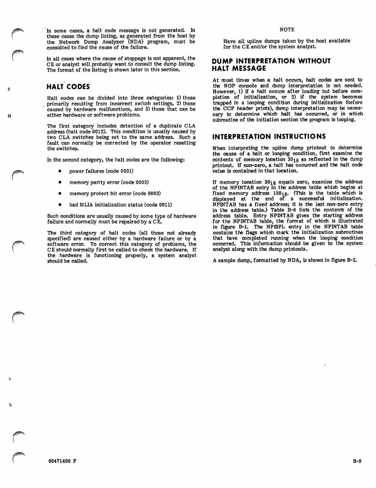
In some cases, a halt code message is not generated. In
these cases the dump listing, as generated from the host by
the Network Dump Analyzer (NDA) program, must be
consulted to find the cause of the failure.
In all eases where the cause of stoppage is not apparent, the
CE or analyst will probably want to consult the dump listing.
The format of the listing is shown later in this section.
HALT CODES
Halt codes can be divided into three categories: 1) those
primarily resulting from incorrect switch settings, 2) those
caused by hardware malfunctions, and 3) those that can be
either hardware or software problems.
The first category includes detection of a duplicate CLA
address (halt code 0012). This condition is usually caused by
two CLA switches being set to the same address. Such a
fault can normally be corrected by the operator resetting
the switches.
In the second category, the halt codes are the following:
• power failures (code 0001)
• memory parity error (code 0002)
• memory protect bit error (code 0003)
• bad MLIA initialization status (code 0011)
Such conditions are usually caused by some type of hardware
failure and normally must be repaired by a CE.
The third category of halt codes (all those not already
specified) are caused either by a hardware failure or by a
software error. To correct this category of problems, the
CE should normally first be called to check the hardware. If
the hardware is functioning properly, a system analyst
should be called.
NOTE
Have all upline dumps taken by the host available
for the CE and/or the system analyst.
DUMP INTERPRETATION WITHOUT
HALT MESSAGE
At most times when a halt occurs, halt codes are sent to
the NOP console and dump interpretation is not needed.
However, 1) if a halt occurs after loading but before com
pletion of initialization, or 2) if the system becomes
trapped in a looping condition during initialization (before
the CCP header prints), dump interpretation may be neces
sary to determine which halt has occurred, or in which
subroutine of the initiation section the program is looping.
INTERPRETATION INSTRUCTIONS
When interpreting the upline dump printout to determine
the cause of a halt or looping condition, first examine the
contents of memory location 30^6 as reflected in the dump
printout. If non-zero, a halt has occurred and the halt code
value is contained in that location.
If memory location 30ig equals zero, examine the address
of the NPINTAB entry in the address table which begins at
fixed memory address 150ie« (This is the table which is
displayed at the end of a successful initialization.
NPINTAB has a fixed address; it is the last non-zero entry
in the address table.) Table B-6 lists the contents of the
address table. Entry NPINTAB gives the starting address
for the NPINTAB table, the format of which is illustrated
in figure B-l. The NPISFL entry in the NPINTAB table
contains the flags which mark the initialization subroutines
that have completed running when the looping condition
occurred. This information should be given to the system
analyst along with the dump printouts.
A sample dump, formatted by NDA, is shown in figure B-2.
60471400 F B-9
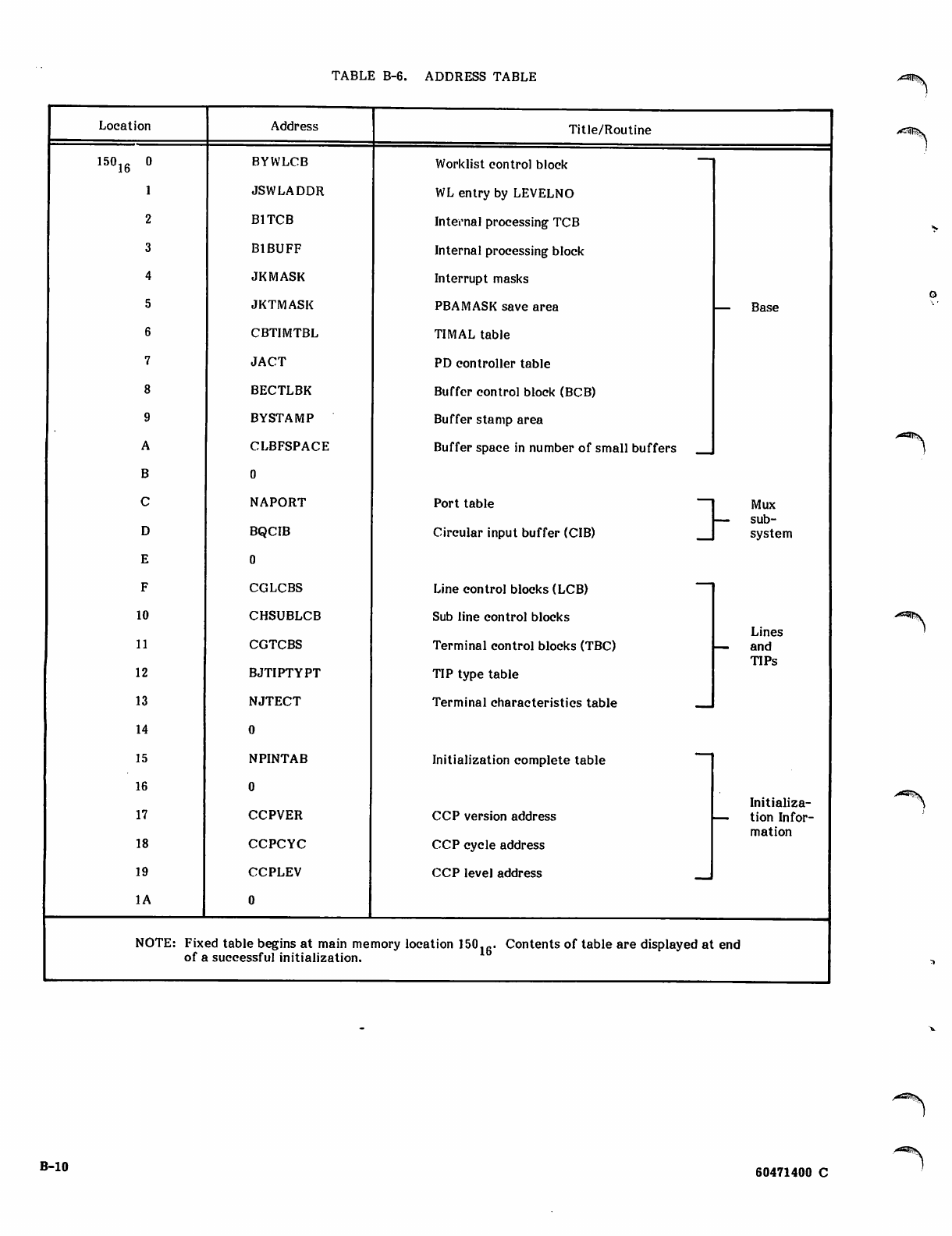
TABLE B-6. ADDRESS TABLE
Location Address Title/Routine
15016 0 BYWLCB Worklist control block
1JSWLADDR WL entry by LEVELNO
2B1TCB Internal processing TCB
3B1BUFF Internal processing block
4JKMASK Interrupt masks
5 JKTMASK PBAMASK save area — B ase
6CBTIMTBL TIMAL table
7JACT PD controller table
8BECTLBK Buffer control block (BCB)
9BYSTAMP Buffer stamp area
ACLBFSPACE Buffer space in number of small buffers
B0
CNAPORT Port table ~~ Mux
DBQCIB Circular input buffer (CIB)
— s u b
system
E0
FCGLCBS Line control blocks (LCB)
10 CHSUBLCB Sub line control blocks
11 CGTCBS Terminal control blocks (TBC)
Lines
— a n d
12 BJTIPTYPT TIP type table TIPs
13 NJTECT Terminal characteristics table
14
15 NPINTAB Initialization complete table
16
17 CCPVER CCP version address
Initializa-
— tion Infor
18 CCPCYC CCP cycle address mation
19 CCPLEV CCP level address
IA
NOTE: Fix
of 8
ed table begins at main me
i successful initialization. mory location 150.fi. Contents of table are displayed at end
a**is
B-10 60471400 C
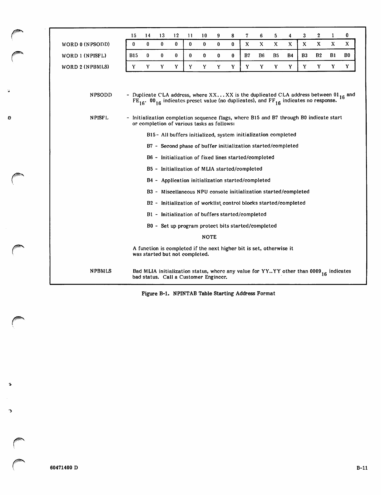
WORDO (NPSODD)
WORD 1 (NPISFL)
WORD 2 (NPBMLS)
NPSODD
NPISFL
15 14 13 12 11 10
0 0 0 0 0 0
B15 B7 B6 B5 B4 B3 B2 Bl BO
YYYYYYYYYYYYYYYY
NPBMLS
n
Duplicate CLA address, where XX... XX is the duplicated CLA address between 01 lg and
FE1fi. 00._ indicates preset value (no duplicates), and FFlfi indicates no response.
Initialization completion sequence flags, where B15 and B7 through BO indicate start
or completion of various tasks as follows:
B15- All buffers initialized, system initialization completed
B7 - Second phase of buffer initialization started/completed
B6 - Initialization of fixed lines started/completed
B5 - Initialization of MLIA started/completed
B4 - Application initialization started/completed
B3 - Miscellaneous NPU console initialization started/completed
B2 - Initialization of worklist control blocks started/completed
Bl - Initialization of buffers started/completed
BO - Set up program protect bits started/completed
NOTE
A function is completed if the next higher bit is set, otherwise it
was started but not completed.
Bad MLIA initialization status, where any value for YY..YY other than 0009-fi indicates
bad status. Call a Customer Engineer.
Figure B-l. NPINTAB Table Starting Address Format
60471400 D B-ll
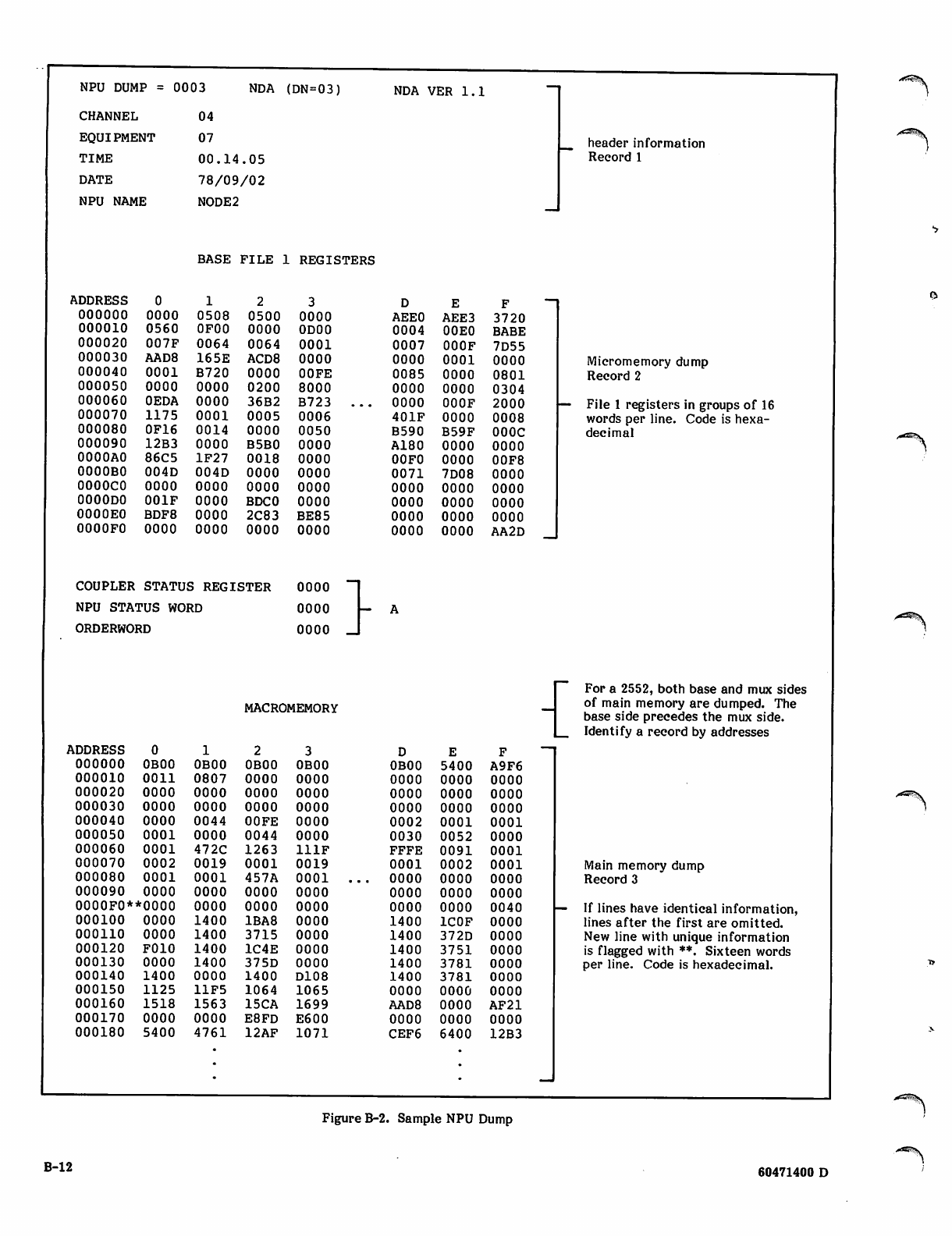
NPU DUMP = 0003
CHANNEL
EQUIPMENT
TIME
DATE
NPU NAME
NDA (DN=03)
04
07
00.14.05
78/09/02
NODE2
BASE FILE 1 REGISTERS
NDA VER 1.1
header information
Record 1
\DDRESS F ~ ~
oooooo oooo 0508 0500 0000 AEE0 AEE3 3720
000010 0560 0F00 0000 0D00 0004 00E0 BABE
000020 007F 0064 0064 0001 0007 000F 7D55
000030 AAD8 165E ACD8 0000 0000 0001 OOOO Micromemory dump
000040 0001 B720 0000 OOFE 0085 0000 0801 Record 2
000050 0000 0000 0200 8000 0000 0000 0304
000060 OEDA 0000 36B2 B 7 2 3 . . . 0 0 0 0 OOOF 2000 — File 1 registers in groups of 16
000070 1175 0001 0005 0006 401F OOOO 0008 words per line. Code is hexa
000080 0F16 0014 0000 0050 B590 B59F OOOC decimal
000090 12B3 0000 B5B0 OOOO A180 OOOO OOOO
0000A0 86C5 1F27 0018 0000 00F0 OOOO 00F8
0000B0 004D 004D 0000 0000 0071 7D08 OOOO
OOOOCO 0000 0000 0000 0000 0000 OOOO OOOO
OOOODO 001F 0000 BDCO oooo 0000 OOOO OOOO
0000E0 BDF8 0000 2C83 BE85 0000 OOOO OOOO
0000F0 0000 0000 0000 0000 0000 OOOO A A 2 D _
COUPLER STATUS REGISTER 0 0 0 0 " I
NPU STATUS WORD oooo - A
ORDERWORD oooo J
MACROMEMORY
ADDRESS
000000 OBOO OBOO OBOO OBOO OBOO
000010 0011 0807 OOOO OOOO OOOO
000020 0000 OOOO OOOO OOOO OOOO
000030 0000 OOOO OOOO OOOO OOOO
000040 oooo 0044 OOFE OOOO 0002
000050 0001 OOOO 0044 OOOO 0030
000060 0001 472C 1263 111F FFFE
000070 0002 0019 0001 0019 0001
000080 0001 0001 457A 0 0 0 1 . . . OOOO
000090 oooo OOOO OOOO OOOO OOOO
0000F0**0000 OOOO OOOO OOOO OOOO
000100 oooo 1400 1BA8 OOOO 1400
000110 oooo 1400 3715 OOOO 1400
000120 F010 1400 1C4E oooo 1400
000130 oooo 1400 375D oooo 1400
000140 1400 OOOO 1400 D108 1400
000150 1125 11F5 1064 1065 OOOO
000160 1518 1563 15CA 1699 AAD8
000170 OOOO OOOO E8FD E600 OOOO
000180 5400 4761 12AF 1071 CEF6
For a 2552, both base and mux sides
of main memory are dumped. The
base side precedes the mux side.
Identify a record by addresses
E
5400
0000
0000
0000
0001
0052
0091
0002
0000
0000
OOOO
1C0F
372D
3751
3781
3781
OOOO
OOOO
OOOO
6400
A9F6
OOOO
OOOO
OOOO
0001
OOOO
0001
0001
OOOO
OOOO
0040
OOOO
OOOO
oooo
oooo
oooo
oooo
AF21
oooo
12B3
Main memory dump
Record 3
If lines have identical information,
lines after the first are omitted.
New line with unique information
is flagged with **. Sixteen words
per line. Code is hexadecimal.
A^S.
Figure B-2. Sample NPU Dump
B-12 60471400 D
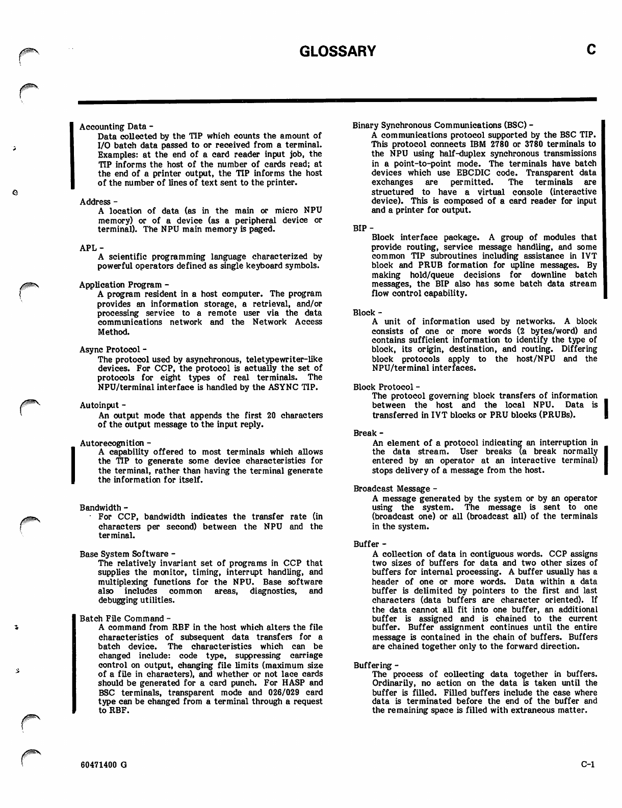
GLOSSARY
jtf'wy&'^s
Accounting Data -
Data collected by the TIP which counts the amount of
I/O batch data passed to or received from a terminal.
Examples: at the end of a card reader input job, the
TIP informs the host of the number of cards read; at
the end of a printer output, the TIP informs the host
of the number of lines of text sent to the printer.
Address -
A location of data (as in the main or micro NPU
memory) or of a device (as a peripheral device or
terminal). The NPU main memory is paged.
APL-
A scientific programming language characterized by
powerful operators defined as single keyboard symbols.
Application Program -
A program resident in a host computer. The program
provides an information storage, a retrieval, and/or
processing service to a remote user via the data
communications network and the Network Access
Method.
Async Protocol -
The protocol used by asynchronous, teletypewriter-like
devices. For CCP, the protocol is actually the set of
protocols for eight types of real terminals. The
NPU/terminal interface is handled by the ASYNC TIP.
Autoinput -
An output mode that appends the first 20 characters
of the output message to the input reply.
Autorecognition -
A capability offered to most terminals which allows
the TIP to generate some device characteristics for
the terminal, rather than having the terminal generate
the information for itself.
Bandwidth -
• For CCP, bandwidth indicates the transfer rate (in
characters per second) between the NPU and the
terminal.
Base System Software -
The relatively invariant set of programs in CCP that
supplies the monitor, timing, interrupt handling, and
multiplexing functions for the NPU. Base software
also includes common areas, diagnostics, and
debugging utilities.
Batch File Command -
A command from RBF in the host which alters the file
characteristics of subsequent data transfers for a
batch device. The characteristics which can be
changed include: code type, suppressing carriage
control on output, changing file limits (maximum size
of a file in characters), and whether or not lace cards
should be generated for a card punch. For HASP and
BSC terminals, transparent mode and 026/029 card
type can be changed from a terminal through a request
to RBF.
Binary Synchronous Communications (BSC) -
A communications protocol supported by the BSC TIP.
This protocol connects IBM 2780 or 3780 terminals to
the NPU using half-duplex synchronous transmissions
in a point-to-point mode. The terminals have batch
devices which use EBCDIC code. Transparent data
exchanges are permitted. The terminals are
structured to have a virtual console (interactive
device). This is composed of a card reader for input
and a printer for output.
BIP-
Block interface package. A group of modules that
provide routing, service message handling, and some
common TIP subroutines including assistance in IVT
block and PRUB formation for upline messages. By
making hold/queue decisions for downline batch
messages, the BIP also has some batch data stream
flow control capability.
Block -
A unit of information used by networks. A block
consists of one or more words (2 bytes/word) and
contains sufficient information to identify the type of
block, its origin, destination, and routing. Differing
block protocols apply to the host/NPU and the
NPU/terminal interfaces.
Block Protocol -
The protocol governing block transfers of information
between the host and the local NPU. Data is
transferred in IVT blocks or PRU blocks (PRUBs).
Break -
An element of a protocol indicating an interruption in
the data stream. User breaks (a break normally
entered by an operator at an interactive terminal)
stops delivery of a message from the host.
Broadcast Message -
A message generated by the system or by an operator
using the system. The message is sent to one
(broadcast one) or all (broadcast all) of the terminals
in the system.
Buffer -
A collection of data in contiguous words. CCP assigns
two sizes of buffers for data and two other sizes of
buffers for internal processing. A buffer usually has a
header of one or more words. Data within a data
buffer is delimited by pointers to the first and last
characters (data buffers are character oriented). If
the data cannot all fit into one buffer, an additional
buffer is assigned and is chained to the current
buffer. Buffer assignment continues until the entire
message is contained in the chain of buffers. Buffers
are chained together only to the forward direction.
Buffering -
The process of collecting data together in buffers.
Ordinarily, no action on the data is taken until the
buffer is filled. Filled buffers include the case where
data is terminated before the end of the buffer and
the remaining space is filled with extraneous matter.
60471400 G C-l
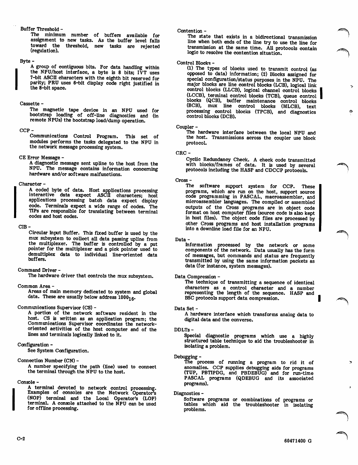
Buffer Threshold -
The minimum number of buffers available for
assignment to new tasks. As the buffer level falls
toward the threshold, new tasks are rejected
(regulation).
Byte-
A group of contiguous bits. For data handling within
the NPU/host interface, a byte is 8 bits; IVT uses
7-bit ASCII characters with the eighth bit reserved for
parity; PRU uses 6-bit display code right justified in
the 8-bit space.
Cassette -
The magnetic tape device in an NPU used for
bootstrap loading of off-line diagnostics and (in
remote NPUs) the bootstrap load/dump operation.
CCP-
Communications Control Program. This set of
modules performs the tasks delegated to the NPU in
the network message processing system.
CE Error Message -
A diagnostic message sent upline to the host from the
NPU. The message contains information concerning
hardware and/or software malfunctions.
Character -
A coded byte of data. Host applications processing
interactive data expect ASCII characters; host
applications processing batch data expect display
code. Terminals expect a wide range of codes. The
TIPs are responsible for translating between terminal
codes and host codes.
CIB-
Circular Input Buffer. This fixed buffer is used by the
mux subsystem to collect all data passing upline from
the multiplexer. The buffer is controlled by a put
pointer for the multiplexer and a pick pointer used to
demultiplex data to individual line-oriented data
buffers.
Command Driver -
The hardware driver that controls the mux subsystem.
Common Area -
Areas of main memory dedicated to system and global
data. These are usually below address 100016.
Communications Supervisor (CS) -
A portion of the network software resident in the
host. CS is written as an application program; the
Communications Supervisor coordinates the network-
oriented activities of the host computer and of the
lines and terminals logically linked to it.
Configuration -
See System Configuration.
Connection Number (CN) -
A number specifying the path (line) used to connect
the terminal through the NPU to the host.
Console -
A terminal devoted to network control processing.
Examples of consoles are the Network Operator's
(NOP) terminal and the Local Operator's (LOP)
terminal. A console attached to the NPU can be used
for offline processing.
Contention -
The state that exists in a bidirectional transmission
line when both ends of the line try to use the line for
transmission at the same time. All protocols contain
logic to resolve the contention situation.
Control Blocks -
(1) The types of blocks used to transmit control (as
opposed to data) information; (2) Blocks assigned for
special configuration/status purposes in the NPU. The
major blocks are line control blocks (LCB), logical link
control blocks (LLCB), logical channel control blocks
(LCCB), terminal control blocks (TCB), queue control
blocks (QCB), buffer maintenance control blocks
(BCB), mux line control blocks (MLCB), text
processing control blocks (TPCB), and diagnostics
control blocks (DCB).
Coupler -
The hardware interface between the local NPU and
the host. Transmissions across the coupler use block
protocol.
CRC-
Cyclic Redundancy Check. A check code transmitted
with blocks/frames of data. It is used by several
protocols including the HASP and CDCCP protocols.
Cross -
The software support system for CCP. These
programs, which are run on the host, support source
code programming in PASCAL, macroassembler, and
microassembler languages. The compiled or assembled
outputs of the Cross programs are in object code
format on host computer files (source code is also kept
in host files). The object code files are processed by
other Cross programs and host installation programs
into a downline load file for an NPU.
Data-
Information processed by the network or some
components of the network. Data usually has the form
of messages, but commands and status are frequently
transmitted by using the same information packets as
data (for instance, system messages).
Data Compression -
The technique of transmitting a sequence of identical
characters as a control character and a number
representing the length of the sequence. HASP and
BSC protocols support data compression.
Data Set -
A hardware interface which transforms analog data to
digital data and the converse.
DDLTs -
Special diagnostic programs which use a highly
structured table technique to aid the troubleshooter in
isolating a problem.
Debugging -
The process of running a program to rid it of
anomalies. CCP supplies debugging aids for programs
(TUP, PBTIPDG, and PBDEBUG) and for run-time
PASCAL programs (QDEBUG and its associated
programs).
Diagnostics -
Software programs or combinations of programs or
tables which aid the troubleshooter in isolating
problems.
-«%
,'^^S.
C-2 60471400 G
Direct Calls -
The method of passing control directly from one
program to another. This is the usual transfer mode
for CCP. Some CCP calls are indirect, through the
monitor. Such OPS level indirect calls pass
information to the called program through parameter
areas called worklists. See Worklist.
Directories -
Tables in CCP which contain information used to route
blocks to the proper interface and line. There are
directories for source and destination node and for
connection number. A routed message is attached to
the TCB for the line over which the message will pass.
DMA-
Direct Memory Access. The high-speed I/O channel to
the NPU main memory. This channel is used for
host/NPU buffered transfers.
DN-
Destination Node. The network node to which a
message is directed; for instance, the DN of an upline
message may be the host process (CS) which passes the
message to the application program responsible for
processing the message.
Downline -
The direction of output information flow, from host to
I NPU to terminal.
Dump-
The process of transferring the contents of the NPU
main memory, registers, and file 1 registers to the
host. The dump can be processed by the Network
Dump Analyzer in the host to produce a listing of the
dumped hexadecimal information.
Echo-
The process of displaying a keystroke on a terminal's
display. Echoing can be done from the TIP, from a
modem, or from the terminal itself.
Format Effectors -
Characters in an output data stream that determine
the appearance of data at the terminal. A format
effector usually takes the form of a single character
in the output message. For printers, the character is
translated by the output side of the TIP into a
combination of carriage returns, line feeds, or spaces.
Similarly, FEs for displays can command new lines,
screen clearing, or cursor positioning.
Frame -
A medium for transmitting data across a high-speed
link. Frames of different types are used by the LIP
and by the X.25 TIP. A frame provides high data
density in bit-serial format over data-grade lines.
Data assurance is also provided.
Frame (LIP) -
The basic communications unit used in trunk (NPU to
NPU) communications. Frames are composed of
control bytes, a CRC sum, and (in some cases) data
bytes in sub-block sequence. A sub-block may be a
block protocol block or a part of a block. Frames are
transmitted as a sequence of bytes through the mux
subsystem.
Frame (MUX) -
The mux subsystem uses a hardware-controlled frame
on the input and output mux loops.
Full Duplex (FDX) -
A transmission mode allowing data transfer in both
directions at the same time. An FDX system requires
a dual set of data lines, each set dedicated to
transmission in one direction only.
Function Codes -
Codes used by the service module to designate the
type of function (command or status) being
transmitted. Two codes are defined: Primary
Function Code (PFC) and Secondary Function Code
(SFC). See Appendix C of the CCP System
Programmer's Reference Manual for definitions of
these codes.
FE-
Format Effectors. See below.
File-
A unit of batch data. Files are transferred between
application programs and terminals by using PRUBs on
the NPU's host side and transmission blocks on the
NPU's terminal side. A file contains one or more
records. Example: a card reader job can consist of a
file containing the card image records of all the cards
in the job deck.
File Registers -
The two sets of microregisters (file 1 and file 2) in the
NPU. File 1 registers contain parameter information
that is reloaded whenever the NPU is initialized.
Microprograms using file 1 registers may also change
values in them. File 2 registers are invariant
firmware registers that come preprogrammed with the
NPU.
Global Variables -
PASCAL variables which are defined for use by any
CCP program. Contrast global variables with local
variables, which are identified only within a program.
Halt Codes -
Codes generated by the NPU when it executes a
soft-stop. These codes, which indicate the cause of
the stoppage, are sent to the host's engineering file. I
They are also contained in a CCP dump. |
Half Duplex (HDX) -
A transmission mode allowing data transfer in one
direction at a time. Normally a single set of data
lines carry input, output, and part of the control
information. Contention for use is possible in HDX
mode and must be resolved by the protocol governing
line transfers.
60471400 G C-3
HASP-
A protocol based on the BSC protocol; it is used by
HASP workstations. A workstation has both
interactive and batch devices. The standard code of
all HASP devices is EBCDIC; however, transparent
data exchanges with the host are also permitted. The
HASP TIP converts interactive HASP data between
EBCDIC transmission blocks and ASCn IVT blocks; it
converts batch HASP data between EBCDIC
transmission blocks and display code PRUBs.
Header -
The portion or portions of a message holding
information about the message source, destination,
and type. During network movement, a message can
acquire several headers. For example, during
movement of a message from a terminal to the host
over an X.25/NOS network, the message acquires the
following headers: one at the terminal (also a trailer),
one for the frame, one for the packet, and another for
the host block. Headers are discarded by the
appropriate stage of processing, so that in this
example, the host sees only the host block header.
Conversely, headers are generated and discarded as
needed downline, so that the terminal sees only the
terminal header (and trailer).
High-Speed Synchronous Line -
A data transmission line operating at or above 19,200
baud. These lines are normally used for local
LIP/remote LIP transfers and for PDN/NOS network
transfers.
HIP-
Host Interface Package. The CCP program which
handles block transfers across the host/local NPU
interface. The HIP transfers control blocks and data
blocks (IVT blocks or PRUBs).
Host-
The computer that controls the network and contains
the applications programs that process network
messages.
ID-
Identifiers. Identifiers can refer to port/subport,
nodes, lines, links, or terminals. Any hardware
element or connection can have an ID, normally a
sequentially assigned number.
Initialization -
The process of loading an NPU and optionally dumping
the NPU contents. After downline loading from the
host, the NPU network-oriented tables are configured
by the host so that all network processors have the
same IDs for all network terminals, lines, trunks, etc.
Input Buffer -
A data buffer reserved by CCP for receiving an upline
message for the host. These buffers are assigned and
released dynamically. Contrast with the CIB on the
mux subsystem interface.
Interface (NPU) -
The set of hardware and software that permits
transfers between the NPU and an external device.
There are three principal interfaces: to the host
through a coupler (block protocol in IVT or PRU
format handled by a HIP), to a neighbor NPU via the
mux subsystem (CDCCP protocol handled by a LIP),
and to the terminals (various protocols). Standard
terminal protocols are handled by the ASYNC, BSC,
MODE 4, HASP, and X.25 TIPs.
Interrupts -
A set of hardware lines and software programs that
allow external events to interrupt NPU processing.
Interrupting programs allow preferential processing on
a priority basis. The lowest priority level is processed
by an OPS monitor.
I V T-
Interactive Virtual Terminal. A block protocol format
for interactive terminals. CCP TIPs convert all upline
interactive messages to this format (exception: no
transformations are made to transparent data except
to put the messages into block format). By this
method, application programs in the host need only to
be able to process interactive data in IVT format
rather than in the multiplicity of formats that real
terminals use. Downline messages from the host to
interactive terminals (including virtual consoles) are
converted from IVT to real terminal format. IVT
processing is controlled by the TIPs; the TIPs use some
common IVT modules.
IVT Commands -
A group of commands that aUow the operator at the
terminal or a host application program to control some
of the IVT transforms made by a TIP. These
commands can (1) change the destination of the
terminal characters for breaks and cancel signals, (2)
select output page format (such as page width and
length, number of padding characters after a line feed
or carriage return), (3) designate parity type, terminal
class, and other terminal-related features.
LCB-
Line Control Block. A table assigned to each active
line in the system. It contains configuration infor
mation as well as current processing information.
LCCB-
Logical channel control block. A data structure
holding information about logical channels. These are
used by the X.25 TIP for terminals connected to the
NOS network through a public data network.
Line-
A connection between an NPU and a terminal.
<SS53Sv
Link
A connection between two NPUs or an NPU and a
host. In release 3.1, a line which connects NPUs is the
same as a trunk.
L I P -
Link Interface Package. The CCP program which
handles frame transfers across a trunk; that is, across
the connection between a local and a remote NPU. A
LIP uses CDCCP protocol and interfaces on the local
NPU side to the HIP. On the remote NPU side, the
LIP interfaces with the appropriate TIP. In both local
and remote NPUs, the LIP interfaces with the mux
sub- system for transfer across the trunk.
LLCB-
Logical Link Control Block. A table assigned to each
logical link in the system which touches this NPU.
The table contains configuration information as well
as current processing information.
Load -
The processing of moving programs downline from the
host and storing them in the NPU main and
micromemory. Loading of a remote NPU is
accomplished by the host through the use of overlays
in the local NPU.
C-4 60471400 G
vs&%
Local NPU -
An NPU which is connected to the host via a coupler.
A local NPU always contains a HIP for processing
block protocol transfers across the host/local NPU
interface.
Logical Connection -
A logical message path established between two
application programs or between a network terminal
and an application program. Until terminated, the
logical connection allows messages to pass between
the two entities.
Logical Line -
The basic message unit of a terminal. In most cases a
logical line is designated by a carriage return. See
Physical Line.
Logical Link -
See Link.
Local Operator (LOP) -
The operator of that terminal in the network that is
connecting a specific application program in the host
to the messages being processed. The terminal by
default is the host terminal, but the LOP can be
transferred to any other interactive terminal in the
network. The operator manages the communications
elements of the network within the local computer
system by communicating with the Communications
Supervisor in the host computer. Contrast with
network operator. The local operator is an
administrative operator within the network and need
not be the host computer's operating system operator.
Loop Multiplexer (LM) -
The hardware which interfaces the CLAs (which
convert data between bit-serial digital and bit-parallel
digital character format) and the input and output
loops.
Low/Medium-Speed Voice-Grade Line -
A line that operates at bit transmission rates at or
below 19,200 baud. These lines characteristically
connect individual terminals to an NPU or to a PAD
access device. Such lines can be either dedicated or
dial-up. Normal telephone lines operate in this
transmission range.
Main Memory -
The macromemory of the NPU. It is partly dedicated
to programs and common areas; the remainder is
buffer area used for data and overlay programs. Word
size is 16 data bits plus three additonal bits for parity
and program protection. Memory is packaged in 16K
and 32K word increments.
Mask-
A bit pattern used in the interrupt subsystem to check
if an interrupt is of sufficiently high priority to be
processed now. An interrupt mask (M) register is used
in this processing.
Message -
A logical unit of information, as processed by an
application program. When transmitted over a
network, a message can consist of one or more
physical blocks.
Mode 4 -
A communications line transmission protocol for
synchronous terminals. The protocol requires the
polling of sources for input to the data
communications network. CCP supports Mode 4A, 4B
and 4C terminals. Mode 4A equipment is polled
through a single hardware address (usually that of the
console device), regardless of how many devices use
the address as the point of interface to the network.
Mode 4C equipment is polled through several hardware
addresses, depending on the point each device uses to
interface with the network. The Mode 4 TIP processes
the interface between the NPU and the Mode 4
terminals.
Modem -
A hardware device for converting analog levels to
digital signals and the converse. Long lines interface
to digital equipment via modems. Modem is
synonymous with data set.
Micromemory -
The micro portion of the NPU memory. This consists
of 2048 words of 60-bit length. 1024 words are Read
Only Memory (ROM); the remaining 1024 words are
Random Access Memory (RAM) and are alterable. The
ROM memory contains the emulator microprogram
that allows use of assembly language.
Microprocessor -
The portion of the NPU that processes the programs.
MLIA-
Multiplex Loop Interface Adapter. The hardware
portion of the mux subsystem that controls the mux
loops (input and output) as well as the interface
between the NPU and the mux subsystem.
Module -
See program.
Monitor -
The portion of the NPU base system software
responsible for time and space allocation within the
computer. The principal monitor program is OPSMON,
which executes OPS level programs by scanning a
table of programs which have pending tasks.
Mux Subsystem -
The portion of the base NPU software which performs
multiplexing tasks for upline and downline data, and
also demultiplexes upline data from the CIB and places
the data in line-oriented data input data buffers.
NAM-
See Network Access Method.
Neighbor NPUs -
Two NPUs connected to one another by means of a
trunk. The NPU connected to the host via a coupler is
designated as the local NPU. The other NPU is a
remote NPU; it is not connected directly to the host in
any fashion.
Network -
An interconnected set of network elements consisting
of a host, one or more NPUs, and terminals.
60471400 G C-5
Network Access Method (NAM) -
A software package that provides a generalized
method of using a communications network for
switching, buffering, queuing, and transmission of
data. NAM resides in the host.
Network Definition Language (NDL) -
The compiler-level language used to define the
network configuration file and local configuration file
contents.
Network Logical Address -
The address used by block protocol to establish routing
for the message. It consists of three parts; DN - the
destination node, SN - the source node, and CN - the
connection number.
Network Operator (NOP) -
An administrative operator at the network operator
console. This terminal by default is the host console,
but the NOP function can be assigned to any other
| terminal in the system. The network operator
manages the NPU hardware, linkages, and other
network elements of the entire data communications
network by communicating with the Network
Supervisor in the network control center host
computer. Contrast with local operator. The network
operator can also be a local operator, but need not be
the operating system operator for the host computer
at the network control center.
Network Processing Unit (NPU) -
The collection of 255X hardware and peripherals
together with the software that includes Commu
nications Control Processor (CCP) macromemory
modules. These CCP programs buffer and transmit
data between terminals and host computer.
Network Supervisor (NS) -
A portion of the network software which coordinates
all of the NPUs in the communications network. NS is
written as an application program.
Node -
A network element that creates, absorbs, switches,
and/or buffers message blocks. Typical system nodes
are NS and CS in the host, the coupler node of a local
NPU and a terminal node of a remote NPU.
Off-Line Diagnostics -
Optional diagnostics for the NPU that require the NPU
be disconnected from the network.
On-Line Diagnostics -
Optional diagnostics for the NPU that can be executed
while the NPU is connected to, and operating as a part
of the network. Individual lines being tested must,
however, be disconnected from the network. These
diagnostics are provided if the user purchases a
network maintenance contract.
OPS Monitor -
The NPU monitor. See Monitor.
Output Buffer -
Any buffer which is currently used to output
I information from the NPU to another NPU or to a
terminal via the mux subsystem.
Overlay Area -
An area in upper main memory which is used to
execute overlay programs.
Overlay Programs -
Programs which are not normally resident in main
memory but which are called into the buffer area of
main memory to execute special tasks. These
programs are downline loaded (usually) from the host
and perform such tasks as NPU initialization
debugging, loading/dumping a remote NPU, and on-line
diagnostics.
Packet -
A group of binary digits, including data and call
control signals, which is switched as a single unit. The
data, control signals, and error-control information
are arranged in a specific format.
Packet Assembly/Disassembly (PAD) -
Assembly: The accumulation of characters from an
asynchronous device into data blocks for transmission
via a PDN. Disassembly: The encoding of blocks for
transmission to an asynchronous terminal.
PAD SubTIP -
A subTIP used with the X.25 TIP which allows a class
of asynchronous terminals to communicate over a
public data network.
Paging (NPU) -
A method of executing programs and accessing data in
the NPU main memory region above 65K. Paging is
required for addressing where the address is larger
than 16 bits (NPU word size) in length.
Paging (Screen) -
The process of filling a CRT display with data and
holding additonal data for subsequent displays.
Changing the paged display is an operator controlled
function if the page wait option is selected. |
Parity -
A type of data assurance. The most common parity is
character parity; that is, the supplying of one extra bit
per character so that the sum of all the bits in the
character (including the parity bit) is always an even
or odd number.
PASCAL -
A high level programming language used for CCP
programs. Almost all CCP programs are written in
PASCAL language.
PFC-
Primary Function Code. See Function Codes.
Physical Line -
A string of data that is determined by the terminal's
physical characteristics (page width or line feed).
Contrast with logical line, which is determined by a
carriage return or other forwarding signal.
Physical Link -
A connection between two major network nodes such
as neighboring nodes. Messages can be transmitted
over active physical links.
Polling -
The action of checking terminals to find if an input
device is ready to transmit upline data. Certain TIPs
(such as Mode 4) poll terminal devices for data. The
host requests such polling; the TIP determines the
timing of the polling operation.
A ^ S \
,^Sfev
C-6 60471400 G
>^3s!v
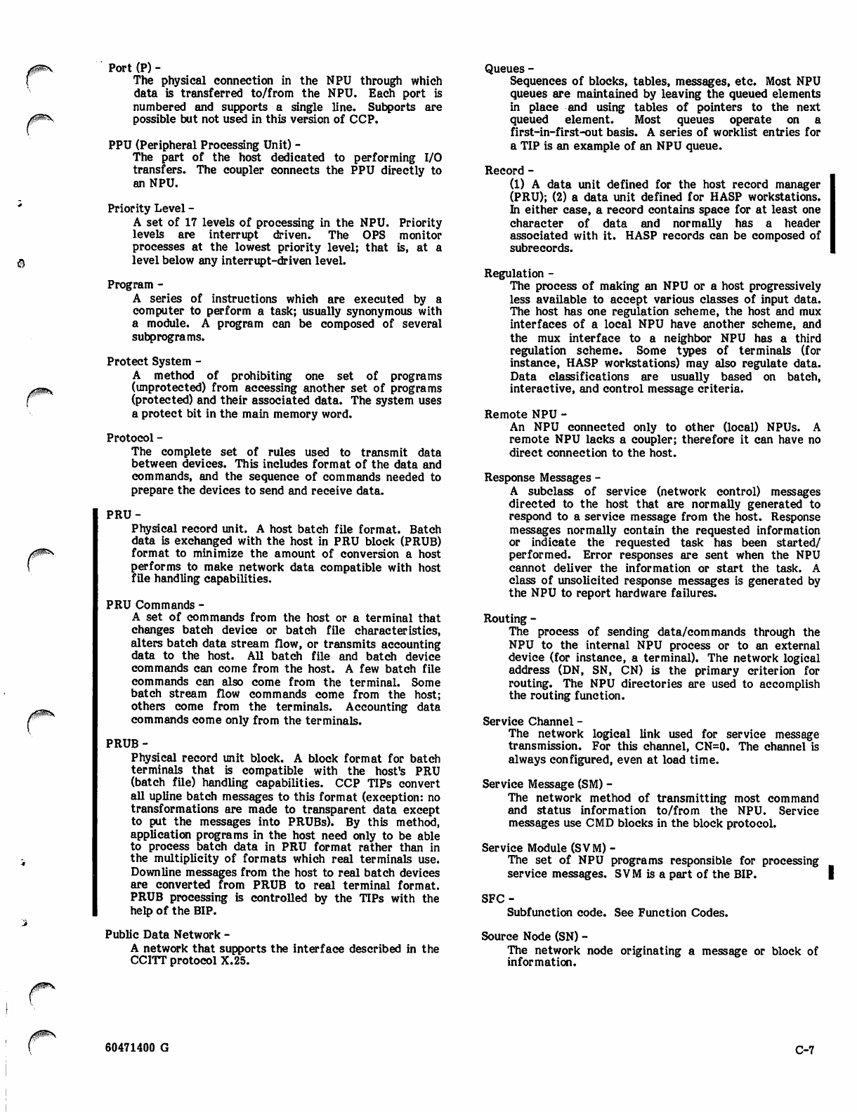
Port (P) -
The physical connection in the NPU through which
data is transferred to/from the NPU. Each port is
numbered and supports a single line. Subports are
possible but not used in this version of CCP.
PPU (Peripheral Processing Unit) -
The part of the host dedicated to performing I/O
transfers. The coupler connects the PPU directly to
an NPU.
Priority Level -
A set of 17 levels of processing in the NPU. Priority
levels are interrupt driven. The OPS monitor
processes at the lowest priority level; that is, at a
level below any interrupt-driven level.
Program -
A series of instructions which are executed by a
computer to perform a task; usually synonymous with
a module. A program can be composed of several
subprograms.
Protect System -
A method of prohibiting one set of programs
(unprotected) from accessing another set of programs
(protected) and their associated data. The system uses
a protect bit in the main memory word.
Protocol -
The complete set of rules used to transmit data
between devices. This includes format of the data and
commands, and the sequence of commands needed to
prepare the devices to send and receive data.
PRU-
Physical record unit. A host batch file format. Batch
data is exchanged with the host in PRU block (PRUB)
format to minimize the amount of conversion a host
performs to make network data compatible with host
file handling capabilities.
PRU Commands -
A set of commands from the host or a terminal that
changes batch device or batch file characteristics,
alters batch data stream flow, or transmits accounting
data to the host. All batch file and batch device
commands can come from the host. A few batch file
commands can also come from the terminal. Some
batch stream flow commands come from the host;
others come from the terminals. Accounting data
commands come only from the terminals.
PRUB-
Physical record unit block. A block format for batch
terminals that is compatible with the host's PRU
(batch file) handling capabilities. CCP TIPs convert
all upline batch messages to this format (exception: no
transformations are made to transparent data except
to put the messages into PRUBs). By this method,
application programs in the host need only to be able
to process batch data in PRU format rather than in
the multiplicity of formats which real terminals use.
Downline messages from the host to real batch devices
are converted from PRUB to real terminal format.
PRUB processing is controlled by the TIPs with the
help of the BIP.
Public Data Network -
A network that supports the interface described in the
CCITT protocol X.25.
Queues -
Sequences of blocks, tables, messages, etc. Most NPU
queues are maintained by leaving the queued elements
in place and using tables of pointers to the next
queued element. Most queues operate on a
first-in-first-out basis. A series of worklist entries for
a TIP is an example of an NPU queue.
Record -
(1) A data unit defined for the host record manager
(PRU); (2) a data unit defined for HASP workstations.
In either case, a record contains space for at least one
character of data and normally has a header
associated with it. HASP records can be composed of
subrecords.
Regulation -
The process of making an NPU or a host progressively
less available to accept various classes of input data.
The host has one regulation scheme, the host and mux
interfaces of a local NPU have another scheme, and
the mux interface to a neighbor NPU has a third
regulation scheme. Some types of terminals (for
instance, HASP workstations) may also regulate data.
Data classifications are usually based on batch,
interactive, and control message criteria.
Remote NPU -
An NPU connected only to other (local) NPUs. A
remote NPU lacks a coupler; therefore it can have no
direct connection to the host.
Response Messages -
A subclass of service (network control) messages
directed to the host that are normally generated to
respond to a service message from the host. Response
messages normally contain the requested information
or indicate the requested task has been started/
performed. Error responses are sent when the NPU
cannot deliver the information or start the task. A
class of unsolicited response messages is generated by
the NPU to report hardware failures.
Routing -
The process of sending data/commands through the
NPU to the internal NPU process or to an external
device (for instance, a terminal). The network logical
address (DN, SN, CN) is the primary criterion for
routing. The NPU directories are used to accomplish
the routing function.
Service Channel -
The network logical link used for service message
transmission. For this channel, CN=0. The channel is
always configured, even at load time.
Service Message (SM) -
The network method of transmitting most command
and status information to/from the NPU. Service
messages use CMD blocks in the block protocol.
Service Module (SVM) -
The set of NPU programs responsible for processing
service messages. SVM is a part of the BIP. |
SFC-
Subfunction code. See Function Codes.
Source Node (SN) -
The network node originating a message or block of
information.
60471400 G C-7
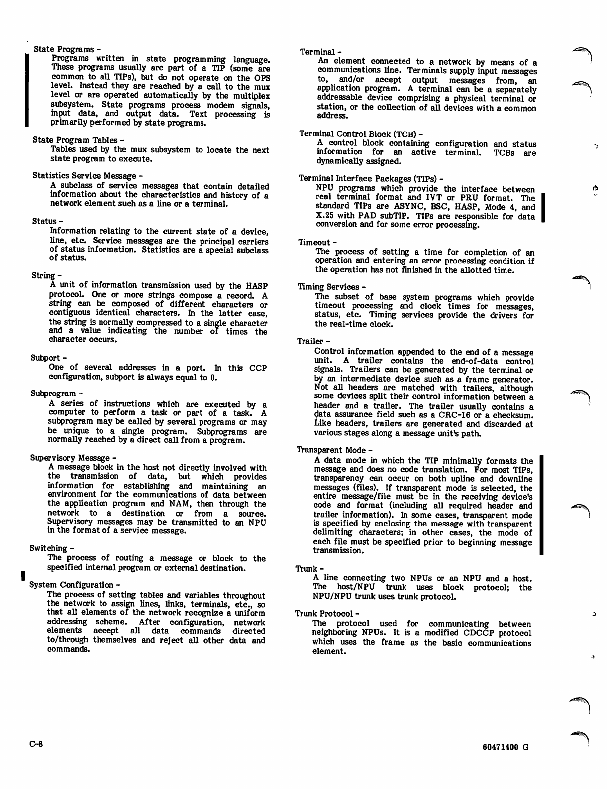
State Programs -
Programs written in state programming language.
These programs usually are part of a TIP (some are
common to all TIPs), but do not operate on the OPS
level. Instead they are reached by a call to the mux
level or are operated automatically by the multiplex
subsystem. State programs process modem signals,
input data, and output data. Text processing is
primarily performed by state programs.
State Program Tables -
Tables used by the mux subsystem to locate the next
state program to execute.
Statistics Service Message -
A subclass of service messages that contain detailed
information about the characteristics and history of a
network element such as a line or a terminal.
Status -
Information relating to the current state of a device,
line, etc. Service messages are the principal carriers
of status information. Statistics are a special subclass
of status.
String -
A unit of information transmission used by the HASP
protocol. One or more strings compose a record. A
string can be composed of different characters or
contiguous identical characters. In the latter case,
the string is normally compressed to a single character
and a value indicating the number of times the
character occurs.
Subport -
One of several addresses in a port. In this CCP
configuration, subport is always equal to 0.
Subprogram -
A series of instructions which are executed by a
computer to perform a task or part of a task. A
subprogram may be called by several programs or may
be unique to a single program. Subprograms are
normally reached by a direct call from a program.
Supervisory Message -
A message block in the host not directly involved with
the transmission of data, but which provides
information for establishing and maintaining an
environment for the communications of data between
the application program and NAM, then through the
network to a destination or from a source.
Supervisory messages may be transmitted to an NPU
in the format of a service message.
Switching -
The process of routing a message or block to the
specified internal program or external destination.
System Configuration -
The process of setting tables and variables throughout
the network to assign lines, links, terminals, etc., so
that all elements of the network recognize a uniform
addressing scheme. After configuration, network
elements accept all data commands directed
to/through themselves and reject all other data and
commands.
Terminal -
An element connected to a network by means of a
communications line. Terminals supply input messages
to, and/or accept output messages from, an
application program. A terminal can be a separately
addressable device comprising a physical terminal or
station, or the collection of all devices with a common
address.
Terminal Control Block (TCB) -
A control block containing configuration and status
information for an active terminal. TCBs are
dynamically assigned.
Terminal Interface Packages (TIPs) -
NPU programs which provide the interface between
real terminal format and IVT or PRU format. The
standard TIPs are ASYNC, BSC, HASP, Mode 4, and
X.25 with PAD subTIP. TIPs are responsible for data
conversion and for some error processing.
Timeout -
The process of setting a time for completion of an
operation and entering an error processing condition if
the operation has not finished in the allotted time.
Timing Services -
The subset of base system programs which provide
timeout processing and clock times for messages,
status, etc. Timing services provide the drivers for
the real-time clock.
Trailer -
Control information appended to the end of a message
unit. A trailer contains the end-of-data control
signals. Trailers can be generated by the terminal or
by an intermediate device such as a frame generator.
Not all headers are matched with trailers, although
some devices split their control information between a
header and a trailer. The trailer usually contains a
data assurance field such as a CRC-16 or a checksum.
Like headers, trailers are generated and discarded at
various stages along a message unit's path.
Transparent Mode -
A data mode in which the TIP minimally formats the
message and does no code translation. For most TIPs,
transparency can occur on both upline and downline
messages (files). If transparent mode is selected, the
entire message/file must be in the receiving device's
code and format (including all required header and
trailer information). In some cases, transparent mode
is specified by enclosing the message with transparent
delimiting characters; in other cases, the mode of
each file must be specified prior to beginning message
transmission.
Trunk-
A line connecting two NPUs or an NPU and a host.
The host/NPU trunk uses block protocol; the
NPU/NPU trunk uses trunk protocol.
Trunk Protocol -
The protocol used for communicating between
neighboring NPUs. It is a modified CDCCP protocol
which uses the frame as the basic communications
element.
C-8 60471400 G
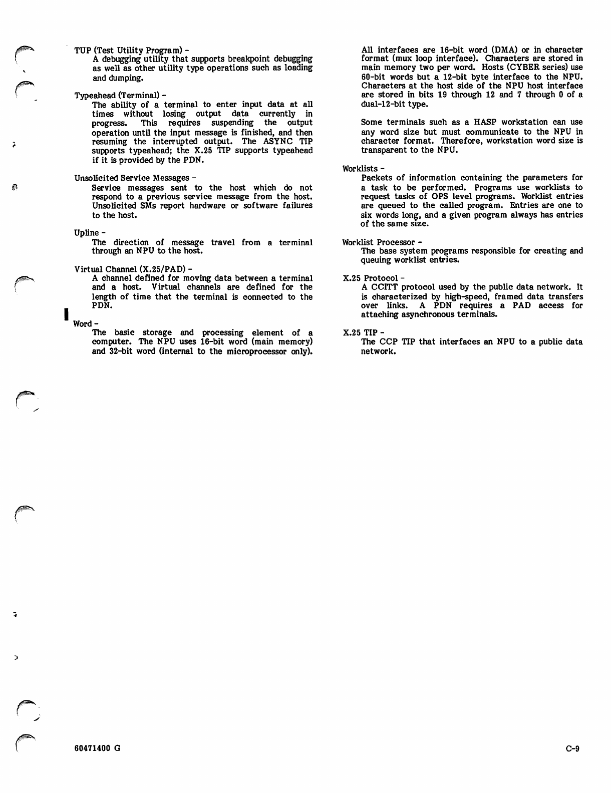
TUP (Test UtUity Program) -
A debugging utility that supports breakpoint debugging
as well as other utility type operations such as loading
and dumping.
Typeahead (Terminal) -
The ability of a terminal to enter input data at all
times without losing output data currently in
progress. This requires suspending the output
operation until the input message is finished, and then
resuming the interrupted output. The ASYNC TIP
supports typeahead; the X.25 TIP supports typeahead
if it is provided by the PDN.
Unsolicited Service Messages -
Service messages sent to the host which do not
respond to a previous service message from the host.
Unsolicited SMs report hardware or software failures
to the host.
Upline -
The direction of message
through an NPU to the host.
travel from a terminal
Virtual Channel (X.25/PAD) -
A channel defined for moving data between a terminal
and a host. Virtual channels are defined for the
length of time that the terminal is connected to the
PDN.
Word-
The basic storage and processing element of a
computer. The NPU uses 16-bit word (main memory)
and 32-bit word (internal to the microprocessor only).
All interfaces are 16-bit word (DMA) or in character
format (mux loop interface). Characters are stored in
main memory two per word. Hosts (CYBER series) use
60-bit words but a 12-bit byte interface to the NPU.
Characters at the host side of the NPU host interface
are stored in bits 19 through 12 and 7 through 0 of a
dual-12-bit type.
Some terminals such as a HASP workstation can use
any word size but must communicate to the NPU in
character format. Therefore, workstation word size is
transparent to the NPU.
Worklists -
Packets of information containing the parameters for
a task to be performed. Programs use worklists to
request tasks of OPS level programs. Worklist entries
are queued to the called program. Entries are one to
six words long, and a given program always has entries
of the same size.
Worklist Processor -
The base system programs responsible for creating and
queuing worklist entries.
X.25 Protocol -
A CCITT protocol used by the public data network. It
is characterized by high-speed, framed data transfers
over links. A PDN requires a PAD access for
attaching asynchronous terminals.
X.25 TIP -
The CCP TIP that interfaces an NPU to a public data
network.
J0&&*.
60471400 G C-9

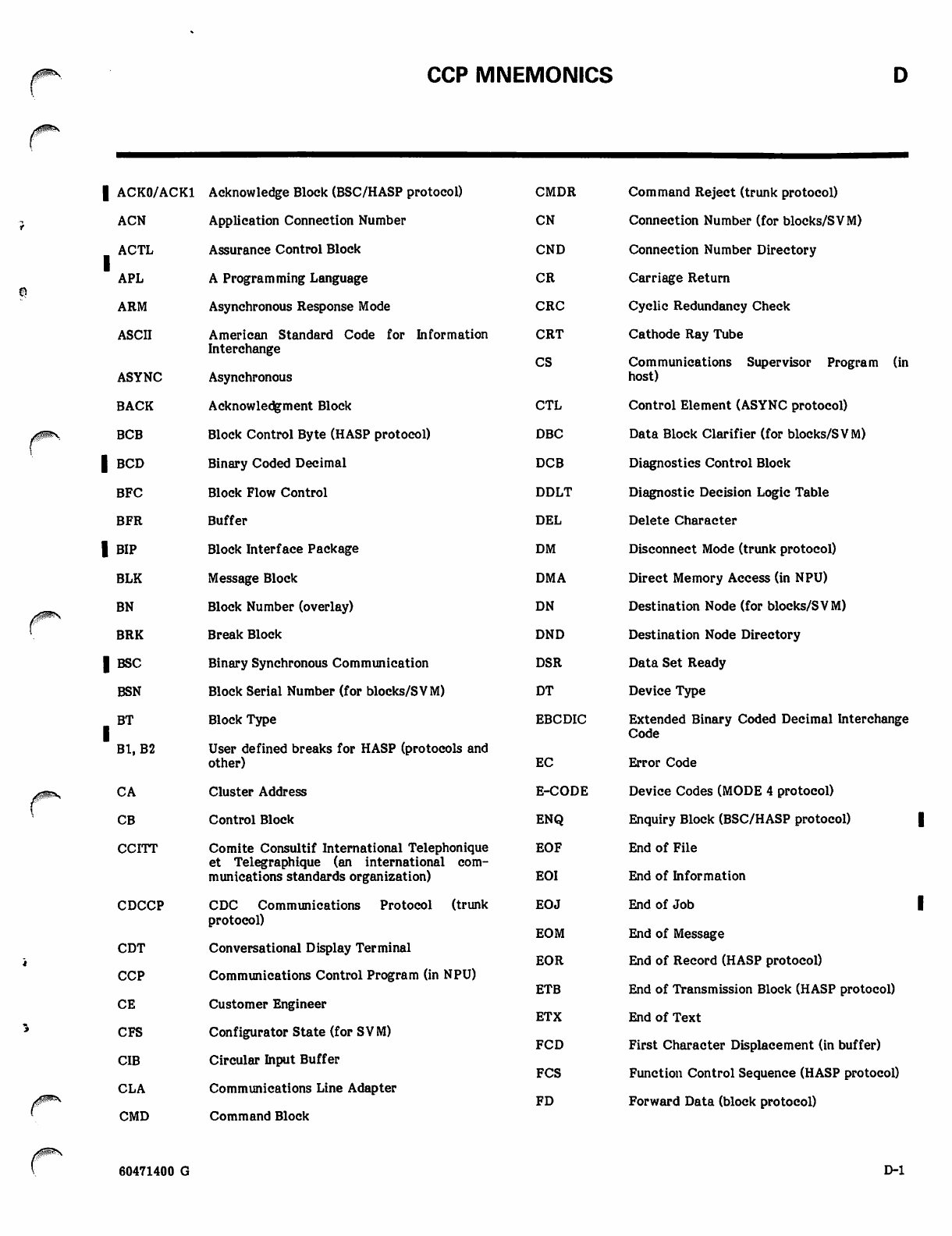
CCP MNEMONICS
| ACK0/ACK1 Acknowledge Block (BSC/HASP protocol) CMDR
ACN Application Connection Number CN
ACTL
1APL
Assurance Control Block CND
A Programming Language CR
ARM Asynchronous Response Mode CRC
ASCII American Standard Code for Information CRT
Interchange CS
ASYNC Asynchronous
BACK Acknowledgment Block CTL
BCB Block Control Byte (HASP protocol) DBC
| BCD Binary Coded Decimal DCB
BFC Block Flow Control DDLT
BFR Buffer DEL
| BIP Block Interface Package DM
BLK Message Block DMA
BN Block Number (overlay) DN
BRK Break Block DND
| BSC Binary Synchronous Communication DSR
BSN Block Serial Number (for blocks/SVM) DT
BT
1Bl, B2
Block Type EBCDIC
User defined breaks for HASP (protocols and
other) EC
CA Cluster Address E-CODE
CB Control Block ENQ
CCITT Comite Consultif International Telephonique
et Telegraphique (an international com
munications standards organization)
EOF
EOI
CDCCP CDC Communications Protocol (trunk EOJ
protocol) EOM
CDT Conversational Display Terminal EOR
ETB
CCP Communications Control Program (in NPU)
CE Customer Engineer
ETX
CFS Configurator State (for SVM) FCD
CIB Circular Input Buffer
FCS
CLA Communications Line Adapter FD
CMD Command Block
Command Reject (trunk protocol)
Connection Number (for blocks/SVM)
Connection Number Directory
Carriage Return
Cyclic Redundancy Check
Cathode Ray Tube
Communications Supervisor Program (in
host)
Control Element (ASYNC protocol)
Data Block Clarifier (for blocks/SVM)
Diagnostics Control Block
Diagnostic Decision Logic Table
Delete Character
Disconnect Mode (trunk protocol)
Direct Memory Access (in NPU)
Destination Node (for blocks/SVM)
Destination Node Directory
Data Set Ready
Device Type
Extended Binary Coded Decimal Interchange
Code
Error Code
Device Codes (MODE 4 protocol)
Enquiry Block (BSC/HASP protocol)
End of File
End of Information
End of Job
End of Message
End of Record (HASP protocol)
End of Transmission Block (HASP protocol)
End of Text
First Character Displacement (in buffer)
Function Control Sequence (HASP protocol)
Forward Data (block protocol)
60471400 G D-l
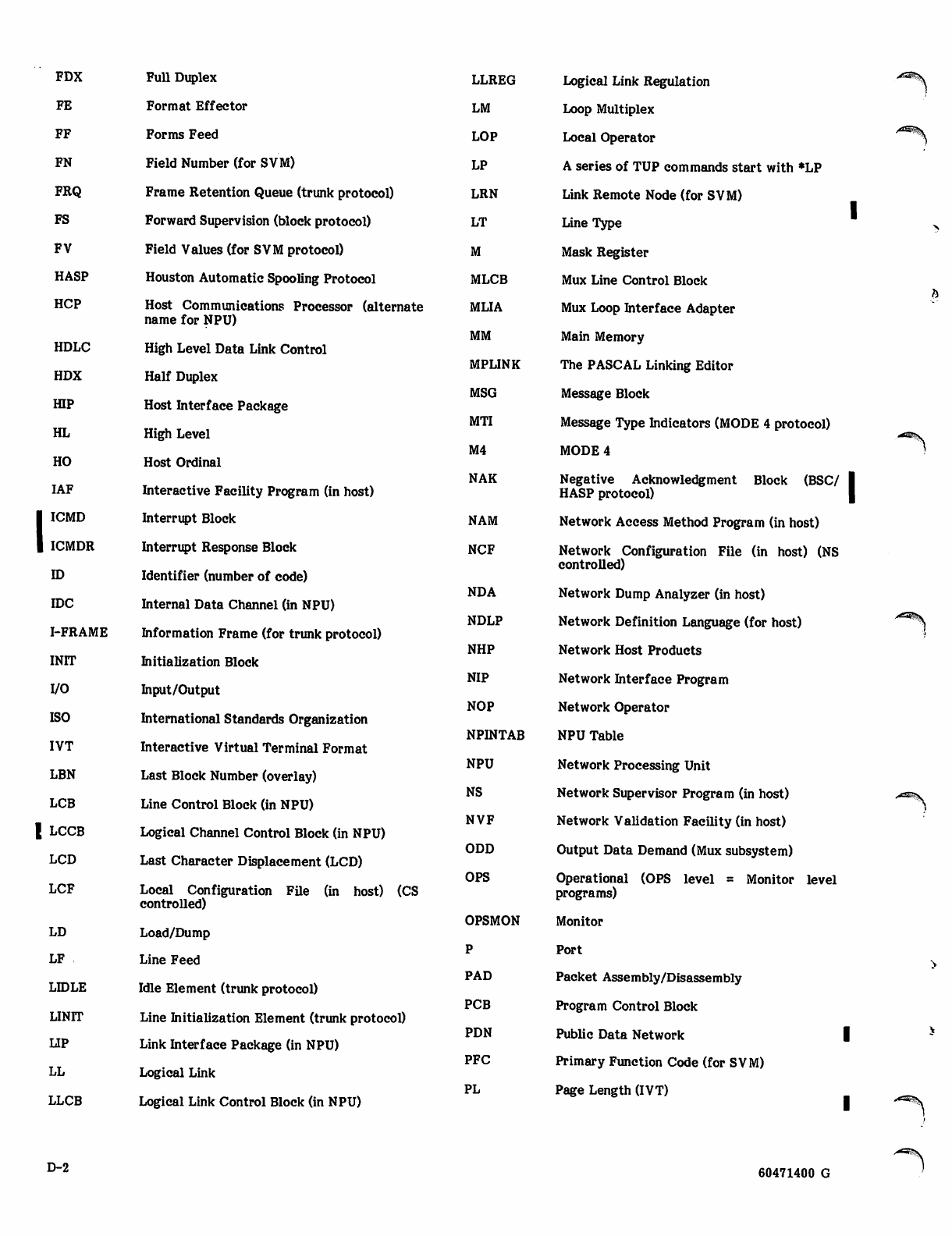
FDX Full Duplex LLREG
FE Format Effector LM
FF Forms Feed LOP
FN Field Number (for SVM) LP
FRQ Frame Retention Queue (trunk protocol) LRN
FS Forward Supervision (block protocol) LT
FV Field Values (for SVM protocol)
HASP Houston Automatic Spooling Protocol MLCB
HCP Host Communications Processor (alternate
name for NPU) MLIA
MM
HDLC High Level Data Link Control
MPLINK
HDX Half Duplex
MSG
HIP Host Interface Package
MTI
HL High Level
M4
HO Host Ordinal
NAK
IAF Interactive Facility Program (in host)
1 ICMD Interrupt Block NAM
1 ICMDR Interrupt Response Block NCF
ID Identifier (number of code)
NDA
IDC Internal Data Channel (in NPU)
NDLP
I-FRAME Information Frame (for trunk protocol)
NHP
INIT Initialization Block
NIP
I/O Input/Output
NOP
ISO International Standards Organization
NPINTAB
IVT Interactive Virtual Terminal Format
NPU
LBN Last Block Number (overlay)
NS
LCB Line Control Block (in NPU)
NVF
| LCCB Logical Channel Control Block (in NPU)
ODD
LCD Last Character Displacement (LCD)
OPS
LCF Local Configuration File (in host) (CS
controlled)
OPSMON
LD Load/Dump
LF Line Feed
PAD
LIDLE Idle Element (trunk protocol)
PCB
UNIT Line Initialization Element (trunk protocol)
PDN
LIP Link Interface Package (in NPU)
PFC
LL Logical Link
PL
LLCB Logical Link Control Block (in NPU)
Logical Link Regulation
Loop Multiplex
Local Operator
A series of TUP commands start with *LP
Link Remote Node (for SVM)
Line Type
Mask Register
Mux Line Control Block
Mux Loop Interface Adapter
Main Memory
The PASCAL Linking Editor
Message Block
Message Type Indicators (MODE 4 protocol)
MODE 4
Negative Acknowledgment Block (BSC/ I
HASP protocol) |
Network Access Method Program (in host)
Network Configuration File (in host) (NS
controlled)
Network Dump Analyzer (in host)
Network Definition Language (for host)
Network Host Products
Network Interface Program
Network Operator
NPU Table
Network Processing Unit
Network Supervisor Program (in host)
Network Validation Facility (in host)
Output Data Demand (Mux subsystem)
Operational (OPS level = Monitor level
programs)
Monitor
Port
Packet Assembly/Disassembly
Program Control Block
Public Data Network |
Primary Function Code (for SVM)
Page Length (IVT)
4^tWSS
>5^V
D-2 60471400 G
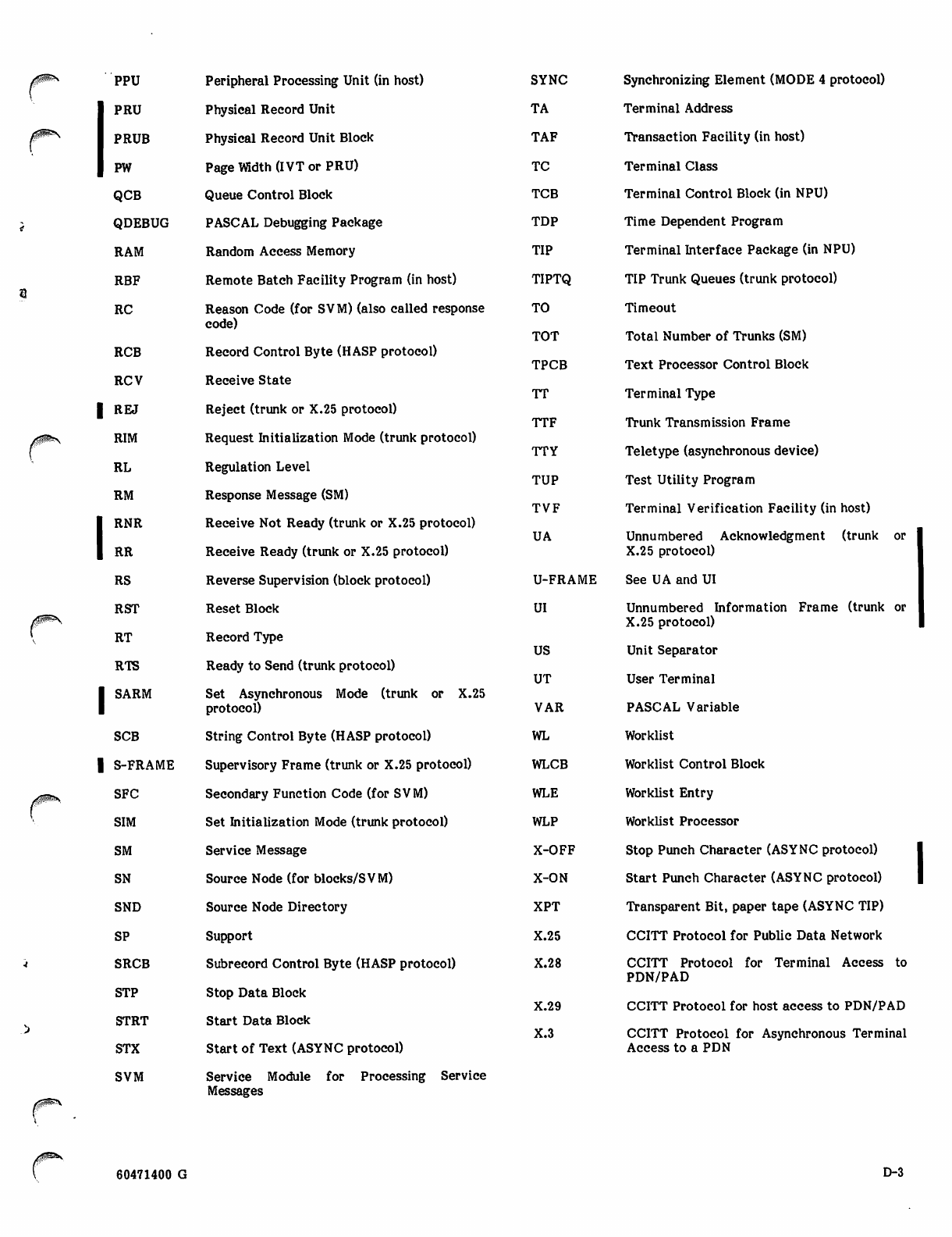
PPU Peripheral Processing Unit (in host)
PRU Physical Record Unit
PRUB Physical Record Unit Block
PW Page Width (IVT or PRU)
QCB Queue Control Block
QDEBUG PASCAL Debugging Package
RAM Random Access Memory
RBF Remote Batch Facility Program (in host)
RC Reason Code (for SVM) (also called response
code)
RCB Record Control Byte (HASP protocol)
RCV Receive State
| REJ Reject (trunk or X.25 protocol)
RIM Request Initialization Mode (trunk protocol)
RL Regulation Level
RM Response Message (SM)
RNR Receive Not Ready (trunk or X.25 protocol)
RR Receive Ready (trunk or X.25 protocol)
RS Reverse Supervision (block protocol)
RST Reset Block
R T R e c o r d T y p e
RTS Ready to Send (trunk protocol)
ISA R M Se t A s y n chron o u s M o d e ( t r u n k or X . 25protocol)
SCB String Control Byte (HASP protocol)
| S-FRAME Supervisory Frame (trunk or X.25 protocol)
SFC Secondary Function Code (for SVM)
SIM Set Initialization Mode (trunk protocol)
SM Service Message
SN Source Node (for blocks/SVM)
SND Source Node Directory
SP Support
SRCB Subrecord Control Byte (HASP protocol)
S T P S t o p D a t a B l o c k
STRT Start Data Block
STX Start of Text (ASYNC protocol)
SVM Service Module for Processing Service
Messages
SYNC Synchronizing Element (MODE 4 protocol)
TA Terminal Address
TAF Tr a nsacti on Facili t y ( in host)
TC Terminal Class
TCB Terminal Control Block (in NPU)
TDP Time Dependent Program
TIP Terminal Interface Package (in NPU)
TIPTQ TIP Trunk Queues (trunk protocol)
T O T i m e o u t
TOT Total Number of Trunks (SM)
TPCB Text Processor Control Block
TT Terminal Type
TTF Trunk Transmission Frame
TTY Teletype (asynchronous device)
TUP Test Utility Program
TVF Terminal Verification Facility (in host)
UA Unnumbered Acknowledgment (trunk or
X.25 protocol)
U-FRAME See UA and UI
UI Unnumbered Information Frame (trunk or
X.25 protocol)
US Unit Separator
UT User Terminal
VAR PASCAL Variable
WL Worklist
WLCB Worklist Control Block
WLE Worklist Entry
WLP Worklist Processor
X-OFF Stop Punch Character (ASYNC protocol)
X-ON Start Punch Character (ASYNC protocol)
X P T Tran s p a r e nt B it , p a p e r t a pe ( AS Y N C T IP )
X.25 CCITT Protocol for Public Data Network
X.28 CCITT Protocol for Terminal Access to
PDN/PAD
X.29 C C I TT Pro t o c ol f o r h o s t a c c ess t o P D N / PA D
X.3 CCITT Protocol for Asynchronous Terminal
Access to a PDN
60471400 G D-3

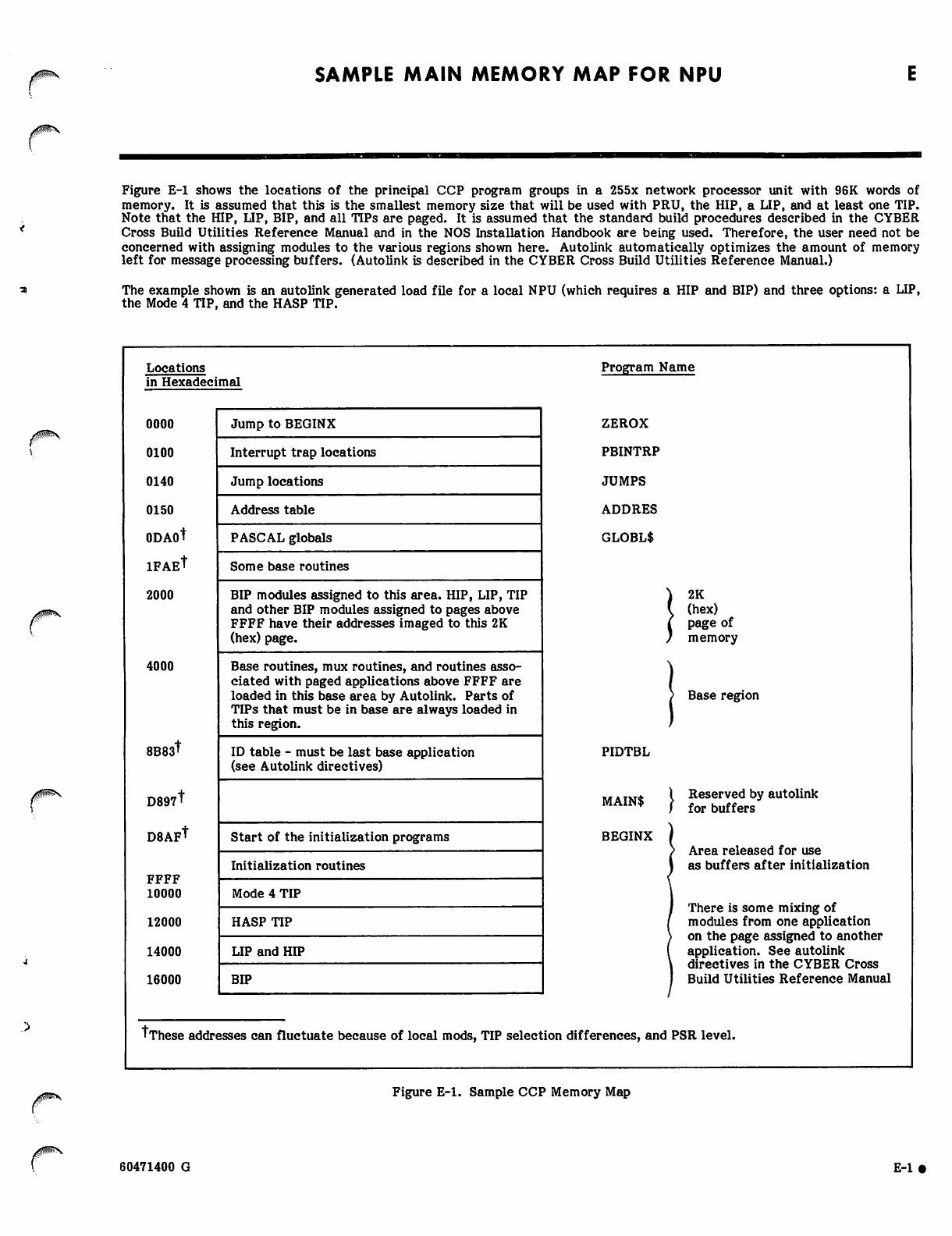
SAMPLE MAIN MEMORY MAP FOR NPU
Figure E-l shows the locations of the principal CCP program groups in a 255x network processor unit with 96K words of
memory. It is assumed that this is the smallest memory size that will be used with PRU, the HIP, a LIP, and at least one TIP.
Note that the HIP, LIP, BIP, and all TIPs are paged. It is assumed that the standard build procedures described in the CYBER
Cross Build Utilities Reference Manual and in the NOS Installation Handbook are being used. Therefore, the user need not be
concerned with assigning modules to the various regions shown here. Autolink automatically optimizes the amount of memory
left for message processing buffers. (Autolink is described in the CYBER Cross Build Utilities Reference Manual.)
The example shown is an autolink generated load file for a local NPU (which requires a HIP and BIP) and three options: a LIP,
the Mode 4 TIP, and the HASP TIP.
0*9*S
Locations
in Hexadecimal
0000
0100
0140
0150
0DAOT
ifaeT
2000
4000
8B83t
D897T
D8AF*
FFFF
10000
12000
14000
16000
Jump to BEGINX
Interrupt trap locations
Jump locations
Address table
PASCAL globals
Some base routines
BIP modules assigned to this area. HIP, LIP, TIP
and other BIP modules assigned to pages above
FFFF have their addresses imaged to this 2K
(hex) page.
Base routines, mux routines, and routines asso
ciated with paged applications above FFFF are
loaded in this base area by Autolink. Parts of
TIPs that must be in base are always loaded in
this region.
ID table - must be last base application
(see Autolink directives)
Start of the initialization programs
Initialization routines
Mode 4 TIP
HASP TIP
LIP and HD?
BIP
Program Name
ZEROX
PBINTRP
JUMPS
ADDRES
GLOBL$
2K
(hex)
page of
memory
Base region
PIDTBL
main$ \ Reserved by autolink
BEGINX
for buffers
Area released for use
as buffers after initialization
There is some mixing of
modules from one application
on the page assigned to another
application. See autolink
directives in the CYBER Cross
Build Utilities Reference Manual
'These addresses can fluctuate because of local mods, TIP selection differences, and PSR level.
Figure E-l. Sample CCP Memory Map
60471400 G E-l«

■{*%
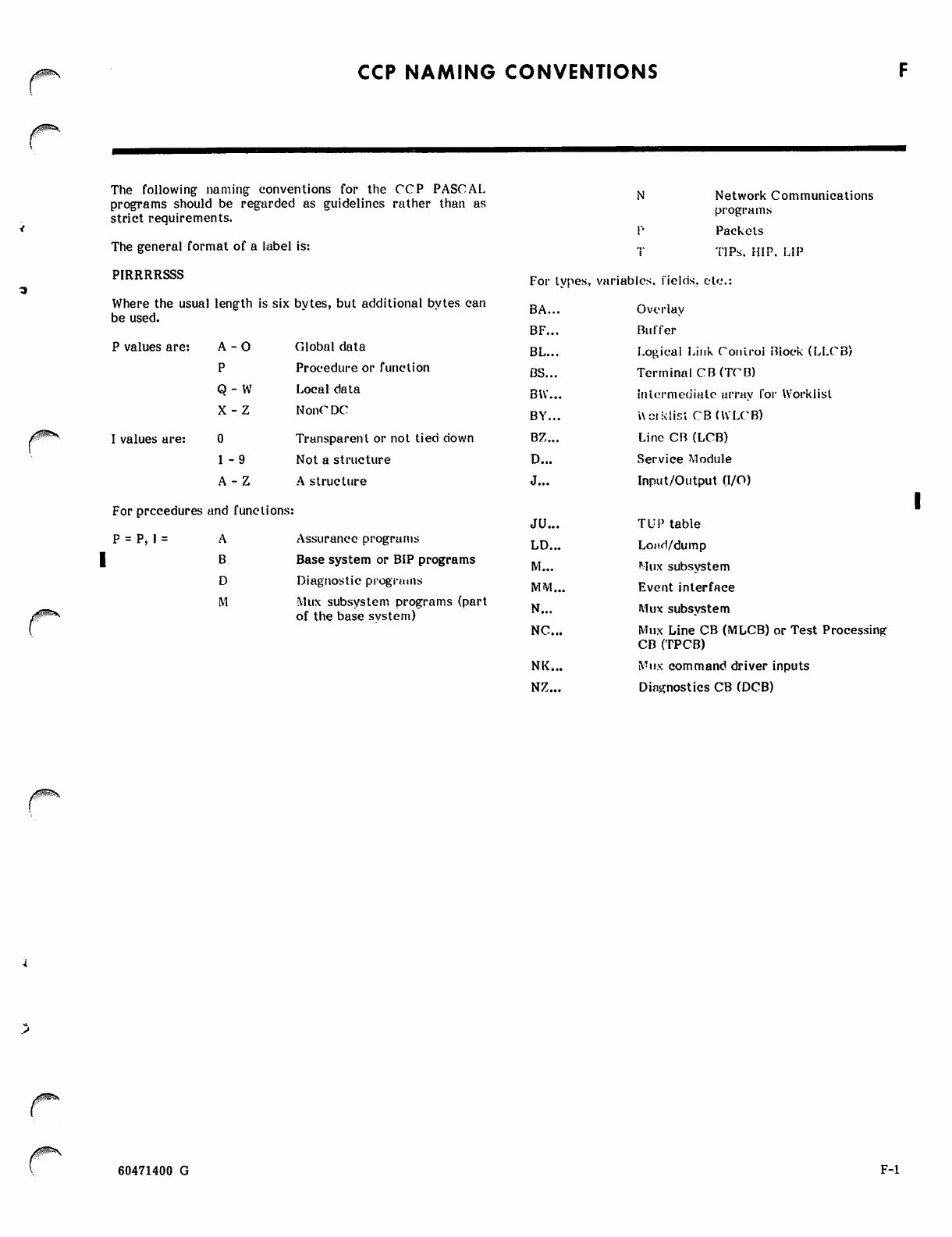
CCP NAMING CONVENTIONS
The following naming conventions for the CCP PASCAL
programs should be regarded as guidelines rather than as
strict requirements.
The general format of a label is:
PIRRRRSSS
Where the usual length is six bytes, but additional bytes can
be used.
P values are: A-0 Global data
PProcedure or function
Q- W Local data
X -Z NonC DC
I values are: Transparent or not tied down
1 -9 Not a structure
A-Z A structure
For prccedures and functions:
P = P, I = Assurance programs
Base system or BIP programs
Diagnostic programs
Mux subsystem programs (part
of the base system)
Network Communications
programs
Packets
TIPs, HIP, LIP
For types, variables, fields, etc.
BA... Overlay
BF... Buffer
EL Logical Link Control Block (LLCB)
DS... Terminal CB(TCB)
BW... Intermediate array for Worklist
BY... Uciklist CB(WLCB)
BZ... Line CB (LCB)
D... Service Module
J... Input/Output (I/O)
JU... TUP table
LD... Lojtd/dump
M... Mux subsystem
MM... Event interface
N... Mux subsystem
NC... Mux Line CB (MLCB) or Test Proce
CB (TPCB)
NK... Mux command driver inputs
NZ... Diagnostics CB (DCB)
60471400 G F-l

'""^
!^%
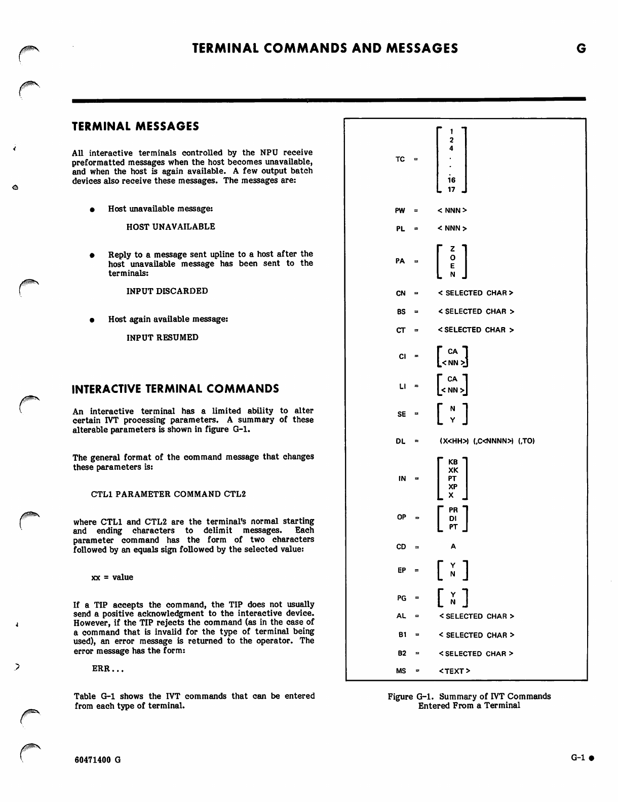
TERMINAL COMMANDS AND MESSAGES
^j
TERMINAL MESSAGES
All interactive terminals controlled by the NPU receive
Preformatted messages when the host becomes unavailable,
and when the host is again available. A few output batch
devices also receive these messages. The messages are:
• Host unavailable message:
HOST UNAVAILABLE
Reply to a message sent upline to a host after the
host unavailable message has been sent to the
terminals:
INPUT DISCARDED
Host again available message:
INPUT RESUMED
INTERACTIVE TERMINAL COMMANDS
An interactive terminal has a limited ability to alter
certain IVT processing parameters. A summary of these
alterable parameters is shown in figure G-l.
The general format of the command message that changes
these parameters is:
CTL1 PARAMETER COMMAND CTL2
where CTL1 and CTL2 are the terminal's normal starting
and ending characters to delimit messages. Each
parameter command has the form of two characters
followed by an equals sign followed by the selected value:
xx = value
If a TIP accepts the command, the TIP does not usually
send a positive acknowledgment to the interactive device.
However, if the TIP rejects the command (as in the case of
a command that is invalid for the type of terminal being
used), an error message is returned to the operator. The
error message has the form:
ERR...
Table G-l shows the IVT commands that can be entered
from each type of terminal.
TC
16
- 17 «
PW < NNN>
PL <NNN>
P A =
C N =
BS =
C T »
C l =
L l =
SE =
D L -
I N =
OP =>
[i]
< SELECTED CHAR >
< SELECTED CHAR >
<SELECTED CHAR >
rcA-i
L<NN>J
l-CA-l
L< NN >J
[:]
(X<HH» (,C<NNNN» (.TO)
KB
XK
PT
XP
X
[5]
CD
EP
PG [ s ]
AL < SELECTED CHAR >
B1 < SELECTED CHAR >
B2 <SELECTED CHAR >
MS <TEXT>
Figure G-l. Summary of IVT Commands
Entered From a Terminal
60471400 G G-l»
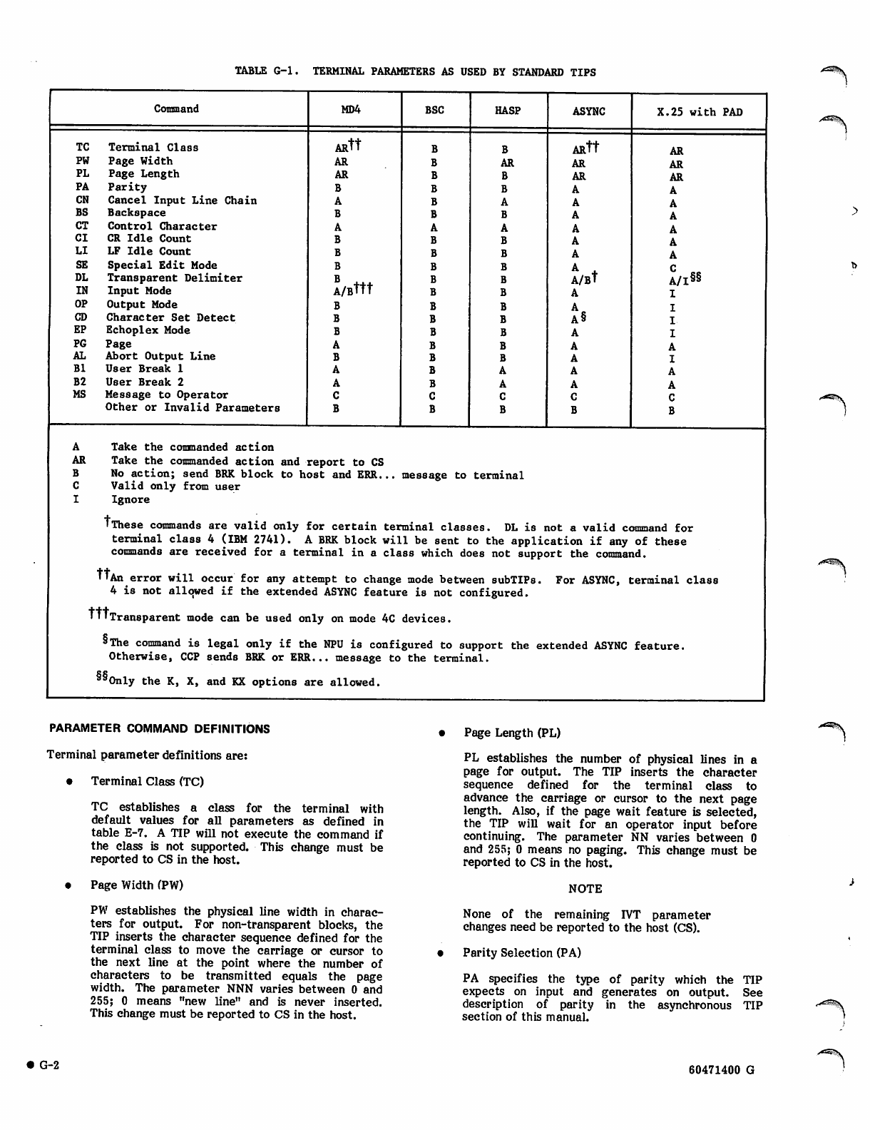
TABLE G-l. TERMINAL PARAMETERS AS USED BY STANDARD TIPS
Conmand MD4 BSC HASP ASYNC X.25 with PAD
TC Terminal Class A R t t A R t t AR
PW Page Width AR AR AR AR
PL Page Length AR AR AR
PA Parity
CN Cancel Input Line Chain
BS Backspace
CT Control Character
CI CR Idle Count
LI LF Idle Count
SE Special Edit Mode A .
DL Transparent Delimiter A/Bttt A/Bt A/I§§
IN Input Mode
OP Output Mode
CD Character Set Detect A§
EP Echoplex Mode
PG Page
AL Abort Output Line
Bl User Break 1
B2 User Break 2
MS Message to Operator
Other or Invalid Parameters
ATake the comnanded action
AR Take the commanded action and report to CS
BNo action; send BRK block to host and ERR... message to terminal
CValid only from user
IIgnore
'These commands are valid only for certain terminal classes. DL is not a valid command for
terminal class 4 (IBM 2741). A BRK block will be sent to the application if any of these
commands are received for a terminal in a class which does not support the command.
'•An error will occur for any attempt to change mode between subTIPs. For ASYNC, terminal class
4 is not allowed if the extended ASYNC feature is not configured.
TTlTransparent mode can be used only on mode 4C devices.
'The command is legal only if the NPU is configured to support the extended ASYNC feature.
Otherwise, CCP sends BRK or ERR... message to the terminal.
§SOnly the K, X, and KX options are allowed.
PARAMETER COMMAND DEFINITIONS
Terminal parameter definitions are:
• Terminal Class (TC)
TC establishes a class for the terminal with
default values for all parameters as defined in
table E-7. A TIP will not execute the command if
the class is not supported. This change must be
reported to CS in the host.
• Page Width (PW)
PW establishes the physical line width in charac
ters for output. For non-transparent blocks, the
TIP inserts the character sequence defined for the
terminal class to move the carriage or cursor to
the next line at the point where the number of
characters to be transmitted equals the page
width. The parameter NNN varies between 0 and
255; 0 means "new line" and is never inserted.
This change must be reported to CS in the host.
Page Length (PL)
PL establishes the number of physical lines in a
page for output. The TIP inserts the character
sequence defined for the terminal class to
advance the carriage or cursor to the next page
length. Also, if the page wait feature is selected,
the TIP will wait for an operator input before
continuing. The parameter NN varies between 0
and 255; 0 means no paging. This change must be
reported to CS in the host.
NOTE
None of the remaining IVT parameter
changes need be reported to the host (CS).
Parity Selection (PA)
PA specifies the type of parity which the TIP
expects on input and generates on output. See
description of parity in the asynchronous TIP
section of this manual.
• G-2 60471400 G
>«S5V
• Cancel Character (CN)
CN establishes the character which is used to
delete the current logical input line. If special edit
mode is engaged, the CN character is treated as
data and is sent to the host; the delete action is not
performed.
• Backspace Character (BS)
BS establishes the character which is used to delete
the previous input character from the current input
buffer. If special edit mode is engaged, the BS
character is treated as data and is sent to the host;
the backspace action is not performed.
• Control Character (CT)
CT establishes the character which is used to enter
operational control messages.
• Carriage Return Idle Count (CI)
CI establishes the number of idle characters to be
inserted in the output stream following carriage
return (CR). The use of Cl-nn overrules the default
value and CI-CA restores the default value.
• Line Feed Idle Count (LI)
LI establishes the number of idle characters to be
inserted in the output stream following line feed
(LF). The use of Ll-nn overrules the default value
and LI-CA restores the default value.
• Special Edit Mode (SE)
A SE = Y selection places the terminal in special
edit mode; an SE = N selection returns the terminal
to the normal character edit mode. Special edit
mode provides two types of special operations:
(1) backspace (BS), linefeed (LF), and cancel input
control symbols are not treated as control
characters by the TIP; instead, they are sent
upline as data.
(2) a character delete sequence (one or more
backspaces followed by a linefeed) causes the
TIP to issue a caret prompt to the terminal,
and then to continue with input processing.
• Transparent Text Delimiter (DL)
DL establishes the transparent text delimiter for
input. The delimiter may be a character, a
character count or a timeout of 300 ± 100 ms. One
or more of the delimiters may be active
simultaneously.
• Input Device (EN)
IN specifies the input device as a keyboard or paper
tape reader in character or transparent mode.
Note that paper tape input is allowed in keyboard
mode, but that the TIP does not send the < X-ON>
characters to start the paper tape reader.
• Output Device (OP)
OP specifies the output device as printer, CRT
display, or paper tape punch. Printer and CRT
display are functionally equivalent. The user may
punch a paper tape in any mode, but the TIP
provides the X-OFF character only if OP=PT and if
data is not transparent.
• Character Set Detect (CD)
This restarts the character set recognition logic
when changing a character set during a message
exchange sequence. First, the terminal operator
enters the IVT command: CD = A. Then the
operator has 60 seconds to (1) physically change the
terminal's code set (for instance, by changing the
type element on a typewriter), and (2) activate the
TIP's code set recognition sequence by pressing the
carriage return key.
• Echoplex Mode (EP)
EP specifies where input character echoing will
take place. EP=N implies the terminal is doing its
own input echoing and EP=Y causes the TIP to set
the CLA to provide character echoing.
• Page Wait (PG)
PG selects the page wait feature. It allows the
user to control output by demanding each page
explicitly after the previous page has been viewed
for the desired period of time.
• Abort Output Line Character (AL)
AL selects the character which, when input
followed by a carriage return, will result in the
current output line being discarded.
• User Break 1 (Bl)
Bl selects the character which, when input
followed by a carriage return, will cause the TIP to
send an upline BRK block with reason code
specifying "user break 1". Conventionally user
break 1 is used to abort the queue.
• User Break 2 (B2)
B2 selects the character which, when input
followed by a carriage return, will cause the TIP to
send an upline BRK block reason code specifying
"user break 2". Conventionally user break 2 is used
to abort the job.
NOTE
At 2741 terminal, when an operator
uses a break 1 or break 2 character, he
must precede it by an ATTN character.
• Message (MS)
MS defines the character used to delimit messages
to the LOP.
ym«s 60471400 G G-3 •

BATCH TERMINAL FILE (transparent/non-transparent) by entering information in /^S
CHARACTERISTIC COMMANDS columns 79/80 of aJ'ob or E0R card-
In the current release only the BSC and HASP batch • 26 selects 026 mode
terminals can send requests to the host remote batch
facility (RBF) to change the operating charcteristics of • 29 selects 029 mode
batch files. • TR selects transparent mode (used on EOR card
A BSC/HASP card reader can change the card punching only; the terminal transparent switch must be on
characteristics (026/029) or the device data mode when this card is read)
/rf^^S
• G"4 60471400 G
NPU OPERATING INSTRUCTIONS
yss
Except for the diagnostics which are described elsewhere,
the only operator actions that might be needed at the NPU
concern loading the system. Even these actions are needed
only in exceptional conditions, since once CCP has been
successfully loaded, the host should control all subsequent
load operations automatically. Nonetheless, following a
failure, it may be desirable to check NPU control switch
positions and initiate a CCP load manually.
LOCAL NPU PROCEDURE
To prepare for a downline load, the NPU operator should
perform the following steps:
1. Verify that ports (CLA addresses) to the
communications network are correct.
2. On loop multiplexer circuit card, set power (PWR)
switch to ON. See figure H-l.
3. On CLA circuit card, set CLA/OFF switches to
CLA (on). See figure H-2. Only those cards that
are configured are affected.
4. Verify that local console is in normal ON
condition.
5. Stop the NPU at the maintenance panel by
pressing the MASTER CLEAR switch (figure H-3).
The host discovers that NPU has stopped and initiates the
dump and reload sequence.
Upon successful completion of the downline load operation
by the host, the host is notified. The host then configures
the NPU terminals and normal system operation begins.
If the downline load is unsuccessful, the host initiates and
receives a dump of the NPU memory, micromemory
checksum, and file 1 registers. The initiation of another
downline load attempt is under control of the host.
REMOTE NPU PROCEDURE
The procedure for the remote NPU is the same as that for
the local NPU except for the following:
• Check bootstrap load (SAM-C) tape equipment
mounted on NPU cabinet door. The SAM-C tape
cassette should be loaded and the ENABLE/
DISABLE switch should be set to ENABLE.
• The NPU is downline loaded via a local NPU.
60471400 G H - l •
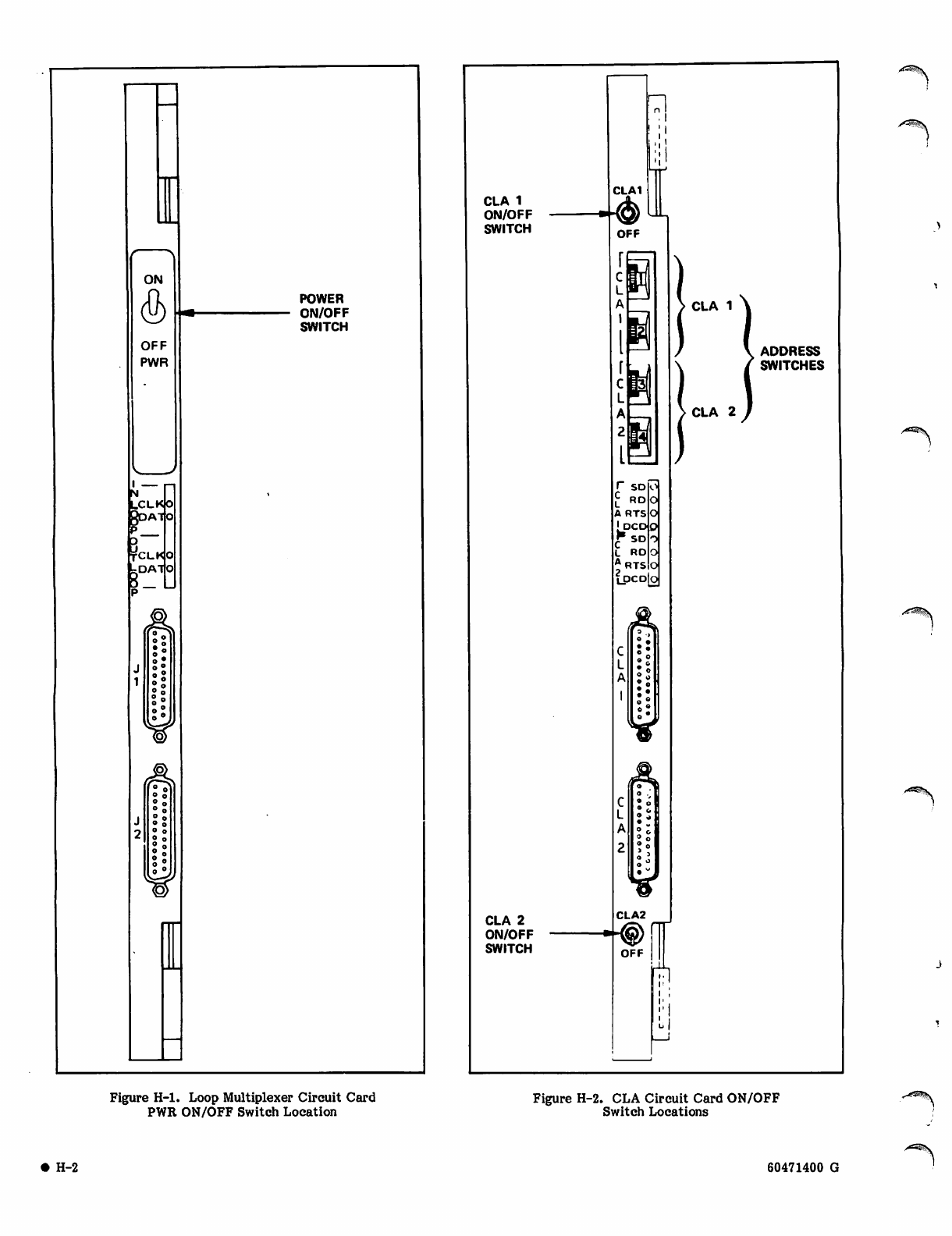
I ■
N
LCLKIO
AT O
TCLKjO
kDAllo
rl
ON
<2>
OFF
PWR
POWER
ON/OFF
SWITCH
o -
V
¥
CLA 1
ON/OFF
SWITCH
CLA 2
ON/OFF
SWITCH
CLA1
OFF
! ;i
u
r
i
RTS
LPCD
r sd
£ RD
A RTS
f S D
L RO
A
CLA 1
ADDRESS
SWITCHES
CLA 2
CLA2
<§)
OFF
-®
li!
Figure H-l. Loop Multiplexer Circuit Card
PWR ON/OFF Switch Location Figure H-2. CLA Circuit Card ON/OFF
Switch Locations
H-2 60471400 G
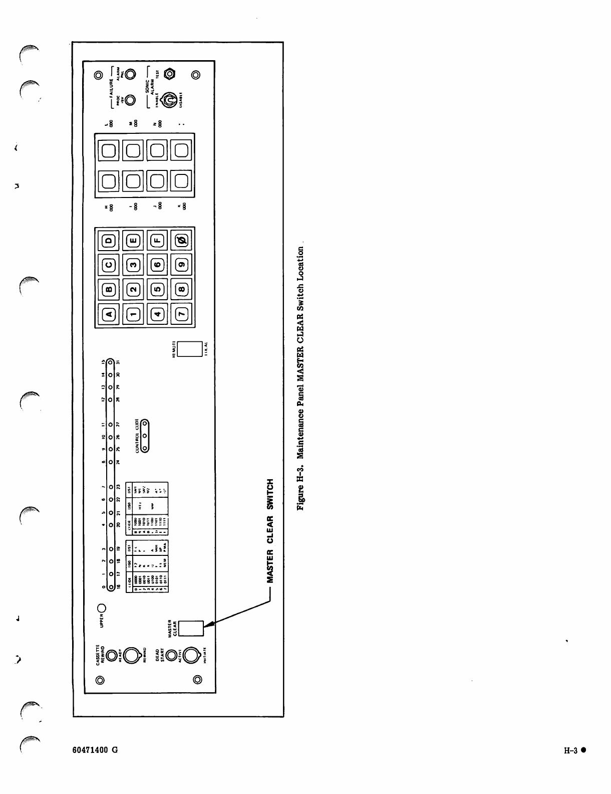
Uio h®
15
ooO
oo□
« § - 8 - 8 - 1
©© 0 ®
©©© ®
©©©©
©Q 0 8
rZ J 5 5 8 ' * ' . ?
t+ Z i
z *
8-liiiil?E
-«=■««.--.
s
|I
~ j < < ; . .' J
soooo 0001 0010 0100 0101 0110 om
o
UJ
§>
60471400 G H-3*

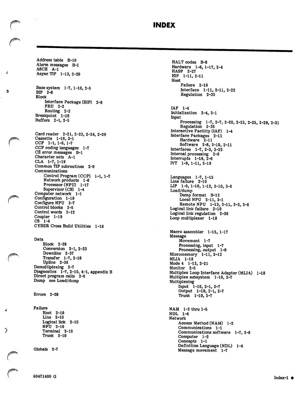
INDEX
Address table B-10
Alarm messages B-l
ASCII A-l
Async TIP 1-13, 2-20
Base system 1-7,1-10, 2-5
BIP 2-8
Block
Interface Package (BIP) 2-8
PRU 2-2
Routing 2-2
Breakpoint 1-18
Buffers 2-1, 2-5
Card reader 2-21, 2-23, 2-24, 2-29
Cassette 1-18, 3-1
CCP 1-1, 1-6,1-7
CCP coding languages 1-7
CE error messages B-l
Character sets A-l
CLA 1-7,1-19
Common TIP subroutines 2-9
Communications
Control Program (CCP) 1-1, 1-7
Network products 1-6
Processor (NPU) 1-17
Supervisor (CS) 1-4
Computer network 1-1
Configuration 1-19
Configure NPU 3-7
Control blocks 2-5
Control words 2-12
Coupler 1-19
CS 1-4
CYBER Cross Build Utilities 1-16
Data
Block 2-28
Conversion 2-1, 2-23
Downline 2-37
Transfer 1-7, 2-18
Upline 2-36
Demultiplexing 2-7
Diagnostics 1-7, 2-10, 4-1, appendix B
Direct program calls 2-6
Dump see Load/dump
Errors 2-28
HALT codes B-8
Hardware 1-6, 1-17, 2-4
HASP 2-27
HIP 1-11, 2-11
Host
Failure 2-10
Interface 1-11, 2-11, 2-22
Regulation 2-35
IAF 1-4
Initialization 2-4, 3-1
Input
Processing 1-7, 2-7, 2-20, 2-22, 2-25, 2-29, 2-31
Regulation 2-35
Interactive Facility (IAF) 1-4
Interface Packages 2-11
Hardware 2-11
Software 2-8, 2-10, 2-11
Interfaces 1-7, 2-3, 2-22
Internal processing 2-9
Interrupts 1-18, 2-6
IVT 1-9, 1-11, 2-19
Languages 1-7, 1-15
Line failure 2-10
LIP 1-9, 1-10, 1-12, 2-10, 3-6
Load/dump
Dump format B-12
Local NPU 2-11, 3-1
Remote NPU 1-13, 2-11, 3-2, 3-6
Logical link failure 2-10
Logical link regulation 2-36
Loop multiplexer 1-18
Macro assembler 1-15, 1-17
Message
Movement 1-7
Processing, input 1-7
Processing, output 1-8
Micromemory 1-11, 2-12
MLIA 1-18
Mode 4 1-13, 2-21
Monitor 2-5
Multiplex Loop Interface Adapter (MLIA) 1-18
Multiplex subsystem 1-18, 2-7
Multiplexing
Input 1-10, 2-1, 2-7
Output 1-10, 2-1, 2-7
Trunk 1-10, 2-7
Failure
Host 2-10
Line 2-10
Logical link
NPU 2-10
Terminal 2-10
Trunk 2-10
Globals 2-7
2-10
NAM 1-2 thru 1-5
NDL 1-4
Network
Access Method (NAM) 1-2
Communications 1-1
Communications software 1-7, 2-8
Computer 1-2
Concepts 1-1
Definition Language (NDL) 1-4
Message movement 1-7
60471400 G Index-1 •
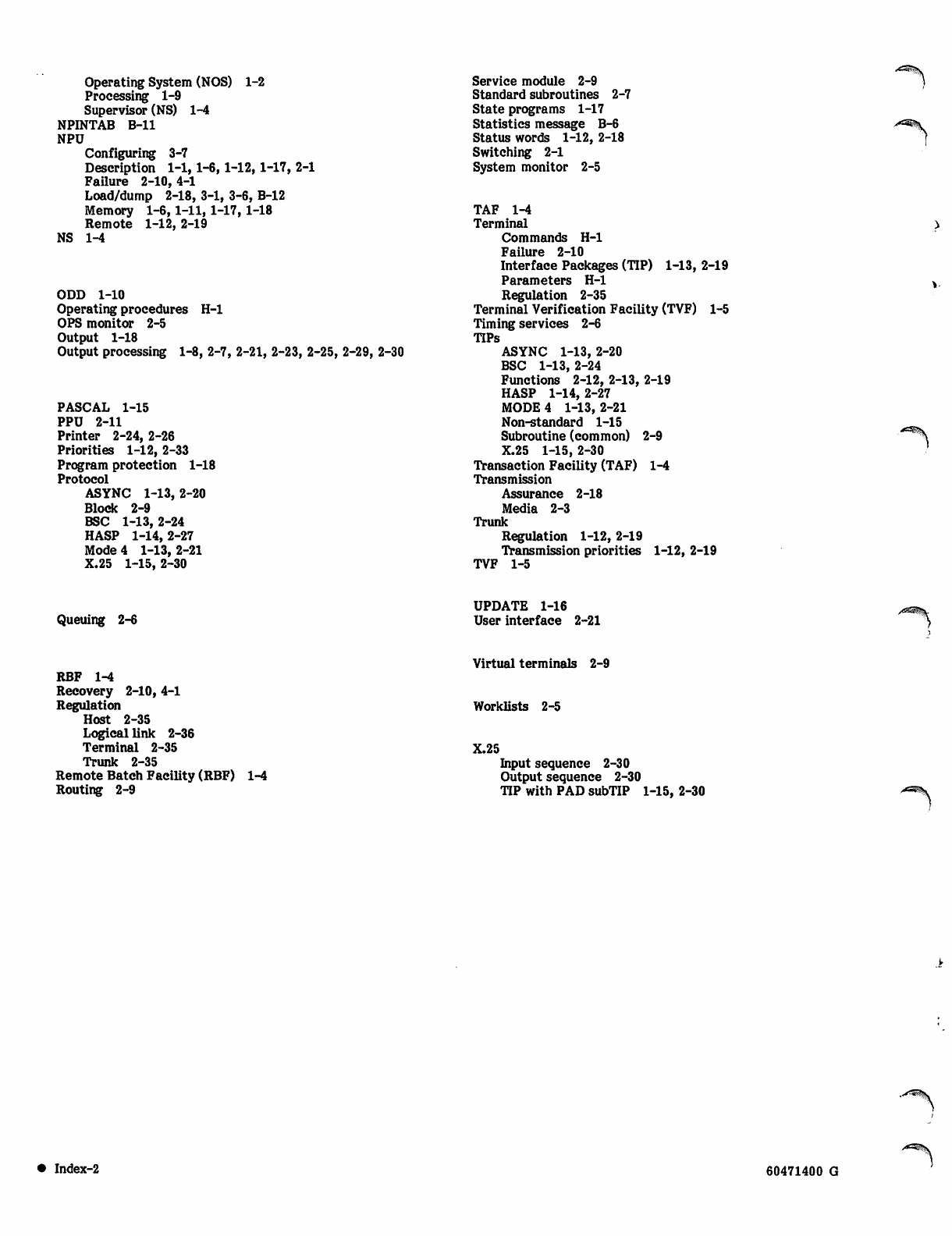
Operating System (NOS) 1-2
Processing 1-9
Supervisor (NS) 1-4
NPINTAB B-ll
NPU
Configuring 3-7
Description 1-1,1-6,1-12,1-17, 2-1
Failure 2-10, 4-1
Load/dump 2-18, 3-1, 3-6, B-12
Memory 1-6,1-11,1-17,1-18
Remote 1-12, 2-19
NS 1-4
ODD 1-10
Operating procedures H-l
OPS monitor 2-5
Output 1-18
Output processing 1-8, 2-7, 2-21, 2-23, 2-25, 2-29, 2-30
PASCAL 1-15
PPU 2-11
Printer 2-24, 2-26
Priorities 1-12, 2-33
Program protection 1-18
Protocol
ASYNC 1-13,2-20
Block 2-9
BSC 1-13,2-24
HASP 1-14,2-27
Mode 4 1-13,2-21
X.25 1-15, 2-30
Service module 2-9
Standard subroutines 2-7
State programs 1-17
Statistics message B-6
Status words 1-12, 2-18
Switching 2-1
System monitor 2-5
TAF 1-4
Terminal
Commands H-l
Failure 2-10
Interface Packages (TIP) 1-13, 2-19
Parameters H-l
Regulation 2-35
Terminal Verification Facility (TVF) 1-5
Timing services 2-6
TIPs
ASYNC 1-13, 2-20
BSC 1-13, 2-24
Functions 2-12, 2-13, 2-19
HASP 1-14, 2-27
MODE 4 1-13,2-21
Non-standard 1-15
Subroutine (common) 2-9
X.25 1-15, 2-30
Transaction Facility (TAF) 1-4
Transmission
Assurance 2-18
Media 2-3
Trunk
Regulation 1-12, 2-19
Transmission priorities 1-12, 2-19
TVF 1-5
Queuing 2-6
UPDATE 1-16
User interface 2-21
RBF 1-4
Recovery 2-10, 4-1
Regulation
Host 2-35
Logical link 2-36
Terminal 2-35
Trunk 2-35
Remote Batch Facility (RBF)
Routing 2-9
Virtual terminals 2-9
Worklists 2-5
X.25
1-4 Input sequence 2-30
Output sequence 2-30
TIP with PAD subTIP 1-15, 2-30
• Index-2 60471400 G
00m\
I COMMENT SHEET
MANUAL TITLE: Communications Control Program Version 3 Reference Manual
PUBLICATION NO.: 60471400
NAME:
COMPANY:
STREET ADDRESS:
CITY:
REVISION: G
STATE: zip CODE:
Hit ™™J8 "pi intended to. be used as an ^der blank. Control Data Corporation welcomes your evaluation of
this manual. Please indicate any errors, suggested additions or deletions, or general comments below (please
include page number references).
Please reply No reply necessary
NO POSTAGE STAMP NECESSARY IF MAILED IN U.S.A.
FOLD ON DOTTED LINES AND TAPE
TAPE
TAPE
FOLD FOLD
NO POSTAGE
NECESSARY
IF MAILED
IN THE
UNITED STATES
BUSINESS REPLY MAIL
FIRST CLASS PERMIT NO. 8241 MINNEAPOLIS, MINN.
POSTAGE WILL BE PAID BY
CONTROL DATA CORPORATION
Publications and Graphics Division
215 Moffett Park Drive
Sunnyvale, California 94086
FOLD FOLD
