Corvus_eco_manual Corvus Eco Manual 1 0
User Manual: Pdf Product ation & Software
Open the PDF directly: View PDF ![]() .
.
Page Count: 94
- Symbols in this documentation
- Introduction
- Starting up
- Functions
- Technical data
- Releasing options
- Firmware update
- Connectors

Version 1.0
Manual
Corvus eco
high resolution positioning controller

Manual Corvus-eco
Content 2
About this documentation................................................................6
Symbols in this documentation...............................................7
Chapter -1- Introduction...................................................................8
Presentation of the controller ........................................................9
Function survey ..............................................................................12
Chapter -2- Starting up .....................................................................13
Safety notice.....................................................................................14
Declaration by the manufacturer....................................................15
Mains supply ....................................................................................16
Universal input voltage ...........................................................16
Mains protection .....................................................................16
Line filter .................................................................................16
Motor connection.............................................................................17
Axes designation and assignment..........................................17
Motor types.............................................................................17
Motor characteristics ..............................................................18
Motor wirings ..........................................................................19
Commands to adapt the controller to different motor types....20
Measures against system resonances ...................................21
Motor cable.............................................................................22
Limit switches ..................................................................................23
Limit switch inputs ..................................................................23
Limit switch functions..............................................................23
Limit switch types ...................................................................23
Limit switch wiring ..........................................................................24
Joystick operation ...........................................................................25
General remarks.....................................................................25
Joystick axes assignment.......................................................25
Joystick button speed .............................................................26
Relevant Venus-1 commands for the joystick operation ........26
Notices for the joystick mode..................................................27
Programmed mode ..........................................................................28
Initial operation of the RS-232 connection....................................29
Testing the RS-232 connection ..............................................29
Procedure step by step:..........................................................29
Trouble shooting.....................................................................30
USB-Interface ...................................................................................31

Manual Corvus-eco
Content 3
USB interface driver ...............................................................31
Driver link................................................................................31
Installing VCP drivers for Windows 2000 ...............................32
Installing VCP drivers for Windows XP...................................37
Chapter -3- Functions........................................................................43
Programming mode ........................................................................44
Venus-1 controller commands (examples) .............................45
Motion control functions ................................................................47
Linear interpolation .................................................................47
Velocity and acceleration........................................................47
Velocity profile of a linear acceleration function .....................48
Movement profile of short distances.......................................48
Movement profile of the sin²-acceleration function .................49
Positioning with the joystick .........................................................50
Joystick button speed .............................................................50
Relevant commands:..............................................................50
Notices for the joystick mode..................................................51
Closed-Loop function .....................................................................52
Digital encoder interface.........................................................53
Analog encoder interface with sin/cos module .......................54
Limit switches .................................................................................56
Broadcast limit-switch teach-in .....................................................57
Single axis limit-switch teach-in ....................................................58
Related Venus-1 commands: .................................................58
Programmed limit-switch teach-in in detail .............................59
Limit register, position counter and motor direction...............60
Manually teaching-in the limits ......................................................61
Limit switch teach-in with the joystick in detail........................61
Point of origin if limits are manually determined ....................61
Important notices ....................................................................62
Digital inputs / outputs ...................................................................63
Input circuit .............................................................................63
Output circuit ..........................................................................64
Related Venus-1 commands: .................................................64
Input / output functions ..................................................................65
Output signal generation ........................................................65
Input signal detection..............................................................65
Safety function........................................................................65

Manual Corvus-eco
Content 4
User output voltages ......................................................................66
Chapter -4- Technical data..............................................................67
Specifications ..................................................................................68
Layout and dimensions ..................................................................70
Chapter -5- Releasing options.......................................................71
Releasing options ...........................................................................72
Informations to purchase a release code ...............................72
Fill out form for release code requests ...................................74
Installation procedure .............................................................75
Installation step by step ..........................................................75
Option index table...................................................................78
Troubleshooting......................................................................79
Chapter -6- Firmware update .........................................................81
Firmware update .............................................................................82
Update procedure in three steps ............................................82
What do you need to update the controller.............................82
Update Tool ............................................................................83
Chapter -7- Connectors ....................................................................85
Connectors overview ......................................................................86
Motor and limit switch connectors ................................................87
Digital encoder input ......................................................................88
Analog encoder input .....................................................................89
Digital input / output .......................................................................90
RS-232 / USB programming interface ............................................91
RS-232 Service interface .................................................................92
Joystick interface.............................................................................93
Your notices:...........................................................................94

Manual Corvus-eco
Content 5

Manual Corvus-eco
6
About this documentation
This manual provides detailed information about the hard-
ware and software features of the Corvus-eco controller.
This includes specifications, functions, installation and con-
nector description.
The Venus-1 programming language is described in a sepa-
rate part of the controller documentation.
Manual Corvus-eco
7
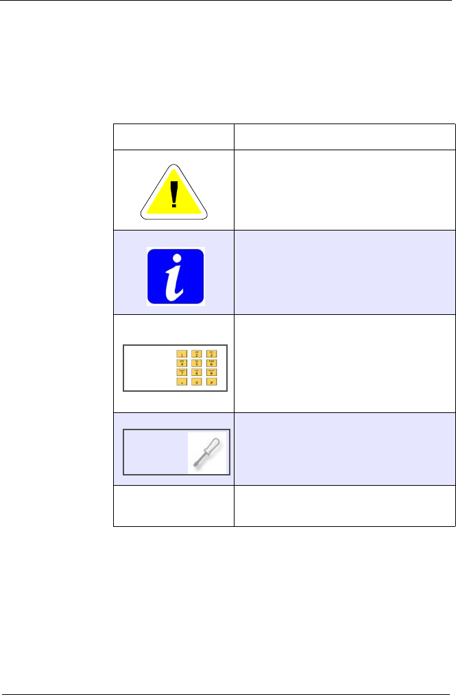
Symbols in this documentation
To clarify the content following symbols are used.
Symbol Description
Warning.
This information must be
observed strictly.
Important information.
Indicates that this function can be
enabled with a release code.
This function must be installed from
the factory personal or experts.
Venus-1 commands are indicated
with this formatting style.
TABLE 1:Symbols and their meaning
Option
Venus-1
Option

Chapter 1
Manual Corvus-eco
Introduction 8
Introduction
Manual Corvus-eco
Introduction 9
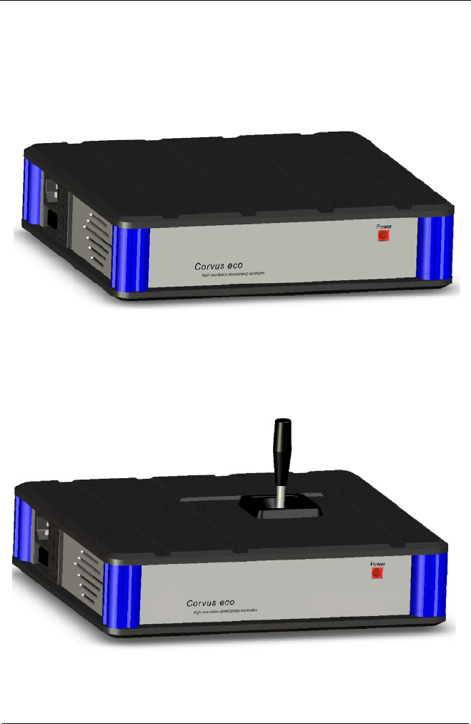
Presentation of the controller
Corvus-eco
Corvus eco with a built in joystick

Manual Corvus-eco
Introduction 10
Technology
Corvus-eco is a complete high resolution stepping motor con-
troller/driver combination for alternatively 2 or 3 axes.
Corvus-eco is equipped with a 32-bit, 133MHz Risc processor
working with a Real-Time-Operating-System (RTOS) for scal-
able performance and high precision synchronized control.
For Closed Loop control a digital PID control loop updates all
axes with a cycle time of 250 µs for precise and accurate po-
sitioning.
A extremely micro-step resolution up to 690.000 steps/rev.
provides ultra-smooth stepper positioning capability and a
very constant velocity profile tracking for challenging position-
ing applications.
Low impedance MosFet motor drivers guarantee high motor
performance and a cool driver electronics.
Motion types
Corvus-eco provides point-to-point, jogging, linear interpolat-
ed moving and also velocity controlled moves with the possi-
bility of on the fly velocity updates.
Software limits can be set to improve the systems safety.
A advanced limit switch teach-in procedure determines the
working range and ensures the precision of homing.
Resolution, velocity and acceleration
The elaborated controller technology enables a low-noise
positioning and an extremely high stepping resolution. In the
programmable mode, a positioning resolution of 1,5 nm is
achieved.
The resolution in the joystick mode is 23.2 fm (femtometer).
Due to the high computing power Corvus-eco has a high
speed and acceleration dynamic from 15nm/s until 25mm/s
(pitch =1mm.)
Linear- or sin²-accelerations modes are also supported.
Options
Corvus-eco is supplied with a great variety of options.
See Table 2, “Function survey,” page 12.

Manual Corvus-eco
Introduction 11
Communication
RS-232 or USB
Programming
Corvus-eco is programmed with ASCII command language
Venus-1. For easy motion programming the controller sup-
ports native units such as µm, mm, inch, m, mm/s, mm/s²
Manual operation
For manual operation a analog joystick interface is provided.
Additionally Corvus-eco is available with a build in joystick.
Firmware update
To keep the Corvus-eco firmware always up to date the
controller firmware can be easily updated.

Manual Corvus-eco
Introduction 12
Function survey
The following table summarizes the functions of the Corvus-
eco motion controller/driver.
Standard: Basic configuration.
Option / Code: Release code required.
Option / Hardware: Additional hardware required.
Option / Code / Hardware: Additional hardware required + release code required.
Features Standard / Option
• Axis-1, Axis-2 • Standard
• Axis-3 • Option / Code
• 24V motor driver voltage • Standard
• Max. motor phase current: 1.5A • Standard
• Max. motor driver resolution: 1.5nm • Standard
• Motor revolution (200 step motor): 15 rev/s • Standard
• Motor revolution (200 step motor): 25 rev/s • Option / Code
• Joystick operation for external joystick • Standard
• Joystick operation with internal joystick • Special order code
• ASCII command language • Standard
• Motion macro execution • Standard
• Error correction 1D, open loop and closed loop • Standard
• Sin²- acceleration (s-curve) • Standard
• Closed Loop (RS422 inputs) • Option / Code
• Closed Loop (1Vss inputs) • Option / Code / Hardware
• 2 Limit switch inputs • Standard
• Digital I/O, 3 inputs / 3 outputs • Option / Code
• Trigger out function, max. 4 kHz, resolution=250µs • Option / Hardware
• Position capture input, max. 1.000 position data • Option / Code
• Motor enable/disable input • Option / Hardware
• Firmware update capability • Standard
• RS-232 interface • Standard
• USB interface • Option / Hardware
Table 2. Function survey

Chapter 2
Manual Corvus-eco
Starting up 13
Starting up
Manual Corvus-eco
Starting up 14
Safety notice
The controller is developed, produced, checked and docu-
mented in consideration of the relevant standards.
If it is used according to the regulations, there is no danger for
persons and things.
The use according to the regulations implies that the device
is solely used in the way that is described in this documenta-
tion and that the stated safety advices are followed.
In no event will the manufacturer be liable for direct, indirect,
special, incidental, or consequential damages arising out the
use of inability to use the product or documentation, even if
advised of the possibility of such damages.

Manual Corvus-eco
Starting up 15
Declaration by the manufacturer
The company
PI miCos GmbH
Freiburger Strasse 30
D-79427 Eschbach
declares that the product:
Corvus-eco
intended use:
Positioning Controller
meet the following directives and standards:
Directive 73/23/EEC Directive 89/336/EEC
Electrical Apparatus Electromag. compatibility
Low Voltage Directive
European Standards:
EN61010-1 (08.2002)
EN61326-1
EN61000-3-2, EN61000-3-3
Remarks:
Initial operation of the Corvus-eco controller sold by us is not
permitted until it has been assured that the machine/system,
in which our Controller is installed, complies with the EU ma-
chine guidelines.
Lucius Amelung (Managing Director)
Eschbach, 06.06.2006
Manual Corvus-eco
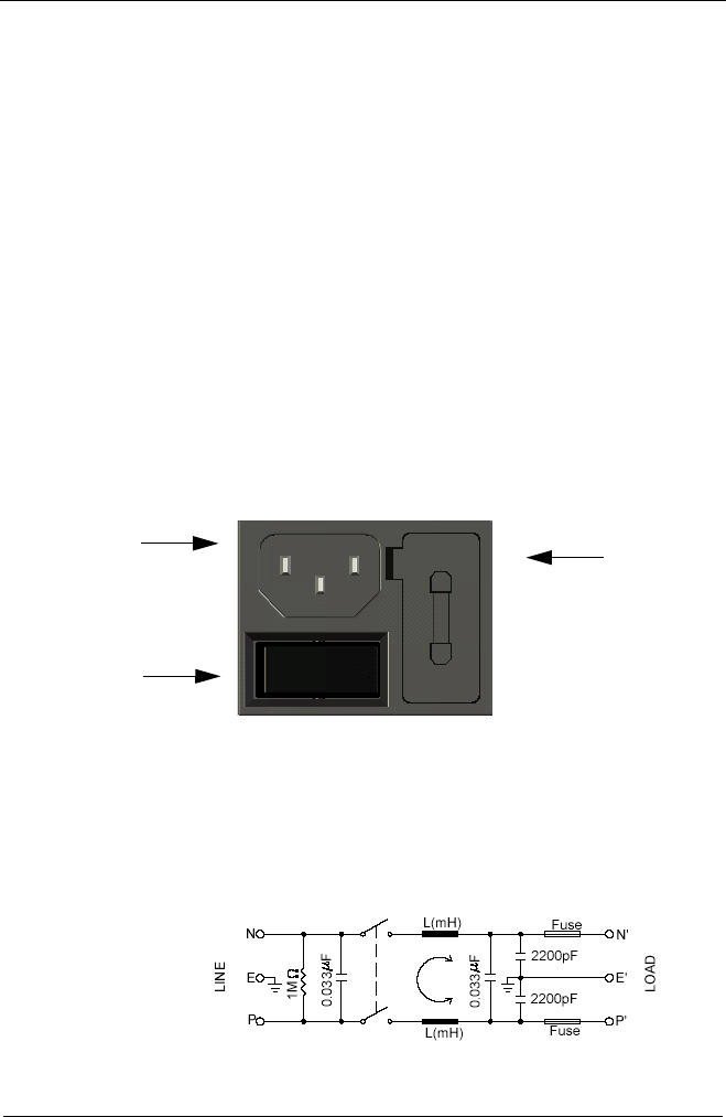
Starting up 16
Mains supply
Universal input voltage
Corvus-eco is ready for connection to the mains.
The integrated power supply unit has a wide range voltage in-
put which adapts the controller automatically to input voltages
from AC 90V up to AC 250V.
Mains protection
The mains side is protected by a standard 250V/ 3A fuse
It is located in the power entry module and accessible from
the outside.
Line filter
A line filter protects the controller from common-mode and
differential -mode interferences.
Mains switch
Fuse
AC Power connector
Manual Corvus-eco
Starting up 17
Motor connection
Axes designation and assignment
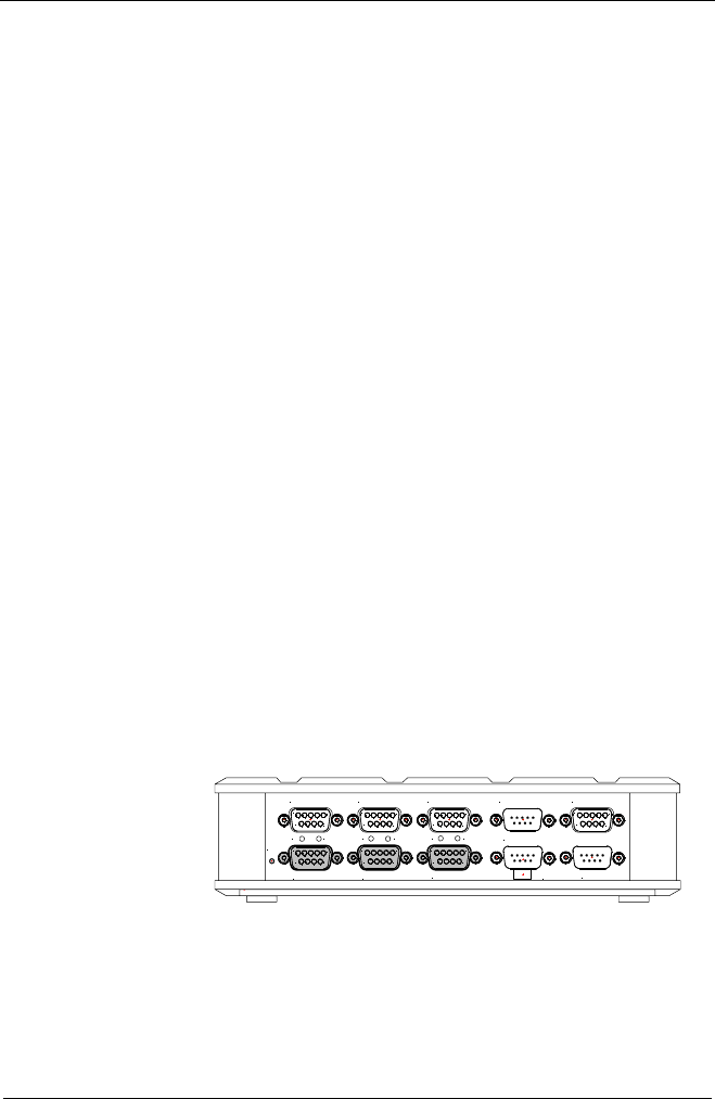
Motor connectors are designated as Axis-1, Axis-2, Axis-3.
They consequental were not labeled as X-Y-Z because this
assignment is determined by the application.
The controller is equipped with two axes by default.
Axis-3 is optional available.
Motor types
Corvus-eco supports 2-Phase DC stepping motors with
step angle 0.9 or 1.8°. Maximum phase current = 1.5A
We recommend Hybrid motors. This motors have 200 rotor
teeth and rotate at 1.80 step angles. Other hybrid motors are
available in 0.9ºand 3.6º step angle configurations. Because
they exhibit high static and dynamic torque and run at very
high step rates, hybrid motors are used in a wide variety of in-
dustrial applications.
Figure 1: Corvus-eco motor connectors
51
96
51
96
51
96
51
96
51
96
51
96
51
96
C
Joystick
Motor Axis-2
RS-232 / Host
Encoder Axis-2 Encoder Axis-3
Encoder Axis-1
S
Motor Axis-1 USB
Motor Axis-3
RS-232 / Service Input / Output
C C
SS
Cycle
Manual Corvus-eco
Starting up 18
Motor characteristics
The following stepper motor parameters are important.
• Step Angle
• Current per Phase
• Resistance per Phase
• Inductance per Phase
• Lead Wires
The motor torque during operation depends on the speed and
has to be taken from the motor characteristic curve.
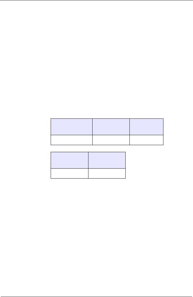
Typical values:
Step Angle Current per
Phase
Resistance
per Phase
0.9°, 1.8°, 3.6° up to 1.5A up to 10R
Inductance
per Phase Lead wires
up to 5mH 4 / 8
Manual Corvus-eco
Starting up 19
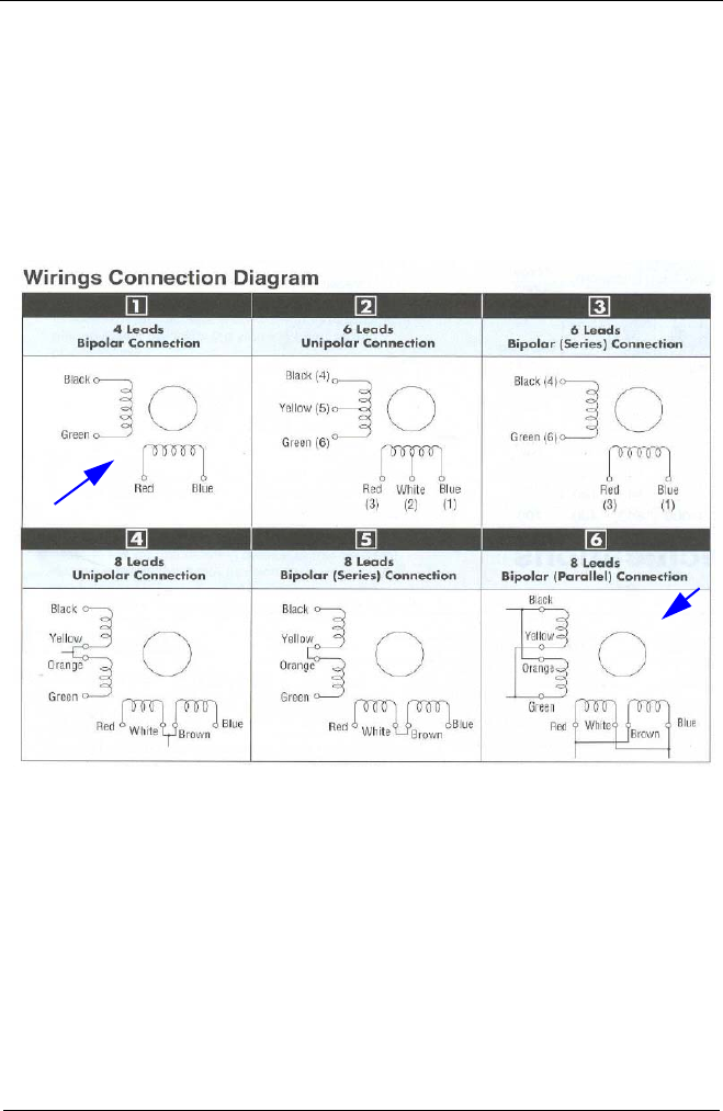
Motor wirings
Following table shows different motor wirings.
We recommend Type 1 and Type 6.
The diagrams are taken from a "Oriental Motor" data
sheet.
Manual Corvus-eco
Starting up 20
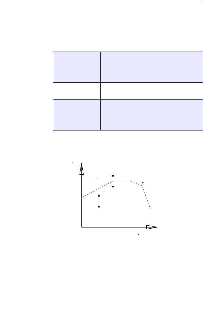
Commands to adapt the controller to different motor types
To adapt the motor driver to the motors the following
Venus-1 commands are provided:
More informations see in the Venus-1 manual.
Above diagram describe the typical stepper motor behavior.
The motor torque depends in the BEMF (back-electromotive-
force) area on the revolutions / torque characteristic of the
motor.
At lower and medium step rates the settings of umotmin and
umotgrad are dominant for the motor characteristic.
setumotmin
Determines the phase current if the
motor stand-still.
This affects the holding torque and pow-
er consumption at the motors.
setumotgrad Determines the phase current and
moving torque if the motor is moving.
setpolepairs
Adapts controller to polepairs of the
different motor types.
0.9° Hybridmotor polepairs = 100
1.8° Hybridmotor polepairs = 50
revolution / s
Phase current
umotmin
umotgrad
BEMF area
Manual Corvus-eco
Starting up 21
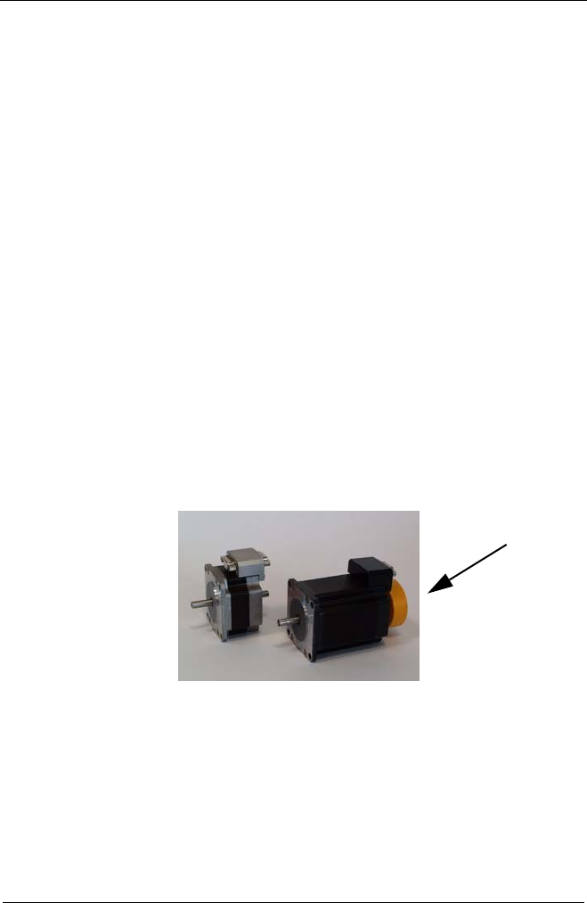
Measures against system resonances
The combination of a motor and the involved mechanical
drive components are forming a typical spring/mass system
that can oscillate if the damping of the mechanics is insuffi-
cient.
Stepper motors resonance appearances are possible. In a
worst case situation the stepping motor will stall with a
whistling sound.
An effective countermeasure against this kind of resonances
are damping elements which are for typically installed on the
extended motor shaft.
For precision position tasks we always recommend the use of
this damping measure.
A cause for resonances are often overdimensioned motors. In
this case we suggest to reduce the torque via the motor pa-
rameter umotmin/umotgrad or choosing a more suitable
motor.
Figure 2: Motor with and without damper
damper
Manual Corvus-eco
Starting up 22
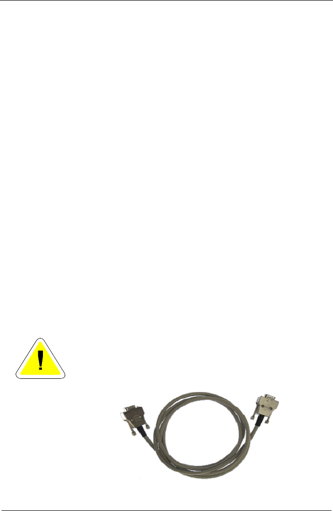
Motor cable
If the motor cables are in-house produced, cable cross-sec-
tion, cable length and shielding have to be considered.
The cable cross-section has to be adapted to the phase cur-
rent. The cable cross-section should be calculated based on
the maximum phase current per motor phase.
For cables longer than 4m it can be necessary to adapt cable
losses by a modified configuration of the motor parameters
setumotmin and setumotgrad.
For the EMC-compatible fitting of the cable, a total shielding
is prescribed whereby the cable shield is connected to the
housing.
The DSUB-9 motor connector should have a metal case. The
fasten nuts of the DSUB connectors of the controller are
equipped with an UNC4-40 thread.
Upon request we manufacture motor cables according to
customer´s demands.
An incorrect wiring of the motor connection can damage
the controller.
Figure 3: Shielded motor cable with metal connector housing

Manual Corvus-eco
Starting up 23
Limit switches
Limit switch inputs
Corvus-eco provides 2 limit switch inputs for each axis.
The inputs are situated at the motor connector. The switch in-
puts are designated due to their function as cal limit switch
input or as rm limit switch input.
The limit switch function is directly linked to these inputs; no
other function can be assigned to them.
Limit switch functions
Following limit switch functions are available:
• teach-in of lower limit switches
(Venus-1 command cal)
The controller moves all axes simultaneously in negative
direction until the cal limit switches are reached.
• teach-in of upper limit switches
(Venus-1 command rm)
The controller moves all axes simultaneously in positive
direction until the rm limit switches are reached.
• teach-in the limits of a single axis
The controller moves a selected axis to the cal or rm limit
switch. Details see chapter "Functions"
Limit switch types
Corvus-eco supports the following limit switch types:
• mechanical switches
• inductive proximity switches
• photo sensors
5V (default) or 12V (upon request) are also available at the
motor connector to supply the switches.
Manual Corvus-eco
Starting up 24
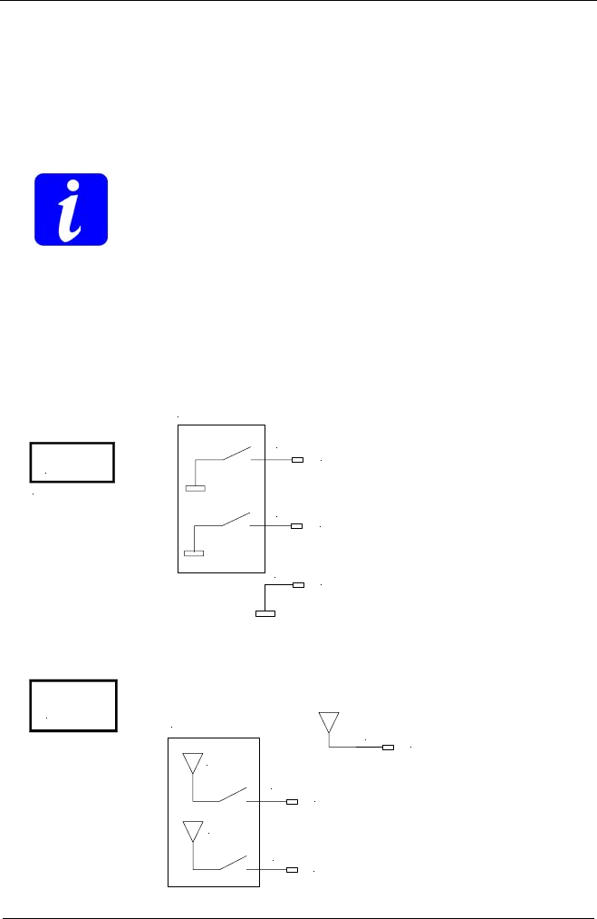
Limit switch wiring
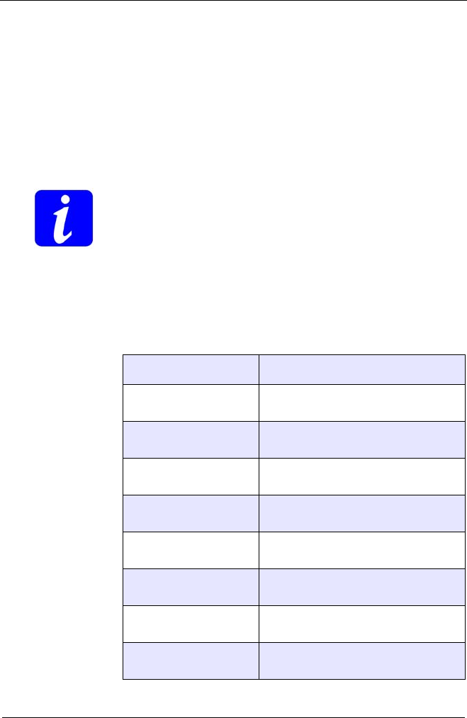
Corvus-eco supports NPN and PNP limit switch wiring.
Default setting is NPN.
The settings NPN to PNP can only be changed from the
factory personal or from authorized experts.
Function of limit switch types:
• NPN = the limit switch closes or opens to Ground
• PNP = the limit switch closes or opens to VCC
The function opener or closer is determined with the Venus-1
command setsw.
NPN
factor
y
settin
g
cal-limit switch input
rm-limit switch input
6
7
5GND
Limit switches
PNP
cal-limit switch input
rm-limit switch input
6
7
8VCC
VCC
VCC
Limit switches
Manual Corvus-eco
Starting up 25
Joystick operation
General remarks
For joystick operation the controller is working independent
from a host control unit (subject the controller settings must
not be changed)
Motor moving is controlled from the deflection of the joystick
axes, this allows a very sensitive and intuitive positioning of
the motors.
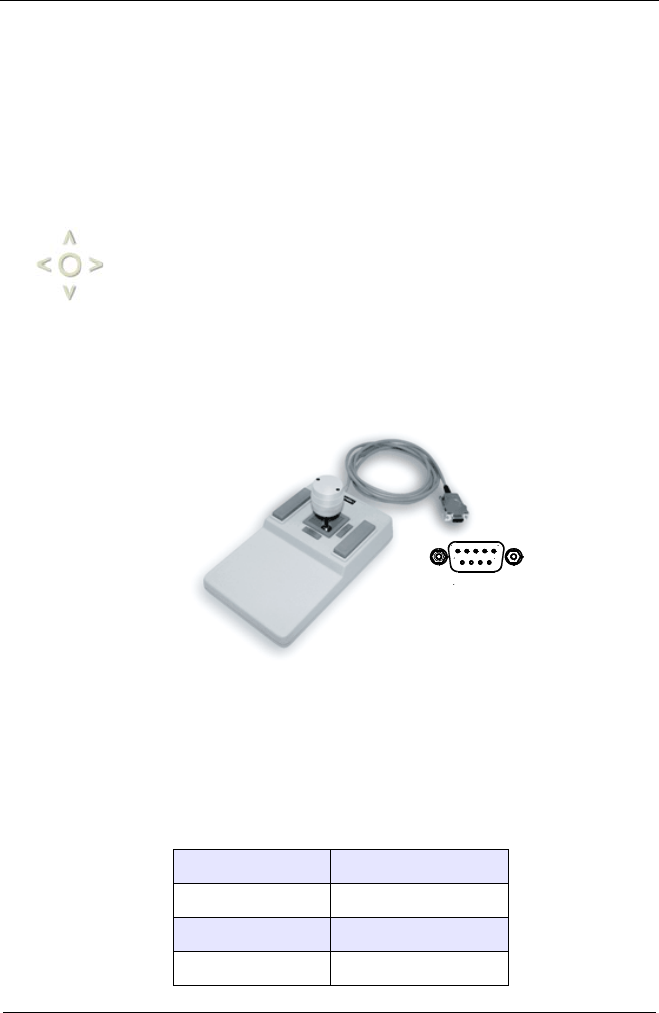
Joystick axes assignment
The axis of the joystick are assigned to the axis of the control-
ler as follows:
Figure 4: FJ Joystick with speed buttons
Joystick axes Controller axes
X-Knob Axis-1
Y-Knob Axis-2
Z-Knob Axis-3
+X-X
+Y
-Y
Z
Jo
y
stick
6
1
9
5

Manual Corvus-eco
Starting up 26
Joystick button speed
Two parallel wired push buttons are provided at the joystick to
activate a second joystick velocity.
This velocity is valid as long as one buttons is pressed.
The second joystick speed can be defined with the Venus-1
command setnjoyspeed
Relevant Venus-1 commands for the joystick operation
Command Description
setjoyspeed max. joystick velocity
valid for all axes
setnjoyspeed max. joystick velocity
each axis separately
setjoybspeed max. joystick velocity if button is pressed
valid for all axes
setmanaccel manual acceleration
valid for all axes

Manual Corvus-eco
Starting up 27
Notices for the joystick mode
• During power up the zero value of the joystick axes
are checked. Due this, the joystick axes may not be
deflected this time.
If the zero value of a joystick axis is out of a deter-
mined value, the manual mode for this axis is dis-
abled.
• If the joystick is disconnected during a manual posi-
tioning, the axes are stopped immediately.
The joystick mode remains active.
• For safety reasons the joystick will be switched off
automatically if a programmed move is performed.
Afterwards the joystick has to be switched on.

Manual Corvus-eco
Starting up 28
Programmed mode
For program controlled operation a programming host has to
be connected with the controller.
Corvus-eco provides the following programming interfaces:
• RS-232 interface
It is not necessary to install a driver to communicate with
the Corvus-eco RS-232 interface.
• USB interface
This communication assumes a driver installation.
The installation procedure for Windows 2000 and Windows
XP is described in this manual.

Manual Corvus-eco
Starting up 29
Initial operation of the RS-232 connection
Testing the RS-232 connection
• Testing with WinPos
WinPos16 LT is added for free to each controller. It is qualified
to execute all functions of the controller and can be used to
check the RS-232 connection.
Procedure step by step:
• Connect RS-232 cable to PC and controller
• Switch on the controller
• Start WinPos
• Select Com Port, choose correct port settings
"Connecting" WinPos
WinPos automatically communicates with the controller
while it is reading the controller settings.
If Status "Ready" is displayed, the RS-232 communica-
tion is well established.
• It is now possible to open the Venus command line to
execute Venus-1 commands.
Details see in the WinPos manual.

Manual Corvus-eco
Starting up 30
Trouble shooting
• The RS-232 cable, included in the delivery, should
preferably be used. If the cable is in-house produced
the correct wiring has to be ensured. See connection
diagram in Chapter "Connectors"
• The interface configurations of the control unit has to
correspond accurately with the following settings.
• If the delivered RS-232 cable is used with an additional
interface adapter, please verify if this adapter does not
modify the RS-232 wiring.
• The serial interface of the control unit may not be
occupied by other programs.
• Data bits • 8
• Stop bits • 1
• Parity • no
• Handshake • no
• Baudrate • 57600

Manual Corvus-eco
Starting up 31
USB-Interface
USB interface driver
Corvus-eco is equipped with an internal USB to RS-232 inter-
face that uses the well established controller chip FT232AM
(FT232BL) from FDI.
To operate with this interface a virtual Com Port must be in-
stalled.
Virtual COM port (VCP) drivers cause the USB device to ap-
pear as an additional COM port available to the PC. Applica-
tion software can access the USB device in the same way as
it would access a standard COM port.
VCP drivers are available which allow the FT232BL device to
work with the following operating systems:
• Windows XP x64
• Windows Server 2003 x64
• Windows XP
• Windows Server 2003
• Windows 2000
• Windows ME
• Windows 98
• Linux
• Mac OS X
• Mac OS 9
• Mac OS 8
• Windows CE.NET (Version 4.2 and greater)
Driver link
The following link provides actual drivers:
http://www.ftdichip.com/Drivers/VCP.htm
Manual Corvus-eco
Starting up 32
Installing VCP drivers for Windows 2000
To install VCP drivers for a FT232AM device under
Windows 2000, follow the instructions below:
• If a device of the same type has been installed on your
machine before and the drivers that are about to be
installed are different from those installed already, the
original drivers need to be uninstalled.
• Download the latest available VCP drivers from the
FTDI website and unzip them to a location on your PC.
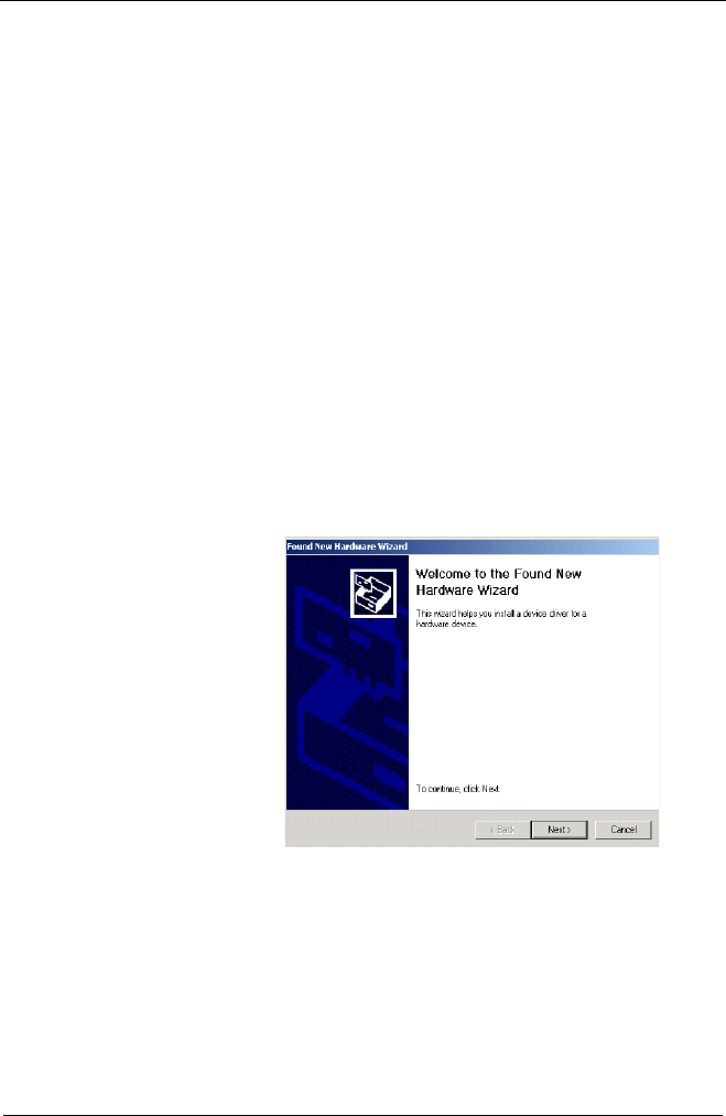
• Connect the Corvus-eco to a spare USB port on your
PC. This will launch the Windows Found New
Hardware Wizard. Click "Next" to proceed with the
installation.
Manual Corvus-eco
Starting up 33
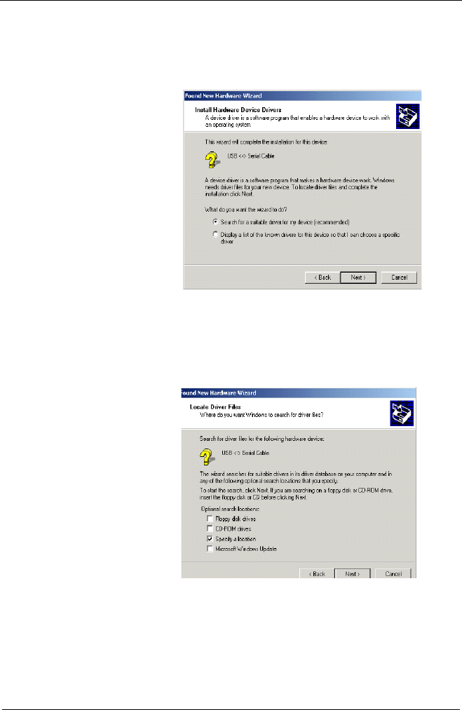
• Select "Search for a suitable driver for my device (rec-
ommended)" as shown below and then click "Next".
• Check the box next to "Specify a location" and
uncheck all others as shown below.
Manual Corvus-eco
Starting up 34
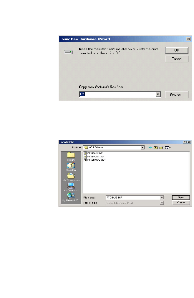
• Clicking "Next" displays a dialog box for you to enter
to the location of the drivers.
• Click "Browse" to display an open file dialog box.
Manual Corvus-eco
Starting up 35
• Locate the folder containing the latest drivers down-
loaded from the FTDI website above and click "Open",
then click "OK". The PC autoselects the correct INF
file, in this case
FTDIBUS.INF. Once Windows has found the required
driver.INF file, click "Next" to proceed.
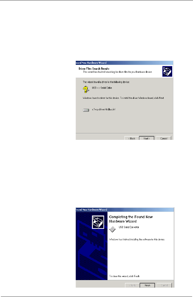
• Windows should then display a message indicating
that the installation was successful. Click "Finish" to
complete the installation. This has installed the serial
converter. The COM port emulation driver must be
installed after this has completed.
Manual Corvus-eco
Starting up 36
• After clicking "Finish", the Found New Hardware Wiz-
ard will continue by installing the COM port emulation
driver. The procedure is the same as that above for
installing the serial converter driver, except the PC will
autoselect the FTDIPORT.INF file.
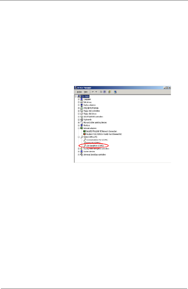
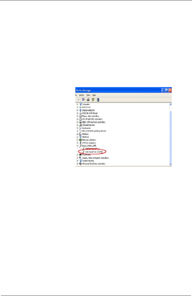
• Open the Device Manager (located in "Control
Panel\System" then select the "Hardware" tab and
click "Device Manager…") and select "View > Devices
by Type". The device appears as an additional COM
port with the label "USB Serial Port".

Manual Corvus-eco
Starting up 37
Installing VCP drivers for Windows XP
To install VCP drivers for a, FT232AM device under
Windows XP and XP SP1, follow the instructions below:
• If a device of the same type has been installed on your
machine before and the drivers that are about to be
installed are different from those installed already, the
original drivers need to be uninstalled.
• Download the latest available VCP drivers from the
FTDI website and unzip them to a location on your PC.
• If you are running Windows XP or Windows XP SP 1,
temporarily disconnect your PC from the Internet. This
can be done by either removing the network cable
from your PC or by disabling your network card by
going to the "Control Panel\Network and Dial-Up Con-
nections", right clicking on the appropriate connec-
tion and selecting "Disable" from the menu. The con-
nection can be re-enabled after the installation is com-
plete. This is not necessary under Windows XP
• SP 2 if configured to ask before connecting to Win-
dows Update. Windows XP SP 2 can have the settings
for Windows Update changed through "Control
Panel\System" then select the "Hardware" tab and
click "Windows Update".
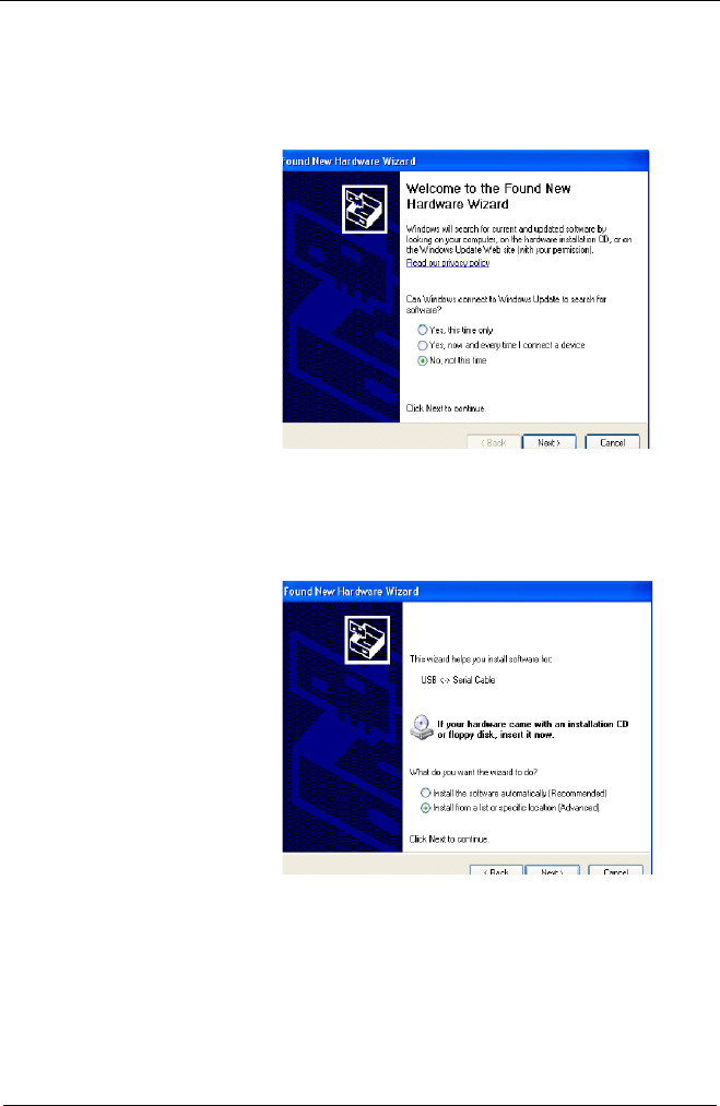
• Connect the Corvus-eco to a spare USB port on your
PC. This will launch the Windows Found New Hard-
ware Wizard. If there is no available Internet connec-
tion or Windows XP.
SP 2 is configured to ask before connecting to Win-
dows Update, the screen below is shown. Select "No,
not this time" from the options available and then click
"Next" to proceed with the installation. If there is an
available Internet connection, Windows XP will silently
connect to the Windows Update website and install
any suitable driver it finds for the device in preference
to the driver manually selected.
Manual Corvus-eco
Starting up 38
• Select "Install from a list or specific location
(Advanced)" as shown below and then click "Next".
Manual Corvus-eco
Starting up 39
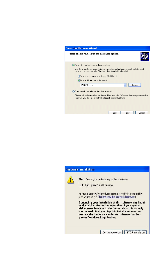
• Select "Search for the best driver in these locations"
and enter the file path in the combo-box ("C:\VCP Driv-
ers" in the example below) or browse to it by clicking
the browse button. Once the file path has been entered
in the box, click next to proceed.
• If Windows XP is configured to warn when unsigned
(non-WHQL certified) drivers are about to be installed,
the following screen will be displayed. Click on "Con-
tinue Anyway" to continue with the installation. If Win-
dows XP is configured to ignore file signature warn-
ings, no message will appear.
Manual Corvus-eco
Starting up 40
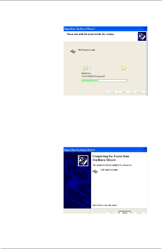
• The following screen will be displayed as Windows XP
copies the required driver files.
• Windows should then display a message indicating
that the installation was successful. Click "Finish" to
complete the installation. This has installed the serial
converter. The COM port emulation driver must be
installed after this has completed.
Manual Corvus-eco
Starting up 41
• After clicking "Finish", the Found New Hardware Wiz-
ard will continue by installing the COM port emulation
driver. The procedure is the same as that above for
installing the serial converter driver.
• Open the Device Manager (located in "Control
Panel\System" then select the "Hardware" tab and-
click "Device Manger") and select "View > Devices by
Type". The device appears as an additional COM port
with the label "USB Serial Port".

Manual Corvus-eco
Starting up 42

Chapter 3
Manual Corvus-eco
Functions 43
Functions

Manual Corvus-eco
Functions 44
Programming mode
Corvus-eco is programmed via the RS-232 or USB interface.
The command language is Venus-1.
The principle of the host control
There are reading commands and writing commands.
Writing commands execute the activities. Reading com-
mands are used to check the controller configuration resp. the
current state.
An automatic status reply message can be generated by a
combination of commands, see example.
During a positioning task is executed, the status of the con-
troller and the current coordinates can be replied.
The Venus-1 command language is described in a second
part of the Corvus-eco documentation.

Manual Corvus-eco
Functions 45
Venus-1 controller commands (examples)
System commands
save parameters:
save
restart controller:
reset
Configuration commands
[parameter] _ [axis index] _ [command] _
Example: switching on the 2nd axis
1 2 setaxis
Positioning commands
[axis 1] [axis 2] [axis 3] move
Example:
Absolute move, all axes are moved to the coordinates below
1.204 4.01 3.4 move
Relative move,
0.001 0.002 0.001 r
Status commands
System status:
st
Status of the digital inputs:
getin
Actual position read out
pos
More information see in manual "Venus-1 command lan-
guage"

Manual Corvus-eco
Functions 46
Automatic status reply
The following command sequence must be sent to the con-
troller to cause the controller to send a status reply
automatically.
Example:
10 12 4 m // move to the desired coordinates
0 0 0 r // no operation command, locks interpreter
until it is executed
st // command will reply status
if interpreter is unlocked
Manual Corvus-eco
Functions 47
Motion control functions
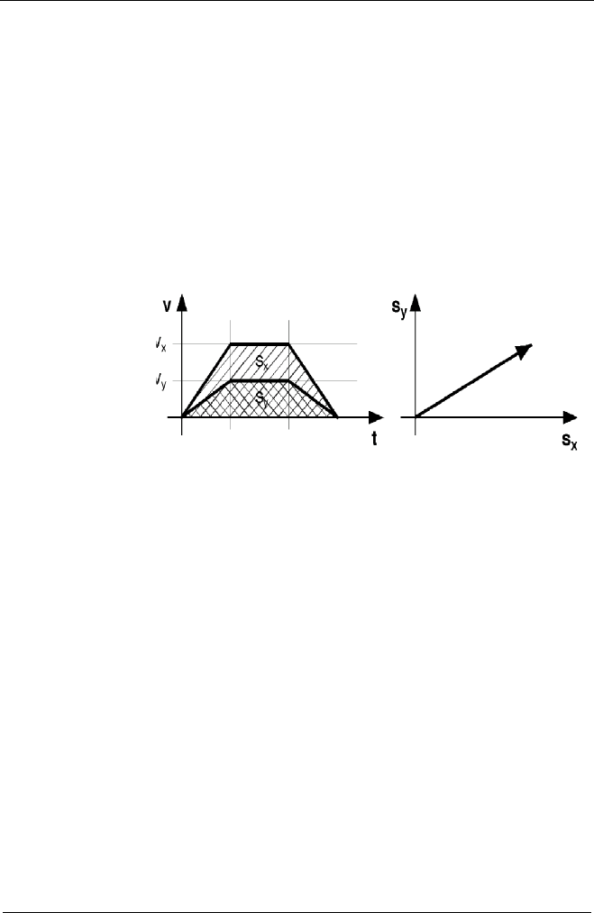
Linear interpolation
In the programmed positioning mode the axes are linear inter-
polated and a so-called vector move is executed.
In doing so, the involved axes are synchronized that way that
the time of acceleration and the time of deceleration are
equal.
A cross table with the axes x and y executes thereby a
straight movement.
Velocity and acceleration
The settings of the velocity and the acceleration always refers
to the axis with the longest moving distance. It is also called
the limiting axis.
The velocity of the other axes v is a result of the ratio of the
moving distance of these axes to the moving distance of the
limiting axis slim
The acceleration of the other axes is a result of their maxi-
mum velocities.
vs
slim
--------- vlim
Þ=
Manual Corvus-eco
Functions 48
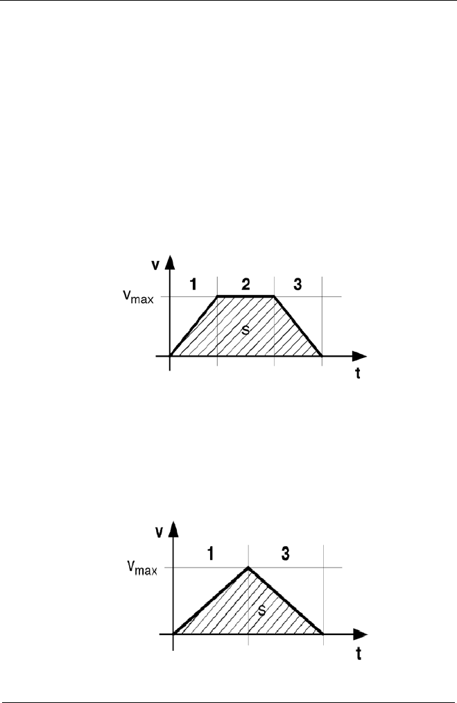
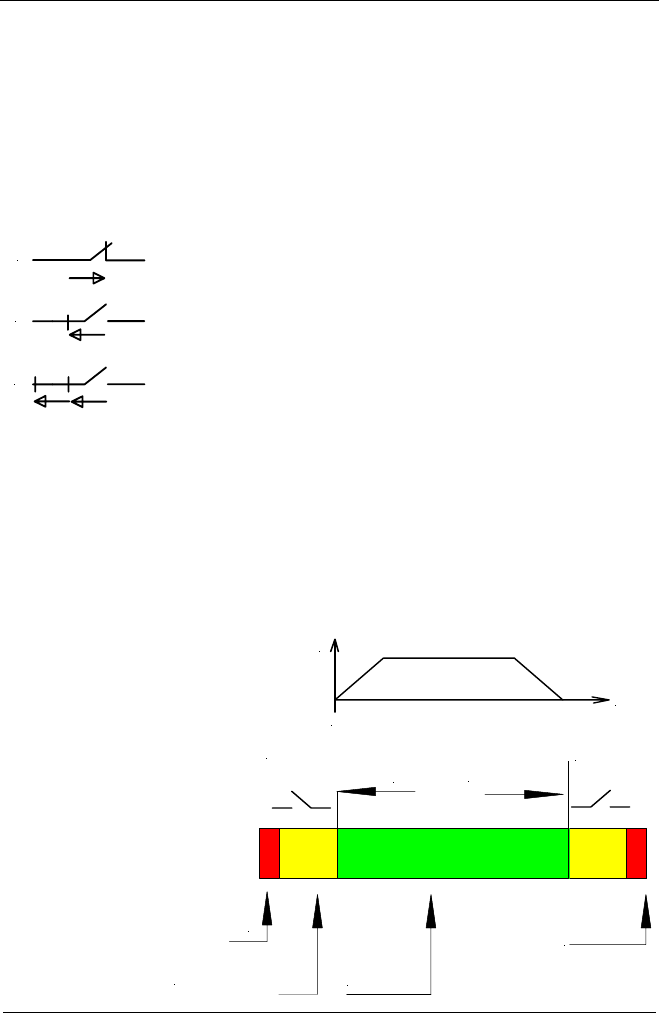
Velocity profile of a linear acceleration function
The movement profile of a programmed move which is pro-
duced with a linear acceleration function has the form of a tra-
pezium. The area under the curve corresponds to the covered
distance s and the pitch of the curve corresponds to the ac-
celeration a.
See v/t graph below.
• 1 = accelerated move
• 2 = continuos move
• 3 = decelerated move
Movement profile of short distances
The graph below shows the positioning of a short distance. It
can not always be guaranteed here that the axis reaches it’s
maximum velocity.
The movement profile has the form of a isosceles triangle.
Manual Corvus-eco
Functions 49
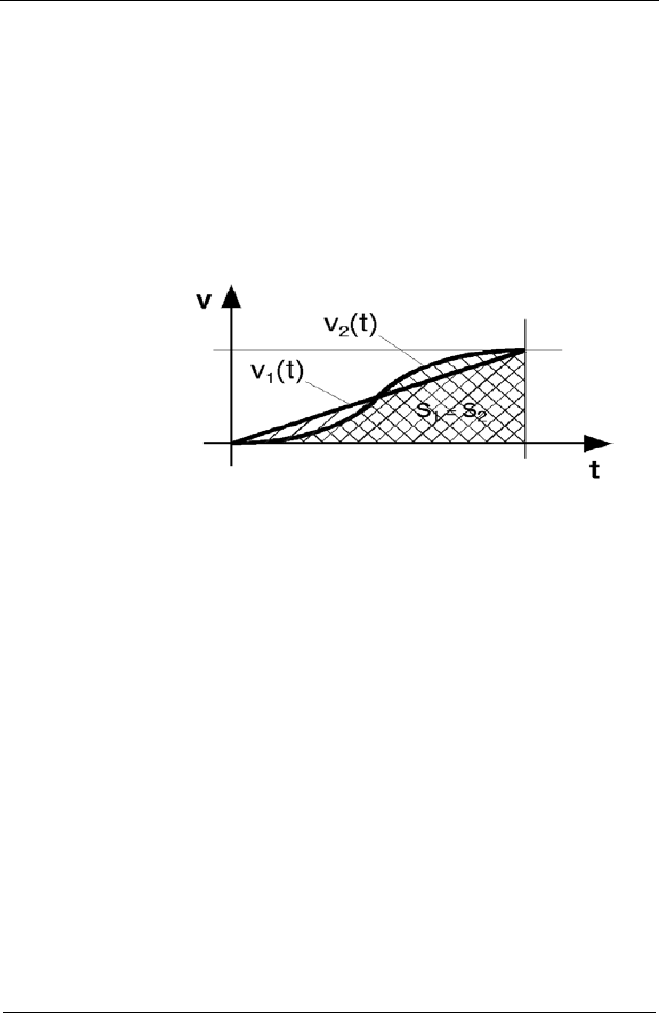
Movement profile of the sin²-acceleration function
For the sin²-acceleration the torque is not provided abruptly
but in form of a sine curve. A very soft start and deceleration
of the motor is achieved with this profile.
Because the acceleration is raised in the lower speed range
it does not lead to an extension of the positioning process.

Manual Corvus-eco
Functions 50
Positioning with the joystick
The joystick mode allows a very sensitive positioning of the
axes with an analog joystick.
This movement is velocity controlled and caused by the de-
flection of the joystick.
The larger the deflection, the larger the velocity. In joystick
mode the axes can be moved independently.
The position resolution with the joystick is enormous.
The internal calculation works with 32 bit and reaches
a resolution of theoretically 23.2 fm (femtometer).
Joystick button speed
The two parallel wired push buttons of the joystick can switch
to a freely definable second joystick velocity.
This velocity is valid as long as one of the buttons are
pressed.
Relevant commands:
Command Description
setjoyspeed max. joystick velocity
valid for all axes
setnjoyspeed max. joystick velocity
each axis separately
setjoybspeed max. joystick velocity if button is pressed
valid for all axes
setmanaccel manual acceleration
valid for all axes

Manual Corvus-eco
Functions 51
Notices for the joystick mode
• During power up the zero values of the joystick axes
are checked. Due this, the joystick axes may not be
deflected this time.
If zero value of a joystick axis is out of a determined
value, the manual mode for this axis is disabled.
• If the joystick is disconnected during a manual posi-
tioning, the axes are stopped immediately.
The joystick mode remains active.
• For safety reasons the joystick will be switched off
automatically if a programmed move is performed.
Afterwards the joystick has to be switched on.

Manual Corvus-eco
Functions 52
Closed-Loop function
This function enables the operation in a feedback control
mode.
Therefore the actual position is monitored by a measuring
system and looped back to the controller.
Depending on the type of the measuring system the function
has the following advantages.
• Increasing the repeatability
• Improvement of the absolute accuracy
• Step monitoring
• Load compensation during the movement and a standstill
• Improved controlling behavior
• Supports fast and high precise positioning procedures
using the closed loop function " in-window "
• Enables high precision measuring functions
• Increases precision of the "trigger out function"
• Increases precision of the "position capture function"
Supported measuring systems
Corvus supports the following measuring systems:
• Digital encoder (RS422 differential)
• Analog encoder (1 Vpp differential)
• Marzhauser MR 500 measuring system
Manual Corvus-eco
Functions 53
Digital encoder interface
The interface supports square wave pulse trains and their in-
verted pulse trains. The encoder interface is also provided
with a reference signal input.
Technical data:
Encoder signal input RS422 differential
Encoder index input RS422 differential
Max. input frequency 20 MHz
Max. input resolution 0.233 nm (233fm)
Option
Manual Corvus-eco
Functions 54
Analog encoder interface with sin/cos module
Each axis can be supplied with a sin/cos module. This module
is a independent hardware data interface for sinusoidal
encoder signals. The input signal is internal multiplied.
The modules are available with a 12 Bit or 16 Bit data acqui-
sition interface.
Technical data:
To calculate the maximum positioning resolution of the
sin/cos module, the cycle time of the measurement signal pe-
riod must be divided by the multiplication factor.
The driver electronics supports a resolution up to 1nm
Input signal 1Vpp, differential
Reference mark 1 Vpp, differential
Max. input frequency 500 kHz
Multiplication factor
of signal interpolation
12 Bit module: 12,865
16 Bit module: 205,884
Option
Option
Manual Corvus-eco
Functions 55
Status LED´s
Related commands:
Cycle LED Status
active Hardware ok
not active Hardware error
Sensor LED Status
active No sensor available or sensor error
not active Sensor ok
Command Description
setcloop enables closed loop mode
setscaleinterface configurates sin/cos module
setclperiode adapts to the encoder types
setclfactor adapts to the encoder types
setscaletype configurates sin/cos modules
setclpara configurates PID controller
refmove executes moves to reference
mark
1
6
9
5
S
C
Sensor
C
y
cle

Manual Corvus-eco
Functions 56
Limit switches
Corvus-eco provides two hardware limits for each axis.
This limits a very useful to protect the mechanical system.
In the following the limit switch teach-in procedure is de-
criped. See also in Chapter "Installation".
• Programmed broadcast limit-switch teach-in
All axes are moved to the limits simultaneously.
• Programmed single axis limit-switch teach-in
The limit teach-in can be performed for each axis
separately.
• Manual teach-in
Limit-switch teach-in by the use of a joystick.
limit switch input (cal)
limit switch input (rm)
6
7
5GND
User limit switches
Manual Corvus-eco
Functions 57
Broadcast limit-switch teach-in
With the Venus-1 commands cal and rm all active axis are
moved synchronous to the "cal" or "rm" limit switches.
Synchronous means the axes are starting at the same time to
move simultaneous to the minus (cal) or plus direction (rm).
If the limit switches of one direction are switched, the axes are
moving automatically in the opposite direction until the switch-
es are released. At this point the limit-switch teach in of one
direction is complete.
The limit-switch movement can be aborted with the command
Ctrl+c.
During the broadcast limit-switch teach-in the Venus-1 com-
mand interpreter is blocked, no other commands except the
abort command Ctrl+c will be executed.
Nevertheless the controller continues to receive commands in
it´s command FIFO. These commands are successive exe-
cuted after a limit-switch teach-in procedure is completed.
Manual Corvus-eco
Functions 58
Single axis limit-switch teach-in
With the Venus-1 single axis command ncal and nrm the
limit-switch teach-in can be performed for each axis
separately.
Contrary to the broadcast limit-switch teach-in, the Venus-1
interpreter is not blocked during the limit-switch procedure.
Related Venus-1 commands:
Command Description
cal moves all axes to the minus limit-
switch direction
ncal moves a single axis to the minus
limit-switch direction
rm moves all axes to plus limit-
switch direction
nrm moves a single axis to the plus
limit-switch direction
setcalvel setting-up the velocities of the
"cal" limit-switch procedure
setncalvel setting-up the velocities of a "cal"
single axis limit-switch procedure
setrmvel setting-up the velocities of the
"rm" limit-switch procedure
setnrmvel setting-up the velocities of a "rm"
single axis limit-switch procedure
Manual Corvus-eco
Functions 59
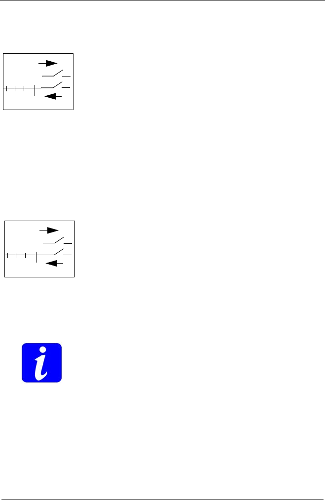
Programmed limit-switch teach-in in detail
In the following pages the procedure of the programmed limit
switch teach-in is described in detail.
The procedure is divided in at least two successive move-
ments for each axis.
1. The axis moves to the limit switch until the limit switch is
activated.
2. The axis moves in the opposite direction until the limit
switch is released.
3. If defined an additional move is performed to the opposite
direction (see command setcalswdist).
If the limit-switch teach-in procedure is performed for each di-
rection, the working area is determined. In regular conditions
further on all movements will be ramped down and terminated
at the limit borders without activating the limit switches again.
1
2
3
cal-switch rm-switch
Distance defined with
setcalswdist
Run out area
working area
lower limit upper limit
Mechanical hard limit
s
v
0
Manual Corvus-eco
Functions 60
Limit register, position counter and motor direction
With command cal or ncal the controller moves in minus
direction to the cal limit-switch(es). The cal limit-switch pro-
cedure defines the origin while the position counter and the
lower limit register is cleared to zero. The upper limit register
is set to it´s maximum value of 16.383mm.
After teaching-in the cal limit-switch, a movement to coordi-
nates less than zero is only possible if the cal limit-switch is
disabled and the lower limit value is changed to negative val-
ues with the command setlimit.
The origin can be changed subsequently with the command
setpos.
With command rm or nrm the controller moves in plus
direction to the rm limit switch(es).
The rm limit-switch procedure, registers the maximum work-
ing range to the rm limit-switch.
After teaching-in the rm limit-switch, a movement to coordi-
nates upper than the registered maximum range is only pos-
sible, if the rm limit-switch is disabled and the range limit value
is changed to larger values with command setlimit.
For safety reasons it is not possible to save the registered lim-
it switch coordinates permanently.
0
-
+
100
+
-
Manual Corvus-eco
Functions 61
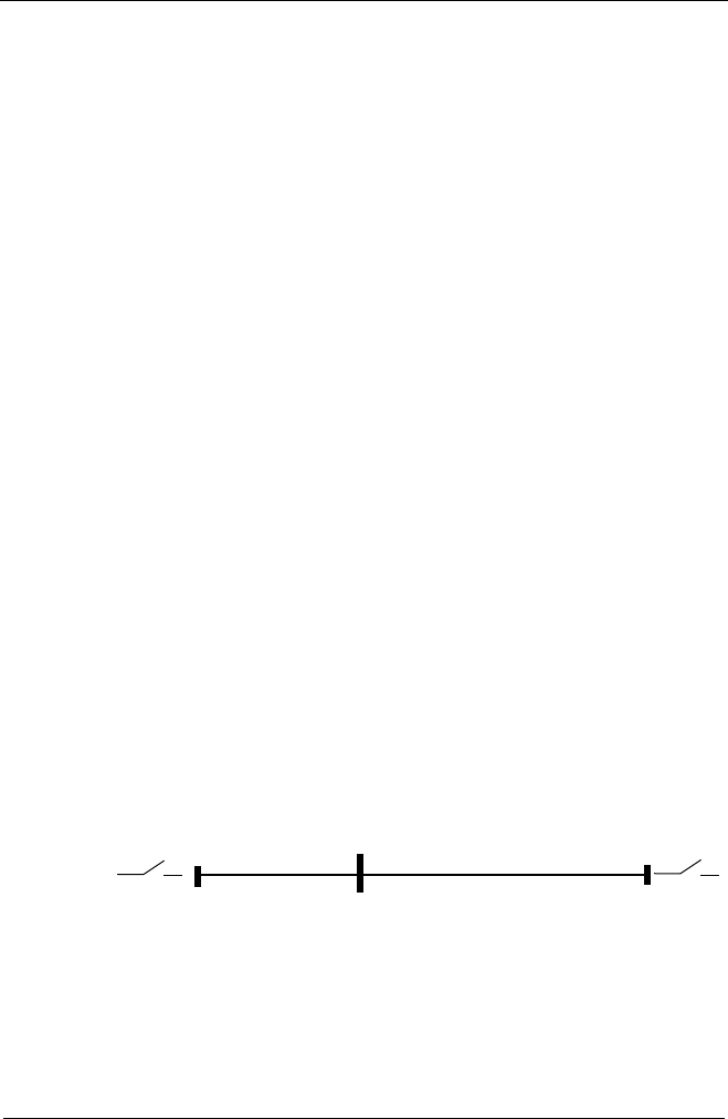
Manually teaching-in the limits
The limits can be determined manually by the use of the joy-
stick. This procedure is similar to the programmed limit-switch
teach-in.
Limit switch teach-in with the joystick in detail
The axis must be manually moved until the limit-switch is
active, then moved out of the switch until it is inactive. At this
point the limit is registered.
If all limits are teached-in, the working area is determined. In
regular conditions further on all movements will be ramped
down and terminated at the limits, without activating the limit
switches again.
Point of origin if limits are manually determined
Contrary to the programmed limit-switch movement, the man-
ual teach-in does not clear the position counter.
The origin is automatically set to zero at power up and can be
changed individually with the command setpos.
It is also possible to change the limits with command
setlimit.
cal rm
0
-24 +123

Manual Corvus-eco
Functions 62
Important notices
• To determine the limits in the programmed mode, it is
essential to execute the cal or ncal procedure first,
because this procedure clears the position counter and the
limit registers.
• The velocities to execute the limit switch movements has
to be chosen very carefully because:
The motors are interrupted immediately if the limit-
switches are activated, this causes a back electromotive
force (bemf) that can reset the controller
To much speed can bring the axis in collision with the
the mechanical limits.
To achieve a good repeatability of the determined limit
coordinates, especially the velocity for moving out of the
limit-switches should be chosen as small as possible.
• The broadcast limit switch teach-in procedure blocks the
Venus-1 interpreter for all other commands except Ctrl+c.
• For safety reasons the determined limits can not be stored
permanently.
• Software limits can be defined additionally. See command
setnlimit.
Manual Corvus-eco
Functions 63
Digital inputs / outputs
For individual controlling tasks Corvus is supplied with an in-
put/output interface with 3 digital inputs and 3 digital outputs.
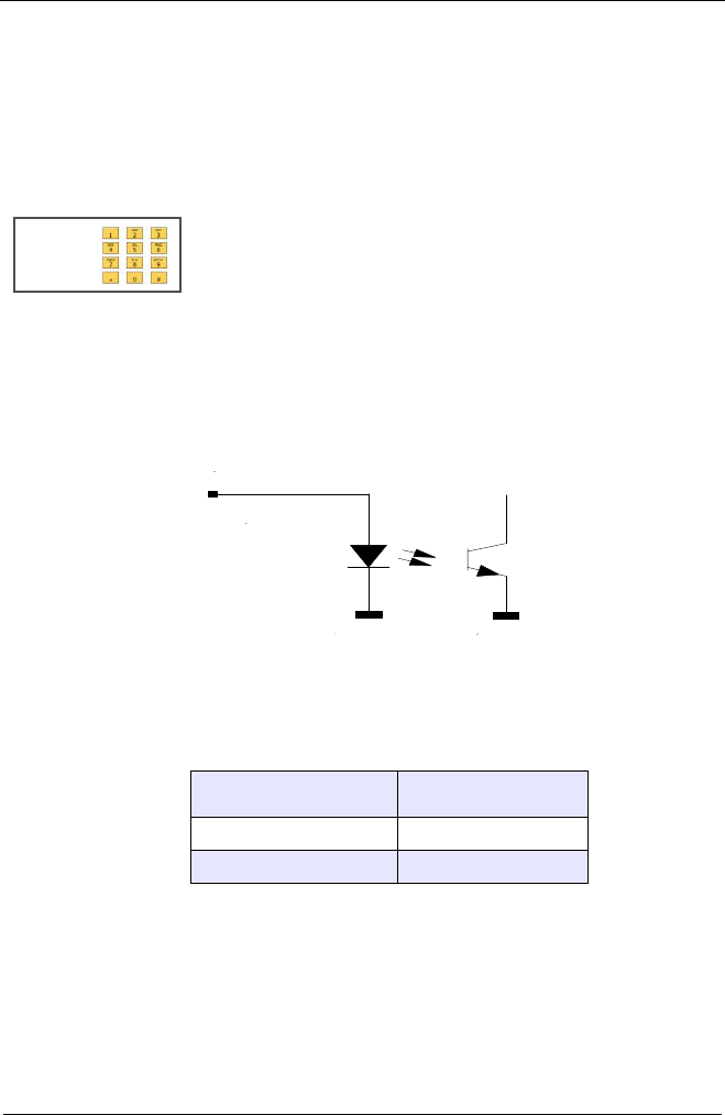
Input circuit
The input voltage range of the digital inputs is between
0 to 24V.
The inputs are optically isolated but not DC-isolated.
Technical data:
Input voltage Identified as
0 - 2 V 0
3 - 24 V 1
Option
DGND DGND
Input
0-24V
Manual Corvus-eco
Functions 64
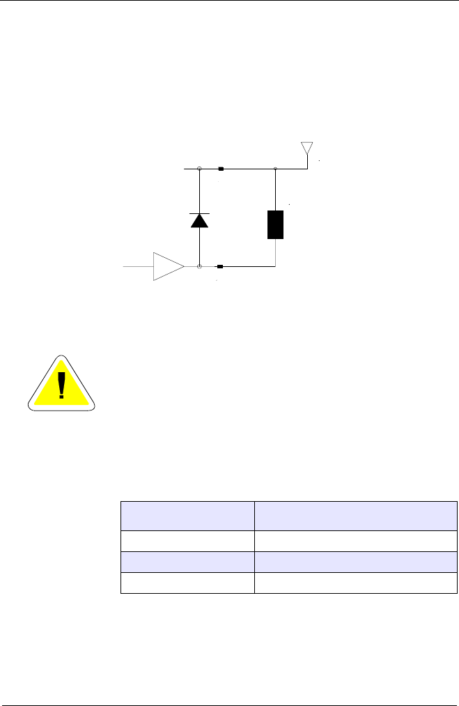
Output circuit
The output driver has a darlington circuit with open-collector
output which is also qualified for switching inductive loads.
The maximum current capacity of each output is 500 mA.
The total output current of all outputs may not exceed
1000 mA.
Related Venus-1 commands:
Command Description
setout generates signal output
getin input signal detection
setinfunc safety function configuration
Output
SPNG
Load
Vcc
5V - 35V

Manual Corvus-eco
Functions 65
Input / output functions
The following functions are realised with the digital
inputs/output interface at connector "input/output"
Output signal generation
The command setout generates digital output signal at
Pin´s 4, 8, 9.
Input signal detection
The command getin reads the binary state of the data inputs
at Pin‘s 2, 6, 7.
Safety function
The function setinfunc uses an input signal (Pin 4,8,9) to
lock a specified axis completely or restrict their moving range
depending on the direction.
This function is works independently from the limit-switch
function.

Manual Corvus-eco
Functions 66
User output voltages
To supply external devices, Corvus-eco provides the user-
voltages +5V or +12V. These voltages are protected with a
electronic fuse.
The fuse elements are self-resetable this means the electric
circuit is closed again after a while when the overload situa-
tion is removed.
Technical data:
User voltage Max. output current
5V (default) 1A
12V (upon request) 0.3A

Chapter 4
Manual Corvus-eco
Technical data 67
Technical data

Manual Corvus-eco
Technical data 68
Specifications
Number of axes • 2 or 3
Phase current • 0.2A...1,5A
Velocity max.
Velocity min.
• 15 mm/s (if pitch = 1mm)
• 15.26 nm/s
Acceleration max.
Acceleration min.
• 1m/s²
• 15.26 nm/s²
Supported motors • Stepper motor, 2-phases or 3-phases
Programming
• ASCII command language Venus-1
• Windows user interface (WinPos)
• Software library (dll)
Resolution
programming mode • 1.5 nm
Resolution
joystick mode • 0.233 nm
Positioning modes
• Absolute, relative, vector, error correction
• speed controlled with on the fly velocity updates
• Limit move algorithm
• Origin move algorithm
Acceleration modes • linear (trapezoid), sin² s-curve)
Processor • 32 Bit Risc Processor
Operating system • Real Time Operating System (RTOS)
Motor driver • Digital, MOS-FET technology
Communication • RS-232 up to 57600 Baud
• USB (option)
Limits
• 2 x limit switch inputs for each axis (isolated)
• 1x origin switch input
• Voltage setting to supply switches: 5V
(12 V upon request)
Input/Outputs
(Option)
• 3 x digital inputs
• 3 x digital outputs

Manual Corvus-eco
Technical data 69
User Output power • +5V, 1000 mA (default)
• +12V, 300 mA (upon request)
Closed Loop interface • 1Vpp
• RS422 quadrature
RS422 inputs
• 3 Channel differential, incremental, RS422
• Multiplication factor: x4
• Encoder index pulse consideration
• Input frequency 20 MHz.
1Vpp inputs
• 3 Channel differential, incremental 1Vpp.
• Multiplication factor: x12,865 or x205,884
• Encoder index pulse consideration
• Input frequency max. 500 kHz
Safety functions • Motor disable interface
• Isolated relay contact
Accessories
• Analog joystick interface with 2 or 3 axes
• Analog joystick with display
• Digital encoder handwheel
• Handheld Terminal
Trigger Out Function
• Position synchronized output (PSO)
• Trigger rate max. 4kHz
• Resolution 250µs
Position capture input
• Position capture after trigger input event
• Max. position memory: 1.000 coordinates
• Max. event capture frequency: 2 kHz
• Max. trigger position resolution: 500µs x velocity
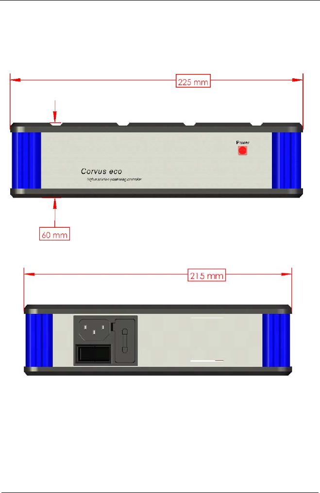
Dimensions • L x W x H: 215 x 225 x 55 (mm)
Motor driver voltage • 24V
Standards • RoHS certified
Manual Corvus-eco
Technical data 70
Layout and dimensions

Chapter 5
Manual Corvus-eco
Releasing options 71
Releasing options
Manual Corvus
Releasing options 72
Releasing options
Corvus-eco is equipped with a various number of options
which can be easily released from the customer with a so
called release code.
Informations to purchase a release code
To purchase an option following informations are essential.
1. Serial number of the controller
The number is fit at the bottom side of the Corvus-eco
chassis.
Model:
Corvus-eco
S/N:
Voltage:
Power:
0604-0243
90-250V
Serial number: 0604-0243
Manual Corvus
Releasing options 73
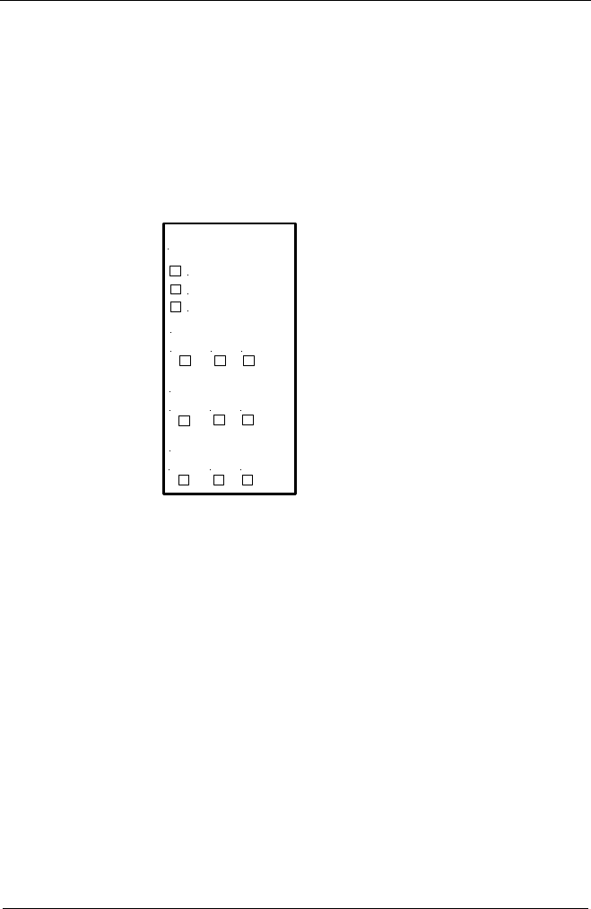
2. Actual released options
The already released options are labeled on the rear side of
the controller. The options index can also readout with the
command getoptions
Options
Axis-3
High speed (25 rev./s)
Input/Output
Axis-1 Closed loop
RS-422 1Vss MR
Axis-1 Closed loop
RS-422 1Vss MR
Axis-1 Closed loop
RS-422 1Vss MR
Manual Corvus
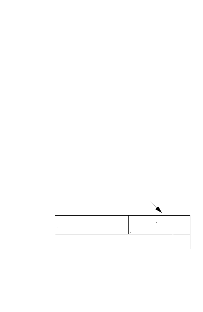
Releasing options 74
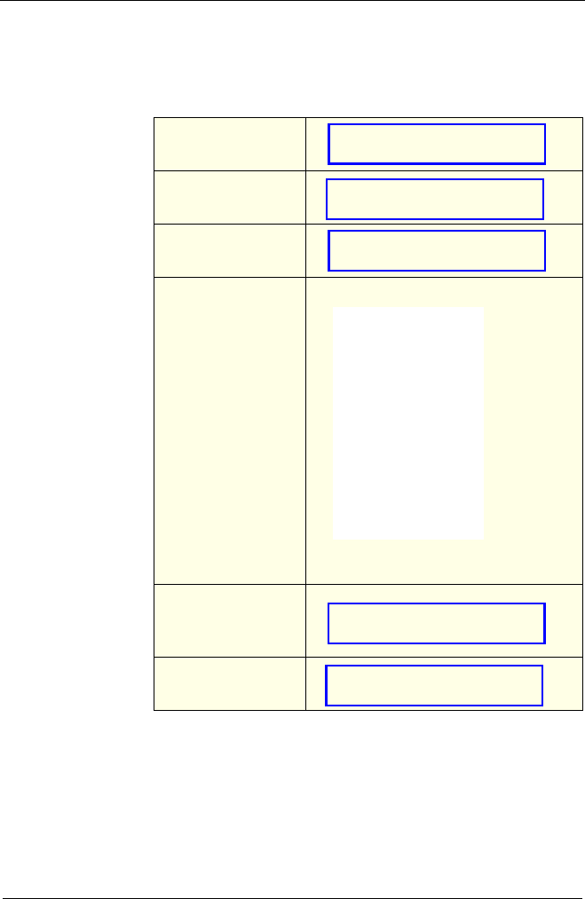
Fill out form for release code requests
Controller type
Serial number
Desired option
Already released
options
current index
(getoptions)
Date
TABLE 1: Fill out form for release code requests
Options
Axis-3
High speed (25 rev./s)
Input/Output
A
xis-1 Closed Loop
RS422 1Vss MR
A
xis-2 Closed Loop
RS422 1Vss MR
A
xis-3 Closed Loop
RS422 1Vss MR
Manual Corvus
Releasing options 75
Installation procedure
To install an option use WinPos16.
WinPos16 LT is added for free to each controller.
Before using WinPos, please check if your WinPos version is
able to release options.
WinPos Version 1.1 with venuscom.dat* dated 14.07.2003
or newer should be used.
*venuscom.dat is found in the WinPos directory.
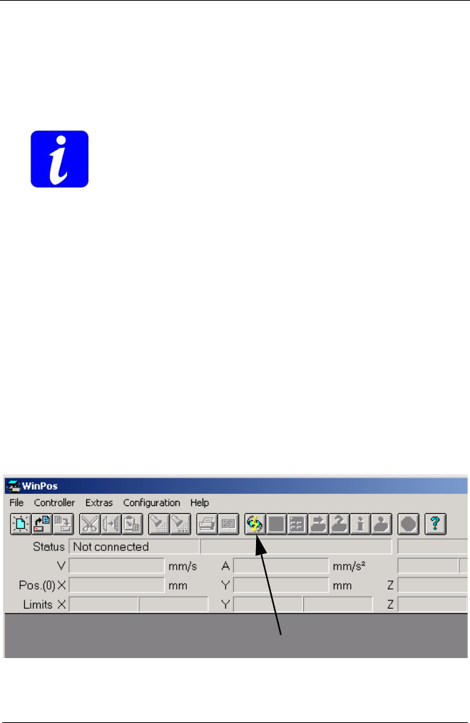
Installation step by step
• Connect serial line with Host and controller
• Switch on the controller
• Start WinPos
• Establish a proper communication between WinPos and
the controller.
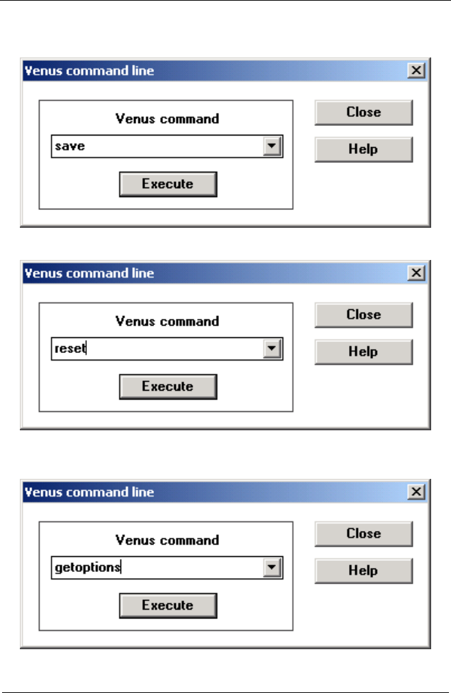
• Open Venus command input line
• Input release code and send it with command setcode
• Input command save and send it to store release code
• Input command reset and send it to restart the controller
• Verify released code with command getoptions
Connect controller
Manual Corvus
Releasing options 76
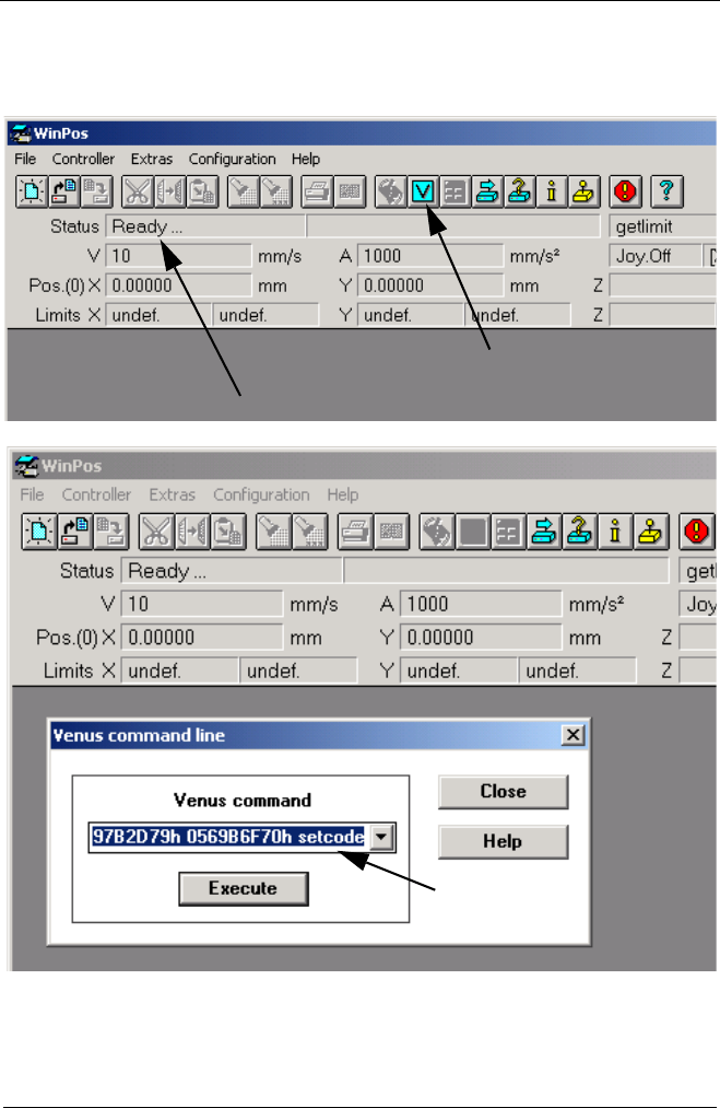
Controller connected
Venus-1 command line
Release Code
with command
setcode
Manual Corvus
Releasing options 77
Manual Corvus
Releasing options 78
Option index table
With the command getoptions the already released
options are replied as a bit coded decimal number from
0 to 1023 as shown in the following table.
Example:
Options: 3 rd. Axis, Input/Output
getoptions = 8 + 1 = 9
Option getoptions
Index Bit
3 rd. Axis 1D0
not used 2D1
not used 4D2
Input / output 8D3
not used 16 D4
not used 32 D5
Closed loop axis 1 64 D6
Closed loop axis 2 128 D7
Closed loop axis 3 256 D8
High speed 512 D9
TABLE 2: Option index table

Manual Corvus
Releasing options 79
Troubleshooting
• After releasing the option doesn‘t work
Check if the option is released. Use command getoptions.
Before you try again to release the option, please make sure
that your release code is correct. A wrong code will disable all
options.
In most cases you got the code via E-mail. It is a reasonable
way to copy the number from the E-mail into the clipboard and
insert it directly in the Venus command line.
- Don‘t forget to send command save after setcode.
- Don‘t forget to send command reset after save.
• During releasing with WinPos you got the message
"unknown command setcode"
You are using an older WinPos Version. Ask you dealer for
WinPos Version 1.1 with "venuscom.dat"
date code: 14.07.2003 or newer.

Manual Corvus
Releasing options 80

Chapter 6
Manual Corvus-eco
Firmware update 81
Firmware update
Manual Corvus
Firmware update 82
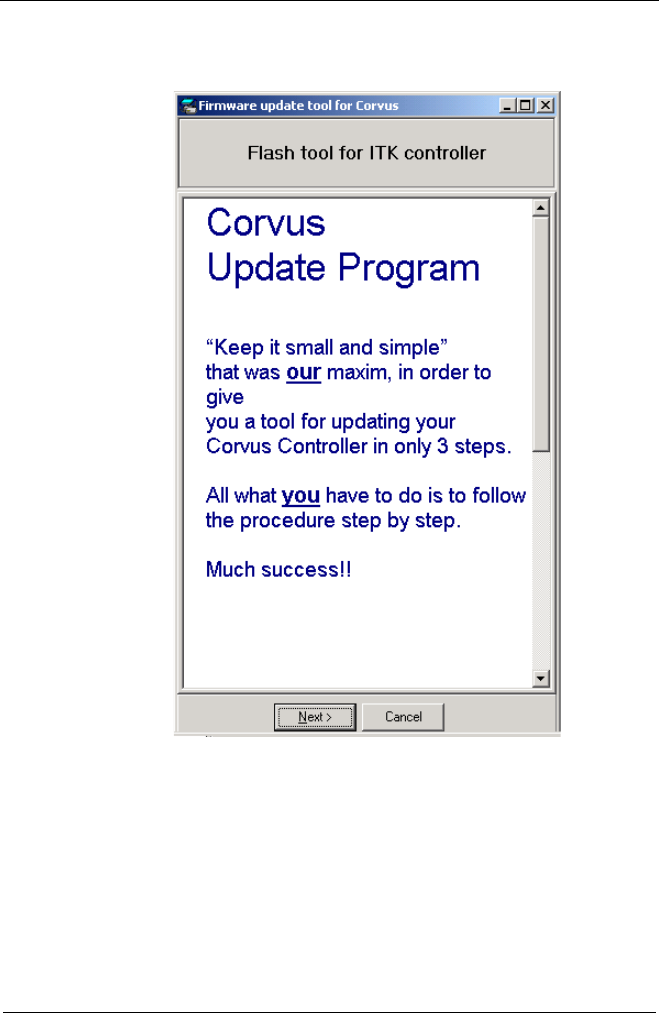
Firmware update
The Firmware update can be easily accomplished with the
ITK Update Tool. This is a self-explanatory tool that guides
you through the process in three steps.
Update procedure in three steps
1. All controller settings will be read from the controller and
stored to disk.
2. A new firmware download is performed.
3. The settings are read from the disk and stored to the
controller again.
What do you need to update the controller
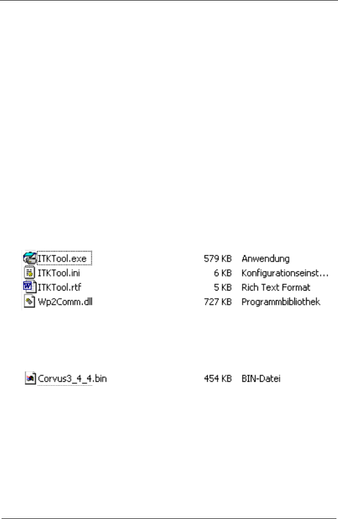
1. Update Tool with following files:
2. New Firmware.bin file
This file can be uploaded from the home page of your dealer
or can send you via E-mail.
3. Computer with a 115 kBaud RS-232 interface
The update is executed via the RS-232 Service line.
The baudrate for parameter upload is selectable.
The firmware download is executed with a fixed baudrate
of 115kBaud.
4. Socket wrench (5mm)
Tool to remove the cover of the D-type connector
"RS-232 Service" at the controller.
Manual Corvus
Firmware update 83
Update Tool

Manual Corvus
Firmware update 84

Chapter 7
Manual Corvus-eco
Connectors 85
Connectors
Manual Corvus-eco
Connectors 86
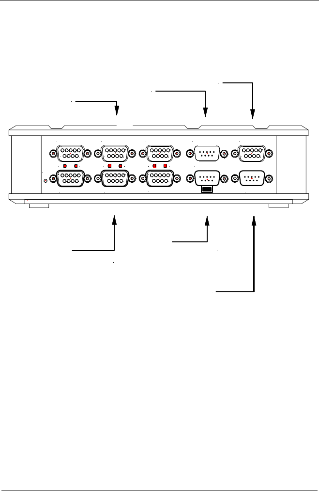
Connectors overview
51
96
51
96
51
96
51
96
51
96
51
96
51
96
C
Joystick
Motor Axis-2
RS-232 / Host
Encoder Axis-2 Encoder Axis-3
Encoder Axis-1
S
Motor Axis-1 USB
Motor Axis-3
RS-232 / Service Input / Output
C C
SS
Cycle
Closed Loop interface
Firmware update interface
I/O connector
Motor connectors /limit switches
RS-232 / USB interface
Joystick input
Manual Corvus-eco
Connectors 87
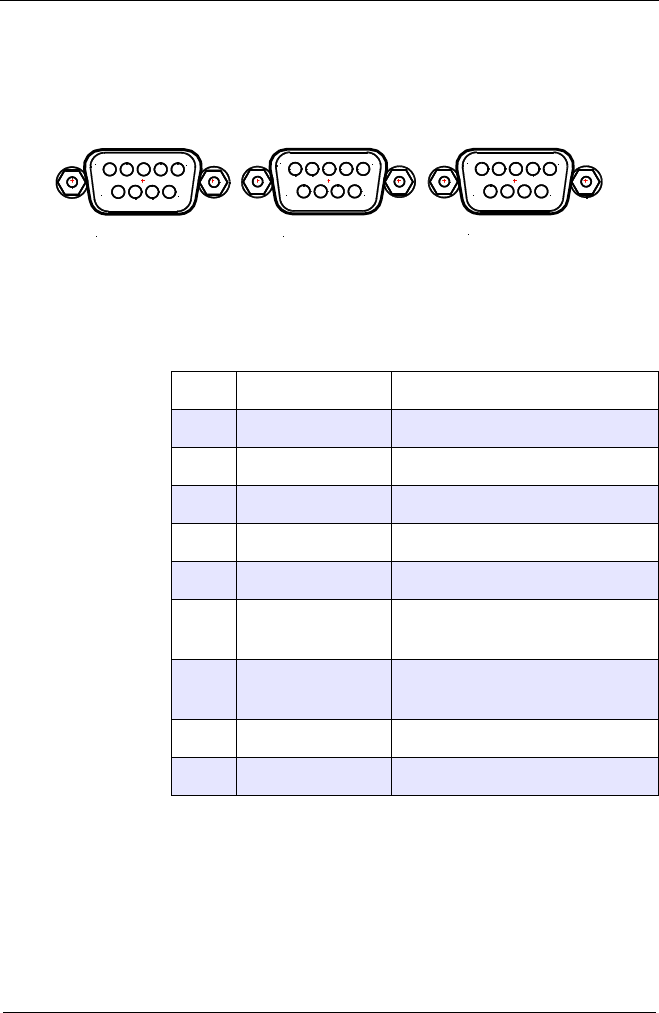
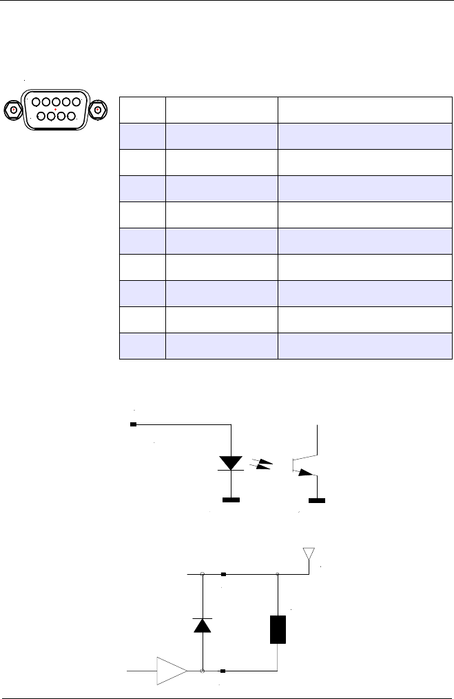
Motor and limit switch connectors
Motor control output and limit switch input a combined in this
connectors.
* factory setting: 5V
The settings can only be changed from the factory personal
or from authorized experts
Pin Name Description
1Ph 1A Motor Phase 1A
2 Ph 1B Motor Phase 1B
3Ph 2A Motor Phase 2A
4 Ph 2B Motor Phase 2B
5 GND Ground
6cal Limit switch input
(negative direction)
7rm Limit switch input
(positive direction)
8 * User 5V (12V) Output voltage 5V (12V)
9
TABLE 3. Motor connector
51
96
51
96
51
96
Motor Axis-2
Motor Axis-1 Motor Axis-3
Manual Corvus-eco
Connectors 88
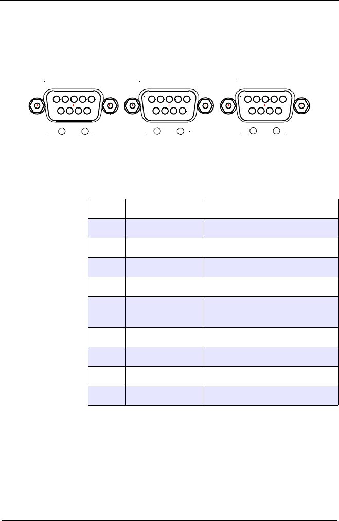
Digital encoder input
Supports closed loop control with digital RS422 encoders.
*Corvus eco provides the encoder supply for each encoder;
the value is fixed.
Pin Name Function
1Ua 1 Channel A (positive)
2 Ua 2 Channel B (positive)
3Ua 0 Reference (positive)
4DGND GND
5User 5V* Encoder supply
User output (max. 1000mA)
6 Ua 1- Channel A (negative)
7Ua 2- Channel B (negative)
8 Ua 0- Reference (negative)
9Error Encoder error
TABLE 4. Digital encoder input
51
96
51
96
51
96
C
Encoder Axis-2 Encoder Axis-3Encoder Axis-1
SC C
SS
Manual Corvus-eco
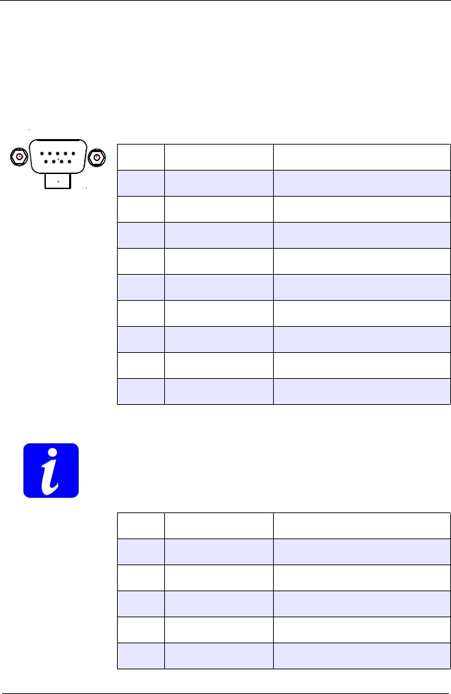
Connectors 89
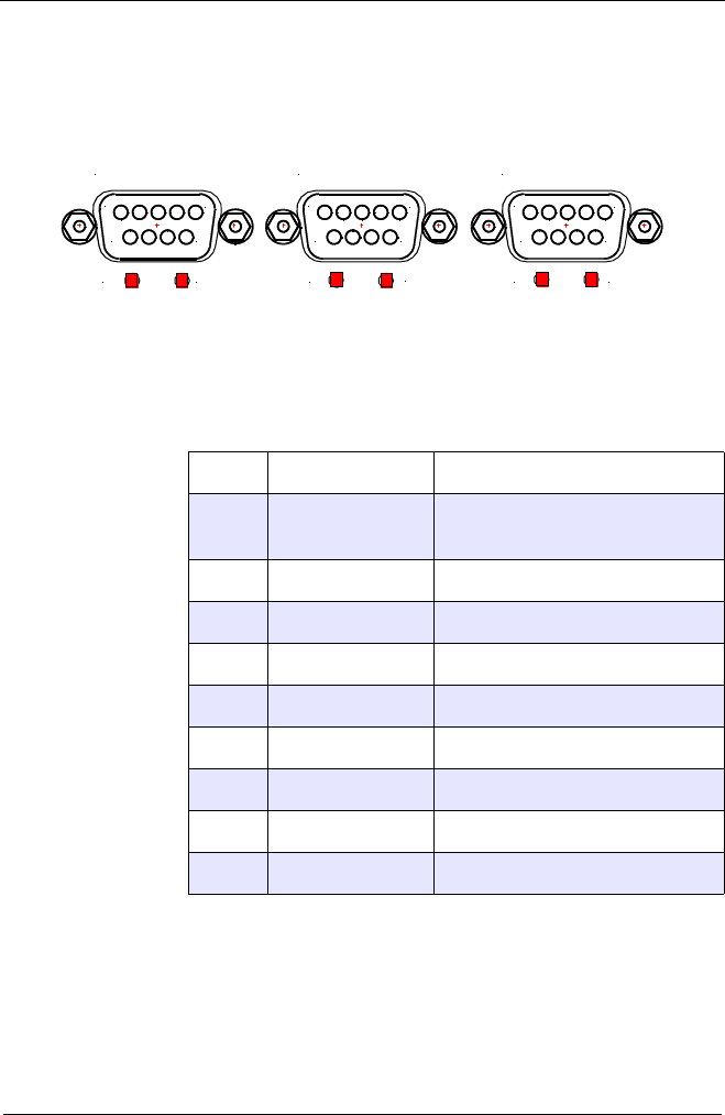
Analog encoder input
Supports closed loop control with standard analog measure-
ment systems 1Vpp.
Connector chassis = Digital GND
*Corvus-eco provides the encoder supply for each encoder;
the value is fixed. Stability has to be achieved for longer
supply lines.
Pin Name Function
1+5V analog Encoder supply
Analog Vcc
2 Event Event
3Ua 1 + sin +
4 Ua 1 - sin -
5Ua 2 + cos +
6 Ua 2 - cos -
7Ua 0 + Reference (positive)
8 Ua 0 - Reference (negative)
9AGND Analog ground
TABLE 5. Analog encoder input
51
96
51
96
51
96
C
Encoder Axis-2 Encoder Axis-3Encoder Axis-1
SC C
SS
Manual Corvus-eco
Connectors 90
Digital input / output
Pin Name Function
1DGND Digital GND
2 Input 2 Input 2 (0-24V)
3User +5V User output
4 Output 2 Output 2 (0-24V)
5SPNG SPNG
6 Input 1 Input 1 (0-24V)
7Input 3 Input 3 (0-24V)
8 Output 3 Output 3 (0-24V)
9Output 1 Output 1 (0-24V)
TABLE 6. Digital input/output
51
96
Input / Outpu
t
DGND DGND
Input
0-24V
Output
SPNG
Load
Vcc
5V - 35V
Manual Corvus-eco
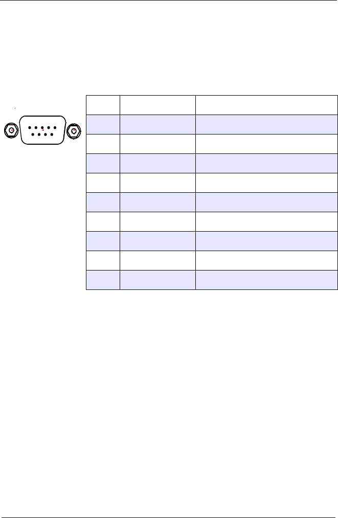
Connectors 91
RS-232 / USB programming interface
This interface is used for the standard programming mode
T
The RS-232 interface is working without flow control.
The handshake signals RTS and CTS are not supported.
DTR and DSR are internal connected.
Pin Name Function
1nc nc
2 RxD Corvus data input
3TxD Corvus data output
4 DTR Connected with Pin6
5 GND GND
6 DSR Connected with Pin4
7RTS
8CTS
9
TABLE 7. RS-232 programming interface
Pin Name Function
1VCC USB +5V
2 D- Corvus data input
3D+ Corvus data output
4nc
5 GND GND
TABLE 8. USB connector
RS-232 / Host
USB
Manual Corvus-eco
Connectors 92
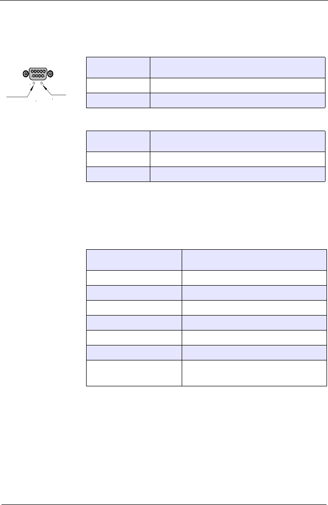
RS-232 Service interface
Pin Name Function
1nc nc
2 RxD Corvus Data input
3TxD Corvus Data output
4 DTR Connected with Pin6
5 GND
6 DSR Connected with Pin4
7
8
9
TABLE 9. RS-232 service interface
RS-232 / Service

Manual Corvus-eco
Connectors 93
Joystick interface
Pin Name Function
1Axis-1 (X) Analog input 0-3.3V
2 Axis-2 (Y) Analog input 0-3.3V
3Axis-3 (Z) Analog input 0-3.3V
4Joystick enable Enable input
GND = enables joystick
5+5V (User) User output
6 SW Joystick button
7 GND GND
8 AGND analog GND
93.3V (analog) Power
TABLE 10. Joystick interface
Jo
y
stic
k

Manual Corvus-eco
Connectors 94
Your notices:
