DAIWA DR 7500 ROTATOR MANUAL3
User Manual: Pdf DAIWA--DR-7500-ROTATOR-MANUAL3
Open the PDF directly: View PDF ![]() .
.
Page Count: 5
~ 6 f>"2-- T
HOBBY ELECi~~NCS
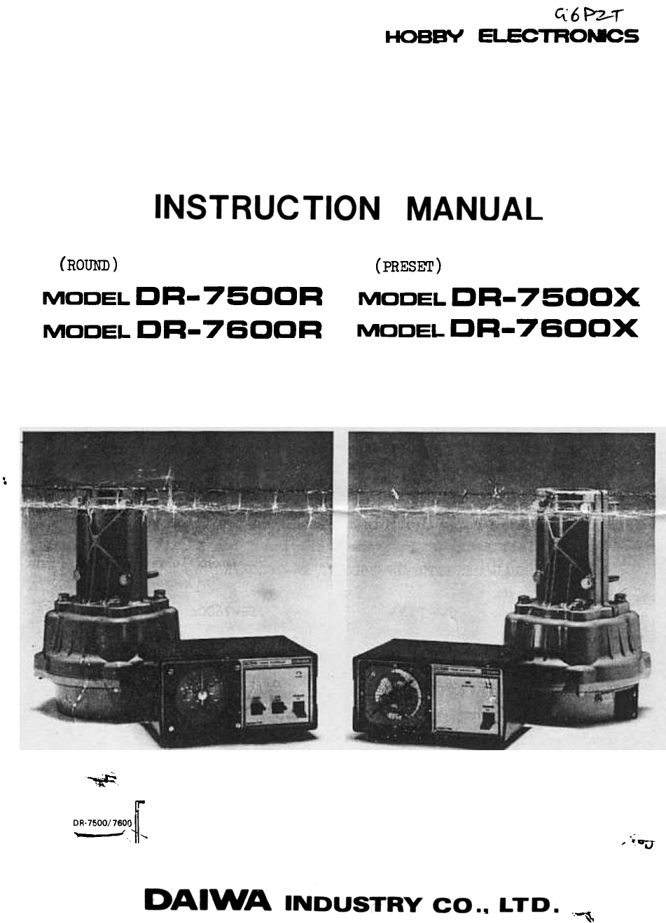
(ROUND) (PRESm)
MODEL DR-75CDR
MODEL DR- 76DDR
MODEL DR- 75DDX
MODEL DR- 76DDX
..
~
DR.7500/760Q r
"---' ~ " , ."
..~

OPERATION
DR-7500R/DR-7600R
I. Before switching on, make sure the wiring of the 6 leads between the
controller and rotator have been connected correctly. Connect the same
terminal number of the controller and rotator.
2. When unpacked, the controller indicator is set at the south position.
After confirming the wiring, switch on the power. The light on the
indicator panel will come on and the indicator will ShoW the direction of
the rotor.
3. Push CW (Right) switch and turn the rotator to the maximum Clock-wise
position. Tighten the antenna to the rotator at the desired starting
position. RemoVe the color panel and re-set the indicator to the direction
of the antenna.
4. When the cable between rotor and controller is cut accidentally, the
indicator StopS on the opposite direction of the start position
i.e. + 180°.
,OEERATION
~ -DR-7500X/DR-7600X ,
,-"- c,~-~ ~_c_"'-=:~, ::--~ " -~"c_c ~ ' -
I. Before switching on, make sure the wiring of the 6 leads between the
controller and rotator have been correctly connected. Connect the same
terminal numbers of the controller and rotator.
2. The pre-set knob has been set to North (Fully clockwise position)
when shipping. If the start position is altered the p+e-set knob can be
set as follows :
a) Set the preset knob to the fully clockwise position.
b Tighten the antenna to the rotator at the desired starting position.
Pull off the preset knob.
I.the preset knob to the start direction, then push the knob.
c)
d)
No.1 to No.1
No.2 to No.2 etc.
(I)
(2)
(1)
(2)
Gas pIpe
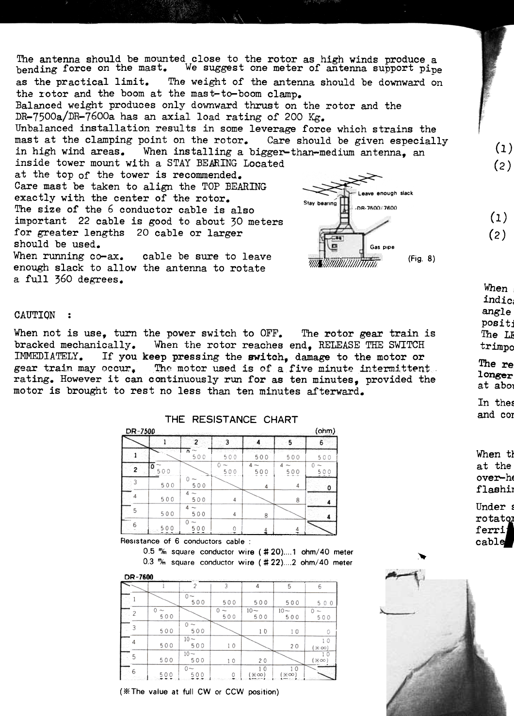
The antenna should be mounted close to the rotor as high winds produce a
bending force on the mast. We suggest one meter of antenna support pipe
as the practical limi t. The weight of the antenna should be downward on
the :rotor and the boom at the mast-to-boom clamp.
Balanced weight produces only downward thrust on the rotor and the
DR-7500a/DR-7600a has an axial load rating of 200 Kg.
Unbalanced installation results in some leverage force which strains the
mast at the clamping point on the rotor. Care should be given especially
in high wind areas. When installing a bigger-than-medium antenna, an
inside tower mount with a STAY BEARING Located
at the top of the tower is recommended.
Care mast be taken to align the TOP BEARING
exactly with the center of the rotor.
The size of the 6 conductor cable is also
important 22 cable is good to about 30 meters
for greater lengths 20 cable or larger
should be used.
When running co-ax. cable be sure to leave
enough slack to allow the antenna to rotate
a full 360 degrees.
(Fig. 8)
'l/lltff/l II II !I;;;1j ; ; ; I11ii7I ~
When
indicc
angle
positj
'I'h e LE
trimpo
The re
longer
at abol
In the~
and cor
CAUTION :
When not is use, turn the power switch to OFF. The rotor gear train is
bracked mechanically. When the rotor reaches end, RELEASE THE SWITCH
IMMEDIATELY. If you keep pressing the switch, damage to the motor or
gear train may occur. ~c motor used is of a five min~te intermitt.~n:t
rating. However it can continuously run for as ten minutes, provided the
motor is brought to rest no less than ten minutes afterward.
THE RESISTANCE CHART
lohm\DR-7!inn
5
,-1
When tr
at the
over-hE
flashir
Under ~
rota
iferri
cabl
2
0
4
Resistance of 6 conductors cable :
0.5 '%, square conductor wire ( # 20) 1 ohm/40 meter
0.3 m,." square conductor wire ( # 22) 2 ohm/40 meter
DR-7600
:.-.
( * The value at full CW or CCW position)
.rotator and controller has been adjusted in the factory. However, if
indication between the indicator and rotator has a more than 5° offset,
; the trimpot (located inside cabinet) as follows :
(Round Controller
(1)
(2)
) Set the pre-set knob to the fully clockwise position.
\-1 Adjust the trimpot to synchronise the rotator and preset knob at the
fully clockwise position.
CAUTION
When setting the trimpot to synchronise the angle of the rotator and
indicator, the rotation angle of the preset knob should be spread the same
angle of the rotator. If the trimpot is adjusted at over the rotating
position, the motor may be damaged by over-heating.
The LED (Operation indicator) will flash fully rotator position when the
trimpot is not adjusted properly. In such cases, readjust the trimpot.
The resistance of the cable is increased when using the control cable
longer than 40 ~eters. When the resistance is too high the LED will flash
at abo'.lt 00 -" 5 :pc=ition.
In these cases 0.75 m/m sq. is recommended to connect between the rotator
and controller.
CAUTION DR-75OOa (in the case of DR-750OX)
When the indicator (LED) of DC-7055 is flashing when the rotator is stopped
at the fully turned position, the motor in the DR-7500a might fail by
over-heating, because AC current is flowing in the motor when the LED is
flashing. Check the wiring of control cable.
Under so~e circumstance it is possible for RF interference to upset the
, In such cases the problem may be cured by inserting
beads or a high toroidal coil on each conductor of the control
~c
~
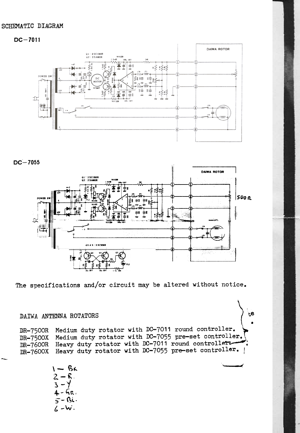
SCHEMATIC DIAGRAM
DC-7011
DC- 7055
DAIWA ROTOR I
1!~SOOIl
...J
-I.t,
I~-
QI 'SCI"'.
Q' , S ..,..
POW
]..W ~ I:. ,
r .,
I >1.' ...
; ~
-..I
T "'
o~
y "', I",
Q.. , ,.cm. I
'.'.-1 ~
The specifications and/or circuit may be altered without notice.
) 't:
DAIWA ANTENNA ROTATORS
Medium duty rotator with DC-7011 round controller
~Medium duty rotator with DC-7055 pre-set controller.
Heavy duty rotator with DC-7011 round controll~ ;
Heavy duty rotator with DC-7055 pre-set controller. I
DR-7500R
DR-7500X
DR-7600R
DR-7600X
~
, ,:
\- ~~
2.- ~.
~-y
+ -~r, ,
~-- {\L .
, -""" .
