DB MAIN Reference Manual
DB-MAIN-Reference-Manual
User Manual: Pdf
Open the PDF directly: View PDF ![]() .
.
Page Count: 300 [warning: Documents this large are best viewed by clicking the View PDF Link!]
- Table of contents
- Introduction
- Projects, products and processes
- Data schemas: Entity types, Relationship types and attributes
- Processing schemas: UML activity and use case diagrams
- Text files
- Common rules
- Engineering process control
- Sample DB-MAIN schemas
- 8.1 An Entity-Relationship conceptual schema
- 8.2 A NIAM/ORM conceptual schema
- 8.3 An UML conceptual schema
- 8.4 A relational logical schema
- 8.5 A CODASYL-DBTG logical schema
- 8.6 A COBOL file logical schema
- 8.7 An object-oriented logical schema
- 8.8 A relational (ORACLE) physical schema
- 8.9 An activity diagram
- 8.10 An use case diagram
- 8.11 An organizational structure model
- 8.12 References
- The components of the DB-MAIN environment (Version 9)
- List of the DB-MAIN functions
- The File menu (File)
- 11.1 The commands of the File menu - Summary
- 11.2 Managing projects
- 11.3 Exporting and importing
- 11.4 Executing a user-defined plug-in
- 11.5 Extracting and generating DDL text files
- 11.6 Using external texts
- 11.7 Reporting and printing
- 11.8 Configuring the DB-MAIN environment
- 11.9 Opening a recently used project
- 11.10 Quitting DB-MAIN
- The Edit menu (Edit)
- The Product menu (Product)
- The New menu (New)
- The Transform menu (Transform)
- The Assist menu (Assist)
- The Engineering menu (Engineering)
- The Log menu (Log)
- The View menu (View)
- The Window menu (Window)
- The Help menu (Help or F1 key)
- Elementary constraints of schema analysis assistant
- 1.1 Constraints on schema
- 1.2 Constraints on collections
- 1.3 Constraints on entity types
- 1.3.1 ALL_ET
- 1.3.2 ATT_per_ET <min> <max>
- 1.3.3 ATT_LENGTH_per_ET <min> <max>
- 1.3.4 ROLE_per_ET <min> <max>
- 1.3.5 ONE_ROLE_per_ET <min> <max>
- 1.3.6 N_ROLE_per_ET <min> <max>
- 1.3.7 MAND_ROLE_per_ET <min> <max>
- 1.3.8 OPT_ROLE_per_ET <min> <max>
- 1.3.9 GROUP_per_ET <min> <max>
- 1.3.10 ID_per_ET <min> <max>
- 1.3.11 PID_per_ET <min> <max>
- 1.3.12 ALL_ATT_in_ID_ET <yn>
- 1.3.13 ALL_ATT_ID_per_ET <min> <max>
- 1.3.14 HYBRID_ID_per_ET <min> <max>
- 1.3.15 KEY_ID_per_ET <min> <max>
- 1.3.16 ID_NOT_KEY_per_ET <min> <max>
- 1.3.17 KEY_ALL_ATT_ID_per_ET <min> <max>
- 1.3.18 EMBEDDED_ID_per_ET <min> <max>
- 1.3.19 ID_DIFF_in_ET <type>
- 1.3.20 KEY_per_ET <min> <max>
- 1.3.21 ALL_ATT_KEY_per_ET <min> <max>
- 1.3.22 HYBRID_KEY_per_ET <min> <max>
- 1.3.23 ID_KEY_per_ET <min> <max>
- 1.3.24 KEY_PREFIX_in_ET <type>
- 1.3.25 REF_per_ET <min> <max>
- 1.3.26 REF_in_ET <type>
- 1.3.27 COEXIST_per_ET <min> <max>
- 1.3.28 EXCLUSIVE_per_ET <min> <max>
- 1.3.29 ATLEASTONE_per_ET <min> <max>
- 1.3.30 PROCUNIT_per_ET
- 1.3.31 COLL_per_ET <min> <max>
- 1.3.32 DYN_PROP_of_ET <dynamic property> <parameters>
- 1.3.33 SELECTED_ET
- 1.3.34 MARKED_ET
- 1.3.35 PLUGIN_CONSTRAINT_on_ET <plugin-file> <plugin-predicate> <parameters>
- 1.4 Constraints on is-a relations
- 1.5 Constraints on rel-types
- 1.5.1 ALL_RT
- 1.5.2 ATT_per_RT <min> <max>
- 1.5.3 ATT_LENGTH_per_RT <min> <max>
- 1.5.4 ROLE_per_RT <min> <max>
- 1.5.5 ONE_ROLE_per_RT <min> <max>
- 1.5.6 N_ROLE_per_RT <min> <max>
- 1.5.7 MAND_ROLE_per_RT <min> <max>
- 1.5.8 RECURSIVITY_in_RT <min> <max>
- 1.5.9 GROUP_per_RT <min> <max>
- 1.5.10 ID_per_RT <min> <max>
- 1.5.11 PID_per_RT <min> <max>
- 1.5.12 ALL_ATT_ID_per_RT <min> <max>
- 1.5.13 HYBRID_ID_per_RT <min> <max>
- 1.5.14 EMBEDDED_ID_per_RT <min> <max>
- 1.5.15 ID_DIFF_in_RT <type>
- 1.5.16 KEY_per_RT <min> <max>
- 1.5.17 COEXIST_per_RT <min> <max>
- 1.5.18 EXCLUSIVE_per_RT <min> <max>
- 1.5.19 ATLEASTONE_per_RT <min> <max>
- 1.5.20 PROCUNIT_per_RT
- 1.5.21 DYN_PROP_of_RT <dynamic property> <parameters>
- 1.5.22 SELECTED_RT
- 1.5.23 MARKED_RT
- 1.5.24 PLUGIN_CONSTRAINT_on_RT <plugin-file> <plugin-predicate> <parameters>
- 1.6 Constraints on roles
- 1.7 Constraints on attributes
- 1.7.1 ALL_ATT
- 1.7.2 MIN_CARD_of_ATT <min> <max>
- 1.7.3 MAX_CARD_of_ATT <min> <max>
- 1.7.4 DEPTH_of_ATT <min> <max>
- 1.7.5 SUB_ATT_per_ATT <min> <max>
- 1.7.6 TYPES_ALLOWED_for_ATT <list>
- 1.7.7 TYPES_NOTALLOWED_for_ATT <list>
- 1.7.8 SET_TYPES_ALLOWED_for_ATT <list>
- 1.7.9 SET_TYPES_NOTALLOWED_for_ATT <list>
- 1.7.10 TYPE_DEF_for_ATT <type> <parameters>
- 1.7.11 PART_of_GROUP_ATT <min> <max>
- 1.7.12 ID_per_ATT <min> <max>
- 1.7.13 PID_per_ATT <min> <max>
- 1.7.14 PART_of_ID_ATT <min> <max>
- 1.7.15 KEY_per_ATT <min> <max>
- 1.7.16 REF_per_ATT <min> <max>
- 1.7.17 PART_of_REF_ATT <min> <max>
- 1.7.18 DYN_PROP_of_ATT <dynamic property> <parameters>
- 1.7.19 SELECTED_ATT
- 1.7.20 MARKED_ATT
- 1.7.21 PLUGIN_CONSTRAINT_on_ATT <plugin-file> <plugin- predicate> <parameters>
- 1.8 Constraints on groups
- 1.8.1 ALL_GROUP
- 1.8.2 COMP_per_GROUP <min> <max>
- 1.8.3 ATT_per_GROUP <min> <max>
- 1.8.4 ROLE_per_GROUP <min> <max>
- 1.8.5 GROUP_per_GROUP <min> <max>
- 1.8.6 ID_in_GROUP <yn>
- 1.8.7 PID_in_GROUP <yn>
- 1.8.8 KEY_in_GROUP <yn>
- 1.8.9 REF_in_GROUP <yn>
- 1.8.10 COEXIST_in_GROUP <yn>
- 1.8.11 EXCLUSIVE_in_GROUP <yn>
- 1.8.12 ATLEASTONE_in_GROUP <yn>
- 1.8.13 LENGTH_of_ATT_GROUP <min> <max>
- 1.8.14 TRANSITIVE_GROUP <yn>
- 1.8.15 DYN_PROP_of_GROUP <dynamic property> <parameters>
- 1.8.16 SELECTED_GROUP
- 1.8.17 MARKED_GROUP
- 1.8.18 PLUGIN_CONSTRAINT_on_GROUP <plugin-file> <plugin- predicate> <parameters>
- 1.9 Constraints on entity type identifiers
- 1.9.1 ALL_EID
- 1.9.2 COMP_per_EID <min> <max>
- 1.9.3 ATT_per_EID <min> <max>
- 1.9.4 OPT_ATT_per_EID <min> <max>
- 1.9.5 MAND_ATT_per_EID <min> <max>
- 1.9.6 SINGLE_ATT_per_EID <min> <max>
- 1.9.7 MULT_ATT_per_EID <min> <max>
- 1.9.8 MULT_ATT_per_MULT_COMP_EID <min> <max>
- 1.9.9 SUB_ATT_per_EID <min> <max>
- 1.9.10 COMP_ATT_per_EID <min> <max>
- 1.9.11 ROLE_per_EID <min> <max>
- 1.9.12 OPT_ROLE_per_EID <min> <max>
- 1.9.13 MAND_ROLE_per_EID <min> <max>
- 1.9.14 ONE_ROLE_per_EID <min> <max>
- 1.9.15 N_ROLE_per_EID <min> <max>
- 1.9.16 GROUP_per_EID <min> <max>
- 1.9.17 ALL_EPID
- 1.9.18 COMP_per_EPID <min> <max>
- 1.9.19 ATT_per_EPID <min> <max>
- 1.9.20 OPT_ATT_per_EPID <min> <max>
- 1.9.21 MAND_ATT_per_EPID <min> <max>
- 1.9.22 SINGLE_ATT_per_EPID <min> <max>
- 1.9.23 MULT_ATT_per_EPID <min> <max>
- 1.9.24 MULT_ATT_per_MULT_COMP_EPID <min> <max>
- 1.9.25 SUB_ATT_per_EPID <min> <max>
- 1.9.26 COMP_ATT_per_EPID <min> <max>
- 1.9.27 ROLE_per_EPID <min> <max>
- 1.9.28 OPT_ROLE_per_EPID <min> <max>
- 1.9.29 MAND_ROLE_per_EPID <min> <max>
- 1.9.30 ONE_ROLE_per_EPID <min> <max>
- 1.9.31 N_ROLE_per_EPID <min> <max>
- 1.9.32 GROUP_per_EPID <min> <max>
- 1.9.33 DYN_PROP_of_EID <dynamic property> <parameters>
- 1.9.34 SELECTED_EID
- 1.9.35 MARKED_EID
- 1.9.36 PLUGIN_CONSTRAINT_on_EID <plugin-file> <plugin-predicate> <parameters>
- 1.10 Constraints on rel-type identifiers
- 1.10.1 ALL_RID
- 1.10.2 COMP_per_RID <min> <max>
- 1.10.3 ATT_per_RID <min> <max>
- 1.10.4 OPT_ATT_per_RID <min> <max>
- 1.10.5 MAND_ATT_per_RID <min> <max>
- 1.10.6 SINGLE_ATT_per_RID <min> <max>
- 1.10.7 MULT_ATT_per_RID <min> <max>
- 1.10.8 MULT_ATT_per_MULT_COMP_RID <min> <max>
- 1.10.9 SUB_ATT_per_RID <min> <max>
- 1.10.10 COMP_ATT_per_RID <min> <max>
- 1.10.11 ROLE_per_RID <min> <max>
- 1.10.12 OPT_ROLE_per_RID <min> <max>
- 1.10.13 MAND_ROLE_per_RID <min> <max>
- 1.10.14 ONE_ROLE_per_RID <min> <max>
- 1.10.15 N_ROLE_per_RID <min> <max>
- 1.10.16 GROUP_per_RID <min> <max>
- 1.10.17 ALL_RPID
- 1.10.18 COMP_per_RPID <min> <max>
- 1.10.19 ATT_per_RPID <min> <max>
- 1.10.20 OPT_ATT_per_RPID <min> <max>
- 1.10.21 MAND_ATT_per_RPID <min> <max>
- 1.10.22 SINGLE_ATT_per_RPID <min> <max>
- 1.10.23 MULT_ATT_per_RPID <min> <max>
- 1.10.24 MULT_ATT_per_MULT_COMP_RPID <min> <max>
- 1.10.25 SUB_ATT_per_RPID <min> <max>
- 1.10.26 COMP_ATT_per_RPID <min> <max>
- 1.10.27 ROLE_per_RPID <min> <max>
- 1.10.28 OPT_ROLE_per_RPID <min> <max>
- 1.10.29 MAND_ROLE_per_RPID <min> <max>
- 1.10.30 ONE_ROLE_per_RPID <min> <max>
- 1.10.31 N_ROLE_per_RPID <min> <max>
- 1.10.32 GROUP_per_RPID <min> <max>
- 1.10.33 DYN_PROP_of_RID <dynamic property> <parameters>
- 1.10.34 SELECTED_RID
- 1.10.35 MARKED_RID
- 1.10.36 PLUGIN_CONSTRAINT_on_RID <plugin-file> <plugin- predicate> <parameters>
- 1.11 Constraints on attribute identifiers
- 1.11.1 ALL_AID
- 1.11.2 COMP_per_AID <min> <max>
- 1.11.3 ATT_per_AID <min> <max>
- 1.11.4 OPT_ATT_per_AID <min> <max>
- 1.11.5 MAND_ATT_per_AID <min> <max>
- 1.11.6 SINGLE_ATT_per_AID <min> <max>
- 1.11.7 MULT_ATT_per_AID <min> <max>
- 1.11.8 MULT_ATT_per_MULT_COMP_AID <min> <max>
- 1.11.9 SUB_ATT_per_AID <min> <max>
- 1.11.10 COMP_ATT_per_AID <min> <max>
- 1.11.11 GROUP_per_AID <min> <max>
- 1.11.12 ALL_APID
- 1.11.13 COMP_per_APID <min> <max>
- 1.11.14 ATT_per_APID <min> <max>
- 1.11.15 OPT_ATT_per_APID <min> <max>
- 1.11.16 MAND_ATT_per_APID <min> <max>
- 1.11.17 SINGLE_ATT_per_APID <min> <max>
- 1.11.18 MULT_ATT_per_APID <min> <max>
- 1.11.19 MULT_ATT_per_MULT_COMP_APID <min> <max>
- 1.11.20 SUB_ATT_per_APID <min> <max>
- 1.11.21 COMP_ATT_per_APID <min> <max>
- 1.11.22 GROUP_per_APID <min> <max>
- 1.11.23 DYN_PROP_of_AID <dynamic property> <parameters>
- 1.11.24 SELECTED_AID
- 1.11.25 MARKED_AID
- 1.11.26 PLUGIN_CONSTRAINT_on_AID <plugin-file> <plugin- predicate> <parameters>
- 1.12 Constraints on access keys
- 1.12.1 ALL_KEY
- 1.12.2 COMP_per_KEY <min> <max>
- 1.12.3 ATT_per_KEY <min> <max>
- 1.12.4 OPT_ATT_per_KEY <min> <max>
- 1.12.5 MAND_ATT_per_KEY <min> <max>
- 1.12.6 SINGLE_ATT_per_KEY <min> <max>
- 1.12.7 MULT_ATT_per_KEY <min> <max>
- 1.12.8 MULT_ATT_per_MULT_COMP_KEY <min> <max>
- 1.12.9 SUB_ATT_per_KEY <min> <max>
- 1.12.10 COMP_ATT_per_KEY <min> <max>
- 1.12.11 ROLE_per_KEY <min> <max>
- 1.12.12 OPT_ROLE_per_KEY <min> <max>
- 1.12.13 MAND_ROLE_per_KEY <min> <max>
- 1.12.14 ONE_ROLE_per_KEY <min> <max>
- 1.12.15 N_ROLE_per_KEY <min> <max>
- 1.12.16 GROUP_per_KEY <min> <max>
- 1.12.17 DYN_PROP_of_KEY <dynamic property> <parameters>
- 1.12.18 SELECTED_KEY
- 1.12.19 MARKED_KEY
- 1.12.20 PLUGIN_CONSTRAINT_on_KEY <plugin-file> <plugin- predicate> <parameters>
- 1.13 Constraints on referential groups
- 1.13.1 ALL_REF
- 1.13.2 COMP_per_REF <min> <max>
- 1.13.3 ATT_per_REF <min> <max>
- 1.13.4 OPT_ATT_per_REF <min> <max>
- 1.13.5 MAND_ATT_per_REF <min> <max>
- 1.13.6 SINGLE_ATT_per_REF <min> <max>
- 1.13.7 MULT_ATT_per_REF <min> <max>
- 1.13.8 MULT_ATT_per_MULT_COMP_REF <min> <max>
- 1.13.9 SUB_ATT_per_REF <min> <max>
- 1.13.10 COMP_ATT_per_REF <min> <max>
- 1.13.11 ROLE_per_REF <min> <max>
- 1.13.12 OPT_ROLE_per_REF <min> <max>
- 1.13.13 MAND_ROLE_per_REF <min> <max>
- 1.13.14 ONE_ROLE_per_REF <min> <max>
- 1.13.15 N_ROLE_per_REF <min> <max>
- 1.13.16 GROUP_per_REF <min> <max>
- 1.13.17 LENGTH_of_REF <operator>
- 1.13.18 TRANSITIVE_REF <yn>
- 1.13.19 DYN_PROP_of_REF <dynamic property> <parameters>
- 1.13.20 SELECTED_REF
- 1.13.21 MARKED_REF
- 1.13.22 PLUGIN_CONSTRAINT_on_REF <plugin-file> <plugin- predicate> <parameters>
- 1.14 Constraints on processing units
- 1.15 Constraints on names
- 1.15.1 CONCERNED_NAMES <list>
- 1.15.2 NONE_in_LIST_NAMES <list>
- 1.15.3 NONE_in_LIST_CI_NAMES <list>
- 1.15.4 ALL_in_LIST_NAMES <list>
- 1.15.5 ALL_in_LIST_CI_NAMES <list>
- 1.15.6 NONE_in_FILE_NAMES <name of file>
- 1.15.7 NONE_in_FILE_CI_NAMES <name of file>
- 1.15.8 ALL_in_FILE_NAMES <name of file>
- 1.15.9 ALL_in_FILE_CI_NAMES <name of file>
- 1.15.10 NO_CHARS_in_LIST_NAMES <list>
- 1.15.11 ALL_CHARS_in_LIST_NAMES <list>
- 1.15.12 LENGTH_of_NAMES <min> <max>
- 1.15.13 UNIQUE_among_NAMES <scope>
- 1.15.14 DYN_PROP_of_NAMES <dynamic property> <parameters>
- 1.15.15 SELECTED_NAMES
- 1.15.16 MARKED_NAMES
- 1.15.17 PLUGIN_CONSTRAINT_on_NAMES <plugin-file> <plugin- predicate> <parameters>
- 1.16 Using plug-in constraints
- 1.17 Using dynamic property constraints
- The Pattern Definition Language syntax

DB-MAIN 9
The Modelling Tool for your Information System
Reference Manual
DB-MAIN 9
Reference Manual
DB-MAIN
http://www.db-main.eu
A product of the LIBD Laboratory
Faculty of computer sciences • University of Namur
Rue Grandgagnage, 21 - B-5000 Namur • Belgium
http://www.info.fundp.ac.be/libd
Developed and Distributed by REVER S.A.
Rue du séminaire, 22 - B-5000 Namur • Belgium
http://www.rever.eu

• Table of contents i
22 juin 2009
Table of contents
Table of contents - - - - - - - - - - - - i
Chapter 1 Introduction - - - - - - - - - - - - - - - 1
What is a CASE tool ? 3
About DB-MAIN 3
Downloading DB-MAIN 4
Installing DB-MAIN 4
About this manual 5
Contact 5
Chapter 2 Projects, products and processes - - - - - 7
Project 7
Data Schema 8
Base Data Schema 9
Processing Schema 10
View Schema 10
Text file 11
Set of products 12
Engineering process 13
Inter-product relationship 13
Chapter 3 Data schemas:
Entity types, Relationship types and
attributes15
Entity type (or object class) 15
Relationship type (rel-type) 17
Collection 20
Attribute 22
Object-attribute 25
Non-set multivalued attribute 26
Group 27
Inter-group constraint 30
Anchored processing units 32

ii • Table of contents
22 juin 2009
Alternate representations 35
Chapter 4 Processing schemas:
UML activity and use case diagrams37
UML activity diagram 37
Action state 37
Object 38
State 38
Decision state 39
Signal 39
Synchronization state 40
Control flow relation 41
Object flow 41
UML use case diagram 42
Use case 42
Actor 43
Use case relationship 43
Actor relationship 44
Chapter 5 Text files - - - - - - - - - - - - - - - 47
Structure of a text file 47
Patterns in text files 47
Dependency graph in program text files 48
Program slice in program text files 48
Chapter 6 Common rules - - - - - - - - - - - - - 51
Common characteristics of schemas 51
Names 52
Rules for data schemas 52
Rules for processing schemas 52
General rules 53
Dynamic properties 54
Marked and coloured objects 54
Notes 55
Stereotypes 56
Chapter 7 Engineering process control - - - - - - 59
Methods 59
History 60

• Table of contents iii
22 juin 2009
Chapter 8 Sample DB-MAIN schemas - - - - - - - 65
An Entity-Relationship conceptual schema 65
A NIAM/ORM conceptual schema 66
An UML conceptual schema 68
A relational logical schema 69
A CODASYL-DBTG logical schema 70
A COBOL file logical schema 73
An object-oriented logical schema 74
A relational (ORACLE) physical schema 76
An activity diagram 78
An use case diagram 78
An organizational structure model 79
References 80
Chapter 9 The components of the DB-MAIN
environment (Version 9)83
The DB-MAIN environment 83
Program files 83
Input/output files 84
The DB-MAIN Application Library 86
DDL extractor: XML 86
DDL generators: COBOL, CODASYL, Oracle, DB2 and XML 87
DocBook generator 87
Mapping assistant 87
NATURAL : Paraphraser 87
METRICS : Schema metrics computation 87
Chapter 10 List of the DB-MAIN functions - - - - - 89
Chapter 11 The File menu (File) - - - - - - - - - - 91
The commands of the File menu - Summary 92
Managing projects 94
New project... 94
Open project... 94
Save project 94
Save project as... 94
Close project 94
Exporting and importing 94
Export... 94
Import... 95
Executing a user-defined plug-in 95

iv • Table of contents
22 juin 2009
Execute Plug-in... 95
Rerun Plug-in... 95
User tools 96
Extracting and generating DDL text files 96
Extract 96
Generate 98
Using external texts 99
Edit text file... 99
Reporting and printing 99
Report textual view... 99
Print... 100
Printer setup... 100
Configuring the DB-MAIN environment 101
Configuration... 101
Opening a recently used project 105
Recent projects 105
Quitting DB-MAIN 105
Exit 105
Chapter 12 The Edit menu (Edit) - - - - - - - - - - 107
The commands of the Edit menu - Summary 108
Preserving and restoring the state of a schema 109
Save point 109
Rollback 109
Undo 109
Copying/pasting parts of a schema 109
Copy <Ctrl>+C 109
Paste <Ctrl>+V 110
Copy graphic 110
Selecting, marking, coloring 110
Select all <Ctrl>+A 110
Mark selected <Ctrl>+M 110
Select marked 110
Color selected 110
Remove color 110
Deleting objects 111
Delete <Del> 111
Goto between objects 111
Goto... 111
Managing colors and fonts 111
Change color... 111
Change font... 111
Chapter 13 The Product menu (Product) - - - - - - 113

• Table of contents v
22 juin 2009
The commands of the Product menu - Summary 114
Managing products 114
New schema... 114
Add text... 114
New set... 114
Open... 115
Properties... 115
Copy product... 115
View 115
Managing meta-objects and user-defined domains 116
Meta-properties... 116
User-domains... 118
Locking products 119
Lock/Unlock 119
Chapter 14 The New menu (New) - - - - - - - - - 121
The commands of the New menu - Summary 123
Adding new objects to a data schema 124
Collection... 124
Entity type... 124
Rel-type... 125
Attribute 125
Role... 126
Group... 126
Constraint... 126
Processing unit... 126
Adding new objects to an activity schema 126
Action state... 126
Initial state... 127
Final state... 127
Horizontal synchronisation... 127
Vertical synchronisation... 127
Decision... 127
Object... 128
State... 128
Signal sending... 128
Signal receipt... 128
Control flow... 128
Object flow... 129
Adding new objects to an use case schema 129
Use case... 129
Actor... 129
Extend relationship... 129
Include relationship... 129
Use case generalization... 130
Association... 130
Use case association role... 130

vi • Table of contents
22 juin 2009
Actor association role... 130
Actor generalization... 130
Adding notes to a schema 131
Note... 131
Link note... 131
Chapter 15 The Transform menu (Transform)- - - - 133
The commands of the Transform menu - Summary 134
Transforming entity types, rel-types, attributes, roles or groups
134
Entity type 135
Rel-type 136
Attribute 137
Role 138
Group 138
Processing names 139
Change prefix... 139
Name processing... 139
Transforming an ERA schema into UML class diagram (and
conversely) 140
ERA -> UML class... 140
UML class -> ERA... 140
Transforming into relational model 140
Relational model 140
Generating SQL 140
Quick SQL 140
Chapter 16 The Assist menu (Assist) - - - - - - - - 141
The commands of the Assist menu - Summary 142
Transforming schema 142
Global transformations... 142
Advanced global transformations... 147
Analyzing schema 151
Schema Analysis... 151
Integrating objects 157
Schemas... 157
Objects... 159
Analyzing text 162
Text Analysis 162
Finding referential key 165
Referential key... 165

• Table of contents vii
22 juin 2009
Chapter 17 The Engineering menu (Engineering) - - 173
The commands of the Engineering menu - Summary 174
Managing primitive or engineering processes 175
Use primitives 175
Copy schema & use primitives 175
End use of primitives 175
New engineering process 176
End current process 176
Continue process 176
Taking decision 176
Take decision 176
Controlling history 177
Control 177
Chapter 18 The Log menu (Log) - - - - - - - - - - 179
The commands of the Log menu - Summary 180
Adding information in schema logs 180
Trace 180
Add check point... 180
Add schema... 180
Add desc... 181
Managing schema logs 181
Clear log 181
Save log as... 181
Replaying log files 181
Replay 181
Chapter 19 The View menu (View) - - - - - - - - - 183
The commands of the View menu - Summary 184
Choosing graphical and textual views 185
Text compact 185
Text standard 186
Text extended 187
Text sorted 187
Graph. compact 188
Graph. standard 188
Graph. dependency 189
Setting graphical views 189
Graphical settings 189
Alignment 197
UML role positioning 199
Move window 200
Auto-Draw 200

viii • Table of contents
22 juin 2009
Displaying engineering method window 200
Engineering method 200
Navigating in graphical and textual views 201
The textual data schema window 201
The graphical data schema window 203
The textual processing schema window 204
The graphical processing schema window 207
The graphical process window 208
The source file window 210
Chapter 20 The Window menu (Window) - - - - - - 213
The commands of the Window menu - Summary 213
Displaying or hiding tool bars 214
Standard tools 214
Graphical tools 216
UML role position tools 218
RE tools 218
Transfo tools 218
Process tools 220
User tools 220
Displaying or hiding properties box, project explorer and status
bar 221
Property box 221
Project explorer 222
Status bar 222
Chapter 21 The Help menu (Help or F1 key) - - - - 223
The commands of the Help menu - Summary 223
Displaying help and other informations 224
Help (<F1>) 224
First steps 224
About DB-MAIN... 224
225
Annexe 1 Elementary constraints of schema analysis
assistant225
Constraints on schema 225
ET_per_SCHEMA <min> <max> 225
RT_per_SCHEMA <min> <max> 225
COLL_per_SCHEMA <min> <max> 225
DYN_PROP_of_SCHEMA <dynamic property> <parameters>
226

• Table of contents ix
22 juin 2009
SELECTED_SCHEMA 226
MARKED_SCHEMA 226
PLUGIN_CONSTRAINT_on_SCHEMA <plugin-file> <plugin-
predicate> <parameters> 226
Constraints on collections 226
ALL_COLL 226
ET_per_COLL <min> <max> 226
DYN_PROP_of_COLL <dynamic property> <parameters> 227
SELECTED_COLL 227
MARKED_COLL 227
PLUGIN_CONSTRAINT_on_COLL <plugin-file> <plugin-
predicate> <parameters> 227
Constraints on entity types 227
ALL_ET 227
ATT_per_ET <min> <max> 227
ATT_LENGTH_per_ET <min> <max> 228
ROLE_per_ET <min> <max> 228
ONE_ROLE_per_ET <min> <max> 228
N_ROLE_per_ET <min> <max> 228
MAND_ROLE_per_ET <min> <max> 228
OPT_ROLE_per_ET <min> <max> 228
GROUP_per_ET <min> <max> 228
ID_per_ET <min> <max> 229
PID_per_ET <min> <max> 229
ALL_ATT_in_ID_ET <yn> 229
ALL_ATT_ID_per_ET <min> <max> 229
HYBRID_ID_per_ET <min> <max> 229
KEY_ID_per_ET <min> <max> 229
ID_NOT_KEY_per_ET <min> <max> 229
KEY_ALL_ATT_ID_per_ET <min> <max> 230
EMBEDDED_ID_per_ET <min> <max> 230
ID_DIFF_in_ET <type> 230
KEY_per_ET <min> <max> 230
ALL_ATT_KEY_per_ET <min> <max> 230
HYBRID_KEY_per_ET <min> <max> 230
ID_KEY_per_ET <min> <max> 231
KEY_PREFIX_in_ET <type> 231
REF_per_ET <min> <max> 231
REF_in_ET <type> 231
COEXIST_per_ET <min> <max> 231
EXCLUSIVE_per_ET <min> <max> 231
ATLEASTONE_per_ET <min> <max> 231
PROCUNIT_per_ET 232
COLL_per_ET <min> <max> 232
DYN_PROP_of_ET <dynamic property> <parameters> 232
SELECTED_ET 232
MARKED_ET 232
PLUGIN_CONSTRAINT_on_ET <plugin-file> <plugin-
predicate> <parameters> 232
Constraints on is-a relations 233

x • Table of contents
22 juin 2009
ALL_ISA 233
SUB_TYPES_per_ISA <min> <max> 233
SUPER_TYPES_per_ISA <min> <max> 233
TOTAL_in_ISA <yn> 233
DISJOINT_in_ISA <yn> 233
DYN_PROP_of_ISA <dynamic property> <parameters> 233
SELECTED_ISA 233
MARKED_ISA 234
PLUGIN_CONSTRAINT_on_ISA <plugin-file> <plugin-
predicate> <parameters> 234
Constraints on rel-types 234
ALL_RT 234
ATT_per_RT <min> <max> 234
ATT_LENGTH_per_RT <min> <max> 234
ROLE_per_RT <min> <max> 234
ONE_ROLE_per_RT <min> <max> 235
N_ROLE_per_RT <min> <max> 235
MAND_ROLE_per_RT <min> <max> 235
RECURSIVITY_in_RT <min> <max> 235
GROUP_per_RT <min> <max> 235
ID_per_RT <min> <max> 235
PID_per_RT <min> <max> 235
ALL_ATT_ID_per_RT <min> <max> 236
HYBRID_ID_per_RT <min> <max> 236
EMBEDDED_ID_per_RT <min> <max> 236
ID_DIFF_in_RT <type> 236
KEY_per_RT <min> <max> 236
COEXIST_per_RT <min> <max> 236
EXCLUSIVE_per_RT <min> <max> 237
ATLEASTONE_per_RT <min> <max> 237
PROCUNIT_per_RT 237
DYN_PROP_of_RT <dynamic property> <parameters> 237
SELECTED_RT 237
MARKED_RT 237
PLUGIN_CONSTRAINT_on_RT <plugin-file> <plugin-
predicate> <parameters> 237
Constraints on roles 238
ALL_ROLE 238
MIN_CON_of_ROLE <min> <max> 238
MAX_CON_of_ROLE <min> <max> 238
ET_per_ROLE <min> <max> 238
DYN_PROP_of_ROLE <dynamic property> <parameters> 238
SELECTED_ROLE 238
MARKED_ROLE 238
PLUGIN_CONSTRAINT_on_ROLE <plugin-file> <plugin-
predicate> <parameters> 239
Constraints on attributes 239
ALL_ATT 239
MIN_CARD_of_ATT <min> <max> 239
MAX_CARD_of_ATT <min> <max> 239

• Table of contents xi
22 juin 2009
DEPTH_of_ATT <min> <max> 239
SUB_ATT_per_ATT <min> <max> 240
TYPES_ALLOWED_for_ATT <list> 240
TYPES_NOTALLOWED_for_ATT <list> 240
SET_TYPES_ALLOWED_for_ATT <list> 240
SET_TYPES_NOTALLOWED_for_ATT <list> 240
TYPE_DEF_for_ATT <type> <parameters> 240
PART_of_GROUP_ATT <min> <max> 241
ID_per_ATT <min> <max> 241
PID_per_ATT <min> <max> 241
PART_of_ID_ATT <min> <max> 241
KEY_per_ATT <min> <max> 241
REF_per_ATT <min> <max> 242
PART_of_REF_ATT <min> <max> 242
DYN_PROP_of_ATT <dynamic property> <parameters> 242
SELECTED_ATT 242
MARKED_ATT 242
PLUGIN_CONSTRAINT_on_ATT <plugin-file> <plugin-
predicate> <parameters> 242
Constraints on groups 243
ALL_GROUP 243
COMP_per_GROUP <min> <max> 243
ATT_per_GROUP <min> <max> 243
ROLE_per_GROUP <min> <max> 243
GROUP_per_GROUP <min> <max> 243
ID_in_GROUP <yn> 243
PID_in_GROUP <yn> 244
KEY_in_GROUP <yn> 244
REF_in_GROUP <yn> 244
COEXIST_in_GROUP <yn> 244
EXCLUSIVE_in_GROUP <yn> 244
ATLEASTONE_in_GROUP <yn> 244
LENGTH_of_ATT_GROUP <min> <max> 244
TRANSITIVE_GROUP <yn> 244
DYN_PROP_of_GROUP <dynamic property> <parameters> 245
SELECTED_GROUP 245
MARKED_GROUP 245
PLUGIN_CONSTRAINT_on_GROUP <plugin-file> <plugin-
predicate> <parameters> 245
Constraints on entity type identifiers 245
ALL_EID 245
COMP_per_EID <min> <max> 245
ATT_per_EID <min> <max> 246
OPT_ATT_per_EID <min> <max> 246
MAND_ATT_per_EID <min> <max> 246
SINGLE_ATT_per_EID <min> <max> 246
MULT_ATT_per_EID <min> <max> 246
MULT_ATT_per_MULT_COMP_EID <min> <max> 246
SUB_ATT_per_EID <min> <max> 246
COMP_ATT_per_EID <min> <max> 247

xii • Table of contents
22 juin 2009
ROLE_per_EID <min> <max> 247
OPT_ROLE_per_EID <min> <max> 247
MAND_ROLE_per_EID <min> <max> 247
ONE_ROLE_per_EID <min> <max> 247
N_ROLE_per_EID <min> <max> 247
GROUP_per_EID <min> <max> 247
ALL_EPID 248
COMP_per_EPID <min> <max> 248
ATT_per_EPID <min> <max> 248
OPT_ATT_per_EPID <min> <max> 248
MAND_ATT_per_EPID <min> <max> 248
SINGLE_ATT_per_EPID <min> <max> 248
MULT_ATT_per_EPID <min> <max> 248
MULT_ATT_per_MULT_COMP_EPID <min> <max> 249
SUB_ATT_per_EPID <min> <max> 249
COMP_ATT_per_EPID <min> <max> 249
ROLE_per_EPID <min> <max> 249
OPT_ROLE_per_EPID <min> <max> 249
MAND_ROLE_per_EPID <min> <max> 249
ONE_ROLE_per_EPID <min> <max> 249
N_ROLE_per_EPID <min> <max> 250
GROUP_per_EPID <min> <max> 250
DYN_PROP_of_EID <dynamic property> <parameters> 250
SELECTED_EID 250
MARKED_EID 250
PLUGIN_CONSTRAINT_on_EID <plugin-file> <plugin-
predicate> <parameters> 250
Constraints on rel-type identifiers 251
ALL_RID 251
COMP_per_RID <min> <max> 251
ATT_per_RID <min> <max> 251
OPT_ATT_per_RID <min> <max> 251
MAND_ATT_per_RID <min> <max> 251
SINGLE_ATT_per_RID <min> <max> 251
MULT_ATT_per_RID <min> <max> 251
MULT_ATT_per_MULT_COMP_RID <min> <max> 252
SUB_ATT_per_RID <min> <max> 252
COMP_ATT_per_RID <min> <max> 252
ROLE_per_RID <min> <max> 252
OPT_ROLE_per_RID <min> <max> 252
MAND_ROLE_per_RID <min> <max> 252
ONE_ROLE_per_RID <min> <max> 252
N_ROLE_per_RID <min> <max> 253
GROUP_per_RID <min> <max> 253
ALL_RPID 253
COMP_per_RPID <min> <max> 253
ATT_per_RPID <min> <max> 253
OPT_ATT_per_RPID <min> <max> 253
MAND_ATT_per_RPID <min> <max> 253
SINGLE_ATT_per_RPID <min> <max> 254

• Table of contents xiii
22 juin 2009
MULT_ATT_per_RPID <min> <max> 254
MULT_ATT_per_MULT_COMP_RPID <min> <max> 254
SUB_ATT_per_RPID <min> <max> 254
COMP_ATT_per_RPID <min> <max> 254
ROLE_per_RPID <min> <max> 254
OPT_ROLE_per_RPID <min> <max> 254
MAND_ROLE_per_RPID <min> <max> 255
ONE_ROLE_per_RPID <min> <max> 255
N_ROLE_per_RPID <min> <max> 255
GROUP_per_RPID <min> <max> 255
DYN_PROP_of_RID <dynamic property> <parameters> 255
SELECTED_RID 255
MARKED_RID 255
PLUGIN_CONSTRAINT_on_RID <plugin-file> <plugin-
predicate> <parameters> 256
Constraints on attribute identifiers 256
ALL_AID 256
COMP_per_AID <min> <max> 256
ATT_per_AID <min> <max> 256
OPT_ATT_per_AID <min> <max> 256
MAND_ATT_per_AID <min> <max> 256
SINGLE_ATT_per_AID <min> <max> 257
MULT_ATT_per_AID <min> <max> 257
MULT_ATT_per_MULT_COMP_AID <min> <max> 257
SUB_ATT_per_AID <min> <max> 257
COMP_ATT_per_AID <min> <max> 257
GROUP_per_AID <min> <max> 257
ALL_APID 257
COMP_per_APID <min> <max> 258
ATT_per_APID <min> <max> 258
OPT_ATT_per_APID <min> <max> 258
MAND_ATT_per_APID <min> <max> 258
SINGLE_ATT_per_APID <min> <max> 258
MULT_ATT_per_APID <min> <max> 258
MULT_ATT_per_MULT_COMP_APID <min> <max> 258
SUB_ATT_per_APID <min> <max> 259
COMP_ATT_per_APID <min> <max> 259
GROUP_per_APID <min> <max> 259
DYN_PROP_of_AID <dynamic property> <parameters> 259
SELECTED_AID 259
MARKED_AID 259
PLUGIN_CONSTRAINT_on_AID <plugin-file> <plugin-
predicate> <parameters> 259
Constraints on access keys 260
ALL_KEY 260
COMP_per_KEY <min> <max> 260
ATT_per_KEY <min> <max> 260
OPT_ATT_per_KEY <min> <max> 260
MAND_ATT_per_KEY <min> <max> 260
SINGLE_ATT_per_KEY <min> <max> 260

xiv • Table of contents
22 juin 2009
MULT_ATT_per_KEY <min> <max> 260
MULT_ATT_per_MULT_COMP_KEY <min> <max> 261
SUB_ATT_per_KEY <min> <max> 261
COMP_ATT_per_KEY <min> <max> 261
ROLE_per_KEY <min> <max> 261
OPT_ROLE_per_KEY <min> <max> 261
MAND_ROLE_per_KEY <min> <max> 261
ONE_ROLE_per_KEY <min> <max> 261
N_ROLE_per_KEY <min> <max> 262
GROUP_per_KEY <min> <max> 262
DYN_PROP_of_KEY <dynamic property> <parameters> 262
SELECTED_KEY 262
MARKED_KEY 262
PLUGIN_CONSTRAINT_on_KEY <plugin-file> <plugin-
predicate> <parameters> 262
Constraints on referential groups 263
ALL_REF 263
COMP_per_REF <min> <max> 263
ATT_per_REF <min> <max> 263
OPT_ATT_per_REF <min> <max> 263
MAND_ATT_per_REF <min> <max> 263
SINGLE_ATT_per_REF <min> <max> 263
MULT_ATT_per_REF <min> <max> 263
MULT_ATT_per_MULT_COMP_REF <min> <max> 264
SUB_ATT_per_REF <min> <max> 264
COMP_ATT_per_REF <min> <max> 264
ROLE_per_REF <min> <max> 264
OPT_ROLE_per_REF <min> <max> 264
MAND_ROLE_per_REF <min> <max> 264
ONE_ROLE_per_REF <min> <max> 264
N_ROLE_per_REF <min> <max> 265
GROUP_per_REF <min> <max> 265
LENGTH_of_REF <operator> 265
TRANSITIVE_REF <yn> 265
DYN_PROP_of_REF <dynamic property> <parameters> 265
SELECTED_REF 265
MARKED_REF 265
PLUGIN_CONSTRAINT_on_REF <plugin-file> <plugin-
predicate> <parameters> 266
Constraints on processing units 266
ALL_PROCUNIT 266
DYN_PROP_of_PROCUNIT <dynamic property> <parameters>
266
SELECTED_PROCUNIT 266
MARKED_PROCUNIT 266
PLUGIN_CONSTRAINT_on_PROCUNIT <plugin-file>
<plugin-predicate> <parameters> 266
Constraints on names 267
CONCERNED_NAMES <list> 267
NONE_in_LIST_NAMES <list> 267

• Table of contents xv
22 juin 2009
NONE_in_LIST_CI_NAMES <list> 267
ALL_in_LIST_NAMES <list> 268
ALL_in_LIST_CI_NAMES <list> 268
NONE_in_FILE_NAMES <name of file> 268
NONE_in_FILE_CI_NAMES <name of file> 268
ALL_in_FILE_NAMES <name of file> 268
ALL_in_FILE_CI_NAMES <name of file> 269
NO_CHARS_in_LIST_NAMES <list> 269
ALL_CHARS_in_LIST_NAMES <list> 269
LENGTH_of_NAMES <min> <max> 269
UNIQUE_among_NAMES <scope> 269
DYN_PROP_of_NAMES <dynamic property> <parameters> 270
SELECTED_NAMES 270
MARKED_NAMES 270
PLUGIN_CONSTRAINT_on_NAMES <plugin-file> <plugin-
predicate> <parameters> 270
Using plug-in constraints 270
Using dynamic property constraints 271
275
Annexe 2 The Pattern Definition Language syntax 275
Pattern 275
Segment 275
Variable 276
Range 276
Optional segment 276
Repetitive segment 276
Group segment 277
Choice segment 277
Regular expression 277
Terminal segment 277
Pattern name 277

xvi • Table of contents
22 juin 2009

22 juin 2009
Chapter 1
Introduction

1 • Introduction 3
22 juin 2009
1.1 What is a CASE tool ?
Many definitions of Computer-Aided Software Engineering tool exist. We
choose a straightforward definition given by the Carnegie Mellon Software
Engineering Institute:
"A CASE tool is a computer-based product aimed at supporting one or more
software engineering activities within a software development process."
1.2 About DB-MAIN
DB-MAIN is a generic CASE tool dedicated to database applications engi-
neering, and in particular to database design, reverse engineering, re-engi-
neering, integration, maintenance and evolution. This tool is one of the main
products of the DB-MAIN programme that was initiated by the Institute of
Informatics in September 1993. The long term objective of this programme is
to study through a uniform framework the problems and processes related to
complex information systems, including those which arise when the require-
ments of database applications evolve. This study has led to methodological
proposals, both in terms of methods and of supporting tools for a great variety
of engineering activities such as reverse engineering, program understanding,
method modelling, meta-CASE, code generation and the like.
Since january 2004, DB-MAIN is developed and marketed by REVER S.A.
As usually is the case, the main reward is the journey, of which this nineth
version of DB-MAIN is a major milestone.
The architectural principles
The DB-MAIN tool is based on five original architectural principles:
•a unique generic repository that can accommodate the description of
information systems at any level of abstraction, and according to the
most popular paradigms and models;
•an extensible toolbox architecture;
•transformation-based engineering processes;
•method-driven user interaction and guidance (through MDL and the
method engine);

4 1 • Introduction
22 juin 2009
•model extensibility, through meta-schema management, and functional
openness (through a Java library)
New features
The current version (9) is a consolidation of Version 8, together with a new
ergonomic interface based on the wxWidgets GUI library. Thanks to this
cross-platform toolkit, DB-MAIN is now available on Windows and Linux
platforms.
Editions
The DB-MAIN environment is available in only one edition, free of charge
and without user-defined object limitation.
1.3 Downloading DB-MAIN
The last version of DB-MAIN can be downloaded from the site http://
www.db-main.eu.
1.4 Installing DB-MAIN
There are two solutions to install DB-MAIN on your machine:
•Download and execute the dbm*.exe file (* stands for version number).
This installation program creates a directory for DB-MAIN and fills it
with programs, documentation and examples. In the registry, only a
single entry is created for easy uninstalling of DB-MAIN. A file
DB_MAIN.INI is created in the user’s directory (application data direc-
tory on Windows or home directory on Linux) when DB-MAIN is run.
Except that, nothing else is written outside of the DB-MAIN directory.
•Download and unzip in a directory the file dbm*.zip (* stands for
version number). This package does not include the installation
program, the documentation and the examples. Run the db_main.exe
file to execute DB-MAIN. A file DB_MAIN.INI is created in the user’s
directory (application data directory on Windows or home directory on
Linux) when DB-MAIN is run.

1 • Introduction 5
22 juin 2009
1.5 About this manual
This reference manual describes the repository (chapters 2 to 9) and the func-
tionalities (chapters 10 to 21) of DB-MAIN.
1.6 Contact
REVER S.A.
Rue du séminaire, 22
B-5000 Namur
Belgium
Phone: +32-81-72 51 31
Fax: +32-81-72 51 28
E-mail: dbm@rever.eu
Web: http://www.db-main.eu

6 1 • Introduction
22 juin 2009

22/6/2009
Chapter 2
Projects, products and processes
The version 9 of DB-MAIN allows analysts to represent and specify informa-
tion, data structures and processing units that make up an information system.
The specifications introduced must comply with the so-called DB-MAIN
specification model which defines the valid objects and their relationships.
Here follows a brief description of the main components and features of this
model.
2.1 Project
Each DB-MAIN repository describes all the specifications related to a project
as well as the activities, or processes, that were carried out to produce these
specifications. A logical piece of specification appears as a product, and a
process (at least most of them) produces products from other products (or
modify the contents of a product). The processes of a project follow guidelines
that are described in a method. A method specifies what kinds of products are
to be used and/or produced, and through what kind of activities. Together, the
products and the processes form the history of the project.
In summary, a project is made up of a method, a collection of products and a
collection of processes.
The products fall into three classes: data schemas, processing schemas and
text files. Products can be grouped into sets of products. A product can
belong to more than one set.
8 2 • Projects, products and processes
22/6/2009
The history of a project appears in the project windows. The latter will also
be used to show the history of a specific process.
Each repository is stored in a *.lun file. A project can be entered manually by
the user or can be imported from an *.isl ASCII text file or a *.xml text file.
There is no explicit relation between two projects. However, products or parts
of products can be exported from a project to another one.
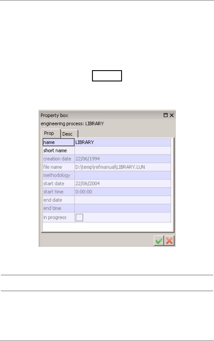
LIBRARY
Figure 2.1 - Iconic representation of a project. Appears in the Project window.
Figure 2.2 - The property box of a project.
2.2 Data Schema
A data schema is a complete or partial description of information/data struc-
tures (such as those implemented in files or databases). There are two kinds of
schemas, namely base schemas and view schemas. A data schema mainly
consists of entity types (or object classes), relationship types (or associa-

2 • Projects, products and processes 9
22/6/2009
tions) (rel-types from now on) and collections. Processing units can be asso-
ciated with entity types, rel-types and schemas. The user can choose between
two representations of a data schema: ER schema or UML class diagram.
2.3 Base Data Schema
A base data schema can be built from scratch, can derive from another schema
(e.g., through import, copy, integration or transformation) called its origin or
can derive from an external text file, e.g., an SQL or CODASYL source file
(Figure 2.3).
LIBRARY
Figure 2.3 - Iconic representation of a base schema. Appears in the Project and
Schema windows.
Figure 2.4 - The property box of a schema.

10 2 • Projects, products and processes
22/6/2009
2.4 Processing Schema
A processing schema describes processing, active or behavioral components
of an application or of an information system. It includes processing units,
internal objects, external objects, resources and relations. In DB-Main,
two kind of processing schema can be represented: UML activity diagrams
and UML use case diagrams. For instance, a processing schema can describe
a set of procedures, internal variables, database tables (imported from a data
schema), the inter-procedure call graph and the input/output relations between
procedures and data objects (Figure 2.5).
Invoicing/Java
Figure 2.5 - Though it has different contents, a processing schema has the same
representation as a data schema.
2.5 View Schema
A view schema (or simply view) is a data or processing schema that derives
from another schema S, called its source, and that includes a subset of the
constructs of S (Figure 2.6). The constructs of a view can be renamed, trans-
formed and moved in the graphical space, but no object can be added or
deleted. Any update in the source schema S can be propagated down to the
views that have been derived from it. A view can be derived from another
view.
CORP/Su
pp
lier
Figure 2.6 - Iconic representation of a view schema. Appears in the Project and
Schema windows.
2 • Projects, products and processes 11
22/6/2009
2.6 Text file
A text file is an external text that generally either derives from a schema (e.g.,
a generated SQL script file), or from which a schema has been (or will be)
derived (e.g., a COBOL source text or an interview report). Text files are
known, and can be processed by the tool, but their contents are not stored in
the repository (Figure 2.7).
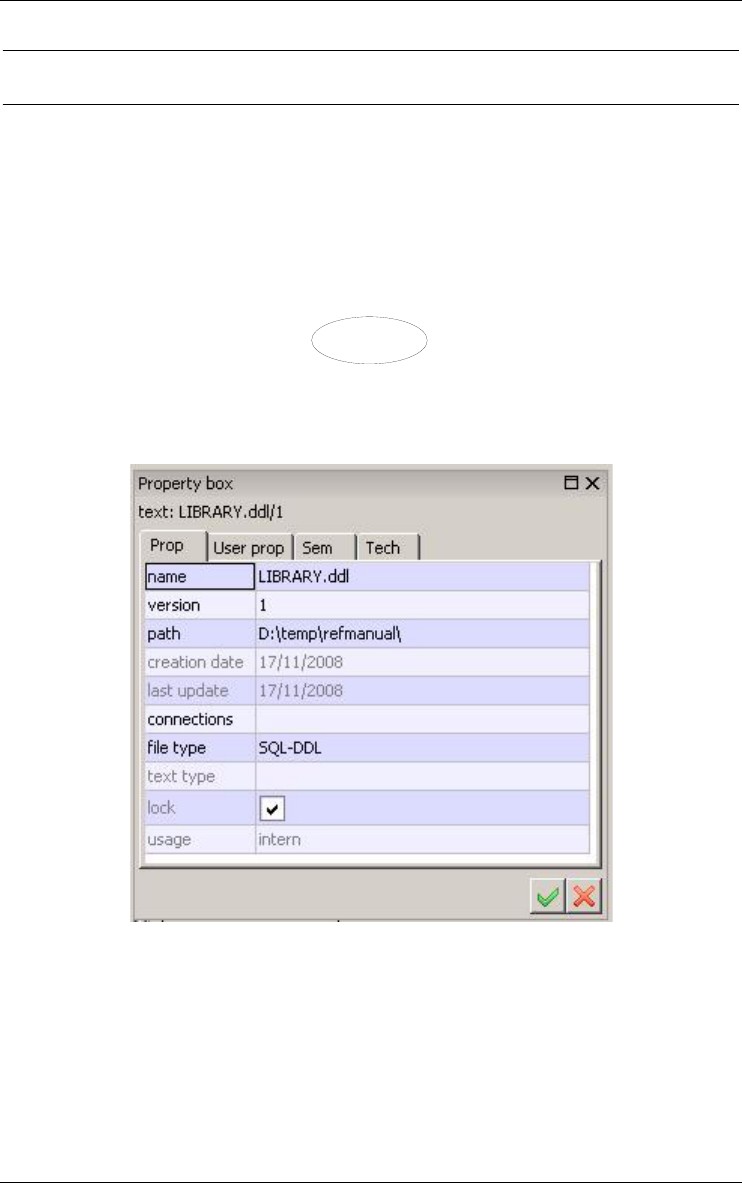
order.cob/1
Figure 2.7 - Iconic representation of a text file. Appears in the Project window.
Figure 2.8 - The property box of a text file, here an SQL-DDL script.
12 2 • Projects, products and processes
22/6/2009
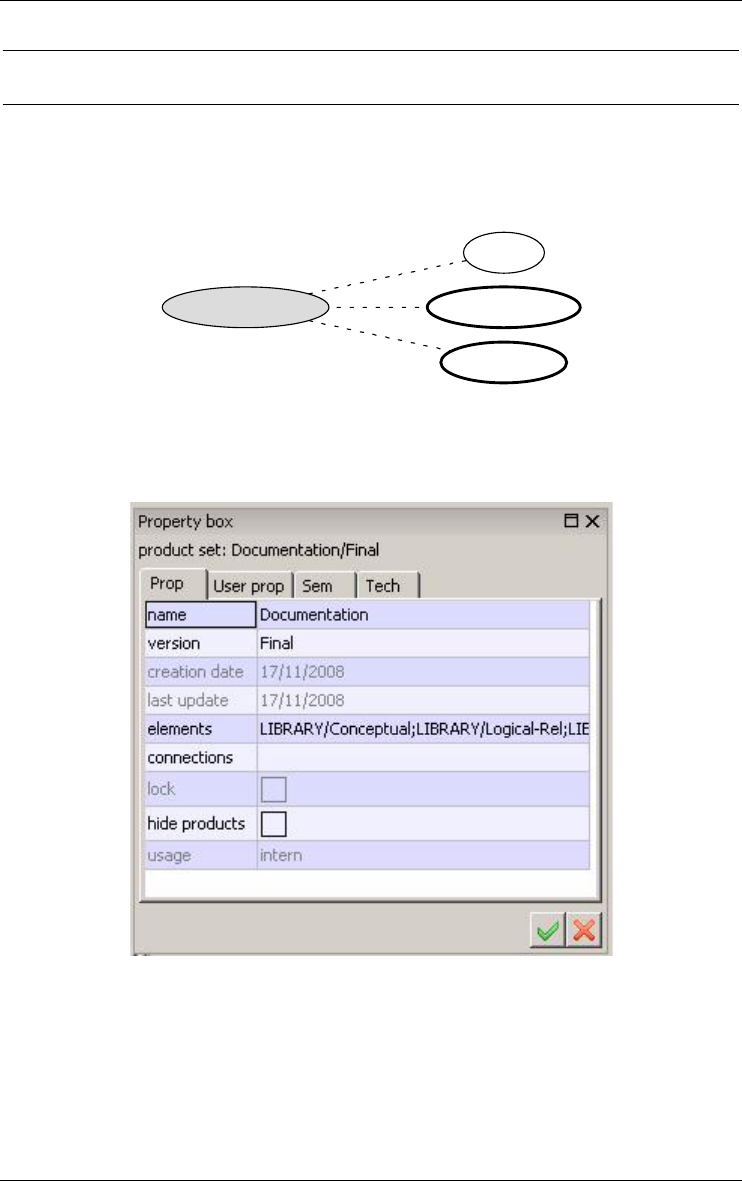
2.7 Set of products
A set of products is a collection of one or several products. This concept
provides a useful way to organize large sets of products (Figure 2.9).
Library/Logical
Library/ConceptualDocumentation/Final
Order/sql
Figure 2.9 - The three products on the right-side of the figure form the set Documen-
tation/final.
Figure 2.10 - The property box of a Product set.
2 • Projects, products and processes 13
22/6/2009
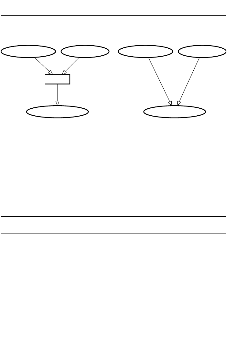
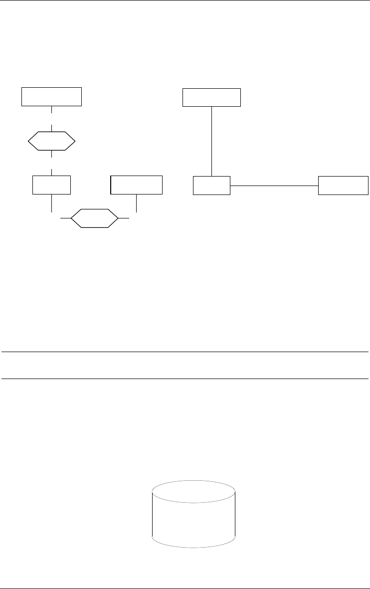
2.8 Engineering process
Integration
CORPORATE/Conceptual
ORDER/ConceptualSUPPLIER/Conceptual
CORPORATE/Conceptual
ORDER/ConceptualSUPPLIER/Conceptual
Figure 2.11 - Left: the process named Integration merges the contents of its input data
schemas and stores them in the output data schema CORPORATE. Right: the
schema CORPORATE derives from schemas SUPPLIER and ORDER.
Any product results from an activity called a process. Adding an external text
file, building a conceptual schema, integrating schemas (Figure 2.11, left)
transforming a conceptual schema into a relation structure, optimizing a data-
base schema, generating a report or a SQL script, all are processes. Each
process belongs to a process type, which is a component of the current method,
and which tells how to do to solve a specific type of problems.
2.9 Inter-product relationship
The products of a project, i.e., its schemas and its text files, generally are
linked by derivation relationships that express the way products are developed

14 2 • Projects, products and processes
22/6/2009
from other products. These derivation relationships can be computed from the
history of processes (Figure 2.11, right and Figure 2.12)
Corporat/sql Supplier/sql
Order/sql
Requ-1.txt/1
CORPORATE/Conceptual
ORDER/Conceptual
ORDER/Refined
SUPPLIER/Conceptual
ORDER/1st-cut
order.cob/2
order.cob/merged
order.cob/1
CORP/Order CORP/Supplier
1.
Figure 2.12 - The network of products of a project. Includes base schemas, view
schemas, input text files and output text files. Each edge comes from a process that
has been hidden.
1. This display is obtained through the dependency view of the history (View/Graph.
dependency).

22/6/2009
Chapter 3
Data schemas:
Entity types, Relationship types
and attributes
A data schema mainly comprises entity types (or object types), relationship
types, attributes, domains, collections, anchored processing units and various
constraints (expressed as properties of groups of components). Two represen-
tations can be chosen: Entity/Relationship schema and UML class diagram.
3.1 Entity type (or object class)
An entity type represents a class of concrete or abstract real-world entities,
such as customers, orders, books, cars and accidents. It can also be used to
model more computer-oriented constructs such as record types, tables,
segments, and the like. This interpretation depends on the abstraction level of
the schema, and therefore of the current process.
In an object-oriented model, we will use the term object class instead. Object
classes generally are given methods and appear in ISA hierarchies.
An entity type can be a subtype of one or several other entity types, called its
super-types. If F is a subtype of E, then each F entity is an E entity as well.
The collection of the subtypes of an entity type E is declared total (symbol T)
if each E entity belongs to at least one subtype; otherwise, it is said to be
partial. This collection is declared disjoint (symbol D) if an entity of a
16 3 • Data schemas: Entity types, Relationship types and attributes
22/6/2009
subtype cannot belong to another subtype of E; otherwise, it is said to
overlap. If this collection is both total and disjoint, it forms a partition
(symbol P).
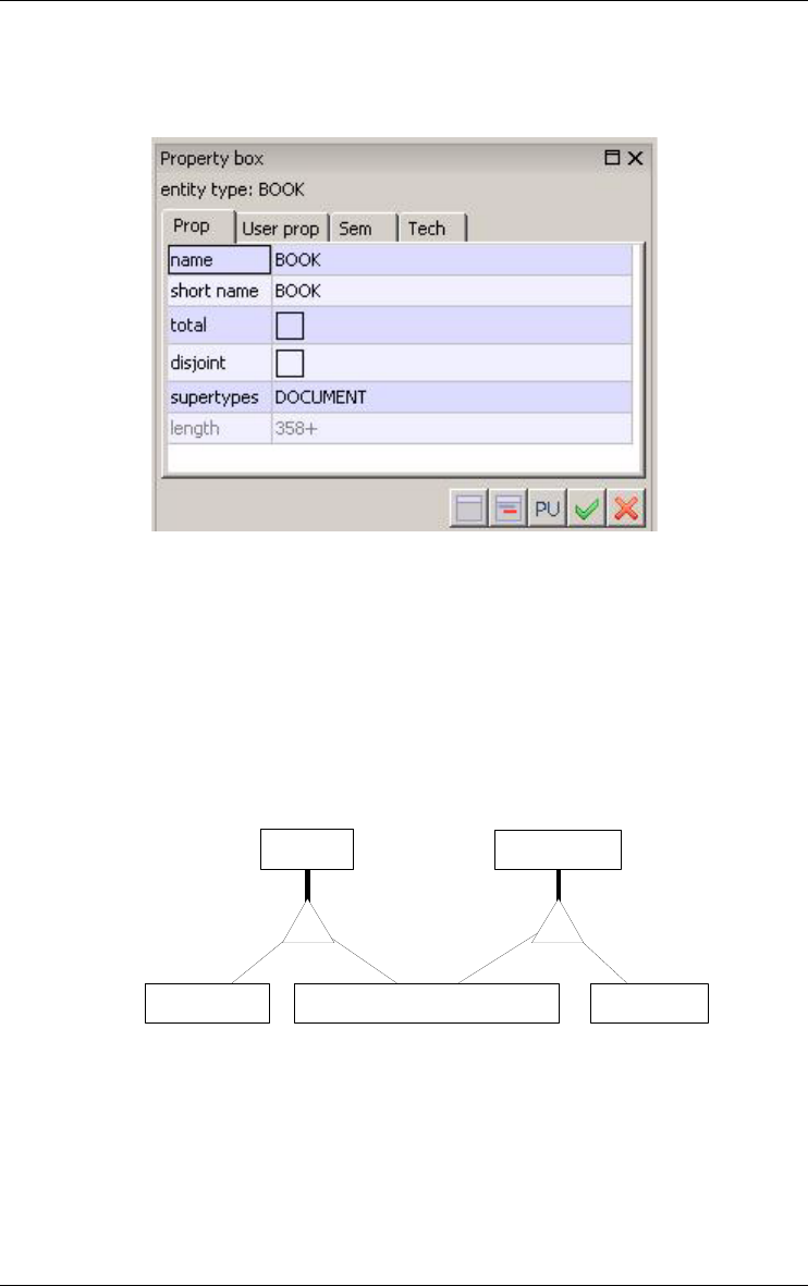
Figure 3.1 - The property box of an entity type.
An entity type can comprise attributes, can play roles in rel-types, can be
collected into collections, can be given constraints (through groups) and can
have processing units.
Since a supertype/subtype relation is interpreted as "each F entity is a E
entity", it is called an ISA relation. ISA relations form what is called an ISA
hierarchy.
TP
PERSON
INDIVIDUAL CUSTOMER EMPLOYEE
CUSTOMER
COMPANY
Figure 3.2 - A hierarchy of entity types. PERSON and CUSTOMER are supertypes,
EMPLOYEE, INDIVIDUAL CUSTOMER and COMPANY are subtypes.
The four supertype/subtype patterns can be summarized in the table below,
where B1 and B2 are two subtypes of A:
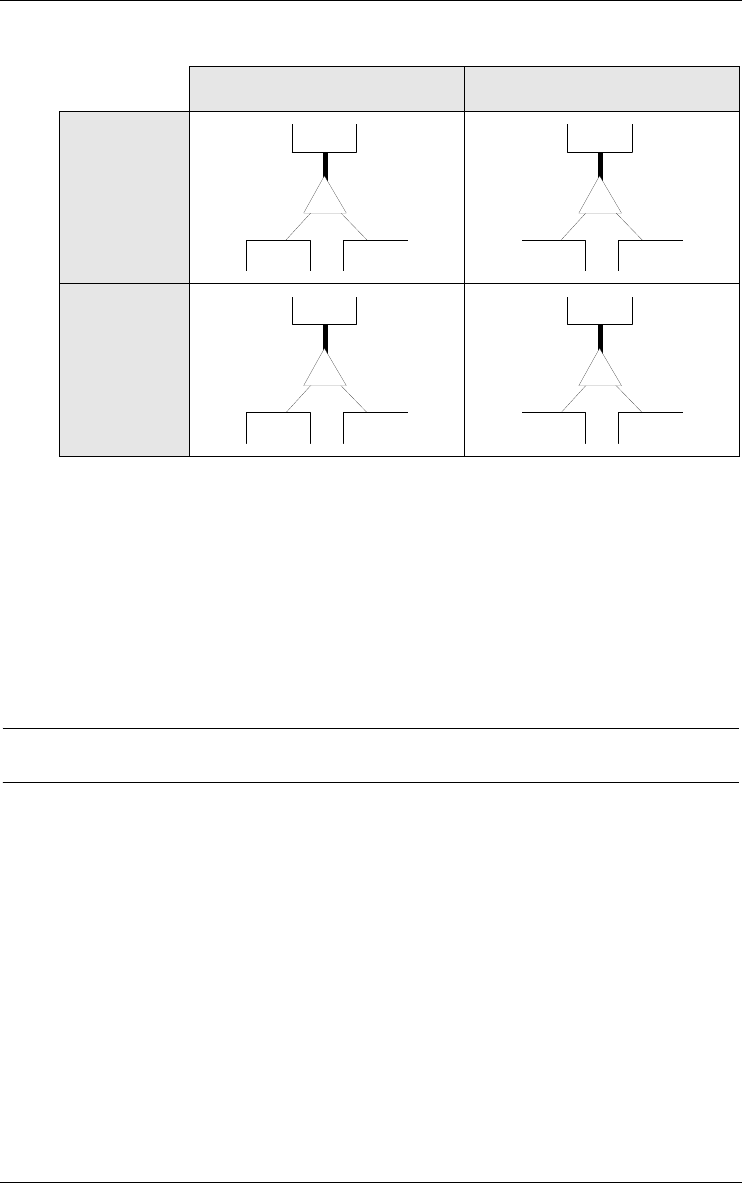
Total (T) Partial (¬T)
Disjoint
(D)
B1 B2
A
P
B1 B2
A
D
Overlap-
ping
(¬D)
B1 B2
A
T
B1 B2
A
3 • Data schemas: Entity types, Relationship types and attributes 17
22/6/2009
Figure 3.3 - The four patterns of ISA hierarchy.
Stereotype
An entity type can be of one or several stereotypes, i.e., it can belong to
domain/method specific categories. For instance, a Java class schema can
make use of entity type stereotypes «class» and «interface». Stereotypes are
user-defined (see Section 6.6). A SQL schema can partition the tables into
«base table» and «view».
3.2 Relationship type (rel-type)
A relationship type represents a class of associations between entities. It
consists of entity types, each playing a specific role. A rel-type with 2 roles is
called binary, while a rel-type with N > 2 roles is generally called N-ary. A
rel-type with at least 2 roles taken by the same entity type is called cyclic.
18 3 • Data schemas: Entity types, Relationship types and attributes
22/6/2009
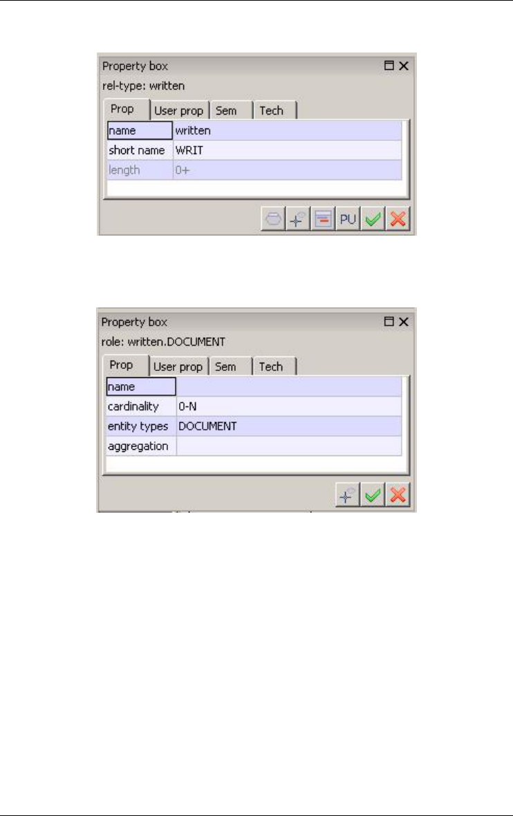
Figure 3.4 - The property box of a relationship type.
Figure 3.5 - The property box of a role.
Normally, a role is played by one entity type only. However, a role can be
taken by more than one entity type. In this case, it is called a multi-ET role.
Each role is characterized by its cardinality [i-j], a constraint stating that any
entity of this type must appear, in this role, in i to j associations or relation-
ships. Generally i is 0 or 1, while j is 1 or N (= many or infinity). However, any
pair of integers can be used, provided that i ≤ j, i ≥ 0 and j > 0.
A binary rel-type between A and B with cardinality [i1-j1] for A , [i2-j2] for B
is called:
•one-to-one if j1 = j2 = 1
•one-to-many from A to B if j1 > 1 and j2 = 1
•many-to-one from A to B if j1 = 1 and j2 > 1
•many-to-many if j1 > 1 and j2 > 1
3 • Data schemas: Entity types, Relationship types and attributes 19
22/6/2009
•optional for A if i1 = 0
•mandatory for A if i1 > 0.
A role can be given a name. When no explicit name is assigned, an implicit
default name is assumed, namely the name of the participating entity type. The
roles of a rel-type have distinct names, be they explicit or implicit. For
instance, in a cyclic rel-type, at least one role must have an explicit name. A
multi-ET role must have an explicit name.
A rel-type can have attributes, and can be given constraints (through
groups) and processing units.
1-1
3-N
«cmp»
has
origin
0-1
target
0-N
references
1-1
0-N
copy-of
by
0-N
0-1 borrowed
0-N
1-20
0-N
assigned
SUPPLIER
SERVICE
PRODUCT
ORDER
WHEEL
CAR
EMPLOYEE
COPY
BOOK
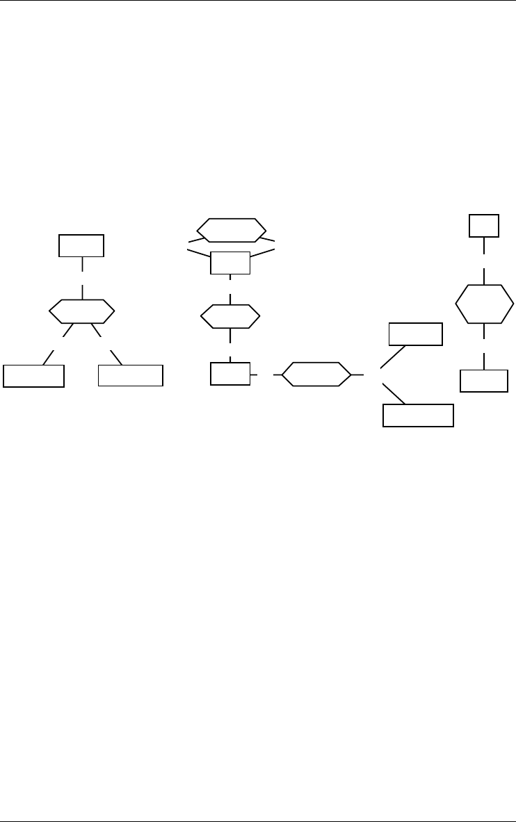
Figure 3.6 - Relationship types. Rel-types references, copy-of and borrowed are
binary, while assigned is 3-ary. Rel-type references is cyclic. Role borrowed.by is
multi-ET. Copy-of and borrowed are functional. references is many-to-many. has
represent an composition.
A rel-type which has attributes, or which is n-ary, will also be called a
complex rel-type. A one-to-one or one-to-many rel-type without attributes
will be called functional, since it materializes a functional relation, in the
mathematical sense.
A rel-type may represent an aggregation (i.e., a whole/part relationship). In
this case, the role attached to the whole element is designated (selects aggre-
gation in his property box), and the other role of the association represents the
parts of the aggregation. Only binary rel-types may be aggregations.
Composite aggregation is a strong form of aggregation, which requires that a
part instance be included in at most one composite at a time and that the
composite object has sole responsibility for the disposition of its parts.
Alternate interpretation
Some models give a different interpretation to role cardinalities. According to
OMT and UML for instance, the cardinality [ia..ja] of role rA of entity type A
20 3 • Data schemas: Entity types, Relationship types and attributes
22/6/2009
in rel-type R(rA:A,rB:B) indicates that each instance of B sees from ia to ja
instances of B through R. For binary rel-type, this style is obtained by swap-
ping the regular cardinalities. For N-ary rel-types, this interpretation is no
longer equivalent to the regular one, and generally is ignored.
0-N0-20 orders
1-1
0-N
places
ORDER PRODUCT
CUSTOMER
0..*
1
0..200..* orders PRODUCTORDER
CUSTOMER
Figure 3.7 - Two interpretations of role cardinalities for the same schema: regular
(left) and inverse (right). The right side schema uses the UML notation.
Stereotype
A rel-type can be of one or several stereotypes. For instance, an IBM IMS
legacy schema can make use of rel-type stereotypes «physical» and «logical»
(see Section 6.6).
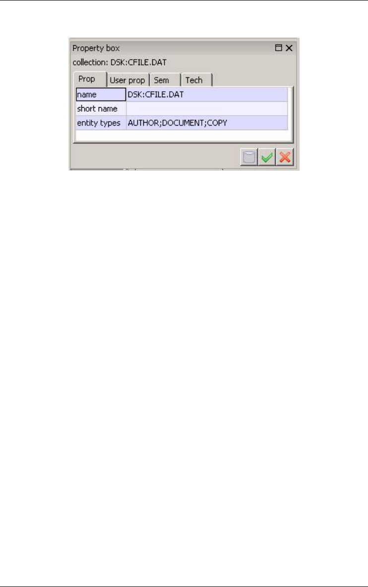
3.3 Collection
A collection is a repository for entities. A collection can comprise entities from
different entity types, and the entities of a given type can be stored in several
collections. Though this concept can be given different interpretations at
different levels of abstraction, it will most often be used in logical and physical
schemas to represent files, data stores, table spaces, etc.
DSK:CFILE.DAT
EMPLOYEE
COPY
BOO
K
Figure 3.8 - DSK:CFILE.DAT is a collection in which EMPLOYEE, COPY and BOOK
entities can be stored.
3 • Data schemas: Entity types, Relationship types and attributes 21
22/6/2009
Figure 3.9 - The property box of a collection.
Stereotype
A collection can be of one or several stereotypes. For instance, an OO-DBMS
database schema can define object containers of two types: «local» and
«remote» (see Section 6.6).
22 3 • Data schemas: Entity types, Relationship types and attributes
22/6/2009
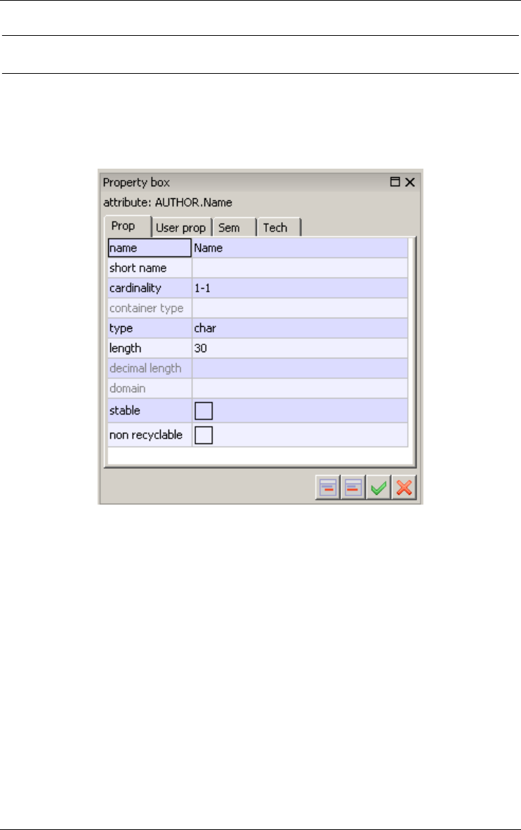
3.4 Attribute
An attribute represents a common property of all the entities (or relationships)
of a given type.
Figure 3.10 - The property box of an attribute.
Simple attributes have a value domain defined by a data type (number, char-
acter, boolean, date,...) and a length (1, 2, ..., 200, ..., N [standing for infinity]).
These attributes are called atomic.
3 • Data schemas: Entity types, Relationship types and attributes 23
22/6/2009
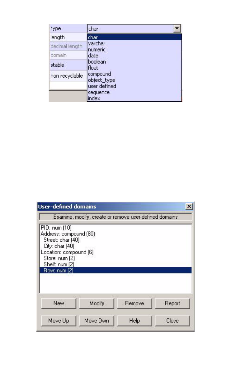
Figure 3.11 - Value domains of an attribute.
An attribute can also consist of other component attributes, in which case it is
called compound. The parent of an attribute is the entity type, the relation-
ship type or the compound attribute to which it is directly attached. An
attribute whose parent is an entity type or a rel-type is said to be at level 1.
The components of a level-i attribute are said to be at level i+1.
If the value domain has some specific characteristics, it can be defined explic-
itly as a user-defined domain, and can be associated with several attributes of
the project. A user-defined domain is atomic or compound.
Figure 3.12 - User-defined domains.

24 3 • Data schemas: Entity types, Relationship types and attributes
22/6/2009
The default value of an attribute or user-defined domain is the value it will be
assigned when no value are explicitly assigned at creation time.
A value constraint can be associated with any attribute or user-defined
domain. It consists in a list of constants and/or ranges. The values of the
attribute must belong to this list.
0-N
0-N
borrows
DateBorrow
DateBack[0-1]
COPY
BookID
Title
Author[0-5]
KeyWord[0-N]
BORROWER
PID
Name
FirstName[0-1]
Address
Company
Street
ZipCode[0-1]
City
Phone[1-5]
Figure 3.13 - Examples of attributes. Name is mandatory [1-1] while FirstName is
optional [0-1]. Address is compound while Name and ZipCode are atomic. Phone,
Author and KeyWord are multivalued. The cardinality of KeyWord is unlimited [0-N].
Each attribute is characterized by its cardinality [i-j], a constraint stating that
each parent has from i to j values of this attribute. Generally i is 0 or 1, while
j is from 1 to N (= infinity). However, any pair of integers can be used,
provided i ≤ j, i ≥ 0 and j > 0. The default cardinality is [1-1], and is not repre-
sented graphically. An attribute with cardinality [i-j] is called:
•single-valued if j = 1
•multivalued if j > 1
•optional if i = 0
•mandatory if i > 0.
Stereotype
An attribute can be of one or several stereotypes, i.e., it can belong to domain/
method specific categories. For instance, a conceptual schema can define
basic and derived (redundant) attributes through the stereotypes «real» and
«derived» (see Section 6.6).
3 • Data schemas: Entity types, Relationship types and attributes 25
22/6/2009
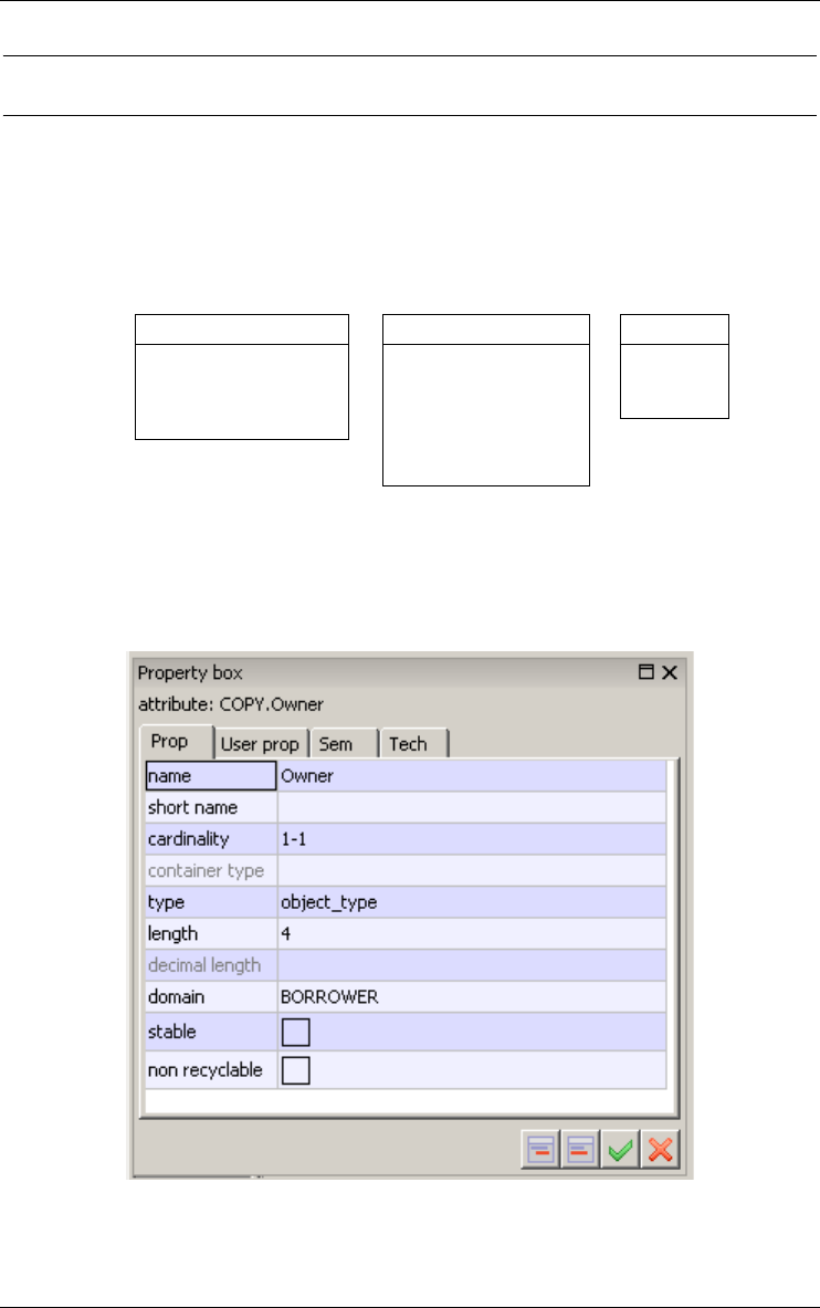
3.5 Object-attribute
Any entity type can be used as a valid domain for attributes. Such attributes
will be called object-attributes. They mainly appear in object-oriented
schemas. This concept is more powerful, but more complex, than that of user-
defined domain.
PRODUCT
PCode
PName
Price
ORDER
OrdID
Date
Owner: *CUSTOMER
Details[1-10]
Item: *PRODUCT
Qty
CUSTOMER
CID
CName
CAddress
Orders[0-N]: *ORDER
Figure 3.14 - Owner is a single-valued object-attribute. For each ORDER entity, the
value of Owner is a CUSTOMER entity. Orders is a multivalued object-attribute of
CUSTOMER. This construct can be used in OO database schemas to express rela-
tionship types.
Figure 3.15 - Defining an object-attribute.
26 3 • Data schemas: Entity types, Relationship types and attributes
22/6/2009
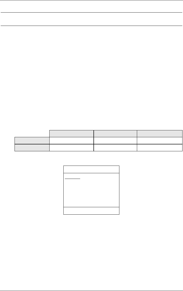
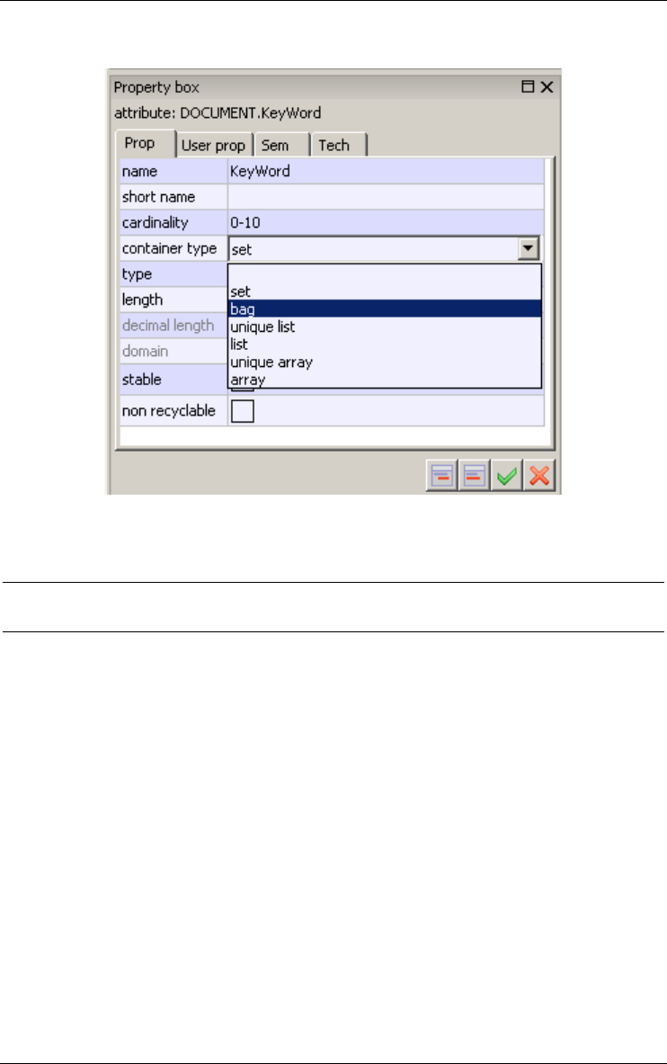
3.6 Non-set multivalued attribute
A plain multivalued attribute represents sets of values, i.e., unstructured
collections of distinct values. In fact, there exist six categories of collections
of values.
–Set: unstructured collection of distinct elements (default).
–Bag: unstructured collection of (not necessarily distinct) elements.
–Unique list: sequenced collection of distinct elements.
–List: sequenced collection of (not necessarily distinct) elements.
–Unique array: indexed sequence of cells that can each contain an element.
The elements are distinct.
–Array: indexed sequence of cells that can each contain an element.
These categories can be classified according to two dimensions: uniqueness
and structure.
Unstructured Sequence Array
Unique (set) ulist uarray
Not unique bag list array
STUDENT
RegNbr
Name
Phone[0-2]
Expenses[0-100] bag
Christ-Name[0-4] ulist
Monthly-score[0-12] array
id: RegNbr
Figure 3.16 - Some non-set multivalued attributes. While Phone defines a pure set,
Expenses represents a bag, Christ(ian)-Name a list of distinct values and Monthly-
score an array of 12 cells, of which from 0 to 12 can be filled.
3 • Data schemas: Entity types, Relationship types and attributes 27
22/6/2009
Figure 3.17 - Defining a bag attribute.
3.7 Group
A group is made up of components, which are attributes, roles and/or other
groups. A group represents a construct attached to a parent object, i.e., to an
entity type, a rel-type or to a multivalued compound attribute. It is used to
represent concepts such as identifiers, foreign keys, indexes, sets of exclusive
or coexistent attributes. A group of an entity type can comprise inherited
attributes and roles, i.e., components from its direct or indirect supertypes.
It can be assigned one or several functions among the following:
primary identifier: the components of the group make up the main identifier
of the parent object; it appears with symbol id; if it comprises attributes
only, the later are underlined in the graphical view; a parent object can
have at most one primary id; all its components are mandatory.
secondary identifier: the components of the group make up a secondary
identifier of the parent object; it appears with symbol id'; a parent
object can have any number of secondary id.
28 3 • Data schemas: Entity types, Relationship types and attributes
22/6/2009
coexistence: the components of the group must be simultaneously present or
absent for any instance of the parent object; the group appears with
symbol coex; all its components are optional.
exclusive: among the components of the group at most one must be present
for any instance of the parent object; the group appears with symbol
excl; all its components are optional.
at-least-1: among the components of the group, at least one must be present
for any instance of the parent object; the group appears with symbol at-
lst-1; all its components are optional.
exactly-1: among the components of the group, one and only one must be
present for any instance of the parent object (= exclusive + at-least-1);
the group appears with symbol exact-1; all its components are
optional.
access key: the components of the group form an access mechanism to the
instances of the parent object (generally an entity type, to be inter-
preted as a table, a record type or a segment type); the access key is an
abstraction of such constructs as indexes, hash organization, B-trees,
access paths, and the like; it appears with symbol acc or access key.
user-defined constraint: any function that does not appear in this list can be
defined by the user by giving it a name; some examples: at-most-2 (no
more than two components can be valued), lhs-fd (left-hand-side of a
functional dependency), less-than (the value of the first component
must be less than that of the second one), etc.
1-1
0-N of
COPY
SerialNbr
DateAcquired
Location
Store
Shelf
Row
NbrOfVolumes
State[0-1]
StateComment[0-1]
id: of.BOOK
SerialNbr
acc
coex: State
StateComment
acc: Location
BOOK
BookID
Title
Publisher
DatePublished
KeyWord[0-10]
Abstract[0-1]
id: BookID
id': Title
Publisher
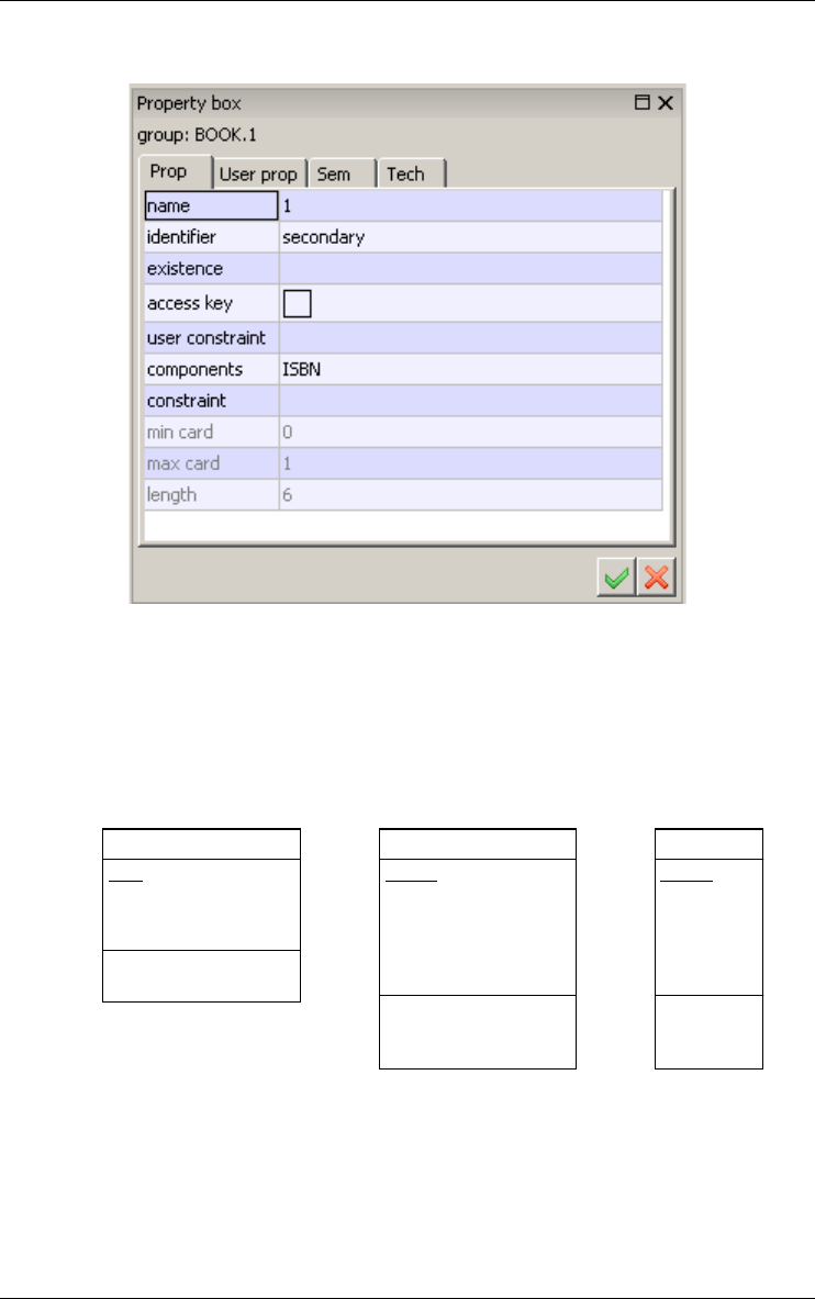
Figure 3.18 - Some constraints. BookID is a primary identifier and {Title, Publisher} a
secondary identifier of BOOK. SerialNbr identifies each COPY within a definite
BOOK. In addition, this identifier is an access key. Optional attributes State and
StateComment both are valued or void (coexistence).
3 • Data schemas: Entity types, Relationship types and attributes 29
22/6/2009
Figure 3.19 - The property box of a group.
A group of an entity type can have a cardinality constraint too. The cardinality
[i-j] of a group states how many entities can share the same component values
for this group. This concept is particularly important for foreign keys, in
which it preserves the cardinality of the remote role.
PRODUCT
PCode
PName
Price
Sales[0-20]
Year
Volume
id: PCode
id(Sales):
Year
ORDER
OrdID
Date
Owner: *CUSTOMER
Details[1-10]
Item: *PRODUCT
Qty
id: OrdID
id(Details):
Item
CUSTOMER
CID
CName
CAddress
Orders[0-N]: *ORDER
id: CID
id': Orders[*]
Figure 3.20 - Multivalued identifiers and Attribute identifiers. Object-attribute Orders
is declared an identifier, stating that any two CUSTOMER entities must have distinct
Orders values (an order is issued by one customer only). All the Details values of
each ORDER entity have distinct Item values (a product cannot be referenced more
than once in an order). The Sales of each PRODUCT entity represent the volume
sold each year.

30 3 • Data schemas: Entity types, Relationship types and attributes
22/6/2009
An identifier can be made of a multivalued attribute, in which case it is called
a multivalued identifier. In this case, no two parent instances can share the
same value of this attribute.
A multivalued compound attribute A, with parent P (entity type, relationship
type or compound attribute) can be given identifiers as well. Such an
attribute identifier I, made of components of A, states that, for each instance
of P, no two instances of A can share the same value of I.
An identifier of entity type E is made up of either:
•one or several single-valued attributes of E (or of supertypes of E),
•one multivalued attribute of E (or of supertypes of E),
•two or more remote roles of E (or of supertypes of E),
•one or more remote roles of E + one or more single-valued attributes of E
(or of supertypes of E).
A primary identifier cannot be defined on an entity type if one of its sub-types
or supertypes already has a primary identifier.
An identifier of relationship type R is made up of either:
•one or several attributes of R,
•two or more roles of R,
•one or more roles of R + one or more attributes of R.
An identifier of attribute A is made up of:
•one or several single-valued component attributes of A.
A technical identifier (technical id) of entity type E is a meaningless, gener-
ally short, attribute that is used to denote entities without reference to applica-
tion domain properties. It is generally used as a substitute for long, complex
and information-bearing identifiers. Object-id (oid) of OO models can be
considered as technical identifiers.
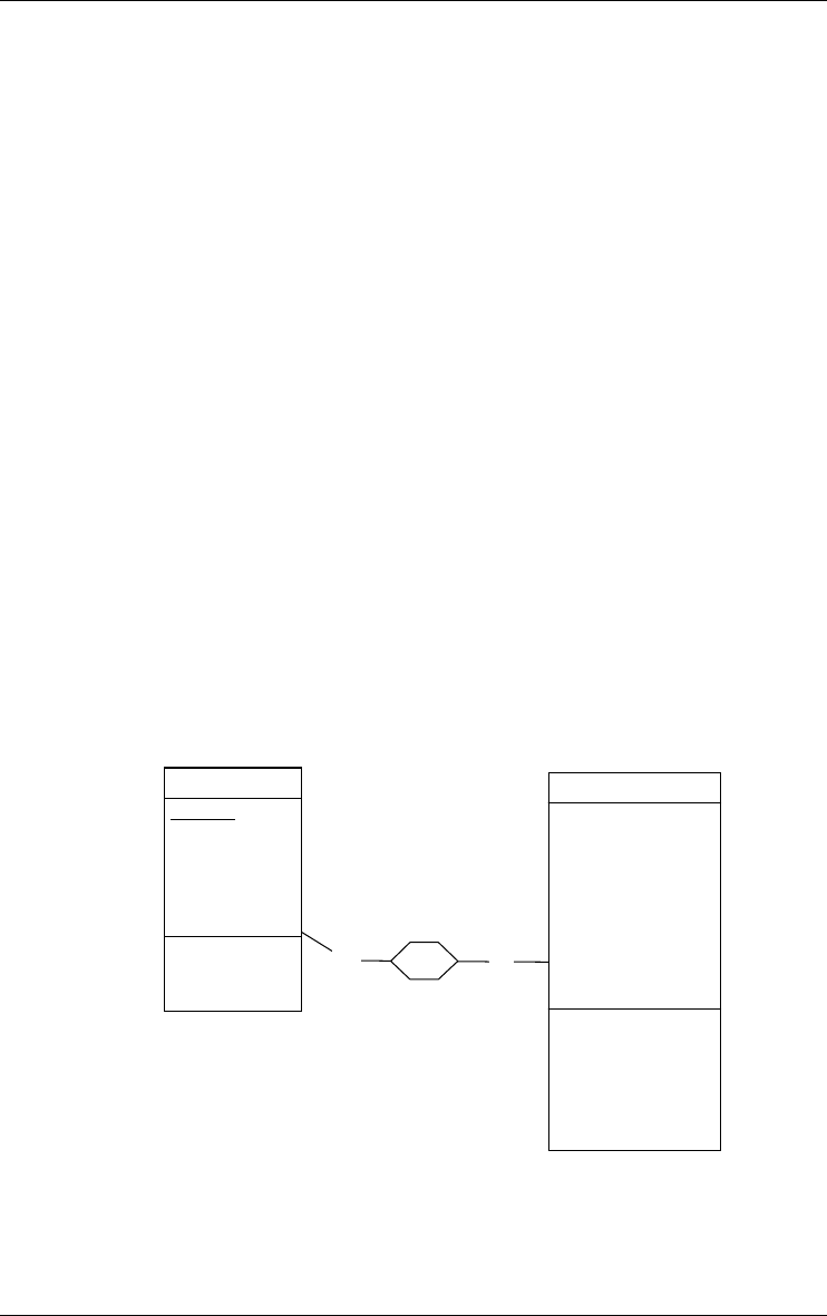
3.8 Inter-group constraint
Independently of their function(s), two groups with compatible components
can be related through a relation that expresses an inter-group integrity
constraint.
The following constraints are available:
reference: the first group is a foreign key and the second group is the refer-
enced (primary or secondary) identifier; the foreign key appears with
symbol ref;
3 • Data schemas: Entity types, Relationship types and attributes 31
22/6/2009
ref equal: the first group is a foreign key and the second group is the refer-
enced (primary or secondary) identifier; in addition, an inclusion
constraint is defined from the second group to the first one; the foreign
key appears with symbol equ;
inclusion: each instance of the first group must be an instance of the second
group; since the second group need not be an identifier, the inclusion
constraint is a generalization of the referential constraint; it includes
with symbol incl;
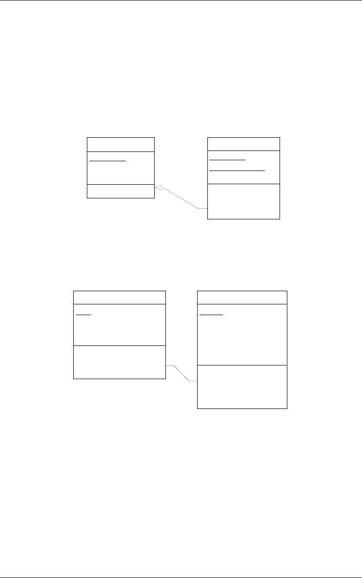
BOOK-ID
TITLE
ABSTRACT[0-1]
id: BOOK-ID
BOOK
BOOK-ID
SER-NUMBER
DATE-ACQU
id: SER-NUMBER
BOOK-ID
ref: BOOK-ID
COPY
Figure 3.21 - Attribute BOOK-ID form a reference group (foreign key) to BOOK.
inverse: this constraint can be asserted between two object-attributes,
expressing that each is the inverse of the other.
ORDER
OrdID
Date
Owner: *CUSTOMER
Details[1-10]
Item: *PRODUCT
Qty
id: OrdID
inv:Owner
id(Details):
Item
CUSTOMER
CID
CName
CAddress
Orders[0-N]: *ORDER
id: CID
id':Orders[*]
inv
Figure 3.22 - Orders of CUSTOMER and Owner of ORDER are declared inverse
object-attributes. If c denotes the Owner of ORDER entity o, then c must belong to
the Orders value set of CUSTOMER c.
generic inter-group constraint : can be drawn from any group to any other
group of the schema; defining the semantics of this constraints is up to
the designer.
32 3 • Data schemas: Entity types, Relationship types and attributes
22/6/2009
1-1 0-N
place
ORDER
OrderID
OrdDate
CustomerName
CustomerAddress
id: OrderID
copy: place.CUSTOMER
CustomerName
CustomerAddress
CUSTOMER
CustomerID
Name
Address
Account
id: CustomerID
source: Name
Address
Figure 3.23 - A redundancy constraint is expressed between two user-defined group
types, namely copy and source, through a generic inter-group constraint. This struc-
ture states that CustomerName and CustomerAddress are copies of Name and
Address of CUSTOMER through rel-type place.
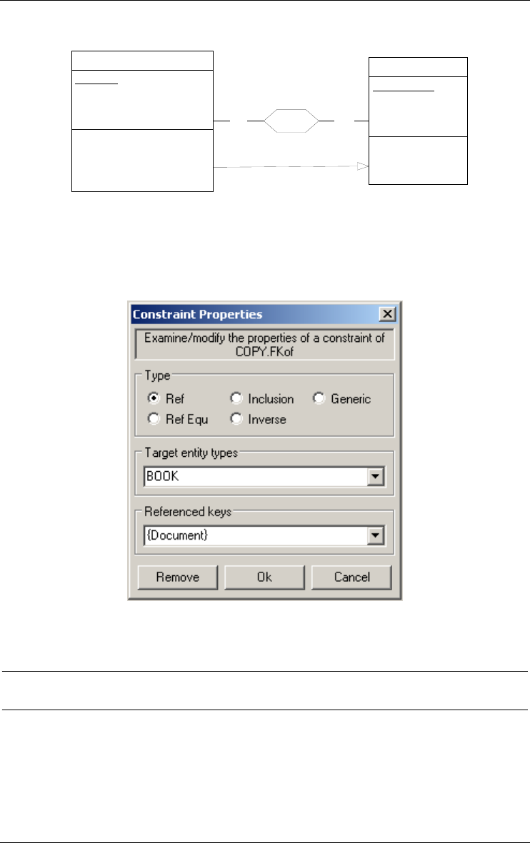
Figure 3.24 - Defining a referential constraint between a foreign key and an identifier.
3.9 Anchored processing units
An anchored processing unit is any dynamic or logical component of the
described system that can be associated with a schema, an entity type or a rela-
tionship type. For instance, a process, a stored procedure, a program, a
trigger, a business rule or a method can each be represented by a processing

3 • Data schemas: Entity types, Relationship types and attributes 33
22/6/2009
unit. Note that independent processing units, such as programs and procedures
are best represented in specific schemas, the processing schemas (see Chapter
3).
There are four types of anchored processing units:
1. method: service which the object class is responsible for; used in advanced
ER and OO models; can represent functions of abstract data types too;
2. predicate: logical rule stating a time-independent property;
3. trigger: active rule;
4. procedure: any other kind of processing units.
ORDER
OrderID
OrdDate
Sender: *CUSTOMER
id: OrderID
record_order()
make_invoice()
validate_order
cancel_order
get_properties()
get_order
get_sender
CUSTOMER
CustID
CustName
CustAddress
Orders[0-N]: *ORDER
id: CustID
register_customer()
remove_customer
get_properties()
get_customer
get_orders
select_customer()
Order Management/OO version
Order_processing
Invoice_processing
Customer_processing
34 3 • Data schemas: Entity types, Relationship types and attributes
22/6/2009
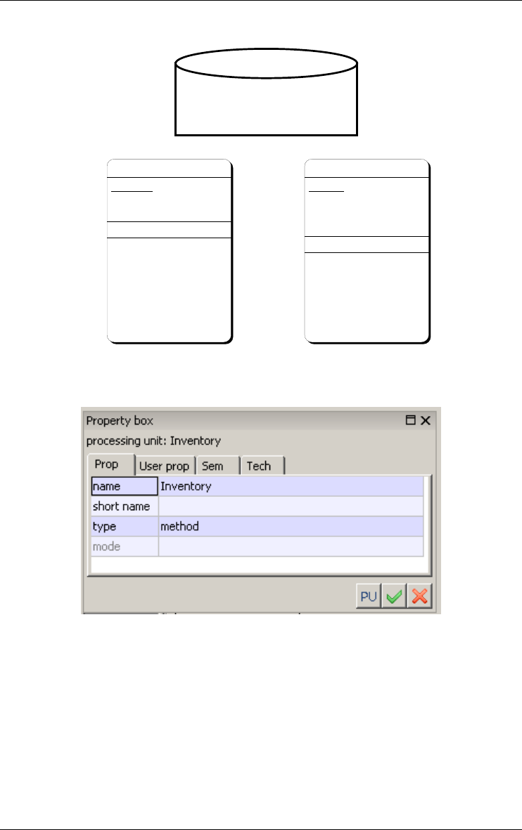
Figure 3.25 - This schema includes two object classes with their methods. In addi-
tion, three global processes have been defined at the database level (attached to the
schema).
Figure 3.26 - The property box of a processing unit.
Stereotype
A processing unit can be of one or several stereotypes (see Section 6.6).
3 • Data schemas: Entity types, Relationship types and attributes 35
22/6/2009
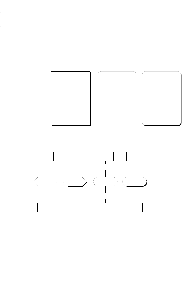
3.10 Alternate representations
To help analysts classify their schemas according to definite abstraction levels,
or according to their personal taste, alternate graphical representations are
proposed for entity types and rel-types (shape and shadow). Using stereotypes
generally is a better and more formal way to define object categories.
BORROWER
PID
NAME
FIRST-NAME[0-1]
ADDRESS
COMPANY
STREET
ZIP-CODE[0-1]
CITY
PHONE[1-5]
BORROWER
PID
NAME
FIRST-NAME[0-1]
ADDRESS
COMPANY
STREET
ZIP-CODE[0-1]
CITY
PHONE[1-5]
BORROWER
PID
NAME
FIRST-NAME[0-1]
ADDRESS
COMPANY
STREET
ZIP-CODE[0-1]
CITY
PHONE[1-5]
BORROWER
PID
NAME
FIRST-NAME[0-1]
ADDRESS
COMPANY
STREET
ZIP-CODE[0-1]
CITY
PHONE[1-5]
Figure 3.27 - Alternate graphical representations of entity types.
0-N
copy-of
COPY
BOOK
1-1
0-N
copy-of
COPY
BOOK
1-1
0-N
copy-of
COPY
BOOK
1-1
0-N
copy-of
COPY
BOOK
1-1
Figure 3.28 - Alternate graphical representations of rel-types.
In the standard graphical representation used in this chapter, the user can
choose to show or to hide some object components:
•show/hide attributes
•show/hide attribute types and lengths
•show/hide groups
•show/hide processing units
•show/hide stereotypes

36 3 • Data schemas: Entity types, Relationship types and attributes
22/6/2009
•show/hide notes.
CUSTOMER
CustID
Name
LegalAddress
Account
AccountNbr
Level
CUSTOMER
CustID: char(10)
Name: char(26)
LegalAddress: address
Account
AccountNbr: char(16)
Level: num(8)
CUSTOMER
CustID
Name
LegalAddress
Account
AccountNbr
Level
id: CustID
CUSTOMER
CustID
Name
LegalAddress
Account
AccountNbr
Level
id: CustID
newOrder()
~newCUSTOMER()
changeAddress()
getOrders()
CUSTOMER
CustID
Name
LegalAddress
Account
AccountNbr
Level
newOrder()
~newCUSTOMER()
changeAddress()
getOrders()
Figure 3.29 - Five display variants of the same object class according to the desired
level of detail.

22/6/2009
Chapter 4
Processing schemas:
UML activity and use case
diagrams
While anchored processing units (such as class/object methods or active rules)
are defined in data schemas, independent processing units such as program,
procedures, activities, use cases or actors need being defined in specific prod-
ucts, namely the processing schemas. A processing schema includes action
states, internal objects, external objects, states, use cases, actors and relations.
There are two kind of processing schemas : UML activity diagram and UML
use case diagram.
4.1 UML activity diagram
4.1.1 Action state
An action state describes a processing component of an application or of an
information system. According to the level of abstraction at which the
description has been developed, an action state can model a task, an organiza-
tion function, an activity, a procedure, a program, and even a mere statement.

Check_Product
38 4 • Processing schemas: UML activity and use case diagrams
22/6/2009
Figure 4.1 - Representation of an action state. The object is in the marked state.
Stereotype
An action state can be of one or several stereotypes (see Section 6.6).
4.1.2 Object
An object is a data type, a variable, a constant or any object that are known by
the action states of the schema. An internal object is unknown outside its
schema. An object used in an activity schema but that has been defined in a
data schema is called external. Such is the case of entity types (or tables),
attributes (or columns), collections (files) or rel-type. For instance, a proce-
dure that reads CUSTOMER records (described in a data schema) appears in
a activity schema where CUSTOMER is declared external.
An object has no representation. It is represented by a state (see Section
4.1.3).
Stereotype
An object can be of one or several stereotypes, i.e., it can belong to domain/
method specific categories. For instance, a Java class schema can make use
of entity type stereotypes "class" and "interface". Stereotypes are user-
defined (see Section 6.6).
4.1.3 State
A state is a condition during the life of an (internal or external) object or an
interaction during which it satisfies some condition, performs some actions,
or waits for some event. An object can have many states that denote a
different point during the object’s live. To distinguish the various appearances
of the same object, its state is placed between brackets.
A state can be used as input or output of action states.
Check_Prod_Msg
Figure 4.2 - Representation of the state of an internal object, here a local variable.
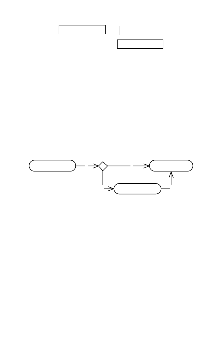
PRODUCT.Qty_OH
PRODUCT.ProID
PRODUCT [Ordered]
4 • Processing schemas: UML activity and use case diagrams 39
22/6/2009
Figure 4.3 - Representation of the states of some external objects: an entity type
PRODUCT and two attributes ProdID and Qty_OH. The object PRODUCT is
represented in the state Ordered.
Stereotype
A state can be of one or several stereotypes. Stereotypes are user-defined (see
Section 6.6).
4.1.4 Decision state
A decision state (or decision) are used to indicate different possible transitions
that depend on boolean conditions.
c
c
c
c
Check_Customer Read_Customer
Create_Customer
Figure 4.4 - Representation of a decision: if a customer does not exist, he is created.
Stereotype
A decision state can be of one or several stereotypes. Stereotypes are user-
defined (see Section 6.6).
4.1.5 Signal
A signal sending (respectively receipt) shows a transition sending (respec-
tively receiving) a signal.
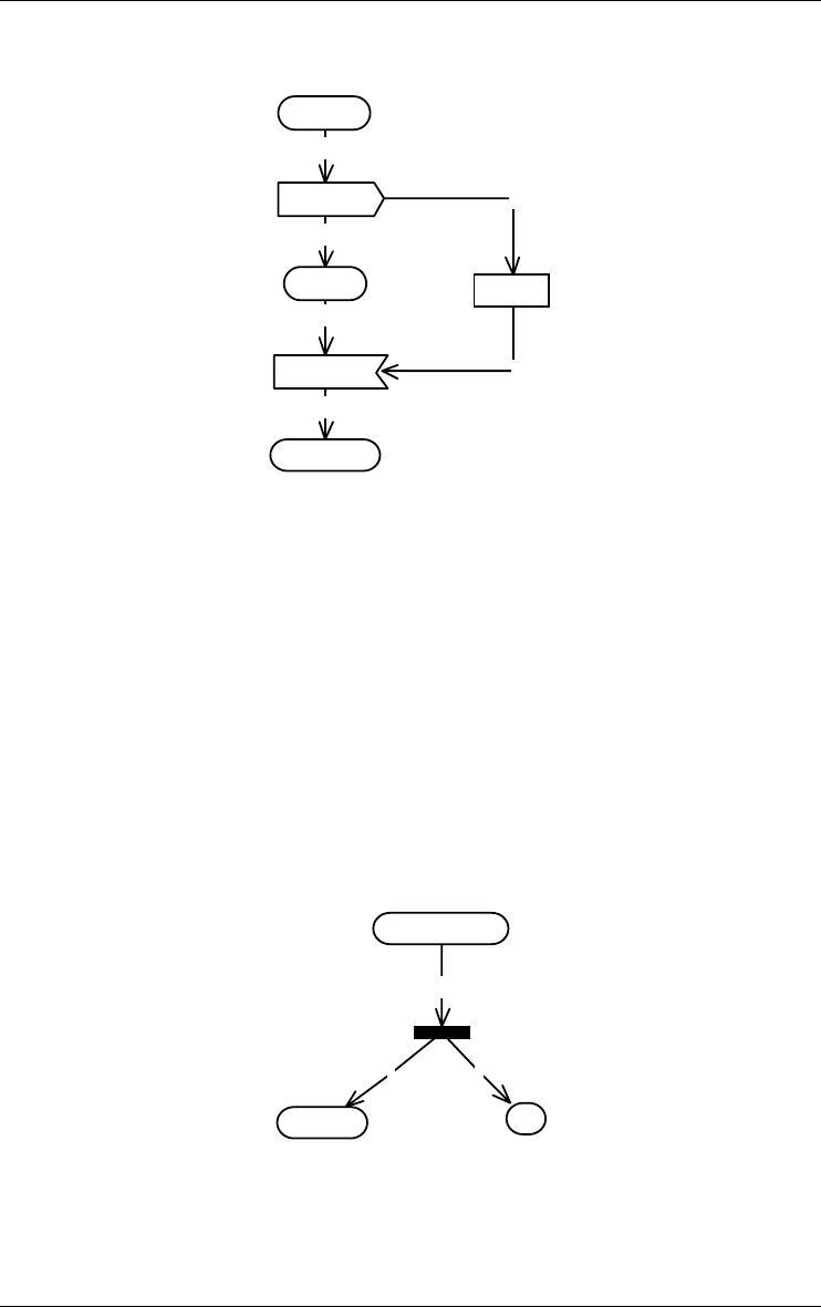
i
c
o
c
c
c
OrderFilled
EnterOrder
DeliverOrder
FillOrder
TakeOrder
ORDER
40 4 • Processing schemas: UML activity and use case diagrams
22/6/2009
Figure 4.5 - The action state TakeOrder sends a signal EnterOrder to the action state
FillOrder. The action state DeliverOrder receives a signal OrderFilled from the action
state FillOrder.
Stereotype
A signal can be of one or several stereotypes. Stereotypes are user-defined
(see Section 6.6).
4.1.6 Synchronization state
A synchronization (synch) state is for synchronizing concurrent action states.
It is used in conjunction with fork and joins to insure that one action state
leaves a particular state before another action state can enter a particular state.
c
c
c
TakeOrder Pay
Request Service
Figure 4.6 - The action state Request Service triggers two other action states:
TakeOrder and Pay.
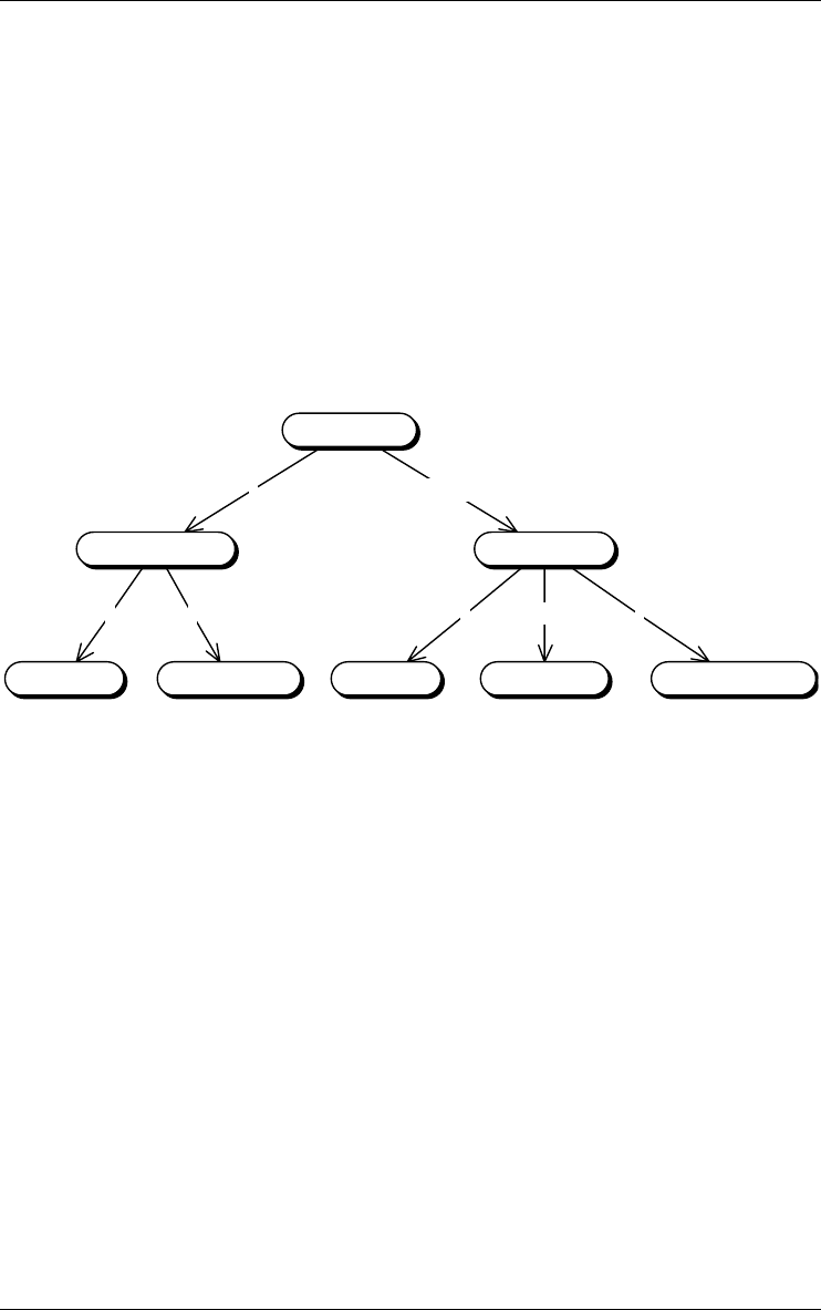
4 • Processing schemas: UML activity and use case diagrams 41
22/6/2009
Stereotype
A state can be of one or several stereotypes. Stereotypes are user-defined (see
Section 6.6).
4.1.7 Control flow relation
The control flow relation is a transition between action states, decisions,
synchronizations or signals. This transition is triggered by the source action
state. This relation describes how an action state is related to another action
state. In Figure 4.7, The source action state O_CHECKING calls the target
action state Check_Customer.
ccccc
«1-N» cc
Compute_Qty_OHRead_ProductGe t_ P ro_ IDRead_Cus tomerGe t_ Cus t_ ID
Check_ProductCheck_Customer
O_CHECKING
Figure 4.7 - The module O_CHECKING calls procedure Check_Customer, which
itself calls procedures Get_Cust_ID and Read_Cust. A stereotype is used to specify
the call multiplicity. For instance, 0_CHECKING calls Check_Product from 1 to N
times, while the other calls have a multiplicity of 1-1 (default).
Stereotype
An control flow relation can be of one or several stereotypes (see Section 6.6).
4.1.8 Object flow
Action states operate by and on objects. These objects either have respons-
ability for initiating an action, or are used or determined by the action. An
action state can use/read/determine object states and create/delete/update
others. The object flow relation describes how an action state relates to states
of internal and external objects.
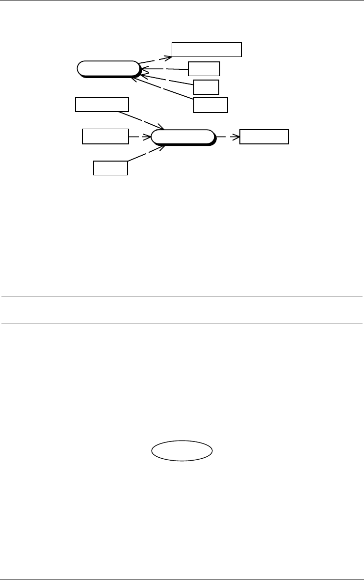
oi
i
i
o
i
i
i
O_CHECKING
Check_Product
Check_Msg
Check_Prod_Msg
Product
Qty_OH
ProID
CUSTOMER
ORDER
PRODUCT
42 4 • Processing schemas: UML activity and use case diagrams
22/6/2009
Figure 4.8 - The procedure Check_Product uses the values of three attributes (e.g.,
columns of tables ORDER and PRODUCT) and produces a value for the internal data
object Check_Prod_Msg. The module O_CHECKING consults tables CUSTOMER,
PRODUCT and ORDER, and sets the value of the internal object Check_Msg.
Stereotype
An object flow relation can be of one or several stereotypes (see Section 6.6).
4.2 UML use case diagram
Use case diagrams show actors and use cases together with their relationships.
4.2.1 Use case
A use case is a kind of classifier representing a coherent unit of functionality
provided by a system or a class.
Order Product
Figure 4.9 - A use case Order Product.
Stereotype
An use case can be of one or several stereotypes (see Section 6.6).
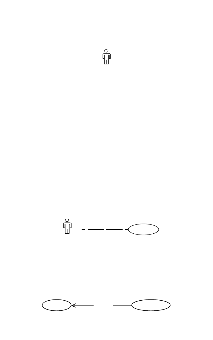
4 • Processing schemas: UML activity and use case diagrams 43
22/6/2009
4.2.2 Actor
An actor defines a coherent set of roles that users can play when interacting
with use cases.
Sales
p
erso
n
Figure 4.10 - An actor Salesperson.
Stereotype
An actor can be of one or several stereotypes (see Section 6.6).
4.2.3 Use case relationship
There are several relationships among use cases or between actors and use
cases.
a) Association
This is the participation of an actor in a use case. This relationship may have
multiplicity:
•the minimum and maximum number of participation of an actor in
instances of a use case,
•the minimum and maximum number of interaction of a use case with
instances of an actor.
* 1a Place Order
Sales
p
erson
Figure 4.11 - The actor Salesperson participates in the use case Place Order.
b) Extend
An extend relationship from use case A to use case B indicates that an instance
of B may be augmented by the behaviour specified by A.
«extend» Request CatalogPlace Order
Figure 4.12 - The behaviour of use case Request Catalog may be augmented by the
behaviour of Place Order.
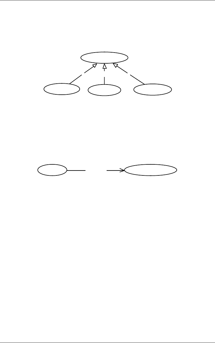
44 4 • Processing schemas: UML activity and use case diagrams
22/6/2009
c) Generalization
A generalization from use case A to use case B indicates that A is a specializa-
tion of B.
g g
g
Deposit Cash
Do One T ransaction
Withdraw Cash
T ransfer F unds
Figure 4.13 - Transfer Funds, Deposit Cash and Withdraw Cash are specializations of
the generic action Do One Transaction.
d) Include
An include relationship from use case A to use case B indicates that an
instance of A will also contain the behaviour as specified by B.
«include» Supply Customer DataPlace Order
Figure 4.14 - Place Order contains the behaviour specified in Supply Customer Data.
Stereotype
An use case relationship can be of one or several stereotypes (see Section
6.6).
4.2.4 Actor relationship
There is one standard relationship among actors and one between actors and
use cases.
a) Association
This relationship is already defined in section 4.2.3 a.
b) Generalization
A generalization from an actor A to an actor B indicates that an instance of A
can communicate with the same kinds of use case instances as an instance of
B.


46 4 • Processing schemas: UML activity and use case diagrams
22/6/2009

22/6/2009
Chapter 5
Text files
5.1 Structure of a text file
At the lowest level of understanding, a text file is a string of printable char-
acters. Most files comprise text lines, that are logical units of text. One or
several (not necessarily contiguous) lines can be selected. They can also be
marked in each of the five marking planes, in order to maintain up to five
permanent sets of lines. Marked lines appear in boldface. An annotation can
be associated with each line. Some text analysis processors can color words
and lines in a text. In addition, lines can be manually colored if needed.
5.2 Patterns in text files
Texts which have a meaningful structure, such as any kind of programs, often
include patterns. A text pattern is a formally defined text structure that can
appear in the text, and that is defined by a set of syntactic rules. Any section
of text that satisfies these rules is a instance of this pattern. For instance, a
COBOL text file will include simple assignment statements which all look
like:
MOVE <variable name> TO <variable name>

48 5 • Text files
22/6/2009
Text sections such as: "MOVE VAT-RATE TO A-FIELD" or "MOVE NAME
OF RECA TO B" are two instances of this pattern.
Text patterns are defined as regular expressions expressed into a specific
pattern definition language (PDL). The exact definition of the pattern
above is as follows (see the Text Analysis Assistant Section 16.5):
cobol_name ::= /g"[a-zA-Z][-a-zA-Z0-9]*";
cobol_var ::= cobol_name | cobol_name "OF" cobol_name;
move ::= "MOVE" - cobol_var - "TO" - cobol_var ;
The first rule describes how COBOL variable names are formed (simplified):
one letter possibly followed by a string made of dashes, letters and digits;
letters can be in upper or lower case.
The second rule defines two forms of variable designation: independent and
component.
The third rule expresses the basic form of the COBOL assignment statement.
5.3 Dependency graph in program text files
The components of a program text are structured according to numerous
meaningful relations. Making these relations explicit is an important activity
of programmers and analysts, specially in maintenance activities which
require program understanding. For example, program variable B is said to
depend on variable A if the program includes an assignment statement such as
"MOVE A TO B" or "B = A + C" or "LET B = SQRT(A)". The graph
that describes all the variables together with the inter-dependencies is called
the dependency graph of the program. As a general rule, the nature of the
dependencies we are interested in are defined by the text patterns of the state-
ments that generate them.
5.4 Program slice in program text files
When we consider a specific point (statement) S of a program P, we can be
interested in collecting all the statements that will be executed just before the
program execution comes to this point. More precisely, we could ask to restrict
these statements to only those which contribute to the state of a definite vari-
able V used by S. This (hopefully small) sub-program P' is called the slice of
P with respect to criterion (S;V).

5 • Text files 49
22/6/2009
Let us be more concrete, and consider statement 12,455 of the 30,000-line
program P. This statement reads:
12455 WRITE COM INVALID KEY GOTO ERROR.
We want to understand which data have been stored into record COM before
it is written on disk. All we want to know is in P', the slice of P according to
(12455;COM). P' is the minimum subset of the statements of P whose execu-
tion would give COM the same state as will give the execution of P in the
same environment.
Trying to understand the properties of record COM is easier when examining
a 200-line fragment than struggling with the complete 30,000-line program!
Text patterns, dependency graphs and program slices are very important
concepts in program understanding activities, and therefore in database
reverse engineering, which strongly relies on them.

50 5 • Text files
22/6/2009

22/6/2009
Chapter 6
Common rules
A data schema mainly comprises entity types (or object types), relationship
types, attributes, domains, collections, anchored processing units and various
constraints (expressed as properties of groups of components).
6.1 Common characteristics of schemas
Some characteristics are common to several objects. Data and processing
schemas, text files, entity types, rel-types, attributes, user-defined domains,
collections, groups, processing units and data objects each have a Name, and
can have a Short-name, a Semantic description (SEM), and a Technical
description (TECH).
The semantic description is a free text annotation explaining the meaning of
the object. It can be accessed by clicking on the SEM button of the object
Property box or in the standard Tool palette.
The technical description is a text giving information on the technical
aspects of the object. Some functions of the tool write statements in this
description. It can be accessed by clicking on the TECH button of the object
Property box or in the standard Tool palette.
The semantic and technical description can include semi-formal properties.
Such a property is declared through the statement
#<property-name> = <property-value>

52 6 • Common rules
22/6/2009
where <property-name> is the name of the property and <property-
value> its value. Semi-formal properties are not managed by the tool, but can
be used by specific plug-ins developed with the Java library JIDBM.
Defining a dynamic property is a more formal, but less flexible, way to
augment the modeling power of the tool.
Semantic and technical descriptions can include document names, such as
URL, which dynamically link (through hyperlinks) the parent object to the
identified document. To follow such a link, selected it and push the CTRL key
on the keyboard when releasing the mouse button.
6.2 Names
The model includes naming uniqueness constraints that make it possible to
denote objects through their name. Here are the main rules.
6.2.1 Rules for data schemas
•the schemas of a project are identified by the combination <name>/
<version>;
•each entity type of a schema is identified by its name;
•each rel-type of a schema is identified by its name;
•a collection of a schema is identified by its name;
•each direct attribute of a definite parent (an entity type, a rel-type or a
compound attribute) is identified by its name;
•a group of a definite parent (idem) is identified by its name.
•each anchored processing unit of a definite parent (an entity type, a rel-
type or a schema) is identified by its name;
6.2.2 Rules for processing schemas
•each processing unit of a schema is identified by its name;
•each internal data object of a schema is identified by its name;
•each external data object of a schema is identified by the name it received
in its data schema (so, two external data objects may appear with the same
name in a processing schema!).
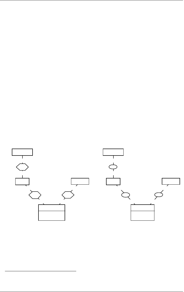
6 • Common rules 53
22/6/2009
6.2.3 General rules
•Two names composed of the same characters, be they in uppercase or in
lowercase, are considered identical; so, "Customer" and "CUSTOMER"
are the same names; the accents are taken into account;
•all the printable characters, including spaces, /, [, {, (, ponctuation symbols
and diacritic characters, can be used to form names; the symbol | has a
special meaning (see below).
Users can enforce stricter rules through the schema analysis assistant.
However, the standard uniqueness rules may appear too strong in some situa-
tions, particularly for rel-types. For instance, the analyst who builds a tree-
like structure of entity type (i.e., in IMS logical schemas) may find it useless
to name rel-types. NIAM or Object-Role models insist on role names but
ignore rel-type names. Many schemas include a large number of rel-types
defining generic relations such as "part of", "in", "of", "cross", "overlap", etc.
In these situations the analyst would want to give these rel-types, either the
same name, or no name at all1. The syntax of DB-MAIN names includes the
special symbol "|", which is a valid character, but which has a special effect
when displayed in a schema view: this character as well as all the characters
that follow are not displayed.
0-N
1-1
of
1-N
1-1
of
1-1
0-N
of
PRODUCTORDER
DETAIL
id: of.ORDER
of.PRODUCT
CUSTOMER
0-N
1-1
1-N
1-1
1-1
0-N
PRODUCTORDER
DETAIL
id: .ORDER
.PRODUCT
CUSTOMER
Figure 6.1 - Use of ambiguous names. The rel-types have been assigned the names
"of|1", "of|2", "of|3" in the left-side schema and "|1", "|2", "|3" in the right-side schema
(in fact, the user simply gave them the names "of|" and "|" respectively).
1. Using rel-type stereotypes "part of", "in", etc. can be another elegant way to define
generic rel-types.

54 6 • Common rules
22/6/2009
Note. When an object is given a name the last character of which is "|", the tool
automatically makes it unique in its context by adding, if needed, a unique
suffix.
6.3 Dynamic properties
In addition to the built-in static properties, such as name, short-name, cardi-
nality, type and length, that appear in the property box of the objects, each
object type can be dynamically given additional properties, called dynamic
properties. They are defined by the analyst at the meta-object level (schema,
entity type, rel-type, attribute, etc.), in such a way that they can be given a
value for each instance of the meta-object (each schema, each entity type, each
rel-type, each attribute, etc.). For instance, attributes can be associated with
such dynamic properties as owners, synonyms, definition, French
name, password, physical format, screen layout, etc. DB-
MAIN itself maintains some internal dynamic properties. They are visible but
have a read-only status.
A dynamic property has a name (Name), a type (Type), and a textual descrip-
tion (Sem). It can be updatable by analysts or not (Updatable). It can be
single-valued or multivalued (Multivalued). It is possible to declare the
list of possible values (Predefined values).
6.4 Marked and coloured objects
Each product and each process in a project, each object in a schema and each
line in a text file can be given a special status, called marked. Marking is a way
to permanently select objects, either to identify them (e.g., validated objects
are marked, while those still to be examined are unmarked), or to apply global
operations on them through the assistant (e.g., transform all marked rel-types
into entity types or export specifications) or as the result of the execution of
some assistants or to define schema views. The marked objects of a schema
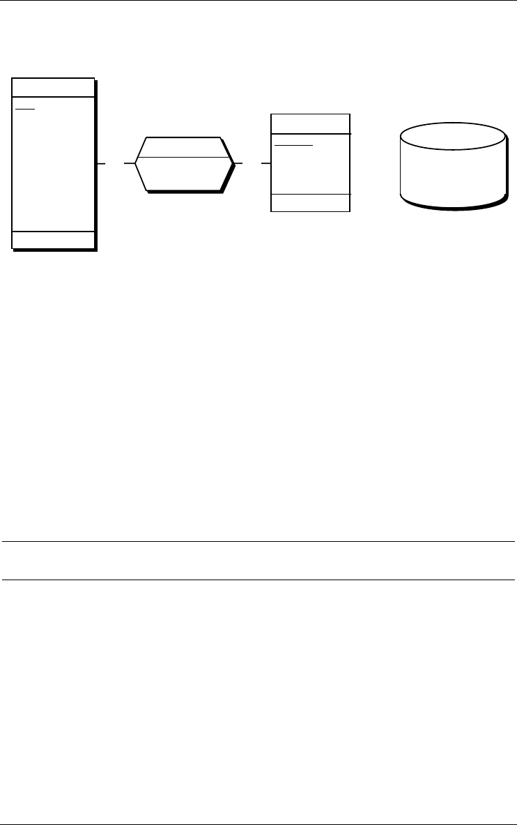
6 • Common rules 55
22/6/2009
are displayed in a special way: bold in textual views and bold and shaded/
unshaded in graphical views.
0-N0-N
borrows
DateBorrow
DateB ack[0-1]
COP Y
BookID
Title
Author[0-5]
KeyWord[0-N]
id: BookID
BORROWER
PID
Name
FirstName[0-1]
Address
Company
Street
ZipCode[0-1]
City
Phone[1-5]
id: PID
DSK:C FI LE.DA T
EMPLOYEE
COP Y
BOOK
Figure 6.2 - Some marked objects: schema SUPPLIER/Concept; entity type
BORROWER and rel-type borrows; attributes ADDRESS, ZIP-CODE, DateEnd and
Title; group {PID}; collection DSK:CFILE.DAT. This marking appears in the current
marking plane. The other four planes may show different marked objects.
In fact, the tool offers five marking planes, numbered 1 to 5, of which one is
the current, or visible, plane. A plane is a set of simultaneous marks associ-
ated with the objects of a schema. All the operations are applied in the current
plane. The concept of plane makes it possible to define up to 5 independent
sets of marks on the same schema, e.g., one to denote validated objects, one
for import/export and one for temporary operations. It is possible to combine
the marks of several planes.
Selected objects of a product can be drawn in a definite colour. Several
colours can be used in the same product.
6.5 Notes
A note is a kind of post-it that can be pasted in a schema or on an object of a
schema. It appears as a small box with some free text in it (Figure 6.3). A note
can be attached to an object (entity type, rel-type, role, attribute, group,
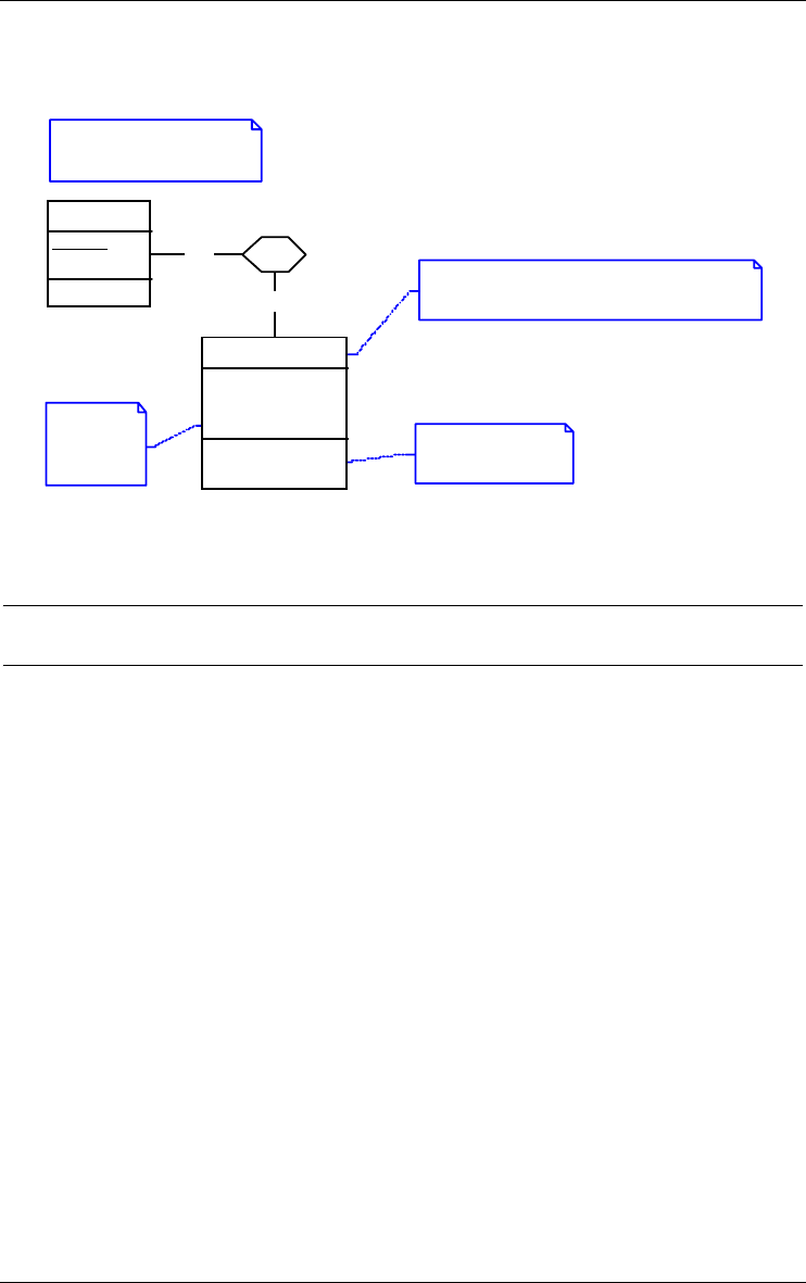
56 6 • Common rules
22/6/2009
processing unit, data object, ISA hierarchy). It can also be left independent
and put anywhere in the schema space.
Checked by Bernard Devos
25 Jan 2001
I think that an appendix is a kind of contract.
Make APPENDIX a subtype of CONTRACT.
Wrong! Should
be "App Nbr" alone.
Valid types:
- extend
- replace
1-1
0-N of
CONTRACT
Ctr Nbr
Date
id: Ctr Nbr
APPENDIX
App Nbr
Date
Type
id: of.CONTRACT
App Nbr
Figure 6.3 - Four notes used to comment or to enrich a schema.
6.6 Stereotypes
A stereotype of a category of schema objects (entity types, rel-types,
processing units, etc.) is a named subcategory which has specific characteris-

6 • Common rules 57
22/6/2009
tics or behaviour2. Any object of a category (e.g., any entity type) can be
included in any number of the steorotypes defined for its type.
*
1
« interface of»
« interface»
CUST_FORM
« class» create_form
«inst» get_Cust_ID()
«inst» get_Cust_Name()
«inst» get_Cust_Address()
«class»
CUSTOMER_FORM
Form_ID
Background
Cust_ID
Cust_Name
Cust_Address
« derived» Nbr_Fields
Figure 6.4 - Using stereotypes to describe Java-like structures. There are two subcat-
egories of entity types: "class", and "interface" associated with classes (through a rel-
type with stereotype "interface of"). An attribute can be basic or derived. A method
can be a "class" method or an "inst"ance method.
2. This concept has been defined in UML, but is available in Entity-relationship schemas as
well.

58 6 • Common rules
22/6/2009

22/6/2009
Chapter 7
Engineering process control
7.1 Methods
Normally, when (s)he intends to solve an engineering problem (to design a
relational schema, to integrate schemas, to optimize a DB or to reverse engi-
neer a legacy DB for example), the user of a CASE tool follows a method, that
is, a disciplined way of working. The description of a method states:
1. what kind of documents (called products) have to be used and produced,
2. what activities (called engineering processes) have to be carried out at
each point of the work in order to solve the problem,
3. and how to carry out these activities, i.e., their strategies.
A method is a guideline that makes the engineering activities more reliable
and less expensive. It defines product types and process types.
A product type uses a product model, which is either a text or a schema. A
schema model is defined by the objects it is made up of together with their
local names. For instance, the relational model comprises entity types
(renamed tables), attributes (renamed columns), primary ID (renamed
primary key) and reference groups (renamed foreign keys). In addition, the
valid object arrangements are defined through structural predicates (e.g., an
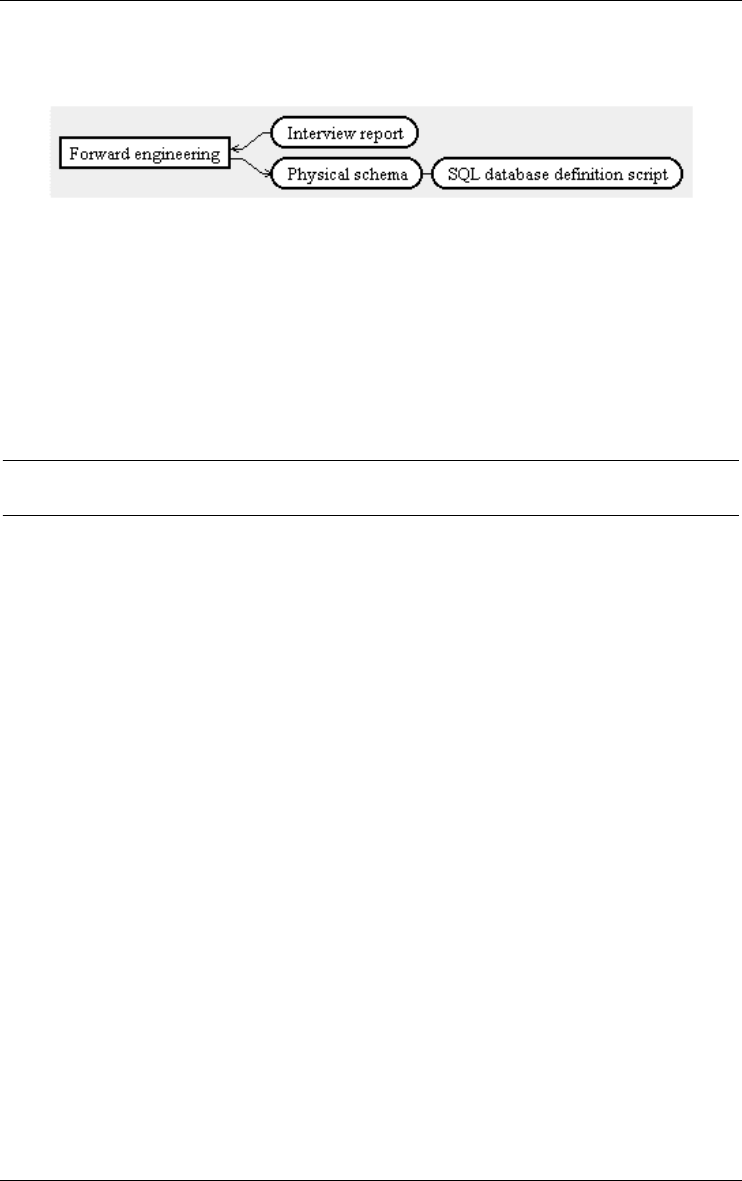
60 7 • Engineering process control
22/6/2009
entity type has at least one attribute). A process type is defined externally by
its input and output product types.
Figure 7.1 - The external description of a process type. The Forward engineering
process uses input product Interview report and produces output products Physical
schema and SQL database definition script.
The internal description is called the strategy of the process type. It specifies
what activities, in what order, and based on what products, must be (or can be)
carried out to perform processes of this type. There are implicit process types
such as choose, that selects one or several products out of a set of products.
7.2 History
The DB-MAIN tool can be instructed to strictly enforce a method, or, on the
contrary, to merely suggest its user what to do to perform the engineering
processes. The trace of the activities of a user that follows the statements of a
method is called a history. The history describes all the products that have
been elaborated, all the processes and the actions that have been performed
and all the decisions that have been taken. This history provides essential
information on how and why the products have been developped, and form
the basis of such activities as maintenance, evolution, reengineering and inter-
schema mapping building.
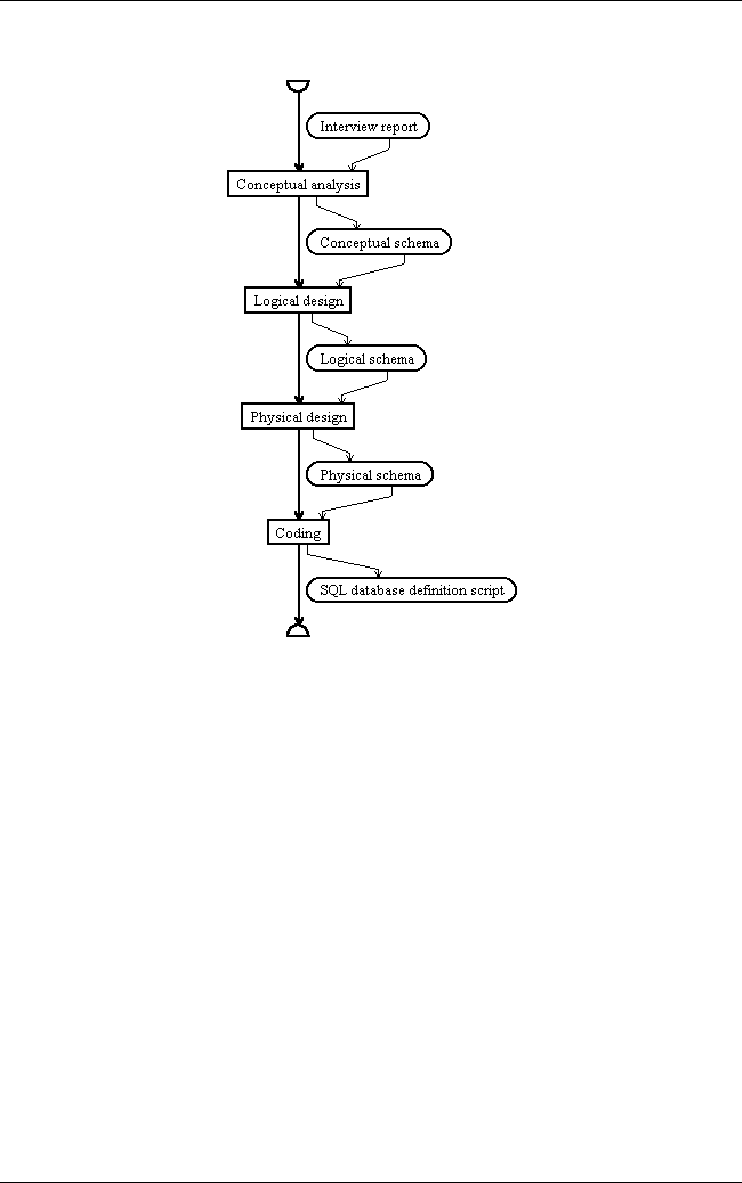
7 • Engineering process control 61
22/6/2009
Figure 7.2 - The internal description of Forward engineering process type. Its strategy
consists in performing a Conceptual Analysis, to express the contents of Interview
report into a Conceptual schema, then to transform the latter into a Logical schema,
which in turn is enriched to form the Physical schema. Finally, the Physical schema is
coded into a SQL database definition script.
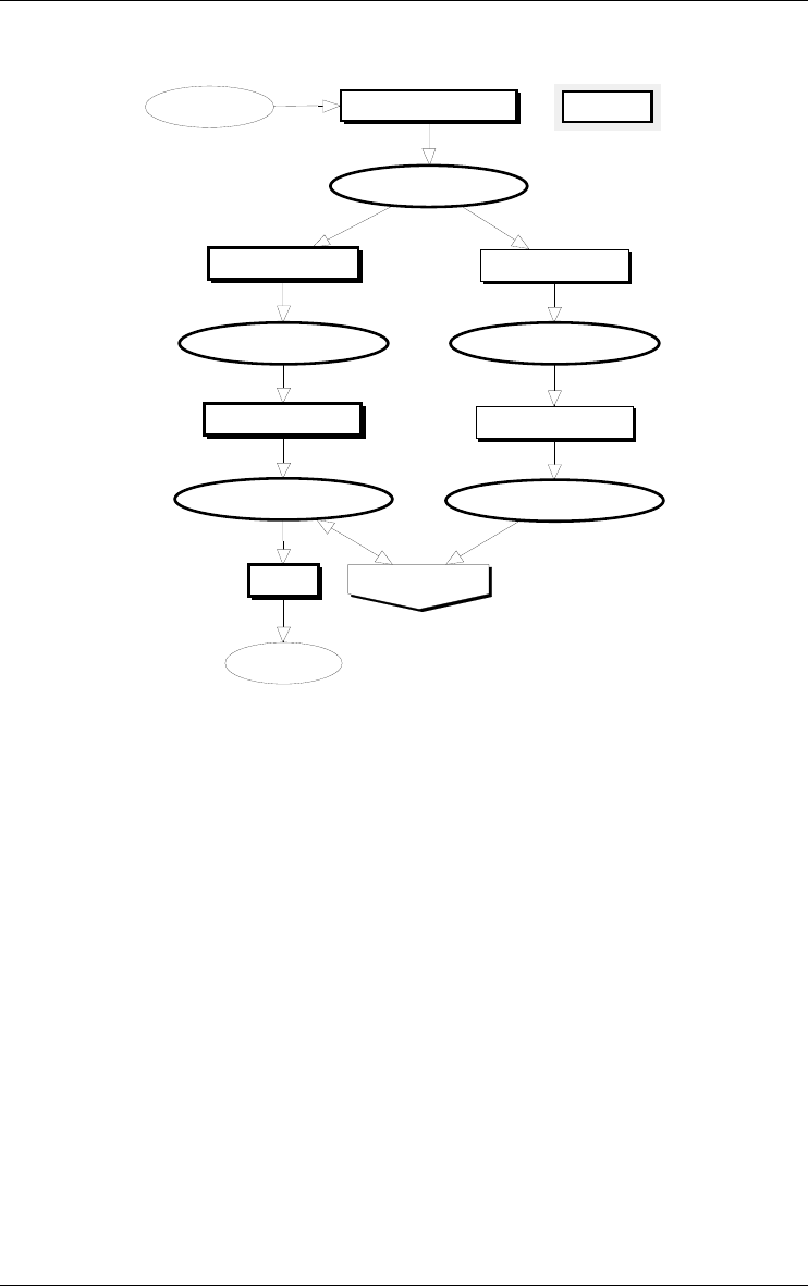
Physical Design 2
Logical Design 2
Coding
Physical Design 1
Logical Design 1
Conceptual Analysis
Minimize Space
LIBRARY/Physical Rel-2
LIBRARY/Logical Rel-2
library.ddl/1
LIBRARY/Physical Rel-1
LIBRARY/Logical Rel-1
LIBRARY/Conceptual
library.TXT/1 LIBRARY
62 7 • Engineering process control
22/6/2009
Figure 7.3 - A top-level history of the development of the Library database (a process
called LIBRARY). It shows how the conceptual schema was obtained by the analysis
of the library.TXT document, then how two tentative physical relational schemas were
developed, among which the first one was chosen for space performance reason.
This schema was then translated into a SQL DDL script.
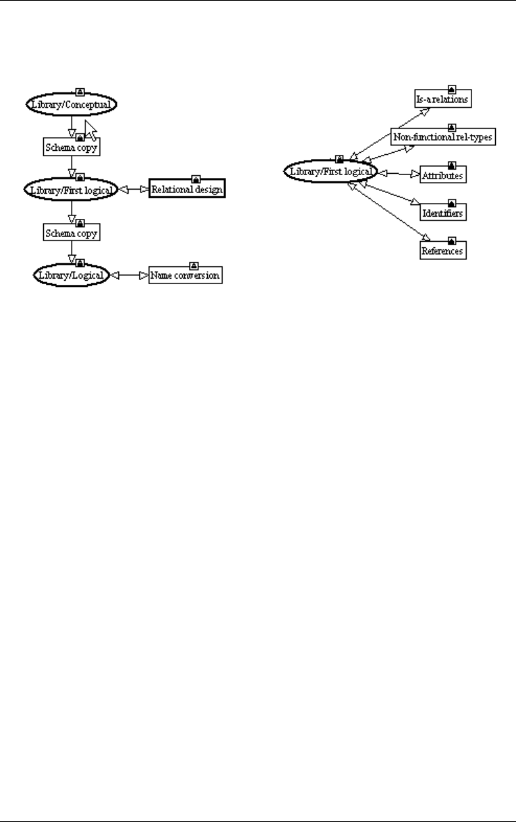
7 • Engineering process control 63
22/6/2009
Figure 7.4 - Development of the first Logical design process (left) and of the Rela-
tional Translation process (right).

64 7 • Engineering process control
22/6/2009

22/6/2009
Chapter 8
Sample DB-MAIN schemas
We will illustrate the use of the DB-MAIN specification model to express
schemas at different levels of abstraction, and according to various widespread
models. Except when explicitly mentioned, all these schemas (try to) repre-
sent the same application domain.
We will propose three conceptual schemas: ER, NIAM and UML class
diagram; then four logical schemas: relational, CODASYL-DBTG, COBOL
files and object-oriented; and finally an Oracle physical schema. We also
propose a non-data model defined with the DB-MAIN constructs.
The way these schemas have been built, either by domain analysis, or by
reverse engineering, or by transformation of other schemas is beyond the
scope of this document. The reader is invited to consult the literature on data-
base design [Batini,1992], [Bodart,1994], [Teorey,1995], [Halpin,1995],
[Elmasri,2000], [Connolly,1996], [Nanci,1996], or [Blaha, 1998].
8.1 An Entity-Relationship conceptual schema
The schema of Figure 8.1 is a computer-independent representation of the
concepts underlying a small technical library which lends books to the
employees assigned to projects. The formalism used belongs to the family of
the Entity-Relationship models [Chen,1976], [Bodart,1994], [Teorey,1995],
[Batini,1992], [Nanci,1996], [Elmasri,1995].
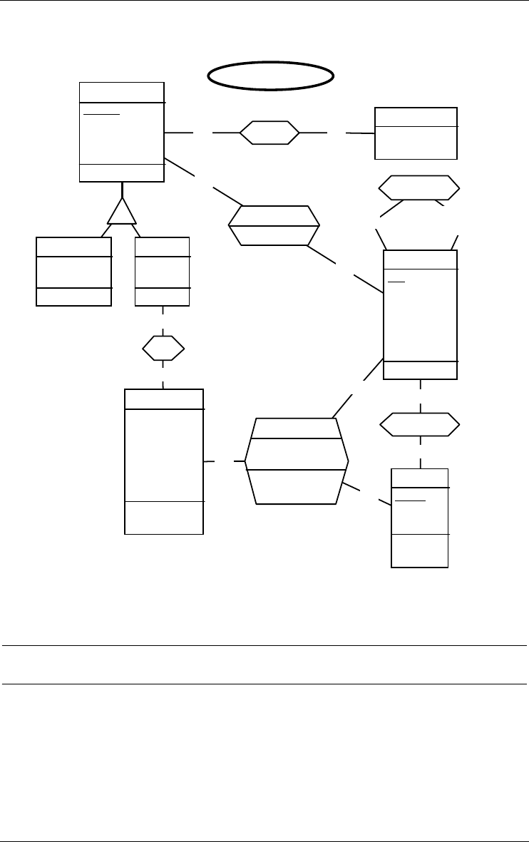
0-N 1-Nwritten
responsible
0-N
0-1
responsible
0-N
0-N
reserved
Date-reserved
1-1
0-N
of
0-N
0-N
0-N
borrowing
Borrow-Date
End-Date[0-1]
id: COPY
Borrow-Date
0-N
0-1
assigned to
D
REP ORT
Report-ID
Project
id': Report-ID
PROJECT
Pcode
Pname
Company
id: Pcode
id': Pname
DOCUMENT
Doc-ID
Tit l e
Date-Published
KeyWord[0-10]
id: Doc-ID
COP Y
Ser-number
Date-Acquired
Location
Store
Shelf
Row
id: of.BOOK
Ser-number
BORROWER
Pid
Name
Address
Street
City
Phone[1-5]
id: Pid
BOOK
ISBN
Publisher
id': ISBN
AUTHOR
Name
First-Name[0-1]
LIBRARY/Conceptual
66 8 • Sample DB-MAIN schemas
22/6/2009
Figure 8.1 - An Entity-relationship conceptual schema.
8.2 A NIAM/ORM conceptual schema
NIAM is a conceptual formalism which is often perceived as a competitor of
the ER model. It allows the analyst to ignore, at least in early steps of concep-
tual design, the distinction between entity types and attributes (or more
precisely attribute domains). In addition, it supports a linguistic interpretation
of the concepts. NIAM, as defined by G. Njissen, is the first published
proposal [Verheijen,1982], but the model has been further refined and formal-
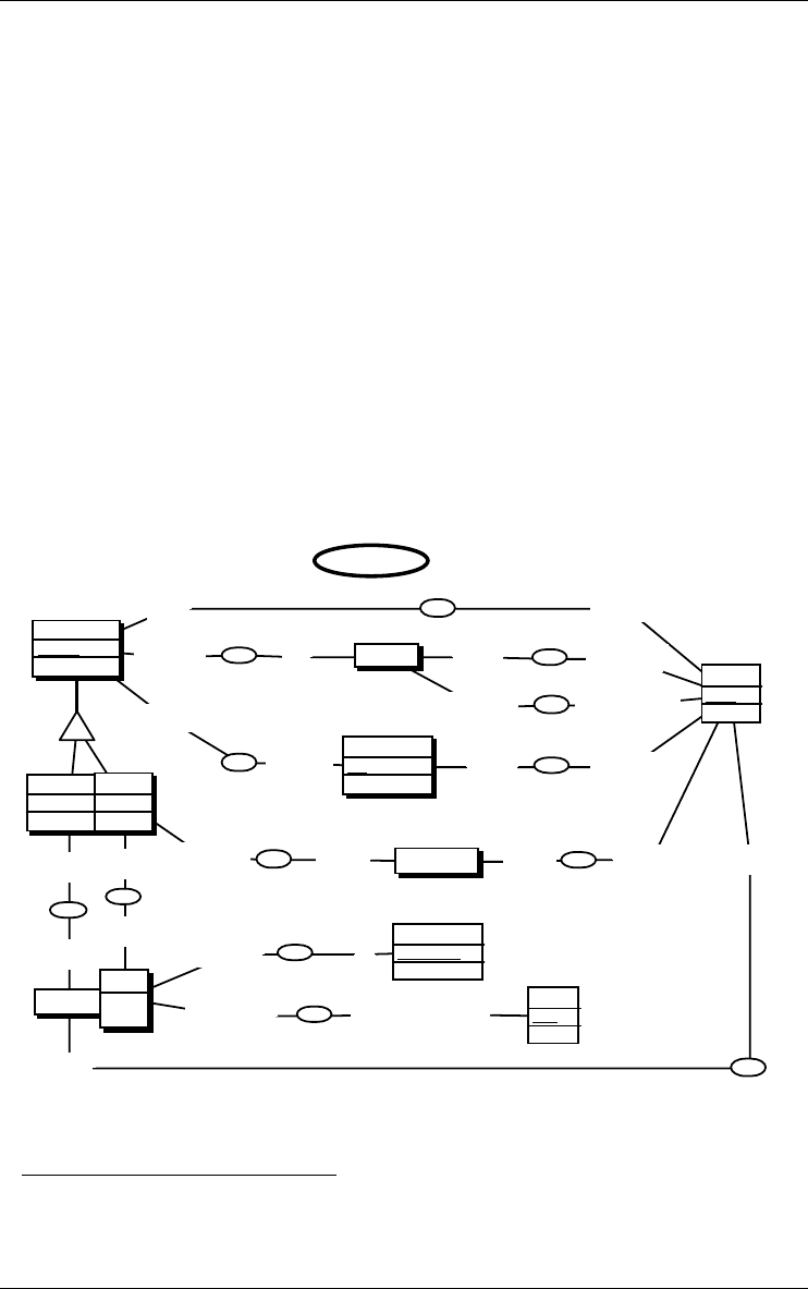
8 • Sample DB-MAIN schemas 67
22/6/2009
ized, among others as the Object-Role model [Halpin,1995]. Two of the most
visible differences with ER schemas are the explicit representation of value
domains (LOT), and the prominence of the concept of role at the expense of
the relationship types, which are left unnamed. Since NIAM-like schemas tend
to get larger than ER schemas, Figure 8.2 illustrates a subset only of the
concepts of Figure 8.1. We have simulated the typical NIAM graphical repre-
sentation through the following conventions.
•A NOLOT1 is represented by a marked entity type, while a LOT2 is repre-
sented by an unmarked entity type.
•As in ORM, when a NOLOT is identified by one primitive LOT (number,
code, etc), the latter is left as an attribute of the NOLOT. This simplifies
the schema considerably.
•Relationship types are made as unobtrusive as possible by giving them an
invisible name.
•Each role receives a meaningful name.
•The role cardinalities express the role identifiers and the total constraints.
produced
1-N
was produced by
1-1
publishes
1-N
is published by
1-1 has name
1-1
is the name of
0-1
is the name of
0-N
has name
1-1
is the name of
0-N
has name
1-1
is the title of
0-N
has title
1-1
has been reserved by
0-N
has reserved
0-N
is written by
0-N
wrote
1-N
has name
0-N
is the name of
0-N
is the first name of
0-N
h as first n ame
0-N
of
1-N
has number
1-1
is the acquisition date of
1-N
was acquired on
1-1
is a copy of
1-1
has
0-N
D
Ser-number
Ser-number
id: Ser-number
REPORT
Report-ID
id': Report-ID
PU B L I S HE R
PR O J E C T
NAME
Name
id: Name
DOCUMENT
Do c-ID
id: Doc-ID
DATE
Date
id: Date
COPY
id: .of
.has
BORROWER
Pid
id: Pid
BOOK
ISB N
id': ISBN
AUT HOR
LIBRARY/NIAM
Figure 8.2 - A (partial) NIAM conceptual schema.
1. NOLOT = non-lexical object type (another name for abstract object or entity type).
2. LOT = lexical object type (a sort of significant value domain made of printable sym-
bols).
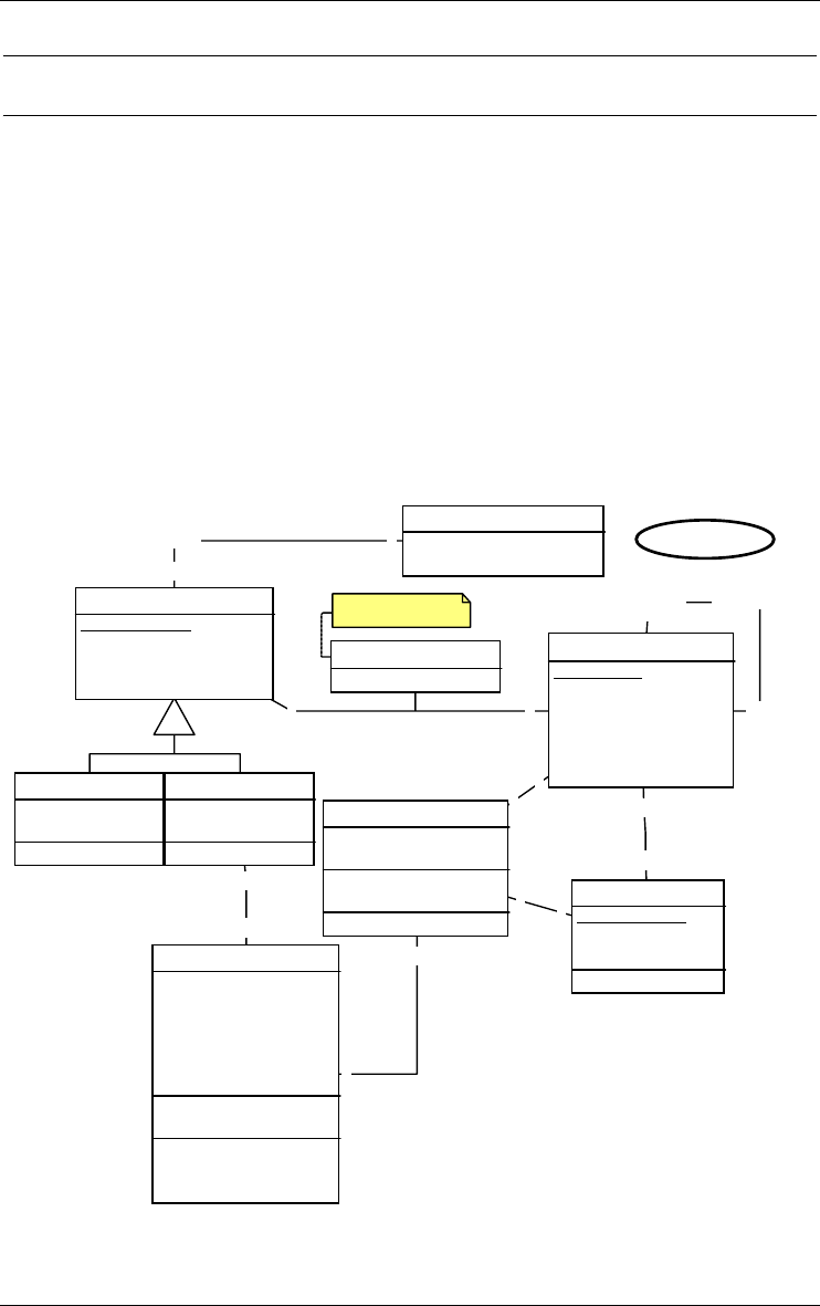
68 8 • Sample DB-MAIN schemas
22/6/2009
8.3 An UML conceptual schema
Though the UML notation has been designed for expressing the constructs of
object-oriented applications. Some authors suggest that UML could also be
used to describe database structures. Though it suffers from severe weak
points as far as conceptual structures are concerned, it is possible to use it to
draw object classes, attributes and associations that are as close as possible to
the standard ER schema. In Figure 8.3, the UML convention have been used
to express classes, associations and attribute. The N-ary rel-type borrowing
has been transformed into a class, while the binary rel-type reserved has been
kept to express an UML association class. Though the concept of identifier is
lacking in UML, we have indicated primary identifiers made up of attributes
by underlining their components. The other identifiers are expressed in a
specific UML compartment through the DB-MAIN notation
! association class
*
1
*1
*
1
*
1
0..1
*
1..*
*written
* *
reserved
date-reserved: date (1)
0..1
responsible
*is responsibl
e
D
Report
report-id: char (12)
project: char (40)
id': report-id
Project
pcode: char (6)
pname: char (30)
company: char (75)
id': pname
Document
doc-id: n um (6)
title: char (60)
dat e-published: dat e (1 0)
keyword[0..10]: char (30)
Copy
ser-number: num (6)
dat e-acquired: dat e (10 )
Location: compound (6)
store: num (2)
shelf: num (2)
row: num (2)
id: .Book
ser-n um ber
«class» record()
remove()
borrow()
Borrowing
borrow-date: date (10)
end-date[0..1]: date (10)
id: .Copy
bo rro w-dat e
return()
Borrower
pid: char (6)
name: char (30)
Address: compound (80)
street: char (40)
city: char (40)
Phone[1..5]: num (12)
Book
isbn: char (14)
publisher: char (40)
id': isbn
Author
name: char (30)
first-name[0..1]: char (16)
LIBRARY/UML
3.
Figure 8.3 - An UML schema that includes classes, attributes, associations, associa-
tion classes, operations, stereotypes (classifying operations) and notes.

8 • Sample DB-MAIN schemas 69
22/6/2009
8.4 A relational logical schema
The schema of Figure 8.4 is the direct translation of the conceptual schemas
proposed in Figure 8.1 to 8.3. Some semantics have been intentionally
dropped for simplicity (e.g., the exact max cardinality of attributes Keyword
and Phone). In addition, some structures and constraints are not fully rela-
3. UML recommendations define three kinds of compartments in the graphical representa-
tion of classes (name, attributes aned operations). However, they admit that other com-
partments can be defined according to specific needs. The constraint compartment is one
of them.
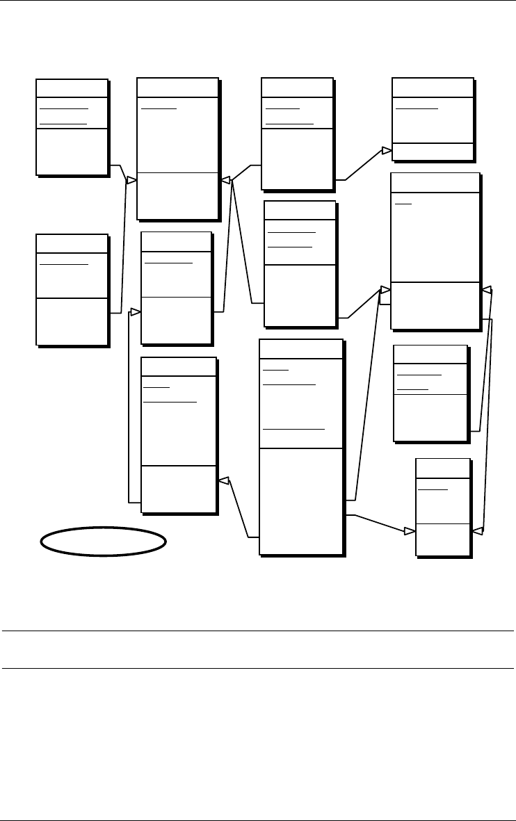
70 8 • Sample DB-MAIN schemas
22/6/2009
tional-compliant (equ, excl), and will be translated through generic techniques
(check, triggers, stored procedures, user interface, application programs, etc).
written
Author
Document
id: Document
Author
ref: Document
equ: Author
reserved
Document
Borrower
Date-reserved
id: Document
Borrower
ref: Document
ref: Borrower
REP ORT
Document
Report-ID
Project
id: Document
ref
id': Report-ID
PROJECT
Pcode
Pname
Company
id: Pcode
id': Pname
Phone
Borrower
Phone
id: Borrower
Phone
equ: Borrower
KeyWord
Document
KeyWord
id: Document
KeyWord
ref: Document
DOCUMENT
Doc-ID
Title
Date-Published
REP ORT[0-1]
BOOK[0-1]
id: Doc-ID
excl: REP ORT
BOOK
COPY
Book
Ser-number
Date-Acquired
Loc_Store
Loc_Shelf
Loc_Row
id: Book
Ser-number
ref: Book
borrowing
Book
Ser-number
Borrower
Project
Borrow-Date
End-Date[0-1]
id: Book
Ser-number
Borrow-Date
ref: Borrower
ref: P roject
ref: Book
Ser-number
BORROWER
Pid
Name
Add_Street
Add_City
Responsible[0-1]
Project[0-1]
id: Pid
ref: Responsible
ref: Project
BOOK
Document
ISBN
Publisher
id: Document
ref
id': ISBN
AUTHOR
ID_AUT
Name
First-Name[0-1]
id: ID_AUT
LIBRARY/Logical-Rel
Figure 8.4 - A relational logical schema.
8.5 A CODASYL-DBTG logical schema
The schema of Figure 8.5 is compliant with the CODASYL DBTG model,
except for some constraints that must be implemented through non declarative
techniques (e.g., application programs, access modules, user interface).
Two redundancy constraints have been left undeclared4. The first one
concerns the value of Doc-ID of WRITTEN, which must be equal to that of

8 • Sample DB-MAIN schemas 71
22/6/2009
field Doc-ID of the owner of work. The second one is similar and concerns
the field Doc-ID of RESERVED.
Representing CODASYL schemas (as well as IMS, IMAGE, TOTAL
schemas) is particularly important in re-engineering, migration and mainte-
nance projects, as well as in Datawarehouse development.
4. They are induced by the constraint stating that an identifier can be either absolute (made
up of attributes) or relative to a set type (and made up of a role and attributes). There-
fore, any identifier comprising more than one role cannot be explicitly declared. All the
roles, but one, must be replaced with the primary identifier of the corresponding entity
type. Hence these redundancy constraints.
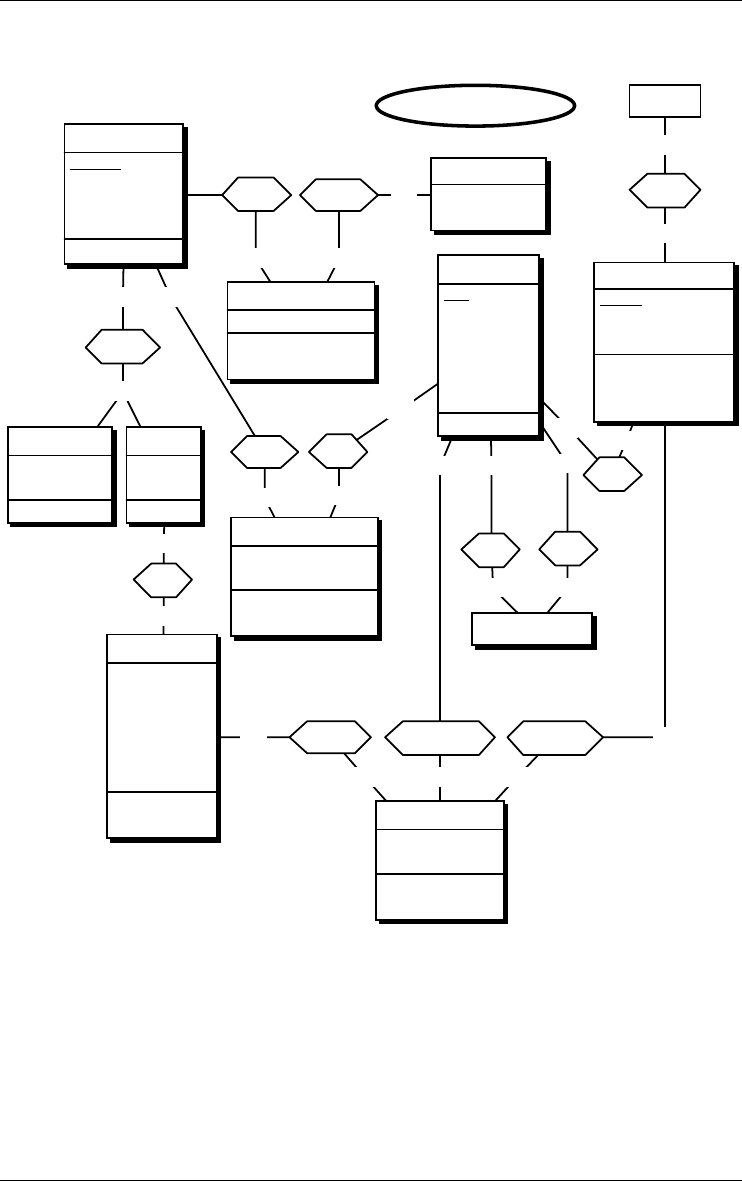
1-1
0-N
work
1-1
0-N
what
1-1
0-N
sys-p
1-1
0-N
of 1-1
0-1
is
0-N
0-1
in
1-1
0-N
fo r
1-1
0-N
by
1-1
0-Nb-project
1-1
0-1
b-is-d
1-1
0-N b-copy
1-1
0-N
b-borrower
1-1
1-Nauthor
WRITTE N
Doc-ID
id: author.AUTHOR
Doc-ID
SYSTEM
RESPONSIBLE
RESERVED
Doc-ID
Date-reserved
id: by.BORROWER
Doc-ID
REP ORT
Report-ID
Project
id': Report-ID
PROJECT
Pcode
Pname
Company
id: Pcode
id': sys-p.SYSTEM
Pname
DOCUMENT
Doc-ID
Title
Date-Published
KeyWord[0-10]
id: Doc-ID
COP Y
Ser-number
Date-Acquired
Location
Store
Shelf
Row
id: of.BOOK
Ser-number BORROWING
Borrow-Date
End-Date[0-1]
id: b-copy.COPY
Borrow-Date
BORROWER
Pid
Name
Address
Street
City
Phone[1-5]
id: Pid
BOOK
ISBN
Publisher
id': ISBN
AUTHOR
Name
First-Name[0-1]
LIBRARY/Logical-DBTG
72 8 • Sample DB-MAIN schemas
22/6/2009
Figure 8.5 - A CODASYL logical schema
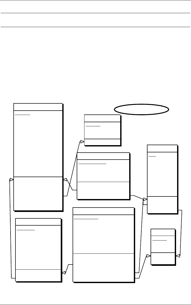
8 • Sample DB-MAIN schemas 73
22/6/2009
8.6 A COBOL file logical schema
Data structures implemented as standard records according to the COBOL
data management can be represented by the schema of Figure 8.6. The files
themselves have been ignored at that stage. Such constraints as foreign keys
do not belong to the standard COBOL data model, and must be considered as
objects that must be implemented through non declarative techniques (e.g.,
application programs, access modules, user interface).
Representing in an acurate way standard files can be useful to develop new
file-based applications, but it will prove more important to re-engineer and
migrate data-centered legacy systems.
RESERVED
RESERVED-ID
DOC-ID
PID
DATE-RESERVED
id: RESERVED-ID
ref: RESERVED-ID.DOC-ID
ref: RESERVED-ID.PID
PROJECT
PCODE
PNAME
COMP ANY
id: PCODE
id': PNAME
DOCUMENT
DOC-ID
TITL E
AUTHORS[0-5]
DATE-PUBLISHED
KEYWORD[0-10]
REP ORT[0-1]
REP ORT-ID
PROJECT
BOOK[0-1]
BOOK-ID
ISBN
PUBLISHER
id: DOC-ID
id': BOOK.BOOK-ID
id': REP ORT.REP ORT-ID
ref: AUTHORS[*]
excl: BOOK
REPORT
COP Y
COP Y-ID
BOOK-ID
SER-NUMBER
DATE-ACQUIRED
LOCATION
STORE
SHELF
ROW
id: COPY-ID
ref: COPY-ID.BOOK-ID
BORROWING
BORROW-ID
BOOK-ID
SER-NUMBER
BORROW-DATE
PID
PCODE
END-DATE[0-1]
id: BORROW-ID
ref: BORROW-ID.BOOK-ID
BORROW-ID.SER-NUMBER
ref: P ID
ref: P CODE
BORROWER
PID
NAME
ADDRESS
STREET
CITY
PHONE[1-5]
PCODE[0-1]
RESP -PID[0-1]
id: PID
ref: RESP -P ID
ref: PCODE
AUTHOR
AUT-ID
NAME
FIRST-NAME[0-1]
id: AUT-ID
LIBRARY/Logical-COBOL
Figure 8.6 - A record/file structure logical schema.

74 8 • Sample DB-MAIN schemas
22/6/2009
8.7 An object-oriented logical schema
We have chosen a model which does not include the concept of relationship5,
but which provides a means to declare inverse object attributes (Figure 8.7).
Operational models that ignore this construct will force the programmer to
resort to explicit programming of the control of this contraint, for instance in
object management methods.
This schema results from some arbitrary design decisions. For instance, the
constructs Reservation, Copy and Borrowing have been transformed into
multivalued compound attributes instead of object classes.
5. As opposed to the ODMG and CORBA models for instance, that provide these con-
structs.
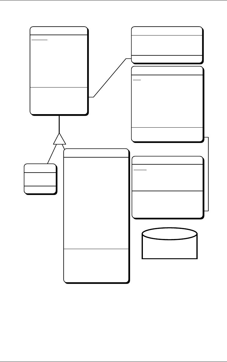
D
REPORT
Report-ID
Project
id': Report-ID
PROJ EC T
Pcode
Pname
Company
Employees[0-N]: *BORROWER
id: Pcode
id': Pname
id': Employees[*]
inv
DOC U MEN T
Doc-ID
Title
Date-Published
KeyWord[0-10]
Reservation[0-N]
Date-reserved
by: *BORROWER
Authors[0-N]: *AUTHOR
id: Doc-ID
inv: Authors[*]
id(Reservation):
by
BORROWER
Pid
Name
Address
Street
City
Phone[1-5]
responsible[0-1]: *BORROWER
Assigned_to[0-1]: *PROJECT
id: Pid
inv: Assigned_to
B OOK
ISBN
Publisher
Copies[0-N]
Ser-number
Date-Acquired
Location
Store
Shelf
Row
Borrowing[0-N]
Borrow-Date
End-Date[0-1]
Borrower: *BORROWER
Project: *PROJECT
id': ISBN
id(Copies):
Ser-number
id(Copies.Borrowing):
Borrow-Date
AUTHOR
Name
First-Name[0-1]
Documents[1-N]: *DOCUMENT
inv: Documents[*]
LIBRARY/Logical-OO
Inventory
Statistics
8 • Sample DB-MAIN schemas 75
22/6/2009
Figure 8.7 - An object-oriented logical schema.

76 8 • Sample DB-MAIN schemas
22/6/2009
8.8 A relational (ORACLE) physical schema
The logical schema of Figure 8.4 has been extended and modified in the
following way:
•the names have been made compliant with the ORACLE syntax,
•triggers have been attached to some tables,
•two stored procedures have been defined (attached to the schema),
•indexes have been defined,
•prefix indexes6 have been discarded,
•each table has been assigned to a tablespace.
6. An index defined on columns {A,B} is a prefix of any index defined on columns
{A,B,...}. Heuristics: if these indexes are implemented through B-tree techniques (i.e.,
not with hashing techniques), then the prefix index can be discarded, since the larger
index can be used to simulate the former.
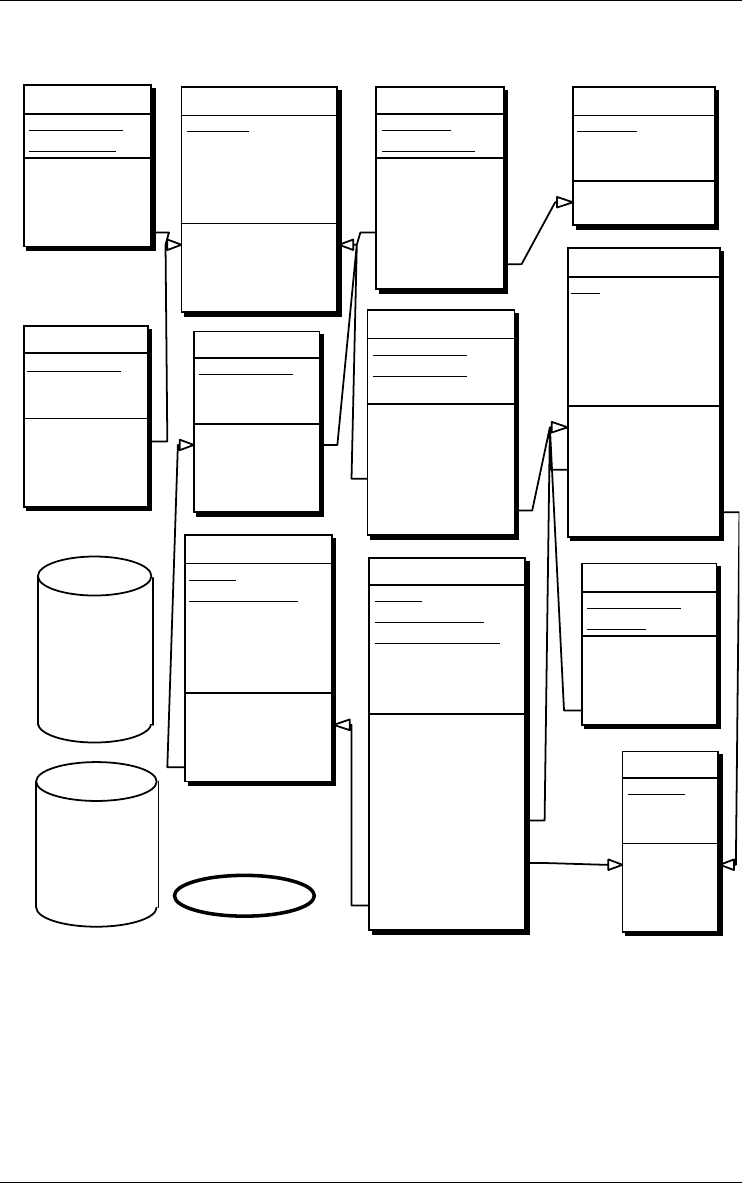
WRITTEN
AUTHOR
DOCUMENT
id: DOCUMENT
AUTHOR
acc
ref: DOCUMENT
equ: AUTHOR
acc
RESERVED
DOCUMENT
BORROWER
DATE_RESERVED
id: DOCUMENT
BORROWER
acc
ref: DOCUMENT
ref: BORROWER
acc
REP ORT
DOCUMENT
REP ORT_ID
PROJECT
id: DOCUMENT
ref acc
id': REP ORT_ID
acc
PROJECT
PCODE
PNAME
COMPANY
id: PCODE
acc
id': PNAME
acc
PHONE
BORROWER
PHONE
id: BORROWER
PHONE
acc
equ: BORROWER
KEYWORD
DOCUMENT
KEYWORD
id: DOCUMENT
KEYWORD
acc
ref: DOCUMENT
DOCUMENT
DOC_ID
TITL E
DATE_PUBLISHED
REP ORT[0-1]
BOOK[0-1]
id: DOC_ID
acc
excl: REPORT
BOOK
COPY
BOOK
SER_NUMBER
DATE_ACQUIRED
LOC_STORE
LOC_SHELF
LOC_ROW
id: BOOK
SER_NUMBER
acc
ref: BOOK
BORROWING
BOOK
SER_NUMBER
BORROW_DATE
BORROWER
PROJECT
END_DATE[0-1]
id: BOOK
SER_NUMBER
BORROW_DATE
acc
ref: BORROWER
acc
ref: PROJECT
acc
ref: BOOK
SER_NUMBER
BORROWER
PID
NAME
ADD_STREET
ADD_CITY
RESP ONSIBLE[0-1]
PROJECT[0-1]
id: PID
acc
ref: RESP ONSIBLE
acc
ref: P ROJECT
acc
BOOK
DOCUMENT
ISBN
PUBLISHER
id: DOCUMENT
ref acc
id': ISBN
acc
AUTHOR
ID_AUT
NAME
FIRST_NAME[0-1]
id: ID_AUT
acc
S_BOOKS
WRITTEN
KEYWORD
DOCUMENT
COP Y
BOOK
AUTHOR
S_BORROW
RESERVED
PROJECT
PHONE
BORROWING
BORROWER LIBRARY/Oracle
8 • Sample DB-MAIN schemas 77
22/6/2009
Figure 8.8 - An ORACLE physical schema with triggers and stored procedures.
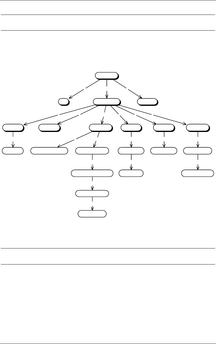
78 8 • Sample DB-MAIN schemas
22/6/2009
8.9 An activity diagram
The call graph of Figure 8.9 has been extracted from the DB reverse engi-
neering case study Order.cob.
ccc
cccccc
c cc c c c
ccc
c
c
PR I N C I PA L
INIT TRAITEMENT CLOTURE
NOUV-CLI NOUV-STK NOUV-COM LISTE-CLI LISTE-STK LISTE-COM
LECTURE-COM
AFFICHE-DETAIL
LECTURE-STKLECTURE-CLI
AFFICHE-CLI
LECTURE-CODE-CLI LECTURE-DETAIL
LECTURE-CODE-PROD
MAJ-COM-DETAIL
MAJ-CLI-HISTO
INIT-HISTO
Figure 8.9 - The call graph of a small COBOL program.
8.10 An use case diagram
The use case diagram of Figure 8.10 shows the relationships among actors and
use cases within a system of orders. The following diagram is from the UML
1.5 specification.
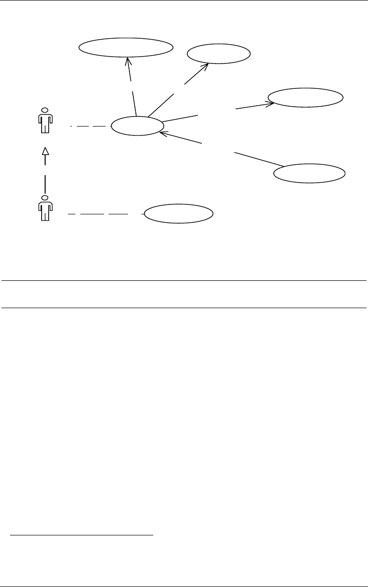
*1..*a
* 1a
g
«extend»
«include»
«include»
«include»
Es tab lis h Credit
Reques t Catalog
Arrange Payment
Order Product
Supply Customer Data
Place Order
Su
p
ervisor
Salesperson
8 • Sample DB-MAIN schemas 79
22/6/2009
Figure 8.10 - The use case diagram of a customer department.
8.11 An organizational structure model
Though it uses the usual DB-MAIN graphical conventions for schema repre-
sentation, Figure 8.11 is not a database schema. Instead, it describes organi-
zation units (services, departments, functions, etc.) and their inter-relations.
Each rectangle represents a unit; the arcs, read from left to right, represent the
units hierarchy, and the names in a rectangle give the list of the persons
assigned to this unit. The symbol [0-1] indicated that the person is partially
assigned to that unit. The names of unit heads/responsibles are in boldface.
This example is an illustration of how the DB-MAIN model can be used to
describe non data-related concepts without augmenting its functionalities. Of
course, specific operators must be developed with the Java library JIDBM7.
7. A complete subsystem has been developed to model organizational units and their links
with data schemas. It is available in the DB-MAIN Application Library #1 (module
ORGA) described in this document.
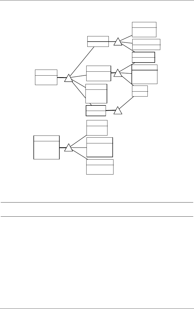
Secretary
Pascale Cartrain
Jo s e P av aro t ti
Lúcia Carvalho
Production
Paolo Accorti
Planning
Diego Roel[0-1]
John Steel
Personnel
Hari Kumar
Paula Wilson
Daniel Tonini
Ordering
Philip Cramer
Fran Wilson[0-1]
Rita Müller
Operations
Maria Anders
Peter Franken
Marketing
Yo s hi La ti m er
Management
Mary Sa veley
Michael Holz
Maintenance
Jaime Yorres[0-1]
Invoicing
Liz Nixon
Finance
Bernardo B atista
Diego Roel[0-1]
Customer
Diego Roel[0-1]
Carine Schmitt
Administration
Mari o Po ntes
Jaime Yorres[0-1]
Fran Wilson[0-1]
Jean Fresnière
Accounting
Georg Pipps
80 8 • Sample DB-MAIN schemas
22/6/2009
Figure 8.11 - An organizational units model.
8.12 References
[Batini,1992] Batini, C., Ceri, S., Navathe, S., B., Conceptual Database
Design, Benjamin/ Cummings, 1992
[Blaha,1998] Blaha, M., Premerlani, W., Object-Oriented Analysis and
Design for Database Applications, Prentice Hall, 1998
[Bodart,1994] Bodart, F., Pigneur, Y., Conception assistée des systèmes
d'information, Masson, 1994
[Chen,1976] Chen, P., The entity-relationship model - toward a unified view
of data, ACM TODS, Vol. 1, N° 1, 1976
[Coad, 1995] Coad, P., North, D., Mayfield, M., Object Models: Strategies,
Patterns and Applications, Prentice Hall, 1995

8 • Sample DB-MAIN schemas 81
22/6/2009
[Connolly,1996] Connolly, T., Begg, C., Strachan, A., Database Systems - A
Practical Approach to Design, Implementation and Management, Addison-
Wesley, 1996, ISBN 0-201-42277-8
[Elmasri,2000] Elmasri, R., Navathe, S., Fundamentals of Database Systems,
Benjamin-Cummings, 2000
[Halpin,1995] Halpin, T., Conceptual SChema & Relational Database
Design, Prentice Hall, 1995
[Nanci,1996] Nanci, D., Espinasse, B., Ingénierie des systèmes d'information
Merise - Deuxième génération (3ème édition), SYBEX, 1996, ISBN 2-7361-
2209-7
[Rumbaugh,1991] Rumbaugh, J., Blaha, M., Premerlani, W., Eddy, F.,
Lorensen, W., Object Oriented Modeling and Design, Prentice Hall, 1991
[Teorey,1995] Teorey, T. J., Database Modeling and Design : the Funda-
mental Principles, Morgan Kaufmann, 1994
[Verheijen,1982] Verheijen, G., Van Bekkum, J., NIAM : an Information
Analysis Method, in Proc. of the IFIP WG 8.1 WC, Information Systems
Design Methodologies: a Comparative Review, Olle, T., Tully, C. (Eds),
North-Holland, 1982

82 8 • Sample DB-MAIN schemas
22/6/2009

22/6/2009
Chapter 9
The components of the DB-MAIN
environment (Version 9)
There are two distinct toolsets, namely the DB-MAIN environment and the
DB-MAIN plug-in library.
9.1 The DB-MAIN environment
DB-MAIN does not use the registry and does not install system components
but in its own directory. It stores its permanent configuration parameters in
the db_main.ini file in the Application Data directory (Windows) or the home
directory (Linux). It can be uninstalled by merely throwing away its compo-
nents and deleting the db_main.ini file. The components of DB-MAIN 9 are
the following (see the README file for possible modification):
9.1.1 Program files
a) Windows platform
•db_main.exe: the DB-MAIN main program (mandatory)
•Microsoft.VC80.CRT: Visual C++ 8 library directory (mandatory)
•wxmsw28_aui_vc_custom.dll: wxWidgets run time library (mandatory)
•wxmsw28_xrc_vc_custom.dll: wxWidgets run time library (mandatory)

84 9 • The components of the DB-MAIN environment (Version 9)
22/6/2009
•wxbase28_xml_vc_custom.dll: wxWidgets run time library (mandatory)
•wxmsw28_html_vc_custom.dll: wxWidgets run time library (mandatory)
•wxmsw28_adv_vc_custom.dll: wxWidgets run time library (mandatory)
•wxmsw28_core_vc_custom.dll: wxWidgets run time library (mandatory)
•wxbase28_vc_custom.dll: wxWidgets run time library (mandatory)
•reposit.dll: repository manager (mandatory)
•jidbm.dll: Java Interface for DB-MAIN (JIDBM)
•jidbm.jar: JIDBM package
•extr_*.dll: source code analyzers for reverse engineering
– extr_sql.dll: SQL source code analyzer
– extr_odbc.dll: SQL source code analyzer via ODBC
– extr_ids.dll: IDS/2 source code analyzer (only available in DB-MAIN
Professional)
– extr_cob.dll: COBOL source code analyzer (only available in DB-
MAIN Professional)
– extr_ims.dll: DL/1 (IMS) source code analyzer (only available in DB-
MAIN Professional)
•GERtoXML-tfs.oxo: XML related functions for the Advanced Global
Transformation assistant; developped in Voyager 2.
•ana_xml.oxo: XML related functions for the Schema Analysis assistant;
developped in Voyager 2.
•db_main.chm: the help file
•1st-step.chm: the first step help file
•db_main.ini: the environment parameters file located in the user’s Appli-
cation Data directory; if not present, will be created by DB-MAIN when
needed.
b) Linux platform
... under construction
9.1.2 Input/output files
The files produced and used by the DB-MAIN environment can be classified
into homogeneous classes. Consult the README file for the last modifica-
tions.
a) repository files
•*.lun: project repository: comprises all the specifications of a project.

9 • The components of the DB-MAIN environment (Version 9) 85
22/6/2009
•*.isl: import/export text file: contents of a repository in a readable text
format (the ISL language); used by commands File / Open, Save as and
Export (choose extension *.isl); as well as by the Integration assistant.
•*.xml: contents of a repository in a XML format; saves everything but the
method.
•*.dic: generated report: simple formatted report file resulting from
command File / Print dictionary.
b) executable program files
•*.ddl: generated DDL text: data structure definition program (e.g., in
COBOL, SQL, CODASYL DDL, etc.); produced by, File / Generate,
Quick SQL and Assist / Global transformation - Generate. Some Java
programs can also generate such files.
•*.sql: SQL source file (default extension): an SQL script file processable
by the SQL extractor.
•*.cob: COBOL source file (default extension): a COBOL program
processable by the COBOL extractor.
•*.ids: IDS source file (default extension): a IDS DDL program processable
by the IDS extractor.
•*.ims: DL/1 (IMS) source file (default extension): a IMS DL/1 program
processable by the IMS extractor.
•*.xml: XML source file (default extension): an XML DTD text.
•others: other source file formats (to be added).
c) user developed functions
•*.java: source version of Java program developed with the Java Interface
for DB-MAIN.
•*.class: executable Java program in DB-MAIN.
d) script files
•*.pat: name pattern substitution list: list of substitution rules (replace X by
Y) which can be applied on selected names of selected objects of a
schema; saved and loaded from within the name processor (command
Transform / Name processing); also used in the assistants Global transfor-
mation and Advanced global transformations.
•*.trf: transformation assistant script file: saved list of actions developed in
the Global transformation assistant.
•*.tfs: transformation assistant script file: saved list of actions developed in
the Advanced global transformation assistant.

86 9 • The components of the DB-MAIN environment (Version 9)
22/6/2009
•*.tfl: transformation assistant library file: library of the Advanced global
transformations.
•*.ana: analysis assistant script file: saved list of constraints developed in
the Analysis assistant.
•*.anl: analysis assistant library file: library of the Analysis assistant.
•*.pdl: text pattern file: list of patterns to be used in text analysis functions;
used in File / Load patterns and in Edit / Search, Dependency and Execute
commands.
•*.nam: reserved names used in the Advanced Global Transformation assis-
tant.
e) log files
•*.log: log file: records the activities carried out by the analyst; these oper-
ations can be replayed automatically; used in the Log menu. Normally, the
activity history is a hidden part of the repository; a log file is created either
to examine its contents or to replay it.
f) method definition files
•*.mdl: method file: MDL specification of the method enacted by the meth-
odological engine of DB-MAIN.
•*.lum: binary version of an MDL description; has been compiled by the
MDL compiler; can be used when opening a new project.
9.2 The DB-MAIN Application Library
The application library comprises general purpose tools for information
system development. These programs have been developed in Java. They are
intended to enrich the DB-MAIN environment, but also to provide Java
developers with representative application models that can be analyzed,
modified, extended or specialized.
9.2.1 DDL extractor: XML
Analyses XML DTD source files and builds in DB-MAIN a physical/logical
schema describing the data structures.
Only available in DB-MAIN PRO. Contact us for more information.

9 • The components of the DB-MAIN environment (Version 9) 87
22/6/2009
9.2.2 DDL generators: COBOL, CODASYL, Oracle, DB2 and XML
These processors translate a physical compliant schema into an executable
DDL text that can be used to build a database. This text is produced according
to various DBMS and styles.
Only available in DB-MAIN PRO. Contact us for more information.
Parametric SQL generators
Two sophisticated parametric SQL generators (for DB2 and Oracle) are avail-
able as plug-ins. They provide more powerful and flexible generation tech-
niques based on check predicates, triggers and stored procedures.
COBOL
A (simple) COBOL generator.
CODASYL
Two CODASYL generators. The first one is a CODASYL DBTG-71 gener-
ator and the second one is an IDS/II generator
XML
An XML DTD generator.
9.2.3 DocBook generator
Generates a XML DocBook file on the contents of a DB-MAIN project.
DocBook is a semantic markup language for technical documentation. The
user must apply XSLT stylesheets to transform DocBook files into HTML,
PDF, RTF, JavaDoc and many other formats.
9.2.4 Mapping assistant
Vizualizes and manages mappings between objects into a DB-MAIN projects.
9.2.5 NATURAL : Paraphraser
Generates a natural language text that describes the contents of a schema.
Especially intended to make users validate conceptual schemas. Two formats:
free text and tagged list of facts.
Only available in DB-MAIN PRO. Contact us for more information.
9.2.6 METRICS : Schema metrics computation
Offers some 200 measures on schemas: number of ET, RT, attribute/ET,
attributes/type, multicomponent identifiers, etc. The metrics are selected

88 9 • The components of the DB-MAIN environment (Version 9)
22/6/2009
through forms which can be saved, reused and modified. Generates a report
(text or spreadsheet).
Only available in DB-MAIN PRO. Contact us for more information.

22/6/2009
Chapter 10
List of the DB-MAIN functions
The following chapters give a list of the functions available in DB-MAIN
version 9 from the menus, toolbars and palettes, together with a short descrip-
tion of each of them.
A more detailed description will be found in technical documents of the
product. A tutorial entitled Computer-Aided Database Engineering - Volume
I: Database Models can be consulted to fully understand the DB-MAIN
models.
Another tutorial, entitled Introduction to Database Engineering, is an intui-
tive introduction to database design, and, as a side effect, to DB-MAIN
mastering.
The functions of the tool are organised according to 11 classes:
•File: controls the exchanges between the tool and its environment;
includes importer, exporter, extractors and generators
•Edit: deletes, copies and pastes objects; copies schema fragments on the
clipboard; select and mark objects; changes color and fonts
•Product: adds, copies, examines and links products, i.e., schemas, text files
and views, meta-level management and user-defined domains.
•New: adds new objects to the current schema
•Transform: the transformation toolkit
•Assist: a series of Expert Assistants
•Engineering: engineering process control
•Log: manages and processes history log files
•View: controls the way in which the specifications appear on the screen

90 10 • List of the DB-MAIN functions
22/6/2009
•Window: as usual
•Help: the help desk
Some of these functions also are available on the tool bar and on the detach-
able palettes.

22 juin 2009
Chapter 11
The File menu (File)
Through the nine sections of this menu, the user will control the data flows
between the DB-MAIN tool and its environment:
1. creating, opening, closing, saving projects and examining their properties;
2. exporting and importing products from other projects;
3. executing user defined plug-ins;
4. extracting data structures from DDL source texts: SQL, COBOL, CODASYL,
IMS; generating SQL DDL texts from schemas;
5. producing and examining external texts;
6. printing and generating reports;
7. configuring the DB-MAIN parameters;
8. opening a recently processed project;
9. exiting the tool.
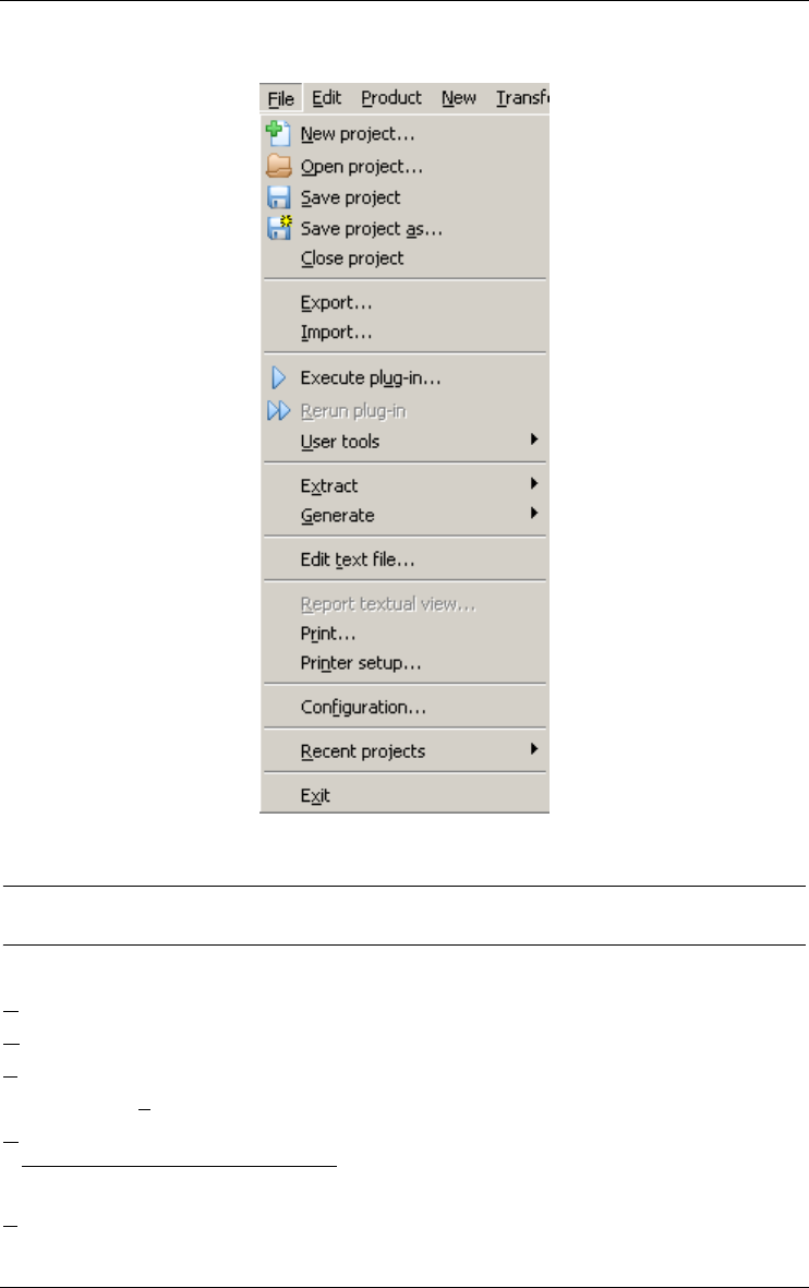
92 11 • The File menu (File)
22 juin 2009
11.1 The commands of the File menu - Summary
New project... builds a new project.
Open project... opens an existing project.
Save project saves the current project.
Save project as... saves the current project under another name.
Close project closes the current project
Export... generates a *.isl or a *.xml file representing the
selected objects of the current window

11 • The File menu (File) 93
22 juin 2009
Import... imports selected schemas from a *.isl or a *.xml file in
the current process
Execute plug-in... runs a plug-in program
Rerun plug-in... reruns the last loaded Voyager 2 plug-in
User tools executes one of the user defined plug-ins or menu items
defined in the db_main.ini file
Extract builds a physical/logical schema describing the data struc-
tures extracted from: SQL, ODBC, COBOL, CODASYL,
IMS.
Generate generates an executable DDL program corresponding to
the current data schema, according to various RDBMS
and SQL styles.
Edit text file... opens MS Windows Notepad
Report... in a textual schema view, generates a dictionary report
(plain text); in a text, copies the content
Print... prints the content of the current process, schema or
source file window (textual or graphical views) to the
chosen printer
Printer setup... chooses and configures the printer
Configuration... sets some general DB-MAIN options
Recent projects opens one of the most recently opened file.
Exit exits from DB-MAIN. Saves the current project if needed
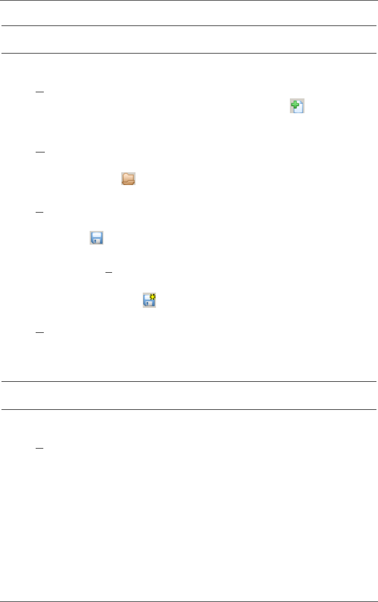
94 11 • The File menu (File)
22 juin 2009
11.2 Managing projects
11.2.1 New project...
Builds a new project. Also available through the button on the standard
tool bar.
11.2.2 Open project...
Opens an existing project (a *.lun, *.isl or *.xml file). Also available
through the button on the standard tool bar.
11.2.3 Save project
Saves the current project as a *.lun, *.isl or *.xml file. Also available
through the button on the standard tool bar.
11.2.4 Save project as...
Saves the current project as a new *.lun, *.isl or *.xml file. Also avail-
able through the button on the standard tool bar.
11.2.5 Close project
Closes the current project.
11.3 Exporting and importing
11.3.1 Export...
Generates a *.isl or *.xml file representing the selected objects of the
current window.
Procedure
•To export one or several schemas: in the project window, select the
schema you want to export, then execute the command File/Export.
The exported project includes a copy of these schemas.
•To export a subset of a schema: in the schema window, select the
objects you want to export, then execute the command File/Export.
The exported project includes a schema comprising a copy of the
selected objects.

11 • The File menu (File) 95
22 juin 2009
11.3.2 Import...
Imports selected schemas from a *.isl or *.xml file in the current
process.
Procedure
•In the project window, execute the command File/Import and select a
*.isl or *.xml project file.
•Select the schema(s) you want to import. The current project now
includes a copy of all the imported schemas.
11.4 Executing a user-defined plug-in
11.4.1 Execute Plug-in...
Runs a Java program (*.class) or an compiled Voyager 2 program
(*.oxo). Voyager 2 was the first programming language in DB-MAIN
before the success of Java. For backward compatibility, the execution of
Voyager 2 plug-ins is always available but, currently, Java is the only
programming language for DB-MAIN plug-ins.
Also available through the button on the standard tool bar.
Example
Open a non empty data schema. Find (in plug-ins directory) and execute the
program StatisticGenerator.class, that computes some elementary
(but useful) statistics of the schema.
11.4.2 Rerun Plug-in...
Reruns the most recently loaded Voyager 2 plug-in. Also available through
the button on the standard tool bar.
Comments
The Voyager 2 plug-in that was re-executed the most recently runs in the
abstract machine until another program is called. Hence this handy short-
hand. If you need several programs being immediately available, use the
user-defined tool bar instead (see Section 11.4.3).
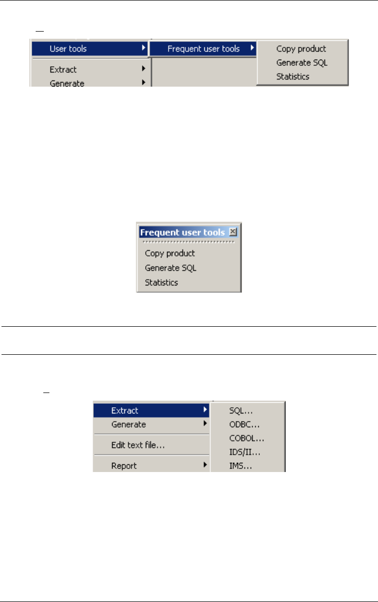
96 11 • The File menu (File)
22 juin 2009
11.4.3 User tools
DB-MAIN allows you to select a set of frequently used actions (one to
twenty-five by user tools menu) from the various menu items and among the
available Java processors, and to gather them into ten user tools as new
menu items for quick and logical access.
The actions are selected and named through the configuration function
(Section 11.8.1). They are executed with this command. However, DB-
MAIN automatically builds User tool bars that includes the selected actions,
and that can be asked for by the command Window/User tools (see Figure
20.2.7).
11.5 Extracting and generating DDL text files
11.5.1 Extract
The DB-MAIN tool can read the DDL source text of an existing database
and create a schema comprising all the data structures and constraints that
are declared in this text. This schema is called the physical schema of the
existing database. It must be enriched with implicit constraints that can be
found by searching application programs, database contents or any other
source related to this database. Schema extraction is the first step of any
database reverse engineering project. For a comprehensive introduction to
this process, see [Hainaut 1998] for instance.

11 • The File menu (File) 97
22 juin 2009
This command builds a physical/logical schema describing the data struc-
tures extracted from:
SQL...
... a SQL DDL source text file. The extractor analyses the statements
create table space, create table, create index, create view and alter
table add constraint.
ODBC...
... a relational database throught an ODBC driver. The extractor anal-
yses the structure extracted from a relational database using an ODBC
driver.
COBOL...
... a COBOL source text file. If the source text contains a COBOL
program, the extractor analyses the statements of the Environment
division (assign statements) and of the FD paragraphs of the Data
division. If the source text is a copybook, the extractor analyzes the
variable declaration and creates an entity type for each 01 level vari-
ables. If only variables of level superior to 01 are declared, an entity
type is created (called as the file) to contain all the variables.
IDS/II...
... an IDS/II DDL text file. The extractor analyses the schema and
sub-schema sections.
IMS...
... an IMS source text file. The extractor analyses IMS DDL.
Procedure
•In the project window, execute the command Product/Add text and
select the source text to be parsed. Alternatively, drag&drop the source
text from the Windows Explorer into the project window.
•Select the text(s) you want to analyse.
•Execute the command File/Extract, and select the language.
•If some errors have been detected, modify the source text accordingly.
The schema is then added to the project as an output product of a primitive
process called Extract.
If the current window is a data schema window, then the extractor adds the
extracted specifications to this schema ("Incremental" mode); if the current
window is the project or a process window, the extractor creates a new
schema comprising the extracted specifications ("New" mode).
Some parameters of the extraction process can be set through the command
File/Configuration (see Section 11.8.1).
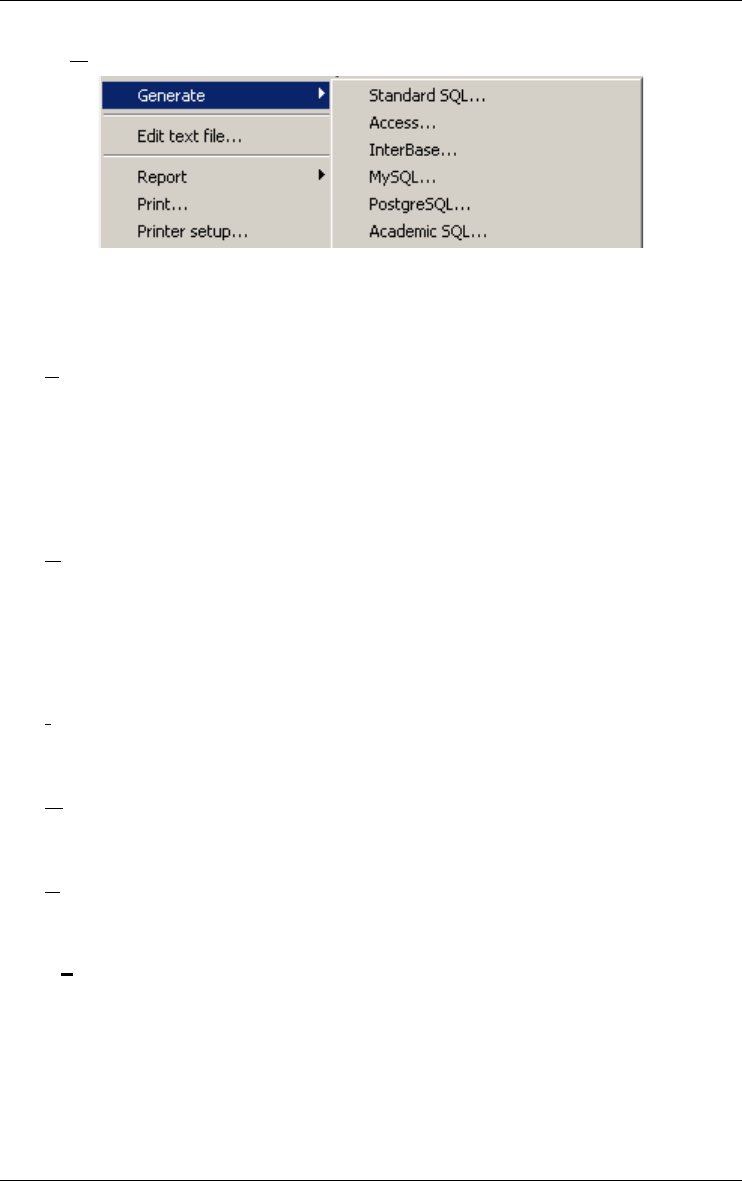
98 11 • The File menu (File)
22 juin 2009
11.5.2 Generate
These processors translate a physical schema into an executable DDL text
that can be used to build a database. This text is produced according to
various DBMS and styles:
Standard SQL...
Unsophisticated standard SQL-2. This generator produces the state-
ments that declares table spaces, tables, mandatory/optional columns,
primary keys, foreign keys, unique constraints and additional
constraints that are translated into check predicates (like equ foreign
keys, coexistence, exclusive, at-least-one, exactly-one). Can be
interpreted by most SQL engines.
Access...
Unsophisticated Access distributed by Microsoft. Same capabilities as
Standard SQL.
The user can open the form "Execute SQL script" in the "SQL-Inter-
preter.mdb" Access database ("plugins\access" directory) to load a
Access DDL file generated by DB-MAIN.
InterBase...
Unsophisticated InterBase distributed by Borland. Same capabilities as
Standard SQL.
MySQL...
Unsophisticated MySQL distributed by MySQL AB. Same capabili-
ties as Standard SQL.
PostgreSQL...
Unsophisticated PostgreSQL distributed by PostgreSQL. Same capa-
bilities as Standard SQL.
Academic SQL...
Academic SQL. Same capabilities as Standard SQL, but the foreign
keys are declared in their source table, leading to possible forward
references.

11 • The File menu (File) 99
22 juin 2009
Comment
Other generators can be developed and integrated into the DB-MAIN tool as
user-developed plug-ins. The java code of a generic SQL generator is avail-
able in the "plugins\sql" directory (SQLGenerator.java).
11.6 Using external texts
11.6.1 Edit text file...
Opens MS Windows Notepad. Can be used to produce or examine external
texts without incorporating them in the project window.
11.7 Reporting and printing
These functions allow you to prepare reports from the current schema, or to
send it directly to the printer.
11.7.1 Report textual view...
The Report textual view function generates a dictionary report of a schema
(in any textual view) or of a source file window in a text file (*.dic). The
semantic and/or technical descriptions, with separators, can be added as well
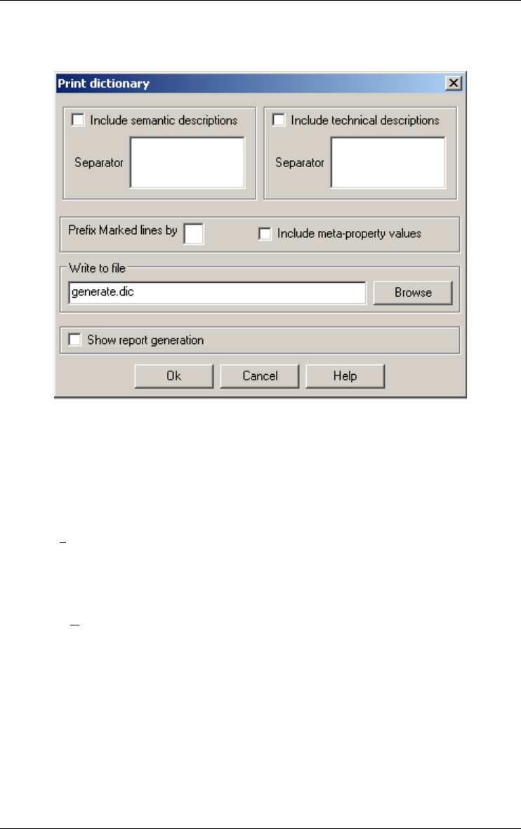
100 11 • The File menu (File)
22 juin 2009
and the report can be included in the current process (Show report genera-
tion).
Comment
Other generators can be developed and integrated into the DB-MAIN tool as
uIf the built-in report generators do not fit yours needs, you can develop
your own customized generator as a java plug-in. A DocBook generator is
available into the "plugins\docbook" directory (see Section 9.2.3).
11.7.2 Print...
Sends the content of the current process, schema or source file window
(textual or graphical views) to the selected printer.
11.7.3 Printer setup...
Selects and configures the default printer through the standard Windows
box.
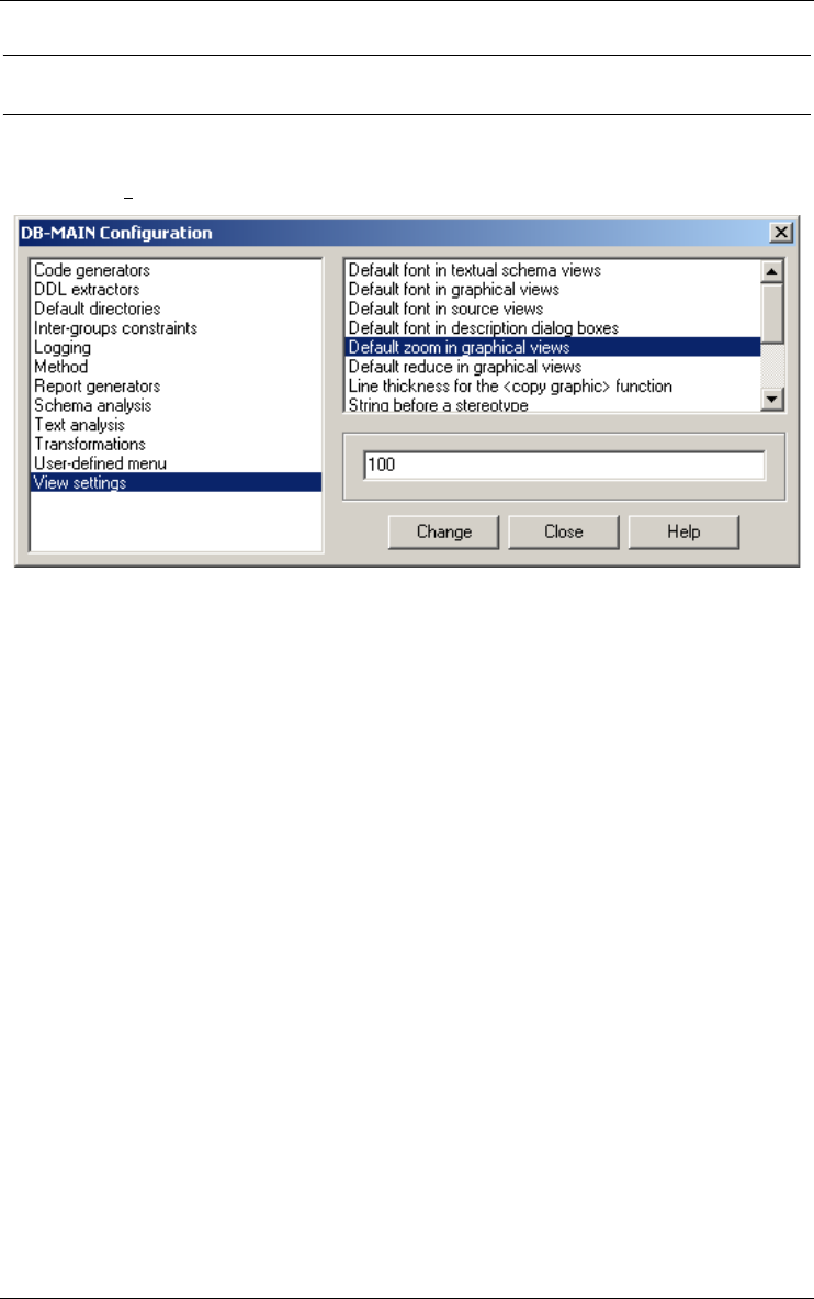
11 • The File menu (File) 101
22 juin 2009
11.8 Configuring the DB-MAIN environment
11.8.1 Configuration...
This command calls for the configuration processor that allows you to set
some general DB-MAIN options. These settings are (transparently) stored in
the file DB-MAIN.INI, located in the user’s directory (application data
directory on Windows or home directory on Linux). The following parame-
ters can be specified:
•Code generators
•(SQL) Separate constraints for tables: to specify if primary key and
unique constraints must be generated in the constraints section or in
tables;
•DDL extractors
•All files in the same schema: when several source files are processed, to
tell the extractor to store the specifications in the same schema or in sepa-
rate schemas;
•(SQL) Columns are ’NULL" by default: to specify the standard SQL
interpretation of columns with unspecified null/not null clause (e.g.,
Oracle vs Sybase);
•(SQL) Views are in the same schema as the tables: when processing
SQL DDL code, to instruct the extractor to store the data structures of the
views in the same schema as the global schema, or to store them in a sepa-
rate schema;

102 11 • The File menu (File)
22 juin 2009
•Default directories
•Project default directory: to specify the default directory when opening a
project (*.lun);
•Plug-in default directory: to specify the default directory when executing
a Java or Voyager plug-in (*.class or *.oxo);
•Pattern default directory: to specify the default directory when loading a
text pattern for text analysis (*.pdl);
•Extraction default directory: to specify the default directory when
running an extractor;
•Generation default directory: to specify the default directory when
generating a DDL text;
•Inter-group constraints
•Verify matching groups for referential and inclusion
constraints: when defining a foreign key or an inclusion constraint, to tell
whether strict inter-group compatibility must be ensured or not;
•Logging
•Trace off by default: to specify whether the history recorded is deacti-
vated or not;
•Log only the replay information: to specify whether a concise form of
history will be recorded; this form is sufficient to replay a history, but is
insufficient to undo some actions;
•Method
•Colour for unused process types (R,G,B): chooses the color for the
unused process types in a method;
•Colour for used process types (R,G,B): chooses the color for the used
process types in a method;
•Colour for allowed process types (R,G,B): chooses the color for the
allowed process types in a method;
•Colour for the types of the currently executing processes
(R,G,B): chooses the color for the types of the currently executing
processes in a method;
•Paint background for unused process types: the background of the
unused process types should be in the same color as the border or remain
white;
•Paint background for used process types: the background color of the
used process types should be in the same color as the border or remain
white;

11 • The File menu (File) 103
22 juin 2009
•Paint background for allowed process types: the background color of
the allowed process types should be in the same color as the border or
remain white;
•Paint background for the types of the currently executing
processes: the background color of the types of the currently executing
processes should be in the same color as the border or remain white;
•Schema analysis
•Library of rules: to specify the default library of rules for the Schema
analysis assistant (a *.anl file; default: default.anl)
•Text analysis
•The secondary file of patterns: in the Text Analysis assistant, to select
the secondary pattern file, which contains the definition of the basic, low-
level, patterns;
•The main file of patterns: in the Text Analysis assistant, to select the
primary pattern file, which contains the definition of the user-oriented,
high-level, patterns;
•The lines copied in the clipboard are prefixed by their number: if
checked, the lines of the source file are copied in the clipboard with their
line number
•Transformations
•Library of transformations: to specify the default directory when loading
a predefined library of global transformations (*.tfl) (Advanced Global
Transformations assistant);
•Technical identifier type (char or num): set the default type for technical
identifiers as created by the Add Tech ID transformation;
•Technical identifier length (integer >0): set the default length for tech-
nical identifiers as created by the Add Tech ID transformation;
•User-defined menu
To select the user-defined actions. For each user tools, define the entries by
chosen a title and the related action as a Java or Voyager program (through
the Browse button) or the menu item (through the Menu button). The Menu
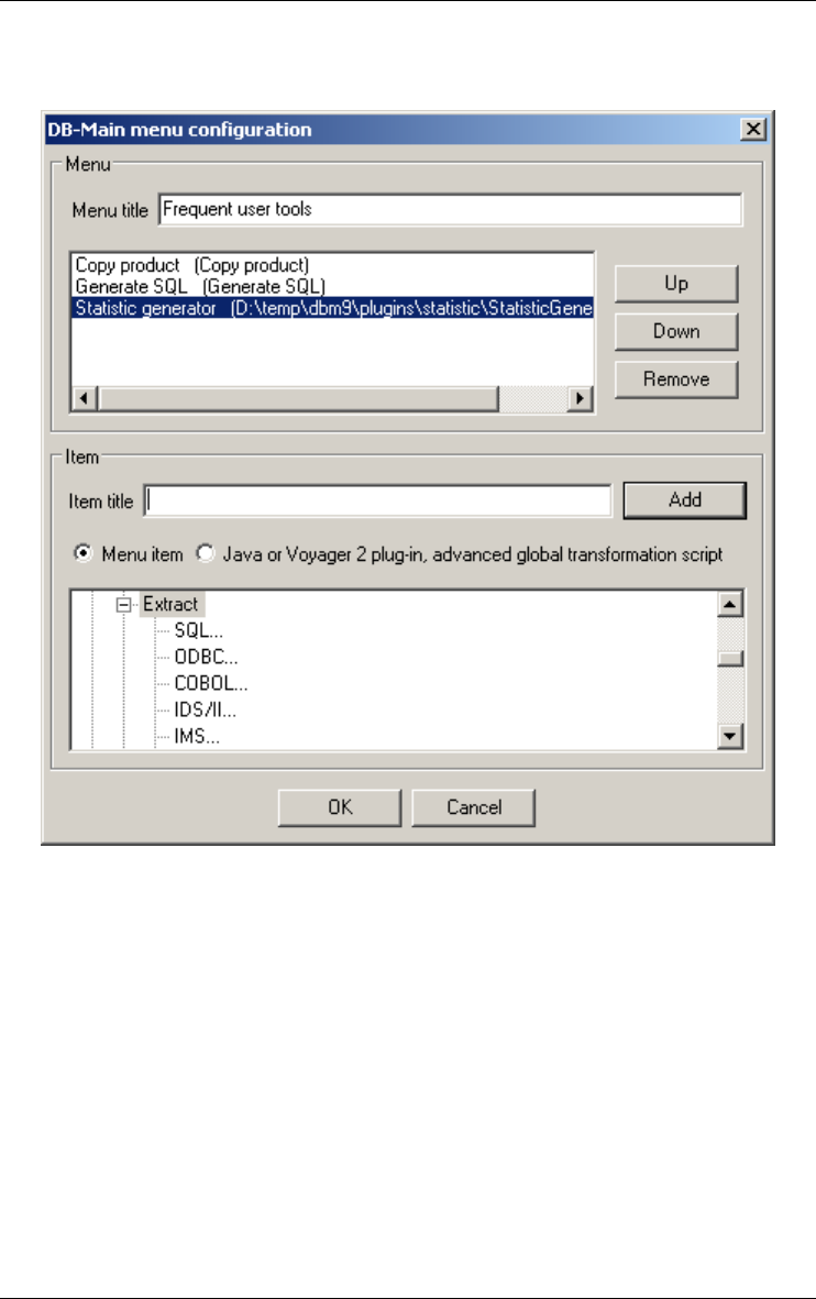
104 11 • The File menu (File)
22 juin 2009
button lists all the menus and toolbar shortcuts available in DB-Main. Select
the leaves of the menu tree.
•View settings
•The default font in textual schema view: chooses the default font for the
new textual schema view;
•The default font in graphical view: chooses the default font for the new
graphical view;
•The default font in source view: chooses the default font for the new
source view;
•The default font in description dialog boxes: chooses the default font
for editing descriptions (semantic, technical, notes,…);
•The default zoom in graphical views: to select the default zoom factor
for new schemas;
•The default reduce factor in graphical views: to select the default
reduce factor for new schemas;

11 • The File menu (File) 105
22 juin 2009
•The line thickness for the <Copy graphic> function: to define the line
thickness when copying schema objects on the clipboard through the Copy
graphic command;
•The string before a stereotype: to select the character string that appears
in front of a stereotype name in a schema; Alt+174 ("«") recommended
for UML schemas;
•The string after a stereotype: to select the character string that closes a
stereotype name in a schema; Alt+175 ("»") recommended for UML
schemas;
•The note color in graphical view: chooses the paint background color for
the note in graphical views;
•Maximum width of notes in graphical views (in centimeters): defines
the maximum width of notes when they are drawn. If a note contains lines
longer than this size, these lines are wrapped to next line;
•Minimum entity type width in graphical views (in centimeters): defines
a minimum width for entity types when they are drawn. An entity type that
should normally be smaller is enlarged with white space.
11.9 Opening a recently used project
11.9.1 Recent projects
Opens one of the ten most recently opened project files (*.lun, *.isl or
*.xml).
11.10Quitting DB-MAIN
11.10.1Exit
Exits from DB-MAIN. Saves the current project if needed.

106 11 • The File menu (File)
22 juin 2009

22 juin 2009
Chapter 12
The Edit menu (Edit)
This menu includes five sections through which the user can change or move
some components of a project:
1. preserve or restore the state of a schema;
2. copy and paste parts of a schema;
3. select, mark and color components of a project;
4. delete objects;
5. manage colors and fonts.
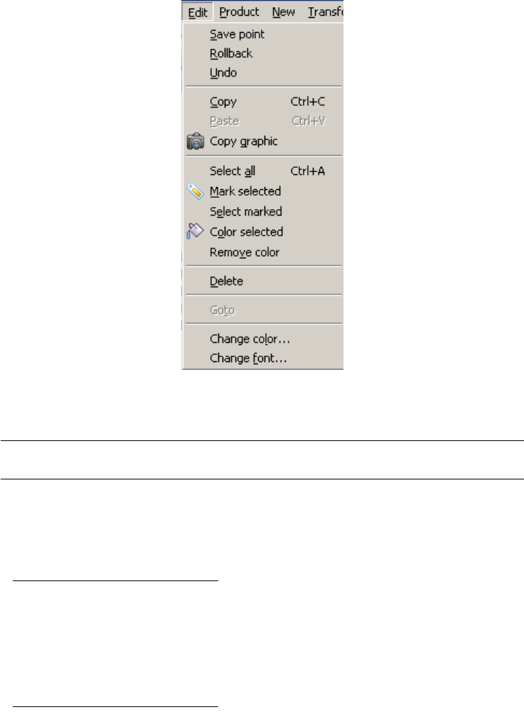
12.1 The commands of the Edit menu - Summary
Save point saves the state of the current schema.
Rollback restores the last saved state of the current schema.
Undo in a data schema view: undo the last action.
Copy <Ctrl>+C copies the selected objects to the clipboard.
Paste <Ctrl>+V pastes the contents of the clipboard in the current
schema.
Copy graphic copies the selected objects to the clipboard as vector
objects.
Select all <Ctrl>+A selects all the objects in the current window.
Mark selected marks the selected objects.

12 • The Edit menu (Edit) 109
22 juin 2009
Select marked selects the marked objects.
Color selected paints the selected objects with the default color.
Remove color paints in black all the selected objects.
Delete <Del> deletes the selected object.
Goto highlights the object state of the selected object and
conversely.
Change color... changes the default color.
Change font... changes the default font.
12.2 Preserving and restoring the state of a schema
12.2.1 Save point
In a data schema view: saves a copy of the current schema.
12.2.2 Rollback
In a data schema view: restores the last copy of the current schema (the
current version is lost).
12.2.3 Undo
In a data schema view: undo the last action. Not yet implemented.
12.3 Copying/pasting parts of a schema
12.3.1 Copy <Ctrl>+C
In a schema view: copies the selected objects to the clipboard; they can then
be pasted in any schema of the same project. It can be used to quickly define

110 12 • The Edit menu (Edit)
22 juin 2009
similar attributes, processing units, groups, entity types, rel-types or sub-
schemas, in the same schema, or in different schemas.
In a source file view: copies the selected lines to the clipboard.
12.3.2 Paste <Ctrl>+V
In a schema view: pastes the contents of the clipboard to the current schema.
12.3.3 Copy graphic
In any graphical window (project, process or schema): copies the selected
objects to the clipboard as graphical objects to be included in another docu-
ment (e.g. Word, OpenOffice). Useful to document reports. Also available
through the button on the graphical tool bar.
12.4 Selecting, marking, coloring
12.4.1 Select all <Ctrl>+A
In any graphical view: selects all the objects of the current schema, project
or process.
12.4.2 Mark selected <Ctrl>+M
In any view: marks all the selected objects of the current schema, project,
process or source file. Also available through the button on the standard
tool bar.
12.4.3 Select marked
In any view: selects all the marked objects of the current schema, project,
process or source file.
12.4.4 Color selected
In any view: colors all the selected objects of the current schema, project,
process or source file. Also available through the button on the standard
tool bar.
12.4.5 Remove color
In any view: colors in black all the selected objects of the current schema,
project, process or source file.

12 • The Edit menu (Edit) 111
22 juin 2009
12.5 Deleting objects
12.5.1 Delete <Del>
Deletes the selected object (in processes or projects: schema, text file and
process; in data schemas: schema, entity type, rel-type, attribute, group,
collection, constraint and processing unit, in processing schemas: action
state, decision state, initial state, final state, synchronization bar, signal
sending, signal receipt, internal object, state, object flow, control flow, use
case, extend, include, use generalization, actor, association, actor generaliza-
tion; in all windows: note).
Deleting a text file only removes its reference from the project or process
12.6 Goto between objects
12.6.1 Goto...
From a data schema, highligths the corresponding object state in its activity
diagram.
From an activity diagram, highligths the corresponding object in its data
schema.
12.7 Managing colors and fonts
12.7.1 Change color...
In any textual or graphical view of a schema, in the window of a project or a
process and in any text file: changes the color used to color the selected
objects.
12.7.2 Change font...
In any textual or graphical view of a schema, in the window of a project or a
process and in any text file: changes the font and character size. It can be
used to shrink a large schema on the screen or in a document.

112 12 • The Edit menu (Edit)
22 juin 2009
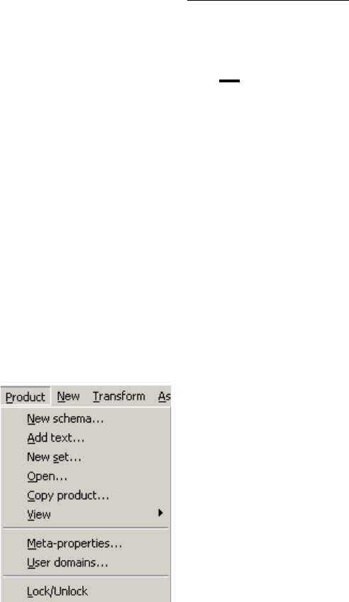
22 juin 2009
Chapter 13
The Product menu (Product)
Functions related to the manipulation of the products of the current project. A
product is any document used or produced in the current project, and which is
under the control of the tool. Currently, the products comprise the schemas, the
views, the source text files, and the generated files (e.g. SQL scripts). The
products and their relationships are presented in the project window or in a
process window. This menu includes three sections through which the user can
manage products:
1. managing products: creating, opening, examining their properties, copying
and managing views;
2. managing meta-properties and user-defined domains;
3. locking products.

13.1 The commands of the Product menu - Summary
New schema... creates a new data or processing schema
Add text... adds an existing external file to the project or a process
New set... creates a new product set
Open... opens the product (schema or text file) selected in the
project windows
Copy product... generates a new schema or text with the same contents
as the current one
View defines, generates, marks, removes, copies or renames a
view
Meta-properties modifies / examines the meta-properties of the meta-
objets in the repository (a.k.a. the meta-schema)
User-domains... adds / deletes / examines / modifies user-defined domains
Lock/Unlock puts or removes the lock on a product
13.2 Managing products
13.2.1 New schema...
In a project or process view: creates a new data or processing schema
13.2.2 Add text...
In a project or process view: adds an existing external file to the project or a
process; can be used, e.g., to extract a logical schema; equivalent to
drag&drop.
13.2.3 New set...
In a project or process view: creates a new product set.
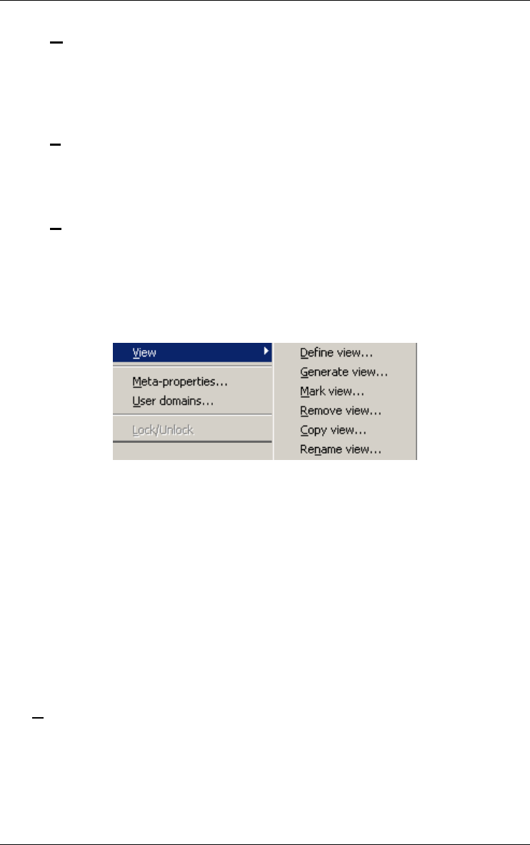
13 • The Product menu (Product) 115
22 juin 2009
13.2.4 Open...
Opens the product (schema or text file) selected in the project or process
windows. Same as double-clicking on the product icon in the project or
process window.
13.2.5 Properties...
In a project or process view: examines/modifies the properties of the
selected product.
13.2.6 Copy product...
Generates a new schema, text or set with the same contents as the current
one. Can be asked from the project or process window, or from the current
schema window
13.2.7 View
A view schema (or simply view) is a schema that derives from another
source schema S and that includes a subset of the constructs of S. The
components of a view can be renamed, transformed and moved in the graph-
ical space, but no object can be added or deleted. Any update in the source
schema S can be propagated down to the views that have been derived from
it. A view can be derived from another view.
In the data and processing schema, the objets have a dynamic property
giving the list of view in which they take part. An attribute is in a view if its
parent is in the view. A group is in a view if all its components are in the
view. A role is in a view if its relationship type and all its entity types are in
the view. A relation is in a view if the related objects are in the view.
The view management functions are:
Define view...
Defines a view comprising the marked objects of the current schema.
The list of the existing views is displayed, give the name of the new
one. All the marked objects are now into this new view. The view itself
is not yet represented by a schema. To represent it as a schema you
must generate it.

116 13 • The Product menu (Product)
22 juin 2009
Generate view...
Generates a view defined on the current schema. The list of the views
defined on the current schema appears. Select a view. If Include
attributes is checked, the sub-attributes of the objects of the view are
also copied otherwise only the attributes defined as belonging to the
view are copied. If Include processing units is checked in a data
schema, the processing units of the objects of the view are also copied,
otherwise only the processing units defined as belonging to the view
are copied. If Include relations is checked in a processing schema, the
relations of the objects of the view are also copied, otherwise only the
relations defined as belonging to the view are copied. An object
attribute is copied only if the referenced object is copied. The roles are
copied into the view only if all their entity types and their rel-type are
also copied. A group is copied into the view only if all its components
are also copied. In a processing schema, the relations are copied into
the view only if all their related objects are also copied.
If it is the first time that the view is generated then the view is only the
copy of the objects that are marked as be part of the view. If the view
already exists, its log is replayed on the generated view.
Mark view...
Marks the objects belonging to a view of the current schema.
Remove view...
Deletes a view defined on the current schema.
Copy view...
Copies a view defined on the current schema.
Rename view...
Renames a view defined on the current schema.
13.3 Managing meta-objects and user-defined domains
13.3.1 Meta-properties...
Modifies or examines the meta-properties of the meta-objects in the reposi-
tory (a.k.a. the meta-schema).
Properties...
Adds, deletes, modifies or examines meta-properties. A meta-property
is a dynamic property that is attached to a meta-object. The user can
add properties to the meta-objects. The existing meta-objects are actor,
actor generalization, association, atomic and compound attribute,

13 • The Product menu (Product) 117
22 juin 2009
collection, entity type, group, in-out (object flow), processing unit
(processing unit, action state, final state, initial state, synchronization
bar, decision state, signal sending or receipt and use case), processing
unit relation (control flow, extend, include, use case generalization),
product set, project, rel-type, role, schema, state and text. These meta-
objects are the objects of the DB-Main repository and they exist in all
the projects. The functions of a meta-property are: system (meta-prop-
erties existing in all the projects and of which the values cannot be
updated), updatable (the value of the meta-property can be updated),
multivalued (the meta-property can have several values) and
predefined values (the values of the meta-property are predefined).
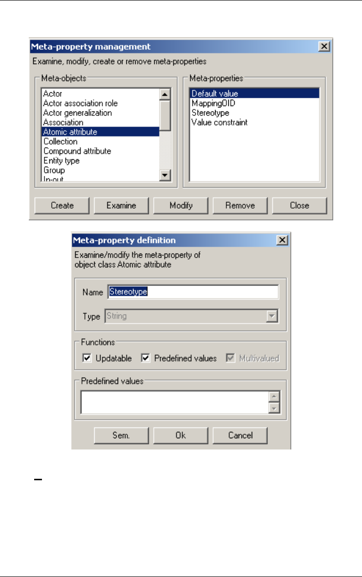
118 13 • The Product menu (Product)
22 juin 2009
13.3.2 User-domains...
The user can add, remove, modify user-defined domains or generate a
report. A user-defined domain is atomic or compound, it can be associated
with several attributes (choose user-defined type and the user-defined
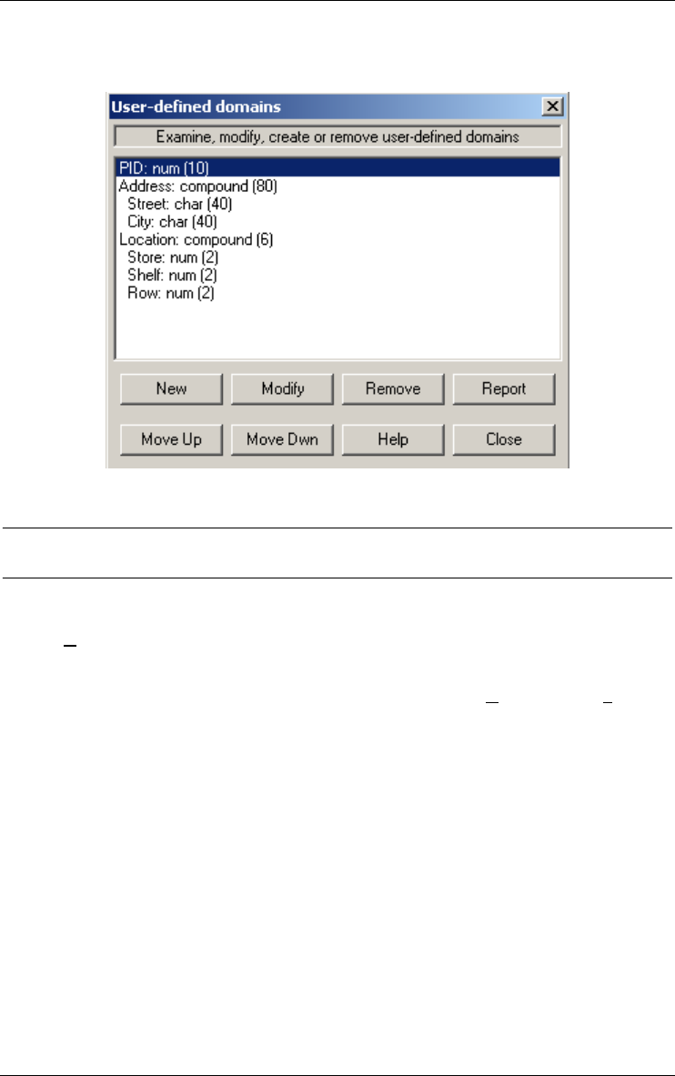
13 • The Product menu (Product) 119
22 juin 2009
domain in the attribute properties dialog box). A user-defined domain is
defined for the current project.
13.4 Locking products
13.4.1 Lock/Unlock
Puts or removes the lock on a product (when a product is locked, no change
can be made). This option is available when the Engineering/Control is
checked.

120 13 • The Product menu (Product)
22 juin 2009

22 juin 2009
Chapter 14-
The New menu (New)
This menu includes three sections through which the user can add new objects
to the current schema:
1. adding new objects to a data schema (ER and UML class diagram);
2. adding new objects to an activity processing schema (UML activity diagram);
3. adding new objects to a use case processing schema (UML use case diagram);
4. adding notes to a project or schema.
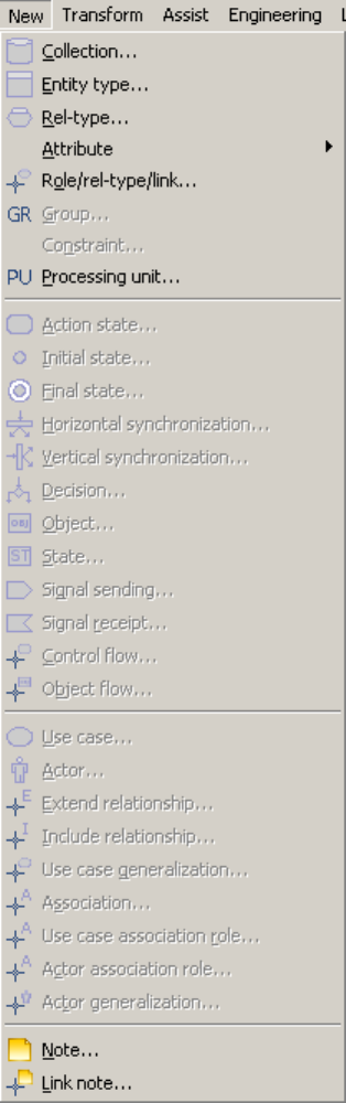

14 • The New menu (New) 123
22 juin 2009
14.1 The commands of the New menu - Summary
Collection... in a data schema: creates a new collection
Entity type... in a data schema: creates a new entity type
Rel-type... in a data schema: creates a new relationship type
Attribute in a data schema: adds a new attribute
Role... in a data schema: adds a new role to the selected relation-
ship type
Group... in a data schema: adds a new group containing the
selected objects
Constraint... in a data schema: adds a new constraint involving the
selected group
Processing unit... in a data schema: adds a new processing unit to a parent
Action state... in an activity schema: adds a new action state to the
schema
Initial state... in an activity schema: adds a new initial state to the
schema
Final state... in an activity schema: adds a new final state to the
schema
Horizontal synchronization...
in an activity schema: adds a new horizontal synchroniza-
tion bar to the schema
Vertical synchronization...
in an activity schema: adds a new vertical synchronization
bar to the schema
Decision... in an activity schema: adds a new decision state to the
schema
Object... in an activity schema: adds a new internal object to a
parent
State... in an activity schema: adds a new object state to a
schema
Signal sending... in an activity schema: adds a new signal sending to a
schema
Signal receipt... in an activity schema: adds a new signal receipt to a
schema
Control flow... in an activity schema: adds a new control flow between
two processing units
Object flow... in an activity schema: adds a new object flow between a
processing unit and an internal or external object

124 14 • The New menu (New)
22 juin 2009
Use case... in a use case schema: adds a new use case to the
schema
Actor... in a use case schema: adds a new actor to the schema
Extend relationship... in a use case schema: adds a new extend relationship
between two use cases
Include relationship... in a use case schema: adds a new extend relationship
between two use cases
Use case generalization...
in a use case schema: adds a new generalization between
two use cases
Association... in a use case schema: adds a new association
Use case association role...
in a use case schema: adds a new association role
between a use case and an association
Actor association role...
in a use case schema: adds a new association role
between an actor and association
Actor generalization... in a use case schema: adds a new generalization
between two actors
Note... adds a new note to a selected parent
Link note... adds a new link between a note and an object
14.2 Adding new objects to a data schema
14.2.1 Collection...
Creates a new collection in a data schema view. Also available through the
button on the standard tool bar.
In the textual views, a collection is created. In the graphical views, the cursor
changes into the object icon and the collection is created where the mouse
points when its left button is pressed. The properties can be changed in the
property box.
14.2.2 Entity type...
Creates a new entity type (interactively or from the current source text) in a
data schema. Also available through the button on the standard tool bar.
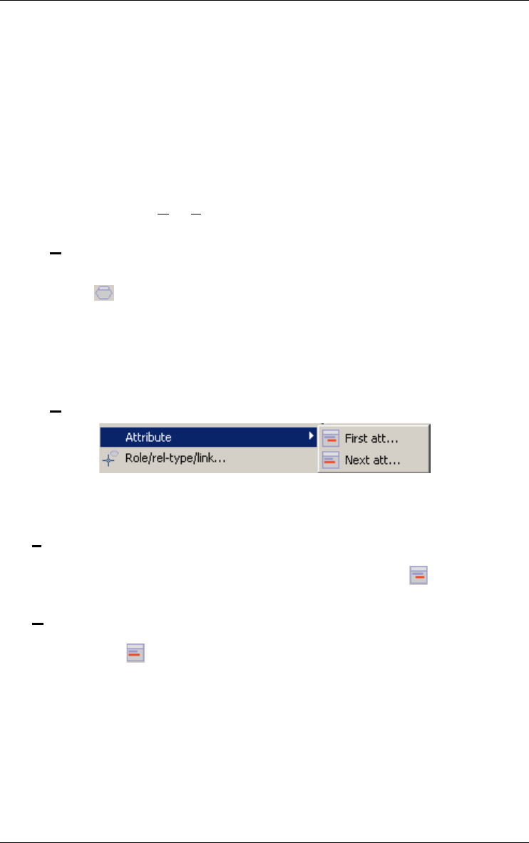
14 • The New menu (New) 125
22 juin 2009
In the textual views, an new entity-type is created. In the graphical views,
the cursor changes into the object icon and the entity type is created where
the mouse points when its left button is pressed. The properties can be
changed in the property box.
This function can be used to create objects from COBOL statements as
follows:
a source text and its corresponding logical data schema are opened;
select a data definition statement in the COBOL text (generally a "01"
record definition);
execute the New/Entity type command.
14.2.3 Rel-type...
Creates a new relationship type in a data schema. Also available through the
button on the standard tool bar.
In the textual views, a relationship type is created. In the graphical views, the
cursor changes into the object icon and the rel-type is created where the
mouse points when its left button is pressed. The properties can be changed
in the property box.
14.2.4 Attribute
Adds a new attribute (interactively or from the current source text) in a data
schema.
First att...
... as first child (of the selected parent object: entity type, relationship
type or attribute). Also available through the button on the standard
tool bar.
Next att...
... as next sibling (of the selected attribute). Also available through the
button on the standard tool bar.
An attribute is created and its properties can be changed in the property box.
This function can be used to create objects from COBOL statements as
follows:
a source text and its corresponding logical data schema are opened;
select the parent object (entity type, rel-type, attribute) or the sibling
attribute in the data schema window;
select one or several field definition statements in the COBOL text;

126 14 • The New menu (New)
22 juin 2009
execute a New/Attribute/First or New/Attribute/Next command.
14.2.5 Role...
Adds a new role to the selected relationship type in a data schema. Also
available through the button on the standard tool bar.
In the textual views, the role is added to the current relationship-type. In the
graphical views, to create a role draw a line with the cross cursor from the
entity type to the rel-type, to create a rel-type draw a line between the two
entity types and to create a multi-ET role draw a line between a role and an
entity type. The role properties can be changed in the property box.
14.2.6 Group...
Adds a new group (primary/secondary id, access key, coexistence, referen-
tial,...) to the selected object (entity type, relationship type or compound
multivalued attribute) in a data schema.
A group containing the selected attributes and/or roles is created. Also avail-
able through the button on the standard tool bar. To create an identifier
with the selected attributes and/or roles, click on the button in the stan-
dard tool bar. The properties can be changed in the property box.
14.2.7 Constraint...
Adds a new constraint involving the selected group in a data schema.
The corresponding dialogue box appears and the properties can be changed.
14.2.8 Processing unit...
Adds a new processing unit to the selected parent (entity type, relationship
type or schema) or as next sibling (of the selected processing unit) in a data
schema. The properties can be changed in the property box.
Also available through the button on the standard tool bar.
14.3 Adding new objects to an activity schema
14.3.1 Action state...
Adds a new action state to an activity schema. In the textual views, an action
state is created. In the graphical views, the cursor changes into the object
icon and the action state is created where the mouse points when its left
button is pressed. The properties can be changed in the property box.

14 • The New menu (New) 127
22 juin 2009
Also available through the button on the standard tool bar.
14.3.2 Initial state...
Adds a new initial state to an activity schema. In the textual views, an initial
state is created. In the graphical views, the cursor changes into the object
icon and the initial state is created where the mouse points when its left
button is pressed. The properties can be changed in the property box.
Also available through the button on the standard tool bar.
14.3.3 Final state...
Adds a new final state to an activity schema. In the textual views, a final
state is created. In the graphical views, the cursor changes into the object
icon and the final state is created where the mouse points when its left button
is pressed. The properties can be changed in the property box.
Also available through the button on the standard tool bar.
14.3.4 Horizontal synchronisation...
Adds a new horizontal synchronization bar to an activity schema. In the
textual views, an horizontal synchronisation is created. In the graphical
views, the cursor changes into the object icon and the horizontal synchroni-
zation bar is created where the mouse points when its left button is pressed.
The properties can be changed in the property box.
Also available through the button on the standard tool bar.
14.3.5 Vertical synchronisation...
Adds a new vertical synchronization bar to an activity schema. In the textual
views, an vertical synchronisation is created. In the graphical views, the
cursor changes into the object icon and the vertical synchronization bar is
created where the mouse points when its left button is pressed. The proper-
ties can be changed in the property box.
Also available through the button on the standard tool bar.
14.3.6 Decision...
Adds a new decision state to an activity schema. In the textual views, a deci-
sion is created. In the graphical views, the cursor changes into the object
icon and the decision state is created where the mouse points when its left
button is pressed. The properties can be changed in the property box.
Also available through the button on the standard tool bar.

128 14 • The New menu (New)
22 juin 2009
14.3.7 Object...
Adds a new internal object to the selected parent (schema or internal object)
or as next sibling (of the selected internal object) in an activity schema. Also
available through the button on the standard tool bar.
In the textual views, an object is created. In the graphical views, the cursor
changes into the object icon and the internal object is created where the
mouse points when its left button is pressed. The properties can be changed
in the property box.
14.3.8 State...
Adds a new state to the selected object (external or first level internal object)
in an activity schema. Also available through the button on the standard
tool bar.
In the textual views, a state of the current object is created. In the graphical
views, the cursor changes into the state icon and the object state is created
where the mouse points when its left button is pressed. The properties can be
changed in the property box.
14.3.9 Signal sending...
Adds a new signal sending to an activity schema. In the textual views, a
signal sending is created. In the graphical views, the cursor changes into the
object icon and the signal sending is created where the mouse points when
its left button is pressed. The properties can be changed in the property box.
Also available through the button on the standard tool bar.
14.3.10Signal receipt...
Adds a new signal receipt to an activity schema. In the textual views, a
signal receipt is created. In the graphical views, the cursor changes into the
object icon and the signal receipt is created where the mouse points when its
left button is pressed. The properties can be changed in the property box.
Also available through the button on the standard tool bar.
14.3.11Control flow...
Adds a new relation between two processing units in an activity schema.
Also available through the button on the standard tool bar.
Not available in the textual views. In the graphical views, draw a line with
the cross cursor between two processing units. The properties can be
changed in the property box. The properties can be changed in the property
box.

14 • The New menu (New) 129
22 juin 2009
14.3.12Object flow...
Adds a new relation between a processing unit and an internal or external
(entity type, relationship type, attribute or collection of a data schema) object
in an activity schema. Also available through the button on the standard
tool bar.
Not available in the textual views. In the graphical views, draw a line with
the cross cursor between a processing unit and an internal or external object.
The properties can be changed in the property box.
14.4 Adding new objects to an use case schema
14.4.1 Use case...
Adds a new use case to an use case schema. In the textual views, an use case
is created. In the graphical views, the cursor changes into the object icon and
the use case is created where the mouse points when its left button is pressed.
The properties can be changed in the property box.
Also available through the button on the standard tool bar.
14.4.2 Actor...
Adds a new actor to an use case schema. In the textual views, an actor is
created. In the graphical views, the cursor changes into the object icon and
the actor is created where the mouse points when its left button is pressed.
The properties can be changed in the property box.
Also available through the button on the standard tool bar.
14.4.3 Extend relationship...
Adds a new extend relation between two processing units in an use case
schema. Also available through the button on the standard tool bar.
Not available in the textual views. In the graphical views, draw a line with
the cross cursor between two processing units. The properties can be
changed in the property box.
14.4.4 Include relationship...
Adds a new include relation between two processing units in an use case
schema. Also available through the button on the standard tool bar.

130 14 • The New menu (New)
22 juin 2009
Not available in the textual views. In the graphical views, draw a line with
the cross cursor between two processing units. The properties can be
changed in the property box.
14.4.5 Use case generalization...
Adds a new generalization relation between two processing units in an use
case schema. Also available through the button on the standard tool bar.
Not available in the textual views. In the graphical views, draw a line with
the cross cursor between two processing units. The properties can be
changed in the property box.
14.4.6 Association...
Adds a new association between a use case (processing unit) and an actor in
an use case schema. Also available through the button on the standard
tool bar.
In the graphical views, draw a line with the cross cursor between a use case
and an actor. In the textual views, create a new association without role. The
properties can be changed in the property box.
14.4.7 Use case association role...
Adds a new association role between a use case (processing unit) and an
association in an use case schema. Also available through the button on
the standard tool bar.
In the graphical views, draw a line with the cross cursor between a use case
and an association. In the textual views, add a new use case association role
to the selected association. The properties can be changed in the property
box.
14.4.8 Actor association role...
Adds a new association role between an actor and an association in an use
case schema. Also available through the button on the standard tool bar.
In the graphical views, draw a line with the cross cursor between an actor
and an association. In the textual views, add a new actor association role to
the selected association. The properties can be changed in the property box.
14.4.9 Actor generalization...
Adds a new generalization relation between two actors in an use case
schema. Also available through the button on the standard tool bar.

14 • The New menu (New) 131
22 juin 2009
Not available in the textual views. In the graphical views, draw a line with
the cross cursor between two actors. The properties can be changed in the
property box.
14.5 Adding notes to a schema
14.5.1 Note...
Adds a new note to the selected object in a schema. Also available through
the button on the standard tool bar.
In the textual views, the note is be added. In the graphical views, the mouse
cursor changes and the note is created where the mouse points when its
button is pressed. The note text can be changed in the property box.
If the current object is not a schema, the note is linked to this object. Other-
wise the note belongs to the schema.
14.5.2 Link note...
Adds a new link between a note and another object in a schema. Also avail-
able through the button on the standard tool bar.
Not available in the textual views. In the graphical views, draw a line with
the cross cursor between a note and another object.

132 14 • The New menu (New)
22 juin 2009
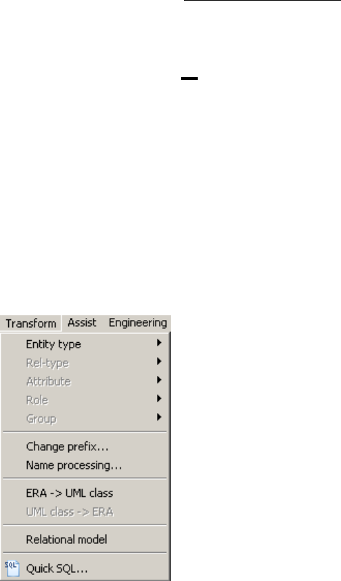
22 juin 2009
Chapter 15
The Transform menu (Transform)
This menu includes four sections through which the user can carry out trans-
formations on the selected object of a data schema:
1. transforming entity types, rel-types, attributes, roles or groups;
2. processing names;
3. transforming an ER schema into UML class diagram (and conversely)
4. transforming into relational model;
5. generating SQL.

15.1 The commands of the Transform menu - Summary
Entity type transforms the selected entity type
Rel-type transforms the selected relationship type
Attribute transforms the selected attribute
Role transforms the selected role
Group transforms the selected group
Change prefix... detects the largest prefix of the components of the
selected object and proposes its replacement with a new
prefix (or absence thereof)
Name processing... processes the names and short names of objects in the
current schema
ERA -> UML class... transforms the current ERA schema into an UML class
schema
UML class -> ERA... transforms the current UML class schema into an ERA
schema
Relational model replaces (by applying ad hoc transformations) the current
schema by its relational logical version, carries out no opti-
mization
Quick SQL This function offers a quick, fast-food style and rather lazy
way to generate the executable code that implements the
data structures corresponding to the current (conceptual
or logical) schema.
15.2 Transforming entity types, rel-types, attributes, roles or
groups
Carries out transformations (most of them are semantic-preserving) on the
selected object of a data schema. This toolbox will be expanded according to
the needs of the different database engineering activities. The current func-
tions allows for, e.g.:
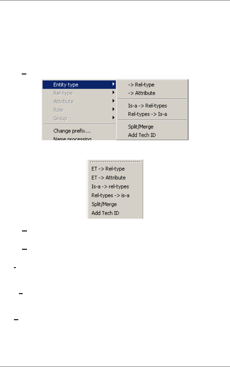
15 • The Transform menu (Transform) 135
22 juin 2009
•the production of relational, CODASYL, standard files, IMS, TOTAL/
IMAGE, (and the like) databases,
•optimization of database schemas,
•conceptual restructuring,
•reverse engineering.
15.2.1 Entity type
Also available through the buttons on the transformation tool bar.
-> Rel-type
Transforms the selected entity type into a relationship type.
-> Attribute
Transforms the selected entity type into an attribute.
Is-a -> Rel-type
Transforms the selected entity type (if it is a supertype) by replacing the
is-a relations into one-to-one rel-types.
Rel-type -> Is-a
Transforms the selected entity type E by replacing one-to-one rel-types
with is-a relations, therefore making E a super-type.
Split/Merge
Transforms the selected entity type E into two entity types linked by a
one-to-one rel-type, or by migrating attributes/processing units/roles/
is-a between E and another entity type, or by merging E with another
entity type.
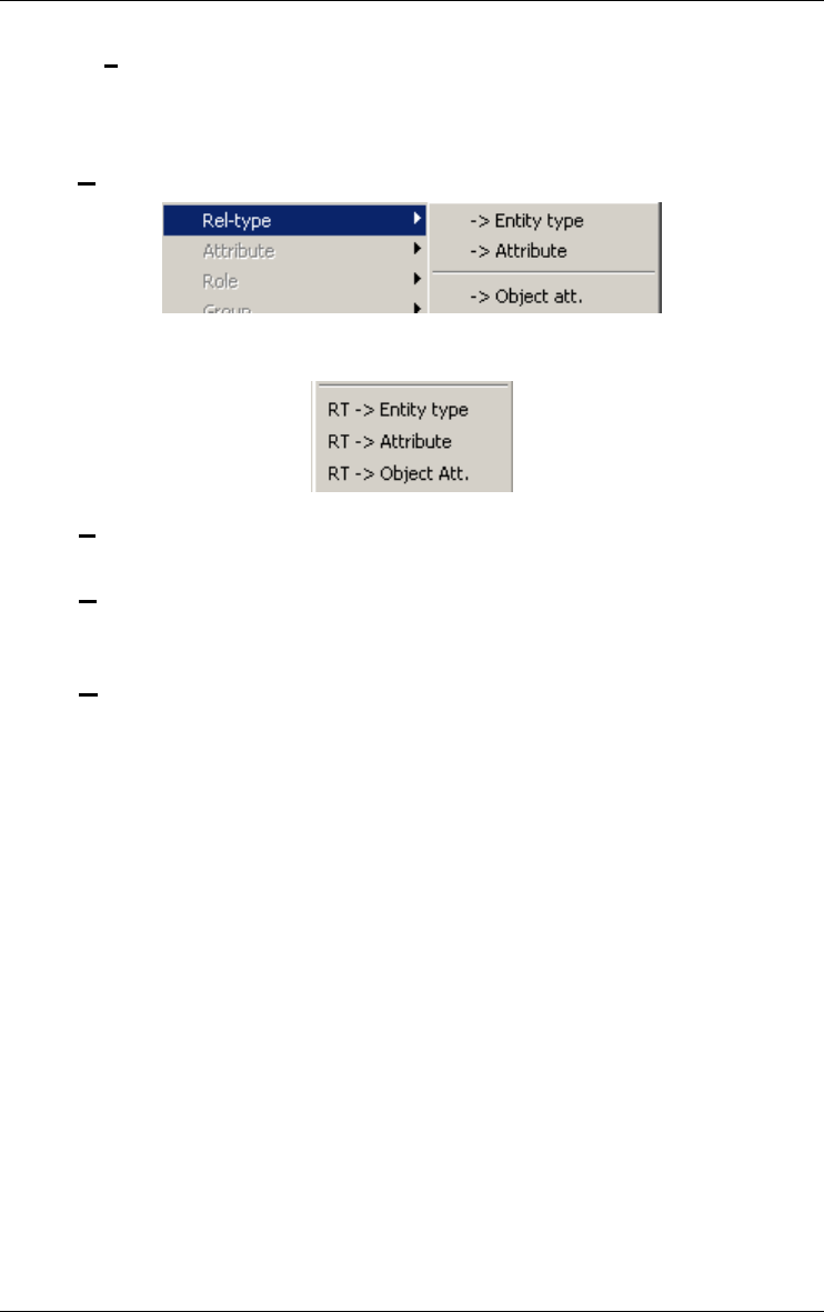
136 15 • The Transform menu (Transform)
22 juin 2009
Add Tech ID
Adds a technical primary identifier (replacing the current primary iden-
tifier, if any).
15.2.2 Rel-type
Also available through the buttons on the transformation tool bar.
-> Entity-type
Transforms the selected relationship type into an entity type.
-> Attribute
Transforms the selected relationship type into a reference attribute
(foreign key).
-> Object att.
Transforms the selected relationship type into an object-attribute (in
object-oriented schemas).
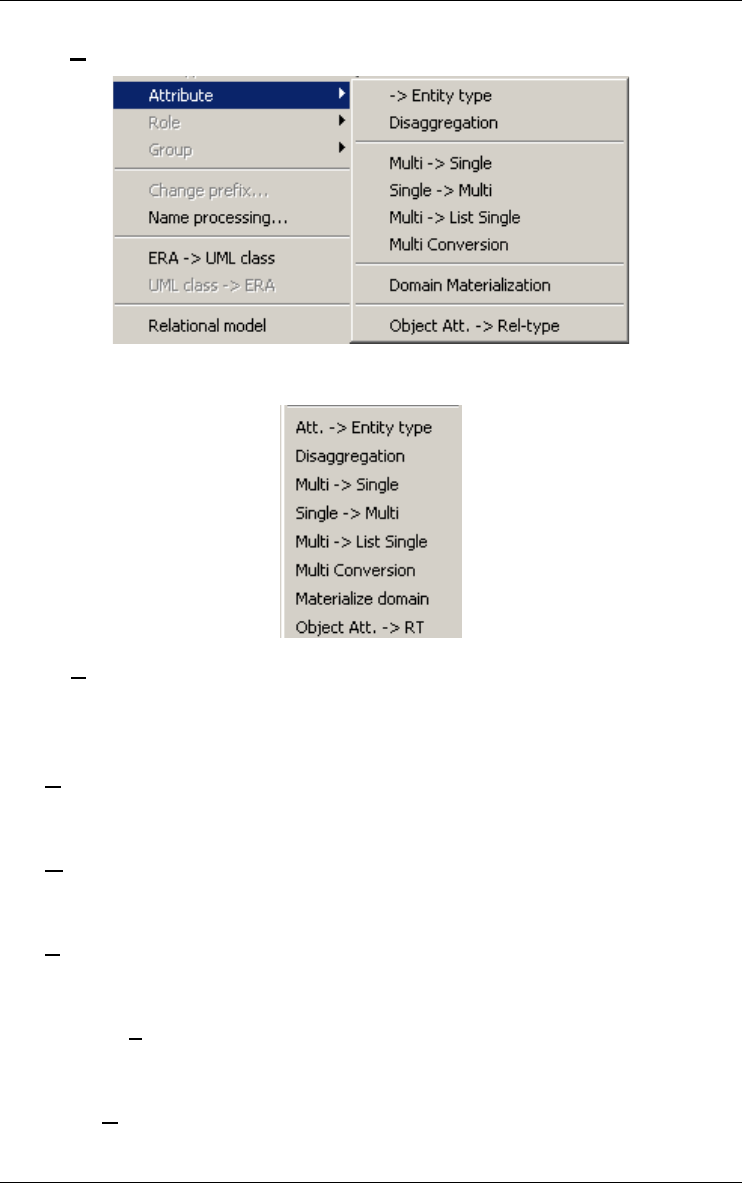
15 • The Transform menu (Transform) 137
22 juin 2009
15.2.3 Attribute
Also available through the buttons on the transformation tool bar.
-> Entity-type
Transforms the selected attribute into an entity type by representing the
possibly duplicate attribute instances (instance representation) or by
representing the distinct attribute values (value representation).
Disaggregation
Transforms the selected attribute, if compound, by replacing it with its
components.
Multi -> Single
Transforms the selected attribute, if multivalued, into a single-valued
attribute (= value concatenation).
Single -> Multi
Transforms the selected attribute, if single-valued, into a multivalued
attribute (= value slicing).
Multi -> List Single
Transforms the selected attribute, if multivalued, into a list of single-
valued attributes (= instantiation).
Multi Conversion
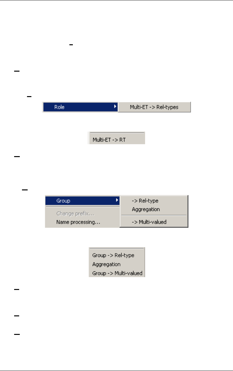
138 15 • The Transform menu (Transform)
22 juin 2009
Changes the collection type of the selected multivalued attribute (set,
bag, list, array, etc.); provides both semantics-preserving and seman-
tics-changing techniques.
Domain Materialization
Materializes the domain of the selected atomic attribute = replaces a
user-defined domain with its definition.
Object Att. -> Rel-type
Transforms the selected attribute, if object-type, into a rel-type.
15.2.4 Role
Also available through the buttons on the transformation tool bar.
Multi-ET -> Rel-types
Transforms the selected role, if multi-ET, into a series of similar rela-
tionship types.
15.2.5 Group
Also available through the buttons on the transformation tool bar.
Rel-type
Transforms the selected group, if referential (e.g. foreign key), into a
relationship type.
Aggregation
Transforms the selected group into a compound attribute.
Multi-valued
Transforms the selected group of single-valued attributes into a multi-
valued attribute (= de-instantiation).
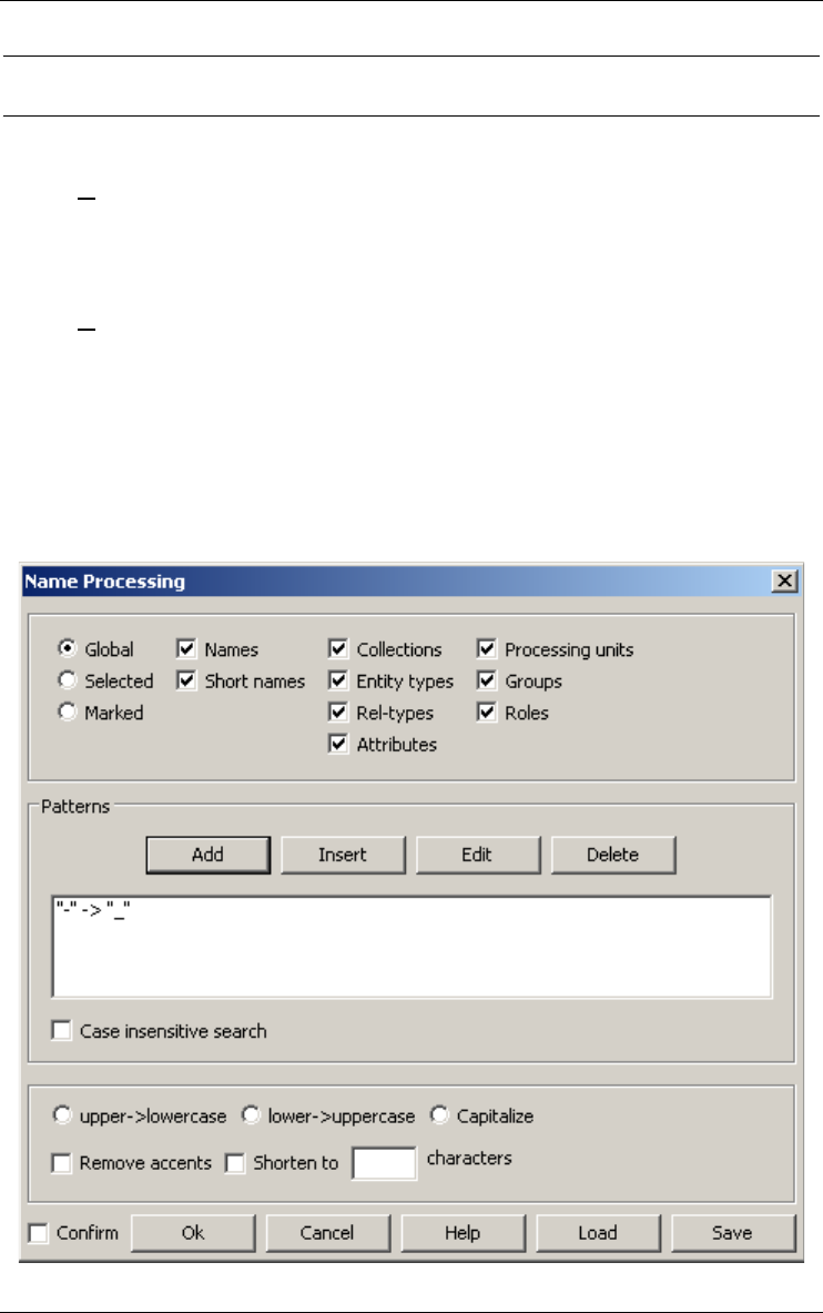
15 • The Transform menu (Transform) 139
22 juin 2009
15.3 Processing names
15.3.1 Change prefix...
Detects the largest prefix of the components of the selected object and
proposes its replacement with a new prefix (or absence thereof).
15.3.2 Name processing...
Processes the names and short names of objects in the current schema. The
scope of the process defines which objects (global, selected or marked) and
which names (depending on the kind of schema). The substitution patterns
are a list of "old string new string". Change case, capitalize, remove accents
and shorten names are additional specific transformations. The substitution
patterns can be save into files.

140 15 • The Transform menu (Transform)
22 juin 2009
15.4 Transforming an ERA schema into UML class diagram
(and conversely)
15.4.1 ERA -> UML class...
Transforms all rel-types with attributes or linked to more than two roles into
entity types. Removes the stereotypes <<agr>> and <<cmp>> on the binary
rel-types. The graphical view uses the UML notation.
15.4.2 UML class -> ERA...
Adds the stereotypes <<agr>> or <<cmp>> on the binary aggregation or
composition rel-types. The graphical view uses the ERA notation.
15.5 Transforming into relational model
15.5.1 Relational model
Replaces (by applying ad hoc transformations) the current schema by its
relational logical version.
15.6 Generating SQL
15.6.1 Quick SQL
This function offers a quick, fast-food style and rather lazy way to generate
the executable code that implements the data structures corresponding to
the current (conceptual or logical) schema. They result into correct, clear,
but unsophisticated DDL (SQL) programs. The schema do not have to be
DMS-compliant. This function has been included to comply with most
commercial modeling tools. Same result as by executing:
Product/Copy schema(product)...;
Transform/Relational model;
File/Generate/Standard SQL;
select schema;
Edit/Delete.
Also available through the button on the assistant tool bar.
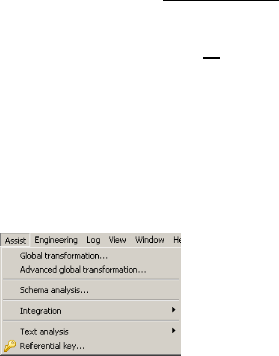
22 juin 2009
Chapter 16
The Assist menu (Assist)
This menu includes five sections through which the user can use expert assis-
tants dedicated to specific classes of problems:
1. transforming schema;
2. analyzing schema;
3. integrating objects;
4. analyzing text;
5. finding referential key.

16.1 The commands of the Assist menu - Summary
Global transformations...
carries out selected actions on selected objects in order to
solve structural problems
Advanced global transformations...
carries out selected actions on selected objects. It is a
sophisticated version of the Global Transformation Assis-
tant providing more flexibility and power in script develop-
ment.
Integration This assistant offers a set of tools for data schemas and
objects integration.
Text Analysis This assistant offers a set of tools for text analysis.
Referential key... This tool proposes some popular heuristics to find foreign
keys.
16.2 Transforming schema
16.2.1 Global transformations...
Carries out selected actions on selected objects in order to solve structural
problems. For each outstanding class of constructs (the problem), the assis-
tant proposes one or several transformations that replace them by equivalent
constructs (the solution). The assistant proposes other additional global
functions. In addition, the user can build (then save and reuse) customized
transformation scripts dedicated to specific complex problems.
a) The problem -> solution transformations
For each operation in the list below, we suggest some standard design
processes in which it can be most useful. The standard processes are coded
as follows:
CN: conceptual normalization;
RE: reverse engineering;
LD: logical design (DBMS-independent);
RLD: relational logical design;

16 • The Assist menu (Assist) 143
22 juin 2009
FLD: standard file logical design (e.g. COBOL);
CLD: CODASYL logical design;
OOD: OO-DBMS design;
OPT: optimization;
PD: physical design.
For each outstanding class of constructs, we have also added the actions
Mark and Unmark (except Group Names, Generate and Name processing).
These actions put or remove a mark on the constructs that belong to the
class.
Entity type: problems related to entity types
Rel. entity types -> Rel-types: the entity type seems to be the repre-
sentation of a relationship type (CN).
Att. entity types -> Attributes: the entity type seems to be the repre-
sentation of an attribute (CN).
Missing id. -> Add a technical id: the entity type will need an identi-
fier when rel-types are transformed into foreign keys (RLD).
Rel-type: problems related to relationship types
With attributes -> Entity types: relationship type with attributes not
allowed: replace with entity type (LD).
Complex -> Entity types: too complex relationship types (N-ary or
with attributes) not allowed: replace with entity type (LD).
Binary 1-1 -> Is-a: transform the one-to-one relationship type into a is-
a relation if it does not conflict with another one-to-one relationship
type (CN, RE).
Binary 1-N -> Referential attributes: each one-to-many relationship
type is replaced by reference attributes (RLD,FLD).
Binary N-N -> Entity types: many-to-many binary relationship type
not allowed: replace by an entity type (LD).
Binary w/o att. -> Object attributes: each binary relationship type
without attribute is replaced by an object-attributes (LD, OOD).
Cyclic -> Entity types: cyclic relationship types not allowed: replace
by entity types (CLD).
Cyclic 1-N -> Referential attributes: one-to-many cyclic relationship
types not allowed: replace with reference attributes (CLD).
Multi-ET roles -> Split rel-types: multi-ET roles not allowed: split
them (LD); if the rel-type contains more than one multi-ET roles, this
global transformation must be carried out as many times.
Is-a: problems related to IS-A relations
All -> Rel-types: each IS-A relation is replaced by a one-to-one rela-
tionship type (LD).

144 16 • The Assist menu (Assist)
22 juin 2009
Attributes: problems related to attributes
Compound -> Disaggregation: compound attributes not allowed:
replace by their components (RLD).
Compound -> Entity type: compound attributes not allowed: replace
by entity types (CN,LD).
Multivalued -> Entity types: multivalued attributes not allowed:
replace by entity types (instance repr.) (LD).
Object -> Rel-types: object-attributes not allowed: replace by relation-
ship types (RE).
User-defined -> Materialize: user-defined attributes are replaced by
their definition (LD).
Comp. att, 1 comp. -> Disaggregation: compound attributes with only
one component: disaggregate (LD).
Single comp. att., FK -> Disaggregation: single-valued compound
attributes with foreign key: disaggregate (RE).
Single comp. att., FK -> Entity-type: single-valued compound
attributes with foreign key: entity type (RE).
Multi. comp. att., FK -> Entity type: multi-valued compound
attribute with foreign key: replace by an entity type (RE).
Groups: problems related to groups
Referential -> Rel-types: each reference group (foreign key) is
replaced by a one-to-many rel- type (RE).
Id & ref w/o AK -> Make access key: an access key is associated with
each id or reference group (PD).
Id >1 comp. -> Add technical id: primary ids with more than 1
component are replaced by a technical id (OPT,PD).
Id >2 comp. -> Add technical id: primary ids with more than 2
components are replaced by a technical id (OPT,PD).
Id >3 comp. -> Add technical id: primary ids with more than 3
components are replaced by a technical id (OPT,PD).
Access keys -> Remove: remove access keys (RE).
Multi-att. identifiers -> Aggregate: makes a compound attribute with
multi-attribute id (FLD).
Multi-att. access keys -> Aggregate: makes a compound attribute
with multi-attribute access key (FLD).
Prefix access key -> Remove: removes each access key which is a
prefix of another access key (RLD,FLD).
Coexistence -> Aggregate: isolates the components of a coexistence
group (CN, LD).
Names -> Rename: renames the groups with unique standardized
names (PD) (Mark/Unmark not available)

16 • The Assist menu (Assist) 145
22 juin 2009
Miscellaneous: problems related to other objects
Technical descript. -> Remove: removes technical descriptions (RE).
Collections -> Remove: removes the collections (RE).
Generate:
generates executable DDL code for the current schema (must be compliant
with the DBMS).
Standard SQL: standard SQL-2 program;
InterBase: InterBase SQL program;
Academic SQL: simplified SQL program (with possible forward refer-
ences);
Standard SQL (check): standard SQL-2 program (with check predi-
cates);
InterBase (check): InterBase SQL program (with check predicates);
Academic SQL (check): simplified SQL program (with check predi-
cates);
COBOL: ENVIRONMENT DIVISION and DATA DIVISION;
CODASYL: CODASYL schema DDL program;
XML: XML (DTD) file.
Name processing:
processes the names of selected objects in the current schema (see section
[15.3.2]).
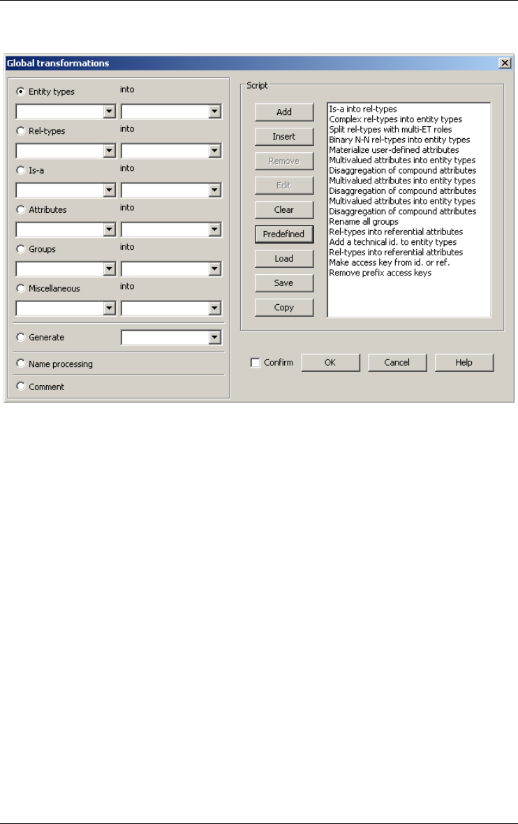
146 16 • The Assist menu (Assist)
22 juin 2009
b) The assistant box
A script is a sequence of operations chosen among those described above. It
implements simple transformation plans. The current script, if any, appears
in the Script window. A selected action can be added at the end of the current
script, inserted before the selected operation in the script or deleted from the
script. The selected Name processing operation can be edited in the script. A
previously saved script (file *.trf) can be loaded and the current script can be
copied in the clipboard. The user can clear the Script window and load a pre-
defined script. The following scripts are available:
•Binary: no is-a, no complex rel-types;
•Bachman: binary + no many-to-many, or cyclic rel-types;
•Flat binary: binary + single-valued, atomic attributes only;
•Flat Bachman: Bachman + single-valued, atomic attributes only;
•Relational rev. eng.: rebuilds a conceptual schema from a (simple)
relational logical schema;
•COBOL rev. eng.: rebuilds a conceptual schema from a (simple)
COBOL logical schema;
•Pseudo-relational: in most cases, generates an acceptable physical
relational schema from a conceptual one;
•Logical pseudo-relational: in most cases, generates an acceptable
logical relational schema from a conceptual one;
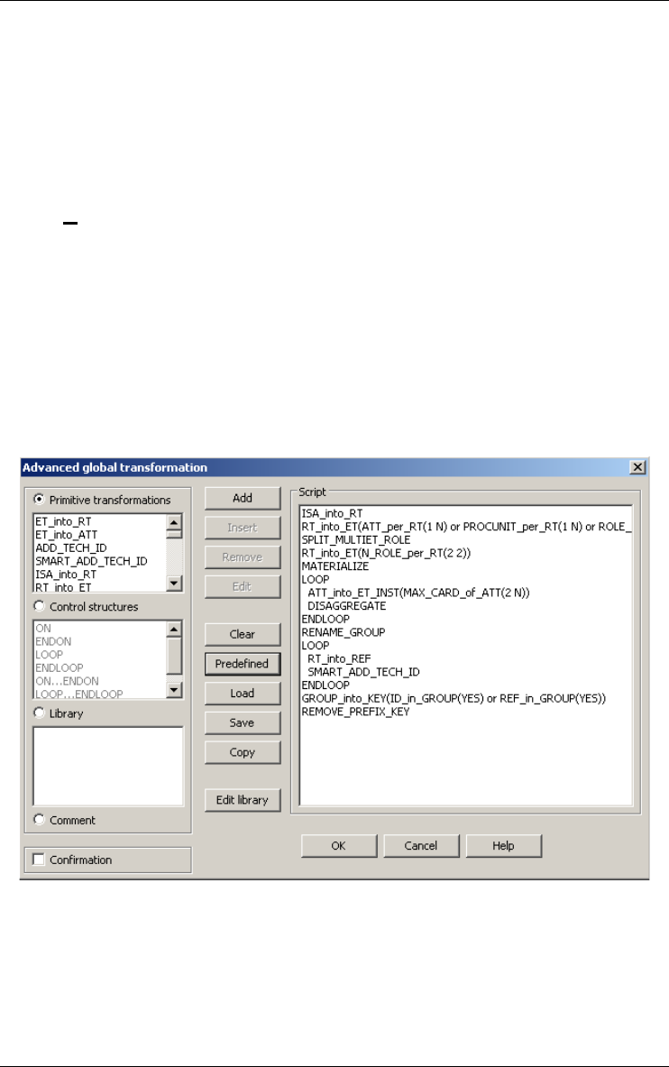
16 • The Assist menu (Assist) 147
22 juin 2009
•Physical pseudo-relational: in most cases, generates an acceptable
physical relational schema from a logical one;
•Pseudo-COBOL: in most cases, generates an acceptable logical
COBOL schema;
•Pseudo-IDS/II: in most cases, generates an acceptable logical IDS/II
schema.
16.2.2 Advanced global transformations...
This one is a sophisticated version of the Global Transformation Assistant
providing more flexibility and power in script development. A script
consists of transformations and control structures. A transformation has the
form A(P) where A is an action (transform, remove, mark, etc.) and P is a
predicate that select specific objects in the data schema. The meaning is
obvious: apply action A on each object that satisfies predicate P. The control
structures include scope restrictions and loops. A library of advanced global
transformations can be defined and reused in the definition of new ones.
a) Transformations
A transformation is designed to perform a given action on a set of objects. A
default set is defined for each transformation. This set may be refined to a
subset defined by a predicative rule. This rule is a search rule of the Schema
Analysis Assistant. For instance, the RT_into_ET transformation is defined

148 16 • The Assist menu (Assist)
22 juin 2009
to transform all rel-types of a schema into entity types. But this transforma-
tion may be refined to transform complex rel-types (i.e. with attributes and/
or with more than 2 roles) only:
RT_into_ET(ATT_per_RT(1 N) or ROLE_per_RT(3 N))
This specific transformation can be renamed as "TRANSFORM-
COMPLEX-RT" for clarity, and reused in scripts.
The following is a table of the available transformations:
•ET_into_RT: transforms all entity types satisfying the preconditions of
the elementary transformation into rel-types.
•ET_into_ATT: transforms all entity types satisfying the preconditions
of the elementary transformation into attributes.
•ADD_TECH_ID: adds a technical identifier to all entity types. This
transformation should never be used without refinement of the scope by
a predicate.
•SMART_ADD_TECH_ID: adds a technical identifier to all entity
types that do not have one but should have, in such a way that all rel-
types can be transformed into foreign keys.
•ISA_into_RT: transforms all is-a relations into binary one-to-one rel-
types.
•RT_into_ET: transforms all rel-types into entity types. This transfor-
mation should never be used without refinement of the scope.
•RT_into_ISA: transforms all binary one-to-one rel-types that satisfy
the preconditions of the elementary transformation into is-a relations if
it can be done without dilemma (the remaining is-a relations can be
transformed with the elementary transformation later on).
•RT_into_REF: transforms all rel-types into referential attributes.
•RT_into_OBJATT: transforms all rel-types into object-attributes.
•REF_into_RT: transforms all referential attributes into rel-types.
•ATT_into_ET_VAL: transforms all attributes into entity types using
the value representation of the attributes. This transformation should
never be used without refinement of the scope.
•ATT_into_ET_INST: transforms all attributes into entity types using
the instance representation of the attributes. This transformation should
never be used without refinement of the scope.
•OBJATT_into_RT: transforms all object-attributes into relationship
types.
•DISAGGREGATE: disaggregates all compound attributes.
•INSTANCIATE: transforms all multivalued attributes into a list of
single-valued attributes.
•MATERIALIZE: replaces all user-defined attributes with their defini-
tion.

16 • The Assist menu (Assist) 149
22 juin 2009
•SPLIT_MULTIET_ROLE: splits all the rel-types that contain one or
more multi-ET roles.
•AGGREGATE: aggregates all groups. This transformation should
never be used without refinement of the scope.
•GROUP_into_KEY: adds the access key property to all groups.
• RENAME_GROUP: gives a new meaningful name to each group.
This name is unique in the schema. Note that the old name is lost
forever.
•REMOVE_KEY: removes all access keys.
•REMOVE_PREFIX_KEY: removes all access keys that are a prefix
of another one.
•REMOVE_TECH_DESC: removes the technical description of all the
objects of the schema.
•REMOVE: removes all the objects that are in the specified scope. The
deleted objects are lost forever. Note that this transformation is very
special, it does not exactly conform to the definition of a transformation
since there is no default scope.
•NAME_PROCESSING: processes the name of objects that are in the
specified scope (define substitution patterns; change case, capitalize,
remove accents and shorten names; load and save substitution patterns).
•MARK: marks all objects that are in the specified scope.
•UNMARK: unmarks all objects that are in the specified scope.
•EXTERN: calls an external Java or Voyager 2 function (user-defined
action).
b) Control structures
ON (<predicate>) ENDON
The predicate serves as a filter for the embedded operations. All the
objects that satisfy the predicate form a set. This set is used as the scope
of the following operations. That is, all the transformations between
ON and ENDON will be carried on the objects of that set rather than on
the objects of the whole schema.
LOOP...ENDLOOP
Through this structure the embedded actions several times until a
fixpoint is reached. The LOOP keyword is just a label; when it is
encountered it does nothing. All the transformations that follow it are
performed until the ENDLOOP keyword is reached. Then, if one or
more transformations have effectively modified the schema, all these
transformations are performed once more. This will continue until the
schema has reached a fixpoint for these transformations, i.e. none of
them modifies it. Be careful, it is a nice way to develop never-ending
scripts!
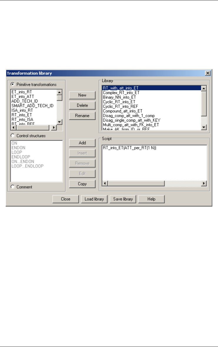
150 16 • The Assist menu (Assist)
22 juin 2009
c) Library
The library is a list of user defined transformations. Such a transformation
has a name (which appears in the list box) and a definition. The definition is
made of one or more transformations of the list above with their scope. The
library can be saved for further reuse. It can be edited by pressing on the
Edit library button. It is a good way to give frequent complex actions a
readable name in the language of the analyst.
d) Script management
A script consists of transformations and control structures. The script
management is identical with the script management of the global transfor-
mations assistant. The script can be saved in file (*.tfs). A new pre-defined
script is available:
•Pseudo-XML: in most cases, generates an acceptable logical XML
schema.
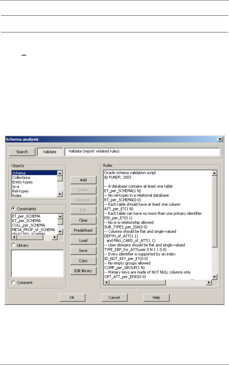
16 • The Assist menu (Assist) 151
22 juin 2009
16.3 Analyzing schema
16.3.1 Schema Analysis...
This assistant is able to detect, in the current data schema, specified struc-
tural patterns of any complexity. A structural pattern is defined by an object
type and properties which the objects have to satisfy. Some examples are
"entity types without attributes", "attributes which are compound but not
multi-valued", "rel-types with more than 2 roles", "names which appears in a
list of reserved words". The assistant proposes more than 200 rules or
constraints, but only some constraints are listed below. User-defined rules
can be developed in Java or Voyager 2.
The ANALYSIS assistant can be used in two ways, namely to validate the
current schema, and to search the schema for specified objects.

152 16 • The Assist menu (Assist)
22 juin 2009
VALIDATE
The assistant performs the analysis of the current schema in order to
evaluate its compliance with a sub-model. A sub-model is a restriction
of the generalized E/R model proposed by DB-MAIN. It is defined as a
collection of structural patterns, specified by rules. Such a rule is a
logical expression concerning a given type of objects where the terms
are predicative constraints on objects of this type.
If all the objects of the schema satisfy the rules of the sub-model, this
schema is said to be compliant with this sub-model. If the analysis
results in a failure, then some objects do not satisfy some rules, and the
assistant presents them in a diagnostic window which can be used as a
notepad. When a diagnostic message is selected, the assistant makes
the offending object current in the schema.
SEARCH
The assistant searches the current schema for all the objects that satisfy
the specified rules. It presents them in a diagnostic window which can
be used as a notepad. When a diagnostic message is selected, the assis-
tant makes the corresponding object current in the schema.
The set of rules can be saved and loaded later on. Some predefined sets
of rules are available.
a) The object types
When an object type is selected, the related constraints appear in the second
list box. The available object types are: schema, collection, entity type,
is-a, rel-type, role, attribute, group, entity type identifier, rel-type
identifier, attribute identifier, access key, referential constraint,
processing unit and names.
b) The elementary constraints
In this section, we describe some elementary constraints classified by object
types. The annex 1 contains the description of all the constraints (+/- 300).
Schema
ET_per_SCHEMA <min> <max>: the schema includes at least
<min> and at most <max> entity types.
RT_per_SCHEMA <min> <max>: the schema includes at least
<min> and at most <max> rel-types.
Entity types
ATT_per_ET <min> <max>: an entity type has at least <min> and at
most <max> attributes.
ID_per_ET <min> <max>: the number of identifiers per entity type
must be at least <min> and at most <max>.

16 • The Assist menu (Assist) 153
22 juin 2009
PID_per_ET <min> <max>: PID_per_ET <min> <max>: the number
of primary identifiers per entity type must be at least <min> and at most
<max>.
ID_NOT_KEY_per_ET <min> <max>: the number of identifiers that
are not access keys must be at least <min> and at most <max>.
Is-a
SUB_TYPES_per_ISA <min> <max>: an entity type can not have
less than <min> sub-types or more than <max> sub-types.
Attributes
DEPTH_of_ATT <min> <max>: the decomposition level of a
compound attribute must be at least <min> and at most <max>.
MAX_CARD_of_ATT <min> <max>: the maximum cardinality of an
attribute must be at least <min> and at most <max>.
Groups
COMP_per_GROUP <min> <max>: the number of terminal compo-
nents in a group must be at least <min> and at most <max>. A compo-
nent is terminal if it is not a group. For instance, let A be a group made
of an attribute a and another group B. B is made of two attributes b1
and b2. Then A has got three terminal components: a, b and c.
Entity type identifiers
OPT_ATT_per_EPID <min> <max>: an entity type primary identi-
fier must have between <min> and <max> optional attributes.
Names
NONE_in_LIST_NAMES <list>: <list> is a list of words. None of
them can be used for any name of any object in the schema.
ALL_CHARS_in_LIST_NAMES <list>: the names of schema, entity
types, rel-types, attributes, roles or groups must be made of the charac-
ters of the list <list> only.
LENGTH_of_NAMES <min> <max>: the length of names of the
schema, entity types, rel-types, attributes, roles and groups must be at
least <min> and at most <max>.
NONE_in_FILE_CI_NAMES <filename>: the names of the schema,
entity types, rel-types, attributes, roles and groups can not be in the file
with the name <filename>. The comparison between names and words
in the file is case insensitive.
c) The library
A library entry is a complex rule. It has a name (which appears in the list
box) and a definition. The definition is a single rule made of one or more
predicates with their parameters. The library can be edited by pressing the
Edit library button.
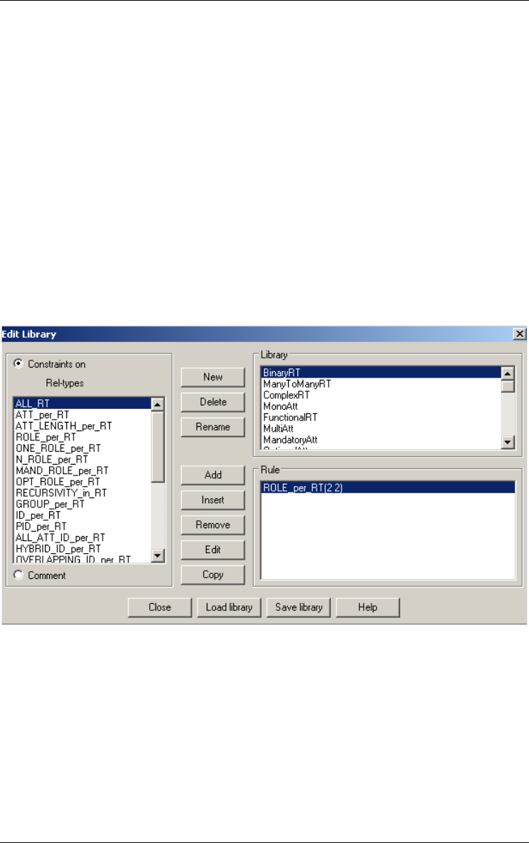
154 16 • The Assist menu (Assist)
22 juin 2009
The analysis rule library is a list of rules made of schema analysis constraints
that have a name. Such a library can be edited by adding new entries,
deleting old ones or editing existing ones. It can also be saved in a file (with
a .ANL extension) and loaded. When the dialogue box is opened, the Library
list is filled with the current library. When an entry in the library is selected,
its definition appears in the Rule list. This rule can be edited exactly the
same way as in the Schema analysis dialogue box, except the script can be
no longer than one rule and that no other library entry may be used. New
library entries may be added with the Add button at any time. A name must
be given in a specific dialogue box as well as the object type on which the
rule is defined. It is added in the list in its alphabetical place and the Rule list
is blanked. Obsolete library entries may be deleted with the delete button. It
acts on the currently selected entry. A default library is loaded the first time
it is needed during a DB-MAIN session. That default library is defined in the
configuration.
d) Comment
The script can contain some comments. A comment is a line of free text that
can be use to enhance the readibility of the scripts. Comments can be inserted
between rules only (not betwwen predicates inside a rule). They don't change
anything to the evaluation of the script.
e) Script management
An Analysis script defines a sub-model as a sequence of rules. Each rule is
associated with one of the object types of the model. A rule is either an

16 • The Assist menu (Assist) 155
22 juin 2009
elementary constraint, among those described above, or a boolean expres-
sion of elementary constraints. The boolean expression uses the logical oper-
ators and, or and not. Parentheses are not allowed, but more than one rule
can be defined for the same object type. The current script, if any, appears in
the Script window.
How to define a script?
All the predefined predicates are listed in the constraints lists. There is one
such list for each object type listed in the Objects list. All the predicates of
one rule must belong to a same Constraints list. Some rules may be stored
with a name in a library.
To define a script, the following procedure should be followed.
•Choose an object type in the Objects list.
•Choose a constraint in the Constraints list or a name in the Library list
and either push the Add button (or double-click on the predicate or the
name) to add it at the end of the script or select a line in the script and
push the insert button to insert the constraint before the chosen line.
•When the Add/Insert constraint dialogue box appears while adding a
constraint, fill in the parameters line. The Help button gives the format
of that string. Then check the box for the AND, OR and NOT operators
that must be put before the predicate. If the predicate is the first of a
rule, neither AND nor OR should be checked, else, one of them must be
chosen. Those two last buttons are not available if the previous predi-
cate in the script does not belong to the same Constraints list.
•Do the same again and again until the script is complete.
•If a correction is necessary, the Remove button removes the selected
predicate from the script and the Edit button (or a double-click on a
predicate of the script) opens the Add/Insert constraint window for
edition of the parameters.
The Clear button erases the script. When one is selected, it appears in the
Rules list and can then be modified or used. The Load and Save buttons save
the script and restore an old one. The Edit library button opens the editor
dialogue to edit the library of analysis rules. The Copy button copies the
script to the clipboard. The Predefined button gives a list of built-in scripts.
The following scripts are available:
•Oracle: Oracle relational model;
•DB2: DB2 relational model;
•Interbase: Interbase relational model;
•MySQL: MySQL relational model;
•COBOL: logical COBOL model;
• CODASYL: logical CODASYL model;
•ER-normalization: conceptual model;
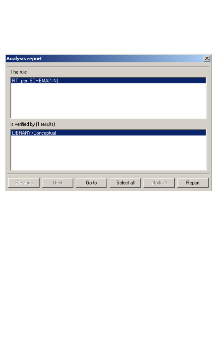
156 16 • The Assist menu (Assist)
22 juin 2009
•Practical UML: UML model extended with DB-Main facilities;
•Strict UML: UML model strictly respected;
•XML: XML (DTD) model;
f) The report window
After the search or validation is completed, a report window is opened. If,
during a search, nothing is found or if, during a validation, no rule is
violated, this window is a simple message. Else, the window is more elabo-
rated and reports a list of found objects for each rule of a search or a list of
objects violating each rule in a validation.
The Next and Previous buttons (shown only when necessary) permit to go
from the report of one rule to another.
When an object is selected in the bottom list, a Goto button appears. A click
on it or a double click on the selected item has the effect of activating the
window containing the analyzed schema, selecting the specified object and
centring it in the middle of the window.
The Report button writes the report in a file.
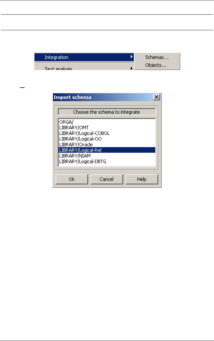
16 • The Assist menu (Assist) 157
22 juin 2009
16.4 Integrating objects
This assistant offers a set of tools for integrating data schemas and objects.
16.4.1 Schemas...
integrates a data schema from the project into the current data schema.
In the list of the data schemas (except the current one), selects the data
schema that must be integrated into the current data schema. The schema
integration rules can be found in the help file. The name of a file is asked,
this file will contains the report of the integration
The rules used to integrate a slave data schema file into the current one (the
master) are:
•The meta-properties, the descriptions and the graphical positions are
always handled in the same way for all the objects of the data schema.
The meta-properties defined into the slave data schema overwrite the
master ones. The descriptions defined into the slave data schema are
appended to the master one. The graphical positions of the master data
schema are updated if they are (0,0).
•The creation date of the data schema is overwritten by the one found in
the ISL file.
•If the slave data schema is connected to another data schema, the
connection is created if it does not exist.

158 16 • The Assist menu (Assist)
22 juin 2009
•If the slave data schema contains a new entity type, it is created. If the
entity type already exists, see the rules for two entity types with the
same name.
•If the slave data schema contains a new rel-type, it is created. If the rel-
type already exists, see the rules for two rel-types with the same name.
•If the slave data schema contains a new collection, it is created. If the
collection already exists, see the rules for two collections with the same
name.
•Two entity types with the same name:
The short name is not modified. If there is an is-a relation in the slave
schema, the connection is created to the cluster if the connection does
not exist. If the entity type in the slave schema contains a new attribute,
it is created. If the attribute already exists, see the rules for two
attributes with the same name. If the entity type in the slave schema
contains a new group, it is created. If the group already exists, see the
rules for two groups with the same name.
•Two rel-types with the same name:
The short name is not modified. If the rel-type in the slave schema
contains a new attribute, it is created. If the attribute already exists, see
the rules for two attributes with the same name. If the rel-type in the
slave schema contains a new role, it is created. If the role already exists,
see the rules for two roles with the same name. If the rel-type in the
slave schema contains a new group, it is created. If the group already
exists, see the rules for two groups with the same name.
•Two roles with the same name:
The short name and the cardinality are not modified. If, in the slave
schema, the role is connected to an entity type to which it is not
connected in the schema, then the connection is created.
•Two attributes with the same name:
The cardinality and the short name are not modified. If the master is a
not compound attribute and the slave is a compound attribute, the
master attribute is deleted and replaced by the slave one. If the master is
a compound attribute and the slave not, the master is not modified. If
they are both compound or not, the master is not modified. If the
attribute in the slave schema is a compound attribute that contains a new
attribute, it is created. If the attribute already exists, see the rules for two
attributes with the same name. If the attribute in the slave schema
contains a new group, it is created. If the group already exists, see the
rules for two groups with the same name.
•Two groups with the same name:
Add the components that are defined in the slave schema to the group if
they are not present in the master. If, in the slave schema, the group is
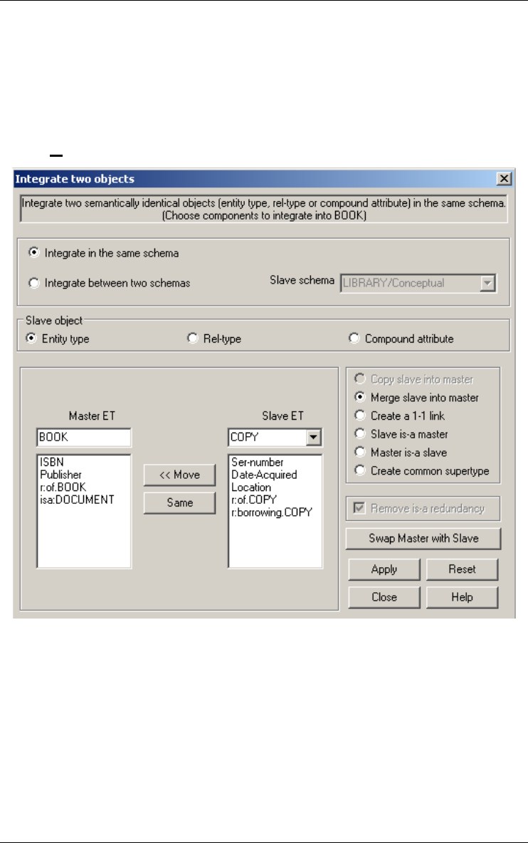
16 • The Assist menu (Assist) 159
22 juin 2009
the origin of a constraint, this constraint is added and the other one in
the master (if it exists) is deleted.
•Two collections with the same name:
Short name is not modified. Add to the collection the entity type that
were not connected.
16.4.2 Objects...
integrates two objects (entity types, relationship types or compound
attributes) in the same data schema or between two different data schemas
(from the slave to the master). There are six integration strategies.
Attributes, processing units, roles, is-a relations and their properties can be
migrated selectively.
First you must select a current object. This is the master object. If there is no
selection, only the Copy slave into master strategy is available.
The integration box has the following features:
•Type of integration: selects the integration in the same data schema
(ISS) or integration between two data schemas (IBS). By default, the

160 16 • The Assist menu (Assist)
22 juin 2009
ISS choice is selected. But if an object is selected in another schema
than the master object schema, the IBS choice is selected.
•Slave schema: in case of IBS, chooses the slave object data schema.
•Type of slave object: chooses the type (entity type, rel-type or
compound attribute) of the slave object.
•Master object: changes the name of the master object.
•Slave object: chooses the slave object.
•Type of strategies: six strategies are possible. For all the strategies we
are going to distinguish both types of integration:
–Copy slave into master (only available for rel-types, entity types and
if no master selected): In case of ISS, copies the master object (if not
empty) and moves the transferred attributes, processing units, roles
and is-a relations into the copy. If empty, the slave object is deleted.
In case of IBS, copies the master ET (if not empty) with the trans-
ferred attributes and processing units into the master schema.
–Merge slave into master: In case of ISS, merges the slave object
(attributes, processing units, roles and is-a relations) with the master
object. If empty, the slave object is deleted. In case of IBS, merges
the slave object (attributes and processing units only) with the master
object.
–Create a 1-1 link (only available if integration of two entity types):
In case of ISS, creates a rel-type between the master and slave ET. Its
roles are (1-1/1-1) or (0-1/1-1). In case of IBS, copies the slave ET
and its attributes into the master schema and creates a rel-type
between the master and slave. Its roles are (1-1/1-1) or (0-1/1-1).
–Slave is-a master (only available if integration of two entity types):
In case of ISS, creates an is-a relation between the master and slave
ET. Master is the supertype. In case of IBS, copies the slave ET and
its attributes into the master schema and creates an is-a relation
between the master and slave ET. Master is the supertype.
–Master is-a slave (only available if integration of two entity types):
In case of ISS, creates an is-a relation between the master and slave
ET. Slave is the supertype. In case of IBS, copies the slave ET and its
attributes into the master schema and creates an is-a relation between
the master and slave ET. Slave is the supertype.
–Create common supertype (only available if integration of two entity
types): In case of ISS, creates a common supertype to the master and
slave ET. In case of IBS, copies the slave ET and its attributes into
the master schema and creates a common supertype to the master
and slave ET.
•rel-type name box: introduces the name of the rel-type for the Create a
1-1 link strategy.
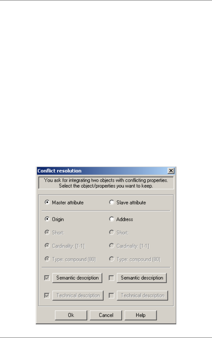
16 • The Assist menu (Assist) 161
22 juin 2009
•Cardinality box: chooses the cardinality of the role played by the
master entity type in the Create a 1-1 link strategy;
•Is-a Type box: introduces the type of the is-a relation (nothing,
D(isjoint), T(otal) or P(artition)) in the Create a common supertype,
Slave is a master and Master is a slave strategies;
•Move: moves the selected items from the slave list box to the end of the
master list box;
•Same: compares the selected items of both list boxes (see the second
dialog box) and either deletes the slave items or transfers the slave item
in the master list box;
•Remove is-a redundancy: if checked (for the slave is-a master or
master is-a slave strategy), the is-a redundancies are removed. For
example, if A is the master entity type, B the slave entity type and (A,B)
are sub-types of C. With the slave is-a master strategy, the is-a relation
between B and C is deleted;
•Swap Master with Slave: the master object becomes the slave and
conversely;
•Apply: applies the integration with the selected strategy;
•Reset: resets the dialog box;
•Close: closes the integration dialog box without applying changes.

162 16 • The Assist menu (Assist)
22 juin 2009
The second dialog box is called by the same button and compares two
different components (attributes, processing units, roles or is-a relations) of
the master and slave objects. It has the following features:
•master: chooses the master component. The slave component is
removed from the slave list box;
•slave: chooses the slave component. The master component is removed
from the master list box and the slave component is added to the master
list box;
•name: chooses the name of the master or slave component;
•short: chooses the short name of the master or slave attribute (only for
attributes and processing units);
•cardinality: chooses the cardinality of the master or slave component
(only for attributes and roles);
•type: chooses the type of the master or slave attribute;
•semantic description: chooses the semantic description of the master
and/or slave component(s);
•technical description: chooses the technical description of the master
and/or slave component(s);
16.5 Analyzing text
Searching for patterns, computing dependency graphs and program slices use
very complex algorithms that can take some time when applied to large and
intricated programs. However, displaying the dependency graph of a variable
is immediate.
16.5.1 Text Analysis
This assistant offers a set of tools for text analysis. The text to analyze can be
an external text (such as a source program) or the contents of semantic or
technical descriptions of the current schema.
The analysis is based on a pattern engine which can search the selected
textual materials for specific patterns. The patterns are defined in PDL, a
Pattern Definition Language whose specification can be found in the help
file.
The patterns used to analyze the texts are stored in pattern libraries (*.PDL
files). In most cases, two libraries are used, the main library, and the
secondary library. The main library contains the patterns to be selected by
user (e.g. COBOL or SQL statements), while the secondary library contains
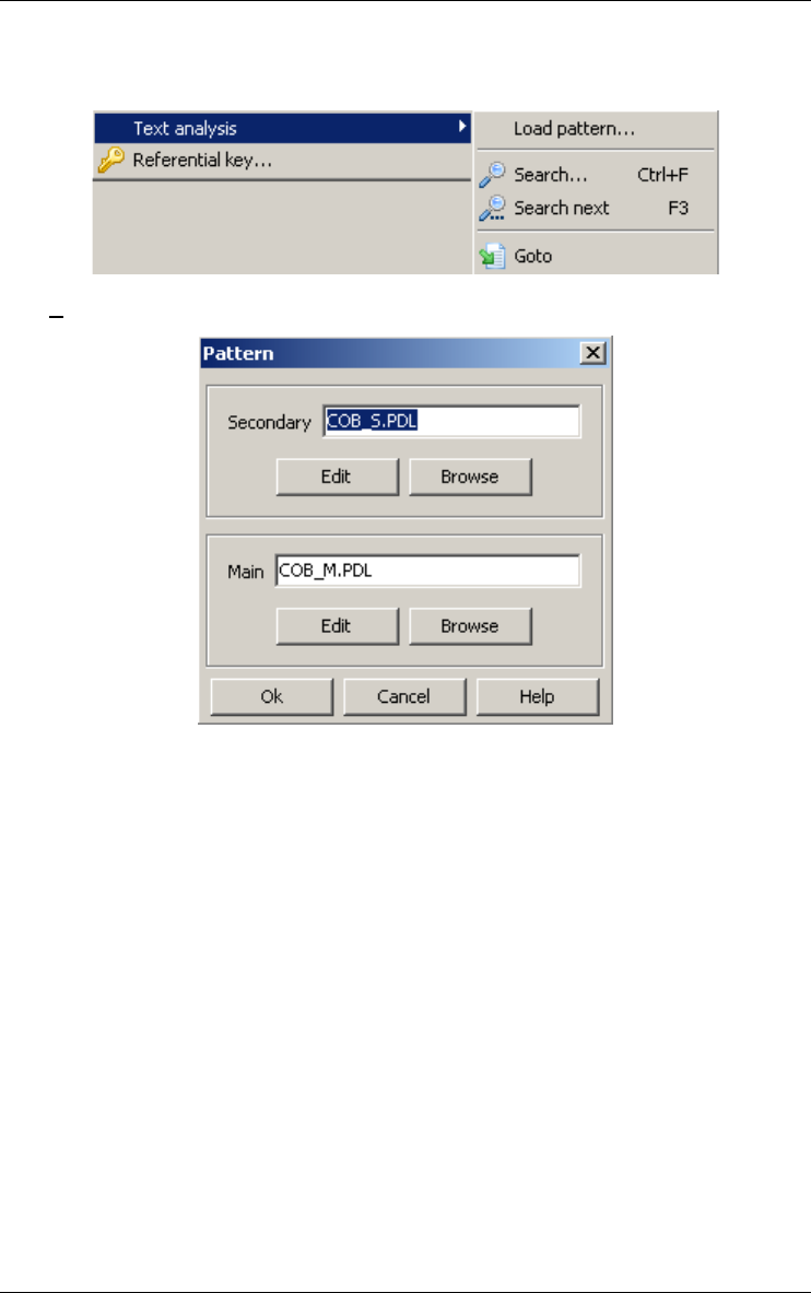
16 • The Assist menu (Assist) 163
22 juin 2009
the definitions of the low-level patterns used, but undefined, in the main
library (e.g. COBOL separators, C name syntax).
Load pattern...
Loads and edits pattern files (*.pdl) to be used in text analysis (source,
SEM, TECH). The complete name of these files are stored in the
WINDOWS\DB_MAIN.INI file. In further uses, these files will be
automatically loaded when the assistant is used. This tool will be used
either the first time the assistant is used, or when you want to use other
libraries.
This dialog box allows us to load and to edit pattern files. The patterns
are split into two files (the main and the secondary patterns), for each of
both pattern files there is a Browse button to change the filename and
an Edit button to edit the file. The two files are mandatory.
Click on the Ok button to compile the patterns and to close the dialog
box. If there is a syntax error, the dialog box is not closed.
Patterns are expressed in a Pattern Definition Language (PDL) close to
BNF notation and have variables. The variables can be instantiated
before the search or by the search. Forward definitions are not allowed,
i.e. patterns used into the definition of a pattern must be already
defined. The complete syntax of the Pattern Definition Language is
available in the annex 2.
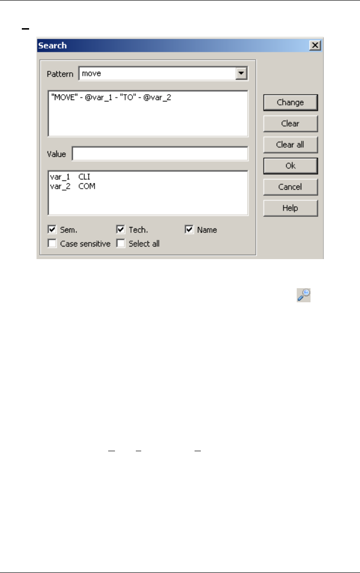
164 16 • The Assist menu (Assist)
22 juin 2009
Search...
Interactive pattern matching processor: searches specified texts for the
next instance of a pattern, or for relationships between text components
defined by patterns. Also available through the button on the RE
tool bar. The text which is searched depends on the current window:
–If the current window is a schema, then the search takes place into
the name or the description of the objects that are displayed into the
window. The next object for which the pattern is found (name and/or
semantics and/or technical depending on the value of Name, Sem and
Tech check boxes) becomes current.
–If the current window is a source text browser, then the search takes
place into the source. The next line in which the pattern is found is
highlighted and becomes current.
To search for a pattern select it in the Pattern combo box, its definition
is displayed. If the combo box is empty it means that there is no pattern
loaded, use Assist/Text analysis/Load pattern... to load the patterns. If
the case sensitive check box is checked, then the search is case sensi-
tive. If the selected pattern contains variables, they are displayed into
the list box. Those variables can be instantiated before the search (you
give them a value) or during the search. The button Clear all clears the
value of all the variables. The button Clear clears the value of the
selected variable. To instantiate a variable, select it, put its value into
the Value text field and then click on the Change button. When you
reopen the search dialog box after a pattern is found, the variables are
instantiated. If the select all box is checked, then all the lines or objects

16 • The Assist menu (Assist) 165
22 juin 2009
that contain the pattern are selected, otherwise only the next line or
object is selected.
Search next (or the <F3> key)
searchs for the next instance of the pattern into the specified text. Also
available through the button on the RE tool bar.
Goto
shows the mapping between a source text file and its corresponding
logical schema. Both must be opened. Also available through the
button on the RE tool bar.
The active mapping can be used in both ways:
–in the schema window:
selects an object in the schema (in any graphical/textual view);
Assist/Text analysis/Goto: the origin source text line of the selected
object is highlighted in the text window.
–in the source text window:
selects a statement in the source text;
Assist/Text analysis/Goto: the object extracted from this statement is
selected in the schema window.
16.6 Finding referential key
16.6.1 Referential key...
The reference key finding assistant proposes some popular heuristics to find
and create foreign keys. Also available through the button on the RE tool
bar.
The analyst gives a list of groups and chooses one of the two strategies:
•given a candidate foreign key (in the list of groups), finds the possible
target record types (a group);
•given a group (usually an identifier - in the list of groups), finds the field
(an existing group or an attribute) of the schema that could reference the
group.
Depending on the chosen strategy, he gives the criteria to find the matching
groups. When the matching groups are found, he can create the foreign keys.
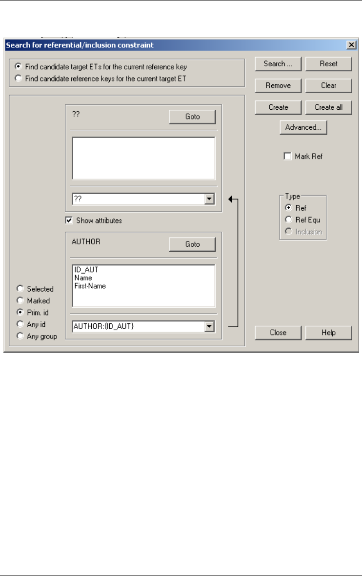
166 16 • The Assist menu (Assist)
22 juin 2009
The reference key finding assistant dialog displays in its top part the chosen
strategy.
On the left, he can choose the list of groups that are used as the origin or the
target of the foreign key (depending of the chosen strategy). This list is
called "selected groups" and contains the selected or marked groups of the
schema, all the primary identifiers, all the identifiers or all the groups.
The entity type, list attributes and selected groups are on the top if the first
strategy is chosen, otherwise they are on the bottom. The other part of the
window displays the groups that match the search criteria (if it is the first call
to the assistant no matching groups are displayed). The list of matching
groups and attributes is displayed in a combo box and is prefixed by the
name of their entity type.
The components of an existing group are surrounded by brackets; if it is an
attribute that is not member of a group only its total name is displayed. If the
group is followed by a "*" then the origin group is already the origin of a
reference key, a second one cannot be created. The user can decide to show

16 • The Assist menu (Assist) 167
22 juin 2009
or not the attributes of the origin and target entity types by checking or not
the Show attributes check box.
The user can change the search criteria by clicking on the Search button (see
below). To give the default value to the search criteria, he can click on the
Reset button. The default values are no constraint on the target group type,
each component of the groups must have the same type and the same length,
does not accept attribute, does not accept multivalued reference key, no
name matching rules (see the search criteria description).
If the matching rules found a group that is not origin or target of a foreign
key, select it and click on the Remove button to remove it from the list. To
obtain the complete list of matching groups, click on the Clear button.
Select the type of the constraint to be created. In this version, only ref (refer-
ential constraint) and ref equ (referential equality constraint) are possible.
Click on the Create button to create a foreign key between the selected group
and the matching group that is visible in the combo box. To create the
foreign key between all the "selected groups" and all the matching groups,
click on the Create all button.
There is a Goto button at the right of the target and origin entity type. If you
click on one of them, then the corresponding entity type is displayed in the
middle of the schema window.
To change the selected groups, select other groups into the schema window
without closing the reference key assistant. Then re-activate the reference
key assistant and it becomes the new selected group and the matching groups
are also displayed, using the criteria as set before
The Advanced button is used to create all the foreign keys between all the
selected groups and the matching groups with a Java or Voyager procedure.
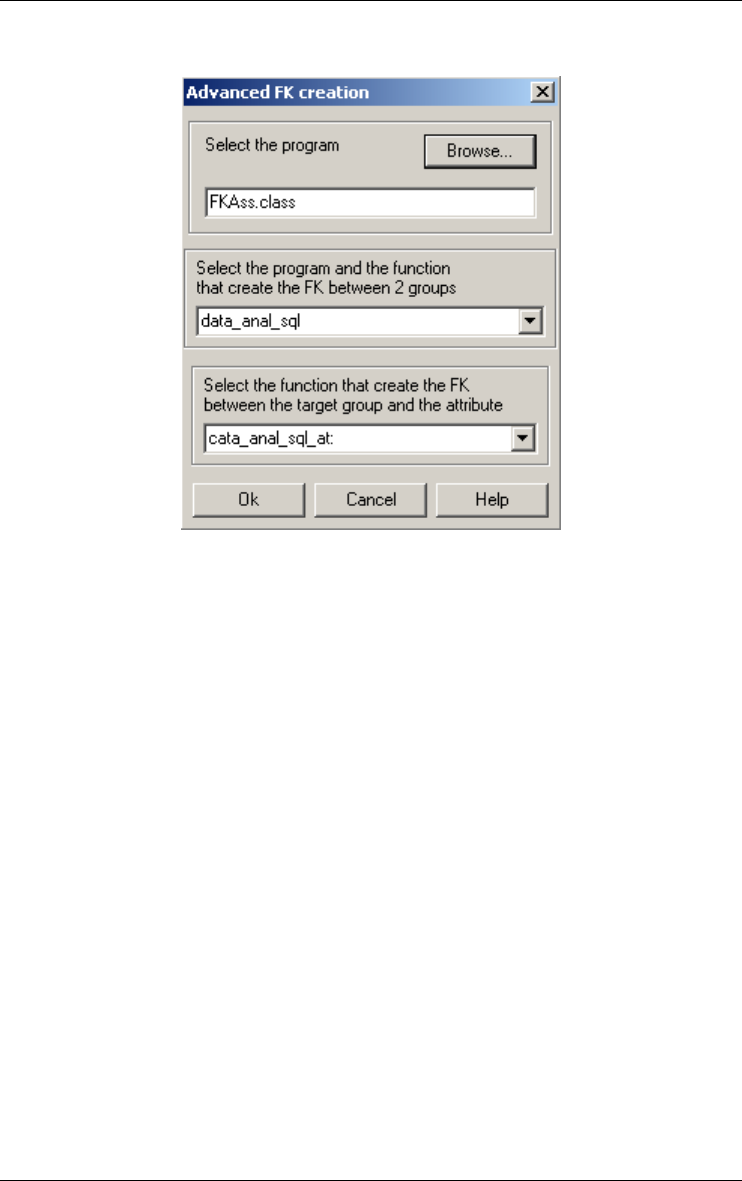
168 16 • The Assist menu (Assist)
22 juin 2009
A new dialog box appears, asking for one Java or Voyager 2 program and
two procedures of this program. One to create the foreign keys between two
groups and the other one to create the foreign keys between an attribute and
a group. The Java program should contain one class with methods having the
following signatures:
public static void <proc_name>(Integer <origin_gr_id>, Integer
<target_gr_id>, Integer <t>)
where
<origin_gr_id> is the ID of the origin group of the foreign key
<target_gr_id> is the ID of the target group of the foreign key
<t> is the type of the foreign key
and
public static void <proc_name>(Integer <origin_att_id>, Integer
<target_gr_id>, integer: <t>)
where
<origin_att_id> is the ID of the origin attribute of the foreign key
<target_gr> is the ID of the target group of the foreign key
<t> is the type of the foreign key
The groups (or attribute) can be retrieved from there ID with the
following instruction:
gr = new dbmGroup(origin_gr_id.intValue());
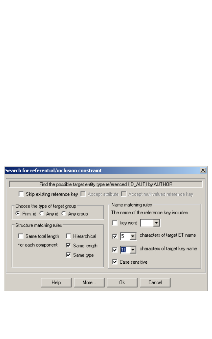
16 • The Assist menu (Assist) 169
22 juin 2009
The Voyager 2 procedures must have the following signature.
export procedure <proc_name>(group: <origin_gr>, group:
<target_gr>, integer: <t>)
where
<origin_gr> is the origin group of the foreign key
<target_gr> is the target group of the foreign key
<t> is the type of the foreign key
and
export procedure <proc_name>(attribute: <origin_att>, group:
<target_gr>, integer: <t>)
where
<origin_att> is the origin attribute of the foreign key
<target_gr> is the target group of the foreign key
<t> is the type of the foreign key
This procedure is executed for each matching group. To select the procedure,
use the Browse button to select the oxo file and then select the procedure
name in the combo box.
The search criteria dialog box is obtained by pressing the Search button in
the reference key assistant dialog box.
Some of the items of the search criteria dialog box are not accessible,
depending of the chosen strategy. The different criteria are:
•Skip existing reference key: the group is not selected if the origin
group is already the origin of a reference constraint.

170 16 • The Assist menu (Assist)
22 juin 2009
•Choose the type of target key (only if we are looking for the target
group): the target group must be a primary identifier, any identifier or
any group (no constraint on the group type).
•Structure matching rules: the two groups must have the same length
(same total length is checked) or each of the groups components must
have the same length (same length is checked) and/or the same type
(Same type is checked) or no constraint on the structure (nothing
checked). If hierarchical is checked (Same total length is also checked)
and if a group contains a role then the length of the group is the length
of the attributes of the group plus the length of the primary identifier of
the entity type connected by the role (if the role is multi-domains then it
is the maximum of the length of the primary identifier of the entity types
connected by the role).
•Accept attribute (only if we are looking for the origin group): if the
selected group has only one attribute then looks for attributes that are
not the only member of a group and that verify the other matching rules.
•Accept multivalued reference key (only if we are looking for the
origin group): accepts groups that contain a multivalued attribute.
•Name matching rules (only if we are looking for the origin groups):
this rule contains three criteria on the name of the attributes. If this rule
is used the origin group can contain only one attribute.
•Key word: the origin attribute must contain a key word. If this rule is
used the two other name matching rules are applied on the attribute
name without the key word.
•Some or all characters of the origin attribute must be included in the
target entity type name.
•Some or all characters of the origin attribute must be included in the
target attribute name.
For the two last rules we can choose that all the characters must be
included and they must be contiguous. If we choose some (a number, i)
then the first i characters of the target entity type or attribute name must
be included in the origin attribute, but not necessarily in a continuous
manner. For example: the three first characters of ABCD are included
into FABCDE and in AFBCE but not in CBADE.
•More: the user can give two Java or Voyager 2 functions, one that
checks if two groups are matching and the other that checks if an
attribute matches with the target group. The signatures of the two func-
tions are the following, in Java:
public static int <match_group>(Integer <origin_gr_id>, Integer
<target_gr_id>);
where
<origin_gr_id> is the ID of the origin group of the foreign key

16 • The Assist menu (Assist) 171
22 juin 2009
<target_gr_id> is the ID of the target group of the foreign key
the returned value is the type of the foreign key
public static int <match_att_group>(Integer <origin_att_id>, Integer
<target_gr_id>);
where
<origin_att_id> is the ID of the origin attribute of the foreign key
<target_gr> is the ID of the target group of the foreign key
the returned value is the type of the foreign key
The groups (or attribute) can be retrieved from there ID with the
following instruction:
gr = new dbmGroup(origin_gr_id.intValue());
and in Voyager 2:
export function integer <match_group>(group: <origin_gr>, group:
<target_gr>)
<origin_gr> is the origin group of the foreign key
<target_gr> is the target group of the foreign key
the returned value is the type of the foreign key
export function integer <match_att_group>(attribute: <origin_att>,
group: <target_gr>)
<origin_att> is the origin attribute of the foreign key
<target_gr> is the target group of the foreign key
the returned value is the type of the foreign key

172 16 • The Assist menu (Assist)
22 juin 2009

22 juin 2009
Chapter 17
The Engineering menu
(Engineering)
The history of a database engineering process contains the trace of all the
activities that were performed, all the products involved, all the hypotheses
that were made, all the versions of the products resulting of those hypotheses
as well as all the decisions taken. Naturally, the result is a complex graph. The
engineering menu is the place where the history can be managed. This menu
includes four sections through which the user can manage all the processes and
their histories:
1. managing primitive or engineering processes;
2. taking decision;
3. controlling history.
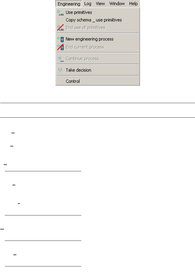
17.1 The commands of the Engineering menu - Summary
Use primitives updates the selected products by using the primitive func-
tions of the tool.
Copy schema & use primitives
copies the selected schema and updates the copy by
using the primitive functions of the tool.
End use of primitives terminates the use of the primitives.
New engineering process
creates a new engineering process using selected prod-
ucts input.
End current process terminates the current engineering process using selected
products as output.
Continue process allows a terminated process to be continued if resulting
products are still to be reused.
Take decision takes the decision of continuing with one or some of the
selected products.

17 • The Engineering menu (Engineering) 175
22 juin 2009
Control allows DB-MAIN to adapt the level of control of user
actions according to the methodology or history coher-
ence.
17.2 Managing primitive or engineering processes
A history should contain all the processes that are performed during an engi-
neering activity. The whole project is made of processes, each of them being
made of sub-processes and so on. Since a process is made of several sub-
processes, it is useful to know in what order they have been performed, e.g.,
serially or in parallel. So each process will be stamped by its beginning date
and time (mandatory) and end date and time. They will be identified by a name
and the begin time stamp. In order to document his work, the analyst will add
a description (some free text) to each process. There are two kinds of
processes:
•A primitive process is a process performed using only primitives (built-in func-
tion of the tool or external functions written in the built-in language of the tool).
The execution of primitives can be recorded in a log file.
•An engineering process follows a strategy: an analyst can make hypotheses, try
different solutions and decide to abandon some of them. The history of an engi-
neering process is a graph in the project window.
17.2.1 Use primitives
Allows an analyst to update the selected products by using the primitive
functions of the tool. To begin a primitive process, first select all the product
you want to use as input or update. Also available through the button on
the process tool bar. The primitive process properties can be changed in the
property box.
17.2.2 Copy schema & use primitives
Copies the selected schema and allows an analyst to update the copy by
using the primitive functions of the tool.
17.2.3 End use of primitives
Terminates the use of primitives. Also available through the button on
the process tool bar.

176 17 • The Engineering menu (Engineering)
22 juin 2009
17.2.4 New engineering process
Creates a new engineering process using selected products in input/update.
To begin an engineering process, first select all the product you want to use
as input or update. Also available through the button on the process tool
bar. The engineering process properties can be changed in the property box.
17.2.5 End current process
Terminates the current engineering process using selected products as
output. To terminate an engineering process, make sure all its sub-processes
are terminated, then select all the products you want to use as outputs. Also
available through the button on the process tool bar.
17.2.6 Continue process
Allows a terminated process to be continued. Also available through the
button on the process tool bar.
17.3 Taking decision
17.3.1 Take decision
Takes the decision of continuing with one or some of the selected products.
Also available through the button on the process tool bar. The decision
properties can be changed in the property box.
A decision is a special kind of process, the sole difference being that it does
not alter products, nor does it generate any product. A decision follows
hypotheses. When an analyst has to perform a process, she can make
different hypotheses and perform the same process several times with each
hypothesis in mind. The description of each process will contain the hypoth-
esis. Each process will generate its own version of the products. When all the
processes are over, the analyst chooses one version among all to continue
her work. The process of decision will show the choice (double headed
arrow) and its description will contain the rationales that lead to that choice.
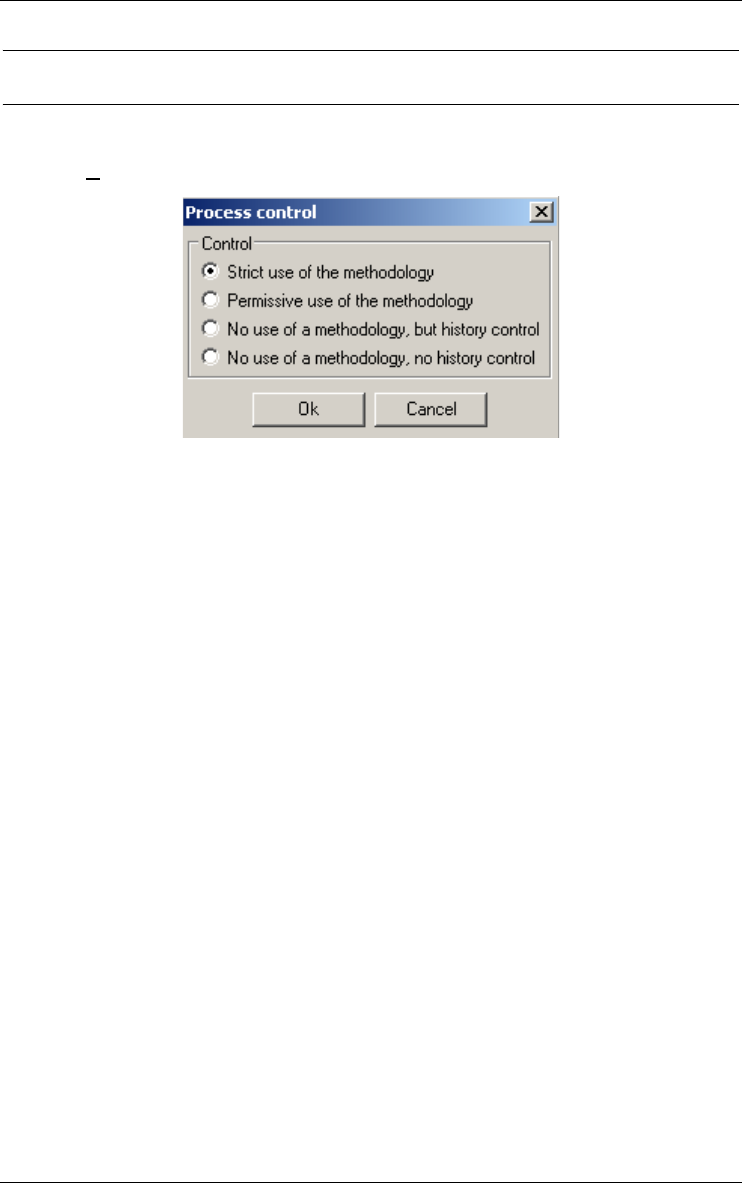
17 • The Engineering menu (Engineering) 177
22 juin 2009
17.4 Controlling history
17.4.1 Control
Allows DB-MAIN to adapt the level of control of user actions according to
the methodology or history coherence. The four level are:
•Strict use of the method. This is the preferred mode. By default, the tool
should automatically be in that mode when a new project is created
using a method. The users should always use this mode and leave only
in case of problem.
•Permissive use of the method. This mode can be used to bypass some
constraints imposed by a method, specially if these are blocking
constraints. In this mode, the tool will operate as if the method engineer
had designed the method with weak conditions only and every product
types defined with a weak respect of their product model.
•No use of the method, but history control. The methodological engine is
unactivated. Database engineers can still view the method in its
window, but for documentation only. They are left to themselves to do
the job and to organize the history manually. The history control is acti-
vated.
•No use of the method, no history control. The methodological engine is
unactivated. Database engineers can still view the method in its
window, but for documentation only. They are left to themselves to do
the job and to organize the history manually. The history control is
unactivated. This mode should only be used in case of major problem in
a method.

178 17 • The Engineering menu (Engineering)
22 juin 2009
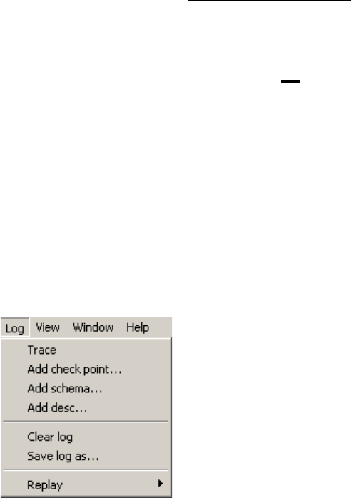
22 juin 2009
Chapter 18
The Log menu (Log)
Logs (records) the actions carried out by the analyst, and replays them selec-
tively. To each schema is associated a log, that is saved into the lun file of the
project. This menu includes three sections through which the user can manage
logs:
1. adding information in schema logs;
2. managing schema logs;
3. replaying log files.

18.1 The commands of the Log menu - Summary
Trace enables/disables the recording of user actions in the
current schema log
Add check point... inserts a checkpoint label in the current schema log
Add schema... inserts a copy of the current schema window in the current
schema log
Add desc... inserts a user message in the current schema log
Clear log... clears the current schema log
Save log as... saves the current schema log into a *.LOG file
Replay replays selected actions recorded in a log file (schema
copies and messages are ignored) onto the current
schema
18.2 Adding information in schema logs
18.2.1 Trace
Enables/disables the recording of user actions in the current schema log.
18.2.2 Add check point...
Inserts a checkpoint label in the current schema log. These records allow to
mark the log to describe significant events (end of normalization, end of
translation, etc.). They are used by the replay function. There are two default
check points: at the begin (begin-file) and at the end (end-file) of the schema
log. Some other ones are placed when beginning or ending a process.
18.2.3 Add schema...
Inserts an image of the current schema in its log. This image is ignored
during the replay process.
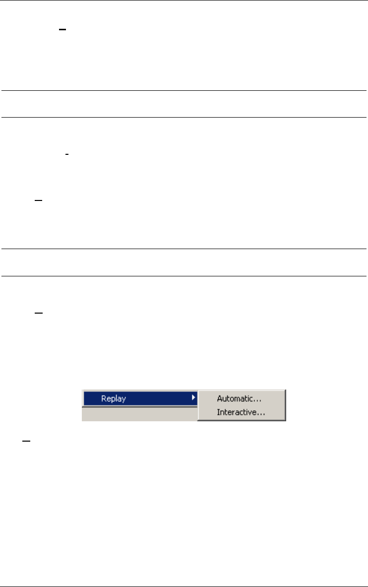
18 • The Log menu (Log) 181
22 juin 2009
18.2.4 Add desc...
Inserts an arbitrary text in the current schema log. This text is ignored during
the replay process.
18.3 Managing schema logs
18.3.1 Clear log
Erases the current schema log.
18.3.2 Save log as...
Saves the current schema log into a file.
18.4 Replaying log files
18.4.1 Replay
Replays selected actions recorded in a log file (schema copies and messages
are ignored) on the current schema. To identify an object, the replay uses its
name (prefixed by the name of its parent). To replay a log-file, the current
schema must contain objects with the same name as those stored into the log
file. There are two kinds of replay process: automatic or interactive.
Automatic...
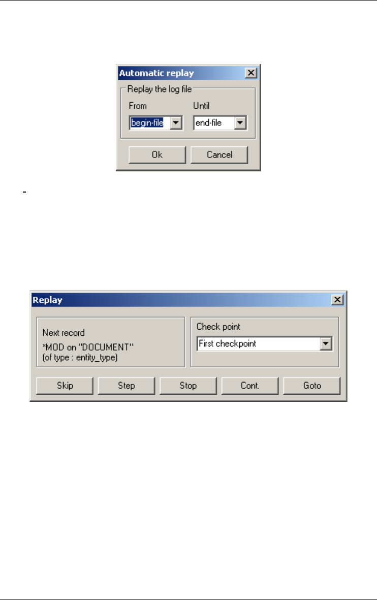
182 18 • The Log menu (Log)
22 juin 2009
Replays all the actions recorded in a log file between selected check-
points. Select two checkpoints, one as the start and the other as the
end of the section of the log file to replay.
Interactive...
Replays the actions recorded in a log file between selected checkpoints
under the control of the user. The next record to be executed is
displayed into the dialog box. The Skip button does not execute the
recorded action. The Step button executes it. The Stop button stops the
replay. The Goto button jumps to the selected check point without
execution. The Continue button executes the log up to the selected
check point.

22 juin 2009
Chapter 19
The View menu (View)
This menu includes three sections through which the user can manage the
different views for schemas, processes or methods:
1. choosing graphical and textual views;
2. setting graphical views;
3. displaying engineering method window;
4. navigating in textual and graphical views.
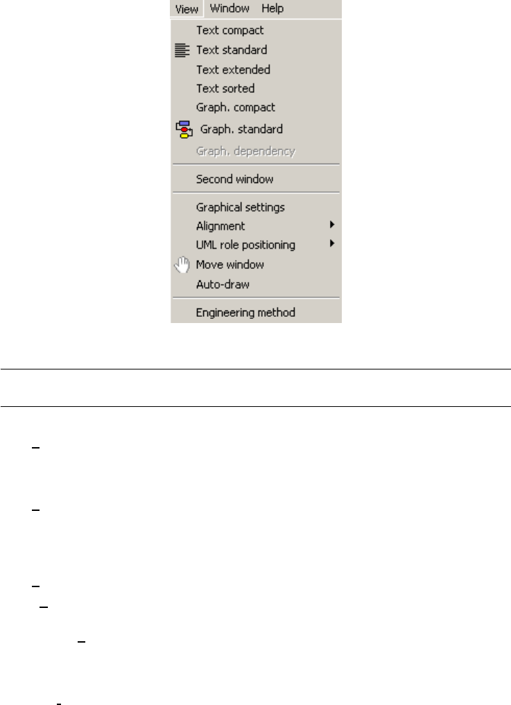
19.1 The commands of the View menu - Summary
Text compact list of the collections, entity types and rel-types of the data
schema
list of action states and object states in a activity schema
list of use cases and actors in a use case schema
Text standard compact textual presentation + collection contents, IS-A,
attributes, processing units, roles, groups, constraints and
notes in a data schema
compact textual presentation + relations and notes in a
processing schema
Text extended standard textual presentation + additional details
Text sorted sorted list of all the names declared in a schema, together
with their object type and parent object
Graph. compact graphical presentation of IS-A, roles, collections, entity
types, rel-types and notes of a data schema
graphical presentation of all products and derived depen-
dencies of the project
Graph. standard compact graphical presentation + attributes, processing
units, groups and constraints of a data schema
graphical presentation of action states, object states,
control flows, object flows and notes of a activity schema

19 • The View menu (View) 185
22 juin 2009
graphical presentation of use cases, actors, extend rela-
tionships, include relationships, use case generalizations,
associations, actor generalizations and notes of a activity
schema
compact graphical presentation + sub-processes of a
process
Graph. dependency graphical presentation of all products and derived depen-
dencies of a process
Second window opens a second window with the same schema as in
current window. If the current window is graphical, the new
one will be textual and conversely.
Graph settings defines settings for graphical views
Alignment aligns the selected object in any graphical view
UML role positioning in UML class graphical view: shifts the names of selected
roles and rel-types
Move window in graphical views, changes the cursor into a hand shape
to help users moving large schemas in the current window
by clicking left mouse button and gragging the mouse.
Auto-Drawin graphical views: proposes a new graphical layout of the
current schema
Engineering method displays a window containing the current engineering
method
19.2 Choosing graphical and textual views
Chooses the way the current schema, process or project will be displayed in its
window.
19.2.1 Text compact
In a data schema window, this view contains the names of the following
objects:
•schema,
•collections,
•entity types,
•rel-types.

186 19 • The View menu (View)
22 juin 2009
In an activity schema window, this view contains the names of the following
objects:
•schema,
•action states,
•initial and final states,
•synchronization bars,
•decision states,
•sending and receipt signals,
•internal (only first level objects) and external objects states.
In an use case schema window, this view contains the names of the following
objects:
•schema,
•use cases,
•actors,
•associations.
19.2.2 Text standard
In a data schema window, this view contains a short description of the
following objects:
•schema + notes with processing units + notes,
•collections + notes with entity types,
•entity types + notes with super-type, attributes + notes, processing units
+ notes and groups + notes,
•rel-types + notes with roles + notes, attributes + notes, processing units
+ notes and groups + notes.
In an activity schema window, this view contains the names of the following
objects:
•schema + notes,
•action states + notes with control and object flows + notes,
•initial and final states + notes with control flows + notes,
•decision states + notes with control flows + notes,
•synchronization bars + notes with control flows + notes,
•sending and receipt signals + notes with control flows + notes,
•internal (all levels) and external objects states + notes.
In an use case schema window, this view contains the names of the following
objects:
•schema + notes,
•use cases + notes with extend and include relationships, use case gener-
alizations + notes,

19 • The View menu (View) 187
22 juin 2009
•actors + notes with actor generalizations + notes,
•associations + notes with use case association roles + notes and actor
association roles + notes.
Also available through the button on the standard tool bar.
19.2.3 Text extended
In a data schema window, this view contains an extended description of the
following objects:
•schema + notes with processing units + notes,
•collections + notes with entity types,
•entity types + notes with super-types, sub-types, attributes + notes,
processing units + notes, groups + notes and roles,
•rel-types + notes with roles + notes, attributes + notes, processing units
+ notes and groups + notes,
•Each attribute has type, length and number of decimal.
In an activity schema window, this view contains the names of the following
objects:
•schema + notes,
•action states + notes with control and object flows + notes,
•initial and final states + notes with control flows + notes,
•decision states + notes with control flows + notes,
•synchronization bars + notes with control flows + notes,
•sending and receipt signals + notes with control flows + notes,
•internal (all levels) and external objects states + notes with control and
object flows.
In an use case schema window, this view contains the names of the following
objects:
•schema + notes,
•use cases + notes with extend and include relationships, use case gener-
alizations + notes,
•actors + notes with associations and actor generalizations + notes,
•associations + notes with use case association roles + notes and actor
association roles + notes.
19.2.4 Text sorted
In a data schema window, this view contains all object names of the schema
(excepted groups and notes) sorted in alphabetical order.
In a processing schema window, this view contains all object names of the
schema (excepted relations and notes) sorted in alphabetical order.

188 19 • The View menu (View)
22 juin 2009
19.2.5 Graph. compact
In a data schema window, this view contains a graphical description of the
following objects:
•schema,
•entity types,
•rel-types,
•roles,
•collections,
•sub-types.
In the project window, this view contains a graphical description of all the
products linked together by their derived dependencies.
19.2.6 Graph. standard
In a data schema window, this view contains a graphical description of the
following objects:
•schema with processing units,
•entity types with attributes, processing units and groups,
•rel-types with attributes, processing units and groups,
•roles,
•collections,
•sub-types.
In an activity schema window, this view contains a graphical description of
the following objects:
•schema,
•action states,
•initial and final states,
•decision states,
•synchronization bars,
•sending and receipt signals,
•internal (all levels) and external objects states,
•control flows,
•object flows,
•notes.
In an use case schema window, this view contains a graphical description of
the following objects:
•schema,
•use cases,
•actors,

19 • The View menu (View) 189
22 juin 2009
•extend relationships,
•include relationships,
•use case generalizations,
•associations,
•actor generalizations,
•notes.
In a process window, this view contains a graphical description of all the
products and all the sub-processes of the current process with their input/
output links.
Also available through the button on the standard tool bar.
19.2.7 Graph. dependency
In a process window, this view contains a graphical description of all the
products of the current process linked together by their derived dependen-
cies.
19.3 Setting graphical views
19.3.1 Graphical settings
This function displays a set of options for configuring the current graphical
view. This set of options depends on the content of the current graphical
window.
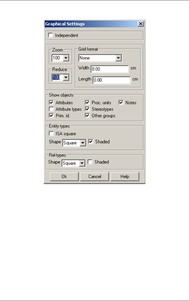
190 19 • The View menu (View)
22 juin 2009
a) In a graphical data schema window
•Independent: This option defines the way the tool reacts when the
selected objects are moved.
All the selected objects have the same moving than the initial one.
When it's checked, only the selected objects are moved (same moving
than the initial one).
When it's unchecked, some connected objects are also moved. The list
below determines how the tool reacts.
–A cluster and a recursive rel-type always stay in the same position
relatively to the entity type which hosts them. So, if the selected
entity type is moved, the cluster or recursive rel-type are move in
exactly the same way.
–Some objects only move a bit in order to remain in the same position
relatively to other objects. For instance, if one object, say A, is
placed at two thirds of the distance between two other objects, then,
when one of these two last objects is moved, A also is moved so that
it is still at two third of the distance between the two other objetcs.

19 • The View menu (View) 191
22 juin 2009
All the objects in the following list will be move proportionally to its
position with respect to several other objects when one of them, the
selected one, is moved:
Selected object
which is moved
Objects connected but not selected
which are moved proportionally
Entity type Non-recursive rel-types
Role played by the entity type
Other roles of the connected rel-types
Rel-type Roles
–Notes are moved with the objects to which they are linked if there are
all moved (selected or following a selected one). If at least one of the
objects to which the note is attached is not selected and not depen-
dent of a selected object, the note will not move at all.
•Zoom: this function shrinks or expands the graphical representation of
the current schema. You can choose a percentage (>= 10 and <= 999)
or the fit option (all the layout is displayed in the window).
•Reduce: this function reduces or enlarges the graphical representation
of the current schema. You must choose a percentage (>= 10 and <=
999). In the clipboard or on the printer, the graphical representation is
also reduced or enlarged.
•Grid: this function draws a grid in the window of the current schema.
You can define the width and length of the grid or choose a predefined
option. The Default printer option draws a grid that has the size of the
printing area of the current printer.
•Show objects: if the check boxes (attributes, primary identifiers, other
groups, processing units, notes, attribute types or stereotypes) are
checked, then the corresponding objects (or stereotypes or type +
length + decim of attributes) are displayed.
•ISA square: if checked, draw the isa relations with horizontal and
vertical lines.
•Entity type shape: in the list box, choose the form of entity types (with
square or round corners).
•Entity type shade: if checked, draw shaded entity types. Otherwise,
draw entity types without shade.
•Rel-type shape: in the list box, choose the form of rel-types (with square
or round corners)
•Rel-type shade: if checked, draw shaded rel-types. Otherwise, draw rel-
types without shade.
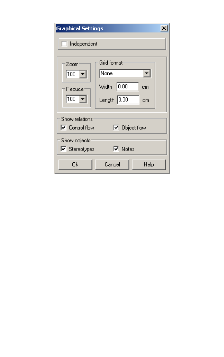
192 19 • The View menu (View)
22 juin 2009
b) In a graphical activity schema window
Defines settings for graphical processing schema views:
–Independent: This option defines the way the tool reacts when the
selected objects are moved in the graphical schema windows.
All the selected objects have the same moving than the initial one.
When it's checked, only the selected objects are moved (same
moving than the initial one).
When it's unchecked, some connected objects move a bit in order to
remain in the same position relatively to other objects. All the
objects in the following list will be move proportionally to its posi-
tion with respect to several other objects when one of them, the
selected one, is moved:
Selected object
which is moved
Objects connected but not selec-
ted which are moved proportio-
nally

19 • The View menu (View) 193
22 juin 2009
Notes are moved with the objects to which they are linked if there are
all moved (selected or following a selected one). If at least one of the
objects to which the note is attached is not selected and not depen-
dent of a selected object, the note will not move at all.
•Zoom: this function shrinks or expands the graphical representation of
the current schema. You can choose a percentage (>= 10 and <= 999) or
the fit option (all the layout is displayed in the window).
•Reduce: this function reduces or enlarges the graphical representation of
the current schema. You must choose a percentage (>= 10 and <= 999).
In the clipboard or on the printer, the graphical representation is also
reduced or enlarged.
•Grid: this function draws a grid in the window of the current schema.
You can define the width and length of the grid or choose a predefined
option. The Default printer option draws a grid that has the size of the
printing area of the current printer.
•Show objects: if the check boxes (control flows, object flows, notes or
stereotypes) are checked, then the corresponding relations, objects or
stereotypes are displayed.
Action state, initial
and final state, syn-
chronization bar,
decision state, sen-
ding and receipt
signal
Control flow
Object flow
Internal or external
object state
Control flow
Object flow
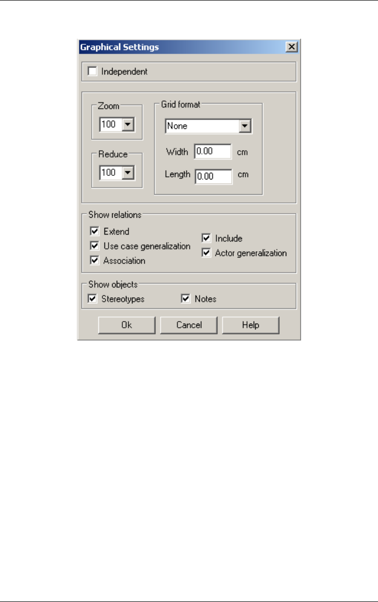
194 19 • The View menu (View)
22 juin 2009
c) In a graphical use case schema window
Defines settings for graphical processing schema views:
–Independent: This option defines the way the tool reacts when the
selected objects are moved in the graphical schema windows.
All the selected objects have the same moving than the initial one.
When it's checked, only the selected objects are moved (same
moving than the initial one).
When it's unchecked, some connected objects move a bit in order to
remain in the same position relatively to other objects. All the
objects in the following list will be move proportionally to its posi-
tion with respect to several other objects when one of them, the
selected one, is moved:
Selected object
which is moved
Objects connected but not selec-
ted which are moved proportio-
nally

19 • The View menu (View) 195
22 juin 2009
Notes are moved with the objects to which they are linked if there are
all moved (selected or following a selected one). If at least one of the
objects to which the note is attached is not selected and not depen-
dent of a selected object, the note will not move at all.
•Zoom: this function shrinks or expands the graphical representation of
the current schema. You can choose a percentage (>= 10 and <= 999) or
the fit option (all the layout is displayed in the window).
•Reduce: this function reduces or enlarges the graphical representation of
the current schema. You must choose a percentage (>= 10 and <= 999).
In the clipboard or on the printer, the graphical representation is also
reduced or enlarged.
•Grid: this function draws a grid in the window of the current schema.
You can define the width and length of the grid or choose a predefined
option. The Default printer option draws a grid that has the size of the
printing area of the current printer.
•Show objects: if the check boxes (extend and include relationship, use
case generalization, associations, actor generalization, notes or stereo-
types) are checked, then the corresponding relations, objects or stereo-
types are displayed.
Use case Extend relationship
Include relationship
Use case generalization
Association
Actor Association
Actor generalization
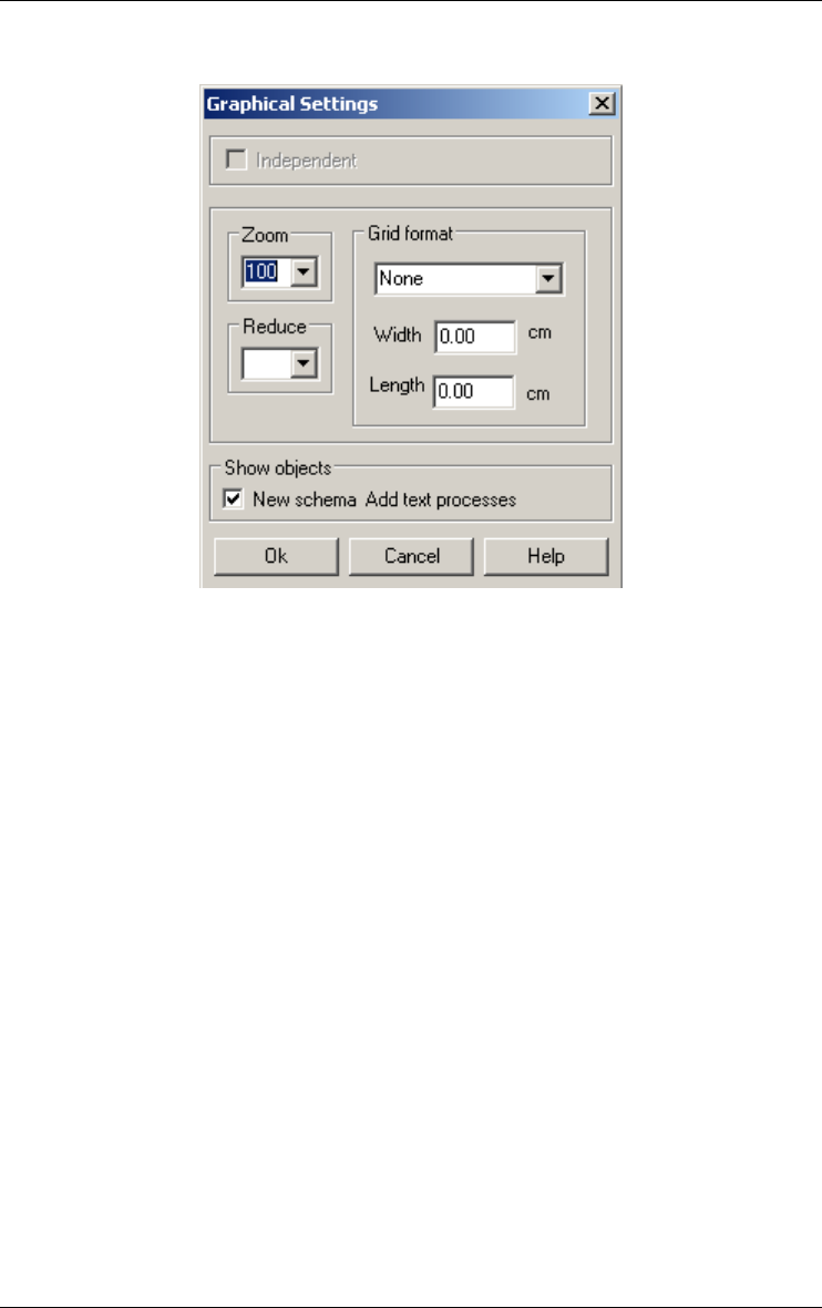
196 19 • The View menu (View)
22 juin 2009
d) In a graphical process view
Defines settings for graphical process views:
•Zoom: this function shrinks or expands the graphical representation of
the current process. You can choose a percentage (>= 10 and <= 999) or
the fit option (all the layout is displayed in the window).
•Reduce: this function reduces or enlarges the graphical representation of
the current process. You must choose a percentage (>= 10 and <= 999).
In the clipboard or on the printer, the graphical representation is also
reduced or enlarged.
•Grid: this function draws a grid in the window of the current process.
You can define the width and length of the grid or choose a predefined
option. The Default printer option draws a grid that has the size of the
printing area of the current printer.
•Show objects: if the check box is checked (new schema & add text
processes), then the corresponding objects are displayed.
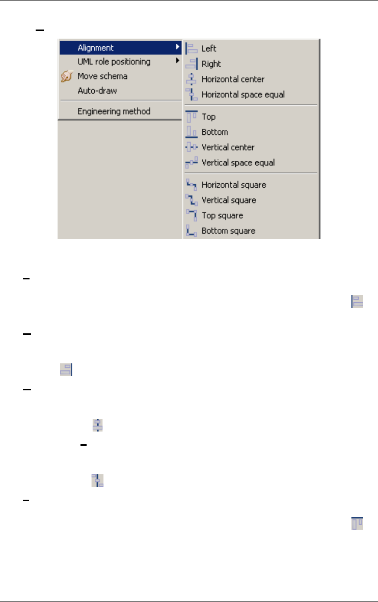
19 • The View menu (View) 197
22 juin 2009
19.3.2 Alignment
Aligns the selected object in any graphical view.
Left
Aligns selected objects so their left sides are on the left of the rectangle
formed by their external edges. Also available through the button on
the graphical tool bar.
Right
Aligns selected objects so their right sides are on the right of the rect-
angle formed by their external edges. Also available through the button
on the graphical tool bar.
Horizontal center
Aligns selected objects so their horizontal centers are in the center of
the rectangle formed by their external edges. Also available through the
button on the graphical tool bar.
Horizontal space equal
Moves selected objects horizontally so they are spaced evenly within
the rectangle formed by their external edges. Also available through the
button on the graphical tool bar.
Top
Aligns selected objects so their tops are at the top of the rectangle
formed by their external edges. Also available through the button on
the graphical tool bar.
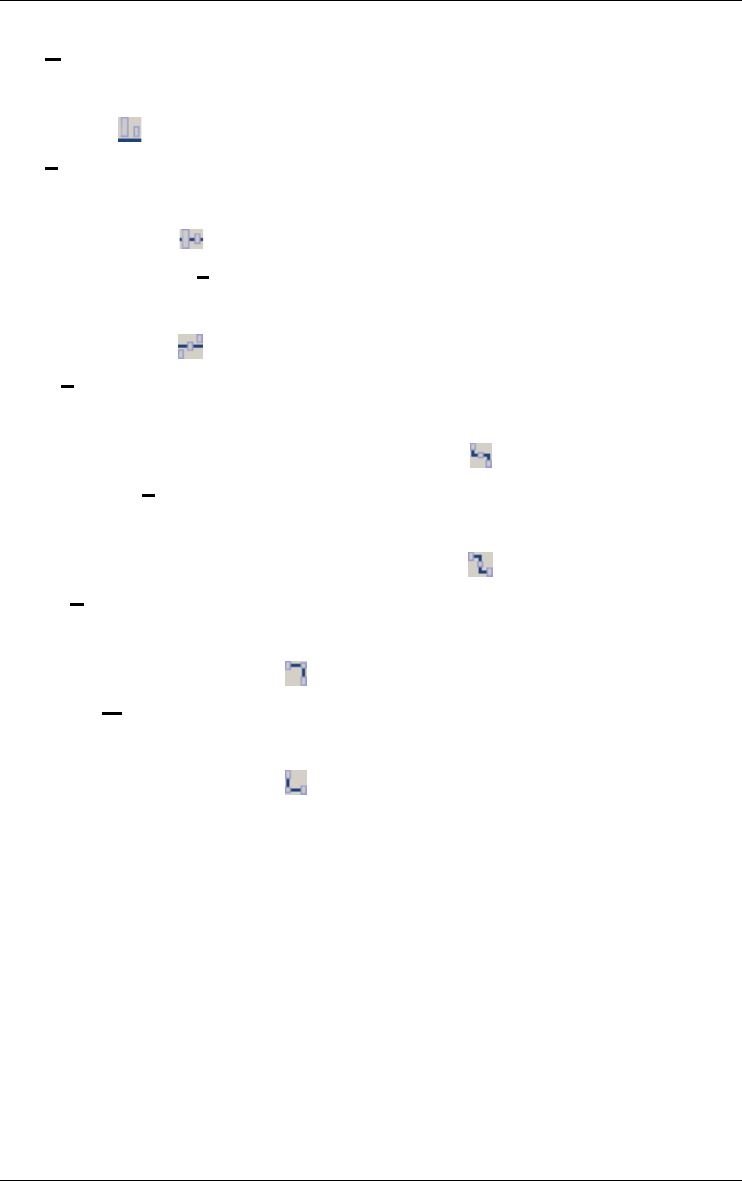
198 19 • The View menu (View)
22 juin 2009
Bottom
Aligns selected objects so their bottoms are at the bottom of the rect-
angle formed by their external edges. Also available through the button
on the graphical tool bar.
Vertical center
Aligns selected objects so their vertical centers are at the center of the
rectangle formed by their external edges. Also available through the
button on the graphical tool bar.
Vertical space equal
Moves selected objects vertically so they are spaced evenly within the
rectangle formed by their external edges. Also available through the
button on the graphical tool bar.
Horizontal square
Aligns roles of selected rel-types horizontally with their rel-type. If the
rel-type is cyclic, first role is aligned horizontally and the other verti-
cally. Also available through the button on the graphical tool bar.
Vertical square
Aligns roles of selected rel-types vertically with their rel-type. If the
rel-type is cyclic, first role is aligned horizontally and the other verti-
cally. Also available through the button on the graphical tool bar.
Top square
Puts the selected rel-types (no cyclic) in a upper corner of the rectangle
formed by the external edges of their entity-types. Also available
through the button on the graphical tool bar.
Bottom square
Puts the selected rel-types (no cyclic) in a lower corner of the rectangle
formed by the external edges of their entity-types. Also available
through the button on the graphical tool bar.
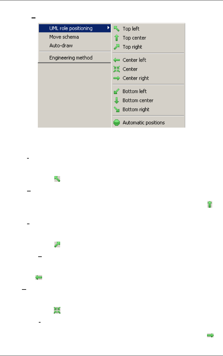
19 • The View menu (View) 199
22 juin 2009
19.3.3 UML role positioning
Places the name and cardinalities of the selected role or rel-type in a graph-
ical UML class diagram view
Top left
Places the name and cardinalities of the selected role or rel-type above
and at the left of the role or rel-type position. Also available through the
button on the UML role positioning tool bar.
Top center
Places the name and cardinalities of the selected role or rel-type above
the role or rel-type position. Also available through the button on
the UML role positioning tool bar.
Top right
Places the name and cardinalities of the selected role or rel-type above
and at right of the role or rel-type position. Also available through the
button on the UML role positioning tool bar.
Center left
Places the name and cardinalities of the selected role or rel-type at the
left of the role or rel-type position. Also available through the button
on the UML role positioning tool bar.
Center
Places the name and cardinalities of the selected role or rel-type
precisely at the role or rel-type position. Also available through the
button on the UML role positioning tool bar.
Center right
Places the name and cardinalities of the selected role or rel-type at right
of the role or rel-type position. Also available through the button on
the UML role positioning tool bar.

200 19 • The View menu (View)
22 juin 2009
Bottom left
Places the name and cardinalities of the selected role or rel-type below
and at the left of the role or rel-type position. Also available through the
button on the UML role positioning tool bar.
Bottom center
Places the name and cardinalities of the selected role or rel-type below
the role or rel-type position. Also available through the button on
the UML role positioning tool bar.
Bottom right
Places the name and cardinalities of the selected role or rel-type below
and at the right of the role or rel-type position. Also available through
the button on the UML role positioning tool bar.
Automatic positions
Sets automatically the name and cardinalities of the selected role or rel-
type. Also available through the button on the UML role positioning
tool bar.
19.3.4 Move window
In project and schema graphical views, toggles on/off the window
moving mode; in that mode, the cursor is changed to a hand, clicking
and dragging (the hand becomes a fist) will move the graphical view
in its window; this is a faster way than using the scroll bars for
browsing through large graphics. Also available through the button on
the standard tool bar.
19.3.5 Auto-Draw
In a graphical schema view, proposes a new graphical layout of the current
schema (useful in reverse engineering). You must use this function with
caution because the new layout is independent of the semantics and no undo
function is available. This function is also a stochastic process, a new activa-
tion gives a new layout.
19.4 Displaying engineering method window
19.4.1 Engineering method
Displays a window containing the current engineering method. The engi-
neering method is the way of working to follow in order to complete the
project. In this version of DB-MAIN, the engineering method is optional and

19 • The View menu (View) 201
22 juin 2009
used for documentation only. It can be shown in a window and it is possible
to browse through it. An analyst can refer to it at any time.
An engineering method must be written in MDL (Method Description
Language) and compiled with the external MDL compiler to produce a
*.LUM file. This file can be added to the project when it is created. This is
optional. If no method is specified, a default one allows analysts to do
anything.
19.5 Navigating in graphical and textual views
There are many ways to navigate into graphical or textual views. For each type
of windows, the user can apply some mouse and keyboard actions.
19.5.1 The textual data schema window
The textual schema window is a hypertext representation of the schema. There
are many ways to navigate into those views.
When objects are selected, this selection is kept when you change the type of
the view, if there is only one object selected this object is displayed in the
centre of the window.
When two windows (graphical and textual) show the same schema, the selec-
tion is common to the two windows.
If there is only one object selected then it is the current object. If there is no
selected object or more then one then there is no current object. All the
instances of the current object are marked.

202 19 • The View menu (View)
22 juin 2009
a) Mouse actions
left-side button (single click): selects an object and shows its
properties in the property box (if
present)
left-side button (double click): if the property box is present,
shows the properties of the
selected object
if the property box is not present,
opens it with the properties of the
selected object
control + left-side button (single
click):
adds an object to the selection or
removes an already selected object
from the selection
shift + left-side button (single
click):
selects objects between the first
selected object and the current one
right-side button (single click): goes to the origin definition of the
object whose name is clicked on.
e.g. clicking on a role sends back
to its entity type
b) Keyboard actions
enter key: if the property box is not present, opens it with the
properties of the selected object
tab key: displays the next occurrence of the selected object
(marked by >>) in the centre of the windows
up-arrow: scrolls the schema one line upward
down-arrow: scrolls the schema one line downward
left-arrow: scrolls the schema one half-screen to the left
right-arrow: scrolls the schema one half-screen to the right
Alt + up-arrow: when an attribute, a processing unit or a group is
selected: swaps it with the previous one
when a role is selected: swaps it with the previous
one
Alt + down-
arrow:
when an attribute, a processing unit or a group is
selected: swaps it with the next one
when a role is selected: swaps it with the next one

19 • The View menu (View) 203
22 juin 2009
19.5.2 The graphical data schema window
If there is only one object selected then it is the current object. If there is no
selected object or more then one then there is no current object.
a) Mouse actions
left-side button (single click): selects an object and shows its
properties in the property box (if
present)
shift + left-side button (single
click):
adds an object to the selection or
removes an already selected object
from the selection
left-side button pressed and drag normal mode: draws a rectangle
for multiple selection
move window mode (menu View/
Move window or hand tool in
standard toolbar): move the
schema in its window
drag a selected object: moves all the selected objects in
the windows
left-side button (double click): if the property box is present,
shows the properties of the
selected object
if the property box is not present,
opens it with the properties of the
selected object
right-side button (single click): on a rel-type: aligns the rel-type
between its entity types
on a role: aligns the role between
its rel-type and its entity type(s)
If, while the left-side button is down, the mouse leaves the window, then the
window is automatically scrolled.
Del key: deletes the selected objects
Ctrl + A: selects all the schema objects
Ctrl + M: marks the selected objects
Ctrl + P: navigates to the previous object
Ctrl + N: navigates to the next object

204 19 • The View menu (View)
22 juin 2009
b) Keyboard actions
enter key: if the property box is not present, opens it with the
properties of the selected object
up-arrow: if an object is selected, moves the object four pixel
up
else scrolls the schema one line upward
down-arrow: if an object is selected, moves the object four pixel
down
else scrolls the schema one line downward
left-arrow: if an object is selected, moves the object four pixel
left
else scrolls the schema one screen to the left
right-arrow: if an object is selected, moves the object four pixel
right
else scrolls the schema one screen to the right
Alt + up-arrow: when an attribute, a processing unit or a group is
selected: swaps it with the previous one
Alt + down-
arrow:
when an attribute, a processing unit or a group is
selected: swaps it with the next one
Control + left-
arrow:
if an object is selected: moves the object one pixel
left
Control + right-
arrow:
if an object is selected: moves the object one pixel
right
Control + up-
arrow:
if an object is selected: moves the object one pixel
up
Control + down-
arrow:
if an object is selected: moves the object one pixel
down
Del key: deletes the selected object
Ctrl + A: selects all the schema objects
Ctrl + M: marks the selected objects
Ctrl + P: navigates to the previous object
Ctrl + N: navigates to the next object
19.5.3 The textual processing schema window
The textual schema window is a hypertext representation of the schema. There
are many ways to navigate into those views.

19 • The View menu (View) 205
22 juin 2009
When objects are selected, this selection is kept when you change the type of
the view, if there is only one object selected this object is displayed in the
centre of the window.
If there is only one object selected then it is the current object. If there is no
selected object or more then one then there is no current object. All the
instances of the current object are marked (>>).

206 19 • The View menu (View)
22 juin 2009
a) Mouse actions
left-side button (single click): selects an object and shows its
properties in the property box (if
present)
left-side button (double click): if the property box is present,
shows the properties of the
selected object
if the property box is not present,
opens it with the properties of the
selected object
control + left-side button (single
click):
adds an object to the selection or
removes an already selected object
from the selection
shift + left-side button (single
click):
selects objects between the first
selected object and the current one
right-side button (single click): goes to the origin definition of the
object whose name is clicked on.
e.g. clicking on a call relation
sends back to its called processing
unit;
b) Keyboard actions
enter key: if the property box is not present, opens it with the
properties of the selected object
tab key: displays the next occurrence of the selected object
(marked by >>) in the centre of the windows
up-arrow: scrolls the schema one line upward
down-arrow: scrolls the schema one line downward
left-arrow: scrolls the schema one half-screen to the left
right-arrow: scrolls the schema one half-screen to the right
Alt + up-arrow: when an internal data object is selected: swaps it
with the previous one
Alt + down-
arrow:
when an internal data object is selected: swaps it
with the next one
Del key: deletes the selected objects
Ctrl + A: selects all the schema objects

19 • The View menu (View) 207
22 juin 2009
19.5.4 The graphical processing schema window
If there is only one object selected then it is the current object. If there is no
selected object or more then one then there is no current object.
a) Mouse actions
left-side button (single click): selects an object and shows its
properties in the property box (if
present)
shift + left-side button (single
click):
adds an object to the selection or
removes an already selected object
from the selection
left-side button pressed and drag normal mode: draws a rectangle
for multiple selection
move window mode (menu View/
Move window or hand tool in
standard toolbar): move the
schema in its window
drag a selected object: moves all the selected objects in
the windows
left-side button (double click): if the property box is present,
shows the properties of the
selected object
if the property box is not present,
opens it with the properties of the
selected object
If, while the left-side button is down, the mouse leaves the window, then the
window is automatically scrolled.
Ctrl + M: marks the selected objects
Ctrl + P: navigates to the previous object
Ctrl + N: navigates to the next object

208 19 • The View menu (View)
22 juin 2009
b) Keyboard actions
enter key: if the property box is not present, opens it with the
properties of the selected object
up-arrow: if an object is selected, moves the object four pixel
up
else scrolls the schema one line upward
down-arrow: if an object is selected, moves the object four pixel
down
else scrolls the schema one line downward
left-arrow: if an object is selected, moves the object four pixel
left
else scrolls the schema one screen to the left
right-arrow: if an object is selected, moves the object four pixel
right
else scrolls the schema one screen to the right
Alt + up-arrow: when an internal data object is selected: swaps it
with the previous one
Alt + down-
arrow:
when an internal data object is selected: swaps it
with the next one
Control + left-
arrow:
if an object is selected: moves the object one pixel
left
Control + right-
arrow:
if an object is selected: moves the object one pixel
right
Control + up-
arrow:
if an object is selected: moves the object one pixel
up
Control + down-
arrow:
if an object is selected: moves the object one pixel
down
Del key: deletes the selected object
Ctrl + A: selects all the schema objects
Ctrl + M: marks the selected objects
Ctrl + P: navigates to the previous object
Ctrl + N: navigates to the next object
19.5.5 The graphical process window

19 • The View menu (View) 209
22 juin 2009
a) Mouse actions
left-side button (single click): selects an object (schema or text
file) and shows its properties in the
property box (if present)
shift + left-side button (single
click):
adds an object to the selection
left-side button pressed and drag normal mode: draws a rectangle
for multiple selection
move window mode (menu View/
Move window or hand tool in
standard toolbar): move the
schema in its window
drag a selected object: moves all the selected objects in
the windows
left-side button (double click): opens the window of an object
(graphical schema window for a
schema and source file window for
a text file) or replace the content of
the window by the history of the
selected engineering process.
right-side button (single click): on a product: aligns the product
between its processes
on a process: aligns the process
between its products
'Close Window' icon closes the history of the current
process and displays the history of
its parent, if there is one; else,
closes the project.
If, while the left-side button is down, the mouse leaves the window, then the
window is automatically scrolled.

210 19 • The View menu (View)
22 juin 2009
b) Keyboard actions
enter key: opens the window of the selected object
up-arrow: if an object is selected, moves the object one pixel
up
else scrolls the schema one line upward
down-arrow: if an object is selected, moves the object one pixel
down
else scrolls the schema one line downward
left-arrow: if an object is selected, moves the object one pixel
left
else scrolls the schema one screen to the left
right-arrow: if an object is selected, moves the object one pixel
right
else scrolls the schema one screen to the right
Control + left-
arrow:
if an object is selected: moves the object one pixel
left
Control + right-
arrow:
if an object is selected: moves the object one pixel
right
Control + up-
arrow:
if an object is selected: moves the object one pixel
up
Control + down-
arrow:
if an object is selected: moves the object one pixel
down
Del key: deletes the selected object (schema, text file,
process or decision)
Ctrl + A: selects all the schema objects
Ctrl + M: marks the selected objects
To add a product in this window use Product/New schema or Product/Add
file. To add a file you can also use the drag & drop technique: select files into
the Explorer (for example) and drop them into the process window (standard
or dependency).
19.5.6 The source file window
This window displays the text file, it is not possible to edit the text. Each line
can be marked, colored and each one have a description.

19 • The View menu (View) 211
22 juin 2009
a) Mouse action
Left-side button (single click): selects a line
if the property box is present,
shows its properties
Left-side button (double click): edits the description of the selected
line
control + left-side button (single
click):
if the line is not selected, adds it to
the selection
if the line is selected, removes it
from the selection
shift + left-side button (single
click):
selects all the lines from the first
selected one till the current one
b) Keyboard actions
Ctrl + A: selects all the lines
Ctrl + M: marks the selected lines

212 19 • The View menu (View)
22 juin 2009
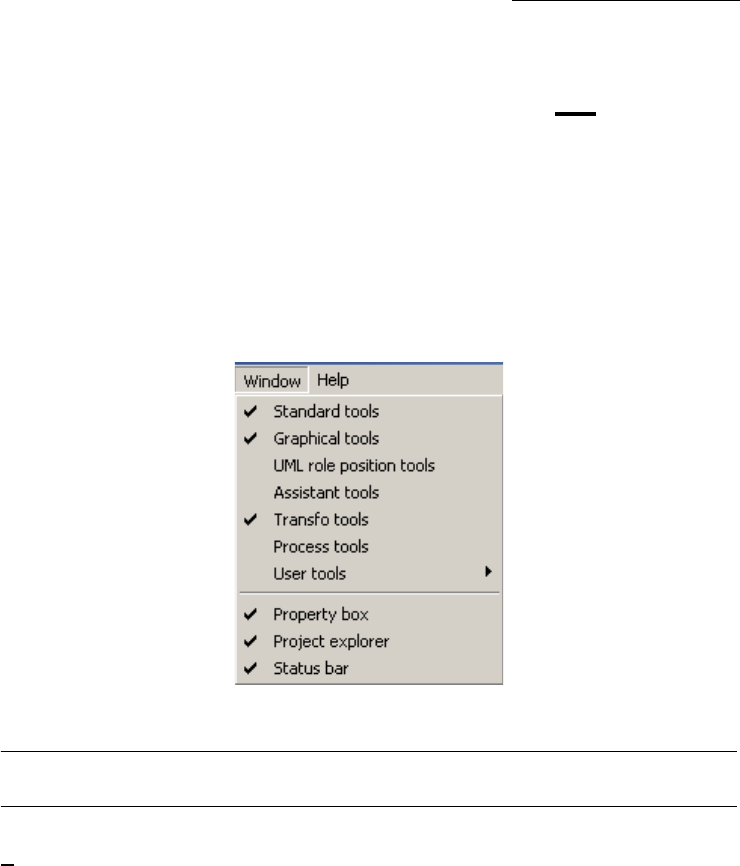
22 juin 2009
Chapter 20
The Window menu (Window)
This menu includes five sections through which the user can manipulate
windows and tool bars:
1. displaying or hiding tool bars;
2. displaying or hiding properties box,project explorer and status bar.
20.1 The commands of the Window menu - Summary
Standard tools displays/hides the standard floating tool bar
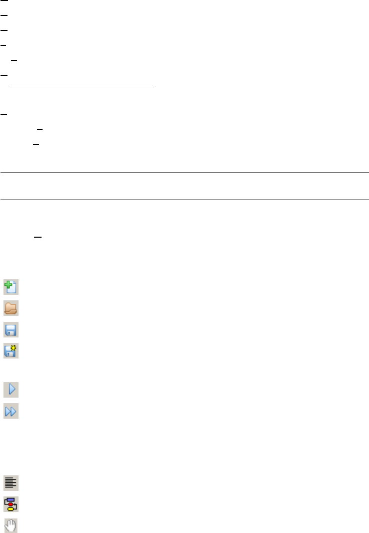
Graphical tools displays/hides the graphical floating tool bar
UML role position tools displays/hides the UML role position floating tool bar
Assistant tools displays/hides the assistant floating tool bar
Transfo tools displays/hides the transformations floating tool bar
Process tools displays/hides the process modeling floating tool bar
User tools displays/hides the user-defined floating tool bars
Property box displays/hides the property box window
Project explorer displays/hide the project explorer window
Status bar displays/hides the status bar
20.2 Displaying or hiding tool bars
20.2.1 Standard tools
Toggles display of standard tool bar. The shortcuts are:
builds a new project
opens an existing project
saves the current project as a *.lun file
saves the current project as a new *.lun file
runs a Java or compiled Voyager 2 plug-in
re-executes the last instance of a Voyager 2 plug-in without loading it
See also the File menu (chapter 11).
Standard textual view for current schema
Standard graphical view for the current schema
Moves the graphical view in its window
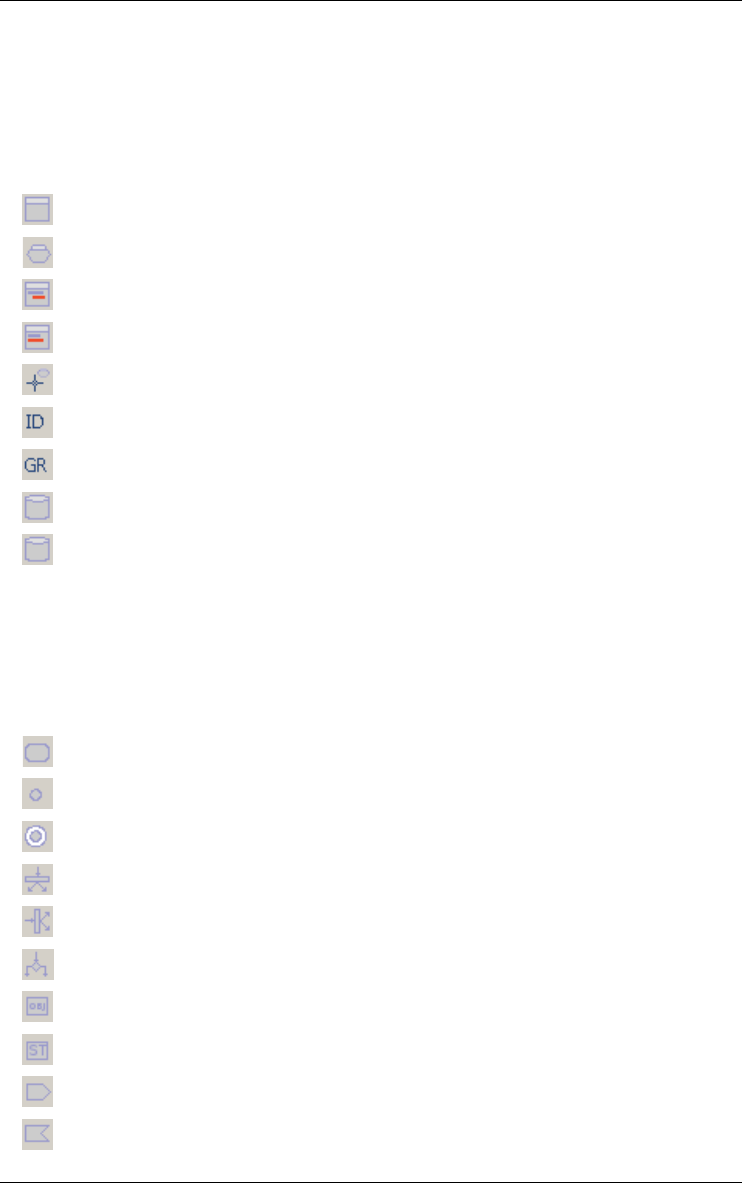
20 • The Window menu (Window) 215
22 juin 2009
See also the View menu (chapter 19).
The following buttons are only present in the toolbar when the current window
hosts a data schema:
creates a new entity type (interactive or from the source text)
creates a new relationship type
adds a new attribute as first child
adds a new attribute as next sibbling
creates a new role
creates a new identifier with the selected attributes and/or roles
creates a new group with the selected attributes and/or roles
creates a new collection
adds a new processing unit to the current schema, rel-type or entity type
See also the New menu (chapter 14).
The following buttons are only present in the toolbar when the current window
hosts a UML activity diagram
creates a new action state
creates a new initial state
creates a new final state
creates a new horizontal synchronization bar
creates a new vertical synchronization bar
creates a new decision
creates a new object
creates a new state
creates a new message sending
creates a new message receipt
216 20 • The Window menu (Window)
22 juin 2009
See also the New menu (chapter 14).
The following buttons are only present in the toolbar when the current window
hosts a UML use case diagram:
creates a new use case
creates a new actor
creates a new extend relationship between two use cases
creates a new inclusion relationship between two use cases
creates a new generalization relationship between use cases
creates a new association relationship between a use case and an actor
creates a new generalization relationship between two actors
See also the New menu (chapter 14).
adds a note to the selected object
adds a link between an existing note and another object
colors the selected objects in the color of the paint in the icon
marks or unmarks the selected objects
chooses a mark plan
See also the Edit menu (chapter 12).
20.2.2 Graphical tools
Toggles display of graphical tool bar.
creates a new control flow relationship
creates a new object flow relationship
if unchecked, all the connected objects are moved together with the
current object, else only the current object is moved
copies the graphical view of the selected object onto the clipboard
20 • The Window menu (Window) 217
22 juin 2009
See also the Edit menu (chapter 12).
aligns selected objects so their left sides are on the left of the rectangle
formed by their external edges
aligns selected objects so their right sides are on the right of the rect-
angle formed by their external edges
aligns selected objects so their horizontal centers are in the center of
the rectangle formed by their external edges
moves selected objects horizontally so they are spaced evenly within
the rectangle formed by their external edges
See also the View menu (chapter 19).
aligns selected objects so their tops are at the top of the rectangle
formed by their external edges
aligns selected objects so their bottoms are at the bottom of the rect-
angle formed by their external edges
aligns selected objects so their vertical centers are at the center of the
rectangle formed by their external edges
moves selected objects vertically so they are spaced evenly within the
rectangle formed by their external edges
See also the View menu (chapter 19).
aligns roles of selected rel-types horizontally with their rel-type
aligns roles of selected rel-types vertically with their rel-type
puts the selected rel-types (no cyclic) in a upper corner of the rectangle
formed by the external edges of their entity-types
puts the selected rel-types (no cyclic) in a lower corner of the rectangle
formed by the external edges of their entity-types
See also the View menu (chapter 19).
expands the graphical representation of the current schema (current
zoom + 10%)
shrinks the graphical representation of the current schema (current
zoom - 10%)
shrinks or expands the graphical representation of the current
schema or project (choose a percentage or the fit option)
218 20 • The Window menu (Window)
22 juin 2009
20.2.3 UML role position tools
Toggles display of UML role position tool bar.
The name or cardinalities of a role or a rel-type are placed above and at
the left of the position of the role or rel-type
The name or cardinalities of a role or a rel-type are placed above the
position of the role or rel-type
The name or cardinalities of a role or a rel-type are placed above and at
the right of the position of the role or rel-type
The name or cardinalities of a role or a rel-type are placed at the right of
the position of the role or rel-type
The name or cardinalities of a role or a rel-type are placed below and at
the right of the position of the role or rel-type
The name or cardinalities of a role or a rel-type are placed below the
position of the role or rel-type
The name or cardinalities of a role or a rel-type are placed below and at
the left of the position of the role or rel-type
The name or cardinalities of a role or a rel-type are placed at the left of
the position of the role or rel-type
The name or cardinalities of a role or a rel-type are placed precisely at
the position of the role or rel-type
The name or cardinalities of a role or a rel-type are placed at the best
position to avoid being one the lines
See also the View menu (chapter 19).
20.2.4 RE tools
Toggles display of reverse engineering tool bar.
Fast transformation of a conceptual schema into physical relational
model
searches a text for the first instance of a pattern
searches a text for the next instance of a pattern
in a logical schema and its source text, hightlights the source text line of
the selected object conversely
finds the "other" groups connected to the current group
See also the Assist menu (chapter 16).
20.2.5 Transfo tools
Toggles display of transformation tool bar.
20 • The Window menu (Window) 219
22 juin 2009
ET -> Rel-type Transforms the current entity type into a relationship
type
ET -> Attribute Transforms the current entity type into an attribute
Is-a -> rel-types Transforms the is-a relation(s) of current entity type
into one-to-one relationship type(s)
Rel-types -> is-a Transforms the current relationship type(s) of
current entity type into is-a relation(s)
Split/Merge Splits the current entity type into two entity types or
merges two entity types linked by a one-to-one rela-
tionship type
Add Tech ID Adds a technical primary id to the current entity type
RT -> Entity type Transforms the current relationship type into an
entity type
RT -> Attribute Transforms the current relationship type into refer-
ence attributes (foreign key)
RT -> Object att. Transforms the current relationship type into object-
attribute(s)
Att. -> Entity type Transforms the current attribute into an entity type
Disaggregation Transforms the current compound attribute,
replacing it by its components
Multi -> Single Transforms the current multivalued attribute into a
single-valued attribute
Single -> Multi Transforms the current single-valued attribute into a
multivalued attribute
Multi -> List Single Transforms the current multivalued attribute into a
list of single-valued attributes
Multi Conversion Changes the collection type of the current attribute
(with or without loss)
Materialize domain Materializes the user-defined domain of the current
attribute
Object att. -> RT Transforms the current object type attribute into a
rel-type
Multi-ET -> RT Transforms the current multi-ET role into a list of
relationship types
Group -> Rel-type Transforms the current referential group (foreign
key) into a relationship type
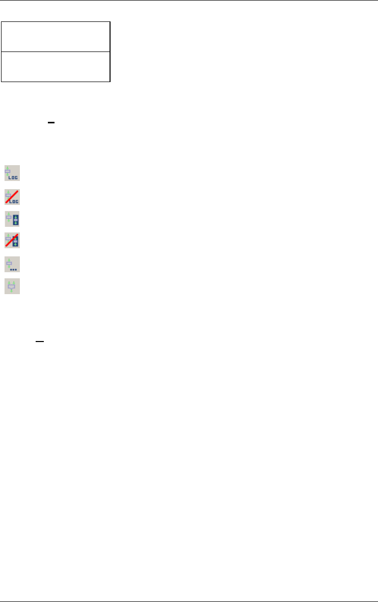
220 20 • The Window menu (Window)
22 juin 2009
See also the Transform menu (chapter 15).
20.2.6 Process tools
Toggles display of process modeling tool bar.
updates the selected products by using the primitive functions of the
tool
terminates the use of primitives
creates a new engineering process using selected products in input
terminates the current engineering process using selected products as
output
allows a terminated process to be continued
takes the decision of continuing with one or some of the selected prod-
ucts
See also the Engineering menu (chapter 17).
20.2.7 User tools
Toggles display of ten user tool bars. The user tools bars contain shortcuts
for the user tools in the File menu (chapter 11). These lists of maximum
twenty-five Java or Voyager 2 plug-ins or menu entries are defined by the
configuration dialog box in the DB_MAIN.INI file (see File menu in chapter
11).
Aggregation Transforms the current group into a compound
attribute
Group -> Multi-valued Transforms the current group of single-valued
attributes into a multivalued attribute
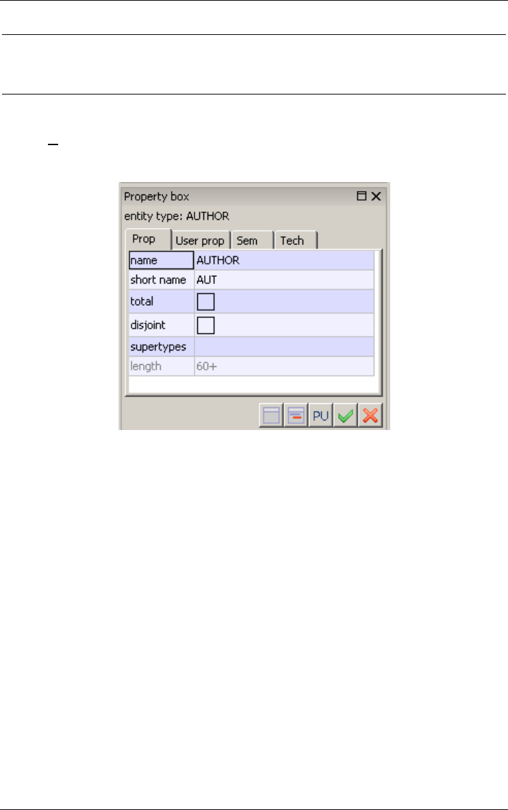
20 • The Window menu (Window) 221
22 juin 2009
20.3 Displaying or hiding properties box, project explorer
and status bar
20.3.1 Property box
Shows/hides the property box.
The property box is a small window always in front of the others that
contains all the properties of the last selected object in another window. In
this window, the user can visualize or change the property values of the
current object. This window can have four different tabs:
•The Prop tab lists all the static built-in properties of the object.
•The User prop tab lists all the dynamic user-defined properties of the
object.
•The Sem tab shows the semantic description of the object that have one.
It can also show the description of the objects that just have one descrip-
tion (processes for instance).
•The Tech tab shows the technical description of the objects that have
one.
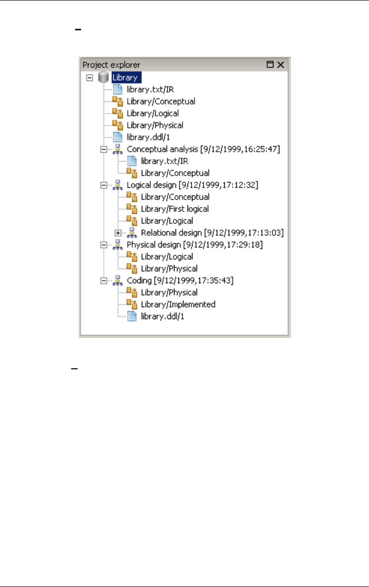
222 20 • The Window menu (Window)
22 juin 2009
20.3.2 Project explorer
Shows/hides the project explorer tree window.
20.3.3 Status bar
Toggles display of status bar. This bar contains a short help for the selected
menu entry, the number of objects in the current project.
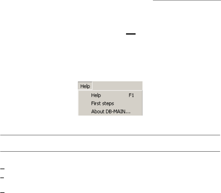
22 juin 2009
Chapter 21
The Help menu (Help or F1 key)
This menu includes one section through which the user can access to help.
21.1 The commands of the Help menu - Summary
Help <F1> displays the table of contents for the help system
First steps displays the first steps for using DB-MAIN to develop a
small relational database
About DB-MAIN displays version, copyrights and DB-MAIN project infor-
mations

21.2 Displaying help and other informations
21.2.1 Help (<F1>)
Displays the table of contents for the help system that provides information
on virtually all aspects of DB-MAIN.
21.2.2 First steps
Displays the First steps for using DB-MAIN to develop a small relational
database. This (very) short tutorial is intended to introduce the first-time user
to the basics of database analysis, database design and SQL generation
through DB-MAIN.
21 • The Help menu (Help or F1 key) 225
22 juin 2009
21.2.3 About DB-MAIN...
Displays version, copyrights and DB-MAIN project information. The user can
also upgrade its license number, create a demo project, access to First Steps
tutorial and help

226 21 • The Help menu (Help or F1 key)
22 juin 2009

22 juin 2009
Annexe 1
Elementary constraints of schema
analysis assistant
1.1 Constraints on schema
1.1.1 ET_per_SCHEMA <min> <max>
Description: The number of entity types per schema must be at least <min>
and at most <max>.
Parameters: <min> and <max> are integer constants or N.
1.1.2 RT_per_SCHEMA <min> <max>
Description: The number of rel-types per schema must be at least <min> and
at most <max>.
Parameters: <min> and <max> are integer constants or N.
1.1.3 COLL_per_SCHEMA <min> <max>
Description: The number of collections per schema must be at least <min>
and at most <max>.
Parameters: <min> and <max> are integer constants or N.

1.1.4 DYN_PROP_of_SCHEMA <dynamic property> <parameters>
Description: Check some properties of the dynamic properties.
Parameters: See Section 1.17.
1.1.5 SELECTED_SCHEMA
Description: Search for all selected objects. This constraint should not be used
for validation.
Parameters: None.
1.1.6 MARKED_SCHEMA
Description: Search for all marked objects. This constraint should not be used
for validation.
Parameters: None.
1.1.7 PLUGIN_CONSTRAINT_on_SCHEMA <plugin-file> <plugin-
predicate> <parameters>
Description: A call to a Java or Voyager 2 boolean function. This constraint
returns the result of the function. It provides an easy way to add any new
constraint.
Parameters: See Section 1.16.
1.2 Constraints on collections
1.2.1 ALL_COLL
Description: Used for a search, this constraint finds all collections. It should
not be used for a validation.
Parameters: None.
1.2.2 ET_per_COLL <min> <max>
Description: The number of entity types per collection must be at least <min>
and at most <max>.
Parameters: <min> and <max> are integer constants or N.

• 227
22 juin 2009
1.2.3 DYN_PROP_of_COLL <dynamic property> <parameters>
Description: Check some properties of the dynamic properties.
Parameters: See Section 1.17.
1.2.4 SELECTED_COLL
Description: Search for all selected objects. This constraint should not be
used for validation.
Parameters: None.
1.2.5 MARKED_COLL
Description: Search for all marked objects. This constraint should not be used
for validation.
Parameters: None.
1.2.6 PLUGIN_CONSTRAINT_on_COLL <plugin-file> <plugin-
predicate> <parameters>
Description: A call to a Java or Voyager 2 boolean function. This constraint
returns the result of the function. It provides an easy way to add any new
constraint.
Parameters: See Section 1.16.
1.3 Constraints on entity types
1.3.1 ALL_ET
Description: Used for a search, this constraint finds all entity types. It should
not be used for a validation.
Parameters: None.
1.3.2 ATT_per_ET <min> <max>
Description: The number of attributes per entity type must be at least <min>
and at most <max>.
Parameters: <min> and <max> are integer constants or N.

228 •
22 juin 2009
1.3.3 ATT_LENGTH_per_ET <min> <max>
Description: The sum of the size of all the attributes of an entity type must be
at least <min> and at most <max>.
Parameters: <min> and <max> are integer constants or N.
1.3.4 ROLE_per_ET <min> <max>
Description: The number of roles an entity type can play must be at least
<min> and at most <max>.
Parameters: <min> and <max> are integer constants or N.
1.3.5 ONE_ROLE_per_ET <min> <max>
Description: Entity types play between <min> and <max> roles with
maximum cardinality = 1.
Parameters: <min> and <max> are integer constants or N.
1.3.6 N_ROLE_per_ET <min> <max>
Description: Entity types play between <min> and <max> roles with
maximum cardinality > 1.
Parameters: <min> and <max> are integer constants or N.
1.3.7 MAND_ROLE_per_ET <min> <max>
Description: The number of mandatory roles played by entity types must be
at least <min> and at most <max>.
Parameters: <min> and <max> are integer constants or N.
1.3.8 OPT_ROLE_per_ET <min> <max>
Description: The number of optional roles played by entity types must be at
least <min> and at most <max>.
Parameters: <min> and <max> are integer constants or N.
1.3.9 GROUP_per_ET <min> <max>
Description: The number of groups per entity type must be at least <min> and
at most <max>.
Parameters: <min> and <max> are integer constants or N.

• 229
22 juin 2009
1.3.10 ID_per_ET <min> <max>
Description: The number of identifiers per entity type must be at least <min>
and at most <max>.
Parameters: <min> and <max> are integer constants or N.
1.3.11 PID_per_ET <min> <max>
Description: The number of primary identifiers per entity type must be at least
<min> and at most <max>.
Parameters: <min> and <max> are integer constants or N.
1.3.12 ALL_ATT_in_ID_ET <yn>
Description: If parameter is "yes", all the identifiers of an entity type contain
all attributes (possibly with or without some roles) or the entity type has no
explicit identifier. If parameter is "no", an entity type must have at least one
identifier which does not contain all the attributes of the entity type.
Parameters: <yn> is either yes or no.
1.3.13 ALL_ATT_ID_per_ET <min> <max>
Description: The number of primary identifiers made of attributes only must
be at least <min> and at most <max>.
Parameters: <min> and <max> are integer constants or N.
1.3.14 HYBRID_ID_per_ET <min> <max>
Description: The number of hybrid identifiers (made of attributes, roles or
other groups) must be at least <min> and at most <max>.
Parameters: <min> and <max> are integer constants or N.
1.3.15 KEY_ID_per_ET <min> <max>
Description: The number of identifiers that are access keys must be at least
<min> and at most <max>.
Parameters: <min> and <max> are integer constants or N.
1.3.16 ID_NOT_KEY_per_ET <min> <max>
Description: The number of identifiers that are not access keys must be at
least <min> and at most <max>.
Parameters: <min> and <max> are integer constants or N.

230 •
22 juin 2009
1.3.17 KEY_ALL_ATT_ID_per_ET <min> <max>
Description: The number of identifiers made of attributes only which are
access keys must be at least <min> and at most <max>.
Parameters: <min> and <max> are integer constants or N.
1.3.18 EMBEDDED_ID_per_ET <min> <max>
Description: The number of overlapping identifiers must be at least <min>
and at most <max>.
Parameters: <min> and <max> are integer constants or N.
1.3.19 ID_DIFF_in_ET <type>
Description: All the identifiers of an entity type are different. Similarity
criteria are function of the specified <type>: components indicates that all the
elements of both identifiers are the same, possibly in a different order,
components_and_order forces the components in both identifiers to be in the
same order for the identifiers to be identical. For instance, let an entity type
have two identifiers, one made of attributes A and B, the other made of
attributes B and A. They will be said to be identical when <type> is compo-
nents and different in the other case.
Parameters: <type> is either components or components_and_order.
1.3.20 KEY_per_ET <min> <max>
Description: The number of access key groups per entity type must be at least
<min> and at most <max>.
Parameters: <min> and <max> are integer constants or N.
1.3.21 ALL_ATT_KEY_per_ET <min> <max>
Description: The number of access keys made of attributes only must be at
least <min> and at most <max>.
Parameters: <min> and <max> are integer constants or N.
1.3.22 HYBRID_KEY_per_ET <min> <max>
Description: The number of hybrid access keys must be at least <min> and at
most <max>.
Parameters: <min> and <max> are integer constants or N.

• 231
22 juin 2009
1.3.23 ID_KEY_per_ET <min> <max>
Description: The number of access keys that are identifiers too must be at
least <min> and at most <max>.
Parameters: <min> and <max> are integer constants or N.
1.3.24 KEY_PREFIX_in_ET <type>
Description: An access key is a prefix of another identifier or access key.
<type> specifies whether the order of the attributes must be the same in the
access key and in the prefix or not.
This constraint is particularly well suited for using the assistant for search. To
use it in order to validate a schema, it should be used with a negation (not
KEY_PREFIX_in_ET).
Parameters: <type> is either same_order or any_order.
1.3.25 REF_per_ET <min> <max>
Description: The number of reference groups in an entity type must be at least
<min> and at most <max>.
Parameters: <min> and <max> are integer constants or N.
1.3.26 REF_in_ET <type>
Description: Reference constraints reference groups of type <type>.
Parameters: <type> is either pid to find ET with primary identifiers or sid to
find ET with secondary identifiers.
1.3.27 COEXIST_per_ET <min> <max>
Description: The number of coexistence groups per entity type must be at
least <min> and at most <max>.
Parameters: <min> and <max> are integer constants or N.
1.3.28 EXCLUSIVE_per_ET <min> <max>
Description: The number of exclusive groups per entity type must be at least
<min> and at most <max>.
Parameters: <min> and <max> are integer constants or N.
1.3.29 ATLEASTONE_per_ET <min> <max>
Description: The number of at-least-one groups per entity type must be at
least <min> and at most <max>.

232 •
22 juin 2009
Parameters: <min> and <max> are integer constants or N.
1.3.30 PROCUNIT_per_ET
Description: The number of processing units per entity type must be at least
<min> and at most <max>.
Parameters: <min> and <max> are integer constants or N.
1.3.31 COLL_per_ET <min> <max>
Description: The number of collections an entity type belongs to must be at
least <min> and at most <max>.
Parameters: <min> and <max> are integer constants or N.
1.3.32 DYN_PROP_of_ET <dynamic property> <parameters>
Description: Check some properties of the dynamic properties.
Parameters: See Section 1.17.
1.3.33 SELECTED_ET
Description: Search for all selected objects. This constraint should not be
used for validation.
Parameters: None.
1.3.34 MARKED_ET
Description: Search for all marked objects. This constraint should not be used
for validation.
Parameters: None.
1.3.35 PLUGIN_CONSTRAINT_on_ET <plugin-file> <plugin-predicate>
<parameters>
Description: A call to a Java or Voyager 2 boolean function. This constraint
returns the result of the function. It provides an easy way to add any new
constraint.
Parameters: See Section 1.16.

• 233
22 juin 2009
1.4 Constraints on is-a relations
1.4.1 ALL_ISA
Description: Used for a search, this constraint finds all is-a relations. It should
not be used for a validation.
Parameters: None.
1.4.2 SUB_TYPES_per_ISA <min> <max>
Description: An entity type can not have less than <min> sub-types or more
than <max> sub-types.
Parameters: <min> and <max> are integer constants or N.
1.4.3 SUPER_TYPES_per_ISA <min> <max>
Description: An entity type can not have less than <min> super-types or more
than <max> super-types.
Parameters: <min> and <max> are integer constants or N.
1.4.4 TOTAL_in_ISA <yn>
Description: Is-a relations have (yes) or do not have (no) the total attribute.
Parameters: <yn> is either yes or no.
1.4.5 DISJOINT_in_ISA <yn>
Description: Is-a relations have (yes) or do not have (no) the disjoint attribute.
Parameters: <yn> is either yes or no.
1.4.6 DYN_PROP_of_ISA <dynamic property> <parameters>
Description: Check some properties of the dynamic properties.
Parameters: See Section 1.17.
1.4.7 SELECTED_ISA
Description: Search for all selected objects. This constraint should not be
used for validation.
Parameters: None.

234 •
22 juin 2009
1.4.8 MARKED_ISA
Description: Search for all marked objects. This constraint should not be used
for validation.
Parameters: None.
1.4.9 PLUGIN_CONSTRAINT_on_ISA <plugin-file> <plugin-predicate>
<parameters>
Description: A call to a Java or Voyager 2 boolean function. This constraint
returns the result of the function. It provides an easy way to add any new
constraint.
Parameters: See Section 1.16.
1.5 Constraints on rel-types
1.5.1 ALL_RT
Description: Used for a search, this constraint finds all rel-types. It should not
be used for a validation.
Parameters: None.
1.5.2 ATT_per_RT <min> <max>
Description: The number of attributes per rel-type must be at least <min> and
at most <max>.
Parameters: <min> and <max> are integer constants or N.
1.5.3 ATT_LENGTH_per_RT <min> <max>
Description: The sum of the size of all the attributes of a rel-type must be at
least <min> and at most <max>.
Parameters: <min> and <max> are integer constants or N.
1.5.4 ROLE_per_RT <min> <max>
Description: The number of roles played in a rel-type must be at least <min>
and at most <max>.
Parameters: <min> and <max> are integer constants or N.

• 235
22 juin 2009
1.5.5 ONE_ROLE_per_RT <min> <max>
Description: Rel-types have between <min> and <max> roles with maximum
cardinality = 1.
Parameters: <min> and <max> are integer constants or N.
1.5.6 N_ROLE_per_RT <min> <max>
Description: Rel-types have between <min> and <max> roles with maximum
cardinality > 1.
Parameters: <min> and <max> are integer constants or N.
1.5.7 MAND_ROLE_per_RT <min> <max>
Description: The number of mandatory roles in a rel-types must be at least
<min> and at most <max>.
Parameters: <min> and <max> are integer constants or N.
1.5.8 RECURSIVITY_in_RT <min> <max>
Description: The number of times an entity type plays a role in a rel-type
should be at least <min> and at most <max>.
Parameters: <min> and <max> are integer constants or N.
1.5.9 GROUP_per_RT <min> <max>
Description: The number of groups per rel-type must be at least <min> and at
most <max>.
Parameters: <min> and <max> are integer constants or N.
1.5.10 ID_per_RT <min> <max>
Description: The number of identifiers per rel-type must be at least <min>
and at most <max>.
Parameters: <min> and <max> are integer constants or N.
1.5.11 PID_per_RT <min> <max>
Description: The number of primary identifiers per rel-type must be at least
<min> and at most <max>.
Parameters: <min> and <max> are integer constants or N.

236 •
22 juin 2009
1.5.12 ALL_ATT_ID_per_RT <min> <max>
Description: The number of identifiers made of attributes only must be at
least <min> and at most <max>.
Parameters: <min> and <max> are integer constants or N.
1.5.13 HYBRID_ID_per_RT <min> <max>
Description: The number of hybrid identifiers (made of attributes, roles or
other groups) must be at least <min> and at most <max>.
Parameters: <min> and <max> are integer constants or N.
1.5.14 EMBEDDED_ID_per_RT <min> <max>
Description: The number of overlapping identifiers must be at least <min>
and at most <max>.
Parameters: <min> and <max> are integer constants or N.
1.5.15 ID_DIFF_in_RT <type>
Description: All the identifiers of a rel-type are different. Similarity criteria
are function of the specified <type> : components indicates that all the
elements of both identifiers are the same, possibly in a different order,
components_and_order forces the components in both identifiers to be in the
same order for the identifiers to be identical. For instance, let an entity type
have two identifiers, one made of attributes A and B, the other made of
attributes B and A. They will be said to be identical when <type> is compo-
nents and different in the other case.
Parameters: <type> is either components or components_and_order.
1.5.16 KEY_per_RT <min> <max>
Description: The number of access keys per rel-type must be at least <min>
and at most <max>.
Parameters: <min> and <max> are integer constants or N.
1.5.17 COEXIST_per_RT <min> <max>
Description: The number of coexistence groups per rel-type must be at least
<min> and at most <max>.
Parameters: <min> and <max> are integer constants or N.

• 237
22 juin 2009
1.5.18 EXCLUSIVE_per_RT <min> <max>
Description: The number of exclusive groups per rel-type must be at least
<min> and at most <max>.
Parameters: <min> and <max> are integer constants or N.
1.5.19 ATLEASTONE_per_RT <min> <max>
Description: The number of at-least-one groups per rel-type must be at least
<min> and at most <max>.
Parameters: <min> and <max> are integer constants or N.
1.5.20 PROCUNIT_per_RT
Description: The number of processing units per rel-type must be at least
<min> and at most <max>.
Parameters: <min> and <max> are integer constants or N.
1.5.21 DYN_PROP_of_RT <dynamic property> <parameters>
Description: Check some properties of the dynamic properties.
Parameters: See Section 1.17.
1.5.22 SELECTED_RT
Description: Search for all selected objects. This constraint should not be
used for validation.
Parameters: None.
1.5.23 MARKED_RT
Description: Search for all marked objects. This constraint should not be used
for validation.
Parameters: None.
1.5.24 PLUGIN_CONSTRAINT_on_RT <plugin-file> <plugin-predicate>
<parameters>
Description: A call to a Java or Voyager 2 boolean function. This constraint
returns the result of the function. It provides an easy way to add any new
constraint.
Parameters: See Section 1.16.

238 •
22 juin 2009
1.6 Constraints on roles
1.6.1 ALL_ROLE
Description: Used for a search, this constraint finds all roles. It should not be
used for a validation.
Parameters: None.
1.6.2 MIN_CON_of_ROLE <min> <max>
Description: The minimum connectivity of a role must be at least <min> and
at most <max>.
Parameters: <min> and <max> are integer constants or N.
1.6.3 MAX_CON_of_ROLE <min> <max>
Description: The maximum connectivity of a role must be at least <min> and
at most <max>.
Parameters: <min> and <max> are integer constants or N.
1.6.4 ET_per_ROLE <min> <max>
Description: The number of entity types per role must be at least <min> and
at most <max>.
Parameters: <min> and <max> are integer constants or N.
1.6.5 DYN_PROP_of_ROLE <dynamic property> <parameters>
Description: Check some properties of the dynamic properties.
Parameters: See Section 1.17.
1.6.6 SELECTED_ROLE
Description: Search for all selected objects. This constraint should not be
used for validation.
Parameters: None.
1.6.7 MARKED_ROLE
Description: Search for all marked objects. This constraint should not be used
for validation.

• 239
22 juin 2009
Parameters: None.
1.6.8 PLUGIN_CONSTRAINT_on_ROLE <plugin-file> <plugin-
predicate> <parameters>
Description: A call to a Java or Voyager 2 boolean function. This constraint
returns the result of the function. It provides an easy way to add any new
constraint.
Parameters: See Section 1.16.
1.7 Constraints on attributes
1.7.1 ALL_ATT
Description: Used for a search, this constraint finds all attributes. It should not
be used for a validation.
Parameters: None.
1.7.2 MIN_CARD_of_ATT <min> <max>
Description: The minimum cardinality of an attribute must be at least <min>
and at most <max>.
Parameters: <min> and <max> are integer constants or N.
1.7.3 MAX_CARD_of_ATT <min> <max>
Description: The maximum cardinality of an attribute must be at least <min>
and at most <max>.
Parameters: <min> and <max> are integer constants or N.
1.7.4 DEPTH_of_ATT <min> <max>
Description: The depth of a compound attribute, that is the amount of encom-
passing compound attributes plus one, must be at least <min> and at most
<max>. For instance, in order to select all sub-attributes, use this constraint
with <min>=2 and <max>=N.
Parameters: <min> and <max> are integer constants or N.

240 •
22 juin 2009
1.7.5 SUB_ATT_per_ATT <min> <max>
Description: The number of sub-attributes of a compound attribute is at least
<min> and at most <max>.
Parameters: <min> and <max> are integer constants or N.
1.7.6 TYPES_ALLOWED_for_ATT <list>
Description: List of allowed types of attribute.
Parameters: <list> is the list of all allowed types (BOOLEAN, CHAR,
DATE, FLOAT, NUMERIC, VARCHAR, COMPUND, OBJECT, USER,
SEQUENCE, INDEX), separated with a space.
1.7.7 TYPES_NOTALLOWED_for_ATT <list>
Description: List of all forbidden types of attribute.
Parameters: <list> is the list of all forbidden types, separated with a space:
BOOLEAN CHAR DATE FLOAT NUMERIC VARCHAR COMPOUND
OBJECT USER SEQUENCE INDEX.
1.7.8 SET_TYPES_ALLOWED_for_ATT <list>
Description: List of allowed set types for compound attributes.
Parameters: <list> is the list of all allowed set types (SET, BAG, LIST,
UNIQUELIST, ARRAY, UNIQUEARRAY), separated with a space.
1.7.9 SET_TYPES_NOTALLOWED_for_ATT <list>
Description: List of all forbidden set types for compound attributes.
Parameters: <list> is the list of all forbidden set types, separated with a space:
SET BAG LIST UNIQUELIST ARRAY UNIQUEARRAY.
1.7.10 TYPE_DEF_for_ATT <type> <parameters>
Description: Specification of the parameters for a type of attributes. For
instance, to specify that all numbers should be coded with 1 to 5 digits and 0
to 2 decimals :
TYPE_DEF_for_ATT NUMERIC 1 5 0 2
Parameters: <type> is the type of attribute for which the parameters must be
specified.
<parameters> is the list of parameters for the type; the content of that list
depends on the type :
CHAR <min. length> <max. length>

• 241
22 juin 2009
FLOAT <min. size> <max. size>
NUMERIC <min. length> <max. length> <min. decimals> <max. deci-
mals>
VARCHAR <min. length> <max. length>
BOOLEAN <min. size> <max. size>
DATE <min. size> <max. size>
COMPOUND <min. size> <max. size>
SEQUENCE <min. size> <max. size>
INDEX <min. size> <max. size>
USER <min. size> <max. size> <min. cardinality> <max. cardinality> <min.
depth> <max. depth>
1.7.11 PART_of_GROUP_ATT <min> <max>
Description: The number of groups the attribute is a component of is at least
<min> and at most <max>.
Parameters: <min> and <max> are integer constants or N.
1.7.12 ID_per_ATT <min> <max>
Description: The number of identifiers per attribute is at least <min> and at
most <max>.
Parameters: <min> and <max> are integer constants or N.
1.7.13 PID_per_ATT <min> <max>
Description: The number of primary identifiers per attribute is at least <min>
and at most <max>.
Parameters: <min> and <max> are integer constants or N.
1.7.14 PART_of_ID_ATT <min> <max>
Description: The number of identifiers the attribute is a component of is at
least <min> and at most <max>.
Parameters: <min> and <max> are integer constants or N.
1.7.15 KEY_per_ATT <min> <max>
Description: The number of access keys per attribute is at least <min> and at
most <max>.
Parameters: <min> and <max> are integer constants or N.

242 •
22 juin 2009
1.7.16 REF_per_ATT <min> <max>
Description: The number of referential groups per attribute is at least <min>
and at most <max>.
Parameters: <min> and <max> are integer constants or N.
1.7.17 PART_of_REF_ATT <min> <max>
Description: The number of foreign keys the attribute is a component of is at
least <min> and at most <max>.
Parameters: <min> and <max> are integer constants or N.
1.7.18 DYN_PROP_of_ATT <dynamic property> <parameters>
Description: Check some properties of the dynamic properties.
Parameters: See Section 1.17.
1.7.19 SELECTED_ATT
Description: Search for all selected objects. This constraint should not be
used for validation.
Parameters: None.
1.7.20 MARKED_ATT
Description: Search for all marked objects. This constraint should not be used
for validation.
Parameters: None.
1.7.21 PLUGIN_CONSTRAINT_on_ATT <plugin-file> <plugin-
predicate> <parameters>
Description: A call to a Java or Voyager 2 boolean function. This constraint
returns the result of the function. It provides an easy way to add any new
constraint.
Parameters: See Section 1.16.

• 243
22 juin 2009
1.8 Constraints on groups
1.8.1 ALL_GROUP
Description: Used for a search, this constraint finds all groups. It should not
be used for a validation.
Parameters: None.
1.8.2 COMP_per_GROUP <min> <max>
Description: The number of terminal components in a group must be at least
<min> and at most <max>. A component is terminal if it is not a group. For
instance, let A be a group made of an attribute a and another group B. B is made
of two attributes b1 and b2. Then A has got three terminal components : a, b
and c.
Parameters: <min> and <max> are integer constants or N.
1.8.3 ATT_per_GROUP <min> <max>
Description: The number of attributes per group must be at least <min> and
at most <max>.
Parameters: <min> and <max> are integer constants or N.
1.8.4 ROLE_per_GROUP <min> <max>
Description: The number of roles per group must be at least <min> and at
most <max>.
Parameters: <min> and <max> are integer constants or N.
1.8.5 GROUP_per_GROUP <min> <max>
Descrition
The number of groups per group must be at least <min> and at most <max>.
Parameters: <min> and <max> are integer constants or N.
1.8.6 ID_in_GROUP <yn>
Description: Identifiers are (yes), are not (no) allowed.
Parameters: <yn> is either yes or no.

244 •
22 juin 2009
1.8.7 PID_in_GROUP <yn>
Description: Primary identifiers are (yes), are not (no) allowed.
Parameters: <yn> is either yes or no.
1.8.8 KEY_in_GROUP <yn>
Description: Access keys are (yes), are not (no) allowed.
Parameters: <yn> is either yes or no.
1.8.9 REF_in_GROUP <yn>
Description: Reference groups are (yes), are not (no) allowed.
Parameters: <yn> is either yes or no.
1.8.10 COEXIST_in_GROUP <yn>
Description: Coexistence groups are (yes), are not (no) allowed.
Parameters: <yn> is either yes or no.
1.8.11 EXCLUSIVE_in_GROUP <yn>
Description: Exclusive groups are (yes), are not (no) allowed.
Parameters: <yn> is either yes or no.
1.8.12 ATLEASTONE_in_GROUP <yn>
Description: At_least_one groups are (yes), are not (no) allowed.
Parameters: <yn> is either yes or no.
1.8.13 LENGTH_of_ATT_GROUP <min> <max>
Description: The sum of the length of all components of a group must be at
least <min> and at most <max>.
Parameters: <min> and <max> are integer constants or N.
1.8.14 TRANSITIVE_GROUP <yn>
Description: The group is transitive. For instance, let A(a,b), B(a,b) and C(b)
be 3 entity types. (A.a,A.b) is a group involved in a constraint with the group
(B.a,B.b), (A.b) is a group involved in a constraint with the group (C.b) and
(B.b) is a group involved in a constraint with the group (C.b). In that case, the
group (A.b) involved in a constraint with the group (C.b) is said to be the
origin of a transitive group.

• 245
22 juin 2009
Note that the type of the constraints are not taken into account.
Parameters: <yn> is either yes or no.
1.8.15 DYN_PROP_of_GROUP <dynamic property> <parameters>
Description: Check some properties of the dynamic properties.
Parameters: See Section 1.17.
1.8.16 SELECTED_GROUP
Description: Search for all selected objects. This constraint should not be
used for validation.
Parameters: None.
1.8.17 MARKED_GROUP
Description: Search for all marked objects. This constraint should not be used
for validation.
Parameters: None.
1.8.18 PLUGIN_CONSTRAINT_on_GROUP <plugin-file> <plugin-
predicate> <parameters>
Description: A call to a Java or Voyager 2 boolean function. This constraint
returns the result of the function. It provides an easy way to add any new
constraint.
Parameters: See Section 1.16.
1.9 Constraints on entity type identifiers
1.9.1 ALL_EID
Description: Used for a search, this constraint finds all entity type identifiers.
It should not be used for a validation.
Parameters: None.
1.9.2 COMP_per_EID <min> <max>
Description: The number of components of an entity type identifier must be
at least <min> and at most <max>.

246 •
22 juin 2009
Parameters: <min> and <max> are integer constants or N.
1.9.3 ATT_per_EID <min> <max>
Description: The number of attributes per entity type identifier must be at
least <min> and at most <max>.
Parameters: <min> and <max> are integer constants or N.
1.9.4 OPT_ATT_per_EID <min> <max>
Description: An entity type identifier must have between <min> and <max>
optional attributes.
Parameters: <min> and <max> are integer constants or N.
1.9.5 MAND_ATT_per_EID <min> <max>
Description: An entity type identifier must have between <min> and <max>
mandatory attributes.
Parameters: <min> and <max> are integer constants or N.
1.9.6 SINGLE_ATT_per_EID <min> <max>
Description: An entity type identifier must have between <min> and <max>
single-valued attributes.
Parameters: <min> and <max> are integer constants or N.
1.9.7 MULT_ATT_per_EID <min> <max>
Description: An entity type identifier must have between <min> and <max>
multi-valued attributes.
Parameters: <min> and <max> are integer constants or N.
1.9.8 MULT_ATT_per_MULT_COMP_EID <min> <max>
Description: An entity type identifier made of several components must have
between <min> and <max> multi-valued attributes.
Parameters: <min> and <max> are integer constants or N.
1.9.9 SUB_ATT_per_EID <min> <max>
Description: An entity type identifier must have between <min> and <max>
sub-attributes.
Parameters: <min> and <max> are integer constants or N.

• 247
22 juin 2009
1.9.10 COMP_ATT_per_EID <min> <max>
Description: An entity type identifier must have between <min> and <max>
compound attributes.
Parameters: <min> and <max> are integer constants or N.
1.9.11 ROLE_per_EID <min> <max>
Description: The number of roles per entity type identifier must be at least
<min> and at most <max>.
Parameters: <min> and <max> are integer constants or N.
1.9.12 OPT_ROLE_per_EID <min> <max>
Description: An entity type identifier must have between <min> and <max>
optional roles.
Parameters: <min> and <max> are integer constants or N.
1.9.13 MAND_ROLE_per_EID <min> <max>
Description: An entity type identifier must have between <min> and <max>
mandatory roles.
Parameters: <min> and <max> are integer constants or N.
1.9.14 ONE_ROLE_per_EID <min> <max>
Description: An entity type identifier must have between <min> and <max>
single-valued roles.
Parameters: <min> and <max> are integer constants or N.
1.9.15 N_ROLE_per_EID <min> <max>
Description: An entity type identifier must have between <min> and <max>
multi-valued roles.
Parameters: <min> and <max> are integer constants or N.
1.9.16 GROUP_per_EID <min> <max>
Description: The number of groups per entity type identifier must be at least
<min> and at most <max>.
Parameters: <min> and <max> are integer constants or N.

248 •
22 juin 2009
1.9.17 ALL_EPID
Description: Used for a search, this constraint finds all entity type primary
identifiers. It should not be used for a validation.
Parameters: None.
1.9.18 COMP_per_EPID <min> <max>
Description: The number of components of an entity type primary identifier
must be at least <min> and at most <max>.
Parameters: <min> and <max> are integer constants or N.
1.9.19 ATT_per_EPID <min> <max>
Description: The number of attributes per entity type primary identifier must
be at least <min> and at most <max>.
Parameters: <min> and <max> are integer constants or N.
1.9.20 OPT_ATT_per_EPID <min> <max>
Description: An entity type primary identifier must have between <min> and
<max> optional attributes.
Parameters: <min> and <max> are integer constants or N.
1.9.21 MAND_ATT_per_EPID <min> <max>
Description: An entity type primary identifier must have between <min> and
<max> mandatory attributes.
Parameters: <min> and <max> are integer constants or N.
1.9.22 SINGLE_ATT_per_EPID <min> <max>
Description: An entity type primary identifier must have between <min> and
<max> single-valued attributes.
Parameters: <min> and <max> are integer constants or N.
1.9.23 MULT_ATT_per_EPID <min> <max>
Description: An entity type primary identifier must have between <min> and
<max> multi-valued attributes.
Parameters: <min> and <max> are integer constants or N.

• 249
22 juin 2009
1.9.24 MULT_ATT_per_MULT_COMP_EPID <min> <max>
Description: An entity type primary identifier made of several components
must have between <min> and <max> multi-valued attributes.
Parameters: <min> and <max> are integer constants or N.
1.9.25 SUB_ATT_per_EPID <min> <max>
Description: An entity type primary identifier must have between <min> and
<max> sub-attributes.
Parameters: <min> and <max> are integer constants or N.
1.9.26 COMP_ATT_per_EPID <min> <max>
Description: An entity type primary identifier must have between <min> and
<max> compound attributes.
Parameters: <min> and <max> are integer constants or N.
1.9.27 ROLE_per_EPID <min> <max>
Description: The number of roles per entity type primary identifier must be at
least <min> and at most <max>.
Parameters: <min> and <max> are integer constants or N.
1.9.28 OPT_ROLE_per_EPID <min> <max>
Description: An entity type primary identifier must have between <min> and
<max> optional roles.
Parameters: <min> and <max> are integer constants or N.
1.9.29 MAND_ROLE_per_EPID <min> <max>
Description: An entity type primary identifier must have between <min> and
<max> mandatory roles.
Parameters: <min> and <max> are integer constants or N.
1.9.30 ONE_ROLE_per_EPID <min> <max>
Description: An entity type primary identifier must have between <min> and
<max> single-valued roles.
Parameters: <min> and <max> are integer constants or N.

250 •
22 juin 2009
1.9.31 N_ROLE_per_EPID <min> <max>
Description: An entity type primary identifier must have between <min> and
<max> multi-valued roles.
Parameters: <min> and <max> are integer constants or N.
1.9.32 GROUP_per_EPID <min> <max>
Description: The number of groups per entity type primary identifier must be
at least <min> and at most <max>.
Parameters: <min> and <max> are integer constants or N.
1.9.33 DYN_PROP_of_EID <dynamic property> <parameters>
Description: Check some properties of the dynamic properties.
Parameters: See Section 1.17.
1.9.34 SELECTED_EID
Description: Search for all selected objects. This constraint should not be
used for validation.
Parameters: None.
1.9.35 MARKED_EID
Description: Search for all marked objects. This constraint should not be used
for validation.
Parameters: None.
1.9.36 PLUGIN_CONSTRAINT_on_EID <plugin-file> <plugin-predicate>
<parameters>
Description: A call to a Java or Voyager 2 boolean function. This constraint
returns the result of the function. It provides an easy way to add any new
constraint.
Parameters: See Section 1.16.

• 251
22 juin 2009
1.10 Constraints on rel-type identifiers
1.10.1 ALL_RID
Description: Used for a search, this constraint finds all rel-type identifiers. It
should not be used for a validation.
Parameters: None.
1.10.2 COMP_per_RID <min> <max>
Description: The number of components of a rel-type identifier must be at
least <min> and at most <max>.
Parameters: <min> and <max> are integer constants or N.
1.10.3 ATT_per_RID <min> <max>
Description: The number of attributes per rel-type identifier must be at least
<min> and at most <max>.
Parameters: <min> and <max> are integer constants or N.
1.10.4 OPT_ATT_per_RID <min> <max>
Description: A rel-type identifier must have between <min> and <max>
optional attributes.
Parameters: <min> and <max> are integer constants or N.
1.10.5 MAND_ATT_per_RID <min> <max>
Description: A rel-type identifier must have between <min> and <max>
mandatory attributes.
Parameters: <min> and <max> are integer constants or N.
1.10.6 SINGLE_ATT_per_RID <min> <max>
Description: A rel-type identifier must have between <min> and <max>
multi-valued attributes.
Parameters: <min> and <max> are integer constants or N.
1.10.7 MULT_ATT_per_RID <min> <max>
Description: A rel-type identifier must have between <min> and <max>
single-valued attributes.

252 •
22 juin 2009
Parameters: <min> and <max> are integer constants or N.
1.10.8 MULT_ATT_per_MULT_COMP_RID <min> <max>
Description: A rel-type identifier made of several components must have
between <min> and <max> multi-valued attributes.
Parameters: <min> and <max> are integer constants or N.
1.10.9 SUB_ATT_per_RID <min> <max>
Description: A rel-type identifier must have between <min> and <max> sub-
attributes.
Parameters: <min> and <max> are integer constants or N.
1.10.10COMP_ATT_per_RID <min> <max>
Description: A rel-type identifier must have between <min> and <max>
compound attributes.
Parameters: <min> and <max> are integer constants or N.
1.10.11ROLE_per_RID <min> <max>
Description: The number of roles per rel-type identifier must be at least
<min> and at most <max>.
Parameters: <min> and <max> are integer constants or N.
1.10.12OPT_ROLE_per_RID <min> <max>
Description: A rel-type identifier must have between <min> and <max>
optional roles.
Parameters: <min> and <max> are integer constants or N.
1.10.13MAND_ROLE_per_RID <min> <max>
Description: A rel-type identifier must have between <min> and <max>
mandatory roles.
Parameters: <min> and <max> are integer constants or N.
1.10.14ONE_ROLE_per_RID <min> <max>
Description: A rel-type identifier must have between <min> and <max>
single-valued roles.
Parameters: <min> and <max> are integer constants or N.

• 253
22 juin 2009
1.10.15N_ROLE_per_RID <min> <max>
Description: A rel-type identifier must have between <min> and <max>
multi-valued roles.
Parameters: <min> and <max> are integer constants or N.
1.10.16GROUP_per_RID <min> <max>
Description: The number of groups per rel-type identifier must be at least
<min> and at most <max>.
Parameters: <min> and <max> are integer constants or N.
1.10.17ALL_RPID
Description: Used for a search, this constraint finds all rel-type primary iden-
tifiers. It should not be used for a validation.
Parameters: None.
1.10.18COMP_per_RPID <min> <max>
Description: The number of components of a rel-type primary identifier must
be at least <min> and at most <max>.
Parameters: <min> and <max> are integer constants or N.
1.10.19ATT_per_RPID <min> <max>
Description: The number of attributes per rel-type primary identifier must be
at least <min> and at most <max>.
Parameters: <min> and <max> are integer constants or N.
1.10.20OPT_ATT_per_RPID <min> <max>
Description: A rel-type primary identifier must have between <min> and
<max> optional attributes.
Parameters: <min> and <max> are integer constants or N.
1.10.21MAND_ATT_per_RPID <min> <max>
Description: A rel-type primary identifier must have between <min> and
<max> mandatory attributes.
Parameters: <min> and <max> are integer constants or N.

254 •
22 juin 2009
1.10.22SINGLE_ATT_per_RPID <min> <max>
Description: A rel-type primary identifier must have between <min> and
<max> single-valued attributes.
Parameters: <min> and <max> are integer constants or N.
1.10.23MULT_ATT_per_RPID <min> <max>
Description: A rel-type primary identifier must have between <min> and
<max> multi-valued attributes.
Parameters: <min> and <max> are integer constants or N.
1.10.24MULT_ATT_per_MULT_COMP_RPID <min> <max>
Description: A rel-type primary identifier made of several components must
have between <min> and <max> multi-valued attributes.
Parameters: <min> and <max> are integer constants or N.
1.10.25SUB_ATT_per_RPID <min> <max>
Description: A rel-type primary identifier must have between <min> and
<max> sub-attributes.
Parameters: <min> and <max> are integer constants or N.
1.10.26COMP_ATT_per_RPID <min> <max>
Description: A rel-type primary identifier must have between <min> and
<max> compound attributes.
Parameters: <min> and <max> are integer constants or N.
1.10.27ROLE_per_RPID <min> <max>
Description: The number of roles per rel-type primary identifier must be at
least <min> and at most <max>.
Parameters: <min> and <max> are integer constants or N.
1.10.28OPT_ROLE_per_RPID <min> <max>
Description: A rel-type primary identifier must have between <min> and
<max> optional roles.
Parameters: <min> and <max> are integer constants or N.

• 255
22 juin 2009
1.10.29MAND_ROLE_per_RPID <min> <max>
Description: A rel-type primary identifier must have between <min> and
<max> mandatory roles.
Parameters: <min> and <max> are integer constants or N.
1.10.30ONE_ROLE_per_RPID <min> <max>
Description: A rel-type primary identifier must have between <min> and
<max> single-valued roles.
Parameters: <min> and <max> are integer constants or N.
1.10.31N_ROLE_per_RPID <min> <max>
Description: A rel-type primary identifier must have between <min> and
<max> multi-valued roles.
Parameters: <min> and <max> are integer constants or N.
1.10.32GROUP_per_RPID <min> <max>
Description: The number of groups per rel-type primary identifier must be at
least <min> and at most <max>.
Parameters: <min> and <max> are integer constants or N.
1.10.33DYN_PROP_of_RID <dynamic property> <parameters>
Description: Check some properties of the dynamic properties.
Parameters: See Section 1.17.
1.10.34SELECTED_RID
Description: Search for all selected objects. This constraint should not be
used for validation.
Parameters: None.
1.10.35MARKED_RID
Description: Search for all marked objects. This constraint should not be used
for validation.
Parameters: None.

256 •
22 juin 2009
1.10.36PLUGIN_CONSTRAINT_on_RID <plugin-file> <plugin-
predicate> <parameters>
Description: A call to a Java or Voyager 2 boolean function. This constraint
returns the result of the function. It provides an easy way to add any new
constraint.
Parameters: See Section 1.16.
1.11 Constraints on attribute identifiers
1.11.1 ALL_AID
Description: Used for a search, this constraint finds all attribute identifiers. It
should not be used for a validation.
Parameters: None.
1.11.2 COMP_per_AID <min> <max>
Description: The number of components of an attribute identifier must be at
least <min> and at most <max>.
Parameters: <min> and <max> are integer constants or N.
1.11.3 ATT_per_AID <min> <max>
Description: The number of attributes per attribute identifier must be at least
<min> and at most <max>.
Parameters: <min> and <max> are integer constants or N.
1.11.4 OPT_ATT_per_AID <min> <max>
Description: An attribute identifier must have between <min> and <max>
optional attributes.
Parameters: <min> and <max> are integer constants or N.
1.11.5 MAND_ATT_per_AID <min> <max>
Description: An attribute identifier must have between <min> and <max>
mandatory attributes.
Parameters: <min> and <max> are integer constants or N.

• 257
22 juin 2009
1.11.6 SINGLE_ATT_per_AID <min> <max>
Description: An attribute identifier must have between <min> and <max>
single-valued attributes.
Parameters: <min> and <max> are integer constants or N.
1.11.7 MULT_ATT_per_AID <min> <max>
Description: An attribute identifier must have between <min> and <max>
multi-valued attributes.
Parameters: <min> and <max> are integer constants or N.
1.11.8 MULT_ATT_per_MULT_COMP_AID <min> <max>
Description: An attribute identifier made of several components must have
between <min> and <max> multi-valued attributes.
Parameters: <min> and <max> are integer constants or N.
1.11.9 SUB_ATT_per_AID <min> <max>
Description: An attribute identifier must have between <min> and <max>
sub-attributes.
Parameters: <min> and <max> are integer constants or N.
1.11.10COMP_ATT_per_AID <min> <max>
Description: An attribute identifier must have between <min> and <max>
compound attributes.
Parameters: <min> and <max> are integer constants or N.
1.11.11GROUP_per_AID <min> <max>
Description: The number of groups per attribute identifier must be at least
<min> and at most <max>.
Parameters: <min> and <max> are integer constants or N.
1.11.12ALL_APID
Description: Used for a search, this constraint finds all attribute primary iden-
tifiers. It should not be used for a validation.
Parameters: None.

258 •
22 juin 2009
1.11.13COMP_per_APID <min> <max>
Description: The number of components of an attribute primary identifier
must be at least <min> and at most <max>.
Parameters: <min> and <max> are integer constants or N.
1.11.14ATT_per_APID <min> <max>
Description: The number of attributes per attribute primary identifier must be
at least <min> and at most <max>.
Parameters: <min> and <max> are integer constants or N.
1.11.15OPT_ATT_per_APID <min> <max>
Description: An attribute primary identifier must have between <min> and
<max> optional attributes.
Parameters: <min> and <max> are integer constants or N.
1.11.16MAND_ATT_per_APID <min> <max>
Description: An attribute primary identifier must have between <min> and
<max> mandatory attributes.
Parameters: <min> and <max> are integer constants or N.
1.11.17SINGLE_ATT_per_APID <min> <max>
Description: An attribute primary identifier must have between <min> and
<max> single-valued attributes.
Parameters: <min> and <max> are integer constants or N.
1.11.18MULT_ATT_per_APID <min> <max>
Description: An attribute primary identifier must have between <min> and
<max> multi-valued attributes.
Parameters: <min> and <max> are integer constants or N.
1.11.19MULT_ATT_per_MULT_COMP_APID <min> <max>
Description: An attribute primary identifier made of several components must
have between <min> and <max> multi-valued attributes.
Parameters: <min> and <max> are integer constants or N.

• 259
22 juin 2009
1.11.20SUB_ATT_per_APID <min> <max>
Description: An attribute primary identifier must have between <min> and
<max> sub-attributes.
Parameters: <min> and <max> are integer constants or N.
1.11.21COMP_ATT_per_APID <min> <max>
Description: An attribute primary identifier must have between <min> and
<max> compound attributes.
Parameters: <min> and <max> are integer constants or N.
1.11.22GROUP_per_APID <min> <max>
Descrition
The number of groups per attribute primary identifier must be at least <min>
and at most <max>.
Parameters: <min> and <max> are integer constants or N.
1.11.23DYN_PROP_of_AID <dynamic property> <parameters>
Description: Check some properties of the dynamic properties.
Parameters: See Section 1.17.
1.11.24SELECTED_AID
Description: Search for all selected objects. This constraint should not be
used for validation.
Parameters: None.
1.11.25MARKED_AID
Description: Search for all marked objects. This constraint should not be used
for validation.
Parameters: None.
1.11.26PLUGIN_CONSTRAINT_on_AID <plugin-file> <plugin-
predicate> <parameters>
Description: A call to a Java or Voyager 2 boolean function. This constraint
returns the result of the function. It provides an easy way to add any new
constraint.
Parameters: See Section 1.16.

260 •
22 juin 2009
1.12 Constraints on access keys
1.12.1 ALL_KEY
Description: Used for a search, this constraint finds all access keys. It should
not be used for a validation.
Parameters: None.
1.12.2 COMP_per_KEY <min> <max>
Description: The number of components of an access key must be at least
<min> and at most <max>.
Parameters: <min> and <max> are integer constants or N.
1.12.3 ATT_per_KEY <min> <max>
Description: The number of attributes per access key must be at least <min>
and at most <max>.
Parameters: <min> and <max> are integer constants or N.
1.12.4 OPT_ATT_per_KEY <min> <max>
Description: An access key must have between <min> and <max> optional
attributes.
Parameters: <min> and <max> are integer constants or N.
1.12.5 MAND_ATT_per_KEY <min> <max>
Description: An access key must have between <min> and <max> mandatory
attributes.
Parameters: <min> and <max> are integer constants or N.
1.12.6 SINGLE_ATT_per_KEY <min> <max>
Description: An access key must have between <min> and <max> single-
valued attributes.
Parameters: <min> and <max> are integer constants or N.
1.12.7 MULT_ATT_per_KEY <min> <max>
Description: An access key must have between <min> and <max> multi-
valued attributes.

• 261
22 juin 2009
Parameters: <min> and <max> are integer constants or N.
1.12.8 MULT_ATT_per_MULT_COMP_KEY <min> <max>
Description: An access key made of several components must have between
<min> and <max> multi-valued attribute.
Parameters: <min> and <max> are integer constants or N.
1.12.9 SUB_ATT_per_KEY <min> <max>
Description: An access key must have between <min> and <max> sub-
attributes.
Parameters: <min> and <max> are integer constants or N.
1.12.10COMP_ATT_per_KEY <min> <max>
Description: An access key must have between <min> and <max> compound
attributes.
Parameters: <min> and <max> are integer constants or N.
1.12.11ROLE_per_KEY <min> <max>
Description: The number of roles per access key must be at least <min> and
at most <max>.
Parameters: <min> and <max> are integer constants or N.
1.12.12OPT_ROLE_per_KEY <min> <max>
Description: An access key must have between <min> and <max> optional
roles.
Parameters: <min> and <max> are integer constants or N.
1.12.13MAND_ROLE_per_KEY <min> <max>
Description: An access key must have between <min> and <max> mandatory
roles.
Parameters: <min> and <max> are integer constants or N.
1.12.14ONE_ROLE_per_KEY <min> <max>
Description: An access key must have between <min> and <max> single-
valued roles.
Parameters: <min> and <max> are integer constants or N.

262 •
22 juin 2009
1.12.15N_ROLE_per_KEY <min> <max>
Description: An access key must have between <min> and <max> multi-
valued roles.
Parameters: <min> and <max> are integer constants or N.
1.12.16GROUP_per_KEY <min> <max>
Description: The number of groups per access key must be at least <min> and
at most <max>.
Parameters: <min> and <max> are integer constants or N.
1.12.17DYN_PROP_of_KEY <dynamic property> <parameters>
Description: Check some properties of the dynamic properties.
Parameters: See Section 1.17.
1.12.18SELECTED_KEY
Description: Search for all selected objects. This constraint should not be
used for validation.
Parameters: None.
1.12.19MARKED_KEY
Description: Search for all marked objects. This constraint should not be used
for validation.
Parameters: None.
1.12.20PLUGIN_CONSTRAINT_on_KEY <plugin-file> <plugin-
predicate> <parameters>
Description: A call to a Java or Voyager 2 boolean function. This constraint
returns the result of the function. It provides an easy way to add any new
constraint.
Parameters: See Section 1.16.

• 263
22 juin 2009
1.13 Constraints on referential groups
1.13.1 ALL_REF
Description: Used for a search, this constraint finds all referential constraints.
It should not be used for a validation.
Parameters: None.
1.13.2 COMP_per_REF <min> <max>
Description: The number of components of a reference group must be at least
<min> and at most <max>.
Parameters: <min> and <max> are integer constants or N.
1.13.3 ATT_per_REF <min> <max>
Description: The number of attributes per reference group must be at least
<min> and at most <max>.
Parameters: <min> and <max> are integer constants or N.
1.13.4 OPT_ATT_per_REF <min> <max>
Description: A reference group must have between <min> and <max>
optional attributes.
Parameters: <min> and <max> are integer constants or N.
1.13.5 MAND_ATT_per_REF <min> <max>
Description: A reference group must have between <min> and <max>
mandatory attributes.
Parameters: <min> and <max> are integer constants or N.
1.13.6 SINGLE_ATT_per_REF <min> <max>
Description: A reference group must have between <min> and <max> single-
valued attributes.
Parameters: <min> and <max> are integer constants or N.
1.13.7 MULT_ATT_per_REF <min> <max>
Description: A reference group must have between <min> and <max> multi-
valued attributes.

264 •
22 juin 2009
Parameters: <min> and <max> are integer constants or N.
1.13.8 MULT_ATT_per_MULT_COMP_REF <min> <max>
Description: A reference group made of several components must have
between <min> and <max> multi-valued attribute.
Parameters: <min> and <max> are integer constants or N.
1.13.9 SUB_ATT_per_REF <min> <max>
Description: A reference group must have between <min> and <max> sub-
attributes.
Parameters: <min> and <max> are integer constants or N.
1.13.10COMP_ATT_per_REF <min> <max>
Description: A reference group must have between <min> and <max>
compound attributes.
Parameters: <min> and <max> are integer constants or N.
1.13.11ROLE_per_REF <min> <max>
Description: The number of roles per reference group must be at least <min>
and at most <max>.
Parameters: <min> and <max> are integer constants or N.
1.13.12OPT_ROLE_per_REF <min> <max>
Description: A reference group must have between <min> and <max>
optional roles.
Parameters: <min> and <max> are integer constants or N.
1.13.13MAND_ROLE_per_REF <min> <max>
Description: A reference group must have between <min> and <max>
mandatory roles.
Parameters: <min> and <max> are integer constants or N.
1.13.14ONE_ROLE_per_REF <min> <max>
Description: A reference group must have between <min> and <max> single-
valued roles.
Parameters: <min> and <max> are integer constants or N.

• 265
22 juin 2009
1.13.15N_ROLE_per_REF <min> <max>
Description: A reference group must have between <min> and <max> multi-
valued roles.
Parameters: <min> and <max> are integer constants or N.
1.13.16GROUP_per_REF <min> <max>
Description: The number of groups per reference group must be at least
<min> and at most <max>.
Parameters: <min> and <max> are integer constants or N.
1.13.17LENGTH_of_REF <operator>
Description: The length of a reference group (the sum of the length of its
components) must be equal, different, smaller than or greater than the length
of the referenced group.
Parameters: <operator> is either equal, different, smaller or greater.
1.13.18TRANSITIVE_REF <yn>
Description: The group is a transitive referential constraints. For instance,
A(a,b), B(a,b) and C(b) are 3 entity types. (A.a,A.b) is a reference attribute of
(B.a,B.b), A.b is a reference attribute of C.b and B.b is a reference attribute of
C.b. In that case, the referential constraint from A.b to C.b is redundant and
should be suppressed.
Parameters: <yn> is either yes or no.
1.13.19DYN_PROP_of_REF <dynamic property> <parameters>
Description: Check some properties of the dynamic properties.
Parameters: See Section 1.17.
1.13.20SELECTED_REF
Description: Search for all selected objects. This constraint should not be
used for validation.
Parameters: None.
1.13.21MARKED_REF
Description: Search for all marked objects. This constraint should not be used
for validation.
Parameters: None.

266 •
22 juin 2009
1.13.22PLUGIN_CONSTRAINT_on_REF <plugin-file> <plugin-
predicate> <parameters>
Description: A call to a Java or Voyager 2 boolean function. This constraint
returns the result of the function. It provides an easy way to add any new
constraint.
Parameters: See Section 1.16.
1.14 Constraints on processing units
1.14.1 ALL_PROCUNIT
Description: Used for a search, this constraint finds all processing units. It
should not be used for a validation.
Parameters: None.
1.14.2 DYN_PROP_of_PROCUNIT <dynamic property> <parameters>
Description: Check some properties of the dynamic properties.
Parameters: See Section 1.17.
1.14.3 SELECTED_PROCUNIT
Description: Search for all selected processing units. This constraint should
not be used for validation.
Parameters: None.
1.14.4 MARKED_PROCUNIT
Description: Search for all marked processing units. This constraint should
not be used for validation.
Parameters: None.
1.14.5 PLUGIN_CONSTRAINT_on_PROCUNIT <plugin-file> <plugin-
predicate> <parameters>
Description: A call to a Java or Voyager 2 boolean function. This constraint
returns the result of the function. It provides an easy way to add any new
constraint.
Parameters: See Section 1.16.

• 267
22 juin 2009
1.15 Constraints on names
1.15.1 CONCERNED_NAMES <list>
Description: This predicate retains all the objects of specified types. This is a
very special predicate in the sense that it does not really treats about object
names, but that it should only be used in conjunction with other predicates on
names. Indeed, it has no real sense by itself, but it allows other predicates to
restrict their scope. For instance, to restrict entity type and rel-type names to 8
characters, the following validation rule can be used :
CONCERNED_NAMES ET RT
and LENGTH_of_NAMES 1 8
or not CONCERNED_NAMES ET RT
Parameters: <list> is a list of object types separated by spaces. The valid
object type names are those used as the suffixes of all the prodecates:
SCHEMA, COLL, ET, RT, ATT, ROLE, ATT, GROUP, EID, EPID, RID,
RPID, AID, APID, KEY, REF, PROCUNIT.
1.15.2 NONE_in_LIST_NAMES <list>
Description: The names of the schema, entity types, rel-types, attributes, roles
and groups aren't in the list <list>.
Parameters: <list> is a list of words separated by a comma. All the characters
between two commas belong to a word, spaces included. The syntax of the
words is the same as for the name processor. Hence, it is possible to use the
following special characters : ^ to represent the beginning of a line, $ to repre-
sent its end, ? to represent any single character and * to represent any suite of
characters. For instance : ^_*, *_$. This list forbids any name that begins by _
or end by _.
1.15.3 NONE_in_LIST_CI_NAMES <list>
Description: The names of the schema, entity types, rel-types, attributes, roles
and groups aren't in the list <list>. The comparison between names and words
in the list is case insensitive.
Parameters: <list> is a list of words separated by a comma. All the characters
between two commas belong to a word, spaces included. The syntax is similar
to the one described in the NONE_in_LIST_NAMES constraint.

268 •
22 juin 2009
1.15.4 ALL_in_LIST_NAMES <list>
Description: The names of the schema, entity types, rel-types, attributes, roles
and groups are in the list <list>.
Parameters: <list> is a list of words separated by a comma. All the characters
between two commas belong to a word, spaces included. The syntax is similar
to the one described in the NONE_in_LIST_NAMES constraint.
1.15.5 ALL_in_LIST_CI_NAMES <list>
Description: The names of the schema, entity types, rel-types, attributes, roles
and groups are in the list <list>. The comparison between names and words in
the list is case insensitive.
Parameters: <list> is a list of words separated by a comma. All the characters
between two commas belong to a word, spaces included. The syntax is similar
to the one described in the NONE_in_LIST_NAMES constraint.
1.15.6 NONE_in_FILE_NAMES <name of file>
Description: The names of the schema, entity types, rel-types, attributes, roles
and groups can not be in the file with the name <name of file>.
Parameters: <name of file> is the name of an ASCII file that contains a list
of all the forbidden names. Each line of the file contains a name. All the char-
acters of a line are part of the name, excepted the end of line characters. The
syntax is similar to the one described in the NONE_in_LIST_NAMES
constraint.
1.15.7 NONE_in_FILE_CI_NAMES <name of file>
Description: The names of the schema, entity types, rel-types, attributes, roles
and groups can not be in the file with the name <name of file>. The compar-
ison between names and words in the file is case insensitive.
Parameters: <name of file> is the name of an ASCII file that contains a list
of all the forbidden names. Each line of the file contains a name. All the char-
acters of a line are part of the name, excepted the end of line characters. The
syntax is similar to the one described in the NONE_in_LIST_NAMES
constraint.
1.15.8 ALL_in_FILE_NAMES <name of file>
Description: The names of the schema, entity types, rel-types, attributes, roles
and groups are in the file with the name <name of file>.
Parameters: <name of file> is the name of an ASCII file that contains a list
of all the forbidden names. Each line of the file contains a name. All the char-

• 269
22 juin 2009
acters of a line are part of the name, excepted the end of line characters. The
syntax is similar to the one described in the NONE_in_LIST_NAMES
constraint.
1.15.9 ALL_in_FILE_CI_NAMES <name of file>
Description: The names of the schema, entity types, rel-types, attributes, roles
and groups are in the file with the name <name of file>. The comparison
between names and words in the file is case insensitive.
Parameters: <name of file> is the name of an ASCII file that contains a list
of all the forbidden names. Each line of the file contains a name. All the char-
acters of a line are part of the name, excepted the end of line characters. The
syntax is similar to the one described in the NONE_in_LIST_NAMES
constraint.
1.15.10NO_CHARS_in_LIST_NAMES <list>
Description: The names of the schema, entity types, rel-types, attributes, roles
and groups can not contain any character of the list <list>.
Parameters: <list> is a list of characters with no separator. By example :
&é"'()§è!çà{}@#[]
1.15.11ALL_CHARS_in_LIST_NAMES <list>
Description: The names of the schema, entity types, rel-types, attributes, roles
and groups must be made of the characters of the list <list> only.
Parameters: <list> is a list of characters with no separator.
By example : ABCDEFGHIJKLMNOPQRSTUVWXYZ
1.15.12LENGTH_of_NAMES <min> <max>
Description: The length of names of the schema, entity types, rel-types,
attributes, roles and groups must be at least <min> and at most <max>.
Parameters: <min> and <max> are integer constants.
1.15.13UNIQUE_among_NAMES <scope>
Description: Check whether the names are unique in the given scope.
Parameters: <scope> can be one of these keywords:
–schema: checks whether a name is unique in the whole schema.
–type: checks whether a name is unique among all the constructs of the
same type in the schema.

270 •
22 juin 2009
–siblings: checks whether a name is unique among all the constructs having
the same owner. For instance, two attributes of the same level, two entity
types or an entity type and a rel-type having the same name can be found.
–siblings_type: checks whether a name is unique among all the constructs
having the same owner and the same type. For instance, two attributes of
the same level or two entity types with the same name can be found.
1.15.14DYN_PROP_of_NAMES <dynamic property> <parameters>
Description: Check some properties of the dynamic properties.
Parameters: See Section 1.17.
1.15.15SELECTED_NAMES
Description: Search for all selected objects. This constraint should not be
used for validation.
Parameters: None.
1.15.16MARKED_NAMES
Description: Search for all marked objects. This constraint should not be used
for validation.
Parameters: None.
1.15.17PLUGIN_CONSTRAINT_on_NAMES <plugin-file> <plugin-
predicate> <parameters>
Description: A call to a Java or Voyager 2 boolean function. This constraint
returns the result of the function. It provides an easy way to add any new
constraint.
Parameters: See Section 1.16.
1.16 Using plug-in constraints
Java or Voyager 2 constraints can be used with all object types. They are called
PLUGIN_CONSTRAINT_on_...
They allow the user to create new constraints. This may be very useful to look
for complex patterns that can not be expressed with all the simple predefined
constraints. All the PLUGIN-CONSTRAINT_on_... are used the same way,
they all need three parameters :

• 271
22 juin 2009
PLUGIN_CONSTRAINT_on_... <plugin-file> <plugin-predicate> <param-
eters>
where <plugin-file> is the name of the Voyager 2 program that contains the
function to execute, <plugin-predicate> is the name of the Voyager 2 function
and <parameters> all its parameters.
The Java or Voyager 2 function must be declared as an integer function with
two parameters : the object of the repository that must be analysed (an entity
type for instance) and a string containing all the parameters. The value
returned by this function must be 0 if the constraint is not satisfied and any
value different of 0 otherwise. The function must be declared as exportable.
Example: Let Num_tech_id_per_et be the name of a Java or Voyager 2 func-
tion that verifies if an entity type as at least a valid number of technical iden-
tifiers. It is in the program ANALYSE.V2, compiled as ANALYSE.OXO in
directory C:\PROJECT. This function needs two parameters, one that is a
minimum valid number of technical identifiers and the other that is a
maximum valid number. The declaration of the Java or Voyager 2 function in
the file ANALYSE.V2 should look like :
export function integer Num_tech_id_per_et(entity_type: ent, string: argu-
ments)
and the constraint in the analyser script should look like:
PLUGIN_CONSTRAINT_on_ET C:\PROJECT\ANALYSE.OXO
Num_tech_id_per_et 0 1
1.17 Using dynamic property constraints
All dynamic property constraints are of the form:
DYN_PROP_of_XXX <dynamic property> <parameters>
where:
– XXX is either SCHEMA, COLL, ET, ISA, RT, ROLE, ATT, GROUP, EID,
RID, AID, KEY, REF, PROCUNIT, NAMES
– <dynamic property> is the name of a dynamic property defined on constructs
of type XXX. If the name contains a space character, it must be surrounded by
double quotes. The name cannot itself contain double quotes. E.g.: owner,
"account number" are valid names.
– <parameters> is a series of parameters, the number and the type of which
depend on the <dynamic property>, as shown hereafter.
The dynamic property can be declared either mono-valued or multi-valued.

272 •
22 juin 2009
If the dynamic property is multi-valued, the <parameters> string is one of the
following:
– count <min> <max>
It specifies that the number of values (whatever they are) is comprised
between <min>, an integer number, and <max>, an integer number or 'N'
– one <mono-valued dynamic property parameters>
It specifies that exactly one of the values must satisfy the <mono-valued
dynamic property parameters>. In fact, each values treated as if the dynamic
property was mono-valued; all the values that satisfy the property are counted
and the multi-valued property is said to be satisfied if the count equals one.
– some <mono-valued dynamic property parameters>
It specifies that at least one of the values must satisfy the <mono-valued
dynamic property parameters>. In fact, each value is treated as if the dynamic
property was mono-valued; all the values that satisfy the property are counted
and the multi-valued property is said to be satisfied if the count is greater or
equal to one.
– each <mono-valued dynamic property parameters>
It specifies that every values must satisfy the <mono-valued dynamic
property parameters>. In fact, each value is treated as if the dynamic property
was mono-valued and the multi-valued property is said to be satisfied if every
value satisfy the "mono-valued property".
If the dynamic property is mono-valued (or one value of a multi-valued prop-
erty is analysed), the <parameters> string format depends on the type of the
dynamic property:
– If the dynamic property is of type Integer; parameters are: <min> <max>
The dynamic property value must be comprised between <min> and <max>,
integer constants or 'N'.
– If the dynamic property is of type Char; parameters are: <min> <max>
The dynamic property value must be comprised, in the ASCII order, between
<min> and <max>, two character constants.
– If the dynamic property is of type Real; parameters are: <min> <max>
The dynamic property value must be comprised between <min> and <max>,
two real constants.
– If the dynamic property is of type Boolean; the single parameter is either true
or false
The dynamic property value must be either true or false.
– If the dynamic property is of type String; parameters are <comparison
operator> <string>
The comparison operator must be one of: =, <, >, =ci, <ci, >ci, and contains.
= is the strict equality of both the <string> value and the dynamic property
value, < means <string> comes before the dynamic property value in alphabe-

• 273
22 juin 2009
tical order, and > is the inverse; =ci, <ci and >ci are the case insensitive equi-
valents of =, <, >; contains is the sub-string operator that checks whether
<string> is a sub-string of the dynamic property value.
Examples:
– DYN_PROP_of_ATT (view count 2 N)
Searches for all attributes used in at least two views (view is the DB-MAIN built-
in dynamic property for the definition of views)
– DYN_PROP_of_ET(owner = "T. Smith")
Assuming owner is a mono-valued string dynamic property defined on entity
types, this constraints looks for all entity types owned by T; Smith.
– DYN_PROP_of_ET("modified by" some contains Smith)
Assuming modified by is a multi-valued string dynamic property defined on
entity types which contains the list of all the persons who modified the entity
type, this constraint looks for all entity types modified by Smith.
– DYN_PROP_of_ATT(line 50 60)
line is a mono-valued integer dynamic property defined on all constructs gene-
rated by the COBOL extractor. This constraint looks for all constructs obtained
from the extraction of a specific part (lines 50-60) of the COBOL source file.

274 •
22 juin 2009

22 juin 2009
Annexe 2
The Pattern Definition Language
syntax
2.1 Pattern
<pattern>:
<pattern_name>::= <segment>*;
2.2 Segment
<segment>:
<terminal_seg>
|<pattern_name>
|<variable>
|<range>
|<optional_seg>
|<repeat_seg>
|<group_seg>
|<choice_seg>

|<regular_expr>
2.3 Variable
<variable>:
@<pattern_name>
The '@' symbol indicates that the segment is a variable. If a variable appears
two times in a pattern, then both occurrences have the same value. When a
pattern is found, the value of the variables can be known. A variable can not
appear into a repetitive structure.
2.4 Range
<range>:
range(c1-c2)
Is any character between c1 and c2. C1 and C2 are two characters.
2.5 Optional segment
<optional_seg>:
[<segment>]
2.6 Repetitive segment
<repeat_seg>:
<segment>*
Repetitive segment: match one or more time <segment>

• 277
22 juin 2009
2.7 Group segment
<group_seg>:
(<segment>*)
2.8 Choice segment
<choice_seg>:
{<segment> | ... | <segment>}
Match any of the <segment>.
2.9 Regular expression
<regular_exp>:
/g"a <regular expression>"
<regular expression> is a regular expression a la grep
2.10 Terminal segment
<terminal_seg>:
"a string"
match the string, respect the case, /t = tabulation; /n = new line
2.11 Pattern name
<pattern_name>:
[A-Za-z0-9][A-Za-z0-9]0-29

278 •
22 juin 2009
This is the name of the pattern
