V2000A DIAMOND V 2000A 6M 2M 70CM
User Manual: Pdf DIAMOND--V-2000A-6M-2M-70CM
Open the PDF directly: View PDF ![]() .
.
Page Count: 2

Diamond V2000A
6M/2M/70CM Triband Base Antenna Instruction Sheet
Description
The V-2000A is the U.S. version of the V-2000 Tri-Band Antenna. This antenna has been optimized for the U.S. FM Bands. Diamond
MX-2000 Triplexer is required for multiband operation.
The V-2000A utilizes a linear phase shift design to couple the different frequency band sections together. The antenna functions as a ½
wavelength counterpoise, two 5/8 wavelength elements at 2m, and four 5/8 wavelength elements at 70cm. A watertight joint assembly
connects the two antenna sections into one ridged assembly. The resulting antenna has the same strength as a one piece structure.
Specifications
Frequency: 52-54 MHz, 144-148 MHz, 440-450 MHz
Gain: 2.15dBi(6m), 6.2dB(2m), 8.4dB(70cm)
Impedance: 50 ohms nominal
VSWR: 1.5:1 (typical)
Power Rating: 150 watts
Element Phasing: (6m) 1/2 wavelength (incl. counterpoise)
(2m) Two 5/8 wavelength
(70cm) Four 5/8 wavelength
Radials: Three
Grounding: DC Ground. Antenna element & radials connected
to mounting pipe.
Max. Wind Rating: 112 m.p.h.
Mast Dia. Acceptance: 1.2 to 2.4 inches
Length: 8.3 ft.
Weight: 2.6 lbs.
Connector: SO-239 female
Req. Triplexer: MX-2000
Limited Warranty: One year against defects in material or workmanship.
Assembly Instructions
(1) Remove antenna sections from package and note how sections are tapered to fit together at the Section Joint Assembly.
(2) Upper & Lower Section Joint Assembly. Lay the Upper and Lower Sections in a line end to end. Connect the antenna elements at the
Element Joint as seen in Figure 2. Tighten the two set screws. (It may be necessary to slide the brass antenna element slightly out of the
upper section in order to fit into the Element Joint Coupler.)
(3) Carefully insert upper fiberglass section into lower fiberglass section. The black line should be touching lower section. Slide gasket
holder down to meet lower section joint. Verify proper seating of gasket. Thread upper joint nut onto lower joint. Verify proper seating
of gasket. Thread upper joint nut onto lower joint. Do not overtighten.
(4) Fasten radials and secure lock nuts. Figure 7 depicts 6m counterpoise.
(5) 6m Adjustment. Support antenna about 10' above ground. Measure VSWR. Adjust counterpoise radial length for best VSWR at
desired operating frequency (see tuning chart below figure 7).
(6) Before final installation, check VSWR on 2m & 70cm. (No adjustment is possible on these two bands.)
(7) Attach mast brackets to Antenna Support Pipe. Pass the coaxial cable through the bottom of the Antenna Support Pipe. Connect
coaxial cable to the feed point (Figure 5). Align hole on Antenna Support Pipe with threaded hole at bottom of antenna. Insert screw with
lock washer and tighten (Figure 5).
(8) Attach antenna to antenna mast using brackets and hardware kit (figure 6). We suggest mounting one turn of coaxial cable of
approximately 10” diameter directly beneath the antenna. This will act as an isolation choke. The coil diameter is not critical—Note:
Some cable require a larger diameter coil to prevent movement of center conductor. Tape coil to mast (Figure 6).
Diamond Antennas and Meters are distributed by
RF Parts Company • 435 S. Pacific Street • San Marcos, CA 92069 • (760) 744-0900
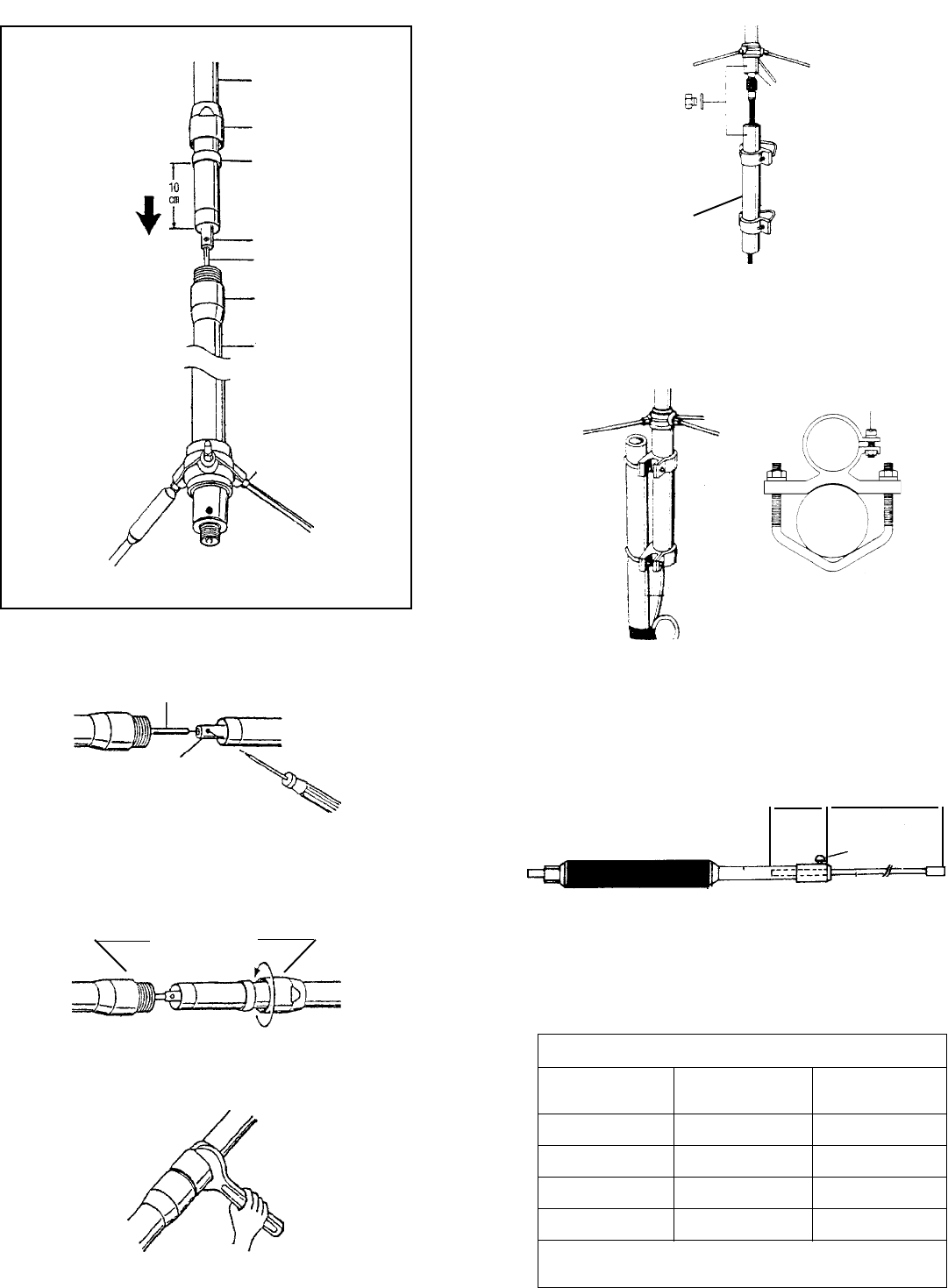
6m Radial Adjustment
6m Center Internal Adjustment Rod
Frequency Length “A” Length “B”
52 MHz 2 5/8” 23”
52.5 MHz 3 5/8” 22”
53 MHz 4 5/8” 21”
53.5 MHz 5 5/8” 20”
For reference only, some installations may vary.
Tune for minimum VSWR.
Figure 1
Fiberglass
Section
Joint
Black Line
Element Coupler
Element
Joint
Fiberglass
Section
Radials
Figure 2
Element
Element
Coupler
Figure 3
Section Joint
Figure 4
Figure 5
Coax Cable
Antenna
Support
Pipe
Figure 6
Mast
Pipe
Figure 7
V2000A 6m Counterpoise Radial
Set Screw
See Chart below
AB
mm
mm
moo
oo
omm
mm
moo
oo
o
6m
Counterpoise Radial
Ì
