DIYino Stardust V2 User Manual V1
User Manual: Pdf
Open the PDF directly: View PDF ![]() .
.
Page Count: 38
DIYino Stardust v2 User Manual
ProtoWerkstatt 2017, All rigths reserved
Author of this documentation is in no way affiliated, associated, licensed or endorsed by Disney or Lucasfilm Ltd., Industrial Light
and Magic or any of their associates. All brands and trademarks listed are the exclusive property of their respective Owners.
DIYINO STARDUST V2 USER
MANUAL

DIYino Stardust v2 User Manual
ProtoWerkstatt 2017, All rigths reserved
Author of this documentation is in no way affiliated, associated, licensed or endorsed by Disney or Lucasfilm Ltd., Industrial Light
and Magic or any of their associates. All brands and trademarks listed are the exclusive property of their respective Owners.
Table of Contents
1 Introduction ........................................................................................................................................... 4
2 Getting Started ...................................................................................................................................... 5
2.1 Preparing the board for first usage ............................................................................................... 5
2.2 Uploading first sound files ............................................................................................................. 6
2.3 A piece of advice on the USB port ................................................................................................. 6
3 Board Supply Concepts .......................................................................................................................... 7
3.1 Standard supply scheme ............................................................................................................... 7
3.2 Alternative supply concepts .......................................................................................................... 8
3.2.1 USB Kill-Keytm using the „B-point“ ......................................................................................... 8
3.2.2 Supply using 5V DC/DC boost ................................................................................................ 9
4 Basic Wirings of external components .................................................................................................. 9
4.1 Wiring buttons and speaker .......................................................................................................... 9
4.2 In-hilt recharge ............................................................................................................................ 10
4.3 Wiring an OLED display (for blaster props) ................................................................................. 11
4.4 Charge Status indication LED connection .................................................................................... 11
4.5 Copying sound files to the on-board 16Mbyte SPI-Flash ............................................................ 11
4.6 Sound font preparation – hum-extension ................................................................................... 13
5 Application Examples .......................................................................................................................... 13
5.1 High-Power RGB LED setup ......................................................................................................... 14
5.2 Neopixels setup ........................................................................................................................... 14
6 Full wiring examples ............................................................................................................................ 17
6.1 RGB High-Power LED setup with 3.7V and Single Button ........................................................... 17
6.2 Neopixels setup with programmable kill-key, 3.7V supply and an USB breakout-board
intergated in the hilt ................................................................................................................................ 17
7 Technical Specification ........................................................................................................................ 20
7.1 Circuit Pinout ............................................................................................................................... 20
7.2 Module description ..................................................................................................................... 22
7.2.1 Low-side drivers................................................................................................................... 23

DIYino Stardust v2 User Manual
ProtoWerkstatt 2017, All rigths reserved
Author of this documentation is in no way affiliated, associated, licensed or endorsed by Disney or Lucasfilm Ltd., Industrial Light
and Magic or any of their associates. All brands and trademarks listed are the exclusive property of their respective Owners.
7.2.2 Gesture- and Motion Detection with the MPU6050 IMU ................................................... 23
7.2.3 Wav/MP3 decode chipset and audio amp .......................................................................... 24
8 Upload software using Arduino IDE: A Step-by-Step walkthrough ..................................................... 25
9 Related links ........................................................................................................................................ 37

DIYino Stardust v2 User Manual
ProtoWerkstatt 2017, All rigths reserved
Author of this documentation is in no way affiliated, associated, licensed or endorsed by Disney or Lucasfilm Ltd., Industrial Light
and Magic or any of their associates. All brands and trademarks listed are the exclusive property of their respective Owners.
1 INTRODUCTION
DIYino Stardust is an Arduino compatible integrated circuit board for all projects implementing
/ / . Its main field of application is to control lightsaber, blaster and other prop/replica
electronics. It is Arduino compatible, i.e. it can be programmed using Arduino compatible IDE’s (Arduino
IDE, Eclipse etc.)
Board features on a glance:
- Compact size: 21 mm(W)x 51 mm(L)x 5 mm(H)
- Arduino Compatible
- Gapless Wav-audio playback
- Full USB integration (code upload, sound file upload, Li-Ion battery recharge, kill-key)
- 3W audio amplifier (supports 8Ω/4Ω speakers up to 3W)
- Built in high-end gesture detection sensor (6-axis accelerometer and gyro)
- K3 Technology: aka. “Kill the Kill-Keytm”: Ultra-low power consumption in sleep/idle mode (0.3mA)
- Unique USB Kill-Keytm feature
- Includes FTDI USB2Serial chipset for plug-and-play programming using Arduino IDE or similar
- 3 PWM controlled build-in low-side drivers as power extenders with up to 2.4A current capability
each
- Input voltage range 3.7V-5V
- No mechanical moving parts involved, sound files stored on on-board 16 Mbyte SPI-Flash
Warning: DIYino Stardust is an electronic board containing parts sensitive to ESD. Final wiring &
assembly is under the responsibility of the user with the appropriate tools and ESD protection. If you’re
not familiar with ESD, please visit : http://en.wikipedia.org/wiki/Electrostatic_discharge
The manufacturer cannot be held responsible for improper use or assembly of the DIYino Stardust board.
DIYino Stardust v2 User Manual
ProtoWerkstatt 2017, All rigths reserved
Author of this documentation is in no way affiliated, associated, licensed or endorsed by Disney or Lucasfilm Ltd., Industrial Light
and Magic or any of their associates. All brands and trademarks listed are the exclusive property of their respective Owners.
2 GETTING STARTED
2.1 PREPARING THE BOARD FOR FIRST USAGE
The Stardust v2 boards are delivered leaving it up to the user to select the supply scheme most
appropriate for the selected application (see Chapter 3). For this reason prior to plugging in the USB
cable to check if the board is alive the BAT+ signal must be connected to the 5V signal, corresponding to
single cell or standard supply scheme as outlined in Chapter 3.1. After these signals are connected, the
4.2V of charging output voltage of the USB charger circuit shall be present on the 5V signal, supplying the
circuits in the digital and mixed signal part.
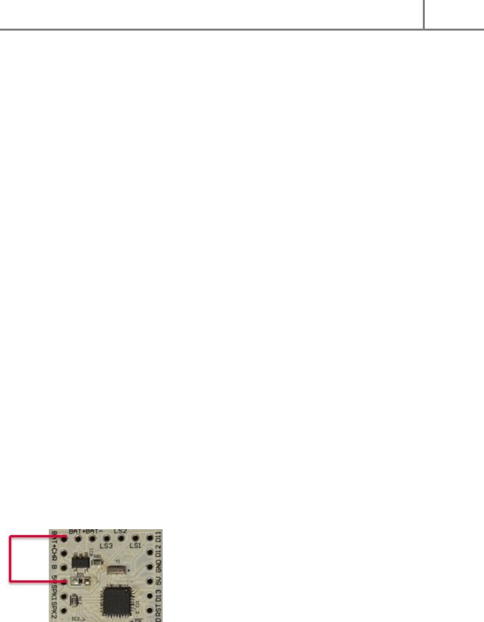
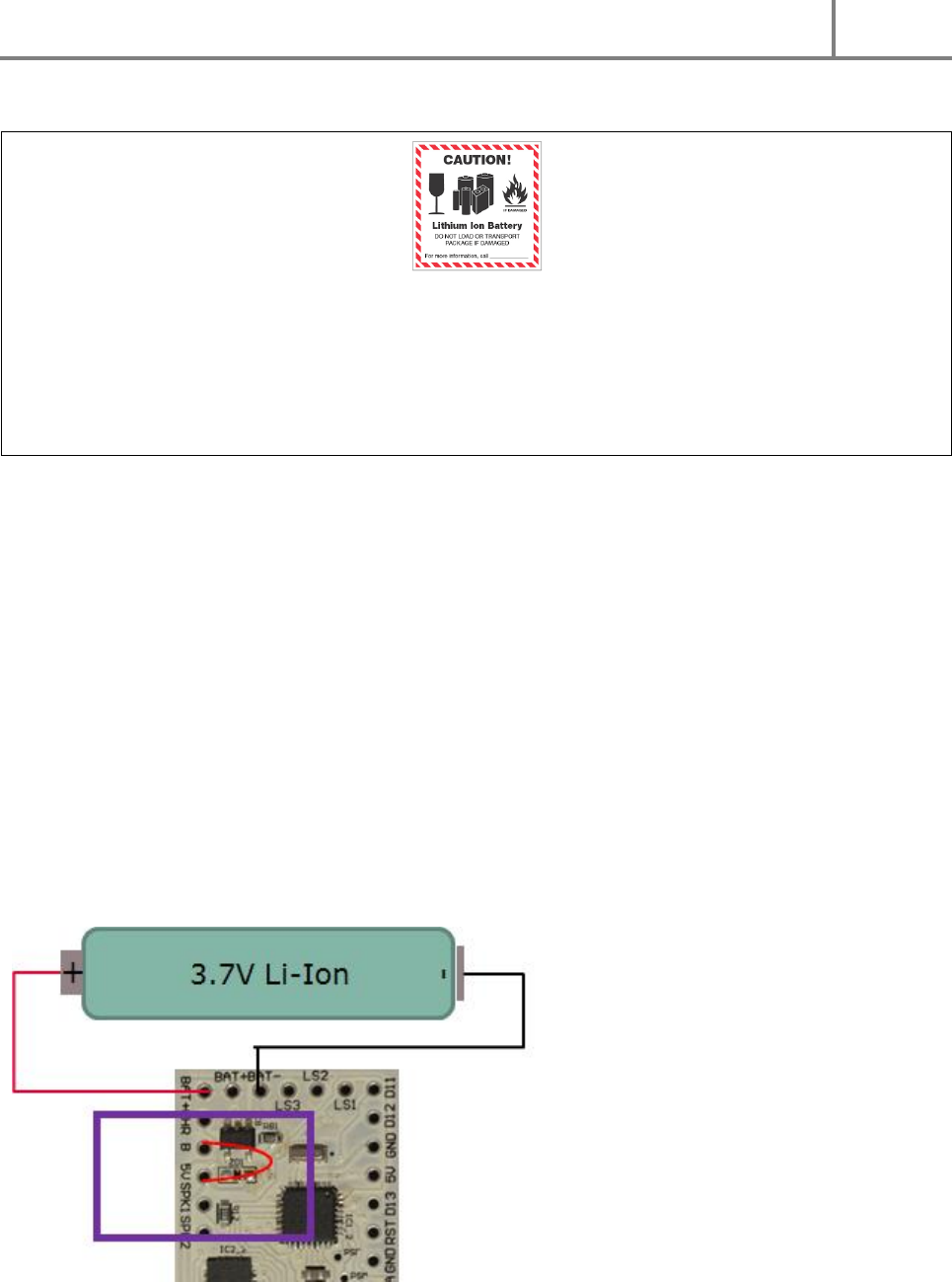
Therefore prior to pluggin in the USB cable for the first time follow these steps:
1. Connect the BAT+ signal to the 5V signal (see Figure 1)
2. Using a multimeter make sure there is no short circuit between GND and 5V, and no short circuit
between BAT+ and BAT-.
3. Now you are set to plug in your USB cable to the on-board USB port. Please do not ram in the
USB connector, see also Chapter 2.3A piece of advice on the USB port
4. Using a multimeter measure the voltage between any GND and the 5V signal. The reading should
show ~4.2V. This is the peak charging voltage of the USB charger and shows that the boad is
supplied through the USB charger and the charger is alive (at this state the battery does not need
to be connected).
5. Now your 4Ohm/8Ohm Speaker can be connected between SPK1 and SPK2. Make sure using a
multimeter that you measure the specified inpedance of the speaker between these two
terminals and no short exists between the terminals and any of the neighboring signals.
6. The board comes delivered with a test sketch which repeats a test sound every 2 secs and shows
over the Serial Monitor of the Arduino IDE the calibrated gyro- and accelero values of the MPU.
To see it open Tools/Serial Monitor in the Arduino IDE (see Chapter 8), and change the default
baud rate (lower right corner) from the default 9600 to 115200. Now you should hear the test
sound repeated every 2 secs and see the acceleration/gyro values. Move the board and observe
that the values react.
7. Now you board is proven to be working fine, you can wire it up fully (of course unpowered) and
upload other “skecthes” (Arduino slang for application code).
If later on the user decides for another supply scheme, this connection can be replaced with the wiring
corresponding to either one of the supply schemes in Chapter 3.
FIGURE 1: PREPAR ING THE BOARD FOR PROGRAMMING VIA USB
DIYino Stardust v2 User Manual
ProtoWerkstatt 2017, All rigths reserved
Author of this documentation is in no way affiliated, associated, licensed or endorsed by Disney or Lucasfilm Ltd., Industrial Light
and Magic or any of their associates. All brands and trademarks listed are the exclusive property of their respective Owners.
2.2 UPLOADING FIRST SOUND FILES
The Stardust v2 board stores sound files on an 16Mbyte on-board SPI-Flash module. The SPI-Flash can be
used just like a pen drive via USB connection. The board has a single USB port which can be used for
various purposes (see Chapter 0), among others to copy files to the SPI-Flash via USB. However to ease
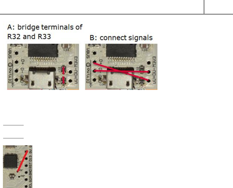
first time programming, the R32 and R33 resistors which connects the USB signals of the UART and the
USB signals of the MP3 player chip are not mounted on the board (to know how to connect them later
on refer to Figure 9).
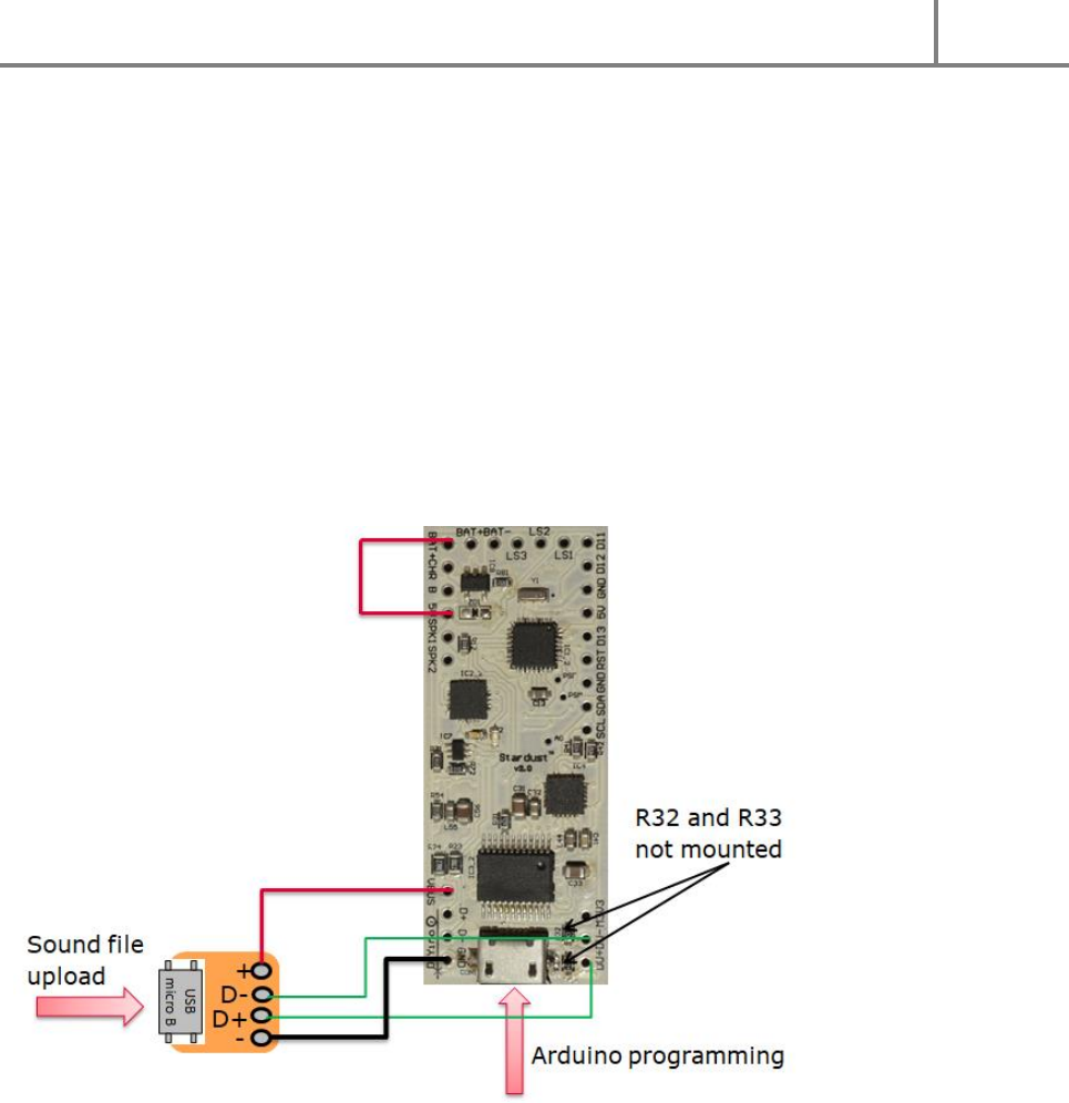
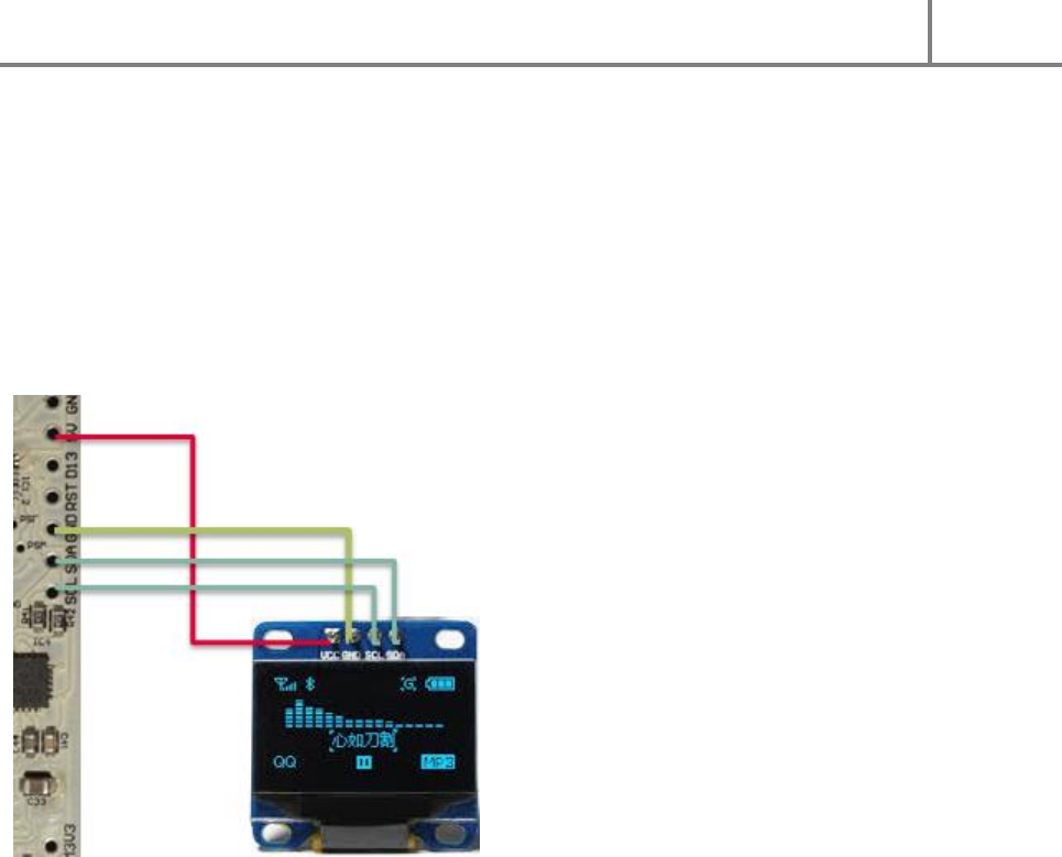
For first time parallel programming of both the controller and the SPI-Flash you can utilize the delivered
USB breakout board to connect it to the USB signals of the SPI-Flash/MP3 chip shown on Figure 2. This
way your computer will see on one USB port the COM port corresponding to your board for code upload
while the other USB port will see the SPI-Flash as a 16Mbyte pen drive where you can upload sound files.
FIGURE 2: UPLOADING SOUND FILES TO THE INTERNAL SPI-FLASH
2.3 A PIECE OF ADVICE ON THE USB PORT
The delivered USB breakout board can be used to wire up a programming/recharge/sound-file-upload
terminal to be accessible from the outside of your prop design. This way the electronics can be enclosed
and all interaction with the electronics can be handled via this single USB port. The USB breakout board
is also recommended to be used for charging the single cell Li-Ion battery. Why it is so? You can of course
use the on-board USB terminal for all these operations as well. However as opposed to the somewhat
larger mini-USB port, the smaller micro-USB port is less mechanically sturdy. It has no guide pins
protruding into the PCB to hold it tight in place like the mini-USB, therefore repeated plug-in and –out
might dislocate the port and severe the solder between the port and the PCB. Therefore please handle
DIYino Stardust v2 User Manual
ProtoWerkstatt 2017, All rigths reserved
Author of this documentation is in no way affiliated, associated, licensed or endorsed by Disney or Lucasfilm Ltd., Industrial Light
and Magic or any of their associates. All brands and trademarks listed are the exclusive property of their respective Owners.
the on-board mini-USB port with care (true for all micro-USB port, not only the one on Stardust v2!) and
utilize the USB breakout board for frequent usage.
3 BOARD SUPPLY CONCEPTS
Warning: Please note that the DIYino Stardust board does not implement a reverse polarity protection.
Reversing the polarity of the supply might lead to board damage!
3.1 STANDARD SUPPLY SCHEME
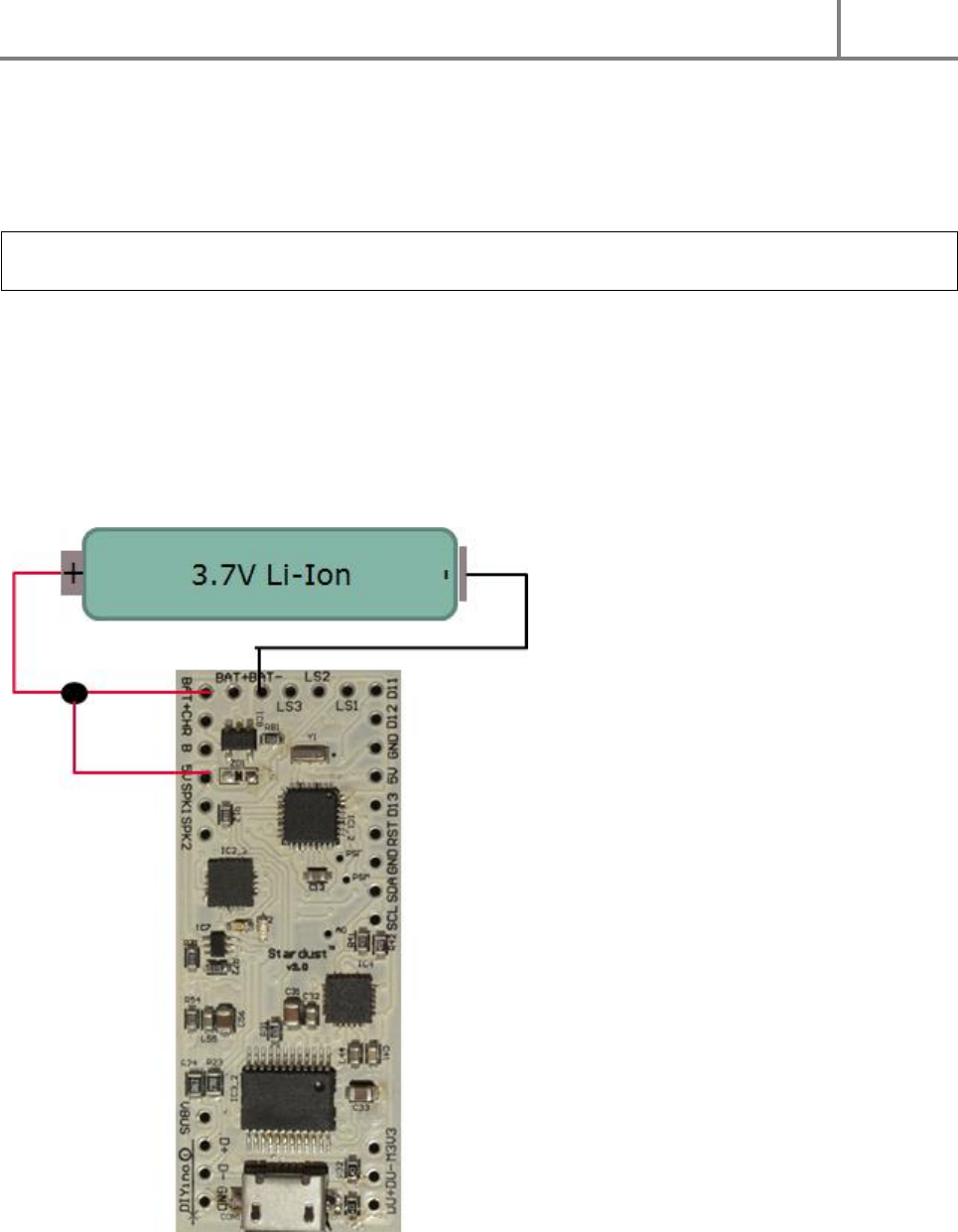
The DIYino Stardust board shall be supplied directly from a single Li-Ion battery cell. Please connect the
positive terminal of the battery to the 5V signal to supply the board directly from the battery.
Figure 3 shows wiring of the voltage source used to supply the board. If the USB cable is plugged in, i.e.
as during sketch upload, the circuit will be supplied by the USB port, with any surplus current used to
charge the battery. If there is no battery connected to the board, it can be supplied via USB through the
USB charger circuitry, providing ~4.2V to the board.
FIGURE 3: STANDARD SUPPLY WIRING
DIYino Stardust v2 User Manual
ProtoWerkstatt 2017, All rigths reserved
Author of this documentation is in no way affiliated, associated, licensed or endorsed by Disney or Lucasfilm Ltd., Industrial Light
and Magic or any of their associates. All brands and trademarks listed are the exclusive property of their respective Owners.
Warning: before connecting any Li-Ion battery to the DIYino Stardust, please ensure that your selected
battery complies to the charging characteristic of the USB on-board charger (CCCV with 250mA average
charge current at 4.2V charge voltage). In case of doubt please consult your battery vendor. The board
manufacturer of the DIYino boards cannot be held liable for any injury or damage due to incompatibility
of the used battery with the on-board Li-Ion charger.
3.2 ALTERNATIVE SUPPLY CONCEPTS
The standard supply scheme is explained in Chapter 3.1 The supply schemes introduced in the current
Chapter are considered technically feasible to supply the DIYino Stardust board, however secial care
should be taken as they represent advanced concepts. Therefore please read the description and only
use the below described supply schemes if you understand how to use them.
3.2.1 USB KILL-KEYTM USING THE „B-POINT“
The „B-point“, or B breakout signal can be used to decouple the battery voltage completely from the
digital subsystem of the board if a supplied USB cable is plugged in. The USB will charge the battery with
no load from the board electronics. Although the Stardust has an extremely low sleep/idle more
quiescent current, this feature effectively disconnects the board from the battery, except for the USB
charger. It is a legacy feature for those who prefer to use a Kill-Key.
It is recommended to use this feature only if the final code and sound files are uploaded to the board, as
using this feature will leave the board unpowered when USB is plugged in, therefore no code upload is
possible.
FIGURE 4: USB KILL-KEYTM WIRING
DIYino Stardust v2 User Manual
ProtoWerkstatt 2017, All rigths reserved
Author of this documentation is in no way affiliated, associated, licensed or endorsed by Disney or Lucasfilm Ltd., Industrial Light
and Magic or any of their associates. All brands and trademarks listed are the exclusive property of their respective Owners.
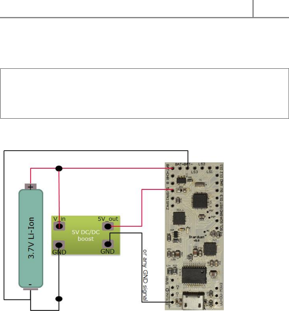
3.2.2 SUPP LY USING 5V DC/DC BOOST
Although the Stardust can be optimally supplied from a single 3.7V battery cell, the input voltage to the
board can be increased to 5V using a DC/DC boost converter. A boost converter regulates (“boosts”) the
voltage from a lower input voltage to a higher output voltage. Please use a DC/DC boost converter with a
5V output.
Warning: DC/DC boost modules which are not rated at 5V output voltage usually have an adjustable
voltage output, which can far exceed 5V. Using such a DC/DC boost module could cause board damage if
the output voltage is not adjusted to 5V (or below) prior to connecting it to the board!
Even DC/DC converters with a nominal regulated (boosted) voltage of 5V might exceed 5V, so always
measure the output voltage of a DC/DC boost converter before connecting to the DIYino Stardust to
avoid board damage.
The clear advantage of this supply scheme is that the board is supplied with the required 5V for best
performance, while the lower input supply voltage can be used to power the LEDs/other external circuits
with nominal voltages below 5V.
FIGURE 5: SUPPLY SCHEME USING 5V DC/DC BOOST CONVERTER
4 BASIC WIRINGS OF EXTERNAL COMPONENTS
4.1 WIRING BUTTONS AND SPEAKER
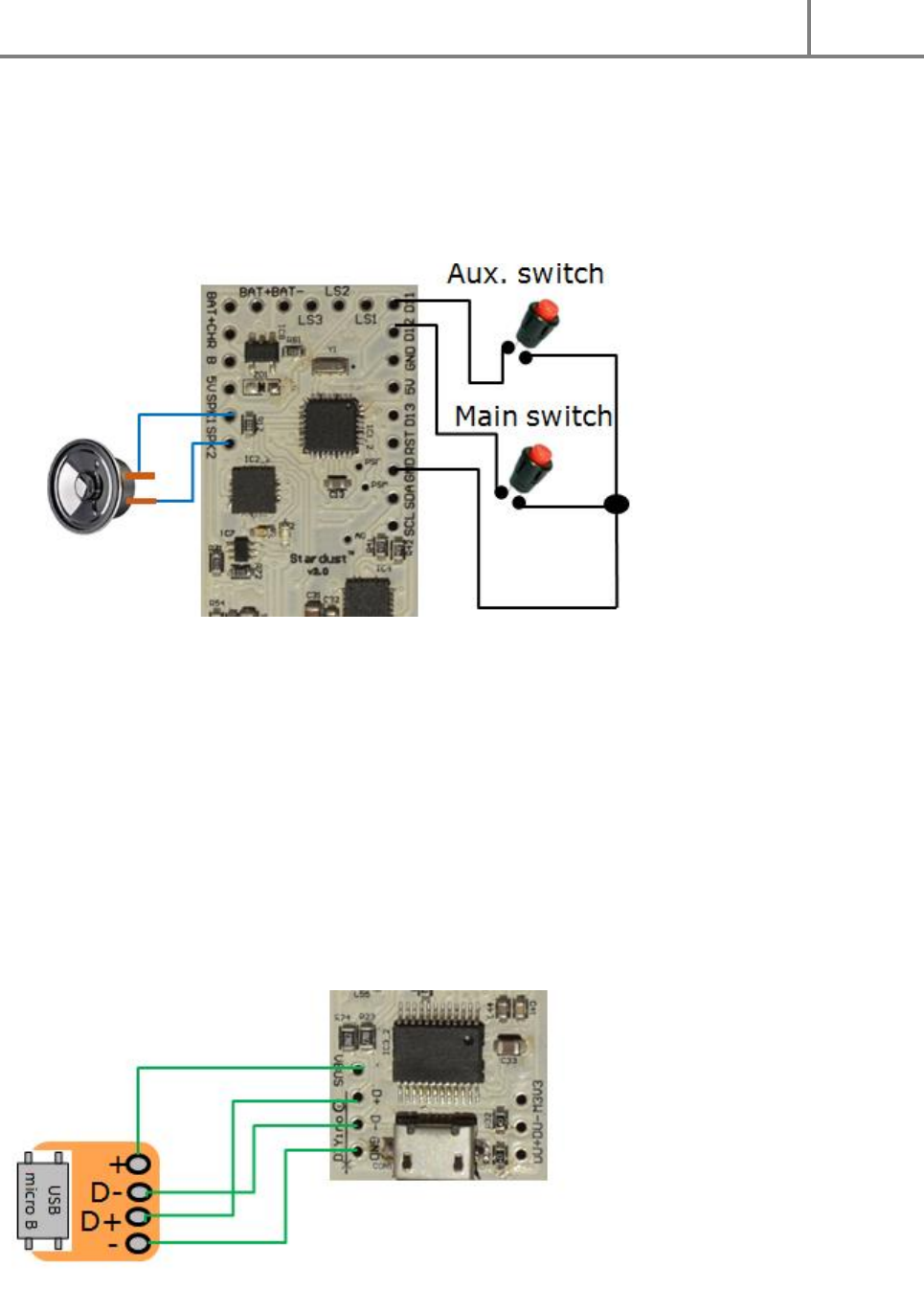
Figure 6 shows wiring of the switches and that of the speaker.
The speaker has to be connected between the SPK1 and SPK2 terminals/pins of the board. 4Ω/8Ω
speaker can be used, up to 3W output power. It does not matter which terminal of the speaker you
DIYino Stardust v2 User Manual
ProtoWerkstatt 2017, All rigths reserved
Author of this documentation is in no way affiliated, associated, licensed or endorsed by Disney or Lucasfilm Ltd., Industrial Light
and Magic or any of their associates. All brands and trademarks listed are the exclusive property of their respective Owners.
connect to which pin. The SPK1 and SPK2 signals are furthermore connected on-board to the ADC input
pins A6 and A7 respectively, which can be used to sample the audio file played. This feature finds
widespread use to control the flicker of the LEDs in-sync with the sound file being played
(SoundTrack`ERtm)
Switches – latching or momentary, although mostly momentary switches are supported by Arduino
libraries – are connected with one terminal connected to GND and the other terminal to a digital I/O.
FIGURE 6: WIRING SWITCHES AND THE SPEAKER
4.2 IN-HILT RECHARGE
It is very convenient if the battery does not have to be removed from the hilt every time it needs
recharging. Therefore so called in-hilt recharge ports found a wide-spread use in saber hilts together
with rechargeable batteries (most common type being the 3.7V type 18650). The DIYino Stardust has an
integrated Li-Ion USB charger module integrated which can be used to charge the battery directly from
USB, thus eliminating the need to include a bulky recharge port in the hilt. To ease recharging and
interaction with the board like sketch upload or uploading sound files to the on-board 16Mbyte SPI
Flash, a USB breakout board can be used to connect the USB signals to a port in the hilt. Connection of
an external USB breakout-board is depicted in Figure 7 .
DIYino Stardust v2 User Manual
ProtoWerkstatt 2017, All rigths reserved
Author of this documentation is in no way affiliated, associated, licensed or endorsed by Disney or Lucasfilm Ltd., Industrial Light
and Magic or any of their associates. All brands and trademarks listed are the exclusive property of their respective Owners.
FIGURE 7: IN-HILT RECHARGE USING AN USB BREAKOUT -BOARD
4.3 WIRING AN OLED DISPLAY (FOR BLASTER PROPS)
If you want to add a small display to your prop project - especially popular with sci-fi blaster, but you can
include one for a custom MP3 player, armor gadgets etc. – there are good OLED displays using the
SSD1306 driver IC.
The wiring of such an OLED display using I2C communication can be seen on Figure 8 . You need to
supply the OLD display with 3.3V (some OLED displays have in-built 3.3V LDO, in which case you can also
use the 5V pin to supply them) and use the Atmega328P’s I2C bus signals A4(SDA)/A5(SCL) to
communicate with the display.
FIGURE 8: WIRING OF AN OLED DISPLAY USING THE SD1306 OLED CONTROLLED (128X32)
4.4 CHARGE STATUS INDICATION LED CONNECTION
The on-board USB charger includes a charge status indication signal which can be accessed on the board
via the CHR signal. The signal remains logic low during charging and changes to logic high when the
battery is fully charged. This signal can be used to connect a charge indication LED via a proper resistor to
light up when charging completes. Connect the LED anode (+) to the CHR singal (via a resistor if needed)
and the cathode (-) of the LED to GND. Alternatively you can connect the CHR signal to the aux. Singal A0
and read the charge status voltage via digitalRead command in the sketch. This makes it possible to
implement more sophisticated charge completion functions i.e. notifying via a unique sound, going back
to sleep mode until charging finishes etc.
4.5 COPYING SOUND FILES TO THE ON-BOARD 16MBYTE SPI-FLASH
On DIYino Stardust sound files can be stored and played back from the on-board 16Mbyte SPI-Flash
module connected to the MP3 chipset.
The on-board SPI Flash can be accessed over USB, which is shared with the UART controller for
communicating with the microcontroller on-board via the Arduino IDE or similar. Upon delivery of the
boad the two USB ports are not shorted to ease first time programming, to wire them up in parallel
follow the two methods shown on Figure 9.
DIYino Stardust v2 User Manual
ProtoWerkstatt 2017, All rigths reserved
Author of this documentation is in no way affiliated, associated, licensed or endorsed by Disney or Lucasfilm Ltd., Industrial Light
and Magic or any of their associates. All brands and trademarks listed are the exclusive property of their respective Owners.
FIGURE 9: METHODS TO CONNECT USB PORTS OF SPI-FLASH AND UART
If the two USB ports are wired in parallel, you have to disable the UART (FTDI) in order for your PC to see
the Flash as an USB drive. You can do it in two ways:
Option 1: Programatically you can disable the FTDI by pulling the A2 pin to HIGH using the digitalWrite
function.
Option 2: Or you can use a piece of wire to connect the aux signal PSF to the 5V signal to achieve the
same effect, as depicted on Figure 10 .
FIGURE 10: FOR USING THE SPI FLASH AS AN USB DRIVE, CONNECT THE PSF AUX. SIGNAL TO TH E 5V SIGNAL FOR THE DURAT ION OF
THE UPLOAD (OPTION 2)
When the FTDI is disabled, and the USB cable is plugged in, your SPI Flash shall appear as a regular USB
drive. You can format it and use it to load your sound fonts to it.
Please note that due to the integrated MP3 chipset acting as an USB protocol handler, file transfer from
PC to the SPI Flash might be slow. Be patient!
After you finish uploading the sound files, please disconnect the USB cable, reset the board, restart your
PC before trying to connect the board again via the UART to upload code.
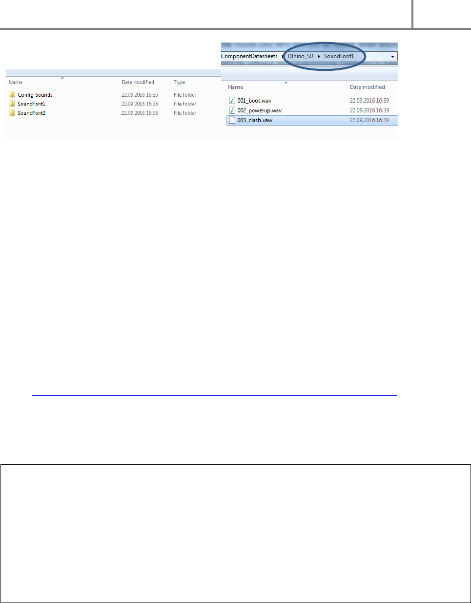
Sound files stored on the SPI-Flash will be indexed and accessed according to their physical copy order to
the storage media. Therefore some simple rules apply to define SPI-Flash content.
1. Format your SPI-Flash, using it exactly as an USB external drive (i.e. pen drive)!
2. Select all the files from this folder and "Drag and Drop" them to your SPI-Flash. NO COPY AND
PASTE !!! : We need to have this file copied in the same order as their filename order. On
Microsoft Windows, Copy/paste produce an anarchic copy order, but Drag and Drop produce an
ordered copy...
You can organize your files in folders to keep a better overview of the content. All what counts to the
MP3/Wav chip is the physical order of the files on the SPI-Flash. You can even drag-and-drop whole
folders, but inside the folder you need to establish a defined copy order by preceding files names with a
numbering for instance:
DIYino Stardust v2 User Manual
ProtoWerkstatt 2017, All rigths reserved
Author of this documentation is in no way affiliated, associated, licensed or endorsed by Disney or Lucasfilm Ltd., Industrial Light
and Magic or any of their associates. All brands and trademarks listed are the exclusive property of their respective Owners.
FIGURE 11: ORGANIZING FILES ON THE SPI-FLASH
4.6 SOUND FONT PREPARATION – HUM-EXTENSION
The DIYino Stardust is capable of gapless playback of sound files in WAV format, i.e. it can change from
one sound track to another without an gap in the audio. This feature is mandatory for lightsaber
electronics where a seamless transition is expected between the different sound files (like hum, clash,
swings etc.).
While the MP3/WAV chips is capable of gapless playback, especially when it comes to relaunching the
background noise of a lightsaber (so called “hum”), it cannot be done without spending a significant
amount of effort and code space. For this reason a more pragmatic approach to hum-relaunch is
implemented in most of the open source lightsaber software which simply relaunches the hum at certain
time intervals. In order not to “loose” the hum if the saber is idling, each sound file (except lockup) has
to be extended with a buffer of hum sounds. This is called a hum-extension. Modifying an existing sound
font file is easy by simply copy+paste a chunk of hum sound after the end of the sound file. This can be
done with freewares (Audacity for instance). A more advanced method is developed by Jakesoft – the
father of Arduino lightsabers – in form of an automatic conversion program which can be downloaded
here: http://forum.arduino.cc/index.php?action=dlattach;topic=361566.0;attach=192631
5 APPLICATION EXAMPLES
Warning : High-power LEDs (such as the Luxeon, Cree atc. Brand LED) and strings/stripes of LEDs (such
as LED strings composed of many single LEDs or neopixel LED moduls such as WS2812B) are extremely
bright. Especially High-power LEDs are considered “class 2 lasers”! You should neither look directly to the
beam nor point someone with it when the light source is not diffused/blocked, just like a powerful lamp
or flashlight. Manufacturer of the DIYino Stardust board could not be held responsible for any injury
resulting from the use of high-power or other type of LEDs/LED modules. To avoid injuries and retina
damage due to the high brightness of LEDs, always use protective googles or other means to avoid
looking directly into the light source and also take care to protect others (like children) from being able
to look directly into the light source.
In this Chapter the most common lighting options of saber designs will be discussed with application
notes and wiring diagrams showing how these options can be interfaced to the DIYino Stardust board.

DIYino Stardust v2 User Manual
ProtoWerkstatt 2017, All rigths reserved
Author of this documentation is in no way affiliated, associated, licensed or endorsed by Disney or Lucasfilm Ltd., Industrial Light
and Magic or any of their associates. All brands and trademarks listed are the exclusive property of their respective Owners.
Caution: in case of a High-Power LED or LED-string setups, you can use the LS pins to adjust the current
flowing through the LEDs using PWM control (Pulse Width Modulation) of the transistor gates. The
transistors which connect the cathode (-) of the LEDs to the GND can act as voltage controlled variable
resistors, thus limiting the current through the LED. For those LEDs having a Vth above the battery
voltage, this intrinsic current limiting is sufficient to ensure no overvoltage/overcurrent to the LED, while
still offering the full dynamic range of brightness control. But in case the LED has a Vth below (or even far
below) the nominal battery voltage (i.e. for red/amber/yellow LEDs), depending on the electrical
characteristic of the LED, this intrinsic limiting might not be enough to ensure no overvoltage to the LED,
which in turn can lead to damage or degradation of the life time of the LED. Even if the limiting through
the transistors is deemed sufficient, during debug the PWM level can be set accidentally to a level which
causes overvoltage. Last but not least, if only a small portion of the available PWM range can be used to
control the brightness, it can lead to less smooth color blending. Therefore in doubt please include a
limiting series resistor, which can be calculated using the following formula:
𝑅𝑠𝑒𝑟𝑖𝑒𝑠 = 𝑉𝑏𝑎𝑡𝑡𝑒𝑟𝑦 − 𝑉𝑡ℎ_𝐿𝐸𝐷
𝐼_𝐿𝐸𝐷
Example: suppose you use a Red LED with Vth_LED=2V and you want the current to be I_LED=700mA,
you use a Vbattery=3.7V, type 18650 battery. The value of the resistor you need to wire in series to the
LED is:
3,7𝑉 − 2,0𝑉
0,7𝐴 = 2.4Ω
Please check the power rating of the resistor you intend to use.
5.1 HIGH-POWER RGB LED SETUP
Figure 15 depicts connection of a High-Power LED module to the DIYino Stardust. It depicts a 3-color LED
module consisting of 3 LED dies in colors Red, Green and Blue. The same wiring can be extended to all
different variants of HP-LEDs, like a single die HP-LED which can be controlled with a single Low-side
driver.
Please note that that maximum DC current which can be switched by the individual LS pins is 2.4A. If the
HP-LED used in the design involves LED dies with a max current above this rating, you must connect the
cathode of the LED die to multiple of these LS pins and ensure they are controlled in tandem to avoid
violating the maximum rating of the transistors.
5.2 NEOPIXELS SETUP
“NeoPixel” is Adafruit’s brand for individually-addressable RGB color pixels and strips based on
the WS2812, WS2811 and SK6812 LED/drivers, using a single-wire control protocol. Commonly used
neopixels stripes are composed of individual LED segments connected together to form a ladder similar
to LED-strings. The stripes can be cut at any joint and multiple striped can be connected together at
these joints as well.
DIYino Stardust v2 User Manual
ProtoWerkstatt 2017, All rigths reserved
Author of this documentation is in no way affiliated, associated, licensed or endorsed by Disney or Lucasfilm Ltd., Industrial Light
and Magic or any of their associates. All brands and trademarks listed are the exclusive property of their respective Owners.
Neopixel LED modules integrate RGB LEDs and a control circuit which uses PWM (Pulse Width
Modulation) to control the brightness of each die individually. For that purpose each LED module has a
shift register composed of 24-bits, 8-bits belonging to each of the colors Red, Green and Blue. The shift
registers are connected between the DI (Data-In) and DO (Data-Out) pins of the individual segments. In a
stripe configuration one segment shift register is connected serially to the shift register of the next
segment. If a blade has a stripe with 100LEDs, it means during programming 100x24=2400 bits of data
have to be transmitted to the stripe using neopixels own serial protocol to fill up all PWM registers,
which in turn determine the brightness of the LEDs. This takes only a few us, so programming can
happen so fast, that transitions seem smooth to the eye.
A neopixel stripe has only 3+1 signals:
5V: supply of the stripe
DI: Data-In for the single-line serial protocol
GND: Ground or negative of the stripe
DO: Data-out, this signal has to be used only of you want to connect several stripes together which are
not continuous (back-to-back stripes or think about the cross guard of a Kylo Ren style saber)
The specification of the neopixel LED segments defines 5V as nominal voltage for the stripes, however
the module can work with a much lower voltage as well. A lower voltage is even necessary to minimize
power loss during operation, because any excess voltage above the voltage threshold of the used LEDs
(Red ~2V, Green and Blue ~3.5V) is “wasted” over protection circuits in the control logic. Therefore a
voltage source around the LED Vth is ideal to power neopixel strings.
For a complete characterization of neopixel brightness and current consumption please see LINK
Neopixels chips consume considerable power even when all the LEDs are switched off (all 0’s). This static
current consumption amounts to 1mA per LED. You can quickly calculate what this means to your
battery life time if you use – let’s say – 60LED/m type of neopixels, back to back, in a 80cm blade. There
will be 100 LEDs in your blade, drawing 100mA even if all LEDs are switched off. It will even discharge the
best battery in less than one day. It is not hard to predict, that with the introduction of the 144LED/m
type neopixel stripes, some blades will include much more than 100 LEDs, which will lead to an even
quicker discharging of the battery. Killing power to the circuitry using a kill-key is a good method to
lengthen the shelf life of your saber, but quite annoying during a show if you have to keep plugging
in/out the kill key. Therefore a unique method was invented using the existing DIYino Stardust
architecture. If the GND pin of the neopixels stripe is connected to the LS pins instead of the GND of the
battery/DIYino Stardust, the transistors of the LS pins can be used to cut power to the neopixels stripe. If
the blade is activated, the transistors have to be fully switched on (using the digitalWrite function) to
connect the GND of the neopixels to the Battery(-), therefore powering the stripe. If the blade is
retracted/switched off, the transistors have to be fully switched off in order to avoid the static current
consumption of the stripes discharging the battery. Please take note that the restrictions as to the
maximum current capability of the DIYino Stardust board apply also here (max 6A!!!).
DIYino Stardust v2 User Manual
ProtoWerkstatt 2017, All rigths reserved
Author of this documentation is in no way affiliated, associated, licensed or endorsed by Disney or Lucasfilm Ltd., Industrial Light
and Magic or any of their associates. All brands and trademarks listed are the exclusive property of their respective Owners.
FIGURE 12: NEOPIXEL S WIRING USI NG 3.7V VOLTAGE SOURCE, “PROGRAMMABLE KILL-KEY”

DIYino Stardust v2 User Manual
ProtoWerkstatt 2017, All rigths reserved
Author of this documentation is in no way affiliated, associated, licensed or endorsed by Disney or Lucasfilm Ltd., Industrial Light
and Magic or any of their associates. All brands and trademarks listed are the exclusive property of their respective Owners.
6 FULL WIRING EXAMPLES
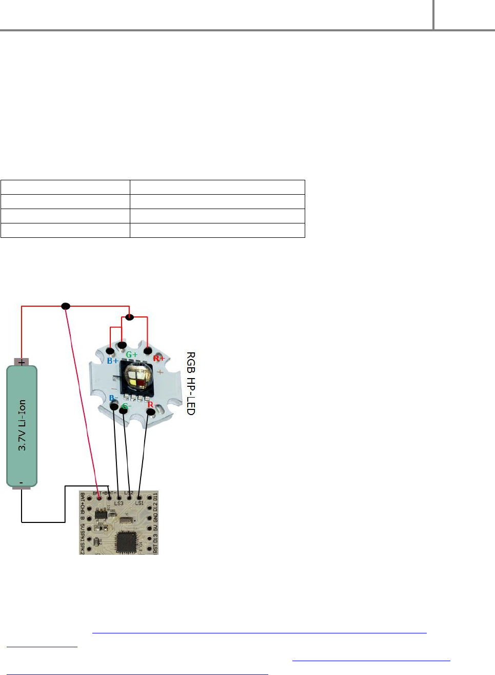
6.1 RGB HIGH-POWER LED SETUP WITH 3.7V AND SINGLE BUTTON
The Figure 13 shows the full wiring diagram of a HP-LED saber using a single 3.7V Li-Ion battery as supply,
using a single main button. The HP-LED module is directly supplied from the Battery+.
FIGURE 13: FULL WIR ING DIAGRAM OF A HIGH-POWER LED (RGB) SABER
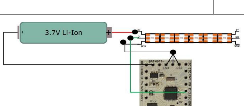
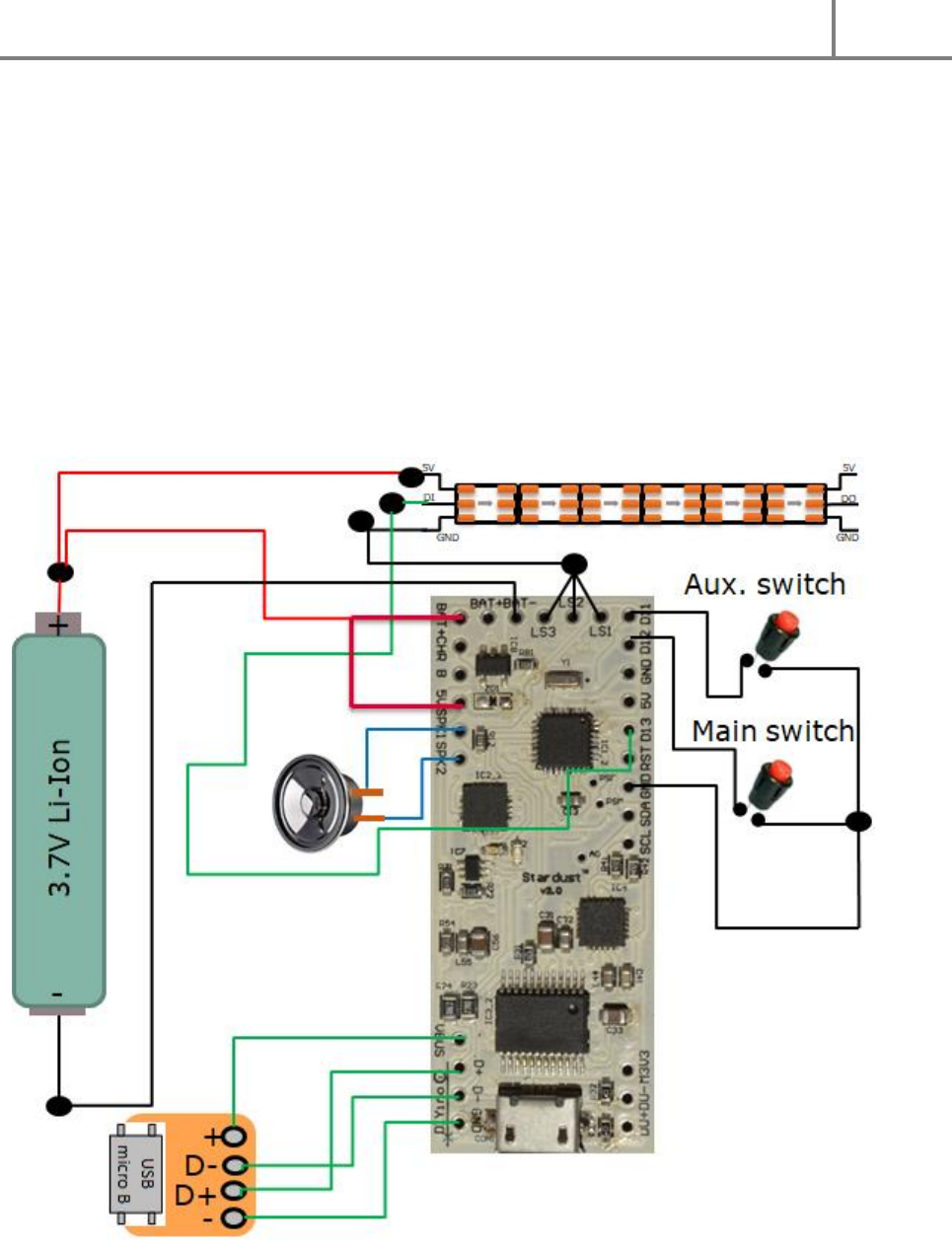
6.2 NEOPIXELS SETUP WITH PROGRAMMABLE KILL-KEY, 3.7V SUPPLY AND AN
USB BREAKOUT-BOARD INTERGATED IN THE HILT
On Figure 14 the full saber wiring diagram can be seen. It includes
- an in-hilt recharge port
DIYino Stardust v2 User Manual
ProtoWerkstatt 2017, All rigths reserved
Author of this documentation is in no way affiliated, associated, licensed or endorsed by Disney or Lucasfilm Ltd., Industrial Light
and Magic or any of their associates. All brands and trademarks listed are the exclusive property of their respective Owners.
- 3.7V Li-Ion battery as voltage source (for instance 18650)
- A neopixels LED-stripe of (theoretically ) any length
- Programmable neopixels stripe kill-key setup
- A main and and aux. switches
- Speaker
- An external USB breakout-board to be integrated in the hilt
When connecting the programmable neopixels stripe kill-key, you have to calculate max. current
consumption of your LED stripe and connect the LSx pins accordingly, i.e. if you anticipate 2A-3A’s,
connect 3 of the LS pins to the GND terminal of the stripe. Up to max. 3A over all LSx pins due to limited
heat dissipation on the board!!!
All considerations in the Chapters describing the individual parts of this circuit diagram apply here as
well. Please read them carefully.
FIGURE 14: FULL WIRING D IAGRAM OF A NEOPIXEL STRIPE BASED SABER

DIYino Stardust v2 User Manual
ProtoWerkstatt 2017, All rigths reserved
Author of this documentation is in no way affiliated, associated, licensed or endorsed by Disney or Lucasfilm Ltd., Industrial Light
and Magic or any of their associates. All brands and trademarks listed are the exclusive property of their respective Owners.
7 TECHNICAL SPECIFICATION
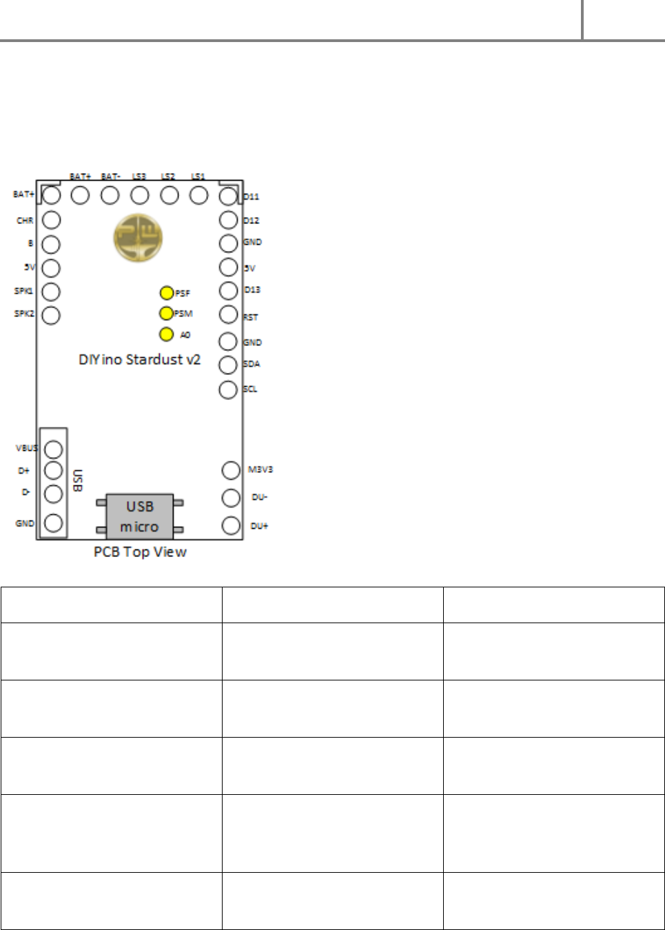
7.1 CIRCUIT PINOUT
Pin
Functionality
Comment
BAT+ (2x)
Positive terminal of a single Li-
Ion 3.7V battery cell.
2 breakout signals
BAT-
Negative terminal of a single Li-
Ion 3.7V battery cell.
LS1
Drain of the Low-Side switch 1
HP-LED: connect cathode of Red
die here (via resistor if needed)
LS2
Drain of the Low-Side switch 2
HP-LED: connect cathode of
Green die here (via resistor if
needed)
LS3
Drain of the Low-Side switch 3
HP-LED: connect cathode of Blue
die here (via resistor if needed)

DIYino Stardust v2 User Manual
ProtoWerkstatt 2017, All rigths reserved
Author of this documentation is in no way affiliated, associated, licensed or endorsed by Disney or Lucasfilm Ltd., Industrial Light
and Magic or any of their associates. All brands and trademarks listed are the exclusive property of their respective Owners.
CHR
Charge completed signal of the
USB charger circuit.
Can be connected to the anode
of an LED (via resistor if
appropriate) to light up when
battery is fully charged over USB.
B
The „B“-point!!!
It can be used to implement the
USB Kill-Keytm Feature
5V (2x)
Legacy Arduino name of board
logic supply.
2 breakout signals.
RST
Reset pin of the Atmega328P,
with pull-up to 5V.
Pin used for burning bootloader.
D11
D11 digital I/O of Atmega328P,
PWM capable, connected to
Gate of LS6 Low-Side driver, with
100kΩ pull-down to GND. MOSI
pin for ICP.
Pin used for burning bootloader.
D12
D12 digital I/O of Atmega328P.
MISO pin for ICP.
Pin used for burning bootloader.
D13
D13 digital I/O of Atmega328P.
SCK pin for ICP.
Pin used for burning bootloader.
GND (3x)
Board(-) or GND. Connected to
GND plane of the PCB.
Pin used for burning bootloader.
SPK1
Speaker terminal 1. Connect to
speaker directly. Other speaker
terminal to SPK2.
Connected to A6 of the
Atmega328 for Sound-Track’ERtm
SPK2
Speaker terminal 2. Connect to
speaker directly. Other speaker
terminal to SPK1.
Connected to A7 of the
Atmega328 for Sound-Track’ERtm
GND
Board(-) or GND. Connected to
GND plane of the PCB.
Connected to BAT- via star-point.
Digital GND, do not connect to
battery negative terminal.
3 breakout signals.
SDA
A4 digital I/O of Atmega328P
SDA I2C signal for

DIYino Stardust v2 User Manual
ProtoWerkstatt 2017, All rigths reserved
Author of this documentation is in no way affiliated, associated, licensed or endorsed by Disney or Lucasfilm Ltd., Industrial Light
and Magic or any of their associates. All brands and trademarks listed are the exclusive property of their respective Owners.
with input 10-bit ADC.
communication with MPU6050
or an external device using I2C
protocol (i.e. OLED display).
SCL
A5 digital I/O of Atmega328P
with input 10-bit ADC.
SDA I2C signal for
communication with MPU6050
or an external device using I2C
protocol (i.e. OLED display).
M3V3
Output of the 3.3V LDO of the
YX5200-24SS chip.
Supplies the SPI Flash as well as
the MPU6050 accelero- and gyro
sensor.
PSF
FTDI power switch
Pulled to GND. Can be connected
to 5V signal to disable FTDI
chipset.
PSM
MP3 power switch
Pulled to GND. Can be connected
to 5V signal to disable MP3
chipset and Audio Amp.
A0
A0 digital I/O of Atmega328P
with input 10-bit ADC.
Auxiliary signal, can be used as
an additional ADC input or as
accent light signal
VBUS
USB supply voltage
5V voltage input from USB bus or
USB charger. Breakout signal for
external USB connector hook-up
D+
USB positive
Breakout signal for external USB
connector hook-up
D-
USB negative
Breakout signal for external USB
connector hook-up
DU+
USB positive signal of the
YX6300-24SS MP3 chip
Connected to D+ via resistor on-
board.
DU-
USB negative signal of the
YX6300-24SS MP3 chip
Connected to D- via resistor on-
board.
7.2 MODULE DESCRIPTION
DIYino Stardust v2 User Manual
ProtoWerkstatt 2017, All rigths reserved
Author of this documentation is in no way affiliated, associated, licensed or endorsed by Disney or Lucasfilm Ltd., Industrial Light
and Magic or any of their associates. All brands and trademarks listed are the exclusive property of their respective Owners.
7.2.1 LOW-SI DE DRIVERS
In order to control High-Power LEDs or LED strings consisting or multiple LEDs, the DIYino Stardust board
implements so called Low-Side drivers to connect the negative side of loads (i.e. cathode of LEDs) to the
GND. A Low-Side driver consists of an n-channel type MOS transistor with its source connected to GND
of the board, the drain is connected to an LS terminals (LS1 to LS6), and the gate is controlled via PWM
by PWM capable pins of the Atmega328 uController.
Therefore code-wise in order to adjust the drive from the Low-Side drivers the PWM capable pins have
to be addressed; the mapping is shown in the next table:
LS pin on DIYino Stardust
Corresponding PWM capable pin
LS1
D5
LS2
D6
LS3
D9
TABLE 1: MAPPING OF PWM CAPABLE ATMEGA328 PINS TO THE LOW-SIDE DRIVER PINS
Wiring of loads via the LS pins is depicted in Figure 15, using as example a RGB(W) HP-LED setup., but the
concept is the same using LED strings or serially connected LEDs in general.
FIGURE 15: CONNECTION OF THE LOAD TO THE LOW-SIDE DRIVER PINS (LS1…LS6). EXAMPLE SH OWS WIRING OF AN RGB HIGH-POWER
LED MODULE ON STAR PCB (I.E. CREE, LUXEON, ETC.). CURRENT LIMITING RESISTORS ARE NOT SHOWN FOR SIMPLICITY’S SAKE.
7.2.2 GESTURE- AND MOTIO N DET ECTION WITH THE MPU6050 IMU
Link to Datasheet: https://www.invensense.com/wp-content/uploads/2015/02/MPU-6000-
Datasheet1.pdf
Link to Register Map Description (for low level programming): https://www.invensense.com/wp-
content/uploads/2015/02/MPU-6500-Register-Map2.pdf
DIYino Stardust v2 User Manual
ProtoWerkstatt 2017, All rigths reserved
Author of this documentation is in no way affiliated, associated, licensed or endorsed by Disney or Lucasfilm Ltd., Industrial Light
and Magic or any of their associates. All brands and trademarks listed are the exclusive property of their respective Owners.
Link to MPU6050 Library for Arduino:
https://github.com/jrowberg/i2cdevlib/tree/master/Arduino/MPU6050
Link to MPU6050 Library for LSOS:
https://github.com/neskweek/LightSaberOS/tree/master/Libraries/MPU6050
Link to MPU6050 USaber MotionManager:
https://github.com/JakeS0ft/USaber/blob/master/motion/Mpu6050MotionManager.h
7.2.3 WAV/MP3 DE CODE CHIPS ET AND A UDIO AMP
The DIYino Stardust v2 implements the chipset of the MP3-TF-16P Arduino Shield/MP3 module, which
includes an YX6300-24SS MP3/Wav decoder chip, a 16Mbyte SPI Flash and a 3W high-fidelity audio amp
(„Boomer“).
Link to Datasheet of the sound module:
http://www.dfrobot.com/image/data/DFR0299/DFPlayer%20Mini%20Manul.pdf
Link to the 3W Audio Amp Datasheet: http://www.ti.com/lit/ds/symlink/lm4871.pdf
Link to simple Library: https://github.com/DFRobot/DFPlayer-Mini-mp3
Link to neskweek’s improved Library:
https://github.com/neskweek/LightSaberOS/tree/master/Libraries/DFPlayer
DIYino Stardust v2 User Manual
ProtoWerkstatt 2017, All rigths reserved
Author of this documentation is in no way affiliated, associated, licensed or endorsed by Disney or Lucasfilm Ltd., Industrial Light
and Magic or any of their associates. All brands and trademarks listed are the exclusive property of their respective Owners.
8 UPLOAD SOFTWARE USING ARDUINO IDE: A STEP-BY-STEP
WALKTHROUGH
Please visit the Arduino Home Page for instructions how to install the Arduino IDE and upload code using
it to your DIYino Stardust board:
https://www.arduino.cc/en/Guide/Windows (instructions are also available for Mac OS X and Linux)
The DIYino Stardust boards are configured as an Arduino/Genuino Uno compatible board, so when
choosing your board please select Arduino/Genuino Uno.
To upload open-sorce code to your Stardust board, follow the steps described here:
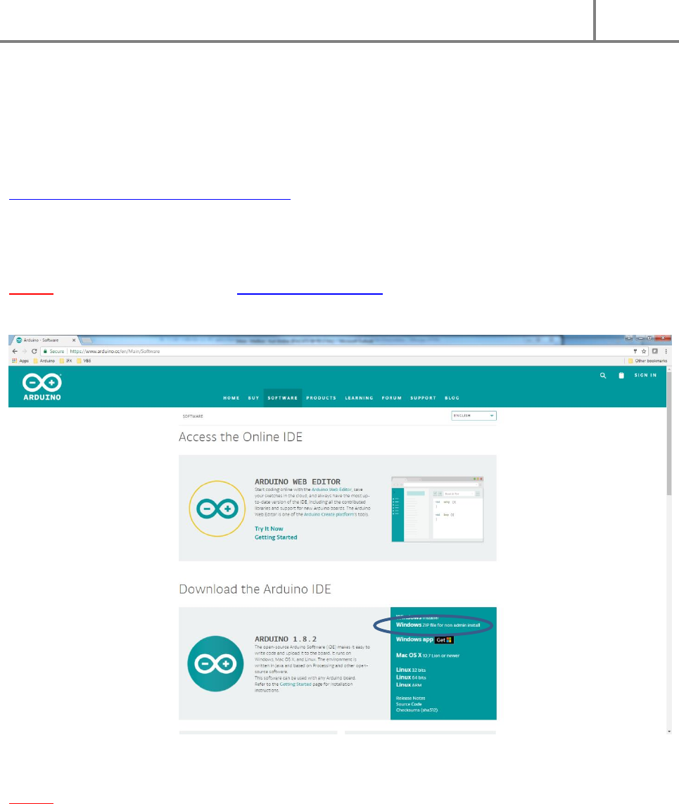
Step 1: Download Arduino IDE from http://www.arduino.cc. Go to Software and then to Download the
Arduino IDE.
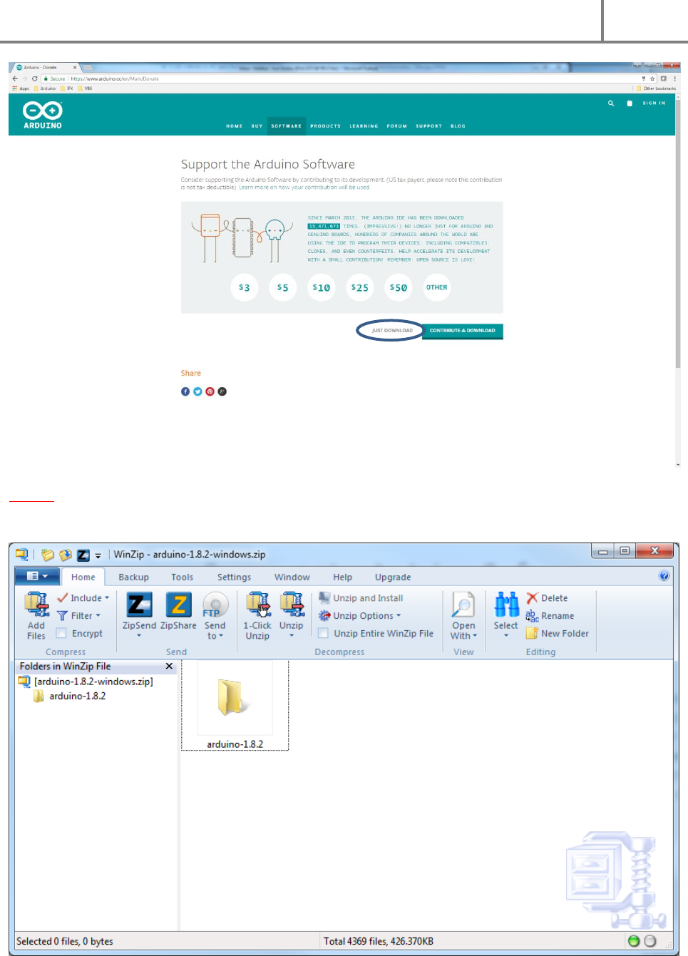
Step 2: From this page you will be redirected to another page where you can donate to the developers of
the Arduino IDE. Optional, you can choose not to donate by clicking on Just Download.
DIYino Stardust v2 User Manual
ProtoWerkstatt 2017, All rigths reserved
Author of this documentation is in no way affiliated, associated, licensed or endorsed by Disney or Lucasfilm Ltd., Industrial Light
and Magic or any of their associates. All brands and trademarks listed are the exclusive property of their respective Owners.
Step 3: The Arduino IDE will be downloaded. When download is completed, unzip the software
anywhere you like to your PC.
DIYino Stardust v2 User Manual
ProtoWerkstatt 2017, All rigths reserved
Author of this documentation is in no way affiliated, associated, licensed or endorsed by Disney or Lucasfilm Ltd., Industrial Light
and Magic or any of their associates. All brands and trademarks listed are the exclusive property of their respective Owners.
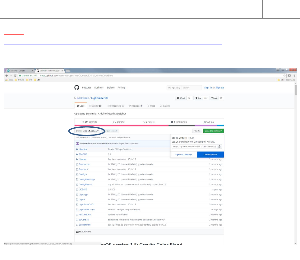
Step 4: Download the lightsaber code of your choice, from example from GitHub:
https://github.com/neskweek/LightSaberOS/tree/LSOS-1.5_GravityColorBlend
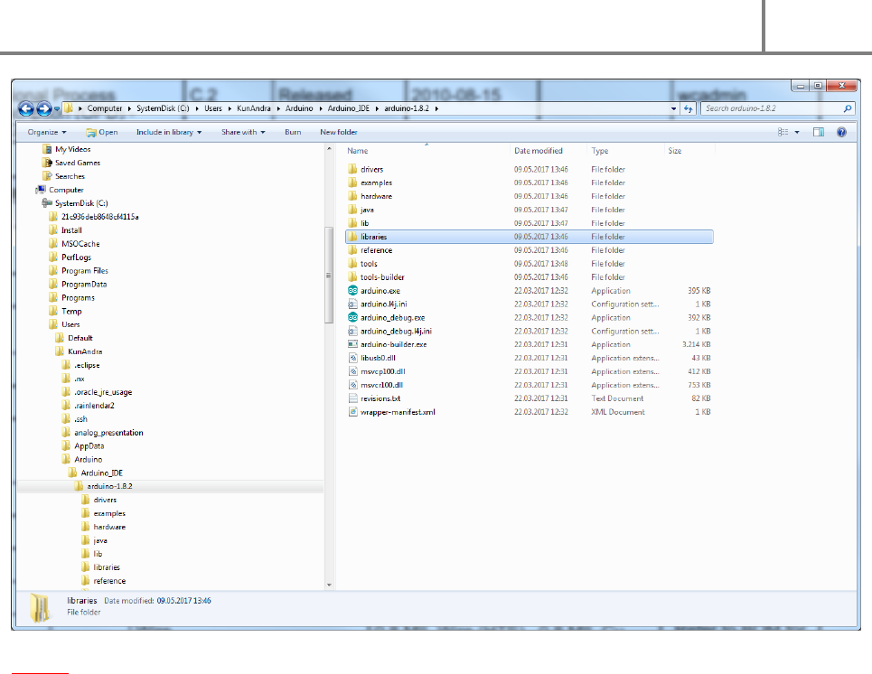
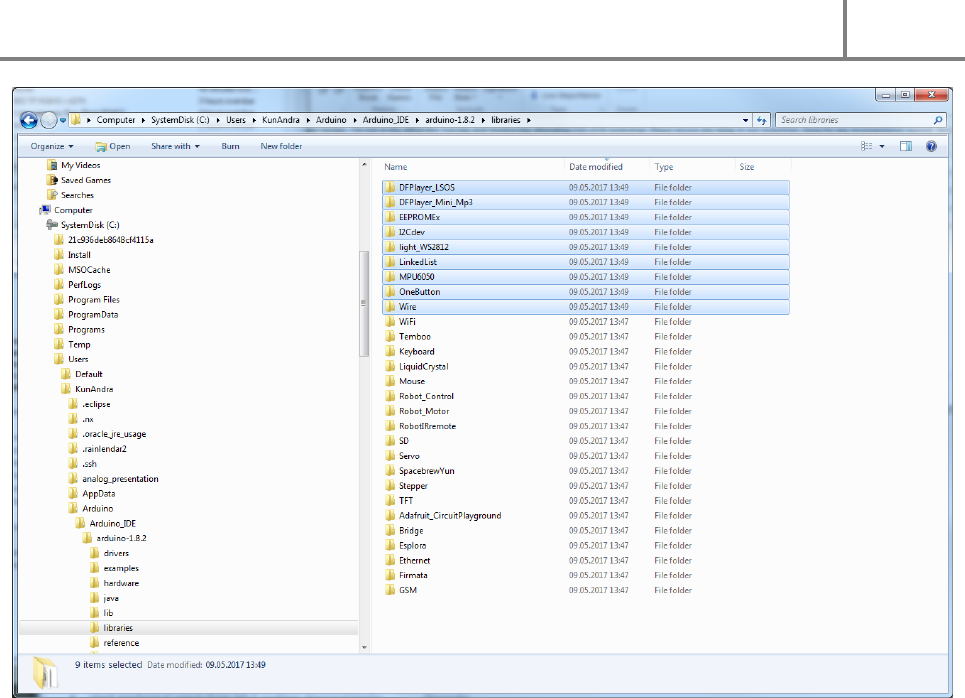
Step 5: Navigate to the folder you unzipped the Arduino IDE and go to the libraries folder.
DIYino Stardust v2 User Manual
ProtoWerkstatt 2017, All rigths reserved
Author of this documentation is in no way affiliated, associated, licensed or endorsed by Disney or Lucasfilm Ltd., Industrial Light
and Magic or any of their associates. All brands and trademarks listed are the exclusive property of their respective Owners.
Step 6: This libraries folder contains basic libraries for Arduino. For the IDE to find the libraries necessary
to compile your downloaded lightsaber code, you must copy all folders located in libraries folder of the
lightsaber software ZIP file to this folder. Sounds more difficult than it really is, look at the next picture
which clearly exlains what is to be done:
DIYino Stardust v2 User Manual
ProtoWerkstatt 2017, All rigths reserved
Author of this documentation is in no way affiliated, associated, licensed or endorsed by Disney or Lucasfilm Ltd., Industrial Light
and Magic or any of their associates. All brands and trademarks listed are the exclusive property of their respective Owners.
And in the next picture you can see where the libraries of the lightsaber software can be found:
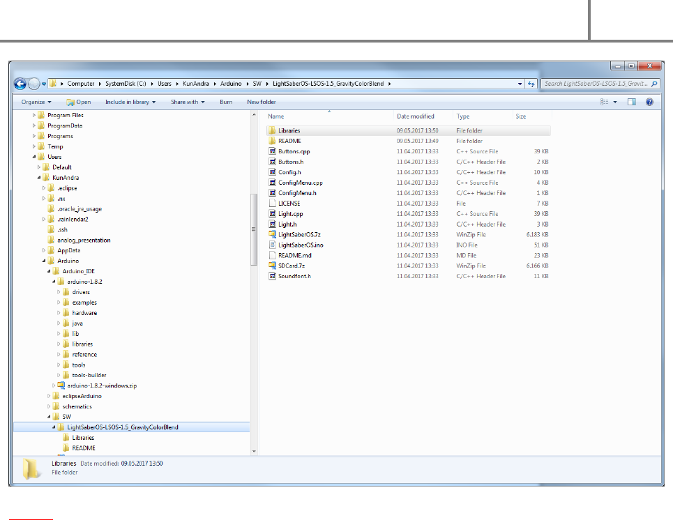
DIYino Stardust v2 User Manual
ProtoWerkstatt 2017, All rigths reserved
Author of this documentation is in no way affiliated, associated, licensed or endorsed by Disney or Lucasfilm Ltd., Industrial Light
and Magic or any of their associates. All brands and trademarks listed are the exclusive property of their respective Owners.
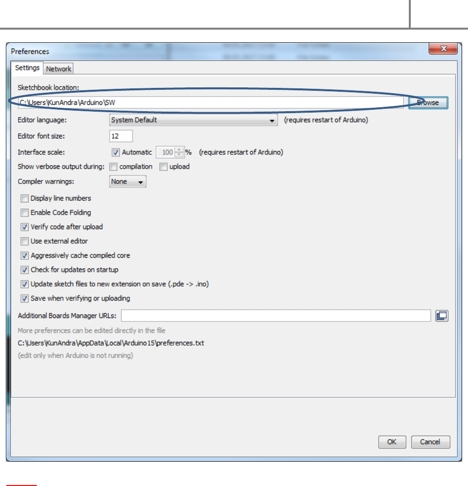
Step 7: Now it’s time to start the Arduino IDE. Simply start the arduino.exe. Then go to File/Preferences
and specify the folder containing the lightsaber code folder you downloaded (see path in the pic above
and compate it to the path indicated under Sketchbook location):
DIYino Stardust v2 User Manual
ProtoWerkstatt 2017, All rigths reserved
Author of this documentation is in no way affiliated, associated, licensed or endorsed by Disney or Lucasfilm Ltd., Industrial Light
and Magic or any of their associates. All brands and trademarks listed are the exclusive property of their respective Owners.
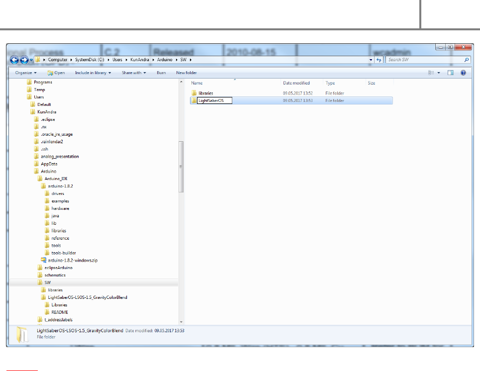
Step 8: It is crucial that the name of the lightsaber code folder be the same as the .ino file in that folder,
see in the next picture. I.e. if the ino file name is LightsaberOS.ino, the folder containing the .ino file also
must be named LightsaberOS. Rename the folder accordingly.
DIYino Stardust v2 User Manual
ProtoWerkstatt 2017, All rigths reserved
Author of this documentation is in no way affiliated, associated, licensed or endorsed by Disney or Lucasfilm Ltd., Industrial Light
and Magic or any of their associates. All brands and trademarks listed are the exclusive property of their respective Owners.
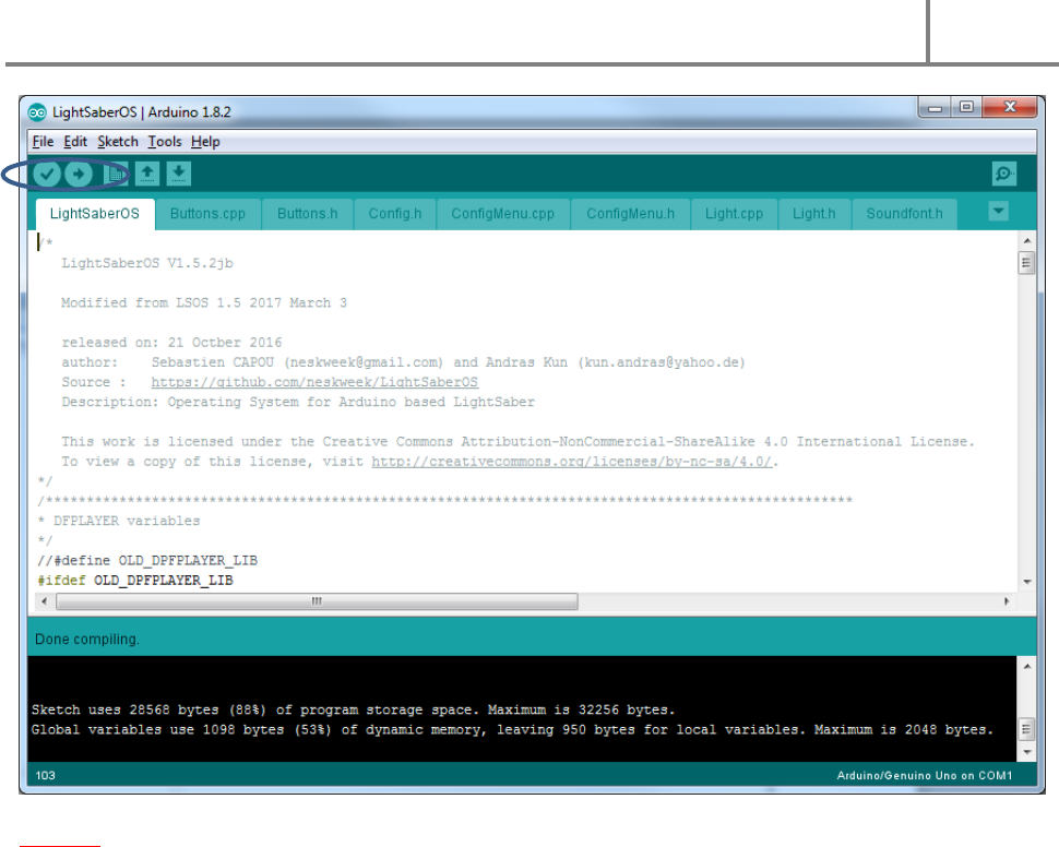
Step 9: Once everything is settled, go to File -> Open -> /../../<lightsaber code .ino file name>. See next
picture how it should look like once the code is opened. The Check and Arrow buttons can be used to
compile or compile/download the code to your Arduino compatible board.
DIYino Stardust v2 User Manual
ProtoWerkstatt 2017, All rigths reserved
Author of this documentation is in no way affiliated, associated, licensed or endorsed by Disney or Lucasfilm Ltd., Industrial Light
and Magic or any of their associates. All brands and trademarks listed are the exclusive property of their respective Owners.
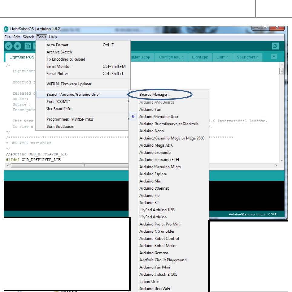
Step 10: Prior to downloading the code to your board, the type of your microcontroller needs to be
specified. To do this, enter the Boards Manager as depicted on the following picture:
DIYino Stardust v2 User Manual
ProtoWerkstatt 2017, All rigths reserved
Author of this documentation is in no way affiliated, associated, licensed or endorsed by Disney or Lucasfilm Ltd., Industrial Light
and Magic or any of their associates. All brands and trademarks listed are the exclusive property of their respective Owners.
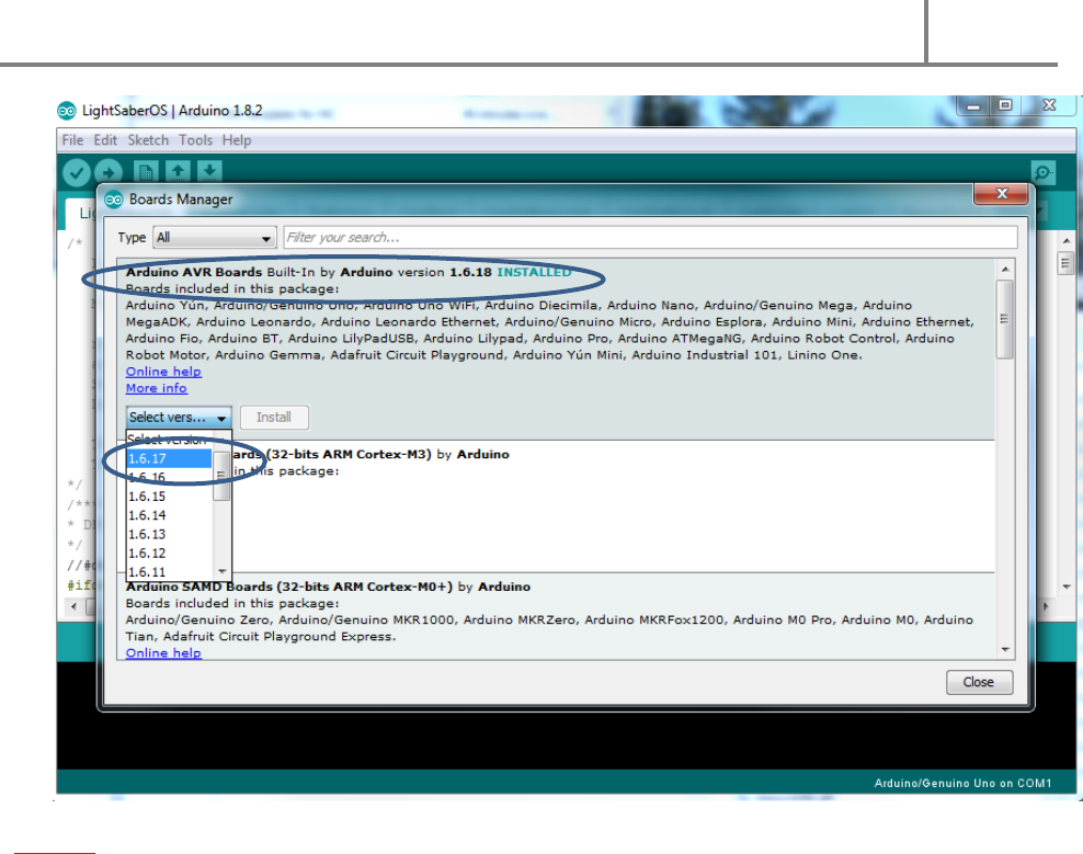
Once the Boards Manager starts, choose Arduino AVR Board, select the version 1.6.17 from the Select
Version drop-down meeu and click on install.
DIYino Stardust v2 User Manual
ProtoWerkstatt 2017, All rigths reserved
Author of this documentation is in no way affiliated, associated, licensed or endorsed by Disney or Lucasfilm Ltd., Industrial Light
and Magic or any of their associates. All brands and trademarks listed are the exclusive property of their respective Owners.
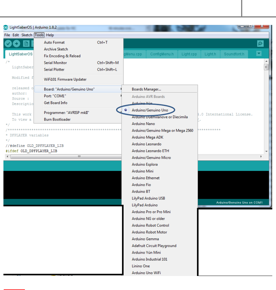
Step 11: Once installation of the Boards Manager is donw, specify your board by selecting
Arduino/Genuino Uno from Tools/Boards (DIYino Stardusts v2 boards are all configured as Arduino/Genuino Uno, as well as
newer runs of DIYino Prime boards. Some older Runs from the Prime configured the boards as Arduino Nano, since the original Prime was based
on the Nano. Later on it was decided to configure the boards unifromly as Uno to benefit from the additional 1.5k code space)
DIYino Stardust v2 User Manual
ProtoWerkstatt 2017, All rigths reserved
Author of this documentation is in no way affiliated, associated, licensed or endorsed by Disney or Lucasfilm Ltd., Industrial Light
and Magic or any of their associates. All brands and trademarks listed are the exclusive property of their respective Owners.
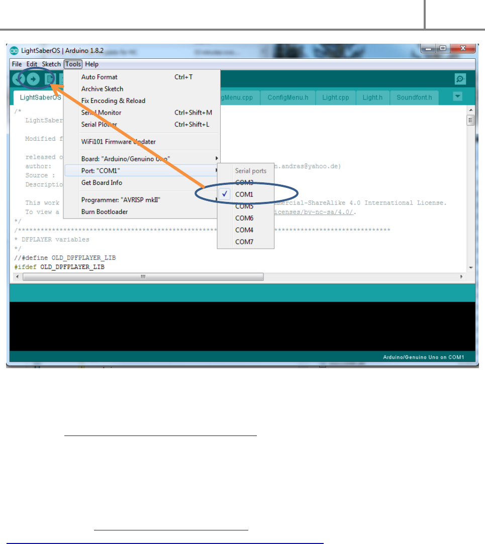
Step 12: Connect the Stardust board to your PC using an USB cable. Once done, a new COM port shall
appear under Tools/Port, which corresponds to your board. Select this COM port and start uloading code
with the Arrow button.
DIYino Stardust v2 User Manual
ProtoWerkstatt 2017, All rigths reserved
Author of this documentation is in no way affiliated, associated, licensed or endorsed by Disney or Lucasfilm Ltd., Industrial Light
and Magic or any of their associates. All brands and trademarks listed are the exclusive property of their respective Owners.
9 QUICK-START GUIDE TO FX-SABEROS
FX-SaberOS (https://github.com/Protonerd/FX-SaberOS) is the world’s most popular open source saber
operating system, evolving out of the world’s first such system, the LightSaberOS written by Sebastien
Capou (neskweek) and Andras Kun (Protonerd). In this Chapter you can learn how to quikcly set up the
most important parameters of the saber code for a first upload.
First of all you need to upload so called sound fonts to your Stardust board. You can use your own sound
fonts (see Chapter 2.2 for uploading sound files and Chapter 4.6 for preparing your own sound fonts for
upload to the Stardust board). There are excellent free-to use sound fonts from Darth PJs (Trinity Force
Sabers) on GitHub (https://github.com/Protonerd/FX-
SaberOS/blob/master/soundfonts/DIYino_Stardust_SPIFlash_image.7z ), the contents of the zip file can
be directly moved to the SPI flash following the instructions in Chapter 4.5. Afterwards you can
download and open FX-SaberOS in your Arduino IDE.
On the Config_HW.h tab, you can configure your hardware and perpherials:
Make sure you select Stardust as board:
//#define DIYINO_PRIME
#define DIYINO_STARDUST
You can select between single and 2-buttons modes by commenting out or leaving following line
uncommented:
#define SINGLEBUTTON -> single button setup
DIYino Stardust v2 User Manual
ProtoWerkstatt 2017, All rigths reserved
Author of this documentation is in no way affiliated, associated, licensed or endorsed by Disney or Lucasfilm Ltd., Industrial Light
and Magic or any of their associates. All brands and trademarks listed are the exclusive property of their respective Owners.
//#define SINGLEBUTTON -> 2- buttons setup
Now it’s time to define your blade type, leave your blade type uncommented and the other two
commented. For instance to select a neopixel blade:
//#define LEDSTRINGS -> defaults to 6 segments, DIYino Prime recommended
//#define STAR_LED -> defaults to Red to LS1, Green to LS2 and Blue to LS3
#define PIXELBLADE -> neopixel blade
And finally if you are using neopixel blade, define the length of your blade in pixels:
#define NUMPIXELS 115
For basic setup that’s all. If you want to understand how the code works, visit the GitHub Wiki. Have fun
and May The Force Be With You! Always!
10 RELATED LINKS
FX-SaberOS: https://github.com/Protonerd/FX-SaberOS
LSOS: https://github.com/neskweek/LightSaberOS
USaber: https://github.com/JakeS0ft/USaber
