DW1000 Software API Guide Rev2p4
DW1000_Software_API_Guide_rev2p4
User Manual: Pdf
Open the PDF directly: View PDF ![]() .
.
Page Count: 94
- 1 Introduction and overview
- 2 General framework
- 3 Typical system start-up
- 4 Interrupt handling
- 5 API function descriptions
- 5.1 dwt_readdevid
- 5.2 dwt_getpartid
- 5.3 dwt_getlotid
- 5.4 dwt_otprevision
- 5.5 dwt_softreset
- 5.6 dwt_rxreset
- 5.7 dwt_initalise
- 5.8 dwt_configure
- 5.9 dwt_configuretxrf
- 5.10 dwt_setsmarttxpower
- 5.11 dwt_setrxantennadelay
- 5.12 dwt_settxantennadelay
- 5.13 dwt_writetxdata
- 5.14 dwt_writetxfctrl
- 5.15 dwt_starttx
- 5.16 dwt_setdelayedtrxtime
- 5.17 dwt_readtxtimestamp
- 5.18 dwt_readtxtimestamplo32
- 5.19 dwt_readtxtimestamphi32
- 5.20 dwt_readrxtimestamp
- 5.21 dwt_readrxtimestamplo32
- 5.22 dwt_readrxtimestamphi32
- 5.23 dwt_readsystime
- 5.24 dwt_readsystimestamphi32
- 5.25 dwt_forcetrxoff
- 5.26 dwt_syncrxbufptrs
- 5.27 dwt_rxenable
- 5.28 dwt_setsniffmode
- 5.29 dwt_setdblrxbuffmode
- 5.30 dwt_setrxtimeout
- 5.31 dwt_setpreambledetecttimeout
- 5.32 dwt_loadopsettabfromotp
- 5.33 dwt_configuresleepcnt
- 5.34 dwt_calibratesleepcnt
- 5.35 dwt_configuresleep
- 5.36 dwt_entersleep
- 5.37 dwt_entersleepaftertx
- 5.38 dwt_spicswakeup
- 5.39 dwt_setlowpowerlistening
- 5.40 dwt_setsnoozetime
- 5.41 dwt_setcallbacks
- 5.42 dwt_setinterrupt
- 5.43 dwt_checkirq
- 5.44 dwt_isr
- 5.45 dwt_lowpowerlistenisr
- 5.46 dwt_setpanid
- 5.47 dwt_setaddress16
- 5.48 dwt_seteui
- 5.49 dwt_geteui
- 5.50 dwt_enableframefilter
- 5.51 dwt_enableautoack
- 5.52 dwt_setrxaftertxdelay
- 5.53 dwt_readrxdata
- 5.54 dwt_readaccdata
- 5.55 dwt_readdiagnostics
- 5.56 dwt_configeventcounters
- 5.57 dwt_readeventcounters
- 5.58 dwt_readtempvbat
- 5.59 dwt_readwakeuptemp
- 5.60 dwt_readwakeupvbat
- 5.61 dwt_otpread
- 5.62 dwt_otpwriteandverify
- 5.63 dwt_setleds
- 5.64 dwt_setfinegraintxseq
- 5.65 dwt_setlnapamode
- 5.66 dwt_setgpiodirection
- 5.67 dwt_setgpiovalue
- 5.68 dwt_setxtaltrim
- 5.69 dwt_getinitxtaltrim
- 5.70 dwt_configcwmode
- 5.71 dwt_configcontinuousframemode
- 5.72 dwt_calcbandwidthtempadj
- 5.73 dwt_calcpgcount
- 5.74 dwt_calcpowertempadj
- 5.75 dwt_setdevicedataptr
- 5.76 dwt_readcarrierintegrator
- 5.77 SPI driver functions
- 5.78 Mutual-exclusion API functions
- 5.79 Sleep function
- 5.80 Subsidiary functions
- 6 Appendix 1 – DW1000 API examples applications
- 6.1 Package structure
- 6.2 Building and running the examples
- 6.3 Examples list
- 6.3.1 Example 1a: simple TX
- 6.3.2 Example 1b: TX with sleep
- 6.3.3 Example 1c: TX with auto sleep
- 6.3.4 Example 1d: TX with timed sleep
- 6.3.5 Example 2a: simple RX
- 6.3.6 Example 2b: simple RX using 64 symbols long preambles
- 6.3.7 Example 2c: simple RX with diagnostics
- 6.3.8 Example 2d: low duty-cycle SNIFF mode
- 6.3.9 Example 2e: RX using double buffering
- 6.3.10 Example 3a: TX then wait for a response
- 6.3.11 Example 3b: RX then send a response
- 6.3.12 Example 3c: TX then wait for a response with GPIOs/LEDs
- 6.3.13 Example 3d: TX then wait for a response using interrupts
- 6.3.14 Example 4a: continuous wave mode
- 6.3.15 Example 4b: continuous frame mode
- 6.3.16 Example 5a: double-sided two-way ranging (DS TWR) initiator
- 6.3.17 Example 5b: double-sided two-way ranging responder
- 6.3.18 Example 6a: single-sided two-way ranging (SS TWR) initiator
- 6.3.19 Example 6b: single-sided two-way ranging responder
- 6.3.20 Example 7a: Auto ACK TX
- 6.3.21 Example 7b: Auto ACK RX
- 6.3.22 Example 8a: Low-power listening RX
- 6.3.23 Example 8b: Low-power listening TX
- 6.3.24 Example 9a: TX Bandwidth and Power Reference Measurements
- 6.3.25 Example 9b: TX Bandwidth and Power Compensation
- 6.3.26
- 7 Appendix 2 – Bibliography:
- 8 Document History
- 9 Major Changes
- 10 About Decawave

© Decawave Ltd 2016
Version 2.4
Page 1 of 94
DW1000 DEVICE DRIVER API GUIDE
DW1000 DEVICE
DRIVER APPLICATION
PROGRAMMING
INTERFACE (API) GUIDE
USING API FUNCTIONS TO
CONFIGURE AND PROGRAM THE
DW1000 UWB TRANSCEIVER
This document is subject to change without notice

DW1000 Device Driver API Guide
© Decawave Ltd 2016
Version 2.4
Page 2 of 94
DOCUMENT INFORMATION
Disclaimer
Decawave reserves the right to change product specifications without notice. As far as possible changes to
functionality and specifications will be issued in product specific errata sheets or in new versions of this
document. Customers are advised to check the Decawave website for the most recent updates on this
product
Copyright © 2015 Decawave Ltd
LIFE SUPPORT POLICY
Decawave products are not authorized for use in safety-critical applications (such as life support) where a
failure of the Decawave product would reasonably be expected to cause severe personal injury or death.
Decawave customers using or selling Decawave products in such a manner do so entirely at their own risk
and agree to fully indemnify Decawave and its representatives against any damages arising out of the use of
Decawave products in such safety-critical applications.
Caution! ESD sensitive device.
Precaution should be used when handling the device in order to prevent permanent damage

DW1000 Device Driver API Guide
© Decawave Ltd 2016
Version 2.4
Page 3 of 94
DISCLAIMER
This Disclaimer applies to the DW1000 API source code (collectively “Decawave Software”) provided
by Decawave Ltd. (“Decawave”).
Downloading, accepting delivery of or using the Decawave Software indicates your agreement to the
terms of this Disclaimer. If you do not agree with the terms of this Disclaimer do not download,
accept delivery of or use the Decawave Software.
Decawave Software is solely intended to assist you in developing systems that incorporate
Decawave semiconductor products. You understand and agree that you remain responsible for using
your independent analysis, evaluation and judgment in designing your systems and products. THE
DECISION TO USE DECAWAVE SOFTWARE IN WHOLE OR IN PART IN YOUR SYSTEMS AND PRODUCTS
RESTS ENTIRELY WITH YOU.
DECAWAVE SOFTWARE IS PROVIDED "AS IS". DECAWAVE MAKES NO WARRANTIES OR
REPRESENTATIONS WITH REGARD TO THE DECAWAVE SOFTWARE OR USE OF THE DECAWAVE
SOFTWARE, EXPRESS, IMPLIED OR STATUTORY, INCLUDING ACCURACY OR COMPLETENESS.
DECAWAVE DISCLAIMS ANY WARRANTY OF TITLE AND ANY IMPLIED WARRANTIES OF
MERCHANTABILITY, FITNESS FOR A PARTICULAR PURPOSE AND NON-INFRINGEMENT OF ANY THIRD
PARTY INTELLECTUAL PROPERTY RIGHTS WITH REGARD TO DECAWAVE SOFTWARE OR THE USE
THEREOF.
DECAWAVE SHALL NOT BE LIABLE FOR AND SHALL NOT DEFEND OR INDEMNIFY YOU AGAINST ANY
THIRD PARTY INFRINGEMENT CLAIM THAT RELATES TO OR IS BASED ON THE DECAWAVE SOFTWARE
OR THE USE OF THE DECAWAVE SOFTWARE WITH DECAWAVE SEMICONDUCTOR TECHNOLOGY. IN
NO EVENT SHALL DECAWAVE BE LIABLE FOR ANY ACTUAL, SPECIAL, INCIDENTAL, CONSEQUENTIAL
OR INDIRECT DAMAGES, HOWEVER CAUSED, INCLUDING WITHOUT LIMITATION TO THE GENERALITY
OF THE FOREGOING, LOSS OF ANTICIPATED PROFITS, GOODWILL, REPUTATION, BUSINESS RECEIPTS
OR CONTRACTS, COSTS OF PROCUREMENT OF SUBSTITUTE GOODS OR SERVICES; LOSS OF USE,
DATA, OR PROFITS; OR BUSINESS INTERRUPTION), LOSSES OR EXPENSES RESULTING FROM THIRD
PARTY CLAIMS. THESE LIMITATIONS WILL APPLY REGARDLESS OF THE FORM OF ACTION, WHETHER
UNDER STATUTE, IN CONTRACT OR TORT INCLUDING NEGLIGENCE OR ANY OTHER FORM OF ACTION
AND WHETHER OR NOT DECAWAVE HAS BEEN ADVISED OF THE POSSIBILITY OF SUCH DAMAGES,
ARISING IN ANY WAY OUT OF DECAWAVE SOFTWARE OR THE USE OF DECAWAVE SOFTWARE.
You are authorized to use Decawave Software in your end products and to modify the Decawave
Software in the development of your end products. HOWEVER, NO OTHER LICENSE, EXPRESS OR
IMPLIED, BY ESTOPPEL OR OTHERWISE TO ANY OTHER DECAWAVE INTELLECTUAL PROPERTY RIGHT,
AND NO LICENSE TO ANY THIRD PARTY TECHNOLOGY OR INTELLECTUAL PROPERTY RIGHT, IS
GRANTED HEREIN, including but not limited to any patent right, copyright, mask work right, or other
intellectual property right relating to any combination, machine, or process in which Decawave
semiconductor products or Decawave Software are used.
You acknowledge and agree that you are solely responsible for compliance with all legal, regulatory
and safety-related requirements concerning your products, and any use of Decawave Software in

DW1000 Device Driver API Guide
© Decawave Ltd 2016
Version 2.4
Page 4 of 94
your applications, notwithstanding any applications-related information or support that may be
provided by Decawave.
Decawave reserves the right to make corrections, enhancements, improvements and other changes
to its software at any time.
Mailing address: -
Decawave Ltd.,
Adelaide Chambers,
Peter Street,
Dublin 8

DW1000 Device Driver API Guide
© Decawave Ltd 2016
Version 2.4
Page 5 of 94
TABLE OF CONTENTS
1 INTRODUCTION AND OVERVIEW ........................................................................................................... 10
2 GENERAL FRAMEWORK ......................................................................................................................... 11
3 TYPICAL SYSTEM START-UP ................................................................................................................... 13
4 INTERRUPT HANDLING .......................................................................................................................... 14
5 API FUNCTION DESCRIPTIONS ............................................................................................................... 15
5.1 DWT_READDEVID ..................................................................................................................................... 15
5.2 DWT_GETPARTID ...................................................................................................................................... 15
5.3 DWT_GETLOTID ....................................................................................................................................... 16
5.4 DWT_OTPREVISION ................................................................................................................................... 16
5.5 DWT_SOFTRESET ...................................................................................................................................... 17
5.6 DWT_RXRESET ......................................................................................................................................... 17
5.7 DWT_INITALISE ........................................................................................................................................ 18
5.8 DWT_CONFIGURE ..................................................................................................................................... 19
5.9 DWT_CONFIGURETXRF .............................................................................................................................. 23
5.10 DWT_SETSMARTTXPOWER ......................................................................................................................... 24
5.11 DWT_SETRXANTENNADELAY ....................................................................................................................... 25
5.12 DWT_SETTXANTENNADELAY ....................................................................................................................... 26
5.13 DWT_WRITETXDATA ................................................................................................................................. 26
5.14 DWT_WRITETXFCTRL ................................................................................................................................. 27
5.15 DWT_STARTTX ......................................................................................................................................... 28
5.16 DWT_SETDELAYEDTRXTIME ........................................................................................................................ 29
5.17 DWT_READTXTIMESTAMP .......................................................................................................................... 30
5.18 DWT_READTXTIMESTAMPLO32 ................................................................................................................... 31
5.19 DWT_READTXTIMESTAMPHI32 ................................................................................................................... 31
5.20 DWT_READRXTIMESTAMP .......................................................................................................................... 32
5.21 DWT_READRXTIMESTAMPLO32 .................................................................................................................. 32
5.22 DWT_READRXTIMESTAMPHI32 ................................................................................................................... 33
5.23 DWT_READSYSTIME .................................................................................................................................. 33
5.24 DWT_READSYSTIMESTAMPHI32 .................................................................................................................. 33
5.25 DWT_FORCETRXOFF .................................................................................................................................. 34
5.26 DWT_SYNCRXBUFPTRS .............................................................................................................................. 34
5.27 DWT_RXENABLE ....................................................................................................................................... 34
5.28 DWT_SETSNIFFMODE ................................................................................................................................ 36
5.29 DWT_SETDBLRXBUFFMODE ........................................................................................................................ 36
5.30 DWT_SETRXTIMEOUT ................................................................................................................................ 37
5.31 DWT_SETPREAMBLEDETECTTIMEOUT ........................................................................................................... 37
5.32 DWT_LOADOPSETTABFROMOTP .................................................................................................................. 38
5.33 DWT_CONFIGURESLEEPCNT ........................................................................................................................ 39
5.34 DWT_CALIBRATESLEEPCNT ......................................................................................................................... 40
5.35 DWT_CONFIGURESLEEP ............................................................................................................................. 41
5.36 DWT_ENTERSLEEP .................................................................................................................................... 43
5.37 DWT_ENTERSLEEPAFTERTX ......................................................................................................................... 43
5.38 DWT_SPICSWAKEUP .................................................................................................................................. 44
5.39 DWT_SETLOWPOWERLISTENING .................................................................................................................. 45
5.40 DWT_SETSNOOZETIME .............................................................................................................................. 46

DW1000 Device Driver API Guide
© Decawave Ltd 2016
Version 2.4
Page 6 of 94
5.41 DWT_SETCALLBACKS ................................................................................................................................. 46
5.42 DWT_SETINTERRUPT ................................................................................................................................. 47
5.43 DWT_CHECKIRQ ....................................................................................................................................... 49
5.44 DWT_ISR ................................................................................................................................................ 49
5.45 DWT_LOWPOWERLISTENISR ....................................................................................................................... 51
5.46 DWT_SETPANID ....................................................................................................................................... 52
5.47 DWT_SETADDRESS16 ................................................................................................................................ 52
5.48 DWT_SETEUI ........................................................................................................................................... 53
5.49 DWT_GETEUI ........................................................................................................................................... 53
5.50 DWT_ENABLEFRAMEFILTER ........................................................................................................................ 54
5.51 DWT_ENABLEAUTOACK ............................................................................................................................. 54
5.52 DWT_SETRXAFTERTXDELAY ......................................................................................................................... 55
5.53 DWT_READRXDATA ................................................................................................................................... 55
5.54 DWT_READACCDATA ................................................................................................................................. 56
5.55 DWT_READDIAGNOSTICS ........................................................................................................................... 57
5.56 DWT_CONFIGEVENTCOUNTERS ................................................................................................................... 59
5.57 DWT_READEVENTCOUNTERS ...................................................................................................................... 59
5.58 DWT_READTEMPVBAT ............................................................................................................................... 61
5.59 DWT_READWAKEUPTEMP .......................................................................................................................... 62
5.60 DWT_READWAKEUPVBAT ........................................................................................................................... 62
5.61 DWT_OTPREAD ........................................................................................................................................ 62
5.62 DWT_OTPWRITEANDVERIFY ........................................................................................................................ 63
5.63 DWT_SETLEDS ......................................................................................................................................... 65
5.64 DWT_SETFINEGRAINTXSEQ ......................................................................................................................... 65
5.65 DWT_SETLNAPAMODE ............................................................................................................................... 66
5.66 DWT_SETGPIODIRECTION ........................................................................................................................... 66
5.67 DWT_SETGPIOVALUE................................................................................................................................. 67
5.68 DWT_SETXTALTRIM .................................................................................................................................. 67
5.69 DWT_GETINITXTALTRIM ............................................................................................................................. 68
5.70 DWT_CONFIGCWMODE ............................................................................................................................. 68
5.71 DWT_CONFIGCONTINUOUSFRAMEMODE ....................................................................................................... 70
5.72 DWT_CALCBANDWIDTHTEMPADJ ................................................................................................................. 72
5.73 DWT_CALCPGCOUNT................................................................................................................................. 73
5.74 DWT_CALCPOWERTEMPADJ........................................................................................................................ 73
5.75 DWT_SETDEVICEDATAPTR .......................................................................................................................... 74
5.76 DWT_READCARRIERINTEGRATOR ................................................................................................................. 74
5.77 SPI DRIVER FUNCTIONS ............................................................................................................................. 75
5.77.1 writetospi .................................................................................................................................... 76
5.77.2 readfromspi ................................................................................................................................ 76
5.78 MUTUAL-EXCLUSION API FUNCTIONS .......................................................................................................... 77
5.78.1 decamutexon .............................................................................................................................. 77
5.78.2 decamutexoff .............................................................................................................................. 78
5.79 SLEEP FUNCTION ...................................................................................................................................... 79
5.79.1 deca_sleep .................................................................................................................................. 79
5.80 SUBSIDIARY FUNCTIONS ............................................................................................................................. 79
5.80.1 dwt_writetodevice ...................................................................................................................... 79
5.80.2 dwt_readfromdevice .................................................................................................................. 80
5.80.3 dwt_read32bitreg ....................................................................................................................... 80
5.80.4 dwt_read32bitoffsetreg ............................................................................................................. 80

DW1000 Device Driver API Guide
© Decawave Ltd 2016
Version 2.4
Page 7 of 94
5.80.5 dwt_write32bitreg ...................................................................................................................... 80
5.80.6 dwt_write32bitoffsetreg ............................................................................................................ 80
5.80.7 dwt_read16bitoffsetreg ............................................................................................................. 80
5.80.8 dwt_write16bitoffsetreg ............................................................................................................ 80
5.80.9 dwt_read8bitoffsetreg ............................................................................................................... 80
5.80.10 dwt_write8bitoffsetreg .............................................................................................................. 81
6 APPENDIX 1 – DW1000 API EXAMPLES APPLICATIONS .......................................................................... 82
6.1 PACKAGE STRUCTURE ................................................................................................................................ 82
6.2 BUILDING AND RUNNING THE EXAMPLES ....................................................................................................... 82
6.3 EXAMPLES LIST ........................................................................................................................................ 83
6.3.1 Example 1a: simple TX .................................................................................................................... 83
6.3.2 Example 1b: TX with sleep .............................................................................................................. 83
6.3.3 Example 1c: TX with auto sleep ...................................................................................................... 83
6.3.4 Example 1d: TX with timed sleep .................................................................................................... 83
6.3.5 Example 2a: simple RX .................................................................................................................... 84
6.3.6 Example 2b: simple RX using 64 symbols long preambles .............................................................. 84
6.3.7 Example 2c: simple RX with diagnostics ......................................................................................... 84
6.3.8 Example 2d: low duty-cycle SNIFF mode ......................................................................................... 84
6.3.9 Example 2e: RX using double buffering .......................................................................................... 84
6.3.10 Example 3a: TX then wait for a response ................................................................................... 85
6.3.11 Example 3b: RX then send a response ........................................................................................ 85
6.3.12 Example 3c: TX then wait for a response with GPIOs/LEDs ........................................................ 85
6.3.13 Example 3d: TX then wait for a response using interrupts ......................................................... 85
6.3.14 Example 4a: continuous wave mode .......................................................................................... 85
6.3.15 Example 4b: continuous frame mode ......................................................................................... 86
6.3.16 Example 5a: double-sided two-way ranging (DS TWR) initiator ................................................ 87
6.3.17 Example 5b: double-sided two-way ranging responder ............................................................. 87
6.3.18 Example 6a: single-sided two-way ranging (SS TWR) initiator ................................................... 87
6.3.19 Example 6b: single-sided two-way ranging responder ............................................................... 88
6.3.20 Example 7a: Auto ACK TX ........................................................................................................... 88
6.3.21 Example 7b: Auto ACK RX ........................................................................................................... 88
6.3.22 Example 8a: Low-power listening RX .......................................................................................... 88
6.3.23 Example 8b: Low-power listening TX .......................................................................................... 89
6.3.24 Example 9a: TX Bandwidth and Power Reference Measurements ............................................. 89
6.3.25 Example 9b: TX Bandwidth and Power Compensation ............................................................... 89
7 APPENDIX 2 – BIBLIOGRAPHY: ............................................................................................................... 90
8 DOCUMENT HISTORY ............................................................................................................................ 91
9 MAJOR CHANGES .................................................................................................................................. 91
9.1 RELEASE 1.5 ........................................................................................................................................... 91
9.2 RELEASE 1.7 ........................................................................................................................................... 91
9.3 RELEASE 2.0 ........................................................................................................................................... 91
9.4 RELEASE 2.1 ........................................................................................................................................... 92
9.5 RELEASE 2.2 ........................................................................................................................................... 93
9.6 RELEASE 2.3 ........................................................................................................................................... 93
9.7 RELEASE 2.4 ........................................................................................................................................... 93
10 ABOUT DECAWAVE ........................................................................................................................... 94

DW1000 Device Driver API Guide
© Decawave Ltd 2016
Version 2.4
Page 8 of 94

DW1000 Device Driver API Guide
© Decawave Ltd 2016
Version 2.4
Page 9 of 94
List of Tables
TABLE 1: CONFIG PARAMETER TO DWT_INITIALISE() FUNCTION .......................................................................................... 18
TABLE 2: DW1000 SUPPORTED UWB CHANNELS AND RECOMMENDED PREAMBLE CODES ...................................................... 21
TABLE 3: RECOMMENDED PREAMBLE LENGTHS ................................................................................................................ 22
TABLE 4: RECOMMENDED PAC SIZE .............................................................................................................................. 22
TABLE 5: PGDLY RECOMMENDED VALUES ....................................................................................................................... 23
TABLE 6: TX POWER RECOMMENDED VALUES (WHEN SMART POWER IS DISABLED) ................................................................. 24
TABLE 7: TX POWER RECOMMENDED VALUES (WHEN SMART POWER IS ENABLED) .................................................................. 24
TABLE 8: MODE PARAMETER TO DWT_STARTTX() FUNCTION .............................................................................................. 29
TABLE 9: VALUES FOR DWT_LOADOPSETTABFROMOTP() OPS_SEL PARAMETER ...................................................................... 38
TABLE 10: BITMASK VALUES FOR DWT_CONFIGURESLEEP() MODE BIT MASK .......................................................................... 41
TABLE 11: BITMASK VALUES FOR DWT_CONFIGURESLEEP() WAKE BIT MASK .......................................................................... 42
TABLE 12: BITMASK VALUES FOR DWT_SETINTERRUPT() INTERRUPT MASK ENABLING/DISABLING .............................................. 48
TABLE 13: LIST OF EVENTS HANDLED BY THE DWT_ISR() FUNCTION AND SIGNALLED IN CALL-BACKS ............................................ 49
TABLE 14: BITMASK VALUES FOR FRAME FILTERING ENABLING/DISABLING ............................................................................. 54
TABLE 15: OTP MEMORY MAP .................................................................................................................................... 64
TABLE 16: DW1000 API PACKAGE STRUCTURE .............................................................................................................. 82
TABLE 17: BIBLIOGRAPHY ........................................................................................................................................... 90
TABLE 18: DOCUMENT HISTORY................................................................................................................................... 91
List of Figures
FIGURE 1: GENERAL SOFTWARE FRAMEWORK OF DW1000 DEVICE DRIVER .......................................................................... 11
FIGURE 2: TYPICAL FLOW OF INITIALISATION.................................................................................................................... 13
FIGURE 3: INTERRUPT HANDLING .................................................................................................................................. 14
FIGURE 4: INTERRUPT HANDLING .................................................................................................................................. 51
FIGURE 5: SELECT TOOLCHAIN PATH .............................................................................................................................. 83
FIGURE 6: CONTINUOUS WAVE OUTPUT ......................................................................................................................... 86
FIGURE 7: CONTINUOUS FRAME OUTPUT ........................................................................................................................ 87

DW1000 Device Driver API Guide
© Decawave Ltd 2016
Version 2.4
Page 10 of 94
1 INTRODUCTION AND OVERVIEW
The DW1000 IC is a radio transceiver IC implementing the UWB physical layer defined in IEEE
802.15.4-2011 standard [3]. For more details of this device the reader is referred to:
The DW1000 Data Sheet [1]
The DW1000 User Manual [2]
This document, “DW1000 Device Driver - Application Programming Interface (API) Guide” is a guide
to the device driver software developed by Decawave to drive Decawave’s DW1000 UWB radio
transceiver IC.
The device driver is essentially a set of low-level functions providing a means to exercise the main
features of the DW1000 transceiver without having to deal with the details of accessing the device
directly through its SPI interface register set.
The device driver is provided as source code to allow it to be ported to any target microprocessor
system with an SPI interface
1
. The source code employs the C programming language.
The DW1000 device driver is controlled through its Application Programming Interface (API) which is
comprised of a set of functions. This document is predominately a guide to the device driver API
describing each of the API functions in detail in terms of its parameters, functionality and utility.
This document relates to: "DW1000 Device Driver Version 04.00.xx"
The device driver version information may be found in source code file “deca_version.h”.
1
Since the DW1000 is controlled through its SPI interface, an SPI interface is a mandatory requirement for the
system.
DW1000 Device Driver API Guide
© Decawave Ltd 2016
Version 2.4
Page 11 of 94
2 GENERAL FRAMEWORK
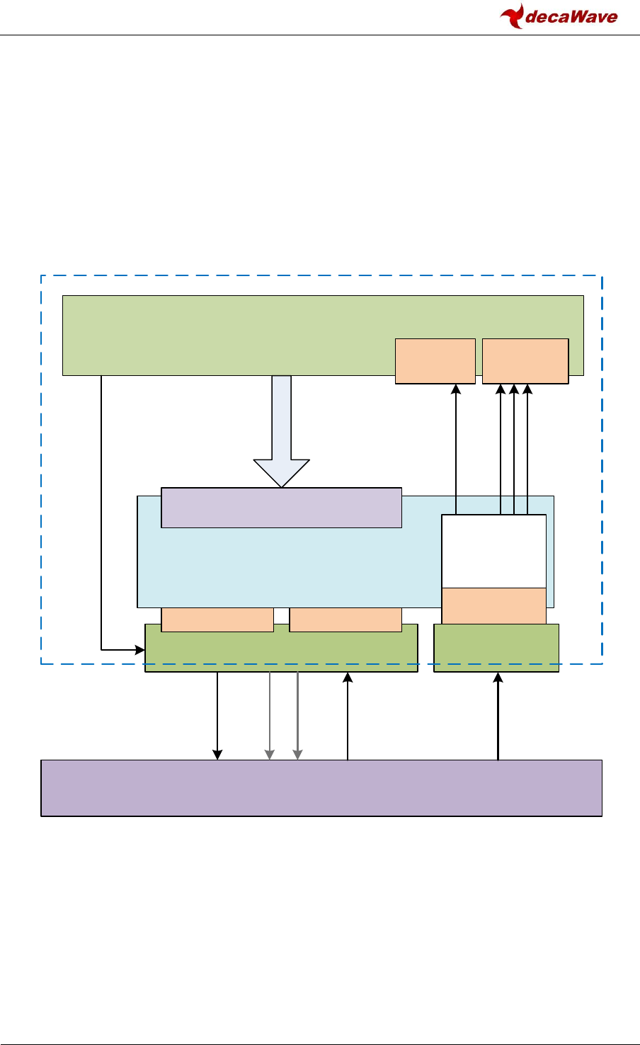
Figure 1 shows the general framework of the software system encompassing the DW1000 device
driver. The DW1000 device driver controls the DW1000 IC through its SPI interface. The DW1000
device driver abstracts the target SPI device by calling it through generic functions writetospi() and
readfromspi(). In porting the DW1000 device driver to different target hardware, the body of these
SPI functions are written/re-written/provided to drive the target microcontroller device’s physical
SPI hardware. The initialisation of the physical SPI interface mode and data rate is considered to be
part of the target system outside the DW1000 device driver.
Figure 1: General software framework of DW1000 device driver
The control of the DW1000 IC through the DW1000 device driver software is achieved via a set of
API functions, documented in section 5 – API function descriptions below, and called from the upper
layer application code.
The IRQ interrupt line output from the DW1000 IC (assuming interrupts are being employed) is
connected to the target microcontroller system’s interrupt handling logic. Again this is considered to
be outside the DW1000 device driver. It is assumed that the target systems interrupt handling logic
and its associated target specific interrupt handling software will correctly identify the assertion of
DW1000 API Functions
Interrupt
Handler
DW1000 Device Driver
DW1000 PHYSICAL IC
writetospi() readfromspi() dwt_isr()
Target SPI Target IRQ
SPICLK
SPICSn
SPIMOSI
SPIMISO
IRQ
Upper Layer / Application Code
TX
callback RX
callbacks
SPI initialisation and configuration
Software
TX Done RX Okay
RX Error
RX Timeout

DW1000 Device Driver API Guide
© Decawave Ltd 2016
Version 2.4
Page 12 of 94
the DW1000’s IRQ and will as a result call the DW1000 device driver’s interrupt handling function
dwt_isr() to process the interrupt.
The DW1000 device driver’s dwt_isr() function processes the DW1000 interrupts and calls TX and RX
call-back functions in the upper layer application code. This is done via function pointers
*cbTxDone(), *cbRxOk(), *cbRxTo and *cbRxErr() which are configured to call the upper layer
application code’s own call-back functions via the dwt_setcallbacks() API function.
Using interrupts is recommended, but it is possible to drive the DW1000 without employing
interrupts. In this case the background loop can periodically call the DW1000 device driver’s
dwt_isr() function, which will poll the DW1000 status register and process any events that are active.
The following is IMPORTANT:
Note background application activity invoking API functions employing the SPI interface can
conflict with foreground interrupt activity also needing to employ the SPI interface.
The DW1000 device driver’s interrupt handler accesses the DW1000 IC through the writetospi() and
readfromspi() functions, and, it is generally expected that the call-back functions will also access the
DW1000 IC through the DW1000 device driver’s API functions which ultimately also call the
writetospi() and readfromspi() functions.
This means that the writetospi() and readfromspi() functions need to incorporate protection
against foreground activity occurring when they are being used in the background. This is
achieved by incorporating calls to decamutexon() and decamutexoff() within the writetospi() and
readfromspi() functions to disable interrupts from the DW1000 from being recognised while the
background SPI access is in progress.
Examples of be decamutexon()and decamutexoff() within the writetospi() and readfromspi()
functions found in source code file “deca_irq.c” and the definitions of the writetospi() and
readfromspi() functions in “deca_spi.c” source file.
Other than the provisions for interrupt handling, the DW1000 device driver and its API functions are
not written to be re-entrant or for simultaneous use by multiple threads. The design in general
assumes a single caller that allows each function to complete before it is called again.
DW1000 Device Driver API Guide
© Decawave Ltd 2016
Version 2.4
Page 13 of 94
3 TYPICAL SYSTEM START-UP
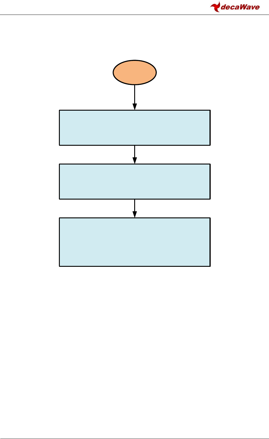
Figure 2 shows the typical flow of initialisation of the DW1000 in a microprocessor system.
Figure 2: Typical flow of initialisation
Power
ON
Microprocessor initialisation of its system hardware
including the SPI interface necessary for talking to the
DW1000 via writetospi() and readfromspi() functions.
Assuming the DW1000 has been powered on it should be
in its IDLE state. The microprocessor system can call the
API functions dwt_initialise() and dwt_configure() to initialise
the DW1000 and configure it for operation.
The microprocessor system can then enable its interrupt
handling system to accept interrupts from the DW1000
and the application can progress into its normal operating
flow -- initiating a transmission or reception as appropriate
to the application and/or putting the DW1000 into a low-
power sleep mode until it is needed for operation.
DW1000 Device Driver API Guide
© Decawave Ltd 2016
Version 2.4
Page 14 of 94
4 INTERRUPT HANDLING
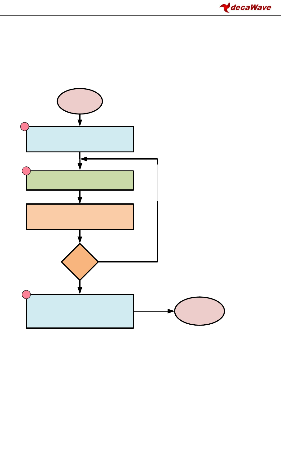
Figure 3 shows how the DW1000 interrupts should be processed by the microcontroller system.
Once the interrupt is active, the microcontroller’s target specific interrupt handler for that interrupt
line should get called. This in turn calls the DW1000 device driver’s interrupt handler service
routine, the dwt_isr() API function, which processes the event that triggered the interrupt.
Figure 3: Interrupt handling
The flow shown above, with the rechecking of DW1000 to check for continued IRQ line activation
and calling the dwt_isr() API function again, is only required for edge sensitive interrupts. This is
done in case another interrupt becomes pending during the processing of the first interrupt, in this
case if all interrupt sources are not cleared the IRQ line will not be de-asserted and edge sensitive
interrupt processing hardware will not see another edge. For proper level sensitive interrupts only
steps numbered 1, 2, and 3 are required – any still pending interrupt should cause the interrupt
handler to be re-invoked as soon as it finishes processing the first interrupt.
More information about individual interrupt events and associated processing is shown in Figure 4.
DW1000 IRQ
is asserted
Assuming interrupts are enabled,
target specific hardware invokes target
specific interrupt processing software
Read state of DW1000 IRQ line input
to microprocessor to check whether a
DW1000 IRQ is pending
NO
1
Call dwt_isr() the DW1000 device
driver’s interrupt handler routine
2
Clear and re-enable target specific
interrupt processing hardware for the
DW1000 IRQ line and return from the
interrupt servicing routine
3
IRQ
Pending
?
dwt_isr() will process the event that triggered the
interrupt (clearing it to enable a new interrupt on
the next event) and call the configured TX or RX
call-back functions as appropriate.
YES
Done
Return from
Interrupt

DW1000 Device Driver API Guide
© Decawave Ltd 2016
Version 2.4
Page 15 of 94
5 API FUNCTION DESCRIPTIONS
This section describes DW1000 device driver’s API function calls. The API functions are provided to
aid developers in driving the DW1000 (Decawave’s ScenSor IEEE 802.15.4 UWB transceiver IC).
These functions are implemented in the device driver source code file “deca_device.c”, written in
the ‘C’ programming language.
The device driver code interacts with the DW1000 IC using simple SPI read and write functions.
These are abstracted from the physical hardware, and are easily ported to any specific SPI
implementation of the target system. There are two SPI functions: writetospi() and readfromspi()
these prototypes are defined in the source code file “deca_spi.c”.
The functions of the device driver are covered below in individual sub-sections.
5.1 dwt_readdevid
uint32 dwt_readdevid(void);
This function returns the device identifier (DEV_ID) register value (32 bit value). It reads the DEV_ID
register (0x00) and returns the result to the caller. This may be used for instance by the application
to verify the DW IC is connected properly over the SPI bus and is running.
Parameters:
none
Return Parameters:
type
description
uint32
32-bit device ID value, e.g. for DW1000 the device ID is 0xDECA0130.
Notes:
This function can be called any time to read the device ID value. A return value of 0xFFFFFFFF
indicates an error unless the device is in DEEP_SLEEP or SLEEP mode.
Example code:
uint32 devID = dwt_readdevid();
5.2 dwt_getpartid
uint32 dwt_getpartid(void);
This function returns the part identifier as programmed in the factory during device test and
qualification.
Parameters:
none

DW1000 Device Driver API Guide
© Decawave Ltd 2016
Version 2.4
Page 16 of 94
Return Parameters:
type
description
uint32
32-bit part ID value.
Notes:
This function can be called any time to read the locally stored value which will be valid after device
initialisation is done by a call to the dwt_initalise() function.
Example code:
uint32 partID = dwt_getpartid();
5.3 dwt_getlotid
uint32 dwt_getlotid(void);
This function returns the lot identifier as programmed in the factory during device test and
qualification.
Parameters:
none
Return Parameters:
type
description
uint32
32-bit lot ID value.
Notes:
This function can be called any time to read the locally stored value which will be valid after device
initialisation is done by a call to the dwt_initalise() function.
Example code:
uint32 lotID = dwt_getlotid();
5.4 dwt_otprevision
uint8 dwt_otprevision(void) ;
This function returns OTP revision as read while DW1000 was initialised with a call to dwt_initialise.
This location is suggested for customer programming, (and is used in Decawave’s evaluation board
products to identify different/changes in usage of the OTP area).
Parameters:
none
Return Parameters:

DW1000 Device Driver API Guide
© Decawave Ltd 2016
Version 2.4
Page 17 of 94
type
description
uint8
8-bit OTP revision value.
Notes:
none
5.5 dwt_softreset
void dwt_softreset(void) ;
This function performs a software controlled reset of DW1000. All of the IC configuration will be
reset back to default. Please refer to the DW1000 User Manual [2] for details of IC default
configuration register values.
Parameters:
none
Return Parameters:
none
Notes:
This function is used to reset the IC, e.g. before applying new configuration to clear all of the
previously set values. After reset the DW1000 will be in the IDLE state, and all of the registers will
have default values. Any values programmed into the always on (AON) low-power configuration array
store will also be cleared.
Note: DW1000 RSTn pin can also be used to reset the device. Host microprocessor can use this pin to
reset the device instead of calling dwt_softreset() function. The pin should be driven low (for 10 ns)
and then left in open-drain mode. It should never be driven high.
5.6 dwt_rxreset
void dwt_rxreset(void) ;
This function performs a software controlled reset of DW1000 receiver. This can be used to put it
back to a clean state after some errors, for example.
Parameters:
none
Return Parameters:
none
Notes:

DW1000 Device Driver API Guide
© Decawave Ltd 2016
Version 2.4
Page 18 of 94
none
5.7 dwt_initalise
int dwt_initialise(uint16 config);
This function initialises the DW1000 transceiver and sets up values in an internal static data
structure used within the device driver functions, which is private data for use in the device driver
implementation. The dwt_initalise() function also kicks off loading of LDE microcode, if config
parameter has DWT_LOADUCODE bit set, (from the IC ROM into its runtime location) so that it is
available to for future receiver use. If this is not configured the automatic execution of LDE
(LDERUNE bit) will be disabled. The LDE algorithm is responsible for generating an accurate RX
timestamp and calculating some signal quality statistics related to the received packet.
Parameters:
type
name
description
int
config
This is a bitmask which specifies which configuration to load from
OTP as part of initialisation. Table 1 shows the values of individual bit
fields.
Return Parameters:
type
description
int
Return values can be either DWT_SUCCESS = 0 or DWT_ERROR = -1.
Notes:
NB: the SPI frequency has to be set to < 3 MHz before a call to this function.
This dwt_initalise() function is the first function that should be called to initialise the device, e.g. after
the power has been applied. It reads the device ID to verify the IC is one supported by this software
(e.g. DW1000 32-bit device ID value is 0xDECA0130). Then it performs a software reset of the
DW1000 to make sure it is in its default state, and does some initial once only device configurations
(e.g. configures the clocks for normal TX/RX functionality) needed for use. It also reads some data
from OTP:
LDO tune and crystal trim values, which are applied directly if they are valid.
Device’s Part ID and Lot ID which are stored in driver’s local structure for future access.
If the DWT_ERROR is returned by dwt_initalise() then further configuration and operation of the IC is
not advised, as the IC will not be functioning properly.
Table 1: Config parameter to dwt_initialise() function

DW1000 Device Driver API Guide
© Decawave Ltd 2016
Version 2.4
Page 19 of 94
Mode
Mask
Value
Description
DWT_LOADNONE
0x0
Do not load any data from OTP.
DWT_LOADUCODE
0x1
Loads LDE microcode (from the IC ROM into its runtime
location) so that it is available to for future receiver use. The
LDE algorithm is responsible for generating an accurate RX
timestamp and calculating some signal quality statistics
related to the received packet.
Notes:
For more details of the OTP memory programming please refer to section dwt_otpwriteandverify().
Programming OTP memory is a one-time only activity, any values programmed in error cannot be
corrected. Also, please take care when programming OTP memory to only write to the designated
areas – programming elsewhere may permanently damage the DW1000’s ability to function
normally.
5.8 dwt_configure
void dwt_configure(dwt_config_t *config);
This function is responsible for setting up the channel configuration parameters for use by both the
Transmitter and the Receiver. The settings are specified by the dwt_config_t structure passed into
the function, see notes below. (Note also there is a separate function dwt_configuretxrf() for setting
certain TX parameters. This is described in section 5.9 below).
Parameters:
type
name
description
dwt_config_t*
config
This is a pointer to the configuration structure,
which contains the device configuration data.
Individual fields are described in detail in the notes
below.
typedef struct
{
uint8 chan ; //!< channel number {1, 2, 3, 4, 5, 7}
uint8 prf ; //!< Pulse Repetition Frequency
//{DWT_PRF_16M or DWT_PRF_64M}
uint8 txPreambLength; //!< DWT_PLEN_64..DWT_PLEN_4096
uint8 rxPAC ; //!< Acquisition Chunk Size (Relates to RX
// preamble length)
uint8 txCode ; //!< TX preamble code
uint8 rxCode ; //!< RX preamble code
uint8 nsSFD ; //!< Boolean, use non-std SFD for better
// performance
uint8 dataRate ; //!< Data Rate {DWT_BR_110K, DWT_BR_850K or
// DWT_BR_6M8}
uint8 phrMode ; //!< PHR mode:
// 0x0 - standard DWT_PHRMODE_STD
// 0x3 - extended frames
DWT_PHRMODE_EXT
uint16 sfdTO ; //!< SFD timeout value (in symbols)

DW1000 Device Driver API Guide
© Decawave Ltd 2016
Version 2.4
Page 20 of 94
} dwt_config_t ;
Return Parameters:
none
Notes:
The dwt_configure() function should be used to configure the DW1000 channel (TX/RX) parameters
before receiver enable or before issuing a start transmission command. It can be called again to
change configurations as needed, however before using dwt_configure()the DW1000 should be
returned to idle mode using the dwt_forcetrxoff() API call.
The config parameter points to a dwt_config_t structure that has various fields to select and configure
different parameters within the DW1000. The fields of the dwt_config_t structure are identified are
individually described below:
Fields
Description of fields within the dwt_config_t structure
chan
The chan parameter sets the UWB channel number, (defining the centre
frequency and bandwidth). The supported channels are 1, 2, 3, 4, 5, and 7.
txCode and rxCode
The txCode and rxCode parameters select the preamble codes to use in the
transmitter and the receiver – these are generally both set to the same values.
For correct operation of the DW1000, the selected preamble code should
follow the rules of IEEE 802.15.4-2011 UWB with respect to which codes are
allowed in the particular channel and PRF configuration, this is shown in Table
2 below.
prf
The prf parameter allows selection of the nominal PRF (pulse repetition
frequency) being used by the receiver which can be either 16 MHz or 64 MHz,
via the symbolic definitions DWT_PRF_16M and DWT_PRF_64M.
nsSFD
The nsSFD parameter enables the use of an alternate non-standard SFD (Start
Frame Delimiter) sequence, which Decawave has found to be more robust
than that specified in the IEEE 802.15.4 standard, and which therefore gives
improved performance.
dataRate
The dataRate parameter specifies the data rate to be one of 110kbps, 850kbps
or 6800kbps, via symbolic definitions DWT_BR_110K, DWT_BR_850K and
DWT_BR_6M8.
txPreambLength
The txPreambLength parameter specifies preamble length which has a range
of values given by symbolic definitions: DWT_PLEN_4096, DWT_PLEN_2048,
DWT_PLEN_1536, DWT_PLEN_1024, DWT_PLEN_512, DWT_PLEN_256,
DWT_PLEN_128, DWT_PLEN_64. Table 3 gives recommended preamble
sequence lengths to use depending on the data rate.

DW1000 Device Driver API Guide
© Decawave Ltd 2016
Version 2.4
Page 21 of 94
Fields
Description of fields within the dwt_config_t structure
rxPAC
The rxPAC parameter specifies the Preamble Acquisition Chunk size to use.
Allowed values are DWT_PAC8, DWT_PAC16, DWT_PAC32 or DWT_PAC64.
Table 4 below gives the recommended PAC size to use in the receiver
depending on the preamble length being used in the transmitter. PAC size is
specified in preamble symbols, which are approximately 1 µs each.
Note: The dwt_setsniffmode() and dwt_setpreambledetecttimeout() API
functions use PACs as the unit to specify the time the receiver is on looking for
preamble.
phrMode
The phrMode parameter selects between either the standard or extended PHR
mode is set, either DWT_PHRMODE_STD for standard length frames 5 to 127
octets long or non-standard DWT_PHRMODE_EXT allowing frames of length 5
to 1023 octets long.
sfdTO
The sfdTO parameter sets the SFD timeout value. The purpose of the SFD
detection timeout is to recover from the occasional false preamble detection
events that may occur. By default this value is 4096 + 64 + 1 symbols, which is
just longer the longest possible preamble and SFD sequence. This is the
maximum value that is sensible. When it is known that a shorter preamble is
being used then the value can be reduced appropriately. The function does
not allow a value of zero. (If a 0 value is selected the default value of 4161
symbols (DWT_SFDTOC_DEF) will be used). The recommended value is
preamble length + 1 + SFD length – PAC size.
The dwt_configure() function does not error check the input parameters unless the
DWT_API_ERROR_CHECK code switch is defined. If this is defined, it will assert in case an error is
detected. It is up to the developer to ensure that the assert macro is correctly enabled in order to
trap any error conditions that arise. If DWT_API_ERROR_CHECK switch is not defined, error checks
are not performed.
NOTE: SFD timeout cannot be set to 0; if a zero value is passed into the function the default value will
be programmed. To minimise power consumption in the receiver, the SFD timeout of the receiving
device, sfdTO parameter, should be set according to the TX preamble length of the transmitting
device. As an example if the transmitting device is using 1024 preamble length, an SFD length of 64
and a PAC size of 32, the corresponding receiver should have sfdTO parameter set to 1057 (1024 + 1 +
64 - 32).
Table 2: DW1000 supported UWB channels and recommended preamble codes
Channel
number
Preamble Codes
(16 MHz PRF)
Preamble Codes
(64 MHz PRF)
1
1, 2
9, 10, 11, 12
2
3, 4
9, 10, 11, 12

DW1000 Device Driver API Guide
© Decawave Ltd 2016
Version 2.4
Page 22 of 94
Channel
number
Preamble Codes
(16 MHz PRF)
Preamble Codes
(64 MHz PRF)
3
5, 6
9, 10, 11, 12
4
7, 8
17, 18, 19, 20
5
3, 4
9, 10, 11, 12
7
7, 8
17, 18, 19, 20
In addition to the preamble codes in shown in Table 2 above, for 64 MHz PRF there are eight additional
preamble codes, (13 to 16, and 21 to 24), available for use on all channels. These should only be
selected as part of implementing dynamic preamble selection (DPS). Please refer to the IEEE 802.15.4-
2011 standard [3] for more details of the dynamic preamble selection technique.
The preamble sequence used on a particular channel is the same at all data rates, however its length,
(i.e. the number of symbol times for which it is repeated), has a significant effect on the operational
range. Table 3 gives some recommended preamble sequence lengths to use depending on the data
rate. In general, a longer preamble gives improved range performance and better first path time of
arrival information while a shorter preamble gives a shorter air time and saves power. When
operating a low data rate for long range, then a long preamble is needed to achieve that range. At
higher data rates the operating range is naturally shorter so there is no point in sending an overly long
preamble as it wastes time and power for no added range advantage.
Table 3: Recommended preamble lengths
Data Rate
Recommended preamble
sequence length
6.8Mbps
64 or 128 or 256
850kbps
256 or 512 or 1024
110kbps
1024 or 1536, or 2048
The preamble sequence is detected by cross-correlating in chunks which are a number of preamble
symbols long. The size of chunk used is selected by the PAC size configuration, which should be
selected depending on the expected preamble size. A larger PAC size gives better performance when
the preamble is long enough to allow it. But if the PAC size is too large for the preamble length then
receiver performance will reduce, or fail to work at the extremes – (e.g. a PAC of 64 will never receive
frames with just 64 preamble symbols). Table 4 below gives the recommended PAC size configuration
to use in the receiver depending on the preamble length being used in the transmitter.
Table 4: Recommended PAC size
Expected preamble length
of frames being received
Recommended PAC size
64
8
128
8
256
16
512
16

DW1000 Device Driver API Guide
© Decawave Ltd 2016
Version 2.4
Page 23 of 94
Expected preamble length
of frames being received
Recommended PAC size
1024
32
1536
64
2048
64
4096
64
See also: dwt_configuretxrf() for setting certain TX parameters
dwt_setsniffmode() for setting certain RX (preamble hunt) operating mode.
5.9 dwt_configuretxrf
void dwt_configuretxrf(dwt_txconfig_t *config);
The dwt_configuretxrf() function is responsible for setting up the transmit RF configuration
parameters. One is the pulse generator delay value which sets the width of transmitted pulses
effectively setting the output bandwidth. The other value is the transmit output power setting.
Parameters:
type
name
description
dwt_txconfig_t*
config
This is a pointer to the TX parameters configuration structure, which
contains the device configuration data. Individual fields are
described in detail below.
typedef struct
{
uint8 PGdly; //Pulse generator delay value
uint32 power; //the TX power – 4 bytes
} dwt_txconfig_t ;
Return Parameters:
none
Notes:
This function can be called any time and it will configure the DW1000 spectrum parameters. The
config parameter points to a dwt_txconfig_t structure (shown below) with fields to configure the
pulse generator delay (PGdly) and TX power (power). Recommended values for PGdly are given in
Table 5 below.
Table 5: PGdly recommended values
TX Channel
recommended PGdly value
1
0xC9
2
0xC2
3
0xC5

DW1000 Device Driver API Guide
© Decawave Ltd 2016
Version 2.4
Page 24 of 94
TX Channel
recommended PGdly value
4
0x95
5
0xC0
7
0x93
Table 6: TX power recommended values (when smart power is disabled)
TX Channel
recommended TX power value
16 MHz
recommended TX power value
64 MHz
1
0x75757575
0x67676767
2
0x75757575
0x67676767
3
0x6F6F6F6F
0x8B8B8B8B
4
0x5F5F5F5F
0x9A9A9A9A
5
0x48484848
0x85858585
7
0x92929292
0xD1D1D1D1
Table 6 above includes the recommended TX power spectrum vales, for use in the case of smart
power being disabled using the dwt_setsmarttxpower() API function, while Table 7 below applies
when smart power is enabled.
Table 7: TX power recommended values (when smart power is enabled)
TX Channel
recommended TX power value
16 MHz
recommended TX power value
64 MHz
1
0x15355575
0x07274767
2
0x15355575
0x07274767
3
0x0F2F4F6F
0x2B4B6B8B
4
0x1F1F3F5F
0x3A5A7A9A
5
0x0E082848
0x25456585
7
0x32527292
0x5171B1D1
NB: The values in Table 6 and Table 7 have been chosen to suit Decawave’s EVB1000 evaluation
boards. For other hardware designs the values here may need to be changed as part of the transmit
power calibration activity, and there is a location in OTP memory where the calibrated values can be
stored and then read as part of device initialisation (see function dwt_initalise()). Please consult with
Decawave’s applications support team for details of transmit power calibration procedures and
considerations.
5.10 dwt_setsmarttxpower
void dwt_setsmarttxpower(int enable);
This function enables or disables smart TX power functionality of DW1000.

DW1000 Device Driver API Guide
© Decawave Ltd 2016
Version 2.4
Page 25 of 94
Parameters:
type
name
description
int
enable
1 to enable, 0 to disable the smart TX power feature.
Return Parameters:
none
Notes:
This function enables or disables smart TX power functionality.
Regional power output regulations typically specify the transmit power limit as -41 dBm in each 1
MHz of channel bandwidth, and generally measure this using a 1 ms dwell time in each 1 MHz
segment. When sending short frames at 6.8 Mbps it is possible for a single frame to be sent in a
fraction of a millisecond, and then as long as the transmitter does not transmit again within that same
millisecond the power of that transmission can be increased and still comply with the regulations.
This power increase will increase the transmission range. To make use of this the DW1000 includes
functionality we call “Smart Transmit Power Gating” which automatically boosts the TX power for a
transmission when the frame is short.
Smart TX power control acts at the 6.8 Mbps data rate. When sending short data frames at this rate
(and providing that the frame transmission rate is at most 1 frame per millisecond) it is possible to
increase the transmit power and still remain within regulatory power limits which are typically
specified as average power per millisecond.
NB: When enabling/disabling smart TX power, the TX power values programmed via the
dwt_configuretxrf() function also need to be set accordingly. When smart TX power is disabled the
appropriate value from Table 6 should be used, and when smart TX power is enabled the appropriate
value from Table 7 should be used. The values in Table 6 and Table 7 have been chosen to suit
Decawave’s evaluation boards. For other hardware designs the values here may need to be changed
as part of the transmit power calibration activity. Please consult with Decawave’s applications
support team for details of transmit power calibration procedures and considerations.
5.11 dwt_setrxantennadelay
void dwt_setrxantennadelay(uint16 antennaDelay);
This function sets the RX antenna delay. The antennaDelay value passed is programmed into the RX
antenna delay register. This needs to be set so that the RX timestamp is correctly adjusted to
account for the time delay between the antenna and the internal digital RX timestamp event. This is
determined by a calibration activity. Please consult with Decawave applications support team for
details of antenna delay calibration procedures and considerations.
Parameters:
type
name
description
uint16
antennaDelay
The delay value is in DWT_TIME_UNITS (15.65 picoseconds ticks)

DW1000 Device Driver API Guide
© Decawave Ltd 2016
Version 2.4
Page 26 of 94
Return Parameters:
none
Notes:
This function is used to program the RX antenna delay.
5.12 dwt_settxantennadelay
void dwt_settxantennadelay(uint16 antennaDelay);
This function sets the TX antenna delay. The antennaDelay value passed is programmed into the TX
antenna delay register. This needs to be set so that the TX timestamp is correctly adjusted to
account for the time delay between internal digital TX timestamp event and the signal actually
leaving the antenna. This is determined by a calibration activity. Please consult with Decawave
applications support team for details of antenna delay calibration procedures and considerations.
Parameters:
type
name
description
uint16
antennaDelay
The delay value is in DWT_TIME_UNITS (15.65 picoseconds ticks)
Return Parameters:
none
Notes:
This function is used to program the TX antenna delay.
5.13 dwt_writetxdata
int dwt_writetxdata(uint16 txFrameLength, uint8 *txFrameBytes, uint16 txBufferOffset) ;
This function is used to write the TX message data into the DW1000 TX buffer.
Parameters:
type
name
description
uint16
txFrameLength
This is the total frame length, including the two byte CRC.
uint8*
txFrameBytes
Pointer to the buffer containing the data to send.
uint16
txBufferOffset
This specifies an offset in the DW1000’s TX Buffer at which to
start writing data.
Return Parameters:
type
description
int
Return values can be either DWT_SUCCESS = 0 or DWT_ERROR = -1.

DW1000 Device Driver API Guide
© Decawave Ltd 2016
Version 2.4
Page 27 of 94
Notes:
This function writes two bytes less than the specified txFrameLength from the memory, pointed to by
the txFrameBytes parameter, into the DW1000 IC’s transmit data buffer, starting at the specified
offset (txBufferOffset). During transmission, the DW1000 will automatically add the two CRC bytes to
complete the TX frame to its full txFrameLength.
NOTE: standard PHR mode allows frames of up to 127 bytes. For longer lengths non-standard PHR
mode DWT_PHRMODE_EXT needs to be set in the phrMode configuration passed into the
dwt_configure() function.
The dwt_writetxdata() function checks that the sum of txFrameLength and txBufferOffset is less than
DW1000’s TX buffer length to avoid messing with DW1000’s other registers and memory. If such an
error occurs, the write is not performed and the function returns DWT_ERROR. Otherwise, the
functions returns DWT_SUCCESS.
If DWT_API_ERROR_CHECK code switch is defined, the function will perform additional checks on
input parameters. If an error is detected, the function will assert. It is up to the developer to ensure
that the assert macro is correctly enabled in order to trap any error conditions that arise.
Example code:
Typical usage is to write the data, configure the frame control with starting buffer offset and frame
length and then enable transmission as follows:
dwt_writetxdata(frameLength,DataBufferPtr,0); // write the frame data at
// offset 0
dwt_writetxfctrl(frameLength,0,0); // set the frame control
// register
dwt_starttx(DWT_START_TX_IMMEDIATE); // send the frame
5.14 dwt_writetxfctrl
void dwt_writetxfctrl(uint16 txFrameLength, uint16 txBufferOffset, int ranging) ;
This function is used to configure the TX frame control register.
Parameters:
type
name
description
uint16
txFrameLength
This is the total frame length, including the two byte CRC.
uint16
txBufferOffset
This specifies an offset in the DW1000’s TX Buffer at which to
start writing data.
int
ranging
This specifies whether the TX frame is a ranging frame or not, i.e.
whether the ranging bit is set in the PHY header (PHR) of the
frame. A value of 1 will cause the ranging bit to be set in the PHR
of the outgoing frame, while a value of 0 will cause it to be clear.
Return Parameters:
none

DW1000 Device Driver API Guide
© Decawave Ltd 2016
Version 2.4
Page 28 of 94
Notes:
This function configures the TX frame control register parameters, namely the length of the frame and
the offset in the DW1000 IC’s transmit data buffer where the data starts. It also controls whether the
ranging bit is set in the frame’s PHR.
The ranging bit identifies a frame as a ranging frame. This has no operational effect on the DW1000,
but in some receiver implementations, it might be used to enable hardware or software associated
with time stamping the frame. In the DW1000 receiver, the time stamping does not depend or use
the ranging bit in the received PHR. The status of the ranging bit in received frames is reported by the
cbRxOk function (if enabled) in the rx_flags element of its dwt_cb_data_t structure parameter. See
the dwt_isr() and the dwt_setcallbacks() functions.
The dwt_writetxfctrl() function does not error check the txFrameLength input parameter unless the
DWT_API_ERROR_CHECK code switch is defined. If this is defined it will assert if an error is detected.
It is up to the developer to ensure that the assert macro is correctly enabled in order to trap any error
conditions that arise.
Example code:
Typical usage is to write the data, configure the frame control with starting buffer offset and frame
length and then enable transmission as follows:
dwt_writetxdata(frameLength,DataBufferPtr,0); // write the frame data at
// offset 0
dwt_writetxfctrl(frameLength,0,0); // set the frame control
// register
dwt_starttx(DWT_START_TX_IMMEDIATE); // send the frame
5.15 dwt_starttx
int dwt_starttx(uint8 mode) ;
This function initiates transmission of the frame. The mode parameter is described below.
Parameters:
type
name
description
uint8
mode
This is a bit mask defining the operation of the function, see notes and
Table 8 below.
Return Parameters:
type
description
int
Return values can be either DWT_SUCCESS = 0 or DWT_ERROR = -1.
Notes:
This function is called to start the transmission of a frame.
Transmission begins immediately if the mode parameter is zero. When the mode parameter is 1
transmission begins when the system time reaches the starttime specified in the call to the
dwt_setdelayedtrxtime() function described below. The mode parameter, when 2 or 3, is used to turn

DW1000 Device Driver API Guide
© Decawave Ltd 2016
Version 2.4
Page 29 of 94
the receiver on immediately after the TX event is complete (see table below). This is used to make
sure that there are no delays in turning on the receiver and that the DW1000 can start receiving data
(e.g. ACK/response) which might come within 12 symbol times from the end of transmission. It
returns 0 for success, or -1 for error.
In performing a delayed transmission, if the host microprocessor is late in invoking the dwt_starttx()
function, (i.e. so that the DW1000’s system clock has passed the specified starttime and would have
to complete almost a whole clock count period before the start time is reached), then the
transmission is aborted (transceiver off) and the dwt_starttx() function returns the -1 error indication.
Table 8: Mode parameter to dwt_starttx() function
Mode
Mask
Value
Description
DWT_START_TX_IMMEDIATE
0x0
The transmitter starts sending frame immediately.
DWT_START_TX_DELAYED
0x1
The transmitter will start sending a frame once the
programmed starttime is reached.
See dwt_setdelayedtrxtime().
DWT_RESPONSE_EXPECTED
0x2
Response is expected, once the frame is sent the transceiver
will enter receive mode to wait for response message. See
dwt_setrxaftertxdelay().
DWT_START_TX_DELAYED +
DWT_RESPONSE_EXPECTED
0x3
The transmitter will start sending a frame once the
programmed delayed TX time is reached, see
dwt_setdelayedtrxtime(), and once the frame is sent the
transceiver will enter receive mode to wait for response
message.
Example code:
Typical usage is to write the data, configure the frame control with starting buffer offset and frame
length and then enable transmission as follows:
dwt_writetxdata(frameLength,DataBufferPtr,0); // write the frame data at
// offset 0
dwt_writetxfctrl(frameLength,0,0); // set the frame control
// register
dwt_starttx(DWT_START_TX_IMMEDIATE); // send the frame
5.16 dwt_setdelayedtrxtime
void dwt_setdelayedtrxtime (uint32 starttime) ;
This function sets a send time to use in delayed send or the time at which the receiver will turn on (a
delayed receive). This function should be called to set the required send time before invoking the
dwt_starttx() function (above) to initiate the transmission (in DELAYED_TX mode), or dwt_rxenable()
(below) with delayed parameter set to 1.
Parameters:
type
name
description
uint32
starttime
The TX or RX start time. The 32-bit value is the high 32-bits of the
system time value at which to send the message, or at which to
turn on the receiver. The low order bit of this is ignored. This

DW1000 Device Driver API Guide
© Decawave Ltd 2016
Version 2.4
Page 30 of 94
essentially sets the TX or RX time in units of approximately 8 ns.
(or more precisely 512/(499.2e6*128) seconds)
For transmission this is the raw transmit timestamp not including
the antenna delay, which will be added. For reception it specifies
the time to turn the receiver on.
Return Parameters:
none
Notes:
This function is called to program the delayed transmit or receive start time. The starttime parameter
specifies the time at which to send/start receiving, when the system time reaches this time (minus
the times it needs to send preamble etc.) then the sending of the frame begins. The actual time at
which the frame’s RMARKER transits the antenna (the standard TX timestamp event) is given by the
starttime + the transmit antenna delay. If the application wants to embed this time into the message
being sent it must do this calculation itself.
The system time counter is 40 bits wide, giving a wrap period of 17.20 seconds.
NOTE: Typically delayed sending might be used to give a fixed response delay with respect to an
incoming message arrival time, or, because the application wants to embed the message send time
into the message itself. The delayed receive might be used to save power and turn the receiver on
only when response message is expected.
Example code:
Typical usage is to write the data, configure the frame control with starting buffer offset and frame
length and then enable transmission as follows:
In this example the previous frame’s TX timestamp time is read and new TX time calculated by adding
100 ms to it. The full 40-bit representation of 100ms would be 0x17CDC0000, however as the code is
operating on just the high 32 bits a value of 0x17CDC00 is used. (The TX timestamp value should be
read after a TX done interrupt triggers.)
uint32 dlyTxTime ;
dlyTxTime = dwt_readtxtimestamphi32() ; // read last TX time
dlyTxTime = dlyTxTime + 0x17CDC00; // add 100ms
dwt_writetxdata(frameLength,dataBufferPtr,0); // write the frame data at
// offset 0
dwt_writetxfctrl(frameLength,0,0); // set the frame control
// register
dwt_setdelayedtrxtime(dlyTxTime); // set previously calculated
// TX time
r = dwt_starttx(DWT_START_TX_DELAYED); // send the frame at
// appropriate time
if (r != DWT_SUCCESS)
{
// start TX was late, TX has been aborted.
// Application should take appropriate recovery activity
}
5.17 dwt_readtxtimestamp
void dwt_readtxtimestamp(uint8* timestamp);

DW1000 Device Driver API Guide
© Decawave Ltd 2016
Version 2.4
Page 31 of 94
This function reads the actual time at which the frame’s RMARKER transits the antenna (the
standard TX timestamp event). This time will include any TX antenna delay if programmed via the
dwt_settxantennadelay() API function. The function returns a 40-bit timestamp value in the buffer
passed in as the input parameter.
Parameters:
type
name
description
uint8*
timestamp
The pointer to the buffer into which the timestamp value is read.
(The buffer needs to be at least 5 bytes long.) The low order byte
is the first element.
Return Parameters:
none
Notes:
This function can be called after the transmission complete event, DWT_INT_TFRS (see dwt_isr()
function).
5.18 dwt_readtxtimestamplo32
uint32 dwt_readtxtimestamplo32(void);
This function returns the low 32-bits of the 40-bit transmit timestamp.
Parameters:
none
Return Parameters:
type
description
uint32
Low 32-bits of the 40-bit transmit timestamp.
Notes:
This function can be called after the transmission complete event, DWT_INT_TFRS (see dwt_isr()
function).
5.19 dwt_readtxtimestamphi32
uint32 dwt_readtxtimestamphi32(void);
This function returns the high 32-bits of the 40-bit transmit timestamp.
Parameters:
none
Return Parameters:

DW1000 Device Driver API Guide
© Decawave Ltd 2016
Version 2.4
Page 32 of 94
type
description
uint32
High 32-bits of the 40-bit transmit timestamp.
Notes:
This function can be called after the transmission complete event, DWT_INT_TFRS (see dwt_isr()
function).
5.20 dwt_readrxtimestamp
void dwt_readrxtimestamp(uint8* timestamp);
This function returns the time at which the frame’s RMARKER is received, including the antenna
delay adjustments if this is programmed via the dwt_setrxantennadelay() API function. The function
returns a 40-bit value.
Parameters:
type
name
description
uint8*
timestamp
The pointer to the buffer into which the timestamp value is read.
(The buffer needs to be at least 5 bytes long.) The low order byte
is the first element.
Return Parameters:
none
Notes:
This function can be called after the frame received event, DWT_INT_RFCG (see dwt_isr() function).
5.21 dwt_readrxtimestamplo32
uint32 dwt_readrxtimestamplo32(void);
This function returns the low 32-bits of the 40-bit received timestamp.
Parameters:
none
Return Parameters:
type
description
uint32
Low 32-bits of the 40-bit received timestamp.
Notes:
This function can be called after the frame received event, DWT_INT_RFCG (see dwt_isr() function).

DW1000 Device Driver API Guide
© Decawave Ltd 2016
Version 2.4
Page 33 of 94
5.22 dwt_readrxtimestamphi32
uint32 dwt_readrxtimestamphi32(void);
This function returns the high 32-bits of the 40-bit received timestamp.
Parameters:
none
Return Parameters:
type
description
uint32
High 32-bits of the 40-bit received timestamp.
Notes:
This function can be called after the frame received event, DWT_INT_RFCG (see dwt_isr() function).
5.23 dwt_readsystime
void dwt_readsystime(uint8* timestamp);
This function returns the system time. The function returns a 40-bit value.
Parameters:
type
name
description
uint8*
timestamp
The pointer to the buffer into which the timestamp value is read.
(The buffer needs to be at least 5 bytes long.) The low order byte
is the first element. The low order 9 bits will always be 0, as the
system timer runs in units of approximately 8 ns. (more precisely
512/(499.2e6*128) seconds or 63.8976GHz).
Return Parameters:
none
Notes:
This function can be called to read the DW1000 system time.
5.24 dwt_readsystimestamphi32
uint32 dwt_readsystimestamphi32(void);
This function returns the high 32-bits of the 40-bit system time.
Parameters:
none
Return Parameters:

DW1000 Device Driver API Guide
© Decawave Ltd 2016
Version 2.4
Page 34 of 94
type
description
uint32
High 32-bits of the 40-bit system timestamp.
Notes:
This function can be called to read the DW1000 system time.
5.25 dwt_forcetrxoff
void dwt_forcetrxoff(void);
This function may be called at any time to disable the active transmitter or the active receiver and
put the DW1000 back into idle mode (transceiver off).
Parameters:
none
Return Parameters:
none
Notes:
The dwt_forcetrxoff() function can be called any time and it will disable the active transmitter or
receiver and put the device in IDLE mode. It issues a transceiver off command to the DW1000 IC and
also clears status register event flags, so that there should be no outstanding/pending events for
processing.
5.26 dwt_syncrxbufptrs
void dwt_syncrxbufptrs(void);
This function synchronizes RX buffer pointers. This is needed to make sure that the host and
DW1000 buffer pointers are aligned before starting RX.
Parameters:
none
Return Parameters:
none
Notes:
The function is called as part of dwt_rxenable() and dwt_forcetrxoff(), to make sure the buffers are
synchronized as the receiver is switched off or switched on. For more information see
dwt_setdblrxbuffmode() function below.
5.27 dwt_rxenable
int dwt_rxenable(int mode);
This function turns on the receiver to wait for a receive frame. The mode parameter is a bit field
that allows for selection of immediate or delayed RX operation. In delayed RX the receiver is not

DW1000 Device Driver API Guide
© Decawave Ltd 2016
Version 2.4
Page 35 of 94
turned on until as specific time, set via dwt_setdelayedtrxtime(). This facility is useful to save power
in the case when the timing of a response is known. The mode parameter also controls whether the
receiver is enabled in case of error, i.e. the delayed RX being late, see notes below for details.
Parameters:
type
name
description
int
mode
This is a bit field value interpreted as follows:
DWT_START_RX_IMMEDIATE / DWT_START_RX_DELAYED (bit 0)
- If this is clear, the receiver is activated immediately, otherwise
the receiver will be turned on when the time reaches the start
time set through the dwt_setdelayedtrxtime() function.
DWT_IDLE_ON_DLY_ERR (bit 1)
- This bit applies only when a delayed start is determined to be
late (see notes below). If this is set the receiver will not be
enabled in case of a late error, i.e. the DW1000 will be left in
IDLE mode. Otherwise, the receiver will be enabled.
DWT_NO_SYNC_PTRS (bit 2)
- This bit is used to control whether or not the double-buffering
pointers are realigned or not. In the case of double-buffering
for the initial enable we want to synchronise the pointers, but
during the double-buffering IRQ handling we do not want to do
this, as we re-enable the receiver, since we have not yet read
the data, (in this case the toggle of the pointers in done
separately when data reading is completed). When the caller
knows that double buffering is not being used this bit can be
set to save some time by suppressing the alignment of host and
IC double-buffer pointers.
Other bits are reserved
Return Parameters:
type
description
int
Return values can be either DWT_SUCCESS = 0 or DWT_ERROR = -1.
Notes:
This function can be called any time to enable the receiver. The device should be initialised and have
its RF configuration set.
In performing a delayed RX, the host microprocessor can be late in invoking the dwt_rxenable()
function, (i.e. the DW1000’s system clock has passed the starttime specified in the call to the
dwt_setdelayedtrxtime() function). The DW1000 has a status flag warning when the specified start
time is more than a half period (of the system clock) away. If this is the case, since the clock has a
period of over 17 seconds, it is assumed that such a long RX delay is not needed, and the delayed RX is
cancelled. The receiver is then either immediately enabled or left off depending on whether

DW1000 Device Driver API Guide
© Decawave Ltd 2016
Version 2.4
Page 36 of 94
DWT_IDLE_ON_DLY_ERR was set in the supplied “mode” parameter, and error flag is returned
indicating that the RX on was late. It is up to the application to take whatever remedial action is
needed in the case of this late error.
5.28 dwt_setsniffmode
void dwt_setsniffmode(int enable, uint8 timeOn, uint8 timeOff);
When the receiver is enabled, it begins looking for preamble sequence symbols, and by default, in this
preamble-hunt mode the receiver is continuously active. This dwt_setsniffmode() function allows the
configuration of a lower power preamble-hunt mode. In SNIFF mode the receiver (RF and digital) is not on all
the time, but rather is sequenced on and off with a specified duty-cycle. Using SNIFF mode causes a reduction
in RX sensitivity depending on the ratio and durations of the on and off periods. See “Low-Power SNIFF mode”
chapter in the DW1000 User Manual [2] for more details.
Parameters:
type
name
description
int
enable
1 to activate SNIFF mode, 0 to deactivate it and go back to the
normal higher-powered reception mode.
uint8
timeOn
The receiver ON time in PACs (as per the rxPAC parameter in the
dwt_config_t structure parameter to the dwt_configure() API
function call). The DW1000 automatically adds 1 to the value
configured. The minimum value for correct operation is 1, giving
an on time of 2 PACs. The maximum value is 15.
uint8
timeOff
The receiver OFF time, expressed in multiples of 128/125 µs (~1
µs).
Return Parameters:
none
Notes:
This function can be called as part of device receiver configuration.
By default (where this API is not invoked) the DW1000 will operate its receiver in normal reception
mode. If this API is used to enable SNIFF mode this will be maintained until a reset or it is disabled or
re-configured by another call to this dwt_setsniffmode() function. The SNIFF mode setting is not
affected by the dwt_configure() function.
5.29 dwt_setdblrxbuffmode
void dwt_setdblrxbuffmode (int enable);
This function enables double buffered receive mode.
Parameters:

DW1000 Device Driver API Guide
© Decawave Ltd 2016
Version 2.4
Page 37 of 94
type
name
description
int
enable
1 to enable, 0 to disable the double buffer RX feature.
Return Parameters:
none
Notes:
The dwt_setdblrxbuffmode() function is used to configure the receiver in double buffer mode. This
should not be done when the receiver is enabled. It should be selected in idle mode before the
dwt_rxenable() function is called.
As automatic re-enabling is not supported by this API, it is required to manually re-enable the receiver
between two frame receptions. To make the best possible use of double buffering, this can be done
as soon as entering the RX callback, before reading the data from the received frame. This can be
done using the dwt_rxenable() API with DWT_NO_SYNC_PTRS bit set in “mode” parameter.
Once the data for the received frame is read, the host side buffer pointer must be toggled to be ready
to read the next received frame. This is done in the dwt_isr() which handles the DW1000 IRQ.
The reader is referred to “Double Receive Buffer” chapter in the DW1000 User Manual [2] for more
details.
5.30 dwt_setrxtimeout
void dwt_setrxtimeout (uint16 time) ;
The dwt_setrxtimeout() function sets the receiver to timeout (and disable) when no frame is
received within the specified time. This function should be called before the dwt_rxenable()
function is called to turn on the receiver. The time parameter used here is in 1.0256 us (512/499.2
MHz) units. The maximum RX timeout is ~ 65 ms.
Parameters:
type
name
description
uint16
time
Timeout time in micro seconds (1.0256 us). If this is 0, the timeout
will be disabled.
Return Parameters:
none
Notes:
If RX timeout is being employed then this function should be called before dwt_rxenable() to
configure the frame wait timeout time, and enable the frame wait timeout.
5.31 dwt_setpreambledetecttimeout
void dwt_setpreambledetecttimeout (uint16 time);

DW1000 Device Driver API Guide
© Decawave Ltd 2016
Version 2.4
Page 38 of 94
This dwt_setpreambledetecttimeout() API function sets the receiver to timeout (and disable) when
no preamble is received within the specified time. This function should be called before the
dwt_rxenable() function is called to turn on the receiver. The time parameter units are PACs (as per
the rxPAC parameter in the dwt_config_t structure parameter to the dwt_configure() API function
call).
Parameters:
type
name
description
uint16
time
This is the preamble detection timeout duration. If preamble is not
detected within this time, counted from the time the receiver is
enabled, the receiver will be turned off.
The time here is specified in multiples of PAC size, (as per the rxPAC
parameter in the dwt_config_t structure parameter to the
dwt_configure() API function call). The DW1000 automatically
adds 1 to the configured value. A value of 0 disables the timer and
timeout.
Return Parameters:
none
Notes:
If preamble detection timeout is being employed then this function should be called before
dwt_rxenable() is called.
5.32 dwt_loadopsettabfromotp
void dwt_loadopsettabfromotp (uint8 ops_sel);
The dwt_loadopsettabfromotp() function selects which Operational Parameter Set table to load from
OTP memory. The DW1000 receiver has the capability of operating with specific parameter sets that
relate to how it acquires the preamble signal and decodes the data. Three distinct operating
parameter sets are defined within the IC for selection by the host system designer depending on
system characteristics. Table 9 below lists and defines these operating parameter sets indicating their
recommended usages.
Parameters:
type
name
description
uint8
ops_sel
This specifies the table to use, see Table 9 below.
Return Parameters:
none
Table 9: Values for dwt_loadopsettabfromotp() ops_sel parameter

DW1000 Device Driver API Guide
© Decawave Ltd 2016
Version 2.4
Page 39 of 94
Mode
Mask
Value
Description
DWT_OPSET_64LEN
0x0
This operating parameter set is designed to give good
performance for very short preambles, i.e. the length 64
preamble. However, this performance optimization comes at
a cost, which is that it cannot tolerate large crystal offsets. In
order to use this operating parameter set the total clock
offset from transmitter to receiver needs to be kept below
±15 ppm.
DWT_OPSET_TIGHT
0x1
This operating parameter set maximises the operating range
of the system. However this performance optimization again
comes at a cost, which is that the total crystal offset must be
kept very tight, at or below about ±1 ppm. This might be done
for example by using very high quality 0.5 ppm TCXO in both
the transmitter and the receiver.
DWT_OPSET_DEFLT
0x2
This is the default operating parameter set. This parameter
set is designed to work at all data rates and can tolerate
crystal offsets of the order of ±40 ppm (e.g. 20ppm XTAL in
transmitter and receiver) between the transmitter and
receiver. It is however not optimum for the very short
preamble.
Notes:
NB: the SPI frequency has to be set to < 3 MHz before a call to this function.
5.33 dwt_configuresleepcnt
void dwt_configuresleepcnt (uint16 sleepcnt);
The dwt_configuresleepcnt() function configures the sleep counter to a new value.
Parameters:
type
name
description
uint16
sleepcnt
This is the sleep count value to set. The high 16-bits of 28-bit
counter. See note below for details of units and code example for
configuration detail.
Return Parameters:
none
Notes:
NB: the SPI frequency has to be set to < 3 MHz before a call to this function.
The units of the sleepcnt parameter depend on the oscillating frequency of the IC’s internal L-C
oscillator, which is between approximately 7,000 and 13,000 Hz depending on process variations
within the IC and on temperature and voltage. This frequency can be measured using the
dwt_calibratesleepcnt() function so that sleep times can be more accurately set.

DW1000 Device Driver API Guide
© Decawave Ltd 2016
Version 2.4
Page 40 of 94
The sleepcnt is actually setting the upper 16 bits of a 28-bit counter, i.e. the low order bit is equal to
4096 counts. So, for example, if the L-C oscillator frequency is 9500 Hz then programming the
sleepcnt with a value of 24 would yield a sleep time of 24 × 4096 ÷ 9500, which is approximately 10.35
seconds.
Example code:
This example shows how to calibrate the low-power oscillator and set the sleep time to 10 seconds.
Double t;
uint32 sleep_time = 0;
uint16 lp_osc_cal = 0;
uint16 sleepTime16;
// MUST SET SPI <= 3 MHz for this calibration activity.
Setspibitrate(SPI_3MHz); // target platform function to set SPI rate to 3
// MHz
// Measure low power oscillator frequency
lp_osc_cal = dwt_calibratesleepcnt();
// calibrate low power oscillator
// the lp_osc_cal value is number of XTAL/2 cycles in one cycle of LP OSC
// to convert into seconds (38.4 MHz/2 = 19.2 MHz (XTAL/2) => 1/19.2 MHz ns)
// so to get a sleep time of 10s we need a value of:
// 10 / period and then >> 12 as the register holds upper 16-bits of 28-bit
// counter
t = ((double) 10.0 / ((double) lp_osc_cal/19.2e6));
sleep_time = (int) t;
sleepTime16 = sleep_time >> 12;
dwt_configuresleepcnt(sleepTime16); //configure sleep time
// CAN restore/increase SPI clock up to its maximum after the calibration
// activity.
Setspibitrate(SPI_20MHz); // target platform function to set
// SPI rate to 20 MHz
5.34 dwt_calibratesleepcnt
uint16 dwt_calibratesleepcnt (void);
The dwt_calibratesleepcnt() function calibrates the low-power oscillator. It returns the number of
XTAL/2 cycles per one low-power oscillator cycle.
Parameters:
none
Return Parameters:
type
description
uint16
This is number of XTAL/2 cycles per one low-power oscillator cycle.
Notes:
NB: the SPI frequency has to be set to < 3 MHz before a call to this function.

DW1000 Device Driver API Guide
© Decawave Ltd 2016
Version 2.4
Page 41 of 94
The DW1000’s internal L-C oscillator has an oscillating frequency which is between approximately
7,000 and 13,000 Hz depending on process variations within the IC and on temperature and voltage.
To do more precise setting of sleep times its calibration is necessary. See also example code given
under the dwt_configuresleepcnt() function.
5.35 dwt_configuresleep
void dwt_configuresleep(uint16 mode, uint8 wake);
The dwt_configuresleep() function may be called to configure the activity of DW1000 DEEPSLEEP or
SLEEP modes. Note TX and RX configurations are maintained in DEEPSLEEP and SLEEP modes so that
upon "waking up" there is no need to reconfigure the devices before initiating a TX or RX, although
as the TX data buffer is not maintained the data for transmission will need to be written before
initiating transmission.
Parameters:
Type
name
description
uint16
mode
A bit mask which configures which configures the SLEEP parameters,
see Table 10.
uint8
wake
A bit mask that configures the wakeup event.
Return Parameters:
none
Notes:
This function is called to configure the DW1000 sleep and on wake parameters.
Table 10: Bitmask values for dwt_configuresleep() mode bit mask
Event
Bit mask
Description
DWT_PRESRV_SLEEP
0x0100
Preserves sleep. When this is set to these sleep controls are not
cleared upon wakeup, so that the DW1000 can be returned to
sleep without needing to call configuresleep again.
DWT_LOADOPSET
0x0080
On Wake-up load the receiver operating parameter When the
bit is 0 the receiver operating parameter set reverts to its
power-on-reset value (the default operating parameter set)
when the DW1000 wakes from SLEEP or DEEP-SLEEP.
DWT_CONFIG
0x0040
Restore saved configurations.
DWT_LOADEUI
0x0008
On Wake-up load the EUI value from OTP memory into register
0x1. The 64-bit EUI value will be stored in register 0x1 when the
DW1000 wakes from DEEPSLEEP or SLEEP states.
DWT_GOTORX
0x0002
On Wake-up turn on the receiver. With this bit it is possible to
make the IC transition into RX automatically as part of IC wake
up.
DWT_TANDV
0x0001
On Wake-up run the (temperature and voltage) ADC. Setting
this bit will cause the automatic initiation of temperature and

DW1000 Device Driver API Guide
© Decawave Ltd 2016
Version 2.4
Page 42 of 94
Event
Bit mask
Description
input battery voltage measurements when the DW1000 wakes
from DEEPSLEEP or SLEEP states. The sampled temperature
value may be accessed using the dwt_readwakeuptemp()
function and, the sampled battery voltage value may be
accessed using the dwt_readwakeupvbat() function.
Table 11: Bitmask values for dwt_configuresleep() wake bit mask
Event
Bit mask
Description
DWT_WAKE_SLPCNT
0x8
Wake up after sleep count expires. By default this configuration
is set enabling the sleep counter as a wake-up signal. Setting this
configuration bit to 0 will mean that the sleep counter cannot
awaken the DW1000 form SLEEP.
DWT_WAKE_CS
0x4
Wakeup on chip select, SPICSn, line.
DWT_WAKE_WK
0x2
Wake up on WAKEUP line.
DWT_SLP_EN
0x1
This is the sleep enable configuration bit. This needs to be set to
enable DW1000 SLEEP/DEEPSLEEP functionality.
The DEEPSLEEP state is the lowest power state except for the OFF state. In DEEPSLEEP all internal
clocks and LDO are off and the IC consumes approximately 100 nA. To wake the DW1000 from
DEEPSLEEP an external pin needs to be activated for the “power-up duration” approximately 300 to
500 μs .This can be either be the SPICSn line pulled low or the WAKEUP line driven high. The duration
quoted here is dependent on the frequency of the low power oscillator (enabled as the DW1000
comes out of DEEPSLEEP) which will vary between individual DW1000 IC and will also vary with
changes of battery voltage and different temperatures. To ensure the DW1000 reliably wakes up it is
recommended to either apply the wakeup signal until the 500 μs has passed, or to use the SLP2INIT
event status bit (in Register file: 0x0F – System Event Status Register) to drive the IRQ interrupt
output line high to confirm the wake-up. Once the DW1000 has detected a “wake up” it progresses
into the WAKEUP state. While in DEEPSLEEP power should not be applied to GPIO, SPICLK or SPIMISO
pins as this will cause an increase in leakage current.
There are three mechanisms to awaken the DW1000:
a) By driving the WAKEUP pin (pin 23) of the DW1000 high for a period > 500 µs (as per DW1000
Data Sheet [1])
b) Driving SPICSn low for a period > 500 µs. This can also be achieved by an SPI read (of register 0,
offset 0) of sufficient length
c) If the DW1000 is sleeping using its own internal sleep counter it will be awoken when the timer
expires. This is configured by setting the wake parameter to 0x8 (+ 0x1 – to enable sleep).
Example code:
This example shows how to configure the device to enter DEEPSLEEP mode after some event e.g.
frame transmission. The mode parameter into the dwt_configuresleep() function has value 0x0140
which is a combination of parameters to load IC configurations, and preserve the sleep setting. The
wake parameter value, 5, enables the sleeping with SPICSn as the wakeup signal.

DW1000 Device Driver API Guide
© Decawave Ltd 2016
Version 2.4
Page 43 of 94
dwt_configuresleep(0x0140, 0x5); //configure sleep and wake parameters
// then ... later... after some event we can instruct the IC to go into
// DEEPSLEEP mode
dwt_entersleep(); //go to sleep
/// then ... later ... when we want to wake up the device
dwt_spicswakeup(buffer, len);
// buffer is declared locally and needs to be of length (len) which must be
// sufficiently long keep the SPI CSn pin low for at least 500us this
// depends on SPI speed – see also dwt_spicswakeup() function
5.36 dwt_entersleep
void dwt_entersleep(void);
This function is called to put the device into DEEPSLEEP or SLEEP mode.
NOTE: dwt_configuresleep() needs to be called before calling this function to configure the sleep and
on wake parameters.
(Before entering DEEPSLEEP, the device should be programmed for TX or RX, then upon “waking up"
the TX/RX settings will be preserved and the device can immediately perform the desired action
TX/RX see dwt_configuresleep()).
Parameters:
none
Return Parameters:
none
Notes:
This function is called to enable (put the device into) DEEPSLEEP mode. The dwt_configuresleep()
should be called first to configure the sleep/wake parameters. (See code example on the
dwt_configuresleep() function).
5.37 dwt_entersleepaftertx
void dwt_entersleepaftertx (int enable);
The dwt_entersleepaftertx() function configures the “enter sleep after transmission completes” bit.
If this is set, the device will automatically go to DEEPSLEEP/SLEEP mode after a TX event.
Parameters:
type
name
description
int
enable
If set the “enter DEEPSLEEP/SLEEP after TX” bit will be set, else it will
be cleared.
Return Parameters:

DW1000 Device Driver API Guide
© Decawave Ltd 2016
Version 2.4
Page 44 of 94
none
Notes:
When this mode of operation is enabled the DW1000 will automatically transition into SLEEP or
DEEPSLEEP mode (depending on the sleep mode configuration set in dwt_configuresleep()) after
transmission of a frame has completed so long as there are no unmasked interrupts pending. See
dwt_setinterrupt() for details of controlling the masking of interrupts.
To be effective dwt_entersleepaftertx() function should be called before dw_starttx() function and
then upon TX event completion the device will enter sleep mode.
Example code:
This example shows how to configure the device to enter DEEP_SLEEP mode after frame transmission.
dwt_configuresleep(0x0140, 0x5); //configure the on-wake parameters
//(upload the IC config settings)
dwt_entersleepaftertx(1); //configure the auto go to sleep
//after TX
dwt_setinterrupt(DWT_INT_TFRS, 0); //disable TX interrupt
// won’t be able to enter sleep if any other unmasked events are pending
dwt_writetxdata(frameLength,DataBufferPtr,0); // write the frame data at
//offset 0
dwt_writetxfctrl(frameLength,0,0) // set the frame control register
dwt_starttx(DWT_START_TX_IMMEDIATE); // send the frame immediately
// when TX completes the DW1000 will go to sleep....then…..later...when we
// want to wake up the device
dwt_spicswakeup(buffer, len);
// buffer is declared locally and needs to be of length (len) which must be
// sufficiently long keep the SPI CSn pin low for at least 500us this
// depends on SPI speed – see also dwt_spicswakeup() function
5.38 dwt_spicswakeup
int dwt_spicswakeup (uint8 *buff, uint16 length);
The dwt_spicswakeup() function uses an SPI read to wake up the DW1000 from SLEEP or DEEPSLEEP.
Parameters:
type
name
description
uint8*
buff
This is the pointer to a buffer where the data from SPI read will be
read into.
uint16
length
This is the length of the input buffer.
Return Parameters:

DW1000 Device Driver API Guide
© Decawave Ltd 2016
Version 2.4
Page 45 of 94
type
description
int
Return values can be either DWT_SUCCESS = 0 or DWT_ERROR = -1.
Notes:
When the DW1000 is in DEEPSLEEP or SLEEP mode, this function can be used to wake it up, assuming
SPICSn has been configured as a wakeup signal in the dwt_configuresleep()) call. This is done using an
SPI read. The duration of the SPI read, keeping SPICSn low, has to be long enough to provide the low
for a period > 500 µs.
See example code below.
Example code:
This example shows how to configure the device to enter DEEPSLEEP mode after some event e.g.
frame transmission.
dwt_configuresleep(0x0140, 0x5); //configure sleep and wake parameters
// then ... later....after some event we can instruct the IC to go into
// DEEPSLEEP mode
dwt_entersleep(); //go to sleep
// then ... later ... when we want to wake up the device
dwt_spicswakeup(buffer, len);
// buffer is declared locally and needs to be of length (len) which must be
// sufficient to keep the SPI CSn pin low for at least 500us This depends
// on SPI speed
5.39 dwt_setlowpowerlistening
void dwt_setlowpowerlistening (int enable);
This function is used to enable/disable and configure low-power listening mode.
Low-power listening is a feature whereby the DW1000 is predominantly in the SLEEP state but wakes
periodically for a very short time to sample the air for a preamble sequence. The listening phase is
actually two reception phases separated by a very short time ("short sleep"). See "Low-Power
Listening" section in [2] for more details.
Parameters:
type
name
Description
int
enable
1 to activate set low-power listening, 0 to deactivate it.
Return Parameters:
none
Notes:
In addition, the following functions have to be called to totally configure low-power listening:

DW1000 Device Driver API Guide
© Decawave Ltd 2016
Version 2.4
Page 46 of 94
- dwt_configuresleep() to configure long sleep phase. "mode" parameter should at least have
DWT_PRESRV_SLEEP, DWT_CONFIG and DWT_RX_EN set and "wake" parameter should at
least have DWT_WAKE_SLPCNT and DWT_SLP_EN set.
- dwt_calibratesleepcnt() and dwt_configuresleepcnt() to define the "long sleep" phase
duration.
- dwt_setsnoozetime() to define the "short sleep" phase duration.
- dwt_setpreambledetecttimeout() to define the reception phases duration.
- dwt_setinterrupt() to activate RX good frame interrupt (DWT_INT_RFCG) only.
Once all this is done, low-power listening mode can be triggered either by putting the DW1000 to
sleep (using dwt_entersleep()) or by activating reception (using dwt_rxenable()).
5.40 dwt_setsnoozetime
void dwt_setsnoozetime (uint8 snooze_time);
This function is used to set the duration of the "short sleep" phase when in low-power listening
mode.
Parameters:
type
name
Description
uint8
snooze_time
"short sleep" phase duration, expressed in multiples of 512/19.2
µs (~26.7 µs). The DW1000 adds 1 to the configured value. The
minimum value that can be set is 1 (i.e. a snooze time of
2*512/19.2 µs (~53 µs)).
Return Parameters:
none
Notes:
none
5.41 dwt_setcallbacks
void dwt_setcallbacks(dwt_cb_ t cbTxDone, dwt_cb_ t cbRxOk, dwt_cb_ t cbRxTo, dwt_cb_ t
cbRxErr));
This function is used to configure the TX/RX callback function pointers. These callback functions will
be called when TX or RX events happen and the dwt_isr() is called to handle them (See dwt_isr()
description below for more details about the events and associated callbacks).
Parameters:
type
name
Description
dwt_cb_ t
cbTxDone
Function pointer for the cbTxDone function. See type description
below.

DW1000 Device Driver API Guide
© Decawave Ltd 2016
Version 2.4
Page 47 of 94
type
name
Description
dwt_cb _t
cbRxOk
Function pointer for the cbRxOk function. See type description
below.
dwt_cb _t
cbRxTo
Function pointer for the cbRxTo function. See type description
below
dwt_cb _t
cbRxErr
Function pointer for the cbRxErr function. See type description
below
// Call-back type for all events
typedef void (*dwt_cb_t)(const dwt_cb_data_t *);
// TX/RX call-back data
typedef struct
{
uint32 status; //initial value of register as ISR is entered
uint16 datalength; //length of frame
uint8 fctrl[2]; //frame control bytes
uint8 rx_flags; //RX frame flags
}dwt_cb_data_t;
Return Parameters:
none
Notes:
This function is used to set up the TX and RX events call-back functions.
Fields
Description of fields within the dwt_cb_data_t structure
status
The status parameter holds the initial value of the status (0xF) register as
read on entry into the ISR.
datalength
The datalength parameter specifies the length of the received frame.
fctrl[2]
The fctrl is the two byte array holding the two frame control bytes.
rx_flags
The rx_flags parameter is a bit field value valid only for received frames. It is
interpreted as follows:
- Bit 0: 1 if the ranging bit was set for this frame, 0 otherwise.
- Bit 1-7: Reserved.
For more detailed information on interrupt events and especially for details on which status events
trigger each one of the different callbacks, see dwt_isr() function description below.
5.42 dwt_setinterrupt
void dwt_setinterrupt( uint32 bitmask, uint8 enable);

DW1000 Device Driver API Guide
© Decawave Ltd 2016
Version 2.4
Page 48 of 94
This function sets the events which will generate an interrupt. Here are the main events that can be
enabled:
Parameters:
type
name
description
uint32
bitmask
This is the bitmask of the events that will generate the DW1000
interrupt, see Table 12.
uint8
enable
When the enable parameter is set to 1 the function enables the
interrupt mask bits (specified in the bitmask parameter) allowing
them to cause interrupts, otherwise the selected interrupt mask
bits are cleared disallowing them to cause interrupts.
To disable particular interrupt or a set of interrupts enable needs to
be set to 0.
Return Parameters:
none
Notes:
This function is called to enable/set events which are going to generate interrupts.
For the transmitter it is sufficient to enable the SY_STAT_TFRS event which will trigger when a frame
has been sent, and for the receiver it is sufficient to enable the good frame reception event and also
any error events which will disable the receiver.
Table 12: Bitmask values for dwt_setinterrupt() interrupt mask enabling/disabling
Event
Bit mask
Description
DWT_INT_TFRS
0x00000080
Transmit Frame Sent: This is set when the transmitter has
completed the sending of a frame.
DWT_INT_RPHE
0x00001000
Receiver PHY Header Error: Reception completed, Frame
Error
DWT_INT_RFCG
0x00004000
Receiver FCS Good: The CRC check has matched the
transmitted CRC, frame should be good
DWT_INT_RFCE
0x00008000
Receiver FCS Error: The CRC check has not matched the
transmitted CRC, frame has some error
DWT_INT_RFSL
0x00010000
Receiver Frame Sync Loss: The RX lost signal before frame
was received, indicates excessive Reed Solomon decoder
errors
DWT_INT_RFTO
0x00020000
Receiver Frame Wait Timeout: The RX_FWTO time period
expired without a Frame RX.
DWT_INT_SFDT
0x04000000
SFD Timeout
DWT_INT_RXPTO
0x00200000
Preamble detection timeout
DWT_INT_ARFE
0x20000000
ARFE – frame rejection status

DW1000 Device Driver API Guide
© Decawave Ltd 2016
Version 2.4
Page 49 of 94
5.43 dwt_checkirq
uint8 dwt_checkirq(void);
This API function checks the DW1000 interrupt line status.
Parameters:
none
Return Parameters:
type
Description
uint8
1 if the DW1000 interrupt line is active (IRQS bit in STATUS register is set), 0
otherwise.
Notes:
This function is typically intended to be used in a PC based system using (Cheetah or ARM)
USB to SPI converter, where there can be no interrupts. In this case we can operate in a
polled mode of operation by checking this function periodically and calling dwt_isr() if it
returns 1.
5.44 dwt_isr
void dwt_isr(void);
This function processes device events, (e.g. frame reception, transmission). It is intended that this
function be called as a result of an interrupt from the DW1000 – the mechanism by which this is
achieved is target specific. Where interrupts are not supported this function can be called from a
simple runtime loop to poll the DW1000 status register and take the appropriate action, but this
approach is not as efficient and may result in reduced performance depending on system
characteristics.
The dwt_isr() function makes use of call-back functions in the application to indicate that received
data is available to the upper layers (application) or to indicate when frame transmission has
completed. The dwt_setcallbacks() API function is used to configure the call back functions.
The dwt_isr() function reads the DW1000 status register and recognises the following events:
Table 13: List of events handled by the dwt_isr() function and signalled in call-backs
Event
Corresponding
DW1000 status
register event flags
Comments
Reception of a good
frame
(cbRxOk callback)
RXFCG
This means that a frame with a good CRC has
been received and that the RX data and the
frame receive time stamp can be read.
Frame length and frame control information are
reported through “datalength” and “fctrl” fields
of the dwt_cb_data_t structure.

DW1000 Device Driver API Guide
© Decawave Ltd 2016
Version 2.4
Page 50 of 94
Event
Corresponding
DW1000 status
register event flags
Comments
The value of the Ranging bit (from the PHY
header), is reported through RNG bit in the
rx_flags field of the dwt_cb_data_t structure.
When automatic acknowledgement is enabled
(via the dwt_enableautoack() API function), if a
frame is received with the ACK request bit set
then the AAT bit will be set in the “status” field
of the dwt_cb_data_t structure, indicating that
an ACK is being sent (or has been sent).
Reception timeout
(cbRxTo callback)
RXRFTO/RXPTO
These events indicate that a timeout occurred
while waiting for an incoming frame.
If needed, the “status” field of the
dwt_cb_data_t structure can be examined to
distinguish between these events.
Reception error
(cbRxErr callback)
RXRXPHE/RXSFDTO/
RXRFSL/RXRFCE/
LDEERR/AFFREJ
This means that an error event occurred while
receiving a frame.
If needed, the “status” field of dwt_cb_data_t
structure can be examined to determine which
DW1000 event caused the interrupt.
Transmission of a
frame completed
(cbTxDone callback)
TXFRS
This means that the transmission of a frame is
complete and that the transmit time stamp can
be read.
When an event is recognised and processed the status register bit is cleared to clear the event
interrupt. Figure 4 below shows the dwt_isr() function flow diagram.
Parameters:
none
Return Parameters:
none
Notes:
The dwt_isr() function should be called from the microprocessor’s interrupt handler that is used to
process the DW1000 interrupt.
It is recommended to read the DW1000 User Manual [2], especially chapters 3, 4, and 5 to become
familiar with DW1000 events and their operation.
Also if the microprocessor is not fast enough and two events are set in the status register, the order in
which they are processed is as shown in Figure 4 below. This may not be the order in which they
were triggered.
Automatic RX re-enabling support in both single buffering and double buffering mode has been
removed in DW1000 driver from version 4.0.0, due to some IC issues that made its management too
complex and inefficient in most of the useful cases.
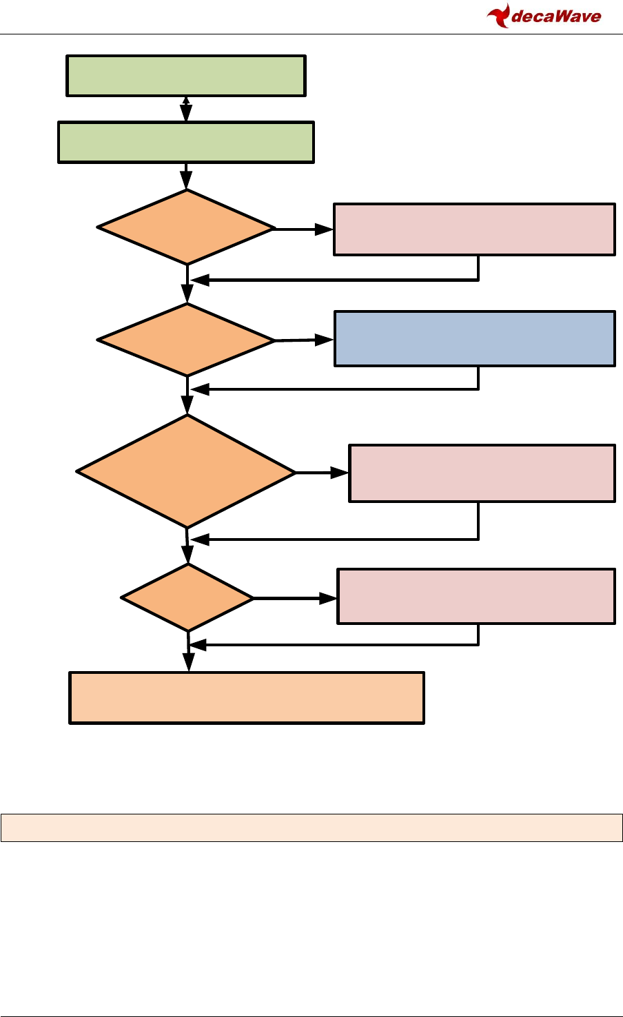
DW1000 Device Driver API Guide
© Decawave Ltd 2016
Version 2.4
Page 51 of 94
Figure 4: Interrupt handling
5.45 dwt_lowpowerlistenisr
void dwt_lowpowerlistenisr(void);
This function is the ISR intended to be used when low-power listening mode is activated. The
differences compared to the normal dwt_isr() are the following:
- RX frame good (RXFCG) event is the only event handled.
- The very first thing this ISR does is to deactivate low-power listening mode. This is done
before clearing the interrupt. This is needed to prevent the DW1000 from going back to sleep
when the interrupted is cleared.
Read state of DW1000 IRQ line input to microprocessor
to check whether a DW1000 IRQ is pending
Call dwt_isr() the DW1000 device
driver’s interrupt handler routine
Read the status (0xF) register to check
which event triggered interrupt
DWT_INT_RFCG
bit set ?
NO
YES
NO
YES
NO
YES
NO
Clear the event and call RX OK call-back
Clear the event and call RX ERR call-back
YES
DWT_INT_RFTO or
DWT_INT_RXPTO
bits set ?
Clear the event and call RX TO call-back
DWT_INT_TFRS
bit set ? Clear the event and call TX DONE call-back
Any RX error
bits set ?

DW1000 Device Driver API Guide
© Decawave Ltd 2016
Version 2.4
Page 52 of 94
- This ISR only supports single buffering mode, i.e. there is no toggling of the RX buffer pointer
after the call of the RX OK call-back.
Parameters:
none
Return Parameters:
none
Notes:
none
5.46 dwt_setpanid
void dwt_setpanid(uint16 panID) ;
This function sets the PAN ID value. These are typically assigned by the PAN coordinator when a
node joins a network. This value is only used by the DW1000 for frame filtering. See the
dwt_enableframefilter() function.
Parameters:
type
name
description
uint16
panID
This is the PAN ID.
Return Parameters:
none
Notes:
This function can be called to set device’s PANID for frame filtering use, it does not need to be set if
frame filtering is not being used. Insertion of PAN ID in the TX frames is the responsibility of the
upper layers calling the dwt_writetxdata() function.
5.47 dwt_setaddress16
void dwt_setaddress16(uint16 shortAddress) ;
This function sets the 16-bit short address values. These are typically assigned by the PAN
coordinator when a node joins a network. This value is only used by the DW1000 for frame filtering.
See the dwt_enableframefilter() function.
Parameters:
type
name
description
uint16
shortAddress
This is the 16-bit address to set.
Return Parameters:
none

DW1000 Device Driver API Guide
© Decawave Ltd 2016
Version 2.4
Page 53 of 94
Notes:
This function is called to set device’s short (16-bit) address, it does not need to be set if frame filtering
is not being used. Insertion of short (16-bit) address, in the TX frames is the responsibility of the upper
layers calling the dwt_writetxdata() function.
5.48 dwt_seteui
void dwt_seteui (uint8* eui) ;
The dwt_seteui() function sets the 64-bit address.
Parameters:
type
name
description
uint8*
eui
This is a pointer to the 64-bit address to set, arranged as 8
unsigned bytes. The low order byte comes first.
Return Parameters:
none
Notes:
This function may be called to set a long (64-bit) address into the DW1000 internal register used for
address filtering. If address filtering is not being used then this register does not need to be set.
It is possible for a 64-bit address to be programmed into the DW1000’s one-time programmable
memory (OTP memory) during customers’ manufacturing processes and automatically loaded into
this register on power-on reset or wake-up from sleep. dwt_seteui() may be used subsequently to
change the value automatically loaded.
5.49 dwt_geteui
void dwt_geteui (uint8* eui) ;
The dwt_geteui() function gets the programmed 64-bit EUI value from the DW1000.
Parameters:
type
name
description
uint8*
eui
This is a pointer to the 64-bit address to read, arranged as 8
unsigned bytes. The low order byte comes first.
Return Parameters:
none
Notes:
This function may be called to get programmed the DW1000 EUI value. The value will be
0xFFFFFFFF00000000 if it has not been programmed into OTP memory or has not been set by a call to
dwt_seteui() function.

DW1000 Device Driver API Guide
© Decawave Ltd 2016
Version 2.4
Page 54 of 94
It is possible for a 64-bit address to be programmed into the DW1000’s one-time programmable
memory (OTP memory) during customers’ manufacturing processes and automatically loaded into
this register on power-on reset or wake-up from sleep. dwt_seteui() may be used subsequently to
change the value automatically loaded.
5.50 dwt_enableframefilter
void dwt_enableframefilter(uint16 mask) ;
This dwt_enableframefilter() function enables frame filtering according to the mask parameter.
Parameters:
type
name
description
uint16
mask
The bit mask which enables particular frame filter options, see
Table 14.
Return Parameters:
none
Notes:
This function is used to enable frame filtering, the device address and pan ID should be configured
beforehand.
Table 14: Bitmask values for frame filtering enabling/disabling
Definition
Value
Description
DWT_FF_NOTYPE_EN
0x000
no frame types allowed – frame filtering will be disabled
DWT_FF_COORD_EN
0x002
behave as coordinator (can receive frames with no
destination address (PAN ID has to match))
DWT_FF_BEACON_EN
0x004
beacon frames allowed
DWT_FF_DATA_EN
0x008
data frames allowed
DWT_FF_ACK_EN
0x010
ACK frames allowed
DWT_FF_MAC_EN
0x020
MAC command frames allowed
DWT_FF_RSVD_EN
0x040
reserved frame types allowed
5.51 dwt_enableautoack
void dwt_enableautoack(uint8 responseDelayTime) ;
This function enables automatic ACK to be automatically sent when a frame with ACK request is
received. The ACK frame is sent after a specified responseDelayTime (in preamble symbols, max is
255).
Parameters:

DW1000 Device Driver API Guide
© Decawave Ltd 2016
Version 2.4
Page 55 of 94
type
name
description
uint8
responseDelayTime
The delay between the ACK request reception and ACK
transmission.
Return Parameters:
none
Notes:
This dwt_enableautoack() function is used to enable the automatic ACK response. It is
recommended that the responseDelayTime is set as low as possible consistent with the ability of the
frame transmitter to turn around and be ready to receive the response. If the host system is using the
RESPONSE_EXP mode (with rxDelayTime in dwt_setrxaftertxdelay() function set to 0) in the
dwt_starttx() function then the responseDelayTime can be set to 3 symbols (3 µs) without loss of
preamble symbols in the receiver awaiting the ACK.
5.52 dwt_setrxaftertxdelay
void dwt_setrxaftertxdelay(uint32 rxDelayTime) ;
This function sets the delay in turning the receiver on after a frame transmission has completed. The
delay, rxDelayTime, is in UWB microseconds (1 UWB microsecond is 512/499.2 microseconds). It is a
20-bit wide field. This should be set before start of frame transmission after which a response is
expected, i.e. before invoking the dwt_starttx() function (above) to initiate the transmission (in
RESPONSE_EXP mode). E.g. transmission of a frame with an ACK request bit set.
Parameters:
type
name
description
uint32
rxDelayTime
The turnaround time, in UWB microseconds, between the TX
completion and the RX enable.
Return Parameters:
none
Notes:
This function is used to set the delay time before automatic receiver enable after a frame
transmission. The smallest value that can be set is 0. If 0 is set the DW1000 will turn the RX on as soon
as possible, which approximately takes 6.2 µs. So if setting a value smaller than 7 µs it will still take 6.2
µs to switch to receive mode.
5.53 dwt_readrxdata
void dwt_readrxdata(uint8 *buffer, uint16 len, uint16 bufferOffset);
This function reads a number, len, bytes of rx buffer data, from a given offset, bufferOffset, into the
given buffer, buffer.
Parameters:

DW1000 Device Driver API Guide
© Decawave Ltd 2016
Version 2.4
Page 56 of 94
type
name
description
uint8*
buffer
The pointer to the buffer into which the data will be read.
Uint16
len
The length of data to be read (in bytes).
Uint16
bufferOffset
The offset at which to start to read the data.
Return Parameters:
none
Notes:
This function should be called on the reception of a good frame to read the received frame data. The
offset might be used to skip parts of the frame that the application is not interested in, or has read
previously.
5.54 dwt_readaccdata
void dwt_readaccdata(uint8 *buffer, uint16 len, uint16 bufferOffset);
This API function reads data from the DW1000 accumulator memory. This data represents the impulse
response of the RF channel. Reading this data is not required in normal operation but it may be useful
for diagnostic purposes. The accumulator contains complex values, a 16-bit real integer and a 16-bit
imaginary integer, for each tap of the accumulator, each of which represents a 1ns sample interval (or
more precisely half a period of the 499.2 MHz fundamental frequency). The span of the accumulator
is one symbol time. This is 992 samples for the nominal 16 MHz mean PRF, or, 1016 samples for the
nominal 64 MHz mean PRF. The dwt_readaccdata() function reads, len, bytes of accumulator buffer
data, from a given offset, bufferOffset, into the given destination buffer, buffer. The output data
starts from buffer[1]. The first byte, buffer[0], is always a dummy byte, so the length read should
always be 1 larger that the length required.
Parameters:
type
name
description
uint8*
buffer
The pointer to the destination buffer into which the read
accumulator data will be written.
Uint16
len
The length of data to be read (in bytes). Since each complex
value occupies four octets, the value used here should
naturally be a multiple of four. Maximum lengths are 3968
bytes (@ 16 MHz PRF) and 4064 bytes (@ 64 MHz PRF).
Uint16
bufferOffset
The offset at which to start to read the data. Offset 0 should
be used when reading the full accumulator. Since each
complex value is 4 octets, the offset should naturally be a
multiple of 4.
Return Parameters:

DW1000 Device Driver API Guide
© Decawave Ltd 2016
Version 2.4
Page 57 of 94
none
Notes:
dwt_readaccdata() may be called after frame reception to read the accumulator data for diagnostic
purposes. The accumulator is not double buffered so this access must be done before the receiver is
re-enabled since the accumulator data is overwritten during the reception of the next frame. The data
returned in the buffer has the following format (for bufferOffset input of zero):
buffer index
Description of elements within buffer
0
Dummy Octet
1
Low 8 bits of real part of accumulator sample index 0
2
High 8 bits of real part of accumulator sample index 0
3
Low 8 bits of imaginary part of accumulator sample index 0
4
High 8 bits of imaginary part of accumulator sample index 0
5
Low 8 bits of real part of accumulator sample index 1
6
High 8 bits of real part of accumulator sample index 1
7
Low 8 bits of imaginary part of accumulator sample index 1
8
High 8 bits of imaginary part of accumulator sample index 1
:
:
In examining the CIR it is normal to compute the magnitude of the complex values.
5.55 dwt_readdiagnostics
void dwt_readdiagnostics(dwt_diag_t * diagnostics);
This function reads receiver frame quality diagnostic values.
Parameters:
type
name
description
dwt_rxdiag_t*
diagnostics
Pointer to the diagnostics structure which will contain the
read data.
Typedef struct
{
uint16 maxNoise ; // LDE max value of noise
uint16 firstPathAmp1 ; // Amplitude at floor(index FP) + 1
uint16 stdNoise ; // Standard deviation of noise
uint16 firstPathAmp2 ; // Amplitude at floor(index FP) + 2
uint16 firstPathAmp3 ; // Amplitude at floor(index FP) + 3
uint16 maxGrowthCIR ; // Channel Impulse Response max growth CIR
uint16 rxPreamCount; // count of preamble symbols accumulated
uint16 firstPath ; // First path index
}dwt_rxdiag_t ;
Return Parameters:
none
Notes:
This function is used to read the received frame diagnostic data. They can be read after a frame is
received (e.g. after DWT_SIG_RX_OKAY event reported in the RX call-back function called from
dwt_isr()).

DW1000 Device Driver API Guide
© Decawave Ltd 2016
Version 2.4
Page 58 of 94
Fields
Description of fields within the dwt_rxdiag_t structure
maxNoise
The maxNoise parameter.
firstPathAmp1
First path amplitude is a 16-bit value reporting the magnitude of the leading
edge signal seen in the accumulator data memory during the LDE algorithm’s
analysis. The amplitude of the sample reported in this firstPathAmp
parameter is the value of the accumulator tap at index given by
floor(firstPath) reported below. This amplitude value can be used in
assessing the quality of the received signal and/or the receive timestamp
produced by the LDE.
firstPathAmp2
Is a 16-bit value reporting the magnitude of signal at index floor (firstPath)
+2.
firstPathAmp3
Is a 16-bit value reporting the magnitude of signal at index floor (firstPath)
+ 3.
stdNoise
The stdNoise parameter is a 16-bit value reporting the standard deviation
of the noise level seen during the LDE algorithm’s analysis of the
accumulator data. This value can be used in assessing the quality of the
received signal and/or the receive timestamp produced by the LDE.
maxGrowthCIR
Channel impulse response max growth is a 16-bit value reporting a growth
factor for the accumulator which is related to the receive signal power. This
value can be used in assessing the quality of the received signal and/or the
receive timestamp produced by the LDE.
rxPreamCount
This reports the number of symbols of preamble accumulated. This may be
used to estimate the length of TX preamble received and also during
diagnostics as an aid to interpreting the accumulator data. It is possible for
this count to be a little larger than the transmitted preamble length, because
of very early detection of preamble and because the accumulation count
may include accumulation that continues through the SFD (until the SFD is
detected).

DW1000 Device Driver API Guide
© Decawave Ltd 2016
Version 2.4
Page 59 of 94
Fields
Description of fields within the dwt_rxdiag_t structure
firstPath
First path index is a 16-bit value reporting the position within the
accumulator that the LDE algorithm has determined to be the first path. This
value is set during the LDE algorithm’s analysis of the accumulator data. This
value may be of use during diagnostic graphing of the accumulator data, and
may also be of use in assessing the quality of the received message and/or
the receive timestamp produced by the LDE.
The first path (or leading edge) is a sub-nanosecond quantity. Each tap in
the accumulator corresponds to a sample time, which is roughly 1
nanosecond (or 30 cm in terms of the radio signal’s flight time through air).
To report the position of the leading edge more accurately than this 1-
nanosecond step size, the index value consist of a whole part and a fraction
part. The 16-bits of firstPath are arranged in a fixed point “10.6” style value
where the low 6 bits are the fractional part and the high 10 bits are the
integer part. Essentially this means if the firstPath is read as a whole number,
then it has to be divided by 64 to get the fractional representation.
5.56 dwt_configeventcounters
void dwt_configeventcounters (int enable) ;
This function enables event counters (TX, RX, error counters) in the DW1000.
Parameters:
type
name
description
int
enable
Set to 1 to clear and enable the DW1000’s internal digital
counters. Set to 0 to disable.
Return Parameters:
none
Notes:
This function is used to enable DW1000 counters, which count the number of frames transmitted, and
received, and various types of error events.
5.57 dwt_readeventcounters
void dwt_readeventcounters (dwt_deviceentcnts_t *counters) ;
This function reads the event counters (TX, RX, error counters) in the DW1000.
Parameters:

DW1000 Device Driver API Guide
© Decawave Ltd 2016
Version 2.4
Page 60 of 94
type
name
description
dwt_deviceentcnts_t *
counters
Pointer to the device event counters structure.
Typedef struct
{
uint16 PHE ; //number of received header errors
uint16 RSL ; //number of received frame sync loss events
uint16 CRCG ; //number of good CRC received frames
uint16 CRCB ; //number of bad CRC (CRC error) received frames
uint16 ARFE ; //number of address filter rejections
uint16 OVER ; //number of RX overflows (used in double buffer mode)
uint16 SFDTO ; //SFD timeouts
uint16 PTO ; //Preamble timeouts
uint16 RTO ; //RX frame wait timeouts
uint16 TXF ; //number of transmitted frames
uint16 HPW ; //half period warnings
uint16 TXW ; //power up warnings
} dwt_deviceentcnts_t ;
Return Parameters:
none
Notes:
This function is used to read the internal counters. These count the number of frames transmitted,
received, and also number of errors received/detected.
Fields
Description of fields within the dwt_deviceentcnts_t structure
PHE
PHR error counter is a 12-bit counter of PHY header errors.
RSL
RSE error counter is a 12-bit counter of the non-correctable error events
that can occur during Reed Solomon decoding.
CRCG
Frame check sequence good counter is a 12-bit counter of the frames
received with good CRC/FCS sequence.
CRCB
Frame check sequence error counter is a 12-bit counter of the frames
received with bad CRC/FCS sequence.
ARFE
Frame filter rejection counter is a 12-bit counter of the frames rejected by
the receive frame filtering function.
OVER
RX overrun error counter is a 12-bit counter of receive overrun events. This
is essentially a count of the reporting of overrun events, i.e. when using
double buffer mode, and the receiver has already received two frames,
and the host has not processed the first one. The receiver will flag an
overrun when it starts receiving a third frame.
SFDT
SFD timeout errors counter is a 12-bit counter of SFD timeout error events.

DW1000 Device Driver API Guide
© Decawave Ltd 2016
Version 2.4
Page 61 of 94
Fields
Description of fields within the dwt_deviceentcnts_t structure
PTO
Preamble detection timeout event counter is a 12-bit counter of preamble
detection timeout events.
RTO
RX frame wait timeout event counter is a 12-bit counter of receive frame
wait timeout events.
TXF
TX frame sent counter is a 12-bit counter of transmit frames sent events.
This is incremented every time a frame is sent.
HPW
Half period warning counter is a 12-bit counter of “Half Period Warning”
events. These relate to late invocation of delayed transmission or
reception functionality.
TXW
TX power-up warning counter is a 12-bit counter of “Transmitter Power-Up
Warning” events. These relate to a delayed sent time that is too short to
allow proper power up of TX blocks before the delayed transmission.
5.58 dwt_readtempvbat
uint16 dwt_readtempvbat(uint8 fastSPI);
This function reads the temperature and battery voltage.
Parameters:
type
name
description
uint8
fastSPI
Should be set to 1 if this function is called when SPI rate used is
> 3 MHz. If this is set to 0, then the SPI rate has to be < 3 MHz
and the DW1000 has to be in IDLE.
Return Parameters:
type
description
uint16
The low 8-bits are voltage value, and the high 8-bits are temperature value.
Notes:
This function can be called to read the battery voltage and temperature of DW1000. It enables the
DW1000 internal convertors to sample the current IC temperature and battery.
To correctly read temperature and voltage values the DW1000 should be configured to use xtal
clock and a SPI rate of < 3 MHz needs to be used. However if the application wants to read this e.g.
while receiver is turned on or using fast SPI rate then the function will use a delay of 1 ms to
stabilise the values being read.

DW1000 Device Driver API Guide
© Decawave Ltd 2016
Version 2.4
Page 62 of 94
5.59 dwt_readwakeuptemp
uint8 dwt_readwakeuptemp(void);
This function reads the IC temperature sensor value that was sampled during IC wake-up.
Parameters:
none
Return Parameters:
type
description
uint8
The 8-bits are temperature value sampled at wakeup event.
Notes:
This function may be used to read the temperature sensor value that was sampled by DW1000 on
wake up, assuming the DWT_TANDV bit in the mode parameter was set in a call to
dwt_configuresleep() before entering sleep mode. If the wakeup sampling of the temperature sensor
was not enabled then the value returned by dwt_readwakeuptemp() will not be valid.
5.60 dwt_readwakeupvbat
uint8 dwt_ readwakeupvbat (void);
This function reads the battery voltage sensor value that was sampled during IC wake-up.
Parameters:
none
Return Parameters:
type
description
uint8
The 8-bits are voltage value sampled at wake up event.
Notes:
This function may be used to read the battery voltage sensor value that was sampled by DW1000 on
wake up, assuming the DWT_TANDV bit in the mode parameter was set in the call to
dwt_configuresleep() before entering sleep mode. If the wakeup sampling of the battery voltage
sensor was not enabled then the value returned by dwt_readwakeupvbat() will not be valid.
5.61 dwt_otpread
void dwt_otpread(uint32 address, uint32 *array, uint8 length);
This function is used to read a number (given by length) of 32-bit values from the DW1000 OTP
memory, starting at given address. The given array will contain the read values.
Parameters:

DW1000 Device Driver API Guide
© Decawave Ltd 2016
Version 2.4
Page 63 of 94
type
name
description
uint32
address
This is starting address in the OTP memory from which to read
uint16*
array
This is the 32-bit array that will hold the read values. It should
be of at least length 32-bit words long.
Uint8
length
The number of values to read
Return Parameters:
none
Notes:
5.62 dwt_otpwriteandverify
int dwt_otpwriteandverify(uint32 value, uint16 address);
This function is used to program 32-bit value into the DW1000 OTP memory.
Parameters:
type
name
description
uint32
value
this is the 32-bit value to be programmed into OTP memory
uint16
address
this is the 16-bit OTP memory address into which the 32-bit
value is programmed
Return Parameters:
type
description
int
Return values can be either DWT_SUCCESS = 0 or DWT_ERROR = -1.
Notes:
The DW1000 has a small amount of one-time-programmable (OTP) memory intended for device
specific configuration or calibration data. Some areas of the OTP memory are used to save device
calibration values determined during DW1000 testing, while other OTP memory locations are
intended to be set by the customer during module manufacture and test.
Programming OTP memory is a one-time only activity, any values programmed in error cannot be
corrected. Also, please take care when programming OTP memory to only write to the designated
areas – programming elsewhere may permanently damage the DW1000’s ability to function
normally.

DW1000 Device Driver API Guide
© Decawave Ltd 2016
Version 2.4
Page 64 of 94
The OTP memory locations are as defined in Table 15. The OTP memory locations are each 32-bits
wide, OTP addresses are word addresses so each increment of address specifies a different 32-bit
word.
Table 15: OTP memory map
OTP
Address
Size
(Used
Bytes)
Byte [3]
Byte [2]
Byte [1]
Byte [0]
Programmed
By
0x000
4
64 bit EUID
(These 64 bits get automatically copied over to Register File 0x01:EUI on each reset.)
Customer
0x001
4
0x002
4
Alternative 64bit EUID
Customer
0x003
4
0x004
4
40 bit LDOTUNE_CAL
(These 40 bits can be automatically copied over to Sub Register File 0x28:30 LDOTUNE
on wakeup)
Decawave Test
0x005
1
0x006
4
{“0001,0000,0001“, "CHIP ID (20 bits)"}
Decawave Test
0x007
4
{“0001”“, "LOT ID (28 bits)"}
DecawaveTest
0x008
2
-
-
Vmeas @ 3.7 V
Vmeas @ 3.3 V
DecawaveTest
0x009
1 / 1
-
-
Tmeas @ Ant Cal
Tmeas @ 23 °C
Customer / Deca-
wave Test
0x00A
0
-
Reserved
0x00B
4
-
Reserved
0x00C
2
-
Reserved
0x00D
4
-
Reserved
0x00E
4
-
Reserved
0x00F
4
-
Reserved
0x010
4
CH1 TX Power Level PRF 16
Customer
0x011
4
CH1 TX Power Level PRF 64
Customer
0x012
4
CH2 TX Power Level PRF 16
Customer
0x013
4
CH2 TX Power Level PRF 64
Customer
0x014
4
CH3 TX Power Level PRF 16
Customer
0x015
4
CH3 TX Power Level PRF 64
Customer
0x016
4
CH4 TX Power Level PRF 16
Customer
0x017
4
CH4 TX Power Level PRF 64
Customer
0x018
4
CH5 TX Power Level PRF 16
Customer
0x019
4
CH5 TX Power Level PRF 64
Customer
0x01A
4
CH7 TX Power Level PRF 16
Customer
0x01B
4
CH7 TX Power Level PRF 64
Customer
0x01C
4
TX/RX Antenna Delay – PRF 64
TX/RX Antenna Delay – PRF 16
Customer
0x01D
0
-
-
-
-
Customer
0x01E
2
-
-
OTP Revision
XTAL_Trim[4:0]
Customer
0x01F
0
-
-
-
-
Customer
:
:
:
:
:
:
Reserved
0x400
4
SR Register (see below)
Customer

DW1000 Device Driver API Guide
© Decawave Ltd 2016
Version 2.4
Page 65 of 94
The SR (“Special Register”) is a 32-bit segment of OTP that is directly readable via the register
interface upon power up. To program the SR register follow the normal OTP programming method
but set the OTP address to 0x400. The value of the SR register can be directly read back at address.
For more information on OTP memory programming please consult the DW1000 User Manual [2]
and Data Sheet [1].
5.63 dwt_setleds
void dwt_setleds(uint8 value);
This is used to set up Tx/Rx GPIOs which are then used to control (for example) LEDs. This is not
completely IC dependent and requires that LEDs are connected to the DW1000 GPIO lines.
Parameters:
type
name
description
uint8
mode
This is a bit field value interpreted as follows:
- bit 0: set to 1 to enable LEDs, 0 to disable them.
- bit 1: set to 1 to make LEDs blink once on init. This is only
valid if bit 0 is set (enable LEDs).
- Bits 2 to 7: Reserved.
Return Parameters:
none
Notes:
For more information on GPIO control and configuration please consult the DW1000 User Manual [2]
and Data Sheet [1].
5.64 dwt_setfinegraintxseq
void dwt_setfinegraintxseq(int enable);
This is used to activate/deactivate fine grain TX sequencing. This is needed for some modes of
operation, e.g. continuous wave mode or when driving an external PA. Please refer to [2] for more
details about those modes.
Parameters:
type
name
description
int
enable
Set to 1 to enable fine grain TX sequencing, 0 to disable it.
Return Parameters:
none

DW1000 Device Driver API Guide
© Decawave Ltd 2016
Version 2.4
Page 66 of 94
Notes:
none
5.65 dwt_setlnapamode
void dwt_setlnapamode(void);
This is used to enable GPIO for external LNA or PA functionality – HW dependent, consult the
DW1000 User Manual [2]. This can also be used for debug as enabling TX and RX GPIOs is can help
monitoring DW1000's activity.
Parameters:
type
name
description
int
lna
1 to enable LNA functionality, 0 to disable it.
int
pa
1 to enable PA functionality, 0 to disable it.
Return Parameters:
none
Notes:
Enabling PA functionality requires that fine grain TX sequencing is deactivated. This can be done using
the dwt_setfinegraintxseq() API function.
For more information on GPIO control and configuration please consult the DW1000 User Manual [2]
and Data Sheet [1].
5.66 dwt_setgpiodirection
void dwt_setgpiodirection(uint32 gpioNum, uint32 direction);
This is used to configure the direction of DW1000 GPIOs. The GPIOs can be used as either inputs (1)
or outputs (0). Reader should study this functionality in the DW1000 User Manual [2].
Parameters:
type
name
description
uint32
gpioNum
This selects the GPIOs ports to configure. It is a bitmask, which
allows for many ports to be configured simultaneously. The
mask values (GxM0... GxM8) are defined in deca_regs.h
uint32
direction
This sets the GPIOs direction. A value of zero is used to set the
direction to output, and the appropriate direction mask value
is used to set the port as input. This allows multiple ports to
be configured simultaneously.

DW1000 Device Driver API Guide
© Decawave Ltd 2016
Version 2.4
Page 67 of 94
type
name
description
Any ports not selected by the gpioNum (mask) parameter are
unchanged.
Return Parameters:
none
Notes:
For more information on GPIO control and configuration please consult the DW1000 User Manual [2]
and Data Sheet [1].
5.67 dwt_setgpiovalue
void dwt_setgpiovalue(uint32 gpioNum, uint32 value);
This is used to set GPIO output lines high (1) or low (0).
Parameters:
type
name
description
uint32
gpioNum
This selects the GPIOs ports to output on. It is a bitmask, which
allows for many ports to be changed simultaneously. The mask
values (GxM0... GxM8) are defined in deca_regs.h.
uint32
value
This sets the GPIOs value. A value of zero outputs a low voltage,
and the appropriate output mask value is used to set the port
high. This allows multiple ports to be controlled
simultaneously.
Any ports not selected by the gpioNum (mask) parameter or
not configured as outputs by dwt_setgpiodirection are
unchanged.
Return Parameters:
none
Notes:
For more information on GPIO control and configuration please consult the DW1000 User Manual [2]
and Data Sheet [1].
5.68 dwt_setxtaltrim
void dwt_setxtaltrim(uint8 value);
This function writes the crystal trim value parameter into the DW1000 crystal trimming register.
Parameters:

DW1000 Device Driver API Guide
© Decawave Ltd 2016
Version 2.4
Page 68 of 94
type
name
description
uint8
value
Crystal trim value (in range 0x0 to 0x1F, 31 steps (~1.5ppm per
step).
Return Parameters:
none
Notes:
This function can be called any time to set the crystal trim register value. This is used to fine tune and
adjust the XTAL frequency. Better long range performance may be achieved when crystals are more
closely matched. Crystal trimming may allow this without using expensive TCXO devices. Please
consult the DW1000 User Manual [2], Data Sheet [1] and application notes available on
www.decawave.com.
5.69 dwt_getinitxtaltrim
uint8 dwt_getinitxtaltrim(void);
This function returns the value of XTAL trim that has been applied during initialisation. This can be
either the value read in OTP memory or a default value.
Parameters:
none
Return Parameters:
type
Description
uint8
Crystal trim value set upon initialisation.
Notes:
The value returned by this function is the initial value only. It is not updated on dwt_setxtaltrim()
calls.
5.70 dwt_configcwmode
void dwt_configcwmode(uint8 chan);
This function configures the device to transmit a Continuous Wave (CW) at a specified channel
frequency. This may be of use as part of crystal trimming procedure. Please consult with Decawave’s
applications support team for details of crystal trimming procedures and considerations.
Parameters:

DW1000 Device Driver API Guide
© Decawave Ltd 2016
Version 2.4
Page 69 of 94
type
name
description
uint8
chan
This sets the UWB channel number, (defining the centre
frequency and bandwidth). The supported channels are 1, 2, 3,
4, 5, and 7.
Return Parameters:
none
Notes:
Example code below of how to use this function in conjunction with dwt_setxtaltrim() function
(please also see Example 4a: continuous wave mode) :
Example code:
// The table below specifies the default TX spectrum configuration
// parameters... this has been tuned for DW EVK hardware units
const tx_struct tx_spectrumconfig[NUM_CH] =
{
// Channel 1
{
0xc9, //PG_DELAY
{
0x75757575, //16M prf power
0x67676767 //64M prf power
}
},
// Channel 2
{
// Add other channels here
},
// Channel 7
{
0x93, //PG_DELAY
{
0x92929292, //16M prf power
0xd1d1d1d1 //64M prf power
}
}
};
void xtalcalibration(void)
{
int i;
uint8 chan = 2 ;
uint8 prf = DWT_PRF_16M ;
dwt_txconfig_t configTx ;
// MUST SET SPI <= 3 MHz for this calibration activity.
Setspibitrate(SPI_3MHz); // target platform function to set SPI rate
// to 3 MHz
//
// reset device
//
dwt_softreset();
//
// configure TX channel parameters

DW1000 Device Driver API Guide
© Decawave Ltd 2016
Version 2.4
Page 70 of 94
//
configTx.pGdly = tx_spectrumconfig[chan-1].PG_DELAY ;
configTx.power = tx_spectrumconfig[chan-1].tx_pwr[prf - DWT_PRF_16M];
dwt_configuretxrf(&configTx);
dwt_configcwmode(chan);
for(i=0; i<=0x1F; i++)
{
dwt_setxtaltrim(i);
// measure the frequency
// Spectrum Analyser set:
// FREQ to be channel default e.g. 3.9936 GHz for channel 2
// SPAN to 10MHz
// PEAK SEARCH
} // end for
// when the crystal trim has completed, the device should be reset
// with a call to dwt_softreset()after which it can be programmed
// using the API functions for desired operation
return;
} // end xtalcalibration()
5.71 dwt_configcontinuousframemode
void dwt_configcontinuousframemode(uint32 framerepetitionrate);
This function configures the DW1000 in continuous frame mode. This facilitates measurement of the
power in the transmitted spectrum.
Parameters:
type
name
description
uint32
framerepetitionrate
This is a 32-bit value that is used to set the interval
between transmissions. The minimum value is 4. The units
are approximately 8 ns. (or more precisely
512/(499.2e6*128) seconds)).
Return Parameters:
none
Notes:
This function is used to configure continuous frame (transmit power spectrum test) mode, used in TX
power spectrum measurements. This test mode is provided to help support regulatory approvals
spectral testing. Please consult with Decawave’s applications support team for details of regulatory
approvals considerations. The dwt_configcontinuousframemode() function enables a repeating
transmission of the data from the transmit buffer. To use this test mode, the operating channel,
preamble code, data length, offset, etc. should all be set-up as if for a normal transmission.
The framerepititionrate parameter value is programmed in units of one quarter of the 499.2 MHz
fundamental frequency, (~ 8 ns). To send one frame per millisecond, a value of 124800 or

DW1000 Device Driver API Guide
© Decawave Ltd 2016
Version 2.4
Page 71 of 94
0x0001E780 should be set. A value <4 will not work properly, and a time value less than the frame
length will cause the frames to be sent back-to-back without any pause.
We expect there to be two use cases for the dwt_configcontinuousframemode() function:
(a) Testing to figure out the TX power/pulse width to meet the regulations.
(b) In the approvals house to enable the spectral test.
To end the test and return to normal operation the device can be rest with dwt_softreset() function.
Example code below of how to use this function (please also see Example 4b: continuous frame
mode):
Example code :
// The table below specifies the default TX spectrum configuration
// parameters... this has been tuned for DW EVK hardware units
const tx_struct tx_s [NUM_CH] =
{
{// Channel 1
0xc9, //PG_DELAY
{
0x75757575, //16M prf power
0x67676767 //64M prf power
}
},
{// Channel 2
… Add other channels should be added here
},
{// Channel 7
0x93, //PG_DELAY
{
0x92929292, //16M prf power
0xd1d1d1d1 //64M prf power
}
}
};
int powertest(void)
{
dwt_config_t config ;
dwt_txconfig_t configTx ;
uint8 msg[127]= "The quick brown fox jumps over the lazy dog."
"The quick brown fox jumps over the lazy dog."
"The quick brown fox jumps over the l";
// MUST SET SPI <= 3 MHz for this calibration activity.
Setspibitrate(SPI_3MHz); // target platform function to set SPI rate
// to 3 MHz
// reset device
dwt_softreset();
// configure channel parameters
config.chan = 2;
config.rxCode = 9;
config.txCode = 9;
config.prf = DWT_PRF_64M;
config.dataRate = DWT_BR_110K;
config.txPreambLength = DWT_PLEN_2048;
config.rxPAC = DWT_PAC64;
config.nsSFD = 1;

DW1000 Device Driver API Guide
© Decawave Ltd 2016
Version 2.4
Page 72 of 94
dwt_configure(&config) ;
configtx.Pgdly = tx_s[config.chan-1].PG_DELAY ;
configTx.power = tx_s[config.chan-1].tx_pwr[config.prf - DWT_PRF_16M];
dwt_configuretxrf(&configTx);
// the value here 0x1000 gives a period of 32.82 µs
dwt_configcontinuousframemode(0x1000);
dwt_writetxdata(127, (uint8 *) msg, 0) ;
dwt_writetxfctrl(127, 0, 0);
//to start the first frame - set TXSTRT
dwt_starttx(DWT_START_TX_IMMEDIATE);
//measure the channel power
//Spectrum Analyser set:
//FREQ to be channel default e.g. 3.9936 GHz for channel 2
//SPAN to 1GHz
//SWEEP TIME 1s
//RBW and VBW 1MHz
// After the power is measured, the values in configTx can be changed
// to tune the spectrum. To stop the continuous frame mode, a call to
// dwt_softreset()is needed, after which the device can be programmed
// using the API functions for desired operation
return DWT_SUCCESS ;
}
5.72 dwt_calcbandwidthtempadj
uint8 dwt_calcbandwidthtempadj(uint16 target_count);
This function runs a bandwidth compensation algorithm that adjusts the bandwidth of the DW1000
output spectrum to correct for the effects of different temperatures. This ensures that the
bandwidth is constant at any temperature. The target count parameter is a reference value taken at
a known temperature for a known good bandwidth using the dwt_calcpgcount() API call, which
relates directly to the bandwidth of the spectrum.
Parameters:
Type
name
description
uint16
target_count
This is a 16-bit value that is used by the DW1000 to calculate
a bandwidth adjust value
Return Parameters:
type
Description
uint8
This is an 8-bit value that represents a pulse generator delay (PG_DELAY) value

DW1000 Device Driver API Guide
© Decawave Ltd 2016
Version 2.4
Page 73 of 94
Notes:
See the app note in [4] for more details. The return value should that should be set in the PGdly
member of the dwt_txconfig_t struct and passed to dwt_configtxrf() to adjust the bandwidth
correctly at the current temperature. See the section on dwt_configtxrf() for details.
5.73 dwt_calcpgcount
uint16 dwt_calcpgcount(uint8 pgdly);
This function returns a pulse generator count value that is used as a reference for bandwidth
compensation over temperature. The pulse generator delay value that is passed in should be the
current bandwidth setting.
Parameters:
Type
Name
description
uint8
pgdly
This is an 8-bit value representing the current pulse generator
delay for the current bandwidth setting for the DW1000
Return Parameters:
type
Description
uint16
This is a 16-bit value that represents the pulse generator count value for the
current pulse generator delay. It is directly related to the bandwidth.
Notes:
See the app note in [4] for more details. The return value should be stored as a reference to be used
with dwt_calcbandwidthtempadj().
5.74 dwt_calcpowertempadj
uint32 dwt_calcpowertempadj(uint8 channel, uint32 ref_powerreg, double curr_temp, double
ref_temp);
This function returns an adjusted TX power register value for the current temperature, based off the
channel, current temperature and the reference measurements made during calibration of the
DW1000, namely the temperature and the TX power register value during calibration.
Parameters:
Type
Name
Description
uint8
channel
This is an 8-bit value containing the channel number at
which the DW1000 is operating. Only channels 2 and 5 are
supported

DW1000 Device Driver API Guide
© Decawave Ltd 2016
Version 2.4
Page 74 of 94
uint32
ref_powerreg
This is a 32-bit value containing the TX power register value
at the time of calibration. Adjustments are made relative to
this
double
curr_temp
This is a double value containing the current temperature of
the IC
double
ref_temp
This is a double value containing the reference temperature
at which calibration was carried out. Adjustments are made
relative to this
Return Parameters:
type
Description
uint32
This is a 32-bit value that represents the TX power register value adjusted to
account for the effects of temperature on the output power of the DW1000
Notes:
See the app note in [4] for more details. The return value should be set as the power member of the
dwt_txconfig_t, see dwt_configtxrf() for details.
5.75 dwt_setdevicedataptr
int dwt_setdevicedataptr (unsigned int index);
This function sets the local data structure pointer to point to the element in the local array as given
by the index.
Parameters:
none
Return Parameters:
type
Description
int
Return values can be either DWT_SUCCESS = 0 or DWT_ERROR = -1 (if index is out
of range).
Notes:
The local device static data is an array to support multiple DW1000 devices, e.g. in testing applications
and platforms. This function selects which element of the array is being accessed. For example if two
DW1000 devices are controlled in your application then this function should be called before
accessing either of the devices to configure the local structure pointer.
5.76 dwt_readcarrierintegrator
int32 dwt_readcarrierintegrator(void) ;

DW1000 Device Driver API Guide
© Decawave Ltd 2016
Version 2.4
Page 75 of 94
The dwt_readcarrierintegrator() API function reads the receiver carrier integrator value and returns
it as a 32-bit signed value. The receive carrier integrator value is valid at the end of reception of a
frame, (and before the receiver is re-enabled). It reflects the frequency offset of the remote
transmitter with respect to the local receive clock. A positive carrier integrator value means that the
local receive clock is running faster than that of the remote transmitter device.
Parameters:
none
Return Parameters:
type
Description
int32
Receiver carrier integrator value
Notes:
This dwt_readcarrierintegrator() API may be called after receiving a frame to determine the clock
offset of the remote transmitter the sent the frame. The receive frame should be valid (i.e. with good
CRC) otherwise the clock offset information may be incorrect. The following constants are defined to
allow the returned carrier integrator be converted to a frequency offset in Hertz (which depends on
the data rate, 110Kb/s is different to the rest), and from that to a clock offset in PPM (which depends
on the channel centre frequency): FREQ_OFFSET_MULTIPLIER, FREQ_OFFSET_MULTIPLIER_110KB,
HERTZ_TO_PPM_MULTIPLIER_CHAN_1, HERTZ_TO_PPM_MULTIPLIER_CHAN_2,
HERTZ_TO_PPM_MULTIPLIER_CHAN_3 and HERTZ_TO_PPM_MULTIPLIER_CHAN_5.
The HERTZ_TO_PPM_xxx multipliers are negative quantities, so when the resultant clock offsets are
positive it means that the local receiver’s clock is running slower than that of the remote transmitter.
Example code:
int32 ci ;
float clockOffsetHertz ;
float clockOffsetPPM ;
ci = dwt_readcarrierintegrator() ; // Read carrier integrator value
// at 110 kb/s data rate convert carrier integrator to clock offset in Hz.
clockOffsetHertz = ci * FREQ_OFFSET_MULTIPLIER_110KB ;
// On channel 5 convert this to clock offset in PPM.
clockOffsetPPM = clockOffsetHertz * and HERTZ_TO_PPM_MULTIPLIER_CHAN_5 ;
NB: Please also refer to simple example 6: single-sided two-way ranging (SS TWR) where the
initiator end (since driver version 4.0.6) uses the carrier integrator to correct the range estimate
calculation for the clock offset of the remote responder node.
5.77 SPI driver functions
These functions are platform specific SPI read and write functions, external to the DW1000 driver
code, used by the device driver to send and receive data over the SPI interface to and from the
DW1000. The DW1000 device driver abstracts the target SPI device by calling it through generic
functions writetospi() and readfromspi(). In porting the DW1000 device driver, to different target

DW1000 Device Driver API Guide
© Decawave Ltd 2016
Version 2.4
Page 76 of 94
hardware, the body of these SPI functions should be written, re-written, or provided in the target
specific code to drive the target microcontroller device’s physical SPI hardware. The initialisation of
the target host controller’s physical SPI interface mode and its data rate is considered to be part of
the target system and is done in the host code outside of the DW1000 device driver functions.
5.77.1 writetospi
int writetospi (uint16 hLen, const uint8 *hbuff, uint32 bLen, const uint8 *buffer) ;
This function is called by the DW1000 device driver code (from the dwt_writetodevice() function)
when it wants to write to the DW1000’s SPI interface (registers) over the SPI bus.
Parameters:
type
name
description
uint16
hLen
This is gives the length of the header buffer (hbuff)
uint8*
hbuff
This is a pointer to the header buffer byte array. The LSB is the first
element.
Uint32
bLen
This is gives the length of the data buffer (buffer), to write.
Uint8*
buffer
This is a pointer to the data buffer byte array. The LSB is the first
element. This holds the data to write.
Return Parameters:
Type
description
int
Return values can be either DWT_SUCCESS = 0 or DWT_ERROR = -1.
Notes:
The return values can be used to notify the upper application layer that there was a problem with SPI
write. In DW1000 API dwt_writetodevice() function the return value from this function is returned.
However it should be noted that the DW1000 device driver itself does not take any notice of
success/error return value but instead assumes that SPI accesses succeed without error.
5.77.2 readfromspi
int readfromspi (uint16 hLen, const uint8 *hbuff, uint32 bLen, uint8 *buffer) ;
This function is called by the DW1000 device driver code (from the dwt_readfromdevice() function)
when it wants to read from the DW1000’s SPI interface (registers) over the SPI bus.
Parameters:
type
name
description

DW1000 Device Driver API Guide
© Decawave Ltd 2016
Version 2.4
Page 77 of 94
uint16
hLen
This is gives the length of the header buffer (hbuff)
uint8*
hbuff
This is a pointer to the header buffer byte array. The LSB is the first
element.
Uint32
bLen
This is gives the number of bytes to read.
Uint8*
buffer
This is a pointer to the data buffer byte array. The LSB is the first
element. This holds the data being read.
Return Parameters:
Type
description
int
Return values can be either DWT_SUCCESS = 0 or DWT_ERROR = -1.
Notes:
The return values can be used to notify the upper application layer that there was a problem with SPI
read. In DW1000 API dwt_readfromdevice() function the return value from this function is returned.
However it should be noted that the DW1000 device driver itself does not take any notice of
success/error return value but instead assumes that SPI accesses succeed without error.
5.78 Mutual-exclusion API functions
The purpose of these functions is to provide for microprocessor interrupt enable/disable, which is
used for ensuring mutual exclusion from critical sections in the DW1000 device driver code where
interrupts and background processing may interact. The only use made of this is to ensure SPI
accesses are non-interruptible.
The mutual exclusion API functions are decamutexon() and decamutexoff(). These are external to the
DW1000 driver code but used by the device driver when it wants to ensure mutual exclusion from
critical sections. This usage is kept to a minimum and the disable period is also kept to a minimum
(but is dependent on the SPI data rate). A blanket interrupt disable may be the easiest way to
provide this mutual exclusion functionality in the target system, but at a minimum those interrupts
coming from the DW1000 device should be disabled/re-enabled by this activity.
In implementing the decamutexon() and decamutexoff() functions in a particular microprocessor
system, the implementer may choose to use #defines to map these calls transparently to the target
system. Alternatively the appropriate code may be embedded in the functions provided in the
deca_mutex.c source file.
5.78.1 decamutexon
decaIrqStatus_t decamutexon (void) ;
This function is used to turn on mutual exclusion (e.g. by disabling interrupts). This is called at the
start of the critical section of SPI access. The decamutexon() function should operate to read the
current system interrupt status in the target microcontroller system’s interrupt handling logic with

DW1000 Device Driver API Guide
© Decawave Ltd 2016
Version 2.4
Page 78 of 94
respect to the handling of the DW1000’s interrupt. Let’s call this “IRQ_State” Then it should disable
the interrupt relating to the DW1000, and then return the original IRQ_State.
Parameters:
none
Return Parameters:
Type
Description
decaIrqStatus_t
This is the state of the target microcontroller’s interrupt logic with
respect to the handling the DW1000’s interrupt, as it was on entry to
the decamutexon() function before it did any interrupt disabling.
Typedef int decaIrqStatus_t ;
Notes:
The decamutexon() function returns the DW1000 interrupt status, which can be noted and
appropriate action taken. The returned status is intended to be used in the call to
decamutexoff() function to be used to restore the interrupt enable status to its original pre-
decamutexon() state.
5.78.2 decamutexoff
void decamutexoff (decaIrqStatus_t state) ;
This function is used to restore the DW1000’s interrupt state as returned by decamutexon() function.
It is used to turn off mutual exclusion (e.g. by enabling interrupts if appropriate). This is called at the
end of the critical section of SPI access. The decamutexoff() function should operate to restore the
system interrupt status in the target microcontroller system’s interrupt handling logic to the state
indicated by the input “IRQ_State” parameter, state.
Parameters:
type
name
description
decaIrqStatus_t
state
This is the state of the target microcontroller’s interrupt
logic with respect to the handling of the DW1000’s
interrupt, as it was on entry to the decamutexon() function
before it did any interrupt disabling.
Return Parameters:
none
Notes:
The state parameter passed into decamutexoff() function should be used to appropriately
set/restore the system interrupt status in the target microcontroller system’s interrupt
handling logic.

DW1000 Device Driver API Guide
© Decawave Ltd 2016
Version 2.4
Page 79 of 94
5.79 Sleep function
The purpose of this function is to provide a platform dependent implementation of sleep feature, i.e.
waiting for a certain amount of time before proceeding with the application’s next step.
This is an external function used by DW1000 driver code to wait for the end of a process, e.g. the
stabilization of a clock or the completion of a write command. This function is provided in the
deca_sleep.c source file.
5.79.1 deca_sleep
void deca_sleep (unsigned int time_ms) ;
This function is used to wait for a given amount of time before proceeding to the next step of the
calling function.
Parameters:
type
name
description
unsigned int
time_ms
The amount of time to wait, expressed in milliseconds.
Return Parameters:
None
Notes:
The implementation provided here is designed for a simple single-threaded system and is
blocking, i.e. it will prevent the system from doing anything else during the waiting time.
5.80 Subsidiary functions
These functions are used to provide low-level access to individually numbered registers and buffers
(or register files). These may be needed to access IC functionality not included in the main API
functions above.
5.80.1 dwt_writetodevice
dwt_writetodevice (uint16 regID, uint16 index, uint32 length, const uint8 *buffer) ;
This function is used to write to the DW1000’s registers and buffers. The regID specifies the main
address of the register or parameter block being accessed, e.g. a regID of 9 selects the transmit
buffer. The index parameter selects a sub-address within the register file. A regID value of 0 is used
for most of the accesses employed in the device driver. The length parameter specifies the number
of bytes to write, and the buffer parameter points at the bytes to actually write. If
DWT_API_ERROR_CHECK code switch is defined, this function will check input parameters and assert
if an error is detected.

DW1000 Device Driver API Guide
© Decawave Ltd 2016
Version 2.4
Page 80 of 94
5.80.2 dwt_readfromdevice
void dwt_readfromdevice (uint16 regID, uint16 index, uint32 length, uint8 *buffer) ;
This function is used to read from the DW1000’s registers and buffers. The parameters are the same
as for the dwt_writetodevice function above except that the buffer parameter points at a location
where the bytes being read are placed by the function call. If DWT_API_ERROR_CHECK code switch
is defined, this function will check input parameters and assert if an error is detected. It is up to the
developer to ensure that the assert macro is correctly enabled in order to trap any error conditions that arise.
5.80.3 dwt_read32bitreg
uint32 dwt_read32bitreg(int regFileID) ;
This function is used to read 32-bit DW1000 registers.
5.80.4 dwt_read32bitoffsetreg
uint32 dwt_read32bitoffsetreg(int regFileID, int regOffset) ;
This function is used to read a 32-bit DW1000 register that is part of a sub-addressed block.
5.80.5 dwt_write32bitreg
void dwt_write32bitreg(int regFileID, uint32 regval);
This function is used to write a 32-bit DW1000 register that is part of a sub-addressed block.
5.80.6 dwt_write32bitoffsetreg
void dwt_write32bitoffsetreg(int regFileID, int regOffset, uint32 regval);
This function is used to write to a 32-bit DW1000 register that is part of a sub-addressed block.
5.80.7 dwt_read16bitoffsetreg
uint16 dwt_read16bitoffsetreg(int regFileID, int regOffset) ;
This function is used to read a 16-bit DW1000 register that is part of a sub-addressed block.
5.80.8 dwt_write16bitoffsetreg
void dwt_write16bitoffsetreg(int regFileID, int regOffset, uint16 regval);
This function is used to write a 16-bit DW1000 register that is part of a sub-addressed block.
5.80.9 dwt_read8bitoffsetreg
uint8 dwt_read8bitoffsetreg(int regFileID, int regOffset) ;
This function is used to read an 8-bit DW1000 register that is part of a sub-addressed block.

DW1000 Device Driver API Guide
© Decawave Ltd 2016
Version 2.4
Page 81 of 94
5.80.10 dwt_write8bitoffsetreg
void dwt_write8bitoffsetreg(int regFileID, int regOffset, uint8 regval);
This function is used to write an 8-bit DW1000 register that is part of a sub-addressed block.

DW1000 Device Driver API Guide
© Decawave Ltd 2016
Version 2.4
Page 82 of 94
6 APPENDIX 1 – DW1000 API EXAMPLES APPLICATIONS
The DW1000 API package provides, along with the DW1000 driver itself, a set of simple example
applications designed to show how to achieve a number of basic features of the DW1000 IC like
sending a frame, receiving a frame, putting the DW1000 IC to sleep, etc.
All these examples have been designed to be as simple as possible. The main idea is to make the
code self-explanatory and include the least possible amount of code not directly involved in the
achievement of the example-related feature. One of the consequences of this design is that the
examples output very little (or even no) debug information, and are designed so that the application
flow can be followed using a debugger to examine run-time operations.
On the hardware side, the examples have been designed to run on an EVB1000 board. The base
layers included in this package (see detail below) provide specific implementations for this HW.
6.1 Package structure
The folder structure of the package is the following:
Table 16: DW1000 API package structure
Folder
Brief description
decadriver
DW1000 device driver
examples
Example applications
example 1
Specific code and CooCox project file for example
application 1
example 2
Specific code and CooCox project file for example
application 2
…
…
Libraries
ARM and STM32 low-level layers
CMSIS
Hardware abstraction layer for ARM Cortex-M
processors
STM32F10x_StdPeriph_Driver
Hardware abstraction layer for ST STM32 F1
processors
Linkers
Linker script for STM32F105RC processor
platform
Platform dependent implementation of low-level
features (IT management, mutex, sleep, etc.)
All example applications are named after the feature or set of features they implement.
6.2 Building and running the examples
All examples provide a specific main.c source file and a CooCox project file. To build and run the
code, just unzip the source and open the .coproj project file corresponding to the example one
wants to build.
CooCox IDE can be downloaded from: http://www.coocox.org/software.html. Please follow the
“Read More” link and download version 1.7.8. These examples have been developed using version
1.7.8.
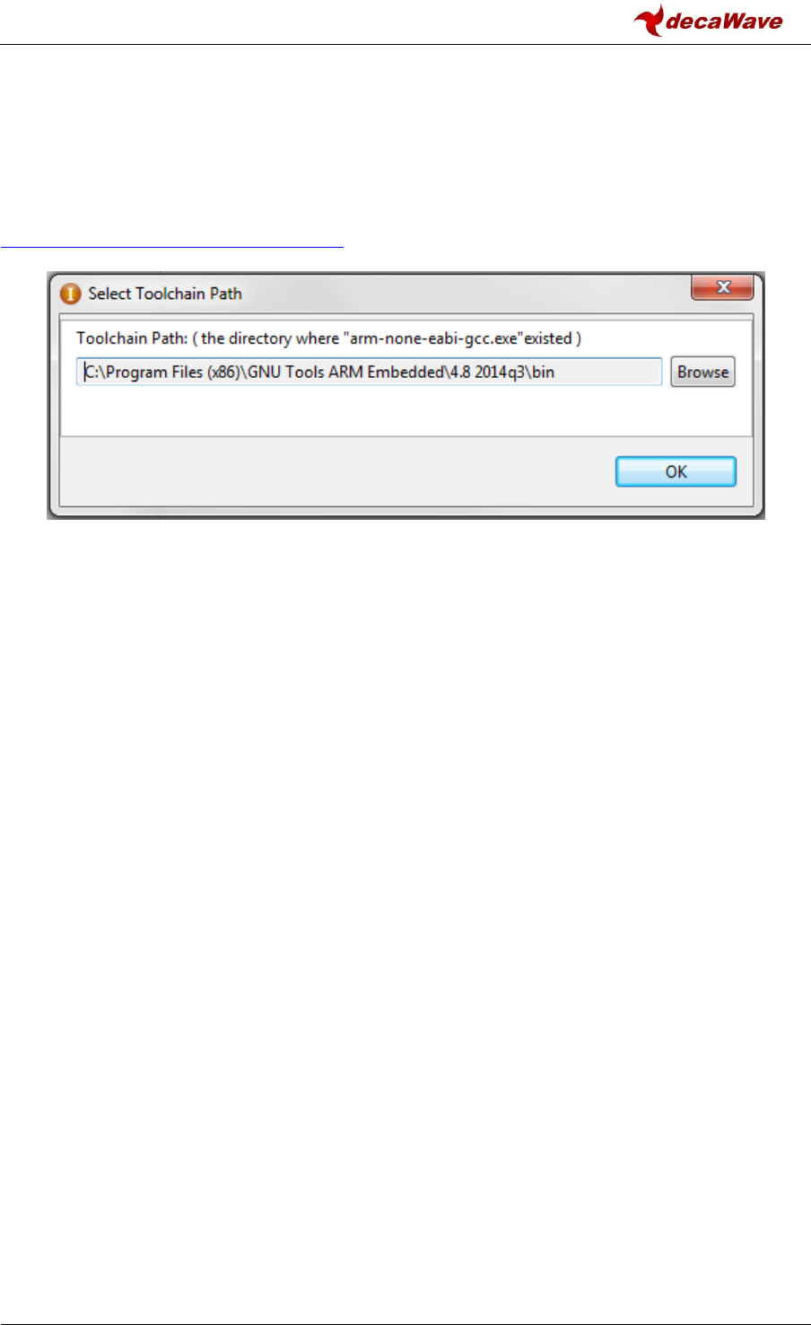
DW1000 Device Driver API Guide
© Decawave Ltd 2016
Version 2.4
Page 83 of 94
This code building guide assumes that the reader has ARM Toolchains installed and is familiar with
building code using the CooCox IDE. Those examples have been developed using the GNU Tools ARM
for Embedded.
As shown in Figure 5 please enter the path to ARM tools for embedded toolchain – e.g.
“C:\GNUToolsARMEmbedded\4.8_2014q1\bin”. GNU Tools ARM for Embedded can be found here:
https://launchpad.net/gcc-arm-embedded
Figure 5: Select toolchain path
Please note that an ST-LINK/V2 probe will be needed to be able to program a board with an example
application and observe the application flow using the debugger mode of CooCox.
6.3 Examples list
As all examples have been designed to be self-explanatory and quite straightforward to read. The
following is a list of all the examples provided with a brief description of the function of each.
6.3.1 Example 1a: simple TX
This example application repeatedly sends a hard-coded standard blink frame. Hard-coded delay
between frames is 1 second.
6.3.2 Example 1b: TX with sleep
This is a variation of example 1a, where the DW1000 is commanded to sleep and then awoken after
the delay between each frame.
6.3.3 Example 1c: TX with auto sleep
This is a variation of example 1b where the DW1000 automatically goes to sleep after the
transmission of a frame. DW1000 is still commanded to wake up after the desired sleep period has
elapsed before sending the next frame.
6.3.4 Example 1d: TX with timed sleep
This is a variation of example 1c where the DW1000 automatically wakes up using an internal sleep
timer. Before the DW1000 is put to sleep for the first time, the internal low-power oscillator driving

DW1000 Device Driver API Guide
© Decawave Ltd 2016
Version 2.4
Page 84 of 94
the sleep counter is calibrated so that the desired sleep time can be properly set through the sleep
timer counter.
6.3.5 Example 2a: simple RX
This example application waits indefinitely for an incoming frame. When a frame is received, it is
read into a local buffer where it can be examined and then the application re-enables the receiver to
start waiting for another frame. It is intended that the simple TX examples (like that in 6.3.1 above)
should be used as a source of frames when running these simple RX examples.
6.3.6 Example 2b: simple RX using 64 symbols long preambles
This is a variation of example 2a where the DW1000 is configured to receive frames that have a short
preamble of just 64 symbols in length. This code applies a configuration change to give more
success in receiving the short preamble. Where it is known that the preamble is longer, it is not
recommended to use this mode of operation.
6.3.7 Example 2c: simple RX with diagnostics
This is a variation of example 2a where RX frame diagnostic information (first path index, channel
impulse response power) and accumulator (channel impulse response) values are read for each
received frame. This information is read into a local structure where it can be examined.
6.3.8 Example 2d: low duty-cycle SNIFF mode
This is a variation of example 2a where the low duty-cycle SNIFF mode of DW1000 is used. When
the receiver is enabled, it begins preamble-hunt mode with the receiver on. In SNIFF mode, the
receiver is not on all the time, but is sequenced on and off, with a defined duty-cycle. In this
example, these durations are defined to give roughly a 50% duty-cycle, which allows a corresponding
reduction in the preamble-hunt power consumption while still being able to receive frames. It is
suggested that the simple TX example, from 6.3.1 above, is used as a source of frames to test this.
Note: SNIFF mode reduces RX sensitivity depending on the on and off period configurations. Please
see the “Low-Power SNIFF mode” chapter in the DW1000 User Manual [2] for more details.
6.3.9 Example 2e: RX using double buffering
This is a variation of example 2a where the double buffering mode of the DW1000 is used. This
example uses interrupts. It is suggested that the reader reviews/tries the “Example 3d: TX then wait
for a response using interrupts”, see 6.3.13 below, before reviewing/examining this example.
Automatic RX re-enable is not used/supported by the API, instead code in the RX callback calls
dwt_rxenable() to re-enable the receiver. The double buffering management (switching between RX
buffers) is integrated to driver’s ISR for performance reasons. The RX interrupt callback handles the
RX re-enabling. It also handles all processing of the received frame to simplify the code flow of this
example. In a larger application, the RX callback (at interrupt level) would typically read the data
from the IC and set a flag (or use some operating system mechanism) to signal the arrival of the
frame (to the background code) for further processing.

DW1000 Device Driver API Guide
© Decawave Ltd 2016
Version 2.4
Page 85 of 94
6.3.10 Example 3a: TX then wait for a response
This example application is a combination of examples 1a and 2a. This example sends a frame then
waits for a response (with receive timeout enabled). If a response is received, it is stored in a local
buffer for examination and then flow proceeds to the transmission of the next frame. If a response is
not received, the timeout will trigger and the application will proceed to the next transmission.
6.3.11 Example 3b: RX then send a response
This example application is the complement of example 3a. It waits indefinitely for a frame. When a
frame is received, it is stored in a local buffer. If the received frame is the one transmitted by the
example 3a application, then a response is sent. In any case, when the received frame is processed
this simple example application re-enables the receiver to starts waiting again for another frame.
6.3.12 Example 3c: TX then wait for a response with GPIOs/LEDs
This is a variation of example 3a where TX/RX LEDs and TX/RX GPIO lines are activated so that TX and
RX activity can be monitored.
6.3.13 Example 3d: TX then wait for a response using interrupts
This is a variation of example 3a where interrupts and call-backs are used to process received
frames, reception errors and timeouts and transmission confirmation instead of polling with an
infinite loop.
6.3.14 Example 4a: continuous wave mode
This example application activates continuous wave mode for 2 minutes with a predefined
configuration. On a correctly configured spectrum analyser (use configuration values on the picture
below), the output should look like this:
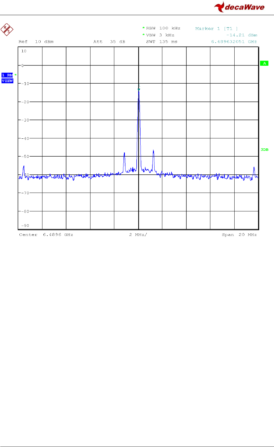
DW1000 Device Driver API Guide
© Decawave Ltd 2016
Version 2.4
Page 86 of 94
Figure 6: Continuous wave output
6.3.15 Example 4b: continuous frame mode
This example application activates continuous frame mode for 2 minutes with a predefined
configuration. On a correctly configured spectrum analyser (use configuration values on the picture
below), the output should look like this:
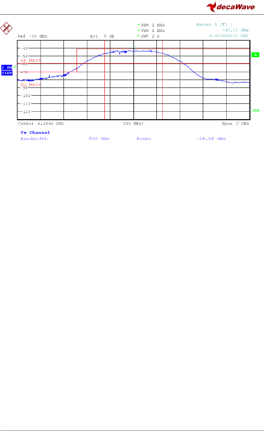
DW1000 Device Driver API Guide
© Decawave Ltd 2016
Version 2.4
Page 87 of 94
Figure 7: Continuous frame output
6.3.16 Example 5a: double-sided two-way ranging (DS TWR) initiator
This is a simple code example that acts as the initiator in a DS TWR distance measurement exchange.
This application sends a “poll” frame (recording the TX time-stamp of the poll), and then waits for a
“response” message expected from the “DS TWR responder” example code (companion to this
application – see section 6.3.17 below). When the response is received its RX time-stamp is recorded
and we send a “final” message to complete the exchange. The final message contains all the time-
stamps recorded by this application, including the calculated/predicted TX time-stamp for the final
message itself. The companion “DS TWR responder” example application works out the time-of-
flight over-the-air and, thus, the estimated distance between the two devices.
6.3.17 Example 5b: double-sided two-way ranging responder
This is a simple code example that acts as the responder in a DS TWR distance measurement
exchange. This application waits for a “poll” message (recording the RX time-stamp of the poll)
expected from the “DS TWR initiator” example code (companion to this application), and then sends
a “response” message recording its TX time-stamp, after which it waits for a “final” message from
the initiator to complete the exchange. The final message contains the remote initiator’s time-
stamps of poll TX, response RX and final TX. With this data and the local time-stamps, (of poll RX,
response TX and final RX), this example application works out a value for the time-of-flight over-the-
air and, thus, the estimated distance between the two devices, which it writes to the LCD.
6.3.18 Example 6a: single-sided two-way ranging (SS TWR) initiator
This is a simple code example that acts as the initiator in a SS TWR distance measurement exchange.
This application sends a “poll” frame (recording the TX time-stamp of the poll), after which it waits
for a “response” message from the “SS TWR responder” example code (companion to this
application) to complete the exchange. The response message contains the remote responder’s
time-stamps of poll RX, and response TX. With this data and the local time-stamps, (of poll TX and

DW1000 Device Driver API Guide
© Decawave Ltd 2016
Version 2.4
Page 88 of 94
response RX), this example application works out a value for the time-of-flight over-the-air and, thus,
the estimated distance between the two devices, which it writes to the LCD.
Heretofore, we would have recommended use of double-sided TWR (as per examples 5a and 5b)
instead of this single-sided two-way ranging because the SS-TWR time-of-flight estimation typically
suffers poor accuracy due to the clock offset between the two nodes participating in the TWR
exchange. However since driver version 4.0.6 we are now making use of the carrier integrator
diagnostic from the DW1000 (accessible via the new dwt_readcarrierintegrator() API function) to
measure the clock offset and improve the accuracy SS-TWR range estimate calculation.
6.3.19 Example 6b: single-sided two-way ranging responder
This is a simple code example that acts as the responder in a SS TWR distance measurement
exchange. This application waits for a “poll” message (recording the RX time-stamp of the poll)
expected from the “SS TWR initiator” example code (companion to this application), and then sends
a “response” message to complete the exchange. The response message contains all the time-
stamps recorded by this application, including the calculated/predicted TX time-stamp for the
response message itself. The companion “SS TWR initiator” example application works out the time-
of-flight over-the-air and, thus, the estimated distance between the two devices.
6.3.20 Example 7a: Auto ACK TX
This example, with its companion example 8b below, demonstrates the operation of the DW1000’s
auto-ACK function. The code here is based on example 3a, except that in this case the transmitted
frame has the AR (acknowledgement request) bit set in the frame control field of the MAC header,
(following the MAC frame definitions of IEEE 802.15.4), and the turn-around to await response is
immediate, reflecting the ACK response timing of the DW1000.
6.3.21 Example 7b: Auto ACK RX
This complement to example 8a. Here the Auto ACK feature of DW1000 is activated so that frames
sent by companion example 8a are automatically acknowledged.
6.3.22 Example 8a: Low-power listening RX
This example sets up low-power listening mode and then waits to be woken-up by the wake-up
sequence that is sent by the companion example 8b "Low-power listening TX". When a wake up-
frame is received, this example checks if it is the intended recipient of the wake-up sequence, and if
so, it sleeps until the expected end of the wake-up sequence and then takes part in the subsequent
interaction period by sending a frame. After this interaction it reactivates low-power listening. If the
received wake-up sequence is addressed to some other node the code sleeps until after the end of
wakeup and the subsequent the interaction period before reactivating low-power listening.
See "Low-Power Listening" section in [2] for more details.

DW1000 Device Driver API Guide
© Decawave Ltd 2016
Version 2.4
Page 89 of 94
6.3.23 Example 8b: Low-power listening TX
This example is a companion to example 8a "Low-power listening RX". It sends the wake-up
sequence (a sufficient number of frames sent back-to-back) so that the companion example can be
woken up every once in a while. In every second wake-up sequence sent, the destination address is
changed to a dummy one, to show the effect in the companion receive example of a wakeup for
another node. After the wake-up sequence is sent, an interaction period is started during which this
example awaits for an incoming frame from the awoken node. When the interaction period is over,
this example waits for a 5 seconds before proceeding to another transmission of the wake-up
sequence. (In a real use case for low-powered listening, the time between wake-ups is expected to
be much longer).
6.3.24 Example 9a: TX Bandwidth and Power Reference Measurements
This example is a prerequisite for example 9b “TX Bandwidth and Power Compensation”. It sets the
DW1000 to chip default settings for transmit bandwidth and power. It then takes reference
measurements that are used during the compensation algorithm in normal operation. The
measurements that it takes are the IC temperature, pulse generator delay and count values (which
are related to bandwidth) and transmit power settings (related to power). The data is displayed on
the LCD screen of the device.
6.3.25 Example 9b: TX Bandwidth and Power Compensation
This example is a companion to example 9a “TX Bandwidth and Power Reference Measurements”.
The recorded reference measurements from example 9a should be set in this example before
running. The compensation algorithm corrects the bandwidth and power settings for the effects of
temperature. Using the reference measurements as a base, it samples the current temperature and
performs the correction algorithm for bandwidth and then for power. The DW1000 is then put into
TX continuous frame mode with these corrected settings applied and the spectrum can be measured
on a spectrum analyser.

DW1000 Device Driver API Guide
© Decawave Ltd 2016
Version 2.4
Page 90 of 94
7 APPENDIX 2 – BIBLIOGRAPHY:
[1]
Decawave DW1000 Data Sheet
[2]
Decawave DW1000 User Manual
[3]
IEEE 802.15.4‐2011 or “IEEE Std 802.15.4™‐2011” (Revision of IEEE Std 802.15.4-2006).
IEEE Standard for Local and metropolitan area networks— Part 15.4: Low-Rate Wireless
Personal Area Networks (LR-WPANs). IEEE Computer Society Sponsored by the LAN/MAN
Standards Committee.
Available from http://standards.ieee.org/
[4]
Application note APS023 Part 2: TX Bandwidth and Power Compensation
Table 17: Bibliography

DW1000 Device Driver API Guide
© Decawave Ltd 2016
Version 2.4
Page 91 of 94
8 DOCUMENT HISTORY
Table 18: Document History
Revision
Date
Description
1.0
1st November 2013
Initial release for production device.
1.5
4th November 2014
Scheduled update
1.7
1st July, 2015
Scheduled update
2.0
4th December, 2015
Added new simple example project descriptions
2.1
22nd July, 2016
Added new examples and updated API after driver review
2.2
2nd December, 2016
Added new API calls and examples for TX bandwidth/power compensation
2.3
22nd February, 2017
Added new dwt_setdevicedataptr API function, some minor corrections
2.4
27th February, 2017
Added new dwt_readcarrierintegrator() API function.
9 MAJOR CHANGES
9.1 Release 1.5
Page
Change Description
All
Update of version number to 1.5
All
Various typographical changes
9
Updated the API to match driver version 2.12.0
9.2 Release 1.7
Page
Change Description
All
Update of version number to 1.7
All
Various typographical changes
3
New Disclaimer as new source includes ST’s library files
9
Updated the API to match driver version 2.16.0
New APIs
New API functions: dwt_OTPrevision, dwt_setGPIOvalue, dwt_setGPIOdirection, dwt_setGPIOforEXTTRX,
Table 17
New OTP map
9.3 Release 2.0
Page
Change Description
All
Update of version number to 2.0
All
Various typographical changes
9
Updated the API to match driver version 3.0.0
API removal
Removal of the following APIs: dwt_getldotune, dwt_getotptxpower, dwt_readantennadelay
17
Updated dwt_initialise parameters
18
Updated dwt_configure parameters

DW1000 Device Driver API Guide
© Decawave Ltd 2016
Version 2.4
Page 92 of 94
Page
Change Description
40
Updated dwt_configuresleep parameters
41 to 44
Fixed wake-up time value occurrences from 200 to 500 microseconds
54
Renamed dwt_readdignostics to dwt_readdiagnostics
59
Added new dwt_otp read API
68
Added missing function dwt_checkoverrun
71
Added new deca_sleep API
Appendix 1
Added new simple example project descriptions
9.4 Release 2.1
Page
Change Description
All
Update of version number to 2.1
All
Various typographical changes
All
Changed DWT_DECA_ERROR to DWT_ERROR and DWT_DECA_SUCCESS to DWT_SUCCESS
9
Updated the API to match driver version 04.00.xx
17
Updated dwt_initialise description
18
Updated dwt_configure return value and description
25
Updated dwt_writetxdata description
26
Updated dwt_writetxfctrl parameters and return value
33
Updated dwt_rxenable parameters and description
34
Added new API dwt_setsniffmode
44
Added new API set_lowpowerlistening
44
Added new API set_snoozetime
45
Updated dwt_setcallbacks parameters and description
47
Added missing API dwt_checkirq
47
Updated dwt_isr description
50
Added new API dwt_lowpowerlistenisr
63
Update Table 15 (OTP memory map)
64
Updated dwt_setleds parameters
64
Added new API dwt_setfinegraintxseq
65
Added new API dwt_setlnapamode
65
Renamed dwt_setGPIOdirection to dwt_setgpiodirection
66
Renamed dwt_setGPIOvalue to dwt_setgpiovalue
66
Renamed dwt_xtaltrim to dwt_setxtaltrim
67
Added new dwt_getinitxtaltrim API
67
Updated dwt_configcwmode description
75
Updated dwt_writetodevice return value and description
75
Updated dwt_readfromdevice return value and description
76
Updated dwt_write32bitoffsetreg return value
76
Updated dwt_write16bitoffsetreg return value
76
Added new dwt_read8bitoffsetreg and dwt_write8bitoffsetreg APIs
77 to 84
Added the descriptions of the following new examples: 1d, 2b, 2c, 2d, 2e, 3c, 3d, 7a, 7b, 8a, 8b.

DW1000 Device Driver API Guide
© Decawave Ltd 2016
Version 2.4
Page 93 of 94
Page
Change Description
API removal
Removal of the following APIs: dwt_getrangebias, dwt_setrxmode, dwt_checkoverrun,
dwt_setautorxreenable, dwt_setGPIOforEXTTRX
Table removal
Removal of former tables 9 and 14
9.5 Release 2.2
Page
Change Description
All
Update of version number to 2.2
New APIs
New API functions: dwt_calcpowertempadj, dwt_calcbandwidthtempadj, dwt_calcpgcount
86
Added new examples for the new API calls
9.6 Release 2.3
Page
Change Description
All
Update of version number to 2.3
44
Fixed dwt_spicswakeup API return value and description to match the return values in the driver code
74
Add new dwt_setdevicedataptr API function
9.7 Release 2.4
Page
Change Description
19
Fix dwt_configure() API function, the parameters did not match the code.
74
Added new dwt_readcarrierintegrator() API function.
87
Updated text of 6.3.18 Example 6a: single-sided two-way ranging (SS TWR) initiator.
All
Update of version number to 2.4

DW1000 Device Driver API Guide
© Decawave Ltd 2016
Version 2.4
Page 94 of 94
10 ABOUT DECAWAVE
Decawave is a pioneering fabless semiconductor company whose flagship product, the DW1000, is a
complete, single chip CMOS Ultra-Wideband IC based on the IEEE 802.15.4 standard UWB PHY. This
device is the first in a family of parts.
The resulting silicon has a wide range of standards-based applications for both Real Time Location
Systems (RTLS) and Ultra Low Power Wireless Transceivers in areas as diverse as manufacturing,
healthcare, lighting, security, transport, and inventory and supply-chain management.
For further information on this or any other Decawave product contact a sales representative as
follows: -
Decawave Ltd,
Adelaide Chambers,
Peter Street,
Dublin 8,
Ireland.
mailto:sales@decawave.com
http://www.decawave.com/
