Da Vinci Resolve 15 New Features Guide
User Manual: Pdf
Open the PDF directly: View PDF ![]() .
.
Page Count: 282 [warning: Documents this large are best viewed by clicking the View PDF Link!]
- PART 1
- New Features in 15
- General Improvements
- Overall User Interface Enhancements
- Performance Enhancements
- Selective Timeline and Incremental Project Loading
- Bypass All Grades Command Available on All Pages
- Improved PostgreSQL Database Optimization
- Optimized Viewer Updates
- Improved Playback on Single GPU Systems Showing Scopes
- Improved Playback With Mismatched Output Resolution and Video Format
- Audio I/O Processing Block Size
- Support for OpenGL Compute I/O on Supported Systems
- Video Stabilization Has Been GPU Accelerated
- ResolveFX Match Move is GPU Accelerated
- Quality Enhancements
- Audio I/O Enhancements
- Media and Export Improvements
- Improved Media Management for Temporally Compressed Codecs
- Support for Frame Rates Up to 32,000 Frames Per Second
- Support for XAVC-Intra OP1A HDR Metadata
- Support for ARRI LF Camera Files
- Support for HEIC Still Image Media
- Support for TGA Files
- Support for DNX Metadata in QuickTime Media
- Kakadu-based JPEG2000 Encoding and Decoding (Studio Only)
- Native IMF Encoding and Decoding (Studio Only)
- Native Unencoded DCP Encoding and Decoding (Studio Only)
- Scripting Support for DaVinci Resolve
- Edit Page Improvements
- Media Pool and Clip Display Enhancements
- Display Name is Now Called Clip Name, On by Default
- Display Audio Clip Waveforms in Media Pool and Media Storage
- Media Pool Command for Finding Synced Audio Files
- Improved Media Pool Column Customization
- Larger Thumbnails in the Media Pool
- Recent Clips Pop-Up Menu
- Ability to Create Subclips via Drag and Drop from Source Viewer
- Ability to Remove Subclip Limits
- Import Hierarchically Organized Nests of Empty Directories
- Import Clips with Metadata via Final Cut Pro 7 XML
- Enhancements to Markers and Flags
- Editing Enhancements
- Tabbed and Stacked Timelines
- Improved Dynamic Trim Behaviors
- Ability to Modify Clip Duration Via Timecode
- Ability to Delete Multiple Timeline Gaps at Once
- Improved Separation Between the Video and Audio Tracks
- Improved Ripple Cut and Ripple Delete Behavior
- Improved Automatic Audio Track Creation
- New Play Again Command
- Option to “Stop and Go To Last Position”
- Single Viewer Mode is Available in Dual Screen Layout
- Copy and Paste Timecode in Viewer Timecode Fields
- Improved Timecode Entry
- Replace Edit Using Clips Already in the Timeline
- Option to Ripple the Timeline in Paste Attributes
- Transition Categories in the Effects Library
- Linked Move Across Tracks
- Track Destination Keyboard Shortcuts Also Disable Tracks
- Ability to Mark In and Out Points in Cinema Mode
- Updated Timeline View Options Menu in the Toolbar
- Edit Page Effects Enhancements
- Media Pool and Clip Display Enhancements
- Subtitles and Closed Captioning
- Color Page Improvements
- Clip, LUT, and Grade Browsing Features
- Media Pool in Color Page
- Dedicated LUT Browser
- New Split Screen Modes to Preview Selected LUTs, Albums
- Live Previews of Gallery Stills and LUTs
- Live Previews of Composite Modes in the Layer Mixer
- Live Previews of LUTs in the Node Editor
- Favorite LUTs Submenu in Node Editor
- Browse All Timeline Grades From the Current Project in the Gallery
- Browse and Import Timeline Grades From Other Projects
- RED SDK-Based RED IPP2 Setting in RCM Gamut Mapping
- New Color Page Features
- Multiple Timeline Playheads
- Batch Version Management
- Draggable Qualifier Controls
- Additional Matte Finesse Controls
- Node-Specific Color Space and Gamma Settings
- Timeline Wipe Ganging to Current Clip
- Camera RAW Palette for Canon RAW, Panasonic RAW Clips
- Stereoscopic Convergence Support for Power Windows
- Marker Overlays Visible in the Color Page Viewer
- Timeline Marker List Available in Color Page Viewer Option Menu
- Improved Noise Reduction
- Improved Face Refinement
- Node Editor Enhancements
- Shared nodes for Group Management
- Single-Click Node Selection in the Color Page
- Ability to Disable/Enable Multiple Selected Nodes All at Once
- Ability to Drag Connections From One Input to Another
- Single-Click Connection Deletion
- Edit Node Label Text by Double-Clicking
- Dynamic Keyframe Indicator in the Node Graph
- Improved Node Graph Interface
- Thumbnail-Optional Nodes
- Ability to Open Compound Nodes in “Display Node Graph”
- HDR Enhancements
- Clip, LUT, and Grade Browsing Features
- New ResolveFX
- Fairlight Page Improvements
- New Fairlight Page Features
- General Fairlight Page Enhancements
- Normalize Audio Levels Command
- Clip Pitch Control
- Support for Mixed Audio Track Formats from Source Clips
- Oscillator for Generating Tone, Noise, and Beeps
- Compound Clips Breadcrumb Controls Below Fairlight Timeline
- Level and Effects Appear in Inspector for Selected Bus
- Audio Waveform Display While Recording
- Audio Playback for Variable Speed Clips
- Paste and Remove Attributes for Clips, Audio Tracks
- Loop Jog Scrubbing
- Improved Speaker Selection Includes Multiple I/O Devices
- Fairlight Page Editing Enhancements
- FairlightFX
- General Improvements
- New Features in 15
- PART 2
- Fusion Page Manual Preview
- Introduction to Compositing in Fusion
- Using the Fusion Page
- Getting Clips into the Fusion Page
- Image Processing and Color Management
- Understanding Image Channels and Node Processing
- Learning to Work in the Fusion Page
- What’s a Composition?
- Moving From the Edit to the Fusion Page
- Applying and Masking Effects
- Color Management in the Public Beta
- Compositing Two Clips Together
- Composite Modes and the Corner Positioner
- Setting Up the Initial Composite
- Controlling Which Node You See in the Viewer
- Adding the Corner Positioner Node With a Search
- Warping the Image With the Corner Positioner Node
- Toggling On-screen Control Visibility
- Navigating the Viewer
- Using the Screen Composite Mode in the Merge Node
- Tweaking Color in the Foreground Layer
- Creating and Using Text
- Match Moving Text With Motion Tracking
- Using Paint and Planar Tracking
- Building a Simple Green Screen Composite
- Animating an Image Using Keyframes
- Congratulations
- Creating Fusion Templates
- Fusion Page Manual Preview
New Features Guide
PUBLIC BETA
DaVinci
Resolve 15

Welcome
Welcome to DaVinci Resolve 15 for Mac, Linux and Windows!
DaVinci is the world’s most trusted name in color and has been used to grade
more Hollywood films, TV shows, and commercials than anything else. Now, with
DaVinciResolve15, you get a complete set of editing, advanced color correction,
professional Fairlight audio post production tools and now Fusion visual effects
combined in one application so you can composite, edit, grade, mix and master
deliverables from start to finish, all in a single tool!
DaVinci Resolve 15 has the features professional editors, colorists, audio engineersand
VFXartists need, and is built on completely modern technology with advanced audio,
colorandimage processing that goes far beyond what any other system can do.
Withthis release, we hope to inspire creativity by letting you work in a comfortable,
familiar way, whilealso giving you an entirely new creative toolset that will help you cut
and finish projects at higher quality than ever before!
We hope you enjoy reading this manual. With its customizable interface and keyboard
shortcuts, DaVinci Resolve 15 is easy to learn, especially if you’re switching from
another editor, and has all of the tools you need to create breathtaking, high end work!
The DaVinci Resolve Engineering Team
Grant Petty
CEO Blackmagic Design
3DaVinci Resolve 15 BETA New Features Guide
About This Guide
DaVinci Resolve 15 is a huge release, with the headlining addition of the
Fusion page for advanced effects and motion graphics, and
workflow‑enhancing features added in equal measure to the Edit page, the
Color page, and the Fairlight page. Consequently, this year’s public beta
needed a different approach to the documentation. This “NewFeatures
Guide” provides a focused and comprehensive look at only the new features
in DaVinci Resolve 15. If you’re a Resolve user already and you just want to
know what’s changed, this is for you. If you’re a new user who needs to learn
the fundamentals, you should refer to the DaVinciResolve 14 Manual, but
know that none of the new features in version 15 are covered there.
This PDF is divided into two parts. Part 1 covers new features in the previously
existing pages of DaVinci Resolve, including chapters on overall interface
enhancements, Editpage improvements, Color page features, and Fairlight
page additions.
Part 2 provides a “documentation preview” of chapters that cover the basics
of the new Fusion page. Fusion compositing is a huge topic, and the chapters
of Part 2 seek to provide guidance on the fundamentals of working in Fusion
so that you can try these features for yourself, even if you don’t have a
background in node‑based compositing.
Eventually, the information in this guide will be rolled into the next update
ofthemanual that will accompany the final release of DaVinci Resolve 15.
Fornow, use this guide as a tour of the exciting new features being unveiled,
and havefun.
4DaVinci Resolve 15 BETA New Features Guide
PART 1
New Features in 15
1 General Improvements 1-2
2 Edit Page Improvements 1-15
3 Subtitles and Closed Captioning 1-37
4 Color Page Improvements 1-49
5 New ResolveFX 1-68
6 Fairlight Page Improvements 1-81
7 FairlightFX 1-105
PART 2
Fusion Page ManualPreview
8 Introduction toCompositing inFusion 2-2
9 Using the FusionPage 2-7
10 Getting Clips into the Fusion Page 2-46
11 Image Processing and Color Management 2-52
12 Understanding Image Channels and NodeProcessing 2-58
13 Learning to Work in the Fusion Page 2-84
14 Creating Fusion Templates 2-150
Contents
PART 1
New Features in 15
Chapter 1
General
Improvements
Part I of the DaVinci Resolve 15 New Features Guide explores and explains
all of the new features that have been added to the Media, Edit, Color,
Fairlight, and Deliver pages in this year’s public beta. This particular
chapter covers overall enhancements that affect the entire application.
DaVinci Resolve 15 introduces numerous improvements to saving, to the
overall user interface, to Project Settings and Preferences, and to export.
Furthermore, many improvements to performance have been implemented to
make working in DaVinci Resolve even faster. There are avariety of image
quality enhancements, including support for “SuperScale” image
enlargement for doing higher‑quality enlargements when you’re dealing with
smaller‑resolution archival footage or when you’re punching way into a clip to
create an emergency closeup. There’salso support for numerous additional
media formats, with support for built‑in IMF encoding and decoding, and the
beginning of workflow‑oriented scripting support for DaVinci Resolve.
1-2Chapter – 1 General Improvements
Contents
Overall User Interface Enhancements 1-4
Menu Bar Reorganization 1-4
Contextual Menu Consolidation 1-4
Page‑Specific Keyboard Mapping 1-4
Project Versioning Snapshots 1-5
Ability to Open DRP Files From the macOS Finder 1-6
Floating Timecode Window 1-6
Ability to Minimize Interface Toolbars and the Resolve Page Bar 1-7
Performance Enhancements 1-7
Selective Timeline and Incremental Project Loading 1-7
Bypass All Grades Command Available on All Pages 1-8
Improved PostgreSQL Database Optimization 1-8
Optimized Viewer Updates 1-8
Improved Playback on Single GPU Systems Showing Scopes 1-8
Improved Playback With Mismatched Output Resolution and Video Format 1-8
Audio I/O Processing Block Size 1-8
Support for OpenGL Compute I/O on Supported Systems 1-9
Video Stabilization Has Been GPU Accelerated 1-9
ResolveFX Match Move is GPU Accelerated 1-9
Quality Enhancements 1-9
“Super Scale” High Quality Upscaling 1-9
Improved Motion Estimation for Retime andNoiseReduction Eects 1-10
Audio I/O Enhancements 1-11
Full Fairlight Engine Support For the Edit Page 1-11
Support for Native Audio on Linux 1-11
Record Monitoring Using the Native Audio Engine 1-11
Media and Export Improvements 1-11
Improved Media Management for Temporally Compressed Codecs 1-11
Support for Frame Rates Up to 32,000 Frames Per Second 1-11
Support for XAVC‑Intra OP1A HDR Metadata 1-12
Support for ARRI LF Camera Files 1-12
Support for HEIC Still Image Media 1-12
Support for TGA Files 1-12
Support for DNX Metadata in QuickTime Media 1-12
Kakadu‑based JPEG2000 Encodingand Decoding (Studio Only) 1-12
Native IMF Encoding and Decoding (Studio Only) 1-13
Native Unencoded DCP Encodingand Decoding (Studio Only) 1-14
Scripting Support for DaVinci Resolve 1-14
1-3Chapter – 1 General Improvements
Overall User Interface Enhancements
A number of usability enhancements improve command access and keyboard shortcuts
throughout every page of DaVinci Resolve, as well as facilitate the backing up of your projects
in DaVinci Resolve.
Menu Bar Reorganization
In an effort to accommodate the additional functionality of the Fusion and Fairlight pages with
their attendant menus, all commands from the Nodes menu have been moved into the
Colormenu, making room for the new Fusion menu on laptops with limited screen real estate.
The menus have been updated to accommodate the Fusion and Fairlight pages
Additionally, most menus have been reorganized internally to place multiple variations on
commands within submenus, making each menu less cluttered so that commands are easier
tospot.
Contextual Menu Consolidation
Contextual menus throughout DaVinci Resolve have been consolidated to omit commands that
were formerly disabled, with the result being shorter contextual menus showing only commands
that are specific to the area or items you’ve right‑clicked on.
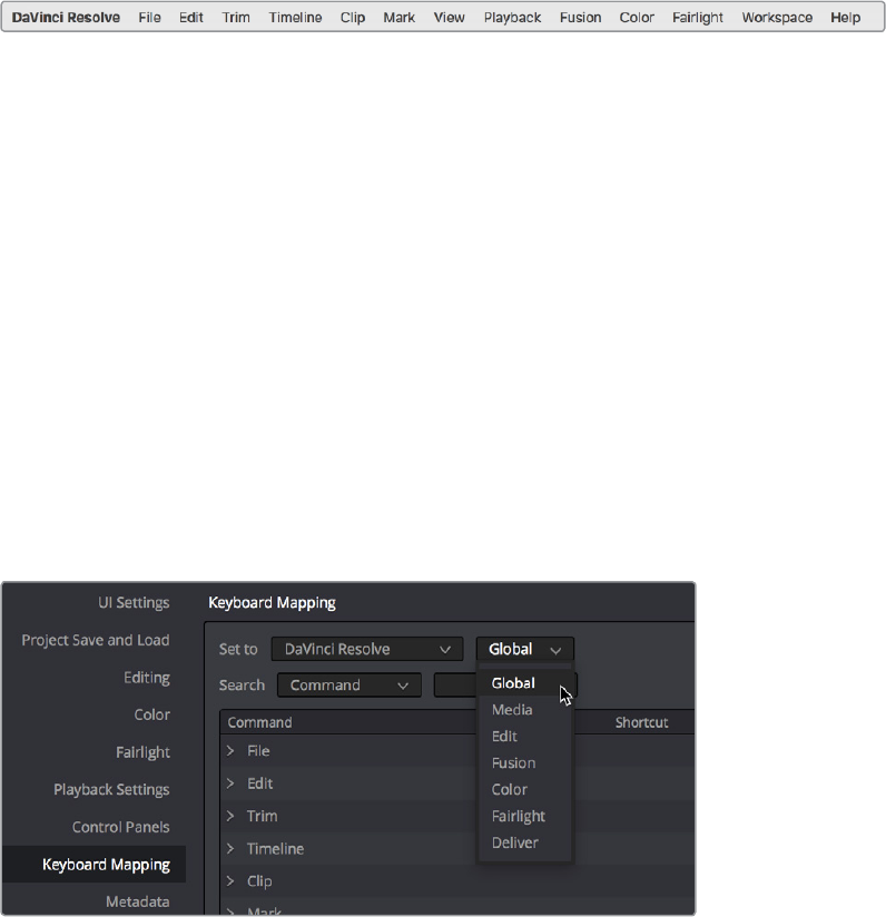
Page-Specific Keyboard Mapping
When customizing keyboard shortcuts, you can now specify whether a keyboard shortcut is
“Global” so that it works identically on every page, or you can map a particular keyboard
shortcut to do a particular thing on a specific page. With page‑specific keyboard shortcuts, you
can have a single key do different things on the Edit, Fusion, Color, or Fairlight pages.
Keyboard shortcuts can now be mapped to specific pages, if you like
1-4Chapter – 1 General Improvements
Project Versioning Snapshots
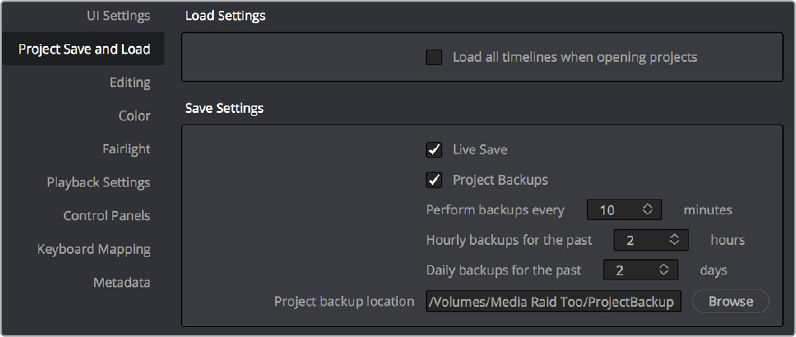
Turning on the Project Backups checkbox in the Project Save and Load panel of the User
Preferences enables DaVinci Resolve to save multiple backup project files at set intervals, using
a method that’s analogous to a GFS (grandfather father son) backup scheme. This can be done
even while Live Save is turned on. Each project backup is a complete project file, excluding
stills and LUTs.
The User Preferences controls for Project Backups
Project backups are only saved when changes have been made to a project. If DaVinci Resolve
sits idle for any period of time, such as when your smart watch tells you to go outside and walk
around the block, no additional project backups are saved, preventing DaVinci Resolve from
overwriting useful backups with unnecessary ones.
Three fields let you specify how often to save a new project backup.
Perform backups every X minutes: The first field specifies how often to save a new
backup within the last hour you’ve worked. By default, a new backup is saved every
10 minutes, resulting in six backups within the last hour. Once an hour of working has
passed, an hourly backup is saved and the per‑minute backups begin to be discarded
on a “first in, first out” basis.” By default, this means that you’ll only ever have six
backups at a time that represent the last hour’s worth of work.
Hourly backups for the past X hours: The second field specifies how many hourly
project backups you want to save. By default, 8 hourly backups will be saved for the
current day you’re working, which assumes you’re working an eight hour day (wouldn’t
that be nice). Past that number, hourly backups will begin to be discarded on a “first in,
first out” basis.
Daily backups for the past X days: The third field specifies for how many days
you want to save backups. The very last project backup saved on any given day is
preserved as the daily backup for that day, and by default daily backups are only saved
for five days (these are not necessarily consecutive if you take some days off of editing
for part of the week). Past that number, daily backups will begin to be discarded on a
“first in, first out” basis. If you’re working on a project over a longer stretch of time, you
can always raise this number.
Project backup location: Click the Browse button to choose a location for these project
backups to be saved. By default they’re saved to a “ProjectBackup” directory on your
scratch disk.
1-5Chapter – 1 General Improvements
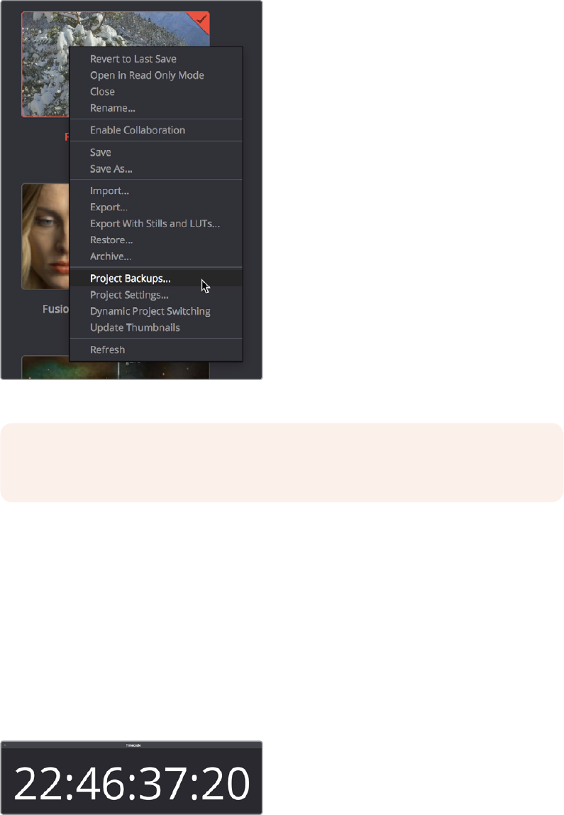
Once you’ve enabled Project Backups for a long enough time, saved project backups are
retrievable in the Project Manager, via the contextual menu that appears when you right‑click a
project. Opening a project backup does not overwrite the original project; project backups are
always opened as independent projects.
Restoring a project backup in the Project Browser
Ability to Open DRP Files From the macOS Finder
This is a feature that’s specific to macOS. If you double‑click a DaVinci Resolve .drp file in the
Finder, this will automatically open DaVinci Resolve, import that project into the File Browser,
and open that project so that you’re ready to work.
Floating Timecode Window
A Timecode Window is available from the Workspace menu on every page. Choosing this option
displays a floating timecode window that shows the timecode of the Viewer or Timeline that
currently has focus. This window is resizable so you can make the timecode larger or smaller.
A new floating timecode window is available
NOTE: When using this feature, the very first project backup that’s saved for a given
day may be a bit slow, but all subsequent backups should be unnoticeable.
1-6Chapter – 1 General Improvements
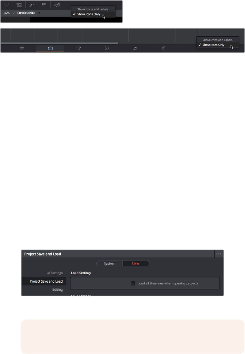
Ability to Minimize Interface Toolbars
and the Resolve Page Bar
If you right‑click anywhere within the UI toolbar at the top of each page, or the Resolve Page
Bar at the bottom of the DaVinci Resolve UI, you “Show Icons and Labels” or “ Show Icons
Only.” If you show icons only, the Resolve Page Bar at the bottom takes less room, and the
UItoolbar becomes less cluttered.
The UI Toolbar and Page bar showing icons only, to save space
Performance Enhancements
Several new features have been added to improve performance.
Selective Timeline and Incremental Project Loading
To improve the performance of longer projects with multiple timelines, the “Load all timelines
when opening projects” checkbox in the Project Save and Load panel of the User Preferences
defaults to off.
When this checkbox is off, opening a project only results in the last timeline you worked
on being opened into memory; all other timelines are not loaded into RAM. This speeds
up the opening of large projects. However, you may experience brief pauses when you
open other timelines within that project, as each new timeline must be loaded into RAM
as you open it. If you open a particularly gigantic timeline, a progress bar will appear
letting you know how long it will take to load. Another advantage of this is the reduction
of each project’s memory footprint, which is particularly valuable when working among
multiple projects using Dynamic Project Switching.
If you turn this on, all timelines will be loaded into RAM and you’ll experience no pauses
when opening timelines you haven’t opened already. However, projects with many
timelines may take longer to open and save.
The new “Load all timelines when opening projects” preference,
that defaults to off to speed up project load times
NOTE: While “Load all timelines when opening projects” is turned on, the
Smart and User Cache become unavailable.
1-7Chapter – 1 General Improvements
Bypass All Grades Command Available on All Pages
The Bypass All Grades command, previously available only on the Color page, is now available
on the Edit page either via View > Bypass All Grades, or via a button in the Timeline Viewer.
Turning off grades is an easy way to improve performance on low power systems, and it’s also a
convenient way to quickly evaluate the original source media.
The Bypass All Grades button in the
Timeline Viewer title bar of the Edit page
Improved PostgreSQL Database Optimization
The Optimize command for PostgreSQL project databases in the Database sidebar of the
Project window produces improved results for large projects, resulting in better project load
and save performance.
Optimized Viewer Updates
A new preference, “Optimized Viewer Updates,” which only appears on multi‑GPU macOS
andWindows systems, and on single‑ or multi‑GPU Linux systems, enables faster viewer
updateperformance.
Improved Playback on Single GPU
Systems Showing Scopes
Video scope playback performance is improved on single‑GPU systems.
Improved Playback With Mismatched
Output Resolution and Video Format
Playback performance has been greatly improved when you set Output Resolution in the Image
Scaling panel of the Projects settings to a different frame size than Video Format in the Master
Settings panel, while outputting to any Blackmagic Design capture and playback device.
Audio I/O Processing Block Size
A new “Audio Processing Block Size X Samples” parameter in the Hardware Configuration
panel of the System Preferences lets you increase the sample block size to add processing
headroom to the system, at the expense of adding latency to audio playback. The default value
is Auto, which automatically chooses a suitable setting for the audio I/O device you’re using.
For those who have specific needs and are interested in setting this manually, here are some
examples of use. In a first example, when a system is under a heavy load (there are many
plug‑ins being used on many tracks), then increasing the block size to add processing
headroom will result in a longer delay every time your audio hardware requests samples to feed
the speakers. If you’re only mixing, the resultant latency may not be a problem, so this gives you
the option to add headroom so your system can run a few more plug‑ins or tracks.
1-8Chapter – 1 General Improvements

On the other hand, this increased delay in the processed audio running through the mixer is a
much bigger problem if you’re recording an artist in an ADR session, where they need to hear
themselves in the headphones, or when you’re recording foley or voice over and there’s an
increased delay between what you see and what you’re recording, so in this case sticking with
the default value (or smaller) will sacrifice processing headroom for diminished latency.
Support for OpenGL Compute I/O on Supported Systems
The “GPU processing mode” pop‑up menu in the Hardware Configuration panel of the System
Preferences has a new option for OpenCL on supported systems.
Video Stabilization Has Been GPU Accelerated
Video stabilization in DaVinci Resolve has been accelerated, demonstrating an up to
6ximprovement vs. 14.3 on the Late 2014 Retina 5K iMac. Additionally, the automatic cropping
behavior has been improved.
ResolveFX Match Move is GPU Accelerated
The Match Move ResolveFX plug‑in is now GPU Accelerated, resulting in faster tracking and
compositing workflows on the Color page.
Quality Enhancements
Two image quality enhancements have been incorporated providing higher visual quality
forsome of the most challenging operations in DaVinci Resolve: upscaling, retiming, and
noisereduction.
“Super Scale” High Quality Upscaling
For instances when you need higher‑quality upscaling than the standard Resize Filters allow,
you can now enable one of three “Super Scale” options in the Video panel of the Clip Attributes
window for one or more selected clips. The Super Scale pop‑up menu provides three options
of 2x, 3x, and 4x, as well as Sharpness and Noise Reduction options to tune the quality of the
scaled result. Note that all of the Super Scale parameters are in fixed increments; you cannot
apply Super Scale in variable amounts.
Super Scale options in the Video panel of the Clip Attributes
TIP: A common strategy when you need to force more cooperation from a particular
workstation and audio interface is to reduce Audio Processing Block Size when you’re
about to do a recording session, when track and plug‑in use is lower. Later, when you
start mixing in earnest and adding plug‑ins, you can increase Audio Processing Block
Size to give you better performance once you’re finished recording.
1-9Chapter – 1 General Improvements
Selecting one of these options enables DaVinci Resolve to use advanced algorithms to improve
the appearance of image detail when enlarging clips by a significant amount, such as when
editing SD archival media into a UHD timeline, or when you find it necessary to enlarge a clip
past its native resolution in order to create a closeup.
This is an extremely processor‑intensive operation, so be aware that turning this on will likely
prevent real‑time playback. One way to get around this is to create a string‑out of all of the
source media you’ll need to enlarge at high‑quality, turn on Super Scale for all of them, and then
render that timeline as individual clips, while turning on the “Render at source resolution” and
“Filename uses > Source Name” options.
Improved Motion Estimation for Retime
andNoiseReduction Effects
When using mixed frame rate clips in a timeline that has Optical Flow retiming enabled, when
using Optical Flow to process speed change effects, or when using Image Stabilization or
Temporal Noise Reduction controls in the Color page, the Motion Estimation pop‑up of the
Master Settings (in the Project Settings window) lets you choose options that control the
trade‑off between speed and quality.
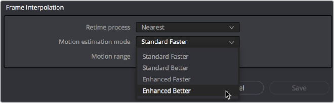
There are additional “Enhanced” Optical Flow settings available in the “Motion estimation
mode” pop‑up in the Master Settings panel of the Project Settings. The “Standard Faster” and
“Standard Better” settings are the same options that have been available in previous versions
of DaVinci Resolve. They’re more processor‑efficient and yield good quality that are suitable for
most situations. However, “Enhanced Faster” and “Enhanced Better” should yield superior
results in nearly every case where the standard options exhibit artifacts, at the expense of
being more computationally intensive, and thus slower on most systems.
New improved Motion estimation mode settings in the
Master Settings panel of the Project Settings
1-10Chapter – 1 General Improvements
Audio I/O Enhancements
Audio processing, playback, and recording in DaVinci Resolve 15 has been improved for better
cross‑platform support.
Full Fairlight Engine Support For the Edit Page
All Edit page features now use the Fairlight audio engine, providing superior transport control
performance, as well as the ability to choose which audio I/O device to output to.
Support for Native Audio on Linux
DaVinci Resolve on Linux now supports using your workstation’s system audio on Linux, instead
of only supporting Decklink audio, as with previous systems. This means that DaVinci Resolve
can use your Linux workstation’s on‑board audio, or any Advanced Linux Sound Architecture
(ALSA)‑supported third party audio interface.
Record Monitoring Using the Native Audio Engine
The native audio of your workstation’s operating system can now be used for record
monitoring. This makes it possible to set up recording sessions where your audio input is
patched via a third party interface, and the audio output you’re monitoring can be patched via
your computer’s native audio.
Media and Export Improvements
DaVinci Resolve 15 supports several new media formats and metadata encoding methods.
Improved Media Management for
Temporally Compressed Codecs
As of DaVinci Resolve 15, the Media Management window can “copy and trim” clips using
temporally compressed media codecs such as H.264, XAVC, and AVC‑Intra, enabling you to
eliminate unused media for these formats during media management without recompressing
ortranscoding.
Support for Frame Rates Up to 32,000 Frames Per Second
To accommodate media from different capture devices capable of high‑frame‑rate slow motion
capture, and to future‑proof DaVinci Resolve against the rapidly improving array of capture
devices being developed every year, DaVinci Resolve has shifted the upper limit of supported
frame rates to 32,000 frames per second. Hopefully that’ll cover things for a while. Please note,
just because extremely high frame rate media is supported, do not expect real time
performance at excessively high frame rates, and understand that what performance your
workstation is capable of depends on its configuration and the speed of your storage.
1-11Chapter – 1 General Improvements

Support for XAVC-Intra OP1A HDR Metadata
DaVinci Resolve 15 now supports writing color space and gamma metadata to MXF OP1A format
media using the XAVC‑Intra codecs.
Support for ARRI LF Camera Files
Media from the new ARRI LF (Large Format) camera is now supported at all resolutions and
frame rates.
Support for HEIC Still Image Media
DaVinci Resolve 15 supports the High Efficiency Video Compression (HEIF) standard used by
Apple for capturing images on newer iPhones. With HEIF support, these still images can be
used in DaVinci Resolve projects.
Support for TGA Files
TGA stills and image sequences are supported for import.
Support for DNX Metadata in QuickTime Media
DaVinci Resolve 15 supports DNX Metadata including Color Range, Color Volume, and
HasAlpha within QuickTime files.
Kakadu-based JPEG2000
Encodingand Decoding (Studio Only)
DaVinci Resolve 15 supports the encoding and decoding of JPEG2000 using a library licensed
from Kakadu software. This includes a complete implementation of the JPEG2000 Part 1
standard, as well as much of Parts 2 and 3. JPEG2000 is commonly used for IMF and
DCPworkflows.
A variety of Kakadu JPEG2000 options are available when you choose MJ2, IMF, JPEG 2000,
MXF OP‑Atom, MXF OP1A, or QuickTime from the Format pop‑up menu of the Video panel of
the Render Settings on the Deliver page.
Choosing a JPEG2000‑compatible format
enables Kakadu JPEG 2000 codec options
1-12Chapter – 1 General Improvements
Native IMF Encoding and Decoding (Studio Only)
The Format pop‑up in the Video panel of the Render Settings now has a native IMF option that
lets you export to the SMPTE ST.2067 Interoperable Master Format (IMF) for tapeless
deliverables to networks and distributors. No additional licenses or plug‑ins are required to
output to IMF. The IMF format supports multiple tracks of video, multiple tracks of audio, and
multiple subtitle and closed caption tracks, all of which are meant to accommodate multiple
output formats and languages from a single deliverable. This is done by wrapping a timeline’s
different video and audio tracks (media essences) and subtitle tracks (data essences) into a
“composition” within the Material eXchange Format (MXF).
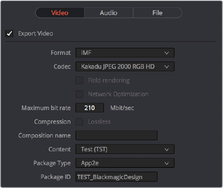
When the IMF format is selected, the Codec pop‑up menu presents numerous options for
Kakadu JPEG2000 output, including RGB, YUV, and Dolby Vision options. Additional controls
appear for Maximum bit rate, Lossless compression, the Composition name, the Package Type
(current options include App2e), and a Package ID field.
Render settings in the Export Video section for the IMF format
1-13Chapter – 1 General Improvements
Native Unencoded DCP
Encodingand Decoding (Studio Only)
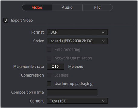
DaVinci Resolve 15 also has new native DCP Encoding and Decoding support built‑in, for
unencoded DCP files only. That means that you can output and import (for test playback)
unencoded DCP files without needing to purchase a license of EasyDCP. If you have a license,
a preference enables you to choose whether to use EasyDCP (for creating encrypted
DCPoutput), or the native Resolve encoding.
Native DCP settings in Resolve
Scripting Support for DaVinci Resolve
As of DaVinci Resolve 15, Resolve Studio begins to add support for Python and LUA scripting to
support various kinds of workflow automation. More information will be forthcoming as it
becomes available via developer documentation.
1-14Chapter – 1 General Improvements
Chapter 2
Edit Page
Improvements
The Edit page sees a wide variety of improvements and enhancements to
nearly every area of editing in DaVinci Resolve 15. Media Pool
improvements include new editable Clip names by default and larger
thumbnails. Marker enhancements include drawn annotations and the
ability to turn markers with duration into In and Out points. Editing
enhancements are far‑reaching, beginning with the ability to stack multiple
timelines to accommodate so‑called “pancake editing” techniques,
improved dynamic trim behaviors with automatic edit selection and the
ability to move to next and previous edits, the ability to create subclips via
drag and drop from the Source Viewer to the Media Pool, and many, many
more improvements large and small. Finally, editorial effects
enhancements include the new TextPlus generator, keyframable OpenFX
and ResolveFX, alpha transparency support in compound clips, and
improved optical flow options for speed effects.
1-15Chapter – 2 Edit Page Improvements
Contents
Media Pool and Clip DisplayEnhancements 1-18
Display Name is Now Called Clip Name, On by Default 1-18
Display Audio Clip Waveforms in MediaPool and Media Storage 1-18
Media Pool Command for Finding Synced Audio Files 1-19
Improved Media Pool Column Customization 1-19
Larger Thumbnails in the Media Pool 1-19
Recent Clips Pop‑Up Menu 1-19
Ability to Create Subclips via Dragand Drop from Source Viewer 1-20
Ability to Remove Subclip Limits 1-20
Import Hierarchically Organized Nests of Empty Directories 1-20
Import Clips with Metadata via Final Cut Pro 7 XML 1-20
Enhancements to Markers and Flags 1-21
Drawn Annotations on the Viewer 1-21
Ability to Create Markers and Flags With Specific Colors 1-22
Timecode Entry in Marker Dialogs 1-22
Clip Markers Show Overlays in the Timeline Viewer 1-22
Command to Turn Markers With Duration into In and Out Points 1-23
Editing Enhancements 1-23
Tabbed and Stacked Timelines 1-23
Improved Dynamic Trim Behaviors 1-25
Ability to Modify Clip Duration Via Timecode 1-26
Ability to Delete Multiple Timeline Gaps at Once 1-26
Improved Separation Between the Video and Audio Tracks 1-27
Improved Ripple Cut and Ripple Delete Behavior 1-27
Improved Automatic Audio Track Creation 1-28
New Play Again Command 1-28
Option to “Stop and Go To Last Position” 1-28
Single Viewer Mode is Available in Dual Screen Layout 1-28
Copy and Paste Timecode in Viewer Timecode Fields 1-28
Improved Timecode Entry 1-29
Replace Edit Using Clips Already in the Timeline 1-29
Option to Ripple the Timeline in Paste Attributes 1-30
Transition Categories in the Eects Library 1-30
Linked Move Across Tracks 1-30
Track Destination Keyboard Shortcuts Also Disable Tracks 1-31
Ability to Mark In and Out Points in Cinema Mode 1-31
Updated Timeline View Options Menu in the Toolbar 1-31
1-16Chapter – 2 Edit Page Improvements
Edit Page Effects Enhancements 1-32
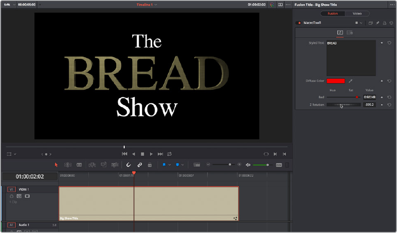
The Text+ Title Generator in the Edit Page 1-32
Fusion Titles and Fusion Templates 1-34
Support for Caching of Titles and Generators 1-35
Position Curves in the Timeline Curve Editor 1-35
Keyframable OpenFX and ResolveFX 1-35
Compound Clips Support Alpha Transparency 1-36
Improved Smooth Cut 1-36
Improved Optical Flow for Speed Eects 1-36
1-17Chapter – 2 Edit Page Improvements

Media Pool and Clip
DisplayEnhancements
A variety of improvements have been made to clip display and the Media Pool.
Display Name is Now Called Clip Name, On by Default
The clip metadata that was formerly called “Display Name” is now known as “Clip Name,” so
that there are two sets of clip identification metadata available to DaVinci Resolve, Clip Name
and File Name, both of which are visible in the Media Pool in List View.
Starting in DaVinci Resolve 15, Clip Name is the default clip identifier, while File Name is hidden
by default. This means that you can freely edit the default name that’s visible in the Media Pool,
either in List or Icon view, without needing to change modes. When necessary, you can switch
DaVinci Resolve to identify clips by file name only by choosing View > Show File Names.
Display Audio Clip Waveforms in
MediaPool and Media Storage
The Media Pool option‑menu presents an option to Show Audio Waveforms. When you do so,
every audio clip in the Media Pool appears with an audio waveform within its thumbnail area. If
Live Media Preview is on in the Source Viewer, you can then scrub through each clip and hear
its contents. If you don’t want to see audio waveforms, you can turn this option off.
You can now enable waveform thumbnails in the
MediaPool that you can scrub with Live MediaPreview
TIP: Don’t forget that you can use % variables to automatically populate Clip Names
viametadata, such as Scene, Take, and Description (%Scene_%Take_%Description),
leveraging whatever metadata entry you’ve done to prepare your clips to automatically
create useful clip naming conventions. Using Clip Attributes, you can edit the
ClipNamefor multiple selected clips using metadata variables all at once, which is a
real time‑saver.
1-18Chapter – 2 Edit Page Improvements
Media Pool Command for Finding Synced Audio Files
When you’ve synced dual‑system audio and video clips together in DaVinci Resolve, you can
find the audio clip that a video clip has been synced to using the following procedure.
To find the audio clip that a video clip has been synced to:
Right‑click a video clip that’s been synced to audio, and choose “Reveal synced audio
in Media Pool” from the contextual menu. The bin holding the synced audio clip is
opened and that clip is selected.
Improved Media Pool Column Customization
The list of Media Pool columns that appears when you right‑click on one of the column headers
is alphabetized, making it easier to find the columns you need when you’re choosing which
columns to show or hide.
Larger Thumbnails in the Media Pool
The maximum size of thumbnails in the Media Pool has been increased.
The maximum size of thumbnails has increased
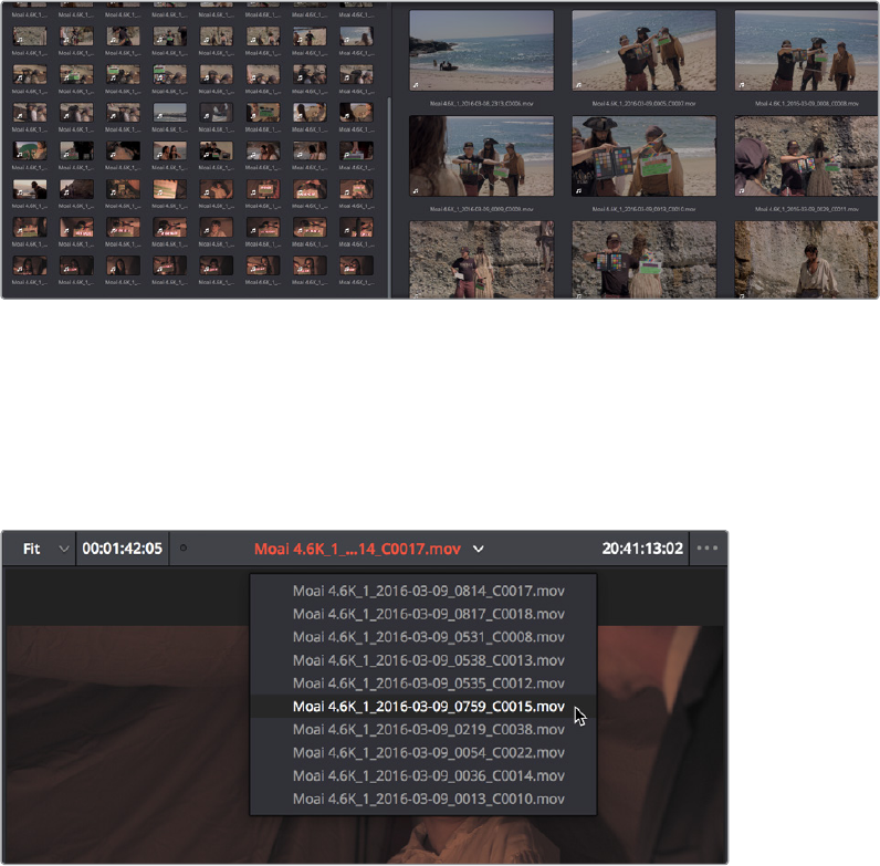
Recent Clips Pop-Up Menu
A new pop‑up at the top of the Source Viewer, next to the name of the currently open clip, lets
you open a menu containing a list of the last 10 clips you opened in the Source Viewer. This list
is first in, first out, with the most recently opened clips appearing at the top.
A recent clips menu lets you recall the last 10 clips you opened in the Source Viewer
1-19Chapter – 2 Edit Page Improvements
Ability to Create Subclips via
Dragand Drop from Source Viewer
There’s a new way of creating subclips. Simply open a clip into the Source Viewer, set In and
Out points, and then drag a clip from the Source Viewer to the Media Pool. The new clip that’s
added to the Media Pool will be a subclip with a total duration that’s bounded by the duration
you marked.
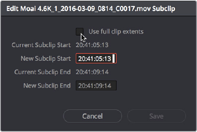
Ability to Remove Subclip Limits
You can right‑click any subclip in the Media Pool and choose Edit Subclip to open a dialog in
which you can turn on a checkbox to use the subclip’s full extents, or to change the start or end
timecode of the subclip via timecode fields, before clicking Save to modify the subclip.
The Edit Subclip dialog
Import Hierarchically Organized Nests of Empty Directories
You can import a nested series of directories and subdirectories that constitutes a default bin
structure you’d like to bring into projects, even if those directories are empty, by dragging them
from your file system into the Media Pool bin list of a project. The result is a hierarchically
nested series of bins that mimics the structure of the directories you imported. This is useful if
you want to use such a series of directories as a preset bin structure for new project.
Import Clips with Metadata via Final Cut Pro 7 XML
In order to support workflows with media asset management (MAM) systems, DaVinci Resolve
supports two additional Media Pool import workflows that use Final Cut Pro 7 XML to import
clips with metadata.
To import clips with metadata using Final Cut Pro 7 XML files, do one of the following:
Right‑click anywhere in the background of the Media Pool, choose Import Media
from XML, and then choose the XML file you want to use to guide import from the
importdialog.
Drag and drop any Final Cut Pro 7 XML file into the Media Pool from the macOS Finder.
Every single clip referenced by that XML file that can be found via its file path will be imported
into the Media Pool, along with any metadata entered for those clips. If the file path is invalid,
you’ll be asked to navigate to the directory with the corresponding media.
1-20Chapter – 2 Edit Page Improvements
Enhancements to Markers and Flags
The use of markers and flags to identify moments in clips and things to keep track of has been
significantly enhanced in DaVinci Resolve 15.
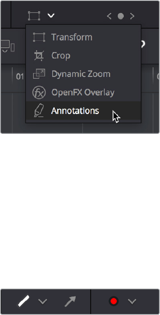
Drawn Annotations on the Viewer
It’s now possible to use the Annotations mode of the Timeline Viewer to draw arrows and
strokes of different weights and colors directly on the video frame, in order to point out or
highlight things that need to be fixed. These annotations are stored within markers, similarly to
marker names and notes. To start, simply choose Annotations mode from the Timeline Viewer
mode pop‑up menu to do this.
Choosing Annotations from the Viewer Mode pop‑up menu
Once in Annotations mode, an Annotations toolbar appears showing the following options:
Draw tool with line weight pop-up: Click the Draw tool to be able to free‑form draw on
the Viewer. Click the Line Weight pop‑up to choose from one of three line weights to
draw with.
Arrow tool: Click the Arrow tool to draw straight‑line arrows pointing at features you
want to call attention to. Arrows are always drawn at the same weight, regardless of the
weight selected for the Line tool.
Color pop-up: Choose a color for drawing or lines.
The annotations toolbar in the Viewer
Methods of making and editing annotations:
To create an annotation: Simply enable Annotations mode, then park the playhead on
any frame of the Timeline and start drawing. A marker will automatically be added to
the Timeline at that frame, and that marker contains the annotation data. If you park the
playhead over a preexisting Timeline marker, annotations will be added to that marker.
To edit a stroke or arrow you’ve already created: Move the pointer over a stroke or
arrow and click to select it, then choose a new line weight or color from the appropriate
pop‑up menu, or drag that stroke or arrow to a new location to move it.
To delete a stroke or arrow: Move the pointer over a stroke or arrow and click to select
it, then press the Delete or Backspace keys.
1-21Chapter – 2 Edit Page Improvements
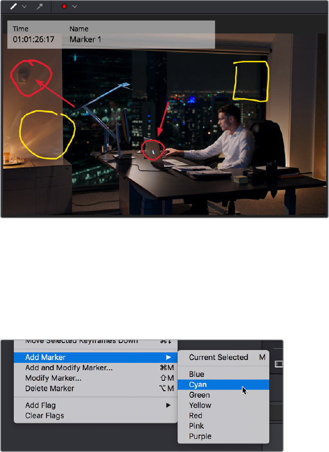
Drawing annotations to highlight feedback
Ability to Create Markers and Flags With Specific Colors
The Mark > Add Marker and Add Flag submenus have individual commands for adding markers
and flags of specific colors directly to clips and the Timeline. Additionally, these individual
commands can be assigned specific keyboard shortcuts if you want to be able to place a
specific marker color or flag color at a keystroke.
Individually mappable marker color commands
Timecode Entry in Marker Dialogs
The Time and Duration timecode fields of marker dialogs can now be manually edited, to
numerically move a marker, or to create a marker with a specific duration. Furthermore, the
timecode in these fields can be copied from or pasted to.
Clip Markers Show Overlays in the Timeline Viewer
Clip markers and Timeline markers both appear as Timeline Viewer overlays when
ShowMarker Overlays is enabled in the Timeline Viewer option menu. Pressing Shift‑Up
orDown Arrow moves the playhead back and forth among both Timeline and Clip markers in
the currently open Timeline.
1-22Chapter – 2 Edit Page Improvements
Command to Turn Markers With
Duration into In and Out Points
Two commands, in the contextual menu of the Source Viewer Jog Bar, work together to let you
turn In and Out points into Markers with Duration, and vice versa:
Convert In and Out to Duration Marker: Turns a pair of In and Out points into a marker
with duration. By default, no key shortcut is mapped to this command, but you can map
one if you like.
Convert Duration Marker to In and Out: Turns a marker with duration into a pair of In
and Out points, while retaining the marker. By default, no key shortcut is mapped to this
command, but you can map one if you like.
Using these two commands, you can easily use markers with duration to mark regions of
clipsthat you want to log for future use, turning each region into an In and Out point when
necessary for editing.
Editing Enhancements
Quite a few enhancements improve the editing experience in the Edit page.
Tabbed and Stacked Timelines
The Timeline now supports the option to have tabs that let you browse multiple timelines
quickly. With tabbed timeline browsing enabled, a second option lets you open up stacked
timelines to simultaneously display two (or more) timelines one on top of another.
Tabbed Timelines
The Timeline View Options menu in the toolbar has a button that lets you enable tabbed
browsing and the stacking of timelines.
A button in the Timeline View Options
enables tabbed timelines
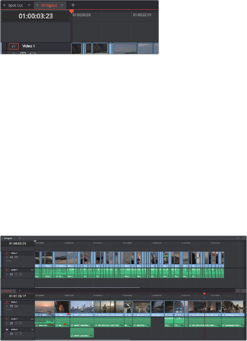
When you first turn this on, a Timeline tab bar appears above the Timeline, displaying a tab for
the currently open timeline that contains a Close button and a Timeline pop‑up menu. Once you
enable Tab mode, opening another timeline from the Media Pool opens it into a new tab.
1-23Chapter – 2 Edit Page Improvements
To the right of the currently existing tabs, an Add Tab button lets you create additional tabs that
default to “Select Timeline.” Click any tab’s pop‑up menu to choose which timeline to display in
that tab.
Tabs above the timeline editor let you switch among multiple timelines quickly
Methods of working with tabbed timelines:
Click any tab to switch to that timeline.
Use the pop‑up menu within any tab to switch that tab to display another timeline from
the Media Pool. Each tab’s pop‑up menu shows all timelines within that project, in
alphabetical order, but a timeline can only be open in one tab or stack at a time.
Drag any tab left or right to rearrange the order of timeline tabs.
Click any tab’s Close button to close that timeline and remove that tab.
Stacked Timelines
While tabbed browsing is turned on, an Add Timeline button appears to the right that enables
you to stack two (or more) timelines one on top of another. This lets you have two (or more)
timelines open at the same time, making it easy to edit clips from one timeline to another.
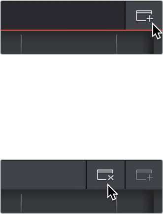
A good example of when this is useful is when you’ve created a timeline that contains a
stringout of selects from a particular interview. You can stack two Timeline Editors, one on top
of another, and then open the Selects Timeline at the top and the Timeline you’re editing into at
the bottom. With this arrangement, it’s easy to play through the top timeline to find clips you
want to use, to drag and drop into the bottom timeline to edit into your program.
Two timelines stacked on top of one another
1-24Chapter – 2 Edit Page Improvements
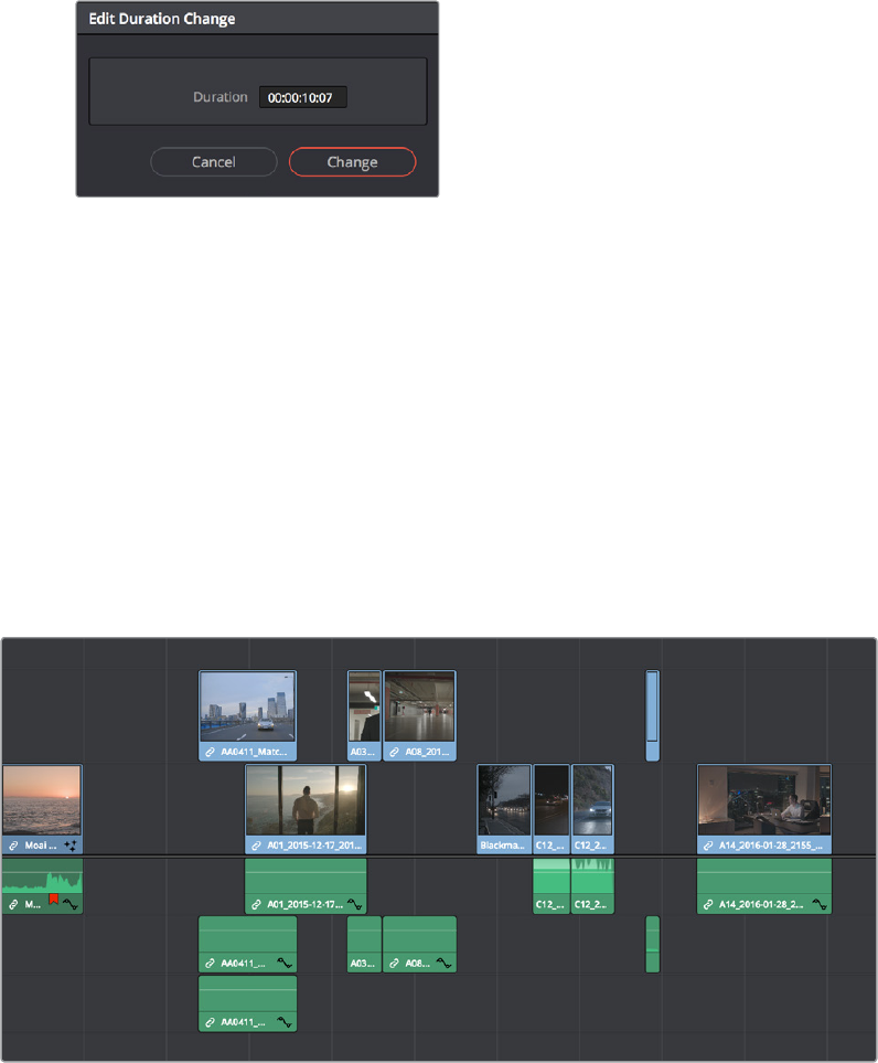
To enable or disable stacked timelines:
Click the Add Timeline button at the right of the Timeline tab bar.
The button for adding a stacked timeline
Once you’ve enabled stacked timelines, each timeline has its own tab bar and an
orange underline shows which timeline is currently selected.
At the right of each Timeline tab bar, a Close Timeline button appears next to the
AddTimeline button, which lets you close any timeline and remove that timeline
browsing area from the stack.
The button for closing a stacked timeline
Improved Dynamic Trim Behaviors
The Dynamic Trim mode that lets you use JKL playback behaviors to do resize or ripple
trimming to one or more selected edits has been improved in a number of key ways.
Pressing W to Enable Dynamic Trimming Automatically Selects the Nearest Edit
If no edit is currently selected in the Timeline, then pressing W to enable Dynamic Trim
automatically selects the nearest edit, similarly to if you pressed V to initiate the Select Nearest
Edit Point command. If you’ve already selected an edit, or made a multiple‑edit‑point selection,
nothing changes and the edit points you’ve selected will be used for dynamic trimming.
By default, the entire edit is selected, positioning you to perform a dynamic Roll edit. However,
you can press the U key (Edit Point Type) to toggle the edit selection among three positions, in
order to trim the outgoing half or incoming half of the selected edit point.
Also by default, both the Video and Audio of the current edit are selected if Linked Selection is
enabled. Pressing Option‑U (Toggle V+A/V/A) lets you toggle the edit selection to include both
Video+Audio, Video only, or Audio only.
When you’re finished trimming, whatever edit point type and A/V toggle you used last is
remembered by DaVinci Resolve, and will be selected the next time you enable
DynamicTrimming.
You Can Use the Next and Previous Edit Commands While in Dynamic Trim Mode
Previously, you were unable to use the Up and Down Arrow keys to move the selected edit
from one edit point to another. This has been fixed so you can now move the selected edit
forward and back in your timeline, using Dynamic Trim to adjust as many edits as you like.
1-25Chapter – 2 Edit Page Improvements
Ability to Modify Clip Duration Via Timecode
You can change a clip’s duration numerically in one of two ways.
To change a selected clip’s duration:
1 Decide if you want to ripple the Timeline or overwrite neighboring clips when you
change a clip’s duration. If you want to ripple the Timeline, choose the Trim tool. If you
want to overwrite neighboring clips or leave a gap, choose the Selection tool.
2 Do one of the following:
Select a clip and choose Clip > Change Clip Duration
Right‑click any clip in the Timeline and choose Change Clip Duration from the
contextual menu
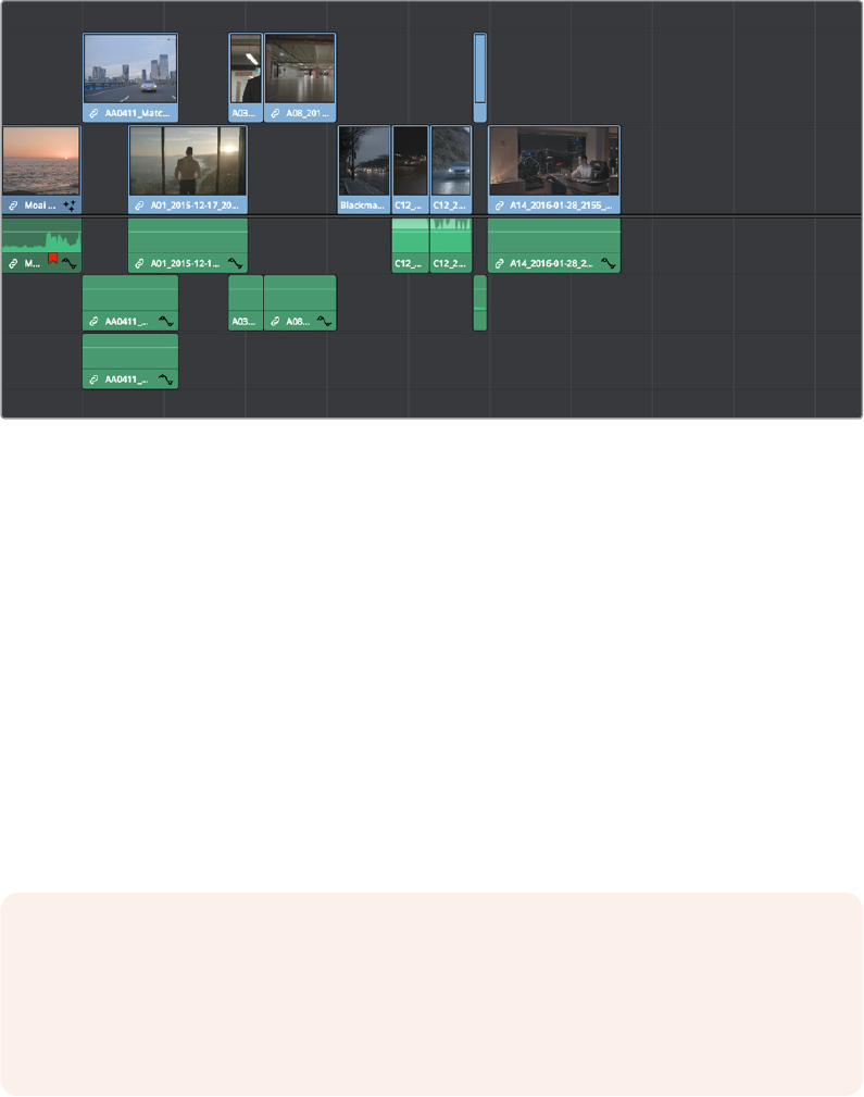
3 When the Edit Duration Change dialog appears, enter a new duration in the Timecode
field, and click Change.
A window for changing the duration
of a clip in the Timeline
Ability to Delete Multiple Timeline Gaps at Once
You can now ripple‑delete video and audio gaps in the Timeline all at once using the
Edit>Delete Gaps command. This removes gaps among consecutive clips in the Timeline on
allAuto Select enabled tracks. Each segment of the Timeline with a gap is rippled, in order to
move clips that are to the right of each gap left to close that gap.
All gaps are defined for purposes of this command as empty spaces between clips that span
alltracks in the Timeline. In the following example, various audio/video, audio‑only, and
video‑only clips have gaps between them. Using Remove Gaps causes the Timeline to be
rippled such thatthese clips abut one another as a continuous sequence, without any of them
overlappinganyothers.
Before removing gaps
1-26Chapter – 2 Edit Page Improvements
After removing gaps
This is an extremely powerful and wide‑ranging command. However, it’s made safer
byfollowing strict rules in order to maintain overall A/V sync in timelines:
Gaps will not be removed past the point where video and/or audio clips will
overlapone another
Gaps will not be removed if they’re under superimposed video clips that bridge the gap
Gaps will not be removed if one or more continuous audio clips bridge the gap
If a linked set of Video and Audio items has a gap that includes an L or J split edit, it will
be closed to the point that the audio or video, whichever extends the farthest, abuts
the nearest clip to it
Disabling a track’s Auto Select Control omits that track from consideration when
following the above rules. This lets gaps on other tracks be closed so clips overlap
those on the Auto Select‑disabled track
Improved Separation Between the Video and Audio Tracks
The separator between the video and audio tracks in the Timeline has been made thicker and
easier to drag.
Improved Ripple Cut and Ripple Delete Behavior
Performing a Ripple Cut or Ripple Delete upon multiple tracks using In and Out points ripples all
Auto Select enabled tracks.
WARNING: Performing Remove Gaps with Auto Select disabled on one or more tracks
could result in massive loss of video/audio sync if you’re not careful. To avoid this,
Shift‑click one video Auto Select Control (or press Option‑F9) and one audio Auto
Select control (or press Command‑Option‑F9) to toggle all video and all audio
AutoSelect Controls until they’re all turned on at once.
1-27Chapter – 2 Edit Page Improvements
Improved Automatic Audio Track Creation
When dragging an audio clip to the undefined gray area of the Timeline below currently
existing audio tracks in order to create a new track, the new track is set to a channel mapping
that reflects the number of channels of the audio clip you’re dragging.
This also means that if you’ve used Clip Attributes to map a clip’s audio to consist of multiple
tracks where each track has a different channel mapping, for example, one 5.1 track, one stereo
track, and six mono tracks, then editing that clip into the Timeline so that the audio portion
creates new tracks will automatically create eight tracks, one that’s 5.1, one that’s stereo, and six
that are mono.
New Play Again Command
The Play Again command (Option‑L) lets you restart playback from where the playhead began
without stopping, for instances where you quickly want to replay the beginning of what you’re
listening to.
Option to “Stop and Go To Last Position”
A new option, Playback > Stop and go to last position, lets you choose whether or not to have
the playhead return to where playback began whenever you stop. This option is most useful
when editing audio, although it’s available any time.
This option is also available when you right‑click on the Stop button in the transport controls of
any viewer. A contextual menu appears where you can turn “Stop and go to last position” on or
off as the default behavior.
Single Viewer Mode is Available in Dual Screen Layout
The Single Viewer mode is now available when using the dual screen Edit page layout.
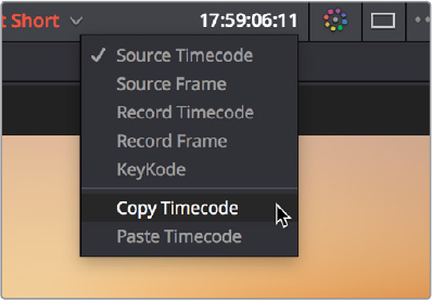
Copy and Paste Timecode in Viewer Timecode Fields
You can right‑click on most Viewer timecode fields in the Media, Edit, and Color pages to
choose Copy and Paste commands from a contextual menu for copying and pasting timecode
values. The timecode value you’re pasting must be valid timecode, for example you can’t paste
0 hour timecode onto a 1 hour timeline.
Right‑clicking on a timecode field to use the
Copy Timecode command
1-28Chapter – 2 Edit Page Improvements
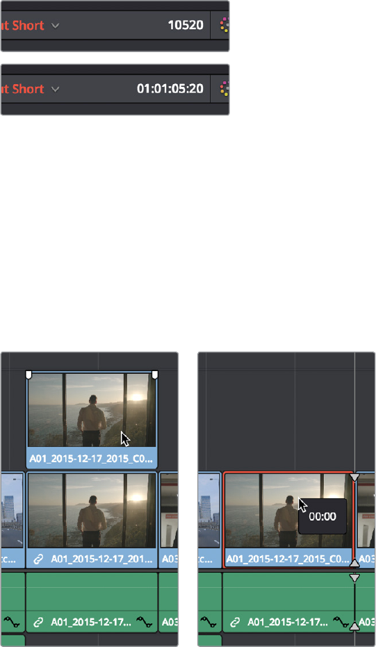
Improved Timecode Entry
When typing a combination of numbers and periods to enter a timecode value in the Edit page,
whether to move the playhead or trim selected clips, the numbers you type are not converted
into actual timecode until you press the Return or Enter key, making it easier to see what
you’reentering.
(Top) Entering timecode, (Bottom) The result
Replace Edit Using Clips Already in the Timeline
To facilitate workflows where multiple clips are stacked in the Timeline to manually track
different takes or versions of stock footage, VFX clips, or other versionable media, there’s a
method of drag‑and‑drop replace editing that copies the grade of the clip being replaced to the
clip you’re replacing it with at the same time, so that newer versions of effects can inherit the
same grade as the previous version of the effect being replaced. This only works for clips that
have already been edited into the Timeline and that are superimposed (over or under) other
clips in the Timeline, such as in the following screenshot. Be aware that this technique can also
be used for multiple selected clips on the Timeline, to do several replace edits all at once.
(Left) Before replace editing a clip in the Timeline, (Right) After
Command‑dragging a clip over one under it in the Timeline to
replace edit the one below with the one above
1-29Chapter – 2 Edit Page Improvements
To replace edit one clip that’s stacked on the Timeline into another:
1 Select one or more clips that are already on the Timeline. Typically these will be clips
that are superimposed over other clips.
2 Hold the command key down while dragging one superimposed clip on top of another
to overwrite a clip and copy its grade to the clip you’re overwriting it with.
Option to Ripple the Timeline in Paste Attributes
When using Paste Attributes to copy speed effects from one clip to another, a checkbox lets
you choose whether or not the pasted speed effect will ripple the Timeline.
Transition Categories in the Effects Library
Transitions have been organized into logical categories to make it easier to find what you need.
Categories include Dissolve, Iris, Motion, Shape, and Wipes.
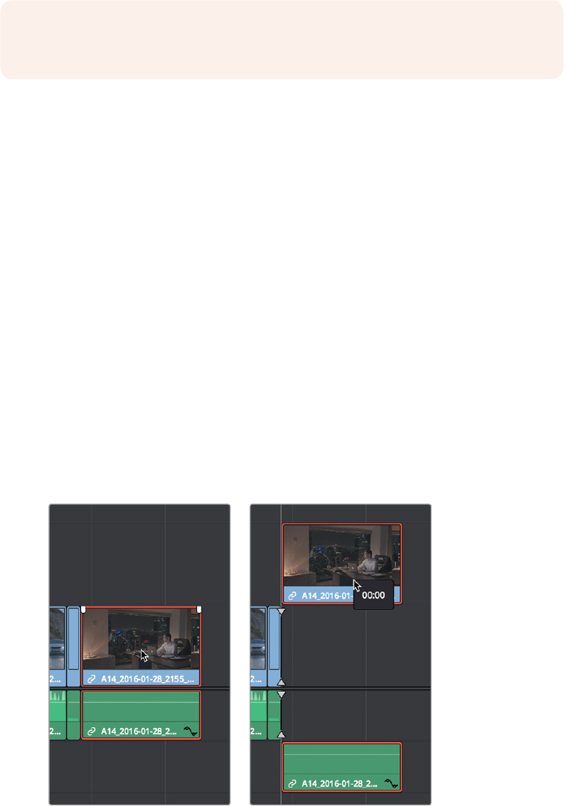
Linked Move Across Tracks
The Timeline > Linked Move Across Tracks setting lets you change how linked video and audio
items move in the Timeline when you drag them up and down to reorganize clips from track to
track. Depending on the task at hand, one or the other behaviors might be more convenient,
but no matter how you have this mode set, video/audio sync is always maintained when you
move clips left and right.
When Linked Move Across Tracks is enabled: (On by default) Dragging one of a linked
pair of video and audio items up or down in the Timeline moves the linked item up or
down as well. So, moving a video clip from track V1 to V2 results in its linked audio clip
moving from track A1 to A2 as well.
(Left) Before dragging video up one track, (Right) After
NOTE: This won’t work with clips you’re editing into the Timeline from the Media Pool or
Source Viewer.
1-30Chapter – 2 Edit Page Improvements
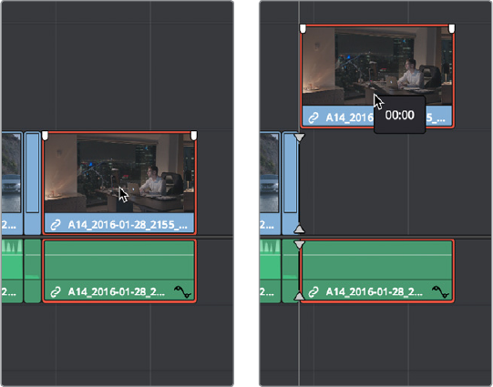
When Linked Move Across Tracks is disabled: Dragging one of a linked pair of video
and audio items up or down to another track in the Timeline only moves that one
item, other linked item(s) remain in the same track. So, moving a video clip from track
V1to V2 leaves the audio clip in track A1, where it was originally. This makes it easy to
reorganize video clips into different tracks while leaving your audio clips organized the
way they were, or vice versa. Keep in mind that in this mode, while you can move one
item of a linked pair up and down freely, moving that item left or right results in all linked
items moving by the same amount, so sync is maintained.
(Left) Before dragging video up one track, (Right) After
Track Destination Keyboard Shortcuts Also Disable Tracks
Pressing any of the Track Destination Selection keyboard shortcuts (Option‑1–8 for video,
Option‑Control‑1–8 for audio) repeatedly toggles the destination control on that track on and off.
Ability to Mark In and Out Points in Cinema Mode
When you’re in the full‑screen playback of Cinema Mode on the Edit page, you can use the Iand
O keys to mark In and Out points on the Timeline. If you move the pointer, you can see marked
timeline In and Out points on the Jog Bar of the onscreen controls, before they fade away again.
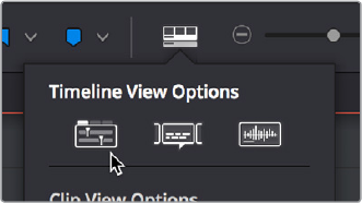
Updated Timeline View Options Menu in the Toolbar
The Timeline View Options menu has been updated with new options at the top to enable
tabbed and stacked Timelines and to show and hide the Subtitle and Captions tracks area of
the Timeline, while the third option is the previously available button to show or hide audio
waveforms. The other previously available options are located below.
1-31Chapter – 2 Edit Page Improvements
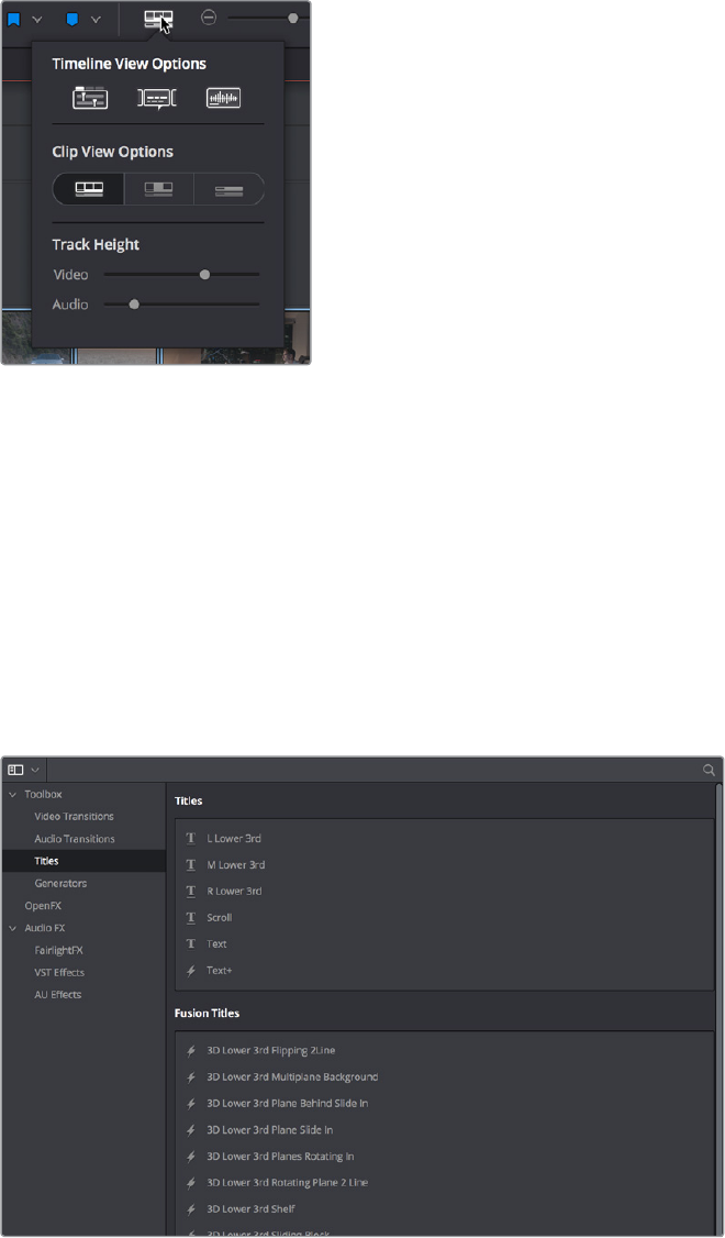
The new Timeline View Options menu
Edit Page Effects Enhancements
A variety of Edit page effects features have been added and improved in DaVinci Resolve 15.
The Text+ Title Generator in the Edit Page
A new kind of title generator, named TextPlus, is available in the Titles category of the Effects
Library’s Toolbox. This is the exceptionally fully‑featured 2D text generator from Fusion,
available for editing and customizing right in the Edit page.
The new Text+ title generator, along with new Fusion titles below
You can use the TextPlus generator the same way you use any generator in the Edit page.
Simply edit it into a video track of the Timeline, select it, and open the Inspector to edit and
keyframe its numerous properties to create whatever kind of title you need.
1-32Chapter – 2 Edit Page Improvements
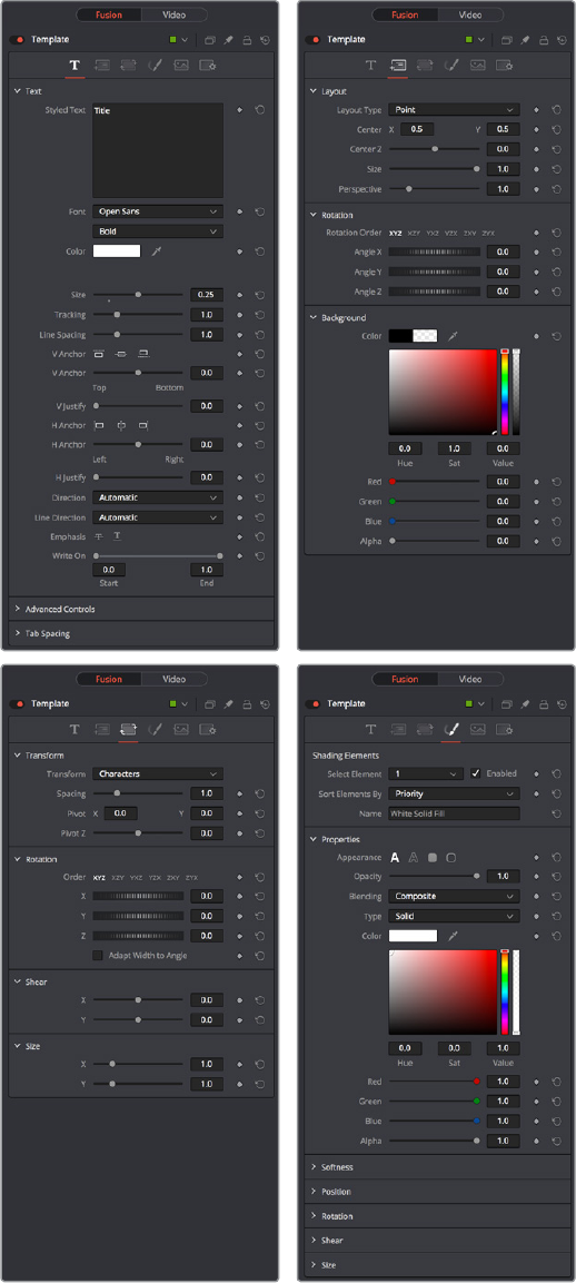
In addition to having many more styling origins, the origin of the TextPlus generator in a
compositing tool means that it offers many more panels worth of keyframable parameters, along
with advanced animation controls built‑in. These include keyframable Write On/Write Off controls,
layout and animation using shapes (options include point, frame, circle, and path), character, word,
and line transforms and animation, advanced shading, and full interlacingsupport.
Four panels of the Text+ title generator, including Text, Layout, Transform, and Shading
1-33Chapter – 2 Edit Page Improvements
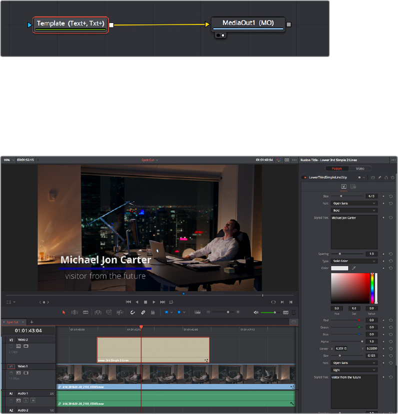
Better yet, with the playhead parked on your new TextPlus “Fusion Title,” you can open the
Fusion page and access its parameters there too, if you want to start building upon this single
generator to create a multi‑layered motion graphics extravaganza.
Opening the Text+ node in the Fusion page reveals it as an actual Fusion page operation
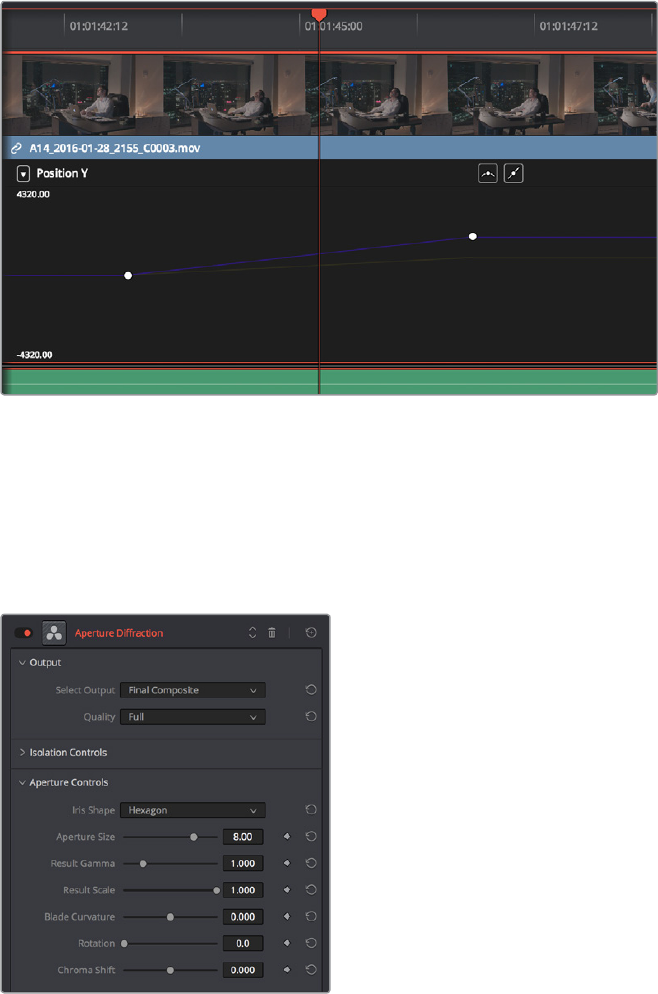
Fusion Titles and Fusion Templates
The abundance of other Fusion Titles in the Effects Library are custom‑built text compositions
with built‑in animation that expose custom controls in the Inspector.
A Fusion Title creating an animated lower third, with controls open in the Inspector
In actuality, these text generators are Fusion templates, which are Fusion compositions that
have been turned into macros and come installed with DaVinci Resolve to be used from within
the Edit page like any other generator.
It’s possible to make all kinds of Fusion title compositions in the Fusion page, and save them for
use in the Edit page by creating a macro and placing it within the /Library/Application Support/
Blackmagic Design/DaVinci Resolve/Fusion/Templates/Edit/Titles directory, but this is a topic
for another day.
There’s one other benefit to TextPlus generators, and that is they can be graded like any other
clip, without needing to create a compound clip first.
1-34Chapter – 2 Edit Page Improvements
Support for Caching of Titles and Generators
You can now enable Clip caching for titles and generators, in case you’re using processor
intensive effects.
Position Curves in the Timeline Curve Editor
You can now expose Position X and Position Y curves in the Edit page clip Curve Editor. This
makes it possible to edit X and Y position keyframes independently, as well as to adjust the arc
of geometric curves of the motion path in the Timeline Viewer by selecting one or more control
points and making them into Bezier control points.
Position X and Y curves in the Edit page Curve Editor
Keyframable OpenFX and ResolveFX
The parameters of OpenFX and ResolveFX have keyframe controls to the right of each
parameter’s numeric field in the Inspector of the Edit and Color pages, so you can animate
effects that you add to clips and grades.
ResolveFX can now be animated in the Edit page
using keyframe controls in the Inspector
1-35Chapter – 2 Edit Page Improvements

Compound Clips Support Alpha Transparency
Creating compound clips preserves transparency of clips with alpha channels. For example,
ifyou edit a series of title generators into the Timeline and turn them into a compound clip, the
resulting compound clip will have the same transparency as the original generators.
Improved Smooth Cut
The Smooth Cut transition lets you seamlessly remove certain kinds of small jump cuts in
interview clips. This transition has been updated with a Mode pop‑up menu giving two options:
Faster and Better. The Faster option is the original Smooth Cut method, which morphs between
stills of the outgoing and incoming frames.
The Better option is the new default, with improved quality and the capability of preserving the
motion of subjects over the life of the transition. In most practical circumstances, the Better
mode will give you a superior result, but certain cuts or effects may be better addressed with
the Faster option.
Improved Optical Flow for Speed Effects
There are additional “Enhanced” Optical Flow settings available in the “Motion estimation
mode” pop‑up in the Master Settings panel of the Project Settings. These new settings provide
better quality for slow motion and frame rate retiming effects, at the expense of being more
processor intensive to play and render.
The “Standard Faster” and “Standard Better” settings are the same options that have been
available in previous versions of DaVinci Resolve. They’re more processor‑efficient, and yield
good quality that are suitable for most situations. However, “Enhanced Faster” and
“EnhancedBetter” should yield superior results in nearly every case where the standard
options exhibit artifacts, at the expense of being more computationally intensive, and thus
slower on most systems.
NOTE: There are no keyframe tracks in the Keyframe Editors of the Edit page or
Colorpage at this time, so keyframes added to OpenFX or ResolveFX can only
beedited in the Inspector.
1-36Chapter – 2 Edit Page Improvements
Chapter 3
Subtitles and
Closed Captioning
DaVinci Resolve 15 adds new features to support subtitles and closed
captioning in sophisticated ways. With dedicated subtitle/closed caption
tracks that can be shown or hidden, subtitle file import and export,
sophisticated subtitle editing and styling at the track and clip level, and
comprehensive export options, adding subtitles and closed captions to
finish your project is a clear and straightforward workflow.
1-37Chapter – 3 Subtitles and Closed Captioning
Contents
Subtitles and Closed Captioning Support 1-39
Viewing Subtitle/Caption Tracks 1-39
Importing Subtitles and Captions 1-40
Adding Subtitles and Captions Manually 1-42
Editing Subtitles and Captions 1-44
Styling Subtitles and Captions 1-44
Linking Subtitles to Clips 1-45
Exporting Subtitles and Closed Captions 1-46
Naming Subtitle Tracks 1-47
1-38Chapter – 3 Subtitles and Closed Captioning
Subtitles and Closed Captioning Support
Subtitles are supported in DaVinci Resolve using specially typed subtitle tracks containing
specifically designed subtitle generators to add and edit subtitles for a program. Typically each
subtitle track corresponds to a single language or use, and you can change the name of a
subtitle track to reflect its contents.
Subtitle tracks can be locked, have auto select controls, and can be enabled or disabled like
any other track. Additionally, a special subtitle‑only destination control lets you choose which
subtitle track to edit subtitle clips into. Furthermore, subtitle generator clips can be resized,
moved, edited, and overwritten like most other clips.
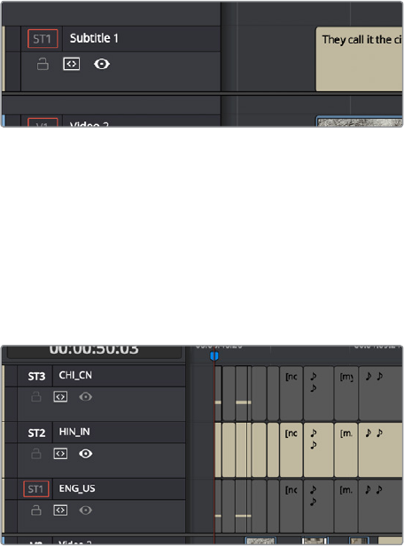
A subtitle track in the timeline
Viewing Subtitle/Caption Tracks
One important difference between subtitle tracks and other kinds of tracks is that only one
subtitle track can be visible at any given time. That means if you have multiple subtitle tracks,
each for a different language, clicking the Enable control for one subtitle track disables
allothers.
Viewing one subtitle track at a time
1-39Chapter – 3 Subtitles and Closed Captioning
Importing Subtitles and Captions
Oftentimes, adding subtitles or closed captions to a DaVinci Resolve timeline will involve
importing a subtitle file that’s been prepared elsewhere. Currently, DaVinci Resolve supports
subtitle files in the .srt SubRip format.
To import an .SRT-formatted subtitle or closed captioning file:
1 Open the Media Pool.
2 Right‑click on any bin in the Bin list, or anywhere in the background of the
MediaPoolbrowser, and choose Import Subtitle.
3 In the resulting file dialog, find and select the subtitle file you want to import,
andclickOpen.
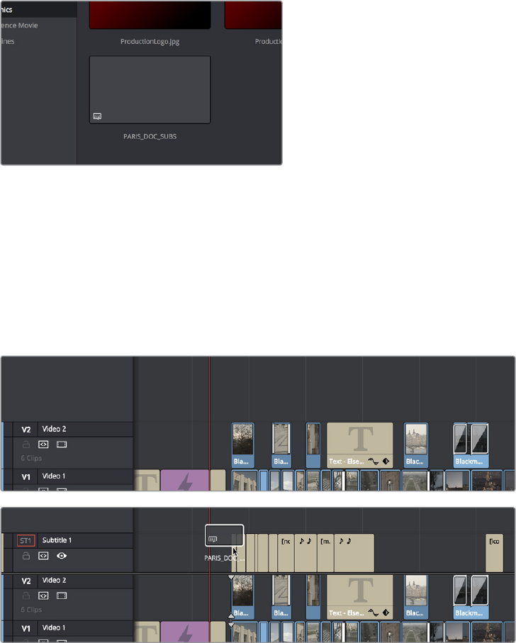
4 The subtitle file appears as a subtitle clip in the Media Pool, ready for editing into
asubtitle track. An “ST” badge indicates that it’s a subtitle clip.
An imported .srt subtitle file
5 To add a subtitle clip to a timeline, do one of the following:
Drag a subtitle file you’ve imported into the unused gray area at the top of your video
tracks, and a subtitle track will automatically be created for adding those subtitles into
Drag a subtitle file you’ve imported into a pre‑existing subtitle track
As you drag the subtitle clip, it’ll immediately be decomposed so that each title is
added to the Timeline as an individual subtitle clip, with its timing offset relative to the
position of the first frame of the first subtitle in that file.
(Top) The original timeline, (Bottom) The timeline after
dragging a subtitle file has created a new subtitle track
1-40Chapter – 3 Subtitles and Closed Captioning
6 Position the imported subtitles so that they align with the first frame of your program
that they’re supposed to, and drop the titles into the track. If you inadvertently misplace
the subtitles, don’t worry, you can always select them all and slide them earlier or later,
just like any other clips.
7 If you’ve added a new subtitle track, you can rename it to identify what language and
country that track corresponds to. Please note that subtitle track names are used
when exporting or encoding subtitles, so please make sure your tracks are named
appropriately prior to export/delivery.
8 If you want to restyle all of the subtitles you’ve just added, for example to make them
smaller or change the font, then click on the header of the subtitle track you’ll be
working on, open the Track Style panel of the Inspector, and select the formatting you
want that track to use.
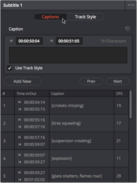
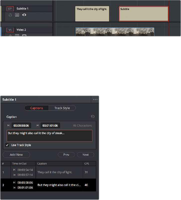
To see a list of every subtitle clip you’ve added, you can select the header of the subtitle track
you’ve just added and open the Captions panel in the Inspector. A list at the bottom of the
Captions panel gives you a convenient way of navigating the subtitles in a given track (using the
Prev and Next buttons) and making selections. If you set the Inspector to be full height, you’ll
have even more room for browsing the subtitle list.
The Captions list shows you every caption or subtitle on a
track, for selecting, editing, deleting, or navigating
1-41Chapter – 3 Subtitles and Closed Captioning
Adding Subtitles and Captions Manually
Other times, you may need to create subtitles on your own. Before doing so, you’ll need to add
one or more subtitle tracks. Once those tracks are created, you can add subtitle generators to
them in a variety of ways. You can add as many subtitle tracks as you need, one for each
language you require.
To add new subtitle tracks:
Right‑click in any track header of the currently open timeline, and choose Add Subtitle
Track. An empty subtitle track will appear at the top of the Timeline, named “Subtitle 1.”
Once you’ve added a new subtitle track, you can rename it to identify what language
and country that track corresponds to. Please note that subtitle track names are used
when exporting or encoding subtitles, so please make sure your tracks are named
appropriately prior to export/delivery.
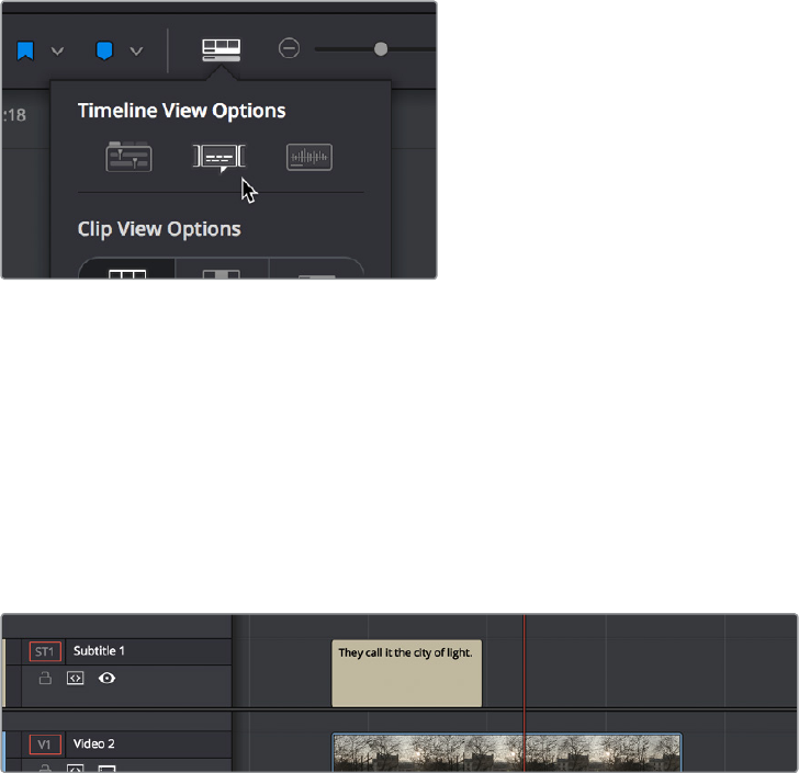
Showing and hiding subtitles tracks:
Open the Timeline View options, and click on the Subtitle button to toggle the visibility
of subtitles tracks on and off.
The show/hide subtitle tracks button in the Timeline View Options
To add individual subtitles to a subtitle track:
1 If you want to adjust the default style of a particular subtitle track before you start
adding subtitles, then click on the header of the subtitle track you’ll be working on,
open the Track Style panel of the Inspector, and select the formatting you want that
track to use.
2 If you have multiple subtitle tracks, click the destination control of the subtitle track you
want to add titles to. They’re labeled ST1, ST2, ST3, etc.
3 Move the playhead to the frame where you want the new subtitle to begin.
Positioning the playhead where you want a new subtitle to begin
1-42Chapter – 3 Subtitles and Closed Captioning
4 To add a new subtitle clip, do one of the following:
Open the Inspector and click Create Caption in the Captions panel of the Inspector. If
there’s already one or more captions in that subtitle track, click the Add New button
above the caption list, instead.
Right‑click anywhere on the subtitle track and choose Add Subtitle to add a subtitle clip
starting at the position of the playhead
Open the Effects Library, click the Titles category, and drag a Subtitle generator to the
Subtitle track you want it to appear on.
Manually adding a subtitle
5 If necessary, you can now edit the clip to better fit the dialog that’s being spoken or the
sound that’s being described, by dragging the clip to the left or right, or dragging the
beginning or end of the clip to resize it.
6 While the new subtitle clip you’ve created is selected, use the Captions panel in the
Inspector to type the text for that particular subtitle. The text appears on the subtitle
clip as you type it.
Editing the text of the subtitle we just created
Every time you add a subtitle, an entry is added to the subtitle list at the bottom of the Captions
panel in the Inspector. This list gives you another convenient way of navigating the subtitles in a
given track (using the Prev and Next buttons) and making selections.
1-43Chapter – 3 Subtitles and Closed Captioning
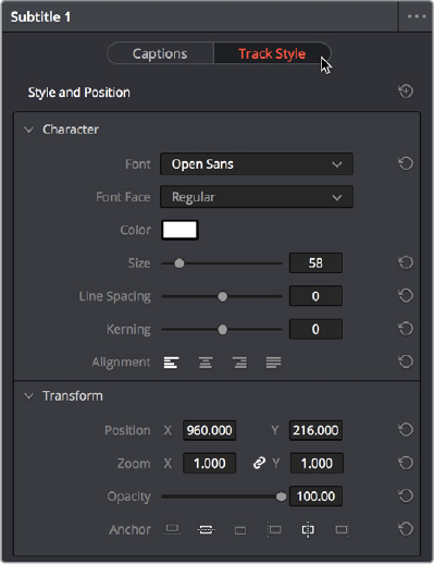
Editing Subtitles and Captions
Subtitle clips can be selected singly or together, and slipped, slid, resized, rolled, and rippled
just like any other clip in the Timeline, using the mouse or using keyboard commands, with
either the Selection, Trim, or Razor tools. You can select subtitle clips in their entirety, or just
their edit points, in preparation for nudging or dynamic trimming. In short, subtitle clips can be
edited, in most ways, just like any other clips.
Styling Subtitles and Captions
When it comes to styling subtitle text, there are a wealth of styling controls in the Track Style
panel of the Inspector.
To modify the styling of all titles on a particular subtitle track:
1 Click on the header of the subtitle track you’ll be working on, or select a clip on a
particular subtitle track either in the subtitle track or in the subtitle list of the Captions
panel in the Inspector.
2 Open the Inspector, and then open the Track Style panel that appears within.
3 Edit whatever parameters you need to set the default style of all subtitles and closed
captions that appear on that track. The Track Style panel has many more options than
the Captions panel, including a group of Style and Position controls over Font and Font
Face, Color, Size, Line Spacing, and Kerning, Alignment, Position X and Y, Zoom X and
Y, Opacity, and Text Anchoring.
The Track Style panel of the Inspector sets styling for
every subtitle on that track
Keep in mind that there are additional groups of controls that let you add a Drop
Shadow, Stroke, and/or Background to all text on that track, which can be found at the
bottom of the Track Style panel of the Inspector.
1-44Chapter – 3 Subtitles and Closed Captioning
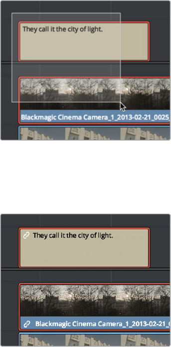
Linking Subtitles to Clips
If you like, you can link one or more subtitles to their accompanying clip, so that if you re‑edit a
subtitled scene, each clip’s subtitles move along with the clips. This arrangement doesn’t always
work the way you’d expect when trimming, but it works great when you’re rearranging clips.
To link a subtitle to another clip:
1 Select a clip and its subtitles all at once.
Selecting a video clip and its
accompanying subtitle to link them
2 Choose Clip > Linked Clips (Option‑Command‑L). A Link icon appears to show that the
subtitle clips are linked to the video/audio clip.
The now linked clip and subtitle have link
badges to show their state
1-45Chapter – 3 Subtitles and Closed Captioning
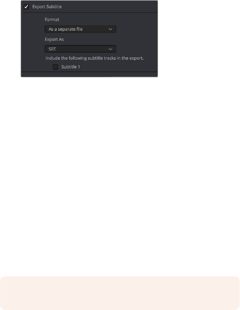
Exporting Subtitles and Closed Captions
Once you’ve set up one or more subtitle tracks in a program, the Deliver page exposes a group
of Subtitle Settings at the bottom of the Video panel of the Render Settings that control if and
how subtitles or closed captions are output along with that timeline.
Available options for exporting subtitles can be found
at the bottom of the Video panel of the Render Settings
This panel has the following controls:
Export Subtitle checkbox: Lets you enable or disable subtitle/closed caption output.
Format pop-up: Provides four options for outputting subtitles/closed captions.
–As a separate file: Outputs each subtitle track you select as a separate file using
the format specified by the Export As pop‑up. A set of checkboxes lets you choose
which subtitle tracks you want to output.
–Burn into video: Renders all video with the currently selected subtitle track burned
into the video.
–As embedded captions: Outputs the currently selected subtitle track as an
embedded metadata layer within supported media formats. There is currently
support for CEA‑608 closed captions within MXF OP1A and QuickTime files. You can
choose the subtitle format from the Codec pop‑up that appears.
Export As: (only available when Format is set to “As a separate file”) Lets you choose
the subtitle/closed captioning format to output to. Options include SRT and WebVTT.
Include the following subtitle tracks in the export: (only available when Format is set
to “As a separate file”) A series of checkboxes lets you turn on which subtitle tracks to
output.
Codec: (only available when Format is set to “As embedded captions”) Lets you choose
how to format embedded closed captions; choices include Text and CEA‑608.
NOTE: Neither analog (Line 21) nor digital (CEA‑708) closed caption output via
Decklinkor UltraStudio is supported at this time.
1-46Chapter – 3 Subtitles and Closed Captioning

Naming Subtitle Tracks
If necessary, you can double‑click the name of any subtitle track to rename it to something
more descriptive of what that subtitle track will contain, such as the language, and whether a
particular track is for subtitles or closed captions.
Depending on your workflow and delivery specifications, there are existing conventions for
identifying languages, such as ISO‑639‑1 (governing 2‑letter codes) or ISO‑639‑2/B (governing
3‑letter codes). These codes can be found at the International Organization for Standardization
website, at http://www.loc.gov/standards/iso639‑2/php/code_list.php.
Some naming conventions require both language code and country code. For example,
Facebook requires SubRip (.srt) files with the naming format “VideoFilename.[language code]_
[country code].srt” for proper embedding.
If you want to use these codes for subtitle track identification and output, here’s a
representative list of standardized language and country codes from around the world, in
alphabetical order:
Country
ISO 639-1
Language Code
ISO 639-2
Language Code
ISO 3166-1
Country Code
Amharic am amh ET (Ethiopia)
Arabic ar ara
EG (Egypt)
AE (United Arab Emirates)
LB (Lebanon)
Bengali bn ben IN (India)
Chinese zh chi (B)
zho (T)
CN (China)
HK (Hong Kong)
TW (Taiwan)
Danish da dan DK (Denmark)
Dutch nl dut (B)
nld (T) NL (Netherlands)
English en eng
GB (UK)
IN (India)
US (US)
Finnish fi fin FI (Finland)
French fr fre (B)
fra (T)
CA (Canada)
FR (France)
German de ger (B)
deu (T) DE (Germany)
Greek Modern el gre (B)
ell (T) GR (Greece)
Hausa ha hau NG (Nigeria)
TD (Chad)
Hebrew he heb IL (Israel)
Hindi hi hin IN (India)
1-47Chapter – 3 Subtitles and Closed Captioning

Country
ISO 639-1
Language Code
ISO 639-2
Language Code
ISO 3166-1
Country Code
Indonesian id ind ID (Indonesia)
Italian it ita IT (Italy)
Japanese ja jpn JP (Japan)
Malay ms may (B)
msa (T) MY (Malaysia)
Maori mi mao (B)
mri (T) NZ (New Zealand)
Norwegian no nor NO (Norway)
Polish pl pol PL (Poland)
Portuguese pt por BR (Brazil)
PT (Portugal)
Punjabi pa pan IN (India)
Russian ru rus RU (Russia)
Spanish Castilian es spa
CO (Columbia)
ES (Spain)
MX (Mexico)
Swahili sw swa KE (Kenya)
Swedish sv swe SE (Sweden)
Tagalog tl tgl PH (Philippines)
Thai tl tgl TH (Thailand)
Turkish tr tur TR (Turkey)
Urdu ur urd PK (Pakistan)
Vietnamese vi vie VN (Vietnam)
1-48Chapter – 3 Subtitles and Closed Captioning
Chapter 4
Color Page
Improvements
DaVinci Resolve 15 is a great release for colorists. Timesaving new
workflow features such as multiple playheads, the LUT browser, Timeline
Grades browsers, and Shared Nodes make grade management faster than
it’s ever been. New Matte Finesse controls, improved noise reduction, and
camera raw controls for additional formats give you even more control and
quality in everyday operations. Numerous Node Editor enhancements
make it easier to see what’s happening in your grade. And finally,
additional HDR tools supporting Dolby Vision and HDR10+ keep you at the
cutting edge of grading and finishing.
1-49Chapter – 4 Color Page Improvements
Contents
Clip, LUT, and Grade Browsing Features 1-51
Media Pool in Color Page 1-51
Dedicated LUT Browser 1-51
New Split Screen Modes to Preview Selected LUTs, Albums 1-53
Live Previews of Gallery Stills and LUTs 1-53
Live Previews of Composite Modes in the Layer Mixer 1-54
Live Previews of LUTs in the Node Editor 1-54
Favorite LUTs Submenu in Node Editor 1-54
Browse All Timeline Grades From theCurrent Project in the Gallery 1-54
Browse and Import Timeline Grades From Other Projects 1-55
RED SDK‑Based RED IPP2 Setting in RCM Gamut Mapping 1-55
New Color Page Features 1-55
Multiple Timeline Playheads 1-55
Batch Version Management 1-56
Draggable Qualifier Controls 1-56
Additional Matte Finesse Controls 1-57
Node‑Specific Color Space and Gamma Settings 1-57
Timeline Wipe Ganging to Current Clip 1-58
Camera RAW Palette for Canon RAW, Panasonic RAW Clips 1-58
Stereoscopic Convergence Support for Power Windows 1-58
Marker Overlays Visible in the Color Page Viewer 1-59
Timeline Marker List Available in ColorPage Viewer Option Menu 1-59
Improved Noise Reduction 1-60
Improved Face Refinement 1-60
Node Editor Enhancements 1-60
Shared nodes for Group Management 1-60
Single‑Click Node Selection in the Color Page 1-62
Ability to Disable/Enable Multiple Selected Nodes All at Once 1-62
Ability to Drag Connections From One Input to Another 1-63
Single‑Click Connection Deletion 1-63
Edit Node Label Text by Double‑Clicking 1-63
Dynamic Keyframe Indicator in the Node Graph 1-63
Improved Node Graph Interface 1-63
Thumbnail‑Optional Nodes 1-64
Ability to Open Compound Nodes in “Display Node Graph” 1-64
HDR Enhancements 1-65
GPU‑Accelerated Dolby Vision™ CMU Built‑In (Studio Only) 1-65
Optional HDR10+™ Palette (Studio Only) 1-66
1-50Chapter – 4 Color Page Improvements
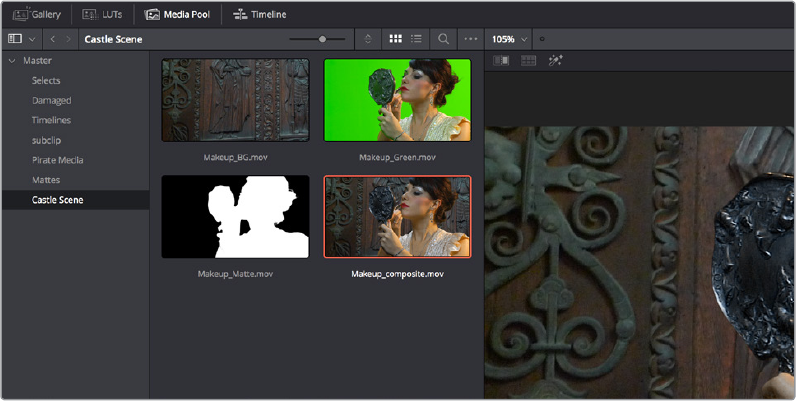
Clip, LUT, and Grade Browsing Features
A family of major new features let you work more efficiently with clips you want to use as
external mattes, LUTs, and grades in the Gallery and in timelines of the current project or
others.
Media Pool in Color Page
The Media Pool is available in the Color page, making it easy to drag and drop clips you want to
use as External Mattes right into the Node Editor, for easy and fast connection to create various
Color page effects. When opened, the Media Pool replaces the Gallery, fitting into the same
area. In most respects, the Media Pool in the Color page works the same as the Media Pool on
nearly every other page of DaVinci Resolve.
The Media Pool now appears in the Color page
When you drag a clip from the Color page Media Pool to the Node Editor, two things happen:
That clip is turned into an External Matte in the current grade, which you can use as
a Matte for secondary adjustments, or as a compositing layer (in conjunction with the
Layer mixer) for mixing textures or images with your grade.
That clip is also automatically attached to the Media Pool clip that corresponds to the
clip you’re grading as a clip matte, to help you keep track of which clips are using other
clips as mattes.
Dedicated LUT Browser
The LUT Browser provides a centralized area for browsing and previewing all of the LUTs
installed on your workstation. All LUTs appear in the sidebar, by category.
1-51Chapter – 4 Color Page Improvements
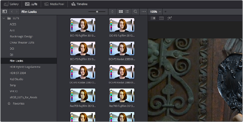
The LUT Browser
By default, all LUTs appear with a test thumbnail that give a preview of that LUT’s effect, but you
can also get a Live Preview of how the current clip looks with that LUT by hover scrubbing with
the pointer over a particular LUT’s thumbnail (this is described in more detail below).
To open the LUT Browser:
Click the LUT Browser button in the UI Toolbar at the top of the Color page.
Methods of working with the LUT Browser:
To see the LUTs in any category: Click on a LUT category to select it in the sidebar,
and its LUTs will appear in the browser area.
To make a LUT a favorite: Hover the mouse over a LUT and click the star badge that
appears at the upper right‑hand corner, or right‑click any LUT and choose Add to
Favorites. That LUT will then appear when you select the Favorites category.
To search or filter for specific LUTs: Open a bin that has the LUT you’re looking for,
then click the magnifying glass icon to open the search field, and type text that will
identify the LUTs you’re looking for.
To see LUTs in Column or Thumbnail view: Click the Column or Thumbnail buttons at
the top right of the LUT Browser to choose how to view LUTs in the browser area.
To sort LUTs in Thumbnail view: Click the Thumbnail Sort pop‑up menu and choose
which criteria you want to sort LUTs by. The options are Filename, Type, Relative Path,
File Path, Usage, Date Modified. There are also options for Ascending and Descending
sort modes.
To sort LUTs in Column view: Click the column header to sort by that column. Click a
header repeatedly to toggle between Ascending and Descending modes.
To update the thumbnail of a LUT with an image from a clip: Choose a clip and frame
that you want to use as the new thumbnail for a particular LUT, then right‑click that LUT
and choose Update Thumbnail With Timeline Frame.
To reset the thumbnail of a LUT to use the standard thumbnail: Right‑click a LUT and
choose Reset Thumbnail to go back to using the standard test image.
To refresh a LUT category with new LUTs that may have been installed: Select a LUT
category, then right‑click anywhere within the browser area and choose Refresh to
refresh the contents of that category from disk.
1-52Chapter – 4 Color Page Improvements
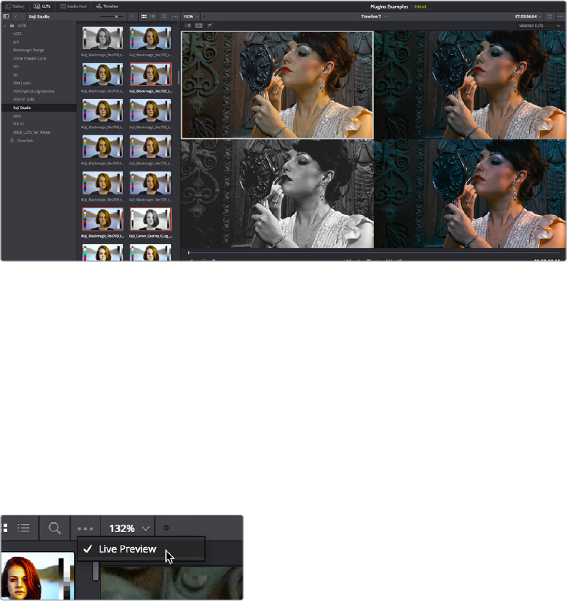
Methods of adding LUTs to a grade from the LUT Browser:
To apply a LUT to a clip: Select a clip in the Thumbnail timeline, then right‑click a LUT
and choose Apply LUT to Clip from the contextual menu. That LUT is added to the
source clip, not the grade.
To Append a LUT to the end of the node tree: Right‑click a LUT and choose Append
to Node Graph. A new node will be appended to the end of the current node tree with
that LUT applied to it.
To apply a LUT to a specific node: Drag a LUT from the LUT Browser and drop it onto
the node you want to apply a LUT to. If you drag a LUT onto a node that already has a
LUT, the previous LUT will be overwritten by the new one.
New Split Screen Modes to Preview Selected LUTs, Albums
A new Split Screen mode lets you simultaneously display previews of different LUTs as a split
screen in the Viewer. To use this, turn Split Screen on, set the mode pop‑up menu to LUTs, and
then use the LUTs browser to Command‑click up to 16 LUTs to preview in a grid.
The Selected LUTs split screen option lets you preview a bunch of LUT looks at once
Another new Split Screen mode lets you display every still within an album in the Gallery as a
split screen in the Viewer. To use this, turn Split Screen on, set the mode pop‑up menu to
Album, and then open the Gallery and select an album. Only up to 16 stills will be displayed.
Live Previews of Gallery Stills and LUTs
The Live Preview option, found in both the Gallery and LUTs browser option menu, lets you
preview how the current clip would look with any Gallery Still’s grade, or with any LUT applied
to it, simply by moving the pointer over the still or LUT you want to preview. By default, the
preview shows how the current clip would look if the scrubbed still or LUT replaced the grade
currently applied to that still.
The Live Preview option for the Gallery and LUT
browser lets you hover over a LUT or saved grade
to preview it on the current clip in the Viewe
1-53Chapter – 4 Color Page Improvements
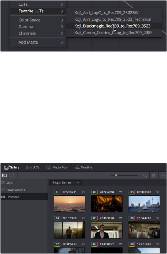
Live Previews of Composite Modes in the Layer Mixer
Scrolling through the submenu of Composite modes in a Layer Mixer node’s contextual menu
now gives you a live update in the Viewer of how each transfer node affects the image.
Live Previews of LUTs in the Node Editor
If you hold down the Option key while scrolling through the submenu of LUTs in a
Correctornode’s contextual menu, you’ll get a live update in the Viewer of how each LUT
affects the image.
Favorite LUTs Submenu in Node Editor
When you label a LUT as a favorite in the LUT Browser, those favorite LUTs appear in a
submenu of the contextual menu that appears when you right‑click on a node in the Node
Editor. This makes it easy to create a shortlist of your go‑to LUTs for various situations, for rapid
application right in the Node Editor.
A Favorite LUTs submenu in the Node Editor contextual menu gives you a short list
Browse All Timeline Grades From
theCurrent Project in the Gallery
The Gallery has a Timelines Album, available at the bottom of the Album list, that lets you
browse all the grades in the current timeline, or in other timelines of the current project (using
apop‑up menu that appears at the top of the Gallery browser area), making it easy to copy
grades from earlier or later in your timeline, or from other timelines that share the same media.
This is particularly useful for reality shows or documentaries where the same clips can appear
multiple times in different parts of a program. Being able to simply show all existing grades in
the Gallery frees you from having to save a still for every grade you think you might
eventuallyreuse.
The Timelines grade browser in the Gallery automatically
shows all grades in the current timeline
1-54Chapter – 4 Color Page Improvements
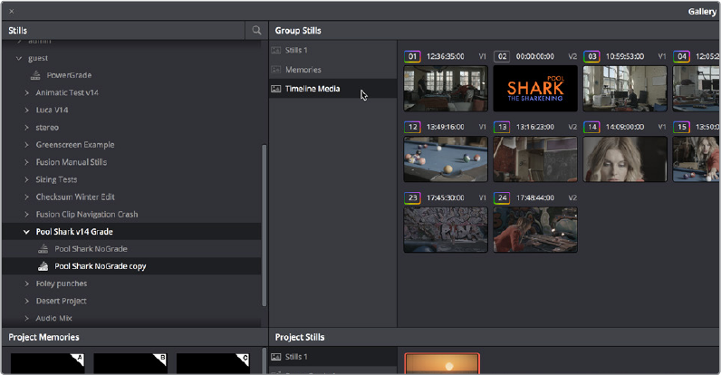
Browse and Import Timeline Grades From Other Projects
The Gallery Window lets you see and import grades in the timelines of other projects, even if
they weren’t saved as stills first. When you open the Gallery Window and use the hierarchical
disclosure controls of the Stills panel to open up and select a specific Database > User > Project
> Timeline, you’ll see at least three browsable albums to the right, the Stills galleries that were
created, the Memories, and at the bottom an album called Timeline Media. The Timeline Media
album lets you browse the currently used grades for every clip in that timeline, making it easy to
copy the ones you need to the current project’s Stills album or Memories.
This is particularly useful if you’re working on a series where and you find that you want to
re‑use different grades, looks, adjustments, or fixes from previous episodes in the current one.
Previously, you’d have to remember to save every clip as a still to be able to browse the grades
in this way. Now you can simply browse the clips in the Timeline directly.
Browsing the timeline grades for another project in the database
RED SDK-Based RED IPP2 Setting in RCM Gamut Mapping
RED WideGamutRGB and Log3G10 are now options in Resolve Color Management workflows
using gamut mapping, and in the Gamut Mapping ResolveFX plug‑in, to better support RED
IPP2 workflows.
New Color Page Features
Many, many new general Color page features have been added to improve a wide
varietyofworkflows
Multiple Timeline Playheads
DaVinci Resolve supports creating up to four separate playheads in the Mini‑Timeline, that you
can use to jump back and forth among different parts of your timeline. Only one playhead can be
selected at any given time, and the currently selected playhead corresponds to the current clip,
highlighted in orange. Each playhead in the Mini‑Timeline is labeled with a letter, A throughD.
1-55Chapter – 4 Color Page Improvements
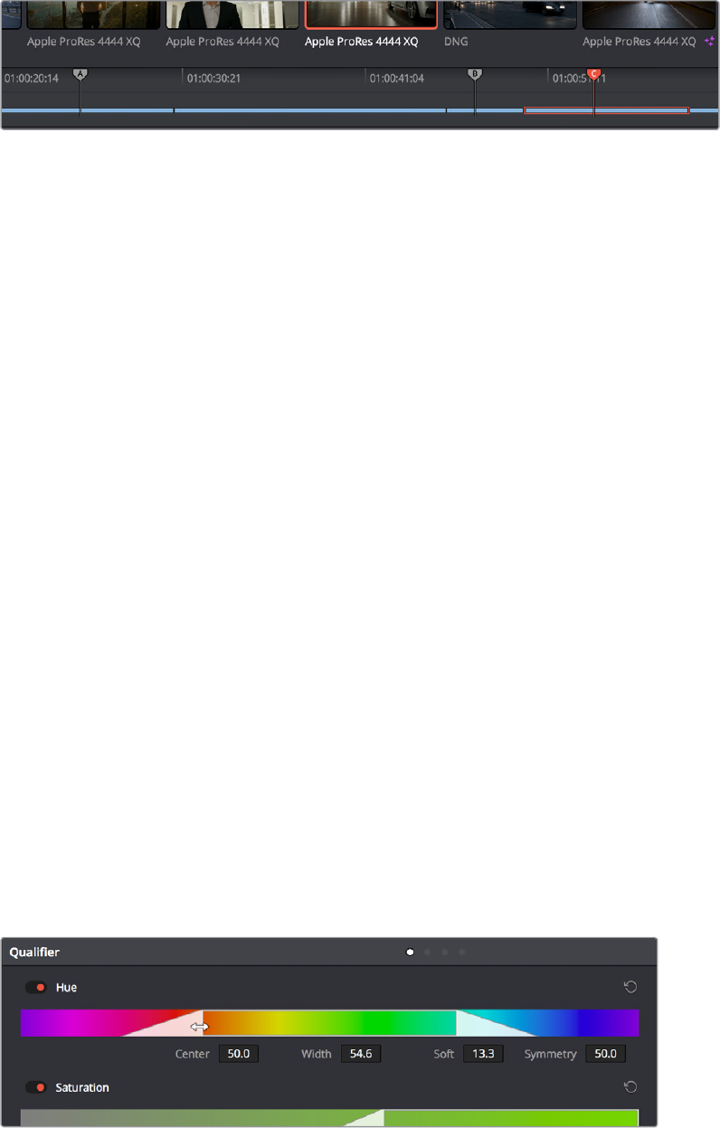
Multiple playheads in the Mini Timeline for multi‑region navigation
To add a new playhead to the Mini-Timeline:
Choose a playhead from the Color > Active Playheads submenu. That playhead will
be placed at the same position as the original playhead, but it is now the one that is
selected, so dragging the new playhead to a new position of the Mini‑Timeline will
reveal the original playhead you were using.
To select another playhead to view:
Click on the top handle of any playhead to select it, making that the currently active
playhead controlled by the transport controls. By default, no keyboard shortcuts are
mapped to the four playheads that are available, but you can create a custom keyboard
mapping that you can use to quickly switch among them.
Using the DaVinci Advanced Control Panel, you can use the A, B, C, and D buttons on
the Jog/Shuttle panel to switch to the playhead you want to control.
To eliminate all additional playheads from the Mini-Timeline:
Choose Color > Active Playheads > Reset Playheads.
Batch Version Management
You can select multiple clips in the Thumbnail timeline and change them all to use a different
Local or Remote version at once by right‑clicking one of the selected thumbnails and choosing
Load from the submenu of the Local or Remote version you want to switch to.
Draggable Qualifier Controls
The Qualifier controls now have draggable overlays, for more direct adjustment by mouse and
tablet users. Drag the left and right edges of any qualifier control overlay to adjust the Low and
High values (or the Width value of the Hue control). Drag the center of any qualifier control to
change the center or to simultaneously change the Low and High parameters together. Option‑
drag the left and right edges of any qualifier overlay to adjust softness.
Draggable qualifier controls
1-56Chapter – 4 Color Page Improvements
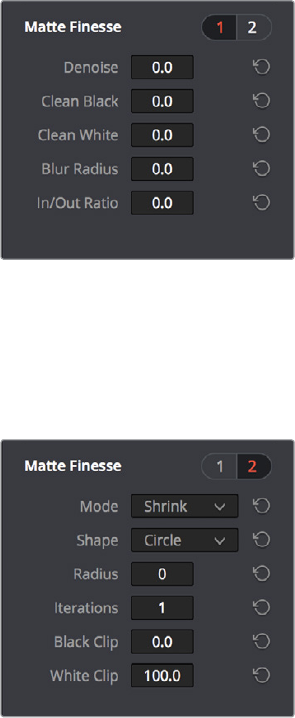
Additional Matte Finesse Controls
Denoise has been re‑added to the Matte Finesse controls, providing a distinct way to post‑
process extracted keys to selectively reduce the noise in a key, getting rid of stray areas of
qualification and softly filling “holes” in a matte.
Denoise in page 1 of the Matte Finesse controls
An additional page of Matte Finesse controls expose controls for Shrink, Grow, Opening, and
Closing functionality, with control over the Shape of the operation, the Radius, and Iterations.
The previously available Black Clip and White Clip controls have also been moved into this
second page.
Shrink/Grow controls in page 2 of the
Matte Finesse controls
Node-Specific Color Space and Gamma Settings
While the ability to change the color space a particular node works within has been available
for several versions, the list of available color spaces has been greatly expanded (all the
previous options such as Lab, HSL, and YUV are still there). Additionally, you have the option of
choosing the gamma that node works with as well, with a similarly long list of options.
Choosing a node‑specific color space and gamma does not directly alter the image, as with the
Color Space Transform ResolveFX plug‑in. Instead, changing a node’s Color Space and Gamma
alters what kind of channels the red, green, and blue controls affect, and how the adjustments
you make within that node are applied. For example, this lets you apply OFX with Gamma set to
Linear, which in some instances may be advantageous
1-57Chapter – 4 Color Page Improvements
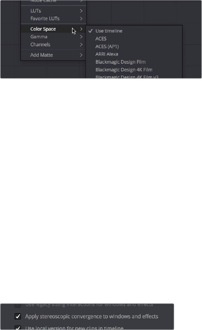
.
Expanded submenus for choosing a color space
and gamma for image processing within a node
Timeline Wipe Ganging to Current Clip
The “Gang timeline wipe with current clip” option, available from the Viewer option menu, lets
you maintain the offset between the current clip and a timeline clip you’re wiping against when
you move the current clip selection to other clips.
If you’re not sure what a Timeline wipe is, it’s when you use the Wipe Timeline Clip command in
the Thumbnail timeline (it’s found in the contextual menu when you right‑click a clip other than
the current clip) to wipe the current clip against another clip in the timeline, without needing to
save a still first. When you turn a Timeline wipe on, the timeline wiped clip is outlined in blue.
With this new option enabled, the offset between the timeline wiped clip and the current clip is
maintained when you move the clip selection. When this option is disabled, the timeline wiped
clip stays where it is regardless of what clip you select.
Camera RAW Palette for Canon RAW, Panasonic RAW Clips
Canon RAW and Panasonic Varicam RAW media now expose dedicated controls in the Camera
RAW panel of the Project Settings, and in the Camera RAW palette of the Color page when
Canon or Panasonic raw media is present in the Timeline.
Stereoscopic Convergence Support for Power Windows
The Color group of the General Options panel of the Project Settings has a new checkbox
called “Apply stereoscopic convergence to windows and effects” that correctly maintains the
position of a window that’s been properly placed over each eye when convergence is adjusted.
You must turn on a checkbox in the Project Settings to
enable stereo convergence for windows
When this option is enabled, the Window palette displays an additional Transform parameter,
“Convergence,” that lets you create properly aligned convergence for a window placed onto a
stereoscopic 3D clip.
1-58Chapter – 4 Color Page Improvements
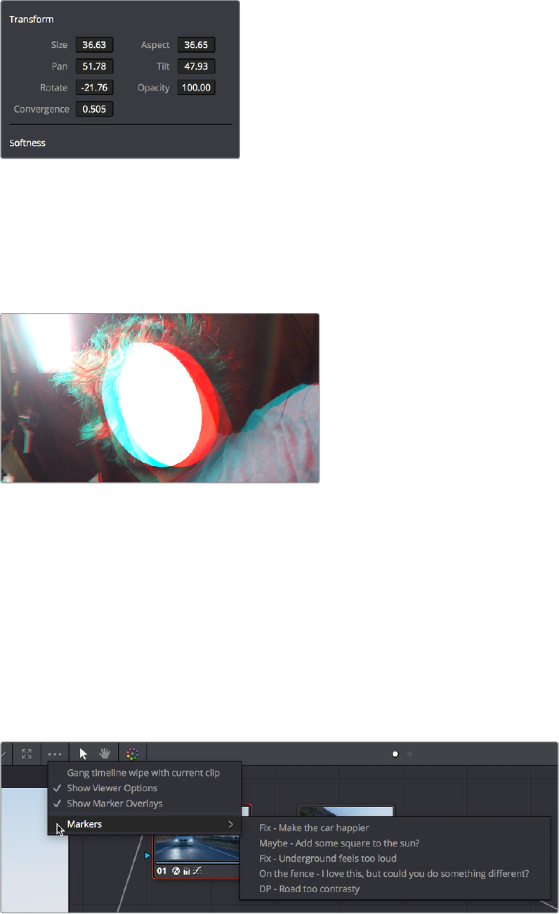
The Convergence control in the Transform
section of the Window palette
After placing a window over a feature within the image while monitoring one eye, you can
enable Stereo output in the stereo 3D palette and use the Pan and Convergence controls to
make sure that window is properly stereo‑aligned over the same feature in both eyes. At that
point, adjusting the Convergence control in the Stereo 3D palette correctly maintains the
position of the window within the grade of each eye.
A convergence‑adjusted window in stereo
Marker Overlays Visible in the Color Page Viewer
If you part the playhead on top of a marker in the timeline of the Color page, that marker’s
information now appears in a Viewer overlay, just like in the Edit page, making it easier to read
notes and see .
Timeline Marker List Available in
ColorPage Viewer Option Menu
The Option menu of the Color page Viewer has a submenu that lists all Timeline Markers in the
currently open timeline. This makes it easy to run down client notes
Timeline markers list available for quick access in the Viewer’s Option menu
1-59Chapter – 4 Color Page Improvements
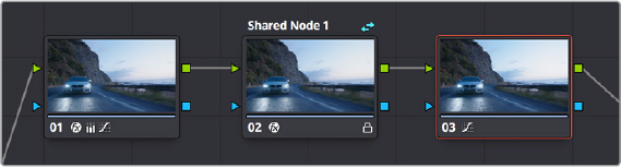
Improved Noise Reduction
A significantly improved new “Best” option has been added to the Mode pop‑up of the Spatial
NR controls, that does a much better job of preserving image sharpness and detail when raising
the Spatial Threshold sliders to eliminate noise. The improvement is particularly apparent when
the Spatial Threshold sliders are raised to high values of 40 or above (although this varies with
the image). At lower values, the improvement may be more subtle when compared to the “Better”
mode, which is less processor intensive than the computationally expensive “Best”setting.
The new “Best” mode also allows you to decouple the Luma and Chroma Threshold sliders for
individual adjustment, something you can’t do in “Better” mode.
Improved Face Refinement
Instances of face keyer chatter and flickering eyebag removal have been improved when using
the Face Refinement plug‑in.
Node Editor Enhancements
A variety of improvements to node editing have been added to DaVinci Resolve 15, starting with
powerful new Shared nodes for making linked adjustments within clip grades, and continuing
with multiple visual upgrades to nodes in the Node Editor.
Shared nodes for Group Management
This is probably one of the biggest improvements added for working colorists. You can now
turn individual Corrector nodes into “Shared nodes,” which can then be copied to multiple clips
to enable linked adjustments right from within the clip grade. This means that the clip grade can
freely mix both clip‑specific nodes and Shared nodes all within the same node tree. This makes
Shared nodes fast to use as there’s no need to create groups or switch to a group node tree to
reap the benefits of linked adjustments among multiple clips.
A grade with an unshared (at left) and shared node (at right),
a badge indicates the shared node, which is also locked
What Are Shared Nodes Good For?
Shared nodes are similar to group grades, except that they don’t require grouping and can be
added to any normal grade. Changes made to a Shared node are automatically rippled to all
other instances of that node in the grades of other clips. Furthermore, you can add as many
Shared nodes to a grade as you like, and you can arrange them in any order to control the order
of the operations they apply. And, of course, you can intersperse them with ordinary
Correctornodes
1-60Chapter – 4 Color Page Improvements

Shared nodes are extremely flexible. For example, you can use Shared nodes to:
Add a Color Space Transform Resolve FX or a LUT to the beginning of every clip from a
particular source
Add a base correction to every talking head shot of a particular interviewee
Add a shot matching adjustment to each clip from a particular angle of coverage within
a scene
Add a stylistic adjustment to every clip in a specific scene
Use Shared nodes to make your base adjustments when grading with Remote
Versions, so those adjustments remain linked when you copy your Remote Versions to
Local Versions for fine tuning
In fact, you can mix and match Shared nodes among differently overlapping sets of clips to
accomplish any or all of the above at once. For example, you can add one Shared node to make
an adjustment to every clip from a particular camera, add a second Shared node to each of
those clips that are in a particular scene, and then add a third Shared node to whichever of
those clips happen to be a closeup of the lead actress, before adding one or two regular
Corrector nodes that aren’t shared to make clip‑specific tweaks.
Creating Shared Nodes
Creating a shared node is easy, assuming you’ve created a node that has an adjustment you’d
like to share among multiple clips.
To create a Shared node:
Right‑click any Corrector node and choose “Save as Shared node.”
Locking Shared Nodes
Once you turn a node into a Shared node, that node is automatically locked, preventing you
from accidentally making adjustments to it that would affect all other grades using that same
Shared node.
To toggle the locked status of a Shared node, do one of the following:
Right‑click any shared node and choose Lock Node from the contextual menu.
Open the Keyframe Editor, and click the Lock icon in the track header of that node’s
keyframe track.
Copying Shared Nodes
Because shared nodes are essentially Corrector nodes within of clip grades, they’re easy to
work with. Once you’ve created one or more Shared nodes, there are a variety of ways you can
copy them to the grades of other clips in your program to take advantage of the linked
adjustments they let you make.
IMPORTANT: At the time of this writing, there are two limitations when using Shared
nodes. Grades using Shared nodes cannot use the Smart or User cache, and Shared
nodes cannot be used in collaborative workflows. It is hoped that these limitations
aretemporary.
1-61Chapter – 4 Color Page Improvements
Ways of copying Shared nodes among multiple clips:
Add a Shared node to another clip’s grade using the Node Editor contextual menu:
Once you save a node as a Shared node, it becomes available from the bottom of the
Add Node submenu of the Node Editor contextual menu, making it easy to add any
Shared node to any clip. If you customize the label of the Shared node, that custom
label appears in the contextual menu, making it easier to find what you’re looking for.
Add Shared nodes to a basic grade you’ll be copying to other clips: If you create one
or more Shared nodes when you initially build a grade, copying that grade to other clips
naturally copies the Shared nodes as well.
Save a Shared node as a Gallery still and apply it to other clips: If you save a grade
with a Shared node in it to the Gallery, then every time you copy that Gallery still to
another clip, you copy its Shared nodes.
Create a Shared node and append it to a selection of additional clips: If you’ve
already graded several clips in a scene, you can add a Shared node to the end of one
of the clips grades and make sure it’s selected, then select all of the other clips in the
scene and choose Append Node to Selected Clips.
Use Shared nodes to preserve linked adjustments when copying Remote grades to
Local grades: If you use Shared nodes to make your base adjustments when you grade
using Remote Versions to automatically copy those grades to other clips that come
from the same source media, those adjustments will remain linked when you copy your
Remote Versions to Local Versions for fine tuning.
Deleting Shared Nodes
If you’ve created a Shared node that’s being used in multiple clips, and you decide you want to
eliminate the linked relationship among these nodes so they all work independently, you can
“delete” a specific shared node. This leaves the now unlinked nodes intact within each node tree
in which they appear. Additionally, that Shared node is removed from the Add Node submenu.
To Delete a Shared node:
Right‑click any Shared node, and choose a node to “un‑share” from the Delete Shared
Node submenu.
Single-Click Node Selection in the Color Page
You need only click once to select the current node in the Color page Node Editor, saving you
years of wear and tear on your index finger.
Ability to Disable/Enable Multiple
Selected Nodes All at Once
If you select more than one node in the node tree, using any of the available methods of turning
nodes off and on (including Command‑D) will toggle Enable/Disable Selected Nodes. This
makes it easy to do before/after comparisons of any combination of nodes doing complicated
adjustments by selecting them, while leaving un‑selected nodes doing base adjustments that
you want to leave enabled alone.
Please note that the current node outlined in orange is always considered to be part of
theselection.
1-62Chapter – 4 Color Page Improvements
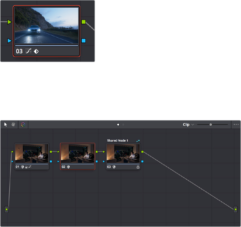
Ability to Drag Connections From One Input to Another
If you move the pointer over the second half of any connection line between two nodes, it
highlights blue and you can click‑and‑drag it to reconnect it to another input.
Single-Click Connection Deletion
If you move the pointer over the second half of any connection line between two nodes so that
it highlights blue, clicking once on the blue part of the connection deletes it.
Edit Node Label Text by Double-Clicking
Double‑clicking the label of any node selects that label text for editing. This will only work if a
node has a label already.
Dynamic Keyframe Indicator in the Node Graph
Nodes with keyframed parameters now display a keyframe badge in the Node Editor.
Keyframed nodes now display a badge
Improved Node Graph Interface
The look and feel of nodes in the Node Graph has been updated for compatibility with the
Fusion page Node Editor. Also, Mixer nodes have new icons to help identify them.
Updated look and feel for Color page node trees
1-63Chapter – 4 Color Page Improvements
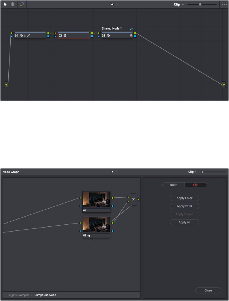
Thumbnail-Optional Nodes
The Node Editor option menu provides a Show Thumbnails option that lets you disable or
enable the thumbnails attached to each Corrector node.
Disabling thumbnails in the Node Editor option menu makes nodes shorter
Ability to Open Compound Nodes in “Display Node Graph”
When you right‑click a Gallery still or a thumbnail and choose Display Node Graph, you can now
right‑click compound nodes and choose “Show compound node,” or Command‑double‑click
compound nodes to open them and see their individual nodes.
Opening a compound node in a floating Node Graph window
1-64Chapter – 4 Color Page Improvements
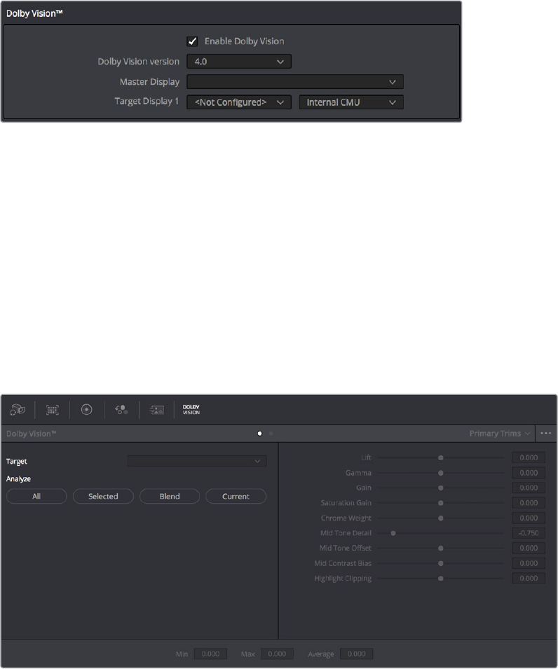
HDR Enhancements
DaVinci Resolve 15 adds support for the latest developments in HDR workflows.
GPU-Accelerated Dolby Vision™ CMU Built-In (Studio Only)
DaVinci Resolve 15 includes a GPU‑accelerated software version of the Dolby Vision CMU
(Content Mapping Unit) box for doing Dolby Vision grading and finishing workflows right in
DaVinci Resolve. This is enabled and set up in the Color Management panel of the Project
Settings with the Enable Dolby Vision checkbox. Turning Dolby Vision on enables the
DolbyVision palette in the Color page.
Dolby Vision settings in the Color Management panel of the Project Settings
Auto Analysis Available to All Studio Users
Resolve Studio enables anyone to generate Dolby Vision analysis metadata automatically.
Thismetadata can be used to deliver Dolby Vision content and to render other HDR and
SDRdeliverables from the HDR grade that you’ve made.
Dolby Vision has two levels of metadata: i) Analysis metadata (Level 1), which is generated
automatically by the project and image parameters; and ii) Artistic trim metadata (Level 2), which
is set by the colorist to adjust the Dolby Vision mapped image to a target that is different from
the mastering display (Rec. 709 as an example). Generating Dolby Vision with L1 analysis
metadata is available without additional licensing from Dolby. Artistic trim metadata is created
with the Dolby vision palette in DaVinci Resolve. The Dolby Vision Palette requires a separate
license from Dolby.
The Dolby Vision palette in the Color page
1-65Chapter – 4 Color Page Improvements
The commands governing Dolby Vision auto‑analysis are in the Color > Dolby Vision™ submenu,
and consist of the following commands:
Analyze All Shots: Automatically analyzes each clip in the Timeline and stores the
results individually.
Analyze Selected Shot(s): Only analyzes selected shots in the Timeline.
Analyze Selected And Blend: Analyzed multiple selected shots and averages the
result, which is saved to each clip. Useful to save time when analyzing multiple clips
that have identical content.
Analyze Current Frame: A fast way to analyze clips where a single frame is
representative of the entire shot.
Analyze All Frames: A fast way to convert an entire HDR deliverable to a Dolby Vision
deliverable without dealing with shot cuts.
Manual Trimming Available Only to Licensees
However, if you want to be able to make manual trims on top of this automatic analysis, email
dolbyvisionmastering@dolby.com to obtain a license. Once you’ve obtained a license file from
Dolby, you can import it by choosing File > Dolby Vision > Load License, and its successful
installation will enable the Dolby Vision palette to be displayed in the Color page.
Dolby Vision Metadata Export
Additionally, DaVinci Resolve now has the ability to render MXF files with embedded Dolby
Vision trim metadata.
Optional HDR10+™ Palette (Studio Only)
DaVinci Resolve 15 supports the new HDR10+ HDR format by Samsung. Please note that this
support is a work in progress as this is a new standard. When enabled, an HDR10+ palette
exposes trimming parameters that let you trim an automated downconversion of HDR to SDR,
creating metadata to control how HDR‑strength highlights look on a variety of supported
televisions and displays. This is enabled and set up in the Color Management panel of the
Project Settings with the Enable HDR10+ checkbox. Turning HDR10+ on enables the Dolby
Vision palette in the Color page.
Dolby Vision settings in the Color Management panel of the Project Settings
HDR10+ Auto Analysis Commands
HDR10+ has its own scheme for auto‑analyzing HDR to SDR downconversion metadata, and the
controls are available in the Color > HDR10+ submenu, consisting of the following commands:
Analyze All Shots: Automatically analyzes each clip in the Timeline and stores the
results individually.
Analyze Selected Shot(s): Only analyzes selected shots in the Timeline.
Analyze Selected And Blend: Analyzed multiple selected shots and averages the
result, which is saved to each clip. Useful to save time when analyzing multiple clips
that have identical content.
Analyze Current Frame: A fast way to analyze clips where a single frame is
representative of the entire shot.
1-66Chapter – 4 Color Page Improvements
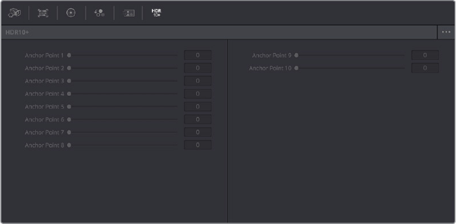
HDR10+ Palette
An HDR trim palette is available to all Resolve Studio users, that provides controls for manually
trimming the auto‑analyzed trim metadata. At the time of this writing, nine sliders control the
bezier handles and control points of a custom curve that can be used to shape the luminance
mapping curve, including Knee X and Y sliders.
The Dolby Vision palette in the Color page
HDR10+ Metadata Export
The resulting metadata is saved per clip, in a JSON sidecar file.
1-67Chapter – 4 Color Page Improvements
Chapter 5
New ResolveFX
DaVinci Resolve 15 adds seven new ResolveFX that will give colorists and
finishing artists significant new image restoration tools, as well as
sophisticated new lighting and stylistic effects with wide‑ranging uses.
Two exciting new plug‑ins have been added to the “ResolveFX Light”
category that simulate different types of optical glows and flares.
Additionally, the ResolveFX category formerly called “Repair” has been
renamed “ResolveFX Revival,” because of three powerful new restoration
effects that have been added. On the other end of the spectrum, two new
plug‑ins that create stylistic degradation have been added to the
“ResolveFX Texture” and “ResolveFX Transform” categories.
1-68Chapter – 5 New ResolveFX
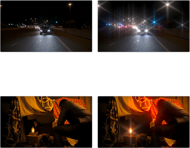
Aperture Diffraction (Studio Only)
Found in the “ResolveFX Light” category, Aperture Diffraction models the starburst effect
usually seen when shooting bright lights with small apertures, the physical cause of which is
light‑diffraction on the aperture blades of a lens. This plug‑in simulates this, with the result
being automatically applied to scene highlights that you can isolate and refine, with
customizable virtual apertures.
Small regions of brightness exhibit a star pattern glow, as seen in the following image.
(Left) Original image, (Right) Applying Aperture Diffraction
Large regions of brightness exhibit a more even glow with shaping and texture that look like a
natural optical effect. It can be used to create a different type of glow effect with a more
realistic look in some situations than the Glow plug‑in, though it’s more processor intensive. In
other situations, this plug‑in opens up many different stylistic possibilities for glowing effects.
(Left) Original image, (Right) Applying Aperture Diffraction
Output
Select Output lets you preview the image with different stages of the Aperture Diffraction effect
applied, viewing the Isolated Source (to help when adjusting the Isolation Controls), Preview
Aperture (to help when adjusting the Aperture Controls), Preview Diffraction Pattern (showing
you the resulting diffraction pattern based on the aperture control settings), Diffraction Patterns
Alone (showing you the glow effect that will be applied to the image by itself), and the
FinalComposite.
Isolation Controls
The Isolation Controls control which highlights in the scene generate visible glow and patterns.
The effect of these controls can be directly monitored by setting Select Output to
IsolatedSource.
Color Mode is a pop‑up menu that lets you either choose to keep the colors of the different
highlight regions that generate glow, or treat them all as greyscale brightness only (color
controls later can change the effect). Greyscale is faster to process, but Color can result in some
brilliant effects.
1-70Chapter – 5 New ResolveFX

Brightness sets the threshold at which highlights are isolated. Gamma lets you shape the
isolated highlights, while Smooth lets you blur details in the highlights that you don’t want to be
pronounced. Color Filter lets you choose a particular color of highlight to isolate (an eyedropper
lets you select a value from the Viewer). The Operation controls let you adjust the resulting
Isolation matte (options include Shrink, Grow, Opening, Closing) with a slider to define howmuch.
Aperture Controls
The Aperture Controls let you define the shape and texture of the resulting glow this
plug‑increates.
Iris Shape lets you choose a shape that determines how many arms the star pattern will have.
Aperture size lets you alter the resulting diffraction pattern alternating between more of a star
shape at higher values and a stippled wave pattern at lower values. Result Gamma lets you
adjust how pronounced will be the glow that appears between the arms of the star patterns
thatappear. Result Scale lets you alternate between pronounced star patterns at high values
and more diffuse glows at low values. Blade Curvature and Rotation let you alter the softness
and orientation of the arms of each star. Chroma Shift lets you introduce some RGB “bleed”
intotheglow.
Compositing Controls
These controls let you adjust how to composite the glow effect against the original image.
The Normalize Brightness checkbox scales the brightness of the glow to a naturalistic range for
the image. Also, when Normalize Brightness is enabled, the Aperture Diffraction effect will keep
to a consistent overall brightness as the scene changes. Brightness lets you adjust the intensity
of the glow effect. Colorize lets you tint the glow effect using a Color control that appears when
Colorize is raised above 0.
Lens Reflections (Studio Only)
Found in the “ResolveFX Light” category, Lens Reflections simulates intense highlights
reflecting off of the various optical elements within a lens to create flaring and scattering effects
based on the shape and motion of highlights you isolate in the scene. It’s an effective simulation
that works best when there are light sources or specular reflections in the scene such as the
sun, car headlights, light fixtures, fire and flame, or other lighting elements that are plausibly
bright enough to cause such flaring.
Also, this plug‑in really shines when these light sources move, as each layer of simulated
reflections moves according to that element’s position within the virtual lens being simulated,
creating organic motion that you don’t have to keyframe. Without intense highlights, the results
of this filter will be somewhat abstract.
(Left) Original image, (Right) Applying Lens Reflections
1-71Chapter – 5 New ResolveFX
Output
Select Output lets you preview the image with different stages of the Lens Reflections effect
applied, viewing the Isolated Source (to help when adjusting the Isolation Controls), Reflections
Alone (showing you the flaring effect that will be applied to the image by itself), and the
FinalComposite.
A Quality pop‑up lets you choose how to render the effect. Options are Full, Half (Faster), and
Quarter (Fast). The tradeoff is between quality and speed.
Isolation Controls
The Isolation Controls control which highlights in the scene generate lens reflections. The
effect of these controls can be directly monitored by setting Select Output to Isolated Source.
It’s highly recommended to customize the Isolation controls for the image at hand when using
this plug‑in, as even more so than other plug‑ins, the particular highlights used will have a huge
impact on the resulting effect.
Color Mode is a pop‑up menu that lets you either choose to keep the colors of the different
highlight regions that generate lens reflections, or treat them all as grayscale brightness only
(color controls later can change the effect). Grayscale is faster to process, but Color can result
in some brilliant effects.
Brightness sets the threshold at which highlights are isolated. Gamma lets you shape the
isolated highlights, while Smooth lets you blur details in the highlights that you don’t want to be
pronounced. Color Filter lets you choose a particular color of highlight to isolate (an eyedropper
lets you select a value from the Viewer). The Operation controls let you adjust the resulting
Isolation matte (options include Shrink, Grow, Opening, Closing) with a slider to define howmuch.
Global Controls
The Global Controls let you quickly adjust the overall quality of the Lens Reflections effect.
Global Brightness lets you raise and lower the level of all reflections. Global Blur lets you
defocus all reflections. Anamorphism lets you deform the reflection elements to simulate an
anamorphic lens’ stretching effect. Global Colorize lets you adjust the color intensity of the
reflections, either intensifying the color of all reflections or desaturating it.
Presets
A Presets pop‑up provides a number of different settings to get you started. Selecting a preset
populates the Reflecting Elements parameters below, at which point you can customize the
effect to work best with the image at hand. It’s highly recommended to customize these effects
to suit the type of highlights in your image, in order to get the best results.
1-72Chapter – 5 New ResolveFX
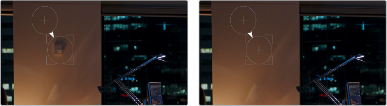
Reflecting Elements
There are four groups of Reflecting elements, each with identical controls. This lets you create
interactions combining up to four sets of reflections. The controls found within each group are
as follows.
Brightness: Lets you adjust the intensity of that reflection.
Position in Optical Path: Lets you shift the reflection according to an element’s position
in the lens. Practically, this means that positive values will enlarge an inverted reflection
based on the highlights, while reducing values towards 0 will shrink the reflection, and
pushing this into negative values will invert the reflection and pull it into the opposite
direction as it begins to enlarge again. A value of –1 positions the reflection right over
the highlight that creates it.
Defocus type: Lets you choose what kind of blur to use, choices include Box Blur,
Triangular Blur, Lens Blur (the most processor intensive), and Gaussian Blur (the default).
Defocus lets you choose how much to blur that element.
Stretch: Lets you give the flare an anamorphic widescreen look, while Stretch Falloff
lets you taper the edges.
Lens Coating: A pop‑up lets you choose common colors such as purple, green, and
yellow that correspond to different anti‑reflective lens coatings, as well as a selection
of other vibrant colors. A color control and eyedropper let you manually choose a
color or pick one from the image. A Colorize slider lets you vary how much to tint the
reflection by the selected color, although setting Colorize to 0 lets the flare take its
color from the source highlights of the image, which can sometimes give you the most
interestinglook.
Patch Replacer (Studio Only)
Found in the new “ResolveFX Revival” category, the Patch Replacer is a quick fix when you
need to “paint out” an unwanted feature from the image. For those of you who’ve been using
windows and Node Sizing to do small digital paint jobs, this plug‑in offers more options and a
streamlined workflow.
On adding the plug‑in, an onscreen control consisting of two oval patches appears, with an
arrow connecting them indicating which patch is being copied into the other. The oval to the left
is the “source” patch, used to sample part of the image, and the oval to the right is the “target”
patch, used to cover up the unwanted feature using pixels from the source patch.
To use the Patch Replacer, simply drag the target patch over the feature you want to obscure,
resize it to fit using the corner controls (the source patch is automatically resized to match), and
then drag the source patch to an area of the image that can convincingly be used to fill the
target patch.
(Left) Original image, (Right) Removing the thermostat with the Patch Replacer
1-73Chapter – 5 New ResolveFX
The source and target patches can be motion tracked using the FX tracker, so this tool is
effective even if the subject or camera is moving.
Main Controls
The “Fill‑in method” pop‑up menu is arguably the most important, as it defines what method to
use to fill the destination patch with whatever is in the source patch. The rest of the primary
controls work differently depending on which fill‑in method you choose.
Clone: Simply copies the source patch into the target patch. When clone is selected,
the Replacement Detail slider (which defaults to 1) lets you fade out the source patch,
while Region Shape lets you choose a different kind of shape to use, and Blur Shape
Edges lets you feather the edge of this operation, to more convincingly blend the
source with the target area.
Adaptive Blend: A much more sophisticated method of obscuring the target area
using pixels from the source patch, and in many cases will yield better results more
quickly than cloning. The source patch is copied into the target patch in such a way as
to combine the source detail with the lighting found inside of the target area, creating
in most instances a fast, seamless match. The Keep Original Detail checkbox, when
turned on, merges detail from the source and target patches to create a composite,
rather than a fill. The Blur Shape Edges slider works a bit differently with Adaptive
Blend selected, but the idea is the same, feathering the effect from the outside in to
obscure instances where there’s a noticeable border around the target area.
Fast Mask: Eliminates the source patch, doing instead a quick neighboring pixel blend
that works well with small patches, but can betray a grid pattern on larger patches.
Region Shape and Blur Shape Edges are both adjustable.
Patch Positions
Source X and Y, Target X and Y, and Target Width and Height are provided as explicit controls
both for numeric adjustment, should that be necessary, and also to allow for keyframing in case
you need to change the position and/or size of the source and fill patches over time.
Keep in mind that the source and target patches can be motion tracked using the FX tracker,
although two checkboxes, Source Follows Track and Target Follows Track, let you disable FX
tracker match moving when necessary.
On-Screen Controls
The Control Visibility pop‑up menu lets you choose whether the source and target onscreen
controls are visible as you work. Show (the default) leaves all onscreen controls visible all the
time. Auto Hide hides all onscreen controls whenever you’re dragging one, letting you see the
image as you adjust it without having these controls in the way. Hide makes all onscreen
controls invisible, so you can see a clean version of the image with the effect, however you can
still edit the effect if you remember where the controls are.
1-74Chapter – 5 New ResolveFX
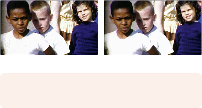
Automatic Dirt Removal (Studio Only)
Found in the new “ResolveFX Revival” category, the Automatic Dirt Removal plug‑in uses
optical flow technology to target and repair temporally unstable bits of dust, dirt, hair, tape hits,
and other unwanted artifacts that last for one or two‑frames and then disappear. All repairs are
made while maintaining structurally consistent detail in the underlying frame, resulting in a
high‑quality restoration of the image. Fortunately, despite its sophistication, this is a relatively
easy plug‑in to use; just drop the plug‑in on a shot, adjust the parameters for the best results,
and watch it go.
(Left) Original image, (Right) Using Automatic Dirt Removal
Main Controls
Motion Estimation Type lets you choose from among None, Faster, Normal, and Better. This
tunes the tradeoff between performance and quality. Neighbor Frames lets you choose how
many frames to compare when detecting dirt. Choosing more frames of comparison take longer
to process, but usually results in finding more dirt and artifacts.
Repair Strength slider lets you choose how aggressively to repair dirt and artifacts that are
found. Lower settings may let small bits through that may or may not be actual dirt, while higher
settings eliminate everything that’s found. The Show Repair Mask checkbox lets you see the
dirt and artifacts that are detected by themselves, so you can see the effectiveness of the
results as you fine tune this filter.
Fine Controls
The Motion Threshold slider lets you choose the threshold at which pixels in motion are
considered to be dirt and artifacts. At lower values more dirt may escape correction, but you’ll
experience fewer motion artifacts. At higher values, more dirt will be eliminated, but you may
experience more motion artifacts in footage with camera or subject motion.
The Edge Ignore slider lets you exclude hard edges in the picture from being affected by dirt or
artifacts that are removed. Higher values omit more edges from being affected.
NOTE: This plug‑in is less successful with vertical scratches that remain in the same
position for multiple frames, and is completely ineffective for dirt on the lens which
remains for the entire shot.
1-75Chapter – 5 New ResolveFX
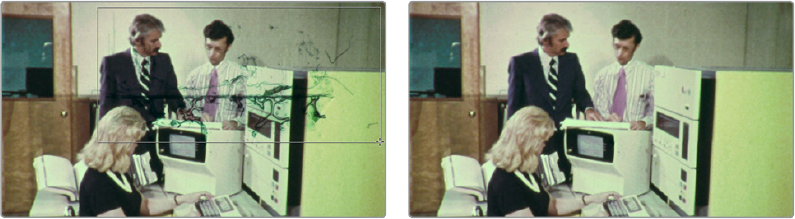
Dust Buster (Studio Only)
Found in the new “ResolveFX Revival” category, this plug‑in is also designed to eliminate dust,
dirt, and other imperfections and artifacts from clips, but it does so only with user guidance, for
clips where the Automatic Dirt Removal plug‑in yields unsatisfactory results. This guidance
consists of moving through the clip frame by frame and drawing boxes around imperfections
you want to eliminate. Once you’ve drawn a box, the offending imperfection is auto‑magically
eliminated in the most seamless way possible. This works well for dirt and dust, but it also works
for really big stains and blotches, as seen below.
(Left) Drawing a box around dirt in the original image, (Right) Result in the Dust Buster plug‑inn
This plug‑in works similarly to, but supersedes the legacy Dust Removal feature, which only
worked on select image sequence formats, and wrote new media files on disk. The Dust Buster
plug‑in works on any format of movie clip, and works non‑destructively, storing all image repairs
within the plug‑in without creating new media. Best of all, this plug‑in is able to do its magic with
only three controls.
Mode: Selects how imperfections within the bounding box you draw are fixed. By
default, Auto just takes care of things without you needing to think about this. However,
if you’re not satisfied with the result, you can undo, and choose a different method from
this pop‑up method. Here are all the options that are available to you.
–Auto: The default method. Once you’ve drawn a bounding box, the two frames
prior to and the two frames after the current clip will be analyzed and compared to
the current image. The best of these 5 frames will be drawn upon to remove the
imperfection in the current frame. Images two frames away are prioritized since that
will avoid the appearance of frozen grain, but only if they’re suitable.
–Prev/Next Frame: If you draw a bounding box from left to right, the next frame will
be drawn upon to remove the imperfection. If you draw a bounding box from right to
left, the previous frame will be used.
–Prev–1/Next+1 Frame: If you draw a bounding box from left to right, the image
two frames forward will be drawn upon to remove the imperfection. If you draw a
bounding box from right to left, the image two frames back will be used.
–Spatial Fill: In cases where the other two modes yield unsatisfactory results, such as
when the underlying image has fast or blurred motion, this mode uses surrounding
information in the current frame to remove the imperfection.
Show Patches: Off by default. Turning this checkbox on lets you see every bounding
box you’ve drawn to eliminate imperfections. While the patches are shown, you can
Shift‑click to select individual patches, group select patches by Command‑dragging a
bounding box, and delete unwanted patches individually by Option‑clicking them.
Reset Frame: Resets all of the bounding boxes drawn on the current frame, so you can
start over.
1-76Chapter – 5 New ResolveFX
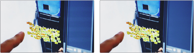
Deflicker (Studio Only)
Found in the new “ResolveFX Revival” category, this brand new plug‑in replaces the previous
“Timelapse Deflicker” filter, and solves a far broader variety of problems in a much more
automatic way. The new Deflicker plug‑in handles such diverse issues as flickering exposure in
timelapse clips, flickering fluorescent lighting, flickering in archival film sources, and in certain
subtle cases even the “rolling bars” found on video screens shot with cameras having
mismatched shutter speeds. Two key aspects to this filter are that it only targets rapid,
temporally unstable variations in lightness, and that it’s able to target only the areas of an
imagewhere flickering appears, leaving all other parts of the image untouched. As a result,
thisplug‑in can often repair problems once considered “unfixable.”
(Left) Original image with flicker, (Right) Result setting Deflicker to Fluro Light, (clip courtesy Redline Films)
Main Settings
By default, the top section of this plug‑in exposes a single control, which in many cases may be
all you need.
Deflicker Setting pop-up menu: The top two options, Timelapse and Fluoro Light,
are presets that effectively eliminate two different categories of flickering artifacts. If
neither of these presets is quite as effective as you’d hoped, a third option, Advanced
Controls, opens up the Isolate Flicker controls at the heart of this plug‑in to let you tailor
it further to your needs.
Isolate Flicker
Hidden by default, these controls only appear when you set “Deflicker Setting” to
AdvancedControls, and let you choose how to detect motion in the scene so that flickering
may be correctly addressed relative to the motion of subjects and items within the frame
whereitappears.
Mo.Est. Type: Picks the method DaVinci Resolve uses to analyze the image to detect
motion. Despite the names of the available options, which options will work best is
highly scene dependent. The default, Faster, is less processor intensive, but less
accurate, however this can be an advantage and actually do a better job with high‑
detail images that would confuse the Better option. Choosing Better is more accurate,
but more processor intensive, and Better will try harder to match fine details which can
sometimes cause problems. None lets you disable motion analysis altogether, which
can work well (and will be considerably faster) in situations where there’s no motion in
the scene at all. The default is Better.
Frames Either Side: Specifies the number of frames to analyze to determine what’s
in motion. Higher values are not always better, the best setting is, again, scene
dependent. The default is 3.
1-77Chapter – 5 New ResolveFX
Motion Range: Three settings, Small, Medium, and Large, let you choose the speed of
the motion in the frame that should be detected.
Gang Luma Chroma: Lets you choose whether to gang the Luma and Chroma
Threshold sliders or not.
Luma Threshold: Determines the threshold above which changes in luma will not be
considered flicker. The range is 0‑100, 0 deflickers nothing, 100 applies deflickering to
everything. The default is 100.
Chroma Threshold: Determines the threshold above which changes in chroma will not
be considered flicker. The range is 0‑100, 0 deflickers nothing, 100 applies deflickering
to everything. The default is 100.
Motion Threshold: Defines the threshold above which motion will not be
consideredflicker.
Speed Optimization Options
Closed by default, opening this control group reveals two controls:
Reduced-Detail Motion checkbox: On by default, reduces the amount of detail that’s
analyzed to detect flicker. In many cases, this setting makes no visible difference, but
increases processing speed. Disable this setting if your clip has fine detail which is
being smoothed too aggressively.
Limit Analysis Area checkbox: Turning this on reveals controls over a sample box that
you can use to limit deflickering to a specific region of the image. This option is useful
when (a) only one part of the image is flickering, so focusing on just that area speeds
the operation considerably, or (b) part of the image is being smoothed too much by
deflickering that’s fixing another part of the image very well.
Restore Original Detail After Deflicker
Closed by default, opening this control group reveals two controls:
Detail to Restore slider: Lets you quickly isolate grain, fine detail, and sharp
edgeswhich should not be affected by the deflicker operation, preserving those fine
detailsexactly.
Show Detail Restored checkbox: Turning this checkbox on lets you see the edges that
are detected and used by the Detail to Restore slider, to help you tune this operation.
Output
The output pop‑up menu lets you choose what Deflicker outputs, with options to help you
troubleshoot problem clips. Here are the available options:
Deflickered Result: The final, repaired result. This is the default setting.
Detected Flicker: This option shows you a mask that highlights the parts of the image
that are being detected as having flickering, to help you evaluate whether the correct
parts of the image are being targeted. This mask can be very subtle, however.
Magnified Flicker: This options shows you an exaggerated version of the Detected
Flicker mask, to make it easier to see what the Deflicker plug‑in is doing.
1-78Chapter – 5 New ResolveFX
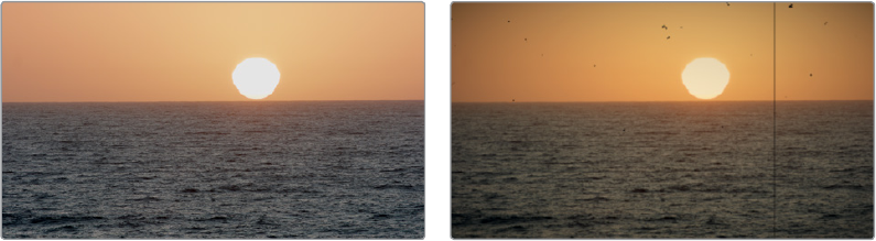
Flicker Addition
On the other hand, why remove flicker when you can add it instead? Found in the “ResolveFX
Transform” category, the Flicker Addition plug‑in adds rapidly animated exposure changes to
make the image appear to flicker, creating animated effects that would be difficult to keyframe
manually. When applied to an image in different ways, this plug‑in can be used to simulate
torchlight, firelight, light fixtures with old ballasts or frayed wiring, or any temporally unstable
light source. For example, you could key only the highlights of a night‑time image, and use
Flicker Addition to affect those isolated highlights.
Two groups of controls let you control the quality of this flickering.
Main Controls
The Flicker Type pop‑up menu lets you apply the flicker as a Lift, Gamma, Gain, or
Vignetteadjustment.
The Range slider lets you set how widely the flickering will vary. Speed lets you adjust how
quickly the flickering is animated. The Smoothness slider lets you adjust the temporal quality of
the flickering, whether it changes abruptly from one value to another (at lower settings) or
whether it makes more continuous transitions from one value to another (at higher settings).
Three checkboxes let you choose which color channels are affected by this flickering.
Flicker Quality
These controls let you adjust the details of how the flickering animates.
The Randomness Scale slider lets you introduce irregularity to the Horizontal, Vertical, and
Rotational motion of the camera shake. The greater this value, the more irregularity will be
introduced. The Randomness Speed slider lets you choose between smoothly erratic motion (at
lower values) or more jagged motion (at higher values).
The Pause Length slider lets you adjust the frequency of intermittent pauses that break up the
random motion added by this filter. The Pause Interval slider lets you adjust the duration of
intermittent pauses that break up the random motion added by this filter. The Pause
Randomness lets you add a degree of randomness to the intervals that happen.
The Random Seed slider lets you alter the value that sets what random values are being 1038
produced. Identical values result in identical randomness.
Film Damage
Found in the “ResolveFX Texture” category. After you’ve used the new ResolveFX Revival
plug‑ins to fix damage in archival footage, you can turn around and use the Film Damage
plug‑in to make brand new digital clips look worn, dirty, and scratched instead. When used in
conjunction with the Film Grain and Flicker Addition plug‑ins, you can convincingly recreate the
feel of poorly kept vintage archival footage.
(Left) Original image, (Right) Result with Film Damage
1-79Chapter – 5 New ResolveFX
Blur and Shift Controls
The three parameters at the top let you alter the foundation of the image to begin creating the
look of an older film. Film Blur lets you add just a bit of targeted defocusing to knock the digital
sharpness out of the image. Temp Shift defaults to warming the image just a bit to simulate the
warmer bulb of a film projector, although you can use it to cool or warm the image in varying
amounts. Tint Shift defaults to yellowing the image to simulate damage to the film dyes, but you
could move the slider in the other direction to add a bit of magenta, simulating a different kind
of dye failure.
Add Dirt
These parameters let you simulate dirt particles (not dust) that have adhered to the film.
Theseare larger specks, although there’s several ways you can customize these.
The Dirt Color control lets you choose what color you want the dirt particles to be
(blacksimulates dirt on a print, while white simulates dirt on a negative). The Changing Dirt
checkbox lets you alternate between simulating temporally unstable dirt on the film
(checkboxon), and dirt on the lens that doesn’t move (checkbox off). Dirt Density lets you
choose more or less dirt particles appearing over time. Dirt Size lets you choose the average
size of dirt particles to appear. Dirt Blur lets you defocus the dirt so it’s not so sharp. Dirt Seed
changes the random distribution of dirt when you change this value, but for any given value,
theresults for any given set of control adjustments remain consistent.
Add Scratch
These parameters add a single scratch to the image, simulating something scratching the
emulsion while the film played.
Scratch Color lets you choose the color you want the scratch to be (scratches can be a variety
of colors depending on the depth of the scratch, type of film, and method of printing). Scratch
Position lets you adjust the scratch’s horizontal position on the image. Scratch Width and
Scratch Strength let you adjust the scratch’s severity, while Scratch Blur lets you defocus it.
The Moving Scratch checkbox lets you choose whether the scratch is jittering around or not.
Moving amplitude determines how far it moves. Moving Speed determines how fast it moves.
Moving Randomness determines how it meanders about, and Flickering Speed determines how
much the scratch flickers lighter and darker in severity.
Add Vignetting
These parameters simulate lens vignetting darkening the edges of the image.
Focal Factor adjusts how far the vignetting extends into the image. Geometry Factor affects
how dark the vignetting is, and how pronounced the edges are. Tilt Amount affects how
balanced the vignetting at the top of the image is versus the bottom of the image, while
TiltAngle affects how balanced the vignetting left of the image is versus the right, but only
when Tilt Amount is set to something other than 0.
1-80Chapter – 5 New ResolveFX
Chapter 6
Fairlight Page
Improvements
The Fairlight Page is full of big new features and small refinements, making
this an even more professional tool for audio postproduction, whether
you’re doing dialog editing, sound design, audio cleanup, or mixing.
Withnew tools for automated dialog replacement, sound effects searching
and auditioning, VSTi support for samplers to do MIDI controller‑driven
foley, 3D audio panning, clip and track bouncing, and numerous new
UIrefinements, controls, and commands for audio playback and editing,
there’s something for every kind of audio professional.
1-81Chapter – 6 Fairlight Page Improvements
Contents
New Fairlight Page Features 1-83
ADR (Automated Dialog Replacement) 1-83
Fixed Playhead Mode 1-90
Video and Audio Scrollers 1-90
3D Audio Pan Window 1-91
Visible Video Tracks 1-92
User‑Selectable Input Monitoring Options 1-93
Commands For Bouncing Audio 1-93
Sound Library Browser 1-94
VSTi Support For Recording Instrument Output 1-96
General Fairlight Page Enhancements 1-99
Normalize Audio Levels Command 1-99
Clip Pitch Control 1-99
Support for Mixed Audio Track Formats from Source Clips 1-100
Oscillator for Generating Tone, Noise, and Beeps 1-100
Compound Clips Breadcrumb ControlsBelow Fairlight Timeline 1-101
Level and Eects Appear in Inspector for Selected Bus 1-101
Audio Waveform Display While Recording 1-101
Audio Playback for Variable Speed Clips 1-101
Paste and Remove Attributes for Clips, Audio Tracks 1-102
Loop Jog Scrubbing 1-102
Improved Speaker Selection Includes Multiple I/O Devices 1-102
Fairlight Page Editing Enhancements 1-103
Media Pool Preview Player 1-103
Edit Page—Compatible Navigation and Selection Keyboard Shortcuts 1-103
Trim Start/End to Playhead Works in the Fairlight Timeline 1-104
New Fade In and Out to Playhead Trim Commands 1-104
Sync Oset Indicator 1-104
1-82Chapter – 6 Fairlight Page Improvements

New Fairlight Page Features
This section describes some of the biggest new features added to the Fairlight page in
DaVinciResolve 15.
ADR (Automated Dialog Replacement)
Clicking the ADR button on the Interface Toolbar opens up the celebrated Fairlight ADR panel,
which provides a thoroughly professional workflow for doing automated dialog replacement.
Dialog replacement, for those who don’t know, is the process whereby audio professionals
bring in actors to re‑record unsalvageably bad dialog recordings from the comfort of their
recording studios, line by line and with a great deal of patience.
The ADR panel on the Fairlight page
It’s an old joke is that ADR isn’t really automatic, but the Fairlight page aims to give you all the
help it can to make this a structured and straightforward process. Simple yet powerful cue list
management lets you efficiently assemble a re‑recording plan. Industry‑standard audio beeps
and visual cues via your BMD video output device help the actors in the booth nail their timings
and their lines. Then, sophisticated take management with star ratings and layered take
organization in the Timeline help you manage the resulting recordings to pick and choose the
best parts of each take when you edit the results.
The ADR Interface
When open, the ADR interface consists of three panels to the left of the Timeline, a Record
panel, a List panel, and a Setup panel. The controls of these panels are described in the order
in which they’re used.
The Setup Panel
As its name implies, the Setup panel is where you configure your ADR session.
1-83Chapter – 6 Fairlight Page Improvements
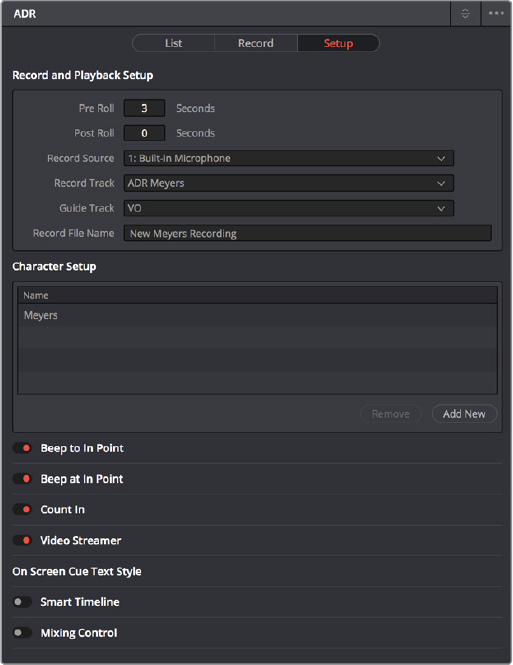
The Setup panel of the ADR interface
This panel presents the following controls:
Pre Roll and Post Roll: Specifies how many seconds to play before and after each
cue’s specified In and Out points, giving actors a chance to listen to what comes before
and after each cue in order to prepare. If you enable the Beep options below, beeps
provide a countdown during the specified pre‑roll.
Record Source: (Disabled until you select a Record Track) A pop‑up menu lets you
choose the input you want to record from, creating a patch to the Record Track.
Record Track: A pop‑up menu lets you choose the track you want to record to.
Selecting a track with this menu creates a patch from the Record Source to the
RecordTrack, and automatically toggles Record Enable on.
Guide Track: A pop‑up menu lets you choose which track the original production audio
you need to re‑record is on. This is used for sending audio playback to the talent to use
as a guide for recording their own replacement performance.
Record File Name: A text entry field that lets you provide a name for the audio files
being recorded to be saved with.
Character List: A list for adding the names of all the characters that have dialog cues
you’ll be re‑recording, to help with cue creation and management. An Add New button
lets you add additional names to this list, while a Remove button lets you delete
characters you no longer need.
Beep to In Point: Enables a three‑beep sequence to be heard leading up to
therecording.
Beep at In Point: Enables one last beep at the In point.
1-84Chapter – 6 Fairlight Page Improvements
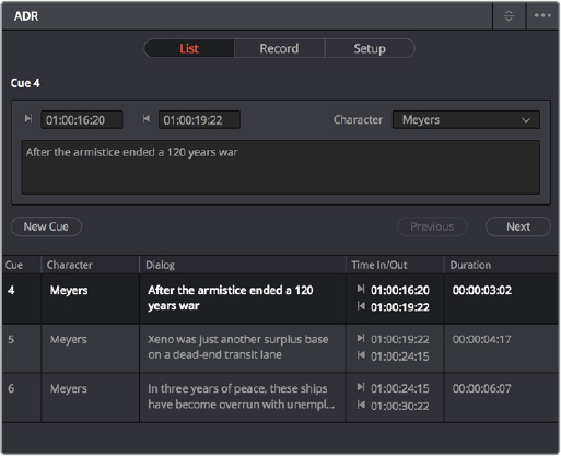
Count In: An onscreen counter that counts down to the start of the cue.
Video Streamer: A visual cue for the talent to watch during pre roll to ready them for
recording. A pair of vertical lines superimposed over the program being output to video
that move towards one another across your video output screen during the pre‑roll
to the cue to give the talent a visual indication of the countdown to the beginning of
the cue. When the beeps play, these lines stretch upward and down briefly. Both lines
come together at the cue point, and a large cross is shown as recording begins.
Smart Timeline: When turned on, this option automatically moves the playhead to each
cue as it’s selected, and zooms in to frame the duration of that cue in the Timeline.
Mixing Control: Enables automated switching of audio playback, to independently
control what the talent and the audio engineer hear at various stages of the ADR
recording process. For example, with this enabled, the Guide track is not routed to the
Control room while the engineer is reviewing a take.
The List Panel
This is where you create a list of cues you need to re‑record, either from within the
Fairlight page, or imported from a .csv file that someone provides you.
The List panel of the ADR interface
This panel presents the following controls:
Cue editing controls: Displays the data for the currently selected cue (or a cue that was
just created). In and Out timecode fields store the timeline In and Out points that were
set when the cue was created, but can be manually edited for fine tuning. A Character
pop‑up menu lets you choose which character that line of dialog belongs to. A text
entry field lets you enter the dialog cue that’s to be re‑recorded, so you and the talent
can both refer to it.
New Cue button: Clicking this button adds a new cue to the list using whatever In and
Out points have been set in the Timeline, and whatever character was last selected.
Cue List: The list of all cues that have been entered or imported. The Cue list can be
filtered using the Filter pop‑up menu at the top‑right of the ADR panel (next to the
option menu). You can choose to show the cues for all characters, or for any selected
combination of characters. You can also choose to hide all cues that are marked as
done to experience the joy of this list shrinking more and more the closer you are to
being finished.
1-85Chapter – 6 Fairlight Page Improvements
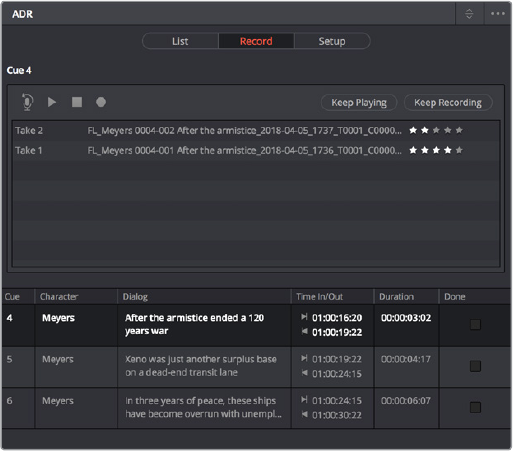
Additionally, the ADR interface option menu has three commands pertaining to the Listpanel:
Import Cue List: Lets you import a properly formatted .csv file to create cues that have
been prepared in a spreadsheet. Correct formatting for cue lists you want to import
is no headers, one line per cue, with four individual columns for In timecode, Out
timecode, Character Name, and Dialog.
Export Cue List: Lets you export the contents of the cue list to a .csv file, for exchange
or safe‑keeping.
Clear Cue List: Deletes all cues in the cue list. It’s recommended you export a copy of
your cue list before eliminating it completely, in case you ever need to revisit a cue.
The Record Panel
This is where you actually run the ADR recording session you’ve set up, using the
dialog cues you’ve put into the Cue List
The Record panel of the ADR Interface
This panel presents the following controls:
Record and rehearse controls: Four transport controls and two buttons let you
control recording during ADR sessions. These controls are only clickable when you’ve
selecteda cue from the Cue List to record.
–Rehearse: Runs the section of the Timeline specified by a cue without actually
recording anything, giving the talent an opportunity to run through their dialog and
practice their timing and delivery. Beeps and on‑screen streamers are not played
during a rehearsal.
–Play: Plays the currently selected take from the Take list (described below). If no take
is selected, the most recently recorded one on top is played.
–Stop: Immediately stops rehearsal, playback, or recording.
–Record: Initiates recording of the cue to the specified audio track, with cue beeps
and video streamer cues.
–Keep Playing: At the end of a take you may wish to keep playing, so the talent
can hear the next section of of the track. Pressing the Keep Playing button at any
time, even while recording, results in post roll being ignored and normal playback
resuming after the cue’s out time.
1-86Chapter – 6 Fairlight Page Improvements
–Keep Recording: At the end of a take you may wish to keep recording until you
manually stop. Pressing the Keep Recording button at any time, even while
recording, results in the Out point of the current cue being ignored and recording
continuing until you stop it.
Take List: The Take list shows every take you’ve recorded for the current cue, with
take number, name, and a five‑star rating that you can set to keep track of which takes
worked and which didn’t. Earlier takes are at the bottom of this list, while recent takes
are at the top (the same order in which the corresponding layered audio clips appear in
the timeline track they’ve been recorded to).
Cue List: The list of all cues that have been entered or imported. The Cue list can be
filtered using the Filter pop‑up menu at the top‑right of the ADR panel (next to the
option menu). You can choose to show the cues for all characters, or for any selected
combination of characters. You can also choose to hide all cues that are marked as
done to experience the joy of this list shrinking more and more the closer you are to
being finished.
Cue List Done column: A sixth column appears in the Record panel only, labeled Done.
It contains check boxes for each cue that you can turn on to keep track of which cues
you’ve successfully finished.
Additionally, the ADR interface option menu has one command pertaining to the Record panel:
Record Early In: Enables recording during pre‑roll, in the event you’re working with
talent that likes to start early.
Setting Up To Do An ADR Session
Setting up to record ADR is straightforward, but requires some steps.
Patching tracks in preparation to record ADR:
1 In the Timeline, create two new audio tracks, one to record ADR to, and another to
route the Oscillator through to play preview beeps.
2 Open Fairlight > Patch Input/Output to choose the Patch window
3 Choose Audio Inputs from the Source pop‑up menu, and choose Track Inputs from the
Destination pop‑up menu, then patch the audio input for your recording microphone to
the track you created to record onto in step 1.
4 Next, choose Osc from the Source pop‑up menu, and patch the Beep output to the
track you created to preview beeps in step 1.
5 Close the Patch Input/Output window.
6 To make sure you can hear the preview beeps, open the Mixer (if necessary), click the
Input pop‑up menu at the top of the channel strip that shows “Beeps,” and choose
Path Settings. When the Path Settings window appears, turn on the Thru button in the
Record Level controls, and close the path settings.
Thru mode places a track into a “live” input mode, bypassing track playback in order to
play the patched input. Thru mode is typically used for external sources that you want
to bring into a mix. While a track is in THRU, there’s need to arm the Record button, the
external source is always feeding to the mix.
7 If you’re recording ADR to your main timeline, Solo the Guide Track, the Record Track,
and the Beep Preview track to focus only on the audio you’re re‑recording.
Now you’re ready to configure the Setup panel.
1-87Chapter – 6 Fairlight Page Improvements
Configuring the Setup panel:
1 Open the ADR interface, and then open the Setup panel.
2 Choose the Pre Roll and Post Roll you want to use, in seconds. A pre roll of at least 3
seconds is recommended to give the talent time to get ready.
3 From the Record Source pop‑up menu, choose the microphone you patched earlier.
4 From the Record Track pop‑up menu, choose the Record Track you created.
5 From the Guide Track pop‑up menu, choose the track with the original production
audio that you’re replacing.
6 At the bottom of this panel, turn on the Preroll Cue options you and the talent want to
use. Options include Beeps to provide an audible lead up to re‑recording, and a Video
Streamer that gives both visual cues and also displays the dialog text for that cue on
screen for the actor to refer to, keeping their eyes on the screen.
Creating and Importing ADR Cue Lists
You must have a list of cues to be able to use the ADR interface properly. There are two ways
you can create a Cue list to record with, make one on the Fairlight page, or import one. If you’ve
been doing all of your dialog editing inside of DaVinci Resolve, you can go ahead and create a
list by marking the sections of the Timeline you need to re‑record and creating cues from
thosetimings.
To manually add cues to the Cue List:
1 Open the Setup panel of the ADR interface, and use the Add New button in the
Character Setup list to create all the character names you’ll be creating dialog cues for.
These will help you to filter and sort the list as necessary later on.
2 Next, open the List panel of the ADR interface. This is where all the controls for creating
and editing cues are.
3 In the Timeline, set In and Out points to mark the section of dialog you want to turn into
a cue. Those timecode values appear in the Cue Editing section of the List panel.
4 In the Cue Editing section, choose the character who’s speaking that cue, and type the
dialog they’re speaking.
5 When you’re done, click New Cue, and that cue will be added to the Cue List.
6 Repeat steps 3 through 5 until you’re finished creating all the cues you intend to
re‑record. If you need to edit any cue, simply click to select that cue, and edit it in the
Cue Editing section above.
To import a .csv file to the Cue List:
1 Choose Import Cue List from the ADR option menu, then use the dialog to choose the
.csv file containing the cue list you were given, and click Open.
2 An ADR Setup dialog appears letting you assign the columns of the .csv file you
selected to the relevant column of the ADR panel. Correct formatting for Cue lists
you want to import is no headers, one line per cue, with four individual columns for In
timecode, Out timecode, Character Name, and Dialog, but if any of these columns are
transposed, you can correct this here.
1-88Chapter – 6 Fairlight Page Improvements
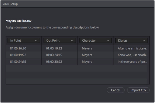
Dialog for rearranging columns of cue data, if necessary
3 Click Import CSV. The cues should appear in the Cue List.
To export a .csv file from the Cue List:
Choose Export Cue List from the ADR option menu, choose a location to save the file,
and click Save.
Recording ADR to the Timeline
Once you’ve configured your workstation for recording, and you’ve set up a cue list to work
with, it’s time to start recording each cue.
To record a cue from the Cue List:
1 Open the Record panel of the ADR interface.
2 If you want to record a particular character’s cues, you can turn off Show All Characters,
and turn off all unnecessary characters, in the ADR option menu.
3 With the list showing the character cues you need, select the cue you want to start
recording. That cue contains the timecode necessary to determine which part of the
Timeline to record to, and the playhead automatically moves to that part of the Timeline.
4 Click the Rehearse button to run through the cue with the talent a few times. Both audio
and video corresponding to that cue will play, including pre roll and post roll.
5 When the talent is ready to try a take, click the Record button, and let the Fairlight page
do the work of playing through pre roll with beep notifications and visual streamer cues,
initiating recording, and then stopping recording automatically once the cue is done.
6 If you or the talent want to hear what the take sounds like again, you can select it in the
Take List and click Play. Depending on how you like the take, you can mark it with the
5‑star ratings control and then record another take.
7 To record another take, click the Record button again. New takes are placed on the
same track using layered audio, so you can record as many takes as you like into the
same area of the Timeline that corresponds to the media you’re replacing. When you’re
finished recording takes, you’ll have a neatly organized stack of alternate takes to draw
upon as you edit the best parts from each recording.
8 When you’re finished recording a cue, click the Done checkbox for that cue, and select
the next cue you want to record. When you’re finished re‑recording dialog, simply close
the ADR interface.
1-89Chapter – 6 Fairlight Page Improvements
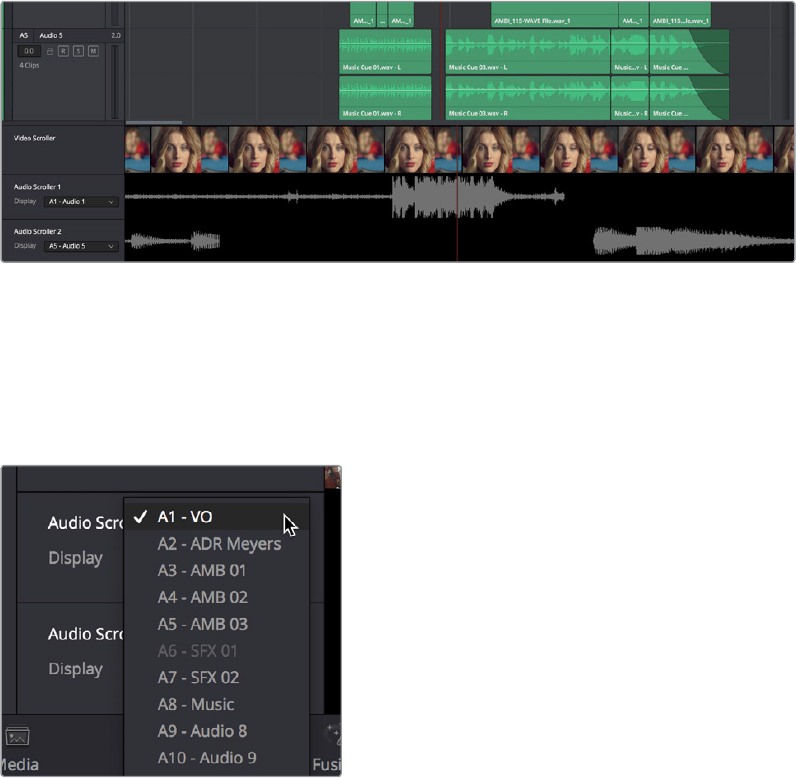
Fixed Playhead Mode
Choosing View > Show Fixed Playhead puts the Fairlight timeline into an audio‑centric mode
where the playhead remains fixed in place, and the Timeline scrolls underneath it as you use
the Transport controls or JKL to play, shuttle, or scrub forward or back.
Video and Audio Scrollers
Checkboxes in the Timeline View Options let you optionally show one “Video Scroller” and up
to two “Audio Scrollers” at the bottom of the Fairlight timeline.
Video and Audio Scrollers at the bottom of the Fairlight timeline
At the default “Low” zoom level, the Video Scroller provides a scrollable frame‑by‑frame
filmstrip view of the video of your program, where one frame of the scroller equals one frame of
your video. Each of the two Audio Scrollers, on the other hand, let you focus on a continuous
waveform view of a particular audio track. You choose which track populates an Audio Scroller
via a pop‑up menu in the Timeline header.
Audio Scrollers showing the pop‑up menu
that selects which track they display
What Are They Used For?
The Audio Scrollers always provide a zoomed‑in view of specific audio tracks that you’re
focused on, regardless of the zoom level of the Timeline tracks above. This means you can
focus on subtle details of the audio of one or two tracks that you’re working on, while the rest of
the Timeline shows you the overall stack of tracks with clips that are playing together at
thatmoment.
Meanwhile, the Video Scroller always shows the exact frame of video that corresponds to the
current moment in time, so it’s an aid to precision editing involving frame‑specific adjustments.
1-90Chapter – 6 Fairlight Page Improvements

Additionally, both the Filmstrip and Waveform viewers scroll continuously during playback,
giving you a preview of what visual actions and audio cues are coming a few moments forward
in time that you can refer to while performing automation or recording foley.
Repositioning the Scroller Playhead
While the Scrollers are visible, the Scroller playhead can be dragged to the left or right in the
Timeline to give you more or less preview room to the right.
Zooming the Video Scroller
Right click on the Video scroller lets you choose a Low, Medium, or High zoom level. At Low,
you get a frame‑by‑frame view of the program that feels like scrolling a strip of film on a
Steenbeck. At Medium and High, you get a progressively abbreviated film strip that lets you
zoom more quickly.
Scrolling the Fairlight Timeline Using the Scroller Tracks
Dragging the scroller tracks to the left or right smoothly scrubs through the Timeline in greater
detail, regardless of the zoom level of the Timeline tracks above.
3D Audio Pan Window
Option‑double‑clicking on the Pan control of the Mixer opens an alternate 3D Audio Pan
window. Whereas the regular Pan window lets you do stereo and conventional 5.1 and 7.1
surround panning, the 3D Audio Pan window lets you do the kind of spatial audio positioning
enabled by advanced surround formats such as Auro 3D and NHK 22.2 (more information about
specific support for these and other formats will come later).
The 3D Pan window
The 3D Audio Pan window has a few more controls than the ordinary Pan window:
Pan enable: Toggles the entire panning effect on and off.
Panner viewer: A large 3D representation of the listener’s perceived sound stage, with
a blue sphere that represents the position of the track’s audio being positioned within
that space, that casts a shadow straight down on the floor and projects a blue box on
the four walls of this space to indicate its position more concretely.
1-91Chapter – 6 Fairlight Page Improvements
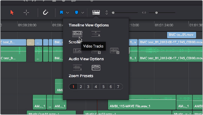
Front panner: A 2D panning control that represents the horizontal Left/Right axis and
the vertical Up/Down axis, letting you make these specific spatial adjustments.
Side panner: A 2D panning control that represents the horizontal Front/Back axis and
the vertical Up/Down axis, letting you make these specific spatial adjustments.
Top panner: A 2D panning control that represents the horizontal Left/Right axis and the
vertical Front/Back axis, letting you make these specific spatial adjustments.
Left/Right: A 1D knob that changes the balance of signal between the left and right
side speakers you’re outputting to, depending on what speaker format you’re mixing to.
Front/Back: A 1D knob that changes the balance of signal between the front and
back sets of speakers you’re outputting to, depending on what speaker format you’re
mixingto.
Rotate: A 1D knob that simultaneously adjusts the left/right and front/back pan controls
in order to horizontally rotate a surround mix about the center of the room.
Tilt: A 1D knob that simultaneously adjusts the left/right and Up/Down pan controls in
order to vertically rotate a surround mix about the center of the room.
Spread: Only available when a linked group is selected. Spread adjusts the perceived
size of a surround mix.
Divergence: Spreads the signal for an individual feed across more of the adjacent
loudspeakers, making the perceived size of the sound source larger.
Boom: The send level of that track to the LFE part of the mix. An On button enables this
functionality, while a Pre button lets you adjust the “dry” part of the signal separately
from the “Wet” part of the signal when effects are applied.
Visible Video Tracks
A checkbox in the Timeline View Options pop‑up menu of the toolbar lets you display small
versions of the video tracks in the Fairlight timeline, for reference. These video tracks are
uneditable; they’re simply there so you can see which audio clips correspond to which video
items, and so they can be used as snapping targets for positioning audio.
Showing video tracks on the Fairlight page
1-92Chapter – 6 Fairlight Page Improvements
User-Selectable Input Monitoring Options
The Fairlight > Input Monitor Style submenu presents five options governing how you want to
monitor inputs while recording.
Input: You only hear the live signal being input, you never hear the contents of tracks.
Auto: When one or more tracks is armed for recording, you hear the live input signal, on
playback you hear the contents of each track.
Record: You only hear the live input signal while actively recording, meaning the
Record button has been pressed while one or more tracks are armed for recording.
Youdon’t hear the input signal while tracks are merely armed.
Mute: You hear nothing.
Repro: While recording, you only hear what’s just been recorded, played from the track.
In other words, you’re not listening to the live input, but you’re reviewing what’s just
been recorded as it’s recording.
Commands For Bouncing Audio
Two new commands are available for bouncing audio on the Fairlight page. Bouncing audio
refers to mixing and rendering audio from Timeline tracks to another track on the Timeline,
inthe process “baking in” processor intensive effects and complicated fixes to create a new
pieceof audio.
Timeline > Bounce Selected Tracks to New Layer
Timeline > Bounce Mix to Track
To use Bounce Selected Tracks to New Layer:
1 Set In and Out points to define the range of the Timeline you want to bounce. If you
don’t do this, nothing will happen.
2 Command click the track header or mixer channel strips of the tracks you want to
bounce to select them.
3 Choose Timeline > Bounce Selected Tracks to New Layer.
The audio on each track is processed and rendered and appears as the top layer of
audio on that track. The original audio with live effects is still available as the bottom of
the stack of layered audio on that track.
To use Bounce Mix to Track:
1 Choose Timeline > Bounce Mix to Track. The Bounce Mix to Track window appears,
showing each Main, Submix, and Auxiliary that’s currently available.
2 In the Destination Track column, set which mixes you want to bounce by choosing
either New Track or a specific track from the pop‑up menus, then click OK.
The specified Mix is processed, mixed, and bounced to the specified track as a
newpieceofaudio.
1-93Chapter – 6 Fairlight Page Improvements
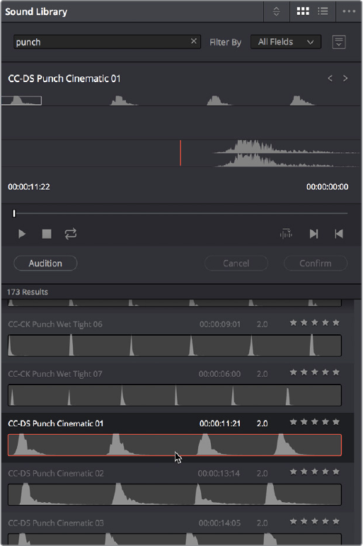
Sound Library Browser
A Sound Library panel is available from the Interface toolbar for browsing sound effects libraries
that you have available to you, on your system or on a SAN you’re connected to. It includes the
capability of scanning specified file paths to catalogue available sound files and their metadata,
storing this data within the currently selected project database (or another database that you
select) to use when searching for the perfect sound effect within your library. Once you’ve
catalogued your sound effects collection, it’s easy to search for sounds, preview what’s been
found in the list, and edit the one you like best into the timeline.
The Sound Library panel
The Sound Library panel has the following controls:
List display controls: The Sound Library title bar has controls for sorting the sound
effects list, showing it in List or Icon view, and an Option menu with various other
settings and commands.
Search field: Enter a term into the search field to look for sound effects files using
that metadata. A pop‑up menu to the right lets you search the database by Name or
Description metadata.
Library controls: Clicking the Library button (to the right of the Search field) reveals a
menu that lets you choose which database to use for searching (and cataloging) sound
effects collections. Each PostgreSQL database can have a different catalog.
1-94Chapter – 6 Fairlight Page Improvements
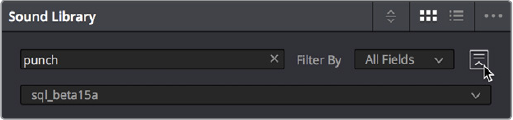
Choosing a library to search
Preview and Audition controls: These controls let you preview and audition sound
effects that you find as you look for the right one.
–Clip name: The name of the current clip you’ve selected.
–Next/Previous buttons: Two buttons let you select the next or previous sound effect
clip in the Sound Effect list.
–Zoom control: Controls the zoom level of the Playthrough waveform.
–Duration field: Shows the duration of the current clip, or of the section of the clip
marked with In and Out points.
–Playhead timecode field: The timecode of the playhead’s position.
–Navigation waveform: The waveform of the entire sound effect appears here,
making it easy to jump to different parts of the selected clip. All channels are
summed together in this display.
–Playthrough waveform: A zoomed‑in section of the selected clip that lets you see
more waveform detail for setting In, Out, and Sync points.
–Jog Bar: Lets you scrub around the clip.
–Transport controls: Stop, play, and Loop buttons let you control playback, although
you can also use the space bar and JKL controls. Right‑click the Stop button to
switch it into “Stop and Go to Last Position” mode.
–Marking controls: The sync point button lets you mark which frame of the sound effect
you want to use to sync to a frame of the Timeline when you audition. In and Out points
let you mark how much of the sound effect clip you want to edit into the Timeline.
–Audition controls: The Audition button puts you into Audition mode where the
currently selected sound effect clip appears at the position of the playhead in
the currently selected Timeline track. Cancel and Confirm buttons let you choose
whether you want to remove the clip from the Timeline and try again with another
clip, or leave the sound effect clip in.
Sound Effect list: All sound effects clips that match the current search criteria appear in
this scrollable list. Each item in the list shows its name, duration, channel mapping, and
star ratings that you can customize.
To catalogue all audio files within a given file path:
1 Open the Sound Library.
2 (Optional) Click the Library button (to the right of the Search field), and select which
PostgreSQL‑based project database you want to save the resulting metadata analysis
to using the Library pop‑up menu that appears. The current database is selected
by default. If you’re using a disk‑database instead, the top compatible PostgreSQL
database in the list will be the default.
3 Click the Option menu and choose Add Library. From the file dialog that appears, select
the top‑most directory of a file path that contains sound effects; if you’ve selected a
directory with sub‑directories inside, each subdirectory will be examined forcontent.
4 Click Open.
1-95Chapter – 6 Fairlight Page Improvements
A progress bar will show you how long the operation will take. When you’re finished, a dialog
will appear letting you know how many clips were added to the current library.
To search for a specific sound effect and edit it into the Timeline:
Type a search term into the Search field. Optionally, you can click the Library button to
the right of the search field, and use the Type, Duration, and Format pop‑up menus to
help limit your search.
All audio cues that include the search term in their file names will appear in a list below.
Selecting an item on the list loads it into the preview player where you can play it or
audition it in your timeline.
Auditioning clips you’ve found in the Timeline:
1 Select a sound effect clip you’ve found from the list that you want to audition in
theTimeline.
2 Move the playhead to the part of the sound effect that you want to sync to, and click
the Sync Point button to place a sync mark on that clip. For example, if you’re syncing a
car door closing, you might sync to the peak of the “slam.”
3 Set In and Out points to define the range of the sound effect you want to potentially use.
4 Select a track you want to preview the sound effect in by clicking its track header or
Mixer channel strip.
5 Position the playhead at the place in the Timeline you want to align the sync mark in the
sound library to.
6 Click the Audition button in the Sound Library. That clip now appears, temporarily, in the
Timeline, and you can play through that section of the Timeline to see how you like the
sound effect in context with the rest of the mix.
7 If you like the sound effect, click Conform to keep it in the Timeline. If you don’t,
clickCancel.
VSTi Support For Recording Instrument Output
DaVinci Resolve 15 introduces support for VSTi instruments working with connected MIDI
controllers to trigger instrument sounds that can be recorded live on audio tracks of the
Timeline. This is intended to be used for loading a VSTi sampler with foley sounds such as
footsteps or punches, so you can perform these sounds in real time and record the result to
another track as you watch performers walking or punching in the edit, even if you lack a
recording booth with foley pits and props.
On the other hand, if you’re a musician, there’s nothing stopping you from loading VSTi musical
instruments of different kinds for playback, and using the Fairlight page as a multi‑track
recorder. DaVinci Resolve doesn’t have MIDI sequencing functionality, but you can record live
playback straight to the Timeline, using layered audio to manage multiple takes for later
re‑editing. Bet you never thought you’d be recording music in DaVinci Resolve….
1-96Chapter – 6 Fairlight Page Improvements
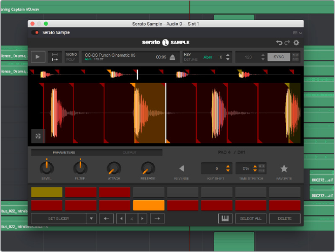
A VST Instrument (in this case Serato Sample) loaded into a track of the timeline
To enable a MIDI controller in macOS:
1 If DaVinci Resolve is running, quit before connecting your MIDI controller and
settingitup.
2 On macOS you’ll use the Audio Midi Setup utility to choose output hardware and
select a speaker configuration to be made available on your system. In the Finder, use
Spotlight and search for Audio MIDI Setup to open it.
3 In Audio MIDI Setup, choose Window > Show MIDI Studio. A window showing icons for
all connected MIDI controllers appears. Your controller should be showing an icon. If it’s
not, you may need to install drivers for it.
4 Select the icon for your controller and turn on the “Enter test MIDI setup mode” button
(it looks like a little keyboard) to test if your keyboard is connecting with the computer.
Ifit is, then turn this off.
For more information on setting up MIDI on different systems, see the DaVinci Resolve
Configuration Guide, available on the web from the Blackmagic Design support page at
https://www.blackmagicdesign.com/support/family/davinci‑resolve‑and‑fusion.
To set up the Fairlight page for VSTi instrument recording using a sampler:
1 Open DaVinci Resolve 15.
2 Make sure you have at least two available audio tracks in the Timeline, one for the
instrument you’ll be playing, and one to record into. This example will use tracks A4 and
A5 for this.
3 Open the Effects Library, find a VSTi sampler you have installed on your system, and
drag it to the track header of the track you want to use for playing, for example track A4.
Massively‑featured sampler/synth combinations such as Native Instruments Kontakt
and Steinberg Halion are ubiquitous and useful when you want to specifically map a
collection of sound effects to specific keys or pads to create re‑usable multi‑purpose
instruments. However, more streamlined samplers that emphasize automatic audio clip
1-97Chapter – 6 Fairlight Page Improvements
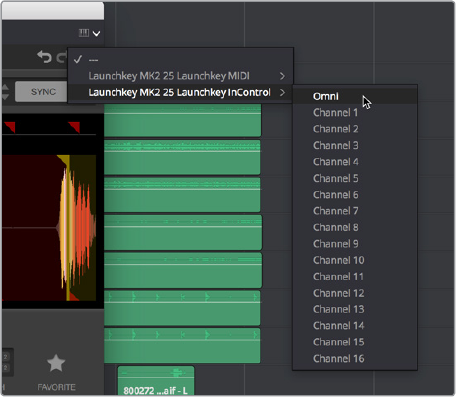
slicing such as Serato Sample (Windows and macOS) or Image Line Slicex (Windows
only) can make short work of the more specialized task of loading library sound effects
recordings (or custom recordings you create) with multiple footsteps, punches,
keyboard presses, cloth rustles, or other foley activities, and quickly splitting them up
into individually playable samples you can trigger with pads or a keyboard.
4 When the VSTi interface window appears, open the MIDI menu at the upper right‑
hand corner of the VSTi window and choose the correct MIDI channel from your MIDI
controller’s submenu. If you’ve selected the correct MIDI channel, the instrument
should start responding to the keys or pads on your controller.
Enabling MIDI control
5 Next, configure the VSTi instrument you’re using to play the sound effects you want
to use for foley. In this example, the Serato Sample VSTi plug‑in is being used to
automatically slice up a recording of footsteps from one of Sound Ideas’ many sound
effects libraries.
Because the VSTi you added is patched to that track’s Insert (if you look at the Mixer
you should see that the I button is enabled on the channel strip the instrument is
patched to), the Send is PRE the Instrument. This means you need to patch that track’s
Track Direct output to the input of another track to record the instrument.
6 Choose Fairlight > Patch Input/Output to open the Patch Input/Output window, then set
the Source pop‑up menu to Track Direct and the Destination pop‑up menu to Track
Input. Click Audio 4 to the left, and Audio 5 to the right, and click the Patch button; this
sets you up to play the VSTi plug‑in on track A4, and record its output on track A5.
Be aware that after patching Track Direct from the track with the instrument to the track
you’re recording onto, you also need to turn “Direct Output” on for that track in the Path
Settings of that track’s channel strip in the Mixer.
7 Open the Mixer (if necessary), click the Input pop‑up menu at the top of the channel
strip that shows the VSTi instrument you’re using, and choose Path Settings. When the
Path Settings window appears, click the ON button for Direct Output, then close the
path settings window.
At this point, you’re ready to begin recording.
1-98Chapter – 6 Fairlight Page Improvements
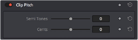
To play and record a VSTi instrument:
1 Click the Record Arming button of the track you’re recording to (in this example A5),
move the playhead to where you want to begin recording, and then click the Record
button to begin recording.
2 As the video of your program plays, use your MIDI controller to trigger sound effects as
necessary. When you’re finished, click the Stop button.
If necessary, you can record multiple takes using track layering until you get the timing
right. When you’re finished, you can remove the instrument from the track it’s on since
the recorded audio is all you need.
General Fairlight Page Enhancements
A wide variety of enhancements and new features have been implemented throughout the
Fairlight page to improve everyday workflows.
Normalize Audio Levels Command
A Normalize Audio Levels command automatically adjusts the level of clips to peak at a specific
target level, measured in dBFS. This is only a volume adjustment, no dynamics are applied, so
the result of using this command is that the loudest parts of each selected clip are going to
match one another at the target level. This command is also available in the Edit page.
To normalize one or more selected audio clips:
1 Right‑click one of the selected clips and choose Normalize Audio Levels
2 A dialog appears with two options. Choose the Reference Level that you want to set
the peak volume of the selected clips to match, and then choose how you want to set
the level of multiple selected clips:
When Set Level is set to Relative, all selected clips are treated as if they’re one clip, so
that the highest peak level of all selected clips is used to define the adjustment, and
the volume of all selected clips is adjusted by the same amount. This is good if you
have a series of clips, such as a dialog recording, where the levels are consistent with
one another, and you want to normalize all of them together.
When Set Level is set to Independent, the peak level of each clip is used to define
the adjustment to that clip, so that the volume of every selected clip is adjusted by
an amount specific to that clip. The end result may be a set of very different volume
adjustments intended to make the peak levels of each audio clip match one another.
This is good if, for example, you’re trying to balance a series of different sound effects
with one another that have very different starting levels.
Clip Pitch Control
Selecting a clip and opening the Inspector reveals a new set of Clip Pitch controls that let you
alter the pitch of a clip without changing the speed. Two sliders let you adjust clip pitch in Semi
Tones (large adjustments, a twelfth of an octave) and Cents (fine adjustments, 100th of an octave).
Clip Pitch Control in the Inspector
1-99Chapter – 6 Fairlight Page Improvements

Support for Mixed Audio Track Formats from Source Clips
DaVinci Resolve 15 now supports media with multiple audio tracks that have differently
formatted channels embedded within them. For example, a clip with one stereo track, one 5.1
surround track, and six mono tracks can all be appropriately set up in the Audio panel of Clip
Attributes after that clip has been imported.
The Audio panel of Clip Attributes now has controls over what format (Mono, Stereo, 5.1, 7.1,
Adaptive) the channels embedded within a particular clip should be configured as. This means
that you can set up clips with multiple tracks, each one using potentially different formats of
audio employing different combinations of clips, which is handy for mastering.
Clip Attributes now lets you assign channels among
different tracks with different channel assignments
Oscillator for Generating Tone, Noise, and Beeps
The Fairlight page has a general purpose Oscillator, the settings of which you can customize by
choosing Fairlight > Oscillator Settings. This opens the Oscillator Settings window that you can
configure to generate tones, noise, or beeps using five sets of controls:
Enable/Disable Oscillator toggle: Lets you turn the Oscillator on or off system‑wide.
Frequency dial: Sets a custom frequency of oscillating tone, from 20 Hz to 10kHz.
Defaults to 1kHz.
Level dial: Sets the output level for the tone or noise, from –50dB to +10dB.
Defaultsto–15 dB.
Frequency presets: Four buttons let you choose from four commonly used tones,
100Hz, 440 Hz, 1 kHz, and 2 kHz.
Noise type buttons: Two buttons let you choose from White noise or Pink noise.
1-100Chapter – 6 Fairlight Page Improvements
You can set up the Oscillator to output whatever kind of tone or noise you require, and then
patch it to tracks for recording tones, or patch it to audio outputs for calibrating speakers. If you
use the beep options of the ADR panel, those are performed via the Oscillator.
To play the Oscillator out of your speakers:
1 Choose Fairlight > Patch Input/Output to open the Patch Input/Output window.
2 Choose Osc from the Source pop‑up menu, and choose Audio Outputs from the
Destination pop‑up menu.
3 At the left, click the button of what you want to output, Osc (Oscillator) or Noise.
4 At the right, click the connected audio outputs that you want to patch to, and click
Patch. Tone or noise should immediately start playing out of your configured speakers.
5 To stop, select one of the patched buttons, and click Un‑Patch.
To record a tone or noise from the Oscillator to an audio track:
1 Choose Fairlight > Patch Input/Output to open the Patch Input/Output window.
2 Choose Osc from the Source pop‑up menu, and choose Track Input from the
Destination pop‑up menu.
3 At the left, click the button of what you want to output, Osc (Oscillator) or Noise.
4 At the right, click the connected audio outputs that you want to patch to, and click
Patch. Close the Patch Input/Output window.
5 Click the Arm Record (R) button in the track header of the track you patched the
Oscillator to. If your Main is properly patched to your outputs, you should hear the tone
or noise, and that track’s audio meter should immediately rise to the level being output
by the Oscillator.
6 Click the Record button of the Transport controls to initiate recording of that tone to
the patched track. Click the Stop button or press the spacebar to halt recording when
you’re done.
Compound Clips Breadcrumb
ControlsBelow Fairlight Timeline
When compound clips containing audio are opened in the Fairlight page, breadcrumbs
controlsappear beneath the Timeline that let you exit the compound clip and get back to the
masterTimeline.
Level and Effects Appear in Inspector for Selected Bus
When you select a Main, Submix, or Auxiliary bus channel strip in the Mixer, the Inspector
updates with the Volume and any plug‑ins that have been applied to that bus.
Audio Waveform Display While Recording
DaVinci Resolve is able to draw an audio waveform for audio that’s being recorded, in real time.
This gives you immediate feedback that the input you’re recording is properly connected or not.
Audio Playback for Variable Speed Clips
Video/Audio clips with variable speed effects applied to them can now play either
pitch‑corrected or un‑pitch‑corrected variable speed audio. An option in the Speed menu of
the Retime controls lets you choose whether or not the audio is pitch‑corrected.
1-101Chapter – 6 Fairlight Page Improvements

Paste and Remove Attributes for Clips, Audio Tracks
The Fairlight page now has Paste Attributes and Remove Attributes commands that allow for
the copying and resetting of audio parameters and effects, similar to the same commands on
the Edit page.
Loop Jog Scrubbing
Currently available only on the Fairlight page, choosing Timeline > Loop Jog enables a brief
sample preview to be heard while scrubbing the playhead through the Timeline. This can make
it easier to recognize bits of dialog or music as you’re quickly scrubbing through tracks, in
situations where you’re trying to locate specific lines or music cues. It also enables this brief
sample preview to loop endlessly when you hold the playhead on a frame, so you can pause
while scrubbing and hear (by default) the current 80 ms prior to the playhead as it loops.
A pair of settings in the User Preferences let you customize this behavior.
Loop Jog Alignment: Three options let you choose whether you loop audio Pre
the position of the playhead, Centered on the playhead, or Post the position of the
playhead.
Loop Jog Width: A field lets you choose how many milliseconds of audio to loop
when Loop Jog is enabled. How many milliseconds of audio corresponds to one
frame depends on the frame rate of the video. For example, at a frame rate of 25 fps,
there are 1000/25 = 40 ms per frame, so the default value of 80 ms equals two frames
oflooping.
Improved Speaker Selection Includes Multiple I/O Devices
The Speaker Setup controls now provide the option to assign specific Monitor Sets to specific
audio I/O devices via a new Device pop‑up menu, making it possible to listen to different
speakers via different audio I/O boxes. Every compatible audio I/O device connected to your
workstation appears in the Device pop‑up menu.
Assigning different audio I/O devices to different speaker configurations
IMPORTANT: This feature works great with clips that were imported linked into the
Media Pool, or that were synced in the Media Pool and then edited into the Timeline
linked. However, clips that were manually linked together in the Timeline using the Link
Clips command won’t play audio properly if you create variable speed effects.
However, there’s a quick fix, which is to drag manually linked clips from the Timeline to
the Media Pool to create a new source clip, and then drag that new source clip back to
the Timeline.
1-102Chapter – 6 Fairlight Page Improvements
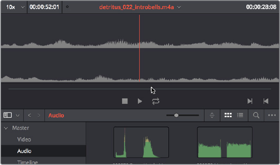
Fairlight Page Editing Enhancements
The following edit‑specific enhancements have been added to the Fairlight page.
Media Pool Preview Player
The Media Pool has a preview player at the top that provides a place to open selected source
clips in the Media Pool, play them, add marks to log them, and set In and Out points in
preparation for editing them into the Timeline via drag and drop. The Media Pool Preview Player
effectively acts as a Source monitor for editing in the Fairlight page.
The preview player in the Media Pool
Various viewing controls populate the title bar at the top. A pop‑up menu at the upper
left lets you choose a zoom level for the audio waveform that’s displayed. To the right
of that, a Timecode window shows you the duration of the clip or the duration that’s
marked with In and Out points. Next to the right, a real‑time performance indicator
shows you playback performance. In the center the title of the currently selected clip
is shown, with a pop‑up menu to the right that shows you the most recent 10 clips
you’ve browsed. To the far left, a Timecode field shows you the current position of
the playhead (right‑clicking this opens a contextual menu with options to change the
timecode that’s displayed, and to copy and paste timecode).
The center of the Media Pool Preview Player shows you the waveforms in all channels
of the currently selected clip, at whatever zoom level is currently selected.
Transport controls at the bottom consist of a Jog bar for scrubbing, Stop, Play, and Loop
buttons, and In and Out buttons.
Edit Page—Compatible Navigation
and Selection Keyboard Shortcuts
Certain navigation and selection keyboard shortcut have been changed in the Fairlight page to
be consistent with identical operations on the Edit page:
Previous Frame (Left Arrow)
Next Frame (Right Arrow)
Previous Edit (Up Arrow)
Next Edit (Down Arrow)
Timeline > Audio Track Destination
1-103Chapter – 6 Fairlight Page Improvements

The previous Fairlight commands that were mapped to the Arrow keys have been preserved,
but now require modifiers to be used:
Up and Down Arrow is now Command‑Option‑Up/Down Arrow.
Left and Right Arrow is now Command‑Option‑Left/Right Arrow.
Trim Start/End to Playhead Works in the Fairlight Timeline
The following Edit page trim commands are now available for editing on the Fairlight page:
Trim Start (Shift‑Left Bracket)
Trim End (Shift‑Right Bracket)
New Fade In and Out to Playhead Trim Commands
A pair of commands in the Trim menu let you move the playhead over a clip, and use the
playhead position to “Fade In to Playhead” or a “Fade Out to Playhead.” These commands work
in both the Edit and Fairlight pages.
(Left) Placing the playhead where you want a fade in to end, (Right) Using Fade In to Playhead
Sync Offset Indicator
Audio clips in the Fairlight page now display “out‑of‑sync” or sync offset indicators when they’re
moved out of sync with the video items they’re linked to.
If you’ve moved an audio clip out of sync with the video clip it’s linked to, there’s an easy way of
getting them back into sync, by right‑clicking the red out‑of‑sync indicator of any clip and
choosing one of the available commands:
Slip into place: Slips the content of the selected clip, without moving the clip, so that it’s
in sync with the other items that are linked to that clip.
Move into place: Moves the selected clip so that it’s in sync with the other items that
are linked to that clip.
1-104Chapter – 6 Fairlight Page Improvements
Chapter 7
FairlightFX
DaVinci Resolve 15 introduces FairlightFX, a DaVinci Resolve‑specific
audio plug‑in format that runs natively on macOS, Windows, and Linux,
providing high‑quality audio effects with professional features to all
DaVinci Resolve users on all platforms. Thirteen new audio plug‑ins that
can be used both in the Edit and the Fairlight page include a wide variety
of plug‑ins for repairing faulty audio, creating effects, and simulating
spaces. This chapter explains what they do and how to use them.
1-105Chapter – 7 FairlightFX
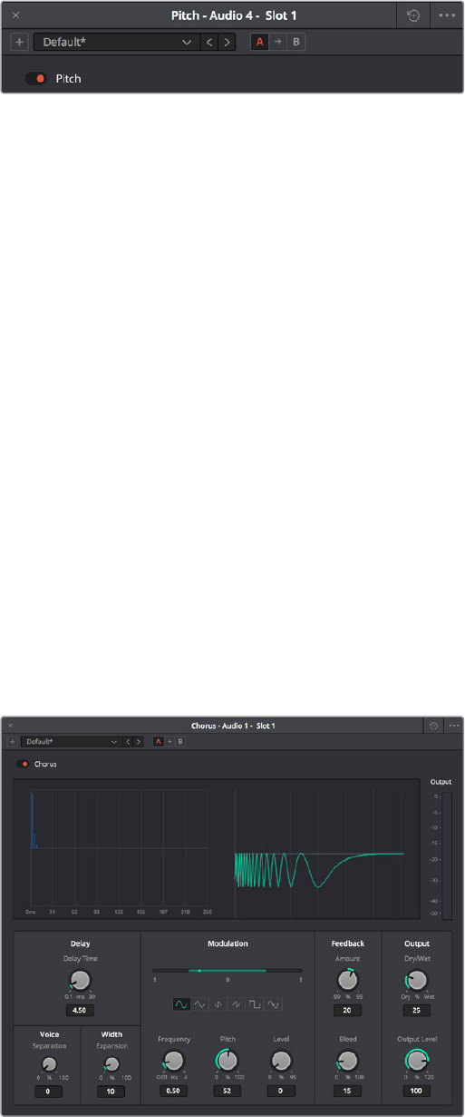
Common Controls For All FairlightFX
Before going into the specific controls of each FairlightFX plug‑in, there are some common
controls that all plug‑ins share, found at the top of the custom GUI window for each plug‑in.
Common controls for all FairlightFX
Presets: A cluster of controls that let you recall and save presets specific to each plug‑in.
–Add Preset button: Click this button to save the current settings of the FairlightFX
you’re using. A dialog lets you enter a Preset name and click OK.
–Preset pop-up menu: All presets for the currently open plug‑in appear in this menu.
–Previous/Next preset buttons: These buttons let you browse presets one by one,
going up and down the list as you evaluate their effects.
A/B Comparison: A set of buttons that lets you compare two differently adjusted
versions of the same plug‑in. The A and B buttons let you create two sets of
adjustments for that plug‑in, and toggle back and forth to hear which one you like
better. The arrow button lets you copy the adjustments from one of these buttons to
the other, to save the version you like best while experimenting further.
Reset: A single reset control brings all parameters in the current plug‑in to their
defaultsettings.
Chorus
An effects plug‑in. A classic Chorus effect, used to layer voices or sounds against modulated
versions of themselves to add harmonic interest in different ways.
An animated graph shows the results of adjusting the Modulation parameters of this plug‑in,
giving you a visualization of the kind of warble or tremolo that will be added to the signal as you
make adjustments.
The Chorus FairlightFX
1-107Chapter – 7 FairlightFX
Chorus has the following controls:
Bypass: Toggles this plug‑in on and off.
Input Format: (Only visible when Echo is inserted on a multi‑channel track.) Lets you
choose how multiple channels are input to the echo. Stereo sets separate Left and
Right channels. Mono sums Left and Right to both channels. Left inputs the Left channel
only, and Right inputs the Right channel only.
Delay: The amount of delay between the original sound and the Chorus effect.
–Delay Time: Length of the Chorus delay lines.
–Separation: Time separation of the delay voices.
–Expansion: Sets L/R length differences, phase offset of modulators
Modulation: These controls adjust the low frequency oscillator (LFO) that drives the
tremolo of the chorus effect in different ways.
–Waveform: Specifies the shape of the LFO that modulates the rate of the Chorus,
affecting the timing of the oscillations. There are six options: Sine (smooth
oscillations), Triangle (sudden oscillations), Saw1, Saw2 (jerky oscillations), Square
(hard stops between oscillations), and Random (randomly variable oscillations).
–Frequency: Rate of LFO controlling the Chorus. Lower values generate a warble,
higher values create a tremolo.
–Pitch: Amount of frequency modulation, which affects the pitch of the Chorus.
–Level: Depth of level modulation. Affects the “length” of the segment of Chorus
that’s added to the sound. Low values add only the very beginning of the Chorus
effect, high values add more fully developed Chorus warble or tremolo.
Feedback
–Amount (%): The percentage of signal fed back to the Chorus Delay Line. Values can
be positive or negative, the default is 0 (no effect). Increasing this parameter adds
more of the Chorus effect to the signal, lowering this parameter adds more of the
inverted Chorus effect to the signal. At values closer to 0, only a faint bit of Chorus
can be heard in the audio, but at values farther away from 0 (maxing at +/‑ 99), a
gradually pronounced Chorus becomes audible.
–Bleed (Hz): Amount of feedback which bleeds into the opposite channel (Stereo
mode only).
Output: Controls for adjusting the final output from this plug‑in.
–Dry/Wet (%): A percentage control of the output mix of “dry” or original signal to
“wet” or processed signal. 0 is completely dry, 100% is completely wet.
–Output Level (dB): Adjusts the overall output level of the affected sound.
1-108Chapter – 7 FairlightFX

De-Esser
A repair plug‑in specific to dialog. The De‑Esser is a specialized filter that’s designed to reduce
excessive sibilance, such as hissing “s” sounds or sharp “ts” sounds, in dialog or vocals.
A graph shows you which part of the signal the controls are set up to adjust, while reduction and
output meters let you see which part of the signal is affected and what level is being output.
The De‑Esser FairlightFX
The De‑Esser has the following controls:
Bypass: Toggles this plug‑in on and off.
Frequency Range: Two controls let you target the frequency of the “s” sound for a
particular speaker.
–Target Frequency: A knob that lets you target the frequency of the offending
sibilance. Sibilant sounds are usually found in the range of 5 ‑ 8kHz.
–Range: switches the operational mode of the De‑esser. Three choices (from top to
bottom) let you switch among Narrow Band, Wide Band, and All High Frequency
which processes all audio above the source frequency.
Amount: Adjusts the amount de‑essing that’s applied.
Reaction Time: Adjusts how suddenly de‑essing is applied. There are three choices.
–Relaxed: Equivalent to a slow attack.
–Fast: Equivalent to a fast attack.
–Pre-emptive: A “lookahead” mode.
1-109Chapter – 7 FairlightFX
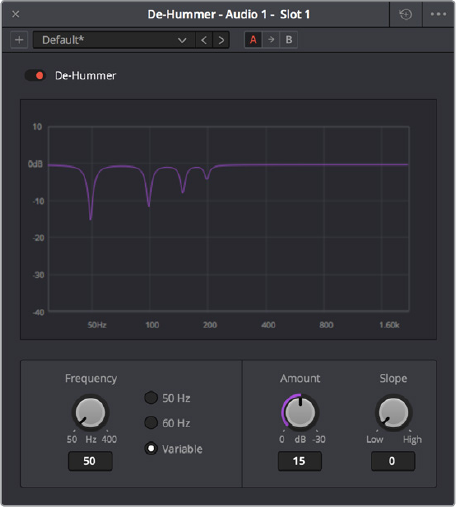
De-Hummer
A repair plug‑in with general applications to any recording. Eliminates hum noise that often
stems from electrical interference with audio equipment due to improper cabling or grounding.
Typically 50 or 60 cycle hum is a harmonic noise, consisting of a fundamental frequency and
subsequent partial harmonics starting at twice this fundamental frequency.
A graph lets you see the frequency and harmonics being targeted as you adjust this
plug‑in’scontrols.
The De‑Hummer FairlightFX
De‑Hummer has the following controls:
Bypass: Toggles this plug‑in on and off.
Frequency: Target source fundamental frequency. A knob lets you make a variable
frequency selection, while radio buttons let you select common frequencies that
correspond to 50Hz/60Hz electrical mains that are the typical culprits for causing hum.
Amount: Adjusts how much De‑Hum extraction you want to apply.
Slope: Adjusts the ratio of fundamental frequency to partial harmonics, the adjustment
of which lets makes it possible for various kinds of hum to be targeted. For example, a
value of 0 biases hum extraction towards the fundamental frequency, while a value of
0.5 gives equal extraction of all harmonics (up to 4), and finally a value of 1.0 targets the
higher frequency partials.
1-110Chapter – 7 FairlightFX
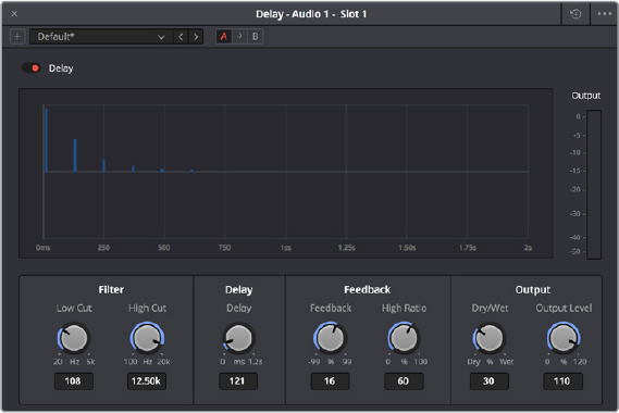
Delay
An effects plug‑in. A general purpose stereo delay effect, suitable for tasks varying from track
doubling, to early reflection generation, through simple harmonic enhancement. Processes in
stereo or mono, depending on the track it’s applied to.
A graph shows the timing and intensity of the echoes generated by this plug‑in on each
channel, and an Output meter displays the output level of the resulting signal.
The Delay FairlightFX
Delay has the following controls:
Bypass: Toggles this plug‑in on and off.
Input mode: (Only visible when Delay is inserted on a multi‑channel track.) Lets you
choose how multiple channels are input to the delay. Stereo sets separate Left and
Right channels. Mono sums Left and Right to both channels. Left inputs the Left channel
only, and Right inputs the Right channel only.
Filters: Alters the proportion of frequencies that are included in the delay effect.
Whenthe Delay plug‑in is inserted on a Mono Channel, the Left and Right sections are
replaced with a single “Delay” section.
–Low Cut (Hz): A global High Pass filter.
–High Cut (Hz): A global Low Pass filter.
Delay: Adjusts the timing of the delay.
–Left/Right Delay (ms): Delay time of each channel.
–Left/Right Feedback (%): Feedback % of the Left or Right channel back to
itself. A negative value equates to % of feedback with a phase reverse from the
originalsignal.
Feedback: Controls for adjusting the amount of bleed between channels.
–High Ratio: Adjusts the frequency of a damping filter for the feedback signal.
–Stereo Bleed: Adjusts the proportion of signal from Left and Right channel feedback
which feeds into the opposite channel. When the Delay plug‑in is inserted on a
Mono channel, Stereo Bleed control does not appear.
Output: Controls for adjusting the final output from this plug‑in.
–Dry/Wet (%): A percentage control of the output mix of “dry” or original signal to
“wet” or processed signal. 0 is completely dry, 100% is completely wet.
–Output Level (dB): Adjusts the overall output level of the affected sound.
1-111Chapter – 7 FairlightFX

Distortion
An effects plug‑in. Creates audio distortion that’s useful for sound design and effects, ranging
from simple harmonic distortion simulating an audio signal going through primitive or faulty
electronics (such as bad speakers, old telephones, or obsolete recording technologies), all the
way to mimicking an overdriven signal experiencing different intensities of hard clipping (think
someone yelling through a cheap bullhorn, megaphone, or PA system). This plug‑in includes
soft tube emulation in the output stage.
An animated graph shows the results of adjusting the Distortion parameters of this plug‑in,
giving you a visualization of the kind of harmonic distortion, waveshaping, and clipping that will
be modifying the signal as you make adjustments. Input and Output meters let you see how the
levels are being affected.
The Distortion FairlightFX
Distortion has the following controls:
Bypass: Toggles this plug‑in on and off.
Filters: Two filters let you simulate devices reproducing limited frequency ranges.
–LF Cut: Low frequency distortion shaping.
–HF Cut: High frequency distortion shaping.
Distortion: Three sets of controls let you create the type and intensity of distortion
youwant.
–Mode buttons: Switch the operational mode of distortion. The one to the left,
Distortion, creates harmonic distortion. The button to the right, Destroy, is a more
extreme polynomial waveshaper.
–Distortion: Adjusts the amount of distortion that’s applied to the signal. Higher
values distort more.
–Ceiling: Adjusts the level of input signal that triggers clipping.
1-112Chapter – 7 FairlightFX
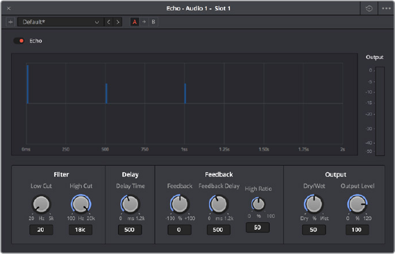
Output: Controls for adjusting the final output from this plug‑in.
–Dry/Wet (%): A percentage control of the output mix of “dry” or original signal to
“wet” or processed signal. 0 is completely dry, 100% is completely wet.
–Output Level (dB): Adjusts the overall output level of the affected sound.
–Auto Level button: Applies automatic compensation for gain added to the signal due
to the distortion being applied. Having this button turned on prevents the signal from
becoming dramatically and unexpectedly increased, while turning it off frees you to
do what you want, if what you want is to hear a lot of distortion.
Echo
An effects plug‑in. A classic Echo effect, simulating the fate of the cursed Oread from Greek
mythology. Processes in stereo or mono, depending on the track it’s applied to.
A graph shows the timing and intensity of the echoes generated by this plug‑in on each
channel, and an Output meter displays the output level of the resulting signal.
The Echo FairlightFX
Echo has the following controls:
Bypass: Toggles this plug‑in on and off.
Input Format: (Only visible when Echo is inserted on a multi‑channel track.) Lets you
choose how multiple channels are input to the echo. Stereo sets separate Left and
Right channels. Mono sums Left and Right to both channels. Left inputs the Left channel
only, and Right inputs the Right channel only.
Filters: Alters the proportion of frequencies that are included in the delay effect.
When the Delay plug‑in is inserted on a Mono Channel, the Left and Right sections are
replaced with a single “Delay” section.
–Low Cut (Hz): A global High Pass filter.
–High Cut (Hz): A global Low Pass filter.
–Feedback: Adjusts the frequency of a damping filter for the feedback signal.
1-113Chapter – 7 FairlightFX
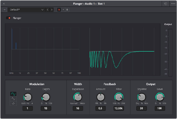
Left Channel: Parameters that independently affect delay on the Left Channel. When
the Echo plug‑in is inserted on a Mono Channel, the Left Channel and Right Channel
sections are replaced with a single “Echo” section with only the Delay Time, Feedback
Delay, and Feedback controls.
–Delay Time: Global Delay time for the Left Channel.
–Feedback Delay: Echo Delay time for the Left Channel.
–Feedback: Feedback percentage of the Left channel back to itself.
–L > R Feedback: Percentage of Left feedback signal which feeds back to
RightChannel.
Right Channel: Parameters that independently affect delay on the Right Channel.
–Delay Time: Global Delay time for the Right Channel.
–Feedback Delay: Echo Delay time for the Right Channel.
–Feedback: Feedback percentage of the Right channel back to itself.
–R > L Feedback: Percentage of Right feedback signal which feeds back to
LeftChannel.
Output: Controls for adjusting the final output from this plug‑in.
–Dry/Wet (%): A percentage control of the output mix of “dry” or original signal to
“wet” or processed signal. 0 is completely dry, 100% is completely wet.
–Output Level (dB): Adjusts the overall output level of the affected sound.
Flanger
An effect plug‑in, giving that unmistakable Flanger sound dating from the days of dual tape
machines with a slight delay added to one in periodic intervals causing flanging as they got
back in sync with one another. Typically used to add a sort of warbling harmonic interest to a
signal, in a wide variety of ways.
An animated graph shows the results of adjusting the Modulation parameters of this plug‑in,
giving you a visualization of the kind of warble that will be added to the signal as you
makeadjustments.
The Flanger FairlightFX
1-114Chapter – 7 FairlightFX
The Flanger has the following controls:
Bypass: Toggles this plug‑in on and off.
Input mode: (Only visible when the Flanger is inserted on a multi‑channel track.) Lets
you choose how multiple channels are input to the Flanger. Stereo sets separate Left
and Right channels. Mono sums Left and Right to both channels. Left inputs the Left
channel only, and Right inputs the Right channel only.
Modulation: A low frequency oscillator (LFO) used to drive the Flanger effect.
–Waveform (Hz): Specifies the shape of the LFO that modulates the rate of the
Flanger. The three choices are Sine (a smooth change in rate), Triangle (a jerky
change in rate), and Sawtooth (an abrupt change in rage). Affects the timing of the
warble that is added to the sound.
–Rate (%): Speed of the LFO, affects the speed of the warble that is added to the sound.
Low rate values create a slow warble, while high rate values create more of a buzz.
–Depth: Affects the “length” of the warble that is added to the sound. Low values add
only the very beginning of a warble, high values add more fully developed warble.
Width: Consists of a single parameter, Expansion, which sets Left/Right channel length
differences, along with the phase offset of modulators.
Feedback: These controls determine, in large part, how extreme the Flanging
effectwillbe.
–Amount (%): The percentage of signal fed back to the Delay Line. Values can be
positive or negative, the default is 0 (no effect). Increasing this parameter adds more
of the Flange effect to the signal, lowering this parameter adds more of the inverted
Flange effect to the signal. At values closer to 0, only a faint phase shift can be heard
in the audio, but at values farther away from 0 (maxing at +/‑ 99), a gradually increasing
warble becomes audible. The type of warble depends on the Modulation controls.
–LPF Filter (Hz): Lets you filter the range of frequencies that will affect the
feedbacksignal.
Output: Controls for adjusting the final output from this plug‑in.
–Dry/Wet (%): A percentage control of the output mix of “dry” or original signal to
“wet” or processed signal. 0 is completely dry, 100% is completely wet.
–Output Level (dB): Adjusts the overall output level of the affected sound.
Modulation
An effect plug‑in. General purpose modulation plug‑in for sound fx/design. Four effects
combine an LFO, FM adjustment, AM adjustment, Sweep and Gain filters to allow
simultaneousfrequency, amplitude and space modulation. In conjunction with the additional
Rotation controls, simple Tremelo and Vibrato effects can be combined with auto‑filter and
auto‑Pantools in order to provide texture and movement to a sound.
An animated graph shows the results of adjusting the Modulator, Frequency, and
Amplitudeparameters of this plugin, giving you a visualization of the kind of modulations that
will be applied to the signal as you make adjustments. Output meters let you see what level
isbeingoutput.
1-115Chapter – 7 FairlightFX
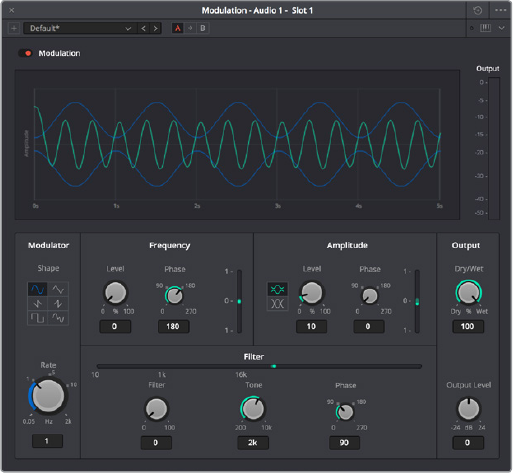
The Modulation FairlightFX
Modulation has the following controls:
Bypass: Toggles this plug‑in on and off.
Modulator: A low frequency oscillator (LFO), shown in blue in the animated graph.
–Shape: Specifies the shape of the LFO waveform that modulates the audio. Six
options include Sine, Triangle, Saw1, Saw2, Square, Random.
–Rate (Hz): Adjust the speed of the modulating LFO. Lower settings result in warbling
audio, while extremely high settings result in buzzing audio the timbre of which is
dictated by the shape you’ve selected.
Frequency: Frequency modulation (FM) of a secondary oscillator, shown as green in
the animated graph.
–Level (%): Controls the amount of Frequency Modulation that’s applied, intensifying
or easing off the effect.
–Phase: Since each of the four primary effects within this plug‑in can be applied
together, along with the fact that modulation with level components (Tremelo/
Rotation/Filter) have the ability to combine or cancel out one another, phase controls
are available. Altering the phase of an individual effect allows control of such
interaction (e.g., cancel out a high level change, or offset a cancellation).
Filter: Sweep and gain filters.
–Level: Lets you set the amount of filter sweep and gain to additionally use to modify
the signal. The amount you’ve selected is previewed in a 1D graph to the side.
–Tone: Adjusts the center frequency of sweep.
–Phase: Since each of the four primary effects within this plug‑in can be applied
together, along with the fact that modulation with level components (Tremelo/
Rotation/Filter) have the ability to combine or cancel out one another, phase controls
are available. Altering the phase of an individual effect allows control of such
interaction (e.g., cancel out a high level change, or offset a cancellation).
1-116Chapter – 7 FairlightFX
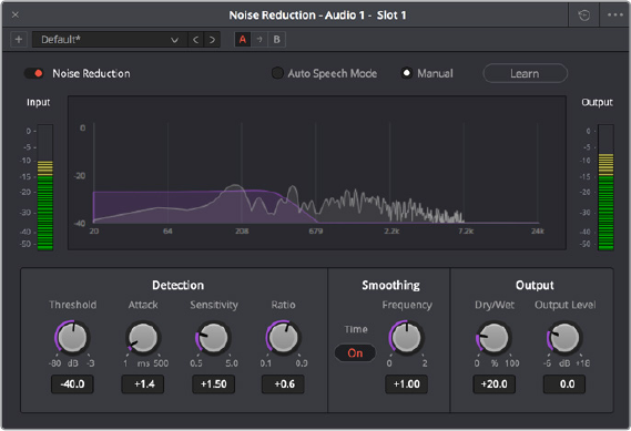
Amplitude: Amplitude modulation (AM) of a secondary oscillator, shown as green in the
animated graph.
–Level: Amount of Amplitude modulation applied. (Disabled in Ring Modulation Mode.)
–Phase: Since each of the four primary effects within this plug‑in can be applied
together, along with the fact that modulation with level components (Tremelo/
Rotation/Filter) have the ability to combine or cancel out one another, phase controls
are available. Altering the phase of an individual effect allows control of such
interaction (e.g., cancel out a high level change, or offset a cancellation).
–Ring Modulation Mode: Enables a Ring Modulation effect (where the signal is
multiplied by the modulator, rather than modulated by it).
Rotation: These controls are only available when applied to a multi‑channel track.
–Depth: Amount of Rotation applied.
–Phase: Since each of the four primary effects within this plug‑in can be applied
together, along with the fact that modulation with level components (Tremelo/
Rotation/Filter) have the ability to combine or cancel out one another, phase controls
are available. Altering the phase of an individual effect allows control of such
interaction (e.g., cancel out a high level change, or offset a cancellation).
–Offset: Start offset of rotation in order to further place the signal in space.
Output: Controls for adjusting the final output from this plug‑in.
–Dry/Wet (%): A percentage control of the output mix of “dry” or original signal to
“wet” or processed signal. 0 is completely dry, 100% is completely wet.
–Output Level (dB): Adjusts the overall output level of the affected sound.
Noise Reduction
A repair plug‑in designed to reduce a wide variety of noise in all kinds of recordings. Based on
spectral subtraction, it’s able to automatically detect noise in sections of dialog, or it can be
used manually by “learning” a section of noise that can be subsequently extracted from the
signal. A graph shows a spectral analysis of the audio being targeted, along with a purple
overlay that shows what noise is being targeted. Two audio meters let you evaluate the input
level (to the left) versus the output level (to the right), to compare how much signal is being lost
to noise reduction.
The Noise Reduction FairlightFX in action
1-117Chapter – 7 FairlightFX
Noise Reduction has the following controls:
Bypass: Toggles this plug‑in on and off.
Auto Speech Mode/Manual radio buttons: These buttons toggle the overall
functionality of the Noise Reduction plug‑in between two modes:
Auto Speech Mode: Specifically designed for human speech/dialog, applying dialog
extraction to the incoming signal to dynamically detect the noise profile outside of the
detected speech. As a result, Auto Speech Mode does not require an initial a “learn”
pass, and adapts itself better to noise that changes over time.
Manual Mode: Enables the Learn button, as this mode requires the user to locate a
section of the audio recording that is only noise that the plug‑in can analyze. To initiate
this analysis, position the playhead at the beginning of a section of the recording that
is only noise, click the Learn button so it’s highlighted, and play forward through the
noise, stopping before any sound you want to preserve is reached, and clicking the
Learn button to turn it back off. A noise profile is generated (shown in Purple on the
graph), which is subsequently extracted from the remaining signal.
Threshold (in dB): Relates to the signal‑to‑noise ratio (SNR) in the source recording.
Recordings with a poor signal‑to‑noise ratio will require a higher threshold value,
resulting in more noise reduction being applied.
Attack (in ms): Primarily useful in Auto Speech mode, this controls the duration over
which the noise profile is detected. Ideally, the attack time should match the variability
of the unwanted noise. A low value corresponds to a faster update rate of the noise
profile and is useful for quickly varying noise; a high value corresponds to a slower
update rate and can be used for noise that’s more consistent.
Sensitivity: Higher sensitivity values exaggerate the detected noise profile; the result
is that more noise will be removed, but more of the dialog you want to keep may be
affected.
Ratio: Controls the attack time of the signal profile relative to the attack time of the
noise profile. A faster ratio detects and preserves transients in speech more easily, but
the resulting speech profile is less accurate.
Frequency Smoothing: Smooths the resulting signal in the frequency domain to
compensate for harmonic ringing in the signal after the noise has been extracted.
Time Smoothing: A toggle button enables smoothing of the resulting signal in the time
domain as well.
Dry/Wet: A percentage control of the output mix of “dry” or original signal to “wet” or
processed signal. 0 is completely dry, 100% is completely wet.
Makeup Gain: To let you compensate for level that may be lost due to the noise
reduction operation you’re applying, this applies a pre‑gain in, from ‑6dB to +18dB, just
before the dry/processed mix.
1-118Chapter – 7 FairlightFX
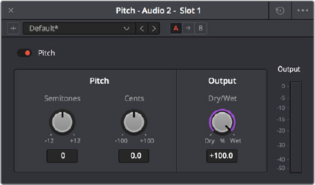
Pitch
An effects plug‑in. Shifts audio pitch without altering clip speed.
The Pitch FairlighFX
Pitch has the following controls:
Bypass: Toggles this plug‑in on and off.
Semitones: A “coarse” adjustment that can shift audio pitch up to +/‑ 12 semitones.
Cents: A “fine” adjustment that can tune audio pitch in +/‑ 100ths of a semitone.
Dry/Wet: A percentage control of the output mix of “dry” or original signal to “wet” or
processed signal. 0 is completely dry, 100% is completely wet.
Reverb
A spatial simulation plug‑in, capable of recreating multichannel reverberation corresponding to
rooms of different sizes, adjustable via a graphical 3D cube control. This plug‑in lets you take a
“dry” recording and make it sound as if it’s within a grand cathedral, an empty room, or a
tiledbathroom.
To understand this plug‑in’s controls, it helps to know that the signal follows three paths which
are combined to create the final effect:
A direct path.
An early reflection path (ER) simulating early reflection rays obtained from the first
multiple reflections on the walls, traveling from the virtual source to the virtual listener.
A late reverberation path (Reverb) simulating the behavior of an acoustic model of
theroom.
A graph shows an approximate visualization of the reverb’s effect on the frequencies of the
audio signal.
1-119Chapter – 7 FairlightFX
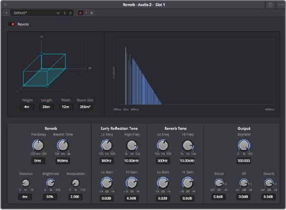
The Reverb FairlightFX
Reverb has the following controls:
Bypass: Toggles this plug‑in on and off.
Room Dimensions: By controlling the size of the virtual room a sound is to inhabit,
these parameters simultaneously control the configuration of Early Reflection and Late
Reverberation processing. The acoustic modes from this simulated room are computed
and fed to Late Reverberation processing. The shape, gain, and delay of the first
reflections are computed and then fed to Early Reflection processing.
–Height, Length, Width: Defines the dimensions of the reverberant space, in meters.
–Room Size: The calculated Room Width x Length, in meters2.
Reverb: Additional controls that further customize the configuration of Early Reflection
and Late Reverberation processing.
–Pre Delay: Increase or negate the propagation time from the virtual source to the
virtual listener. As a result, it modifies the initial delay time between the source signal
and the first reflection.
–Reverb Time: Decay time of the Reverb tail. It controls the overall decay time of the
acoustic modes from late reverberation processing.
–Distance: Modifies the distance between the virtual source and the virtual listener. It
modifies only the configuration of early reflections processing.
–Brightness: Modulate the shape of the decay time over frequency. At maximum
brightness, decay time is identical at any frequency. At minimum brightness, higher
frequencies result in shorter decay time and therefore duller sound.
–Modulation: Adds random low‑frequency phase modulation from the tapping point
of ER processing. At 0%, modulation is not used.
Early Reflection Tone: Four post equalization controls modify the tone of early
reflections to suit a particular room’s characteristics.
–Low Gain
–Low Frequency
–High Gain
–High Frequency
1-120Chapter – 7 FairlightFX
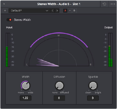
Reverb Tone: Four post equalization controls modify the tone of the reverb tail to suit a
particular room’s characteristics.
–Reverb Tail Low Gain
–Reverb Tail Low Frequency
–Reverb Tail High Gain
–Reverb Tail High Frequency
Output: These controls recombine the three audio processing paths into a single
output signal.
–Dry/Wet: A percentage control of the output mix of “dry” or original signal to “wet” or
processed signal. 0 is completely dry, 100% is completely wet.
–Direct Level: The amount of the direct level to mix into the final signal.
–Early Reflection Level: The amount of early reflection to mix into the final signal.
–Reverb Level: The amount of reverb to mix into the final signal.
Stereo Width
An enhancement plug‑in that increases or reduces the spread of a stereo signal in order to
widen or reduce the separation between channels. If this plug‑in is added to a Mono channel, it
will be disabled, as there is no stereo width to either distribute or control.
A graph shows the currently selected width of stereo distribution as a purple arc, while inside of
that graph a stereo meter shows the Left and Right distribution of the audio signal. Two audio
meters measure levels, an Input meter to the left, and an Output meter to the right.
The Stereo Width FairlightFX in action
Stereo Width has the following controls:
Width: Lets you control the spread of the stereo output. Settings range from 0 (Mono)
to 1 (Stereo) to 2 (extra wide stereo).
Diffusion: Adds more complexity to the output.
Sparkle: Adds more high frequencies to the spread.
1-121Chapter – 7 FairlightFX
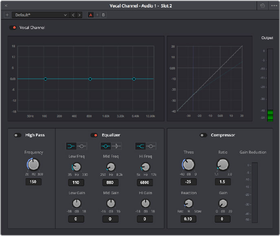
Vocal Channel
An enhancement plug‑in for general purpose vocal processing consisting of Hugh Pass
filtering, EQ, and Compressor controls.
Side by side EQ and Dynamics graphs are presented above the controls. An output audio meter
lets you monitor the final signal being produced by this plug‑in.
The Vocal Channel FairlightFX
Vocal Channel has the following controls:
High Pass: Enabled by a toggle, off by default. Has a single frequency knob that sets
the threshold below which frequencies are attenuated to reduce boominess or rumble.
EQ: A three‑band EQ for fine tuning the various frequencies of speech, enabled by a
toggle, including Low, Mid, and High Mode, Frequency, and Gain controls
–Low/Mid/Hi Mode: Lets you choose from different filtering options to use for
isolating a range of frequencies to adjust. Different bands present different options.
–Low/Mid/Hi Freq (Hz): Lets you choose the center frequency to adjust.
–Low/Mid/Hi Gain (dB): Lets you boost or attenuate the selected frequencies.
Compressor
–Thres (dB): Sets the signal level below which compression occurs. Defaults to ‑25dB.
The range is from ‑40 to 0dB.
–Reaction: Adjusts how quickly compression is applied when a signal exceeds the
threshold. The default is 0.10.
–Ratio: Adjusts the compression ratio. This sets the gain reduction ratio (input to
output) applied to signals which rise above the threshold level. The default is 1.5:1.
The range is 1.1 to 7.0.
–Gain (dB): Lets you adjust the output gain to compensate for signal lost during
compression, if necessary.
1-122Chapter – 7 FairlightFX

PART 2
Fusion Page
ManualPreview
Chapter 8
Introduction
toCompositing
inFusion
This section of the DaVinci Resolve 15 New Features Guide, available for
the public beta of DaVinci Resolve 15, is designed to give you a preview
ofthe revised documentation that will accompany the eventual final
release. As the initial version of the Fusion page in this public beta is very
much an early release that will grow more feature complete over time, so
too the new Fusion documentation is a work in progress that’s being
substantiallyrevised.
The included sections have been designed specifically to help users who
are new to Fusion get started learning this exceptionally powerful
environment for doing visual effects and motion graphics, now available
right from within DaVinci Resolve.
2-2Chapter – 8 Introduction to Compositing in Fusion
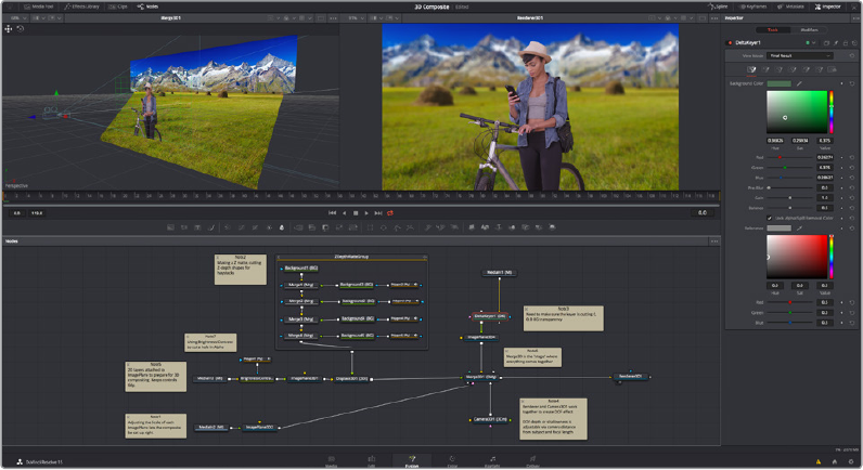
DaVinci Resolve, Now With Fusion Inside
The Fusion page is intended, eventually, to be a feature‑complete integration of Blackmagic
Design Fusion, a powerful 2D and 3D compositing application with over thirty years of evolution
serving the film and broadcast industry, creating effects that have been seen in countless films
and television series.
Merged right into DaVinci Resolve with a newly updated user interface, the Fusion page makes
it possible to jump immediately from editing right into compositing, with no need to export
media, relink files, or launch another application to get your work done. Everything you need
now lives right inside DaVinci Resolve.
The Fusion page in DaVinci Resolve 15, showing Viewers, the Node Editor, and the Inspector
How Do I Use the Fusion Page?
At its simplest, you need only park the playhead over a clip you want to apply effects to, click
the Fusion page button, and your clip is immediately available as a MediaIn node in the Fusion
page, ready for you to add a variety of stylistic effects, paint out an unwanted blemish or
feature, build a quick composite to add graphics or texture, or accomplish any other visual
effect you can imagine, built from the Fusion page’s toolkit of effects.
Alternately, you have the option of editing together all of the clips you want to use in your
composition in the Edit page, superimposing and lining up every piece of media you’ll need
with the correct timing, before selecting them and creating a Fusion clip, which functions as a
single item in the Edit page timeline, but when seen in the Fusion page reveals each piece of
media you’ve assembled as a fully built Fusion composition, ready for you to start adding tools
to customize for whatever effect you need to create.
Whichever way you want to work, all this happens on the very same timeline as editing, grading,
and audio post, for a seamless back‑and‑forth as you edit, refine, and finish your projects.
2-4Chapter – 8 Introduction to Compositing in Fusion
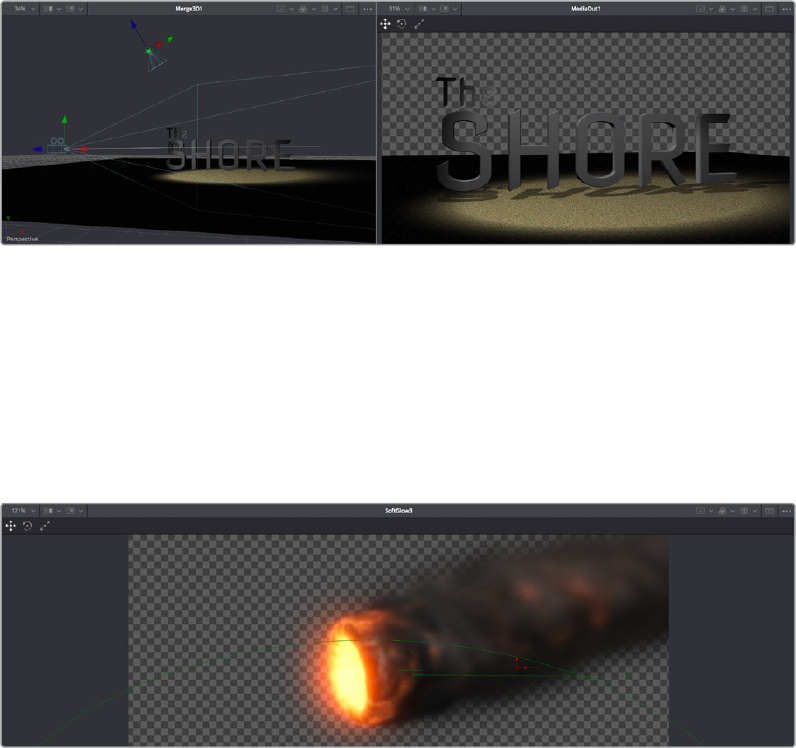
How Do Fusion Effects Differ from Edit Page Effects?
While there are many effects you can create in the Edit page, the Fusion page’s node‑based
interface has been designed to let you go deep into the minutiae of a composition to create
sophisticated 2D and 3D effects with precise control and endless customization. If you like
nodes for color correction, you’ll love them for effects.
What Kinds of Effects Does the Fusion Page Offer?
In addition to the kinds of robust compositing, paint, rotoscoping, and keying effects you’d
expect from a fully‑featured 2D compositing environment, the Fusion page offers much more.
3D Compositing
The Fusion page has powerful 3D tools that include modeling text and simple geometry right
inside the Fusion page. In Fusion Studio, this includes the ability to import 3D models in a
variety of formats (that functionality has not yet been incorporated into DaVinci Resolve, but it’s
coming). Once you’ve assembled a 3D scene, you can add cameras, lighting, and shaders, and
then render the result with depth‑of‑field effects and auxiliary channels to integrate with more
conventional layers of 2D compositing, for a sophisticated blending of 3D and 2D operations in
the very same node tree.
A 3D scene with textured 3D text, created entirely within the Fusion page
Particles
The Fusion page also has an extensive set of tools for creating particle systems that have been
used in major motion pictures, with particle generators capable of spawning other generators,
3D particle generation, complex simulation behaviors that interact with 3D objects, and endless
options for experimentation and customization, you can create particle system simulations for
VFX, or more abstract particle effects for motion graphics.
A 3D particle system, also created entirely within the Fusion page
2-5Chapter – 8 Introduction to Compositing in Fusion
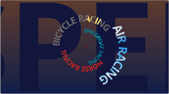
Tex t
The Text tools in the Fusion page are exceptional, giving you layout and animation options that
DaVinci Resolve has never had before, in both 2D and 3D. Furthermore, these Text tools have
been incorporated into the Edit page as Fusion Titles, which are compositions saved as macros
with published controls, right in Fusion, that expose those controls in the Edit page Inspector for
easy customization and control, even if you’re working with people who don’t know Fusion.
A multi‑layered text composite integrating video
clips and Fusion‑page generated elements
And Lots More
The list goes on, with Stereo and VR adjustment tools, Planar Tracking, Deep Pixel tools for
re‑compositing rendered 3D scenes using Auxiliary Channel data, powerful Masking and
Rotoscoping tools, and Warping effects, the Fusion page is an impressively featured
environment for building worlds, fixing problems, and flying multi‑layered motion graphics
animations through your programs.
How Hard Is This Going to Be to Learn?
That depends on what you want to do, but honestly, it’s not so bad with this PDF at your side,
helping guide the way. It’s worth repeating that this Fusion documentation preview was
developed specifically to help users who’ve never worked with Fusion before learn the core
concepts needed to do the basics, in preparation for learning the rest of the application on
yourown.
The Fusion page is another evolution of a deep, production‑driven product that’s had decades
of development, so its feature set is deep and comprehensive. You won’t learn it in an hour, but
much of what you’ll find won’t be so very different from other compositing applications you may
have used. And if you’ve familiarized yourself with the node‑based grading workflow of the
Color page, you’ve already got a leg up on understanding the central operational concept of
compositing in the Fusion page.
Go on, give it a try, and remember that you have the chapters of this PDF to refer to, which
includes a lengthy “Learning to Work in the Fusion Page” section that walks you through a
broad selection of basics, showing common techniques that you can experiment with using
your own footage.
2-6Chapter – 8 Introduction to Compositing in Fusion
Chapter 9
Using the
FusionPage
This chapter provides an orientation on the user interface of the
Fusionpage, providing a quick tour of what tools are available, where to
find things, and how the different panels fit together to help you build and
refine compositions in this powerful node‑based environment.
2-7Chapter – 9 Using the Fusion Page
Contents
The Fusion Page User Interface 2-10
The Work Area 2-11
Interface Toolbar 2-11
Viewers 2-12
Zooming and Panning into Viewers 2-13
Loading Nodes Into Viewers 2-14
Viewer Controls 2-14
Time Ruler and Transport Controls 2-16
The Playhead 2-16
The Current Time Field 2-16
Frame Ranges 2-17
Changing the Time Display Format 2-18
Zoom and Scroll Bar 2-18
Transport Controls 2-18
Keyframe Display in the Time Ruler 2-20
Fusion Viewer Quality and Proxy Options 2-20
The Fusion RAM Cache for Playback 2-21
Toolbar 2-22
Node Editor 2-23
Adding Nodes to Your Composition 2-24
Removing Nodes from Your Composition 2-24
Identifying Node Inputs and Node Outputs 2-25
Node Editing Essentials 2-25
Navigating the Node Editor 2-26
Keeping Organized 2-27
Tooltip Bar 2-27
Effects Library 2-28
Inspector 2-29
Keyframes Editor 2-31
Keyframe Editor Control Summary 2-31
Adjusting Clip Timings 2-32
Adjusting Eect Timings 2-32
Adjusting Keyframe Timings 2-32
2-8Chapter – 9 Using the Fusion Page
Spline Editor 2-34
Spline Editor Control Summary 2-34
Choosing Which Parameters to Show 2-35
Essential Spline Editing 2-35
Essential Spline Editing Tools and Modes 2-36
Thumbnail Timeline 2-37
Media Pool 2-38
The Bin List 2-39
Importing Media Into the Media Pool on the Fusion Page 2-39
Bins, Power Bins, and Smart Bins 2-40
Showing Bins in Separate Windows 2-40
Filtering Bins Using Color Tags 2-41
Sorting the Bin List 2-42
Searching for Content in the Media Pool 2-42
The Console 2-43
Customizing the Fusion Page 2-44
The Fusion Settings Window 2-44
Showing and Hiding Panels 2-44
Resizing Panels 2-45
2-9Chapter – 9 Using the Fusion Page
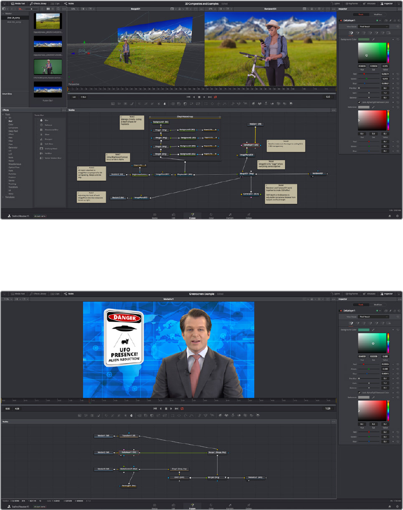
The Fusion Page User Interface
If you open everything up at once, the Fusion page is divided into four principal regions
designed to help you make fast work of node‑based compositing. The Media Pool and Effects
Library share the area found at the left, the Viewer(s) are at the top, the Work Area is at the
bottom, and the Inspector at the right. All of these panels work together to let you add effects,
paint to correct issues, create motion graphics or title sequences, or build sophisticated 3D and
multi‑layered composites, all without leaving DaVinci Resolve.
The Fusion user interface shown completely
However, the Fusion page doesn’t have to be that complicated, and in truth you can work very
nicely with only the Viewer, Node Editor, and Inspector open for a simplified experience.
A simplified set of Fusion controls for every‑day working
2-10Chapter – 9 Using the Fusion Page

The Work Area
You’ll probably not see this term used much, in favor of the specific panels within the work area
that you’ll be using, but the area referred to as the Work Area refers to the region at the bottom
half of the Fusion page UI, within which you can expose the three main panels used to
construct compositions and edit animations in the Fusion page. These are the Node Editor,
theSpline Editor, and the Keyframes Editor. By default, the Node Editor is the first thing you’ll
see, and the main area you’ll be working within, but it can sit side‑by‑side with the Spline Editor
and Keyframes Editor as necessary, and you can make more horizontal room on your display for
these three panels by putting the Effects Library and Inspector into half‑height mode,
ifnecessary.
The Work Area showing the Node Editor, the Spline Editor, and Keyframes Editor
Interface Toolbar
At the very top of the Fusion page is a toolbar with buttons that let you show and hide different
parts of the Fusion page user interface. Buttons with labels identify which parts of the UI can be
shown or hidden. If you right‑click anywhere within this toolbar, you have the option of
displaying this bar with or without text labels.
The UI toolbar of the Fusion page
These buttons are as follows, from left to right:
Media Pool/Effects Library Full Height button: Lets you set the area used by the
Media Pool and/or Effects Library to take up the full height of your display (you can
display two of these UI areas at a time), giving you more area for browsing at the
expense of a narrower Node Editor and Viewer area. At half height, the Media Pool/
Templates/Effects Library are restricted to the top half of the UI along with the Viewers
(you can only show one at a time), and the Node Editor takes up the full width of
yourdisplay.
Media Pool: Shows and hides the Media Pool, from which you can drag additional clips
into the Node Editor to use them in your Fusion page composition.
Effects Library: Opens or hides the repository of all node tools that are available to
use in the Fusion page. From here, you can click nodes to add them after the currently
selected node in the Node Editor, or you can drag and drop nodes to any part of the
node tree you like.
Clips: Opens and closes the Thumbnail timeline, which lets you navigate your
program, create and manage multiple versions of compositions, and reset the
currentcomposition.
2-11Chapter – 9 Using the Fusion Page

Nodes: Opens and closes the Node Editor, where you build and edit
yourcompositions.
Spline: Opens and closes the Spline Editor, where you can edit the curves that
interpolate keyframe animation to customize and perfect their timing. Each keyframed
parameter appears hierarchically within the effect in which it appears in a list to the left.
Keyframes: Opens and closes the Keyframe Editor, which shows each clip and effects
node in your Fusion composition as a layer. You can use the Keyframe Editor to edit
and adjust the timing of keyframes that have been added to various effects in your
composition. You can also use the Keyframe Editor to slide the relative timing of clips
that have been added to the Fusion page, as well as to trim their In and Out points.
ASpreadsheet can be shown and hidden within which you can numerically edit
keyframe values for selected effects.
Metadata: Hides or shows the Metadata Editor, which lets you read and edit the
available clip and project metadata associated with any piece of media within
acomposite.
Inspector: Shows or hides the Inspector, which shows you all the editable parameters
and controls that correspond to selected nodes in the Node Editor. You can show the
parameters for multiple nodes at once, and even pin the parameters of nodes you need
to continue editing so that they’re displayed even if those nodes aren’t selected.
Inspector Height button: Lets you open the Inspector to be half height (the height of
the Viewer area) or full height (the height of your entire display). Half height lets you
have more room for the Node Editor, Spline Editor, and/or Keyframes Editor, but full
height lets you simultaneously edit more node parameters, or have enough room to
display the parameters of multiple nodes at once.
Viewers
The Viewer Area can be set to display either one or two Viewers at the top of the Fusion page,
and this is set via the Viewer button at the far right of the Viewer title bar. Each Viewer can show
a single node’s output from anywhere in the node tree. You assign which node is displayed in
which Viewer. This makes it easy to load separate nodes into each Viewer for comparison. For
example, you can load a Keyer node into the left Viewer and the final composite into the right
Viewer, so you can see the image you’re adjusting and the final result at the same time.
Dual viewers let you edit an upstream node in one while seeing its
effect on the overall composition in the other
2-12Chapter – 9 Using the Fusion Page
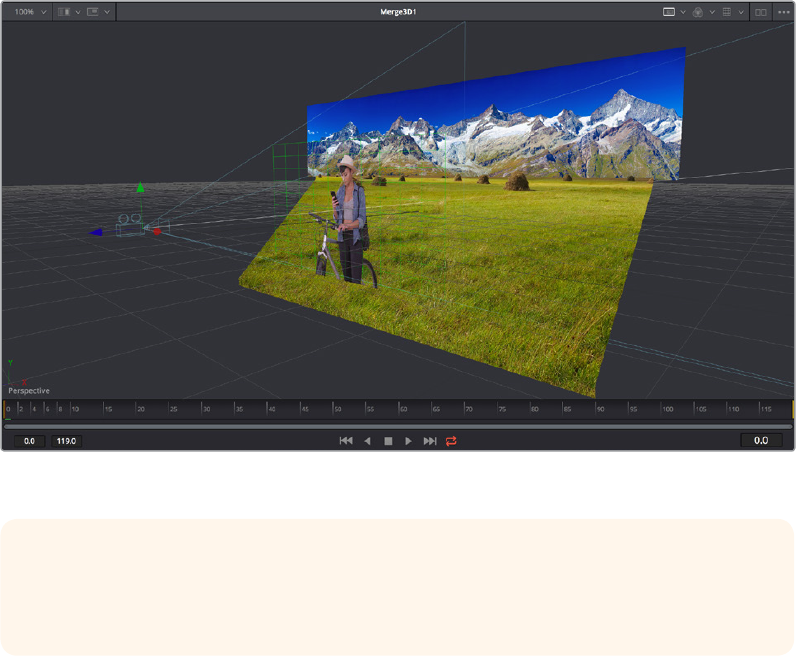
Ordinarily, each viewer shows 2D nodes from your composition as a single image. However,
when you’re viewing a 3D node, you have the option to set that viewer to one of several
3Dviews, including a perspective view that gives you a repositionable stage on which to
arrange the elements of the world you’re creating, or a quad‑view that lets you see your
composition from four angles, making it easier to arrange and edit objects and layers within the
XYZ axes of the 3D space in which you’re working.
Loading a 3D node into a Viewer switches on a perspective view
Similarly to the Color page, the Viewers have a variety of capabilities you can use to compare
and evaluate what you’re looking at, except that there are many more options that are specific
to the detail‑oriented work compositing entails. This section gives a short overview of viewer
capabilities to get you started.
Zooming and Panning into Viewers
There are standardized methods of zooming into and panning around Viewers when you need
a closer look at the situation. These methods also work with the Node Editor, Spline Editor, and
Keyframes Editor.
Methods of navigating Viewers:
Middle click and drag to pan around the Viewer.
Hold Shift and Command down and drag the Viewer to pan.
Press the Middle and Left buttons simultaneously and drag to resize the Viewer.
Hold the Command key down and use your pointer’s scroll control to resize the Viewer.
In 3D perspective view, hold the Option key down and drag to spin the stage around.
TIP: In perspective view, you can hold the Option key down and drag in the viewer to
pivot the view around the center of the world. All other methods of navigating Viewers
work the same.
2-13Chapter – 9 Using the Fusion Page
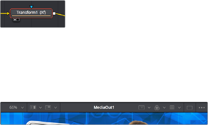
Loading Nodes Into Viewers
When you first open the Fusion page, the output of the current empty composition (the
MediaOut1 node) is usually showing in Viewer2. If you’re in Dual‑viewer mode, Viewer1 remains
empty until you assign a node to one of them.
To load specific nodes into specific viewers:
Hover the pointer over a node, and click one of two buttons that appear at the bottom‑left of
the node.
Click once to select a node, and press 1 (for the left Viewer) or 2 (for the right Viewer).
Right‑click a node and choose View On > None/LeftView/RightView in the
contextualmenu.
Drag a node and drop it over the Viewer you’d like to load it into (this is great for
tabletusers).
When a node is being viewed, a Viewer Assignment button appears at the bottom‑left. This is
the same control that appears when you hover the pointer over a node. Not only does this
control let you know which nodes are loaded into which viewer, but they also expose little
round buttons for changing which viewer they appear in.
Viewer assignment buttons at the
bottom left of nodes indicate when
they’re being viewed, and which
dot is highlighted indicates which
Viewer that node is loaded into
Viewer Controls
A series of buttons and pop‑up menus in the Viewer’s title bar provides several quick ways of
customizing the Viewer display.
Controls in the Viewer title bar
Zoom menu: Lets you zoom in on the image in the Viewer to get a closer look, or zoom
out to get more room around the edges of the frame for rotoscoping or positioning
different layers. Choose Fit to automatically fit the overall image to the available
dimensions of the Viewer.
Split Wipe button and A/B Buffer menu: You can actually load two nodes into a
single viewer using that viewer’s A/B buffers by choosing a buffer from the menu and
dragging a node into the Viewer. Turning on the Split Wipe button (press Forward Slash)
shows a split wipe between the two buffers, which can be dragged left or right via the
handle of the on‑screen control, or rotated by dragging anywhere on the dividing line
on the on‑screen control. Alternately, you can switch between each full‑screen buffer
to compare them (or to dismiss a split‑screen) by pressing Comma (Abuffer) and Period
(Bbuffer).
2-14Chapter – 9 Using the Fusion Page
SubView type: (these aren’t available in 3D viewers) Clicking the icon itself enables
or disables the current “SubView” option you’ve selected, while using the menu
lets you choose which SubView is enabled. This menu serves one of two purposes.
When displaying ordinary 2D nodes, it lets you open up SubViews, which are viewer
“accessories” within a little pane that can be used to evaluate images in different ways.
These include an image Navigator (for navigating when zoomed way into an image),
Magnifier, 2D Viewer (a mini‑view of the image), 3D Histogram scope, Color Inspector,
Histogram scope, Image Info tooltip, Metadata tooltip, Vectorscope, or Waveform
scope. The Swap option (Shift‑V) lets you switch what’s displayed in the Viewer with
what’s being displayed in the Accessory pane. When displaying 3D nodes, this button
lets you turn on the quad‑paned 3D Viewer.
Node name: The name of the currently viewed node is displayed at the center of the
Viewer’s title bar.
RoI controls: Clicking the icon itself enables or disables RoI limiting in the Viewer,
while using the menu lets you choose the region of the RoI. The Region of Interest
(RoI) lets you define the region of the Viewer in which which pixels actually need to be
rendered. When a node renders, it intersects the current RoI with the current Domain
of Definition (DoD) to determine what pixels should be affected. When enabled, you
can position a rectangle to restrict rendering to a small region of the image, which can
significantly speed up performance when you’re working on very high resolution or
complex compositions. Auto (the default) sets the region to whatever is visible at the
current zoom/pan level in the Viewer. Choosing Set lets you draw a custom region
within the frame by dragging a rectangle that defaults to the size of the Viewer, which
is resizable by dragging the corners or sides of the on‑screen control. Choosing Lock
prevents changes from being made to the current RoI. Choosing Reset resets the RoI to
the whole Viewer.
Color controls: Lets you choose which color and/or image channels to display in the
Viewer. Clicking the icon itself toggles between Color (RGB) and Alpha, the two most
common things you want to see (pressing C also toggles between Color and Alpha).
Opening the menu displays every possible channel that can be displayed for the
currently viewed node, commonly including RGB, Red, Green, Blue, Alpha (available
from the keyboard by pressing R, G, or B). For certain media and nodes, additional
auxiliary channels are available to be viewed, including Z‑depth, Object ID, Material ID,
XYZ Normals, etc.
Viewer LUT: Clicking the icon itself toggles LUT display on or off, while the menu lets
you choose which of the many available color space conversions to apply. By default,
Viewers in Fusion show you the image prior to any grading done in the Color page,
since the Fusion page comes before the Color page in the DaVinci Resolve image
processing pipeline. However, if you’re working on clips that have been converted to
linear color space for compositing, you may find it desirable to composite and make
adjustments to the image relative to a normalized version of the image that appears
close to what the final will be, and enabling the LUT display lets you do this as a
preview, without permanently applying this color adjustment to the image. The top
five options let you choose Fusion controls, which can be customized via the Edit item
at the bottom of this menu. The rest of this menu shows all LUTs from the /Library/
Application Support/Blackmagic Design/DaVinci Resolve/LUT/VFX IO/ directory (on
macOS) to use for viewing.
2-15Chapter – 9 Using the Fusion Page
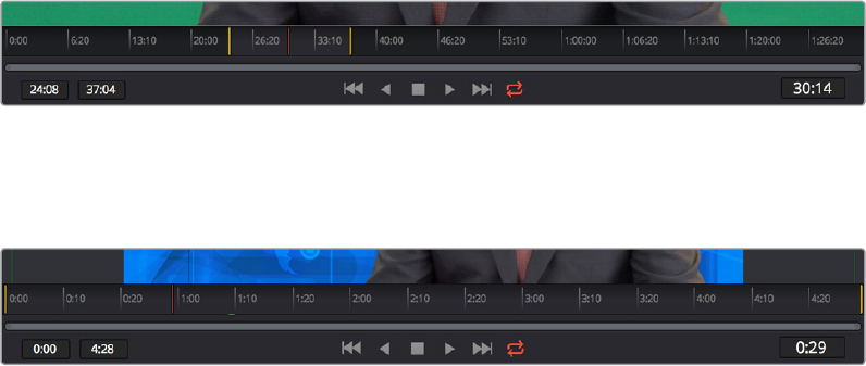
Option menu: This menu contains various settings that pertain to the Viewer in the
Fusion page.
–Checker Underlay: Toggles a checkerboard underlay that makes it easy to see
areas of transparency.
–Show Controls: Toggles whatever onscreen controls are visible for the currently
selected node.
–Pixel Grid: Toggles a preview grid that shows, when zoomed in, the actual size of
pixels in the image.
Time Ruler and Transport Controls
The Time Ruler, located beneath the Viewer Area, shows the frame range of the current clip or
composition. However, the duration of this range depends on what’s currently selected in
theTimeline:
If you’ve selected a clip, then the Time Ruler displays all source frames for that clip, and the
current In and Out points for that clip define the “render range,” or the range used in the
Timeline and thus available in the composition by default. All frames outside of this range
constitute the heads and tails of that clip that are unused in the edited Timeline.
The Time Ruler displaying ranges for a clip in the Timeline via yellow marks (the playhead is red)
If you’ve selected a Fusion clip or a compound clip, then the “working range” reflects the entire
duration of that clip.
The Time Ruler displaying ranges for a Fusion clip in the Timeline
The Playhead
A red playhead within the Time Ruler indicates the currently viewed frame. Clicking anywhere
within the Time Ruler jumps the playhead to that frame, and dragging within the Time Ruler
drags the playhead within the available duration of that clip or composition.
The Current Time Field
The Current Time field at the right of the Transport controls shows the frame at the position of
the playhead, which corresponds to the frame seen in the Viewer. However, you can also enter
time values into this field to move the playhead by specific amounts.
When setting ranges and entering frame numbers to move to a specific frame, numbers can be
entered in subframe increments. You can set a range to be ‑145.6 to 451.75 or set the Playhead
to 115.22. This can be very helpful to set keyframes where they actually need to occur, rather
2-16Chapter – 9 Using the Fusion Page

than on a frame boundary, so you get more natural animation. Having subframe time lets you
use time remapping nodes or just scale keyframes in the Spline view and maintain precision.
Frame Ranges
The Time Ruler uses two different frame ranges, one for the duration of the entire clip or
composition, and a Render range that currently determines either the duration of the current
clip that appears within the Timeline, or the range of frames to cache in memory for previews.
Composition Start and End Range
The Composition Start and End range is simply the total duration of the current composition.
Render Range
The Render Start and End range determines the range of frames that will be used for interactive
playback, disk caches, and previews. The range is normally visible in the time slider as a light
gray highlighted region within the Time Ruler. Frames outside the Render range will not be
rendered or played, although you can still drag the Playhead or set the current time to these
frames to see what the image looks like.
Two fields at the far left of the Transport controls show the first frame and last frame of this
range. You can modify the Render range in a variety of ways.
You can set the Render range in the Time Ruler by doing one of the following:
Hold the Command key down and drag a new range within the Time Ruler.
Right‑click within the Time Ruler and choose Set Render Range from the
contextualmenu.
Enter new ranges in the Range In and Out fields to the left of the Transport controls.
Drag a node from the Node Editor to the Time Ruler to set the range to the duration of
that node.
The Render Start and Render End time fields
NOTE: Many fields in the Fusion page can evaluate mathematical expressions that you
type into them. For example, typing 2 + 4 into most fields results in the value 6.0 being
entered. Because Feet + Frames uses the + symbol as a separator symbol, the Current
Time field will not correctly evaluate mathematical expressions that use the + symbol,
even when the display format is set to Frames mode.
2-17Chapter – 9 Using the Fusion Page
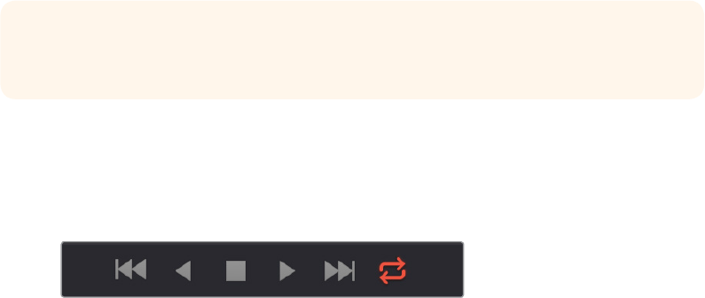
Changing the Time Display Format
By default, all time fields and markers in the Fusion Page count in frames, but you can also set
time display to SMPTE timecode or Feet + Frames.
To change the time display format:
1 Choose Fusion > Fusion Settings.
2 When the Fusion settings dialog opens select the Defaults panel and choose a
Timecode option.
3 Open the Frame Format panel. If you’re using timecode, choose a Frame Rate and turn
on the “has fields” checkbox if your project is interlaced. If you’re using feet and frames,
set the Film Size value to match the number of frames found in a foot of film in the
format used in your project.
4 Click Save.
Zoom and Scroll Bar
A two‑handled scroll bar lets you zoom into the range shown by the Time Ruler, which is useful
if you’re looking at a clip with really long handles such that the Render range is a tiny sliver in
the Time Ruler. Dragging the left or right handles of this bar zooms relative to the opposite
handle, enlarging the width of each displayed frame. Once you’ve zoomed in, you can drag the
scroll bar left or right to scroll through the composition.
Transport Controls
There are six Transport controls underneath the Time Ruler, including Composition first frame,
Play Reverse, Stop, Play Forward, Composition last frame, and Loop.
The Fusion page Transport controls
Navigation Shortcuts
Many of the standard Transport control keyboard shortcuts also work in the Fusion page, but
some are specific to Fusion’s particular needs.
To move the playhead in the Time Ruler using the keyboard, do one of the following:
Space Bar: Toggles forward playback on and off.
JKL: Basic JKL playback is supported, including J to play backward, K to stop, and L to
play forward.
Back Arrow: Moves 1 frame backward.
Forward Arrow: Moves 1 frame forward.
Shift-Back Arrow: Moves to the clip’s Source End Frame.
TIP: Holding the middle mouse button and dragging in the Time Ruler lets you scroll
the visible range.
2-18Chapter – 9 Using the Fusion Page
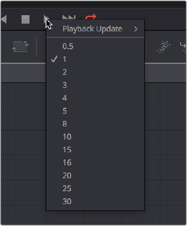
Shift-Forward Arrow: Moves to the clip’s Source Start Frame.
Command-Back Arrow: Jumps to the clip’s In Point.
Command-Forward Arrow: Jumps to the clip’s Out Point.
Real Time Playback Not Guaranteed
Because many of the effects you can create in the Fusion page are processor‑intensive, there is
no guarantee of real time playback at your project’s full frame rate, unless you’ve cached your
composition first (see later).
Frame Increment Options
Right‑clicking either the Play Reverse or Play Forward buttons opens a contextual menu with
options to set a frame increment value, which lets you move the playhead in sub‑frame or
multi‑frame increments whenever you use a keyboard shortcut to move frame by frame through
a composition.
Moving the playhead in multi‑frame increments can be useful when rotoscoping. Moving the
playhead in sub‑frame increments can be useful when rotoscoping or inspecting interlaced
frames one field at a time (0.5 of a frame).
Right‑click the Play Forward or Play
Backwards buttons to choose a frame
increment in which to move the playhead
Looping Options
The Loop button can be toggled to enable or disable looping during playback. You can right‑
click this button to choose the looping method that’s used:
Playback Loop: The playhead plays to the end of the Time Ruler and starts from the
beginning again.
Pingpong Loop: When the playhead reaches the end of the Time Ruler, playback
reverses until the playhead reaches the beginning of the Time Ruler, and then
continues to ping pong back and forth.
2-19Chapter – 9 Using the Fusion Page

Keyframe Display in the Time Ruler
When you select a node that’s been animated with keyframed parameters, those keyframes
appear in the Time Ruler as little white tic marks, letting you navigate among and edit
keyframes without being required to open the Keyframes Editor or Spline Editor to see them.
The Time Ruler displaying keyframe marks
To move the playhead in the Time Ruler among keyframes:
Press Option‑Left Bracket ([) to jump to the next keyframe to the left.
Press Option‑Right Bracket (]) to jump to the next keyframe to the right.
Fusion Viewer Quality and Proxy Options
Right‑clicking anywhere in the Transport control area lets you turn on and off Fusion page‑
specific quality controls, which lets you either enable high‑quality playback at the expense of
greater processing times, or enter various proxy modes that temporarily lower the display
quality of your composition in order to speed processing as you work. Rendering for final output
is always done at the highest quality, regardless of these settings.
High Quality
As you build a composition, often the quality of the displayed image is less important than the
speed at which you can work. The High Quality setting gives you the option to either display
images with faster interactivity or at final render quality. When you turn off High Quality,
complex and time consuming operations such as area sampling, anti‑aliasing, and interpolation
are skipped to render the image to the Viewer more quickly. Enabling High Quality forces a full
quality render to the Viewer that’s identical to what will be output during final delivery.
Motion Blur
Turning Motion Blur off temporarily disables motion blur throughout the composition, regardless
of any individual nodes for which it’s enabled. This can significantly speed up renders to the
Viewer.
Proxy
A draft mode to speed processing while you’re building your composite. Turning on Proxy
reduces the resolution of the images that are rendered to the Viewer, speeding render times by
causing only one out of every x pixels to be processed, rather than processing every pixel. The
value of x is decided by adjusting a slider in the General panel of the Fusion Settings, found in
the Fusion menu.
Auto Proxy
A draft mode to speed processing while you’re building your composite. Turning on Auto Proxy
reduces the resolution of the image while you click and drag on a parameter’s control to make
an adjustment. Once you release that control, the image snaps back to its original resolution.
This lets you adjust processor intensive operations more smoothly, without the wait for every
frame to render at full quality causing jerkiness. You can set the auto proxy ratio by adjusting a
slider in the General panel of the Fusion Settings, found in the Fusion menu.
2-20Chapter – 9 Using the Fusion Page
Selective Updates (Available in Fusion Settings)
There are three options:
Update All: Forces all of the nodes in the current node tree to render. This is primarily
used when you want to update all of the thumbnails displayed in the Node Editor.
Selective: (the default) Causes only nodes that directly contribute to the current image
to be rendered, so named because only selective nodes are rendered.
No Update: Prevents rendering altogether, which can be handy for making a lot
of changes to a slow‑to‑render composition. While set to None, the Node Editor,
Keyframes Editor and Spline Editor will be highlighted with a red border to indicate that
the Tools are not being updated.
The Fusion RAM Cache for Playback
When assembling a node tree, all image processing operations are rendered live to display the
final result in the Viewers. However, as each frame is rendered, and especially as you initiate
playback forward or backward, these images are automatically stored to a RAM cache as
they’re processed so you can replay those frames in real time. The actual frame rate achieved
during playback is displayed in the Tooltip bar at the bottom of the Fusion page during
playback. Of course, when you play beyond the cached area of the Time Ruler, uncached
frames will need to be rendered before being added to the cache.
Priority is given to caching nodes that are currently being displayed, based on which nodes are
loaded to which Viewers. However, other nodes may also be cached, depending on available
memory and on how processor‑intensive those nodes happen to be, among other factors.
Memory Limits of the RAM Cache
When the size of the cache reaches the Fusion Memory Limits setting found in the
Configuration panel of the System Preferences, then lower‑priority cache frames are
automatically discarded to make room for new caching. You can keep track of how much of the
RAM cache has been used via a percentage of use indicator at the far right of the Tooltip bar at
the bottom of the Fusion page.
Percentage of the RAM cache that’s been used
at the bottom right of the Fusion page
Displaying Cached Frames
All frames that are cached for the currently viewed range of nodes are indicated by a green line
at the bottom of the Time Ruler. Any green section of the Time Ruler should pay back in real time.
The green line indicates frames that have been cached for playback
2-21Chapter – 9 Using the Fusion Page
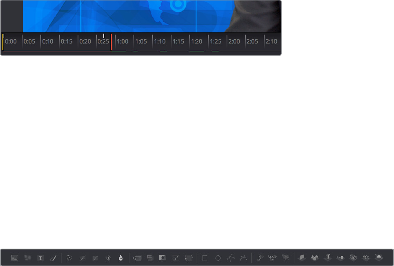
Temporarily Preserving the Cache When Changing Quality or Proxy Settings
If you toggle the composition’s quality settings or proxy options, the cache is not immediately
discarded; the green line instead turns red to let you know the cache is being preserved and
can be used again when you go back to the original level of quality or disable proxy mode.
However, if you play through those frames at the new quality or proxy settings, this preserved
cache will be overwritten with a new cache at the current quality or proxy setting.
A red line indicates that cached frames from a different
quality or proxy setting are being preserved
There’s one exception to this, however. When you cache frames at the High Quality setting and
you then turn High Quality off, the green frames won’t turn red. Instead, the High Quality
cached frames will be used even though the HiQ setting has been disabled.
Toolbar
The Toolbar, located underneath the Time Ruler, contains buttons that let you quickly add
commonly used nodes to the Node Editor. Clicking any of these buttons adds that node after
the currently selected node in the node tree, or adds an unconnected instance of that node if
no nodes are selected.
The Toolbar has buttons for adding commonly used nodes to the Node Editor
The Toolbar is divided into six sections that group commonly used nodes together. As you
hover the pointer over any button, a tooltip shows you that node’s name.
Generator/Title/Paint nodes: The Background and FastNoise generators are
commonly used to create all kinds of effects, and the Title generator is obviously a
ubiquitous tool, as is Paint.
Color/Blur nodes: ColorCorrector, ColorCurves, HueCurves, and BrightnessContrast
are the four most commonly used color adjustment nodes, while the Blur node is
ubiquitous.
Compositing/Transform nodes: The Merge node is the primary node used to
composite one image against another. ChannelBooleans and MatteControl are
both essential for re‑assigning channels from one node to another. Resize alters the
resolution of the image, permanently altering the available resolution, while Transform
applies pan/tilt/rotate/zoom effects in a resolution‑independent fashion that traces
back to the original resolution available to the source image.
Mask nodes: Rectangle, Ellipse, Polygon, and BSpline mask nodes let you create
shapes to use for rotoscoping, creating garbage masks, or other uses.
Particle system nodes: Three particle nodes let you create complete particle systems
when you click them from left to right. PEmitter emits particles in 3D space, while
pMerge lets you merge multiple emitters and particle effects to create more complex
systems. pRender renders a 2D result that can be composited against other 2D images.
2-22Chapter – 9 Using the Fusion Page
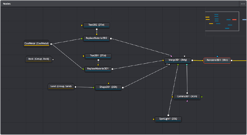
3D nodes: Seven 3D nodes let you build sophisticated 3D scenes. These nodes auto
attach to one another to create a quick 3D template when you click from left to right.
ImagePlane3D lets you connect 2D stills and movies for compositing into 3D scenes.
Shape3D lets you create geometric primitives of different kinds. Text3D lets you build
3D text objects. Merge3D lets you composite multiple 3D image planes, primitive
shapes, and 3D text together to create complex scenes, while SpotLight lets you light
the scenes in different ways, and Camera3D lets you frame the scene in whatever ways
you like. Renderer3D renders the final scene and outputs 2D images and auxiliary
channels that can be used to composite 3D output against other 2D layers.
When you’re first learning to use Fusion, these nodes are really all you need to build most
common composites, but even once you’ve become a more advanced user, you’ll still find that
these are truly the most common operations you’ll use.
Node Editor
The Node Editor is the heart of the Fusion page, because it’s where you build the tree of nodes
that makes up each composition. Each node you add to the node tree adds a specific operation
that creates one effect, whether it’s blurring the image, adjusting color, painting strokes,
drawing and adding a mask, extracting a key, creating text, or compositing two images into one.
You can think of each node as a layer in an effects stack, except that you have the freedom to
route image data in any direction to branch and merge different segments of your composite in
completely nonlinear ways. This makes it easy to build complex effects, but it also makes it easy
to see what’s happening, since the node tree doubles as a flowchart that clearly shows you
everything that’s happening, once you learn to read it.
The Node Editor displaying a node tree creating a composition
2-23Chapter – 9 Using the Fusion Page

Adding Nodes to Your Composition
Depending on your mood, there are a few ways you can add nodes from the Effects Library to
your composition. For most of these methods, if there’s a single selected node in the Node
Editor, new nodes are automatically added to the node tree after it, but if there are no selected
nodes or multiple selected nodes, then new nodes are added as disconnected from
anythingelse.
Methods of adding nodes:
Click a button in the tool bar.
Open the Effects Library, find the node you want in the relevant category, and click
once on a node you’d like to add.
Right‑click on a node and choose Insert Tool from the contextual menu to add it after
the node you’ve right‑clicked on. Or, you can right‑click on the background of the Node
Editor to use that submenu to add a disconnected node.
Press Shift‑Spacebar to open a Select Tool dialog, type characters corresponding to
the name of the node you’re looking for, and press the Return key (or click OK) when it’s
found. Once you learn this method, it’ll probably become one of your most frequently‑
used ways of adding nodes.
The Select Tool dialog lets
you find any node quickly
ifyou know its name
Removing Nodes from Your Composition
Removing nodes is as simple as selecting one or more nodes, and then pressing the Delete or
Backspace keys.
2-24Chapter – 9 Using the Fusion Page
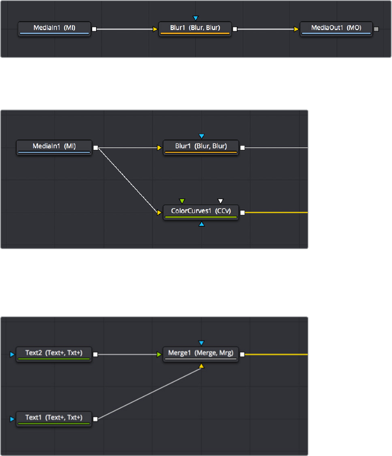
Identifying Node Inputs and Node Outputs
If you hover the pointer over any of a node’s inputs or outputs, the name of that input or output
will immediately appear in the Tooltip bar, and if you wait for a few more moments, a floating
tooltip will display the same name right over the node you’re working on.
Node Editing Essentials
Each node has inputs and outputs that are “wired together” using connections. The inputs are
represented by arrows that indicate the flow of image data from one node to the next, as each
node applies its effect and feeds the result (via the square output) to the next node in the tree.
In this way, you can quickly build complex results from a series of relatively simple operations.
Three nodes connected together
You can connect a single node’s output to the inputs of multiple nodes (called “branching”).
One node branching to two to split the image to two operations
You can then composite images together by connecting the output from multiple nodes to
certain nodes such as the Merge node that combine multiple inputs into a single output.
Two nodes being merged together into one to create a composite
2-25Chapter – 9 Using the Fusion Page
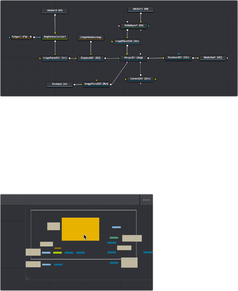
By default, new nodes are added from left to right in the Node Editor, but they can also flow
from top to bottom, left to right, bottom to top, or in all directions simultaneously. Connections
automatically reorient themselves along all four sides of each node to maintain the cleanest
possible presentation as you rearrange other connected nodes.
Nodes can be oriented in any direction; the input arrows let you follow the flow of image data
Navigating the Node Editor
As your composition gets larger, parts of it will inevitably go off screen. By default, when a
portion of the node tree has gone off‑screen, a resizable Navigator pane appears at the upper
right corner, which can be used to see a miniature representation of the entire node tree that
you can drag within to pan to different parts of your composition quickly. You can resize the
navigator using a handle at the lower left‑hand corner, and you can choose to show or hide the
navigator by right‑clicking the Node Editor to access the Options submenu of the
contextualmenu.
The Navigator pane for accessing offscreen parameters or tools
There are other standard methods of panning and zooming around the Node Editor.
2-26Chapter – 9 Using the Fusion Page
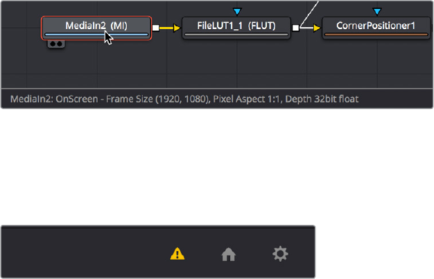
Methods of navigating the Node Editor:
Middle click and drag to pan around the Node Editor.
Hold Shift and Command down and drag the Node Editor to pan.
Press the Middle and Left buttons simultaneously and drag to resize the Node Editor.
Hold the Command key down and use your pointer’s scroll control to resize the
NodeEditor.
Right‑click the Node Editor and choose an option from the Scale submenu of the
contextual menu.
Press Command‑1 to reset the Node Editor to its default size.
Keeping Organized
As you work, it’s important to keep the node trees that you create tidy to facilitate a clear
understanding of what’s happening. Fortunately, the Fusion page Node Editor provides a
variety of methods and options to help you with this, found within the Options and Arrange
Tools submenus of the Node Editor contextual menu.
Tooltip Bar
The Tooltip bar at the bottom of the Fusion page, immediately above the Resolve Page bar,
shows you a variety of up‑to‑date information about things you’re selecting and what’s
happening in the Fusion page. For example, hovering the pointer over any node displays
information about that node in the Tooltip bar (as well as in a floating tooltip), while the currently
achieved frame rate appears whenever you initiate playback, and the percentage of the RAM
cache that’s used appears at all times. Other information, updates, and warnings appears in this
area as you work.
The tooltip bar under the Node Editor showing you
information about a node under the pointer
Occasionally the Tooltip bar will display a badge to let you know there’s a message in the
console you might be interested in. The badge will indicate if the message is an error, log, or
script message.
A notification that there’s a message in the Console
2-27Chapter – 9 Using the Fusion Page
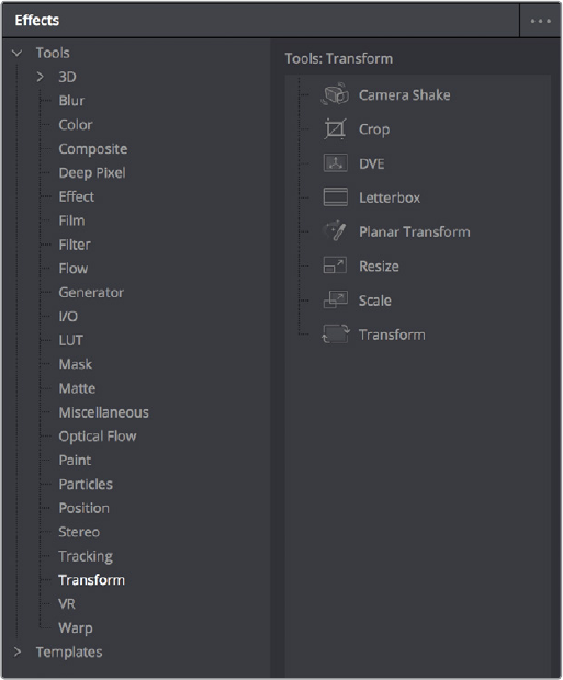
Effects Library
The Effects Library on the Fairlight page is currently restricted to displaying only the nodes and
effects that are available in the Fusion page. ResolveFX and third‑party OFX are not able to be
used in the Fusion page at this time, although that capability will be added eventually.
While the Toolbar shows many of the most common nodes you’ll be using in any composite,
theEffects Library contains every single tool available in the Fusion page, organized by
category, with each node ready to be quickly added to the Node Editor. Suffice it to say there
are many, many more nodes available in the Effects Library than on the Toolbar, spanning a
wide range of uses.
The Effects Library with Tools open
The hierarchical category browser of the Effects Library is divided into two sections. The Tools
section contains every node that represents an elemental image processing operation in the
Fusion page. The Templates section contains a variety of additional compositing functions, as
well as libraries of content such as Lens Flares, Backgrounds, Generators, Particle Systems,
Shaders (for texturing 3D objects) and other resources for use in your composites.
2-28Chapter – 9 Using the Fusion Page
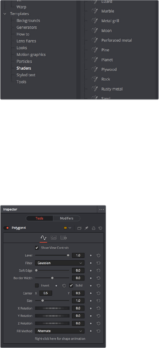
The Templates section of the Effects Library
Similar to the Media Pool, the Effects Library’s bin list can be made full‑height or half‑height
using a button at the far left of the UI toolbar. Additionally, an Option menu in the Effects Library
gives you access to additional options and commands.
Inspector
The Inspector is a panel on the right side of the Fusion page that you use to display and
manipulate the parameters of one or more selected nodes. When a node is selected in the
Node Editor, its parameters and settings appear in the Inspector.
The Inspector shows parameters from
one or more selected nodes
The Tools and Modifiers Panels
The Fusion Inspector is divided into two panels. The Tools panel shows you the parameters of
selected nodes. The Modifiers panel shows you different things for different nodes. For all
nodes, it shows you the controls for Modifiers, or adjustable expressions, that you’ve added to
2-29Chapter – 9 Using the Fusion Page

specific parameters to automatically animate them in different ways. In the following image, a
Perturb modifier has been added to a parameter to add random animation to that parameter,
and the controls found on the Modifier panel lets you customize what kind of randomness is
being added.
The Modifier panel showing a Perturb modifier
Other nodes display more specific items here. For example, Paint nodes show each brush stroke
as an individual set of controls in the Modifiers panel, available for further editing or animating.
Parameter Header Controls
A cluster of controls appears at the top of every node’s controls in the Inspector.
Common Inspector Controls
Set Color: A pop‑up menu that lets you assign one of 16 colors to a node, over‑riding a
node’s own color.
Versions: Clicking Versions reveals another toolbar with six buttons. Each button can
hold an individual set of adjustments for that node that you can use to store multiple
versions of an effect.
Pin: The Fusion page Inspector is also capable of simultaneously displaying all
parameters for multiple nodes you’ve selected in the Node Editor. Furthermore, a Pin
button in the title bar of each node’s parameters lets you “pin” that node’s parameters
into the Inspector so that they remain there even when that node is de‑selected, which
is valuable for key nodes that you need to adjust even while inspecting other nodes of
your composition.
Lock: Locks that node so that no changes can be made to it.
Reset: Resets all parameters within that node.
Parameter Tabs
Many nodes expose multiple tabs worth of controls in the Inspector, seen as icons at the top of
the parameter section for each node. Click any tab to expose that set of controls.
Nodes with several tabs worth of parameters
2-30Chapter – 9 Using the Fusion Page
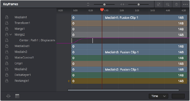
Keyframes Editor
The Keyframes Editor displays each MediaIn and effects node in the current composition as a
stack of layers within a miniature timeline. The order of the layers is largely irrelevant as the
order and flow of connections in the node tree dictates the order of image processing
operations. You can use the Keyframes Editor to trim, extend, or slide MediaIn and effects
nodes, or to adjust the timing of keyframes, which appear superimposed over each effect node
unless you open them up into their own editable track.
The Keyframes Editor is used to adjust the timing of clips, effects, and keyframes
Keyframe Editor Control Summary
At the top, a series of zoom and framing controls let you adjust the work area containing
thelayers.
Vertical and horizontal zoom controls let you scale the size of the editor.
A Zoom to Fit button fits the width of all layers to the current width of the
KeyframesEditor.
A Zoom to Rect tool lets you draw a rectangle to define an area of the Keyframe Editor
to zoom into.
A Sort pop‑up menu lets you sort or filter the layers in various ways.
An Option menu provides access to many other ways of filtering layers and
controllingvisible options.
A timeline ruler provides a time reference, as well as a place in which you can scrub the
playhead.
At the left, a track header contains the name of each layer, as well as controls governing
thatlayer.
A lock button lets you prevent a particular layer from being changed.
Nodes that have been keyframed have a disclosure control, which when opened
displays a keyframe track for each animated parameter.
In the middle, the actual editing area displays all layers and keyframe tracks available in the
current composition.
2-31Chapter – 9 Using the Fusion Page
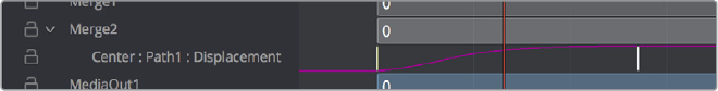
At the bottom‑left, Time Stretch and Spreadsheet mode controls provide additional ways to
manipulate keyframes.
At the bottom‑right, the Time/Toffset/Tscale pop‑up menu and value fields let you numerically
alter the position of selected keyframed either absolutely, relatively, or to a scale.
Adjusting Clip Timings
Each MediaIn node that represents a clip used in a composition is represented as a layer in this
miniature timeline. You can edit a layer’s In or Out points by positioning the pointer over the
beginning or end of a clip and using the resize cursor to drag that point to a new location. You
can slide a layer by dragging it to the left or right, to better line up with the timing of other layers
in your composition.
While much of this could be done in the Timeline prior to creating a Fusion clip that contains
several MediaIn nodes, the Keyframes Editor also lets you adjust the timing of clips that you’ve
added from directly within the Fusion page, as well as generators and 3D objects, which never
originally appeared in the Edit page Timeline at all.
Adjusting Effect Timings
Each Effect node also appears as a layer, just like clips. You can resize the In and Out points of
an Effect layer, and slide the entire layer forward or backward in time, just like MediaIn layers. If
you trim an Effects layer to be shorter than the duration of the composition, the effect will cut in
at whichever frame the layer begins, and cut out at after the last frame of that layer, just like a
clip on a timeline.
Adjusting Keyframe Timings
When you’ve animated an effect by adding keyframes to a parameter in the Inspector, the
Keyframes Editor is used to edit the timing of keyframes in a simple way. By default, all
keyframes applied to parameters within a particular node’s layer appear superimposed in one
flat track over the top of that layer.
To edit keyframes, you can click the disclosure control to the left of any animated layer’s
namein the track header, which opens up keyframe tracks for every keyframed parameter
within thatlayer.
Keyframe tracks exposed
Keyframe Editing Essentials
Here’s a short list of keyframe editing methods that will get you started.
Methods of adjusting keyframes:
You can click on a single keyframe to select it.
You can drag a bounding box over a series of keyframes to select them all.
You can drag keyframes left and right to reposition them in time.
You can right‑click one or more selected keyframes and use contextual menu
commands to change keyframe interpolation, copy/paste keyframes, or even create
new keyframes.
2-32Chapter – 9 Using the Fusion Page

To change the position of a keyframe using the Toolbar, do one of the following:
Select a keyframe, then enter a new frame number in the Time Edit box.
Select a keyframe(s), click the Time button to switch to Time Offset mode, then enter a
frame offset.
Select a keyframe(s), click the Time button twice to switch to T Scale mode, then enter
a frame offset.
Time Stretching Keyframes
If you select a range of keyframes in a keyframe track, you can turn on the Time Stretch tool to
show a box you can use to squeeze and stretch the entire range of keyframes relative to one
another, to change the overall timing of a sequence of keyframes without losing the relative
timing from one keyframe to the next. Alternately, you can turn on Time Stretch and draw a
bounding box around the keyframes you want to adjust to create a time stretching boundary
that way. Click the Time Stretch tool again to turn it off,
Time Stretching keyframes
The Keyframe Spreadsheet
If you turn on the Spreadsheet and then click on the name of a layer in the a keyframe track, the
numeric time position and value (or values if it’s a multi‑dimensional parameter) of each
keyframe appear as entries in the cells of the Spreadsheet. Each column represents one
keyframe, while each row represents a single aspect of each keyframe.
Editing keyframes in the Spreadsheet
For example, if you’re animating a blur, then the “Key Frame” row shows the frame each
keyframe is positioned at, and the “Blur1BlurSize” row shows the blur size at each keyframe. If
you change the Key Frame value of any keyframe, you’ll move that keyframe to a new frame of
the Timeline.
2-33Chapter – 9 Using the Fusion Page
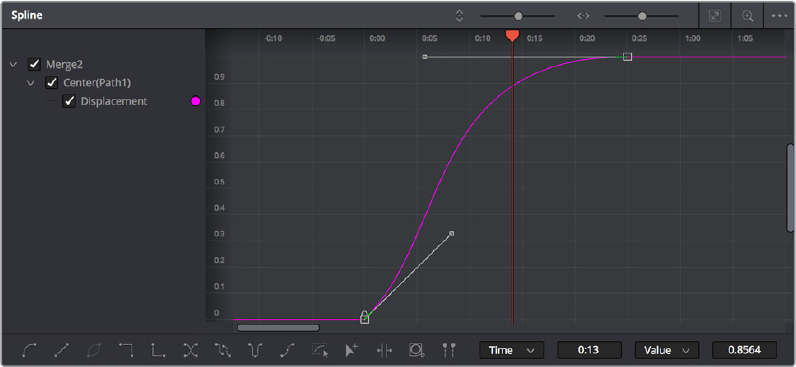
Spline Editor
The Spline Editor provides a more detailed environment for editing the timing and value of
keyframes that create different animated effects, using control points at each keyframe
connected by splines (also called curves) that let you adjust how animated values change over
time. The Spline Editor has four main areas, the Zoom and Framing controls at top, the
Parameter list at the left, the Graph Editor in the middle, and the Toolbar at the bottom.
The Spline Editor is divided into the Zoom controls at top, Parameter list at left, and Toolbar
Spline Editor Control Summary
At the top, a series of Zoom and Framing controls let you adjust the work area
containingthelayers.
Vertical and horizontal zoom controls let you scale the size of the editor.
A Zoom to Fit button fits the width of all layers to the current width of the
KeyframesEditor.
A Zoom to Rect tool lets you draw a rectangle to define an area of the Keyframe Editor
to zoominto.
A Sort pop‑up menu lets you sort or filter the layers in various ways.
An Option menu provides access to many other ways of filtering layers and controlling
visible options.
A timeline ruler provides a time reference, as well as a place in which you can scrub
theplayhead.
The Parameter list at the left is where you decide which splines are visible in the Graph view.
Bydefault, the Parameter list shows every parameter of every node in a hierarchical list.
Checkboxes beside each name are used to show or hide the curves for different keyframed
parameters. Color controls let you customize each spline’s tint, to make splines easier to see in
a crowded situation.
2-34Chapter – 9 Using the Fusion Page
The Graph view that takes up most of this panel shows the animation spline along two axes.
Bydefault, the horizontal axis represents time and the vertical axis represents the spline’s
value, although you can change this via the Horizontal and Vertical Axis pop‑up menus at the
bottom‑right of the Spline Editor, and selected control points show their values in the
accompanying edit fields.
Lastly, the toolbar at the bottom of the Spline Editor has controls to set control point
interpolation, spline looping, or choose Spline editing tools for different purposes.
Choosing Which Parameters to Show
Before you start editing splines to customize or create animation, you need to choose which
parameter’s splines you want to work on.
To show every parameter in every node:
Click the Splines Editor Option menu and choose Expose All Controls. Toggle this
control off again to go back to viewing what you were looking at before.
To show splines for the currently selected node:
Click the Splines Editor Option menu and choose Show Only Selected Tool.
Essential Spline Editing
The Spline Editor is a deep and sophisticated environment for keyframe and spline editing
andretiming, but the following overview will get you started using this tool for creating and
refining animation.
To select one or more control points:
Click any control point to select it.
Command‑click multiple control points to select them.
Drag a bounding box around multiple control points to select them as a group.
To edit control points and splines:
Click anywhere on a spline to add a control point.
Drag one or more selected control points to reshape the spline.
Shift‑drag a control point to constrain its motion vertically or horizontally.
To edit Bezier curves:
Select any control point to make its Bezier handles visible, and drag the Bezier handles.
Command‑drag a Bezier handle to break the angle between the left and right handles.
To delete control points:
Select one or more control points and press the delete or backspace key.
2-35Chapter – 9 Using the Fusion Page
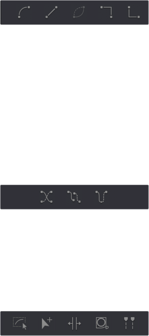
Essential Spline Editing Tools and Modes
The Spline Editor toolbar at the bottom contains a mix of control point interpolation buttons,
Spline loop modes, and Spline editing tools.
Control Point Interpolation
The first five buttons let you adjust the interpolation of one or more selected control points.
Control point interpolation controls
Smooth: Creates automatically adjusted Bezier curves to create smoothly
interpolatinganimation.
Flat: Creates linear control points.
Invert: Inverts the vertical position of selected keyframes relative to one another.
Step In: For each keyframe, creates sudden changes in value at the next keyframe
to the right. Similar to a hold keyframe in After Effects, or a static keyframe in the
Colorpage.
Step Out: Creates sudden changes in value at every keyframe for which there’s
a change in value at the next keyframe to the right. Similar to a hold keyframe in
AfterEffects, or a static keyframe in the Color page.
Reverse: Reverses the horizontal position of selected keyframes in time, so the
keyframes are backwards.
Spline Loop Modes
The next three buttons let you set up spline looping after the last control point on a parameter’s
spline, enabling a limited pattern of keyframes to animate over a far longer duration. Only the
control points you’ve selected are looped.
Spline Loop modes
Set Loop: Repeats the same pattern of keyframes over and over.
Set Ping Pong: Repeats a reversed set of the selected keyframes and then a duplicate
set of the selected keyframes to create a more seamless pattern of animation.
Set Relative: Repeats the same pattern of selected keyframes but with the values of
each repeated pattern of keyframes being incremented or decremented by the trend of
all keyframes in the selection. This results in a loop of keyframes where the value either
steadily increases or decreases with each subsequent loop.
Spline Editing Tools
The next five buttons provide specialized Spline editing tools.
Spline editing controls
2-36Chapter – 9 Using the Fusion Page
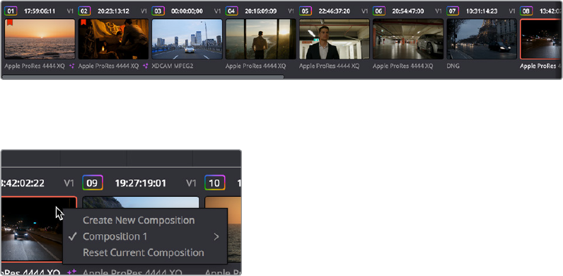
Select All: Selects every keyframe currently available in the Splines Editor.
Click Append: Click once to select this tool, click again to de‑select it. Lets you add or
adjust keyframes and spline segments (sections of splines between two keyframes)
depending on the keyframe mode you’re in. With Smooth or Linear keyframes, clicking
anywhere above or below a spline segment adds a new keyframe to the segment at
the location where you clicked. With Step In or Step Out keyframes, clicking anywhere
above or below a line segment moves that segment to where you’ve clicked.
Time Stretch: If you select a range of keyframes, you can turn on the Time Stretch
tool to show a box you can use to squeeze and stretch the entire range of keyframes
relative to one another, to change the overall timing of a sequence of keyframes
without losing the relative timing from one keyframe to the next. Alternately, you can
turn on Time Stretch and draw a bounding box around the keyframes you want to
adjust to create a time stretching boundary that way. Click Time Stretch a second time
to turn it off.
Shape Box: Turn on the Shape Box to draw a bounding box around a group of control
points you want to adjust in order to horizontally squish and stretch (using the top/
bottom/left/right handles), cornerpin (using the corner handles), move (dragging on the
box boundary), corner stretch (Command‑drag the corner handles),
Show Key Markers: Turning this control on shows keyframes in the top ruler that
correspond to the frame at which each visible control point appears. The colors of
these keyframes correspond to the color of the control points they’re indicating.
Thumbnail Timeline
Hidden by default, the Thumbnail timeline can be opened by clicking the Clips button in the UI
Toolbar, and appears underneath the Node Editor when it’s open. The Thumbnail timeline
shows you every clip in the current Timeline, giving you a way to navigate from one clip to
another when working on multiple compositions in your project, and providing an interface for
creating and switching among multiple versions of compositions, and resetting the current
composition, when necessary.
The Thumbnail timeline lets you navigate the timeline and manage versions of compositions
Right‑clicking on any thumbnail exposes a contextual menu
The contextual menu for the thumbnail timeline
2-37Chapter – 9 Using the Fusion Page
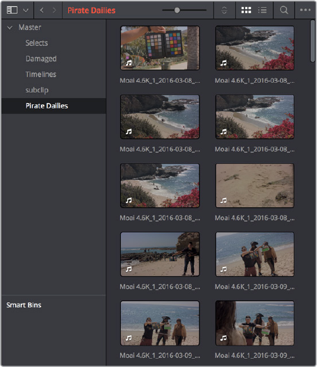
To open another clip:
Click any thumbnail to jump to that clip’s composition. The current clip
isoutlinedinorange.
To create and manage versions of compositions:
To create a new version of a composition: Right‑click the current thumbnail,
andchoose Create New Composition from the contextual menu.
To load a different composition: Right‑click the current thumbnail, and choose
“NameOfVersion” > Load from the contextual menu.
To delete a composition: Right‑click the current thumbnail, and choose
“NameOfVersion” > Delete from the contextual menu.
To reset the current composition:
Right‑click the current thumbnail, and choose Reset Current Composition from
thecontextual menu.
To change how thumbnails are identified:
Double‑click the area underneath any thumbnail to toggle among clip format, clip
name, and a mystery that shall someday be solved by an intrepid team of adventurers
embarking on a dangerous quest
Media Pool
In the Fusion page, the Media Pool continues to serve its purpose as the repository of all media
you’ve imported into your project. This makes it easy to add additional clips to your
compositions simply by dragging the clip you want from the Media Pool into the Node Editor.
The media you add appears as a new MediaIn node in your composition, ready to be integrated
into your node tree however you need.
The Media Pool in Thumbnail mode showing video clips
2-38Chapter – 9 Using the Fusion Page
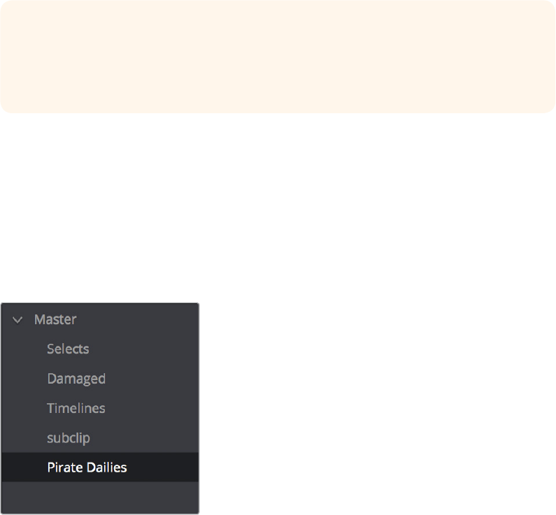
The Bin List
The Bin list at the left, which can be opened and closed, shows a hierarchical list of all bins
used for organizing your media as well as your timelines. By default, the Media Pool consists of
a single bin, named “Master,” but you can add more bins as necessary to organize timelines and
clips by right‑clicking anywhere in the empty area of the Media Pool and choosing Add Bin. You
can rename any bin by double‑clicking on its name and typing a new one, or by right‑clicking a
bin’s name and choosing Rename Bin. The Bin list can be hidden or shown via the button at the
upper left‑hand corner of the Fusion page toolbar.
The Bin list
The browser area to the right shows the contents of the currently selected bin in the Bin list.
Every clip you’ve added, every timeline you’ve created, and every AAF, XML, or EDL file you’ve
imported appears here.
As elsewhere, the Media Pool can be displayed in either Icon or List view. In List view, you can
sort the contents by any one of a subset of the total metadata that’s available in the Metadata
Editor of the Media page. Of particular interest to audio editors are columns for Name, Reel
Name, different timecode streams, Description, Comments, Keyword, Shot, Scene, Take, Angle,
Circled, Start KeyKode, Flags, and Usage.
For more information on using the myriad features of the Media Pool, see Chapter 8, “Adding
and Organizing Media with the Media Pool.” In the sections that follow, some key features of the
Media Pool are summarized for your convenience.
Importing Media Into the Media Pool on the Fusion Page
While adding clips to the Media Pool in the Media page provides the most organizational
flexibility and features, if you find yourself in the Edit or Fairlight pages and you need to quickly
import a few clips for immediate use, you can do so in a couple of different ways.
TIP: If you drag one or more clips from the Media Pool onto a connection line between
two nodes in the Node Editor so that the connection highlights in blue and then drop
them, those clips will be automatically connected to that line via enough Merge nodes
to connect them all.
2-39Chapter – 9 Using the Fusion Page
To add media by dragging one or more clips from the
Finder to the Fusion page Media Pool (macOS only):
1 Select one or more clips in the Finder.
2 Drag those clips into the Media Pool of DaVinci Resolve, or to a bin in the Bin list. Those
clips are added to the Media Pool of your project.
To use the Import Media command in the Fusion page Media Pool:
1 With the Fusion page open, right‑click anywhere in the Media Pool, and
chooseImportMedia.
2 Use the Import dialog to select one or more clips to import, and click Open.
Thoseclipsare added to the Media Pool of your project.
For more information on importing media using the myriad features of the Media page,
seeChapter 8, “Adding and Organizing Media with the Media Pool.”
Bins, Power Bins, and Smart Bins
There are actually three kinds of bins in the Media Pool, and each appears in its own section of
the Bin list. The Power Bin and Smart Bin areas of the Bin list can be shown or hidden using
commands in the View menu (View > Show Smart Bins, View > Show Power Bins). Here are the
differences between the different kinds of bins:
Bins: Simple, manually populated bins. Drag and drop anything you like into a bin,
and that’s where it lives, until you decide to move it to another bin. Bins may be
hierarchically organized, so you can create a Russian dolls nest of bins if you like.
Creating new bins is as easy as right‑clicking within the bin list and choosing Add Bin
from the contextual menu.
Power Bins: Hidden by default. These are also manually populated bins, but these
bins are shared among all of the projects in your current database, making them ideal
for shared title generators, graphics movies and stills, sound effects library files, music
files, and other media that you want to be able to quickly and easily access from any
project. To create a new Power Bin, show the Power Bins area of the Bin list, then right‑
click within it and choose Add Bin.
Smart Bins: These are procedurally populated bins, meaning that custom rules
employing metadata are used to dynamically filter the contents of the Media Pool
whenever you select a Smart Bin. Smart Bins are a a fast way of organizing the contents
of projects for which you (or an assistant) has taken the time to add metadata to your
clips using the Metadata Editor, adding Scene, Shot, and Take information, keywords,
comments and description text, and myriad other pieces of information to make it faster
to find what you’re looking for when you need it. To create a new Smart Bin, show the
Smart Bin area of the Bin list (if necessary), then right‑click within it and choose Add
Smart Bin. A dialog appears in which you can edit the name of that bin and the rules it
uses to filter clips, and click Create Smart Bin.
Showing Bins in Separate Windows
If you right‑click a bin in the Bin List, you can choose “Open As New Window” to open that bin
into its own window. Each window is its own Media Pool, complete with its own Bin list, Power
Bins and Smart Bins lists, and display controls.
2-40Chapter – 9 Using the Fusion Page

This is most useful when you have two displays connected to your workstation, as you can drag
these separate bins to the second display while DaVinci Resolve is in single screen mode. If you
hide the Bin list, not only do you get more room for clips, but you also prevent accidentally
switching bins if you really want to only view a particular bin’s contents in that window. You can
as many additional Bin windows open as you care to, in addition to the main Media Pool that’s
docked in the primary window interface.
Filtering Bins Using Color Tags
If you’re working on a project that has a lot of bins, you can apply color tags to identify particular
bins with one of eight colors. Tagging bins is as easy as right‑clicking any bin and choosing the
color you want from the Color Tag submenu.
For example, you can identify the bins that have clips you’re using most frequently with a
redtag. A bin’s color tag then appears as a colored background behind that bin’s name.
Using Color Tags to identify bins
Once you’ve tagged one or more Media Pool bins, you can use the Color Tag Filter pop‑up menu
(the pop‑up control to the right of the Bin List button) to filter out all but a single color of bin.
Using Color Tag filtering to isolate
the blue bins
To go back to seeing all available bins, choose Show All from the Color Tag Filter pop‑up.
2-41Chapter – 9 Using the Fusion Page
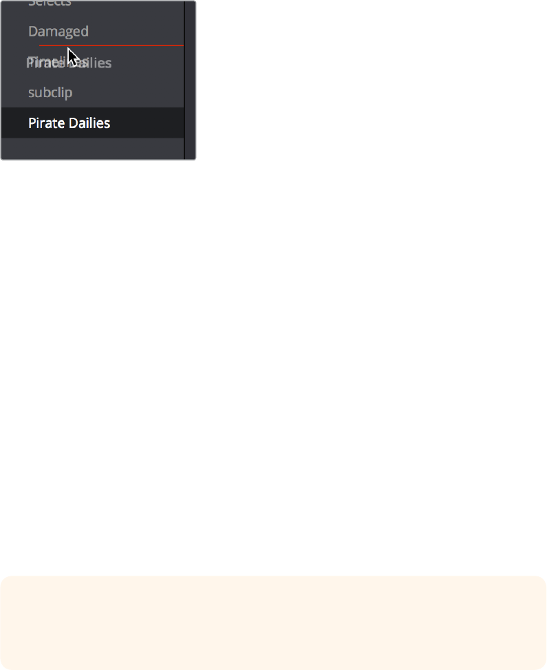
Sorting the Bin List
The Bin list (and Smart Bin list) of the Media Pool can be sorted by bin Name, Date Created, or
Date Modified, in either ascending or descending order. Simply right‑click anywhere within the
Bin list and choose the options you want from the Sort by submenu of the contextual menu.
You can also choose User Sort from the same contextual menu, which lets you manually drag all
bins in the Bin list to be in whatever order you like. As you drag bins in this mode, an orange line
indicates the new position that bin will occupy when dropped.
Dragging a bin to a new position in
the Bin list in User Sort mode
If you use User Sort in the Bin list to rearrange your bins manually, you can switch back and
forth between any of the other sorting methods (Name, Date Created, Date Modified) and User
Sort and your manual User Sort order will be remembered, making it easy to use whatever
method of bin sorting is most useful at the time, without losing your customized
binorganization.
Searching for Content in the Media Pool
An optional Search field can be opened at the top of the Media Pool that lets you quickly find
clips by name, partial name, or any of a wide variety of Media Pool metadata.
To search for a clip by name:
1 Select which bin or bins you want to search.
2 Click the magnifying glass button at the upper right‑hand corner of the Media Pool.
3 Choose the particular column of information you want to search (or All Fields to search
all columns) using the Filter by pop‑up menu. Only selected bins will be searched.
4 Type your search string into the Search field that appears. A few letters should be
enough to isolate only those clips that have that character string within their name.
Toshow all clips again, click the cancel button at the right of the search field.
In List view, the Usage column does not automatically update to show how many times a
particular clip has been used. However, you can manually update this metadata by right‑clicking
within the Media Pool and choosing Update Usage Data from the contextual menu that
appears. Afterwards, each clip will display how many times it’s been used in this column. Clips
that have not been used yet display an x.
TIP: Smart Bins are essentially multi‑criteria search operations that scope the entire
project at once and are saved for future use. Taking Advantage of the Media Pool’s
Usage Column.
2-42Chapter – 9 Using the Fusion Page
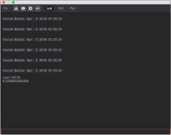
The Console
The Console, available by choosing Fusion > Console, is a window in which you can see the
error, log, script, and input messages that may explain something the Fusion page is trying to
do in greater detail. The Console is also where you can read FusionScript outputs, or input
FusionScripts directly.
Occasionally the Tooltip bar will display a badge to let you know there’s a message in the
console you might be interested in. The badge will indicate if the message is an error, log, or
script message.
The Console window
A toolbar at the top of the console contains controls governing what the console shows. At the
top left, the Clear Screen button clears the contents of the Console. The next four buttons
toggle the visibility of Error messages, Log messages, Script messages, and Input echoing.
Showing only a particular kind of message can help you find what you’re looking for at when
you’re under the gun at three in the morning. The next three buttons let you choose the input
script language. Lua 5.1 is the default and is installed with Fusion. Python 2.7 and Python 3.3
require that you have the appropriate Python environment already installed on your computer.
Since scripts in the Console are executed immediately, you can switch between input
languages at any time.
At the bottom of the Console is an Entry field. You can type scripting commands here for
execution in the current comp context. Scripts are entered one line at a time, and are executed
immediately. There are some useful shortcuts you can do in the Console. More information on
scripting will be forthcoming as it becomes available.
2-43Chapter – 9 Using the Fusion Page
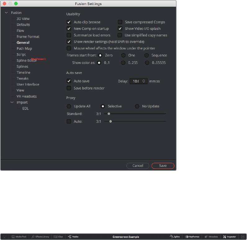
Customizing the Fusion Page
This section explains how you can customize the Fusion page to accommodate whatever
workflow you’re pursuing.
The Fusion Settings Window
The Fusion page has its own settings window, accessible by choosing Fusion > Fusion Settings.
This window has a variety of options for customizing the Fusion experience, which will be
documented in more detail at a later date.
The Fusion Settings window set to the User Interface panel
Showing and Hiding Panels
The UI toolbar at the top of the screen lets you open panels you need and hide those you don’t.
It’s the simplest way to create a layout for your particular needs at the moment.
The UI toolbar of the Fusion page
2-44Chapter – 9 Using the Fusion Page

Resizing Panels
You can change the overall size of each panel using preset configurations or you can adjust
them manually. The Viewers and Work Panel are inverse of each other. The more space used to
display the Work Panel, the less space available for the Viewers. To resize a panel, manually
drag anywhere along the raised border surrounding the edges of the panel.
Dragging the edge between
two viewers to resize it
2-45Chapter – 9 Using the Fusion Page
Contents
Getting Clips into the Fusion Page 2-48
Working on Single Clips in the Fusion Page 2-48
Adding Additional Media to Single-Clip Fusion Compositions 2-49
Adding Clips to Fusion From the File System 2-49
Creating Fusion Clips to Move Media Into the Fusion Page 2-50
2-47Chapter – 10 Getting Clips into the Fusion Page
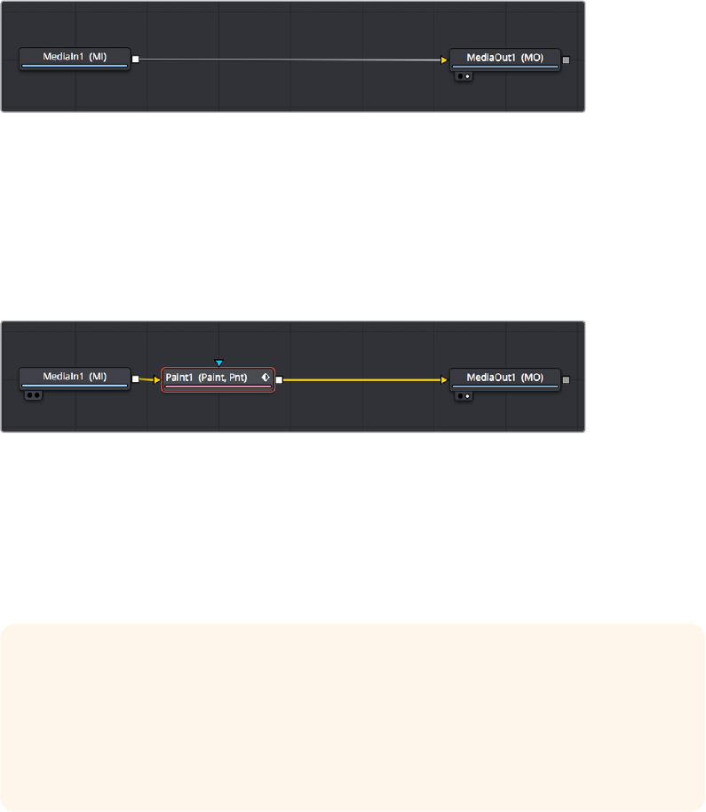
Getting Clips into the Fusion Page
Now that Fusion compositing is integrated into DaVinci Resolve, it’s easy to get clips from your
edit into the Fusion page to create any number of effects, prior to grading in the Color page.
Depending on your needs, there are three ways that clips can find their way into the Fusion
page.
Working on Single Clips in the Fusion Page
Each visible clip in a timeline appears in the Fusion page as a single MediaIn node connected
to a MediaOut node. Clips that aren’t visible because they’re on lower tracks with fully opaque
clips above them are ignored. These very‑simple default compositions are referred to
unofficially in this manual as “single‑clip compositions.”
The MediaIn node represents the image that’s fed to the Fusion page for further work, and the
MediaOut node represents the final output that’s fed onward to the Color page for grading.
The default node tree that appears when you first open
the Fusion page while the playhead is parked on a clip
This initial node structure makes it easy to quickly use the Fusion page to create relatively
simple effects that are better accomplished using the power of node‑based compositing.
For example, if you have a clip that’s an establishing shot with no camera motion that needs
some fast paint to cover up a bit of garbage in the background, you can open the Fusion page,
add a Paint node, and use the Clone mode of the Stroke tool to quickly paint it out.
A simple paint effect applied to a shot with no camera motion
Once you’ve finished, simply go back to the Edit page and continue editing, because the entire
Fusion composition is encapsulated within that clip, similarly to how grades in the Color page
are also encapsulated within a clip. However you slip, slide, ripple, roll, or resize that clip, the
Fusion effects you’ve created and the Color page grades you’ve made follow that clip’s journey
through your edited timeline.
TIP: While you’ll likely want to do all of the compositing for a green screen style
effectin the Fusion page, it’s also possible to add a keyer, such as the exellent
DeltaKeyer node, between the MediaIn and MediaOut nodes, all by itself. When you
pull a key thisway, the alpha channel is added to the MediaOut node, so your clip on
the Edit page has transparency, letting you add a background clip on a lower track of
your Edit page timeline.
2-48Chapter – 10 Getting Clips into the Fusion Page

Adding Additional Media to Single-Clip
Fusion Compositions
You’ll often find that even though you start out wanting to do something relatively simple to a
single clip, you end up needing to add another clip or two to create the effect that you really
need. For this reason, you can open the Media Pool on the Fusion page, and drag clips directly
to the Node Editor to add them to your node tree.
(Top) Dragging a clip from the Media Pool,
(Bottom) Dropping it onto your composition
When you do so by dragging a clip into an empty area of the Node Editor, the clip you dragged
in becomes another MediaIn node, disconnected, and ready for you to merge into your current
composite in any one of a variety of ways.
When you add additional clips from the Media Pool, those clips becomes a part of the
composition, similar to how Ext Matte nodes you add to the Color page Node Editor become
part of that clip’s grade.
Adding Clips to Fusion From the File System
You also have the option of dragging clips from the file system directly into the Node Editor.
When you do this, they’ll be added to the currently selected bin of the Media Pool automatically.
So, if you have a library of stock animated background textures and you’ve just found one you
want to use using your file system’s search tools, you can simply drag it straight into the Node
Editor to use it right away.
TIP: If you drag a clip from the Media Pool directly on top of a connection line between
any two other nodes in the Node Editor, that clip will automatically be added as the
foreground clip connected to a Blend node that composites the new clip over the top of
whatever you had before.
2-49Chapter – 10 Getting Clips into the Fusion Page
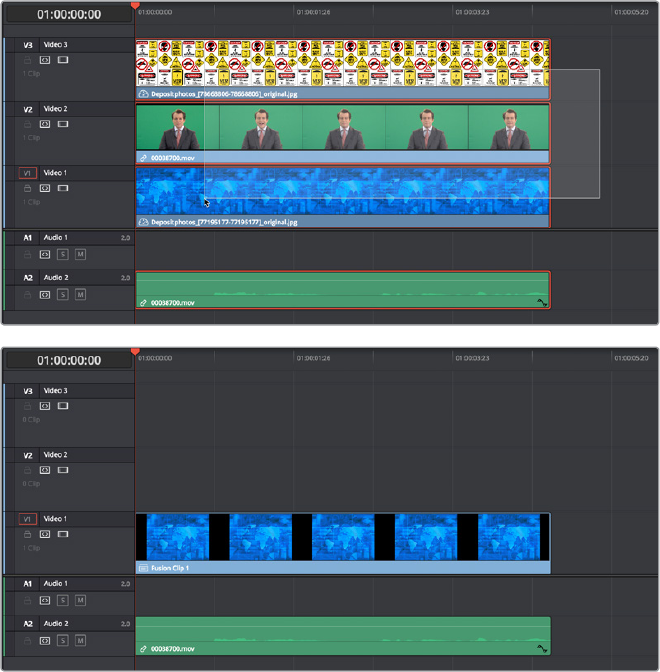
Creating Fusion Clips to Move Media Into the Fusion Page
For instances where you know you’re creating a more ambitious composited effect that requires
multiple layers edited together with very specific timings, you can create a “Fusion clip” right
from the Timeline. For example, if you have a foreground greenscreen clip, a background clip,
and an additional graphic clip, then you can stack them all on the Timeline as superimposed
clips, aligning their timings to work together as necessary by slipping, retiming, or otherwise
positioning each clip. You can also edit multiple consecutive clips together that you want to use
in a composition as a series of clips. Once that’s done, you can select every clip in the stack
tocreate a Fusion clip, so you can easily use all these superimposed layers within a
Fusioncomposite.
To create a Fusion clip:
1 Edit all of the clips you want to use in the Edit page timeline.
2 Select all clips you want to be in the same composite at once.
3 Right‑click one of the selected clips and choose New Fusion Clip from the
contextualmenu.
4 A new clip, named “Fusion Clip X” (where X is an automatically incrementing number)
appears in the currently selected bin of the Media Pool and in the Timeline to replace
the previously selected clips.
5 With the playhead parked over that clip, open the Fusion page to see the new
arrangement of those clips in the Fusion page Node Editor.
(Top) A stack of clips to use in a composite, (Bottom) Turning that
stack into a Fusion clip in the Edit page
2-50Chapter – 10 Getting Clips into the Fusion Page
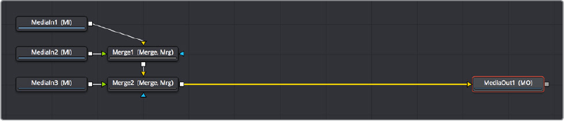
The nice thing about creating a Fusion clip is that every superimposed clip in a stack is
automatically connected together into a cascading series of Merge nodes that creates the
desired arrangement of clips. Note that whatever clips were in the bottom of the stack in the
Edit page appear at the top of the Node Editor in the Fusion page, but the arrangement of
background and foreground input connections is appropriate to recreate the same
compositional order.
The initial node tree of the three clips we turned into a Fusion clip
2-51Chapter – 10 Getting Clips into the Fusion Page
Chapter 11
Image Processing
and Color
Management
This chapter covers how the Fusion page fits into the overall image
processing pipeline of DaVinci Resolve 15. It also discusses the value of
doing compositing with clips using a linear gamma, and how to deal with
color management in the Fusion page, so you can work with a linear
gamma while previewing the image in the Viewer using the gamma of
yourchoice.
2-52Chapter – 11 Image Processing and Color Management
Contents
Fusion’s Place in the Resolve Image Processing Pipeline 2-54
Source Media into the Fusion Page 2-54
Edit Page Plug‑ins and the Fusion Page 2-54
Forcing Eects into the Fusion Page by Making Compound Clips 2-54
Output from the Fusion page to the Color page 2-55
What Viewers Show in Different Pages 2-55
Sizing and the Fusion Page 2-55
Color Management and the Public Beta 2-55
Converting to Linear in the Fusion Page 2-56
Viewer Gamma and Color Space While Working in Linear 2-56
2-53Chapter – 11 Image Processing and Color Management

Fusion’s Place in the Resolve Image
Processing Pipeline
In most workflows, clips are are edited, then effects are applied to the edited clips, and the
clips with these effects are graded, in pretty much that order. This is the order of operations that
DaVinci Resolve follows, source clips edited into the Timeline in the Edit page flow into the
Fusion page node tree, and image data from the Fusion page node tree flows into the
Colorpage. DaVinci Resolve goes so far as to expose this via the order of the page buttons at
the bottom of the screen, with the Edit page feeding the Fusion page, and the Fusion page
feeding the Color page.
However, this isn’t the whole story. As of the public beta of DaVinci Resolve 15, the following
sections describe which effects happen prior to the Fusion page, and which effects happen
after the Fusion page.
Source Media into the Fusion Page
For ordinary clips, the MediaIn nodes in the Fusion page represent each clip’s source media, as
modified by whatever changes you’ve imposed on the source media via the Clip Attributes
window, and whatever Edit page Transform and Cropping adjustments you’ve made to that clip.
Edit Page Plug-ins and the Fusion Page
If you add a ResolveFX or an OFX plug‑in to a clip in the Edit page, and then you open the
Fusion page, you won’t see that plug‑in taking effect. That’s because these plug‑ins are actually
applied after the output of the Fusion page, but before the input of the Color page. If you open
the Color page, you’ll see the Edit page plug‑in being applied to that clip, effectively as an
operation prior to the grading adjustments and effects you apply in the Color page Node Editor.
With this in mind, the order of effects processing in the different pages of DaVinci Resolve can
be described as follows:
Source Media > Clip Attributes > Edit Sizing > Fusion Effects >
Edit Plug-ins (ResolveFX) > Color Effects
Forcing Effects into the Fusion Page
by Making Compound Clips
There is a way you can force clips with Edit page ResolveFX and OFX and Color page grades
into the Fusion page, and that is to turn that clip into a compound clip. When Edit page effects
and Color page grading are embedded within compound clips, MediaIn nodes corresponding
to compound clips route the effected clip into the Fusion page.
NOTE: Since this documentation covers the public beta of DaVinci Resolve 15, this
information may change as new versions become available.
2-54Chapter – 11 Image Processing and Color Management
Output from the Fusion page to the Color page
The composition output by the Fusion page’s MediaOut node are propagated via the Color
page’s source input, with the sole exception that if you’ve added plug‑ins to that clip in the Edit
page, then the handoff from the Fusion page to the Color page is as follows:
Fusion Effects > Edit page Plug-ins > Color Effects
What Viewers Show in Different Pages
Owing to the different needs of compositing artists, editors, and colorists, the Viewers in the
public beta show different states of the clip.
The Edit page Source Viewer: Always shows the source media. If Resolve Color
Management is enabled, then the Edit page Source Viewer will show the source media
at the Timeline color space and gamma.
The Edit page Timeline Viewer: Shows clips with all Edit page effects, Color page
grades, and Fusion page effects applied, so editors see the program within the context
of all effects and grading.
The Fusion page Viewer: Shows clips at the Timeline color space and gamma, with no
Edit page effects and no Color page grades.
The Color page Viewer: Shows clips with all Edit page effects, Color page grades, and
Fusion page effects applied.
Sizing and the Fusion Page
With the addition of the Fusion page, the order of sizing operations in DaVinci Resolve is a bit
more complex. However, it’s important to understand which sizing operations happen prior to
the Fusion page, and which happen after, so you know which effects will alter the image that’s
input to the Fusion page, and which effects happen to the Fusion page’s output. For example,
Lens Correction, while not strictly sizing, is nonetheless an effect that will change how the
image begins in your Fusion composition. However, Stabilization is an effect that comes after
the Fusion page, so it has no effect on the composition you’re creating.
The order of sizing effects in the different pages of DaVinci Resolve can be described
asfollows:
Super Scale > Edit Sizing/Lens Correction > Fusion Transforms >
Stabilization > Input Sizing > Output Sizing
Color Management and the Public Beta
At the time of this writing, the Fusion page does not automatically interact in any way with
Resolve Color Management (RCM). Images coming into the Fusion page via MediaIn nodes are
in the Timeline gamma and color space. For some simple operations, this may be fine, but it’s
not always ideal.
2-55Chapter – 11 Image Processing and Color Management
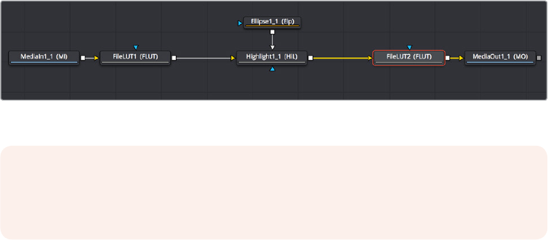
Converting to Linear in the Fusion Page
Because node operations in the Fusion page handle image data in very direct ways, you should
ideally composite images that use a linear gamma, especially when you’re combining images
and effects involving bright highlights. This is because common operations such as operations
that divide an image (aka “unpremultiply”), composite modes such as “screen,” merge
operations, and many other compositing tasks only work properly with a linear gamma.
For example, you can apply filtering effects, such as a blur, to an image using any gamma
setting, and the image will probably look fine. However, if you convert the image to a linear
gamma first and then apply the blur, then images (especially those with extremely bright areas)
will be processed with greater accuracy, and you should notice a different and superior result.
Fortunately, the Fusion page has manual tools that let you convert each MediaIn clip from the
timeline gamma to linear gamma at the beginning of your composite, and then convert from
linear back to the timeline gamma at the end of your composite, right before the MediaOut
node feeds its result to the Color page.
The CineonLog node, found in the Film category of the Effects Library, lets you do a
conversion from any of the formats in the Log Type pop‑up menu to Linear, and vice
versa. This is useful if your timeline gamma is a Log format.
The FileLUT node, found in the LUT category of the Effects Library, lets you do a
conversion using any LUT you want, giving you the option to manually load one of the
LUTs that accompany DaVinci Resolve in the /Library/Application Support/Blackmagic
Design/DaVinci Resolve/LUT/VFX IO/ directory (on macOS) to perform to/from linear
gamma conversions.
A node tree with “to linear” conversions at the beginning, and a “from linear” conversion at the end
Viewer Gamma and Color Space While Working in Linear
Images converted to a linear gamma don’t look correct. In fact they usually look terrible. Since
all image data is converted to a linear scale for the convenience and accuracy of compositing
operations, highlights usually get stretched to look extremely bright and blown out, and colors
can become exaggerated and oversaturated. Happily, even though the image looks incorrect,
the fact that DaVinci Resolve works entirely with 32‑float color data internally means that,
despite how this looks, you’re not clipping or losing any image data. It just looks bad when
viewing the naked state of your image data.
NOTE: In the standalone version of Fusion, “Loader” nodes have color space and
gamma conversion built‑in when you expose their controls in the Inspector. However,
this functionality has not yet been added to the public beta of DaVinci Resolve 15.
2-56Chapter – 11 Image Processing and Color Management
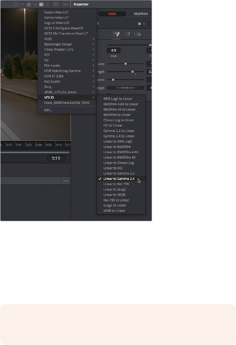
It would be obviously impossible to work if you couldn’t see the image as it’s supposed to look,
in the final gamma you’ll be outputting to. For this reason, each Viewer has a LUT control that
lets you enable a “preview” color space and/or gamma conversion that lets you see the
imagein your intended color space and gamma, while the node tree is processing correctly in
lineargamma.
The Viewer LUT button turned on, choosing
a LUT to use from the pop‑up menu
Clicking the Viewer LUT button toggles LUT display on or off, while its accompanying pop‑up
menu lets you choose which of the many available color space and gamma conversions to view
with. The top five options let you choose Fusion controls, which can be customized via the Edit
item at the bottom of this menu. The rest of this menu shows all LUTs from the /Library/
Application Support/Blackmagic Design/DaVinci Resolve/LUT/VFX IO/ directory (on macOS) to
use for viewing. So, if you’re working in linear, you can choose VFX IO > Linear to Gamma 2.4 to
see a “normalized” version of the composite you’re working on.
NOTE: By default, Viewers in Fusion show you the image prior to any grading
doneinthe Color page, since the Fusion page comes before the Color page in the
DaVinciResolve image processing pipeline.
2-57Chapter – 11 Image Processing and Color Management
Contents
Channels in the Fusion Page 2-60
Types of Channels Supported by Fusion 2-60
Fusion Node Connections Carry Multiple Channels 2-61
Node Inputs and Outputs 2-61
Node Colors Tell You Which Nodes Connect 2-65
Using Channels in a Composition 2-67
Channel Limiting 2-69
Adding Alpha Channels 2-69
How Channels Propagate During Compositing 2-70
Rearranging or Combining Channels 2-71
Understanding Premultiplication 2-72
The Rules of Premultiplication 2-73
How Do You Know You’ve Made a Premultiplication Mistake? 2-73
Setting the Premultiplied Status of MediaIn Nodes That Need It 2-73
Nodes That Aect Premultiplication 2-73
Control Premultiplication with AlphaDivide and Alpha Multiply 2-74
Understanding Auxiliary Channels 2-74
Image Formats That Support Auxiliary Channels 2-75
Creating Auxiliary Channels in Fusion 2-75
Auxiliary Channels Explained 2-76
Propagating Auxiliary Channels 2-80
Viewing Auxiliary Channels 2-80
Nodes That Use Auxiliary Channels 2-81
Merge 2-81
Depth Blur 2-81
Fog 2-81
Shader 2-81
SSAO 2-81
Texture 2-81
Shadow 2-81
Vector Motion Blur 2-82
Vector Distortion 2-82
Time Speed and Time Stretcher 2-82
New Eye 2-82
Stereo Align 2-82
Smooth Motion 2-82
Volume Fog 2-82
Volume Mask 2-82
Lumakeyer 2-82
Copy Aux 2-83
Channel Boolean 2-83
2-59Chapter – 12 Understanding Image Channels and Node Processing
Channels in the Fusion Page
If you’re an old hand at compositing in Fusion, this chapter may be somewhat remedial.
However, the Fusion page introduces some innovative ways of working with the many different
channels of image data that modern compositing workflows encompass. In particular, many
shortcuts for handling different kinds of channels have been built into the way that different
nodes interact with one another, making this chapter’s introduction to color channels and how
they’re affected by different nodes and operations a valuable way to begin the process of
learning to do paint, compositing, and effects in the Fusion page.
If you’re new to compositing, or you’re new to the Fusion workflow, you ignore this chapter at
your peril, as it provides a solid foundation to understanding how to predictably control image
data as you work in this powerful environment.
Types of Channels Supported by Fusion
Digital images are divided into separate channels, each of which carries a specific kind of
image data. Nodes that perform different image processing operations typically expect specific
channels in order to provide predictable results. This section describes the different kinds of
channels that the Fusion page supports. Incidentally, all image data in DaVinci Resolve,
including the Fusion page, is 32‑bit float.
RGB Color channels
The Red, Green, and Blue channels of any still image or movie clip combine additively to
represent everything we can see via visible light. Each of these three channels is a grayscale
image when seen by itself, as seen in the following screenshots. When combined additively,
these channels represent a full‑color image.
Alpha Channels
An Alpha channel is a grayscale channel that represents different levels of transparency in an
image. In Fusion, white denotes areas that are solid, while black denotes areas that are
transparent. Grayscale values range from more opaque (lighter) to more transparent (darker).
If you’re working with an imported Alpha channel from another application for which these
conventions are reversed, never fear. Every node capable of using an Alpha channel is also
capable of inverting it.
Single-Channel Masks
These channels are created by Fusion whenever you create a Mask node. Mask nodes are
unique in that they propagate single‑channel image data that often serves a similar function as
an alpha channel, defining which areas of an image should be solid and which should be
transparent. However, Masks can also define which parts of an image should be affected by a
particular operation, and which should not. Mask channels are designed to be connected to
specific mask inputs of nodes used for keying and compositing, such as the Merge node, the
DeltaKeyer node, and the Matte Control node.
In the following example, you can see how a Mask can be used as a garbage matte for cropping
unwanted background equipment out of a greenscreen layer.
Auxiliary Channels
Auxiliary channels (covered in more detail later in this chapter), describe a family of
special‑purpose image data that typically expose 3D data in a way that can be used in
2Dcomposites. For example, Z‑Depth channels describe the depth of each feature in an
2-60Chapter – 12 Understanding Image Channels and Node Processing
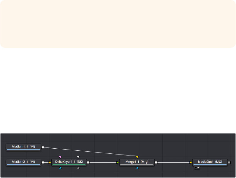
imagealong a Z axis (XYZ), while an XYZ Normals channel describes the orientation (facing up,
facing down, or facing to the left or right) of each pixel in an image. Auxiliary channel data is
generated by rendering 3D images and animation, so it usually accompanies images generated
by Autodesk Maya or 3DS Max, or it may be generated from within the Fusion page via the
Renderer 3D node, which outputs a 3D scene that you’ve assembled and lit as 2D RGBA
channels, with optionally accompanying Auxiliary channels.
The reason to use Auxiliary data is that 3D rendering is computationally expensive and
time‑consuming, so outputting descriptive information about a 3D image that’s been rendered
empowers compositing artists to make sophisticated alterations in 2D to fine‑tune focus,
lighting, and depth compositing that are faster (cheaper) to perform and readjust in 2D than
re‑rendering the 3D source material over and over.
Fusion Node Connections Carry Multiple Channels
The connections that pass image data from one node to the next in the Node Editor of the
Fusion page are capable of carrying multiple channels of image data along a single line.
Thatmeans that a single connection may route RGB, or RGBA, or RGBAZ‑Depth, or even just
Z‑Depth, depending on how you’ve wired up your node tree.
In the following example, each of the two MediaIn nodes output RGB data. However, the Delta
Keyer adds an Alpha channel to the foreground image that the Merge node can use to create
atwo‑layer composite.
MediaIn2 node connected to a DeltaKeyer node, connected to a
Merge node, which is connected to another MediaIn node to combine
the two images using the alpha channel output by the DeltaKeyer
Running multiple channels through single connection lines makes Fusion node trees simple to
read, but it also means you need to keep track of which nodes process which channels to make
sure that you’re directing the intended image data to the correct operations.
Node Inputs and Outputs
MediaIn nodes output all available channels from the source media on disk. When you connect
one node’s output to another node’s input, those channels are passed from the upstream
nodeto the downstream node, which then processes the image according to that node’s
function. Only one node output can be connected to a node input at a time. In this simple
example, aMediaIn node’s output is connected to the input of a Hilight node to create a sparkly
highlighteffect.
TIP: You can view any of a node’s channels in isolation using the Color control in the
Viewer. Clicking the Color control switches between Color (RGB) and Alpha, but
clicking its pop‑up menu control reveals a list of all channels within the currently
selected node, including red, green, blue, or auxiliary channels.
2-61Chapter – 12 Understanding Image Channels and Node Processing
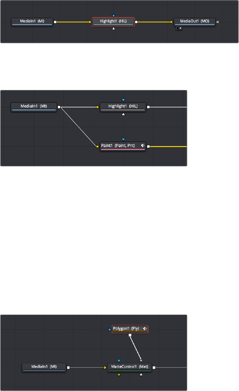
MediaIn node connected to a Highlight node connected to MediaOut node
When connecting nodes together, a single node output can be connected to multiple node’s
inputs, which is known as “branching.” This is useful when you have a single node that you want
to feed multiple operations at the same time.
The MediaIn node’s output is branched to the inputs of two other nodes
Using Multiple Inputs
Most nodes have two inputs, one for RGBA and another for a mask that can be optionally used
to limit the effect of that node to a particular part of the image (a similar idea to using a KEY
input to perform secondary corrections in the Color page). However, some nodes have three or
even more inputs, and it’s important to make sure you connect the correct image data to the
appropriate input in order to obtain the desired result. If you connect a node to another node’s
input and nothing happens, chances are you’ve connected to the wrong input.
For example, the MatteControl node has a background input and a foreground input, both of
which accept RGBA channels. However, it also has SolidMatte, GarbageMatte, and EffectsMask
inputs that accept Matte or Mask channels to modify the alpha key being extracted from the
image in different ways. If you want to perform the extremely common operation of using a
MatteControl node to attach a Polygon node for rotoscoping an image, you need to make sure
that you connect the Polygon node to the GarbageMatte input to obtain the correct result, since
the GarbageMatte input is automatically set up to use the input mask to alter the alpha channel
of the image. If you connect to any other input, your Polygon mask won’t work.
Polygon node connected to a MatteControl node for rotoscoping
2-62Chapter – 12 Understanding Image Channels and Node Processing

In another example, the DeltaKeyer node has a primary input (labeled “Input”) that accepts
RGBA channels, but it also has a CleanPlate input for attaching an RGB image with which to
clean up the background (typically the CleanPlate node), and SolidMatte, GarbageMatte, and
EffectsMask inputs that accept Matte or Mask channels to modify the alpha key being extracted
from the image in different ways. To pull a key successfully, though, you must connect the
image you want to key to the “Input” input.
MediaIn node connected to the main “Input” input of a DeltaKeyer node,
other nodes connected to specific inputs for those particular nodes
If you position your pointer over any node’s input or output, a tooltip will appear in the Tooltip
bar at the bottom of the Fusion page letting you know what that input or output is for, to help
guide you to using the right input for the job. If you pause for a moment longer, another tooltip
will appear in the Node Editor itself.
(Left) The node input’s tooltip in the Tooltip bar, (Right) The node tooltip in the Node Editor
Connecting to the Correct Input
When you’re connecting nodes together, pulling a connection line from the output of one node
and dropping it right on top of the body of another node makes a connection to the default
input for that node, which is commonly “Input” or “Background.”
Side by side, dropping a connection on a node’s
body to connect to that node’s primary input
2-63Chapter – 12 Understanding Image Channels and Node Processing
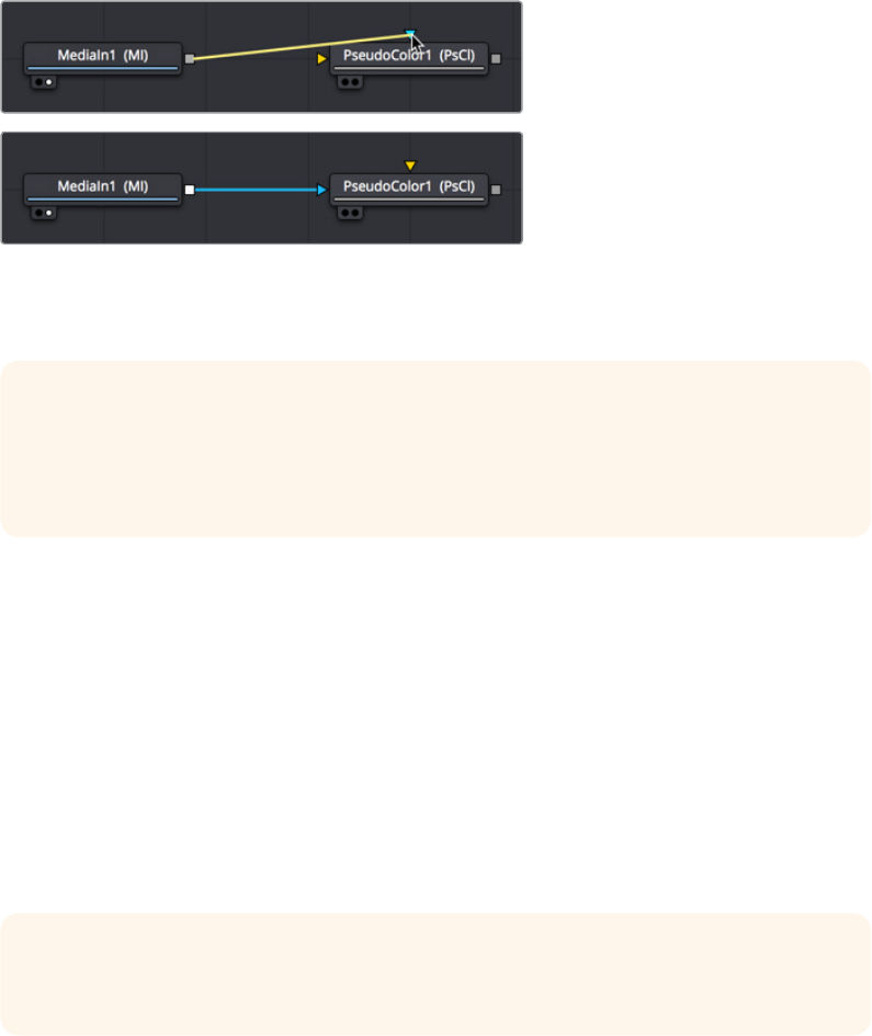
However, if you drop a connection line right on top of a specific input, then you’ll connect to that
input, so it’s important to be mindful of where you drop connection lines as you wire up different
node trees together.
Side by side, dropping a connection on a specific node
input, note how the inputs rearrange themselves afterwards
to keep the node tree tidy‑looking
Some Nodes are Incompatible With Some Inputs
Usually, you’re prevented from connecting a node’s output to another node or node input that’s
not compatible with it. For example, if you try to connect a Merge3D node’s output directly to
the input of a regular Merge node, it won’t work; you must first connect to a Renderer3D node
that creates output appropriate for 2D compositing operations.
In other cases, connecting the wrong image data to the wrong node input won’t give you any
sort of error, it will simply fail to produce the result you were expecting, necessitating you to
troubleshoot the composition. If this happens to you, check the Node Reference section (or the
Fusion Tool Manual for previous versions of Fusion) to see if the node you’re trying to connect
to has any limitations as to how it must be attached.
Always Connect the Background Input First
Many nodes combine images in different ways using “background” and “foreground” inputs,
including the Merge node, the Matte Control node, and the Channel Booleans node as
commonly used examples. To help you keep things straight, background inputs are always
orange, and foreground inputs are always green.
TIP: If you hold the Option key down while you drag a connection line from one node
onto another, and you keep the Option key held down while you release the pointer’s
button to drop the connection, a menu appears that lets you choose which specific
input you want to connect to, by name.
TIP: This chapter tries to cover many of the little exceptions to node connection that are
important for you to know, so don’t skim too fast.
2-64Chapter – 12 Understanding Image Channels and Node Processing
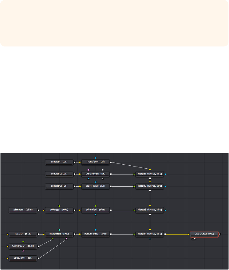
When you first connect any node’s output to a multi‑input node, you usually want to connect the
background input first. This is handled for you automatically when you first drop a connection
line onto the body of a new multi‑input node, it usually connects to the orange‑colored
background input first (the exception is mask nodes, which always connect to the first available
mask input). This is good, because you want to get into the habit of always connecting the
background input first.
If you connect to only one input of a multi‑input node and you don’t connect to the background
input, you may find that you don’t get the results you wanted. This is because each multi‑input
node expects that the background will be connected before anything else, so that the internal
connections and math used by that node can be predictable.
Node Colors Tell You Which Nodes Connect
Unlike the Color page, where each Corrector node is capable of performing nearly every kind
of grading operation in combination for speed of grading, each of the many nodes in the Fusion
page accomplish a single type of effect or operation. These single‑purpose nodes make it
easier to decipher a complex composition when examining its node tree, and it also makes it
easier for artists to focus on fine‑tuning specific adjustments, one at a time, when assembling
the ever‑growing tree of MediaIn nodes and image processing operations that comprise one’s
composite.
Because each Fusion page node has a specific function, they’re categorized by type to make it
easier to keep track of which nodes require what types of image channels as input, and what
image data you can expect each node to output. These general types are described here.
A node tree showing the main categories of node colors
TIP: The only node to which you can safely connect the foreground input prior to the
background input is the Dissolve node, which is a special node that can be used to
either dissolve between two inputs, or automatically switch between two inputs of
unequal duration.
2-65Chapter – 12 Understanding Image Channels and Node Processing

Blue MediaIn Nodes and Green Generator Nodes
Blue MediaIn nodes add clips to a composite, and green Generator nodes create images. Both
types of nodes output RGBA channels (depending on the source and generator), and may
optionally output auxiliary channels for doing advanced compositing operations.
Because these are sources of images, both kinds of nodes can be attached to a wide variety of
other nodes for effects creation besides just 2D nodes. For example, you can also connect
MediaIn nodes to Image Plane 3D nodes for 3D compositing, or to pEmitter nodes set to
“Bitmap” for creating different particle systems. Green Generator nodes can be similarly
attached to many different kinds of nodes, for example attaching a FastNoise node to a
Displace 3D node to impose undulating effects to 3D shapes.
2D Processing Nodes, Color Coded by Type
These encompass most 2D processing and compositing operations in DaVinci Resolve, all of
which process RGBA channels and pass along auxiliary channels. These include:
Orange Blur nodes
Olive Color Adjustment nodes (color adjustment nodes additionally concatenate with
one another)
Pink Paint nodes
Dark orange Tracking nodes
Tan Transform node (transform nodes additionally concatenate with one another)
Teal VR nodes
Dark brown Warp nodes
Gray which includes Compositing nodes as well as many other types.
Additionally, some 2D nodes such as Fog and Depth Blur (in the Deep Pixel category) accept
and use Auxiliary channels such as Z‑Depth to create different perspective effects in 2D.
Purple Particle System Nodes
These are nodes that connect together to create different particle systems, and they’re
incompatible with other kinds of nodes until you add a pRender node which outputs 2D RGBA
and Auxiliary data that can be composited with other 2D nodes and operations.
Dark Blue 3D Nodes
These are 3D operations, which generate and manipulate 3D data (including auxiliary channels)
that is incompatible with other kinds of nodes until processed via a Renderer 3D node, which
then outputs RGBA and Auxiliary data.
TIP: Two 2D nodes that specifically don’t process alpha channel data are the Color
Corrector node, designed to let you color correct a foreground layer to match a
background layer without affecting an alpha channel being used to create a composite.
and the Gamut node, which lets you perform color space conversions to RGB data from
one gamut to another without affecting the alpha channel.
2-66Chapter – 12 Understanding Image Channels and Node Processing

Brown Mask Nodes
Masks output single‑channel images that can only be connected to one another (to combine
masks) or to specified Mask inputs. Masks are useful for defining transparency (Alpha masks),
defining which parts of an image should be cropped out (Garbage masks), or defining which
parts of an image should be affected by a particular node operation (Effects masks).
Using Channels in a Composition
When you connect one node’s Output to another node’s Input, you feed all of the channels that
are output from the upstream node to the downstream node. 2D nodes, which constitute most
simple image processing operations in the Fusion page, propagate all channel data from node
to node, including RGB, alpha, and auxiliary channels, regardless of whether or not that node
actually uses or affects a particular channel.
Incidentally, if you want to see which channels are available for a node, you can open the Color
pop‑up menu in the Viewer to get a list. This control also lets you view any channel on this list,
so you can examine the channel data of your composite anywhere along the node tree.
All channels that are available to the
currently viewed node can be isolated via
the Viewer’s Color control
2D nodes also typically operate upon all channel data routed through that node. For example, if
you connect a node’s output with RGBA and XYZ Normals channels to the input of a Vortex
node, all channels are equally transformed by the Size, Center, and Angle parameters of this
operation, including the alpha and XYZ normals channels, as seen in the following screenshot.
2-67Chapter – 12 Understanding Image Channels and Node Processing
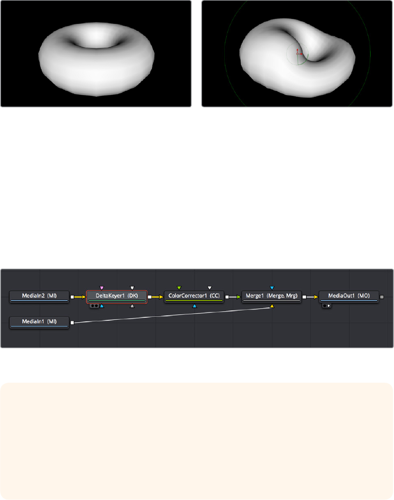
(Left) The Normal Z channel output by a rendered torus, (Right) The Normal Z channel after the output is
connected to a Vortex node, note how this auxiliary channel warps along with the RGB and A channels
This is appropriate, because in most cases you want to make sure that all channels are
transformed, warped, or adjusted together. You wouldn’t want to shrink the image without also
shrinking the alpha channel along with it, and the same is true for most other operations.
On the other hand, some nodes deliberately ignore specific channels, when it makes sense. For
example, the Color Corrector and Gamut nodes, both of which are designed to alter RGB data
specifically, have no effect on alpha or auxiliary channels. This makes them convenient for
color‑matching foreground and background layers you’re compositing, without worrying that
you’re altering the transparency or depth information accompanying that layer.
MediaIn, DeltaKeyer, Color Corrector, and Merge/MediaIn node
TIP: If you’re doing something exotic and you actually want to operate on a channel
that’s usually unaffected by a particular node, you can always use the Channel
Booleans node to reassign the channel you want to modify to another output channel
that’s compatible with the operation you’re trying to perform, and then use another
Channel Booleans node to reassign it back. When doing this to a single image, it’s
important to connect that image to the background input of the Channel Booleans
node, so the alpha and auxiliary channels are properly handled.
2-68Chapter – 12 Understanding Image Channels and Node Processing
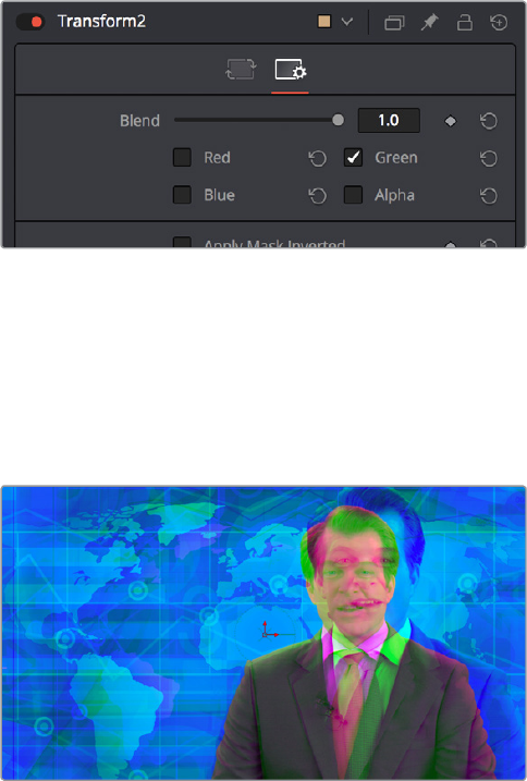
Channel Limiting
Most nodes have a set of Red, Green, Blue, and Alpha checkboxes in the Settings panel of that
node’s controls in the Inspector. These checkboxes let you exclude any combination of these
channels from being processed by that node.
The channel limiting checkboxes in the Settings panel of a
Transform node so only the Green channel is affected
For example, if you wanted to use the Transform node to add a bump map to only the green
channel of an image, you can turn off the Green, Blue, and Alpha checkboxes. As a result, the
green channel is processed by this operation, and the red, blue, and alpha channels are copied
straight from the node’s input to the node’s output, skipping that node’s processing to
remainunaffected.
Transforming only the Green color channel
of the image with a Transform effect
Adding Alpha Channels
One of the whole reasons for compositing is to begin with an image that lacks an alpha channel,
add one via keying or rotoscoping, and then composite that result against other images. While
the methods for this are covered in detail in later chapters, here’s an overview of how this is
handled within the Fusion page.
In the case of extracting a alpha matte from a greenscreen image, you typically connect the
image’s RGB output to the “Input” input of a Keyer node such as the Delta Keyer, and you
thenuse the keyer’s controls to pull the matte. The Keyer node automatically inserts the alpha
channel that’s generated alongside the RGB channels, so the output is automatically RGBA.
Then, when you connect the Keyer’s output to a Merge node in order to composite it over
another image, the Merge node automatically knows to use the embedded alpha channel
coming into the foreground input to create the desired composite, as seen in the
followingscreenshot.
2-69Chapter – 12 Understanding Image Channels and Node Processing
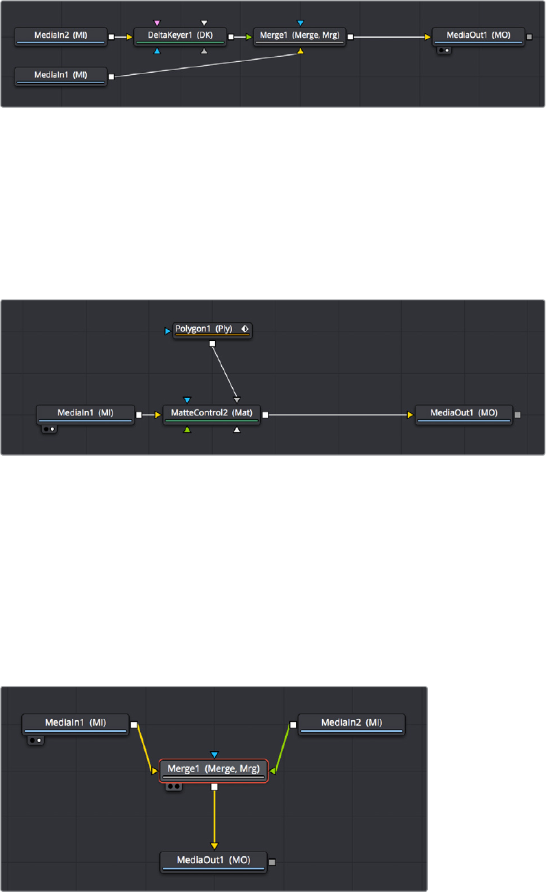
A simple node tree for keying, note that only one
connection links the DeltaKeyer to the Merge node
In the case of rotoscoping using a Polygon node, you’ll typically connect the image being
rotoscoped to the background input of a MatteControl node, and a Polygon node to its Garbage
Matte input (which you invert in the Inspector, unless you invert the Polygon’s output). This lets
you view the image while drawing, using the controls of the Polygon node, and the resulting
alpha channel is merged together with the RGB channels so the Merge Alpha node’s output is
RGBA, which can be connected to a Merge node to composite the rotoscoped subject over
another image.
A simple rotoscoping node tree
In both cases, you can see how the Fusion page node tree’s ability to carry multiple channels of
image data over a single connection line simplifies the compositing process.
How Channels Propagate During Compositing
As you’ve seen above, images are combined, or composited together, using the Merge node.
The Merge node takes two RGBA inputs labeled “Foreground” (green) and “Background”
(orange) and combines them into a single RGB output (or RGBA if both the foreground and
background input images have alpha), where the foreground image is in front (or on top,
depending on what you’re working on), and the background image is, you guessed it, in back.
A simple Merge node composite
2-70Chapter – 12 Understanding Image Channels and Node Processing

Auxiliary channels, on the other hand, are handled in a much more specific way. When you
composite two image layers using the Merge node, auxiliary channels will only propagate
through the image that’s connected to the background input. The rationale for this is that in
most composites that include computer generated imagery, the background is most often the
CG layer that contains auxiliary channels, while the foreground is a live‑action greenscreen
plate with subjects or elements that are meant to be combined against the background.
Many compositions use multiple Merge nodes to bring together many differently processed
branches of a large node tree, so it pays to be careful about how you connect the background
and foreground inputs of each Merge node to make sure that the correct channels
flowproperly.
Rearranging or Combining Channels
Last, but certainly not least, it’s also possible to rearrange and re‑combine channels in any way
you need, using one of three different node operations. For example, you might want to
combine the red channel from one image with the blue and green channels of a second image
to create a completely different channel mix. Alternately, you might want to take the Alpha
channel from one image and merge it with the alpha channel of a second image in different
ways, adding, subtracting, or using other intersection operations to create a very specific blend
of the two.
The following nodes are used to re‑combine channels in different ways:
Channel Boolean: Used to switch among or combine two sets of input channels in
different ways, using a variety of simple pre‑defined imaging math operations.
Channel Booleans: Used to rearrange YRGB/auxiliary channels within a single input
image, or among two input images, to create a single output image. If you only connect
a single image to this node, it must be connected to the background input to make sure
everything works.
Matte Control: Designed to do any combination of the following: (a) recombining
mattes, masks, and alpha channels in various ways, (b) modifying alpha channels using
dedicated matte controls, and (c) copying alpha channels into the RGB stream of the
image connected to the background input in preparation for compositing. You can copy
specific channels from the foreground input to the background input to use as an alpha
channel, or you can attach masks to the garbage matte input to use as alpha channels
as well.
TIP: Merge nodes are also capable of combining the foreground and background
inputs using Z‑Depth channels using the “Perform Depth Merge” checkbox, in which
case every pair of pixels are compared. Which one is in front depends on its Z‑Depth
and not which input it’s connected to.
2-71Chapter – 12 Understanding Image Channels and Node Processing
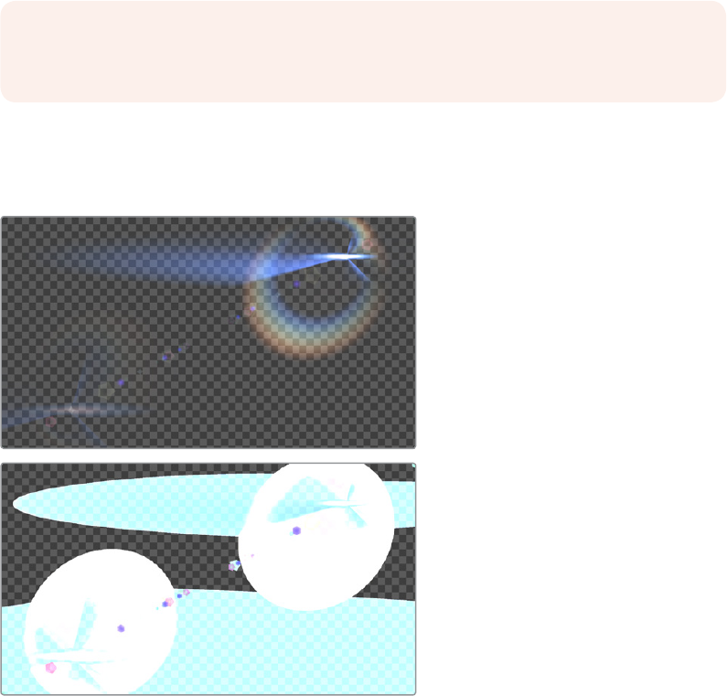
Understanding Premultiplication
Now that you understand how to direct and recombine image, alpha, and auxiliary channels in
the Fusion page, it’s time to learn a little something about premultiplication, to make sure you
always combine RGB and alpha channels correctly to get the best results from Merge
nodecomposites.
Premultiplication is an issue whenever you find yourself compositing multiple images together,
and at least one of them contains RGB with an Alpha channel. For example, if a motion graphics
artist gives you a media file with an animated title graphic that has transparency rendered into it
to accommodate later compositing, or if an animator gives you an isolated VFX plate of a
spaceship coming in for a landing with the transparency baked in, you may need to consider the
pre‑multiplied state of the RGBA image data as you use these images.
Most computer‑generated images you’ll be given should be premultiplied. A premultiplied alpha
channel means that, for every pixel of an image, the RGB channels are multiplied by the alpha
channel. This is standard practice in VFX workflows, and it guarantees that translucent parts of
the rendered image, such as flares, smoke, or atmospheric effects, are correctly integrated into
the background black areas of the isolated image, so that the image appears correct when you
view that layer by itself.
So‑called “straight” alpha channels, where the RGB channels have not been multiplied by the
alpha channel, will appear weirdly bright in these same translucent areas, which tells you that
you probably need to multiply the RGB and A channels prior to doing specific tasks.
(Top) Premultiplied alpha image, (Bottom) Straight alpha image
NOTE: Computer generated 3D images that were rendered anti‑aliased are almost
always premultiplied.
2-72Chapter – 12 Understanding Image Channels and Node Processing
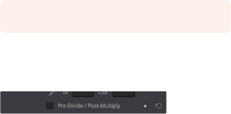
The Rules of Premultiplication
In general, when you’re compositing multiple images together, and one or more has a built‑in
alpha channel, you want to make sure you follow these general rules:
Always color‑correct images that are not premultiplied
Always filter and transform images that are premultiplied
How Do You Know You’ve Made
a Premultiplication Mistake?
Improper handling of premultiplication manifests itself in two obvious ways:
You see thin fringing around a subject composited with a Merge node
You notice a node adjustment affecting parts of the image that shouldn’t be affected by
that operation
You’ve combined RGB and alpha channels from different sources and the
checkerboard background pattern in the Viewer (if enabled) is only semi‑transparent
when it should be fully transparent
If you spot these sorts of issues, the good news is they’re easy to fix using either the internal
settings of the nodes causing the problem, or with dedicated nodes to force the premultiplied
state of the image at specific points in your node tree.
Setting the Premultiplied Status
of MediaIn Nodes That Need It
When you select a MediaIn node, the Import panel in the Inspector have a group of checkboxes
that let you determine how an alpha channel embedded with that image should be handled.
There are checkboxes to Make the alpha channel solid (to eliminate transparency), to invert
thealpha channel, and to Post‑Multiply the RGB channels with the alpha channel, should that
benecessary.
Nodes That Affect Premultiplication
Most nodes that require you to explicitly deal with the state of premultiplication of RGBA image
input have a “Pre‑Divide, Post‑Multiply” checkbox. This includes simple color correction nodes
such as Brightness Contrast and Color Curves, as well as the Color Correct node, which has the
“Pre‑Divide/Post‑Multiply” checkbox in the Options panel of its Inspector settings.
The Pre‑Divide/Post‑Multiply checkbox of the
Color Curves node, seen in the Inspector
NOTE: This functionality was not yet available in the Public Beta of DaVinci Resolve 15
as of this writing.
2-73Chapter – 12 Understanding Image Channels and Node Processing

Control Premultiplication with
AlphaDivide and Alpha Multiply
The Alpha Divide and Alpha Multiply nodes, found in the Matte category of the Effects Library,
are provided whenever you need to do operations on RGBA image data where you need explicit
control over the pre‑multiplied state of an image’s RGB channels against its alpha channel.
Simply add the Alpha Divide node when you want the RGBA image data to not be premultiplied,
and add the Alpha Multiply node when you want the image data to be premultiplied again.
Forexample, if you’re using third‑party OFX nodes that make color adjustments, you may need
to manually control premultiplication before and after such an adjustment.
A node tree with explicit Alpha Divide and Alpha Multiply nodes
Understanding Auxiliary Channels
Auxiliary channels describe a family of special‑purpose image data that typically describes 3D
position, orientation, and object information for use in 2D composites. For example, Z‑Depth
channels describe the depth of each region of an image along a Z axis (XYZ), while an XYZ
Normals channel describes the orientation (facing up, facing down, facing to the left or right) of
each pixel in an image. Auxiliary channel data is generated by rendering 3D data, so it may
accompany images generated by Autodesk Maya or 3DS Max, or it may be generated from
within the Fusion page via the Renderer 3D node, which outputs a 3D scene that you’ve
assembled and lit as 2D RGBA channels, with optionally accompanying Auxiliary channels.
One of the most common reasons to use Auxiliary data is that 3D rendering is computationally
expensive and time‑consuming, so outputting descriptive information about a 3D image that’s
been rendered empowers compositing artists to make sophisticated alterations in 2D affecting
focus, lighting, and depth compositing, that are faster to perform and readjust in 2D it would be
to re‑render the 3D source material over and over.
There are two ways of obtaining Auxiliary channel data:
First, auxiliary data may be embedded within a clip exported from a 3D application
that’s in a format capable of containing Auxiliary channels. In this case, it’s best to
consult your 3D application’s documentation to determine which auxiliary channels can
be generated and output.
You may also obtain Auxiliary channel data by generating it within the Fusion page, via
3D operations output by the Renderer 3D node, using the Optical Flow node, or using
the Disparity node.
2-74Chapter – 12 Understanding Image Channels and Node Processing
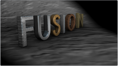
An RGBA 3D rendered scene that can also
generate auxiliary channels
Image Formats That Support Auxiliary Channels
Fusion supports auxiliary channel information contained in a variety of image formats.
Thenumber of channels and methods used are different for each format.
OpenEXR (*.exr)
The OpenEXR file format can contain an arbitrary number of additional image channels. Many
renderers that will write to the OpenEXR format will allow the creation of channels that contain
entirely arbitrary data. For example, a channel with specular highlights might exist in an
OpenEXR. In most cases, the channel will have a custom name that can be used to map the
extra channel to one of the channels recognized by Fusion.
SoftImage PIC (*.PIC, *.ZPIC and *.Z)
The PIC image format (used by SoftImage) can contain Z‑Depth data in a separate file marked
by the ZPIC file extension. These files must be located in the same directory as the RGBA PIC
files and must use the same names. Fusion will automatically detect the presence of the
additional information and load the ZPIC images along with the PIC images.
Wavefront RLA (*.RLA), 3ds Max RLA (*.RLA) and RPF (*.RPF)
These image formats are capable of containing any of the image channels mentioned above. All
channels are contained within one file, including RGBA, as well as the auxiliary channels. These files
are identified by the RLA or RPF file extension. Not all RLA or RPF files contain auxiliary channel
information but most do. RPF files have the additional capability of storing multiple samples per
pixel, so different layers of the image can be loaded for very complex depth composites.
Fusion RAW (*.RAW)
Fusion’s native RAW format is able to contain all of the auxiliary channels as well as other
metadata used within Fusion.
Creating Auxiliary Channels in Fusion
The following nodes create auxiliary channels:
Renderer 3D: Creates these channels in the same way as any other 3D application
would, and you have the option of outputting every one of the auxiliary data channels
that the Fusion page supports.
Optical Flow: Generates Vector and Back Vector channels by analyzing pixels over
consecutive frames to determine likely movements of features in the image.
Disparity: Generates Disparity channels by comparing stereoscopic image pairs.
2-75Chapter – 12 Understanding Image Channels and Node Processing
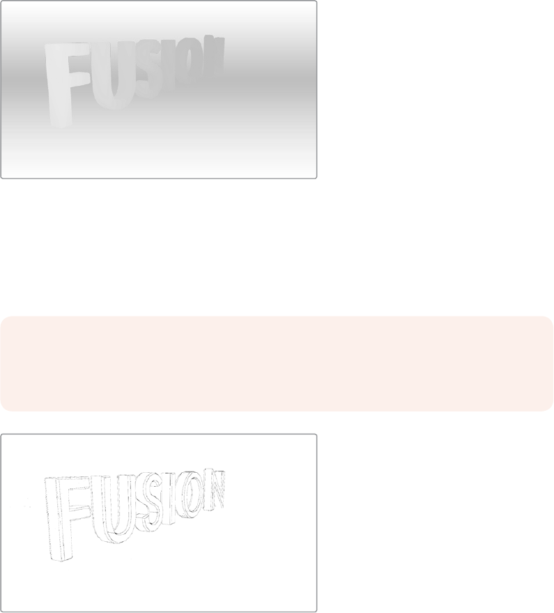
Auxiliary Channels Explained
Fusion is capable of using auxiliary channels, where available, to perform depth based
compositing, to create masks and mattes based on Object or Material IDs, and for texture
replacements. Tools that work with auxiliary channel information have been specifically
developed to work with this data.
Z-Depth
Each pixel in a Z‑Depth channel contains a value that represents the relative depth of that pixel
in the scene. In the case of overlapping objects in a model, most 3D applications take the depth
value from the object closest to the camera when two objects are present within the same
pixel, since the closest object typically obscures the farther object.
When present, Z‑depth can be used to perform depth merging using the Merge node, or to
control simulated depth‑of‑field blurring using the Depth Blur node.
The rendered Z‑Depth channel for the previous RGBA image
Z-Coverage
The Z‑Coverage channel is used to indicate pixels in the Z‑Depth that contains two objects.
Thevalue is used to indicate, as a percentage, how transparent that pixel is in the final
depthcomposite.
Z‑Coverage channel
WARNING: Depth composites in Fusion that are based on images that lack a
Z‑Coverage channel, as well as a background RGBA channel, will not be properly
anti‑aliased
2-76Chapter – 12 Understanding Image Channels and Node Processing

Background RGBA
This channel contains the color values from the objects behind the pixels described in
theZ‑Coverage.
Background RGBA
Object ID
Most 3D applications are capable of assigning ID values to objects in a scene. Each pixel in the
Object ID channel will be identified by that ID number, allowing for the creation of masks.
Object ID
Material ID
Most 3D applications are capable of assigning ID values to materials in a scene. Each pixel in
the Material ID channel will be identified by that ID number, allowing for the creation of masks
based on materials.
Material ID
2-77Chapter – 12 Understanding Image Channels and Node Processing

UV Texture
The UV Texture channels contain information about mapping coordinates for each pixel in the
scene. This is used to apply textures wrapped to the object.
UV Texture
X, Y and Z Normals
The X, Y and Z Normal channels contain information about each pixel’s orientation (the
direction it faces) in 3D space.
XYZ Normals
XY Vector and XY BackVector
The Vector channels indicates the pixel’s motion from frame to frame. It can be used to apply
motion blur to an image as a post process or to track pixels over time for retiming. The XY
Vector points to the next frame, while the XY BackVector points to the previous frame.
XY Vector
2-78Chapter – 12 Understanding Image Channels and Node Processing
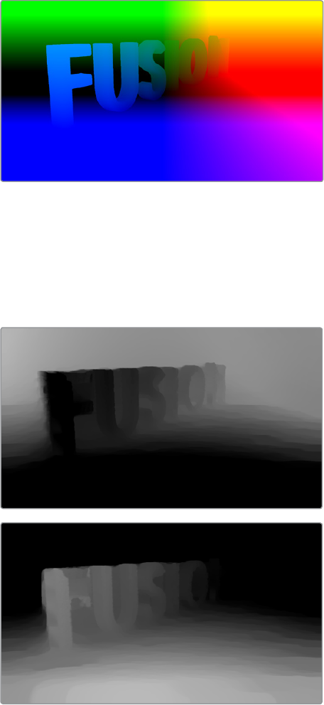
XYZ Position
The XYZ Position channels indicate where each pixel is assigned; the XYZ position of its
location is in 3D space, typically in world coordinates. This can be used, like Z‑depth, for
compositing in depth but can also be used for masking based on 3D position, regardless of
camera transforms.
For more information on using Position channels in Fusion, read Chapter 12, 3D.
XYZ Position
XY Disparity
The XY Disparity channels indicate where each pixel’s corresponding matte can be found in a
stereo image. Each eye, left and right, will use this vector to point to where that pixel would be
in the other eye. This can be used for adjusting stereo effects, or to mask pixels in stereo space.
XY Disparity
2-79Chapter – 12 Understanding Image Channels and Node Processing
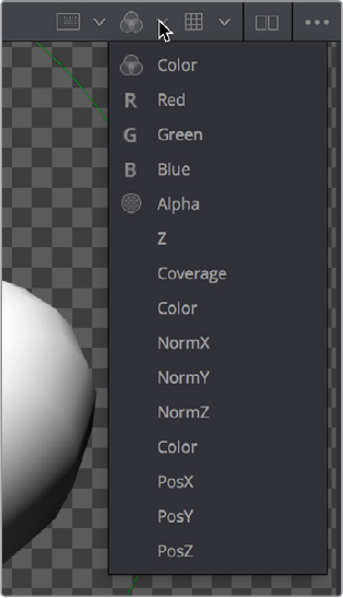
Propagating Auxiliary Channels
Ordinarily, auxiliary channels will be propagated along with RGBA image data, from node to
node, among gray‑colored nodes including those in the Blur, Filter, Effect, Transform, and Warp
categories. Basically, most nodes that simply manipulate channel data will propagate (and
potentially manipulate) auxiliary channels no problem.
However, when you composite two image layers using the Merge node, auxiliary channels will
only propagate through the image that’s connected to the background input. The rationale for
this is that in most composites that include computer generated imagery, the background is
most often the CG layer that contains auxiliary channels, while the foreground is a live‑action
greenscreen plate with subjects or elements that are combined against the background, which
lack auxiliary channels.
Viewing Auxiliary Channels
You can view the Auxiliary Channels by selecting the desired channel from the Viewer’s toolbar
or from the Viewer’s contextual menu. The Color Inspector SubV can also be used to read
numerical values from all of the channels.
Selecting a channel from the Viewer’s Toolbar
2-80Chapter – 12 Understanding Image Channels and Node Processing
Nodes That Use Auxiliary Channels
The availability of Auxiliary channels opens up a world of advanced compositing functionality.
This section describes every Fusion node that has been designed to work with images that
contain Auxiliary channels.
Merge
In addition to regular compositing operations, Merge is capable of merging two or more images
together using the Z‑Depth, Z‑Coverage, and BG RGBA buffer data. This is accomplished by
enabling the Perform Depth Merge checkbox from the Channels tab.
Depth Blur
The Depth Blur tool is used to blur an image based on the information present in the Z‑Depth. A
focal point is selected from the Z‑Depth values of the image and the extent of the focused
region is selected using the Depth of Field control.
Fog
The Fog tool makes use of the Z‑Depth to create a fog effect that is thin closer to the camera
and thickens in regions farther away from the camera. You use the Pick tool to select the Depth
values from the image and to define the Near and Far planes of the fog’s effect.
Shader
The Shader tool applies data from the RGBA, UV and the Normal channels to modify the
lighting applied to objects in the image. Control is provided over specular highlights, ambient
and diffuse lighting, and position of the light source. A second image can be applied as a
reflection or refraction map.
SSAO
SSAO is short for Screen Space Ambient Occlusion. Ambient Occlusion is the lighting caused
when a scene is surrounded by a uniform diffuse spherical light source. In the real world, light
lands on surfaces from all directions, not from just a few directional lights. Ambient Occlusion
captures this low frequency lighting, but it does not capture sharp shadows or specular lighting.
For this reason, Ambient Occlusion is usually combined with Specular lighting to create a full
lighting solution.
The SSAO tool uses the Z‑Depth channel, but requires a Camera3D input.
Texture
The Texture tool uses the UV channels to apply an image from the second input as a texture.
This can replace textures on a specific object when used in conjunction with the Object ID or
Material ID masks.
Shadow
The Shadow tool can use the Z‑Depth channel for a Z‑Map. This allows the shadow to fall onto
the shape of the objects in the image.
2-81Chapter – 12 Understanding Image Channels and Node Processing
Vector Motion Blur
Using the forward XY Vector channels, the Vector Motion Blur tool can apply blur in the
direction of the velocity, creating a motion blur effect.
Vector Distortion
The forward XY Vector channels can be used to warp an image with this tool.
Time Speed and Time Stretcher
These tools can use the Vector and BackVector channels to retime footage.
New Eye
For stereoscopic footage, New Eye uses the Disparity channels to create new viewpoints or to
transfer RGBA data from one eye to the other.
Stereo Align
For stereoscopic footage, the Disparity channels can be used by Stereo Align to warp one or
both of the eyes to correct misalignment or to change the convergence plane.
Smooth Motion
Smooth Motion uses Vector and Back Vector channels to blend other channels temporally. This
can remove high frequency jitter from problematic channels such as Disparity.
Volume Fog
Volume Fog is a raymarcher that uses the Position channels to determine ray termination and
volume dataset placement. It can also use cameras and lights from a 3D scene to set the
correct ray start point and Illumination parameters.
Volume Mask
Volume Mask uses the Position channels to set a mask in 3D space as opposed to screen
space. This allows a mask to maintain perfect tracking through a camera move.
Custom Tool, Custom Vertex 3D, pCustom
The “Custom” tools can sample data from the auxiliary channels per pixel, vertex, or particle
and use that for whatever processing you would like.
Lumakeyer
The Lumakeyer tool can be used to perform a key on the Z‑Depth channel by selecting the
Z‑Depth in the channel drop down list.
Disparity to Z, Z to Disparity, Z to WorldPos
These tools use the inherent relationships between depth, position, and disparity to convert
from one channel to another.
2-82Chapter – 12 Understanding Image Channels and Node Processing

Copy Aux
The Copy Aux tool can copy auxiliary channels to RGB and then copy them back. It includes
some useful options for remapping values and color depths, as well as removing auxiliary
channels.
Channel Boolean
The Channel Boolean tool can be used to combine or copy the values from one channel to
another in a variety of ways.
TIP: The Object ID and Material ID auxiliary channels can be used by some tools in
Fusion to generate a mask. The “Use Object” and “Use Material” settings used to
accomplish this are found in the Settings tab of that node’s controls in the Inspector.
2-83Chapter – 12 Understanding Image Channels and Node Processing
Chapter 13
Learning to Work
in the Fusion Page
This chapter is a grand tour of the basics of the Fusion page, walking you
through the process of shepherding a clip from the Edit page to the Fusion
page, and then working in the Node Editor to create some simple effects.
Subsequent topics build upon these basics to show you how to use the
different features in Fusion to accomplish common compositing and
effects tasks. In the process you’ll learn how node trees are best
constructed, and how to use the different panels of the Fusion page
together to work efficiently.
2-84Chapter – 13 Learning to Work in the Fusion Page
Contents
What’s a Composition? 2-87
Moving From the Edit to the Fusion Page 2-87
How Nodes Are Named 2-88
Applying and Masking Effects 2-88
Adding a Node to the Tree 2-89
Editing Parameters in the Inspector 2-89
Replacing Nodes 2-91
Adjusting Fusion Page Sliders 2-91
Masking Node Eects 2-92
Color Management in the Public Beta 2-95
Compositing Two Clips Together 2-97
Adding Additional Media to Compositions 2-97
Automatically Creating Merge Nodes 2-98
Adjusting the Timing of Clips Added From the Media Pool 2-99
Fixing Problem Edges in a Composite 2-100
Composite Modes and the Corner Positioner 2-101
Setting Up the Initial Composite 2-101
Controlling Which Node You See in the Viewer 2-103
Adding the Corner Positioner Node With a Search 2-104
Warping the Image With the Corner Positioner Node 2-105
Toggling On‑screen Control Visibility 2-106
Navigating the Viewer 2-107
Using the Screen Composite Mode in the Merge Node 2-107
Tweaking Color in the Foreground Layer 2-108
Creating and Using Text 2-110
Creating Text Using the Text+ Node 2-110
Styling and Adjusting Text 2-111
Using One Image’s Alpha Channel in Another Image 2-112
Using Transform Controls in the Merge Node 2-116
Match Moving Text With Motion Tracking 2-117
Adding a Layer We Want to Match Move 2-117
Setting Up to Track 2-118
A Simple Tracking Workflow 2-119
Connecting Motion Track Data to Match Move 2-122
Osetting the Position of a Match Moved Image 2-123
2-85Chapter – 13 Learning to Work in the Fusion Page
Using Paint and Planar Tracking 2-125
Using a Planar Tracker to Steady a Subject to Paint 2-125
Painting Over Blemishes 2-128
Inverting the Steady Eect to Put the Motion Back In 2-131
Fixing the Edges by Only Using the Fixed Part of the Frame 2-133
Building a Simple Green Screen Composite 2-137
Organizing Clips in the Edit Page to Create a Fusion Clip 2-137
Pulling a Greenscreen Key Using the Delta Keyer 2-138
Using the Transform Node to Resize a Background 2-142
Masking a Graphic 2-143
Animating an Image Using Keyframes 2-146
Animating a Parameter in the Inspector 2-146
Using the Spline Editor 2-147
Congratulations 2-149
2-86Chapter – 13 Learning to Work in the Fusion Page
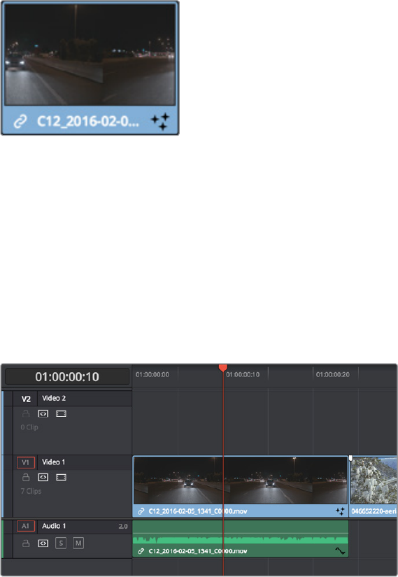
What’s a Composition?
A “composition” describes the collection of nodes that creates an effect in the Fusion page, just
as a “grade” describes the collection of nodes that creates a color adjustment or look on the
Color page. The relationship between the Edit page and the Fusion page, at a basic level, is
similar to the relationship between the Edit page and the Color page. Every clip can have a
grade applied to it in the Color page, and similarly every clip can have a composition applied to
it in the Fusion page.
If you use the Fusion page to add effects or do any compositing at all, a badge appears on that
clip in all timelines to show that clip has a composition applied to it.
Clips with Fusion page compositions have a
Fusion badge to the right of the name
Moving From the Edit to the Fusion Page
Whenever you want to create a composite using a clip from the Edit page, the simplest way to
work is to just move the playhead so it intersects the desired clip in the Edit page timeline,
make sure the clip you want to composite is the topmost clip of any superimposed stack of clips
(whichever clip you see in the Timeline Viewer is the one you’ll be compositing with), and then
open the Fusion page.
Positioning the playhead over a clip you want to use in a composition
In the Fusion page, you should see a single selected MediaIn1 node representing only the
top‑most clip you where parked on in the Edit page, and that image should be showing in the
Viewer thanks to the MediaOut1 node automatically being loaded in the Viewer (the Viewer
buttons visible underneath that node confirm this). Any clips that were underneath that clip are
ignored when you work this way, because the idea is you’re only doing a quick fix to the current
clip at the position of the playhead.
2-87Chapter – 13 Learning to Work in the Fusion Page
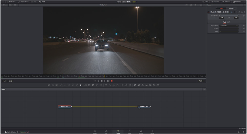
How the Fusion page appears when you first open it while the playhead is on a new clip
The playhead should still be on the same frame you were parked on in the Edit page, except
now it’s on the equivalent source frame in the Time Ruler underneath the Viewer that
represents that clip’s media. Yellow markers indicate the range of the current clip that appears
in the Timeline, while the source clip’s handles extend to the left and right. Lastly, the selected
MediaIn1 node displays its parameters in the Inspector to the right.
In the Node Editor at the bottom, the MediaIn1 node is connected to a MediaOut1 node. If this is
all you see, there is no effect yet applied to this clip. It’s only when you start adding nodes
between MediaIn and MediaOut that you begin to assemble a composition.
At this point, you’re ready to start compositing.
How Nodes Are Named
While the documentation refers to nodes by their regular name, such as “MediaIn,” the actual
names of nodes in the Fusion Node Editor have a number appended to them, to indicate which
node is which when you have multiple instances of a particular type of node.
Applying and Masking Effects
Let’s begin by looking as some very simple effects, and build up from there. Opening the
Effects Library, then clicking the Disclosure control to the left of Tools, reveals a list of
categories containing all the effects nodes that are available in Fusion. As mentioned before,
each node does one thing, and by using these nodes in concert you can create extremely
complex results from humble beginnings.
Clicking the Effect category reveals its contents. For now, we’re interested in the TV effect.
2-88Chapter – 13 Learning to Work in the Fusion Page
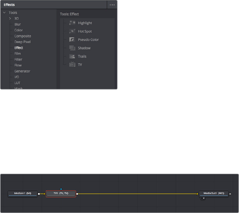
Browsing the Effect category to find the TV node
Adding a Node to the Tree
Assuming the MediaIn node is selected in the Node Editor, clicking once on the TV node in the
Effects Library automatically adds that node to the node tree to the right of the selected node,
and it immediately takes effect in the Viewer thanks to the fact that the MediaOut1 node is
what’s loaded in the Viewer, since that means that all nodes upstream of the MediaOut1 node
will be processed and shown.
A new node added from the Effects Library
There are many other ways of adding nodes to your node tree, but it’s good to know how to
browse the Effects Library as you get started.
Editing Parameters in the Inspector
Looking at the TV effect in the Viewer, you may notice a lot of transparency in the image
because of the checkerboard pattern. If you don’t see the checkerboard pattern in the Viewer,
it might be turned off. You can turn it on by clicking the Viewer option menu and choosing
Checker Underlay.
To improve the effect, we’ll make an adjustment to the TV1 node’s parameters in the Inspector
at the left. Whichever node is selected shows its controls in the Inspector, and most nodes have
several panels of controls in the Inspector, seen as little icons just underneath that node’s
titlebar.
2-89Chapter – 13 Learning to Work in the Fusion Page
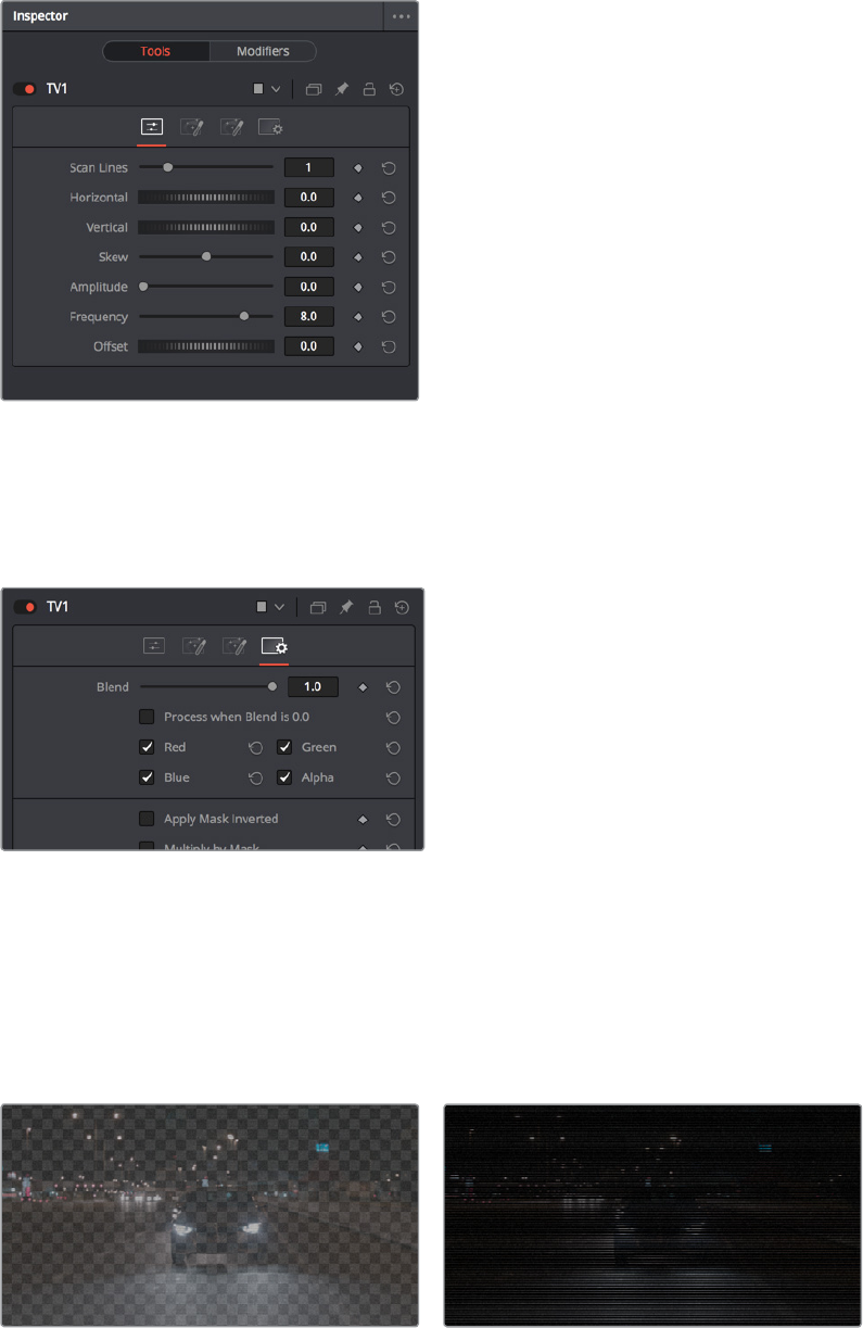
The Inspector showing the parameters of the TV effect
Clicking the last panel opens the Settings panel. Every node has a Settings panel, and this is
where the parameters that every node shares, such as the Blend slider and RGBA checkboxes,
are found. These let you choose which image channels are affected, and let you blend
The Settings panel, which has channel limiting and
mask handling controls that every node shares
In our case, the TV effect has a lot of transparency because the scan lines being added are also
being added to the alpha channel, creating alternating lines of transparency. Turning the Alpha
checkbox off results in a more solid image, while opening the Controls panel (the first panel)
and dragging the Scan Lines slider to the right to raise its value to 4 creates a more visible
television effect.
(Left) The original TV effect, (Right) Modifications to the TV effect to make the clip more solid
2-90Chapter – 13 Learning to Work in the Fusion Page

Replacing Nodes
That was fun, but having previewed this effect, we decide we want to try something different
with this shot. Going back to the Effect category of the Effects Library, there is a Highlight node
we can use to add some pizazz to this shot, instead of the TV node.
Instead of clicking the Highlight node, which would add it after the currently selected node,
we’ll drag and drop it on top of the TV1 node in the Node Editor. A dialog appears asking “Are
you sure you want to replace TV1 with Highlight?” and clicking OK makes the replacement.
Dragging a node from the Effects Library
onto a node in the Node Editor to replace it
A Highlight1 node takes the TV node’s place in the node tree, and the new effect can be seen
in the Viewer, which in this image’s case consists of star highlights over the lights in the image.
Incidentally, another way you can replace an existing node with another type of node in the
Node Editor is to right‑click a node you want to replace, and choose the new node you want
from the Replace Tool submenu of the contextual menu that appears.
Right‑clicking a node to use the contextual menu Replace Node submenu
It’s time to use the Inspector controls to customize this effect, but first, let’s take a look at how
sliders in the Fusion page differ somewhat from sliders on other pages in DaVinci Resolve.
Adjusting Fusion Page Sliders
When you drag a slider in the Fusion page Inspector, in this case the “Number of Points” slider,
a little dot appears underneath it. This dot indicates the position of the default value for that
slider, and also serves as a reset button if you click it.
2-91Chapter – 13 Learning to Work in the Fusion Page
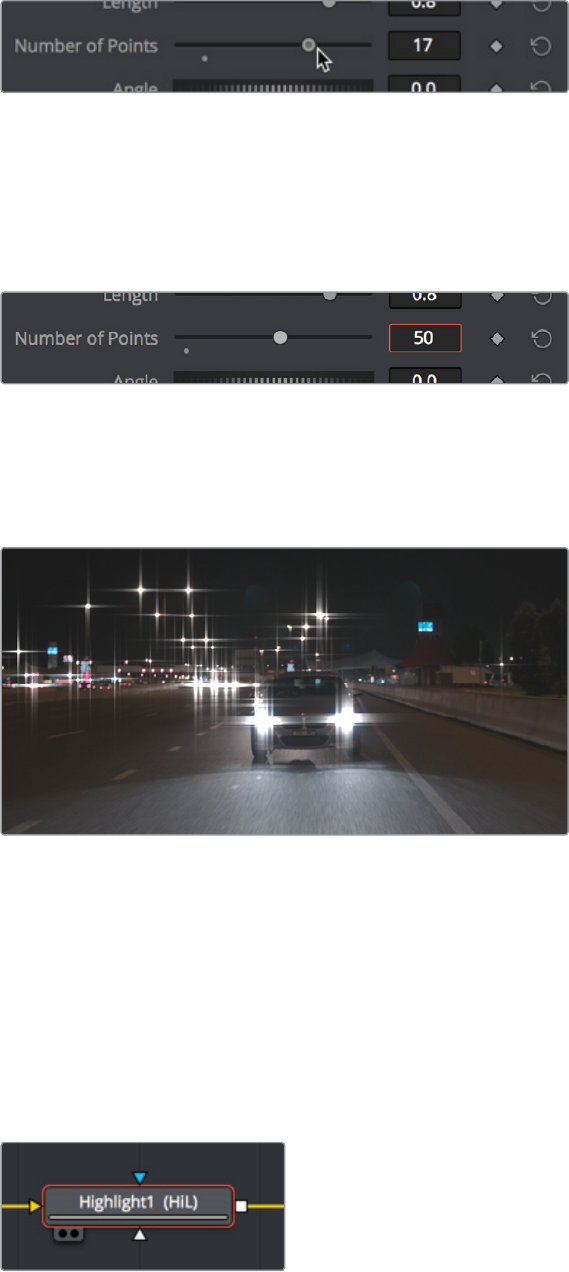
Adjusting a slider reveals a reset button underneath it
Each slider is limited to a different range of minimum and maximum values that is particular to
the parameter you’re adjusting. In this case, the “Number of Points” slider maxes out at 24.
However, you can re‑map the range of many (not all) sliders by entering a larger value in the
number field to the right of that slider. Doing so immediately repositions the slider’s controls to
the left as the slider’s range increases to accommodate the value you just entered.
Entering a larger value to expand the range over which a slider will operate
Masking Node Effects
Going back to the Length slider, increasing its value gives us a nice big flare.
The Highlight effect with a raised Length value (zoomed in)
This is a nice effect, but maybe we only want to apply it to the car in the foreground, rather than
to every single light in the scene. This can be accomplished using a Mask node connected to
the Effect input of the Highlight node. The Effect Mask input is a blue input that serves a similar
function to the KEY input of nodes in the Color page; it lets you use a mask or matte to limit that
node’s effect on the image, like a secondary adjustment in color correction. Most nodes have
an Effects Mask input, and it’s an enormously useful technique.
However, there’s another node input that’s more interesting, and that’s the gray Highlight Mask
input on the bottom of the node. This is an input that’s specific to the Highlight node, and it lets
you use a mask to limit the part of the image that’s used to generate the Highlight effect.
The blue Effect input of a node is on top, and
the gray Highlight Mask input that’s specific
to the Highlight node is on the bottom
2-92Chapter – 13 Learning to Work in the Fusion Page

Adding a Mask Node
To see the results of using either of these two inputs, let’s add a mask, this time using the
toolbar, which presents a collection of frequently‑used mask nodes that we can quickly create.
Clicking the Ellipse button on the Toolbar
With the Highlight node selected already, clicking the Ellipse button (the circle) automatically
creates an Ellipse1 node that’s connected to the blue Effect Mask input. Creating new masks
while a node is selected always auto‑connects to that node’s Effect Mask input as the
defaultbehavior.
Automatically connecting an Ellipse
node to the blue Effect Mask
Adjusting Mask Nodes
Masks, in the Fusion page, are shapes you can either draw or adjust that have a special
single‑channel output that’s meant to be connected to specialized mask inputs, to either create
transparency or limit effects in different ways as described above. With the Ellipse1 node
connected and selected, a round on‑screen control appears in the Viewer that can be adjusted
in different ways.
Drag on the edges of the mask to reshape it
Drag the center handle to reposition it freely
Drag the up or right arrows to reposition it constrained vertically or horizontally
Drag the top, bottom, left, or right sides of the ellipse to stretch it vertically
orhorizontally
Drag any of the corners of the ellipse to resize it proportionally.
Resizing the ellipse to hug only the headlights of the main car, you can see that using the Effect
Mask cuts off the long flares we’ve created, because this masks the final effect to reveal the
original image that’s input into that node.
2-93Chapter – 13 Learning to Work in the Fusion Page
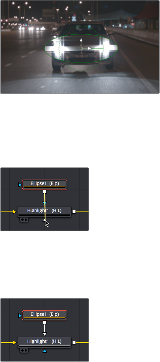
The result of using the Effect Mask input
Reconnecting Node Connections to Dierent Inputs for a Dierent Result
This isn’t satisfactory, so we drag the connection line attaching the Ellipse node off the Effect
Mask input and onto the Highlight Mask input underneath. It’s easy to reconnect previously
connected nodes in different ways simply by dragging the second half of any connection (it
highlights when you hover the pointer over it) to any other node input you want to connect to.
Dragging a connection from one node input to another
After you make the connection, the connection line goes back to the top of the node, and the
top connection is now gray. This is because node inputs in the Fusion page automatically
rearrange themselves to keep the node tree tidy, preventing connection lines from overlapping
nodes unnecessarily and creating a mess. This may take a bit of getting used to, but once you
do, you’ll find it an indispensable behavior.
The Ellipse node now connected to the
Highlight Mask input, which has moved to
the top of the node to keep things neat
2-94Chapter – 13 Learning to Work in the Fusion Page
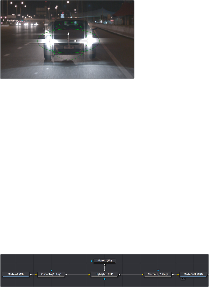
Now that the Ellipse1 node is connected to the Highlight Mask, the tight mask we’ve created just
around the car headlights restrict the node in a different way. The Highlight Mask lets you
restrict which part of the image is used to trigger the effect, so that only the masked car
headlights will generate the Highlight effect in this filter. The result is that the flares of the
Highlight effect themselves are unhindered, and stretch well beyond the boundaries of the
mask we’ve created.
The highlight effect is uncropped because the effect is being limited
via the Highlight Mask input, rather than the Effect Mask input
Unlike nodes on the Color page that have largely the same inputs and outputs, nodes on the
Fusion page may have any number of inputs that are particular to what that node does. This
example should underscore the value of getting to know each node’s unique set of inputs, in
order to best control that node’s effect in the most appropriate way.
Color Management in the Public Beta
If you want to follow a professional compositing workflow of converting media gamma to linear
as it comes into the Fusion page, and then back to the original timeline gamma prior to the
MediaOut node, at the time of this writing, you must do this manually using either CineonLog or
FileLUT nodes.
The CineonLog node is good if you’re converting from or to a log‑encoded gamma.
The FileLUT node is good if you’re converting from or to a gamma of 2.4, since it can
use the LUTs that are available in the /Library/Application Support/Blackmagic Design/
DaVinci Resolve/LUT/VFX IO/ directory (on macOS).
What this looks like in the node tree is that each MediaIn node will have a CineonLog or FileLUT
node attached to it doing a conversion to linear gamma, while the MediaOut node will have a
CineonLog or FileLUT node attached just before it doing a conversion from linear gamma to the
timeline gamma, whatever that happens to be. All other operations in the composition must be
applied between these two conversions.
Converting all images to Linear coming into the composite, and converting out of linear
out of the composite, in this case using CineonLog nodes at the beginning and end
2-95Chapter – 13 Learning to Work in the Fusion Page

In this example, the timeline gamma is BMD Film 4.6K, which is a log‑encoded gamma, so the
first CineonLog node does a Log to Lin conversion from this format. The second CineonLong
node then does a Lin to Log conversion to this format, in order to move the image data out of
the Fusion page in the way DaVinci Resolve expects.
(Left) The first CineonLog node does a Log to Lin conversion,
(Right) the second CineonLog node does a Lin to Log conversion
While this is happening, you’ll want to set your Viewer to a gamma setting that lets you see the
image as it will look when the audience sees it (more or less). You can do this using the Viewer
LUT button. Click to turn it on, and then choose a setting from the VFX IO submenu that you
want to preview your composite with as you work, such as Linear to 2.4, corresponding to the
BT.1886 standard for gamma used for SDR HD output.
The Viewer LUT button (enabled) and pop‑up menu
TIP: The CineonLog node can be found in the Film category of the Effects Library, while
the FileLUT node is found in the LUT category.
2-96Chapter – 13 Learning to Work in the Fusion Page
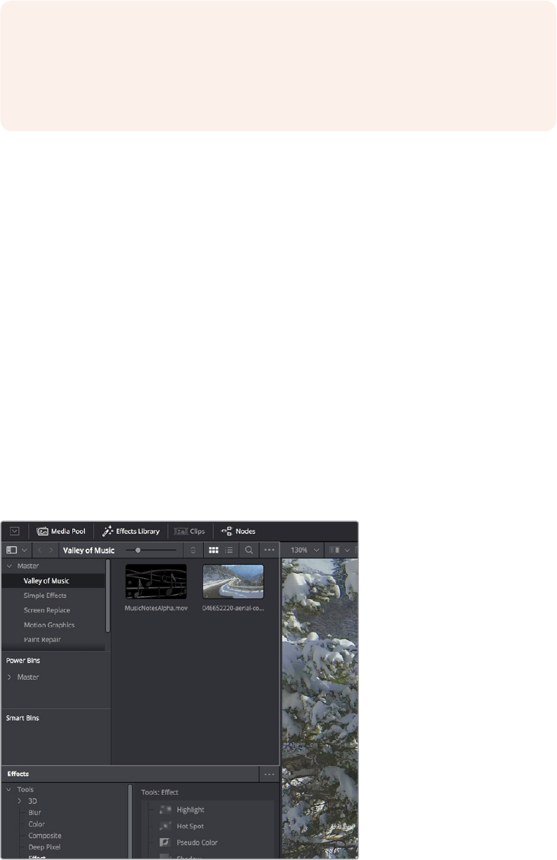
This is a bit of set‑up, it’s true, but it will provide superior compositing results, especially for
compositions with filtering and lighting effects.
Compositing Two Clips Together
As entertaining as it is adding individual nodes to create simple effects, eventually you need to
start adding additional layers of media in order to merge them together as composites. Let’s
turn our attention to another composition in which we need to combine a background clip with
a foreground clip that’s been handed to us that already has a built‑in alpha channel, to see a
simple composite in action.
Adding Additional Media to Compositions
You’ll often find that even though you start out wanting to do something relatively simple, you
end up adding additional media to create the effect that you need. For this reason, you can
open the Media Pool on the Fusion page and drag clips directly to the Node Editor to add them
to your node tree.
Clicking the Media Pool button in the UI Toolbar opens the Media Pool, which if you’re already
familiar with DaVinci Resolve, is the same Media Pool that’s now found in every page except for
the Deliver page. The Media Pool shares the same area with the Effects Library, so if you have
them both open at the same time, they’ll be stacked one on top of another
The Media Pool as seen in the Fusion Page
NOTE: Eventually, the MediaIn and MediaOut nodes will include built‑in functionality for
doing gamma and color space conversions, similarly to the standalone version of
Fusion. Furthermore, the Fusion page will at some point in the future be governed by
Resolve Color Management (RCM), similarly to the Edit and Color pages, so many of the
examples in this chapter will omit these nodes from the node trees.
2-97Chapter – 13 Learning to Work in the Fusion Page
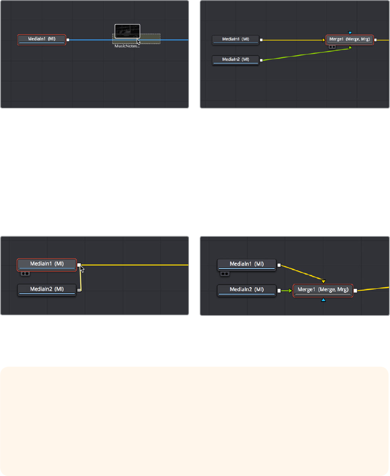
If you drag a clip from the Media Pool to an empty area of the Node Editor, you’ll add an
unconnected MediaIn2 node (incremented to keep it unique) that you can then connect in any
way you want.
Automatically Creating Merge Nodes
However, there’s a shortcut if you want to connect the incoming clip immediately to your node
tree as the top layer of a composite, and that’s to drag the clip right on top of any connection
line. When you drop the resulting node, this automatically creates a Merge1 node, the
“background input” of which is connected to the next node to the left of the connection you
dropped the clip onto, and the “foreground input” of which is connected to the new MediaIn2
node that represents the clip you’ve just added.
(Left) Dragging a node from the Media Pool onto a connection,
(Right) Dropping it to create a Merge node composite
The Fusion page Node Editor is filled with shortcuts like this to help you build your
compositions more quickly. Here’s one for if you have a disconnected node that you want to
composite against another node with a Merge node. Drag a connection from the output of the
node you want to be the foreground layer, and drop it on top of the output of the node you want
to be the background layer, and a Merge node will be automatically created to build that
composite. Remember, background inputs are orange, and foreground inputs are green.
(Left) Dragging a connection from a disconnected node to another
node’s output (Right) Dropping it to create a Merge node composite
Adding Clips to Fusion From the File System
If you drag clips from the file system directly into the Node Editor, they’ll be added to
the Media Pool automatically. So, if you have a library of stock animated background
textures and you’ve just found one you want to use using your file system’s search
tools, you can simply drag it straight into the Node Editor and it’ll be added to the
currently selected bin of the Media Pool.
2-98Chapter – 13 Learning to Work in the Fusion Page
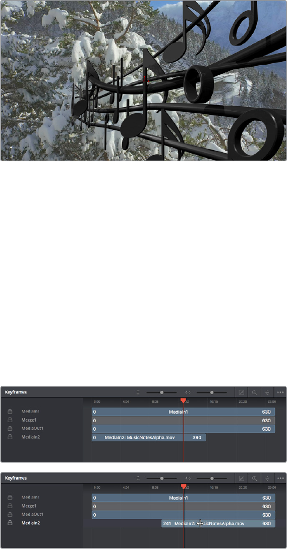
Adjusting the Timing of Clips Added From the Media Pool
Because the MediaIn2 node that’s connected to the Merge1 node’s foreground input has an
alpha channel, this simple Merge node composite automatically creates a result that we can see
in the Viewer, but the way the two clips line up at the beginning of the composition’s range in
the Time Ruler is not great, because the MediaIn2 node’s clip is being lined up with the very
first frame of the MediaIn1 clip’s handles, rather than the first frame of the actual composition
range as seen by the yellow marks in the Time Ruler.
The composite is good, but the timing of the foreground clip relative to the
background clips is not ideal
This a not uncommon issue with clips you add from the Media Pool in the Fusion page, because
those clips were never edited into the Timeline in the Edit page where they could be properly
timed and trimmed relative to the other clips in the composition. Fortunately, you can slip clips
and resize their In and Out points using the Keyframes Editor, which can be opened via a button
in the UI Toolbar.
The Keyframes Editor shows each MediaIn and Effect node as a bar in a vertical stack that
shows you the relative timing of each clip and effect. Keep in mind that the vertical order of
these layers is not indicative of which layers are in front of others, as that is defined by layer
input connections in the Node Editor. The layers displayed in the Keyframe Editor are only
intended to show you the timing of each composited clip of media.
In this case, we can see that the MediaIn2 node is offset to the left, so it’s easy for us to drag it
to the right, watching the image in the Viewer, until the frame at the composition in point is what
we want.
(Top) The original stack of layers, (Bottom) Sliding the
MediaIn2 layer to line it up better with the MediaIn1 layer
2-99Chapter – 13 Learning to Work in the Fusion Page
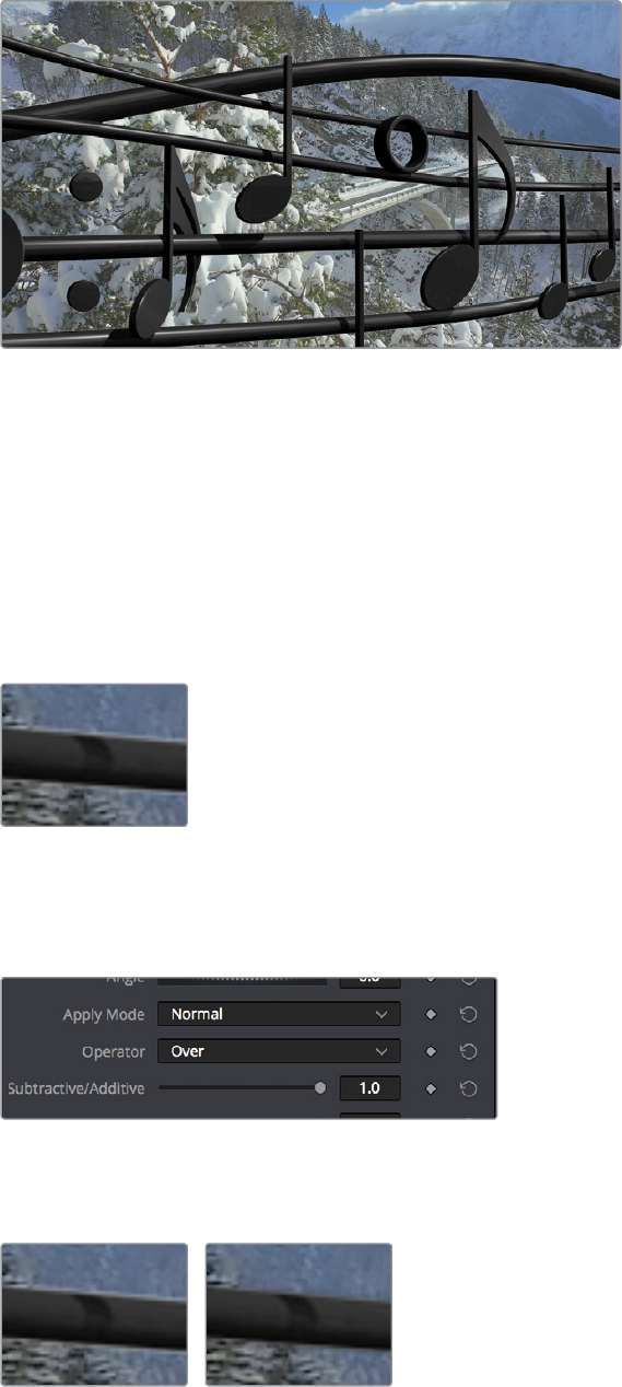
As a result, the MediaIn2 clip lines up much better with the MediaIn1 clip.
After sliding the MediaIn2 clip to improve its
alignment with the other clip in the composite
Fixing Problem Edges in a Composite
Most of the time, the Merge node does a perfectly good job when handed a foreground image
with premultiplied alpha transparency to composite against a solid background image.
However, from time to time, you may notice a small bit of fringing at the edge of the border of a
foreground element and transparent area, such as seen in the following close‑up. This slight
lightening at the edge is a tell‑tale sign that the clip probably wasn’t pre‑multiplied. But this is
something that’s easily fixed.
A bit of fringing at the edge of a foreground
element surrounded by transparency
Click to select the Merge node for that particular composite, and look for the Subtractive/
Additive slider.
The Subtractive/Additive slider, which can be
used to fix or improve fringing in composites
Drag the slider all the way to the left, to the Subtractive position, and the fringing disappears.
(Left) A clip with alpha exhibits fringing, (Right) Fixing fringing
by dragging the Subtractive/Additive slider to the left
2-100Chapter – 13 Learning to Work in the Fusion Page
The Subtractive/Additive slider, which is only available when the Apply Mode is set to Normal,
controls whether the Normal mode performs an Additive merge, a Subtractive merge, or a
blend of both. This slider defaults to Additive merging, which assumes that all input images with
alpha transparency are pre‑multiplied (which is usually the case). If you don’t understand the
difference between Additive and Subtractive merging, here’s a quick explanation:
An Additive merge, with the slider all the way to the right, is necessary when the
foreground image is pre‑multiplied, meaning that the pixels in the color channels have
been multiplied by the pixels in the alpha channel. The result is that transparent pixels
are always black, since any number multiplied by 0 is always going to be 0. This
obscures the background (by multiplying with the inverse of the foreground alpha), then
simply adds the pixels from the foreground.
A Subtractive merge, with the slider all the way to the left, is necessary if the
foreground image is not pre‑multiplied. The compositing method is similar to an
Additive merge, but the foreground image is first multiplied by its own alpha, to
eliminate any background pixels outside the alpha area.
The Additive/Subtractive slider lets you blend between two versions of the merge operation,
one Additive and the other Subtractive, to find the best combination for the needs of your
particular composite. Blending between the two is an operation that is occasionally useful for
dealing with problem composites that have edges that are calling attention to themselves as
either too bright or too dark.
For example, using Subtractive merging on a pre‑multiplied image may result in darker edges,
whereas using Additive merging with a non‑premultiplied image will cause any non‑black area
outside the foreground’s alpha to be added to the result, thereby lightening the edges. By
blending between Additive and Subtractive, you can tweak the edge brightness to be just right
for your situation.
Composite Modes and
the Corner Positioner
In this next compositing example, we’ll explore how you can use the Corner Positioner node to
cornerpin warp a composited layer into place as a screen replacement. Then we’ll use a
composite mode in the Blend node to refine the screen replacement effect to incorporate real
reflections from the scene.
Setting Up the Initial Composite
The base image in the MediaIn1 node is a clip that’s been zoomed into in the Edit page. When
you use the Transform, Cropping, or Lens Correction controls for a clip in the Edit page
Inspector, those adjustments are passed along as the initial state of the image in the Fusion
page, allowing for some prep work to be done in the Edit page, if necessary.
2-101Chapter – 13 Learning to Work in the Fusion Page
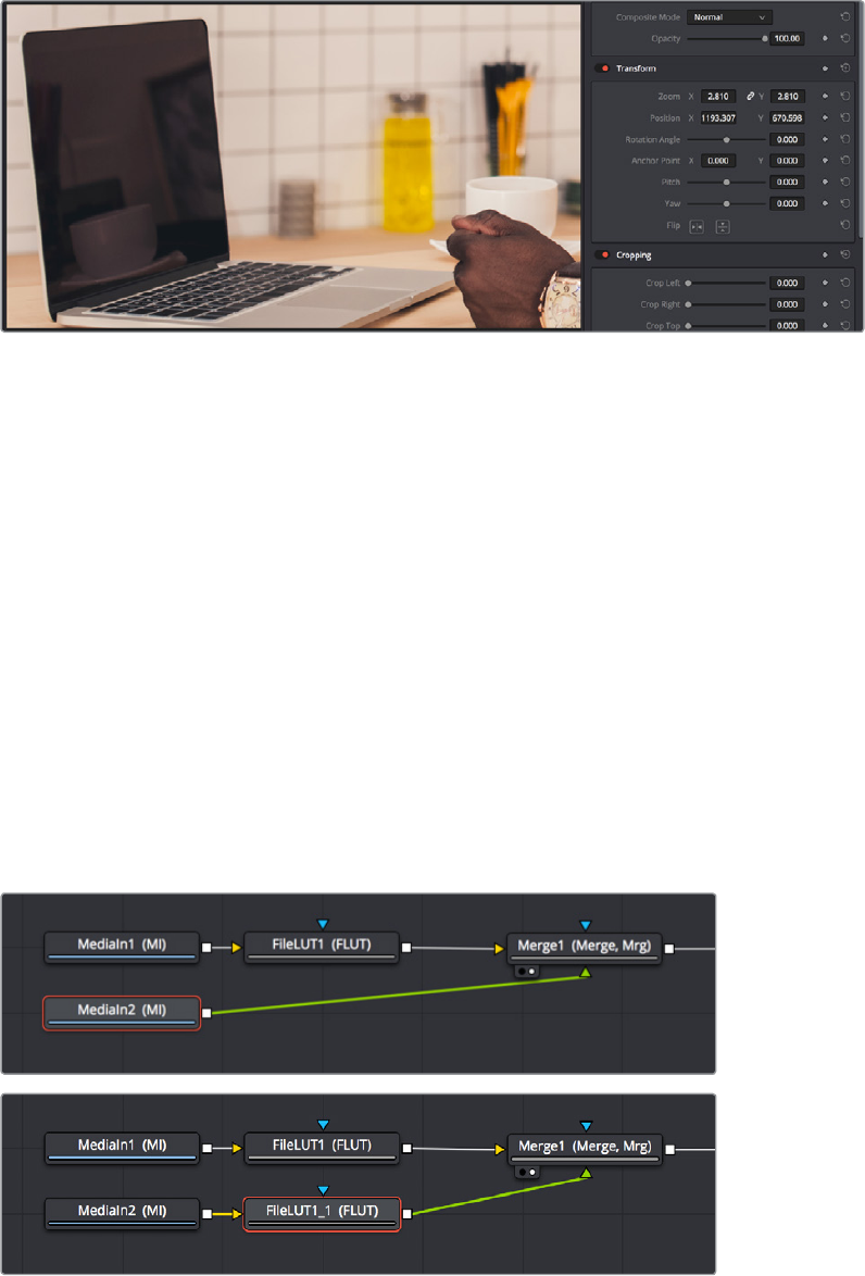
Adjusting the Edit sizing of a clip before moving it into the Fusion page for compositing
Because this particular example uses the Screen Composite mode to do a composite, we’ll start
by setting up some routine color management in the node tree, to illustrate how this should
behandled.
Taking a Shortcut by Copying and Pasting Nodes
In the Fusion page, this first clip has been converted to and from linear gamma using a FileLUT
node set to use the “Gamma 2.4 to Linear.cube” from the /Library/Application Support/
Blackmagic Design/DaVinci Resolve/LUT/VFX IO directory. However, after dragging and
dropping the video image we need to insert into the screen onto a connection to automatically
add it connected to a Merge1 node, we find we need to add another copy of the same FileLUT
node after the new MediaIn2 node.
Happily, this is easy to do by selecting and copying the FileLUT1 node that’s connected to the
MediaIn1 node (Command‑C), then selecting the MediaIn2 node, and pasting (Command‑V).
When you paste one or more nodes while a node is selected in the Node Editor, the nodes you
paste are inserted onto the connection line from the selected node’s output. You can tell when
a node has been copied and pasted because it shares the same name as the copied name, but
with a “_#” appended to it.
Copying a node from one part of the node tree and pasting to insert it into after a selected node
2-102Chapter – 13 Learning to Work in the Fusion Page

If we then select the Merge1 node, we can paste another instance of this FileLUT node to come
just before the MediaOut1 node, setting its LUT File to the “Linear to Gamma 2.4.cube” LUT
that’s also found in the /Library/Application Support/Blackmagic Design/DaVinci Resolve/LUT/
VFX IO directory.
Controlling Which Node You See in the Viewer
Since we’re doing gamma conversions to media coming into and going out of the Fusion page,
it’s no longer suitable to View the MediaOut node as we work, because the Viewer is currently
only set up to convert the linear image data that’s in‑between the two sets of FileLUT nodes to
something normal for you to look at (such as gamma 2.4). Happily, there are a wide variety of
ways you can load a particular node into the Viewer to see what you’re doing as you work:
Hover the pointer over a node, and click one of two buttons that appear at the bottom‑
left of the node.
Click once to select a node, and press 1 (for the left viewer) or 2 (for the right viewer).
Right‑click a node and choose View On > None/LeftView/RightView in the
contextualmenu.
Drag a node and drop it over the viewer you’d like to load it into (this is great for
tabletusers).
Using any of these methods, we load Merge1 into the Viewer.
Loading a node from the middle of the node tree into the Viewer to see a specific node you’re working on
TIP: If you paste one or more nodes while no nodes are selected, then you end up
pasting nodes that are disconnected. However, to control where disconnected nodes
will appear when pasted, you can click the place in the Node Editor where you’d like
pasted nodes to appear, and when you paste, the nodes will appear there.
2-103Chapter – 13 Learning to Work in the Fusion Page
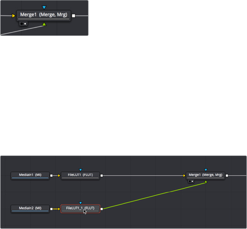
We can tell which node is loaded into the Viewer because of the Viewer indicators/buttons at
the bottom left of the node. Not only is this a visual indication of which node is being viewed,
but these buttons can be clicked to load that node into the left or right Viewer, if you go into
Dual‑viewer mode.
A pair of buttons at the bottom‑left of
nodes that are loaded into the Viewer
let you see which node is being viewed,
as well as giving you a click‑target for
reassigning that node to another Viewer
Adding the Corner Positioner Node With a Search
Now that we have a foreground image composited over the background image of the computer
screen, it’s time to reposition the foreground layer to fit into the screen. To do so, we’ll use the
Corner Positioner node, from the Warp category, which is the main node for doing
cornerpinning. To add this to the node tree, we’ll use a different method to search for the node
we want right from the Node Editor. First, select the node you want to insert a new node after. In
this case, we want to cornerpin the image from the MediaIn2 node, so we’ll select the FileLUT_1
node that’s attached to it.
Selecting a node you want to add another node behind
Next, pressing Shift‑Spacebar opens the Select Tool dialog. Once it appears, just start typing
the first few letters of the name of the node you’re looking for to find it in a master list of every
node in the entire Fusion page. In this case, you’re looking for the CornerPositioner node, so
type “cor” and the list of nodes will shrink to two, with the one we’re looking for being selected.
2-104Chapter – 13 Learning to Work in the Fusion Page
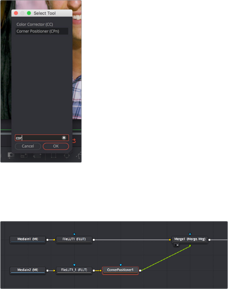
Pressing Shift‑Spacebar opens the
Select Tool dialog for quickly finding
and adding new nodes
With the node we’re looking for found and selected in the Select Tool dialog, pressing the
Return key inserts the new Corner Positioner node after the previously selected node and
closes the Select Tool dialog.
The CornerPositioner node added to cornerpin the foreground image prior to the Merge operation
Warping the Image With the Corner Positioner Node
The Corner Positioner node is a node in the Warp category of the Effects Library that lets you
do absolute positioning at four corner points to fit an image within a rectangular region to into a
scene. Immediately upon adding this node, a default cornerpin operation is applied to the
image to show that it’s being manipulated.
2-105Chapter – 13 Learning to Work in the Fusion Page

The Corner Positioner node adds a default transform to the image
Using the on‑screen control points, we can now warp the image by dragging each corner to fit
within the computer screen.
Using the CornerPositioner node to fit the video image to the screen it’s replacing
Toggling On-screen Control Visibility
It’s worth knowing that you can toggle the visibility of on‑screen controls using Show Controls in
the Viewer Option Menu. You might find it useful to hide on‑screen controls if they’re getting in
the way of seeing the image you’re adjusting, but if you’ve added an effect and you don’t see
any controls available for adjusting it, you’ll know you need to turn this option on.
Show Controls in the Option menu toggles
on‑screen control visibility on and off
2-106Chapter – 13 Learning to Work in the Fusion Page

Navigating the Viewer
As you work, you may find that parts of the image you want to work on extend off screen. To
deal with this, there are a few ways of panning and zooming around the Viewer.
Middle click and drag to pan around the Node Editor.
Press Command and Shift and drag to pan around the Node Editor.
Hold the Middle and Left buttons down simultaneously and drag to zoom into or out of
the Node Editor.
Hold the Command key down and use your scroll wheel to zoom in and out of the
Node Editor.
Using the Screen Composite Mode in the Merge Node
Once the foreground input image is fit to the screen, we have an opportunity to create a more
convincing composite by taking advantage of the reflections of the scene on the front of
thescreen, and using the screen composite mode to make the foreground image look more
likeareflection.
The Merge node has a variety of controls built into it for creating just about every
compositingeffect you need, including an Apply Mode pop‑up menu that has a selection of
composite modes you can use to combine the foreground and background layers together,
anda Blendslider you can use to adjust how much of the foreground input image to merge with
thebackground.
Adjusting the Apply Mode and Blend slider
of the Merge node in the Inspector
The screen node is perfect for simulating reflections, and lowering Blend a bit lets you balance
the coffee cup reflections from the display in the background with the image in the foreground.
It’s subtle, but helps sell the shot.
NOTE: The Subtractive/Additive slider disappears when you choose any other Apply
Mode option besides Normal, because the math would be invalid. This isn’t unusual;
there are a variety of controls in the Inspector which hide themselves when not needed
or when a particular input isn’t connected.
2-107Chapter – 13 Learning to Work in the Fusion Page
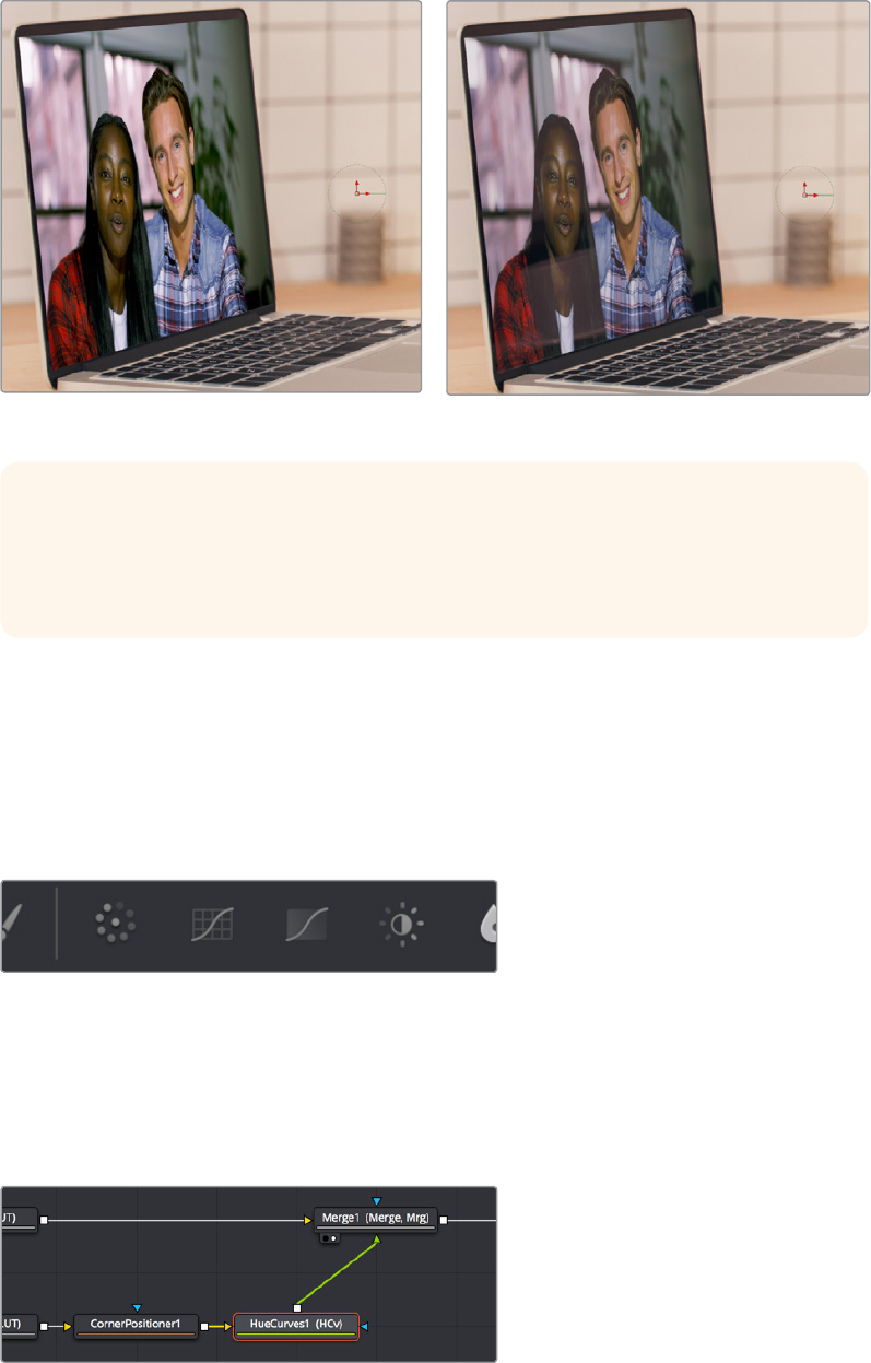
(Left) The original composite, (Right) The composite using the Screen apply mode
Tweaking Color in the Foreground Layer
It’s as important to make sure that the color matches between two images being composited
together as it is to create a convincing blend, and for this reason the Fusion page has a whole
category of color adjustment tools available in the Color category of the Effects Library. In fact,
the ColorCorrector, ColorCurves, HueCurves, and Brightness/Contrast nodes are considered
so important they appear in the Toolbar.
Frequently used Color nodes in the Toolbar
In this particular image, the color of the foreground image on the computer screen is just a bit
green and oversaturated, and the view out the window is a bit magenta. However, these
problems are easily overcome using a HueCurves node from the Toolbar. Selecting the
CornerPositioner node we added, clicking the HueCurves button on the Toolbar adds that
node between the CornerPositioner and the Merge node.
Adding the HueCurves node to make a correction to the foreground image
TIP: You may have noticed that the Merge node also has a set of Flip, Center, Size, and
Angle controls that you can use to transform the foreground image without needing to
add a dedicated Transform node. It’s a nice shortcut for simplifying node trees large
and small.
2-108Chapter – 13 Learning to Work in the Fusion Page
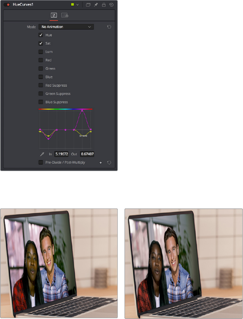
The HueCurves node exposes a curve control in the Inspector with options for adjusting 9
kinds of curves, each overlapping the others for simultaneous adjustment. Turning on first the
Hue checkbox to make adjustments, and then the Sat checkbox in the Inspector, these two
curves can be simultaneously adjusted to push the green towards a healthier red in the skin
tones of both the man and the woman, to desaturate the red, yellow, and green a bit, and to
push the magenta outside the window to more of a warm orange light, to make the foreground
seem like a natural part of the image.
The controls of the HueCurves node, adjusted
to correct the screen replacement image
The result is subtle, but it’s a much more convincing composite.
(Left) The uncorrected foreground, (Right) Using a hue
curve node to adjust the image for a better composite
2-109Chapter – 13 Learning to Work in the Fusion Page

Creating and Using Text
In this next example, we’ll take a look at how to create a simple text object using the Text+
node. Then, we’ll see how to use the text generator’s alpha channel in another image to create
a more complex composite.
Creating Text Using the Text+ Node
The Text+ node is the primary tool for creating 2D text in the Fusion page. This is also the new
text generator that has become available in the Edit page, and because it’s so ubiquitous, it
appears in the Toolbar. The Text+ node is an incredibly deep tool for creating text effects, with
six panels of controls for adjusting everything from text styling, to different methods of layout, to
a variety of shading controls including fills, outlines, shadows, and borders. As sophisticated a
tool as this is, we’ll only be scratching the surface in this next demonstration.
With the MediaIn1 node that will serve as our background selected in the Node Editor, clicking
the Text+ button automatically creates a new Text+ node connected to the foreground input of a
Merge node
(Top) Selecting a node you want to append another
node to, (Bottom) Clicking the Text+ button on the
Toolbar automatically creates a Merge composite
with the text as the foreground input connection
Selecting the Text1 node opens the default “Text” panel parameters in the Inspector, and it also
adds a toolbar at the top of the Viewer with tools that are specific to that node. Clicking on the
first tool at the left lets us type directly into the Viewer, so we type “SCHOOLED” into the Styled
Text field, since that’s the title of the program we’re working on (in case you didn’t know).
The Viewer toolbar for the Text node with tools for
text entry, kerning, and outline controls
2-110Chapter – 13 Learning to Work in the Fusion Page

The text appears in the Viewer, superimposed against the background clip. Onscreen controls
appear that let us rotate (the circle) and reposition (the red center handle and two arrows) the
text, and we can see a faint cursor that lets us edit and kern the text using other tools in the
Viewer toolbar. At this point, we’ve got our basic title text.
Text that’s been typed into the Viewer, with
on‑screen text transform controls
Styling and Adjusting Text
Now we need to style the text to suit our purposes, so we’ll use the controls in the Inspector,
increasing Size and decreasing Tracking to move the letters closer together so they can be
made larger.
The restyled text
The result has somewhat uneven kerning, but we can adjust that. Selecting the manual kerning
tool in the Viewer toolbar (second tool from the left) reveals small red dots underneath each
letter of text.
The Manual Kerning tool in the Viewer toolbar
TIP: Holding the Command key down while dragging any control in the
Inspector“gears down” the adjustment so that you can make smaller and more
gradualadjustments.
2-111Chapter – 13 Learning to Work in the Fusion Page
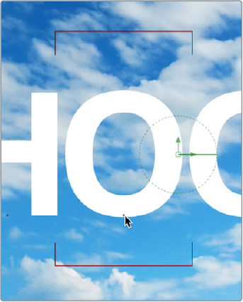
Clicking a red dot under a particular letter puts a kerning highlight over that letter. Here are the
different methods you can use to make Manual kerning adjustments:
Option‑drag the red dot under any letter of text to adjust that character’s kerning while
constraining letter movement to the left and right. You can also drag letters up and
down for other effects.
Depending on your system, the kerning of the letter you’re adjusting might not update
until you drop the red dot in place.
If you don’t like what you’ve done, you can open the Advanced Controls in the
Inspector, and clear either the kerning of selected letters, or all manual kerning, before
starting over again.
Option‑dragging the little red dot revealed
by the Manual Kerning tool to manually
adjust kerning left or right
So there we go, we’ve now got a nice title, styled using the Viewer tools and Inspector controls
on the Text panel. This looks good, but we’ve got much grander designs.
Using One Image’s Alpha Channel in Another Image
We’re not going to use the text we’ve created as a title directly. Instead, we’re going to use the
text as a matte to cut these letters out of another layer we’ll be using for texture. So, first we’ll
drag another clip, of a chalkboard covered with math, from the Media Pool to the Node Editor as
a disconnected MediaIn2 node.
Disconnecting and Reconnecting Nodes
Now we need to do a little rearranging. Moving the Merge1 node up, then clicking the last half
of the connection from the Text1 node to the Merge foreground input to disconnect it.
2-112Chapter – 13 Learning to Work in the Fusion Page
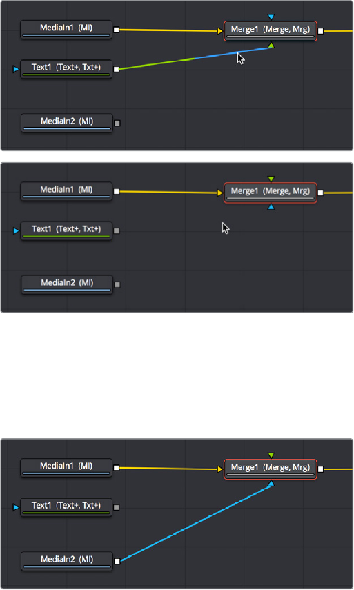
(Top) Clicking the second half of a connection to disconnect it (Bottom) After
Next, we’ll drag a connection from the MediaIn2 node onto the Merge1 node’s foreground input,
so the entire Viewer becomes filled with the chalkboard (assuming we’re still viewing the
MediaOut node). At this point, we need to insert the Text1 node’s image as an alpha channel
into the MediaIn2 node’s connection, and we can do that using a MatteControl node.
The updated composite, with two video images
connected and the text node disconnected
Using Matte Control Nodes
Selecting the MediaIn2 node, we click the Matte Control button of the Toolbar to add it
between the MediaIn2 and Merge1 nodes (to tidy things up, I’ve moved the nodes around a bit
in the screenshot).
The MatteControl node has many, many uses. Among them is taking one or more masks,
mattes, or images that are connected to the garbage matte, solid matte, and/or foreground
inputs, combining them, and using the result as an alpha channel for the image that’s connected
to the background input. It’s critical to make sure that the image you want to add an alpha
channel to is connected to the background input of the MatteControl node, as seen in the
following screenshot, or the MatteControl node won’t work.
2-113Chapter – 13 Learning to Work in the Fusion Page
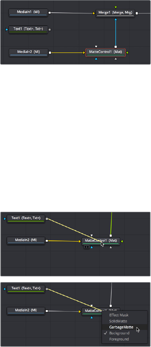
The second image properly connected to the Matte
Control node’s background input
With this done, we’ll connect the Text1 node’s output, which has the alpha channel we want to
use, to the MatteControl node’s garbage matte input, which is a shortcut we can use to make a
mask, matte, or alpha punch out a region of transparency in an image.
Keep in mind that it’s easy to accidentally connect to the wrong input. Since inputs rearrange
themselves depending on what’s connected and where the node is positioned, and frankly the
colors can be hard to keep track of when you’re first learning, it’s key to make sure that you
always check the tooltips associated with the input you’re dragging a connection over to make
sure that you’re really connecting to the correct one. If you don’t, the effect won’t work, and if
your effect isn’t working, the first thing you should always check is whether or not you’ve
connected the proper inputs.
One alternate method of connecting nodes together is to hold the Option key down while
dragging a connection from one node’s output and dropping it onto the body of another node.
This opens a pop‑up menu from which you can choose the specific input you want to connect
to, by name. Note that the menu only appears after you’ve dropped the connection on the node
and released your pointing device’s button.
Before/After Option‑dragging a node connection to
drop onto another node exposes a node input menu
Once the Text1 node is properly connected to the MatteControl node’s Garbage Matte input,
you should see a text‑shaped area of transparency in the graphic if you load the MatteControl
node into the Viewer.
2-114Chapter – 13 Learning to Work in the Fusion Page
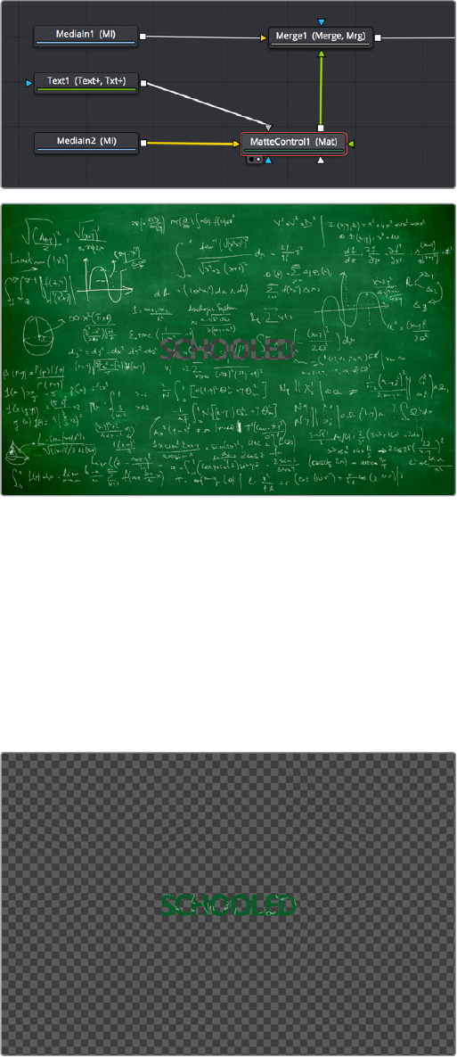
(Top) Connecting the Text node to the Matte Control node’s garbage
matte input, (Bottom) the resulting hole punched in the image
Customizing Matte Control Nodes
With this accomplished, we need to use the Inspector to change some parameters to get the
result we want. In the Inspector controls for the Matte Control node, click the disclosure control
for the Garbage Matte controls to expose their parameters. Because we actually have a
Garbage matte connected, a variety of controls are available to modify how the garbage matte
input is applied to the image. Click Invert to create the effect we really want, which is text that is
textured with the chalkboard image.
The alpha from the Text node punching a hole in another graphic
However, the new chalkboard layer is far bigger than the HD‑sized elements we’ve been
working with, so the alpha from the Text1 node is too small. This is easily fixed by setting the Fit
pop‑up menu to “Width,” which automatically resizes the garbage matte to be as big as possible
from edge to edge within the image.
2-115Chapter – 13 Learning to Work in the Fusion Page
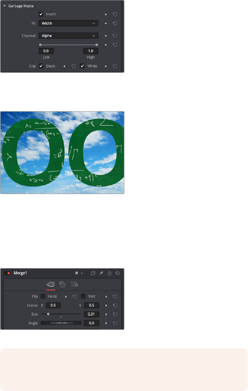
The Garbage Matte settings of the MatteControl node
Now, if we load the Merge1 node into the Viewer, we can see that the text effect is doing
everything we want, but now the chalkboard text is too big.
The final composite
Using Transform Controls in the Merge Node
Fortunately, there’s an easy fix that doesn’t even require us to add another node. Selecting the
Merge1 node, we can see a set of transform parameters in the Inspector that specifically affect
the foreground input’s image. This makes it quick and easy to adjust a foreground image to
match the background.
The final composite
NOTE: When connecting two images of different sizes to a Merge node, the resolution
of the background image defines the output resolution of that node. Keep that in mind
when you run into resolution issues.
2-116Chapter – 13 Learning to Work in the Fusion Page

Dragging the Size slider to the left shrinks the text to create the effect we really want, and at this
point, we’ve got the composite we need.
The final composite
Match Moving Text With Motion Tracking
This next example introduces motion tracking, and how you can create a very simple
match‑moving effect using the Tracker node, which is the Swiss army knife of trackers in the
Fusion page.
Adding a Layer We Want to Match Move
In this example, we have a Text1 node that’s creating a “Switzerland” title, that’s composited
over a drone shot flying over and around a mountain bridge. With the Text1 node selected, the
on‑screen controls that let you position the text it’s generating are visible in the Viewer, and the
text is positioned where we’d like it to start. Note that, with the Text node selected, even the
part of the text that’s off‑screen can still be seen as an outline showing us where it is.
Some text superimposed against a background, ready to track
2-117Chapter – 13 Learning to Work in the Fusion Page
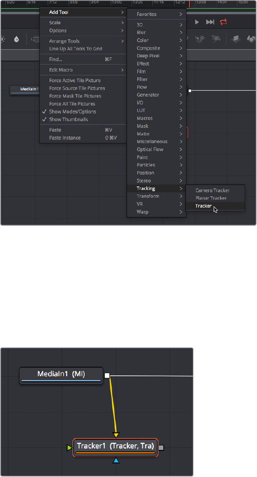
Our goal for this composition is to motion track the background image so that the text moves
along with the scene as the camera flies along.
Setting Up to Track
To set up for doing the motion track, we’ll begin by creating a disconnected Tracker node, using
another method than those seen previously. Right‑click anywhere in the background of the
Node Editor (preferably where you want the new node to appear), and choose Add Tool >
Tracking > Tracker from the contextual menu to create a new Tracker1 node underneath the
MediaIn node.
Creating a new node using the Node Editor contextual menu
Next, we’ll drag a connection from the MediaIn1 node to the Tracker1 node to automatically
connect the source clip to the Tracker1 background input. This branches the output from the
MediaIn1 node to the Tracker node, so that the Tracker1 node processes the image separately
from the rest of the node tree. This is not required, but it’s a nice organizational way to see that
the Tracker node is doing an analysis that must be referred to in another way than a
“physical”connection.
Branching a Tracker node to use to analyze an image
2-118Chapter – 13 Learning to Work in the Fusion Page

A Simple Tracking Workflow
The Tracker node is the simplest tracking operation the Fusion page has, and while there are
several ways of using it. An extremely common workflow is to use the tracker node controls to
analyze the motion of a subject in the frame with motion you want to follow, and then use the
resulting motion path data by “connecting” it to the Center parameter of another node that’s
capable of transforming the image you want to match move.
Positioning the Tracker On-Screen Control
When the Tracker node is selected, a single green box appears in the Viewer, which is the
default on‑screen control for the first default tracker that node contains (seen in the Tracker List
of the Inspector controls). Keep in mind that you only see on‑screen controls for nodes that are
selected, so if you don’t see the on‑screen tracker controls, you know you need to select the
tracker you want to work with. Loading the tracker you want to work on into the Viewer is also
the safest way to make sure you’re positioning the controls correctly relative to the actual image
that you’re tracking.
If you position your pointer over this box, the entire on‑screen control for that tracker appears,
and if you click the on‑screen control to select that tracker, it turns red. As with so many other
tracker interfaces you’ve likely used, this consists of two boxes with various handles for moving
and resizing them:
The inner box is the “pattern box,” which identifies the “pattern” in the image you’re
tracking that you want to follow the motion of. The pattern box has a tiny handle at its
upper‑left‑hand corner that you use to drag the box to overlap whatever you want to
track. You can also resize this box by dragging any corner, or you can squish or stretch
the box by dragging any edge, to make the box better fit the size of the pattern you’re
trying to track. The center position of the tracker is indicated via x and y coordinates.
The outer box is the “search box,” which identifies how much of the image the Tracker
needs to analyze to follow the motion of the pattern. If you have a slow moving image,
then the default search box size is probably fine. However, if you have a fast moving
image, you may need to resize the search box (using the same kind of corner and side
handles) to search a larger area, at the expense of a longer analysis. The name of that
tracker is shown at the bottom right of the search box.
The on‑screen controls of a selected tracker seen in isolation
It’s worth saying a second time, the handle for moving a tracker’s on‑screen control is a tiny dot
at the upper‑left‑hand corner of the inner pattern box. You must click on this dot to drag the
tracker around.
The handle for dragging the tracker boxes to move them around
2-119Chapter – 13 Learning to Work in the Fusion Page
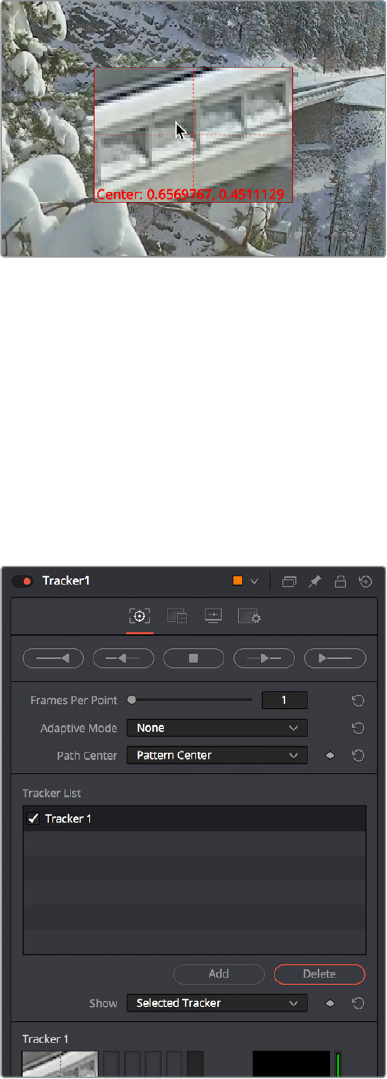
In this example, we’ll drag the on‑screen control so the pattern box overlaps a section of the
bridge right over the leftmost support. As we drag the on‑screen control, we see a zoomed‑in
representation of the part of the image we’re dragging over, to help us position the tracker with
greater precision. For this example, the default sizes of the pattern and search box are fine as is.
The zoomed‑in preview that helps you
position the pattern box as you drag it
Using the Tracker’s Inspector Controls to Perform the Analysis
At this point, let’s look at the Tracker node’s controls in the Inspector. There are a lot of controls,
but for this simple example we only care about the main Trackers panel, with the tracking
analysis buttons at the top, the tracking options below those, and the Tracker List underneath
those. The Tracker list also has buttons for adding and deleting trackers, you have the option of
adding multiple trackers that can be analyzed all at once for different workflows, but we don’t
need that for now.
Tracker Inspector controls, with the tracking
analysis buttons at top, the tracker options
in the middle, and the Tracker List below
2-120Chapter – 13 Learning to Work in the Fusion Page

Additional controls over each tracker and the image channels being analyzed appear at the
bottom, along with offset controls for each tracker, but we don’t need those now (at least, not yet).
Again, this track is so simple that we don’t need to change the default behaviors that much, but
because the drone is flying in a circular pattern, the shape of the pattern area is changing as
the clip plays. Fortunately, we can choose Every Frame from the Adaptive Mode pop‑up, to
instruct the tracker to update the pattern being matched at every frame of the analysis, to
account for this.
Changing the Adaptive Mode of the Tracker node to Every
Frame to account for the camera’s shift of perspective
Now, all we need to do is to use the tracker analysis buttons at top to begin the analysis. These
buttons work like Transport controls, letting you start and stop analysis as necessary to deal
with problem tracks in various ways. Keep in mind that the first and last buttons, Track From Last
Frame and Track From First Frame, always begin a track at the last or first frame of the
composition, regardless of the playhead’s current position, so make sure you’ve placed your
tracker on‑screen controls appropriately at the last or first frame.
The analysis buttons, left to right, Track from last frame, track
backward, stop tracking, track forward, track from first frame
For now, clicking the Track From Beginning button will analyze the entire range of this clip, from
the first frame to the last. A dialog lets you know when the analysis is completed, and clicking
the OK button dismisses it so you can see the nice clean motion path that results.
The analyzed motion path resulting from tracking a section of
the bridge as the camera flies past
Viewing Motion Track Data in the Spline Editor
This is not a necessary part of the tracking workflow, but if you have an otherwise nice track
with a few bumps in it, you can view the motion tracking data in the Spline Editor by viewing that
tracker’s Displacement parameter curve. This curve is editable, so you can massage your
tracking data in a variety of ways, if necessary.
2-121Chapter – 13 Learning to Work in the Fusion Page
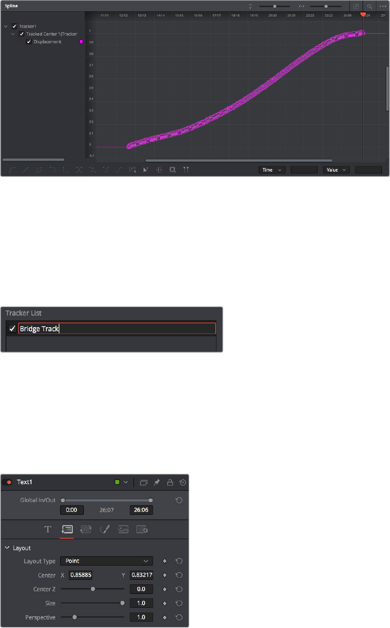
Viewing motion tracking analysis data in the Spline Editor
Connecting Motion Track Data to Match Move
Now that we’ve got a successful analysis, it’s time to use it to create the Match Move effect. To
make this process easier, we’ll double‑click the tracker’s name in the Tracker list of the
Inspector, and enter a new name that’s easier to keep track of (heh). Adding your own names
make that tracker easier to find in subsequent contextual menus, and lets you keep track of
which trackers are following which subjects as you work on increasingly complex compositions.
Renaming a tracker to make it easier to find
Now it’s time to connect the track we’ve just made to the text in order to start it in motion.
Loading the Merge1 node into the Viewer to see the text in context with the overall composite
we’re creating, we’ll select the Text1 node to open its parameters in the Inspector, and click the
Layout panel icon (second button from the left) to expose the Layout controls, which are the
text‑specific transform controls used to position the text object in the Frame. These are the
controls that are manipulated when you use the Text node on‑screen controls for repositioning
or rotating text.
The Layout controls for a Text node, in the Layout panel
2-122Chapter – 13 Learning to Work in the Fusion Page
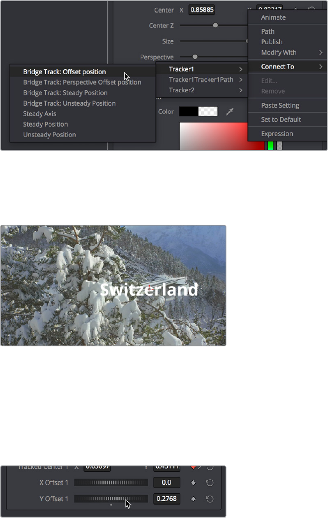
The Center X and Y parameters, while individually adjustable, also function as a single target for
purposes of connecting to tracking to quickly set up match moving animation. You set this up
via the contextual menu that appears when you right‑click any parameter in the Inspector, which
contains a variety of commands for adding keyframing, modifiers, expressions, and other
automated methods of animation including connecting to motion tracking.
If we right‑click anywhere on the line of controls for Center X and Y, we can choose Connect To
> Tracker1 > Bridge Track: Offset position from the contextual menu, which connects this
parameter to the tracking data we analyzed earlier.
Connecting the Center X and Y parameter to the “Bridge Track: Offset position” motion path we analyzed
Immediately, the text moves so that the center position coincides with the center of the tracked
motion path at that frame. This lets us know the center of the text is being match moved to the
motion track path.
The text now aligns with the motion track coordinate
Offsetting the Position of a Match Moved Image
In fact, we want to offset the match‑moved text, so it’s higher up in the frame. To do this, we
select the Tracker1 node again and use the Y Offset 1 dial control to move the text up, since
now any changes we make to the Bridge Track dataset now apply to the center of the text that’s
connected to it.
Using the X and Y Offset controls in the
Tracker1 node to offset the text layer’s
position from the tracked motion path
2-123Chapter – 13 Learning to Work in the Fusion Page
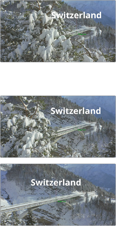
The offset we create is shown as a dotted red line that lets us see the actual offset being
created by the X and Y Offset controls. In fact, this is why we connected to the “Bridge Track:
Offset position” option earlier.
The text offset from the tracked motion path, the offset can
be seen as a dotted red line in the Viewer
Now, if we play through this clip, we can see the text moving along with the bridge.
Two frames of the text being match moved to follow the bridge in the shot
2-124Chapter – 13 Learning to Work in the Fusion Page

Using Paint and Planar Tracking
In this next example, we’ll take a look at a paint example in which we eliminate some facial scars
on an actor’s forehead in a commercial. This workflow combines the Paint node with the Planar
Tracking node, illustrating a common way of using these two powerful tools.
The actor has some scars on his forehead that the director would like painted out
Using a Planar Tracker to Steady a Subject to Paint
Because this is a clip in motion, we can’t just paint out the scars on the man’s forehead, we
need to deal with the motion so that the paint work we do stays put on his face. In this case, a
common workflow is to analyze the motion in the image and use it to apply a “steady”
operation, pinning down the area we want to paint in place so we can paint on an
unmovingsurface.
The best way to do this in the Fusion page is to use the Planar Tracker, so we’ll add the
PlanarTracker node after the MediaIn1 node such that the image we want to track is connected
to the background input of the PlanarTracker node. As always, it’s important to be careful about
which input you connect the image to for the effect to work properly.
Adding a PlanarTracker node to analyze and steady the part
of the image we want to paint on
With the PlanarTracker node selected, and either it or the MediaOut1 node loaded in the
Viewer, a Viewer toolbar appears with a variety of tools for drawing shapes and manipulating
tracking data. The Planar Tracker works by tracking “planar” (read: flat) surfaces that you define
by drawing a shape over the feature you want to track. When you first create a PlanarTracker
node, you’re immediately put into a mode for drawing a shape, so in this case we draw a simple
polygon over the man’s forehead, since that’s the feature we want to steady in preparation
forpainting.
2-125Chapter – 13 Learning to Work in the Fusion Page

We draw a simple box by clicking once each on each corner of the man’s forehead to create
control points, clicking the first one we created to close the shape.
Drawing a shape over the man’s forehead to prepare for Planar Tracking
Turning our attention to the inspector, we can see that the Planar Tracker node has tracking
transport controls that are similar to those of the Tracker, but with one difference. There are two
buttons, Set and Go, underneath the Operation Mode pop‑up, which defaults to “Track” since
that’s the first thing we need to do. The Set button lets you choose which frame to use as the
“reference frame” for tracking, so you should click the Set button first before clicking the Track
Forward button below.
Setting a reference frame at the beginning
of the range of frames we want to track
TIP: The Set button lets you supervise a Planar Track in progress and stop it if you see
it slipping, making adjustments as necessary before clicking Set at the new frame to set
a new reference before continuing to track forward towards the end of the clip.
2-126Chapter – 13 Learning to Work in the Fusion Page
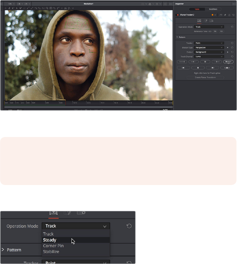
The Pattern controls let you set up how you want to handle the analysis. Of these controls, the
Motion Type pop‑up menu is perhaps the most important. In this particular case, Perspective
tracking is exactly the analysis we want, but in other situations you may find you get better
results with the “Translation,” “Translation/Rotation,” and “Translation/Rotation/Scale” options
that are available.
Once you initiate the track, a series of dots appear within the track region shape you created to
indicate trackable pixels found, and a green progress bar at the bottom of the Timeline Ruler
lets you see how much of the shot is remaining to track.
Clicking the Track From First Frame button to set the Planar Track in progress, green
dots on the image and a green progress bar lets you know the track is happening
Once the track is complete, you can set the Operation Mode of the PlanarTracker node’s
controls in the Inspector to Steady.
Setting the PlanarTracker node to Steady
You’ll immediately see the image be warped as much as is necessary to pin the tracked region
in place for whatever operation you want to perform. If you scrub through the clip, you should
see that the image dynamically cornerpin warps as much as is necessary to keep the forehead
region within the shape you drew pinned in place. In this case, this sets up the man’s head as a
canvas for paint.
NOTE: If you click one of the Track buttons to begin tracking and nothing happens, or
you track for a few frames and then stop, that’s your cue that there isn’t enough
trackable detail within the shape you’ve drawn for the Planar Tracker to work, and your
best bet is to choose a different location of the image to track.
2-127Chapter – 13 Learning to Work in the Fusion Page
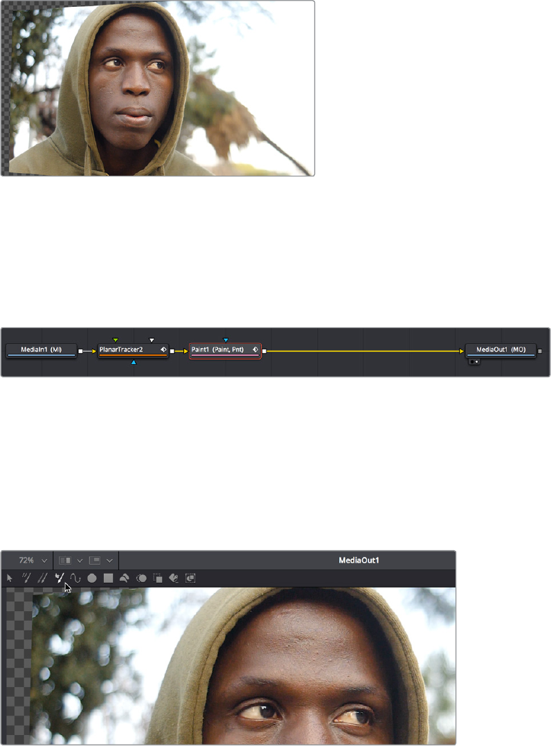
Steadying the image results in warping as the
forehead is pinned in place for painting
At this point, you’re ready to paint out those scars.
Painting Over Blemishes
Adding a Paint node after the PlanarTracker node gets us ready to paint.
Adding a Paint node after the PlanarTracker to paint onto the steady surface
With the Paint node selected and the MediaOut1 node loaded in the Viewer, we can see the
paint tools in the Viewer toolbar. The first thing we want to do is to click on the fourth tool from
the left, the “Stroke” tool, which is the preset tool for drawing strokes that last for the duration of
the clip. The default “Multi‑Stroke” tool is intended for frame by frame work such as painting out
falling raindrops, moving dust and dirt, or other things of limited duration. The Stroke tool is
much more appropriate when you want to paint out features or paint in fixes to subjects within
the frame that need to remain in place for the whole shot.
Choosing the Stroke tool from the Paint node’s tools in the Viewer toolbar
Next, we need to go to the Inspector controls for the Paint node and choose the Clone mode
from the Apply Controls. We’re going to clone part of the man’s face over the scars to get rid of
them, and choosing the Clone mode switches the controls of the Paint node to those used
forcloning.
2-128Chapter – 13 Learning to Work in the Fusion Page
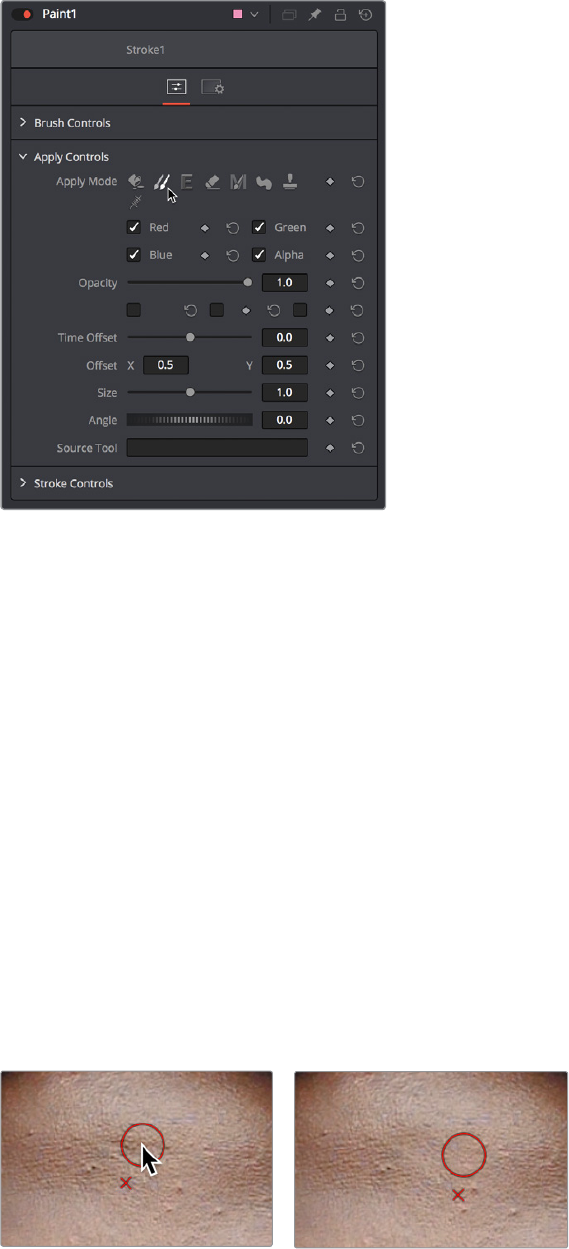
Choosing the Clone mode in the Inspector
There are additional controls located in this palette, however, that you should be familiar with.
Brush Controls (at the top) contain the Brush Shape, Size, and Softness controls, as well
as settings for how to map these parameters for tablet users.
Apply Controls (in the middle) let you choose a paint mode, which includes Color,
Clone, Emboss, Erase, Merge, Smear, Stamp, and Wire Removal. In this example we’ll
be using Clone. The mode you choose updates what controls are available below.
Stroke Controls (at the bottom) are intended to let you adjust strokes after they’ve been
painted, and include controls for animating them with “write‑on” effects, transforming
strokes with standard sizing parameters, and adjusting brush spacing.
With the Stroke tool selected in the Viewer tool bar, and Clone mode selected in the Inspector
controls, we’re ready to start painting. If we move the pointer over the Viewer, a circle shows us
the paint tool, ready to go.
To use the clone brush, first you want to hold the Option key down and click somewhere on the
image you want to clone from. In this example, we’ll sample from just below the first scar we
want to paint. After Option‑clicking to sample part of the image, clicking to begin painting sets
an offset between where we’re sampling from and where we’re painting to, and dragging to
draw paints a clone stroke.
(Left) Setting an offset to sample for cloning, (Right) Dragging to draw a clone stroke
2-129Chapter – 13 Learning to Work in the Fusion Page
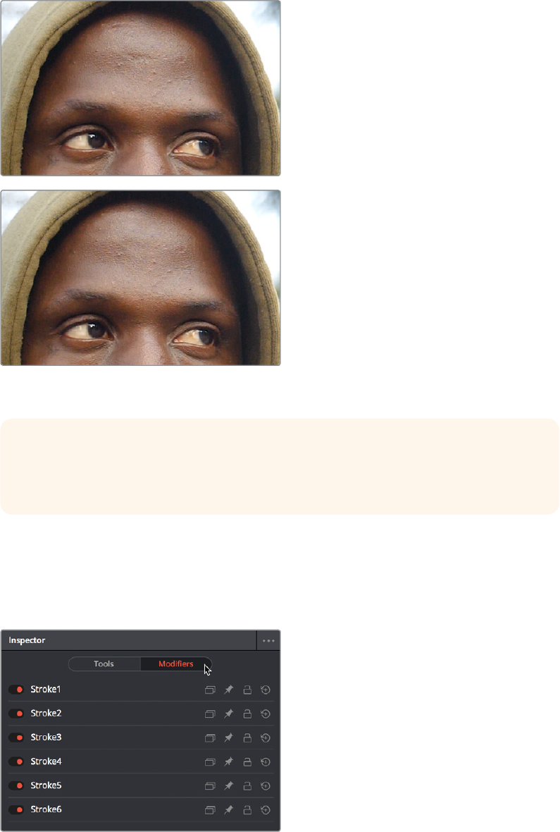
If you don’t like the stroke you’ve created, you can undo with Command‑Z and try again. We
repeat the process with the other scar on the man’s forehead, possibly adding a few other small
strokes to make sure there are no noticeable edges, and in a few seconds we’ve taken care of
the issue.
(Top) Original image, (Bottom) After painting out two scars
on the man’s forehead with the Stroke tool set to Clone
Before moving on, we’ll open the Modifiers panel of the Inspector, where we can see that every
single paint stroke we’ve made appears as an item on the Modifiers list. This gives us access to
the strokes we’ve painted for further modification. We don’t need to do anything at the moment,
but when the time comes that you want to start making changes to strokes you’ve made, this is
where they appear.
Each stroke made appears as an entry with
controls in the Modifiers panel of the Inspector
TIP: You can adjust the size of the brush right in the Viewer, if necessary, by holding the
Command key down and dragging the pointer left and right. You’ll see the brush outline
change size as you do this.
2-130Chapter – 13 Learning to Work in the Fusion Page
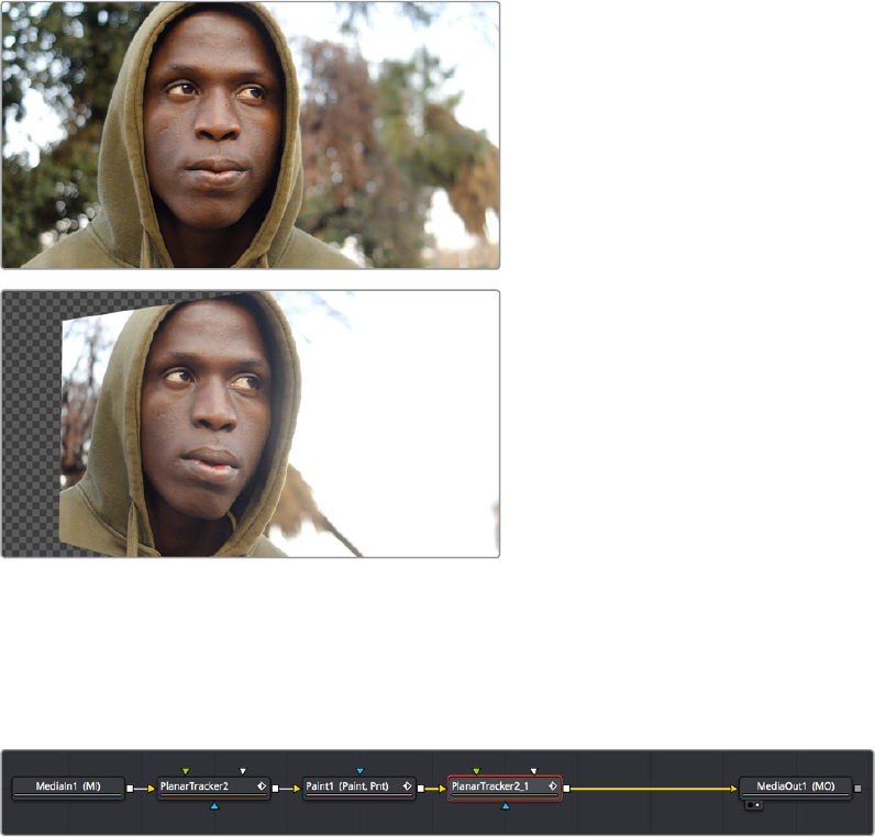
Keep in mind that the last stoke on the Modifiers list isn’t really a stroke, it’s a placeholder for
the next stroke you’re about to make, which might explain the numbering of the strokes if you’re
new to Fusion.
Inverting the Steady Effect to Put the Motion Back In
At this point, scrubbing through the clip shows that the paint strokes we’ve made are indeed
sticking to the man’s forehead as we need them to do. Now we just have to invert the transform
the Planar Tracker applied to put the clip back to the way it was, only with the painted fix
attached in the process. This ends up being a two part process, but the first part is the simplest.
Scrubbing through the steadied clip shows the paint
fix is “sticking” to the man’s forehead
Selecting and copying the PlanarTracker node coming before the Paint node, we select the
Paint node and paste a copy of it after. This copy has all the analysis and tracking data of the
original PlanarTracker node.
Pasting a second copy of the PlanarTracker node after the Paint node
With the second PlanarTracker node selected, we go into the Inspector and turn on the Invert
Steady Transform checkbox, which in theory inverts the steady warp transform to put the image
back to the way it was. However, in practice, the more the image needs to be warped to steady
it, the more likely that inverting the warp will introduce other problems.
2-131Chapter – 13 Learning to Work in the Fusion Page
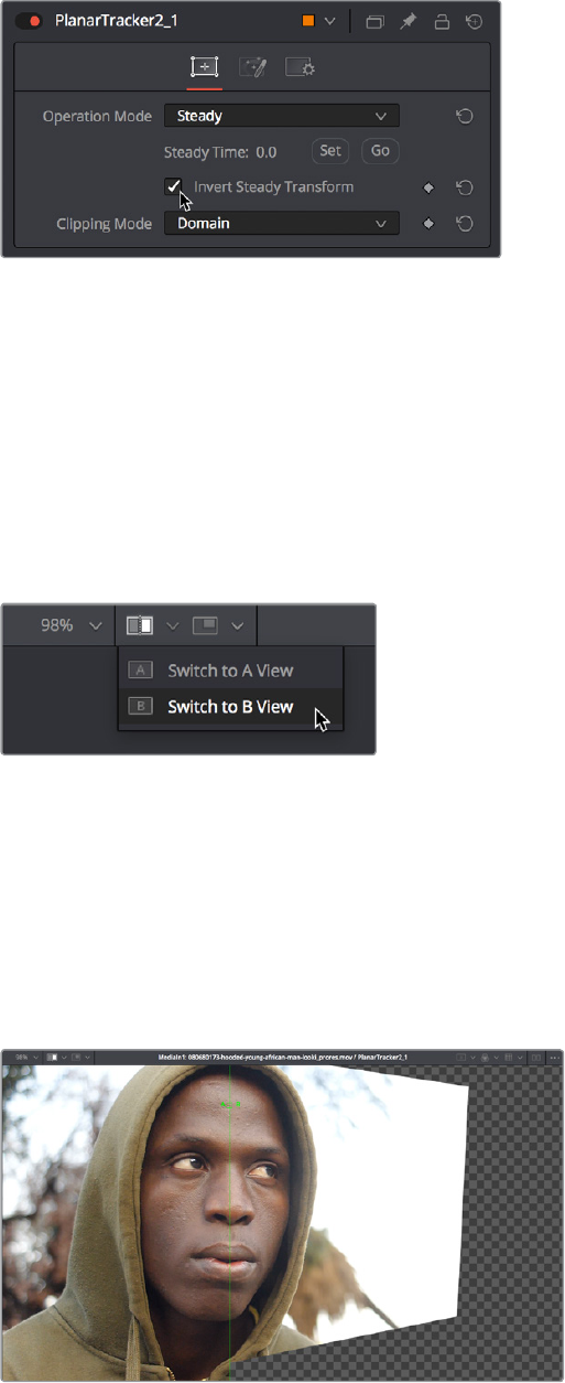
Turning on Invert Steady Transform to try
and put the image back to the way it was.
While the initial result appears to have just another warp applied to it, this time in reverse, the
truth is that the region of the image centered on the shape used to do the planar analysis, the
forehead, has gone back to the way it was before being steadied. It’s just the edges of the
frame that are distorted.
Using the Viewer’s Split Wipe Control
This is a good example of a situation that can be tested using the Split Wipe control in the
Viewer title bar.
Opening the Split Wipe pop‑up menu in the Viewer
Using the Split Wipe pop‑up, switch to B View (the current image is A View), then drag the
second PlanarTracker node into the Viewer to load it into the B buffer, then switch back to
AView and drag the MediaIn1 node into the Viewer to load it into the A buffer.
Turning on the Split Wipe button displays a split screen of the original image (A) against the
transformed image (B). You can drag the handle of the green split control to adjust the split, and
you can drag the line to change the angle of the split (holding Shift lets you snap the angle to
45° angles).
Comparing the “Invert Steady” version of the image with the
original image to see the forehead is the same in both frames
2-132Chapter – 13 Learning to Work in the Fusion Page
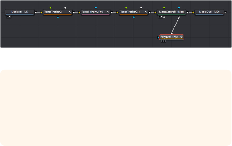
So, the forehead is fine, but the rest of the image is now warping in an unusable way because
of the extremity of the warp needed to steady the region we wanted to paint. That’s fine,
because there’s an easy fix that’s a necessary part of this technique.
Fixing the Edges by Only Using the Fixed Part of the Frame
At this point, we’re ready for the second part of this fix, which is to mask and composite just the
fixed forehead against the original clip.
Isolating the Painted Forehead
First, we need to mask out just the man’s painted forehead. We can do this by connecting a
Polygon node to the garbage matte input of a MatteControl node, and then connecting the
second PlanarTracker node’s output (with the fixed forehead) to the MatteControl node’s
background input. This lets us draw a shape with the Polygon node and use it as a mask to crop
out the man’s painted forehead.
The placement of these two new nodes can be seen in the following screenshot. We can wire
this up before drawing the shape, in fact it’s essential because otherwise you want to trace the
image being fed to the MatteControl node using the Polygon node.
Adding a Polygon node, a MatteControl node, and a Merge node to
composite the painted forehead on the original clip
Drawing a Polygon Mask
Moving the playhead to the first frame of the clip, we’re ready to draw a mask to isolate the fixed
forehead. Loading the MatteControl1 or MediaOut1 node into the Viewer, and selecting the
Polygon1 node so that we see its tools in the Viewer toolbar sets us up for drawing a polygon.
Drawing shapes using the Polygon node is similar to shape drawing in other spline‑based
environments, including the Color page:
Clicking once draws a corner control point.
Clicking and dragging creates a bezier curve.
Click the first control point you created to close a shape.
TIP: When it comes to using Masks to create transparency, there are a variety of ways
to do this, for example (a) attaching the image you want to mask to the background
input of a Brightness/Contrast node with Alpha enabled to darken a hole in the alpha
channel by lowering the Gain slider while the Polygon node is attached to the effect
mask input, or (b) using ChannelBooleans to copy channel data to alpha from a Polygon
node attached to the foreground input while the image you want to mask is attached to
the background layer, however the MatteControl node is flexible enough and useful
enough to merit learning about it now.
2-133Chapter – 13 Learning to Work in the Fusion Page

We click and drag to create a shape that outlines the man’s forehead, and when we close the
shape, we see exactly the opposite of what we want, a hole in the middle of the image.
Drawing a shape to isolate the forehead gives an inverted result at
first when using the Garbage Matte input of the MatteControl node
to attach the Polygon to the MatteControl node
Before fixing this, we drag the Soft Edge slider in the Inspector to the right to blur the edges
justa bit.
Inverting the Garbage Input
Selecting the MatteControl1 node, we open the GarbageMatte controls, and click the Invert
checkbox, which immediately gives us the result we want, of the forehead in isolation, ready
forcompositing.
(Top) Inverting the Garbage Matte input, (Bottom) The resulting
inverted mask inverting the forehead
Compositing the Painted Forehead Against the Original Image
Almost finished, we’ll add one more node, a Merge node, that we’ll use to actually layer the
fixed forehead against the original image being output by the MediaIn node.
2-134Chapter – 13 Learning to Work in the Fusion Page
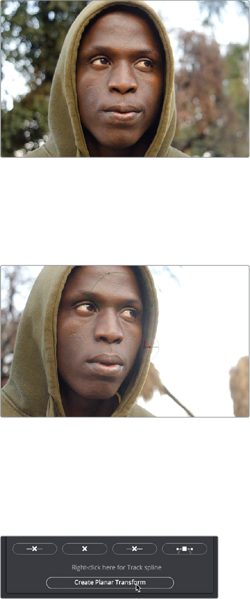
Creating a disconnected Merge node, we reconnect the MatteControl’s output to the green
foreground input of the Merge node, and then pull out a second branch from the MediaIn1
node’s output to connect to the Merge node’s orange background input. This puts the cropped
and fixed forehead on top of the original image.
The painted forehead composited against the original image
Match Moving the Mask to the Shot
So now we’ve got the best of both worlds, a fixed forehead and the background of the shot
looks good. However, if we select the Polygon node and then scrub forward in the clip, the
fixed forehead mask drifts out of sync with the motion of the shot, so we have one last issue to
deal with. Happily, match moving the mask to move with the shot is really simple.
Because the Polygon isn’t animated to match the motion of
the shot, it goes out of sync
Selecting the first PlanarTracker node that comes right after the MediaIn node, and temporarily
choosing Track from the Operation Mode pop‑up menu, we can see there’s a Create Planar
Transform button at the bottom of the listed controls. Clicking this button creates a new,
disconnected node in the Node Editor that uses the planar track as a transform operation, for
doing easy match moving. We click the Create Planar Transform button, and then set Operation
Mode back to Steady.
Creating a PlanarTransform node you can use to
Match Move other images
2-135Chapter – 13 Learning to Work in the Fusion Page
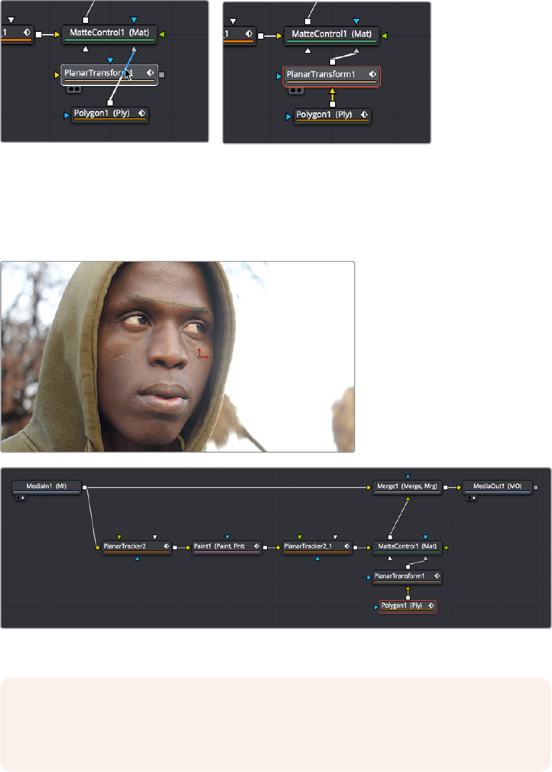
We can insert this new node into the node tree to use it by holding the Shift key down and
dragging it over the connection between the Polygon node and the MatteControl node,
dropping it when the connection highlights.
(Left) Inserting a PlanarTransform node by holding the Shift
key down while dropping over a connection (Right)
With the new PlanarTransform node inserted, the Polygon is automatically transformed to match
the motion of the forehead that was tracked by the original PlanarTracker node, and it animates
to follow along with the movement of the shot. At this point, we’re finished!
The final painted image, along with the final node tree
NOTE: While on‑screen controls are only visible when you select the node they belong
to, on‑screen controls only appear transformed properly when you load a node
downstream of the operations that would transform the image.
2-136Chapter – 13 Learning to Work in the Fusion Page

Building a Simple Green
Screen Composite
In this next example, we’ll take a look at how you can pre‑organize the media you want to use in
a composition in the Edit page, before creating a Fusion clip to bring all of it into the Fusion
page in an organized way. Then, we’ll do a simple composite using a greenscreen key and two
other layers to create a news story.
Organizing Clips in the Edit Page to Create a Fusion Clip
For this example, we’ll take a look at how you can organize multiple clips in the Edit page to use
in the Fusion page by creating a “Fusion clip,” which is effectively a special‑purpose compound
clip used specifically by the Fusion page. The next effect we need to create involves a
greenscreen clip, a background graphic, and a foreground graphic. This is the kind of situation
where superimposing all three layers on the timeline to set up their order and timing can be the
fastest way to set up the foundation of our composition.
With these clips edited together, we select all of them, right‑click the selection, and choose
New Fusion Clip from the contextual menu. This embeds them all within a single clip, which is
easy to manage in the Edit page and keeps all the relevant media necessary for this
composition within one handy object.
(Top) A stack of clips to use in a composite, (Bottom) Turning that
stack into a Fusion clip in the Edit page
2-137Chapter – 13 Learning to Work in the Fusion Page

When we open the Fusion page to begin work, however, Fusion clips expose their contents in
the Node Editor as a pre‑built cascade of MediaIn nodes automatically connected by Merge
nodes (one Merge node for each pair of clips) that take care of combining each layer of video
the way they were in the Edit page timeline.
The initial node tree of the three clips we turned into a Fusion clip
With this node tree already assembled, we can focus our time on adding the nodes we’ll need
to each branch of this tree, rather than assembling everything from scratch.
Pulling a Greenscreen Key Using the Delta Keyer
First, we’ll pull the greenscreen key we’ll need to create transparency behind the newscaster.
To prepare, we’ll pull the Merge nodes off to the right to make room for the additional nodes
we’ll be adding after the MediaIn nodes as we work.
Creating space after the MediaIn nodes, and selecting the
second one in preparation for adding a node
Selecting the MediaIn2 node and loading the Merge1 node into the Viewer lets us see the
greenscreen clip, and makes it easy for us to add a DeltaKeyer node inline by pressing Shift‑
Space to open the Select Tool dialog with which to search for and insert any node.
Adding a DeltaKeyer node inline after the MediaIn2 node
The DeltaKeyer node is a sophisticated keyer that is capable of impressive results combining
different kinds of mattes and a clean‑plate layer, but it can also be used very simply if the
background that needs to be keyed is well lit. And once the DeltaKeyer creates a key, it
embeds the resulting alpha channel in its output, so in this simple case, it’s the only node we
need to add. It’s also worth noting that, although we’re using the DeltaKeyer to key a green
screen, it’s not limited to only keying green or blue; the DeltaKeyer can impressive keys on any
color in your image.
2-138Chapter – 13 Learning to Work in the Fusion Page
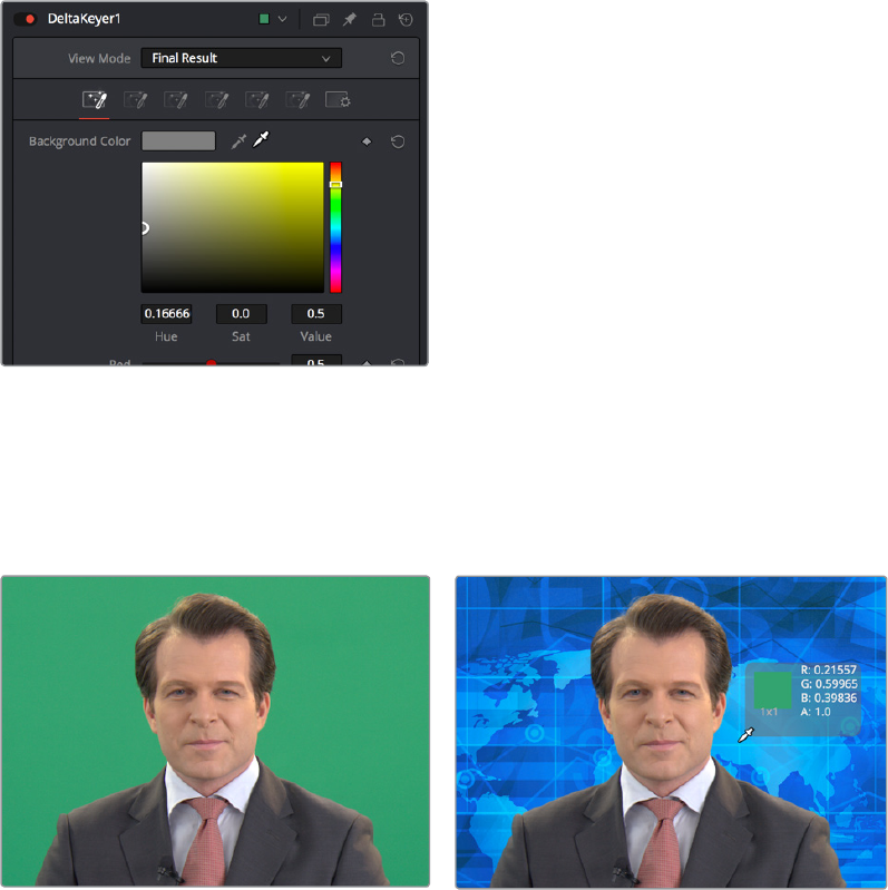
With the DeltaKeyer selected, we’ll use the Inspector controls to pull our key, using a shortcut to
quickly sample the shade of green from the background of the image. The shortcut we’ll use is
a bit unorthodox, but it gives us the ability to preview how different areas of the background will
key as we look for the right place to sample.
We hold the Option key down and click the eyedropper tool, and while continuing to hold the
Option key down, we drag the pointer over the green of the background in the Viewer.
Option‑clicking‑and‑dragging the eyedropper to
the Viewer to sample the Background Color
As we drag in the Viewer, an analysis of the color picked up by the location of the eyedropper
appears within a floating tooltip, giving us some guidance as to which color we’re really picking.
Meanwhile, we get an immediate preview of the transparency we’ll get at that pixel, and since
we’re viewing the Merge1 node, this reveals the image we’ve connected to the background.
(Before) The original image, (After) Sampling the green screen using the eyedropper from the Inspector
When we’re happy with the preview, releasing the pointer button samples the color, and the
Inspector controls update to display the value we’ve chosen.
2-139Chapter – 13 Learning to Work in the Fusion Page
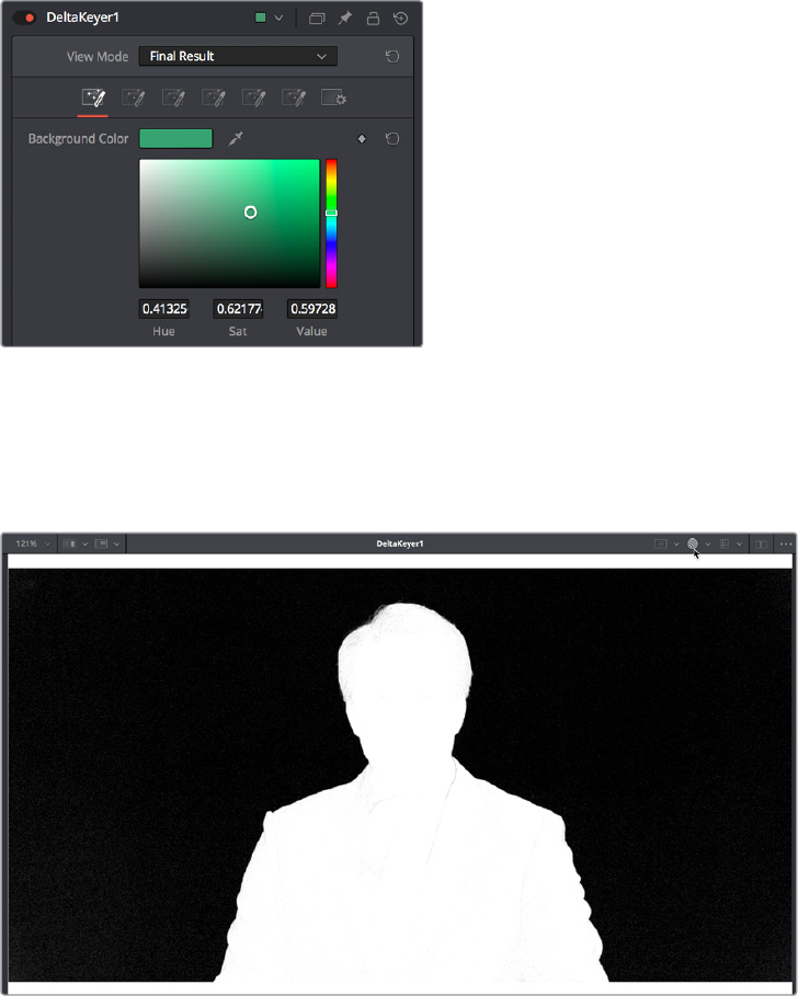
The DeltaKeyer Inspector updates with the sampled color
Now that we’ve selected a background color to pull a key with, we can load the DeltaKeyer
node into the Viewer itself, and click the Color button (or select the Viewer and press C) to
switch the viewer between the RGB color channels of the image and the Alpha channel, to
evaluate the quality of the key.
Loading the DeltaKeyer into the Viewer and clicking the
Color button to view the alpha channel being produced
A close examination of the alpha channel reveals some fringing in the white foreground of the
mask. Happily, the DeltaKeyer has integrated controls for doing post‑processing of the key
being pulled, found in the third of the seven panels of controls available in the DeltaKeyer.
Clicking the Matte panel opens up a variety of controls for manipulating the matte, and since the
fringing we don’t like is on the foreground (white) part of the key, we’ll be using the Clean
Foreground slider to make the fix.
2-140Chapter – 13 Learning to Work in the Fusion Page
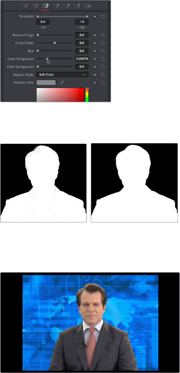
Adjusting the Clean Foreground slider in the Matte
panel of the DeltaKeyer controls
In this case, raising the Clean Foreground slider a bit eliminates the inner fringing we don’t
want, without compromising the edges of the key.
(Before) The original key, (After) The key after using the Clean Foreground slider
With this accomplished, we’re good with the key, so we load the Merge1 node back into the
Viewer, and press C to set the Color control of the Viewer back to RGB. We can see the graphic
in the background, but right now it’s too small to cover the whole frame, so we need to make
another adjustment.
The final key is good, but now we need to work on the background
2-141Chapter – 13 Learning to Work in the Fusion Page
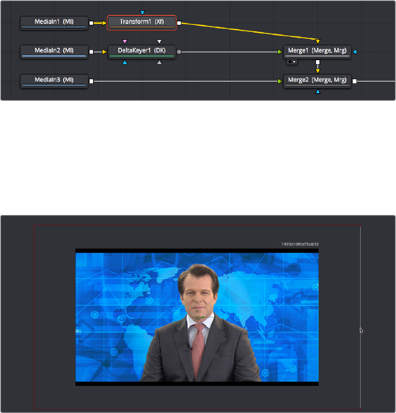
Using the Transform Node to Resize a Background
Since the background isn’t covering up the whole frame, we need to transform it. It’s a high‑
resolution image, so that’s not a problem, however it’s connected to the background input of
the Merge1 node, and although Merge nodes have built‑in transform controls, they only work on
the foreground input (on the premise that the foreground will need to be fit to the background).
This means that we need to add a Transform node to the MediaIn1 node to take care of this.
Selecting the MediaIn1 node and clicking the Transform button in the Toolbar takes care of this,
and we’re ready to work.
Adding a Transform node to change the sizing of the MediaIn1 image connected to the background
While there are slider controls in the Inspector for Center, Size, and Angle (among other
parameters), there are on‑screen controls that give more satisfyingly direct control. Zooming
out of the Viewer a bit by holding the Command key and using the scroll control of your pointer,
we drag the side border of the graphic to proportionally enlarge the blue background until it fills
the screen (there’s still a black border at the top and bottom of the clip, but that’s burned into
the news clip we have).
Enlarging the background to fill the frame using the Viewer’s on‑screen controls
At this point, we decide to make room for the graphic we know we’ll be putting into the frame at
left, so we take advantage of the built‑in transform controls in the Merge1 node that affect the
foreground input. Selecting the Merge1 node, we drag the left arrow of the onscreen controls
that appear to move the man to the right, and we take advantage of knowing the image of the
man is high‑resolution relative to our project resolution by dragging the side edge to
proportionally enlarge the foreground image to crop out the black bars.
2-142Chapter – 13 Learning to Work in the Fusion Page
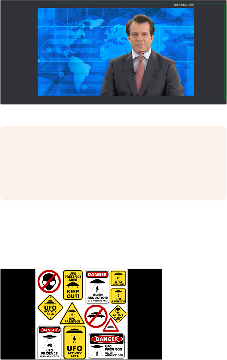
Using the Merge1 node’s on‑screen transform controls to reposition
and enlarge the image to prepare for adding another element
Masking a Graphic
Next, it’s time to work on the news graphic that will appear to the left of the man. If we load the
Merge2 node, that combines the blue background and newscaster we just finished working on
with the logo layer we brought into the Fusion page, we can see that the logo layer is actually a
sheet of different logos that appear on top, so we need to cut one out using a mask and fit it
into place.
We need to mask out a single logo from this sheet to use in our composition
NOTE: You may have noticed that there’s both Transform and Resize buttons in the
Toolbar. It’s important to be aware that while the Transform node always refers to the
original source resolution of the image for resolution‑independent sizing in which
multiple Transform nodes can scale the image down and up repeatedly with no loss of
image resolution, the Resize node actually decreases image resolution when you shrink
an image, or increases image resolution (with filtering) when enlarging. In most
situations, you want to use the Transform node, unless you specifically want to alter and
perhaps reduce image resolution to create a specific effect.
2-143Chapter – 13 Learning to Work in the Fusion Page
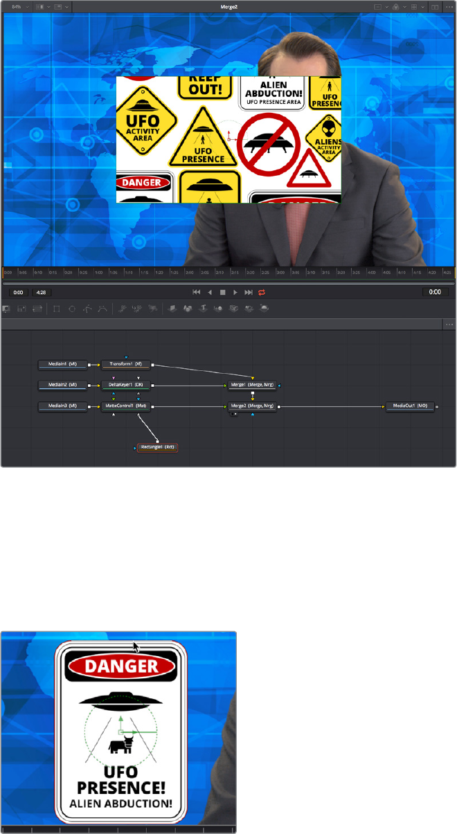
Selecting the MediaIn3 node that’s feeding the logo layer, we click the MatteControl button of
the Toolbar to add a MatteControl node, and then we add a Rectangle mask, manually
connecting the Rectangle mask’s output to the gray garbage mask input of the MatteControl
node. Finally, we select the Rectangle node, and click it’s Invert checkbox to invert the
Rectangle Mask’s output, so it’s cropping the logo layer correctly.
Masking the logo using a Rectangle mask connected to a MatteControl node
Now, all we need to do is to use the on‑screen controls of the Rectangle mask to crop the logo
we want to use, dragging the position of the mask using the center handle, and resizing it by
dragging the top/bottom and left/right handles of the outer border.
As an extra bonus, we can take care of the fact that the logo has rounded borders by using the
Corner Radius slider in the Inspector controls for the Rectangle matte to add the same kind
ofrounding.
Moving and resizing the mask to fit our logo, and rounding
the edges using the Corner Radius Inspector control
2-144Chapter – 13 Learning to Work in the Fusion Page
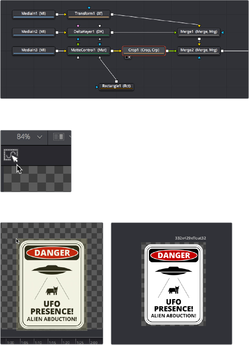
Now that we’ve masked the logo, we’ll crop the unused parts of this image so that the logo
we’re using is centered on the frame, which will make subsequent transform operations much
easier. Selecting the MatteControl1 node, we add the Crop node from the Tools > Transform
category of the Effects Library, and load the new node into the Viewer.
Adding a Crop node after masking the image to center the cropped logo on the frame
With the Crop node selected, we can click the crop tool in the Viewer toolbar
Selecting the crop tool in the Viewer toolbar
This lets us crop the image by dragging a bounding box around it.
(Left) Dragging a bounding box using the Crop tool, (Right) The cropped logo now centered on the frame
2-145Chapter – 13 Learning to Work in the Fusion Page

At this point, we’re all set to move the logo into place, so we select the Merge2 node and load it
into the Viewer, and once again avail ourselves of the built‑in transform controls for foreground
inputs, using the on‑screen controls to put the logo where we want it and make it a
suitablesize.
Placing the logo using the foreground input transform controls of the Merge2 node
Animating an Image Using Keyframes
We’re almost done with this grand tour of Fusion page functionality, but we’ve got one last task
to accomplish. Now that we’ve positioned the logo appropriately, we need to animate it coming
into frame to open the segment. To do this, we’ll use the keyframe controls in the inspector to
begin keyframing, then we’ll use the controls in the Viewer to create a motion path, and finally
we’ll use the Spline editor to refine the result.
Animating a Parameter in the Inspector
Before beginning to keyframe, it’s always good to think your way through what you want to do
before starting anything, just to make sure you’re taking the right approach. In this case, we just
want to slide the logo down from the top of the screen to where we’ve positioned it, so it’s
probably best to start adding keyframes at the end point of the animation we want to create by
moving the playhead in the Time Ruler 24 frames forward from the beginning of the composition.
Selecting the Merge2 node, in which we used transform controls to position the logo, we click
the small diamond control to the right of the Center parameter to create a keyframe for that
parameter, in the process setting that parameter up so that every alteration we make on a
different frame adds a keyframe.
Adding a keyframe to begin animating a parameter
NOTE: The Cropping node discards resolution, just like the Resize node does,
so use it with care.
2-146Chapter – 13 Learning to Work in the Fusion Page
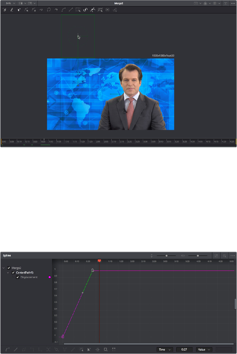
Next, we move the playhead back to the beginning of the composition, then zoom out of the
Viewer so there’s more room around the frame before dragging the center handle of the logo
up until we’ve dragged it off‑screen. In the process, a second keyframe appears next to the
Center parameter in the Inspector to show there’s a keyframe at that frame, and a motion path
appears in the Viewer showing you the route the now animated logo will take.
Moving an object in the Viewer to create animation via a motion path
At this point, if we play though the animation, it’s functional, but not exciting. The motion is linear
so it comes into the frame and stops with a nearly audible “thunk.” Happily, we can fix this using
the Spline Editor.
Using the Spline Editor
Clicking the Spline button in the UI Toolbar opens the Spline Editor at the right of the Node
Editor. The Spline Editor is a keyframe graph where you edit and finesse the curves created by
animated parameters. By default, each animated parameter from every node in the current
composition appears in the parameter list to the left of the curve graph. Turning on the
Displacement checkbox shows our animated curve in the graph so we can work on it.
The Displacement curve from the animated Center parameter of the Merge2 node in the Spline Editor
2-147Chapter – 13 Learning to Work in the Fusion Page
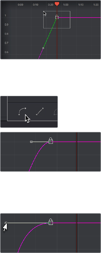
Drag a bounding box over the second of the two control points that are shown in the graph, so
it’s highlighted.
Selecting a control point to modify
With that control point selected, click the Smooth button in the toolbar at the bottom of the
Spline Editor to turn that keyframe into a bezier curve (this also works for multiple selected
keyframes). This has the effect of easing the motion to a stop at that second keyframe.
Clicking the Smooth button to turn the selected
control point in the graph into a Bezier curve
Playing through the animation, the logo does ease to a stop, but it’s subtle. We up the ante by
dragging the bezier handle of the final keyframe to the left, making the curve steeper and
resulting in the logo coasting to a stop more gradually.
Editing the spline to create a steeper curve, making
the logo coast more gradually to a stop
2-148Chapter – 13 Learning to Work in the Fusion Page
Congratulations
At this point, we’re finished with our tour. As many things as we’ve covered, this is still only
scratching the surface of what the Fusion page is capable of. However, this introduction should
have given you a solid look at how to work in the Fusion page so that you can explore farther
on your own.
Have fun!
2-149Chapter – 13 Learning to Work in the Fusion Page
Chapter 14
Creating Fusion
Templates
The integration of Fusion into DaVinci Resolve 15 has resulted in one other
exciting feature, and that’s the ability to use Fusion Titles in the Edit page.
Fusion Titles are essentially generators that were created in the Fusion
page, and which can be edited into the timeline of the Edit page as clips
with custom controls. However, the really exciting this about this is that you
can create your own Fusion Title templates, from nearly any Fusion page
composition you can build using Fusion‑generated objects such as Text+
layers, Fusion generators, and even 3D geometry and 3D text with texture
and lighting effects. This brief chapter shows you how it’s done.
2-150Chapter – 14 Creating Fusion Templates
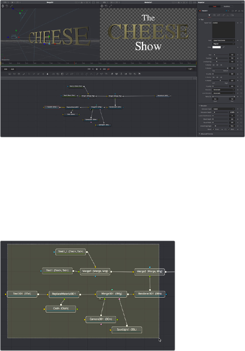
Build a Template in the Fusion Page
The first part of creating a Fusion template is to create a Fusion composition, consisting of
Fusion‑generated objects assembled to create nearly any kind of title or generator you can
imagine. If you’re really ambitious, it can include animation. In this example, 3D titles and 2D
titles have been combined into a show open.
Building a composition to turn into a template
Create a Macro
Macros are basically Fusion compositions that have been turned into self‑contained tools.
Ordinarily, these tools are used as building blocks inside of the Fusion page so that you can
turn frequently‑made compositing tricks that you use all the time into your own nodes. However,
we can also use this macro functionality to build templates for the Edit page.
Having built your composition, select every single node you want to include in that template
except for the MediaOut1 node.
Selecting the nodes you want to turn into a Template
2-152Chapter – 14 Creating Fusion Templates
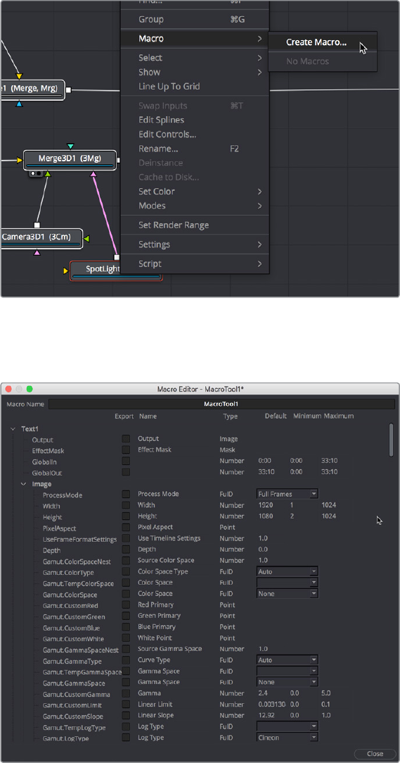
Having made this selection, right‑click one of the selected nodes and choose Macro > Create
Macro from the contextual menu.
Creating a macro from the selected nodes
The Macro Editor window appears, filled to the brim with a hierarchical list of every parameter in
the composition you’ve just selected.
The Macro Editor populated with the parameters of all the nodes you selected
This list may look intimidating, but closing the disclosure control of the top Text1 node shows us
what’s really going on.
2-153Chapter – 14 Creating Fusion Templates
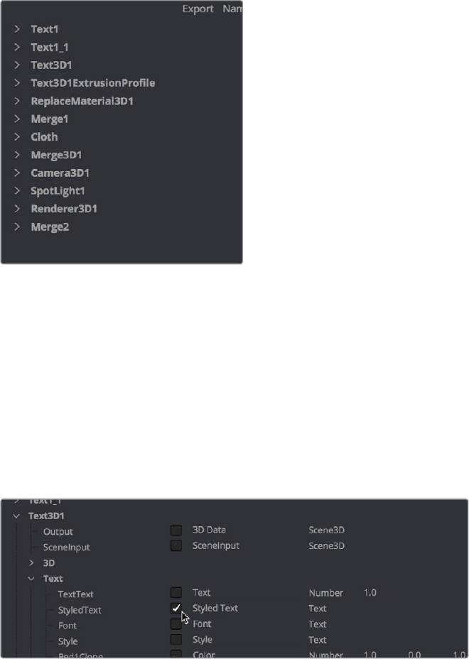
A simple list of all the nodes we’ve selected
Closing the top node’s parameters reveals a simple list of all the nodes we’ve selected. The
Macro Editor is designed to let you choose which parameters you want to expose as custom
editable controls for that macro. Whichever controls you choose will appear in the Inspector
whenever you select that macro, or the node or clip that macro will become.
So all we have to do now is to turn on the checkboxes of all the parameters we’d like to be able
to customize. For this example, we’ll check the Text3D node’s Styled Text checkbox, the Cloth
node’s Diffuse Color, Green, and Blue checkboxes, and the SpotLight node’s Z Rotation
checkbox, so that only the middle word of the template is editable, but we can also change its
color and tilt its lighting (making a “swing‑on” effect possible).
Turning on the checkboxes of parameters we’d like to edit when using this as a template
Once we’ve turned on all the parameters we’d like to use in the eventual Template, we click the
Close button, and a Save Macro As dialog appears. If we’re using macOS, we navigate to the /
Library/Application Support/Blackmagic Design/DaVinci Resolve/Fusion/Templates/Edit/Titles
directory, enter a name in the field below, and click Save.
2-154Chapter – 14 Creating Fusion Templates
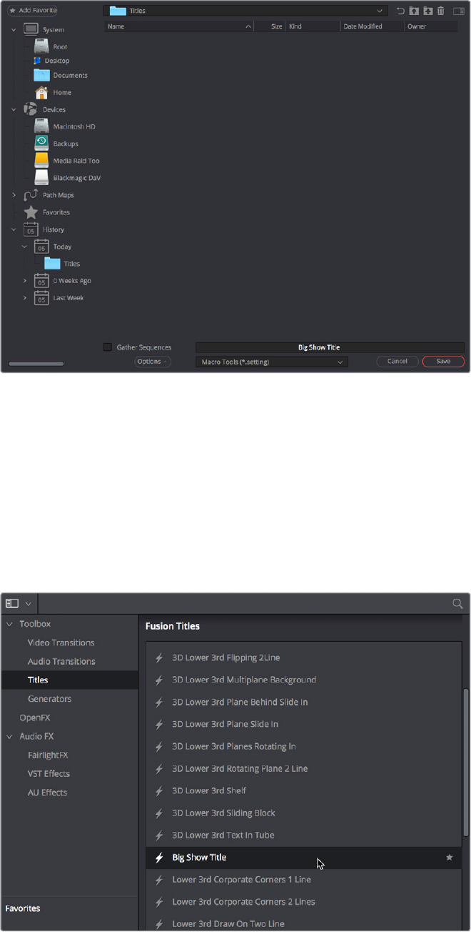
Choosing where to save and name the Macro
Restart Resolve and
Use Your New Template
After you’ve saved your macro, you’ll need to quit and re‑open DaVinci Resolve. When you
open the Effects Library of the Edit page, you should see your new template inside of the Titles
category, ready to go in the Fusion Titles list.
Custom titles appear in the Fusion Titles section of the Effects Library
2-155Chapter – 14 Creating Fusion Templates