Delta Xtend Reverse Shoulder System Surgical Technique
2014-04-09
: Pdf Delta Xtend Reverse Shoulder System Surgical Technique Delta_Xtend_Reverse_Shoulder_System_Surgical_Technique 4 2014 pdf
Open the PDF directly: View PDF ![]() .
.
Page Count: 64
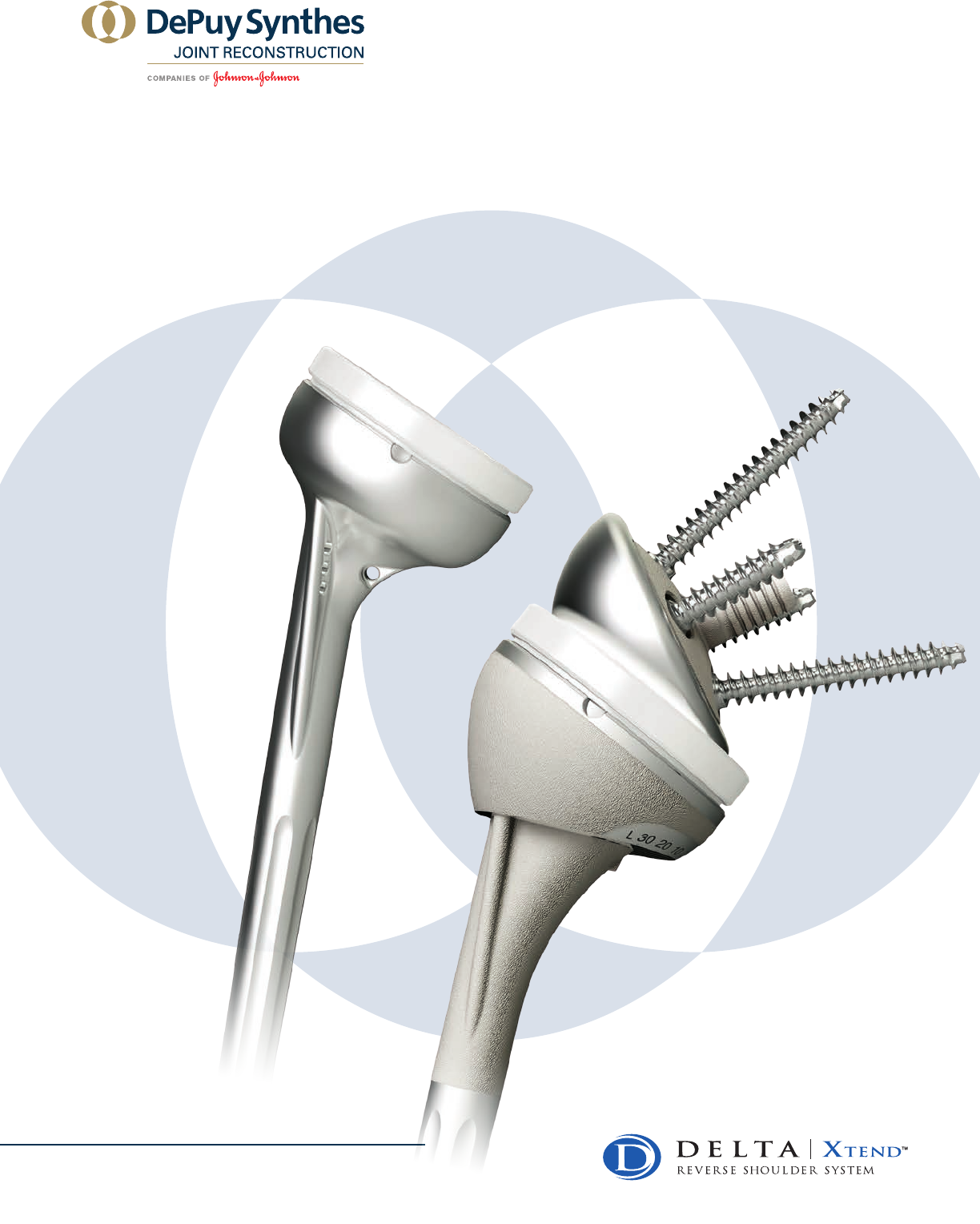
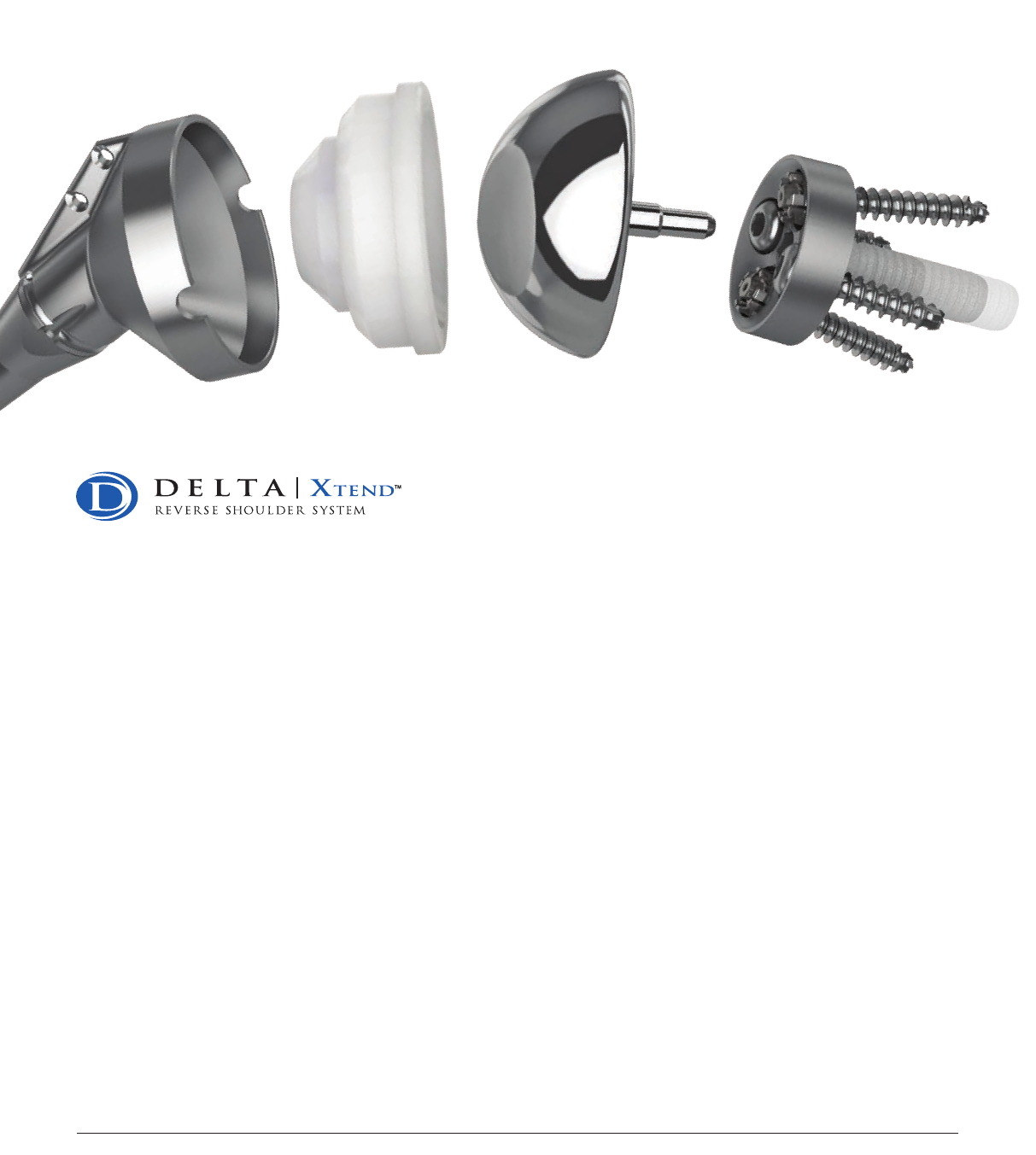
DELTA XTEND™
Reverse Shoulder System
SURGICAL TECHNIQUE

3
Described by Charles Neer in 1983,
1 the shoulder pathology known as Cuff Tear Arthropathy (CTA) has historically
been seen as a significant surgical challenge.
Non-constrained total or hemi shoulder arthroplasties have limited clinical outcomes in such indications, and most of
the constrained and semi-constrained prostheses developed in the 1970’s-1980’s for CTA (in particular, all reversed
ball and socket designs) remained purely experimental due to poor motion capability, instability and a high rate of
glenoid loosening.2,3,4
In 1985, Paul Grammont (Dijon University Hospital – France) designed the first semi-constrained reverse concept that
met the challenges inherent in cuff tear arthropathy cases.5 Known today as the DePuy Synthes Joint Reconstruction’s
DELTA CTA® Shoulder System, this Shoulder Prosthesis is a leading treatment for shoulder cuff tear arthropathy,
6 with
more than twenty years of clinical success and 20,000 cases performed all over the world.
Based on the experience of the DELTA CTA® System, the next generation of reverse shoulder arthroplasty, the
DePuy Synthes Joint Reconstruction’s DELTA XTEND™ Shoulder Prosthesis has been designed using scientific,
engineering, and clinical knowledge in CTA cases in order to extend the clinical success associated with the 20 year
history of the DELTA CTA System.
Keeping the three design features that differentiated the DELTA CTA System from previous reverse designs
and made it successful:
• Joint center of rotation positioned on the glenoid bone surface to avoid
pull-out torques on the glenoid component7
• Non-anatomic neck-shaft angle (155 degrees) for joint stability 3,5
• Optimal deltoid tensioning to maximize its action without over-stretching the tissues7
Reducing the risk of scapular neck erosion and maximizing the shoulder range of motion:8,9
• Inferior overlap of the glenoid component allowed by a new eccentric glenosphere design
and a new metaglene fixation system
Preserving bone to permit intervention and faster recovery with:
• Curved-back metaglene design9
• Reduced proximal geometry monobloc humeral stem for cemented application
• Cementless modular stem with eccentric epiphysis option
Design based on the success of the DELTA CTA Reverse Shoulder means that the DELTA XTEND System is the next
step forward for management of patients with Cuff Tear Arthropathy. The DELTA XTEND System allows you to treat
more patients, effectively.
Dr. Didier Capon
France
Dr. David Collins
USA
Prof. Anders
Ekelund
Sweden
Dr. Laurent
Lafosse
France
Prof. Lieven
De Wilde
Belgium
Dr. Cécile Nérot
France
Dr. Ludwig
Seebauer
Germany
Dr. Michael
Wirth
USA
The DELTA XTEND Surgeon Design Team

3
Surgical Technique DELTA XTEND™ DePuy Synthes Joint Reconstruction
CONTENTS
Surg ica l Tech nique
DELTA XTEND Key Surgical Steps ............................ 4-5
Pre-operative Templating
and Patient Positioning ...............................................7
Surgical Approach ......................................................7
Intramedullary Canal Preparation .............................10
Humeral Head Resection ..................................... 11-13
Exposing the Glenoid .......................................... 14-15
Positioning the Metaglene Central Peg ................16-18
Reaming the Glenoid Bone .................................19-20
Metaglene Implantation ...........................................21
Inferior and Superior
Metaglene Screw Placement ...............................22-25
Anterior and Posterior
Metaglene Screw Placement ...............................26-27
Placement of the Proximal
Humeral Reaming Guide ..........................................28
Proximal Humeral Reaming
Cementless Modular Humeral Implants ...............29-30
Distal Humeral Broaching
Cementless Modular Humeral Implants ....................31
Humeral Trial Stem and Epiphysis Insertion
Cementless Modular Humeral Implants ...............32-33
Proximal Humeral Reaming
Cemented Monobloc Humeral Implants ...................34
Humeral Trial Implant Insertion
Cemented Monobloc Humeral Implants ...................35
Glenosphere Trial Placement ....................................36
Cup Trials and Trial Reduction ..................................37
Joint Tensioning and Stability Assessment ................38
Definitive Glenosphere Fixation .......................... 39-41
Definitive Humeral Implant Insertion
Cementless Modular Humeral Implants ....................42
Definitive Humeral Implants Insertion
Cemented Monobloc Humeral Implants ...................43
Definitive Humeral Implant Insertion .................. 44-46
Cases of Proximal Humeral Bone Loss..................47-48
Revision to Hemi-Arthroplasty .................................. 49
DELTA XTEND Long Peg
Metaglene and DELTA CTA Hybrid Cups ...................50
Post-Operative Management ....................................52
Ordering Information
Implants..............................................................53-55
Instrumentation ................................................. 56-59
54 DePuy Synthes Joint Reconstruction DELTA XTEND™ Surgical Technique
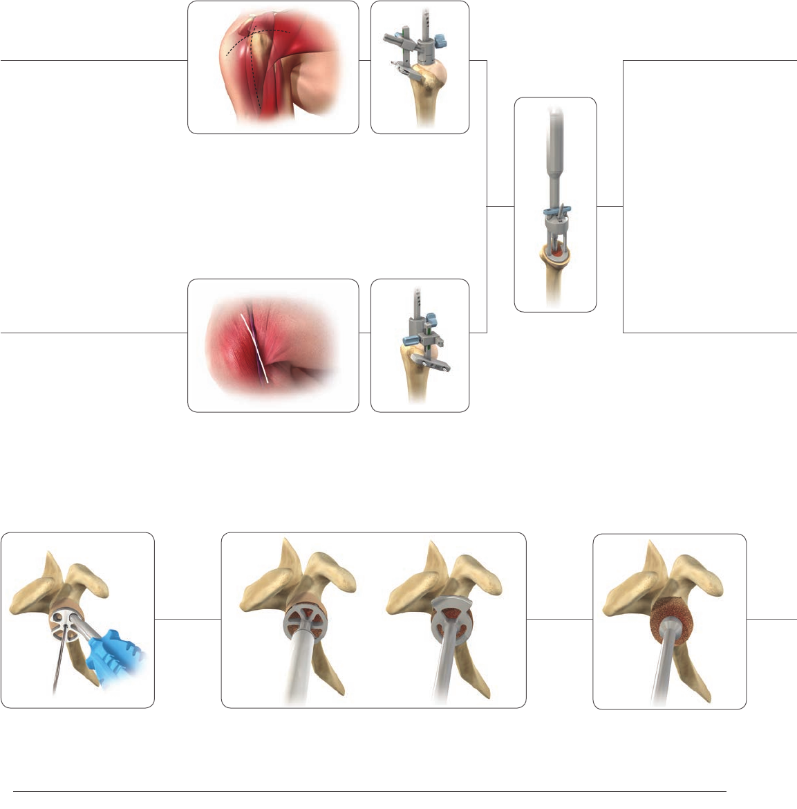
DELTA XTEND KEY SURGICAL STEPS
Humeral Surgical Steps
2. Humeral Head
Resection
1. Approach
2. Humeral Head
Resection
1. Approach
Superior-lateral Approach
Delto-pectoral Approach
3. Metaglene Central
Peg Drilling
2. Cannulated Glenoid Reaming1. Choice of Optimal
Metaglene Positioning
Glenoid Surgical Steps
Modular Implant
Cementless Technique
Monobloc Implant
Cemented Technique
3. Proximal Reaming
Guide Positioning
5
Surgical Technique DELTA XTEND™ DePuy Synthes Joint Reconstruction
4. Metaglene Impaction 5. Inferior and Superior
Locking Screw Fixation
6. Anterior and Posterior
Spherical Head Screw Fixation
7. Glenosphere Implantation
Glenoid Surgical Steps
Modular Implant
Cementless Technique
Monobloc Implant
Cemented Technique
4. Determination of the
Epiphysis Size
5. Proximal Humeral
Reaming
6. Final Implant
Insertion
7. Cup Impaction
4. Determination of the Epiphysis
Size and Eccentricity
5. Proximal Humeral
Reaming
6. Diaphyseal
Broaching and
Angulation
Measurements
7. Epiphysis /
Diaphysis Assembly
8. Final Implant
Insertion
9. Cup Impaction
Standard Option Eccentric Option
HUMERAL SURGICAL STEPS
76 DePuy Synthes Joint Reconstruction DELTA XTEND™ Surgical Technique
7
Surgical Technique DELTA XTEND™ DePuy Synthes Joint Reconstruction
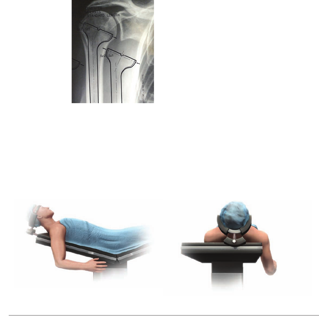
Pre-operative Templating
An initial assessment of the glenoid bone should be
carried out using radiographic and CT imaging to
determine whether the patient is suitable for treatment.
The size of the glenoid vault should be assessed inferiorly
in particular to ensure that all four metaglene screws can
be placed within glenoid bone.
Pre-operative planning
should also be carried
out using AP and lateral
shoulder radiographs of
known magnification
and the available
template to help the
surgeon determine the
size and alignment of
the implant (Figure1).
The final decision
should be made
intraoperatively.
Patient Positioning
The patient should be in the beach chair position, with
the affected arm completely free and on a support
(Figure 2).
PRE-OPERATIVE TEMPLATING AND PATIENT POSITIONING
Figure 1
Figure 2
Surgical Approach
The DELTA XTEND Prosthesis can be implanted using
a superior-lateral deltoid split approach or a delto-
pectoral approach.
The superior-lateral approach enables clear visualization
of the glenoid and therefore facilitates the implantation
of the glenoid components.
The delto-pectoral approach has the advantage of
offering a good view of the inferior part of the glenoid.
Therefore, the choice mainly depends on the surgeon’s
preference and clinical parameters.
Revision surgery, for instance, is usually performed using
a delto-pectoral approach since the patient has already
had that incision and since it allows for a longer humeral
incision when faced with difficult removal of the humeral
stem. However, for cases of retroverted glenoid, the
implant placement can be more difficult via the delto-
pectoral approach and can lead to damage of the deltoid
muscle. Moreover, as the rotator cuff lesion is mainly
located at the supero-posterior aspect of the cuff, the
(partial) insertion of the remaining subscapularis (that
is often needed through this approach) could weaken
the remaining muscular structure. The superior-lateral
approach may be preferred in these cases.

98 DePuy Synthes Joint Reconstruction DELTA XTEND™ Surgical Technique
Superior-lateral Approach
The skin incision is 10-12cm long and can be
antero-posterior along the lateral edge of
the acromion or made in a lateral direction
(Figure 3). Following subcutaneous dissection,
separate the anterior and middle deltoid
muscle bundles opposite the lateral margin of
the acromion using blunt dissection (Figure4).
The dissection starts at the level of the AC
joint, 5-7mm posterior to the tip of the
acromion, and extends straight laterally down
into the deltoid muscle. It should not extend
more than 4cm from the external aspect of
the acromion in order to preserve the axillary
nerve which is located at the turning fold of
the subacromial bursa.
When the subacromial bursa is visible,
gentle longitudinal traction in line with the
limb allows a retractor to be placed in the
subacromial space. The anterior deltoid is
then released subperiosteally from its acromial
insertion up to the AC joint. The deltoid
release from the anterior acromion can include
a small piece of bone to facilitate repair and to
protect the deltoid muscle.
Once the subacromial bursa has been
removed, the humeral head is visible at the
anterior edge of the acromion. Exposure may
be improved, if necessary, by dividing the AC
ligament and performing acromioplasty.
The limb is then externally rotated and the
head is dislocated antero-superiorly to facilitate
positioning of the cutting guide. If the bicep
tendon is still present, a tenotomy or tenodesis
should be performed. The subscapularis,
teres minor and infraspinatus are retained
when present. A partial detachment of the
subscapularis may be performed when the
superior dislocation of the humerus is difficult
to obtain.
Figure 4
Figure 3
SURGICAL TECHNIQUE

9
Surgical Technique DELTA XTEND™ DePuy Synthes Joint Reconstruction
Delto-pectoral Approach
The skin incision follows the line from the
midpoint of the clavicle to the midpoint of
the arm (Figure 5). Subcutaneous flaps are
elevated to expose the fatty strip that marks
the delto-pectoral interval. Dissect medial
to the cephalic vein and retract it laterally
with the deltoid muscle (Figure 6). Incise the
clavipectoral fascia from the inferior border
of the coracoacromial ligament distally to the
superior border of the tendon of the sternal
head of the pectoralis major (Figure 7). Sharply
and bluntly dissect the humeroscapular
motion interface (subacromial, subdeltoid and
subcoracoid). Palpate the axillary nerve at the
anterior-inferior border of the subscapularis
muscle. Electrocoagulate or ligate the anterior
humeral circumflex vessels near the humerus
at the inferior border of the subscapularis
(Figure 8).
If the bicep’s long head tendon is intact, open
its sheath and tenodese the tendon in the
groove or to the pectoralis major tendon with
non-absorbable sutures. Excise the proximal
biceps tendon and hypertrophic sheath. A
biceps tenotomy can also be performed in
elderly patients.
Place a tag suture in the tendon of the
subscapularis, 2cm medial to its point of
insertion, in the lesser tuberosity. Release the
tendon, along with the underlying capsule,
from the lesser tuberosity and the proximal
humerus (Figure 9). Strip the remaining
inferior and posterior-inferior capsule from
the humerus. Dislocate the humeral head
(Figure10).
Figure 9 Figure 10
Figure 7 Figure 8
Figure 5 Figure 6
1110 DePuy Synthes Joint Reconstruction DELTA XTEND™ Surgical Technique
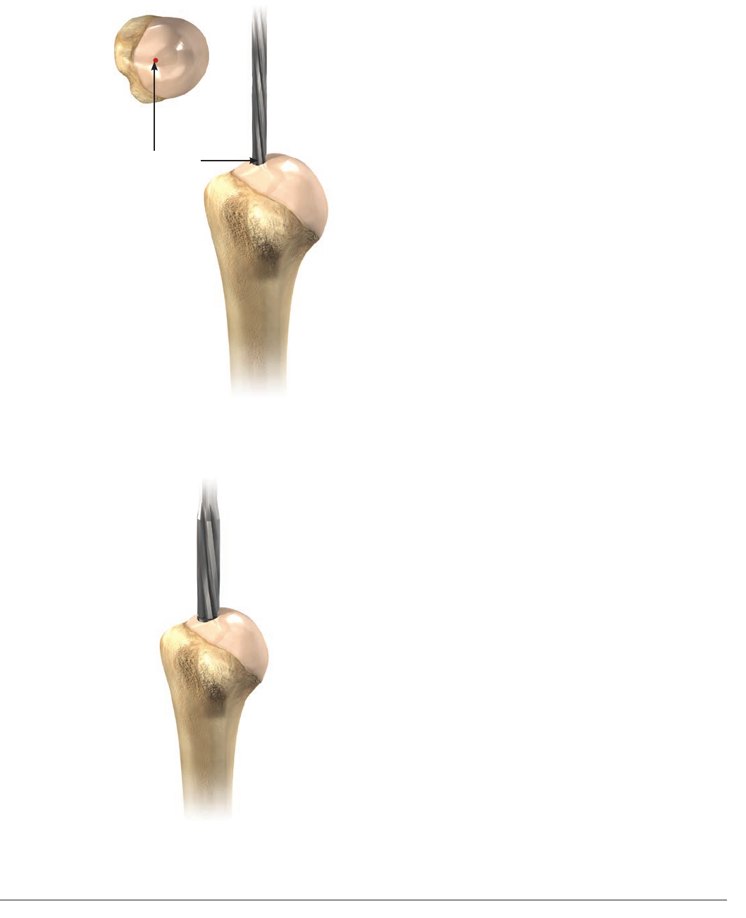
Proximal Entry Point
INTRAMEDULLARY CANAL PREPARATION
Using the 6mm medullary canal reamer, make
a pilot hole in the cortical surface of the bone
eccentrically and as superior as possible so
that the reamer passes directly down the
intramedullary canal (Figure 11). Ream the
medullary canal using the T-Handle on the
reamer. Do not use a power tool as this could
remove more bone than necessary.
When using the standard length prosthesis,
pass the reamer down the intramedullary
canal until the projecting circular mark on
the reamer is level with the pilot hole. When
using the long stem prosthesis, pass the
entire length of the cutting flutes down the
intramedullary canal.
Continue to ream sequentially until the
reamer begins to bite on the cortical bone
of the intramedullary canal of the humerus
(Figure12).
The final reamer size will determine the size
of the cutting guide handle, the epiphyseal
reaming guide, the broach, trial stem and final
implant. For example, if the 12mm reamer
begins to gain purchase in the intramedullary
cortical bone, use a 12mm humeral trial stem
and final component.
Figure 11
Figure 12
11
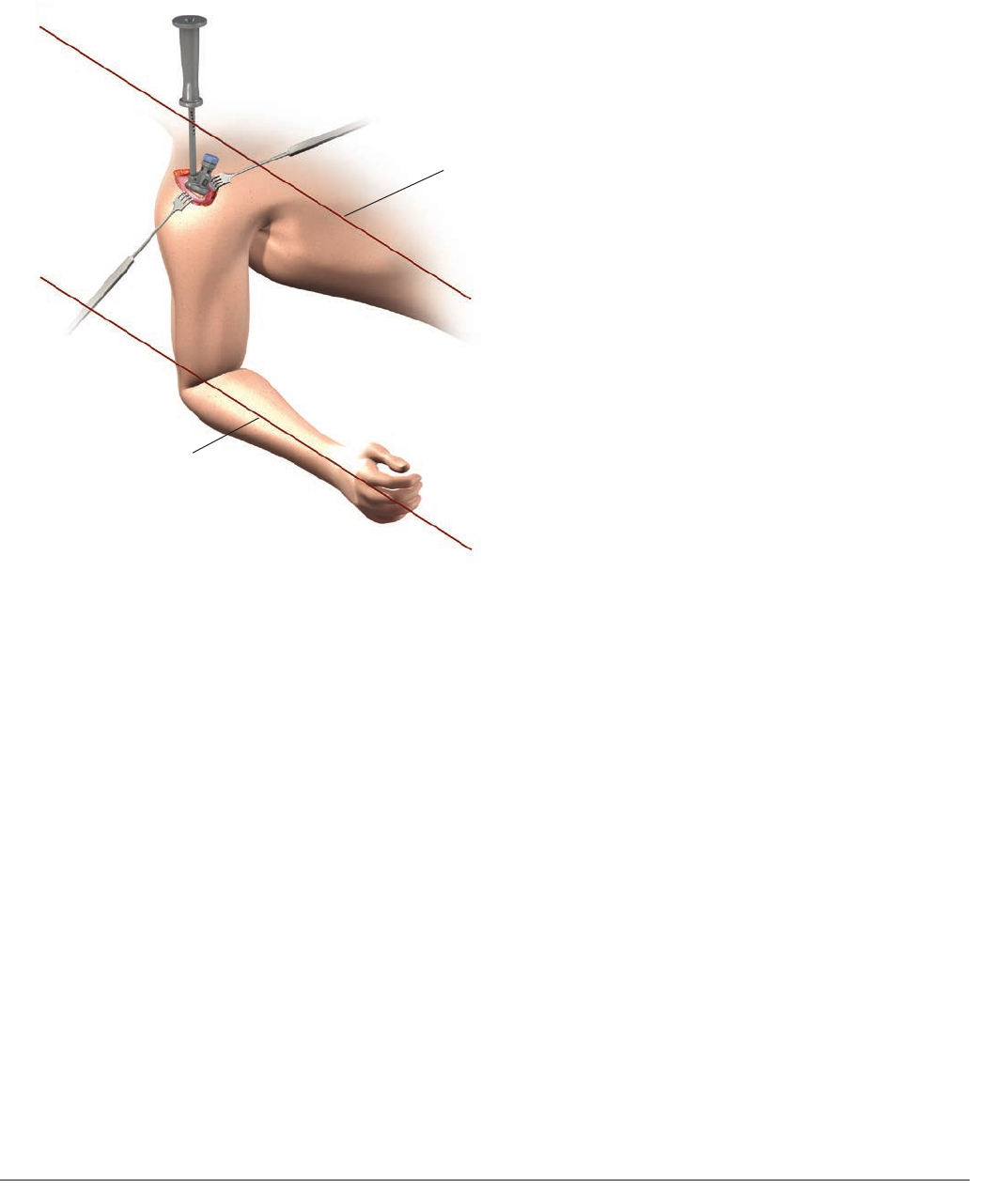
Surgical Technique DELTA XTEND™ DePuy Synthes Joint Reconstruction
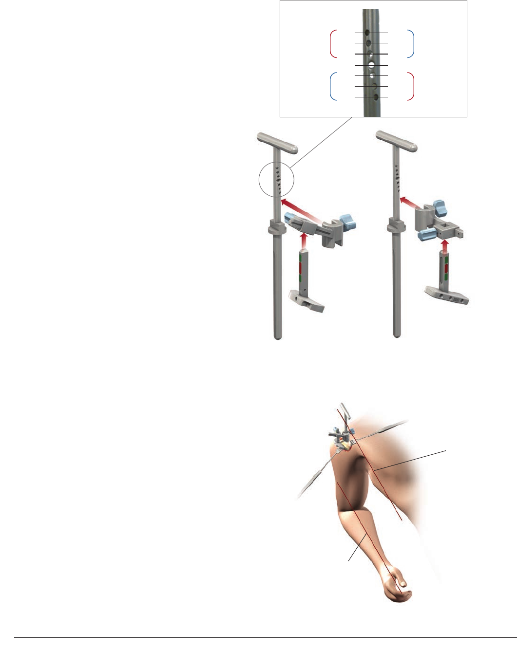
Forearm Axis
0 to 10° Retroversion
Superior-lateral Cutting
Guide Assembly
Delto-pectoral Cutting
Guide Assembly
Figure 14
HUMERAL HEAD RESECTION
Figure 13
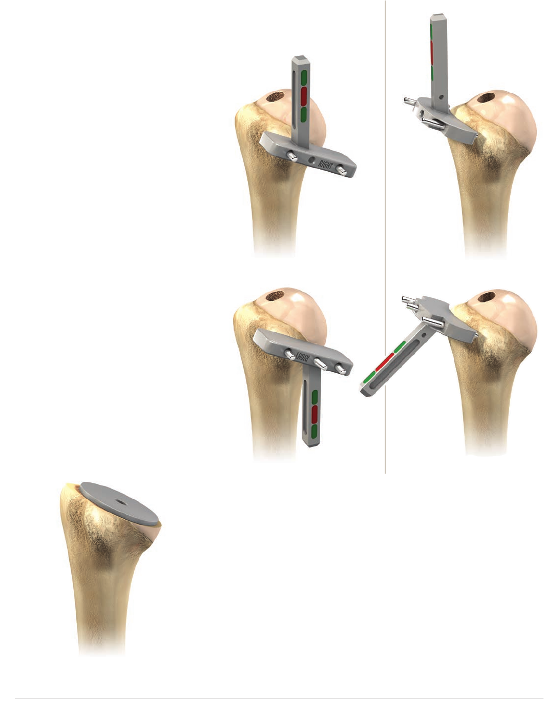
Select the handle for the cutting guide of the
appropriate size. Taking the previous example,
if reaming stopped at 12mm, select the 12mm
handle. Select the cutting guide and cutting
plate according to the surgical approach used
(superior-lateral or delto-pectoral).
Assemble the plate on the cutting guide
first (1) and then fix the cutting guide on the
cutting handle (2) (Figure13).
The cutting guide should be fully seated on
the cutting handle.
Drive the cutting assembly down the
intramedullary canal until it is fully in contact
with the top of the humeral head. The
orientation pin is then passed through the
hole in the cutting handle in the desired
retroversion. The retroversion is calculated
with reference to the forearm axis. This
should preferably be close to 0 to 10 degrees
since excessive retroversion can restrict joint
rotation, especially internal rotation. The
cutting handle should then be turned to align
the orientation pin and the forearm (Figure14).
(1)
(2) Cutting Guide
Cutting Guide Handle
Cutting Plate
(1)
(2)
Cutting Guide
Cutting Guide Handle
Cutting Plate
(1)
(2) Cutting Guide
Cutting Plate
Left Shoulder
Anteversion
Retroversion
Retroversion
Anteversion
Right Shoulder
30°
20°
10°
0°
10°
20°
30°
30°
20°
10°
0°
10°
20°
30°
1312 DePuy Synthes Joint Reconstruction DELTA XTEND™ Surgical Technique
Delto-pectoral ApproachSuperior-lateral Approach
Superior-lateral Cutting Plate Delto-pectoral Cutting Plate
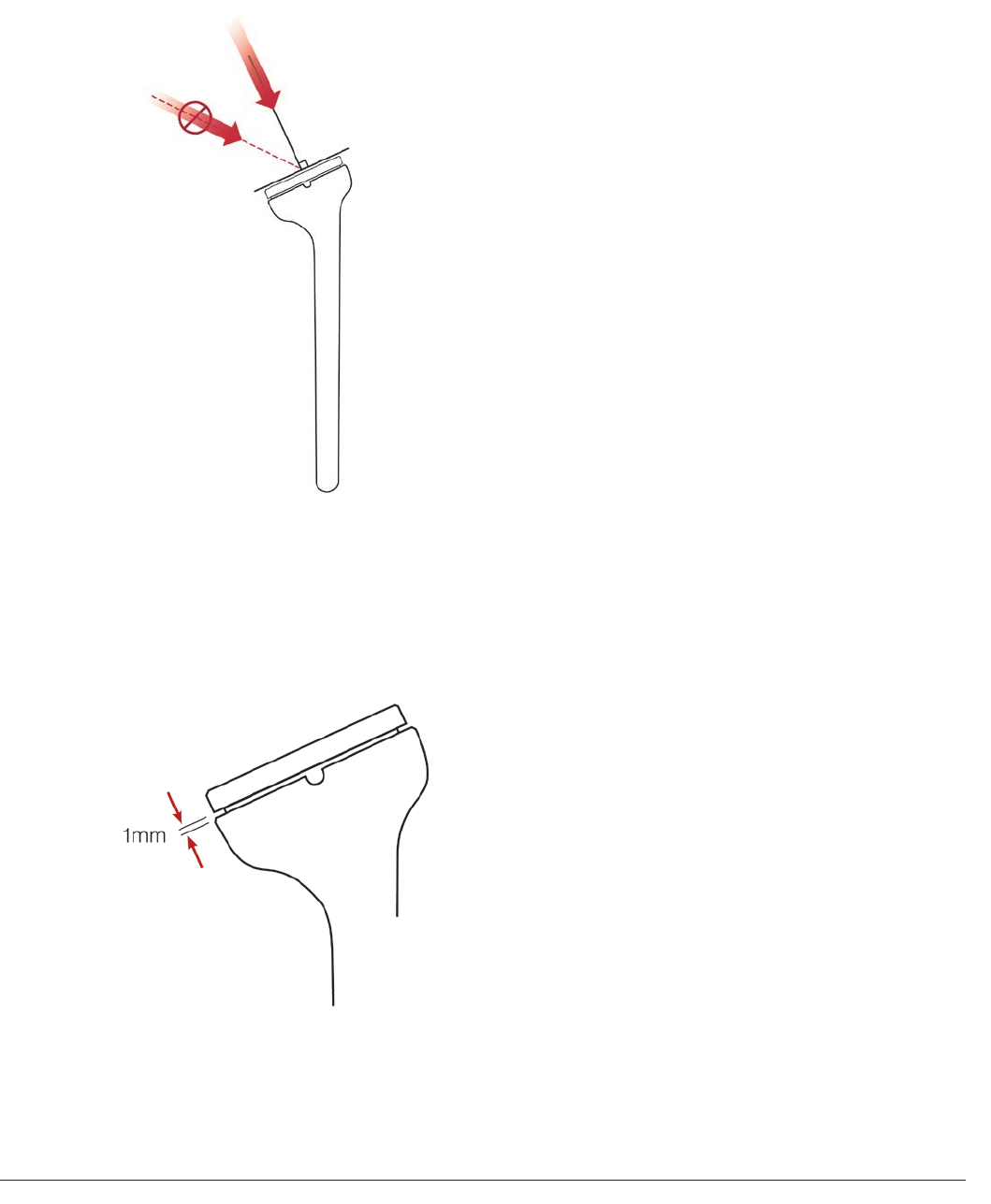
Slide the cutting plate to adjust the resection
level. The cutting plate color code shows if the
resection level is appropriate. If the cutting
level indicator is green, the guide is at the
correct height. If it is red, the cutting plate
needs to be adjusted (Figure 15).
Visually verify that the resection is 1 to 2mm
below the proximal area of the greater
tuberosity (at the level of the supraspinatus
insertion in an intact shoulder).
Note that the angle of the cut is 155 degrees
and therefore different from the anatomical
neck/shaft angle (135 degrees). This angle
gives optimal joint stability to the reverse
prosthesis.6
Pre-drill the cortical bone through the cutting
plate using a 3.2mm drill bit, and insert the
two fixation pins to fix the cutting plate to the
humerus (Figure 16).
Figure 16
Figure 15
13
Surgical Technique DELTA XTEND™ DePuy Synthes Joint Reconstruction
Delto-pectoral Approach Superior-lateral Approach
Remove the cutting guide and add a third
fixation pin through the cutting plate to secure
the assembly and resect the humeral head,
aligning the saw blade with the superior aspect
of the cutting plate (Figure 17, Step 1).
Note: The two external pins are parallel. The
cutting plate can therefore be turned upside
down before securing it with the third pin
to obtain a flat surface (Figure 17, Step 2).
Place a protecting plate on the humeral
resection surface to protect the bone from
damage during the following surgical steps
(Figure 18).
Pass a forked retractor under the scapula to
lower the humerus. If this provides a clear
view of the glenoid surface, the resection
level is correct. If not, a further humeral head
resection may be performed.
Figure 17
Figure 18
Step 2 Step 2
Step 1 Step 1
1514 DePuy Synthes Joint Reconstruction DELTA XTEND™ Surgical Technique
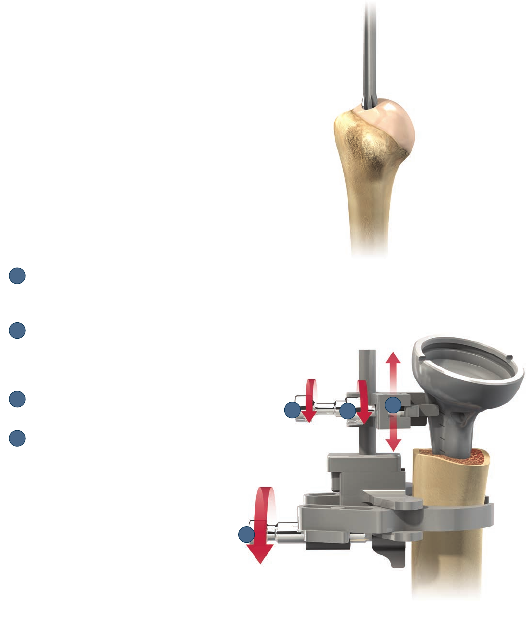
Figure 19
EXPOSING THE GLENOID
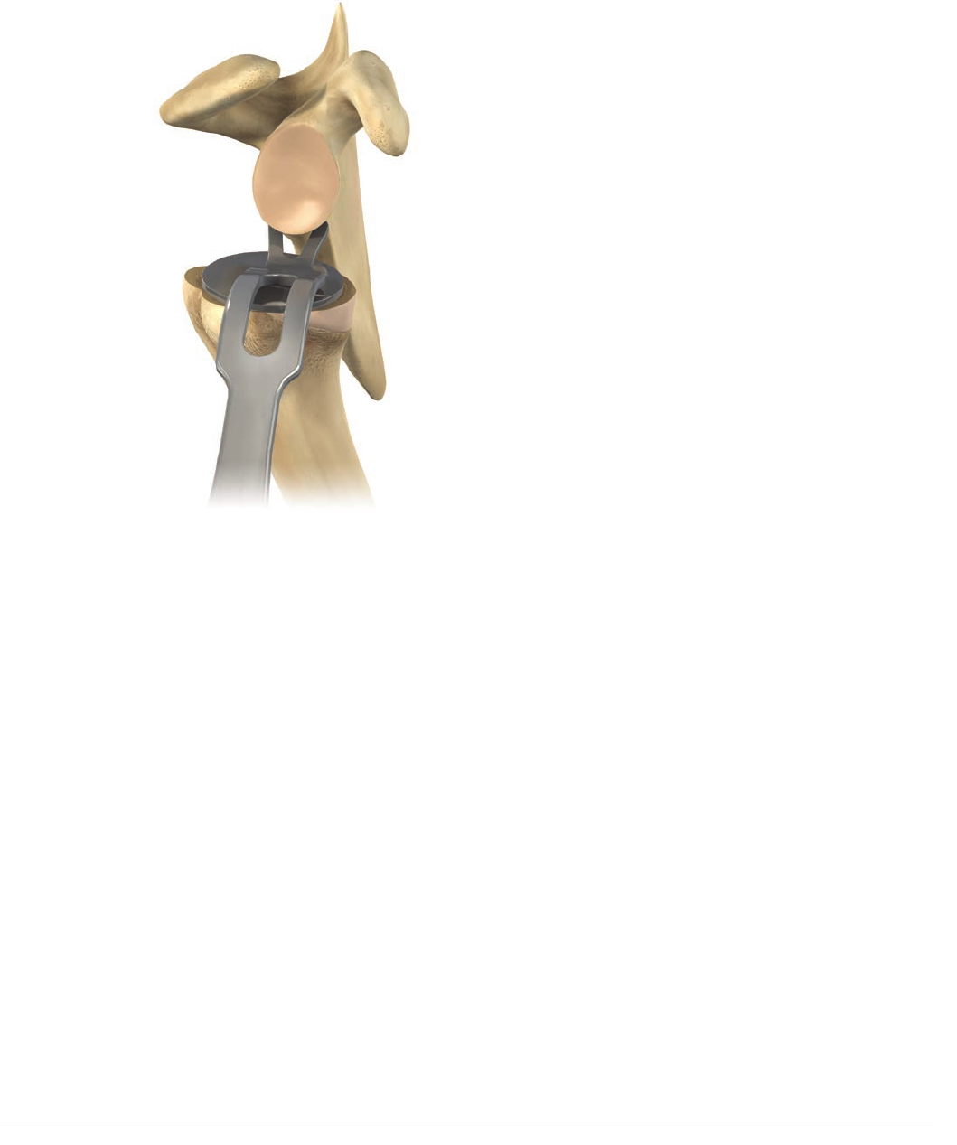
Position a forked retractor in the axillary
margin of the scapula under the inferior
glenoid labrum to move the humerus down or
backward, depending on the approach taken
(Figure 19).
When exposing the glenoid, it is critical to note
the presence of the axillary nerve and protect
it at all times. Excise the biceps remnant and
entire labrum. Release the entire capsule
from around the glenoid. In certain cases, the
capsule may have to be excised depending
on the extent of any contractures and the
adequacy of exposure. In some cases, the
origin of the triceps long head may be incised
from the infraglenoid tubercle.
Bluntly (finger or elevator) dissect in a
circumferential manner from the base of the
coracoid process to well beyond the most
inferior aspect of the glenoid. It is essential
to palpate the following osseous scapular
orientation points: the base of the coracoid
process, the inferior part of the glenoid neck
and, when possible, infra glenoid tubercle and
lateral border of the scapula. Retractors should
be placed so that the entire glenoid face is in
clear view to aid accurate placement of the
guide pin.

15
Surgical Technique DELTA XTEND™ DePuy Synthes Joint Reconstruction
Figure 20
Subscapularis Mobilization in
the Delto-pectoral Approach
Both sharp and blunt methods are used
to mobilize the subscapularis. Completely
release the rotator interval to the base of the
coracoid process and release the superior
border of the subscapularis from the base of
the coracoid process. Then completely release
the motion interface between the coracoid
muscles (conjoined tendon) and the anterior
subscapularis. Lastly, completely release the
posterior border of the subscapularis tendon
and distal muscle belly from the anterior and
anterior-inferior glenoid rim, glenoid neck and
the most lateral part of the scapular body.
Glenoid Preparation
Remove any remnants of labrum from the
glenoid. Then remove all articular cartilage
(large straight curette) from the glenoid face.
In addition, any osteophytes present may
also have to be removed to determine the
bony anatomy (Figure 20).
1716 DePuy Synthes Joint Reconstruction DELTA XTEND™ Surgical Technique
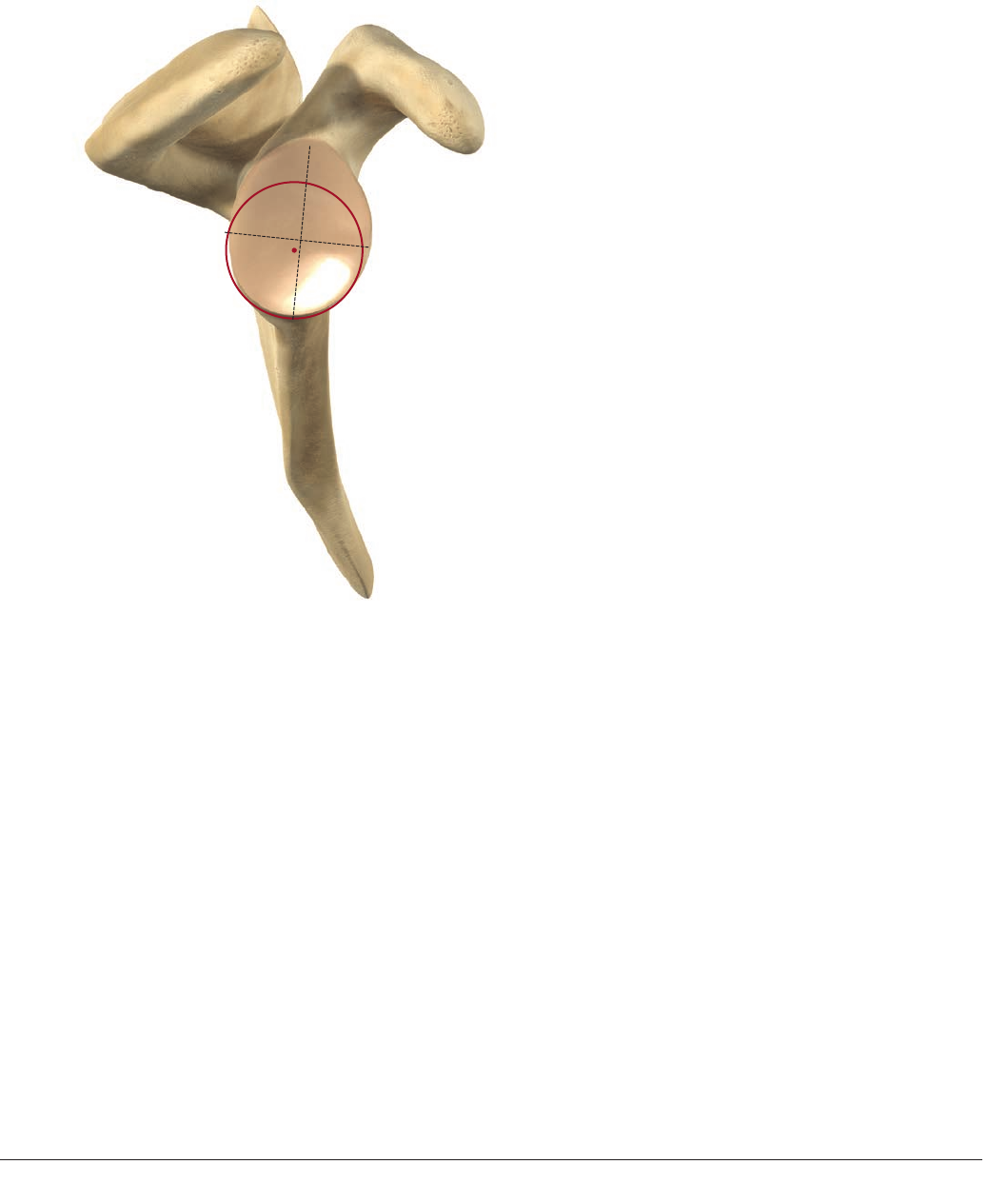
Positioning of the metaglene is important to
achieve an optimal glenoid fixation, to limit
potential bone impingement and to achieve a
final good, stable range of motion. Therefore,
particular attention should be given to that
surgical step.
The position chosen should maximize contact
with the glenoid bone surface and to allow
secure fixation of the screws in bone.
The metaglene should ideally be positioned
on the lower circular area of the glenoid bone.
The metaglene central peg is positioned in
the center of the inferior circle of the glenoid
(This point is often posterior and inferior to the
intersection of the glenoid axis) (Figure 21).
These anatomical reference points help to
position the metaglene as inferior as possible
on the glenoid bone in order to limit potential
bone impingement, while keeping a secure
glenoid implant fixation. However, radiographic,
CT images combined with X-ray templates
and pre-operative view can lead to a choice
of position a little bit more superior to obtain
fixation in good bone stock and complete
seating of the metaglene on the bone.
POSITIONING THE METAGLENE CENTRAL PEG
Figure 21
17
Surgical Technique DELTA XTEND™ DePuy Synthes Joint Reconstruction
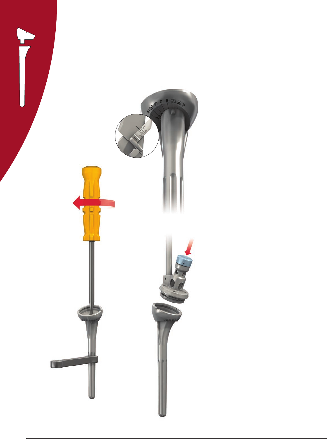
The metaglene positioner is used to obtain the
optimal metaglene position. The positioner
plate is the same diameter as the metaglene.
Assemble the positioner by inserting and
threading the internal rod into the positioner
handle (Figure 22).
Insert the hex head tip of the handle in
the corresponding plate hole (right or left
depending on the shoulder being operated
upon) and lock the assembly by tightening the
internal rod (Figure 23).
Note: The handle is set at an angle
of 20 degrees to the plate to ensure
optimal visibility (Figure 24).
Figure 22
Figure 24
Figure 23
20°
1918 DePuy Synthes Joint Reconstruction DELTA XTEND™ Surgical Technique
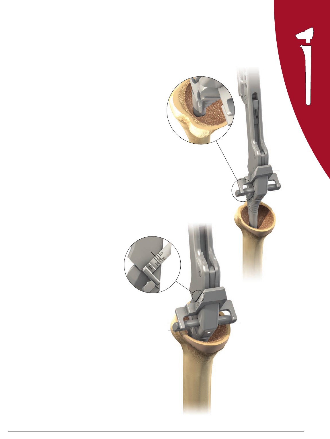
Position the plate as low as possible so that its
border follows the inferior edge of the glenoid.
Note that inferior osteophytes may result in
malpositioning. X-rays should therefore be
checked to avoid this problem.
Providing that the morphology of the glenoid
hasn’t been altered by the disease, the guide
plate is perpendicular to the plane of the
glenoid face. Make sure that the proximal
handle of the instrument is not tilted
superiorly. The guide pin should be inserted
either perpendicularly to the glenoid face
or with the distal tip of the guide pin in a
slightly superior direction. This ensures that
the glenosphere will either be perpendicular
to the plane of the glenoid face or have a
slight inferior tilt which may reduce the risk of
scapular notching.
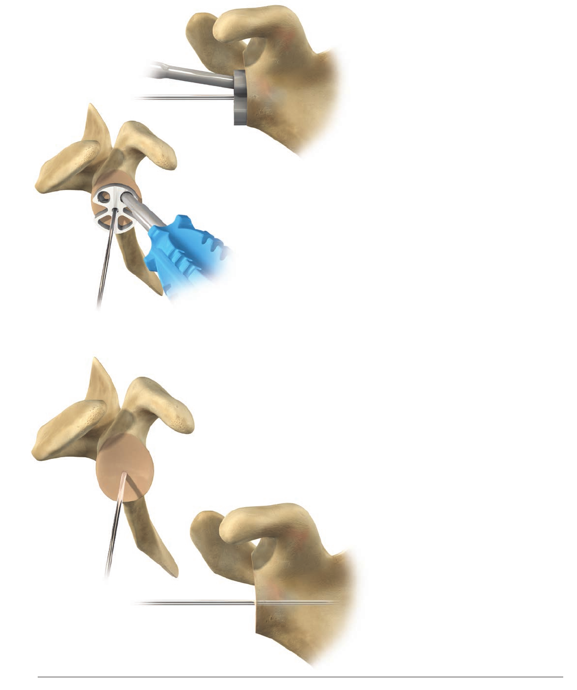
Place the 2.5mm metaglene central guide pin
in the plate is central hole and drill it through
the far cortex using a power tool (Figure 25).
Remove the metaglene positioner, leaving the
guide pin in place (Figure 26).
Note: The 2.5mm Breakaway Guide Pin (2230-
00-019) may be used as a substitute for the
Metaglene Central Guide Pin (2307-87-004).
The grooves on the 2.5mm Breakaway Guide
Pin are exclusively used for the breakaway
feature and are not intended to indicate the
depth to which the pin should be inserted.
The pin is designed to break at the grooves.
Be aware that it may break unintentionally
if subjected to too much bending force.
After use of the guide pin is complete, confirm
that all sections (totaling the full length of the
original, unbroken pin) have been removed.
Figure 25
Figure 26
19
Surgical Technique DELTA XTEND™ DePuy Synthes Joint Reconstruction
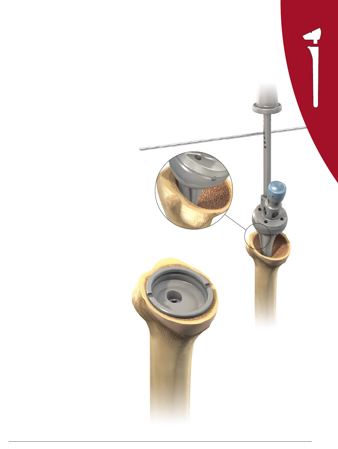
REAMING THE GLENOID BONE
Slide the 27mm glenoid resurfacing reamer
onto the central guide pin and ream either
manually or using a power tool. This reamer
prepares a smooth curved surface with the
same diameter as the metaglene (Figure 27).
Use the metaglene reamer carefully to avoid
any inadvertent fracturing of the glenoid,
especially if the glenoid is sclerotic. Make
sure the axillary nerve is protected. Initiate
and proceed with the reaming, turning at
low speed prior to engaging the glenoid.
It is useful to collect the osseous products
of reaming and irrigate often to maximize
visualization and thereby ensure optimal
reaming. Be careful not to over ream and to
preserve the subchondral bone.
Ream the superior glenoid bone by hand,
using the manual 42mm glenoid reamer
(Figure 28). This step is necessary to avoid any
potential conflict between the glenosphere
and the superior area of the glenoid bone
(Figure 29).
Manual reaming should be carried out until
the central part of the manual reamer is in full
contact with the curved central glenoid surface.
Figure 27
Figure 28
Figure 29
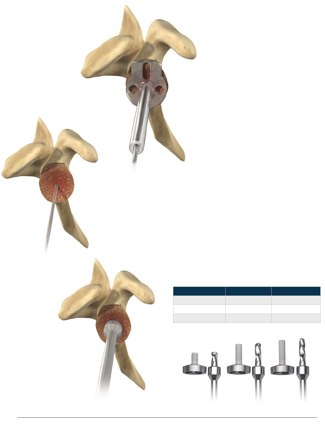
2120 DePuy Synthes Joint Reconstruction DELTA XTEND™ Surgical Technique
Standard
13.5mm
+10mm +15mm
Use the manual glenoid reamer to ream the
glenoid anteriorly, posteriorly and inferiorly
if necessary. A smooth surface without any
remaining cartilage should be obtained.
Check the adequacy of the reaming by
applying the glenoid reaming level checker on
the glenoid surface. No space (except if due
to bone erosion) should be seen between the
instrument and the glenoid surface (Figure 30).
Remove the resurfacing reamer, leaving the
metaglene central guide pin in place
(Figure 31).
Refering to the chart below, connect the
appropriate size cannulated stop drill to the
power source and drill the central hole over
the guide pin until full contact between the
drill and bone is obtained (Figure 32).
Remove the stop drill and the central guide pin.
Note: After use of the guide pin is
complete, confirm that all sections
(totaling the full length of the original,
unbroken pin) have been removed.
Figure 30
Figure 32
Figure 31
Size Metaglene Cannulated Drill
Standard (13.5mm) 1307-60-000 2307-89-000
+10mm 1407-60-020 2407-89-010
+15mm 1407-60-025 2407-89-015
21
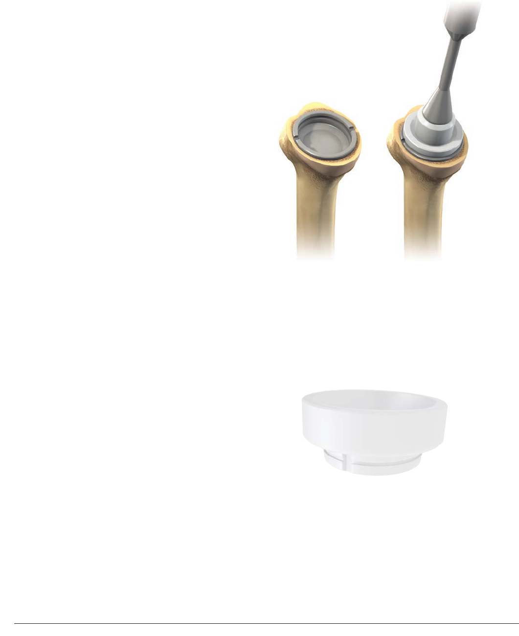
Surgical Technique DELTA XTEND™ DePuy Synthes Joint Reconstruction
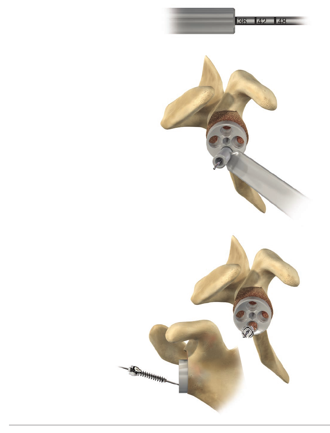
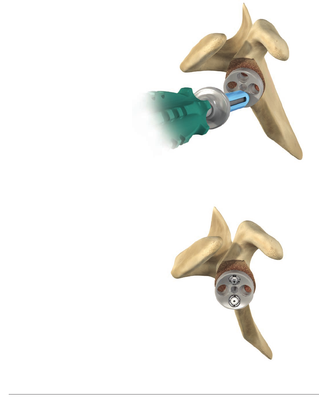
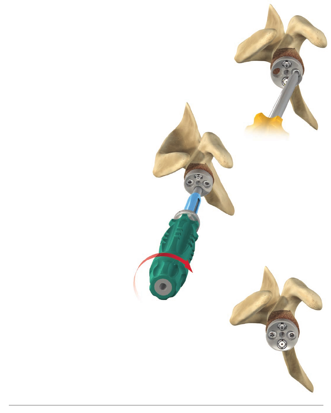
METAGLENE IMPLANTATION
Assemble the internal rod of the metaglene
holder in the metaglene holder main body.
Insert the metaglene holder hex tip in the
desired final metaglene implant central hole
and tighten the assembly. (Figure 33).
Place the metaglene on the glenoid bone
and ensure that the metaglene is fully
seated. Apply bone graft if necessary to
help fill surface irregularities between the
metaglene and the glenoid bone. Rotate the
metaglene so that the inferior screw can be
aimed toward the scapular neck. The vertical
metaglene marking should be aligned with
the scapular neck inferiorly and with the
base of the coracoid process superiorly (long
axis of the glenoid bone) (Figure 34). The
metaglene peg is 0.6mm larger in diameter
than the drill to enable a press fit. Gently
impact with a mallet in the proper orientation
for inferior screw placement and then remove
the metaglene holder.
Figure 33
Figure 34
2322 DePuy Synthes Joint Reconstruction DELTA XTEND™ Surgical Technique
Metaglene Superior-Inferior Cross Section
Polyaxial Locking Screws
17°
±10°
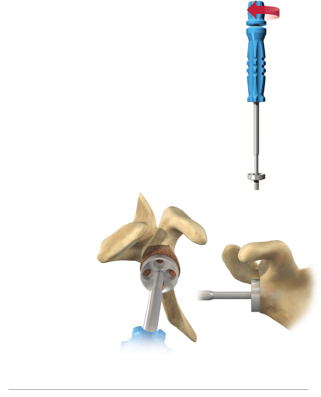
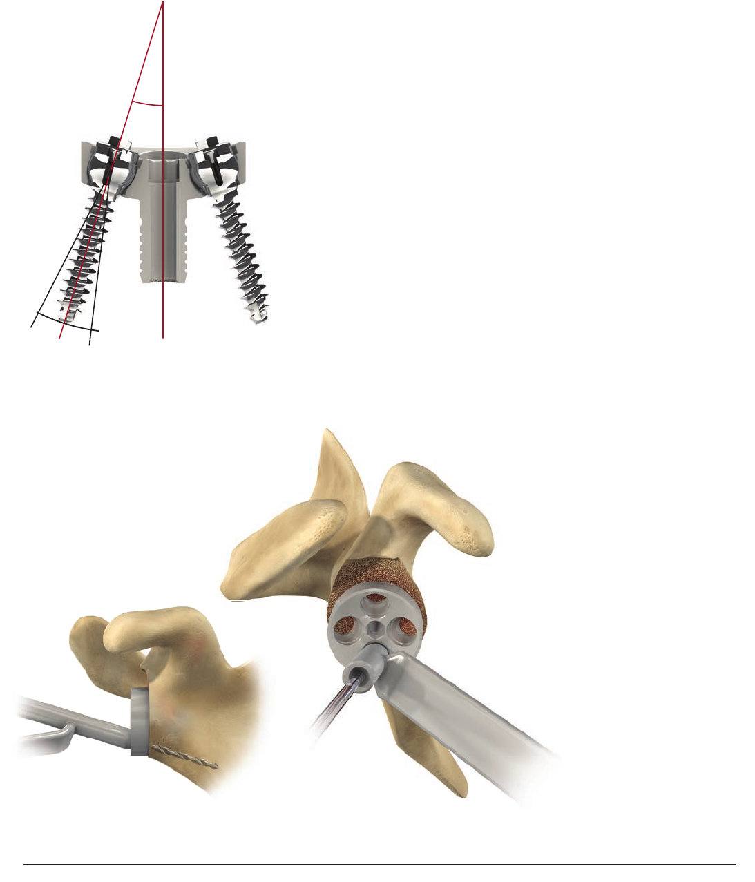
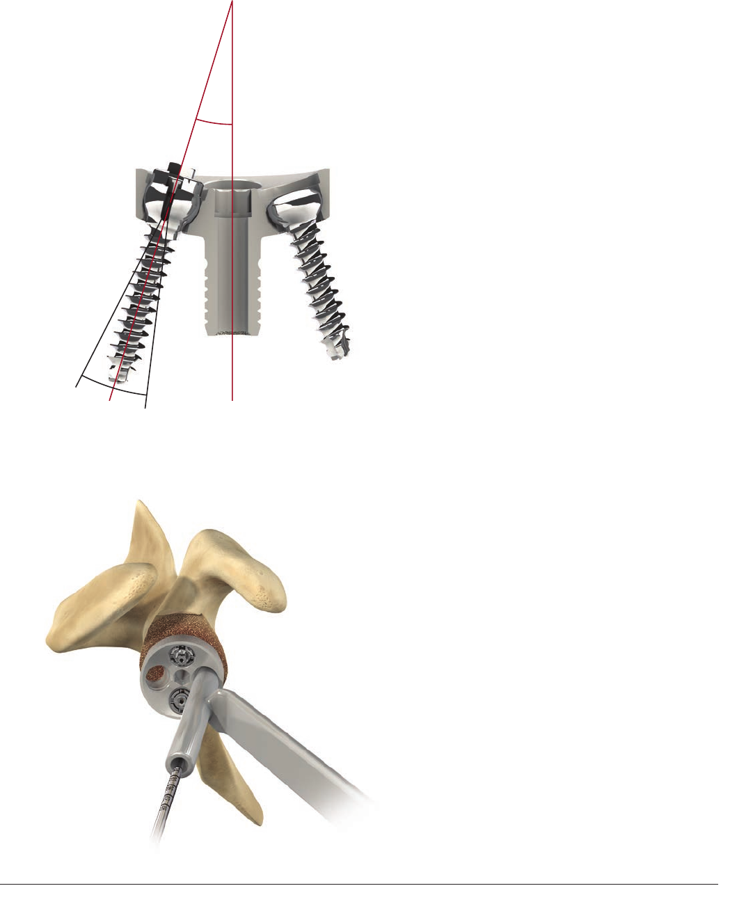
INFERIOR AND SUPERIOR METAGLENE
SCREW PLACEMENT
Locking metaglene screws allow an angulation
of ± 10 degrees around the optimal 17
degrees screw positioning recommended by
Professor Grammont (Figure 35).
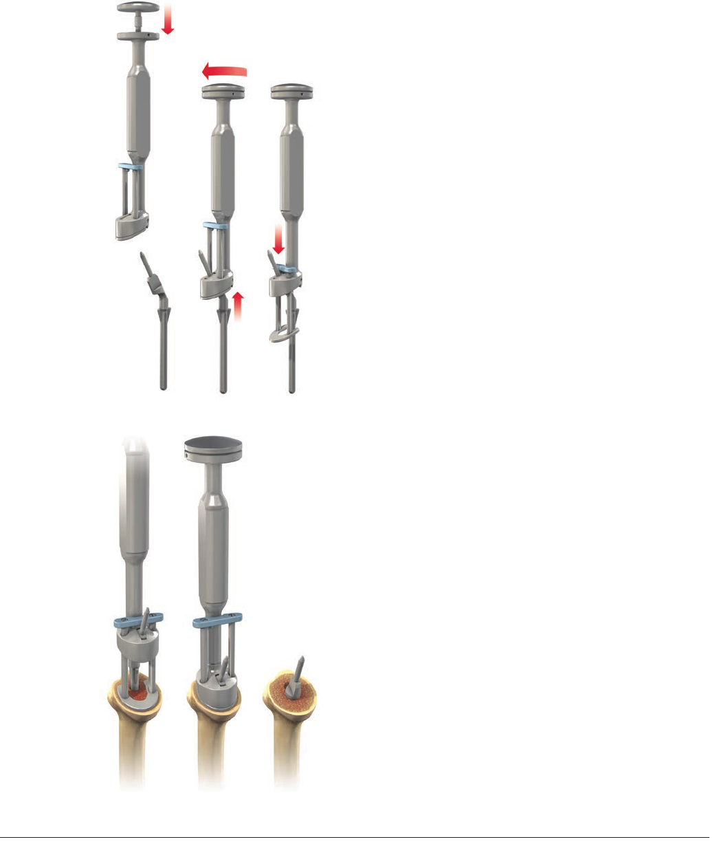
Place the 2.5mm drill guide in the metaglene
inferior hole. The drill guide can be angled
to ± 10 degrees but should always be seated
fully in the metaglene hole. Palpate the
scapular neck and aim into good bone. Using
the 2.5mm drill bit, start drilling through
the subchondral bone to aproximately 10 to
12mm deep (Figure 36). Then stop drilling and
push gently on the drill bit to make sure that
the drill is contained in the bone. Redirect and
redrill if uncontained. When a satisfactory
drilling direction has been obtained, drill and
push until the cortex is perforated.
Figure 35
Figure 36
23
Surgical Technique DELTA XTEND™ DePuy Synthes Joint Reconstruction
The goal is to have a sufficiently long screw
inferiorly, usually 36mm or more. The length
of the screw is indicated on the drill bit by
laser markings (Figure 37). The screw depth
gauge can also be used to assess optimal
screw length.
Insert the 1.2mm guide pin through the
drill guide and then remove the drill guide
(Figure38).
Slide the locking screw of the appropriate
length onto the guide pin. Check that the
internal tightening screw is unlocked (it should
rotate freely) (Figure 39).
Figure 38
Figure 39
Figure 37
2524 DePuy Synthes Joint Reconstruction DELTA XTEND™ Surgical Technique
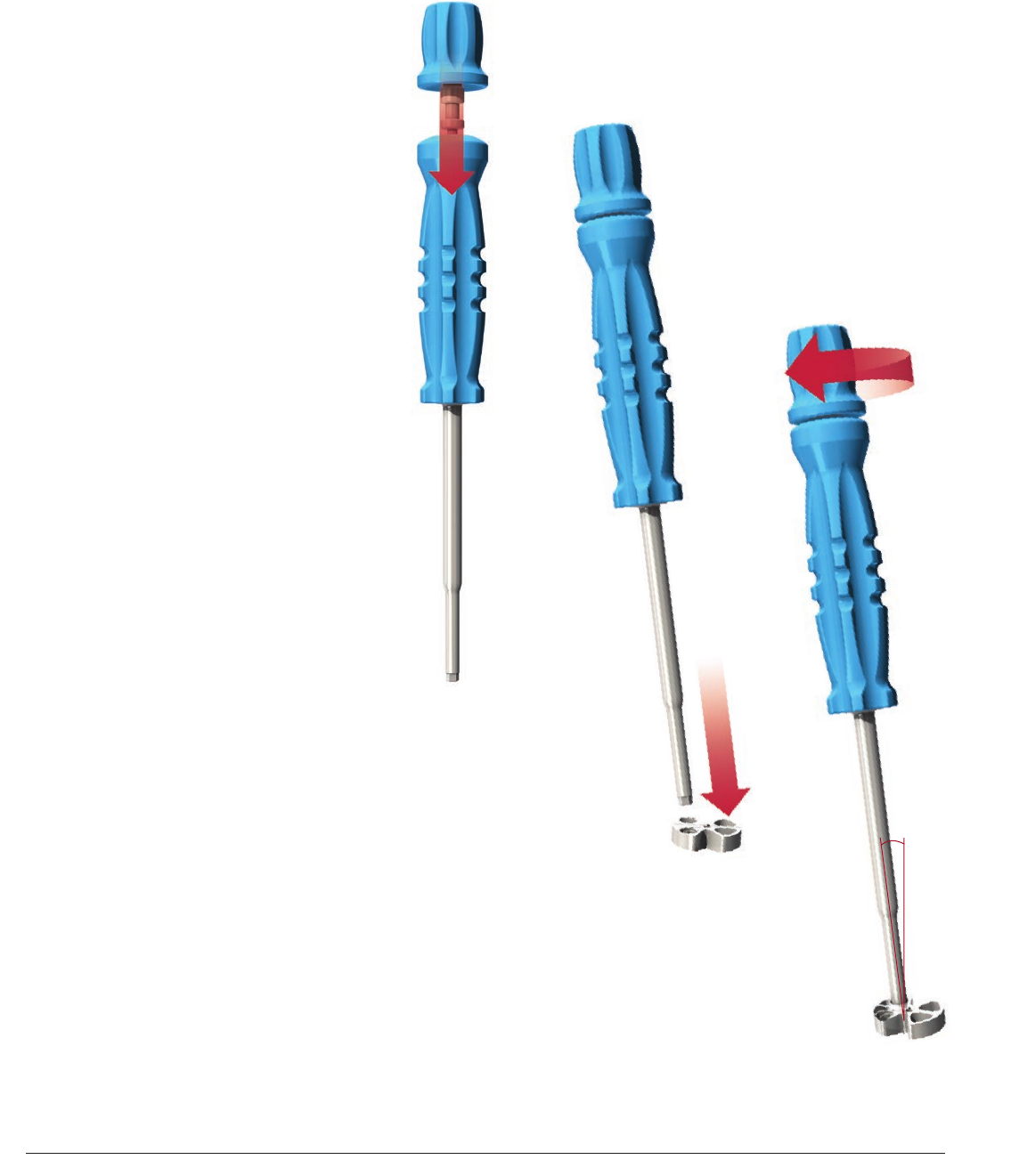
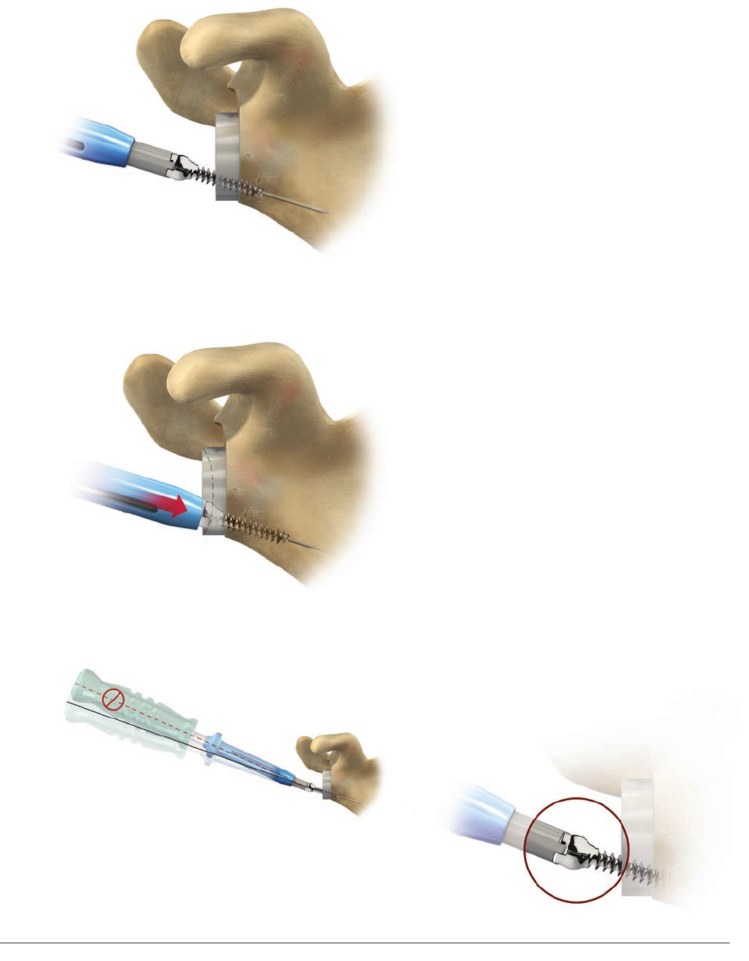
Slide the locking screwdriver body on the
guide pin and insert the tip into the four slots
on the screw (Figure 40). Do not use the
internal screwdriver rod at this stage.
Note: Slide down the screwdriver sleeve
completely to protect the screw head.
Tighten the screw to compress the plate
(Figure 41a).
Remove the screw guide pin with the pin
extractor before final tightening to avoid
stripping, making sure that the internal locking
screw stays in place.
Repeat the same steps for the superior
locking screw.
Note: Use care to ensure that the
driver remains in axial alignment
with the screw so that the driver tip
remains fully engaged (Figure 41b).
Note: The tip of the screwdriver can
lose contact with the fins and does not
torque evenly on all sides if the protecting
sleeve is not used (Figure 41c).
Note: The protecting sleeve is not designed
to lock onto the screw. It must be held
in place with a finger during insertion.
Figure 41a
Figure 41b
Figure 41c
Figure 40
25
Surgical Technique DELTA XTEND™ DePuy Synthes Joint Reconstruction
Figure 43
Figure 42
Drill the hole for the superior locking screw
anticipating exit through the far cortex using
the same methods as Figure 36 (inferior
screw placement) (Figure42). The superior
screw should be directed at the base of the
coracoid process and should have an anterior
orientation to avoid the suprascapular nerve.
To obtain optimal compression of the
metaglene plate on bone, alternate tightening
of the superior and inferior locking screws
(Figure 43).
Note: Use care to ensure that the driver
remains in axial alignment with the screw so
that the driver tip remains fully engaged.
2726 DePuy Synthes Joint Reconstruction DELTA XTEND™ Surgical Technique
Metaglene Anterior-Posterior Cross Section
Polyaxial Locking or Non-locking Screws
17°
±10°
The surgeon may use locking or non-locking
screws in the anterior or posterior holes. Both
types of screws will allow an angulation of
up to ± 10 degrees, but not in a direction
convergent to the central peg axis to avoid
conflict with the central peg (Figure 44).
Use the 2.5mm drill bit with the drill guide to
set the most appropriate angle for ensuring
that each screw is located in reliable bone
stock (Figure 45).
The preferred position is usually chosen by
palpating the anterior and posterior aspects
of the scapula as well as examining the X-rays
and CT scans. Drill in the direction of the
central glenoid vault in an attempt to maximize
the anterior and posterior compression screw
lengths, in a direction parallel to or divergent
from the central peg.
Figure 44
Figure 45
ANTERIOR AND POSTERIOR METAGLENE
SCREW PLACEMENT
27
Surgical Technique DELTA XTEND™ DePuy Synthes Joint Reconstruction
Screw length is determined from the laser marks
on the drill bits or by using the depth gauge.
Slide the corresponding screws onto the guide
pin and tighten using the 3.5mm cannulated
hex screwdriver for non-locking screws or
the locking screwdriver for locking screws
(Figure46).
Follow the same procedure for the posterior
screw, then alternately tighten both screws
until they are fully tightened.
Proceed with locking all variable angle
screws used. Place the locking screwdriver
main body in the head of the inferior screw.
Make sure that the screwdriver sleeve is in its
upper position and not in contact with the
screw head.
Slide the locking screwdriver internal rod into
the main body. The tip of the internal rod will
make contact with the screw head. Tighten it
fully, locking the screw in place by expanding
its head (Figure 47).
Note: After inserting all four screws, tighten
the locking screws with the internal rod
for the locking screwdriver. Pull the sleeve
up and off the screw head for this step.
Repeat the same steps to secure the superior
locking screw and anterior or posterior screws
if variable angle screws have been used.
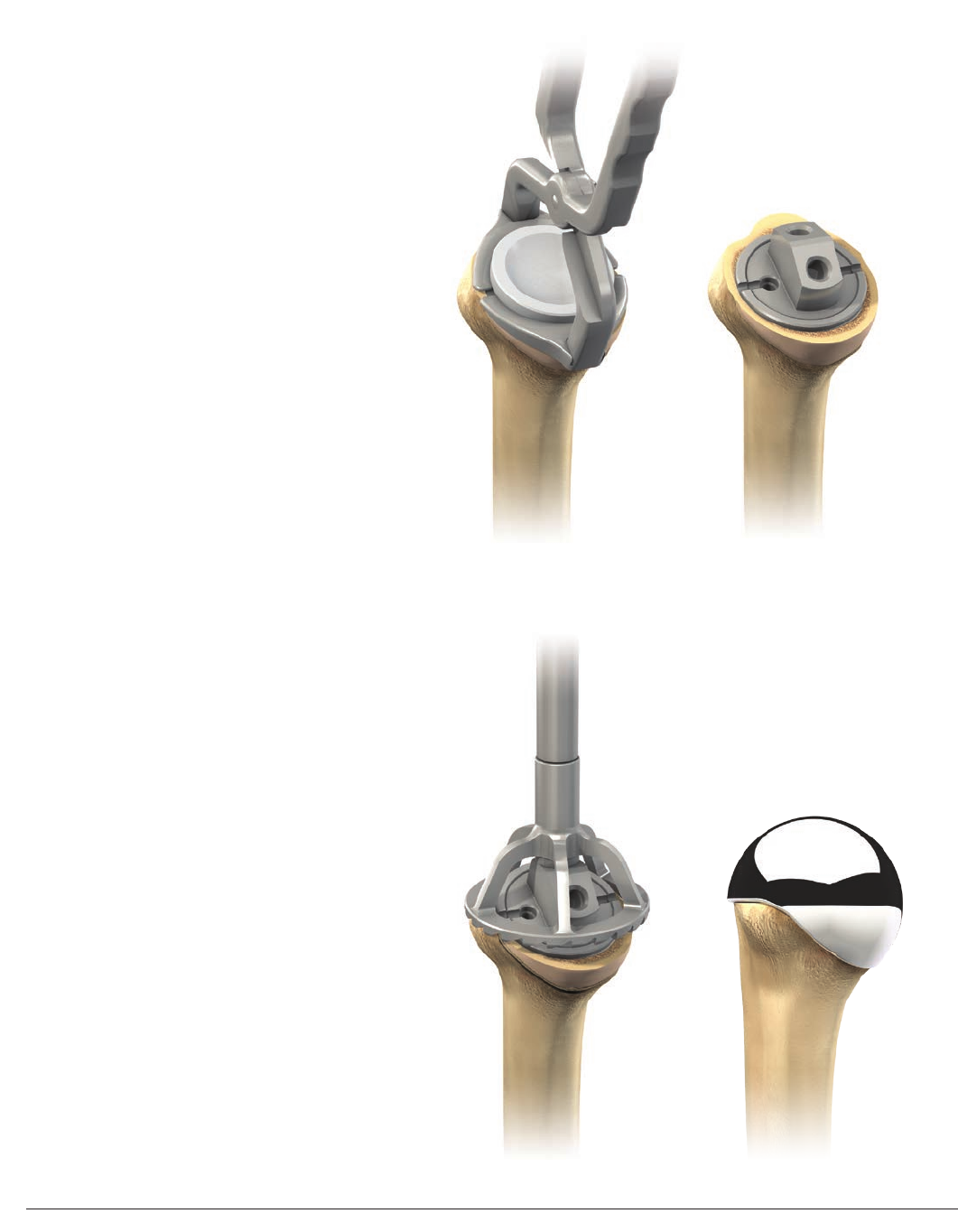
The metaglene is left in place (Figure 48) and
the humeral preparation is then carried out.
Figure 46
Figure 48
Figure 47
2928 DePuy Synthes Joint Reconstruction DELTA XTEND™ Surgical Technique
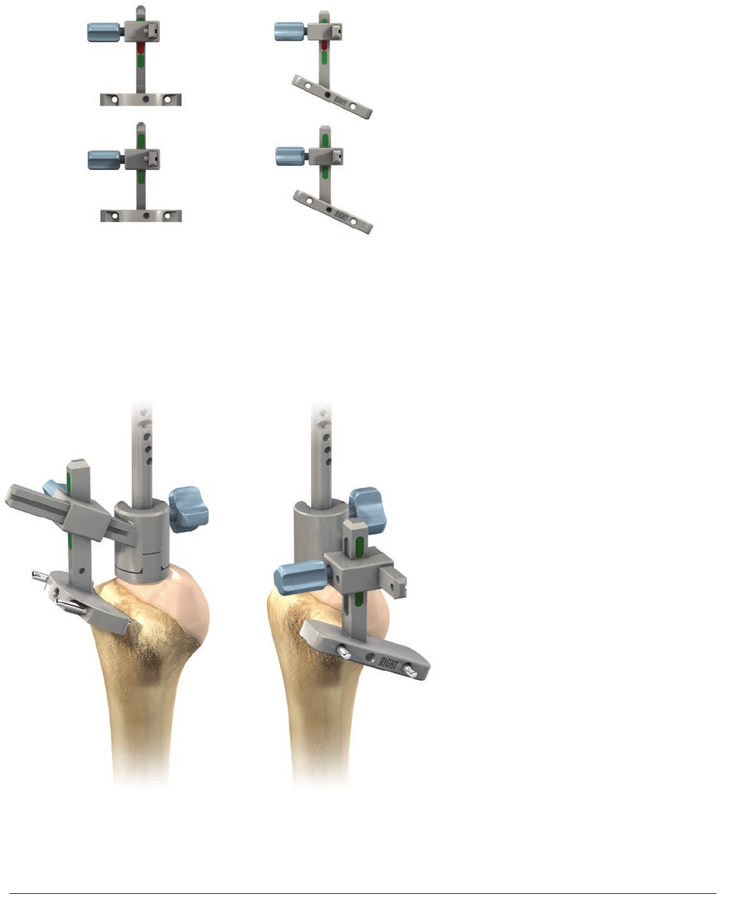
PLACEMENT OF THE PROXIMAL
HUMERAL REAMING GUIDE
Cemented Monobloc Humeral Implants and
Cementless Modular Humeral Implants Select the appropriate proximal reaming
guide size (Figure 49). For example, if a 12mm
intramedullary reamer and a 12mm cutting
handle were previously used, select the 12mm
proximal reaming guide.
Slide and screw the internal rod of the reaming
guide holder into the holder main body. Then
slide the reaming guide into the reamer holder
and fasten the two parts together by firmly
tightening the upper round handle (Figure 50).
Push the holder horseshoe plate fully down
(Figure 51).
Slide the proximal reaming guide down
into the intramedullary canal, rotating it
if necessary to ensure that the horseshoe
plate sits flat on the bone resection surface
(Figure52).
Drive the proximal reaming guide down until
complete contact between the metal block
and the resectioned bone surface is achieved
(Figure 53).
Unscrew the upper round handle of the holder
and remove the holder, leaving the proximal
reamer guide in place (Figure 54).
The subsequent surgical steps depend on
whether the humeral implant is cementless
or cemented. For cementless implants, see
pages 33-37. For cemented implants, see
pages 38-39.
Figure 52 Figure 53 Figure 54
Figure 49 Figure 50 Figure 51
29
Surgical Technique DELTA XTEND™ DePuy Synthes Joint Reconstruction
MAKE SURE YOU ARE USING THE DEDICATED INSTRUMENTS
FOR CEMENTLESS MODULAR IMPLANTS
PROXIMAL HUMERAL REAMING
Cementless Modular Humeral Implants
Figure 55
Figure 56
Centered Adaptor
Size 1 & 2
Disk Size 1
Disk Size 2
Eccentric Adaptor
Size 1
Eccentric Adaptor S1
Disk Size 1
ADEQUATE BONE
COVERAGE Eccentric Adaptor S2
Disk Size 2
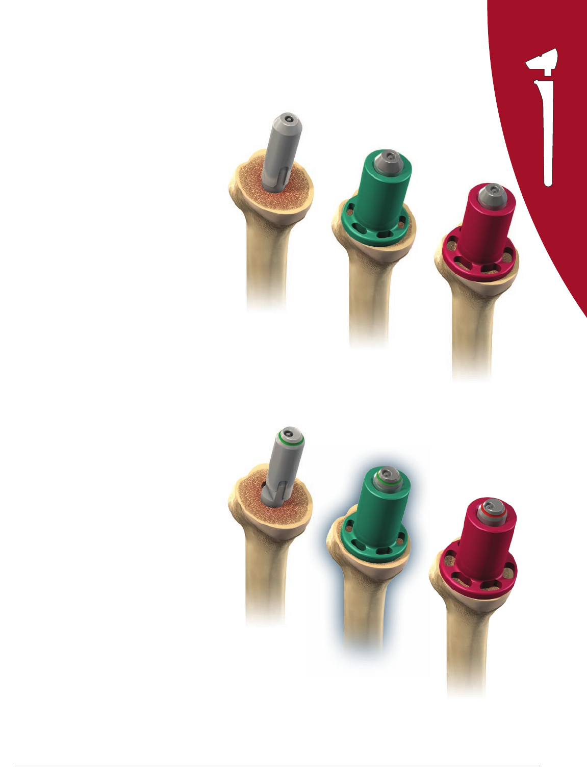
The cementless modular implant is designed
to allow the surgeon to place the epiphysis in
anatomic version and the stem in anatomic
version for an optimal press-fit.
The size and type (centered or eccentric) of
modular epiphysis should be chosen to ensure
that the best possible coverage of the bone
resection surface is achieved.
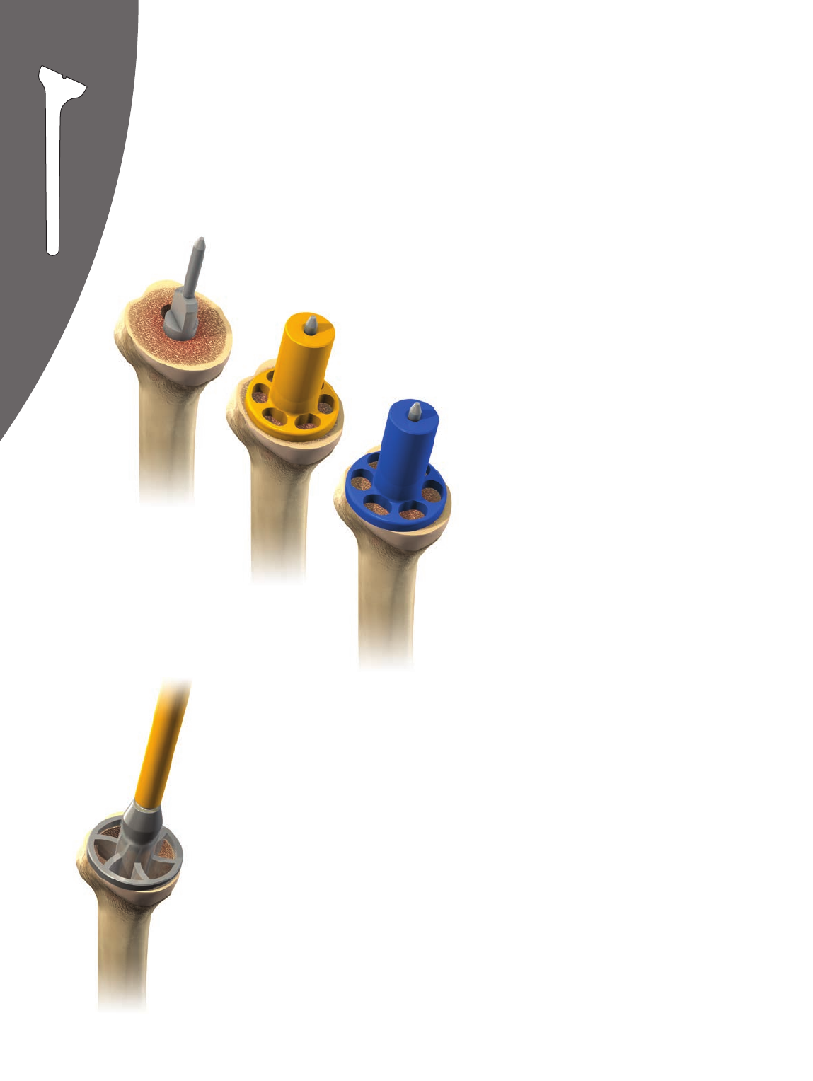
First select the centered proximal modular
reamer adaptor, and place it on the reaming
guide’s angled pin.
Choose the most appropriate epiphysis size
using the modular implant sizer disks, size 1
or 2. The sizer disk chosen should provide the
best coverage of the bone resection surface
without overhang (Figure 55).
If this does not provide a good fit with the
bone resection surface, switch the centered
proximal modular reamer adaptor for the
eccentric adaptor in size 1. Be careful to
position the eccentricity so that it is posterior
and not anterior, double checking with the
markings (anterior and posterior) on the
adaptor.
Then check the epiphysis size again with sizer
disk 1. If the bone coverage is not sufficient,
use eccentric adaptor size 2 and sizer disk size 2
(Figure 56).
Remember the final decision made, with
respect to the centered or eccentric epiphysis
and size 1 or 2, will determine reamer and final
implant sizes.
CEMENTLESS
MODULAR

3130 DePuy Synthes Joint Reconstruction DELTA XTEND™ Surgical Technique
MAKE SURE YOU ARE USING THE DEDICATED INSTRUMENTS
FOR CEMENTLESS MODULAR IMPLANTS
PROXIMAL HUMERAL REAMING
Cementless Modular Humeral Implants
Figure 57
Figure 58
Remove the sizer disk, leaving the proximal
modular reamer adaptor in place (Figure 57).
Select the appropriate proximal modular
reamer in size 1 or 2, according to the results
of the previous trials. Ream using a power
tool. Power reaming should always be carried
out carefully.
Complete reaming is achieved when the
external reamer flange is in full and complete
contact with the bone resection surface
(Figure58).
When the proximal reaming has been
completed, first remove the reaming adaptor.
Then remove the reaming guide using the
reaming guide holder. If any bone remains in
the center of the epiphysis, remove it.
CEMENTLESS
MODULAR
31
Surgical Technique DELTA XTEND™ DePuy Synthes Joint Reconstruction
Goniometer
MAKE SURE YOU ARE USING THE DEDICATED INSTRUMENTS
FOR CEMENTLESS MODULAR IMPLANTS
DISTAL HUMERAL BROACHING
Cementless Modular Humeral Implants
Figure 59
Rocking Bar Contact
Contact
Figure 60
The stem size will have been determined
from the previous intramedullary reaming. If
the 12mm intramedullary reamer has been
used, select the 12mm broach and attach it
to the broach handle. Make sure that the
goniometer is in place on the broach handle.
Drive the broach into place, carefully checking
that its anterior fin is aligned with the anterior
aspect of the bicipital groove. This will ensure
good distal stem orientation (anatomic version)
for an optimized press-fit (Figure 59).
Drive the broach down carefully, (to avoid any
cortical bone damage) until the rocking bar of
the broach handle is in full contact with bone,
both at the anterior and posterior aspects of
the resection surface (Figure 60).
If there is a cortical bone damage where the
rocking bar should contact bone, place the
broach handle plate on the resection.
Read the adjustment angle which is indicated
on the instrument.
CEMENTLESS
MODULAR
3332 DePuy Synthes Joint Reconstruction DELTA XTEND™ Surgical Technique
MAKE SURE YOU ARE USING THE DEDICATED INSTRUMENTS
FOR CEMENTLESS MODULAR IMPLANTS
HUMERAL TRIAL STEM AND
EPIPHYSIS INSERTION
Cementless Modular Humeral Implants
Figure 61
Figure 63
Figure 62
The trial modular epiphysis (centered or
eccentric, size 1 or 2, depending on the
proximal reaming choices made) is placed on
the trial modular stem (diameter chosen during
distal reaming and broaching).
The epiphysis position corresponds to the
adjustment angle previously read on the
broach handle goniometer. For example, if 20
degrees right was read on the goniometer, the
epiphysis hole marked 20 degrees right should
be positioned in line with the stem orientation
peg (Figure 61).
Note: This angulation corresponds to the
difference between the version of the stem
(close to anatomical retroversion – 20 to 30
degrees) and the epiphysis version for a reverse
shoulder (close to 0 degrees retroversion).
No calculation is required: the
instrumentation has been designed to
provide direct measurement of this position
on the goniometer.
The two components are then screwed
together using the 3.5mm hex screwdriver
and the special locking wrench for modular
implants (Figure 62).
Both components are then mounted on the
humeral implant driver by pushing and then
releasing the blue button (Figure 63).
CEMENTLESS
MODULAR
33
Surgical Technique DELTA XTEND™ DePuy Synthes Joint Reconstruction
MAKE SURE YOU ARE USING THE DEDICATED INSTRUMENTS
FOR CEMENTLESS MODULAR IMPLANTS
HUMERAL TRIAL STEM AND
EPIPHYSIS INSERTION
Cementless Modular Humeral Implants
Figure 64
The component is then driven down the
intramedullary canal, aligning the anterior fin
of the stem with the bicipital groove.
The implant orientation can also be checked
using the orientation pin placed in the implant
driver handle. The pin should be placed in the
same retroversion position used to position
the cutting guide, i.e. close to 0 degrees
retroversion. The orientation pin should then
be aligned with the forearm axis and the trial
implants driven down (Figure 64).
Impact the trial implant by gently tapping
in the implant driver handle and remove
the driver, leaving the trial implant in place
(Figure65). The driver is detached by pushing
the blue button.
Figure 65
CEMENTLESS
MODULAR
3534 DePuy Synthes Joint Reconstruction DELTA XTEND™ Surgical Technique
MAKE SURE YOU ARE USING THE DEDICATED INSTRUMENTS
FOR CEMENTED MONOBLOC HUMERAL IMPLANTS
PROXIMAL HUMERAL REAMING
Cemented Monobloc Humeral Implants
Figure 66
Figure 67
Disk Size 1
The monobloc implant size should be chosen
to match the initial distal reaming diameter.
Choose the most appropriate epiphysis size
by placing a monobloc implant sizer disk in
size 1 or 2 on the proximal reaming guide.
The most appropriate size will be the sizer disk
that provides the best possible coverage of the
bone resection surface (Figure 66).
The size chosen, epiphysis size 1 or 2, will
determine proximal reamer and final
implant sizes.
Remove the sizer disk.
Select the appropriate proximal reamer for the
monobloc implant, size 1 or 2, from the results
of the previous trials. Ream the metaphysis
using a power reamer (Figure 67).
Complete reaming is achieved when the
external reamer flange is in full and complete
contact with the bone resection surface.
When the proximal reaming has been
completed, remove the reaming guide using
the reaming guide holder.
CEMENTED
MONOBLOC

35
Surgical Technique DELTA XTEND™ DePuy Synthes Joint Reconstruction
MAKE SURE YOU ARE USING THE DEDICATED INSTRUMENTS
FOR CEMENTED MONOBLOC HUMERAL IMPLANTS
HUMERAL TRIAL IMPLANT INSERTION
Cemented Monobloc Humeral Implants
Figure 68
Figure 69
Select the appropriate trial humeral implant.
For example, if the initial distal reaming was
carried out using the 12mm reamer and
proximal reaming was carried out using the
size 1 proximal reamer, select monobloc
humeral trial epiphysis number 1 with
diameter 12mm.
Mount the trial implant on the humeral
implant driver and drive it down the
intramedullary canal.
The implant orientation should be checked
using the orientation pin placed in the implant
driver handle. The pin should be placed in the
same retroversion position used to position
the cutting guide, i.e. close to 0 to 10 degrees
retroversion. The orientation pin should then
be aligned with the forearm axis and the trial
implants driven down (Figure 68).
Impact the trial implant by gently tapping
the implant driver handle and remove the
driver, leaving the trial implant in place
(Figure 69). The driver is detached by
pushing on the blue button.
Forearm
Axis
1 to 10°
Retroversion
CEMENTED
MONOBLOC
3736 DePuy Synthes Joint Reconstruction DELTA XTEND™ Surgical Technique
Figure 71
Figure 72
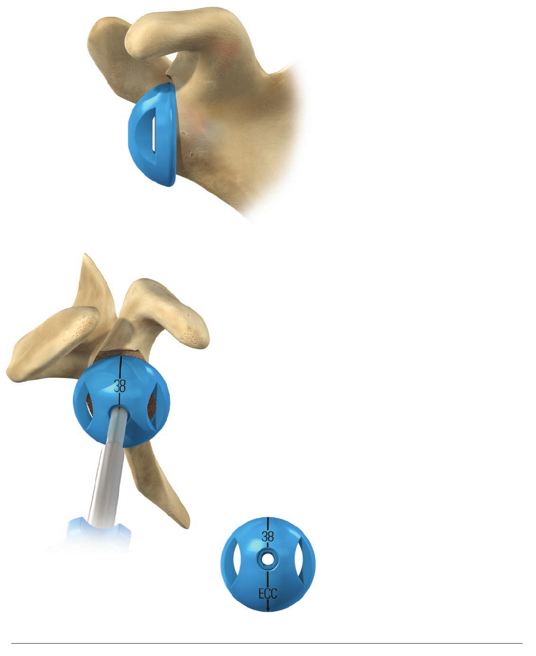
GLENOSPHERE TRIAL PLACEMENT
Figure 70
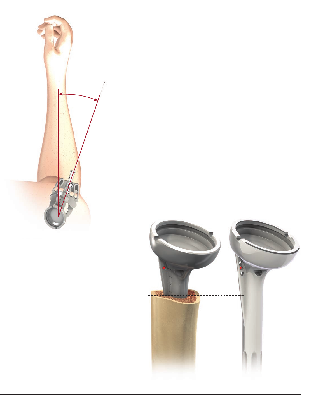
The glenosphere implants are available in
two diameters, 38 and 42mm, and are either
standard or eccentric spheres.
An overlap of 3 to 5mm is recommended to
avoid conflict with the scapular neck (Figure 70).
Depending on the shape of the scapular neck,
this overlap can be achieved by using a standard
metaglene just by lowering the metaglene.
The 42mm glenosphere is recommended if
the size of the joint allows (increases both the
overlap and the range of motion). The eccentric
glenospheres are recommended for more
transverse scapular necks.
Fit the appropriate trial glenosphere (38mm
or 42mm, centered or eccentric) to the the
metaglene using the metaglene holder
(Figure71). The trial glenosphere utilizes an
interference fit to make the connection with
the metaglene.
For eccentric glenospheres, the vertical
laser mark on the trial glenosphere should
be aligned with the base of the coracoid
superiorly and the scapular neck inferiorly
(Figures 71 and 72).
The arrow indicates the position of the
eccentricity and should be positioned inferiorly,
aligned with the scapular neck (Figures 72).
Note: If it is difficult to place the glenosphere
trial, then check to ensure the superior portion
of the glenoid has been reamed adequately
and that there is no soft tissue in the way.
37
Surgical Technique DELTA XTEND™ DePuy Synthes Joint Reconstruction
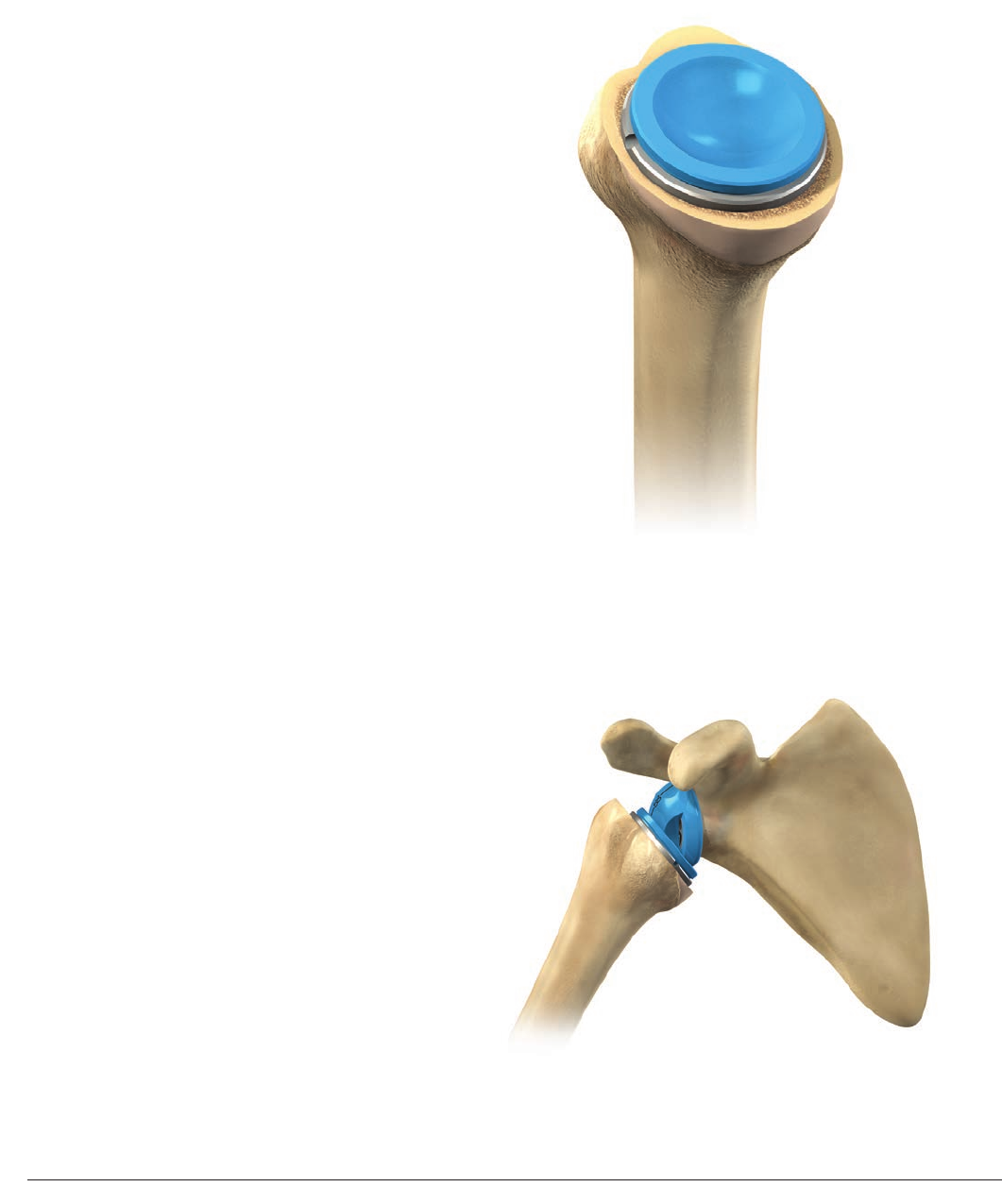
CUP TRIALS AND TRIAL REDUCTION
Figure 73
Place the humeral trial cup (38 or 42mm
depending on the glenosphere size), with
+3mm of lateral offset, in the trial epiphysis
(Figure 73). The shoulder should then be
reduced with longitudinal traction and
assessed for a full range of motion (Figure 74).
Figure 74

3938 DePuy Synthes Joint Reconstruction DELTA XTEND™ Surgical Technique
JOINT TENSIONING AND STABILITY ASSESSMENT
Joint tensioning and stability assessment
should be performed with particular care,
using the following guidelines:
• Tension within the conjoined tendon should
be noticeably increased and detectable by
palpation.
• With the arm in a neutral position, apply
a longitudinal traction force to the arm
while observing the movement of the
shoulder with respect to the entire shoulder
girdle as well as the trial prosthetic joint.
Tension is appropriate if, in response to the
longitudinal traction, the entire shoulder
moves before detectable separation of the
trial prosthetic surfaces.
• External rotation may appropriately
demonstrate slight gapping between
the glenosphere and articular surface
(2 to 3mm maximum).
• Positioning a hand or fist near the axilla
to serve as a fulcrum, further adduct the
arm and look for undesirable tendencies to
sublux or dislocate laterally (a small opening
of 2 to 3mm is acceptable). Estimate the
maximum forward elevation.10
• Assess stability at 90 degrees, abduction
with the humerus in neutral, maximum
internal and maximum external rotation.
Estimate the maximum forward elevation.10
If instability can be demonstrated, it is critical
to identify the cause and develop a solution
to the problem. Make sure that the implants
have been positioned correctly with respect
to the bone and to each other. Overcome
any conflicts between the proximal humeral
component and soft tissues or osseous
structures that surround the glenosphere
(e.g. non-union of the greater tuberosity)
by excision of the conflicting elements.
Inadequate tensioning may be overcome using:
• A thicker cup (+6mm or +9mm)
• A 42mm glenosphere
• A modular humeral lengthener or retentive
cups in more extreme cases
If unable to reduce the joint, the options
include additional soft tissue releases and
lowering the level of humeral resection.
When the trials are satisfactory, the trial
glenosphere should be removed using the
extraction T-Handle so that final implant
fixation can be performed.
39
Surgical Technique DELTA XTEND™ DePuy Synthes Joint Reconstruction
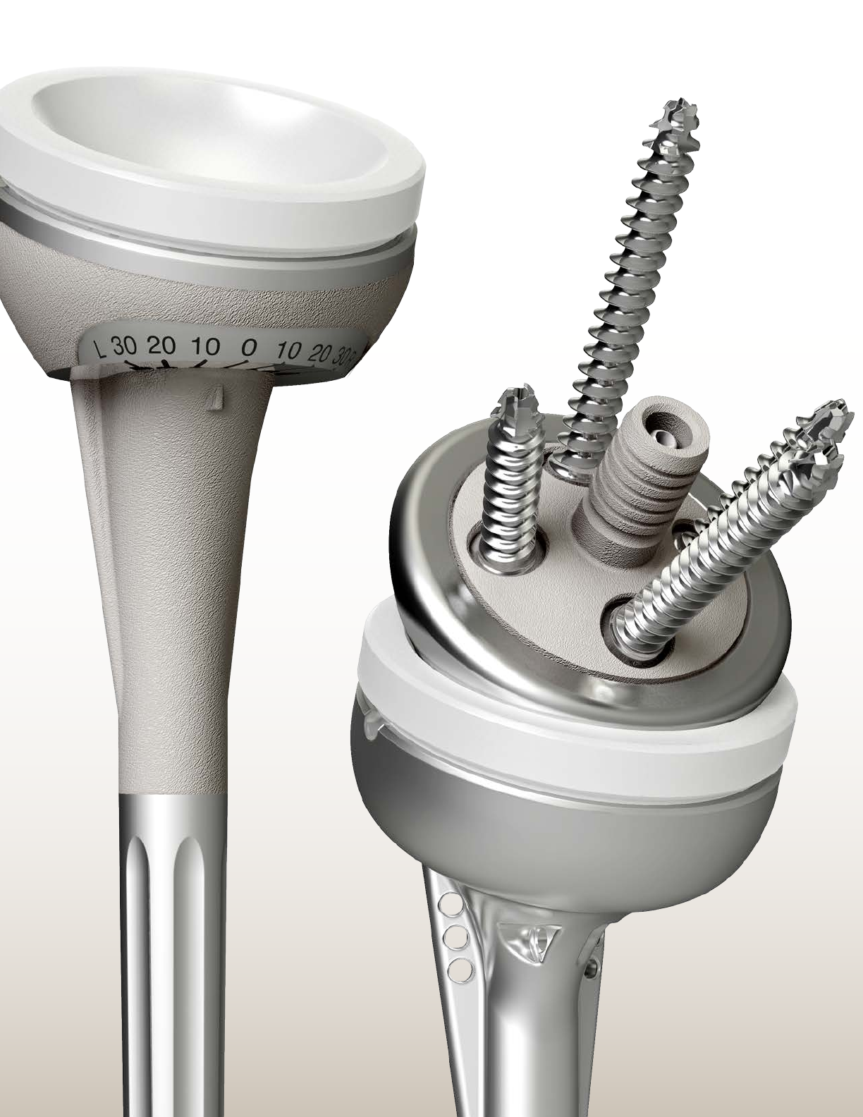
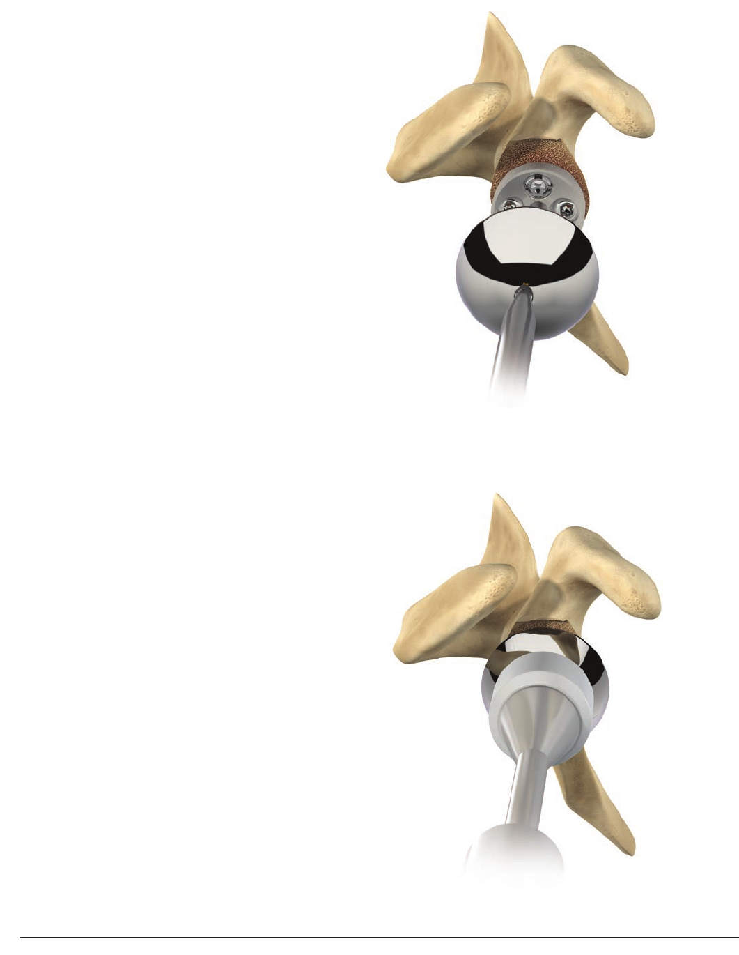
DEFINITIVE GLENOSPHERE FIXATION
Standard Glenosphere
Figure 75
Figure 76
Insert the 1.5mm guide pin through the
central hole of the metaglene.
Engage the 3.5mm cannulated hex screwdriver
in the final glenosphere. Slide the glenosphere
on the 1.5mm guide pin until it is in contact
with the metaglene (Figure 75). Proper
alignment between the glenosphere and
metaglene is absolutely essential to avoid cross
threading between the components.
If the glenosphere seems difficult to thread
onto the metaglene, do not force engagement
but re-align the components. If necessary,
remove the inferior retractor or improve the
capsular release. It is also important to check
that there is no soft tissue between the
metaglene and glenosphere.
When accurate thread engagement is obtained
and after a few turns, remove the guide pin to
avoid stripping in the screwdriver.
Standard glenosphere
Tighten until the scapula begins to rotate
slightly in a clockwise direction, meaning that
the glenoid bearing is closing on the taper of
the metaglene.
Gently tap on the glenosphere with the
glenosphere impactor a minimum of three times
(Figure 76). Tighten the glenosphere central
screw again. Care should be taken to ensure
that the glenoid bearing is fully locked onto the
metaglene. The gentle hammering procedure
and screw tightening can be repeated, if
necessary, until the screw is fully tightened.
Note: Glenosphere will sit about 1mm proud
on the metaglene with consistent uniformity
4140 DePuy Synthes Joint Reconstruction DELTA XTEND™ Surgical Technique
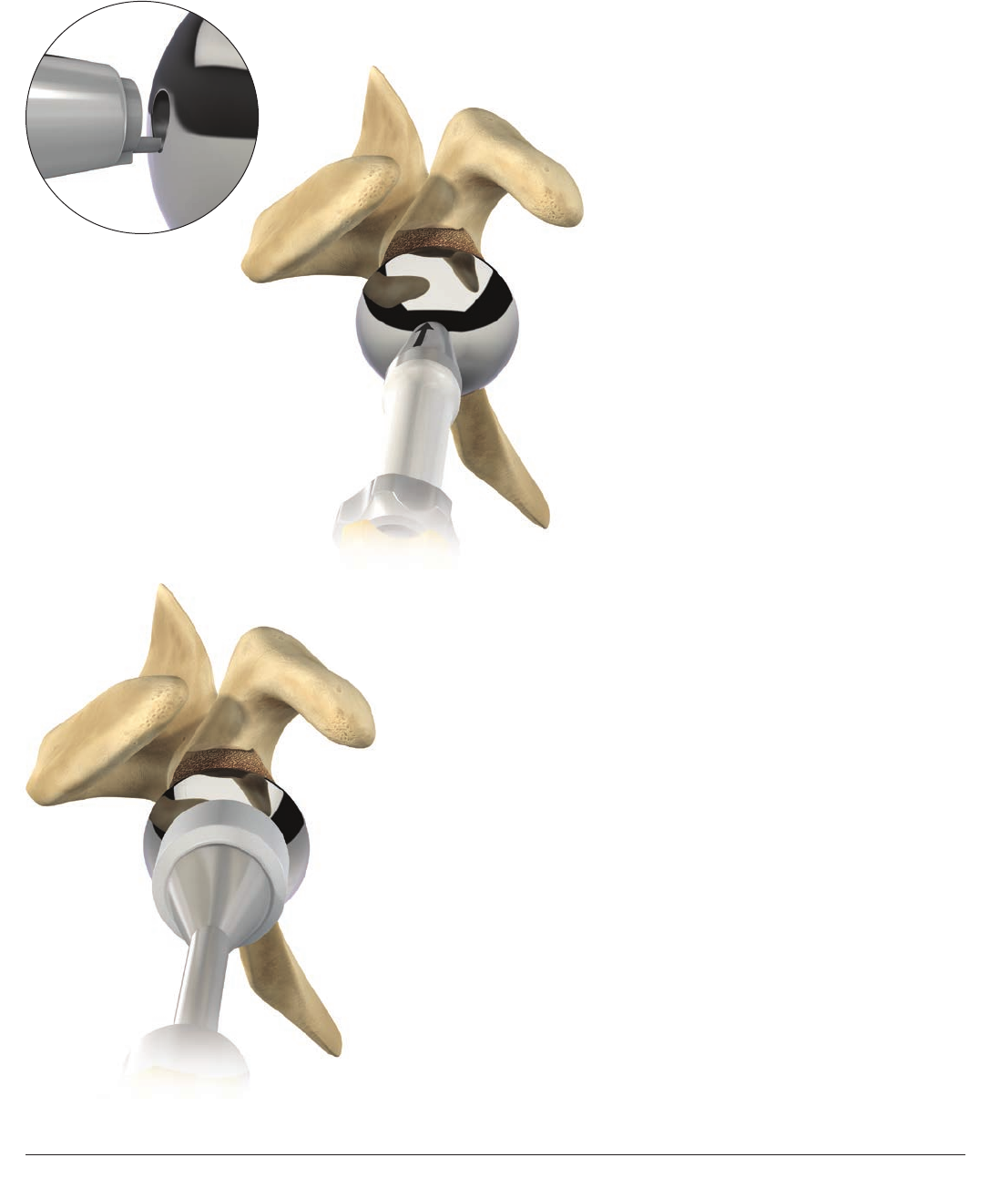
DEFINITIVE GLENOSPHERE FIXATION
Eccentric Glenosphere
Figure 78
Figure 79
Figure 77
Eccentric glenosphere
Slide the glenosphere orientation guide onto
the screwdriver core and position it in the
eccentric glenosphere central slot (Figure 77).
The arrow marked on the orientation guide
should be aligned with the base of the
coracoid process to position the eccentricity
correctly. Maintain the orientation guide in the
required position and screw the glenosphere
into place using the screwdriver until the
glenoid bearing closes on the taper of the
metaglene (Figure 78).
Obtain further impaction of the junction
by gently hammering the glenosphere with
the glenosphere impactor a minimum of
three times (Figure 79). Then tighten the
glenosphere central screw again. Care should
be taken to ensure that the glenoid bearing is
fully locked onto the metaglene.
Repeat if necessary until screw is fully tightened.
Note: Glenosphere will sit about 1mm proud
on the metaglene with consistent uniformity
41
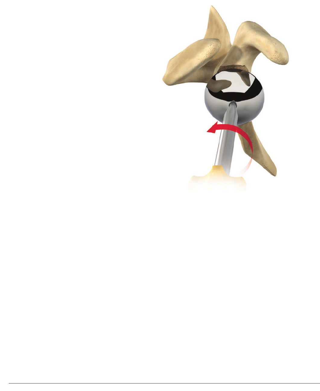
Surgical Technique DELTA XTEND™ DePuy Synthes Joint Reconstruction
DEFINITIVE GLENOSPHERE FIXATION
Glenosphere Removal
Figure 80
If it is necessary to remove the glenosphere
(revision or intra-operative size modification),
the glenosphere/metaglene junction can be
disassembled by unscrewing the glenosphere
central screw using the 3.5mm hex head
screwdriver (Figure 80). This operation
should be done smoothly to avoid central
screw damage.
4342 DePuy Synthes Joint Reconstruction DELTA XTEND™ Surgical Technique
DEFINITIVE HUMERAL IMPLANTS INSERTION
Cementless Modular Humeral Implants
Figure 81
Figure 82
Figure 83
Remove the trial cups and trial implants using
the humeral implant driver.
Select the appropriate final modular humeral
implants that correspond to the trial implants.
Place the final modular epiphysis on the final
modular stem in the same rotational position
used for the trial implants (Figure81).
Screw the final modular epiphysis together
with the final humeral stem, using the 3.5mm
hex screwdriver and the special locking wrench
for modular implants (Figure82).
Both components should then be mounted on
the humeral implant driver and driven down
the intramedullary canal, aligning the anterior
fin of the stem with the bicipital groove
(Figure83). The epiphysis should be aligned
with the edge of the bone resection.
MAKE SURE YOU ARE USING THE DEDICATED INSTRUMENTS
FOR CEMENTLESS MODULAR IMPLANTS
CEMENTLESS
MODULAR
43
Surgical Technique DELTA XTEND™ DePuy Synthes Joint Reconstruction
Remove the trial cups and trial implants
using the humeral implant driver. Select the
appropriate final monobloc humeral implant
corresponding to the trial implant.
Inserting cement restrictor
Determine the trial size of the cement restrictor
and gauge the implantation depth (Figure 84).
Check that the trial restrictor is firmly seated in
the canal, then remove trial.
Use pulsatile lavage and a nylon brush to clear
the humeral canal of debris and to open the
interstices of the bone ready for the cement.
Place the definitive cement restrictor at the
appropriate depth and check that it is firmly
seated in the canal.
Pass non-absorbable sutures such as
DePuy Synthes Mitek Sports Medicine’s
ORTHOCORD® Suture, through the proximal
humerus near the lesser tuberosity to enable
secure re-attachment of the subscapularis (if
possible).11 Avoid re-attachment if unable to
externally rotate the humerus to zero degrees.
Irrigate the canal, during a secondary cleaning,
using pulsatile lavage to remove loose bone
remnants and marrow. Some surgeons may
wish to insert a one-inch gauze pre-soaked
in an epinephrine (1:1,000,000 solution) or
hydrogen peroxide solution to aid haemostasis
and the drying of the humeral canal (Figure 85).
Cement in the humeral implant as directed.
MAKE SURE YOU ARE USING THE DEDICATED INSTRUMENTS
FOR CEMENTED MONOBLOC HUMERAL IMPLANTS
CEMENTED
MONOBLOC
DEFINITIVE HUMERAL IMPLANT INSERTION
Cemented Monobloc Humeral Implants
Figure 84
Figure 85
4544 DePuy Synthes Joint Reconstruction DELTA XTEND™ Surgical Technique
Implant insertion
Introduce the final implant in the chosen
version in line with the long axis of the
humerus, using the humeral implant driver
(0degrees to 10 degrees of retroversion)
(Figure 86).
Excess cement will extrude from the canal
and should be removed before curing is
complete. Inspect the exposed portion of
the humeral component for cement and
remove as necessary. Maintain pressure on
the driver until the cement is fully polymerized
to avoid micromotion that could cause crack
propagation. Remove the lap sponge dam and
irrigate the wound thoroughly. Place the trial
articular surface and reduce the joint. Confirm
stability and dislocate the humerus.
Note: Retroversion is calculated with
reference to the forearm axis (0 to 10 degrees)
DEFINITIVE HUMERAL IMPLANT INSERTION
Figure 86
0° to 10° Retroversion
Forearm Axis
45
Surgical Technique DELTA XTEND™ DePuy Synthes Joint Reconstruction
DEFINITIVE HUMERAL IMPLANT INSERTION
Figure 87
Figure 88
Final cup fixation
Impact the final humeral cup using the cup
impactor (Figure 87).
Step 1
Insert the polyethylene humeral cup by hand.
Turn it 180 degrees in the epiphysis to make
sure that it is evenly seated and that there is no
soft tissue, cement or fluid interfering with the
cup to epiphysis connection (Figure 88).
4746 DePuy Synthes Joint Reconstruction DELTA XTEND™ Surgical Technique
DEFINITIVE HUMERAL IMPLANT INSERTION
Figure 89
Figure 90
Step 2
Once you are confident that you have
perfect aligment, impact the humeral
cup at a 90 degree angle to the epiphysis
(Figure89). Make sure the arm is fully
supported to ensure full impaction.
Step 3
Once fully seated there will be approximately
a 1mm gap between the lip of the cup and
the epiphysis. The 1mm gap will aid future
revisions if necessary. The cup should not
move or shift when touched. If this is the
case, realign the implant and repeat the
impaction steps (Figure 90).
When a humeral spacer is needed, impact
it first on the epiphysis and then impact the
final cup on it.
Note: All junction surfaces between the
implant components should be clean and
free of any tissue before impaction.
Reduce the joint and carry out a final
assessment of joint stability and range
of motion.
Impact Direction
90° from
Surface Plane
47
Surgical Technique DELTA XTEND™ DePuy Synthes Joint Reconstruction
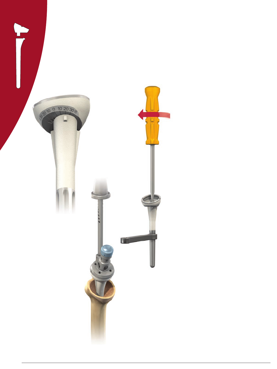
1
1
2
2
3
3
4
4
Cases of proximal bone loss will be treated
using cemented monobloc humeral implants
to avoid any risk of component dissociation.
Long monobloc stems may be required in
some cases.
The preparation of the humeral canal for long
stems uses the same technique described for
standard stems, with the exception of the
procedure for reaming the humeral canal,
which differs in this respect: the entire length
of the cutting flutes should be passed down
the intramedullary canal instead of being
stopped at the mark (Figure 91).
A positioning jig is available to hold both the
trial long stem and the final implant in place at
the correct height and in retroversion.
Tighten the fin clamp on the humeral
shaft first using the 3.5mm screwdriver
(Figure92).
Place the fin clamp over the vertical
height gauge of the humeral shaft clamp
and secure the fin clamp to the central
hole in the anterior fin of the prosthesis.
Place the prosthesis at the
appropriate height.
Tighten the fin clamp to secure it to the
vertical height gauge.
The jig can be left in place while testing
motion, and used to place the final stem at the
height determined during the trials.
CASES OF PROXIMAL HUMERAL BONE LOSS
Figure 91
Figure 92
4948 DePuy Synthes Joint Reconstruction DELTA XTEND™ Surgical Technique
Note that aligning the retroversion guide pin
with the forearm places the implant in 30
degree retroversion. Readjust the retroversion
of the jig to match 0 to 10 degrees
retroversion as used for the reverse shoulder
prosthesis (Figure 93).
Height lines are also present on the trial
long stems to enable better marking of the
appropriate prosthesis height. Determine
an appropriate mark, then place the trial
stem beside the final implant and mark the
corresponding height (Figure 94). Use that mark
to cement the stems at the proper height.
Sutures through the stem fin holes (smooth
edges) can be used to reconstruct the
proximal humerus.
Note: This will have to be done by estimating
when you are between 0 to 10 degrees.
20˚- 30˚
Corresponds to
Middle Suture Hole
on Definitive Implant
Definitive ImplantTrial Implant
CASES OF PROXIMAL HUMERAL BONE LOSS
Figure 93
Figure 94
49
Surgical Technique DELTA XTEND™ DePuy Synthes Joint Reconstruction
When revision of a reverse shoulder is required
due to glenoid loosening, or when glenoid bone
stock is insufficient to fix a metaglene securely,
the reverse shoulder can be converted to an
hemi-prothesis as a salvage procedure. Specific
hemi-heads with lateral head coverage, DELTA
XTEND CTA heads, are available. This is also
indicated for intraoperative glenoid fracture.
Remove the glenosphere using the 3.5mm
hex head screwdriver. Remove the metaglene
locking screws using the locking screwdriver
and the non-locking screw using the 3.5mm hex
head screwdriver. Remove the metaglene using
the extraction T-Handle and remove the humeral
cup using the cup extraction clamp (Figure 95).
Place the DELTA XTEND CTA Head Reamer
Guide in the epiphysis (Figure 96). Align the
anterior and posterior slot of the reaming guide
with the slots of the epiphysis and impact the
reaming guide gently with a mallet.
Assemble the DELTA XTEND CTA Head Reamer
with the T-Handle. Ream the area around the
epiphysis manually (Figure 97). If the DELTA
XTEND CTA Trial Head does not obtain perfect
seating on the epiphysis, finish the preparation
using a rongeur.
Choose the appropriate size of
DELTA XTEND CTA Head using the trial heads.
Gently impact the appropriate final head using
the humeral head impactor (Figure 98). Make
sure that the junction surfaces between the
components are clean and free of any soft tissue
before impaction. The retroversion of the DELTA
XTEND CTA head should be chosen to match
the patient’s anatomy. This requires that the
head is placed in the proper orientation
before impacting.
DELTA XTEND SYSTEM REVISION TO
HEMI-ARTHROPLASTY
Figure 95
Figure 98Figure 97
Figure 96
5150 DePuy Synthes Joint Reconstruction DELTA XTEND™ Surgical Technique
DELTA XTEND/DELTA CTA
Glenoid Revisions
Revision of any Delta CTA or DELTA XTEND glenoid
component due to loosening:
• To remove a DELTA CTA or DELTA XTEND
Glenosphere use the Hexagonal Cannulated
3.5mm Screwdriver (2307-93-000) per page 41
of this technique
• To remove all DELTA CTA Metaglene Screws and
DELTA XTEND Non-Locking Screws use the Hexagonal
Cannulated 3.5mm Screwdriver (2307-93-000)
• To remove DELTA XTEND Metaglene Locking Screws
use the Locking Screwdriver (2307-92-003) with
Internal Rod (2307-92-004)
• To remove any type of metaglene from either
DELTA System once all screws are removed, use the
Monobloc Extraction T-handle (2307-99-002)
• Finally, replace with DELTA XTEND Glenoid
Components using the surgeon’s preferred
bone grafting technique and follow the
DELTA XTEND Surgical Technique
DELTA XTEND Glenoid Bone Defects
In case of a significant glenoid bone defect, or
abnormal medialization of the glenoid bone:
• In order to restore the glenoid joint line,
a long peg metaglene can be used (with
possible associated bone grafting technique).
Two long peg options (+10mm and +15mm)
are available in addition to the existing
standard metaglene peg (13.5mm)
• To implant the long peg metaglenes please
refer to the glenoid section in the DELTA
XTEND System Surgical Technique beginning
on page 14. Dedicated drill bits are offered
for each size (13.5mm, +10mm and +15mm)
DELTA XTEND LONG PEG METAGLENES
AND DELTA CTA HYBRID CUPS
51
Surgical Technique DELTA XTEND™ DePuy Synthes Joint Reconstruction
DELTA CTA Glenoid Revision with
Fixed Humeral Component
DELTA CTA Hybrid Humeral Cups
In case of revision of a DELTA CTA Glenoid
Component where the humeral component is
well fixed, different options are provided:
• In case of a DELTA CTA System 36mm epiphysis,
use 38mm or 42mm hybrid cups consistent
with the glenoid diameter used. Hybrid cups
are available in three different heights (+3mm,
+6mm and +9mm)
• In case of a DELTA CTA 42mm epiphysis,
DELTA CTA System 42mm diameter cups are
compatible with 42mm DELTA XTEND
Glenospheres
• In more extreme cases, a modular humeral
spacer +9mm can be used
DELTA CTA Revision to Hemi-Arthroplasty
In cases of intra-operative fracture of the glenoid cavity,
or revision of the DELTA CTA Glenoid, for example,
a hemi-arthroplasty may be considered. Intermediate
metallic heads are provided within the DELTA CTA System
to complete this procedure. Two epiphyseal diameters,
36mm and 42mm, are available in standard and +4mm
offset. The hemi heads can be assembled either directly
onto the epiphysis or onto the metallic spacer. These
should be introduced using the humeral head impactor
per the DELTA CTA Surgical Technique (0612-26-500).
36mm
Standard
42mm
+4mm Offset

5352 DePuy Synthes Joint Reconstruction DELTA XTEND™ Surgical Technique
POST-OPERATIVE MANAGEMENT
2. Late phase (after 6 weeks)
After the sixth week, active strengthening movements
may gradually be added to the program. These
exercises, which closely follow everyday activities, are
to be performed in a sitting or standing position using
conventional methods, with isometric exercises and
resistance movements becoming increasingly important.
A series of exercises for rhythmic stabilization of the
upper arm as well as eccentric work on lowering the arms
complete the strengthening of the muscles. Physiotherapy
may be performed over a period of at least six months.
1. Early phase (0 to 6 weeks)
Two days after the operation, the patient may be mobile.
This early phase is dedicated to gentle and gradual
recovery of the passive range of shoulder motion:
abduction of the scapula, anterior elevation and medial
and lateral rotation. An abduction cushion may be used
to relieve pressure on the deltoid. Physiotherapy is mainly
performed with the patient supine, passive and with
both hands holding a bar that is manipulated by the
contralateral hand, as described by Neer. The patient is
encouraged to use the affected arm post-operatively to
eat and write, but should not use it to push behind the
back or to raise themselves from the sitting position to
the standing position. In conjunction with these exercises
for scapulohumeral recovery, it is important to strengthen
muscle connection with the scapula in order to facilitate
muscle and implant function. Passive exercise in a
swimming pool is recommended as soon as scars begin
to form. More caution is required to protect the deltoid
muscle from excessive demand if a superior approach has
been used for surgery.
Post- operative physiotherapy is an important factor in the outcome of this procedure, since stability and mobility now
depend on the deltoid alone. The physiotherapy program, which should be planned to suit each individual patient, consists
of two phases:
53
Surgical Technique DELTA XTEND™ DePuy Synthes Joint Reconstruction
STANDARD IMPLANT CODES
Cemented Monobloc Humeral Implants
1307-08-100 Monobloc Humeral Cemented Stem Epiphysis Size 1 8mm Standard
1307-10-100 Monobloc Humeral Cemented Stem Epiphysis Size 1 10mm Standard
1307-12-100 Monobloc Humeral Cemented Stem Epiphysis Size 1 12mm Standard
1307-14-100 Monobloc Humeral Cemented Stem Epiphysis Size 1 14mm Standard
1307-10-200 Monobloc Humeral Cemented Stem Epiphysis Size 2 10mm Standard
1307-12-200 Monobloc Humeral Cemented Stem Epiphysis Size 2 12mm Standard
1307-14-200 Monobloc Humeral Cemented Stem Epiphysis Size 2 14mm Standard
Cementless Modular Humeral Implants
1307-10-000 Modular Humeral Stem 10mm HA
1307-12-000 Modular Humeral Stem 12mm HA
1307-14-000 Modular Humeral Stem 14mm HA
1307-16-000 Modular Humeral Stem 16mm HA
1307-20-101 Modular Centered Epiphysis Size 1 HA
1307-20-102 Modular Eccentric Epiphysis Size 1 Left HA
1307-20-103 Modular Eccentric Epiphysis Size 1 Right HA
1307-20-201 Modular Centered Epiphysis Size 2 HA
1307-20-202 Modular Eccentric Epiphysis Size 2 Left HA
1307-20-203 Modular Eccentric Epiphysis Size 2 Right HA
Polyethylene Cup and Humeral Spacer
1307-38-203 Standard Humeral PE Cup 38mm +3mm
1307-38-206 Standard Humeral PE Cup 38mm +6mm
1307-38-209 Standard Humeral PE Cup 38mm +9mm
1307-42-203 Standard Humeral PE Cup 42mm +3mm
1307-42-206 Standard Humeral PE Cup 42mm +6mm
1307-42-209 Standard Humeral PE Cup 42mm +9mm
1307-38-106 Retentive Humeral PE Cup 38mm +6mm
1307-42-106 Retentive Humeral PE Cup 42mm +6mm
1307-30-009 Humeral Spacer +9mm
High Mobility Cups
1307-38-703 High Mobility PREMIERON® X-Linked PE Humeral Cup Diameter 38mm +3mm
1307-38-706 High Mobility PREMIERON® X-Linked PE Humeral Cup Diameter 38mm +6mm
1307-38-709 High Mobility PREMIERON® X-Linked PE Humeral Cup Diameter 38mm +9mm
1307-42-703 High Mobility PREMIERON® X-Linked PE Humeral Cup Diameter 42mm +3mm
1307-42-706 High Mobility PREMIERON® X-Linked PE Humeral Cup Diameter 42mm +6mm
1307-42-709 High Mobility PREMIERON® X-Linked PE Humeral Cup Diameter 42mm +9mm
ORDERING INFORMATION
Implants
Centered
Eccentric
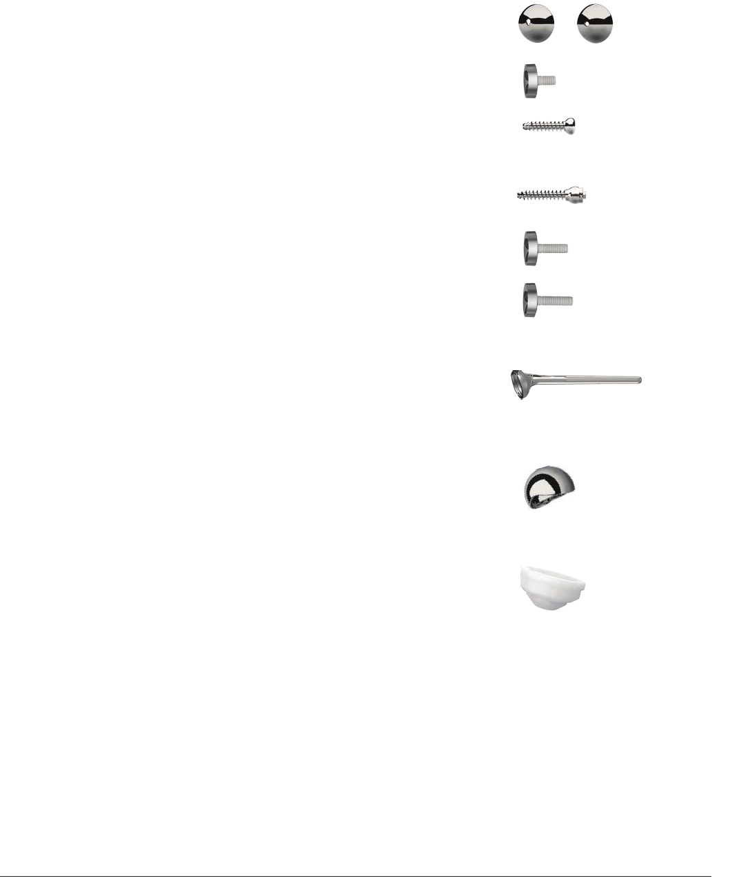
5554 DePuy Synthes Joint Reconstruction DELTA XTEND™ Surgical Technique
GLENOID IMPLANTS
1307-60-038 Eccentric Glenosphere 38mm
1307-60-042 Eccentric Glenosphere 42mm
1307-60-138 Standard Glenosphere 38mm
1307-60-142 Standard Glenosphere 42mm
1307-60-000 Standard Metaglene 13.5mm
1307-70-018 Non-Locking Metaglene Screw 4.5mm x 18mm
1307-70-024 Non-Locking Metaglene Screw 4.5mm x 24mm
1307-70-030 Non-Locking Metaglene Screw 4.5mm x 30mm
1307-70-036 Non-Locking Metaglene Screw 4.5mm x 36mm
1307-70-042 Non-Locking Metaglene Screw 4.5mm x 42mm
1307-90-024 Locking Metaglene Screw 4.5mm x 24mm
1307-90-030 Locking Metaglene Screw 4.5mm x 30mm
1307-90-036 Locking Metaglene Screw 4.5mm x 36mm
1307-90-042 Locking Metaglene Screw 4.5mm x 42mm
1307-90-048 Locking Metaglene Screw 4.5mm x 48mm
REVISION IMPLANT CODES
DELTA XTEND Long Peg Metaglene
1407-60-020 +10mm Long Peg Metaglene
1407-60-025 +15mm Long Peg Metaglene
Cemented Monobloc Long Stems
1307-08-110 Monobloc Humeral Cemented Stem Epiphysis Size 1 8mm Long
1307-10-110 Monobloc Humeral Cemented Stem Epiphysis Size 1 10mm Long
1307-12-110 Monobloc Humeral Cemented Stem Epiphysis Size 1 12mm Long
1307-14-110 Monobloc Humeral Cemented Stem Epiphysis Size 1 14mm Long
1307-10-210 Monobloc Humeral Cemented Stem Epiphysis Size 2 10mm Long
1307-12-210 Monobloc Humeral Cemented Stem Epiphysis Size 2 12mm Long
1307-14-210 Monobloc Humeral Cemented Stem Epiphysis Size 2 14mm Long
CTA Heads
1307-48-021 DELTA XTEND CTA Head 48mm x 21mm
1307-48-026 DELTA XTEND CTA Head 48mm x 26mm
1307-52-021 DELTA XTEND CTA Head 52mm x 21mm
1307-52-026 DELTA XTEND CTA Head 52mm x 26mm
DELTA CTA REVISION COMPONENTS
1407-38-303 Hybrid PE Humeral Cup EPI36 D38 +3mm
1407-38-306 Hybrid PE Humeral Cup EPI36 D38 +6mm
1407-38-309 Hybrid PE Humeral Cup EPI36 D38 +9mm
1407-42-503 Hybrid PE Humeral Cup EPI36 D42 +3mm
1407-42-506 Hybrid PE Humeral Cup EPI36 D42 +6mm
1407-42-509 Hybrid PE Humeral Cup EPI36 D42 +9mm
1407-38-406 Retentive PE Humeral Cup EPI36 D38 +6 mm
RTH236 Humeral Spacer Diameter 36 +9mm
RTH242 Humeral Spacer Diameter 42 +9mm
4CHL336 Humeral Cup Diameter 36 +3mm
4CHL636 Humeral Cup Diameter 36 +6mm
4CHL936 Humeral Cup Diameter 36 +9mm
4CHL342 Humeral Cup Diameter 42 +3mm
4CHL642 Humeral Cup Diameter 42 +6mm
4CHL942 Humeral Cup Diameter 42 +9mm
4CHL636R Humeral Cup Diameter 36 +6mm
4CHL642R Humeral Cup Diameter 42 +6mm
TIH036 Delta Humeral Head 36mm
TIH042 Delta Humeral Head 42mm
TIH436 Delta Humeral Head 36 +4mm
TIH442 Delta Humeral Head 42 +4mm
GSC242 Glenosphere Diameter 42mm
ORDERING INFORMATION
Implants
Standard Eccentric
55
Surgical Technique DELTA XTEND™ DePuy Synthes Joint Reconstruction
ORDERING INFORMATION
Stem Sizes
Length of Cemented Monobloc Humeral Implants
Designation Cat Number Under Epiphysis Total Length
Monobloc Humeral Cemented Epiphysis 1 8 Std 1307-08-100 105mm 132mm
Monobloc Humeral Cemented Epiphysis 1 10 Std 1307-10-100 110mm 137mm
Monobloc Humeral Cemented Epiphysis 1 12 Std 1307-12-100 117mm 144mm
Monobloc Humeral Cemented Epiphysis 1 14 Std 1307-14-100 126mm 153mm
Monobloc Humeral Cemented Epiphysis 2 10 Std 1307-10-200 110mm 137mm
Monobloc Humeral Cemented Epiphysis 2 12 Std 1307-12-200 117mm 145mm
Monobloc Humeral Cemented Epiphysis 2 14 Std 1307-14-200 126mm 154mm
Monobloc Humeral Cemented Epiphysis 1 8 Long 1307-08-110 170mm 197mm
Monobloc Humeral Cemented Epiphysis 1 10 Long 1307-10-110 180mm 207mm
Monobloc Humeral Cemented Epiphysis 1 12 Long 1307-12-110 182mm 209mm
Monobloc Humeral Cemented Epiphysis 1 14 Long 1307-14-110 196mm 223mm
Monobloc Humeral Cemented Epiphysis 2 10 Long 1307-10-210 180mm 207mm
Monobloc Humeral Cemented Epiphysis 2 12 Long 1307-12-210 182mm 210mm
Monobloc Humeral Cemented Epiphysis 2 14 Long 1307-14-210 196mm 224mm
Length of Cementless Modular Humeral Implants
Size Under Epiphysis Total Length Epiphysis Options
10mm 110mm 138mm Epi 1 Cent Ecc-L Ecc-R
Epi 2 Cent Ecc-L Ecc-R
12mm 117mm 145mm Epi 1 Cent Ecc-L Ecc-R
Epi 2 Cent Ecc-L Ecc-R
14mm 126mm 153mm Epi 1 Cent Ecc-L Ecc-R
Epi 2 Cent Ecc-L Ecc-R
16mm 135mm 162mm Epi 1 Cent Ecc-L Ecc-R
Epi 2 Cent Ecc-L Ecc-R
Modular
Under Epiphysis
Monobloc
Under Epiphysis
Modular
Total Length
Monobloc
Total Length
5756 DePuy Synthes Joint Reconstruction DELTA XTEND™ Surgical Technique
1
2
9
3
4
5
6
7
8
10 11 12
1
2
9
3
4
5
6 7
8
10
11
12
13 14
5
4
3
2
1
6
8
9
7
2307-99-005 DELTA XTEND Humeral 1 Case Complete
1 2128-61-070 Standard Hudson T-handle
2 1524-00-000 Hudson AO Converter
3 2128-01-006 Medulary Canal Reamer 6mm
4 2128-01-008 Medulary Canal Reamer 8mm
5 2128-01-010 Medulary Canal Reamer 10mm
6 2128-01-012 Medulary Canal Reamer 12mm
7 2128-01-014 Medulary Canal Reamer 14mm
8 2128-01-016 Medulary Canal Reamer 16mm
9 2001-65-000 Humeral Head Impactor
10 2001-66-000 Head Impactor Tip
11 2307-67-000 Humeral Cup Impactor Tip
12 2307-68-000 Spacer Impactor Tip
1 2307-70-008 Handle for Cutting Guide 8mm
2 2307-70-010 Handle for Cutting Guide 10mm
3 2307-70-012 Handle for Cutting Guide 12mm
4 2307-70-014 Handle for Cutting Guide 14mm
5 2307-70-016 Handle for Cutting Guide 16mm
6 2307-72-003 Delto-pectoral Cutting Guide
7 2307-72-004 Delto-pectoral Cutting Plate
8 2307-73-003 Superior-lateral Cutting Guide
9 2307-73-004 Superior-lateral Cutting Plate
10 2307-99-004 Pin Extractor
11 2307-71-000 Orientation Pin 2.5mm x 200mm
12 2555-89-000 Drill Bit 3.2mm x 127mm
13 2490-95-000 Cutting Guide Fixation Pin 3.2mm x 2
14 2490-95-000 Cutting Guide Fixation Pin 3.2mm x 2
1 2307-74-008 Proximal Reaming Guide 8mm
2 2307-74-010 Proximal Reaming Guide 10mm
3 2307-74-012 Proximal Reaming Guide 12mm
4 2307-74-014 Proximal Reaming Guide 14mm
5 2307-74-016 Proximal Reaming Guide 16mm
6 2307-83-000 Humeral Implant Driver
7 2307-85-000 Humeral Resection Protection Plate
8 2307-74-001 Proximal Reaming Guide Holder
9 2307-74-002 Proximal Reaming Guide Holder Internal Rod
ORDERING INFORMATION
Humeral Instruments
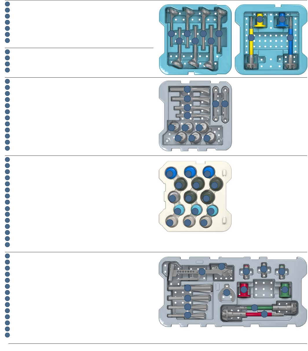
57
Surgical Technique DELTA XTEND™ DePuy Synthes Joint Reconstruction
1
2
9
3
4
5 6
7 8
10 11 12
13 14 15
16 17 18
20 21
22 23 24
25 26 27
19
Monobloc Only
Monobloc Only
1 2
8
3 4
5 6 7 10
9
11
Modular Only
6
5
4
3
1
7
8910
11 12
13
14
2
2307-99-006 DELTA XTEND Humeral 2 Case Complete
1 2307-08-100 Monobloc Humeral Trial Epiphysis Size 1 8mm Standard
2 2307-10 -100 Monobloc Humeral Trial Epiphysis Size 1 10mm Standard
3 2307-12-100 Monobloc Humeral Trial Epiphysis Size 1 12mm Standard
4 2307-14-100 Monobloc Humeral Trial Epiphysis Size 1 14mm Standard
5 2307-10 -200 Monobloc Humeral Trial Epiphysis Size 2 10mm Standard
6 2307-12-200 Monobloc Humeral Trial Epiphysis Size 2 12mm Standard
7 2307-14-200 Monobloc Humeral Trial Epiphysis Size 2 14mm Standard
8 2307-80-003 Monobloc Epiphyseal Disk Size 1
9 2307-80-004 Monobloc Epiphyseal Disk Size 2
10 2307-81-003 Monobloc Proximal Reamer Epiphysis Size 1
11 2307-81-004 Monobloc Proximal Reamer Epiphysis Size 2
1 2307-10 -001 Modular Humeral Stem Trial 10mm
2 2307-12- 001 Modular Humeral Stem Trial 12mm
3 2307-14- 001 Modular Humeral Stem Trial 14mm
4 2307-16 -001 Modular Humeral Stem Trial 16mm
5 2307-84-001 Modular Implant Locking Wrench 10-12mm
6 2307-84-002 Modular Implant Locking Wrench 14-16mm
7 2307-20-102 Modular Eccentric Trial Epiphysis Size 1 Left
8 2307-20-101 Modular Centred Trial Epiphysis Size 1
9 2307-20-103 Modular Eccentric Trial Epiphysis Size 1 Right
10 2307-20-202 Modular Eccentric Trial Epiphysis Size 2 Left
11 2307-20-201 Modular Centred Trial Epiphysis Size 2
12 2307-20-203 Modular Eccentric Trial Epiphysis Size 2 Right
13 2307-38-403 Standard Humeral Cup Trial 38mm +3mm
14 2307-38-406 Standard Humeral Cup Trial 38mm +6mm
15 2307-38-409 Standard Humeral Cup Trial 38mm +9mm
16 2307-42-403 Standard Humeral Cup Trial 42mm +3mm
17 2307-42-406 Standard Humeral Cup Trial 42mm +6mm
18 2307-42-409 Standard Humeral Cup Trial 42mm +9mm
19 2307-30-009 Humeral Spacer Trial +9mm
20 2307-38-506 Retentive Humeral Cup Trial 38mm +6mm
21 2307-42-506 Retentive Humeral Cup Trial 42mm +6mm
22 2307-38-303 High Mobility Humeral Cup Trial 38mm +3mm
23 2307-38-306 High Mobility Humeral Cup Trial 38mm +6mm
24 2307-38-309 High Mobility Humeral Cup Trial 38mm +9mm
25 2307-42-303 High Mobility Humeral Cup Trial 42mm +3mm
26 2307-42-306 High Mobility Humeral Cup Trial 42mm +6mm
27 2307-42-309 High Mobility Humeral Cup Trial 42mm +9mm
1 2307-01-030 Broach Handle
2 2307-01-031 Goniometer
3 2307-79-010 Humeral Broach 10mm
4 2307-79- 012 Humeral Broach 12mm
5 2307-79-014 Humeral Broach 14mm
6 2307-79-016 Humeral Broach 16mm
7 2307-01-032 Broach Handle Plate
8 2307-76-002 Eccentric Proximal Reaming Adaptor Size 2
9 2307-76-000 Centred Proximal Reaming Adaptor
10 2307-76-001 Eccentric Proximal Reaming Adaptor Size 1
11 2307-77-004 Epiphyseal Disk for Modular Implant Size 2
12 2307-77-003 Epiphyseal Disk for Modular Implant Size 1
13 2307-78-003 Proximal Reamer for Modular Implant Size 1
14 2307-78-004 Proximal Reamer for Modular Implant Size 2
ORDERING INFORMATION
Humeral Instruments
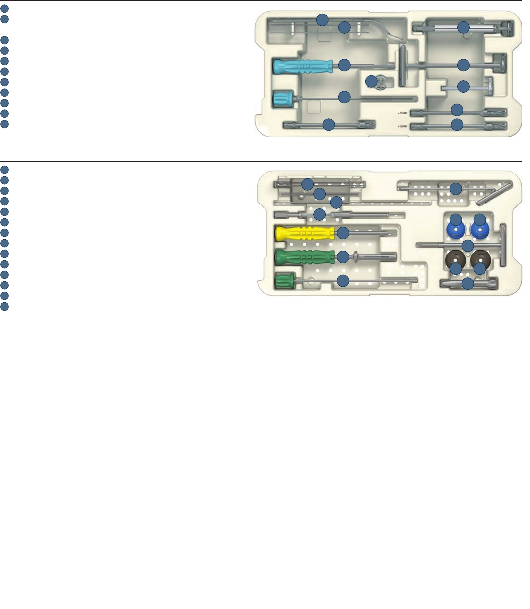
5958 DePuy Synthes Joint Reconstruction DELTA XTEND™ Surgical Technique
5
4
3
2
1
6
7
8
910
11
12 13
14
5
4
3
2
1
6
7
8
910
11
ORDERING INFORMATION
Glenoid Instruments
2307-99-007 DELTA XTEND Glenoid Case Complete
1 2307-86-002 Forked Retractor
2 2307-87-004 Metaglene Central Guide Pin 2.5mm x 2
2230-00-019 2.5mm Breakaway Guide Pin*
3 2307-87-005 Metaglene Holder
4 2307-87-002 Metaglene Holder Internal Rod
5 2307-87-003 Metaglene Positioning Plate
6 2307-88-027 Glenoid Resurfacing Reamer 27mm
7 2307-88-242 Glenoid Manual Reamer 42mm
8 2307-88-300 Glenoid Reaming Level Checker
9 2307-89-000 Glenoid Cannulated Stop Drill Standard
10 2407-89-010 Glenoid Cannulated Stop Drill +10mm
11 2407-89-015 Glenoid Cannulated Stop Drill +15mm
1 2307-90-005 Drill Bit 2.5mm x 170mm x 2
2 2307-90-004 Screw Guide Pin 1.2mm x 150mm x 5
3 2307-96-000 Glenosphere Guide Pin 1.5mm x 300mm
4 2307-91-001 Screw Depth Gauge
5 2307-93-000 3.5mm Cannulated Hex Screwdriver
6 2307-92-003 Locking Screwdriver
7 2307-92-004 Locking Screwdriver Internal Rod
8 2307-90-003 Glenoid Drill Guide 2.5mm
9 2307-60-038 Eccentric Glenosphere Trial 38mm
10 2307-60-138 Standard Glenosphere Trial 38mm
11 2307-99-002 Extraction T-handle
12 2307-60-042 Eccentric Glenosphere Trial 42mm
13 2307-60-142 Standard Glenosphere Trial 42mm
14 2307-95-000 Glenosphere Orientation Guide
*Special order only
59
Surgical Technique DELTA XTEND™ DePuy Synthes Joint Reconstruction
5
4
2
3
1
6
7
5
4
3
2
1
6
7
89
10 11
12
1
2
3
5
6
3
4
4
1 2407-38-203 Hybrid Trial Humeral Cup EPI36 D38 +3 mm
2407-38-206 Hybrid Trial Humeral Cup EPI36 D38 +6 mm
2407-38-209 Hybrid Trial Humeral Cup EPI36 D38 +9 mm
2407-42-203 Hybrid Trial Humeral Cup EPI36 D42 +3 mm
2407-42-206 Hybrid Trial Humeral Cup EPI36 D42 +6 mm
2407-42-209 Hybrid Trial Humeral Cup EPI36 D42 +9 mm
2407-38-106 Hybrid Retentive Trial Humeral Cup EPI36 D38 +6 mm
2 REH236 Humeral Spacer Trial, Dia. 36
REH242 Humeral Spacer Trial, Dia. 42
3 A5469 Lateralized Humeral Cup Trial, +3 mm Dia. 36
A5264 Lateralized Humeral Cup Trial, +6 mm Dia. 36
A5468 Lateralized Humeral Cup Trial, +9 mm Dia. 36
4 A5467 Lateralized Humeral Cup Trial, +3 mm Dia. 42
A5261 Lateralized Humeral Cup Trial, +6 mm Dia. 42
A5466 Lateralized Humeral Cup Trial, +9 mm Dia. 42
5 A5263 Lateralized Humeral Retentive Cup Trial, +6 mm Dia. 36
A5260 Lateralized Humeral Retentive Cup Trial, +6 mm Dia. 42
6 TEH036 Standard Humeral Head Trial, Dia. 36
TEH042 Standard Humeral Head Trial, Dia. 42
TEH436 Standard Humeral Head Trial, Dia. 36 +4 mm
TEH442 Standard Humeral Head Trial, Dia. 42 +4 mm
2307-99-008 DELTA XTEND Revision Case Complete
1 2307-99-001 Humeral Cup Extraction Clamp
2 ITH003 Stem Impactor/Extractor
3 2307-82-001 DELTA XTEND CTA Head Reamer Guide
4 2307-82-003 DELTA XTEND CTA Head Reamer
5 ETH001 Standard Humeral Prosthesis Extractor
6 MAI001 Slap Hammer
7 MDE001 Extraction Rod
1 2307-08-110 Monobloc Humeral Trial Epiphysis Size 1 8mm Long
2 2307-10-110 Monobloc Humeral Trial Epiphysis Size 1 10mm Long
3 2307-12-110 Monobloc Humeral Trial Epiphysis Size 1 12mm Long
4 2307-14-110 Monobloc Humeral Trial Epiphysis Size 1 14mm Long
5 2307-10-210 Monobloc Humeral Trial Epiphysis Size 2 10mm Long
6 2307-12-210 Monobloc Humeral Trial Epiphysis Size 2 12mm Long
7 2307-14-210 Monobloc Humeral Trial Epiphysis Size 2 14mm Long
8 2307-48-121 DELTA XTEND CTA Trial Head 48mm x 21mm
9 2307-48-126 DELTA XTEND CTA Trial Head 48mm x 26mm
10 2307-52-121 DELTA XTEND CTA Trial Head 52mm x 21mm
11 2307-52-126 DELTA XTEND CTA Trial Head 52mm x 26mm
12 2128-01-035 GLOBAL® FX Positioning Jig
ORDERING INFORMATION
Revision Instruments

6160 DePuy Synthes Joint Reconstruction DELTA XTEND™ Surgical Technique
IMPORTANT: This Essential Product Information sheet does not include all of the information necessary for selection and use of the device.
Please see full labeling for all necessary information.
INDICATIONS FOR USE:
The DELTA XTEND Shoulder Prosthesis is indicated for use in treatment of a grossly deficient rotator cuff joint with:
• severe arthropathy and/or;
• a previously failed joint replacement and/or;
• fracture-dislocations of the proximal humerus where the articular surface is severely comminuted, separated from its blood
supply or where the surgeon’s experience indicates that alternative methods of treatment are unsatisfactory
The patient’s joint must be anatomically and structurally suited to receive the selected implant(s), and a functional deltoid muscle is necessary to use
the device.
DELTA XTEND hemi-shoulder replacement is also indicated for hemi-arthroplasty if the glenoid is fractured intraoperatively or for the revision of a
previously failed DELTA XTEND Reverse Shoulder.
The metaglene component is HA coated and is intended for cementless use with the addition of screws for fixation.
The modular humeral stem and humeral epiphysis components are HA coated and intended for cementless use.
All other metallic components are intended for cemented use only.
CONTRAINDICATIONS:
Joint replacements may be contraindicated where the patient is overweight, where there is infection, poor bone stock, severe deformity, drug abuse,
overactivity, tumor, mental incapacity, muscle, nerve or vascular disease.
Note: Diabetes, at present, has not been established as a contraindication. However, because of increased risk for complications such as infection, slow
wound healing, etc., the physician should carefully consider the advisability of shoulder replacement in the severely diabetic patient.
WARNINGS AND PRECAUTIONS:
CAUTION
• Implants and trial components from different manufacturers or implant systems should never be used together, with the exception of
GLOBAL UNITE Humeral Stems and DELTA CTA as described below.
− When well-fixed, the GLOBAL UNITE Humeral Stems, in conjunction with existing DELTA XTEND epiphyseal components,
can be used when conversion to a reverse is necessary.
− When well-fixed DELTA CTA stem, the DELTA XTEND glenosphere and metaglene can be used with DELTA CTA Hybrid
Humeral Cups, Humeral PE Cups dia 42mm and/or spacers described in the DELTA XTEND Surgical Technique.
• Shoulder prosthesis components should never be reimplanted. Even though the implant appears undamaged, the implant may have developed
microscopic imperfections, which could lead to failure. DePuy’s Single Use devices have not been designed to undergo or withstand any form of
alteration, such as disassembly, cleaning or re-sterilization, after a single patient use. Reuse can potentially compromise device performance and
patient safety.
• Always use a trial prosthesis for trial purposes. Trials should not be assembled with any components intended for permanent implantation. Trials
must have the same configuration size, etc., as the corresponding components to be implanted.
• Do not alter or modify implants in any way.
• The use of a glenoid prosthesis in patients with cuff tear arthropathy could increase the risk of glenoid component loosening due to non-anatomic
loading conditions.
• The DELTA XTEND Reverse Shoulder Prosthesis has not been evaluated for safety and compatibility in the MR environment. The DELTA XTEND
Reverse Shoulder Prosthesis has not been tested for heating or migration in the MR environment.
ESSENTIAL PRODUCT INFORMATION

61
Surgical Technique DELTA XTEND™ DePuy Synthes Joint Reconstruction
INDICATIONS FOR USE:
A DELTA CTATM Reverse Shoulder Prosthesis is indicated for use in:
• Grossly rotator cuff deficient joint with severe arthropathy or a previous failed joint replacement with a grossly rotator cuff deficient joint.
• The patient’s joint must be anatomically and structurally suited to receive the selected implant(s), and a functional deltoid muscle is
necessary to use the device.
• The metaglene component is HA coated and is intended for cementless application with the addition of screws for fixation.
For US use only: All other components are intended for cemented use only.
CONTRAINDICATIONS
Joint replacements may be contraindicated where the patient is overweight, where there is infection, poor bone stock, severe deformity, drug abuse,
overactivity, tumour, mental incapacity, muscle, nerve or vascular disease.
WARNINGS AND PRECAUTIONS
CAUTION:
• Implants and trial components from different manufacturers or implant systems should never be used together. However, in case of a DELTA CTA
implant revision with a well-fixed DELTA CTA stem, the DELTA XTEND glenosphere and metaglene can be used with specific DELTA CTA Hybrid
Humeral PE cups described in the DELTA XTEND Surgical Technique, existing DELTA CTA Humeral PE cups diameter 42mm and /or DELTA CTA
Spacers.
• Shoulder prosthesis components should never be reimplanted. Even though the implant appears undamaged, the implant may have developed
microscopic imperfections, which could lead to failure.
• Always use a trial prosthesis for trial purposes. Trials should never be assembled with any components intended for permanent implantation.
Trials must have the same configuration size, etc., as the corresponding components to be implanted.
• Do not alter or modify implants in any way.
• The DELTA CTA Shoulder Prosthesis has not been evaluated for safety and compatibility in the MR environment. The DELTA CTA Shoulder
Prosthesis has not been tested for heating or migration in the MR.
63

63

www.depuysynthes.com
DePuy Orthopaedics, Inc.
700 Orthopaedic Drive
Warsaw, IN 46582
T. +1 (800) 366-8143
Limited Warranty and Disclaimer: DePuy Synthes Joint Reconstruction products are sold with a limited warranty to the original purchaser against defects
in workmanship and materials. Any other express or implied warranties, including warranties of merchantability or fitness, are hereby disclaimed.
WARNING: In the USA, this product has labeling limitations. See package insert for complete information.
CAUTION: USA Law restricts these devices to sale by or on the order of a physician.
To order in the US, call DePuy Synthes Joint Reconstruction Customer Service (800) 473-3789.
Not all products are currently available in all markets.
© DePuy Synthes Joint Reconstruction, a division of DOI 2014. All rights reserved.
0612-53-505 (Rev. 10) 3M 03/14
References
1. Neer, C.S. 2nd, et. al. “Cuff-Tear Arthroplasty.” Journal of Bone Joint Surgery 1983.
2. Broström, L.A., et. al. “The Kessel Prosthesis in Total Shoulder Arthroplasty. A five Year Experience”;
Clinical Orthopaedics and Related Research 1992.
3. Boileau, P., et. al. “Grammont Reverse Prosthesis: Design Rationale and Biomechanics.”
Journal Shoulder Elbow Surgery 2005.
4. Fenlin, J.M. Jr., “Total Glenohumeral Joint Replacement”, Orthopedic Clinics of North America 1975.
5. Grammont, P.M., et. al. “Delta Shoulder Prosthesis For Rotator Cuff Rupture.” Orthopaedics 1993.
6. Sirveaux, F., et. al. “Grammont Inverted Total Shoulder Arthroplasty in the Treatment of Glenohumeral
Osteoarthritis With Massive Rupture of the Cuff. Results of a Multicenter Study of 80 Shoulders.
”Journal of Bone Joint Surgery Br 2004.
7. De Wilde, L.F., et. al. “Shoulder Prosthesis Treating Cuff Tear Arthropathy: A Comparative Biomechanical Study.”
Journal of Orthopedic Research 2004.
8. Nyfeller, R.W., et. al. “Biomechanical Relevance of Glenoid Component Positioning in the Reverse Delta III Prosthesis.”
Journal Shoulder Elbow Surgery 2005.
9. Middernacht, B., et. al., “Consequences of Scapular Anatomy for Reversed Total Shoulder Arthroplasty”, Clinical
Orthopaedics and Related Research 2008.
10. Van Seymortier, P., et. al., “The Reverse Shoulder Prosthesis (Delta III) in Acute Shoulder Fractures: Technical Considerations
with Respect to Stability”, Acta Orthopaedica Belgica 2006.
11. ORTHOCORD® Suture is a registered trademark of DePuy Synthes Mitek Sports Medicine.
