DPY S ROM Noiles Rotating Hinge Surgical Technique 0612 85 510
2014-03-27
: Pdf Dpy S-Rom Noiles Rotating Hinge Surgical Technique 0612-85-510 DPY_S-ROM_Noiles_Rotating_Hinge_Surgical_Technique_0612-85-510 3 2014 pdf
Open the PDF directly: View PDF ![]() .
.
Page Count: 76

S-ROM® NOILES™
ROTATING HINGE
SURGICAL TECHNIQUE

2 DePuy Synthes Joint Reconstruction S-ROM® Noiles Rotating Hinge Surgical Technique
TABLE OF CONTENTS
SURGICAL TECHNIQUE Key Surgical Steps Summary 4
S-ROM® Noiles™ Rotating Hinge Knee System 6
The S-ROM Hinge System Overview 7
Incision and Exposure 8
Intra-operative Evaluation 10
Initial Preparation of the Tibia 11
Preparation of the Metaphyseal Bone 13
– Tapered Reamer
Proximal Tibial Resection – Tapered Reamer 14
Preparation of the Metaphyseal Bone – Broach 16
Tibial Trial Assembly 18
Preparation of Femoral Diaphysis 19
Reaming the Medullary Canal 20
Preparation of the Metaphysis – Sleeve Use 22
Femoral Preparation – Distal Resection 26
Femoral A/P and Chamfer Cuts 29
Femoral Box Cuts 31
Final Preparation of the Tibia 32
Femoral Trial Insertion 33
Trial Reduction 36
Implant Assembly – Tibia 37
Tibial Implantation 38
Implant Assembly – Sleeve and Stem Use 39
Bearing and Hinge Pin Insertion 42
Initial Patellar Resection 43
Patella Reaming 45
Patella Drilling 46
Trial Reduction and Implantation 47

Surgical Technique S-ROM® Noiles Rotating Hinge DePuy Synthes Joint Reconstruction 3
APPENDICES
ORDERING INFORMATION
Appendix 1: The Cemented Tibial Stem Extensions 48
Appendix 2: Step Wedge Preparation 51
Appendix 3: Thick Tray Preparation 54
Implant Listing 55
Compatibility Chart 59
Instruments 60
KEY SURGICAL STEPS SUMMARY
Patella Preparation
Final Trialing
Distal Femoral Resection
Femoral Medullary Canal Preparation
Tibial Medullary Canal PreparationIncision and Exposure
4 DePuy Synthes Joint Reconstruction S-ROM® Noiles Rotating Hinge Surgical Technique
Implantation
Femoral Preparation -
A/P and Chamfer Cuts Femoral Box Cuts
Tibial Resection Tibial Trial Assembly
Surgical Technique S-ROM® Noiles Rotating Hinge DePuy Synthes Joint Reconstruction 5

S-ROM® NOILES™ ROTATING HINGE KNEE SYSTEM
The S-ROM NOILES Rotating Hinge features:
· S-ROM Femoral Components available in three sizes
· 7 degree physiological valgus, fixed in the femoral
component
· Deep femoral trochlear groove
· Modular porous sleeves to accommodate bone defects
of the Engh Type II
and Type III classification and allow possible bone
ingrowth
· Available with both cemented and press-fit slotted
stems for both femur
and tibia
· Broad, congruent contact areas between femoral and
tibial components
to best distribute surface and sub-surface stresses in
the polyethylene
· A rotating hinge that accommodates axial rotation,
reducing stresses at
the bone cement/implant interfaces
6 DePuy Synthes Joint Reconstruction S-ROM® Noiles Rotating Hinge Surgical Technique

THE S-ROM HINGE SYSTEM OVERVIEW
The MBT Revision Knee System is comprised
of the following components:
· Tibial Components are available in eight sizes,
1, 1.5, 2, 2.5, 3, 4, 5 and 6
· Tibial Metaphyseal Sleeves are available in 29 mm
(cemented or porous), 37 mm, 45 mm, 53 mm and
61 mm sizes (M/L dimension)
· Tibial Wedge Augmentation Components:
Step Wedge in 5, 10 and 15 mm thicknesses
· 75, 115 and 150 mm Fluted Universal Stem lengths
in 10 to 24 mm diameters in 2 mm increments
· 30 and 60 mm Cemented Universal Stem lengths in
13 mm diameters. 90, 120, 150 Cemented Tapered
Universal stem lengths in 13 mm diameters
· Thick Trays are available in three different sizes
(2, 3 and 4) and two different thicknesses
(+15 mm and +25 mm)
· Accepts Rotating Platform hinged insert from the LPS™
(Limb Preservation System), which is compatible with
the S-ROM NOILES Rotating Hinge (NRH) Femoral
Component and LPS Femoral Component
The S-ROM Hinge Knee System is comprised
of the following components:
· Hinged Femoral Component is available in three sizes,
X-Small, Small and Medium
· Femoral Metaphyseal Sleeves are available in 20 mm
(cemented only), 31 mm, 34 mm, 40 mm and 46 mm
sizes (M/L dimension), and can be used with or
without a stem
· 5 and 10 mm Distal Femoral Augments
· 75 mm, 115 mm and 150 mm Fluted Universal Stem
lengths in 10 mm to 24 mm diameters in 2 mm
increments
· 30 mm and 60 mm Cemented Universal Stem Lengths
in 13 mm and 15 mm diameters
· 90 mm, 120 mm, and 150 mm Tapered Cemented
Universal Stem lengths in a 13 mm diameter
· 90 mm Tapered Cemented Universal Stem length in a
15 mm diameter (Must be used with a sleeve)
Surgical Technique S-ROM® Noiles Rotating Hinge DePuy Synthes Joint Reconstruction 7
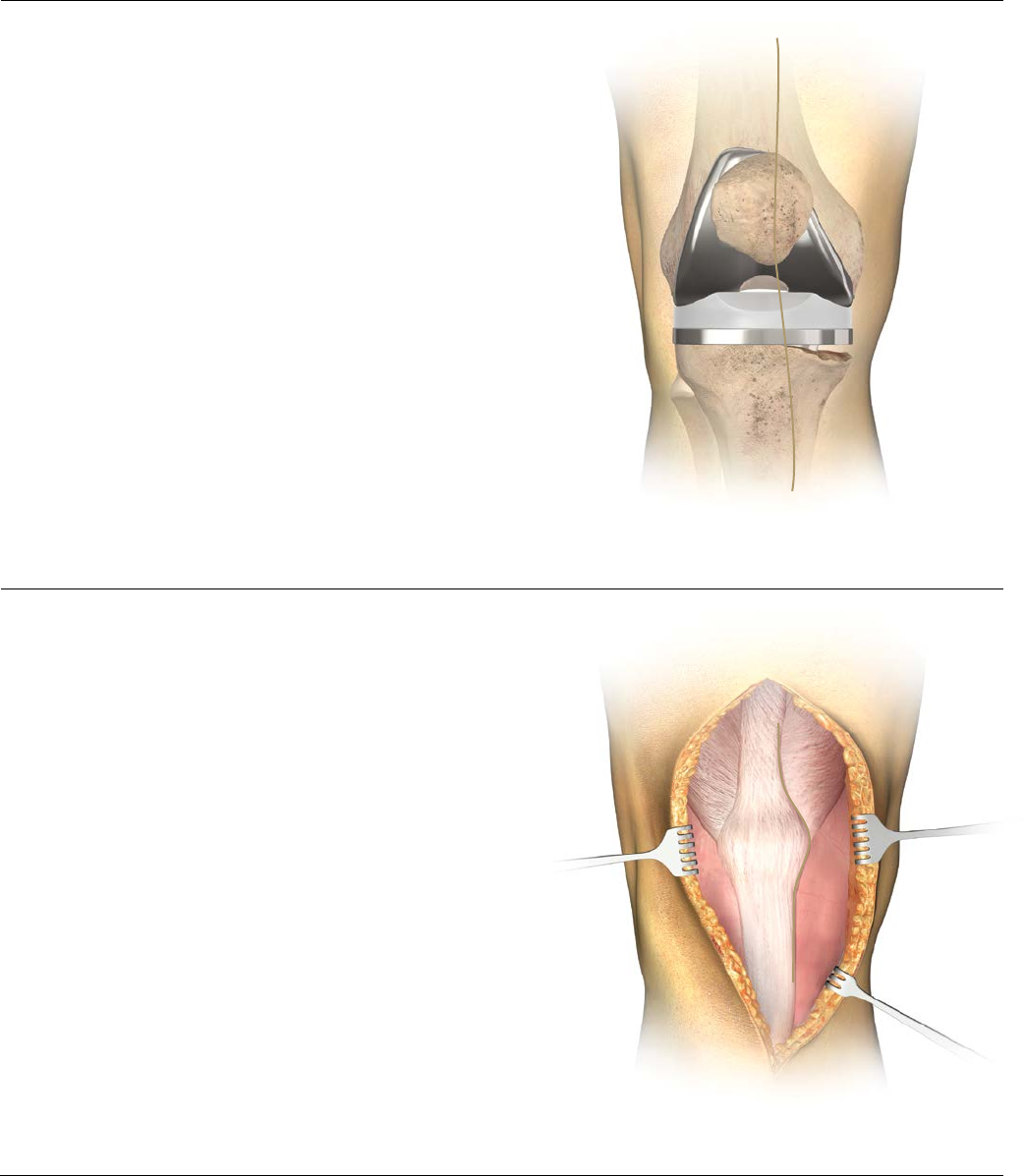
INCISION AND EXPOSURE
Initial Incision
When possible, follow the scar from the primary
procedure (Figure 1). Where parallel incisions are
present, the more lateral is usually preferred, as the
blood supply to the extensor surface is medially
dominant. Where a transverse patellectomy scar is
present, the incision should transect it at 90 degrees.
Where there are multiple incision scars or substantial
cutaneous damage (burn cases, skin grafting, etc.), one
may wish to consult a plastic surgeon prior to surgery to
design the incision, determine the efficacy of
pre-operative soft tissue expansion and plan for
appropriate soft tissue coverage at closure.
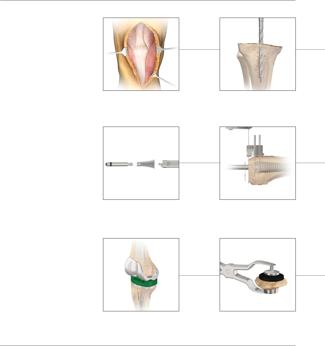
Capsular Incision
The fascial incision extends from the rectus femoris
proximal margin to the distal margin of the tibial
tubercle following the patella’s medial border,
maintaining a 3-4 mm cuff for reapproximation of the
vastus medialis aponeurosis at closure (Figure 2). Where
mobilization of the extensor mechanism and patella is
problematic, extend the skin and capsular incisions
proximally.
Figure 2
Figure 1
8 DePuy Synthes Joint Reconstruction S-ROM® Noiles Rotating Hinge Surgical Technique
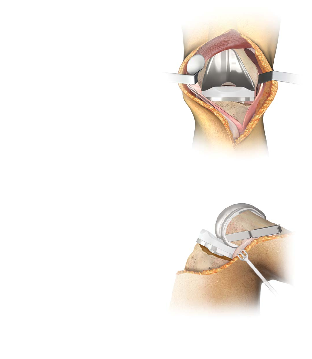
INCISION AND EXPOSURE
Occasionally an early retinacular release is indicated to
assist with patellar eversion. Where eversion difficulties
persist, a quadriceps snip, a proximal inverted quadriceps
incision (modified V-Y) or a tibial-tubercle osteotomy
may be indicated. Perform appropriate ligamentous
release based upon pre-operative and intra-operative
evaluation. Release fibrous adhesions to re-establish the
suprapatellar pouch and medial and lateral gutters
(Figure 3). In many revision cases, the posterior cruciate
ligament will be absent or non-functional; when this is
the situation, excise any residual portion. Exercise care
when everting the patella. Frequently, subluxing the
patella laterally is adequate. Doing so will help avoid
patella tendon avulsion.
Implant Extraction from the Primary Procedure
Take care to preserve as much bone as possible. To this
end, assemble a selection of tools, including thin
Osteotomes, an Oscillating Saw, a Gigli Saw, a
highspeed Burr and various extraction devices, but many
cases will require only the thin Osteotome. Carefully
disrupt the bone/cement or bone prosthesis interface
before attempting extraction (Figure 4).
Disengage the implanted components and extract as
gently as possible, in such manner as to avoid fracture
and unnecessary sacrifice of bone stock. Where the
entire prosthesis is to be replaced, it is advantageous to
remove the femoral component first, as this will enhance
access to the proximal tibia. Clear all residual methyl
methacrylate with hand (chisels) or power tools.
Figure 3
Figure 4
Surgical Technique S-ROM® Noiles Rotating Hinge DePuy Synthes Joint Reconstruction 9
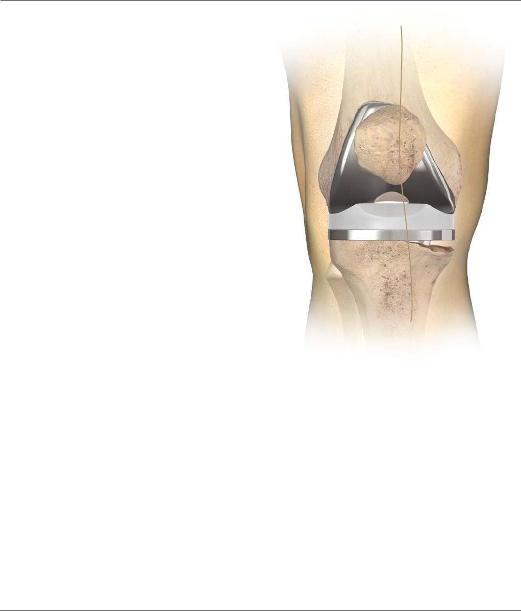
INTRA-OPERATIVE EVALUATION
The surgeon should establish two anatomic conditions
to facilitate revision arthroplasty: the level of the joint
line and the disparity in the flexion and extension gaps
(Figure 5).
Joint Line Evaluation
In an average knee in full extension, the true joint line
can be approximated in reference to several landmarks.
· It lies 12–16 mm distal to the femoral PCL
attachment
· It lies approximately 3 cm distal to the medial
epicondyle and 2.5 cm distal to the lateral
epicondyle
· It lies distal to the inferior pole of the patella
(approximately one finger width)
· Level with the old meniscal scar, if available
Additional pre-operative joint line assessment
tools include:
1) Review of original pre-operative roentgenogram
of the Total Knee Arthroplasty (TKA)
2) Review of roentgenogram of contralateral knee
if non-implanted
Figure 5
10 DePuy Synthes Joint Reconstruction S-ROM® Noiles Rotating Hinge Surgical Technique
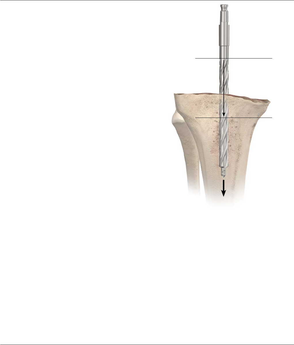
Figure 6
INITIAL PREPARATION OF THE TIBIA
The Tibial Alignment System
When pre-operative evaluation and X-rays indicate that
Fluted Stem Extensions, Metaphyseal Sleeves or Wedges
are required, it is recommended that the proximal tibia be
prepared with reference to the position of the I.M. Rod.
Note: Where a Cemented Stem Extension is
indicated, see Appendix 1 (page 48).
Place the knee in maximal flexion with the patella
laterally retracted and the tibia distracted anteriorly and
stabilized. Release fibrosis around the tibial border or
excise as required to ensure complete visualization of its
periphery.
Approximate the location of the medullary canal with
reference to pre-operative anterior/posterior (A/P) and
lateral X-rays and to the medial third of the tibial
tubercle.
Introduce a 9 mm drill into the canal to a depth of
2–4 cm. Avoid cortical contact (Figure 6).
4 cm
2 cm
Surgical Technique S-ROM® Noiles Rotating Hinge DePuy Synthes Joint Reconstruction 11
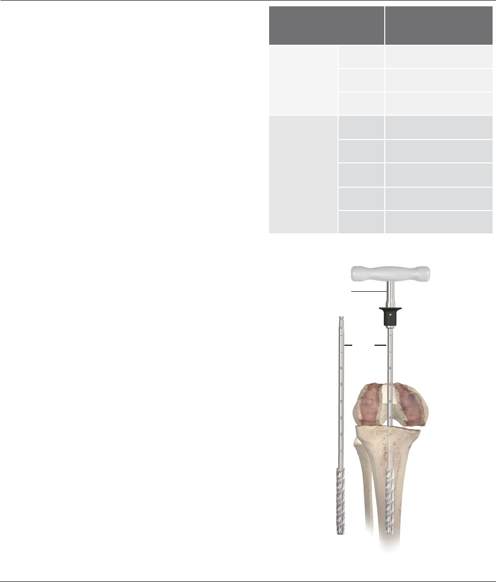
Reaming the Medullary Canal
Assemble the Straight Reamer to the T-Handle. If power
reaming, it will be necessary to attach the modified
Hudson Adapter to the Straight Reamer. The shaft of the
reamer contains markings in 25.4 mm (1 in) increments.
Each marking is numbered to use as a reference when
reaming to the appropriate depth. Fluted stem lengths
are available in 75, 115 and 150 mm. Determine the
length and diameter of the prosthetic Stem Extension
with Templates (Cat. No. 2178-30-100) applied to pre-
operative X-rays.
Use the Reamer Depth Chart (Figure 7) to determine the
appropriate mark on the reamer for canal reaming
depth. Another option to determine reamer depth is to
measure the trial assembly against the reamer and note
the corresponding depth mark for reaming. Sequentially
open the canal with progressively larger reamers until
firm endosteal engagement is established (Figure 8).
Note: Simple cortical contact should not be
construed as engagement.
The fixed relationship of the reamer to the cortices
ensures the secure fit of the appropriate reamer and,
subsequently, the corresponding fluted stem. It is equally
important to not over-ream osteopenic bone. While
reaming the proximal tibia, pay close attention to the
reamer to assure that it is somewhat centrally located to
the exposed proximal tibial surface. Eccentric reaming
can occur, which could lead to undersizing of the tibial
component.
The size of the final reamer indicates the diameter
of the implant stem. The fluted stems are available in
even sizes (10 through 24 mm). Perform final reaming
with an even-sized reamer. The final implant will have a
.4 mm press-fit versus the reamer and a .5 mm press- fit
versus the Stem Trials.
Note: Refer to Appendix 1 (page 48) for cemented
stem preparation.
T-Handle
Straight
Reamer
INITIAL PREPARATION OF THE TIBIA
Figure 7
Figure 8
MBT Revision Tray Reamer Line Depth
Press-Fit
Stems
75 mm 2
115 mm 3
150 mm 4
Cemented
Stems
30 mm 1
60 mm 2
90 mm 2.5
120 mm 3.5
150 mm 4
12 DePuy Synthes Joint Reconstruction S-ROM® Noiles Rotating Hinge Surgical Technique
Tibial
Resection
Plane Notches on the Drill
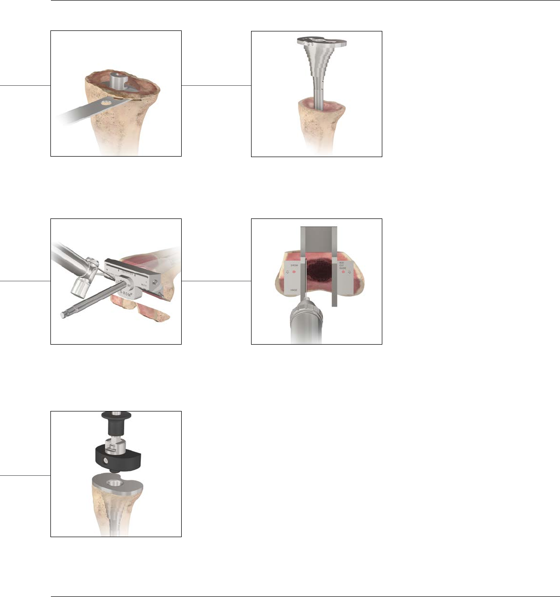
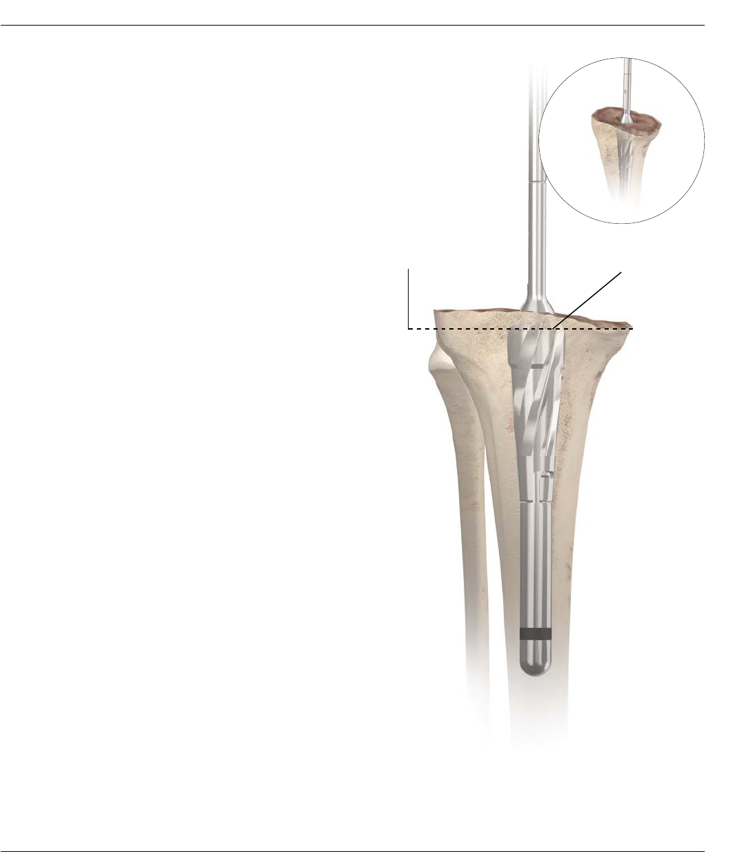
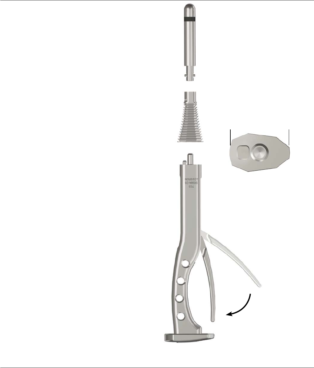
PREPARATION OF THE METAPHYSEAL BONE
– TAPERED REAMER
For Diaphyseal Engaging Stem and
Metaphyseal Filling Sleeve
Attach the appropriately sized Stem Trial to the end of
the MBT Revision Tapered Reamer.
Note: Assembly of the Stem Trial may be aided
by the pre-attachment of the T-Handle to the MBT
Revision Tapered Reamer.
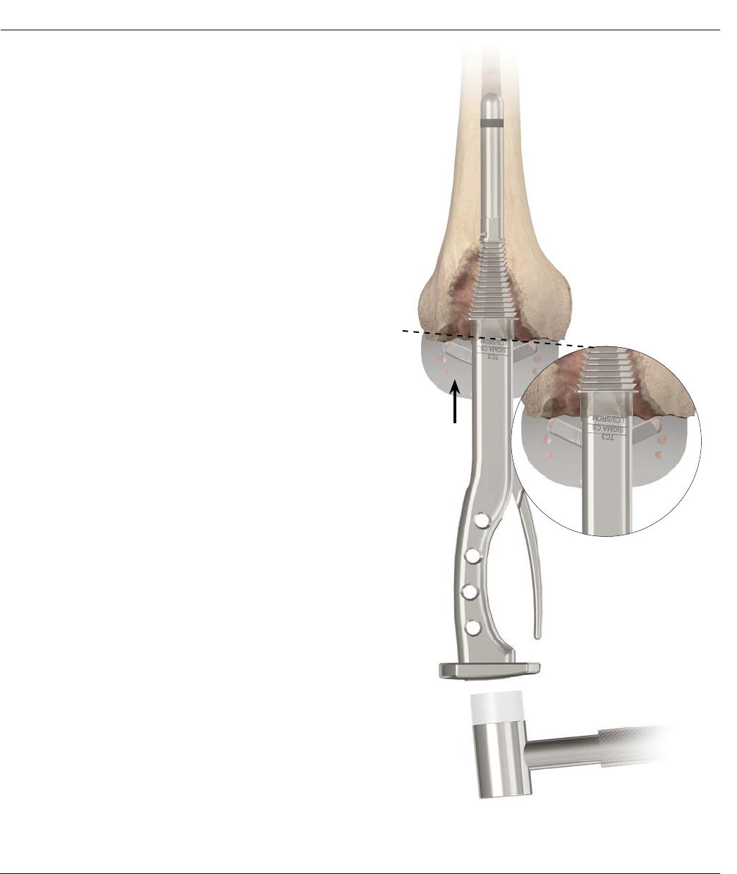
Taper ream to the planned proximal tibial resection level
(Figure 9). When finished reaming, the notches on the
Drill should line up with the planned proximal tibial
resection level.
Note: Use the “cemented” Tapered Reamer when
requiring a cement mantle or when utilizing a
sleeve. Use the Press-Fit Tapered Reamer when
line-to-line fit is desired and a sleeve will not be
utilized (Figure 10). Use End-Cutting Primary
Reamer (Cat. No. 2178-63-199) when a stem or
sleeve will not be used.
Note: To avoid Stem Trial disengagement, do not
reverse ream.
At this point, intra-operatively determine if a
Metaphyseal Sleeve will be used.
Note: Metaphyseal Sleeves are ideal to provide
filling of Engh Type II or III defects in revision
TKA. The steps of the Metaphyseal Sleeve also
provide progressive loading of the bone with porous
coating, which enhances fixation.
If a Metaphyseal Sleeve is selected, see page 16 in order
to broach the metaphyseal bone.
If a Metaphyseal Sleeve will not be used, see the
following page to prepare for the proximal tibial
resection.
Figure 9
Surgical Technique S-ROM® Noiles Rotating Hinge DePuy Synthes Joint Reconstruction 13
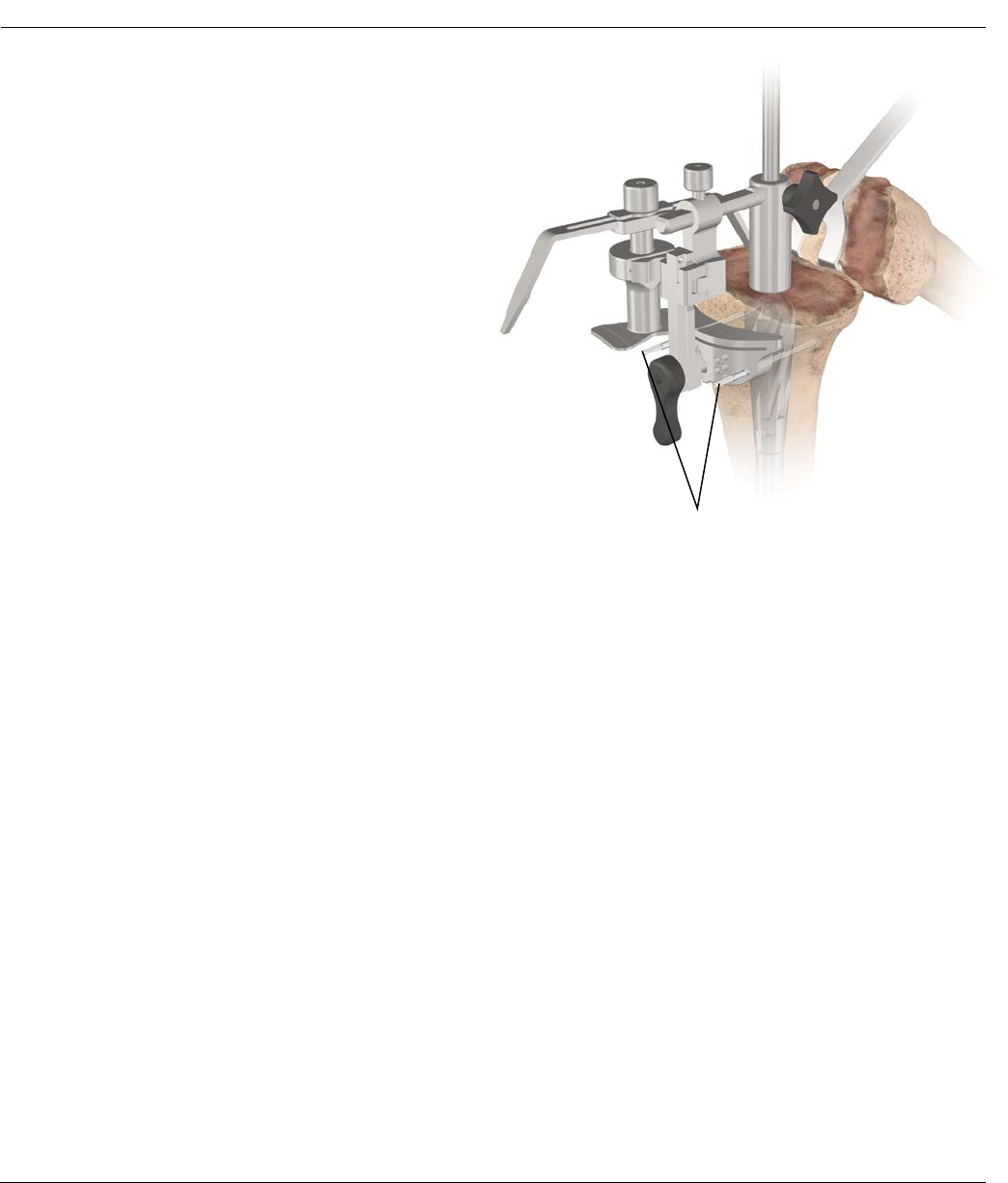
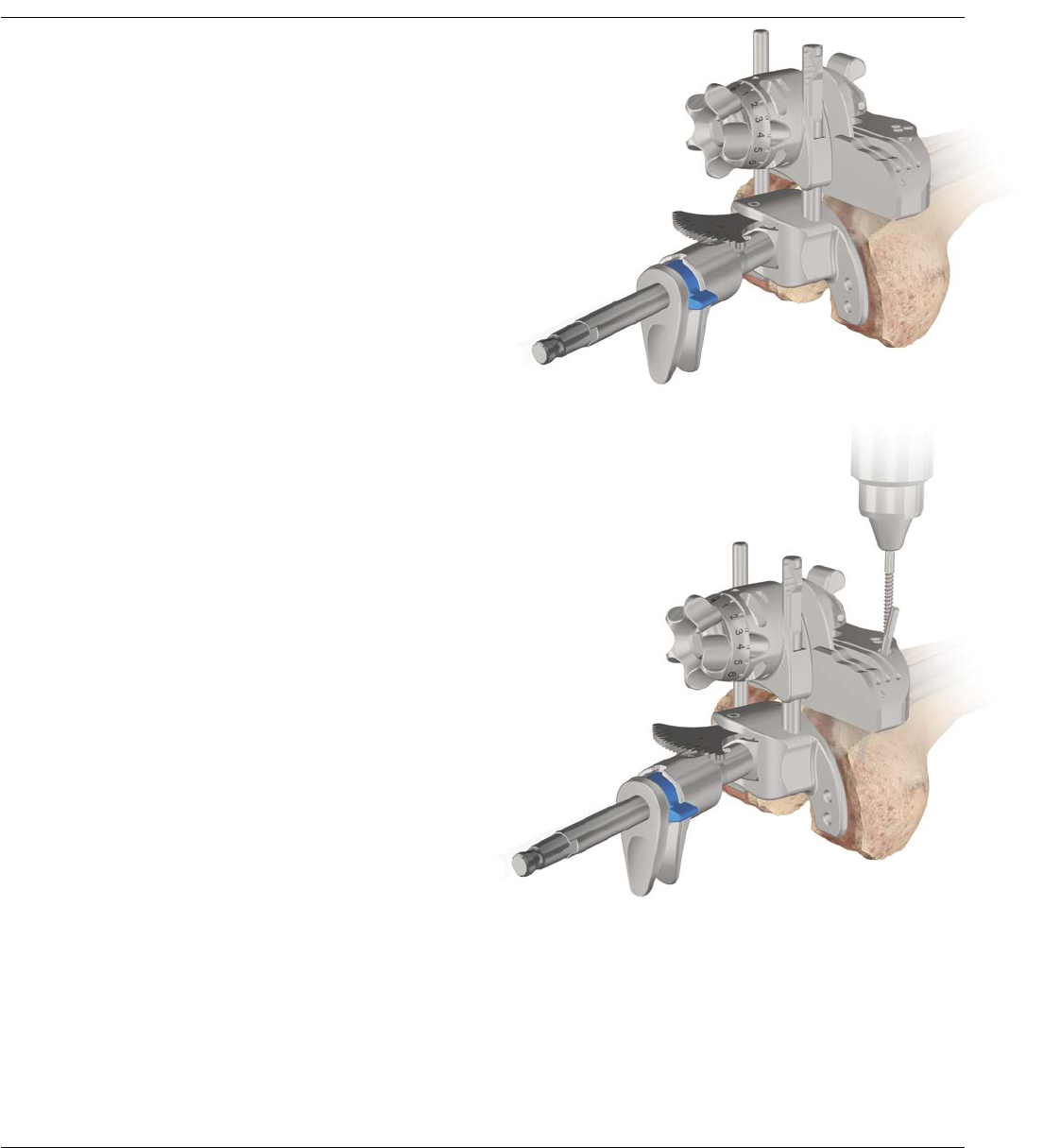
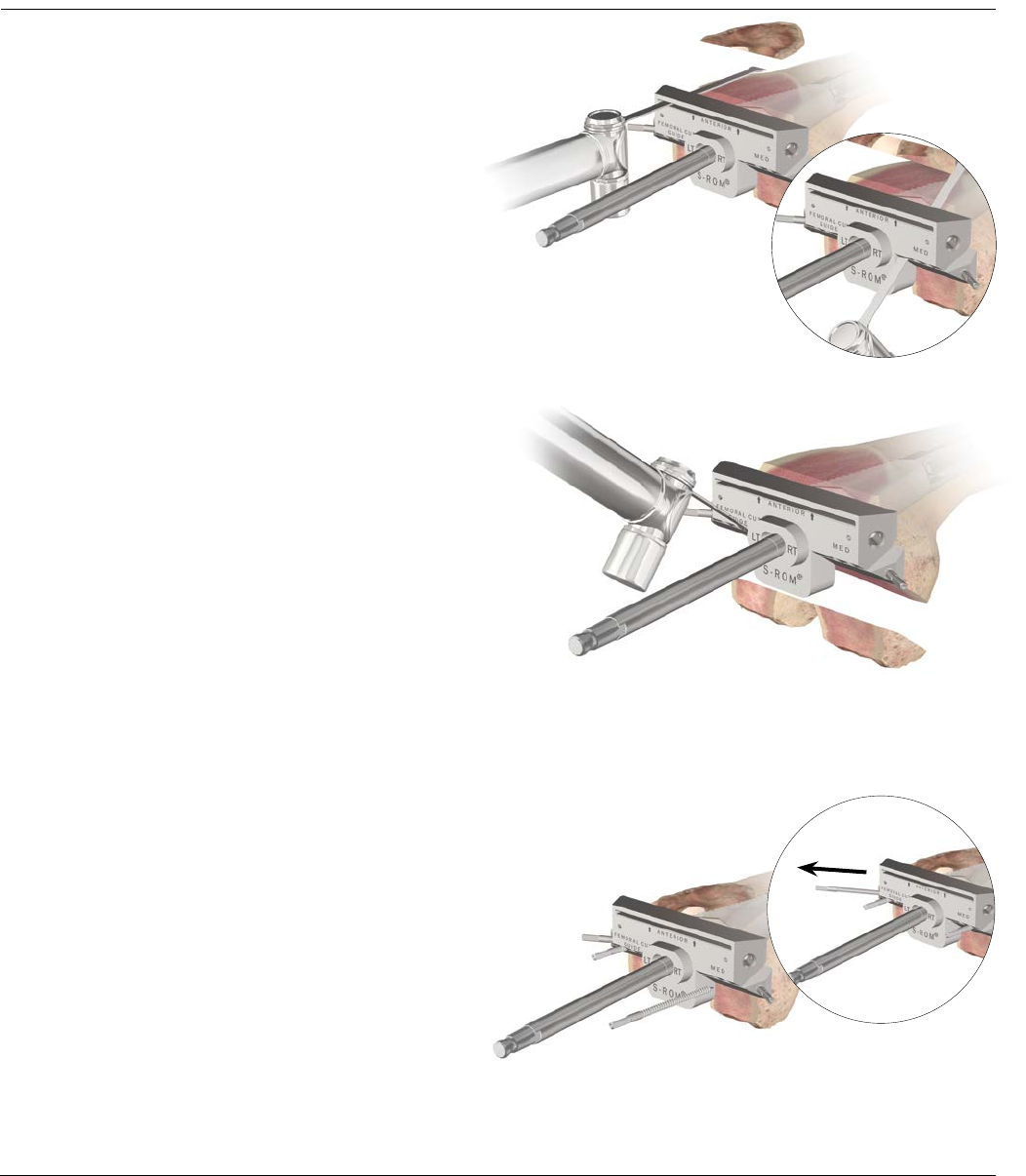
PROXIMAL TIBIAL RESECTION – TAPERED REAMER
Attach the 2 degree Tibial Cutting Block to the I.M.
Tibial Referencing Device. Attach the I.M. Tibial
Referencing Device to the shaft of the Tapered Reamer.
Position the I.M. Tibial Referencing Device with the pre-
attached 2 degree Cutting Block onto the shaft and
allow it to descend to the proximal tibial surface. Since
considerable bone stock may have been sacrificed in the
primary TKA, minimize the amount resected: no more
than 1-2 mm from the most prominent condyle,
managing residual defects of the contralateral condyle
with either prosthetic augment or bone graft.
Resection is based on tibial deficiency and the level of
the joint line. Compensate deficiencies with sleeves,
wedges and/or bone grafts. Advance the cutting block
to the anterior tibial cortex and lock into position by
tightening the knurled knob on the outrigger.
Preliminary rotational alignment is based on the medial
third of the tibial tubercle. Secure the alignment device
to the reamer shaft with the lateral Setscrew (Figure 10).
Pin the Tibial Cutting Block so a minimal resection is
made from the proximal tibia. Utilize the Stylus when
necessary (Figure 10).
Note: There is a slotted and non-slotted end to the
Stylus. The difference between the two is
5 mm.
Note: If a Metaphyseal Sleeve is to be used the tibial
resection will be performed using the Tibial Sleeve
Broach (see page 16, Figure 12).
Figure 10
Pins
14 DePuy Synthes Joint Reconstruction S-ROM® Noiles Rotating Hinge Surgical Technique
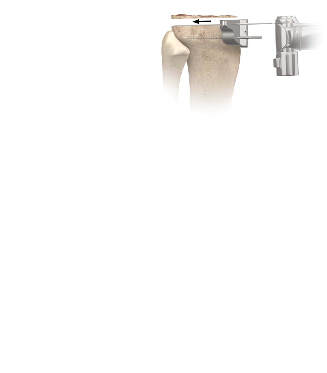
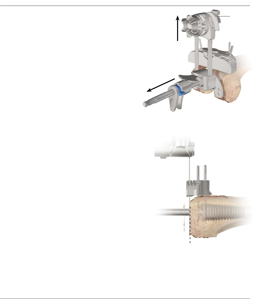
PROXIMAL TIBIAL RESECTION – TAPERED REAMER
Remove the I.M. device while leaving the degree Cutting
Block in place. Remove the Tapered Reamer and resect
the proximal tibia (Figure 11).
Note: At this point determine whether a step wedge
is necessary on either the medial or lateral side to
augment a defect, or both sides in order to restore
the joint line. If a wedge is necessary on one side,
it is recommended that the step wedge be prepared
after rotational position of both the femoral and
tibial components have been determined. For step
wedge preparation see Appendix 2 (page 51).
Figure 11
Surgical Technique S-ROM® Noiles Rotating Hinge DePuy Synthes Joint Reconstruction 15
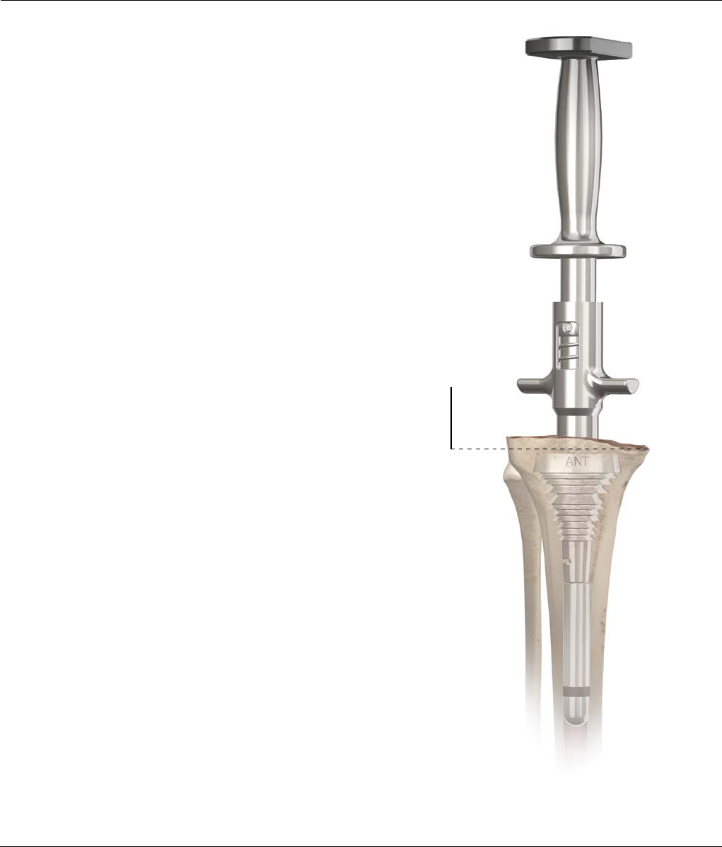
PREPARATION OF THE METAPHYSEAL BONE – BROACH
Optional For Sleeve Utilization Only
Note: The MBT Revision Tibial Tray will accept
either a tibial Metaphyseal Sleeve or a tibial Step
Wedge. Only the 29 mm Sleeve is indicated for use
with a Tibial Step Wedge.
Attach the MBT Revision Broach Handle to the smallest
broach and then attach the appropriately sized Stem
Trial. The broaches are asymmetrical, position the “ANT”
engraving on the broach anteriorly. Impact the broach
into the tibia until the top surface of the broach is at the
desired proximal tibial resection level. When broaching
the proximal metaphysis, take care to assure the
appropriate rotation of the Broach.
Note: The corresponding tibial sleeve implant
allows up to +/- 20 degrees of rotation from
the centerline of the MBT Revision Tray.
Check for rotational stability of the broach. If the broach
(not the handle) moves in the canal, it is not rotationally
stable.
If the broach is unstable or the defect is unfilled, repeat
with consecutively larger broaches until the desired fit is
achieved (Figure 12). Remove the Broach Handle, leaving
the last broach in place. Any defects remaining can be
filled with allograft or autologous bone placed in
intimate contact with the sleeve.
Two common tibial broaching techniques:
1) Chase the defect by rotating the broach to fill the
defect until reaching rotational stability of the broach.
If utilizing this technique the surgeon must be aware
that the sleeves are allowed to rotate +/-20 degrees
with respect to the MBT Revision Tibial Tray.
2) Align the broach with the medial third of the tibial
tubercle and progressively broach until rotational
stability of the broach is attained.
Figure 12
Tibial
Resection
Plane
16 DePuy Synthes Joint Reconstruction S-ROM® Noiles Rotating Hinge Surgical Technique
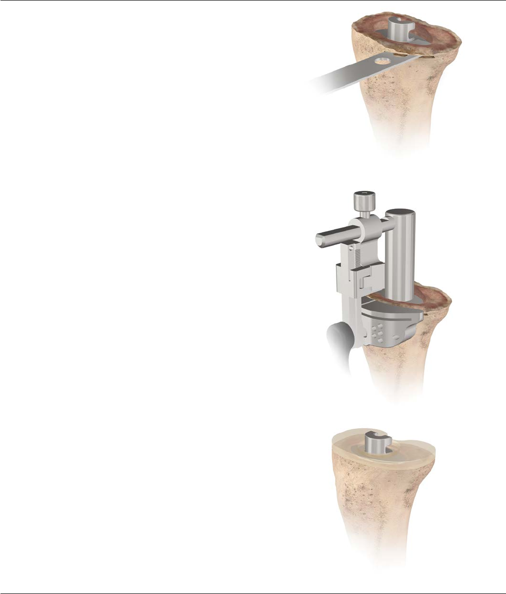
PREPARATION OF THE METAPHYSEAL BONE – BROACH
Resect the proximal tibia utilizing the top of the broach
as a guide (Figure 13). The top of the broach has a 2
degree slope built in. The proximal cut should be parallel
to the top of the broach.
Note: If a cutting guide is desired for resecting
the proximal tibia with the tibial broach in place,
assemble the SP2 0 degree Tibial Cutting Block
(Cat. No. 96-6320) to the SP2 IM Tibial Guide and
slide over the Broach Adapter Outrigger (Cat. No.
2178-01-108). Slide this assembly onto the boss of
the seated tibial broach, pin the block, remove the
outrigger, and resect through the slot of the cutting
block (Figure 14).
Slide the tibial view plate which best covers the proximal
tibial over the broach post. Note the view plate size as it
will dictate the size of the MBT Revision Tibial Base Trial
that will be used. The tibial view plate is transparent to
help visualize tibial coverage (Figure 15). The template
matches the implant to aid in orienting the tibial sleeve
to the tibial base during assembly.
Figure 15
Figure 14
Figure 13
Surgical Technique S-ROM® Noiles Rotating Hinge DePuy Synthes Joint Reconstruction 17
TIBIAL TRIAL ASSEMBLY
Assemble the tibial tray trial with the stem extension and
sleeve trial, if applicable (Figure 16). Position the Tibial
Trial construct into the prepared tibial canal (Figure 17).
Assess proximal tibial coverage and rotation of tibial
component. The base plate should be positioned to
provide the best coverage of the tibial condylar surface.
Note: The MBT Revision Tibial Keel Punch with the
Universal Handle may be utilized to assist with seating of
tibial trial construct. Once the tibial trial construct is
seated the Keel Punch must be removed in order to
accommodate the use of Spacer Blocks.
Leave the trial in place and proceed to femoral
preparation, final tibial preparation will occur after
femoral preparation is complete.
Note: A 14 mm or smaller size stem implant can be
pulled through the sleeve implant. If the stem is 16
mm or greater it will not pull through the sleeve.
Figure 16
Figure 17
18 DePuy Synthes Joint Reconstruction S-ROM® Noiles Rotating Hinge Surgical Technique
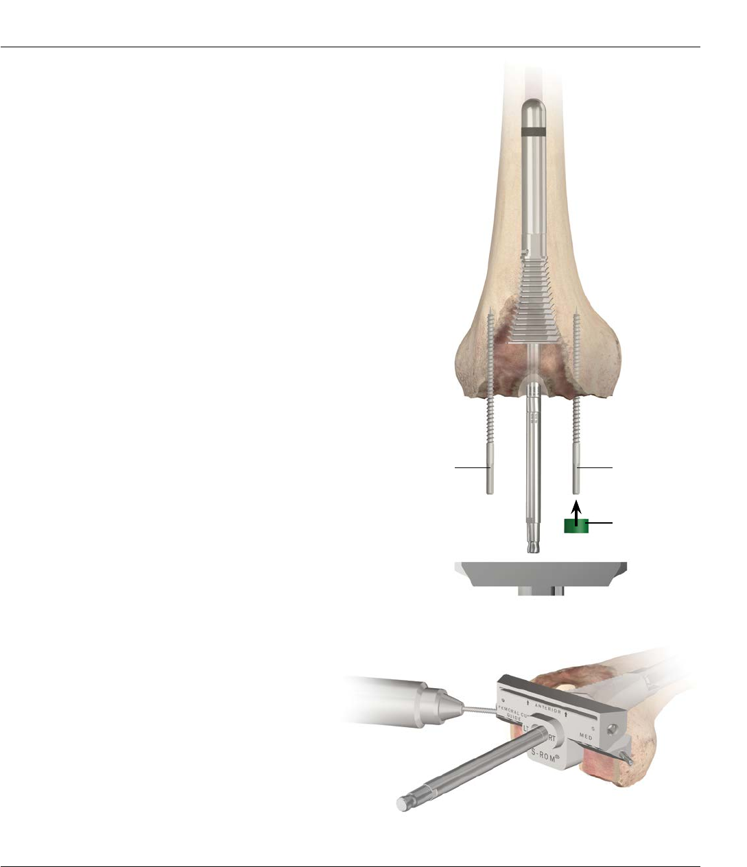
PREPARATION OF FEMORAL DIAPHYSIS
Figure 18
Intramedullary Femoral Alignment System
This technique is designed to flow in a logical sequence,
from reaming the diaphysis, to broaching the
metaphysis and cutting the bone. The length and
diameter of the stem extension is determined with
templates applied to pre-operative roentgenograms.
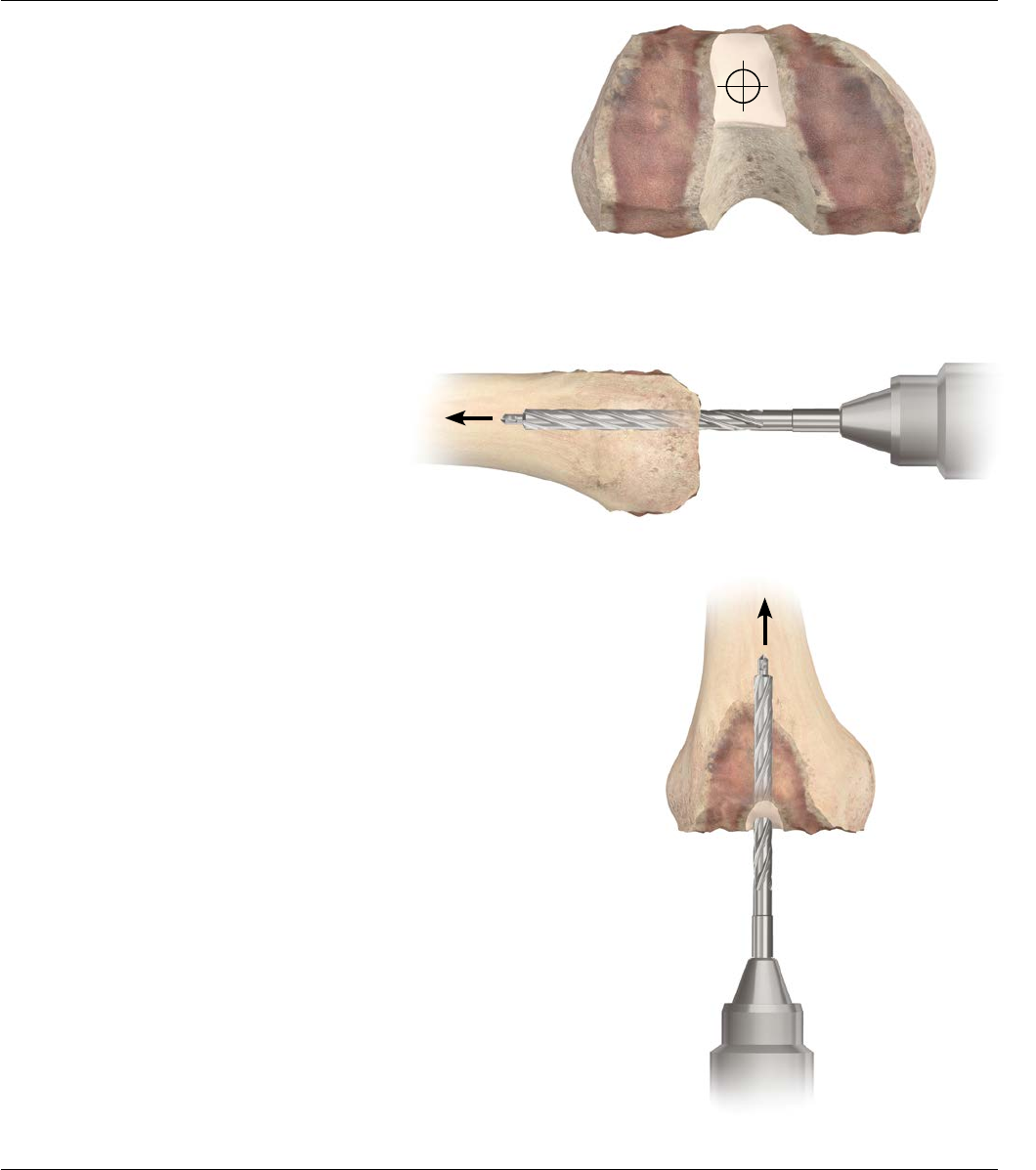
Begin the procedure with the preparation of the
medullary canal (Figures 18 and 19).
Enter the medullary canal with a 9 mm drill to a depth
of 3-5 cm (Figure 20). Take care that the drill avoids the
cortices. It is helpful to palpate the distal femoral shaft
as the drill is advanced.
Where impedance of the intramedullary canal is
anticipated, adjust the entry point accordingly.
Figure 20
Figure 19
Surgical Technique S-ROM® Noiles Rotating Hinge DePuy Synthes Joint Reconstruction 19
REAMING THE MEDULLARY CANAL
Figure 21
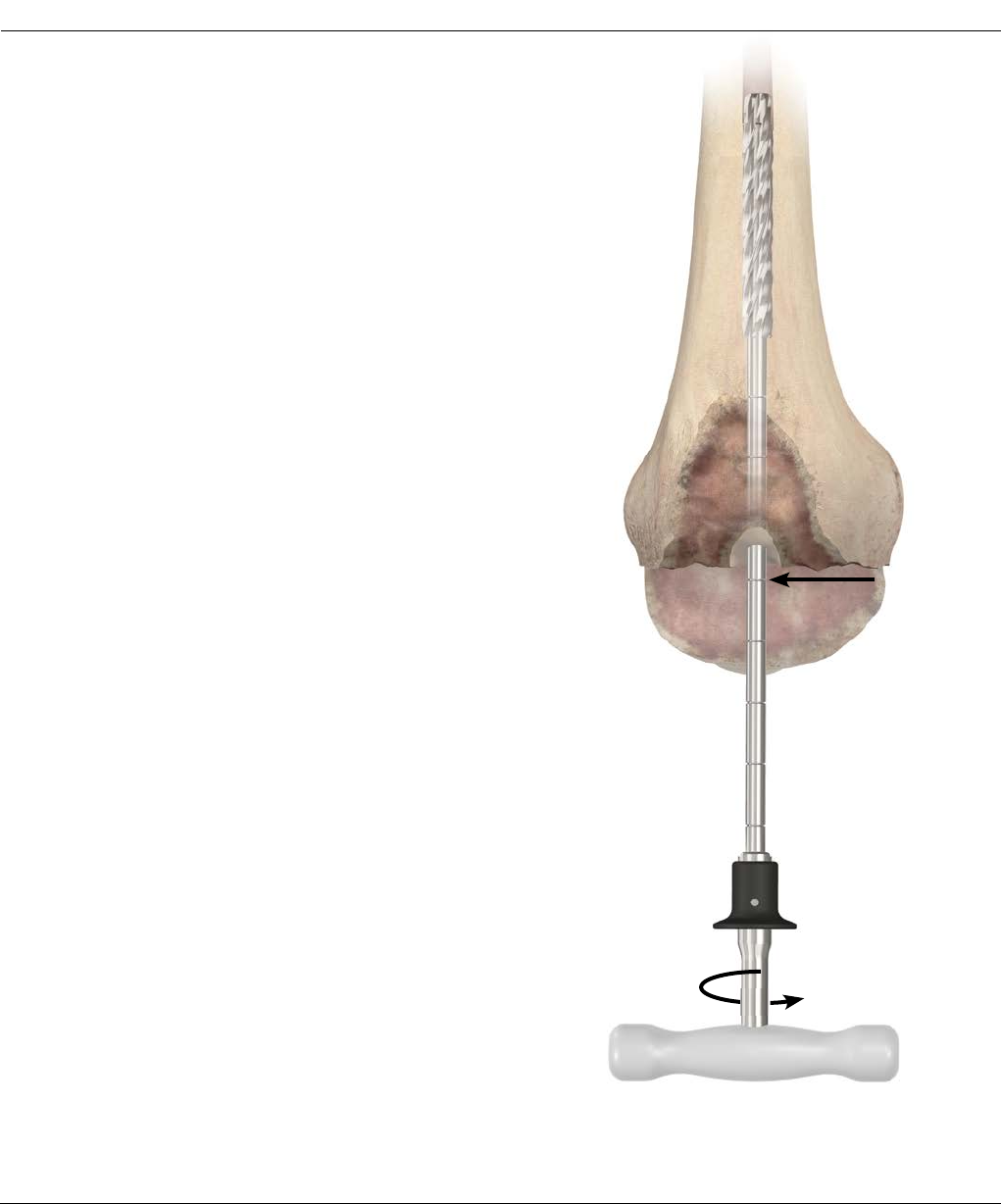
Connect the Reamer Handle to a small diameter MBT
Revision Reamer. If power reaming, it will be necessary
to attach the modified Hudson Adapter to the Straight
Reamer.
Note: The reamer shaft contains markings in
25.4 mm increments to accommodate the various
Universal Stem/Sleeve length combinations (Figure 21).
Use the Reamer Depth Chart to determine reamer depth
for each combination of components (Figure 22).
Another option to determine reamer depth is to
measure the trial assembly against the reamer and note
the corresponding depth mark for reaming.
You may also determine the length and diameter of the
prosthetic stem extension with templates (Cat. No.
2294-99-035: SIGMA Femoral Adapter Sleeve and Stem
Template) applied to pre-operative X-ray. The S-ROM
femoral components can be found on the S-ROM
Templates (XRT-115).
The S-ROM Femoral Component accepts the
following stems, only with the use of a femoral
sleeve:
· Universal Fluted Stems of 75, 115 and 150 mm in
diameters of 10-24 mm in 2 mm increments
· Cemented Stems available in lengths of 30 and
60 mm lengths and a diameter 13 mm or 15 mm
· Cemented Tapered Stems available in lengths of
90 mm (13 mm and 15 mm diameter) and 120 mm
and 150 mm (13 mm diameter only)
Note: The Stem is the same as is currently used
with the MBT Revision Trays.
Example: Ream to the tick mark
#4 when using S-ROM femur with
31 mm Sleeve and 75 mm Press-
Fit Stem
20 DePuy Synthes Joint Reconstruction S-ROM® Noiles Rotating Hinge Surgical Technique

S-ROM Femur 20 mm
31 mm
34 mm
40 mm
46 mm
Cemented
Stems
30 mm 2 2
60 mm 3 3
90 mm 4 4
120 mm 5 6
150 mm 6 7
Press-Fit
Stems
75 mm 4 4
115 mm 5 5
150 mm 6 7
REAMING THE MEDULLARY CANAL
Figure 22
In 1 mm diameter increments, sequentially open the
medullary canal with MBT Revision Reamers of
progressively greater size until firm endosteal
engagement is established.
Take care to ream the canal in line with the femoral axis
to avoid putting the implant in flexion.
Note: Do not reverse ream.
It is important that simple cortical contact of the tip not
be construed as engagement.
Cemented Stem Use
Where a cemented stem extension is indicated, perform
final reaming with a 15 mm diameter reamer for the 13
mm diameter stem extension; similarly a 17 mm
diameter reamer is used to accommodate the 15 mm
diameter stem extension.
This allows for creation of a cement mantle.
Surgical Technique S-ROM® Noiles Rotating Hinge DePuy Synthes Joint Reconstruction 21
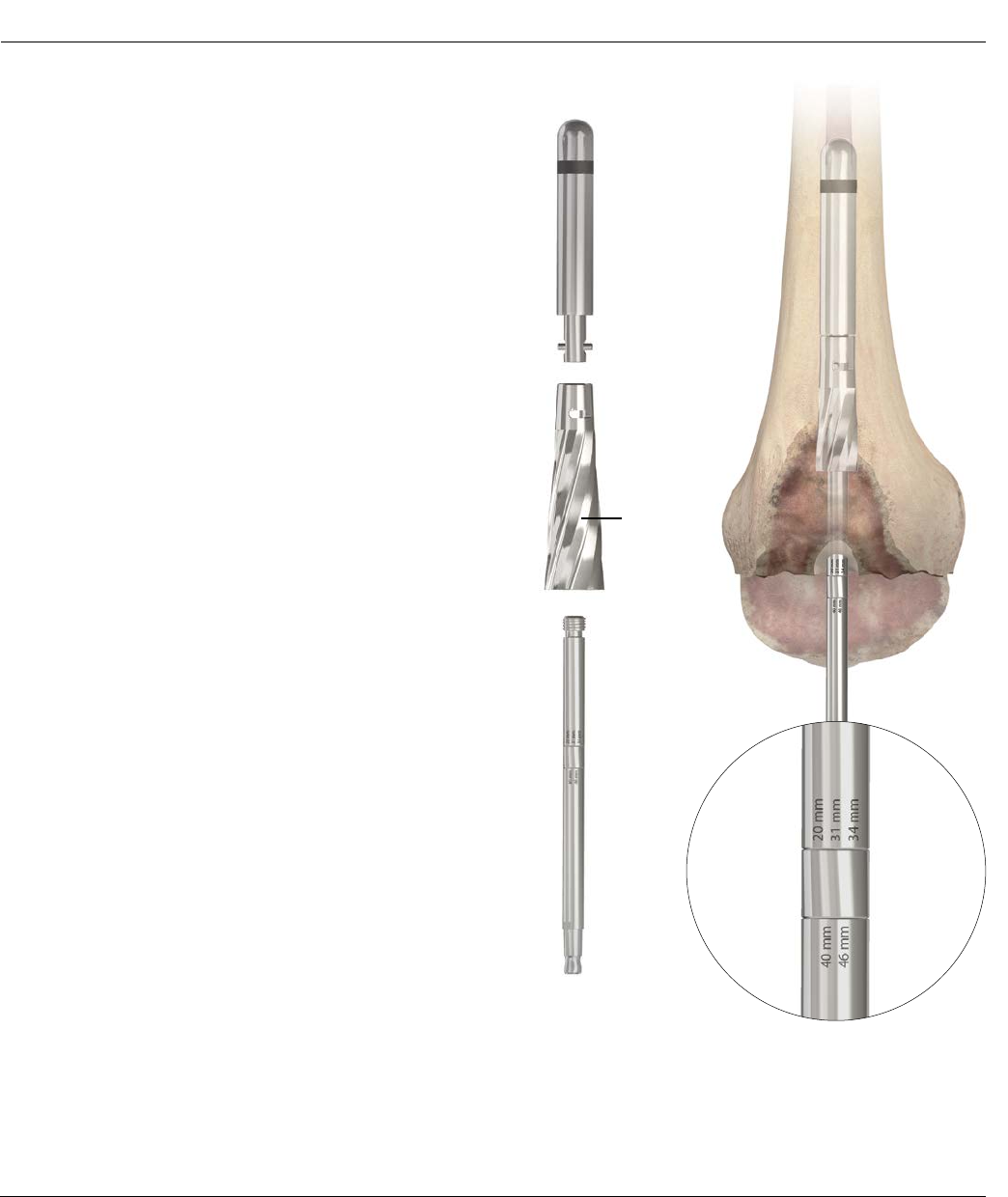
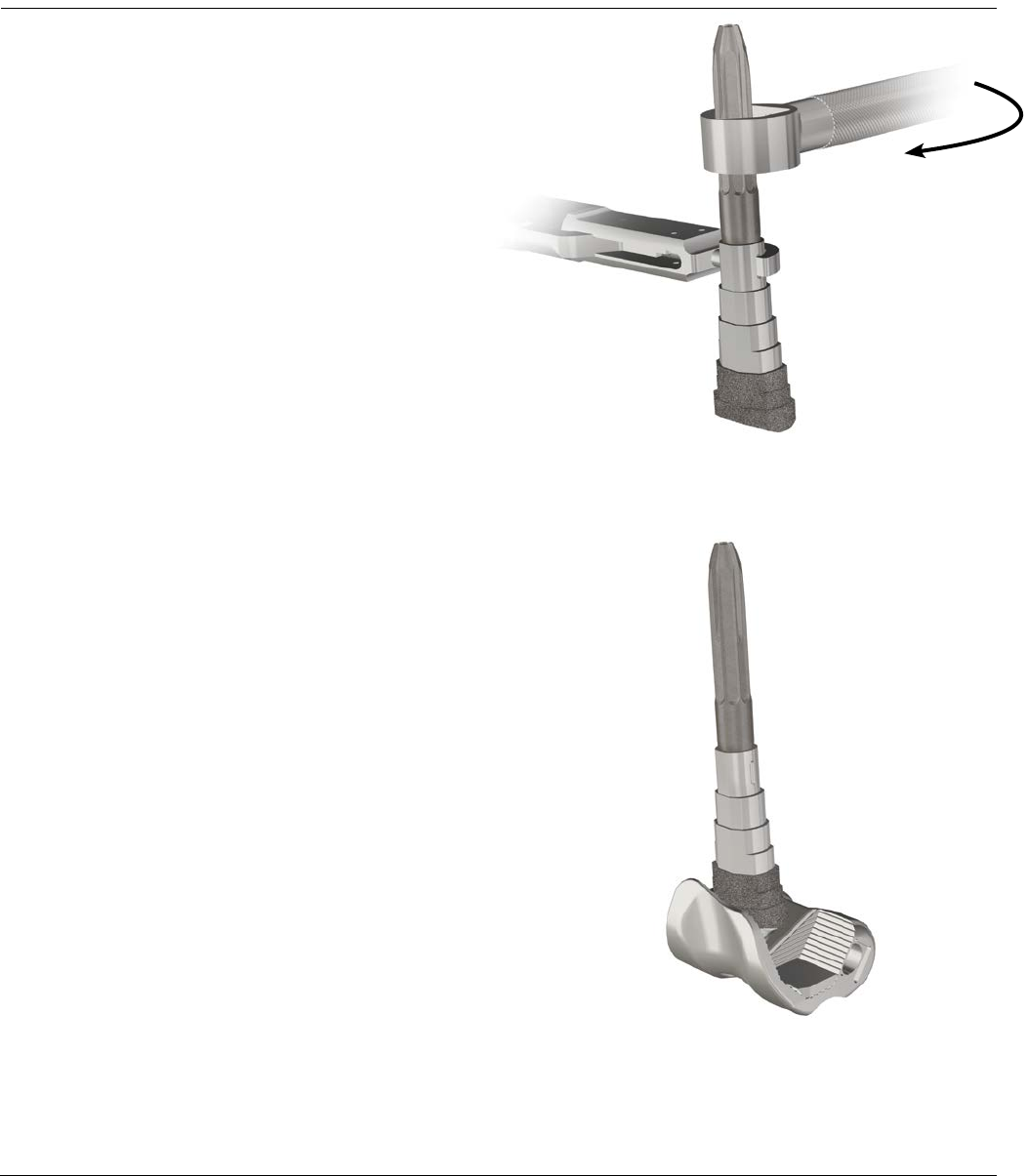
Figure 23 Figure 24
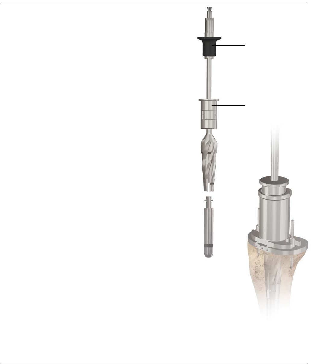
Broach
Reamer
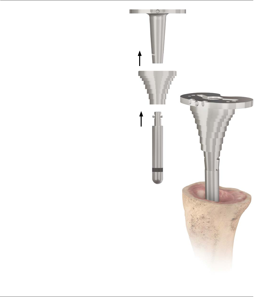
After reaming the intramedullary canal, attach the
Threaded Shaft to the Broach Reamer and then to the
appropriate Stem Trial as determined by straight reaming
(Figure 23).
Ream to the 20 mm, 31 mm, 34 mm etch mark on the
Threaded Shaft (Figure 24).
PREPARATION OF THE METAPHYSIS – SLEEVE USE
22 DePuy Synthes Joint Reconstruction S-ROM® Noiles Rotating Hinge Surgical Technique
Medial SideLateral Side
Figure 26
Figure 25
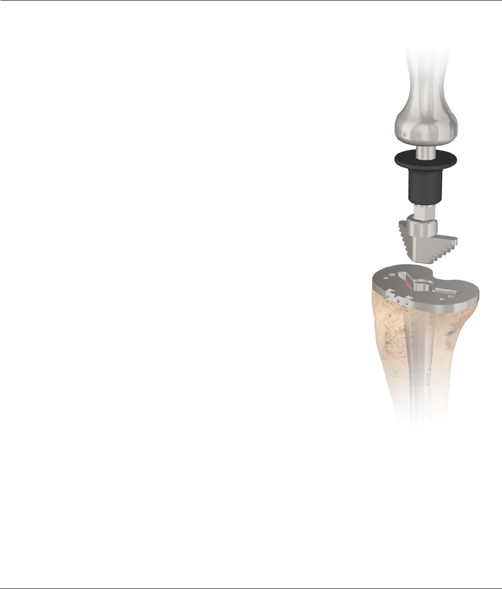
PREPARATION OF THE METAPHYSIS – SLEEVE USE
When using the Broach Reamer, the next smaller
diameter Stem Trial may be used to allow for easier
reaming. The Broach Reamer will be necessary when
utilizing a 20 mm sleeve and for the beginning of larger
sequential broaching when using a 31 mm
or larger sleeve. After broach reaming has been
completed, attach the 31 mm broach to the Broach
Handle (Figure 25). Attach the appropriate Stem Trial to
the broach as determined by straight reaming. Give
close attention to the medial orientation of
the broach.
Note: The broach is asymmetrical; and the narrow
side of the broach must point medially (Figure 26).
Note: When prepping for a 20 mm sleeve, leave the
Broach Reamer and threaded shaft in the canal and
perform the subsequent femoral cuts off the reamer.
Surgical Technique S-ROM® Noiles Rotating Hinge DePuy Synthes Joint Reconstruction 23
PREPARATION OF THE METAPHYSIS – SLEEVE USE
Sequentially broach to the desired dimension of 31, 34,
40 or 46 mm (Figure 27). When the LCS®/SROM etch
mark on the Broach Handle is at the planned distal
resection level, check the broach’s rotational stability. If
the broach (not the handle) moves in the canal, it is not
rotationally stable.
If the stability of the broach is unsatisfactory, move up to
the next broach size. The last broach used will be the
femoral sleeve size. The broach depth sets the extension
gap/joint line.
In patients with a large degree of distal femoral bow,
closely monitor the anterior progression of the broach
during impaction. Excessive anterior placement of the
broach may result in a loose flexion gap.
Figure 27
Planned Level of Distal Resection
24 DePuy Synthes Joint Reconstruction S-ROM® Noiles Rotating Hinge Surgical Technique
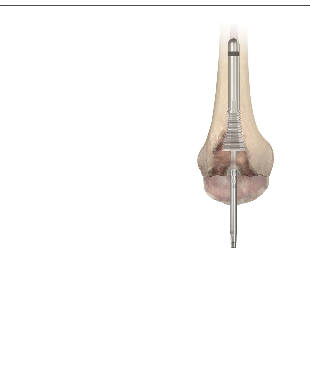
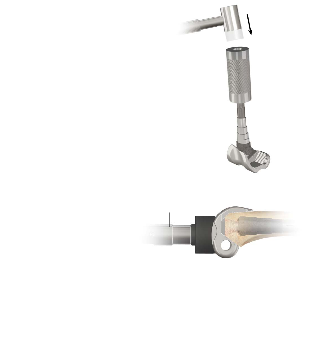
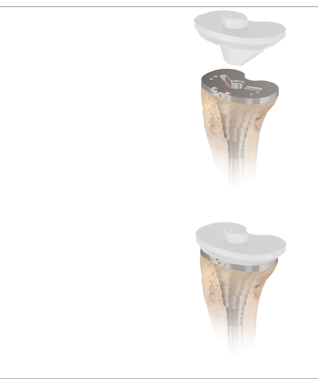
Figure 28
PREPARATION OF THE METAPHYSIS – SLEEVE USE
After broaching is complete, remove the Broach Handle
from the broach. With the broach seated in the femur,
attach the Threaded Shaft to the broach (Figure 28).
Distal, anterior, chamfer, and notch cuts will reference
off the Threaded Shaft/Broach assembly.
Surgical Technique S-ROM® Noiles Rotating Hinge DePuy Synthes Joint Reconstruction 25

FEMORAL PREPARATION – DISTAL RESECTION
Distal Femoral Resection Guide
Distal Femoral Connector
Revision Distal Cutting Block
Figure 29
Figure 31
Figure 30
Figure 32
Distal Resection
Set the valgus angle to 7 degrees and Left/Right on the
Distal Femoral Alignment Guide by compressing the two
triggers and lock in place by rotating the blue locking
lever clockwise. Place the Femoral Alignment Guide on
the Threaded Shaft and seat against the distal femur
(Figure 29).
Rotate the knob on the Femoral Resection Guide
counterclockwise until the arrow is pointing to the
padlock symbol. Slide the Distal Femoral Connector into
the Femoral Resection Guide. Rotate the knob on the
Femoral Resection Guide clockwise. Every click moves
the Revision Distal Cutting Block 1 mm proximal or
distal. Turn the knob clockwise from 15 all the way
down to 0 (which is the padlock symbol). This will set
the block up for a 0 mm resection (Figure 30).
Slide the revision Distal Cutting Block onto the Distal
Femoral Block attachment. The tang on the block
connector will slide into the 0 mm cutting slot on the
cutting block. The trigger should engage in the hole
behind the 0 mm slot (Figure 31).
Note: An open resection will resect 4 mm less
femur. When a 0 mm open resection is desired, the
dial should be set to 4 mm.
Position the resection guide over the two legs of the
Distal Femoral Alignment Guide until the Distal Cutting
Block touches the anterior femur (Figure 32).
Note: The Revision Distal Block is equipped with 0,
4, and 8 mm saw slots. Please keep in mind that if
the resection level is not at 0 (the padlock symbol)
this will alter the resection. If the resection knob is
set at 2, for instance, the saw slots will perform 2, 6,
and 10 mm resections.
26 DePuy Synthes Joint Reconstruction S-ROM® Noiles Rotating Hinge Surgical Technique
FEMORAL PREPARATION – DISTAL RESECTION
Rest the Femoral Alignment Guide against the most
prominent distal condyle. If no distal augments are
needed, proceed with pinning the distal resection block
and making the distal cuts through the 0 mm resection
slot (Figures 33 and 34).
If it is determined that a 5 mm or a 10 mm Distal
Augment will be needed on only one condyle, perform a
0 mm clean-up cut first on the prominent condyle. Then
turn the dial on the Femoral Resection Guide to 5 mm or
10 mm and make the cut on the other condyle through
the 0 mm resection slot.
Note: Do not use the saw slots on the Distal Block to
make augment cuts. The augment slots on this block
are set up in 4 mm increments instead of the needed
5 mm increments for S-ROM.
Alternatively, the LCS Revision Distal Femoral Resection
Guide may be used instead of the SIGMA Revision Distal
Femoral Resection Guide. The LCS Revision Block (Cat.
No. 2178-60-070) is already set up to accommodate
augments in increments of 5 mm.
Note: When adding 5 or 10 mm Distal Augments
to both sides of the femur, it may be necessary to
re-evaluate the depth the sleeve was broached
to, based upon the addition of augments. If the
augments require the broach to be distalized,
rebroaching should occur with a larger broach in
order to distalize the sleeve in the canal without
losing press-fit.
Figure 33
Figure 34
Surgical Technique S-ROM® Noiles Rotating Hinge DePuy Synthes Joint Reconstruction 27
FEMORAL PREPARATION – DISTAL RESECTION
Figure 36
Figure 35
2. Remove femoral alignment
guide towards the T-Handle
1. Slide femoral resection
guide upwards
Release
attachment
Once the pins are in place, unlock the Distal Cutting
Block from the Distal Femoral Connector, using your
thumb and index finger to release the attachment. Slide
the Femoral Resection Guide upwards on the Alignment
Guide legs until the block connector disengages from
the Cutting Block and in one motion remove the
Femoral Alignment Guide by pulling the instruments
distally over the Threaded Shaft (Figure 35).
In many cases, little, if any, bone is removed from the
distal femur as the joint line is effectively elevated with
the removal of the primary femoral component. As the
level of resection is based on the preservation of bone
stock, each condyle is cut only to the level required to
establish a viable surface, with augmentation employed
to correct imbalance.
The resection is then performed through the slot
appropriate for each condyle, using a standard 1.19
mm thick blade (Figure 36).
Note: If a ½in. wide Standard Saw Blade is used it
can complete both medial and lateral distal femoral
cuts with the entire jig still in place.
An example of a medial
resection at 0 mm
28 DePuy Synthes Joint Reconstruction S-ROM® Noiles Rotating Hinge Surgical Technique
The Femoral Cutting Guide is size specific (two blocks –
X-Small/Small and Medium). Determine the femoral
component size by pre-operative templating and
comparing the Femoral Component Trial to the size of
the femur. Use the size which gives the best medial/
lateral (M/L) coverage.
Slide the appropriately sized cutting guide over the
Threaded Shaft. Use the corresponding hole for a left or
a right knee (Figure 37).
Place the guide into neutral rotation by aligning the
anterior cortex parallel with the anterior portion of the
guide. The SIGMA Angel Wing (part number: 96-6530)
may be helpful in this step. Also use the femoral
epicondylar axis as the rotational reference.
Note: If distal augmentation will be used,
use 5 or 10 mm Box Cut Guide Spacers on the
appropriate condyle(s). Establish the proper
rotation of the A/P block first, then pin through one
each of the medial and lateral pin holes. Remove
the block from the pins, then put the appropriate
spacer(s) over the pins before replacing the A/P
block. These spacers should rest between the
cutting guide and the distal condyle(s) to fill these
gaps appropriately (part numbers: 5 mm - 63-3305A
and 10 mm - 63-3306A).
Achieve fixation of the cutting guide with 1/8 in. drill
pins, introduced through the convergent holes on the
side of the block. These Pins will need to be temporarily
removed later to move to the notch guide (Figure 38).
Attach the Removable Handles to the cutting guide
(optional).
FEMORAL A/P AND CHAMFER CUTS
Figure 37
Figure 38
PinPin
Box Cut Guide Spacer
(5 mm)
Surgical Technique S-ROM® Noiles Rotating Hinge DePuy Synthes Joint Reconstruction 29
FEMORAL A/P AND CHAMFER CUTS
Anterior
Chamfer Cut
Remove Pins
Figure 39
Figure 40
Figure 41
Make the anterior cut (Figure 39) first. Proceed to make
the anterior chamfer cut through the captured slot. If
the block was previously pinned, temporarily remove one
pin at a time while making the resection.
Make the posterior chamfer cut (Figure 40) by
holding the saw blade flush with the cutting guide. If
anterior pins are being used for fixation, remove the pin
while resecting, then replace. Care should be taken to
avoid damaging posterior soft tissue.
If not previously pinned, place at least one 1/8 in
drill pin on each side of the guide. These will be
used to position the Box Cut Guide. Next, remove the
convergent pins.
Finally, remove the femoral cutting guide, leaving the 1/8
in. drill pins in place (Figure 41).
Note: It may be easier to remove the threaded shaft
first, before trying to slide the blocks off the pins.
30 DePuy Synthes Joint Reconstruction S-ROM® Noiles Rotating Hinge Surgical Technique
FEMORAL BOX CUTS
Use 5 or 10 mm Box Cut Guide Spacers if distal
Augmentation Blocks will be used (Figure 42).
Slide the Hinge Femoral Box Cut Guide over the 1⁄8 in.
drill pins placed in the previous step or align with the
lines marked off the Femoral Cutting Guide. If Distal
Augmentation Blocks will be used, slide 5 or 10 mm Box
Cut Guide Spacers over the drill pins before positioning
the Box Cut Guide.
Four additional 1⁄8 in. drill holes are provided on the
anterior surface of the Box Cut Guide; 1⁄8 in. drill pins
are recommended for additional stability.
Holding the saw blade flat against the inner surface of
the Box Cut Guide, make the side cuts for the center
box (Figure 43).
Use a narrow saw blade (12.7 mm or 0.5 in), placed on
the sloped guide surface, to remove the bone block of
the center box (Figure 44).
Figure 44
Figure 42
Box Cut Guide
Hinge Box Cut Guide
Narrow Saw Blade (1⁄2 in. wide)
Saw Blade
Box Cut
Guide Spacer
1/8 in. Drill Pin
Figure 43
Surgical Technique S-ROM® Noiles Rotating Hinge DePuy Synthes Joint Reconstruction 31
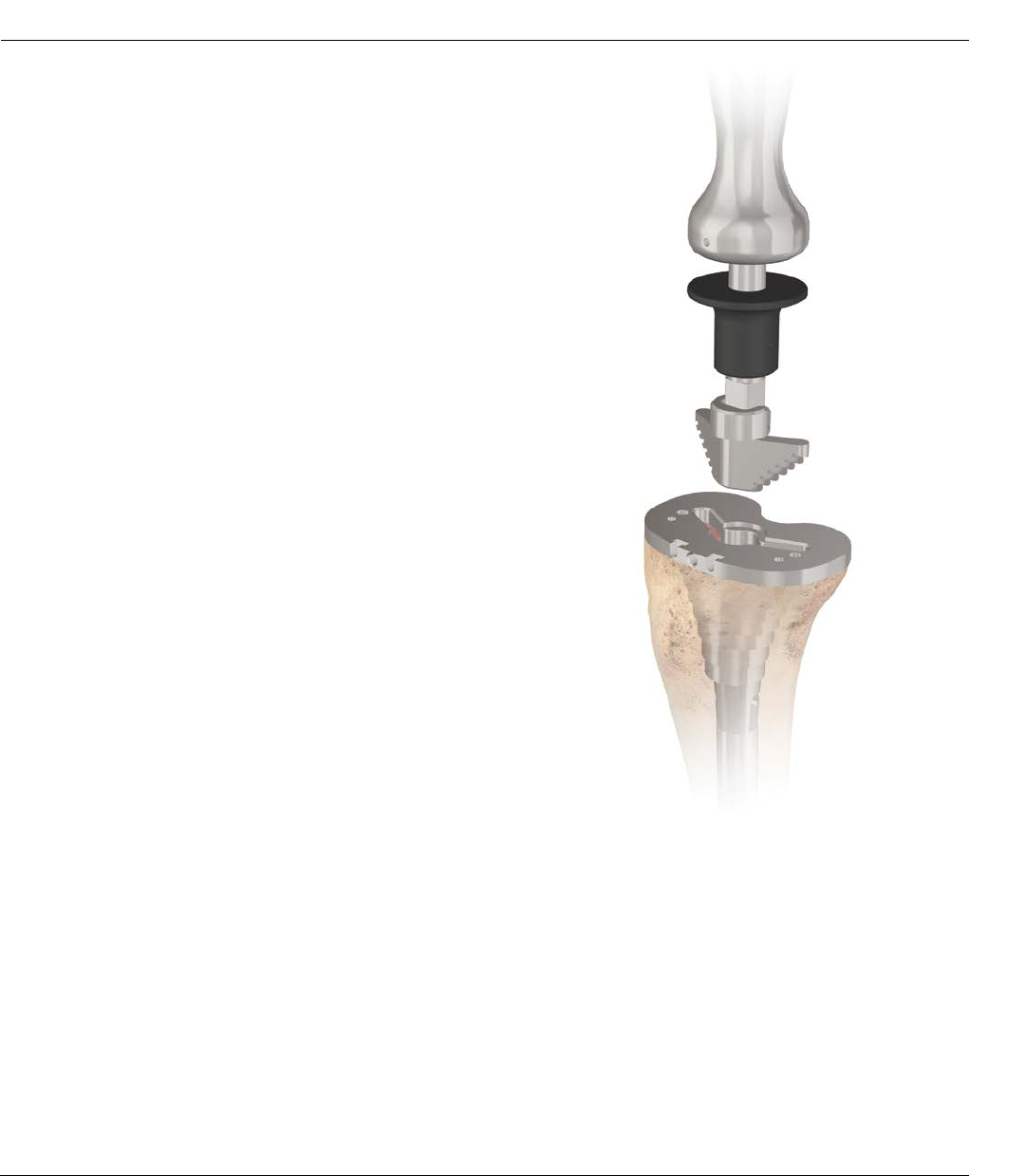
FINAL PREPARATION OF THE TIBIA
Figure 45
Assess proximal tibial coverage and rotation of tibial
component. Impact the appropriate Keel Punch (utilize
the cemented Keel Punch if a cement mantle is desired
or the Press-Fit Keel Punch if line-to-line contact is
desired) (Figure 45). The base plate should be positioned
to provide the best coverage of the tibial condylar
surface.
32 DePuy Synthes Joint Reconstruction S-ROM® Noiles Rotating Hinge Surgical Technique
FEMORAL TRIAL INSERTION
Two femoral Augmentation Blocks are available for the
S-ROM Noiles Rotating Hinge Total Knee System. They
are 5 and 10 mm Distal Blocks. One size fits all, i.e.
X-Small, Small and Medium hinge femoral components.
If distal augmentation is required, attach the
Augmentation Block Trial(s) with bone wax to the
Femoral Component Trial (Figure 46).
Figure 46
Implant
Cat. No.
Femoral
Location
Use with S-ROM Noiles
Rotating Hinge Femoral Size
Augment
Thickness
Trial Cat. No.
623805 Distal All Sizes 5 mm 633785
623810 Distal All Sizes 10 mm 633790
Femoral Augment Block
Surgical Technique S-ROM® Noiles Rotating Hinge DePuy Synthes Joint Reconstruction 33
Stem Trial
Trial Assembly inserted into
Femoral Cavity
Femoral
Component
Trial
Femoral
Sleeve Trial
Figure 47
Figure 48
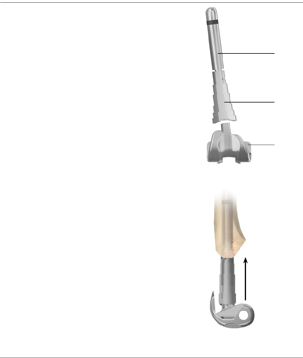
Connect the Stem Trial into the appropriate Femoral
Sleeve Trial. The diameter of the Stem Trial will be the
same as the final Straight Reamer used; the size of the
Femoral Sleeve Trial will be the same as the final Femoral
Broach used (Figure 47).
Slide the Sleeve/Stem Trial assembly into the prepared
cavity in the femoral canal to allow the assembly to self
align with the broached surfaces (Figure 48).
Note: The narrow side of the Sleeve Trial
points medially.
FEMORAL TRIAL INSERTION
34 DePuy Synthes Joint Reconstruction S-ROM® Noiles Rotating Hinge Surgical Technique
Universal Handle Femoral Driver
Femoral Component Trial
FEMORAL TRIAL INSERTION
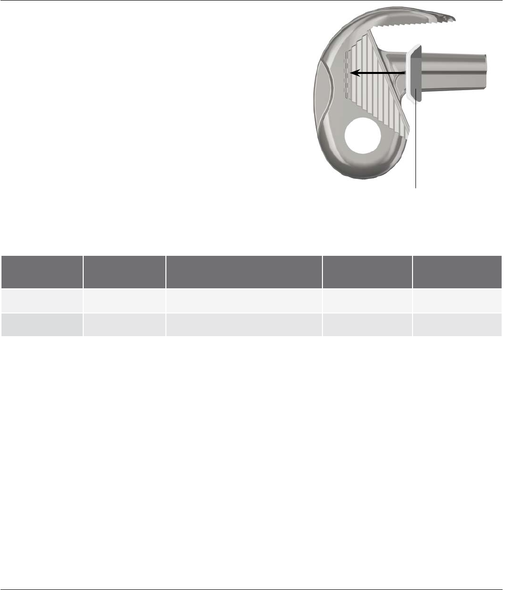
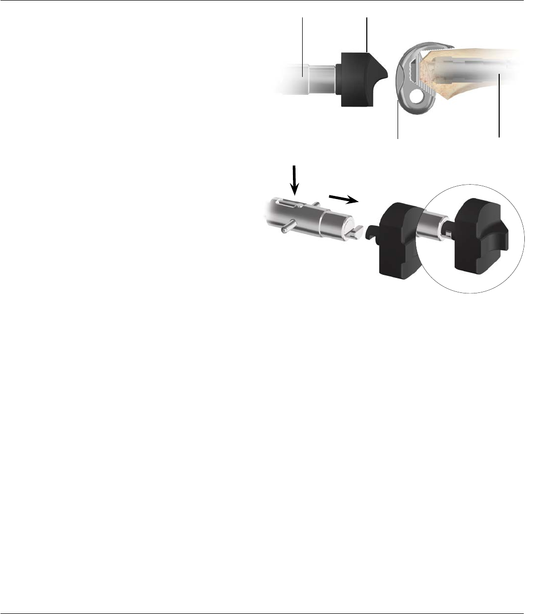
Slide the Femoral Component Trial onto the resected
femur, aligning the anterior cut with the posterior aspect of
the patellar flange. After the Femoral Component Trial
engages the Femoral Sleeve Trial, impact using the Femoral
Driver on the Universal Handle. Check accuracy of the
bone cuts. Revise or rebroach if necessary (Figure 49).
Note: If Distal Augmentation Blocks will be used,
fix Distal Augment Block Trials to the Femoral Trial
with bone wax before impacting the Trial onto the
femur.
Figure 49
Push down on the button on the quick release
handle and connect the femoral driver
Two ends engage
Femoral Sleeve Trial
Femoral
Component
Trial
Femoral
Sleeve Trial
Surgical Technique S-ROM® Noiles Rotating Hinge DePuy Synthes Joint Reconstruction 35
TRIAL REDUCTION
Without hinge pin,“lift off”
during flexion indicates
posterior impingement
Figure 50
Figure 52
Figure 51
Slide the condyles of the Femoral Trial into the Plateau
Trial. If the insert trial lifts off the tibial baseplate during
flexion, check the posterior area for soft tissue,
osteophyte or bone impingement (Figure 50).
It is easier to insert the Hinge Pin Trial prior to placing the
insert trial into the tibial baseplate. The Hinge Pin Trial can
be inserted either medially or laterally (Figure 50).
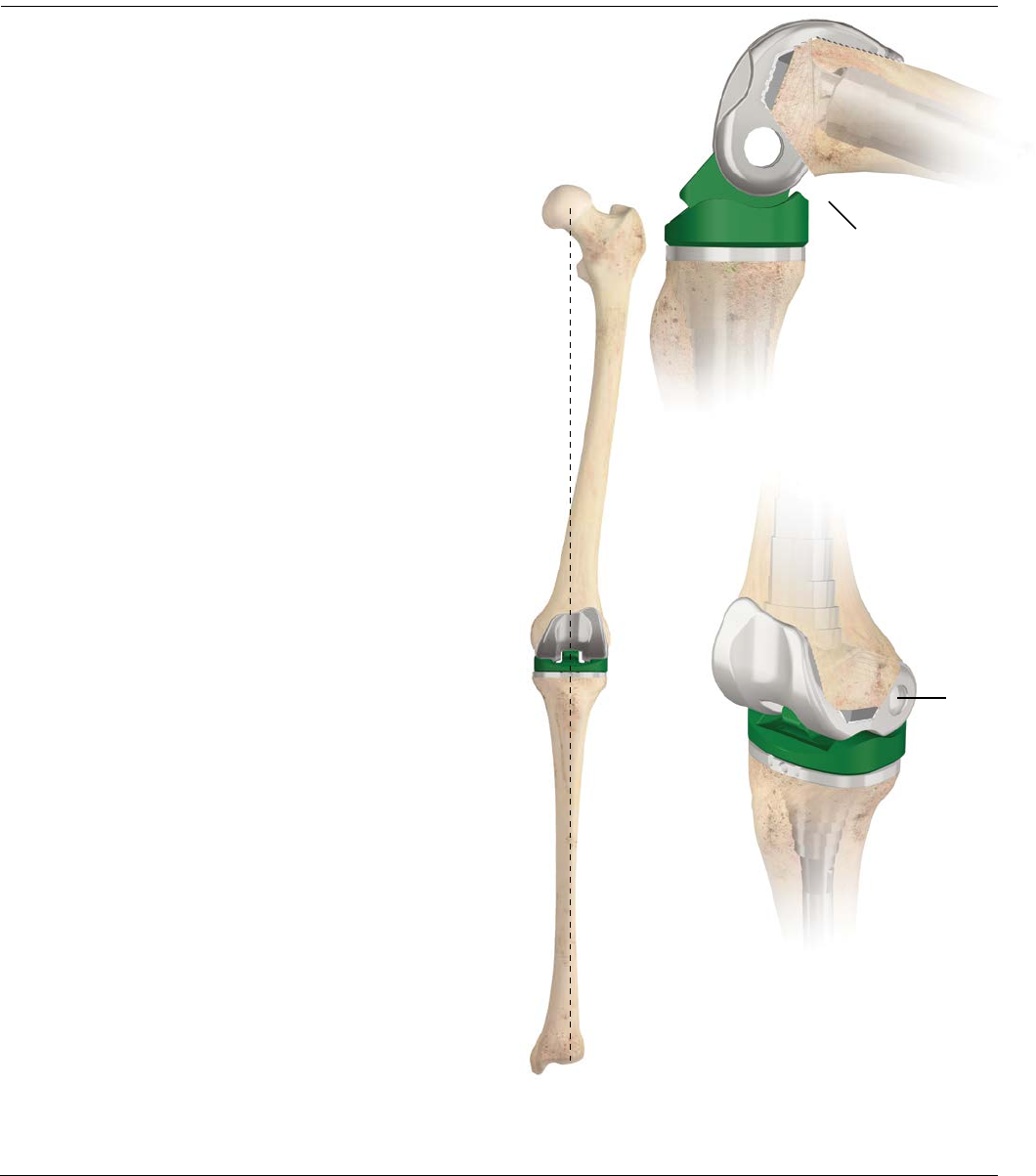
With the leg in full extension, evaluate the mechanical
axis. The center of the femoral head, knee and talus
should all be in line (Figure 51).
The knee should be stable throughout the full range of
motion (Figure 52).
Check ligament tension and leg length.
Revision of the tibial or femoral resection may be
required if satisfactory stability cannot be achieved.
Accommodate additional bone resection with
rebroaching.
Remove the femoral trials and ensure that the rotational
alignment of the assembly is preserved.This is used as a
reference when assembling the modular implant.
Note: In patients with severe soft tissue loss,
flexion of the knee beyond 90 degrees may cause
distraction and subluxation of the tibial plateau out
of the modular tibial base. In this instance, fit the
patient with a post-operative brace, limiting flexion
to 90 degrees and no more for at least three months.
This helps soft tissue establishment of flexion
tension. Consult package insert.
Hinge Pin Trial
36 DePuy Synthes Joint Reconstruction S-ROM® Noiles Rotating Hinge Surgical Technique
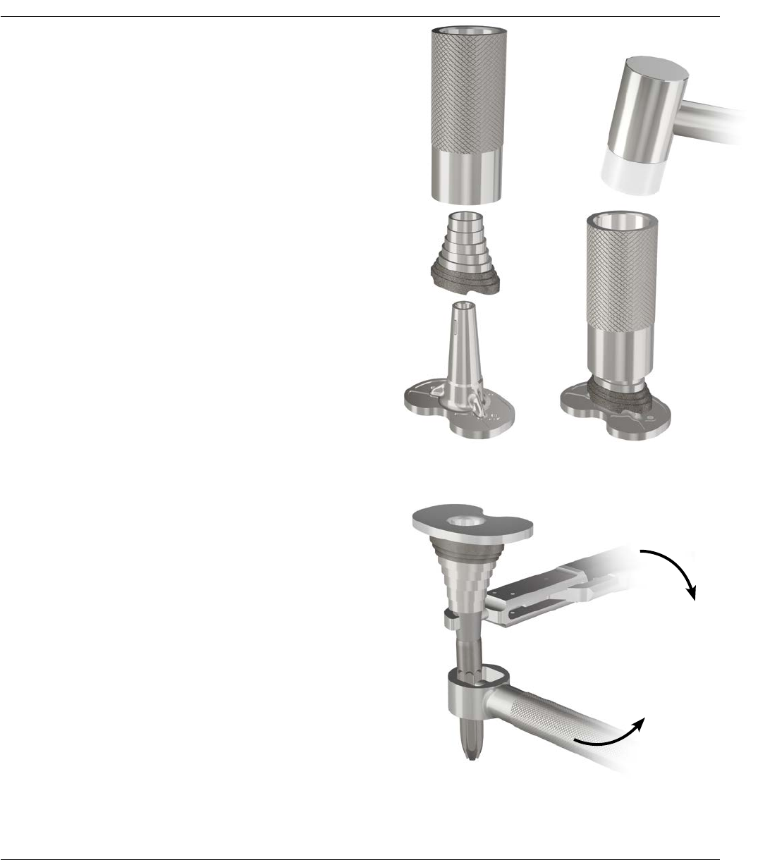
Figure 55
IMPLANT ASSEMBLY – TIBIA
Figure 53 Figure 54
Tibial Sleeve Assembly
Note: It is imperative to assemble the Sleeve prior
to stem attachment.
Note: Sleeves and Step Wedges can only be used
together if using a 29 mm Sleeve.
Remove trial component in one piece (use as guide for
assembly of implants).
Place the MBT Revision Tray on a firm, stable, padded
surface. Set the Tibial Sleeve in an orientation that
matches the prepared canal. Matching the orientation of
the Tray/Sleeve Trial is helpful in determining appropriate
rotation of the final tibial tray/sleeve implant (Figure 53).
The sleeve can rotate 20 degrees internally or externally.
Using the Sleeve Impactor and a Mallet, impact the
sleeve onto the MBT Revision Tray. Deliver several strikes
to engage the two components (Figure 54).
Stem Component Assembly
Attach the Stem Extension to the prosthetic tray using
the two appropriate Wrenches to ensure full
engagement (Figure 55).
Surgical Technique S-ROM® Noiles Rotating Hinge DePuy Synthes Joint Reconstruction 37
Implanting the Tibial Component
Thoroughly cleanse the site with pulsatile lavage.
Perforate with small drill holes on the prepared tibial
surface to facilitate penetration of methyl methacrylate
(Figure 56). Pack residual small cavitory bone defects
with cancellous autograft, if available, or allograft.
Apply methyl methacrylate cement to the proximal tibial
surface (Figure 57) or directly to the underside of the
tibial tray component.
When a Fluted Stem or a Fluted Stem with a
Metaphyseal Sleeve is used, ensure the medullary canal
remains free of cement. Clear all extruded cement with
a Curette.
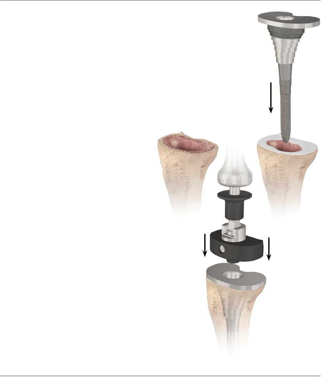
Seat the Tibial Implant construct into the prepared tibia
by impacting the RP Tray Impactor and Universal Handle
assembly (Figure 58).
Figure 58
Figure 56 Figure 57
TIBIAL IMPLANTATION
38 DePuy Synthes Joint Reconstruction S-ROM® Noiles Rotating Hinge Surgical Technique
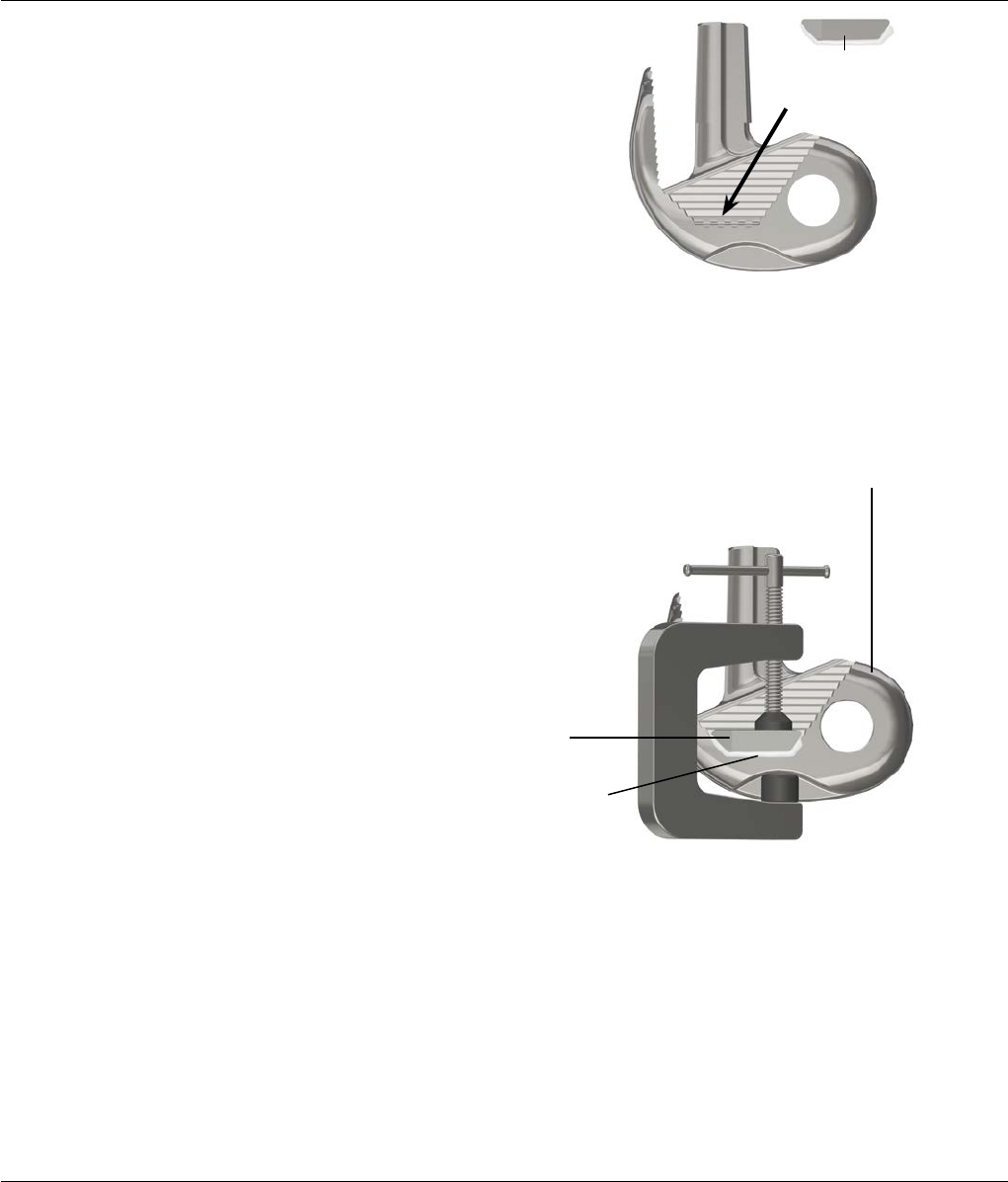
Figure 59
Apply cement to this side of
the distal augmentation block
Implant Assembly - Sleeve and Stem Use
Implant assembly order (with Sleeve and Stem use):
· Add distal augments if necessary
· Attach stem to sleeve
· Attach sleeve construct to femoral construct
Implantation
After assembling the femoral components, prepare one
package of bone cement according to instructions.
Apply cement to the augmentation block(s) on the side
which contacts the femoral component, and to the
corresponding surface(s) of the femoral component
(Figure 59).
Attach the augmentation block(s) to the femoral
component. Use an Augment Block Clamp to secure to
the femoral component until the cement is fully cured.
Note: When distal augmentation blocks are used
with the S-ROM Noiles Rotating Hinge femoral
component, place the Augment Block Clamp
into the distal condylar “pocket” of the femoral
component (Figure 60).
The remainder of the mixed cement may be used to
implant the patella and tibial component while the blocks
are setting.
IMPLANT ASSEMBLY – SLEEVE AND STEM USE
Figure 60
S-ROM Noiles Rotating Hinge
Femoral Component
Distal Augment
Apply cement only to this side of
the distal augmentation block
Surgical Technique S-ROM® Noiles Rotating Hinge DePuy Synthes Joint Reconstruction 39
To attach the Universal Stem to the Universal Femoral
Sleeve, thread the stem onto the sleeve. Grasp the
sleeve with the Tibial Sleeve Clamp and use the Stem
Extension Wrench to grasp Universal Stem and tighten
(Figure 61).
Apply sufficient force to both Wrenches to ensure that
the Stem is secure.
Place the femoral component with the Femoral Adapter
on a firm, stable surface. Place the appropriate sleeve
and stem construct on top of the Femoral Adapter
assembly (Figure 62). Use the sleeve and femoral
construct trial to help set the final sleeve and femur
implant rotation.
Figure 61
IMPLANT ASSEMBLY – SLEEVE AND STEM USE
Figure 62
40 DePuy Synthes Joint Reconstruction S-ROM® Noiles Rotating Hinge Surgical Technique
IMPLANT ASSEMBLY – SLEEVE AND STEM USE
Slide the Femoral Stem/Sleeve Impactor on top of the
stem and forcefully apply three strikes with a Mallet to
engage the two component assemblies (Figure 63).
Note: The Femoral Stem/Sleeve Impactor has
two uses, one end for use of a sleeve without a
stem extension and one end for a sleeve and stem
combination.
The definitive components are implanted in the
following order:
· Tibial tray (with stem, sleeve or wedges)
· Femoral component (with stem, sleeve and
augments)
· LPS Hinged insert
Implant the femoral component using the Femoral
Impactor (Figure 64).
Universal Handle
Figure 63
Figure 64
Surgical Technique S-ROM® Noiles Rotating Hinge DePuy Synthes Joint Reconstruction 41
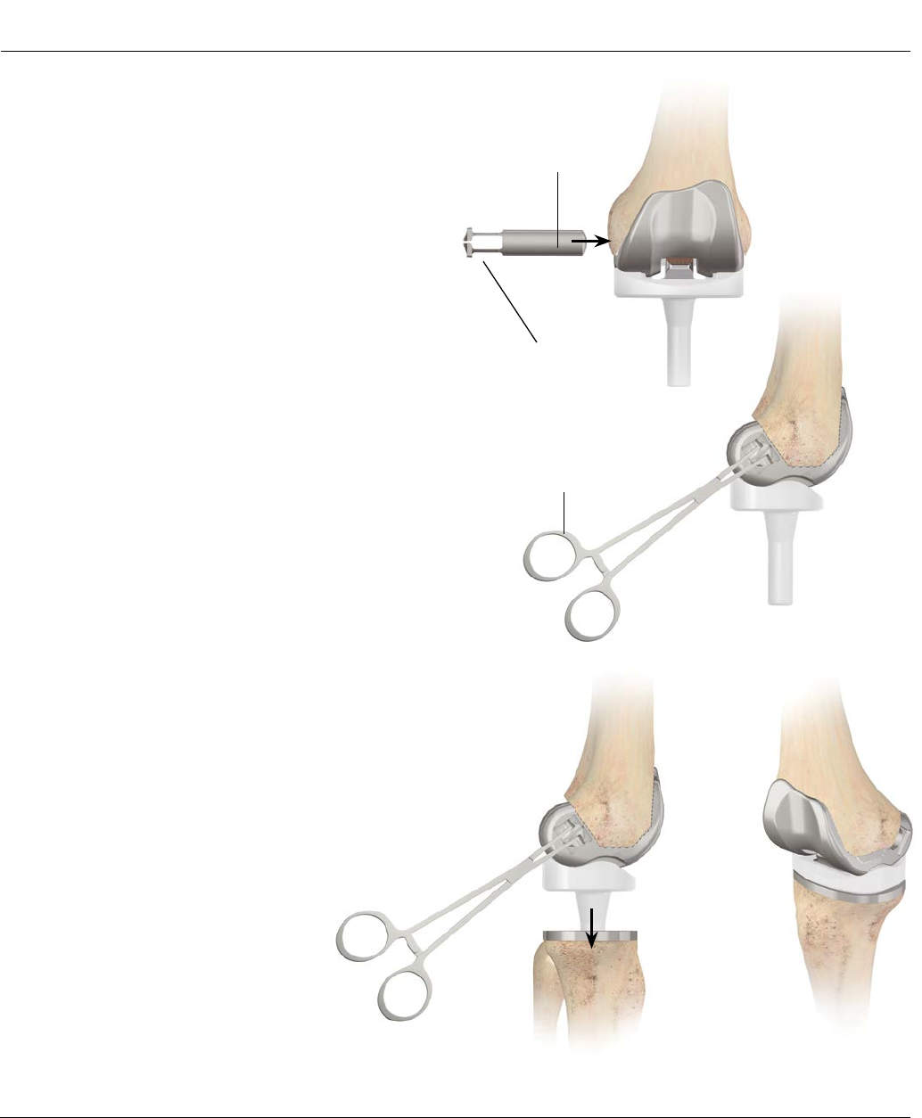
Figure 68
After the femoral component and tibial tray have been
cemented into place, do one final check with the trial
inserts. Once the proper thickness has been verified,
introduce the actual implant into the sterile field.
Note: Take extreme care when opening the LPS
Universal Insert to hold onto the bushings to ensure
they do not fall out.
Put the condyles of the femoral component into the
corresponding recesses in the tibial plateau.
Insert the Hinge Pin through the hole on the medial or
lateral side of the femoral component. Orient the
rectangular head of the Hinge Pin with the rectangular
recess in the femoral component (Figure 65).
Squeeze the “clothespin” of the Hinge Pin together and
insert the Hinge Pin into the femoral component. Make
sure the Hinge Pin is securely locked in place (Figure 66).
Place the LPS Universal Insert post into the cone of the
MBT Revision Implant (Figure 67).
Test the knee through full range of motion (Figure 68).
Figure 66
Hinge Pin
Needle Holder or Clamp
"Clothespin"
Figure 65
Figure 67
BEARING AND HINGE PIN INSERTION
42 DePuy Synthes Joint Reconstruction S-ROM® Noiles Rotating Hinge Surgical Technique
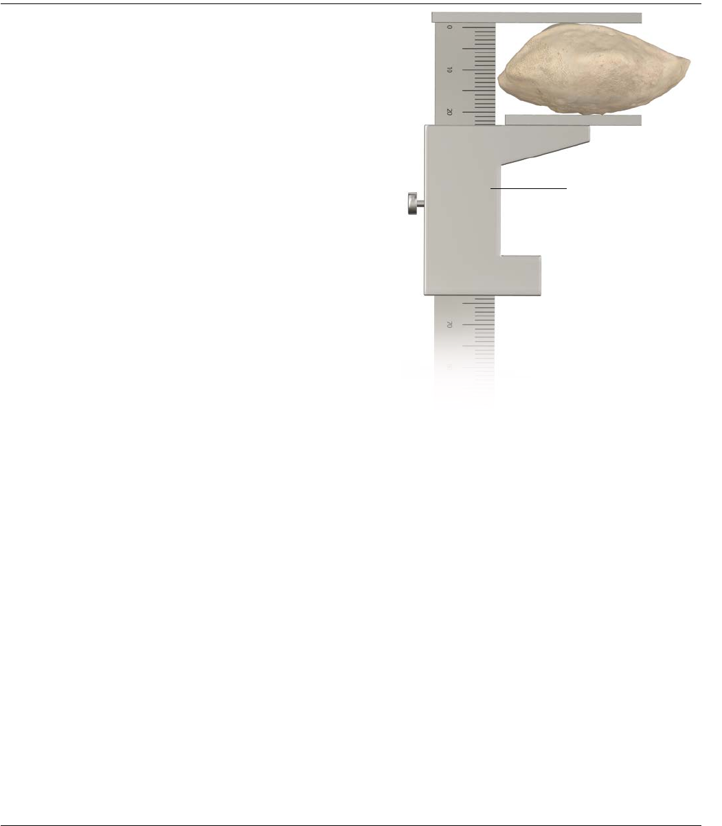
INITIAL PATELLAR RESECTION
Measure and record the overall thickness of the patella
using a Caliper (Figure 69).
Resect approximately 7 mm of bone from the posterior
patella surface using an Oscillating Saw.
Measure and record the thickness of the resected/
removed bone in order to properly duplicate the original
thickness.
Figure 69
Caliper
Surgical Technique S-ROM® Noiles Rotating Hinge DePuy Synthes Joint Reconstruction 43
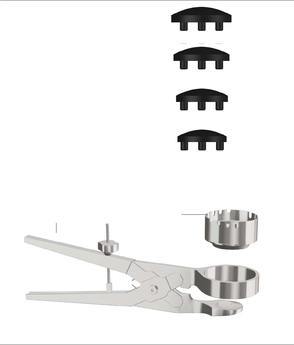
INITIAL PATELLAR RESECTION
Figure 70
Figure 71
Patella Domes are available in four diameters (Figure 70).
Select a patella trial with the diameter that best matches
the patient’s patella (Figure 70).
Select the Patella Reamer Depth Adjuster that is the
same diameter as the patella trial.
Insert the Patella Reamer Depth Adjuster into the Patella
Restraining Instrument. Rotate the depth adjuster 120
degrees clockwise to lock into position (Figure 71).
38 mm
35 mm
32 mm
30 mm
Patella Reamer
Depth Adjuster
Patella Restraining
Instrument
44 DePuy Synthes Joint Reconstruction S-ROM® Noiles Rotating Hinge Surgical Technique
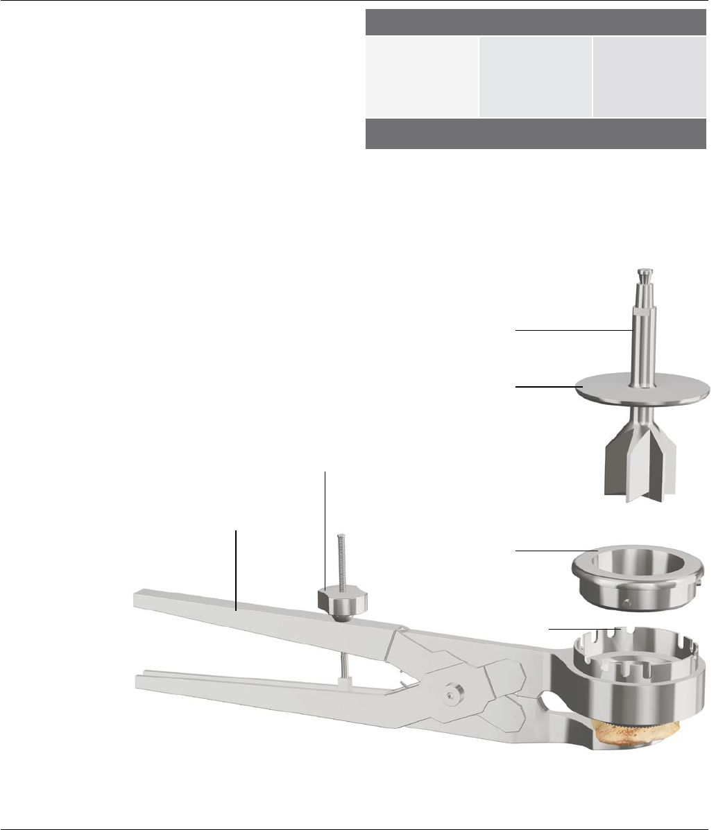
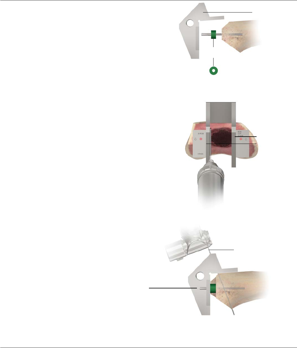
PATELLA REAMING
Clamp the Patella Restraining Instrument assembly onto
the patella. Lock into position by turning the Thumb Nut
clockwise (Figure 72).
Insert the Patella Reamer Bushing into the appropriate set
of slots on the Patella Reamer Depth Adjuster. Slots on the
depth adjuster are marked 1, 2, 3 and 4, which indicate
the reaming depth in millimeters. To determine the correct
slot, use the formula shown in (Table 1) as a guide.
Select the Patella Reamer that matches the diameter of
the patella component to be used and insert through the
Patella Reamer Bushing into the Patella Reamer Depth
Adjuster. Ensure that the Patella Reamer is making full
contact with the bone prior to reaming. Ream until the
Patella Reamer flange makes contact with the Patella
Reamer Bushing.
Table 1
Figure 72
Turn Thumb Nut clockwise
to lock into position
Patella Reamer
Flange
Patella Reamer Bushing
Patella Reamer
Depth Adjuster
Patella Restraining
Instrument
Thickness of
selected patella
component
Measured
thickness of
bone resected
and removed
Select Slot
number
9 mm -=
7 mm 2
Surgical Technique S-ROM® Noiles Rotating Hinge DePuy Synthes Joint Reconstruction 45
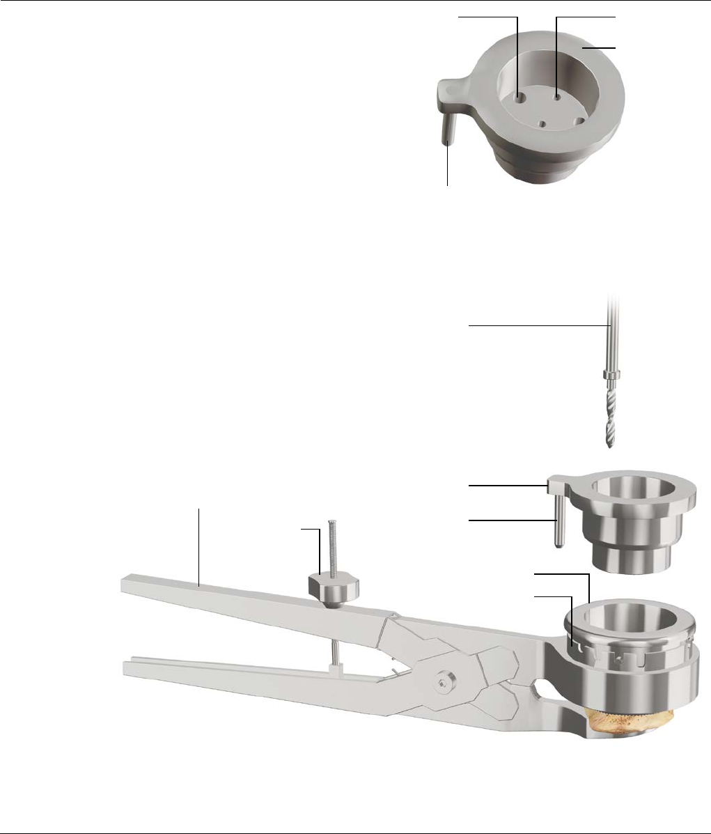
PATELLA DRILLING
Figure 73
Figure 74
Remove the Patella Reamer and insert the Patella Drill
Guide into the Patella Reamer Bushing. The Locating
“Pin” on the Drill Guide will insert into the hole in the
Patella Restraining Instrument (Figure 73).
Select the 3⁄16 in. Patella Shoulder Drill and prepare the
three patella peg holes by drilling through the three
larger holes in the Patella Drill Guide.
The depth of the holes drilled is correct for the length of
the pegs on the selected Patella Button (Figure 74).
Optional: Select the 1⁄8 in. Patella Shoulder Drill and drill
through the four smaller holes to enhance the cement
fixation to the patellar bone. Loosen the Thumb Nut on
the Patella Restraining Instrument and remove the entire
assembly from the patella bone.
Patella Shoulder Drill
Patella Drill Guide
Thumb Nut
Patella Reamer Bushing
Locating Pin
Patella Restraining
Instrument
Patella Reamer
Depth Adjuster
3⁄16 in. Drill Hole
Locating Pin
1⁄8 in. Drill Hole
Patella Drill Guide
46 DePuy Synthes Joint Reconstruction S-ROM® Noiles Rotating Hinge Surgical Technique
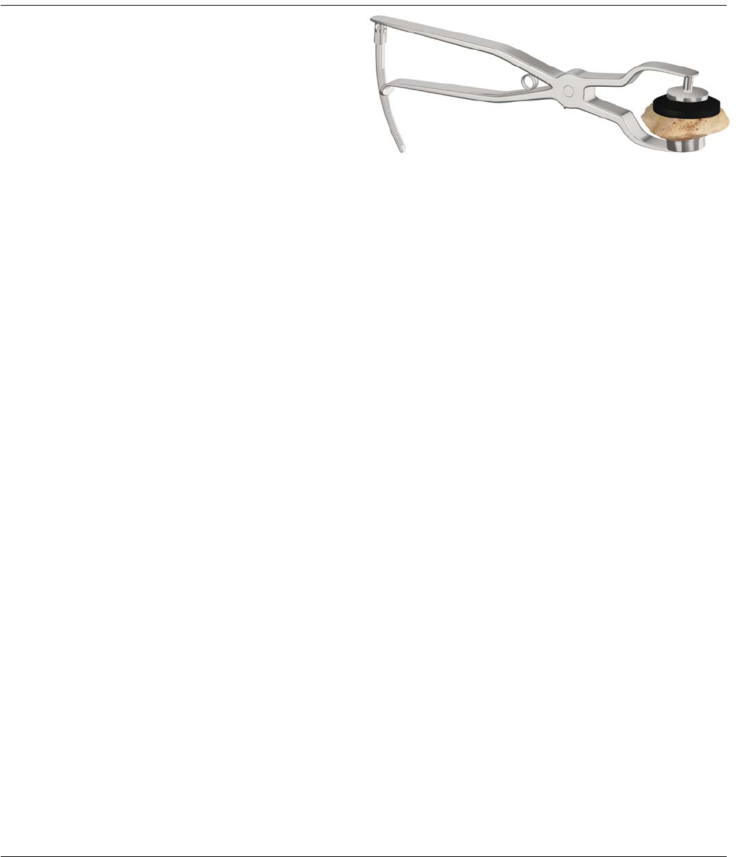
TRIAL REDUCTION AND IMPLANTATION
Place the appropriate diameter Patella Trial into the
prepared patella bone. Measure the overall thickness of
the patella construct to ensure that it is the desired
thickness, i.e. equal to or 1-2 mm less than the original
patella thickness. A “no-thumbs” trial reduction and
patella tracking evaluation can now be performed.
Note: If the reconstructed patella is too thick, repeat
the reaming and drilling steps using the number 2,
3 or 4 slot on the Patella Reamer Depth Adjuster.
If a greater thickness must be removed, take
additional resection from the patella. The reaming
and drilling steps must be repeated. (Take care
to make sure the patella bone is not cut too thin.
Maintain at least 10 mm of patella bone to prevent
drill or peg penetration of the anterior cortex).
The appropriately sized Patella Dome may now be
cemented into place. A Patella Cement Clamp is
provided for this purpose (Figure 75).
Figure 75
Surgical Technique S-ROM® Noiles Rotating Hinge DePuy Synthes Joint Reconstruction 47

APPENDIX 1: THE CEMENTED TIBIAL STEM EXTENSIONS
Figure 2 Figure 3
Cemented
Drill Bushing
MBT Revision
Drill Bushing
Figure 1
Cemented Stem Reamer
Align the Tibial Tray and secure with two Fixation Pins
inserted through the holes designated (Figure 1). Seat
the MBT Revision Drill bushing onto the tibia trial. Place
in the posterior holes.
Place the Cemented Drill Bushing into the MBT Revision
Drill Bushing (Figure 2).
Use the “cemented” reamer to ream to the
predetermined selected depths for tray only or the Tray
with a 30 or 60 mm cemented stem.
Remove the reamer and “cemented” bushing, leaving
the tray trial and MBT Revision Drill Bushing in place
(Figure 3).
Note: Only a 13 mm diameter cemented stem should
be used in conjunction with the MBT Revision Tray
to avoid a step off at the stem/tray junction.
48 DePuy Synthes Joint Reconstruction S-ROM® Noiles Rotating Hinge Surgical Technique
APPENDIX 1: THE CEMENTED TIBIAL STEM EXTENSIONS
Tapered Reamer
Assemble the Revision Reamer Adapter onto the
Cemented Tapered Reamer.
Next, attach the modified Hudson Adapter to the
Tapered Reamer, if power reaming.
Attach the appropriately sized Cemented Stem Trial
(13 x 30 mm or 13 x 60 mm) to the Tapered Reamer, if
utilizing a cemented stem extension (Figure 4). Ream
until the Revision Reamer Adapter is flush with the MBT
Revision Drill Bushing (Figure 5).
Note: To avoid Stem Trial disengagement, do not
reverse ream.
Figure 4
Figure 5
Modified Hudson Adapter
Revision Reamer Adapter
Surgical Technique S-ROM® Noiles Rotating Hinge DePuy Synthes Joint Reconstruction 49
APPENDIX 1: THE CEMENTED TIBIAL STEM EXTENSIONS
Tapered Cemented Stems
Note: Tapered Cemented Stem sizes 13 x 90/120/150
mm are compatible with MBT Revision Trays.
Ream the canal with a reamer two sizes larger than the
stem. Ream the medullary canal with a 15 mm reamer
to implant a 13 mm Tapered Cemented Stem, which
allows for a 1 mm circumferential cement mantle at the
proximal end of the stem. The cement mantle will be
greater around the distal end of the Cemented Tapered
Stem (3 mm per side).
This provides the following benefits:
· Thicker cement mantle distally helps assure that a
circumferential mantle is present and reduces the
possibility of thin or non-existent cement coverage of
the stem distally
· Stresses are greatest at the tip of the stem. A larger
cement mantle is advantageous in dissipating these
stresses. Thinner cement mantles are more prone to
breakdown when exposed to higher stresses
Tibial Keel Preparation
Place the knee in full extension and determine appropriate
rotation of the Tibial Tray. Mark the appropriate rotation
with electrocautery on the anterior tibial cortex at the
center and sides of the Alignment Handle.
Assemble the appropriate Stem Trial to the MBT Revision
Tray Trial and seat in the prepared bone bed. Impact the
Cemented Keel Punch (Figure 6).
Disconnect the Universal Handle leaving the Keel Punch in
place for trial reduction (if appropriate).
It is recommended that a Cement Restrictor be placed
at the appropriate level prior to cementing the
component. Use a Cement Gun to fill the canal with
methyl methacrylate.
Figure 6
50 DePuy Synthes Joint Reconstruction S-ROM® Noiles Rotating Hinge Surgical Technique
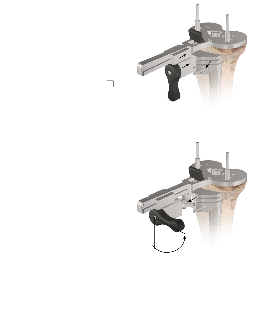
Figure 1
Figure 2
APPENDIX 2: STEP WEDGE PREPARATION
Step Wedge Augmentation
Resection for supplementary tibial augmentation may be
based on the established position of the Trial Tray. Remove
the Femoral Trial to provide greater access. Confirm
rotational alignment of the Tibial Tray Trial. Secure the Tray
with two Fixation Pins.
Attach the Tray Trial Wedge cutting attachment with the
Step Wedge Cutting Guide to the Trial Tray. The Step
Wedge Cutting Block allows for a 5, 10 or 15 mm Step
Wedge preparation as necessary. Slide the block forward
to the anterior proximal tibia and secure in place with two
Steinmann Pins through the holes marked with
(Figure 1).
Unlock the block and slide the assembly out of the block.
Disconnect the handle from the Trial Tray (Figure 2).
Surgical Technique S-ROM® Noiles Rotating Hinge DePuy Synthes Joint Reconstruction 51

APPENDIX 2: STEP WEDGE PREPARATION
Trim the tibia accordingly with an Oscillating Saw so the
cut does not extend beyond the central riser (Figure 3).
Remove the Block and Pins.
Assemble the Trial Wedge to the appropriate Tibial Tray
Trial (Figure 4) and introduce into the prepared site.
Perform minimal correction with a Bone File where
indicated to ensure maximal contact.
Figure 4
Step Wedge
Cutting Block
Figure 3
52 DePuy Synthes Joint Reconstruction S-ROM® Noiles Rotating Hinge Surgical Technique

Confirm positioning, alignment and security of the tray
assembly. If there is old cement or sclerotic bone,
remove this first with a saw blade or burr prior to
punching. Position the MBT Revision Tibial Keel Punch at
the tray and cancellous bone interface and impact into
the keel configuration. Leave the punch in place and
perform a final trial reduction if necessary (Figure 5).
Note: Utilize the “cemented” Keel Punch when a
cement mantle is desired.
Alternative Step Wedge Preparation
This is a “free-hand” resection. Assemble the Wedge
Trial and Stem Trial to the Tibial Tray Trial. Position the
device slightly proximal to the planned resection level.
Make a conservative “free-hand” wedge resection and
then check cuts with the Trials (Figure 6).
Wedge Implant Assembly
Note: To aid wedge implant assembly, attach wedge
prior to attaching the stem attachment.
Assemble the designated wedge to the tray and secure
using the appropriate screw. Carefully tighten with the
large T-Handle Torque Driver until an audible "click" is
discerned, ensuring a full and permanent interlock
(Figure 7).
Figure 7
APPENDIX 2: STEP WEDGE PREPARATION
Figure 5 Figure 6
Surgical Technique S-ROM® Noiles Rotating Hinge DePuy Synthes Joint Reconstruction 53
APPENDIX 3: THICK TRAY PREPARATION
After impacting the cement or Press-Fit Keel Punch,
remove the Keel Punch. Insert the MBT Thick Tray Trial
Adapter (15 or 25 mm) onto the Tibial Tray Trial (Figures
1 and 2).
Note: The Tibial Tray Trial must be used with the
Thick Tray Adapters as the two pieces equal the
appropriate sizing – 15 or 25 mm.
Perform the final trial reductions utilizing the same
technique as the standard MBT Revision Tray. Implant
assembly and implantation is also the same as with the
standard MBT Revision Tray. If utilizing a Wedge, refer to
the Step Wedge Preparation in Appendix 2.
Note: A Tibial Wedge can be used with all Thick
Tray sizes, except for size 2. Due to the taper, use
size 2 Tibial Wedges with size 4 MBT Revision
Thick Trays, and use size 1 Tibial Wedges with size
3 MBT Revision Thick Trays. Sleeves may be used
with all Thick Trays.
Note: Due to the taper, trial with appropriate tray
trial size. For example, a size 4 Thick Tray tapers
down to a size 2. Use the size 2 Tray Trial with the
size 4 Thick Tray Adapter. The size 3 Thick Tray
tapers down to a size 1. And the size 2 Thick Tray
tapers down to a size 0. The size 0 Tray Trial can be
found in the MBT Thick Tray Instrument Set.
Figure 1
Figure 2
54 DePuy Synthes Joint Reconstruction S-ROM® Noiles Rotating Hinge Surgical Technique

IMPLANT LISTING
S-ROM Femoral Components
(hinge pin is packaged with the femur)
Universal Femoral Sleeves
Universal Press-Fit Stems
S-ROM Femoral Augments
Surgical Technique S-ROM® Noiles Rotating Hinge DePuy Synthes Joint Reconstruction 55
62-3401L Medium Left S-ROM Femur
62-3401R Medium Right S-ROM Femur
62-3411L Small Left S-ROM Femur
62-3411R Small Right S-ROM Femur
62-3421L X-Small Left S-ROM Femur
62-3421R X-Small Right S-ROM Femur
1294-53-205 20 mm Cemented Femoral Sleeve
1294-53-215 31 mm Distally Porous Femoral Sleeve
1294-53-216 31 mm Fully Porous Femoral Sleeve
1294-53-225 34 mm Distally Porous Femoral Sleeve
1294-53-226 34 mm Fully Porous Femoral Sleeve
1294-53-235 40 mm Distally Porous Femoral Sleeve
1294-53-236 40 mm Fully Porous Femoral Sleeve
1294-53-245 46 mm Distally Porous Femoral Sleeve
1294-53-246 46 mm Fully Porous Femoral Sleeve
62-3805 Distal Augment, 5 mm (used on all femur sizes)
62-3810 Distal Augment, 10 mm (used on all femur sizes)
86-7410 75 mm x 10 mm Universal Fluted Stem
86-7412 75 mm x 12 mm Universal Fluted Stem
86-7414 75 mm x 14 mm Universal Fluted Stem
86-7416 75 mm x 16 mm Universal Fluted Stem
86-7418 75 mm x 18 mm Universal Fluted Stem
86-7419 75 mm x 20 mm Universal Fluted Stem
86-7420 75 mm x 22 mm Universal Fluted Stem
86-7421 75 mm x 24 mm Universal Fluted Stem
86-7424 115 mm x 10 mm Universal Fluted Stem
86-7426 115 mm x 12 mm Universal Fluted Stem
86-7428 115 mm x 14 mm Universal Fluted Stem
86-7430 115 mm x 16 mm Universal Fluted Stem
86-7432 115 mm x 18 mm Universal Fluted Stem
86-7433 115 mm x 20 mm Universal Fluted Stem
86-7434 115 mm x 22 mm Universal Fluted Stem
86-7435 115 mm x 24 mm Universal Fluted Stem
86-7438 150 mm x 10 mm Universal Fluted Stem
86-7440 150 mm x 12 mm Universal Fluted Stem
86-7442 150 mm x 14 mm Universal Fluted Stem
86-7444 150 mm x 16 mm Universal Fluted Stem
86-7446 150 mm x 18 mm Universal Fluted Stem
86-7447 150 mm x 20 mm Universal Fluted Stem
86-7448 150 mm x 22 mm Universal Fluted Stem
86-7449 150 mm x 24 mm Universal Fluted Stem

IMPLANT LISTING
56 DePuy Synthes Joint Reconstruction S-ROM® Noiles Rotating Hinge Surgical Technique
Universal Femoral Sleeves
S-ROM Patella
LPS Universal Inserts (compatible with S-ROM
and LPS femurs, must match femur size-to-size)
86-6401 30 mm x 13 mm Cemented Stem
(used on MBT Revision Trays size 3 and smaller)
86-6402 60 mm x 13 mm Cemented Stem
(used on MBT Revision Trays size 3 and smaller)
86-6403 30 mm x 15 mm Cemented Stem
(used on MBT Revision Trays size 4 and larger)
86-6404 60 mm x 15 mm Cemented Stem
(used on MBT Revision Trays size 4 and larger)
86-6468 90 mm x 13 mm Cemented Tapered Stem
86-6469 90 mm x 15 mm Cemented Tapered Stem
86-6498 120 mm x 13 mm Cemented Tapered Stem
86-6499 150 mm x 13 mm Cemented Tapered Stem
62-1630 30 mm S-ROM Dome Patella
62-1632 32 mm S-ROM Dome Patella
62-1635 35 mm S-ROM Dome Patella
62-1638 38 mm S-ROM Dome Patella
1987-27-112 X-Small 12 mm LPS Universal Insert
1987-27-114 X-Small 14 mm LPS Universal Insert
1987-27-116 X-Small 16 mm LPS Universal Insert
1987-27-118 X-Small 18 mm LPS Universal Insert
1987-27-121 X-Small 21 mm LPS Universal Insert
1987-27-123 X-Small 23 mm LPS Universal Insert
1987-27-126 X-Small 26 mm LPS Universal Insert
1987-27-128 X-Small 28 mm LPS Universal Insert
1987-27-131 X-Small 31 mm LPS Universal Insert
1987-27-212 Small 12 mm LPS Universal Insert
1987-27-214 Small 14 mm LPS Universal Insert
1987-27-216 Small 16 mm LPS Universal Insert
1987-27-218 Small 18 mm LPS Universal Insert
1987-27-221 Small 21 mm LPS Universal Insert
1987-27-223 Small 23 mm LPS Universal Insert
1987-27-226 Small 26 mm LPS Universal Insert
1987-27-228 Small 28 mm LPS Universal Insert
1987-27-231 Small 31 mm LPS Universal Insert
1987-27-312 Medium 12 mm LPS Universal Insert
1987-27-314 Medium 14 mm LPS Universal Insert
1987-27-316 Medium 16 mm LPS Universal Insert
1987-27-318 Medium 18 mm LPS Universal Insert
1987-27-321 Medium 21 mm LPS Universal Insert
1987-27-323 Medium 23 mm LPS Universal Insert
1987-27-326 Medium 26 mm LPS Universal Insert
1987-27-328 Medium 28 mm LPS Universal Insert
1987-27-331 Medium 31 mm LPS Universal Insert

IMPLANT LISTING
Cat. No. Size (mm) A/P M/L Stem Length Tray Thickness
1294-35-110 1 39.0 59.2 61.8 4.8
1294-35-115 1.5 40.7 61.8 61.8 4.8
1294-35-120 2 42.6 64.6 61.8 4.8
1294-35-125 2.5 44.2 67.1 61.8 4.8
1294-35-130 3 45.8 69.6 61.8 4.8
1294-35-140 4 49.3 74.9 61.8 4.8
1294-35-150 5 53.1 80.6 61.8 4.8
1294-35-160 6 57.2 86.8 61.8 4.8
1294-35-215 2+15 42.6 64.6 61.8 15
1294-35-225 2+25 42.6 64.6 61.8 25
1294-35-315 3+15 45.8 69.6 61.8 15
1294-35-325 3+25 45.8 69.6 61.8 25
1294-35-415 4+15 49.3 74.9 61.8 15
1294-35-425 4+25 49.3 74.9 61.8 25
Cat. No. Size (mm) A/P M/L Height
1294-54-000 29 26 29 40
1294-54-140 (Cemented) 29 26 29 40
1294-54-100 37 27 37 40
1294-54-110 45 27 45 40
1294-35-120 53 31 53 40
1294-35-130 61 34 61 40
MBT Revision Tray
MBT Revision Sleeve
Surgical Technique S-ROM® Noiles Rotating Hinge DePuy Synthes Joint Reconstruction 57

IMPLANT LISTING
Cat. No. Size (mm)
1294-56-110 1-5
1294-56-111 1-10
1294-56-112 1-15
1294-56-115 1.5-5
1294-56-116 1.5-10
1294-56-117 1.5-15
1294-56-120 2-5
1294-56-121 2-10
1294-56-122 2-15
1294-56-125 2.5-5
1294-56-126 2.5-10
1294-56-127 2.5-15
Cat. No. Size (mm)
1294-56-130 3-5
1294-56-131 3-10
1294-56-132 3-15
1294-56-135 4-5
1294-56-136 4-10
1294-56-137 4-15
1294-56-140 5-5
1294-56-141 5-10
1294-56-142 5-15
1294-56-145 6-5
1294-56-146 6-10
1294-56-147 6-15
MBT Revision Augments
Note: If a tibial sleeve is used, MBT Revision Augments are only
compatible with the 29 mm sleeve.
58 DePuy Synthes Joint Reconstruction S-ROM® Noiles Rotating Hinge Surgical Technique

COMPATIBILITY CHART
LPS
XX-Small
Femoral
Component
LPS X-Small
Femoral
Component
and
S-ROM
X-Small
Femoral
Component
S-ROM
Small
Femoral
Component
S-ROM
Medium
Femoral
Component
Tray No. M/L 56.6 66.7 66.7 71.2
MBT Revision Tray
Size 1 1294-35-110 59.2
MBT Revision Tray
Size 1.5 1294-35-115 61.8
MBT Revision Tray
Size 2 1294-35-120 64.6
MBT Revision Tray
Size 2.5 1294-35-125 67.1
MBT Revision Tray
Size 3 1294-35-130 69.6
MBT Revision Tray
Size 4 1294-35-140 74.9
MBT Revision Tray
Size 5 1294-35-150 80.6
MBT Revision Tray
Size 6 1294-35-160 86.8
LPS Universal inserts must match S-ROM or LPS femoral component size-to-size.
For example, XX-Small femoral component = XX-Small polyethylene; Small femoral component = Small polyethylene, etc.
3
3
3 3 3
3 3 3
3 3 3 3
3 3 3 3
3 3 3 3
3 3 3 3
signifies preferred match
Surgical Technique S-ROM® Noiles Rotating Hinge DePuy Synthes Joint Reconstruction 59
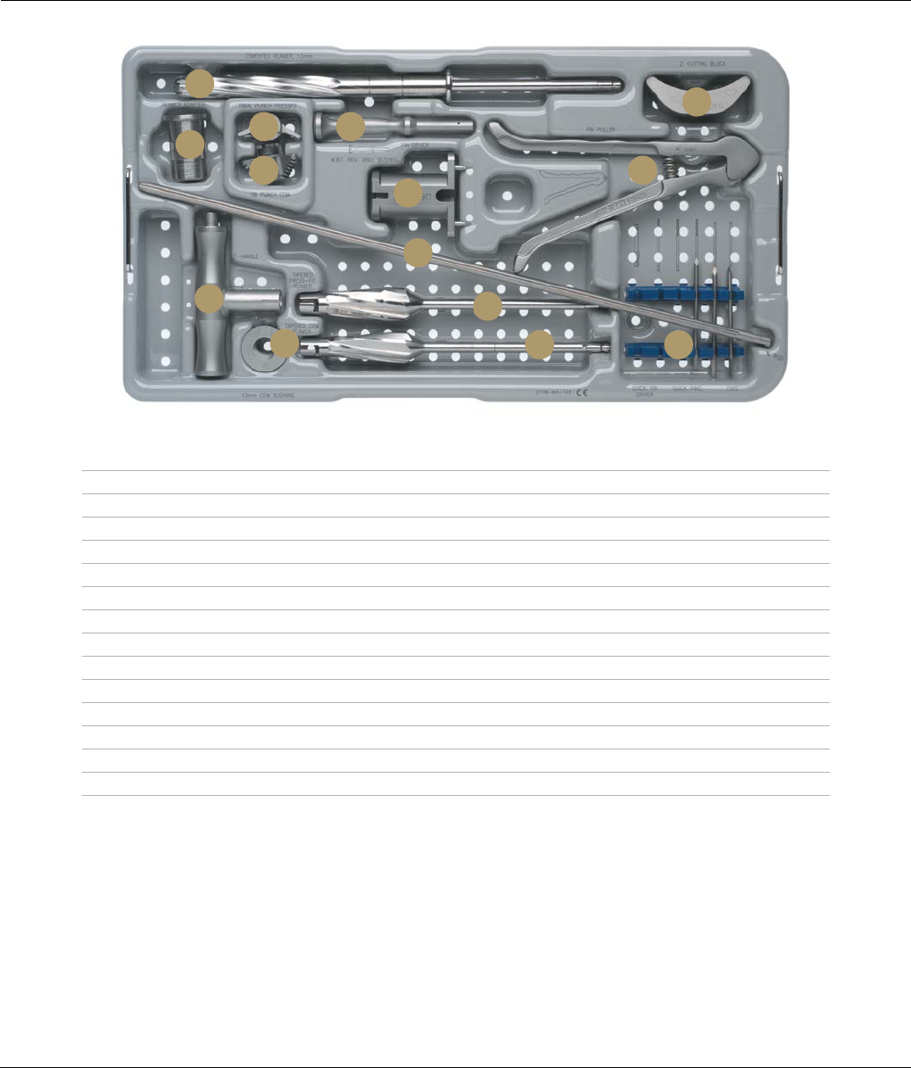
MBT REVISION PREPARATION CASE
CAT. NO. 2178-64-100
Description Cat. No.
A MBT Revision Cemented Stem Reamer, 13 mm 2178-63-185
B Tibial Cutting Block, 2 Degree 2178-40-086
C MBT Revision Reamer Adapter 2178-63-128
D MBT Revision Press-Fit Tibial Punch 2178-63-118
E MBT Revision Cemented Tibial Punch 2178-63-120
F Pin Driver 2490-94-000
G MBT Revision Drill Bushing 2178-63-100
H Pin Puller 96-6515
I SP2 IM Rod, 400 mm 96-6120
J SP2 IM Rod Handle 99-2011
K MBT Revision Cemented Bushing, 13 mm 2178-63-196
L MBT Revision Tapered Press-Fit Reamer 2178-63-104
M MBT Revision Tapered Cemented Reamer 2178-63-106
N Steinman Pins (Package of 10) 86-9117
Top Tray
A
C
D F
G
B
H
NM
L
I
E
J
K
60 DePuy Synthes Joint Reconstruction S-ROM® Noiles Rotating Hinge Surgical Technique
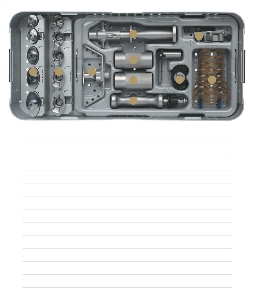
Description Cat. No.
A MBT Revision 2-Degree Tibial Broaches 29 mm 2178-63-109
MBT Revision 2-Degree Tibial Broaches 37 mm 2178-63-111
MBT Revision 2-Degree Tibial Broaches 45 mm 2178-63-113
MBT Revision 2-Degree Tibial Broaches 53 mm 2178-63-115
MBT Revision 2-Degree Tibial Broaches 61 mm 2178-63-117
B MBT Tray Sleeve Trials 29 mm 2294-54-000
MBT Tray Sleeve Trials 37 mm 2294-54-100
MBT Tray Sleeve Trials 45 mm 2294-54-110
MBT Tray Sleeve Trials 53 mm 2294-54-120
MBT Tray Sleeve Trials 61 mm 2294-54-130
C LCS Completion Tibial Stylus 2178-40-045
D MBT Revision Tibial Broach Handle 96-6521
E Revision Sleeve Impactor 2178-63-124
F Revision Femoral Sleeve/Stem Impactor 2178-63-126
G SP2 Universal Handle 96-6520
H SP2 IM Tibial Alignment Device 96-6315
I MBT Tibial Impactor 9505-01-558
J MBT Revision Tibial View Plate, Size 1 2178-65-110
MBT Revision Tibial View Plate, Size 1.5 2178-65-115
MBT Revision Tibial View Plate, Size 2 2178-65-120
MBT Revision Tibial View Plate, Size 2.5 2178-65-125
MBT Revision Tibial View Plate, Size 3 2178-65-130
MBT Revision Tibial View Plate, Size 4 2178-65-140
MBT Revision Tibial View Plate, Size 5 2178-65-150
MBT Revision Tibial View Plate, Size 6 2178-65-160
MBT REVISION PREPARATION CASE
CAT. NO. 2178-64-100
A B C
E
DH
FI J
G
Bottom Tray
Surgical Technique S-ROM® Noiles Rotating Hinge DePuy Synthes Joint Reconstruction 61
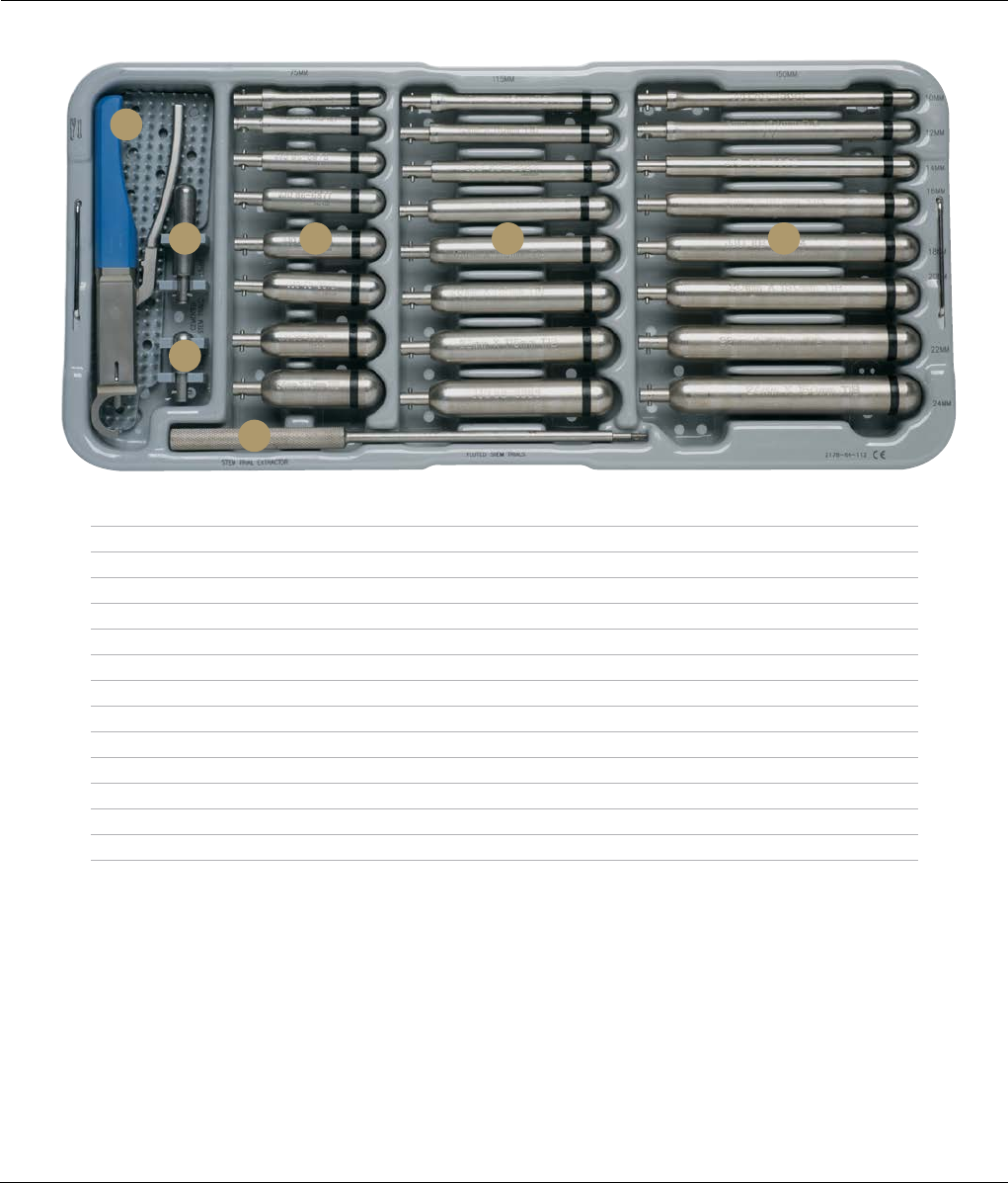
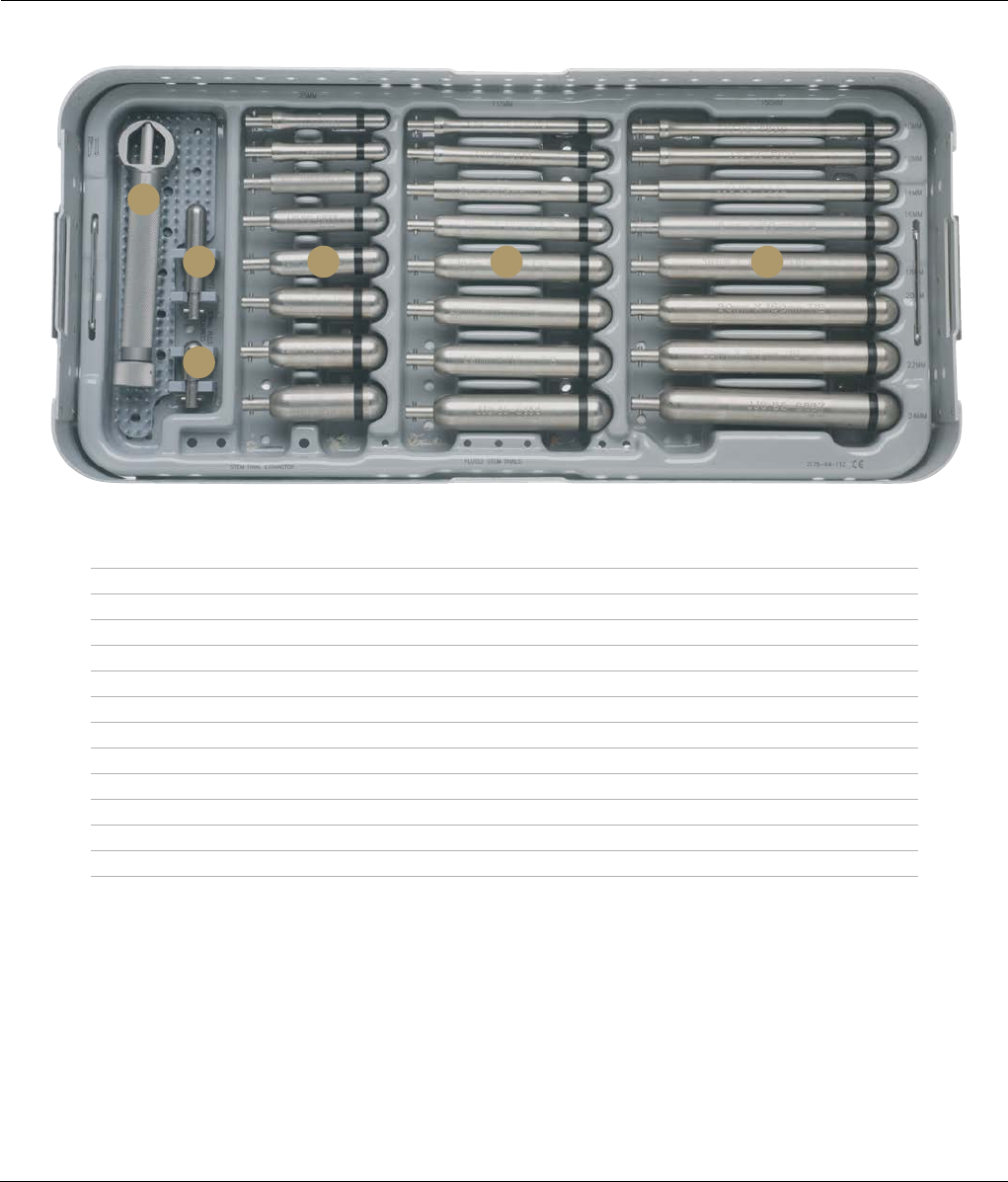
MBT REVISION STEM TRIALS AND INSTRUMENTS CASE
CAT. NO. 2178-64-110
Top Tray
Description Cat. No.
A Revision Femoral/Tibial Sleeve Clamp 2178-63-134
B SIGMA Tibial Cemented Stem Trial, Sizes 2-3, 13 x 60 mm 86-6502
C SIGMA Tibial Cemented Stem Trial, Sizes 1.5-3, 13 x 30 mm 86-6501
D Stem Trial Extractor 86-5226
E Fluted Tibial Stem Trials – 75 mm
75 x 10 mm 86-6874
75 x 12 mm 86-6875
75 x 14 mm 86-6876
75 x 16 mm 86-6877
75 x 18 mm 86-6878
75 x 20 mm 86-6879
75 x 22 mm 86-6880
75 x 24 mm 86-6881
A
B F GE
C
D
62 DePuy Synthes Joint Reconstruction S-ROM® Noiles Rotating Hinge Surgical Technique
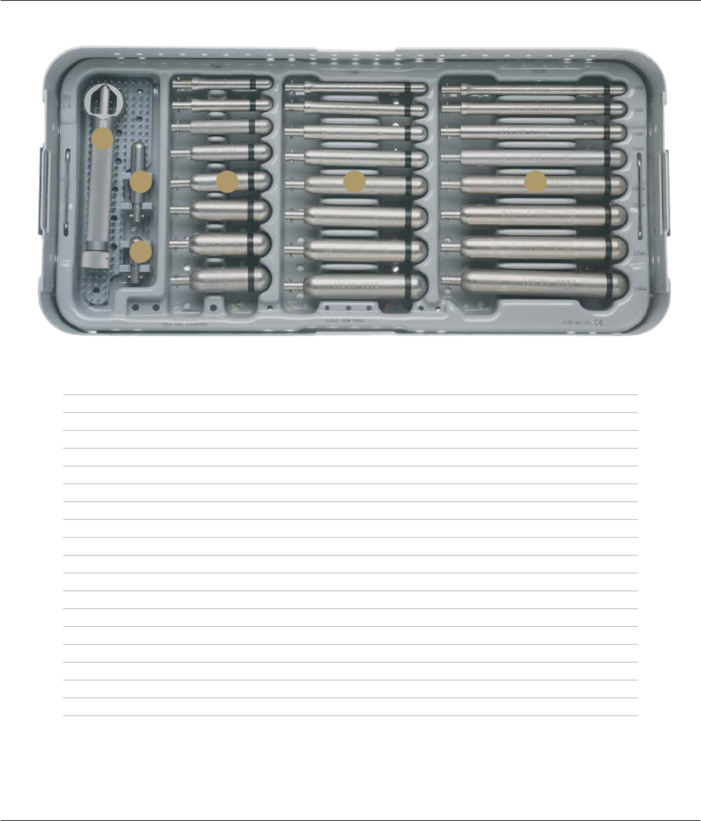
MBT REVISION STEM TRIALS AND INSTRUMENTS CASE
CAT. NO. 2178-64-110
Top Tray
Description Cat. No.
F Fluted Tibial Stem Trials – 115 mm
115 x 10 mm 86-6882
115 x 12 mm 86-6883
115 x 14 mm 86-6884
115 x 16 mm 86-6885
115 x 18 mm 86-6886
115 x 20 mm 86-6887
115 x 22 mm 86-6888
115 x 24 mm 86-6889
G Fluted Tibial Stem Trials – 150 mm
150 x 10 mm 86-6890
150 x 12 mm 86-6891
150 x 14 mm 86-6892
150 x 16 mm 86-6893
150 x 18 mm 86-6894
150 x 20 mm 86-6895
150 x 22 mm 86-6896
150 x 24 mm 86-6897
A
B F GE
C
D
Surgical Technique S-ROM® Noiles Rotating Hinge DePuy Synthes Joint Reconstruction 63
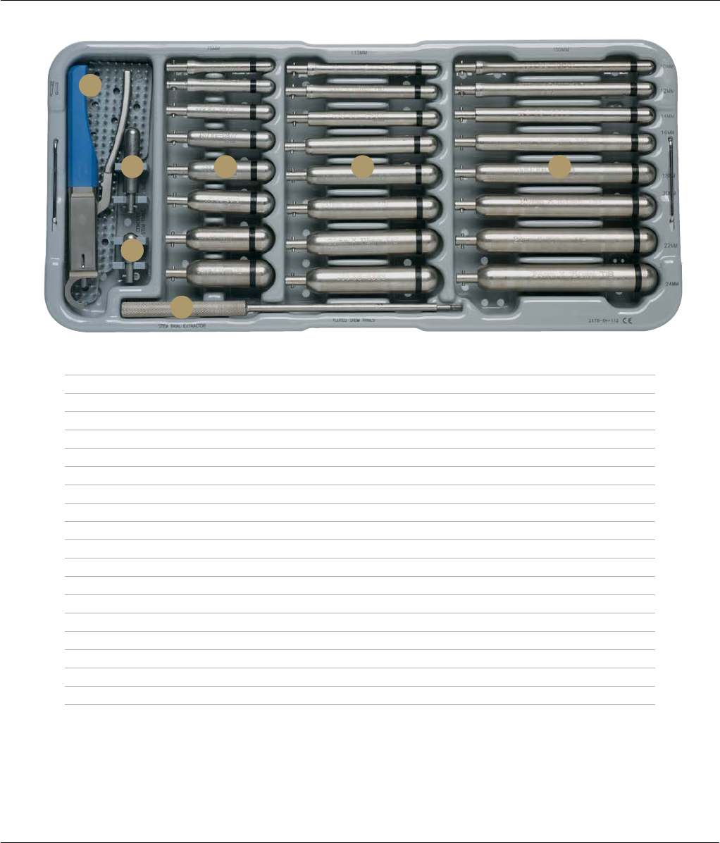
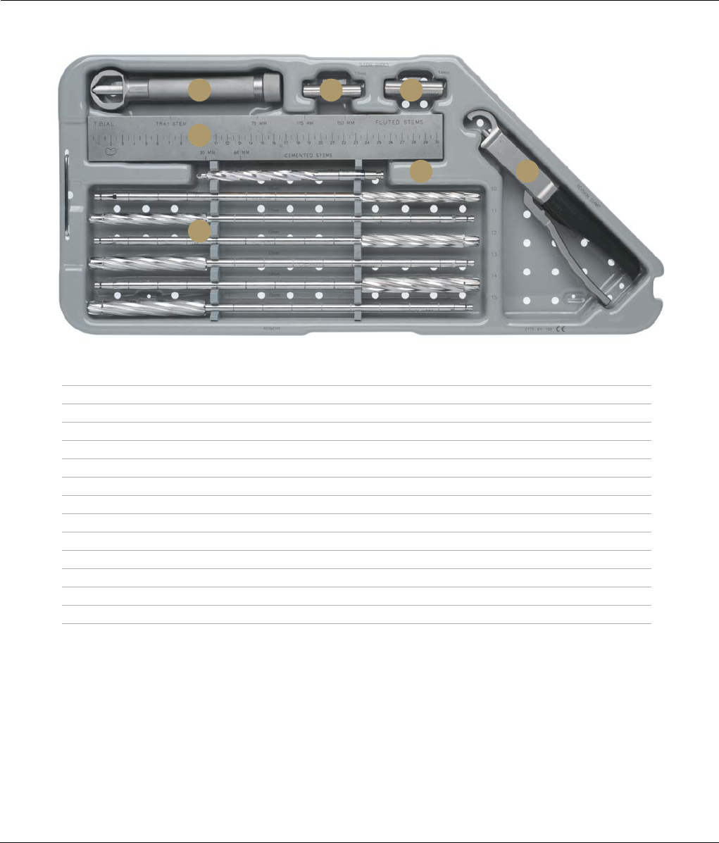
MBT REVISION STEM TRIALS AND INSTRUMENTS CASE
CAT. NO. 2178-64-110
Bottom Tray
Description Cat. No.
A Press-Fit Rod Wrench 86-5189
B SIGMA Tibial Cemented Stem Trial, Sizes 2-3, 13 x 60 mm 86-6502
C SIGMA Tibial Cemented Stem Trial, Sizes 1.5-3, 13 x 30 mm 86-6501
D Fluted Tibial Stem Trials – 75 mm
75 x 10 mm 86-6874
75 x 12 mm 86-6875
75 x 14 mm 86-6876
75 x 16 mm 86-6877
75 x 18 mm 86-6878
75 x 20 mm 86-6879
75 x 22 mm 86-6880
75 x 24 mm 86-6881
A
B D E F
C
64 DePuy Synthes Joint Reconstruction S-ROM® Noiles Rotating Hinge Surgical Technique
MBT REVISION STEM TRIALS AND INSTRUMENTS CASE
CAT. NO. 2178-64-110
Bottom Tray
Description Cat. No.
E Fluted Tibial Stem Trials – 115 mm
115 x 10 mm 86-6882
115 x 12 mm 86-6883
115 x 14 mm 86-6884
115 x 16 mm 86-6885
115 x 18 mm 86-6886
115 x 20 mm 86-6887
115 x 22 mm 86-6888
115 x 24 mm 86-6889
F Fluted Tibial Stem Trials – 150 mm
150 x 10 mm 86-6890
150 x 12 mm 86-6891
150 x 14 mm 86-6892
150 x 16 mm 86-6893
150 x 18 mm 86-6894
150 x 20 mm 86-6895
150 x 22 mm 86-6896
150 x 24 mm 86-6897
A
B D E F
C
Surgical Technique S-ROM® Noiles Rotating Hinge DePuy Synthes Joint Reconstruction 65
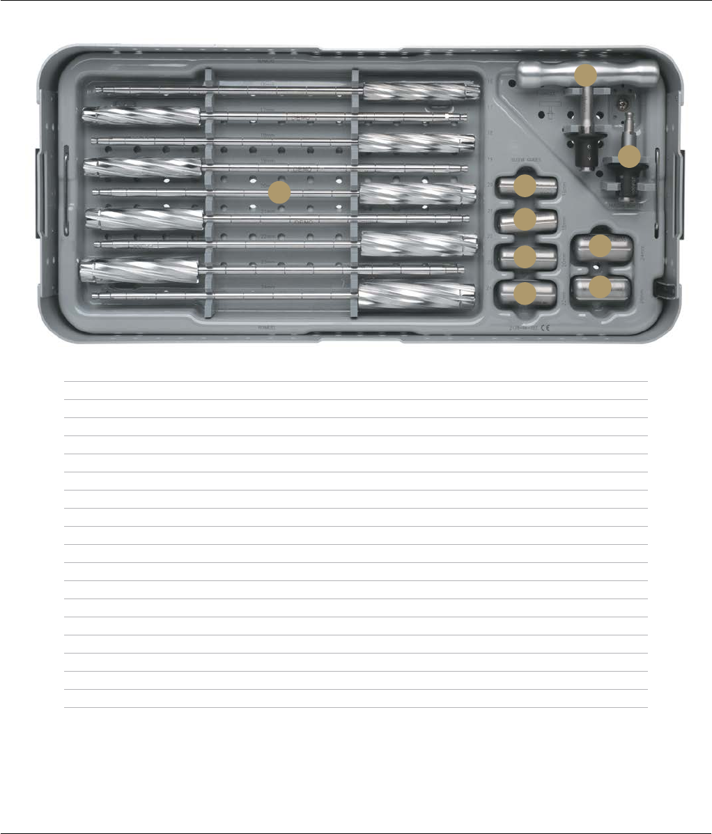
MBT REVISION REAMERS CASE
CAT. NO. 2178-64-105
Description Cat. No.
A Press-Fit Rod Wrench 86-5189
B I.M. Rod Sleeve Guide, 12 mm 2178-63-187
C I.M. Rod Sleeve Guide, 14 mm 2178-63-188
D LCS Reamer Depth Scale 2178-63-102
E Revision Femoral/Tibial/Sleeve Clamp 2178-63-134
F I.M. Reamer, 9 mm 2178-56-045
G MBT Revision Reamers
MBT Revision Reamer, 10 mm 2178-63-170
MBT Revision Reamer, 11 mm 2178-63-171
MBT Revision Reamer, 12 mm 2178-63-172
MBT Revision Reamer, 13 mm 2178-63-173
MBT Revision Reamer, 14 mm 2178-63-174
MBT Revision Reamer, 15 mm 2178-63-175
Top Tray
A
D
G
F E
B C
66 DePuy Synthes Joint Reconstruction S-ROM® Noiles Rotating Hinge Surgical Technique
Description Cat. No.
A MBT Revision Reamers
MBT Revision Reamer, 16 mm 2178-63-176
MBT Revision Reamer, 17 mm 2178-63-177
MBT Revision Reamer, 18 mm 2178-63-178
MBT Revision Reamer, 19 mm 2178-63-179
MBT Revision Reamer, 20 mm 2178-63-180
MBT Revision Reamer, 21 mm 2178-63-181
MBT Revision Reamer, 22 mm 2178-63-182
MBT Revision Reamer, 23 mm 2178-63-183
MBT Revision Reamer, 24 mm 2178-63-184
B I.M. Rod Sleeve Guide, 16 mm 2178-63-189
C I.M. Rod Sleeve Guide, 18 mm 2178-63-190
D I.M. Rod Sleeve Guide, 20 mm 2178-63-191
E I.M. Rod Sleeve Guide, 22 mm 2178-63-192
F I.M. Rod Sleeve Guide, 24 mm 2178-63-193
G I.M. Rod Sleeve Guide, 26 mm 2178-63-194
H MBT Revision T-Handle 2178-63-137
I Modified Hudson Adapter 2178-63-136
MBT REVISION REAMERS CASE
CAT. NO. 2178-64-105
Bottom Tray
A
H
I
B
C
DF
EG
Surgical Technique S-ROM® Noiles Rotating Hinge DePuy Synthes Joint Reconstruction 67
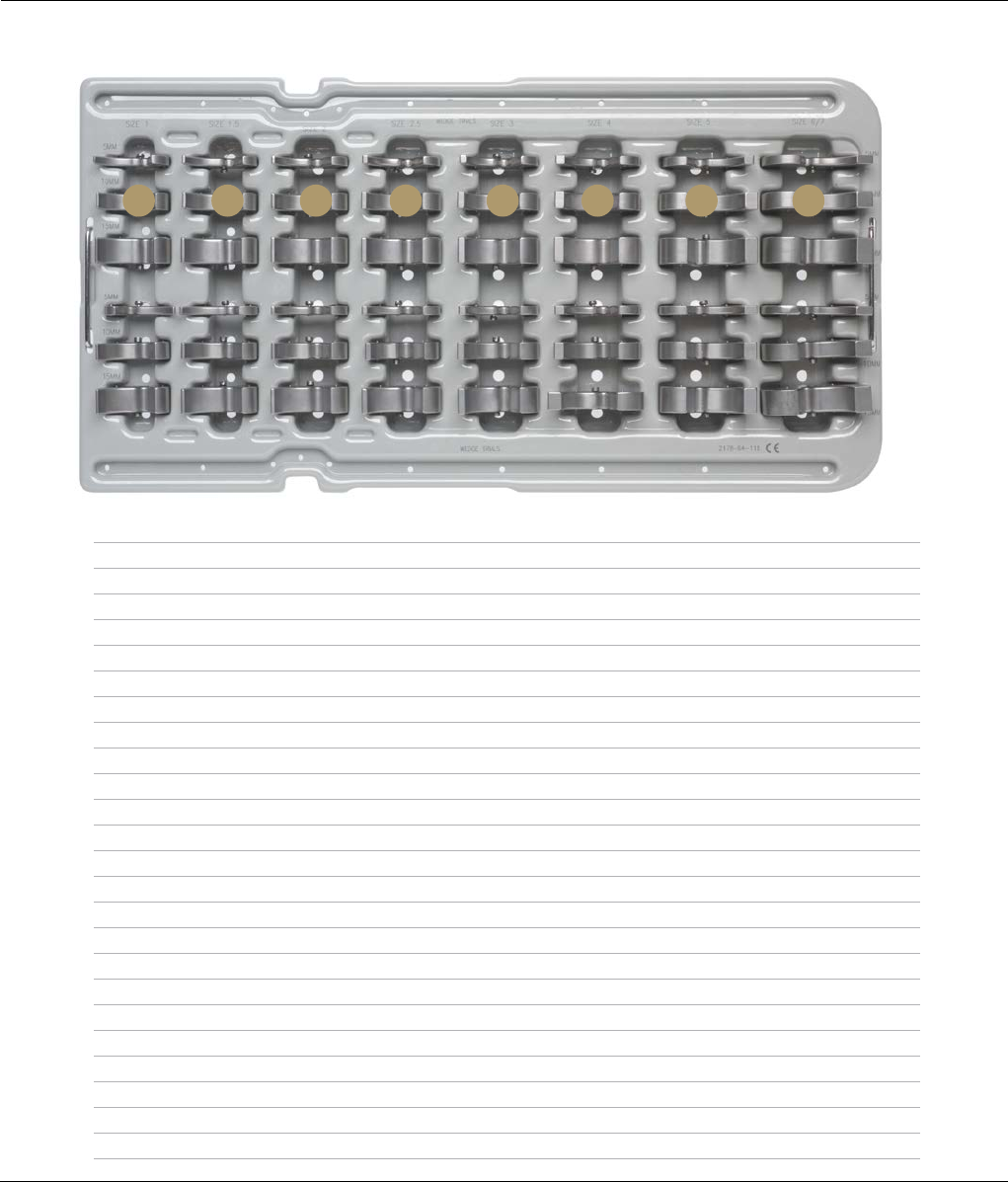
MBT REVISION WEDGE TRIALS AND INSTRUMENTS
CAT. NO. 2178-64-115
Top Tray
Description Cat. No.
A Size 1, 5 mm 2294-56-110
Size 1, 10 mm 2294-56-111
Size 1, 15 mm 2294-56-112
B Size 1.5, 5 mm 2294-56-115
Size 1.5, 10 mm 2294-56-116
Size 1.5, 15 mm 2294-56-117
C Size 2, 5 mm 2294-56-120
Size 2, 10 mm 2294-56-121
Size 2, 15 mm 2294-56-122
D Size 2.5, 5 mm 2294-56-125
Size 2.5, 10 mm 2294-56-126
Size 2.5, 15 mm 2294-56-127
E Size 3, 5 mm 2294-56-130
Size 3, 10 mm 2294-56-131
Size 3, 15 mm 2294-56-132
F Size 4, 5 mm 2294-56-135
Size 4, 10 mm 2294-56-136
Size 4, 15 mm 2294-56-137
G Size 5, 5 mm 2294-56-140
Size 5, 10 mm 2294-56-141
Size 5, 15 mm 2294-56-142
H Size 6/7, 5 mm 2294-56-145
Size 6/7, 10 mm 2294-56-146
Size 6/7, 15 mm 2294-56-147
A B C D E F G H
Size 1
5 mm
10 mm
15 mm
5 mm
10 mm
15 mm
Size 1.5 Size 2 Size 2.5 Size 3 Size 4 Size 5 Size 6/8
68 DePuy Synthes Joint Reconstruction S-ROM® Noiles Rotating Hinge Surgical Technique
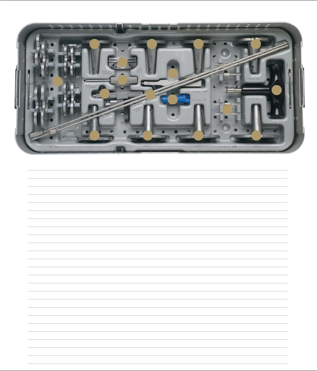
MBT REVISION WEDGE TRIALS AND INSTRUMENTS
CAT. NO. 2178-64-115
Bottom Tray
Description Cat. No.
A MBT Revision Tray Trial, Size 1 2294-36-110
MBT Revision Tray Trial, Size 1.5 2294-36-115
MBT Revision Tray Trial, Size 2 2294-36-120
MBT Revision Tray Trial, Size 2.5 2294-36-125
MBT Revision Tray Trial, Size 3 2294-36-130
MBT Revision Tray Trial, Size 4 2294-36-140
MBT Revision Tray Trial, Size 5 2294-36-150
MBT Revision Tray Trial, Size 6 2294-36-160
B MBT Revision Tray Trial with Stem, Size 1 2294-35-110
C MBT Revision Tray Trial with Stem, Size 1.5 2294-35-115
D MBT Revision Tray Trial with Stem, Size 2 2294-35-120
E MBT Revision Tray Trial with Stem, Size 2.5 2294-35-125
F MBT Revision Cutting Block 2178-63-122
G Tibial Wedge Trial Screwdriver 86-0277
H MBT Wedge Cutting Attachment 2178-63-130
I SP2 Alignment Rods 99-1016
J Tibial Trial Alignment Handle 96-6330
K MBT Revision Trial Post 2178-63-132
L Modular Plus Torque Driver 86-0284
M MBT Tray Trial Fixation Pins 2178-30-123
N MBT Revision Tray Trial with Stem, Size 3 2294-35-130
O MBT Revision Tray Trial with Stem, Size 4 2294-35-140
P MBT Revision Tray Trial with Stem, Size 5 2294-35-150
Q MBT Revision Tray Trial with Stem, Size 6 2294-35-160
A
B C
F
G
HIK
J
D E
M
QPON
L
Surgical Technique S-ROM® Noiles Rotating Hinge DePuy Synthes Joint Reconstruction 69
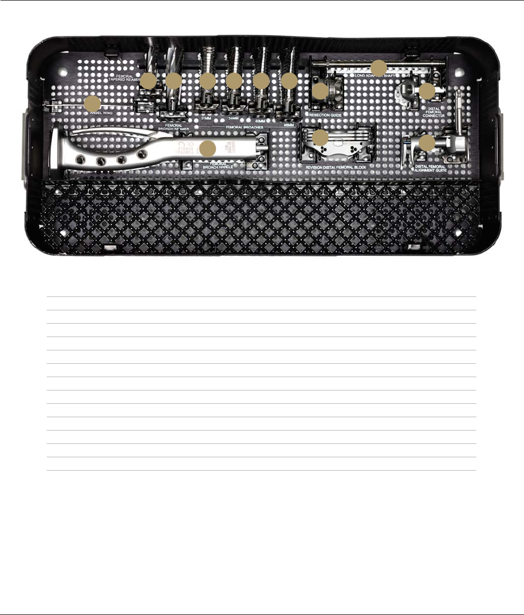
Bottom Tray
SIGMA HP REVISION FEMORAL PREP INSTRUMENT CASE
CAT. NO. 2011-03-049
Description Cat. No.
A Visualization Wing 96-6530
B Completion Revision Femoral Tapered Reamer 2178-60-030
C Universal Revision Femoral Broach Reamer 96-1671
D Universal Revision Femoral Broach 31 mm 96-1683
E Universal Revision Femoral Broach 34 mm 96-1684
F Universal Revision Femoral Broach 40 mm 96-1685
G Universal Revision Femoral Broach 46 mm 96-1686
H SIGMA HP Revision Adapter Removable Shaft 2011-03-029
I SIGMA HP Distal Femoral Resection Guide 9505-01-235
J SIGMA HP Distal Femoral Connector 9505-01-238
K SIGMA HP Revision Distal Femoral Block 9505-01-239
L SIGMA HP Distal Femoral Alignment Guide 9505-01-234
M Universal Revision Femoral Broach Handle 96-1682
A
B C D
M
E F G
I
K
J
L
H
70 DePuy Synthes Joint Reconstruction S-ROM® Noiles Rotating Hinge Surgical Technique
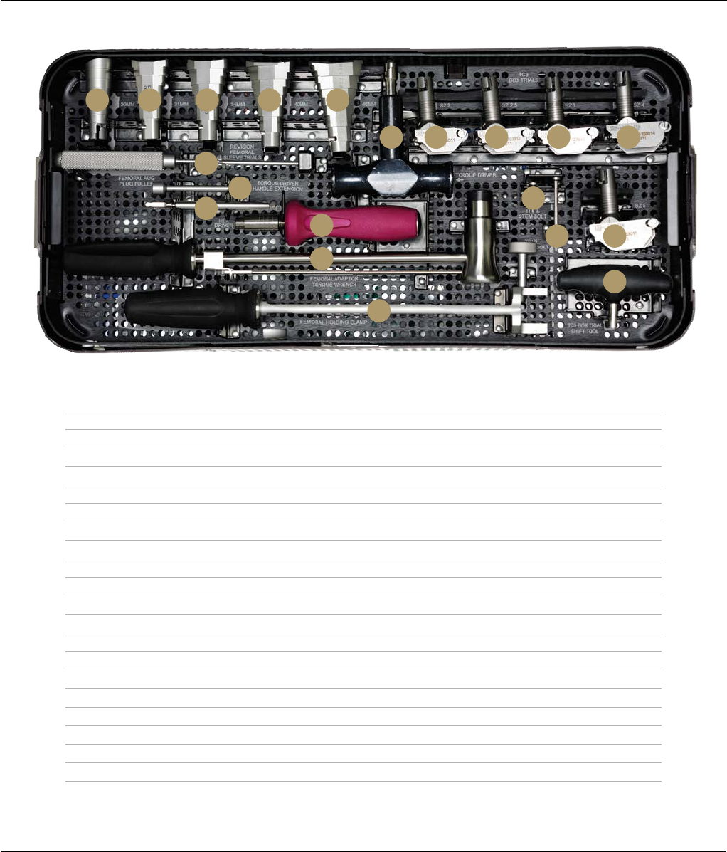
SIGMA HP REVISION FEMORAL TRIAL INSTRUMENT CASE
CAT. NO. 2011-03-050
Top Tray
Description Cat. No.
A LCS/SIGMA Revision Femoral Sleeve Trial 20 mm 2294-53-100
B LCS/SIGMA Revision Femoral Sleeve Trial 31 mm 2294-53-110
C LCS/SIGMA Revision Femoral Sleeve Trial 34 mm 2294-53-120
D LCS/SIGMA Revision Femoral Sleeve Trial 40 mm 2294-53-130
E LCS/SIGMA Revision Femoral Sleeve Trial 46 mm 2294-53-140
F Modular Plus Torque Driver 86-0284
G SIGMA HP Revision TC3 Box Trial Size 2 2011-03-011
H SIGMA HP Revision TC3 Box Trial Size 2.5 2011-03-012
I SIGMA HP Revision TC3 Box Trial Size 3 2011-03-013
J SIGMA HP Revision TC3 Box Trial Size 4 2011-03-014
K SIGMA HP Revision TC3 Box Trial Size 5 2011-03-015
L SIGMA HP Revision Femoral Adapter Shift Tool 2011-03-057
M SIGMA Femoral Adapter Sleeve Bolt Trial Neutral 2011-03-052
N SIGMA Femoral Adapter Stem Bolt Trial Neutral 2011-03-051
O Femoral Augment Plug Puller 86-5151
P SP2 Torque Driver Handle Extension 96-6301
Q Large Fragment Screwdriver Shank 8242-19-000
R 2.0 Nm Torque-limiting Screwdriver 2141-18-001
S Femoral Adapter Torque Wrench 96-1673
T Femoral Adapter Holding Clamp 96-1674
A B C
O
Q
P
R
N
M K
L
S
T
ED
F G H I J
Surgical Technique S-ROM® Noiles Rotating Hinge DePuy Synthes Joint Reconstruction 71
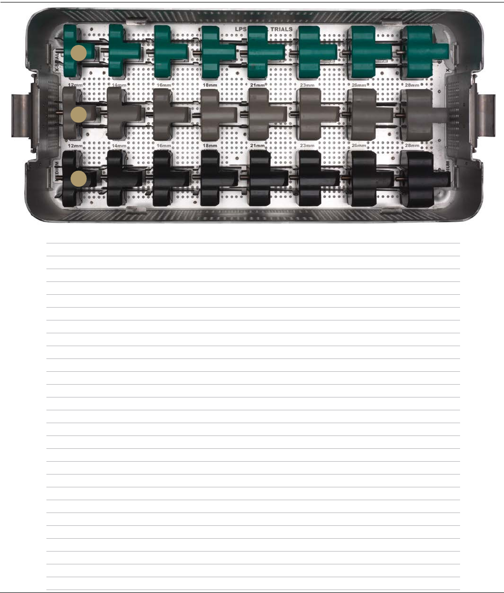
LPS HINGE INSERT TRIALS
Description Cat. No.
A Xsm Hinged Insert Trials
LPS Hinge Insert Trial 12 mm, Xsm 2987-22-112
LPS Hinge Insert Trial 14 mm, Xsm 2987-22-114
LPS Hinge Insert Trial 16 mm, Xsm 2987-22-116
LPS Hinge Insert Trial 18 mm, Xsm 2987-22-118
LPS Hinge Insert Trial 21 mm, Xsm 2987-22-121
LPS Hinge Insert Trial 23 mm, Xsm 2987-22-123
LPS Hinge Insert Trial 26 mm, Xsm 2987-22-126
LPS Hinge Insert Trial 28 mm, Xsm 2987-22-128
B Sm Hinged Insert Trials
LPS Hinge Insert Trial 12 mm, Sm 2987-22-212
LPS Hinge Insert Trial 14 mm, Sm 2987-22-214
LPS Hinge Insert Trial 16 mm, Sm 2987-22-216
LPS Hinge Insert Trial 18 mm, Sm 2987-22-218
LPS Hinge Insert Trial 21 mm, Sm 2987-22-221
LPS Hinge Insert Trial 23 mm, Sm 2987-22-223
LPS Hinge Insert Trial 26 mm, Sm 2987-22-226
LPS Hinge Insert Trial 28 mm, Sm 2987-22-228
C Med Hinged Insert Trials
LPS Hinge Insert Trial 12 mm, Med 2987-22-312
LPS Hinge Insert Trial 14 mm, Med 2987-22-314
LPS Hinge Insert Trial 16 mm, Med 2987-22-316
LPS Hinge Insert Trial 18 mm, Med 2987-22-318
LPS Hinge Insert Trial 21 mm, Med 2987-22-321
LPS Hinge Insert Trial 23 mm, Med 2987-22-323
LPS Hinge Insert Trial 26 mm, Med 2987-22-326
LPS Hinge Insert Trial 28 mm, Med 2987-22-328
A
B
C
72 DePuy Synthes Joint Reconstruction S-ROM® Noiles Rotating Hinge Surgical Technique
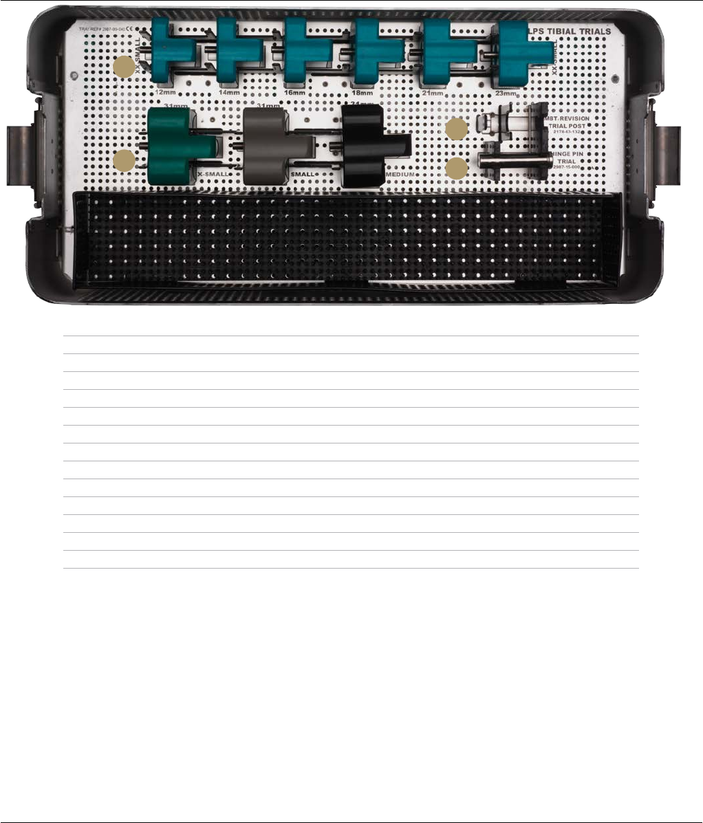
LPS HINGE INSERT TRIALS
Description Cat. No.
A XXSm Hinged Insert Trials
LPS Hinge Insert Trial XX-Sm 12 mm 2987-22-012
LPS Hinge Insert Trial XX-Sm 14 mm 2987-22-014
LPS Hinge Insert Trial XX-Sm 16 mm 2987-22-016
LPS Hinge Insert Trial XX-Sm 18 mm 2987-22-018
LPS Hinge Insert Trial XX-Sm 21 mm 2987-22-021
LPS Hinge Insert Trial XX-Sm 23 mm 2987-22-023
B 31mm Hinged Insert Trials
LPS Hinge Insert Trial 31 mm, Xsm 2987-22-131
LPS Hinge Insert Trial 31 mm, Sm 2987-22-231
LPS Hinge Insert Trial 31 mm, Med 2987-22-331
C MBT Rev Trial Post 2178-63-132
D LPS Hinge Pin Trial 2987-15-000
D
A
B
C
Surgical Technique S-ROM® Noiles Rotating Hinge DePuy Synthes Joint Reconstruction 73
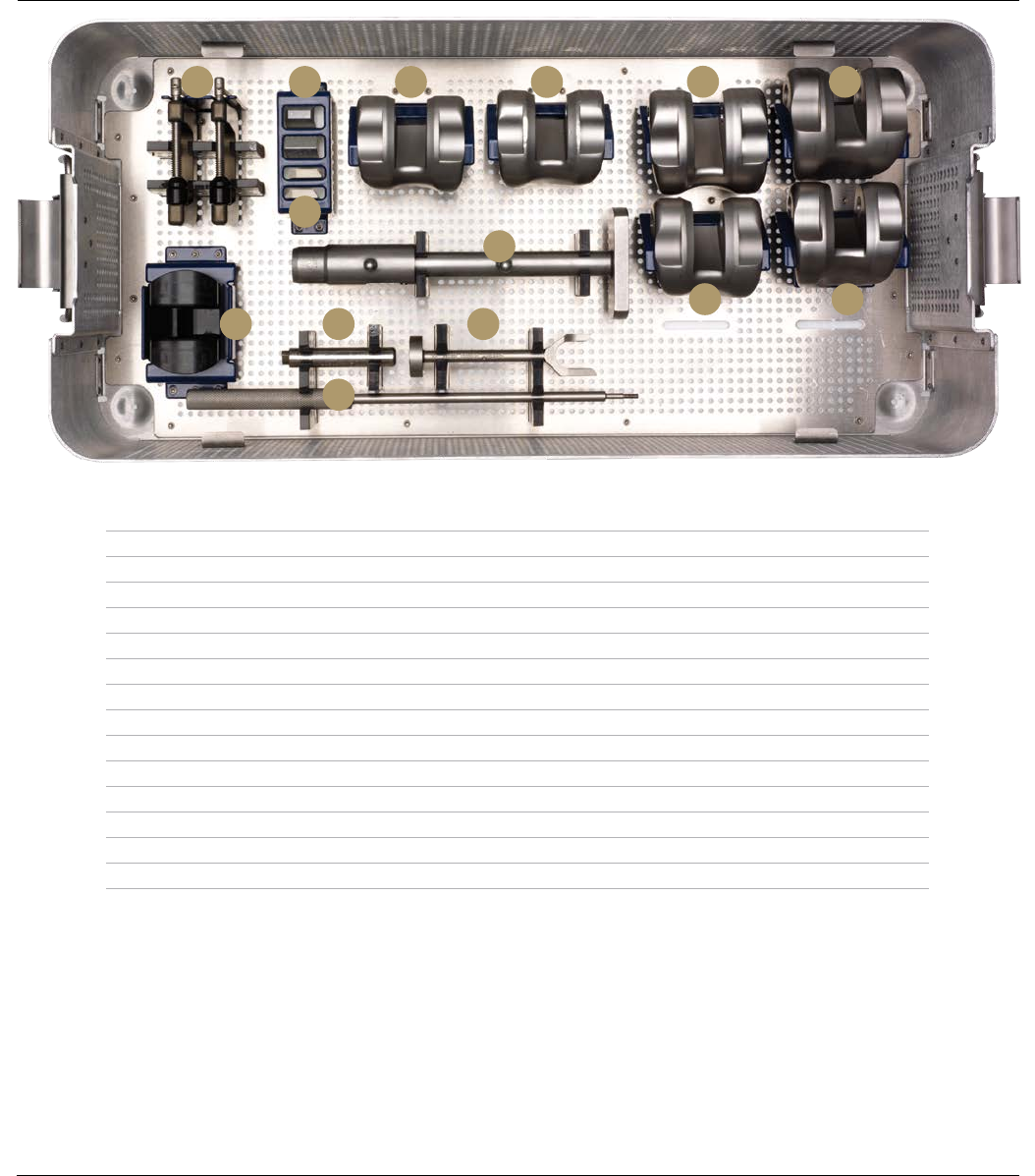
S-ROM HINGE FEMORAL INSTRUMENTS
Description Cat. No.
A S-ROM Driver Femoral 633802
B S-ROM Knee Aug Blk Cem Clamp 633810
C S-ROM Separator,Femoral Sleeve 634182
D Sleeve/Stem Extractor 86-5226
E S-ROM NRH Dist Fem Aug Trl 5 mm 633785
F S-ROM NRH Dist Fem Aug Trl 10 mm 633790
G S-ROM NRH Hinge Pin Trial 634133
H S-ROM Universal Handle 633806a
I S-ROM NRH Fem Trial Right Med 634131r
J S-ROM NRH Fem Trial Left Med 634132l
K S-ROM NRH Fem Trial Right Small 634151l
L S-ROM NRH Fem Trial Left Small 634151r
M S-ROM NRH Fem Trial Right Xsmall 634161
N S-ROM NRH Fem Trial Left Xsmall 634161
A G
D
C
B E
F
H
I J K L
M N
74 DePuy Synthes Joint Reconstruction S-ROM® Noiles Rotating Hinge Surgical Technique
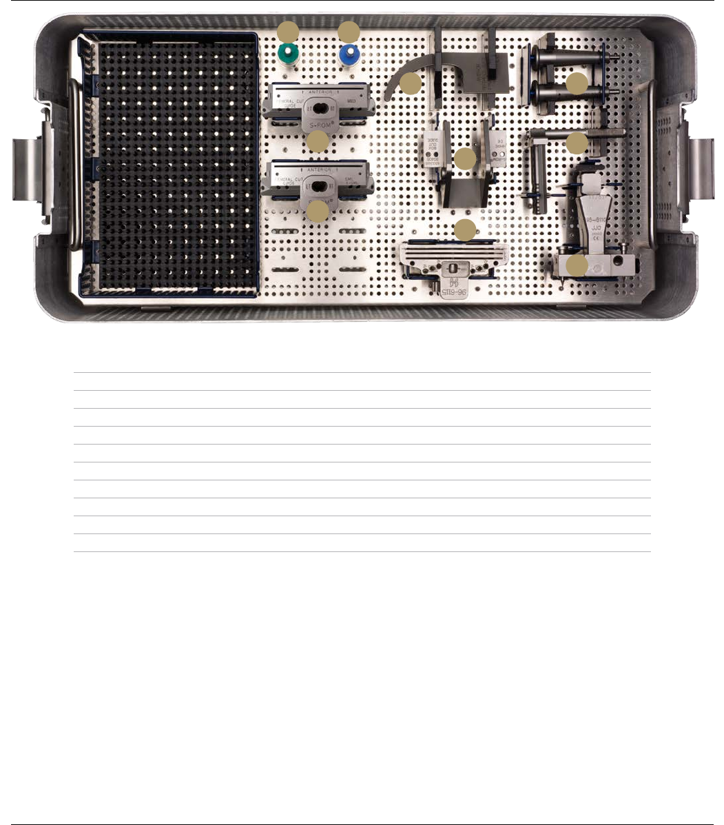
S-ROM HINGE FEMORAL INSTRUMENTS
Description Cat. No.
A S-ROM Guide Anterior Reference 633370a
B S-ROM Xsm/Sm A/P Block 2163-11-001
C S-ROM Med A/P Block 2163-11-004
D S-ROM NRH Fem Box Cut Guide 633385
E S-ROM Box Cut Guide Augment Space, 5 mm 633305a
F S-ROM Box Cut Guide Augment Space, 10 mm 633306a
G SP2 Removable Handles 96-6147
H Femoral Locating Device Outrigger 96-6112
I Femoral Locating Device 96-6110
J Distal Femoral Cutting Block 96-6115
C
B
F E
A G
H
I
D
J
Surgical Technique S-ROM® Noiles Rotating Hinge DePuy Synthes Joint Reconstruction 75

IMPORTANT:
This Essential Product Information sheet does not include all of the information
necessary for selection and use of a device. Please see full labeling for all
necessary information.
INDICATIONS AND USAGE:
The NOILES Rotating Hinge Knee is indicated for use with PMMA bone cement in
primary or revision cases in patients:
• who have reached skeletal maturity and
• for whom the surgeon has decided to resect both cruciate ligaments or whose
cruciate ligaments are absent or incompetent and
• who exhibit insufficiency of lateral/collateral ligaments and other soft
supporting tissue due to the following conditions:
• Rheumatoid arthritis, osteoarthritis, post-traumatic arthritis, and arthritis
secondary to a variety of diseases and anomalies
• Failure of a previous knee reconstruction procedure
• Trauma
CONTRAINDICATIONS:
1. Active infection or history of general infections or local infectious disease.
2. Vascular insufficiency, muscular atrophy or neuromuscular disease in the
affected limb.
3. Advanced loss of osteochondral structure that would preclude proper fixation
of the prosthesis.
4. Tumors of the supporting bone structure, systemic and metabolic disorders
leading to progressive deterioration of solid bone support.
5. Drug or alcohol addiction, or limiting neuropathic disease.
6. Skeletal immaturity.
7. Obesity or very active lifestyle that can produce loads on the prosthesis that
can lead to failure of the fixation of the device or device itself.
8. Allergic reaction to the implant materials.
9. Inadequate flexor and extensor mechanism necessary to achieve a functional
prosthetic joint.
WARNINGS:
Improper prosthesis selection or alignment, inadequate fixation, use where
contraindicated or in patients whose medical, physical, mental, or occupational
conditions will likely result in extreme stresses to the implant, may result in
premature failure due to loosening, fracture, or wear.
Post-operative care is extremely important. The patient should be instructed on
the limitations of the device and should be cautioned regarding load bearing,
ranges of motion, and activity levels permissible. Early motion and load bearing
should be carefully controlled.
The S-ROM tibial base, tibial sleeve, tibial stem extension, and tibial
augmentation blocks may not be used with the NOILES Posterior Stabilized Knee.
CAUTION: Federal (USA) law restricts this device to sale by or on the order
of a physician.
PRECAUTIONS:
The NOILES Rotating Hinge Knee is designed to articulate from 6 degrees
hyperextension to 110 degrees flexion. If, due to grossly inadequate soft tissue
integrity, flexion beyond 90 degrees causes luxation of the plateau assembly out
of the tibial base, the patient must have a knee brace posto-peratively to limit
flexion to 90 degrees. In such cases, the surgeon should consider closing the
wound with the knee in full extension.
The size of the tibial plateau assembly must correspond with the size of the
femoral component.
The size of the tibial augmentation block must correspond to the size of the
tibial base.
Femoral sleeves are required when using femoral stem extensions.
A femoral plug is required with the femoral sleeve when a femoral stem
extension is not used.
A tibial cap is required with the tibial sleeve when a tibial stem extension is
not used.
Tibial augmentation blocks cannot be used when tibial sleeves are being used.
An implant should never be reused. Any implant, once used, should be discarded.
Even though it appears undamaged, it may have small defects and/or internal
stress patterns that may lead to failure. Likewise, a new implant should be
handled carefully to avoid damage that could compromise the integrity of the
device and cause early failure or loosening.
The wear rate of prosthesis contact surfaces is greatly accelerated if loose
fragments of bone cement become detached and act as an abrasive in the
bearing surfaces. When using bone cement, care should be taken to remove all
excess cement from the periphery of the implant.
DePuy’s Single Use devices have not been designed to undergo or withstand any
form of alteration, such as disassembly, cleaning or re-sterilization, after a single
patient use. Reuse can potentially compromise device performance and patient
safety.
ADVERSE EFFECTS:
Fracture may occur due to improper preparation of the implant site or if excessive
force is used during seating of the implant. Transient peroneal palsy has been
reported following total knee arthroplasty, especially after correction of severe
flexion or valgus deformities.
Patients have complained of persistent pain and stiffness following total knee
arthroplasty. In addition, patellar tendon rupture, femoral-tibial subluxation or
dislocation, and persistent ligamentary laxity have been reported with the use of
total knee implants. Infection and loosening have been reported following total
joint arthroplasty, as have wear and failure due to fracture of knee prosthesis
components.
Histological reactions have been reported as an apparent response to exposure to
a foreign material. The actual clinical significance of these reactions is unknown.
Serious adverse side effects may necessitate surgical intervention.
The third party trademarks used herein are trademarks of their respective owners.
S-ROM® MODULAR TOTAL KNEE SYSTEM | NOILES™ ROTATING HINGE KNEE SYSTEM
DePuy Orthopaedics, Inc.
700 Orthopaedic Drive
Warsaw, IN 46582
T. +1 (800) 366-8143
www.depuysynthes.com
© DePuy Synthes Joint Reconstruction, a division of DOI 2014. All rights reserved.
0612-85-510 (Rev. 3) EO 1/14
