Dura_1021_Computer_Terminal_Users_Manual Dura 1021 Computer Terminal Users Manual
User Manual: Pdf Dura_1021_Computer_Terminal_Users_Manual
Open the PDF directly: View PDF ![]() .
.
Page Count: 16

DURA
1021
Computer Terminal User's Manual
Contents
INTRODUCTION
1
See-Through
Card
Holder
7
OPERATING
PROCEDURES
2
Margin
Stops
7
KEYBOARD
LAYOUTS
3
Typing
Position
Indicator
7
CODE
CHARTS
4
KEYBOARD
CONTROLS
8
OPERATING
CONTROLS
5
Power
On/Off
Switch
and
Indicator
8
Carrier
Return
5
Index
Key
8
Interrupt
5
Carrier
Return
8
Shift
5
Tab
Control
8
NP/NE
(Non
Print/Non
Escape)
5
Shift
and
Shift
Lock
8
Ribbon
Shift
5
Multiple
Character
Keys
8
Reverse
Index
5
Backspace
8
First
Line.
6
Margin
Release
8
Check
Function
6 CHANGING
TYPE
STYLE
9
Timing
6
Front
Cover
Plate
9
Data
Flow
Chart
6 CHANGING
RIBBON
CARTRIDGE
10
TYPEWRITER
OPERATION
7
Ribbon
Controls
10
PAPER
CARRIER
CONTROLS
7 CHANGING
FILM
RIBBON
11
Paper
Bail
7
CARE
AND
CLEANING
12
Platen
Variable
7
Platen
12
Paper
Guide
7
Deflector
Plate
12
Multiple
Copy
Impression
Control
7
Erasure
Dustpan
12
Vertical
Spacing
Control
7
Typing
Element
12
Paper
Release
Lever
7
Index
13
DURA
is
a trademark
of
DURA,. Division Intercontinental Systems, Inc.
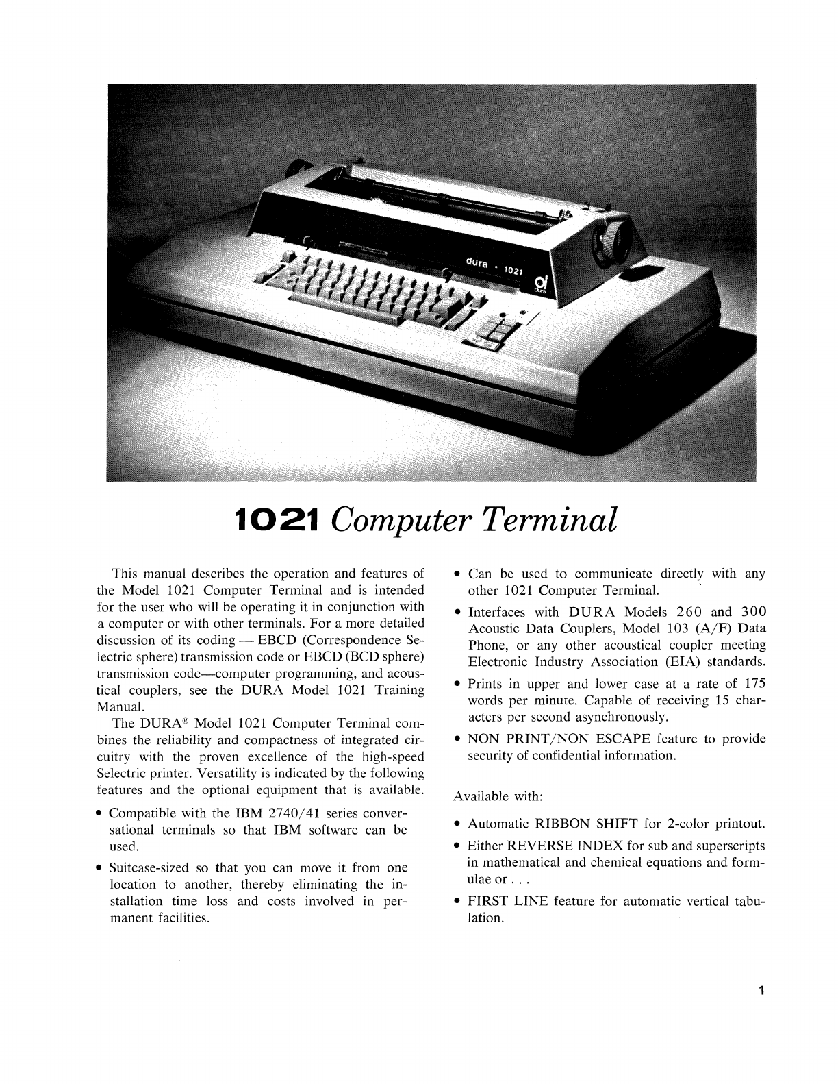
1021
Computer Terminal
This manual describes the operation and features of
the Model 1021 Computer Terminal and
is
intended
for the user who will be operating it in conjunction with
a computer or with other terminals.
For
a more detailed
discussion of its coding -EBCD (Correspondence Se-
lectric sphere) transmission code or EBCD (BCD sphere)
transmission
code-computer
programming, and acous-
tical couplers, see the
DURA
Model 1021 Training
Manual.
The DURA® Model 1021 Computer Terminal com-
bines the reliability and compactness of integrated cir-
cuitry with the proven excellence of the high-speed
Selectric printer. Versatility is indicated by the following
features and the optional equipment that
is
available.
• Compatible with the IBM
2740/41
series conver-
sational terminals so that IBM software can be
used.
• Suitcase-sized
so
that you can move it from one
location to another, thereby eliminating the in-
stallation time loss and costs involved in per-
manent facilities.
• Can be used to communicate directly with any
other 1021 Computer Terminal.
• Interfaces with
DURA
Models
260
and
300
Acoustic
Data
Couplers, Model 103
(A/F)
Data
Phone,
or
any other acoustical coupler meeting
Electronic Industry Association (EIA) standards.
• Prints in upper and lower case
at
a rate of 175
words per minute. Capable of receiving 15 char-
acters per second asynchronously.
•
NON
PRINT/NON
ESCAPE feature to provide
security of confidential information.
Available with:
• Automatic RIBBON
SHIFT
for 2-color printout.
• Either REVERSE
INDEX
for sub and superscripts
in mathematical and chemical equations and form-
ulae
or
...
•
FIRST
LINE
feature for automatic vertical tabu-
lation.
1
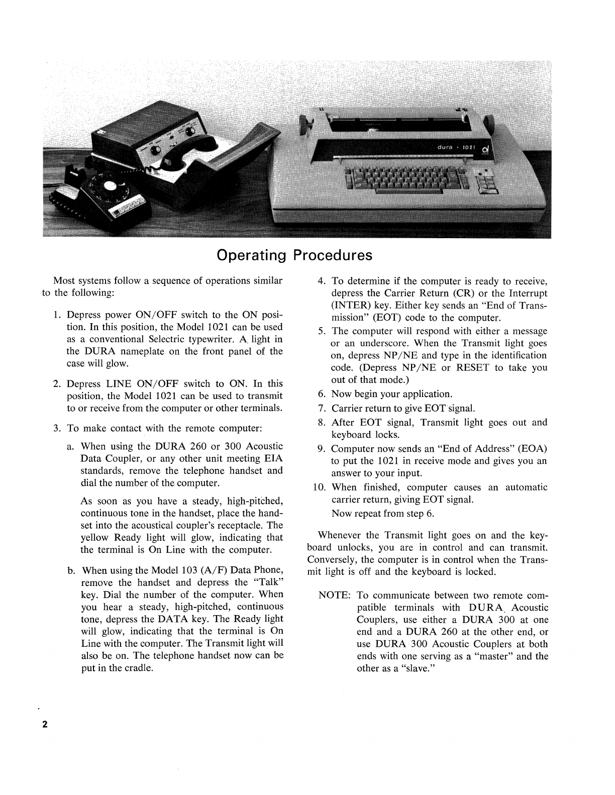
Operating Procedures
Most systems follow a sequence of operations similar
to the following:
2
1.
Depress power
ON/OFF
switch to the
ON
posi-
tion.
In
this position, the Model 1021 can be used
as
a conventional Selectric typewriter. A light in
the
DURA
nameplate on the front panel of the
case will glow.
2.
Depress
LINE
ON/OFF
switch to ON.
In
this
position, the Model 1021 can be used to transmit
to
or
receive from the computer
or
other terminals.
3.
To
make contact with the remote computer:
a.
When using the
DURA
260
or
300 Acoustic
Data
Coupler,
or
any other unit meeting
EIA
standards, remove the telephone handset and
dial the number of the computer.
As soon as you have a steady, high-pitched,
continuous tone in the handset, place the hand-
set into the acoustical coupler's receptacle. The
yellow Ready light will glow, indicating that
the terminal
is
On Line with the computer.
b. When using the Model 103
(A/F)
Data
Phone,
remove the handset and depress the "Talk"
key. Dial the number of the computer. When
you hear a steady, high-pitched, continuous
tone, depress the
DATA
key. The Ready light
will glow, indicating that the terminal is
On
Line with the computer. The Transmit light will
also
be
on.
The
telephone handset now can be
put
in the cradle.
4. To determine if the computer
is
ready to receive,
depress the Carrier Return (CR)
or
the Interrupt
(INTER) key. Either key sends an
"End
of Trans-
mission" (EOT) code to the computer.
5.
The
computer will respond with either a message
or
an underscore. When the Transmit light goes
on, depress
NP
/NE
and type in the identification
code. (Depress
NP
/NE
or
RESET
to take you
out of that mode.)
6.
Now begin your application.
7.
Carrier return to give EOTsignal.
8. After
EOT
signal, Transmit light goes out and
keyboard locks.
9. Computer now sends an
"End
of Address" (EOA)
to
put
the 1021 in receive mode and gives you an
answer to your input.
10. When finished, computer causes an automatic
carrier return, giving
EOT
signal.
Now repeat from step
6.
Whenever the Transmit light goes on and the key-
board unlocks, you are in control and can transmit.
Conversely, the computer is in control when the Trans-
mit light is off and the keyboard
is
locked.
NOTE: To communicate between two remote com-
patible terminals with
DURA,
Acoustic
Couplers, use either a
DURA
300 at one
end and a
DURA
260 at the other end, or
use
DURA
300 Acoustic Couplers
at
both
ends with one serving
as
a "master" and the
other
as
a "slave."

1021
-"SELECTRIC "KEYBOARD LAYOUT
Ready Transmit
Ught
light
(yellow) (green)
~
0
ITflII]
CJ
CJ
[I]
[J]
OJ
CJ
OJ
OJ
D
CJ
rn
~,o
0
N'M
DO
".
[QJ00000000[gCJD
ElD
+
1,-------,10
0 0 0 0 0
~
D D
CJ
1'---------11
OFF B B
Optional
1.
Reverse Index Key
2.
First Line Key
3,
Ribbon Shift Key
1021-
BCD
KEYBOARD LAYOUT
Ready Transmit
Ught Light
liB
0
CJ
IT]
D
[J
[I]
[J
IT]
[J
OJ
OJ
[J
[J
rn
~,'"o
O'N.,"'
DO
".
[QJ00000000[gCJCJ
ElD
Optional
1.
Reverse Index Key
2. First Line Key
3. Ribbon Shift Key
3
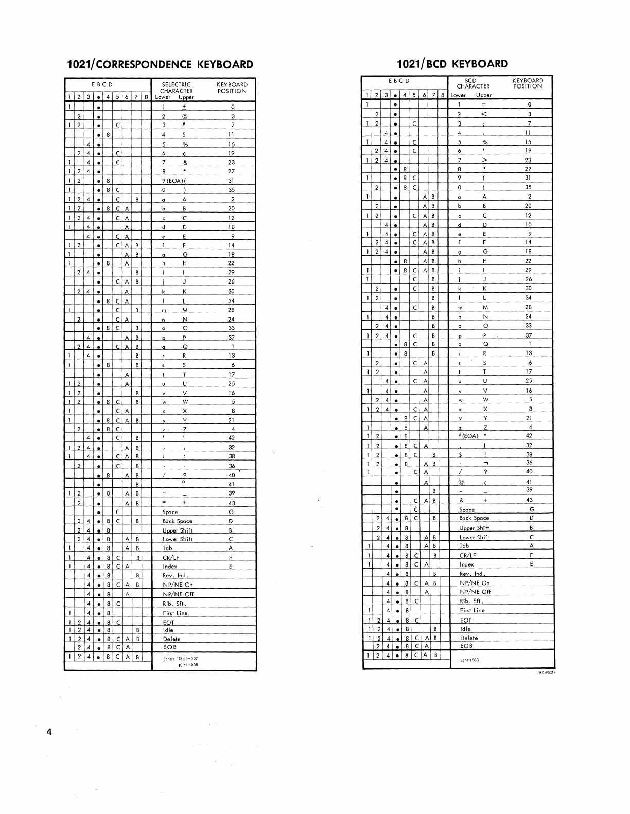
1021/
CORRESPONDENCE
KEYBOARD
1021/BCD
KEYBOARD
E
BCD
SELECTRIC
KEYBOARD
CHARACTER
POSITION
1 2 3 • 4 5 6 7 8 Lower Upper
E
BCD
BCD
KEYBOARD
CHARACTER
POSITION
1 2 3 • 4 5 6 7 8 Lower
UDDer
1 • 1 + 0 1 • 1 = 0
2 • 2 @ 3 2 · 2 < 3
1 2 • C 3 # 7 1 2 · C 3 7
• 8 4 $
11
4 • 4 :
11
4 • 5 % 15 1 4 • C 5 %
15
2 4 • C 6 ¢
19
2 4 • C 6 ,
19
1 4 • C 7 & 23 1 2 4 • 7 >
23
1 2 4 • 8 . 27 ·
8 8 . 27
1 2 • 8 9 (EOA)(
31
1 • 8 C 9 (
31
1 • 8 C 0 )
35
2 • 8 C 0 )
35
1 2 4 • C B a A 2
I'
• A B a A 2
1 2 ·
8 C A b B
20
2 · A B b B
20
1 2 4 • C A c C
12
1 2 • C A B c C
12
1 4 • A d 0 10 4 • A B d 0
10
4 • C A e E 9 1 4 • C A B e E 9
1 2 • C A B I F
14
2 4 • C A B I F
14
1 • A B a G 18 1 2 4 · A B 9 G
18
1 • 8 A h H
22
·
8 A
'B
h H
22
2 4 · B i 1 29 1 • 8 C A B i 1
29
• C A B J 26 1 C B i J 26
2 4 • A k K
30
2 • C B k K
30
• 8 C A I L
34
1 2 • B I L
34
1 • C B m M
28
4 • C B m M
28
2 • C A n N 24 1 4 • B n N
24
• 8 C B 0 0
33
2 4 • B 0 0
33
4 • A B 0 P
37
1 2 4 • C B 0 P
37
2 4 • C A B n Q 1 ·
8 C B 0 Q 1
1 4 • B r R 13 1 • 8 B r R
13
1 ·
8 B 5 S 6 2 • C A 5 S 6
· A I T 17 1 2 • A I T 17
1 2 · A u U 25 4 • C A u U
25
1 2 • B v V
16
1 4 • A v V
16
1 2 • 8 C B w W 5 2 4 • A w W 5
1 · C A x X 8 1 2 4 · C A x X 8
1 • 8 C A B v Y
21
• 8 C A Y
21
2 • 8 C • Z 4
4 • C B ,
42
1 • 8 A . Z 4
1 2 • 8
DrEaA)
"
42
1 2 4 • A B
32
1 2 ·
8 C A I
32
I 4 • C A B ; :
38
1 2 • 8 C B $ I
38
2 • C B
36
1 2 • 8 A B
..,
36
· R A B I ? 40 1 • C A / ? 40
• B ! 0
41
• A
(ciJ
,
41
1 2 • 8 A B -
39
• B -
39
2 • " B = + 43 • C A B & +
43
• C
S~ce
G • C Snace G
2 4 ·
8 C B
Bock
SQace
0 2 4 • 8 C 8
Bock
Space
0
2 4 • 8 Unner Shift B 2 4 • 8
UDDer
Shifl B
2 4 • 8 A B
Lower
Shift C 2 4 • 8 A B
Lower
Shift C
1 4 • 8 A B
Tab
A
1 4 ·
8 C B
CRILF
F
1 4 • 8 A B
Tab
A
1 4 • 8 C B CRiLF F
1 4 • 8 C A
Index
E 1 4 • 8 C A
Index
E
4 • 8 B
Rev.
Ind. 4 • 8 B Rev. Ind.
4 • 8 C A B NP/NE On
4 •
8·
A NP/NE
Off
4
.1
R C A B NP/NE On
4 • 8 A
NPiNE
Off
4 • 8 C Rib. SIt. 4 • 8 C Rib. Sit.
1 4 • 8
First
line
1 4 • 8
First
line
1 2 4 • 8 C
EOT
1 2 4 • 8 C eaT
1 2 4 • 8 B Idle 1 2 4 • 8 B Idle
1 2 4 • 8 C A B Delete 1 2 4 ·
8 C A B Delete
2 4 • 8 C A EOB 2 4 • 8 C A
EOB
1 2 4 · 8 C A B
Sphere
12pt-007
1 2 4 ·
8 C A B
Sphere
963
lOpt-008
4
Operating Controls
CARRIER RETURN (CR)
As a typewriter key, depressing the carrier return
key will cause the paper to advance vertically one
or
more lines and return to the left margin. However,
when On Line with the computer, the carrier return
key also serves to return control to the computer.
MODE
OFF
LINE
ON
LINE
CARRIER
RETURN FUNCTION
Return carrier
Return carrier, transmit
CR
code
and EOT code. Lock keyboard,
turn Transmit light off.
INTERRUPT (INTER)
This key has two functions:
1.
In the transmit mode, it ends transmit conditions
by
sending an
EOT
code, turning off the Trans-
mit light, and locking the keyboard.
2.
In
the receive mode, it sends an interrupt signal
(200-millisecond spacing signal used by the IBM
2741) to the remote computer. This signal alerts
the computer. The computer in turn can put the
terminal in a transmit status or can continue send-
ing data. In the latter case, the printer continues
to function and all data
is
received and printed
out.
SHIFT
The Shift key on the Model 1021 Computer Terminal
functions as a conventional typewriter shift key. The
user can leave the printer in either upper or lower case
when returning control
io
the remote computer. Like-
wise the printer may be in upper or lower case when
the computer returns control to the terminal.
NP/NE
(Non Print/Non Escape)
This standard feature enables the user to maintain
security on information such
as
identification code, job
code, and account numbers which might make it pos-
sible for others to query the computer for confidential
data.
In
the ON position (indicated by a yellow light),
the printing of any of the 44 characters (A, B, C, etc.)
transmitted
is
inhibited. Operation of the control keys
(shift, TAB, etc.)
is
not affected. Depression of the
NP
/NE
key affects the printers in the local terminal, all
remote terminals, and in the originating terminal. To
take the equipment out of the
NP
/NE
mode, depress
the
NP
/NE
key again.
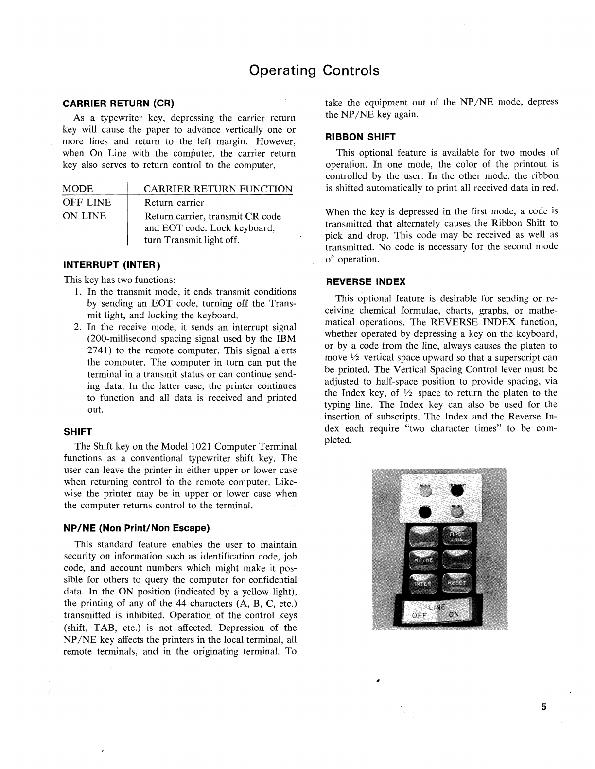
RIBBON SHIFT
This optional feature
is
available for two modes of
operation. In one mode, the color of the printout
is
controlled by the user. In the other mode, the ribbon
is
shifted automatically to print all received data in red.
When the key
is
depressed in the first mode, a code
is
transmitted that alternately causes the Ribbon Shift to
pick and drop. This code may be received
as
well
as
transmitted. No code
is
necessary for the second mode
of operation.
REVERSE INDEX
This optional feature
is
desirable for sending or re-
ceiving chemical formulae, charts, graphs, or mathe-
matical operations. The REVERSE INDEX function,
whether operated
by
depressing a key on the keyboard,
or by a code from the line, always causes the platen to
move
lh
vertical space upward so that a superscript can
be printed. The Vertical Spacing Control lever must be
adjusted to half-space position to provide spacing, via
the Index key, of
lh
space to return the platen to the
typing line. The Index key can also be used for the
insertion of subscripts. The Index and the Reverse In-
dex each require "two character times" to be com-
pleted.
5
FIRST LINE (Vertical Tabulation)
This optional feature
is
desirable when working with
continuous forms, such
as
with a forms tractor. The
function of this key
is
to provide automatic indexing of
the paper in the printer until pre-set stops are reached.
A cam-operated switch in the forms tractor senses that
the appropriate. stop has been reached and stops the
indexing at the "First Line" position. The time re-
quired to complete the indexing operation
is
determined
by
the number of indexes required; each index takes
two character times. The First Line code can be gener-
ated by the key or received On Line. After receiving
First Line code, indexing occurs, and upon completion
the terminal will transmit an
EaT
code.
CHECK FUNCTION
When the terminal
is
in the
reCeIVIng
mode, the
check light will
go
on if a received code
is
a parity
error, or if the printer
is
unable to keep up with or
follow the incoming data. Any character that
is
a parity
error prints out
as
a period, and the check light glows.
The terminal will automatically transmit an interrupt
signal back to the computer (which causes it to stop
sending), and the keyboard remains locked. On special
order, the 1021 terminal can be wired
so
that the
SERIALIZER
RECEIVE
CLOCK
CONTROL
r4
.-
KEYBOARD
PRINTER
~
SWITCHES
..
INTERLOCK
r
RECEIVE
4
SHIFT
REG.
...
PRINTER
...
&
OUTPUT
REGISTER
GATES
..
...
terminal does not send an interrupt signal. When the
terminal
is
in the transmitting mode, the check light
will go on if an interrupt signal (200-millisecond spac-
ing)
is
received. In the transmitting mode, the user can
return control to the remote system by depressing the
reset, then either the Carrier Return or the Interrupt
key. The user must not turn off the check light by de-
pressing the Reset key unless the transmit light is on.
TIMING CONSIDERATIONS
In
the software, time must be allowed for the me-
chanical
fun~tions
of the printer to be completed before
additional character information
is
transmitted. The
amount of time, expressed in terms of "character times,"
is
given by the following formulae:
CARRIER
RETURN
TAB
INDEX/REVERSE
INDEX
(1
each)
FIRST
LINE
(each Index)
RIBBON SHIFT
N=T+1.5
N=T+1.5
N=2
N=2
N=l
where N = number of character times required, and
T = number of inches of carrier travel. Answers should
be rounded off to the next highest whole number.
TRANSMIT TRANSMIT
SHIFT
REG.
I ....
CONTROL
....
~
INPUT
GATES
GATING
PRINT
DECODE
&
..
..
MAGNETS
PRINT
OPERATION
f-<
OPERATION
F
~
&
CONTROL
,-.
DECODE
STROBE
&
r+
MAGNETS
I----
PRINT
OPTIONAL
..
FEATURES
EOA
..
&
EOT
CONTROL
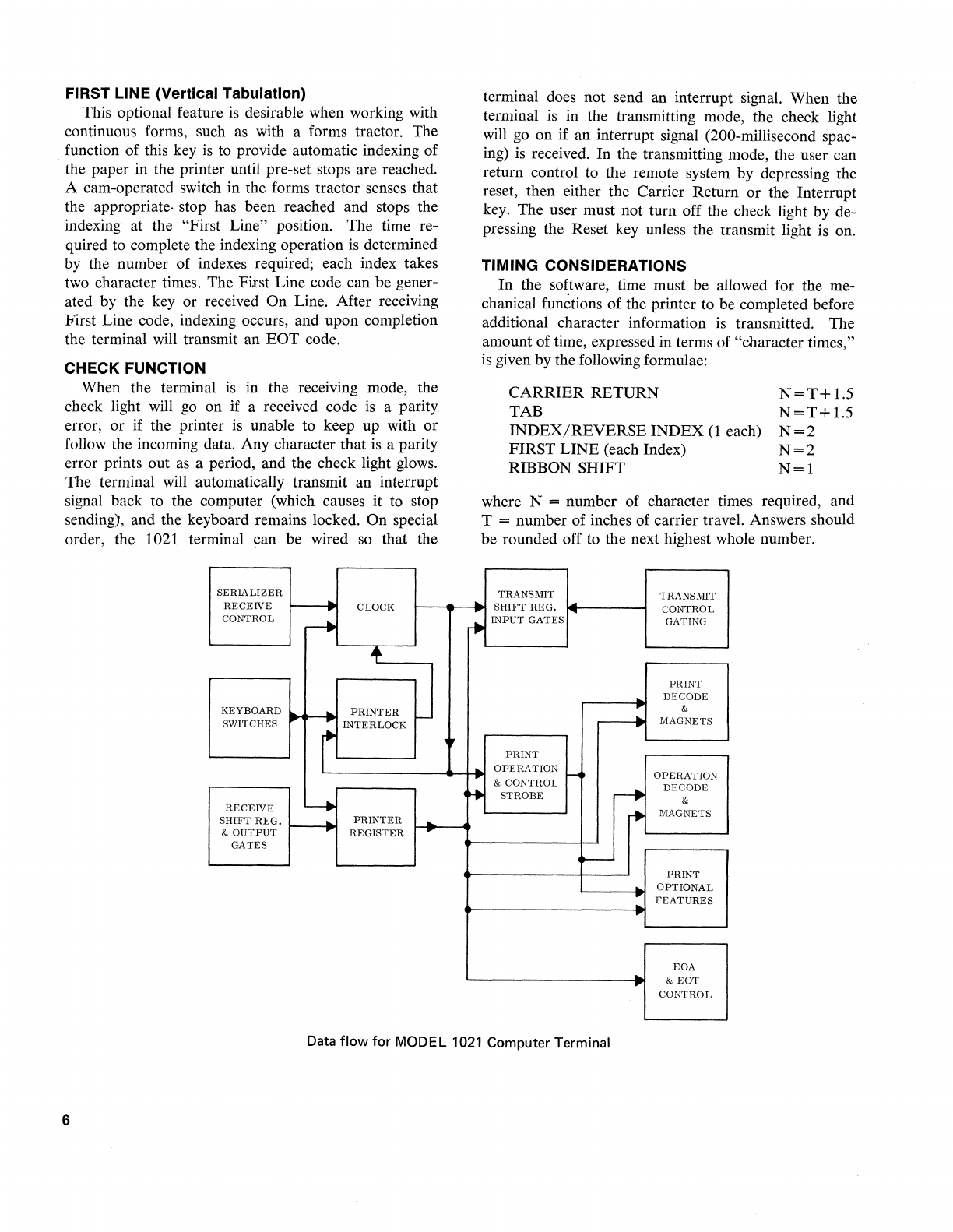
Data
flow
for
MODEL
1021
Computer Terminal
6
Typewriter Operation
PAPER
CARRIER
CONTROLS
Paper Bail
Move
forward when inserting paper. Release
it
to hold
the paper against the platen.
Platen Variable
Push in on the left platen knob and the platen can
be
rotated freely in either direction to adjust the printing line.
This
is
particularly useful when a typed
page
is
being rein-
serted for additions or corrections.
Paper Guide
Position by sliding it to the left or right.
When
insert-
ing a new sheet
of
paper, place the left
edge
of
the
paper against the paper guide and turn the platen knob
to feed in the paper. This procedure will ensure uniform
left margins.
Multiple
Copy Impression Control Lever
Move
the lever toward the rear to compensate for multi-
ple carbon copies or heavy paper. This ensures that the typ-
ing element
will
continue to strike the paper squarely. There
are
five
lever positions. Typical settings are the second posi-
tion for an original and three carbon copies and the third
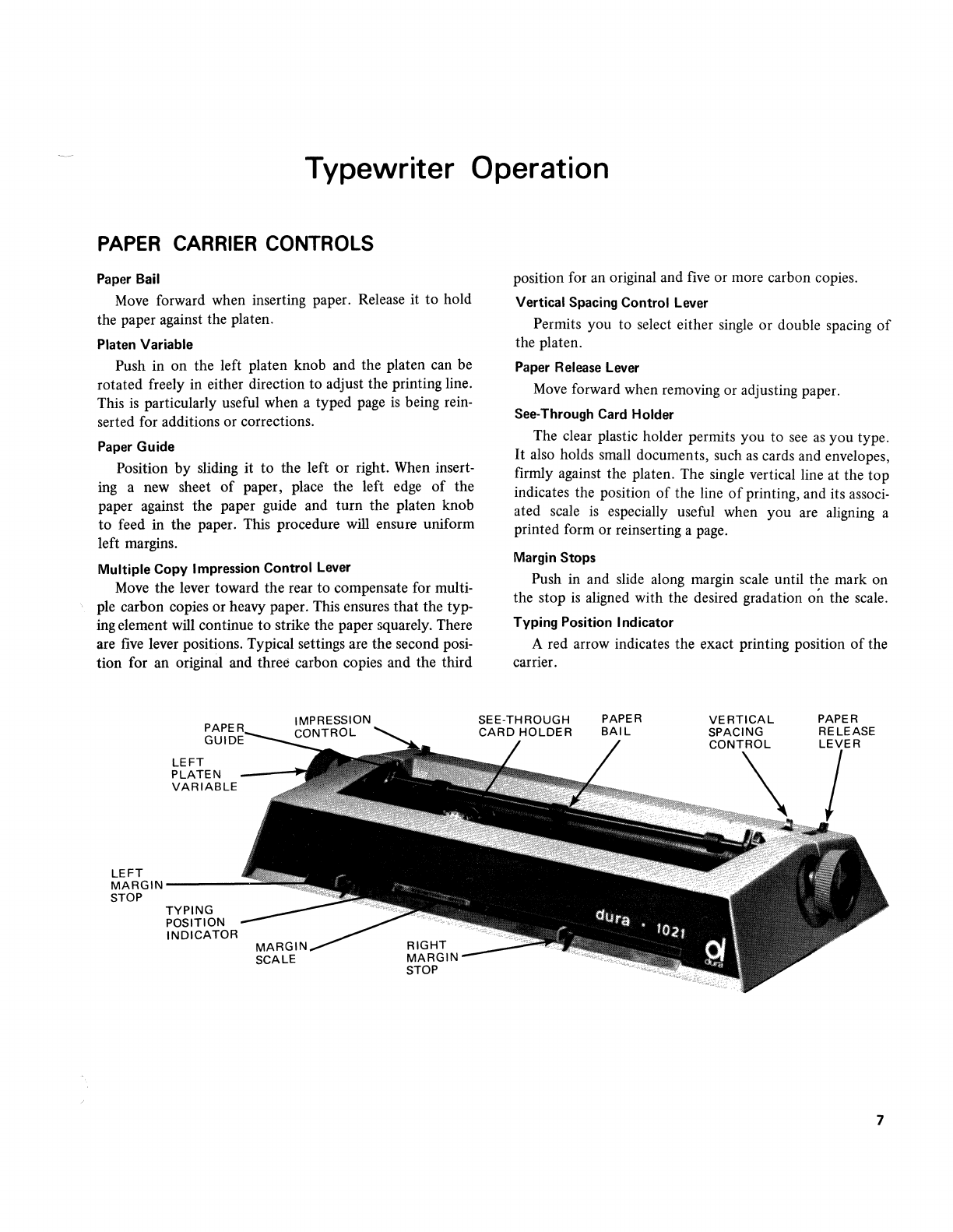
LEFT
PLATEN
VARIABLE
LEFT
MARGIN-----
STOP
TYPING
POSITION
INDICATOR
MARGIN
SCALE
position for
an
original and
five
or more carbon copies.
Vertical Spacing Control Lever
Permits you to select either
single
or double spacing
of
the platen.
Paper Release Lever
Move
forward when removing or adjusting paper.
See-Through Card Holder
The clear plastic holder permits you to
see
as
you type.
It
also
holds
small
documents, such
as
cards and envelopes,
firmly against the platen. The
single
vertical line at the top
indicates the position
of
the line
of
printing, and its
associ-
ated scale
is
especially useful when you
are
aligning a
printed form or reinserting a
page.
Margin Stops
Push in and slide along margin
scale
until the mark on
the stop
is
aligned with the desired gradation on the
scale.
Typing Position Indicator
A red arrow indicates the exact printing position
of
the
carrier.
7
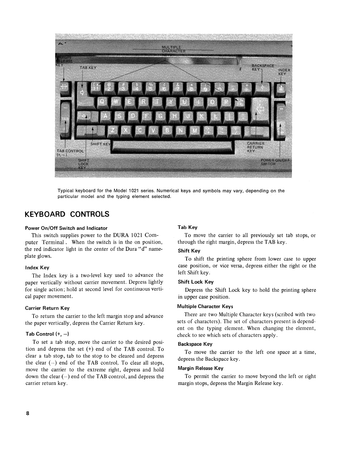
Typical keyboard for the Model
1021
series. Numerical keys and symbols may vary, depending on the
particular model and the typing element selected.
KEYBOARD
CONTROLS
Power
On/Off
Switch
and
Indicator
This switch supplies power to the DURA 1021
Com-
puter
Terminal.
When the switch
is
in the on position,
the red indicator light in the center
of
the Dura
"d"
name-
plate glows.
Index Key
The Index key
is
a two-level key used to advance the
paper vertically without carrier movement. Depress lightly
for single action; hold at second level for continuous verti-
cal paper movement.
Carrier Return Key
To return the carrier to the left margin stop and advance
the paper vertically, depress the Carrier Return key.
Tab Control (+,
-)
To set a tab stop, move the carrier to the desired posi-
tion and depress the set (+) end
of
the
TAB
control. To
clear a tab stop, tab
to
the stop to be cleared and depress
the clear
(-)
end
of
the
TAB
control.. To clear
all
stops,
move the carrier to the extreme right, depress and hold
down the clear (
-)
end
of
the
TAB
control, and depress the
carrier return key.
8
Tab Key
To move the carrier to
all
previously set tab stops, or
through the right margin, depress the
TAB
key.
Shift
Key
To shift the printing sphere from lower
case
to upper
case position, or vice versa, depress either the right or the
left Shift key.
Shift Lock Key
Depress the Shift Lock key
to
hold the printing sphere
in upper case position.
Multiple Character
Keys
There are two Multiple Character keys (scribed with two
sets
of
characters). The set
of
characters present is depend-
ent on the typing element.
When
changing the element,
check to
see
which sets
of
characters apply.
Backspace Key
To move the carrier to the left one space
at
a time,
depress the Backspace key.
Margin
Release
Key
To permit the carrier to move beyond the left or right
margin stops, depress the Margin Release key.

CHANGING
THE
TYPE
STYLE
The DURA
1021
typing element can
be
replaced readily,
permitting various type faces to
be
used.
On
the top
of
each typing element are shown the type
face, typewriter pitch number (10 characters per inch or 12
characters per inch), and an orientation arrow.
SPRING
LEVERS
Removing the Typing Element
1.
Turn
off
keyboard power.
2.
Make
sure the typing element
is
positioned in lower
case
with the arrow pointing toward the piaten.
3. With spring·type element, squeeze the spring levers
together and lift upward to release the typing ele·
ment from the groove in the element post.
4. With lever-type element, raise element release lever
until it clicks into position, and
use
lever to lift
ele-
ment off
of
the post.
Installing the Typing Element
1.
Make
sure the system
is
in lower case.
2.
Place the element on the element post with the arrow
on top pointing toward the platen.
3. To install the spring-type element, squeeze the spring
levers together and gently press down until the
ele-
ment snaps into place.
4. To install a lever-type element, raise the release lever
until it clicks, slip element into position on the post,
and close the
lever~
Front Cover Plate
To remove, grasp front
of
cover plate and lift up
smartly.
To reinstall, slip prongs (on top rear edge
of
cover)
under the
top
casing, then push down until cover locks into
place.
9
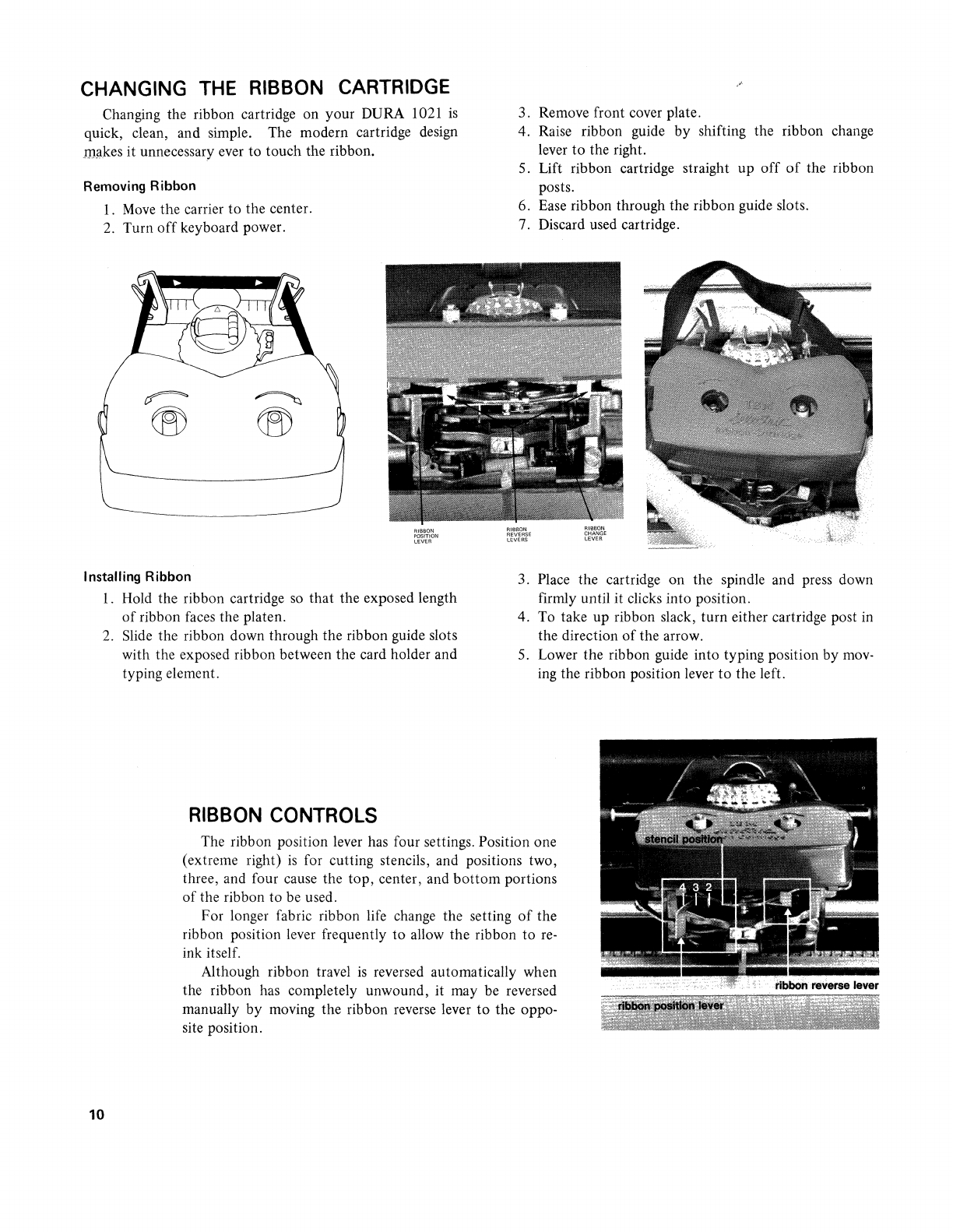
CHANGING THE RIBBON CARTRIDGE
Changing the ribbon cartridge on your DURA 1021
is
quick, clean, and simple. The modern cartridge design
ID!lkes
it unnecessary ever to touch the ribbon.
Removing Ribbon
1.
Move
the carrier
to
the center.
2.
Turn
off
keyboard power.
Installing Ribbon
RIBBON
POSITION
LEVER
1.
Hold the ribbon cartridge
so
that the exposed length
of
ribbon
faces
the platen.
2.
Slide the ribbon down through the ribbon guide slots
with the exposed ribbon between the card holder and
typing element.
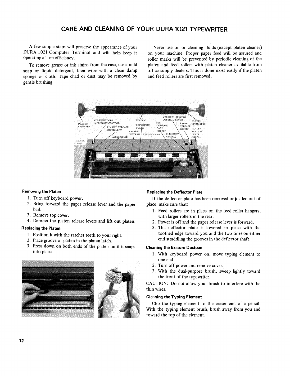
RIBBON CONTROLS
3. Remove front cover plate.
4. Raise ribbon guide by shifting the ribbon change
lever
to
the right.
s.
Lift ribbon cartridge straight up
off
of
the ribbon
posts.
6.
Ease
ribbon through the ribbon guide slots.
7. Discard used cartridge.
RIBBON
REVERSE
LEVERS
RIBBON
CHANGE
LEVER
3. Place the cartridge on the spindle and press down
firmly until it clicks into position.
4.
To
take up ribbon slack, turn either cartridge post in
the direction
of
the arrow.
S.
Lower the ribbon guide into typing position by
mov-
ing the ribbon position lever
to
the left.
The ribbon position lever has four settings. Position one
(extreme right)
is
for cutting stencils, and positions two,
three, and four cause the top, center, and bottom portions
of
the ribbon to be used.
10
For longer fabric ribbon life change the setting
of
the
ribbon position lever frequently to allow the ribbon to
re-
ink itself.
Although ribbon travel
is
reversed automatically when
the ribbon has completely unwound, it may be reversed
manually by moving the ribbon reverse lever to the oppo-
site position.

CHANGING
FILM
RIBBON
When
you
see
the cross-hatching on the ribbon trailer, it
is time
to
replace the ribbon. To change the ribbon, first
center the carrier and then turn
off
keyboard power. Care-
fully remove the top cover. Keep the paper bail against the
platen. Then follow these steps:
Removing Used Ribbon
1.
Press
LOAD
lever to raise ribbon lifts.
2.
Remove the ribbon from both ribbon lifts.
3.
While
turning the left (empty) core clockwise, gently
lift it from spindle.
4. Turn the right (plastic) spool clockwise· and lift it
from spindle.
S.
Discard the used ribbon, the empty core, and the
plastic spool.
Installing
New
Ribbon
1. Before threading, carefully separate the empty clear
plastic spool from the ribbon.
2.
Push the ribbon LOAD lever toward the platen (it
will lock into position) to lift the ribbon guides.
3. Drop the ribbon with the gray center core onto the
left spindle and guide the ribbon, using the clear
plastic spool (with printing on top), to the left
of
the tension wire.
4. Continue holding the clear plastic spool and thread
ribbon through the left and right ribbon guides.
5. Guide the ribbon
to
the left and past the carrier
position post.
6. Continue around
to
the right
of
the ribbon guide
post.
7. Thread the ribbon carefully between the ribbon
feed rollers.
8. Place the clear plastic spool on the right spindle and
turn in a clockwise direction until it clicks into posi-
tion.
9. Take up slack
by
turning the ribbon roll on the left
spindle clockwise.
10. Press against the CLOSE portion
of
the ribbon
LOAD
lever.
11. The illustration shows the way the film ribbon will
look when
it
is
correctly inserted and ready for use.
(The arrows indicate the direction in which the rib-
bon moves.)
11
CARE AND CLEANING OF YOUR DURA 1021 TYPEWRITER
A few simple steps will preserve the appearance
of
your
DURA 1021
Computer
Terminal
and will help keep it
operating
at
top efficiency.
To remove grease or ink stains from the case, use a mild
soap or liquid detergent, then wipe with a clean damp
sponge or cloth. Tape chad or dust may be removed
by
gentle brushing.
Removing
the
Platen
1. Turn
off
keyboard power.
2. Bring forward the paper release lever and the paper
bail.
3. Remove
top
cover.
4. Depress the platen release levers and lift
out
platen.
Replacing
the
Platen
12
1. Position
it
with the ratchet
teeth
to
your
right.
2. Place groove
of
platen in
the
platen latch.
3. Press down on
both
ends
of
the
platen until
it
snaps
into place.
Never use oil or cleaning fluids (except platen cleaner)
on your machine. Proper paper feed will be assured and
roller marks will be prevented
by
periodic cleaning
of
the
platen and feed rollers with platen cleaner available from
office supply dealers. This
is
done most easily
if
the platen
and feed rollers are first removed.
Replacing
the
Deflector
Plate
If
the deflector plate has been removed or jostled
out
of
place, make sure that:
1. Feed rollers are in place on the feed roller hangers,
with larger rollers in the rear.
2. Power is
off
and the paper release lever
is
forward.
3. The deflector plate
is
lowered in place with the
toothed edge toward you and the two tines on either
end straddling the grooves in the deflector shaft.
Cleaning
the
Erasure
Dustpan
1. With keyboard power on, move typing element
to
one end.
2. Turn
off
power and remove cover.
3. With the dual-purpose brush, sweep lightly toward
the front
of
the typewriter.
CAUTION: Do not allow your brush
to
interfere with the
thin wires.
Cleaning
the
Typing
Element
Clip the typing element
to
the eraser end
of
a pencil.
With the typing element brush, brush away from you and
toward the
top
of
the element.

Index
Card
Holder
7
NP/NE
(Non
Print/Non
Escape)
5
Care
and
Cleaning
12
Carrier
Return
8
Operating
Controls
5
Changing
Type
Style
9
Operating
Procedures
2
Check
Function
6
Code
Charts
4
Paper
Bail
7
Paper
Carrier
Controls
7
Data
Flow
Chart
6
Paper
Guide 7
Paper
Release
Lever
7
Deflector
Plate
12
Platen
7
Platen
-
Cleaning
12
Erasure
Dustpan
12
Platen
Variable
7
Power
Switch
8
Film
Ribbon
11
First
Line
6
Shift
5
Front
Cover
Plate
9
Shift
Keys
and
Lock
8
Reverse
Index
5
Index
Key
8
Ribbon
Cartridge
10
Interrupt
5
Ribbon
Controls
10
Ribbon
Shift
5
Keyboard
Controls
8
Keyboard
Layouts
3
Timing
6
Type
Style
9
Margin
Release
8
Typing
Element
9
Margin
Stops
7
Typing
Position
Indicator
7
Mul
tiple
Character
Keys
8
Typewriter
Operation
7
13
Printed
in U.S.A.
'"
Intercontinental
Systems Inc.
~I'II'I'II!!~
DURA DIVISION
MS·69278
