DVR Anatomic Surgical Technique
2016-04-01
: Pdf Dvr Anatomic Surgical Technique DVR_Anatomic_Surgical_Technique 3 2016 pdf
Open the PDF directly: View PDF ![]() .
.
Page Count: 24
Surgical Technique
DVR® Anatomic
Volar Plating System
BMET0011 DVRtech ST.indd 1 6/19/12 9:20 AM

DVR® Anatomic Volar Plating System
BMET0011 DVRtech ST.indd 2 6/19/12 9:20 AM

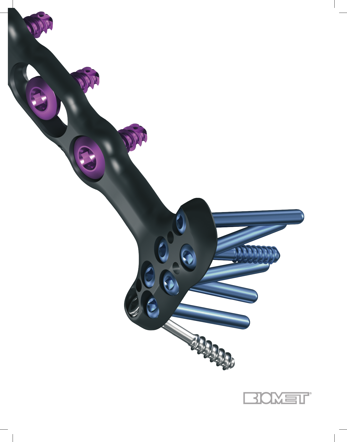
• F.A.S.T. Guide® Technology to
simplify and speed up surgery
• Cobalt chrome multi-directional
pegs to provide the surgeon
the flexibility to adjust peg
trajectories while still creating
a strong, stable construct
Clinical Indications
The DVR® Anatomic Plate is intended for
the fixation of fractures and osteotomies
involving the distal radius.
Surgical Approaches
Simple and acute fractures can be treated
through the standard Flexor Carpi Radialis
(FCR) approach.
Intra-articular fractures, nascent malunions
and established malunions are best man-
aged through the extended form of the
FCR approach.
Introduction
Ten years ago the DVR helped change the treatment of
distal radius fractures. Through the past decade the DVR
has been continually improved and adapted to provide a
broad range of surgical options to help surgeons address
the needs of their patients. With 10 years of positive clini-
cal experience and over 300,0001 plates sold worldwide,
Biomet, Inc. is proud and honored to have participated
with Dr. Orbay and the surgeon community to advance the
art and science of fracture fixation. Biomet, Inc. is commit-
ted to providing our surgeons with the best combination of
technology and service possible in order to treat their pa-
tients. We look forward to another 10 years of innovation
and clinical success for the DVR® Anatomic Distal Radius
Plating System.
The list of DVR innovations include:
• The first implant system with divergent pegs to
capture dorsally displaced fractures from a volar
approach
• A low profile implant designed
to mimic the volar aspect of
the bone and be used as a reduction template
• Fixed angle K-wires to confirm implant placement
prior to final implantation
1
BMET0011 DVRtech ST.indd 1 6/19/12 9:20 AM

The distal end of the plate is contoured to match
the watershed line and the topographic surface
of the distal volar radius
Multi-directional threaded pegs allow for angula-
tion within a cone of 20 degrees for maximum in-
teroperative flexibility of locking screw placement
F.A.S.T. Guide
®
technology allows for easy
drilling of fixed angle locking screws as well as
indicates side specific implants by color coding
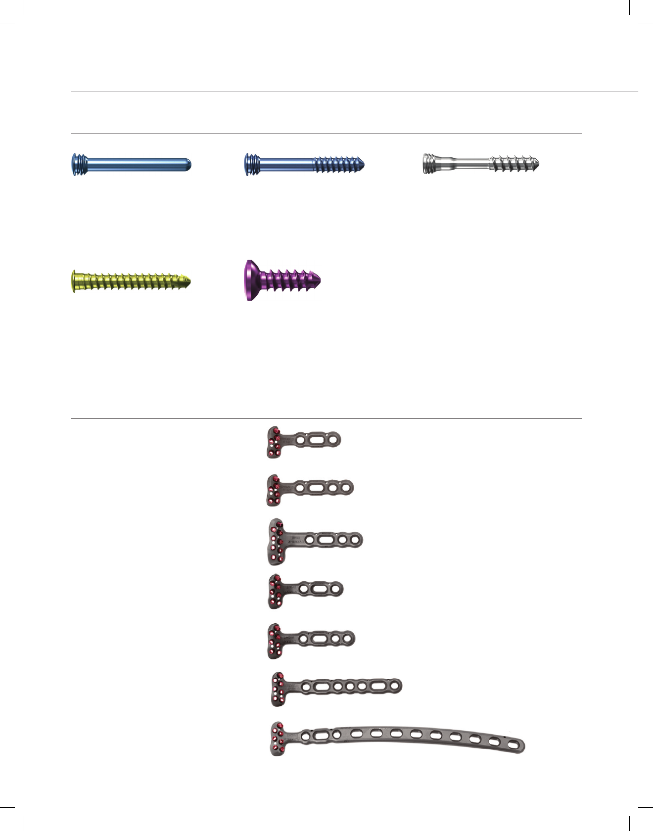
Screws/Pegs Available Lengths
Smooth Pegs (Locking) 10, 12, 14, 16, 18, 20, 22, 24, 26, 28 and 30 mm
Partially Threaded Pegs (Locking) 10, 12, 14, 16, 18, 20, 22, 24, 26, 28 and 30 mm
Multi Directional Threaded Pegs (Locking) 10, 12, 14, 16, 18, 20, 22, 24, 26, 28 and 30 mm
Cortical Bone Screws 10, 12, 13, 14, 15, 16, 18 and 20 mm
Screws (Non-locking) 10, 12,14, 16, 18, 20, 22, 24, 26, 28 and 30 mm
Screws and Pegs
Oblong screw hole allows for fine tuning
of the plate position.
Proprietary divergent and converging
rows of pegs provide 3 dimensional scaf-
fold for maximum subchondral support
Ulnar most proximal fixed angle k-wire is used to reference
proper plate position as well as predict peg distribution when
using the standard technique
Locking pegs and screws provide a strong peg
to plate interface
Threaded pegs available to secure fragments in
the coronal plane
Distal fixed angle k-wire hole used to reference proper plate
position when using the distal first technique
Anatomic design of the plate matches the to-
pography of the distal radius and thus follows
the “watershed” line to provide maximum but-
tress for volar marginal fragments
Available plate sizes and lengths listed on page 18.
2
DVR® Anatomic Volar Plating System
DVR® Anatomic Volar Plating System
BMET0011 DVRtech ST.indd 2 6/19/12 9:20 AM
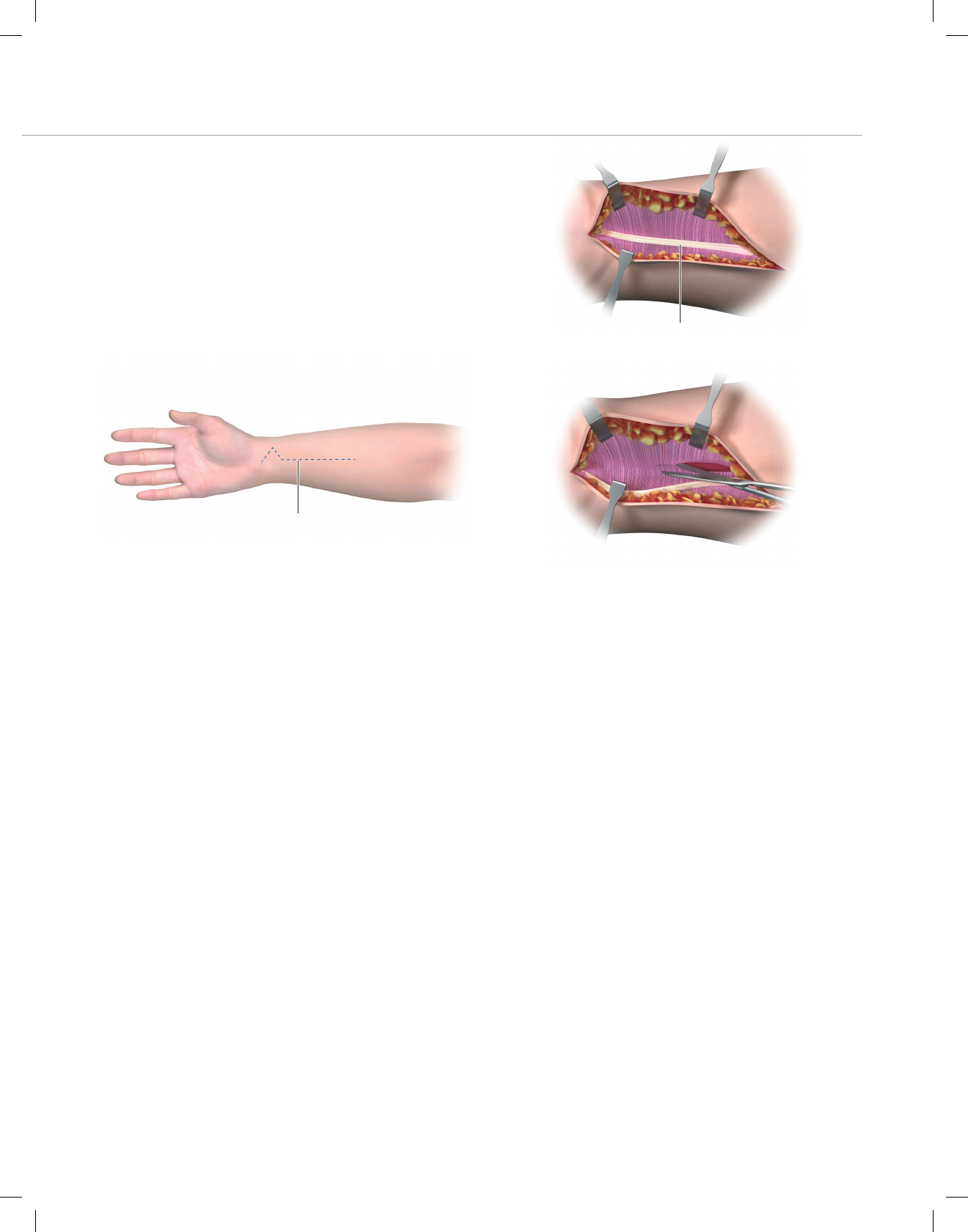
FCR Approach
Incision
Make an incision over the course of the flexor carpi radialis
(FCR) tendon.
A zigzag incision is made across the wrist flexion creases
to allow better access and visualization. (Figure 1)
Flexor Carpi Radialis (FCR)
Incision
Figure 2
Figure 3 Figure 1
Release the Flexor Carpi Radialis (FCR)
Tendon Sheath
Expose and open the sheath of the FCR tendon. (Figure 2)
Dissect the FCR tendon distally to the level of the superfi-
cial radial artery.
Crossing the Deep Fascia
Retract the FCR tendon towards the ulna while protecting
the median nerve. (Figure 3)
Incise through the floor of the FCR sheath to gain access
to the deeper levels.
Split the sheath of the FCR tendon distally up to the tuber-
osity of the scaphoid.
3
BMET0011 DVRtech ST.indd 3 6/19/12 9:20 AM
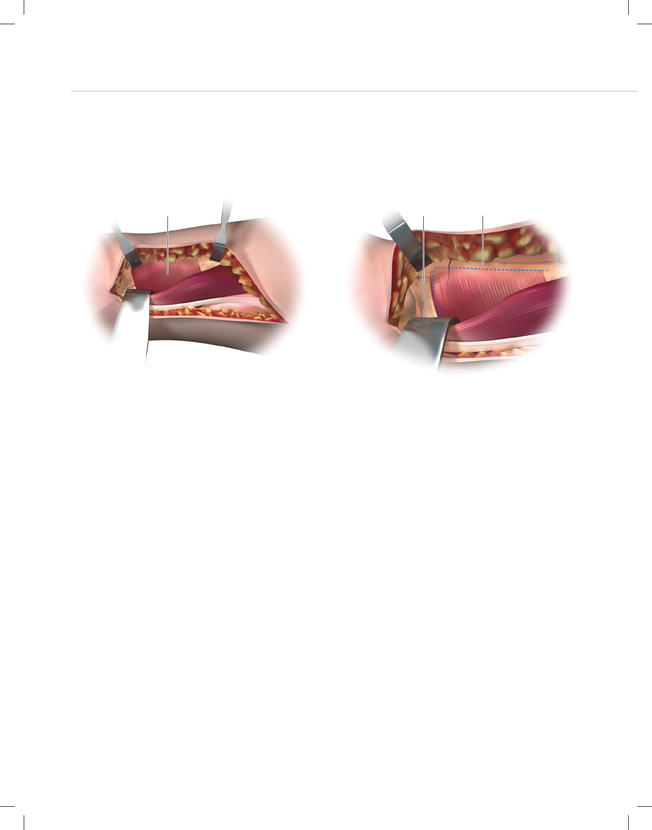
Figure 4 Figure 5
Watershed Line
Pronator Quadratus (PQ) Incision
Mid-Level Dissection
Develop the plane between the flexor pollicis longus (FPL)
and the radial septum to reach the surface of the radius.
Develop widely the subtendinous space of parona and
expose the pronator quadratus muscle (PQ). (Figure 4)
Identifying the Watershed Line
Palpate the radius distally to identify the volar rim of the lu-
nate fossa. This establishes the location of the watershed
line. (Figure 5)
The transitional fibrous zone (TFZ) is a 1 cm wide band of
fibrous tissue located between the watershed line and the
PQ that must be elevated to properly visualise the fracture.
Release the PQ by sharply incising over the watershed line
and proximally on the lateral edge of the radius. (Figure 5)
4
DVR® Anatomic Volar Plating System
BMET0011 DVRtech ST.indd 4 6/19/12 9:20 AM
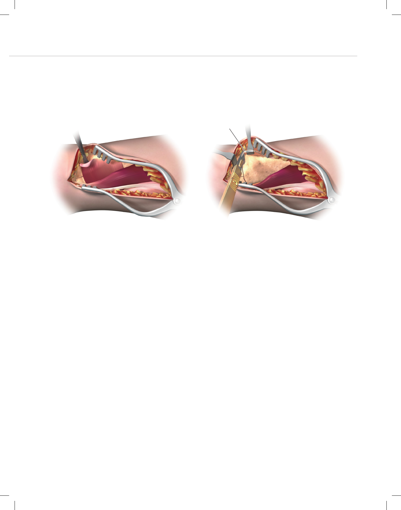
Figure 6 Figure 7
Brachioradialis
Elevating the Pronator Quadratus (PQ)
Use a periosteal elevator to elevate the PQ to expose the
volar surface of the radius. (Figure 6)
The fracture line on the volar cortex is usually simple,
facilitating reduction.
The origin of the FPL muscle can be partially released for
added exposure.
Note: The pronator quadratus is frequently ruptured.
Caution: Please refer to Warning and Precautions Section
on Page 21.
Release of the Distal Fragment
Release the insertion of the brachioradialis which is found
on the floor of the first compartment in a step cut fashion.
(Figure 7)
Note: The brachioradialis is the prime deforming force of
the distal fragment.
Identify and retract the APL and EPB tendons.
Note: Care should be taken to protect the radial artery.
5
BMET0011 DVRtech ST.indd 5 6/19/12 9:20 AM

Figure 8 Figure 9
The Extended FCR Approach
Pronation of the proximal fragment out of the way provides
exposure to the dorsal aspect of the fracture allowing frac-
ture debridement and reduction.
Intra-Focal Exposure
Intra-focal exposure is obtained by pronating the proximal
fragment out of the way. A bone clamp facilitates this ma-
neuver. (Figure 8)
Preserve the soft tissue attachments to the medial aspect
of the proximal fragment.
Note: This is where the anterior interosseous vessels that
feed the radial shaft are located.
Provisional Fracture Reduction
After fracture debridement, supinate the proximal radius
back into place and restore radial length by reducing the
volar cortex. (Figure 9)
6
DVR® Anatomic Volar Plating System
BMET0011 DVRtech ST.indd 6 6/19/12 9:20 AM
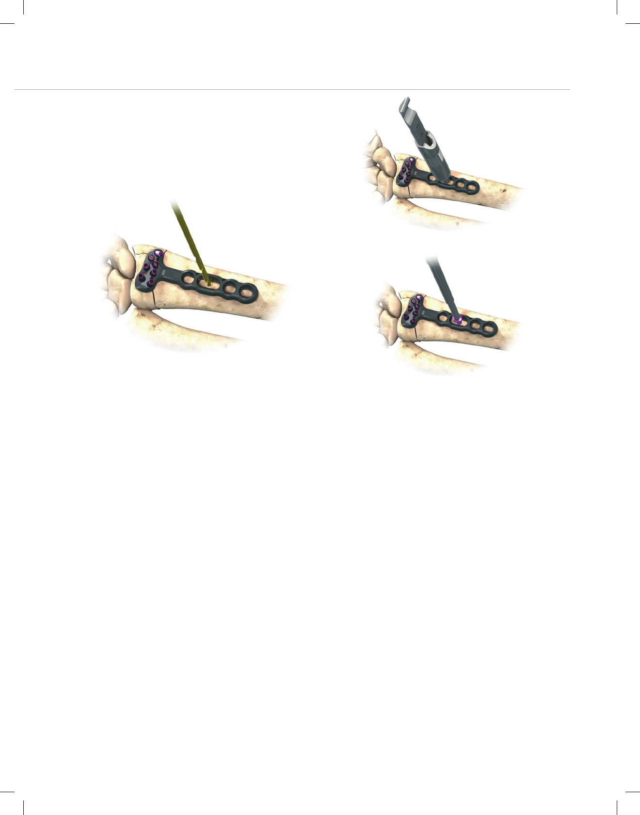
Figure 10
Figure 11
Figure 12
Proximal Plate Positioning
Determine the correct position for the plate by judging how
the plate conforms to the watershed line and the volar
surface of the radius.
Using the 2.5 mm bit, drill through the proximal oblong
hole of the plate, which will allow for plate adjustments.
(Figure 10)
Measure the required screw depth using the flat side of the
Depth Gauge. (Figure 11)
Insert the appropriate length cortical screw. (Figure 12)
7
BMET0011 DVRtech ST.indd 7 6/19/12 9:20 AM
Distal Plate Fixation
Final Fracture Reduction
Final reduction is obtained by indirect means using the
DVR® Anatomic Plate as a template, then applying trac-
tion, ligamentotaxis and direct pressure over the dorsal
aspect. (Figure 13)
Note: A properly applied bolster helps to maintain the
reduction.
Distal Plate Fixation
First, secure the distal fragment to the plate by inserting a
k-wire through the most ulnar k-wire hole on the proximal
row. (Figure 14) Proper plate positioning can be confirmed
by obtaining a 20-30 degree lateral. The k-wire should be
2–3 mm subchondral to the joint line on this view.
Figure 13
Figure 14 Figure 15
Drilling the Proximal Rows
Using a 2.0 mm bit, drill through the proximal single-use
F.A.S.T. Guide® starting on the ulnar side in order to stabi-
lize the lunate fossa. (Figure 15)
Note: Bend the K-wire out of the way to facilitate drilling.
8
DVR® Anatomic Volar Plating System
BMET0011 DVRtech ST.indd 8 6/19/12 9:20 AM

Figure 17
Figure 18 Figure 16
Gauging Through the F.A.S.T. Guide®
Assess carefully the length of the proximal row pegs with
the appropriate side of the depth gauge. (Figure 16)
Caution: Avoid excessive peg length as this can poten-
tially cause extensor tendon irritation.
Note: if the F.A.S.T. Guide® is removed before gauging the
screw depth, use the scale on the flat side of the depth
gauge.
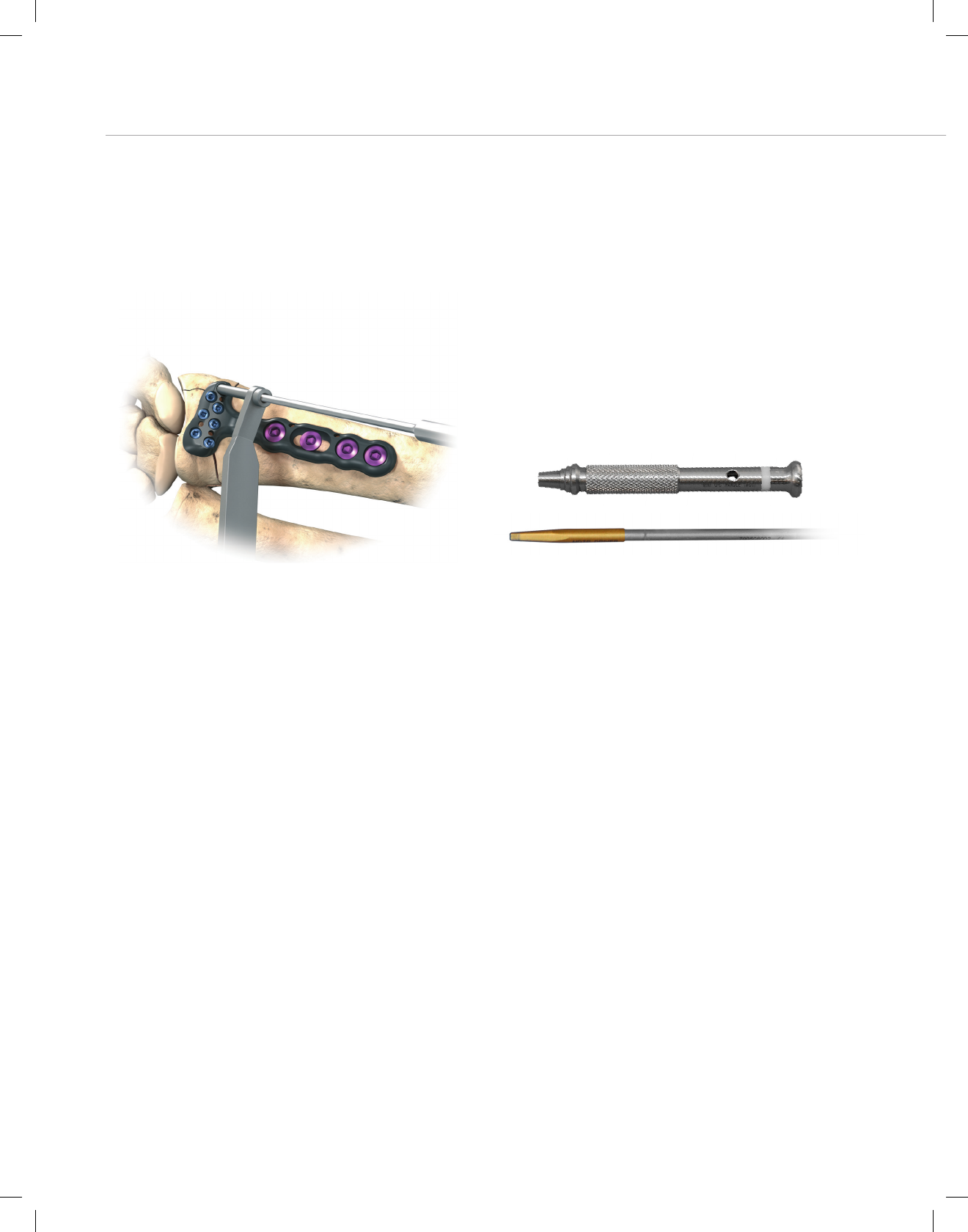
Proximal Peg Placement
Remove each F.A.S.T. Guide® with the peg driver after
checking the drilled depth. (Figure 17)
Using the same peg driver, fill the peg holes with the ap-
propriate length peg. (Figure 18)
Note: The use of threaded pegs will help to capture dorsal
comminuted fragments.
9
BMET0011 DVRtech ST.indd 9 6/19/12 9:20 AM

Final Proximal Plate Fixation
Final Plate Fixation
Fill all the holes of the distal peg row.
As the distal row converges on the proximal row between
16 mm and 18 mm, an 18 mm length peg is all that is
needed in the distal row.
Apply the remaining proximal cortical screws. (Figure 19)
SP screws are not intended to provide subchondral sup-
port and use should be limited to capture of remote bone
fragments where partially threaded pegs can not be used.
Note: The proximal row of pegs provides support to the
dorsal aspect of the articular surface. The distal row of
pegs provides support to the central and volar aspects of
the subchondral plate.
Remove all F.A.S.T. Guide® even if the peg hole is not
used.
Figure 19 Figure 20
Final Radiographs
A 20° – 30° elevated lateral fluoroscopic view allows visu-
alization of the articular surface, evaluation of volar tilt, and
confirmation for proper peg placement 2 – 3 mm proximal
to the subchondral plate. (Figure 20)
To confirm that the length of each individual peg is correct,
pronate and supinate the wrist under fluoroscopy.
10
DVR® Anatomic Volar Plating System
BMET0011 DVRtech ST.indd 10 6/19/12 9:20 AM

Final Appearance
A properly applied plate should be just proximal to the
watershed line and not project above or beyond it in order
to avoid contact with the flexor tendons. (Figure 21)
Wound Closure
Repair the TFZ in order to cover the distal edge of the
DVR® Anatomic Plate.
Repair the brachioradialis.
Suture the PQ to the TFZ and the repaired brachioradialis.
Figure 21
11
BMET0011 DVRtech ST.indd 11 6/19/12 9:20 AM
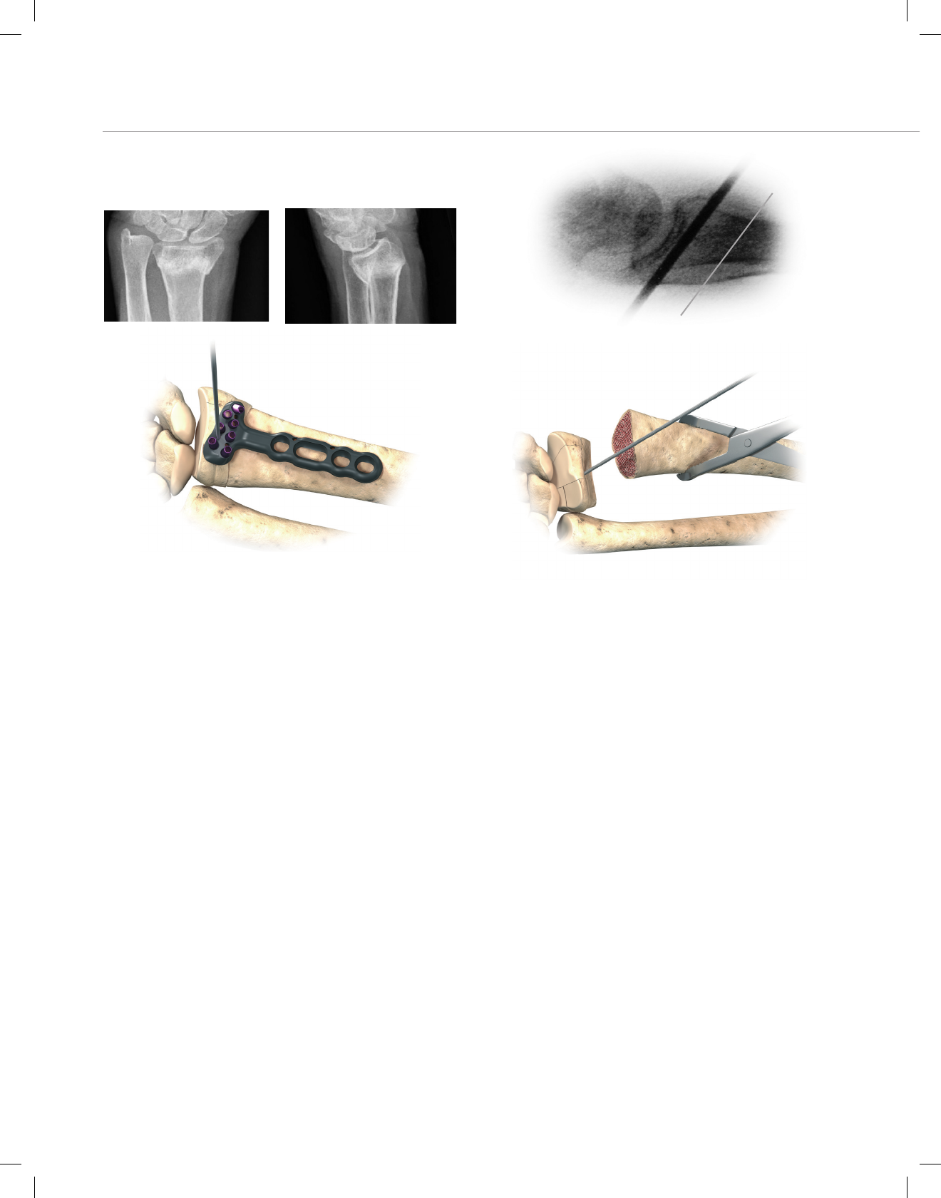
Distal Fragment First Technique
For Established Malunions
Complete exposure and place a K-wire 2 – 3 mm proximal
to the articulating surface and parallel to the joint line.
Note: Use the K-wire hole on the distal row of the DVR®
Anatomic Plate as a guide for proper K-wire placement.
(Figure 22)
Create the osteotomy plane parallel to the K-wire. (Figure 23)
Figure 22
Figure 23
Osteotomy Plane
K-wire
Figure 24
Release the brachioradialis, then pronate the radius and
release the dorsal periosteum. (Figure 24)
Note: The location of the distal peg rows can be identified
and drilled prior to the osteotomy.
12
DVR® Anatomic Volar Plating System
BMET0011 DVRtech ST.indd 12 6/19/12 9:20 AM

Supinate the proximal fragment and slide the DVR®
Anatomic Plate over the K-wire. (Figure 25) The K-Wire will
assure proper restoration of volar tilt.
Fix the DVR® Anatomic Plate to the distal fragment. (Figure
26) The watershed line provides guidance for proper radio-
lunate deviation.
Figure 25
Figure 26
Figure 27
Figure 28
Once distal fixation is complete, the tail of the implant is
secured to the shaft of the radius to re-create the 12 de-
grees of normal volar tilt.
After fixation, autograft is applied and the wound closed.
(Figure 28)
Confirm postoperative results with radiographs.
13
BMET0011 DVRtech ST.indd 13 6/19/12 9:20 AM
Installation of Multi Directional
Threaded Peg
Ensure that the fixed-angle pegs have been installed prior
to installing the MDTP.
Remove the F.A.S.T. Guide® using the peg driver.
Place the 2.0 mm end of the Soft Tissue Guide (STG) into
the radial styloid and/or the most ulnar hole in the proximal
row of the DVR Anatomic plate.
Note: The MDTPs are not recommended for the distal row.
Figure 29 Figure 30
Place the 2.0 mm drill bit through the STG until it comes
in contact with the bone. Determine the trajectory of the
drill bit by varying the angle of the STG and drill (Figure 29).
The MDTP’s can be successfully installed within a cone of
20 degrees off of the fixed angle trajectory.
Assemble the Multi Direct 2.0 mm insert (231211002) into
the modular handle (MQC), verifying that it is firmly at-
tached. (Figure 30)
14
DVR® Anatomic Volar Plating System
BMET0011 DVRtech ST.indd 14 6/19/12 9:20 AM
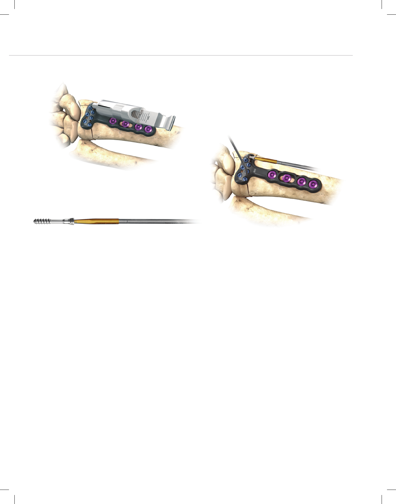
Figure 31
Figure 33 Figure 32
Measure the depth of the hole using the flat side of the
F.A.S.T. Bone Depth Gauge (FBDG). (Figure 31)
Load the appropriately sized MDTP into the driver. The
peg should grip the driver. (Figure 32)
Install the MDTP into the pre-drilled hole. Be careful to
keep the driver fully engaged with the peg. Install the peg
firmly until increased torque yields in no further rotation.
(Figure 33)
Note: If necessary, after installation the MDTP can be re-
moved and reinstalled to further improve positioning.
15
BMET0011 DVRtech ST.indd 15 6/19/12 9:20 AM
Ordering Information
Smooth Peg, Locking
Provides subchondral support
PXX000
Diameter: 2.0 mm
10 mm – 30 mm lengths (2 mm steps)
Threaded Peg, Locking
Distal threads to capture and lag fragments
TPXX000
Diameter 2.5 mm
10 mm – 30 mm lengths (2 mm steps)
Multi Directional Threaded Peg
Provides interoperative freedom to vary the tra-
jectory of a fixed angle locking trajectory within
a cone of 20 degrees.
1312111XX
Diameter: 2.5 mm
10 mm – 30 mm lengths (2 mm steps)
Screws, Non-Locking
Fully threaded to anchor fragments for
added fixation
SPXX000
Diameter: 2.5 mm
10 mm – 30 mm lengths (2 mm steps)
Cortical Screws
Provide bicortical fixation for proximal fragments
CSXX000
Diameter: 3.5 mm
10,12,13,14,15,16, 18 and 20 mm
Pegs and Screws
DVR® Anatomic Plates
Narrow Short:
21.6 mm x 48.9 mm
DVRANSL
DVRANSR
Narrow Standard:
21.6 mm x 57.2 mm
DVRANL
DVRANR
Wide:
28.2 mm x 62.6 mm
DVRAWL
DVRAWR
Standard Short:
24.4 mm x 51.3 mm
DVRASL
DVRASR
Standard:
24.4 mm x 59.5 mm
DVRAL
DVRAR
Standard Extended:
24.4 mm x 89.5 mm
DVRAXL
DVRAXR
Standard Extra Extended:
24.4 mm x 175.3 mm
DVRAXXL
DVRAXXR
16
DVR® Anatomic Volar Plating System
BMET0011 DVRtech ST.indd 16 6/19/12 9:20 AM

DVR® Anatomic Plate Modular Tray
Fully modular tray system addresses multiple applications with the use of a single tray
• Reduced OR Instruments
• Improved Workflow
17
BMET0011 DVRtech ST.indd 17 6/19/12 9:21 AM

DVRA Tray System Instrumentation
DG20 Drill Guide 2.0
FPD20 Peg Driver F.A.S.T.
FBDG Bone Depth Gauge F.A.S.T.
SDG Depth Gauge Sleeveless
MQC Handle Peg Driver/Handle Mini Quick Connect
BC Bone Clamp DR
MHR Retractor Mini Hohmann
STG Soft Tissue Guide DR
231211000 Modular QK Connect Handle
231211001 Captive Insert
231211002 MDTP Driver Mini Quick Connect
DVRA Plate System Cortical Screws
CS10000 Screw Cortical 3.5mm, 10mm
CS12000 Screw Cortical 3.5mm, 12mm
CS13000 Screw Cortical 3.5mm, 13mm
CS14000 Screw Cortical 3.5mm, 14mm
CS15000 Screw Cortical 3.5mm, 15mm
CS16000 Screw Cortical 3.5mm, 16mm
CS18000 Screw Cortical 3.5mm, 18mm
CS20000 Screw Cortical 3.5mm, 20mm
DVRA Plate System
DVRAR DVR Anatomic Standard Right
DVRAL DVR Anatomic Standard Left
DVRAXR DVR Anatomic Ext Right
DVRAXL DVR Anatomic Ext Left
DVRASR DVR™ Anatomic Short Right with F.A.S.T. Guides
DVRASL DVR™ Anatomic Short Left with F.A.S.T. Guides
DVRANR DVR™ Anatomic Narrow Right with F.A.S.T. Guides
DVRANL DVR™ Anatomic Narrow Left with F.A.S.T. Guides
DVRANSR DVR™ Anatomic Narrow Short Right with F.A.S.T. Guides
DVRANSL DVR™ Anatomic Narrow Short Left with F.A.S.T. Guides
DVRAWR DVR™ Anatomic Wide Head Right with F.A.S.T. Guides
DVRAWL DVR™ Anatomic Wide Head Left with F.A.S.T. Guides
DVRAXXR DVR™ Anatomic Extra Ext Right with F.A.S.T. Guides
DVRAXXL DVR™ Anatomic Extra Ext Left with F.A.S.T. Guides
Disposables:
FDB20 Drill Bit F.A.S.T. 2.0mm
DB25 Drill Bit 2.5mm
KW062SS KWIRE 1.6MM SS
DVRA Steel Tray
DRT Sterilization Tray DVR Anatomic
DRTSC Screw Caddy DRT
18
DVR® Anatomic Volar Plating System
BMET0011 DVRtech ST.indd 18 6/19/12 9:21 AM

Multidiectional threaded Pegs (MDTP)
131211110 Peg Thread Multidir 2.5X10Mm
131211112 Peg Thread Multidir 2.5X12Mm
131211114 Peg Thread Multidir 2.5X14Mm
131211116 Peg Thread Multidir 2.5X16Mm
131211118 Peg Thread Multidir 2.5X18Mm
131211120 Peg Thread Multidir 2.5X20Mm
131211122 Peg Thread Multidir 2.5X22Mm
131211124 Peg Thread Multidir 2.5X24Mm
131211126 Peg Thread Multidir 2.5X26Mm
131211128 Peg Thread Multidir 2.5X28Mm
131211130 Peg Thread Multidir 2.5X30Mm
Screw Pegs (Non-Locking)
SP10000 Peg Screw 2.5mm, 10mm
SP12000 Peg Screw 2.5mm, 12mm
SP14000 Peg Screw 2.5mm, 14mm
SP16000 Peg Screw 2.5mm, 16mm
SP18000 Peg Screw 2.5mm, 18mm
SP20000 Peg Screw 2.5mm, 20mm
SP22000 Peg Screw 2.5mm, 22mm
SP24000 Peg Screw 2.5mm, 24mm
SP26000 Peg Screw 2.5mm, 26mm
SP28000 Peg Screw 2.5mm, 28mm
SP30000 Peg Screw 2.5mm, 30mm
Threaded Pegs
TP10000 Peg Thread 2.5mm, 10mm
TP12000 Peg Thread 2.5mm, 12mm
TP14000 Peg Thread 2.5mm, 14mm
TP16000 Peg Thread 2.5mm, 16mm
TP18000 Peg Thread 2.5mm, 18mm
TP20000 Peg Thread 2.5mm, 20mm
TP22000 Peg Thread 2.5mm, 22mm
TP24000 Peg Thread 2.5mm, 24mm
TP26000 Peg Thread 2.5mm, 26mm
TP28000 Peg Thread 2.5mm, 28mm
TP30000 Peg Thread 2.5mm, 30mm
Smooth Pegs
P10000 Peg Smooth 2.0mm, 10mm
P12000 Peg Smooth 2.0mm, 12mm
P14000 Peg Smooth 2.0mm, 14mm
P16000 Peg Smooth 2.0mm, 16mm
P18000 Peg Smooth 2.0mm, 18mm
P20000 Peg Smooth 2.0mm, 20mm
P22000 Peg Smooth 2.0mm, 22mm
P24000 Peg Smooth 2.0mm, 24mm
P26000 Peg Smooth 2.0mm, 26mm
P28000 Peg Smooth 2.0mm, 28mm
P30000 Peg Smooth 2.0mm, 30mm
19
BMET0011 DVRtech ST.indd 19 6/19/12 9:21 AM

Notes
20
DVR® Anatomic Volar Plating System
BMET0011 DVRtech ST.indd 20 6/19/12 9:21 AM

DVR® Anatomic Plate
Important
This Essential Product Information sheet does not include all of the
information necessary for selection and use of a device. Please
see full labelling for all necessary information.
Indications (DVR
®
Anatomic and DNP
®
Anatomic Systems)
The Distal Radius Fracture Repair System is intended for the
fixation of fractures and osteotomies involving the distal radius.
Indications (Fragment Plate System)
The Fragment Plate System is intended for essentially non-load
bearing stabilization and fixation of small bone fragments in fresh
fractures, revision procedures, joint fusion and reconstruction of
small bones of the hand, foot, wrist, ankle, humerus, scapula,
finger, toe, pelvis and craniomaxillofacial skeleton.
Contraindications
If any of the following are suspected, tests are to be performed
prior to implantation. Active or latent infection. Sepsis. Insufficient
quantity or quality of bone and/or soft tissue. Material sensitivity.
Patients who are unwilling or incapable of following post operative
care instructions.
Warning and Precautions
Although the surgeon is the learned intermediary between the
company and the patient, the important information conveyed
in this document should be conveyed to the patient. The patient
must be cautioned about the use, limitations and possible adverse
effects of these implants. The patient must be warned that failure
to follow postoperative care instructions may cause the implant or
treatment to fail.
An implant must never be reused. Previous stresses may have
created imperfections that can potentially lead to device failure.
Protect implant appliances against scratching or nicking. Such
stress concentration can lead to failure.
Orthopaedic instrumentation does not have an indefinite functional
life. All re-usable instruments are subjected to repeated stresses
related to bone contact, impaction, routine cleaning and sterilization
processes. Instruments should be carefully inspected before each
use to ensure that they are fully functional. Scratches or dents can
result in breakage. Dullness of cutting edges can result in poor
functionality. Damaged instruments should be replaced to prevent
potential patient injury such as metal fragments into the surgical
site. Care should be taken to remove any debris, tissue or bone
fragments that may collect on the instrument. Most instrument
systems include inserts/trays and a container(s). Many instruments
are intended for use with a specific implant system. It is essential
that the surgeon and operating theatre staff are fully familiar
with the appropriate surgical technique for the instruments and
associated implant, if any.
• Do NOT open the volar wrist capsule. Doing so may cause
devascularisation of the fracture fragments and destabilisation
of the volar wrist ligaments.
• If necessary, contour the DVR
®
Anatomic plate in small incre-
ments. Excessive contouring may weaken or fracture the plate.
• Exercise care when bending the fragment plates to avoid
weakening or fracture of the plates.
• Ensure removal of all F.A.S.T. Guide
®
inserts after use.
• Do NOT use fully threaded pegs (FP) with the DVR
®
Anatomic
and DNP
®
Anatomic plates. The fully threaded pegs (FP) are
designed for use with the fragment plates.
• Do NOT use peg/screw lengths that will excessively protrude
through the far cortex. Protrusion through the far cortex may
result in soft tissue irritation.
• SP series screws are NOT intended to provide subchondral
support and use should be limited to capture of remote bone
fragments where partially or fully threaded pegs cannot be
used.
• Do NOT permanently implant K-wires through the holes of the
plate as they may back out and cause tissue damage. Use of
the K-wires allows you to provisionally secure the plates to the
anatomy.
• Do NOT use the MDTPs in the distal row of the DVR
®
Anatomic Plate. The MDTPs are intended to be used
only with the DVR
®
Anatomic plates. Ensure the MDTPs
are installed after insertion of the fixed angle pegs.
Adverse Effects
The following are possible adverse effects of these implants:
potential for these devices failing as a result of loose fixation and/or
loosening, stress, excessive activity, load bearing particularly when
the implants experience increased loads due to a delayed union,
nonunion, or incomplete healing.
Note: It is NOT required to remove F.A.S.T. Guide
®
inserts to
sterilize the plate.
21
BMET0011 DVRtech ST.indd 21 6/19/12 9:21 AM

References
1. Biomet Internal Sales Data
All trademarks herein are the property of Biomet, Inc. or its subsidiaries unless
otherwise indicated.
This material is intended for the sole use and benefit of the Biomet sales force and
physicians. It is not to be redistributed, duplicated or disclosed without the express
written consent of Biomet.
For product information, including indications, contraindications, warnings, precautions
and potential adverse effects, see the product labeling.
P.O.Box587,Warsaw,IN46581-0587•800.348.9500x1501
©2012BiometOrthopedics•biomet.com
FormNo.BMET0011.0•REV053112
BMET0011 DVRtech ST.indd 22 6/19/12 9:21 AM
